Topcon America 840801 USI Bluetooth Module, UBI-1111 User Manual HiPer Operator s Manual
Topcon America Corporation USI Bluetooth Module, UBI-1111 HiPer Operator s Manual
UserManual.wiki
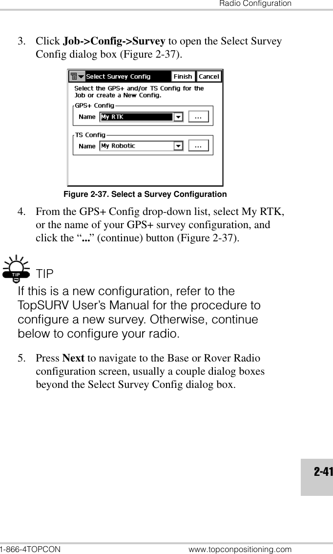
>
Topcon America
>
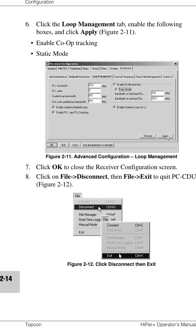
840801 User Manual
Users Manual
Navigation menu
Upload a User Manual
Namespaces
Wiki Guide
HTML
PDF
Info
Views
User Manual
Discussion / Help
Navigation
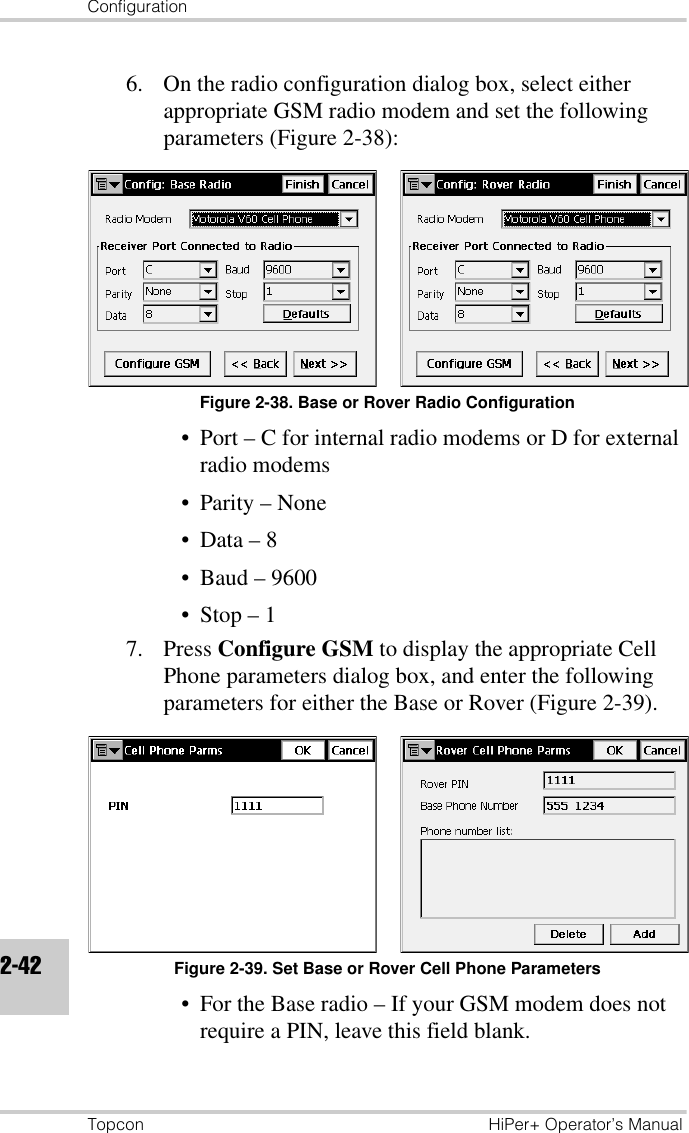
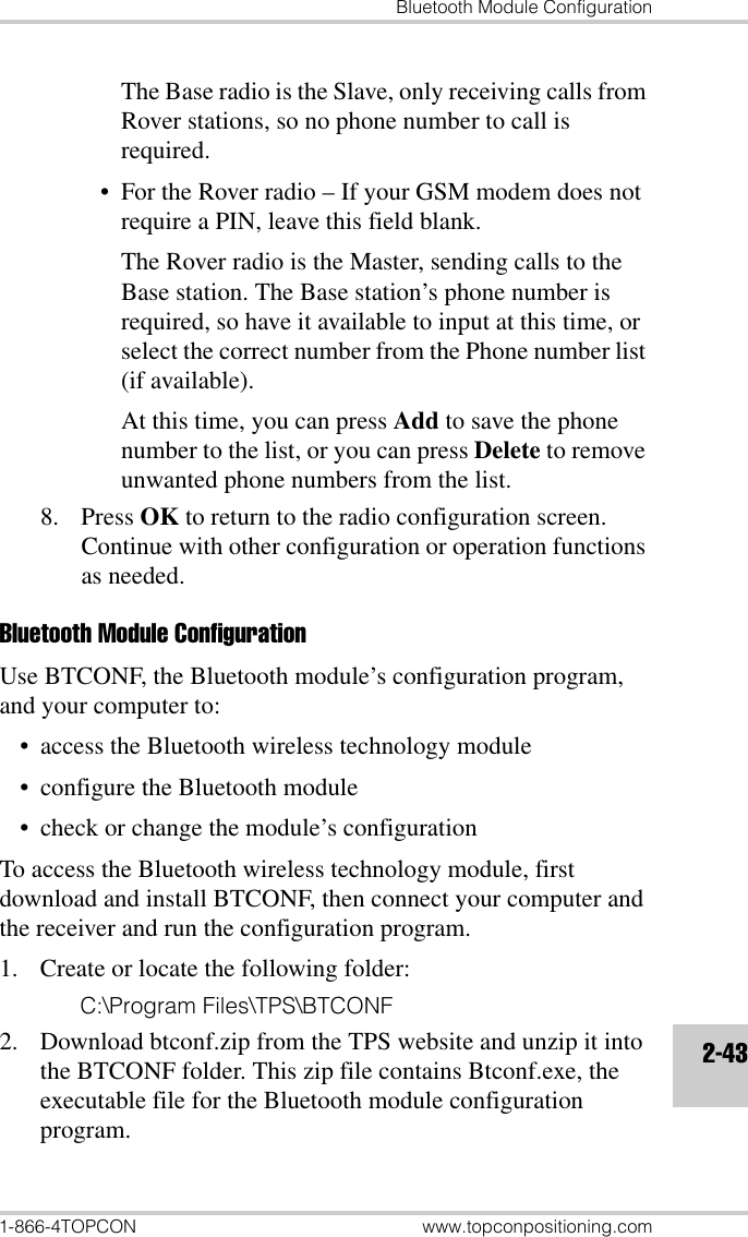
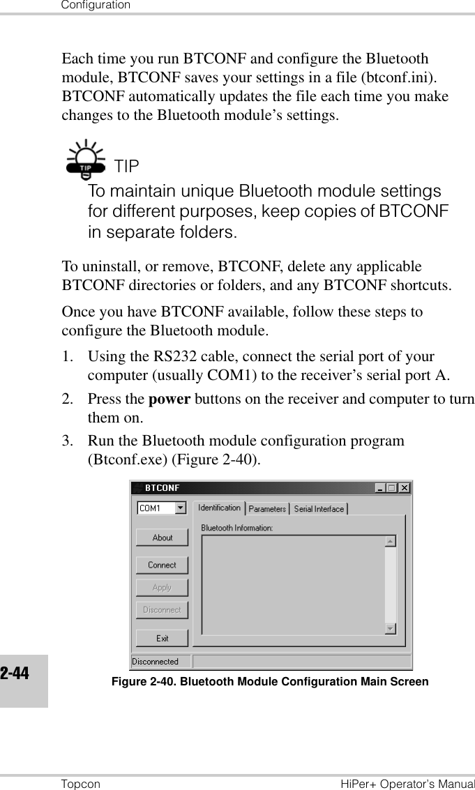
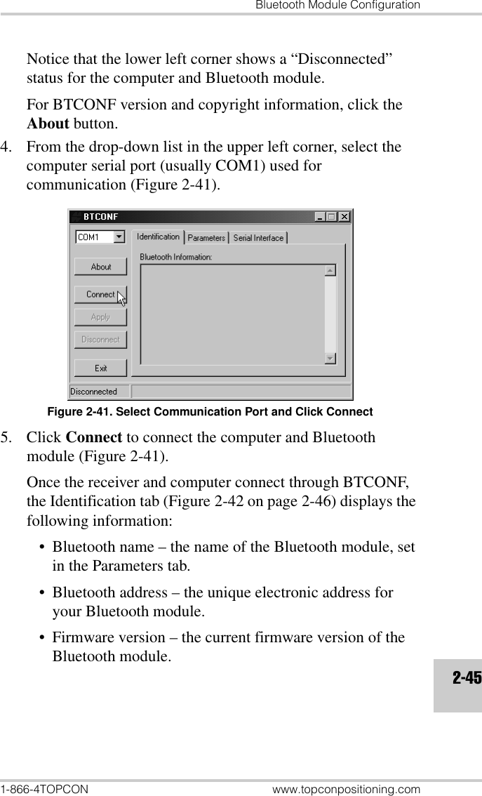
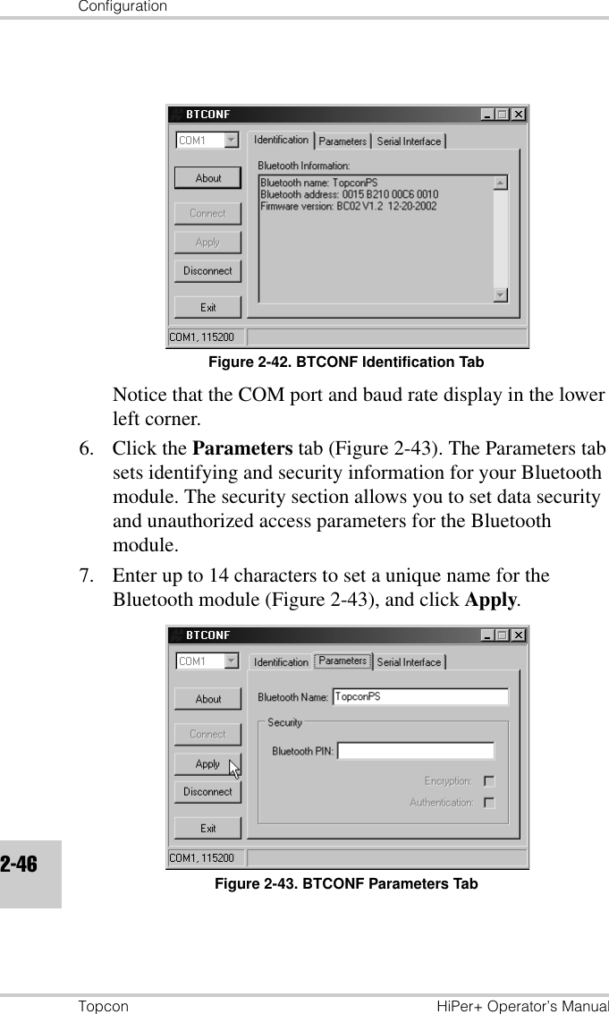
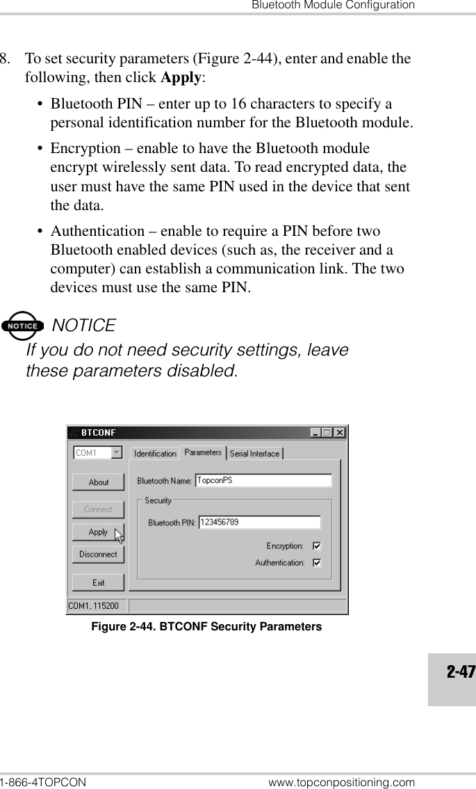
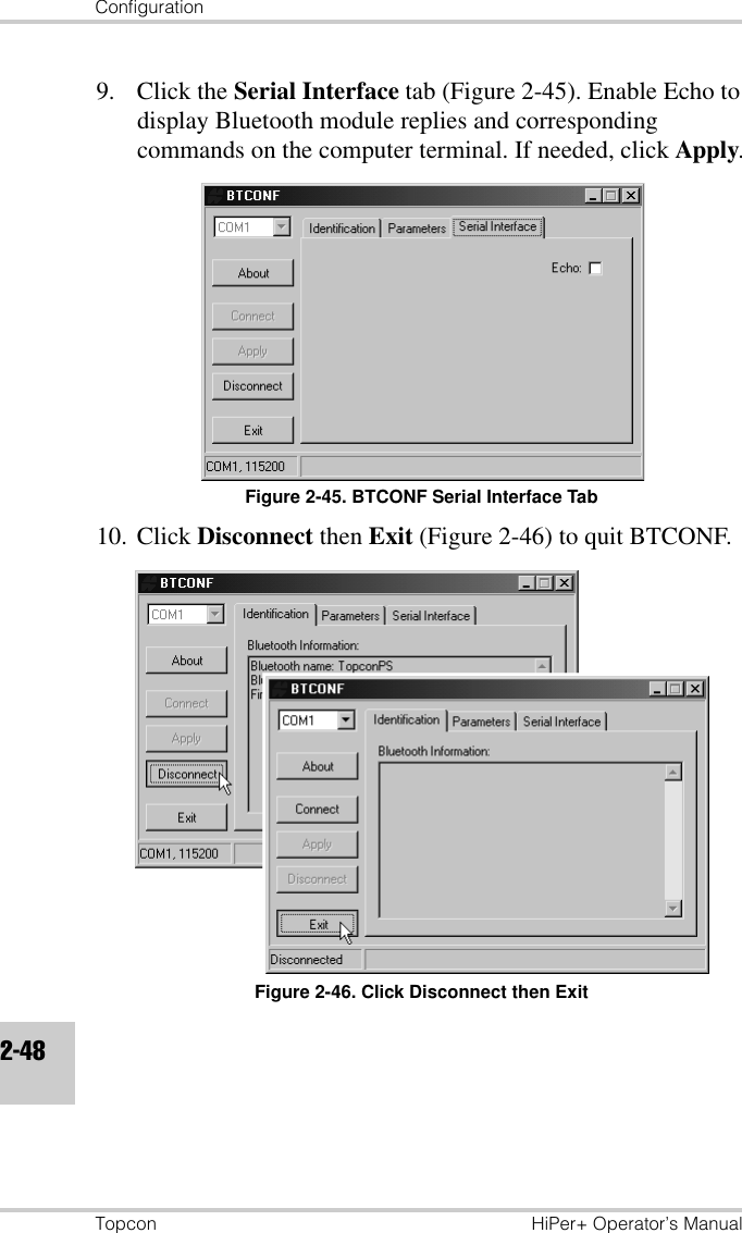
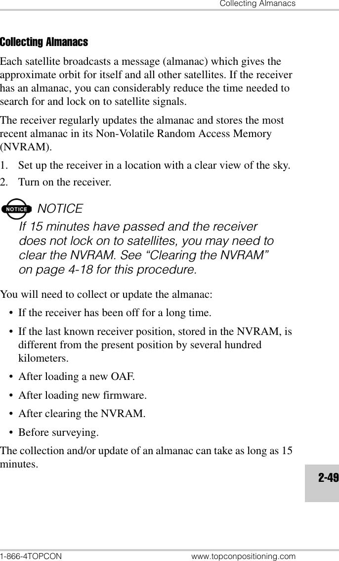
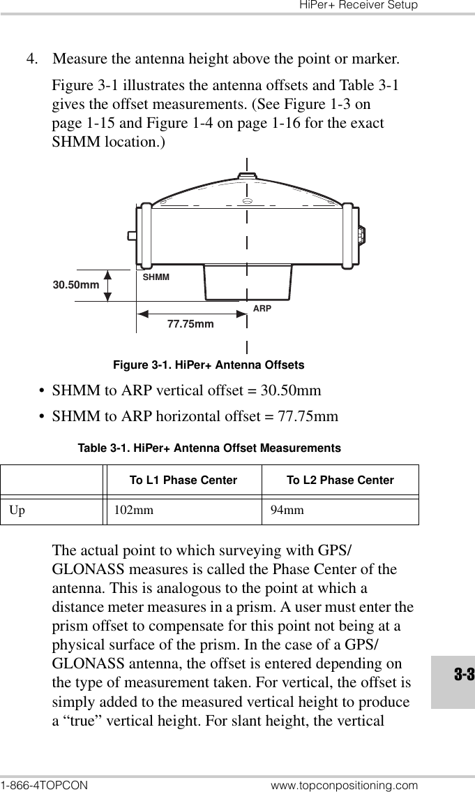
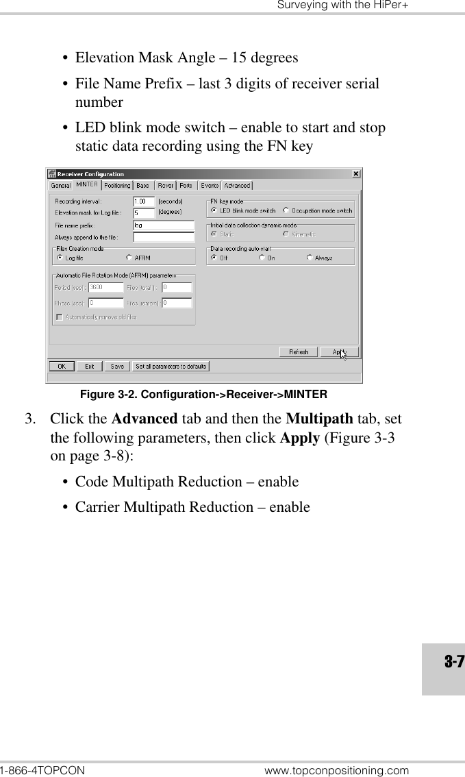
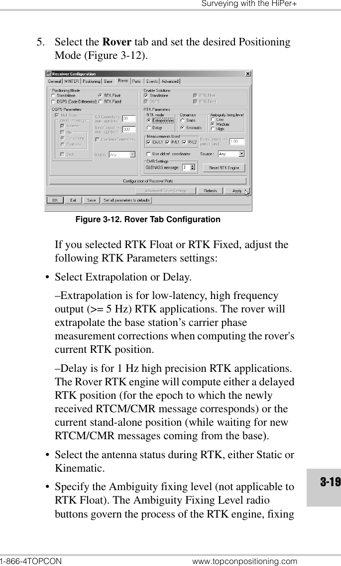
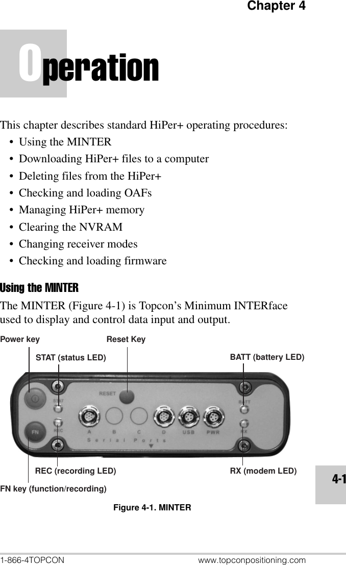
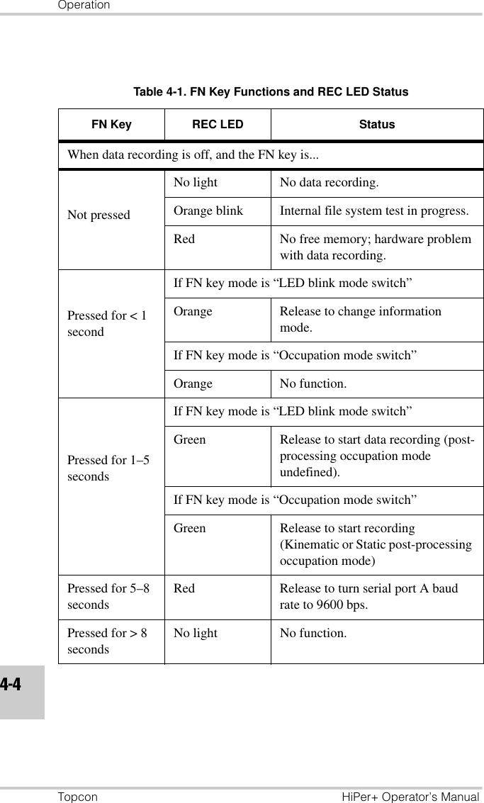
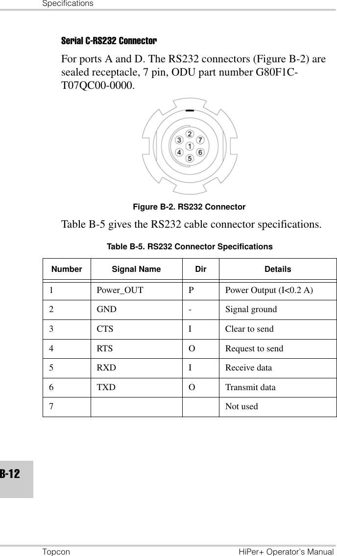
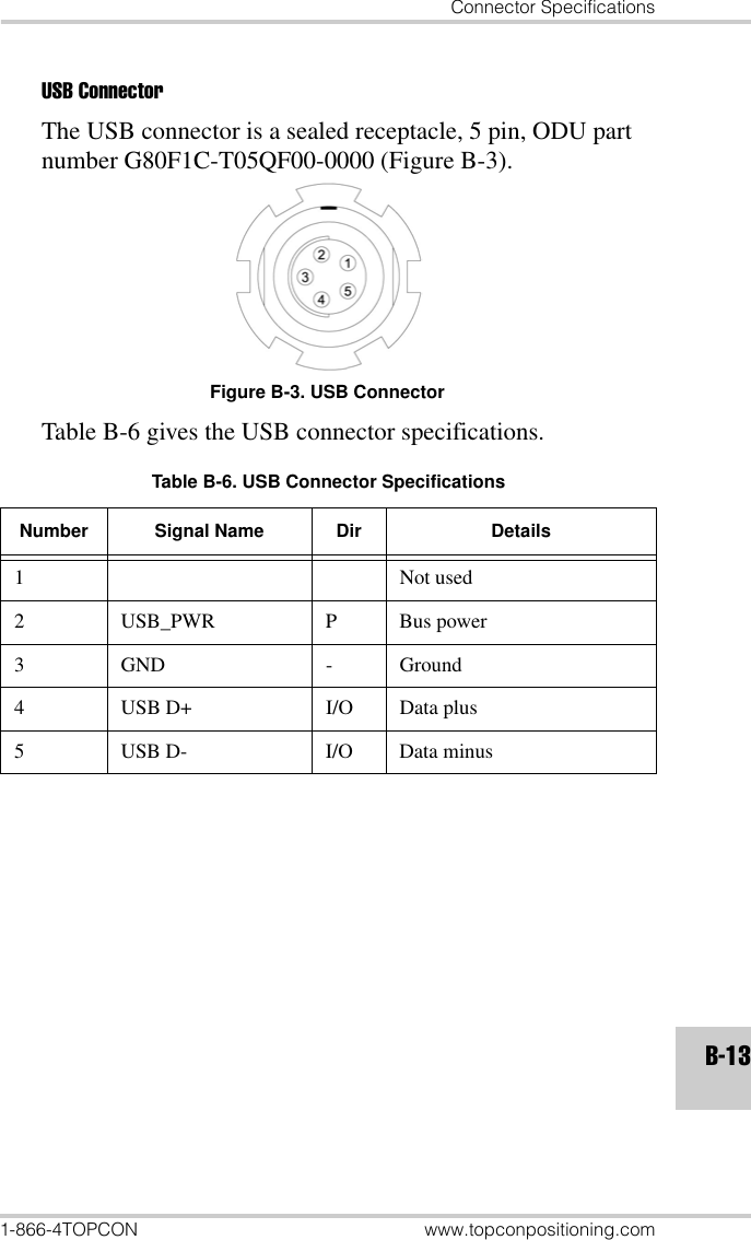
![MINTER Configuration1-866-4TOPCON www.topconpositioning.com2-27• Period – specifies the time duration of each log file created in AFRM mode. Values are 60 to 86400 seconds. The default value is 3600 seconds.• Phase – specifies the “phase” (constant time shift) of creating multiple log files in AFRM mode. Values are 0 to 86400 seconds. The default value is zero seconds.• Files (total) – a counter that specifies how many multiple log files must be created in AFRM until this mode automatically turns off. This counter decrements on every file rotation until it value becomes zero, then file rotation automatically stops. The counter initializes with AFRM.Note that a log file opens immediately after turning AFRM on. This startup file is not considered a file rotation event; the AFRM counter will not decrement.Values are 0 to [231-1]. The default value is 0 (zero). Zero means that an unlimited number of log files will be created.NOTICEThe receiver’s memory holds up to 256 files.• Files (remain) – specifies the number of files left for the receiver to create in AFRM.Values are 0 to [231-1]. The default value is zero.• Automatically remove old files – when no free memory is available to log data, automatically removes the earliest log file. If this parameter is enabled, your receiver will erase the file with the earliest file creation time/date. AFRM must be enabled to use this FIFO (First-In, First-Out) feature.The default value is off (disabled).](https://usermanual.wiki/Topcon-America/840801/User-Guide-322681-Page-67.png)