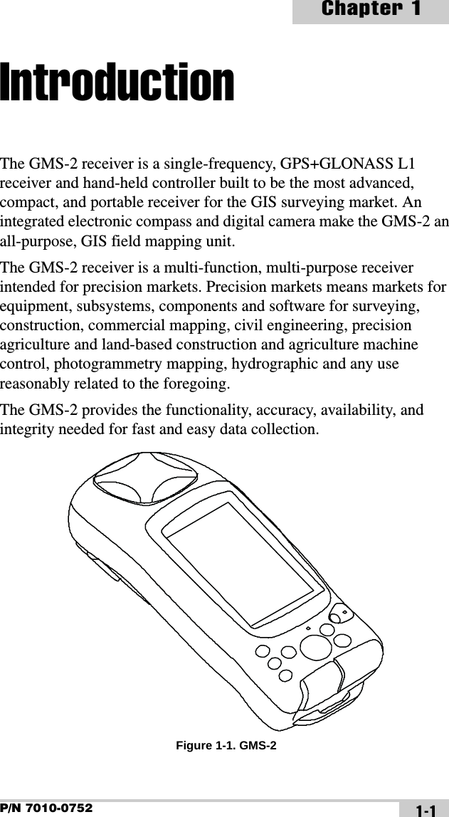
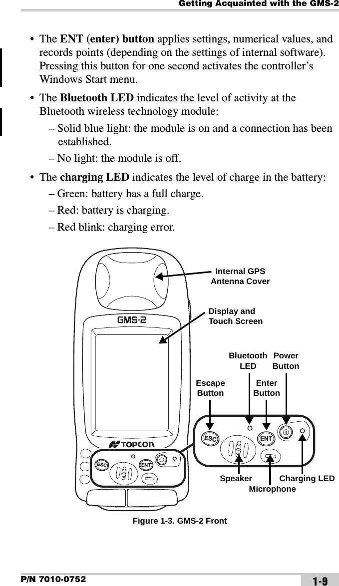
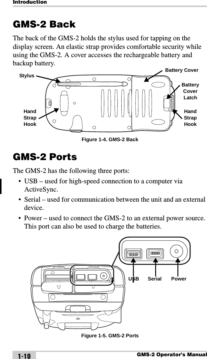
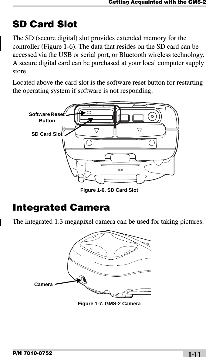
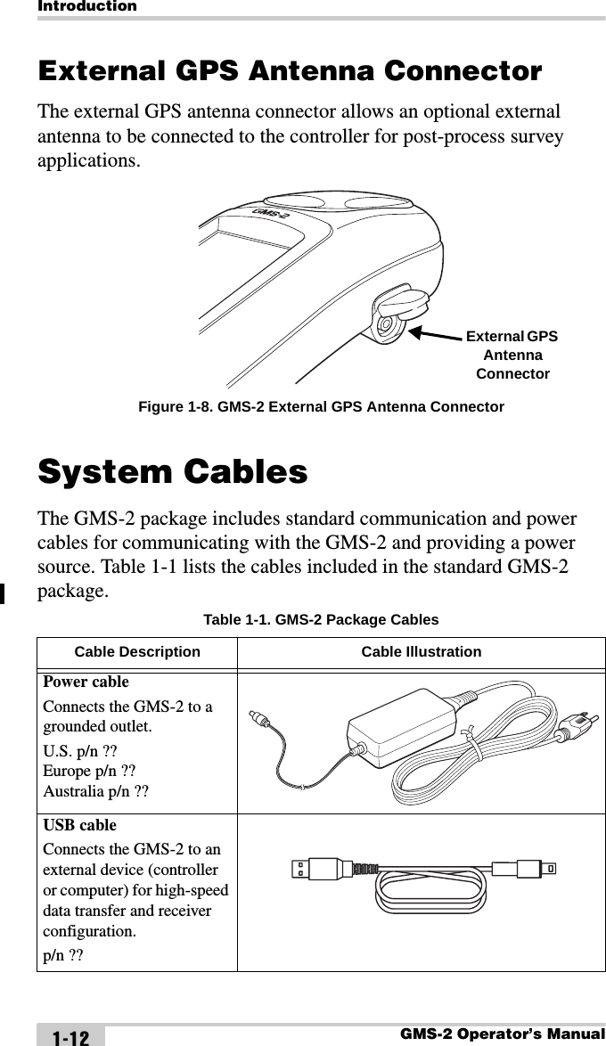
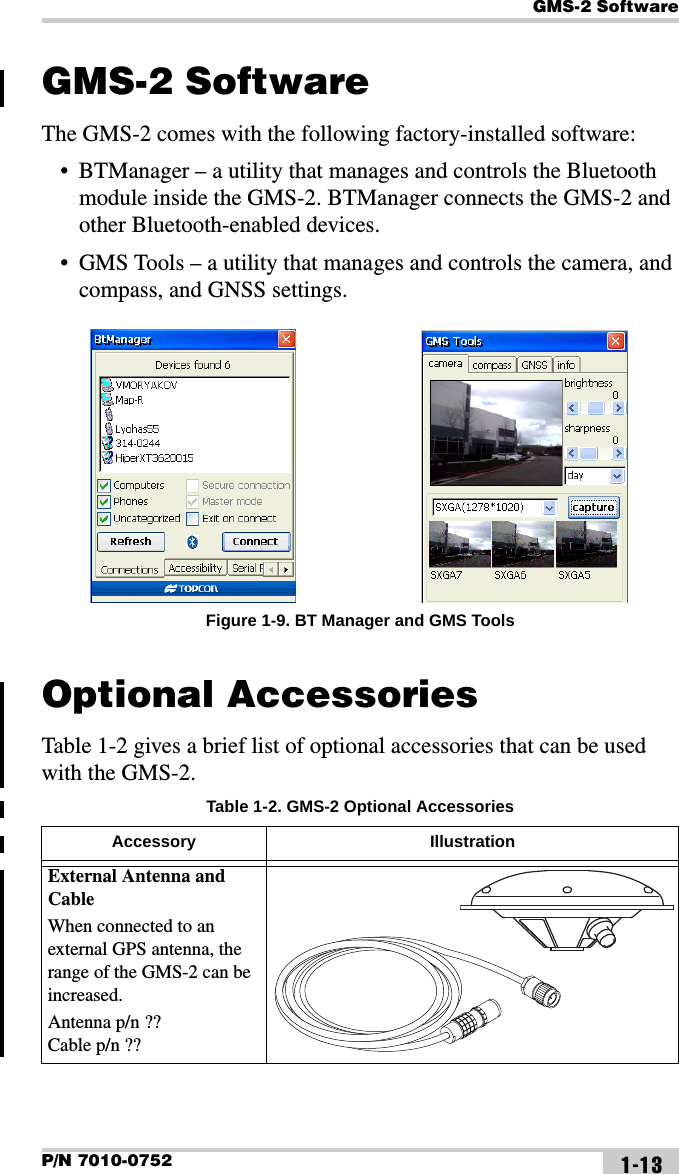
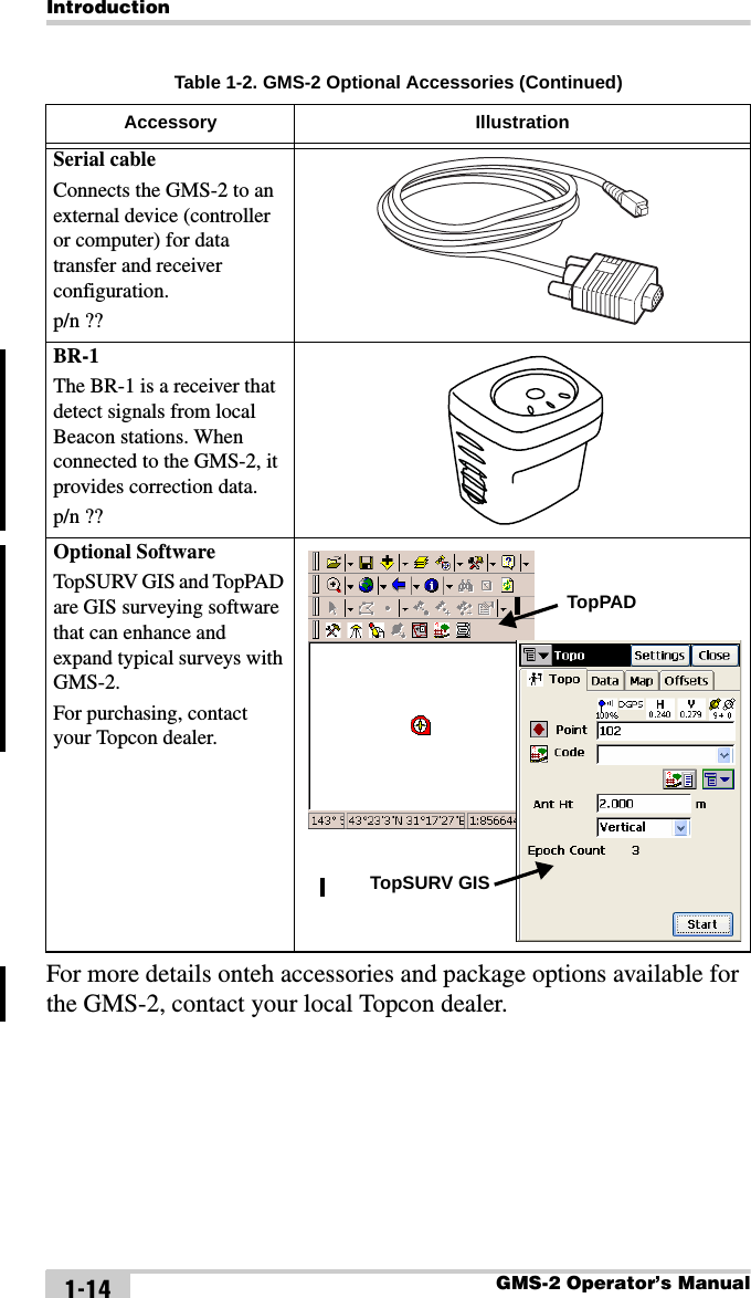
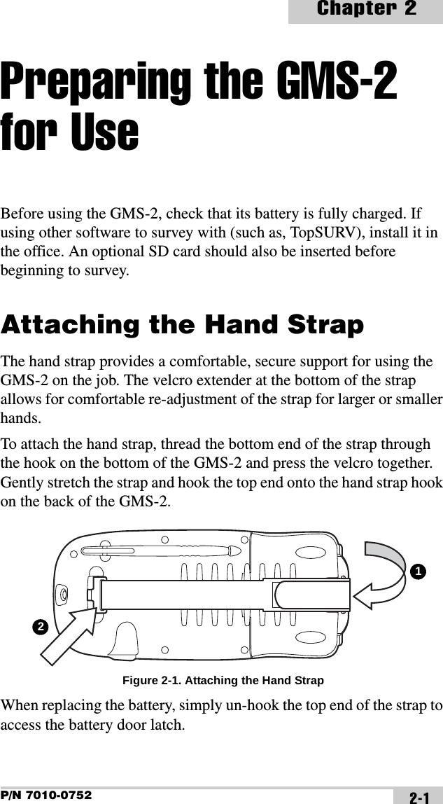
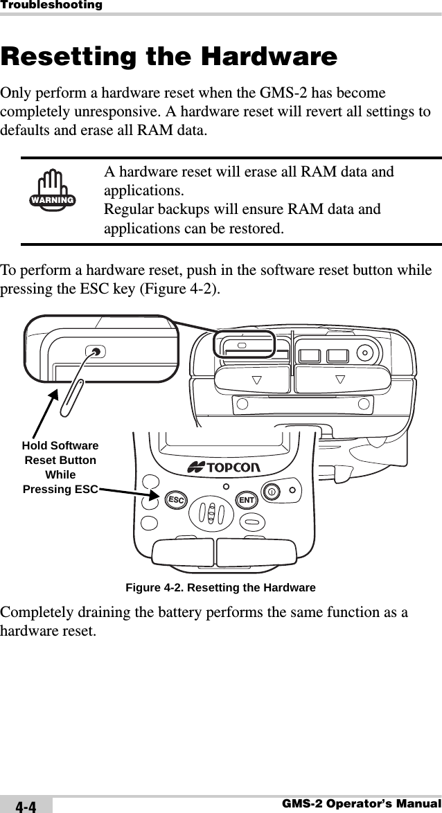
Topcon America 841201 Geodetic Mapping System User Manual GMS 2 om

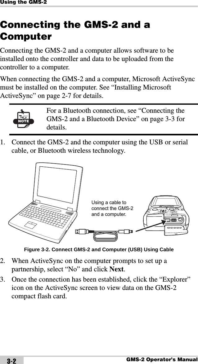
Topcon America Corporation Geodetic Mapping System GMS 2 om

User Manual

Topcon only sells GPS products into Precision Markets.Please go to www.topcongps.com for detailed market information.POSITIONING SYSTEMSGMS-2Operator’s ManualPart Number 7010-0752     DRAFTRev 2©Copyright Topcon Positioning Systems, Inc.April, 2006All contents in this manual are copyrighted by Topcon. All rights reserved. The information contained herein may not be used, accessed, copied, stored, displayed, sold, modified, published, or distributed, or otherwise reproduced without express written consent from Topcon.
ECO#xxxx
P/N 7010-0752TOCiTable of ContentsPreface .................................................................. vTerms and Conditions ......................................................  vManual Conventions ........................................................  viiiChapter 1Introduction .......................................................... 1-1Principles of Operation ....................................................  1-2GNSS Overview ........................................................  1-2Calculating Absolute Positions ...........................  1-3Calculating Differential Positions  ......................  1-4Essential Components for Quality Surveying  ....  1-5Conclusion ..........................................................  1-5GMS-2 Overview ......................................................  1-6Getting Acquainted with the GMS-2 ...............................  1-7Rechargeable and Backup Batteries ..........................  1-8GMS-2 Front  .............................................................  1-8GMS-2 Back ..............................................................  1-10GMS-2 Ports ..............................................................  1-10SD Card Slot  .............................................................  1-11Integrated Camera  .....................................................  1-11External GPS Antenna Connector .............................  1-12System Cables ..................................................................  1-12GMS-2 Software ..............................................................  1-13Optional Accessories  .......................................................  1-13Option Authorization File (OAF)  ....................................  1-15Chapter 2Preparing the GMS-2 for Use  .............................. 2-1Attaching the Hand Strap .................................................  2-1Powering the GMS-2  .......................................................  2-2Charging the Battery  .................................................  2-2Charging and Battery Storage Notes .........................  2-3
Table of ContentsGMS-2 Operator’s ManualiiInstalling the Battery .................................................. 2-4Replacing the Backup Battery  ................................... 2-4Starting the GMS-2  .......................................................... 2-6Installing Software  ........................................................... 2-7Installing an Optional SD Card ........................................ 2-8Chapter 3Using the GMS-2 ..................................................  3-1Connecting the GMS-2 with Other Devices  .................... 3-1Connecting the GMS-2 and a Computer  ................... 3-2Connecting the GMS-2 and a Bluetooth Device  ....... 3-3Surveying with the GMS-2  .............................................. 3-6Surveying with the GMS-2 ........................................ 3-6Surveying with the GMS-2 and an External Antenna  3-7Surveying with the GMS-2 and a Beacon Receiver  .. 3-8Surveying with the GMS-2 and an External GPS Receiver ........................................... 3-9Backing up Windows CE RAM Data  .............................. 3-10Chapter 4Troubleshooting ..................................................  4-1Check This First! .............................................................. 4-1Troubleshooting Quick List  ............................................. 4-2Resetting the Software  ..................................................... 4-3Restoring BTManager and Receiver Defaults  ................. 4-3Resetting the Hardware  .................................................... 4-4Charging/Powering Problems  .......................................... 4-5GMS-2 Problems .............................................................. 4-6Bluetooth Problems .......................................................... 4-7Obtaining Technical Support  ........................................... 4-9Phone ......................................................................... 4-9E-mail ........................................................................ 4-9Website ...................................................................... 4-10
Table of ContentsP/N 7010-0752 iiiAppendix AGMS-2 Software Reference  ................................. A-1BTManager ......................................................................  A-1Getting Acquainted  ...................................................  A-1Working with BTManager  ........................................  A-4Select Accessibility Options ...............................  A-4Enable Serial Port/Dial-up Services  ...................  A-5Connect to a Bluetooth Device ...........................  A-6Resetting the Bluetooth Module ................................  A-8GMS Tools .......................................................................  A-9Getting Acquainted  ...................................................  A-9Working with GMS Tools .........................................  A-11Using the Camera  ...............................................  A-11Using the Compass  .............................................  A-12Viewing GNSS Information and Logging Data  .  A-14Appendix BSpecifications ....................................................... B-1GMS-2 Specifications ......................................................  B-2General Details ..........................................................  B-2GPS Details  ...............................................................  B-5Connector Specifications  .................................................  B-6Serial Connector ........................................................  B-6USB Connector  .........................................................  B-7Appendix CSafety Warnings  ................................................... C-1General Warnings   ...........................................................  C-1Battery Pack Warnings    ..................................................  C-1Usage Warnings  ..............................................................  C-2Appendix DRegulatory Information ........................................ D-1FCC Compliance  .............................................................  D-1Community of Europe Compliance .................................  D-2WEEE Directive  ..............................................................  D-2
Table of ContentsGMS-2 Operator’s ManualivAppendix EWarranty Terms  ...................................................  E-1Index
P/N 7010-0752PrefacevPrefaceThank you for purchasing this Topcon product. The materials available in this Manual (the “Manual”) have been prepared by Topcon Positioning Systems, Inc. (“TPS”) for owners of Topcon products, and are designed to assist owners with the use of the receiver and its use is subject to these terms and conditions (the “Terms and Conditions”). Terms and ConditionsUSE This product is designed to be used by a professional. The user should have a good knowledge of the safe use of the product and implement the types of safety procedures recommended by the local government protection agency for both private use and commercial job sites.COPYRIGHT All information contained in this Manual is the intellectual property of, and copyrighted material of TPS. All rights are reserved. You may not use, access, copy, store, display, create derivative works of, sell, modify, publish, distribute, or allow any third party access to, any graphics, content, information or data in this Manual without TPS’ express written consent and may only use such information for the care and operation of your receiver. The information and data in this Manual are a valuable asset of TPS and are developed by the expenditure of considerable work, time and money, and are the result of original selection, coordination and arrangement by TPS.NOTICE Please read these Terms and Conditions carefully.
PrefaceGMS-2 Operator’s ManualviTRADEMARKS HiPer®, GMS-2™, GMS Tools™, BTManager™, Topcon® and Topcon Positioning Systems™ are trademarks or registered trademarks of TPS. Windows® is a registered trademark of Microsoft Corporation. The Bluetooth® word mark and logos are owned by Bluetooth SIG, Inc. and any use of such marks by Topcon Positioning Systems, Inc. is used under license. Other product and company names mentioned herein may be trademarks of their respective owners.DISCLAIMER OF WARRANTY EXCEPT FOR ANY WARRANTIES IN AN APPENDIX OR A WARRANTY CARD ACCOMPANYING THE PRODUCT, THIS MANUAL AND THE RECEIVER ARE PROVIDED “AS-IS.” THERE ARE NO OTHER WARRANTIES. TPS DISCLAIMS ANY IMPLIED WARRANTY OF MERCHANTABILITY OR FITNESS FOR ANY PARTICULAR USE OR PURPOSE. TPS AND ITS DISTRIBUTORS SHALL NOT BE LIABLE FOR TECHNICAL OR EDITORIAL ERRORS OR OMISSIONS CONTAINED HEREIN; NOR FOR INCIDENTAL OR CONSEQUENTIAL DAMAGES RESULTING FROM THE FURNISHING, PERFORMANCE OR USE OF THIS MATERIAL OR THE RECEIVER. SUCH DISCLAIMED DAMAGES INCLUDE BUT ARE NOT LIMITED TO LOSS OF TIME, LOSS OR DESTRUCTION OF DATA, LOSS OF PROFIT, SAVINGS OR REVENUE, OR LOSS OF THE PRODUCT’S USE. IN ADDITION TPS IS NOT RESPONSIBLE OR LIABLE FOR DAMAGES OR COSTS INCURRED IN CONNECTION WITH OBTAINING SUBSTITUTE PRODUCTS OR SOFTWARE, CLAIMS BY OTHERS, INCONVENIENCE, OR ANY OTHER COSTS. IN ANY EVENT, TPS SHALL HAVE NO LIABILITY FOR DAMAGES OR OTHERWISE TO YOU OR ANY OTHER PERSON OR ENTITY IN EXCESS OF THE PURCHASE PRICE FOR THE RECEIVER. LICENSE AGREEMENT Use of any computer programs or software supplied by TPS or downloaded from a TPS website (the “Software”) in connection with the receiver constitutes acceptance of these Terms and Conditions in this Manual and an agreement to abide by these Terms and Conditions. The user is granted a personal, non-exclusive, non-transferable license to use such Software under the terms stated herein and in any case only with a single receiver or single computer.
Terms and ConditionsP/N 7010-0752 viiYou may not assign or transfer the Software or this license without the express written consent of TPS. This license is effective until terminated. You may terminate the license at any time by destroying the Software and Manual. TPS may terminate the license if you fail to comply with any of the Terms or Conditions. You agree to destroy the Software and manual upon termination of your use of the receiver. All ownership, copyright and other intellectual property rights in and to the Software belong to TPS. If these license terms are not acceptable, return any unused software and manual.CONFIDENTIALITY This Manual, its contents and the Software (collectively, the “Confidential Information”) are the confidential and proprietary information of TPS. You agree to treat TPS’ Confidential Information with a degree of care no less stringent that the degree of care you would use in safeguarding your own most valuable trade secrets. Nothing in this paragraph shall restrict you from disclosing Confidential Information to your employees as may be necessary or appropriate to operate or care for the receiver. Such employees must also keep the Confidentiality Information confidential. In the event you become legally compelled to disclose any of the Confidential Information, you shall give TPS immediate notice so that it may seek a protective order or other appropriate remedy.WEBSITE; OTHER STATEMENTS No statement contained at the TPS website (or any other website) or in any other advertisements or TPS literature or made by an employee or independent contractor of TPS modifies these Terms and Conditions (including the Software license, warranty and limitation of liability). SAFETY Improper use of the receiver can lead to injury to persons or property and/or malfunction of the product. The receiver should only be repaired by authorized TPS warranty service centers. Users should review and heed the safety warnings in an Appendix.MISCELLANEOUS The above Terms and Conditions may be amended, modified, superseded, or canceled, at any time by TPS. The above Terms and Conditions will be governed by, and construed in accordance with, the laws of the State of California, without reference to conflict of laws.
PrefaceGMS-2 Operator’s ManualviiiManual ConventionsThis manual uses the following conventions:Example DescriptionFileExit Click the File menu and click Exit.Connection Indicates the name of a dialog box or screen.Frequency Indicates a field on a dialog box or screen, or a tab within a dialog box or screen.Enter Press or click the button or key labeled Enter.     NOTEFurther information to note about the configuration, maintenance, or setup of a system.TIPSupplementary information that can help you configure, maintain, or set up a system.NOTICESupplementary information that can have an affect on system operation, system performance, measurements, or personal safety.CAUTIONNotification that an action has the potential to adversely affect system operation, system performance, data integrity, or personal health.WARNINGNotification that an action will result in system damage, loss of data, loss of warranty, or personal injury.
Manual ConventionsP/N 7010-0752 ixDANGER Under no circumstances should this action be performed.
PrefaceGMS-2 Operator’s ManualNotes:x
P/N 7010-0752Chapter 11-1IntroductionThe GMS-2 receiver is a single-frequency, GPS+GLONASS L1 receiver and hand-held controller built to be the most advanced, compact, and portable receiver for the GIS surveying market. An integrated electronic compass and digital camera make the GMS-2 an all-purpose, GIS field mapping unit.The GMS-2 receiver is a multi-function, multi-purpose receiver intended for precision markets. Precision markets means markets for equipment, subsystems, components and software for surveying, construction, commercial mapping, civil engineering, precision agriculture and land-based construction and agriculture machine control, photogrammetry mapping, hydrographic and any use reasonably related to the foregoing.The GMS-2 provides the functionality, accuracy, availability, and integrity needed for fast and easy data collection. Figure 1-1. GMS-2
IntroductionGMS-2 Operator’s Manual1-2Principles of OperationSurveying with the right GPS receiver can provide users accurate and precise positioning, a requirement for any surveying project.This section gives an overview of existing and proposed Global Navigation Satellite Systems (GNSS) and receiver functions to help you understand and apply basic operating principles, allowing you to get the most out of your receiver.GNSS OverviewCurrently, the following three global navigation satellite systems (GNSS) offer line-of-site radio navigation and positioning, velocity, and time services on a global, all-weather, 24-hour scale to any user equipped with a GNSS tracking receiver on or near the Earth’s surface:• GPS – the Global Positioning System maintained and operated by the United States Department of Defense. For information on the status of this system, visit the US Naval Observatory website (http://tycho.usno.navy.mil/) or the US Coast Guard website (http://www.navcen.uscg.gov/).• GLONASS – the Global Navigation Satellite System maintained and operated by the Russian Federation Ministry of Defense. For information on the status of this system, visit the Ministry of Defense website (http://www.glonass-center.ru/frame_e.html).• GALILEO – an upcoming global positioning system maintained and operated by Galileo Industries, a joint venture of several European space agencies working closely with the European Space Agency. Unlike GPS and GLONASS, this is a civil endeavor and is currently in the development and validation stage. For information on the status of this system, visit the Galileo Industries website (http://www.galileo-industries.net).
Principles of OperationP/N 7010-0752 1-3Despite numerous technical differences in the implementation of these systems, satellite positioning systems have three essential components:• Space – GPS, GLONASS, and GALILEO satellites orbit approximately 12,000 nautical miles above Earth and are equipped with a clock and radio. These satellites broadcast digital information (ephemerides, almanacs, time&frequency corrections, etc.).• Control – Ground stations located around the Earth that monitor the satellites and upload data, including clock corrections and new ephemerides (satellite positions as a function of time), to ensure the satellites transmit data properly.• User – The community and military that use GNSS receivers and the corresponding satellites to calculate positions.Calculating Absolute PositionsWhen calculating an absolute position, a stationary or moving receiver determines its three-dimensional position with respect to the origin of an Earth-Center Earth-Fixed coordinate system. To calculate this position, the receiver measures the distance (called pseudo-ranges) between it and at least four satellites. The measured pseudo-ranges are corrected for clock differences (receiver and satellites) and signal propagation delays due to atmospheric effects. The positions of the satellites are computed from the ephemeris data transmitted to the receiver in navigation messages. When using a single satellite system, the minimum number of satellites needed to compute a position is four. In a mixed satellite scenario (GPS, GLONASS, GALILEO), the receiver must lock onto at least five satellites to obtain an absolute position. To provide fault tolerance using only GPS or only GLONASS, the receiver must lock onto a fifth satellite. Six satellites will provide fault tolerance in mixed scenarios.
IntroductionGMS-2 Operator’s Manual1-4Calculating Differential PositionsDGPS, or Differential GPS, typically uses the measurements from two or more remote receivers to calculate the difference (corrections) between measurements, thus providing more accurate position solutions.With DGPS, one receiver is placed at a known, surveyed location and is referred to as the reference receiver or base station. Another receiver is placed at an unknown, location and is referred to as the remote receiver or rover. The reference station collects the range measurements from each GPS satellite in view and forms the differences (corrections) between the calculated distance to the satellites and the measured pseudo-ranges to the satellites.These corrections are then built up to the industry standard (RTCM or various proprietary standards) established for transmitting differential corrections and broadcast to the remote receiver(s) using a data communication link. The remote receiver applies the transmitted DGPS corrections to its range measurements of the same satellites.Using this technique, the spatially correlated errors—such as satellite orbital errors, ionospheric errors, and tropospheric errors—can be significantly reduced, thus improving the position solution accuracy of the GPS.A number of differential positioning implementations exist, including post-processing surveying, real-time kinematic surveying, maritime radio beacons, geostationary satellites (as with the OmniSTAR service), and the wide area augmentation system (WAAS) service.The real-time kinematic (RTK) method is the most precise method of real-time surveying. RTK requires at least two receivers collecting navigation data and communication data link between the receivers. One of the receivers is usually at a known location (Base) and the other is at an unknown location (Rover). The Base receiver collects carrier phase measurements, generates RTK corrections, and sends this data to the Rover receiver. The Rover processes this transmitted data with its own carrier phase observations to compute its relative position with high accuracy, achieving an RTK accuracy of up to 1 cm horizontal and 1.5 cm vertical.
Principles of OperationP/N 7010-0752 1-5Essential Components for Quality SurveyingAchieving quality position results requires the following elements:• Accuracy – The accuracy of a position primarily depends upon the satellite geometry (Geometric Dilution of Precision, or GDOP) and the measurement (ranging) errors.– Differential positioning (DGPS and RTK) strongly mitigates atmospheric and orbital errors, and counteracts Selective Availability (SA) signals the US Department of Defense transmits with GPS signals.– The more satellites in view, the stronger the signal, the lower the DOP number, the higher positioning accuracy.• Availability – The availability of satellites affects the calculation of valid positions. The more visible satellites available, the more valid and accurate the position. Natural and man-made objects can block, interrupt, and distort signals, lowering the number of available satellites and adversely affecting signal reception.• Integrity – Fault tolerance allows a position to have greater integrity, increasing accuracy. Several factors combine to provide fault tolerance, including:– Receiver Autonomous Integrity Monitoring (RAIM) detects faulty GPS and GLONASS satellites and removes them from the position calculation.– Five or more visible satellites for only GPS or only GLONASS; six or more satellites for mixed scenarios.– Wide Area Augmentation Systems (WAAS, EGNOS, etc.) creates and transmit, along with DGPS corrections, data integrity information (for example, satellite health warnings).– Current ephemerides and almanacs.ConclusionThis overview simply outlines the basics of satellite positioning. For more detailed information, visit the TPS website.
IntroductionGMS-2 Operator’s Manual1-6GMS-2 OverviewThe GMS-2 is a fully integrated hand-held controller and GPS+ receiver. Included in the system is an electronic compass and digital camera.The hand-held controller component of the GMS-2 includes the Windows® CE operating system and color LCD touch screen. Integrated Bluetooth® wireless technology allows this system to be a cable-free controller/receiver for maximum portability. The rugged casing is durable and built for rugged use.As a field controller, the GMS-2 can run a full suite of field software for working with total stations and RTK GPS systems.The GPS+ receiver component of the GMS-2 can receive and process GPS+GLONASS L1 signals improving the accuracy of your survey points and positions. The GPS+ features of the receiver combine to provide a positioning system accurate for any survey. Several other features, including multipath mitigation, provide under-canopy and low signal strength reception.When power is turned on and the receiver self-test completes, the receiver’s 50 channels initialize and begin tracking visible satellites. Each of the receiver’s channels can be used to track any one of the GPS or GLONASS signals. The number of channels available allows the receiver to track all visible GPS satellites at any time and location.An internal GPS antenna equipped with a low noise amplifier (LNA) and the receiver’s radio frequency (RF) device are connected with a coaxial cable. The wide-band signal received is down-converted, filtered, digitized, and assigned to different channels. The receiver processor controls the process of signal tracking.Once the signal is locked in the channel, it is demodulated and necessary signal parameters (carrier and code phases) are measured. Also, broadcast navigation data are retrieved from the navigation frame. After the receiver locks on to four or more satellites, it is possible to solve the so-called “absolute positioning problem” and compute the receiver’s coordinates (in WGS-84) and the time offset between the
Getting Acquainted with the GMS-2P/N 7010-0752 1-7receiver clock and GPS time. All this information can be stored in the the optional SD card and internal flash memory, then processed using a post-processing software package.Depending on your options, capabilities of the receiver include:• Multipath reduction• Wide area augmentation system (WAAS)• Single-frequency static, kinematic, and differential GPS (DGPS) survey modes• Setting different mask angles• Setting different survey parametersThe integrated 1.3 megapixel camera is used taking pictures of surveyed objects or survey sites.Getting Acquainted with the GMS-2The GMS-2 is an integrated field controller and 50-channel GPS receiver with an internal electronic compass and digital camera. USB and serial ports, along with Bluetooth® wireless technology provide communication paths with other devices. An external GPS antenna connector allows an optional PG-A5 antenna to be connected for centimeter-level surveys.The standard GMS-2 package contains the following items:• GMS-2 integrated receiver/controller activated for GPS L1 signals• Handstrap and soft case• USB cable and power converter/adapter cable• BTManager and GMS Tools factory-installed softwareFor more details on accessories and options available for the GMS-2, contact your local Topcon dealer.
IntroductionGMS-2 Operator’s Manual1-8Rechargeable and Backup BatteriesThe GMS-2 comes equipped with a rechargeable battery (Figure 1-2) for powering the unit. The battery can be charged in the unit or in an optional battery charger. A backup battery is also located in the battery pocket. The battery provides seven hours of operation, depending on the mode of the receiver. Under normal conditions, the backup battery provides eight to ten years of power backup for data and system integrity. Figure 1-2. GMS-2 BatteryGMS-2 FrontThe front of the GMS-2 (Figure 1-3 on page 1-9) is the primary interface with its components and installed software.•The internal GPS antenna detects signals from GPS+ satellites and sends them to the GPS receiver board for processing.•The display screen and touch panel provides a graphical and tactile user interface for the unit.•The power button turns the receiver on and off.•The ESC (escape) button exits from the current screen or function.Backup BatteryBattery
Getting Acquainted with the GMS-2P/N 7010-0752 1-9•The ENT (enter) button applies settings, numerical values, and records points (depending on the settings of internal software). Pressing this button for one second activates the controller’s Windows Start menu.•The Bluetooth LED indicates the level of activity at the Bluetooth wireless technology module:– Solid blue light: the module is on and a connection has been established.– No light: the module is off.•The charging LED indicates the level of charge in the battery:– Green: battery has a full charge.– Red: battery is charging.– Red blink: charging error. Figure 1-3. GMS-2 FrontENTESCENTESCEscape ButtonSpeakerMicrophoneCharging LEDEnter ButtonPower ButtonBluetooth LEDDisplay and Touch ScreenInternal GPS Antenna Cover
IntroductionGMS-2 Operator’s Manual1-10GMS-2 BackThe back of the GMS-2 holds the stylus used for tapping on the display screen. An elastic strap provides comfortable security while using the GMS-2. A cover accesses the rechargeable battery and backup battery. Figure 1-4. GMS-2 BackGMS-2 PortsThe GMS-2 has the following three ports:• USB – used for high-speed connection to a computer via ActiveSync.• Serial – used for communication between the unit and an external device.• Power – used to connect the GMS-2 to an external power source. This port can also be used to charge the batteries. Figure 1-5. GMS-2 PortsStylus Battery CoverHand Strap HookHand Strap HookBattery Cover LatchUSB Serial Power
Getting Acquainted with the GMS-2P/N 7010-0752 1-11SD Card SlotThe SD (secure digital) slot provides extended memory for the controller (Figure 1-6). The data that resides on the SD card can be accessed via the USB or serial port, or Bluetooth wireless technology. A secure digital card can be purchased at your local computer supply store. Located above the card slot is the software reset button for restarting the operating system if software is not responding. Figure 1-6. SD Card SlotIntegrated CameraThe integrated 1.3 megapixel camera can be used for taking pictures. Figure 1-7. GMS-2 CameraSD Card SlotSoftware Reset ButtonCamera
IntroductionGMS-2 Operator’s Manual1-12External GPS Antenna ConnectorThe external GPS antenna connector allows an optional external antenna to be connected to the controller for post-process survey applications. Figure 1-8. GMS-2 External GPS Antenna ConnectorSystem CablesThe GMS-2 package includes standard communication and power cables for communicating with the GMS-2 and providing a power source. Table 1-1 lists the cables included in the standard GMS-2 package. Table 1-1. GMS-2 Package CablesCable Description Cable IllustrationPower cableConnects the GMS-2 to a grounded outlet. U.S. p/n ??Europe p/n ??Australia p/n ??USB cableConnects the GMS-2 to an external device (controller or computer) for high-speed data transfer and receiver configuration.p/n ??External GPS Antenna Connector
GMS-2 SoftwareP/N 7010-0752 1-13GMS-2 SoftwareThe GMS-2 comes with the following factory-installed software:• BTManager – a utility that manages and controls the Bluetooth module inside the GMS-2. BTManager connects the GMS-2 and other Bluetooth-enabled devices.• GMS Tools – a utility that manages and controls the camera, and compass, and GNSS settings. Figure 1-9. BT Manager and GMS ToolsOptional AccessoriesTable 1-2 gives a brief list of optional accessories that can be used with the GMS-2. Table 1-2. GMS-2 Optional AccessoriesAccessory IllustrationExternal Antenna and CableWhen connected to an external GPS antenna, the range of the GMS-2 can be increased.Antenna p/n ??Cable p/n ??
IntroductionGMS-2 Operator’s Manual1-14For more details onteh accessories and package options available for the GMS-2, contact your local Topcon dealer.Serial cableConnects the GMS-2 to an external device (controller or computer) for data transfer and receiver configuration.p/n ??BR-1The BR-1 is a receiver that detect signals from local Beacon stations. When connected to the GMS-2, it provides correction data.p/n ??Optional SoftwareTopSURV GIS and TopPAD are GIS surveying software that can enhance and expand typical surveys with GMS-2.For purchasing, contact your Topcon dealer.Table 1-2. GMS-2 Optional Accessories (Continued)Accessory IllustrationTopPADTopSURV GIS
Option Authorization File (OAF)P/N 7010-0752 1-15Option Authorization File (OAF)Topcon Positioning Systems issues an Option Authorization File (OAF) to enable the specific options that customers purchase. An Option Authorization File allows customers to customize and configure the receiver according to particular needs, thus only purchasing those options needed. Typically, all receivers ship with a temporary OAF that allows it to be used for a predetermined period of time. When the receiver is purchased, a new OAF permanently activates desired, purchased options. Receiver options remain intact when clearing the NVRAM or resetting the receiver.The OAF enables the following kinds of functions. For a complete list of available options and details, visit the TPS website or consult your TPS dealer.• Type of signal (standard GPS L1; optional GLONASS L1)• Update rate standard 1Hz (optional 5, 10, or 20Hz)• RTK at 1Hz, 5Hz, 10Hz, and 20Hz• RTCM/CMR Input/Output•Event marker• Advanced multipath reduction• Wide Area Augmentation System (WAAS)• Receiver Autonomous Integrity Monitoring (RAIM)
IntroductionGMS-2 Operator’s ManualNotes:1-16
P/N 7010-0752Chapter 22-1Preparing the GMS-2 for UseBefore using the GMS-2, check that its battery is fully charged. If using other software to survey with (such as, TopSURV), install it in the office. An optional SD card should also be inserted before beginning to survey.Attaching the Hand StrapThe hand strap provides a comfortable, secure support for using the GMS-2 on the job. The velcro extender at the bottom of the strap allows for comfortable re-adjustment of the strap for larger or smaller hands.To attach the hand strap, thread the bottom end of the strap through the hook on the bottom of the GMS-2 and press the velcro together. Gently stretch the strap and hook the top end onto the hand strap hook on the back of the GMS-2. Figure 2-1. Attaching the Hand StrapWhen replacing the battery, simply un-hook the top end of the strap to access the battery door latch.12
Preparing the GMS-2 for UseGMS-2 Operator’s Manual2-2Powering the GMS-2The GMS-2 uses a BT-62Q battery for it’s primary power source. When using the GMS-2 for GPS activities, the battery will last up to seven hours. The battery will last up to fifty hours during continuous standby use (that is, no GPS usage, the display LED is off, and the touch screen is not being used). A backup coin battery saves GPS and clock settings. An internal, rechargeable battery backs up RAM data for Windows CE.Charging the BatteryThe AC/DC converter both provides power to the GMS-2 and charges the primary battery. Note that using the GMS-2 while charging increases the charge time. The battery will be fully charged in approximately seven hours. To charge the battery using the converter, (Figure 2-2) plug the connector into the power port of the GMS-2. Then plug the converter into a grounded outlet. The battery will be fully charged after about six hours.The charging LED indicates the level of charge in the battery:• Green – battery has a full charge.• Red – battery is charging.• Red blink – charging error. Figure 2-2. Charging the Battery in the GMS-2Charge LEDTo Grounded Outlet
Powering the GMS-2P/N 7010-0752 2-3To charge the battery using the optional charger, (Figure 2-3) remove the battery from the GMS-2 (see “Installing the Battery” on page 2-4 for details) and slide it onto the charger. Plug the charger in to a grounded outlet. Figure 2-3. Charging the Battery in the ChargerCharging and Battery Storage NotesKeep the following in mind for proper charging, maintenance, and storage of the battery.• Only recharge the battery at room temperature, approximately 50°F to 104°F (10°C to 40°C). Charging at a high temperature will increase the time it takes to charge the battery.• The battery will discharge during storage. Always check the battery charge before using the GMS-2.• Charge a stored battery every 7 days. Allowing a battery to become discharged can reduce the overall performance of the battery and charge efficiency.• The charger may become somewhat heated while charging the GMS-2.To Grounded Outlet
Preparing the GMS-2 for UseGMS-2 Operator’s Manual2-4Installing the BatteryThe rechargeable battery can be charged using either the power port (see “Charging the Battery” on page 2-2) or the optional charger. Follow these steps to remove/replace the battery (Figure 2-4).1. If needed, unhook the top of the strap from the GMS-2.2. Open the battery cover and pop out the primary battery. The GMS-2 automatically turns off when the battery cover is opened.3. Replace the battery with a fully charged one, snapping it into place. Then close the battery cover and replace the hand strap. Figure 2-4. Installing the Primary BatteryReplacing the Backup BatteryThe backup battery ensures GPS and clock settings are saved when the primary battery becomes depleted. Under normal conditions, the backup battery will last two to three years. TIPIf the battery cover does not close, rotate the battery 180° to snap it into place.NOTEThe Windows CE RAM has a separate backup, rechargeable battery. This battery will power the RAM for five minutes after removing the primary battery.
Powering the GMS-2P/N 7010-0752 2-5The backup battery is a CR2032 coin battery that can be purchased at many general retailers. You will need Phillips-head and flat-head screwdrivers to replace the backup battery. Follow these steps to replace the backup battery (Figure 2-5).1. If needed, back up data on the internal CF card. See “Backing up Windows CE RAM Data” on page 3-10 for details. 2. Open the battery cover and remove the primary battery.3. Using a Phillips-head screwdriver, remove the coin battery cover.4. Using a flat-head screwdriver, insert the tip of the screwdriver in the slot to the left of the coin battery. Gently push the coin battery to the right to pop it out of the holder. Repeat these steps on the left side of the holder to remove the coin battery.5. Insert the new coin battery, plus side up, into the holder. Slide the coin battery under the tabs and gently push into place.6. Replace the coin battery cover and screw. Figure 2-5. Replacing the Coin BatteryNOTICE Removing the primary battery will erase any data saved to the internal CF card.
Preparing the GMS-2 for UseGMS-2 Operator’s Manual2-6Starting the GMS-2To start the GMS-2, briefly press the power button. The touch screen lights up and the GMS-2 splash screen displays while the system loads, then the Microsoft CE desktop displays. Figure 2-6. Press Power to Start the GMS-2The touch screen will need to be calibrated when first starting the GMS-2 or after a hard reset. The configuration function automatically starts and is simple to complete.1. Using the stylus, tap the center target.2. Tap the corner targets.3. Press the Enter key. Figure 2-7. Calibrate the Touch ScreenENTESCPress Power to StartENTESCTap Center Target1Tap Corner Targets2Press Enter3
Installing SoftwareP/N 7010-0752 2-7Installing SoftwareThe GMS-2 runs standard Microsoft® CE operating system and applications. When installing other software applications onto the GMS-2, Microsoft ActiveSync is required. The following software may be useful for taking full advantage of the integrated features found in the GMS-2 controller/receiver.• TopPAD – field data collection software used on a hand-held controller for GIS surveys. TopPAD is structured to provide the surveyor with capture and update functions for geographical data in a wide range of GIS-related applications.• TopSURV – full-featured data collection software used on a hand-held controller. TopSURV is structured into several modules to provide scalable, cost effective functionality for a variety of uses. TopSURV GIS is used to capture and update functions for geographical data in a wide range of GIS-related applications.• CE-CDU – a utility that configures GPS and DGPS receivers connected to a hand-held controller.Installing software onto the GMS-2 requires a connection to a computer that contains the software. Software is first downloaded onto a desktop/laptop computer, then installed onto a connected controller via Microsoft ActiveSync.Refer to the corresponding manual for specific instructions to install software onto the GMS-2.Installing Microsoft ActiveSync ActiveSync is available for free from the Microsoft website (www.microsoft.com) and must be installed on the computer before installing software onto the GMS-2.
Preparing the GMS-2 for UseGMS-2 Operator’s Manual2-8Installing an Optional SD CardSD (secure digital) cards can be purchased at a local computer supply stores. When inserted into the GMS-2, an SD card provides additional data storage, as well as data transfer. 1. Open the SD card slot door.2. Gently insert an SD card into the slot.3. Close the SD card slot door. Figure 2-8. Insert SD CardENTESC
P/N 7010-0752Chapter 33-1Using the GMS-2The GMS-2 can be used as a stand-alone, L1 GPS+ receiver, or with other devices. When installing software or performing file transfers, the USB cable of Bluetooth module connects the GMS-2 to a computer for in-office processing. For increased surveying accuracy, a connected external GPS antenna or external receiver allows other signals (such as L2 or Beacon) to be recorded.Connecting the GMS-2 with Other DevicesThe GMS-2 provides direct connection to devices with serial or USB port, devices that support Bluetooth wireless technology, external GPS antennas (such as the PG-A5), and receivers that provide correction information. The various devices are optional and can be purchased from your local Topcon dealer, or at a commercial retail store for commercially sold products (such as the SD card). Figure 3-1. GMS-2 System ConnectionsBeacon ReceiverBR-1 (optional)Battery Recharger(optional)Serial Cable forBR-1 (optional)External Antenna(optional), e.g. PG-A5External Antennacable (optional)AC/DC PowerConverterSD Card*Computer*USB CableSerial CableBT-60QBattery*commercially sold
Using the GMS-2GMS-2 Operator’s Manual3-2Connecting the GMS-2 and a ComputerConnecting the GMS-2 and a computer allows software to be installed onto the controller and data to be uploaded from the controller to a computer.When connecting the GMS-2 and a computer, Microsoft ActiveSync must be installed on the computer. See “Installing Microsoft ActiveSync” on page 2-7 for details. 1. Connect the GMS-2 and the computer using the USB or serial cable, or Bluetooth wireless technology. Figure 3-2. Connect GMS-2 and Computer (USB) Using Cable2. When ActiveSync on the computer prompts to set up a partnership, select “No” and click Next. 3. Once the connection has been established, click the “Explorer” icon on the ActiveSync screen to view data on the GMS-2 compact flash card.NOTEFor a Bluetooth connection, see “Connecting the GMS-2 and a Bluetooth Device” on page 3-3 for details.Using a cable toconnect the GMS-2and a computer.
Connecting the GMS-2 with Other DevicesP/N 7010-0752 3-3Connecting the GMS-2 and a Bluetooth DeviceBTManager is a utility that connects the GMS-2 with available Bluetooth devices for communication purposes. BTManager manages and controls the Bluetooth module inside the GMS-2.1. If needed, check the device to ensure Bluetooth communication is supported.2. On the GMS-2 control panel, double-tap the BTManager icon. When BTManager starts, it immediately begins scanning GMS-2 ports to use for establishing a connection with the internal Bluetooth module (the Bluetooth indicator will be red). Once a connection has been established, the Bluetooth indicator will turn white (Figure 3-3). Figure 3-3. BTManager Connected with GMS-2 Port3. Tap the Accessibility tab to check the current state of the Bluetooth module (Figure 3-4 on page 3-4). For most applications, the following parameters should be enabled:• Allow other device to connect• All devices• Other devices can discover meNote that at first-time use and after a reset, these parameters will be disabled. Bluetooth Indicator
Using the GMS-2GMS-2 Operator’s Manual3-4Figure 3-4. Check Bluetooth Module Accessibility Settings4. If using a Phone device (Serial Port tab) or Dial-up network service (Dial-Up tab), select “Enable Service” and the port to use for communication (typically COM1).Selecting one device/service disables the parameters for the other. Figure 3-5. If Needed, Enable Serial Port or Dial-Up Parameters5. Tap the Connections tab and tap View to detect Bluetooth devices in range (Figure 3-6 on page 3-5). TIPTo only search for desired devices (and decrease the search time), select/deselect “Computers”, “Phones” or “Uncategorized”, then tap View. Serial Port Service (Enabled) Dial-UpService (Disabled)
Connecting the GMS-2 with Other DevicesP/N 7010-0752 3-56. To close BTManager but remain connected to the internal GMS-2 Bluetooth module, select “Exit on connect”.This allows other programs to open and use the port for communicating with other Bluetooth-enabled devices. 7. Once the Devices list has been populated, select the device to connect to and tap Connect (Figure 3-6). Figure 3-6. View Devices and ConnectOnce a connection has been established, the Bluetooth Indicator turns green (Figure 3-7 on page 3-6).• If a connection takes more than two minutes, tap Reset on the Accessibility tab. Then try connecting to the device again.• To view information on the connected device, double-tap the device (Figure 3-7 on page 3-6).• Selecting/deselecting “Master mode” will switch between Master mode and Slave mode while connected.• To disconnect from the device, tap Disconnect.NOTICEIf “Exit on connect” is unchecked and BTManager is closed, BTManager and the Bluetooth module will remain connected, but the port used for communication will be disconnected from the module. Other programs will not be able to use this port for communicating with Bluetooth-enable devices.67
Using the GMS-2GMS-2 Operator’s Manual3-6Figure 3-7. Connected to Device and Device PropertiesSurveying with the GMS-2The GMS-2 can be used in many surveying situations. From GIS surveying to data collection on a construction jobsite, the GMS-2 provides an integrated solution for all your needs.Simple surveying (data collection) with the GMS-2 can be handled with the on-board GMS Tools software. Other surveys may require an external GPS antenna and/or a Beacon receiver to acquire GPS signals or correction data for better position accuracy.Surveying with the GMS-2For more information on GMS Tools, see “GMS Tools” on page A-9.1. Complete any required pre-survey steps as described in Chapter 2.2. Open GMS Tools and tap the GNSS tab.3. Check the antenna, interval, and mask settings. For typical surveys, the antenna should be “Internal”.4. Tap Logging.5. Enter a name for the file in which to log data and tap OK to begin saving position information.
Surveying with the GMS-2P/N 7010-0752 3-7Surveying with the GMS-2 and an External Antenna1. Complete any required pre-survey steps as described in Chapter 2.2. Setup the external antenna according to it’s documentation.3. Using the external antenna cable, connect the GMS-2 and external antenna. 4. Open GMS Tools and tap the GNSS tab. 5. Select “External” for the antenna setting. Edit the interval and elevation mask settings as needed.6. Tap Logging.7. Enter a name for the file in which to log data and tap OK to begin saving position information. Figure 3-8. GMS-2 and PG-A5 Antenna SetupConnect GMS-2 andExternal GPS AntennaSelect “External” in GMS Tools
Using the GMS-2GMS-2 Operator’s Manual3-8Surveying with the GMS-2 and a Beacon Receiver1. Complete any required pre-survey steps as described in Chapter 2.2. Setup the Beacon receiver according to it’s documentation.3. Using BTManager, connect the GMS-2 and GPS receiver as described in “Connecting the GMS-2 and a Bluetooth Device” on page 3-3. In BTManager, the BR-1 would be considered an “Uncategorized”device. Figure 3-9. GMS-2 and BR-1 Setup4. Configure the GMS-2 for data collection as described in the corresponding software manual. For example, if using TopPAD as the data collection software, refer to the TopPAD Reference Manual.5. Via the data collection software, begin logging data.6. When you reach a location to record a point, pause and press the Enter button on the GMS-2. Wait until the point is recorded before moving to the next location.NOTICE Ensure the survey configuration is for an external receiver.Connect GMS-2 andBR-1 Receiver via Bluetooth
Surveying with the GMS-2P/N 7010-0752 3-9Surveying with the GMS-2 and an External GPS ReceiverThis setup uses Bluetooth wireless technology for communication between the GMS-2 and a GPS receiver.1. Complete any required pre-survey steps as described in Chapter 2.2. Setup the external GPS receiver according to it’s documentation.3. Using BTManager, connect the GMS-2 and GPS receiver as described in “Connecting the GMS-2 and a Bluetooth Device” on page 3-3. In BTManager, the BR-1 would be considered an “Uncategorized”device. Figure 3-10. GMS-2 and HiPer Series Receiver Setup (Using Bluetooth)4. Configure the GMS-2 for data collection as described in the corresponding software manual. For example, if using TopSURV as the data collection software, refer to the TopSURV Reference Manual.5. Via the data collection software, begin logging data.6. When you reach a location to record a point, pause and press the Enter button on the GMS-2. Wait until the point is recorded before moving to the next location. NOTICE Ensure the survey configuration is for an external receiver.Connect GMS-2 andGPS Receiver via Bluetooth
Using the GMS-2GMS-2 Operator’s Manual3-10Backing up Windows CE RAM DataThe Windows CE RAM data stores such items as collected/saved data, registry information, and installed programs. Performing a regular backup of this data will ensure efficient and continued use of the GMS-2. RAM data will be lost in the following situations:• Losing battery power through draining the battery or removing the battery. • Performing a hardware reset.• Upgrading the operating system.When backing up RAM data, data is stored on the internal Compact Flash memory in a “Backup” directory. 1. On the main screen of the GMS-2, tap StartControl PanelSystemBackup. 2. On the RAM Backup screen, tap RAM data backup. The backup to the Flash memory will begin.• If desired, turn on “Ram data will be backed up...” to automatically back up RAM data as the GMS-2 shuts down.• Leave “Data restoration after hard reset” to recover data after a hardware reset. If desired, turn it off.3. When the backup completes, tap OK.Note the following conditions of a backup and restoration cycle:• If the Flash memory does not have enough space to store a RAM backup, the backup will be incomplete. • After upgrading the OS, some items may not be fully restored.??How do you restore RAM data?? NOTEThe Windows CE RAM has a separate backup, rechargeable battery. This battery will power the RAM for five minutes after removing the primary battery.
P/N 7010-0752Chapter 44-1TroubleshootingThis chapter will help you diagnose and solve some common problems you may encounter with the GMS-2. Check This First!Before contacting Topcon support, check the following:• If software is unresponsive, perform a software reset. See “Resetting the Software” on page 4-3 for details.• Check all external connections (cable and wireless).• Check all power sources for drained batteries or incorrectly connected batteries/cables.• Check that the most current software is downloaded onto the GMS-2 and that the most current firmware is loaded into the receiver. Check the TPS website for the latest updates.Then, try the following:• Reset the hardware. See “Resetting the Hardware” on page 4-4.• Restore default settings for the Bluetooth module and GPS+ receiver. See “Restoring BTManager and Receiver Defaults” on page 4-3 for details.• Clear the SDRAM (remove the battery).• Initialize the GPS+ receiver (in GMS Tools, click Init on the GNSS page). This will erase all files inside the receiver.If the problem persists, see the following sections for other solutions.WARNINGDo not attempt to repair equipment yourself. Doing so will void your warranty and may damage the hardware.
TroubleshootingGMS-2 Operator’s Manual4-2Troubleshooting Quick ListTo reset the software, see “Resetting the Software” on page 4-3.To reset the hardware, see “Resetting the Hardware” on page 4-4.For power problems:If “The GMS-2 does not power up.” see page 4-5.For general GMS-2 problems:If “The GMS-2 is not receiving data (corrections) from an external receiver.” see page 4-6.If “Installed software and other data has been erased.” see page 4-6.For Bluetooth problems:If “Cannot connect to a Bluetooth-enabled device.” see page 4-7.If “The GMS-2 is no longer connected via Bluetooth.” see page 4-7.If “Cannot connect to a serial port device.” see page 4-8.If “Cannot connect to a dial-up network service.” see page 4-8.
Resetting the SoftwareP/N 7010-0752 4-3Resetting the SoftwareOnly perform a software reset in the following instances:• To quit all active applications.• After installing new applications.• When an application is unresponsive.To perform a software reset, use a pin or the end of a standard paper clip to push in the software reset button (Figure 4-1). Figure 4-1. Resetting the SoftwareRestoring BTManager and Receiver DefaultsIf the Bluetooth module or GPS receiver are not performing as expected, try returning settings to defaults.• For the Bluetooth module, tap Reset on the Accessibility tab in BTManager.• For the GPS receiver, tap Init on the GNSS tab in GMS Tools.
TroubleshootingGMS-2 Operator’s Manual4-4Resetting the HardwareOnly perform a hardware reset when the GMS-2 has become completely unresponsive. A hardware reset will revert all settings to defaults and erase all RAM data. To perform a hardware reset, push in the software reset button while pressing the ESC key (Figure 4-2). Figure 4-2. Resetting the HardwareCompletely draining the battery performs the same function as a hardware reset.WARNINGA hardware reset will erase all RAM data and applications.Regular backups will ensure RAM data and applications can be restored.ENTESCHold Software Reset Button While Pressing ESC
Charging/Powering ProblemsP/N 7010-0752 4-5Charging/Powering ProblemsThe GMS-2 does not power up. DThe batteries may be discharged.• Connect the GMS-2 to a grounded outlet to charge the battery. See “Charging the Battery” on page 2-2.• Insert a fully charged battery. See “Installing the Battery” on page 2-4.DThe charging cable may be disconnected or damaged.Check that the cable is securely connected and undamaged.DThe GMS-2 may have a defective charger or defective internal battery.If, after changing the battery or connecting an external power source, the GMS-2 still does not power up, contact TPS Customer Support for advice.
TroubleshootingGMS-2 Operator’s Manual4-6GMS-2 ProblemsThe following are some of the most commonly encountered problems with the GMS-2.The GMS-2 is not receiving data (corrections) from an external receiver. DCheck the Bluetooth LED. The LED will be blue when a connection has been established; it will blink during data transfer.DCheck if BTManager was closed manually.If BTManager was closed manually (tapping the close button on the title bar), the port used for communication between the GMS-2 and an external device will be disconnected from the Bluetooth module.1. Open BTManager and check the Bluetooth Indicator.• Red – no connection between BTManager and the Bluetooth module.• White – a connection between BTManager and the Bluetooth module has been established.• Green – via a serial port, a connection between the GMS-2 and an external, Bluetooth-enabled device has been established.2. If needed, select the device to connect to and tap Connect.See “Connecting the GMS-2 and a Bluetooth Device” on page 3-3 for more details.Installed software and other data has been erased. DThe battery in the GMS-2 has been completely drained.Re-install all software. See “Installing Software” on page 2-7 and the software manual for details.Restore data backed up from the CF card.
Bluetooth ProblemsP/N 7010-0752 4-7DA hardware reset has been performed.Re-install all software. See “Installing Software” on page 2-7 and the software manual for details.Restore data backed from on the CF card.Bluetooth ProblemsThe following are some of the most commonly encountered problems with the GMS-2.Cannot connect to a Bluetooth-enabled device. DCheck accessibility settings in BTManager. The following parameters should be selected:• Allow other device to connect• All devices• Other devices can discover meThe GMS-2 is no longer connected via Bluetooth. DCheck the Bluetooth LED. The LED will be blue when a connection has been established; it will blink during data transfer.DCheck if BTManager was closed manually.If BTManager was closed manually (tapping the close button on the title bar), the port used for communication between the GMS-2 and an external device will be disconnected from the Bluetooth module.1. Open BTManager and check the Bluetooth Indicator.• Red – no connection between BTManager and the Bluetooth module.• White – a connection between BTManager and the Bluetooth module has been established.• Green – via a serial port, a connection between the GMS-2 and an external, Bluetooth-enabled device has been established.
TroubleshootingGMS-2 Operator’s Manual4-82. If needed, select the device to connect to and tap Connect.See “Connecting the GMS-2 and a Bluetooth Device” on page 3-3 for more details.Cannot connect to a serial port device. DIn BTManager, serial port settings have been disabled.1. Open BTManager and tap the Serial Port tab.2. Select “Enable service”.3. Select the COM port.4. On the Connections tab, select the desired device and tap Connect.DThe Bluetooth connection requires authentication.1. Open BTManager and tap the Serial Port tab.2. Select “Authentication (Passkey) required”.3. On the Connections tab, select the desired device and tap Connect.Cannot connect to a dial-up network service. DIn BTManager, serial port settings have been disabled.1. Open BTManager and tap the Dial-Up tab.2. Select “Enable service”.3. Select the COM port.4. On the Connections tab, select the desired device and tap Connect.DThe Bluetooth connection requires authentication.1. Open BTManager and tap the Dial-Up tab.2. Select “Authentication (Passkey) required”.3. On the Connections tab, select the desired device and tap Connect.
Obtaining Technical SupportP/N 7010-0752 4-9Obtaining Technical SupportIf the troubleshooting hints and tips in this Operator’s Manual fail to remedy the problem, contact TPS Customer Support.Before contacting TPS Customer support about any problems with the unit, see “Check This First!” on page 4-1 for some solutions that may fix the issue.PhoneTo contact TPS Customer Support by phone, call:1-866-4TOPCON (1-866-486-7266)Monday through Friday7:00am to 5:00pm, Pacific timeE-mailTo contact TPS Customer Support via e-mail, use one of the following electronic mail addresses (Table 4-1).  Table 4-1. Technical Support E-mailFor Questions Related To... Use...Hardware (receivers, antennas, firmware) hardware@topcon.comGPS+ and 3DMC psg@topcon.comOAF options@topcon.comRTK rtk@topcon.comPC-CDU pccdu@topcon.comIf in doubt... support@topcon.comTIPFor quick and effective support, provide a detailed description of the problem as described below.
TroubleshootingGMS-2 Operator’s Manual4-10When e-mailing TPS customer support, provide the following information for better, faster service:How does this list apply to the GMS-2??1. The device’s model and configuration settings.In PC-CDU, click HelpAbout and click Save to file. Enter a name for the file and save it to your computer. Attach this file to the email.2. The system/hardware specifications for the device(s); such as, operating system and version, memory and storage capacity, processor speed, etc.3. The symptoms and/or error codes/messages that precede and follow the problem.4. The activities being tried when the problem occurs. If possible, include the exact steps being taken up to when the error message or other problem occurs.5. How regularly the problem occurs.Generally, a customer support representative will reply within 24 hours, depending on the severity of the problem.WebsiteThe Topcon Positioning Systems website provides current information about Topcon’s line of products. The support area of the website provides access to frequently asked questions, configuration procedures, manuals, e-mail support, etc.To access the TPS website, use:www.topconpositioning.com
P/N 7010-0752Appendix AA-1GMS-2 Software ReferenceThe GMS-2 comes with factory-installed BTManager and GMS Tools utilities. These software utilities provide control, connection, and capture functions for the unit’s integrated components.BTManagerBTManager is a simple utility that connects to the internal Bluetooth module, and allows the GMS-2 to connect to external Bluetooth-enabled devices. Getting AcquaintedThe Bluetooth Indicator icon shows the status of the connection to the Bluetooth module and an external device.• Red – no connection, or establishing a connection, between BTManager and the internal Bluetooth module.• White – a connection between BTManager and the internal Bluetooth module has been established.• Green – a connection between the GMS-2 and an external, Bluetooth-enabled device has been established. Figure A-1. Bluetooth Indicator IconBluetooth Indicator
GMS-2 Software ReferenceGMS-2 Operator’s ManualA-2Table A-1 summarizes the screens and settings in BTManager. Table A-1. BTManager ScreensDescription ScreenConnectionsThe Connections tab searches for and displays available Bluetooth devices. Once the desired device is selected, it can be connected to.AccessibilityThe Accessibility tab defines device information (the internal GMS-2 Bluetooth module) and if external devices can see/connect to the GMS-2.
BTManagerP/N 7010-0752 A-3Serial Port and Dial-UpThe Serial Port tab enables serial port profile services on the Bluetooth module and selects the internal port to use for Bluetooth communication.The Dial-Up tab enables dial-up network profile service on the Bluetooth module and selects the internal port to use for Bluetooth communication. Settings for Serial Port service are only available if Dial-Up service is disabled, and vice versa.AboutThe About tab displays version and copyright information for BTManager, as well as the name of the Bluetooth module (entered on the Accessibility tab) and the version of firmware loaded into the module.Table A-1. BTManager Screens (Continued)Description Screen
GMS-2 Software ReferenceGMS-2 Operator’s ManualA-4Working with BTManagerWhen first opening BTManager or after a reset, accessibility options will need to be entered. If connecting to a computer or phone device, service information will need to be selected. Once parameters have been entered, you can view and connect detected Bluetooth devices.Select Accessibility OptionsThe Accessibility tab defines device information (the internal GMS-2 Bluetooth module) and if external devices can see/connect to the GMS-2. The address of the GMS-2 Bluetooth module also displays on this tab.1. Open BTManager and tap the Accessibility tab.2. Enter a name for the internal GMS-2 Bluetooth module.This name will be used to identify the GMS-2 to other Bluetooth-enabled devices.3. If pairing the GMS-2 with other devices, enter a PIN code.4. Select the following selections:• Allow other device to connect• All devices (or Paired Devices if a PIN is being used)• Other devices can discover meNote that at first-time use and after a reset, these parameters will be de-selected. Figure A-2. Check Bluetooth Module Accessibility Settings
BTManagerP/N 7010-0752 A-5Enable Serial Port/Dial-up ServicesThe Serial Port and Dial-up tabs enable parameters for connecting to computer/network systems.• Serial port service is required to connect to a computer.• Dial-up service is required to connect to a phone.Settings for Serial Port service are only available if Dial-Up service is disabled, and vice versa. An error message will display if trying to connect to a computer/phone device without first setting up the service parameters.1. Open BTManager and tap the Serial Port or Dial-Up tab.2. If using a Phone device (Serial Port tab) or Dial-up network service (Dial-Up tab), select “Enable Service” and the port to use for communication (typically COM1).3. If the service requires authentication, select “Authentication (Passkey) required”. If needed, also select the authorization and encryption options. Figure A-3. Enable Serial Port or Dial-Up ParametersSerial Port Service (Enabled) Dial-UpService (Disabled)
GMS-2 Software ReferenceGMS-2 Operator’s ManualA-6Connect to a Bluetooth DeviceThe Connections tab searches for and displays Bluetooth devices within range of the GMS-2. Tapping on a device also displays information about the device.1. Open BTManager. If needed, see the following sections for changing accessibility and/or device connection parameters:• “Select Accessibility Options” on page A-4• “Enable Serial Port/Dial-up Services” on page A-5 (required if connecting to a computer or phone device)2. On the Connections tab, select the device(s) to discover: computer, phones, or uncategorized devices.Selecting fewer device types will decrease the search time. Uncategorized devices includes Bluetooth-enabled GPS receivers.3. Tap View to begin searching for devices.• While BTManager searches for devices, the Bluetooth Indicator rotates, indicating that the system is busy.• While the device list is being updated, icons will display for each detected device. As device names are retrieved, the list will update with this information. 4. Once the device list is populated, double-tap a device to view device properties. Figure A-4. Discovered Devices and Device Properties (Unconnected)
BTManagerP/N 7010-0752 A-75. If desired, select “Exit on connect” to close BTManager but remain connected to the internal GMS-2 Bluetooth module.This allows other programs to open and use the port for communicating with other Bluetooth-enabled devices. 6. Select a device to connect to and tap Connect.Once a connection has been established, the Bluetooth Indicator turns green (Figure A-5). The connection to the module will remain established until you tap Disconnect, even if BTManager is closed.• If a connection takes more than two minutes, tap Reset on the Accessibility tab. Then try connecting to the device again.• To view information on the connected device, double-tap the device (Figure A-5).• Selecting/deselecting “Master mode” will switch between Master mode and Slave mode while connected.• To disconnect from the device, tap Disconnect. Figure A-5. Connected to Device and Device PropertiesNOTICEIf “Exit on connect” is unchecked and BTManager is closed, BTManager and the Bluetooth module will remain connected, but the port used for communication will be disconnected from the module. Other programs will not be able to use this port for communicating with Bluetooth-enable devices.
GMS-2 Software ReferenceGMS-2 Operator’s ManualA-8Resetting the Bluetooth ModuleOccasionally, the internal Bluetooth module may need to be reset to ensure efficient detection/connection with other devices.A reset of the module will occur after performing a software/hardware reset or after tapping Reset in BTManager. A reset of the module will return all settings to the defaults (including removing the name and PIN information??). After a reset has occurred, check the Accessibility tab in BTManager to enter/select the Bluetooth module’s access information.The Bluetooth module may need to be reset in the following circumstances:• If the search for available devices takes more than a couple minutes.• If a device connection takes more than a couple of minutes.• When else??To reset the internal GMS-2 Bluetooth module, open BTManager. Once a connection to the module has been established, tap Reset on the Accessibility tab. Figure A-6. Reset Bluetooth ModuleResetBluetooth Module
GMS ToolsP/N 7010-0752 A-9GMS ToolsGMS Tools is a simple utility that manages the camera, compass, and receiver board settings in the GMS-2. Getting AcquaintedTable A-2 summarizes the screens and settings in GMS Tools. Table A-2. GMS Tools ScreensDescription ScreenCameraThe Camera tab defines settings for the integrated camera, as well as captures and saves images.CompassThe Compass tab displays the current North/South direction and the angle to North, displays the pitch and roll of the unit, and calibrates the compass.
GMS-2 Software ReferenceGMS-2 Operator’s ManualA-10GNSSThe GNSS tab selects the antenna (internal or external), logging interval, and elevation mask. This tab also displays current position and satellite information.InfoThe Info tab displays version and copyright information for GMS Tools, as well as what?? Table A-2. GMS Tools Screens (Continued)Description Screen
GMS ToolsP/N 7010-0752 A-11Working with GMS ToolsWhen first opening GMS Tools or after a reset, all settings will be at the default selections. Typical camera, compass, and GNSS settings only need to be configured once. Occasionally, individual uses may require different settings. GMS Tools takes and saves pictures, as well as saves logged satellite information.Using the CameraThe Camera tab defines certain picture qualities for captured images, including the brightness/sharpness and time of day. This tab also takes and previews pictures, as well as saves the picture to the internal memory. A thumbnail row shows the last three pictures taken (but not necessarily saved).Adjust camera settings using the following selections: • Brightness – drag the slider right/left to increase/decrease the brightness of the captured image. Settings are from -5 to +5.• Sharpness – drag the slider right/left to increase/decreas the shapness of the captured images. Settings are from 0 to +6.• Time of day – select “day” for images captured taken in bright light, “night” for images captured in low light, or “auto” to have the setting automatically detect the ambient light.• Capture size – select the size of the image to capture, in bits. Figure A-7. Adjust Camera Settings
GMS-2 Software ReferenceGMS-2 Operator’s ManualA-12To take a picture, 1. Aim the camera at the desired object(s), using the finder/review pane to frame the image.2. Press Capture. 3. To save the picture, press Yes .4. Enter a file name and navigate to the location in which to save the picture. Press OK.By default, captured images will be saved using the ID of the capture size (SXGA, VGA, etc.) and an incrementing number. Figure A-8. Take and Save a PictureUsing the CompassThe Compass tab (Figure A-9 on page A-13) displays the current direction, roll, and pitch of the GMS-2. This tab also calibrates the compass.• Pointer – North (red portion of pointer) and South (white portion of pointer) directions.• Angle – the angle from North, in degrees.• Tilt – the roll and pitch ??from North??, in degrees minutes.
GMS ToolsP/N 7010-0752 A-13Figure A-9. View the CompassCalibrating the compass ...??what does the calibration do?? under what circumstances would the compass need to be calibrated??When calibrating the compass, the calibration is only used until the GMS-2 is turned off, then the calibration will return to it’s default settings.1. To calibrate the compass, tap Calibration on the Compass tab.2. Tap Start at the confirmation.The calibration process causes the internal compass to do what?? The red marker shows what?? Figure A-10. Calibrating the Compass
GMS-2 Software ReferenceGMS-2 Operator’s ManualA-14Viewing GNSS Information and Logging DataThe GNSS tab displays current position and satellite information, as well as applies certain settings to the internal GPS receiver.• Position informaiton pane – displays the observation mode (No Solution, Autonomous, or Code Differential), the number of satellites being tracked, current time, current posistion (Lat/Lon/Alt), and current PDOP. • Antenna – selects the type of GPS antenna used, either the internal GMS-2 antenna or an external antenna.• Interval – the time interval for recording data. For example, selecting 10 will record a position every 10 minutes.• Elevation – the elevation mask for recording data from satellites above the selected elevation (angle). For example, selecting 10 will have GMS Tools only record data from satellites that are 10° above the horizon. Figure A-11. View GNSS Information
GMS ToolsP/N 7010-0752 A-15To log data, tap Logging on the GNSS tab of GMS Tools. Enter a name for the file in which to log data and tap OK to begin saving position information.To stop logging data, tap Stop. Figure A-12. Logging Data
GMS-2 Software ReferenceGMS-2 Operator’s ManualNotes:A-16
P/N 7010-0752Appendix BB-1SpecificationsThis TPS product is a 50-channel GPS receiver integrated with an internal computer and Windows CE operating system with touch screen, a digital camera, a Bluetooth® wireless technology module, an electronic compass, and an SD card slot. The portable design and product integration allows this device to be a fully-functional, productive tool at any job.   NOTICEPerformance specifications assume a minimum of 6 GPS satellites above 15 degrees in elevation and adherence to the procedures recommended in this manual.NOTICEIn areas of high multipath, during periods of large PDOP, and during periods of increased ionospheric activity, performance may degrade.NOTICE Use robust checking procedures in areas of extreme multipath or under dense foliage.
SpecificationsGMS-2 Operator’s ManualB-2GMS-2 SpecificationsThe following sections provide specifications for the GMS-2 and its internal components.General DetailsTable B-1 table lists the receiver’s general specifications. Table B-1. GMS-2 General SpecificationsPhysicalEnclosure ABSColor Topcon Yellow and Topcon GreyDimensions W:90 x H:197 x D:46 mmWeight 0.7 kgAntenna InternalBattery Internal, rechargeable/replaceableBackup, replaceableController Integrated; uses Windows CE operating systemKeys (buttons) Three keys:Power – On/OffENT – applies settings, numerical values, and records points; shows Windows Start menuESC – exits from the current screen or functionLEDs Two LEDs:Bluetooth – indicates Bluetooth wireless technology connection statusPower – indicates charge levelEnvironmentOperating temperature-20 C° to +50 C° with batteries-10 C° to +50 C° using cameraStorage temperature -30 C° to +60 C° with batteriesWaterproof IP66
GMS-2 SpecificationsP/N 7010-0752 B-3PowerInternal battery Li-ion, 2200 mAh, 7.4 V; repeatableOperating time No less than 7 hoursExternal power 1 portInput voltage 8 to 15 V DC (for work)10 to 15 V DC (for charge battery) Consumption TBD..Battery charger Connect the AC adaptor to charge the power port.Available run charge when connected to a portable external power source.Charging time ~6 hours for full chargeOn-board Backup battery for timekeeping; replaceable button-type battery; 8–10 years normal operationConnectors and SlotSerial port 1 port for communication with the GMS+ board (port A); small connectorUSB port 1 port for Windows CE; type B mini ver 1.1; connect to PC using ActiveSyncExternal power port 1 port; DC Jack type A; for connecting the AC adaptor or external batteryExternal antenna connectorLemo connector (EPS.01.250.DLN); 5 VDC output to external antennaSD card slot 1 slot for memory storage and I/OCommunicationSerial port Port A of GPS+ boardBaud rate = 460800, 230400, 115200, 2400, 1200, 600, 300Flow control = RTC/CTSLength= 7, 8 (default)Stop bit= 1 (default, 2Parity= None (default), Odd, EvenTable B-1. GMS-2 General Specifications (Continued)
SpecificationsGMS-2 Operator’s ManualB-4Bluetooth Version: Bluetooth standard 1.2; Class 2; Profile: SPP, DUNUSB Version 1.1Windows CEProcessor Intel PXA270 BulverdeProcessor speed 520MHz (changeable to 416, 312, 208, 104MHz)Operating System Microsoft Windows CE 5.0Digital CameraPixel 1.3M (SXGA...1280x960)Sensor element 1/4 inches color C-MOS sensorCompassType Magnet resistive sensorAccuracy 16 divisionsLCD DisplaySize 240x320 QVGA (portrait) 3.5 inch color TFT transmissive typeBacklight LEDTouch screen Resistive touch screen; passiveAudioSpeaker MonoMicrophone MonoMemoryInternal memory SDRAM 128MBExternal memory Via SD card slotTable B-1. GMS-2 General Specifications (Continued)
GMS-2 SpecificationsP/N 7010-0752 B-5GPS DetailsTable B-2 lists the GPS board’s general specifications. Table B-2. GPS Board SpecificationsTracking SpecificationsTracked Signals GPS/GLONASS, L1 C/A Code & CarrierWAAS/EGNOS/MSASReceiver Type G – GPS L1GG – GPS/GLONASS L1Standard Channels 50Cold StartWarm StartReacquisition< 60 sec< 10 sec< 1 secSurvey AccuracyStatic For L1 – H: 3mm + 0.8ppm (x baseline length); V: 4mm + 1.0ppm (x baseline length)PP Kinematic For L1 – H: 10mm + 1.0ppm (x baseline length); V: 15mm + 1.0ppm (x baseline length)DGPS Post processing: typically 0.3mDGPS/RTCM based: typically less than 0.5mOther (GPS)Real time data formatRTCM 2.3, 3.0; CMR, CMR+; TPSNMEA NMEA 2.2, 2.3, 3.0Output rate Up to 10Hz
SpecificationsGMS-2 Operator’s ManualB-6Connector SpecificationsThe GMS-2 has one antenna connector for radio transmission/reception and three port connectors for power and data upload/download.Serial ConnectorThe serial connector (Figure B-1) is a sealed receptacle, 5 pin, port. Figure B-1. Serial RS232 ConnectorTable B-3 gives the serial port’s pin specifications. Table B-3. Serial Pin SpecificationsNumber Signal Name Dir Details1 TXD O Clear to send2 RXD I Request to send3 GND - Signal ground4 GND - Signal ground5 Not used
Connector SpecificationsP/N 7010-0752 B-7USB ConnectorRimmed in yellow, the USB connector is a sealed receptacle, 4 pin TPS cable connector (Figure B-2). Figure B-2. USB Connector for GGD OptionsTable B-4 gives the USB connector specifications. Table B-4. USB SpecificationsNumber Signal Name Dir Details1 VDD P Bus power input2 V- I/O Data minus3 V+ I/O Data plus4 Not usedGND - Ground
SpecificationsGMS-2 Operator’s ManualNotes:B-8
P/N 7010-0752Appendix CC-1Safety WarningsGeneral Warnings Battery Pack Warnings  WARNINGTPS receivers are designed for survey and survey related uses (that is, surveying coordinates, distances, angles and depths, and recording such measurements). This product should never be used:• Without the user thoroughly understanding this manual.• After disabling safety systems or altering the product.• With unauthorized accessories.• Without proper safeguards at the survey site.• Contrary to applicable laws, rules, and regulations.DANGERTPS receivers should never be used in dangerous environments. Use in rain or snow for a limited period is permitted.DANGERNever attempt to open the casing of the removable battery! Lithium-Ion batteries can be dangerous if mishandled!
Safety WarningsGMS-2 Operator’s ManualC-2Usage Warnings DANGERDo not incinerate or the heat battery above 212° fahrenheit (100° celsius). Excessive heat can cause serious damage and possible explosion.WARNINGTampering with the batteries by end users or non-factory authorized technicians will void the battery’s warranty.• Do not attempt to open the battery pack or replace it.• Do not disassemble the battery pack.• Do not charge in conditions different than specified.• Do not use other than the specified battery charger.• Do not short circuit.• Do not crush or modify.CAUTIONIf this product has been dropped, altered, transported or shipped without proper packaging, or otherwise treated without care, erroneous measurements may occur.The owner should periodically test this product to ensure it provides accurate measurements.Inform TPS immediately if this product does not function properly.CAUTIONOnly allow authorized TPS warranty service centers to service or repair this product.
P/N 7010-0752Appendix DD-1Regulatory InformationThe following sections provide information on this product’s compliance with government regulations for use.FCC ComplianceThis device complies with Part 15 of the FCC rules. Operation is subject to the following two conditions:1. This device may not cause harmful interference, and2. This device must accept any interference received, including interference that may cause undesired operation.This equipment has been tested and found to comply with the limits for a digital device, pursuant to Part 15 of the FCC rules. These limits are designed to provide reasonable protection against harmful interference in residential installations. This equipment generates, uses, and can radiate radio frequency energy, and if not installed and used in accordance with the instructions, may cause harmful interference to radio communications. However, there is no guarantee that interference will not occur in a particular installation.If this equipment does cause interference to radio or television equipment reception, which can be determined by turning the equipment off and on, the user is encouraged to try to correct the interference by one or more of the following measures:• Reorient or relocate the receiving antenna.• Move the equipment away from the receiver.• Plug the equipment into an outlet on a circuit different from that to which the receiver is powered.• Consult the dealer or an experienced radio/television technician for additional suggestions.
Regulatory InformationGMS-2 Operator’s ManualD-2Community of Europe ComplianceThe product described in this manual is in compliance with the R&TTE and EMC directives from the European Community.WEEE DirectiveFollowing information is for EU-member states only:The use of the symbol indicates that this product may not be treated as household waste. By ensuring this product is disposed of correctly, you will help prevent potential negative consequences for the environment and human health, which could otherwise be caused by inappropriate waste handling of this product. For more detailed information about the take-back and recycling of this product, please contact your supplier where you purchased the product or consult. CAUTIONAny changes or modifications to the equipment not expressly approved by the party responsible for compliance could void your authority to operate such equipment.
P/N 7010-0752Appendix EE-1Warranty TermsTPS laser and electronic positioning equipment are guaranteed against defective material and workmanship under normal use and application consistent with this Manual. The equipment is guaranteed for the period indicated, on the warranty card accompanying the product, starting from the date that the product is sold to the original purchaser by TPS’ Authorized Dealers.1During the warranty period, TPS will, at its option, repair or replace this product at no additional charge. Repair parts and replacement products will be furnished on an exchange basis and will be either reconditioned or new. This limited warranty does not include service to repair damage to the product resulting from an accident, disaster, misuses, abuse or modification of the product.Warranty service may be obtained from an authorized TPS warranty service dealer. If this product is delivered by mail, purchaser agrees to insure the product or assume the risk of loss or damage in transit, to prepay shipping charges to the warranty service location and to use the original shipping container or equivalent. A letter should accompany the package furnishing a description of the problem and/or defect.The purchaser’s sole remedy shall be replacement as provided above. In no event shall TPS be liable for any damages or other claim including any claim for lost profits, lost savings or other incidental or consequential damages arising out of the use of, or inability to use, the product.1. The warranty against defects in a Topcon battery, charger, or cable is 90 days.
Warranty TermsGMS-2 Operator’s ManualNotes:E-2
P/N 7010-0752IndexIndexP/N 7010-0752 IndexIndexAAC/DC converter 1-12, 2-2ActiveSync 2-7connnecting using 3-2install 2-7no partnership 3-2Antenna, external 1-12See also External antennaBBackup battery 1-8, 2-4replace 2-4Backup data 3-10Battery 1-8, 2-2charge LED 1-9charge time 2-2chargine LED 2-2charging 1-8delete data 3-10, 4-1deleting data 2-5discharge 2-3hardware reset 4-4install 2-4optional charger 2-3Battery cover 1-10Battery performance 2-3Beacon receiver, surveying with 3-8Beacon, DGPS overview 1-4Bluetooth indicator 3-3, 4-6Bluetooth LED, blink pattern 1-9Bluetooth module 3-3accessibility A-4and BTManager 1-13, A-1Bluetooth indicator 4-6connecting to device 3-3LED 1-9reset A-8restore defaults 4-3Bluetooth, connect devices 3-3–3-5BT-62Q battery 2-2See also BatteryBTManager 1-13, 3-3, A-1–A-8Bluetooth indicator 3-3, 4-6exit notice 3-5serial port 3-4, 4-6, A-5CCables 1-12Calibratecompass A-13touch screen 2-6Camera 1-1, 1-7, 1-11, A-11capture picture A-12settings A-11Capture picture A-12Charger, battery 2-2Charger, optional 2-3Charging LED, blink pattern 1-9, 2-2Charging time 2-2Clear SDRAM 4-1Coin battery, replace 2-5Compass 1-1, A-12calibrate A-13Controller 1-1Converter, power 2-2DData backup 3-10DGPS 1-4Differential corrections 1-4overview 1-4Display 1-8
IndexGMS-2 Operator’s ManualIndexEEnter button 1-9Escape button 1-8External antenna 1-12connector 1-12, B-3GMS Tools setting 3-7, A-14surveying with 3-7GGALILEO 1-2GLONASS 1-2GMS Tools 1-13, A-9–A-15capture picture A-12external antenna setting 3-7GMS-2 1-9cables 1-12connect to device 3-5connect to network 3-4connect to phone 3-4software 1-13standard package 1-7system connections diagram 3-1GMS-2, overview 1-6–1-7GNSS, definition 1-2GNSS, overview 1-2–1-5GPS 1-2GPS antenna 1-6, 1-8GPS position A-14HHand strap 1-10accessing battery 2-1attach 2-1Hardware reset 4-4, 4-7LLEDBluetooth 1-9charging 1-9, 2-2Log data A-15OOAF 1-15OmniSTAR, DGPS overview 1-4Operating times 1-8Option authorization fileSee OAFPPorts, GMS-2 1-10Power 1-8, 2-2battery depletion 1-8operating times 1-8Power port 1-10RRAM 2-4, 3-10Receiver 1-1, 1-6connect using Bluetooth 3-9, A-6external 3-9initialize 4-1restore defaults 4-3RTK 1-4SSD card 1-11, 2-8accessing 1-11install 2-8SDRAM B-4backup 2-5, 3-10Serial port 1-10, A-3, B-3and Phone connection 3-4BTManager A-5communication B-3Software 1-13, 2-7Software reset 1-11, 4-3Start menu, and ENT button 1-9Stylus 1-10Surveying 3-6–3-9standard 3-6with Beacon receiver 3-8with external antenna 3-7with external receiver 3-9
IndexP/N 7010-0752 IndexTTest C-2Touch screen 1-8calibrate 2-6UUSB port 1-10, B-3connecting with computer 3-2WWarnings C-1battery pack C-1general C-1usage C-2Windows CE RAM 2-4, 3-10
GMS-2 Operator’s ManualNotes:Index

Navigation menu