Topcon America 860805 GNSS Receiver User Manual HiPer GaGb Operator s Manual
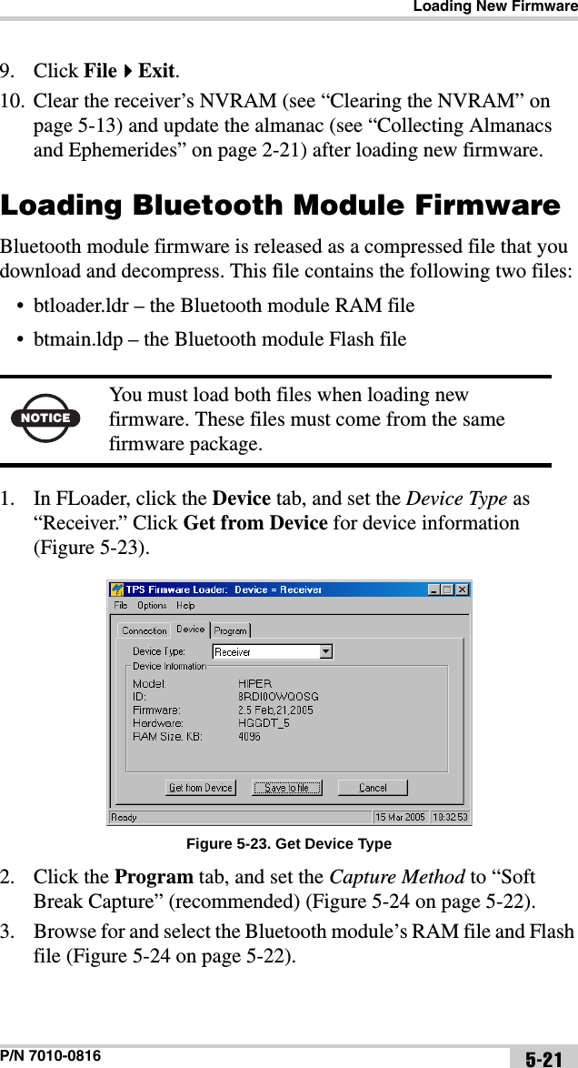
Topcon America Corporation GNSS Receiver HiPer GaGb Operator s Manual
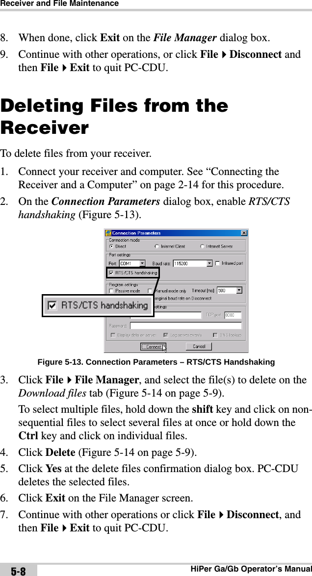
UserManual.wiki
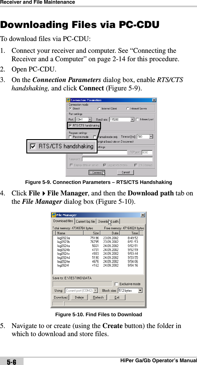
>
Topcon America
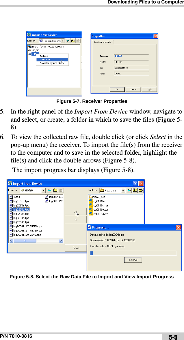
>
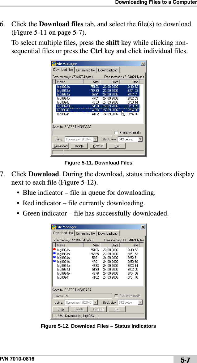
860805 User Manual
>
User manual
Contents
1.
User manual
2.
User Manual
User manual
Navigation menu
Upload a User Manual
Namespaces
Wiki Guide
HTML
PDF
Info
Views
User Manual
Discussion / Help
Navigation
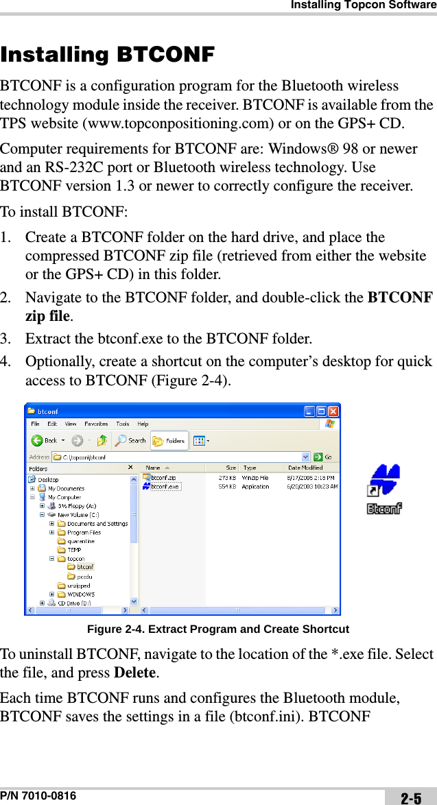
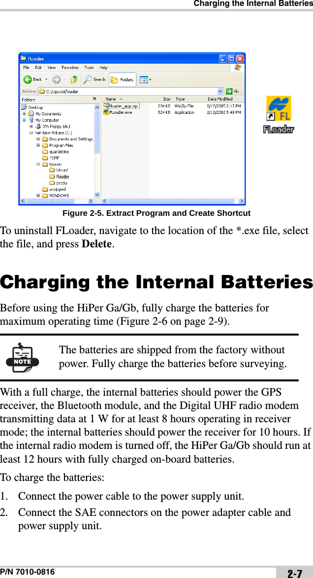
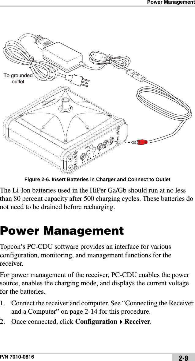
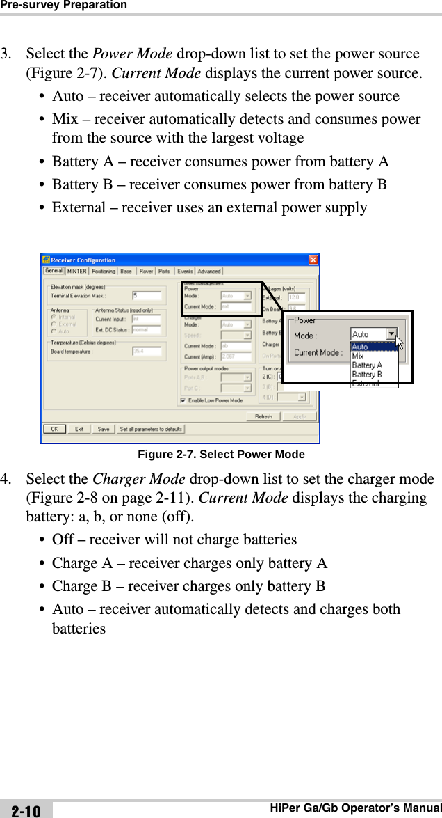
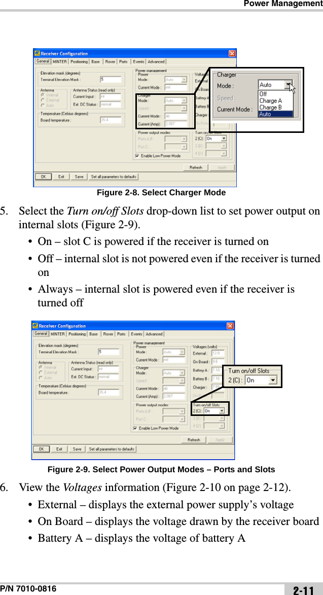
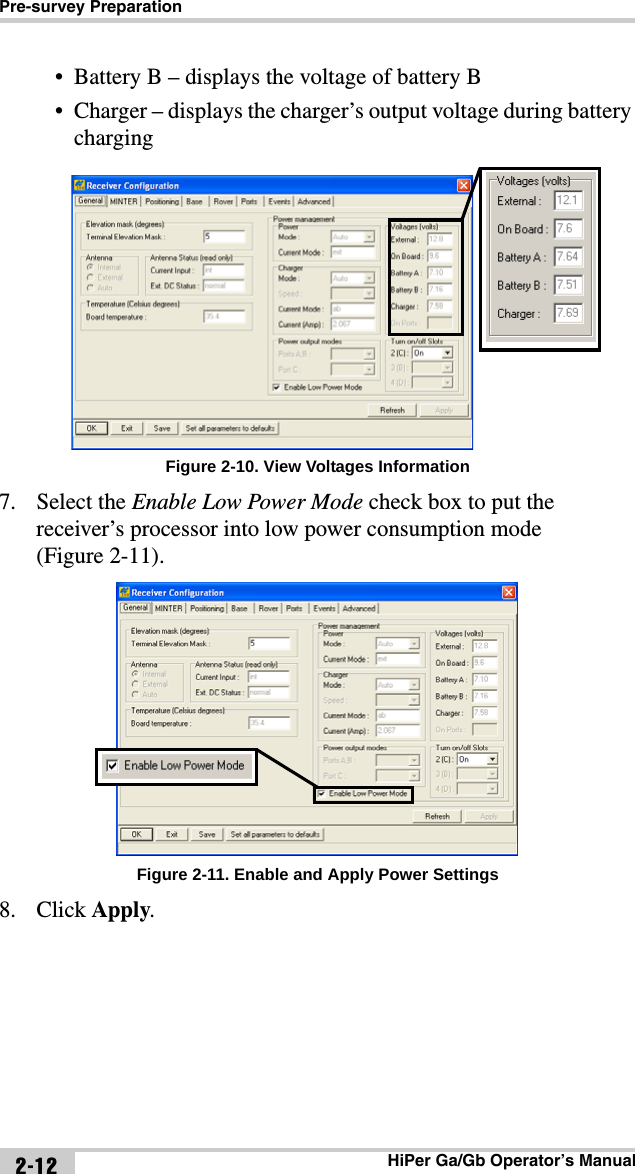
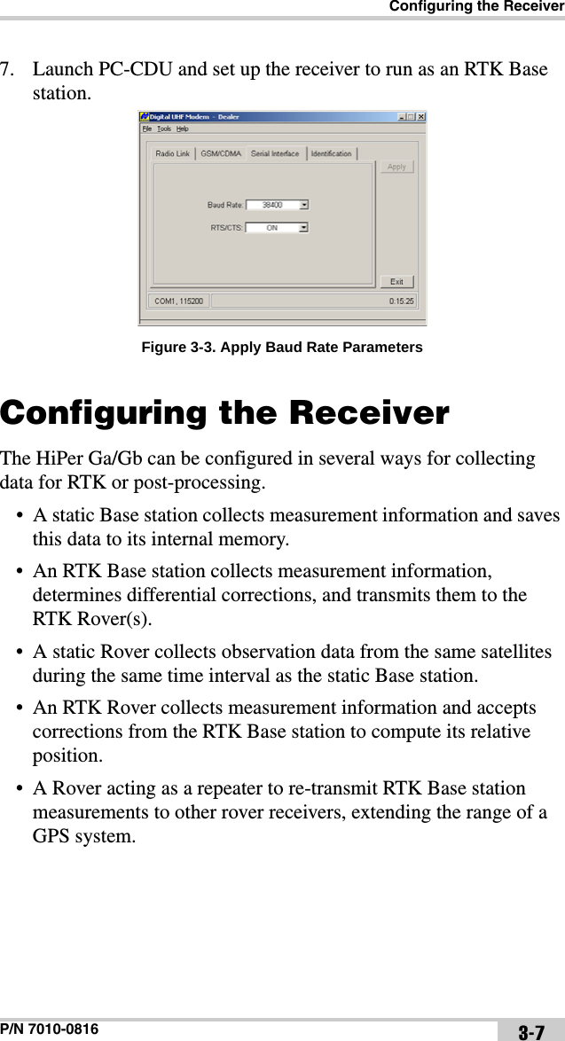
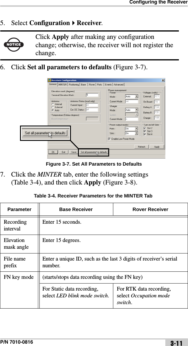
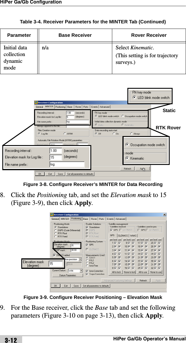
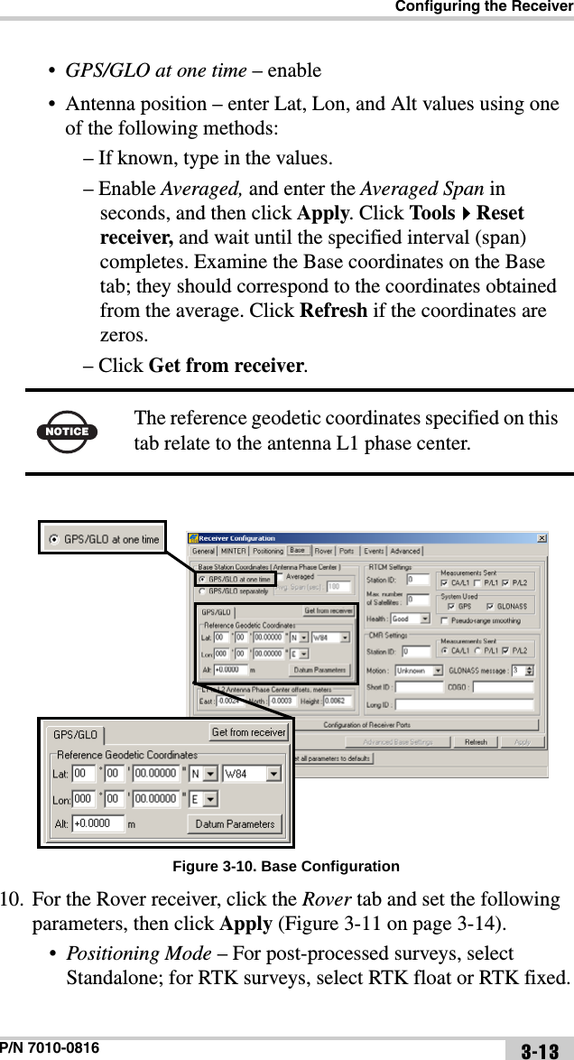
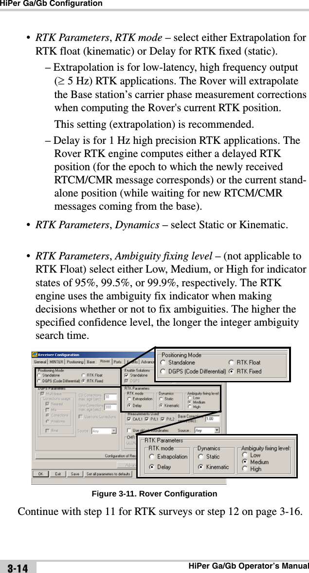
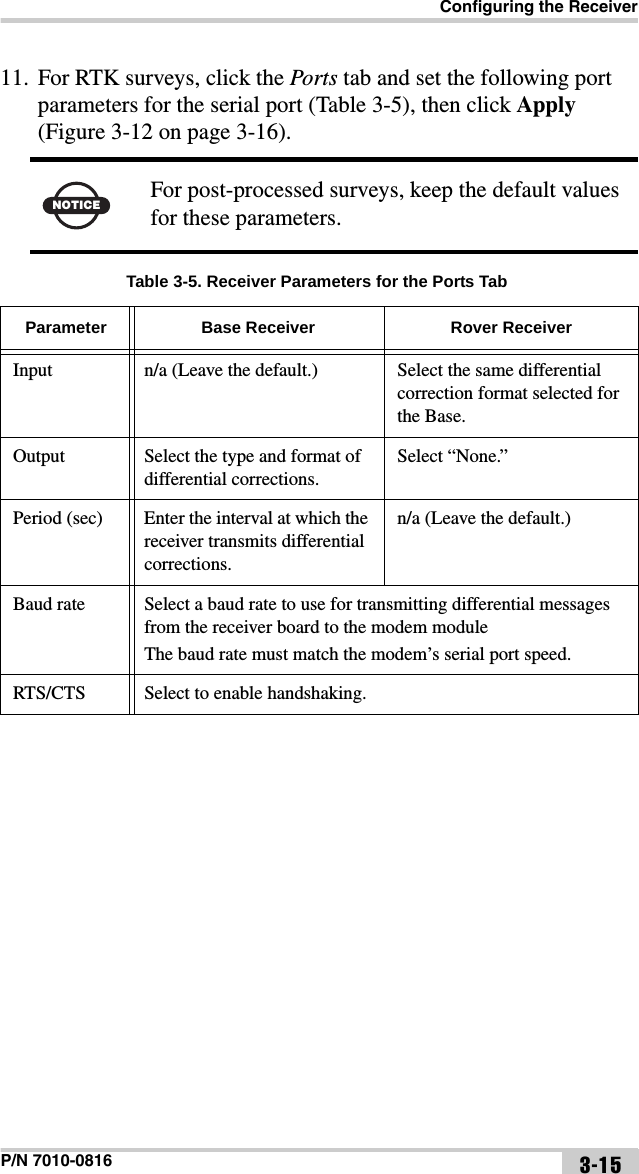
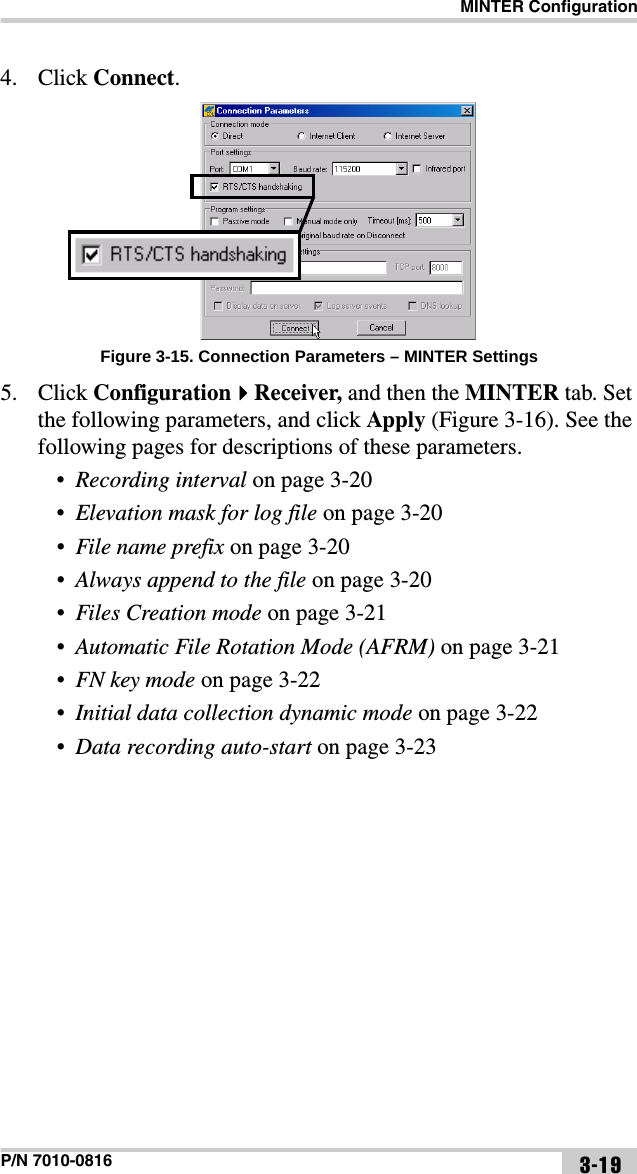
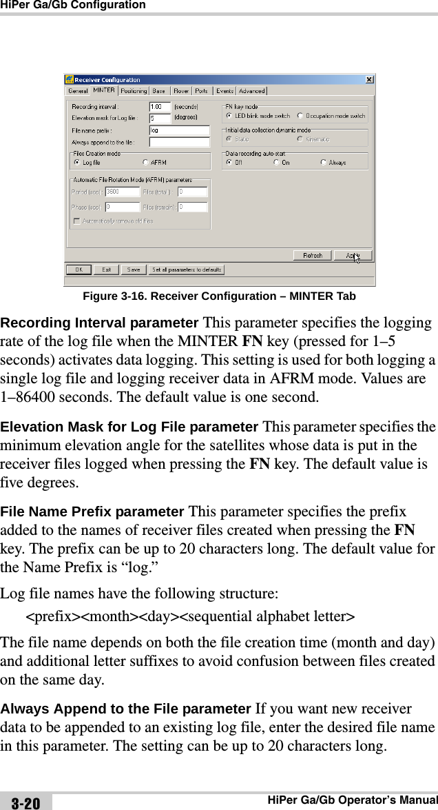
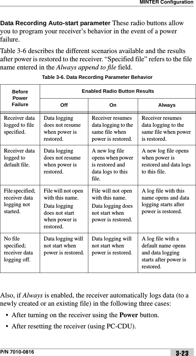
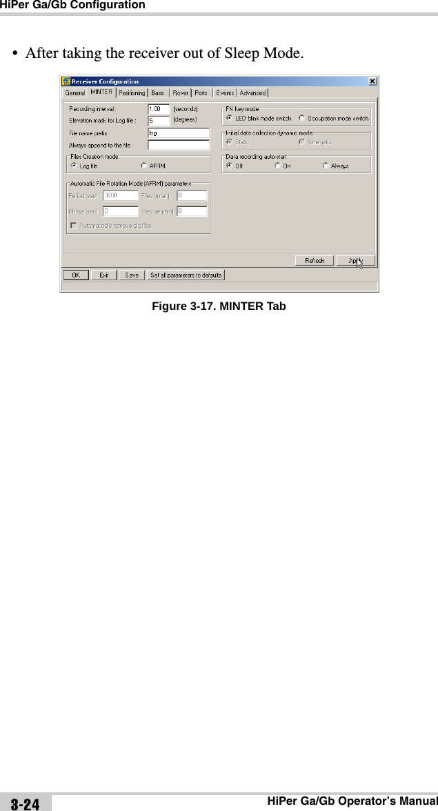
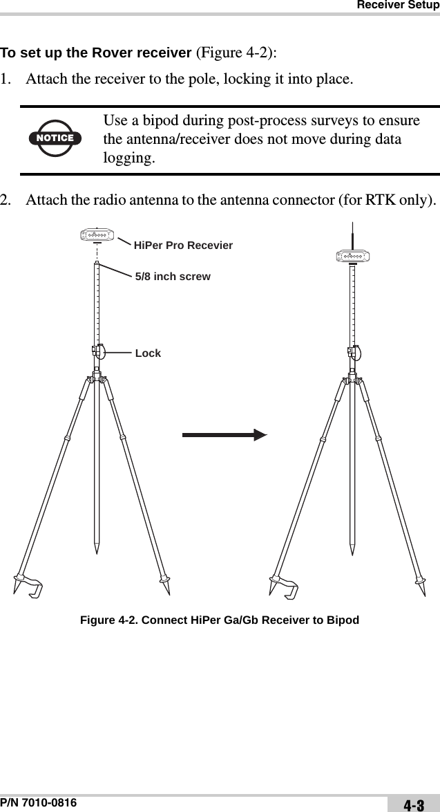
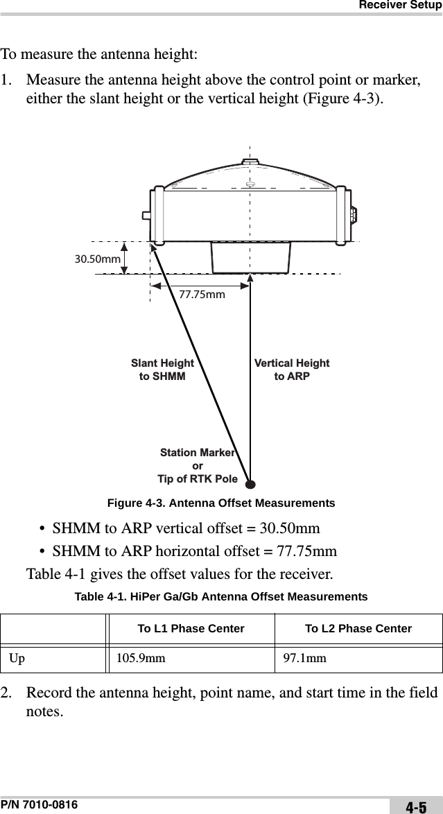
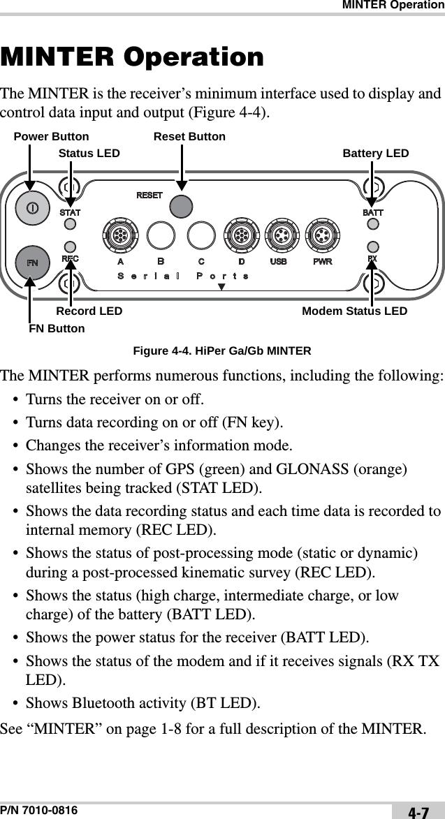
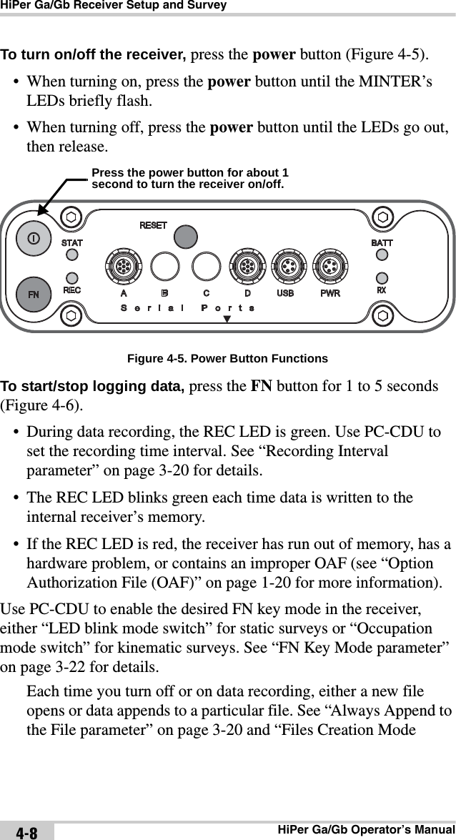
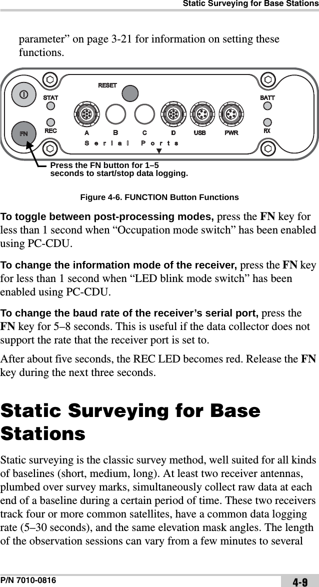
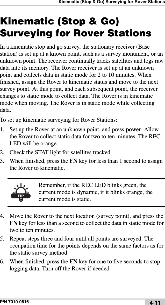
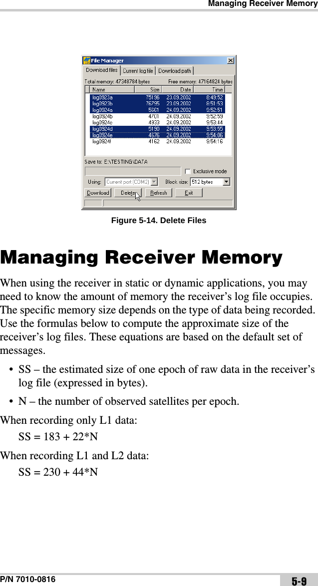
![HiPer Ga/Gb ConfigurationHiPer Ga/Gb Operator’s Manual3-22Values are 0 to [231-1]; default value is 0 (zero). Zero means that an unlimited number of log files are created. • Files (remain) – specifies the number of files left for the receiver to create in AFRM. Values are 0 to [231-1]; default value is zero.• Automatically remove old files – when no free memory is available to log data, automatically removes the earliest log file. If this parameter is enabled, then the receiver erases the file with the earliest file creation time/date. AFRM must be enabled to use this FIFO (First-In, First-Out) feature. The default value is off (disabled).FN Key Mode parameter Use these two radio buttons to program how the receiver reacts when pressing the FN key.• LED blink mode switch – pressing the FN key toggles between the MINTER’s normal/extended information modes and start/stop data recording of Static survey.– Pressing the FN key for less than 1 second changes the information mode (Normal or Extended Information Modes).– Pressing the FN key for 1 to 5 seconds starts or stops data recording (Static post-processing mode).• Occupation mode switch – pressing the FN key (less than one second) will insert a message into the corresponding log file, indicating that the survey type changed from static to kinematic, or vice versa. If the REC LED blinks green, the current mode is dynamic, if it blinks orange, the current mode is static. For more details, see Table 1-2 on page 1-12 and refer to the PC-CDU Reference Manual.Initial Data Collection Dynamic Mode parameter These radio buttons specify the starting occupation type descriptor inserted at the beginning of receiver files logged. Select Static or Kinematic to specify that the corresponding log file starts with a static (STOP) or kinematic (GO, Trajectory) occupation, respectively.NOTICEThe receiver’s memory holds up to 512 files.](https://usermanual.wiki/Topcon-America/860805.User-manual/User-Guide-1919663-Page-78.png)