Topcon Positioning Systems TPSWT41 Bluetooth Module User Manual 1000717 01 HiPer SR OM
Topcon Positioning Systems, Inc. Bluetooth Module 1000717 01 HiPer SR OM
User Manual

HiPer SR
Operator’s Manual
PartNumber1000737‐01
RevC
ECO#000187
©CopyrightTopconPositioningSystems,Inc.
December,2013
AllcontentsinthismanualarecopyrightedbyTopconPositioningSystems,Inc.Allrightsreserved.

Preface
i
P/N:1000737‐01
• • • • • •
Preface
ThankyouforpurchasingthisTopconproduct.ThematerialsavailableinthisManual(the“Manual”)havebeenpreparedby
TopconPositioningSystems,Inc.(“TPS”)forownersofTopconproducts,andaredesignedtoassistownerswiththeuseofthe
receiveranditsuseissubjecttothesetermsandconditions(the“TermsandConditions”).
Terms and Conditions
Use
Thisproductisdesignedtobeusedbyaprofessional.Theusershouldhaveagoodknowledgeofthesafeuseoftheproductand
implementthetypesofsafetyproceduresrecommendedbythelocalgovernmentprotectionagencyforbothprivateuseand
commercialjobsites.
Pleasereadthetermsandconditionscarefully.

Preface
TermsandConditions
ii
P/N:1000737‐01
Copyrights
AllinformationcontainedinthisManualistheintellectualpropertyof,andcopyrightedmaterialofTPS.Allrightsarereserved.
Donotuse,access,copy,store,display,createderivativeworksof,sell,modify,publish,distribute,orallowanythirdpartyaccess
to,anygraphics,content,informationordatainthisManualwithoutTPS’expresswrittenconsentandmayonlyusesuch
informationforthecareandoperationofthereceiver.TheinformationanddatainthisManualareavaluableassetofTPSand
aredevelopedbytheexpenditureofconsiderablework,timeandmoney,andaretheresultoforiginalselection,coordination
andarrangementbyTPS.
Trademarks
HiPerSR™,TRU™,Magnet™,Pocket‐3D™,Topcon®andTopconPositioningSystems™aretrademarksorregisteredtrademarks
ofTPS.Windows®isaregisteredtrademarkofMicrosoftCorporation.TheBluetooth®wordmarkandlogosareownedby
BluetoothSIG,Inc.andanyuseofsuchmarksbyTopconPositioningSystems,Inc.isusedunderlicense.Otherproductand
companynamesmentionedhereinmaybetrademarksoftheirrespectiveowners.
Disclaimer of Warranty
EXCEPTFORANYWARRANTIESINANAPPENDIXORAWARRANTYCARDACCOMPANYINGTHEPRODUCT,THISMANUALAND
THERECEIVERAREPROVIDED“AS‐IS.”THEREARENOOTHERWARRANTIES.TPSDISCLAIMSANYIMPLIEDWARRANTYOF
MERCHANTABILITYORFITNESSFORANYPARTICULARUSEORPURPOSE.TPSANDITSDISTRIBUTORSSHALLNOTBELIABLEFOR
TECHNICALOREDITORIALERRORSOROMISSIONSCONTAINEDHEREIN;NORFORINCIDENTALORCONSEQUENTIALDAMAGES
RESULTINGFROMTHEFURNISHING,PERFORMANCEORUSEOFTHISMATERIALORTHERECEIVER.SUCHDISCLAIMED
DAMAGESINCLUDEBUTARENOTLIMITEDTOLOSSOFTIME,LOSSORDESTRUCTIONOFDATA,LOSSOFPROFIT,SAVINGSOR
REVENUE,ORLOSSOFTHEPRODUCT’SUSE.INADDITIONTPSISNOTRESPONSIBLEORLIABLEFORDAMAGESORCOSTS

Preface
TermsandConditions
iii
P/N:1000737‐01
INCURREDINCONNECTIONWITHOBTAININGSUBSTITUTEPRODUCTSORSOFTWARE,CLAIMSBYOTHERS,INCONVENIENCE,OR
ANYOTHERCOSTS.INANYEVENT,TPSSHALLHAVENOLIABILITYFORDAMAGESOROTHERWISETOYOUORANYOTHER
PERSONORENTITYINEXCESSOFTHEPURCHASEPRICEFORTHERECEIVER.
License Agreement
UseofanycomputerprogramsorsoftwaresuppliedbyTPSordownloadedfromaTPSwebsite(the“Software”)inconnection
withthereceiverconstitutesacceptanceoftheseTermsandConditionsinthisManualandanagreementtoabidebythese
TermsandConditions.Theuserisgrantedapersonal,non‐exclusive,non‐transferablelicensetousesuchSoftwareunderthe
termsstatedhereinandinanycaseonlywithasinglereceiverorsinglecomputer.YoumaynotassignortransfertheSoftware
orthislicensewithouttheexpresswrittenconsentofTPS.Thislicenseiseffectiveuntilterminated.Youmayterminatethe
licenseatanytimebydestroyingtheSoftwareandManual.TPSmayterminatethelicenseifyoufailtocomplywithanyofthe
TermsorConditions.YouagreetodestroytheSoftwareandmanualuponterminationoftheuseofthereceiver.Allownership,
copyrightandotherintellectualpropertyrightsinandtotheSoftwarebelongtoTPS.Iftheselicensetermsarenotacceptable,
returnanyunusedsoftwareandmanual.
Confidentiality
ThisManual,itscontentsandtheSoftware(collectively,the“ConfidentialInformation”)aretheconfidentialandproprietary
informationofTPS.YouagreetotreatTPS’ConfidentialInformationwithadegreeofcarenolessstringentthatthedegreeof
careyouwoulduseinsafeguardingyourownmostvaluabletradesecrets.Nothinginthisparagraphshallrestrictyoufrom
disclosingConfidentialInformationtoyouremployeesasmaybenecessaryorappropriatetooperateorcareforthereceiver.
SuchemployeesmustalsokeeptheConfidentialityInformationconfidential.Intheeventyoubecomelegallycompelledto
discloseanyoftheConfidentialInformation,youshallgiveTPSimmediatenoticesothatitmayseekaprotectiveorderorother
appropriateremedy.

Preface
TermsandConditions
iv
P/N:1000737‐01
Website; Other Statements
NostatementcontainedattheTPSwebsite(oranyotherwebsite)orinanyotheradvertisementsorTPSliteratureormadeby
anemployeeorindependentcontractorofTPSmodifiestheseTermsandConditions(includingtheSoftwarelicense,warranty
andlimitationofliability).
Safety
Improperuseofthereceivercanleadtoinjurytopersonsorpropertyand/ormalfunctionoftheproduct.Thereceivershould
onlyberepairedbyauthorizedTPSwarrantyservicecenters.UsersshouldreviewandheedthesafetywarningsinanAppendix.
Miscellaneous
TheaboveTerms andConditionsmaybeamended,modified,superseded,orcanceled,atanytimebyTPS.TheaboveTermsand
Conditionswillbegovernedby,andconstruedinaccordancewith,thelawsoftheStateofCalifornia,withoutreferenceto
conflictoflaws.

Preface
TermsandConditions
v
P/N:1000737‐01
Manual Conventions
Thismanualusesthefollowingconventions:
Convention Description Example
Bold Menu,ordrop‐downmenuselection FileExit(ClicktheFilemenuandclickExit)
Nameofadialogboxorscreen FromtheConnectionscreen...
Buttonorkeycommands ClickFinish.
Mono Usersuppliedtextorvariable Typeguest,andclickEnter.
Italic Referencetoanothermanualorhelpdocument RefertotheTopconReferenceManual.
Furtherinformationtonoteaboutsystemconfiguration,maintenance,orsetup.
Supplementaryinformationthatcanhaveanadverseaffectonsystemoperation,systemperformance,data
integrity,measurements,orpersonalsafety.
Notificationthatanactionhasthepotentialtoresultinsystemdamage,lossofdata,lossofwarranty,or
personalinjury.

• • • • • •
Table of Contents
vi
P/N:1000737‐01
Preface..................................................................i
TermsandConditions............................................................i
Use........................................................................i
Copyrights..................................................................ii
Trademarks.................................................................ii
DisclaimerofWarranty.......................................................ii
LicenseAgreement...........................................................iii
Confidentiality ..............................................................iii
Website;OtherStatements....................................................iv
Safety .....................................................................iv
Miscellaneous...............................................................iv
ManualConventions .........................................................v
Introduction.............................................................1
vii
P/N:1000737‐01
HiPerSRFeatures...............................................................2
UnpackingYourReceiverKit ......................................................3
SystemComponents .........................................................4
Accessories .................................................................5
TechnicalDocuments............................................................5
UsingTopconSoftwareWithYourReceiver ..........................................6
GettingTechnicalSupport........................................................7
Website ....................................................................8
GettingAcquainted........................................................9
ReceiverOverview ..............................................................9
BasicReceiverHousingOverview ...............................................10
HiPerSRCellularHousingOverview .............................................11
Cables.........................................................................12
Memory .......................................................................14
SIMCardSlots(Option) ..........................................................14
InternalBatteries ...............................................................15
LongLINKWirelessCommunication.................................................15
viii
P/N:1000737‐01
CellularCommunication(Option)..................................................15
PortsPanel.....................................................................16
DisplayPanelOperations...................................................17
PowerButton ..................................................................18
ReceiverStatusLEDs.............................................................19
TrackingStatusLED ..........................................................19
RecordingLED...............................................................20
CommunicationLED..........................................................21
Bluetooth Only Status 21
Cellular and Bluetooth Status 21
Cellular Status 23
BatteryLED .................................................................24
ManagingPower..........................................................25
TurningOn/OfftheReceiver......................................................25
UsingInternalandExternalPowerSources ..........................................25
InternalBatteries............................................................26
ChargingtheBatteries ........................................................27
InsufficientPower ...............................................................28
ix
P/N:1000737‐01
ConfiguringtheReceiver...................................................30
ViewingReceiverInformation.....................................................30
LoadingNewFirmware...........................................................32
AbouttheOAF..................................................................40
CheckingtheReceiver’sOAF...................................................40
LoadinganOAF..............................................................41
ResettingtheReceiver(ClearingtheNVRAM)........................................44
UsingtheResetButton...........................................................45
FieldSystemSetup........................................................47
SettingUptheBaseReceiver ......................................................48
SettingUptheRoverReceiver .....................................................50
MeasuringAntennaHeight .......................................................52
CollectingData...........................................................54
SettingRecordingParameters .....................................................54
LoggingRates...................................................................54
RecordingData .................................................................54
ManagingFiles..................................................................55
x
P/N:1000737‐01
DownloadingandDeletingFiles................................................56
Troubleshooting..........................................................57
CheckThisFirst! ................................................................57
PoweringProblems..............................................................58
ReceiverProblems ..............................................................59
LongLINKProblems ..............................................................62
BluetoothProblems .............................................................63
TRUProblems ..................................................................65
CleaningandStoringtheReceiver..................................................66
GettingCustomerSupport ........................................................66
Specifications............................................................67
GeneralDetails .................................................................67
SafetyWarnings..........................................................74
GeneralWarnings..............................................................74
ReceiverWarnings ..............................................................75
UsageWarnings................................................................75
Regulatory...............................................................76
xi
P/N:1000737‐01
FCCCompliance.................................................................76
IndustryCanadaCompliance ......................................................77
CommunityofEuropeCompliance.................................................78
EuropeanCommunityDeclarationofConformitywithR&TTEDirective1999/5/EC ......78
DeclarationofConformity(R&TTEDirective1999/5/EC)...............................79
WEEEDirective .................................................................83
BluetoothTransmissionStatements/Compliance.....................................83
KoreanKC‐RFCompliance ........................................................84
Glossary.................................................................85

Introduction
1
P/N:1000737‐01
• • • • • •
Introduction
Topcon’sHiPerSRreceiverisacompact,lightweight,andcompletelyintegratedGNSSreceiverforstaticandcable‐freestop‐and‐
go/kinematicapplications.TheintegratedreceiverdesignincludesaGNSSreceiverboardbasedonVanguard™technology,
industryleadingFenceAntenna™,internallong‐lifebatteries,memorystorage,andTopcon’sinnovativeLongLINK™andcellular
wirelesscommunicationtechnology.TheHiPerSRdeliversworld‐classpositioningandnavigationcapabilitytoyourapplicationby
trackingsignalsfrommulti‐constellationsatellitesystems,includingGPS,GLONASS,andSBAS.
TopconofferstwomodelsoftheHiPerSRreceiver:BasicandCellular.TheBasicreceiverincludesTopcon’sexclusiveLongLINK
communicationtechnology,whichprovidestheperfectsmalljobsitesystemsuitableforshortrange(upto300mfromtheBase
station)RTKcommunication.TheCellularmodelincludesLongLINKtechnologyandanexpandedrange(wherecellularcoverageis
provided)forlong‐distanceRTKcommunication.UsingtheCellularreceiver,youcansetupaBaseorRovernetworkwithupto
10??receivers???
TheHiPerSRofferscompleteIP67protectionagainstdustandwateringress,inadditiontosuperiorvibrationandshockresistance.
TheTopconcommunicationinterfaceallowsyoutoquicklyintegrateTopcon’spremiumGNSSperformancewithinnewsystems
andquicklydeliverworld‐classpositioningandnavigationsupporttoyourapplications.
Introduction
HiPerSRFeatures
2
P/N:1000737‐01
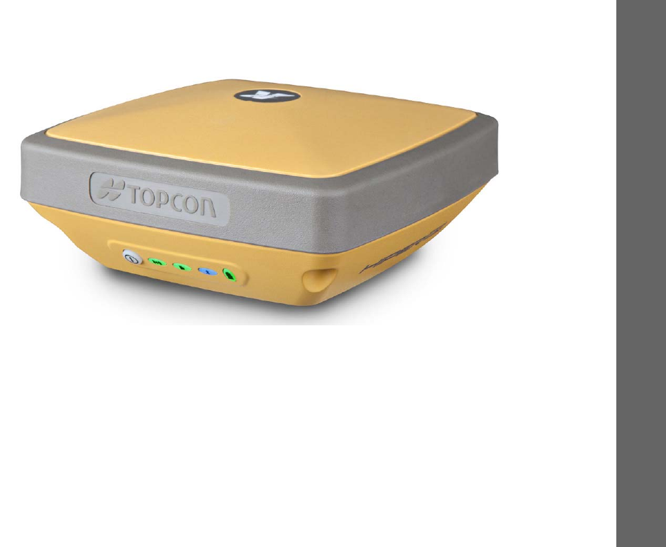
Figure1:HiPerSRReceiver
HiPer SR Features
TheHiPerSRreceiver’sadvanceddesigneliminatestheneedforcablesduringoperation,allowingforasimplifiedsetupandless
partstokeeptrackof.TheHiPerSRreceiverfeaturesthefollowing:
•
Compact,lightweight,andruggeddesign
•
Industry‐leadingFenceAntenna™technology
•
Apremiermulti‐constellationVanguard™technologyGNSSboard

Introduction
UnpackingYourReceiverKit
3
P/N:1000737‐01
•
Integratedmulti‐channelLongLINK™wirelesscommunicationtechnology
•
(Cellular)Integratedcellularmodemforindependentandcable‐freenetworkoperation
•
(Cellular)DualSIMoperationtoallowuseoftwoservices
•
8GBinternalmemory
•
Internalbatteries,providingatleast15hoursofoperationinanyconfiguration
•
Ahighlyvisibledisplaypanelwithsingle‐buttonoperation
•
USBandpower/RS‐232ports
YoucanconfiguretheHiPerSRreceiverinavarietyofways,dependingonyourprojectrequirements.Typically,thereceiver
supportsthefollowingoperationmodes:
•
Staticpost‐processing
•
LongLINKBaseandRoverRTK
•
NetworkRoverRTK
•
NetworkBaseRTK
•
SBAS‐enablednavigation
Unpacking Your Receiver Kit
Thissectiondescribesthedocumentation,standardkitcomponents,andaccessories(dependingonyourpurchase)that
accompanyyourreceiver.Whenyouunpackyourreceiverkit,verifyyoureceivedtheitemslistedinthissection.Makesurethe
itemsdonotappeardamagedfromshipment.Ifanyoftheitemsaremissingordamaged,contactyourTopcondealerorTopcon
technicalsupport.See“GettingTechnicalSupport”onpage7.
•
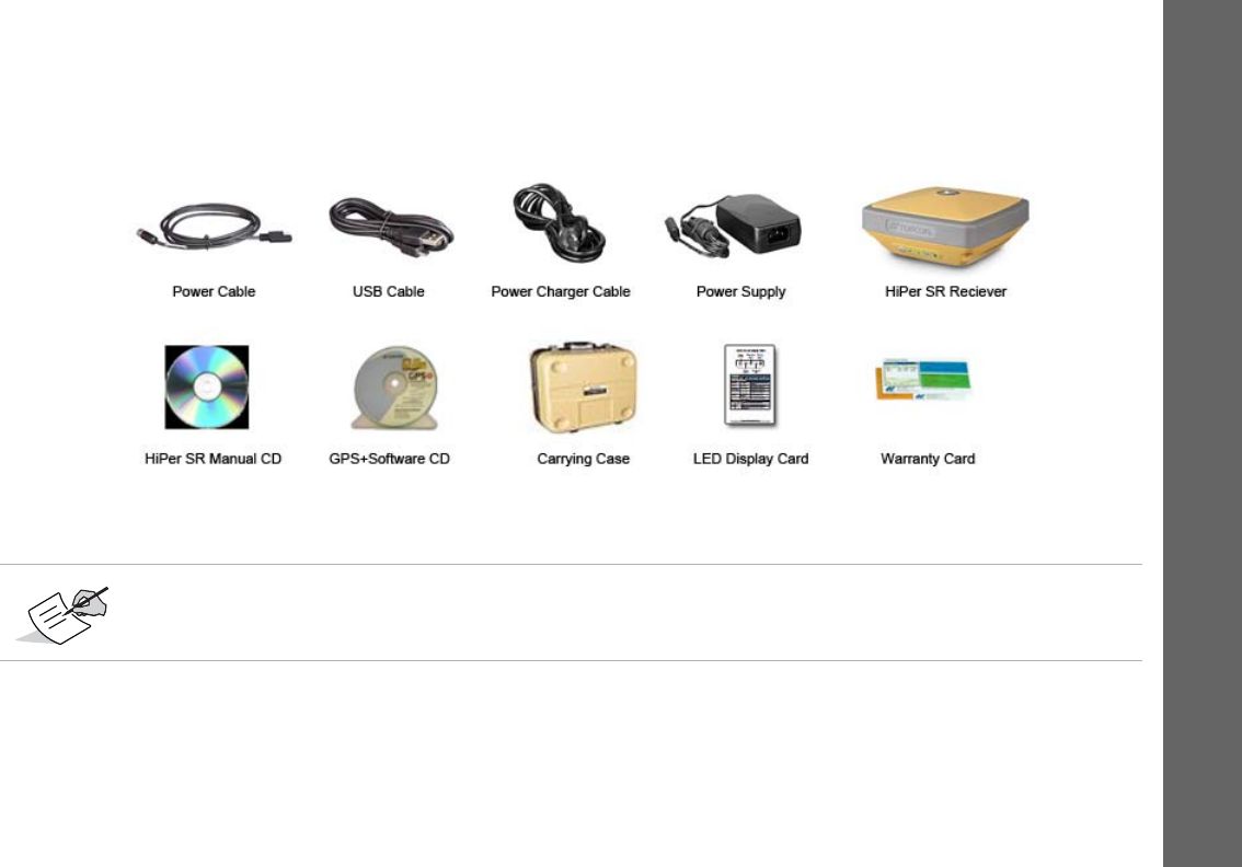
StandardcomponentsareillustratedinFigure2.
•
ReceiveraccessoriesareillustratedinFigure3.
•
Receiverdocumentationislistedonpage5.
Introduction
TechnicalDocuments
5
P/N:1000737‐01
Accessories
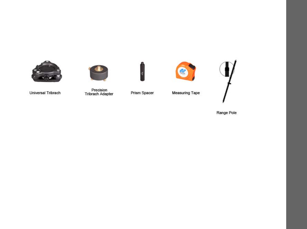
Topconoffersawidevarietyofaccessories(seeFigure3)speciallydesignedtoimprovesystemflexibilityandjobsiteefficiency.
FormoredetailsontheoptionalaccessoriesavailableforHiPerSR,contactyourTopcondealer.
Figure3:ReceiverAccessories
Technical Documents
TheHiPerSRManualCDincludestwomanuals(listedbelow)thathelpyousetupanduseyournewreceiverquicklyand
efficiently.
•
HiPerSROperator’sManual–Anon‐screenhelpdocumentthatcontainsdetailedinformationonhowtouseyournew
receiver.
•
TopconReceiverUtility(TRU)ReferenceGuide–Anon‐screenhelpdocumentthatcontainsdetailedinformationonhow
tousetheTRUsoftwareincludedontheGPS+SoftwareCD.FormoreinformationabouttheTRUsoftware,see“Using
TopconSoftwareWithYourReceiver”.

Introduction
UsingTopconSoftwareWithYourReceiver
6
P/N:1000737‐01
Using Topcon Software With Your Receiver
UsetheHiPerSRreceiverinconjunctionwiththeTopconReceiverUtility(TRU)andMAGNETField™orPocket‐3Dapplications
foracable‐freepositioningsolution.Topconsoftwareenablesyoutoconfigurethereceiverandotherexternaldevices,manage
files,collectdata,andperformsurveyandconstructionworkflows.
TheTopconReceiverUtility(TRU)isahardwareconfigurationsoftwareforreceiversandperipheraldevices.Youcaninstalliton
desktopcomputersanddatacontrollers.ThisprogramisprovidedontheGPS+SoftwareCDthataccompaniedyourreceiver.A
TRUhelpdocumentisprovidedontheHiPerSRCD.
Topcon’sMAGNETField™softwarefordatacontrollersprovidesreal‐timecommunication,cloudstorage,datacollectionand
exchange,andfieldsolutions,suchastopo,staking,roads,calculations,andmore.ContactyourTopcondealerformore
informationaboutMAGNETFieldandtheentireMAGNETEnterprisesystem.
Pocket‐3DisaprogramthatrunsondatacontrollerswithWindowsCE®andmobileplatforms.Pocket‐3Dsimplifiesdata
collection,allowingyoutocheckcutsandfills,layoutpointsandsurveyallorpartofthejobsitequicklyandefficiently.Contact
yourTopcondealerformoreinformationaboutPocket‐3D.
MagnetRelay™isaGNSScorrectionservicehostedbytheMAGNETSolution.WithasubscriptiontoMAGNETRelay,youcan
connecttheHiPerSRCellularreceivertotheRelayservice(viaacellularconnection)anduseitasaBaseforupto10Rovers.

Introduction
GettingTechnica lSupport
7
P/N:1000737‐01
Getting Technical Support
BeforecontactingaTopconcustomerrepresentativeaboutanyproblemswiththereceiver,see“Troubleshooting”onpage57
forsomesolutionsthatmayfixtheissue.
ContactyourlocalTopcondealerorvisittheTopconTotalCareWebsite(www.TopconTotalCare.com)fortechnicalsupport.
WhencontactingTopconfortechnicalassistance,providethefollowinginformationforbetterandfasterservice:
1. Adescriptionofthefollowing:
–Fieldoperationthatwasbeingperformedwhentheproblemoccurred
–Detailsoftheunexpectedbehavior,symptoms,andanyerrormessagesthatprecedeorfollowtheproblem
–Problemoccurrencefrequencyorpatterns
2. Receiverinformationandconfigurationsettings.Forreceiverinformation,clickInformationinTRU,selectSaveto
File,enterafilename,andsaveittothecomputer.
3. Specificationsofmobiledevicesandcomputersusedinthefieldorofficeexhibitingtheproblem.These
specificationsshouldincludemodelinformation,versionnumber,operatingsysteminformation,memoryand
storagecapacity,etc.
4. Informationaboutthesystemsoftware,includingtheversionnumberandstepstoreproducetheproblem.
5. Adescriptionofthefieldenvironmentand/orobservationconditionswhentheproblemoccurred.
Forquickandeffectivesupport,provideadetaileddescriptionoftheproblem.

Introduction
GettingTechnica lSupport
8
P/N:1000737‐01
Website
TheTopconwebsiteprovidescurrentinformationaboutTop con’slineofproducts.Thesupportareaofthewebsiteprovides
accesstoTopconfieldandofficesoftware,manuals,frequentlyaskedquestions,andsoforth.ToaccesstheTopco nwebsite,
visitwww.topconpositioning.com.
TheTopcon’sTotalCarewebsitealsoprovidescompletesupport,suchasnews,updates,reminders,training,liveWebinars,and
customerservicetohelpyougettheinformationyouneed.Visitwww.topcontotalcare.com.

GettingAcquainted
9
P/N:1000737‐01
• • • • • •
Getting Acquainted
TheHiPerSRreceiverenclosureisfullysealedandincorporatestheGNSSreceiverboard,antenna,batteries,memorystorage,and
wirelesscommunicationdevice.
Receiver Overview
TheupperportionofthereceivercontainsGNSSandLongLINKantennasenclosedbytheradome,whichissecurelysurrounded
byashock‐absorbingrubberbumper.
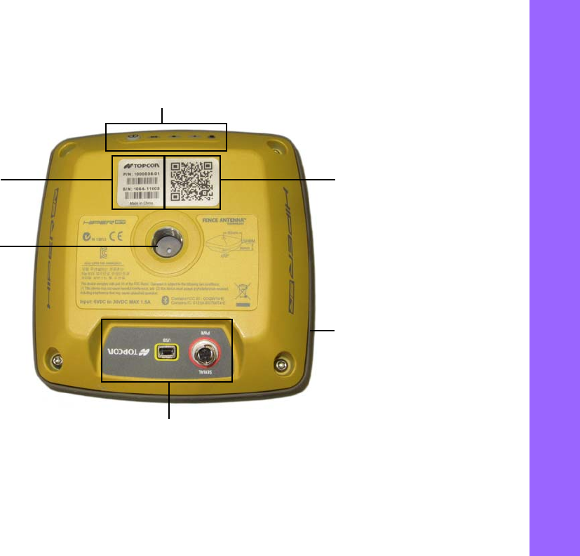
Aneasy‐to‐operatedisplaypanel,mountingsocket,andlabelswithreceiverinformationarelocatedonthebottomofthe
receiver’smagnesiumalloylowerenclosure.
TheHiPerSRreceiverhasahighly‐visibledisplaypanelwithsingle‐buttonoperation.Thedisplaypanelenablesyoutoviewthe
receiver’soperationalstatus.Formoreinformation,see“DisplayPanelOperations”onpage17.
Themountingsocket(Figure4)connectsthereceivertoeitherastandard5/8 ' ' threadpoleoradapter.
Youcanlocateregulatoryandproductidentificationinformationonthetworeceiverlabels.Theproductidentificationlabel
containstheserialnumberandpartnumberalongwithaquickresponse(QR)matrixcode.YoucanscantheQRcodewithanyQR
codeapplicationonasmartphoneanditwillopentheproductinformationpageattheTopcon TotalCarewebsite
(www.topcontotalcare.com).
Getting Acquainted
ReceiverOverview
10
P/N:1000737‐01
Basic Receiver Housing Overview
Figure4:BasicReceiver—BottomEnclosureOverview
LEDDisplayPanel
QRCode
PortsPanel
ProductIDLabelwith
PartNumberand
SerialNumber
Rubber
Bumper
Mounting
Socket
NeedNewPic
Getting Acquainted
ReceiverOverview
11
P/N:1000737‐01
HiPer SR Cellular Housing Overview
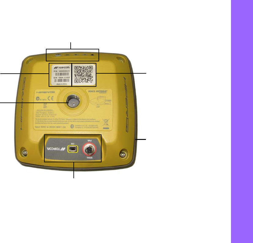
Figure5:HiPerSRCellularReceiver:BottomEnclosureOverview
LEDDisplayPanel
QRCode
PortsPanel
ProductIDLabelwith
PartNumberand
SerialNumber
Rubber
Bumper
Mounting
Socket
NeedNewPic
Getting Acquainted
Cables
12
P/N:1000737‐01
Cables
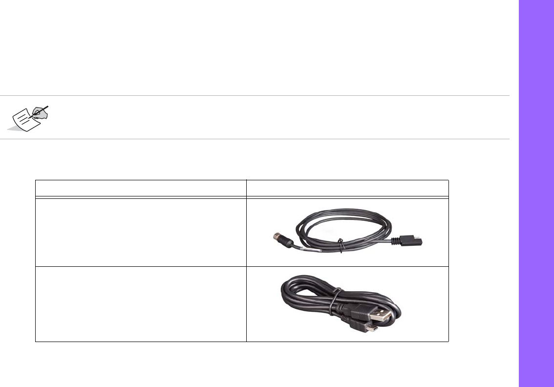
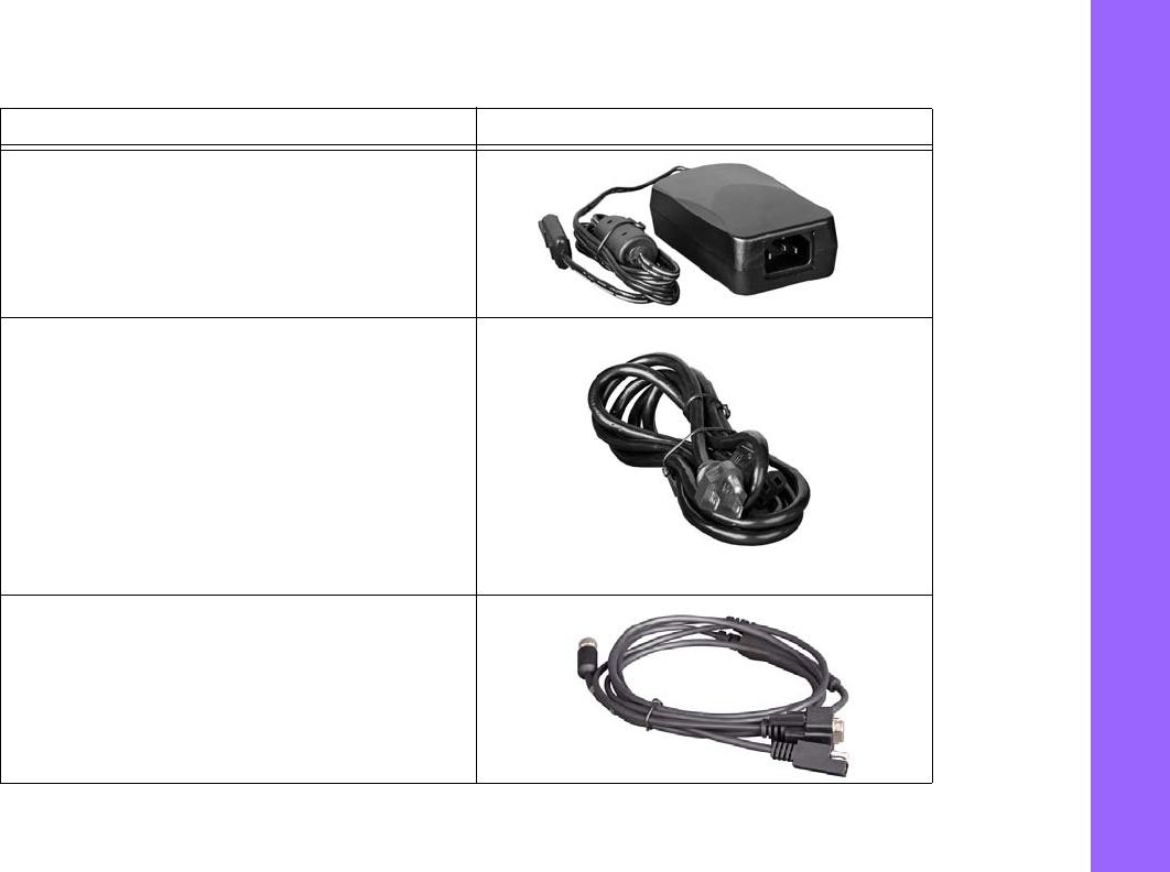
TheHiPerSRpackageincludesapowersupplycable,aUSBcable,andapoweradapter.Table1describesthecablesincluded
withyourreceiver.
Alignthekeywayswhenconnectingthepower/serialcabletothereceiverport.Turnthecablelockclockwise
untilitclickstosecurethecableinplace.Todisconnectthecable,turnthelockcounter‐clockwise,andthen
gentlyremovethecable.
Table1.ReceiverCables
Cable Description Cable Illustration
ReceiverPowerCable
Connectsthereceivertothepoweradapterthroughthe
SAEconnector.
p/n:1000181‐01
USBCable
Connectsthereceivertoanexternaldevice(controlleror
computer)fordatatransferandreceiverconfiguration.
p/n14‐008081‐01
Getting Acquainted
Cables
13
P/N:1000737‐01
PowerAdapter
Chargesthereceiverwhenconnectedtoagrounded
outletandthepowerchargercable.
p/n22‐034101‐01
PowerChargerCable
Connectsthepoweradaptertoagroundedoutlet.Sever‐
aloptionsareavailableforthepowerchargercablebased
onyourcountry.Ifthekitdoesnotincludeapower
chargercable,contactyourTopcondealer.Refertothe
thesepartnumbersforavailablepowerchargercables:
p/n14‐008052‐01(USAconnector)
p/n14‐008054‐01(EURconnector)
p/n14‐008074‐01(AUSconnector)
p/n1000475‐01(BRLconnector)
PowerandSerialCable
Connectsthereceivertothepoweradapterthroughthe
SAEconnectorandanexternaldevicethroughtheRS‐232
port(DB9connector).Typically,thiscableisnotshipped
withthestandardkitconfigurationbutisavailableto
purchaseseparately.
p/n:1000182‐01
Table1.ReceiverCables
Cable Description Cable Illustration

Getting Acquainted
Memory
14
P/N:1000737‐01
Memory
TheHiPerSRisequippedwithaninternal,non‐removablememorycardthatprovidesupto8GBofdatastorage.Asdatais
loggedtothereceiver’smemory,theRECLEDdisplaysthememorycapacitystatus.See“RecordingLED”onpage20formore
information.Toaccesstherawdatafilesinthereceiver’sinternalmemory,see“ManagingFiles”onpage55.
SIM Card Slots (Option)
TheHiPerSRCellularreceiverisequippedwithtwomicro‐SIMcardslotsthatallowyoutoswitchfromoneserviceproviderto
anotherasrequired.UsingdualSIMcardsenableyoutousetwocellularserviceswithouttheneedtoswaptheSIMcardinthe
field.Youcanonlyinstallmicro‐SIMcardsintotheseslots.Onceinstalled,themicroSIMcardprovidesauniqueidentification
forthereceiverandenablesthereceiver’scellularnetworkingfunctionalitybasedonthesubscribedservices.Youcanpurchase
amicro‐SIMcardfromyourlocalcellarprovider.
Figure6:ReceiverMicroSIMCardSlots
NeedPicture

Getting Acquainted
InternalBatteries
15
P/N:1000737‐01
Internal Batteries
TheHiPerSRreceiverwasdesignedwithtwointernal,non‐removablebatteries,sothereisnobatterydoororconnectorsto
worryabout.Thebatteriesareeasilychargedusingthesuppliedpoweradapteroranexternalpowersource.See“Internal
Batteries”onpage26formoreinformation.
LongLINK Wireless Communication
TheHiPerSRreceiverhasintegratedLongLINK™wirelesstechnologythatenablesmultiple(upto3)cable‐freeconnectionsto
otherHiPerSRdevicesforLongLINKBase/RoverRTKsystems.YoucanalsoconnectthereceivertootherClass1‐andClass2‐
enabledBluetoothdevices(suchasdatacollectorsandcomputers)usingBluetoothwirelesstechnologyconcurrentlywith
LongLINKconnections.
Topcon’sLongLINKtechnologyenablescommunicationofRTCM3differentialcorrectionsbetweentwoHiPerSRreceiversover
Bluetooth(upto300meters),eliminatingtheneedforadditionalexternalradiosforcorrections.Formoreinformation,see
“FieldSystemSetup”onpage47.
Cellular Communication (Option)
ThecellularintegrationoftheHiPerSRreceiver...Placecellularmarketingblurbhere.

Getting Acquainted
PortsPanel
16
P/N:1000737‐01
Ports Panel
Thereceiverisequippedwiththefollowingports:
•
USB–Usedforhigh‐speeddatatransferandcommunicationbetweenthereceiverandanexternaldevice.
•
Power/Serial—Usedforcommunicationbetweenthereceiverandanexternaldevice.Alsousedtopowerthereceiver
whentheinternalbatteriesarenotinuse.See“UsingInternalandExternalPowerSources”onpage25.
•
CellularANTConnector—NotaGPSAntennaConnector.ATNCconnectorusedtoconnectthecellularandUHF
antenna.
Figure7:ReceiverPortsPanel
NeedPic

DisplayPanelOperations
17
P/N:1000737‐01
• • • • • •
Display Panel Operations
TheLEDdisplaypanel(Figure8)enablesyoutocontrolreceiverpoweranddatarecording.TheLEDsdisplaythestatusofthe
satellitetracking,recording/memorycapacity,BluetoothandLongLINKconnections,andbatteries.Thischapterdescribesthe
differentLEDblinkpatternsandwhattheymean.
Figure8:LEDDisplayPanel
Power
(PWR)
Status
(STAT)
Recording
(REC)
Communication
(COMM)
Battery
(BATT)

Display Panel Operations
PowerButton
18
P/N:1000737‐01
Power Button
Thepowerbuttonperformsmultiplefunctions.Thenumberofsecondsinwhichthebuttonispressedandhelddetermineshow
thereceiverwillperform.Table2describeshowtousethepowerbutton.
Table2.PowerButtonFunctions
FUNCTION PRESS BUTTON LED DESCRIPTION
PowerOn 1+seconds PowerLEDblinksgreenuntilthestartupiscomplete,andthentheLED
turnsoff.
PowerOff 3‐10seconds AllLEDsareoff.ReleasethePowerbuttonwhentheBatteryLEDissolid
red.
FactoryReset
ClearNVRAM
10‐15seconds AllLEDsareoff.ReleasethePowerbuttonwhentheStatusLEDissolid
red.
EraseAllFiles15‐20seconds AllLEDsareoff.ReleasethePowerbuttonwhentheRecordingLEDis
solidred.
Note:Thisactionisirreversible.Ifyouareunsureaboutthisaction,
continuetoholddownthebuttonuntilallLEDsreturntonormal.
Disregard Morethan20seconds AllLEDsreturntonormal,andthereceiverhasnottakenanyaction.
Open/Closedatafile 3timesinarowwithin
2seconds
RefertotheRecordingLEDdescription.

Display Panel Operations
ReceiverStatusLEDs
19
P/N:1000737‐01
Receiver Status LEDs
TherearefourstatusLEDstoprovideyouinformationaboutthebatterylife,trackedsatellites,memorycapacity,andBluetooth
wirelessconnectivity.ThissectiondescribesthecolorandbehaviorofeachLED.
Tracking Status LED
ThetrackingstatusLEDdisplayshowmanysatellitesthereceiveristracking.
Table 3. Status LED Patterns
LED Color Description
1OneblinkpertrackedGPSsatellite.
2OneblinkpertrackedGLONASSsatellite.
3Oneblinkwhentherearenotracked
satellitesorsolutions.ItisOffotherwise.

Display Panel Operations
ReceiverStatusLEDs
20
P/N:1000737‐01
Recording LED
ThememoryLEDindicatesifdataisbeingwrittentomemoryanddisplayshowmuchmemorythereceiverhasavailablefor
recording.
Table4.RecordingLEDPatterns
Display Function Description
Fileloggingisinprogress.Eachblink
indicatesdataisbeingwrittento
memory.
Thefileisclosed.Asolidlightindicates
nodataisbeingrecorded.
Erasingmemory
AlternatinggreenandredLEDsindicate
allfilesarebeingdeleted.
Formattingmemory
AlternatingredandyellowLEDsindicate
thememorycardisbeinginitializedor
formatted.
Missingorfaulty
memory
TheLEDisoff.

Display Panel Operations
ReceiverStatusLEDs
21
P/N:1000737‐01
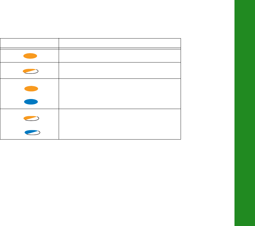
Communication LED
TheCommunicationLEDdisplaysthestatusofthecellularandBluetoothactivity.Thefollowingtablesdescribethe
communicationactivityforthreeusecases.
Bluetooth Only Status
Cellular and Bluetooth Status
Table5.BluetoothLEDPatterns
LED Color Description
AsingleBluetoothconnectionisestablished.
MultipleLongLINKconnectionsareestablished.TheLED
blinksforeachconnectionevery10seconds.
Bluetoothisturnedoff.
Table6.CellularandBluetoothLEDPatterns
LED Color Description
Cellularmodemisstartingup.
Dataisbeingreceivedortransmitted.

Display Panel Operations
ReceiverStatusLEDs
22
P/N:1000737‐01
Thereceiverisconnectedtoadatacollectorusing
Bluetooth.
Thereceiveristransmittingandreceivingdataandis
connectedtoadatacontrollerusingBluetooth.
Table6.CellularandBluetoothLEDPatterns
LED Color Description
Display Panel Operations
ReceiverStatusLEDs
23
P/N:1000737‐01
Cellular Status
Table7.CellularLEDPatterns
LED Color Description
Thecellularmodemisstartingup.
Thecellularmodemistransmittingorreceivingdata.
???
???

Display Panel Operations
ReceiverStatusLEDs
24
P/N:1000737‐01
Battery LED
TheBatteryLEDindicatestheremainingchargeoftheinternalbatteries.Whenanexternalpowersourceisutilized,theLED
turnsgreenandbeginstoblinkifthebatteriesbegintocharge.SeeTable8formoreinformation.
Table8.BatteryLEDPatterns
LED Color Description
THE RECEIVER IS ON; INTERNAL BATTERIES IN USE
Thechargeisgreaterthan50percent.
Thechargeisgreaterthan15percent.
Thechargeislessthan15percent.
THE RECEIVER IS ON; EXTERNAL POWER IN USE; PWR LED IS SOLID GREEN
Anexternalpowersourceisinuse,andtheinternalbatteriesarefullycharged.
Theinternalbatteriesareatgreaterthan50%capacity;thebatteriesarebeingcharged.
Theinternalbatteriesareatgreaterthan15%capacity;thebatteriesarebeingcharged.
Theinternalbatteriesareatlessthan15%capacity;thebatteriesarebeingcharged.
THE RECEIVER IS OFF
Thereceiverisconnectedtoanexternalpowersource,andthebatteriesarefullycharged.
Thereceiverisconnectedtoanexternalpowersource,andthebatteriesarebeingcharged.

ManagingPower
25
P/N:1000737‐01
• • • • • •
Managing Power
Thischapterdescribeshowtopowerthereceiver,chargetheinternalbatteries,anduseanexternalpowersource.
Turning On/Off the Receiver
Toturnonthereceiver,pressandholdthepowerbuttonuntiltheLEDsbrieflyflash.Whenthereceiveristurnedon,thereceiver’s
channelsinitializeandbegintrackingallvisiblesatellitesatanytimeandlocation.
Toturnoffthereceiver,pressandholdthepowerbuttonformorethanthreeandlessthan10seconds(releasethepowerbutton
whentheBATTLEDblinkssolidred).Thisdelaypreventsthereceiverfrombeingturnedoffbymistake.
Using Internal and External Power Sources
Thereceiverispoweredbytheinternalbatteriesoranexternalpowersourceconnectedtothepower/serialport.Ifanexternal
powersourceisconnected,thereceiverdrawspowerfromitoverthebattery.
Thereceiverwilldrawasmallamountofpowerfromthebatterieswhenitisturnedoff.Ifthereceiveris
placedinstorageforalongperiod,suchasafewmonths,thebatteriesmaybecomefullydischarged.Youwill
needtouseanexternalpowersupplyorrechargethebatteriesbeforeuse.

Managing Power
UsingInternalandExternalPowerSources
26
P/N:1000737‐01
Youcanconnectthereceivertoanexternalpowersource,suchasavehiclebattery,with6.5to30VDCtooperatethereceiver.
See“Specifications”onpage67formoreinformationonexternalpowersourcerequirementstopowerthereceiverandcharge
theinternalbatteries.
Internal Batteries
Thereceiverfirstdrawspowerfromaconnectedexternalpowersource.Whenthereisnovalidexternalpowersource
connectedorifthesourcehasdischargedlowerthan6.5V,thereceiverwilldrawitspowerfromtwohigh‐capacity
internalbatteries(non‐removable).Dependingontheusecase,thehoursofoperationprovidedbytheinternalbatteries
vary,asshowninTable9.
Powerinputgreaterthan30VDCcoulddamagethereceiver.
Thebatteriesareshippedfromthefactorywithapartialcharge.Formaximumoperatingtime,fullychargethe
batteriesbeforeusingthereceiver.

Managing Power
UsingInternalandExternalPowerSources
27
P/N:1000737‐01
Charging the Batteries
Whenthebatterychargeislow,theBATLEDchangesfromsolidgreentoyellowandthenred,dependingontheremaining
charge(see“BatteryLED”onpage24).Whenthereceiverisconnectedtoanexternalpowersource,thebatteriesbeginto
chargewhetherthereceiveristurnedonoroff.
Tochargethebatteries:
1. Connectthesuppliedpowercabletothereceiver’spower/communicationport.
2. ConnectthepowercableSAEconnectortotheSAEconnectorofthepoweradapter.
Table9.OperationHours
Use Description
Approx.
Hours of
Operationa
a.Whenoperatedat20°C.
LongLINK RTK Base Base sending RTCM3 differential corrections to one Rover. 15
LongLINK RTK or
Network RTK rover
Rover receiving RTCM3 differential corrections over
LongLINK or from a Network site and connected through
Bluetooth to a data collector.
17
Static Survey Static setup logging raw GNSS data at 1 Hz. 20

Managing Power
InsufficientPower
28
P/N:1000737‐01
3. Plugthepoweradapterintoanavailableoutletforapproximatelyfivehourstofullychargethebatteries.(You
cannotoverchargethebatteries;thebatteriesstopchargingwhentheyarefull.)
TheBATLEDblinksasthebatteriescharge.
Insufficient Power
Ifthebatteriesbecomefullydischargedandanexternalpowersupplyisnotconnected,thereceiverwillshutdownand
automaticallysaverecordedfiles.Toavoiddisruptions,checktheBATLEDonthedisplaypanelforthebatterychargestatus.See
“BatteryLED”onpage24formoreinformation.
Ifthereceivershutsdownduetoinsufficientpower,thereceiverandallcommunicationportsbecomede‐activated.
Torestorepowertoyourreceiverandturnitbackon,dooneorallofthefollowing:
•
Rechargethebatteries.
•
Makesurethepower/serialcableiscorrectlyconnectedtothereceiver’sport.
a. Alignthekeywayswhenconnectingthepower/serialcabletothereceiverport.
b. Turnthecablelockclockwiseuntilitclickstosecurethecableinplace.
c. Todisconnectthecable,turnthelockcounter‐clockwise,andthengentlyremovethecable.
Useagroundedwalloutletorgroundedsurgeprotectorwhilecharging.Thesocketshouldbelocatednearthe
equipmentandeasilyaccessible.

Managing Power
InsufficientPower
29
P/N:1000737‐01
•
Connectthereceivertoadifferentpowersource.
PowersuppliedtothereceivershouldmatchthespecificationsprovidedbyTop conontheproduct.Failureto
complywiththesespecificationsmaydamagethereceiver.

ConfiguringtheReceiver
30
P/N:1000737‐01
• • • • • •
Configuring the Receiver
Thesectionsinthischapterdescribereceiveroptions,andhowtoloadanewOptionAuthorizationFile(OAF),updatefirmware,
andperformafactoryreset.Todothis,youwillneedtousetheTopconReceiverUtility(TRU)softwarethatwassuppliedonthe
HiPerSRCD.Forinformationaboutinstallingthesoftware,seetheTopconReceiverUtility(TRU)ReferenceManual.
Viewing Receiver Information
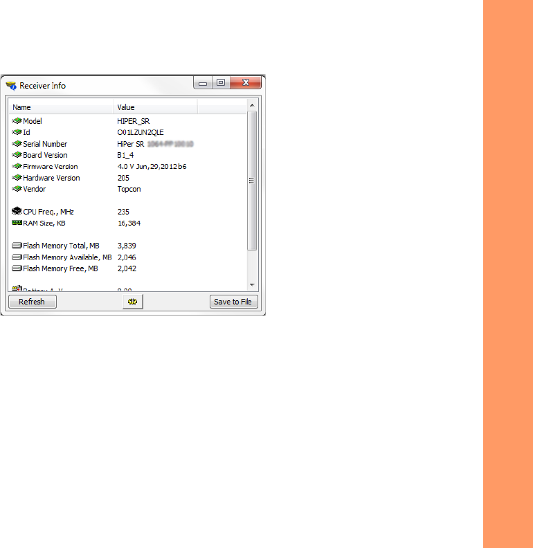
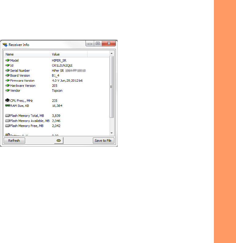
IntheTopcon ReceiverUtility(TRU),the
ReceiverInfo
windowdisplaysbasicReceiverinformation,suchashardwareandfirmware
versions,RAMsize,receiverID,serialnumber,etc.
ToopentheReceiverInfowindow:
1. ConnectthereceivertoacomputerandopenTRU.
2. InTRU,connecttothereceiver.
3. ClickDeviceApplicationModeReceiverManaging.
4. ClickDeviceConnect.
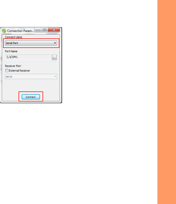
5. IntheConnectionParameterswindow,selectthecorrectserialport,andclickConnect.
6. IntheTRUmainwindow,clicktheInformationicon.TheReceiverInfowindow(Figure6)appears.
Configuring the Receiver
ViewingReceiverInformation
31
P/N:1000737‐01
Figure6:TRU–ReceiverInfo

Configuring the Receiver
LoadingNewFirmware
32
P/N:1000737‐01
Loading New Firmware
Receiverboardfirmwareisreleasedasacompressedfilethatyoudownloadanddecompress.Thisfilecontainsthefollowing
twofiles:
•
ramimage.ldr–theReceiverboardRAMfile
•
main.ldp–theReceiverboardFlashfile
Touploadfirmwarefilestothereceiver:
1. ConnectthereceivertoacomputerusingthePowerandSerialcablereceiveraccessory(p/n:100182‐01).
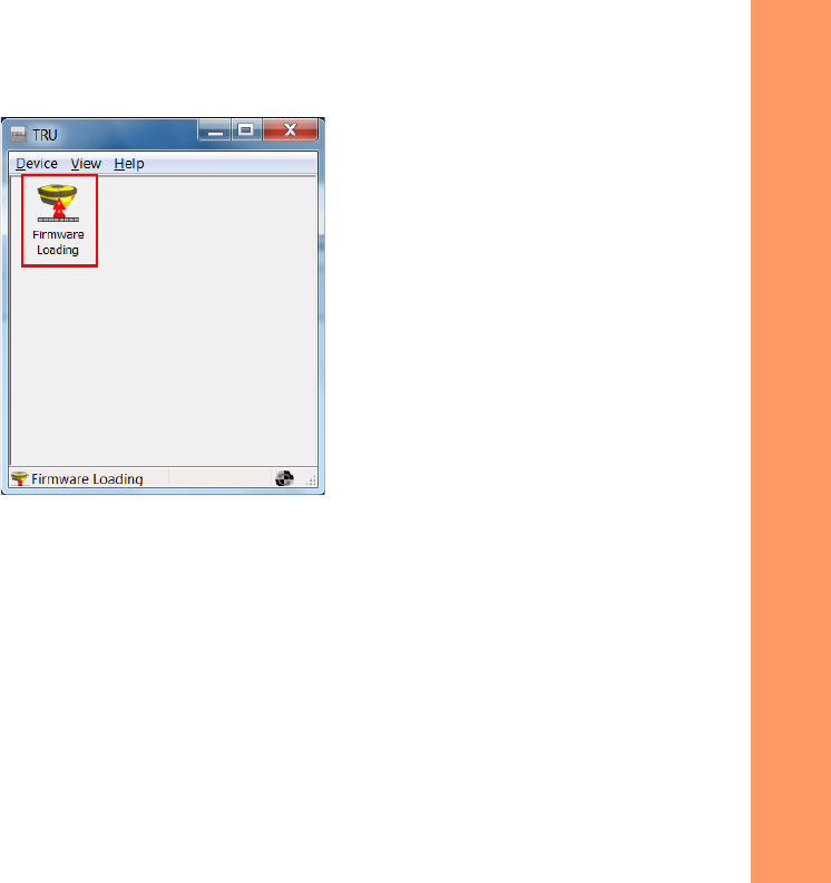
2. ClickDeviceApplicationModeFirmwareLoading.
OnlyusethePowerandSerialcabletouploadfirmwaretothereceiver.UsingaUSBorBluetoothconnection
touploadfirmwarecoulddamagethereceiver.Thenextfirmwarerelease,4.0SR,willsupportUSBor
Bluetoothconnectionsforfirmwareuploads.Seewww.topcontotalcare.comforfirmwareupdates.
Configuring the Receiver
LoadingNewFirmware
34
P/N:1000737‐01
Figure6:ConnectionParametersWindow
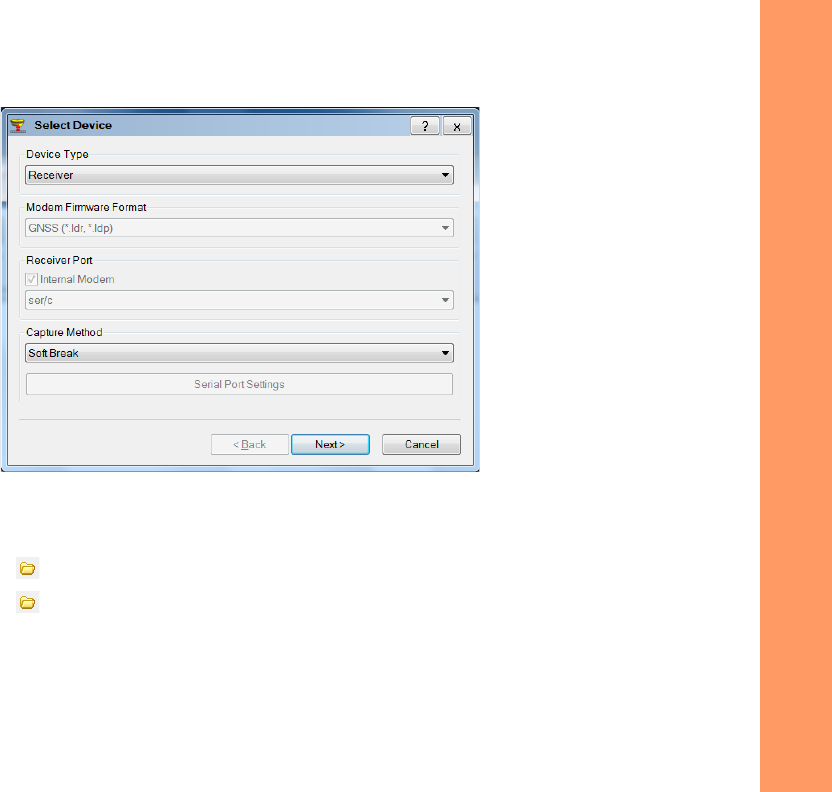
6. IntheSelectDevicewindow,dothefollowing:
a. SelectReceiverintheDeviceTypefield.
b. SettheCaptureMethodtoSoftBreak(recommended).
c. ClickNexttoselectthefirmwareRAMImagefile.
Configuring the Receiver
LoadingNewFirmware
35
P/N:1000737‐01
d. ClickNext.
Figure5:TRU–SelectDevice
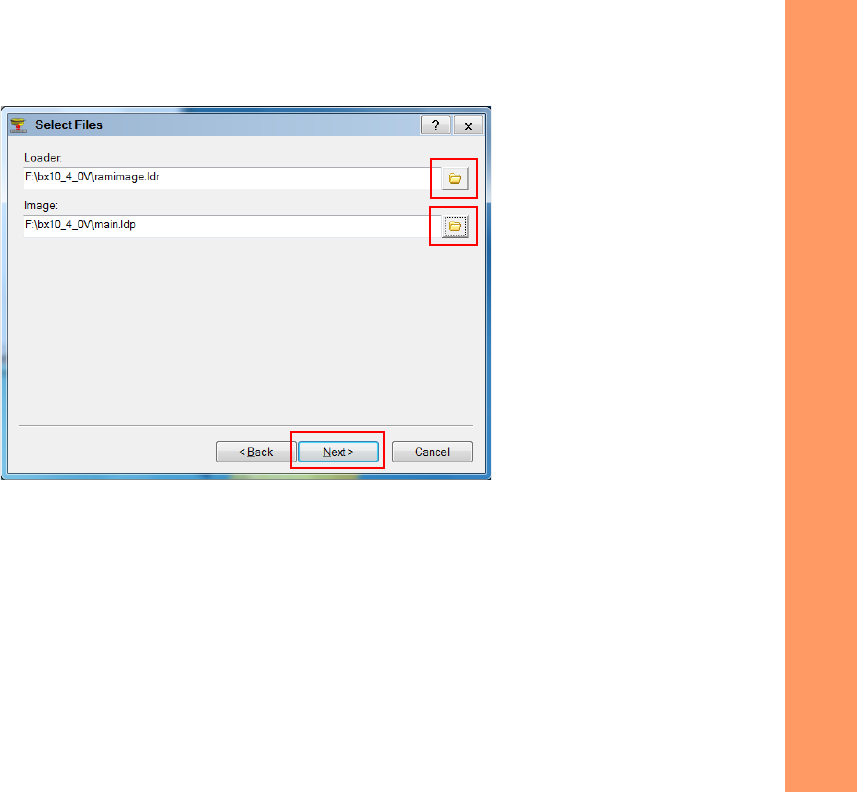
7. OntheSelectFileswindow,dothefollowing:
a. ClicktheBrowsenexttoLoadertosearchforandselectthereceiverboard’sRAMfile.
b. ClicktheBrowsenexttoImagetosearchforandselectthereceiverboard’smainfile.
c. ClickNext.
Configuring the Receiver
LoadingNewFirmware
36
P/N:1000737‐01
Figure4:TRU–SelectFilesWindow
Configuring the Receiver
LoadingNewFirmware
37
P/N:1000737‐01
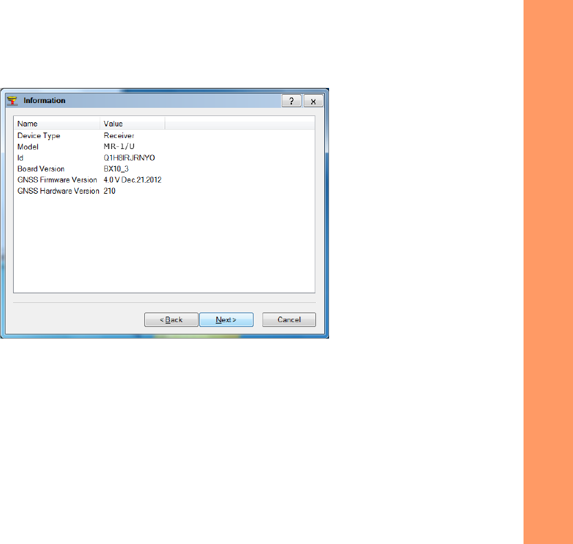
8. WhentheInformationwindowappears,ensurethefirmwareversioniscorrectandclickNexttouploadthe
firmware.
Figure9:TRU—FirmwareInformation
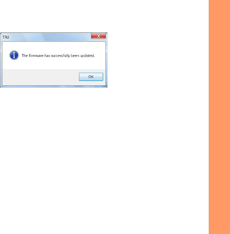
9. Oncethefirmwareloadsandtheconfirmationwindowappears,clickOKtoreturntotheConnectionParameters
window.
Configuring the Receiver
LoadingNewFirmware
38
P/N:1000737‐01
Figure9:TRU–FirmwareConfirmation
10. ClickDeviceConnect.
11. IntheConnectionParameterswindow,selectSerialPortandtheportname,andthenclickConnect.
Configuring the Receiver
LoadingNewFirmware
39
P/N:1000737‐01
12. IntheTRUmainwindow,clicktheInformationiconandverifythefirmwareversionyouuploadappearsinthe
ReceiverInfowindow.
Figure13:TRU–ReceiverInfoWindow

Configuring the Receiver
AbouttheOAF
40
P/N:1000737‐01
About the OAF
TopconissuesanOptionAuthorizationFile(OAF)toenablethespecificoptionsthatyoupurchased.Topcon’sOAFsystemallows
youtocustomizeandconfigurethereceiveraccordingtoyourparticularneeds,thereforepurchasingonlytheoptionsyou
require.
TheHiPerSRreceivertypicallyshipswithanOAFasperinitialpurchaseofthereceiverkitconfiguration.Thereareseveral
upgradeoptionsavailablewiththereceiverthatcanextendthereceiver’sfunctionalitytobettersuityourjobrequirement.
Examplesofupgradeoptionsarelistedbelow:
•
GPS+GLONASSdualfrequencystaticoperation
•
LongLINKbaseandroverRTKoperation
•
NetworkRTKoperation
•
RTKandupdaterateat20Hz
ContactyourTopcondealerorarepresentativeforacompletelistingofavailableoptionsandpricinginformation.
Checking the Receiver’s OAF
TouseTRUtoviewthestatusofthereceiver’soptions:
1. ConnectthereceivertoacomputerandopenTRU.SeetheTopconReceiverUtility(TRU)ReferenceManualfor
moreinformationaboutconnectingthereceivertoacomputer.
2. InTRU,connecttothereceiver.
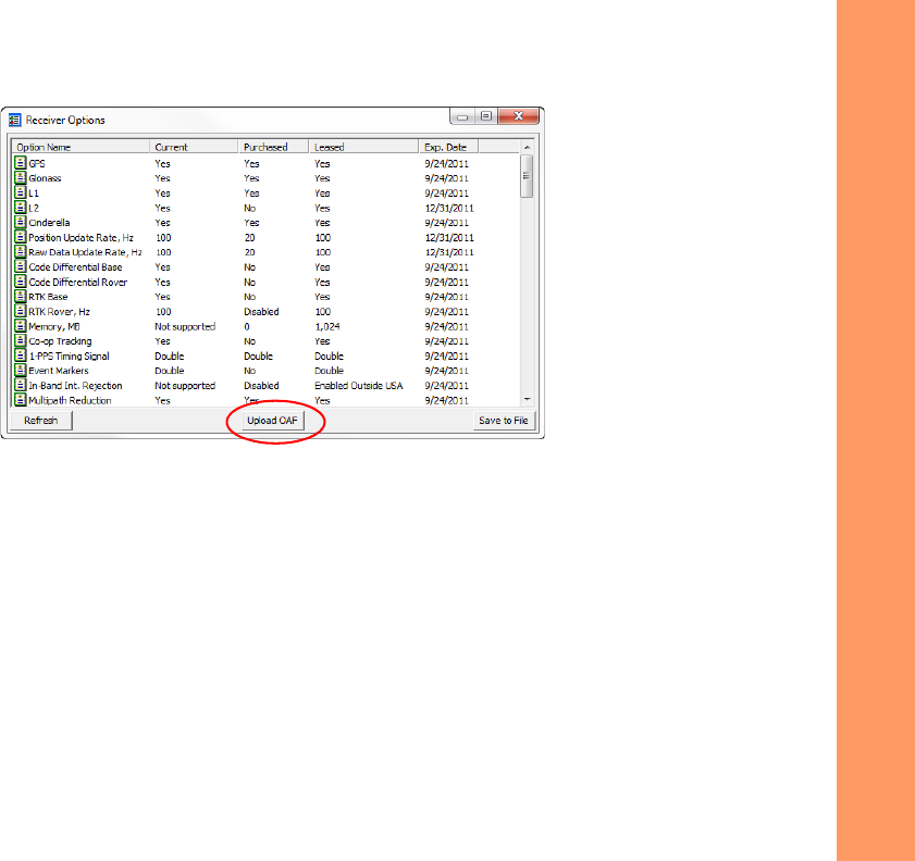
3. ClicktheOptions iconinthemainwindow.TheReceiverOptionswindow(Figure10)displays,soyoucanview
thecurrentauthorizationoptionsanduploadnewones.
Configuring the Receiver
AbouttheOAF
41
P/N:1000737‐01
Figure10:ReceiverOptions
Loading an OAF
TopcondealersprovidecustomerswithOAFfiles.ForanyOAFrelatedquestions,e‐mailTopconat
options@topcon.com
and
includethereceiver’sIDandserialnumber.Toobtainthesenumbers,see“ViewingReceiverInformation”onpage30.
ToloadanewOAF:
1. Followthestepsin“CheckingtheReceiver’sOAF”onpage40.
2. ClickUploadOAFonthebottomoftheReceiverOptionswindow(seeFigure10).
Configuring the Receiver
AbouttheOAF
42
P/N:1000737‐01
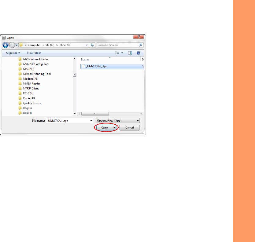
3. NavigatetothelocationofthenewOptionAuthorizationFile(Figure11).
Figure11:LoadOAF
4. Selecttheappropriatefile,andclickOpen(Figure11).
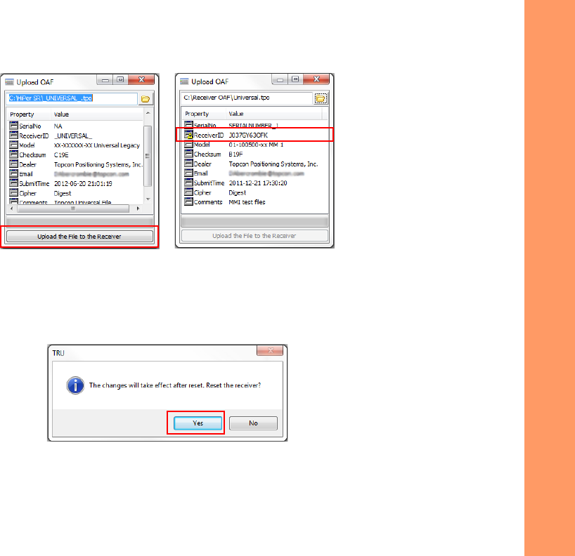
Topcon’s TRUinitiallycheckstoseeiftheselectedfileiscompatiblewiththecurrentlyconnectedreceiver.Ifyou
choseafilenotintendedforthisreceiver,theUploadOAFwindowdisplaysanerroriconnexttotheReceiverIDand
disablestheUploadtheFiletotheReceiverbutton.
Configuring the Receiver
AbouttheOAF
43
P/N:1000737‐01
Figure12:OAFCompatibilityCheck
5. PressUploadtheFiletotheReceiver(Figure12)tostartloadingthefile.
IfanOAFfileisuploadedtothereceiver,TRUwilloffertoresetthereceivertoputnewauthorizationoptionsinto
operation(Figure13).
Figure13:ResettheReceiver
6. ClickYes.

Configuring the Receiver
ResettingtheReceiver(ClearingtheNVRAM)
44
P/N:1000737‐01
Resetting the Receiver (Clearing the NVRAM)
Thereceiver’sNon‐VolatileRandomAccessMemory(NVRAM)holdsdatarequiredforsatellitetracking,suchasephemerisdata
andreceiverposition.TheNVRAMalsokeepsthecurrentreceiver’ssettings,suchasactiveantennainput,elevationmasksand
recordinginterval,andinformationaboutthereceiver’sinternalfilesystem.Clearingthereceiver’sNVRAMresetsthereceiver
andrestoresthefactorydefaultsettings.
Althoughresettingthereceiverisnotrecommendedasacommonpractice,therearetimeswhenitcaneliminate
communicationortrackingproblems.
Afterperformingareset,thereceiverrequirestimetocollectnewephemeridesandalmanacs(around15minutes).
Resettingthereceiverwillnotdeleteanyfilesalreadyrecordedinthereceiver’smemory,andtheNVRAMkeepsinformation
aboutthereceiverfilesystem.
YoucanalsouseTRUtocleartheNVRAM:
1. Connectthereceivertoacomputer,andopenTRU.SeetheTopconReceiverUtility(TRU)ReferenceManualfor
moreinformationaboutconnectingthereceivertoacomputer.
2. InTRU,connecttothereceiver.
Configuring the Receiver
UsingtheResetButton
45
P/N:1000737‐01
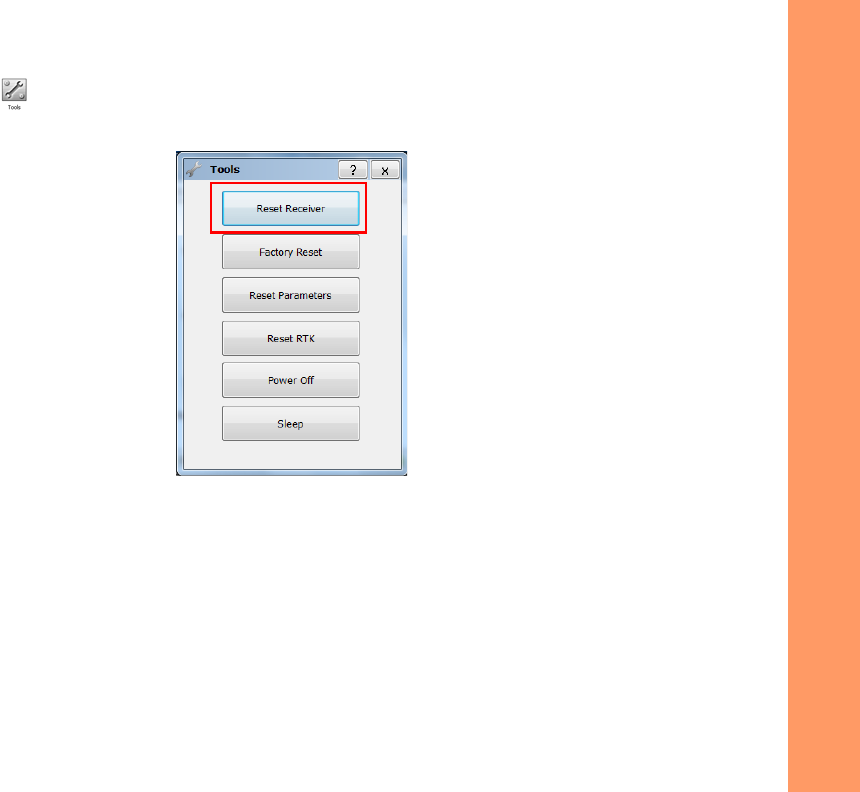
3. ClicktheToolsicon inthemainwindow.
TheToolswindowappears,enablingyoutoresetthereceiverandcleartheNVRAM.
Figure14:ToolsDialogBox
4. ClickResetReceiver,andthenclickYestocontinue.
Using the Reset Button
TheResetbuttoncausesahardresetofthereceiverandshouldonlybeusedif:
•
YouhavealreadyusedTRUtoresetthereceiverandthereisnoperformancechange.See“ResettingtheReceiver
(ClearingtheNVRAM)”onpage44.

Configuring the Receiver
UsingtheResetButton
46
P/N:1000737‐01
•
Thereceiverdoesnotrespondtocommands.
•
Thereceiverdoesnotchargetheinternalbatteries.
Resettingthereceivererasesdatanotsavedtothereceiver’smemory.
Toresetthereceiver,pushtheresetbuttonwiththeendofapaperclipuntilthereceivershutsoff.Wait???secondsbefore
usingthepowerbuttontoturnthereceiveronagain??
Figure5:ReceiverResetButton
NeedPic

FieldSystemSetup
47
P/N:1000737‐01
• • • • • •
Field System Setup
TheHiPerSRreceiver’sadvanceddesigneliminatestheneedforcablesduringoperation,allowingforasimplifiedsetupandless
partstokeeptrackof.
YoucantransmitRTKcorrectionsfromtheBasetotheRoverreceiverwirelesslyupto300metersusingLongLINK™wireless
technologyoruptoxxxusingthecellularnetworkingoption.Atthesametime,youcanconnectoverBluetoothtoacontroller
runningTRU,MAGNETField™,MAGNETRelay™orPocket‐3Dtoconfiguretheinstrument,andcollectandmanagedata.
Thischapterdescribesthefieldsetupofyournewreceiver,soitisreadyforuseasaRover,Base,network,RTKorforstaticdata
collection.
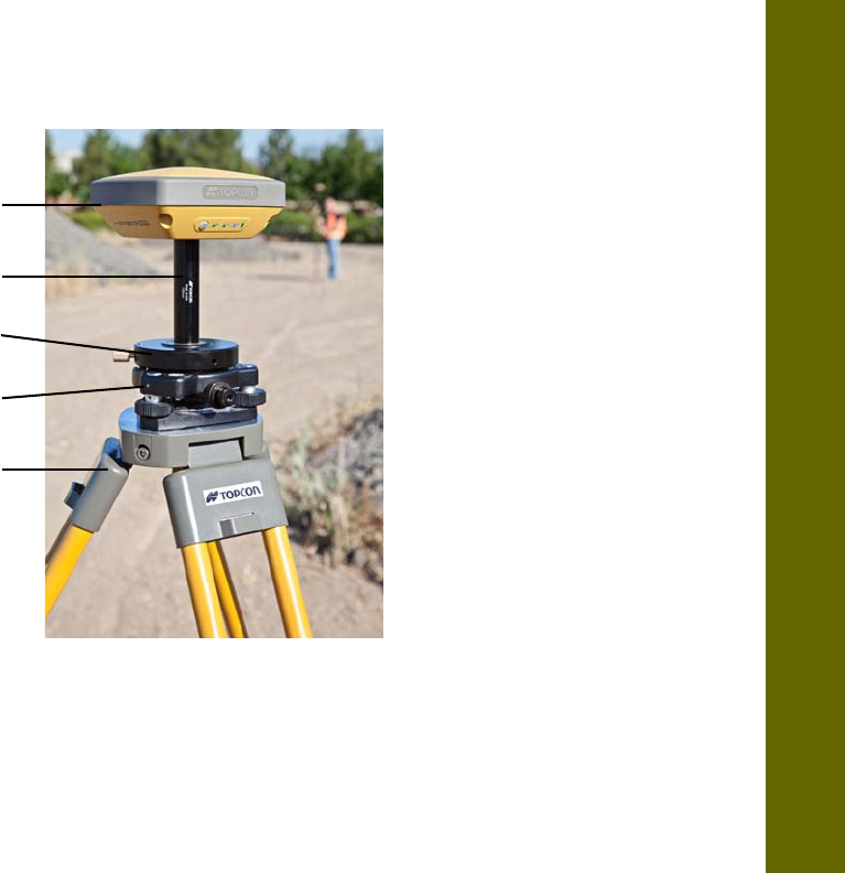
Figure15:EquipmentandSetup
Receiver
Range
Pole
Tripod
Prism Spacer
Tribrach
Adapter
Tribrach

Field System Setup
SettingUptheBaseReceiver
48
P/N:1000737‐01
Setting Up the Base Receiver
1. Mountthereceiveronatripodwithatribrach,tribrachadapter,andprismspacer,asshowninFigure16.
2. Positionthebasesystem(fromstep1)overaknownpoint.
3. Levelthetripodandmeasuretheheightofthereceiverfromthegroundusingthetapemeasure.See“Measuring
AntennaHeight”onpage52.
4. Pressthepowerbuttontoturnonthereceiver.Theintegratedwirelessdeviceinthereceiverturnsonwhenthe
receiverispowered.
5. ConnectthereceivertotheBluetooth‐enableddatacollector,runningTopconFieldsoftware,toconfigureandstart
thebaseHiPerSRreceiver.
6. ViewtheLEDdisplaypanelforthereceiver’scurrentstatus.Seealso“DisplayPanelOperations”onpage17.
Field System Setup
SettingUptheBaseReceiver
49
P/N:1000737‐01
Figure16:BaseReceiver
Tripod
Prism Spacer
Tribrach
Adapter
Tribrach
Receiver

Field System Setup
SettingUptheRoverReceiver
50
P/N:1000737‐01
Setting Up the Rover Receiver
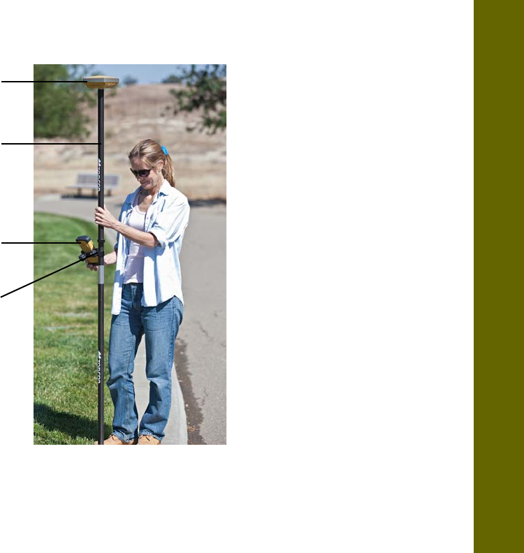
1. Mountthereceiverontheroverpole,asshowninFigure17.
2. AttachaTopconcontrollertothepoleusingamountingbracket.
3. Ifyouarenotusingafixedheightroverpole,measuretheheightofthereceiverfromtheground.See“Measuring
AntennaHeight”onpage52.
4. Pressthepowerbuttontoturnonthereceiver.Theintegratedwirelessdeviceinthereceiverturnsonwhenthe
receiverispowered.
5. ConnectthereceivertotheBluetooth‐enableddatacollector,runningTopconFieldsoftware,toconfiguretheHiPer
SRasaroverreceiver.
6. ViewtheLEDdisplaypanelforthereceiver’scurrentstatus.Seealso“DisplayPanelOperations”onpage17.
Field System Setup
SettingUptheRoverReceiver
51
P/N:1000737‐01
Figure17:RTKRover
Receiver
Range Pole
Data Controller
Controller Bracket

Field System Setup
MeasuringAntennaHeight
52
P/N:1000737‐01
Measuring Antenna Height
Thereceivercalculatesthecoordinatesoftheantenna’sphasecenter.Todeterminethecoordinatesofthestationmarker,
specifythefollowing:
•
Measuredheightoftheantennaabovethestationmarker
•
Methodofmeasuringtheantennaheight
•
Modeloftheantenna/receiverused
Anynecessaryantennaphasecenteradjustments,basedontheantennamodel,isautomaticallyapplied.Thisadjustment,when
combinedwithaccuratelymeasuredheightandmeasurementmethods,allowsforcorrectlycomputedreferencemarker
coordinates.
Toaccuratelymeasuretheantennaheight:
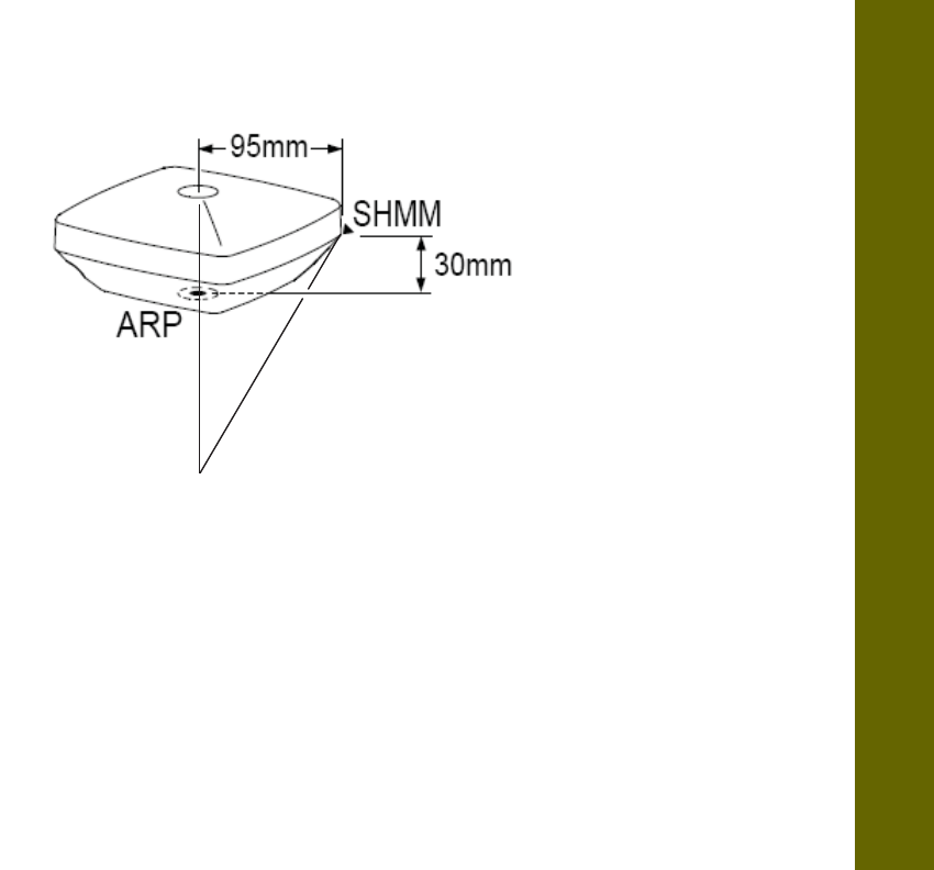
1. Measuretheantennaheightabovethecontrolpointormarker,eithertheslantheightortheverticalheight.
YoumayeithermeasuretheverticalheighttotheAntennaReferencePoint(ARP)locatedatthebottomofthe
receiveratthebaseofthemountingthreads,ormeasuretheslantheighttotheSlantHeightMeasurementMark
(SHMM)onthesideofthereceiver.ForARPandSHMMmarksonthereceiver,seeFigure18.
2. Recordtheantennaheight,pointsname,andstarttimeinthefieldnotes.
Field System Setup
MeasuringAntennaHeight
53
P/N:1000737‐01
Figure18:AntennaHeightMeasurementPoints

CollectingData
54
P/N:1000737‐01
• • • • • •
Collecting Data
Thischapterprovidesgeneralinformationaboutrecordingdata,downloadingit,andremovingfilestofreeupinternalmemory.
Setting Recording Parameters
TheTopconReceiverUtility(TRU)softwareenablesyoutosetloggingparameters,suchasloggingrateandtypesofmessages,in
whichtorecorddata.ThissoftwareandtheTRUReferenceManualissuppliedontheHiPerSRCD.SeetheTRUReferenceManual
formoreinformation.TheHiPerSRiscompatiblewithanyTopconfieldsoftwareforconfigurationandrecordingrawdata.
Logging Rates
Thereceiverprovidesupto2GBoffilespaceontheinternal(non‐removable)memorycard.Theamountofmemoryusedtolog
datadependsontheloggingrate.Formoreinformationaboutsettingloggingrateparameters,seetheTRUReferenceManual.
Recording Data
YoucanlograwGNSSdatatothereceiver’sinternalmemoryandusetheTopc onReceiverUtility(TRU)orMAGNETOffice™
softwaretodownloadthefilestoacomputer.
Tostartorstoprecordingdatatothereceiver,youcanusetheLEDdisplaypanelorTRU.
1. PressthePowerbuttontoturnonthereceiver.

Collecting Data
ManagingFiles
55
P/N:1000737‐01
2. WaitfortheSTATLEDtoindicatesatellitesarebeingtracked.TheSTATLEDblinksgreenforGPSsatellitesandamber
forGLONASS satellites. A short red blink indicates the receiver has not solved a position. Five or more satellites
provide optimal positioning.
3. PressthePOWERbuttonthreetimestobeginrecording.YoucanalsoselectFileExplorerLogsStartinTRUto
beginrecordingdata.
4. MakesuretheREClightisblinkinggreen.Thisindicatesthatafilehasopenedanddatacollectionhasstarted.The
RECLEDblinkseachtimedataissavedtotheinternalmemory.
5. Whenyouhavefinishedrecording,pressthePOWERbuttonthreetimes,andmakesuretheRECLEDisdark.You
canalsoselectFileExplorerLogsStopinTRUtoenddatarecording.
6. Toturnoffthereceiver,pressandholdthePOWERbuttonfor3to10secondsuntilallLEDsturndarkandtheBAT
LEDissolidred.
Managing Files
Rawdataisrecordedastime‐taggedmeasurementsinasinglerawdatafile.Eachfileisrecordedtothereceiver’sinternal
memory,andautomaticallygivenanameanda*.tpsfileextension.Afileofcollecteddatacanthenbetransferredtoa
computerwithfilemanagingsoftware,suchastheTopconReceiverUtility(TRU),whichissuppliedontheGPS+CD.These
programsallowyoutouseanautomaticnamingfeature,enterfilenames,anddeletefilesasnecessary.Formoreinformation,
seetheTRUReferenceManualsuppliedontheHiPerSRCD.
YoucanalsologdatausingMAGNETFieldsoftware.

Collecting Data
ManagingFiles
56
P/N:1000737‐01
Downloading and Deleting Files
Aftercompletingasurvey,downloaddatafilestoacomputeroracontrollerforstorage,post‐processing,orbackup.The
receiver’sinternalmemoryholdsafiniteamountoffiles,soyouwillwanttodeletefilestoincreasememorycapacity.
Whentheinternalmemoryisfull,thereceiverstopsloggingdata,andtheRECLEDturnsdark/off,indicatinganerrorcondition.
Existingdataisnotoverwritten.
Therearetwooptionsfordeletingrawdatafilesfromthereceiver:
•
DeleteallofthefilesusingtheLEDdisplaypanel(i.e.holdthepowerbuttonfor15to20seconds).
Thiserasesallofthe
filesinthereceiversinternalmemory
.
•
UseaUSB,serial,orBluetoothconnectiontodownloadthefilestoacomputer.InTRU,youcanselectthefilesyouwant
todeletefromthereceiver.SeetheTRUReferenceManualformoreinformation.
Onceaconnectionisestablished,youcandownloadallorsomefilestoacomputerorcontrollerandthenusetheFileExplorer
featureinTop conReceiverUtility(TRU)tomanagetherawdatafiles.FormoreinformationaboutusingTRUtodownloador
deletefiles,seetheTopconReceiverUtility(TRU)ReferenceManualincludedontheHiPerSRCD.

Troubleshooting
57
P/N:1000737‐01
• • • • • •
Troubleshooting
Thischapterwillhelpyoudiagnoseandsolvesomecommonproblemsthatmayoccurwiththereceiver.
Check This First!
BeforecontactingyourlocaldealerorTopcon TechnicalSupport,checkthefollowing:
•
Checkallexternalreceiverconnectionscarefullytoensurecorrectandsecureconnections.Doublecheckforwornor
defectivecables.
•
Checkthereceiver’sinternalbatteriesforafullcharge.
•
Checkthepowersourceforincorrectlyconnectedcables,andensurethepowersourceisvalid.See“Specifications”on
page67forexternalpowerrequirements.
•
Checkthesoftware.Makesurethemostcurrentsoftwareversionisdownloadedontothecomputerandthemostcurrent
firmwareisloadedintothereceiver.ChecktheTopconwebsiteforthelatestupdates.
•
CheckTopconTechnicalSupport(www.topconsupport.com)orTopconTotalCare(www.topcontotalcare.com)forthe
latestupdates.
Then,trythefollowing:
•
PoweronandoffthereceiverbypressingthePowerbuttonorbyusingTRU(
Tools
Resetreceiver
).
Donotattempttorepairequipmentyourself.Doingsowillvoidthewarrantyandmaydamagethehardware.

Troubleshooting
PoweringProblems
58
P/N:1000737‐01
•
RestoredefaultsettingsbypressingthePowerbuttonfor10to15secondsorusingTRU(
Tools
ClearNVRAM)
.
This
restoresthereceiver’sparameterstothefactorydefaultsettingsanderasesthealmanacandephemerisfiles.This
actiondoesnotdeletedatafilesfromthereceivermemory.
•
EraseallfilesbypressingthePowerbuttonfor15to20secondsorbyusing
FileExplorer
DeleteAllFiles
inTRU.This
willdeleteallfilesstoredinthereceiver’snon‐removablememorycard.
Iftheproblempersists,seethefollowingsectionsforothersolutions.
Powering Problems
Thefollowingaresomeofthemostcommonlyencounteredpowerproblems.
Thereceiverdoesnotpowerup
•
Thebatterymaybedischarged.
–Chargethebatteryovernight.See“ChargingtheBatteries”onpage27.
•
Ifyouareusinganexternalpowersource,thecablemaybedisconnectedordamaged.
–Makesurethecableissecurelyconnectedandundamaged.
•
Thereceivermayhaveadefectivechargerordefectivebattery.
–If,afterchangingthebatteryorconnectinganexternalpowersource,thereceiverstilldoesnotpowerup,
contactyourlocaldealerorTopconTechni calSupportforadvice.

Troubleshooting
ReceiverProblems
59
P/N:1000737‐01
Receiver Problems
Thefollowingaresomeofthemostcommonlyencounteredreceiverproblems.
Thereceivercannotestablishaconnectiontoacomputerorexternalcontroller
Cablespecificproblems:
•
Thecableisnotproperlypluggedin.
–Unplugthecable,thensecurelyandproperlyreconnectittothereceiver.
•
Thecableisdamaged.
–Useanundamagedcable.Contactadealertoreplacethecable.
•
TheUSBdriverisnotinstalled.
–IfyouareusingaUSBcableconnection,makesuretheUSBdriver,includedontheGPS+SoftwareCD,is
installedonthecomputer.YoucanalsodownloadthedriverfromtheTopconsupportWebsiteat
www.topcontotalcare.com.
Genericproblems:
•
ThereceiverportusedforconnectionisnotinCommandmode.
a. ConnectthereceivertoacomputerandopenTRU(see“Connection”intheTopco nReceiverUtility(TRU)
ReferenceManual).
b. ClickReceiverSettingsPorts.
c. ChangetheInputModefortheportusedforconnectiontocmd.

Troubleshooting
ReceiverProblems
60
P/N:1000737‐01
Thereceiverdoesnotlockontosatellitesforalongperiodoftime
•
Thecorrespondingreceiveroptionsmaybedisabledorexpired(L1/L2,GPS/GLONASSmustbeontotracksatellites).
–OrderanewOAFwiththedesiredoptionsactivatedtoenableorextendvalidityofthecorrespondingreceiver
options.ContactadealerorvisittheTopconwebsitefordetails.
–Refertothe“ReceiverManaging”chapteroftheTopconReceiverUtility(TRU)ReferenceManualforadetailed
descriptionofoptions.
Thereceivertrackstoofewsatellites
•
Thesurveyisconductednearobstructions(treecanopy,tallbuildings,andsoforth).
–MakesuretheMultipathReductionboxeshavebeenenabled.
a. ConnectthereceivertoacomputerandopenTRU(see“Connection”intheTopco nReceiverUtility(TRU)
ReferenceManual).
b. InTRU,connecttothereceiver.
c. OntheTRUmainwindow,chooseReceiverSettingsTrackingAdvtab.MakesuretheC/Acode
multipathreductioncheckboxisselected.
•
Movetoanareafreeofobstructions,ifapplicable.
ThereceivercannotobtainCodeDifferentialand/orRTKsolutions
•
IncorrectBasecoordinatesentered.
–SpecifythecorrectcoordinatesfortheBasestationusing
TRUoranothersuitablefielddatacollectionsoftware.
•
TherecouldbesomeobstructiontotheLongLINKconnection.
–ClearallpossibleobstructionsorrelocatetheBasesothereisa“line‐of‐sight”pathtotheRover.

Troubleshooting
ReceiverProblems
61
P/N:1000737‐01
•
Thecorrespondingreceiveroptionsmaybedisabledorexpired.
–OrderanewOAFwiththerequiredoptionsactivatedtoenableorextendvalidityofthecorrespondingreceiver
options.
–RefertotheTopconReceiverUtility(TRU)ReferenceManualforadetaileddescriptionofoptions.
•
Therearenotenoughcommonsatellites.Inordertoobtainafixedsolution,theBaseandRovershouldtrackatleast
fivecommonsatellites.
–ChecktheelevationmasksoftheRoverandBasereceivers;theyshouldbethesame.Todothis,ontheTRU
mainwindow,chooseReceiverSettingsTrackingObs.
–Verifythereisaclearviewoftheskytoallowsufficientsatellitetracking.
•
AdiscrepancyexistsbetweenthedifferentialstandardsusedattheBaseandRoverreceivers.
–EnsuretheBaseandRoverreceiversusethesamecorrectionsinput/outputformat:
a. ConnectthereceivertoacomputerandopenTRU(see“Connection”intheTopco nReceiverUtility(TRU)
ReferenceManual).
b. InTRU,connecttothereceiver.
c. OntheTRUmainwindow,chooseReceiverSettingsPorts.
d. Double‐clickontheporttobeconfiguredandmakesuretheinputmodeoftheRovermatchestheformat
oftheBaseoutputmode(i.e.RTCM3).
•
Poorsatellitegeometry(PDOP/GDOPvaluesaretoohigh).
–Conductthesurveywheresatellitevisibilityisbetter(lowPDOPvalue).
TheHiPerSRreceiverrequiresdifferentOAFsforLongLINK,network,andNetworkandLongLINKoperations.
ContactaTopcondealerfordetailsaboutavailableoptionstopurchasewiththereceiver.

Troubleshooting
LongLINKProblems
62
P/N:1000737‐01
–Ensuretheelevationmaskislessthan15degrees.
•
Theelevationmaskisabove15degrees.
–Lowertheelevationmask.Todothis,ontheTRUmainwindow,chooseReceiverSettingsTrackingObs.
–Verifythereisaclearviewoftheskytoallowsufficientsatellitetracking.
•
Theremaybeasourceofradiointerferencethatdisruptsradiocommunications.
–ChangetheRFchannel(ifpossible).
–Removingthesourceofthejammingsignalorrelocatetheradioantennas(ifpossible).
Thereceiverdoesnotstartloggingdata
•
Thereceiver’smemoryisdisabledorexpired.
–Makesurethememoryoptionisenabled.Fordetails,seetheTopconReceiverUtility(TRU)ReferenceManual.
•
Thereceiver’sinternalmemorycarddoesnothavefreespace.
–Downloadand/ordeletedatafilestofreeupspacefornewfiles.See“DownloadingandDeletingFiles”on
page56.
LongLINK Problems
Thefollowingaresomeofthemostcommonlyencounteredproblems.
LongLINKcannotdiscover
theBasereceiver
•
TheBaseisoutofrange.
–MakesuretheBasereceiveriswithin300metersoftheRover.
•
TheBaseisnotresponding.

Troubleshooting
BluetoothProblems
63
P/N:1000737‐01
–MakesuretheBaseisturnedon.
•
MakesureBluetoothisturnedonfortheBaseandRover(i.e.theBluetoothLEDsareblueonbothreceivers).
•
Makesuretherearenoobstructionsorinterference.
ABluetoothconnectioncannotbeestablished
•
ALongLINKconnectionisnotavailableattheBase.(i.e.3connectionsarealreadyestablished.)
•
Makesuretherearenoobstructionsorinterference.
Bluetooth Problems
Thefollowingaresomeofthemostcommonlyencounterederrormessagesandotherproblems.
TRUerrormessage:Can’tfindreceiver
•
Thereceiveristurnedoff.
–Ensurethereceiverhaspowerandisturnedon.
•
Bluetoothisnotturnedon;theBTLEDisoff.
–ResetthereceivertothefactorydefaultsettingsbypressingthePowerbuttonfor10to15seconds.
•
Thereisinterference.
–Movethereceiver,controller,orcomputertoanunobstructedlocation.
•
Thereceiveristoofaraway.
–Movethedevicesclosertogether.
•
ThereceiverisalreadyconnectedviaBluetoothtoanotherdevice.

Troubleshooting
BluetoothProblems
64
P/N:1000737‐01
–Disconnectthereceiverfromtheothercontrollerorcomputer.
•
ThereceiverportusedforconnectionisnotinCommandmode.
a. ConnectthereceivertoacomputerandopenTRU(see“Connection”intheTopco nReceiverUtility(TRU)
ReferenceManual).
b. ClickConfigurationReceiverPorts.
c. ChangetheInputModefortheBluetoothserialportusedforconnectiontocmd.
TRUerrormessage:OpenCOM#portfailed:Accessisdenied
•
Anotherapplicationusesthecomputerportdedicatedforconnection.
–Closetheapplication,andthenre‐connect.
–Connectthereceiverviaanother,unusedcomputerport.
LongLINKconnectionswillnotinterferewithBluetoothconnectionstocomputersorcontrollers.
Thisisthemostcommoncauseforthiserrormessage.UseTRUtodoublecheckthesettingsforthe
connectionport.

Troubleshooting
TRUProblems
65
P/N:1000737‐01
Aftersearchingforavailabledevices,nonearediscovered
•
Thereceiverisnotreceivingpower.
–Checkthatthereceiverisgettingpowerandisturnedon.
–Checkthatthepowercableiscorrectlyattachedtotheport.
–Unplugthecable,thensecurelyandproperlyreconnectittothereceiver.
–Ifthepowercableisdamaged,contactaDealertopurchaseanewcable.
Canseetheiconforthereceiver’sBluetoothmoduleonthecomputerscreen,butcannotconnecttoit
•
Devicesecuritysettingsprobablydiffer.
–MakesuretheBluetoothenableddevicesusethesamesecuritysettings.
•
Bluetoothmodulesettingsmayhavechanged.
a. IfthesettingsarechangedfortheBluetoothmodule,removeitfromthelistofdiscoveredBluetooth
devicesusingtheBluetoothmanagerprogram(suppliedwiththedeviceusedtomanagethereceiver).
b. Repeatthesearch.
TRU Problems
ThefollowingisthemostcommonlyencounteredTRUproblem.
TRUcannotconnecttothereceiver
•
Thereceiveristurnedoff.
–Ensurethereceiverhaspowerandisturnedon.
•
Ifusingacable,thecable’sconnectorsareimproperlyattached.

Troubleshooting
CleaningandStoringtheReceiver
66
P/N:1000737‐01
–Checkthatthecableconnectorisattachedtothecorrectserialport.
–Unplugthecable,thensecurelyandproperlyreconnectittothereceiver.
•
Ifusingacable,thecableisdamaged.
–Useanundamagedcable.
–Contactadealertopurchaseanewcable.
•
IfusingBluetoothwirelesstechnology,theincorrectportisselected.
–UseacomputerorreceiverthathasBluetoothwirelesstechnologyenabled/installed.
–Makesurethecomputerandreceiverusethecorrectportsforcommunication.FortheHiPerSRreceiver,thisis
BluetoothserialportA(btsp\a).
Cleaning and Storing the Receiver
•
Useacleanclothmoistenedwithneutraldetergentorwater.
•
Neveruseanabrasivecleaner,ether,thinnerbenzene,orothersolvents.
•
Alwaysmakesurethereceiveriscompletelydrybeforestoringit.Dryanymoisturewithasoft,cleancloth.
Getting Customer Support
Ifthetroubleshootinghintsandtipsinthisoperator’smanualfailtoremedytheproblem,contactTo pconCustomerSupport.
Forcontactinformation,see“GettingTechnicalSupport”onpage7.

Specifications
67
P/N:1000737‐01
• • • • • •
Specifications
TheHiPerSRisaVanguardtechnology‐basedGNSSreceiverfeaturing226channelsandLongLINKwirelesstechnologyforsmalljob
siteoperationsandcable‐freenetworksolutions.Thischapterprovidesspecificationsforthereceiveranditsinternalcomponents.
General Details
Table10liststhereceiver’sgeneralspecifications.
Table10.GeneralReceiverSpecifications
Physical
Enclosure MagnesiumalloywithLexanradome
Color TopconYellowandGray(bumper)
Dimensions(mm) 150(w)x150(d)x64(h)
Weight(g) 850
Antenna Topco nFenceAntenna™Technology
IntegratedGGDantennaw/internalgroundplane
Status
display/panel
MINTER(4LEDs+1powerbutton)

Specifications
GeneralDetails
68
P/N:1000737‐01
Serial/External
Power
HiroseH205‐Series(6‐pin,multiplex)
USB USBMiniB2.0(client)
Externalantenna
connector
None
Bluetoothantenna Fullyintegrated,high‐sensitivity
Tracking
Numberof
Channels
226channelsVanguard™ASICwithpatentedUniversal
TrackingChannelTec hnologya
TrackedSignalsbGPS:L1C/A,L1,L2P(Y),L2,L2Ccodeandcarrier
GLONASS:L1C/A,L1P,L2C/A,L2Pcodeandcarrier
SBAS WAAS/EGNOS/MSAS/QZSS)L1codeandcarrier
Multipath
reduction
Yes,codeandcarrier
PLL/DLLsetting Adjustablebandwidthandorder
Smoothinginterval Adjustable,codeandcarrier
Data Output
RTKCorrections TPS,RTCMSC104v2.x,3.x;CMR/CMR+c
Table10.GeneralReceiverSpecifications

Specifications
GeneralDetails
69
P/N:1000737‐01
ASCIIOutput NMEA0183version2.xand3.x
RTKpositiondata
rate(max.)
20Hz
Measurementdata
rate(max.)
20Hzd
Data and Memory
Removablemedia None
Internalmemory 2GB
Messagestorage
rate(max.)
20Hz
Environment
Operating
temperature
‐20°Cto+65°C(batteries)
‐40°Cto+65°C(w/externalpower)
Storage
temperature
‐40°Cto+70°C
Humidity 100%,condensing
Waterproofrating IPX7(1metersubmersion)
Dustrating IP6X(Fullydustproof)
Table10.GeneralReceiverSpecifications

Specifications
GeneralDetails
70
P/N:1000737‐01
Randomvibration MIL‐STD202G,Method214A,TestCurveA,5.35gRMS
Sinusoidalvibration SAEJ1211:1978Section4.7,4gPeak
ShockIEC60068‐2‐27edition4,TableA.2
25g,6ms
Topple 2.0mpoledrop
Technology
TopconVanguard™ASICtechnology
FenceAntenna™Technology
TopconadvancedMultipathRejection(AMR)
IntegrityMonitoring(RAIM)
TopconAutomaticFileRotationMode(AFRM)
UniversalTrackingChannels
Power
InternalBatteries 7.4V,5000mAh
Batterycharging
time
<5hours
Table10.GeneralReceiverSpecifications

Specifications
GeneralDetails
71
P/N:1000737‐01
Batterycharging
method
ConnecttheACadaptortochargetheinternalbatteries.
Availablerunchargewhenconnectedtoanexternal
battery.Chargingofinternalbatterieswhenpowerinput
isgreaterthan12V.
Operatingtime >15hrs(RTKRoverwithLongLINK,internalbatteries,
20°C)
Externalpower
input
6.5to30VDCe
Power
consumption
2.0W(RTKRoverwithLongLINK,usinginternalbatteries
at20°C)
Externalpower
supplyadapter
rating
Input:100‐240VAC,50‐60Hz,0.8A
Output:+12VDC/2.5A
Communication
Serial 1port;HiroseH205‐Series(6‐pin,multiplex);RS232
RX/TX
USB 1port;USBMiniB2.0(client)
LongLINK™wireless 3simultaneousconnections
Bluetooth v2.1+EDR
Cellular Yes.ViaexternalBluetooth‐enabledcontrollerordevice.
Table10.GeneralReceiverSpecifications

Specifications
GeneralDetails
72
P/N:1000737‐01
Survey Accuracyf
Static,fast‐static
(post‐processed)
L1only:
H:3mm+0.8ppm(xbaselinedistance)
V:4mm+1ppm(xbaselinedistance)
L1+L2:
H:3mm+0.5ppm(xbaselinedistance)
V:5mm+0.5ppm(xbaselinedistance)
Kinematic,RTKL1+L2:
H:10mm+1ppm
V:15mm+1ppm
DGPS
H:0.4m
V:0.6m
SBAS
H:1.0m
V:1.5m
Coldstart
Warmstart
Reacquisition
<40sec.
<20sec.
<1sec.
RTKTime‐to‐First‐
Fix(TTFF)
<20sec.
Table10.GeneralReceiverSpecifications

Specifications
GeneralDetails
73
P/N:1000737‐01
a.VanguardASICincludestwodedicatedchannelsforL‐Bandsignaltracking.The
HiPerSRreceiverdoesnotsupportL‐Bandsignaltracking.
b.TheHiPerSRincludesthelatestVanguardASICtechnology,andiscapableof
supportingplannedsignalsforbothGalileoandCOMPASS.Supportwillbe
incorporatedtoHiPerSRwhentheseconstellationshavematuredandareready
forcommercialuse.
c.CMR/CMR+isathird‐partyproprietaryformat.Useofthisformatisnot
recommendedandperformancecannotbeguaranteed.Useofindustrystandard
RTCM3.xisalwaysrecommendedforoptimalperformance.
d.100Hzoperationcanbesupportedforcustomapplications.Formore
information,contactyourdealer.
e.6.5to30VDCistheoperatingrangeoftheexternalpowersourcewhenthe
receiverison.Toturnthereceiveron,thepowerinputmustbebetween8to30
VDC.Tochargetheinternalbatteries,theexternalpowerinputmustbegreater
than12VDC.
f.Accuracywillvarydependingonthenumberofsatellitesused,obstructions,
satellitegeometry(PDOP),occupationtime,multipatheffects,andatmospheric
conditions.PerformancemaybedegradedinconditionswithhighIonospheric
activity,extrememultipath,orunderdensefoliage.Formaximumsystem
accuracy,alwaysfollowbestpracticesforGNSSdatacollections.

SafetyWarnings
74
P/N:1000737‐01
• • • • • •
Safety Warnings
General Warnings
TocomplywithRFexposurerequirements,maintainatleast25cmbetweentheuserandthereceiverwhen
operatingLongLINKtechnology.
TPSreceiversaredesignedforsurveyandsurveyrelateduses(thatis,surveyingcoordinates,distances,anglesand
depths,andrecordingsuchmeasurements).Thisproductshouldneverbeused:
•
Withouttheuserthoroughlyunderstandingthismanual.
•
Afterdisablingsafetysystemsoralteringtheproduct.
•
Withunauthorizedaccessories.
•
Withoutpropersafeguardsatthesurveysite.
•
Contrarytoapplicablelaws,rules,andregulations.

Safety Warnings
ReceiverWarnings
75
P/N:1000737‐01
Receiver Warnings
Usage Warnings
Tamperingwiththereceiverbytheendusersornon‐factoryauthorizedtechnicianswillvoidthereceiver’s
warranty:
•Donotattempttoopenthereceiverandmodifyanyofitsinternalcomponents.
•Donotchargeinconditionsdifferentthanspecified.
•Donotshortcircuit.
Ifthisproducthasbeendropped,altered,transportedorshippedwithoutproperpackaging,orotherwise
treatedwithoutcare,erroneousmeasurementsmayoccur.
Theownershouldperiodicallytestthisproducttoensureitprovidesaccuratemeasurements.
InformTPSimmediatelyifthisproductdoesnotfunctionproperly.
OnlyallowauthorizedTop conwarrantyservicecenterstoserviceorrepairthisproduct.

Regulatory
76
P/N:1000737‐01
• • • • • •
Regulatory
Thefollowingsectionsprovideinformationonthisproduct’scompliancewithgovernmentregulationsforuse.
FCC Compliance
ThisequipmentcomplieswithFCCradiationexposurelimitssetforthforuncontrolledequipmentandmeetstheFCCradio
frequency(RF)ExposureGuidelinesinSupplementCtoOET65.ThisequipmenthasverylowlevelsofRFenergythatitdeemedto
complywithoutmaximumpermissiveexposureevaluation(MPE).Butitisdesirablethatitshouldbeinstalledandoperatedwith
atleast20cmandmorebetweentheradiatorandperson’sbody(excludingextremities:hands,wrists,feetandankles).
ThisequipmenthasbeentestedandfoundtocomplywiththelimitsforaClassAdigitaldevicepursuanttopart15oftheFCCrules.
Theselimitsaredesignedtoprovidereasonableprotectionagainstharmfulinterferencewhentheequipmentisoperatedina
commercialenvironment.Thisequipmentgenerates,uses,andcanradiateradiofrequencyenergyand,ifnotinstalledandused
inaccordancewiththeinstructionmanual,maycauseharmfulinterferencetoradiocommunications.Operationofthisequipment
inaresidentialareaislikelytocauseharmfulinterferenceinwhichcasetheuserwillberequiredtocorrecttheinterferenceathis
ownexpense.
Ifthisequipmentdoescauseinterferencetoradioortelevisionequipmentreception,whichcanbedeterminedbyturningthe
equipmentoffandon,theuserisencouragedtotrytocorrecttheinterferencebyoneormoreofthefollowingmeasures:
•
Reorientorrelocatethereceivingantenna.
•
Movetheequipmentawayfromthereceiver.
•
Plugtheequipmentintoanoutletonacircuitdifferentfromthattowhichthereceiverispowered.

Regulatory
IndustryCanadaCompliance
77
P/N:1000737‐01
•
Consultthedealeroranexperiencedradio/televisiontechnicianforadditionalsuggestions.
Industry Canada Compliance
This class A digital apparatus complies with Canadian ICES-003.
Cet appareil numérique de la classe A est conforme à la norme NMB-003 du Canada.
This device complies with Industry Canada licence-exempt RSS standard(s). Operation is subject to the
following two conditions: (1) this device may not cause interference, and (2) this device must accept any
interference, including interference that may cause undesired operation of the device.
Le présent appareil est conforme aux CNR d’Industrie Canada applicables aux appareils radio exempts de
licence. L’exploitation est autorisée aux deux conditions suivantes : (1) l’appareil ne doit pas produire de
brouillage, et (2) l’utilisateur de l’appareil doit accepter tout brouilage radioélectrique subi, même si le
brouillage est susceptible d’en compromettre le fonctionnement.
Anychangesormodificationstotheequipmentnotexpresslyapprovedbythepartyresponsiblefor
compliancecouldvoidyourauthoritytooperatesuchequipment.

Regulatory
CommunityofEuropeCompliance
78
P/N:1000737‐01
Community of Europe Compliance
TheproductdescribedinthismanualisincompliancewiththeR&TTEandEMCdirectivesfromtheEuropeanCommunity.
European Community Declaration of Conformity with R&TTE Directive
1999/5/EC
Thefollowingstandardswereapplied:(R&TTEDirective1999/5/EEC)
•
EN301489‐1V1.8.1(2008‐04)
•
EN301489‐17V2.1.1(2009‐05)
•
EN300328V1.7.1(2006‐10)
•
EN60950‐1:2006+A11:2009/A1:2010
•
EN301489‐3V1.4.1(2002‐08)
•
EN300440‐2V1.4.1
ThefollowingCEmarkisaffixedtothedevice:
ThisisaClassAproduct.Inadomesticenvironmentthisproductmaycauseradiointerferenceinwhichcase
theusermayberequiredtotakeadequatemeasures.

Regulatory
DeclarationofConformity(R&TTEDirective1999/5/EC)
79
P/N:1000737‐01
Declaration of Conformity (R&TTE Directive 1999/5/EC)
esky
[Czech] (Topcon) tímto prohlašuje, že tento (HiPer SR) je ve shod se
základními požadavky a dalšími píslušnými ustanoveními smrnice
1999/5/ES.
Dansk
[Danish] Undertegnede (Topcon) erklærer herved, at følgende udstyr
(HiPer SR) overholder de væsentlige krav og øvrige relevante krav
i direktiv 1999/5/EF.
Deutsch
[German] Hiermit erklärt (Topcon) dass sich das Gerät (HiPer SR) in
Übereinstimmung mit den grundlegenden Anforderungen und den
übrigen einschlägigen Bestimmungen der Richtlinie 1999/5/EG
befindet.
Eesti
[Estonian] Käesolevaga kinnitab (Topcon) seadme (HiPer SR) vastavust
direktiivi 1999/5/EÜ põhinõuetele ja nimetatud direktiivist
tulenevatele teistele asjakohastele sätetele.
English Hereby, (Topcon) declares that this (HiPer SR) is in compliance
with the essential requirements and other relevant provisions of
Directive 1999/5/EC.
Español
[Spanish] Por medio de la presente (Topcon) declara que el (HiPer SR)
cumple con los requisitos esenciales y cualesquiera otras
disposiciones aplicables o exigibles de la Directiva 1999/5/CE.
Regulatory
DeclarationofConformity(R&TTEDirective1999/5/EC)
80
P/N:1000737‐01
[Greek]
Français
[French] Par la présente (Topcon) déclare que l'appareil (HiPer SR) est
conforme aux exigences essentielles et aux autres dispositions
pertinentes de la directive 1999/5/CE.
Italiano
[Italian] Con la presente (Topcon) dichiara che questo (HiPer SR) è
conforme ai requisiti essenziali ed alle altre disposizioni pertinenti
stabilite dalla direttiva 1999/5/CE.
Latviski
[Latvian] Ar šo (Topcon) deklar, ka (HiPer SR) atbilst Direktvas 1999/5/EK
btiskajm prasbm un citiem ar to saisttajiem noteikumiem.
Lietuvi
[Lithuanian] Šiuo (Topcon) deklaruoja, kad šis (HiPer SR) atitinka esminius
reikalavimus ir kitas 1999/5/EB Direktyvos nuostatas.
Nederlands
[Dutch] Hierbij verklaart (Topcon) dat het toestel (HiPer SR) in
overeenstemming is met de essentiële eisen en de andere
relevante bepalingen van richtlijn 1999/5/EG.
Malti
[Maltese] Hawnhekk, (Topcon) , jiddikjara li dan (HiPer SR) jikkonforma
mal-tiijiet essenzjali u ma provvedimenti orajn relevanti li hemm
fid-Dirrettiva 1999/5/EC.

Regulatory
DeclarationofConformity(R&TTEDirective1999/5/EC)
81
P/N:1000737‐01
Magyar
[Hungarian] Alulírott, (Topcon) nyilatkozom, hogy a (HiPer SR) megfelel a
vonatkozó alapvetõ követelményeknek és az 1999/5/EC irányelv
egyéb elõírásainak.
Polski
[Polish] Niniejszym, (Topcon) , deklaruj, e (HiPer SR) spenia wymagania
zasadnicze oraz stosowne postanowienia zawarte Dyrektywie
1999/5/EC.
Português
[Portugues] (Topcon) declara que este (HiPer SR) está conforme com os
requisitos essenciais e outras disposições da Directiva 1999/5/CE.
Slovensko
[Slovenian] (Topcon) izjavlja, da je ta (HiPer SR) v skladu z bistvenimi
zahtevami in ostalimi relevantnimi doloili direktive 1999/5/ES.
Slovensy
[Slovak] (Topcon) týmto vyhlasuje, že (HiPer SR) spa základné
požiadavky a všetky príslušné ustanovenia Smernice 1999/5/ES.
Suomi
[Finnish] (Topcon) vakuuttaa täten että (HiPer SR) tyyppinen laite on
direktiivin 1999/5/EY oleellisten vaatimusten ja sitä koskevien
direktiivin muiden ehtojen mukainen.
Svenska
[Swedish] Härmed intygar (Topcon) att denna (HiPer SR) står I
överensstämmelse med de väsentliga egenskapskrav och övriga
relevanta bestämmelser som framgår av direktiv 1999/5/EG.
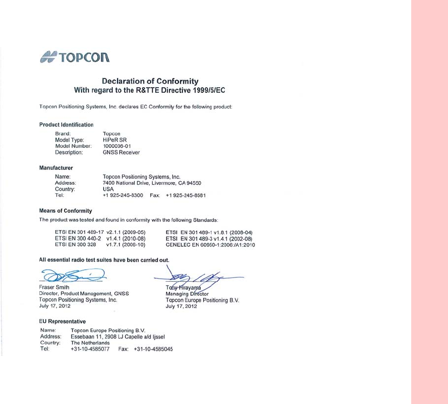
Regulatory
DeclarationofConformity(R&TTEDirective1999/5/EC)
82
P/N:1000737‐01

Regulatory
WEEEDirective
83
P/N:1000737‐01
WEEE Directive
FollowinginformationisforEU‐memberstatesonly:
Theuseofthesymbolbelowindicatesthatthisproductmaynotbetreatedashouseholdwaste.Byensuringthisproductis
disposedofcorrectly,tohelppreventpotentialnegativeconsequencesfortheenvironmentandhumanhealth,whichcould
otherwisebecausedbyinappropriatewastehandlingofthisproduct.Formoredetailedinformationaboutthetake‐backand
recyclingofthisproduct,pleasecontactasupplierwhereyoupurchasedtheproductorconsult.
Bluetooth Transmission Statements/Compliance
ThisBluetoothdeviceiscomplianttothefollowingprofilesofthecorespecversion2.1/2.1+EDR:
•
Baseband
•
HCI
•
LinkManager
•
Radio
Theradiohasbeentestedusingthemaximumantennagainof2.3dBiandtheBluetoothqualificationisvalidforanyantenna
withthesameorlessgain.

Regulatory
KoreanKC‐RFCompliance
84
P/N:1000737‐01
Korean KC-RF Compliance
해당 무선설비는 전파혼신 가능성이 있으므로 인명안전과 관련된 서비스는 할 수 없습니다 .
무선사양 (Wireless specification): Bluetooth 2.1 + EDR
사용주파수 (Used Frequency): 2402-2480 MhZ
채널 수 (the number of channels): 79
공중선전력 (Antenna Power): 2.1 dBi
변조방식 (Type of the modulation): GFSK, 8PSK
인증정보 (Product Id Code): KCC-CRM-T8S-1000036-01
신청자 (Applicant): Topcon Positioning Systems, Inc.
기기명칭 (Type of equipment): GPS surveying device with Bluetooth radio
모델 이름 (Model Name): HiPeR SR or GSX2
제조연월 (Year of manufacture): 2012
제조자 및 제조국가 (Manufacturer and country of origin): PC Partner , China
인증자 식별 부호 (Applicant Code): T8S
Korean KC-EMC Class A Statement
이 기기는 업무용 (A 급 ) 전자파 적합기기로서 판매자 또는 사용자는 이 점을 주의하시기 바라며 ,
가정외의 지역에서 사용하는 것을 목적으로 합니다 .

Glossary
85
P/N:1000737‐01
• • • • • •
Glossary
B
BaseStation
–AGNSSreceiversetupoveraknownpoint,whichisusedtoderivecorrectioninformationfornearbyRover(mobile)
GNSSreceivers.
Bluetooth®–
Oftenusedinplaceofcables,Bluetoothisopenwirelesstechnologyforexchangingdataovershortdistancesfrom
fixedandmobiledevices.
C
COMPASS
–BeiDouNavigationSatelliteSystemmaintainedandoperatedbyChina.
G
GALILEO
–ThesatellitesystemcurrentlybeingmaintainedandoperatedbytheEuropeanUnion(EU)andEuropeanSpaceAgency
(ESA).
GGD
–GPS+GLONASSDualFrequencysignaltracking.
GLONASS–
TheGLObalNAvigationSatelliteSystemmaintainedandoperatedbytheRussianFederation.
GNSS–
GlobalNavigationSatelliteSystems,suchasGPSandGLONASS.
GPS–
TheGlobalPositioningSystemmaintainedandoperatedbytheUnitedStatesDepartmentofDefense.

Glossary
86
P/N:1000737‐01
L
L1
–TheprimaryL‐bandcarrierusedbyGPSandGLONASSsatellitestotransmitsatellitedata.
L2
–ThesecondaryL‐bandcarrierusedbyGPSandGLONASSsatellitestotransmitsatellitedata.
Light‐EmittingDiode(LED)
–Usedasindicatorlightsonthereceivertodisplaythestatusofthereceiver’scomponentsand
controlreceiveroperations.
LongLINK™–
Top con’sLongLINKRTKtechnologyprovidesshort‐rangeRTKcommunicationupto1,000ft.(300mfromtheBase
station).
M
MAGNETField™
–DatacontrollersoftwarethatispartoftheMAGNETsoftwaresystem.
MAGNETOffice™
–Post‐processingandCADsolutionsoftwareforsurveyingandgradeapplication.ItispartoftheMAGNET
softwaresystem.
MINTER–
Thereceiver’sMinimumINTERfaceusedtodisplayandcontroldatainputandoutput.
N
NetworkRTK–
CollectssatelliteobservationsfromthereferencestationswithinthenetworkandsendsRTKcorrectionstothe
Rover.
O
OptionAuthorizationFile(OAF)–
Thisenablesthespecificfeaturesthatacustomerpurchases.

Glossary
87
P/N:1000737‐01
P
PhaseCenterofAntenna
–Thepointfromwhichtheelectromagneticradiationspreadssphericallyoutward,withthephaseof
thesignalbeingequalatanypointonthesphere.
Pocket‐3D–
FieldcontrollersoftwarebyTopconthatsupportsbothGNSSandTS.
R
Real‐TimeKinematic(RTK)–
Aprecisemethodofreal‐timesurveying.RTKenablesyoutocheckthemeasurementquality
withouthavingtoprocessthedata.
RootMeanSquare(RMS)
–Statisticalmeasureofthemagnitudeofavaryingquantity.
Rover–
AmobileGNSSreceiveranddatacollectorusedfordetermininglocationinthefield.
S
Satellite‐BasedAugmentationSystems(SBAS)–
Complementsexistingglobalnavigationsystems.SBAStransmitsdifferential
correctionsandmessagesfornavigationsatellitesthatarewithinsightofanetworkorreferencestationsinawidearea,such
asacontinent.
StaticSurvey–
Typicallyusesanetworkormultiplebaselineapproachforpositioning.Thismethodprovidesthehighest
accuracyandrequiresthelongestobservationtimes.

Glossary
88
P/N:1000737‐01
T
TopconReceiverUtility(TRU)–
Hardwareconfigurationsoftwareforreceiversandperipheraldevices.TRUisincludedonthe
GPS+SoftwareCDthataccompaniedyourreceiver.
U
UniversalSerialBus(USB)–
Aconnectionstandardusedbydevices,suchasareceiver,controller,computer,etc.
