Toppan Forms TR33MUE013 NFC Reader Module (FFC Type) User Manual
Toppan Forms Co., LTD NFC Reader Module (FFC Type)
User Manual

TR33MUE013
NFC Reader Module (FFC Type)
(PR533 NFC Reader/Writer for Toppan Forms)
User Manual
Version: 1.0
Toppan Forms Co. Ltd
TR33MUE013 User Manual
ii July 19,2012/v1.0
TABLE OF CONTENTS
1About this Document .......................................................................................................... 1
1.1 Purpose and Contents ............................................................................................................. 1
2TR33MUE013 NFC Reader/Writer module description ..................................................... 1
2.1 Description .............................................................................................................................. 1
2.2 How to use this product ........................................................................................................... 1
3TR33MUE013 PCB and Antenna Dimension overview ...................................................... 3
4Regulatory information ....................................................................................................... 4
TR33MUE013 User Manual
1July 19,2012/v1.0
1About this Document
1.1 Purpose and Contents
This document describes the setup and use of TR33MUE013 NFC Reader/Writer Module.
It includes the board layout, the antenna size and the interface to the host.
2TR33MUE013 NFC Reader/Writer module description
The interface with the host controller is USB 2.0 full speed via FFC cable.
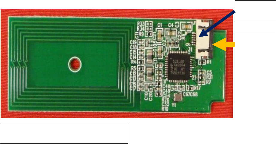
2.1 Description
On the product, the 6-way FFC connector is easily visible from external. The host controller will
connect to this module via a FFC cable using USB interface. Refer to Fig 4 on the pinning
definition of the FFc connector.
2.2 How to use this product
For testing this product using a PC/laptop , an additional converter is needed to bridge the
USB interface to the FFC connector of the module. The product should be recognized and
installed with CCID driver automatically as soon as it is plugged.
For read/write application tests, below are application example using STYL’s Toolkit software.
Fig 3. TR33MUE013 NFC Reader/Writer
Module
FFC
connector
Host
Interface
via FFC
cable
TR33MUE013 User Manual
2July 19,2012/v1.0
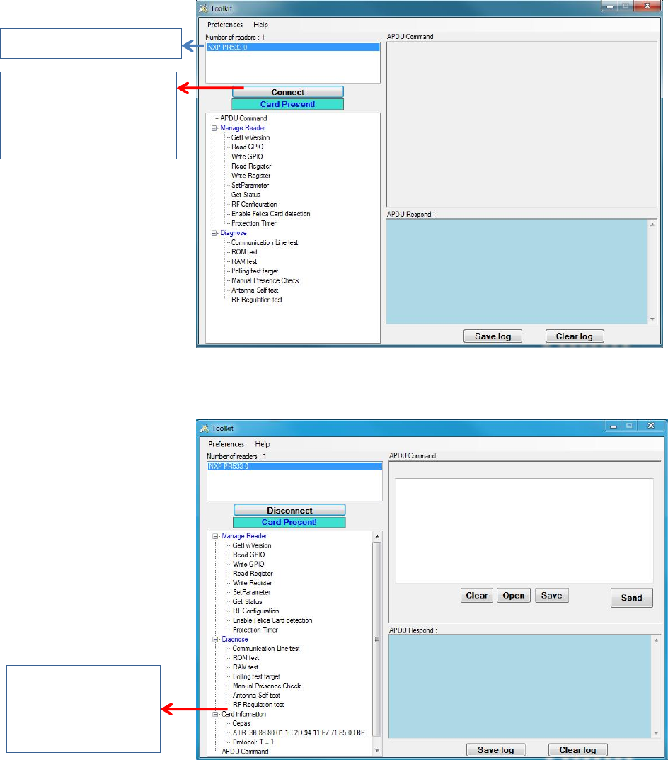
STYL’s Toolkit application software used for communication test
Case of smart card presented and detected in polling
Case of connecting to card to read card information
When Contactless
card is present and
detected, “Connect”
tab is highlighted.
PR533 reader detected
Example of getting
card information
TR33MUE013 User Manual
3July 19,2012/v1.0
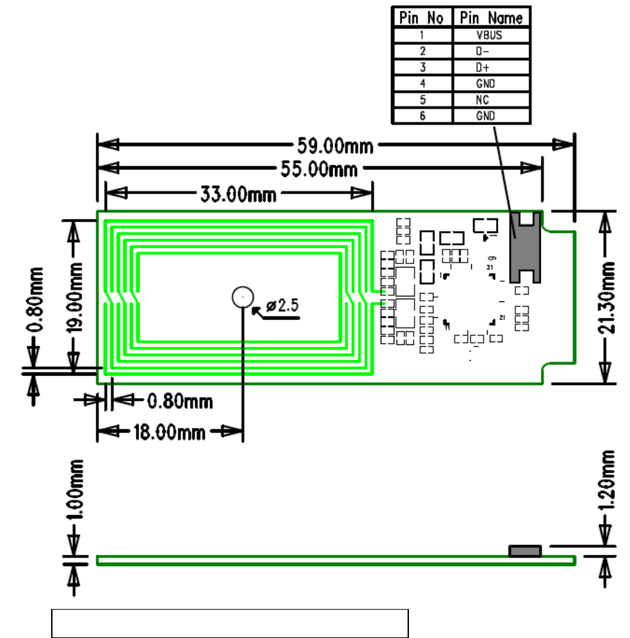
3TR33MUE013 PCB and Antenna Dimension overview
Fig 4. TR33MUE013 PCB and Antenna dimension

TR33MUE013 User Manual
4July 19,2012/v1.0
4Regulatory information
Regulatory Information
Federal Communication Commission Notice
FCC Identifier: ORK-TR33MUE013
This device complies with part 15 of the FCC Rules. Operation is subject to the following two conditions:
(1) This device may not cause harmful interference, and (2) this device must accept any interference
received, including interference that may cause undesired operation.
Note: This equipment has been tested and found to comply with the limits for a Class B digital device,
pursuant to part 15 of the FCC Rules. These limits are designed to provide reasonable protection against
harmful interference in a residential installation. This equipment generates, uses and can radiate radio
frequency energy and, if not installed and used in accordance with the instructions, may cause harmful
interference to radio communications. However, there is no guarantee that interference will not occur in a
particular installation. If this equipment does cause harmful interference to radio or television reception,
which can be determined by turning the equipment off and on, the user is encouraged to try to correct the
interference by one or more of the following measures:
—Reorient or relocate the receiving antenna.
—Increase the separation between the equipment and receiver.
—Connect the equipment into an outlet on a circuit different from that to which the receiver is connected.
—Consult the dealer or an experienced radio/TV technician for help.
Caution: Any changes or modifications not expressly approved by the party responsible for compliance to
this equipment would void the user’s authority to operate this device.
Note :
1. This module is intended for end device installation. The installer is still responsible for the FCC
compliance requirement of the end product, which integrates this module. The host end product must
also pass the FCC Part 15 unintentional emission testing requirement and be properly authorized per
FCC Part 15. The host end product must include a user manual that clearly defines operating
requirements and conditions that must be observed to ensure compliance with current FCC RF exposure
guidelines.
2. The built-in antenna is integrated to the module and no other antenna should be used.
3. This module must not be co-located or jointly operated with any other antenna or transmitter within
host.
4. A label should be attached to the host end product in a visible area with the following statement:
“Contains Transmitter Module FCC ID: ORK-TR33MUE013” or “Contains FCC ID: ORK-TR33MUE013”.
EC R&TTE directive:
We, hereby declare that the above named module is in conformity to all the essential requirements of
Directive 1999/5/EC. The Conformity Assessment procedure referred to Article 10 and detailed in Annex
[III] or [IV] of Directive 1999/5/EC has been followed with involvement of the following notified body:
TIMCO ENGINEERING, INC., P.O BOX 370, NEW BERRY, FLORIDA 32669.
Identification mark: 1177 (Notified Body number)
The technical documentation relevant to the above equipment is held at:
• Toppan Forms Co. Ltd, 1-7-3 Higashi Shimbashi, Minato-Ku, Tokyo 105-8311, Japan