Toro 4100 D Gm4100 1 User Manual To The 4d5728a6 7a38 482c 8308 E2999cdbc5fb
User Manual: Toro 4100-D to the manual
Open the PDF directly: View PDF ![]() .
.
Page Count: 369 [warning: Documents this large are best viewed by clicking the View PDF Link!]
- Preface
- Table Of Contents
- Table Of Contents (Continued)
- 1 - Safety
- 2 - Product Records and Maintenance
- 3 - Yanmar Diesel Engine
- YANMAR TNV (Tier 4i) SERIES SERVICE MANUAL
- YANMAR TNV (Tier 4i) SERIES TROUBLESHOOTINGMANUAL
- YANMAR TNV (Tier 4) SERIES SERVICE MANUAL
- YANMAR TNV (Tier 4) SERIES TROUBLESHOOTINGMANUAL
- 4 - Hydraulic System
- Table of Contents
- Specifications
- General Information
- Hydraulic Schematic
- Hydraulic Flow Diagrams
- Special Tools
- Troubleshooting
- Testing
- Traction Circuit Charge Pressure
- Traction Circuit Relief Pressure
- Counterbalance Pressure
- Reverse Traction Circuit Reducing Valve (PR) Pressure
- Rear Traction Circuit Relief Valve (RV) Pressure
- Piston (Traction) Pump Flow
- Cutting Deck Circuit Pressure
- PTO Relief Pressure
- Cutting Deck Motor Case Drain Leakage
- Lift/Lower Circuit Relief Pressure
- Steering Circuit Relief Pressure
- Steering Cylinder Internal Leakage
- Engine Cooling Fan Circuit
- Gear Pump Flow
- Adjustments
- Service and Repairs
- General Precautions for Removing and Installing Hydraulic System Components
- Check Hydraulic Lines and Hoses
- Priming Hydraulic Pumps
- Flush Hydraulic System
- Filtering Closed-Loop Traction Circuit
- Charge Hydraulic System
- Hydraulic Reservoir
- Radiator and Oil Cooler Assembly
- Gear Pump
- Gear Pump Service
- Piston (Traction) Pump
- Piston (Traction) Pump Service
- Rear Axle Motor
- Front Wheel Motors
- Rear Axle and Front Wheel Motor Service
- Rear Traction Manifold
- Rear Traction Manifold Service
- Control Manifold Cartridge Valve Service
- Combination Manifold
- Combination Manifold Service
- Steering Control Valve
- Steering Control Valve Service
- Steering Cylinder
- Steering Cylinder Service
- Engine Cooling Fan Motor
- Engine Cooling Fan Motor Service
- Cutting Deck Motor
- Cutting Deck Motor Service (Sauer-Danfoss)
- Cutting Deck Motor Service (Casappa)
- PTO Manifolds
- PTO Manifold Service
- Cutting Deck Lift Cylinders
- Wing Deck Lift Cylinders
- Lift Cylinder Service
- SAUER--DANFOSS H1 CLOSED CIRCUIT AXIAL PISTONPUMPS SERVICE MANUAL
- SAUER--DANFOSS K and L FRAME VARIABLE MOTORSSERVICE MANUAL
- EATON PARTS AND REPAIR INFORMATION: 5 SERIES STEERING CONTROL UNITS
- 5 - Electrical System
- Table of Contents
- General Information
- Special Tools
- InfoCenter Display
- Troubleshooting
- Electrical System Quick Checks
- Adjustments
- Component Testing
- Ignition Switch
- Fuses
- Operator Cab Fuses (Groundsmaster 4110-D)
- Fusible Link Harness
- PTO Switch
- HI/LOW Speed, Engine Speed and Cutting Deck Lift Switches
- Cruise Control Switch
- Seat Switch
- Parking Brake Switch
- Service Brake Switches
- Headlight Switch (Groundsmaster 4110-D)
- Windshield Wiper/Washer Switch (Groundsmaster 4110-D)
- Air Conditioning Switch (Groundsmaster 4110-D)
- Turn Signal Switch (Groundsmaster 4110-D)
- Flasher Switch (Groundsmaster 4110-D)
- Relays with Four (4) Terminals
- Relays with Five (5) Terminals
- Toro Electronic Controllers (TEC)
- Traction Pedal Position Sensor
- Audio Alarm
- Hydraulic Valve Solenoid Coils
- Piston (Traction) Pump Control Solenoid Coils
- CAN-bus Termination Resistor
- Diode Assemblies
- Resistor Assembly
- Fuel Sender
- Fuel Pump (Models 30602 and 30604)
- Fuel Pump (Models 30606 and 30608)
- Wing Deck Position Switches
- Hydraulic Oil Temperature Sender
- Service and Repairs
- 6 - Axles, Planetaries and Brakes
- 7 - Chassis
- 8 - Cutting Deck
- 9 - Operator Cab
- 10 - Foldout Drawings
- Table of Contents
- Electrical Drawing Designations
- Hydraulic Schematic
- Electrical Schematic: Models 30602 and 30604
- Electrical Schematic: Models 30606 and 30608
- Electrical Schematic: GM4110-D Operator Cab
- Electrical Schematic: GM4110-D International Light Kits
- Platform Wire Harness Drawing
- Rear Wire Harness Drawing
- Engine Wire Harness Drawing: Models 30606 and 30608
- Engine Wire Harness Drawing: Models 30602 and 30604
- Cutting Deck Wire Harness
- Operator Cab Interconnect Wire Harness
- Operator Cab Wire Harness Drawing
(Models 30602, 30604, 30606 and 30608)
Part No. 13203SL
Service Manual
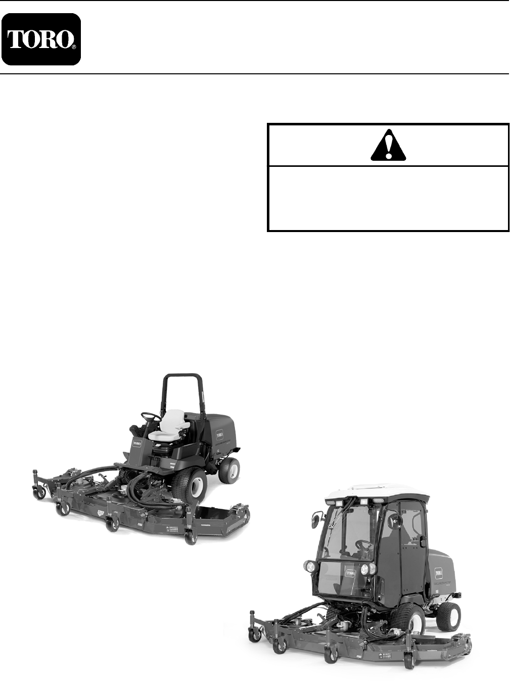
GroundsmasterR4100--D & 4110--D
Preface
The purpose of this publication is to provide the service
technician with information for troubleshooting, testing
and repair of major systems and components on the
Groundsmaster 4100--D (Model 30604 and 30608) and
4110--D (Model 30602 and 30606).
REFER TO THE OPERATOR’S MANUAL FOR OPER-
ATING, MAINTENANCE AND ADJUSTMENT
INSTRUCTIONS. For reference, insert a copy of the
Operator’s Manual and Parts Catalog for your machine
into Chapter 2 of this service manual. Additional copies
of the Operator’s Manual and Parts Catalog are avail-
able on the internet at www.Toro.com.
The Toro Company reserves the right to change product
specifications or this publication without notice.
This safety symbol means DANGER, WARNING
or CAUTION, PERSONAL SAFETY INSTRUC-
TION. When you see this symbol, carefully read
the instructions that follow. Failure to obey the
instructions may result in personal injury.
NOTE: ANOTE will give general information about the
correct operation, maintenance, service, testing or re-
pair of the machine.
IMPORTANT: The IMPORTANT notice will give im-
portant instructions which must be followed to pre-
vent damage to systems or components on the
machine.
EThe Toro Company -- 2014
Groundsmaster 4110--D
Groundsmaster 4100--D
Groundsmaster 4100--D/4110--D
This page is intentionally blank.

Groundsmaster 4100--D/4110--D
Table Of Contents
Chapter 1 -- Safety
General Safety Instructions 1 -- 2..................
Jacking Instructions 1 -- 5.........................
Safety and Instruction Decals 1 -- 6................
Chapter 2 -- Product Records and Maintenance
Product Records 2 -- 1...........................
Maintenance 2 -- 1...............................
Equivalents and Conversions 2 -- 2................
Torque Specifications 2 -- 3.......................
Chapter 3 -- Yanmar Diesel Engine
Specifications 3 -- 2..............................
General Information 3 -- 5........................
Service and Repairs 3 -- 10.......................
YANMAR TNV (Tier 4i) SERIES SERVICE MANUAL
YANMAR TNV (Tier 4i) SERIES TROUBLE--
SHOOTING MANUAL
YANMAR TNV (Tier 4) SERIES SERVICE MANUAL
YANMAR TNV (Tier 4) SERIES TROUBLESHOOTING
MANUAL
Chapter 4 -- Hydraulic System
Specifications 4 -- 2..............................
General Information 4 -- 3........................
Hydraulic Schematic 4 -- 9........................
Hydraulic Flow Diagrams 4 -- 10...................
Special Tools 4 -- 26.............................
Troubleshooting 4 -- 31...........................
Testing 4 -- 38...................................
Adjustments 4 -- 68..............................
Service and Repairs 4 -- 69.......................
SAUER DANFOSS PISTON PUMP
SAUER DANFOSS WHEEL MOTORS
EATON PARTS AND REPAIR INFORMATION: 5
SERIES STEERING CONTROL UNITS
Chapter 5 -- Electrical System
General Information 5 -- 2........................
Special Tools 5 -- 6..............................
InfoCenter Display 5 -- 8..........................
Troubleshooting 5 -- 15...........................
Electrical System Quick Checks 5 -- 26.............
Adjustments 5 -- 27..............................
Component Testing 5 -- 31........................
Service and Repairs 5 -- 64.......................
Chapter 6 -- Axles, Planetaries and Brakes
Specifications 6 -- 2..............................
General Information 6 -- 3........................
Adjustments 6 -- 4...............................
Service and Repairs 6 -- 6........................
Chapter 7 -- Chassis
General Information 7 -- 1........................
Service and Repairs 7 -- 2........................
Chapter 8 -- Cutting Deck
Specifications 8 -- 2..............................
General Information 8 -- 3........................
Troubleshooting 8 -- 4............................
Service and Repairs 8 -- 6........................
SafetyProduct Records
and Maintenance
Yanmar
Diesel Engine
Hydraulic
System
Electrical
System
Axles, Planetaries
and Brakes
Chassis
Cutting
Deck
Groundsmaster 4100--D/4110--D
This page is intentionally blank.

Groundsmaster 4100--D/4110--D
Table Of Contents (Continued)
Chapter 9 -- Operator Cab
General Information 9 -- 2........................
Service and Repairs 9 -- 3........................
SANDEN SD COMPRESSOR SERVICE GUIDE
Chapter 10 -- Foldout Drawings
Electrical Drawing Designations 10 -- 2.............
Hydraulic Schematic 10 -- 3.......................
Electrical Schematics 10 -- 4......................
Wire Harness Drawings 10 -- 9....................
OperatorFoldout
Drawings Cab
Groundsmaster 4100--D/4110--D
This page is intentionally blank.

Groundsmaster 4100--D/4110--D Page 1 -- 1 Safety
Chapter 1
Safety
Table of Contents
GENERAL SAFETY INSTRUCTIONS 2............
Before Operating 2............................
While Operating 3............................
Maintenance and Service 4....................
JACKING INSTRUCTIONS 5.....................
Jacking the Front End 5.......................
Jacking the Rear End 5........................
SAFETY AND INSTRUCTION DECALS 6..........
Safety

Groundsmaster 4100--D/4110--DPage 1 -- 2Safety
General Safety Instructions
The Groundsmaster 4100-D and 4110--D are tested and
certified by Toro for compliance with existing safety
standards and specifications. Although hazard control
and accident prevention partially are dependent upon
the design and configuration of the machine, these fac-
tors are also dependent upon the awareness, concern
and proper training of the personnel involved in the op-
eration, transport, maintenance and storage of the ma-
chine. Improper use or maintenance of the machine can
result in injury or death. To reduce the potential for injury
or death, comply with the following safety instructions.
WARNING
To reduce the potential for injury or death,
comply with the following safety instructions.
Before Operating
1. Review and understand the contents of the Opera-
tor’s Manual and Operator’s DVD before starting and
operating the vehicle. Become familiar with the controls
and know how to stop the vehicle and engine quickly.
Additional copies of the Operator’s Manual are available
on the internet at www.Toro.com.
2. Keep all shields, safety devices and decals in place.
If a shield, safety device or decal is defective, illegible or
damaged, repair or replace it before operating the ma-
chine.
3. Tighten any loose nuts, bolts or screws to ensure
machine is in safe operating condition.
4. Assure interlock switches are adjusted correctly so
engine cannot be started unless traction pedal is in
NEUTRAL and cutting deck is DISENGAGED.
5. Since diesel fuel is highly flammable, handle it care-
fully:
A. Useanapprovedfuelcontainer.
B. Do not remove fuel tank cap while engine is hot or
running.
C. Do not smoke while handling fuel.
D. Fill fuel tank outdoors and only to within an inch of
the top of the tank, not the filler neck. Do not overfill.
E. Wipe up any spilled fuel.

Groundsmaster 4100--D/4110--D Page 1 -- 3 Safety
While Operating
1. Sit on the seat when starting and operating the ma-
chine.
2. Before starting the engine:
A. Apply the parking brake.
B. Make sure traction pedal is in neutral and the
PTO switch is OFF (disengaged).
3. After engine is started, release parking brake and
keep foot off traction pedal. Machine must not move. If
movement is evident, there may be a problem with trac-
tion pedal calibration or the piston (traction) pump that
needs to be corrected before using the machine.
4. Do not run engine in a confined area without ade-
quate ventilation. Exhaust fumes are hazardous and
could possibly be deadly.
5. Do not touch engine, muffler or exhaust pipe while
engine is running or soon after it is stopped. These areas
could be hot enough to cause burns.
6. Before getting off the seat:
A. Ensure that traction pedal is in neutral.
B. Fully lower and disengage cutting deck. Wait for
blades to stop.
C. Apply the parking brake.
D. Stop engine and remove key from switch.
7. Toro recommends that anytime the machine is
parked (short or long term), the cutting deck should be
lowered to the ground. This relieves pressure from the
deck lift circuit and eliminates the risk of the cutting deck
unexpectedly lowering to the ground.
8. Do not park on slopes unless wheels are chocked or
blocked.
Safety

Groundsmaster 4100--D/4110--DPage 1 -- 4Safety
Maintenance and Service
1. Before servicing or making adjustments, lower deck,
stop engine, apply parking brake and remove key from
the switch.
2. Make sure machine is in safe operating condition by
keeping all nuts, bolts and screws tight.
3. Never store the machine or fuel container inside
where there is an open flame, such as near a water heat-
er or furnace.
4. Make sure all hydraulic line connectors are tight and
all hydraulic hoses and lines are in good condition be-
fore applying pressure to the system.
5. Keep body and hands away from pin hole leaks in hy-
draulic lines that eject high pressure hydraulic fluid. Use
cardboard or paper to find hydraulic leaks. Hydraulic
fluid escaping under pressure can penetrate skin and
cause injury. Fluid accidentally injected into the skin
must be surgically removed within a few hours by a doc-
tor familiar with this form of injury or gangrene may re-
sult.
6. Before disconnecting or performing any work on the
hydraulic system, all pressure in system must be re-
lieved by lowering cutting deck to the ground and stop-
ping engine.
7. If major repairs are ever needed or assistance is de-
sired, contact an Authorized Toro Distributor.
8. To reduce potential fire hazard, keep engine area
free of excessive grease, grass, leaves and dirt. Clean
protective screen on machine frequently.
9. If engine must be running to perform maintenance or
an adjustment, keep hands, feet, clothing and other
parts of the body away from cutting deck and other mov-
ing parts. Keep bystanders away.
10.To assure safety and accuracy, check maximum en-
gine speed.
11. Shut engine off before checking or adding oil to the
crankcase.
12.Disconnect battery before servicing the machine.
Disconnect negative cable first and positive cable last.
If battery voltage is required for troubleshooting or test
procedures, temporarily connect the battery. Reconnect
positive cable first and negative cable last.
13.Battery acid is poisonous and can cause burns.
Avoid contact with skin, eyes and clothing. Protect your
face, eyes and clothing when working with a battery.
14.Battery gases can explode. Keep cigarettes, sparks
and flames away from the battery.
15.At the time of manufacture, the machine conformed
to the safety standards for riding mowers. To assure op-
timum performance and continued safety certification of
the machine, use genuine Toro replacement parts and
accessories. Replacement partsandaccessoriesmade
by other manufacturers may result in non-conformance
with the safety standards and the warranty may be
voided.
16.When changing attachments, tires or performing
other service, use correct jacks and supports. Make
sure machine is parked on a solid level surface such as
a concrete floor. Prior to raising the machine, remove
any attachments that may interfere with the safe and
proper raising of the machine. Always chock or block
wheels. Use appropriate jack stands to support the
raised machine. If the machine is not properly supported
by jack stands, the machine may move or fall, which may
result in personal injury (see Jacking Instructions in this
chapter).
17.When welding on machine, disconnect battery
cables to prevent damage to machine electronic equip-
ment. Disconnect negative battery cable first and posi-
tive cable last. Also, disconnect wire harness connector
from both of the TEC controllers, disconnect and re-
move the engine ECU and disconnect the terminal con-
nector from the alternator. Attach welder ground cable
no more than two (2) feet (0.61 meters) from the welding
location.
18.Make sure to dispose of potentially harmful waste
(e.g. fuel, oil, engine coolant, filters, battery) in an envir-
onmentally safe manner. Follow all local codes and reg-
ulations when recycling or disposing of waste.

Groundsmaster 4100--D/4110--D Page 1 -- 5 Safety
Jacking Instructions
CAUTION
When changing attachments, tires or perform-
ing other service, use correct jacks and sup-
ports. Make sure machine is parked on a solid,
level surface such as a concrete floor. Prior to
raising machine, remove any attachments that
may interfere with the safe and proper raising of
the machine. Always chock or block wheels. Use
jack stands to support the raised machine. If the
machine is not properly supported by jack
stands, the machine may move or fall, which
may result in personal injury.
Jacking the Front End
1. Set parking brake and chock both rear tires to pre-
vent the machine from moving.
2. Position jack securely under the frame, just to the in-
side of the front tire. Jack front wheel off the ground.
3. Once the machine is raised, position suitable jack
stand under the frame as close to the wheel as possible
to support the machine.
Jacking the Rear End
1. Set parking brake and chock both front tires to pre-
vent the machine from moving.
2. Place jack securely under the center of rear axle.
Jack rear of machine off the ground.
3. Once the machine is raised, use jack stands under
theaxletosupportthemachine.
Safety
Groundsmaster 4100--D/4110--DPage 1 -- 6Safety
Safety and Instruction Decals
Numerous safety and instruction decals are affixed to
your Groundsmaster machine. If any decal becomes il-
legible or damaged, install a new decal. Decal part num-
bers are listed in your Parts Catalog.

Groundsmaster 4100--D/4110--D Page 2 -- 1 Product Records and Maintenance
Chapter 2
Product Records and Maintenance
Table of Contents
PRODUCT RECORDS 1.........................
MAINTENANCE 1..............................
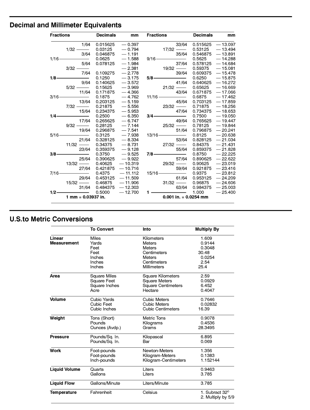
EQUIVALENTS AND CONVERSIONS 2...........
Decimal and Millimeter Equivalents 2............
U.S. to Metric Conversions 2...................
TORQUE SPECIFICATIONS 3...................
Fastener Identification 3.......................
Using a Torque Wrench with an Offset Wrench 3..
Standard Torque for Dry, Zinc Plated and
Steel Fasteners (Inch Series) 4...............
Standard Torque for Dry, Zinc Plated and
Steel Fasteners (Metric) 5....................
Other Torque Specifications 6..................
Conversion Factors 6.........................
Product Records
Insert Operator’s Manual and Parts Catalog for your
Groundsmaster at the end of this chapter. Refer to Oper-
ator’s Manual for recommended maintenance intervals.
Additionally, insert Installation Instructions, Operator’s
Manuals and Parts Catalogs for any accessories that
have been installed on your Groundsmaster at the end
of this section.
Maintenance
Maintenance procedures and recommended service in-
tervals for your Groundsmaster are covered in the Oper-
ator’s Manual. Refer to that publication when performing
regular equipment maintenance. Several maintenance
procedures have break--in intervals identified in the Op-
erator’s Manual. Refer to the Engine Operator’s Manual
for additional engine specific maintenance procedures.
Product Records
and Maintenance
0.09375
Groundsmaster 4100--D/4110--DPage 2 -- 2Product Records and Maintenance
Equivalents and Conversions
Groundsmaster 4100--D/4110--D Page 2 -- 3 Product Records and Maintenance
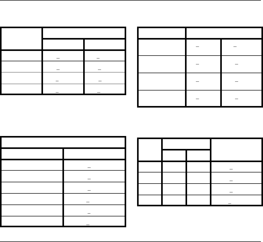
Torque Specifications
Recommended fastener torque values are listed in the
following tables. For critical applications, as determined
by Toro, either the recommended torque or a torque that
is unique to the application is clearly identified and spe-
cified in this Service Manual.
These Torque Specifications for the installation and
tightening of fasteners shall apply to all fasteners which
do not have a specific requirement identified in this Ser-
vice Manual. The following factors shall be considered
when applying torque: cleanliness of the fastener, use
of a thread sealant (e.g. Loctite), degree of lubrication
on the fastener, presence of a prevailing torque feature
(e.g. Nylock nut), hardness of the surface underneath
the fastener’s head or similar condition which affects the
installation.
As noted in the following tables, torque values should be
reduced by 25% for lubricated fasteners to achieve
the similar stress as a dry fastener. Torque values may
also have to be reduced when the fastener is threaded
into aluminum or brass. The specific torque value
should be determined based on the aluminum or brass
material strength, fastener size, length of thread en-
gagement, etc.
The standard method of verifying torque shall be per-
formed by marking a line on the fastener (head or nut)
and mating part, then back off fastener 1/4 of a turn.
Measure the torque required to tighten the fastener until
thelinesmatchup.
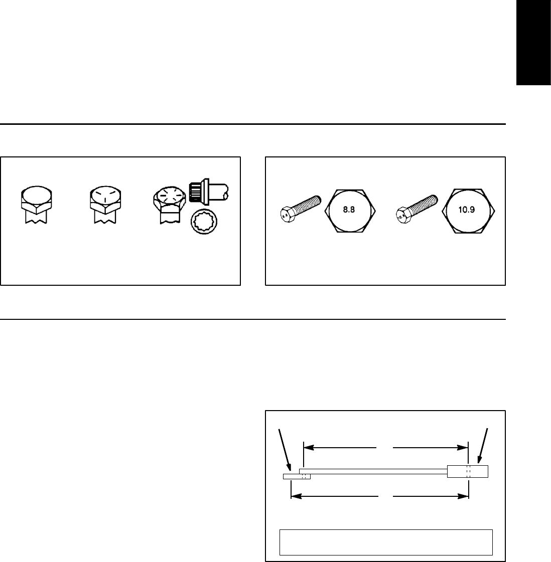
Fastener Identification
Figure 1
Grade 1 Grade 5 Grade 8
Inch Series Bolts and Screws
Figure 2
Class 8.8 Class 10.9
Metric Bolts and Screws
Using a Torque Wrench with an Offset Wrench
Use of an offset wrench (e.g. crowfoot wrench) will affect
torque wrench calibration due to the effective change of
torque wrench length. When using a torque wrench with
an offset wrench, multiply the listed torque recommen-
dation by the calculated torque conversion factor (Fig.
3) to determine proper tightening torque. Tightening
torque when using a torque wrench with an offset
wrench will be lower than the listed torque recommen-
dation.
Example: The measured effective length of the torque
wrench (distance from the center of the handle to the
center of the square drive) is 18”.
The measured effective length of the torque wrench with
the offset wrench installed (distance from the center of
the handle to the center of the offset wrench) is 19”.
The calculated torque conversion factor for this torque
wrench with this offset wrench would be 18 / 19 = 0.947.
If the listed torque recommendation for a fastener is
from 76 to 94 ft--lb, the proper torque when using this
torque wrench with an offset wrench would be from 72
to 89 ft--lb.
Figure 3
(effective length of
torque wrench)
TORQUE CONVERSION FACTOR = A / B
A
B
(effective length of torque
Torque wrenchOffset wrench
wrench + offset wrench)
Product Records
and Maintenance

Groundsmaster 4100--D/4110--DPage 2 -- 4Product Records and Maintenance
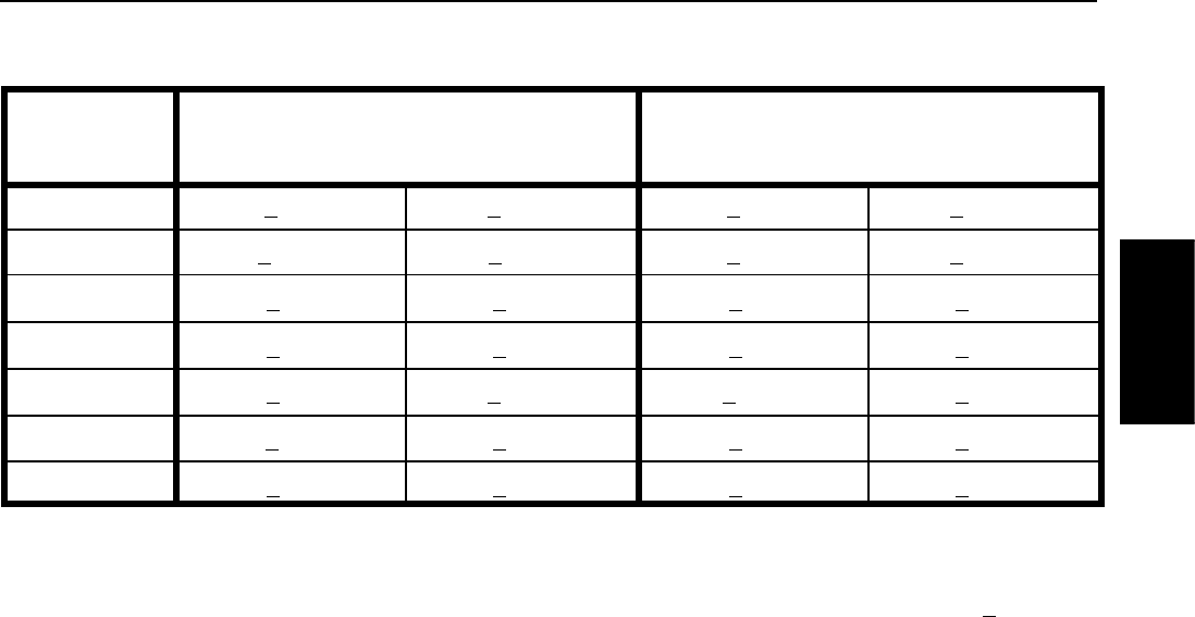
Standard Torque for Dry, Zinc Plated and Steel Fasteners (Inch Series)
Thread Size
Grade 1, 5 &
8withThin
Height Nuts
SAE Grade 1 Bolts, Screws, Studs &
Sems with Regular Height Nuts
(SAE J995 Grade 2 or Stronger Nuts)
SAE Grade 5 Bolts, Screws, Studs &
Sems with Regular Height Nuts
(SAE J995 Grade 2 or Stronger Nuts)
SAE Grade 8 Bolts, Screws, Studs &
Sems with Regular Height Nuts
(SAE J995 Grade 5 or Stronger Nuts)
in--lb in--lb N--cm in--lb N--cm in--lb N--cm
#6--32UNC
10 + 213 + 2147 + 23
15 + 2169 + 23 23 + 3262 + 34
#6--40UNF 17 + 2192 + 23 25 + 3282 + 34
#8--32UNC
13 + 225 + 5282 + 30
29 + 3328 + 34 41 + 5463 + 56
#8--36UNF 31 + 4350 + 45 43 + 5486 + 56
#10--24UNC
18 + 230 + 5339 + 56
42 + 5475 + 56 60 + 6678 + 68
#10--32UNF 48 + 5542 + 56 68 + 7768 + 79
1/4 -- 20 UNC 48 + 753 + 7599 + 79 100 + 10 1130 + 113 140 + 15 1582 + 169
1/4 -- 28 UNF 53 + 765 + 10 734 + 113 115 + 12 1299 + 136 160 + 17 1808 + 192
5/16 -- 18 UNC 115 + 15 105 + 15 1186 + 169 200 + 25 2260 + 282 300 + 30 3390 + 339
5/16 -- 24 UNF 138 + 17 128 + 17 1446 + 192 225 + 25 2542 + 282 325 + 33 3672 + 373
ft--lb ft--lb N--m ft--lb N--m ft--lb N--m
3/8 -- 16 UNC 16 + 216 + 222 + 330 + 341 + 443 + 558 + 7
3/8 -- 24 UNF 17 + 218 + 224 + 335 + 447 + 550 + 668 + 8
7/16 -- 14 UNC 27 + 327 + 337 + 450 + 568 + 770 + 795 + 9
7/16 -- 20 UNF 29 + 329 + 339 + 455 + 675 + 877 + 8104 + 11
1/2 -- 13 UNC 30 + 348 + 765 + 975 + 8102 + 11 105 + 11 142 + 15
1/2 -- 20 UNF 32 + 453 + 772 + 985 + 9115 + 12 120 + 12 163 + 16
5/8 -- 11 UNC 65 + 10 88 + 12 119 + 16 150 + 15 203 + 20 210 + 21 285 + 28
5/8 -- 18 UNF 75 + 10 95 + 15 129 + 20 170 + 18 230 + 24 240 + 24 325 + 33
3/4 -- 10 UNC 93 + 12 140 + 20 190 + 27 265 + 27 359 + 37 375 + 38 508 + 52
3/4 -- 16 UNF 115 + 15 165 + 25 224 + 34 300 + 30 407 + 41 420 + 43 569 + 58
7/8 -- 9 UNC 140 + 20 225 + 25 305 + 34 430 + 45 583 + 61 600 + 60 813 + 81
7/8 -- 14 UNF 155 + 25 260 + 30 353 + 41 475 + 48 644 + 65 667 + 66 904 + 89
NOTE: Reduce torque values listed in the table above
by 25% for lubricated fasteners. Lubricated fasteners
are defined as threads coated with a lubricant such as
engine oil or thread sealant such as Loctite.
NOTE: Torque values may have to be reduced when
installing fasteners into threaded aluminum or brass.
The specific torque value should be determined based
on the fastener size, the aluminum or base material
strength, length of thread engagement, etc.
NOTE: The nominal torque values listed above for
Grade 5 and 8 fasteners are based on 75% of the mini-
mum proof load specified in SAE J429. The tolerance is
approximately + 10% of the nominal torque value. Thin
height nuts include jam nuts.
Groundsmaster 4100--D/4110--D Page 2 -- 5 Product Records and Maintenance
Standard Torque for Dry, Zinc Plated and Steel Fasteners (Metric Series)
Thread Size
Class 8.8 Bolts, Screws and Studs with
Regular Height Nuts
(Class 8 or Stronger Nuts)
Class 10.9 Bolts, Screws and Studs with
Regular Height Nuts
(Class 10 or Stronger Nuts)
M5 X 0.8 57 + 6in--lb 644 + 68 N--cm 78 + 8in--lb 881 + 90 N--cm
M6 X 1.0 96 + 10 in--lb 1085 + 113 N-- cm 133 + 14 in--lb 1503 + 158 N--cm
M8 X 1.25 19 + 2ft--lb 26 + 3N--m 28 + 3ft--lb 38 + 4N--m
M10 X 1.5 38 + 4ft--lb 52 + 5N--m 54 + 6ft--lb 73 + 8N--m
M12 X 1.75 66 + 7ft--lb 90 + 10 N--m 93 + 10 ft--lb 126 + 14 N--m
M16 X 2.0 166 + 17 ft--lb 225 + 23 N--m 229 + 23 ft--lb 310 + 31 N--m
M20 X 2.5 325 + 33 ft--lb 440 + 45 N--m 450 + 46 ft--lb 610 + 62 N--m
NOTE: Reduce torque values listed in the table above
by 25% for lubricated fasteners. Lubricated fasteners
are defined as threads coated with a lubricant such as
engine oil or thread sealant such as Loctite.
NOTE: Torque values may have to be reduced when
installing fasteners into threaded aluminum or brass.
The specific torque value should be determined based
on the fastener size, the aluminum or base material
strength, length of thread engagement, etc.
NOTE: The nominal torque values listed above are
based on 75% of the minimum proof load specified in
SAE J1199. The tolerance is approximately + 10% of the
nominal torque value.
Product Records
and Maintenance
Groundsmaster 4100--D/4110--DPage 2 -- 6Product Records and Maintenance
Other Torque Specifications
SAE Grade 8 Steel Set Screws
Thread Size
Recommended Torque
Square Head Hex Socket
1/4 -- 20 UNC 140 + 20 in--lb 73 + 12 in--lb
5/16 -- 18 UNC 215 + 35 in--lb 145 + 20 in--lb
3/8 -- 16 UNC 35 + 10 ft--lb 18 + 3ft--lb
1/2 -- 13 UNC 75 + 15 ft--lb 50 + 10 ft--lb
Thread Cutting Screws
(Zinc Plated Steel)
Type 1, Type 23 or Type F
Thread Size Baseline Torque*
No. 6 -- 32 UNC 20 + 5in--lb
No. 8 -- 32 UNC 30 + 5in--lb
No. 10 -- 24 UNC 38 + 7in--lb
1/4 -- 20 UNC 85 + 15 in--lb
5/16 -- 18 UNC 110 + 20 in--lb
3/8 -- 16 UNC 200 + 100 in--lb
Wheel Bolts and Lug Nuts
Thread Size Recommended Torque**
7/16 -- 20 UNF
Grade 5
65 + 10 ft--lb 88 + 14 N--m
1/2 -- 20 UNF
Grade 5
80 + 10 ft--lb 108 + 14 N--m
M12 X 1.25
Class 8.8
80 + 10 ft--lb 108 + 14 N--m
M12 X 1.5
Class 8.8
80 + 10 ft--lb 108 + 14 N--m
** For steel wheels and non--lubricated fasteners.
Thread Cutting Screws
(Zinc Plated Steel)
Thread
Size
Threads per Inch
Baseline Torque*
Type A Type B
No. 6 18 20 20 + 5in--lb
No. 8 15 18 30 + 5in--lb
No. 10 12 16 38 + 7in--lb
No. 12 11 14 85 + 15 in--lb
* Hole size, material strength, material thickness and fin-
ish must be considered when determining specific
torque values. All torque values are based on non--lubri-
cated fasteners.
Conversion Factors
in--lb X 11.2985 = N--cm N--cm X 0.08851 = in--lb
ft--lb X 1.3558 = N--m N--m X 0.7376 = ft--lb

Groundsmaster 4100--D/4110--D Page 3 -- 1 Yanmar Diesel Engine
Chapter 3
Yanmar Diesel Engine
Table of Contents
SPECIFICATIONS 2............................
Models 30602 and 30604 2....................
Models 30606 and 30608 3....................
GENERAL INFORMATION 5.....................
Operator’s Manuals 5.........................
Yanmar Service and Troubleshooting Manuals 5..
Stopping the Engine 5.........................
Engine Electronic Control Unit (ECU) 6..........
Yanmar Engine: Models 30602 and 30604 7.....
Yanmar Engine: Models 30606 and 30608 8.....
SERVICE AND REPAIRS 10.....................
Air Filter System 10...........................
Fuel System 12...............................
Check Fuel Lines and Connections 13.........
Empty and Clean Fuel Tank 13................
Priming the Fuel System 13...................
Fuel Tank Removal 13.......................
Fuel Tank Installation 13......................
Radiator and Oil Cooler Assembly 14............
Engine 18....................................
Engine Removal 19..........................
Engine Installation 21........................
Spring Coupler 24............................
Exhaust System (Models 30606 and 30608) 26...
YANMAR TNV (Tier 4i) SERIES SERVICE MANUAL
YANMAR TNV (Tier 4i) SERIES TROUBLESHOOTING
MANUAL
YANMAR TNV (Tier 4) SERIES SERVICE MANUAL
YANMAR TNV (Tier 4) SERIES TROUBLESHOOTING
MANUAL
Yanmar
Diesel Engine

Groundsmaster 4100--D/4110--DPage 3 -- 2Yanmar Diesel Engine
Specifications (Models 30602 and 30604)
Item Description
Make / Designation Yanmar Model 4TNV84T--ZMTR: 4--Cycle, 4 Cylinder,
Water Cooled, Turbocharged, Tier 4i Diesel Engine
Bore 3.307 in (84 mm)
Stroke 3.543 in (90 mm)
Total Displacement 121.7 in3(1995 cc)
Firing Order 1 (closest to flywheel end) -- 3 -- 4 (farthest from flywheel) -- 2
Direction of Rotation Counterclockwise (viewed from flywheel)
Fuel Diesel or Biodiesel (up to B20) Fuel with Low or
Ultra Low Sulfur Content
Fuel Tank Capacity 21 U.S. gallons (79.5 liters)
Fuel Injection Pump Yanmar MP2 Distributor Type Pump
Fuel Injection Type Direct Injection
Starting Aid Intake Air Heater
Governor Electronic All Speed
Low Idle (no load) 1200 RPM
High Idle (no load) 2600 RPM
Engine Oil API CH--4, CI--4 or higher
Engine Oil Viscosity See Operator’s Manual
Crankcase Oil Capacity 6 U.S. quarts (5.7 liters) with Filter
Oil Pump Trochoid Type
Coolant Capacity
Groundsmaster 4100--D 9 U.S. quarts (8.5 liters)
Groundsmaster 4110--D 14.5 U.S. quarts (13.7 liters)
Alternator/Regulator 12 VDC, 80 amp
Engine Weight (Dry) 375 U.S. pounds (170 kg)

Groundsmaster 4100--D/4110--D Page 3 -- 3 Yanmar Diesel Engine
Specifications (Models 30606 and 30608)
Item Description
Make / Designation Yanmar Model 4TNV86CT--DTR: 4--Cycle, 4 Cylinder,
Water Cooled, Tier 4 Diesel Engine
Bore 3.386 in (86 mm)
Stroke 3.543 in (90 mm)
Total Displacement 127.5 in3(2090 cc)
Firing Order 1 (closest to flywheel end) -- 3 -- 4 (farthest from flywheel) -- 2
Direction of Rotation Counterclockwise (viewed from flywheel)
Fuel Diesel or Biodiesel (up to B7) Fuel with
Ultra Low Sulfur Content
Fuel Capacity 21 U.S. gallons (79.5 liters)
Fuel Pump Yanmar Supply Pump
Fuel Injection Type Common Rail with Direct Injection
Governor Electronic All Speed
Low Idle (no load) 1000 RPM
High Idle (no load) 2700 RPM
Engine Oil API CJ--4 or higher
Engine Oil Viscosity See Operator’s Manual
Crankcase Oil Capacity 6 U.S. quarts (5.7 liters) with Filter
Oil Pump Trochoid Type
Coolant Capacity
Groundsmaster 4100--D 9 U.S. quarts (8.5 liters)
Groundsmaster 4110--D 14.5 U.S. quarts (13.7 liters)
Alternator/Regulator 12 VDC
Groundsmaster 4100--D 40 amp
Groundsmaster 4110--D 80 amp
Engine Weight (Dry) 496 U.S. pounds (225 kg)
Yanmar
Diesel Engine
Groundsmaster 4100--D/4110--DPage 3 -- 4Yanmar Diesel Engine
This page is intentionally blank.

Groundsmaster 4100--D/4110--D Page 3 -- 5 Yanmar Diesel Engine
General Information
This Chapter gives information about specifications and
repair of the diesel engine used in the Groundsmaster
4100--D and 4110--D.
General maintenance procedures are described in your
Operator’s Manual. Information on engine troubleshoot-
ing, testing, disassembly and reassembly is identified in
the Yanmar Service Manual.
Most repairs and adjustments require tools which are
commonly available in many service shops. Special
tools are described in the Yanmar Service Manual. The
use of some specialized test equipment is explained.
However, the cost of the test equipment and the special-
ized nature of some repairs may dictate that the work be
done at an engine repair facility.
Service and repair parts for Yanmar engines are sup-
plied through your Authorized Toro Distributor. If no
parts list is available, be prepared to provide your distrib-
utor with the Toro model and serial number of your ma-
chine.
Operator’s Manuals
The Operator’s Manual provides information regarding
the operation, general maintenance and maintenance
intervals for your Groundsmaster machine. The Yanmar
Operator’s Manual includes information specific to the
engine used in your Groundsmaster. Refer to these pub-
lications for additional information when servicing the
machine.
Yanmar Service and Troubleshooting Manuals
The engine that powers your Groundsmaster machine
is either a Yanmar model 4TNV84T--Z (used on
Groundsmaster models 30602 and 30604) (Tier 4i) or a
Yanmar model 4TNV86CT (used on Groundsmaster
models 30606 and 30608) (Tier 4). Both the Yanmar
Service Manual and Yanmar Troubleshooting Manual
are available for these engines. Make sure that the cor-
rect engine manuals are used when servicing the en-
gine on your Groundsmaster.
Stopping the Engine
IMPORTANT: Before stopping the engine after
mowing or full load operation, cool the turbo-char-
ger by allowing the engine to run at low idle speed
for five (5) minutes. Failure to do so may lead to tur-
bo-charger trouble.
Yanmar
Diesel Engine
Groundsmaster 4100--D/4110--DPage 3 -- 6Yanmar Diesel Engine
Engine Electronic Control Unit (ECU)
The Yanmar engine that powers your Groundsmaster
uses an electronic control unit (ECU) for engine man-
agement and also to communicate with the machine
TEC controllers and the operator Info Center display on
the machine. All wire harness electrical connectors
should be plugged into the ECU before the machine igni-
tion switch is moved from the OFF position to either the
ON or START position.
NOTE: On models 30606 and 30608, a ground wire is
used to ground the ECU to the machine frame. The
ground wire is connected to the ECU with one of the
ECU mounting screws and is connected to the frame at
the engine mount.
The engine electrical components (e.g. ECU, fuel inject-
ors, EGR, exhaust DPF) are identified and matched in
the engine ECU program. If engine electrical compon-
ents are replaced on the engine, the Yanmar electronic
tool must be used to update the ECU program which will
ensure correct engine operation.
If the engine ECU identifies that an engine problem ex-
ists, the engine speed may be reduced or the engine
might stop. The Yanmar electronic tool and
troubleshooting manual should be used to provide as-
sistance in identifying the cause of the problem and the
repairs that are necessary. Contact your Toro distributor
for assistance in Yanmar engine troubleshooting.
IMPORTANT: Do not plug or unplug the engine ECU
for a period of thirty (30) seconds after the machine
key switch is turned OFF. The ECU may remain ener-
gized even though the ignition switch is OFF.
If the engine ECU is to be disconnected for any reason,
make sure that the ignition switch is in the OFF position
with the key removed before disconnecting the engine
ECU. Also, to prevent possible ECU damage when
welding on the machine, disconnect and remove the en-
gine ECU from the machine before welding.
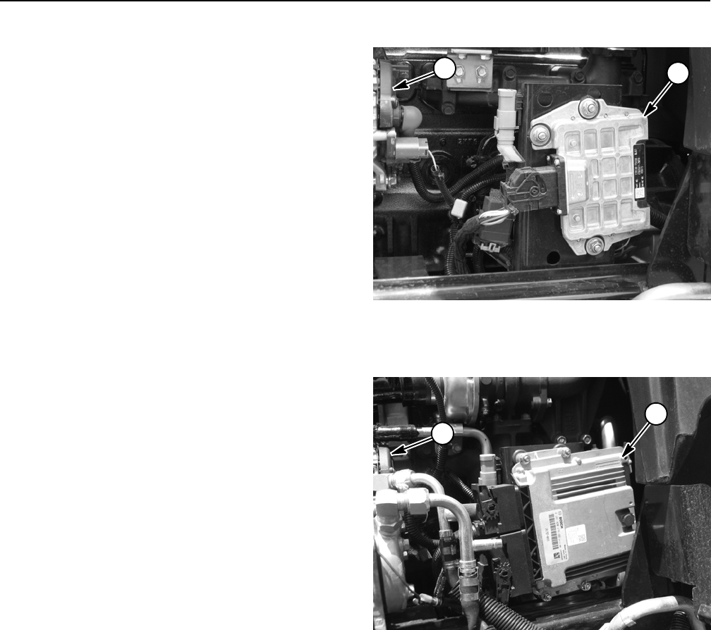
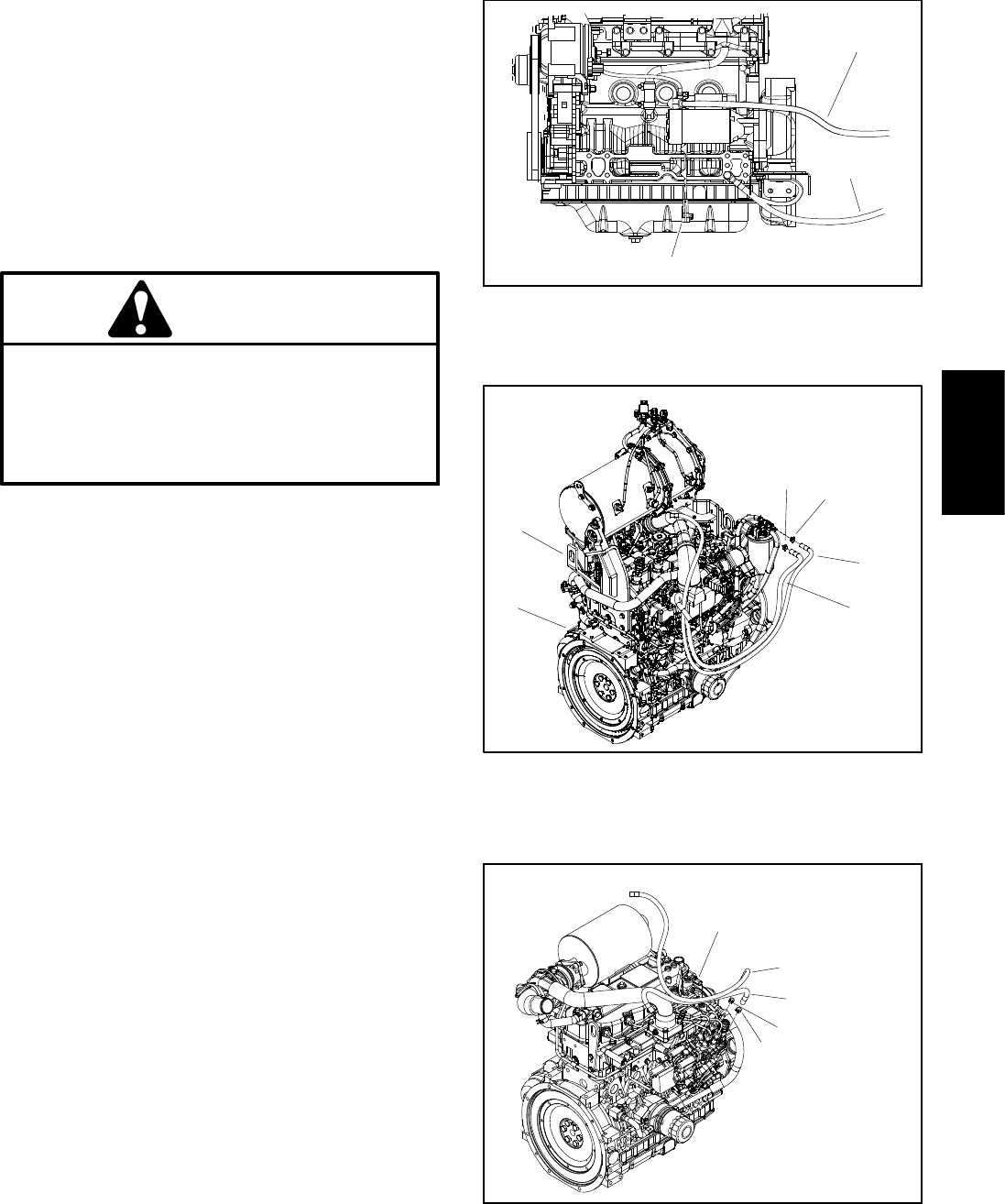
Figure 1
1. Electronic control unit (30602 / 30604)
2. Alternator
21
Figure 2
1. Electronic control unit (30606 / 30608)
2. Alternator
2
1
Groundsmaster 4100--D/4110--D Page 3 -- 7 Yanmar Diesel Engine
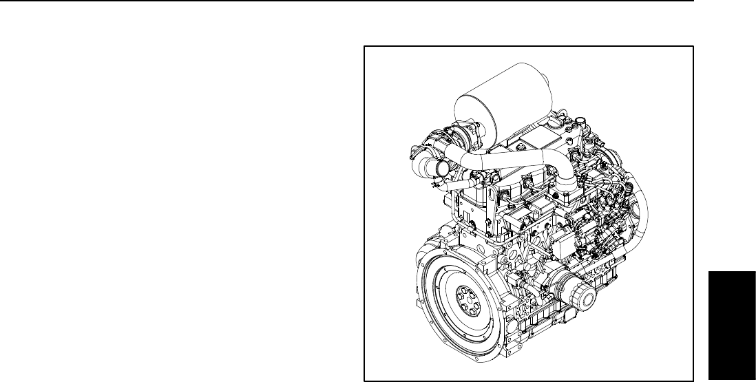
Yanmar Engine: Models 30602 and 30604
The engine used on Groundsmaster models 30602 and
30604 is a Yanmar TNV Series, turbocharged, diesel
engine that complies with EPA interim Tier 4 emission
regulations. Engine features include an electronic con-
trol unit (ECU) controlled direct fuel injection and elec-
tronic governor. An air heater in the intake system is
used to assist starting the engine. Numerous engine
sensors are used to allow the engine electronic control
unit (ECU) to monitor and control engine operation for
optimum engine performance.
During machine operation, if an engine fault occurs, the
machine InfoCenter display can be used to identify the
fault. Also, the Yanmar SMARTASSIST--Direct electron-
ic control diagnostics service system is available to con-
firm real--time engine running status and to offer timely
technical services.
Figure 3
Yanmar
Diesel Engine
Groundsmaster 4100--D/4110--DPage 3 -- 8Yanmar Diesel Engine
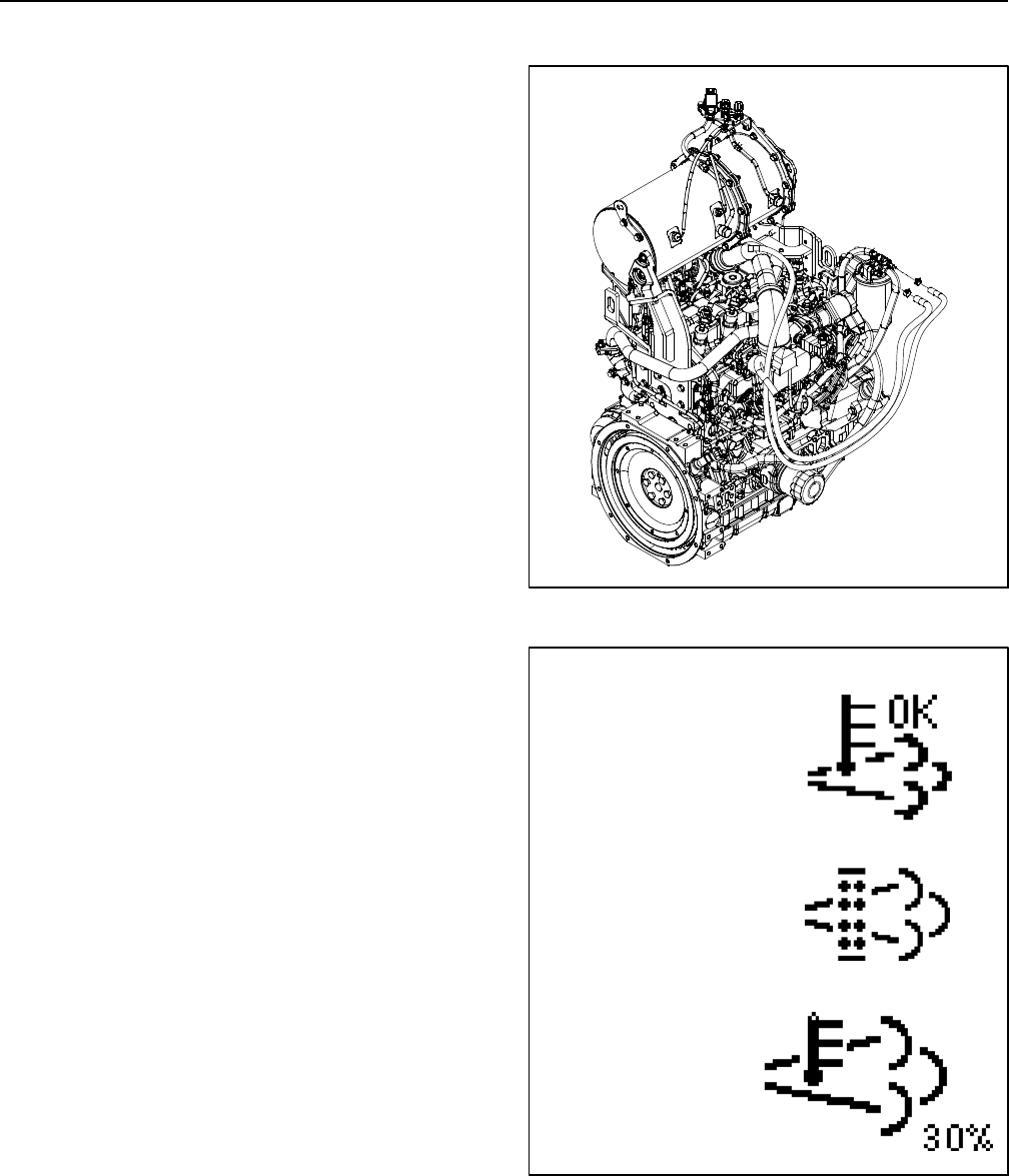
Yanmar Engine: Models 30606 and 30608
The engine used on Groundsmaster models 30606 and
30608 is a Yanmar TNV Series, turbocharged, diesel
engine that complies with EPA Tier 4 emission regula-
tions. Engine features include an electronic control unit
(ECU) that controls a common rail fuel injection system
with direct injection, water--cooled exhaust gas recircu-
lation (EGR), an electronic governor, an exhaust system
diesel oxidation catalyst (DOC) and an exhaust diesel
particulate filter (DPF) with active regeneration. Glow
plugs are used to assist starting the engine. Numerous
engine sensors are used to allow the engine ECU to
monitor and control engine operation for optimum en-
gine performance.
During machine operation, if an engine fault occurs, the
machine InfoCenter display can be used to identify the
fault. Also, the Yanmar SMARTASSIST--Direct electron-
ic control diagnostics service system is available to con-
firm the real--time engine running status and to offer
timely technical services.
The exhaust system DPF has four (4) modes for main-
tenance: passive regeneration, assist regeneration, re-
set regeneration and stationary regeneration.
Passive regeneration is the primary mode regenera-
tion that occurs during normal operation. When the en-
gine is running at normal loads, the exhaust
temperature will keep the DPF above the minimum tem-
perature for regeneration so normal particulate matter
(PM) accumulation in the DPF is expected.
Assist regeneration occurs if the engine ECU senses
that the DPF backpressure has increased to its maxim-
um threshold. During assist regeneration, the intake
throttle valve limits the air flow into the engine while the
injectors add additional fuel. This process increases the
DPF temperature which allows accumulated particulate
to burn off, without changing the load on the engine.
Burning of the accumulated PM decreases the pressure
across the DPF. The assist regeneration is completed
automatically when necessary. A small icon will be dis-
played on the InfoCenter during assist regeneration
(Fig. 5) to inform the operator. The machine can contin-
ue to be used during an assist regeneration.
Reset regeneration takes place at a time interval
(every 100 hours) to reset the baseline sensor readings
in the DPF. The reset regeneration ensures that the en-
gine is running at peak efficiency. During this mode, post
injection is the means of increasing the DPF temperat-
ure. The reset regeneration is completed automatically
when necessary. A small icon will be displayed on the In-
foCenter during reset regeneration (Fig. 5) to inform the
operator. The machine can continue to be used during
a reset regeneration.
Figure 4
Figure 5
ICON
ASSIST OR RESET
REGENERATION
ICON
REGENERATION
STATIONARY
IN PROCESS
ICON
REGENERATION
STATIONARY
REQUEST
NOTE: If the engine is turned off during an assist or re-
set regeneration process, the regeneration will resume
once the engine is restarted and required temperature
level is reached.

Groundsmaster 4100--D/4110--D Page 3 -- 9 Yanmar Diesel Engine
Stationary regeneration is requested by the engine
ECU if the assist and reset regenerations do not return
the DPF particulate level to an acceptable level. During
the stationary regeneration, the engine ECU controls
engine speed, load and air/fuel mixture to perform a
controlled burn of the particulate collected in the DPF.
This type of regeneration is not a normal condition and
may indicate that the DPF will require service soon, that
an engine problem exists (e.g. incorrect engine fuel or
oil) or that a DPF pressure sensor is failing. If a station-
ary regeneration is necessary, an advisory will occur on
the InfoCenter and the necessary steps will be listed. A
large icon will be displayed on the InfoCenter instead of
the temperature gauge during stationary regeneration
(Fig. 5). During the stationary regeneration process, the
InfoCenter display will identify the percent completed
during the process. The machine cannot be used during
a stationary regeneration.
When the regeneration process is completed, the In-
foCenter will remove the stationary regeneration icon
and cease periodic regeneration messages. The engine
will return to low idle speed with operator controls re-
turned to normal.
IMPORTANT: A stationary regeneration should
ONLY be initiated if an InfoCenter display advisory
requests that this be done.
IMPORTANT: During a stationary regeneration,
make sure that the machine is parked on a hard,
level surface in a well ventilated area. This process
runs the machine at a higher exhaust temperature
for a period of approximately thirty (30) minutes to
burn off collected particulate in the DPF.
Yanmar
Diesel Engine
Groundsmaster 4100--D/4110--DPage 3 -- 10Yanmar Diesel Engine
Service and Repairs
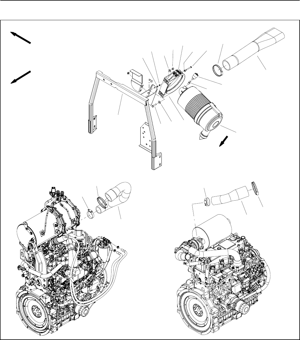
AirFilterSystem
Figure 6
FRONT
RIGHT
1. Air cleaner assembly
2. Tank support
3. Indicator
4. Adapter
5. Air cleaner strap
6. Flat washer (4 used)
7. Cap screw (2 used)
8. Lock nut (2 used)
9. Flat washer (2 used)
10. Lock nut (2 used)
11. Spring (2 used)
12. Flat washer (2 used)
13. Socket head screw (2 used)
14. Hose clamp
15. Air cleaner inlet hose
16. Hose clamp
17. Air cleaner outlet hose (tier 4)
18. Air cleaner outlet hose (tier 4i)
17
2
3
6
8
910
11
13
5
12
14
15
4
7
1
6
VACUATOR
DIRECTION
MODELS
30606 and
30608
MODELS
30602 and
30604
14
14 16
16
18
Groundsmaster 4100--D/4110--D Page 3 -- 11 Yanmar Diesel Engine
Removal (Fig. 6)
1. Park machine on a level surface, lower cutting deck,
stop engine, apply parking brake and remove key from
the ignition switch.
2. Raise and support hood.
3. Remove air cleaner components as needed using
Figure 6 as a guide.
Installation (Fig. 6)
IMPORTANT: Any leaks in the air cleaner system
will cause serious engine damage. Make sure that
all air cleaner components are in good condition
and are properly secured during assembly.
1. Assemble air cleaner system using Figure 6 as a
guide.
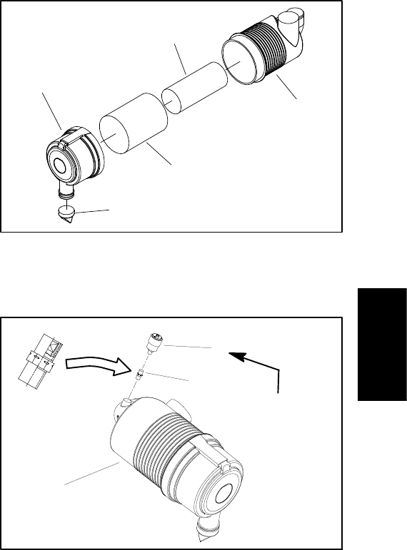
A. If service indicator (item 4 in Fig. 6) and adapter
(item 15 in Fig. 6) were removed from air cleaner
housing, apply thread sealant to adapter threads be-
fore installing adapter and indicator to housing.
Install adapter so that grooves in adapter hex and
adapter filter element are installed toward service in-
dicator (shown in Fig. 8). Torque indicator from 12 to
15 in--lb (1.4 to 1.6 N--m).
B. When installing air cleaner, orientate the vacuat-
or valve on the air cleaner cover so that the valve is
pointing in a downward position and between 5:00 to
7:00 (approximate clock position) when viewed from
the end.
C. When securing air cleaner in air cleaner strap,
tighten cap screws (item 14) only enough to prevent
air cleaner from rotating in strap.
D. When installing air cleaner outlet hose between
air cleaner and engine, position hose to allow maxi-
mum clearance between air cleaner hose and muf-
fler bracket.
E. Make sure that air cleaner hoses do not contact
the engine or exhaust system after assembly. To en-
sure clearance, move and/or rotate air cleaner body
in air cleaner strap if necessary.
2. After all air cleaner components have been installed,
lower and secure hood.
Figure 7
1. Air cleaner housing
2. Safety filter element
3. Air filter element
4. Air cleaner cover
5. Vacuator valve
1
3
2
4
5
Figure 8
1. Air cleaner assembly
2. Service indicator
3. Adapter
1
3
2
12 to 15 in--lb
(1.4 to 1.6 N--m)
Yanmar
Diesel Engine
Groundsmaster 4100--D/4110--DPage 3 -- 12Yanmar Diesel Engine
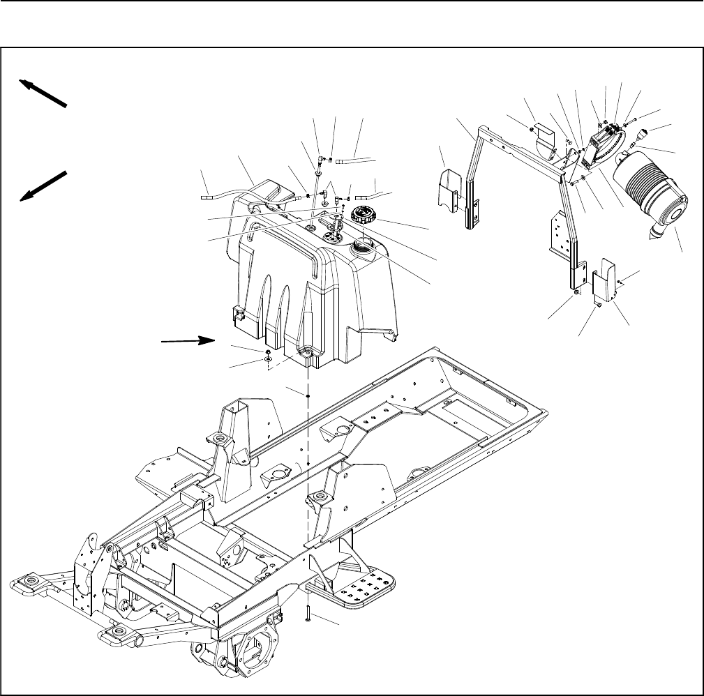
Fuel System
Figure 9
1. Carriage screw (2 used)
2. Retaining ring (2 used)
3. Flat washer (2 used)
4. Flange nut (6 used)
5. Vent hose
6. Fuel tank
7. Hose clamp (2 used)
8. Elbow fitting (2 used)
9. Stand pipe
10. Grommet (3 used)
11. Hose clamp
12. Lock washer (5 used)
13. Phillips head screw (5 used)
14. Fuel sender
15. Gasket
16. Fuel cap
17. Fuel supply hose
18. Fuel return hose
19. RH latch bracket
20. Tank support assembly
21. Flange nut (2 used)
22. Fuel tank bracket
23. Carriage screw (2 used)
24. Lock nut (2 used)
25. Flat washer (2 used)
26. Flat washer (4 used)
27. Lock nut (2 used)
28. Spring (2 used)
29. Flat washer (2 used)
30. Socket head screw (2 used)
31. Indicator
32. Adapter
33. Air cleaner assembly
34. Air cleaner strap
35. Cap screw (2 used)
36. Screw (4 used)
37. LH latch bracket
38. Cap screw (4 used)
60 to 80 in--lb
(7 to 9 N--m)
FRONT
RIGHT
2
3
6
8
9
10
11
13
1
57
12
14
15
16
4
7
19
20 21
22
23
24 25 26
27 28 29
30
31
32
33
34
35
36
37
4
17
18
38
26
Groundsmaster 4100--D/4110--D Page 3 -- 13 Yanmar Diesel Engine
DANGER
Because diesel fuel is flammable, use caution
when storing or handling it. Do not smoke while
filling the fuel tank. Do not fill fuel tank while en-
gine is running, hot or when machine is in an en-
closed area. Always fill fuel tank outside and
wipe up any spilled diesel fuel before starting the
engine. Store fuel in a clean, safety--approved
container and keep cap in place. Use diesel fuel
for the engine only; not for any other purpose.
Check Fuel Lines and Connections
Check fuel lines and connections periodically as recom-
mended in the Operator’s Manual. Check lines for dete-
rioration, damage, leaking or loose connections.
Replace hoses, clamps and connections as necessary.
Empty and Clean Fuel Tank
Empty and clean the fuel tank periodically as recom-
mended in the Operator’s Manual, if the fuel system be-
comes contaminated or if the machine is to be stored for
an extended period.
IMPORTANT: Follow all local codes and regulations
when recycling or disposing waste fuel.
To clean fuel tank, flush tank out with clean diesel fuel.
Make sure tank is free of contaminates and debris.
Priming the Fuel System
The fuel system needs to be primed before starting the
engine for the first time, after running out of fuel or after
fuel system maintenance (e.g. draining the filter/water
separator, replacing a fuel hose). To prime the fuel sys-
tem, make sure that the fuel tank has fuel in it. Then, turn
the ignition key to the RUN position for 10 to 15 seconds
which allows the fuel pump to prime the fuel system. DO
NOT use the engine starter motor to crank the engine in
order to prime the fuel system.
Fuel Tank Removal (Fig. 9)
1. Park machine on a level surface, lower cutting deck,
stop engine, apply parking brake and remove key from
the ignition switch.
2. Raise and support operator seat and hood.
3. Use a fuel transfer pump to remove fuel from the fuel
tank and into a suitable container.
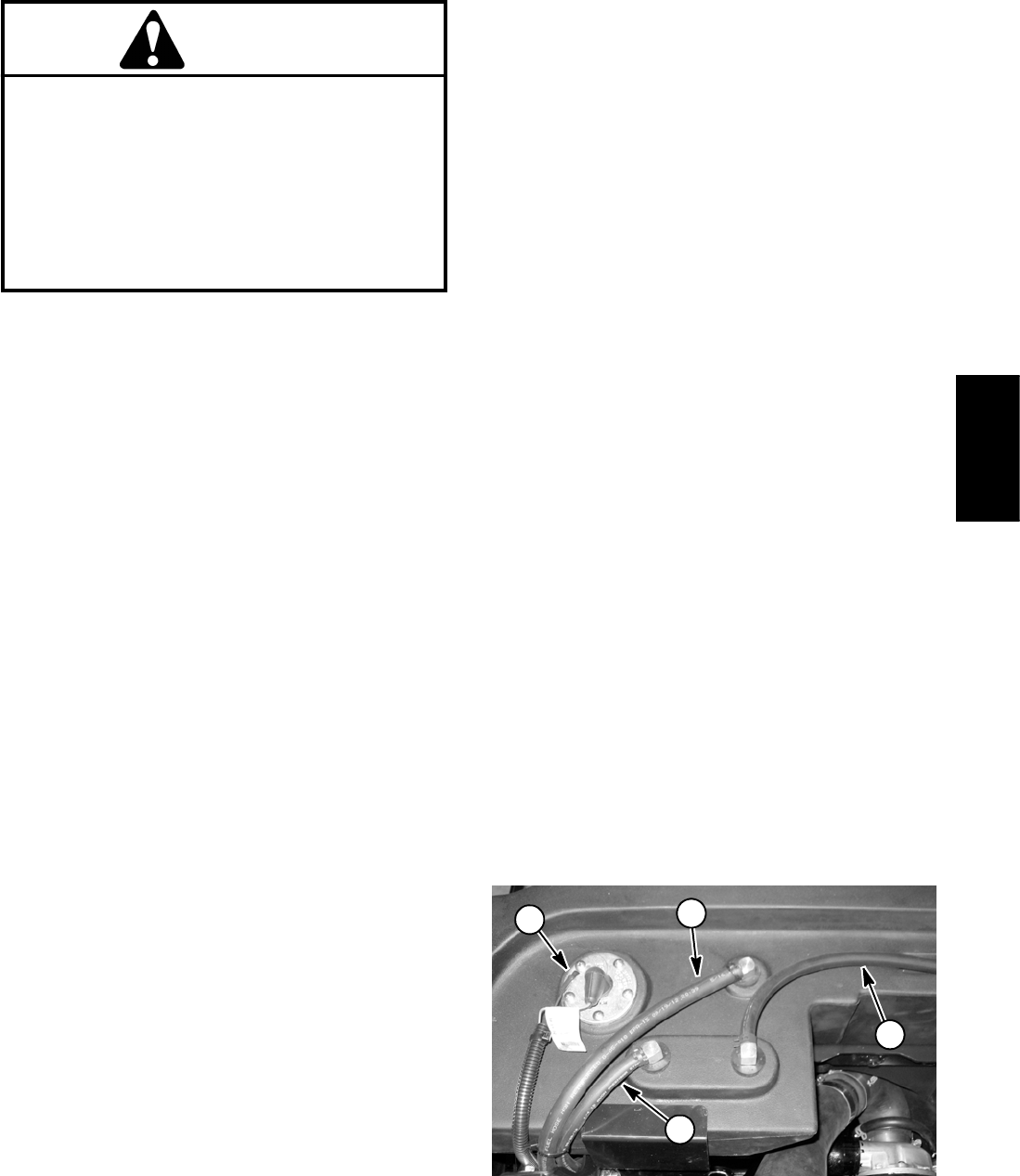
NOTE: Fuel sender may have two (2) wire harness ter-
minals (shown in Fig. 10) or a single harness connector.
4. Disconnect wire harness connections from the fuel
sender (item 14).
5. Disconnect fuel supply, vent and return hoses from
elbow fittings in top of tank (Fig. 10).
6. Remove fuel tank using Figure 9 as a guide. Tank is
secured to frame with fasteners (items 1, 2, 3 and 4) on
the forward side and bracket (item 22) on the rear side.
Fuel Tank Installation (Fig. 9)
1. Install fuel tank using Figure 9 as a guide. When se-
curing tank to frame, follow the following sequence:
A. Loosely install fasteners on front of tank (items 1,
2, 3 and 4).
B. Install and tighten bracket (item 22) at rear of
tank.
C. Torque two (2) flange nuts (item 4) from 60 to 80
in--lb (7 to 9 N--m).
2. Connect fuel supply hose to the standpipe and vent
and return hoses to the elbow fittings (Fig. 10). Secure
hoses with clamps.
3. Secure wire harness connector(s) to fuel sender. On
senders with two (2) wire harness terminals, apply skin--
over grease (see Special Tools in this chapter) to har-
ness terminals after installation.
4. Lower and secure operator seat and hood.
5. Fill fuel tank with new fuel.
6. Prime the fuel system (see above).
7. Before returning machine to operation, make sure
that no fuel leaks exist.
Figure 10
1. Fuel supply hose
2. Vent hose
3. Return hose
4. Fuel sender
2
1
3
4
Yanmar
Diesel Engine
Groundsmaster 4100--D/4110--DPage 3 -- 14Yanmar Diesel Engine
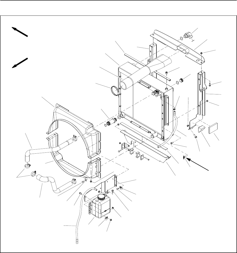
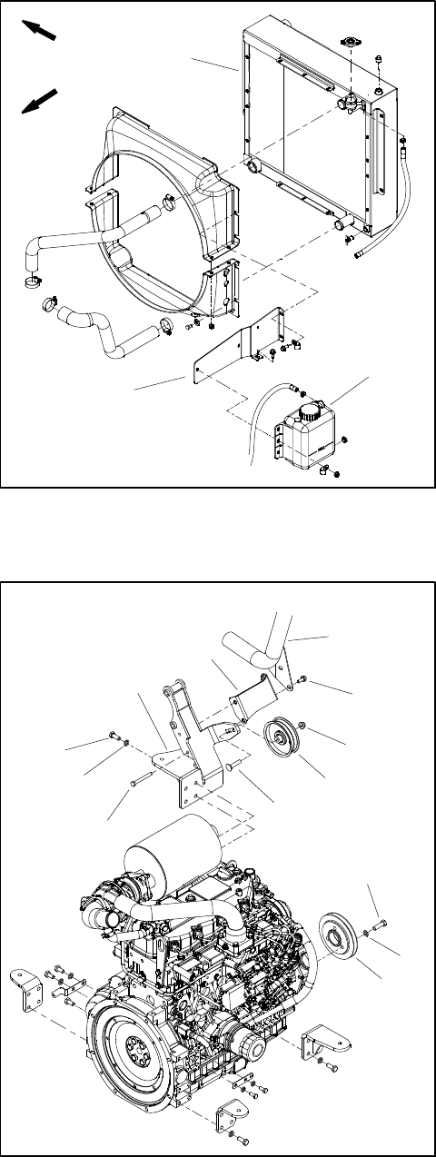
Radiator and Oil Cooler Assembly
Figure 11
FRONT
RIGHT
2
3
6
8
9
10
11
1
5
7
4
24
25
3
26
27
28
29
30
31
32
33
34
35 Thread
Sealant
1. LH radiator support
2. Cap screw (2 used)
3. Flange nut (12 used)
4. Hose clamp (3 used)
5. Hose
6. Flange nut (6 used)
7. Foam plug (2 used)
8. Flange head screw (6 used)
9. Flange head screw (9 used)
10. Foam strip
11. Hose bracket
12. R--clamp (2 used)
13. Cap screw (2 used)
14. Hose
15. Coolant reservoir
16. Tank mount
17. Flat washer (7 used)
18. Cap screw (6 used)
19. Lower radiator hose
20. Hose clamp (4 used)
21. Upper radiator hose
22. Lower radiator shroud
23. Upper radiator shroud
24. Hose clamp
25. Air cleaner inlet hose
26. Radiator/hydraulic oil cooler
27. Bulb seal
28. RH radiator support
29. Straight hydraulic fitting
30. Intake bracket
31. 90ohydraulic fitting
32. Pipe plug
33. Hex plug with O--ring
34. Foam pad (2 used)
35. Draincock
36. Cap screw (2 used)
13
12
14 15
16
17
18
19
20
21
22
23
3
4
9
12
3
36
Groundsmaster 4100--D/4110--D Page 3 -- 15 Yanmar Diesel Engine
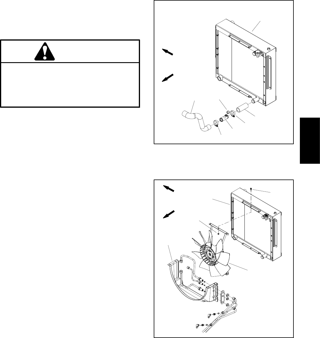
Removal (Fig. 11)
1. Park machine on a level surface, lower cutting deck,
stop engine, apply parking brake and remove key from
the ignition switch. Open and support hood.
CAUTION
Do not open radiator cap or drain coolant if the
radiator or engine is hot. Pressurized, hot cool-
ant can escape and cause burns.
Ethylene--glycol antifreeze is poisonous. Dis-
pose of coolant properly or store it in a properly
labeled container away from children and pets.
2. Drain radiator into a suitable container either by us-
ing the draincock (item 35) near the lower left side corner
of the radiator or by removing the lower radiator hose
from the radiator.
IMPORTANT: Follow all local codes and regulations
when recycling or disposing engine coolant.
3. Disconnect radiator hoses from the radiator.
Groundsmaster 4110--D machines with a Tier 4 compli-
ant engine (model 30606) use the lower radiator hose
assemblyshowninFigure12.
4. Remove air cleaner inlet hose (item 25).
5. Read the General Precautions for Removing and
Installing Hydraulic System Components in the Service
and Repairs section of Chapter 4 -- Hydraulic System.
6. Thoroughly clean hydraulic lines at lower radiator
shroud (Fig. 13) and oil cooler ports (Fig. 14). Discon-
nect hydraulic lines and put caps or plugs on lines to pre-
vent contamination. Label disconnected hydraulic lines
for proper installation.
7. Disconnect hood rods from hood and radiator sup-
ports (see Hood in the Service and Repairs section of
Chapter 7 -- Chassis).
8. Remove flange head screws (item 8) and flange nuts
(item 6) that secure the radiator supports (items 1 and
28) to the frame.
9. Carefully raise radiator assembly with shrouds, fan
motor assembly and supports from the machine.
10.Disassemble radiator/oil cooler assembly as needed
using Figures 11 and 13 as guides.
11.If necessary, remove hydraulic fittings (items 29 and
31) from oil cooler and discard O--rings.
12.Plug all radiator and hose openings to prevent con-
tamination.
Figure 12
1. Radiator/oil cooler
2. Lower radiator hose
3. Hose clamp
4. Radiator fitting
5. Hose clamp
6. Radiator hose
6
3
5
4
2
3
1
MODEL 30606 (WITH TIER 4 ENGINE)
FRONT
RIGHT
Figure 13
1. Radiator/oil cooler
2. Motor and fan assembly
3. Cap screw (6 used)
4. Flange nut (6 used)
5. Lower radiator shroud
FRONT
RIGHT
2
3
1
4
5
Yanmar
Diesel Engine
Groundsmaster 4100--D/4110--DPage 3 -- 16Yanmar Diesel Engine
Installation (Fig. 11)
1. Inspect seals (items 7, 10, 27 and 34) around radiat-
or location for wear or damage. Replace seals if neces-
sary.
2. Remove all plugs placed during the removal proce-
dure.
3. If hydraulic fittings (items 29 and 31) were removed
from oil cooler, lubricate and place new O--rings onto fit-
tings. Install fittings into port openings and tighten fit-
tings (see Hydraulic Fitting Installation in the General
Information section of Chapter 4 -- Hydraulic System).
4. Assemble radiator/oil cooler using Figures 11 and 13
as guides.
A. If fan motor bracket was removed, position brack-
et as far as possible from radiator to maximize dis-
tance between radiator and fan motor location.
B. Make sure that clearance between radiator
shrouds and cooling fan is at least 0.180” (4.6 mm)
at all points.
5. Carefully lower radiator assembly with shrouds, fan
motor assembly and supports to the machine frame.
6. Secure radiator supports (items 1 and 28) to the
frame with flange head screws (item 8) and flange nuts
(item 6).
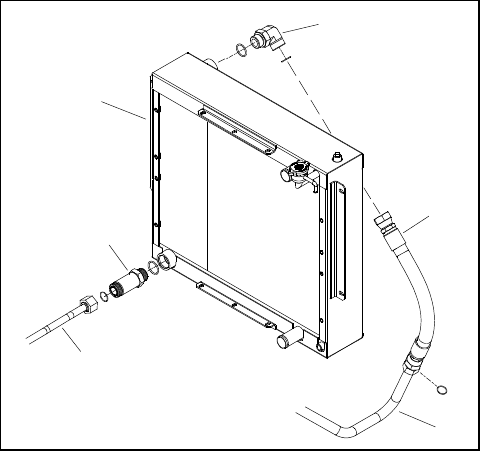
7. Connect hydraulic lines to fittings in oil cooler ports
(Fig. 14) and at lower radiator shroud (Fig. 13) (see Hy-
draulic Hose and Tube Installation in the General Infor-
mation section of Chapter 4 -- Hydraulic System).
8. Connect upper and lower radiator hoses to the radi-
ator and secure with hose clamps.
9. Install and secure air cleaner inlet hose (item 25).
10.Make sure radiator draincock is closed. Fill radiator
with coolant.
11. Connect hood rods to radiator supports and hood
(see Hood in the Service and Repairs section of Chapter
7 -- Chassis).
12.Close and secure hood.
Figure 14
1. Radiator/oil cooler
2. Straight fitting
3. Hydraulic tube
4. 90ofitting
5. Hydraulic hose
6. Hydraulic tube
5
4
3
2
1
6

Groundsmaster 4100--D/4110--D Page 3 -- 17 Yanmar Diesel Engine
This page is intentionally blank.
Yanmar
Diesel Engine
Groundsmaster 4100--D/4110--DPage 3 -- 18Yanmar Diesel Engine
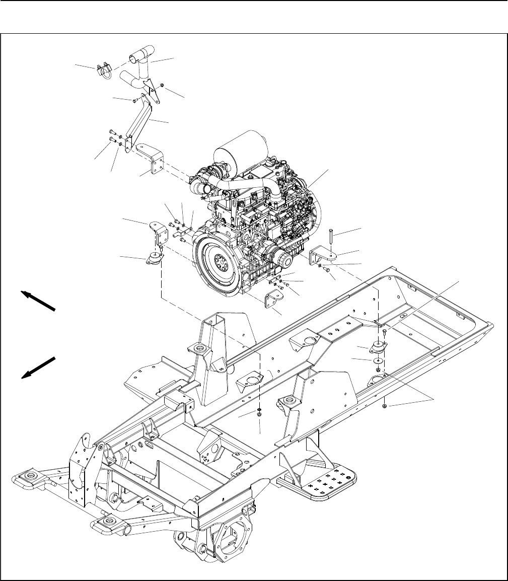
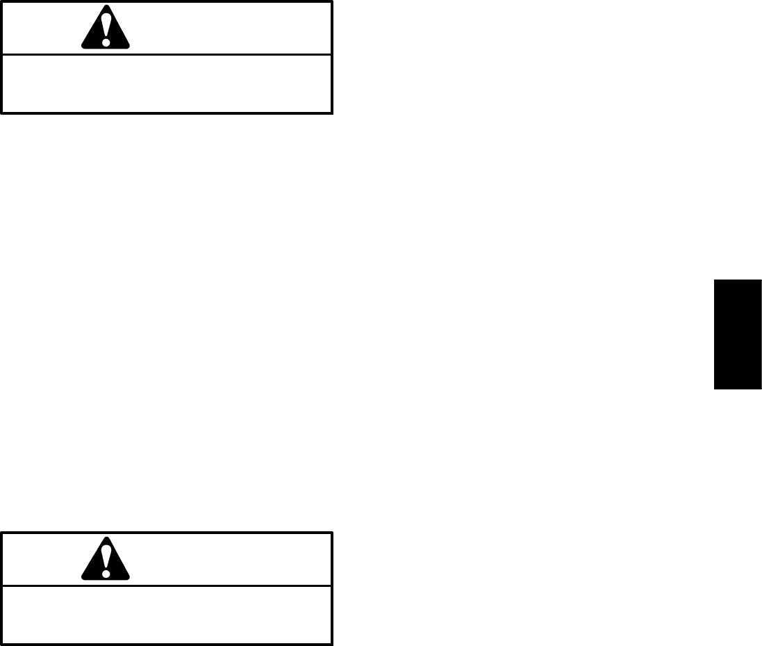
Engine
Figure 15
1. Engine (model 30604 shown)
2. Cap screw (4 used)
3. Rebound washer (4 used)
4. Flange nut (12 used)
5. Engine mount (4 used)
6. Cap screw (2 used per mount)
7. Engine mount bracket (2 used)
8. Lock washer
9. Engine mount bracket (2 used)
10. Cap screw (14 used)
11. Lock washer (18 used)
12. Cap screw (2 used)
13. Exhaust bracket
14. Cap screw (2 used)
15. Flange nut (2 used)
16. Exhaust pipe
17. Wire harness bracket
18. Cap screw (3 used)
19. Wire harness bracket
20. Lock washer (2 used)
21. Cap screw (2 used)
22. Clamp assembly
FRONT
RIGHT
2
3
6
8
9
11
13
1
5
7
12
14 15
16
19
20
4
21
11
5
22
7
9
11
4
10
17
18
MODEL 30604 SHOWN
Groundsmaster 4100--D/4110--D Page 3 -- 19 Yanmar Diesel Engine
Engine Removal (Fig. 15)
1. Park machine on a level surface, lower cutting deck,
stop engine, apply parking brake and remove key from
the ignition switch.
2. Disconnect negative battery cable from battery ter-
minal and then disconnect positive cable from battery
(see Battery Service in the Service and Repairs section
of Chapter 5 -- Electrical System).
3. Raise and support hood.
CAUTION
Do not open radiator cap or drain coolant if the
radiator or engine is hot. Pressurized, hot cool-
ant can escape and cause burns.
Ethylene--glycol antifreeze is poisonous. Dis-
pose of coolant properly or store it in a properly
labeled container away from children and pets.
4. Drain coolant from the radiator into a suitable con-
tainer (see Radiator and Oil Cooler Assembly in this sec-
tion). Disconnect upper and lower hoses from the
radiator.
5. Remove air cleaner assembly from engine (see Air
Cleaner System in this section).
6. Remove exhaust pipe (item 16 in Fig. 15) and ex-
haust bracket (item 13 in Fig. 15 or item 6 in Fig. 20) from
engine.
7. Note location of cable ties used to secure wire har-
ness to the machine. Disconnect wires and/or electrical
connections from the following electrical components:
A. The engine wire harness from the machine wire
harness.
B. The positive battery cable from the engine starter
motor (Fig. 16).
C. The fusible link harness from the main wire har-
ness (Fig. 16).
D. The negative battery cable at the engine block
(Fig. 16).
8. Carefully disconnect engine wire harness connector
from engine ECU.
9. Disconnect fuel supply and return hoses from engine
(Fig. 17 or 18). Position fuel hoses away from engine.
10.Remove fasteners that secure the coolant reservoir
tank mount to the radiator and radiator shrouds (Fig.
19). Position and support coolant reservoir with mount
away from the engine.
Figure 16
1. Positive battery cable
2. Negative battery cable
3. Fusible link harness
2
3
1
Figure 17
1. Tier 4 engine
2. Hose clamp
3. Fuel supply hose
4. Hose clamp
5. Fuel return hose
6. Front lift bracket
2
3
1
4
5
MODELS 30606 and 30608
6
Figure 18
1. Tier 4i engine
2. Hose clamp
3. Fuel supply hose
4. Hose clamp
5. Fuel return hose
1
2
3
4
5
MODELS 30602 and 30604
Yanmar
Diesel Engine
Groundsmaster 4100--D/4110--DPage 3 -- 20Yanmar Diesel Engine
11. On machines with a Tier 4 compliant engine (models
30606 and 30608):
A.Removefueltanktoallowenginetoberaised
frommachine(seeFuelSysteminthissection).
B. Install lift bracket to front of engine cylinder head
(item 6 in Fig. 17). Front lift bracket was included with
new machine or is available as a service part (refer to
parts catalog for part number).
12.On Groundsmaster 4110--D machines:
A. Remove air conditioning compressor from com-
pressor mount (see Air Conditioning Compressor in
the Service and Repairs section of Chapter 9 -- Oper-
ator Cab). Position compressor away from engine
taking care to not damage compressor or AC hoses.
Support compressor to make sure it will not fall dur-
ing engine removal.
B. Disconnect coolant hoses from fittings on engine
water flange. On Groundsmaster 4110--D machines
with a Tier 4 compliant engine (model 30606), dis-
connect coolant hose from fitting on lower radiator
hose assembly. Label coolant hoses for proper as-
sembly.
IMPORTANT: The hydraulic pump assembly can re-
main in machine during engine removal. To prevent
pump from shifting or falling, make sure to support
pump assembly before the fasteners that secure
pump assembly to engine are removed.
13.Support hydraulic pump assembly. Remove fasten-
ers that secure pump assembly to engine (see Pump
Assembly in the Service and Repairs section of Chapter
4 -- Hydraulic System).
14.Note location of all cable ties securing the wire har-
ness, fuel lines and hydraulic hoses to the engine for as-
sembly purposes. Remove cable ties as needed for
engine removal.
15.Connect lift or hoist to the lift brackets on engine.
16.Remove flange nuts, rebound washers and cap
screws that secure the engine mount brackets to the en-
gine mounts.
Figure 19
1. Radiator/oil cooler
2. Tank Mount
3. Coolant reservoir
FRONT
RIGHT
2
3
1
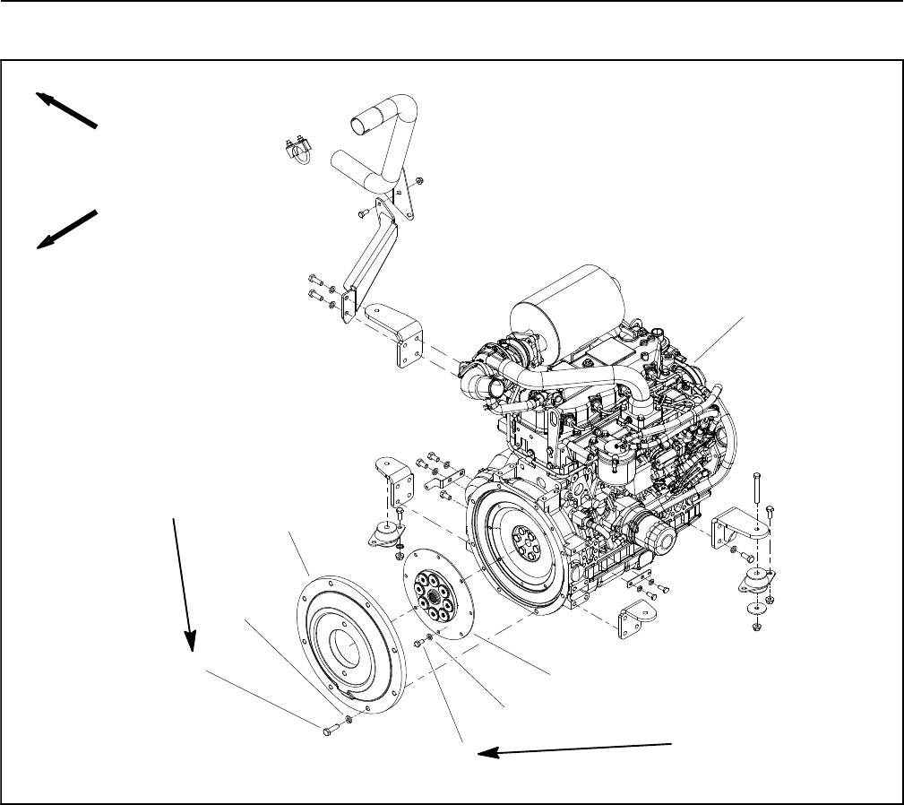
Figure 20
1. Exhaust pipe
2. Flange screw (2 used)
3. Flange nut
4. Idler pulley
5. Carriage screw
6. Exhaust bracket
7. Compressor mount
8. Cap screw (2 used)
9. Cap screw (4 used)
10. Lock washer
11. Cap screw (3 used)
12. Pulley
2
3
6
8
9
10
1
5
7
4
11
12
10
MACHINES WITH
OPERATOR CAB
Groundsmaster 4100--D/4110--D Page 3 -- 21 Yanmar Diesel Engine
CAUTION
One person should operate lift or hoist while a
second person guides the engine out of the ma-
chine.
IMPORTANT: Make sure to not damage the engine,
radiator assembly, fuel lines, hydraulic lines, elec-
trical wire harness or other components while re-
moving the engine.
17.Slowly move the engine assembly away from the hy-
draulic pump assembly to allow the pump input shaft to
slide out of the spring coupler on the engine flywheel.
Once the engine has cleared the pump input shaft, care-
fully remove the engine from the machine.
18.If necessary, remove engine mount brackets from
theengineusingFigure15or20asaguide.
Engine Installation (Fig. 15)
1. Make sure that all parts removed from the engine
during maintenance or rebuilding are installed to the en-
gine.
2. If removed, install engine mount brackets to the en-
gine using Figure 15 or 20 as a guide.
3. Connect lift or hoist to the engine lift brackets.
CAUTION
One person should operate lift or hoist while a
second person guides the engine into the ma-
chine.
IMPORTANT: Make sure to not damage the engine,
radiator assembly, fuel lines, hydraulic lines, elec-
trical wire harness or other components while
installing the engine.
4. Carefully lower engine into the machine. Slowly
move the engine assembly toward the hydraulic pump
assembly to allow the pump input shaft to slide into the
spring coupler on the engine flywheel.
5. Align engine to the engine mounts. Secure engine to
engine mounts with cap screws, rebound washers and
flange nuts.
6. Secure hydraulic pump assembly to engine (see
Pump Assembly in the Service and Repairs section of
Chapter 4 -- Hydraulic System).
7. On machines with a Tier 4 compliant engine (models
30606 and 30608):
A. Remove lift bracket from front of engine cylinder
head (item 6 in Fig. 17). The bracket must be re-
moved before fuel tank installation. Retain lift brack-
et and fasteners for future use.
B. Install and secure fuel tank to machine (see Fuel
System in this section).
8. Position coolant reservoir with mount to the radiator.
Secure reservoir tank mount to the radiator and radiator
shrouds with removed fasteners.
9. Connect fuel supply and return hoses to the engine
fittings (Fig. 17 or 18).
10.On Groundsmaster 4110--D machines:
A. Install air conditioning compressor to compressor
mount (see Air Conditioning Compressor Installation
in the Service and Repairs section of Chapter 9 -- Op-
erator Cab). Make sure that drive belt is properly ten-
sioned.
B. Connect coolant hoses to fittings on engine water
flange.
11. Connect wires and/or electrical connections to en-
gine locations.
A. The engine wire harness from the machine wire
harness.
B. The positive battery cable from the engine starter
motor (Fig. 16).
C. The fusible link harness from the main wire har-
ness (Fig. 16).
D. The negative battery cable at the engine block
(Fig. 16).
12.Carefully connect engine wire harness connector to
engine ECU.
13.Install and secure exhaust bracket (item 13 in Fig. 15
or item 6 in Fig. 20) and exhaust pipe (item 16 in Fig. 15)
from engine.
14.Install air cleaner assembly to the engine (see Air
Cleaner System in this section).
15.Connect coolant hoses to the radiator. Make sure ra-
diator draincock is closed. Fill radiator and coolant
reservoir with coolant.
16.Secure the wire harness, fuel lines and hydraulic
hoses to the engine with cable ties as noted during en-
gine removal.
Yanmar
Diesel Engine
Groundsmaster 4100--D/4110--DPage 3 -- 22Yanmar Diesel Engine
17.Check position of electrical wires, fuel lines and hy-
draulic lines for proper clearance with rotating, high tem-
perature and moving components.
18.Connect positive battery cable to positive battery ter-
minal first and then connect negative cable to battery
(see Battery Service in the Service and Repairs section
of Chapter 5 -- Electrical System).
19.Check and adjust engine oil as needed.
20.Check and adjust oil level in hydraulic reservoir as
needed.
21.Prime the fuel system (see Fuel System in this sec-
tion).
22.Start engine and operate hydraulic controls to prop-
erly fill hydraulic system (see Charge Hydraulic System
in the Service and Repairs section of Chapter 4 -- Hy-
draulic System).
23.Close and secure hood.

Groundsmaster 4100--D/4110--D Page 3 -- 23 Yanmar Diesel Engine
This page is intentionally blank.
Yanmar
Diesel Engine
Groundsmaster 4100--D/4110--DPage 3 -- 24Yanmar Diesel Engine
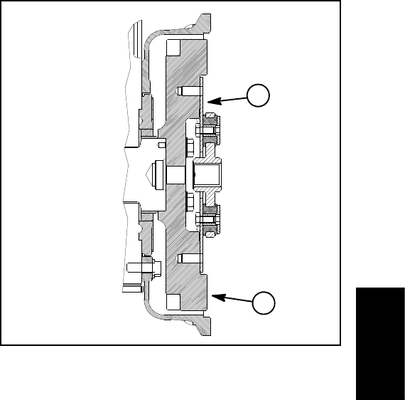
Spring Coupler
Figure 21
1. Cap screw (8 used)
2. Washer (8 used)
3. Flywheel plate
4. Cap screw (8 used)
5. Washer (8 used)
6. Spring coupler
7. Engine (model 30604 shown)
FRONT
RIGHT
29 to 33 ft--lb
(40to44N--m)
28 to 32 ft--lb
(38 to 43 N--m)
1
2
3
6
5
4
7
Groundsmaster 4100--D/4110--D Page 3 -- 25 Yanmar Diesel Engine
Coupler Removal (Fig. 21)
NOTE: The hydraulic pump assembly needs to be re-
moved from engine before coupler can be removed.
1. If engine is in machine, remove hydraulic pump as-
sembly from machine (see Piston (Traction) Pump Re-
moval in the Service and Repairs section of Chapter 4
-- Hydraulic System).
2. Remove flywheel plate and spring coupler from en-
gine using Figure 21 as a guide.
Coupler Installation (Fig. 21)
1. Position spring coupler to engine flywheel and align
mounting holes. Make sure that coupling hub is away
from engine flywheel (Fig. 22).
2. Secure coupler to flywheel with eight (8) cap screws
and washers. Torque cap screws in a crossing pattern
from 29 to 33 ft--lb (40 to 44 N--m).
3. Position flywheel plate to engine. Secure flywheel
plate with eight (8) cap screws (item 1) and washers us-
ing a crossing pattern tightening procedure. Torque cap
screws in a crossing pattern from 28 to 32 ft--lb (38 to
43 N--m).
4. If engine is in machine, install hydraulic pump as-
sembly to machine (see Piston (Traction) Pump Installa-
tion in the Service and Repairs section of Chapter 4 --
Hydraulic System).
Figure 22
1. Spring coupler 2. Engine flywheel
Engine Side Hydraulic
Pump Side
1
2
Yanmar
Diesel Engine
Groundsmaster 4100--D/4110--DPage 3 -- 26Yanmar Diesel Engine
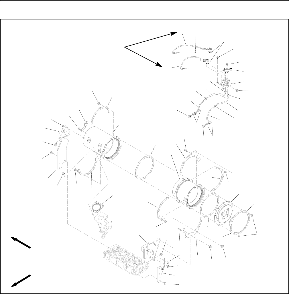
Exhaust System (Models 30606 and 30608)
Figure 23
1. Gasket
2. Exhaust assembly stay
3. Exhaust assembly stay
4. Exhaust assembly stay
5. Exhaust assembly stay
6. Nut
7. DOC temp sensor (inlet)
8. DOC temp sensor (outlet)
9. Nut (4 used)
10. DOC assembly
11. Nut (3 used)
12. DPF assembly
13. Nut
14. Outlet flange
15. DPF gasket (2 used)
16. Bolt (20 used)
17. DPF lifter
18. DPF stiffener (5 used)
19. DPF stiffener
20. DPF stiffener
21. DPF stiffener
22. Bolt (2 used)
23. Nut (20 used)
24. Bolt (2 used)
25. Pipe joint bolt (2 used)
26. Exhaust pressure pipe (DPF inlet)
27. Sensor gasket (4 used)
28. Exhaust pressure pipe (DPF outlet)
29. Exhaust hose
30. Bolt (2 used)
31. Hose clip (2 used)
32. Hose
33. Bolt (3 used)
34. Hose clip (2 used)
35. Pressure sensor
36. Sensor bracket
37. Bolt (2 used)
38. Bolt (2 used)
39. Clip band
40. Band
41. Connector clip (2 used)
42. Bolt (2 used)
43. Bolt (2 used)
44. Bolt (2 used)
FRONT
RIGHT
19 to 29 ft--lb
(25to40N--m)
2
3
8
10
13
1
5
7
12
14
15
16
17
18
19
21
22
23
25
27
28
29
31
32
34
35
37
38
39
40
31
34
41
27
25
18
18
18
16
624
23
18
15
43
42
44
16
9
4
33
16
11
30 20
23
26
36
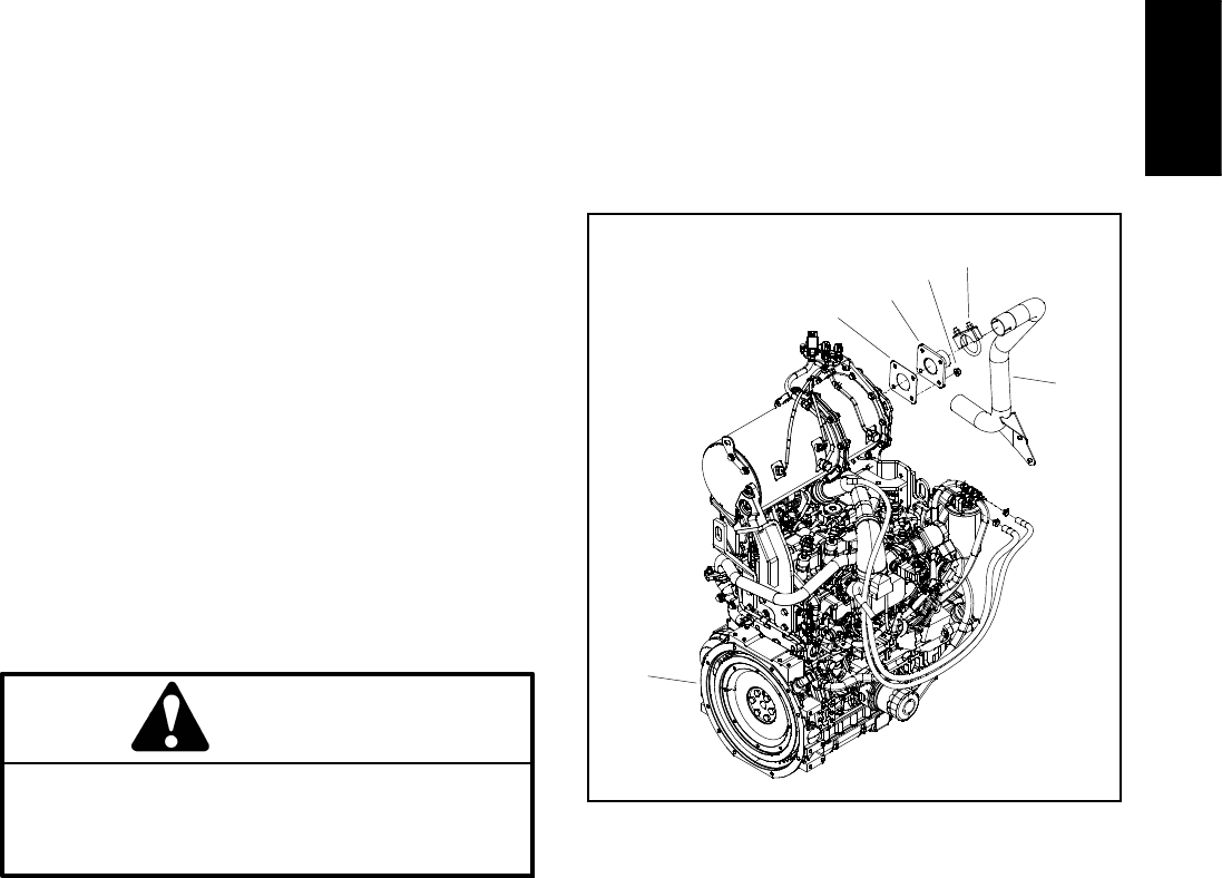
Groundsmaster 4100--D/4110--D Page 3 -- 27 Yanmar Diesel Engine
Groundsmaster models that are powered by a diesel en-
gine that complies with EPA Tier 4 emission regulations
are equipped with an exhaust system that includes a
diesel oxidation catalyst (DOC) and a diesel particulate
filter (DPF). These exhaust components require service
or component replacement at intervals identified in your
Operator’s Manual. Additionally, the exhaust assembly
uses two (2) temperature sensors and a pressure differ-
ential sensor which are used as inputs for the engine
ECU to monitor the operation of the exhaust system.
The diesel particulate filter (DPF) is cleaned periodically
through a regenerative process that is controlled by the
engine ECU (see Yanmar Engine: Models 30606 and
30608 in the General Information section of this
chapter). The InfoCenter display will identify the status
of DPF regeneration. At recommended intervals, DPF
reconditioning is necessary which will require exhaust
system disassembly, DPF removal and DPF recondi-
tioning by a company that has the necessary equip-
ment. Once the DPF has gone through the
reconditioning process, it can be re--installed in the ex-
haust system. Contact your Toro Distributor for informa-
tion on reconditioning the DPF.
The diesel oxidation catalyst (DOC) has a service life ex-
pectancy and requires replacement at recommended
intervals. Replacement of the DOC will require exhaust
system disassembly, removal of the existing DOC and
installation of the new DOC.
Refer to the Parts Catalog to identify individual compon-
ents for the exhaust system on your Groundsmaster.
Removal (Figs. 23 and 24)
NOTE: TheexhaustsystemDPFandDOCcanbere-
moved from the exhaust system without removing the
entire exhaust from the engine. Certain engine service
procedures (e.g. rocker cover removal for valve clear-
ance adjustment) will require removal of the exhaust
system assembly.
CAUTION
The muffler and exhaust pipe may be hot. To
avoid possible burns, allow the engine and ex-
haust system to cool before working on the ex-
haust system.
1. Raise and support hood to gain access to exhaust
system. Allow engine and exhaust to cool before doing
any disassembly of exhaust system components.
2. Remove exhaust system components from the en-
gine as necessary using Figure 23 and 24 as guides.
Discard all removed gaskets (items 1 and 15 in Fig. 23
or item 6 in Fig. 24).
Installation (Figs. 23 and 24)
NOTE: Make sure that all exhaust system flanges and
sealing surfaces are free of debris or damage that may
prevent a tight seal.
1. Make sure to install new gaskets in place of all gas-
kets that were removed. Do not use any type of gasket
sealant on gasket or flange surfaces.
2. Assemble all removed exhaust system components
usingFigure23and24asguides.
A. If exhaust sensors (items 7 and 8 in Fig. 23) were
removed, torque sensors from 19 to 29 ft--lb (25 to
40 N--m).
B. If exhaust pressure pipes (items 26 and 28 in Fig.
23) were removed, replace sensor gaskets (item 27)
on both sides of the pressure pipe fitting.
C. If DPF stiffeners (items 18, 19, 20 and 21 in Fig.
23) were loosened or removed, tighten fasteners
that secure stiffeners before tightening fasteners
that secure exhaust system to DPF stays.
Figure 24
1. Engine
2. Exhaust pipe
3. Clamp assembly
4. Flange nut (4 used)
5. Exhaust flange
6. Exhaust gasket
1
2
3
4
5
6
Yanmar
Diesel Engine
Groundsmaster 4100--D/4110--DPage 3 -- 28Yanmar Diesel Engine
This page is intentionally blank.

Groundsmaster 4100--D/4110--D Hydraulic SystemPage 4 -- 1
Chapter 4
Hydraulic System
Table of Contents
SPECIFICATIONS 2............................
GENERAL INFORMATION 3.....................
Operator’s Manual 3..........................
Check Hydraulic Fluid 3.......................
Relieving Hydraulic System Pressure 3..........
Towing Traction Unit 4.........................
Traction Circuit Component Failure 4............
Hydraulic Hoses 5............................
Hydraulic Hose and Tube Installation 6..........
Hydraulic Fitting Installation 7..................
HYDRAULIC SCHEMATIC 9.....................
HYDRAULIC FLOW DIAGRAMS 10...............
Traction Circuit: LOW Speed (Mow) 10..........
Traction Circuit: HI Speed (Transport) 12.........
Lower Cutting Deck 14........................
Raise Cutting Deck 16.........................
Mow Circuit 18...............................
Mow Circuit Cutting Deck Blade Braking 20......
Steering Circuit 22............................
Engine Cooling Fan Circuit 24..................
SPECIAL TOOLS 26............................
TROUBLESHOOTING 31........................
TESTING 38...................................
Traction Circuit Charge Pressure 40.............
Traction Circuit Relief Pressure 42..............
Counterbalance Pressure 44...................
Reverse Traction Circuit Reducing Valve (PR)
Pressure 46................................
Rear Traction Circuit Relief Valve (RV) Pressure 48
Piston (Traction) Pump Flow 50.................
Cutting Deck Circuit Pressure 52................
PTO Relief Pressure 54........................
Cutting Deck Motor Case Drain Leakage 56......
Lift/Lower Circuit Relief Pressure 58.............
Steering Circuit Relief Pressure 60..............
Steering Cylinder Internal Leakage 62...........
Engine Cooling Fan Circuit 64..................
Gear Pump Flow 66...........................
ADJUSTMENTS 68.............................
Adjust Control Manifold Relief Valves 68.........
SERVICE AND REPAIRS 69.....................
General Precautions for Removing and
Installing Hydraulic System Components 69....
Check Hydraulic Lines and Hoses 70............
Priming Hydraulic Pumps 70...................
Flush Hydraulic System 71.....................
Filtering Closed--Loop Traction Circuit 72........
Charge Hydraulic System 73...................
Hydraulic Reservoir 74........................
Radiator and Oil Cooler Assembly 76............
Gear Pump 78................................
Gear Pump Service 82........................
Piston (Traction) Pump 84.....................
Piston (Traction) Pump Service 88..............
Rear Axle Motor 90...........................
Front Wheel Motors 92........................
Rear Axle and Front Wheel Motor Service 94.....
Rear Traction Manifold 96......................
Rear Traction Manifold Service 98..............
Control Manifold Cartridge Valve Service 99......
Combination Manifold 100.....................
Combination Manifold Service 102..............
Steering Control Valve 104.....................
Steering Control Valve Service 106..............
Steering Cylinder 108.........................
Steering Cylinder Service 110..................
Engine Cooling Fan Motor 112..................
Engine Cooling Fan Motor Service 116..........
Cutting Deck Motor 119........................
Cutting Deck Motor Service (Sauer--Danfoss) 120.
Cutting Deck Motor Service (Casappa) 124.......
PTO Manifolds 126............................
PTO Manifold Service 128.....................
Cutting Deck Lift Cylinders 130.................
Wing Deck Lift Cylinders 132...................
Lift Cylinder Service 134.......................
SAUER--DANFOSS H1 CLOSED CIRCUIT AXIAL PIS-
TON PUMPS SERVICE MANUAL
SAUER--DANFOSS K and L FRAME VARIABLE MO-
TORS SERVICE MANUAL
EATON PARTS AND REPAIR INFORMATION: 5
SERIES STEERING CONTROL UNITS
Hydraulic
System

Groundsmaster 4100--D/4110--DHydraulic System Page 4 -- 2
Specifications
Item Description
Piston (Traction) Pump Sauer--Danfoss Variable Displacement Axial Piston Pump
Maximum Displacement (per revolution) 2.75 in3(45 cc)
System Relief Pressure: Forward 4350 PSI (300 bar)
System Relief Pressure: Reverse 5000 PSI (345 bar)
Charge Pressure 250PSI(17bar)
Front Wheel Motors Sauer--Danfoss 2--Position Axial Piston Motors
Displacement (per revolution) 1.40 in3(23 cc) Maximum / 0.79 in3(13 cc) Minimum
Rear Axle Motor Sauer--Danfoss 2--Position Axial Piston Motor
with Loop Flushing Valve
Displacement (per revolution) 2.14 in3(35 cc) Maximum / 1.16 in3(19 cc) Minimum
Gear Pump Casappa 4 Section, Positive Displacement Gear pump
Section P1/P2 Displacement (per revolution) 1.37 in3(22.46 cc)
Section P3 Displacement (per revolution) 0.40 in3(6.61 cc)
Section P4 Displacement (per revolution) 0.30 in3(4.96 cc)
Steering Control Valve Eaton Steering Unit, Series 5
Displacement (per revolution) 6.1 in3(100 cc)
Steering Circuit Relief Pressure 1350PSI(93bar)
Lift/Lower Circuit Relief Pressure 2500 PSI (172 bar)
Cutting Deck Motors Gear Motor
Displacement (per revolution) 1.17 in3(19.2 cc)
PTO Circuit Relief Pressure
Front and Left Side 3000 PSI (207 bar)
Right Side 2000 PSI (138 bar)
Engine Cooling Fan Motor Casappa Gear Motor
Displacement (per revolution) 0.51 in3(8.4 cc)
Engine Cooling Fan Circuit Relief Pressure 3000 PSI (207 bar)
Hydraulic Filters Spin--on Cartridge Type
In--line Suction Strainer 100 Mesh (In Reservoir)
Hydraulic Reservoir 7.75 U.S. Gallons (29.3 Liters)
Hydraulic Oil See Operator’s Manual
NOTE: Thepressurespecificationslistedaboveare
component settings. When using pressure gauges to
measure circuit pressures, values may be different than
these specifications. See the Testing section of this
chapter for hydraulic test procedures and expected test
results.
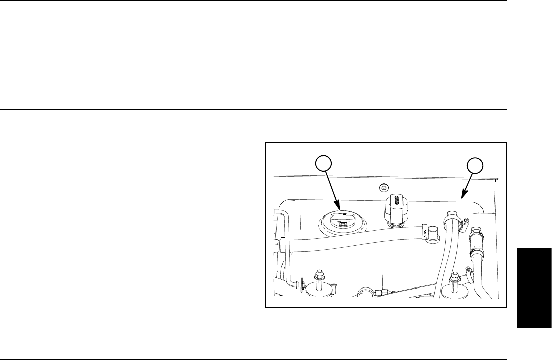
Groundsmaster 4100--D/4110--D Hydraulic SystemPage 4 -- 3
General Information
Operator’s Manual
The Operator’s Manual provides information regarding
the operation, general maintenance and maintenance
intervals for your Groundsmaster machine. Refer to that
publication for additional information when servicing the
machine.
Check Hydraulic Fluid
Your Groundsmaster hydraulic system is designed to
operate on anti--wear hydraulic fluid. The reservoir
holds approximately 7.75 U.S. gallons (29.3 liters) of
hydraulic fluid. Check level of hydraulic fluid daily.
See Operator’s Manual for fluid level checking proce-
dure and oil recommendations.
1. Hydraulic reservoir 2. Reservoir cap
Figure 1
1
2
Relieving Hydraulic System Pressure
Before disconnecting or performing any work on the hy-
draulic system, all pressure in the hydraulic system
must be relieved. Park machine on a level surface, make
sure that PTO switch is OFF, lower cutting deck fully,
stop engine and engage parking brake. Wait for all mov-
ing parts to come to a complete stop.
System pressure in lift circuit is relieved when the cutting
deck is fully lowered.
System pressure in mow circuit is relieved when the
PTO switch is disengaged.
To relieve hydraulic pressure in traction circuit, turn igni-
tion switch to ON (engine not running) and move traction
pedal to both forward and reverse directions. Turn igni-
tion switch to OFF after relieving traction circuit pres-
sure.
To relieve hydraulic pressure in steering circuit, rotate
steering wheel in both directions.
After all hydraulic system pressures have been relieved,
remove key from ignition switch.
Hydraulic
System
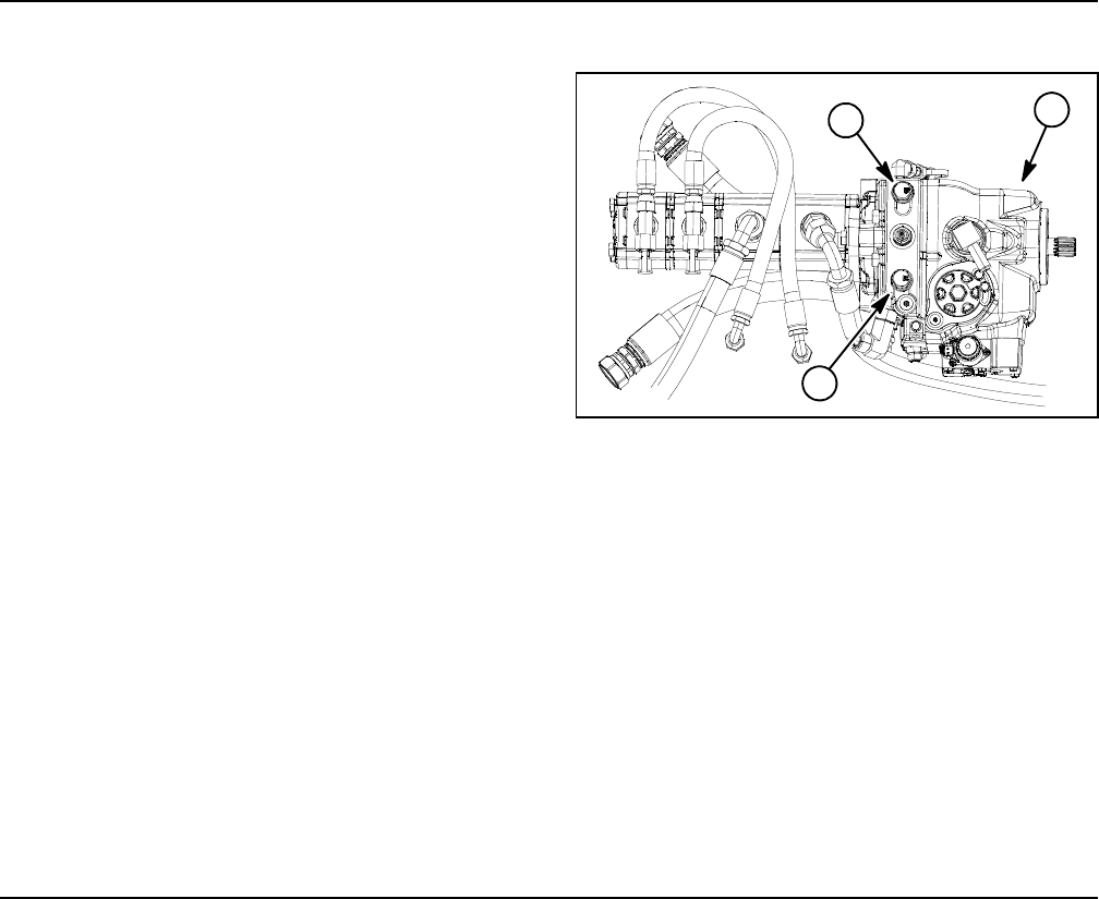
Groundsmaster 4100--D/4110--DHydraulic System Page 4 -- 4
Towing Traction Unit
IMPORTANT: If towing limits are exceeded, severe
damage to the piston (traction) pump may occur.
If it becomes necessary to tow (or push) the machine,
tow (or push) in a forward direction only and at a
speed below 3 mph (5 kph). The piston (traction) pump
relief valves (both forward and reverse) need to be
loosened three (3) revolutions to allow the machine to
be moved (Fig. 2). To prevent leakage from relief valves,
do not loosen them more than three (3) revolutions.
Refer to your Operator’s Manual for additional towing in-
structions.
IMPORTANT: Do not loosen relief valves when en-
gine is running.
Before returning machine to service, tighten both of the
relief valves until seated. Then, torque relief valves to 52
ft--lb (70 N--m).
IMPORTANT: If the machine must to be pushed or
towed in reverse, the check valve in the rear traction
manifold must also be bypassed. To bypass this
check valve, connect a hydraulic hose assembly to
the reverse traction pressure test port, located on
the piston (traction) pump, and on the port located
in--between ports M8 and P2 on the rear traction
manifold which is located behind the front tire. Use
Toro part numbers 95--8843 (hydraulic hose),
95--0985 (quantity 2) (coupler fitting) and 340--77
(quantity 2) (hydraulic fitting).
Figure 2
1. Piston pump
2. Relief valve (forward)
3. Relief valve (reverse)
1
2
3
Traction Circuit Component Failure
The traction circuit on Groundsmaster 4100--D and
4110--D machines is a closed loop system that includes
the piston (traction) pump, two (2) front wheel motors
and the rear axle motor. If a component in the traction
circuit should fail, debris and contamination from the
failed component will circulate throughout the traction
circuit. This contamination can damage other compo-
nents in the circuit so it must be removed to prevent
additional component failure.
The recommended method of removing traction circuit
contamination would be to temporarily install the Toro
high flow hydraulic filter (see Special Tools in this chap-
ter) into the circuit. This filter should be used when con-
necting hydraulic test gauges in order to test traction
circuit components or after replacing a failed traction cir-
cuit component (e.g. traction (piston) pump or wheel
motor). The filter will ensure that contaminates are re-
moved from the closed loop and thus, do not cause addi-
tional component damage.
Once the Toro high flow hydraulic filter kit has been
placed in the circuit, raise and support the machine with
all wheels off the ground. Then, operate the traction cir-
cuit to allow oil flow throughout the circuit. The filter will
remove contamination from the traction circuit during
operation. Because the Toro high flow filter is bi--direc-
tional, the traction circuit can be operated in both the for-
ward and reverse direction. The filter should be
removed from the machine after contamination has
been removed from the traction circuit. See Filtering
Closed--Loop Traction Circuit in the Service and Repairs
section of this chapter for additional information on us-
ing the Toro high flow hydraulic filter.
The alternative to using the Toro high flow hydraulic filter
kit after a traction circuit component failure would be to
disassemble, drain and thoroughly clean all compo-
nents, hydraulic tubes and hydraulic hoses in the trac-
tion circuit. If any debris remains in the traction circuit
and the machine is operated, the debris can cause addi-
tional circuit component failure.
Groundsmaster 4100--D/4110--D Hydraulic SystemPage 4 -- 5
Hydraulic Hoses
Hydraulic hoses are subject to extreme conditions such
as pressure differentials during operation and exposure
to weather, sun, chemicals, very warm storage condi-
tions or mishandling during operation and maintenance.
These conditions can cause hose damage and deterio-
ration. Some hoses are more susceptible to these
conditions than others. Inspect all machine hydraulic
hoses frequently for signs of deterioration or damage:
Hard, cracked, cut, abraded, charred, leaking or
otherwise damaged hose.
Kinked, crushed, flattened or twisted hose.
Blistered, soft, degraded or loose hose cover.
Cracked, damaged or badly corroded hose fittings.
When replacing a hydraulic hose, be sure that the hose
is straight (not twisted) before tightening the fittings.
This can be done by observing the imprint (layline) on
the hose. Use two wrenches when tightening a hose;
hold the hose straight with one wrench and tighten the
hose swivel nut onto the fitting with the second wrench
(see Hydraulic Hose and Tube Installation in this sec-
tion). If the hose has an elbow at one end, tighten the
swivel nut on that end before tightening the nut on the
straight end of the hose.
For additional hydraulic hose information, refer to Toro
Service Training Book, Hydraulic Hose Servicing (Part
Number 94813SL).
WARNING
Before disconnecting or performing any work on
hydraulic system, relieve all pressure in system
(see Relieving Hydraulic System Pressure in this
section).
Keep body and hands away from pin hole leaks or
nozzles that eject hydraulic fluid under high
pressure. Use paper or cardboard, not hands, to
search for leaks. Hydraulic fluid escaping under
pressure can have sufficient force to penetrate
the skin and cause serious injury. If fluid is in-
jected into the skin, it must be surgically re-
moved within a few hours by a doctor familiar
with this type of injury. Gangrene may result from
such an injury.
Hydraulic
System
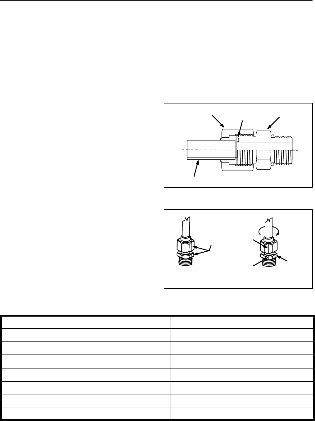
Groundsmaster 4100--D/4110--DHydraulic System Page 4 -- 6
Hydraulic Hose and Tube Installation (O--Ring Face Seal Fitting)
1. Make sure threads and sealing surfaces of the hose/
tube and the fitting are free of burrs, nicks, scratches or
any foreign material.
2. As a preventative measure against leakage, it is rec-
ommended that the face seal O--ring be replaced any
time the connection is opened. Make sure the O--ring is
installed and properly seated in the fitting groove. Lightly
lubricate the O--ring with clean hydraulic oil.
3. Place the hose/tube against the fitting body so that
theflatfaceofthehose/tubesleevefullycontactstheO--
ring in the fitting.
4. Thread the swivel nut onto the fitting by hand. While
holding the hose/tube with a wrench, use a torque
wrench to tighten the swivel nut to the recommended
installation torque shown in Figure 5. This tightening
process will require the use of an offset wrench (e.g.
crowfoot wrench). Use of an offset wrench will affect
torque wrench calibration due to the effective length
change of the torque wrench. Tightening torque when
usingatorquewrenchwithanoffsetwrenchwillbelower
than the listed installation torque (see Using a Torque
Wrench with an Offset Wrench in the Torque Specifica-
tions section of Chapter 2 -- Product Records and Main-
tenance).
5. If a torque wrench is not available or if space at the
swivel nut prevents use of a torque wrench, an alternate
method of assembly is the Flats From Wrench Resist-
ance (F.F.W.R.) method (Fig. 2).
A. Using a wrench, tighten the swivel nut onto the fit-
ting until light wrench resistance is reached (approxi-
mately 30 in--lb).
B. Mark the swivel nut and fitting body. Hold the
hose/tube with a wrench to prevent it from turning.
C. Useasecondwrenchtotightenthenuttothecor-
rect Flats From Wrench Resistance (F.F.W.R.). The
markings on the nut and fitting body will verify that the
connection has been properly tightened.
Siz e F.F.W.R .
4 (1/4 in. nominal hose or tubing) 1/2 to 3/4
6 (3/8 in.) 1/2 to 3/4
8 (1/2 in.) 1/2 to 3/4
10 (5/8 in.) 1/2 to 3/4
12 (3/4 in.) 1/3 to 1/2
16 (1 in.) 1/3 to 1/2
Figure 3
O--ring Fitting Body
Swivel Nut
Tube or Hose
Figure 4
Final
AT WRENCH RESISTANCE
Position
Mark Nut
and Fitting
Initial
Position
Extend Line
AFTER TIGHTENING
Body
Fitting Dash Size Hose/Tube Side Thread Size Installation Torque
49/16 -- 18 18to22ft--lb(25to29N--m)
611/16 -- 16 27to33ft--lb(37to44N--m)
813/16 -- 16 37to47ft--lb(51to63N--m)
10 1--14 60 to 74 ft--lb (82 to 100 N--m)
12 13/16--12 85 to 105 ft--lb (116 to 142 N--m)
16 17/16--12 110 to 136 ft--lb (150 to 184 N--m)
20 1 11/16 -- 12 140to172ft--lb(190to233N--m)
Figure 5
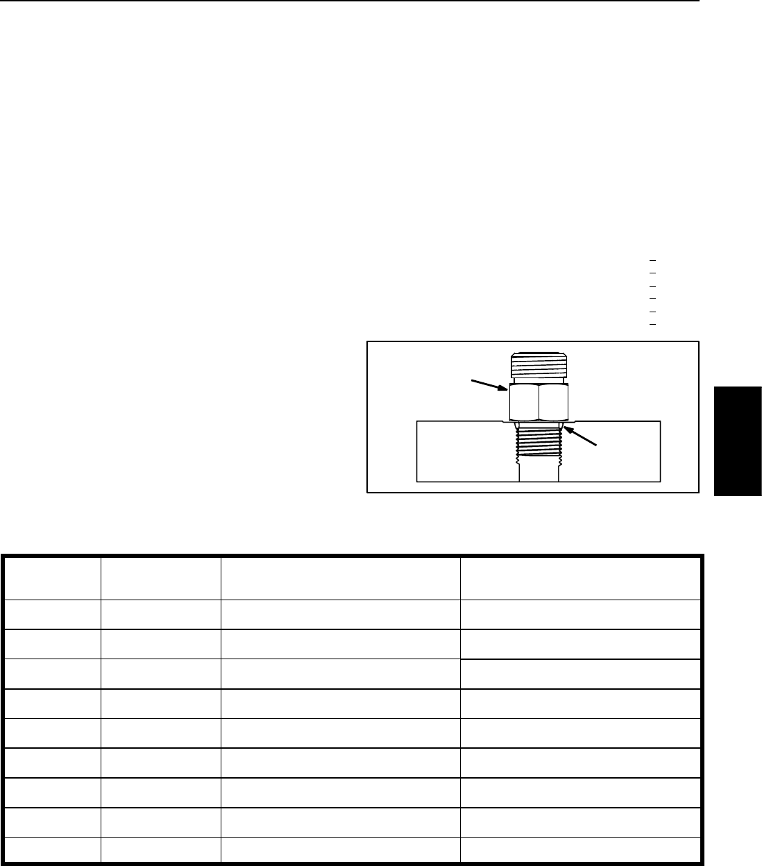
Groundsmaster 4100--D/4110--D Hydraulic SystemPage 4 -- 7
Hydraulic Fitting Installation (SAE Straight Thread O--Ring Fitting into Component Port)
Non--Adjustable Fitting (Fig. 6)
1. Make sure all threads and sealing surfaces of fitting
and component port are free of burrs, nicks, scratches
or any foreign material.
2. As a preventative measure against leakage, it is rec-
ommended that the O--ring be replaced any time the
connection is opened.
3. Lightly lubricate the O--ring with clean hydraulic oil.
Fitting threads should be clean with no lubricant applied.
IMPORTANT: Before installing fitting into port, de-
termine port material. If fitting is to be installed into
an aluminum port, installation torque is reduced.
4. Install the fitting into the port. Then, use a torque
wrench and socket to tighten the fitting to the recom-
mended installation torque shown in Figure 7.
NOTE: Use of an offset wrench (e.g. crowfoot wrench)
will affect torque wrench calibration due to the effective
length change of the torque wrench. Tightening torque
when using a torque wrench with an offset wrench will
be less than the recommended installation torque. See
UsingaTorqueWrenchwithanOffsetWrenchinthe
Torque Specifications section of Chapter 2 -- Product
Records and Maintenance to determine necessary con-
version information.
5. If a torque wrench is not available, or if space at the
port prevents use of a torque wrench, an alternate meth-
od of assembly is the Flats From Finger Tight (F.F.F.T.)
method.
A. Install the fitting into the port and tighten it down
full length until finger tight.
B. If port material is steel, tighten the fitting to the
listed F.F.F.T. If port material is aluminum, tighten fit-
ting to 60% of listed F.F.F.T.
Siz e F.F.F.T.
4 (1/4 in. nominal hose or tubing) 1.00 + 0.25
6(3/8in.) 1.50+0.25
8(1/2in.) 1.50+0.25
10 (5/8 in.) 1.50 + 0.25
12 (3/4 in.) 1.50 + 0.25
16 (1 in.) 1.50 + 0.25
Figure 6
O--ring
Fitting
Fitting
Dash Size
Fitting Port Side
Thread Size
Installation Torque Into
Steel Port
Installation Torque Into
Aluminum Port
47/16 -- 20 15to19ft--lb(21to25N--m) 9to11ft--lb(13to15N--m)
51/2 -- 20 18to22ft--lb(25to29N--m) 11to15ft--lb(15to20N--m)
69/16 -- 18 34to42ft--lb(47to56N--m) 20to26ft--lb(28to35N--m)
83/4 -- 16 58to72ft--lb(79to97N--m) 35to43ft--lb(48to58N--m)
10 7/8 -- 14 99 to 121 ft--lb (135 to 164 N--m) 60 to 74 ft--lb (82 to 100 N--m)
12 11/16--12 134 to 164 ft--lb (182 to 222 N--m) 81 to 99 ft--lb (110 to 134 N--m)
14 13/16--12 160 to 196 ft--lb (217 to 265 N--m) 96to118ft--lb(131to160N--m)
16 15/16--12 202 to 248 ft--lb (274 to 336 N--m) 121 to 149 ft--lb (165 to 202 N--m)
20 15/8--12 247 to 303 ft--lb (335 to 410 N--m) 149 to 183 ft--lb (202 to 248 N--m)
Figure 7
Hydraulic
System
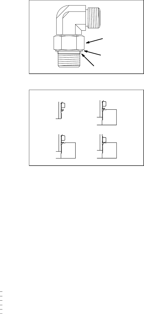
Groundsmaster 4100--D/4110--DHydraulic System Page 4 -- 8
Adjustable Fitting (Fig. 8)
1. Make sure all threads and sealing surfaces of fitting
and component port are free of burrs, nicks, scratches
or any foreign material.
2. As a preventative measure against leakage, it is rec-
ommended that the O--ring be replaced any time the
connection is opened.
3. Lightly lubricate the O--ring with clean hydraulic oil.
Fitting threads should be clean with no lubricant applied.
4. Turn back the lock nut as far as possible. Make sure
the back up washer is not loose and is pushed up as far
aspossible(Step1inFigure9).
IMPORTANT: Before installing fitting into port, de-
termine port material. If fitting is to be installed into
an aluminum port, installation torque is reduced.
5. Install the fitting into the port and tighten finger tight
until the washer contacts the face of the port (Step 2 in
Figure 9). Make sure that the fitting does not bottom in
the port during installation.
6. To put the fitting in the desired position, unscrew it by
therequiredamounttoalignfittingwithincominghose
or tube, but no more than one full turn (Step 3 in Figure
9).
7. Hold the fitting in the desired position with a wrench
and use a torque wrench to tighten the lock nut to the
recommended installation torque shown in Figure 7.
This tightening process will require the use of an offset
wrench (e.g. crowfoot wrench). Use of an offset wrench
will affect torque wrench calibration due to the effective
length change of the torque wrench. Tightening torque
when using a torque wrench with an offset wrench will
be lower than the listed installation torque (see Using a
Torque Wrench with an Offset Wrench in the Torque
Specifications section of Chapter 2 -- Product Records
and Maintenance).
8. If a torque wrench is not available, or if space at the
port prevents use of a torque wrench, an alternate meth-
od of assembly is the Flats From Finger Tight (F.F.F.T.)
method. Hold the fitting in the desired position with a
wrench and, if port material is steel, tighten the lock nut
withasecondwrenchtothelistedF.F.F.T.(Step4inFig-
ure 9). If port material is aluminum, tighten fitting to 60%
of listed F.F.F.T.
Si z e F.F. F. T.
4 (1/4 in. nominal hose or tubing) 1.00 + 0.25
6(3/8in.) 1.50+0.25
8(1/2in.) 1.50+0.25
10 (5/8 in.) 1.50 + 0.25
12 (3/4 in.) 1.50 + 0.25
16 (1 in.) 1.50 + 0.25
Figure 8
Lock Nut
Back--up Washer
O--ring
Figure 9
Step 3Step 1
Step 2 Step 4
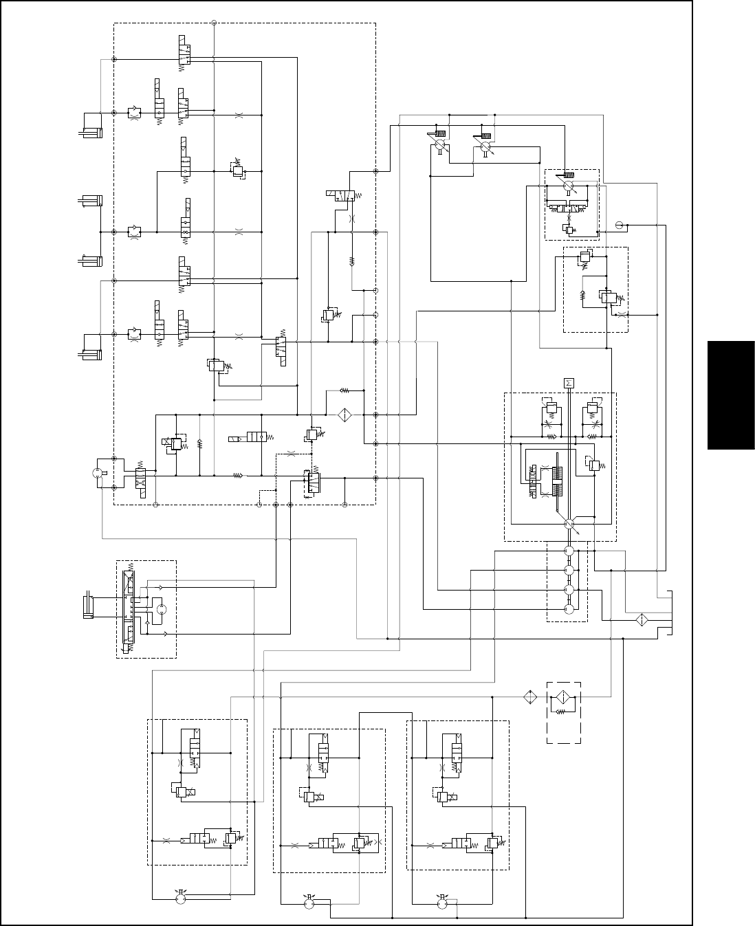
Groundsmaster 4100--D/4110--D Hydraulic SystemPage 4 -- 9
Hydraulic Schematic
NOTE: A larger hydraulic schematic is
included in Chapter 10 -- Foldout Drawings
S10
RV1
CV1
S2
S4
S5
PRV
P4 CH2 P3
EC
CF
LS
S3
OR1
C3
OR4
.040
S6
OR5
.070
C4 C2 C5
RV2
2500 PSI
S7
S9
S8
C6
M1 M2
CH1
CV3
CH4
OR2
.063
OR6
.063
OR3
.070
OR7
.070
T2SP
CH3
G2
G4
CV4
PR
G1
G3
3250
PSI
1350
PSI
3.3 GPM
4.4 GPM
15.2 GPM
310
PSI
4PSI
4PSI .030
OR9
S1
3300 PSI
RV3 S12
15.2 GPM
S11
CV2
4PSI
1.17 CID 3000 PSI
P1
P1
P1
P2
P2
P2
M1
M2
LC1
PRV
PD
CD
RV
2000 PSI
M1
M2
LC1
PRV
PD
RV
3000 PSI
M1
M2
LC1
PRV
PD
RV
CD
CD
LEFT DECK
CENTER DECK
RIGHT DECK
50 PSI
1.17 CID
1.17 CID
6.1 CID
0.625” ROD
EP
LR
T
STEERING
CYLINDER 0.51 CID
VALVE
PR
380 PSI RV
650 PSI
.050
CV
T
P2
M8
CH
OR1
250 psi
2.14 CID /
1.16 CID
600 PSI
600 PSI
600 PSI
.030”
200 PSI
2.75
CID
1.37
CID
1.37
CID
4350 PSI
5000 PSI
.025
.025
.025
.0315
G
G
G
2.00” BORE
4.20” STROKE
1.50” BORE
3.08” STROKE
CENTER DECK
RAM CYLINDERS
1.4 CID/
0.79 CID
1.4 CID/
0.79 CID
60 PSI
80
PSI
30.5 GPM
0.4
CID
0.3
CID ENGINE
REAR
TRACTION
.0315
1.125” ROD
2.50” BORE
6.50” STROKE
WING DECK
RIGHT
1.125” ROD
2.50” BORE
6.50” STROKE
WING DECK
LEFT
Hydraulic
System
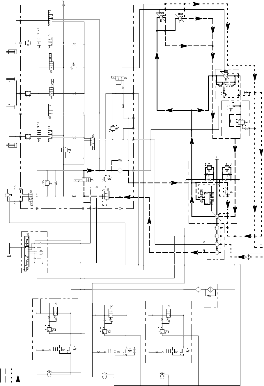
Groundsmaster 4100--D/4110--DHydraulic System Page 4 -- 10
Hydraulic Flow Diagrams
Traction Circuit: LOW Speed (Mow) (Forward Shown)
Working Pressure
Low Pressure (Charge)
Return or Suction
Flow
Groundsmaster 4100--D/4110--D
S10
RV1
CV1
S2
S4
S5
PRV
P4 CH2 P3
EC
CF
LS
S3
OR1
C3
OR4
.040
S6
OR5
.070
C4 C2 C5
RV2
S7
S9
S8
C6
M1 M2
CH1
CV3
CH4
OR2
.063
OR6
.063
OR3
.070
OR7
.070
T2SPCH3
G2
G4
CV4
PR
G1
G3
3250
PSI
1350
PSI
3.3 GPM
4.4 GPM
15.2 GPM
4 PSI
4PSI
.030
OR9
S1
3300 PSI
RV3
S12
S11
CV2
4 PSI
1.17 CID 3000 PSI
P1
P1
P1
P2
P2
P2
M1
M2
LC1
PRV
PD
CD
RV
2000 PSI
M1
M2
LC1
PRV
PD
RV
3000 PSI
M1
M2
LC1
PRV
PD
RV
CD
CD
LEFT DECK
CENTER DECK
RIGHT DECK
50 PSI
1.17 CID
1.17 CID
6.1 CID
EP
LR
T
STEERING
CYLINDER
0.51 CID
PR
380 PSI
RV
650 PSI
.050
CV
T
P2
M8
CH
OR1
250 PSI
2.14 CID /
1.16 CID
600 PSI
600 PSI
600 PSI
.030”
200 PSI
4350 PSI
5000 PSI
.025
.025
.025
.0315 .0315
0.4
CID
0.3 1.37 1.37
CID CID CID
2.75
CID
REAR
TRACTION
MANIFOLD
ENGINE
30.5
GPM
80
PSI 60
PSI
310
PSI
1.50” BORE
3.08” STROKE
RAM CYLINDERS
CENTER DECK
2.00” BORE
4.20” STROKE
0.625” ROD
GG
G
GG
G
COMBINATION MANIFOLD
STEERING
CONTROL
VALVE
G
G
G
2500 PSI
15.2 GPM
1.4 CID/
0.79 CID
1.4 CID/
0.79 CID
1.125” ROD
2.50” BORE
6.50” STROKE
WING DECK
RIGHT
1.125” ROD
2.50” BORE
6.50” STROKE
WING DECK
LEFT

Groundsmaster 4100--D/4110--D Hydraulic SystemPage 4 -- 11
Traction Circuit: LOW Speed (Mow)
The traction circuit piston pump is a variable displace-
ment pump that is directly coupled to the engine fly-
wheel. This pump utilizes an integral electro--hydraulic
servo piston assembly that controls the rate and direc-
tion of hydraulic flow. Pressing the traction pedal rotates
a potentiometer that provides an input to the machine
TEC controller. The controller in turn sends a corre-
sponding PWM (Pulse Width Modulation) output to the
electronic pump control to rotate the pump swash plate
accordingly to control pump output and direction. Trac-
tion circuit oil is directed to the dual displacement front
wheel and rear axle motors. Operating pressure on the
high pressure side of the closed traction circuit loop is
determined by the amount of load developed at the
wheel and axle motors. As the traction load increases,
circuit pressure can increase to relief valve settings:
4350 PSI (300 bar) in forward and 5000 PSI (345 bar)
in reverse. If traction circuit pressure exceeds the relief
setting, oil flows through the piston pump relief valve to
the low pressure side of the closed loop traction circuit.
Traction circuit pressure can be measured at test ports
attached to the sides of the piston pump. The forward
traction port is on the right side of the pump and the re-
verse traction port is on the left side.
Front wheel and rear axle motors are positive displace-
ment, two speed variable motors that allow operation in
either LOW (mow) or HI (transport) speed. The motors
are spring biased to maximum displacement for LOW
speed and are hydraulically shifted to minimum dis-
placement for HI speed. The rear axle motor includes a
flushing valve that bleeds off a small amount of hydraulic
oil for cooling of the closed loop traction circuit. The
charge circuit replaces oil that is bled from the circuit by
theflushingvalve.
The Smart PowerTM feature prevents the engine from
slowing down in heavy load conditions (e.g. cutting tall
grass) by automatically decreasing the traction speed if
necessary. With a reduced traction speed, the cutting
blades can continue to be at optimum speed.
Traction circuit components use small amounts of hy-
draulic oil for internal lubrication. Fluid is designed to
leak across traction pump and motor components into
the case drain. This leakage results in the loss of hy-
draulic oil from the closed loop traction circuit that is re-
placed by the charge circuit. The gear pump sections
that supply the steering, cooling fan and lift/lower cir-
cuits also provide charge circuit oil.
Gear pump flow for the charge circuit is directed through
the oil filter and to the low pressure side of the closed
loop traction circuit. Charge pressure is limited to 250
PSI (17 bar) by a relief valve located in the piston pump.
An optional traction circuit flow divider splits traction
pump hydraulic flow between the front wheel motors
(approximately 43%) and rear axle motor (approximate-
ly 57%) to prevent excessive circuit flow going to a spin-
ning wheel.
Forward Direction
With the armrest console HI/LOW speed switch in the
LOW speed (mow) position, solenoid valve (S12) in the
combination manifold is not energized which keeps the
front wheel motors and rear axle motor at their maxim-
um displacement. With the motors at maximum dis-
placement, a lower traction speed is available for
mowing conditions.
When the HI/LOW switch is in the LOW speed (mow)
position and the traction pedal is pushed in the forward
direction, oil from the piston pump is directed to the front
wheel motors and rear axle motor through a parallel sys-
tem. Oil flow to the front wheel motors drives the motors
in the forward direction and then returns to the piston
pump. Oil flow to the rear axle motor drives the motor in
the forward direction. Oil returning from the axle motor
entersthereartractionmanifoldattheM8port.Flowby-
passes the PR cartridge through the CV check valve, out
manifold port P2 and returns to the piston pump.
When going down a hill, the tractor becomes an over--
running load that drives the front wheel and rear axle
motors. In this condition, the rear axle motor could lock
up as the oil pumped from the motor increases pressure
as it returns to the piston pump. To prevent rear wheel
lock up, an adjustable relief valve (RV) in the rear trac-
tion manifold reduces rear axle motor pressure created
in down hill, dynamic braking conditions.
Reverse Direction
The traction circuit operates essentially the same in re-
verse LOW speed (mow) as it does in the forward direc-
tion. However, the flow through the circuit is reversed.
Oil flow from the piston pump is directed to the front
wheel motors and also to the rear traction manifold. The
oil to the front wheel motors drives them in the reverse
direction and then returns to the piston pump. The oil to
the rear traction manifold enters the manifold at port P2
and flows through pressure reducing valve (PR) which
limitsthedownstreampressuretotherearaxlemotor
to 380 PSI (26 bar) so the rear wheels will not scuff the
turf during reverse operation. This reduced pressure
flow is directed out rear traction manifold port M8 to drive
the rear axle motor in reverse. Return oil from the rear
motor returns to the piston pump.
Hydraulic
System
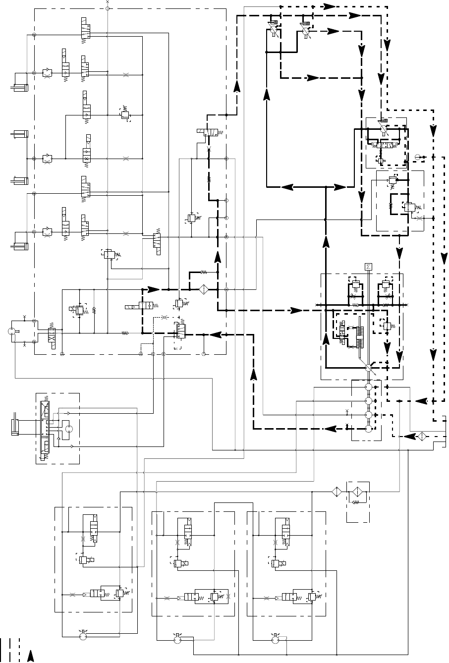
Groundsmaster 4100--D/4110--DHydraulic System Page 4 -- 12
Traction Circuit: HI Speed (Transport) (Forward Shown)
Working Pressure
Low Pressure (Charge)
Return or Suction
Flow
Groundsmaster 4100--D/4110--D
S10
RV1
CV1
S2
S4
S5
PRV
P4 CH2 P3
EC
CF
LS
S3
OR1
C3
OR4
.040
S6
OR5
.070
C4 C2 C5
RV2
S7
S9
S8
C6
M1 M2
CH1
CV3
CH4
OR2
.063
OR6
.063
OR3
.070
OR7
.070
T2SPCH3
G2
G4
CV4
PR
G1
G3
3250
PSI
1350
PSI
3.3 GPM
4.4 GPM
4PSI
4 PSI
.030
OR9
S1
3300 PSI
RV3 S12
S11
CV2
4PSI
1.17 CID 3000 PSI
P1
P1
P1
P2
P2
P2
M1
M2
LC1
PRV
PD
CD
RV
2000 PSI
M1
M2
LC1
PRV
PD
RV
3000 PSI
M1
M2
LC1
PRV
PD
RV
CD
CD
LEFT DECK
CENTER DECK
RIGHT DECK
50 PSI
1.17 CID
1.17 CID
6.1 CID
EP
LR
T
STEERING
CYLINDER
0.51 CID
PR
380 PSI
RV
650 PSI
.050
CV
T
P2
M8
CH
OR1
250 PSI
2.14 CID /
1.16 CID
600 PSI
600 PSI
600 PSI
.030”
200 PSI
4350 PSI
5000 PSI
.025
.025
.025
.0315 .0315
0.4
CID
0.3 1.37 1.37
CID CID CID
2.75
CID
REAR
TRACTION
MANIFOLD
ENGINE
30.5
GPM
1.4 CID/
0.79 CID
80
PSI 60
PSI
310
PSI
1.50” BORE
3.08” STROKE
RAM CYLINDERS
CENTER DECK
2.00” BORE
4.20” STROKE
0.625” ROD
GG
G
GG
G
COMBINATION MANIFOLD
STEERING
CONTROL
VALVE
G
G
G
2500 PSI
1.4 CID/
0.79 CID
15.2 GPM
15.2 GPM
1.125” ROD
2.50” BORE
6.50” STROKE
WING DECK
RIGHT
1.125” ROD
2.50” BORE
6.50” STROKE
WING DECK
LEFT

Groundsmaster 4100--D/4110--D Hydraulic SystemPage 4 -- 13
Traction Circuit: HI Speed (Transport)
The traction circuit piston pump is a variable displace-
ment pump that is directly coupled to the engine fly-
wheel. This pump utilizes an integral electro--hydraulic
servo piston assembly that controls the rate and direc-
tion of hydraulic flow. Pressing the traction pedal rotates
a potentiometer that provides an input to the machine
TEC controller. The controller in turn sends a corre-
sponding PWM (Pulse Width Modulation) output to the
electronic pump control to rotate the pump swash plate
accordingly to control pump output and direction. Trac-
tion circuit oil is directed to the dual displacement front
wheel and rear axle motors. Operating pressure on the
high pressure side of the closed traction circuit loop is
determined by the amount of load developed at the
wheel and axle motors. As the traction load increases,
circuit pressure can increase to relief valve settings:
4350 PSI (300 bar) in forward and 5000 PSI (345 bar)
in reverse. If traction circuit pressure exceeds the relief
setting, oil flows through the piston pump relief valve to
the low pressure side of the closed loop traction circuit.
Traction circuit pressure can be measured at test ports
attached to the sides of the piston pump. The forward
traction port is on the right side of the pump and the re-
verse traction port is on the left side.
Front wheel and rear axle motors are positive displace-
ment, two speed variable motors that allow operation in
either LOW (mow) or HI (transport) speed. The motors
are spring biased to maximum displacement for LOW
speed and are hydraulically shifted to minimum dis-
placement for HI speed. The rear axle motor includes a
flushing valve that bleeds off a small amount of hydraulic
oil for cooling of the closed loop traction circuit. The
charge circuit replaces oil that is bled from the circuit by
theflushingvalve.
Traction circuit components use small amounts of hy-
draulic oil for internal lubrication. Fluid is designed to
leak across traction pump and motor components into
the case drain. This leakage results in the loss of hy-
draulic oil from the closed loop traction circuit that is re-
placed by the charge circuit. The gear pump sections
that supply the steering, cooling fan and lift/lower cir-
cuits also provide charge circuit oil.
Gear pump flow for the charge circuit is directed through
the oil filter and to the low pressure side of the closed
loop traction circuit. Charge pressure is limited to 250
PSI (17 bar) by a relief valve located in the piston pump.
An optional traction circuit flow divider splits traction
pump hydraulic flow between the front wheel motors
(approximately 43%) and rear axle motor (approximate-
ly 57%) to prevent excessive circuit flow going to a spin-
ning wheel.
Forward Direction
WiththearmrestconsoleHI/LOWspeedswitchintheHI
speed (transport) position, solenoid valve (S12) in the
combination manifold is energized. The energized
solenoid valve directs charge pressure to shift the front
wheel motors and rear axle motor to their minimum dis-
placement. With the motors at their minimum displace-
ments, a higher traction speed is available for transport.
When the HI/LOW switch is in the HI speed (transport)
position and the traction pedal is pushed in the forward
direction, oil from the piston pump is directed to the front
wheel motors and rear axle motor through a parallel sys-
tem. Oil flow to the front wheel motors drives the motors
in the forward direction and then returns to the piston
pump. Oil flow to the rear axle motor drives the motor in
the forward direction. Oil returning from the axle motor
entersthereartractionmanifoldattheM8port.Flowby-
passes the PR cartridge through the CV check valve, out
manifold port P2 and returns to the piston pump.
When going down a hill, the tractor becomes an over--
running load that drives the front wheel and rear axle
motors. In this condition, the rear axle motor could lock
up as the oil pumped from the motor increases pressure
as it returns to the piston pump. To prevent rear wheel
lock up, an adjustable relief valve (RV) in the rear trac-
tion manifold reduces rear axle motor pressure created
in down hill, dynamic braking conditions.
Reverse Direction
The traction circuit operates essentially the same in re-
verse HI speed (transport) as it does in the forward
direction. However, the flow through the circuit is re-
versed. Oil flow from the piston pump is directed to the
front wheel motors and also to the rear traction manifold.
The oil to the front wheel motors drives them in the re-
verse direction and then returns to the piston pump. The
oil to the rear traction manifold enters the rear traction
manifold at port P2 and flows through pressure reducing
valve (PR) which limits the down stream pressure to the
rear axle motor to 380 PSI (26 bar) so the rear wheels
will not scuff the turf during reverse operation. This re-
duced pressure flow is directed out rear traction mani-
fold port M8 to drive the rear axle motor in reverse.
Return oil from the rear motor returns to the piston
pump.
Hydraulic
System
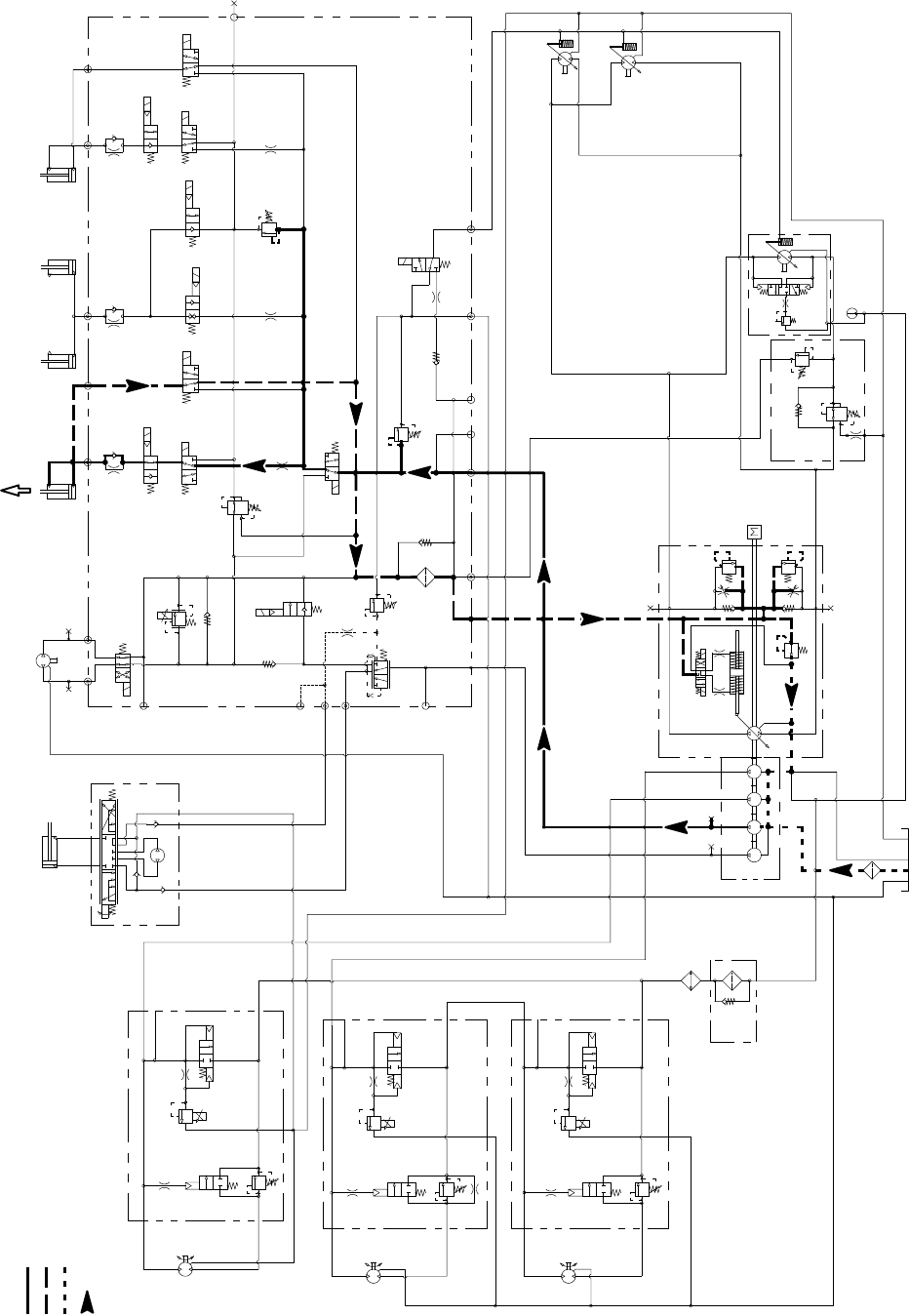
Groundsmaster 4100--D/4110--DHydraulic System Page 4 -- 14
Lower Cutting Deck (LH Wing Deck Shown)
Working Pressure
Low Pressure (Charge)
Return or Suction
Flow
Groundsmaster 4100--D/4110--D
S10
RV1
CV1
S2
S4
S5
PRV
P4 CH2 P3
EC
CF
LS
S3
OR1
C3
OR4
.040
S6
OR5
.070
C4 C2 C5
RV2
S7
S9
S8
C6
M1 M2
CH1
CV3
CH4
OR2
.063
OR6
.063
OR3
.070
OR7
.070
T2SPCH3
G2
G4
CV4
PR
G1
G3
3250
PSI
1350
PSI
3.3 GPM
4.4 GPM
4PSI
4PSI
.030
OR9
S1
3300 PSI
RV3 S12
S11
CV2
4 PSI
1.17 CID 3000 PSI
P1
P1
P1
P2
P2
P2
M1
M2
LC1
PRV
PD
CD
RV
2000 PSI
M1
M2
LC1
PRV
PD
RV
3000 PSI
M1
M2
LC1
PRV
PD
RV
CD
CD
LEFT DECK
CENTER DECK
RIGHT DECK
50 PSI
1.17 CID
1.17 CID
6.1 CID
EP
LR
T
STEERING
CYLINDER
0.51 CID
PR
380 PSI
RV
650 PSI
.050
CV
T
P2
M8
CH
OR1
250 PSI
2.14 CID /
1.16 CID
600 PSI
600 PSI
600 PSI
.030”
200 PSI
4350 PSI
5000 PSI
.025
.025
.025
.0315 .0315
0.4
CID
0.3 1.37 1.37
CID CID CID
2.75
CID
REAR
TRACTION
MANIFOLD
ENGINE
30.5
GPM
80
PSI 60
PSI
310
PSI
1.50” BORE
3.08” STROKE
RAM CYLINDERS
CENTER DECK
2.00” BORE
4.20” STROKE
0.625” ROD
GG
G
GG
G
COMBINATION MANIFOLD
STEERING
CONTROL
VALVE
EXTENDING
G
G
G
2500 PSI
1.4 CID/
0.79 CID
15.2 GPM
15.2 GPM
1.4 CID/
0.79 CID
1.125” ROD
2.50” BORE
6.50” STROKE
WING DECK
RIGHT
1.125” ROD
2.50” BORE
6.50” STROKE
WING DECK
LEFT

Groundsmaster 4100--D/4110--D Hydraulic SystemPage 4 -- 15
Lower Cutting Deck
A four section gear pump is coupled to the piston (trac-
tion) pump. The third gear pump section supplies hy-
draulic flow to the lift/lower circuit, the engine cooling fan
circuit and the traction charge circuit.
Each of the cutting deck sections (main, right wing and
left wing) can be lowered independently with the use of
three (3) switches on the armrest console. Pressing the
front of a lift switch provides an input for the TEC control-
ler to lower the cutting deck or wing deck. The controller
provides electrical outputs to solenoids in the combina-
tion control manifold to allow appropriate manifold valve
shift that causes a cutting deck to lower.
A relief valve (RV2) located in the combination control
manifold limits lift/lower circuit pressure to 2500 PSI
(172 bar). An adjustable pressure relieving valve (PR)
in the combination manifold maintains back pressure
(counterbalance) on the deck lift cylinders to allow some
of the cutting deck weight to be transferred to the traction
unit to improve traction.
When the lift/lower circuit is not being used (all lift
switches in the neutral position), solenoid valve S1 in the
combination manifold is not energized and gear pump
section oil flow is directed toward the engine cooling fan
motor.
NOTE: To lower a cutting deck, the operator must be in
the operator seat and the traction speed must be in the
LOW speed (mow) position.
Lower Cutting Deck
To lower the cutting deck, the front of the center console
liftswitchisdepressed.Theswitchsignalisaninputto
the TEC controller which provides an electrical output to
solenoid valve S6 in the combination manifold. The en-
ergized solenoid valve shifts to allow a passage for oil
flow from the barrel end of the cutting deck lift cylinders.
The weight of the cutting deck causes the cutting deck
lift cylinders to retract and lower the cutting deck. Check
orifice OR5 (.070) under the manifold fitting in port C2
controls the lowering speed of the cutting deck. Oil from
the retracting cylinders is directed to pressure reducing
valve (PR). As return oil pressure increases, the PR
valve will shift to direct circuit oil to the oil filter and then
to the traction charge circuit.
Lower Right Wing Deck
Tolowertherightwingdeck,thefrontoftherightconsole
lift switch is pushed as an input to the TEC controller.
The controller provides an electrical output to solenoid
valves S1, S8 and S9 in the combination manifold. The
energized solenoid valves shift to allow a passage for
circuit oil flow to the rod end of the right wing deck lift cyl-
inder. Shifted S1 allows gear pump section oil flow to be
available for the lift/lower circuits. Shifted S8 allows an
oilpathtotherodendoftherightliftcylindertoretract
the lift cylinder and lower the right wing deck. Check ori-
fice OR7 (.070) controls the lowering speed of the wing
deck. Oil from the retracting cylinder is directed through
energized S9, de--energized S7 and then to pressure re-
ducing valve (PR). As return oil pressure increases, the
PR valve will shift to direct circuit oil to the oil filter and
thentothetractionchargecircuit.
Lower Left Wing Deck
To lower the left wing deck, the front of the left console
lift switch is pushed as an input to the TEC controller.
The controller provides an electrical output to solenoid
valves S1, S3 and S4 in the combination manifold. The
energized solenoid valves shift to allow a passage for
circuit oil flow to the left deck lift cylinder rod end. Shifted
S1 allows gear pump section oil flow to be available for
the lift/lower circuits. ShiftedS3allowsanoilpathtothe
rod end of the left lift cylinder to retract the lift cylinder
and lower the left cutting deck. Check orifice OR3 (.070)
controls the lowering speed of the cutting deck. Oil from
the retracting cylinder is directed through energized S4,
de--energized S2 and then to pressure reducing valve
(PR). As return oil pressure increases, the PR valve will
shift to direct circuit oil to the oil filter and then to the trac-
tion charge circuit.
Cutting Deck Float
Cutting deck float allows the fully lowered cutting deck
to follow ground surface contours. Combination man-
ifold solenoid valves S4 (left wing deck), S6 (center
deck) and S9 (right wing deck) are energized when the
deck is fully lowered. These energized solenoids pro-
vide an oil passage to and from the lift cylinders to allow
cylinder and cutting deck movement while mowing.
Counterbalance pressure (PR) will affect deck float op-
eration.
NOTE: If a deck is already fully lowered when the igni-
tion switch is moved from OFF to RUN, the deck will not
be in float until the appropriate deck lift/lower switch is
momentarily pressed to lower.
Hydraulic
System
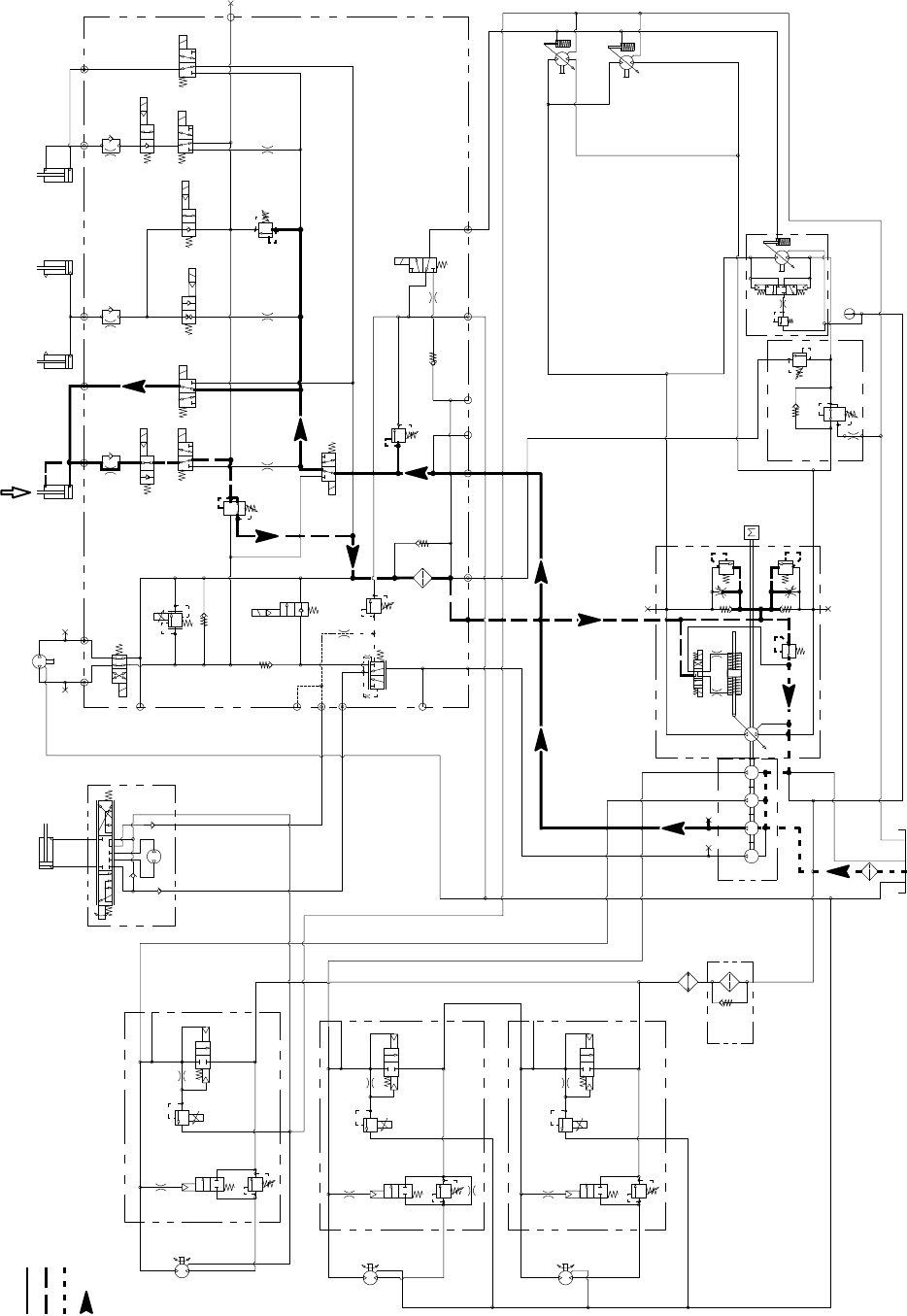
Groundsmaster 4100--D/4110--DHydraulic System Page 4 -- 16
Raise Cutting Deck (LH Wing Deck Shown)
Working Pressure
Low Pressure (Charge)
Return or Suction
Flow
Groundsmaster 4100--D/4110--D
S10
RV1
CV1
S2
S4
S5
PRV
P4 CH2 P3
EC
CF
LS
S3
OR1
C3
OR4
.040
S6
OR5
.070
C4 C2 C5
RV2
S7
S9
S8
C6
M1 M2
CH1
CV3
CH4
OR2
.063
OR6
.063
OR3
.070
OR7
.070
T2SPCH3
G2
G4
CV4
PR
G1
G3
3250
PSI
1350
PSI
3.3 GPM
4.4 GPM
4PSI
4PSI
.030
OR9
S1
3300 PSI
RV3 S12
S11
CV2
4 PSI
1.17 CID 3000 PSI
P1
P1
P1
P2
P2
P2
M1
M2
LC1
PRV
PD
CD
RV
2000 PSI
M1
M2
LC1
PRV
PD
RV
3000 PSI
M1
M2
LC1
PRV
PD
RV
CD
CD
LEFT DECK
CENTER DECK
RIGHT DECK
50 PSI
1.17 CID
1.17 CID
6.1 CID
EP
LR
T
STEERING
CYLINDER
0.51 CID
1.125” ROD
PR
380 PSI
RV
650 PSI
.050
CV
T
P2
M8
CH
OR1
250 PSI
2.14 CID /
1.16 CID
600 PSI
600 PSI
600 PSI
.030”
200 PSI
4350 PSI
5000 PSI
.025
.025
.025
.0315 .0315
0.4
CID
0.3 1.37 1.37
CID CID CID
2.75
CID
REAR
TRACTION
MANIFOLD
ENGINE
30.5
GPM
80
PSI 60
PSI
310
PSI
2.50” BORE
6.50” STROKE
1.50” BORE
3.08” STROKE
RAM CYLINDERS
CENTER DECK
1.125” ROD
2.50” BORE
6.50” STROKE
2.00” BORE
4.20” STROKE
0.625” ROD
GG
G
GG
G
COMBINATION MANIFOLD
STEERING
CONTROL
VALVE
WING DECK
RETRACTING
G
G
G
2500 PSI
15.2 GPM
1.4 CID/
0.79 CID
1.4 CID/
0.79 CID
15.2 GPM
RIGHT
WING DECK
LEFT
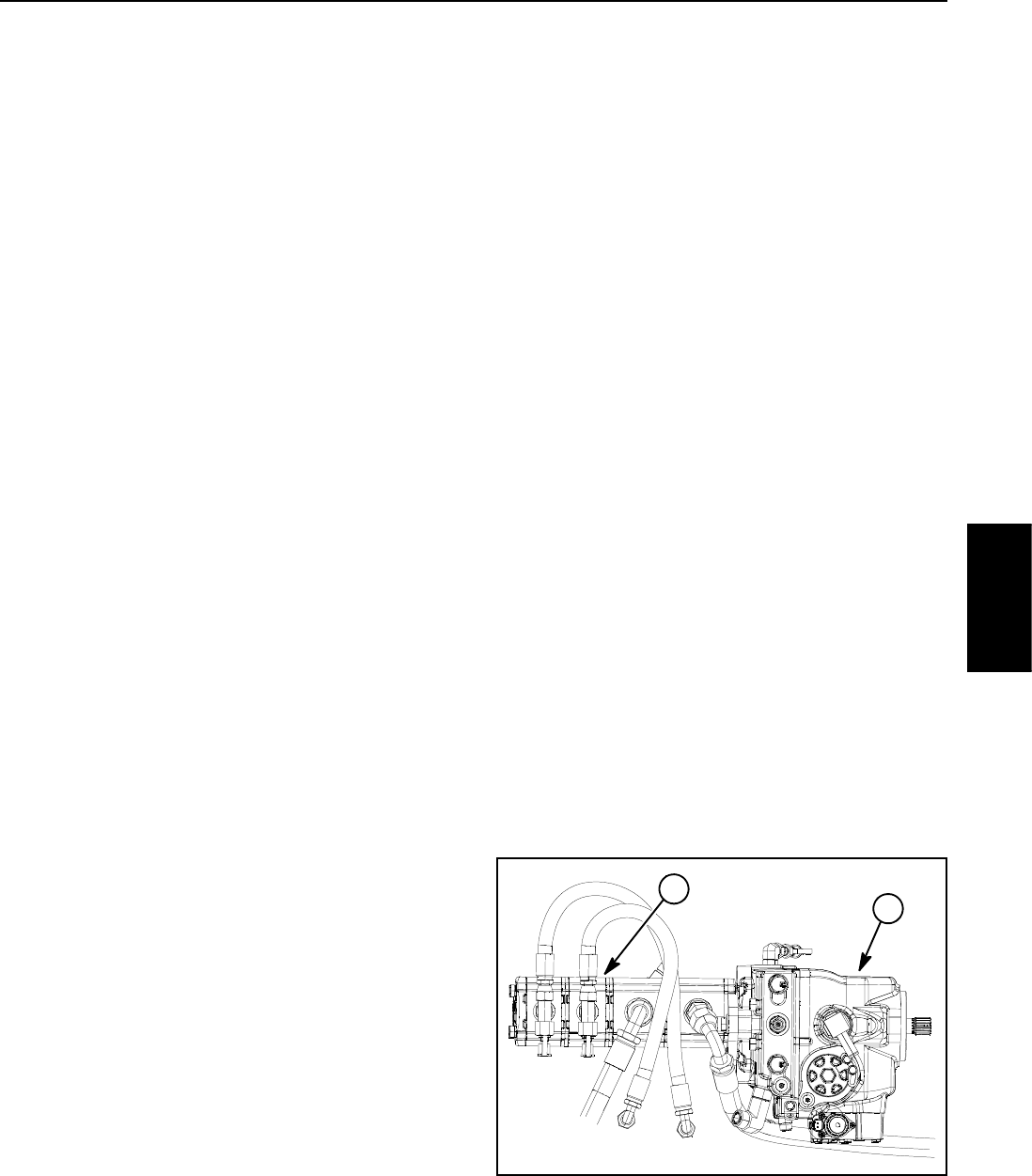
Groundsmaster 4100--D/4110--D Hydraulic SystemPage 4 -- 17
Raise Cutting Deck
A four section gear pump is coupled to the piston (trac-
tion) pump. The third gear pump section supplies hy-
draulic flow to the lift/lower circuit, the engine cooling fan
circuit and the traction charge circuit.
Each of the cutting deck sections (main, right wing and
left wing) can be raised independently with the use of
three (3) switches on the armrest console. Pressing the
rear of a lift switch provides an input for the TEC control-
ler to raise the cutting deck or wing deck. The controller
provides electrical outputs to solenoids in the combina-
tion control manifold to allow appropriate manifold valve
shift that causes a cutting deck to raise.
A relief valve (RV2) located in the combination control
manifold limits lift/lower circuit pressure to 2500 PSI
(172 bar). An adjustable pressure relieving valve (PR)
in the combination manifold maintains back pressure
(counterbalance) on the deck lift cylinders to allow some
of the cutting deck weight to be transferred to the traction
unit to improve traction.
When the lift/lower circuit is not being used (all lift
switches in the neutral position), solenoid valve S1 in the
combination manifold is not energized and gear pump
section oil flow is directed toward the engine cooling fan
motor.
NOTE: To raise a cutting deck, the operator must be in
the operator seat.
Raise Center Cutting Deck
To raise the cutting deck, the rear of the center console
liftswitchisdepressed.Theswitchsignalisaninputto
the TEC controller which provides an electrical output to
solenoid valves S1 and S5 in the combination manifold.
The energized solenoid valves shift to allow a passage
for circuit oil flow to the barrel end of the cutting deck lift
cylinders. Shifted S1 allows gear pump section oil flow
to be available for the lift/lower circuits. Shifted S5 allows
an oil path to the barrel end of the front lift cylinders caus-
ing the lift cylinders to extend and raise the cutting deck.
Check orifice OR5 under the fitting in manifold port C2
allows oil flow to bypass the orifice when the deck is rais-
ing. An orifice in manifold port OR4 (.040) exists to con-
trol the raise speed of the cutting deck.
Raise Right Wing Deck
To raise the right wing deck, the rear of the right console
lift switch is depressed as an input to the TEC controller.
The controller provides an electrical output to solenoid
valves S1, S7 and S9 in the combination manifold. The
energized solenoid valves shift to allow a passage for
circuit oil flow to the barrel end of the right wing deck lift
cylinder. Shifted S1 allows gear pump section oil flow to
be available for the lift/lower circuits. Shifted S7 and S9
allow an oil path to the barrel end of the right lift cylinder
to extend the lift cylinder and raise the right wing deck.
Orifice OR6 (.063) controls the raising of the wing deck.
Check orifice OR7 is bypassed when raising the right
wing deck. Oil from the extending cylinder is directed
through S8 (de--energized), to the oil filter and then to
thetractionchargecircuit.
Raise Left Wing Deck
To raise the left wing deck, the rear of the left console lift
switch is depressed as an input to the TEC controller.
The controller provides an electrical output to solenoid
valves S1, S2 and S4 in the combination manifold. The
energized solenoid valves shift to allow a passage for
circuit oil flow to the barrel end of the left wing deck lift
cylinder. Shifted S1 allows gear pump section oil flow to
be available for the lift/lower circuits. Shifted S2 and S4
allow an oil path to the barrel end of the right lift cylinder
to extend the lift cylinder and raise the right wing deck.
Orifice OR2 (.063) controls the raising of the wing deck.
Check orifice OR3 is bypassed when raising the left
wing deck. Oil from the extending cylinder is directed
through S3 (de--energized), to the oil filter and then to
thetractionchargecircuit.
1. Piston (traction) pump 2. 3rd gear pump section
Figure 10
2
1
Hydraulic
System
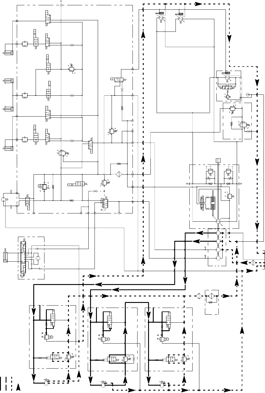
Groundsmaster 4100--D/4110--DHydraulic System Page 4 -- 18
Mow Circuit (All Deck Motors Rotating)
Working Pressure
Low Pressure (Charge)
Return or Suction
Flow
Groundsmaster 4100--D/4110--D
S10
RV1
CV1
S2
S4
S5
PRV
P4 CH2 P3
EC
CF
LS
S3
OR1
C3
OR4
.040
S6
OR5
.070
C4 C2 C5
RV2
S7
S9
S8
C6
M1 M2
CH1
CV3
CH4
OR2
.063
OR6
.063
OR3
.070
OR7
.070
T2SPCH3
G2
G4
CV4
PR
G1
G3
3250
PSI
1350
PSI
3.3 GPM
4.4 GPM
4 PSI
4 PSI
.030
OR9
S1
3300 PSI
RV3 S12
S11
CV2
4PSI
1.17 CID 3000 PSI
P1
P1
P1
P2
P2
P2
M1
M2
LC1
PRV
PD
CD
RV
2000 PSI
M1
M2
LC1
PRV
PD
RV
3000 PSI
M1
M2
LC1
PRV
PD
RV
CD
CD
LEFT DECK
CENTER DECK
RIGHT DECK
50 PSI
1.17 CID
1.17 CID
6.1 CID
EP
LR
T
STEERING
CYLINDER
0.51 CID
PR
380 PSI
RV
650 PSI
.050
CV
T
P2
M8
CH
OR1
250 PSI
2.14 CID /
1.16 CID
600 PSI
600 PSI
600 PSI
.030”
200 PSI
4350 PSI
5000 PSI
.025
.025
.025
.0315 .0315
0.4
CID
0.3 1.37 1.37
CID CID CID
2.75
CID
REAR
TRACTION
MANIFOLD
ENGINE
30.5
GPM
80
PSI 60
PSI
310
PSI
1.50” BORE
3.08” STROKE
RAM CYLINDERS
CENTER DECK
2.00” BORE
4.20” STROKE
0.625” ROD
GG
G
GG
G
COMBINATION MANIFOLD
STEERING
CONTROL
VALVE
COOLING
FAN MOTOR
G
G
G
2500 PSI
15.2 GPM
1.4 CID/
0.79 CID
15.2 GPM
1.4 CID/
0.79 CID
1.125” ROD
2.50” BORE
6.50” STROKE
WING DECK
RIGHT
1.125” ROD
2.50” BORE
6.50” STROKE
WING DECK
LEFT
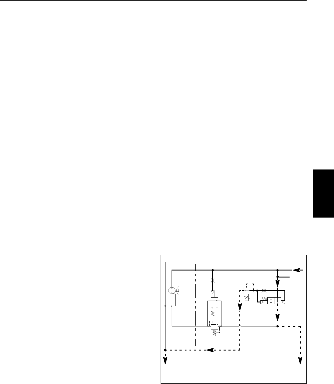
Groundsmaster 4100--D/4110--D Hydraulic SystemPage 4 -- 19
Mow Circuit
A four section gear pump is coupled to the piston (trac-
tion) pump. Hydraulic flow for the mow circuit is supplied
by two sections of the gear pump. The gear pump sec-
tion closest to the piston (traction) pump supplies hy-
draulic flow to the wings of the cutting deck, while the
next gear pump section supplies the center section of
the cutting deck.
Each cutting deck section is controlled by a hydraulic
manifold equipped with a proportional relief valve
(PRV), a pilot directional valve (PD), a logic valve (LC1)
and a relief valve (RV). The proportional relief valve is
a solenoid operated valve that also functions as the cir-
cuit relief valve when energized. Circuit pressure can be
measured at port (G) of the hydraulic manifold for each
cutting deck.
NOTE: To engage the mow circuit, the operator must
be in the operator seat, the traction speed must be in the
LOW speed (mow) position, the PTO switch must be ON
and the wing decks must be fully lowered and in float.
PTO Not Engaged
When the PTO switch is OFF or if the deck or wing deck
is raised with the PTO switch ON, the PTO manifold pro-
portional relief valve (PRV) is not energized which al-
lows a small amount of hydraulic flow through the valve.
As this hydraulic flow returns to the hydraulic reservoir,
a circuit pressure increase shifts logic valve LC1. The
pump flow is routed through shifted LC1 and out man-
ifold port P2 bypassing the cutting deck motors. Pilot dir-
ection valve PD and relief valve RV remain in the
unshifted position to prevent any return flow from the
deck motor which keeps the deck section motor and cut-
ting blades from rotating.
Return flow from the center and right PTO manifolds is
routed through the oil cooler, oil filter and then to the gear
pump input. Return flow from the left PTO manifold pro-
vides supply for the right deck.
PTO Engaged
When the PTO switch is turned ON and the deck is low-
ered, the PTO manifold proportional relief valve (PRV)
is energized by the TEC controller. This shifted solenoid
valve prevents any flow through the valve which allows
the logic valve LC1 to be in its neutral position directing
circuit flow toward the cutting deck motors. Gear pump
flow entering the manifold is routed out manifold port M1
and to the cutting deck motor to cause the motor and cut-
ting blades to rotate. As circuit pressure increases, pilot
direction valve PD shifts to provide a return path for cir-
cuit flow. The return flow from the deck motor re--enters
manifold port M2, is routed through shifted PD, out man-
ifold port P2, through the oil cooler and filter and then is
routed to the gear pump input. The deck motor contin-
ues to rotate as long as proportional relief valve (PRV)
is energized.
Deck motor case drain leakage returns to the hydraulic
reservoir.
PTO Circuit Relief
Maximum mow circuit pressure is limited for each deck
section by proportional relief valve (PRV) in the PTO
manifold. The center and left wing deck relief valves are
set at 3000 PSI (207 bar) and the right wing deck relief
valve is set at 2000 PSI (138 bar).
Proportional relief valve (PRV) and logic valve (LC1)
work together as a two stage circuit relief. When in-
creased circuit resistance is met (e.g. a cutting blade
strikes an object), the pressure increase is felt at the pro-
portional relief valve. If the pressure should exceed the
relief valve setting, the relief valve will open, allowing a
small amount of hydraulic flow through the valve. This
flow causes a pressure increase that shifts logic valve
LC1 and diverts circuit flow away from the deck motor to
manifold port P2 (Fig. 11). When circuit pressure lowers,
proportional relief valve (PRV) closes which returns lo-
gic valve LC1 back to its neutral position allowing flow
to return to the deck section motor.
Figure 11
PRV ENERGIZED
PRV AND LC1 SHIFTED
DECK MOTOR STALLED
P1
P2
M1
M2
LC1
PRV
PD
RV
3000 PSI
CD RIGHT DECK
1.17 CID
600 PSI
.025
PUMP
RETURN
FLOW
RETURN
G
Hydraulic
System
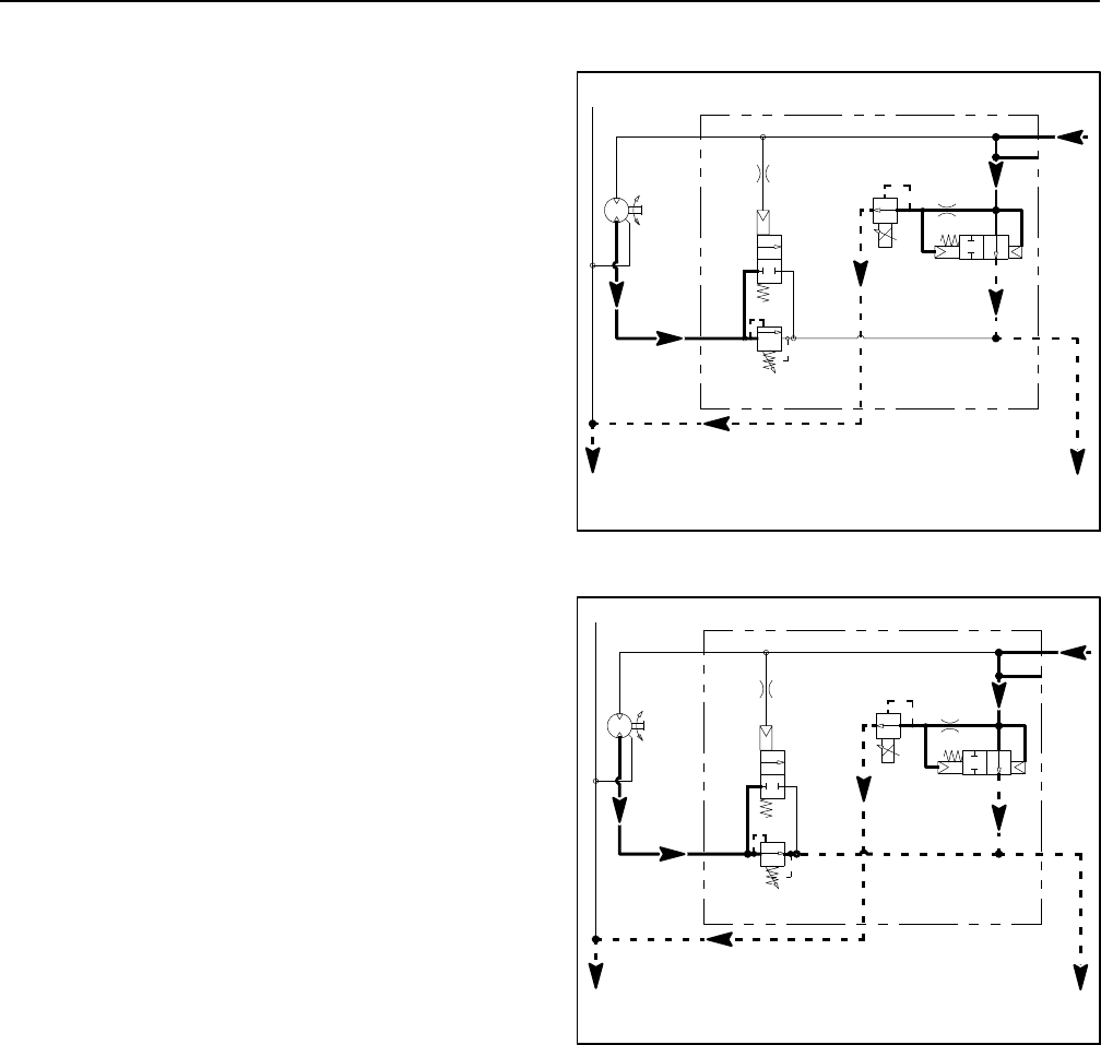
Groundsmaster 4100--D/4110--DHydraulic System Page 4 -- 20
Mow Circuit Cutting Deck Blade Braking
When the operator turns the PTO switch OFF or if a wing
deck is raised with the PTO switch ON, PTO manifold
proportional relief valve (PRV) is de--energized causing
logic valve (LC1) to shift (refer to information in Mow Cir-
cuit in this section). This shifted cartridge directs oil re-
turn out of manifold port P2. As circuit pressure
decreases, pilot direction valve PD is shifted to it’s neut-
ral position, preventing return flow from the deck motor
and slows the cutting blades (Fig. 12).
The inertia of the rotating cutting blades, however, effec-
tively turns the deck motor into a pump causing an in-
crease in pressure as the flow from the motor comes up
against the closed relief valve (RV). When this pressure
builds to approximately 600 PSI (41 bar), relief valve
(RV) opens which allows hydraulic flow to flow from the
motor (Fig. 13). When return pressure drops below 600
PSI (41 bar), relief valve (RV) reseats to once again
block return flow from the deck motor to further slow the
cutting blades. This action of the brake relief valve open-
ing occurs several times in a very short time frame as the
blades finally come to a stop. Once the deck section
blades have stopped, relief valve (RV) remains seated
to keep the deck motor from rotating.
Figure 12
P1
P2
M1
M2
LC1
PRV
PD
RV
3000 PSI
CD RIGHT DECK
1.17 CID
600 PSI
.025
PUMP
RETURN
FLOW
RETURN
PRV NOT ENERGIZED
LC1 SHIFTED
PTO SWITCH OFF
G
Figure 13
P1
P2
M1
M2
LC1
PRV
PD
RV
3000 PSI
CD RIGHT DECK
1.17 CID
600 PSI
.025
PUMP
RETURN
FLOW
RETURN
PRV NOT ENERGIZED
LC1 AND RV SHIFTED
PTO SWITCH OFF
G

Groundsmaster 4100--D/4110--D Hydraulic SystemPage 4 -- 21
This page is intentionally blank.
Hydraulic
System
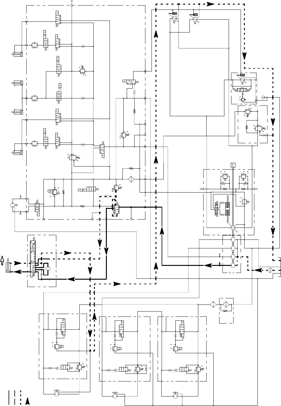
Groundsmaster 4100--D/4110--DHydraulic System Page 4 -- 22
Steering Circuit (Right Turn Shown)
Working Pressure
Low Pressure (Charge)
Return or Suction
Flow
Groundsmaster 4100--D/4110--D
S10
RV1
CV1
S2
S4
S5
PRV
P4 CH2 P3
EC
CF
LS
S3
OR1
C3
OR4
.040
S6
OR5
.070
C4 C2 C5
RV2
S7
S9
S8
C6
M1 M2
CH1
CV3
CH4
OR2
.063
OR6
.063
OR3
.070
OR7
.070
T2SPCH3
G2
G4
CV4
PR
G1
G3
3250
PSI
1350
PSI
3.3 GPM
4.4 GPM
4 PSI
4PSI
.030
OR9
S1
3300 PSI
RV3 S12
S11
CV2
4 PSI
1.17 CID 3000 PSI
P1
P1
P1
P2
P2
P2
M1
M2
LC1
PRV
PD
CD
RV
2000 PSI
M1
M2
LC1
PRV
PD
RV
3000 PSI
M1
M2
LC1
PRV
PD
RV
CD
CD
LEFT DECK
CENTER DECK
RIGHT DECK
50 PSI
1.17 CID
1.17 CID
6.1 CID
EP
LR
T
STEERING
CYLINDER 0.51 CID
PR
380 PSI
RV
650 PSI
.050
CV
T
P2
M8
CH
OR1
250 PSI
2.14 CID /
1.16 CID
600 PSI
600 PSI
600 PSI
.030”
200 PSI
4350 PSI
5000 PSI
.025
.025
.025
.0315 .0315
0.4
CID
0.3 1.37 1.37
CID CID CID
2.75
CID
REAR
TRACTION
MANIFOLD
ENGINE
30.5
GPM
80
PSI 60
PSI
310
PSI
1.50” BORE
3.08” STROKE
RAM CYLINDERS
CENTER DECK
2.00” BORE
4.20” STROKE
0.625” ROD
GG
G
GG
G
COMBINATION MANIFOLD
STEERING
CONTROL
VALVE
EXTENDING
G
G
G
2500 PSI
15.2 GPM
1.4 CID/
0.79 CID
15.2 GPM
1.4 CID/
0.79 CID
1.125” ROD
2.50” BORE
6.50” STROKE
WING DECK
RIGHT
1.125” ROD
2.50” BORE
6.50” STROKE
WING DECK
LEFT

Groundsmaster 4100--D/4110--D Hydraulic SystemPage 4 -- 23
Steering Circuit
A four section gear pump is coupled to the piston (trac-
tion) pump. The fourth gear pump section (farthest from
the piston pump) supplies hydraulic flow to the steering
circuit, the engine cooling fan circuit and the traction
charge circuit. Priority hydraulic flow from this gear
pump section is provided to the steering circuit by the
pressure compensator valve (EC) located in the com-
bination manifold.
NOTE: The hydraulic schematic symbol for the pres-
sure compensator valve (EC) appears to be a two (2) po-
sition valve. In operation, this valve will direct the gear
pump section flow to the steering circuit as priority de-
pending on steering input. The remainder of the gear
pump section flow will be directed to the charge and en-
gine cooling fan circuits. If there is no steering input, the
compensator valve (EC) directs all gear pump section
flow to the charge and engine cooling fan circuits.
The combination manifold controls the operation of the
steering control valve, the engine cooling fan motor and
the cutting deck lift cylinders. The pressure compensat-
or valve (EC) in the manifold controls the oil flow to the
steering control valve which is a closed center, load
sensing valve. The steering control valve senses the oil
flow that is needed for steering and the compensator
valve (EC) will supply the correct amount. Oil flow not
needed for the steering circuit is provided to the engine
cooling fan motor and then to the traction charge circuit.
With the steering wheel in the neutral, at rest position
and the engine running, hydraulic oil from the final gear
pump section enters the combination manifold port P4,
flows through the pressure compensator valve (EC) and
to the steering control valve where it dead heads at the
steering control spool. Oil is also sent to both ends of the
compensator valve (EC) spool. On one end of the spool,
oil is directed to the steering relief valve (RV1) and also
is directed through the OR1 orifice and out the LS man-
ifold port to the steering control valve. This flow provides
steering load sense pressure and is directed through a
small passage in the steering control valve spool and
sleeve before returning to the hydraulic reservoir. While
this load sense pressure is returning to the reservoir, the
compensator valve (EC) spool shifts to direct pump flow
to the engine cooling fan motor circuit and then to the
traction charge circuit. Without steering input, no oil is
flowing through the steering control valve to the steering
cylinder.
Right Turn
When a right turn is made with the engine running, the
turning of the steering wheel positions the steering con-
trol valve spool so that the load sense flow is blocked off.
Without load sense flow, pressures on the ends of man-
ifold compensator valve (EC) start to equalize causing
(EC) to move toward its neutral position which allows the
needed oil flow to the steering control valve. Oil is routed
out manifold port CF, into steering valve port P, through
the steering control spool, is drawn through the rotary
meter section and out the R port to the steering cylinder.
Pressure extends the steering cylinder for a right turn.
The rotary meter ensures that the oil flow to the cylinder
is proportional to the amount of the turning on the steer-
ing wheel. Fluid leaving the cylinder flows back through
the steering valve L port, the spool valve, out the T port
and then returns to the hydraulic reservoir.
The steering control valve returns to the neutral position
when turning is completed.
Left Turn
When a left turn is made with the engine running, the
turning of the steering wheel positions the steering con-
trol valve spool so that the load sense flow is blocked off.
Without load sense flow, pressures on the ends of man-
ifold compensator valve (EC) start to equalize causing
(EC) to move toward its neutral position which allows the
needed oil flow to the steering control valve. Oil is routed
out manifold port CF, into steering valve port P, through
the steering control spool, is drawn through the rotary
meter section and out the L port to the steering cylinder.
Pressure retracts the steering cylinder for a left turn. The
rotary meter ensures that the oil flow to the cylinder is
proportional to the amount of the turning on the steering
wheel. Fluid leaving the cylinder flows back through the
steering valve R port, the spool valve, out the T port and
then returns to the hydraulic reservoir.
The steering control valve returns to the neutral position
when turning is completed.
Steering Relief Operation
When the steering cylinder reaches the end of its stroke
or if a rear wheel should encounter an obstruction (e.g.
a curb) while steering, the pressure in the steering circuit
will rise. Relief valve (RV1) in the combination manifold
senses this pressure increase. When steering circuit
pressure builds to approximately 1350 PSI (93 bar), re-
lief valve (RV1) opens and allows hydraulic flow to return
to the hydraulic reservoir. This action causes flow
across the relief valve side orifice of compensator valve
(EC) which shifts the spool in (EC) to send oil away from
the steering circuit to the fan motor circuit. Relief valve
(RV1) controls the action of compensator valve (EC)
and allows the compensator valve to divert only enough
oil flow to the steering circuit to maintain relief pressure.
Hydraulic
System
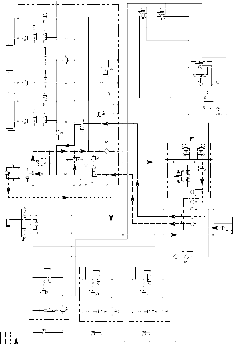
Groundsmaster 4100--D/4110--DHydraulic System Page 4 -- 24
Engine Cooling Fan Circuit (Forward Direction Shown)
Working Pressure
Low Pressure (Charge)
Return or Suction
Flow
Groundsmaster 4100--D/4110--D
S10
RV1
CV1
S2
S4
S5
PRV
P4 CH2 P3
EC
CF
LS
S3
OR1
C3
OR4
.040
S6
OR5
.070
C4 C2 C5
RV2
2500 PSI
S7
S9
S8
C6
M1 M2
CH1
CV3
CH4
OR2
.063
OR6
.063
OR3
.070
OR7
.070
T2SPCH3
G2
G4
CV4
PR
G1
G3
3250
PSI
1350
PSI
3.3 GPM
4.4 GPM
4 PSI
4PSI
.030
OR9
S1
3300 PSI
RV3 S12
S11
CV2
4 PSI
1.17 CID 3000 PSI
P1
P1
P1
P2
P2
P2
M1
M2
LC1
PRV
PD
CD
RV
2000 PSI
M1
M2
LC1
PRV
PD
RV
3000 PSI
M1
M2
LC1
PRV
PD
RV
CD
CD
LEFT DECK
CENTER DECK
RIGHT DECK
50 PSI
1.17 CID
1.17 CID
6.1 CID
EP
LR
T
STEERING
CYLINDER
0.51 CID
PR
380 PSI
RV
650 PSI
.050
CV
T
P2
M8
CH
OR1
250 PSI
2.14 CID /
1.16 CID
600 PSI
600 PSI
600 PSI
.030”
200 PSI
4350 PSI
5000 PSI
.025
.025
.025
.0315 .0315
0.4
CID
0.3 1.37 1.37
CID CID CID
2.75
CID
REAR
TRACTION
MANIFOLD
ENGINE
30.5
GPM
80
PSI 60
PSI
310
PSI
1.50” BORE
3.08” STROKE
RAM CYLINDERS
CENTER DECK
2.00” BORE
4.20” STROKE
0.625” ROD
G
GG
G
GG
G
COMBINATION MANIFOLD
STEERING
CONTROL
VALVE
G
G
1.4 CID/
0.79 CID
15.2 GPM
1.4 CID/
0.79 CID
15.2 GPM
1.125” ROD
2.50” BORE
6.50” STROKE
WING DECK
RIGHT
1.125” ROD
2.50” BORE
6.50” STROKE
WING DECK
LEFT
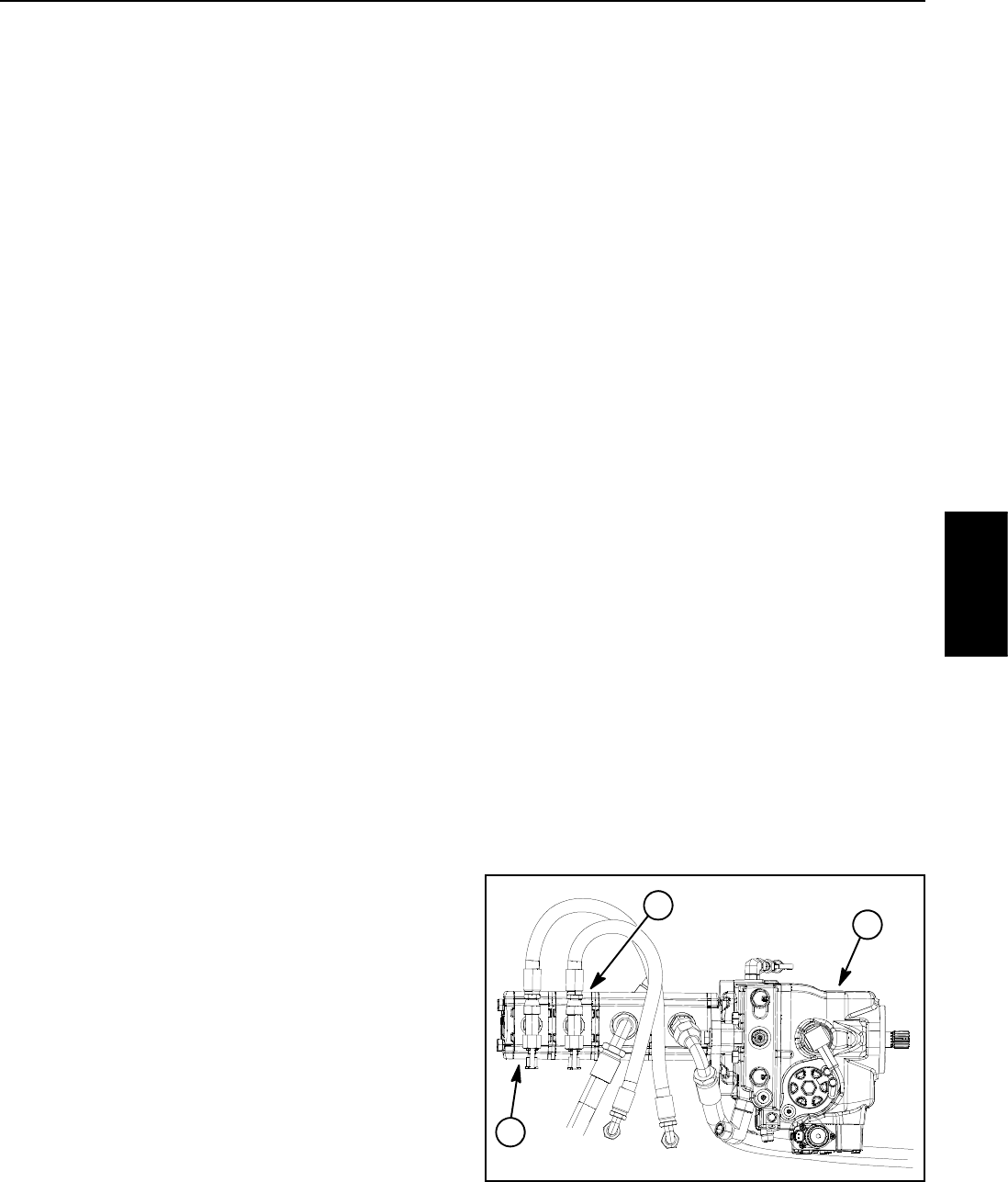
Groundsmaster 4100--D/4110--D Hydraulic SystemPage 4 -- 25
Engine Cooling Fan Circuit
A four section gear pump is coupled to the piston (trac-
tion) pump (Fig. 14). The fourth gear pump section
(farthest from the piston pump) supplies hydraulic flow
to the steering circuit, the engine cooling fan circuit and
the traction charge circuit. The third gear pump section
supplies hydraulic flow to the engine cooling fan circuit,
the lift/lower circuit and the traction charge circuit.
So that there is sufficient oil flow for the engine cooling
fan circuit, oil flow from either or both of the third or fourth
gear pump section is used to drive the hydraulic cooling
fan motor depending on what other machine functions
are being used (steering, lift/lower). If additional oil flow
is needed for cooling fan operation in extreme condi-
tions (e.g. high ambient temperatures, cutting very
heavy grass), the TEC controller can allow flow from the
twopumpsectionstobecombined.
Oil flow from the third gear pump section is routed to the
combination manifold (port P3) where it is available
either for the lift/lower circuit or the engine cooling fan
circuit. When the lift/lower circuit is not being used (all lift
switches in the neutral position), solenoid valve (S1) in
the combination manifold is not energized and gear
pump section oil flow is directed toward the engine cool-
ing fan motor.
Priority oil flow from the fourth gear pump section is
provided to the steering circuit. All excess flow from this
gear pump section is normally routed to the traction
charge circuit by energized solenoid valve (S11). This
valve is energized by the TEC controller as long as the
lift/lower function is not being used and the hydraulic oil
and engine coolant temperatures are within normal
ranges. If inputs to the TEC controller suggest additional
oil flow is necessary for the cooling fan (e.g. lift/lower cir-
cuit is engaged or engine coolant temperature is elev-
ated), solenoid valve (S11) will be de--energized
allowing excess pump section oil flow to be directed to-
wardtheenginecoolingfanmotor.
Oil flow from the gear pump section(s) to the cooling fan
motor is controlled by the proportional relief valve (PRV)
in the combination manifold. This valve adjusts fan cir-
cuit pressure and flow based on a PWM (Pulse Width
Modulation) signal from the TEC controller. The control-
ler uses engine coolant and hydraulic oil temperatures
as inputs to determine the proper PWM signal for the
(PRV) valve. The fan circuit flow determines the speed
of the cooling fan motor and thus, the speed of the cool-
ing fan.
If the fan motor is stalled for any reason during machine
operation, the manifold proportional relief valve (PRV)
has a secondary function as a circuit relief to limit fan
motor pressure to 3250 PSI (224 bar).
When the engine is shut off, the over--running inertia
load of the engine cooling fan blades keeps driving the
fan motor and turns it into a pump. The check valve
(CV1) in the combination manifold will open to keep the
motor circuit full of oil so the fan motor will not cavitate.
Forward Direction Fan Operation
During normal, forward direction fan operation, circuit oil
flow is sent through the de--energized solenoid valve
(S10) in the combination manifold to rotate the cooling
fan motor. Return flow from the motor re--enters the
manifold (port M2), through the de--energized solenoid
valve (S10), to the oil filter and then out of the manifold
(port CH2). After exiting the manifold, circuit oil is routed
to the traction charge circuit.
Reverse Direction Fan Operation
The TEC controller can reverse the cooling fan to clean
debris from the rear intake screen. If hydraulic oil and/or
engine coolant temperatures increase to an unsuitable
level, a high PWM signal is sent to the (PRV) valve to
slow the cooling fan and direct all pump oil flow to the
traction charge circuit. The controller then energizes so-
lenoid valve (S10) in the combination manifold to re-
verse cooling fan motor oil flow so that the motor runs in
the reverse direction. A lower PWM signal is sent to the
(PRV) valve allowing oil flow to return to the fan motor
but in the reverse direction causing the motor and cool-
ing fan to run in reverse. The controller determines the
length of time that the fan should be run in reverse be-
fore fan rotation is returned to the forward direction.
NOTE: The operator can manually cause the cooling
fan to reverse by simultaneously pressing the right and
left buttons on the InfoCenter display.
1. Piston (traction) pump
2. 4th gear pump section
3. 3rd gear pump section
Figure 14
2
3
1
Hydraulic
System
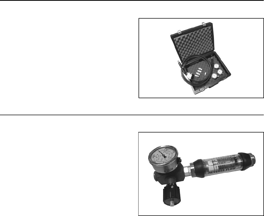
Groundsmaster 4100--D/4110--DHydraulic System Page 4 -- 26
Special Tools
Order these special tools from your Toro Distributor.
Hydraulic Pressure Test Kit
Use to take various pressure readings for diagnostic
tests. Quick disconnect fittings provided attach directly
to mating fittings on machine test ports without tools. A
high pressure hose is provided for remote readings.
Contains one each: 1000 PSI (70 bar), 5000 PSI (350
bar) and 10000 PSI (700 bar) gauges. Use gauges as
recommended in the Testing section of this chapter.
Toro Part Number: TOR47009
Figure 15
15 GPM Hydraulic Tester Kit (Pressure and Flow)
Use to test hydraulic circuits and components for flow
and pressure capacities as recommended in the Testing
section of this chapter. This tester includes the following:
1. INLET HOSE: Hose connected from the system cir-
cuit to the inlet side of the hydraulic tester.
2. LOAD VALVE: A simulated working load is created
in the circuit by turning the valve to restrict flow.
3. PRESSUREGAUGE:Glycerinefilled0to5000PSI
gauge to provide operating circuit pressure.
4. FLOW METER: This meter measures actual oil flow
in the operating circuit with a gauge rated from 1 to 15
GPM(5to55LPM).
5. OUTLET HOSE: A hose from the outlet side of the
hydraulic tester connects to the hydraulic system circuit.
6. FITTINGS: An assortment of hydraulic fittings are in-
cluded with this kit.
Toro Part Number: TOR214678
Figure 16
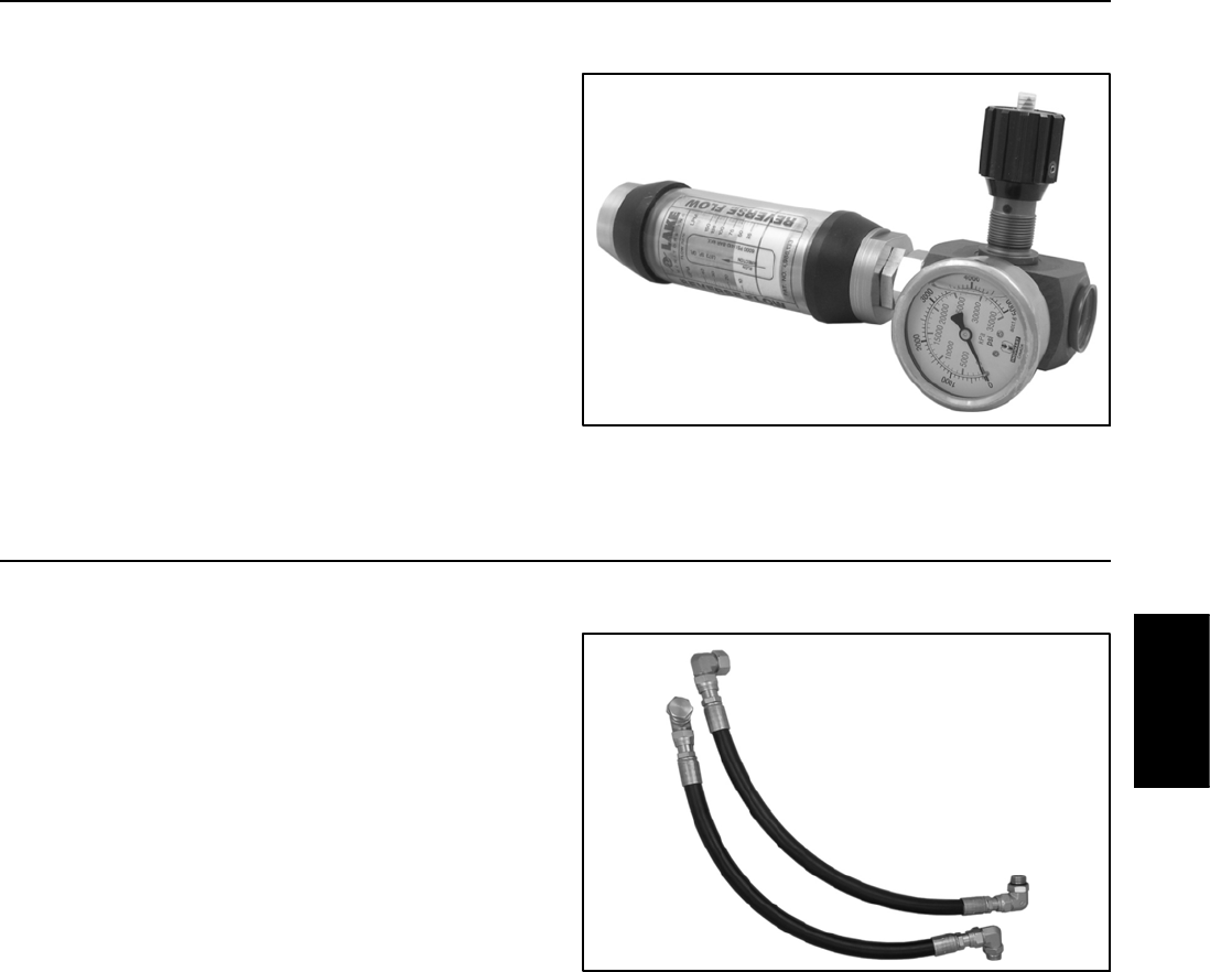
Groundsmaster 4100--D/4110--D Hydraulic SystemPage 4 -- 27
40 GPM Hydraulic Tester (Pressure and Flow)
Use to test hydraulic circuits and components for flow
and pressure capacities as recommended in the Testing
section of this chapter. This tester includes the following:
1. LOAD VALVE: A simulated working load is created
in the circuit by turning the valve to restrict flow.
2. PRESSURE GAUGE: Glycerine filled 0 to 5000 PSI
gauge to provide operating circuit pressure.
3. FLOW METER: This meter measures actual oil flow
intheoperatingcircuitwithagaugeratedfrom4to40
GPM (20 to 150 LPM).
Toro Part Number: AT40002
NOTE: This tester does not include hydraulic hoses
(see Hydraulic Hose Kit TOR6007 below).
Figure 17
Hydraulic Hose Kit
This kit includes hydraulic fittings and hoses needed to
connect 40 GPM hydraulic tester (AT40002) or high flow
hydraulic filter kit (TOR6011) to machine hydraulic trac-
tion system components.
Toro Part Number: TOR6007
Figure 18
Hydraulic
System
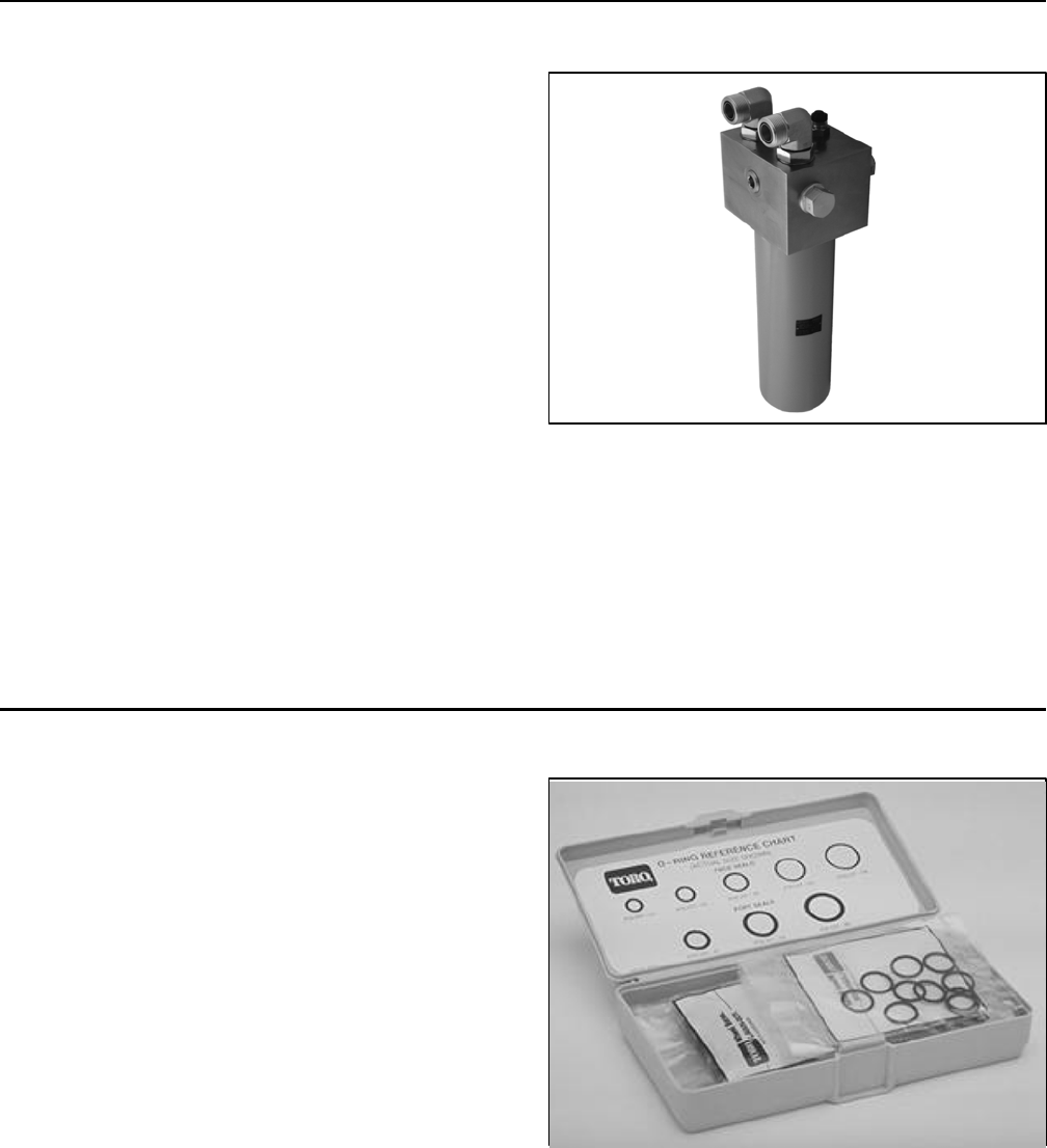
Groundsmaster 4100--D/4110--DHydraulic System Page 4 -- 28
High Flow Hydraulic Filter Kit
The high flow hydraulic filter kit is designed with large
flow (40 GPM/150 LPM) and high pressure (5000
PSI/345 bar) capabilities. This kit provides for bi--direc-
tional filtration which prevents filtered debris from being
allowed back into the circuit regardless of flow direction.
If a component failure occurs in the closed loop traction
circuit, contamination from the failed part will remain in
the circuit until removed. When connecting hydraulic
test gauges in order to test traction circuit components
or after replacing a failed traction circuit component (e.g.
piston pump or wheel motor), the high flow hydraulic fil-
ter can be installed in the traction circuit. The filter will
ensure that contaminates are removed from the closed
loop and thus, do not cause additional component dam-
age.
Toro Part Number: TOR6011
NOTE: This kit does not include hydraulic hoses (see
Hydraulic Hose Kit TOR6007 above).
NOTE: Replacement filter element is Toro part number
TOR6012. Filter element cannister tightening torque is
25 ft--lb (34 N--m).
Figure 19
O--Ring Kit
The O--ring kit includes O--rings in a variety of sizes for
face seal and port seal hydraulic connections. It is rec-
ommended that O--rings be replaced whenever a hy-
draulic connection is loosened.
Toro Part Number: 117--2727
Figure 20
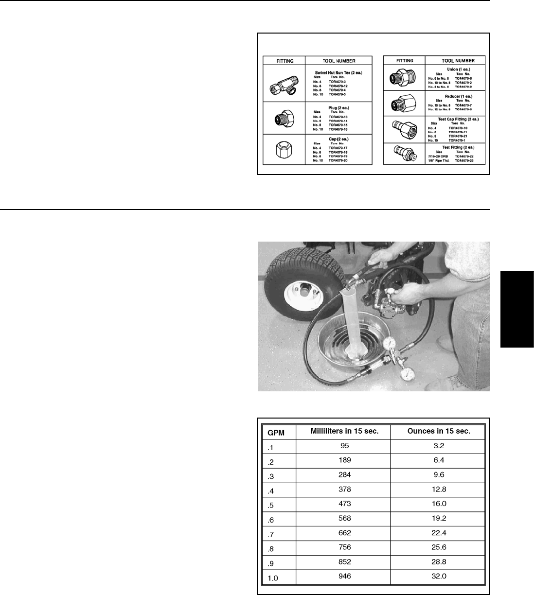
Groundsmaster 4100--D/4110--D Hydraulic SystemPage 4 -- 29
Hydraulic Test Fitting Kit
This kit includes a variety of O--ring face seal fittings to
enable the connection of test gauges into the system.
The kit includes: tee’s, unions, reducers, plugs, caps
and male test fittings.
Toro Part Number: TOR4079
Figure 21
TORO TEST FITTING KIT (TOR4079)
Measuring Container
Use this container for doing hydraulic motor efficiency
testing (motors with case drain lines only). Measure effi-
ciency of a hydraulic motor by restricting the outlet flow
from the motor and measuring leakage from the case
drain line while the motor is pressurized by the hydraulic
system.
The table in Figure 23 provides gallons per minute
(GPM) conversion for measured milliliter or ounce motor
case drain leakage.
Toro Part Number: TOR4077
Figure 22
Figure 23
Hydraulic
System
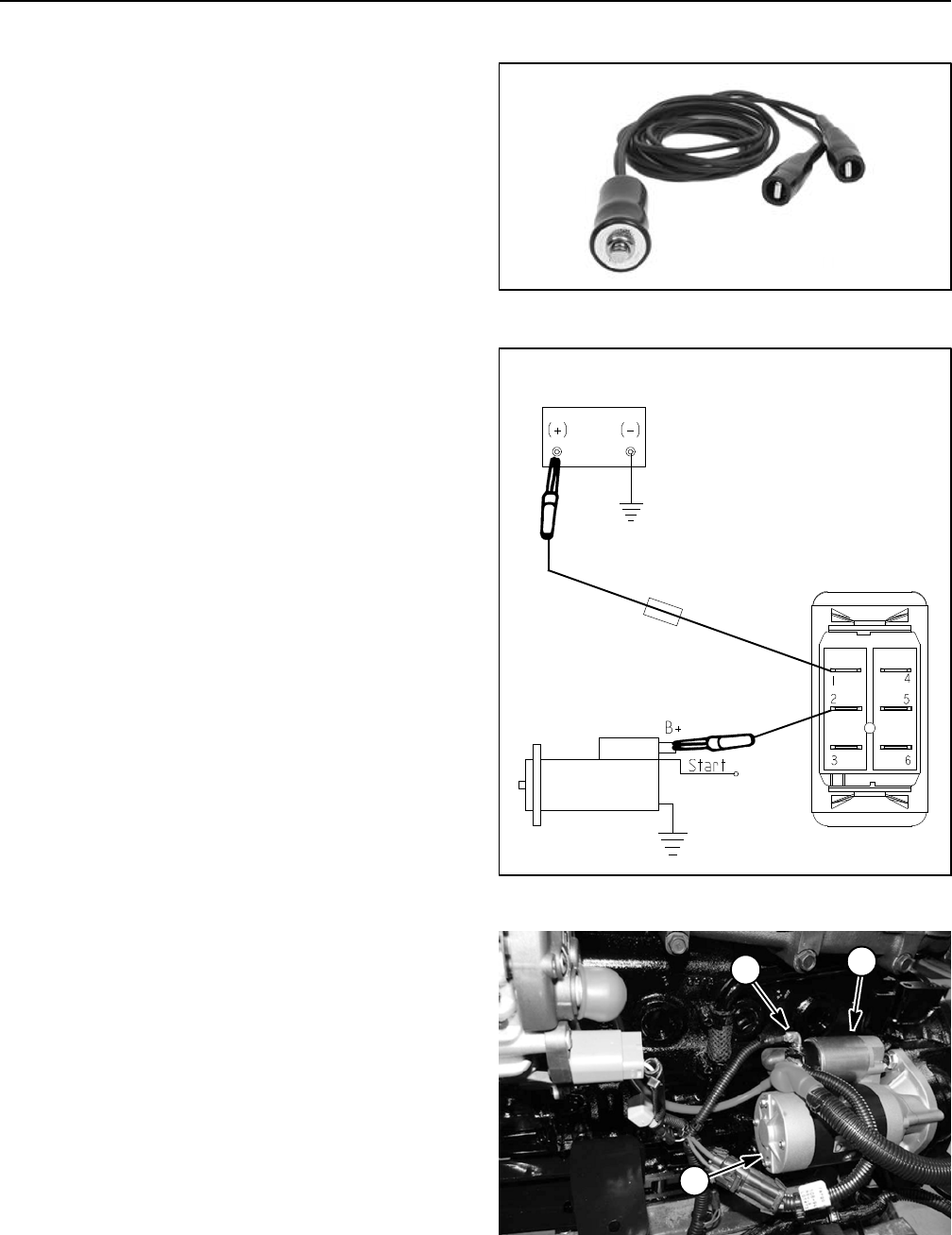
Groundsmaster 4100--D/4110--DHydraulic System Page 4 -- 30
Remote Starter Switch
After flushing the hydraulic system or replacing a hy-
draulic component (e.g. gear pump, piston pump, wheel
motor), it is necessary to prime the hydraulic pumps. A
remote starter switch (Fig. 24) can be used for this pur-
pose. Obtain a remote starter switch locally.
IMPORTANT: When using a remote starter switch, it
is highly recommended to include a 20 amp inline
fuse between the battery and switch connector for
circuit protection.
A remote stater switch can also be constructed using
Toro switch #106--2027, a length of 14 gauge wire, a 20
amp in--line fuse, two (2) alligator clips and necessary
connectors. Connecting the wire to switch terminals 1
and 2 will allow the momentary switch contacts to be
used for the remote starter switch (Fig. 25).
NOTE: For information on using the remote starter
switch to prime the hydraulic pumps, see Flush Hydraul-
ic System in the Service and Repairs section of this
chapter.
Figure 24
Figure 25
TORO SWITCH
(#106--2027)
BATTERY
MACHINE
SOLENOID
STARTER
STARTER
MACHINE
20 AMP
FUSE
1. Starter motor
2. Starter solenoid
3. B+ terminal
Figure 26
1
2
3

Groundsmaster 4100--D/4110--D Hydraulic SystemPage 4 -- 31
Troubleshooting
The charts that follow contain suggestions that can be
used to assist in diagnosing hydraulic system perfor-
mance issues. The suggestions are not all--inclusive.
Also, consider that there may be more than one cause
for a machine problem.
Review the hydraulic schematic and information on hy-
draulic system operation in the Hydraulic Flow Dia-
grams section of this Chapter. This information will be
useful during the hydraulic troubleshooting process.
Refer to the Testing section of this Chapter for precau-
tions and specific hydraulic test procedures.
General Hydraulic System Problems
Problem Possible Cause
Hydraulic oil leaks from machine Fitting(s), hose(s) or tube(s) is (are) loose or damaged.
O--ring(s) or seal(s) is (are) missing or damaged.
Hydraulic system operates hot.
NOTE: An indication that the hy-
draulic system is operating at exces-
sive temperatures would be frequent
reversing of the cooling fan and a
normal engine coolant temperature.
Engine RPM is too low.
Brakes are applied or sticking.
Hydraulic reservoir oil level is low.
Hydraulic oil is contaminated or the wrong type.
Piston pump by--pass valve is open or damaged.
Cooling system is not operating properly.
Charge pressure is low.
Traction circuit pressure is incorrect.
Pump(s)ormotor(s)aredamaged.
Hydraulic oil in reservoir foams. Hydraulic reservoir oil level is low.
Wrong type of oil is in the hydraulic system.
Air is leaking into a pump suction line.
Hydraulic
System

Groundsmaster 4100--D/4110--DHydraulic System Page 4 -- 32
Traction Circuit Problems
Problem Possible Cause
Machineoperatesinonedirection
only.
Piston (traction) pump by--pass valve is open or damaged.
Traction relief valve is leaking or faulty.
Piston (traction) pump servo control valve orifices or screens are
plugged or damaged.
Problem with TEC output to piston (traction) pump servo control
exists (see Chapter 5 -- Electrical System).
Traction pedal response is sluggish. Traction pedal components are stuck or binding.
Traction charge pressure is low.
Piston (traction) pump servo control valve orifices are plugged or
damaged.
Machinetravelstoofarbeforestop-
ping when the traction pedal is re-
leased.
Traction pedal components are stuck or binding.
Traction charge pressure is low.
Adjustment of relief valve (RV) in rear traction manifold is incorrect.
Piston (traction) pump servo control valve orifices are plugged or
damaged.
Traction power is lost or machine will
not operate in either direction.
Hydraulic reservoir oil level is low (NOTE: Other hydraulic systems
are affected as well).
Piston (traction) pump by--pass valve is open or damaged.
Traction charge pressure is low.
Traction circuit pressure is low.
Traction pedal position sensor is not plugged in or is faulty (see
Chapter 5 -- Electrical System).
Problem with TEC output to piston (traction) pump servo control
exists (see Chapter 5 -- Electrical System).
LOW traction speed (mow) will not
engage.
NOTE: LOW (mow) will not engage
when the cutting deck is lowered.
Electrical problem exists that prevents solenoid valve S12 from be-
ing de--energized (see Chapter 5 -- Electrical System).
Solenoid valve (S12) in combination manifold is faulty.
LOW traction speed (mow) will not
disengage.
Electrical problem exists that prevents solenoid valve S12 from be-
ing energized (see Chapter 5 -- Electrical System).
Solenoid valve (S12) in combination manifold is faulty.

Groundsmaster 4100--D/4110--D Hydraulic SystemPage 4 -- 33
Mow Circuit Problems
Problem Possible Cause
None of the cutting deck sections
will operate.
NOTE: To engage the mow circuit,
theseatmustbeoccupied,thecut-
ting deck(s) must be fully lowered,
the traction speed must be in the
LOW (mow) position and the PTO
switch must be ON.
Electrical problem exists that prevents PRV solenoid valve in PTO
manifolds from being energized (see Chapter 5 -- Electrical Sys-
tem).
Front two (2) gear pump sections for mow circuits are worn or dam-
aged.
One cutting deck section will not op-
erate.
Electrical problem (e.g. solenoid coil in PTO manifold, cutting deck
position switch) exists (see Chapter 5 -- Electrical System).
Cutting deck section problem exists (e.g. drive belt, deck spindle).
System pressure to the affected cutting deck section is low.
Woodruff key on affected deck section motor is damaged.
Proportional relief valve (PRV) in PTO manifold for affected deck sec-
tion is faulty.
Cartridge valve in PTO manifold for affected deck section is damaged
or sticking.
Deck motor for affected deck section is damaged (NOTE: if appropri-
ate, transfer a suspected damaged motor to another cutting deck. If
problem follows the motor, motor is faulty and needs repair or re-
placement).
Gear pump section for affected deck section is worn or damaged.
All cutting deck sections operate
slowly.
Engine RPM is low.
All deck motors are worn or damaged.
Front two (2) gear pump sections for mow circuits are worn or dam-
aged.
Cutting deck section stops under
load.
Proportional relief valve in PTO manifold for affected deck section
is by--passing.
Deck motor has internal leakage (by--passing oil).
Gear pump section for affected deck section is worn or damaged.
Hydraulic
System

Groundsmaster 4100--D/4110--DHydraulic System Page 4 -- 34
Lift Circuit Problems
Problem Possible Cause
Cutting deck (or wing decks) will not
raise.
NOTE: The seat must be occupied
in order to raise cutting deck.
Engine RPM is too low.
Hydraulic oil level in reservoir is low (NOTE: Other hydraulic systems
are affected as well).
Solenoid valve (S1) in combination manifold is faulty.
Electrical problem exists (see Chapter 5 -- Electrical System).
Lift arm pivots are binding.
Relief valve in combination manifold is stuck.
Lift cylinder(s) is (are) damaged.
Gear pump section for lift/lower circuit is worn or damaged (NOTE: A
worn or damaged gear pump section will also affect the steering, en-
gine cooling fan motor and traction charge circuits).
Cutting deck (or wing decks) raise,
but will not stay up.
NOTE: Lift cylinders cannot provide
an absolutely perfect seal. The cut-
ting deck will eventually lower if left
in the raised position during storage.
Lift circuit hydraulic lines or fittings are leaking.
Cartridge valve(s) in combination manifold has damaged seals or is
faulty.
Lift cylinder for affected deck section is damaged.
Cutting deck (or wing decks) will not
lower.
NOTE: To lower cutting deck (or
wing deck), the seat must be occu-
pied and the traction speed must be
in the Low (4WD) position.
Lift arm pivots are binding.
Electrical problem exists (see Chapter 5 -- Electrical System).
Solenoid valve (S1) in combination manifold is faulty.
Counterbalance pressure is excessive.
Lift cylinder for affected deck section is damaged.

Groundsmaster 4100--D/4110--D Hydraulic SystemPage 4 -- 35
Steering Circuit Problems
Problem Possible Cause
Steering is inoperative or sluggish. Steering components (e.g. tie rods, steering cylinder ends) are
worn or binding.
Steering cylinder is binding.
Oil level in hydraulic reservoir is low (NOTE: other hydraulic sys-
tems are affected as well).
Steering relief valve (RV1) in combination manifold is stuck or dam-
aged.
The pressure compensator valve (EC) in combination manifold is
stuck or damaged.
Steering cylinder leaks internally.
Steering control valve is worn or damaged.
Gear pump section is worn or damaged (NOTE: A worn or dam-
aged gear pump section will also affect the lift/lower, engine cooling
fan motor and traction charge circuits).
Hydraulic
System

Groundsmaster 4100--D/4110--DHydraulic System Page 4 -- 36
Engine Cooling Fan Circuit Problems
Problem Possible Cause
Cooling fan runs only in forward di-
rection(fandoesnotruninreverse
direction).
Solenoid cartridge valve (S10) in combination control manifold is
faulty.
Electrical problem exists that prevents combination control manifold
solenoid valve (S10) operation (see Chapter 5 -- Electrical System).
Cooling fan does not rotate. Cooling fan motor is worn or damaged.
Proportional relief valve (PRV) in combination manifold is stuck or
damaged.
Gear pump section for engine cooling fan circuit is worn or damaged
(NOTE: A worn or damaged gear pump section will also affect the
steering, lift/lower and traction charge circuits).
Cooling fan always rotates at slow
speed.
Combination manifold cartridge valve seals are leaking.
Check valve in combination manifold is not seating.
Proportional relief valve (PRV) in combination manifold is stuck or
damaged.
Hydraulic fan motor is worn or damaged.
Cooling fan always rotates at fast
speed.
Proportional relief valve (PRV) in combination manifold is faulty.
Electrical problem exists that prevents correct operation of combin-
ation manifold proportional relief valve (PRV) (see Chapter 5 --
Electrical System).

Groundsmaster 4100--D/4110--D Hydraulic SystemPage 4 -- 37
This page is intentionally blank.
Hydraulic
System
Groundsmaster 4100--D/4110--DHydraulic System Page 4 -- 38
Testing
The most effective method for isolating problems in the
hydraulic system is by using hydraulic test equipment
such as pressure gauges and flow meters in the circuits
during various operational checks (see the Special
Tools section in this Chapter).
IMPORTANT: All obvious areas such as hydraulic
oil supply, oil filters, binding components, loose
fasteners or improper adjustments must be
checked before assuming that a hydraulic compo-
nent is the source of the problem.
CAUTION
Failure to use gauges with recommended pres-
sure (PSI/bar) rating as listed in test procedures
could result in damage to the gauge and possible
personal injury from leaking hot oil.
WARNING
Keep body and hands away from pin hole leaks or
nozzles that eject hydraulic fluid under high pres-
sure. Do not use hands to search for leaks; use
paper or cardboard. Hydraulic fluid escaping un-
der pressure can have sufficient force to pene-
trate the skin and cause serious injury. If fluid is
injected into the skin, it must be surgically re-
moved within a few hours by a doctor familiar
with this type of injury. Gangrene may result from
such an injury.
WARNING
Before disconnecting or performing any work
on the hydraulic system, all pressure in the sys-
tem must be relieved. See Relieving Hydraulic
System Pressure in the General Information sec-
tion in this chapter.
CAUTION
All testing should be performed by two (2)
people. One person should be in the seat to oper-
ate the machine, and the second person should
read test instruments and record test results.
Precautions for Hydraulic Testing
1. Clean machine thoroughly before disconnecting or
disassembling any hydraulic components. Always keep
in mind the need for cleanliness when working on hy-
draulic equipment. Contamination will cause excessive
wear of components.
2. Before conducting a hydraulic test, make sure hy-
draulic oil is at normal operating temperature by operat-
ing the machine under load for approximately ten (10)
minutes.
3. Put metal caps or plugs on any hydraulic lines left
open or exposed during testing or removal of compo-
nents.
4. Theenginemustbeingoodoperatingcondition.Use
a phototac to determine engine speed when performing
a hydraulic test. Engine speed will affect the accuracy of
the tester readings. See Chapter 3 -- Yanmar Diesel En-
gine for engine speed specifications.
5. When using the hydraulic tester with flow and pres-
sure capabilities, the inlet and the outlet hoses must be
properly connected and not reversed to prevent dam-
age to the hydraulic tester or components.
6. When using the hydraulic tester with flow and pres-
sure capabilities, completely open flow control valve on
tester before starting the engine to minimize the possi-
bility of damaging components.
7. Install fittings finger tight and far enough to make
sure that they are not cross--threaded before tightening
them with a wrench.
8. Position tester hoses to prevent rotating machine
parts from contacting and damaging the hoses or tester.
9. Check oil level in the hydraulic reservoir. After con-
necting test equipment, make sure tank is full.
10.Check control linkages for improper adjustment,
binding or broken parts.
11. After installing test gauges, run engine at low idle
speed and check for any hydraulic oil leaks. Correct any
leaks before proceeding with test procedure.
12.Before returning machine to use, make sure that hy-
draulic reservoir has correct fluid level.

Groundsmaster 4100--D/4110--D Hydraulic SystemPage 4 -- 39
Which Hydraulic Tests Are Necessary?
Before beginning any hydraulic test, identify if the prob-
lem is related to the traction circuit, cutting (mow) circuit,
lift/lower circuit, steering circuit or engine cooling fan cir-
cuit. Once the faulty system has been identified, perform
tests that relate to that circuit.
1. If a traction circuit problem exists, consider perform-
ing one or more of the following tests: Traction Circuit
Charge Pressure, Traction Circuit Relief Pressure,
Counterbalance Pressure, Reverse Traction Circuit Re-
ducing Valve (PR) Pressure, Rear Traction Circuit Relief
Valve (RV) Pressure, Piston (Traction) Pump Flow and/
or Gear Pump Flow Tests.
IMPORTANT: Refer to Traction Circuit Component
Failure in the General Information section of this
chapter for information regarding the importance of
removing contamination from the traction circuit.
2. If a cutting (mow) circuit problem exists, consider
performing one or more of the following tests: Cutting
Deck Circuit Pressure, PTO Relief Pressure, Cutting
Deck Motor Case Drain Leakage and/or Gear Pump
Flow Tests.
3. If a lift/lower circuit problem exists, consider perform-
ing one or more of the following tests: Lift/Lower Circuit
Relief Pressure and/or Gear Pump Flow Tests.
4. If a steering circuit problem exists, consider perform-
ing one or more of the following tests: Steering Circuit
Relief Pressure, Steering Cylinder Internal Leakage
and/or Gear Pump Flow Tests.
5. If a engine cooling fan circuit problem exists, consid-
er performing one or more of the following tests: Engine
Cooling Fan Circuit and/or Gear Pump Flow Tests.
Hydraulic
System
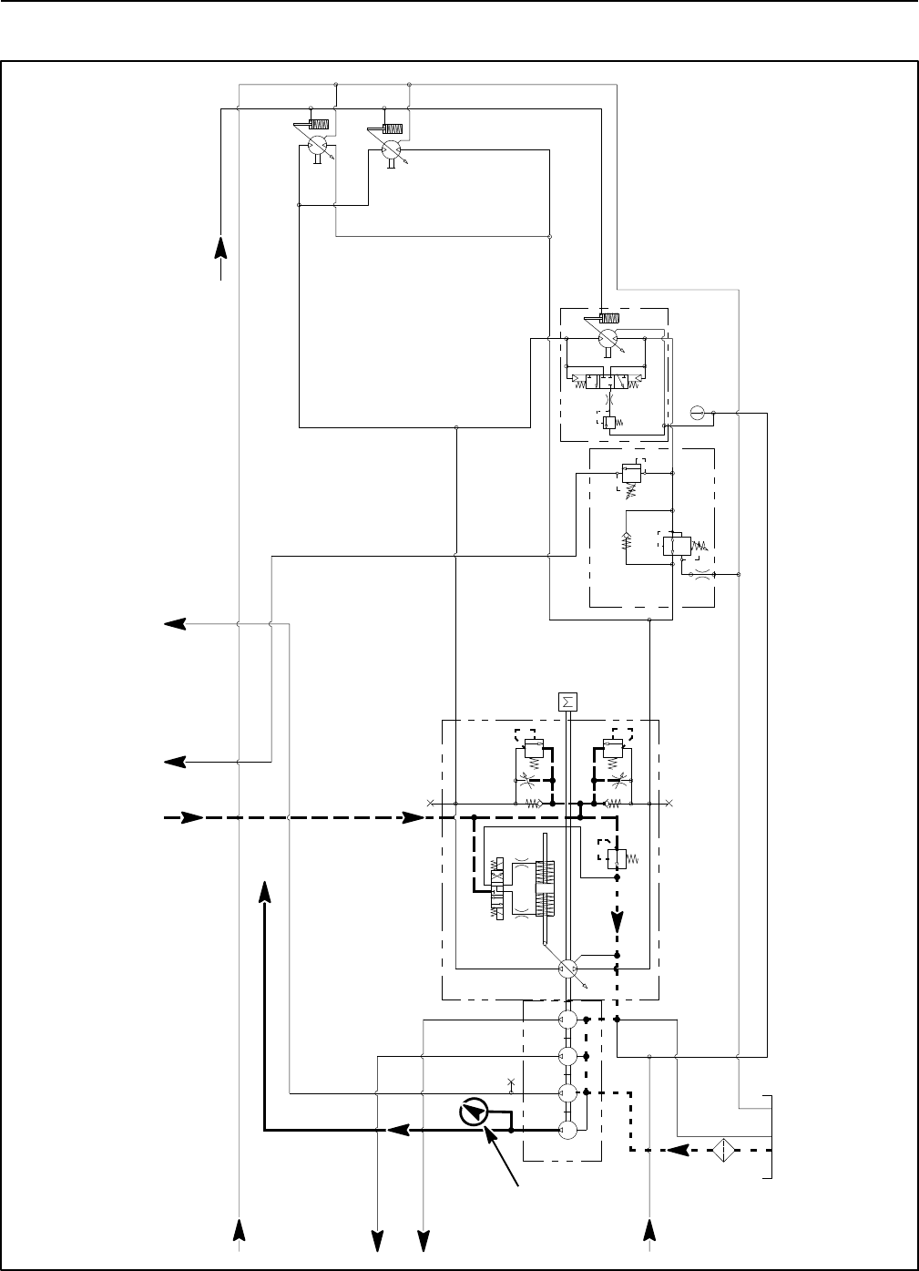
Groundsmaster 4100--D/4110--DHydraulic System Page 4 -- 40
Traction Circuit Charge Pressure (Using Pressure Gauge)
3.3 GPM
4.4 GPM
14.3 GPM
14.3 GPM
PR
380 PSI
RV
650 PSI
.050
CV
T
P2
M8
CH
OR1
250 PSI
2.14 CID /
1.16 CID
200 PSI
4350 PSI
5000 PSI
.0315 .0315
0.4
CID
0.3 1.29 1.29
CID CID CID
2.75
CID
REAR
TRACTION
MANIFOLD
ENGINE
30.5 GPM
1.2 CID /
0.64 CID
1.2 CID /
0.64 CID
G
G
G
G
FROM COMBINATION MANIFOLD
TO
COMBINATION
MANIFOLD
FROM
FROM
COMBINATION
MANIFOLD
PTO MANIFOLD
CENTER DECK
FROM
OIL FILTER
TO
PTO MANIFOLD
LEFT DECK
TO
PTO MANIFOLD
CENTER DECK
TO COMBINATION MANIFOLD
PRESSURE
GAUGE
TO
COMBINATION
MANIFOLD
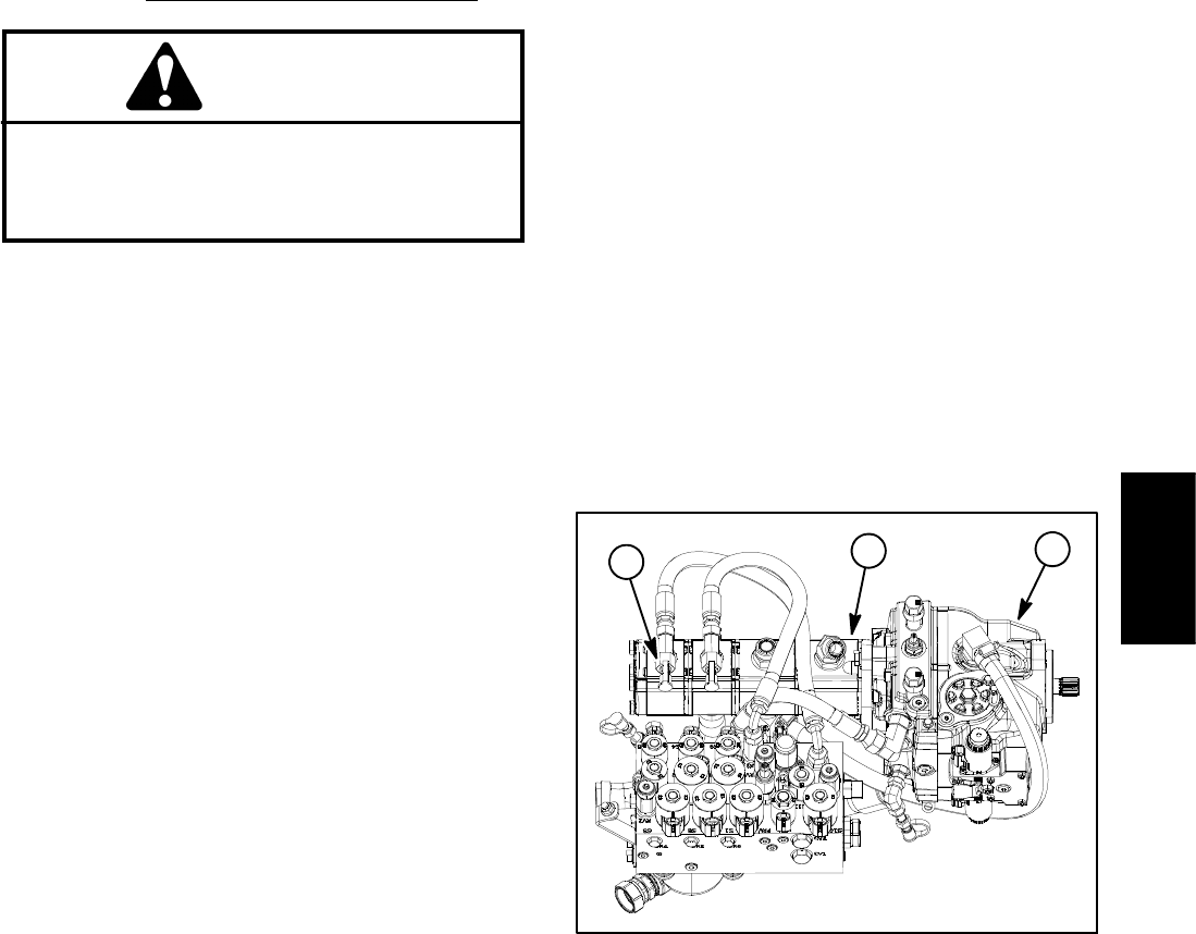
Groundsmaster 4100--D/4110--D Hydraulic SystemPage 4 -- 41
The traction charge circuit is designed to replace loss of
hydraulic fluid from the closed loop traction circuit. This
test is used to make sure that traction charge pressure
is correct.
Procedure for Traction Circuit Charge Pressure Test
CAUTION
Prevent personal injury and/or damage to equip-
ment. Read all WARNINGS, CAUTIONS and Pre-
cautions for Hydraulic Testing at the beginning
of this section.
1. Park machine on a level surface with the cutting deck
lowered and off. Make sure hydraulic oil is at normal op-
erating temperature, engine is off and the parking brake
is applied.
2. Raise and support operator seat.
3. Connect a 1000 PSI (70 bar) pressure gauge to test
fitting attached to tee fitting in final section of gear pump
(Fig. 27).
NOTE: Make sure that steering wheel is not turned dur-
ing charge pressure testing. Also, if engine coolant tem-
perature is elevated, gear pump flow from the final pump
section might be directed to the cooling fan motor which
may affect charge pressure testing results.
4. Start engine and increase engine speed to high idle
speed with no load on the hydraulic system.
GAUGE READING TO BE 200 to 300 PSI (13.8 to
20.6 bar).
5. Stop engine and record test results.
6. If there is no pressure or pressure is low, check for
restriction in gear pump intake line. Also, inspect charge
relief valve located in piston (traction) pump (see Piston
(Traction) Pump Service in the Service and Repairs sec-
tion of this chapter). A worn or damaged gear pump sec-
tioncouldalsobeconsidered(seeGearPumpFlowTest
in this section).
NOTE: If the gear pump section that supplies the
charge circuit is worn or damaged, charge, steering, lift/
lower and engine cooling fan circuits may all be affected.
7. Next, with the pressure gauge still connected to the
charge pressure test port, take a gauge reading while
operating the machine in forward and reverse. Start the
engine and put throttle at high idle speed. Apply the
brakes and push the traction pedal forward while moni-
toring the pressure gauge. Repeat for reverse direction.
Stop engine and record test results.
8. If charge pressure meets specifications under no
load conditions (step 5 above), but consistently drops
more than 15% when under traction load, the piston
(traction) pump and/or traction motor(s) should be sus-
pected of wear and inefficiency. When the pump or mo-
tors are worn or damaged, the charge pump is not able
to keep up with internal leakage in the traction system
components.
9. When testing is completed, disconnect pressure
gauge from test fitting. Secure dust cap to test fitting.
10.Lower and secure operator seat.
1. Piston (traction) pump
2. Gear pump
3. Charge pressure port
Figure 27
1
2
3
Hydraulic
System
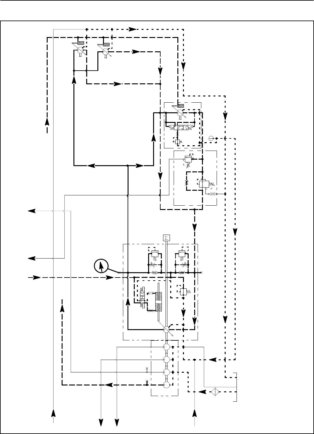
Groundsmaster 4100--D/4110--DHydraulic System Page 4 -- 42
Traction Circuit Relief Pressure (Using Pressure Gauge)
3.3 GPM
4.4 GPM
14.3 GPM
14.3 GPM
PR
380 PSI
RV
650 PSI
.050
CV
T
P2
M8
CH
OR1
250 PSI
2.14 CID /
1.16 CID
200 PSI
4350 PSI
5000 PSI
.0315 .0315
0.4
CID
0.3 1.29 1.29
CID CID CID
2.75
CID
REAR
TRACTION
MANIFOLD
ENGINE
30.5 GPM
1.2 CID /
0.64 CID
1.2 CID /
0.64 CID
GG
G
G
FROM COMBINATION MANIFOLD
TO
COMBINATION
MANIFOLD
FROM
COMBINATION
MANIFOLD
TO
COMBINATION
MANIFOLD
FROM
PTO MANIFOLD
CENTER DECK
FROM
OIL FILTER
TO
PTO MANIFOLD
LEFT DECK
TO
PTO MANIFOLD
CENTER DECK
TO COMBINATION MANIFOLD
PRESSURE
GAUGE
FORWARD TRACTION CIRCUIT
RELIEF PRESSURE TEST SHOWN
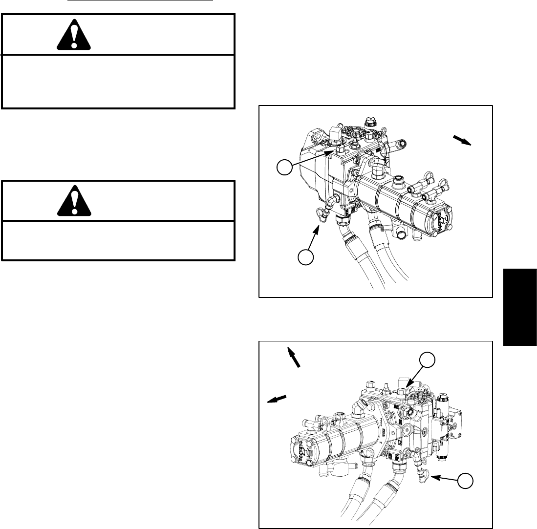
Groundsmaster 4100--D/4110--D Hydraulic SystemPage 4 -- 43
Procedure for Traction Circuit Relief Pressure Test
CAUTION
Prevent personal injury and/or damage to equip-
ment. Read all WARNINGS, CAUTIONS and Pre-
cautions for Hydraulic Testing at the beginning
of this section.
1. Park machine on a level surface with the cutting deck
lowered and off. Make sure hydraulic oil is at normal op-
erating temperature, engine is off and the parking brake
is applied.
When performing the traction circuit relief pres-
sure test, move machine to an open area, away
from people and obstructions.
CAUTION
2. Drive machine to an open area, lower cutting deck,
turn the engine off and apply the parking brake.
3. Connect a 10,000 PSI (700 bar) pressure gauge to
traction circuit test port for function to be checked (Fig.
28 or 29).
4. Start engine and increase engine speed to high idle
speed. Release parking brake. Make sure that HI/LOW
speed switch is in the HI (transport) position.
NOTE: If possible, turn off Smart PowerTM by using the
InfoCenter display protected menu. Machines with TEC
software above revision level G will allow Smart
PowerTM to be disabled for testing. Check software revi-
sion level using the InfoCenter About screen.
5. Sit on seat, apply brakes fully and slowly depress the
traction pedal in the appropriate direction (forward or re-
verse). While pushing traction pedal, look at pressure
reading on gauge:
GAUGE READING TO BE:
Forward: 4100 to 4600 PSI (283 to 317 bar)
Reverse: 4750 to 5250 PSI (328 to 362 bar)
6. Release traction pedal and stop engine. Record test
results.
7. If traction pressure is too low, inspect traction pump
relief valves (Fig. 28 or 29). Clean or replace relief
valves as necessary. These cartridge type valves are
factory set, and are not adjustable. If relief valves are in
good condition, traction pump or wheel motors should
be suspected of wear and inefficiency.
8. When testing is completed, disconnect pressure
gauge from test port. Secure dust cap to test fitting.
1. Forward traction port 2. Forward relief valve
Figure 28
FRONT
1
2
1. Reverse traction port 2. Reverse relief valve
Figure 29
FRONT
RIGHT
1
2
Hydraulic
System
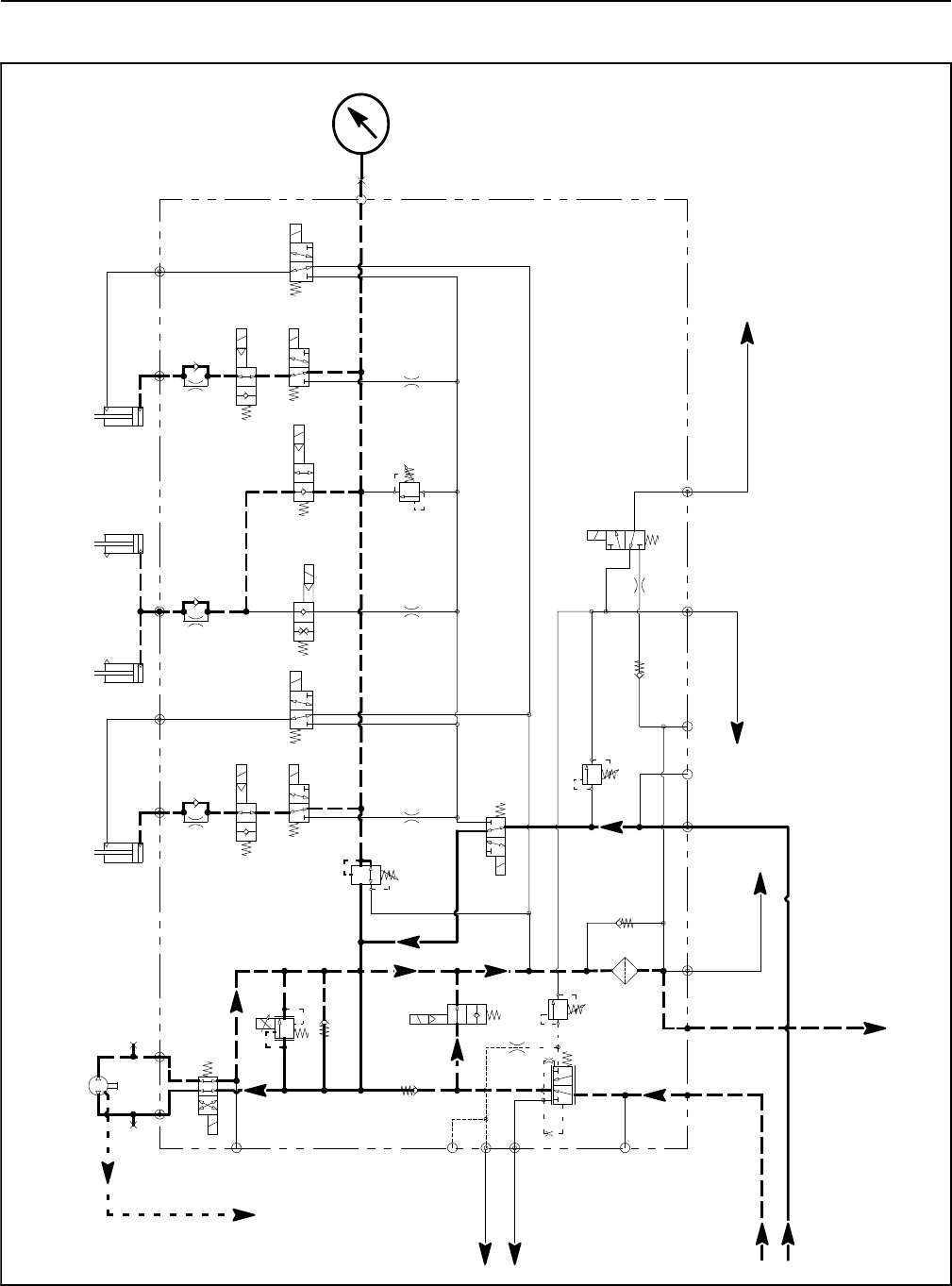
Groundsmaster 4100--D/4110--DHydraulic System Page 4 -- 44
Counterbalance Pressure (Using Pressure Gauge)
PRESSURE
GAUGE
S10
RV1
CV1
S2
S4
S5
PRV
P4 CH2 P3
EC
CF
LS
S3
OR1
C3
OR4
.040
S6
OR5
.070
C4 C2 C5
RV2
S7
S9
S8
C6
M1 M2
CH1
CV3
CH4
OR2
.063
OR6
.063
OR3
.070
OR7
.070
T2SPCH3
G2
G4
CV4
PR
G1
G3
3250
PSI
1350
PSI
4PSI
4PSI
.030
OR9
S1
3300 PSI
RV3 S12
S11
CV2
4PSI
0.51 CID
1.125” ROD
.030”
80
PSI
60
PSI
310
PSI
2.50” BORE
6.50” STROKE
1.50” BORE
3.08” STROKE
RAM CYLINDERS
CENTER DECK
1.125” ROD
2.50” BORE
6.50” STROKE
GG
COMBINATION MANIFOLD
RIGHT DECK
LEFT DECK
TO FRONT
TO RESERVOIR TO STEERING
CONTROL VALVE
TO STEERING
CONTROL VALVE
FROM GEAR PUMP
TRACTION
VALVE
TO PISTON
PUMP
TO RESERVOIR TO WHEEL/AXLE
MOTORS
FROM GEAR PUMP
2500 PSI
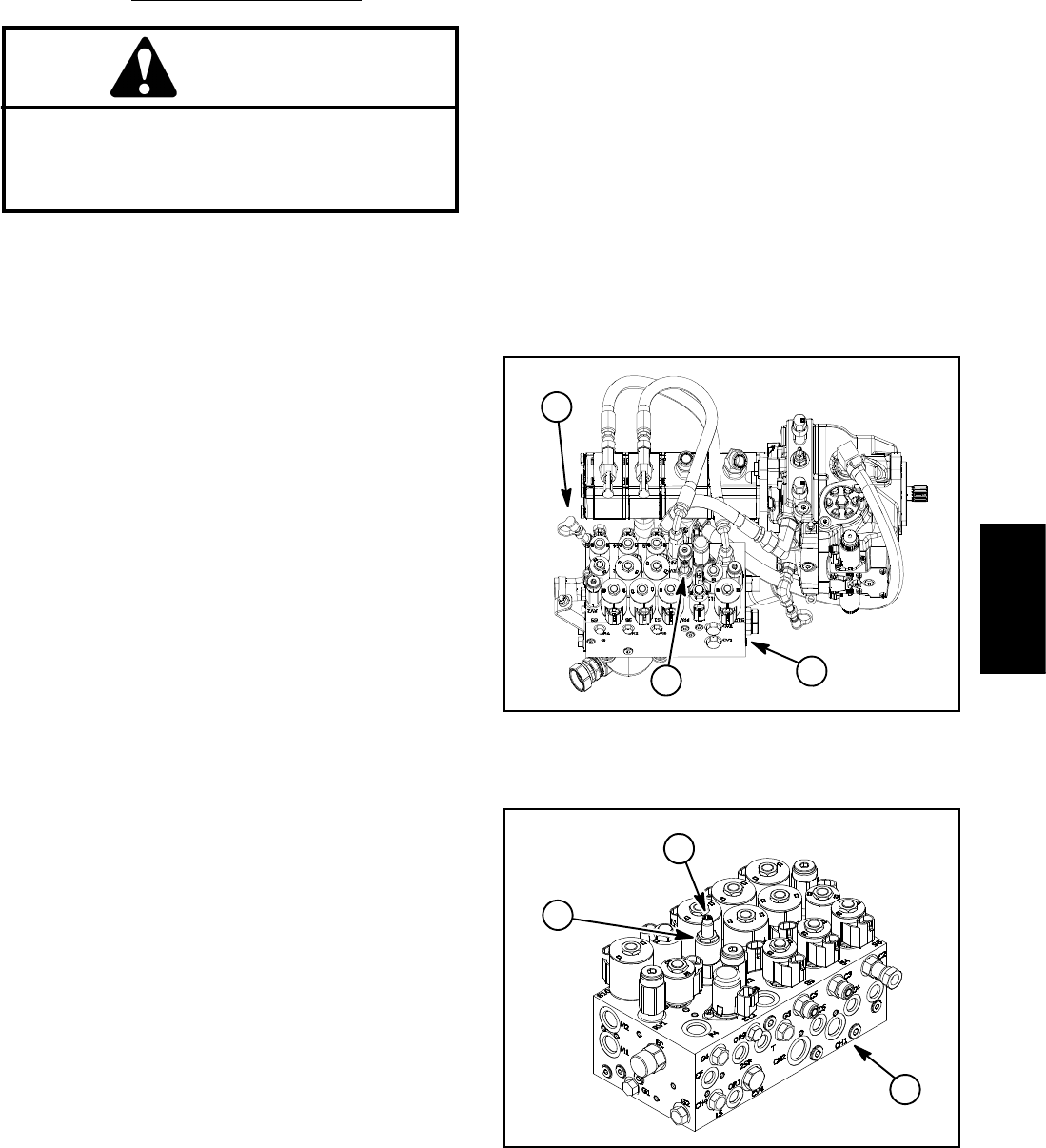
Groundsmaster 4100--D/4110--D Hydraulic SystemPage 4 -- 45
Procedure for Counterbalance Pressure Test
CAUTION
Prevent personal injury and/or damage to equip-
ment. Read all WARNINGS, CAUTIONS and Pre-
cautions for Hydraulic Testing at the beginning
of this section.
1. Park machine on a level surface with the cutting deck
lowered and off. Make sure hydraulic oil is at normal op-
erating temperature, engine is off and the parking brake
is applied.
2. Raise and support operator seat to gain access to
combination manifold.
3. Connect a 1000 PSI (70 bar) pressure gauge to test
port G1 on combination manifold (Fig. 30).
NOTE: The cutting deck need to be in the float position
when checking counterbalance pressure. Also, make
sure that all of the cutting deck castor wheels are on the
ground when testing or adjusting counterbalance pres-
sure.
IMPORTANT: While testing counterbalance pres-
sure, DO NOT raise the cutting deck. If deck is
raised, system pressure increase will damage pres-
sure gauge.
4. Start engine and increase engine speed to high idle
speed with no load on the hydraulic system. Do not en-
gage the cutting deck.
GAUGE READING TO BE approximately 325 PSI
(22.4 bar).
NOTE: The recommended counterbalance pressure is
325 PSI (22.4 bar).
5. Stop engine and record test results.
6. The pressure reducing valve on the combination
manifold is used to set the counterbalance pressure
(Fig. 31). If necessary, adjust pressure reducing valve:
NOTE: Because of valve design, the pressure reducing
valve can be adjusted with the engine running. Do not
remove the pressure reducing valve from the hydraulic
manifold for adjustment.
A. Locate pressure reducing valve on combination
manifold (Fig. 31). Loosen lock nut on pressure redu-
cing valve.
B. Start engine and increase engine speed to high
idle speed with no load on the hydraulic system. Do
not engage the cutting deck.
C. To increase pressure setting, turn the adjust-
ment screw on the valve in a clockwise direction. A
1/8 turn on the screw will make a measurable change
in counterbalance pressure.
D. To decrease pressure setting, turn the adjust-
ment screw on the valve in a counterclockwise direc-
tion. A 1/8 turn on the screw will make a measurable
change in counterbalance pressure.
E. Tighten lock nut to secure adjustment. Check
counterbalance pressure and readjust as needed.
7. When testing is completed, disconnect pressure
gauge from manifold test port. Secure dust cap to test
fitting. Lower operator seat.
1. Combination manifold
2. Test port G1
3. Pressure reducing valve
Figure 30
2
1
3
1. Combination manifold
2. Pressure reducing valve
3. Adjustment screw
Figure 31
2
3
1
Hydraulic
System

Groundsmaster 4100--D/4110--DHydraulic System Page 4 -- 46
Reverse Traction Circuit Reducing Valve (PR) Pressure (Using Pressure Gauge)
3.3 GPM
4.4 GPM
14.3 GPM
14.3 GPM
PR
380 PSI
RV
650 PSI
.050
CV
T
P2
M8
CH
OR1
250 PSI
2.14 CID /
1.16 CID
200 PSI
4350 PSI
5000 PSI
.0315 .0315
0.4
CID
0.3 1.29 1.29
CID CID CID
2.75
CID
REAR
TRACTION
MANIFOLD
ENGINE
30.5 GPM
1.2 CID /
0.64 CID
1.2 CID /
0.64 CID
GG
G
G
FROM COMBINATION MANIFOLD
TO
COMBINATION
MANIFOLD
FROM
COMBINATION
MANIFOLD
FROM
PTO MANIFOLD
CENTER DECK
FROM
OIL FILTER
TO
PTO MANIFOLD
LEFT DECK
TO
PTO MANIFOLD
CENTER DECK
TO COMBINATION MANIFOLD
PRESSURE
GAUGE
TO
COMBINATION
MANIFOLD
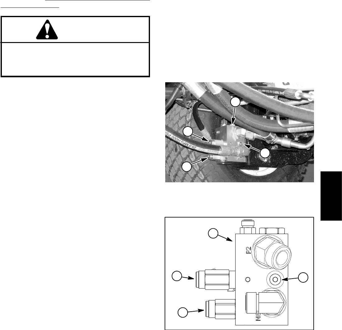
Groundsmaster 4100--D/4110--D Hydraulic SystemPage 4 -- 47
Procedure for Reverse Traction Circuit Reducing
Valve (PR) Pressure Test
CAUTION
Prevent personal injury and/or damage to equip-
ment. Read all WARNINGS, CAUTIONS and Pre-
cautions for Hydraulic Testing at the beginning
of this section.
1. Park machine on a level surface with the cutting deck
lowered and off. Make sure hydraulic oil is at normal op-
erating temperature, engine is off and the parking brake
is applied.
NOTE: The #6 zero leak plug on the inside of rear trac-
tion manifold is a zero leak plug that has a tapered seal-
ing surface on the plug head. Lightly rap the plug head
using a punch and hammer before using an allen
wrench to remove the plug: the impact will allow plug re-
moval with less chance of damage to the socket head of
the plug.
2. Locate rear traction manifold that is attached to the
front frame next to the left side front wheel (Fig. 32). Re-
move #6 zero leak plug on the inside of rear traction
manifold and install diagnostic fitting (Toro part number
59--7410) into manifold port.
3. Connect a 1000 PSI (70 bar) pressure gauge with hy-
draulic hose attached to installed diagnostic fitting.
4. Start engine and increase engine speed to high idle
speed. Make sure that HI/LOW speed switch is in the
LOW speed (mow) position and release parking brake.
5. Sit on seat, apply brakes fully and slowly depress the
traction pedal in the reverse direction. While pushing
traction pedal, carefully monitor the pressure gauge to
identify the opening pressure of the pressure reducing
(PR) valve:
GAUGE READING TO BE approximately 380 PSI
(26 bar) when the pressure reducing (PR) valve
opens.
6. Stop engine and record test results.
7. The pressure reducing (PR) valve is located on the
rear side of the rear traction manifold (Figs. 32 and 33).
If test pressure is incorrect, adjust pressure reducing
(PR) valve (see Adjust Control Manifold Relief Valves in
the Adjustments section of this chapter). Recheck pres-
sure reducing valve pressure after any adjustment.
NOTE: The rear traction circuit relief valve (RV) pres-
sure test uses the same pressure gauge position as
used to measure reverse traction circuit reducing valve
(PR) pressure. If necessary, conduct the rear traction
circuit relief valve (RV) pressure test before removing
pressure gauge from rear traction manifold.
8. When testing is completed, disconnect pressure
gauge from the installed diagnostic fitting. Remove
diagnostic fitting from manifold and install removed plug
into manifold. Torque plug to 25 ft--lb (34 N--m).
1. Rear traction manifold
2. #6 zero leak plug
3. Relief(RV)valve
4. Reducing (PR) valve
Figure 32
2
1
3
4
1. Rear traction manifold
2. #6 zero leak plug
3. Relief(RV)valve
4. Reducing (PR) valve
Figure 33
1
2
3
4
Hydraulic
System
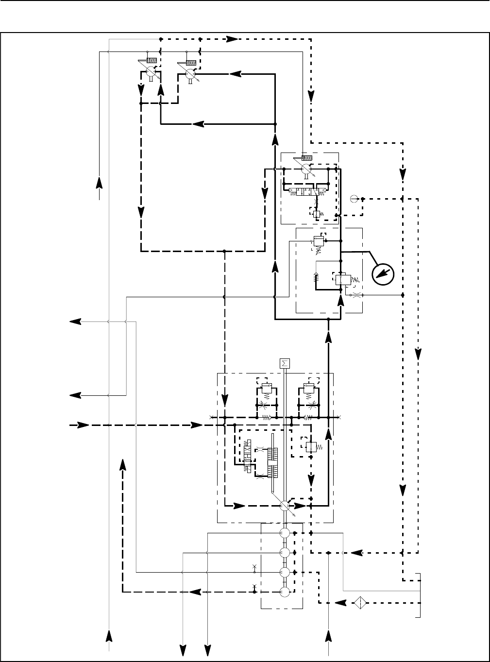
Groundsmaster 4100--D/4110--DHydraulic System Page 4 -- 48
Rear Traction Circuit Relief Valve (RV) Pressure (Using Pressure Gauge)
3.3 GPM
4.4 GPM
14.3 GPM
14.3 GPM
PR
380 PSI
RV
650 PSI
.050
CV
T
P2
M8
CH
OR1
250 PSI
2.14 CID /
1.16 CID
200 PSI
4350 PSI
5000 PSI
.0315 .0315
0.4
CID
0.3 1.29 1.29
CID CID CID
2.75
CID
REAR
TRACTION
MANIFOLD
ENGINE
30.5 GPM
1.2 CID /
0.64 CID
1.2 CID /
0.64 CID
GG
G
G
FROM COMBINATION MANIFOLD
TO
COMBINATION
MANIFOLD
FROM
COMBINATION
MANIFOLD
FROM
PTO MANIFOLD
CENTER DECK
FROM
OIL FILTER
TO
PTO MANIFOLD
LEFT DECK
TO
PTO MANIFOLD
CENTER DECK
TO COMBINATION MANIFOLD
PRESSURE
GAUGE
TO
COMBINATION
MANIFOLD
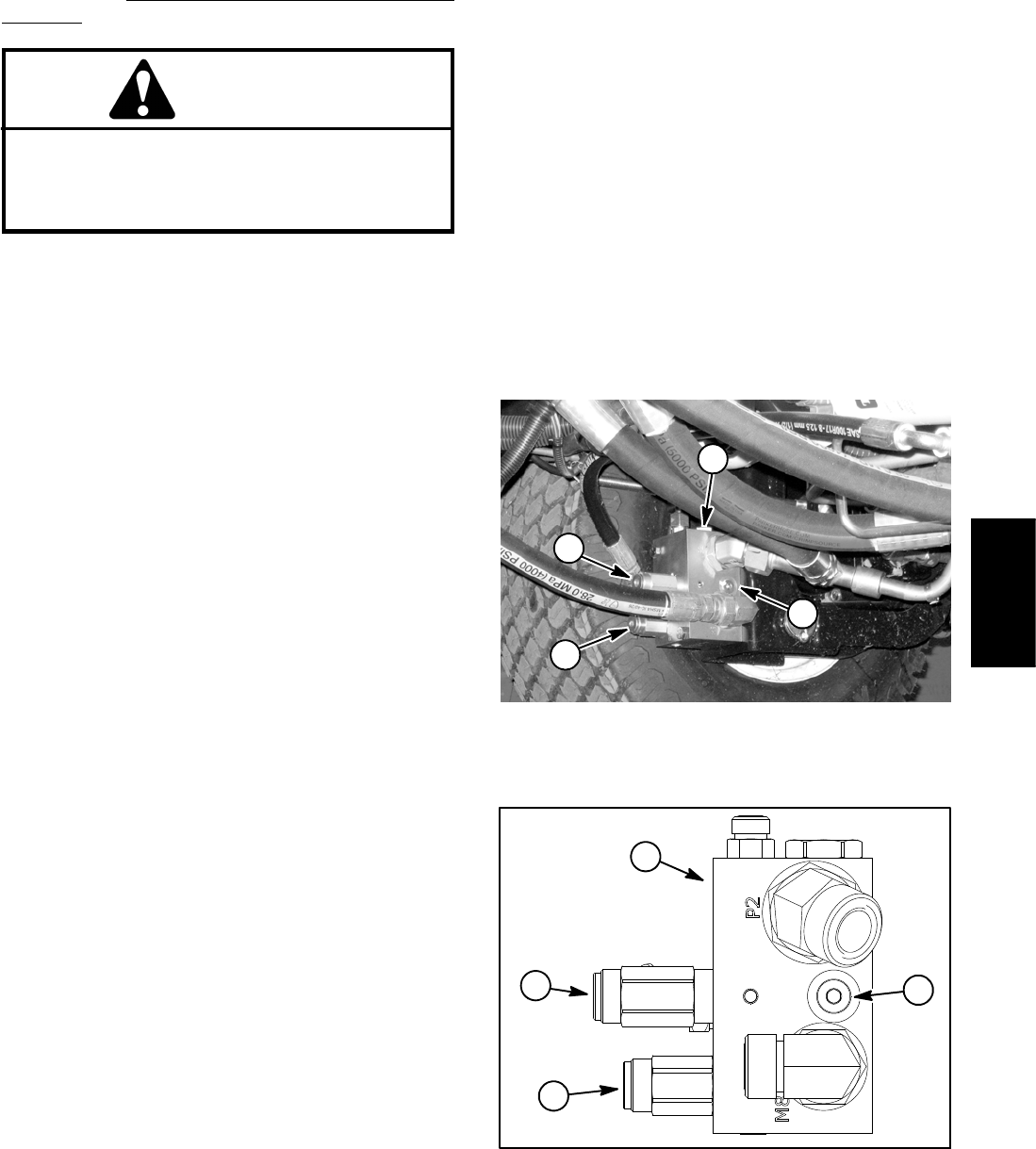
Groundsmaster 4100--D/4110--D Hydraulic SystemPage 4 -- 49
Procedure for Rear Traction Circuit Relief Valve (RV)
Pressure Test
CAUTION
Prevent personal injury and/or damage to equip-
ment. Read all WARNINGS, CAUTIONS and Pre-
cautions for Hydraulic Testing at the beginning
of this section.
1. Park machine on a level surface with the cutting deck
lowered and off. Make sure hydraulic oil is at normal op-
erating temperature, engine is off and the parking brake
is applied.
NOTE: This test uses the same pressure gauge posi-
tion as used to measure reverse traction circuit reducing
valve (PR) pressure.
NOTE: The #6 zero leak plug on the inside of rear trac-
tion manifold is a zero leak plug that has a tapered seal-
ing surface on the plug head. Lightly rap the plug head
using a punch and hammer before using an allen
wrench to remove the plug: the impact will allow plug re-
moval with less chance of damage to the socket head of
the plug.
2. Locate rear traction manifold that is attached to the
front frame next to the left side front wheel (Fig. 34). Re-
move #6 zero leak plug on inside of rear traction mani-
fold and install diagnostic fitting (Toro part number
59--7410) into manifold port.
3. Connect a 1000 PSI (70 bar) pressure gauge with hy-
draulic hose attached to installed diagnostic fitting.
4. Start engine and increase engine speed to high idle
speed. Make sure that HI/LOW switch is in the LOW
(mow) position and release the parking brake.
5. OperatethemachineinLOWspeed(mow)withthe
cutting deck lowered. Drive down a slope in a forward di-
rection, decrease pressure on the traction pedal and
monitor the pressure gauge. Pressure should increase
until the rear traction circuit relief valve lifts.
GAUGE READING TO BE approximately 650 PSI
(45 bar) when the rear traction relief valve (RV)
opens.
6. Stop engine and record test results.
NOTE: If the rear traction circuit reducing valve (PR)
pressure is excessive, operation of the rear traction re-
lief valve (RV) may be affected. Before adjusting rear
traction relief valve (RV), make sure that pressure redu-
cing valve (PR) pressure is correct.
7. The rear traction circuit relief valve (RV) is located on
the rear side of the rear traction manifold (Figs. 34 and
35). If test pressure is incorrect, adjust relief valve (RV)
(see Adjust Control Manifold Relief Valves in the Adjust-
ments section of this chapter).
8. When testing is completed, disconnect pressure
gauge from the installed diagnostic fitting. Remove
diagnostic fitting from manifold and install removed plug
into manifold. Torque plug to 25 ft--lb (34 N--m).
1. Rear traction manifold
2. #6 zero leak plug
3. Relief(RV)valve
4. Reducing (PR) valve
Figure 34
2
1
3
4
1. Rear traction manifold
2. #6 zero leak plug
3. Relief(RV)valve
4. Reducing (PR) valve
Figure 35
1
2
3
4
Hydraulic
System
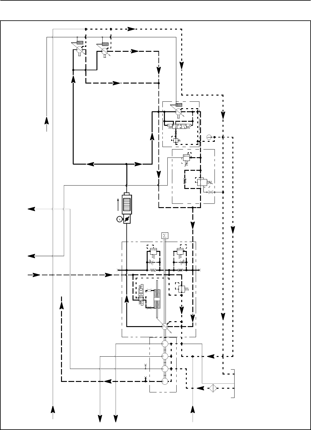
Groundsmaster 4100--D/4110--DHydraulic System Page 4 -- 50
Piston (Traction) Pump Flow (Using Tester with Flow meter and Pressure Gauge)
3.3 GPM
4.4 GPM
14.3 GPM
14.3 GPM
PR
380 PSI
RV
650 PSI
.050
CV
T
P2
M8
CH
OR1
250 PSI
2.14 CID /
1.16 CID
200 PSI
4350 PSI
5000 PSI
.0315 .0315
0.4
CID
0.3 1.29 1.29
CID CID CID
2.75
CID
REAR
TRACTION
MANIFOLD
ENGINE
30.5 GPM
1.2 CID /
0.64 CID
1.2 CID /
0.64 CID
GG
G
G
FROM COMBINATION MANIFOLD
TO
COMBINATION
MANIFOLD
FROM
COMBINATION
MANIFOLD
TO
COMBINATION
MANIFOLD
FROM
PTO MANIFOLD
CENTER DECK
FROM
OIL FILTER
TO
PTO MANIFOLD
LEFT DECK
TO
PTO MANIFOLD
CENTER DECK
TO COMBINATION MANIFOLD
TESTER
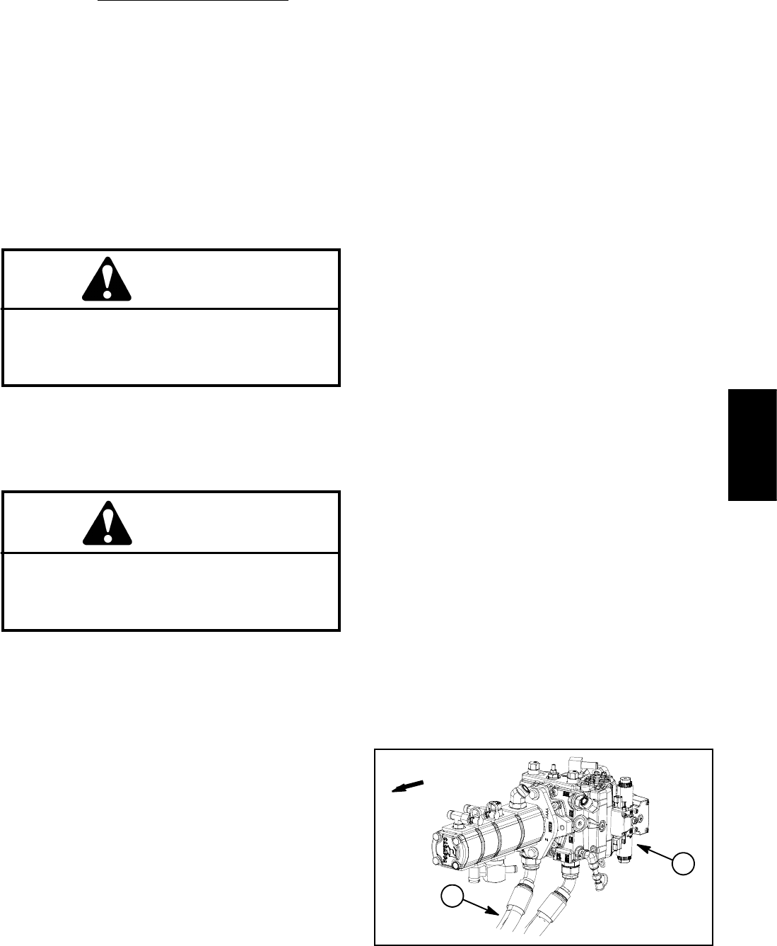
Groundsmaster 4100--D/4110--D Hydraulic SystemPage 4 -- 51
Procedure for Piston (Traction) Pump Flow Test
This test measures piston (traction) pump output (flow).
During this test, pump load is created at the flow meter
using the adjustable load valve on the tester.
NOTE: Before performing piston pump flow test, make
sure that traction speed is set to 100% using the In-
foCenter settings menu.
IMPORTANT: Traction circuit flow for the
Groundsmaster 4100--D/4110--D is approximately 30
GPM(113.5LPM).Use40GPMHydraulicTester
#AT40002 (pressure and flow) for this test (see Spe-
cial Tools in this chapter).
CAUTION
Prevent personal injury and/or damage to equip-
ment. Read all WARNINGS, CAUTIONS and Pre-
cautions for Hydraulic Testing at the beginning
of this section.
1. Park machine on a level surface with the cutting deck
lowered and off. Make sure hydraulic oil is at normal op-
erating temperature, engine is off and the parking brake
is applied.
CAUTION
All wheels will be off the ground and rotating dur-
ing this test. Make sure machine is supported so
it will not move and accidentally fall to prevent in-
juring anyone near the machine.
2. Raise and support machine so all wheels are off the
ground (see Jacking Instructions in Chapter 1 -- Safety).
3. Thoroughly clean junction of hydraulic hose and
right side fitting on bottom of piston pump (forward port)
(Fig. 36). Disconnect hose from right side pump fitting.
4. Install tester with pressure gauge and flow meter in
series between piston pump fitting and disconnected
hosetoallowflowfromtractionpumptotester.Usehy-
draulic hose kit (see Special Tools in this chapter) to con-
nect tester to machine. Make sure that fitting and hose
connections are properly tightened. Also, make sure the
flow control valve on tester is fully open.
5. Start engine and increase engine speed to high idle
speed.
NOTE: If possible, turn off Smart PowerTM by using the
InfoCenter display protected menu. Machines with TEC
software above revision level G will allow Smart
PowerTM to be disabled for testing. Check software revi-
sion level using the InfoCenter About screen.
6. Slowly push traction pedal to fully forward position.
Keep pedal fully depressed in the fully forward position.
7. Have second person watch pressure gauge on test-
er carefully while slowly closing the flow control valve
until 1000 PSI (69 bar) is obtained. Verify with the In-
foCenter display that the engine speed is still at the cor-
rect high idle speed.
NOTE: If engine speed drops during testing, pump flow
will decrease and flow test results will be inaccurate.
8. Observe flow gauge. Flow indication should be
approximately 30 GPM (113 LPM).
9. Release traction pedal to neutral, open flow control
valveontesterandshutoffengine. Record test results.
10.If flow is less than 24 GPM (91 LPM), consider the
following:
A. The traction pedal is not calibrated correctly (see
Traction Pedal Calibration in the Adjustments sec-
tion of Chapter 5 -- Electrical System).
B. The piston pump swash plate is not being rotated
fully (e.g. traction speed is not set to 100%).
C. The forward traction relief valve is leaking or
faulty.
D.Thepistonpumpneedstoberepairedorre-
placed as necessary.
11. Make necessary repairs before performing any addi-
tional traction circuit tests.
12.When testing is complete, disconnect tester from
pump fitting and machine hydraulic hose. Reconnect
hose to pump fitting. Lower machine to ground.
1. Piston (traction) pump 2. Forward direction hose
Figure 36
FRONT
1
2
Hydraulic
System
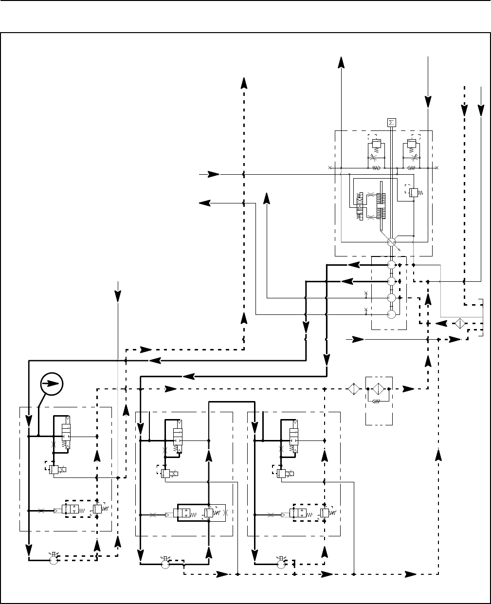
Groundsmaster 4100--D/4110--DHydraulic System Page 4 -- 52
Cutting Deck Circuit Pressure (Using Pressure Gauge)
CENTER DECK CIRCUIT PRESSURE TEST SHOWN
PRESSURE
GAUGE
3.3 GPM
14.3 GPM
14.3 GPM
1.17 CID 3000 PSI
P1
P1
P1
P2
P2
P2
M1
M2
LC1
PRV
PD
CD
RV
2000 PSI
M1
M2
LC1
PRV
PD
RV
3000 PSI
M1
M2
LC1
PRV
PD
RV
CD
CD
LEFT DECK
CENTER DECK
RIGHT DECK
50 PSI
1.17 CID
1.17 CID
250 PSI
600 PSI
600 PSI
600 PSI
4350 PSI
5000 PSI
.025
.025
.025
.0315 .0315
0.4
CID
0.3 1.29 1.29
CID CID CID
2.75
CID
ENGINE
30.5
GPM
G
GG
G
G
CONTROL VALVE
FROM STEERING
TO COMBINATION MANIFOLD
TO
COMBINATION
MANIFOLD
FROM
COMBINATION
MANIFOLD
TO WHEEL
MOTORS
TO RESERVOIR
FROM MANIFOLD
AND FAN MOTOR
FROM REAR
TRACTION
MANIFOLD
FROM CENTER
DECK MANIFOLD
FROM REAR AXLE MOTOR
G
G
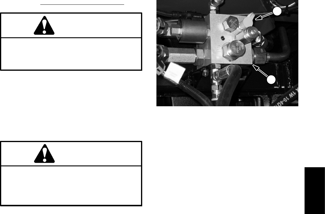
Groundsmaster 4100--D/4110--D Hydraulic SystemPage 4 -- 53
Procedure for Cutting Deck Circuit Pressure Test
CAUTION
Prevent personal injury and/or damage to equip-
ment. Read all WARNINGS, CAUTIONS and Pre-
cautions for Hydraulic Testing at the beginning
of this section.
1. Park machine on a level surface with the cutting deck
lowered and off. Make sure hydraulic oil is at normal op-
erating temperature, engine is off and the parking brake
is applied.
2. Install 5000 PSI (350 bar) pressure gauge with hy-
draulic hose attached to manifold test port (G) for the
deck to be tested (Fig. 37).
CAUTION
Cutting deck blades will rotate when cutting
deck is lowered with PTO switch in ON position.
Keep away from deck during test to prevent per-
sonal injury from rotating blades. Do not stand in
front of the machine.
3. Start engine and increase engine speed to high idle
speed. Release the parking brake.
4. Watch pressure gauge carefully while mowing with
the machine.
5. Cutting deck circuit pressure should be as follows
and will vary depending on mowing conditions:
LH Wing Deck: 1000 to 3000 PSI (69 to 207 bar)
Center Deck: 1000 to 3000 PSI (69 to 207 bar)
RHWingDeck:1000to2000PSI(69to137bar)
6. Disengage cutting deck. Shut off engine and record
test results.
7. When testing is completed, disconnect pressure
gauge with hose from manifold test fitting. Secure dust
captotestfitting.
1. PTO manifold (front) 2. Manifold test port
Figure 37
1
2
Hydraulic
System
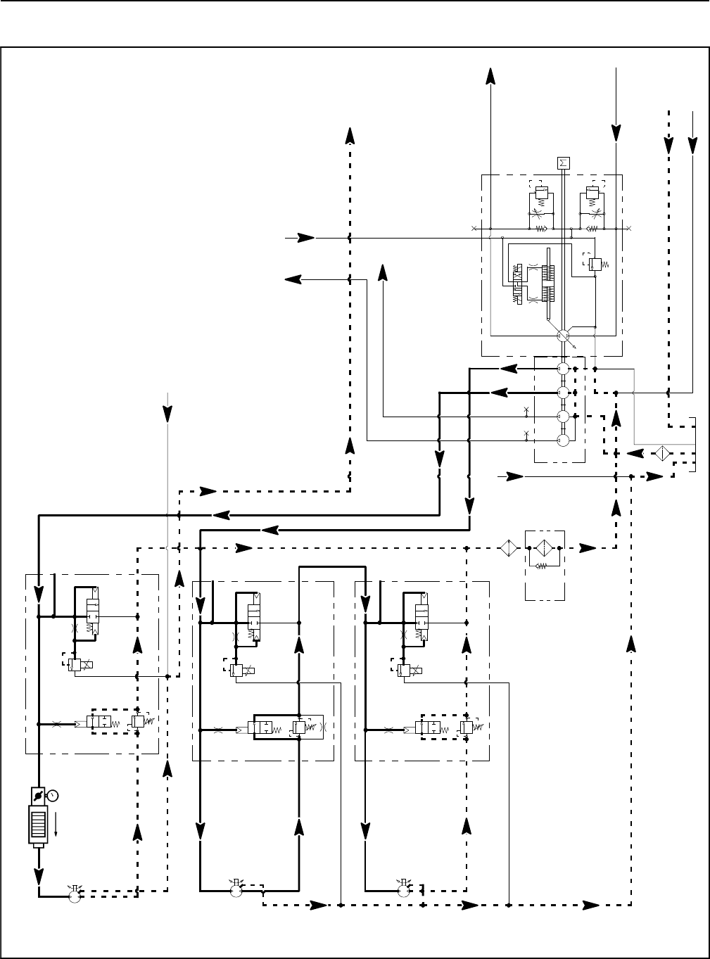
Groundsmaster 4100--D/4110--DHydraulic System Page 4 -- 54
PTO Relief Pressure (Using Tester with Pressure Gauge and Flow Meter)
CENTER DECK PTO RELIEF PRESSURE TEST SHOWN
3.3 GPM
14.3 GPM
14.3 GPM
1.17 CID 3000 PSI
P1
P1
P1
P2
P2
P2
M1
M2
LC1
PRV
PD
CD
RV
2000 PSI
M1
M2
LC1
PRV
PD
RV
3000 PSI
M1
M2
LC1
PRV
PD
RV
CD
CD
LEFT DECK
CENTER DECK
RIGHT DECK
50 PSI
1.17 CID
1.17 CID
250 PSI
600 PSI
600 PSI
600 PSI
4350 PSI
5000 PSI
.025
.025
.025
.0315 .0315
0.4
CID
0.3 1.29 1.29
CID CID CID
2.75
CID
ENGINE
G
G
G
GG
G
G
CONTROL VALVE
FROM STEERING
TO COMBINATION MANIFOLD
TO
COMBINATION
MANIFOLD
FROM
COMBINATION
MANIFOLD
TO RESERVOIR
FROM MANIFOLD
AND FAN MOTOR
FROM REAR
TRACTION
MANIFOLD
FROM CENTER
DECK MANIFOLD
FROM REAR AXLE MOTOR
TESTER
TO TRACTION
MOTORS
30.5 GPM
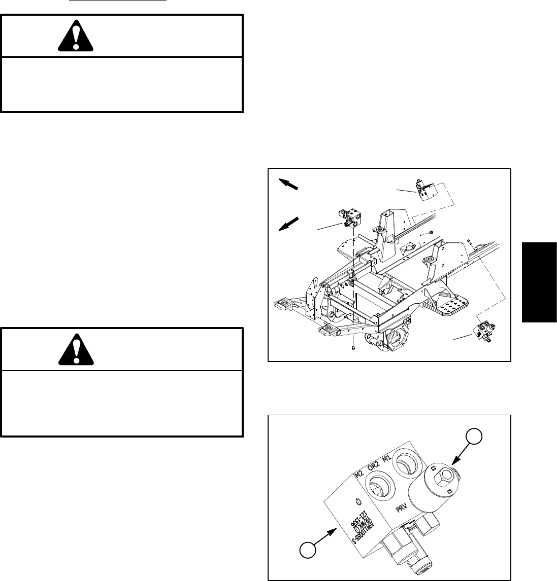
Groundsmaster 4100--D/4110--D Hydraulic SystemPage 4 -- 55
The PTO circuit relief pressure test should be performed
to make sure that the PTO circuit relief pressures are
correct.
Procedure for PTO Relief Pressure Test
CAUTION
Prevent personal injury and/or damage to equip-
ment. Read all WARNINGS, CAUTIONS and Pre-
cautions for Hydraulic Testing at the beginning
of this section.
1. Park machine on a level surface with the cutting deck
lowered and off. Make sure hydraulic oil is at normal op-
erating temperature, engine is off and the parking brake
is applied.
2. Locate PTO (deck) manifold to be tested (Fig. 38).
Disconnect hydraulic hose at PTO manifold port (M1).
NOTE: An alternative to using manifold port (M1) would
be to disconnect the inlet hydraulic hose to the deck mo-
tor.
3. Install tester (flow and pressure) in series with the
disconnected hose and PTO manifold port (M1) (or mo-
tor inlet if hose was disconnected at deck motor). Make
sure the flow control valve on tester is fully open.
CAUTION
Cutting deck blades will rotate when cutting
deck is lowered with PTO switch in ON position.
Keep away from cutting deck during test to pre-
vent personal injury from rotating blades. Do not
stand in front of the machine.
4. Start engine and increase engine speed to high idle
speed. Release the parking brake.
5. Watch pressure gauge carefully while slowly closing
the tester flow control valve to fully closed.
6. As the PTO relief valve lifts, system pressure should
be approximately:
2900 to 3100 PSI (200 to 213 bar) for the center and
left wing decks
1900 to 2100 PSI (131 to 144 bar) for the right wing
deck
7. Fully open tester flow control valve and disengage
cutting deck. Shut off engine and record test results.
8. If relief pressure is incorrect, remove PRV valve on
mow manifold and clean or replace valve (see PTO
Manifold Service in the Service and Repairs section of
this chapter). Also, if pressure is still low after PRV valve
service, check for restriction in pump intake line. The
front gear pump section (center cutting deck circuit) and/
or the second gear pump section (side cutting deck cir-
cuits) could also be suspected of wear, damage or
inefficiency (see Gear Pump Flow Test in this section).
9. When relief pressure testing is complete, disconnect
tester from PTO manifold and hydraulic hose. Recon-
nect hydraulic hose that was disconnected for test pro-
cedure.
1. Center PTO manifold
2. LH PTO manifold
3. RH PTO manifold
Figure 38
FRONT
RIGHT
1
3
2
1. PTO manifold 2. PRV valve
Figure 39
1
2
LEFT PTO MANIFOLD SHOWN
Hydraulic
System
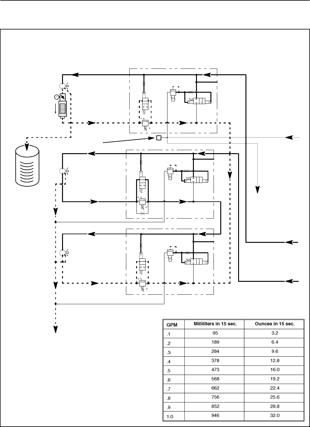
Groundsmaster 4100--D/4110--DHydraulic System Page 4 -- 56
Cutting Deck Motor Case Drain Leakage (Using Tester with Pressure Gauge and Flow
Meter)
CENTER CUTTING DECK MOTOR
CASE DRAIN LEAKAGE TEST SHOWN
1.17 CID
3000 PSI
P1
P1
P2
P2
M1
M2
LC1
PRV
PD
CD
RV
2000 PSI
M1
M2
LC1
PRV
PD
RV
3000 PSI
M1
M2
LC1
PRV
PD
RV
CD
CD
LEFT DECK
CENTER DECK
RIGHT DECK
1.17 CID
1.17 CID
600 PSI
600 PSI
600 PSI
.025
.025
.025
G
G
CONTROL VALVE
FROM STEERING
TO RESERVOIR
TESTER
TO RESERVOIR
FROM SECOND
GEAR PUMP SECTION
FROM FRONT
GEAR PUMP SECTION
MEASURING
CONTAINER
CAP
G
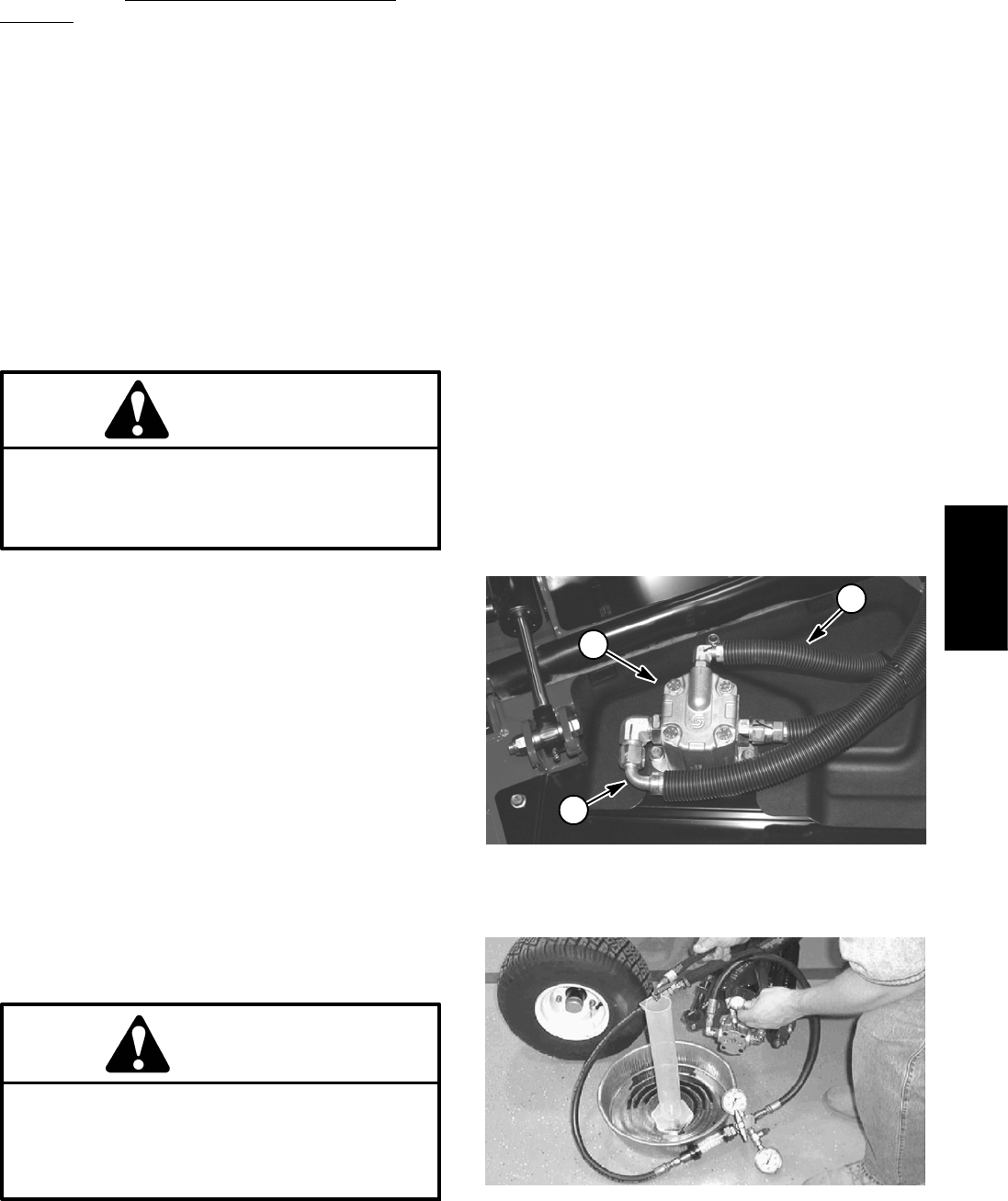
Groundsmaster 4100--D/4110--D Hydraulic SystemPage 4 -- 57
Procedure for Cutting Deck Motor Case Drain
Leakage Test
NOTE: Over a period of time, a deck motor can wear in-
ternally. A worn motor may by--pass oil to its case drain
causing the motor to be less efficient. Eventually,
enough oil loss will cause the deck motor to stall under
heavy cutting conditions. Continued operation with a
worn, inefficient motor can generate excessive heat,
cause damage to seals and other components in the hy-
draulic system and affect quality of cut.
NOTE: Onemethodtofindafailingormalfunctioning
deck motor is to have another person observe the ma-
chine while mowing in dense turf. A bad motor will run
slower, produce fewer clippings and may cause a differ-
ent appearance on the turf.
CAUTION
Prevent personal injury and/or damage to equip-
ment. Read all WARNINGS, CAUTIONS and Pre-
cautions for Hydraulic Testing at the beginning
of this section.
1. Park machine on a level surface with the cutting deck
lowered and off. Make sure hydraulic oil is at normal op-
erating temperature, engine is off and the parking brake
is applied.
NOTE: The wing deck motors are connected in series.
To isolate a faulty wing deck motor, both motors in the
circuit may have to be tested by starting with the left side
motor first.
2. Disconnect hose from return of the motor to be
tested (Fig. 40). Install tester (flow and pressure) in se-
ries with the motor and disconnected return hose. Make
sure the flow control valve on tester is fully open.
3. Disconnect the motor case drain hose (small diame-
ter hose) where it connects to hydraulic manifold tee fit-
ting (not at the motor). Put a steel cap on the fitting at the
tee fitting; leave the case drain hose open.
CAUTION
Cutting deck blades will rotate when cutting
deck is lowered with PTO switch in ON position.
Keep away from cutting deck during test to pre-
vent personal injury from rotating blades. Do not
stand in front of the machine.
4. Sit on seat and start the engine. With engine running,
increase engine speed to high idle speed and release
the parking brake. Engage the cutting deck.
5. While watching pressure gauge, slowly close flow
control valve on tester until a pressure of 1200 PSI (83
bar) is obtained.
NOTE: Use a graduated container, special tool
TOR4077, to measure case drain leakage (Fig. 41).
6. Have a second person collect the flow from the case
drain line for 15 seconds, then move the PTO switch to
OFF and stop the engine (Fig. 41). Record test results.
TEST RESULTS: Flow less than 22.4 ounces (662
ml) (0.7 GPM/2.6 LPM) of hydraulic fluid in 15 sec-
onds.
7. If flow is more than 22.4 ounces (662 ml) (0.7
GPM/2.6 LPM) in 15 seconds, the motor is worn or dam-
aged and should be repaired or replaced.
8. After testing is completed, disconnect tester from
motor and hose. Reconnect hose to the deck motor. Re-
move cap from tee fitting and reconnect case drain hose
to tee fitting.
1. Deck motor (RH shown)
2. Return hose
3. Case drain hose
Figure 40
1
3
2
Figure 41
Hydraulic
System
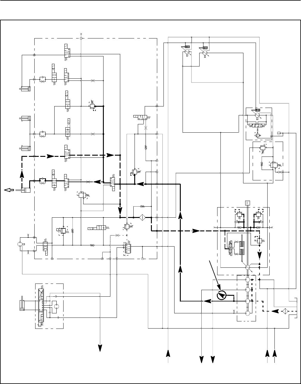
Groundsmaster 4100--D/4110--DHydraulic System Page 4 -- 58
Lift/Lower Circuit Relief Pressure (Using Pressure Gauge)
S10
RV1
CV1
S2
S4
S5
PRV
P4 CH2 P3
EC
CF
LS
S3
OR1
C3
OR4
.040
S6
OR5
.070
C4 C2 C5
RV2
S7
S9
S8
C6
M1 M2
CH1
CV3
CH4
OR2
.063 OR6
.063
OR3
.070
OR7
.070
T2SPCH3
G2
G4
CV4
PR
G1
G3
3250
PSI
1350
PSI
3.3 GPM
4.4 GPM
14.3 GPM
4PSI
4 PSI
.030
OR9
S1
3300 PSI
RV3 S12
14.3 GPM
S11
CV2
4PSI
6.1 CID
EP
LR
T
STEERING
CYLINDER
0.51 CID
1.125” ROD
PR
380 PSI
RV
650 PSI
.050
CV
T
P2
M8
CH
OR1
250 PSI
2.14 CID /
1.16 CID
.030”
200 PSI
4350 PSI
5000 PSI
.0315 .0315
0.4
CID
0.3 1.29 1.29
CID CID CID
2.75
CID
REAR
TRACTION
MANIFOLD
ENGINE
30.5
GPM
1.2 CID /
0.64 CID
1.2 CID /
0.64 CID
80
PSI 60
PSI
310
PSI
2.50” BORE
6.50” STROKE 1.50” BORE
3.08” STROKE
RAM CYLINDERS
CENTER DECK
1.125” ROD
2.50” BORE
6.50” STROKE
2.00” BORE
4.20” STROKE
0.625” ROD
GG
G
GG
G
COMBINATION MANIFOLD
STEERING
CONTROL
VALVE
RIGHT DECK
LEFT DECK
EXTENDED
PRESSURE
GAUGE
FROM
PTO MANIFOLD
CENTER DECK
FROM
OIL FILTER
TO
PTO MANIFOLD
LEFT DECK
TO
PTO MANIFOLD
CENTER DECK
FROM LEFT AND
PTO MANIFOLDS
RIGHT DECK
TO
PTO MANIFOLD
CENTER DECK
LEFT WING DECK LIFT SWITCH PRESSED IS SHOWN
FULLY
2500 PSI
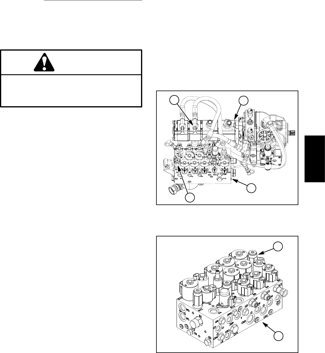
Groundsmaster 4100--D/4110--D Hydraulic SystemPage 4 -- 59
The lift/lower circuit relief pressure test should be per-
formed to make sure that the cutting unit lift and lower
circuit relief pressure is correct.
Procedure for Lift/Lower Circuit Relief Pressure
Test
NOTE: Before attempting to check or adjust lift/lower
circuit relief pressure, make sure that counterbalance
pressure is correctly adjusted (see Counterbalance
Pressure Test in this section).
CAUTION
Prevent personal injury and/or damage to equip-
ment. Read all WARNINGS, CAUTIONS and Pre-
cautions for Hydraulic Testing at the beginning
of this section.
1. Park machine on a level surface with the cutting deck
lowered and off. Make sure hydraulic oil is at normal op-
erating temperature, engine is off and the parking brake
is applied.
2. Raise and support operator seat.
3. Connect a 5,000 PSI (345 bar) pressure gauge to
test fitting attached to tee fitting in third section of gear
pump (Fig. 42).
4. Sit on the seat and start the engine. With engine run-
ning, increase engine speed to high idle speed.
5. While sitting on the seat, depress the rear of one of
the lift switches to fully raise the cutting deck section.
Momentarily hold the switch with the deck section fully
raised while watching the pressure gauge.
GAUGE READING TO BE approximately 2450 to
2550 PSI (170 to 175 bar).
6. Release the lift switch,stoptheengineandrecord
test results.
7. If specification is not met, clean or adjust relief valve
RV2 located in the combination control manifold (see
Combination Manifold Service in the Service and Re-
pairs section of this chapter).
A. If relief pressure is too high, adjust relief valve
RV2 to reduce lift/lower circuit relief pressure (see
Adjust Control Manifold Relief Valves in the Adjust-
ments section of this chapter).
B. If relief pressure is too low, check for restriction in
gear pump intake line. Check the lift cylinders for in-
ternal leakage. If pump intake line is not restricted
and lift cylinders are not leaking, adjust relief valve
RV2 to increase lift/lower circuit relief pressure (see
Adjust Control Manifold Relief Valves in the Adjust-
ments section of this chapter).
C. If pressure is still too low after relief valve adjust-
ment, lift cylinder(s) or the third section of the gear
pump should be suspected of wear or damage.
8. When relief pressure testing is completed, discon-
nect pressure gauge from test fitting. Secure dust cap to
test fitting.
9. Lower and secure operator seat.
1. Gear pump
2. Third section test fitting
3. Combination manifold
4. Relief valve RV2
Figure 42
2
3
4
1
1. Combination manifold 2. Relief valve RV2
Figure 43
2
1
Hydraulic
System
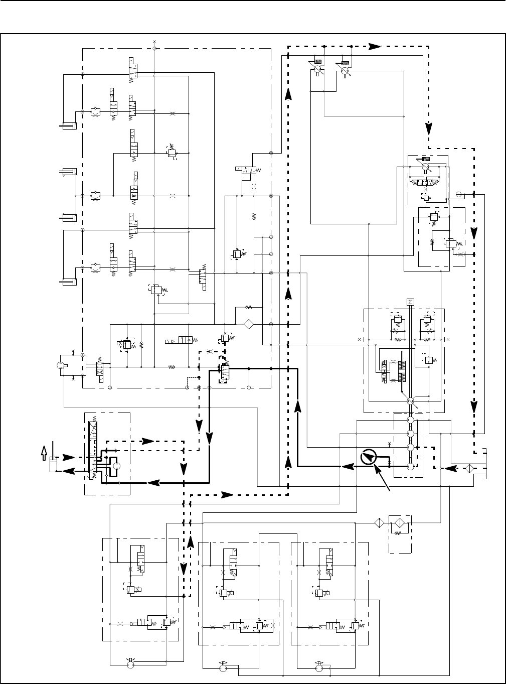
Groundsmaster 4100--D/4110--DHydraulic System Page 4 -- 60
Steering Circuit Relief Pressure (Using Pressure Gauge)
S10
RV1
CV1
S2
S4
S5
PRV
P4 CH2 P3
EC
CF
LS
S3
OR1
C3
OR4
.040
S6
OR5
.070
C4 C2 C5
RV2
2500 PSI
S7
S9
S8
C6
M1 M2
CH1
CV3
CH4
OR2
.063
OR6
.063
OR3
.070
OR7
.070
T2SPCH3
G2
G4
CV4
PR
G1
G3
3250
PSI
1350
PSI
3.3 GPM
4.4 GPM
14.3 GPM
4PSI
4PSI
.030
OR9
S1
3300 PSI
RV3 S12
14.3 GPM
S11
CV2
4 PSI
1.17 CID 3000 PSI
P1
P1
P1
P2
P2
P2
M1
M2
LC1
PRV
PD
CD
RV
2000 PSI
M1
M2
LC1
PRV
PD
RV
3000 PSI
M1
M2
LC1
PRV
PD
RV
CD
CD
LEFT DECK
CENTER DECK
RIGHT DECK
50 PSI
1.17 CID
1.17 CID
6.1 CID
EP
LR
T
STEERING
CYLINDER 0.51 CID
1.125” ROD
PR
380 PSI
RV
650 PSI
.050
CV
T
P2
M8
CH
OR1
250 PSI
2.14 CID /
1.16 CID
600 PSI
600 PSI
600 PSI
.030”
200 PSI
4350 PSI
5000 PSI
.025
.025
.025
.0315 .0315
0.4
CID
0.3 1.29 1.29
CID CID CID
2.75
CID
REAR
TRACTION
MANIFOLD
ENGINE
30.5
GPM
1.2 CID /
0.64 CID
1.2 CID /
0.64 CID
80
PSI 60
PSI
310
PSI
2.50” BORE
6.50” STROKE
1.50” BORE
3.08” STROKE
RAM CYLINDERS
CENTER DECK
1.125” ROD
2.50” BORE
6.50” STROKE
2.00” BORE
4.20” STROKE
0.625” ROD
G
G
G
GG
G
GG
G
COMBINATION MANIFOLD
STEERING
CONTROL
VALVE
RIGHT DECK
LEFT DECK
EXTENDED
FULLY
PRESSURE
GAUGE
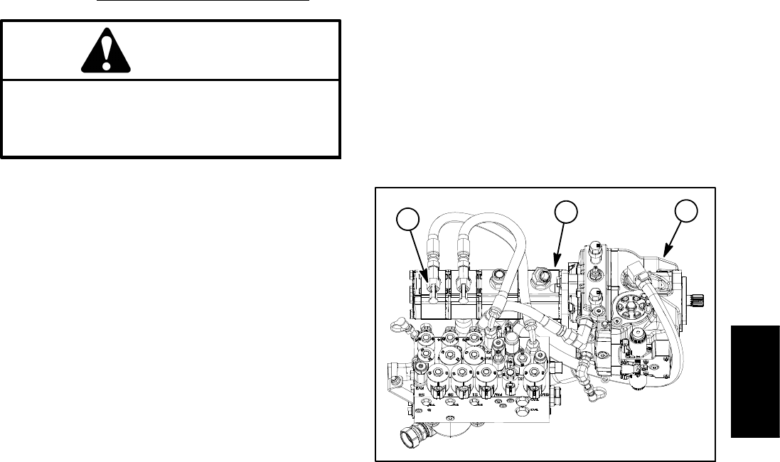
Groundsmaster 4100--D/4110--D Hydraulic SystemPage 4 -- 61
The steering circuit relief pressure test should be per-
formed to make sure that the steering circuit relief pres-
sure is correct.
Procedure for Steering Circuit Relief Pressure Test
CAUTION
Prevent personal injury and/or damage to equip-
ment. Read all WARNINGS, CAUTIONS and Pre-
cautions for Hydraulic Testing at the beginning
of this section.
1. Park machine on a level surface with the cutting deck
lowered and off. Make sure hydraulic oil is at normal op-
erating temperature, engine is off and the parking brake
is applied.
2. Raise and support operator seat.
3. Connect a 5000 PSI (350 bar) pressure gauge to test
fitting attached to tee fitting in final section of gear pump
(Fig. 44).
4. Start engine and increase engine speed to high idle
speed.
IMPORTANT: Hold steering wheel at full lock only
long enough to get a system relief pressure reading.
Holding the steering wheel against the stop for an
extended period can damage the steering control
valve.
5. Turn steering all the way in one direction and mo-
mentarily hold the steering wheel against resistance.
GAUGE READING TO BE 1300 to 1400 PSI (90 to
96 bar).
6. Stop the engine and record test results.
7. If pressure is incorrect, inspect steering relief valve
in steering control valve (see Steering Control Valve in
the Service and Repairs section of this chapter). If relief
valve is operating properly and if lift/lower problems also
exist, flow divider in fan manifold and/or gear pump
(third section) should be suspected of wear and ineffi-
ciency. If steering wheel continues to turn at end of cylin-
der travel (with lower than normal effort), steering
cylinder or steering control valve should be suspected
of wear or damage.
8. When testing is completed, disconnect pressure
gauge from test fitting. Secure dust cap to test fitting.
9. Lower and secure operator seat.
1. Piston (traction) pump
2. Gear pump
3. Test fitting
Figure 44
1
2
3
Hydraulic
System
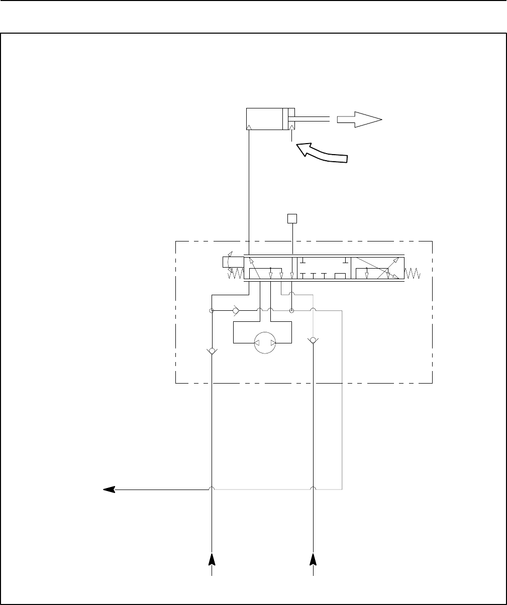
Groundsmaster 4100--D/4110--DHydraulic System Page 4 -- 62
Steering Cylinder Internal Leakage
6.1 CID
EP
LR
T
STEERING
CYLINDER
2.00” BORE
4.20” STROKE
0.625” ROD
STEERING
CONTROL
VALVE
STEERING WHEEL
TURNED FOR
RIGHT TURN
CYLINDER FULLY
EXTENDED
LOOK FOR
LEAKAGE
STEEL CAP
FROM COMBINATION
MANIFOLD
FROM COMBINATION
MANIFOLD
TO RESERVOIR

Groundsmaster 4100--D/4110--D Hydraulic SystemPage 4 -- 63
The steering cylinder internal leakage test should be
performed if a steering problem is identified. This test
will determine if the steering cylinder is faulty.
Procedure for Steering Cylinder Internal Leakage
Test
NOTE: Steering circuit operation will be affected by
rear tire pressure, binding of steering cylinder, extra
weight on the vehicle and/or binding of rear axle steering
components. Make sure that these items are checked
before proceeding with steering cylinder internal leak-
age test.
CAUTION
Prevent personal injury and/or damage to equip-
ment. Read all WARNINGS, CAUTIONS and Pre-
cautions for Hydraulic Testing at the beginning
of this section.
1. Park machine on a level surface with the cutting deck
lowered and off. Make sure hydraulic oil is at normal op-
erating temperature, engine is off and the parking brake
is applied.
2. Turn the steering wheel for a right turn so that the
steering cylinder rod is fully extended.
3. Thoroughly clean the area around the hydraulic hose
at the rod end of the steering cylinder.
4. Place a drain pan under the steering cylinder. Re-
move hydraulic hose from the fitting on the rod end of the
steering cylinder. Install a steel plug in the disconnected
hose. Leave cylinder fitting open.
5. Remove all hydraulic oil from drain pan. Make sure
that empty drain pan remains under the open fitting of
the steering cylinder.
6. With the engine off, turn the steering wheel for a right
turn. Observe the open fitting on the extended steering
cylinder as the steering wheel is turned. If oil comes out
of the fitting while turning the steering wheel, the steer-
ing cylinder has internal leakage and must be repaired
(see Steering Cylinder and Steering Cylinder Service in
the Service and Repairs section of this chapter). Check
drain pan for any evidence of oil that would indicate cyl-
inder leakage.
7. If a steering problem exists and the steering cylinder
tested acceptably, the steering control valve requires
service (see Steering Control Valve and Steering Con-
trol Valve Service in the Service and Repairs section of
this chapter).
8. After testing is completed, remove plug from the hy-
draulic hose. Connect hose to the steering cylinder fit-
ting.
9. Check oil level in hydraulic reservoir and adjust if
needed.
Hydraulic
System
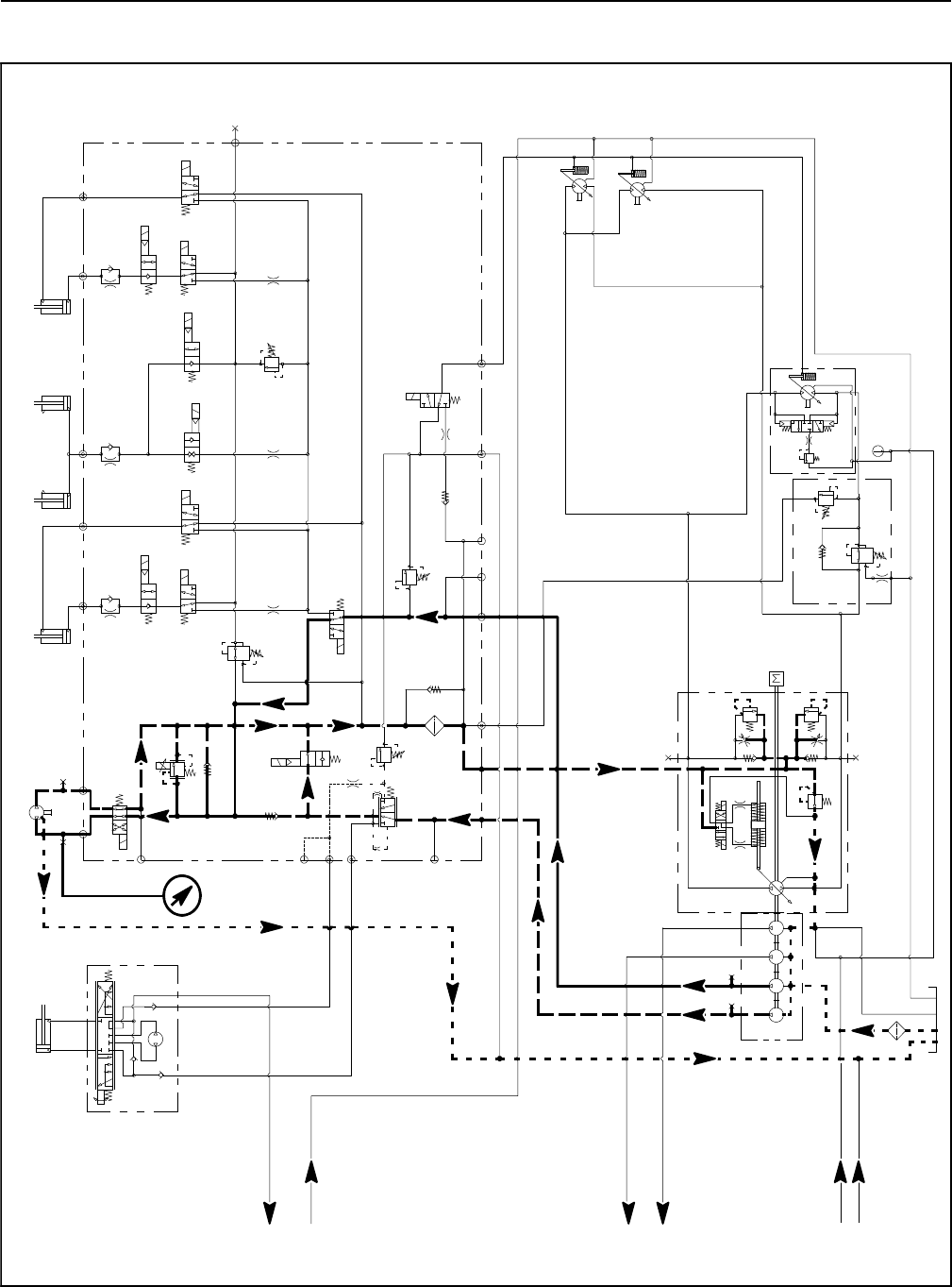
Groundsmaster 4100--D/4110--DHydraulic System Page 4 -- 64
Engine Cooling Fan Circuit (Using Pressure Gauge and Phototac)
S10
RV1
CV1
S2
S4
S5
PRV
P4 CH2 P3
EC
CF
LS
S3
OR1
C3
OR4
.040
S6
OR5
.070
C4 C2 C5
RV2
2500 PSI
S7
S9
S8
C6
M1 M2
CH1
CV3
CH4
OR2
.063
OR6
.063
OR3
.070
OR7
.070
T2SPCH3
G2
G4
CV4
PR
G1
G3
3250
PSI
1350
PSI
3.3 GPM
4.4 GPM
14.3 GPM
4 PSI
4 PSI
.030
OR9
S1
3300 PSI
RV3 S12
14.3 GPM
S11
CV2
4PSI
6.1 CID
EP
LR
T
STEERING
CYLINDER
0.51 CID
1.125” ROD
PR
380 PSI
RV
650 PSI
.050
CV
T
P2
M8
CH
OR1
250 PSI
2.14 CID /
1.16 CID
.030”
200 PSI
4350 PSI
5000 PSI
.0315 .0315
0.4
CID
0.3 1.29 1.29
CID CID CID
2.75
CID
REAR
TRACTION
MANIFOLD
ENGINE
30.5
GPM
1.2 CID /
0.64 CID
1.2 CID /
0.64 CID
80
PSI 60
PSI
310
PSI
2.50” BORE
6.50” STROKE
1.50” BORE
3.08” STROKE
RAM CYLINDERS
CENTER DECK
1.125” ROD
2.50” BORE
6.50” STROKE
2.00” BORE
4.20” STROKE
0.625” ROD
GG
G
GG
G
COMBINATION MANIFOLD
STEERING
CONTROL
VALVE
RIGHT DECK
LEFT DECK
FROM
PTO MANIFOLD
CENTER DECK
TO
PTO MANIFOLD
CENTER DECK
TO
PTO MANIFOLD
LEFT DECK
TO
PTO MANIFOLD
CENTER DECK
FROM
OIL FILTER
FROM LEFT AND
PTO MANIFOLDS
RIGHT DECK
PRESSURE
GAUGE
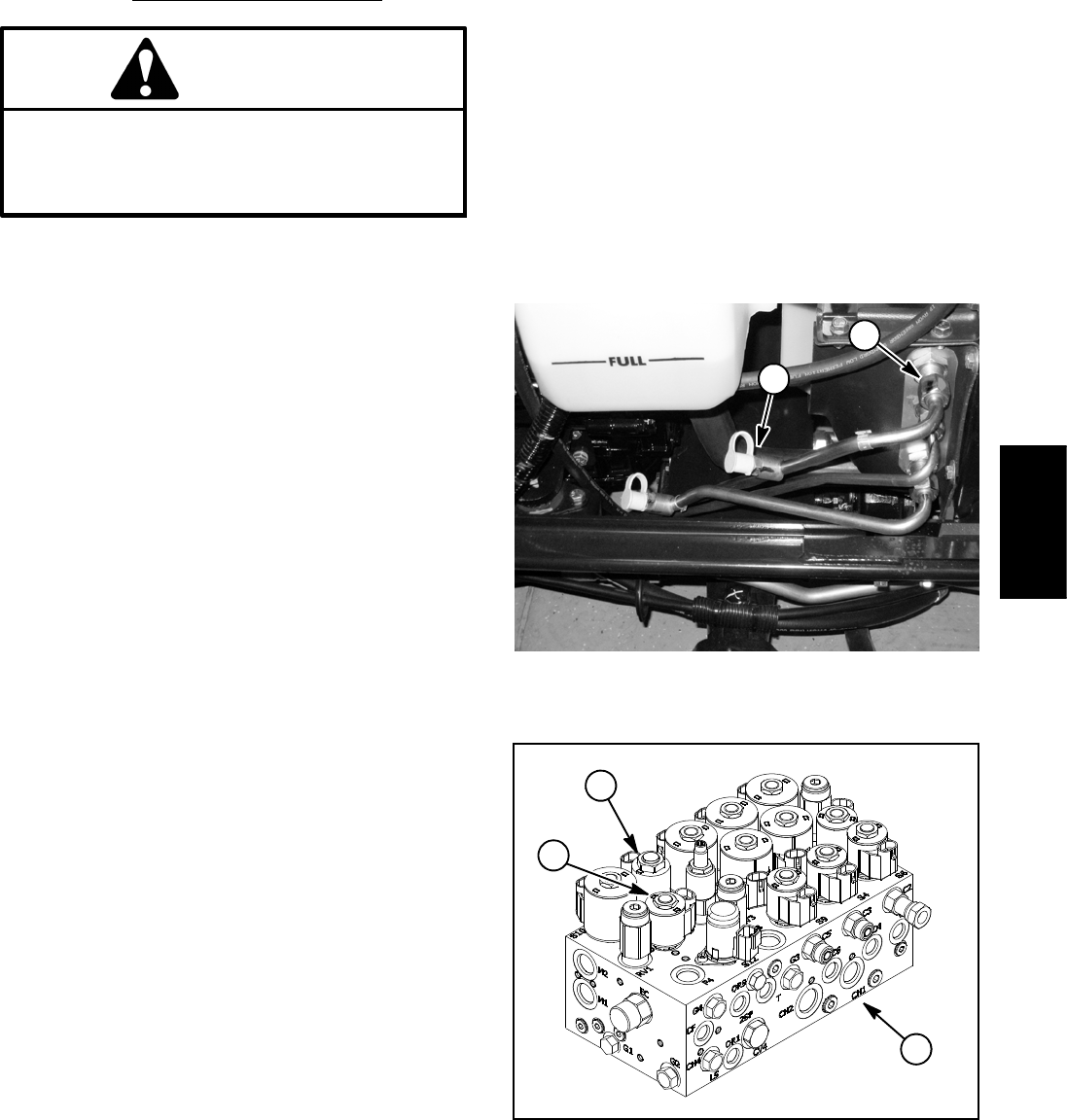
Groundsmaster 4100--D/4110--D Hydraulic SystemPage 4 -- 65
The cooling fan circuit test should be performed to make
sure that the engine cooling fan circuit has the correct
system pressure and fan speed.
Procedure for Engine Cooling Fan Circuit Test
CAUTION
Prevent personal injury and/or damage to equip-
ment. Read all WARNINGS, CAUTIONS and Pre-
cautions for Hydraulic Testing at the beginning
of this section.
1. Park machine on a level surface with the cutting deck
lowered and off. Make sure hydraulic oil is at normal op-
erating temperature, engine is off and the parking brake
is applied.
2. Raiseandsupporthoodtogainaccesstothehy-
draulic tubes that supply hydraulic flow to engine cooling
fan motor (Fig. 45). Connect a 5,000 PSI (345 bar) pres-
sure gauge with hydraulic hose attached to test port on
hydraulic tube connected in the upper location on radiat-
or shroud.
3. Raise seat to gain access to the combination man-
ifold (Fig. 46). Locate PRV and S11 solenoid valves on
manifold.
4. Have a phototac available to identify cooling fan
speed once engine is running.
5. Start engine and increase engine speed to high idle
speed. DO NOT engage the cutting deck.
6. While monitoring the pressure gauge and using the
phototac to identify the cooling fan speed, disconnect
the wire harness connectors from the PRV solenoid
(white/green and black wires) and S11 solenoid (violet
and black wires) on combination manifold (Fig. 46). Both
fan speed and pressure should increase and stabilize
after the solenoids are disconnected.
PRESSURE GAUGE READING TO BE approxi-
mately 3250 PSI (224 bar).
PHOTOTAC READING (FAN SPEED) TO BE ap-
proximately 2800 to 3000 RPM.
NOTE: The cooling fan speed will depend on hydraulic
oil temperature. Higher oil temperatures will result in
slower fan speed.
7. Stop engine and record test results.
8. If circuit pressure rises to approximately 3250 PSI
(224 bar) but fan speed is low, consider that the fan mo-
tor is worn or damaged. If pressure and fan speed are
both low, consider that the gear pump section is worn or
damaged (see Gear Pump Flow Test in this section).
NOTE: If pressure and fan speed are both low and gear
pump flow proves to be correct, suspect that engine
cooling fan circuit cartridge valve seals in combination
manifold(e.g.S10,S11,PRV)areleakingorfaulty(see
Combination Manifold Service in the Service and Re-
pairs section of this chapter).
9. When testing is complete, remove pressure gauge
from hydraulic tube test port and reconnect wire harness
connectors to PRV and S11 solenoids. Lower and se-
cure hood and operator seat.
1. Upper hydraulic tube 2. Test port
Figure 45
1
2
1. Combination manifold
2. PRV solenoid
3. S11 solenoid
Figure 46
1
2
3
Hydraulic
System
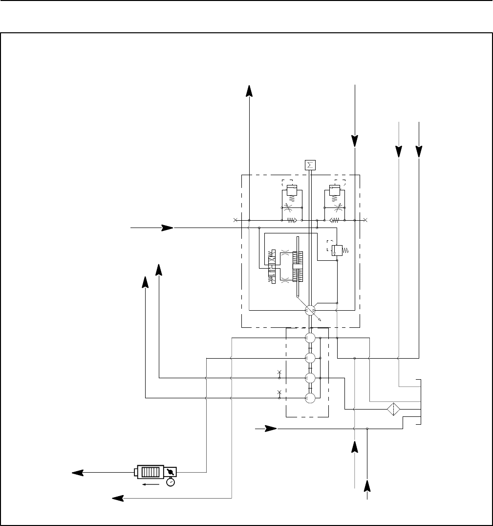
Groundsmaster 4100--D/4110--DHydraulic System Page 4 -- 66
Gear Pump Flow (Using Tester with Pressure Gauge and Flow Meter)
SECOND GEAR PUMP SECTION FLOW TEST SHOWN
3.3 GPM
14.3 GPM
14.3 GPM
250 PSI
4350 PSI
5000 PSI
.0315 .0315
0.4
CID
0.3 1.29 1.29
CID CID CID
2.75
CID
ENGINE
30.5 GPM
GG
G
G
TO COMBINATION
MANIFOLD
FROM
COMBINATION
MANIFOLD
FROM MANIFOLD
AND FAN MOTOR
FROM REAR
TRACTION
MANIFOLD
FROM CENTER
DECK MANIFOLD
FROM REAR AXLE MOTOR
TO COMBINATION
MANIFOLD
FROM
OIL FILTER
FROM
MOW CIRCUIT
TESTER
TO CENTER DECK
PTO MANIFOLD
TO LEFT DECK
PTO MANIFOLD
TO TRACTION
MOTORS
The gear pump flow test should be performed to make
sure that the mow, steering, lift/lower, cooling fan and
traction charge circuits have adequate hydraulic flow.
The front gear pump section provides hydraulic flow for
the cutting wing decks (Fig. 47). The second gear pump
section provides hydraulic flow for the center cutting
deck. The third gear pump section provides hydraulic
flow for the cooling fan, lift/lower and traction charge cir-
cuits. The fourth gear pump section provides hydraulic
flow for the steering, traction charge and cooling fan cir-
cuits.
NOTE: Overaperiodoftime,thegearsandwearplates
in the gear pump can wear. A worn pump will by pass oil
and make the pump less efficient. Eventually, enough oil
loss will occur to cause circuit problems (e.g. cutting
deck motors stalling under heavy cutting conditions, lift
or steering problems). Continued operation with a worn,
inefficient gear pump can generate excessive heat and
cause damage to the seals and other components in the
hydraulic system.
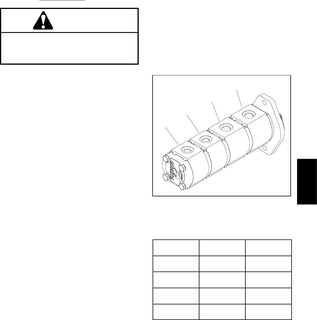
Groundsmaster 4100--D/4110--D Hydraulic SystemPage 4 -- 67
Procedure for Gear Pump Flow Test
CAUTION
Prevent personal injury and/or damage to equip-
ment. Read all WARNINGS, CAUTIONS and Pre-
cautions for Hydraulic Testing at the beginning
of this section.
1. Park machine on a level surface with the cutting deck
lowered and off. Make sure hydraulic oil is at normal op-
erating temperature, engine is off and the parking brake
is applied.
2. Raise and support operator seat to gain access to
gear pump.
3. Determine which gear pump section is to be tested.
Disconnect hydraulic hose from fitting in gear pump sec-
tion that is to be tested (Fig. 47).
4. Install tester (flow and pressure) in series with the
disconnected hose and hydraulic fitting in gear pump
section.
5. Make sure the flow control valve on tester is fully
open.
6. Start engine and increase engine speed to high idle
speed. Do not engage the cutting deck.
IMPORTANT: Do not fully restrict oil flow through
tester. In this test, the flow tester is positioned be-
fore the relief valve. Pump damage can occur if the
oil flow is fully restricted.
7. Watch pressure gauge carefully while slowly closing
the flow control valve until 1000 PSI (69 bar) is obtained.
Verify with the InfoCenter display that the engine is still
running at the correct high idle speed.
NOTE: If engine speed drops during testing, pump flow
will decrease and flow test results will be inaccurate.
8. Normal flow indication for the four (4) gear pump sec-
tionsislistedinFigure48.
9. Shut off engine and record test results.
10.If a pressure of 1000 PSI (69 bar) cannot be obtained
or flow was less than the minimum flow listed in Figure
48, check for restriction in the pump intake line. If line is
not restricted, consider that the tested gear pump sec-
tion is worn or damaged.
11. After testing is completed, disconnect flow tester
from hydraulic hose and fitting in gear pump section. Re-
connect hose to the pump fitting.
12.Lower and secure operator seat.
1. Front pump section (LH and RH PTO)
2. 2nd pump section (front PTO)
3. 3rd pump section (cooling fan, lift/lower and charge)
4. 4th pump section (steering, charge and cooling fan)
Figure 47
2
3
1
4
PUMP
SECTION
NORMAL
FLOW
MINIMUM
FLOW
FRONT
SECTION
14 GPM
(53 LPM)
11 GPM
(41.6 LPM)
SECOND
SECTION
14 GPM
(53 LPM)
11 GPM
(41.6 LPM)
THIRD
SECTION
4.3 GPM
(16.3 LPM)
3.4 GPM
(12.8 LPM)
FOURTH
SECTION
3.2 GPM
(12.1 LPM)
2.5 GPM
(9.5 LPM)
Figure 48
Hydraulic
System
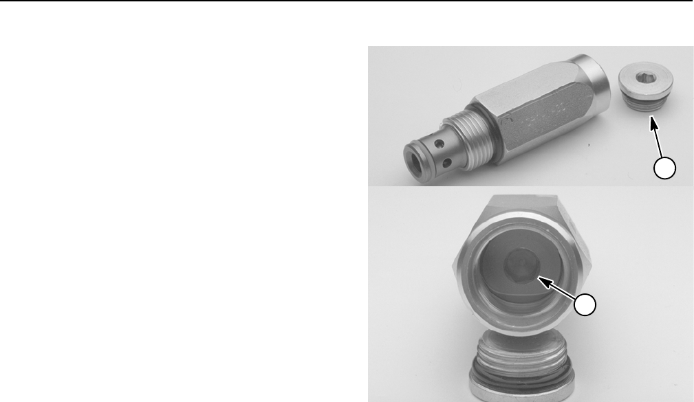
Groundsmaster 4100--D/4110--DHydraulic System Page 4 -- 68
Adjustments
Adjust Control Manifold Relief Valves
Several of the hydraulic control manifolds on the
Groundsmaster include adjustable relief valves. The fol-
lowing procedure can be used to adjust these relief
valves. Refer to the Testing section of this chapter for in-
formation on testing relief pressure.
NOTE: Do not remove relief valve from the hydraulic
manifold for adjustment.
1. Locate relief valve and remove cap from valve.
2. Remove cap on relief valve with an allen wrench.
3. To increase pressure setting, turn the adjustment
socket on the valve in a clockwise direction. A 1/8 turn
on the socket will make a measurable change in relief
pressure.
4. To decrease pressure setting, turn the adjustment
socket on the valve in a counterclockwise direction. A
1/8 turn on the socket will make a measurable change
in relief pressure.
5. Install and tighten cap on relief valve.
6. Recheck relief pressure and readjust as needed.
Figure 49
1. Relief valve cap 2. Adjustment socket
1
2
Groundsmaster 4100--D/4110--D Hydraulic SystemPage 4 -- 69
Service and Repairs
General Precautions for Removing and Installing Hydraulic System Components
Before Repair or Replacement of Components
1. Before removing any parts from the hydraulic sys-
tem, park machine on a level surface, engage parking
brake, lower cutting deck or attachments and stop en-
gine. Remove key from the ignition switch.
2. Clean machine before disconnecting, removing or
disassembling any hydraulic components. Make sure
hydraulic components, hoses connections and fittings
are cleaned thoroughly. Always keep in mind the need
for cleanliness when working on hydraulic equipment.
WARNING
Before disconnecting or performing any work
on the hydraulic system, all pressure in the sys-
tem must be relieved. See Relieving Hydraulic
System Pressure in the General Information sec-
tion in this chapter.
3. Put caps or plugs on any hydraulic lines, hydraulic fit-
tings and components left open or exposed to prevent
contamination.
4. Put labels on disconnected hydraulic lines and
hoses for proper installation after repairs are completed.
5. Note the position of hydraulic fittings (especially el-
bow fittings) on hydraulic components before removal.
Mark parts if necessary to make sure they will be aligned
properly when reinstalling hydraulic hoses and tubes.
After Repair or Replacement of Components
1. Check oil level in the hydraulic reservoir and add cor-
rect oil if necessary. Drain and refill hydraulic system
reservoir and change oil filter if component failure was
severe or system is contaminated (see Flush Hydraulic
System in this section).
IMPORTANT: Follow all local codes and regulations
when recycling or disposing hydraulic fluid and fil-
ters.
2. Lubricate O--rings and seals with clean hydraulic oil
before installing hydraulic components.
3. Make sure all caps or plugs are removed from hy-
draulic tubes, hydraulic fittings and components before
reconnecting.
4. Use proper tightening methods when installing hy-
draulic hoses and fittings (see Hydraulic Fitting Installa-
tion and Hydraulic Hose and Tube Installation in the
General Information section of this chapter).
5. After repairs, check control linkages or cables for
proper adjustment, binding or broken parts.
6. If piston (traction) pump, front wheel motors or rear
axle motor was removed from machine for service, fill
housing through case drain with new hydraulic oil before
starting engine. This will ensure that internal compon-
ents have adequate lubrication during initial operation.
7. After disconnecting or replacing any hydraulic com-
ponents, operate machine functions slowly until air is
out of system (see Charge Hydraulic System in this sec-
tion).
8. Check for hydraulic oil leaks. Shut off engine and cor-
rect leaks if necessary. Check oil level in hydraulic reser-
voir and add correct oil if necessary.
Hydraulic
System
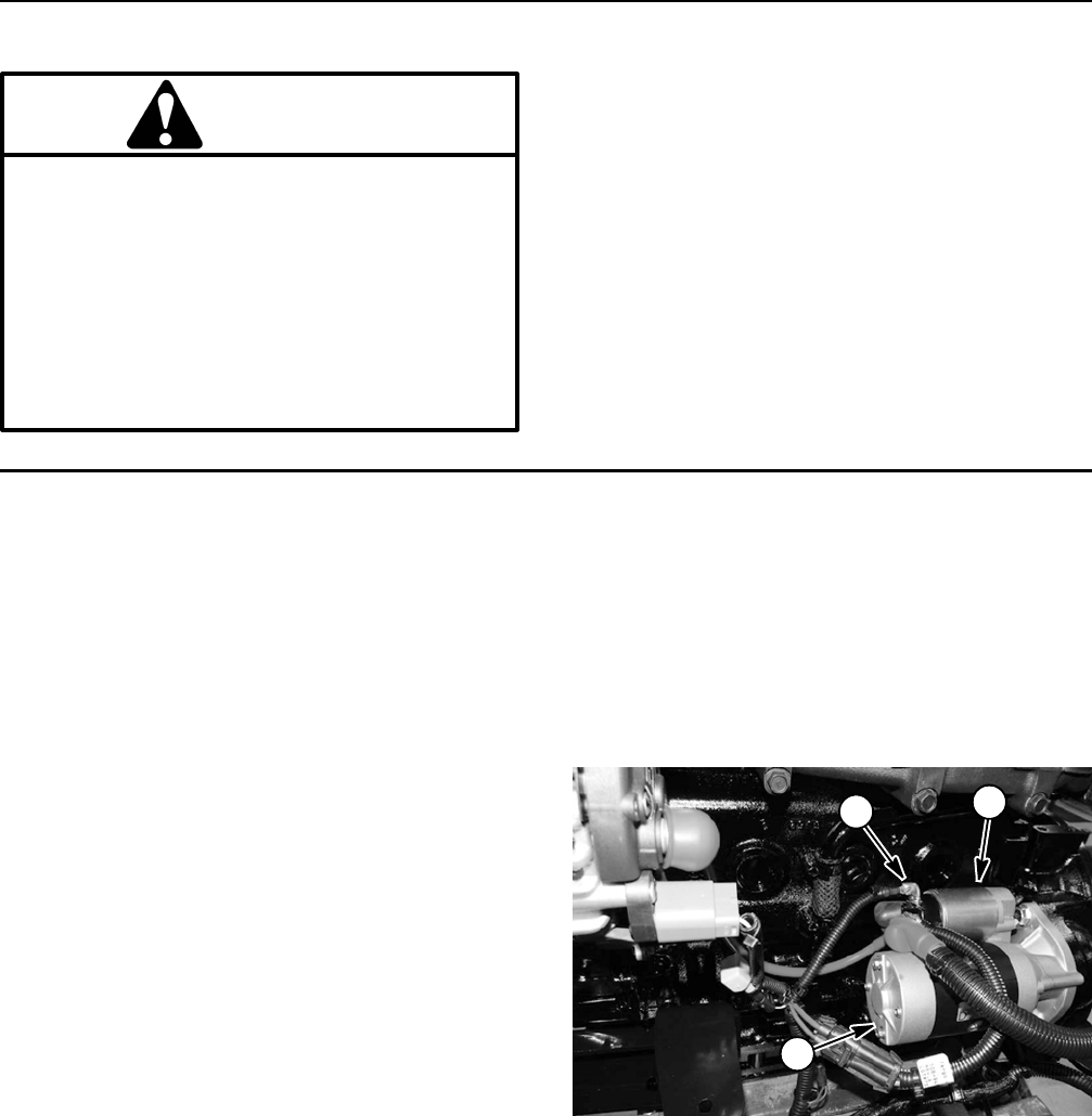
Groundsmaster 4100--D/4110--DHydraulic System Page 4 -- 70
Check Hydraulic Lines and Hoses
WARNING
Keep body and hands away from pin hole leaks
or nozzles that eject hydraulic fluid under high
pressure. Use paper or cardboard, not hands, to
search for leaks. Hydraulic fluid escaping under
pressure can have sufficient force to penetrate
the skin and cause serious injury. If fluid is in-
jected into the skin, it must be surgically re-
moved within a few hours by a doctor familiar
with this type of injury. Gangrene may result from
such an injury.
IMPORTANT: Check hydraulic lines and hoses daily
for leaks, kinked lines, loose mounting supports,
wear, loose fittings or deterioration. Make all neces-
sary repairs before operating.
Priming Hydraulic Pumps
Whenever the hydraulic system is flushed, the hydraulic
system is charged or hydraulic components are in-
stalled, it is important to properly prime the hydraulic
pumps. Hydraulic pump priming ensures that the gear
pump and piston (traction) pump have adequate oil dur-
ing initial start--up and running. The pumps can be
primed by using a remote starter switch (see Special
Tools in this chapter) to crank engine which allows the
pumps to prime.
Use the following procedure to prime the hydraulic
pumps:
1. Make sure that ignition switch is in the OFF position
and key is removed from switch.
2. Check hydraulic reservoir oil level and adjust if ne-
cessary.
NOTE: A blue wire connects to the starter motor solen-
oid B+ terminal (Fig. 50). It is not necessary to remove
this blue wire from the solenoid terminal for hydraulic
pump priming.
3. Connect remote starter switch electrical leads to the
starter motor solenoid B+ terminal and the positive post
of the battery.
4. Engage remote starter switch and crank starter for
thirty (30) seconds to prime hydraulic pumps. Wait thirty
(30) seconds to allow the starter motor and starter
solenoid to cool. Repeat cranking procedure a second
time.
5. Disconnect remote starter switch leads from starter
motor solenoid terminal and positive post of the battery.
1. Starter motor
2. Starter solenoid
3. B+ terminal
Figure 50
1
2
3
Groundsmaster 4100--D/4110--D Hydraulic SystemPage 4 -- 71
Flush Hydraulic System
IMPORTANT: Flush the hydraulic system any time
there is a severe component failure or the system is
contaminated. Contaminated oil may appear milky
or black or may contain metal particles.
IMPORTANT: If a component failure occurred in the
closed loop traction circuit (e.g. piston pump or
wheel motor), filtering the traction circuit is recom-
mended. See Filtering Closed--Loop Traction Circuit
in this section.
1. Park machine on a level surface. Lower cutting deck
to the ground, stop engine and apply parking brake. Re-
move key from the ignition switch.
WARNING
Before disconnecting or performing any work
on the hydraulic system, all pressure in the sys-
tem must be relieved. See Relieving Hydraulic
System Pressure in the General Information sec-
tion in this chapter.
IMPORTANT: Make sure to clean around any hy-
draulic connections that will be disconnected for
draining.
2. Drain hydraulic reservoir. Remove suction screen
from reservoir and clean thoroughly. Consider removing
and cleaning reservoir if necessary.
3. Drain hydraulic system. Drain all hoses, tubes and
components while the system is warm.
4. Change and replace both hydraulic oil filters.
IMPORTANT: Follow all local codes and regulations
when recycling or disposing hydraulic fluid and fil-
ters.
5. Inspect and clean hydraulic reservoir (see Hydraulic
Reservoir in this section).
6. Connect all hydraulic hoses, lines and components
that were disconnected while draining system.
IMPORTANT: When filling hydraulic reservoir, use
only hydraulic fluids specified in Operator’s Manu-
al. Other fluids could cause system damage.
7. Fill hydraulic reservoir with new hydraulic fluid.
8. Prime hydraulic pumps (see Priming Hydraulic
Pumps in this section).
9. Start engine and let it run at low idle speed for a mini-
mum of two (2) minutes. Increase engine speed to high
idle for minimum of one (1) minute under no load.
10.Raise and lower cutting deck several times. Turn
steering wheel fully left and right several times.
11. Shut off engine and check for hydraulic oil leaks.
Check oil level in hydraulic reservoir and add correct
amount of oil if necessary.
12.Operate machine for two (2) hours under normal op-
erating conditions.
13.Check condition of hydraulic oil. If the new fluid
shows any signs of contamination, repeat steps 1
through 12 again until oil is clean.
14.Assume normal operation and follow recommended
maintenance intervals.
Hydraulic
System
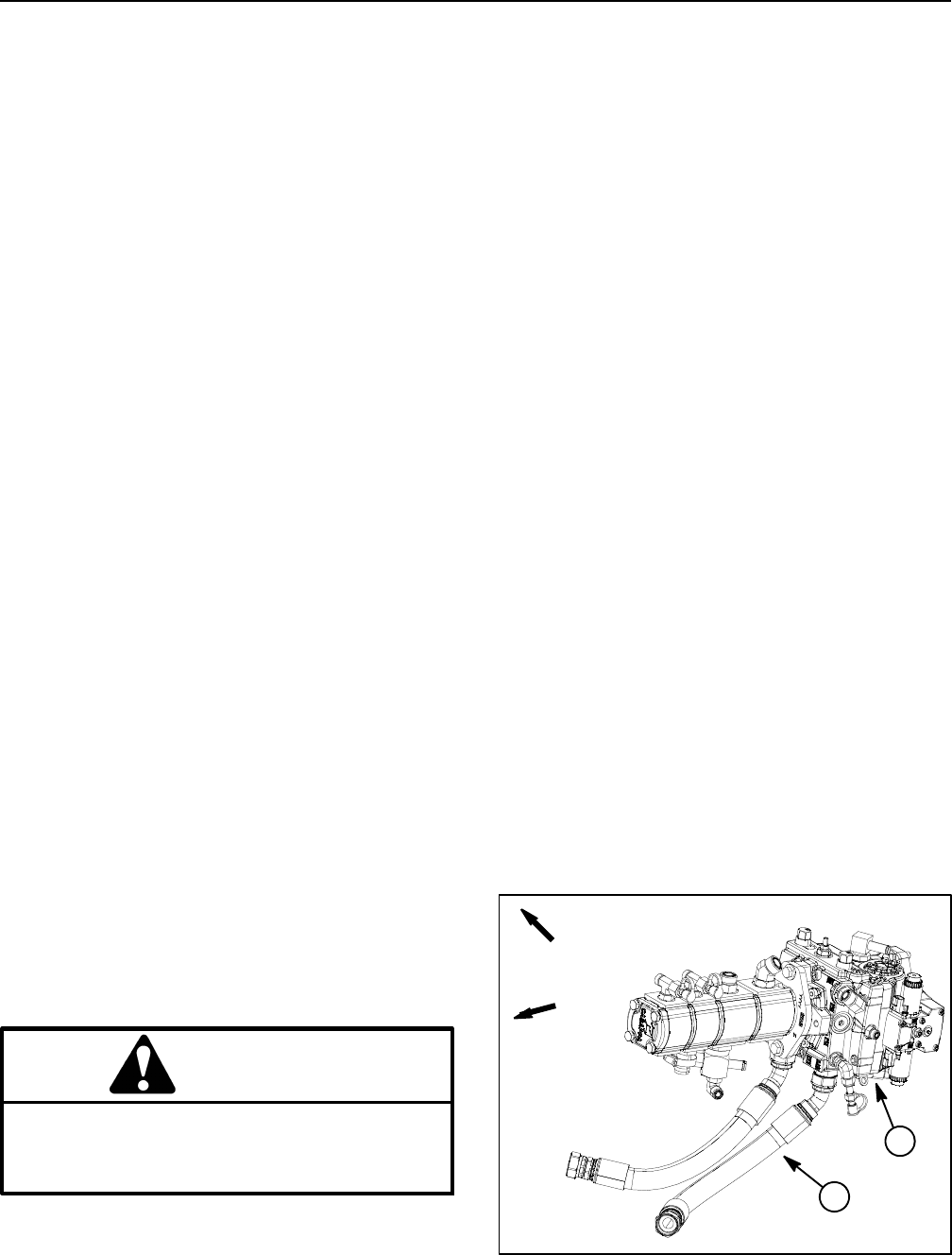
Groundsmaster 4100--D/4110--DHydraulic System Page 4 -- 72
Filtering Closed--Loop Traction Circuit
Filtering of a closed--loop hydraulic system after a major
component failure (e.g. traction (piston) pump or front
wheel motor) is a requirement to prevent debris from
transmitting throughout the system. If a closed--loop hy-
draulic system filtering tool is not used to ensure system
cleanliness, repeat failures, as well as subsequent dam-
age to other hydraulic components in the affected sys-
tem, will occur. To effectively remove contamination
from closed--loop traction circuit, use of the Toro high
flow hydraulic filter and hydraulic hose kits are recom-
mended (see Special Tools in this chapter).
1. Park machine on a level surface with engine stopped
and key removed from ignition switch.
2. Raise and support machine so all wheels are off the
ground (see Jacking Instructions in Chapter 1 -- Safety).
NOTE: If front wheel or rear axle motor was replaced,
install high flow filter to the inlet of new motor instead of
to the traction pump fitting. This will prevent system con-
tamination from entering and damaging the new motor.
3. Thoroughly clean junction of hydraulic hose and left
side fitting on bottom of piston (traction) pump (Fig. 51).
Disconnect hose from left side pump fitting.
4. Connect Toro high flow hydraulic filter in series be-
tweenpistonpumpfittinganddisconnectedhose.Use
hydraulic hose kit (see Special Tools in this chapter) to
connect filter to machine. Make sure that fitting and hose
connections are properly tightened.
IMPORTANT: Use only hydraulic fluids specified in
Operator’s Manual. Other fluids could cause system
damage.
5. After installing high flow filter to machine, check and
fill hydraulic reservoir with new hydraulic oil as required.
6. Start engine and run at idle speed. Check for any hy-
draulic leakage from filter and hose connections. Cor-
rect any leaks before proceeding.
CAUTION
All wheels will be off the ground and rotating dur-
ing this procedure. Make sure machine is well
supported so it will not move and accidentally
fall to prevent injuring anyone around machine.
IMPORTANT: While engaging the traction circuit,
monitor the high flow hydraulic filter indicator. If the
indicator should show red, either reduce traction
pedal setting or reduce engine speed to decrease
hydraulic flow through the filter.
7. With engine running at low idle speed, slowly move
thetractionpedaltotheforward direction to allow flow
through the traction circuit and high flow filter. Keep trac-
tion circuit engaged for five (5) minutes while gradually
increasing both forward pressure on traction pedal and
engine speed. Monitor filter indicator to make sure that
green color is showing during operation.
8. With engine running at high idle speed and traction
pedal moved to the forward direction, periodically apply
brakes to increase pressure in traction circuit. While
monitoring filter indicator, continue this process for an
additional five (5) minutes.
IMPORTANT: If using a filter that is not the bi--direc-
tional Toro high flow filter, do not press the traction
pedal in the reverse direction. If flow is reversed
when using a filter that is not bi--directional, debris
from the filter will re--enter the traction circuit.
9. With engine running at high idle speed, alternately
move traction pedal from forward to reverse. While mon-
itoring filter indicator, continue this process for an addi-
tional five (5) minutes.
10.Shut engine off and remove key from ignition switch.
11.Removehighflowhydraulic filter and hydraulic hose
kit from machine. Connect hydraulic hose to right side
piston (traction) pump fitting. Make sure to properly
tighten hose (see Hydraulic Hose and Tube Installation
in the General Information section of this chapter).
12.Lower machine to ground.
13.Check oil level in hydraulic reservoir and add correct
oil if necessary.
1. Piston (traction) pump 2. Left side fitting/hose
Figure 51
FRONT
RIGHT
1
2
Groundsmaster 4100--D/4110--D Hydraulic SystemPage 4 -- 73
Charge Hydraulic System
NOTE: When initially starting the hydraulic system with
new or rebuilt components such as motors, pumps or lift
cylinders, it is important that the hydraulic system be
charged properly. Air must be purged from the system
to reduce the chance of component damage.
IMPORTANT: Change hydraulic oil filters whenever
hydraulic components are repaired or replaced.
1. Park machine on a level surface. Lower cutting deck,
stop engine and apply parking brake. Remove key from
the ignition switch.
2. Make sure all hydraulic connections, lines and com-
ponents are secured tightly.
3. If hydraulic component failure was severe or the hy-
draulic system is contaminated, flush and refill hydraulic
system and hydraulic reservoir (see Flush Hydraulic
System in this section).
IMPORTANT: When filling hydraulic reservoir, use
only hydraulic fluids specified in Operator’s Manu-
al. Other fluids could cause system damage.
4. Make sure hydraulic reservoir is full. Add correct hy-
draulic oil to reservoir if necessary.
5. Prime hydraulic pumps (see Priming Hydraulic
Pumps in this section).
WARNING
Before jacking up the machine, review and follow
Jacking Instructions in Chapter 1 -- Safety.
6. Raise machine so that all wheels are off the ground
and place appropriate jack stands under the frame to
support the machine.
IMPORTANT: During initial operation, check hy-
draulic reservoir oil level frequently and add oil as
necessary.
7. Make sure traction pedal and lift switches are in neu-
tral. Start engine and run at low idle speed. The gear
pump should pick up oil and fill the hydraulic system. If
there is no indication of fill in thirty (30) seconds, stop the
engine and determine the cause.
8. After the hydraulic system starts to show signs of fill,
actuate a lift switch until the lift cylinder rod moves in and
out several times. If the lift cylinder does not move after
10 to 15 seconds, or if the pump emits abnormal
sounds, shut the engine off immediately and determine
cause or problem. Inspect for the following:
A. Loose filter or suction lines.
B. Blocked suction line.
C. Faulty charge relief valve.
D. Faulty gear pump.
9. Once the lift cylinder does move in 10 to 15 se-
conds, proceed to the next step.
10.Operate the traction pedal in the forward and reverse
directions. The wheels should rotate in the proper direc-
tion.
A. If the wheels rotate in the wrong direction, stop
engine and check for proper hydraulic hose and
electrical connections at traction pump and motors.
Correct as needed.
B. If the wheels rotate in the proper direction, stop
engine.
11. Check operation of the traction interlock switch (see
Check Interlock System in Chapter 5 -- Electrical Sys-
tem).
12.With engine not running and ignition switch in the
OFF position, remove jack stands that are supporting
the machine and lower the machine to the ground.
13.If the piston (traction) pump or a traction motor was
replaced or rebuilt, run the machine so all wheels turn
slowly for ten (10) minutes.
14.Operate machine by gradually increasing its work
load to full over a ten (10) minute period.
15.Stop the machine. Check hydraulic reservoir and fill
if necessary. Check hydraulic components for leaks and
tighten any loose connections.
Hydraulic
System
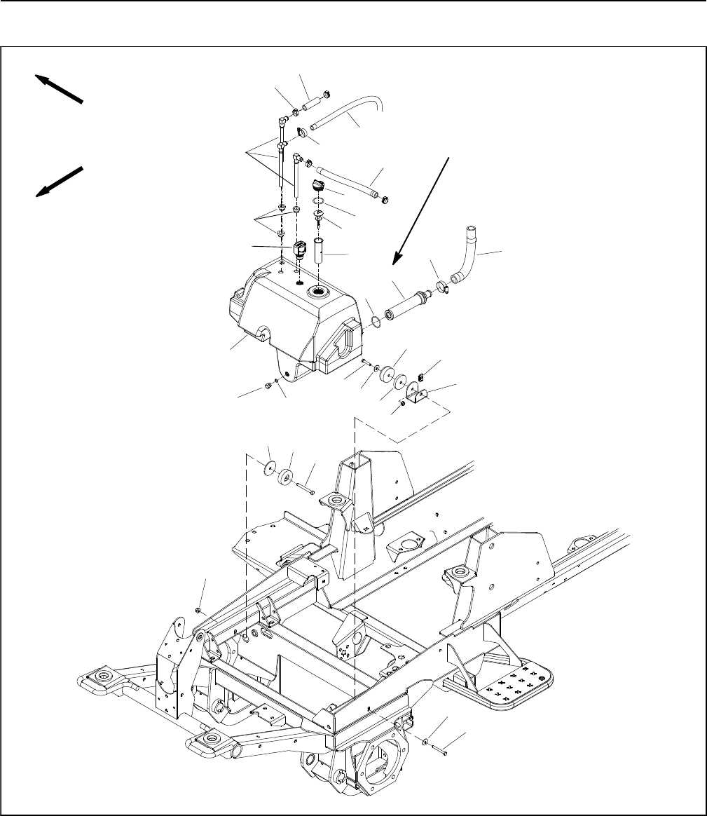
Groundsmaster 4100--D/4110--DHydraulic System Page 4 -- 74
Hydraulic Reservoir
Figure 52
FRONT
RIGHT
2
3
6
89
10
11
13
1
5
7
12
14
15
16 17
18
19
20
4
21
22
23
24 25
26 27
28
29
30
3
31
1. Hydraulic reservoir
2. Cap screw
3. Recess bumper (2 used)
4. Thin spacer
5. Flange nut
6. Breather
7. Bushing (3 used)
8. Stand pipe (3 used)
9. Hose clamp
10. Reservoir cap
11. O -- ring
12. Dipstick
13. Screen filter
14. Tank strainer
15. Cap screw
16. Flat washer
17. Thick spacer
18. Retainer nut
19. Tank mount
20. Flange nut
21. Flat washer
22. Cap screw
23. Plug
24. Hose clamp
25. Suction hose
26. Hose clamp (4 used)
27. Hydraulic hose
28. Hydraulic hose
29. O--ring
30. Hydraulic hose
31. O--ring
80 to 88 ft--lb
(109 to 119 N--m)
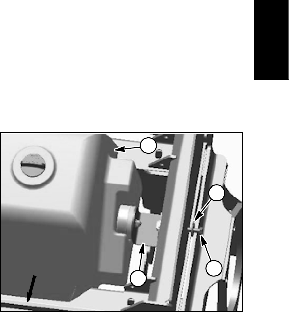
Groundsmaster 4100--D/4110--D Hydraulic SystemPage 4 -- 75
NOTE: The operator platform needs to be raised from
the main frame so that the hydraulic reservoir can be re-
moved from the machine (see Operator Platform in the
Service and Repairs section of Chapter 6 -- Chassis).
Removal (Fig. 52)
1. Park machine on a level surface, lower cutting deck,
stop engine, apply parking brake and remove key from
the ignition switch.
2. Read the General Precautions for Removing and
Installing Hydraulic System Components at the begin-
ning of the Service and Repairs section of this chapter.
3. Drain reservoir into a suitable container.
IMPORTANT: Follow all local codes and regulations
when recycling or disposing hydraulic fluid.
IMPORTANT: Make sure to not damage the electric-
al wire harness, hydraulic hoses or other compo-
nents while raising the operator platform.
4. Raise and support operator platform from the main
frame to allow clearance to remove the hydraulic reser-
voir from the machine (see Operator Platform in the Ser-
vice and Repairs section of Chapter 6 -- Chassis).
5. Disconnect hydraulic hoses from reservoir. Label
disconnected hydraulic hoses for proper installation.
Put plugs on open hydraulic hoses and reservoir fittings
to prevent contamination.
6. Loosen hose clamp (item 24) that secures suction
hose to tank strainer. Remove suction hose (item 25)
from strainer.
7. Remove tank strainer (item 14) from reservoir.
8. Remove cap screw (item 22) and flat washer (item
21) that secure tank mount (item 19) to left side of frame.
9. Carefully remove hydraulic reservoir and tank mount
assembly (items 3, 15, 16, 17, 18 and 19) from machine.
Inspection
1. Clean hydraulic reservoir and tank strainer with sol-
vent.
2. Inspect reservoir for leaks, cracks or other damage.
Installation (Fig. 52)
NOTE: Make sure that recess bumper (item 3) and thin
spacer (item 4) are secured to right side of frame before
hydraulic reservoir is installed to machine.
1. Position hydraulic reservoir to machine. Make sure
that recess bumper (item 3) on right side of frame is in-
serted into tank slot.
2. Slide tank mount assembly (items 15, 16, 3, 17, 18
and 19) between frame and hydraulic tank and position
bumper into slot on left side of reservoir. Align tank
mount with hole in frame. Secure mount with cap screw
and flat washer (Fig. 53).
3. Install tank strainer into reservoir port and torque
from 80 to 88 ft--lb (109 to 119 N--m).
4. Remove plugs from hydraulic hoses and reservoir fit-
tings that were placed during the removal process. Us-
ing labels placed during reservoir removal, connect
hydraulic hoses to fittings on reservoir. Secure hoses
with hose clamps.
IMPORTANT: Make sure to not damage the electric-
al wire harness, hydraulic hoses or other compo-
nents while lowering the operator platform.
5. Carefully lower operator platform to the main frame
(see Operator Platform in the Service and Repairs sec-
tion of Chapter 6 -- Chassis). Make sure that fasteners
are properly torqued during assembly.
IMPORTANT: Use only hydraulic fluids specified in
Operator’s Manual. Other fluids could cause system
damage.
6. Fill reservoir with new hydraulic oil to proper level.
7. Properly fill hydraulic system (see Charge Hydraulic
System in this section).
8. Stop engine and check for hydraulic oil leaks. Check
hydraulic reservoir oil level.
1. Hydraulic reservoir
2. Cap screw
3. Flat washer
4. Tank mount
Figure 53
FRONT
1
2
3
4
Hydraulic
System
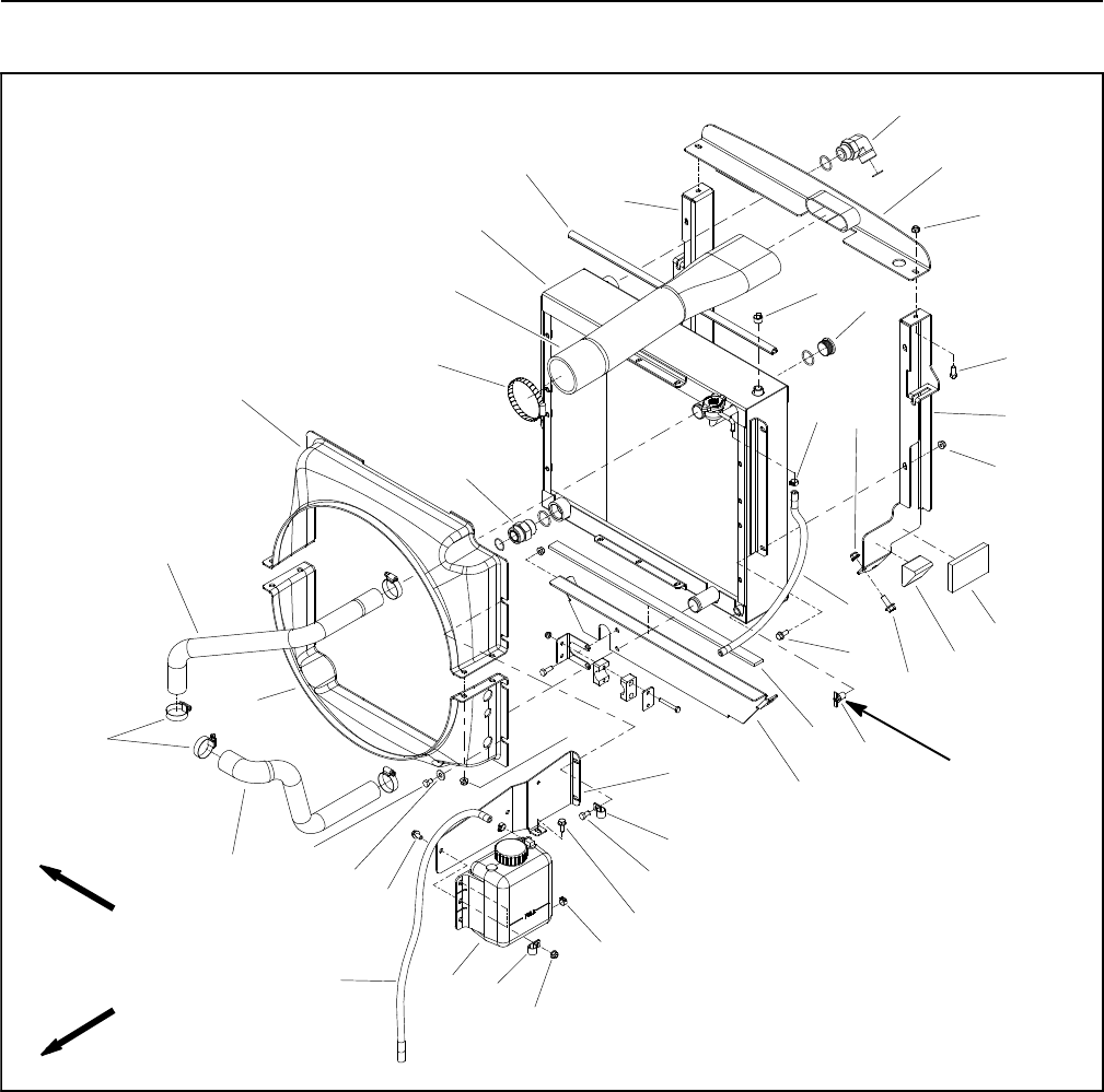
Groundsmaster 4100--D/4110--DHydraulic System Page 4 -- 76
Radiator and Oil Cooler Assembly
1. LH radiator support
2. Cap screw (2 used)
3. Flange nut (12 used)
4. Hose clamp (3 used)
5. Hose
6. Flange nut (6 used)
7. Foam plug (2 used)
8. Flange head screw (6 used)
9. Flange head screw (9 used)
10. Foam strip
11. Hose bracket
12. R--clamp (2 used)
13. Cap screw (2 used)
14. Hose
15. Coolant reservoir
16. Tank mount
17. Flat washer (7 used)
18. Cap screw (6 used)
19. Lower radiator hose
20. Hose clamp (4 used)
21. Upper radiator hose
22. Lower radiator shroud
23. Upper radiator shroud
24. Hose clamp
25. Air cleaner inlet hose
26. Radiator/hydraulic oil cooler
27. Bulb seal
28. RH radiator support
29. Straight hydraulic fitting
30. Intake bracket
31. 90ohydraulic fitting
32. Pipe plug
33. Hex plug with O--ring
34. Foam pad (2 used)
35. Draincock
36. Cap screw (2 used)
Figure 54
FRONT
RIGHT
2
3
6
8
9
10
11
13
1
5
7
12
14 15
16
17
18
19
20
4
21
22
23
24
25
3
3
4
9
12
26
27
28
29
30
31
32 33
34
35
3
Thread
Sealant
36
NOTE: The hydraulic oil cooler on your Groundsmaster
is combined with the radiator. See Radiator and Oil
Cooler Assembly in the Service and Repairs section of
Chapter 3 -- Yanmar Diesel Engine for information on re-
moval and installation of the radiator/oil cooler as-
sembly.

Groundsmaster 4100--D/4110--D Hydraulic SystemPage 4 -- 77
This page is intentionally blank.
Hydraulic
System
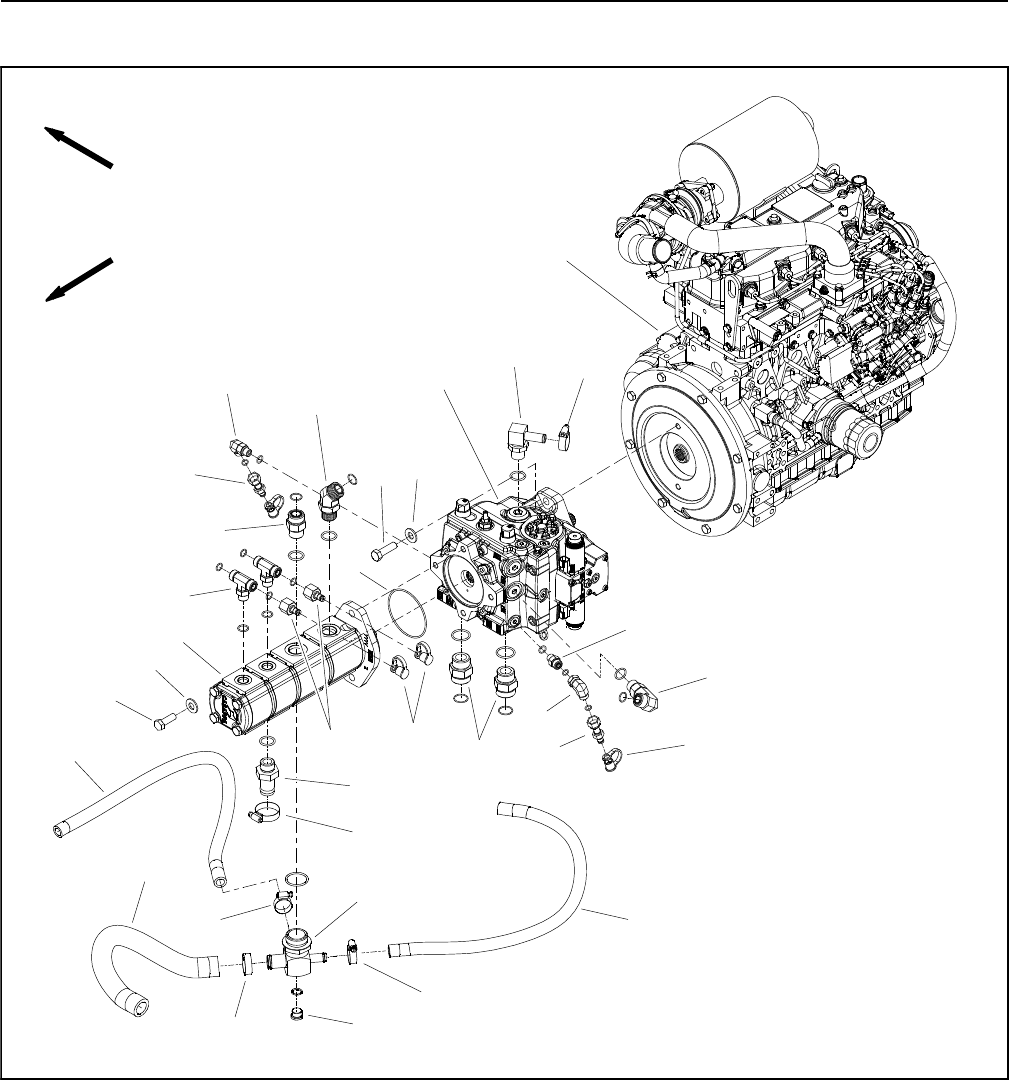
Groundsmaster 4100--D/4110--DHydraulic System Page 4 -- 78
Gear Pump
Figure 55
FRONT
RIGHT
2
3
8
9
10
11
13
1
7
12
14
15
16
17
18
19
20
4
21
22
23
24
2
1
15
9
20
26
6
25
1
5
27
1. Hose clamp (3 used)
2. Hose clamp (2 used)
3. Hydraulic hose
4. Suction hose
5. Tee fitting
6. Straight hydraulic fitting
7. Plug
8. Cap screw (2 used)
9. Flat washer (4 used)
10. Gear pump
11. O -- ring
12. Hydraulic fitting
13. 45ohydraulic fitting
14. Hydraulic tee fitting (2 used)
15. Dust cap (4 used)
16. Piston pump
17. 90ohydraulic fitting
18. Cap screw (2 used)
19. 90ohydraulic fitting
20. Test nipple (2 used)
21. Straight hydraulic fitting (2 used)
22. Straight hydraulic fitting
23. 90ohydraulic fitting
24. Engine (model 30602/30604 shown)
25. Test fitting (2 used)
26. 90obarbed hydraulic fitting
27. Hydraulic hose
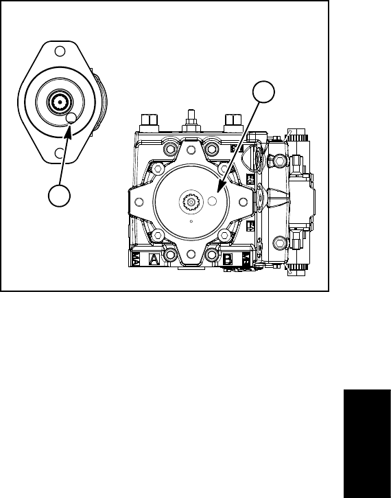
Groundsmaster 4100--D/4110--D Hydraulic SystemPage 4 -- 79
Removal (Fig. 55)
1. Park machine on a level surface, lower cutting deck,
stop engine, apply parking brake and remove key from
the ignition switch.
2. Raise and support machine to gain access to gear
pump from the underside of the machine.
3. Drain the hydraulic reservoir.
IMPORTANT: Follow all local codes and regulations
when recycling or disposing hydraulic fluid.
4. To prevent contamination of hydraulic system during
removal, thoroughly clean exterior of pump and fittings.
5. Read the General Precautions for Removing and
Installing Hydraulic System Components at the begin-
ning of the Service and Repairs section of this chapter.
6. Disconnect hydraulic lines from gear pump and put
caps or plugs on open hydraulic lines and fittings. Label
disconnected hydraulic lines for proper installation.
IMPORTANT: Dry weight of gear pump is 23 pounds
(10.2 kg).
7. Support gear pump assembly to prevent it from fal-
ling.
8. Remove two (2) cap screws and washers securing
gear pump to piston pump. Lower and remove gear
pump from machine.
NOTE: A case drain exists in the piston (traction) pump
and a suction port is near the input shaft of the gear
pump (Fig. 56). When the gear pump is removed from
the piston pump, plug piston pump case drain hole to
prevent draining the piston pump.
9. Remove O--ring (item 11) from between the gear
pump and piston pump. Discard O--ring.
10.If hydraulic fittings are to be removed from gear
pump, mark fitting orientation to allow correct assembly.
Remove fittings from pump and discard O--rings.
Installation (Fig. 55)
1. If fittings were removed from gear pump, lubricate
and place new O--rings onto fittings. Install fittings into
pump openings using marks made during the removal
process to properly orientate fittings. Tighten fittings
(see Hydraulic Fitting Installation in the General Infor-
mation section of this chapter).
2. Make sure mounting and O--ring sealing surfaces on
the gear pump and piston pump are clean.
3. Apply clean hydraulic oil to gear pump flange O--ring
(item 11). Place O--ring on the gear pump.
1. Piston pump case drain 2. Gear pump suction port
Figure 56
Remove plugs before installing
gear pump to piston pump
2
1
IMPORTANT: Position gear pump to the piston
(traction) pump so that the gear pump inlet (suction)
ports are facing down.
IMPORTANT: A case drain exists in the piston (trac-
tion) pump and a suction port is near the input shaft
of the gear pump (Fig. 56). Before the gear pump is
installed to the piston pump, make sure that plugs
placed in either of these ports are removed. Failure
to remove plugs will cause excessive pressure in
the piston pump and damage seals. Also, before se-
curing gear pump to piston pump, fill piston pump
housing with clean hydraulic oil through case drain
hole.
4. Remove plugs that were placed in piston pump case
drain and gear pump suction port. Fill piston pump hous-
ing with clean hydraulic oil through case drain hole.
5. Position gear pump to the piston (traction) pump so
that the pump inlet ports are facing down.
6. Align gear teeth and slide gear pump input shaft into
piston pump shaft. Secure gear pump to piston pump
with two (2) cap screws and flat washers.
7. Remove caps and plugs from hydraulic lines and fit-
tings. Using labels placed during gear pump removal,
properly install lines to gear pump (see Hydraulic Hose
and Tube Installation in the General Information section
of this chapter).
8. Fill piston pump housing through case drain (90o
barbed fitting) with new hydraulic oil (Fig. 57). This will
ensure that internal pump components have adequate
lubrication during initial operation.
9. Lower machine to ground.
Hydraulic
System
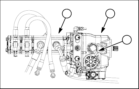
Groundsmaster 4100--D/4110--DHydraulic System Page 4 -- 80
10.Replace hydraulic filters and fill hydraulic reservoir
with new hydraulic oil.
11. Prime hydraulic pumps (see Priming Hydraulic
Pumps in this section).
12.Properly fill hydraulic system (see Charge Hydraulic
System in this section).
13.Stop engine and check for hydraulic oil leaks. Check
hydraulic reservoir oil level.
1. Piston (traction) pump
2. Gear pump
3. Piston pump case drain
Figure 57
2
3
1

Groundsmaster 4100--D/4110--D Hydraulic SystemPage 4 -- 81
This page is intentionally blank.
Hydraulic
System
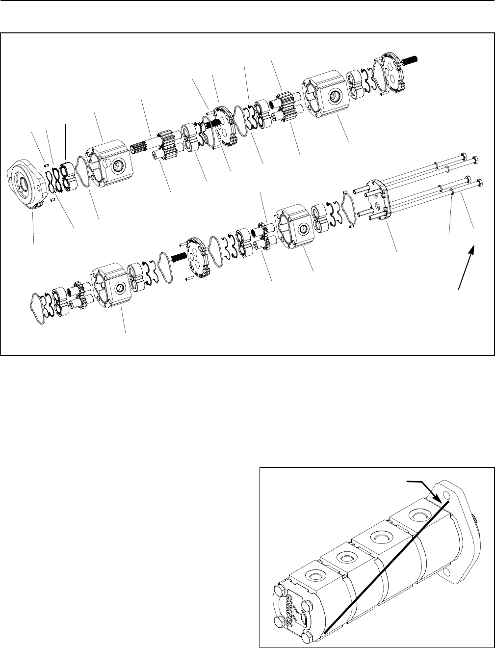
Groundsmaster 4100--D/4110--DHydraulic System Page 4 -- 82
Gear Pump Service
1. Front cover
2. Dowel pin (4 used)
3. Pressure seal
4. Back--up gasket
5. Front thrust plate
6. Seal (8 used)
7. Front body
8. Idler gear
9. Drive shaft
10. Thrust plate (7 used)
11. Dowel pin (6 used)
12. Splined connecting shaft (3 used)
13. Flange(3used)
14. Back--up gasket
15. Pressure seal
16. Drive gear
17. Idler gear
18. Body (2nd pump section)
19. Body (3rd pump section)
20. Idler gear
21. Drive gear
22. Rear body (4th pump section)
23. Rear cover
24. Washer (4 used)
25. Cap screw (4 used)
Figure 58
33 ft--lb
(45 N--m)
10
11
8
15
5
3
19
20
21
22
23
24
9
7
6
1
2
16
17
18
4
14
13
12
25
Disassembly (Fig. 58)
NOTE: The gear pump must be replaced as a complete
assembly. Individual gears, housings and thrust plates
are not available separately. Disassemble gear pump
for cleaning, inspection and seal replacement only.
IMPORTANT: Keep bodies, gears, flanges and
thrust plates for each pump section together; do not
mix parts between pump sections.
1. Plug pump ports and thoroughly clean exterior of
pump with cleaning solvent. Make sure work area is
clean.
2. Useamarkertomakeadiagonal line across the
gear pump for assembly purposes (Fig. 59). Figure 59
DIAGONAL LINE
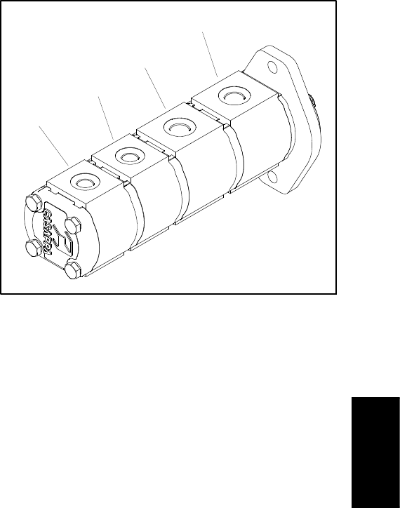
Groundsmaster 4100--D/4110--D Hydraulic SystemPage 4 -- 83
IMPORTANT: Use caution when clamping gear
pump in a vise to avoid distorting any pump compo-
nents.
3. Securethefrontcoverofthepumpinavisewiththe
drive shaft pointing down.
4. Loosen the four (4) cap screws that secure pump as-
sembly.
5. Remove pump from vise and remove fasteners.
6. Support the pump assembly and gently tap the pump
case with a soft face hammer to loosen the pump sec-
tions. Be careful to not drop parts or disengage gear
mesh.
IMPORTANT: Mark the relative positions of the gear
teeth and the thrust plates so they can be reassem-
bled in the same position. Do not touch the gear sur-
faces as residue on hands may be corrosive to gear
finish.
7. Remove the thrust plates and seals from each pump
section. Before removing each gear set, apply marking
dye to mating teeth to retain ”timing”. Pump efficiency
may be affected if the teeth are not installed in the same
position during assembly. Keep the parts for each pump
section together; do not mix parts between sections.
8. Clean all parts. Check all components for burrs,
scoring, nicks and other damage.
9. Replace the entire pump assembly if parts are ex-
cessively worn or scored.
Assembly (Fig. 58)
1. Apply clean hydraulic oil to all parts before assem-
bling.
NOTE: Pressure seals and back--up gaskets fit in
grooves machined into thrust plates. Body seals fit in
grooves machined in body faces.
2. Assemble pump sections starting at front cover end.
Apply grease or petroleum jelly to new section seals to
holdtheminpositionduringgearpumpassembly.
3. After pump has been assembled, tighten cap screws
by hand. Rotate the drive shaft to check for binding. Pro-
tect the shaft if using a pliers.
4. Tighten the four (4) cap screws evenly in a crossing
patterntoatorqueof33 ft--lb (45 N--m).
1. LH and RH PTO pump section
2. Front PTO pump section
3. Cooling fan, lift/lower and charge pump section
4. Steering, charge and cooling fan pump section
Figure 60
2
3
1
4
Hydraulic
System

Groundsmaster 4100--D/4110--DHydraulic System Page 4 -- 84
Piston (Traction) Pump
Figure 61
FRONT
RIGHT
1. Hose clamp (2 used)
2. Hose clamp (2 used)
3. Hose
4. Suction hose
5. Tee fitting
6. Straight hydraulic fitting
7. Plug
8. Cap screw (2 used)
9. Flat washer (4 used)
10. Gear pump
11. O -- ring
12. Hydraulic fitting
13. 45ohydraulic fitting
14. Hydraulic tee fitting (2 used)
15. Dust cap (5 used)
16. Piston pump
17. 90ohydraulic fitting
18. Cap screw (2 used)
19. 90ohydraulic fitting
20. Test nipple (2 used)
21. Straight hydraulic fitting (2 used)
22. Straight hydraulic fitting
23. 90ohydraulic fitting
24. Engine (model 30602/30604 shown)
25. Test fitting (2 used)
26. 90obarbed hydraulic fitting
2
3
8
9
10
11
13
1
7
12
14
15
16
17
18
19
20
4
21
22
23
24
2
1
15
9
20
26
6
25
1
5
27
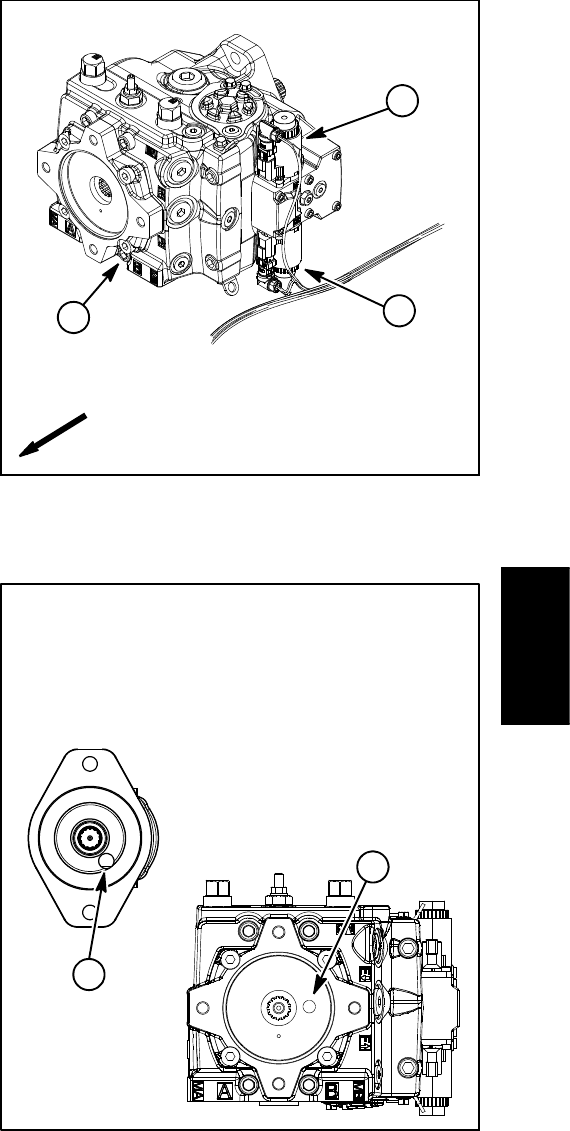
Groundsmaster 4100--D/4110--D Hydraulic SystemPage 4 -- 85
Removal (Fig. 61)
1. Park machine on a level surface, lower cutting deck,
stop engine, apply parking brake and remove key from
the ignition switch.
2. To prevent contamination of hydraulic system during
removal, thoroughly clean exterior of pump assembly.
3. Raise and support machine to gain access to pump
assembly from the underside of machine.
4. Label wire harness connectors that attach to the two
(2) solenoid coils on left side of piston pump (Fig. 62).
Disconnect harness connectors from solenoid coils on
piston pump.
5. Read the General Precautions for Removing and
Installing Hydraulic System Components at the begin-
ning of the Service and Repairs section of this chapter.
6. For installation purposes, label all hydraulic lines that
connect to gear pump and piston pump.
7. Put a drain pan below the pump assembly. Remove
hydraulic lines connected to piston and gear pump fit-
tings. Put plugs or caps on disconnected hydraulic lines
and fittings to prevent contamination of the system.
NOTE: If fuel tank is removed from the machine, the
gear pump and piston pump can be removed as a com-
plete assembly.
8. Remove gear pump from machine (see Gear Pump
in this section).
IMPORTANT: Dry weight of piston (traction) pump
is 90 pounds (41 kg).
NOTE: A case drain exists in the piston (traction) pump
and a suction port is near the input shaft of the gear
pump (Fig. 63). When the gear pump is removed from
the piston pump, plug piston pump case drain hole to
prevent draining the piston pump.
9. Support the piston pump to prevent it from falling.
Remove two (2) cap screws and washers retaining
pump assembly to engine flywheel plate. Carefully pull
pump assembly from flywheel plate and lower it out of
the machine.
10.If hydraulic fittings are to be removed from piston
pump, mark fitting orientation to allow correct assembly.
Remove fittings from pump and discard O--rings.
1. Piston pump
2. Solenoid coil (forward)
3. Solenoid coil (reverse)
Figure 62
2
3
1
FRONT
1. Piston pump case drain 2. Gear pump suction port
Figure 63
after gear pump is removed.
2
1
drain and gear pump suction port
install plugs in piston pump case
To prevent draining the pumps,
Remove plugs before installing
gear pump to piston pump
Hydraulic
System
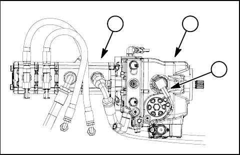
Groundsmaster 4100--D/4110--DHydraulic System Page 4 -- 86
Installation (Fig. 61)
1. If fittings were removed from piston pump, lubricate
and place new O--rings onto fittings. Install fittings into
pump openings using marks made during the removal
process to properly orientate fittings. Tighten fittings
(see Hydraulic Fitting Installation in the General Infor-
mation section of this chapter).
IMPORTANT: To prevent spring coupler damage,
make sure that piston pump is properly supported
and does not put side load into coupler during pump
installation.
2. Carefully raise piston pump into the machine, align
pump input shaft to spring coupler on engine and posi-
tion it to the engine flywheel plate. Support pump to pre-
vent it from producing any side load into coupler and
also to align pilot diameter of pump to flywheel plate
bore.
3. While maintaining pump alignment with spring cou-
pler and flywheel plate, install two (2) cap screws and
washers to secure piston pump to engine.
IMPORTANT: A case drain exists in the piston (trac-
tion) pump and a suction port is near the input shaft
of the gear pump (Fig. 63). Before the gear pump is
installed to the piston pump, make sure that plugs
placed in either of these ports are removed. Failure
to remove plugs will cause excessive pressure in
the piston pump and damage seals. Also, before se-
curing gear pump to piston pump, fill piston pump
housing with clean hydraulic oil through case drain
hole.
4. Remove plugs that were placed in piston pump case
drain and gear pump suction port. Fill piston pump hous-
ing with new hydraulic oil through case drain hole.
5. Install gear pump to piston pump (see Gear Pump in
this section).
6. Using labels placed during pump removal, connect
wire harness connectors to the two (2) solenoid coils on
left side of piston pump.
7. Fill piston (traction) pump housing with new hydraul-
ic oil through the case drain (90obarbed fitting) at the top
of the pump (Fig. 64). This will ensure that internal pump
components have adequate lubrication during initial op-
eration.
8. Remove plugs and caps from disconnected hydrau-
lic lines and fittings of the pump assembly. Install hy-
draulic lines to correct location on gear and piston
pumps (see Hydraulic Fitting Installation and Hydraulic
Hose and Tube Installation in the General Information
section of this chapter).
9. Lower machine to ground.
10.Install new hydraulic filter and fill hydraulic reservoir
with correct oil.
IMPORTANT: Refer to Traction Circuit Component
Failure in the General Information section of this
chapter for information regarding the importance of
removing contamination from the traction circuit.
11. Prime hydraulic pumps (see Priming Hydraulic
Pumps in this section).
12.Properly fill hydraulic system (see Charge Hydraulic
System in this section).
13.Stop engine and check for hydraulic oil leaks. Check
hydraulic reservoir oil level.
1. Piston (traction) pump
2. Gear pump
3. Piston pump case drain
Figure 64
2
3
1

Groundsmaster 4100--D/4110--D Hydraulic SystemPage 4 -- 87
This page is intentionally blank.
Hydraulic
System
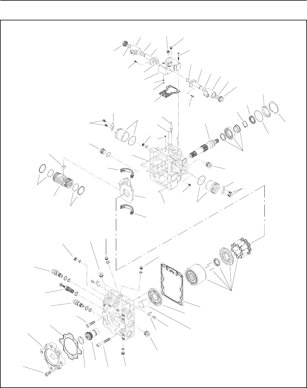
Groundsmaster 4100--D/4110--DHydraulic System Page 4 -- 88
Piston (Traction) Pump Service
Figure 65
2
3
6
8
9
10
11
13
1
5
7
12
14
15
16
17
18
19
20
4
21
22
23
24
25
26
27
28
29
30
31
32 33
34
35
2
3
10
7
25
10
29
33
34 36
37
38
39
40
41
46
47
42
43
48
49
44
45
41
42
42 55 42
44
45
46
50
51 52
53
54
10

Groundsmaster 4100--D/4110--D Hydraulic SystemPage 4 -- 89
1. Screen (2 used)
2. Plug with O--ring (2 used)
3. Plug with O--ring (2 used)
4. Cylinder block assembly
5. Valve plate
6. Servo piston
7. Screw (4 used)
8. Orifice(2used)
9. Screw (4 used)
10. Plug with O--ring (4 used)
11. Screw (2 used)
12. Plug
13. Shaft
14. Bearing assembly
15. Retaining ring
16. Gasket
17. Adapter
18. Adapter seal
19. Coupling
20. Bearing
21. Screw (4 used)
22. Thrust plate
23. Forward relief valve assembly
24. Reverse relief valve assembly
25. Swash plate bearing assembly
26. Screw (2 used)
27. Bracket (2 used)
28. Charge relief valve assembly
29. Servo piston seal assembly
30. Piston follower
31. Swashplate
32. Dowel pin (2 used)
33. Servo cylinder assembly (2 used)
34. Locking plate (2 used)
35. Dowel pin (2 used)
36. Feedback pin
37. Seal
38. O--ring
39. Seal carrier
40. Retaining ring
41. Coil nut (2 used)
42. O--ring
43. Forward solenoid coil
44. Screw (3 used per solenoid)
45. Solenoid (2 used)
46. O--ring
47. Control housing
48. Screen (2 used)
49. Retaining ring (2 used)
50. Gasket
51. Lock nut
52. Plug
53. Screw (6 used)
54. Plug (2 used)
55. Reverse solenoid coil
Figure 65 (Continued)
Piston (Traction) Pump Service (Fig. 65)
For service of the piston (traction) pump, see the Sauer--
Danfoss H1 Closed Circuit Axial Piston Pumps Service
Manual at the end of this chapter.
NOTE: The forward (item 43) and reverse (item 55)
solenoid coils are identical.
Hydraulic
System
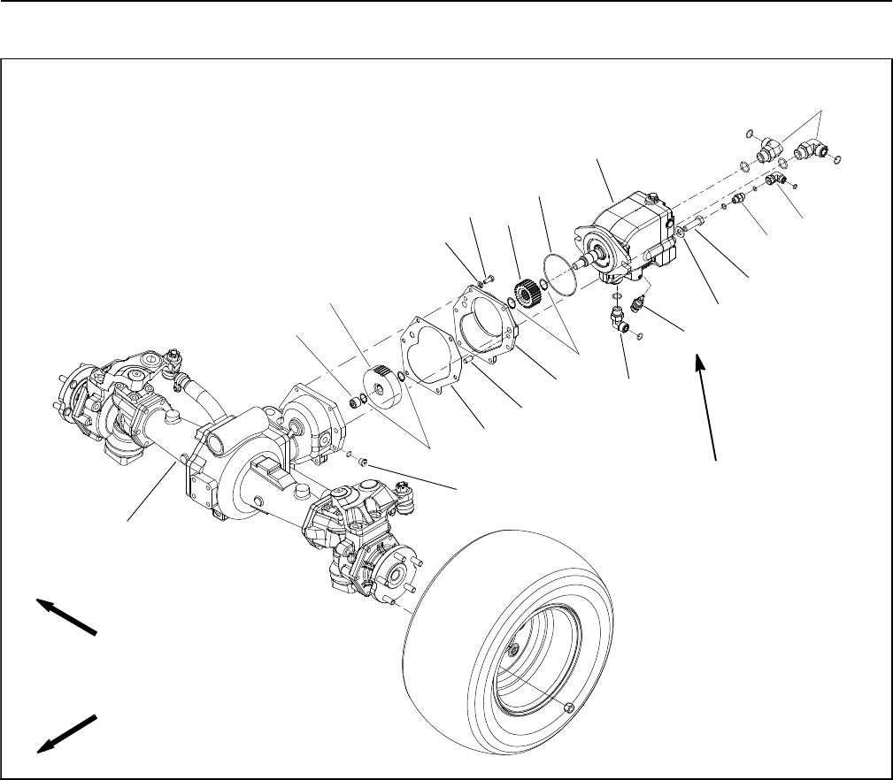
Groundsmaster 4100--D/4110--DHydraulic System Page 4 -- 90
Rear Axle Motor
1. Rear axle motor
2. 90ohydraulic fitting (2 used)
3. 90ohydraulic fitting
4. Straight hydraulic fitting
5. 90ohydraulic fitting
6. Temperature sender
7. Cap screw (2 used)
8. Flat washer (2 used)
9. O--ring
10. External snap ring (2 used)
11. Pinion gear (27T)
12. Cap screw (6 used)
13. Lock washer (6 used)
14. Cover plate
15. Dowel pin (2 used)
16. Gasket
17. External snap ring (2 used)
18. Gear (45T)
19. Needle bearing
20. Plug with O--ring
21. Drive axle assembly
Figure 66
FRONT
RIGHT
16
11
10
5
4
3
9
7
8
6
1
15
14
13
12
18
21
19
17
20
2
9to11ft--lb
(12.3to14.9N--m)

Groundsmaster 4100--D/4110--D Hydraulic SystemPage 4 -- 91
Removal (Fig. 66)
1. Park machine on a level surface, lower cutting deck,
stop engine, apply parking brake and remove key from
the ignition switch.
2. Drain lubricant from rear axle gearbox.
3. Read the General Precautions for Removing and
Installing Hydraulic System Components at the begin-
ning of the Service and Repairs section of this chapter.
4. To prevent contamination of hydraulic system during
axle motor removal, thoroughly clean exterior of motor
and fittings.
5. Disconnect wire harness connector from temperat-
ure sender (item 6) on rear axle motor.
NOTE: To ease installation, label the hydraulic lines to
show their correct position on the axle motor.
6. Disconnect hydraulic lines from motor. Put caps or
plugs on motor fittings and hydraulic line openings to
prevent contamination.
IMPORTANT: Before loosening fasteners that se-
cure rear axle motor, support motor to prevent it
from falling during removal.
7. Remove motor from rear axle using Figure 66 as a
guide.
8. If hydraulic fittings are to be removed from motor,
mark fitting orientation to allow correct assembly. Re-
move fittings from motor and discard O--rings.
9. If necessary, remove temperature sender (item 6)
from rear axle motor.
10.If necessary, remove pinion gear (item 11) from rear
axle motor shaft.
Installation (Fig. 66)
IMPORTANT: Refer to Traction Circuit Component
Failure in the General Information section of this
chapter for information regarding the importance of
removing contamination from the traction circuit.
1. If fittings were removed from axle motor, lubricate
and place new O--rings onto fittings. Install fittings into
port openings using marks made during the removal
process to properly orientate fittings. Tighten fittings
(see Hydraulic Fitting Installation in the General Infor-
mation section of this chapter).
2. If temperature sender (item 6) was removed from
rear axle motor, thread sender into motor port. Torque
sender from 9to11ft--lb(12.3to14.9N--m).
3. If removed, install pinion gear (item 11) to axle motor.
Make sure that retaining rings are fully seated into the
grooves of the motor shaft.
4. Install O--ring (item 9) onto motor. Position motor to
rear axle assembly and align gear teeth. Slide motor into
place.
5. Secure motor to axle with cap screws and flat wash-
ers.
6. Remove plugs from motor fittings and hydraulic line
openings. Using labels placed during motor removal,
correctly attach hydraulic lines to axle motor fittings (see
Hydraulic Hose and Tube Installation in the General In-
formation section of this chapter).
7. Secure wire harness connector to temperature
sender (item 6) on rear axle motor.
8. Fill rear axle gearbox with SAE 85W--140 weight
gear lube. Gearbox capacity is approximately 16 fl. oz.
(0.47 liters).
9. Fill reservoir with hydraulic fluid as required.
10.Properly fill hydraulic system (see Charge Hydraulic
System in this section).
11. After assembly is completed, verify that hydraulic
lines and fittings do not contact anything.
Hydraulic
System
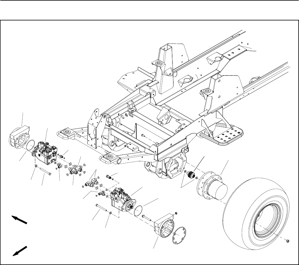
Groundsmaster 4100--D/4110--DHydraulic System Page 4 -- 92
Front Wheel Motors
1. Front wheel motor
2. Internal retaining ring
3. Splined brake shaft
4. RH brake assembly
5. Planetary assembly (2 used)
6. Cap screw (2 used per motor)
7. Flat washer (2 used per motor)
8. O--ring
9. LH brake assembly
10. Hydraulic tee fitting
11. 90ohydraulic fitting (2 used)
12. Hydraulic connector
13. Hydraulic tee fitting (2 used)
14. 90ohydraulic fitting
15. Straight hydraulic fitting
Figure 67
FRONT
RIGHT
2
3
6
8
9
11
13
1
5
7
12
14
15
4
10
1
6
7
8
13

Groundsmaster 4100--D/4110--D Hydraulic SystemPage 4 -- 93
Removal (Fig. 67)
1. Park machine on a level surface, lower cutting deck,
stop engine, apply parking brake and remove key from
the ignition switch.
2. Read the General Precautions for Removing and
Installing Hydraulic System Components at the begin-
ning of the Service and Repairs section of this chapter.
3. To prevent contamination of hydraulic system during
wheel motor removal, thoroughly clean exterior of motor
and fittings.
NOTE: To ease installation, label the hydraulic lines to
show their correct position on the wheel motor.
4. Disconnect hydraulic hoses and tubes from wheel
motor. Put caps or plugs on motor ports and hose open-
ings to prevent contamination.
IMPORTANT: Before loosening fasteners that se-
cure wheel motor, support motor to prevent it from
falling during removal.
5. Remove wheel motor using Figure 67 as a guide.
6. If hydraulic fittings are to be removed from wheel mo-
tor, mark fitting orientation to allow correct assembly.
Remove fittings from motor and discard O--rings.
Installation (Fig. 67)
IMPORTANT: Refer to Traction Circuit Component
Failure in the General Information section of this
chapter for information regarding the importance of
removing contamination from the traction circuit.
1. If fittings were removed from motor, lubricate and
place new O--rings onto fittings. Install fittings into port
openings using marks made during the removal process
to properly orientate fittings. Tighten fittings (see Hy-
draulic Fitting Installation in the General Information
section of this chapter).
2. Install new O--ring (item 8) onto motor.
3. Align splines on motor shaft and splined brake shaft.
Slide motor into brake assembly.
4. Secure motor to brake assembly with cap screws
and flat washers.
5. Remove plugs from wheel motor fittings and hydraul-
ic line openings. Using labels placed during motor re-
moval, correctly attach hydraulic hoses and tubes to
wheel motor fittings (see Hydraulic Hose and Tube
Installation in the General Information section of this
chapter).
6. Fill reservoir with hydraulic fluid as required.
7. Properly fill hydraulic system (see Charge Hydraulic
System in this section).
Hydraulic
System
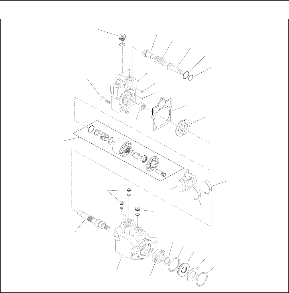
Groundsmaster 4100--D/4110--DHydraulic System Page 4 -- 94
Rear Axle and Front Wheel Motor Service
Figure 68
2
3
6
8
9
10
11
13
1
5
7
12
14
15
16
17
18
19
20
4
21
22
23
21
25
1. Plug with O--ring
2. Minimum angle stop
3. Bias spring
4. Servo piston
5. O--ring
6. O--ring
7. Socket head screw (5 used)
8. Endcap
9. Dowel
10. Dowel pin
11. Bearing
12. Gasket
13. Valve plate
14. Cylinder block kit
15. Swashplate
16. Swash plate bearing assembly
17. Output shaft
18. Housing
19. Bearing
20. Retaining ring
21. Retaining ring (2 used)
22. Seal
23. Support washer
24. Plug with O--ring (2 used)
25. Plug with O--ring
24
16

Groundsmaster 4100--D/4110--D Hydraulic SystemPage 4 -- 95
NOTE: The front wheel motors on your Groundsmaster
are identical (Fig. 68). The rear axle motor includes a
flushing valve for cooling of the closed loop traction cir-
cuit and therefore has some differences from the front
motors (Fig. 69). Service of the wheel and axle motors
uses the same procedure.
NOTE: For service of the front wheel and rear axle mo-
tors, see the Sauer--Danfoss K and L Frame Variable
Motors Service Manual at the end of this chapter.
1. Plug
2. O--ring
3. Centering spring
4. Spring retaining washer
5. Shift spool
6. Plug
7. O--ring
8. Centering spring
9. Orifice poppet
10. Motor endcap
Figure 69
2
3
6
8
9
1
5
7
4
1
2
3
4
REAR AXLE MOTOR FLUSHING VALVE
10
Hydraulic
System
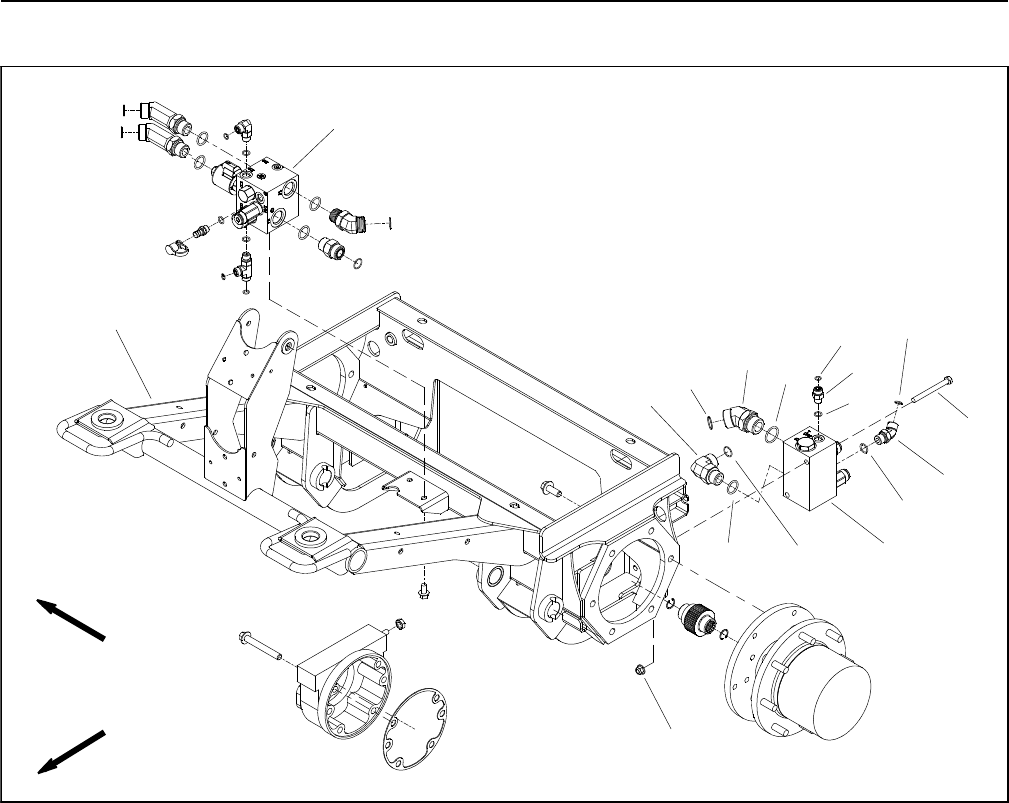
Groundsmaster 4100--D/4110--DHydraulic System Page 4 -- 96
Rear Traction Manifold
1. Front frame
2. PTO manifold (center deck section)
3. Rear traction manifold
4. Cap screw (2 used)
5. Flange nut (2 used)
6. 90ohydraulic fitting
7. O--ring
8. 45ohydraulic fitting
9. O--ring
10. O--ring
11. Straight fitting
12. O--ring
13. O--ring
14. 45ohydraulic fitting
15. O--ring
16. O--ring
17. O--ring
Figure 70
FRONT
RIGHT
2
3
6
89
10
11
13
1
5
7
12
14
15
1617
4
NOTE: The ports on the rear traction control manifold
are marked for easy identification of components. Ex-
ample: P2 is a piston pump connection port and RV is
the location for the relief valve (see Hydraulic Schematic
in Chapter 10 -- Foldout Drawings to identify the function
of the hydraulic lines and cartridge valves at each port).

Groundsmaster 4100--D/4110--D Hydraulic SystemPage 4 -- 97
Removal (Fig. 70)
1. Read the General Precautions for Removing and
Installing Hydraulic System Components at the begin-
ning of the Service and Repairs section of this chapter.
2. To prevent contamination of hydraulic system during
manifold removal, thoroughly clean exterior of manifold
and fittings.
3. Disconnect hydraulic lines from manifold and put
caps or plugs on open hydraulic lines and fittings. Label
disconnected hydraulic lines for proper installation.
4. Remove hydraulic manifold from the frame using
Figure 70 as a guide.
5. If hydraulic fittings are to be removed from manifold,
mark fitting orientation to allow correct assembly. Re-
move fittings from manifold and discard O--rings.
Installation (Fig. 70)
1. If fittings were removed from manifold, lubricate and
place new O--rings onto fittings. Install fittings into man-
ifold openings using marks made during the removal
process to properly orientate fittings. Tighten fittings
(see Hydraulic Fitting Installation in the General Infor-
mation section of this chapter).
2. Install hydraulic manifold to the frame using Figure
70 as a guide.
3. Remove caps and plugs from fittings and hydraulic
lines. Using labels placed during manifold removal,
properly connect hydraulic lines to manifold (see Hy-
draulic Hose and Tube Installation in the General Infor-
mation section of this chapter).
4. Make sure hydraulic tank is full. Add correct oil if nec-
essary before returning machine to service.
Hydraulic
System
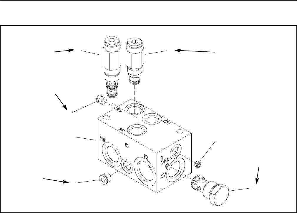
Groundsmaster 4100--D/4110--DHydraulic System Page 4 -- 98
Rear Traction Manifold Service
1. Rear traction manifold body
2. Relief valve (port RV)
3. Pressure reducing valve (port PR)
4. #4 zero leak plug with O--ring
5. #6 zero leak plug with O--ring
6. Check valve (port CV)
7. Orifice (0.050) (port T/OR1)
Figure 71
25 ft--lb
(34 N--m)
35 ft--lb
(47 N--m)
20 ft--lb
(27 N--m)
50 ft--lb
(67 N--m)
1
2
4
3
56
7
25 ft--lb
(34 N--m)
NOTE: The ports on the rear traction manifold are
marked for easy identification of components. Example:
P2 is a piston pump connection port and RV is the loca-
tion for the relief valve (see Hydraulic Schematic in
Chapter 10 -- Foldout Drawings to identify the function
of the hydraulic lines and cartridge valves at each port).
NOTE: The rear traction manifold uses several zero
leak plugs. These plugs have a tapered sealing surface
on the plug head that is designed to resist vibration in-
duced plug loosening. The zero leak plugs also have an
O--ring as a secondary seal. If zero leak plug removal is
necessary, lightly rap the plug head using a punch and
hammer before using an allen wrench to remove the
plug: the impact will allow plug removal with less chance
of damage to the socket head of the plug.
For rear traction manifold cartridge valve service proce-
dures, see Control Manifold Cartridge Valve Service in
this section. Refer to Figure 71 for rear traction manifold
cartridge valve and plug installation torque.
IMPORTANT: A flow control orifice (item 7) is lo-
cated beneath the hydraulic fitting in rear traction
manifold port T/OR1. If the orifice is removed from
this manifold port, make sure to label its position for
assembly purposes. When installing the orifice in
the manifold, make sure that the orifice is properly
tightened in the port.
Groundsmaster 4100--D/4110--D Hydraulic SystemPage 4 -- 99
Control Manifold Cartridge Valve Service
1. Make sure the control manifold is clean before re-
moving the cartridge valve from the control manifold.
2. If cartridge valve is solenoid operated, remove nut
securing solenoid coil to the cartridge valve. Carefully
slidecoiloffthevalve.
IMPORTANT: Use care when handling the cartridge
valve. Slight bending or distortion of the stem tube
can cause binding and malfunction. When remov-
ing cartridge valve from manifold, make sure that
deep well socket fully engages the valve base.
3. Remove cartridge valve from manifold using a deep
socket wrench. Note correct location for O--rings, seal-
ing rings and backup rings. Remove seal kit from car-
tridge valve and discard removed seals.
4. Visually inspect the port in the manifold for damage
to the sealing surfaces, damaged threads and contami-
nation.
5. Visually inspect cartridge valve for damaged sealing
surfaces and contamination.
A. Contamination may cause valves to stick or hang
up. Contamination can become lodged in small valve
orifices or seal areas causing malfunction.
B. If valve sealing surfaces appear pitted or dam-
aged, the hydraulic system may be overheating or
there may be water in the system.
CAUTION
Use eye protection such as goggles when using
compressed air.
6. Clean cartridge valve using clean mineral spirits.
Submerge valve in clean mineral spirits to flush out con-
tamination. Particles as fine as talcum powder can affect
the operation of high pressure hydraulic valves. If car-
tridge design allows, use a wood or plastic probe to push
the internal spool in and out 20 to 30 times to flush out
contamination. Be extremely careful not to damage car-
tridge. Use compressed air for cleaning.
7. Install the cartridge valve into the manifold:
A. Lubricate new seal kit components with clean hy-
draulic oil and install on valve. The O--rings, sealing
rings and backup rings must be arranged properly on
the cartridge valve for proper operation and sealing.
B. Dip assembled cartridge into clean hydraulic oil.
IMPORTANT: Use care when handling the valve
cartridge. Slight bending or distortion of the
stem tube can cause binding and malfunction.
When installing cartridge valve into manifold,
make sure that deep well socket fully engages
the valve base.
C. Thread cartridge valve carefully into manifold
port by hand until the top O--ring is met. The valve
should go into manifold port easily without binding.
D. Torque cartridge valve using a deep socket
wrench to value identified in control manifold illustra-
tion.
8. If cartridge valve is solenoid operated, carefully
install solenoid coil to the cartridge valve. Secure coil to
valve with nut and torque nut to 60 in--lb (6.8 N--m).
9. If problems still exist after assembly, remove valve
and clean again or replace valve.
Hydraulic
System
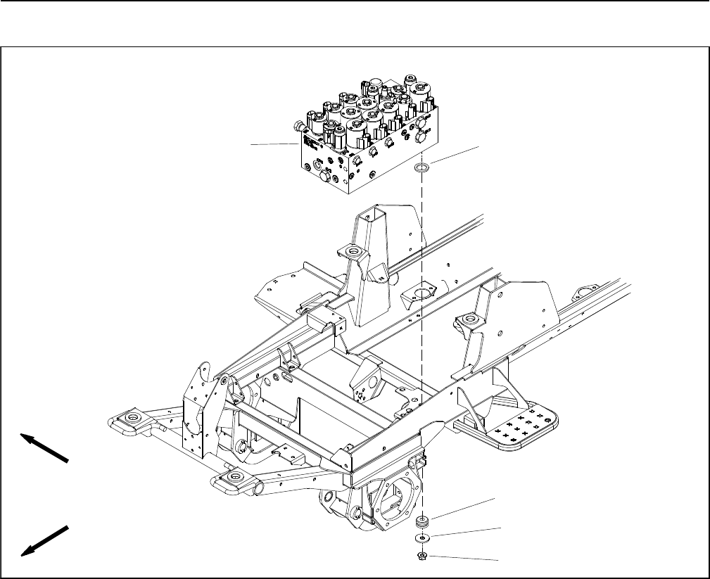
Groundsmaster 4100--D/4110--DHydraulic System Page 4 -- 100
Combination Manifold
1. Combination manifold
2. Flange nut (3 used)
3. Flat washer (3 used)
4. Mount (3 used)
5. Spacer (3 used)
Figure 72
FRONT
RIGHT
2
3
15
4
NOTE: The ports on the combination manifold are
marked for easy identification of components. Example:
P3andP4arethegearpumpconnectionports,S1isthe
location for solenoid valve S1 and OR6 is the location for
orifice OR6 (see Hydraulic Schematic in Chapter 10 --
Foldout Drawings to identify the function of the hydraulic
lines and cartridge valves at each port).
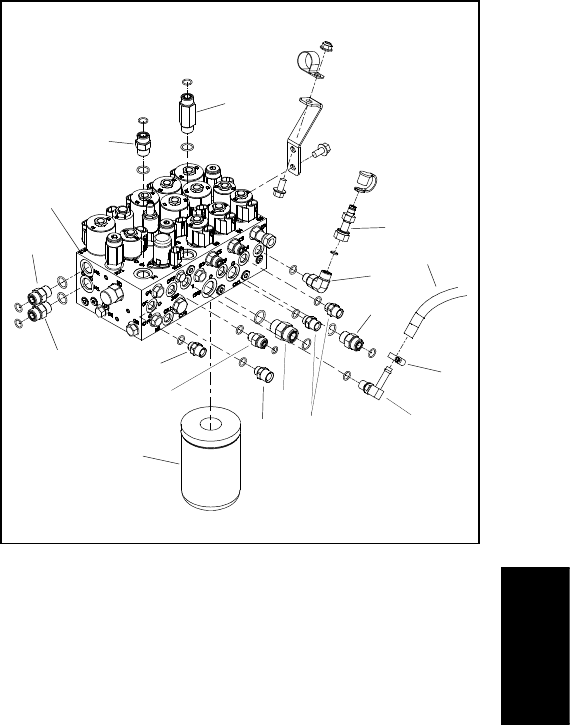
Groundsmaster 4100--D/4110--D Hydraulic SystemPage 4 -- 101
Removal (Fig. 72)
1. Read the General Precautions for Removing and
Installing Hydraulic System Components at the begin-
ning of the Service and Repairs section of this chapter.
2. To prevent contamination of hydraulic system during
manifold removal, thoroughly clean exterior of combina-
tion manifold and fittings.
3. Label all wire harness connectors that attach to
solenoid coils on combination manifold. Disconnect wire
harness connectors from solenoid coils on the combina-
tion manifold.
4. Disconnect hydraulic lines from combination man-
ifold and put caps or plugs on open hydraulic lines and
fittings. Label disconnected hydraulic lines for proper re-
assembly.
NOTE: The combination manifold has three (3) studs
on the bottom surface of the manifold used for securing
themanifoldtothemachine.
5. Remove combination manifold from the frame using
Figure 72 as a guide.
6. If hydraulic fittings are to be removed from manifold,
mark fitting orientation to allow correct assembly (Fig.
73). Remove fittings from manifold and discard O--rings.
Installation (Fig. 72)
1. If fittings were removed from manifold, lubricate and
place new O--rings onto fittings. Install fittings into man-
ifold openings using marks made during the removal
process to properly orientate fittings. Tighten fittings
(see Hydraulic Fitting Installation in the General Infor-
mation section of this chapter).
2. Install combination manifold to the frame using Fig-
ure72asaguide.
3. Remove caps and plugs from fittings and hydraulic
lines. Using labels placed during manifold removal,
properly connect hydraulic lines to manifold (see Hy-
draulic Hose and Tube Installation in the General Infor-
mation section of this chapter).
4. Using labels made during manifold removal, connect
wire harness connectors to the solenoid coils on the
combination manifold.
5. Make sure hydraulic tank is full. Add correct oil if nec-
essary before returning machine to service.
1. Manifold
2. Straight fitting
3. Straight fitting
4. Straight fitting
5. Oil filter
6. Straight fitting
7. Straight fitting
8. Straight fitting
9. Barbed 90ofitting
10. Hose clamp
11. Hose
12. 90ofitting
13. Test nipple
14. Straight fitting
Figure 73
2
3
689
10
11
14
1
5
7
12
4
2
2
2
13
Hydraulic
System
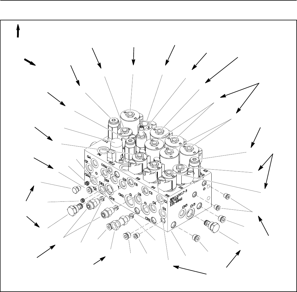
Groundsmaster 4100--D/4110--DHydraulic System Page 4 -- 102
Combination Manifold Service
1. Combination manifold
2. #6 zero leak plug with O--ring
3. Check valve (CV3)
4. #4 zero leak plug with O--ring
5. Solenoid valve (S4, S6 and S9)
6. Solenoid valve (S5)
7. Relief valve (RV2)
8. Solenoid valve (S2, S3, S7 and S8)
9. Solenoid valve (S1)
10. Pressure reducing valve (PR)
11. Proportional relief valve (PRV)
12. Solenoid valve (S10)
13. Solenoid valve (S11)
14. Relief valve (RV1)
15. Relief valve (RV3)
16. Solenoid valve (S12)
17. Orifice (0.070) (C2, C3 and C5)
18. Orifice (0.030) (OR1 and OR9)
19. #4zeroleakplugwithO--ring
20. Check valve (CV4)
21. Straight fitting
22. Fitting adapter
Figure 74
FRONT
UP
2
3
6
8
9
10
11
13
1
5
7
12
14
15
16
17
18
19
20
4
21
22
2
2
2
4
2
5
5
8
17 17
18
20 ft--lb
(27 N--m)
25 ft--lb
(34 N--m)
25 ft--lb
(34 N--m)
25 ft--lb
(34 N--m)
25 ft--lb
(34 N--m)
20 ft--lb
(27 N--m)
20 ft--lb
(27 N--m)
20 ft--lb
(27 N--m)
20 ft--lb
(27 N--m)
20 ft--lb
(27 N--m)
20 ft--lb
(27 N--m)
20 ft--lb
(27 N--m)
20 ft--lb
(27 N--m)
20 ft--lb
(27 N--m)
25 ft--lb
(34 N--m)
25 ft--lb
(34 N--m) 25 ft--lb
(34 N--m)
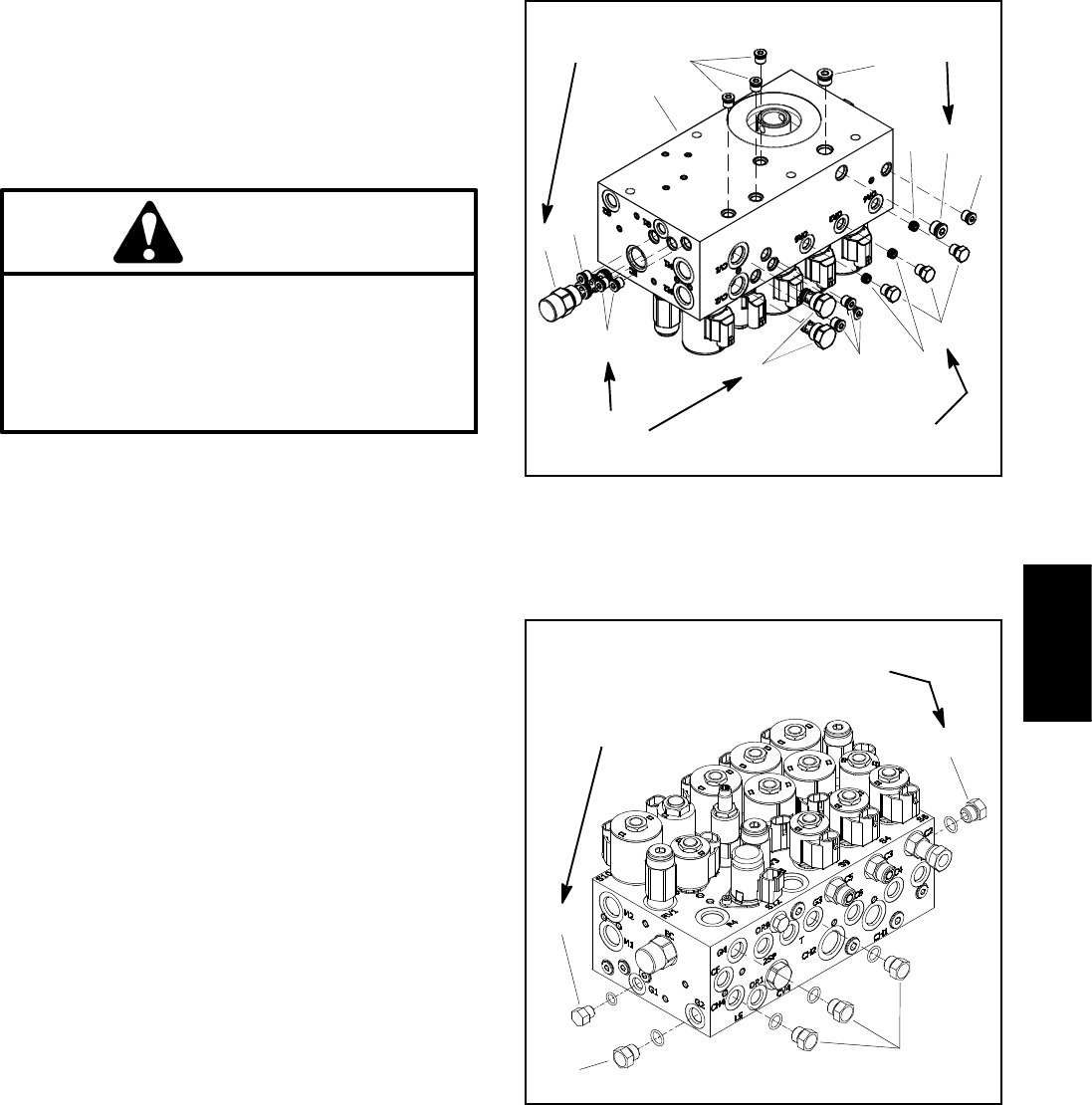
Groundsmaster 4100--D/4110--D Hydraulic SystemPage 4 -- 103
NOTE: The ports on the combination manifold are
marked for easy identification of components. Example:
P4 is the gear pump connection port, S1 is the lift/lower
solenoid valve and SV10 is the engine cooling fan solen-
oid valve (see Hydraulic Schematic in Chapter 10 --
Foldout Drawings to identify the function of the hydraulic
lines and cartridge valves at each port).
WARNING
If combination manifold is attached to machine,
make sure that cutting units are fully lowered be-
fore loosening hydraulic lines or cartridge valves
from combination manifold. If cutting units are
raised as components are loosened in manifold,
cutting units may drop unexpectedly.
NOTE: The combination manifold uses several zero
leak plugs. These plugs have a tapered sealing surface
on the plug head that is designed to resist vibration in-
duced plug loosening. The zero leak plugs also have an
O--ring as a secondary seal. If zero leak plug removal is
necessary, lightly rap the plug head using a punch and
hammer before using an allen wrench to remove the
plug: the impact will allow plug removal with less chance
of damage to the socket head of the plug.
Combination Manifold Service
For combination manifold cartridge valve service pro-
cedures, see Control Manifold Cartridge Valve Service
in this section. Refer to Figures 74, 75 and 76 for com-
bination manifold cartridge valve and plug installation
torque.
IMPORTANT: A flow control orifice is located be-
neath several plugs in the combination control man-
ifold. If an orifice is removed from a manifold port,
make sure to label its position for assembly pur-
poses. When installing the orifice in the manifold,
make sure that the orifice is properly tightened in
the port.
IMPORTANT: A flow control orifice is placed be-
neath hydraulic fittings in combination manifold
ports C2, C3 and C5. If any of these fittings is re-
moved from the manifold, make sure to remove ori-
fice and label its position for assembly purposes.
Also note location of groove in orifice for assembly
purposes. When installing the orifice in the man-
ifold, make sure that the orifice is flat in the base of
the port.
1. #4 zero leak plug
2. #6 zero leak plug
3. Orifice (0.040)
4. #4 zero leak plug
5. Orifice (0.063)
6. Check valve
7. Compensator valve
Figure 75
2
3
6
8
1
5
7
4
1
1
1
1
2
20 ft--lb
(27 N--m)
25 ft--lb
(34 N--m)
25 ft--lb
(34 N--m)
20 ft--lb
(27 N--m)
1. #6 hex head plug 2. #4 hex head plug
Figure 76
1
2
1
1
9to11ft--lb
(12to14N--m)
20 to 26 ft--lb
(27to35N--m)
Hydraulic
System
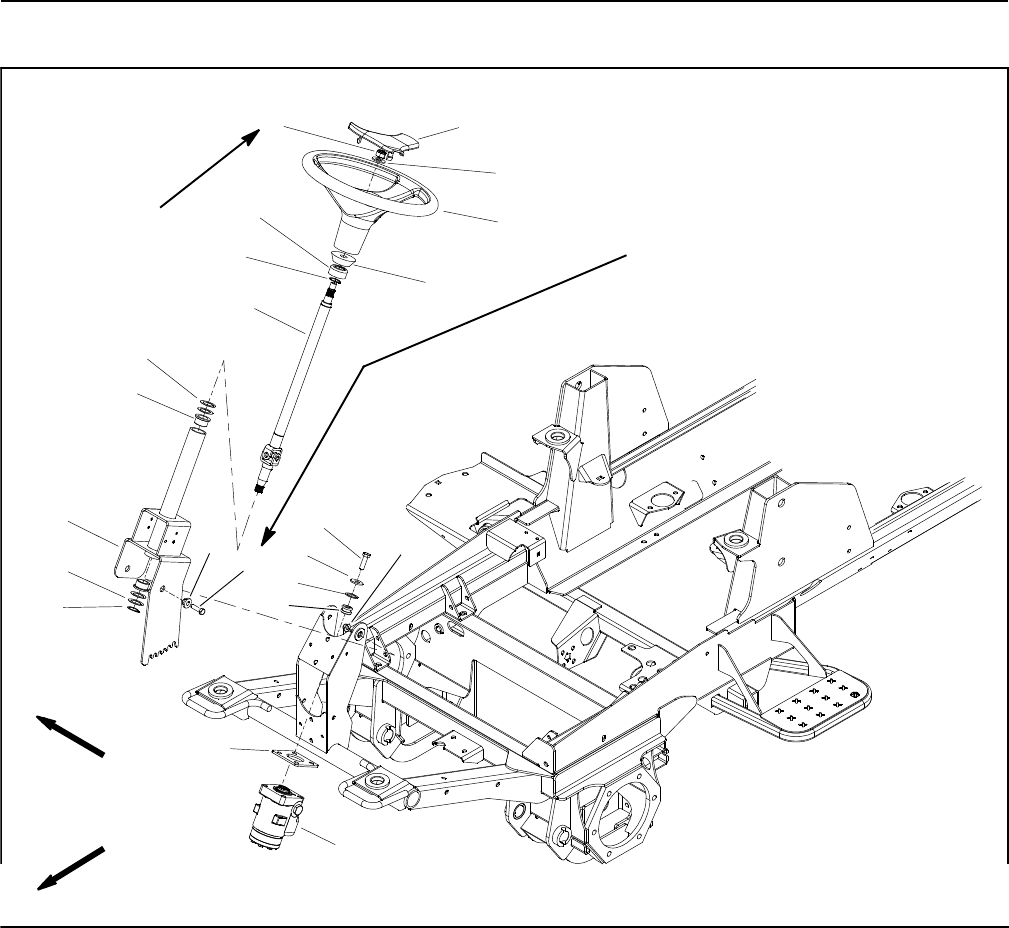
Groundsmaster 4100--D/4110--DHydraulic System Page 4 -- 104
Steering Control Valve
1. Steering wheel cover
2. Hex nut
3. Flat washer
4. Steering wheel
5. Foam collar
6. Steering seal
7. External snap ring (2 used)
8. Steering shaft
9. Flange bushing
10. Thrust washer (as needed)
11. Cap screw (4 used)
12. Washer (4 used)
13. Washer (4 used)
14. Mount (4 used)
15. Valve mount plate
16. Steering control valve
17. Steering column
18. Cap screw (2 used)
19. Pivot hub (2 used)
20. Flange nut (2 used)
Figure 77
FRONT
RIGHT
27 to 33 ft--lb
(37to44N--m)
2
3
6
8
9
10
11
13
1
5
7
12
14
15
16
17
18
19 20
4
7
10
20 to 26 ft--lb
(28 to 35 N--m)
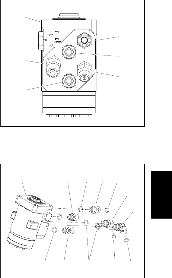
Groundsmaster 4100--D/4110--D Hydraulic SystemPage 4 -- 105
Removal (Fig. 77)
1. Park machine on a level surface, lower cutting deck,
stop engine, apply parking brake and remove key from
the ignition switch.
2. Remove steering tower cover to allow access to
steering control valve.
3. Read the General Precautions for Removing and
Installing Hydraulic System Components at the begin-
ning of the Service and Repairs section of this chapter.
4. To prevent contamination of hydraulic system during
steering control valve removal, thoroughly clean exteri-
or of control valve and fittings.
NOTE: To ease installation, label the hydraulic lines to
show their correct position on the steering control valve.
5. Remove hydraulic lines from steering control valve.
6. Remove steering control valve from machine using
Figure 77 as a guide.
7. If hydraulic fittings are to be removed from steering
control valve, mark fitting orientation to allow correct as-
sembly. Remove fittings from valve and discard O--rings
(Figs. 78 and 79).
Installation (Fig. 77)
1. If fittings were removed from steering control valve,
lubricate and place new O--rings onto fittings. Install fit-
tings into port openings using marks made during the re-
moval process to properly orientate fittings (Figs. 78 and
79). Tighten fittings (see Hydraulic Fitting Installation in
the General Information section of this chapter).
2. Install steering control valve using Figure 77 as a
guide.
3. Using labels placed during steering control valve re-
moval, properly install hydraulic lines to control valve
(see Hydraulic Hose and Tube Installation in the Gener-
al Information section of this chapter).
4. Make sure hydraulic tank is full.
5. Properly fill hydraulic system (see Charge Hydraulic
System in this section).
6. Install steering tower cover to machine.
1. Steering control valve
2. 45ohydraulic fitting
3. Straight fitting (2 used)
4. 45ohydraulic fitting
5. Straight fitting
Figure 78
1
2
4
5
3
3
1. Steering control valve
2. O--ring
3. Straight fitting
4. Straight fitting
5. 45ofitting
6. 45ofitting
7. O--ring
8. O--ring
Figure 79
1
2
4
5
32
23
6
7
7
8
Hydraulic
System
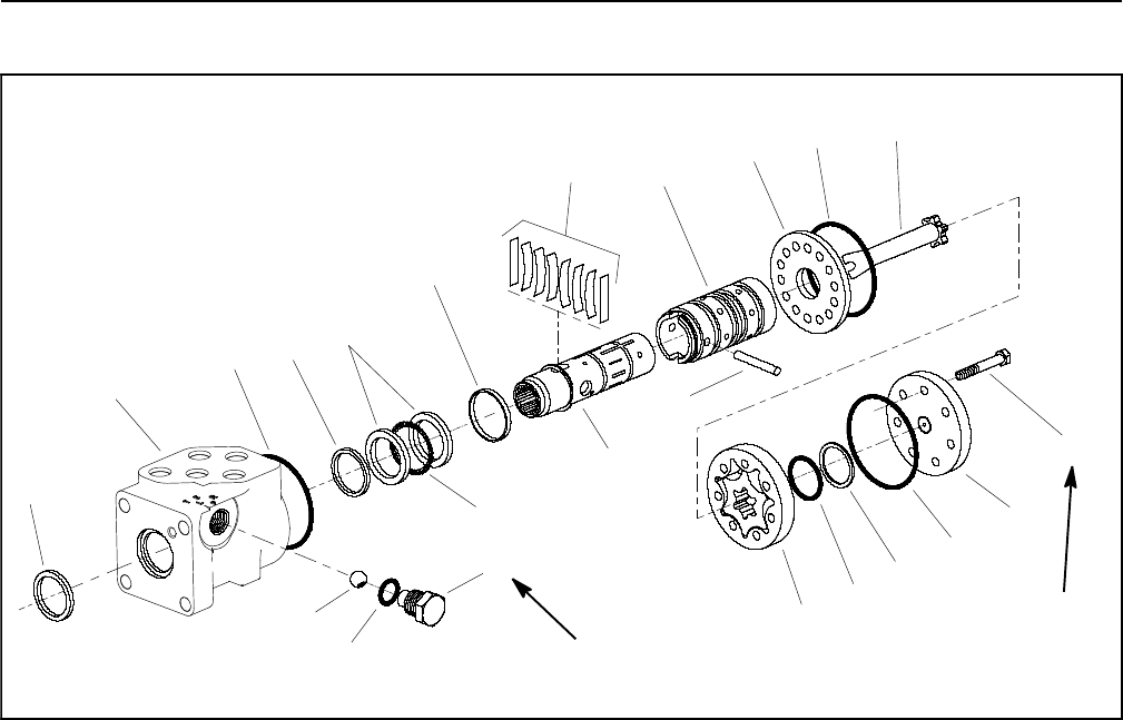
Groundsmaster 4100--D/4110--DHydraulic System Page 4 -- 106
Steering Control Valve Service
1. Steering valve housing
2. Dust seal
3. O--ring
4. Spool
5. Spring retaining ring
6. Pin
7. Sleeve
8. Centering springs/spacers
9. Cap screw (7 used)
10. End cap
11. O -- ring
12. Seal ring
13. O--ring
14. Geroter
15. O--ring
16. Quad seal
17. Geroter drive
18. Wear plate
19. Bearing race
20. Thrust bearing
21. Plug
22. O--ring
23. Check ball
Figure 80
140 to 160 in--lb
(16to18N--m)
150 in--lb
(17 N--m)
3
5
6
4
7
1
2
19
20
8
9
10
11
12
13
14
15
21
22
23
16
17
18
NOTE: For steering control valve repair procedures,
see the Eaton Parts and Repair Information: 5 Series
Steering Control Units at the end of this chapter.

Groundsmaster 4100--D/4110--D Hydraulic SystemPage 4 -- 107
This page is intentionally blank.
Hydraulic
System
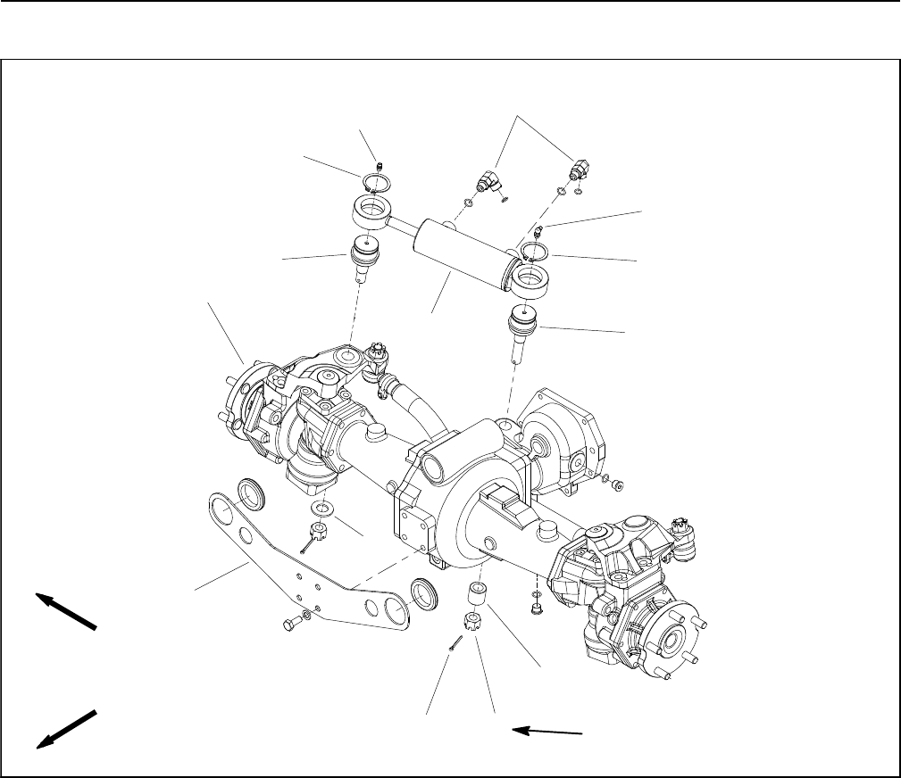
Groundsmaster 4100--D/4110--DHydraulic System Page 4 -- 108
Steering Cylinder
1. Steering cylinder
2. Ball joint
3. Ball joint
4. Retaining ring (2 used)
5. Grease fitting
6. Grease fitting
7. 90ohydraulic fitting (2 used)
8. Drive axle assembly
9. Ball joint spacer
10. Axle washer
11. Slotted hex nut (2 used)
12. Cotter pin (2 used)
13. Bulkhead mount plate
Figure 81
FRONT
RIGHT
79 to 84 ft--lb
(108 to 113 N--m)
2
3
6
8
9
10
11
13
1
5
7
12
4
4
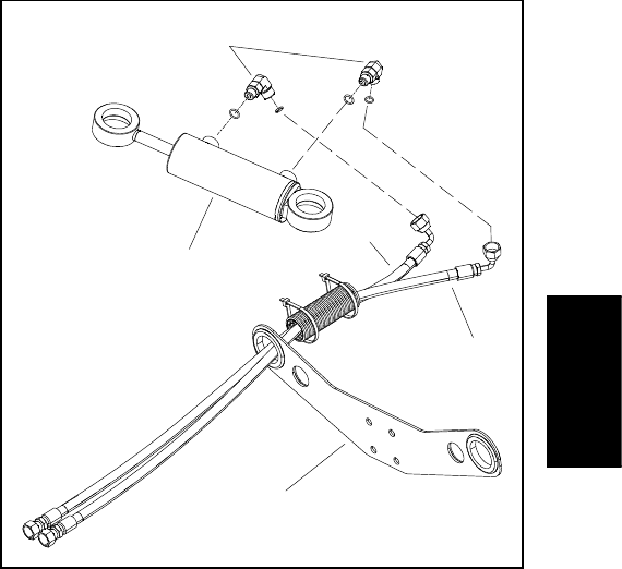
Groundsmaster 4100--D/4110--D Hydraulic SystemPage 4 -- 109
Removal (Fig. 81)
1. Park machine on a level surface, lower cutting deck,
stop engine, apply parking brake and remove key from
the ignition switch.
2. Read the General Precautions for Removing and
Installing Hydraulic System Components at the begin-
ning of the Service and Repairs section of this chapter.
3. To prevent contamination of hydraulic system during
cylinder removal, thoroughly clean exterior of cylinder
and fittings.
NOTE: To ease installation, label the hydraulic hoses to
show their correct position on the steering cylinder.
4. Remove hydraulic hoses from steering cylinder (Fig.
82).
5. Remove cotter pins, slotted hex nuts, axle washer
and ball joint spacer from the threaded ends of ball
joints. Remove steering cylinder with ball joints from ma-
chine.
6. If hydraulic fittings are to be removed from steering
cylinder, mark fitting orientation to allow correct assem-
bly. Remove fittings from cylinder and discard O--rings.
7. If needed, remove ball joints from steering cylinder.
Installation (Fig. 81)
1. If removed, install ball joints into steering cylinder.
2. If fittings were removed from steering cylinder, lubri-
cate and place new O--rings onto fittings. Install fittings
into port openings using marks made during the removal
process to properly orientate fittings. Tighten fittings
(see Hydraulic Fitting Installation in the General Infor-
mation section of this chapter).
3. Slide ram end ball joint through hole on steering arm.
Secure with axle washer and hex slotted nut. Slide fixed
end of cylinder through hole on axle. Secure with slotted
hex nut. Torque slotted hex nuts from 79 to 84 ft--lbs
(108 to 113 N--m) and then continue tightening the nut
until hex nut groove aligns with cotter pin hole in ball
joint. Install cotter pin to nut and ball joint.
4. Install hydraulic hoses to steering cylinder (see Hy-
draulic Hose and Tube Installation in the General Infor-
mation section of this chapter).
5. Fill reservoir with new hydraulic fluid as required.
6. Properly fill hydraulic system (see Charge Hydraulic
System in this section).
7. After assembly is completed, operate steering cylin-
der to verify that hydraulic hoses and fittings are not con-
tacted by anything.
1. Steering cylinder
2. Hydraulic hose
3. Hydraulic hose
4. 90ohydraulic fitting
5. Bulkhead mount plate
Figure 82
2
4
3
5
1
Hydraulic
System
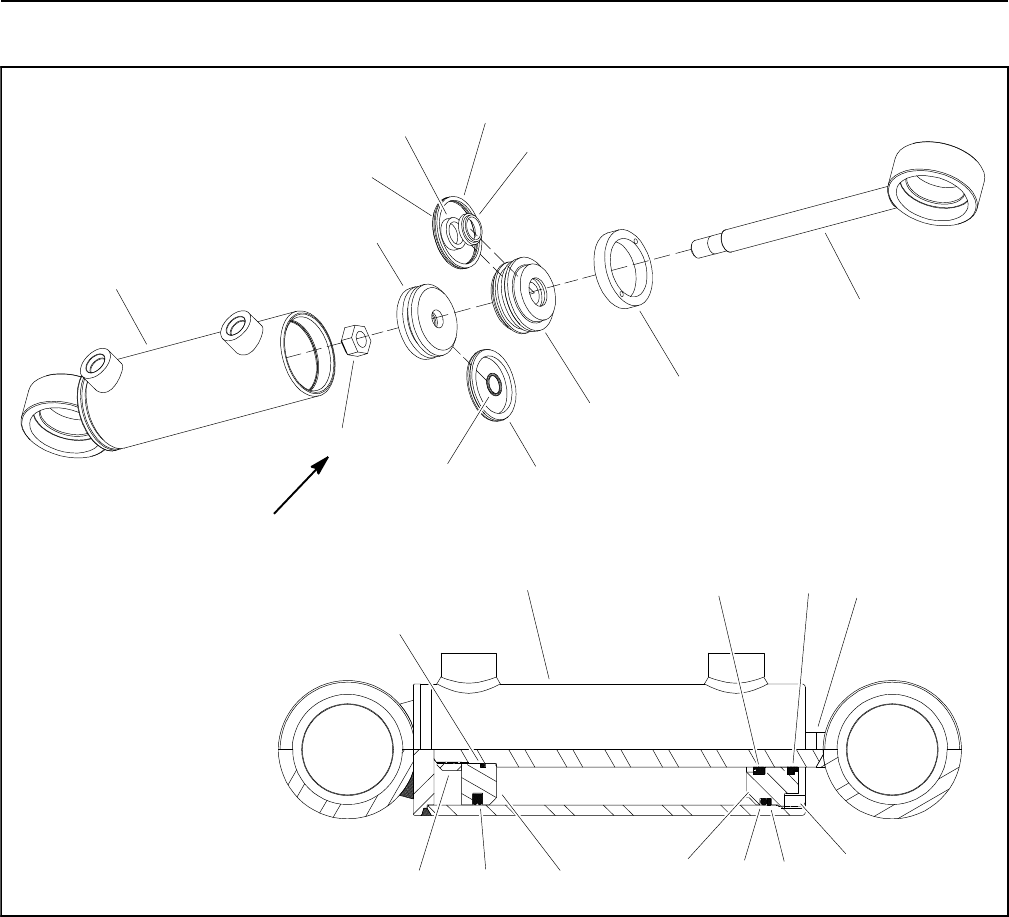
Groundsmaster 4100--D/4110--DHydraulic System Page 4 -- 110
Steering Cylinder Service
1. Barrel
2. Rod
3. Piston
4. Head
5. Internal collar
6. Backup ring
7. O--ring
8. Dust seal
9. Rod seal
10. O--ring
11. Piston seal
12. Lock nut
Figure 83
40 ft--lb
(54 N--m)
1
6
7
3
9
10
4
11
2
8
5
12
1
6
7
3
98
10
4
11
2
5
12

Groundsmaster 4100--D/4110--D Hydraulic SystemPage 4 -- 111
Disassembly (Fig. 83)
1. Pump oil out of steering cylinder into a drain pan by
slowly moving rod in and out of cylinder bore. After oil
has been removed from cylinder, plug ports and clean
outside of cylinder.
IMPORTANT: Prevent damage when clamping the
cylinder in a vise, clamp on the clevis only. Use of a
vise with soft jaws is recommended.
2. Mount steering cylinder securely in a vise by clamp-
ing on the clevis end of the barrel. Use of a vise with soft
jaws is recommended.
3. Use a spanner wrench to loosen and remove internal
collar (item 5) from barrel.
4. Grasp end of rod and use a twisting and pulling mo-
tion to carefully extract rod, piston and head assembly
from cylinder barrel.
IMPORTANT: Do not clamp vise jaws against rod
surface; the rod will be damaged.
5. Securely mount rod, piston and head assembly into
vise with soft jaws.
6. Remove lock nut and then piston from the rod. Slide
head and then internal collar off the rod.
7. Remove and discard all seals and O--rings from the
piston and the head.
CAUTION
Use eye protection such as goggles when using
compressed air to dry cylinder components.
8. Wash cylinder parts in clean solvent. Dry parts with
compressed air. Do not wipe parts dry with paper towels
or cloth. Lint in a hydraulic system will cause damage.
9. Carefully inspect internal surface of barrel for dam-
age (deep scratches, out--of--round, etc.). Inspect rod
and piston for evidence of excessive scoring, pitting or
wear. Replace steering cylinder if internal components
are worn or damaged.
Assembly (Fig. 83)
1. Use a complete repair kit when rebuilding the steer-
ing cylinder. Put a coating of clean hydraulic oil on all
new seals and O--rings.
2. Install new lubricated O--rings and seals to the piston
and head.
IMPORTANT: Do not clamp vise jaws against the
rod surface.
3. Mount rod securely in a vise by clamping on the cle-
vis of the rod.
4. Lubricate rod with clean hydraulic oil. Carefully slide
internal collar, head and then piston onto the rod.
5. Install and tighten lock nut onto rod. Torque lock nut
40 ft--lb (54 N--m).
6. Remove rod assembly from vise.
7. Put a coating of clean hydraulic oil on all cylinder
partstoeaseassembly.
8. Carefully slide rod assembly into cylinder barrel.
IMPORTANT: Prevent damage when clamping the
cylinder in a vise, clamp on the clevis only. Use of a
vise with soft jaws is recommended.
9. Mount steering cylinder securely in a vise by clamp-
ing on the clevis end of the barrel. Use of a vise with soft
jaws is recommended.
10.Secure head in barrel by using a spanner wrench to
install and tighten internal collar (item 5) into barrel.
Hydraulic
System
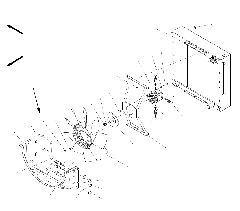
Groundsmaster 4100--D/4110--DHydraulic System Page 4 -- 112
Engine Cooling Fan Motor
1. Hydraulic fan motor
2. O--ring
3. Fan bracket
4. Hydraulic fitting (2 used)
5. O--ring
6. Radiator/oil cooler assembly
7. Fan hub
8. Washer
9. Hex nut
10. Lower radiator shroud
11. Cap screw (4 used)
12. Washer (4 used)
13. Fan
14. Lock nut (2 used)
15. Cap screw (2 used)
16. Flat washer (2 used)
17. O--ring
18. Hydraulic fitting
19. O--ring
20. Hydraulic tube
21. Hydraulic tube
22. Hydraulic tube
23. Support shim
24. Bulkhead nut (2 used)
25. Bulkhead nut
26. Cap used (6 used)
27. Flange nut (6 used)
Figure 84
(17to18N--m)
12 to 14 ft--lb
FRONT
RIGHT
2
3
6
8
9
10
11
13
1
5
7
12
14
15
16
17 18
19
20
4
21
22
23 24
25
26
27
5
5
19
24
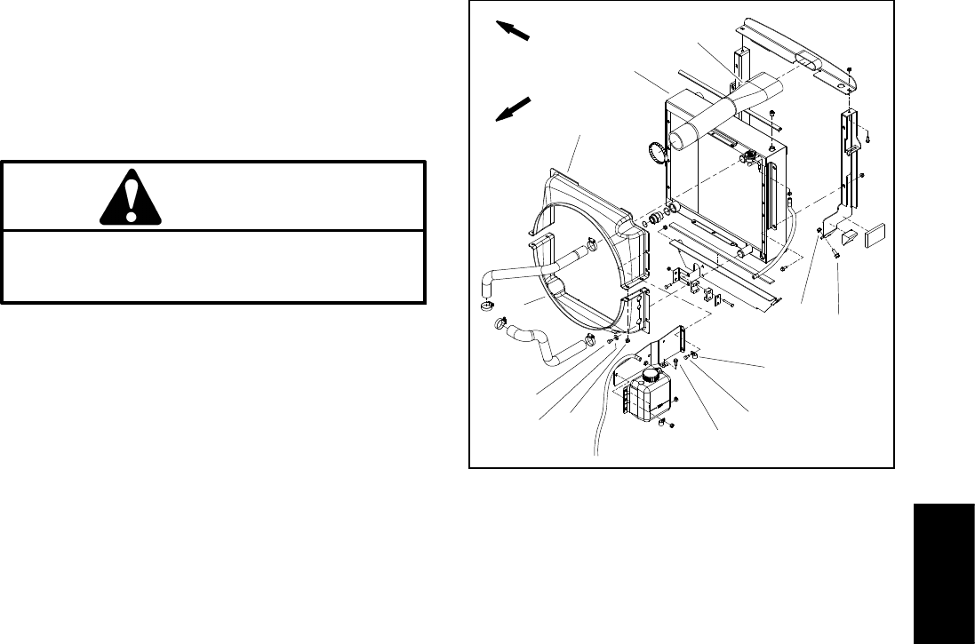
Groundsmaster 4100--D/4110--D Hydraulic SystemPage 4 -- 113
Removal (Fig. 84)
1. Park machine on a level surface, lower cutting deck,
stop engine, apply parking brake and remove key from
the ignition switch.
2. Unlatch and raise hood.
CAUTION
The radiator and oil cooler may be hot. To avoid
possible burns, allow the engine and cooling
systems to cool before removing fan motor.
3. Read the General Precautions for Removing and
Installing Hydraulic System Components at the begin-
ning of the Service and Repairs section of this chapter.
4. Thoroughly clean three (3) hydraulic tubes at lower
radiator shroud. Disconnect hydraulic tubes and put
caps or plugs on tubes to prevent contamination. Label
disconnected hydraulic tubes for proper installation.
5. Remove air cleaner inlet hose and radiator shrouds
(upper and lower) to allow easier access to hydraulic fan
motor (Fig. 85).
6. Remove flange head screws and flange nuts that se-
cure radiator supports to frame (items 11 and 12 in Fig.
85). This will allow radiator assembly to be moved
slightly to ease removal of cooling fan motor and bracket
assembly.
7. Remove four (4) cap screws (item 11) and washers
used to secure fan to fan hub. Remove fan.
IMPORTANT: Make sure to not damage the radiator
or other machine components while loosening and
removing the fan motor and bracket assembly.
8. Remove cooling fan motor and bracket assembly.
A. To prevent contamination of hydraulic system,
thoroughly clean exterior of fan motor and fittings.
B. Disconnect three (3) hydraulic tubes from fan mo-
tor. Put caps or plugs on fittings and tubes to prevent
contamination. Label hydraulic lines for proper as-
sembly.
C. Remove six (6) cap screws and flange nuts that
secure fan motor bracket to radiator.
D. Carefully remove fan motor and bracket assem-
bly from machine and place on suitable work sur-
face.
1. Radiator/oil cooler
2. Upperradiatorshroud
3. Lower radiator shroud
4. Screw (4 used)
5. Flange nut (4 used)
6. Cap screw (2 used)
7. Cap screw (6 used)
8. Flat washer (7 used)
9. R--clamp
10. Air cleaner inlet hose
11. Screw (4 used)
12. Flange nut (4 used)
Figure 85
3
56
4
7
1
2
8
9
10
11
12
FRONT
RIGHT
9. Remove hex nut (item 9) and washer (item 8) that se-
cure fan hub to fan motor. Use suitable puller to carefully
remove fan hub from fan motor shaft. Locate and re-
trieve woodruff key from motor shaft.
10.Remove two (2) cap screws (item 15), flat washers
(item 16) and lock nuts (item 14) that secure fan motor
to fan motor bracket. Remove fan motor from bracket.
11. If necessary, remove fittings from motor and discard
O--rings.
Installation (Fig. 84)
1. If fittings were removed from fan motor, lubricate and
place new O--rings onto fittings. Install and tighten fit-
tings in port openings (see Hydraulic Fitting Installation
in the General Information section of this chapter).
2. Position fan motor to fan motor bracket and secure
with cap screws (item 15), flat washers (item 16) and
lock nuts (item 14).
3. Thoroughly clean tapered surfaces of fan motor
shaft and fan hub. Place woodruff key in slot in motor
shaft.
Hydraulic
System
Groundsmaster 4100--D/4110--DHydraulic System Page 4 -- 114
4. Position fan hub onto motor shaft and secure with
washer (item 8) and hex nut (item 9).
IMPORTANT: Make sure to not damage the radiator
or other machine components while installing the
fan motor and bracket assembly.
5. Carefully position fan motor and bracket assembly to
radiator and secure with six (6) cap screws and flange
nuts.
6. Secure radiator assembly to frame with removed
fasteners (Fig. 85).
7. Connect three (3) hydraulic tubes to cooling fan mo-
tor (see Hydraulic Hose and Tube Installation in the
General Information section of this chapter).
8. Position fan to fan hub and secure with four (4) cap
screws and washers. Torque screws from 12 to 14 ft--lb
(17to18N--m).
9. Install radiator shrouds (lower and upper) and air
cleaner hose (Fig. 85). Make sure that clearance be-
tween shrouds and cooling fan is at least 0.180” (4.6
mm) at all points.
10.Connect three (3) hydraulic tubes at lower radiator
shroud (see Hydraulic Hose and Tube Installation in the
General Information section of this chapter).
11. Lower and secure hood.
12.Make sure hydraulic tank is full.
13.Properly fill hydraulic system (see Charge Hydraulic
System in this section).

Groundsmaster 4100--D/4110--D Hydraulic SystemPage 4 -- 115
This page is intentionally blank.
Hydraulic
System
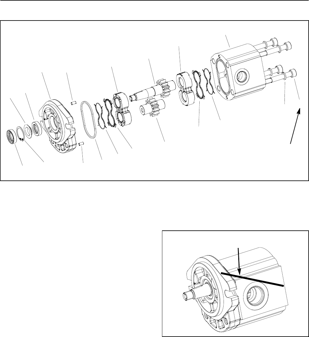
Groundsmaster 4100--D/4110--DHydraulic System Page 4 -- 116
Engine Cooling Fan Motor Service
1. Flange washer
2. O--ring
3. Front flange
4. Dust seal
5. Retaining ring
6. Front wear plate
7. Shaft seal
8. Backup gasket
9. Pressure seal
10. Rear wear plate
11. Body
12. Idler gear
13. Cap screw (4 used)
14. Dowel (2 used)
15. Drive gear
16. Washer (4 used)
Figure 86
8
7
4
3
2
5
6
9
10
11
9
12
13
8
14
16
15
14
1
(45 N--m)
33 ft--lb
NOTE: Internal components for a cooling fan motor are
not available separately. Disassemble motor for clean-
ing, inspection and seal replacement only.
Disassembly (Fig. 86)
1. Plug motor ports and clean the outside of the motor
thoroughly. After cleaning, remove plugs and drain any
oil out of the motor.
2. Useamarkertomakeadiagonal line across the
front flange and body for assembly purposes (Fig. 87).
IMPORTANT: Prevent damage when clamping the
fan motor into a vise; clamp on the front flange only.
Also, use a vise with soft jaws.
3. Clamp front flange of motor in a vise with soft jaws
with the shaft end down.
4. Loosen cap screws from the rear cover.
5. Remove motor from the vise. Turn motor so that the
shaft end is facing down. Remove cap screws.
6. Carefully remove body. Lift body straight up to re-
move. Make sure the rear wear plate remains on the
drive and idler gear shafts. Remove and discard O--
rings from the body. Locate and retrieve dowel pins.
Figure 87
MARKER LINE
IMPORTANT: Note position of the open and closed
side of the wear plates before removing. Also, iden-
tify wear plates (front and rear) with a marker for
proper assembly.
7. Carefully remove rear wear plate, idler gear, drive
gear and front wear plate from the front flange.
8. Remove and discard back--up gaskets and pressure
seals from wear plates.
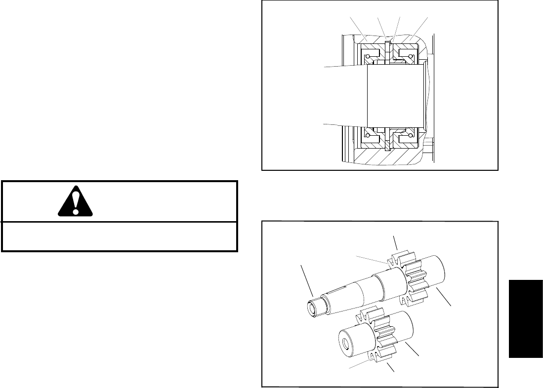
Groundsmaster 4100--D/4110--D Hydraulic SystemPage 4 -- 117
9. Turn front flange over, with seal side up.
IMPORTANT: Make sure not to damage the front
flange counter bore when removing the seals from
the front flange.
10.Carefully remove dust seal, retaining ring, flange
washer and shaft seal from the front flange (Fig. 88).
Note orientation of seal lips during removal. Discard re-
moved seals.
Inspection
1. Remove any nicks and burrs from all parts with
emery cloth.
CAUTION
Use eye protection such as goggles when using
compressed air.
2. Clean all parts with solvent. Dry all parts with com-
pressed air.
3. Inspect drive gears and idler gears for the following
(Fig. 89):
A. Gear shafts should be free of rough surfaces and
excessive wear at bushing points and sealing areas.
Scoring, rough surfaces or wear on gear shafts indi-
cates need for replacement.
B. Gear teeth should be free of excessive scoring
and wear. Any broken or nicked gear teeth must be
replaced.
C. Inspect gear face edge for sharpness. Sharp
edges of gears will mill into wear plates and, thus,
must be replaced.
4. Inspect wear plates for the following:
A. Bearing areas should not have excessive wear or
scoring.
B. Face of wear plates that are in contact with gears
should be free of wear, roughness or scoring.
C. Thickness of wear plates should be equal.
5. Inspect front flange and body for damage or wear.
1. Dust seal
2. Retaining ring
3. Flange washer
4. Shaft seal
Figure 88
1234
1. Gear shaft spline
2. Gear shaft
3. Gear teeth
4. Gear face edge
Figure 89
1
3
4
2
3
4
2
Assembly (Fig. 86)
NOTE: When assembling motor, check the marker line
oneachparttomakesurepartsareproperlyaligned
during assembly.
1. Lubricate O--rings, pressure seals, back--up gaskets
and wear plate grooves with a thin coat of petroleum jel-
ly. Lubricate all other internal parts freely with clean hy-
draulic oil.
2. Install new seals into front flange (Fig. 88). Note ori-
entation of seal lips during installation:
A. Press shaft seal into front flange until it reaches
the bottom of the bore.
B. Install flange washer into front flange and then
install retaining ring into the groove of the front
flange.
C. Install new dust seal into front flange.
Hydraulic
System
Groundsmaster 4100--D/4110--DHydraulic System Page 4 -- 118
3. Place front flange, seal side down, on a flat surface.
4. Install the pressure seals, flat side outward, into the
grooves in the wear plates. Follow by carefully placing
thebackupgaskets,flatsideoutward,betweenthe
pressure seals and the grooves in the wear plate.
5. Apply a light coating of petroleum jelly to the exposed
side of the front flange.
6. Lubricate the drive gear shaft with clean hydraulic oil.
Insert the drive end of the drive shaft through the wear
plate with the pressure seal side down and the open side
of the pressure seal pointing to the inlet side of the mo-
tor. Carefully install shaft into front flange.
7. Lubricate the idler gear shaft with clean hydraulic oil.
Install idler gear shaft into the remaining position in the
front wear plate. Apply a light coating of clean hydraulic
oil to gear faces.
8. Install rear wear plate with pressure seal side up and
open side of the pressure seal pointing to the inlet side
of the motor.
9. Apply a light coating of petroleum jelly to new O--
rings and O--ring grooves in the body. Install new O--
rings to the body.
10.Install locating dowels in body. Align marker line on
the body and front flange.
IMPORTANT: Do not dislodge seals during installa-
tion.
11. Gently slide the body onto the assembly. Firm hand
pressure should be sufficient to engage the dowels.
12.Install the four (4) cap screws with washers and hand
tighten.
IMPORTANT: Prevent damage when clamping the
fan motor into a vise; clamp on the front flange only.
Also, use a vise with soft jaws.
13.Place front flange of the motor into a vise with soft
jaws and alternately torque the cap screws 33 ft--lb (45
N--m).
14.Remove motor from vise.
15.Place a small amount of clean hydraulic oil in the inlet
of the motor and rotate the drive shaft away from the inlet
one revolution. If any binding is noted, disassemble the
motor and check for assembly problems.
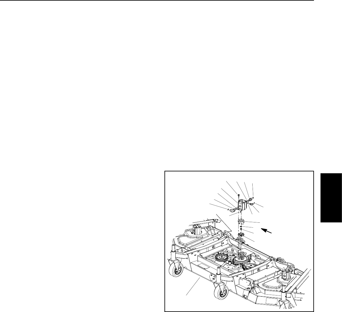
Groundsmaster 4100--D/4110--D Hydraulic SystemPage 4 -- 119
Cutting Deck Motor
Removal (Fig. 90)
1. Park machine on a level surface, lower cutting deck,
stop engine, engage parking brake and remove key
from the ignition switch.
2. Read the General Precautions for Removing and
Installing Hydraulic System Components at the begin-
ning of this section.
3. To prevent contamination of hydraulic system during
motor removal, thoroughly clean exterior of motor and
fittings.
4. Disconnect hydraulic lines from deck motor. Put
caps or plugs on fittings and hoses to prevent contami-
nation. Label hydraulic lines for proper installation.
5. Remove two (2) flange head screws that secure hy-
draulic motor to motor mount (Fig. 90).
6. Carefully remove hydraulic motor from cutting deck
taking care not to damage spider hub attached to motor.
Locate and remove spider from the deck.
7. If required, remove spider hub from motor shaft.
Straighten tab washer and remove nut, spider and
woodruff key.
8. If hydraulic fittings are to be removed from motor,
mark fitting orientation to allow correct assembly. Re-
move fittings from motor and discard O--rings.
Installation (Fig. 90)
1. If fittings were removed from motor, lubricate and
place new O--rings onto fittings. Install fittings into port
openings using marks made during the removal process
to properly orientate fittings. Tighten fittings (see Hy-
draulic Fitting Installation in the General Information
section of this chapter).
2. If spider hub was removed from motor shaft, thor-
oughly clean tapered surfaces of hub and shaft. Install
spider hub to motor shaft with tab washer and nut.
Torque nut from 27 to 33 ft--lb (37 to 44 N--m).Bend
small tab of washer into keyway and large tab against
nut.
3. Position spider in spindle pulley and carefully install
hydraulic motor to the cutting deck taking care to not
damage spider hub attached to motor.
4. Secure motor to cutting deck with two (2) flange head
screws.
IMPORTANT: For proper hydraulic hose routing,
make sure cutting deck is fully lowered before
installing hoses to deck motor.
5. Remove caps or plugs from fittings and hoses. Using
labels placed during motor removal, properly connect
hydraulic hoses to deck motor (see Hydraulic Hose and
Tube Installation in the General Information section of
this chapter).
6. After assembly is completed, verify that hydraulic
hoses and fittings are not contacted by moving compo-
nents through full range of deck movement.
1. Cutting deck motor
2. O--ring
3. Hydraulic adapter
4. O--ring
5. Flange head screw (2)
6. O--ring
7. 90ohydraulic fitting
8. O--ring
9. 90ohydraulic fitting
10. Woodruff key
11. Spider hub
12. Tab washer
13. Nut
14. Spider
15. Cutting deck
Figure 90
(37 to 44 N--m)
27 to 33 ft--lb
9
1
10
11
4
2
6
8
7
12
13
15
14
524
3
Hydraulic
System
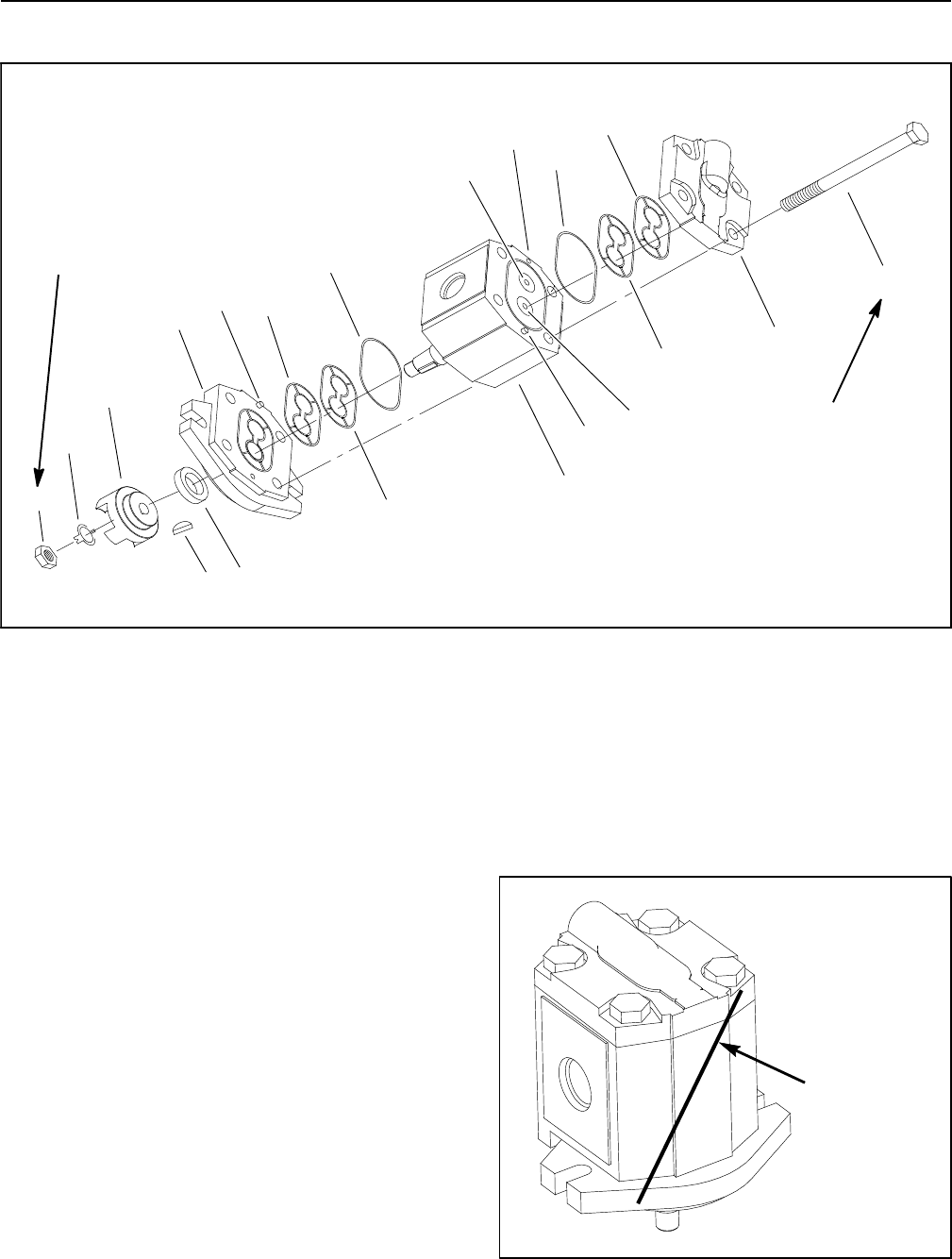
Groundsmaster 4100--D/4110--DHydraulic System Page 4 -- 120
Cutting Deck Motor Service (Sauer--Danfoss)
1. Rear cover
2. Drive gear
3. Seal
4. Woodruff key
5. Nut
6. Tab washer
7. Spider hub
8. Pressure seal
9. Back--up ring
10. O--ring
11. Body
12. Idler gear
13. Cap screw (4 used)
14. Front flange
15. Dowel pin
Figure 91
8
7
43
1
2
5
6
9
10
11
10
9
12
(45to55N--m)
33 to 40 ft--lb
13
8
14
15
15
15
(37to45N--m)
27 to 33 ft--lb
NOTE: Internal components for a cutting deck motor
are not available separately. Disassemble motor for
cleaning, inspection and seal replacement only.
Disassembly (Fig. 91)
1. Plug motor ports and clean the outside of the motor
thoroughly. After cleaning, remove plugs and drain any
oil out of the motor.
2. Straighten tabs on tab washer to allow removal of nut
from motor shaft. Remove tab washer, spider hub and
woodruff key from motor.
3. Use a marker to make a diagonal mark across the
front flange, body and rear cover for assembly purposes
(Fig. 92).
IMPORTANT: Prevent damage when clamping the
deck motor into a vise; clamp on the front flange
only. Also, use a vise with soft jaws.
4. Clamp front flange of motor in a vise equipped with
soft jaws with the shaft end down.
5. Loosen cap screws that secure the rear cover.
6. Take motor from the vise and remove cap screws.
7. Remove front flange from the body, then remove rear
cover. Locate and remove dowel pins from body.
Figure 92
DIAGONAL
MARK
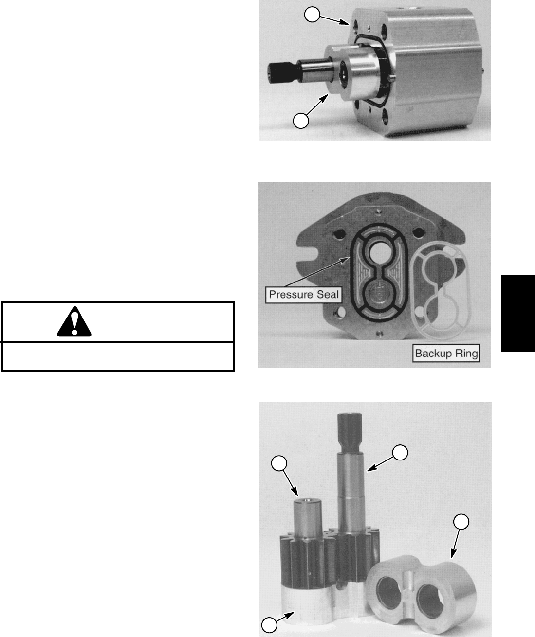
Groundsmaster 4100--D/4110--D Hydraulic SystemPage 4 -- 121
IMPORTANT: Mark the relative positions of the gear
teeth and the bearing blocks so they can be re-
assembled in the same position. Do not touch the
gear surfaces as residue on hands may be corrosive
to gear finish.
8. Place the motor on its side and push on the rear bear-
ing block to remove the bearing block and gear set (Fig.
93).
9. Carefully remove and discard O--rings, pressure
seals and back--up rings (Fig. 94) from motor. Do not
cause any damage to the machined grooves during the
removal process.
IMPORTANT: Make sure to not damage the counter
bore when removing the shaft seal from the front
plate.
10.Position front flange with seal side up. Carefully re-
move shaft seal from front flange.
Inspection
1. Remove any nicks and burrs from all motor compo-
nents with emery cloth.
CAUTION
Use eye protection such as goggles when using
compressed air.
2. Clean all motor components with clean solvent. Dry
all parts with compressed air.
3. Inspect drive gear, idler gear and bearing blocks
(Fig. 95) for the following:
A. Gear shafts should be free of rough surfaces and
excessive wear at bushing points and sealing areas.
Scoring, rough surfaces or wear on gear shafts indi-
cates need for replacement.
B. Gear teeth should be free of excessive scoring
and wear. Any broken or nicked gear teeth must be
replaced.
C. Inspect gear face edge for sharpness. Sharp
edges of gears will mill into bearing blocks and, thus,
must be replaced.
D. Bearing areas of bearing blocks should not have
excessive wear or scoring.
E. Face of bearing blocks that are in contact with
gears should be free of wear, roughness or scoring.
4. Inspect front flange and rear cover for damage or
wear.
1. Motor body 2. Bearing block & gear set
Figure 93
1
2
Figure 94
1. Drive gear
2. Idler gear
3. Bearing block
Figure 95
1
3
2
3
Hydraulic
System
Groundsmaster 4100--D/4110--DHydraulic System Page 4 -- 122
Assembly (Fig. 91)
NOTE: When assembling the motor, check the identifi-
cation marks made during disassembly to make sure
the parts are properly aligned during assembly.
1. Lubricate O--rings, pressure seals, back--up gaskets
and seal grooves with a thin coat of petroleum jelly. Lu-
bricate all other internal parts freely with clean hydraulic
oil.
2. Install new shaft seal into front flange.
3. Install lubricated pressure seals into the grooves in
the front flange and rear cover. Follow by carefully plac-
ing the back--up rings into the grooves.
4. Install new O--rings to the body.
5. Lubricate gear faces and bearing surfaces of drive
gear, idler gear and bearing blocks with clean hydraulic
oil. Carefully assemble bearing blocks and gears noting
identification marks made during disassembly.
6. Position the motor body on its side. Carefully slide
bearing block and gear assembly into the body cavity
using identification marks made during disassembly.
7. Remove any excess lubrication from mating sur-
faces of body, rear cover and front flange. Make sure
that these surfaces are clean and dry.
8. Install dowel pins in body.
IMPORTANT: Do not dislodge O--rings, pressure
seals or back--up rings during final assembly.
9. Gently slide the rear cover onto the assembly using
marker or scribe mark for proper location. Firm hand
pressure should be sufficient to engage the dowel pins.
10.Position the motor with rear cover downwards. Care-
fully slide the front flange onto the assembly using mark-
er line for proper location.
11. Install the four (4) cap screws and hand tighten.
IMPORTANT: Prevent damage when clamping the
deck motor into a vise; clamp on the front flange
only. Also, use a vise with soft jaws.
12.Place motor front flange in a vise and alternately
torque the screws from 33 to 40 ft--lb (45 to 55 N--m).
13.Put a small amount of hydraulic oil in port on motor
and rotate driveshaft one revolution. Protect the shaft if
using a pliers. If drive shaft binds, disassemble motor
and repeat assembly process.
14.Make sure that tapered surface of motor shaft and
spider hub are thoroughly clean.
15.Place woodruff key in motor shaft slot. Install spider
hub and tab washer on shaft. Secure spider hub to shaft
with nut. Torque nut from 27 to 33 ft--lb (37 to 45 N--m).
16.Secure nut to motor shaft by bending small tab of tab
washer into keyway and large tab against nut.
17.Remove motor from vise.

Groundsmaster 4100--D/4110--D Hydraulic SystemPage 4 -- 123
This page is intentionally blank.
Hydraulic
System
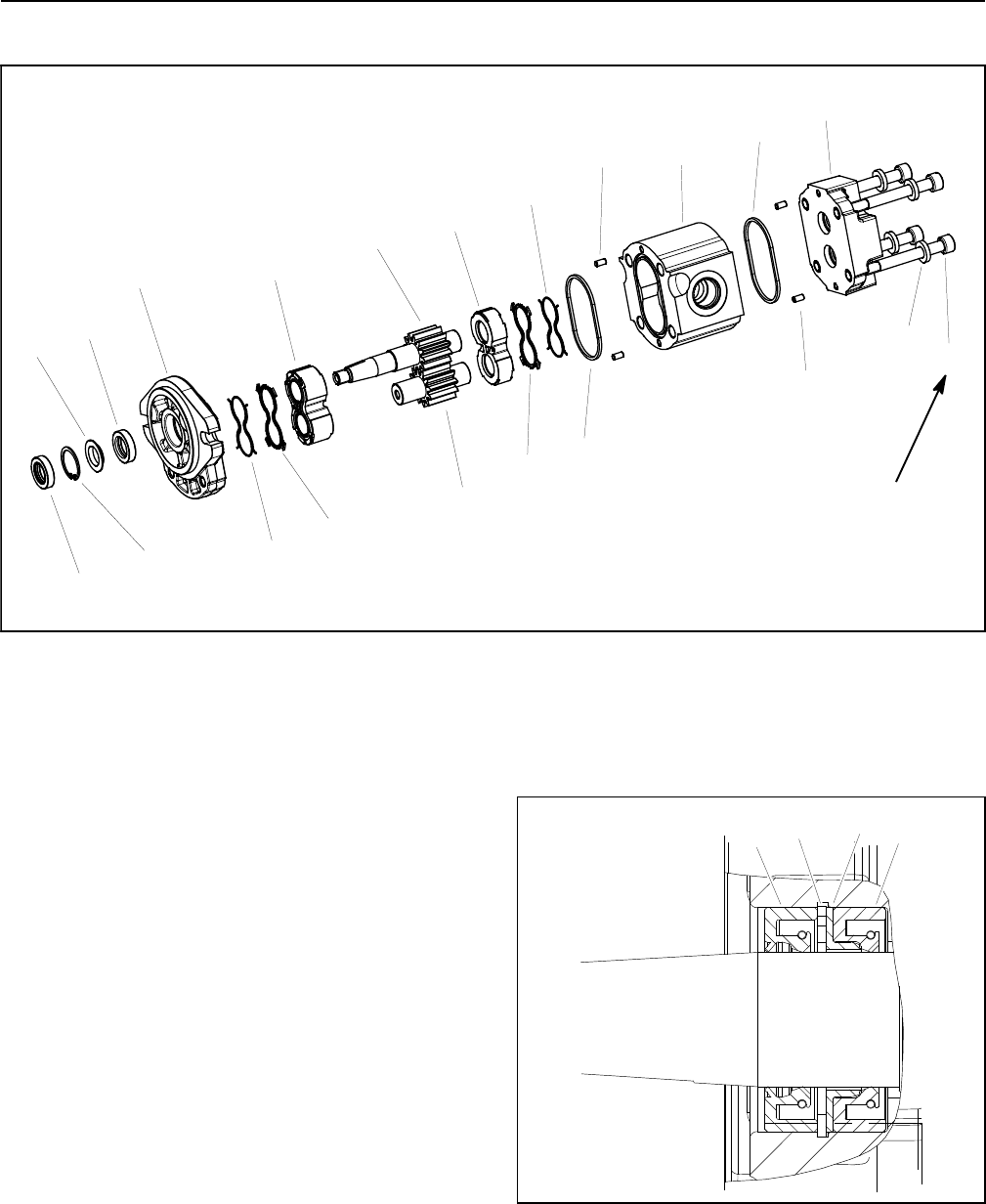
Groundsmaster 4100--D/4110--DHydraulic System Page 4 -- 124
Cutting Deck Motor Service (Casappa)
(45 to 55 N--m)
33 to 40 ft--lb
8
7
4
3
2
6
9
10
11
9
12
13
8
14
16
15
14
1
1. Flange washer
2. O--ring
3. Front flange
4. Dust seal
5. Retaining ring
6. Front wear plate
7. Shaft seal
8. Backup gasket
9. Pressure seal
10. Rear wear plate
11. Body
12. Idler gear
13. Cap screw (4 used)
14. Dowel (4 used)
15. Drive gear
16. Washer (4 used)
17. Rear cover
Figure 96
5
2
17
The Casappa cutting deck motors have similar con-
struction as the cooling fan motor (also a Casappa
brand) used on the Groundsmaster 4100--D and
4110--D. The deck motors have a separate rear cover
(item 17 in Fig. 96) which is a difference from the cooling
fan motor which includes the rear cover with the motor
body. Orientation of the dust seal (item 4 in Fig. 96) is dif-
ferent in the deck motors than in the cooling fan motor.
For disassembly, inspection and assembly procedures
of the Casappa cutting deck motors, refer to Engine
Cooling Fan Motor Service in this section. When in-
stalling the seals into the front flange in a cutting deck
motor, use the orientation shown in Figure 97.
NOTE: Internal components for a cutting deck motor
are not available separately. Disassemble motor for
cleaning, inspection and seal replacement only.
Figure 97
1234
1. Dust seal
2. Retaining ring
3. Flange washer
4. Shaft seal

Groundsmaster 4100--D/4110--D Hydraulic SystemPage 4 -- 125
This page is intentionally blank.
Hydraulic
System
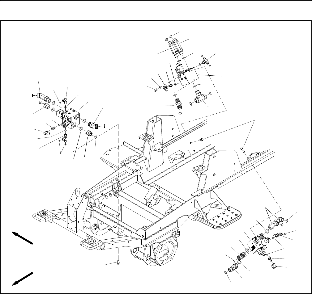
Groundsmaster 4100--D/4110--DHydraulic System Page 4 -- 126
PTO Manifolds
1. Hydraulic PTO manifold (center deck)
2. Quick fitting (1 used per manifold)
3. Flange screw (2 used per manifold)
4. O--ring
5. Hydraulic tee fitting
6. O--ring
7. O--ring
8. O--ring
9. Hydraulic adapter
10. Straight fitting
11. Flange screw (2 used per manifold)
12. Dust cap
13. 45ohydraulic fitting
14. Hydraulic PTO manifold (LH deck)
15. 90ohydraulic fitting
16. Hydraulic PTO manifold (RH deck)
17. Hex head plug
18. 45ohydraulic fitting
19. Hydraulic tee fitting
20. 90ohydraulic fitting
Figure 98
FRONT
RIGHT
2
3
6
8
9
11
13
1
5
7
12
14
15
16
17
20
4
10
2
2
12
12
9
10
19
18
18
18
18
13
13
4
4
4
4
4
6
6
7
7
7
7
8
8
8
8
7
NOTE: The ports on the manifold are marked for easy
identification of components. Example: PRV is the pro-
portional relief valve and P1 is a gear pump connection
port (see Hydraulic Schematic in Chapter 10 -- Foldout
Drawings to identify the function of the hydraulic lines
and cartridge valves at each port).
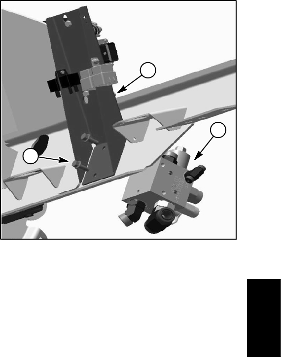
Groundsmaster 4100--D/4110--D Hydraulic SystemPage 4 -- 127
Removal (Fig. 98)
1. Read the General Precautions for Removing and
Installing Hydraulic System Components at the begin-
ning of the Service and Repairs section of this chapter.
2. To prevent contamination of hydraulic system during
manifold removal, thoroughly clean exterior of PTO
manifold and fittings.
3. Disconnect wire harness connector from the propor-
tional relief valve coil on the PTO manifold.
4. Disconnect hydraulic lines from manifold and put
caps or plugs on open hydraulic lines and fittings. Label
disconnected hydraulic lines for proper installation.
5. Remove PTO manifold from the frame using Figure
98 as a guide.
NOTE: The flange head screws that secure the right
side PTO manifold also secures the controller mount to
the frame (Fig. 99). Support controller mount before re-
moving the right side PTO manifold.
6. If hydraulic fittings are to be removed from manifold,
mark fitting orientation to allow correct assembly. Re-
move fittings from manifold and discard O--rings.
Installation (Fig. 98)
1. If fittings were removed from manifold, lubricate and
place new O--rings onto fittings. Install fittings into man-
ifold openings using marks made during the removal
process to properly orientate fittings. Tighten fittings
(see Hydraulic Fitting Installation in the General Infor-
mation section of this chapter).
2. Install PTO manifold to the frame using Figure 98 as
a guide.
NOTE: Make sure that the controller mount is secured
when installing the right side PTO manifold (Fig. 99).
3. Remove caps and plugs from fittings and hoses. Us-
ing labels placed during manifold removal, properly con-
nect hydraulic lines to manifold (see Hydraulic Hose and
Tube Installation in the General Information section of
this chapter).
4. Connect wire harness connector to the proportional
relief valve coil on the PTO manifold.
5. Make sure hydraulic tank is full. Add correct oil if nec-
essary before returning machine to service.
1. RH PTO manifold
2. Controller mount
3. Flange screw (2 used)
Figure 99
2
1
3
Hydraulic
System
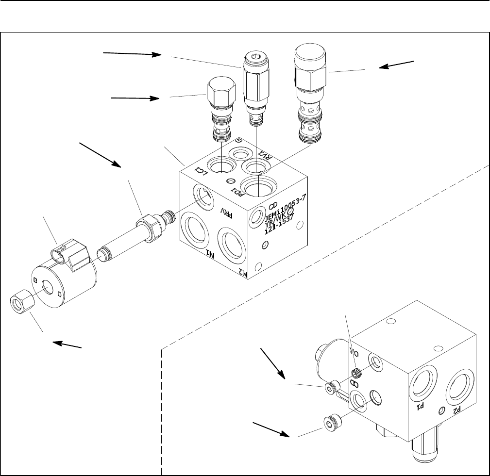
Groundsmaster 4100--D/4110--DHydraulic System Page 4 -- 128
PTO Manifold Service
1. PTO manifold body
2. NWD SAE #4 plug with O--ring
3. Orifice (0.025) (port OR)
4. #6 zero leak plug with O--ring
5. Relief valve (port RV1)
6. Proportional relief valve (port PRV)
7. Solenoid coil
8. Nut
9. Logic cartridge valve (port LC1)
10. Pilot directional valve (port PD1)
Figure 100
20 ft--lb
(27 N--m)
5ft--lb
(6.7 N--m)
20 ft--lb
(27 N--m)
8
6
7
5
25 ft--lb
(34 N--m)
35 ft--lb
(47 N--m)
10
9
1
4
2
3
25 ft--lb
(34 N--m)
20 ft--lb
(27 N--m)
NOTE: The ports on the manifold are marked for easy
identification of components. Example: RV is the relief
valve port and P1 is the gear pump connection port (see
Hydraulic Schematic in Chapter 10 -- Foldout Drawings
to identify the function of the hydraulic lines and car-
tridge valves at each port location).
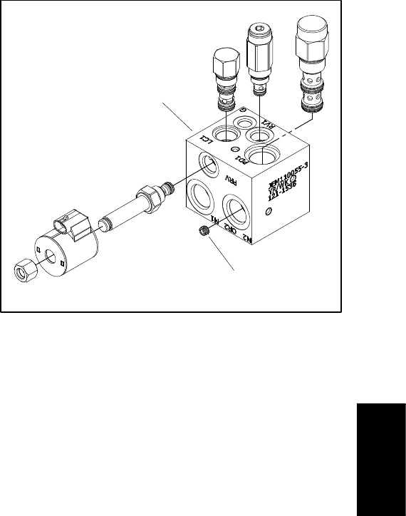
Groundsmaster 4100--D/4110--D Hydraulic SystemPage 4 -- 129
The manifolds for the three (3) cutting deck sections are
very similar. The front and right side PTO manifolds are
identical. The left side PTO manifold uses the same cart-
ridges and plugs as the front and right side manifolds but
also includes an additional orifice that threads into the
manifold OR2 port (Fig. 101). NOTE: When servicing
the PTO manifolds, DO NOT interchange parts from one
manifold to another.
NOTE: The PTO manifold assembly includes zero leak
plugs. These plugs have a tapered sealing surface on
theplugheadthatisdesignedtoresistvibrationinduced
plug loosening. The zero leak plugs also have an O--ring
as a secondary seal. If zero leak plug removal is neces-
sary, lightly rap the plug head using a punch and ham-
mer before using an allen wrench to remove the plug:
the impact will allow plug removal with less chance of
damage to the socket head of the plug.
PTO Manifold Service (Fig. 100)
For PTO manifold solenoid and control valve service
procedures, see Control Manifold Cartridge Valve Ser-
vice in this section. Refer to Figure 100 for PTO manifold
cartridge valve and plug installation torque.
1. LH PTO manifold 2. Orifice (OR2 port)
Figure 101
1
2
Hydraulic
System
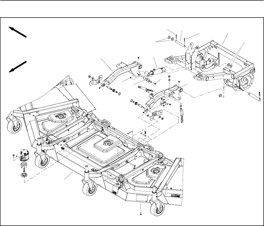
Groundsmaster 4100--D/4110--DHydraulic System Page 4 -- 130
Cutting Deck Lift Cylinders
FRONT
RIGHT
1. Cutting deck
2. RH lift arm
3. LH lift arm
4. Lift cylinder (2 used)
5. Pin (1 used per cylinder)
6. Flange nut (1 used per pin)
7. Cap screw (1 used per pin)
8. Grease fitting (1 used per pin)
9. Clevis pin (1 used per cylinder)
10. Cotter pin (2 used per clevis pin)
11. Flat washer (4 used per clevis pin)
12. Front frame
2
3
6
8
9
10
11
1
5
7
12
4
Figure 102
10
11
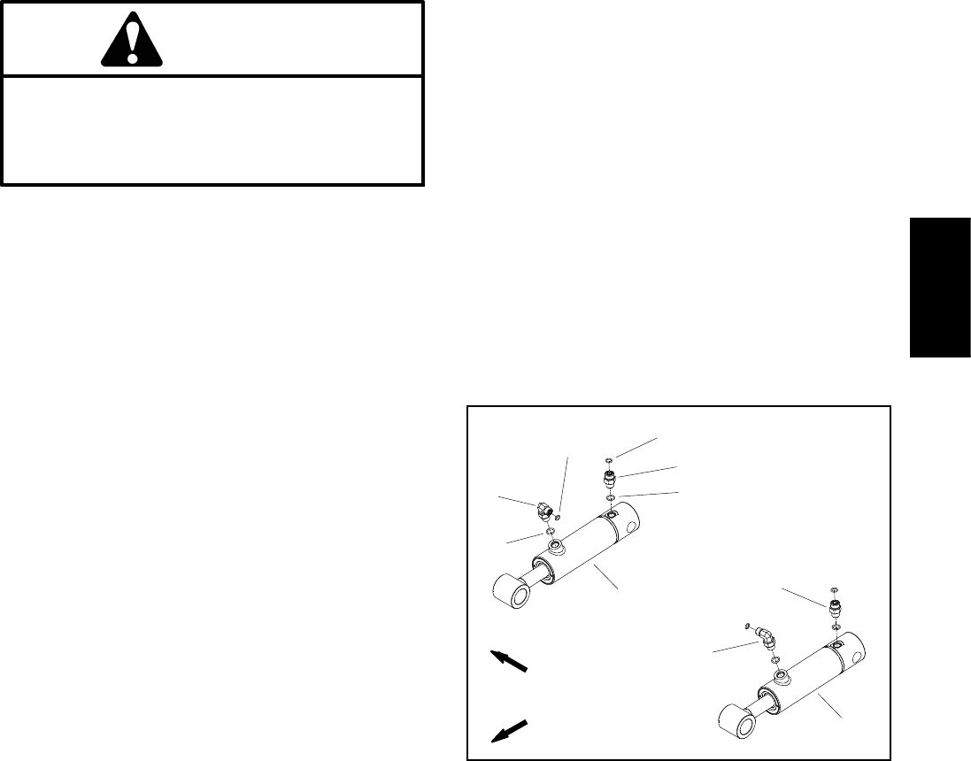
Groundsmaster 4100--D/4110--D Hydraulic SystemPage 4 -- 131
Removal (Fig. 102)
1. Park machine on a level surface, lower cutting deck,
stop engine, engage parking brake and remove key
from the ignition switch.
2. Read the General Precautions for Removing and
Installing Hydraulic System Components at the begin-
ning of this section.
3. To prevent contamination of hydraulic system during
lift cylinder removal, thoroughly clean exterior of cylin-
der and fittings.
WARNING
Make sure that cutting deck (including wing
decks) is fully lowered before loosening hydrau-
lic lines from lift cylinders. If deck sections are
not fully lowered as hydraulic lines are loosened,
deck may drop unexpectedly.
NOTE: To ease installation, label the hydraulic hoses to
show their correct position on the lift cylinder.
4. Disconnect hydraulic lines from lift cylinder and put
caps or plugs on open hydraulic lines and fittings. Label
disconnected hydraulic lines for proper installation.
5. Support lift cylinder to prevent it from falling.
6. Remove cap screw and flange nut that secure the pin
(item 5) to the lift arm. Remove pin from lift arm and cylin-
der shaft clevis which will free lift cylinder from lift arm.
7. Remove one (1) cotter pin and two (2) flat washers
from clevis pin (item 9) that secures lift cylinder to front
frame. Pull clevis pin from frame and cylinder barrel cle-
vis.
8. Remove lift cylinder from machine.
9. If hydraulic fittings are to be removed from lift cylind-
er, mark fitting orientation to allow correct assembly. Re-
move fittings from cylinder and discard O--rings (Fig.
103).
Installation (Fig. 102)
1. If fittings were removed from lift cylinder, lubricate
and place new O--rings onto fittings. Install fittings into
cylinder port openings using marks made during the re-
moval process to properly orientate fittings (Fig. 103).
Tighten fittings (see Hydraulic Fitting Installation in the
General Information section of this chapter).
2. Make sure that cotter pin and two (2) flat washers are
installed on one end of clevis pin (item 9).
3. Position lift cylinder barrel clevis to front frame and
insert clevis pin into frame and clevis. Secure clevis pin
with two (2) flat washers and one (1) cotter pin.
4. Insert pin (item 5) through lift arm and cylinder shaft
clevis. Secure pin to lift arm with cap screw and flange
nut.
5. Remove caps and plugs from fittings and hydraulic
lines. Using labels placed during cylinder removal, prop-
erly attach hydraulic hoses to lift cylinder (see Hydraulic
Hose and Tube Installation in the General Information
section of this chapter).
6. Lubricate lift cylinder grease fittings.
7. Fill reservoir with hydraulic fluid as required.
8. After assembly is completed, operate lift cylinders to
verify that hydraulic hoses and fittings are not contacted
by anything.
1. RH lift cylinder
2. LH lift cylinder
3. Straight fitting
4. O--ring
5. O--ring
6. 90ofitting
7. O--ring
8. O--ring
Figure 103
2
3
6
8
1
5
7
4
3
6
FRONT
RIGHT
Hydraulic
System
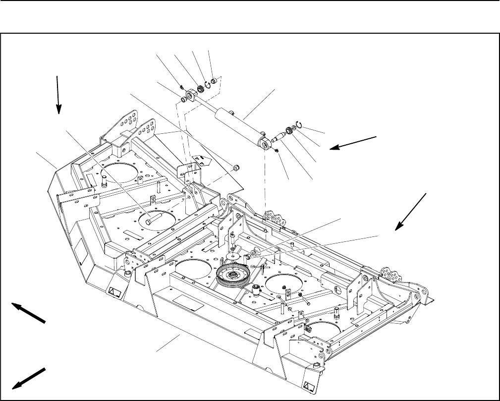
Groundsmaster 4100--D/4110--DHydraulic System Page 4 -- 132
Wing Deck Lift Cylinders
1. Center deck
2. Grease fitting
3. Tapered stud
4. Spherical bearing
5. Flange nut
6. Retaining ring
7. Wing deck lift cylinder
8. Lock nut
9. Flat washer
10. Lock nut
11. Pilot spacer
12. Cap screw
13. Wing deck (RH shown)
Figure 104
FRONT
RIGHT
6
5
7
8
4
3
2
9
10
1
6
4
11
13
12
211
30 to 40 ft--lb
(41to54N--m)
160 to 180 ft--lb
(217 to 244 N--m)
160 to 180 ft--lb
(217 to 244 N--m)

Groundsmaster 4100--D/4110--D Hydraulic SystemPage 4 -- 133
Removal (Fig. 104)
1. Park machine on a level surface, lower cutting deck,
stop engine, engage parking brake and remove key
from the ignition switch.
2. Read the General Precautions for Removing and
Installing Hydraulic System Components at the begin-
ning of this section.
WARNING
Make sure that cutting deck (including wing
decks) is fully lowered before loosening hydrau-
lic lines from wing deck lift cylinders. If deck sec-
tions are not fully lowered as hydraulic lines are
loosened, deck may drop unexpectedly.
3. Remove deck covers as needed to allow access to
lift cylinder hoses and fasteners.
4. To prevent contamination of hydraulic system during
lift cylinder removal, thoroughly clean exterior of cylin-
der and hose fittings.
NOTE: To ease installation, label the hydraulic hoses to
show their correct position on the lift cylinder.
5. Disconnect hydraulic hoses from lift cylinder and put
caps or plugs on open hydraulic hoses and fittings. La-
bel disconnected hydraulic hoses for proper installation.
6. Remove cap screw and lock nut that secure the lift
cylinder clevis to the wing deck.
7. Remove lock nut and flat washer from the tapered
stud on the barrel end of the lift cylinder.
8. Remove lift cylinder from deck assembly.
9. Remove spherical bearings from lift cylinder clevis
ends, if required.
A. On shaft clevis, remove retaining ring and then
press spherical bearing from clevis.
B. On barrel clevis, remove retaining ring and then
press tapered stud with spherical bearing and flange
nut from clevis. Remove flange nut and then spheri-
cal bearing from stud.
Installation (Fig. 104)
1. If removed, install spherical bearings into lift cylinder
clevis ends.
A. On shaft clevis, press spherical bearing into cle-
vis and secure with retaining ring.
B. On barrel clevis, install spherical bearing on ta-
pered stud and secure with flange nut. Torque flange
nut from 30 to 40 ft--lb (41 to 54 N--m). Install stud
with spherical bearing into clevis and secure with re-
taining ring.
2. Thoroughly clean tapered surfaces of lift cylinder
studandmountingbossondeck.
3. Position lift cylinder to cutting deck. Insert tapered
stud into deck mounting boss. Secure stud with flat
washer and lock nut. Torque flange nut from 160 to 180
ft--lb (217 to 244 N--m).
4. Insert cap screw from the front of the deck through
the deck brackets and cylinder shaft clevis. Secure cap
screw with lock nut. Torque lock nut from 160 to 180 ft--
lb (217 to 244 N--m).
5. Remove caps and plugs from fittings and hydraulic
hoses. Using labels placed during cylinder removal,
properly attach hydraulic hoses to lift cylinder (see Hy-
draulic Hose and Tube Installation in the General Infor-
mation section of this chapter).
6. Install all removed deck covers.
7. Fill reservoir with hydraulic fluid as required.
8. After assembly is completed, operate lift cylinder to
verify that hydraulic hoses and fittings are not contacted
by anything.
Hydraulic
System
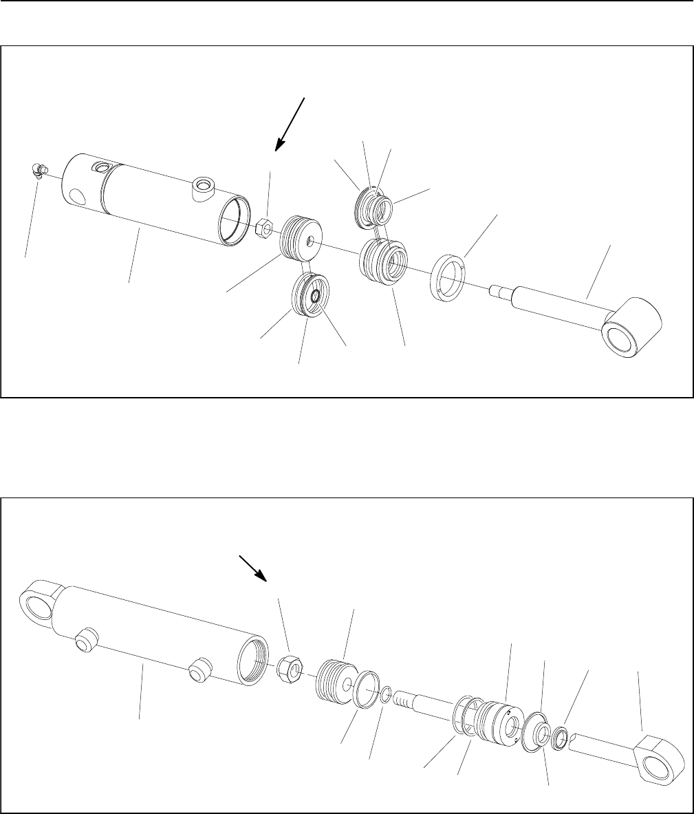
Groundsmaster 4100--D/4110--DHydraulic System Page 4 -- 134
Lift Cylinder Service
1. Barrel with clevis
2. Internal collar
3. Shaft with clevis
4. Dust seal
5. Rod seal
6. O--ring
7. Back--up ring
8. Head
9. O--ring
10. Wear ring
11. Piston
12. Lock nut
13. Piston seal
14. Grease fitting
Figure 105
11
6
5
7
8
4
3
2
9
12
1
10
13
FRONT DECK LIFT CYLINDER 40 ft--lb
(54 N--m)
14
1. Barrel with clevis
2. Retaining ring
3. Shaft with clevis
4. Dust seal
5. Rod seal
6. O--ring
7. Back--up ring
8. Head
9. O--ring
10. Seal with O--ring
11. Piston
12. Lock nut
Figure 106
12 11
9
10
7
6
5
8
43
1
2
60 to 75 ft--lb
(82 to 101 N--m)
WING DECK LIFT CYLINDER

Groundsmaster 4100--D/4110--D Hydraulic SystemPage 4 -- 135
Disassembly (Figs. 105 and 106)
1. Remove oil from lift cylinder into a drain pan by slowly
pumping the cylinder shaft. Plug both ports and clean
the outside of the cylinder.
IMPORTANT: Prevent damage when clamping the
cylinder in a vise; clamp on the clevis only.
2. Mount lift cylinder securely in a vise by clamping on
the clevis end of the barrel. Use of a vise with soft jaws
is recommended.
3. For front deck lift cylinder, use a spanner wrench to
loosen and remove internal collar (item 2 in Fig. 105)
from barrel.
4. For wing deck lift cylinder, loosen head from barrel as
follows:
A. Use a spanner wrench to rotate head clockwise
until the edge of the retaining ring appears in the bar-
rel opening.
B. Insert a screwdriver under the beveled edge of
the retaining ring to start the retaining ring through
the opening.
C. Rotate the head counter--clockwise to remove re-
taining ring from barrel and head.
5. Extract shaft with head and piston by carefully twist-
ing and pulling on the shaft.
IMPORTANT: Do not clamp vise jaws against the
shaft surface.
6. Mount shaft securely in a vise by clamping on the cle-
vis of the shaft. Remove lock nut and then slide piston
and head off the shaft. For front deck lift cylinder, remove
internal collar from shaft.
7. Remove and discard all seals and O--rings from the
piston and the head.
CAUTION
Use eye protection such as goggles when using
compressed air
8. Wash parts in clean solvent. Dry parts with com-
pressed air. Do not wipe parts dry with paper towels or
cloth. Lint in a hydraulic system will cause damage.
9. Carefully inspect internal surface of barrel for dam-
age (deep scratches, out--of--round, etc.). Inspect piston
rod and piston for evidence of excessive scoring, pitting
or wear. Replace lift cylinder if internal components are
found to be worn or damaged.
Assembly (Figs. 105 and 106)
1. Make sure all lift cylinder components are clean be-
fore assembly.
2. Coat new seal kit components with clean hydraulic
oil.
A. Install new seals and O--rings to the piston.
B. Install new seals, O--ring and back--up ring to the
head.
IMPORTANT: Do not clamp vise jaws against the
shaft surface.
3. Mount shaft securely in a vise by clamping on the cle-
vis of the shaft.
A. Coat shaft with clean hydraulic oil.
B. For front deck lift cylinder, slide internal collar
onto shaft.
C. Carefully slide head and piston onto the shaft.
Secure piston to shaft with lock nut.
D. Torque lock nut to specification in Figure 105
(front deck lift cylinder) or Figure 106 (wing deck lift
cylinder).
4. Lubricate head and piston with clean hydraulic oil.
Carefully slide shaft assembly into cylinder barrel.
IMPORTANT: Prevent damage when clamping the
cylinder’s barrel into a vise; clamp on the clevis
only.
5. Mount lift cylinder in a vise with soft jaws by clamping
on the clevis end of the barrel.
6. For front deck lift cylinder, use a spanner wrench to
install and tighten internal collar (item 2 in Fig. 105) into
barrel.
7. For wing deck lift cylinder, secure head in barrel as
follows:
A. Align retaining ring hole in the head with the ac-
cess slot in the barrel.
B. Insert the retaining ring hook into the hole and ro-
tate head clockwise until the retaining ring is com-
pletely pulled into the barrel and the ring ends are
covered.
C. Apply silicone sealer to barrel access slot.
Hydraulic
System
Groundsmaster 4100--D/4110--DHydraulic System Page 4 -- 136
This page is intentionally blank.

Groundsmaster 4100--D/4110--D Page 5 -- 1 Electrical System
Chapter 5
Electrical System
Table of Contents
GENERAL INFORMATION 2.....................
Operator’s Manual 2..........................
Toro Electronic Controllers (TEC) 2.............
Yanmar Engine Electronic Control Unit (ECU) 3...
Yanmar Engine Electrical Components 3.........
CAN--bus Communications 4...................
Electrical Drawings 4..........................
SPECIAL TOOLS 6.............................
INFOCENTER DISPLAY 8.......................
TROUBLESHOOTING 15........................
Operator Advisories 15........................
Fault Codes 16...............................
Starting Problems 18..........................
General Run & Transport Problems 20...........
Cutting Deck Operating Problems 21............
Cutting Deck Lift/Lower Problems 23............
ELECTRICAL SYSTEM QUICK CHECKS 26.......
Battery Test (Open Circuit) 26..................
Charging System Test 26......................
Check Operation of Interlock Switches 26........
ADJUSTMENTS 27.............................
Wing Deck Position Switch Adjustment 27.......
Traction Pedal Adjustment 28..................
Traction Pedal Position Sensor Calibration 30....
COMPONENT TESTING 31......................
Ignition Switch 31.............................
Fuses 32....................................
Operator Cab Fuses (Groundsmaster 4110--D) 33.
Fusible Link Harness 34.......................
PTO Switch 35...............................
HI/LOW Speed, Engine Speed and Cutting Deck
Lift Switches 36.............................
Cruise Control Switch 37.......................
Seat Switch 38...............................
Parking Brake Switch 39.......................
Service Brake Switches 40.....................
Headlight Switch (Groundsmaster 4110--D) 41....
Windshield Wiper/Washer Switch (Grounds--
master 4110--D) 42..........................
Air Conditioning Switch (Groundsmaster
4110--D) 43.................................
Turn Signal Switch (Groundsmaster 4110--D) 44..
Flasher Switch (Groundsmaster 4110--D) 45......
Relays with Four (4) Terminals 46...............
Relays with Five (5) Terminals 48...............
Toro Electronic Controllers (TEC) 50............
Traction Pedal Position Sensor 52..............
Audio Alarm 53...............................
Hydraulic Valve Solenoid Coils 54...............
Piston (Traction) Pump Control Solenoid Coils 56.
CAN--bus Termination Resistor 57..............
Diode Assemblies 58..........................
Resistor Assembly 58.........................
Fuel Sender 59...............................
Fuel Pump (Models 30602 and 30604) 60........
Fuel Pump (Models 30606 and 30608) 61........
Wing Deck Position Switches 62................
Hydraulic Oil Temperature Sender 63............
SERVICE AND REPAIRS 64.....................
Battery Care 64...............................
Battery Storage 64............................
Battery Service 65............................
Electrical
System
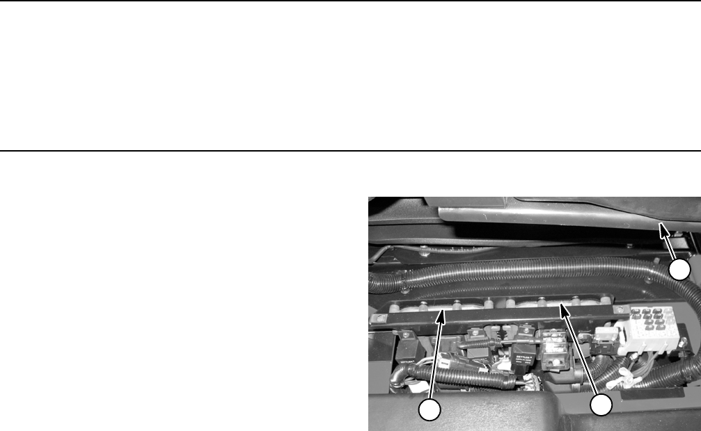
Groundsmaster 4100--D/4110--DPage 5 -- 2Electrical System
General Information
Operator’s Manual
The Operator’s Manual provides information regarding
the operation, general maintenance and maintenance
intervals for your Groundsmaster machine. Refer to that
publication for additional information when servicing the
machine.
Toro Electronic Controllers (TEC)
Groundsmaster 4100--D and 4110--D machines use two
(2) Toro Electronic Controllers (TEC) to manage ma-
chine electrical functions. The controllers are micropro-
cessor controlled that sense the condition of various
switches and sensors (inputs). The controllers then dir-
ect electrical power to control appropriate machine func-
tions (outputs) based on the input state. Communication
between the two (2) TEC controllers, the Yanmar engine
electronic control unit (ECU) and the machine InfoCen-
ter Display is provided with a CAN--bus system. The sta-
tus of inputs to the controllers as well as outputs from the
controllers can be monitored with the InfoCenter Dis-
play.
The TEC controllers are attached to the machine under
the power center cover next to the operator seat. The
TEC controllers are visually identical but they have dif-
ferent software and therefore cannot be interchanged.
IMPORTANT: To prevent machine electrical system
damage while welding on the machine, disconnect
the battery cables from the batteries, disconnect the
wire harness connectors from both Toro Electronic
Controllers, disconnect the wire harness connec-
tors from the engine electronic control unit and dis-
connect the terminal connector from the alternator.
Also, disconnect and remove the engine ECU from
the machine before welding.
1. Front TEC controller
2. Rear TEC controller
3. Operator seat
Figure 1
21
3
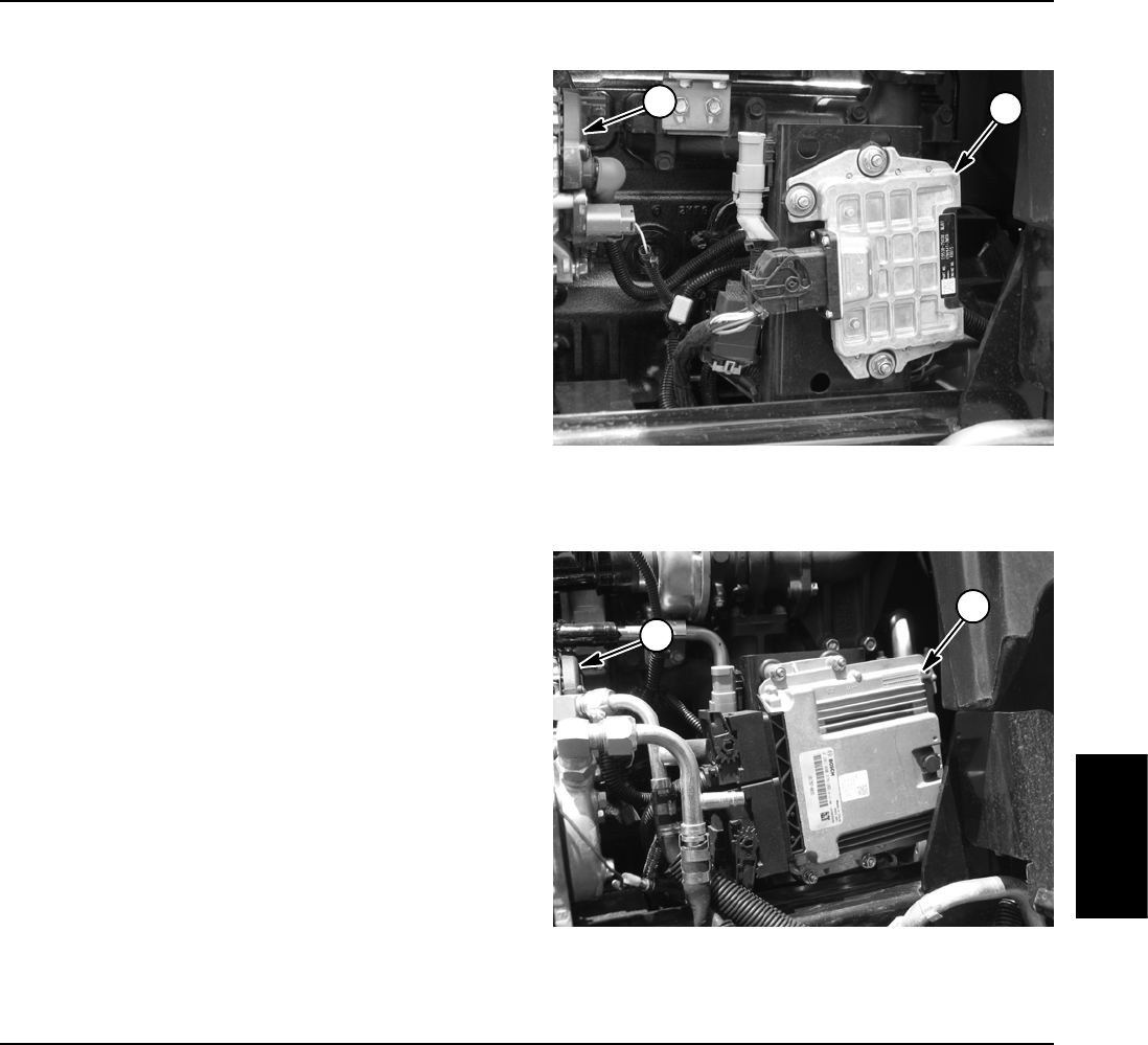
Groundsmaster 4100--D/4110--D Page 5 -- 3 Electrical System
Yanmar Engine Electronic Control Unit (ECU)
The Yanmar engine that powers the Groundsmaster
4100--D and 4110--D uses an electronic control unit
(ECU) for engine management and also to communi-
cate with the TEC controllers and the InfoCenter Display
on the machine. All engine ECU electrical connectors
should be plugged into the controller before the machine
ignition switch is moved from the OFF position to either
the RUN or START position. If the engine ECU is to be
disconnected for any reason, make sure that the ignition
switch is in the OFF position with the key removed for a
minimum of thirty (30) seconds before disconnecting the
engine ECU. See Chapter 3 -- Yanmar Diesel Engine for
additional engine ECU information.
Figure 2
1. Electronic control unit (model 30602 / 30604)
2. Alternator
21
Figure 3
1. Electronic control unit (model 30606 / 30608)
2. Alternator
2
1
Yanmar Engine Electrical Components
When servicing or troubleshooting the engine electrical
components, use the correct engine service manual and
troubleshooting manual. Also, the Yanmar SMART-
ASSIST--Direct electronic control diagnostics service
system is available to support the error diagnosis and
maintenance services of engine electrical control
devices.
Electrical
System

Groundsmaster 4100--D/4110--DPage 5 -- 4Electrical System
CAN--bus Communications
The two (2) TEC controllers, the Yanmar engine elec-
tronic control unit and the InfoCenter Display used on
the Groundsmaster 4100--D and 4110--D communicate
with each other on a CAN--bus system. Using this sys-
tem allows the traction unit to fully integrate all the differ-
ent electrical components of the tractor and bring them
together as one. The CAN--bus system reduces the
number of electrical components and connections used
on the machine and allows the number of wires in the
wire harness to be significantly reduced. The integration
of electrical functions also allows the InfoCenter Display
to assist with electrical system diagnostics.
CAN identifies the Controller Area Network that is used
between the controllers on the Groundsmaster. Two (2)
specially designed, twisted wires form the bus. These
wires provide the data pathways between the control-
lers (the TEC controllers and the Yanmar electronic con-
trol unit) and the InfoCenter Display used on the
machine. The engineering term for these wires are CAN
High and CAN Low. At the ends of the twisted pair of bus
wires are 120 ohm termination resistors. One of these
resistors is included in the wire harness and the second
is inside the engine ECU.
Each of the components that is controlled by the CAN--
bus link needs only four (4) wires to operate and commu-
nicate to the system: CAN High, CAN Low, B+ (power)
and ground. The CAN--bus needs the ignition switch ON
input for both the TEC and engine ECU to be activated.
Electrical Drawings
The electrical schematics and wire harness drawings for
Groundsmaster 4100--D and 4110--D machines are lo-
cated in Chapter 10 -- Foldout Drawings.

Groundsmaster 4100--D/4110--D Page 5 -- 5 Electrical System
This page is intentionally blank.
Electrical
System
Groundsmaster 4100--D/4110--DPage 5 -- 6Electrical System
Special Tools
Order special tools from your Toro Distributor. Some
tools may also be available from a local supplier.
Multimeter
The multimeter can test electrical components and cir-
cuits for current, resistance or voltage.
NOTE: Toro recommends the use of a DIGITAL Volt--
Ohm--Amp multimeter when testing electrical circuits.
The high impedance (internal resistance) of a digital me-
ter in the voltage mode will make sure that excess cur-
rent is not allowed through the meter. This excess
current can cause damage to circuits not designed to
carry it.
Figure 4
Dielectric Gel
Dielectric gel should be used to prevent corrosion of
connection terminals. To ensure complete coating of ter-
minals, liberally apply gel to both component and wire
harness connector, plug connector to component, un-
plug connector, reapply gel to both surfaces and recon-
nect harness connector to component. Connectors
should be thoroughly packed with gel for effective re-
sults.
Toro Part Number: 107--0342
Figure 5
Battery Terminal Protector
Aerosol spray that should be used on battery terminals
to reduce corrosion problems. Apply terminal protector
after the battery cable has been secured to the battery
terminal.
Toro Part Number: 107--0392
Figure 6
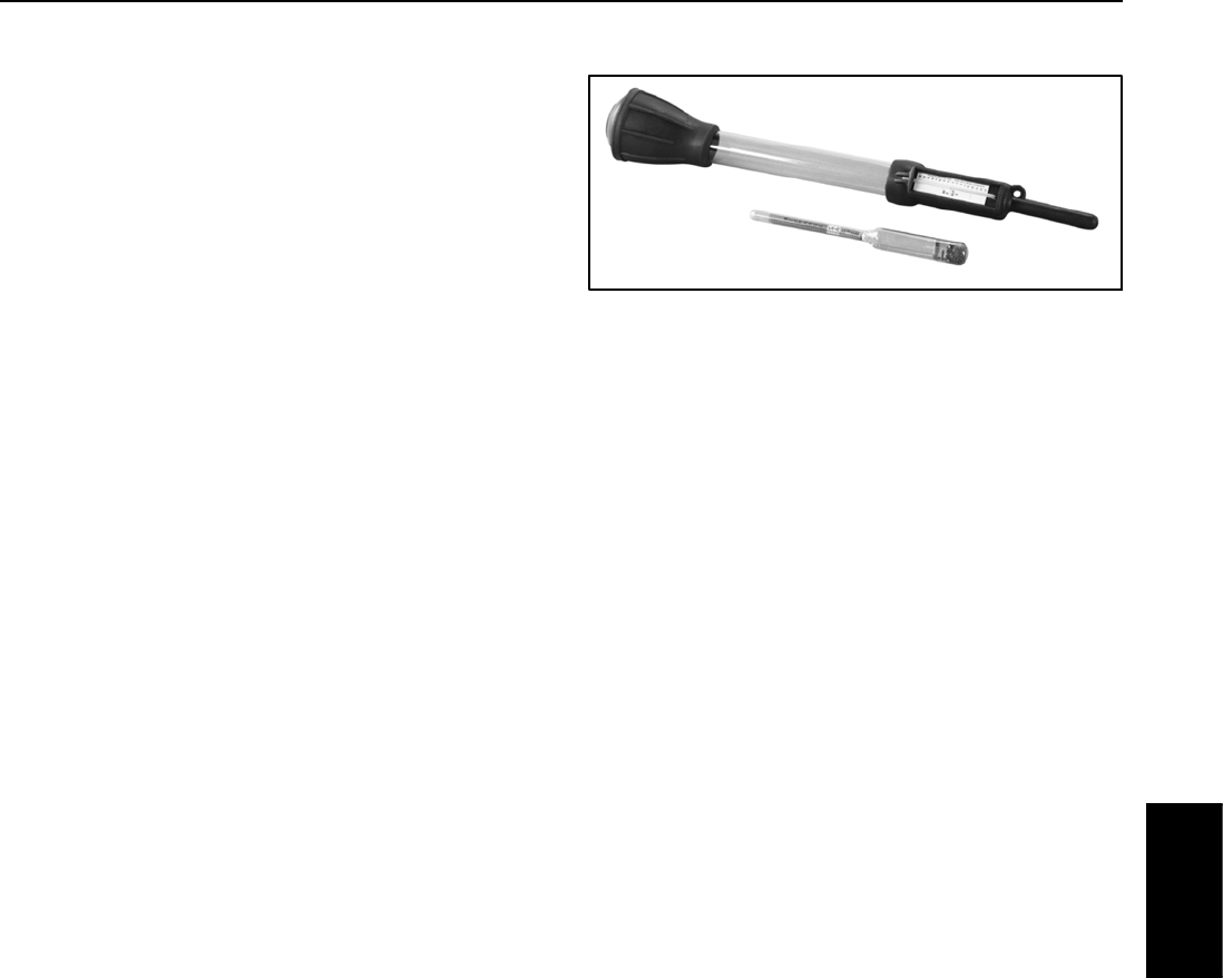
Groundsmaster 4100--D/4110--D Page 5 -- 7 Electrical System
Battery Hydrometer
Use the Battery Hydrometer when measuring specific
gravity of battery electrolyte. Obtain this tool locally.
Figure 7
Electrical
System
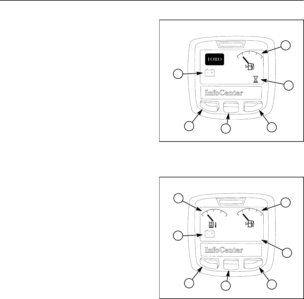
Groundsmaster 4100--D/4110--DPage 5 -- 8Electrical System
InfoCenter Display
The InfoCenter Display used on your Groundsmaster is
a LCD device that is located on the console. The Info-
Center provides information for the machine operator
during machine operation, provides electrical system
diagnostic assistance for technicians and allows inputs
for adjustable machine settings.
Power for the InfoCenter is available when energized by
the main power relay (ignition switch in the RUN or
START position). A CAN--bus system involving the ma-
chine TEC controllers, the Yanmar engine electronic
control unit and the InfoCenter is used to provide neces-
sary machine communication for InfoCenter operation.
Splash Screen
The two (2) InfoCenter splash screens (Figs. 8 and 9)
are displayed when the ignition switch is initially turned
to the RUN or START position. The splash screens allow
basic machine information to be reviewed by the operat-
or. After each of the splash screens has been on the In-
foCenter for several seconds, the main information
screen will be displayed on the InfoCenter.
The splash screens can be used to identify machine bat-
tery voltage, fuel level, hourmeter reading, hydraulic oil
temperature and engine status.
1. Battery voltage
2. Fuel gauge
3. Hour meter
4. Right button
5. Down button
6. Menu/back button
Figure 8
1
2
65
12.6V
4
3
95.2
T
1. Battery voltage
2. Hydraulic oil temperature
3. Fuel gauge
4. Engine RPM
5. Right button
6. Down button
7. Menu/back button
Figure 9
1
3
76
0
12.6V
2
RPM
140
180 220
oF
5
4
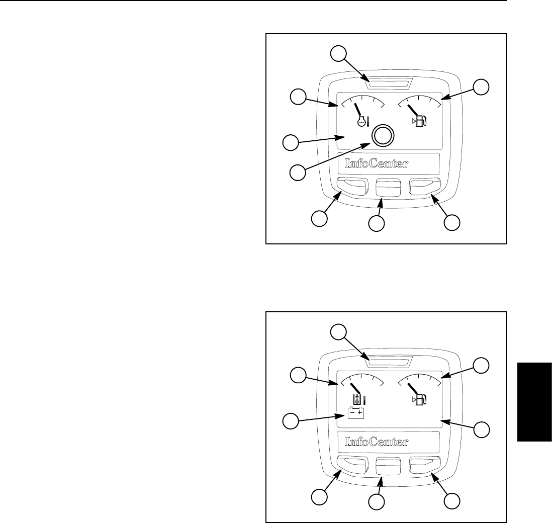
Groundsmaster 4100--D/4110--D Page 5 -- 9 Electrical System
Main Information Screen
The two (2) InfoCenter main information screens (Figs.
10 and 11) are displayed after the initial splash screen
has been displayed for several seconds. During normal
machine operation, the main information screens
provide machine information for the operator. Toggling
between the main information screens is done by press-
ing the right button on the InfoCenter.
The main information screens can be used to monitor
engine coolant temperature, fuel level, hydraulic oil tem-
perature, battery voltage, engine RPM and traction
speed range. The screens will also identify if the parking
brake is applied, if the PTO is engaged or if the cruise
control is activated.
The main information screens will also display arrows
whenever the cutting deck sections are either raising
(up arrows) or lowering (down arrows).
If controls are not selected properly to allow certain ma-
chine operations, an advisory will be displayed on the
InfoCenter Display. Typically, an advisory can be elimin-
ated with a change in controls by the operator.
If an electrical machine fault occurs during machine op-
eration, the InfoCenter fault indicator will blink to notify
the operator. Accessing the fault log is described below
in Faults Screen.
If an electrical engine fault occurs during machine op-
eration, the fault will be displayed on the InfoCenter to
notify the operator. The engine fault will be retained in
the engine ECU and can be viewed using the engine
diagnostic tool. Engine faults are not stored in the TEC
controller so they cannot be viewed using the InfoCenter
Faults Screen.
The main menu and additional information screens can
be accessed from the InfoCenter main information
screen by pressing and releasing the menu/back button
(left button) on the display. Information on the main
menu and menu item screens is included below.
1. Parking brake applied
2. Traction speed
3. Coolant temperature
4. Fault log indicator
5. Fuel gauge
6. Right button
7. Down button
8. Menu/back button
Figure 10
3
2
876
100
170 240
P
1
4
L
5
1. Battery voltage
2. Hydraulic oil temperature
3. Fault indicator
4. Fuel gauge
5. Engine RPM
6. Right button
7. Down button
8. Menu/back button
Figure 11
2
1
876
3
4
12.6V
140
180 220
o
2120 RPM 5
Electrical
System
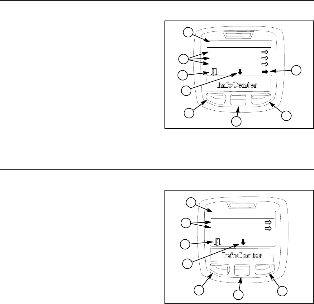
Groundsmaster 4100--D/4110--DPage 5 -- 10Electrical System
Main Menu Screen
The main menu screen can be accessed from the Info-
Center main information or splash screen by pressing
and releasing the menu/back button (left button) on the
display. Once to the main menu screen (Fig. 12), naviga-
tion to the five (5) different menu items can occur. Press-
ing the move to menu item button (center button) allows
a different menu item to be highlighted. Selection of the
highlighted item is completed by pressing the choose
item button (right button).
The main menu items include faults, service, diagnos-
tics, settings and about. These menu items are de-
scribed below.
To return to the main information screen from the main
menu screen, press the back button (left button).
1. Main menu
2. Menu items
3. Move to menu items
4. Choose menu item
5. Back button
Figure 12
1
3
4
5
34
Main Menu
Faults
Service
Diagnostics
2
5
Faults Screen
The faults screen (Fig. 13) will list all machine electrical
faults that have occurred since the faults were last
cleared from the InfoCenter. The faults will be identified
by a fault number and when the fault occurred. Faults
that might occur on the machine are listed in Fault
Codes in the Troubleshooting section of this chapter.
After entry of the PIN code, the InfoCenter fault log can
be cleared by selecting the clear system faults menu
item. The cleared faults will be removed from the Info-
Center list but will be retained in the TEC controller
memory.
If a fault occurs during machine use, there may be a
change in machine functionality due to the fault. Should
there be machine operation issues due to a fault, a first
step to remedy the issue would be to disengage the cut-
ting deck, release the traction pedal, turn the ignition
switch OFF and allow all machine functions to stop.
Then, attempt to restart the machine to see if operation
has returned to normal. Some faults will be reset during
the restart and will then allow normal function. If a fault
continues to occur, further system evaluation and pos-
sible component repair or replacement will be neces-
sary.
To return to the main menu screen from the faults
screen, press the back button (left button).
1. Fault menu
2. Fault items
3. Move to menu items
4. Choose menu item
5. Back button
Figure 13
1
3
534
Faults
#39
Clear System Faults
-- 5 7 . 3 A g o
2
5
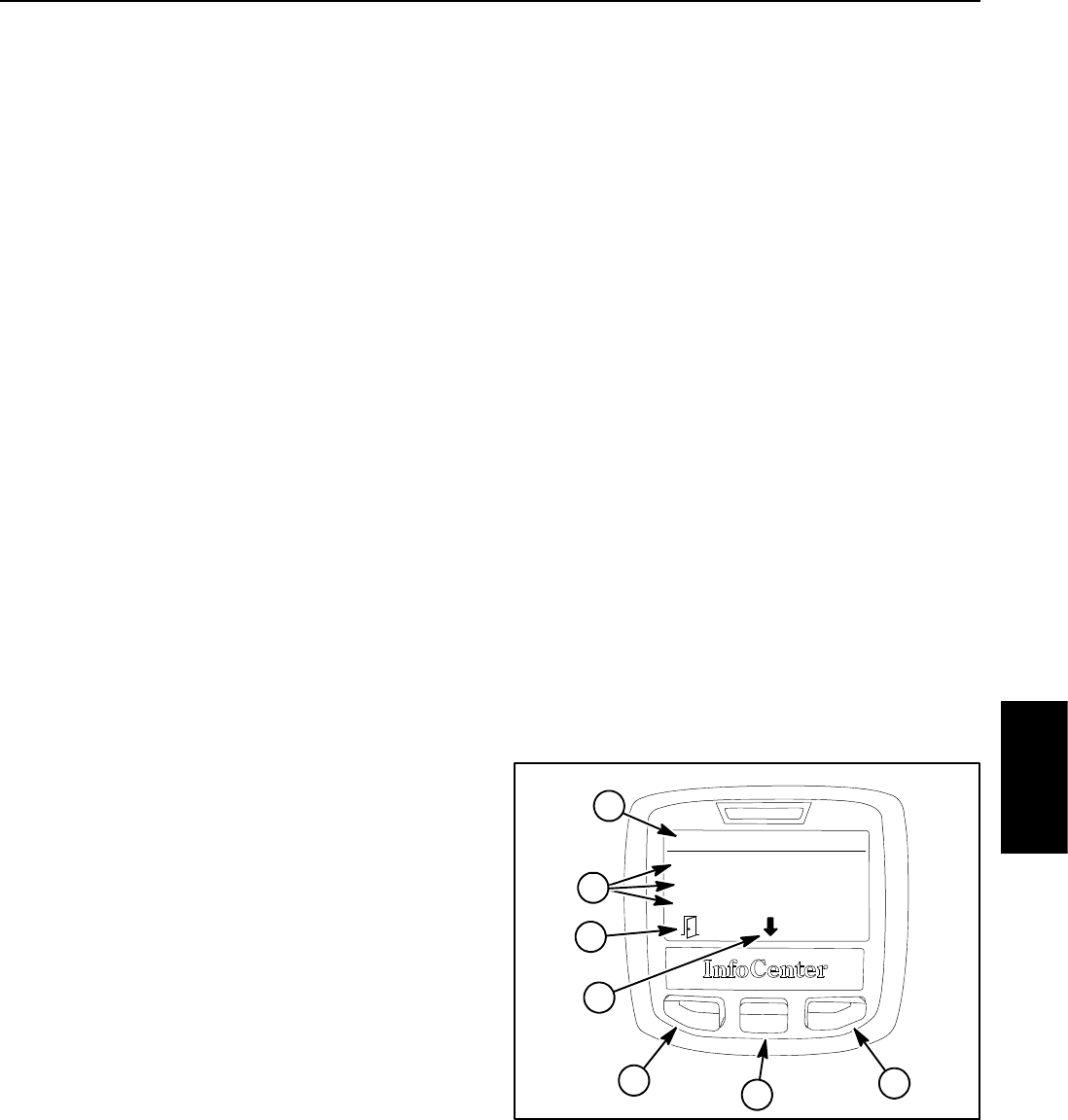
Groundsmaster 4100--D/4110--D Page 5 -- 11 Electrical System
Service Screen
The service screen (Fig. 15) contains machine opera-
tional information including hours and counts. Values
listed for these service menu items cannot be changed.
If the machine PIN has been entered to allow access to
protected menu items in the settings screen, the protec-
ted service menu items will be listed and available in the
service screen.
NOTE: If the protected menu items are available, PIN
will be shown in the upper right corner of the InfoCenter
display.
The options listed for hours include the following:
DKey On identifies the number of hours that the igni-
tion switch has been in the RUN position.
DMachine Run identifies the number of hours that the
engine has been running.
DPTO On identifies the number of hours that the ma-
chine has been operated with the cutting deck engaged.
DHigh Range identifies the number of hours that the
machine has been operated in HI range speed (trans-
port).
DService Due identifies the number of hours before
the next scheduled maintenance is due.
The options listed for counts include the following:
DStarts identifies the number of times that the engine
has been started.
DLeft Deck identifies the number of times that the left
wing deck has been energized.
DCenter Deck identifies the number of times that the
center cutting deck has been energized.
DRight Deck identifies the number of times that the
right side wing deck has been energized.
DFan Reversals identifies the number of times that
the engine cooling fan has been operated in the reverse
direction.
DFan -- Coolant identifies the number of times that en-
gine coolant temperature caused the engine cooling fan
speed to change.
DFan -- Oil identifies the number of times that hydraul-
ic oil temperature caused the engine cooling fan speed
to change.
DInlet identifies the temperature of the inlet air into the
engine intake system.
The protected menu items include the following:
DDPF Regeneration provides the necessary proced-
ure for stationary regeneration for the exhaust system
DPF (diesel particulate filter) on machines with a Tier 4
engine (models 30606 and 30608). If the engine ECU
identifies that a stationary DPF regeneration is neces-
sary, an advisory will occur on the InfoCenter and the ne-
cessary steps will be listed in the service screen menu.
DTraction Pedal allows the traction pedal sensor to
be calibrated (see Traction Pedal Position Sensor Calib-
ration in the Adjustments section of this chapter for calib-
ration procedure).
DFan Reverse provides the necessary inputs to
cause the cooling fan to reverse direction. This protec-
ted menu item allows the demonstration of the fan re-
versal and would never be necessary to use on a
normally functioning machine.
To return to the main menu screen from the service
screen, press the back button (left button).
1. Service menu
2. Service items
3. Move to menu items
4. Choose menu item
5. Back button
Figure 15
Hours
Key On:
Machine Run:
PTO On:
92.5 Hours
88.4 Hours
63.7 Hours
1
534
5
2
3
Electrical
System
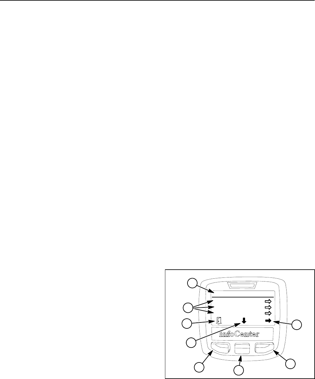
Groundsmaster 4100--D/4110--DPage 5 -- 12Electrical System
Diagnostics Screen
The diagnostics screen (Fig. 16) lists the various states
of machine electrical components. The diagnostics
screen should be used to check operation of machine
controls and to verify that switches and circuit wiring are
functioning correctly.
For each of the diagnostics screen items, inputs, qualifi-
ers and outputs are identified. The diagnostics screen
includes the following:
DLeft Deck identifies machine requirements to allow
the left wing deck to raise and lower. Inputs indicate the
state of the left wing deck lift/lower switch and whether
the machine is in LOW range speed. Qualifiers include
the LOW range speed, seat switch and parking brake
position. Identified outputs consist of master, lower,
raise and float solenoids.
DCenter Deck identifies machine requirements to al-
low the cutting deck to raise and lower. Inputs indicate
the state of the center deck lift/lower switch. Qualifiers
include the LOW range speed, seat switch and parking
brake position. Identified outputs consist of master,
raise and float solenoids.
DRight Deck identifies machine requirements to allow
the right wing deck to raise and lower. Inputs indicate the
state of the right deck lift/lower switch. Qualifiers include
the LOW range speed, seat switch and parking brake
position. Identified outputs consist of master, lower,
raise and float solenoids.
DTraction Pedal identifies position of the traction ped-
al. Inputs indicate the state of the traction pedal position
sensor. Outputs indicate whether the traction circuit is in
forward, neutral or reverse.
DTraction identifies machine requirements to allow
the traction system to be engaged. Inputs indicate the
state of the traction pedal. Qualifiers include the seat
switch and parking brake position. Outputs indicate
whether the piston (traction) pump is engaged in for-
ward or reverse.
DHi/Low Range identifies machine requirements to
allow HI or LOW speed range to be engaged. Inputs indi-
cate the state of the hi/low switch. Qualifiers identify the
position of the PTO switch and the cutting deck (raised
or lowered). Outputs indicate whether HI range is en-
gaged (solenoid S12 is energized).
DPTO identifies machine requirements to allow the
PTO to be engaged. Inputs indicate the state of the PTO
switch. Qualifiers identify whether LOW speed range is
selected, if the seat is occupied and if the cutting deck
is lowered. Outputs indicate which cutting deck is en-
gaged.
DEngine Run identifies whether necessary TEC out-
puts exists to allow the engine to run. Inputs indicate the
state of the ignition switch. Qualifiers identify whether
the PTO is off, if the traction pedal is in neutral, if the seat
is occupied (or parking brake is applied) and if all deck
lift switches are not activated. Outputs indicate that re-
quirements have been met to allow engine to run or
start. NOTE: The components for engine operation (i.e.
glow plugs, starter) are controlled by the Yanmar engine
electronic control unit.
DCruise Control identifies machine requirements to
allow the cruise control to be engaged. Inputs indicate
the state of the cruise control switch and service brakes.
Qualifiers identify whether the seat is occupied, if the
parking or service brakes are applied and if the traction
pedal is not in neutral. Outputs indicate that the cruise
function is engaged.
DLight Kit identifies machine requirements to allow
machine lights (if equipped) to be energized. Inputs indi-
cate the state of the light switches. Outputs indicate that
the lights are energized.
To return to the main menu screen from the diagnostics
screen, press the back button (left button).
1. Diagnostics menu
2. Diagnostics items
3. Move to menu items
4. Choose menu item
5. Back button
Figure 16
Diagnostics
Left Deck
Center Deck
Right Deck
1
53
4
5
2
3
4
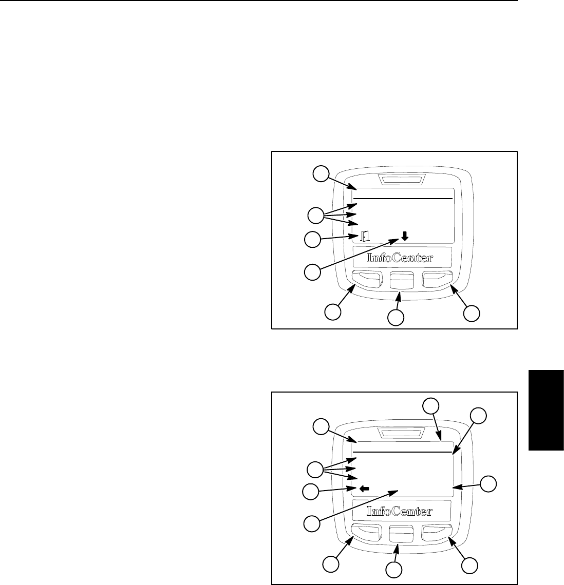
Groundsmaster 4100--D/4110--D Page 5 -- 13 Electrical System
Settings Screen
The settings screen identifies the InfoCenter language
and units (English or Metric). The settings screen also
allows the operator to customize the backlight (bright-
ness) and contrast settings for the InfoCenter display.
If either the backlight (brightness) or contrast items are
selected, the center button (--) or right button (+) can be
used to change the display settings.
Protected menus allows the machine PIN to be en-
tered so that hidden machine service screen items can
be viewed and modified. The protected service items in-
clude traction pedal sensor calibration, cooling fan re-
versal demonstration, Smart PowerTM ON/OFF and
exhaust system DPF regeneration (Tier4 engines). If the
protect settings is ON (see below), auto idle, mow
speed, transport speed and counterbalance are also in-
cluded in the protected menu.
To allow access to the protected menu items, enter the
four (4) digit pin PIN using the center and right InfoCen-
ter buttons. After PIN has been entered, a check mark
should be visible above center InfoCenter button. Press
center button and the InfoCenter display screen should
indicate “PIN” in the upper right hand corner if the correct
PIN number was entered. Use back button to return to
Settings menu. The protected menu items should be
available in the Service menu and can be changed as
long as the ignition switch remains in RUN.
NOTE: The initial PIN will either be 1234 or 0000. If the
PIN has been changed and is forgotten, a temporary
PIN can be obtained from your Toro distributor.
Protect settings allows the settings for auto idle, mow
speed and transport speed to be hidden so they cannot
be changed unless the PIN is entered. If the protect set-
tings is ON, these settings will not be seen when using
the InfoCenter until the protected menus is selected and
the machine PIN is entered. If protect settings is OFF
(default setting), settings for these functions will be vis-
ible on the InfoCenter and can be adjusted by the opera-
tor.
Reset Defaults allows machine settings to be returned
to factory defaults.
Auto Idle causes the engine speed to decrease to low
idle after the machine has not been in use for the set time
delay in seconds. Auto idle can be adjusted to 8, 10, 15,
20 or 30 seconds or the auto idle feature can be turned
OFF.
Mow Speed allows the maximum traction speed to be
adjusted when in LOW (mow) speed. Mow speed can be
adjusted to 40%, 70% or 100%.
Trans. (Transport) Speed allows the maximum traction
speed to be adjusted when in HI (transport) speed. HI
speed can be adjusted to 40%, 70% or 100%.
Smart Power allows the Smart PowerTM feature to be
turned OFF and ON.
To return to the main menu screen from the settings
screen, press the back button (left button).
1. Settings menu
2. Settings items
3. Move to menu items
4. Change menu item
5. Back button
Figure 17
Settings
Units:
Language:
LCD Backlight:
English
English
40%
+/--
1
3
534
5
2
Figure 18
1. Settings menu
2. Settings items
3. Current setting
4. Increase setting
5. Decrease setting
6. Back button
7. PIN activated
Settings
Auto Idle:
Mow Speed:
Trans. Speed:
-- 5
1
4
645
6
2
+
20s
70 %
70 %
PIN
3
7
Electrical
System
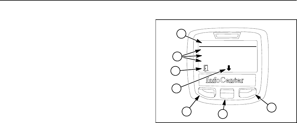
Groundsmaster 4100--D/4110--DPage 5 -- 14Electrical System
About Screen
The about screen (Fig. 19) identifies the machine model
number, serial number and software revisions for the
TEC controllers, InfoCenter and engine electronic con-
trol unit (if available). The about screen also lists the
CAN--bus status. Additional information is identified if
the about screen is accessed after the protected menus
have been accessed by entering the PIN.
To return to the main menu screen from the about
screen, press the back button (left button).
Figure 19
About
Model:
SN:
S/W Rev:
30607
313000103
120--6363C
1
53
4
5
2
1. About menu
2. About items
3. Move to menu items
4. Choose menu item
5. Back button
3

Groundsmaster 4100--D/4110--D Page 5 -- 15 Electrical System
Troubleshooting
CAUTION
Remove all jewelry, especially rings and
watches, before doing any electrical trouble-
shooting or testing. Also, disconnect the battery
cables unless the test requires battery voltage.
For effective troubleshooting and repairs, you must
have a good understanding of the electrical circuits and
components used on this machine (see electrical
schematics and wire harness drawings in Chapter 10 --
Foldout Drawings).
If the machine has any interlock switches by--passed,
reconnect the switches for safety and efficient trouble-
shooting.
NOTE: Check the InfoCenter Display for possible oper-
ator advisories or faults whenever diagnosing machine
electrical problems.
Operator Advisories
The list below identifies the operator advisories that are
generated by the TEC controller. An advisory will be dis-
played on the InfoCenter Display. Typically, an advisory
can be eliminated with a change in machine controls by
the operator.
Advisory Advisory Description
160 Inhibit start
161 Inhibit PTO
162 Inhibit cutting unit lower
163 Inhibit traction HIGH speed range
164 Inhibit traction LOW speed range
165 Inhibit traction
166 Inhibit cruise control
167 Derate traction setting
168 Inhibit traction teach (traction pedal calibration)
169 Engine shutdown
170 Recycle keyswitch (ignition switch)
171 Auto idle engaged
172 Calibrate (traction pedal)
173 Master address claim (front TEC controller)
174 Slave address claim (rear TEC controller)
175 Derate engine
Electrical
System

Groundsmaster 4100--D/4110--DPage 5 -- 16Electrical System
Fault Codes
The list below identifies the fault codes that are gener-
ated by the TEC controller to identify an electrical sys-
tem malfunction (fault) that occurred during machine
operation. Use the InfoCenter Display for fault retrieval.
NOTE: The following list of fault codes identifies elec-
trical problems that typically will prevent normal ma-
chine operation. The InfoCenter Display will identify
existing faults if they should occur. Fault codes 13
through 25 identify problems with inputs (e.g. switches,
sensors) to the TEC controllers. For input problems, use
the InfoCenter Display to check the different switch posi-
tions before removing or replacing the component.
NOTE: Fault codes 26 through 62 identify problems
with outputs (e.g. solenoid coils, light bulbs) from the
TEC controllers. These output problems might involve
issues with the wire harness or the actual output device
(solenoid coil or bulb).
Fault Code Fault Description
1Excessive engine coolant temperature (above 105oC) caused PTO to
disengage
2Excessive engine coolant temperature (above 115oC) caused engine to stop
3One of the TEC output fuses (7.5 Amp) is faulty
4IPE voltage too low indicating that TEC controller is faulty
5Main power relay is faulty
6Ignition switch was held in the START position for more than 30 seconds or the
ignition switch is faulty
7TEC software needs to be reprogrammed (contact Toro Distributor)
8Alternator charging is too high
9Alternator charging is too low
10 Engine has not been seen on CAN--bus for 10 seconds
11 Rear TEC controller has not been seen on CAN--bus for 1 second
12 InfoCenter has not been seen on CAN--bus for 1 second
13 Ignition switch is faulty (check ignition switch)
14 Traction pedal position sensor is faulty (check traction sensor)
15 Engine speed switch is faulty (check engine speed switch)
16 Traction system HI/LOW speed switch is faulty (check HI/LOW speed switch)
17 Traction pedal position sensor is out of range
18 Hydraulic temperature sensor circuit has open or short
21 Center cutting deck lift switch is faulty (check center lift switch)
22 Left cutting deck lift switch is faulty (check left lift switch)
23 Right cutting deck lift switch is faulty (check right lift switch)
25 Cruise control switch is faulty (check cruise control switch)
26 Engine START output has open or short to ground
27 Engine RUN output has open or short to ground
28 Traction system HIGH range output has open or short to ground
29 RH turn/warning light output has open or short to ground
30 LH turn/warning light output has open or short to ground

Groundsmaster 4100--D/4110--D Page 5 -- 17 Electrical System
Fault Code Fault Description
31 Brake/RH turn light output has open or short to ground
32 Brake/LH turn light output has open or short to ground
33 Forward piston (traction) pump output has open or short to ground
34 Reverse piston (traction) pump output has open or short to ground
35 Reverse engine cooling fan output (solenoid valve S10) has open or short to
ground
36 Disable dual engine cooling fan output (solenoid valve S11) has open or short
to ground
38 Center PTO output has open or short to ground
39 LH PTO output has open or short to ground
40 RH PTO output has open or short to ground
41 Solenoid valve S1 (lift/lower enable) output has open or short to ground
42 Solenoid valve S2 (LH deck raise) output has open or short to ground
43 Solenoid valve S3 (LH deck lower) output has open or short to ground
44 Solenoid valve S4 (LH deck float) output has open or short to ground
45 Solenoid valve S5 (center deck raise) output has open or short to ground
46 Solenoid valve S6 (center deck float) output has open or short to ground
47 Solenoid valve S7 (RH deck raise) output has open or short to ground
48 Solenoid valve S8 (RH deck lower) output has open or short to ground
49 Solenoid valve S9 (RH deck float) output has open or short to ground
52 Engine cooling fan output has open or short to ground
63 Traction pedal position sensor is returning a voltage higher than 4.75V or lower
than 0.25V (replace the traction pedal position sensor)
64 Traction pedal position sensor neutral switches do not align with calibrated
sensor values (recalibrate traction pedal position sensor)
65 Traction pedal position sensor forward/reverse switches are indicating the pedal
is in both positions at the same time (replace the traction pedal position sensor)
66 TEC controller overcurrent in traction circuit
67 Traction current validation failure: make sure TEC forward traction output is
connected to the piston pump forward traction solenoid coil. If circuit is connec-
ted, replace the front TEC controller.
Electrical
System

Groundsmaster 4100--D/4110--DPage 5 -- 18Electrical System
Starting Problems
NOTE: Check InfoCenter Display for possible operator
advisories or faults whenever diagnosing machine elec-
trical problems.
Problem Possible Causes
No electrical power to machine. The battery is discharged.
The battery cables are loose or corroded.
FuseF--D1(2Amp)isfaulty.
FuseF--D2(2Amp)isfaulty.
Fuse M1 (60 Amp) is faulty.
A faulty ground connection exists on machine.
The ignition switch or circuit wiring is faulty.
Starter solenoid clicks, but starter will not crank.
NOTE: If the solenoid clicks, the problem is not in the in-
terlock circuit.
The battery is discharged.
The battery cables are loose or corroded.
A ground wire or cable is loose or corroded.
The wiring at the starter motor is faulty.
The starter solenoid is faulty.
The starter motor is faulty.
Nothing happens when start attempt is made.
InfoCenter display operates with the ignition switch in
the RUN position.
NOTE: Use InfoCenter Display to assist with identifying
problem.
The traction pedal is not in the neutral position.
The operator seat is unoccupied OR the parking brake
is not applied.
The PTO switch is ON (engaged).
Fuses for TEC are faulty.
The ignition switch or circuit wiring is faulty.
Traction pedal position sensor is out of adjustment.
Traction pedal position sensor or circuit wiring is faulty.
The seat switch or circuit wiring is faulty.
The parking brake switch or circuit wiring is faulty.
The start relay or circuit wiring is faulty.
The starter solenoid or starter motor is faulty.
The engine or fuel system is malfunctioning (see
Yanmar Service Manual).

Groundsmaster 4100--D/4110--D Page 5 -- 19 Electrical System
Starting Problems (Continued)
Problem Possible Causes
Starter cranks, but should not, when the traction pedal
is depressed.
Traction pedal position sensor is out of adjustment.
Traction pedal position sensor or circuit wiring is faulty.
Engine cranks, but does not start. The fuel tank is empty.
The engine is not cranking fast enough.
The fuel pump or circuit wiring is faulty.
The engine or fuel system is malfunctioning (see
Yanmar Service Manual).
Electrical
System

Groundsmaster 4100--D/4110--DPage 5 -- 20Electrical System
General Run and Transport Problems
NOTE: Check InfoCenter Display for possible operator
advisories or faults whenever diagnosing machine elec-
trical problems.
Problem Possible Causes
Engine continues to run, but should not, when the
ignition switch is turned off.
The ignition switch or circuit wiring is faulty.
The alternator circuit is faulty (machines with 80 Amp
alternator)
The engine or fuel system is malfunctioning (see
Yanmar Service Manual).
Machine continues to run without an InfoCenter
Advisory, but should not, when the traction pedal is
depressed with no operator in the seat.
The seat switch or circuit wiring is faulty.
Traction pedal position sensor is out of adjustment.
Traction pedal position sensor or circuit wiring is faulty.
Engine stops during operation, but is able to restart.
NOTE: Excessive engine coolant temperature will
cause the cutting deck to be disengaged and can lead to
engine shutdown. If excessive coolant temperature
causes engine shutdown, the operator can restart the en-
gine to allow the machine to be moved a short distance.
After a restart in this condition, the engine will run for
approximately ten (10) seconds before the engine shuts
down again.
The operator is lifting off the seat switch while mowing.
The seat switch or circuit wiring is faulty.
The ignition switch or circuit wiring is faulty.
The engine coolant temperature is excessive.
Machine is being operated on a slope with a low fuel
level.
The engine or fuel system is malfunctioning (see
Yanmar Service Manual).
Battery does not charge. Loose, corroded or broken wire(s) exist in charging
circuit.
The engine alternator belt is out of adjustment.
The battery is faulty.
The alternator is faulty.

Groundsmaster 4100--D/4110--D Page 5 -- 21 Electrical System
Cutting Deck Operating Problems
NOTE: Check InfoCenter Display for possible operator
advisories or faults whenever diagnosing machine elec-
trical problems.
NOTE: To engage the mow circuit, the operator must
be in the operator seat, the traction speed must be in the
LOW speed (mow) position, the PTO switch must be ON
and the cutting deck(s) must be fully lowered and in float.
Problem Possible Causes
The cutting deck remains engaged, but should not,
with no operator in the seat.
The seat switch or circuit wiring is faulty.
A hydraulic problem in the mow circuit exists (see
Troubleshooting section of Chapter 4 -- Hydraulic
System).
The TEC controller is faulty.
The cutting deck runs, but should not, with PTO switch
in the OFF (disengage) position.
The PTO switch or circuit wiring is faulty.
A hydraulic problem in the mow circuit exists (see
Troubleshooting section of Chapter 4 -- Hydraulic
System).
The TEC controller is faulty.
A cutting wing deck runs, but should not, when raised.
Deck shuts off with PTO switch.
The wing deck position switch or circuit wiring is faulty.
A hydraulic problem in the mow circuit exists (see
Troubleshooting section of Chapter 4 -- Hydraulic
System).
Electrical
System

Groundsmaster 4100--D/4110--DPage 5 -- 22Electrical System
Cutting Deck Operating Problems (Continued)
Problem Possible Causes
Wing cutting deck does not operate. The wing cutting deck is not fully lowered.
The wing deck position switch or circuit wiring is faulty.
Hydraulic valve solenoid(s) or circuit wiring to the
affected wing deck manifold is faulty.
A hydraulic problem in the mow circuit exists (see
Troubleshooting section of Chapter 4 -- Hydraulic
System).
The TEC controller is faulty.
Cutting deck does not operate. The operator is lifting off the seat switch.
Traction circuit is not in LOW speed (mow) mode.
High temperature of engine coolant or hydraulic oil has
disabled the cutting deck.
Fuse is faulty preventing PTO manifold solenoids from
being energized.
Front deck jumper harness is faulty or not plugged into
platform wire harness.
The seat switch or circuit wiring is faulty.
The PTO switch or circuit wiring is faulty.
The wing deck position switch or circuit wiring is faulty.
The HI/LOW speed switch or circuit wiring is faulty.
Hydraulic valve solenoid(s) or circuit wiring to the
affected deck(s) is faulty.
A hydraulic problem in the mow circuit exists (see
Troubleshooting section of Chapter 4 -- Hydraulic
System).
The TEC controller is faulty.

Groundsmaster 4100--D/4110--D Page 5 -- 23 Electrical System
Cutting Deck Lift/Lower Problems
NOTE: Check InfoCenter Display for possible operator
advisories or faults whenever diagnosing machine elec-
trical problems.
NOTE: Toloweracuttingdeck,theoperatormustbein
the operator seat and the traction speed must be in the
LOW speed (mow) position. To raise a cutting deck, the
operator must be in the operator seat.
Problem Possible Causes
Neither the cutting deck or wing decks will lower. The HI/LOW speed switch is in the HI speed position.
Operator is not fully depressing the seat switch.
TEC fuse(s) are faulty.
The seat switch or circuit wiring is faulty.
The HI/LOW speed switch or circuit wiring is faulty.
Combination control manifold solenoid coil S1 or circuit
wiring is faulty.
A hydraulic problem in the lift/lower circuit exists (see
Troubleshooting section of Chapter 4 - Hydraulic
System).
The TEC controller is faulty.
Neither the cutting deck or wing decks will raise. TEC fuse(s) are faulty.
Combination control manifold solenoid coil S1 or circuit
wiring is faulty.
A hydraulic problem in the lift/lower circuit exists (see
Troubleshooting section of Chapter 4 - Hydraulic
System).
The TEC controller is faulty.
Front cutting deck will not raise or lower, but both wing
cutting decks will raise and lower.
The deck lift switch or circuit wiring is faulty.
Combination control manifold solenoid coils S5 or S6
or circuit wiring is faulty.
A hydraulic problem in the lift/lower circuit exists (see
Troubleshooting section of Chapter 4 - Hydraulic
System).
The TEC controller is faulty.
Electrical
System

Groundsmaster 4100--D/4110--DPage 5 -- 24Electrical System
Cutting Deck Lift/Lower Problems (Continued)
Problem Possible Causes
RH wing cutting deck will not raise or lower, but the
front and LH wing cutting decks will raise and lower.
The RH deck lift switch or circuit wiring is faulty.
Fuse is faulty.
Combination control manifold solenoid coils S7, S8 or
S9 or circuit wiring is faulty.
A hydraulic problem in the lift/lower circuit exists (see
Troubleshooting section of Chapter 4 - Hydraulic
System).
The TEC controller is faulty.
LH wing cutting deck will not raise or lower, but the
front and RH wing cutting decks will raise and lower.
The LH deck lift switch or circuit wiring is faulty.
Fuse is faulty.
Combination control manifold solenoid coils S2, S3 or
S4 or circuit wiring is faulty.
A hydraulic problem in the lift/lower circuit exists (see
Troubleshooting section of Chapter 4 - Hydraulic
System).
The TEC controller is faulty.

Groundsmaster 4100--D/4110--D Page 5 -- 25 Electrical System
This page is intentionally blank.
Electrical
System
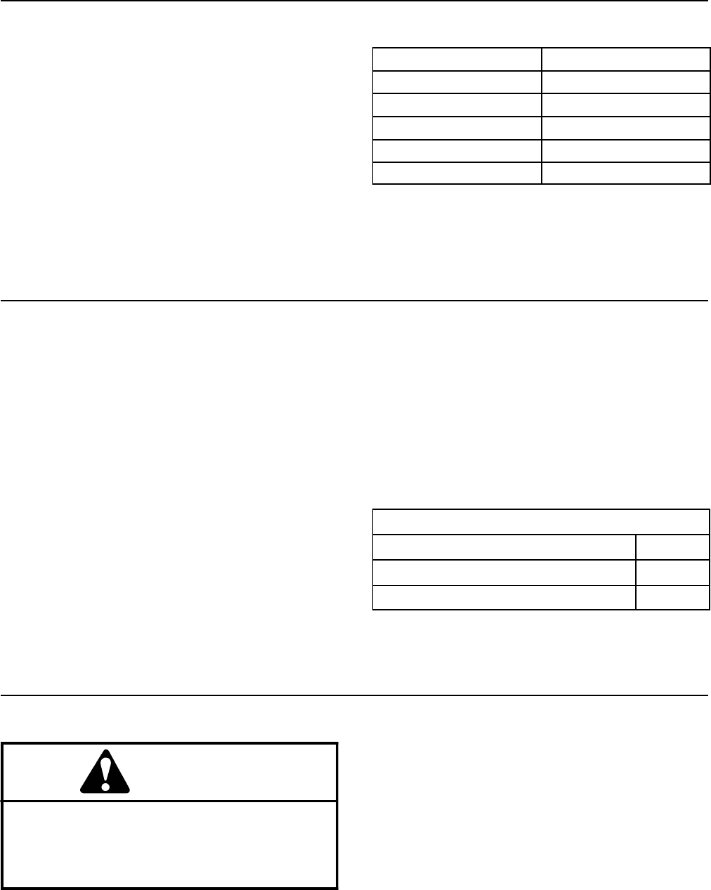
Groundsmaster 4100--D/4110--DPage 5 -- 26Electrical System
Electrical System Quick Checks
Battery Test (Open Circuit)
Use a multimeter to measure the voltage between the
battery terminals.
Set multimeter to the DC volts setting. The battery
should be at a temperature of 60oto 100oF(16
oto
38oC). The ignition key should be off and all accessories
turned off. Connect the positive (+) multimeter lead to
the positive battery post and the negative (--) multimeter
lead to the negative battery post. The multimeter will dis-
play battery voltage.
NOTE: This test provides a relative condition of the bat-
tery. Load testing of the battery will provide additional
and more accurate information.
Voltage Measured Battery Charge Level
12.68 V (or higher) Fully charged (100%)
12.45 V 75% charged
12.24 V 50% charged
12.06 V 25% charged
11.89 V 0% charged
Charging System Test
This is a simple test used to determine if a charging sys-
tem is functioning. It will tell you if the charging system
has an output, but not its capacity.
NOTE: The InfoCenter display can be used to identify
battery voltage during machine operation.
Use a digital multimeter set to DC volts. Connect the
positive (+) multimeter lead to the positive battery post
and the negative (--) multimeter lead to the negative bat-
tery post. Keep the test leads connected to the battery
posts and record the battery voltage.
NOTE: Upon starting the engine, the battery voltage
will drop and then should increase once the engine is
running.
NOTE: Depending upon the condition of the battery
charge and battery temperature, the battery voltage will
increase at different rates as the battery charges.
Start the engine and run at high idle. Allow the battery
to charge for at least three (3) minutes. Record the bat-
tery voltage.
After running the engine for at least three (3) minutes,
battery voltage should be at least 0.50 volt higher than
initial battery voltage.
An example of a charging system that is functioning:
At least 0.50 volt over initial battery voltage.
Initial Battery Voltage =12.30v
Battery Voltage after 3 Minute Charge =12.95v
Difference = +0.65 v
Check Operation of Interlock Switches
CAUTION
Do not disconnect safety switches. They are for
the operator’s protection. Check the operation of
the interlock switches daily for proper operation.
Replace any malfunctioning switches before op-
erating the machine.
Interlock switch operation is described in the Traction
Unit Operator’s Manual. Your Groundsmaster is
equipped with two (2) Toro Electronic Controllers (TEC)
which monitor interlock switch operation. Testing of indi-
vidual interlock switches and relays is included in the
Component Testing section of this Chapter.
NOTE: Use the InfoCenter Display when troubleshoot-
ing an electrical problem on your Groundsmaster.
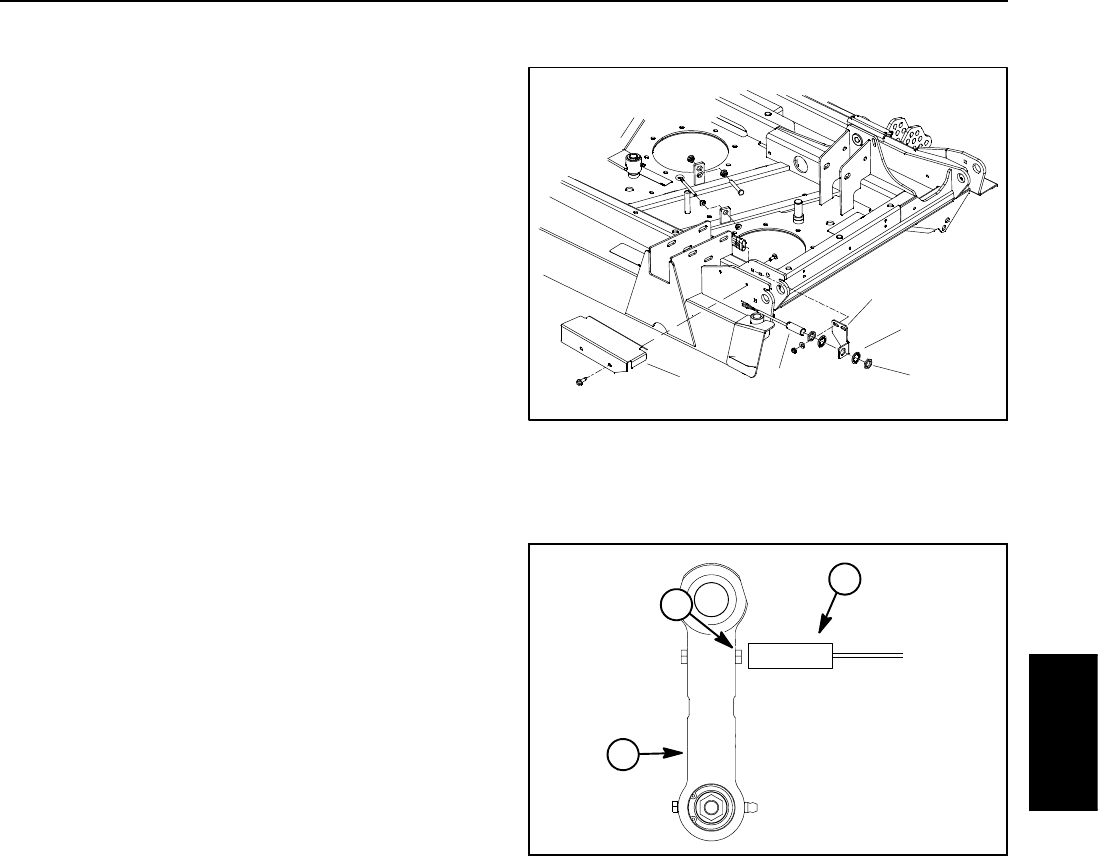
Groundsmaster 4100--D/4110--D Page 5 -- 27 Electrical System
Adjustments
Wing Deck Position Switch Adjustment
1. Park machine on a level surface, lower cutting deck,
stop engine, engage parking brake and remove key
from the ignition switch.
2. Remove switch cover from deck to allow access to
position switch that requires adjustment.
3. Raise and lower wing deck while monitoring the wing
deck latch and the position switch LED on cable end of
switch:
A. The position switch should open (switch LED is
not illuminated) when the wing deck link causes the
wing deck latch to disengage as wing deck is raised.
B. Thepositionswitchshouldclose(switchLEDis
illuminated) when the wing deck link causes the wing
deck latch to engage as wing deck is lowered.
4. If necessary, adjust switch location to allow correct
operation:
A. Loosen jam nuts on switch and adjust switch
location to allow proper switch operation.
B. After switch adjustment, torque jam nuts from
165 to 195 in--lb (18.7 to 22.0 N--m).
C. Make sure that position switch does not contact
bolt head on wing deck link when wing deck is fully
lowered.
5. After testing is complete, make sure that switch con-
nector is plugged into deck wire harness and switch cov-
er is secured to deck.
1. Switch cover
2. Position switch
3. Switch bracket
4. Lock washer (2 used)
5. Jam nut (2 used)
Figure 20
12
3
4
5
1. Position switch
2. Bolt head
3. Wing deck link
Figure 21
1
3
2
Electrical
System
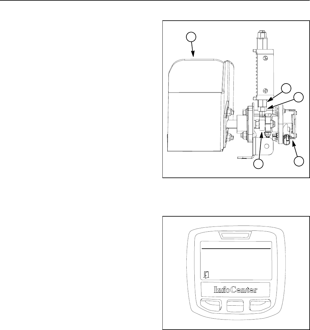
Groundsmaster 4100--D/4110--DPage 5 -- 28Electrical System
Traction Pedal Adjustment
The traction pedal includes a neutral assembly that is
used to adjust the traction neutral position (Fig. 22).
Traction pedal adjustment may be necessary to make
sure that traction pedal movement provides the correct
full reverse and full forward positions for the traction
pedal position sensor. The InfoCenter display can be
used to check traction pedal adjustment using the fol-
lowing procedure.
1. Parkmachineonalevelsurface, lower cutting deck,
engage parking brake and stop engine.
2. Turn ignition switch to RUN but do not start engine.
3. Use the InfoCenter Display Diagnostics menu (see
InfoCenter Display in this chapter) to obtain and select
the Traction Pedal menu item. Choose Inputs and the In-
foCenter display should identify sensor voltage (Fig.
23).
4. Move traction pedal from full reverse to full forward
positions while noting the range of voltage displayed on
the InfoCenter.
A. Voltage in full reverse should be from 0.5 to 1.75V
(approximate).
B. Voltage in full forward should be from 3.5 to 4.5V
(approximate).
5. If voltage range from full reverse to full forward is in-
correct, adjustment of the spring shaft and rod end bear-
ing is necessary (Fig. 22).
A. Remove steering cover to access traction pedal
components (see Steering Tower in the Service and
Repairs section of Chapter 7 -- Chassis).
B. Loosen hex nut that secures rod end bearing in
spring shaft.
C. Rotate spring shaft which changes traction pedal
position in relation to traction pedal position sensor.
D. Check range of voltage as described in step 4
above and make additional adjustments to the spring
shaft until range of voltage is within specifications.
E. Tighten hex nut to secure rod end bearing. Check
that traction pedal range of voltage is still correct
after hex nut is tightened.
F. Install steering cover (see Steering Tower in the
Service and Repairs section of Chapter 7 -- Chassis).
1. Traction pedal
2. Pedal position sensor
3. Spring shaft
4. Hex nut
5. Rod end bearing
Figure 22
1
2
4
3
5
Figure 23
Traction Pedal
Sensor: 2.407V

Groundsmaster 4100--D/4110--D Page 5 -- 29 Electrical System
6. After any adjustment of the spring shaft and rod end
bearing, use the InfoCenter Display Diagnostics menu
(see InfoCenter Display in this chapter) to obtain and se-
lect the Traction Pedal menu item. Choose Outputs and
the InfoCenter display will identify the traction pedal po-
sition (Fig. 24).
A. When the traction pedal is in the neutral position,
the InfoCenter should display Neutral as ON and
both Forward Range and Reverse Range as OFF.
B. Move traction pedal in the forward direction and
the InfoCenter should display the Forward Range as
ON and both Neutral and Reverse Range as OFF.
C. Return the traction pedal to neutral and then
move pedal in the reverse direction. The InfoCenter
should display the Reverse Range as ON and both
Neutral and Forward Range as OFF.
D. If outputs are incorrect, additional adjustment of
the spring shaft and rod end bearing are necessary.
7. After completing all adjustments and before return-
ing the machine to operation, calibrate traction pedal po-
sition sensor (see Traction Pedal Position Sensor
Calibration in this section of this chapter).
Figure 24
Traction Pedal
Forward Range: OFF
Neutral
Reverse Range: OFF
ON
Electrical
System
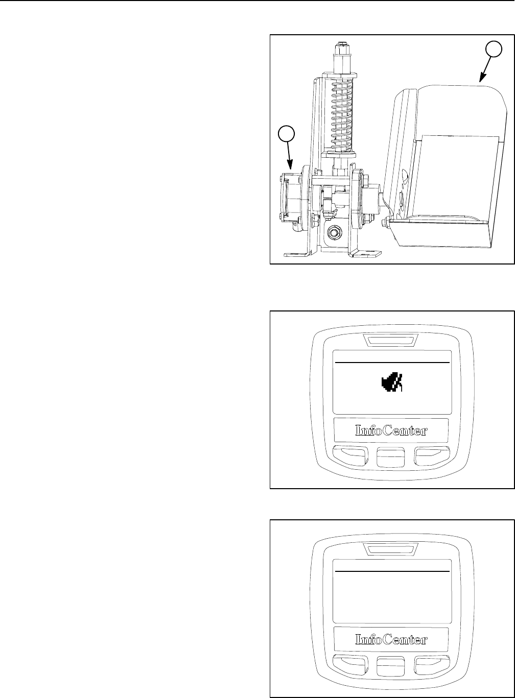
Groundsmaster 4100--D/4110--DPage 5 -- 30Electrical System
Traction Pedal Position Sensor Calibration
IMPORTANT: A properly installed and calibrated
traction pedal position sensor is critical to accurate
traction system response and for reliable sensor
life. Use care when removing, installing and cali-
brating the traction pedal position sensor.
Calibration of the traction pedal position sensor ensures
that the TEC controller can identify the traction neutral,
forward and reverse positions.
1. Parkmachineonalevelsurface, lower cutting deck,
engage parking brake and stop engine.
2. Turn ignition switch to RUN but do not start engine.
3. Use the InfoCenter Display Settings menu (see Info-
Center Display in this chapter) to obtain and select Pro-
tected Menus. Enter valid PIN for the machine to allow
access to protected menu items including calibration of
the traction pedal position sensor. The InfoCenter dis-
play screen should indicate “PIN” in the upper right hand
corner when the correct PIN number has been entered.
4. Use the InfoCenter Display Service menu (see Info-
Center Display in this chapter) to obtain and select the
Traction Pedal menu item. The InfoCenter display
should indicate that the traction pedal calibration pro-
cess is engaged (Fig. 26).
5. Follow the prompts on the InfoCenter display screen
to calibrate the traction pedal position sensor. The calib-
ration steps are listed below:
A. Slowly press traction pedal to the forward direc-
tion.
B. Press and hold traction pedal to the full forward
position.
C. Allow traction pedal to return to the neutral posi-
tion.
D. Slowly press traction pedal to the reverse direc-
tion.
E. Press and hold traction pedal to the full reverse
position.
F. Check that InfoCenter display indicates a suc-
cessful calibration process (Fig. 27).
6. Turn ignition switch to OFF which exits the traction
pedal calibration menu.
1. Traction pedal 2. Pedal position sensor
Figure 25
1
2
Figure 26
ADVISORY #172
Calibrate Teach Is
Engaged
Figure 27
ADVISORY #172
Calibrate. Exit Good
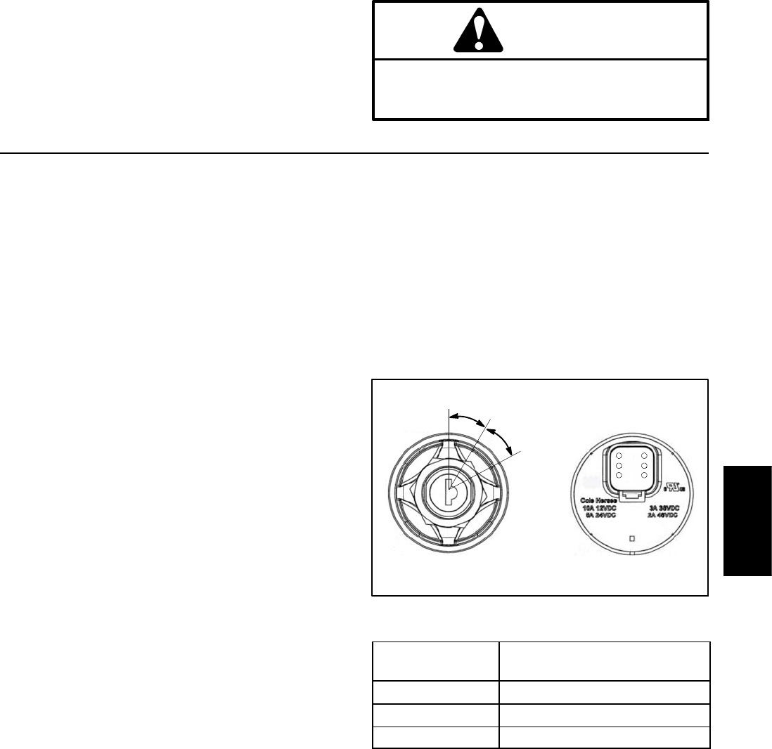
Groundsmaster 4100--D/4110--D Page 5 -- 31 Electrical System
Component Testing
For accurate resistance and/or continuity checks, elec-
trically disconnect the component being tested from the
circuit (e.g. unplug the ignition switch connector before
doing a continuity check).
NOTE: For engine component testing information, see
the Yanmar Service Manual and Yanmar Troubleshoot-
ing Manual.
CAUTION
When testing electrical components for continu-
ity with a multimeter (ohms setting), make sure
that power to the circuit has been disconnected.
Ignition Switch
The ignition (key) switch is located on the control panel
and has three (3) positions: STOP, RUN and START
(Fig. 28). The Toro Electronic Controller (TEC) monitors
the operation of the ignition switch.
Testing
1. Park machine on a level surface, lower cutting deck,
engage parking brake and stop engine. Remove key
from ignition switch.
2. Before disconnecting the ignition switch for testing,
the switch and its circuit wiring should be tested as a
TEC electrical input using the InfoCenter Display (see
InfoCenter Display in this chapter). If input testing veri-
fies that the ignition switch and circuit wiring are func-
tioning correctly, no further ignition switch testing is
necessary. If, however, input testing determines that the
ignition switch and circuit wiring are not functioning cor-
rectly, proceed with the following ignition switch testing
procedure.
3. Remove control arm covers to gain access to ignition
switch (see Control Arm in the Service and Repairs sec-
tion of Chapter 7 -- Chassis).
4. Make sure ignition switch is in the OFF position. Dis-
connect wire harness connector from ignition switch.
5. The ignition switch terminals are identified in Figure
28 and the circuitry of the switch is shown in the chart in
Figure 29. With the use of a multimeter (ohms setting),
the switch functions can be tested to determine whether
continuity exists between the various terminals for each
switch position. Verify continuity between switch termi-
nals.
6. Replace ignition switch if testing determines that it is
faulty.
7. If the ignition switch tests correctly and a circuit prob-
lem still exists, check wire harness (see Electrical Sche-
matics and Wire Harness Drawings in Chapter 10 --
Foldout Drawings).
8. After testing is complete, connect machine wire har-
ness connector to ignition switch. Secure control arm
covers to machine with removed fasteners (see Control
Arm in the Service and Repairs section of Chapter 7 --
Chassis).
Figure 28
REAR VIEW
FRONT VIEW
START
STOP
RUN
3
2
4
5
61
SWITCH
POSITION CIRCUITS
STOP 1+6
RUN 1+3+4+5+6
START 1+2+4+5+6
Figure 29
NOTE: Ignition switch terminals 1 and 6 are connected
internally. Terminals 4 and 5 are also connected internal-
ly. These terminals should have continuity regardless of
switch position.
Electrical
System
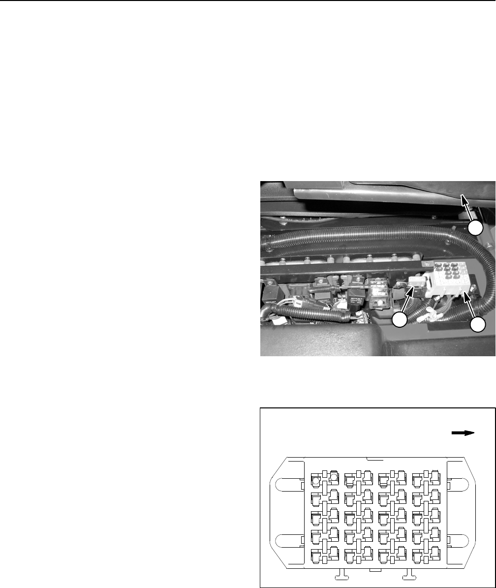
Groundsmaster 4100--D/4110--DPage 5 -- 32Electrical System
Fuses
The fuse block is located under the controller cover next
to the operator seat (Fig. 30).
In addition to the fuses in the fuse block, a 60 Amp fuse
is included in the wire harness to protect the power cir-
cuit for the operator cab. This fuse resides in a fuse hold-
er near the fuse block (Fig. 30).
Fuse Identification and Function
UseFigure31toidentifyeachindividualfuseanditscor-
rect amperage in the fuse block. The fuses have the fol-
lowing functions.
FuseA--1(7.5Amp)protects power supply for the out-
puts of the front TEC controller.
FuseA--2(7.5Amp)protects power supply for the out-
puts of the rear TEC controller.
Fuse A--3 (10 Amp) protects turn signal light circuit (if
equipped on models 30602 and 30604).
Fuse A--4 (10 Amp) protects headlight circuit (if
equipped).
FuseB--1(7.5Amp)protects power supply for the out-
puts of the front TEC controller.
FuseB--2(7.5Amp)protects power supply for the out-
puts of the rear TEC controller.
Fuse B--3 (10 Amp) protects power supply to the engine
ECU.
Fuse B--4 (10 Amp) protects operator air--ride seat cir-
cuit.
FuseC--1(7.5Amp)protects power supply for the out-
puts of the front TEC controller.
FuseC--2(7.5Amp)protects power supply for the out-
puts of the rear TEC controller.
Fuse C--3 (10 Amp) protects main power supply circuit.
Fuse C--4 (10 Amp) protects power point circuit.
FuseD--1(2Amp)protects logic power circuit to the
front TEC controller.
FuseD--2(2Amp)protects logic power circuit to the
rear TEC controller.
FuseD--3(2Amp)protects power supply for the In-
foCenter display.
Fuse D--4 (10 Amp) protects power supply for the horn
(if equipped).
Fuse Testing
Turn ignition switch to the RUN position (do not start en-
gine). With the fuse installed in the fuse block, use a
multimeter to verify that 12 VDC exists at both of the ter-
minal test points on the fuse. If 12 VDC exists at one of
the fuse test points but not at the other, the fuse is faulty.
If fuse removal is necessary, make sure that ignition
switch is OFF and key is removed from switch. Remove
fuse from fuse block and check that fuse has continuity
across the fuse terminals.
Figure 30
1. Fuse block
2. 60 Amp fuse
3. Operator seat
1
2
3
Figure 31
AB
1
2
3
4
CD
FRONT
5
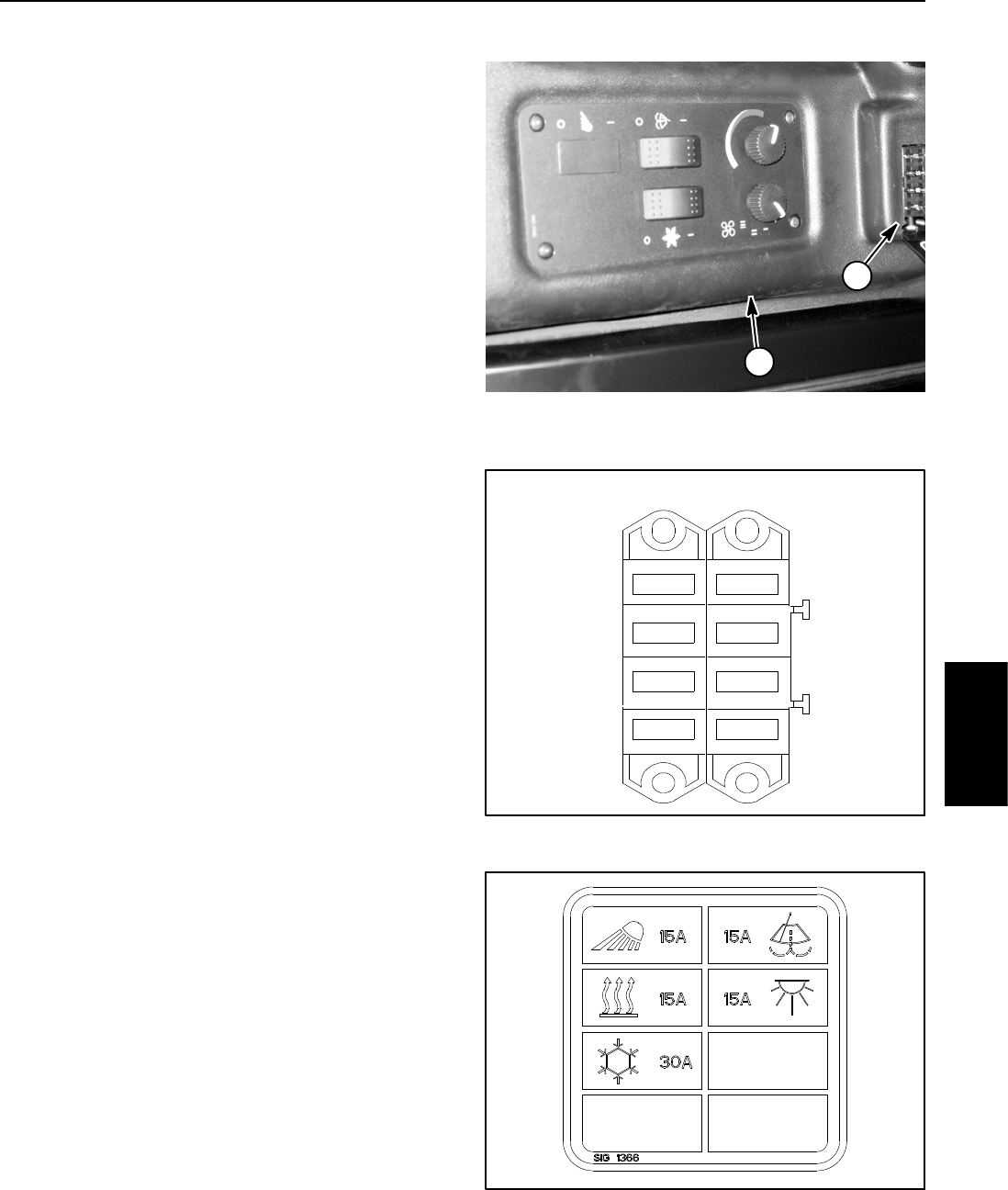
Groundsmaster 4100--D/4110--D Page 5 -- 33 Electrical System
Operator Cab Fuses (Groundsmaster 4110--D)
The operator cab fuse blocks are located in the cab
headliner (Fig. 32).
Identification and Function (Figs. 33 and 34)
Fuse F1--2 (15 Amp) protects the cab fan circuit.
Fuse F1--3 (30 Amp) protects the air conditioner circuit.
Fuse F2--1 (15 Amp) protects the windshield wiper/
washer circuit.
Fuse F2--2 (15 Amp) protects the cab dome light circuit.
Fuses F1--1, F1--4, F2--3 and F2--4 are available for op-
tional equipment.
Testing
Turn ignition switch to the RUN position (do not start en-
gine). With the fuse installed in the fuse block, use a
multimeter to verify that 12 VDC exists at both of the ter-
minal test points on the fuse. If 12 VDC exists at one of
the fuse test points but not at the other, the fuse is faulty.
If necessary, make sure that ignition switch is OFF and
key is removed from switch. Remove fuse from fuse
block and check that fuse has continuity across the fuse
terminals.
Figure 32
1. Cab headliner 2. Cab fuse blocks
1
2
Figure 33
1
2
3
4
30A
F1 F2
15 A
15 A
15 A
Figure 34
Electrical
System
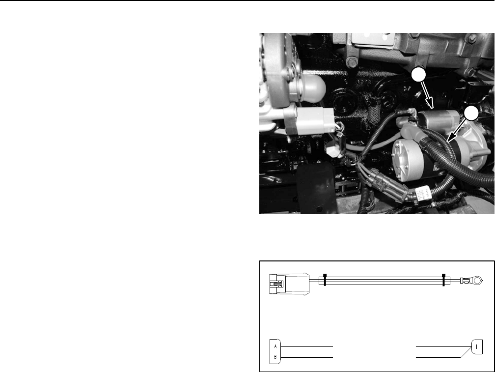
Groundsmaster 4100--D/4110--DPage 5 -- 34Electrical System
Fusible Link Harness
Your Groundsmaster uses two (2) fusible links for circuit
protection. These fusible links are located in a harness
that connects the starter B+ terminal to the wire harness
(Fig. 35). If either of these links should fail, current to the
protected circuits will cease. Refer to wire harness
drawings in Chapter 10 -- Foldout Drawings for addition-
al fusible link information.
Testing
Make sure that ignition switch is OFF. Disconnect nega-
tive battery cable from battery terminal and then discon-
nect positive cable from battery (see Battery Service in
the Service and Repairs section of this chapter). Locate
and unplug fusible link connector from machine wire
harness. Use a multimeter to make sure that continuity
exists between the fusible link terminals. If either fusible
link is open, replace the fusible link harness.
NOTE: It is not recommended to replace individual fus-
ible link conductors of the fusible link harness. If any of
the harness links are open (failed), replace the entire
fusible link harness.
After fusible link testing is complete, make sure that fus-
ible link harness is securely attached to starter B+ termi-
nal and wire harness. Connect positive battery cable to
battery terminal first and then connect negative cable to
battery.
1. Starter motor 2. Fusible link harness
Figure 35
2
1
Figure 36
FUSIBLE LINK (14 GAUGE)
FUSIBLE LINK (16 GAUGE)
P01
STARTER B+
P02
TO MAIN HARNESS
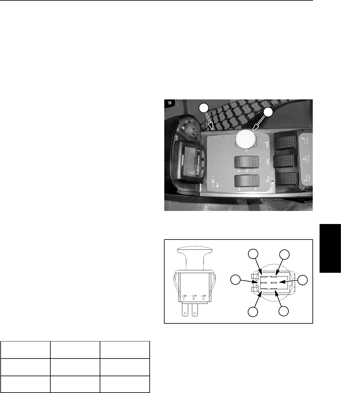
Groundsmaster 4100--D/4110--D Page 5 -- 35 Electrical System
PTO Switch
The PTO switch is located on the control arm (Fig. 37).
The PTO switch is pulled up to engage the PTO and
pushed in to disengage the PTO.
The TEC controller monitors the position of the PTO
switch (up or down). Using inputs from the PTO switch
and other switches in the interlock system, the TEC con-
troller controls the energizing of the hydraulic solenoid
valves used to drive the cutting deck motors.
NOTE: To engage the PTO, the seat has to be occu-
pied, traction speed has to be in LOW range and the cut-
ting deck has to be fully lowered.
Testing
1. Before disconnecting the PTO switch for testing, the
switch and its circuit wiring should be tested as a TEC
input with the InfoCenter Display (see InfoCenter Dis-
play in this chapter). If the InfoCenter verifies that the
PTO switch and circuit wiring are functioning correctly,
no further switch testing is necessary. If, however, the In-
foCenter determines that the PTO switch and circuit wir-
ing are not functioning correctly, proceed with test.
2. Make sure ignition switch is OFF. Remove key from
ignition switch.
3. Disassemble control arm to gain access to PTO
switch (see Control Arm in the Service and Repairs sec-
tion of Chapter 7 -- Chassis).
4. Disconnect harness electrical connector from the
PTO switch.
5. The switch terminals are marked as shown in Figure
38. The circuit logic of the PTO switch is shown in the
chart below. With the use of a multimeter (ohms setting),
the switch functions can be tested to determine whether
continuity exists between the various terminals for each
switch position. Verify continuity between switch termi-
nals. Replace PTO switch if testing identifies that switch
is faulty.
SWITCH
POSITION
CLOSED
CIRCUITS
OPEN
CIRCUITS
OFF (DOWN) COM B + NC B
COM C + NC C
COM B + NO B
COM C + NO C
ON (UP) COM B + NO B
COM C + NO C
COM B + NC B
COM C + NC C
6. If PTO switch tests correctly and circuit problem still
exists, check wire harness (see Electrical Schematics
and Wire Harness Drawings in Chapter 10 -- Foldout
Drawings).
7. After testing is completed, connect the wire harness
connector to the PTO switch.
8. Assemble control arm (see Control Arm in the Ser-
vice and Repairs section of Chapter 7 -- Chassis).
1. Control arm 2. PTO switch
Figure 37
2
1
1. COM B terminal
2. NO B terminal
3. NC B terminal
4. COM C terminal
5. NO C terminal
6. NCCterminal
Figure 38
2
3
1
6
4
5
NOTE: Only PTO switch terminals COM C and NO C
are used on Groundsmaster 4100--D and 4110--D ma-
chines.
Electrical
System
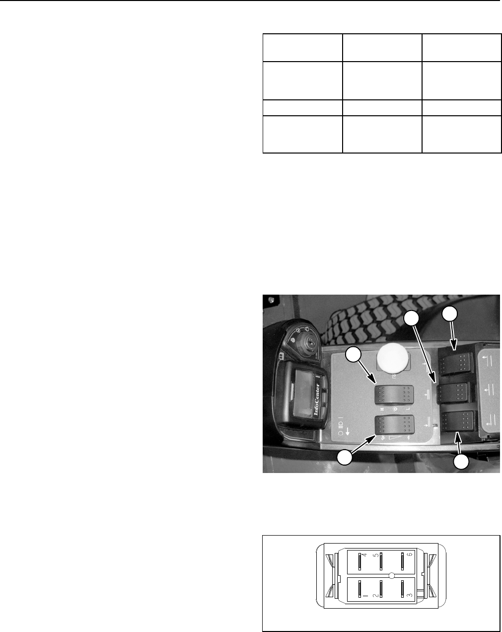
Groundsmaster 4100--D/4110--DPage 5 -- 36Electrical System
HI/LOW Speed, Engine Speed and Cutting Deck Lift Switches
The HI/LOW, engine speed and cutting deck lift
switches are all identical momentary switches. These
switches are located on the control arm (Fig. 39).
The HI/LOW speed switch is used as an input for the
TEC controller to select either the HI (transport) or LOW
(mow) traction speed.
The engine speed switch is used as an input for the en-
gine electronic control unit to raise or lower the engine
speed. When the switch is depressed and held in the for-
ward position, the engine speed will increase. Con-
versely, when the rear of the switch is depressed, engine
speed will decrease.
The cutting deck lift switches are used as inputs for the
TEC controller to raise or lower the cutting deck sec-
tions. When the front of a lift switch is depressed, the
controlled deck section will lower. When the rear of a lift
switch is depressed and held, the controlled deck sec-
tions will raise.
NOTE: To raise or lower the deck sections, the operator
seat has to be occupied. Also, to lower the cutting deck
sections, the traction speed has to be in LOW (mow)
range.
Testing
1. Before disconnecting a switch for testing, the switch
and its circuit wiring should be tested as a TEC input with
the InfoCenter Display (see InfoCenter Display in this
chapter). If the InfoCenter verifies that the switch and
circuit wiring are functioning correctly, no further switch
testing is necessary. If, however, the InfoCenter deter-
mines that the switch and circuit wiring are not function-
ing correctly, proceed with test.
2. Make sure ignition switch is OFF. Remove key from
ignition switch.
3. Disassemble control arm to gain access to switch
that is to be tested (see Control Arm in the Service and
Repairs section of Chapter 7 -- Chassis).
4. Disconnect harness electrical connector from the
switch that is to be tested.
5. The switch terminals are marked as shown in Figure
40. The circuit logic of the switch is shown in the chart
below. With the use of a multimeter (ohms setting), the
switch functions may be tested to determine whether
continuity exists between the various terminals for each
position. Verify continuity between switch terminals. Re-
place switch if testing identifies a faulty switch.
SWITCH
POSITION
CLOSED
CIRCUITS
OPEN
CIRCUITS
FRONT OF
SWITCH
PRESSED
2+3
5+6
2+1
5+4
NEUTRAL NONE ALL
REAR OF
SWITCH
PRESSED
2+1
5+4
2+3
5+6
6. If switch tests correctly and circuit problem still ex-
ists, check wire harness (see Electrical Schematics and
Wire Harness Drawings in Chapter 10 -- Foldout Draw-
ings).
7. After testing is completed, connect wire harness
connector to the switch.
8. Assemble control arm (see Control Arm in the Ser-
vice and Repairs section of Chapter 7 -- Chassis).
1. HI/LOW speed switch
2. Engine speed switch
3. RH deck lift switch
4. Center deck lift switch
5. LH deck lift switch
Figure 39
2
1
3
5
4
Figure 40
BACK OF SWITCH
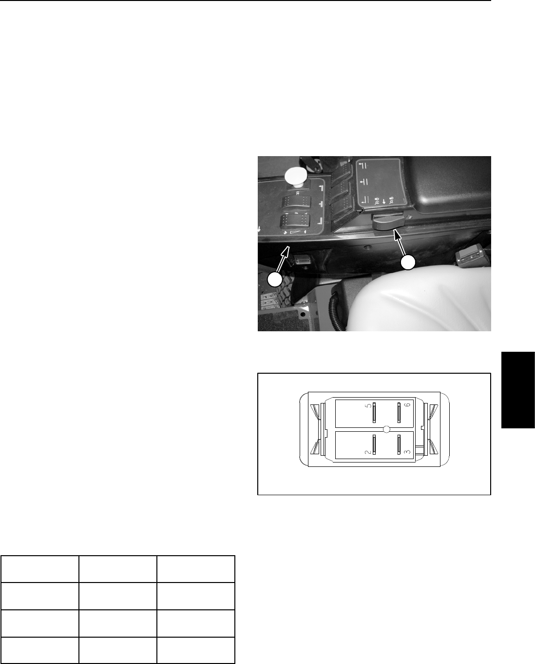
Groundsmaster 4100--D/4110--D Page 5 -- 37 Electrical System
Cruise Control Switch
The cruise control switch is used as an input for the TEC
controller to maintain ground speed when engaged. The
cruise control function is enabled when the switch is in
the ON (center) position. Pressing the front of the switch
to the momentary position sets the desired ground
speed. The cruise control function is disengaged when
the rear of the cruise control switch is depressed. On
machine with serial number below 314000000, the
cruise control switch is located on the operator side of
the console arm (as shown in Fig. 41). On machine with
serial number above 314000000, the cruise control
switch is located on the outside the console arm.
NOTE: The cruise control function can also be disen-
gaged if either brake pedal is pressed or if the traction
pedal is pressed and held in the reverse direction.
Testing
1. Before disconnecting the cruise control switch for
testing, the switch and its circuit wiring should be tested
as a TEC input with the InfoCenter Display (see In-
foCenter Display in this chapter). If the InfoCenter Dis-
play verifies that switch and circuit wiring are functioning
correctly, no further switch testing is necessary. If, how-
ever, the Display determines that the switch and circuit
wiring are not functioning correctly, proceed with test.
2. Make sure ignition switch is OFF. Remove key from
ignition switch.
3. Disassemble control arm to gain access to the cruise
control switch (see Control Arm in the Service and Re-
pairs section of Chapter 7 -- Chassis).
4. Disconnect harness electrical connector from the
switch.
5. With the use of a multimeter (ohms setting), the
switch functions may be tested to determine whether
continuity exists between the various terminals for each
position. The switch terminals are marked as shown in
Figure 42. The circuitry of the cruise control switch is
shown in the chart below. Verify continuity between
switch terminals.
SWITCH
POSITION
CLOSED
CIRCUITS
OPEN
CIRCUITS
CRUISE
DISENGAGE
NONE ALL
CRUISE ON
(CENTER)
2+3 5+6
SPEED SET
(MOMENTARY)
2+3
5+6
NONE
6. If switch tests correctly and circuit problem still ex-
ists, check wire harness (see Electrical Schematics and
Wire Harness Drawings in Chapter 10 -- Foldout Draw-
ings).
7. After testing is completed, connect wire harness
connector to the cruise control switch.
8. Assemble control arm (see Control Arm in the Ser-
vice and Repairs section of Chapter 7 -- Chassis).
1. Control arm 2. Cruise control switch
Figure 41
1
2
Figure 42
BACK OF SWITCH
Electrical
System
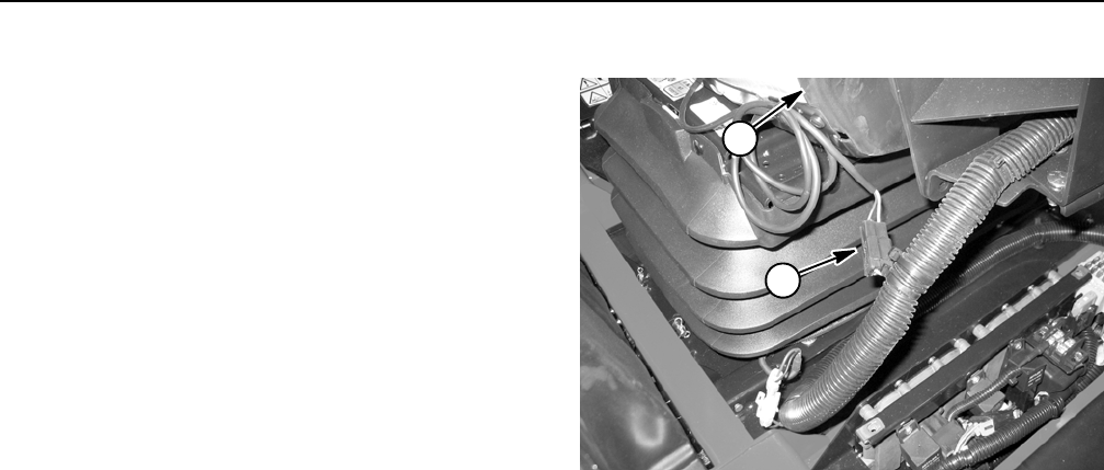
Groundsmaster 4100--D/4110--DPage 5 -- 38Electrical System
Seat Switch
The seat switch is normally open and closes when the
operator is on the seat. This switch is used as an input
for the TEC controller. The seat switch and its electrical
connector are located in the seat assembly. If the trac-
tion system or PTO switch is engaged when the operator
raises out of the seat, an operator advisory will be dis-
played on the InfoCenter. Testing of the switch can be
done without seat removal by disconnecting the switch
wire from the machine wire harness (Fig. 43).
Testing
1. Before disconnecting the seat switch for testing, the
switch and its circuit wiring should be tested as a TEC
input with the InfoCenter Display (see InfoCenter Dis-
play in this chapter). If the InfoCenter verifies that the
seat switch and circuit wiring are functioning correctly,
no further switch testing is necessary. If, however, the In-
foCenter determines that the seat switch and circuit wir-
ing are not functioning correctly, proceed with test.
2. Make sure ignition switch is OFF. Remove key from
ignition switch.
3. Disconnect seat switch connector from the machine
wire harness connector.
4. Check the continuity of the switch by connecting a
multimeter (ohms setting) across the seat switch con-
nector terminals.
5. With no pressure on the seat, there should be no
continuity between the seat switch terminals.
6. Press directly onto the seat switch through the seat
cushion. There should be continuity as the seat cush-
ion approaches the bottom of its travel.
7. If testing determines that seat switch is faulty, re-
place seat switch (see Operator Seat Service in the Ser-
vice and Repairs section of Chapter 7 -- Chassis).
8. Connect seat switch connector to wire harness con-
nector after testing is complete.
1. Seat switch electrical connector
2. Operator seat
Figure 43
1
2
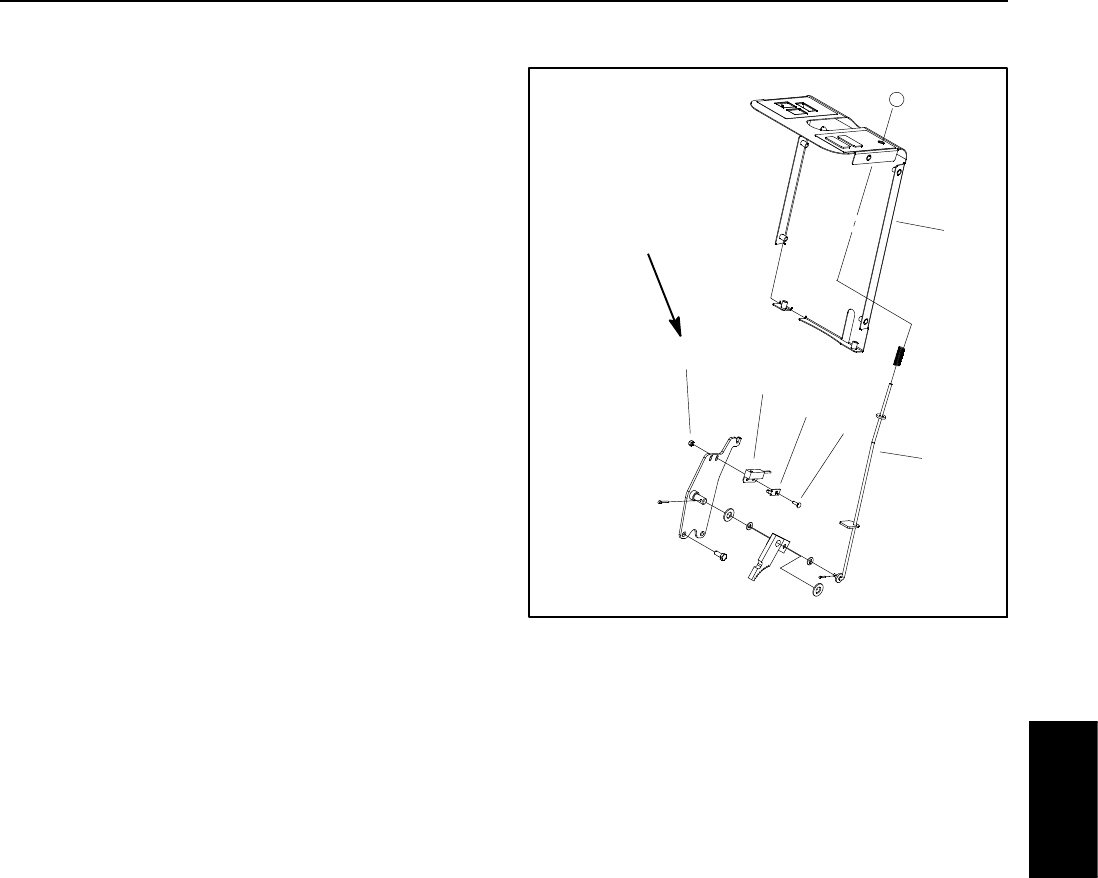
Groundsmaster 4100--D/4110--D Page 5 -- 39 Electrical System
Parking Brake Switch
Theswitchusedfortheparkingbrakeisanormallyopen
proximity switch that is located under the steering tower
cover (Fig. 44). The parking brake switch is an input for
the TEC controller. When the parking brake is not ap-
plied, a tab on the brake rod is positioned near the switch
sense zone which causes the switch to close (continu-
ity). When the parking brake is applied,thebrakerodtab
is positioned away from the switch allowing the switch
to be in its normal, open position (no continuity).
Switch Testing
1. Before disconnecting the parking brake switch for
testing, the switch and its circuit wiring should be tested
as a TEC input with the InfoCenter Display (see In-
foCenter Display in this chapter). If the InfoCenter veri-
fies that the brake switch and circuit wiring are
functioning correctly, no further switch testing is neces-
sary. If, however, the InfoCenter determines that the
brake switch and circuit wiring are not functioning cor-
rectly, proceed with test.
2. Make sure ignition switch is OFF. Remove key from
ignition switch.
3. Remove front steering tower cover (see Steering
Tower in the Service and Repairs section of Chapter 7
-- Chassis).
4. Locate parking brake switch and unplug wire har-
ness connector from switch.
5. Check the continuity of the switch by connecting a
multimeter (ohms setting) across the connector termi-
nals.
6. When the parking brake is not applied (brake rod tab
close to brake switch), there should be continuity (zero
resistance) between the switch terminals.
7. When the parking brake is applied (brake rod tab
away from brake switch), there should be no continuity
(infinite resistance) between the switch terminals.
8. Replace parking brake switch if necessary.
9. Correctly connect the wire harness connector to the
parking brake switch after testing is completed.
10.Install front steering tower cover (see Steering Tower
in the Service and Repairs section of Chapter 7 -- Chas-
sis).
Switch Adjustment
With the parking brake not applied (brake rod tab near
the switch), there should be a 0.062” (1.6 mm) gap be-
tween the switch and the brake rod tab.
1. Lock nut
2. Parking brake switch
3. Switch plate
4. Carriage bolt
5. Parking brake rod
6. Steering tower cover
Figure 44
34 to 42 in--lb
(3.9 to 4.7 N--m)
2
3
6
1
5
4
Electrical
System
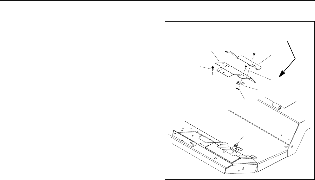
Groundsmaster 4100--D/4110--DPage 5 -- 40Electrical System
Service Brake Switches
The two (2) switches used for the service brakes are nor-
mally open switches that are located under the footrest
panel (Fig. 45). The service brake switches provide in-
puts for the TEC controller. When a brake pedal is not
depressed, the brake pedal assembly contacts the
switch plunger to close the switch. When a brake is ap-
plied, the brake pedal assembly moves away from the
switch plunger, allowing the switch plunger to extend
and the switch to open.
Testing
1. Before disconnecting a service brake switch for test-
ing, the switch and its circuit wiring should be tested as
a TEC input with the InfoCenter Display (see InfoCenter
Display in this chapter). If the InfoCenter verifies that the
brake switch and circuit wiring are functioning correctly,
no further switch testing is necessary. If, however, the In-
foCenter determines that the brake switch and circuit
wiring are not functioning correctly, proceed with test.
2. Make sure ignition switch is OFF. Remove key from
ignition switch.
3. Remove brake cover and switch plate on operator
platform to access service brake switches (Fig. 45).
4. Disconnect switch electrical connector from the ma-
chine wire harness.
5. Check the continuity of the switch by connecting a
multimeter (ohms setting) across the connector termi-
nals.
6. When the service brake switch plunger is depressed,
there should be continuity (zero resistance) between
theswitchterminals.
7. When the service brake switch plunger is extended,
there should be no continuity (infinite resistance) be-
tween the switch terminals.
8. Replace service brake switch if necessary.
9. Connect switch electrical connector to the machine
wire harness after testing. Secure brake cover and
switch plate to operator platform.
Adjustment
Adjust the service brake switch so that the switch plung-
er always makes full contact with the brake pedal. Tight-
en fasteners from 13 to 17 in--lb (1.5 to 1.9 N--m).
1. Flange screw (3 used)
2. Cover
3. Switch bracket
4. Brake switch (2 used)
5. Screw (2 per switch)
6. Switch nut (2 used)
7. Clip (3 used)
Figure 45
13 to 17 in--lb
(1.5 to 1.9 N--m)
1
3
5
2
4
6
7
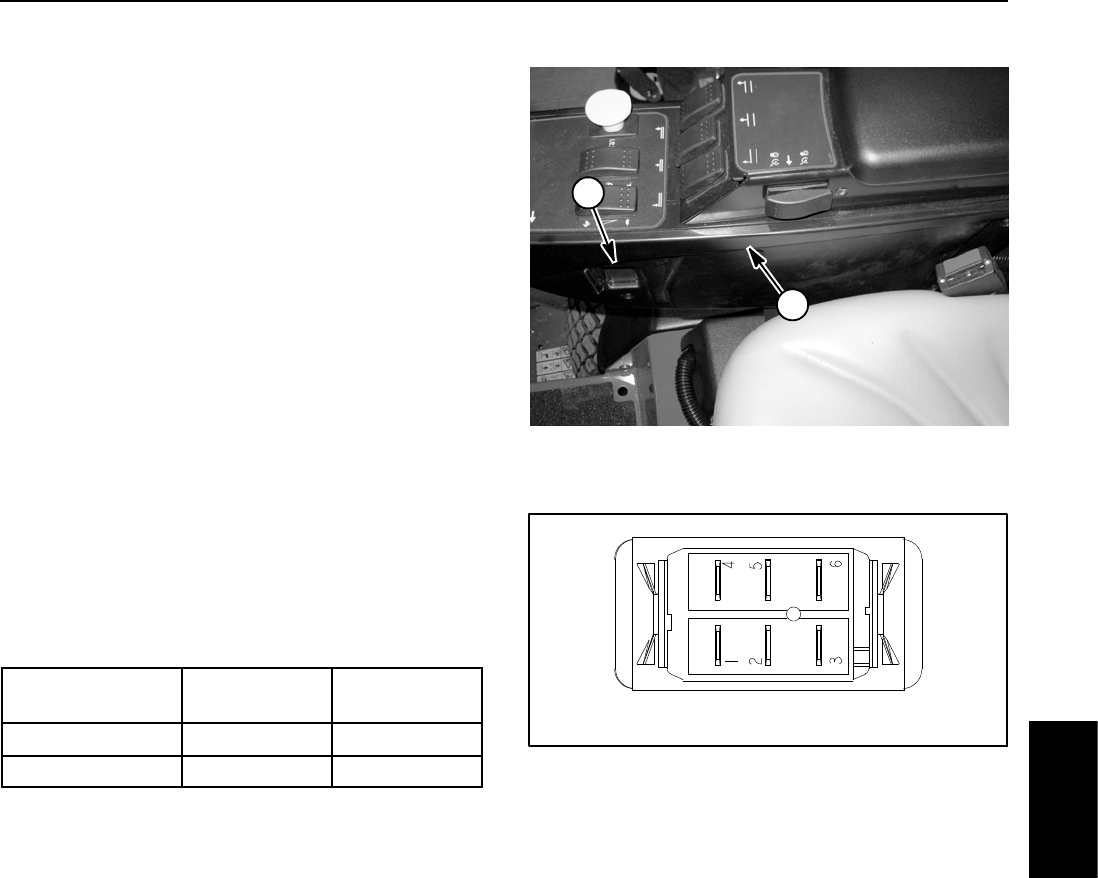
Groundsmaster 4100--D/4110--D Page 5 -- 41 Electrical System
Headlight Switch (Groundsmaster 4110--D)
The Groundsmaster 4110--D headlight switch is a two
(2) position rocker switch that is located on the inside of
the control arm (Fig. 46). The headlight switch allows the
headlights and taillights to be turned on and off.
Testing
1. Make sure ignition switch is OFF. Remove key from
ignition switch.
2. Disassemble control arm to gain access to headlight
switch (see Control Arm in the Service and Repairs sec-
tion of Chapter 7 -- Chassis).
3. Disconnect harness electrical connector from the
headlight switch.
4. With the use of a multimeter (ohms setting), the
switch functions may be tested to determine whether
continuity exists between the various terminals for each
switch position. The switch terminals are marked as
showninFigure47.Thecircuitryoftheswitchisshown
in the chart below. Verify continuity between switch ter-
minals. Replace switch if testing identifies a faulty
switch.
SWITCH
POSITION CIRCUIT 1 CIRCUIT 2
ON 2+3 5+6
OFF 2+1 5+4
5. If the headlight switch tests correctly and circuit prob-
lem still exists, check wire harness (see Electrical Sche-
matics and Wire Harness Drawings in Chapter 10 --
Foldout Drawings).
6. After testing is completed, connect wire harness
connector to the headlight switch.
7. Assemble control arm (see Control Arm in the Ser-
vice and Repairs section of Chapter 7 -- Chassis).
1. Control arm 2. Headlight switch
Figure 46
1
2
Figure 47
BACK OF SWITCH
NOTE: Switch terminals 1, 4, 5 and 6 are not used on
Groundsmaster 4110--D machines.
Electrical
System
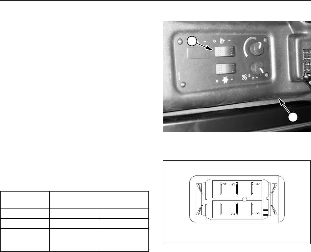
Groundsmaster 4100--D/4110--DPage 5 -- 42Electrical System
Windshield Wiper/Washer Switch (Groundsmaster 4110--D)
The windshield wiper/washer switch is used to control
operation of the windshield wiper and washer pump on
the Groundsmaster 4110--D. The windshield wiper/wa-
sher switch is located in the cab headliner (Fig. 48).
Testing
1. Make sure ignition switch is OFF. Remove key from
ignition switch.
2. Remove switch plate from cab headliner.
3. Locate windshield wiper/washer switch and unplug
wire harness connector from switch.
4. The switch terminals are marked as shown in Figure
49. The circuit logic of the wiper/washer switch is shown
in the chart below. With the use of a multimeter (ohms
setting), the switch functions may be tested to determine
whether continuity exists between the various terminals
for each position. Verify continuity between switch termi-
nals. Replace wiper/washer switch if testing identifies a
faulty switch.
SWITCH
POSITION
CLOSED
CIRCUITS
OPEN
CIRCUITS
OFF 2+1 5+6
WIPER ON 2+3 5+6
WASHER and
WIPER ON
(MOMENTARY)
2+3
5+6
2+1
5. If switch tests correctly and circuit problem still ex-
ists, check wire harness (see Electrical Schematics and
Wire Harness Drawings in Chapter 10 -- Foldout Draw-
ings).
6. Connect the wire harness connector to the switch af-
ter testing.
7. Install switch plate to cab headliner after switch test-
ing is complete.
1. Cab headliner 2. Wiper/washer switch
Figure 48
1
2
Figure 49
BACK OF SWITCH
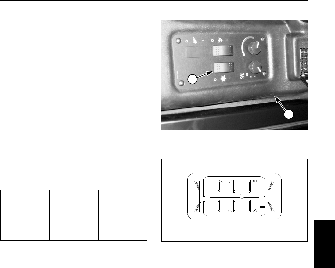
Groundsmaster 4100--D/4110--D Page 5 -- 43 Electrical System
Air Conditioning Switch (Groundsmaster 4110--D)
The air conditioning switch is used to control operation
of the air conditioning system on the Groundsmaster
4110--D. The switch is located in the cab headliner (Fig.
50).
Testing
1. Make sure ignition switch is OFF. Remove key from
ignition switch.
2. Remove switch plate from cab headliner.
3. Locate air conditioning switch and unplug wire har-
ness connector from switch.
4. The switch terminals are marked as shown in Figure
51. The circuit logic of the air conditioning switch is
shown in the chart below. With the use of a multimeter
(ohms setting), the switch functions may be tested to de-
termine whether continuity exists between the various
terminals for each position. Verify continuity between
switch terminals. Replace switch if testing identifies a
faulty switch.
SWITCH
POSITION
CLOSED
CIRCUITS
OPEN
CIRCUITS
AC OFF 2+1
5+4
2+3
5+6
AC ON 2+3
5+6
2+1
5+4
5. If switch tests correctly and circuit problem still ex-
ists, check wire harness (see Electrical Schematics and
Wire Harness Drawings in Chapter 10 -- Foldout Draw-
ings).
6. Connect the wire harness connector to the air condi-
tioningswitchaftertesting.
7. Install switch plate to cab headliner after switch test-
ing is complete.
1. Cab headliner 2. Air conditioning switch
Figure 50
1
2
Figure 51
BACK OF SWITCH
Electrical
System
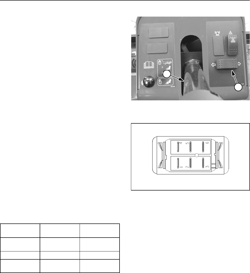
Groundsmaster 4100--D/4110--DPage 5 -- 44Electrical System
Turn Signal Switch (Groundsmaster 4110--D)
On Groundsmaster 4110--D machines, the turn signal
switch is used as an input for the TEC controller to pro-
vide power for the turn signals. The switch is located on
the steering tower (Fig. 52).
Testing
1. Before disconnecting the turn signal switch for test-
ing, the switch and its circuit wiring should be tested as
a TEC input with the InfoCenter Display (see InfoCenter
Display in this chapter). If the InfoCenter verifies that the
turn signal switch and circuit wiring are functioning cor-
rectly, no further switch testing is necessary. If, however,
the InfoCenter determines that the turn signal switch
and circuit wiring are not functioning correctly, proceed
with test.
2. Make sure ignition switch is OFF. Remove key from
ignition switch.
3. Remove front steering tower cover (see Steering
Tower in the Service and Repairs section of Chapter 7
-- Chassis).
4. Locate turn signal switch and unplug wire harness
connector from switch.
5. The switch terminals are marked as shown in Figure
53. The circuit logic of the turn signal switch is shown in
the chart below. With the use of a multimeter (ohms set-
ting), the switch functions may be tested to determine
whether continuity exists between the various terminals
for each position. Verify continuity between switch termi-
nals. Replace turn signal switch if testing identifies a
faulty switch.
SWITCH
POSITION
CLOSED
CIRCUITS
OPEN
CIRCUITS
RIGHT
TURN
2+3
5+6
2+1
5+4
NEUTRAL NONE ALL
LEFT
TURN
2+1
5+4
2+3
5+6
6. Connect the harness connector to the switch after
testing.
7. If switch tests correctly and circuit problem still ex-
ists, check wire harness (see Electrical Schematics and
Wire Harness Drawings in Chapter 10 -- Foldout Draw-
ings).
8. Install front steering tower cover (see Steering Tower
in the Service and Repairs section of Chapter 7 -- Chas-
sis).
1. Steering column 2. Turn signal switch
Figure 52
1
2
Figure 53
BACK OF SWITCH
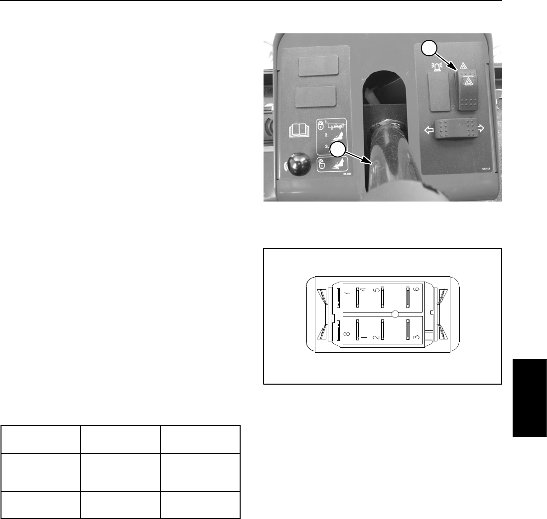
Groundsmaster 4100--D/4110--D Page 5 -- 45 Electrical System
Flasher Switch (Groundsmaster 4110--D)
On Groundsmaster 4110--D machines, the flasher
switch is used as an input for the TEC controller to pro-
vide power for the four way flashers. The switch is lo-
cated on the steering tower (Fig. 54).
Testing
1. Before disconnecting the flasher switch for testing,
the switch and its circuit wiring should be tested as a
TEC input with the InfoCenter Display (see InfoCenter
Display in this chapter). If the InfoCenter verifies that the
flasher switch and circuit wiring are functioning correct-
ly, no further switch testing is necessary. If, however, the
InfoCenter determines that the flasher switch and circuit
wiring are not functioning correctly, proceed with test.
2. Make sure ignition switch is OFF. Remove key from
ignition switch.
3. Remove front steering tower cover (see Steering
Tower in the Service and Repairs section of Chapter 7
-- Chassis).
4. Locate flasher switch and unplug wire harness con-
nector from switch.
5. The switch terminals are marked as shown in Figure
55. The circuit logic of the flasher switch is shown in the
chart below. With the use of a multimeter (ohms setting),
theswitchfunctionsmaybetestedtodeterminewhether
continuity exists between the various terminals for each
position. Verify continuity between switch terminals. Re-
place flasher switch if testing identifies a faulty switch.
SWITCH
POSITION
CLOSED
CIRCUITS
OPEN
CIRCUITS
ON (LIGHT
END DE-
PRESSED)
2+3
5+6
2+1
5+4
OFF 2+1
5+4
2+3
5+6
6. Connect the harness connector to the switch after
testing.
7. If switch tests correctly and circuit problem still ex-
ists, check wire harness (see Electrical Schematics and
Wire Harness Drawings in Chapter 10 -- Foldout Draw-
ings).
8. Install front steering tower cover (see Steering Tower
in the Service and Repairs section of Chapter 7 -- Chas-
sis).
Figure 54
1. Steering column 2. Flasher switch
1
2
Figure 55
BACK OF SWITCH
Electrical
System
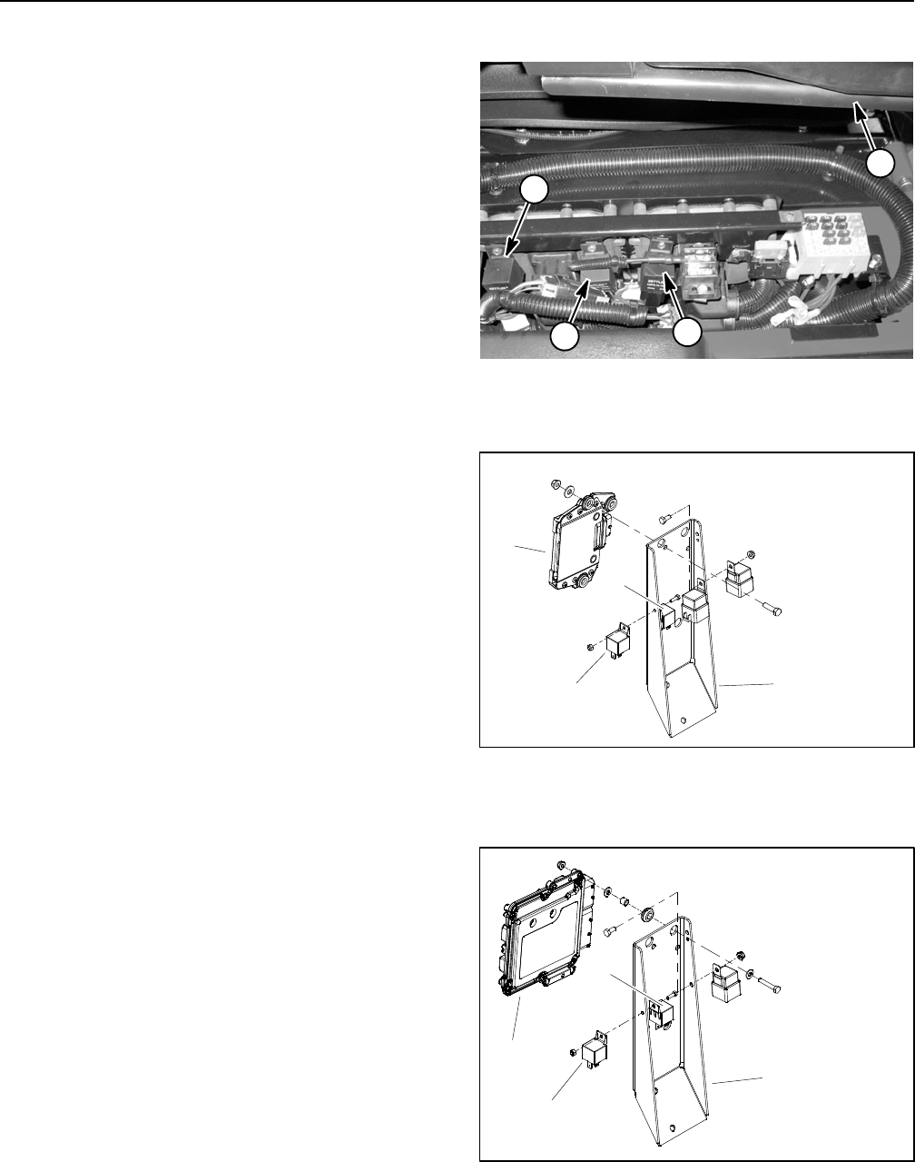
Groundsmaster 4100--D/4110--DPage 5 -- 46Electrical System
Relays with Four (4) Terminals
Your Groundsmaster uses a number of electrical relays
that have four (4) terminals. A tag near the wire harness
relay connector can be used to identify each relay.
The main power relay is used to provide current to most
of the fuse protected circuits (operator seat, InfoCenter
display, power point and optional electric equipment).
The main power relay is energized when the ignition
switch is in the RUN or START position.
The TEC power relay is used to provide current to the
fuse protected circuits for the TEC controller. The TEC
power relay is energized when the ignition switch is in
the RUN or START position.
The cab power relay is used on Groundsmaster 4110--D
machines to provide current to the operator cab electri-
cal components. The cab power relay is energized when
theignitionswitchisintheRUNorSTARTposition.
The start relay is used to provide current to the engine
starter motor solenoid. The start relay is energized by
the engine ECU.
The air heater relay is used on models 30602 and 30604
to provide current for the engine air heater used for start-
ing a cold engine. When necessary, the air heater relay
is energized by the engine ECU.
The glow relay is used on models 30606 and 30608 to
provide current to the engine glow plugs when ener-
gized by the engine ECU.
The main power, TEC power and cab power relays are
located under the controller cover next to the operator
seat (Fig. 56). The start, air heater and glow relays are
attached to the controller mount on the right side of the
engine (Fig. 57 or 58).
Testing
1. Parkmachineonalevelsurface, lower cutting deck,
stop engine, engage parking brake and remove key
from the ignition switch.
2. To make sure that machine operation does not occur
unexpectedly, disconnect negative (--) cable from bat-
tery and then disconnect positive (+) cable from battery
(see Battery Service in the Service and Repairs section
of this chapter).
3. Locate relay that is to be tested.
4. Disconnect wire harness connector from relay. Re-
move relay from mounting bracket for testing.
1. Main power relay
2. TEC power relay
3. Cab power relay
4. Operator seat
Figure 56
1
2
4
3
1. Controller mount
2. Engine ECU
3. Start relay
4. Airheaterrelay
Figure 57
MODELS 30602 AND 30604
1
3
2
4
1. Controller mount
2. Engine ECU
3. Start relay
4. Glow relay
Figure 58
MODELS 30606 AND 30608
2
3
1
4

Groundsmaster 4100--D/4110--D Page 5 -- 47 Electrical System
5. Using a multimeter, verify that coil resistance be-
tween terminals 86 and 85 is approximately 72 ohms.
6. Connect multimeter (ohms setting) leads to relay ter-
minals 30 and 87. Ground terminal 86 and apply +12
VDC to terminal 85. The relay should make and break
continuity between terminals 30 and 87 as +12 VDC is
applied and removed from terminal 85.
7. Disconnect voltage and test leads from the relay ter-
minals.
8. Secure relay to mounting bracket and connect wire
harness connector to relay.
9. Secure all removed components to machine.
10.Connect positive (+) cable to battery and then con-
nect negative (--) cable to battery (see Battery Service
in the Service and Repairs section of this chapter).
Figure 59
86 87
85 30
85 86
87
30
Electrical
System
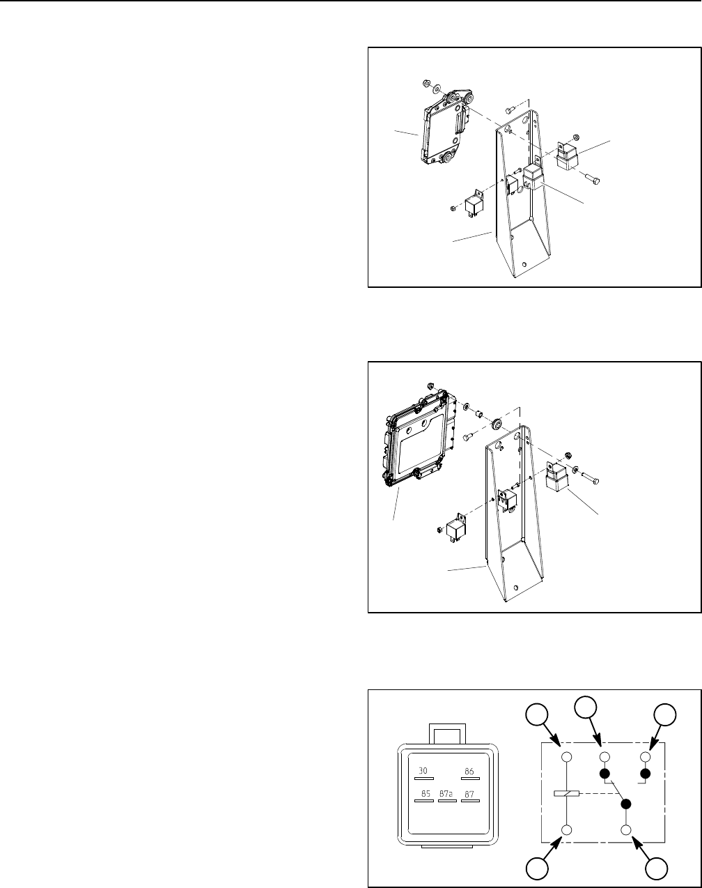
Groundsmaster 4100--D/4110--DPage 5 -- 48Electrical System
Relays with Five (5) Terminals
Your Groundsmaster uses a number of electrical relays
that have five (5) terminals. A tag near the wire harness
relay connector can be used to identify each relay.
The air conditioning relay is used to control the air condi-
tioning electrical power circuit on the Groundsmaster
4110--D. When energized by the air conditioning switch,
the relay provides current for the air conditioning com-
ponents.
The main relay is used on models 30602 and 30604 to
provide current for several engine components when
energized by the engine ECU.
The rack actuator relay is used on models 30602 and
30604 to provide current for the engine rack actuator
when energized by the engine ECU.
The EGR relay is used on models 30606 and 30608 to
provide current to the engine EGR valve when ener-
gized by the engine ECU.
The air conditioning relay is attached to the cab headlin-
er above the switch panel. The main, rack actuator and
EGR relays are attached to the controller mount on the
right side of the engine (Fig. 60 or 61).
Testing
1. Parkmachineonalevelsurface, lower cutting deck,
stop engine, engage parking brake and remove key
from the ignition switch.
2. To make sure that machine operation does not occur
unexpectedly, disconnect negative (--) cable from bat-
tery and then disconnect positive (+) cable from battery
(see Battery Service in the Service and Repairs section
of this chapter).
3. Locate relay that is to be tested.
4. Disconnect wire harness connector from relay. Re-
move relay from mounting bracket for testing.
5. Using a multimeter, verify that coil resistance be-
tween terminals 85 and 86 is from 71 to 88 ohms.
6. Connect multimeter (ohms setting) leads to relay ter-
minals 30 and 87. Ground terminal 86 and apply +12
VDC to terminal 85. The relay should make and break
continuity between terminals 30 and 87 as +12 VDC is
applied and removed from terminal 85.
7. Disconnect voltage from terminal 85 and multimeter
lead from terminal 87.
1. Controller mount
2. Engine ECU
3. Main relay
4. Rack actuator relay
Figure 60
MODELS 30602 AND 30604
1
3
2
4
1. Controller mount
2. Engine ECU
3. EGR relay
Figure 61
MODELS 30606 AND 30608
23
1
Figure 62
86
85
87A 87
30
2
134
1. Coil terminal
2. Common terminal
3. Normally closed term.
4. Normally open term.
1

Groundsmaster 4100--D/4110--D Page 5 -- 49 Electrical System
8. Connect multimeter (ohms setting) leads to relay ter-
minals 30 and 87A. Apply +12 VDC to terminal 85. The
relay should make and break continuity between termi-
nals 30 and 87A as +12 VDC is applied and removed
from terminal 85.
9. After testing, disconnect voltage and multimeter test
leads from the relay terminals. Secure relay to mounting
bracket and connect wire harness connector to relay.
10.Secure all removed components to machine.
11. Connect positive (+) cable first to battery and then
connect negative (--) cable to battery (see Battery Ser-
vice in the Service and Repairs section of this chapter).
Electrical
System
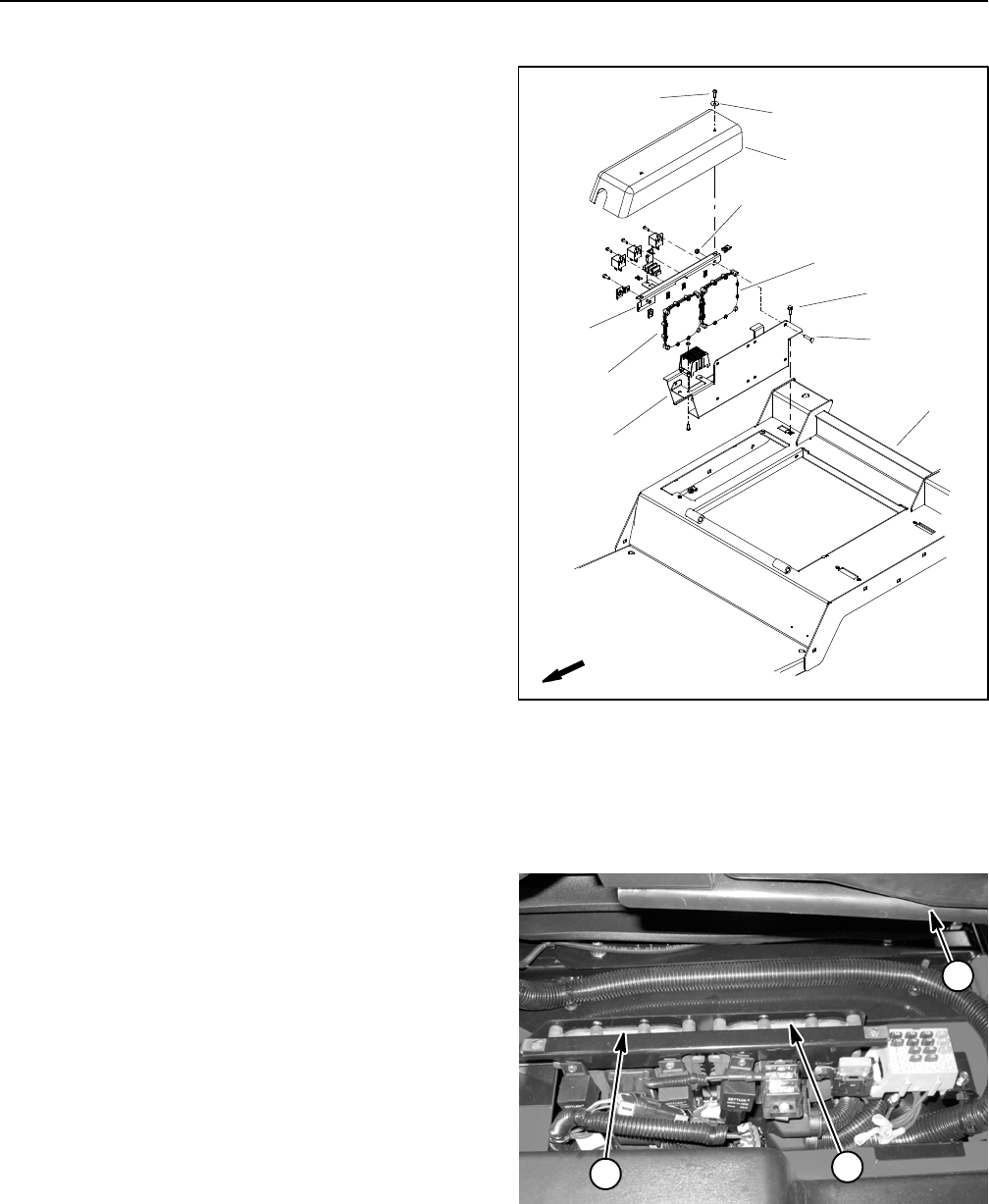
Groundsmaster 4100--D/4110--DPage 5 -- 50Electrical System
Toro Electronic Controllers (TEC)
Groundsmaster 4100--D and 4110--D machines use two
(2) Toro Electronic Controllers (TEC) to control electrical
system operation. The controllers are attached to the
operator platform under the controller cover (Figs. 63
and 64).
Logic power is provided to the controllers as long as the
battery cables are connected to the battery. A pair of 2
Amp fuses (fuse D--1 for the front controller and fuse
D--2 for the rear controller) provide circuit protection for
this logic power to the controllers.
The front TEC controller monitors the states of the fol-
lowing components as inputs: ignition switch, traction
pedal position sensor, parking brake switch, HI/LOW
speed switch, service brake switches, seat switch, en-
gine speed switch, hydraulic temperature sender, turn
signal switch (if equipped) and hazard switch (if
equipped).
The front TEC controller controls electrical output to the
engine ECU (start and run functions), fan drive solenoid
coils (direction and flow source), traction (piston) pump
solenoids (forward and reverse) and traction solenoid
coil (HI/LOW speed). Additionally, electrical outputs for
brake lights, turn lights and warning lights on Grounds-
master 4110--D machines are provided by the front TEC
controller. Circuit protection for front TEC outputs is pro-
vided by three (3) 7.5 Amp fuses (fuse locations A--1,
B--1 and C--1).
The rear TEC controller monitors the states of the fol-
lowing components as inputs: ignition switch, cutting
deck lift switches, PTO switch, cruise control switch and
wing deck position switches.
The rear TEC controller controls electrical output to the
PTO solenoid coils, lift/lower solenoid coils and fan drive
solenoid coil (speed). Circuit protection for rear TEC
outputs is provided by three (3) 7.5 Amp fuses (fuse loc-
ations A--2, B--2 and C--2).
The InfoCenter display should be used to check inputs
and outputs of the TEC controllers. Information on using
the InfoCenter is included in the InfoCenter Display sec-
tion of this chapter.
The diagram in Figure 65 depicts the connection termi-
nal functions for the TEC controllers. Note that electrical
power for controller outputs is provided through three (3)
connectors (PWR 2, PWR 3 and PWR 4) each protected
with a 7.5 amp fuse. A fifty (50) pin wire harness connec-
tor attaches to the controller. The connector pins are
identified in the diagram in Figure 65. The layout of the
wire harness connectors that plug into the TEC control-
lersisshowninFig.66.
1. Controller cover
2. Screw (2 used)
3. Flat washer (2 used)
4. Flange screw (2 used)
5. Power mount
6. Relay mount
7. Carriage screw (8 used)
8. Flange nut (8 used)
9. Front TEC controller
10. Rear TEC controller
11. Operator platform
Figure 63
FRONT
2
3
7
1
6
4
5
8
9
10
11
1. Front TEC controller
2. Rear TEC controller
3. Operator seat
Figure 64
21
3
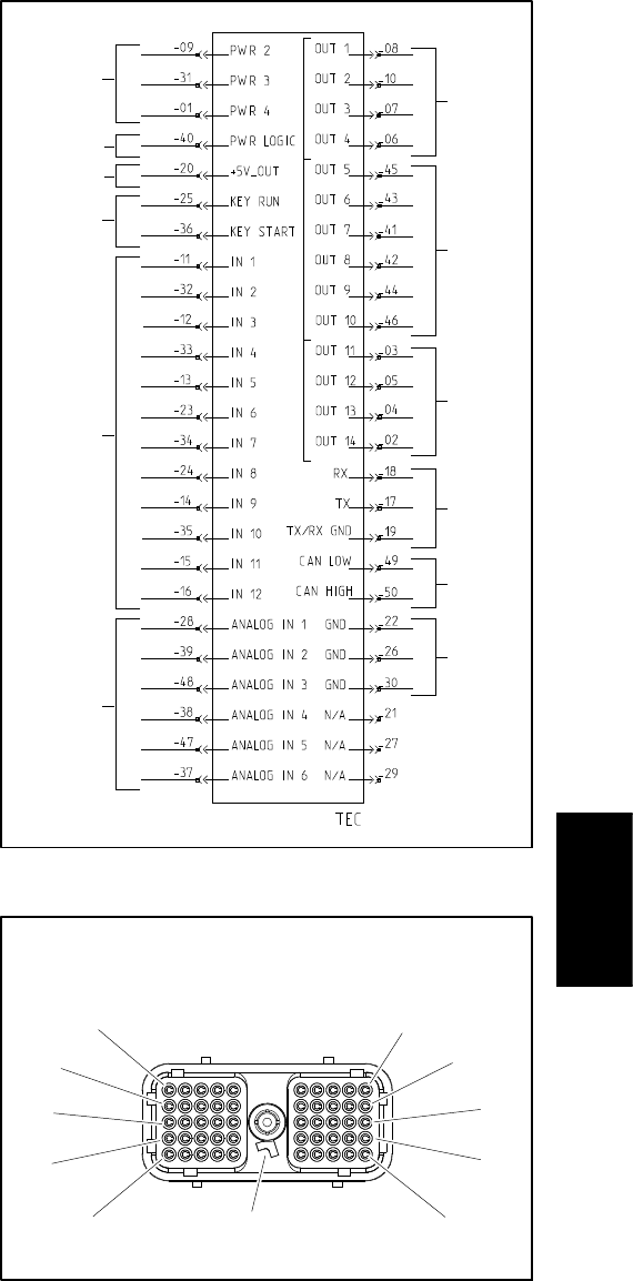
Groundsmaster 4100--D/4110--D Page 5 -- 51 Electrical System
IMPORTANT: When testing for wire harness con-
tinuity at the connector for the TEC controller, take
care to not damage the connector pins with multi-
meter test leads. If connector pins are enlarged or
damaged during testing, connector repair will be
necessary for proper machine operation.
The machine electrical schematic and wire harness
drawings in Chapter 10 -- Foldout Drawings can be used
to identify possible circuit problems between the control-
lers and the input/output devices (e.g. switches and
solenoid coils).
Because of the solid state circuitry built into the TEC
controllers, there is no method to test a controller direct-
ly. A controller may be damaged if an attempt is made
to test it with an electrical test device (e.g. digital multi-
meterortestlight).
If removal of the TEC controllers is necessary, label the
controllers to make sure they are properly connected to
the machine. The two (2) TEC controllers are visually
identical but they have different software and therefore
cannot be interchanged. The power mount (item 5 in
Fig. 63) can be separated from the operator platform
and carefully lifted from the platform to access the con-
troller fasteners.
NOTE: The TEC controllers used on the Groundsmas-
ter 4100--D and 4110--D are matched for correct ma-
chine operation. If either of these components are
replaced for any reason, system software needs to be
reprogrammed by your Toro Distributor.
IMPORTANT: Before performing any welding on
your Groundsmaster, disconnect both positive and
negative battery cables from the battery, disconnect
the wire harness connector from both of the TEC
controllers and disconnect the terminal connector
from the alternator. Also, disconnect and remove
the engine ECU from the machine before welding.
These steps will prevent damage to the machine
electrical system.
Figure 65
12V POWER
(7.5A FUSES)
12V LOGIC
IGNITION
SWITCH
INPUTS
DIGITAL
INPUTS
(OPEN/
ANALOG
INPUTS
POWER
(2 AMP FUSE)
COMM
PORT
CAN BUS
CLOSED)
OUTPUTS
(PWR 2)
GROUND
(VARIABLE)
OUTPUTS
(PWR 3)
OUTPUTS
(PWR 4)
VOLTAGE
OUT
Figure 66
WIRE HARNESS CONNECTOR FOR
TEC CONTROLLERS
11
1
21
31
41
10
50
40
30
20
POSITION
NOTE TAB
Electrical
System
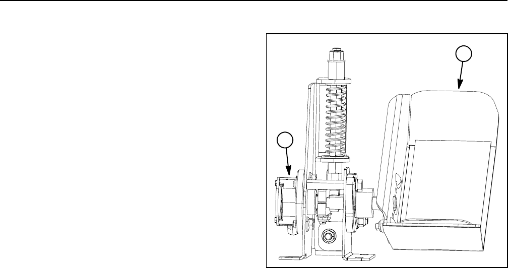
Groundsmaster 4100--D/4110--DPage 5 -- 52Electrical System
Traction Pedal Position Sensor
The traction pedal position sensor is connected to the
traction pedal assembly (Fig. 67). This position sensor
determines the neutral band for the traction pedal, the
direction of travel desired by the operator and the trac-
tion speed. The position sensor is a single analog, dual
digital signal electronic device. The position sensor por-
tion is a variable resistor that provides an analog signal
for the TEC controller to determine the desired ground
speed based on how far the traction pedal is moved. The
traction pedal position sensor also houses two (2)
switches that are used to determine the neutral position
(deadband) and the indicated direction of travel (forward
or reverse). As the traction pedal is depressed, the inter-
nal wiper of the position sensor moves and sends the
analog signal to the TEC controller to determine ma-
chine direction and speed.
The traction pedal position sensor must be calibrated
with the TEC controller to determine the neutral and full
speed set points for both the forward and reverse direc-
tions. The position sensor calibration process can be
completed using the InfoCenter display.
A properly installed and calibrated traction pedal posi-
tion sensor is critical to accurate traction response and
position sensor life. Use care when installing and cali-
brating the position sensor.
Before suspecting a faulty position sensor, the sensor
and its circuit wiring should be tested as a TEC input with
the InfoCenter Display (see InfoCenter Display in this
chapter). If necessary, follow calibration procedures for
the traction pedal position sensor found in the Adjust-
ments section of this chapter. If position sensor replace-
ment is necessary, refer to Traction Pedal in the Service
and Repairs section of Chapter 7 -- Chassis.
1. Traction pedal 2. Pedal position sensor
Figure 67
1
2
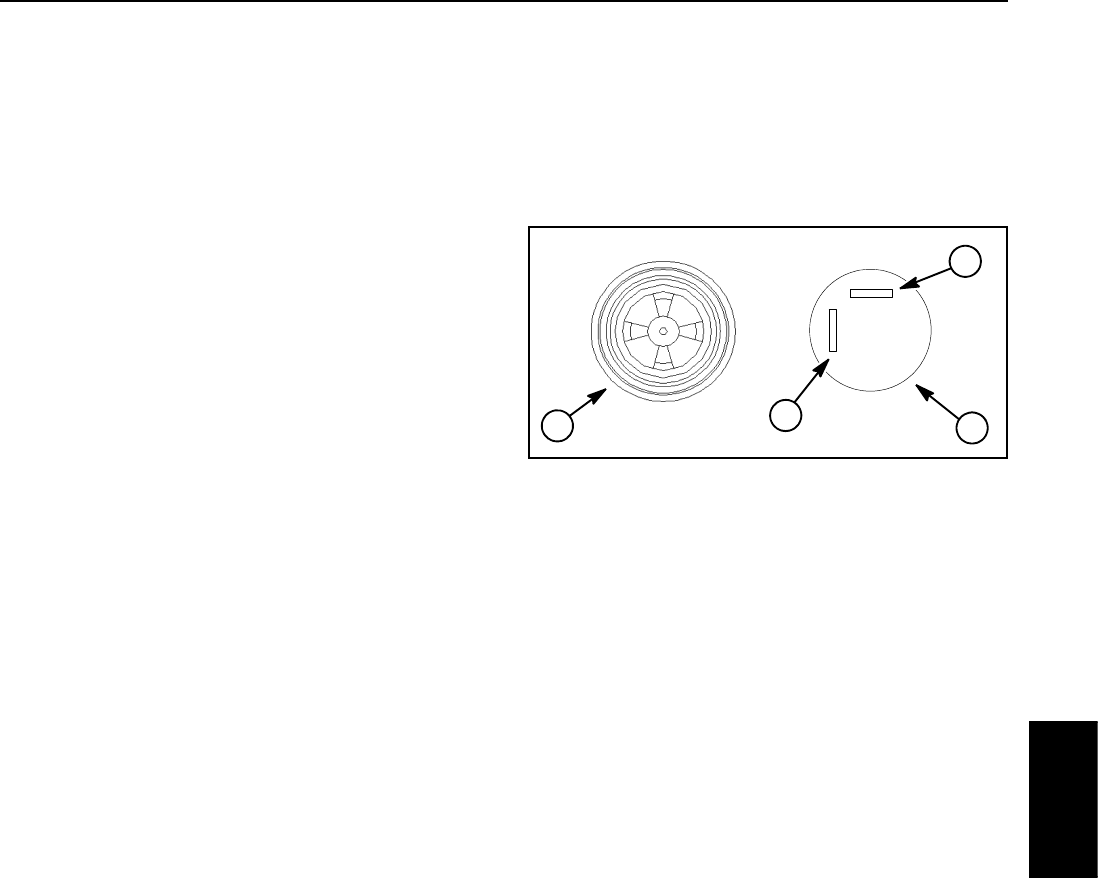
Groundsmaster 4100--D/4110--D Page 5 -- 53 Electrical System
Audio Alarm
The audio alarm sounds to notify the operator when a
machine problem exists. Electrical current for the alarm
is provided as an output from the TEC controller. The
alarm is attached to the console arm next to the operator
seat.
Testing
1. Make sure ignition switch is OFF. Remove key from
ignition switch.
2. Disassemble console arm to gain access to the au-
dio alarm (see Console Arm Disassembly in the Service
and Repairs section of Chapter 7 -- Chassis).
3. Disconnect wire harness connector from alarm.
IMPORTANT: Make sure to observe polarity on the
alarm terminals when testing. Damage to the alarm
may result from an improper connection.
4. Correctly connect 12VDC source to the alarm termi-
nals (Fig. 68).
5. Alarm should sound as long as 12VDC is connected
to the alarm terminals.
6. Disconnect voltage source from the alarm. Recon-
nect harness connector to alarm.
7. Assemble console arm (see Console Arm Assembly
in the Service and Repairs section of Chapter 7 -- Chas-
sis).
1. Top view
2. Bottom view
3. Positive (+) terminal
4. Negative (--) terminal
Figure 68
12
3
4
Electrical
System
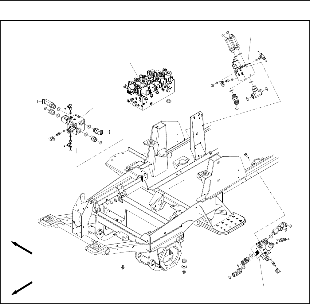
Groundsmaster 4100--D/4110--DPage 5 -- 54Electrical System
Hydraulic Valve Solenoid Coils
Figure 69
1. Front PTO manifold
2. RH PTO manifold
3. LH PTO manifold 4. Combination manifold
FRONT
RIGHT
2
3
1
4
Several hydraulic solenoid valvecoilsareusedonthe
hydraulic control manifolds of Groundsmaster 4100--D
and 4110--D machines. When energized by the TEC
controller, these coils provide hydraulic circuit control.
Solenoid valve coils with two (2) different resistance
specifications are used on the 4100--D and 4110--D. The
correct resistance of a coil can be identified by measur-
ing the height and diameter of the coil (Fig. 70). Resist-
ance testing of the coils can be done with the coil
remaining on the hydraulic valve.
NOTE: To assist in troubleshooting, identical solenoid
coils can be exchanged. If the problem follows the ex-
changed coil, a problem with the coil likely exists. If the
problem remains unchanged, something other than the
solenoid coil is the problem source (e.g. switch, circuit
wiring, hydraulic problem). Refer to your parts catalog to
determine if solenoid coils are identical.
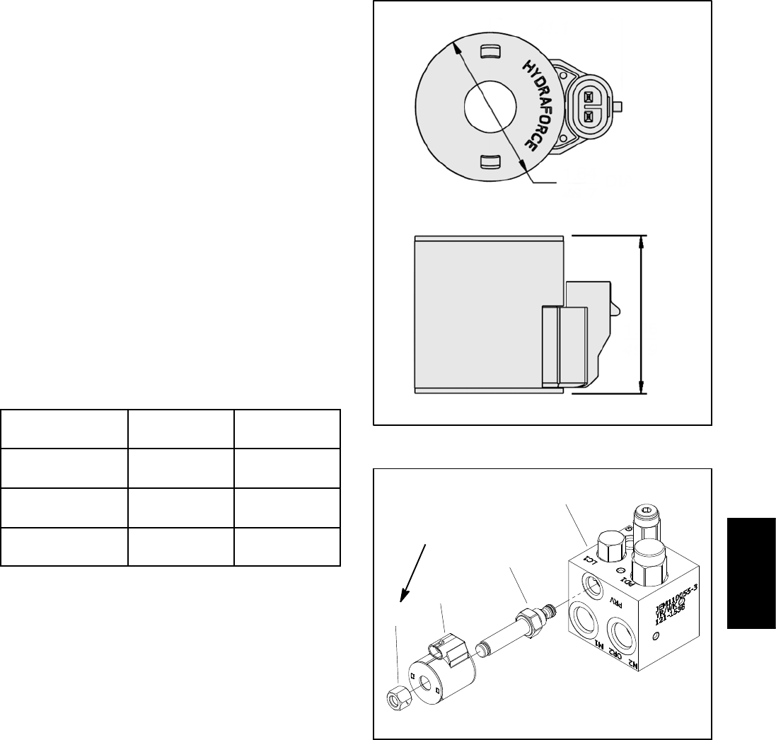
Groundsmaster 4100--D/4110--D Page 5 -- 55 Electrical System
Testing
1. Park machine on a level surface, lower cutting deck,
stop engine, engage parking brake and remove key
from the ignition switch.
2. Locate hydraulic solenoid valve coil to be tested (Fig.
69). Disconnect wire harness connector from coil.
3. Identify coil resistance specification by measuring
the coil diameter and coil height (Fig. 70).
NOTE: Prior to taking small resistance readings with a
digital multimeter, short the meter test leads together.
The meter will display a small resistance value (usually
0.5 ohms or less). This resistance is due to the internal
resistance of the meter and test leads. Subtract this val-
ue from from the measured value of the component you
are testing.
4. Using a multimeter (ohms setting), measure resis-
tance between the two (2) connector terminals on the
solenoid valve coil. The correct resistance for the sole-
noid coil is identified below:
COIL
DIAMETER
COIL
HEIGHT
COIL
RESISTANCE
1.34 in
(34.0 mm)
1.53 in
(38.9 mm)
5.4 ohm
1.84 in
(46.7 mm)
1.96 in
(49.9 mm)
7.1 ohm
1.41 in
(35.8 mm)
1.43 in
(36.3 mm)
8.8 ohm
NOTE: Solenoid valve coil resistance should be mea-
sured with solenoid at approximately 68oF(20
oC). Re-
sistance may be slightly different than listed at different
temperatures. Typically, a failed solenoid coil will either
be shorted (very low or no resistance) or open (infinite
resistance).
5. If solenoid valve coil resistance is incorrect, replace
solenoid coil (Fig. 71):
A. Remove nut securing solenoid coil to the car-
tridge valve. Carefully slide coil off the valve.
B. Install new solenoid coil to the cartridge valve.
Install and torque nut 5 ft--lb (6.7 N--m).Over--tight-
ening may damage the solenoid coil or cause the
cartridge valve to malfunction.
6. After testing is completed, connect wire harness
connector to the solenoid coil.
Figure 70
COIL
DIAMETER
COIL
HEIGHT
1. Hydraulic manifold
2. Cartridge valve
3. Solenoid coil
4. Nut
Figure 71
LH PTO
MANIFOLD SHOWN
5ft--lb
(6.7 N--m)
1
2
3
4
Electrical
System
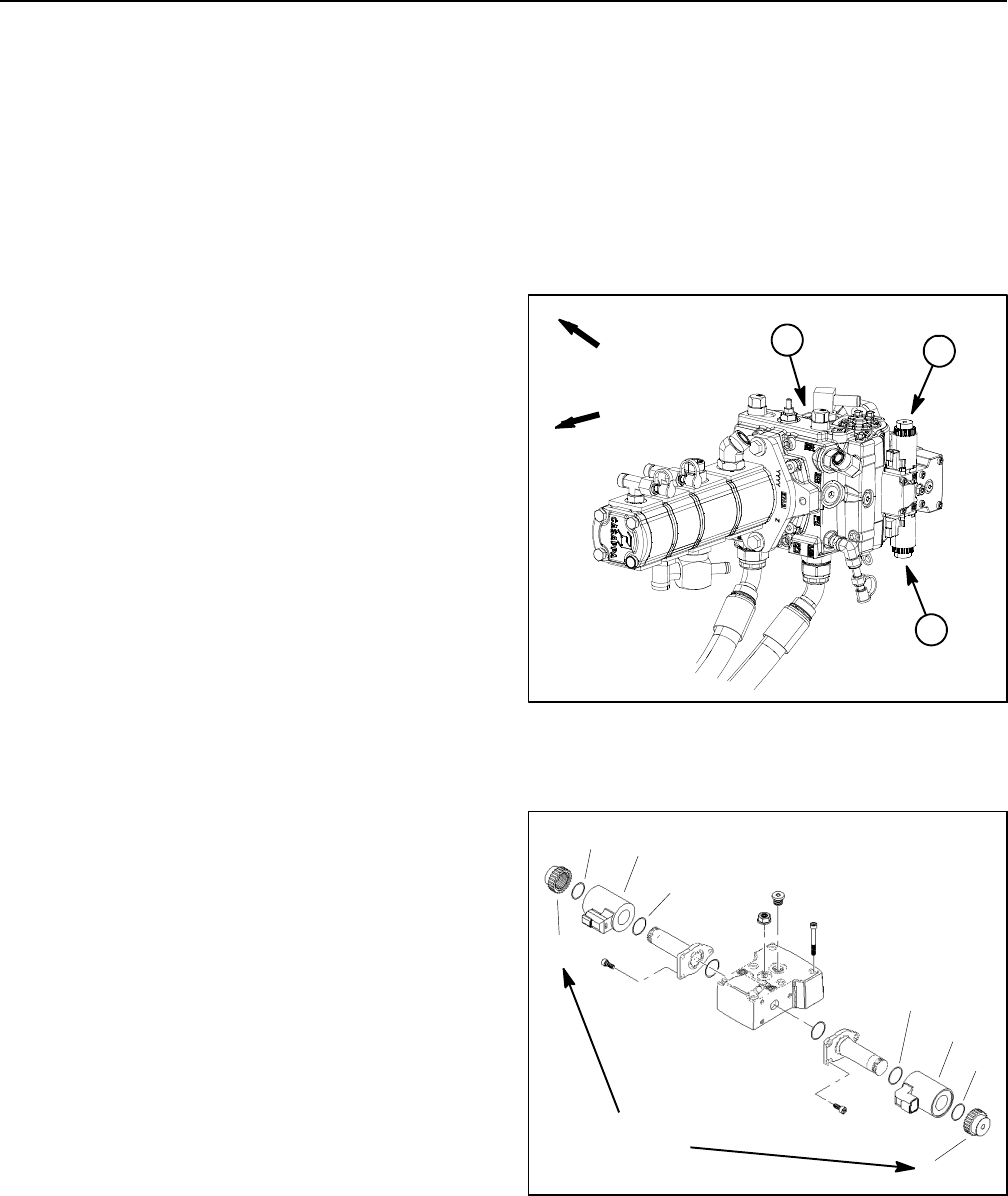
Groundsmaster 4100--D/4110--DPage 5 -- 56Electrical System
Piston (Traction) Pump Control Solenoid Coils
The piston (traction) pump uses an electronic control as-
sembly for swash plate rotation. Electrical outputs from
the machine TEC controller are provided to two (2)
solenoid coils for pump control. The piston pump control
assembly is attached to the left side of the piston pump
(Fig. 72).
NOTE: To assist in troubleshooting, the piston pump
solenoid coils can be exchanged because they are
identical. If the problem follows the exchanged coil, a
problem with the coil likely exists. If the problem remains
unchanged, something other than the solenoid coil is
the problem source (e.g. traction pedal, circuit wiring,
hydraulic problem).
Solenoid Coil Testing
1. Parkmachineonalevelsurface, lower cutting deck,
stop engine, engage parking brake and remove key
from the ignition switch.
2. Locate piston pump solenoid coil to be tested (Fig.
72). Disconnect wire harness connector from solenoid
coil.
NOTE: Prior to taking small resistance readings with a
digital multimeter, short the meter test leads together.
The meter will display a small resistance value (usually
0.5 ohms or less). This resistance is due to the internal
resistance of the meter and test leads. Subtract this val-
ue from from the measured value of the component you
are testing.
3. Using a multimeter (ohms setting), measure resis-
tance between the two (2) connector terminals on the
solenoid coil. Solenoid coil resistance should be 3.66
ohms.
NOTE: Solenoid coil resistance should be measured
with solenoid at approximately 68oF(20
oC). Resistance
may be slightly different than listed at different tempera-
tures. Typically, a failed solenoid coil will either be
shorted (very low or no resistance) or open (infinite re-
sistance).
4. If solenoid coil resistance is incorrect, replace coil
(Fig. 73):
A. Use a 12 point, 26 mm socket to loosen and re-
move the coil nut that secures solenoid coil.
B. Slide solenoid coil and O--rings from valve stem.
Clean all corrosion and dirt from the valve.
C. Slide new coil with O--rings onto the solenoid
stem.
D. Usea12point,26mmsockettoinstallandtorque
coil nut to 44 in--lb (5 N--m) (do not over--tighten coil
nut).
5. After testing is completed, connect wire harness
connector to the solenoid coil.
1. Piston pump
2. Forward solenoid coil
3. Reverse solenoid coil
Figure 72
FRONT
RIGHT
12
3
1. Solenoid coil
2. O--ring
3. Coil nut
Figure 73
1
3
2
2
1
3
2
2
44 in--lb
(5 N--m)

Groundsmaster 4100--D/4110--D Page 5 -- 57 Electrical System
CAN--bus Termination Resistor
System communication between electrical components
on Groundsmaster 4100--D and 4110--D machines is
accomplished on a CAN--bus communication system.
Two (2) specially designed, twisted wires form the bus
for the network used on the machine. These wires pro-
vide the data pathways between machine components.
At the end of the twisted pair of bus wires near the
InfoCenter display is a 120 ohm termination resistor.
The CAN--bus termination resistor plugs into the plat-
form wire harness in the control arm. The resistor can be
accessed by removing the cover plate on the right side
of the control arm. The wire harness connector has a
blue insert to identify the proper location for the termina-
tion resistor.
NOTE: The Groundsmaster 4100--D and 4110--D en-
gine ECU includes the second CAN--bus system termin-
ation resistor. This resistor cannot be accessed for
testing.
NOTE: Refer to the Electrical Schematics and Wire
Harness Drawings in Chapter 10 -- Foldout Drawings for
additional information on termination resistor location
and wire connections.
IMPORTANT: The termination resistor is required
for proper electrical system operation.
Termination Resistor Test
Theterminationresistor(Fig.74)canbetestedusinga
digital multimeter (ohms setting). There should be 120
ohms resistance between terminals A and B of the ter-
mination resistor. Terminal C is not used on Grounds-
master 4100--D and 4110--D machines.
Figure 74
Termination A
B
C
Resistor
Electrical
System
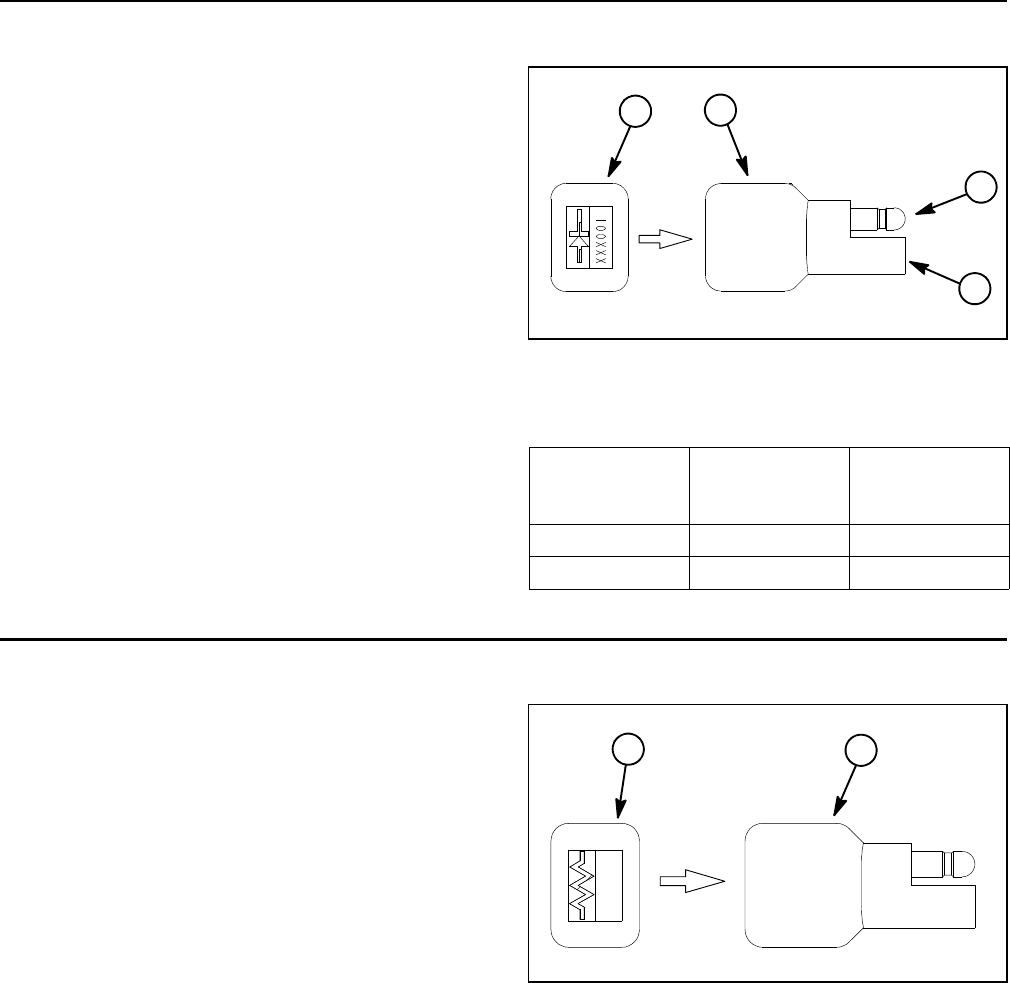
Groundsmaster 4100--D/4110--DPage 5 -- 58Electrical System
Diode Assemblies
The Groundsmaster engine wire harness contains a
diode assembly that is used for circuit protection from
voltage spikes when the engine starter solenoid is de--
energized.
Groundsmaster models 30606 and 30608 use an addi-
tional diode assembly in the engine wire harness that
protects the engine EGR circuit from reverse polarity.
The diode assemblies plug into the wiring harness near
the engine starter motor (see engine wire harness draw-
ing in Chapter 10 -- Foldout Drawings). The diode as-
semblies can be identified by a black color and diode
symbol on end of diode assembly body.
Testing
The diode can be tested using a digital multimeter
(diode test or ohms setting) and the table to the right.
Figure 75
1. Diode assembly
2. Male terminal
3. Female terminal
4. End of diode body
1
2
3
4
Multimeter
Red Lead (+)
on Terminal
Multimeter
Black Lead (--)
on Terminal
Continuity
Female Male YES
Male Female NO
Resistor Assembly
On Groundsmaster machines with an 80 Amp alternator
(see Engine Specifications in Chapter 3 -- Yanmar Dies-
el Engine), the engine wire harness contains a resistor
that is necessary for ignition switch operation. The res-
istor plugs into the wiring harness near the engine start-
er motor (see engine wire harness drawing in Chapter
10 -- Foldout Drawings).
The resistor assembly can be identified by its gray color
and resistor symbol on end of resistor assembly body.
Testing
The resistor can be tested using a digital multimeter
(ohms setting). The resistance across the resistor ter-
minals should be 1.6K ohms.
1. Resistor assembly 2. End of resistor body
Figure 76
1
2
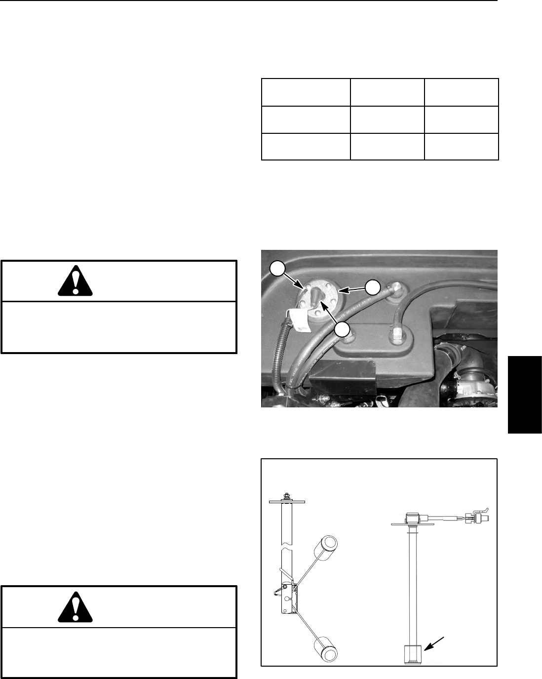
Groundsmaster 4100--D/4110--D Page 5 -- 59 Electrical System
Fuel Sender
The fuel sender is attached to the top of the fuel tank.
The resistance of the fuel sender increases as the fuel
level in the fuel tank decreases. The TEC controller uses
the fuel sender as an input to generate an output for the
InfoCenter fuel gauge.
Two (2) styles of fuel senders have been used on
Groundsmaster 4100--D and 4110--D machines. Early
production machines are equipped with a pivoting float
design that has two (2) wire harness terminals (shown
in Fig. 77). Later machines have a sliding float design
and a single harness connector.
Testing
1. Make sure ignition switch is OFF. Remove key from
ignition switch.
2. Disconnect wire harness connector(s) at fuel sender.
CAUTION
If testing circuit wiring, make sure wire connec-
tions at fuel sender are secure before turning
ignition switch to RUN to prevent an explosion or
fire from sparks.
3. To test the circuit wiring and InfoCenter fuel gauge,
use a jumper wire to connect the two (2) harness wires
leading to the fuel sender and turn ignition switch to
RUN. InfoCenter fuel gauge should indicate full. Turn
ignition switch OFF and continue testing fuel sender if
circuit wiring and gauge are acceptable.
4. Remove screws and lock washers that secure the
fuel sender to the fuel tank.
5. Carefully remove fuel sender and gasket from the
fuel tank. Clean all fuel from the sender.
NOTE: Before taking small resistance readings with a
digital multimeter, short meter test leads together. The
meter will display a small resistance value. This internal
resistance of the meter and test leads should be sub-
tracted from the measured value of the component.
CAUTION
Make sure fuel sender is completely dry (no fuel
on it) before testing. Perform test away from the
fuel tank to prevent an explosion or fire from
sparks.
6. Using a multimeter, check resistance of the sender
with the float in the full and empty positions. Expected
resistance values are shown in the table below.
CONNECTOR
STYLE
RESISTANCE
(FULL)
RESISTANCE
(EMPTY)
Two Terminals 27.5 to 39.5
Ohms
240to260
Ohms
Single Connector 28 to 33
Ohms
240to250
Ohms
7. Replace sender as necessary. Carefully install send-
er into fuel tank and secure with removed fasteners.
8. Secure wire harness connector(s) to fuel sender. On
two (2) terminal senders, apply skin--over grease (see
Special Tools in this chapter) to sender terminals.
1. Fuel sender
2. White (+) lead
3. Black (--) lead
Figure 77
1
2
3
Figure 78
FULL POSITION
EMPTY POSITION
TWO TERMINAL SINGLE
CONNECTOR
SLIDING
FLOAT
SENDER
SENDER
Electrical
System
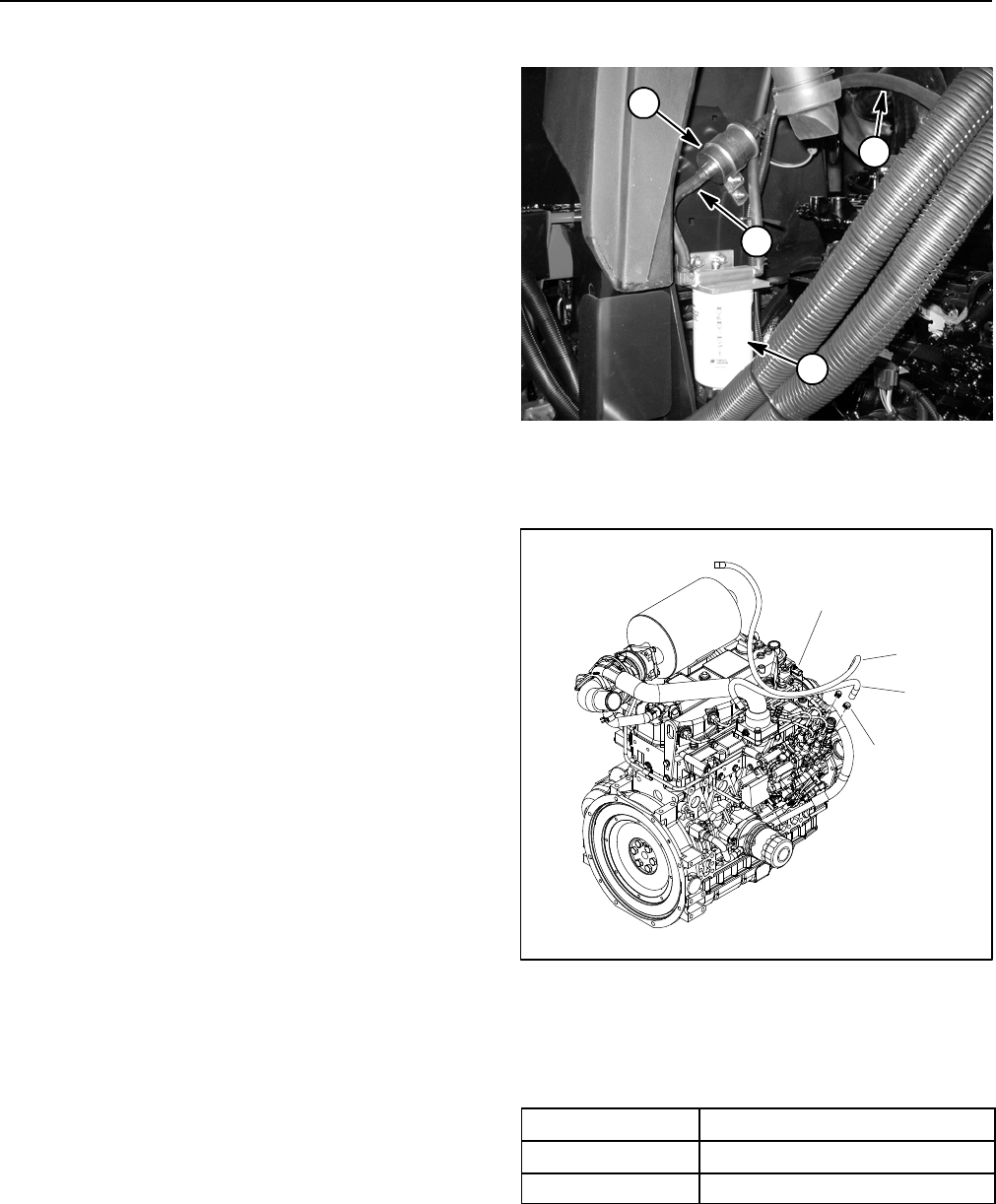
Groundsmaster 4100--D/4110--DPage 5 -- 60Electrical System
Fuel Pump (Models 30602 and 30604)
The fuel pump is attached to the fuel tank support above
the fuel water separator (Fig. 79).
Operational Test
1. Parkmachineonalevelsurface, lower cutting deck,
stop engine and apply parking brake. Raise hood to ac-
cess fuel pump.
2. Disconnect fuel pump discharge hose from the fuel
injection pump fitting on the engine (Fig. 80).
3. Make sure fuel hoses attached to the fuel pump are
free of obstructions.
4. Place disconnected end of fuel pump discharge
hose into a large, graduated cylinder sufficient enough
to collect 1 quart (0.95 liter).
IMPORTANT: When testing fuel pump output, do
not turn ignition switch to the START position.
5. Collect fuel in the graduated cylinder by turning igni-
tion switch to the RUN position. Allow pump to run for fif-
teen (15) seconds, then turn switch to OFF.
6. The amount of fuel collected in the graduated cylin-
der should be approximately 16 fl oz (475 ml) after fif-
teen (15) seconds.
7. Replace fuel pump as necessary.
IMPORTANT: If fuel pump is replaced, make sure
that replacement pump is the correct pump for your
Groundsmaster by using your Parts Catalog. If in-
correct pump is used, fuel system components can
be damaged.
8. Install fuel hose to the water separator and secure
with hose clamp.
9. Prime fuel system (see Fuel System in the Service
and Repairs section of Chapter 3 -- Yanmar Diesel En-
gine).
10.Lower and secure hood.
1. Fuel water separator
2. Fuel pump
3. Pump inlet hose
4. Pump discharge hose
Figure 79
2
1
3
4
Figure 80
1
2
3
4
1. Tier 4i engine
2. Hose clamp
3. Fuel supply hose
4. Fuel return hose
Fuel Pump Specifications
Pump Capacity 64 fl oz/min (1.9 l/min)
Pressure 7PSI(48.3kPa)
Current Draw 2.0 Amp
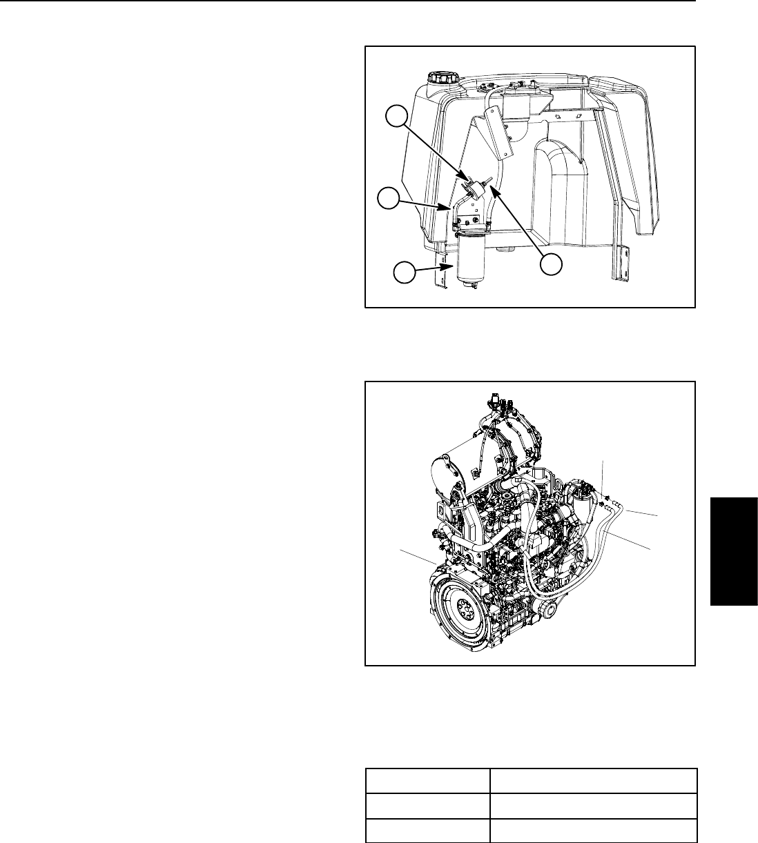
Groundsmaster 4100--D/4110--D Page 5 -- 61 Electrical System
Fuel Pump (Models 30606 and 30608)
The fuel pump is attached to the fuel tank support above
the fuel water separator (Fig. 81).
Operational Test
1. Park machine on a level surface, lower cutting deck,
stop engine and apply parking brake. Raise hood to ac-
cess fuel pump.
2. Disconnect fuel pump discharge hose from the fuel
filter attached to the engine (Fig. 82).
3. Make sure fuel hoses attached to the fuel pump are
free of obstructions.
4. Place disconnected end of fuel pump discharge
hose into a large, graduated cylinder sufficient enough
to collect 1 quart (0.95 liter).
IMPORTANT: When testing fuel pump output, do
not turn ignition switch to the START position.
5. Collect fuel in the graduated cylinder by turning igni-
tion switch to the RUN position. Allow pump to run for
thirty (30) seconds, then turn switch to OFF.
6. The amount of fuel collected in the graduated cylin-
der should be approximately 11.8 fl oz (350 ml) after
thirty (30) seconds.
7. Replace fuel pump as necessary.
IMPORTANT: If fuel pump is replaced, make sure
that replacement pump is the correct pump for your
Groundsmaster by using your Parts Catalog. If in-
correct pump is used, fuel system components can
be damaged.
8. Install fuel hose to the engine mounted fuel filter and
secure with hose clamp.
9. Prime fuel system (see Fuel System in the Service
and Repairs section of Chapter 3 -- Yanmar Diesel En-
gine).
10.Lower and secure hood.
1. Fuel water separator
2. Fuel pump
3. Pump inlet hose
4. Pump discharge
Figure 81
2
1
3
4
Figure 82
1. Tier 4 engine
2. Hose clamp
3. Pump discharge hose
4. Fuel return hose
2
3
1
4
Fuel Pump Specifications
Pump Capacity 23.5 fl oz/min (700 ml/min)
Pressure 3.3 PSI (22.8 kPa)
Current Draw 0.9 Amp
Electrical
System
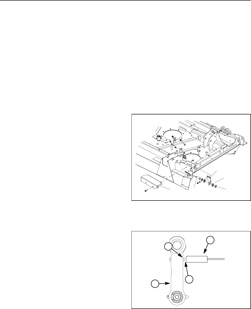
Groundsmaster 4100--D/4110--DPage 5 -- 62Electrical System
Wing Deck Position Switches
Two (2) wing deck position switches are used on the
Groundsmaster 4100--D and 4110--D as inputs for the
TEC controller. The position switches are powered prox-
imity switches that are normally open. The switches in-
corporate an internal reed switch and a LED. These
switches are secured to the center section of the cutting
deck (Fig. 83). A bolt head on the wing deck link is the
sensing plate for the position switch (Fig. 84).
When a wing deck is lowered, the bolt head on the wing
deck link is positioned close to the position switch caus-
ing the switch to close. The closed switch provides an
input for the TEC controller to allow wing deck operation.
When a wing deck is raised, the bolt head on the wing
deck link is moved away from the position switch so the
switch is in its normally open state. The open position
switch prevents wing deck operation when the wing
deck is raised.
Testing
1. Before disconnecting a wing deck position switch for
testing, the switch and its circuit wiring should be tested
as a TEC input with the InfoCenter Display (see In-
foCenter Display in this chapter). If the InfoCenter veri-
fies that the deck position switch and circuit wiring are
functioning correctly, no further switch testing is neces-
sary. If, however, the InfoCenter determines that the
deck position switch and circuit wiring are not function-
ing correctly, proceed with test.
2. Park machine on a level surface, lower cutting deck
(including wing decks), stop engine and apply parking
brake. Remove switch cover from deck to allow access
to switch that requires testing (Fig. 83).
3. Turn ignition switch to the ON position (do not start
engine) and check LED on cable end of position
switches. LED should be illuminated when the wing
decks are fully lowered.
4. Start engine, fully raise wing decks and then stop en-
gine. Then, turn ignition switch to the ON position (do not
start engine) and check LED on cable end of position
switches. LED should not be illuminated when the wing
decks are fully raised.
5. Lower wing decks and then stop engine.
6. If a position switch LED did not function correctly:
A. Make sure that ignition switch is OFF and discon-
nect the switch connector from deck wire harness.
B. Using a multimeter, verify that wire harness con-
nector terminal for pink wire has 12 VDC when the
ignition switch is ON.
C. Make sure that gap between end of position
switch and bolt head on wing deck link when the wing
deck is lowered is from 0.070” to 0.130” (1.8 to 3.3
mm) (Fig. 84).
D. If pink wire has system voltage present and gap is
correct but switch LED did not function, replace posi-
tion switch.
7. After testing is complete, make sure that switch con-
nector is plugged into deck wire harness. Install switch
cover to deck.
1. Switch cover
2. Position switch
3. Switch bracket
4. Lock washer (2 used)
5. Jam nut (2 used)
Figure 83
12
3
4
5
1. Position switch
2. Bolt head
3. Wing deck link
4. Gap location
Figure 84
1
2
34
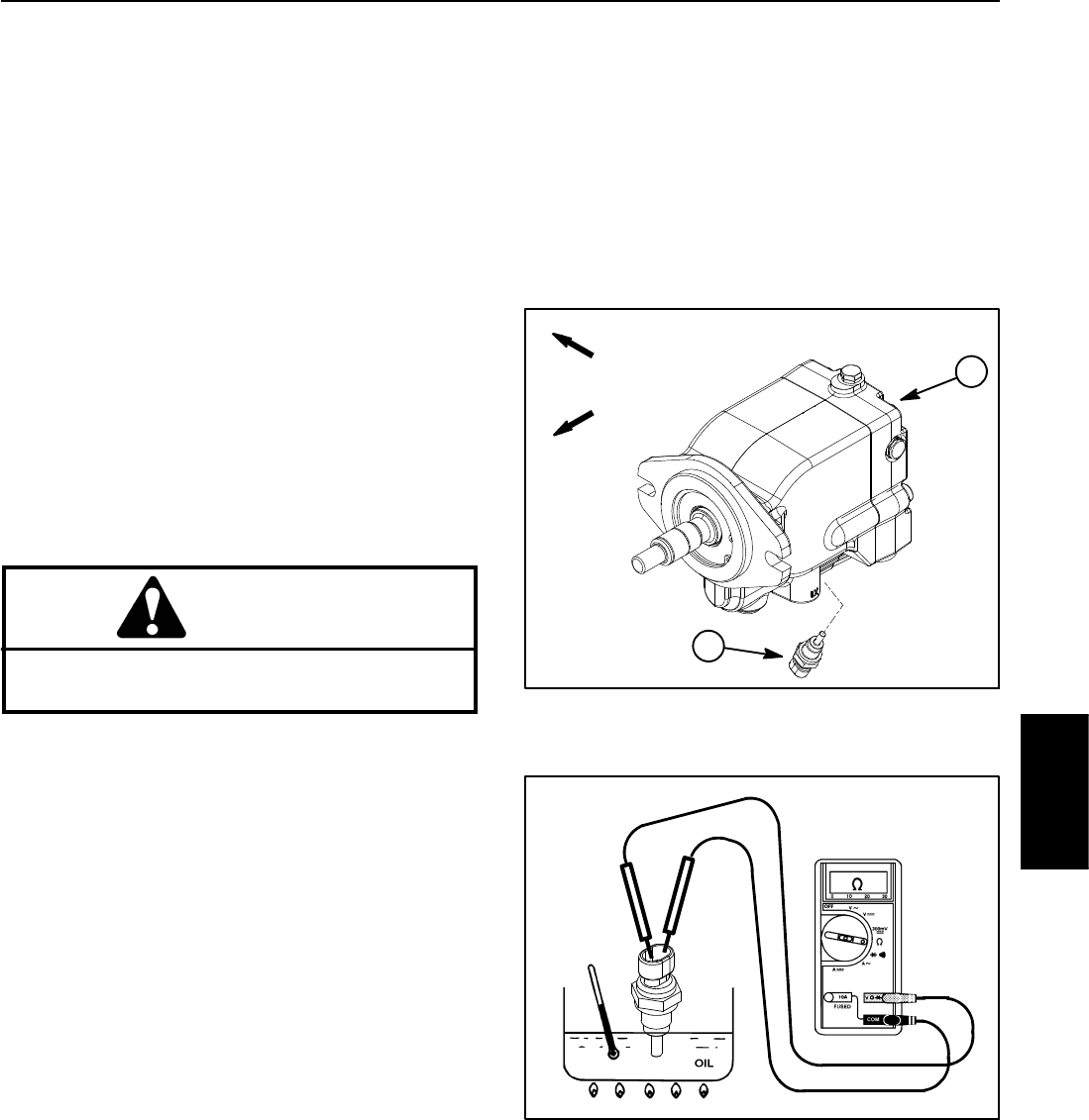
Groundsmaster 4100--D/4110--D Page 5 -- 63 Electrical System
Hydraulic Oil Temperature Sender
The Groundsmaster 4100--D and 4110--D use a temper-
ature sender as an input for the TEC controller to identify
if the hydraulic oil temperature has reached an exces-
sive level. The hydraulic oil temperature sender is at-
tached to the bottom of the rear axle motor (Fig. 85).
The InfoCenter will display fault code 18 if the hydraulic
oil temperature sender inputs to the TEC controller are
not in the normal range.
Testing
1. Locate temperature sender in rear axle motor. Dis-
connect wire harness connector from sender.
2. Place suitable drain pan under temperature sender
in rear axle motor. Thoroughly clean area around tem-
perature sender and remove sender from axle motor.
3. Put sensing end of sender in a container of oil with
a thermometer and slowly heat the oil (Fig. 86).
CAUTION
Handle the hot oil with extreme care to prevent
personal injury or fire.
NOTE: Prior to taking resistance readings with a digital
multimeter, short the meter test leads together. The me-
ter will display a small resistance value (usually 0.5
ohms or less). This resistance is due to the internal re-
sistance of the meter and test leads. Subtract this value
from from the measured value of the component you are
testing.
4. Check resistance of the sender with a multimeter
(ohms setting) as the oil temperature increases.
A. The meter should indicate from 11.6 to 13.5 kilo
ohms at 68oF(20
oC).
B. The meter should indicate from 2.3 to 2.5 kilo
ohms at 140oF(60
oC).
C. The meter should indicate from 605 to 669 ohms
at 212oF(100
oC).
D. Replace sender if specifications are not met.
5. After allowing the sender to cool, install sender:
A. Install new O--ring on sender.
B. Install sender into port and torque from 9to11ft--
lb(12.3to14.9N--m).
C. Connect wire harness connector to sender.
6. Check and fill hydraulic system to proper level.
Figure 85
1. Rear axle motor 2. Oil temp sender
FRONT
RIGHT 1
2
Figure 86
Electrical
System
Groundsmaster 4100--D/4110--DPage 5 -- 64Electrical System
Service and Repairs
NOTE: For engine component repair information (e.g.
starter motor), refer to the Yanmar Service Manual that
is correct for your Groundsmaster model.
Battery Care
1. The top of the battery must be kept clean. lf the ma-
chine is stored in a location where temperatures are ex-
tremely high, the battery will discharge more rapidly
than if the machine is stored in a location where temper-
atures are cool.
WARNING
Wear safety goggles and rubber gloves when
working with electrolyte. Charge battery in a
well ventilated place so gasses produced while
charging can dissipate. Since the gases are ex-
plosive, keep open flames and electrical sparks
away from the battery; do not smoke. Nausea
may result if the gases are inhaled. Unplug char-
ger from electrical outlet before connecting or
disconnecting charger leads to or from battery
posts.
IMPORTANT: Do not remove fill caps (if equipped)
while cleaning the battery.
2. Check battery condition weekly or after every 50
hours of operation. Keep terminals and entire battery
case clean because a dirty battery will discharge slowly.
A. Clean battery by washing entire case with a solu-
tion of baking soda and water. Rinse with clear water.
B. Coat battery posts and cable connectors with bat-
tery terminal protector (Toro Part No. 107--0392) or
petroleum jelly to prevent corrosion.
3. Battery cables must be tight on terminals to provide
good electrical contact.
Connecting battery cables to the wrong battery
post could result in personal injury and/or dam-
age to the electrical system.
WARNING
4. If corrosion occurs at terminals, disconnect cables.
Always disconnect negative (--) cable first. Clean
clamps and terminals separately. Reconnect cables
with positive (+) cable first. Coat battery posts and cable
connectors with battery terminal protector (Toro Part No.
107--0392) or petroleum jelly to prevent corrosion.
5. If the battery electrolyte is accessible, check electro-
lyte level every 25 operating hours and every 30 days if
machineisinstorage.Maintain cell level with distilled
water. Do not fill cells above the fill line.
Battery Storage
If the machine will be stored for more than 30 days:
1. Remove the battery and charge it fully (see Battery
Service in this section).
2. Either store battery on a shelf or on the machine.
3. Leave battery cables disconnected if the battery is
stored on the machine.
4. Store battery in a cool atmosphere to avoid quick de-
terioration of the battery charge.
5. To help prevent the battery from freezing, make sure
it is fully charged (see Battery Service in this section).
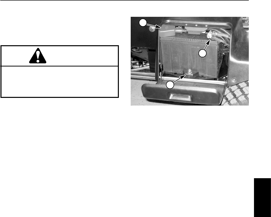
Groundsmaster 4100--D/4110--D Page 5 -- 65 Electrical System
Battery Service
The battery is the heart of the electrical system. With
regular and proper service, battery life can be extended.
Additionally, battery and electrical component failure
canbeprevented.
CAUTION
When working with batteries, use extreme cau-
tion to avoid splashing or spilling electrolyte.
Electrolyte can destroy clothing and burn skin or
eyes. Always wear safety goggles and a face
shield when working with batteries.
Battery Specifications
BCI Group Size 34
690 CCA at 0oF(--18
oC)
110 minutes reserve capacity at 80oF(27
oC)
Electrolyte Specific Gravity
Fully charged: 1.265 corrected to 80oF(27
oC)
Discharged: less than 1.240
Battery Removal and Installation (Fig. 87)
1. Open battery cover to access battery.
2. Loosen and remove negative cable from battery. Af-
ter negative cable is removed, loosen and remove posi-
tive cable.
3. Loosen battery retainer and then carefully remove
battery from machine.
4. Install battery in reverse order making sure to con-
nect and tighten positive cable to battery before con-
necting negative cable.
NOTE: Before connecting the negative (ground) cable
to the battery, connect a digital multimeter (set to DC
Amps) between the negative battery post and the nega-
tive (ground) cable connector. The reading should be
less than 0.1 Amp. If the reading is 0.1 Amp or more, the
machine’s electrical system should be tested for short
circuits or faulty components and repaired.
5. Secure battery to machine with battery retainer.
Close battery cover.
1. Negative battery post
2. Positive battery post
3. Battery retainer
Figure 87
1
2
3
Battery Inspection and Maintenance
1. Check battery for cracks. Replace battery if cracked
or leaking.
2. Check battery terminal posts for corrosion. Use wire
brush to clean corrosion from posts.
IMPORTANT: Before cleaning the battery, tape or
block vent holes to the filler caps and make sure the
caps are on tightly.
3. Check for signs of wetness or leakage on the top of
the battery which might indicate a loose or missing filler
cap, overcharging, loose terminal post or overfilling.
Also, check battery case for dirt and oil. Clean the bat-
tery with a solution of baking soda and water, then rinse
it with clean water.
4. Check that the cover seal is not broken away. Re-
place the battery if the seal is broken or leaking.
5. If the battery electrolyte is accessible, check the
electrolyte level in each cell. If the level is below the tops
of the plates in any cell, fill all cells with distilled water
between the minimum and maximum fill lines. Charge at
15 to 25 Amps for fifteen (15) minutes to allow sufficient
mixing of the electrolyte.
Electrical
System
Groundsmaster 4100--D/4110--DPage 5 -- 66Electrical System
Battery Testing
1. Perform a high--discharge test with an adjustable
load tester. This is one of the most reliable means of test-
ing a battery as it simulates the cold--cranking test. A
commercial battery load tester is required to perform
this test.
CAUTION
Follow the manufacturer’s instructions when us-
ing a battery load tester.
A. Check the voltage across the battery terminals
prior to testing the battery. If the voltage is less than
12.4 VDC, charge the battery before performing a
load test.
B. If the battery has recently been charged, use a
battery load tester following the manufacturer’s in-
structions to apply a 150 Amp load for fifteen (15)
seconds. This step will remove the surface charge.
C. Make sure battery terminals are free of corrosion.
D. Estimate the internal temperature of the battery
to the nearest 10 degrees F.
E. Connect a battery load tester to the battery termi-
nals following the manufacturer’s instructions.
Connect a digital multimeter to the battery terminals.
F. Apply a test load of 345 Amps (one half the crank-
ing performance rating of the battery) to the battery
for fifteen (15) seconds.
G. Take a battery voltage reading at fifteen (15) se-
conds, then remove the load.
H. Usingthetableinthecolumntotheright,deter-
mine the minimum voltage for the battery tempera-
ture reading. If the test voltage is below the minimum
voltage for the battery temperature, replace the bat-
tery.Ifthetestvoltageisatorabovetheminimum,
return the battery to service.
Minimum
Voltage
Battery
Temperature
9.6 70oF(andup) 21oC(andup)
9.5 60oF16oC
9.4 50oF10oC
9.3 40oF 4oC
9.1 30oF-- 1 oC
8.9 20oF-- 7 oC
8.7 10oF-- 1 2 oC
8.5 0oF-- 1 8 oC
2. If the battery electrolyte is accessible, the specific
gravity of the electrolyte can be used to determine the
battery condition.
IMPORTANT: Make sure the area around the cells is
clean before opening the battery caps.
A. Measure the specific gravity of each cell with a
hydrometer. Draw electrolyte in and out of the
hydrometer barrel prior to taking a reading to warm--
up the hydrometer. At the same time take the tem-
perature of the cell.
B. Temperature correct each cell reading. For each
10oF(5.5
oC) above 80oF(26.7
oC) add 0.004 to the
specific gravity reading. For each 10oF(5.5
oC) be-
low 80oF(26.7
oC) subtract 0.004 from the specific
gravity reading.
Example: Cell Temperature 100oF
Cell Gravity 1.245
100oF minus 80oF equals 20oF
(37.7oC minus 26.7oC equals 11.0oC)
20oF multiply by 0.004/10oF equals 0.008
(11oC multiply by 0.004/5.5oC equals 0.008)
ADD (conversion above) 0.008
Correction to 80oF(26.7oC) 1.253
C. If the difference between the highest and lowest
cell specific gravity is 0.050 or greater or the lowest
cell specific gravity is less than 1.225, charge the bat-
tery. Charge at the recommended rate and time giv-
en in Charging or until all cells specific gravity is
1.225 or greater with the difference in specific gravity
between the highest and lowest cell less than 0.050.
If these charging conditions can not be met, replace
the battery.
Groundsmaster 4100--D/4110--D Page 5 -- 67 Electrical System
Battery Charging
To minimize possible damage to the battery and allow
the battery to be fully charged, the slow charging meth-
od is presented here. This charging method can be ac-
complished with a constant current battery charger
which is readily available.
CAUTION
Follow the manufacturer’s instructions when us-
ing a battery charger.
NOTE: Using specific gravity of the battery electrolyte
is the most accurate method of determining battery
condition.
1. Determine the battery charge level from either its
open circuit voltage or electrolyte specific gravity (if
electrolyte is accessible).
Battery Charge
Level
Open Circuit
Voltage
Specific
Gravity
100% 12.6 1.265
75% 12.4 1.225
50% 12.2 1.190
25% 12.0 1.155
0% 11.8 1.120
2. Determine the charging time and rate using the bat-
tery charger manufacturer’s instructions or the fol-
lowing table.
Battery
Reserve
Capacity
(Minutes)
Battery Charge Level
(Percent of Fully Charged)
75% 50% 25% 0%
80 or less 3.8 hrs
@
3Amps
7.5 hrs
@
3Amps
11.3 hrs
@
3Amps
15 hrs
@
3Amps
81 to 125 5.3 hrs
@
4Amps
10.5 hrs
@
4Amps
15.8 hrs
@
4Amps
21 hrs
@
4Amps
126 to
170
5.5 hrs
@
5Amps
11 hrs
@
5Amps
16.5 hrs
@
5Amps
22 hrs
@
5Amps
171 to
250
5.8 hrs
@
6Amps
11.5 hrs
@
6Amps
17.3 hrs
@
6Amps
23 hrs
@
6Amps
above
250
6hrs
@10
Amps
12 hrs
@10
Amps
18 hrs
@10
Amps
24 hrs
@10
Amps
CAUTION
Do not charge a frozen battery because it can ex-
plode and cause injury. Let the battery warm to
60oF(16
oC) before connecting to a charger.
Charge the battery in a well--ventilated place to
dissipate gases produced from charging. These
gases are explosive; keep open flame and elec-
trical spark away from the battery. Do not smoke.
Nausea may result if the gases are inhaled. Un-
plug the charger from the electrical outlet before
connecting or disconnecting the charger leads
from the battery posts.
3. Following the battery charger manufacturer’s
instructions, connect the charger cables to the battery.
Make sure a good connection is made.
4. Charge the battery following the battery charger
manufacturer’s instructions.
5. While charging, occasionally check the battery. If the
electrolyte is violently gassing or spewing or if the bat-
tery case feels hot to the touch, the charging rate must
be lowered or temporarily stopped.
6. Determine if battery is fully charged before removing
battery from charger. Either of the following procedures
can be used:
A. Continue charging and reduce charging rate as
needed until a two (2) hour period results in no in-
crease in voltage. Open circuit voltage should be ap-
proximately 12.6 volts for a fully charged battery.
B. If the battery electrolyte is accessible, three (3)
hours prior to the end of the charging, measure the
specific gravity of a battery cell once per hour. The
battery is fully charged when the cells are gassing
freely at a low charging rate and there is less than a
0.003 change in specific gravity for three (3) consec-
utive readings.
Electrical
System
Groundsmaster 4100--D/4110--DPage 5 -- 68Electrical System
This page is intentionally blank.

Groundsmaster 4100--D/4110--D Page 6 -- 1 Axles, Planetaries and Brakes
Chapter 6
Axles, Planetaries and Brakes
Table of Contents
SPECIFICATIONS 2............................
GENERAL INFORMATION 3.....................
Operator’s Manual 3..........................
ADJUSTMENTS 4..............................
Planetary Wheel Drive Assembly Endplay 4......
SERVICE AND REPAIRS 6......................
Brake Assembly 6............................
Brake Inspection and Repair 10.................
Planetary Wheel Drive Assembly 12.............
Planetary Wheel Drive Service 14...............
Rear Axle Assembly 18........................
Rear Axle Service 22..........................
Bevel Gear Case and Axle Case 24.............
Differential Shafts 28..........................
Axle Shafts 29................................
Input Shaft/Pinion Gear 30.....................
Differential Gear 32...........................
Pinion Gear to Ring Gear Engagement 35.......
Axles, Planetaries
and Brakes

Groundsmaster 4100--D/4110--DPage 6 -- 2Axles, Planetaries and Brakes
Specifications
Item Specification
Tire pressure (front and rear) 25 to 30 PSI (172 to 207 kPa)
Rear wheel toe--in 0.250in(6mm)
Planetary gear drive oil SAE 85W--140 wt. gear lube
System gear lube capacity (each wheel) 22 fl. oz. (0.65 liters)
Rear axle lubricant SAE 85W--140 wt. gear lube
System gear lube capacity 80 fl. oz. (2.4 liters)
Rear axle gear box lubricant SAE 85W--140 wt. gear lube
System gear lube capacity 16 fl. oz. (0.5 liters)
Wheel lug nut torque 85 to 100 ft--lb (115 to 135 N--m), front and rear
Steering cylinder castle nut torque 79 to 84 ft--lb (107 to 113 N--m)
Planetary mounting screw torque 75 to 85 ft--lb (101 to 115 N--m)
Brake housing mounting screw torque 75 to 85 ft--lb (101 to 115 N--m)
Front wheel motor mounting screw torque 75 to 85 ft--lb (101 to 115 N--m)

Groundsmaster 4100--D/4110--D Page 6 -- 3 Axles, Planetaries and Brakes
General Information
Operator’s Manual
The Operator’s Manual provides information regarding
the operation, general maintenance and maintenance
intervals for your Groundsmaster machine. Refer to that
publication for additional information when servicing the
machine.
Axles, Planetaries
and Brakes
Groundsmaster 4100--D/4110--DPage 6 -- 4Axles, Planetaries and Brakes
Adjustments
Planetary Wheel Drive Assembly Endplay
A front planetary wheel drive assembly that is properly
operating should have no endplay. Any endplay in a
planetary assembly indicates that there are potential
problems with the planetary. Check planetary endplay at
intervals specified in your Operator’s Manual.
Endplay Checking Procedure
1. Parkmachineonalevelsurface, lower cutting deck,
stop engine and remove key from the ignition switch.
CAUTION
When raising and supporting machine, use cor-
rect jacks and supports. Make sure machine is
parked on a solid, level surface such as a con-
crete floor. Prior to raising machine, remove any
attachments that may interfere with the safe and
proper raising of the machine. Always chock or
block wheels. Use jack stands to support the
raised machine. If the machine is not properly
supported by jack stands, the machine may
move or fall, which may result in personal injury.
2. Chock rear wheels and jack up front of machine (see
Jacking Instructions in Chapter 1 -- Safety). Support ma-
chine with jack stands.
3. Grasp front wheel and check for endplay in the plan-
etary assembly as indicated by axial wheel movement.
Make sure that there is no endplay in assembly.
4. If any endplay is detected, the planetary should be
disassembled, inspected and serviced as necessary
(see Planetary Wheel Drive Assembly in the Service
and Repairs section of this chapter).
5. After planetary endplay checking is completed,
lower machine to ground.

Groundsmaster 4100--D/4110--D Page 6 -- 5 Axles, Planetaries and Brakes
This page is intentionally blank.
Axles, Planetaries
and Brakes
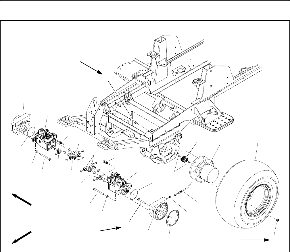
Groundsmaster 4100--D/4110--DPage 6 -- 6Axles, Planetaries and Brakes
Service and Repairs
Brake Assembly
Figure 1
FRONT
RIGHT
75 to 85 ft--lb
(101 to 115 N--m) 85 to 100 ft--lb
(115 to 135 N--m)
75 to 85 ft--lb
(101 to 115 N--m)
2
3
6
8
9
11
13
1
5
7
12
14
15
4
10
1
6
7
8
13
1. Front wheel motor
2. Internal retaining ring
3. Splined brake shaft
4. RH brake assembly
5. Planetary assembly (2 used)
6. Cap screw (2 used per motor)
7. Flat washer (2 used per motor)
8. O--ring
9. LH brake assembly
10. Hydraulic tee fitting
11. 90ohydraulic fitting (2 used)
12. Hydraulic connector
13. Hydraulic tee fitting (2 used)
14. 90ohydraulic fitting
15. Straight hydraulic fitting
16. Flange screw (4 used per brake)
17. Jam nut
18. Gasket
19. Flange screw (6 used per side)
20. Front wheel assembly
21. Lug nut (8 used per wheel)
22. Brake cable (RH shown)
16
17
18
19
20
21
22
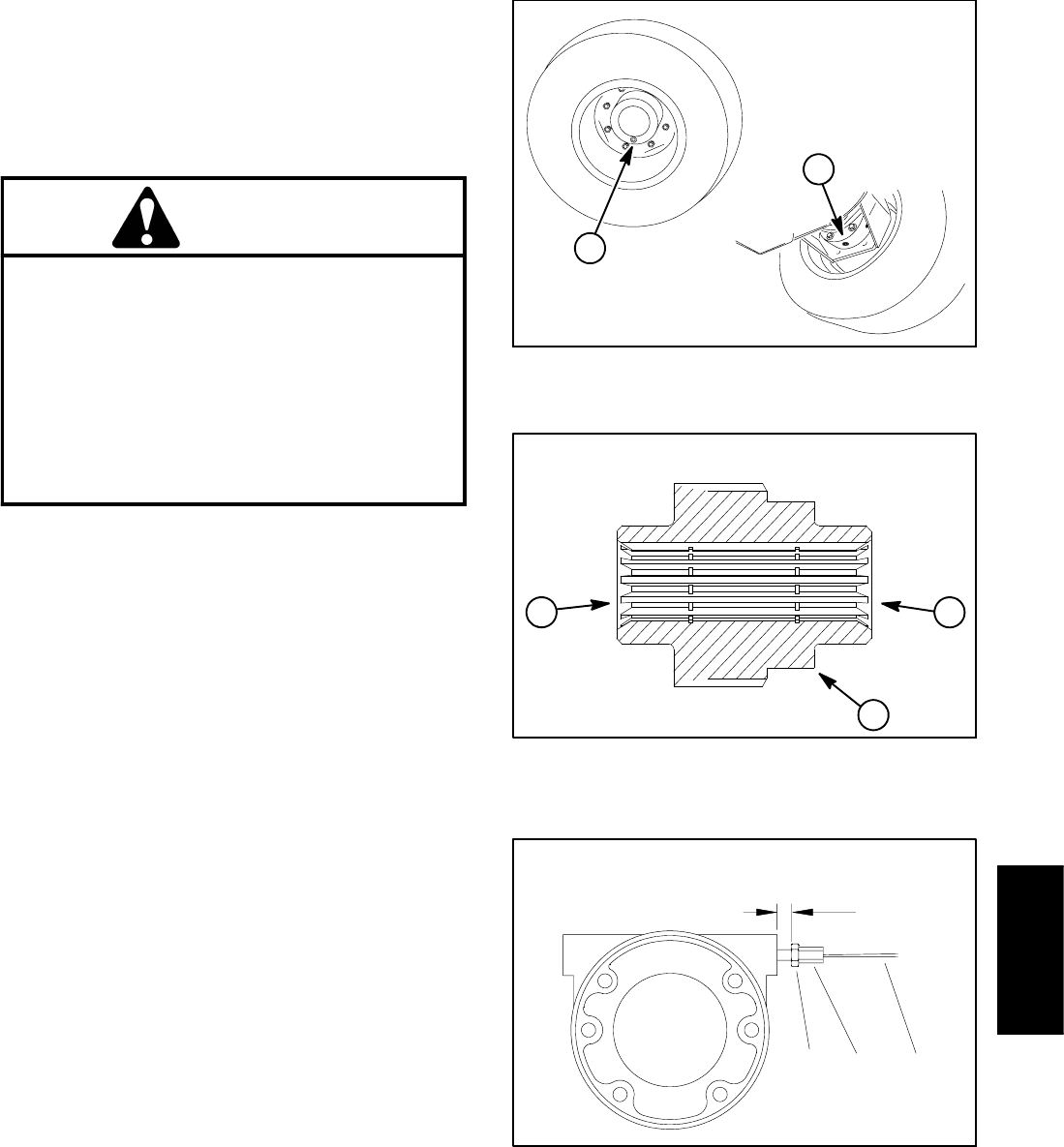
Groundsmaster 4100--D/4110--D Page 6 -- 7 Axles, Planetaries and Brakes
Removal (Fig. 1)
1. Park machine on a level surface, lower cutting deck,
stop engine and remove key from the ignition switch.
2. Drain oil from planetary wheel drive/brake assembly
(Fig. 2).
CAUTION
When removing front wheel, use correct jacks
and supports. Make sure machine is parked on a
solid, level surface such as a concrete floor.
Prior to raising machine, remove any attach-
ments that may interfere with the safe and prop-
er raising of the machine. Always chock or block
wheels. Use jack stands to support the raised
machine. If the machine is not properly sup-
ported by jack stands, the machine may move or
fall, which may result in personal injury.
3. Chock rear wheels and jack up front of machine (see
Jacking Instructions in Chapter 1 -- Safety). Support ma-
chinewithjackstands.
4. Remove front wheel assembly.
5. Remove hydraulic wheel motor (see Front Wheel
Motors in the Service and Repairs section of Chapter 4
-- Hydraulic System).
6. Disconnect brake cable from pull rod on brake as-
sembly.
7. Support brake assembly to prevent it from falling.
8. Remove flange head screws (item 16) that secure
brake assembly to frame.
9. Remove brake assembly from machine. Be careful
to not drop splined brake shaft (item 3) as brake assem-
bly is removed.
10.Remove splined brake shaft from brake assembly.
11.Remove and discard gasket (item 18). Make sure
that all gasket material is removed from both brake and
planetary assemblies.
12.Complete brake inspection and repair (see Brake In-
spection and Repair in this section).
Installation (Fig. 1)
1. Install splined brake shaft (item 3) into brake assem-
bly. NOTE: The stepped end of the splined brake shaft
must be aligned toward the hydraulic wheel motor (Fig.
3).
Figure 2
1. Planetary drain 2. Brake drain
1
2
1. Splined brake shaft step
2. Hydraulic motor end
3. Planetary assembly end
Figure 3
1
2
3
1. Pull rod jam nut
2. Brake cable
3. Brake cable hex
Figure 4
12
0.340” to 0.400”
(8.7 to 10.1 mm)
3
Axles, Planetaries
and Brakes
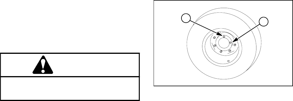
Groundsmaster 4100--D/4110--DPage 6 -- 8Axles, Planetaries and Brakes
2. Apply gasket sealant to sealing surfaces of new gas-
ket (item 18). Apply gasket to brake assembly.
3. Install brake assembly onto machine, aligning
splined brake shaft with input shaft on planetary wheel
drive. Make sure that brake pull rod is orientated toward
rear of machine.
4. Secure brake assembly to planetary assembly with
four (4) flange head screws (item 16). Tighten screws in
acrossingpatterntoatorquefrom75 to 85 ft--lb (101
to 115 N--m).
5. Secure hex on end of brake cable to pull rod on brake
assembly. Brake cable end should be completely
threaded onto pull rod before tightening jam nut.
6. Install new O--ring on hydraulic wheel motor. Install
wheel motor and torque cap screws from 75 to 85 ft--lb
(101 to 115 N--m).
7. Install wheel assembly.
WARNING
Failure to maintain proper wheel lug nut torque
could result in failure or loss of wheel and may
result in personal injury.
8. Lower machine to ground. Torque lug nuts from 85
to100ft--lb(115to135N--m).
9. Make sure drain plugs are installed in brake and
planetary drive assemblies (Fig. 2).
10.Fill planetary wheel drive/brake assembly with SAE
85W--140 gear lube (Fig. 5). Capacity is approximately
22 fl. oz. (0.65 liters) per wheel.
11. Check and adjust brake cables for proper brake op-
eration. If necessary, adjust hex on end of brake cable
so that pull rod jam nut is positioned from 0.340” to
0.400” (8.7 to 10.1 mm) from brake casting surface
when brakes are disengaged (Fig. 4). Brakes should be
adjusted so that both brake pedals have approximately
1” (25mm) of freeplay and have equal brake tension.
1. Check plug 2. Fill plug
Figure 5
1
2

Groundsmaster 4100--D/4110--D Page 6 -- 9 Axles, Planetaries and Brakes
This page is intentionally blank.
Axles, Planetaries
and Brakes
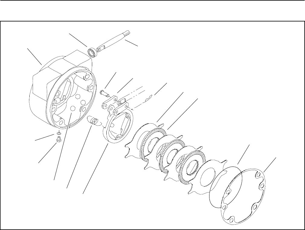
Groundsmaster 4100--D/4110--DPage 6 -- 10Axles, Planetaries and Brakes
Brake Inspection and Repair
1. Brake housing (LH shown)
2. Seal
3. Pull rod
4. Clevis pin (2 used)
5. Link (2 used)
6. Hitch pin (2 used)
7. Stationary disc (4 used)
8. Rotating disc (3 used)
9. Retaining ring
10. Gasket
11. Rotating actuator
12. Extension spring (3 used)
13. Ball (3 used)
14. Plug
15. O--ring
Figure 6
3
2
4
5
6
7
8
9
10
14
13
12
11
15
1
Brake Inspection and Repair (Fig. 6)
1. Carefully scrape gasket material (item 10) from
brake housing and planetary wheel drive mounting sur-
faces.
2. Remove retaining ring (item 9) from brake housing
groove.
3. Remove stationary discs (item 7) and rotating discs
(item 8).
4. Remove extension springs (item 12).
5. Remove actuator assembly (items 11, 6, 5, 4 and 3)
and balls (item 13).
6. Remove seal (item 2) from brake housing.
7. Wash parts in cleaning solvent. Inspect components
forwearordamage.
8. Reverse steps 2 through 6 to assemble brakes,
installing new parts as necessary. Install a new seal
(item 2).
9. Use a new gasket (item 10) when installing brake as-
sembly to machine.

Groundsmaster 4100--D/4110--D Page 6 -- 11 Axles, Planetaries and Brakes
This page is intentionally blank.
Axles, Planetaries
and Brakes
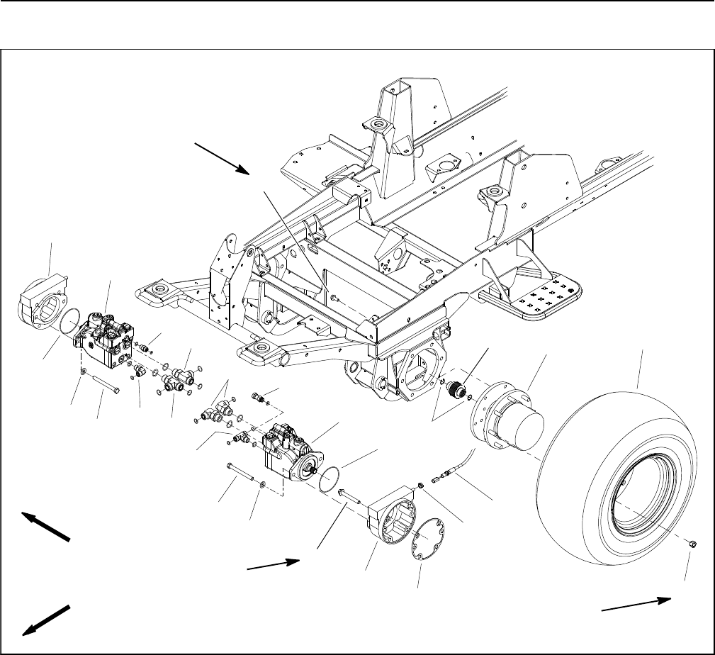
Groundsmaster 4100--D/4110--DPage 6 -- 12Axles, Planetaries and Brakes
Planetary Wheel Drive Assembly
Figure 7
FRONT
RIGHT 75 to 85 ft--lb
(101 to 115 N--m)
85 to 100 ft--lb
(115 to 135 N--m)
75 to 85 ft--lb
(101 to 115 N--m)
1. Front wheel motor
2. Internal retaining ring
3. Splined brake shaft
4. RH brake assembly
5. Planetary assembly (2 used)
6. Cap screw (2 used per motor)
7. Flat washer (2 used per motor)
8. O--ring
9. LH brake assembly
10. Hydraulic tee fitting
11. 90ohydraulic fitting (2 used)
12. Hydraulic connector
13. Hydraulic tee fitting (2 used)
14. 90ohydraulic fitting
15. Straight hydraulic fitting
16. Flange screw (4 used per brake)
17. Jam nut
18. Gasket
19. Flange screw (6 used per side)
20. Front wheel assembly
21. Lug nut (8 used per wheel)
2
3
6
8
9
11
13
1
5
7
12
14
15
4
10
1
6
7
8
13
16
17
18
19
20
21
22
NOTE: Theplanetarywheeldriveassemblycanbeser-
viced with the planetary installed to machine (see Plane-
tary Wheel Drive Service in this section). Use the
following procedure to remove and install planetary
wheel drive assembly from machine.
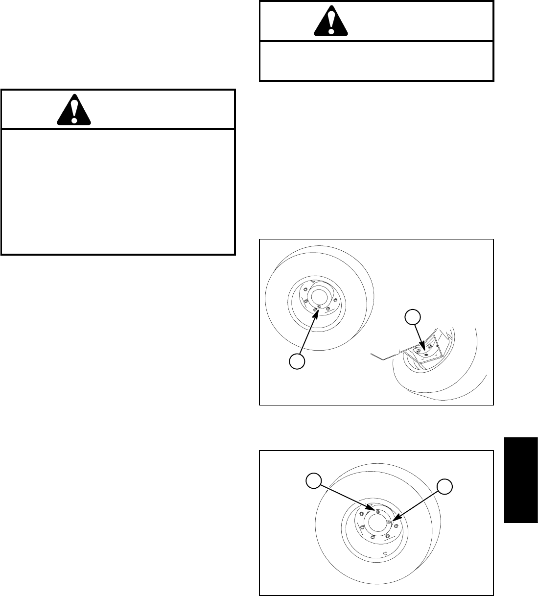
Groundsmaster 4100--D/4110--D Page 6 -- 13 Axles, Planetaries and Brakes
Removal (Fig. 7)
1. Park machine on a level surface, lower cutting deck,
stop engine and remove key from the ignition switch.
2. Drain oil from planetary wheel drive/brake assembly
(Fig. 8).
CAUTION
When removing front wheel, use correct jacks
and supports. Make sure machine is parked on a
solid, level surface such as a concrete floor.
Prior to raising machine, remove any attach-
ments that may interfere with the safe and prop-
er raising of the machine. Always chock or block
wheels. Use jack stands to support the raised
machine. If the machine is not properly sup-
ported by jack stands, the machine may move or
fall, which may result in personal injury.
3. Chock rear wheels and jack up front of machine (see
Jacking Instructions in Chapter 1 -- Safety). Support ma-
chinewithjackstands.
4. Remove front wheel assembly.
5. Remove hydraulic wheel motor (see Front Wheel
Motors in the Service and Repairs section of Chapter 4
-- Hydraulic System).
6. Remove brake assembly (see Brake Assembly in
this section).
7. Support planetary assembly to prevent it from falling.
Loosen and remove flange head screws that secure
planetary assembly to frame. Remove planetary as-
sembly from machine.
Installation (Fig. 7)
1. Position planetary assembly to machine. Install
flange head screws that secure planetary assembly.
Torque screws in a crossing pattern from 75 to 85 ft--lb
(101 to 115 N--m).
2. Install brake assembly (see Brake Assembly in this
section).
3. Install hydraulic wheel motor (see Front Wheel Mo-
tors in the Service and Repairs section of Chapter 4 --
Hydraulic System).
4. Install wheel assembly.
WARNING
Failure to maintain proper wheel lug nut torque
could result in failure or loss of wheel and may
result in personal injury.
5. Lower machine from jack stands. Torque lug nuts
from 85to100ft--lb(115to135N--m).
6. Make sure drain plugs are installed in brake and
planetary drive assemblies (Fig. 8).
7. Fill planetary wheel drive/brake assembly with SAE
85W--140 gear lube (Fig. 9). Capacity is approximately
22 fl. oz. (0.65 liters) per wheel.
8. Check and adjust brake cables for proper brake op-
eration.
1. Planetary drain 2. Brake drain
Figure 8
1
2
1. Check plug 2. Fill plug
Figure 9
1
2
Axles, Planetaries
and Brakes
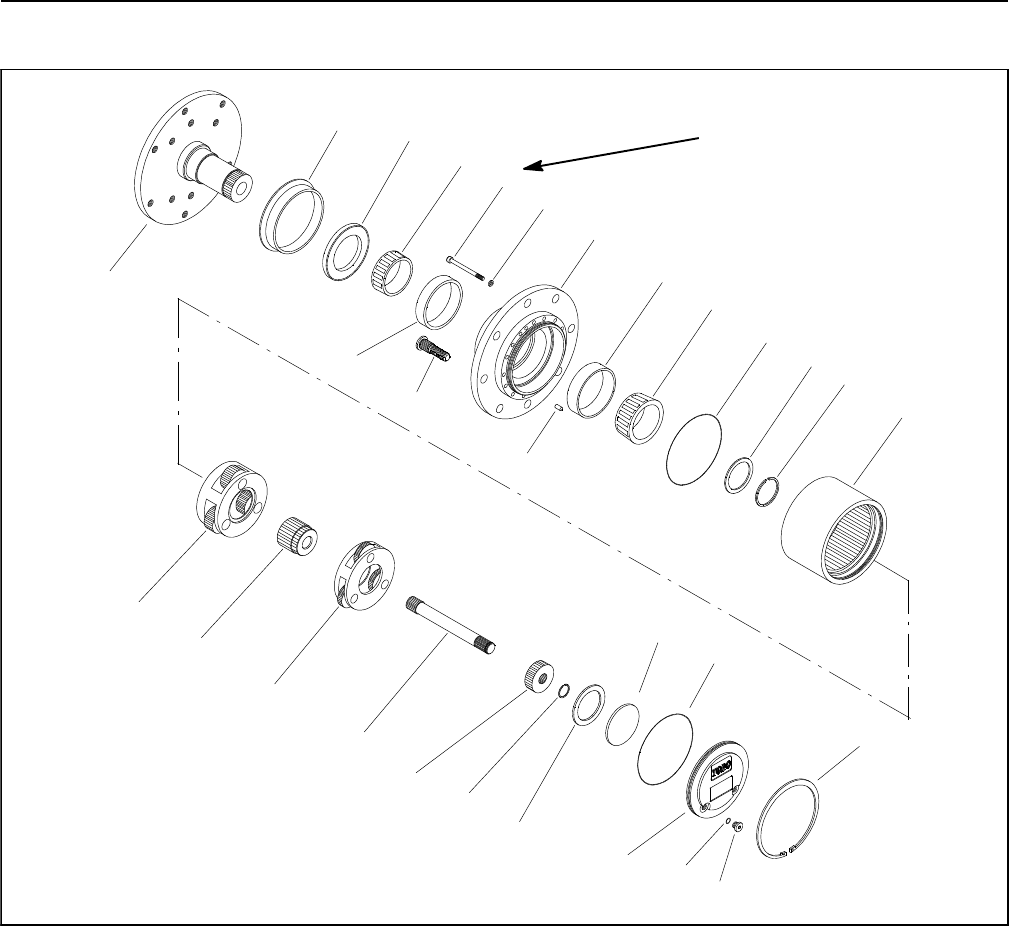
Groundsmaster 4100--D/4110--DPage 6 -- 14Axles, Planetaries and Brakes
Planetary Wheel Drive Service
1. Spindle
2. Boot seal
3. Oil seal
4. Inner bearing cone
5. Inner bearing cup
6. Wheel stud (8 used)
7. Socket head screw (16 used)
8. Lock washer (16 used)
9. Housing
10. Dowel pin (2 used)
11. Outer bearing cup
12. Outer bearing cone
13. O--ring
14. Thrust washer
15. Retaining ring (external)
16. Ring gear
17. Retaining ring (internal)
18. Plug (2 used)
19. O--ring (2 used)
20. End cap
21. Thrust plug
22. Thrust washer
23. Retaining ring
24. Primary gear
25. Drive shaft
26. Primary carrier assembly
27. Secondary gear
28. Secondary carrier assembly
Figure 10
118 to 144 in--lb
(13.3to16.3N--m)
23
1
4
5
6
8
9
7
12
13
14
15
17
18
23
21
24
22
19
11
10
16
13
27
20
25
26
28
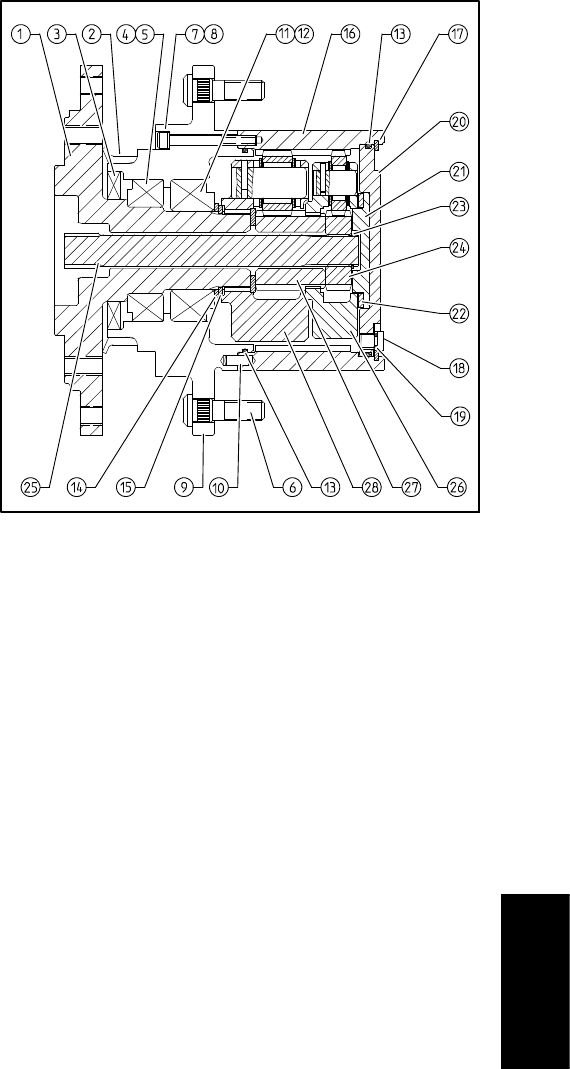
Groundsmaster 4100--D/4110--D Page 6 -- 15 Axles, Planetaries and Brakes
NOTE: The planetary wheel drive assembly can be ser-
viced with the planetary installed to machine. If the
spindle (item 1) needs to be removed from machine, see
Planetary Wheel Drive Assembly in this section.
Disassembly (Figs. 10 and 11)
1. If planetary wheel drive assembly is installed on ma-
chine:
A. Park machine on a level surface, lower cutting
units, stop engine and remove key from the ignition
switch.
B. Drain oil from planetary wheel drive/brake as-
sembly.
C. Chock rear wheels and jack up front of machine
(see Jacking Instructions in Chapter 1 -- Safety).
Support machine with jack stands.
D. Remove front wheel assembly.
2. Remove retaining ring (item 17).
3. Remove end cap (item 20). Thrust plug (item 21) and
thrust washer (item 22) usually remain in end cap bore
and should be removed for cleaning and inspection.
4. Remove drive shaft assembly (items 23, 24 and 25)
If necessary, remove retaining ring and primary gear
from shaft.
5. Remove primary carrier (item 26), secondary gear
(item 27) and secondary carrier (item 28).
NOTE: Steps 6 through 10 are necessary only if in-
specting or replacing bearings and/or seals.
IMPORTANT: Do not reuse retaining ring (item 10)
after it has been removed.
6. Remove retaining ring (item 15) and thrust washer
(item 14). Discard retaining ring.
7. Carefully remove housing (item 9) from spindle (item
1). Remove outer bearing cone (item 12).
8. Remove and discard seals (items 2 and 3) and O--
rings (item 13) from housing.
9. Remove inner bearing cone (item 4) from housing. If
necessary, remove bearing cups (items 5 and 11) from
housing.
10.If wheel stud (item 6) removal is necessary, use
press to extract stud(s) from housing.
11. If necessary, remove socket head screws (item 7)
with lock washers (item 8) that secure ring gear (item 16)
to housing. Remove ring gear and two (2) dowel pins
(item 10) from housing.
Figure 11
Assembly (Figs. 10 and 11)
1. Thoroughly clean parts in solvent and dry completely
after cleaning. Inspect parts for damage or excessive
wear and replace as necessary.
2. If any wheel studs were removed, use a press to
install new studs into housing. Make sure that stud
shoulder is fully pressed against housing surface.
NOTE: Use new seal and shim kits when assembling
planetary wheel drive.
3. If spindle and housing were separated:
A. Press bearing cups (items 5 and 11) into housing
(item 9). Cups should be pressed fully to shoulder of
the housing bore.
B. Set inner bearing cone (item 4) into inner bearing
cup.
C. Make sure that seal bore in housing is thoroughly
cleaned. If OD of seal (item 3) is not rubber or does
not have a sealant coating, apply light coating of sili-
cone sealant to seal bore in housing. Install seal into
housing so it is flush with housing face. Lightly
grease seal lips.
D. Pack boot seal (item 2) with grease and install on
housing.
E. If ring gear was removed from housing, place
dowel pins (item 10) in housing. Secure ring gear to
housing with lock washers (item 8) and socket head
screws (item 7). Torque socket head screws from
118 to 144 in--lb (13.3 to 16.3 N--m).
Axles, Planetaries
and Brakes
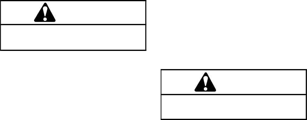
Groundsmaster 4100--D/4110--DPage 6 -- 16Axles, Planetaries and Brakes
F. Lightly oil bearing journals on spindle shaft. Slide
housing assembly onto spindle (item 1) taking care
to not damage seal or spindle. Make sure that inner
bearing in housing fully seats against spindle shaft
shoulder.
G. Install outer bearing cone (item 12) onto spindle.
NOTE: The planetary shim kit includes the retaining
ring and several thrust washers with thickness in in-
cremental steps of 0.004 inch (0.10 mm). Refer to
your Parts Catalog to identify the correct part number
for the planetary shim kit.
H. Measure thickness of thrust washer (item 14) that
was removed during disassembly. Choose new
thrust washer of equal thickness or the next available
thickness from thrust washers in the shim kit.
I. Apply a light coating of oil to spindle shaft, thrust
washer (item 14) and new retaining ring (item 15).
Install thrust washer onto spindle shaft.
WARNING
If retaining ring (item 15) is not fully installed in
spindle groove, loss of wheel and personal inju-
ry may result.
J. Carefully install new retaining ring (item 15) into
the spindle shaft groove taking care to not distort
ring. If the proper thrust washer has been installed,
the retaining ring should fit tightly between the thrust
washer and spindle groove. Tap the OD of the re-
tainingringstartinginthecenterandworkingoutto-
ward each end to ensure that the retaining ring is
properly seated into the spindle groove. Make sure
that retaining ring ID is fully seated to spindle shaft
groove.
K. After retaining ring is installed, make sure that
there is no endplay in assembly. If required, remove
retaining ring and install a thrust washer of different
thickness to adjust endplay.
L. Install new O--ring (item 13) into groove in hous-
ing.
4. Install secondary carrier (item 28), secondary gear
(item 27) and primary carrier (item 26) making sure that
carrier gear teeth align with ring gear and spline on
spindle shaft.
5. If primary gear (item 24) was removed from drive
shaft, slide gear onto shaft and secure with retaining ring
(item 23).
6. Install drive shaft assembly (items 25, 24 and 23)
making sure that drive shaft spline aligns with carrier
gears.
7. Install thrust plug (item 21) and thrust washer (item
22) into end cap (item 20). Make sure that thrust plug
and thrust washer are captive on inside of end cap (item
20).
8. Install new O--ring (item 13) to end cap and then
install end cap. Secure cap with retaining ring (item 17).
9. Check operation of planetary wheel drive. With a
constant turning force applied, rotation of the planetary
should be consistent. If there is more drag at certain
points, gears are not rolling freely and the planetary
should be examined for improper assembly or damaged
components.
10.If planetary wheel drive assembly is installed on ma-
chine:
A. Install front wheel assembly.
WARNING
Failure to maintain proper wheel lug nut torque
could result in failure or loss of wheel and may
result in personal injury.
B. Lower machine to ground. Torque wheel lug nuts
in a crossing pattern from 85to100ft--lb(116to135
N--m).
C. Make sure drain plug is installed in bottom of
brake assembly. Fill planetary wheel drive/brake as-
sembly with SAE 85W--140 gear lube to proper level.
Capacity is approximately 16 oz. (0.47 l) per wheel.

Groundsmaster 4100--D/4110--D Page 6 -- 17 Axles, Planetaries and Brakes
This page is intentionally blank.
Axles, Planetaries
and Brakes
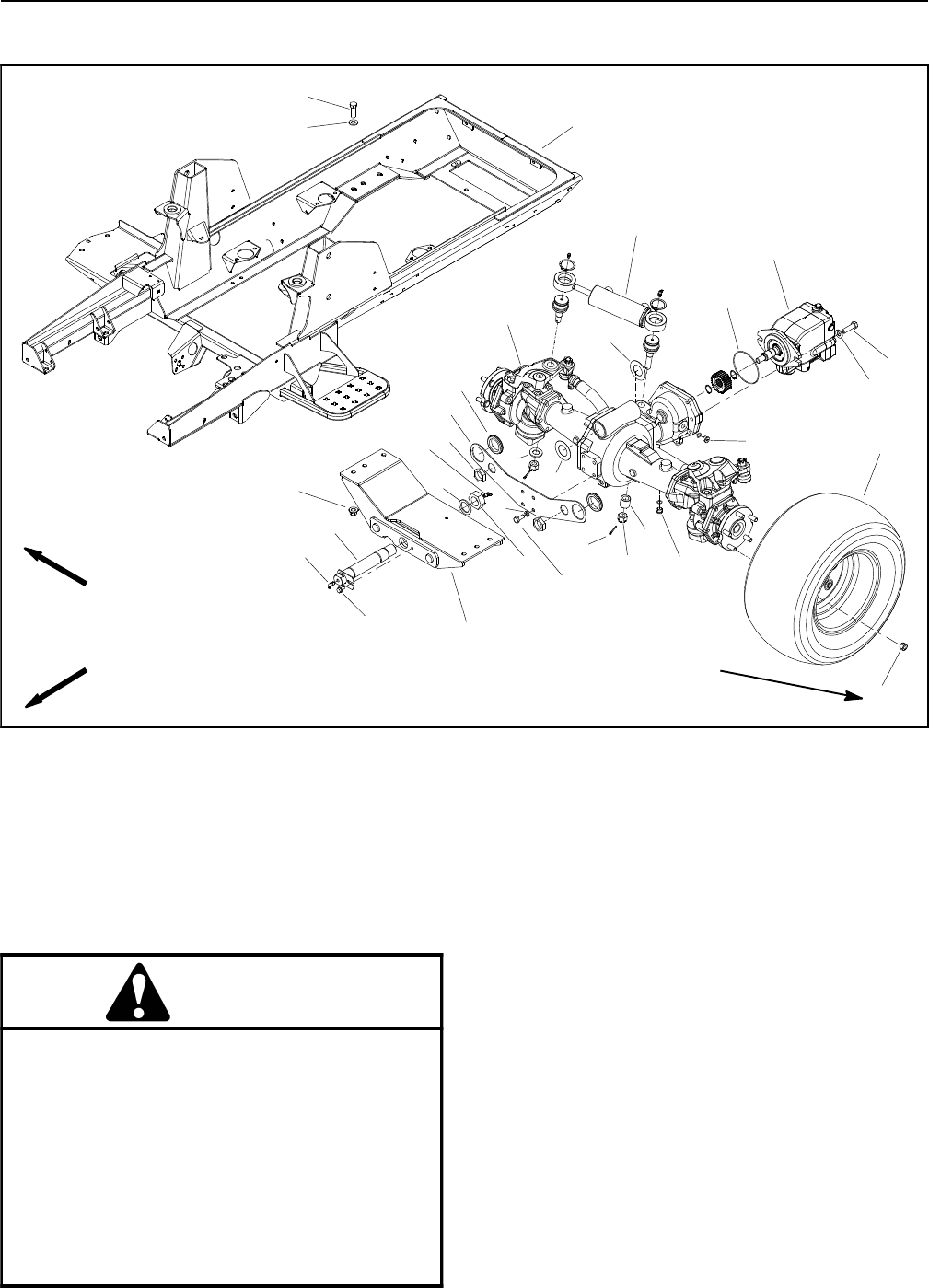
Groundsmaster 4100--D/4110--DPage 6 -- 18Axles, Planetaries and Brakes
Rear Axle Assembly
1. Plug with O--ring
2. Lug nut (5 used per wheel)
3. Rear wheel assembly (2 used)
4. Cap screw (2 used)
5. Flat washer (8 used)
6. Rear axle motor
7. O--ring
8. Steering cylinder
9. Spacer
10. Cotter pin (2 used)
11. Slotted hex nut (2 used)
12. Washer
13. Cap screw (4 used)
14. Lock washer (4 used)
15. Bulkhead mount plate
16. Grommet (2 used)
17. Bulkhead nut (2 used)
18. Cap screw (6 used)
19. Frame assembly
20. Lock nut (6 used)
21. Rear axle mount
22. Rear axle assembly
23. Lock nut
24. Thrust washer
25. Rear axle pin
26. Washer head screw
27. Grease fitting
28. Thrust washer (0.033”)
29. Thrust washer (0.018”)
Figure 12
FRONT
RIGHT
2
6
8
9
10
11
13 1
5
7
12
14
15
16
17
18
19
20
4
21
22
23
24
25
26
27
28
29
27
5
13
85 to 100 ft--lb
(115 to 135 N--m)
CAUTION
When changing attachments, tires or perform-
ing other service, use correct jacks and sup-
ports. Make sure machine is parked on a solid,
level surface such as a concrete floor. Prior to
raising machine, remove any attachments that
may interfere with the safe and proper raising of
the machine. Always chock or block wheels. Use
jack stands to support the raised machine. If the
machine is not properly supported by jack
stands, the machine may move or fall, which
may result in personal injury.
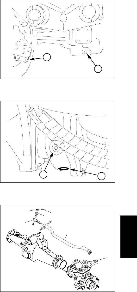
Groundsmaster 4100--D/4110--D Page 6 -- 19 Axles, Planetaries and Brakes
Removal (Fig. 12)
1. Park machine on a level surface, lower cutting deck,
stop engine, apply parking brake and remove key from
the ignition switch.
2. Drain oil from rear axle and axle gearbox (Figs. 13
and 14).
3. Chock front wheels and jack up rear of machine (see
Jacking Instructions in Chapter 1 -- Safety). Support ma-
chine with appropriate jack stands.
4. Remove both wheels from rear axle.
5. Remove hydraulic motor from rear axle assembly
(see Rear Axle Motor in the Service and Repairs section
of Chapter 4 -- Hydraulic System).
6. Remove steering cylinder from rear axle (see Steer-
ing Cylinder in the Service and Repairs section of Chap-
ter 4 -- Hydraulic System).
7. Remove cap screws and lock washers that secure
bulkhead mount plate (item 15) to rear axle. Separate
mount plate from rear axle and support it along with at-
tached hydraulic hoses and tubes to allow the rear axle
to be lowered from machine.
8. If required, remove tie rod ends from steering arms
on rear axle (Fig. 15). Remove the cotter pins and castle
nuts from the tie rod ball joints. Use a ball joint fork and
remove the tie rod ends from the axle steering arms.
9. Support rear axle to prevent it from falling. Remove
six (6) cap screws, flat washers and lock nuts that se-
cure rear axle mount to machine frame. Lower rear axle
and rear axle mount from machine.
10.Remove lock nut and washer from rear axle pin that
attaches rear axle to rear axle mount. Remove washer
head screw that secures flange of rear axle pin to axle
mount (Fig. 16).
11.Remove rear axle pin from rear axle and mount. Sep-
arate rear axle mount from rear axle. Note location of
thrust washers (items 28 and 29) on both ends of axle
mounting boss.
Installation (Fig. 12)
1. Position rear axle mount to axle. Install thrust wash-
ers (items 28 and 29) between axle boss and axle
mount. The thicker thrust washer should be installed on
thehydraulicmotorendoftheaxle(towardtherearof
the machine). With washers installed, there should be
from 0.002” to 0.020” (0.05 mm to 0.51 mm) clearance
between rear axle mount and axle mounting boss. Add
thrust washers if needed to adjust clearance.
1. Center axle drain plug 2. Outside plug (2 used)
Figure 13
1
2
1. Gearbox drain plug 2. Gearbox fill plug
Figure 14
1
2
1. Tie rod
2. Dust cover
3. Cotter pin
4. Castle nut
5. Tie rod end
6. Steering arm (LH)
Figure 15
1
2
3
5
4
6
Axles, Planetaries
and Brakes
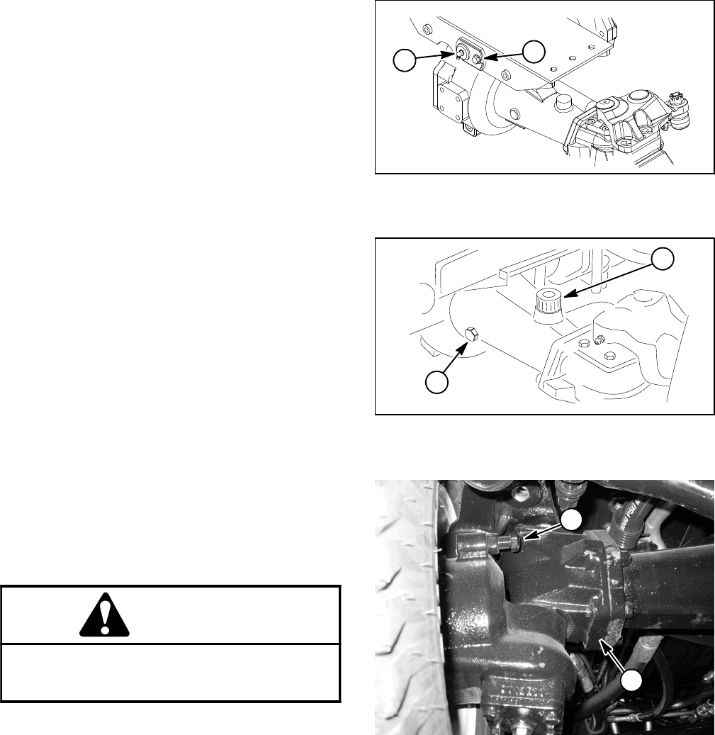
Groundsmaster 4100--D/4110--DPage 6 -- 20Axles, Planetaries and Brakes
2. Secure rear axle to rear axle mount.
A. Slide rear axle pin through rear axle mount and
rear axle. Install washer and lock nut onto rear axle
pin.
B. Secure pivot pin to axle mount with washer head
screw (Fig. 16).
C. Torque lock nut from 135 to 165 ft--lb (184 to 223
N--m). After tightening the lock nut, makes sure that
the rear axle pivots freely.
3. Position rear axle with attached mount under ma-
chine. With a jack, raise assembly to machine frame and
align mounting holes of rear axle mount and machine
frame.
4. Secure rear axle mount to frame with six (6) cap
screws, flat washers and lock nuts.
5. If removed, install the tie rod to rear axle (Fig. 15).
Tighten ball joint castle nuts and install new cotter pins.
6. Position bulkhead mount plate (item 15) with at-
tached hydraulic hoses and tubes to rear axle. Secure
mount plate to axle with cap screws and lock washers.
7. Install steering cylinder to rear axle assembly (see
Steering Cylinder in the Service and Repairs section of
Chapter 4 -- Hydraulic System).
8. Install hydraulic motor to rear axle assembly (see
Rear Axle Motor in the Service and Repairs section of
Chapter 4 -- Hydraulic System).
WARNING
Failure to maintain proper wheel lug nut torque
could result in failure or loss of wheel and may
result in personal injury.
9. Install rear wheels to axle.
10.Lower machine to ground. Torque wheel lug nuts
from 85 to 100 ft--lb (115 to 135 N--m).
11. Fill gearbox and rear axle with SAE 85W--140 weight
gear lube (Figs. 14 and 17). Lubricant capacity is
approximately 16 fl. oz. (0.47 liters) for the gearbox and
80 fl. oz. (2.37 liters) for the rear axle assembly.
12.Check rear wheel toe--in and adjust if necessary.
13.Check steering stop bolt adjustment. When the
steering cylinder is fully extended (right turn), a gap of
1/16” (1.6 mm) should exist between bevel gear case
casting and stop bolt on left axle case. Figure 18 shows
stop bolt location.
1. Rear axle pin 2. Washer head screw
Figure 16
12
1. Rear axle check plug 2. Rear axle fill plug
Figure 17
1
2
1. Steering stop bolt 2. Bevel gear case (LH)
Figure 18
1
2

Groundsmaster 4100--D/4110--D Page 6 -- 21 Axles, Planetaries and Brakes
This page is intentionally blank.
Axles, Planetaries
and Brakes
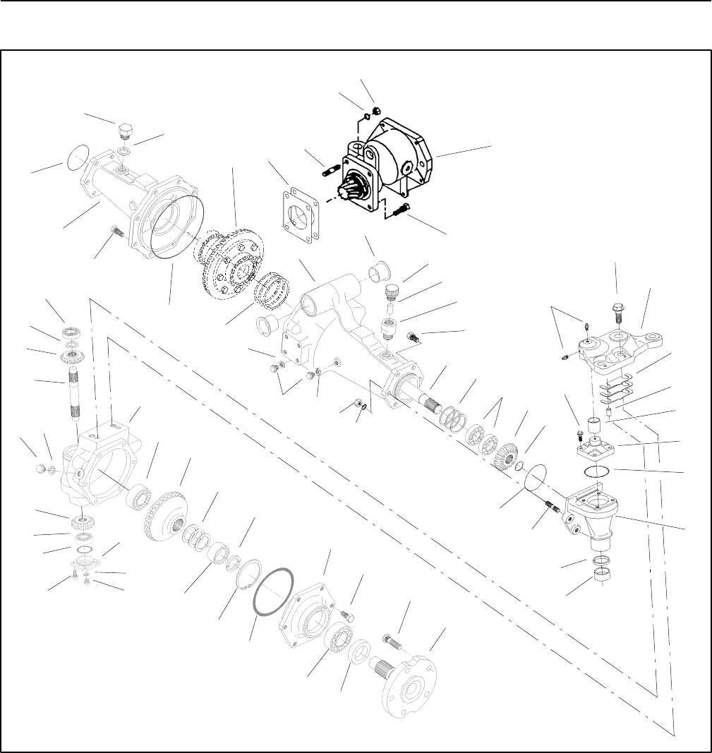
Groundsmaster 4100--D/4110--DPage 6 -- 22Axles, Planetaries and Brakes
Rear Axle Service
Figure 19
3
2
4
5
6
7
8
9
10
14
13 12
11
15
1
10
11
8
9
8
13
16
17
18
19
21
22
23
24
25
26
27
28
29
30
31
32
33
34
35
36
37
38
39
40
20
41
42
43
50
44
45
46
47
48
49
51
54
55
56
57
58
59
52
53
60
61
62
63
64
22

Groundsmaster 4100--D/4110--D Page 6 -- 23 Axles, Planetaries and Brakes
1. LH axle support
2. Flange bushing (2 used)
3. Axle vent
4. Filter
5. Vent extension
6. Cap screw (4 used per gear case)
7. Shim set
8. Seal washer
9. Plug
10. Lock nut
11. Lock washer
12. Grease fitting
13. Ball bearing
14. Screw (2 used per steering arm)
15. Axle case support (LH shown)
16. Bolt (2 used)
17. Stud (2 used)
18. Shim set
19. Differential assembly
20. O--ring
21. Plug
22. O--ring
23. RH axle support
24. Input shaft assembly
25. Bolt (8 used)
26. O--ring
27. Differential shaft (LH shown)
28. Shim set
29. Ball bearing
30. Bevel gear (15 tooth)
31. Retaining ring
32. Bolt (4 used per knuckle)
33. Shim set
34. Dowel pin (2 used per axle case)
35. Bushing
36. Knuckle pin
37. O--ring
38. Bevel gear case (LH shown)
39. Bushing
40. Shaft seal
41. Stud (2 used per gear case)
42. Bolt (4 used per cover)
43. Collar
44. Bevel gear (17 tooth)
45. Bevel gear shaft
46. Axle case (LH shown)
47. Ball bearing
48. Bevel gear (29 tooth)
49. Shim set
50. Clip (2 used per axle case)
51. Axle cover
52. Screw (6 used per cover)
53. Wheel stud (5 used per axle)
54. Axle
55. Oil seal
56. Ball bearing
57. O--ring
58. Retaining ring
59. Spacer
60. Axle case cover
61. Seal washer
62. Plug
63. Bevel gear (17 tooth)
64. O--ring
Figure 19 (Continued)
NOTE: Figure 19 illustrates the rear axle used on the
Groundsmaster 4100--D and 4110--D. Service proce-
dures for the rear axle is on the following pages of this
section.
Axles, Planetaries
and Brakes
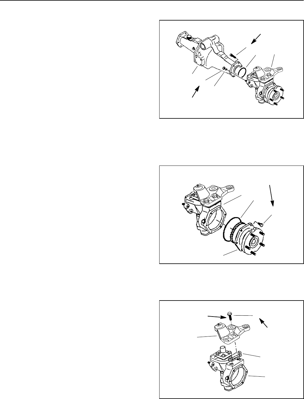
Groundsmaster 4100--D/4110--DPage 6 -- 24Axles, Planetaries and Brakes
Bevel Gear Case and Axle Case
The following procedures assume the rear axle assem-
bly has been removed from the machine.
Removal
1. Remove the mounting screws, nuts and lock wash-
ers. Remove the bevel gear case/axle case assembly
and O-ring from the axle support (Fig. 20).
2. Mark both right and left bevel gear case/axle case
assemblies.
IMPORTANT: Do not interchange right and left bev-
el gear case/axle case assemblies.
1
2
3
4
5
6
1. Cap screw (4 used)
2. Lock nut (2 used)
3. Lock washer (2 used)
4. Axle support
5. Bevel gear case/axle
case assembly
6. O-ring
Figure 20
35 to 41 ft--lb
(47to56N--m)
35 to 41 ft--lb
(47 to 56 N--m)
3. Remove the axle cover mounting screws. Remove
the axle cover from the axle case as an assembly
(Fig. 21).
1. Axle case
2. Axle cover assembly
3. Screw (6 used)
4. O-ring
Figure 21
1
2
3
4
17 to 20 ft--lb
(23to27N--m)
4. Remove the axle case support mounting screws, the
axle case support and the support shims (Fig. 22).
1. Axle case
2. Axle case support
3. Screw (2 used)
4. Support shim
Figure 22
1
2
3
4
57 to 67 ft--lb
(77to91N--m)
Threadlocking
Compound
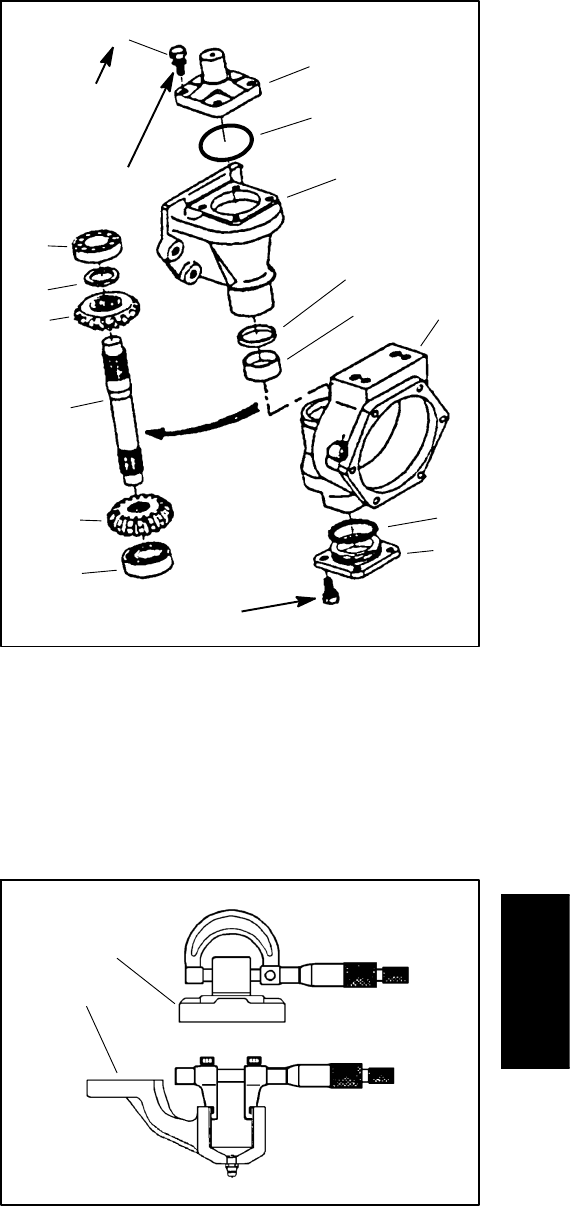
Groundsmaster 4100--D/4110--D Page 6 -- 25 Axles, Planetaries and Brakes
5. Remove the knuckle pin mounting screws and the
knuckle pin. Remove the gasket and any remaining gas-
ket material from either mating surface (Fig. 23).
6. While holding the bevel gear case, tap the upper end
of the bevel gear shaft out of the upper bearing and up-
per bevel gear.
7. Pull the bevel gear case from the axle case and re-
move the upper bevel gear and collar from the gear
case.
8. Remove the axle case cover screws, cover and the
O-ring from the axle case.
9. Remove the plug and sealing washer from the center
of the axle case cover. While holding the axle case cov-
er, lightly tap the lower end of the bevel gear shaft out of
the lower bearing and lower bevel gear.
10.Remove and discard bevel gear shaft seal from axle
case (Fig. 23).
1. Knuckle pin
2. Mounting screw (4 used)
3. O--ring
4. Bevel gear case
5. Upper bearing
6. Bevel gear shaft
7. Collar
8. Upper bevel gear
9. Lower bevel gear
10. Lower bearing
11. Axle case
12. Axle case cover
13. O-ring
14. Shaft seal
15. Bushing
Figure 23
1
2
3
4
5
6
7
8
9
10
11
12
13
14
15
17 to 20 ft--lb
(23to27N--m)
17 to 20 ft--lb
(23 to 27 N--m)
Threadlocking
Compound
Inspection
1. Measure the knuckle pin O.D. and the axle case sup-
port bushing I.D. to determine the bushing to pin clear-
ance (Fig. 24). Replace components as necessary.
BUSHING TO PIN CLEARANCE:
0.002to0.016inch(0.05to0.40mm)
KNUCKLE PIN O.D. (Factory Spec.):
0.982 to 0.983 inch (24.95 to 24.98 mm)
AXLE CASE SUPPORT BUSHING I.D.
(Factory Spec.):
0.984 to 0.987 inch (25.00 to 25.08 mm)
2. Inspect all gears, shafts, bearings, cases and covers
for damage and wear. Replace components as neces-
sary.
1. Knuckle pin 2. Axle case support
Figure 24
1
2
Axles, Planetaries
and Brakes
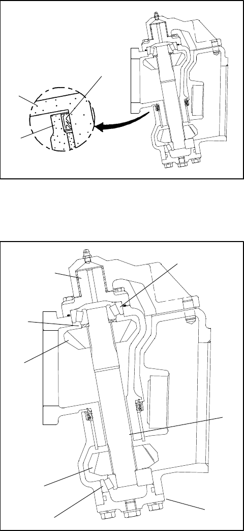
Groundsmaster 4100--D/4110--DPage 6 -- 26Axles, Planetaries and Brakes
Installation
1. Coat new shaft seal with grease and install in axle
case as shown (Fig. 25).
1. Axle case
2. Bevel gear case
3. Shaft seal
Figure 25
1
2
3
2. Install the lower bevel gear and bevel gear shaft in
the axle case cover. Coat a new O-ring with grease and
install the axle case cover (Fig. 26). Tighten cover
screws from 17 to 20 ft-lb (23 to 27 N--m).
3. Slide the bevel gear case over the bevel gear shaft
and install the bevel gear and collar. Make sure the bevel
gear shaft is completely seated in the upper and lower
bearings (Fig. 26).
4. Install the knuckle pin. Use medium strength thread-
locking compound and tighten the knuckle pin mounting
screws from 17 to 20 ft-lb (23 to 27 N--m).
1. Axle case cover
2. Lower bevel gear
3. Bevel gear shaft
4. Lower bearing
5. Upper bevel gear
6. Collar
7. Upper bearing
8. Knuckle pin
Figure 26
1
2
3
4
5
6
7
8
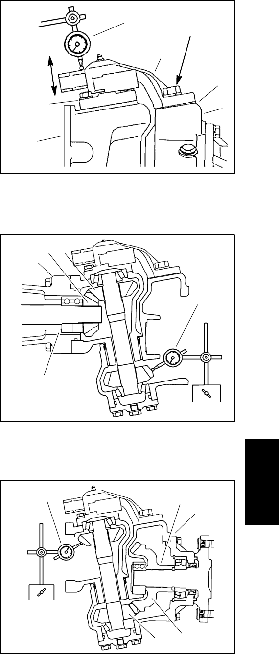
Groundsmaster 4100--D/4110--D Page 6 -- 27 Axles, Planetaries and Brakes
5. Determine necessary quantity of support shims.
A. Lubricatetheaxlecasesupportbushingwitha
thin coat of grease and slide axle case support onto
knuckle pin.
B. Position support shims that were removed during
disassembly between axle case support and axle
case. Install mounting screws into axle case. Slowly
tighten screws while frequently checking for clear-
ance (vertical endplay) between axle case support
and knuckle pin. If binding of components is noted
before screws are fully tightened, add additional sup-
port shims. Torque screws from 57 to 67 ft--lb (77 to
91 N--m).
C. Use dial indicator to measure vertical endplay of
axle case (Fig. 27).
AXLE CASE ASSEMBLY ENDPLAY:
0.001to0.008inch(0.02to0.20mm)
D. Adjust endplay by increasing or reducing number
of axle case support shims.
NOTE: Axle case support shims are available in
0.004 inch (0.1 mm), 0.008 inch (0.2 mm) and 0.016
inch (0.4 mm) thickness.
6. After correct support shims have been determined,
remove mounting screws, apply heavy strength thread-
locking compound to screw threads, reinstall screws
and torque from 57 to 67 ft--lb (77 to 91 N--m).
IMPORTANT: Correct engagement between bevel
gears is critical to axle performance and durability.
7. Temporarily install the bevel gear case/axle case as-
sembly on the axle support. Position a dial indicator at
the tooths center. Prevent the axle from turning and
measure the upper bevel gear to differential shaft gear
backlash (Fig. 28).
UPPER BEVEL GEAR BACKLASH:
0.004to0.016inch(0.10to0.40mm)
8. Adjust backlash by increasing or reducing axle bear-
ing shim thickness (see Differential Shafts in this section
of this manual).
NOTE: Axle bearing shims are available in 0.004 inch
(0.1 mm), 0.008 inch (0.2 mm) and 0.020 inch (0.5 mm)
thickness.
1. Axle case support
2. Axle case
3. Bevel gearcase
4. Dial indicator
5. Knuckle pin
6. Support shim location
Figure 27
1
2
4
5
3
6
VERTICAL
ENDPLAY
57 to 67 ft--lb
(77 to 91 N--m)
1
2
3
4
5
1. Axle support
2. Upper bevel gear
3. Differential shaft gear
4. Dial indicator
5. Axle bearing shims
Figure 28
1. Axle cover assembly
2. Lower bevel gear
3. Axle gear
4. Dial indicator
5. Axle bearing shims
Figure 29
1
23
45
Axles, Planetaries
and Brakes
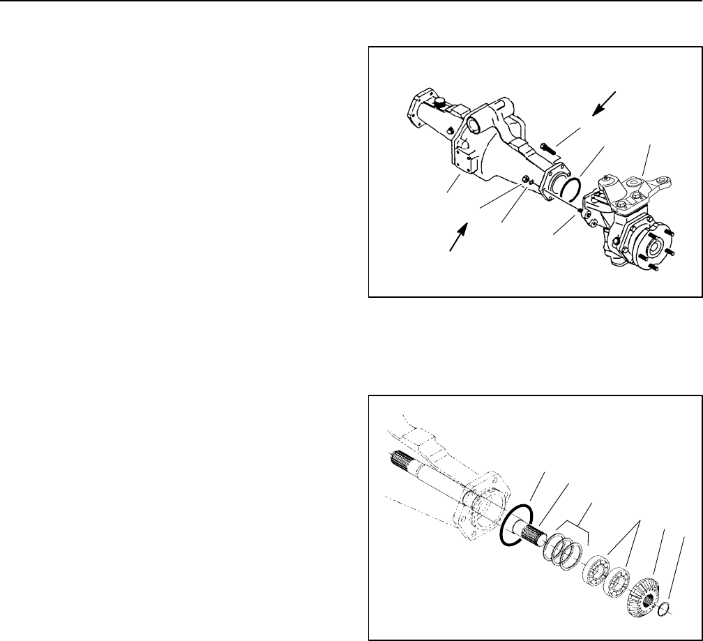
Groundsmaster 4100--D/4110--DPage 6 -- 28Axles, Planetaries and Brakes
9. Remove the bevel gear case/axle case assembly
from the axle support. Coat a new O-ring with grease
and temporarily install the axle cover assembly. Position
a dial indicator at the tooths center. Prevent the axle
from turning and measure the lower bevel gear to axle
gear backlash (Fig. 29).
LOWER BEVEL GEAR BACKLASH:
0.004to0.016inch(0.10to0.40mm)
10.Adjust backlash by increasing or reducing axle bear-
ing shim thickness (see Axle Shafts in this section of this
manual).
NOTE: Axle bearing shims are available in 0.008 inch
(0.2 mm), 0.012 inch (0.3 mm) and 0.020 inch (0.5 mm)
thickness.
11. Tighten axle cover screws from 17 to 20 ft-lb (23 to
27 N--m).
12.Coat a new O-ring with grease and install the bevel
gear case/axle case assembly on the axle support.
Tighten mounting screws and nuts from 35 to 41 ft-lb
(47to56N--m)(Fig. 30).
Differential Shafts
The following procedures assume the rear axle assem-
bly has been removed from the machine.
Removal
IMPORTANT: Do not interchange right and left dif-
ferential shaft assemblies.
1. Remove the mounting screws, nuts and lock wash-
ers. Remove the bevel gear case/axle case assembly
and O-ring from the axle support (Fig. 30).
2. Mark and pull the differential shaft assembly from the
axle support.
3. Remove the retaining ring and bevel gear (Fig 31).
4. Drive the differential shaft out of the bearings. Re-
move the bearings and bearing shims.
5. Inspect all gears, shafts, bearings and cases for
damage and wear. Replace components as necessary.
Installation
1. Press bearings onto differential shaft. Place correct
combination of bearing shims in axle support and drive
differential shaft and bearing assembly into axle sup-
port.
2. Install bevel gear and retaining ring.
3. Coat new O-ring with grease. Align differential shaft
splines with differential gear assembly and slide differ-
ential shaft assembly onto axle support.
4. Install bevel gear case/axle case assembly (see
Bevel Gear Case/Axle Case Assembly in this section of
this manual).
1
2
3
4
5
6
1. Cap screw (4 used)
2. Lock nut (2 used)
3. Lock washer (2 used)
4. Axle support
5. Bevel gear/axle case
assembly
6. O-ring
7. Stud (2 used)
Figure 30
7
35 to 41 ft--lb
(47to56N--m)
35 to 41 ft--lb
(47to56N--m)
1
2
3
4
5
6
1. Retaining ring
2. Bevel gear
3. Differential shaft
4. Bearing
5. Bearing shims
6. O-ring
Figure 31
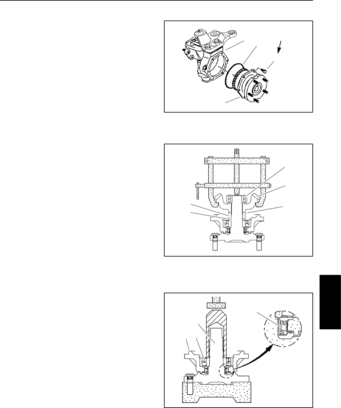
Groundsmaster 4100--D/4110--D Page 6 -- 29 Axles, Planetaries and Brakes
Axle Shafts
The following procedures assume the rear axle assem-
bly has been removed from the machine.
Removal
1. Remove the axle cover mounting screws. Remove
theaxlecoverfromtheaxlecaseasanassembly
(Fig. 32).
2. Use a bearing puller to remove the bearing and bevel
gear as shown (Fig. 33).
3. Remove the shims, spacer and retaining ring. Drive
the axle out of the bearing and cover. Remove and dis-
cardtheaxleshaftseal.
4. Inspect all gears, shafts, bearings, spacers and
cases for damage and wear. Replace components as
necessary.
Installation
1. Coat new axle shaft seal with grease and install in
axle cover as shown (Fig. 34).
2. Press the axle cover and bearing assembly onto the
axle shaft. Press only on the inner race of the cover
bearing (Fig. 34).
3. Install retaining ring, spacer and correct combination
of bearing shims. Install bevel gear and bearing.
4. Coat a new O-ring with grease and install the axle
cover assembly. Tighten axle cover screws from 17 to
20 ft-lb (23 to 27 N--m).
1
2
3
4
1. Axle case
2. Axle cover assembly
3. Screw (6 used)
4. O-ring
Figure 32
17 to 20 ft--lb
(23to27N--m)
1. Bearing
2. Bevel gear
3. Shims
4. Spacer
5. Retaining ring
Figure 33
1
2
3
4
5
1. Axle shaft seal
2. Axle cover
3. Bearing
4. Axle shaft
Figure 34
1
23
4
Axles, Planetaries
and Brakes
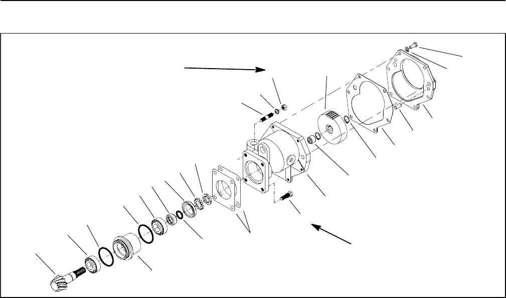
Groundsmaster 4100--D/4110--DPage 6 -- 30Axles, Planetaries and Brakes
Input Shaft/Pinion Gear
Figure 35
1
1. Nut (2 used)
2. Lock washer (2 used)
3. Stud (2 used)
4. Lock nut
5. Stake washer
6. Oil seal
7. O-ring
8. Seal collar
9. Bearing
10. O-ring
11. Input shaft/pinion gear
12. Bearing case
13. Shim
14. Screw (2 used)
15. Gear case
16. Gasket
17. Cover plate
18. Dowel pin (2 used)
19. Lock washer (6 used)
20. Cap screw (6 used)
21. Retaining ring (2 used)
22. Driven gear (45 tooth)
23. Needle bearing
2
3
4
5
6
7
8
9
10
9
11
12
13
14
15
16
17
10
18
35 to 41 ft--lb
(47to56N--m)
35 to 41 ft--lb
(47to56N--m) 19
20
22
21
23
The following procedures assume the rear axle assem-
bly has been removed from the machine.
Removal (Fig. 35)
1. Remove the cover plate, gasket and gear case as-
sembly from the axle assembly. Remove the gasket and
any remaining gasket material.
2. Remove the retaining rings, the driven gear and the
needle bearing from the input shaft/pinion gear.
3. Remove input shaft/pinion gear assembly from the
gear case. Remove the shims and bearing case O-
rings.
4. Release the stake washer and remove the lock nut.
Remove and discard the stake washer.
5. Drive the input shaft/pinion gear out from the outer
bearing cone and bearing case. Remove and discard
the oil seal and O-ring.
6. Inspect all gears, shafts, bearings, spacers and
cases for damage and wear. Replace components as
necessary.
NOTE: Replacement input shaft/pinion gear (item 11)
is only available in matched set with differential ring
gear.
Installation (Fig. 35)
NOTE: When installing bearing cones onto the input
shaft/pinion gear, press only on the inner race of the
bearing cone.
1. If the inner bearing cone was removed, press a new
bearing cone all the way onto the input shaft/pinion gear.
2. Place the shaft and bearing assembly in the bearing
case and install the outer bearing cone.
NOTE: The bearings must be completely seated.
There should be no input shaft/pinion gear end play.
3. Coat a new oil seal with grease and install as shown
in Figure 36. The seal should be installed with the garter
spring towards the hydraulic motor location.
4. Coat new O-ring with grease. Install O-ring in the oil
seal collar and install the collar.
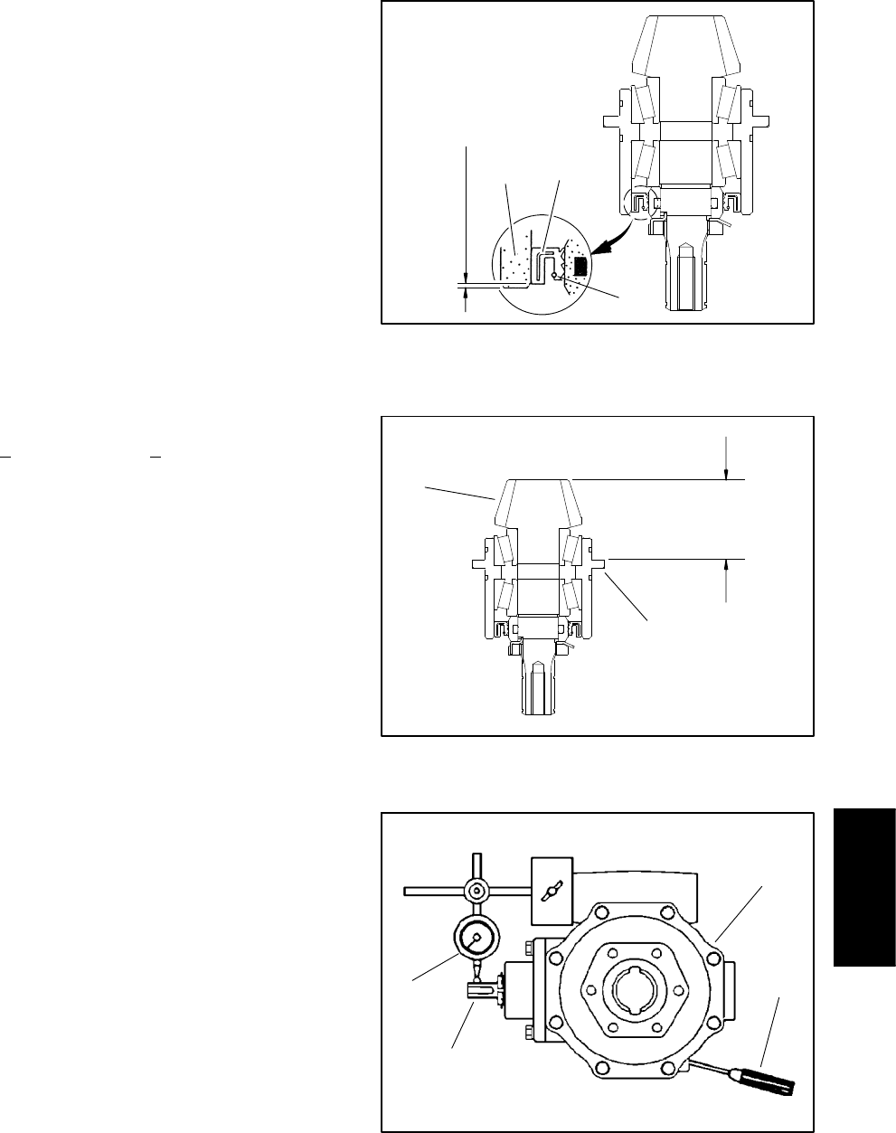
Groundsmaster 4100--D/4110--D Page 6 -- 31 Axles, Planetaries and Brakes
5. Install a new stake washer. Install the lock nut finger
tight.
6. Set the bearing preload by securing the bearing case
in a vise. Thread a M12 x 1.5 hex head cap screw into
the splined end of the input shaft/pinion gear and slowly
tighten the lock nut until 4 to 6 in-lb (0.4 to 0.7 N--m) of
force is required to rotate the input shaft/pinion gear in
the bearing case.
7. Secure the lock nut with the stake washer.
8. Use a depth gauge to measure the distance from the
end face of the input shaft/pinion gear to the mating sur-
face of the bearing case. Subtract the “Design Cone
Center Distance” from this distance to determine initial
shim thickness (Fig. 37).
DESIGN CONE CENTER DISTANCE
(distance from mating surface of axle support to end
face of pinion gear):
1.870 + 0.002 inch (47.5 + 0.05 mm)
NOTE: Bearing case shims are available in 0.004 inch
(0.1 mm) and 0.008 inch (0.2 mm) thickness.
9. Coat new O-rings with grease and install the bearing
case in the gear case. Place shims on the gear case and
temporarily install gear case assembly into axle case.
Tighten mounting nuts and screws from 35 to 41 ft-lb
(47to56N--m).
10.Insert a screwdriver through the drain plug hole to
hold ring gear and measure the pinion gear to ring gear
backlash (Fig. 38).
PINION GEAR TO RING GEAR BACKLASH:
0.004to0.016inch(0.10to0.40mm)
11. Adjust backlash by increasing or reducing gear case
shim thickness.
12.Check pinion gear to ring gear engagement (see Pin-
ion Gear to Ring Gear Engagement in this section of this
manual).
13.Place the correct combination of shims on the gear
case. Tighten mounting nuts and screws from 35 to 41
ft-lb (47 to 56 N--m).
14.Install retaining rings and driven gear on input shaft/
pinion gear.
15.If the drive gear (on drive motor shaft) was removed,
install the retaining rings and drive gear on the motor
shaft.
16.Use a new gasket and install the cover plate. Use a
new O-ring and install the drive motor.
1. Oil seal
2. Bearing case
3. Seal garter spring
Figure 36
1
2
3
0.040 in. (1.0 mm)
1. Input shaft/pinion gear 2. Bearing case
Figure 37
1
2
Design
Cone Center
Distance
1. Axle case
2. Screwdriver
3. Dial indicator
4. Input shaft/pinion gear
Figure 38
1
2
3
4
Axles, Planetaries
and Brakes
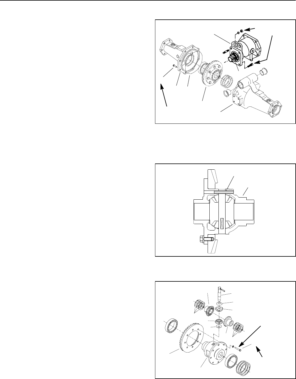
Groundsmaster 4100--D/4110--DPage 6 -- 32Axles, Planetaries and Brakes
Differential Gear
The following procedures assume the rear axle assem-
bly has been removed from the machine.
Removal
1. Remove bevel gear case/axle case assemblies (see
Bevel Gear Case/Axle Case Assembly in this section of
this manual).
IMPORTANT: Do not interchange right and left dif-
ferential shafts assemblies.
2. Mark and pull the differential shaft assemblies from
theaxlesupport.
3. Remove input shaft/pinion gear assembly, shims
and O-ring from the axle support (Fig. 39).
4. Remove the axle support case screws. Separate the
axle support halves and remove the O-ring.
5. Remove the differential gear assembly, bearings and
adjusting shims from the axle case.
6. Drive the spring pin from the differential case with a
punch and hammer. Discard the spring pin (Fig. 40).
NOTE: Mark and arrange all components so they can
be reassembled in their original position.
7. Remove the differential pinion shaft, pinion gears
and pinion washers. Remove the differential side gears
and side gear shims. Remove the ring gear only if it will
be replaced (Fig. 41).
NOTE: Replacement ring gears are only available in
matched ring and pinion sets.
1. Gear Case
2. Pinion Gear
3. Axle support (left)
4. Axle support (right)
5. Case screw (8 used)
6. Differential gear
7. O-ring
Figure 39
1
3
4
5
6
7
2
35 to 41 ft--lb
(47 to 56 N--m)
35 to 41 ft--lb
(47to56N--m)
1. Differential case 2. Spring pin
Figure 40
1
2
1. Differential pinion shaft
2. Pinion gear
3. Pinion washer
4. Side gear
5. Side gear shims
6. Ring gear
7. Differential case
8. Bolt/washer (8 used)
Figure 41
22 to 25 ft--lb
(30to34N--m)
Threadlocking
Compound
1
3
45
6
7
2
2
3
4
5
8
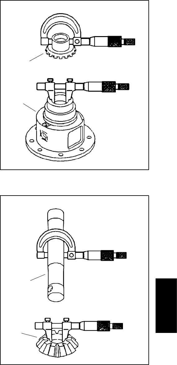
Groundsmaster 4100--D/4110--D Page 6 -- 33 Axles, Planetaries and Brakes
Inspection
1. Measure the differential side gear O.D. and the dif-
ferential case I.D. to determine the side gear to case
clearance (Fig. 42). Replace components as necessary.
SIDE GEAR TO CASE CLEARANCE:
0.002to0.012inch(0.05to0.30mm)
SIDE GEAR O.D. (Factory Spec.):
1.335 to 1.337 inch (33.91 to 33.95 mm)
DIFFERENTIAL CASE I.D. (Factory Spec.):
1.339 to 1.341 inch (34.00 to 34.06 mm)
2. Measure the differential pinion shaft O.D. and the
pinion gear I.D. to determine the pinion shaft to pinion
gear clearance (Fig. 43). Replace components as nec-
essary.
PINION SHAFT TO PINION GEAR CLEARANCE:
0.001to0.010inch(0.03to0.25mm)
PINION SHAFT O.D. (Factory Spec.):
0.550 to 0.551 inch (13.97 to 13.10 mm)
PINION GEAR I.D. (Factory Spec.):
0.551 to 0.552 inch (13.10 to 14.02 mm)
3. Inspect all gears, shafts, bearings, cases and covers
for damage and wear. Replace components as neces-
sary.
1. Side gear 2. Differential case
Figure 42
1
2
1. Pinion shaft 2. Pinion gear
Figure 43
1
2
Axles, Planetaries
and Brakes

Groundsmaster 4100--D/4110--DPage 6 -- 34Axles, Planetaries and Brakes
Installation
1. If the ring gear was removed from the differential
case, use medium strength Loctite thread locker and
tighten the mounting screws from 22 to 25 ft-lb (30 to
34 N--m).
2. Apply molybdenum disulfide lubricant (Three Bond
1901 or equivalent) to the splines and bearing surfaces
of the differential pinion gears, pinion washers and side
gears.
3. Install the side gear shims and side gears in their
original location in the differential case.
4. Place the differential pinion gears and pinion wash-
ers in their original location in the differential case. Tem-
porarily install the differential pinion shaft.
5. Secure the differential case in a soft jawed vise. Posi-
tion a dial indicator on a tooth of the differential pinion
gear. Press the pinion and side gear against the differen-
tial case and measure the pinion gear to side gear back-
lash (Fig. 44).
PINION GEAR TO SIDE GEAR BACKLASH:
0.004to0.016inch(0.10to0.40mm)
6. Adjust backlash by increasing or reducing side gear
shim thickness.
NOTE: Side gear shims are available in 0.043 inch
(1.10 mm), 0.047 inch (1.20 mm) and 0.051 inch (1.30
mm) thickness.
7. Apply gear marking compound, such as DyKemR
Steel Blue lightly over several gear teeth.
8. While applying a light load to either side gear, rotate
either pinion gear until the side gears have made one
complete revolution.
9. Ideal tooth contact should cover more than 35% of
each tooth surface. The contact area should be in the
center of each tooth and extend 1/3 to 1/2 way across
each tooth from the toe (small) end (Fig. 45).
10.Adjust side gear shims if necessary to correct tooth
contact. Recheck differential pinion gear to side gear
backlash if any changes are made.
11. After backlash and tooth contact have been ad-
justed, align the hole in the differential pinion shaft with
the hole in the differential case and install a new spring
pin.
1. Vise
2. Differential gear case
3. Dial indicator
Figure 44
1
2
3
Figure 45
More than 35% total tooth contact
1/3 to 1/2 of entire width
from small end of tooth
12.Install differential gear assembly in right side axle
support half.
13.Coat a new O-ring with grease and install left side
axle support half. Tighten axle support case screws from
35 to 41 ft-lb (47 to 56 N--m).
14.Install input shaft/pinion gear assembly (see Input
Shaft/Pinion Gear in this section of this manual).
15.Coat new O-rings with grease, align differential shaft
splines with differential gear assembly and slide differ-
ential shaft assemblies onto axle support.
16.Install bevel gear case/axle case assemblies (see
Bevel Gear Case/Axle Case Assembly in this section of
this manual).
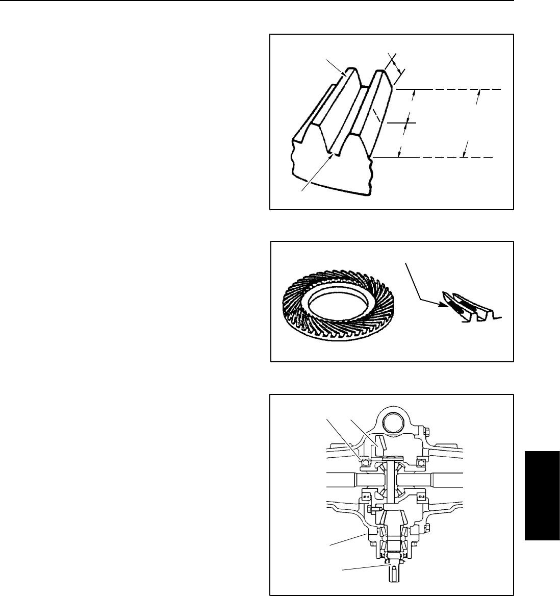
Groundsmaster 4100--D/4110--D Page 6 -- 35 Axles, Planetaries and Brakes
Pinion Gear to Ring Gear Engagement
The final position of the pinion gear is verified by using
the gear contact pattern method as described in the fol-
lowing procedure.
GEAR TOOTH DEFINITIONS (Fig. 46):
Toe -- the portion of the tooth surface at the end to-
wards the center.
Heel -- the portion of the gear tooth at the outer end.
Top Land -- top surface of tooth.
1. Paint the teeth of the ring gear, both drive and coast
side, with a gear marking compound, such as DyKemR
Steel Blue.
2. Install the input shaft/pinion gear assembly into axle
case.
3. While applying a light load to the ring gear, rotate the
pinion gear in the direction of forward travel until the ring
gear has made one complete revolution.
Ideal tooth contact observed on the ring gear should
cover more than 35% of each tooth surface. The contact
area should be in the center of each tooth and extend 1/3
to 1/2 way across each tooth from the toe end (Fig. 47).
Adjustments to the gear contact position are made by
moving the input shaft/pinion gear (bearing case shims)
or by moving the differential gear case (differential bear-
ing shims) (Fig. 48).
NOTE: Bearing case shims are available in 0.004 inch
(0.10 mm) and 0.008 inch (0.20 mm) thickness.
NOTE: Differential bearing shims are available in
0.004 inch (0.10 mm), 0.008 inch (0.20 mm) and 0.016
inch (0.40 mm) thickness.
Study the different contact patterns (Figs. 49 and 50)
and correct gear engagement as necessary.
NOTE: When making changes, note that two variables
are involved (see Gear Pattern Movement Summary in
this section of this manual).
Example: If the pinion gear to ring gear backlash is set
correctly to specifications and the bearing case shim is
changed to adjust tooth contact, it may be necessary to
readjust backlash to the correct specification before
checking the contact pattern.
Figure 46
TOE
HEEL
PROFILE
TOP LAND
ROOT
LENGTHWISE
BEARING
ARC
Figure 47
More than 35% total tooth contact
1/3to1/2ofentirewidth
from small end of tooth
1. Input shaft/pinion gear
2. Bearing case shims
3. Differential gear case
4. Differential bearing
shims
Figure 48
1
2
3
4
Axles, Planetaries
and Brakes
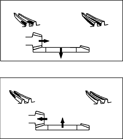
Groundsmaster 4100--D/4110--DPage 6 -- 36Axles, Planetaries and Brakes
Gear Pattern Movement Summary
Every gear has a characteristic pattern. The illustrations
show typical patterns only and explain how patterns shift
as gear location is changed.
1. If contact is toward the heel or base of the gear (Fig.
49):
A. Install thicker or additional bearing case shim(s)
to move pinion shaft toward ring gear.
B. Install thinner or remove differential bearing
shim(s)tomoveringgearbackward.
C. Repeat until proper tooth contact and pinion gear
to ring gear backlash are correct.
2. If contact is toward the toe or tip of the gear (Fig. 50):
A. Install thinner or remove bearing case shim(s) to
move pinion shaft away from ring gear.
B. Install thicker or additional differential bearing
shim(s)tomoveringgearforward.
C. Repeat until proper tooth contact and pinion gear
to ring gear backlash are correct.
Figure 49
Heel Contact Base Contact
Figure 50
Toe Contact Tip Contact

Groundsmaster 4100--D/4110--D Page 7 -- 1 Chassis
Chapter 7
Chassis
Table of Contents
GENERAL INFORMATION 1.....................
Operator’s Manual 1..........................
SERVICE AND REPAIRS 2......................
Steering Tower 2.............................
Cutting Deck Lift Arms 4.......................
Console Arm 8...............................
Traction Pedal Assembly 10....................
Operator Platform 12..........................
Operator Seat 16.............................
Operator Seat Service 18......................
Operator Seat Suspension 20..................
Hood 22.....................................
General Information
Operator’s Manual
The Operator’s Manual provides information regarding
the operation, general maintenance and maintenance
intervals for your Groundsmaster machine. Refer to that
publication for additional information when servicing the
machine.
Chassis
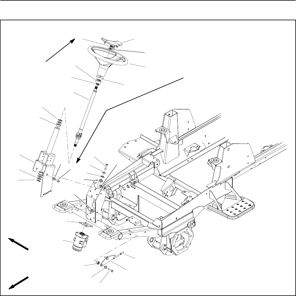
Groundsmaster 4100--D/4110--DPage 7 -- 2Chassis
Service and Repairs
Steering Tower
Figure 1
FRONT
RIGHT
27 to 33 ft--lb
(37to44N--m)
2
3
6
8
9
10
11
13
1
5
7
12
14
15
16
17
18
19 20
4
7
10
20 to 26 ft--lb
(28to35N--m)
20
19
1. Steering wheel cover
2. Hex nut
3. Flat washer
4. Steering wheel
5. Foam collar
6. Steering seal
7. External snap ring (2 used)
8. Steering shaft
9. Flange bushing
10. Thrust washer (as needed)
11. Cap screw (4 used)
12. Washer (4 used)
13. Washer (4 used)
14. Mount (4 used)
15. Valve mount plate
16. Steering control valve
17. Steering column
18. Cap screw (2 used)
19. Pivot hub (3 used)
20. Flange nut (3 used)
21. Spacer
22. Cap
23. Tilt lever
24. Cap screw
22
23
24
21
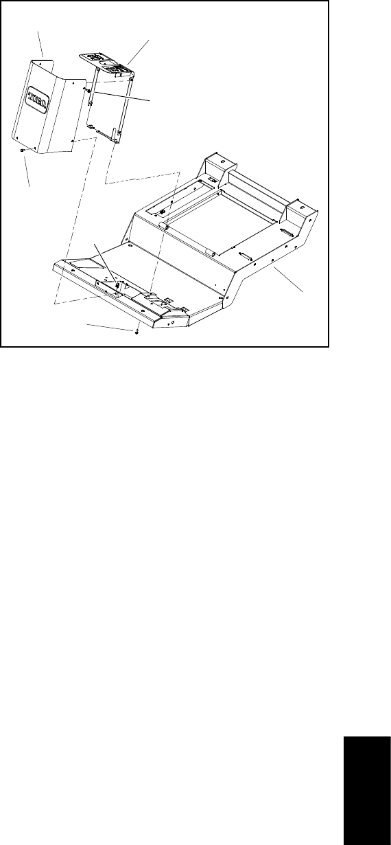
Groundsmaster 4100--D/4110--D Page 7 -- 3 Chassis
Disassembly (Fig. 1)
1. Park machine on a level surface, lower cutting deck,
stop engine, apply parking brake and remove key from
the ignition switch.
2. Remove steering tower covers to access steering
tower components (Fig. 2).
3. Disassemble steering tower as needed using Figure
1 as a guide.
Assembly (Fig. 1)
1. Assemble steering tower using Figures 1 and 2 as
guides.
A. If steering column (item 17) was removed, torque
cap screws (item 18) that secure steering column to
frame bracket from 27 to 33 ft--lb (37 to 44 N--m).
B. Thrust washer(s) (item 10 in Fig. 1) on steering
column are used as needed to remove end play of
steering shaft.
C. If steering wheel was removed, torque hex nut
that secures steering wheel from 20 to 26 ft--lb (28
to 35 N--m).
1. Operator platform
2. Flange screw (10 used)
3. Front cover
4. Clip (2 used)
5. Rear cover
Figure 2
2
3
1
5
4
2
2
Chassis
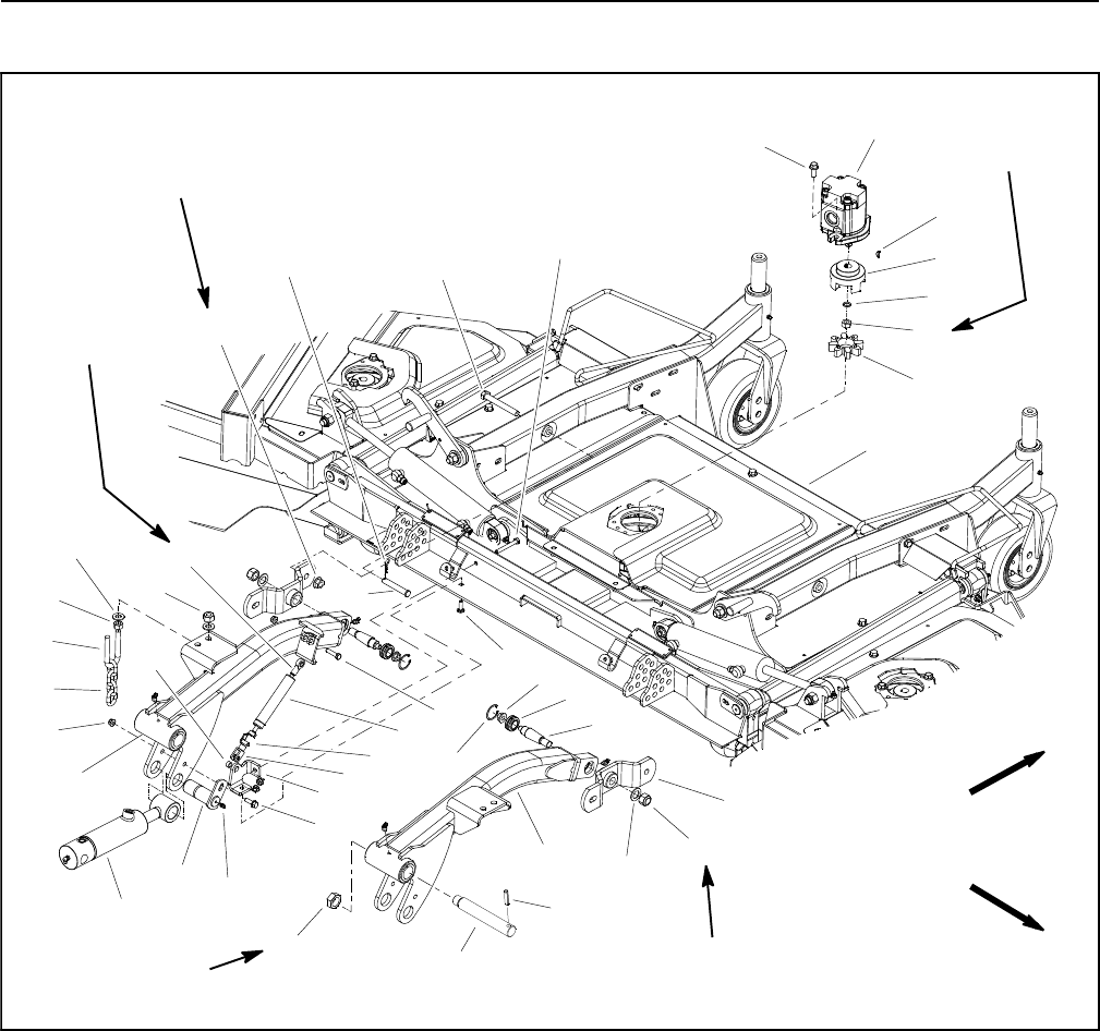
Groundsmaster 4100--D/4110--DPage 7 -- 4Chassis
Cutting Deck Lift Arms
1. Deck assembly
2. Deck motor (3 used)
3. Spider hub (3 used)
4. Spider (3 used)
5. Damper support
6. Clevis rod end
7. Spherical rod end
8. Damper
9. Spacer
10. Spring pin
11. LH lift arm
12. Pin (2 used)
13. Grease fitting (2 used)
14. RH lift arm
15. Flange nut (5 used)
16. Cap screw
17. Carriage screw
18. Cap screw (4 used)
19. Cap screw
20. Flange head screw (2 used)
21. HOC chain (2 used)
22. U--bolt (2 used)
23. Lock nut (4 used)
24. Flat washer (8 used)
25. Hex nut (4 used)
26. Flange head screw (6 used)
27. Hair pin (2 used)
28. Clevis pin (2 used)
29. Flange nut (4 used)
30. Flat washer (2 used)
31. Lock nut (2 used)
32. Hydraulic lift cylinder (2 used)
33. Retaining ring (2 used)
34. Flange nut (2 used)
35. Spherical bearing (2 used)
36. Tapered stud (2 used)
37. Woodruff key (3 used)
38. Lock nut (3 used)
39. Support hub (2 used)
40. Hardened washer (3 used)
41. Spring pin (2 used)
42. Lift arm pin (2 used)
43. Lock nut (2 used)
Figure 3
FRONT
RIGHT
155 to 185 ft--lb
(211 to 251 N--m)
75 to 85 ft--lb
(102 to 115 N--m)
Loctite #271
on threads
11
15
28
32
2
3
6
8
9
10
13
1
5
7
12
14
16
17
18
19
20
4
21
22
23
24
25
26
27
29
30
31
33
34
35
36
37
38
39
40
(37to44N--m)
27 to 33 ft--lb
41
42
43
60 to 70 ft--lb
(82 to 94 N--m)
(both ends)
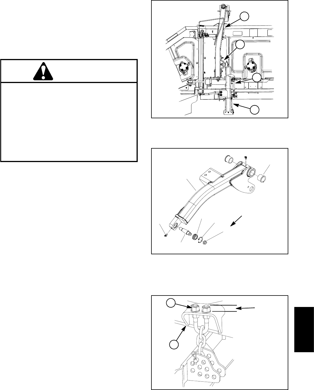
Groundsmaster 4100--D/4110--D Page 7 -- 5 Chassis
Removal (Fig. 3)
1. Park machine on a level surface, lower cutting deck,
stop engine, engage parking brake and remove key
from the ignition switch.
2. Remove front cutting deck (see Cutting Deck Re-
moval in Chapter 8 -- Cutting Deck).
CAUTION
When changing attachments, tires or perform-
ing other service, use correct jacks and sup-
ports. Make sure machine is parked on a solid,
level surface such as a concrete floor. Prior to
raising machine, remove any attachments that
may interfere with the safe and proper raising of
the machine. Always chock or block wheels. Use
jack stands to support the raised machine. If the
machine is not properly supported by jack
stands, the machine may move or fall, which
may result in personal injury.
3. Chock rear wheels and jack up front of machine.
Support machine on jack stands. Remove front wheel
next to lift arm that is being removed.
4. Remove flange head screw and lock nut that secure
lift cylinder pin to lift arm. Remove pin and separate lift
cylinder from lift arm.
5. Remove lock nut that secures lift arm pin. Support lift
arm and slide pin from frame and lift arm. Remove lift
armfromframe.
6. As needed, disassemble lift arm:
A. Remove height--of--cut chain (items 21 and 22 in
Fig. 3).
B. Remove damper assembly (items 6, 7 and 8 in
Fig. 3).
C. Remove flange nut, flat washer and support hub
(item 39 in Fig. 3) from tapered stud in end of lift arm.
D. Remove tapered stud with spherical bearing from
lift arm after removing retaining ring from lift arm (Fig.
5). Remove flange nut and spherical bearing from
stud.
E. Press flange bushings from lift arm (Fig. 5).
Figure 4
1. Lift arm
2. Deck castor arm
3. Support hub
4. Damper
1
2
3
4
1. Lift arm (RH shown)
2. Flange nut
3. Retaining ring
4. Spherical bearing
5. Tapered stud
6. Flange bushing (2 used)
7. Grease fitting (2 used)
Figure 5
2
1
4
3
5
6
7
100 to 140 in--lb
(12to15N--m)
1. Lift arm 2. U--bolt threads
Figure 6
0.750 in.
(19.1 mm)
1
2
Chassis
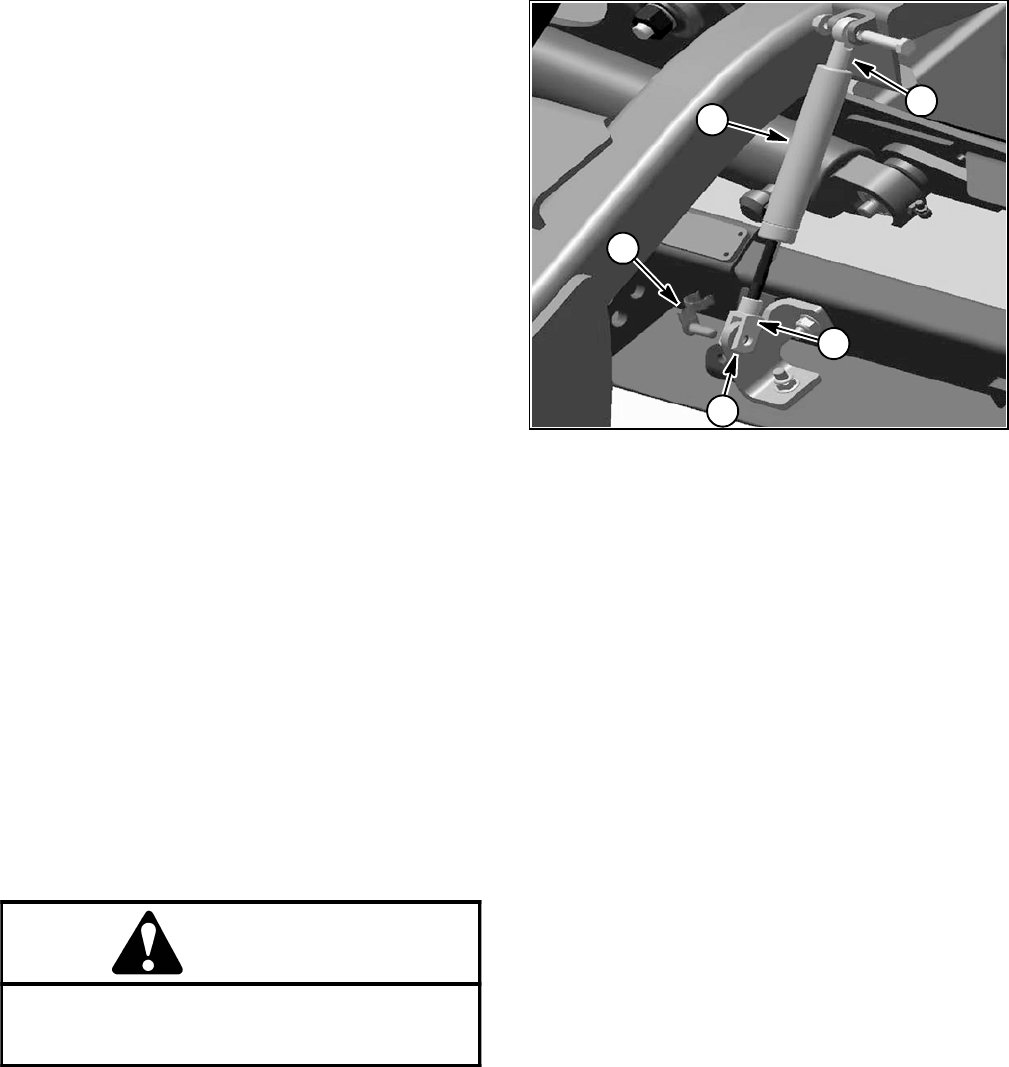
Groundsmaster 4100--D/4110--DPage 7 -- 6Chassis
Installation (Fig. 3)
1. If removed, install components to lift arm.
A. Press flange bushings into lift arm.
B. Install spherical bearing on tapered stud and se-
cure with flange nut. Torque flange nut from 30 to 40
ft--lb(41to54N--m). Install stud with spherical bear-
ing into lift arm and secure with retaining ring.
C. If rod and clevis ends were removed from damp-
er, apply Loctite #271 (or equivalent) to threads on
damper shaft and stud. Install ends on damper.
Install damper assembly to lift arm with damper clev-
is end toward deck location (Fig. 7).
D. Assemble height--of--cut chain u--bolt so that
threaded portion of u--bolt extends 0.750 in. (19.1
mm) above mounting plate on lift arm (Fig. 6). This
dimension is a starting point that might need addi-
tional adjustment for deck pitch correction (see step
8below).
E. Thoroughly clean tapered surfaces of stud and
mounting boss of support hub. Secure support hub
(position slotted hole in hub toward rear of deck) to
tapered stud with flat washer and flange nut. Torque
flange nut from 155 to 185 ft--lb (211 to 251 N--m).
2. Position lift arm to frame and insert lift arm pin. En-
gage roll pin in lift arm pin into frame slots and install lock
nut on pin. Torque lock nut from 60 to 70 ft--lb (82 to 94
N--m).
3. Align lift cylinder with lift arm. Slide lift cylinder pin
through lift arm and cylinder end. Secure pin with flange
head screw and lock nut.
WARNING
Failure to maintain proper wheel lug nut torque
could result in failure or loss of wheel and may
result in personal injury.
4. Install front wheel assembly. Lower machine to the
ground. Torque wheel lug nuts from 85 to 100 ft--lb (115
to 135 N--m).
5. Install cutting deck (see Cutting Deck Installation in
Chapter 8 -- Cutting Deck).
6. Lubricate lift arm grease fittings.
7. After assembly is completed, raise and lower the cut-
ting deck to verify that hydraulic hoses and fittings do not
contact anything.
8. Check height--of--cut and deck pitch adjustment.
1. Damper
2. Spring pin
3. Damper rod end
4. Damper clevis end
5. Spacer location
Figure 7
13
4
2
5

Groundsmaster 4100--D/4110--D Page 7 -- 7 Chassis
This page is intentionally blank.
Chassis
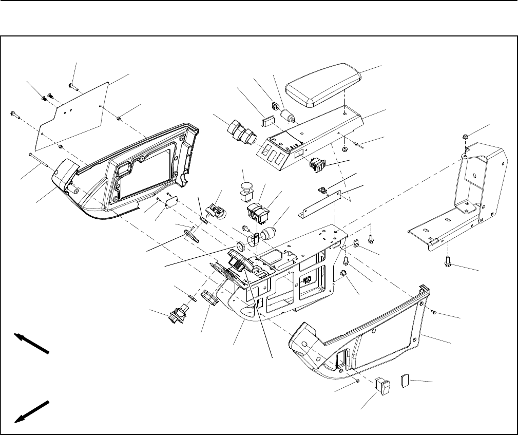
Groundsmaster 4100--D/4110--DPage 7 -- 8Chassis
Console Arm
1. Flange nut (3 used)
2. Flange head screw (2 used)
3. Washer head screw (10 used)
4. LH cover
5. Lock nut
6. Control arm panel
7. Ignition switch
8. InfoCenter display
9. R--clamp
10. Audio alarm
11. PTO switch
12. Nut
13. Bracket
14. U--nut (5 used)
15. Clip (2 used)
16. Flange head screw (6 used)
17. Flange nut (2 used)
18. Hole plug
19. Rivet (2 used)
20. Switch panel
21. Arm rest
22. Power point
23. Cap
24. Nut
25. Flange spacer (2 used)
26. Cover plate
27. Flange head screw (2 used)
28. Plug (2 used)
29. Screw
30. RH cover
31. Cruise control switch
32. Cover plate
33. Cap screw (2 used)
34. Lift/lower switch (3 used)
35. Ignition key
36. Nut
37. Screw (2 used)
38. Switch step
39. Hex nut
40. HI--LOW traction speed switch
41. Engine speed switch
42. Hole plug (GM4100--D)
43. Headlight switch (GM4110--D)
Figure 8
FRONT
RIGHT
2
3
6
8
9
10
11
13
1
5
7
12
14
15
16
17
18
19
20
4
21
22
23
24
25
26
27
28
29
30
31
32
33 37
35
36
34
38
40
41
42
43
39
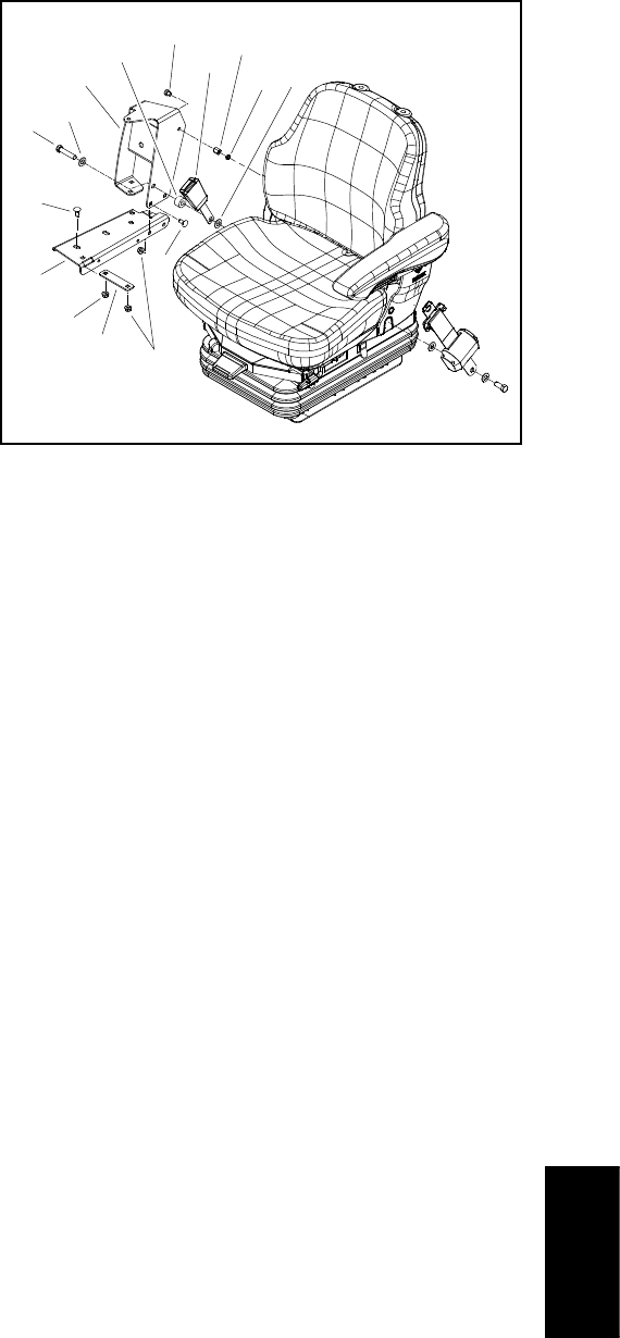
Groundsmaster 4100--D/4110--D Page 7 -- 9 Chassis
Disassembly (Fig. 8)
1. Park machine on a level surface, lower cutting units,
stop engine and engage parking brake. Remove key
from ignition switch.
2. Remove two (2) flange head screws (item 27) and
then cover plate (item 26) from outside of control arm.
Locate and retrieve two (2) spacers (item 25).
3. At front of control arm, remove screw (item 29) and
lock nut (item 5) that secure control arm covers to each
other.
4. Remove five (5) washer head screws (item 3) that
secure each cover to control arm panel.
5. Remove control arm covers from machine. As LH
cover (item 4) is removed from control arm, unplug wire
harness connector from headlight switch if equipped.
6. Remove electrical components from control arm as
needed using Figure 8 as a guide.
7. If necessary, remove control arm panel and supports
from machine using Figures 8 and 9 as guides.
Assembly (Fig. 8)
1. Install all removed electrical and control arm compo-
nentsusingFigure8and9asguides.
2. Position covers to control arm. As LH cover (item 4)
is placed, plug wire harness connector to headlight
switch if equipped.
3. Secure each cover to control arm with five (5) washer
head screws (item 3). Install screw (item 29) and lock nut
(item 5) to secure covers at front of control arm.
4. Position cover plate and spacers to outside of control
arm. Secure with two (2) flange head screws.
1. Flat washer
2. Seat belt buckle
3. Coupling nut
4. Spacer
5. Carriage screw (5 used)
6. Cap screw
7. Screw
8. Arm support
9. Hex nut
10. Support bracket
11. Flange nut (5 used)
12. Support channel
Figure 9
23
6
7
5
4
1
89
10
11
5
11
12
1
Chassis
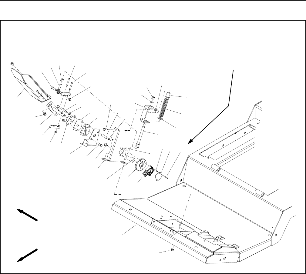
Groundsmaster 4100--D/4110--DPage 7 -- 10Chassis
Traction Pedal Assembly
1. Carriage bolt (6 used)
2. Traction pedal
3. Bushing
4. Operator platform
5. Cap screw
6. Rod end bearing
7. Hex nut
8. Flange nut (10 used)
9. Traction pedal shaft
10. Roll pin
11. Cap screw (2 used)
12. Clamp block (2 used)
13. Lock nut
14. Cap screw
15. Flange nut (2 used)
16. Lock washer
17. Flange mount bearing
18. Cover plate
19. Butterfly plate
20. Butterfly bracket
21. Carriage screw
22. Spacer
23. Threadlock screw (2 used)
24. Cap screw (5 used)
25. Lock nut (6 used)
26. Sensor bracket
27. Bushing hub
28. Position sensor
29. Capture plate
30. Standoff spacer (2 used)
31. Screw (2 used)
32. Spring shaft
33. Flat washer
34. Compression spring
35. Spring retainer
36. Flat washer
37. Lock nut
38. Spring bracket
Figure 10
13 to 17 in--lb
(1.5 to 1.9 N--m)
FRONT
RIGHT
2
3
6
8
9
10
11
13
1
5
7
12
14
15
16
17
18 19
20
4
21
22
23
24
25
26
27
28
29
30 31
32 33
34
35
36
37
38
8
8
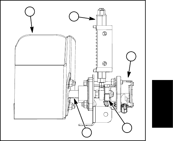
Groundsmaster 4100--D/4110--D Page 7 -- 11 Chassis
IMPORTANT: A properly installed and calibrated
traction pedal position sensor is critical to accurate
traction system response and for reliable sensor
life. Use care when removing, installing and cali-
brating the traction pedal position sensor.
Disassembly (Fig. 10)
1. Park machine on a level surface, lower cutting deck,
stop engine, apply parking brake and remove key from
the ignition switch.
2. Remove front steering tower cover (see Steering
Tower in this section).
3. Disconnect machine wire harness connector from
position sensor (item 28) on traction pedal.
4. If the traction pedal is to be removed from the traction
pedal shaft, use a marker or paint pen on pedal and shaft
to identify location of pedal for assembly purposes.
5. Disassemble traction pedal as needed using Figures
10 and 11 as guides. When removing roll pin (item 10 in
Fig. 10), make sure to support shaft to prevent compo-
nent damage.
Assembly (Fig. 10)
1. Assemble traction pedal using Figures 10 and 11 as
guides noting the following items:
A. Apply grease to both the OD and ID of the spring
retainer (item 35 in Fig. 10) before installation. Take
care to not get grease on threads of spring shaft (item
32 in Fig. 10) or lock nut (item 37 in Fig. 10).
B. If lock nut (item 37 in Fig. 10) was removed, tight-
en nut until washer (item 36 in Fig. 10) does not ro-
tate.
C. If traction pedal shaft (item 9 in Fig. 10) was re-
moved, apply grease to the shaft areas that will be
inside the bearings after assembly.
D. Use a press to install roll pin (item 10 in Fig. 10).
DO NOT damage flange mount bearing (item 17 in
Fig. 10) or cover plate (item 18 in Fig. 10) when in-
stalling roll pin. Also, take care to not distort roll pin
during assembly.
E. Make sure that roll pin (item 10 in Fig. 10) is fully
inside the butterfly groove of the shim plate (item 20
in Fig. 10). The roll pin should not contact the shim
plate throughout the operating range.
F. To install the traction pedal position sensor (item
28 in Fig. 10), press and hold the traction pedal in the
reverse direction slightly. Align the slot on the end of
the pedal shaft with the slot in the position sensor.
Slide position sensor onto screws and release pedal.
Hold position sensor in position while installing cap-
ture plate (item 29 in Fig. 10) and lock nuts (item 25 in
Fig. 10).
G. Torque screws (item 31 in Fig. 10) from 13 to 17
in--lb (1.5 to 1.9 N--m).
H. Leave the hex nut (item 7 in Fig. 10) loose so that
the position sensor can be calibrated.
2. After traction pedal assembly, make sure that there
is no binding in pedal movement and also that pedal re-
turns to the centered position when released. Correct
any sticking or binding before machine operation.
3. Plug machine wire harness connector into traction
pedal position sensor (item 28 in Fig. 10).
4. After assembly of the traction pedal, adjust and calib-
rate the traction pedal and position sensor using the In-
foCenter display (see Traction Pedal Adjustment and
Traction Pedal Calibration in the Adjustments section of
Chapter 5 -- Electrical System).
5. Make sure that hex nut (item 7 in Fig. 10) is tightened
after position sensor adjustment.
6. Install front steering tower cover (see Steering Tower
in this section).
1. Traction pedal
2. Pedal position sensor
3. Traction pedal shaft
4. Clamp block (2 used)
5. Spring shaft assembly
Figure 11
1
2
4
3
5
Chassis
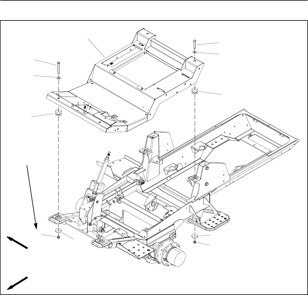
Groundsmaster 4100--D/4110--DPage 7 -- 12Chassis
Operator Platform
1. Operator platform
2. Cap screw (2 used)
3. Flat washer (4 used)
4. Center mount (4 used)
5. Plain washer (4 used)
6. Lock nut (4 used)
7. Cap screw (2 used)
Figure 12
FRONT
RIGHT
3
2
1
4
5
6
7
3
4
5
6
95 to 115 ft--lb
(129 to 155 N--m)
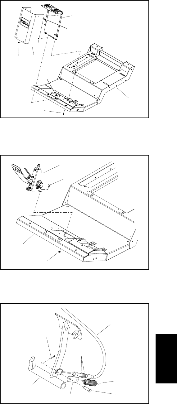
Groundsmaster 4100--D/4110--D Page 7 -- 13 Chassis
Some service procedures (e.g. removing the hydraulic
reservoir) require the operator platform to be raised. The
followingstepscanbeusedtoraisetheplatform.
Disassembly (Fig. 12)
1. Park machine on a level surface, lower cutting deck,
stop engine, apply parking brake and remove key from
the ignition switch.
2. Disconnect negative battery cable from battery ter-
minal and then disconnect positive cable from battery
(see Battery Service in the Service and Repairs section
of Chapter 5 -- Electrical System).
3. Remove steering tower covers (see Steering Tower
in this section).
4. Disconnect machine wire harness connector from
position sensor on traction pedal assembly.
5. Remove fasteners that secure traction pedal as-
sembly to operator platform and then remove traction
pedal assembly from platform (Fig. 14).
6. Disconnect both brake cables from brake pedals and
operator frame (Fig. 15). Access to brake cable jam nuts
can obtained by removing adjustment cover on operator
platform (Fig. 16). Position brake cables away from op-
erator platform.
7. Disconnect all electrical wire harness connections
between operator platform components and main frame
locations. As needed, label disconnected electrical con-
nections for proper installation.
8. On Groundsmaster 4110--D machines:
A. Remove operator cab from machine.
B. Remove cable ties that secure operator cab
coolant and air conditioner hoses in engine compart-
ment to allow the operator platform to be raised. Note
location of cable ties for assembly purposes.
NOTE: If desired, operator seat can be removed from
operator platform to reduce overall weight of operator
platform assembly (see Operator Seat in this section).
9. Remove four (4) cap screws, flat washers, plain
washers and lock nuts that secure operator platform to
machine frame.
IMPORTANT: Make sure to not damage the electric-
al wire harness or other components while raising
the operator platform.
10.Carefully raise operator platform as needed to ac-
cess components to be serviced. Support platform to
prevent it from moving or shifting.
1. Operator platform
2. Flange screw (10 used)
3. Front cover
4. Clip (2 used)
5. Rear cover
Figure 13
23
1
5
4
2
2
1. Traction pedal assembly
2. Carriage screw (4 used)
3. Flange nut (4 used)
4. Operator platform
Figure 14
3
1
4
2
1. Brake pedal (RH shown)
2. Cotter pin
3. Clevis pin
4. Brake strap
5. Spring
6. Brake cable (RH shown)
7. Brake cable jam nuts
Figure 15
2
1
3
4
5
6
7
Chassis
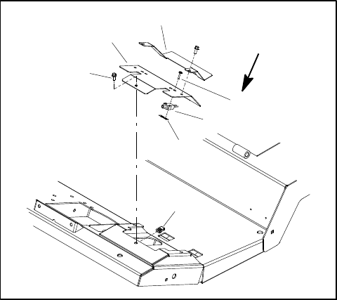
Groundsmaster 4100--D/4110--DPage 7 -- 14Chassis
Assembly (Fig. 12)
1. Make sure that all machine components are installed
below operator platform before platform is lowered to
frame.
IMPORTANT: Make sure to not damage the electric-
al wire harness or other components while lowering
the operator platform.
2. Carefully lower operator platform and position over
center mounts (item 4) that are installed in the frame.
3. Secure operator platform to machine frame with four
(4) cap screws, flat washers, plain washers and lock
nuts. Torque lock nuts from 95 to 115 ft--lb (129 to 155
N--m).
4. Connect all electrical wire harness connections
between operator platform components and main frame
locations.
5. On Groundsmaster 4110--D machines:
A. Install operator cab to machine.
B. Secure operator cab coolant and air conditioner
hoses in engine compartment with cable ties in loca-
tions noted during disassembly.
6. Connect both brake cables to brake pedals and op-
erator frame. Adjust brakes so that both pedals have 1/2
to 1 inch (13 to 25 mm) of free travel.
7. Position traction pedal assembly to operator plat-
form and secure with removed fasteners (Fig. 14). Con-
nect machine wire harness connector to position sensor
on traction pedal assembly.
8. Secure steering tower covers to machine (see Steer-
ing Tower in this section).
9. Connect positive battery cable from battery terminal
and then connect negative cable to battery (see Battery
Service in the Service and Repairs section of Chapter 5
-- Electrical System).
1. Flange screw (3 used)
2. Adjustment cover
3. Switch bracket
4. Brake switch (2 used)
5. Screw (2 per switch)
6. Switch nut (2 used)
7. Clip (3 used)
Figure 16
13 to 17 in--lb
(1.5 to 1.9 N--m)
1
3
5
2
4
6
7

Groundsmaster 4100--D/4110--D Page 7 -- 15 Chassis
This page is intentionally blank.
Chassis
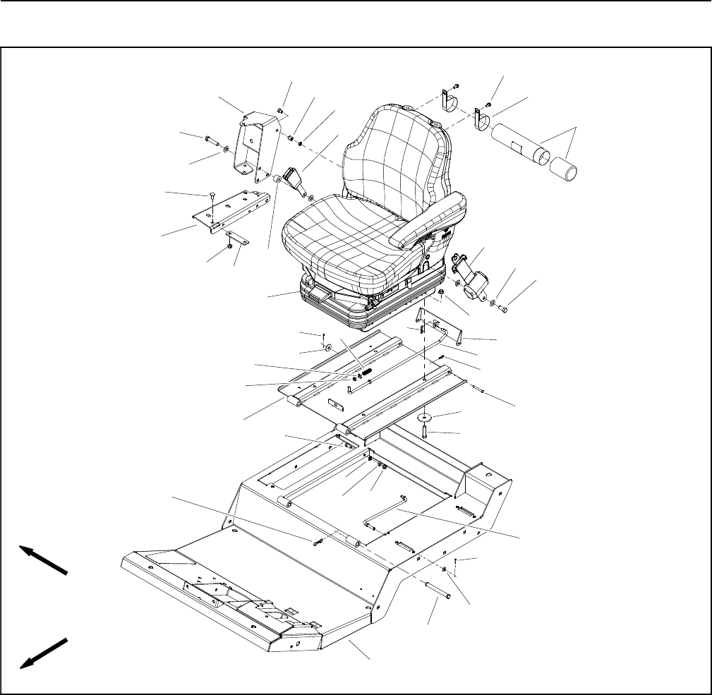
Groundsmaster 4100--D/4110--DPage 7 -- 16Chassis
Operator Seat
1. Carriage screw (5 used)
2. Support channel
3. Support bracket
4. Flange nut (6 used)
5. Cap screw
6. Flat washer (4 used)
7. Arm support
8. Screw
9. Coupler nut
10. Spacer
11. Flange nut (4 used)
12. Seat belt
13. Cap screw
14. Seat latch
15. Locking cotter pin
16. Latch rod
17. Locking cotter pin (2 used)
18. Clevis pin (2 used)
19. Flat washer (4 used)
20. Cap screw (4 used)
21. Seat belt latch
22. Lock washer
23. Cap screw
24. Operator platform
25. Hex nut
26. Prop rod
27. Flat washer (3 used)
28. Cotter pin (2 used)
29. Clevis pin (2 used)
30. Locking cotter pin (2 used)
31. Manual tube
32. Seat and suspension assembly
33. Flat washer
34. Bushing
35. Compression spring
36. Seat plate
37. R--clamp (2 used)
38. Flange head screw (2 used)
Figure 17
FRONT
RIGHT
2
3
6
8
9
10
11
13
1
5
7
12
14
15
16
17
18
19
20
4
21
22
23
24
26
27
28
29
30
32
33
34
35
36
37
38
31
25
28
27 4
6
27
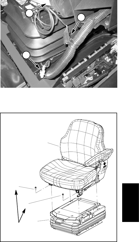
Groundsmaster 4100--D/4110--D Page 7 -- 17 Chassis
Removal (Fig. 17)
1. Park machine on a level surface, lower cutting deck,
stop engine, apply parking brake and remove key from
the ignition switch.
2. Disconnect seat electrical connector from machine
wire harness (Fig. 18).
3. Support control arm assembly to prevent it from shift-
ing.
4. Remove flange nut (item 4) and carriage screw (item
1) that secure support bracket (item 3) to support chan-
nel (item 2).
5. Remove screw (item 8) that secures control arm sup-
port (item 7) to coupler nut (item 9).
6. Remove cap screw (item 5), flat washers (item 6),
spacer (item 10) and seat belt latch (item 21) from seat
and control arm support (item 7).
IMPORTANT: Make sure to not damage the electri-
cal harness, control cable or other parts while mov-
ing the control arm assembly.
7. Carefully move control arm assembly away from
seat.
8. Remove four (4) torx head screws that secure seat
to seat suspension (Fig. 19). Note that the screw near
the seat adjustment handle is longer than the other three
(3) screws.
9. Lift seat from seat suspension and remove from ma-
chine.
NOTE: Refer to Operator Seat Suspension in this sec-
tion if seat suspension service is necessary.
Installation (Fig. 17)
1. Carefully position seat to seat suspension.
2. Secure seat to seat suspension with four (4) torx
head screws (Fig. 19). Make sure that longer screw is
positioned near the seat adjustment handle. Torque
screws 18 ft--lb (25 N--m).
IMPORTANT: Make sure to not damage the electri-
cal harness, control cable or other parts while mov-
ing the control arm assembly.
3. Position and secure control arm assembly to seat.
Install all fasteners before fully tightening them.
A. Secure support bracket (item 3) and support
channel (item 2) with flange nut (item 4) and carriage
screw (item 1).
B. Secure control arm support (item 7) to coupler nut
(item 9) with screw (item 8).
C. Place flat washer (item 6), seat belt latch (item 21)
and spacer (item 10) between seat and control arm
support (item 7). Secure with cap screw (item 5) and
second flat washer (item 6).
D. Fully tighten all fasteners to secure control arm
assembly to seat.
4. Connect seat electrical connector to machine wire
harness (Fig. 18).
1. Operator seat
2. Seat switch connector
3. Suspension connector
Figure 18
12
3
1. Seat
2. Suspension assembly
3. Screw (M8x12) (3 used)
4. Screw (M8x16)
Figure 19
2
3
1
4
18 ft--lb
(25 N--m)
Chassis
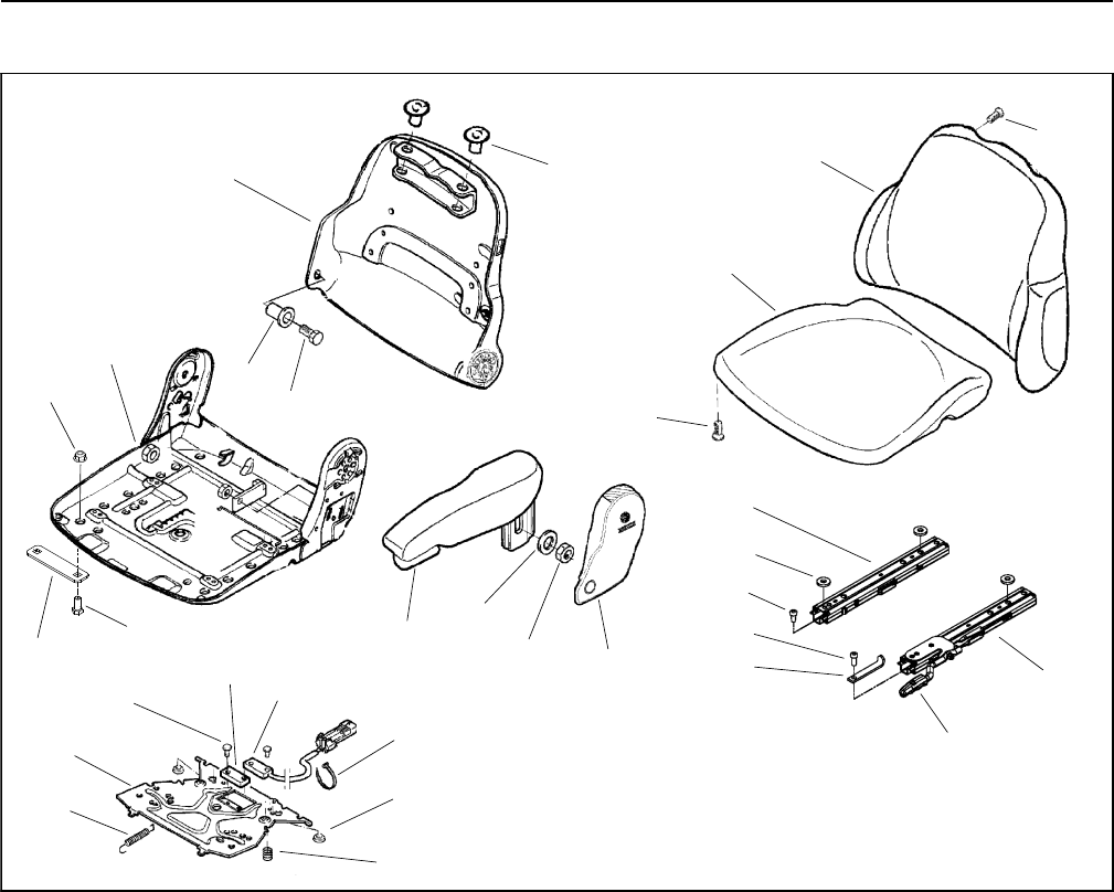
Groundsmaster 4100--D/4110--DPage 7 -- 18Chassis
Operator Seat Service
1. Backrest cushion
2. Seat cushion
3. Armrest cover
4. LH armrest
5. Bushing (2 used)
6. Backrest
7. Plug (2 used)
8. Cable tie (3 used)
9. LH adjustment rail
10. Bumper (2 used)
11. Washer
12. Cap screw (2 used)
13. Seat
14. Nut
15. Spring (2 used)
16. Magnet
17. Seat switch
18. Rivet (4 used)
19. Mounting plate
20. Return spring
21. Torx screw (5 used)
22. RH adjustment rail
23. Rail stop
24. Torx screw
25. Torx screw (3 used)
26. Washer (3 used)
27. Handle
28. Nut
29. Support bracket
30. Cap screw
Figure 20
8
10
6
5
7
4
3
2
1
11
14
12
13
9
15
16 17
18
19
20
21
21
23
24
25
26
22
27
28
29
30
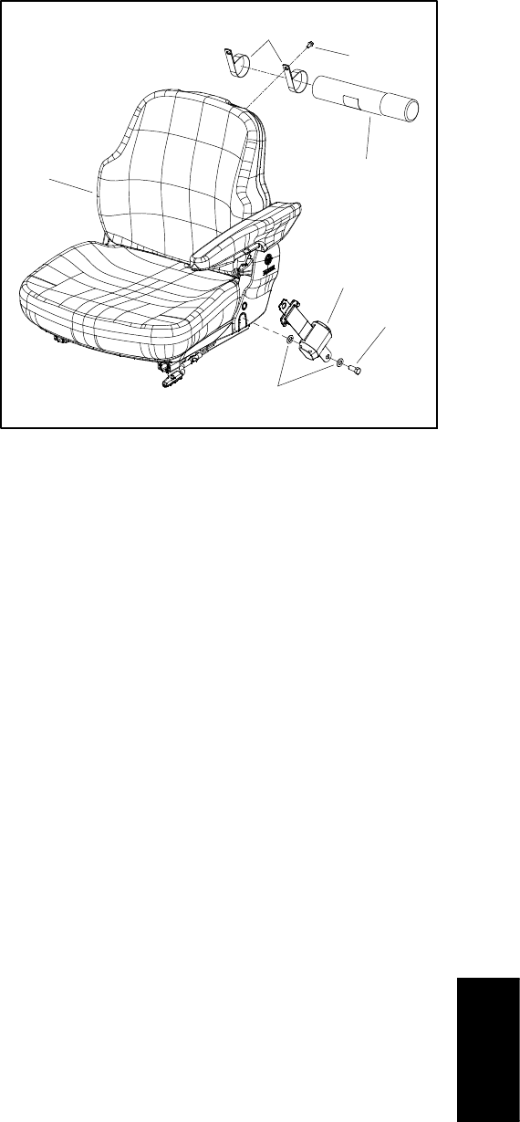
Groundsmaster 4100--D/4110--D Page 7 -- 19 Chassis
Disassembly (Fig. 20)
1. Disassemble operator seat as necessary using Fig-
ures 20 and 21 as guides.
Assembly (Fig. 20)
1. Assemble operator seat using Figures 20 and 21 as
guides.
1. Operator seat
2. R--clamp (2 used)
3. Screw (2 used)
4. Manual tube
5. Flat washer
6. Seat belt
7. Cap screw
Figure 21
2
3
6
1
5
4
7
Chassis
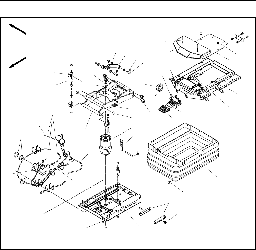
Groundsmaster 4100--D/4110--DPage 7 -- 20Chassis
Operator Seat Suspension
1. Cover
2. Cover
3. Level control
4. Air control valve
5. Shock absorber
6. Air spring
7. Air tube assembly
8. Wire harness
9. Compressor
10. Bellows
11. Stop
12. Bumper set (2 used)
13. Roller (4 used)
14. Washer (2 used)
15. Tether
16. Rivet (2 used)
17. Washer (4 used)
18. C--clip (4 used)
19. Pin (2 used)
20. Rivet (2 used)
21. Washer (3 used)
22. Screw (2 used)
23. Washer
24. Housing support (4 used)
25. Spacer (4 used)
26. Hose nipple
27. Clamp (2 used)
28. Hose nipple
29. Screw
30. Handle
31. Bumper
32. Nut
33. Plastic plug (23 used)
34. Screw (2 used)
35. Roller (2 used)
36. Screw (4 used)
37. Base plate
38. Suspension frame
39. Upper plate
Figure 22
FRONT
RIGHT
11
8
7
30
10
15
6
12
13
5
3
4
2
1
9
21
33
16
17
18
19
20
22
23
24
25
26
27
28
29
31
32
33
34
35
36
14
37
38
39
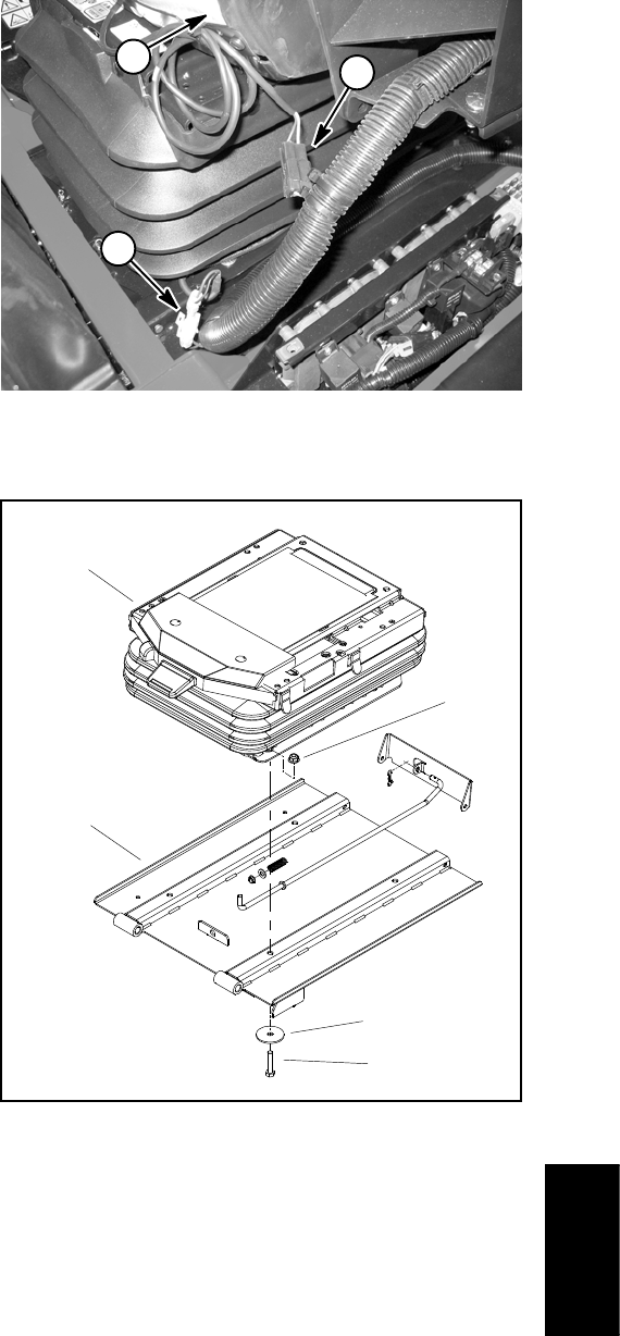
Groundsmaster 4100--D/4110--D Page 7 -- 21 Chassis
NOTE: Most of the seat suspension components can
be serviced with the seat suspension base mounted to
the frame platform. If the air spring assembly (item 6) re-
quires removal, the seat suspension base will have to be
removed from the seat platform.
Disassembly (Fig. 22)
1. Remove operator seat from seat suspension (see
Operator Seat Removal in this section).
2. Disconnect seat suspension connector from ma-
chinewireharness(Fig.23).
3. If the air spring assembly (item 6) or base plate (item
37) requires removal, remove seat suspension from
seat plate (Fig. 24):
A. Raise and support seat plate assembly. Support
seat suspension to prevent it from falling.
B. Remove four (4) cap screws, flat washers and
flange nuts that secure seat suspension to seat
plate.
C. Remove seat suspension from machine.
4. Remove seat suspension components as needed
using Figure 22 as a guide.
Assembly (Fig. 22)
1. Install all removed seat suspension components us-
ingFigure22asaguide.
2. If seat suspension was removed from seat plate, se-
cure suspension to seat plate (Fig. 24):
A. Position seat suspension onto seat plate.
B. Secure seat suspension to seat plate with four (4)
cap screws, flat washers and flange nuts.
C. Lower and secure seat plate assembly.
3. Install operator seat to seat suspension (see Opera-
tor Seat Installation in this section).
4. Make sure that seat electrical connectors are con-
nected to machine wire harness (Fig. 23).
1. Operator seat
2. Seat switch connector
3. Suspension connector
Figure 23
12
3
1. Seat suspension
2. Flat washer (4 used)
3. Cap screw (4 used)
4. Flange nut (4 used)
5. Seat plate
Figure 24
4
1
2
3
5
Chassis
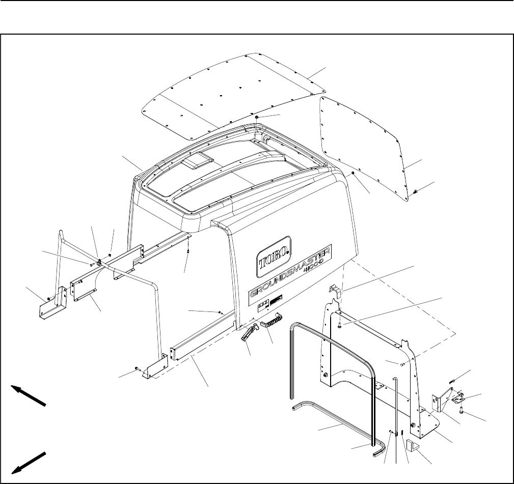
Groundsmaster 4100--D/4110--DPage 7 -- 22Chassis
Hood
1. Hood
2. Screen assembly
3. Bulb seal
4. Flange nut (2 used)
5. Screen pivot (2 used)
6. Hair pin (2 used)
7. Hood support
8. Plastite screw (4 used)
9. Door handle (2 used)
10. Bulb seal
11. Hood pivot (2 used)
12. Flexible draw latch (2 used)
13. Corner screen seal (2 used)
14. Screw (8 used)
15. LH hood support
16. Hood rod (2 used)
17. Clevis pin (2 used)
18. R--clamp (2 used)
19. Hair pin (2 used)
20. Rear screen
21. Top screen
22. Carriage bolt (24 used)
23. Carriage bolt (2 used)
24. Plastic plug (43 used)
25. Foam seal (2 used)
26. Flange nut (2 used)
27. Screw (2 used)
28. Cap screw (2 used)
29. Flange nut (24 used)
30. RH hood support
31. Pop rivet (8 used)
Figure 25
FRONT
RIGHT
2
3
6
8
9
10 11
13
1
5
7
12
14
15
16
17
18
19
20
4
21
22
23
24
25
26
27
28
29
30
31
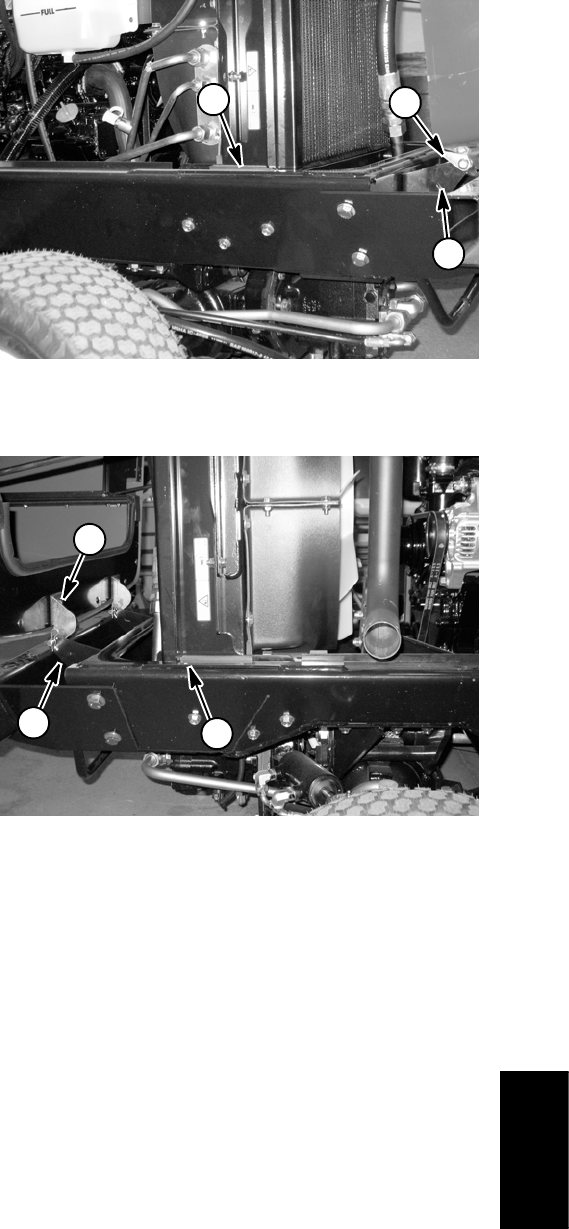
Groundsmaster 4100--D/4110--D Page 7 -- 23 Chassis
Removal
1. Park machine on a level surface, lower cutting deck,
stop engine, apply parking brake and remove key from
the ignition switch.
2. Remove hood assembly from machine:
A. Remove hair pins (item 6) that retain screen
pivots to hood pivots.
B. Slide hood assembly to disengage screen pivots
from hood pivots and lift hood from machine.
3. Disassemble hood as needed using Figure 25 as a
guide.
Installation
1. Assemble hood using Figure 25 as a guide.
2. Install hood to machine:
A. Position hood to machine and engage screen
pivots to hood pivots.
B. Install hair pins (item 6) to secure screen pivots to
hood pivots.
3. Align hood to machine to allow correct operation of
hood latch and dust seals:
A. Place shim that is from 3/8” to 7/16“ (9.5 to 11.1
mm) thick on top of frame (both RH and LH sides)
near the sides of radiator/oil cooler (Figs. 26 and 27).
B. Close hood so that it rests on shims and fasten
thehoodlatches.
C. Loosen hood pivots at frame to adjust vertical
placement of pivots. Re--tighten hood pivot fasten-
ers.
D. Loosen screen pivots to allow hood latches to pull
hood against radiator support. Re--tighten screen
pivot fasteners.
4. After hood is assembled to machine, check for the
following:
A. Check that bulb and foam seals are equally com-
pressed at all contact points with hood. Bulb and
foam seals should compress from 0.125” to 0.375”
(3.2 to 9.5 mm) when hood assembly is correct.
B. Hood should open and close without contacting
oil cooler hardware.
C. Hood should fit to fuel tank with no open gaps.
1. LH shim location
2. LH hood pivot
3. LH screen pivot
Figure 26
1
2
3
1. RH shim location
2. RH hood pivot
3. RH screen pivot
Figure 27
3
21
Chassis
Groundsmaster 4100--D/4110--DPage 7 -- 24Chassis
This page is intentionally blank.

Groundsmaster 4100--D/4110--D Cutting DeckPage 8 -- 1
Chapter 8
Cutting Deck
Table of Contents
SPECIFICATIONS 2............................
GENERAL INFORMATION 3.....................
Operator’s Manual 3..........................
Castor Wheel Tire Pressure 3..................
Blade Stopping Time 3........................
TROUBLESHOOTING 4.........................
Factors That Can Affect Quality of Cut 4.........
SERVICE AND REPAIRS 6......................
Cutting Deck 6...............................
Wing Deck Service 10.........................
Cutting Deck Link Service 13...................
Wing Deck Latch 14...........................
Blade Spindle 16.............................
Blade Spindle Service 18......................
Idler Assembly 20.............................
Castor Forks and Wheels 22...................
Deck Rollers and Skids 24.....................
Cutting
Deck
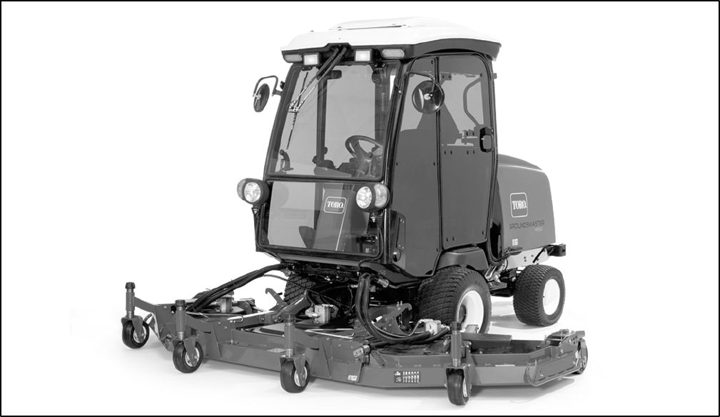
Groundsmaster 4100--D/4110--DCutting Deck Page 8 -- 2
Specifications
MOUNTING: Cutting deck is supported by lift arms con-
trolled with individual lift switches for complete deck,
right wing deck and left wing deck.
CONSTRUCTION: Deck chamber is welded 12 gauge
steel construction reinforced with channels and plates.
HEIGHT--OF--CUT RANGE: 1” to 5” (25.4 mm to 127
mm) adjustable in 1/2” (12.7 mm) increments. Center
deck height--of--cut adjustment is achieved by changing
spacers on castor wheels and adjusting length of deck
support chains. Wing deck adjustment is achieved by
changing spacers on castor wheels, re--positioning the
castor wheel axles in the castor forks and securing the
castor wheel bracket to the correct height--of--cut brack-
et holes.
DECK DRIVE: Closed loop hydraulic system operates
hydraulic motor on each cutting deck section. Motor
drives one deck spindle directly with remaining deck
section spindle(s) driven by B section kevlar v--belt(s).
Blade spindles are 1--1/4” (31.7 mm) shafts supported
by greaseable, tapered roller bearings.
CUTTING BLADE: Cutting blade dimensions are 19”
(483 mm) long, 2.5” (64 mm) wide and 0.250” (6.4 mm)
thick. Anti--scalp cup installed on each cutting blade.
Center deck includes three (3) blades and each wing
deck includes two (2) blades.
WIDTH OF CUT: Center deck section provides 54”
(1372 mm) width of cut. Each wing deck has 37” (940
mm) width of cut. Total width of cut is 124” (3150 mm).
DISCHARGE: Clippings are discharged from the rear of
the cutting deck.
SUSPENSION SYSTEM: A fully floating suspension
with hydraulic counterbalance. Front deck is suspended
from lift arms and has six (6) castor wheels, two (2) ad-
justable skids and five (5) anti--scalp rollers.

Groundsmaster 4100--D/4110--D Cutting DeckPage 8 -- 3
General Information
CAUTION
Never install or work on the cutting deck or lift
arms with the engine running. Always stop en-
gine and remove ignition key first.
Operator’s Manual
The Operator’s Manual provides information regarding
the operation, general maintenance, adjustments and
maintenance intervals for your Groundsmaster cutting
deck. Refer to that publication for additional information
when servicing the machine.
Castor Wheel Tire Pressure
Castor tires on the cutting deck should be inflated to 50
PSI (345 kPa).
Blade Stopping Time
The blades of the cutting deck should come to a com-
plete stop in approximately five (5) seconds after the
PTO is disengaged (PTO switch is pushed in).
NOTE: Make sure the deck is lowered onto a clean sec-
tion of turf or hard surface to avoid dust and debris.
To verify blade stopping stopping time, have a second
person stand back from the deck at least twenty (20) feet
and watch one of the cutting deck blades. Have the op-
erator push the PTO switch in to disengage the cutting
deck and record the time it takes for the blades to come
to a complete stop. If this stopping time is excessive, the
braking valve(s) (RV) on the hydraulic deck control man-
ifold(s) may need adjustment.
Cutting
Deck

Groundsmaster 4100--D/4110--DCutting Deck Page 8 -- 4
Troubleshooting
There are a number of factors that can contribute to un-
satisfactory quality of cut, some of which may be turf
conditions. Turf conditions such as excessive thatch,
uneven ground conditions, “sponginess” or attempting
to cut off too much grass height may not always be over-
come by adjusting the machine.
Remember that the “effective” or actual height--of--cut
depends on cutting deck weight, tire pressures, hydrau-
lic counterbalance settings and turf conditions. Effective
height--of--cut will be different than the bench set height--
of--cut.
Factors That Can Affect Quality of Cut
Factor Possible Problem/Correction
1. Maximum governed engine speed. Check maximum governed engine speed. Adjust
speed to specifications if necessary (see Chapter 3 --
Yanmar Diesel Engine).
2. Blade speed. All deck blades should rotate at the same speed.
See items in Troubleshooting Section of Chapter 4 --
Hydraulic System.
3. Tire pressure. Check air pressure of each tire including castor tires.
Adjust to pressures specified in Operator’s Manual.
4. Cutting blade condition. Sharpen cutting blades if their cutting edges are dull or
nicked.
Inspect blade sail for wear or damage. Replace blade if
needed.
5. Mower housing condition. Make sure that cutting chambers are in good condition.
Keep underside of deck clean. Debris buildup will
reduce cutting performance.
6. Height--of--cut. Make sure all deck height--of--cut adjustments are the
same. Adjust deck as specified in the Operator’s
Manual.
7. Cutting deck alignment and ground following. Check lift arms and cutting deck pivot linkages for
wear, damage or binding. Also, inspect for bent or
damaged pivot shafts.
8. Roller and castor wheel condition. All rollers and caster wheels should rotate freely.
Replace bearings, shafts or rollers if worn or damaged.
9. Grass conditions. Mow when grass is dry for best cutting results. Also,
remove only 1” (25 mm) or 1/3 of the grass blade when
cutting.

Groundsmaster 4100--D/4110--D Cutting DeckPage 8 -- 5
This page is intentionally blank.
Cutting
Deck
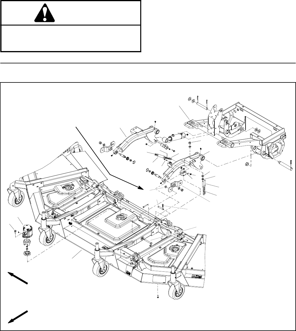
Groundsmaster 4100--D/4110--DCutting Deck Page 8 -- 6
Service and Repairs
CAUTION
Never install or work on the cutting deck or lift
arms with the engine running. Always stop en-
gine and remove ignition key first.
Cutting Deck
1. Cutting deck
2. Cap screw (4 used)
3. LH lift arm
4. Flange nut (4 used)
5. Spacer
6. Damper
7. Damper rod end
8. Damper clevis end
9. Spring pin
10. Cap screw
11. Flange nut
12. Hair pin
13. Hex nut (2 per u--bolt)
14. U--bolt (2 used)
15. Height of cut chain (2 used)
16. Support hub (2 used)
17. Clevis pin (2 used)
18. Flat washer (4 per u--bolt)
19. Lock nut (2 per u--bolt)
20. Hydraulic motor (3 used)
21. Flange head screw (2 per motor)
22. RH lift arm
23. Front frame
Figure 1
FRONT
RIGHT
75 to 85 ft--lb
(102 to 115 N--m)
2
3
6
8
9
10
11 13
1
5
7
12
14
15
16
17
18
19
20
4
21
22
23
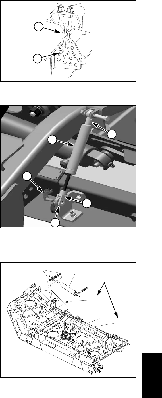
Groundsmaster 4100--D/4110--D Cutting DeckPage 8 -- 7
Removal (Fig. 1)
1. Position machine on a clean, level surface. Lower
cutting deck, stop engine, engage parking brake and re-
move key from the ignition switch.
NOTE: Removal of clevis pins from deck and height--
of--cut chains is easier if deck is lifted slightly.
2. Note location of clevis pins that secure height of cut
chains to the rear of the cutting deck. Remove hairpins
and clevis pins that secure the height--of--cut chains to
the cutting deck (Fig. 2).
3. Remove hydraulic motors from cutting deck (see
Cutting Deck Motors in the Service and Repairs Section
of Chapter 4 -- Hydraulic System). Position motors away
from cutting deck.
4. Remove spring pin that secures damper assembly to
bracket on cutting deck (Fig. 3). Locate and retrieve
spacer from between damper clevis and bracket. Separ-
ate damper from cutting deck bracket.
5. Remove hydraulic hoses from wing deck lift cylin-
ders (Fig. 4):
A. Remove deck covers to allow access to wing
deck lift cylinders.
B. Thoroughly clean exterior of wing deck lift cylin-
ders and fittings. For assembly purposes, label hy-
draulic hoses to show their correct position on the lift
cylinders.
C. Disconnect hydraulic hoses from wing deck lift
cylinders. Cap hoses and fittings to prevent contami-
nation.
6. Disconnect cutting deck wire harness from machine
wire harness.
7. Remove cap screws and flange nuts that secure
support hubs to cutting deck castor arms (Fig. 5).
8. Slide the cutting deck away from the traction unit.
Installation (Fig. 1)
1. Position machine on a clean, level surface. Lower lift
arms, stop engine, engage parking brake and remove
key from the ignition switch.
2. Position the cutting deck to the lift arms.
3. Align support hub to cutting deck castor arms making
sure that slotted mounting hole of hub is orientated to-
ward rear of cutting deck. Secure hubs with cap screws
and flange nuts (Fig. 5). Torque flange nuts from 75 to
85 ft--lb (102 to 115 N--m).
1. Hairpin and clevis pin 2. Height--of--cut chain
Figure 2
1
2
1. Damper
2. Spring pin
3. Damper rod end
4. Damper clevis end
5. Spacer location
Figure 3
13
4
2
5
1. Wing deck lift cylinder
2. Flat washer
3. Lock nut
4. Lock nut
5. Cap screw
6. Spacer
Figure 4
160 to 180 ft--lb
(217 to 244 N--m)
4
3
5
61
2
Cutting
Deck
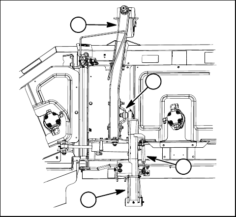
Groundsmaster 4100--D/4110--DCutting Deck Page 8 -- 8
NOTE: Installation of clevis pins to deck and height--of--
cut chains is easier if deck is lifted slightly.
4. Install clevis pins and hairpins that secure the
height--of--cut chains to the rear of the cutting deck (Fig.
2).
5. Remove plugs from hydraulic hoses and fittings on
wing deck lift cylinders. Using labels placed during re-
moval, correctly attach hydraulic hoses to lift cylinders.
6. Connect cutting deck wire harness to machine wire
harness.
7. Position damper to cutting deck bracket. Place
spacer between cutting deck bracket and damper clevis
end. Secure damper to bracket with spring pin (Fig. 5).
8. Install all removed cutting deck covers.
9. Install hydraulic motors to cutting deck (see Cutting
Deck Motors in the Service and Repairs Section of
Chapter 4 -- Hydraulic System).
10.Lubricate grease fittings on cutting deck and lift as-
semblies.
11. Check and fill hydraulic reservoir with hydraulic fluid
as required.
1. Lift arm
2. Castor arm
3. Support hub
4. Damper assembly
Figure 5
1
2
3
4

Groundsmaster 4100--D/4110--D Cutting DeckPage 8 -- 9
This page is intentionally blank.
Cutting
Deck
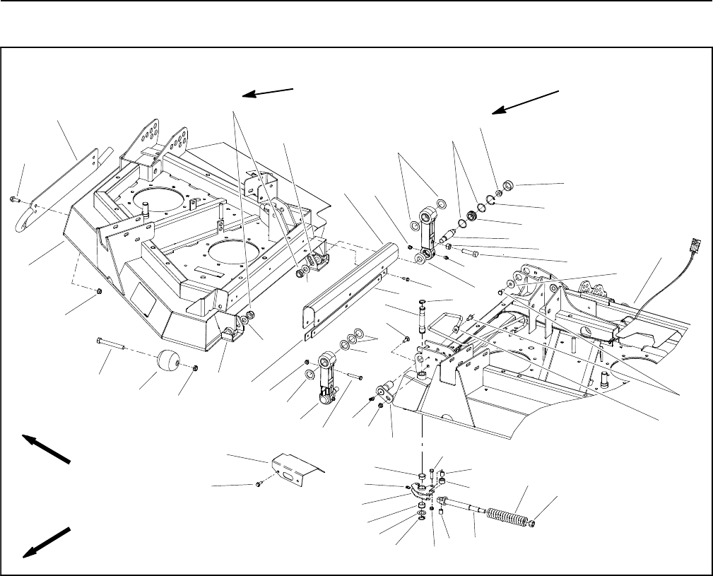
Groundsmaster 4100--D/4110--DCutting Deck Page 8 -- 10
Wing Deck Service
1. Wing deck (RH shown)
2. Skid (RH shown)
3. Flange screw (2 used per skid)
4. Flange nut (2 used per skid)
5. Cap screw
6. Roller (2 used)
7. Lock nut
8. Pivot latch (2 used)
9. Flat washer
10. Retaining ring (2 used per latch)
11. Cap screw (3 used per latch)
12. Lock nut (3 used per latch)
13. Spring support
14. Compression spring
15. Lug nut
16. Lock roller (2 used per latch)
17. Bushing (3 used per latch)
18. Pivot pin (4 used)
19. Flange nut (front links)
20. Grease fitting
21. Link assembly (4 used)
22. Cap screw (front links)
23. Thrust washer (0.030” thick)
24. Flat washer (4 used)
25. Lock nut (4 used)
26. Carriage bolt (4 used)
27. Latch pin
28. Flat washer (2 used)
29. Cap screw (4 used)
30. Cap screw (rear links)
31. Hex jam nut (rear links)
32. Washer head screw (12 used)
33. Wing strap (2 used)
34. Flex shield (2 used)
35. Shield strap (center deck)
36. Washer head screw (2 per shield)
37. Tapered stud
38. Hose guide
39. Hardened spacer (0.120” thick)
40. Plug
41. Grease fitting
42. Foam washer (4 used)
43. Link skid (2 used)
44. Link skid (2 used)
45. Flat washer
46. Flange nut
47. Dust cap
48. Retaining ring
49. Spherical bearing
50. Switch shield (RH shown)
51. Center deck
52. Flange bushing
53. Grease fitting
Figure 6
FRONT
RIGHT
1
2
10
15
9
16
33
34
8
37
38
39 29
28
35
36
30
17
21
18
22 19
23
20
24
26
27
25
32
67
31
3
4
5
42
40
41
11
12 13
14
10 17
19
23
24
39
43
44
47
48
45 46
49
50
51
52
53
52
100 to 140 in--lb
(12 to 15 N--m)
160 to 180 ft--lb
(217 to 244 N--m)
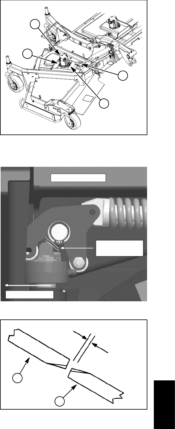
Groundsmaster 4100--D/4110--D Cutting DeckPage 8 -- 11
Removal (Fig. 6)
1. Position machine on a clean, level surface. Lower
cutting deck and engage parking brake.
2. Fully raise wing deck, stop engine and remove key
from the ignition switch. Remove three (3) washer head
screws and shield strap that secure flex shield to wing
deck. Lower wing deck.
3. Remove hydraulic motor from wing deck (see Cut-
ting Deck Motor in the Service and Repairs Section of
Chapter 4 -- Hydraulic System).
4. Remove cap screw and lock nut that secure lift cylin-
der clevis to the wing deck (Fig. 7).
5. Remove switch shield (item 50) from center deck.
6. Support wing deck to prevent it from falling as link as-
semblies (item 21) are removed.
7. Remove cap screw (item 29) from pivot pin on upper
end of both link assemblies. Cap screw on rear link also
uses a flat washer (item 28).
NOTE: When removing pivot pins from deck, note loca-
tion of thrust washers (item 6) and hardened spacers
(item 42) for assembly purposes.
8. Remove flange nut (item 19) from carriage bolt (item
26) and pull pivot pins (item 18) from deck. Locate and
retrieve thrust washers (item 6) and hardened spacers
(item 42) from between links and deck brackets.
9. Slide the wing deck away from the center deck.
10.If required, remove link(s) from wing deck by remov-
ing lock nut and flat washer that secure tapered stud to
deck. Press tapered stud from deck to remove link as-
sembly. Remove foam washer (item 42) and link skid.
Installation (Fig. 6)
1. Park machine on a clean, level surface. Stop engine,
engage parking brake and remove key from the ignition
switch.
2. If links were removed from wing deck, thoroughly
clean tapered stud on link and mounting boss of wing
deck. Place foam washer on tapered stud and insert
stud into deck mounting boss. Make sure that plug (item
40) is orientated toward wing deck and grease fitting
(item 41) is toward center deck. Position link skid to stud
and secure with flat washer and lock nut. Torque lock nut
from 160 to 180 ft--lb (217 to 244 N--m).
NOTE: Pivot latches (item 8) may need to be manually
opened prior to wing deck installation. If necessary, use
a pry bar to carefully open latch.
3. Position the wing deck to the center deck.
Figure 7
1
2
2
3
1. Hydraulic motor
2. Flange head screw
3. Lift cylinder clevis
Figure 8
Front of center deck
Wing opens this way
0.060” to 0.090”
(1.5 to 2.2 mm)
(wing lowered & latched)
1. Wing deck blade 2. Center deck blade
Figure 9
(9.7 to 15.7 mm)
0.380” to 0.620”
1
2
Cutting
Deck
Groundsmaster 4100--D/4110--DCutting Deck Page 8 -- 12
4. Position upper end of link assemblies to center cut-
ting deck brackets.
5. Align upper end of link assemblies with mounting
holes in center deck. While installing pivot pins to center
deck and links, insert spacers and washers as follows:
A. Place one (1) hardened spacer (item 42) on each
side of the front link. Use two (2) thrust washers on
rear side of assembly so that link is snug between
deck brackets. Additional thrust washers should be
installed, if necessary, to remove excess clearance.
B. Place one (1) thrust washer (item 6) on each side
of rear link. Clearance between rear link and deck
bracket is acceptable.
6. Secure pins with carriage screw and flange head
screw.
7. Install cap screw (item 29) to pivot pin on both links.
Cap screw on rear link uses a flat washer (item 28). Cap
screw on front link also secures hose guide (item 38).
8. Position lift cylinder clevis to the wing deck and se-
cure with cap screw and lock nut (Fig. 7).
9. Install hydraulic motor to cutting deck (see Cutting
Deck Motor in the Service and Repairs Section of Chap-
ter 4 -- Hydraulic System).
10.Fully raise wing deck, stop engine and remove key
from the ignition switch. Secure flex shield to wing deck
with shield strap and three (3) washer head screws.
Lower wing deck.
11. Inspect deck latch assembly to insure that front link
is locked when the wing deck is in the lowered position.
There should be a gap from 0.060” to 0.090” (1.5 to 2.2
mm) between the arm latch actuator and the latch pivot
(Fig. 8). If gap is incorrect, adjust link position by reposi-
tioning the location of the hardened spacers (item 42)
and thrust washers (item 6). At a minimum, there must
be one (1) hardened spacer positioned to the rear of the
front link.
12.Lubricate grease fittings on cutting deck and lift com-
ponents.
13.Check distance between inner deck blade on wing
deck and outer deck blade on center deck. Distance be-
tween blades should be 0.380” to 0.620” (9.7 to 15.7
mm) (Fig. 9). If blade distance is incorrect, loosen hex
jam nut (item 32) on rear link assembly and adjust cap
screw (item 31). Tighten jam nut when blade distance is
correct.
14.Check operation of wing deck position switch. Adjust
if necessary (see Wing Deck Position Switches in the
Adjustments section of Chapter 5 -- Electrical System).
15.Secure switch shield (item 50) to center deck.

Groundsmaster 4100--D/4110--D Cutting DeckPage 8 -- 13
Cutting Deck Link Service
Disassembly (Fig. 10)
1. Press bushings from top of link.
2. Remove dust cap and retaining ring from link.
3. Press tapered stud with spherical bearing, flat wash-
ers and flange nut from link.
4. Remove flange nut and press spherical bearing from
tapered stud.
Assembly (Fig. 10)
1. Install new spherical bearing onto tapered stud. Se-
cure bearing with flange nut. Torque nut from 100 to 140
in--lb (12 to 15 N--m).
2. Position flat washer in both sides of spherical bear-
ing.
3. Press tapered stud with spherical bearing, flat wash-
ers and flange nut into link. Secure spherical bearing
into link with retaining ring.
4. Press bushings into top bore of link.
5. If cap screw and jam nut were removed from rear
link, install cap screw to allow 1.625” (41.3 mm) be-
tween the head of the screw and the side of the link (Fig.
11).
6. After link is installed on deck, check distance be-
tween center deck blade and wing deck blade. Readjust
cap screw and jam nut on rear link if needed (see Wing
Deck Service in this Chapter).
1. Link
2. Bushing (2 used)
3. Tapered stud
4. Spherical bearing
5. Flat washer (2 used)
6. Retaining ring
7. Flange nut
8. Dust cap
Figure 10
1
36745
2
8
100 to 140 in--lb
(12to15N--m)
5
1. Rear link
2. Cap screw
3. Hex jam nut
Figure 11
1.625”
(41.3 mm)
1
2
3
Cutting
Deck
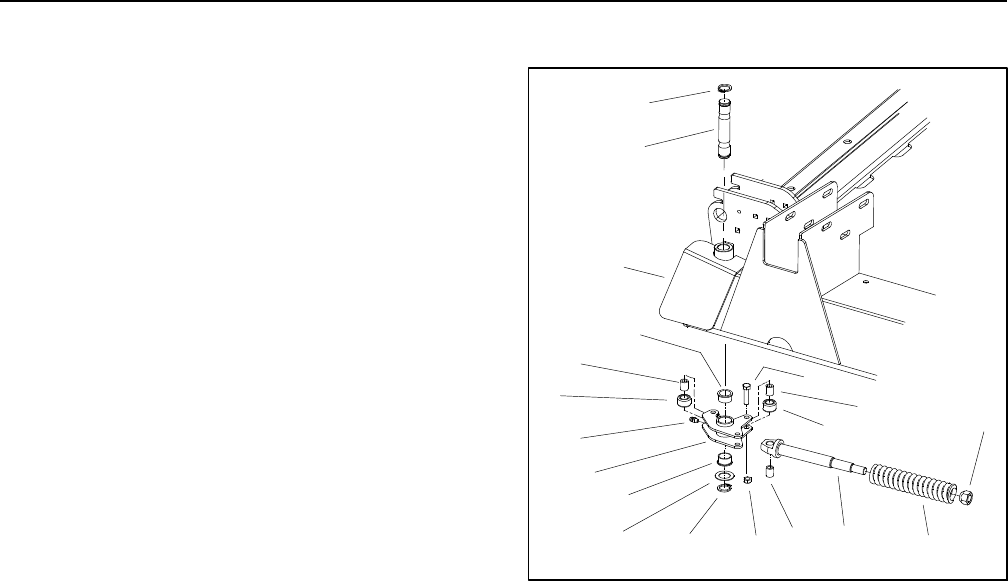
Groundsmaster 4100--D/4110--DCutting Deck Page 8 -- 14
Wing Deck Latch
Disassembly (Fig. 12)
1. Raise wing deck to transport position. Carefully ro-
tate latch to closed position.
2. Loosen lug nut to release compression spring ten-
sion.
3. Remove retaining ring and flat washer from bottom
of latch pin. Rotate lug nut enough to allow latch pin to
be removed from latch.
4. Remove lug nut from spring support. Remove latch
assembly from deck.
5. Disassemble latch (items 1 through 8) using Figure
12 as a guide.
Assembly (Fig. 12)
1. Assemble latch (items 1 through 8) using Figure 12
as a guide.
2. Slide spring onto spring support and insert end of
spring support into hole located on underside of center
deck. Start lug nut (tapered side towards plate on deck)
onto spring support.
3. Tighten lug nut until holes in front of deck align with
bushings in latch. Insert latch pin with retaining ring
down through deck and latch. Secure latch pin on under-
side of deck with flat washer and retaining ring.
4. Carefully rotate latch to the open position. Lower
wing deck to allow link to engage latch.
5. Lubricate latch grease fitting.
1. Latch
2. Grease fitting
3. Lock roller
4. Bushing
5. Flange bushing
6. Cap screw (3 used)
7. Spring support
8. Lock nut (3 used)
9. Retaining ring
10. Flat washer
11. Compression spring
12. Lug nut
13. Latch pin
14. Center deck
Figure 12
5
6
1
7
3
8
10 11
2
9
4
13
9
14
12
3
4
5
4

Groundsmaster 4100--D/4110--D Cutting DeckPage 8 -- 15
This page is intentionally blank.
Cutting
Deck
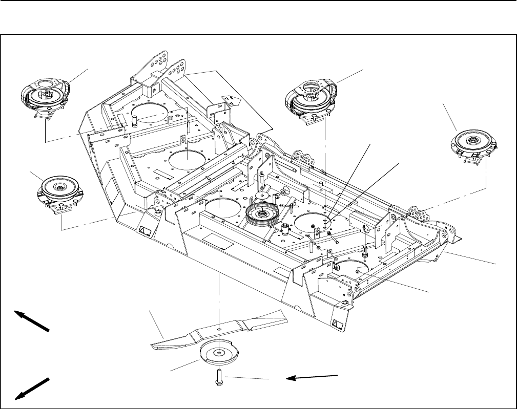
Groundsmaster 4100--D/4110--DCutting Deck Page 8 -- 16
Blade Spindle
1. Cutting deck
2. Drive spindle: single pulley (2 used)
3. Low driven spindle (3 used)
4. Drive spindle: double pulley (1 used)
5. High driven spindle (1 used)
6. Flange nut
7. Blade bolt
8. Cutting blade (7 used)
9. Anti--scalp cup
10. Flat washer
11. Cap screw
Figure 13
4
3
1
11
88 to 108 ft--lb
(119 to 146 N--m)
2
FRONT
RIGHT
5
7
6
9
8
10
Removal (Fig. 13)
1. Parkmachineonalevelsurface, lower cutting deck,
stop engine, engage parking brake and remove key
from the ignition switch.
2. If drive spindle is to be serviced, remove hydraulic
motor from cutting deck (see Cutting Deck Motor Re-
moval in the Service and Repairs Section of Chapter 4
-- Hydraulic System). Position motor away from spindle.
3. Remove belt covers from top of cutting deck. Loosen
idler pulley to release belt tension (see Idler Assembly
Removal in this section). Remove drive belt from spindle
to be serviced.
4. Start the engine and raise the cutting deck. Stop en-
gine and remove key from the ignition switch. Latch or
block up the cutting deck so it cannot fall accidentally.
5. Remove cutting blade, anti--scalp cup and blade bolt
from spindle to be serviced.
6. Remove spindle housing assembly from deck:
A. For driven spindle assemblies, remove eight (8)
flange nuts that secure spindle to deck.
B. For drive spindle assemblies, loosen and remove
four (4) flange nuts that secure spindle to deck.
Then, remove four (4) cap screws with flat washers
that secure spindle and motor mount to deck.
7. If necessary, press screws from spindle housing.
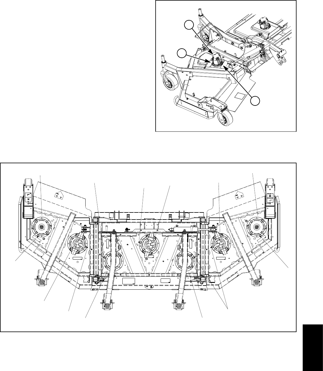
Groundsmaster 4100--D/4110--D Cutting DeckPage 8 -- 17
Installation (Fig. 13)
1. If screws were removed from spindle housing, press
new screws into housing. Make sure that screw head is
squarely seated against housing after installation.
2. Position spindle on cutting deck noting orientation of
grease fitting (Fig. 15). Secure spindle assembly to deck
with removed fasteners.
3. Install cutting blade, anti--scalp cup and blade bolt.
Tighten blade bolt from 88to108ft--lb(119to146
N--m).
4. Slowly rotate cutting blades to verify that blades do
not contact any deck component(s).
5. Install drive belt and adjust belt tension (see Idler As-
sembly Installation in this section).
6. If drive spindle was removed, install hydraulic motor
to cutting deck (see Cutting Deck Motor Installation in
the Service and Repairs Section of Chapter 4 -- Hydrau-
lic System).
IMPORTANT: Pneumatic grease guns can produce
air pockets when filling large cavities and therefore,
are not recommended to be used for proper greas-
ing of spindle housings.
7. Attach a hand pump grease gun to grease fitting on
spindle housing and fill housing cavity with grease until
grease starts to come out of lower seal.
8. Install belt covers to cutting deck.
1. Hydraulic motor 2. Flange head screw
Figure 14
1
2
2
1. Driven spindle
2. Driven spindle (high pulley)
3. Drive spindle (wing deck)
4. Drive spindle (center deck)
5. Spindle grease fitting location
Figure 15
5
3
2
5
1
1
43
5
1
5
5
5
Cutting
Deck
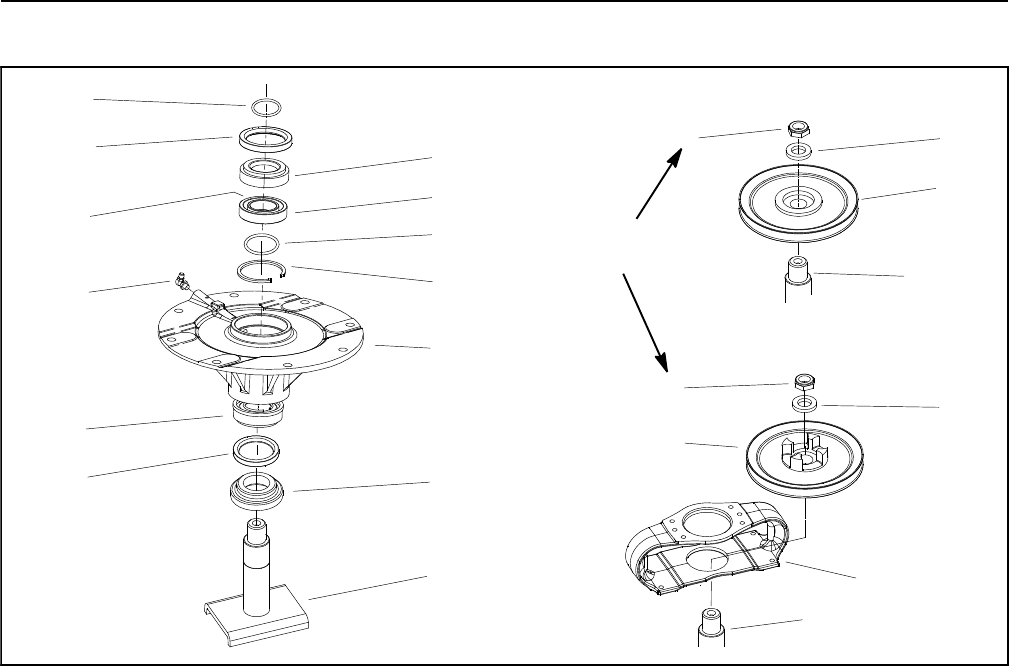
Groundsmaster 4100--D/4110--DCutting Deck Page 8 -- 18
Blade Spindle Service
1. Lock nut
2. Flat washer
3. Driven pulley
4. Spindle shaft
5. Drive pulley (single shown)
6. Hydraulic motor mount
7. O--ring
8. Oil seal
9. Bearing cup and cone
10. Outer bearing spacer
11. Inner bearing spacer
12. Spacer ring
13. Snap ring
14. Grease fitting
15. Spindle housing
16. Spindle shaft spacer
17. Spindle shaft
Figure 16
12
4
13
15
1
5
4
6
89
14
16
8
2
3
7
17
9
130 to 150 ft--lb
(176 to 203 N--m)
DRIVEN SPINDLE
DRIVE SPINDLE
11 12
10
Disassembly (Fig. 16)
1. Loosen and remove lock nut from top of spindle
shaft. Remove hardened washer and pulley from
spindle. For drive spindle, remove hydraulic motor
mount.
2. Remove the spindle shaft from the spindle housing
which may require the use of an arbor press. The spindle
shaft spacer should remain on the spindle shaft as the
shaft is being removed.
3. Carefully remove oil seals from spindle housing tak-
ingcaretonotdamagesealboreinhousing.
4. Allow the bearing cones, inner bearing spacer and
spacer ring to drop out of the spindle housing (Fig. 17).
5. Using an arbor press, remove both of the bearing
cups and the outer bearing spacer from the housing.
6. The large snap ring can remain inside the spindle
housing. Removal of this snap ring is very difficult.
Assembly (Fig. 16)
NOTE: A replacement spindle bearing set contains two
(2) bearings, a spacer ring and a large snap ring (items
1, 2 and 3 in Fig. 17). These parts cannot be purchased
separately. Also, do not mix bearing set components
from one deck spindle to another.
NOTE: A replacement bearing spacer set includes the
inner spacer and outer spacer (items 4 and 5 in Fig. 17).
Do not mix bearing spacers from one deck spindle to
another.
IMPORTANT: If new bearings are installed into a
used spindle housing, it may not be necessary to re-
place the original large snap ring. If the original
snap ring is in good condition with no evidence of
damage (e.g. spun bearing), leave the snap ring in
the housing and discard the snap ring that comes
with the new bearings. If the large snap ring is found
to be damaged, replace the snap ring.
1. Iflargesnapringwasremovedfromspindlehousing,
install snap ring into housing groove. Make sure snap
ring is fully seated in housing groove.
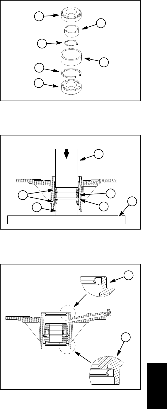
Groundsmaster 4100--D/4110--D Cutting DeckPage 8 -- 19
2. Install outer bearing spacer into top of spindle hous-
ing. The spacer should fit against the snap ring.
3. Using an arbor press, push the bearing cups into the
top and bottom of the spindle housing. The top bearing
cup must contact the outer bearing spacer previously
installed, and the bottom bearing cup must contact the
snap ring. Make sure that the assembly is correct by
supporting the first bearing cup and pressing the second
cup against it (Fig 18).
4. Pack the bearing cones with grease. Apply a film of
grease on lips of oil seals and O--ring.
5. Install lower bearing cone and oil seal into bottom of
spindle housing. Note: The bottom seal must have the
lip facing out (down) (Fig. 19). This seal installation al-
lows grease to purge from the spindle during the lubrica-
tion process.
IMPORTANT: If bearings are being replaced, make
sure to use the spacer ring that is included with new
bearing set (Fig. 17).
6. Slide spacer ring and inner bearing spacer into
spindle housing, then install upper bearing cone and oil
seal into top of housing. Note: The upper seal must have
the lip facing in (down) (Fig. 19). Also, upper seal should
be flush or up to 0.060” (1.5 mm) recessed into housing.
7. Inspect the spindle shaft and shaft spacer to make
sure there are no burrs or nicks that could possibly dam-
age the oil seals. Lubricate the shaft and spacer with
grease.
8. Install spindle shaft spacer onto shaft. Place thin
sleeve or tape on spindle shaft splines to prevent seal
damage during shaft installation.
9. Carefully slide spindle shaft with spacer up through
spindle housing. The bottom oil seal and spindle spacer
fit together when the spindle is fully installed.
10.Install O--ring to top of spindle shaft. For drive
spindle, position hydraulic motor mount to top of spindle.
11.Install pulley (hub down), hardened washer and lock
nut to spindle shaft. Tighten lock nut from 130 to 150 ft--
lb (176 to 203 N--m).
IMPORTANT: Pneumatic grease guns can produce
air pockets when filling large cavities and therefore,
are not recommended to be used for proper greas-
ing of spindle housings.
12.Attach a hand pump grease gun to grease fitting on
housing and fill housing cavity with grease.
13.Rotate spindle shaft to make sure that it turns freely.
1. Bearing
2. Spacer ring
3. Large snap ring
4. Inner bearing spacer
5. Outer bearing spacer
Figure 17
4
1
1
2
35
1. Bearing cups
2. Large snap ring
3. Large outer spacer
4. Arbor press
5. Support
6. Arbor press base
Figure 18
PRESS
52
4
3
6
1
1. Bottom seal installation 2. Upper seal installation
Figure 19
1
2
Cutting
Deck
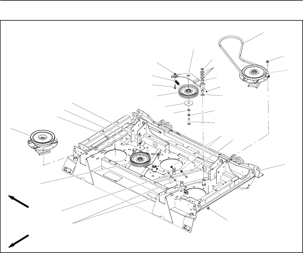
Groundsmaster 4100--D/4110--DCutting Deck Page 8 -- 20
Idler Assembly
1. Center deck
2. Flange nut
3. Flange nut
4. Adjusting screw
5. Idler pulley
6. High driven pulley
7. Flat washer
8. Lock washer
9. Socket head screw
10. Idler stop bolt
11. Flange nut
12. Cap screw
13. Spacer
14. Shoulder bolt
15. Idler spring
16. Lock nut
17. Idler arm
18. Retaining ring
19. Thrust washer (4 used per idler)
20. Bushing (2 used per idler)
21. Grease fitting
22. Low driven pulley
23. Flange head screw
24. Drive belt
Figure 20
FRONT
RIGHT
1
2
4
3
5
6
7
8
9
10
11
12
15
16
13
14
17
18
5
78
19
20
23
21
24
22
19
NOTE: The center deck is shown in Figure 20. The idler
assemblies used on the wing decks use the same idler
components.
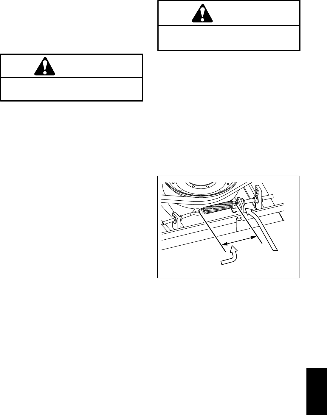
Groundsmaster 4100--D/4110--D Cutting DeckPage 8 -- 21
Removal (Fig. 20)
1. Park machine on a level surface, lower cutting deck,
stop engine, engage parking brake and remove key
from the ignition switch.
2. Remove deck covers from top of cutting deck.
CAUTION
Be careful when removing idler spring. The
spring is under heavy load and may cause per-
sonal injury.
3. Use spring hook tool to unhook the idler spring (item
15) from the adjusting screw (item 4).
4. Remove drive belt(s) from deck pulleys.
5. Loosen flange nuts (item 11) that secure idler stop
bolt (item 10) to cutting deck to allow clearance between
idler arm and stop bolt.
6. Remove idler components as needed using Figure
20 as a guide. Note location of washers, idler spacer and
screw as idler assemblies are being removed.
Installation (Fig. 20)
1. Install removed idler components using Figure 20 as
a guide.
A. Make sure that one (1) thrust washer (item 19) is
placed below the idler arm and three (3) thrust wash-
ers are placed between the idler and retaining ring
location.
B. Secure idler arm assembly to cutting deck with
retaining ring.
C. If idler stop bolt (item 10) was removed from deck,
make sure that it is installed in the hole that allows the
stop bolt head to align with the idler arm.
2. Install drive belt to pulleys.
CAUTION
Be careful when installing the idler spring. The
spring is under heavy load and may cause per-
sonal injury.
3. Use spring hook tool to attach the idler spring (item
15) onto the adjusting screw (item 4) and shoulder bolt
on idler arm. With the idler arm tensioning the drive belt,
the spring hook to hook length should be from 3.250” to
3.750” (82.6 to 95.2 mm) (Fig.21).Ifnecessary,discon-
nect spring and change position of adjusting screw.
When idler spring is the correct length, tighten second
flange nut to secure adjustment.
4. Adjust location of idler stop bolt (item 10) so that the
clearance between idler arm and idler stop bolt head is
from 0.125” to 0.185” (3.2 to 4.6 mm) (Fig. 21).
5. Lubricate idler arm grease fitting.
6. Install deck covers to cutting deck.
Figure 21
3.250” to 3.750”
(82.6 to 95.2 mm)
0.125” to 0.185”
(3.2 to 4.6 mm)
Cutting
Deck
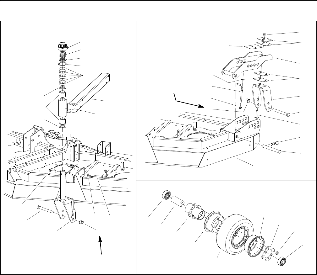
Groundsmaster 4100--D/4110--DCutting Deck Page 8 -- 22
Castor Forks and Wheels
1. Castor arm (wing deck shown)
2. Cap screw (6 per arm)
3. Castor fork
4. Castor wheel bolt
5. Lock nut
6. Castor spacer
7. Thrust washer
8. Flange lock nut
9. Grease fitting
10. Flange bushing
11. Retaining ring
12. Cap washer
13. Compression spring
14. Cap
15. Flat washer (6 per arm)
16. Clevis pin (2 used per fork)
17. Lock nut
18. Carriage screw (3 used per fork)
19. Castor fork bracket
20. Shim
21. Castor fork bracket
22. Hairpin
23. Cutting deck (LH shown)
24. Decal
25. Flat washer
26. Tension rod
27. Bearing
28. Inner bearing spacer
29. Wheel hub
30. Wheel rim half
31. Castor tire/tube
32. Wheel rim half
33. Plate
34. Flange nut (4 used per wheel)
Figure 22
34
32
33
30
27
28
29
31
60 to 80 ft--lb
(81 to 108 N--m)
DECK CASTOR ARM WING DECK CASTOR FORK
CASTOR WHEEL
20
21
19
22
24
17
18
16
4
25
8
20
23
26
5
60 to 80 ft--lb
(81 to 108 N--m)
27
9
1
11
6
12
13
14
10
7
7
3
4
5
8
2
15

Groundsmaster 4100--D/4110--D Cutting DeckPage 8 -- 23
Disassembly (Fig. 22)
1. Park machine on a level surface, lower cutting deck,
stop engine, engage parking brake and remove key
from the ignition switch.
2. Disassemble castor forks and wheels using Figure
22 as a guide.
Assembly (Fig. 22)
1. Assemble castor forks and wheels using Figure 22
as a guide.
2. Torque castor wheel lock nut from 60 to 80 ft--lb (81
to 108 N--m).
3. If castor fork was removed, lubricate grease fitting.
4. See Operator’s Manual for castor wheel adjustment.
Cutting
Deck

Groundsmaster 4100--D/4110--DCutting Deck Page 8 -- 24
Deck Rollers and Skids
1. Roller
2. Flange head screw
3. Roller shaft
4. Flange nut
5. Lock nut
6. Roller
7. Cap screw
8. Flange nut
9. Skid (RH shown)
10. Flange head screw
Figure 23
1
2
3
4
5
6
7
5
6
7
5
6
7
8
10
9
FRONT
RIGHT
Removal (Fig. 23)
1. Remove skids and rollers from deck using Figure 23
as a guide.
Installation (Fig. 23)
1. Install skids (item 9) to deck using Figure 23 as a
guide. Make sure to install skids in the same mounting
hole height position (lower or upper).
2. Install rollers (items 1 and 6) to deck using Figure 23
as a guide. When installing roller (item 6), install cap
screw with the threads orientated toward the centerline
of the deck. Install and tighten lock nut until roller will not
rotate, then loosen lock nut only enough to allow roller
to rotate freely. Make sure to install all deck rollers in the
same mounting hole height position (lower or upper).

Groundsmaster 4110--D Operator CabPage 9 -- 1
Chapter 9
Operator Cab
Table of Contents
GENERAL INFORMATION 2.....................
Operator’s Manual 2..........................
Electrical Components and Schematic 2.........
Air Conditioning System 2.....................
Cab Heater System 2.........................
SERVICE AND REPAIRS 3......................
General Precautions for Removing and Installing
Air Conditioning System Components 3........
Air Conditioning Compressor 4.................
Roof Assembly 6.............................
Air Conditioning Condenser Assembly 8.........
Heater/Evaporator Assembly 10................
Windshield Wiper 12..........................
SANDEN SD COMPRESSOR SERVICE GUIDE
Operator
Cab

Groundsmaster 4110--DOperator Cab Page 9 -- 2
General Information
The information in this chapter pertains to the operator
cab on the Groundsmaster 4110--D.
Operator’s Manual
The Operator’s Manual provides information regarding
the operation, general maintenance and maintenance
intervals for your Groundsmaster. Refer to the Opera-
tor’s Manual for additional information when servicing
the machine.
Electrical Components and Schematic
Information regarding Groundsmaster 4110--D electri-
cal cab components (switches and relay) is included in
Chapter 5 -- Electrical System. The electrical schematic
and wire harness drawings for the operator cab are in-
cluded in Chapter 10 -- Foldout Drawings.
Air Conditioning System
The air conditioning system used on the Groundsmaster
4110--D consists of the following components:
1. A compressor mounted on the engine and driven by
av--belt.
2. A condenser and condenser fan located on the top
of the cab.
3. A drier--receiver, an expansion valve and an evapo-
rator (combined with the heater core) mounted in the
headliner of the cab.
4. The necessary hoses and tubes that connect the
system components.
5. A fan motor that provides air movement through the
evaporator and into the cab. The fan motor is located in
the cab headliner and is also used for the cab heater
system.
6. Operator controls to turn the air conditioning on, to
adjust the fan speed and to control the cab air tempera-
ture.
Cab Heater System
The cab heater system used on the Groundsmaster
4110--D consists of the following components:
1. A heater core (combined with the A/C evaporator) lo-
cated in the cab headliner.
2. Hoses to allow a circuit for engine coolant to circulate
through the heater core. The heater core (combined
with the A/C evaporator) is located in the headliner of the
cab.
3. A fan motor that provides air movement through the
heater core and into the cab. The fan motor is located in
the cab headliner and is also used for the air condition-
ing system.
4. Operator controls to adjust the fan speed and to con-
trol the cab air temperature.
Groundsmaster 4110--D Operator CabPage 9 -- 3
Service and Repairs
General Precautions for Removing and Installing Air Conditioning System Components
CAUTION
The air conditioning system is under high pres-
sure. Do not loosen any system fitting or compo-
nent until after the system has been completely
discharged by a certified A/C service technician.
WARNING
Always wear safety goggles or a face shield
when working with air conditioning system com-
ponents. Also, do not allow refrigerant contact
with your skin or eyes as there would be the pos-
sibility of serious injury.
CAUTION
Never use compressed air to leak test or pres-
sure test the air conditioning system. Under cer-
tain conditions, pressurized mixtures of refriger-
ant and air can be combustible.
1. Before servicing any air conditioning system compo-
nents, park machine on a level surface, apply parking
brake, lower cutting deck or attachments and stop en-
gine. Remove key from the ignition switch.
2. Clean machine before disconnecting, removing or
disassembling any air conditioning system compo-
nents. Thorough cleaning will prevent system contami-
nation while performing service procedures.
3. Put caps or plugs on any lines, fittings or components
left open or exposed to prevent system contamination.
4. Before loosening or removing any air conditioning
system hose or other component, have a certified air
conditioning service technician recover the system re-
frigerant and then evacuate the air conditioning system
completely. It is illegal to vent refrigerant to the atmo-
sphere.
5. Put labels on disconnected lines and hoses for prop-
er installation after repairs are completed.
6. If compressor is removed from machine, keep com-
pressor in the same orientation as the installed position.
This will prevent compressor oil from filling the compres-
sor cylinders.
7. Note the position of fittings (especially elbow fittings)
before removal. Mark parts if necessary to make sure
they will be aligned properly when reinstalling hoses and
tubes.
8. Always use a DOT approved tank for storing used
and recycled refrigerants.
9. The Groundsmaster 4110--D air conditioning system
uses R134a refrigerant. DO NOT use other refrigerants
in the system. A/C system capacity is 1.35 pounds of
R134a refrigerant.
10.Refrigerant containers (either full or empty) are un-
der pressure that will increase if the containers are
heated. DO NOT expose refrigerant containers to high
heat sources or flame.
11. Be sure the work area is properly ventilated to pre-
vent any accumulation of refrigerant or other fumes.
12.Make sure that caps are always placed on the pres-
sure hose ports. These caps prevent refrigerant leakage
from the system.
13.The drier--receiver component is used to collect
moisture that will reduce air conditioning performance.
If the air conditioning system is opened for component
repair or replacement, drier--receiver replacement is
recommended.
14.After installing air conditioning components, have a
certified air conditioning service technician evacuate the
air conditioning system completely, properly recharge
the system with R134a refrigerant and then leak test the
system.
Operator
Cab
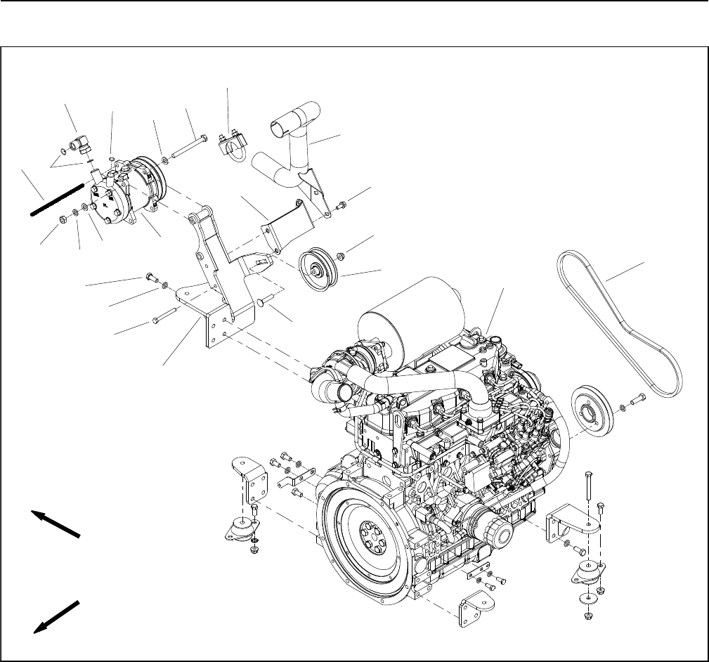
Groundsmaster 4110--DOperator Cab Page 9 -- 4
Air Conditioning Compressor
Figure 1
FRONT
RIGHT
1. Cap screw (2 used)
2. Flat washer (4 used)
3. Lock washer (6 used)
4. Hex nut (2 used)
5. Conduit
6. O--ring (2 used)
7. 90ofitting
8. O--ring
9. A/C compressor
10. Cap screw (4 used)
11. Cap screw (2 used)
12. A/C compressor mount
13. Flange head screw (2 used)
14. Exhaust bracket
15. Exhaust pipe
16. Flange nut
17. Carriage screw
18. Idler pulley
19. Compressor drive belt
20. Engine (model 30602 shown)
21. Clamp assembly
2
3
6
8
9
10
11
13
1
5
7
12
14
15
16
17
18
19
42
3
20
21
Removal (Fig. 1)
1. Parkmachineonalevelsurface, lower cutting deck,
stop engine, engage parking brake and remove key
from the ignition switch.
2. Raise hood to allow access to engine.
3. Remove exhaust pipe (item 15).
4. Loosen flange nut that secures idler pulley. Move
pulley to loosen A/C compressor drive belt. Remove
drive belt from A/C compressor pulley.
5. Inspect compressor drive belt for glazing or damage.
Replace belt if necessary.
6. Disconnect compressor electrical connector from
machine wire harness.
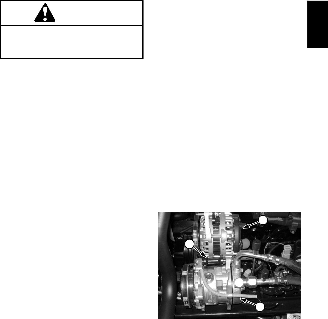
Groundsmaster 4110--D Operator CabPage 9 -- 5
7. Read the General Precautions for Removing and
Installing Air Conditioning System Components at the
beginning of the Service and Repairs section of this
chapter.
CAUTION
The air conditioning system is under high pres-
sure. Do not loosen any system fitting or compo-
nent until after the system has been completely
discharged by a certified A/C service technician.
8. Have refrigerant evacuated from air conditioning
system by a certified A/C service technician.
9. Label and remove hoses from compressor. Immedi-
ately cap hoses and fittings to prevent moisture and con-
taminants from entering the system.
10.Support compressor to prevent it from shifting or fal-
ling.
NOTE: There may be shims mounted between com-
pressor and compressor mount. When removing com-
pressor, note shim location and quantity for assembly
purposes.
11.Remove fasteners and washers that secure com-
pressor to compressor mount.
IMPORTANT: To prevent compressor oil from filling
the compressor cylinders, keep compressor in the
same orientation as the installed position.
12.Carefully remove compressor from engine and ma-
chine.
NOTE: The replacement of the drier--receiver is recom-
mended whenever A/C compressor is removed from the
system (see Heater and Evaporator Assembly in this
section).
NOTE: The air conditioning compressor used on the
Groundsmaster 4110--D is a Sanden model SD5H09.
For air conditioning compressor repair procedures, see
the Sanden SD Compressor Service Guide at the end
of this chapter.
Installation (Fig. 1)
1. Position compressor to compressor mount on en-
gine.
NOTE: The clearance between the compressor mount-
ing flanges and compressor mount must be less than
0.004” (0.10 mm). If necessary, install shims between
compressor flanges and mount to adjust clearance. See
Compressor Parts Catalog for shim kit.
2. Secure compressor to compressor mount with re-
moved fasteners and spacers. Do not fully tighten fas-
teners.
IMPORTANT: After the compressor has been
installed, make sure to rotate the compressor drive
shaft several times to properly distribute oil in the
compressor. Compressor damage due to oil slug-
ging can occur if this procedure is not performed.
3. Manually rotate the compressor drive shaft at least
ten (10) revolutions to make sure that no compressor oil
is in the compressor cylinders.
4. Place drive belt onto compressor pulley.
5. Tension compressor drive belt with idler pulley. Make
sure to tighten flange nut to secure belt adjustment.
6. Install exhaust pipe (item 15).
7. Remove caps that were placed on hoses and fittings
during the removal process. Using labels placed during
removal, properly secure hoses to compressor.
8. Connect compressor electrical connector to ma-
chine wire harness.
9. Have a certified air conditioning service technician
evacuate the air conditioning system completely, prop-
erly recharge the system with R134a refrigerant and
then leak test the system. A/C system capacity is 1.35
pounds of R134a refrigerant.
10.Lower and secure hood.
1. A/C compressor
2. Alternator
3. Compressor mount
Figure 2
1
2
3
Operator
Cab
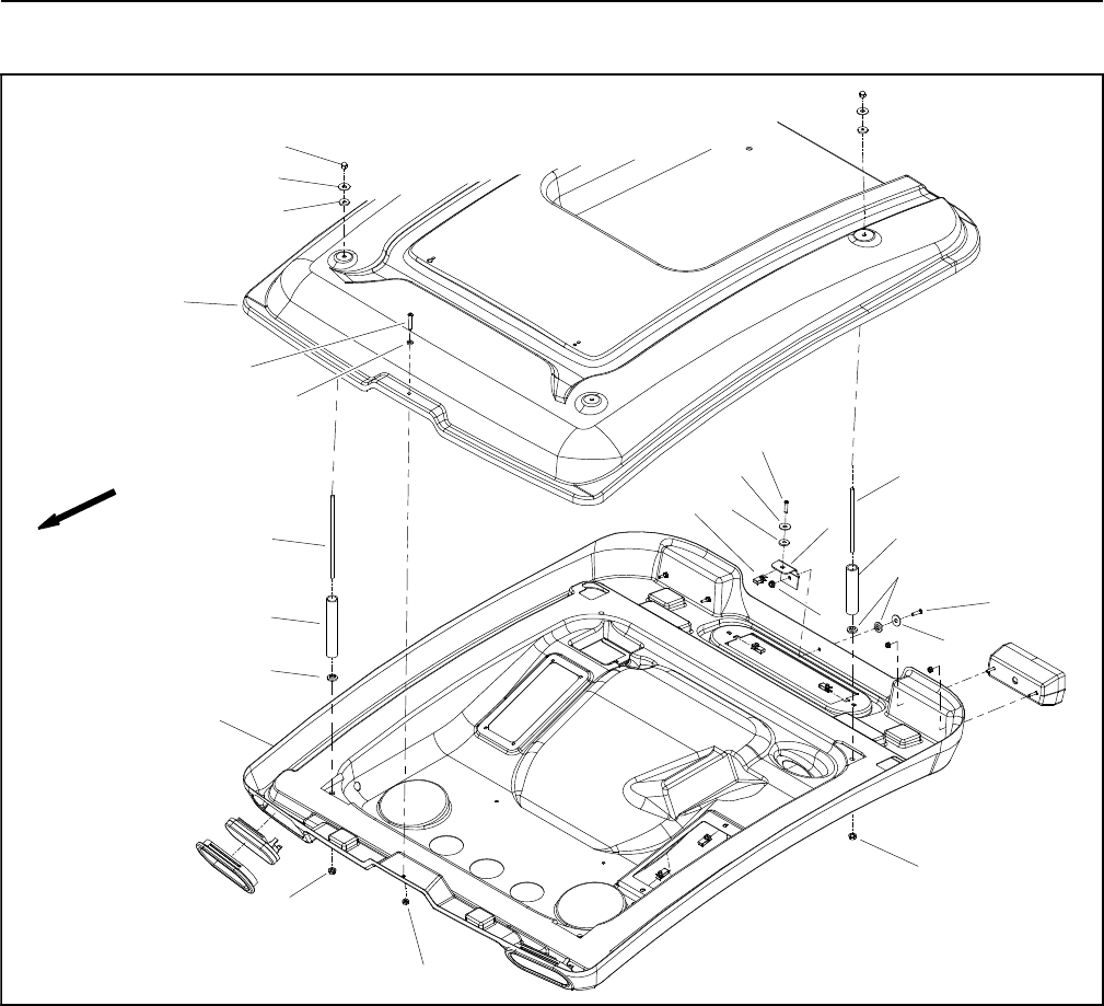
Groundsmaster 4110--DOperator Cab Page 9 -- 6
Roof Assembly
1. Roof
2. Screw (2 used)
3. Flat washer (6 used)
4. Bushing (10 used)
5. Rear fastener (2 used)
6. Rear spacer (2 used)
7. Panel nut
8. Roof mount
9. Flange nut (2 used)
10. Flange nut (4 used)
11. Headliner
12. Front spacer (2 used)
13. Front fastener (2 used)
14. Rubber washer
15. Cap screw
16. Hex nut (4 used)
Figure 3
FRONT
2
7
9
6
8
4
10
16
1
5
2
3
3
3
4
4
4
9
10
11
12
13
14
15
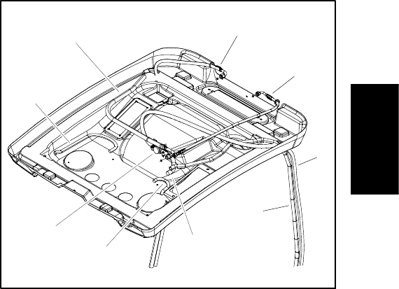
Groundsmaster 4110--D Operator CabPage 9 -- 7
To gain access to the heater core and air conditioning
components that are located under the cab roof, the roof
panel can be loosened, raised and supported.
Removal (Fig. 3)
1. Park machine on a level surface, lower cutting deck,
stop engine, engage parking brake and remove key
from the ignition switch.
2. Remove screw (item 2), flat washer (item 3) and
bushing (item 4) that secure the rear of the roof to the
roof mount.
3. Remove the cap screw (item 15) and rubber washer
(item 14) that secure the front of the roof.
4. Remove four (4) hex nuts (item 16), flat washers
(item 3) and bushings (item 4) that secure roof to front
and rear fasteners.
5. Carefully lift front of roof while leaving rear of roof
against headliner. Support front of roof in the raised
position to allow access to heater and air conditioning
components.
Installation (Fig. 3)
1. Make sure that all components in headliner and roof
are installed and secure.
2. Remove support and carefully lower roof into posi-
tion.
3. Secure roof to headliner with all removed fasteners.
1. Condensation drain hose (2 used)
2. Heater valve
3. A/C hose: evaporator to compressor
4. Heater hose: heater valve to heater core
5. A/C hose: compressor to condenser
6. A/C hose: condenser to drier
7. Heater hose: thermostat to heater valve
8. Heater hose: heater core to water pump
Figure 4
2
3
7
8
6
5
4
1
1
Operator
Cab
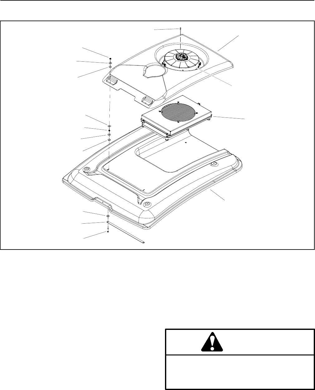
Groundsmaster 4110--DOperator Cab Page 9 -- 8
Air Conditioning Condenser Assembly
1. Condenser cover
2. Lock nut (4 used)
3. Condenser fan
4. Condenser coil assembly
5. Carriage screw (2 used)
6. Flat washer (8 used)
7. Roof
8. Bushing (4 used)
9. Mounting strap
10. Button head screw (4 used)
Figure 5
2
1
3
4
7
8
5
9
6
2
6
8
10
6
6
Removal (Fig. 5)
1. Parkmachineonalevelsurface, lower cutting deck,
stop engine, engage parking brake and remove key
from the ignition switch.
2. Remove fasteners that secure roof in place. Raise
and support roof to allow access to condenser assembly
(see Roof Assembly in this section).
3. Disconnect wire harness connector from condenser
fan motor.
4. Remove button head screws (item 10) that secure
condenser fan and cover to condenser coil.
5. Remove fasteners (items 2, 6 and 8) that secure
front of condenser cover to roof. Lift condenser fan and
cover from roof.
6. Read the General Precautions for Removing and
Installing Air Conditioning System Components at the
beginning of the Service and Repairs section of this
chapter.
CAUTION
The air conditioning system is under high pres-
sure. Do not loosen any system fitting or compo-
nent until after the system has been completely
discharged by a certified A/C service technician.
7. Have refrigerant evacuated from air conditioning
system by a certified A/C service technician.
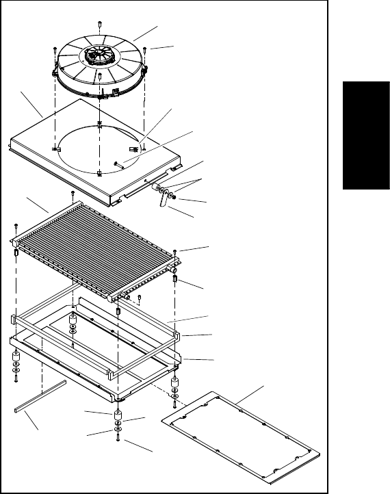
Groundsmaster 4110--D Operator CabPage 9 -- 9
8. Label and remove hoses from condenser coil. Imme-
diately cap hoses and fittings to prevent moisture and
contaminants from entering the system.
9. Remove condenser coil from roof using Figure 6 as
a guide.
NOTE: The replacement of the drier--receiver is recom-
mended whenever the air conditioning system is
opened (see Heater/Evaporator in this section).
Installation (Fig. 5)
1. Install condenser coil to roof using Figure 6 as a
guide.
2. Remove caps that were placed on hoses and fittings
during the removal process. Using labels placed during
removal, properly secure hoses to condenser coil.
3. Position condenser cover and condenser fan to roof.
Secure cover and fan with removed fasteners (items 2,
6 and 8).
4. Secure condenser fan to condenser coil with button
head screws (item 10).
5. Connect wire harness connector to condenser fan
motor.
6. Make sure that all machine air conditioning compo-
nents are installed and secure.
7. Have a certified air conditioning service technician
evacuate the air conditioning system completely, prop-
erly recharge the system with R134a refrigerant and
then leak test the system. A/C system capacity is 1.35
pounds of R134a refrigerant.
8. Lower and secure roof assembly (see Roof Assem-
bly in this section).
1. Bushing (4 used)
2. Condenser coil
3. Fan shroud
4. Condenser fan
5. Isolator mount (4 used)
6. Coupler nut (4 used)
7. Screw (4 used)
8. Screw (4 used)
9. Screw (4 used)
10. Flat washer (4 used)
11. Clip (4 used)
12. Tray foam
13. Screen frame
14. End foam (2 used)
15. Screen
16. Side foam (2 used)
17. Lock nut
18. Latch plate
19. Friction washer (2 used)
20. Latch spacer
21. Carriage screw
Figure 6
1
2
3
4
5
6
7
8
9
10
11
12
13
14
15
16
19
20
21
17
18
Operator
Cab
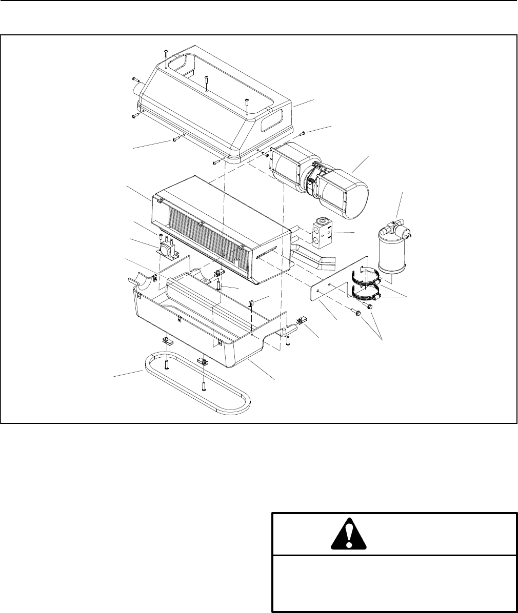
Groundsmaster 4110--DOperator Cab Page 9 -- 10
Heater/Evaporator Assembly
1. Heater/evaporator assembly
2. Top cover
3. Flange head screw (2 used)
4. Drier--receiver mount
5. Bottom cover
6. Hose clamp (2 used)
7. Speed nut (8 used)
8. Panel nut (4 used)
9. Drier--receiver assembly
10. Screw (8 used)
11. Screw (4 used)
12. Blower fan assembly
13. Expansion valve
14. Freeze switch
15. Screw (2 used)
16. Screw (12 used)
Figure 7
1
2
3
4
5
6
7
8
9
10
11
12
13
14 13
12
15
16
Removal (Fig. 7)
1. Parkmachineonalevelsurface, lower cutting deck,
stop engine, engage parking brake and remove key
from the ignition switch.
2. Remove fasteners that secure roof in place. Raise
and support roof to allow access to heater/evaporator
assembly (see Roof Assembly in this section).
3. Disconnect wire harness connectors from fan motor
and binary switch on drier--receiver.
4. Read the General Precautions for Removing and
Installing Air Conditioning System Components at the
beginning of the Service and Repairs section of this
chapter.
CAUTION
The air conditioning system is under high pres-
sure. Do not loosen any system fitting or compo-
nent until after the system has been completely
discharged by a certified A/C service technician.
5. Have refrigerant evacuated from air conditioning
system by a certified A/C service technician.
6. Label and remove hoses from heater core, evapora-
tor and drier--receiver. Immediately cap hoses and fit-
tings to prevent moisture and contaminants from
entering the system.
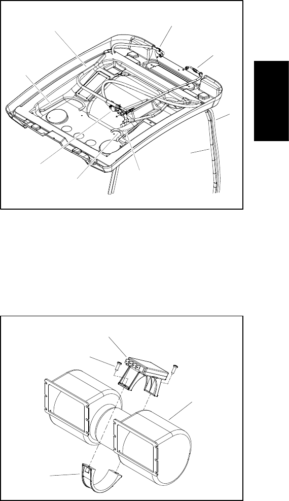
Groundsmaster 4110--D Operator CabPage 9 -- 11
7. Loosen hose clamp that secures air duct hose to
heater/evaporator assembly covers. Slide hose from
covers.
8. Remove screws that secure top cover to bottom cov-
er. Remove top cover to access heater/evaporator as-
sembly.
9. Disassemble heater/evaporator assembly using Fig.
7 as a guide.
10.If necessary, remove fan resistor from blower fan as-
sembly (Fig. 9).
NOTE: The replacement of the drier--receiver is recom-
mended whenever the air conditioning system is
opened.
Installation (Fig. 7)
1. Assemble heater/evaporator assembly using Fig. 7
as a guide. Make sure that expansion valve is covered
with insulating tape to prevent condensation issues.
2. If removed, secure fan resistor to blower fan as-
sembly (Fig. 9).
3. Position heater/evaporator assembly into bottom
cover in headliner. Secure top cover to bottom cover
with removed screws.
4. Slide air duct hose onto heater/evaporator assembly
covers and secure with hose clamp.
5. Remove caps that were placed on hoses and fittings
during the removal process. Using labels placed during
removal, properly secure hoses to heater core, evapo-
rator and drier--receiver.
6. Make sure that condensation hoses are secured to
bottom housing of heater/evaporator assembly and are
routed to cab frame for proper draining of condensate.
7. Connect wire harness connectors to fan motor and
binary switch on drier--receiver.
8. Make sure that all machine air conditioning compo-
nents are installed and secure.
9. Have a certified air conditioning service technician
evacuate the air conditioning system completely, prop-
erly recharge the system with R134a refrigerant and
then leak test the system. A/C system capacity is 1.35
pounds of R134a refrigerant.
10.Operate the heater system to make sure that no en-
gine coolant leaks exist.
11.Lower and secure roof assembly (see Roof Assem-
bly in this section).
1. Condensation drain hose (2 used)
2. Heater valve
3. A/C hose: evaporator to compressor
4. Heater hose: heater valve to heater core
5. A/C hose: compressor to condenser
6. A/C hose: condenser to drier
7. Heater hose: thermostat to heater valve
8. Heater hose: heater core to water pump
Figure 8
2
3
7
8
6
5
4
1
1
1. Fan resistor
2. Blower fan assembly
3. Clamp
4. Screw (2 used)
Figure 9
2
1
3
4
Operator
Cab
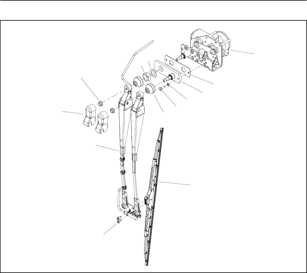
Groundsmaster 4110--DOperator Cab Page 9 -- 12
Windshield Wiper
1. Wiper motor
2. Gasket
3. Linkage bracket
4. Lock washer
5. Cap screw
6. Cap (2 used)
7. Washer
8. Nut
9. Flange nut (2 used)
10. Cover (2 used)
11. Wiper arm assembly
12. Wiper blade
13. Screw (2 used)
Figure 10
2
3
6
8
9
10
11
13
1
5
7
12
4

Groundsmaster 4110--D Operator CabPage 9 -- 13
Disassembly (Fig. 10)
1. Park machine on a level surface, lower cutting deck,
stop engine, engage parking brake and remove key
from the ignition switch.
2. If access to wiper motor is necessary, remove fasten-
ers that secure roof in place. Raise and support roof to
allow access to condenser assembly (see Roof Assem-
bly in this section).
3. Remove windshield wiper components as needed
using Figure 10 as a guide.
Assembly (Fig. 10)
1. Assemble windshield wiper components using Fig-
ure10asaguide.
2. If roof was raised, lower and secure roof assembly
(see Roof Assembly in this section).
Operator
Cab
Groundsmaster 4110--DOperator Cab Page 9 -- 14
This page is intentionally blank.

Groundsmaster 4100--D/4110--D Foldout DrawingsPage 10 -- 1
Chapter 10
Foldout Drawings
Table of Contents
ELECTRICAL DRAWING DESIGNATIONS 2.......
HYDRAULIC SCHEMATIC 3.....................
ELECTRICAL SCHEMATICS
Models 30602 and 30604 4....................
Models 30606 and 30608 5....................
Operator Cab 6...............................
International Light Kits 7.......................
WIRE HARNESS DRAWINGS
Platform Wire Harness Drawing 9...............
Rear Wire Harness Drawing 12.................
Engine Wire Harness Drawing: Models 30606
and 30608 14...............................
Engine Wire Harness Drawing: Models 30602
and 30604) 16..............................
Cutting Deck Wire Harness Drawing 18..........
Operator Cab Interconnect Wire Harness
Drawing 19.................................
Operator Cab Wire Harness Drawing 20.........
Foldout
Drawings

Groundsmaster 4100--D/4110--DFoldout Drawings Page 10 -- 2
Electrical Drawing Designations
The following abbreviations are used for wire harness
colors on the electrical schematics and wire harness
drawings in this chapter.
ABBREVIATION COLOR
BK BLACK
BR or BN BROWN
BU BLUE
GN GREEN
GY GRAY
OR ORANGE
PK PINK
RorRD RED
TTAN
VIO VIOLET
WorWH WHITE
YorYE YELLOW
Numerous harness wires used on Groundsmaster
4100--D and 4110--D machines include a line with an al-
ternate color. These wires are identified with the wire
colorandlinecolorwitheithera/or_separatingthecol-
or abbreviations listed above (e.g. R/BK is a red wire
with a black line, OR_BK is an orange wire with a black
line).
NOTE: The electrical harness drawings in this chapter
identify both the wire color and the wire gauge. For ex-
ample, 16 BK on a harness diagram identifies a 16
gauge wire that has a black insulator.
NOTE: A splice used in a wire harness will be identified
on the wire harness diagram by SP. The manufacturing
number of the splice is also identified on the wire har-
ness diagram (e.g. SP01 is splice number 1).
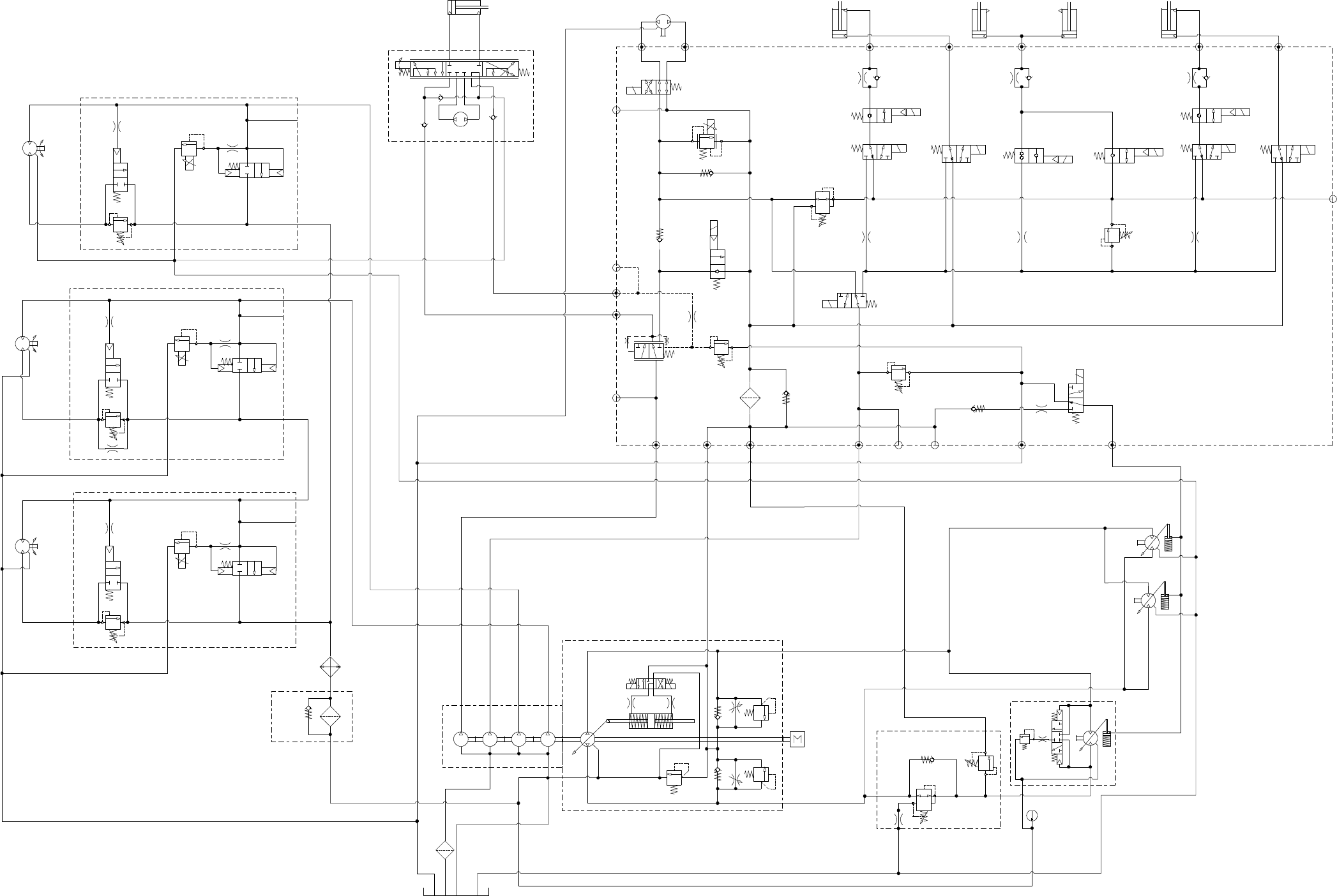
Page 10 -- 3
Hydraulic Schematic
Groundsmaster 4100--D/4110--D
S10
RV1
CV1
S2
S4
S5
PRV
P4 CH2 P3
EC
CF
LS
S3
OR1
C3
OR4
.040
S6
OR5
.070
C4 C2 C5
RV2
2500 PSI
S7
S9
S8
C6
M1 M2
CH1
CV3
CH4
OR2
.063
OR6
.063
OR3
.070
OR7
.070
T2SPCH3
G2
G4
CV4
PR
G1
G3
3250
PSI
1350
PSI
3.3 GPM
4.4 GPM
15.2 GPM
310
PSI
4 PSI
4 PSI
.030
OR9
S1
3300 PSI
RV3 S12
15.2 GPM
S11
CV2
4 PSI
1.17 CID 3000 PSI
P1
P1
P1
P2
P2
P2
M1
M2
LC1
PRV
PD
CD
RV
2000 PSI
M1
M2
LC1
PRV
PD
RV
3000 PSI
M1
M2
LC1
PRV
PD
RV
CD
CD
LEFT DECK
CENTER DECK
RIGHT DECK
50 PSI
1.17 CID
1.17 CID
6.1 CID
0.625” ROD
EP
LR
T
STEERING
CYLINDER 0.51 CID WING DECK
1.125” ROD
WING DECK
1.125” ROD
VALVE
PR
380 PSI
RV650 PSI
.050
CV
T
P2
M8
CH
OR1
250 PSI
EU -- 2600 / 1200 RPM
2.14 CID /
1.16 CID
1. FLOWS SHOWN ARE CALCULATED AT HIGH IDLE AND
95% PUMP EFFICIENCY UNLESS OTHERWISE NOTED
600 PSI
600 PSI
600 PSI
.030”
200 PSI
2.75
CID
1.37
CID
1.37
CID
4350 PSI
5000 PSI
.025
.025
.025
.0315
G
G
G
2.00” BORE
4.20” STROKE
2.50” BORE
6.50” STROKE
1.50” BORE
3.08” STROKE
2.50” BORE
6.50” STROKE
CENTER DECK
RAM CYLINDERS
1.4 CID/
0.79 CID
1.4 CID/
0.79 CID
60
PSI
80
PSI
30.5 GPM
0.4
CID
0.3
CID
ENGINE IDLE
T4 -- 2700 / 1200 RPM
REAR
TRACTION
.0315
COMBINATION MANIFOLD
STEERING
CONTROL
VALVE
RIGHT
LEFT
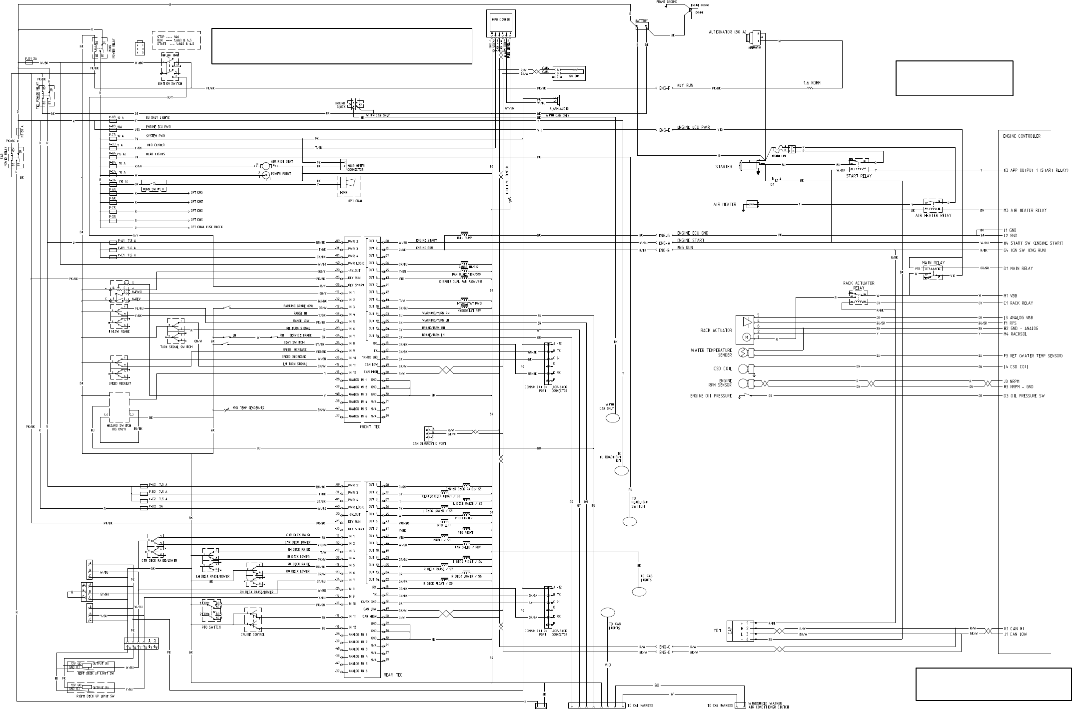
Page 10 -- 4
Electrical Schematic
Groundsmaster 4100--D/4110--D
All relays and solenoids
are shown as de--energized.
All ground wires are black.
Models 30602 and 30604
1
2
3
4
5
CAB, A REFERENCE NUMBER WILL BE LISTED. THE CAB SCHEMATIC WILL ALSO
INCLUDE THE REFERENCE NUMBER.
NOTE: WHEN A WIRE FROM THIS SCHEMATIC CONTINUES TO THE OPERATOR
WIRE COLOR ABBREVIATIONS.
NOTE: REFER TO ELECTRICAL DRAWING
DESIGNATIONS IN THIS CHAPTER FOR
TRACTION PEDAL
POSITION SENSOR
TRACTION PEDAL
POSITION SENSOR
NOT USED
ON GM4100-- D
NOT USED
ON GM4100-- D
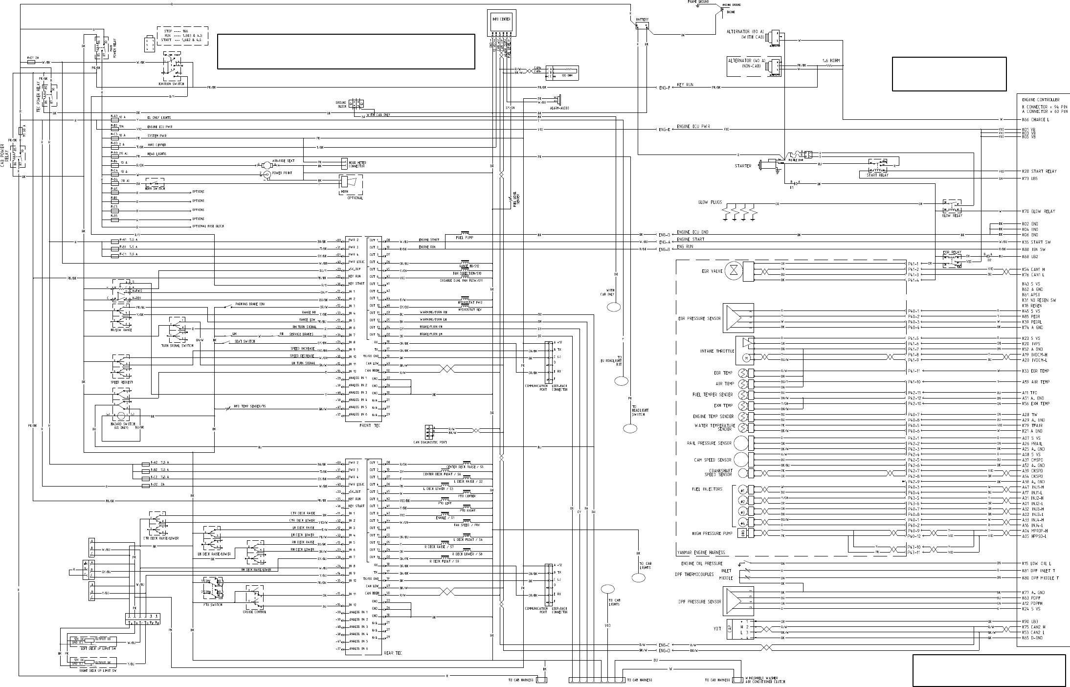
Page 10 -- 5
All relays and solenoids
are shown as de--energized.
All ground wires are black.
Electrical Schematic
Models 30606 and 30608
Groundsmaster 4100--D/4110--D
5
2
4
3
1
CAB, A REFERENCE NUMBER WILL BE LISTED. THE CAB SCHEMATIC WILL ALSO
INCLUDE THE REFERENCE NUMBER.
NOTE: WHEN A WIRE FROM THIS SCHEMATIC CONTINUES TO THE OPERATOR
WIRE COLOR ABBREVIATIONS.
NOTE: REFER TO ELECTRICAL DRAWING
DESIGNATIONS IN THIS CHAPTER FOR
TRACTION PEDAL
POSITION SENSOR
TRACTION PEDAL
POSITION SENSOR
NOT USED
ON GM4100-- D
NOT USED
ON GM4100-- D
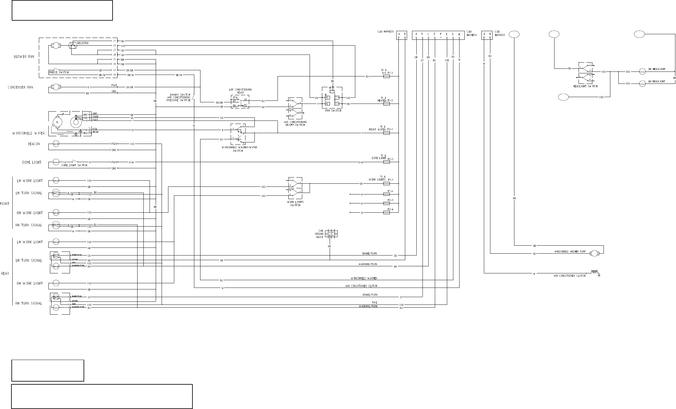
Page 10 -- 6
TO GROUND
BLOCK PLATFORM
WIRE HARNESS
FROM OPERATOR PLATFORM
WIRE HARNESS
TO OPERATOR
Operator Cab (shown with lights for US model)
Groundsmaster 4110--D
All relays and solenoids
are shown as de--energized.
All ground wires are black.
Electrical Schematic
1 2
3
4
TO CAB
WIRE HARNESS
SCHEMATIC FOR THE APPROPRIATE MODEL NUMBER WHICH IS ON A SEPARATE PAGE.
WHEN A WIRE FROM THIS CAB SCHEMATIC CONTINUES TO THE MACHINE SCHEMATIC,
NOTE: THE OPERATOR CAB SCHEMATIC SHOULD BE USED WITH THE ELECTRICAL
A REFERENCE NUMBER WILL BE LISTED.
WIRE COLOR ABBREVIATIONS.
NOTE: REFER TO ELECTRICAL DRAWING
DESIGNATIONS IN THIS CHAPTER FOR
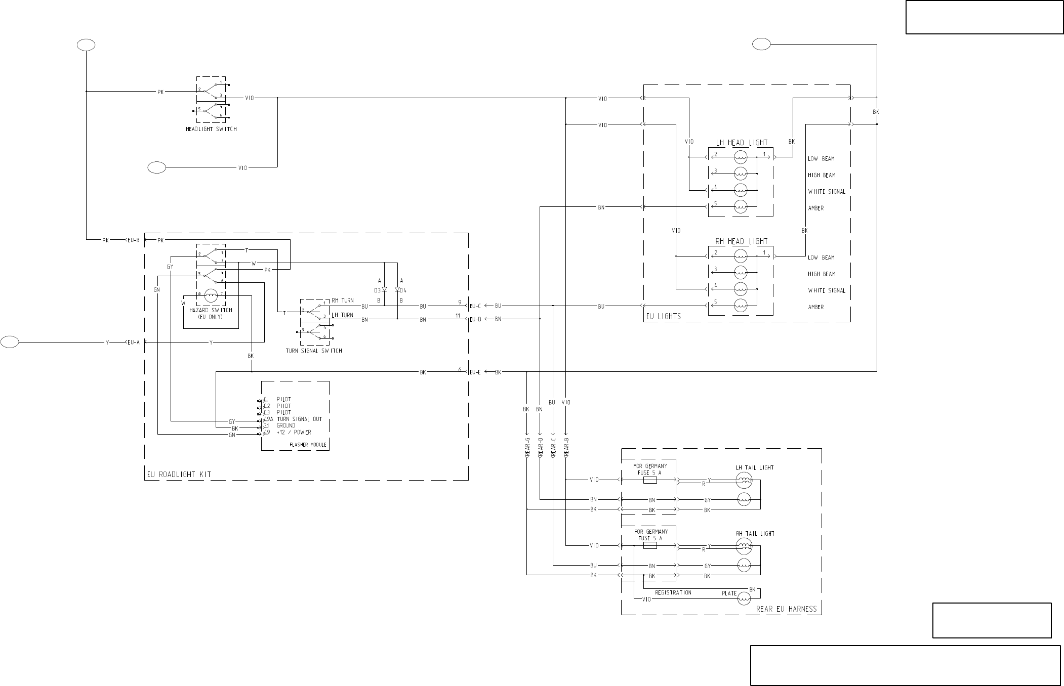
Page 10 -- 7
Electrical Schematic
Groundsmaster 4110--D
All relays and solenoids
are shown as de--energized.
All ground wires are black.
International Light Kits
2
3
4
5
PLATFORM
WIRE HARNESS
FROM OPERATOR
PLATFORM
WIRE HARNESS
TO OPERATOR
TO CAB
WIRE HARNESS
PLATFORM
WIRE HARNESS
TO OPERATOR
SCHEMATIC FOR THE APPROPRIATE MODEL NUMBER WHICH IS ON A SEPARATE PAGE.
WHEN A WIRE FROM THIS CAB SCHEMATIC CONTINUES TO THE MACHINE SCHEMATIC,
NOTE: THE OPERATOR CAB SCHEMATIC SHOULD BE USED WITH THE ELECTRICAL
A REFERENCE NUMBER WILL BE LISTED.
WIRE COLOR ABBREVIATIONS.
NOTE: REFER TO ELECTRICAL DRAWING
DESIGNATIONS IN THIS CHAPTER FOR
Page 10 -- 8
This page is intentionally blank.
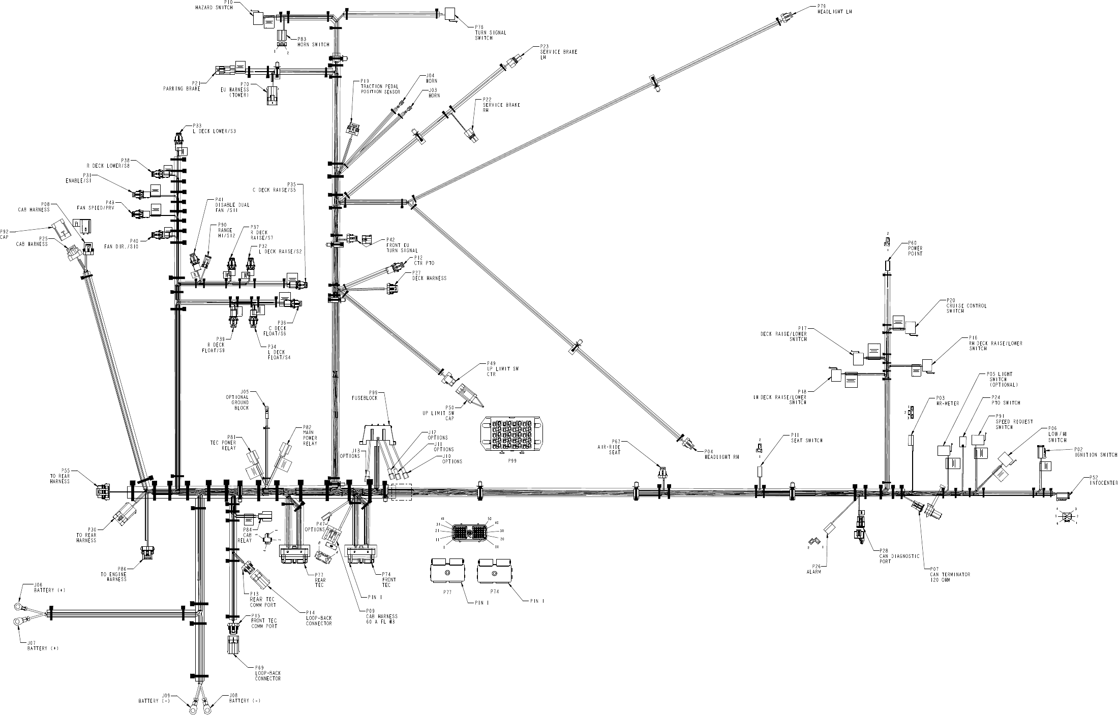
Page 10 -- 9
Groundsmaster 4100--D/4110--D
Platform Wire Harness Drawing
ABCD
1
2
3
4
5
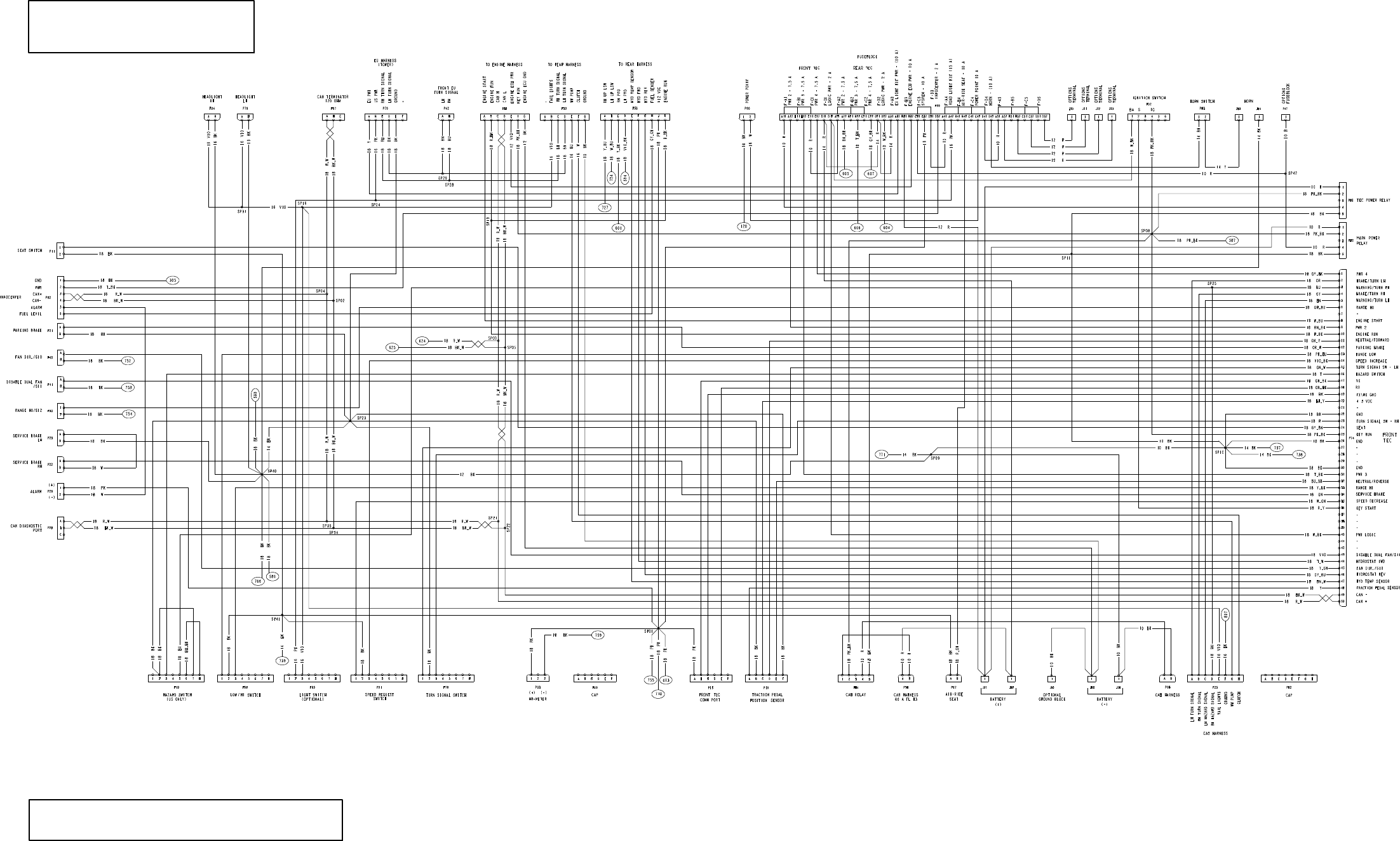
Page 10 -- 10
Groundsmaster 4100--D/4110--D
Platform Wire Harness Diagram
Sheet 1 of 2
REFERENCE NUMBER WILL BE IDENTIFIED.
NOTE: THE PLATFORM WIRE HARNESS DIAGRAM IS SHOWN ON TWO (2)
SHEETS. WHEN A CONDUCTOR CONTINUES ON ANOTHER SHEET, A
DRAWING DESIGNATIONS IN THIS CHAPTER
NOTE: THIS DRAWING IDENTIFIES WIRE GAUGE
SIZE AND WIRE COLOR. REFER TO ELECTRICAL
FOR ADDITIONAL INFORMATION.
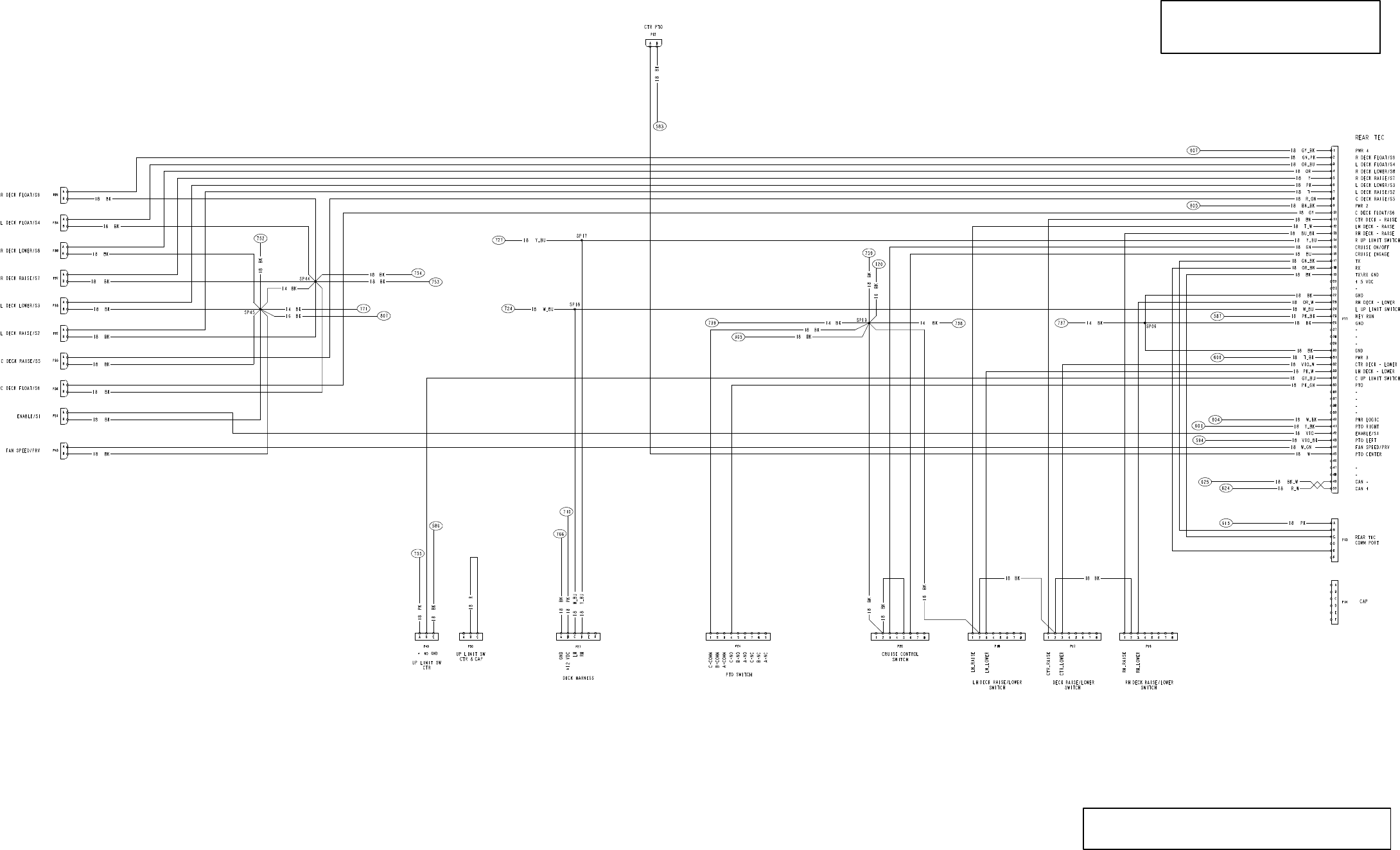
Page 10 -- 11
Groundsmaster 4100--D/4110--D
Platform Wire Harness Diagram
Sheet 2 of 2
REFERENCE NUMBER WILL BE IDENTIFIED.
NOTE: THE PLATFORM WIRE HARNESS DIAGRAM IS SHOWN ON TWO (2)
SHEETS. WHEN A CONDUCTOR CONTINUES ON ANOTHER SHEET, A
DRAWING DESIGNATIONS IN THIS CHAPTER
NOTE: THIS DRAWING IDENTIFIES WIRE GAUGE
SIZE AND WIRE COLOR. REFER TO ELECTRICAL
FOR ADDITIONAL INFORMATION.
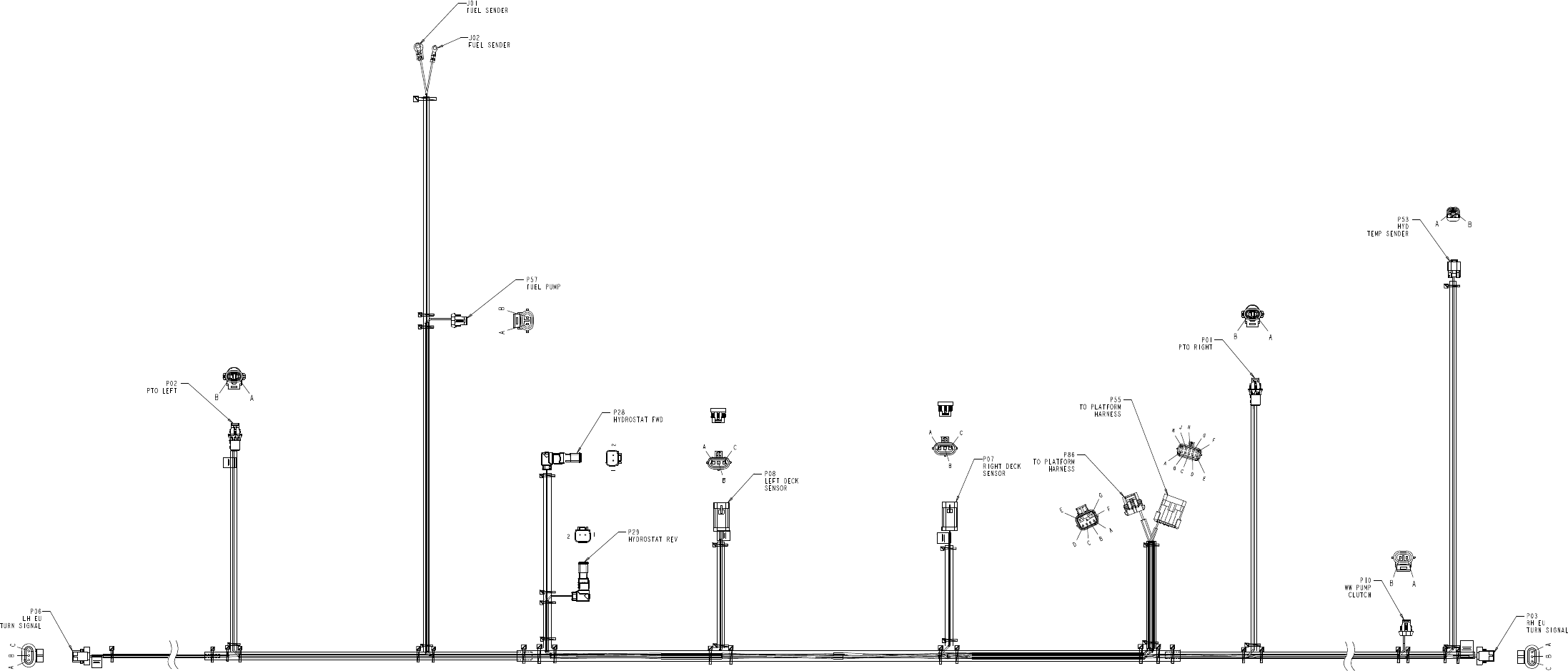
Page 10 -- 12
Groundsmaster 4100--D/4110--D
Rear Wire Harness Drawing
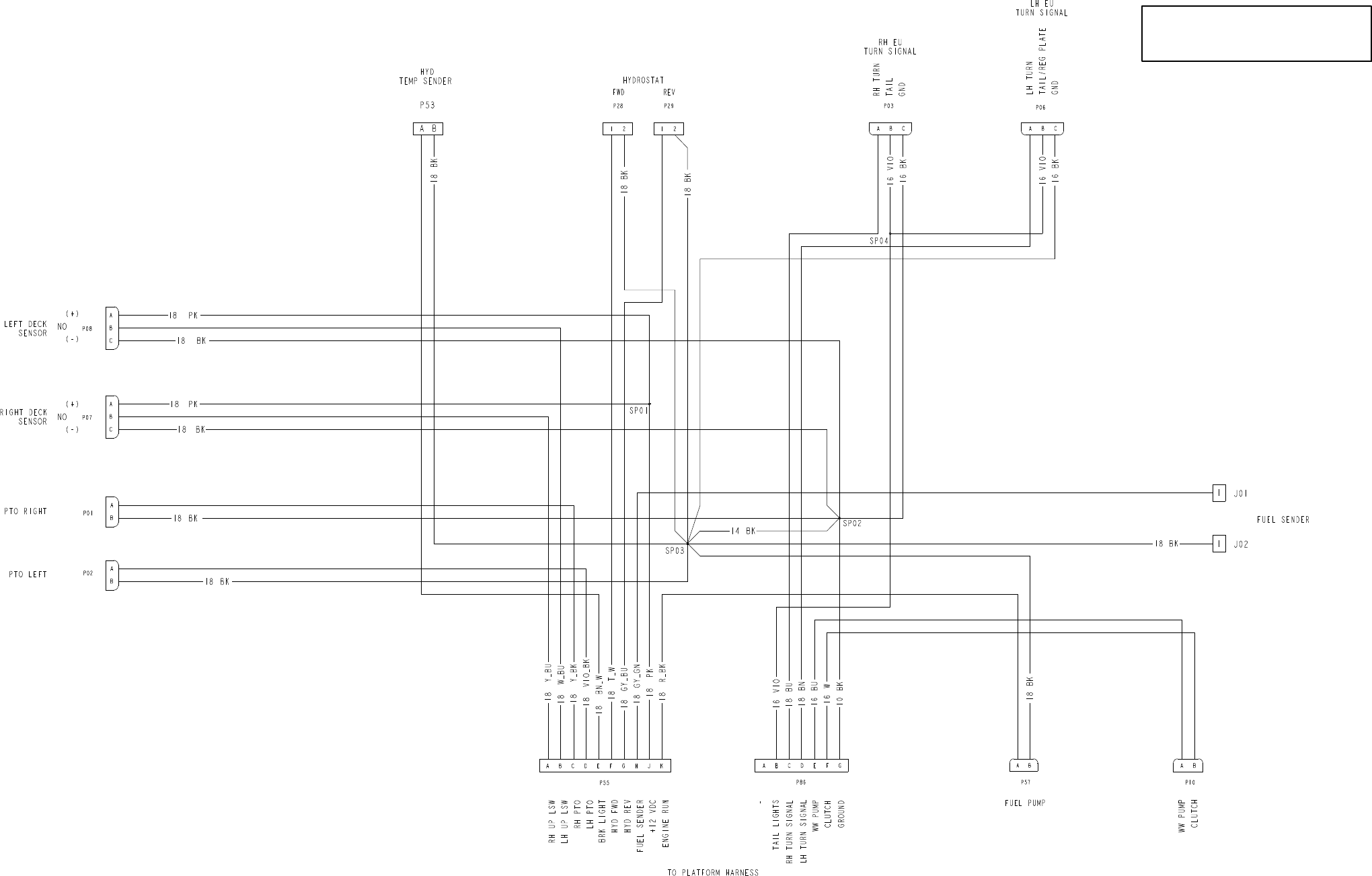
Page 10 -- 13
Groundsmaster 4100--D/4110--D
Rear Wire Harness Diagram
DRAWING DESIGNATIONS IN THIS CHAPTER
NOTE: THIS DRAWING IDENTIFIES WIRE GAUGE
SIZE AND WIRE COLOR. REFER TO ELECTRICAL
FOR ADDITIONAL INFORMATION.
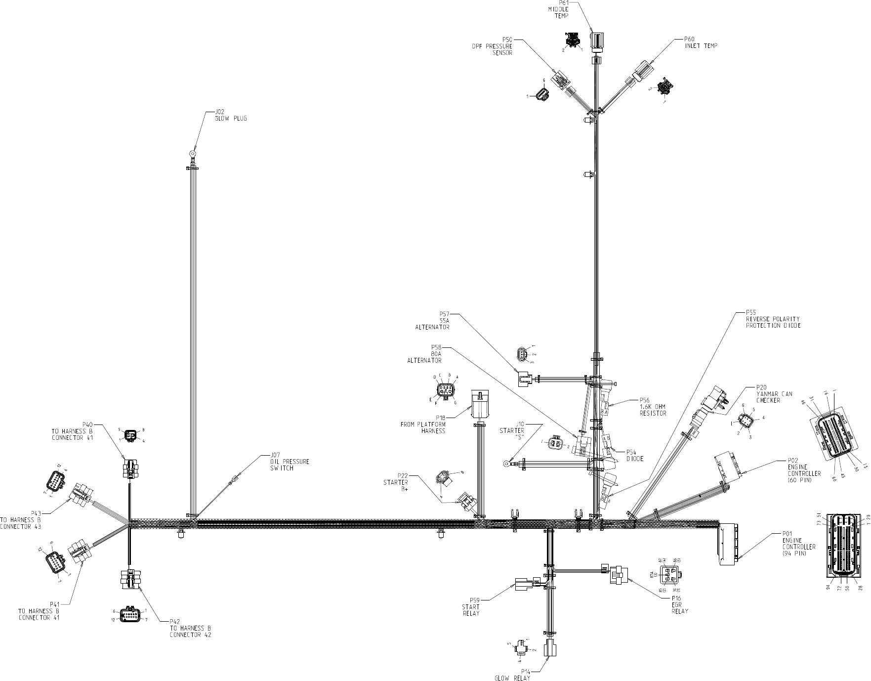
Page 10 -- 14
Models 30606 and 30608
Engine Wire Harness Drawing
Groundsmaster 4100--D/4110--D
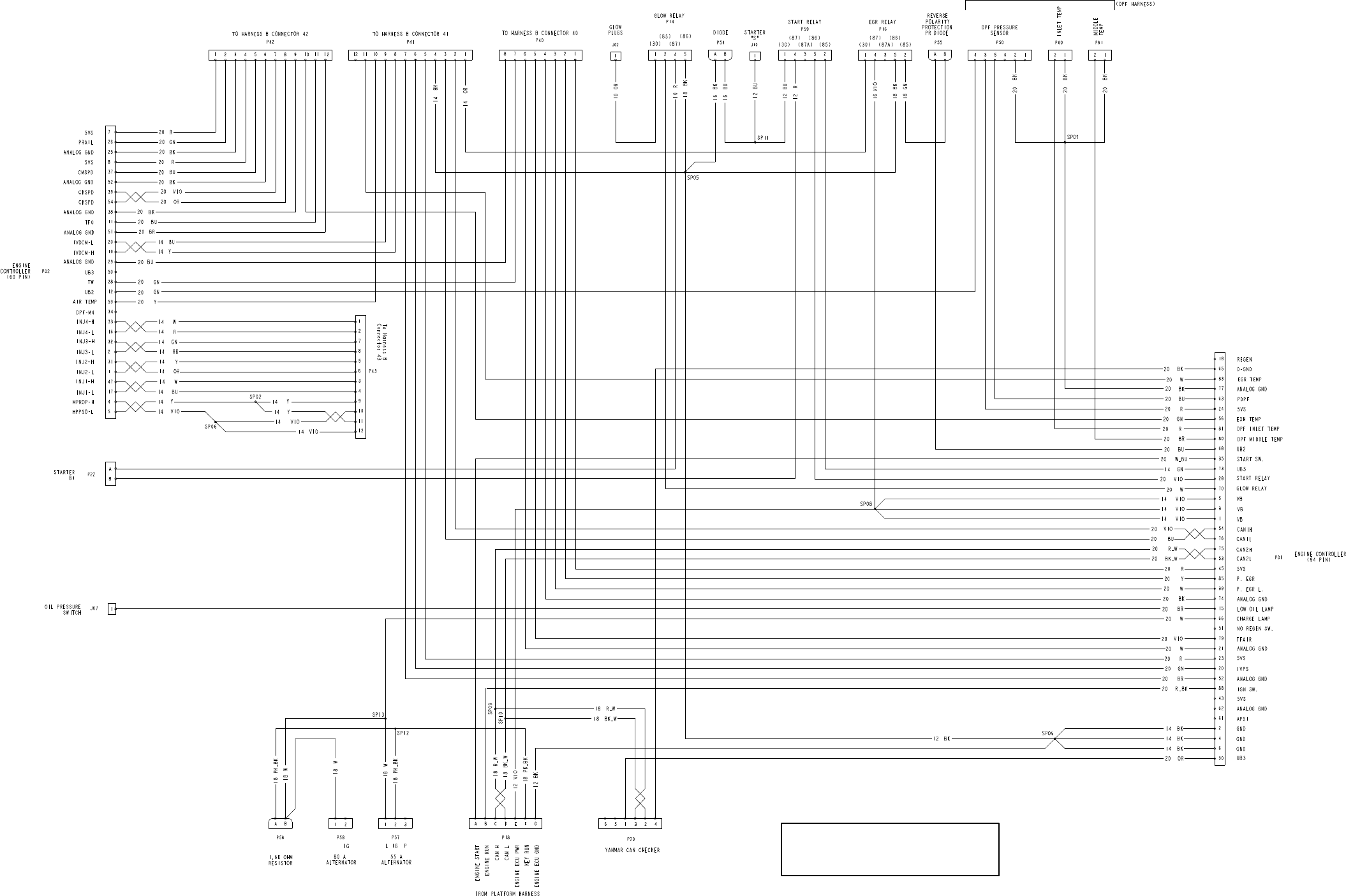
Page 10 -- 15
Models 30606 and 30608
Engine Wire Harness Diagram
Groundsmaster 4100--D/4110--D
DRAWING DESIGNATIONS IN THIS CHAPTER
NOTE: THIS DRAWING IDENTIFIES WIRE GAUGE
SIZE AND WIRE COLOR. REFER TO ELECTRICAL
FOR ADDITIONAL INFORMATION.
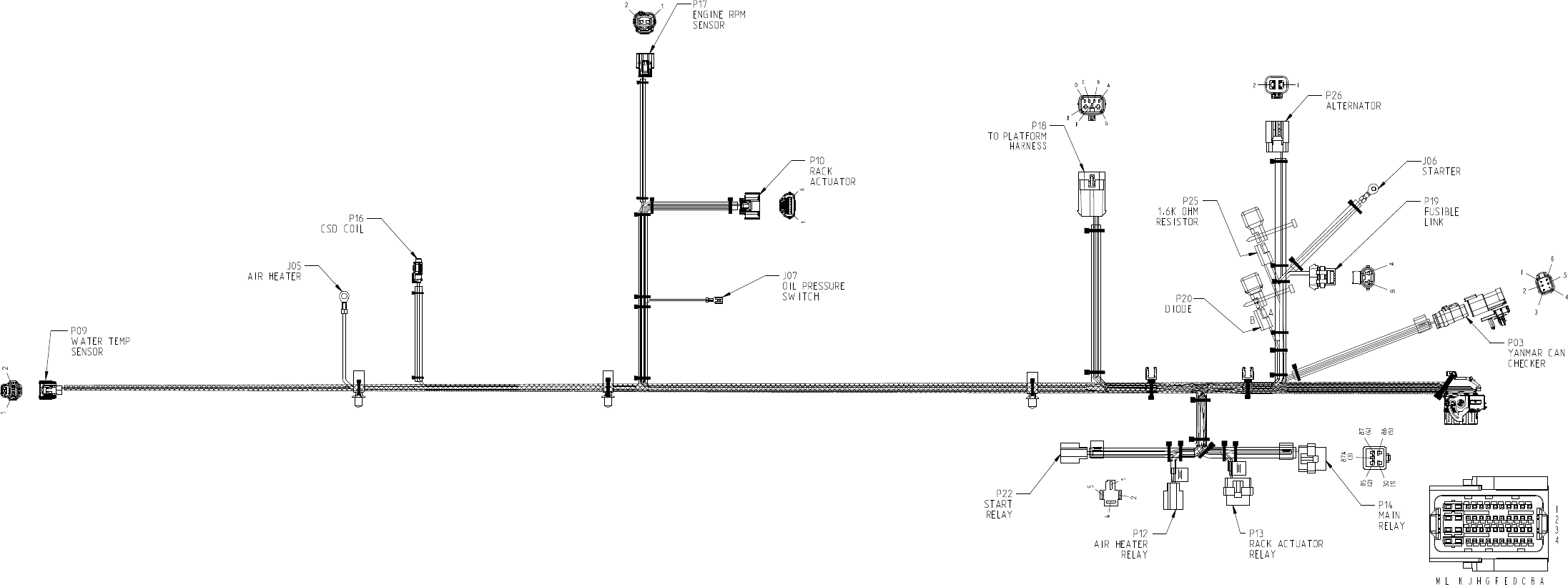
Page 10 -- 16
Models 30602 and 30604
Engine Wire Harness Drawing
Groundsmaster 4100--D/4110--D
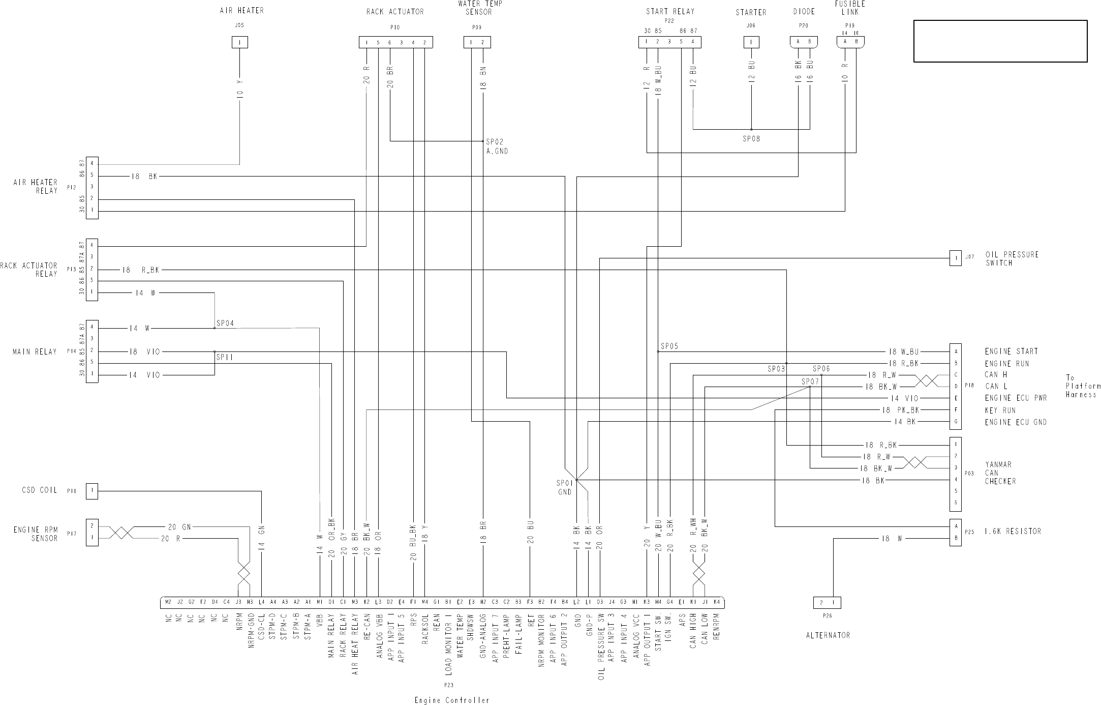
Page 10 -- 17
Models 30602 and 30604
Engine Wire Harness Diagram
Groundsmaster 4100--D/4110--D
DRAWING DESIGNATIONS IN THIS CHAPTER
NOTE: THIS DRAWING IDENTIFIES WIRE GAUGE
SIZE AND WIRE COLOR. REFER TO ELECTRICAL
FOR ADDITIONAL INFORMATION.
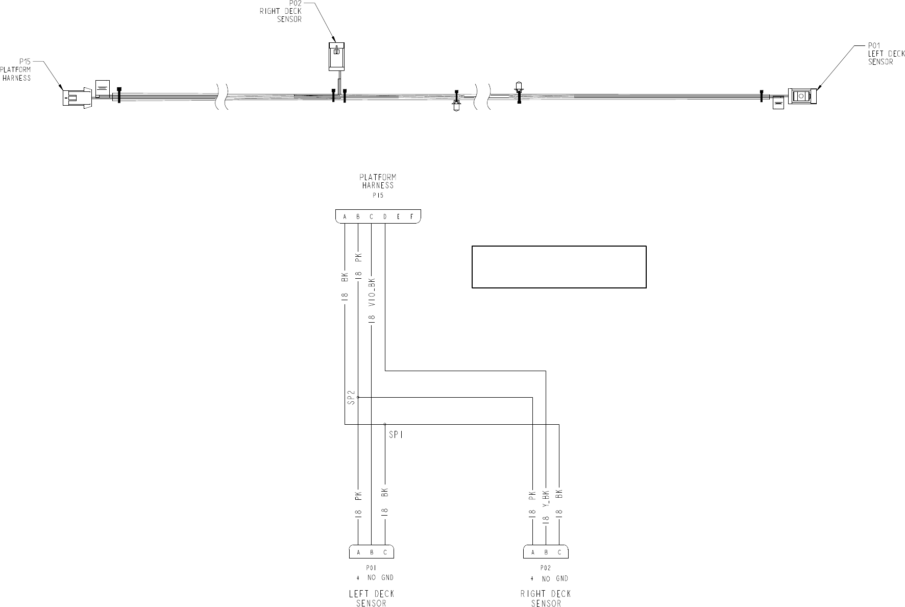
Page 10 -- 18
Groundsmaster 4100--D/4110--D
Cutting Deck Wire Harness
DRAWING DESIGNATIONS IN THIS CHAPTER
NOTE: THIS DRAWING IDENTIFIES WIRE GAUGE
SIZE AND WIRE COLOR. REFER TO ELECTRICAL
FOR ADDITIONAL INFORMATION.
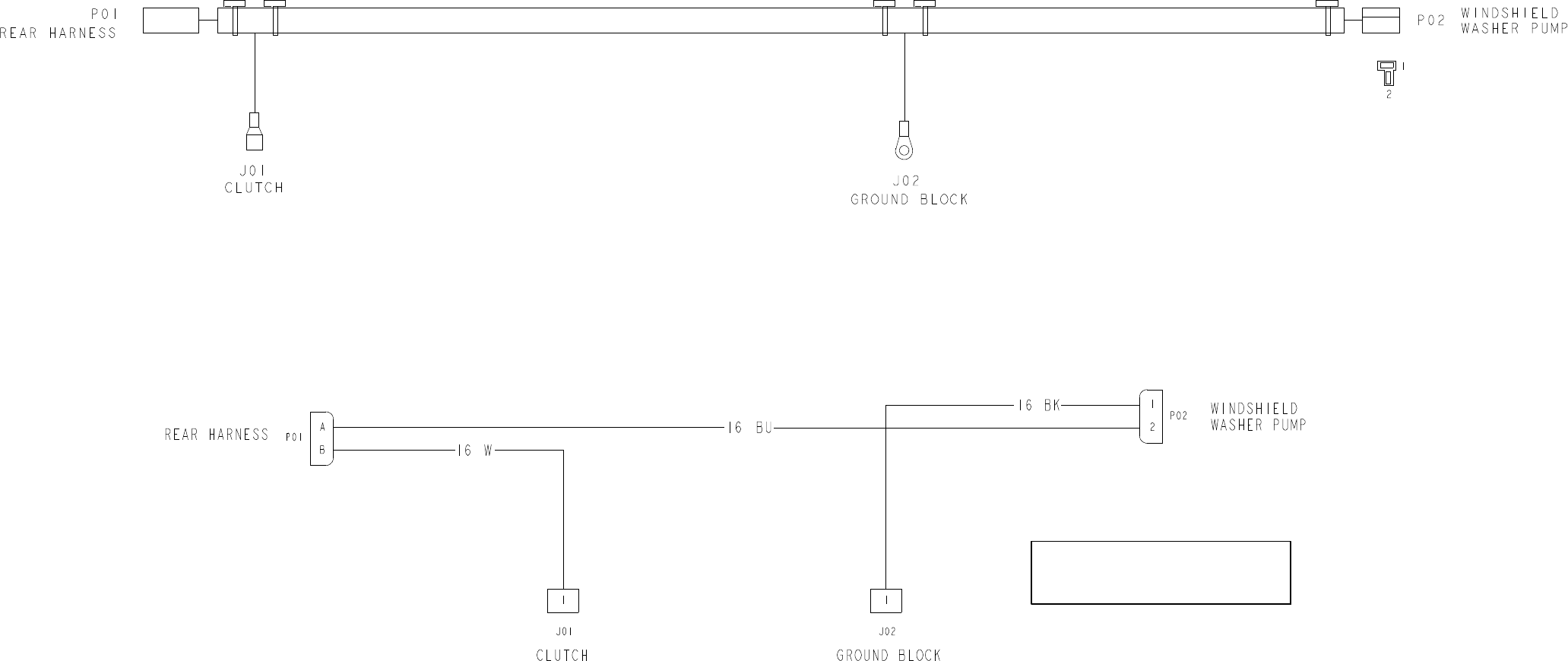
Page 10 -- 19
Groundsmaster 4110--D
Operator Cab Interconnect Wire Harness
DRAWING DESIGNATIONS IN THIS CHAPTER
NOTE: THIS DRAWING IDENTIFIES WIRE GAUGE
SIZE AND WIRE COLOR. REFER TO ELECTRICAL
FOR ADDITIONAL INFORMATION.
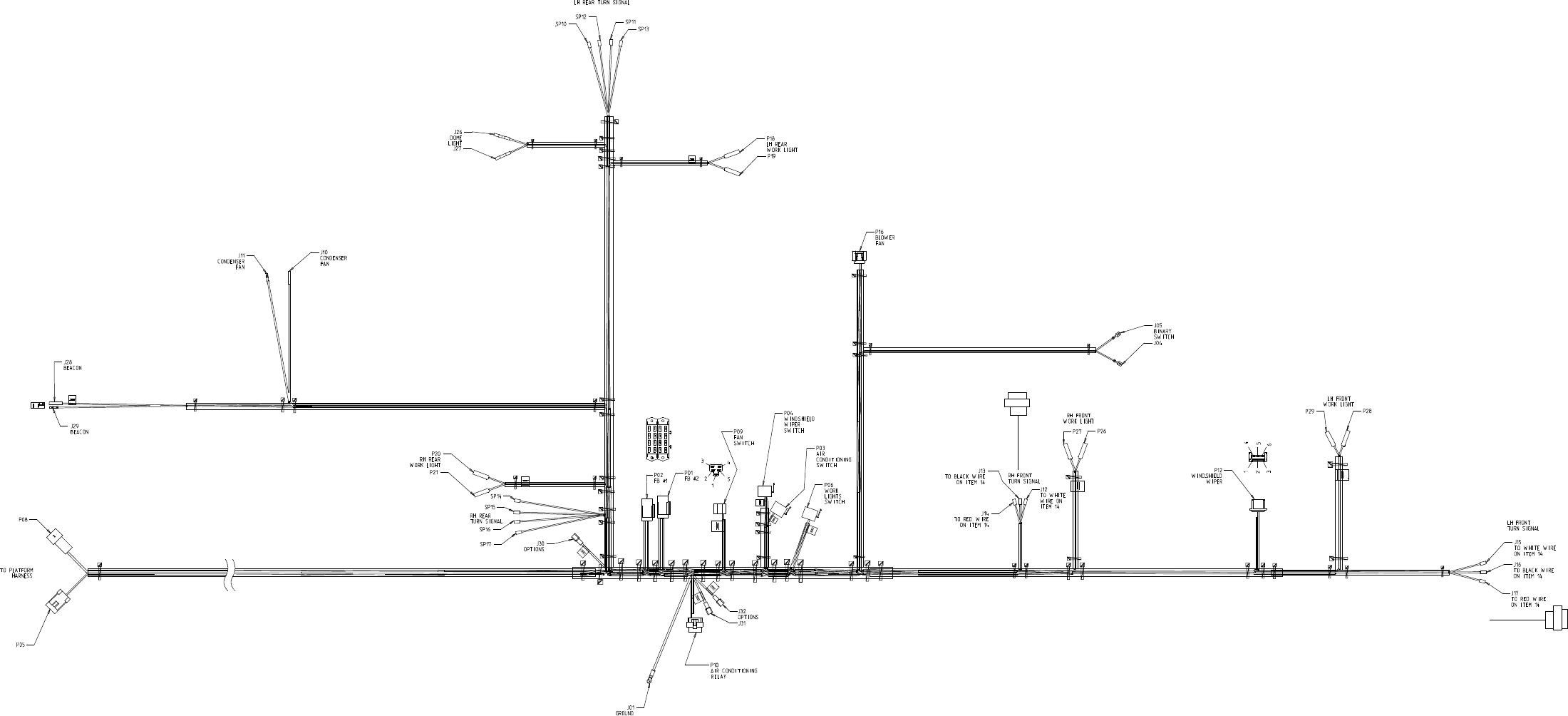
Page 10 -- 20
Groundsmaster 4110--D
Operator Cab Wire Harness Drawing
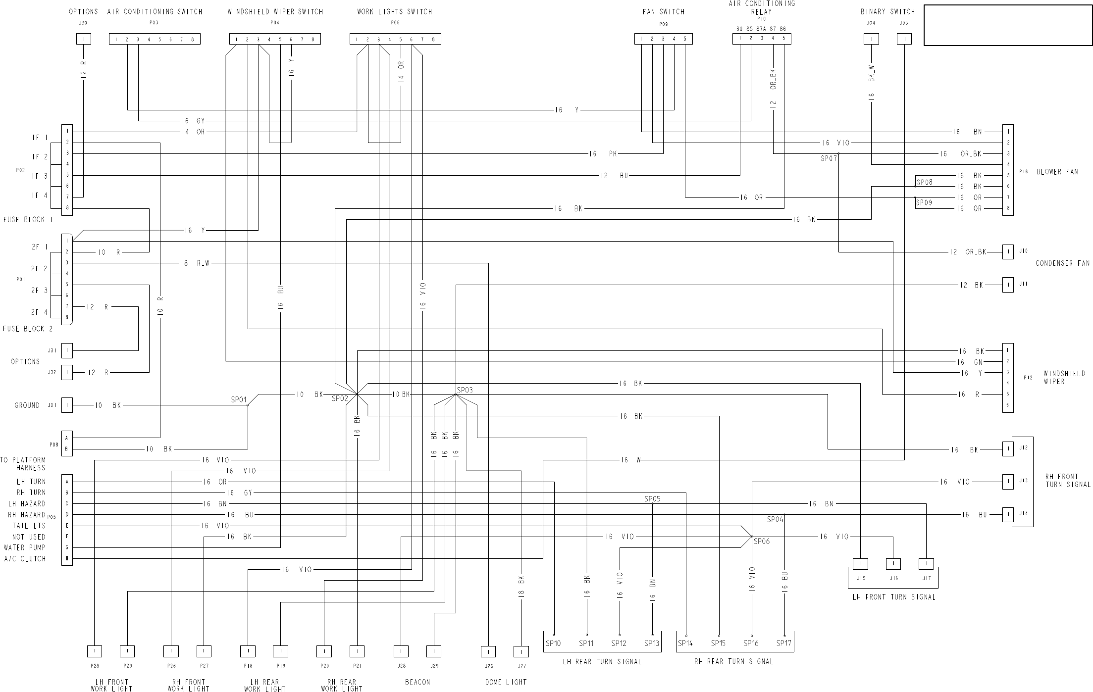
Page 10 -- 21
Groundsmaster 4110--D
Operator Cab Wire Harness Diagram
DRAWING DESIGNATIONS IN THIS CHAPTER
NOTE: THIS DRAWING IDENTIFIES WIRE GAUGE
SIZE AND WIRE COLOR. REFER TO ELECTRICAL
FOR ADDITIONAL INFORMATION.
