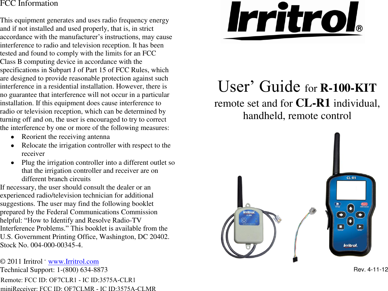
Toro CLMR R-100-KIT MINI-RECEIVER CL-MR User Manual USERS GUIDE

Toro Company R-100-KIT MINI-RECEIVER CL-MR USERS GUIDE

USERS GUIDE

FCC Information  This equipment generates and uses radio frequency energy and if not installed and used properly, that is, in strict accordance with the manufacturer’s instructions, may cause interference to radio and television reception. It has been tested and found to comply with the limits for an FCC Class B computing device in accordance with the specifications in Subpart J of Part 15 of FCC Rules, which are designed to provide reasonable protection against such interference in a residential installation. However, there is no guarantee that interference will not occur in a particular installation. If this equipment does cause interference to radio or television reception, which can be determined by turning off and on, the user is encouraged to try to correct the interference by one or more of the following measures:  Reorient the receiving antenna  Relocate the irrigation controller with respect to the receiver  Plug the irrigation controller into a different outlet so that the irrigation controller and receiver are on different branch circuits If necessary, the user should consult the dealer or an experienced radio/television technician for additional suggestions. The user may find the following booklet prepared by the Federal Communications Commission helpful: “How to Identify and Resolve Radio-TV Interference Problems.” This booklet is available from the U.S. Government Printing Office, Washington, DC 20402. Stock No. 004-000-00345-4.  © 2011 Irritrol .  www.Irritrol.com   Technical Support: 1-(800) 634-8873                        User’ Guide for R-100-KIT remote set and for CL-R1 individual, handheld, remote control                                                                                  Rev. 4-11-12 Remote: FCC ID: OF7CLR1 - IC ID:3575A-CLR1 miniReceiver: FCC ID: OF7CLMR - IC ID:3575A-CLMR
 Introduction: When used with compatible irrigation systems, the R-100-KIT remote control set and the CL-R1 individual remote allow the user to activate watering zones with no need to stand at the controller. For testing or troubleshooting the system or providing supplemental watering, the user is free to walk the landscape site, turning zones on and off.   The R-100-Kit remote set allows the user to plug its mini-receiver unit into a variety of irrigation controllers to receive and process the remote signal from the handheld transmitter.                                   The R-100-KIT remote kit from Irritrol  The CL-R1 individual, handheld remote transmitter is also available, separately, as the compatible remote for Irritrol’s CLIMATE LOGIC® wireless weather sensing system.             1.   To teach the transmitter the maximum number of stations on the controller: To save time using the remote, set the number of stations in the transmitter to match the number of stations on the controller. For example, for a 12- station controller, set the transmitter to a station maximum of twelve also. If only using 10 of the 12, set max to 10.  Press the SETUP button once to view the Max Station screen. Leave the Max Station screen in the display.  Use either the UP or the DOWN button to set the desired maximum station number.  With the desired number displayed, press ENTER   Start Program “A or B or C”   MANUAL PROGRAM DOES NOT WORK WITH THE MC-E CONTROLLER. A MANUALLY STARTED PROGRAM RUNS CONTINUOUSLY. o In manual station mode, use the UP arrow button to go beyond the highest station. “P-A” appears. Press the UP button again for “P-B” or again for “P- C”. o With the desired Program displayed, press ENTER for a sequential station run.  ASC (All Stations Cycle) To run all stations, in sequence, see Start a Program, above. Use the UP arrow key to move above “PGM C” to “TEST ALL” mode;   Use the UP or DOWN buttons to set the running time (all stations will run the same length of time, in sequence, from lowest to highest number).  Press ENTER to start. (Leave the transmitter on during the TEST ALL sequence.)                                                                                                                  14.
OPERATING INSTRUCTIONS:   Power Up or Power Down the transmitter o Press the red MODE/PWR button to turn on  o Press and hold MODE/PWR to turn off  With the exception of All-Station-Test mode, turning off the transmitter does not turn off a station in operation. (See Stop all watering.)  Automatic Power Down of transmitter  o To extend battery life, five minutes of button inactivity will shut off the transmitter   Turn on a station or zone (with transmitter on) o Press the UP or DOWN arrow button to scroll to the station number desired o Use RIGHT ARROW key to move to run time o Use the UP or DOWN arrow button to set the station’s 1-time manual running time o Press ENTER to start the station (The controller may display a differing countdown. It has been overridden by the remote’s countdown.)   To Stop all watering, press the Cancel button  Change from one running station to another o Use UP or DOWN button to find the station o Press RIGHT ARROW key to move to run time o Set running time with the Up or Down button o Press ENTER to turn on the new station. The previously running station will shut off   To select PIN number o See previous section above on setting PIN numbers in the mini-Receiver or in the CLIMATE LOGIC receiver module. 13.                                          The line-of-sight (LOS) range from the remote, handheld transmitters to their receivers is up to 1,000 feet. Objects in the way and radio frequency interference will reduce the range. Even with the above-mentioned environmental handicaps, the range should be adequate for most residential applications.   The operation and performance of the remote kit with its compatible controllers and the CL-R1 transmitter-only with the CLIMATE LOGIC system are similar. This User’s Guide explains the installation of the R-100-KIT and covers the use and operations the remotes have in common. The CLIMATE LOGIC weather-sensing system has its own installation and User’s Guide.                                                                                                 2. The CLIMATE LOGIC weather sensing system shares its own receiver with the CL-R1. The individual, handheld, transmitter, CL-R1 needs no receiver to work with the CLIMATE LOGIC.
 So far there are eight series of controllers with which the R-100-Kit is compatible. Our intent is to add more series to this list as we introduce new irrigation controllers to the market.       Irritrol® Brand                                  Toro® Brand  Rain Dial®-R Series                Custom Command™ Rain Dial®-Blue Series    TCM-212 Series Total Control®-R Series                      TCM-424 & 424-E KwikDial® Series                                       MC®-E “Blue” series (Version 5.02 or later)  The R-100 remote kit has three components as noted in Diagram 1.   Diagram 1: R-100-KIT                                    CL-R1 Remote            CL-MR mini-         CMR-ADP    Transmitter                 Receiver             Adapter Cable   3.  “Hidden” features for remote control of the Unique® brand of landscape lighting: As an allied brand to Irritrol in the landscaping industry, Unique plans to offer similar capabilities for remote control of landscape lighting. For the convenience of landscaping and  irrigation professionals and by permission from Unique, the commands for its remote lighting control are included in the remote system described in this  guide. The basic control functions are furnished below (ahead of the description of remote irrigation commands) in case of inadvertent activation of lighting controls on an irrigation-only system.      Two switch over to Unique lighting remote control, after activating the remote, repeatedly press the SETUP button until “UL” (for Unique Lighting) appears in the display.  “of” in the display means the light control is turned off  Use the UP Arrow button to turn “on” the lighting control   Press and hold the PWR/mode button until the display goes past “off” to “LITE”.  When the PWR/mode button is released, “L1” for light station #1 appears along with its default remote time of 10 minutes. There are four light stations available, accessed with the UP Arrow button (see next page for zone control).  Above L4, are “LA on” and the “LA of” for lighting all on or lighting all off. After selection, press ENTER.  To return to irrigation remote, press and hold the PWR/mode button until “CL” appears. Release button to see the irrigation station #1.                                                                                                                                                                                                                                           12.
 To set the PIN in the CLIMATE LOGIC receiver module:  After setting the PIN in the handheld transmitter (see above), open the CLIMATE LOGIC receiver module.  Press the MENU button to get to the Main Menu on the module’s display                                                                                                                           Repeatedly press the UP or Down key on the module to move the cursor to REMOTE.  Press ENTER to get to the Remote PIN screen.  Repeatedly press the UP or DOWN key to set the first digit on the left.  Press NEXT to move one digit to the right.  Repeat the steps to set all four digits in the PIN.  With your desired PIN displayed, press SAVE   11.  The handheld transmitter gets its power from a user-supplied, 9-volt, battery. The kit’s mini-receiver has a single cable and plug for simple connection to most controllers. The controller to which it is connected powers the CL-MR mini-receiver. The adapter cable, CMR-ADP, is for connection to the early models of the MC-E “Blue” (later models have the RJ socket) and for the KwikDial controllers. Those controllers do not have RJ sockets for their remote ports.          The 5-position header on one end of the cable slides on to a 5-pin connector in the controller. On its other end, the cable provides the RJ- connector for the CL-MR mini-receiver’s cord.  QUICK START UP: Install a fresh 9-volt battery into the CL-R1 Remote by removing the three screws from the battery cover on the back of the transmitter. Snap the battery on to the battery clip, place the battery into the compartment, and reinstall the cover with its three screws.                                                                                                                                                               .4
Route the single cable from the mini-receiver up into the controller. If this application is for temporary use only, you can just swing open the front panel or remove the access cover on the controller for cable entry because you will unplug the cord and close or re-install the panel after the remote session.   Find the female socket for connection to the RJ jack on the mini-receiver’s cord. On the early models of the MC-E “Blue” and on the KwikDial controllers, use the CMR-ADP adapter to convert the 5-pin connector on the controller to the socket for the jack. (Later models of the MC-E “Blue” have the RJ socket.) On the Rain Dial-R (and other blue-faced Rain Dials) and the Total Control-R, the connection is on the swing out face panel, just under the edge of the circuit board. For permanent installations, the CL-MR mini-receivers and CMR-ADP cable adapters are sold separately.   If needed, to put the receiver in a better location for reception, lengthen the cord from the mini-Receiver to the controller with extension cables (50’ or less). The cables and RJ connections must have six (6) conductors. NEVER PLUG THE REMOTE’S CORD INTO A TELEPHONE SYSTEM.  Diagram 2: Controller Connection Points   The Irritrol Rain Dial-R and Rain Dial “Blue” do not require the adapter cable. The cord from the mini-receiver plugs directly into the edge of the front panel.     5.                   R-100-KIT, Remote Kit: After connecting the receiver, it is time to set the PIN numbers in the transmitter and receiver. Set the PIN you plan to use in the transmitter first.  Setting the PIN in the handheld transmitter:  Press the red “MODE” PWR button to turn on the remote transmitter  Press the “Setup” button twice; “SET PIN” appears  Use the UP or Down arrow button the set the first digit of the PIN number on the left  Use the Right Arrow button to move to the second digit   With the UP or Down arrow button set the second PIN number  Repeat the steps to set the other numbers in your 4-digit PIN  When the 4-digit PIN is set, press the “Enter” button to save the PIN  To teach the new PIN to the mini-receiver, (not CLIMATE LOGIC’s receiver)  Turn transmitter on with the red “MODE/PWR” button  Press the Setup button twice; “SET PIN” screen appears with your PIN displayed  Hold down the only button on the mini-receiver for more than 8 seconds.    When the green light on the receiver begins flashing rapidly, release the receiver’s button (intermittent flashing will continue) press the ENTER button on your transmitter. The red light on the receiver will blink briefly.  The receiver has now learned the new PIN and has exited the “learn” mode.                                                                               10.
                            9.                  The Irritrol Total Control-R controller needs no adapter cable, but its receptacle for the RJ jack is located further up on the edge of the front panel than the Rain Dial-R.                                                                                                                                                                   6. Setup key  Left Arrow key  USB cover (Future use)   Cancel key  Down Arrow key  LCD display  Up Arrow button  Power button  Right Arrow button        Enter       button  Rain Dial-R or Rain Dial “blue” Total Control-R Transmitter Controls
 Early models of the Irritrol MC-E “Blue”, need the CMR-ADP cabler. The 5-pin connector is sandwiched between the front panel and the circuit board in the lower right hand corner. Attach the cable adapter to the controller with the black wire up. Later models have an RJ connector in the same location.                                                                                                                                                                                                              Orient the cable adapter with the black wire up for the MC-E “Blue” controller. (Later models have the RJ socket.)     The “Manual Program” feature does not work with MC-E controllers. A remotely started program runs continuously.  7.                                                                        The KwikDial controller requires the CMR-ADP cable adapter to attach its 5-Pin connector to the mini-receiver. Attach the cable adapter to the controller with the blue wire up.  The other end of the cable adapter has the female socket for the RJ jack.                     Orient the cable adapter with the blue wire up for the                   KwikDial controller.                                                                                                                                                                                                                                                                                                                           8.

Navigation menu