Toro RTS1 Frequency Hopping Device RTS1 User Manual PC Control Installation V1d
Toro Company Frequency Hopping Device RTS1 PC Control Installation V1d
Toro >
Contents
- 1. Users Manual Module
- 2. Users Manual Host
Users Manual Host
PC Control
Installation and
Start Up

2
Specifications
•Dimensions -Controller
•6" W x 9" H x 3" D
•(15.3 cm W x 22.9 cm H x 7.6 cm D)
•Dimensions -Remote
•3" W x 8" H x 2" D
•(7.6 cm W x 20.3 cm H x 5.1 cm D)
•Power Specifications:
•Controller
•Plug-in Transformer, Class 2, UL Listed,
•CSA Certified (or equivalent)
••Input: 120 V a.c. 50/60 Hz, 0.5 Amps
••Output: 24 V a.c. 50/60 Hz, 20 VA
•Remote
••Input: 9 VDC -battery
•Maximum Load Per Station:
•0.4 Amps @ 24 V a.c.
•Maximum Load For Pump/Master Valve:
•0.4 Amps @ 24 V a.c.
•Total Maximum Output: One station plus pump,
•not to exceed 0.80 Amps @ 24 V a.c.
•Temperature Limit Range:
•Operating – 14°F to 140°F (0°C to 60°C)
•Storage –-22°F to 149°F (0°C to 60°C)
•Wireless:
•902-927 MHz frequency hopping
•up to 1000 ft. range, LOS
•Computer Interface:
•USB 1.1
•Windows 98SE or higher

3
Table of Contents
Wire Terminal Diagram………15
Controller (VCU) Overview………6
Remote Overview………5
FCC notice –Electromagnetic compatibility………16
Installing the Controller –Wire Hookup………14
Installing the Controller………13
Range –Computer/Controller Location………12
Range –Remote Preparation………11
Range –Controller Preparation………10
Range Check………9
Computer Requirements………8
Quick Overview………7
System Connections………4
Page
4
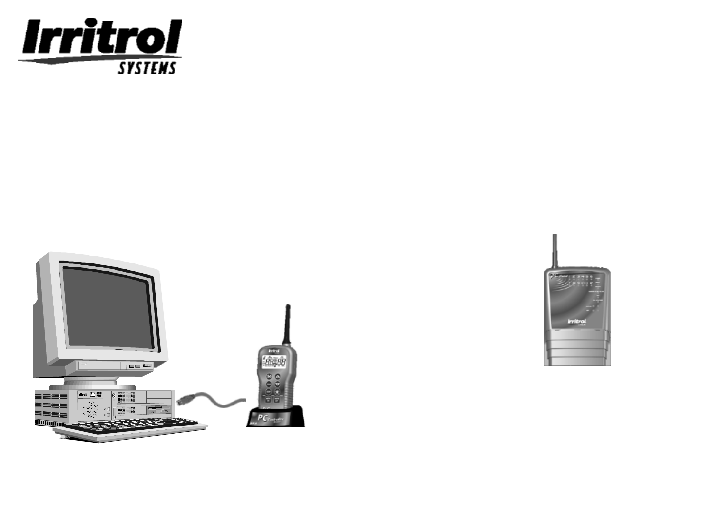
System Connections
Desktop or
laptop computer
with software
USB
cable,
(included)
USB module/ hand-
held remote control
with desktop stand
Irrigation
controller
with built-in
transceiver
In the
garage
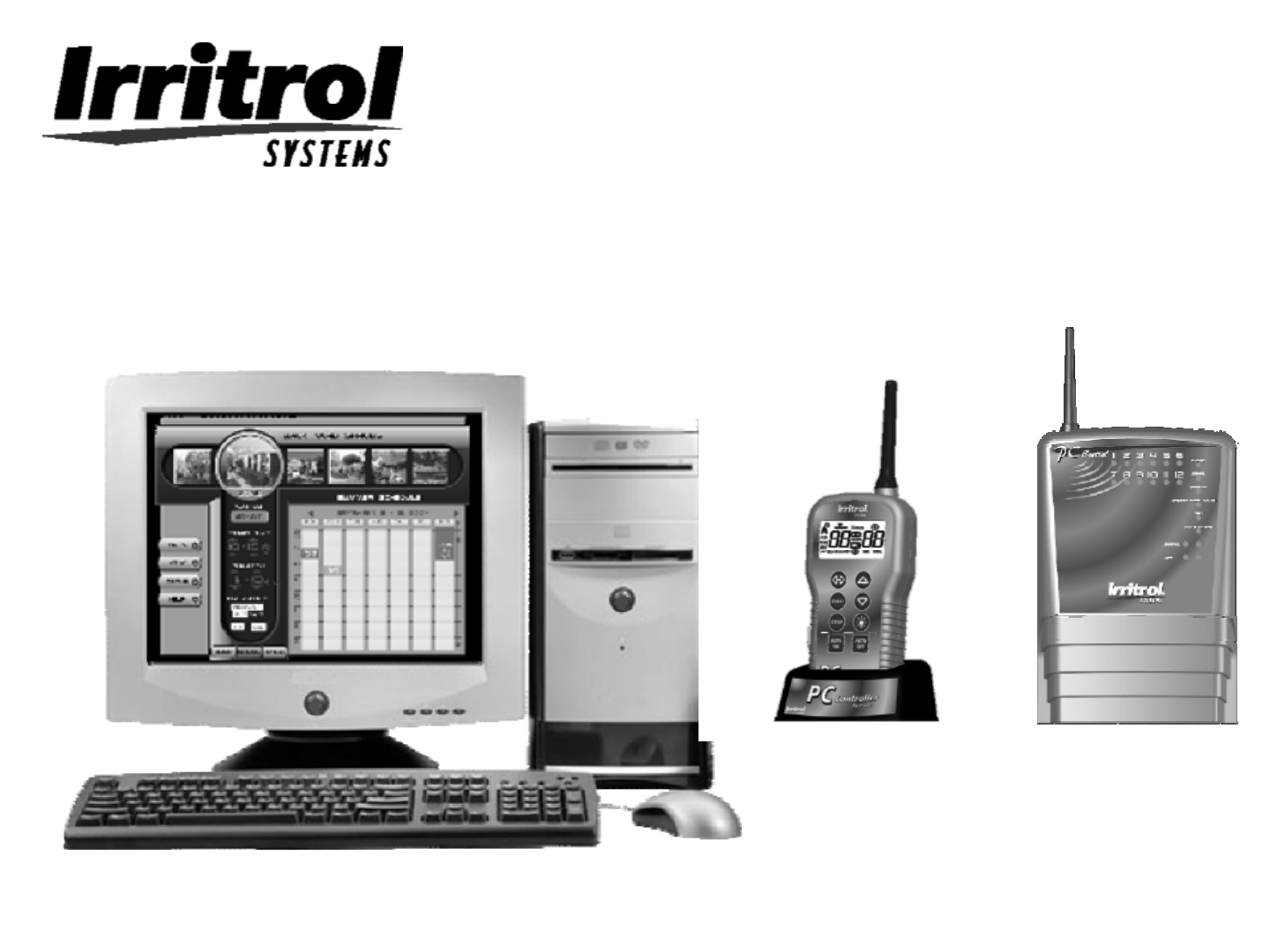
The PC Control system is made
up of three main components;
the software disk for the
customer’s computer, the remote
control device (with desktop
stand and USB cord) and the 12-
station, indoor controller.
In the
home
The remote relays
commands and
programming
from the computer
to the controller .
5
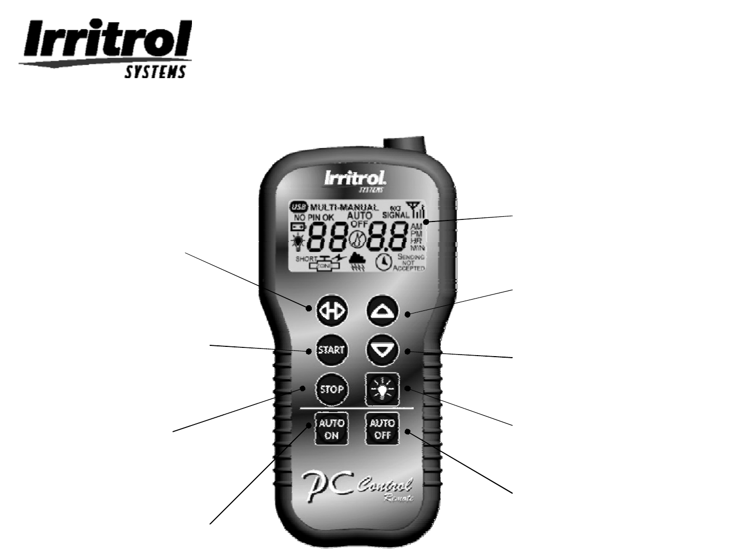
Remote Overview
LCD
–all segments shown
Shuttle
-Move between segments
Up Arrow
-Move values upward
Down Arrow
-Move values downward
Lights
-Turn lighting station on/off
Auto Off
-Suspend automatic operations
Auto On
-Resume automatic operations
Stop
-Stop all active zones
Start
-Start currently selected zone
6
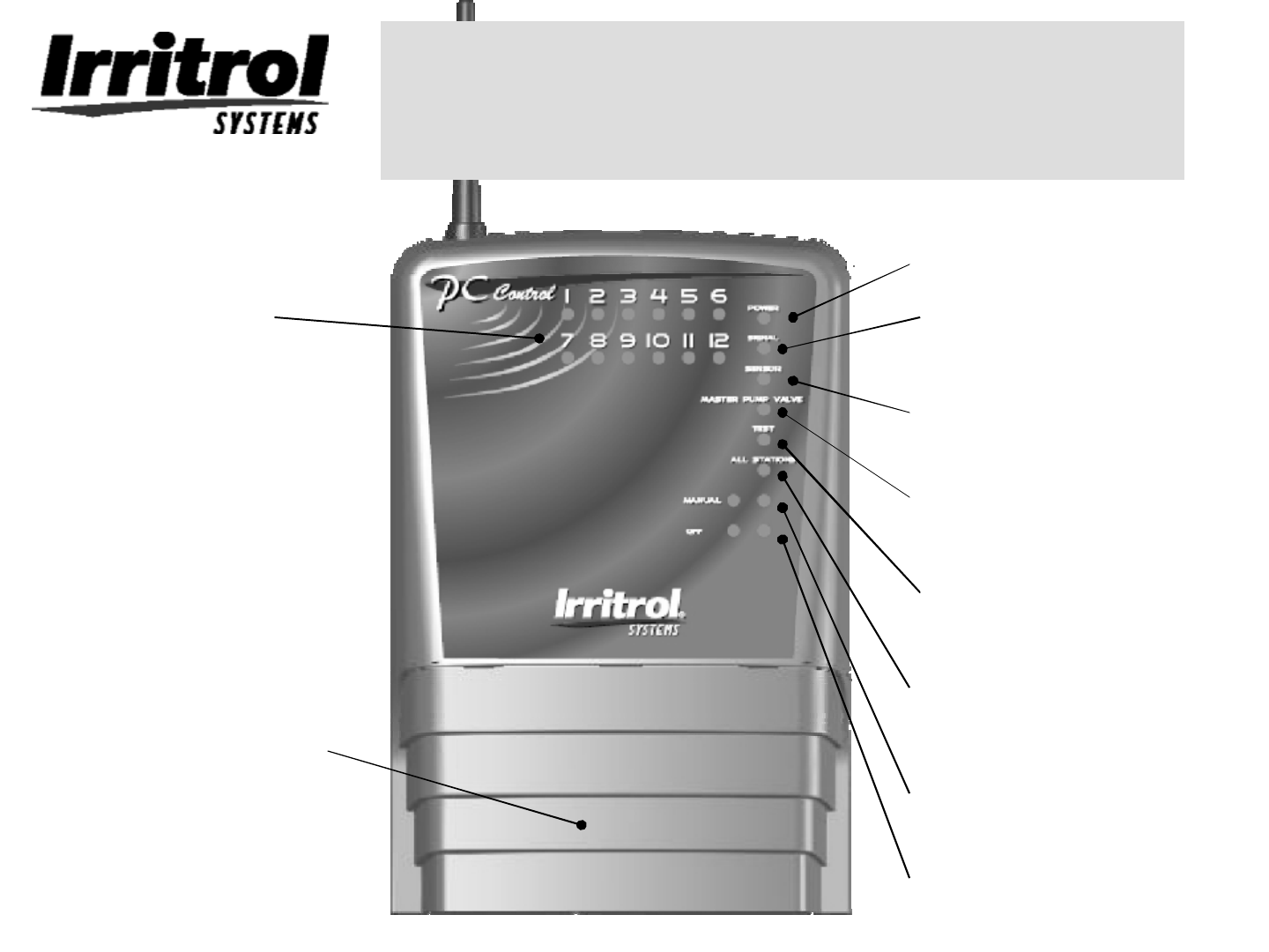
Controller (VCU) Overview
Zone Indicators
-Shows active zones
Power
Sensor
-Shows an active sensor (flow/rain)
Signal Indicator
-Indicates signal quality
All Stations
-All station run mode
Manual (button/light)
-When manual mode is active
Off (button/light)
-VCU is off
Master Pump/Valve
-Indicates active MP/MPV
Test Indicator
-Lights during test modes
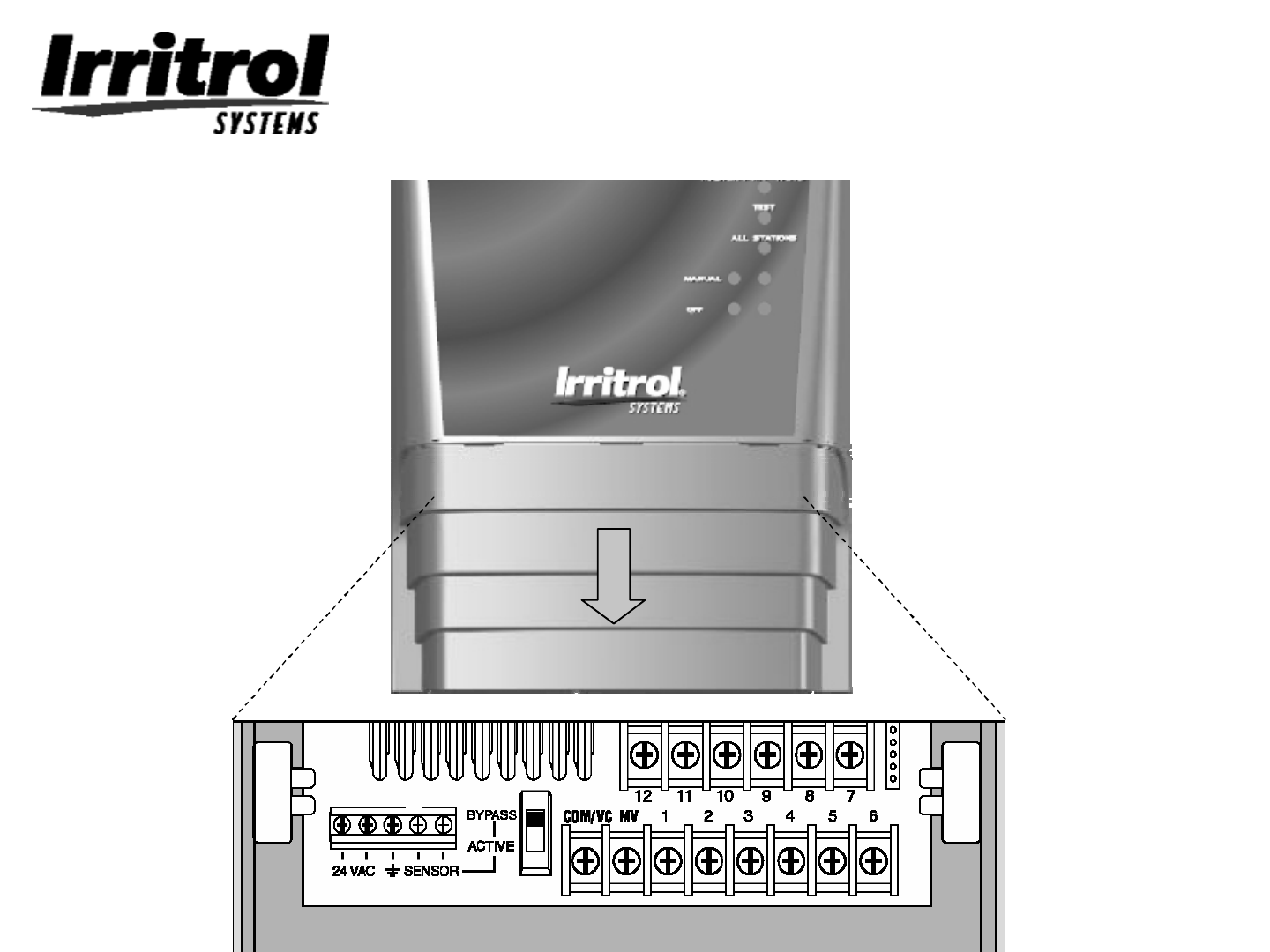
Hook-up Panel
-Remove for wire installation

7
Here is a quick overview of
the installation steps
1. Make sure the computer meets the
system requirements.
2. Check to see if the remote and the
controller will be within range of each
other.
3. Install the controller
4. Connect the remote to the computer
5. Load the software into the computer
(Details on each step follow)

8
Make sure the computer meets
these System Requirements
•Windows 98SE (second edition)*, 2000, ME, XP
Prof, or 2003
•Windows compatible PC with CD-ROM drive
•Available USB port (1.0 or greater)
•900 MHz CPU
•64 MB RAM
•12MB free hard disk space
•1024x768 64K color display/monitor
•Mouse & keyboard
•Internet capability (preferably high speed)
•Digital photo capability
* The 2nd edition of Windows 98 was the first
version to support the USB capability required.

9
Check the range between
the remote and controller
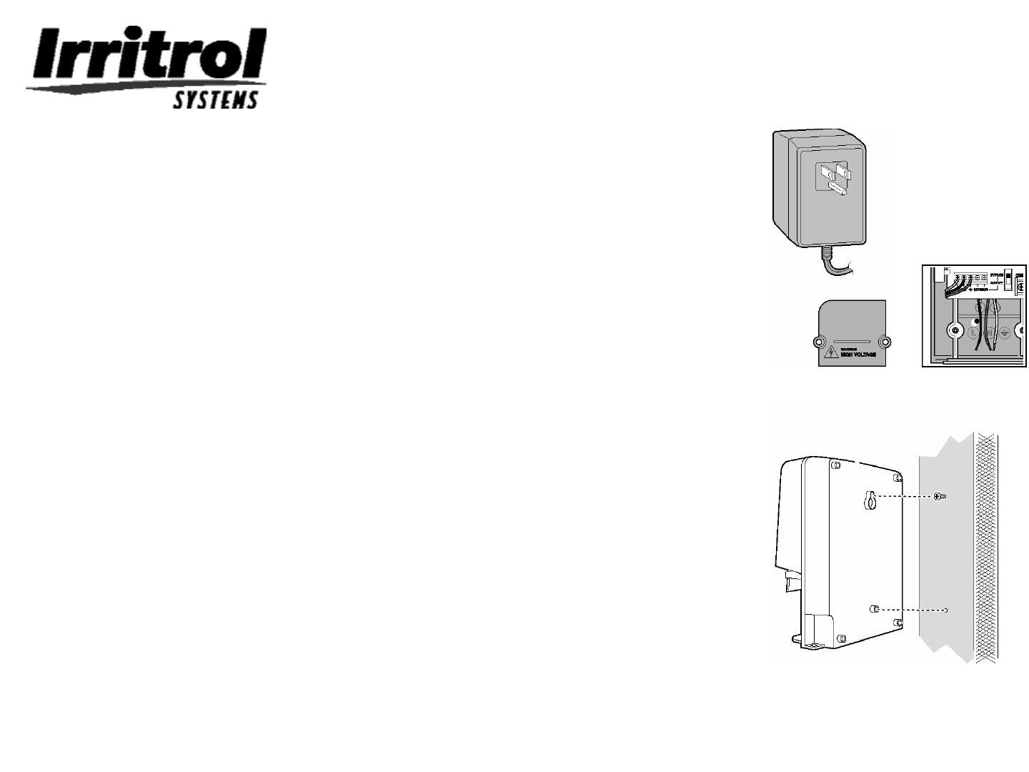
1. Connect the controller’s transformer following these steps
•Do not plug in the transformer!
•First, remove the access cover from the controller by pushing
inward on the finger grips on both sides and sliding the cover
forward and off the controller.
•Slip the 3-wire cord from the transformer through the small
whole on the left hand side of the bottom of the controller’s
case.
•Pull about 6 inches of cable into the controller and tie a loose,
half knot in the cord to prevent it from being pulled back out.
•With a screwdriver, connect the red wire to the left hand
terminal on the terminal strip, the black wire to the terminal
that is second from the left and the green wire to the third
screw terminal from the left.
•Connect the 9-volt battery to the battery clip and replace the
access cover.
•Without mounting the controller, you can now plug it in to
prepare for a communications check.

10
Checking the range:
Preparing the controller
To wirelessly communicate and to prevent
interference from other systems, the
controller and remote need to be set with the
same personal identification number or PIN.
The controller, the handheld remote and the
program on CD are all shipped from the
factory with “0000”as their PIN. This default
PIN will allow immediate communication.
A few moments after the controller is plugged in,
its POWER and AUTO ON indicator lights will
illuminate. The SIGNAL light may blink
occasionally, which is normal.

11
Checking the range:
Preparing the remote
1. Connect a 9-volt battery to the battery clip in the rear compartment of
the remote. Insert the battery into the compartment and (without
crimping the wires) replace the compartment’s cover.
2. Make sure the controller is plugged in.
3. Press any button on the remote to “wake it up”. All the segments in the
display will illuminate for about 2 seconds.
4. If your controller in plugged in and its AUTO ON light is lit, the remote
will soon display “AUTO”and the signal strength indicator. This means
the two devices are communicating.
5. You can further test the communication by pressing the UP Arrow
button. You will see “MANUAL”along with “01”flashing for zone #1.
Press the START button. On the controller’s face panel, you should see
the station #1 indicator light come on. If so, the units are
communicating.
6. Press the STOP button. You should see “SENDING”and then
“ACCEPTED”momentarily in the display and Station #1’s indicator light
should go out on the controller.
7. Now you are ready to see if the range is adequate for your application.

12
Checking the range: Computer
location to the controller.
•Place the controller, plugged in and upright, at the approximate
location at which it will be mounted in the garage. If the controller’s
AUTO ON indicator light is not on, press the AUTO ON button to
turn on the light.
•Take the handheld remote to the location of the computer within the
home.
•Press any button to wake up the remote. It should then
automatically contact the controller and then display the signal
strength icon in the upper right hand corner of the display and
“AUTO”to indicate the controller is in AUTO ON mode.
•Press the remote’s AUTO OFF button. The display should
momentarily show “SENDING”then “ACCEPTED”and then “OFF”
to indicate you have turned off the controller.
•You now know the locations of components for your PC Control
system are within range of each other.
•Now you can install the controller.
13
Installing the controller
The installation procedure for the PC Control’s irrigation controller is the
same as conventional controllers. Make sure the controller is
unplugged.
•Choose an indoor location that allows the plug-in-style
transformer to easily reach from the electrical outlet to the
controller with its 3-wire cord. Make sure the outlet is the type
with an earth ground that will accept the 3-pronged transformer
connection.
•Drive a woodscrew into the wall at eye level and leave
approximately ¼” (6mm) of its shank showing.
•With the access panel removed, hang the controller by its rear,
keyhole slot on the screw. If the controller does not hang
securely, remove it from the wall and drive the screw a little
further into the wall. When the controller does hangs securely by
the first screw, then drive a second screw through the lower wall
mounting hole in the wiring compartment.
•The recommended field wire is 18AWG (1.0mm2) UF with
multiple, insulated wires within a single jacket. This cable is
insulated for direct burial and its inner wires are color coded to
simplify zone idenification.
•Route all the zone wires, the valve common wire, the Master
Valve wire (if required), any sensor wires and even zone wires for
landscape light switching (if needed) in from the field and up
through the bottom, right hand opening in the controller.
•The field wire opening has two “knockouts”to accommodate ¾”
and 1”conduit adapters if you need more room for incoming wires
or connectors.

14
Installing the controller: wire
hookup
•If you are not using a conduit to cover the incoming field wires, the open entrance hole in the
bottom of the controller is large enough to accommodate two 7-wire (one white-colored
valve common and six different colored valve wires) cables just in case the less common13-
conductor (for a 12-station controller) cable is not available.
•The wire connections out at the valves need to be waterproof using connectors like insulated
wire nuts or grease caps.
Wire Pattern:
•Attach the white color-coded wire from the cable to one wire lead from each valve solenoid
(or 24 VAC relay for landscape light switching). This wire is the “valve common”wire.
•Attach a separate cable wire to the remaining wire lead from each valve solenoid (or lighting
relay). Note the color code if you want to keep track of each zone’s location.
•At the controller end of the valve connection cable, bring the cable up into the bottom of the
controller and cut the cable leaving 5 inches for reaching the terminal strip. Separate the
colored wires and then strip back ¼-inch (6mm) of insulation from the end of each.
•Secure the white-colored valve common wire to the screw terminal labeled “VC-COM”
•Connect the individual valve wires to the appropriate numbered station or zone terminals.
•If the system includes a master valve or pump start relay, connect that wire to the “MV”
terminal screw. (See illustration on valve connections and pump start). Either the master
valve or the pump start relay will use Valve Common for their other wire connection.
•If a rain or rain/freeze sensor is being used, loosen the screw terminals labeled “SL”and
“SH”and remove the jumper wire connecting them. Then connect the two wires from the
sensor, or in the case of a wireless sensor, the two wires from the receiver, to the “SL”and
“SH”terminals.
•At this point the field wiring to the controller is complete. Replace the controllers access
cover and plug in the transformer to power up the controller.
15
Wire Terminal Diagram

16
Electromagnetic Compatibility
Domestic: This device complies with FCC rules Part 15. Operation is subject to the following two
conditions: (1) This device may not cause harmful interference and (2) this device must accept any
interference that may be received, including interference that may cause undesirable operation.
This equipment generates and uses radio frequency energy and if not installed and used properly,
that is, in strict accordance with the manufacturer's instructions, may cause interference to radio and
television reception. It has been type tested and found to comply with the limits for a FCC Class B
computing device in accordance with the specifications in Subpart J of Part 15 of FCC Rules, which
are designed to provide reasonable protection against such interference in a residential installation.
However, there is no guarantee that interference will not occur in a particular installation. If this
equipment does cause interference to radio or television reception, which can be determined by
turning the equipment off and on, the user is encouraged to try to correct the interference by one or
more of the following measures:
Reorient the receiving antenna, relocate the remote control receiver with respect to the radio/TV
antenna or plug the irrigation controller into a different outlet so that the irrigation controller and
radio/TV are on different branch circuits.
If necessary, the user should consult the dealer or an experienced radio/television technician for
additional suggestions. The user may find the following booklet prepared by the Federal
Communications Commission helpful:
"How to Identify and Resolve Radio-TV Interference Problems". This booklet is available from the
U.S. Government Printing Office, Washington, DC 20402. Stock No. 004-000-00345-4.
International: This is a CISPR 22 Class B product.
Contains FCC ID: OF7RTS1
For Technical Assistance: 951-785-3623 or 800-634-8873
Operation is subject to the following two conditions: (1) this device may not cause interference, and (2) this device must
accept any interference, including interference that may cause undesired operation of the device.
Industry Canada: Contains IC: 3575A-RTS1
Caution: The user that changes or modifications not expressly approved by the party
responsible for compliance could void the user's authority to operate the equipment.