Toro Tr50Xt Series Rotor Users Manual Multilanguage
TR50XT SERIES ROTOR to the manual 9b8776ad-1c28-4bbe-a40a-de916174069b
2015-01-21
: Toro Toro-Tr50Xt-Series-Rotor-Users-Manual-350616 toro-tr50xt-series-rotor-users-manual-350616 toro pdf
Open the PDF directly: View PDF ![]() .
.
Page Count: 4
TR50XT
SERIES ROTOR
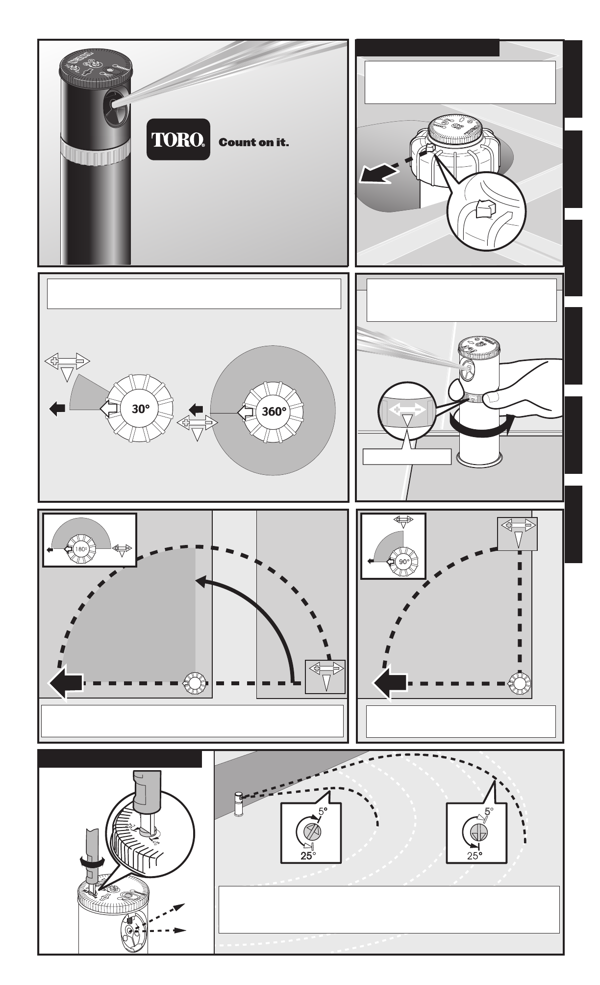
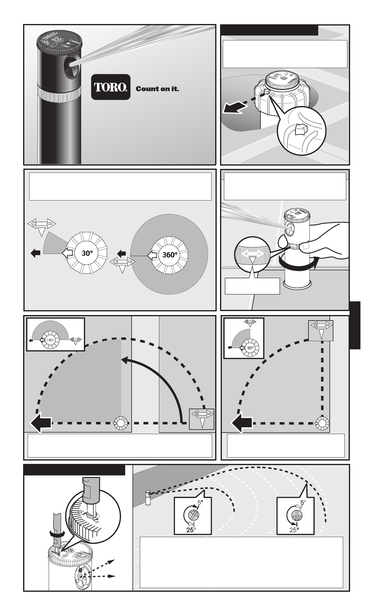
Align the cap arrow with the left side
of the watering area. This is the non-
adjustable side of the watering arc.
Turn the arc adjustment ring to align
the white arrow to the right side of
the watering arc.
The nozzle trajectory angle can be adjusted between 5° and 25°.
Turn the adjustment screw right to decrease the angle and shorten
spray radius, or left to increase the angle and lengthen spray radius.
The watering area can be adjusted between 30° and 360°.
When set to 360°, the nozzle does not reverse direction.
Instruction Guide
Watering Arc Adjustment
Nozzle Trajectory Adjustment
The watering area is between the cap arrow and the right stop
arrow on the arc adjustment ring. This example is set to 180°.
Align the right stop arrow to the right
side of the watering arc.
Right Stop Arrow
Español
English Français Deutsch Italiano português
© 2004 The Toro Company, Irrigation Division • An ISO 9000-certified Company • www.toro.com Form Number 373-0291 Rev. B
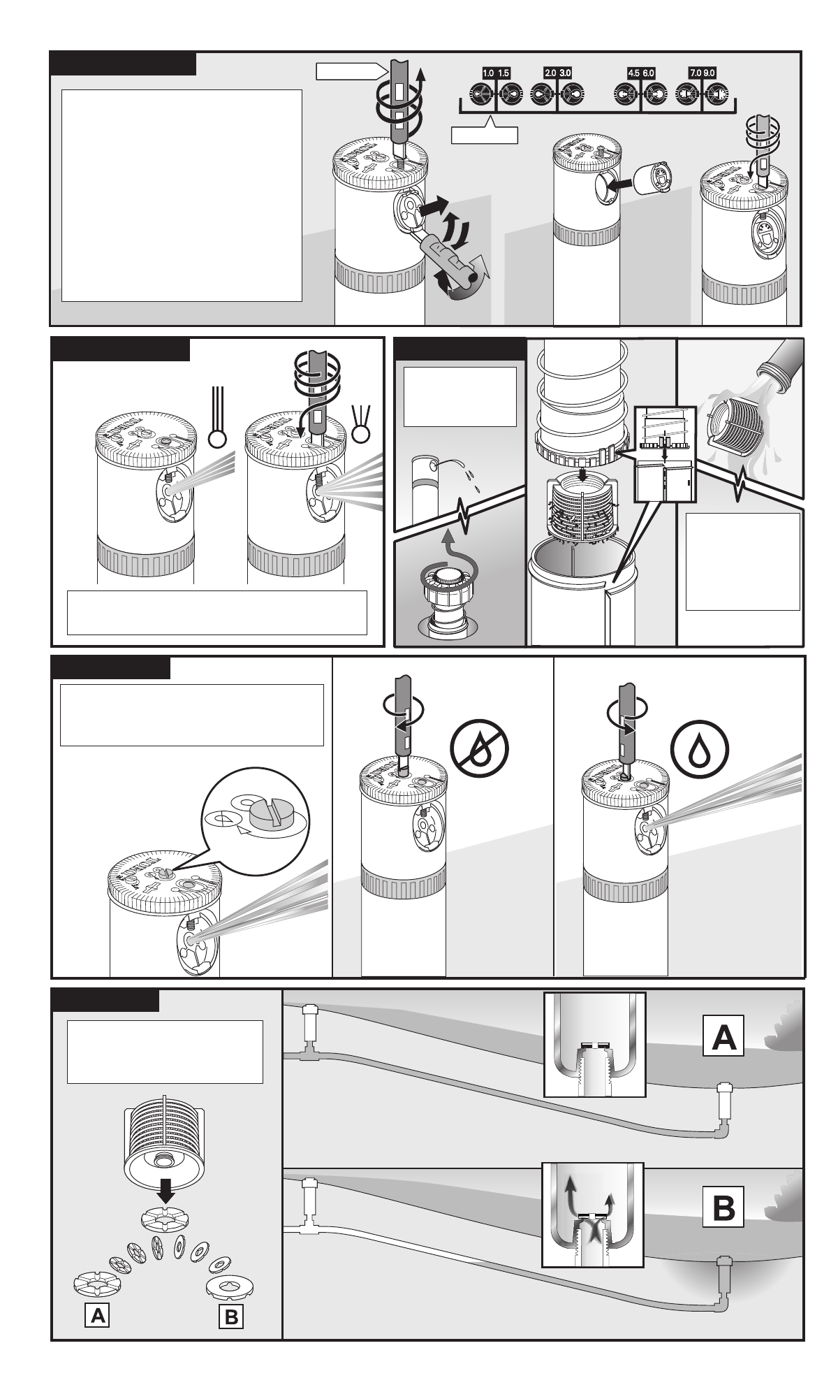
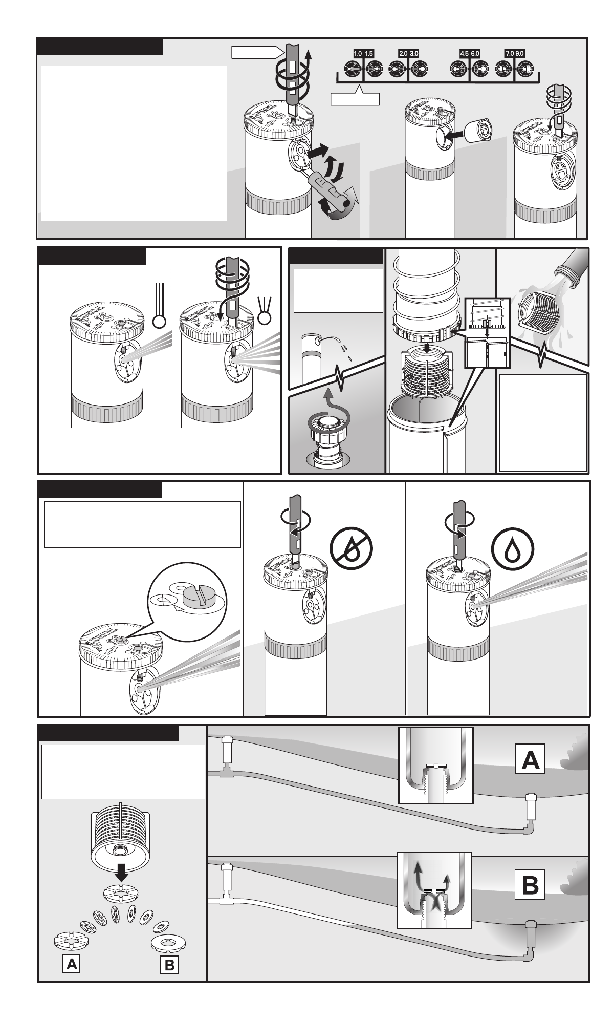
The TR50XT sprinkler comes with
eight additional nozzle sizes from
1 to 9 GPM (4.5 to 41 LPM). To
change the nozzle, use the blade
end of the sprinkler tool or a
screwdriver to turn the nozzle
screw out until it clears the nozzle.
Pry the nozzle out at the bottom
and install the new nozzle. Return
the nozzle screw to its previous
position.
Turn the nozzle screw in to diffuse and
shorten the spray radius.
Turn the center screw right to shut
off flow. Turn the screw left to open
flow.
To eliminate check valve
function, install the check
valve disk in position B.
Remove and
flush screen
as needed.
Changing Nozzle
Adjusting Spray Cleaning Screen
Check Valve
Flow Shut Off
To maintain left
stop, align riser
with body as
shown when
reassembling.
102-1303
102-1877
Alinhe a seta da tampa com o limite
lateral esquerdo da área de irrigação.
Este é o limite fixo do arco de irrigação.
Rode o anel de ajuste do arco para
alinhar a seta de paragem na direcção
do limite direito do arco de irrigação.
O ângulo da trajetória do bico pode ser ajustado entre 5 e 25°.
Insira a extremidade da lâmina da ferramenta do irrigador
automático ou uma chave de fenda através da tampa. Gire o
parafuso de ajuste para a direita quando quiser diminuir o ângulo
e reduzir o raio de borrifo, ou para a esquerda quando quiser
aumentar o ângulo e alongar do jacto da água.
Aárea de irrigação pode ser ajustada entre 30 e 360°.
Quando o ajuste for feito para uma área de 360°,
o bico não reverte a direção, faz rotaçã continua.
Ajuste do Arco de Irrigação
Ajuste da Trajetória do Bico
Aárea de irrigação encontra-se entre a seta da tampa e a
seta de paragemà direita no anel de ajuste de arco.
Este exemplo faz o ajuste para 180°.
Alinhe a seta de paragem à direita
na direcção do limite direito do arco
de irrigação.
Seta de Parada
Direita
TR50XT
ASPERSOR DA SÉRIE
Manual de Instruções
português
© 2004 The Toro Company, Irrigation Division • Uma empresa certificada pelo ISO 9000 • www.toro.com Número de formulário 373-0291 Rev. B
Oito tamanhos diferentes de bico,
de 1 a 9 GPM (de 4,5 a 41 LPM)
acompanham o irrigador automático
TR50XT. Para substituir o bico,
insira a extremidade da lâmina da
chave do aspersor ou então pode
usar uma chave de fenda para girar
o parafuso do bico até retirá-lo.
Solte o bico de sua base e instale o
novo bico. Recoloque o parafuso do
bico na sua posição anterior.
Aparte o parafuso do bico para dentro a fim
de abrir (espalhar) e encurtar o raio do jacto
da água.
Gire o parafuso central para direita
a fim de interromper o fluxo. Gire-o
para a esquerda para abrir o fluxo.
Para eliminar a função da
válvula de anti-drenagem,
instale o disco da válvula de
anti-drenagem na posição B.
Remova e lave
a filtro sempre
que necessário.
Substituição do Bico
Ajuste do Jacto Limpeza da Filtro
Válvula Anti-Drenagem
Interrupção de Fluxo
Para conservar a
paragem à
esquerda, alinhe o
tubo elevador com
o corpo, conforme
demonstrado,
quando realizar a
montagem.
102-1303
102-1877
