Toshiba TEC OH0006 RFID Printer Module User Manual
Toshiba TEC Corporation RFID Printer Module Users Manual
Users Manual
EO2-38058
1/24
RFID Module
B-SX704-RFID-U2-US-R Installation Manual
Thank you for purchasing TOSHIBA TEC UHF RFID kit, B-SX704-RFID-U2-US-R.
The B-SX704-RFID-U2-US-R is exclusively for the B-SX4T and B-SX5T series.
This RFID kit complies with EPCglobal Class1 Generation2 (Gen2) and radio laws of all applicable countries.
As this product is a wireless communication device, please be sure to read the following precautions carefully.
1. Do not use a printer embedded with this product near medical equipment. Radio wave emitted from this
product may affect the operation of medical equipment, such as an implanted cardiac pacemaker and
implantable cardioverter-defibrillator.
If a use of this product should be likely to have affected medical equipment, immediately turn off the product and
contact your TOSHIBA TEC sales agent.
Keep a printer embedded with this product at least 23cm away from a person with an implanted cardiac
pacemaker or implantable cardioverter-defibrillator.
2. Do not export a printer embedded with this product to the countries or areas where a use of this product is no
t
allowed, without permission. Doing so is against the law, and you may be punished.
When exporting this product, check the laws and regulations of a destination country and take necessar
y
procedures.
3. Follow all manual instructions. Failure to do so could create safety hazards such as fire or electrocution.
• Manual instructions must be followed when installing option kits or adding cables to avoid system failures
and to insure proper performance and operation.
• Failure to follow manual instructions or any unauthorized modifications, substitution or change to this
product will void the limited product warranty.
4. Turn the power OFF and disconnect the power cord before installing the RFID module.
5. Be careful not to pinch your fingers or hands with the covers.
6. The print head and stepping motor becomes very hot immediately after printing. Do not touch the print head,
stepping motor and around it right after printing, or you may get burned.
7. When opening the top cover, it must be fully opened. Failure to do this may cause the top cover to close under
its own weight, resulting in an injury.
WARNING!
CAUTION!
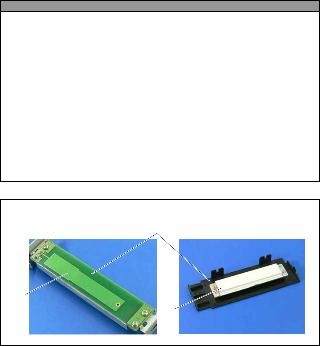
Be careful not to damage the pattern of the Antenna Ass’y or peel off the Shield Sheet. Damaged pattern or
removed Shield Sheet may affect the ability to read or write RFID tags.
Pattern
Shield
Shee
t
Antenna Ass’y
EO2-38058
2/24
1. APPLICABLE MODEL
(1) This optional device is intended for the following models:
B-SX4T-GS20-QM-R and B-SX5T-TS22-QM-R, RFID ready printer.
An RFID Ready printer can be identified by the model name sticker on the front of the printer.
Be careful not to install this product in the B-SX4T-GS10-QQ/QQ-US and B-SX5T-TS10-QQ/QQ-US
RFID Ready printers.
(2) To use this device, printer firmware V4.5 or greater is required. Upgrade the firmware to V4.5 or greater, if
necessary. For the downloading procedure, refer to the B-SX4T/SX5T Series Maintenance Manual.
Note that a RAM clear needs to be performed after downloading, so print out the maintenance counter and
parameter settings prior to downloading. After performing a RAM clear, restore the printer parameter
settings to the former states.
(3) The countries where the use of this device is allowed are as follows:
Model Name Frequency Band Applicable Countries
B-SX704-RFID–U2-US-R UHF 902.75 to 927.5MHz U.S.A., Canada
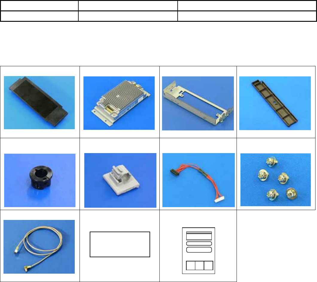
2. PACKING LIST
All the following parts are supplied with the kit. Make sure you have all items shown below.
If any part is missing, please contact your TOSHIBA TEC sales agent.
• Antenna Ass’y (1 pc.)
•RFID R/W Module (1 pc.)
• Antenna Frame
• Ribbon Guide (1 pc.)
• Bush (1 pc.)
• Cable Clamp (1 pc.)
•Interface Cable (1 pc.)
• Double Sems Screw
SMW-3x6 (5 pcs.)
• Antenna Cable (1 pc.)
• FCC ID Sticker (1 pc.)
• Installation Manual
(1 copy)
Contains
FCC ID: BJIOH0006
EO2-38058
3/24
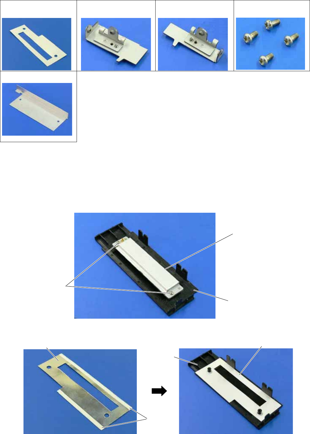
The following parts are required when short-pitch tags (20 mm) are used. Keep them safe when not in use.
• Shield Sheet (1 pc.)
• Antenna Plate L (1 pc.)
• Antenna Plate R (1 pc.)
• Pan Head Screw
P-3x6 (4 pcs.)
• Shield Plate (1 pc.)
3. INSTALLATION PROCEDURE
3.1 Preparation for Use of Short-Pitch RFID Tags (20mm)
When short-pitch tags (20 mm) are to be used, the Antenna Ass’y and the Antenna Frame need to be converted
before installing an RFID module in the printer, for proper read/write operation. When short-pitch tags are not
used, skip this section and go to Section 3.2.
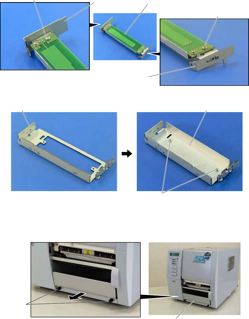
1. Remove the two Tapping Screws to detach the Antenna from the Antenna Ass’y.
2. Remove the backing tapes from the reverse side of the Shield Sheet and attach it to the Antenna Cover, as
shown below.
Tapping Screw
Antenna
Antenna Ass’y
Tape
Shield Shee
t
Shield Sheet
A
ntenna
Cove
r
EO2-38058
4/24
3. Attach the Antenna Plate L and Antenna Plate R to the Antenna with the P-3x6 screws.
4. Attach the Shield Plate to the Antenna Frame. Secure the Shield Plate to the Antenna Frame with the P-3x6
screws.
5. Refer to Section 3.2 and install an RFID module in the printer.
3.2 Preparing for the RFID Module Installation
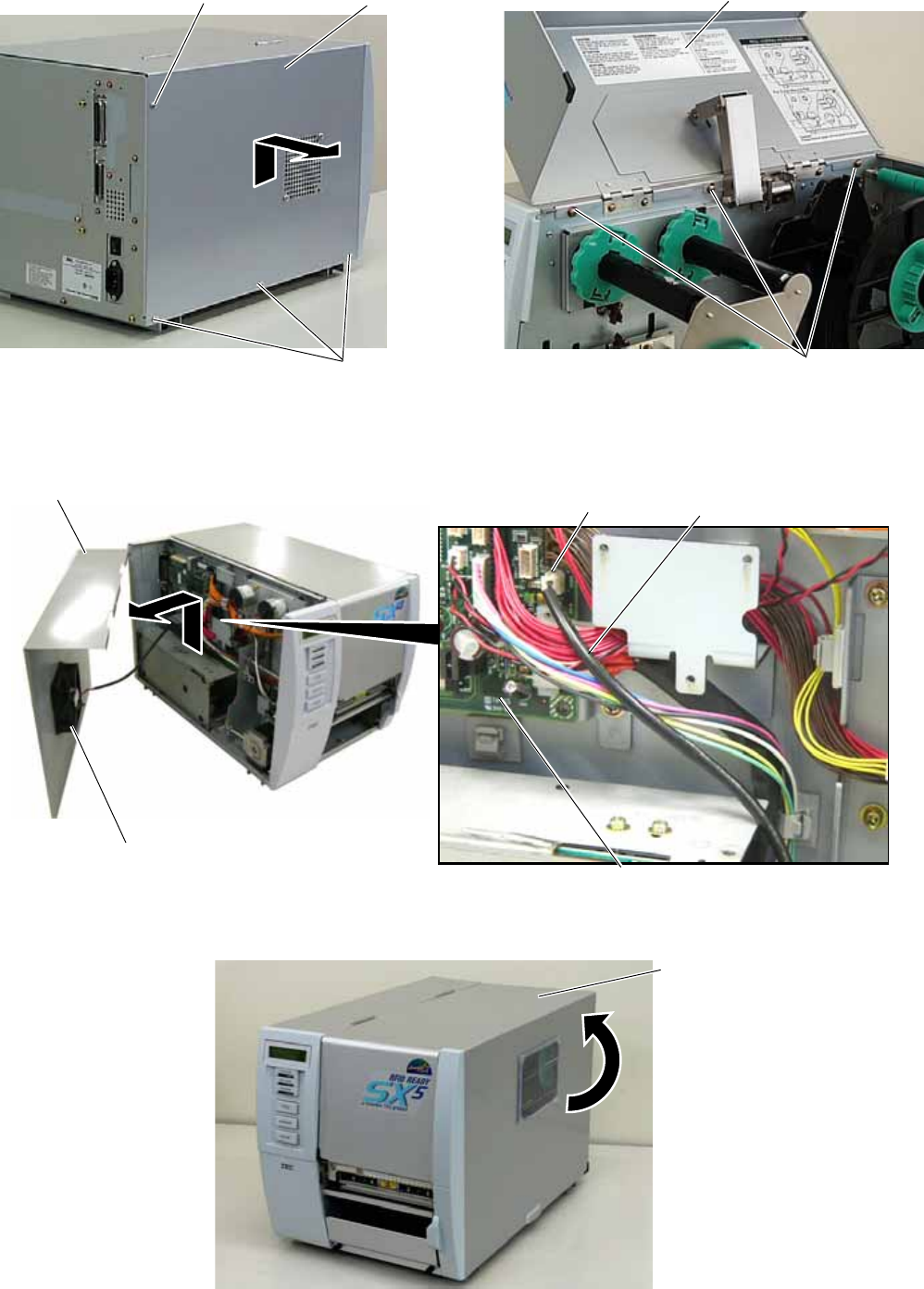
1. Turn the power off and disconnect the Power Cord.
2. Remove the two Black Screws to detach the Front Plate.
Front Plate
Black
Screws
P-3x6 Screw
A
ntenna Plate R
P-3x6 Screw
Antenna Plate L Antenna (with Antenna Plate)
Antenna Frame Shield Plate
P-3x6 Screw
EO2-38058
5/24
3. Remove the four B-4x5 screws from the Side Panel (L).
4. Open the Top Cover and remove the three P-4x8 screws that secure the Side Panel (L).
5. Lift the Side Panel (L) and put it aside.
6. Disconnect the Fan Motor Harness from CN19 on the Main PC Board, and then remove the Side Panel (L).
7. Fully open the Top Cover.
P-4x8 Screw
Top Cover
B-4x5 Screw
B-4x5 Screw Side Panel (L)
Side Panel (L)
Fan Motor Harness
Fan Motor
CN19
Main PC Board
Top Cover
EO2-38058
6/24
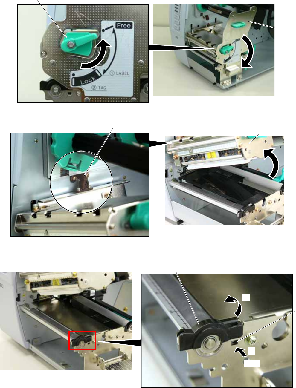
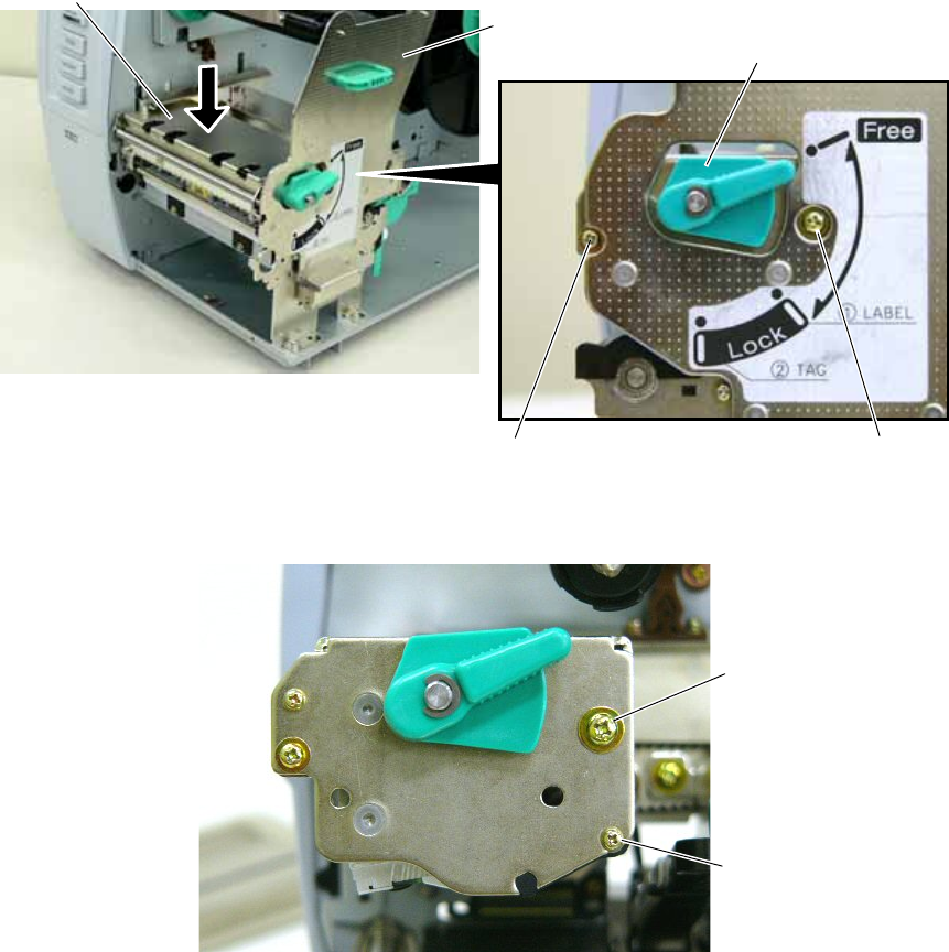
8. Turn the Head Lever to Free position and open the Ribbon Shaft Holder Plate.
9. Open the Print Head Block and lock it with the Latch.
10. Push the Hook through the rectangle hole with a jeweler’s screw driver or something, and remove the Platen
Holder Cover in the direction indicated by the arrow.
Ribbon Shaft
Holder Plate
Head Leve
r
Print Head Block
Latch
Hook
Platen Holder Cover
Push
1
2
EO2-38058
7/24
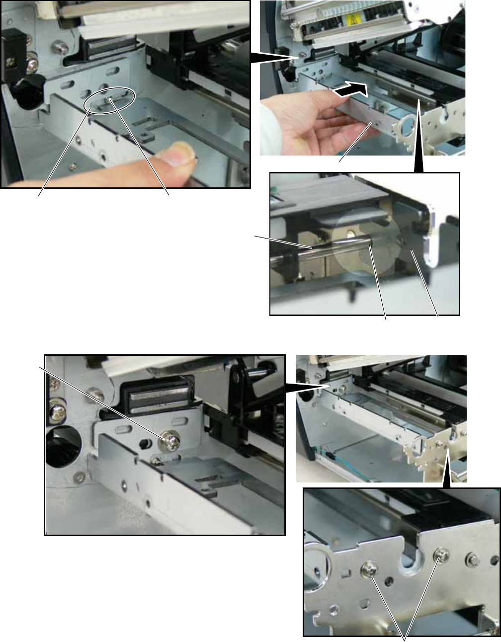
11. Lift the right side of the Strip Plate, and then pull and remove it.
12. Remove the Platen and the Platen Holder in the direction of the arrows 1 to 3 as shown below.
13. Remove the following three screws.
Strip Plate
2
1
Platen
Platen
Holder
1
2
3
SMW-3x6 Screw
SMW-4x8 Screw
EO2-38058
8/24
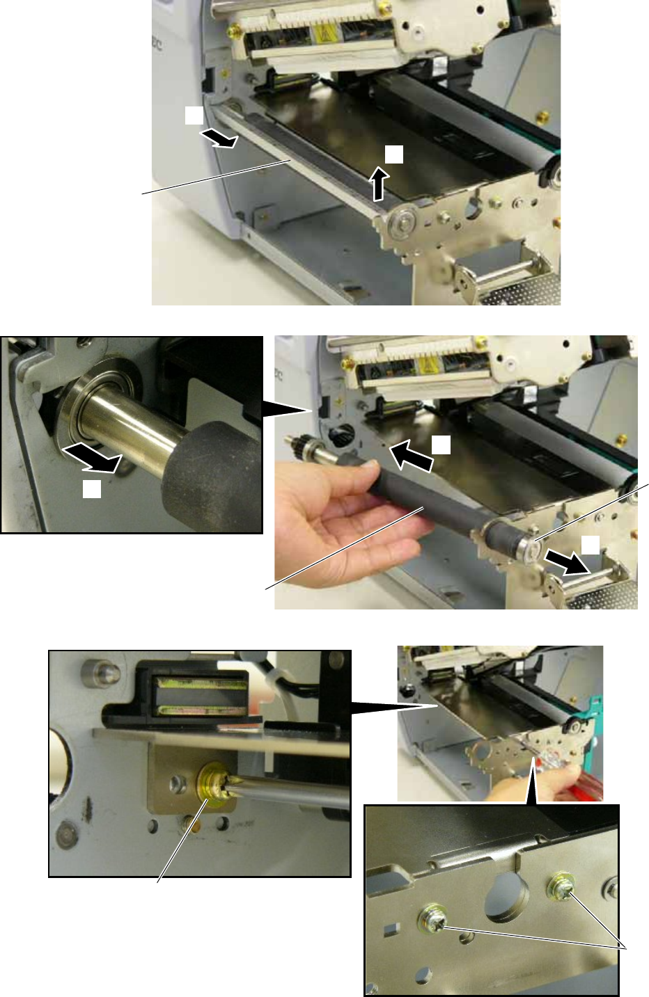
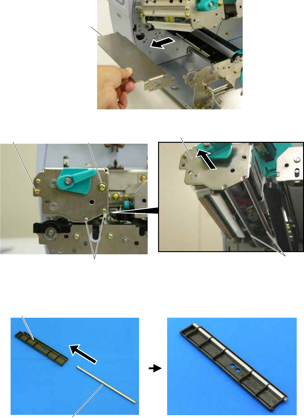
14. Remove the Platen Frame Top from the printer.
15 Remove the four screws from the side of the Print Head Block, slightly pull the Head Side Plate, and remove
the two Ribbon Guide Shafts.
NOTE: One of the removed Ribbon Guide Shafts and SMW-2.6x6 Screws are re-used when attaching the Ribbon
Guide. Keep the unused ones for future use
16. Insert one of the Ribbon Guide Shafts removed in Step 15 into the Ribbon Guide.
Platen Frame Top
SMW-3x6 Screw SMW-4x8 Screw
SMW-2.6x6 Screw Ribbon Guide Shaft
Head Side Plate
Ribbon Guide
Ribbon Guide Shaf
t
EO2-38058
9/24
17. Rotate the Ribbon Guide Shaft so that its D-cut is in the same orientation with the Ribbon Guide’s D-cut.
Without doing this, the Ribbon Guide cannot be fit in the Print Head Block.
18. Fit the Ribbon Guide including the Ribbon Guide Shaft in the Print Head Block, and secure it to the Head Side
Plate with the SMW-2.6x6 screw. Temporarily secure the Head Side Plate to the Print Head Block with the
SMW-3x6 Screw and the SMW-4x8 Screw. Be sure to fit the locating pins provided on the other side of the
Ribbon Guide into the locating holes of the Print Head Block.
Ribbon Guide’s D-cu
t
Ribbon Guide Shaft’s D-cut
Ribbon
Guide
Double Sems Screw
SMW-3x6
Double Sems Screw
SMW-4x8
Double Sems Screw
SMW-2.6x6
Head Side Plate
Print Head Block
Locating Hole (A) Locating Hole (B) Locating Pin (A)
Locating Pin(B)
Ribbon Guide Ribbon Guide
EO2-38058
10/24
19. Close the Ribbon Shaft Holder Plate, and tighten the two screws, which were temporarily tightened in Step 18,
while holding down the Print Head Block.
20. Open the Ribbon Shaft Holder Plate again, and tighten the SMW-2.6x6 screw to secure the Head Side Plate.
3.3 Attaching the Antenna Frame and the Antenna Ass’y
This section describes the procedure for attaching the Antenna Frame and the Antenna Ass’y.
When short-pitch tags (20 mm) are used, the procedure is different from the following. Skip Section 3.3.1 and go
to Section 3.3.2.
Print Head Block
Double Sems Screw
SMW-4x8
Double Sems Screw
SMW-3x6
Ribbon Shaft
Holder Plate Head Lever
Double Sems Screw
SMW-2.6x6
Head Side Plate
EO2-38058
11/24
3.3.1 When using RFID tags other than short-pitch type:
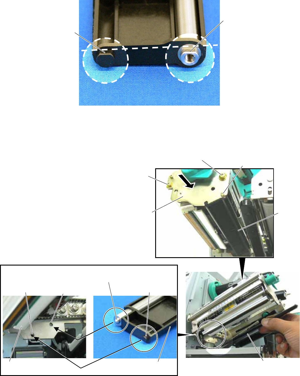
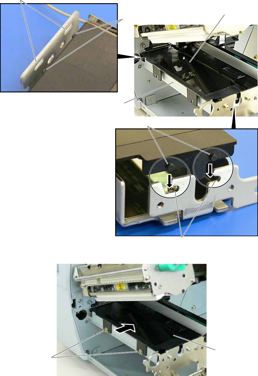
1. Raise the Print Head Block, and slide the Antenna Frame into the printer as shown below. Make the
protruding screw shaft of the printer pass through the slit of the Antenna Frame. Also, make the Shaft of the
printer fit in the Cut of the right side of Antenna Frame
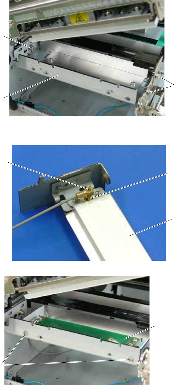
2. Secure the Antenna Frame with the three screws removed in Step 13 of Section 3.2.
A
ntenna Frame
Screw Shaft
Slit
Shaf
t
Cut
A
ntenna Frame
SMW-3x6 Screw
SMW-4x8
Screw
EO2-38058
12/24
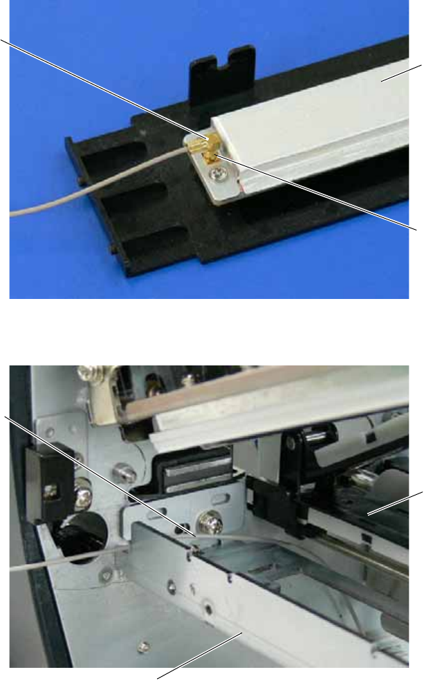
3. Connect the Antenna Cable to the Antenna Ass’y until it clicks.
4. Pass the Antenna Cable between the Sensor Block and the Antenna Frame, as shown below.
A
ntenna Cable
A
ntenna Ass’y
Connector
A
ntenna Frame
Sensor Block
A
ntenna Cable
EO2-38058
13/24
5. Fit the Antenna Ass’y in the Antenna Frame.
Be sure to fit the locating pins of the Antenna Cover into the oval holes and the cuts in the Antenna Frame.
6. Push the Antenna Ass’y in the arrow-indicating direction, and secure it with the two SMW-3x6 screws.
7. Go to Section 3.4 and attach the RFID Module.
A
ntenna Ass’y
Cut
Location Pin
A
ntenna Frame
Location Hole
Location Pin
SMW-3x6 Scre
w
A
ntenna Ass’y
EO2-38058
14/24
3.3.2 When using short-pitch tags (20 mm)
1. Attach the Antenna Frame to which the Shield Plate was attached in Section 3.1, to the printer in the same
way as described in Step 1 of Section 3.3.1.
2. Connect the Antenna Cable to the Antenna, to which the Antenna Plates were attached in Section 3.1, until it
clicks.
3. Secure the Antenna to the Antenna Frame with the P-3x6 screws.
A
ntenna Cable
A
ntenna
Connector
A
ntenna Frame
(with Shield Plate)
SMW-4x8 Screw
SMW-3x6 Screw
A
ntenna (with Antenna Plates)
P-3x6 Screw
EO2-38058
15/24
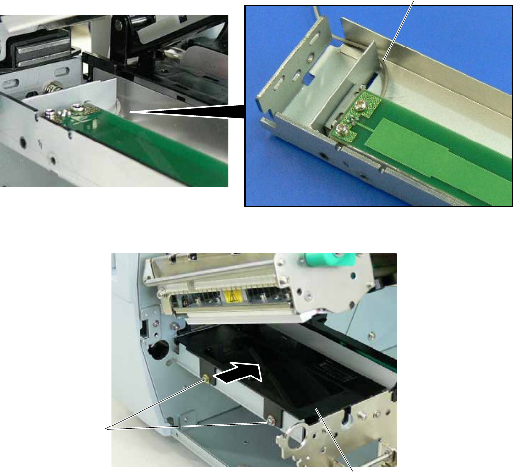
4. Place the Antenna Cable in the Antenna Frame, as shown below.
5. Refer to Steps 5 and 6 in Section 3.3.1 and attach the Antenna Cover, to which the Shield Sheet was attached
in Section 3.1, to the Antenna Frame with the SMW-3x6 screws.
6. Go to Section 3.4 and attach the RFID Module.
SMW-3x6 Screw
A
ntenna Cover (with Shield Sheet)
A
ntenna Cable
EO2-38058
16/24
3.4 Attaching the RFID Module
1. Attach the Cable Clamp to and fit the Bush into the positions shown in the picture below.
2. Pass the Antenna Cable through the Bush, and fasten the cable with the Cable Clamp.
3. Attach the RFID Module to the RFID Attachment Plate A and the RFID Attachment Plate B with the three
SMW-3x6 screws.
Bush
Cable Clamp
Bush
Cable Clamp
A
ntenna Cable
RFID Attachment Plate B
SMW-3x6 Screw
SMW-3x6 Screw
RFID Module
RFID Attachment Plate
A
EO2-38058
17/24
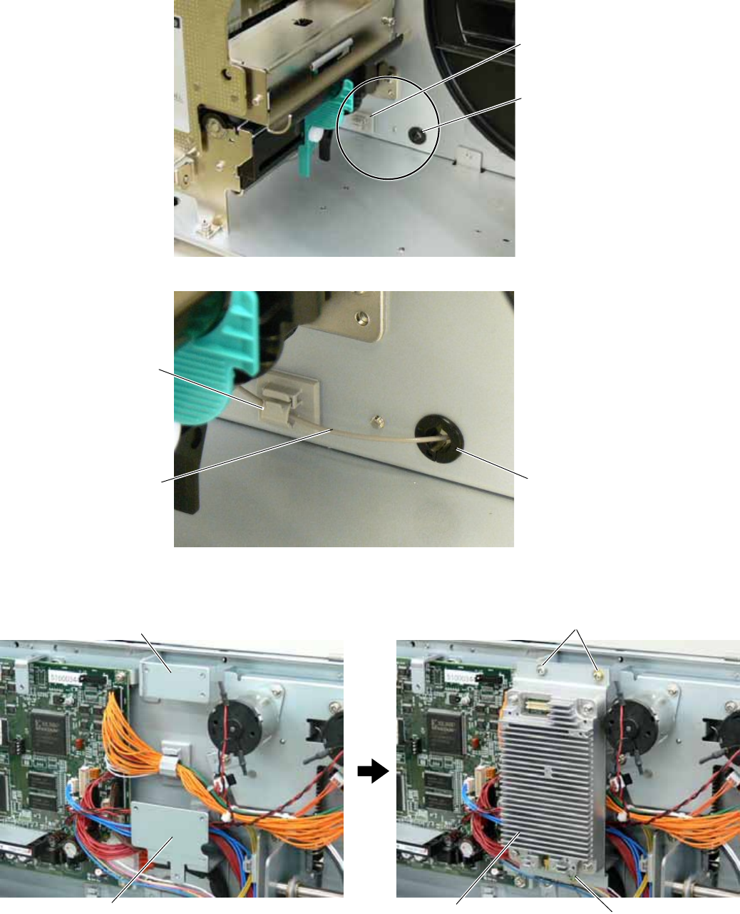
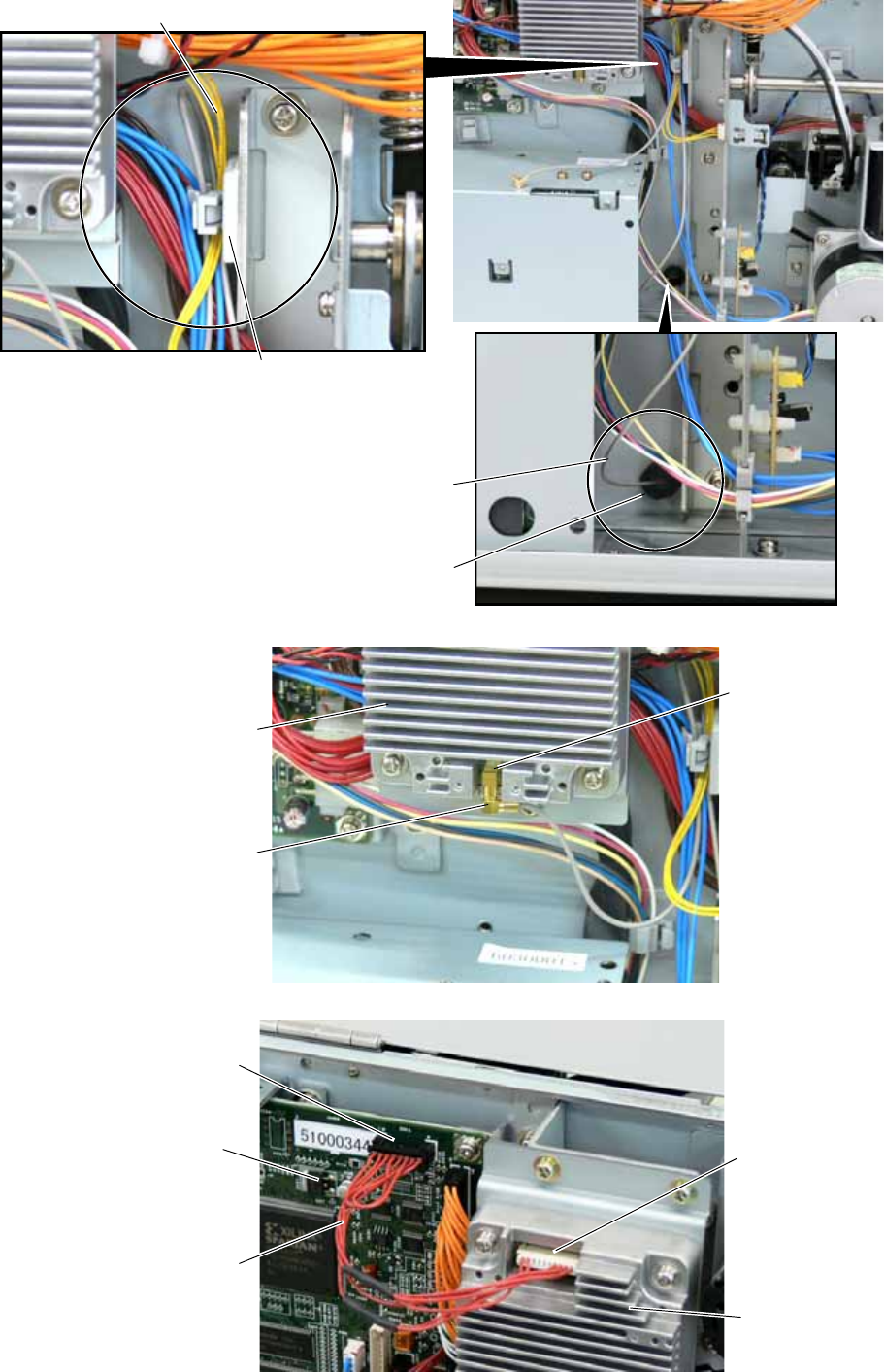
4. Fold the Antenna Cable and fasten it with the Cable Clamp together with the other cables to prevent the
Antenna Cable from being caught in the Side Panel (L) or Fan Motor.
5. Connect the Antenna Cable to the RFID Module until it clicks.
6. Connect the RFID Module to CN14 on the Main PC Board with the Interface Cable.
Cable Clamp
Bush
A
ntenna Cable
A
ntenna Cable
A
ntenna Cable
RFID Module
Connector
Connector
Connector CN14
RFID Module
Interface Cable
Main PC Board
EO2-38058
18/24
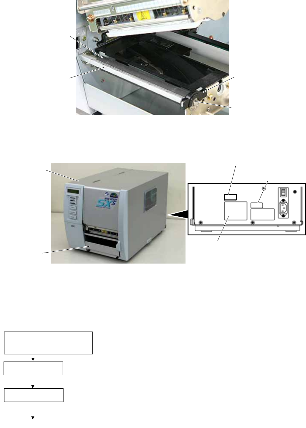
7. Re-install the Platen, Platen Holder, Strip Plate, and Platen Holder Cover in the reverse order of removal.
8. Re-install the Front Plate and Side Cover (L) in the reverse order of removal. Do not forget to connect the
Fan Motor Cable to CN19 on the Main PC Board. Be careful not to catch any cables in the Side Cover (L).
And attach the FCC ID sticker to the backside of the printer as shown below.
9. Installing the RFID kit in the printer is now completed. Then, go to Section 4 and configure the RFID module
settings.
4 RFID Module Settings
After installing the RFID Module on the printer, configure the RFID module settings using the system mode on the
printer.
Strip Plate
Platen
Platen Holder
Platen Holder Cover
Front Plate
Side Cover (L)
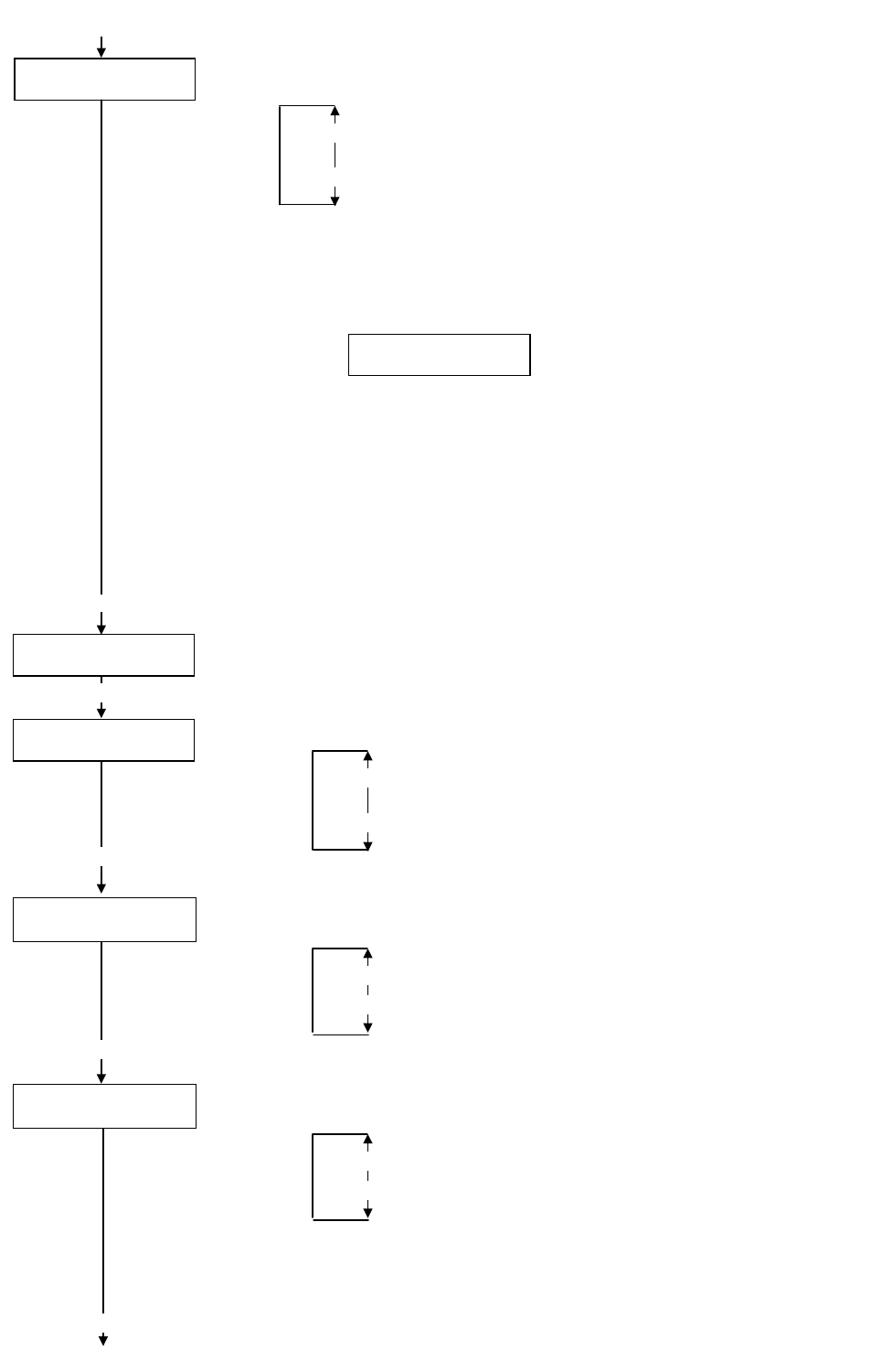
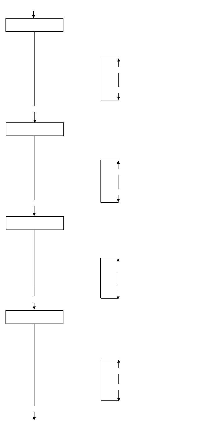
RFID setting menu ”<10>RFID” is displayed.
Press the [PAUSE] key.
[RESTART]
<10>RFID
<1>DIAG. V4.5
Turn on the printer while holding
down the [FEED] and [PAUSE]
keys at the same time.
When “<1>DIAG. V4.5“ appears on the LCD, press the [RESTART] key.
[PAUSE]
Continued to the next page.
FCC ID Sticker
ROM Version Label
FCC/DOC Lable
EO2-38058
19/24
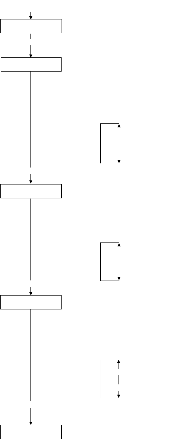
<10>RFID
TAG NONE
RFID tag type setting menu is displayed.
Choose “EPC C1 Gen2: 24” with the [FEED] or [RESTART] key.
[RESTART]
[FEED]
NONE: When a tag type is not selected.
EPC C1 Gen2: 24
[PAUSE] Press the [PAUSE] key.
<10>RFID
ERR CHK OFF
RFID error tag detection menu is displayed. Choose whether to perform an error tag detection o
r
not with the [FEED] or [RESTART] key.
[RESTART]
[FEED]
OFF: An error tag detection is not performed. (Usually, choose
OFF.)
ON: An error tag detection is performed.
ON: A tag is read before writing data on it, and data is written on the tag only when the heade
r
data is “A5A5”.
OFF: Though a tag is read before writing data on it, data write is always performed whatever
data has been set as the header data.
[PAUSE] Press the [PAUSE] key.
<10>RFID
READ TEST OFF
[PAUSE]
Read test menu is displayed. Choose whether to perform a read test or not with
the [RESTART] or [FEED] key.
[RESTART]
[FEED]
READ TEST OFF
READ TEST ON
<10>RFID
CAREERSENSE OFF
OFF: A read test is not performed. (Initially, choose “OFF”.)
ON: A read test is performed.
The printer enters the read test mode, and a read test is performed each time the [PAUSE]
key is pressed. When the data of a tag can be read, it is displayed on the LCD.
• Read data is displayed in hex. value, up to 14 bytes on 2 lines.
When the RFID tag contains 14 bytes or more data, the first 14 digits are displayed. When data
volume is less than 14 bytes, the vacant digits will be filled with spaces.
The right most hex. value on the lower line, enclosed with parentheses, indictes an AGC value
of a read tag. When more than one tag is read at one time, especially when short-pitch tags
are used, pressing the [FEED] or [RESTART] key shows the other tags’ data. Among them, a
tag with the highest AGC value is considered to be positioned just above the antenna.
• If the tag cannot be read, “RFID TIMEOUT” or “RFID READ ERROR” is displayed.
• If the type of the tag to be read and one selected by the RFID tag type selection do not match,
an RFID tag read error will result.
Make sure the RFID tag type has been selected before the read test is started.
After choosing an option, press the [PAUSE] key.
1234567890123456
65432109 (0E)
Carrier sense setting menu is displayed. This menu is not available to the B-SX704-RFID-U2-US
-R. Press the [PAUSE] key to skip this menu.
[PAUSE]
<10>RFID
MODULE NONE
Module type setting menu is displayed. Choose “U2” with the [FEED] or [RESTART] key.
[RESTART]
[FEED]
U1: Not available.
H1: Not available.
NONE: No RFID Module is installed.
U3: Not available.
U2: B-SX704-RFID-U2-US-R
H2: Not available.
[PAUSE]
Press the [PAUSE] key.
Continued to the next page.
Continued from the
previous page.
Example)
EO2-38058
20/24
Continued from the
previous page.
<10>RFID
ISSUE RETRY 3
Max. number of issue retries setting menu is displayed.
Set a maximum number of retries to issue an RFID tag.
When issuing an RFID tag failed, the printer prints the error pattern, and retries to issue the tag fo
r
up to specified number of times. If the printer does not succeed even after having retried for the
max. times, the printer stops, resulting in an error.
Choose the max. number of retries with the [FEED] or [RESTART] key.
[PAUSE]
[RESTART]
[FEED]
255
•
•
•
3 (Default)
•
•
0
Press the [PAUSE] key.
Continued to the next page.
<10>RFID
R CYCLE CNT 5
Max. number of read retries setting menu is displayed.
Set a maximum number of retries to read an RFID tag.
The printer retries to read the data in an RFID tag for up to specified number of times. If the
timeout period expired before the max. number retries have been done, the printer stops the
retries at the time.
Whenever the printer writes data onto an RFID tag, the tag is read first. The max.
number of retries set by this parameter becomes also effective in this pre-read.
Choose the max. number of retries with the [FEED] or [RESTART] key.
[RESTART]
[FEED]
255
•
•
•
5 (Default)
•
•
0
Press the [PAUSE] key.
[PAUSE]
<10>RFID
R CYCLE TIM 4.0
Read retry timeout setting menu is displayed.
Set the timeout period during which RFID tag read retries are allowed, with the [FEED] or
[RESTART] key. If the printer has retried for the max. number of times within the RFID read
retry timeout, the printer stops the retries at the time.
Whenever the printer writes data onto an RFID tag, the tag is read first. The read retry timeout
set by this parameter becomes also effective in this pre-read.
[RESTART]
[FEED]
9.9 (9.9 sec.)
•
•
•
4.0 (Default)
•
•
0.0 (0.0 sec.)
[PAUSE]
<10>RFID
W CYCLE CNT 5
Press the [PAUSE] key.
Max. number of write retries setting menu is displayed.
Set a maximum number of retries to write data onto an RFID tag.
T
he printer retries to write data onto an RFID tag for up to specified number of times. If the
t
imeout period expired before the max. number of retries have been done, the printer stops the
retries at the time.
Set the max. number of times with the [FEED] or [RESTART] key.
[RESTART]
[FEED]
255
•
•
•
5 (Default)
•
•
0
[PAUSE]
Press the [PAUSE] key.
EO2-38058
21/24
Continued from the
previous page.
Continued to the next page.
<10>RFID
W CYCLE TIM 2.0
[PAUSE]
Write retry timeout setting menu is displayed.
Set the timeout period during which RFID tag write retries are allowed, with the [FEED] or
[RESTART] key.
If the printer has retried for the max. number of times within the RFID write retry timeout, the
printer stops the retries at the time.
[RESTART]
[FEED]
9.9 (9.9 sec.)
•
•
•
2.0 (Default)
•
•
0.0 (0.0 sec.)
Press the [PAUSE] key.
<10>RFID
A
DJ RETRY +00
RFID adjustment for retry menu is displayed.
If writing data on a tag failed, the printer feeds the RFID tag forward or backward for specified
length in order to retry writing data. When “0” is set for this parameter, this function and a retry
are not performed.
Only the value of –3mm or less or +3mm or more becomes effective.
Set a value to move the RFID tag position with the [FEED] or [RESTAT] key.
[RESTART]
[FEED]
+99 (99mm) Reverse feed
•
•
•
+00 (Default)
•
•
-99 (-99mm) Forward feed
[PAUSE]
Press the [PAUSE] key.
<10>RFID
POWER LEVEL 18
Radio output power level setting menu is displayed.
When the value is “9”, the power is the weakest, and when “18”, the power is the strongest. The
factory default setting is “18”. The optimum value differs depending on the tag types. Usually, it
is not necessary to change this value but changing the value may be able to increase the number
of successful read/write times.
Set the power level with the [FEED] or [RESTART] key.
[RESTART]
[FEED]
18 (Default, Strongest)
•
•
•
•
•
9 (Weakest)
[PAUSE]
Press the [PAUSE] key.
<10>RFID
A
GC THRESHOLD 0
[PAUSE]
AGC threshold setting menu is displayed.
When the obtained gain of an RFID tag is lower than the AGC threshold, the tag is considered as
an error tag even if a data write succeeds.
W
hen the AGC threshold is set to “0”, all tags are writable.
W
hen set to “8”, for example, only tags with the AGC threshold level of 9 or greater are writable.
The optimum value is different depending on the tag types. The factory default is 0.
Set an AGC threshold with the [FEED] or [RESTART] key.
Press the [PAUSE] key.
[RESTART]
[FEED]
15
•
•
•
•
•
0 (Factory Default)
EO2-38058
22/24
Continued from the
previous page
<10>RFID
RF CHANNEL AUTO RFID channel setting menu is not available to the B-SX704-RFID-U2-US-R.
[PAUSE] Press the [PAUSE] key to skip this menu.
<10>RFID
Q VALUE 0
[PAUSE]
Q value setting menu is displayed.
In the case multiple RFID tags are read at the same time, this menu is useful to pinpoint a targe
t
tag.
Set the Q value to “1” or greater (2 is recommended.) with the [FEED] or [RESTART] key. Q
value “0” causes the tags to interfere with each other and disables proper data write.
When a Q value is set, set an AGC threshold for data write and an AGC threshold lower limit fo
r
retry, also. Setting all these values enable writing data to a tag placed just above the antenna.
(For details, refer to Section 6. AGC Threshold Setting.)
The factory default is 0.
[RESTART]
[FEED]
15
•
•
•
•
0 (Default)
Press the [PAUSE] key.
<10>RFID
WT AGC 0
[PAUSE]
AGC threshold for data write setting menu is displayed.
When the Q value is set to 1 or greater, the AGC threshold for data write becomes effective.
When the obtained gain of an RFID tag is lower than the AGC thresholdfor data write, data write
is not performed. In other words, setting an AGC threshold for data write enables writing data
only to a tag placed just above the antenna.
The optimum value differs depending on the tag type.
(For details, refer to Section 6. AGC Threshold Setting.)
Set an AGC threshold for data write with the [FEED] or [RESTART] key, if necessary.
[RESTART]
[FEED]
15
•
•
•
•
0 (Default)
Press the [PAUSE] key.
<10>RFID
WT MIN AGC 0
AGC threshold lower limit for retry setting menu is displayed.
When the Q value is set to 1 or greater, the AGC threshold lower limit for retry becomes effective.
When there are tags of which AGC values fall within the range between the AGC threshold fo
r
data write and the lower limit, the printer retries data write for a tag with the highest AGC value
among those tags. When printer retries data write, that value is then used as an AGC threshold.
The optimum value differs depending on the tag type.
(For details, refer to Section 6. AGC Threshold Setting.)
Set the lower limit for retry with the [FEED] or [RESTART] key, if necessary.
[PAUSE]
[RESTART]
[FEED]
15
•
•
•
•
0 (Default)
Press the [PAUSE] key.
<10>RFID
The LCD message returns to ”<10>RFID”.
Now, the RFID module settings are completed. If data write to RFID tags cannot be properly
performed, refer to Section 5.
EO2-38058
23/24
5 AGC THRESHOLD SETTING
The B-SX704-RFID-U2-US-R chooses a tag to write data on according to a radio intensity of RFID tags (AGC value).
An AGC threshold value has been set to 0 (00h) as factory default, but it may be necessary to change this value
according to the tag type to be used.
When the factory default threshold value is not proper for the tag type used, follow the procedure below to configure the
following settings.
As the changes are stored in the internal memory, they are retained after the printer power is turned off and on again.
When the tag type is changed or data write cannot be operated properly, perform the setting again.
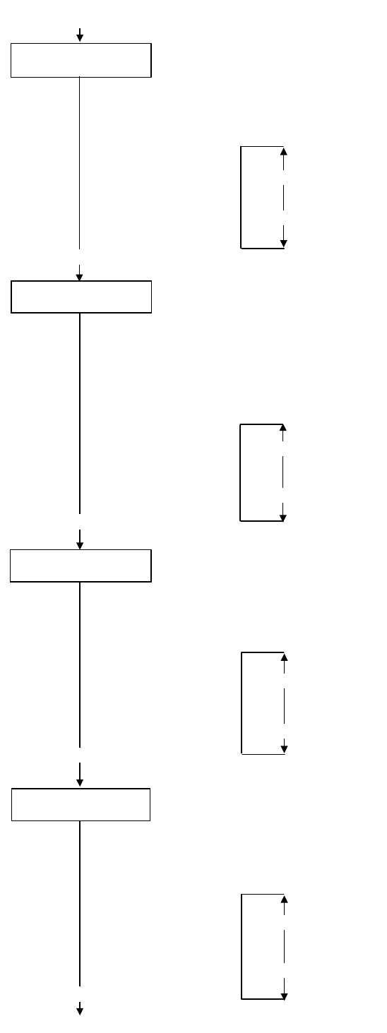
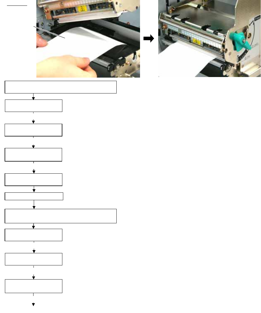
Step 1. Load an RFID tag embedded media in the printer.
Step 2. Follow the procedure below to measure the radio intensity of the tags.
1) Place the media so that an RFID tag (IC chip) is positioned above the Antenna, and close the Top Cover.
Note: If an RFID tag is not positioned above the Antenna while the Print Head is at a print start position, use
@003 command to adjust the media position so that an RFID tag is positioned above the Antenna.
For detail of the command, refer to the External Equipment Interface Specification (Printer Command
Manual).
2) Start the printer in the system mode and perform a read test to measure the AGC value.
To measure the AGC value, place only one RFID tag on the Antenna.
Example
RFID Tag
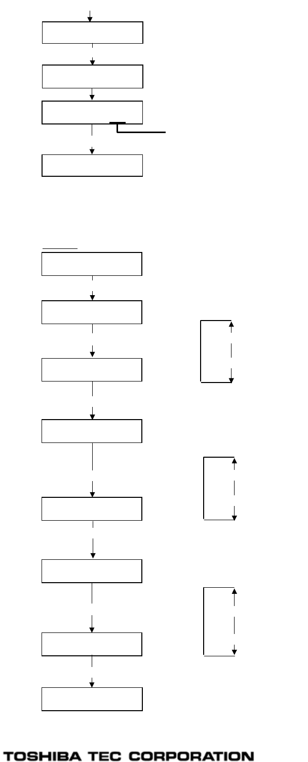
Read test menu is displayed.
Press the [FEED] or [RESTAT] key to choose “READ TEST ON”.
[RESTART]
<10>RFID
<1>DIAG. V4.5
[PAUSE]
[FEED] or [RESTAT]
Turn the printer on while holding down the
[FEED] and [PAUSE] keys at the same time.
When “<1>DIAG. V4.5” is displayed, press the [RESTART] key.
<10>RFID
READ TEST OFF
When ”<10>RFID” is displayed, press the [PAUSE] key until the Q value setting menu is
displayed.
<10>RFID
Q VALUE 2 Choose “2” with the [FEED] or [RESTART] key.
Press the [PAUSE] key and turn off the printer.
[PAUSE]
<10>RFID
WT AGC 0
Turn the power off.
Turn the printer on while holding down the
[FEED] and [PAUSE] keys at the same time.
[RESTART]
<1>DIAG. V4.5
<10>RFID
[PAUSE]
Continued to the next page.
When “<1>DIAG. V4.5” is displayed, press the [RESTART] key.
When “<10>RFID” is displayed, press the [PAUSE] key.
EO2-38058
24/24
3) Set an AGC threshold of data write.
Set a value which is lower than the AGC value obtained by a read test by 1 or 2, taking variation of RFID
tags in performance into consideration.
Press the [PAUSE] key to implement a read test.
<10>RFID
READ TEST ON
[PAUSE]
<10>RFID
READING•••.
Read data is displayed.
3132333435363738
39304142 (0A)
Press the [FEED] and [RESTART] keys to return to the RFID Setting Menu (”<10>RFID”).
<10>RFID
[FEED], [RESTART] Data in parentheses ( ) is the AGC value expressed in hex. code. Write down this value.
<10>RFID
[PAUSE]
<10>RFID
Q VALUE 0
Choose “2” with the [FEED] or [RESTART] key.
When “2” is already chosen, go to the AGC threshold for data write setting menu.
[RESTART]
[FEED]
15
•
•
•
•
0 (Default)
<10>RFID
WT AGC 0
[FEED] or [RESTAT]
<10>RFID
WT AGC 9
A
GC threshold for data write setting menu is displayed.
Choose a threshold value (decimal number) with the [FEED] or [RESTART] key.
When the measured AGC is 10 (0A), for example, choose “9” (a value lower than the
measured AGC by 1 or 2).
[RESTART]
[FEED]
15
•
•
•
•
0 (Default)
[PAUSE]
<10>RFID
Q VALUE 2
[FEED] or [RESTART]
[PAUSE]
Example
Press the [PAUSE] key.
When ”<10>RFID” is displayed, press the [PAUSE] key until the Q value setting menu is
displayed.
Press the [PAUSE] key.
<10>RFID
WT MIN AGC 0
A
GC threshold lower limit for retry setting menu is displayed.
Choose a lower limit (decimal number) with the [FEED] or [RESTART] key.
Usually, choose the same value with the AGC threshold for data write (WT AGC).
[FEED] or [RESTAT]
<10>RFID
WT MIN AGC 9
[PAUSE]
[RESTART]
[FEED]
15
•
•
•
•
0 (Default)
Press the [PAUSE] key.
<10>RFID
RFID Setting Menu (”<10>RFID”) is displayed.
A
n AGC th
r
eshold setting is completed.
7FM03205000
PRINTED IN JAPAN
EO2-38058
Continued from the previous page
FCC and IC label information:
This device complies with Part 15 of the FCC Rules and RSS 210 Industry Canada Rules.
Operation is subject to the following two conditions: (1) this device may not cause harmful
interference, and (2) this device must accept any interference received, including interference that
may cause undesired operation.
Note: Users are cautioned that changes or modifications not expressly approved by the party
responsible for compliance could void the user's authority to operate the equipment. In cases
where the manual is provided only in a form other than paper, such as on a computer disk or over
the Internet, the information required by this section may be included in the manual in that
alternative form, provided the user can reasonably be expected to have the capability to access
information in that form.
In order to ensure compliance with the Commission’s RF Exposure guidelines, the user MUST
maintain a separation of 20 cm (8 inches) from the unit antenna when it is transmitting. Under no
circumstances is it permitted for this device to be collocated or used in conjunction with any othe
r transmitter, and any installer if not the end-user is instructed to provide the end-user with this
information.