Toshiba 15Lv505 Service Manual 51T 01P COVER.p65
15LV505 15LV505
2014-12-13
: Toshiba Toshiba-15Lv505-Service-Manual-131950 toshiba-15lv505-service-manual-131950 toshiba pdf
Open the PDF directly: View PDF ![]() .
.
Page Count: 100

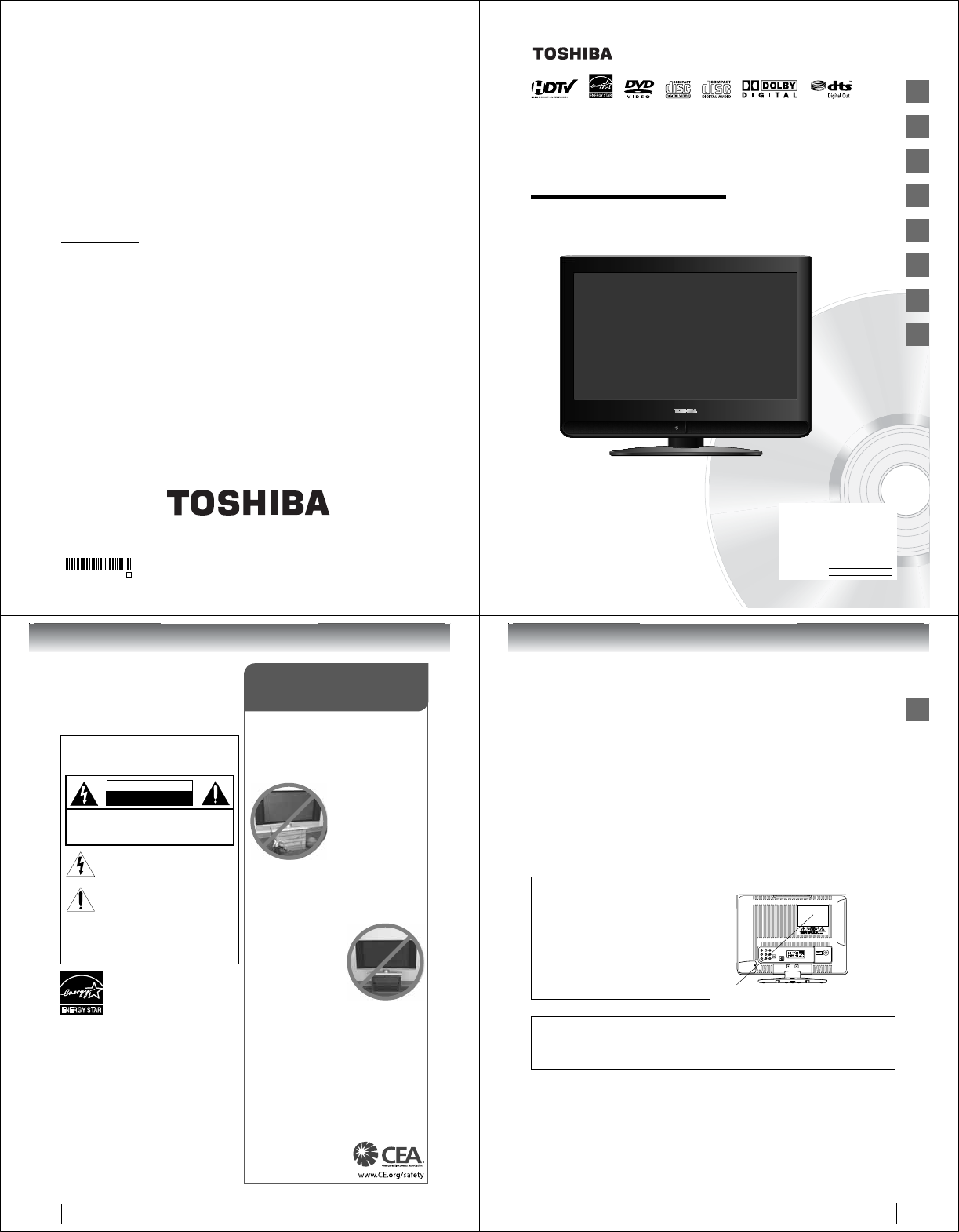
SERVICE MANUAL
15-inch Diagonal LCD TV/DVD
COMBINATION
DOCUMENT CREATED IN JAPAN, August, 2008 GREEN
FILE NO. 810-200882GR
The above model is classified as a green product (*1), as indicated by the underlined serial number.
This Service Manual describes replacement parts for the green product. When repairing this green
product, use the part(s) described in this manual and lead-free solder (*2).
For (*1) and (*2), see the next page.
©2008 Toshiba Corporation
15LV505

(*1) GREEN PRODUCT PROCUREMENT
The EC is actively promoting the WEEE & RoHS Directives that define standards for recycling
and reuse of Waste Electrical and Electronic Equipment and for the Restriction of the use of
certain Hazardous Substances. From July 1, 2006, the RoHS Directive will prohibit any
marketing of new products containing the restricted substances.
Increasing attention is given to issues related to the global environmental. Toshiba Corporation
recognizes environmental protection as a key management tasks, and is doing its utmost to
enhance and improve the quality and scope of its environmental activities. In line with this,
Toshiba proactively promotes Green Procurement, and seeks to purchase and use products,
parts and materials that have low environmental impacts.
Green procurement of parts is not only confined to manufacture. The same green parts used in
manufacture must also be used as replacement parts.
(*2) LEAD-FREE SOLDER
This product is manufactured using lead-free solder as a part of a movement within the consumer
products industry at large to be environmentally responsible. Lead-free solder must be used in
the servicing and repair of this product.
WARNING
This product is manufactured using lead free solder.
DO NOT USE LEAD BASED SOLDER TO REPAIR THIS PRODUCT !
The melting temperature of lead-free solder is higher than that of leaded solder by 86°F to 104°F
(30°C to 40°C). Use of a soldering iron designed for lead-based solders to repair product made
with lead-free solder may result in damage to the component and or PCB being soldered. Great
care should be made to ensure high-quality soldering when servicing this product especially
when soldering large components, through-hole pins, and on PCBs as the level of heat
required to melt lead-free solder is high.
TABLE OF CONTENTS
GREEN PRODUCT PROCUREMENT
LEAD-FREE SOLDER
TABLE OF CONTENTS
• OWNER'S MANUAL
CAUTION .....................................................................................................................................
SERVICING NOTICES ON CHECKING ....................................................................................
HOW TO ORDER PARTS ..........................................................................................................
IMPORTANT SAFEGUARDS.....................................................................................................
WHEN REPLACING DVD DECK ...............................................................................................
DISC REMOVAL METHOD AT NO POWER SUPPLY ............................................................
PARENTAL CONTROL-RATING LEVEL ................................................................................
REMOTE CONTROL KEY CODE ..............................................................................................
GENERAL SPECIFICATIONS....................................................................................................
DISASSEMBLY INSTRUCTIONS
1.REMOVAL OF MECHANICAL PARTS AND P. C. BOARDS.............................................
2.REMOVAL OF DVD DECK PARTS .....................................................................................
3.REMOVAL AND INSTALLATION OF FLAT PACKAGE IC................................................
SERVICE MODE LIST .................................................................................................................
SERVICING FIXTURES AND TOOLS.......................................................................................
RE-WRITE FOR DVD FIRMWARE ............................................................................................
WHEN REPLACING EEPROM (MEMORY) IC .........................................................................
ELECTRICAL ADJUSTMENTS..................................................................................................
TROUBLESHOOTING GUIDE .....................................................................................................
BLOCK DIAGRAMS
DVD ...........................................................................................................................................
POWER .....................................................................................................................................
POWER(DIGITAL PCB) ..........................................................................................................
SIGNAL .....................................................................................................................................
PRINTED CIRCUIT BOARDS
DVD MT.....................................................................................................................................
DIGITAL ....................................................................................................................................
POWER/OPERATION/REMOCON/SW .................................................................................
POWER/OPERATION/REMOCON .........................................................................................
SCHEMATIC DIAGRAMS
MPEG/MICON/DSP/RF_AMP .................................................................................................
MEMORY...................................................................................................................................
MOTOR DRIVE .........................................................................................................................
AUDIO/VIDEO ..........................................................................................................................
MICON.......................................................................................................................................
SCALER VIDEO/AUDIO ..........................................................................................................
TUNER ......................................................................................................................................
HDMI..........................................................................................................................................
LVDS..........................................................................................................................................
SCALER POWER .....................................................................................................................
FLASH .......................................................................................................................................
DDR ...........................................................................................................................................
JACK..........................................................................................................................................
AV SWITCH ..............................................................................................................................
REGULATOR ...........................................................................................................................
POWER .....................................................................................................................................
BACKLIGHT INVERTER .........................................................................................................
SOUND AMP ............................................................................................................................
JACK OUT ................................................................................................................................
SW .............................................................................................................................................
INTERCONNECTION DIAGRAM ................................................................................................
WAVEFORMS ...............................................................................................................................
MECHANICAL EXPLODED VIEW ..............................................................................................
DVD DECK EXPLODED VIEW ...................................................................................................
MECHANICAL REPLACEMENT PARTS LIST...........................................................................
DVD DECK REPLACEMENT PARTS LIST ..............................................................................
ELECTRICAL REPLACEMENT PARTS LIST ............................................................................
A1-1
A1-2
A1-2
A1-3~A1-5
A1-6
A1-7
A1-7
A1-8
A2-1~A2-8
B1-1, B1-2
B2-1, B2-2
B3-1, B3-2
C-1
C-2
C-2
C-3
D-1~D-5
E-1~E-9
F-1, F-2
F-3, F-4
F-5, F-6
F-7, F-8
G-1, G-2
G-3, G-4
G-5, G-6
G-7, G-8
H-1, H-2
H-3, H-4
H-5, H-6
H-7, H-8
H-9, H-10
H-11, H-12
H-13, H-14
H-15, H-16
H-17, H-18
H-19, H-20
H-21, H-22
H-23, H-24
H-25, H-26
H-27, H-28
H-29, H-30
H-31, H-32
H-33, H-34
H-35, H-36
H-37, H-38
H-39, H-40
H-41, H-42
I-1, I-2
J1-1~J1-3
J2-1
K1-1
K2-1
K3-1~K3-4
•
•
•
No person, agent, distributor, dealer, or company
is authorized to change, modify, or extend
the terms of these warranties in any manner
whatsoever. The time within which an action must
be commenced to enforce any obligation of TACP
arising under the warranty or under any statute
or law of the United States or any state thereof is
hereby limited to ninety (90) days from the date
you discover, or should have discovered, the
defect. This limitation does not apply to implied
warranties arising under state law.
THIS WARRANTY GIVES YOU SPECIFIC LEGAL
RIGHTS AND YOU MAY ALSO HAVE OTHER
RIGHTS WHICH MAY VARY FROM STATE TO
STATE IN THE U.S.A. SOME STATES OF THE
U.S.A. DO NOT ALLOW LIMITATIONS ON HOW
LONG AN IMPLIED WARRANTY LASTS, WHEN
AN ACTION MAY BE BROUGHT, OR THE
EXCLUSION OR LIMITATION OF INCIDENTAL
OR CONSEQUENTIAL DAMAGES, SO THE
ABOVE PROVISIONS MAY NOT APPLY TO YOU
UNDER SUCH CIRCUMSTANCES.
How to Obtain Warranty Services
If, after following all of the operating instructions
in this manual and checking the section
“Troubleshooting,” you fi nd that service is needed:
(1) For instructions on how to obtain warranty
service for your LCD TV/DVD Combination,
contact TACP·s Consumer Solution Center toll
free at 1-800-631-3811.
(2) You must include a copy or original bill of
sale or other proof of purchase along with
the entire LCD TV/DVD Combination to the
Depot Warranty Repair Center specifi ed by
the TACP Consumer Solutions Center. You
are responsible for all inbound transportation
and insurance charges for the LCD TV/DVD
Combination to the Depot Warranty Repair
Center specifi ed by the TACP Consumer
Solutions Center.
For additional information, visit TACP·s website:
www.tacp.toshiba.com
ALL WARRANTIES IMPLIED BY THE LAW OF
ANY STATE OF THE U.S.A., INCLUDING THE
IMPLIED WARRANTIES OF MERCHANTABILITY
AND FITNESS FOR A PARTICULAR PURPOSE,
ARE EXPRESSLY LIMITED TO THE DURATION
OF THE LIMITED WARRANTIES SET FORTH
ABOVE. WITH THE EXCEPTION OF ANY
WARRANTIES IMPLIED BY THE LAW OF ANY
STATE OF THE U.S.A. AS HEREBY LIMITED,
THE FOREGOING WARRANTY IS EXCLUSIVE
AND IN LIEU OF ALL OTHER WARRANTIES,
GUARANTEES, AGREEMENTS, AND SIMILAR
OBLIGATIONS OF TACP WITH RESPECT TO
THE REPAIR OR REPLACEMENT OF ANY
PARTS. IN NO EVENT SHALL TACP BE LIABLE
FOR CONSEQUENTIAL OR INCIDENTAL
DAMAGES (INCLUDING, BUT NOT LIMITED TO,
LOST PROFITS, BUSINESS INTERRUPTION, OR
MODIFICATION OR ERASURE OF RECORDED
DATA CAUSED BY USE, MISUSE OR INABILITY
TO USE THIS LCD TV/DVD COMBINATION).
Printed in Thailand
ColorStream is registered trademark of Toshiba America Consumer Products, L.L.C.
J51T0101A SH 08/08 N
15LV505
OWNER’S MANUAL
4
14
20
42
45
57
Introduction
Connections
Basic setup
Basic playback
Advanced playback
Function setup
62
Others
25
TV operation
©2008 Toshiba Corporation
Before operating the unit, please read this manual thoroughly.
15-inch* Diagonal LCD TV/DVD
COMBINATION
*Screen size is approximate.
Owner·s Record
The model number and serial number
are on the back of your TV/DVD.
Record these numbers in the spaces
below. Refer to these numbers
whenever you communicate with your
Toshiba dealer about this TV/DVD.
Model number:
Serial number:
2
Dear Customer,
Thank you for purchasing this Toshiba LCD TV or TV/DVD
Combination television.
This manual will help you use the many exciting features of
your new LCD TV. Before operating your LCD TV or TV/DVD
Combination, please read this manual completely, and keep it
nearby for future reference.
The lightning flash with arrowhead symbol, within an
equilateral triangle, is intended to alert the user to
the presence of uninsulated “dangerous voltage”
within the product’s enclosure that may be of
sufficient magnitude to constitute a risk of electric
shock to persons.
The exclamation point within an equilateral triangle,
is intended to alert the user to the presence of
important operating and maintenance (servicing)
instructions in the literature accompanying the
appliance.
CAUTION: To reduce the risk of electric shock,
do not use the polarized plug with an extension
cord, receptacle, or other outlet unless the blades
can be inserted completely to prevent blade
exposure.
NOTE TO CATV INSTALLERS
This is a reminder to call the CATV system installer’s attention
to Article 820-40 of the NEC, which provides guidelines for proper
grounding and, in particular, specifies that the cable ground shall be
connected to grounding system of the building, as close to the point of
cable entry as practical. For additional antenna grounding information,
see item 26 on page 5.
Safety Precautions
WARNING: TO REDUCE THE RISK OF FIRE OR
ELECTRIC SHOCK, DO NOT EXPOSE THIS
APPLIANCE TO RAIN OR MOISTURE.
WARNING
RISK OF ELECTRIC SHOCK
DO NOT OPEN
CAUTION: TO REDUCE THE RISK OF ELECTRIC
SHOCK, DO NOT REMOVE COVER (OR BACK).
NO USER-SERVICEABLE PARTS INSIDE. REFER
SERVICING TO QUALIFIED SERVICE PERSONNEL.
ENERGY STAR® qualified TV. Products that earn
the ENERGY STAR prevent green house gas
emissions by meeting strict energy efficiency
guidelines set by the U.S. Environmental
Protection Agency and the U.S. Department of
Energy. ENERGY STAR and the ENERGY STAR
mark are registered U.S. marks.
Congratulations on your purchase! As you enjoy your
new product, please keep these safety tips in mind:
The Issue
• The home theater entertainment experience is a growing trend
and larger flat panel displays are popular purchases. However,
flat panel displays are not always supported on the proper stands
or installed according to the manufacturer’s recommendations.
• Flat panel displays that are
inappropriately situated on dressers,
bookcases, shelves, desks,
speakers, chests or carts may fall
over and cause injury.
TOSHIBA Cares!
• The consumer electronics industry
is committed to making home
entertainment enjoyable and safe.
Tune Into Safety
•
One size does NOT fit all. Follow the manufacturer’s recommendations
for the safe installation and use of your flat panel display.
• Carefully read and understand all enclosed instructions for
proper use of this product.
• Don’t allow children to climb on or play with furniture and
television sets.
• Don’t place flat panel displays on furniture
that can easily be used as steps, such
as a chest of drawers.
• Remember that children can
become excited while watching a
program, especially on a “larger
than life” flat panel display. Care
should be taken to place or install
the display where it cannot be
pushed, pulled over, or knocked down.
• Care should be taken to route all cords and
cables connected to the flat panel display so that they cannot be
pulled or grabbed by curious children.
Wall Mounting: If you decide to wall mount your
flat panel display, always:
• Use a mount that has been recommended by the display
manufacturer and/or listed by an independent laboratory (such
as UL, CSA, ETL).
• Follow all instructions supplied by the display and wall mount
manufacturers.
• If you have any doubts about your ability to safely install your
flat panel display, contact your retailer about professional
installation.
• Make sure that the wall where you are mounting the display is
appropriate. Some wall mounts are not designed to be mounted
to walls with steel studs or old cinder block construction. If you
are unsure, contact a professional
installer.
• A minimum of two people are
required for installation. Flat panel
displays can be heavy.
CHILD SAFETY:
It Makes A Difference How and Where You Use Your Flat
Panel Display
WARNING
: Handling the cord on this product or cords associated
with accessories sold with this product will expose you to lead, a
chemical known to the State of California to cause birth defects or
other reproductive harm. Wash hands after handling.
Introduction
3
Location of the required Marking
The rating sheet and the safety caution are the rear of the unit.
CERTIFICATION: COMPLIES WITH FDA RADIATION
PERFORMANCE STANDARDS, 21 CFR SUBCHAPTER J.
CAUTION:
THIS DIGITAL VIDEO PLAYER EMPLOYS A LASER SYSTEM.
TO ENSURE PROPER USE OF THIS PRODUCT, PLEASE READ
THIS OWNER'S MANUAL CAREFULLY AND RETAIN FOR
FUTURE REFERENCE. SHOULD THE UNIT REQUIRE
MAINTENANCE, CONTACT AN AUTHORIZED SERVICE
LOCATION.
USE OF CONTROLS, ADJUSTMENTS OR THE PERFORMANCE
OF PROCEDURES OTHER THAN THOSE SPECIFIED HEREIN
MAY RESULT IN HAZARDOUS RADIATION EXPOSURE.
TO PREVENT DIRECT EXPOSURE TO LASER BEAM, NEVER
OPEN THE ENCLOSURE. VISIBLE LASER RADIATION MAY BE
PRESENT WHEN THE ENCLOSURE IS OPENED. NEVER STARE
INTO BEAM.
FCC compliance information
CAUTION: TO PREVENT ELECTRIC SHOCK DO NOT USE THIS POLARIZED PLUG WITH AN EXTENSION CORD, RECEPTACLE
OR OTHER OUTLET UNLESS THE BLADES CAN BE FULLY INSERTED TO PREVENT BLADE EXPOSURE.
FCC Declaration of Conformity Compliance Statement (Part 15):
The Toshiba 15LV505 LCD TV/DVD Combination complies with Part 15 of the FCC rules.
Operation is subject to the following two conditions: (1) this device may not cause harmful interference, and (2) this device
must accept any interference received, including interference that may cause undesired operation.
The party responsible for compliance to these rules is:
Toshiba America Consumer Products, L.L.C.
82 Totowa Rd. Wayne, NJ 07470.
Ph: (800) 631-3811 or visit TACP·s website at www.tacp.Toshiba.com
NOTE: This equipment has been tested and found to comply with the limits for a Class B digital device, pursuant to Part 15 of the
FCC rules. These limits are designed to provide reasonable protection against harmful interference in a residential
installation. This equipment generates, uses, and can radiate radio frequency energy and, if not installed and used in
accordance with the instructions, may cause harmful interference to radio communications. However, there is no guarantee
that interference will not occur in a particular installation. If this equipment does cause harmful interference to radio or
television reception, which can be determined by removing and applying power to the equipment, the user is encouraged to
try to correct the interference by one or more of the following measures:
- Reorient or relocate the receiving antenna.
- Increase the separation between the equipment and the receiver.
- Connect the equipment into an outlet on a circuit different from that to which the receiver is connected.
- Consult the dealer or an experienced radio/TV technician for help.
CAUTION: Changes or modifications to this equipment not expressly approved by Toshiba could void the user·s authority to operate this
equipment.
ON DISPOSAL
The lamp(s) inside this product contain mercury. Disposal may be regulated due to environmental
considerations. For disposal or recycling information, contact your local authorities or the
Electronic Industries Alliance (www.eiae.org).
Introduction
4
SAFETY INSTRUCTIONS
15) To avoid damage to this product, never place or
store the TV in direct sunlight; hot, humid areas;
or areas subject to excessive dust or vibration.
16)
Never modify this equipment. Changes or modifi cations
may void: a) the warranty, and b) the user·s authority
to
operate this equipment under the rules of the
Federal Communications Commission.
17) DANGER: RISK OF SERIOUS
PERSONAL INJURY, DEATH, OR
EQUIPMENT DAMAGE! Never place
the TV on an unstable cart,
stand, or table. The TV may fall, causing
serious personal injury, death, or serious
damage to the TV.
18) Never place items such as vases, aquariums, or
candles on top of the TV.
19) WARNING: Always place the TV on the fl oor or a
sturdy, level, stable
surface that can
support the weight
of the unit. To
secure the TV, use a
sturdy strap from the
hooks on the rear
of the TV pedestal
to a wall stud, pillar
or other immovable structure. Make sure the strap is
tight, secure, and parallel to the fl oor.
20)
Never expose the apparatus to dripping or splashing
liquid or place items such as vases, aquariums, any
other item fi lled with liquid, or candles on top of the TV.
21)
Never block or cover the slots or openings in the TV
cabinet back, bottom, and sides.
Never place the TV:
•
on a bed, sofa, rug, or similar surface;
• too close to drapes, curtains,
or walls; or
• in a confi ned space such as
a bookcase, built-in cabinet,
or any other place with poor ventilation.
The slots and openings are provided to protect the TV from
overheating and to help maintain reliable operation of the TV.
Leave a space of at least 4 inches around the TV.
22) Always place the back of the television at least four
(4) inches away from any vertical surface (such as a
wall) to allow proper ventilation.
23) Never allow anything to rest on or roll over the power
cord, and never place the TV where the power cord
is subject to wear or abuse.
24) Never overload wall outlets and extension cords.
25)
Always operate the TV with a 120V AC, 60Hz power source only.
1) Read these instructions.
2) Keep these instructions.
3) Heed all warnings.
4) Follow all instructions.
5) Do not use this apparatus near water.
6) Clean only with dry cloth.
7) Do not block any ventilation openings.
Install in accordance with the manufacturer·s instructions.
8) Do not install near any heat sources such as
radiators, heat registers, stoves, or other apparatus
(including amplifi ers) that produce heat.
9)
Do not defeat the safety purpose of the polarized or
grounding type plug. A polarized plug has two blades
with one wider than the other. A grounding type plug has
two blades and a third grounding prong.
The wide blade or the third prong
are provided for your safety. If
the provided plug does not fi t into
your outlet, consult an electrician for
replacement of the obsolete outlet.
10)
Protect the power cord from being walked
on or pinched, particularly at plugs,
convenience receptacles, and the point
where they exit from the apparatus.
11) Only use attachments/accessories specifi ed by the
manufacturer.
12)
Use only with the cart, stand, tripod,
bracket, or table specifi ed by the
manufacturer, or sold with the
apparatus.
When a cart is used, use
caution when moving the cart/
apparatus combination to avoid
injury from tip-over.
13)
Unplug this apparatus during
lightning storms or when unused
for long periods of time.
14) Refer all servicing to qualifi ed service personnel.
Servicing is required when the apparatus has been damaged
in any way, such as power-supply cord or plug is damaged,
liquid has been spilled or objects have fallen into the
apparatus, the apparatus has been exposed to rain or
moisture, does not operate normally, or has been dropped.
Installation, Care, and Service
Installation
Follow these recommendations and precautions and
heed all warnings when installing your TV:
CAUTION: To reduce the risk of electric shock, do not use the
polarized plug with an extension cord, receptacle, or other outlet
unless the blades can be inserted completely with three-wire
grounding type to prevent blade exposure.
Important Safety Instructions
Hooks
TV side
TV top
Band
Sturdy tie (as short as possible; min. 4 in.)
Screw
Clip
Wide plug
Additional Safety Precautions
14a) CAUTION: If the TV is dropped and the cabinet or
enclosure surface has been damaged or the TV does
not operate normally, take the following precautions:
• ALWAYS turn off the TV and unplug the power
cord to avoid possible electric shock or fi re.
• NEVER allow your body to come in contact with
any broken glass or liquid from the damaged
television. The LCD panel inside the TV contains
glass and a toxic liquid. If the liquid comes in contact
with your mouth or eyes, or your skin is cut by
broken glass, rinse the affected area thoroughly
with
water and consult your doctor.
• ALWAYS contact a service technician to inspect
the TV any time it has been damaged or dropped.
14b) WARNING: To prevent the spread of fi re, keep
candles or other open fl ames away from this product
at all times.
Introduction
5
Installation (cont. from previous page)
26) Always make sure the antenna system is properly
grounded to provide adequate protection against
voltage surges and built-up static charges (see
Section 810 of the National Electric Code.)
27) DANGER: RISK OF SERIOUS
PERSONAL INJURY OR DEATH!
• Use extreme care to make sure you
are never in a position where your body
(or any item
you are in contact with,
such
as a ladder or screwdriver) can
accidentally touch overhead power lines.
Never locate the antenna near overhead
power lines or other electrical circuits.
•
Never attempt to install any of the following during
lightning activity: a) an antenna system; or b) cables,
wires, or any home theater component connected
to an antenna or phone system.
Care
For better performance and safer operation of your
TOSHIBA TV, follow these recommendations and precautions:
28) Always unplug the TV before cleaning.
Wipe the display panel
surface gently using only a
soft cloth (cotton, fl annel,
etc.) A hard cloth may
damage the surface of the
panel. Avoid contact with
alcohol, thinner, benzene,
acidic or and alkaline solvent cleaners, abrasive
cleaners, or chemical cloths, which may damage
the surface. Never spray volatile compounds such
as insecticide on the cabinet. Such products may
damage or discolor the cabinet
.
29)
WARNING: RISK OF ELECTRIC SHOCK!
Never spill liquids or push objects of
any kind into the TV cabinet slots.
30)
While it is thundering, do not touch the connecting
cables or apparatus.
31)
For added protection of your TV from lightning and
power surges, always unplug the power cord and
disconnect the antenna from the TV if you leave the
TV unattended or unused for long periods of time.
Antenna discharge unit
(NEC Section 810-20)
Antenna
lead-in wire
Grounding conductors
(NEC Section 810-21)
Ground clamps
Power service grounding
electrode system
(NEC Art 250 Part H)
Ground clamp
Electric service
equipment
SAFETY INSTRUCTIONS
(Continued)
Care (cont. from previous column)
32) During normal use, the TV may make occasional
snap ping or popping sounds. This is normal,
especially when the unit is being turned on or off.
If these sounds become frequent or continuous,
unplug the power cord and contact a Toshiba
Authorized Service Center.
33)
Keep your fi ngers well clear of the disc slot as it is closing.
Failure to do so may cause serious personal injury.
34) When you use headphones, keep the volume at a
moderate level. Using headphones continuously
at a high volume may cause hearing damage.
35)
NEVER look directly into the disc slot or ventilation
slots at the source of the laser beam. Doing so
may cause sight damage.
36) NEVER use a cracked, deformed, or repaired disc.
Such discs are easily broken and may cause serious
personal injury or product damage. SUCH DAMAGE
IS NOT COVERED UNDER YOUR WARRANTY.
37) WARNING: RISK OF SERIOUS PERSONAL
INJURY OR EQUIPMENT DAMAGE!
• Never strike the screen with a sharp or heavy
object.
• Never touch, press, or place anything on the
LCD screen. These actions will damage the LCD
screen If you need to clean the LCD screen,
follow the instructions in item 28 on this page.
Service
38)
WARNING: RISK OF ELECTRIC SHOCK!
Never attempt to service the TV
yourself.
Opening and removing the covers
may expose you to dangerous voltage or other
hazards. Failure to follow this WARNING may
result in death or serious injury.
Refer all servicing to a Toshiba Authorized Service
Center.
39) If you have the TV serviced:
•
Ask the service technician to use only replacement
parts specifi ed by the manufacturer.
• Upon completion of service, ask the service
technician to perform routine safety checks to
determine that the TV is in safe operating condition.
40) When the TV reaches the end of its useful life,
ask a qualifi ed service technician to properly
dispose of the TV.
Introduction
6
Precautions
Notes on handling
Q Do not subject the LCD panel to physical shock, such
as dropping it. It may cause unit damage and malfunction.
Q When shipping the unit, the original shipping carton
and packing materials come in handy. For fully
protection, repack the unit as it was originally packed
at the factory.
Q Do not use volatile liquids, such as insecticide, near
the unit.
Do not leave rubber or plastic products in contact with
the unit for prolonged periods of time.
Doing so will leave marks on the fi nish.
Q
The top and rear panels of the unit may become warm
after a long period of use. This is not a malfunction.
Q When the unit is not in use, always remove the disc
and turn off the power.
Notes on locating the unit
Q When you place this unit near a TV, radio, or VCR,
the playback picture may become poor and the sound
may be distorted. In this case, place the unit away
from the TV, radio, or VCR.
Q To avoid damage to this product, never place or store
the TV/DVD in direct sunlight; hot, humid areas; or
areas subject to excessive dust or vibration.
E
x
a
m
p
l
e
o
f
m
o
i
s
t
u
r
e
c
o
n
d
e
n
s
a
t
i
o
n
!
Optical pick-up
lens
Notes on moisture condensation
Moisture condensation damages the unit. Please
read the following carefully.
Moisture condensation occurs, for example, when you
pour a cold drink into a glass on a warm day and drops
of water form on the outside of the glass. In the same
way, moisture may condense on this unit·s internal optical
pick-up lens, one of the most crucial internal parts of the unit.
Q Moisture condensation may occur in the following
situations:
When you move the unit from a cold area to a warm area.
When you use the unit in a room in which the heat
was just turned on.
When you use the unit in an area where cold air from
an air conditioner directly hits the unit.
When you use the unit in a humid area.
Wait!
Wall outlet
Q Never use the unit when moisture condensation
may occur
Using the unit when moisture condensation exists may
damage discs and internal parts. Connect the power
cord of the unit to the wall outlet, turn on the unit,
remove the disc, and leave it for two or three hours.
After two or three hours, the unit will have warmed up
and evaporated any moisture. Leaving the TV
connected to the wall outlet will help prevent moisture
condensation in the TV or DVD Player.
Choosing a location for your LCD TV
Q
To Display your LCD TV on the included Pedestal Stand:
Observe the following safety precautions:
1) Place the TV on a sturdy, level surface that can
support the weight of the TV.
2) Be sure to secure the TV to a wall, pillar, surface, or
other immovable structure. To secure the TV in this
manner, use the included strap located at the rear of
pedestal stand. (see item 19, page 4).
Important notes about your LCD TV
The following symptoms are technical limitations of
LCD Display technology and are not an indication of
malfunction; therefore, Toshiba is not responsible for
perceived defects resulting from these symptoms.
1) An after image (ghost) may appear on the screen
if a fi xed, non-moving image is displayed for a long
period of time. The after image is not permanent and
will disappear in a short period of time.
2) The LCD panel contained in this TV is manufactured
using an extremely high level of precision technology;
however, there may be an occasional pixel (dot of light)
that does not operate properly (does not light, remains
constantly lit, etc.). This is a structural property of
LCD
technology, is not a sign of malfunction, and is
not covered under your warranty. Such pixels are
not visible when the picture is viewed from a normal
viewing distance.
Note: Interactive video games that involve shooting a
“gun” type of joystick at an on-screen target may not
work on this TV.
Introduction
7
On handling discs
Do not touch the playback side of the disc.
For example, handle the disc so that it is shown in
fi gure below.
Do not attach paper or tape to discs.
On cleaning discs
Fingerprints and dust on the disc cause picture and
sound deterioration. Wipe the disc from the center
outwards with a soft cloth. Always keep the disc
clean.
Do not use any type of solvent such as thinner,
benzine, commercially available cleaners or antistatic
spray for vinyl LPs. It may damage the disc.
On storing discs
Do not store discs in a place subject to direct sunlight
or near heat sources.
Do not store discs in places subject to moisture and
dust such as a bathroom or near a humidifi er.
Store discs vertically in a case. Stacking or placing
objects on discs outside of their case may cause
warping.
Playback side
Title 1 Title 2
Chapter 1 Chapter 2 Chapter 1 Chapter 2 Chapter 3
DVD video disc
Track 1 Track 2 Track 3 Track 4 Track 5
Video CD/Audio CD
Notes on discs
Structure of disc contents
Normally, DVD video discs are divided into titles, and
the titles are sub-divided into chapters. Video CDs and
Audio CDs are divided into tracks.
DVD video disc
Video CD/Audio CD
Each title, chapter or track is assigned a number, which
is called “title number”, “chapter number” or “track
number” respectively.
There may be discs that do not have these numbers.
About this owner·s manual
This owner·s manual explains the basic instructions of this
unit. Some DVD video discs are produced in a manner
that allows specifi c or limited operation during playback. As
such, the unit may not respond to all operating command.
This is not a defect in the unit. Refer to instruction notes of
discs.
The following symbol may appear on the TV screen during
operation.
It means that the operation is not permitted by the TV/DVD
or the disc.
For example, sometimes it is unable to stop the playback
of copyright message of the disc when the STOP (Q)
button is pressed. Alternatively, this symbol may also
indicate that the feature is not available for the disc.
Notes on region numbers
The region number of this unit is 1. If region numbers,
which stand for their playable area, are printed on your
DVD video disc and you do not fi nd
1
or
ALL
, disc
playback will not be allowed by the player. (In this case,
the unit will display a message on-screen.)
Some DVDs that have no region code label may still be
subject to area restrictions and therefore not playable.
On Video CDs
This unit supports Video CDs equipped with the PBC
(Version 2.0) function. (PBC is the abbreviation of
Playback Control.) You can enjoy two playback variations
depending on types of discs.
•
Video CD not equipped with PBC function (Version 1.1)
Sound and movie can be played on this unit in the same
way as a DVD.
•
Video CD equipped with PBC function (Version 2.0)
In addition to operation of a Video CD not equipped with
the PBC function, you can enjoy playback of interactive
software with search function by using the menu
displayed on the TV screen (Menu Playback). Some of
the functions described in this owner·s manual may not
work with some discs.
Notes on copyright
The unauthorized recording, use, distribution, or revision
of copyrighted materials including, without limitation,
television programs, videotapes, and DVDs, is prohibited
under the Copyright Laws of the United States and other
countries, and may subject you to civil and criminal liability.
Introduction
8
Playable discs
This unit can play the following discs.
• You cannot play discs other than those listed above.
• You cannot play discs of DVD-RAM, DVD-ROM, CD-
ROM, Photo CD, etc., or non standardized discs even
if they may be labeled as above.
• Some CD-R/RWs cannot be played back depending
on the recording conditions.
• This unit uses the NTSC color system, and cannot
play DVD video discs recorded in any other color
system (PAL, SECAM, etc.).
• This unit can play an 8cm disc. Please do not use a
disc adapter. It may cause trouble.
• Please do not insert any disc of an irregular shape into
the unit, as it may interfere with the function of the unit.
You may not be able to remove it.
• Please do not use after market accessories, such as a
ring protector, as this may cause trouble with the
operation of the unit.
Because of problems and errors that can occur during the
creation of DVD and CD Software and/or the manufacture
of DVD and CD discs, Toshiba cannot assure that the
DVD player contained in this TV will successfully play
every disc bearing the DVD and CD logos.
If you happen to experience any diffi culty playing a DVD
and/or CD disc on the DVD player contained in this TV,
please contact Toshiba Customer Service.
is a trademark of DVD Format/Logo Licensing
Corporation.
Disc Mark Contents
Disc
Size
Maximum
playback time
DVD
video
discs
Audio
+
Video
(moving
pictures)
12 cm
Approx. 4 hours
(single sided disc)
Approx. 8 hours
(double sided disc)
8 cm
Approx. 80 minutes
(single sided disc)
Approx. 160 minutes
(double sided disc)
Video
CDs
DIGITAL VIDEO
Audio
+
Video
(moving
pictures)
12 cm
Approx. 74 minutes
(single sided disc)
8 cm
Approx. 20 minutes
(single sided disc)
Audio
CDs Audio
12 cm
Approx. 74 minutes
(single sided disc)
8 cm
Approx. 20 minutes
(single sided disc)
The following discs are also available.
DVD-R/RW discs of DVD video format
CD-R/CD-RW discs of CD-DA, Video CD, MP3, WMA or
JPEG format
Kodak Picture CD and FUJICOLOR CD format
Some of these discs may be incompatible.
Notes on discs (Continued)
Introduction
9
Contents
Introduction
SAFETY INSTRUCTIONS ................................ 4
Precautions....................................................... 6
Notes on discs .................................................. 7
Contents ........................................................... 9
Identifi cation of controls ..................................10
Connections
Antenna connections ...................................... 14
Cable TV connections .................................... 15
Connecting to optional equipment .................. 16
Power source.................................................. 19
Basic setup
Auto setup ...................................................... 20
Setting the language....................................... 21
To memorize channels.................................... 22
TV operation
TV operation ................................................... 25
Labeling channels........................................... 27
Labeling video inputs ...................................... 28
Setting the V-Chip........................................... 29
Setting the closed captions............................. 33
CC advanced .................................................. 34
Adjusting the picture preference ..................... 35
Picture settings ............................................... 35
Viewing the wide-screen picture formats ........ 36
Film Mode ....................................................... 37
DNR ................................................................ 37
Sound control adjustment ............................... 38
Selecting Stereo/Second Audio Program (SAP) .... 38
Selecting the audio language ......................... 39
Using the aspect feature................................. 40
Adjusting the back lighting .............................. 40
Setting the Auto Shut Off ................................ 41
Resetting your settings ................................... 41
Basic playback
Playing a disc ................................................. 42
Advanced playback
Zooming.......................................................... 45
Locating desired scene................................... 45
Marking desired scenes.................................. 46
Repeat playback ............................................. 47
A-B Repeat playback ...................................... 47
Program playback........................................... 48
Random playback ........................................... 48
Changing angles..............................................49
Title selection ...................................................49
DVD menu .......................................................49
Changing soundtrack language .......................50
Subtitles ...........................................................50
Disc status .......................................................51
To turn off the PBC ..........................................51
MP3/WMA/JPEG and Audio CD operation ......52
Repeat, random and program playback
using fi le browser.............................................55
Function setup
Customizing the function settings ....................57
Temporary cancel the rating level
by DVD disc .....................................................61
Others
Understanding the Power Return feature ........62
Troubleshooting ...............................................62
Reception disturbances ...................................64
Language code list ..........................................65
Specifi cations ..................................................66
Limited United States Warranty .......................67
Introduction
10
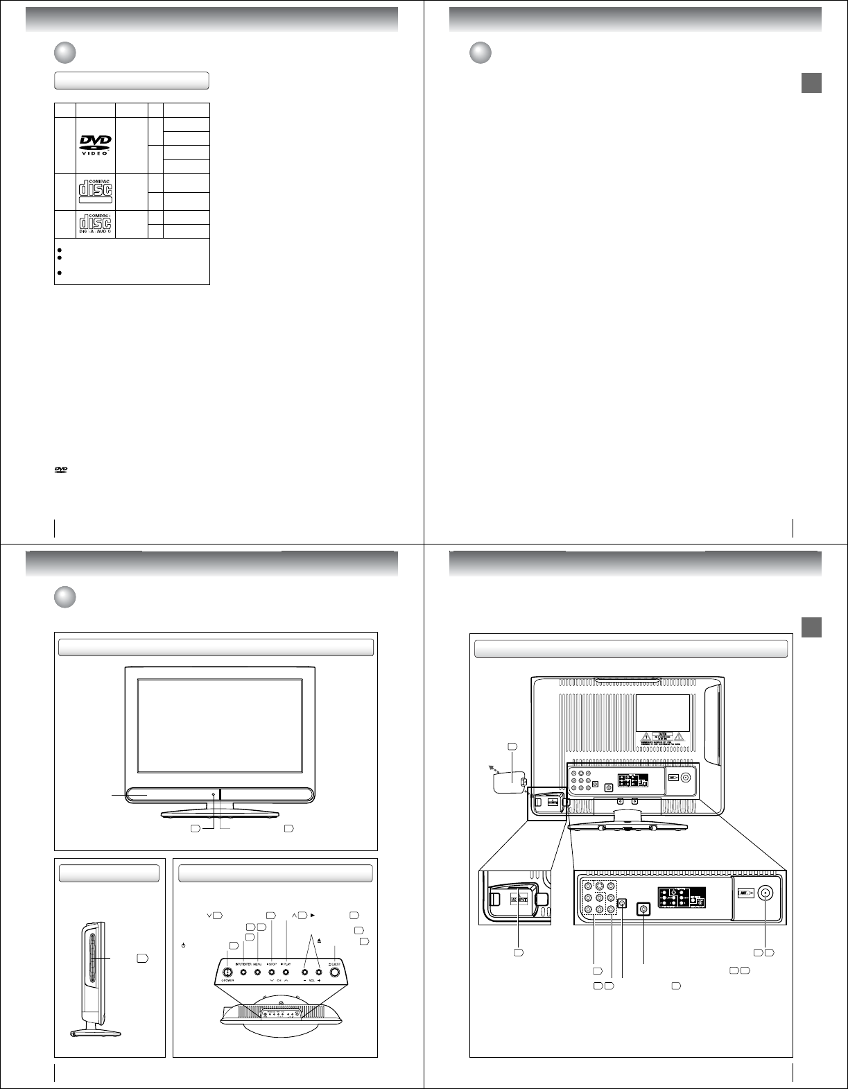
Identification of controls
Speaker
Front
Remote sensor 13
Side
Disc slot 42
EJECT button 43
CH 25 / PLAY button 42
VOLUME (+/–) buttons 25
CH 25 /QSTOP button 42
MENU button 21 57
INPUT/ENTER button 16
POWER button 20
Top
POWER indicator 20
Introduction
11
Rear
AC INPUT 19
HEAD PHONE jack 26
COLORSTREAM HD IN jacks 17
VIDEO/GAME IN jack 16 17
COAXIAL DIGITAL AUDIO OUT jack 18 19
Antenna jack 14 15
AC INPUT
cover 19
12
Introduction
SLOW ( ) button
Direction buttons ( / / / )
EJECT button
43
DISPLAY button
Numbered buttons (0
-
9)
5126
29
SUBTITLE button
50
INPUT button
16
ZOOM button
45
MENU button
21
SETUP button
57
48
PLAY MODE button
47 51
PLAY button
42
PAUSE button
43
TOP MENU button
49
RETURN button
GAME button
5753
TV/DVD button
42
25
Direct channel selection
buttons (0
-
9)
25
CH RTN button CLOSED CAPTION button
26
SKIP ( ) button
44
REV button
44
FF button
44
44
16
POWER button
JUMP button
45
25
Direct channel selection button ( )
AUDIO SELECT button
50
MUTE button
26
49
EXIT/CANCEL button
20
33
SKIP ( )button
44
STOP button
42
44
REPEAT A-B button
47
PIC SIZE button
SE-R0305
36
ENTER button
20
SLEEP button
26
*DVD MENU button
25
VOL +/– button
20
SLOW ( ) button
MARKER button
49
46
ANGLE button
CH / button
4220
Remote control
The instructions in this manual describe the function on the remote control. See the page in for details.
*DVD MENU button
Use the DVD MENU button to
display the menu included on
many DVD video discs.
To operate a menu, follow the
instructions in “DVD menu.” 49
Identification of controls (Continued)
Introduction
13
Replace the compartment
cover.
Install two “R03/AAA” batteries
(supplied), paying attention to
the polarity indicated in the
battery compartment.
Open the battery compartment
cover in the direction of the
arrow.
123
• Aim the remote control at the remote sensor and press control buttons to operate.
•
Operate the remote control within 30° angle on either side of the remote sensor, up to a distance of approx. 5 meters.
Caution:
• Never throw batteries into a fi re.
Note:
•Be sure to use AAA size batteries.
• Dispose of batteries in a designated disposal area.
•
Batteries should always be disposed of with the environment in mind. Always dispose of batteries in accordance with
applicable laws and regulations.
• If the remote control does not operate correctly, or if the operating range becomes reduced, replace batteries with
new ones.
• When necessary to replace batteries in the remote control, always replace both batteries with new ones.
Never mix battery types or use new and used batteries in combination.
•
Always remove batteries from remote control if they are dead or if the remote control is not to be used for an extended
period of time. This will prevent battery acid from leaking into the battery compartment.
Inserting batteries
Operation
Approx. 5 meters
Connections
14
75 ohm coaxial cable
(not supplied)
300-75 ohm matching
transformer (not supplied)
300-75 ohm matching
transformer (not supplied)
UHF 300 ohm
twin-lead wire
(not supplied)
VHF 300 ohm
twin-lead wire
(not supplied)
UHF 300 ohm
twin-lead wire
(not supplied)
VHF 75 ohm
(not supplied)
Antenna
jack
Antenna
jack
Antenna
jack
Combiner
(not supplied)
Antenna
jack
Combiner
(not supplied)
Connect the 75 ohm cable from the combination
VHF/UHF antenna to the antenna jack on the back
of the TV/DVD.
If your combination VHF/UHF antenna has a 300
ohm twin-lead wire, use the 300-75 ohm matching
transformer (not supplied).
Connect the UHF 300 ohm twin-lead wire to the
combiner (not supplied). Connect the VHF 300 ohm
twin-lead wire to the 300-75 ohm matching transformer
(not supplied). Attach the transformer to the combiner,
then attach the combiner to the antenna jack on the
back of the TV/DVD.
Connect the VHF 75 ohm cable and UHF 300 ohm
twin-lead wire to the combiner (not supplied).
Attach the combiner to the antenna jack on the back
of the TV/DVD.
Combination VHF/UHF antenna (Separate VHF and UHF 300 ohm twin-lead wires)
Antenna connections
If you are using an indoor or outdoor antenna, follow the instructions below that correspond to your antenna system.
If you are using a cable TV service (CABLE), see 15 for Cable TV connections.
Separate VHF/UHF antennas (75 ohm VHF cable and 300 ohm UHF twin-lead wires)
Combination VHF/UHF antenna (Single 75 ohm cable or 300 ohm twin-lead wire)
Connections
15
For basic cable service not requiring a converter/descrambler
box, connect the Cable TV 75 ohm coaxial cable directly to the
Antenna jack on the back of the TV/DVD.
75 ohm
coaxial cable
If you subscribe to a cable TV service in which basic channels are unscrambled and premium channels require
the use of a converter/descrambler box, you may wish to use a signal splitter and an A/B Switch box (available
from the cable company or an electronics supply store). Follow the connections shown below. With the switch in
the “B” position, you can directly tune any nonscrambled channels on your TV/DVD. With the switch in the “A”
position, tune your TV/DVD to the output of the converter/descrambler box (usually channel 3 or 4) and use the
converter/descrambler box to tune scrambled channels.
Incoming 75 ohm
Cable TV
75 ohm cable to
TV/DVD
Antenna
jack
Antenna
jack
Converter/
descrambler
If you subscribe to a cable TV service which requires the use of a converter/descrambler box, connect the
incoming 75 ohm coaxial cable to the converter/descrambler box. Using another 75 ohm coaxial cable, connect
the output jack of the converter/descrambler box to the antenna jack on the TV/DVD. Follow the connections
shown below. Set the TV/DVD to the output channel of the converter/descrambler box (usually channel 3 or 4)
and use the converter/descrambler box to select channels.
For subscribers to basic cable TV service
For subscribers to scrambled cable TV service
For subscribers to unscrambled basic cable TV service with scrambled
premium channels
Splitter B
A
Incoming
75 ohm
Cable TV A/B switch
75 ohm cable
to TV/DVD
Converter/
descrambler Antenna
jack
Cable TV connections
This TV/DVD has an extended tuning range and can tune most cable channels without using a Cable TV converter box.
Some cable companies offer “premium pay channels” in which the signal is scrambled. Descrambling these signals for
normal viewing requires the use of a descrambler device which is generally provided by the cable company.
Connections
16
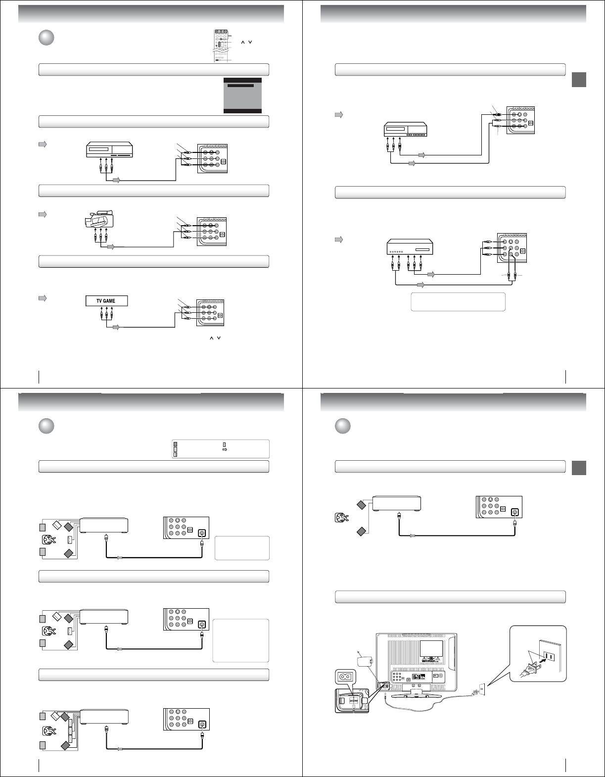
To playback from the VCR, connect the VCR to the TV/DVD as shown.
Select the “Video” by pressing INPUT repeatedly.
You can enjoy playing a TV game on the screen by adjusting to the suitable brightness for your eyes.
1. Connect a TV Game to the TV/DVD.
2. Select the Game mode by pressing GAME. The Game mode screen appears.
• If GAME is pressed during standby mode, the unit turns on automatically and the Game mode screen
appears on the screen.
Camcorder
To Audio/Video OUT
Audio/Video cable (not supplied)
Audio/Video cable (not supplied)
To Audio/Video OUT
INPUT
Connecting to a VCR
Connecting to a TV Game
Connecting to optional equipment
You can enjoy VCR, camcorder or TV game with connection to external input.
Note:
• You can also change the TV/DVD screen to the desired mode by pressing the CH / .
• The TV/DVD can also be used as a display device for many video games. However, due to the wide variety of
different types of signal generated by these devices and subsequent hook-up variations required, they have not all
been included in the suggested connection diagrams. You·ll need to consult each component·s Owner·s Manual
for additional information.
• Interactive video games that involve shooting a “gun” type of joystick at on-screen target may not work on this
TV/DVD.
: Signal fl ow
: Signal fl ow
: Signal fl ow
Using the audio/video inputs
Press INPUT to view a signal from another device connected to your TV/DVD, such
as a VCR player. You can select TV, Video or ColorStream HD depending on which
input jacks you used to connect your devices.
Press INPUT on the remote control to display the current signal source.
To change the input source, press INPUT again or press 0-2. (3is for selection DVD
mode.)
To Audio/Video OUT
(yellow)
(red)
(white)
Audio/Video cable (not supplied)
VCR
To VIDEO/GAME IN
To playback from the camcorder, connect the camcorder to the TV/DVD as shown.
Select the “Video” by pressing INPUT repeatedly.
Connecting to a camcorder
Back side
GAME
0-3
CH /
Source Selection
1.Video
2.ColorStream HD
3.DVD
[0-3]:Select
0.TV
Back side
(yellow)
(red)
(white)
Back side
(yellow)
(red)
(white)
To VIDEO/GAME IN
To VIDEO/GAME IN
Connections
17
If you connect a VCR with an S-Video cable to the S-VIDEO IN jack on the left side of the TV/DVD, you must
also connect the audio cables to the AUDIO IN jacks as shown below. The S-Video cable only carries the video
signal. The audio signal is separated.
Select the “Video” by pressing INPUT repeatedly.
Note:
When the S-Video cable and the standard video cable are connected at the same time, the S-video cable takes
precedence.
•
Connecting to an optional equipment with S-video output
Ex. VCR with S-Video
To S-VIDEO OUT
To Audio (L/R) OUT
To S-VIDEO IN
Audio cable (not supplied)
S-Video cable (not supplied)
Connecting an optional equipment with ColorStream
®
(Component video) output
Your TV/DVD is capable of using ColorStream® (component video). Connecting your TV/DVD to a component
video compatible DVD player, such as a Toshiba DVD player with ColorStream® can greatly enhance picture
quality and performance.
Select the “ColorStream HD” by pressing INPUT repeatedly.
Ex. DVD player with Component video
Audio cable (not supplied)
Component video cable
(not supplied)
To Audio (L/R) OUT To Component Video OUT
To COLORSTREAM HD
AUDIO (L/R) IN
To COLORSTREAM HD
(Y, PB, PR) IN
When using the Component video cable,
an Audio cable must be connected to
COLORSTREAM HD AUDIO(L/R) IN jacks.
Note:
• The ColorStream® (component video) inputs on this unit are for use with devices that output 480i, 1080i inter-
laced signals and 480p, 720p progressive signals.
• Refer to the owner·s manual of the connected equipment as well.
• When you connect the unit to other equipment, be sure to turn off the power and unplug all of the equipment
from the wall outlet before making any connections.
• If you place the unit near a tuner or radio, the radio broadcast sound might be distorted. In this case, place the
unit away from the tuner and radio.
: Signal fl ow
: Signal fl ow
(playback)
(red)
(white)
To AUDIO (L/R) IN
Back side
Back side
(red)
(white)
To VIDEO/GAME IN
Connections
18
Dolby Digital
Dolby Digital is the surround sound technology used in theaters showing the latest movies, and is now available to reproduce
this realistic effect in the home. You can enjoy motion picture and live concert DVD video discs encoded via the Dolby Digital
recording system with this dynamic realistic sound by connecting the TV/DVD to a 6 channel amplifi er equipped with a Dolby
Digital decoder or Dolby Digital processor. If you have a Dolby Surround Pro Logic decoder, you will obtain the full benefi t of
Pro Logic from the same DVD movies that provide full 5.1-channel Dolby Digital soundtracks, as well as from titles with the
Dolby Surround mark.
Connecting to an amplifi er equipped with a Dolby® Digital decoder
Manufactured under license
from Dolby Laboratories.
Dolby and the double-D symbol
are trademarks of Dolby
Laboratories.
Amplifi er equipped with a
Dolby Digital decoder
To COAXIAL
type digital
audio input
Connecting to an amplifi er equipped with a DTS® decoder
Digital Theater Systems (DTS)
DTS is a high quality surround technology used in theaters and now available for home use, on DVD video discs or audio CDs.
If you have a DTS decoder or processor, you can obtain the full benefi t of 5.1 channel DTS encoded sound tracks on DVD
video discs or audio CDs.
Manufactured under license
under U.S. Patent #: 5,451,942 &
other U.S. and worldwide
patents issued & pending. DTS
and DTS Digital Out are
registered trademarks and the
DTS logos and Symbol are
trademarks of DTS, Inc.
© 1996-2007 DTS, Inc. All Rights
Reserved.
Amplifi er equipped with
a DTS decoder
To COAXIAL
type digital
audio input
75 Ω coaxial cable (not supplied)
75 Ω coaxial cable (not supplied)
Back side
To COAXIAL DIGITAL
AUDIO OUT
: Front speaker
: Rear speaker
: Sub woofer
: Center speaker
: Signal fl ow
*This section uses the following reference mark.
MPEG2 sound
You can enjoy motion picture and live concert DVD video discs encoded via the MPEG2 recording system with dynamic
realistic sound by connecting an amplifi er equipped with an MPEG2 audio decoder or MPEG2 audio processor.
Connecting to an amplifi er equipped with an MPEG audio decoder
Amplifi er equipped with an
MPEG2 audio decoder
To COAXIAL
type digital
audio input
75 Ω coaxial cable (not supplied)
Connecting to optional equipment (Continued)
You can enjoy high quality dynamic sounds by connecting the
TV/DVD to optional audio equipment.
Back side
To COAXIAL DIGITAL
AUDIO OUT
Back side
To COAXIAL DIGITAL
AUDIO OUT
Connections
19
Amplifi er equipped with a
Digital audio input
To COAXIAL
type digital
audio input
75 Ω coaxial cable (not supplied)
Connecting to an amplifi er equipped with a digital audio input
2 channel digital stereo
You can enjoy the dynamic sound of 2 channel digital stereo by connecting an amplifi er equipped with a digital audio input and speaker
system (right and left front speakers).
Note: PCM audio is limited to DVD or CD playback.
Note:
• DO NOT connect the COAXIAL DIGITAL AUDIO OUT jack of the TV/DVD to the AC-3 RF input of a Dolby Digital Receiver.
This input on your A/V Receiver is reserved for Laserdisc use only and is incompatible with the COAXIAL DIGITAL AUDIO OUT jack
of the TV/DVD.
• Connect the COAXIAL DIGITAL AUDIO OUT jack of the TV/DVD to the “COAXIAL” input of a Receiver or Processor.
• Refer to the owner·s manual of the connected equipment as well.
• When you connect the TV/DVD to other equipment, be sure to turn off the power and unplug all of the equipment from the wall outlet
before making any connections.
•
The output sound of the TV/DVD has a wide dynamic range. Be sure to adjust the receiver·s volume to a moderate listening level.
Otherwise, the speakers and your hearing may be damaged by a sudden high volume sound.
• Turn off the amplifi er before you connect or disconnect the TV/DVD·s power cord. If you leave the amplifi er·s power on, the speakers
may be damaged.
Back side
To COAXIAL DIGITAL
AUDIO OUT
Connecting to optional equipment (Continued)/
Power source
Power source
Note:
Never connect the AC line cord plug to other than the specified voltage (120V 60Hz). Use the attached power cord only.
If the polarized AC cord does not fit into a non-polarized AC outlet, do not attempt to file or cut the blade. It is the user’s
responsibility to have an electrician replace the obsolete outlet.
If you cause a static discharge when touching the unit and the unit fails to function, simply unplug the unit from the AC outlet
and plug it back in. The unit should return to normal operation.
If the AC cord plug is plugged in for the first time, wait for approx. 5 seconds before pressing POWER.
•
•
•
•
To use AC power source
Open the AC INPUT cover.
Connect the AC cord plug into this TV/DVD’s AC INPUT jack, then close the AC INPUT cover.
Connect the AC cord into an AC outlet.
1.
2.
3.
AC cord (supplied)
AC 120V, 60Hz
Wider Hole
and Blade
AC Outlet
20
Basic setup
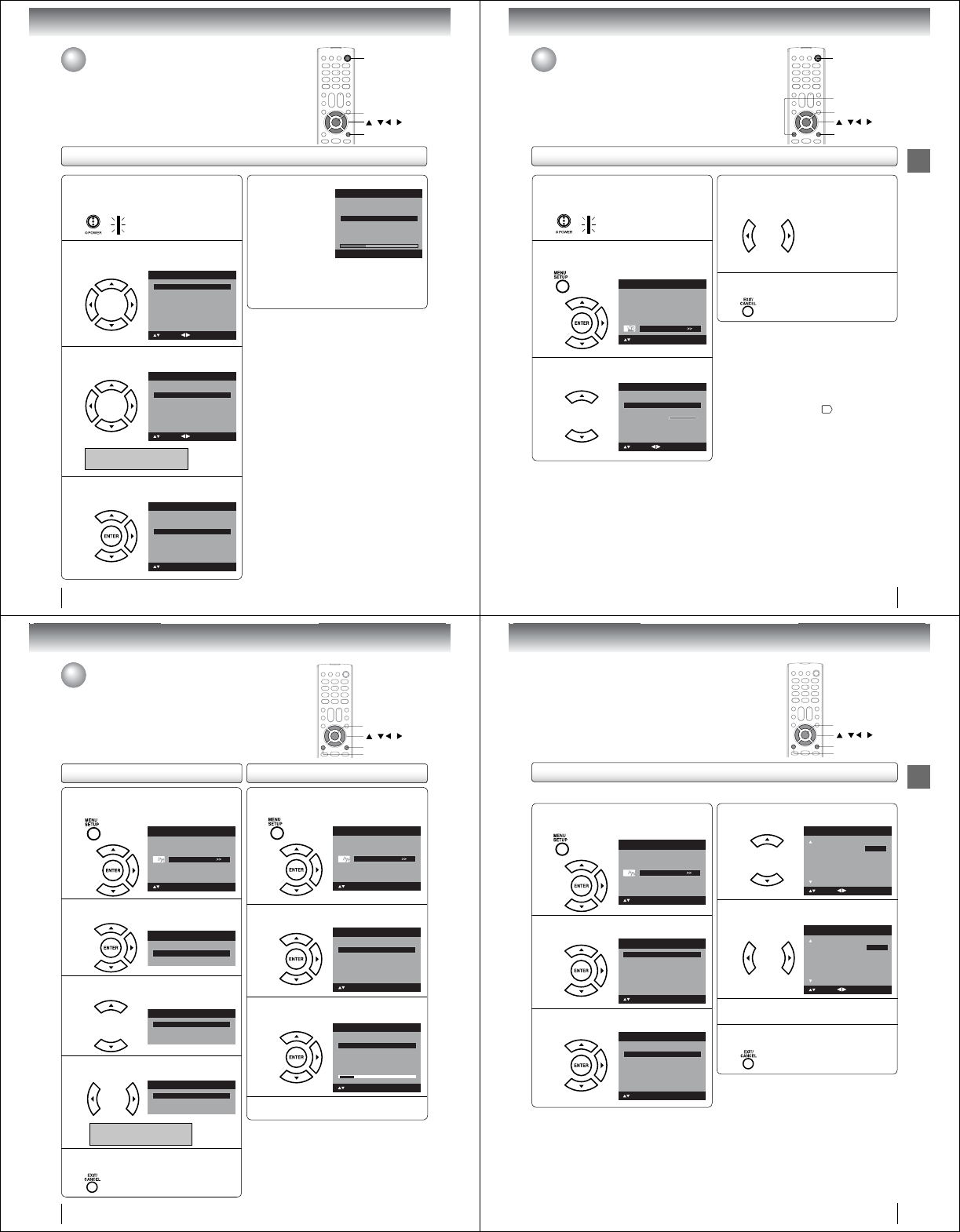
Auto Setup
Auto Setup
The Auto Setup function helps to install your TV/DVD easily.
It leads you the Language selection, Air/Cable selection and Automatic
channel search.
IMPORTANT: Make sure that the antenna or cable TV system
connection is made!
POWER
EXIT/CANCEL
/ / /
ENTER
1To turn on the TV/DVD, press POWER.
POWER indicator on the front of the unit
changes blue. It may take approx. 10 seconds
for a picture to appear on screen.
•
2Auto Setup menu appears on the screen.
Press ϳ or ϴ to select “Language”, then
press ϵ or ϶ to select your desired language.
Automatic Search
Auto Setup
Language
Signal Type Cable
Start
English
: Adjust
: Select
3Press ϳ or ϴ to select “Signal Type”, then
press ϵ or ϶ to select “Air” or “Cable”.
Automatic Search
Auto Setup
Language
Signal Type Cable
Start
English
: Adjust
: Select
Air - VHF/UHF channels
Cable
- Cable TV channels
4Press ϳ or ϴto select “Automatic Search”,
then press ϶ or ENTER.
Auto Setup
Language
Signal Type Cable
Start
English
: Select
Automatic Search
ENTER:Set
5Now the “Automatic Search” starts.
Auto Setup
Language
Signal Type Cable
Start
Digtal Channel Found :
Analog Channel Found : 0
0
English
EXIT : End
Automatic Search
If you press EXIT/CANCEL, the Automatic
Search stops and changes to the TV screen.
After the starting setup is completed, the TV
channel appears on the screen.
•
•
Note:
The Auto Setup function will work only when you
press POWER for the first time.
The process of “Automatic Search” may take 15 to
30 minutes to complete, depending on your regional
cable service.
•
•
21
Basic setup
Setting the language
Setting the language
This TV/DVD can display the on screen language in English, French or
Spanish.
Select the language you prefer fi rst, then proceed with the other menu options.
EXIT/CANCEL
1To turn on the TV/DVD, press POWER.
POWER indicator on the front of the unit
changes blue. It may take approx. 10 seconds
for a picture to appear on screen.
•
2Press MENU. The TV menu screen will
appear. Press ϳ or ϴ to select “Setup”, then
press ϶ or ENTER.
Picture
Audio
Channel
Lock
Setup
Main Menu
: Select ENTER:Set
3Press ϳ or ϴ to select “Language”.
Video Label >>
Backlight
Auto Shut Off Off
On
Aspect
Reset>>
16
Setup
Closed Caption >>
Language English
: Adjust
: Select
4Press ϵ or ϶ to select the desired language:
English, French (Français) or Spanish
(Español).
5Press EXIT/CANCEL to return to the normal
screen.
Note:
If the unit does not operate properly, or No key
operation (by the unit and/or the remote control):
Static electricity, etc., may affect the TV/DVD’s
operation. In such case, disconnect the AC cord once,
then connect it again.
If no buttons are pressed for more than about 60
seconds, the MENU screen will return to normal
operation automatically.
The TV section has its own menu and the DVD
section also has its own menu 57 .
•
•
•
MENU
/ / /
ENTER
POWER
22
Basic setup
1Press MENU in the TV mode. The TV menu
screen will appear. Press ϳ or ϴ to select
“Channel”, then press ϶ or ENTER.
Picture
Audio
Channel
Lock
Setup
Main Menu
: Select ENTER:Set
2Press ϳ or ϴ to select “Auto Ch Memory”,
then press ϶ or ENTER.
Ch Label >>
Channel
Add/Delete>>
>>
Auto Ch Memory
3Press ϳ or ϴ to select “Signal Type”.
Automatic Search Start
Auto Ch Memory
Signal Type Cable
4Press ϵ or ϶ to select “Air” or “Cable”.
Automatic Search Start
Auto Ch Memory
Signal Type Air
Air - VHF/UHF channels
Cable
- Cable TV channels
5Press EXIT/CANCEL to return to the normal
screen.
/ / /
To memorize channels
This TV/DVD is equipped with a channel memory feature which allows
channels to skip up or down to the next channel set into memory, skipping
over unwanted channels. Before selecting channels, they must be
programmed into the TV/DVD·s memory. To use this TV/DVD with an antenna,
set the Signal Type option to the Air mode. When shipped from the factory, this
menu option is in the Cable mode.
Air/Cable selection
MENU
EXIT/CANCEL
ENTER
1Press MENU in the TV mode. The TV menu
screen will appear. Press ϳ or ϴ to select
“Channel”, then press ϶ or ENTER.
Picture
Audio
Channel
Lock
Setup
Main Menu
: Select ENTER:Set
2Press ϳ or ϴ to select “Auto Ch Memory”,
then press ϶ or ENTER.
: Select ENTER:Set
Ch Label >>
Channel
Add/Delete>>
>>
Auto Ch Memory
3Press ϳ or ϴ to select “Automatic Search”,
then press ϶ or ENTER.
Auto Ch Memory
Signal Type Cable
Digital Channel Found : 0
Analog Channel Found : 0
: Select ENTER:Cancel
Automatic Search Stop
4The TV/DVD will begin memorizing all the
channels available in your area.
Automatic search
23
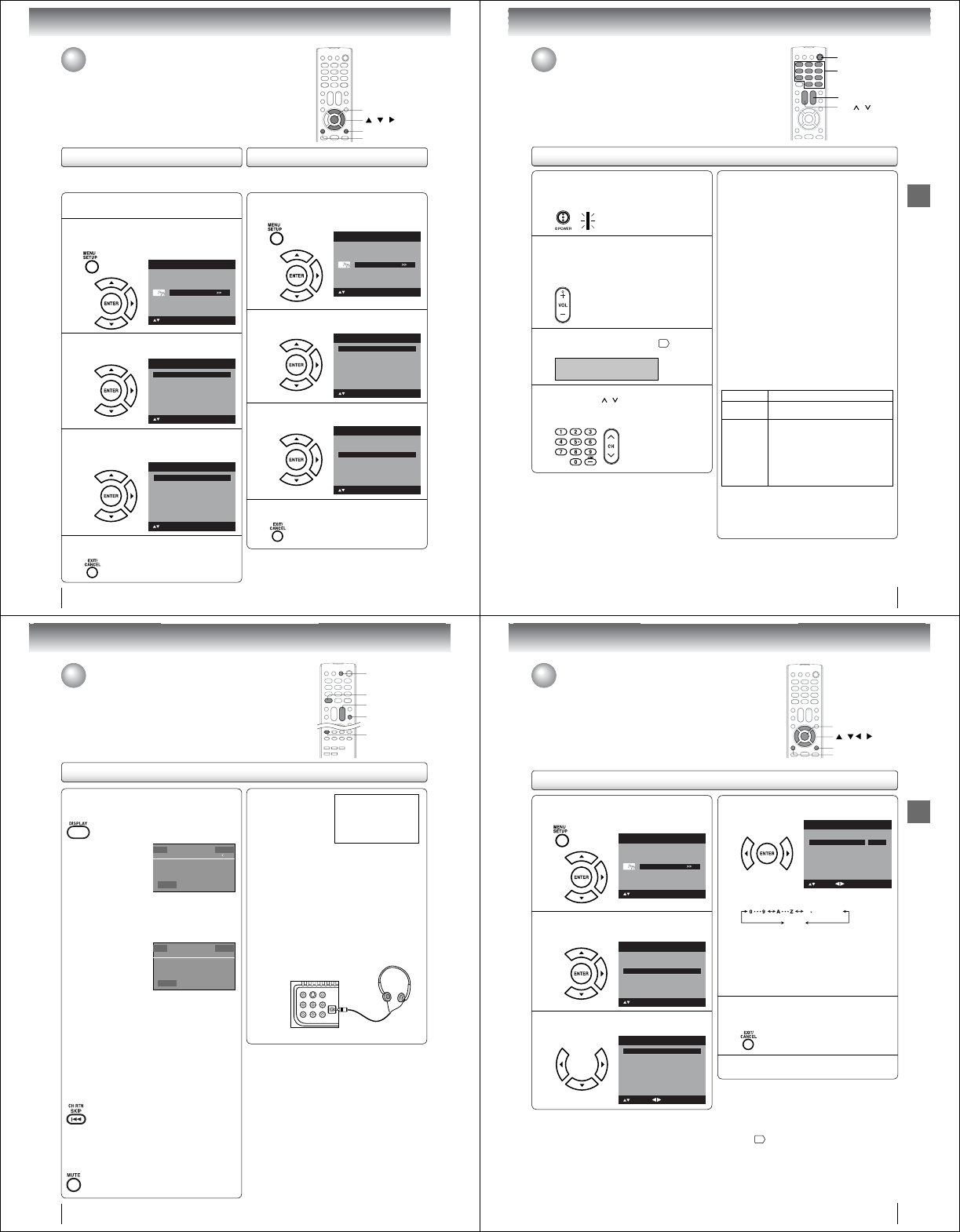
Basic setup
Add/Delete channel
You can select the channel that you want to skip.
1Press MENU in the TV mode. The TV menu
screen will appear. Press ϳ or ϴ to select
“Channel”, then press ϶ or ENTER.
Picture
Audio
Channel
Lock
Setup
Main Menu
: Select ENTER:Set
2Press ϳ or ϴ to select “Add/Delete”, then
press ϶ or ENTER.
: Select ENTER:Set
Ch Label >>
Channel
Add/Delete>>
>>
Auto Ch Memory
3Press ϳ or ϴ to select “Add/Delete”, then
press ϶ or ENTER.
Clear All >>
Add/Delete
Adding Channel >>
: Select ENTER:Set
Add/Delete>>
/ / /
MENU
EXIT/CANCEL
ENTER
4Press ϳ or ϴ to select the channel that you
want to skip.
CH Signal
2Analog
3Analog Add
3-001 Digital Delete
3-002 DigitalAdd
4Analog Delete
Add/Delete
: Adjust
Add
: Select
5Press ϵ or ϶ to select “Add” or “Delete”,
whichever function you want to perform.
CH Signal
2Analog
3Analog Add
3-001 Digital Delete
3-002 DigitalAdd
4Analog Delete
Add/Delete
: Adjust
Delete
: Select
6Repeat steps 4 - 5 for other channels you
want to add or delete.
7Press EXIT/CANCEL to return to the normal
screen.
24
Basic setup
If you find a new channel unregistered, you can add the
new channel into the channel memory.
1Tune in the new channel.
2Press MENU. The TV menu screen will appear.
Press ϳ or ϴ to select “Channel”, then press
϶ or ENTER.
Picture
Audio
Channel
Lock
Setup
Main Menu
: Select ENTER:Set
3Press ϳ or ϴ to select “Add/Delete”, then
press ϶ or ENTER.
: Select ENTER:Set
Ch Label >>
Channel
Add/Delete>>
>>
Auto Ch Memory
4Press ϳ or ϴ to select “Adding Channel”,
then press ϶ or ENTER. The new channel will
be added into the channel memory.
Add/Delete>>
Clear All >>
Add/Delete
Adding Channel >>
: Select ENTER:Set
5Press EXIT/CANCEL to return to the normal
screen.
Adding Channel
/ /
MENU
EXIT/CANCEL
ENTER
All channels are deleted from the channel memory.
1Press MENU in the TV mode. The TV menu
screen will appear. Press ϳ or ϴ to select
“Channel”, then press ϶ or ENTER.
Picture
Audio
Channel
Lock
Setup
Main Menu
: Select ENTER:Set
2Press ϳ or ϴ to select “Add/Delete”, then
press ϶ or ENTER.
: Select ENTER:Set
Ch Label >>
Channel
Add/Delete>>
>>
Auto Ch Memory
3Press ϳ or ϴ to select “Clear All”, then press
϶ or ENTER.
Add/Delete>>
Add/Delete
Adding Channel >>
: Select ENTER:Set
Clear All >>
4Press EXIT/CANCEL to return to the normal
screen.
Clear All
To memorize channels (Continued)
25
TV operation
1To turn on the TV/DVD, press POWER.
(POWER indicator on the front of the unit changes
blue. It may take approx. 10 seconds for a picture
to appear on screen.)
2Adjust the volume level by pressing VOL + or – .
The volume level will be indicated on the screen
by orange bars. As the volume level increases, so
do the number of bars. If the volume decreases,
the number of orange bars also decreases.
3Set the Signal Type option to the appropriate
position (see “Air/Cable selection” 22 ).
Air - VHF/UHF channels
Cable
- Cable TV channels
4Press the Direct Channel Selection (0-9, –)
buttons or CH / to select the channel.
(If you press only channel number, channel
selection will be delayed for a few seconds.)
TV operation
TV operation
POWER
TV operation
0–9, –
VOL +/–
CH /
TO SELECT ANALOG CHANNELS
1-9: Press 1-9 as needed. Example, to
select channel 2, press 2.
10-99: Press the 2 digits in order. Example, to
select channel 12, press 1,2.
100-125: Press the 3 digits in order. Example, to
select channel 120, press 1,2,0.
TO SELECT DIGITAL CHANNELS
Press the first 3 digits, then press the –button,
followed by the remaining number.
Example, to select channel 015-001, press 0, 1,
5, –, 0, 0, 1.
If a channel is selected with only audio content,
“Audio only” will be displayed on the screen.
If a channel is selected with a weak digital
signal, “Digital channel signal strength is low”
will be displayed on the screen.
The same program may be available on either
an analog channel or a digital channel. You may
choose to watch either format.
If a channel is selected to which you have not
subscribed,
“Digital channel is encrypted” will
be displayed on the screen.
•
•
•
VHF/UHF/CABLE CHANNELS
AirCable
VHF
2-13
VHF
2-13
UHF
14-69
STD/HRC/IRC
14-36 (A) (W)
37-59 (AA) (WW)
60-85 (AAA) (ZZZ)
86-94 (86) (94)
95-99 (A-5) (A-1)
100-125 (100) (125)
01 (5A)
Note:
If a channel with no broadcast is selected, the sound
will automatically be muted.
It may take a few seconds for a digital channel picture
to appear on screen after being selected.
•
•
26
TV operation
Ϯ DISPLAY
Press DISPLAY to display the current information on the
screen.
When the TV/DVD
receives a digital signal,
the digital information
will appear.
62-001 HDTV Moving Picture1
CH-1
Digital Air
No Program Information is available
Sleep Timer
Off
English
Natural
1080i
Channel number • Station name
Channel label (if preset) •
Broadcast program name
V-Chip rating • Signal type
Sleep timer • Audio language
Program guide • Picture size
Resolution
•
•
•
•
•
•
When the TV/DVD
receives a analog signal,
the analog information
will appear.
14
Analog Cable
Sleep Timer
Off
Natural
480i
Channel number • Channel label (if preset)
V-Chip rating • Signal type
Sleep timer •
Audio information (Stereo or SAP)
Picture size • Resolution
Press DISPLAY again to clear the call display.
•
•
•
•
Note:
After a few seconds, DISPLAY screen will return to
normal TV-operation automatically.
•
Ϯ CH RTN
This button allows you to go back to the last channel
selected by pressing CH RTN. Press CH RTN again to
return to the last channel you were watching.
Ϯ MUTE
Press MUTE to switch off the sound. The TV/DVD’s
sound will be silenced and “Mute” will appear on the
screen. The sound can be switched back on by pressing
this button again or the VOL + or –.
TV operation (continued)
Ϯ SLEEP
To set the TV/DVD to
turn off after a preset
amount of time, press
SLEEP on the remote
control. The clock will
count up 10 minutes for
Sleep Timer
0h 10m
each press of the SLEEP button (Off, 0h 10m, 0h 20m,
..., 2h 0m). After the sleep time is programmed, the
display will appear briefly every ten minutes to remind
you that the sleep timer is operating. To confirm the
sleep timer setting, press SLEEP and the remaining
time will be displayed for a few seconds. To cancel the
sleep timer, press SLEEP repeatedly until the display
turns to Off.
ϮHEAD PHONES
Insert a stereo headphones (not supplied) with a 1/8” mini
plug into the HEAD PHONE jack on the rear panel.
If you connect headphones, the sound from TV/DVD
speakers is muted.
DISPLAY
CH RTN
VOL +/–
SLEEP
MUTE
TV operation (Continued)
27
TV operation
Labeling channels
1Press MENU in the TV mode. The TV menu
screen will appear. Press ϳ or ϴ to select
“Channel” menu, then press ϶ or ENTER.
Picture
Audio
Channel
Lock
Setup
Main Menu
: Select ENTER:Set
2Press ϳ or ϴ to select “Ch Label”, then
press ϶ or ENTER.
The “Ch Label” menu will appear.
: Select ENTER:Set
Channel
Add/Delete>>
>>
Ch Label >>
Auto Ch Memory
3Press ϵ or ϶ to select a channel you want to
label, then press ϴ.
Ch Label
Label Clear>>
: Adjust
Ch Label
Channel Number 15-1
: Select
4Press ϵ or ϶ repeatedly until the character
you want appears in the first space.
Label Clear>>
: Adjust
Ch Label
Channel Number 15-1
: Select
Ch Label A
ENTER:Set
The characters rotation as follows:
SPACE
-
, () @ / + =
-
If the character which you desire appears, press
ENTER.
Repeat this step to enter the rest of the
characters.
If you would like a blank space in the label name,
you must choose the empty space from the list of
characters.
5When you finish inputting the label name,
press EXIT/CANCEL to return to the normal
screen.
6Repeat steps 3-5 for other channel. You can
assign a label to each channel.
To clear a Ch Label
After step 3 above, press ϳ or ϴ to select “Label Clear”,
then press ϶ or ENTER.
Note:
The channel labels will be reset after “Automatic
Search” 22 .
•
Labeling channels
Channel label appear with the channel number display each time you turn on the
TV/DVD, select a channel, or press DISPLAY.
You can choose any four characters to identify a channel.
/ / /
MENU
EXIT/CANCEL
ENTER
TV operation
28
Labeling video inputs
The Video Label feature allows you to label each input source for your TV/DVD.
/ / /
MENU
EXIT/CANCEL
ENTER
Labeling video inputs
1Press MENU in the TV mode. The TV menu
screen will appear. Press ϳ or ϴ to select
“Setup”, then press ϶ or ENTER.
Picture
Audio
Channel
Lock
Setup
Main Menu
: Select ENTER:Set
2Press ϳ or ϴ to select “Video Label”, then
press ϶ or ENTER.
Video Label >>
Backlight
Auto Shut Off Off
On
Aspect
Reset>>
16
Setup
Closed Caption >>
Language English
: Select ENTER:Set
3Press ϳ or ϴ to select an input which you
want to label.
ColorStream HD -
Video Label
: Adjust
: Select
Video -
4Press ϵ or ϶ to select the desired label for
that input source.
Video Label
: Adjust
ColorStream HD SAT
: Select
Video -
– : Uses the default label name
VCR : Video cassette recorder
DVD : DVD video
DTV : Digital TV set-top box
SAT : Satellite box
CBL : Cable box
5Press EXIT/CANCEL to return to the normal
screen.
TV operation
29
Setting the V-Chip
An age limitation can be set to restrict children from viewing or hearing
violent scenes or pictures that you may choose to exclude. The restriction
applies to “TV Rating” and “Movie Rating” if this data is transmitted. You may
set this restriction separately. To use the V-Chip function, you must register
a password.
0–9
/ /
MENU
ENTER
To register a password
1Press MENU in the TV mode. The TV menu
screen will appear. Press ϳ or ϴ to select
“Lock”, then press ϶ or ENTER.
Picture
Audio
Channel
Lock
Setup
Main Menu
: Select ENTER:Set
2Select and enter your password (4 digits)
using Number buttons (0-9), then press
ENTER.
[0-9]
Lock
: Select ENTER:Set
New Password
----
3Enter the same password again to confirm,
then press ENTER.
The password is now registered.
[0-9]
Lock
: Select ENTER:Set
Confirm Password
----
1Press MENU in the TV mode. The TV menu
screen will appear. Press ϳ or ϴ to select
“Lock”, then press ϶ or ENTER.
Picture
Audio
Channel
Lock
Setup
Main Menu
: Select ENTER:Set
2Press ϳ or ϴ to select “Change Password”,
then press ϶ or ENTER.
The Change Password screen will appear.
V-Chip Set>>
Lock
V-Chip Off
: Select ENTER: Set
V-Chip Set (DTV) >>
Update>>
Change Password >>
3Enter a new password using Number buttons
(0-9), then press ENTER.
[0-9]
Change Password
Confirm Password
: Select ENTER:Set
New Password
----
----
4Enter the same password again to confirm,
then press ENTER.
The new password is now registered.
To change a password
Notes:
If you forget the password, press DISPLAY four times within
fi ve seconds while the TV is in password entering mode. This
allows you to reset your password.
Note:
The V-Chip feature is available only for the U.S. V-Chip
system. The Canadian V-Chip system is not supported.
•
DISPLAY
TV operation
Setting the V-Chip (Continued)
30
To set the V-Chip
1Press MENU in the TV mode. The TV menu
screen will appear. Press ϳ or ϴ to select
“Lock”, then press ϶ or ENTER.
Picture
Audio
Channel
Lock
Setup
Main Menu
: Select ENTER:Set
2Use Number buttons (0-9) to enter your pass-
word, then press ENTER. Then Lock menu will
appear.
[0-9]
Lock
: Select ENTER:Set
Password
----
3Press ϳ or ϴ to select “V-Chip”, then press
ϵ or ϶ to select “On” .
V-Chip Set>>
Lock
V-Chip On
: Select
V-Chip Set (DTV) >>
Update>>
Change Password >>
: Adjust
4Press ϳ or ϴ to select “V-Chip Set”, then
press ϶ or ENTER.
The V-Chip Set Menu appears.
Lock
V-Chip On
: Select ENTER: Set
V-Chip Set (DTV) >>
Update>>
Change Password >>
V-Chip Set>>
5Press ϳ or ϴ to select which rating will be
used, then press ϶ or ENTER. Each rating
below will appear.
V-Chip Set
TV Rating >>
: Select ENTER: Set
Movie Rating >>
TV Rating
ALL D L S V FV
TV-Y
TV-Y7
TV-G
TV-PG
TV-14
TV-MA
ENTER:Set
TV Rating
: Select
You can set the rating using age level and genre.
Age:
TV-Y : All children
TV-Y7 : 7 years old and above
TV-G : General audience
TV-PG : Parental guidance
TV-14 : 14 years old and above
TV-MA : 17 years old and above
Genre:
ALL : All
D: Dialogue
L: Language
S: Sex
V: Violence
FV : Fantasy Violence
0–9
/ / /
MENU
ENTER
TV operation
TV operation
31
Movie Rating
G
PG
PG-13
R
NC-17
X
ENTER:Set
Movie Rating
: Select
G: All ages
PG : Parental guidance
PG-13: Parental guidance less than 13 years old
R: Under 17 years old parental guidance
suggested
NC-17 : 17 years old and above
X: Adult only
6Press ϳ or ϴ to select the desired rating, then
press ENTER.
7Press EXIT/CANCEL to return to the normal
screen.
To use the TV/DVD after it is protected.
When a program is received that is blocked by the V-
Chip, press MUTE, then enter your password.
The protection will be temporarily overridden. If the TV/
DVD is turned off or the channel is changed, the V-Chip
restriction will be reactivated.
Note:
The V-Chip function is activated only on programs and
input sources that include a rating signal.
•
EXIT/CANCEL
/
ENTER
MUTE
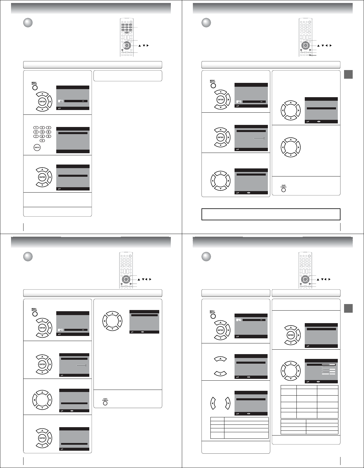
TV operation
Setting the V-Chip (Continued)
32
1Press MENU in the TV mode. The TV menu
screen will appear. Press ϳ or ϴ to select
“Lock”, then press ϶ or ENTER.
Picture
Audio
Channel
Lock
Setup
Main Menu
: Select ENTER:Set
2Use Number buttons (0-9) to enter your pass-
word, then press ENTER. Then Lock menu will
appear.
[0-9]
Lock
: Select ENTER:Set
Password
----
3Press ϳ or ϴ to select “V-Chip Set (DTV)”,
then press ϶ or ENTER.
V-Chip Set>>
Lock
V-Chip On
: Select
V-Chip Set (DTV) >>
Update>>
Change Password >>
ENTER:Set
4If the TV/DVD is not storing the additional
rating system, the TV/DVD will begin down-
loading it, which may take some time to be
completed.
5Set your preferred content rating limits for the
additional rating system.
6You also need “Update” procedure to update
rating information.
Note:
You can only download the additional V-Chip rating
system when your TV/DVD is receiving a digital signal.
When you download the additional rating system, it
may take some time for the download to occur.
The V-Chip rating information and system are not
determined or controlled by the TV/DVD.
The standard V-Chip rating system is available
whether your TV/DVD is receiving a digital signal or
not, and will block both analog and digital programs.
To set the restriction level using the standard V-Chip
rating system, select “V-Chip Set” in step 3.
The downloadable V-Chip rating system is an evolving
technology, and availability, content, and format may
vary.
You cannot select this feature if the TV/DVD is not
receiving a digital signal for the current station.
•
•
•
•
•
•
To download the additional V-Chip rating system (when available)
As a supplement to the standard V-Chip rating system, your television will
be able to download an additional rating system, if such a system becomes
available in the future.
0–9
/ /
MENU
ENTER
TV operation
Setting the closed captions
WHAT IS CLOSED CAPTIONING?
This television has the capability to decode and display closed captioned
television programs. Closed captioning will display text on the screen for
hearing impaired viewers or it will translate and display text in another
language.
33
Setting the closed captions
1Press MENU in the TV mode. Press ϳ or ϴ to
select “Setup”, then press ϶ or ENTER.
Picture
Audio
Channel
Lock
Setup
Main Menu
: Select ENTER:Set
2Press ϳ or ϴ to select “Closed Caption”,
then press ϶ or ENTER.
The Closed Caption menu will appear.
Video Label >>
Backlight
Auto Shut Off Off
On
Aspect
Reset>>
16
Setup
Closed Caption >>
Language English
: Select ENTER:Set
3Press ϳ or ϴ to select “CC Setting”, then
press ϵ or ϶ to select “On”.
On: Captions will be displayed on the screen.
Off: Captions will not be displayed on the screen.
CC Priority
Closed Caption
CC Setting Off
Digital CC
C1
CS1
Default
: Select
Analog Caption
Digital Caption
Digital CC Preset
CC Advanced >>
: Adjust
4Press ϳ or ϴ to select “Analog Caption” or
“Digital Caption”, then press ϵ or ϶ to select
the desired Closed Caption mode.
When you select “Analog Caption”, you can
choose C1, C2, C3, C4, T1, T2, T3 and T4.
When you select “Digital Caption”, you can
choose from CS1, CS2, CS3, CS4, CS5 and CS6.
CC Priority
Closed Caption
CC Setting On
Digital CC
C1
CS1
Default
: Select
Analog Caption
Digital Caption
Digital CC Preset
CC Advanced >>
: Adjust
5Press ϳ or ϴ to select “CC Priority”, then
press ϵ or ϶ to select “Digital CC” or “Analog
CC”.
Note:
Depending on the broadcast signal, some
Analog Captions will function with a Digital
broadcast signal. This step prevent that two kind
of captions are overlapping.
•
6Press EXIT/CANCEL to return to the normal
screen.
/ / /
MENU
EXIT/CANCEL
ENTER
Important Note:
If text is not available in your viewing area, a black rectangle may appear on-screen. If this happens, set
“CC Setting” to “Off”.
Note:
You can also display the Closed Caption menu screen by pressing CLOSED CAPTION on the remote control.
Digital caption feature is not available for analog channel.
•
•
CLOSED CAPTION
TV operation
CC advanced
1Press MENU in the TV mode. Press ϳ or ϴ to
select “Setup”, then press ϶ or ENTER.
Picture
Audio
Channel
Lock
Setup
Main Menu
: Select ENTER:Set
2Press ϳ or ϴ to select “Closed Caption”,
then press ϶ or ENTER.
The Closed Caption menu will appear.
Video Label >>
Backlight
Auto Shut Off Off
Reset>>
16
Setup
Closed Caption >>
Language English
: Select ENTER:Set
On
Aspect
3Press ϳ or ϴ to select “Digital CC Preset”,
then press ϵ or ϶ to select “Custom”.
CC Priority
Closed Caption
CC Setting On
Digital CC
C1
CS1
Custom
: Select
Analog Caption
Digital Caption
Digital CC Preset
CC Advanced >>
: Adjust
4Press ϳ or ϴ to select “CC Advanced”, then
press ϶ or ENTER.
The CC Advanced menu will appear.
CC Priority
Closed Caption
CC Setting On
Digital CC
C1
CS1
Custom
: Select
Analog Caption
Digital Caption
Digital CC Preset
CC Advanced >>
ENTER:Set
5Press ϳ or ϴ to select the desired item,
then press ϵ or ϶ to change the setting.
CC Advanced
Tex t Size Auto
Tex t Type Auto
Tex t Edge Auto
Tex t Color Auto
Tex t Opacity Auto
Background Color Auto
Background Opacity Auto
: Adjust
: Select
You can select from among the following items
and parameters.
Text Size: Auto, Small, Standard, Large
Text Type: Auto, Style1, Style2, Style3,
Style4, Style5, Style6, Style7
Text Edge: Auto, None, Raised, Depressed,
Uniform, Left Shadow, Right
Shadow
Text Color: Auto, Black, White, Red, Green,
Blue, Yellow, Magenta, Cyan
Text Opacity: Auto, Solid, Transparent,
Translucent, Flashing
Background
Color:
Auto, Black, White, Red, Green,
Blue, Yellow, Magenta, Cyan
Background
Opacity:
Auto, Solid, Transparent,
Translucent, Flashing
6Press EXIT/CANCEL to return to the normal
screen.
Note:
You cannnot select “CC Advanced” in the menu
before set “Digital CC preset” to “Custom”.
You cannot set the Closed Caption “Text Color” and
“Background Color” as the same color.
•
•
/ / /
MENU
EXIT/CANCEL
ENTER
CC advanced
When you have selected Custom as the display method, you can adjust the
various setting listed below as follows:
This feature is designed to customize Digital Captions only.
34
35
TV operation
Adjusting the picture preference
Adjusting the picture preference/
Picture settings
You can select four picture modes—Sports, Standard, Movie and Memory—
as described in the following table:
Picture settings are factory preset but you can adjust them individually as
follows: / / /
MENU
EXIT/CANCEL
ENTER
Picture settings
1Press MENU in the TV mode. The TV menu
screen will appear. Press ϳ or ϴ to select
“Picture”, then press ϶ or ENTER.
2Press ϳ or ϴ to select “Picture Setting”, then
press ϶ or ENTER.
The Picture Setting menu will appear.
On
DNR On
Picture
Picture Setting >>
Picture Preference Sports
Picture Size >>
Film Mode
: Select ENTER:Set
3Press ϳ or ϴ to select the item you want to
adjust. Press ϵ or ϶ to adjust the setting.
Brightness
Contrast
Sharpness
Color
Tint
Color Temperature Cool
Picture Setting
25
50
25
25
0
: Adjust
: Select ENTER:Set
ϵ϶
Brightness
decrease
brightness
increase
brightness
Contrast decrease
contrast
increase
contrast
Sharpness makes picture
softer
makes picture
clearer
Colorbe pale color be brilliant color
Tint be reddish color be greenish
color
Color Temperature Picture Quality
Cool Bluish
StandardNeutral
WarmReddish
4After your desired setting, press EXIT/
CANCEL to return to the normal screen.
Note:
The Contrast default setting is set to maximum at the
factory.
•
1Press MENU in the TV mode. The TV menu
screen will appear. Press ϳ or ϴ to select
“Picture”, then press ϶ or ENTER.
Picture
Audio
Channel
Lock
Setup
Main Menu
: Select ENTER:Set
2Press ϳ or ϴ to select “Picture Preference”.
On
DNR On
Picture
Picture Setting >>
Picture Preference Sports
Picture Size >>
Film Mode
: Adjust
: Select
3Press ϵ or ϶ to select a mode you want to
adjust.
On
DNR On
Picture
Picture Setting >>
Picture Preference Standard
Picture Size >>
Film Mode
: Adjust
: Select
Mode Picture Quality
Sports
Bright and dynamic picture (factory-set)
StandardStandard picture quality (factory-set)
Movie Movie-like picture setting (factory-set)
MemoryYour personal preferences (set by
you; see “Picture settings” at right).
4After your desired setting, press EXIT/
CANCEL to return to the normal screen.
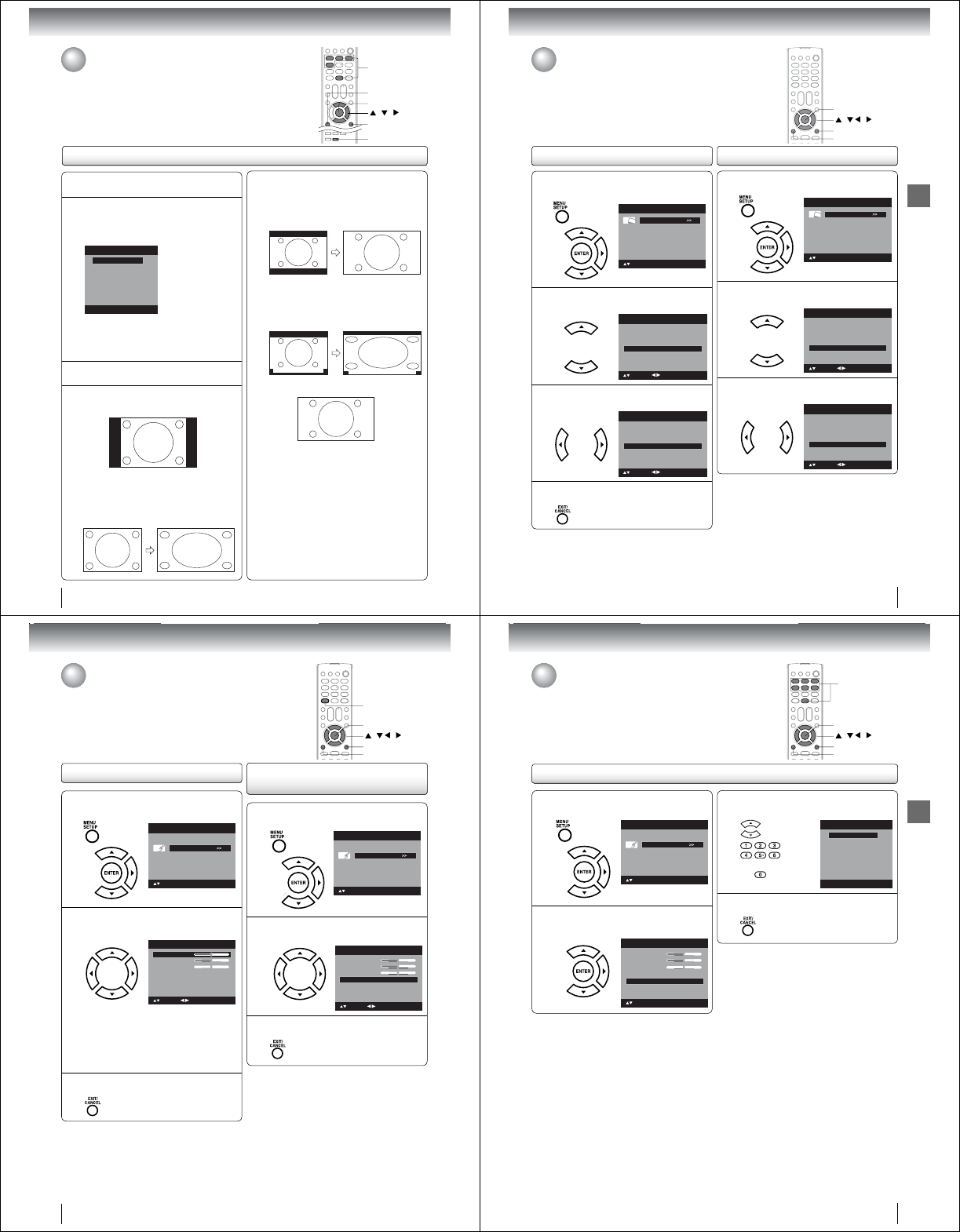
36
TV operation
Theater Wide2 picture size (for letter box
programs)
The entire picture is uniformly enlarged—it is stretched
the same amount both wider and taller (retains its
original proportion).
The top and bottom edges of the picture may be hidden.
A B C D E F G - - - - - - - - - - - - - - - -
Theater Wide3 picture size (for letter box programs
with subtitles)
To fill the width of the screen, it is extended horizontally.
However; it is only slightly extended at the top and the
bottom.
The top and bottom edges of the picture may be hidden.
A B C D E F G - - - - - - - - - - - - - - - -
A B C D E F G - - - - - - - - - - - - - - - - - - - - - - - - - -
Full picture size (for 16:9 source programs)
Full will display the picture at the maximum size.
Note:
Some High Definition and/or Digital broadcasts may
not allow you to change the picture size.
In 720p or 1080i signal, only the Theater Wide2 and
Full picture size features are available.
•
•
1Press MENU. Press ϳ or ϴ to select “Picture”,
then press ϶ or ENTER.
2Press ϳ or ϴ to select “Picture Size”, then
press ϶ or ENTER to display Picture Size
menu. Press ϳ/ϴ or corresponding Number
button (0-4) to select the desired picture size,
as described below.
Picture Size
1.Theater Wide1
2.Theater Wide2
3.Theater Wide3
[0-4]:Select
0.Natural
4.Full
Note:
Selectable picture sizes may vary depending on the
input source or broadcast signal.
Picture Size menu also can be displayed by pressing
PIC SIZE on the remote control.
•
•
3Press EXIT/CANCEL to return to the normal
screen.
Natural picture size
In some cases, this image will display the size of
standard 4:3 with a black side bar.
Theater Wide1 picture size (for 4:3 format
programs)
To fill the screen, the right and left edges are extended,
however; the center of the picture remains near its
former ratio.
The top and bottom edges of the picture may be hidden.
Viewing the wide-screen picture formats
Viewing the wide-screen picture formats
You can view programs in a variety of picture sizes— Natural, Theather
Wide1, Theather Wide2, Theather Wide3 and Full.
PIC SIZE
/ /
0-4
ENTER
EXIT/CANCEL
MENU
37
TV operation
Film Mode/DNR
A smoother motion may be obtained by setting the Film Mode to “On” when
you view a DVD.
DNR (Digital Noise Reduction) can reduce the roughness of the picture.
(This function is available only for analog broadcast.)
DNR
/ / /
MENU
EXIT/CANCEL
ENTER
Film Mode
1Press MENU in the TV mode. The TV menu
screen will appear. Press ϳ or ϴ to select
“Picture”, then press ϶ or ENTER.
Picture
Audio
Channel
Lock
Setup
Main Menu
: Select ENTER:Set
2Press ϳ or ϴ to select “Film Mode”.
DNR On
Picture
Picture Setting >>
Picture Preference Sports
Picture Size >>
Film Mode On
: Adjust
: Select
3Press ϵ or ϶ to select “On” or “Off”.
DNR On
Picture
Picture Setting >>
Picture Preference Sports
Picture Size >>
Film Mode Off
: Adjust
: Select
4Press EXIT/CANCEL to return to the normal
screen.
Note:
A smoother motion may be obtained by setting the Film
Mode to “On” when you view a DVD from the DVD player
connected with ColorStream (component video) inputs.
•
1Press MENU in the TV mode. Then press ϳ or
ϴ to select “Picture”, then press ϶ or ENTER.
Picture
Audio
Channel
Lock
Setup
Main Menu
: Select ENTER:Set
2Press ϳ or ϴ to select “DNR”.
Picture Preference Sports
Picture Size >>
Film Mode On
Picture
Picture Setting >>
DNR On
: Adjust
: Select
3Press ϵ or ϶ to select “On” or “Off”.
Picture Preference Sports
Picture Size >>
Film Mode On
Picture
Picture Setting >>
DNR Off
: Adjust
: Select
38
TV operation
Selecting Stereo/Second
Audio Program (SAP)
Sound control adjustment
1Press MENU in the TV mode. The TV menu
screen will appear. Press ϳ or ϴ to select
“Audio” , then press ϶ or ENTER.
Picture
Audio
Channel
Lock
Setup
Main Menu
: Select ENTER:Set
2Press ϳ or ϴ to select the item you want to
adjust. Then press ϵ or ϶ to adjust each
setting.
Treble
Balance
MTS Stereo
Audio Language English
Audio
15
0
: Adjust
Bass
: Select
15
Bass: Press ϵ or ϶ to adjust the bass sound.
Treble: Press ϵ or ϶ to adjust the treble
sound.
Balance: Press ϵ or ϶ to obtain an equal sound
level from both speakers.
3After your desired setting, press EXIT/CANCEL
to return to the normal screen.
/ / /
MENU
EXIT/CANCEL
ENTER
Sound control adjustment/
Selecting Stereo/Second Audio Program (SAP)
The multi-channel TV sound (MTS) feature provides high-fidelity stereo sound.
MTS also can transmit a second audio program (SAP) containing a second
language or other audio information.
When the TV/DVD receives a stereo or SAP broadcast, the word “Stereo” or
“SAP” displays on-screen every time you press DISPLAY.
DISPLAY
1Press MENU in the TV mode. Press ϳ or ϴ to
select “Audio”, then press ϶ or ENTER.
Picture
Audio
Channel
Lock
Setup
Main Menu
: Select ENTER:Set
2Press ϳ or ϴ to select “MTS”, then press ϵ or
϶ to select “Stereo”.
Treble
Balance
MTS Stereo
Audio Language English
Audio
15
0
: Adjust
Bass
: Select
15
3Press EXIT/CANCEL to return to the normal
screen.
Note:
Generally you can leave your TV in stereo mode
because the TV automatically outputs the type of
sound being broadcast (stereo or mono).
If the stereo sound is noisy, select “Mono” to reduce
the noise.
•
•
To listen to a second audio program (SAP)
Press ϵ or ϶ to select “SAP” in step 2 above. The TV
speakers will output the second audio program instead
of normal audio.
39
TV operation
1Press MENU in the TV mode. Then press ϳ or
ϴ to select “Audio” , then press ϶ or ENTER.
Picture
Audio
Channel
Lock
Setup
Main Menu
: Select ENTER:Set
2Press ϳ or ϴ to select “Audio Language”,
then press ϶ or ENTER to display the Audio
Language menu.
Treble
Balance
MTS Stereo
Audio Language English
Audio
15
0
Bass
: Select
15
ENTER:Set
Selecting the audio language
Selecting the audio language
When two or more audio languages are included in a digital signal, you can
select one of the audio language. (This function is available only for digital
broadcast.)
/ / /
MENU
EXIT/CANCEL
ENTER
0-6
3Press ϳ/ϴ or Number buttons (0-6) to select
your desired language.
Audio Language
0. English
1. Language 1
2. Language 2
3. French
4. Language 3
5. Spanish
6. No Info
[0-6]: Select
4After your desired setting, press EXIT/CANCEL
to return to the normal screen.
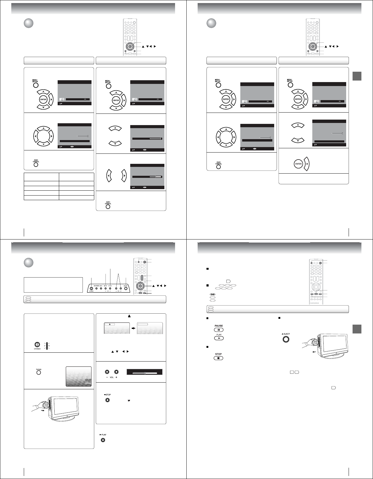
40
TV operation
Using the aspect feature/
Adjusting the back lighting
When the Aspect feature is set to On and the TV receives a 480i signal, the
picture size is automatically selected (as described in the following table).
The Backlight feature adjusts the screen brightness for improved picture
clarity.
1Press MENU in the TV mode. The TV menu
screen will appear. Press ϳ or ϴ to select
“Setup” , then press ϶ or ENTER.
Picture
Audio
Channel
Lock
Setup
Main Menu
: Select ENTER:Set
2Press ϳ or ϴ to select “Backlight”.
Video Label >>
Backlight
Auto Shut Off Off
Reset>>
16
Setup
Closed Caption >>
Language English
: Select : Adjust
On
Aspect
3Press ϵ or ϶ to adjust the setting.
Video Label >>
Backlight
Auto Shut Off Off
Reset>>
8
Setup
Closed Caption >>
Language English
: Select : Adjust
On
Aspect
4After your desired setting, press EXIT/CANCEL
to return to the normal screen.
Adjusting the back lightingUsing the aspect feature
/ / /
MENU
EXIT/CANCEL
ENTER
1Press MENU in the TV mode. The TV menu
screen will appear. Press ϳ or ϴ to select
“Setup” , then press ϶ or ENTER.
Picture
Audio
Channel
Lock
Setup
Main Menu
: Select ENTER:Set
2Press ϳ or ϴ to select “Aspect”.
Press ϵ or ϶ to select “On” or “Off”.
Video Label >>
Backlight
Auto Shut Off Off
Reset>>
16
Setup
Closed Caption >>
Language English
: Select : Adjust
On
Aspect
3After your desired setting, press EXIT/CANCEL
to return to the normal screen.
Aspect ratio of signal
source
Automatic aspect size
(When Aspect is On)
4:3 Normal Natural
16:9 Full Full
4:3 Letter box Theater Wide2
Not defi ned User-set mode
41
TV operation
1Press MENU in the TV mode. The TV menu
screen will appear. Press ϳ or ϴ to select
“Setup” , then press ϶ or ENTER.
Picture
Audio
Channel
Lock
Setup
Main Menu
: Select ENTER:Set
2Press ϳ or ϴ to select “Auto Shut Off”.
Press ϵ or ϶ to select “On” or “Off”.
Video Label >>
Backlight
Auto Shut Off Off
Reset>>
16
Setup
Closed Caption >>
Language English
: Select
On
Aspect
: Adjust
3After your desired setting, press EXIT/CANCEL
to return to the normal screen.
Resetting your settingsSetting the Auto Shut Off
Setting the Auto Shut Off/
Resetting your settings
If the Auto Shut Off feature is On, a station being viewed stops broadcasting
and the TV is not operated, the TV will automatically shut itself off after 15
minutes.
The Reset function returns your settings to the factory settings. / / /
MENU
EXIT/CANCEL
ENTER
1Press MENU in the TV mode. The TV menu
screen will appear. Press ϳ or ϴ to select
“Setup” , then press ϶ or ENTER.
Picture
Audio
Channel
Lock
Setup
Main Menu
: Select ENTER:Set
2Press ϳ or ϴ to select “Reset”.
Video Label >>
Backlight
Auto Shut Off Off
Reset>>
16
Setup
Closed Caption >>
Language English
: Select ENTER:Set
On
Aspect
3Press ϶ or ENTER to return your settings to
the factory settings.
4“Reset” will appear on the screen approx. 3
seconds, then it returns to the normal
Note:
The Reset function returns your adjustments to the
following factory settings:
•
Picture Setting
Brightness ...... center (25)
Contrast ............ max (50)
Sharpness...... center (25)
Color .............. center (25)
Tint ................... center (0)
Color Temperature ... Cool
Picture Preference .... Sports
Film Mode .......................On
Bass................... center (15)
Treble ................ center (15)
Balance................ center (0)
42
Basic playback
Press STOP to end playback.
QResuming facility
• The unit records the stopped
point, depending on the disc.
“ ” appears on the screen.
Press PLAY to resume playback
(from the scene point).
• If you press STOP again
(“Q” appears on the TV screen.),
the unit will clear the stopped
point.
On the TV screen, “ ” changes to “Reading” and
then playback commences.
DVD
VCD
CD
Preparations:
• When connecting to other equipment, turn the power off.
1Press POWER on the unit or on the remote con-
trol to turn on the unit.
• POWER indicator on the front of the unit changes
blue. It may take approx. 10 seconds for a picture to
appear on screen.
• Every time you press POWER, the TV/DVD starts
from TV mode.
• When using an amplifi er, switch on the amplifi er.
4
2Press TV/DVD on the remote control to select DVD
mode.
The DVD startup screen will appear on the TV screen.
3Load a disc in the disc slot.
Basic playback
• Load the disc in the disc slot with the label side fac-
ing forward. (If the disc has a label.) Hold the disc
without touching either of its surfaces, align it with
the guides, and place it in position.
• If a disc is inserted during some modes other than
DVD mode, it may switch to DVD mode and then
playback may be begun automatically.
A menu screen will appear on the TV screen if the
disc has a menu feature.
Press / or / on the remote control to
select title, then press ENTER. Title is selected and
play commences.
6
Q To start playback in the stop mode
Press PLAY.
Note:
If the unit does not operate properly:
Static electricity, etc., may affect the TV/DVD·s operation. In such
case, disconnect the AC cord, then connect it again.
Playing a disc
This section shows you the basics on how
to play a disc.
CAUTION
Keep your fi ngers well clear of the disc slot when
disc is loading or unloading. Neglecting to do so
may cause serious personal injury.
Press VOLUME + or – to adjust the volume.
5
Reading
ENTER
PLAY
STOP
TV/DVD
/ / /
POWER
VOL +/–
Volume : 25
EJECT
STOP VOLUME +/–
PLAY
POWER
Basic playback
43
To pause playback (still mode)
Press PAUSE during playback.
To resume normal playback,
press PLAY.
• The sound is muted during still
mode.
To stop playback
Press STOP.
To remove the disc
Press EJECT.
Remove the disc after the disc comes
out.
Note:
• If a non-compatible disc is loaded, “Incorrect Disc”, “Region Code Error” or “Parental Error” will appear on the TV screen
according to the type of loaded disc. In this case, check your disc again 760 .
• Some discs may take a minute or so to start playback.
• When you set a single-faced disc label downwards (ie. the wrong way up), “Reading” will appear on the display for a few
minutes and then “Incorrect Disc” will continue to be displayed.
• Some discs may not work the resuming facility.
• Resuming cannot function when you play a PBC-featured Video CD while the PBC is on. To turn off the PBC 51 .
• Some playback operations of DVDs may be intentionally fi xed by software producers. Since this unit plays DVDs according
to the disc contents the software producers designed, some playback features may not be available. Also refer to the
instructions supplied with the DVDs.
• Do not move the unit during playback. Doing so may damage the disc.
• Use the EJECT to unload and eject the disc.
• Do not put any objects other than discs on the disc slot. Doing so may cause the unit to malfunctions.
• In many instances, a menu screen will appear after playback of a movie is completed. Prolonged display of an on-screen
menu may damage your television set, permanently etching that image onto its screen. To avoid this, be sure to press
POWER on the remote control once the movie is completed.
• There may be a slight delay between the button is pressed and the function activates.
To obtain a higher quality picture
Occasionally, some picture noise may appear on the TV screen while playing a
DVD video disc because the high resolution pictures on these discs include a
lot of information. In such case, you may reduce the Sharpness with the Picture
Setting menu 35 .
About
DVD VCD CD
The
DVD VCD CD
icons on the heading bar show the playable discs for the
function described under that heading.
: You can use this function with DVD video discs.
VCD
: You can use this function with Video CDs.
CD
: You can use this function with Audio CDs and CD-R/RW CDs.
DVD
VCD
CD
Basic playback (continued)
PAUSE
STOP
PLAY
POWER
EJECT
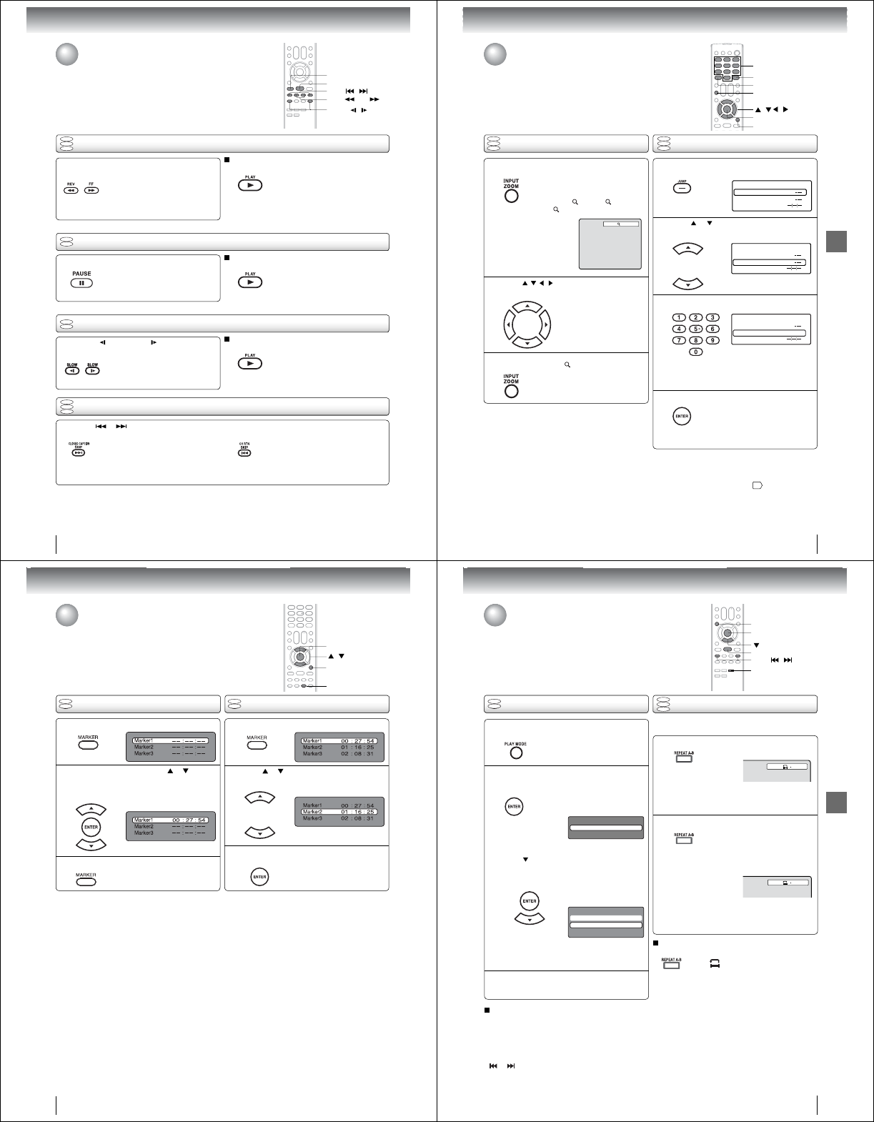
Basic playback
44
Playing frame by frame
Playing in fast reverse or fast forward directions
Press REV or FF during playback.
REV: Fast reverse playback
FF: Fast forward playback
Each time you press REV or FF
button, the playback speed changes.
To resume normal playback
Press PLAY.
Press PAUSE during still playback.
Each time you press PAUSE, the
picture advances one frame.
To resume normal playback
Press PLAY.
Note:
• The sound is muted during frame by frame playback.
Press SLOW (REVERSE) or (FORWARD)
during playback.
Each time you press the button, the
slow-motion speed changes.
To resume normal playback
Press PLAY.
Note:
• The sound is muted during slow-motion playback.
• The Video CD cannot play Reverse Slow.
Press SKIP or repeatedly to display the chapter or track number you want.
Playback starts from the selected chapter or track.
Playback starts from the beginning of
the current chapter or track.
When you press twice in quick successions,
playback starts from the beginning of
the preceding chapter or track.
Note:
• A “Prohibition” symbol “” may appear at the upper right of the screen. This symbol means either the feature you tried is not
available on the disc, or the TV/DVD cannot access the feature at this time. This does not indicate a problem with the
TV/DVD.
DVD
VCD
CD
DVD
VCD
CD
Playing in slow-motion
Locating a chapter or track
DVD
VCD
DVD
VCD
Note:
• The TV/DVD mutes sound during reverse and forward scan
of DVD/VCD/Audio CD discs.
• The playback speed may differ depending on the disc.
SLOW /
PAUSE
PLAY
REV / FF
To locate succeeding chapters or tracks.
SKIP /
Playing a disc (Continued)
45
Advanced playback
Advanced playback
Press / / / to view a different part of the
frame.
You may move the frame from
the center position to UP, DOWN,
LEFT or RIGHT direction.
In the zoom mode, press ZOOM repeatedly to
return to a 1:1 view ( Off).
Zooming
Press ZOOM during playback.
The center part of the image will be
zoomed in.
Each press of ZOOM will change
the ZOOM 1 (x 1.3), 2 (x 1.5)
and 3 (x 2.0).
Zooming/Locating desired scene
This unit will allow you to zoom in on the frame image. You can then make
selections by switching the position of the frame.
Use the title, chapter and time recorded on the DVD disc to locate the
desired point to playback. In the case of VCD/Audio CD discs, time and
track are used to locate the desired point to playback.
To check the title/track, chapter/track and time, press DISPLAY.
1
Note:
•In case of the Audio CD and Video-CD, only Track and Time
can be selected.
• In case of the Video-CD playback with PBC, the JUMP does
not work. To turn off PBC, see page 51 .
Locating desired scene
DVD
VCD
CD
Press Number buttons (0–9) to input the number.
Note:
• You can select the Pause, Slow or Search playback in the
zoom mode.
• Some discs may not respond to zoom feature.
Press JUMP during playback or stop mode.
Press or to select the “Title/Track”,
“Chap-
ter” or
“Time”
.
1
Time
Title
Chapter
Jump
Time
Title
Chapter
Jump
Time
Title
Chapter 12
Jump
DVD
VCD
CD
1
2
3
• If you input a wrong number, press
EXIT/CANCEL.
• Refer to the package supplied with
the disc to check the numbers.
2
3
4
Press ENTER. Playback starts.
• When you change the title,
playback starts from Chapter 1 of
the selected title.
• Some discs may not work in the
above operation.
0–9
/ / /
ZOOM
EXIT/CANCEL
DISPLAY
JUMP
ENTER
Advanced playback
46
Press MARKER during playback.
Select the blank Marker using or .
Then press ENTER to mark the desired scene.
• Repeat this procedure to mark the
other 2 scenes.
Marking desired scenes
The unit stores the points that you want to watch again up to 3 points.
You can resume playback from each scene.
/
MARKER
ENTER
Marking the scenes Returning to the scenes
1
2
Press MARKER to clear the display.
3
Note:
• Some discs may not work with the marking operation.
• The marking is cancelled when you eject the disc or turn the
power off.
• Some subtitles recorded around the marker may fail to
appear.
• In case of Video CD with PBC, Marker function is prohibited.
Press MARKER during playback or stop mode.
Press or to select the Marker 1-3.
1
2
Press ENTER.
Playback starts from the marked
scene.
3
QTo cancel the Marker
Follow the above steps 1~2, then press EXIT/CANCEL.
EXIT/CANCEL
DVD
VCD
DVD
VCD
47
Advanced playback
Press REPEAT A-B during playback.
The start point is selected.
Press REPEAT A-B again.
The end point is selected. Playback
starts at the point that you selected.
Playback stops at the end point and
returns to Point A automatically, then
starts again.
[DVD]
Press ENTER repeatedly to select “Chapter”
or “Title”.
The unit automatically starts
repeat playback after fi nishing
the current title or chapter.
[Video CD]
Press to select “Repeat”.
Press ENTER repeatedly to select “Track” or
“All”.
The unit automatically starts
repeat playback after fi nishing
the current track.
• If you set the repeat mode during stop mode,
press PLAY to start Repeat playback.
A-B Repeat playback
Repeat playback
A-B repeat playback allows you to repeat a section between
two selected points.
Note:
• In A-B Repeat mode, subtitles near the A or B locations
may not be displayed.
• You cannot set the A-B Repeat for the scenes that include
multiple angles.
• A-B Repeat playback does not work when Repeat playback
is activated.
• You may not be able to set A-B Repeat during certain
scenes of the DVD.
• A-B Repeat does not work with an interactive DVD and
MP3/WMA/JPEG CD.
• In case of Video CD with PBC, A-B Repeat is prohibited.
To resume normal playback
Press REPEAT A-B again.
“
Off
” appears on the screen.
Press PLAY MODE during playback or stop
mode.
Press PLAY MODE again to clear the screen.
Note:
• Some discs may not work with the repeat operation.
• In case of Video CD with PBC, Repeat function is
prohibited during playback.
• Chapter/Track repeat function is canceled whenever SKIP
or is pressed.
To resume normal playback
Select Repeat : “Off” in step 2.
Repeat playback/A-B Repeat playback
A
Play Mode
Repeat : Off
AB
Play Mode
Repeat : Off
Mode : Off
DVD
VCD
DVD
VCD
CD
ENTER
PLAY MODE
PLAY
REPEAT A-B
1
2
1
2
3
SKIP /
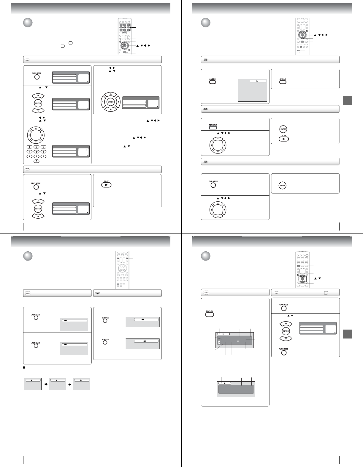
Advanced playback
48
3
2
VCD
CD
1
1
2
Press
/
to return to the left column, then
press
/
to select the “Program Playback”
and press ENTER.
The programs you selected will start to playback in order.
• To resume normal playback,
select Mode: “Off” in step 2.
Program playback
Press PLAY MODE in the stop mode.
4
Note:
• In playing back the Video CD with PBC, you cannot set
Program playback.
• The program is canceled when you eject the disc or turn the
power off.
QTo change the program
1. Select Mode to “Program” (as step 2), press
/ / /
to select the track number you want to change, then
press EXIT/CANCEL.
2. Press Number buttons (0–9) to input the new track
number.
QTo clear the program one by one
Select Mode to “Program”, press
/ / /
to select the
track number. Then press EXIT/CANCEL.
QTo clear all the programs
At the left column, press
/
to select “Clear Program”.
Then press ENTER.
Random playback
Press / to select “Mode”, then press
ENTER repeatedly to select “Random”.
Press PLAY
.
The Random Playback will start.
3
Note:
• In case of Video CD with PBC, you cannot set Random
function during playback.
• The random playback is canceled when you eject the disc or
turn the power off.
Press PLAY MODE during playback or stop
mode.
• If you set “Random” during playback mode,
Random playback will begin after the track that is
currently being played has ended.
• To resume normal playback,
select Mode: “Off” in step 2.
1 – – –
2 – – –
3 – – –
Play Mode
Repeat : Off
Program Playback
Mode : Off
1 – – –
2 – – –
3 – – –
Play Mode
Repeat : Off
Program Playback
Mode : Program
1 9
2 – – –
3 – – –
Play Mode
Repeat : Off
Program Playback
Mode : Program
1 9
2 3
3 11
Play Mode
Repeat : Off
Program Playback
Mode : Program
1 – – –
2 – – –
3 – – –
Play Mode
Repeat : Off
Program Playback
Mode : Random
Press / to select the programming position.
Press
/ and then use
Number buttons (0–9)
to input the track.
•
To program others, repeat this step.
• If you input a wrong number, press
EXIT/CANCEL.
Press or to select “Mode”, then press
ENTER repeatedly to select “Program”.
Program playback/Random playback
You can arrange the playback order of tracks on the disc. And the
unit can also select tracks at random and playback them. These
features work for Video CD.
For Audio CD and MP3/WMA CD, please see “Random playback
(Audio CD/MP3/WMA/JPEG)” 55 and “Program playback (Audio
CD/MP3/WMA/JPEG)” 56 .
0–9
/ / /
PLAY
EXIT/CANCEL
PLAY MODE
ENTER
VCD
VCD
49
Advanced playback
Changing angles
Title selection
DVD menu
Press ANGLE during playback.
The current angle will appear.
When playing back a disc recorded with multi-angle facility, you can change the angle that you are viewing the scene from.
1
Press ANGLE repeatedly until the desired angle
is selected.
2
Note:
• Depending on the DVD, you may not be able to change the
angle even if multi-angles are recorded on the DVD.
Press TOP MENU during playback.
Title menu appears on the screen.
Two or more titles are recorded on some discs. If the title menu is recorded on the disc, you can select the desired title.
1
Press ENTER or PLAY.
The playback of the selected title will
start.
3
Note:
•
Depending on the DVD, you may not be able to select the title.
•
Depending on the DVD, a “title menu” may simply be called a
“menu” or “title” in the instructions supplied with the disc.
2
Press DVD MENU during playback.
Some DVDs allow you to select the disc contents using the menu.
When you playback these DVDs, you can select the subtitle language, soundtrack language, etc, using the menu.
1
Press ENTER.
The menu continues to another
screen. Repeat steps 2 and 3 to set
the item completely.
3
2
Changing angles/Title selection/
DVD menu
Note:
• Depending on the DVD, you may not be able to resume
playback from the scene point when you press DVD MENU.
Press / / / to select the desired title.
1/2
/ / /
TOP MENU
ANGLE
PLAY
DVD MENU
The DVD menu appears on the TV
screen.
• Press DVD MENU again to resume
playback at the scene when you
pressed DVD MENU.
Press / / / to select the desired item.
ENTER
Advanced playback
50
Press SUBTITLE repeatedly during playback until
the desired language is selected.
Press AUDIO SELECT repeatedly until the
desired language is selected.
• The on screen display will disappear after a few
seconds.
Press AUDIO SELECT during playback.
The current soundtrack language will
appear.
1
Changing soundtrack language/Subtitles
You can select the language when you play a multilingual disc.
Note:
• If the desired language is not heard after pressing the
button several times, the language is not recorded on
the disc.
• The selected soundtrack language is cancelled when
you eject the disc. The initial default language or
available language will be heard if the disc is played
back again.
• If you select DTS in playing DTS-encoded disc, no
sound will be heard from the TV/DVD·s speakers.
In case of Video CD playback
Audio type changes as follows each time you press AUDIO
SELECT.
When playing back a disc recorded with subtitles, you can
select the subtitle language or turn the subtitle off.
To turn off the subtitle, press SUBTITLE until
“Off” appears.
• The on screen display will disappear after a
few seconds.
1
Note:
• Depending on the DVD, you may not be able to change
subtitles, or to turn subtitles on or off.
• While playing a DVD, the subtitle may change when
you loaded or eject the disc.
• In some cases, a selected subtitle language may not
be changed immediately.
Subtitles
2
Changing soundtrack language
DVD
VCD
1/2 Eng Dolby Digital
2/2 Fre Dolby Digital
LR L R
1/5 Eng
Off
AUDIO SELECT
SUBTITLE
2
51
Advanced playback
Disc status/To turn off the PBC
DVD
VCD
Disc status
With press of DISPLAY, the status of the disc
will appear on the screen.
To cancel the display, press DISPLAY again.
DVD
DVD 00:15:25 01:41:39
Title 1/3 Chapter 2/24
1/1 Eng Dolby Digital 1/2 Eng
1/1
DISC OPERATION ELAPSED
TIME
TOTAL
TIME
TITLE NO.
ANGLE NO.
AUDIO LANGUAGE A KIND OF AUDIO
SUBTITLE LANGUAGE
CHAPTER
NO.
Video CD
VCD 00:08:32 00:51:03
Track 3/15
DISC OPERATION
ELAPSED
TIME
TOTAL
TIME
TRACK NO.
Q To turn on the PBC
Follow the above steps 1~2, then press ENTER repeatedly
until “PBC” appear.
VCD
To turn off the PBC (see 7)
Press / to select “Mode”, then press
ENTER repeatedly until “Off” appear.
1
Press PLAY MODE in the stop mode.
2
Press PLAY MODE again to clear the screen.
3
1 – – –
2 – – –
3 – – –
Play Mode
Repeat : Off
Program Playback
Mode : Off
ENTER
/
DISPLAY
PLAY MODE
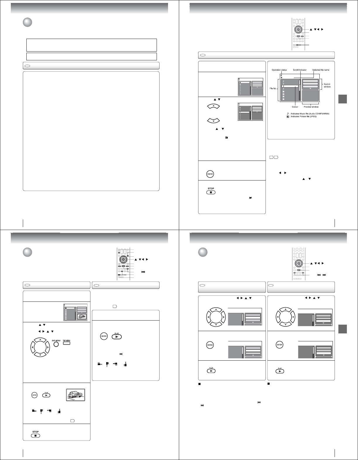
Advanced playback
52
MP3/WMA/JPEG and Audio CD operation
Audio CD/MP3/WMA/JPEG CD information
Limitations on MP3/WMA/JPEG CD playback
• MP3/WMA/JPEG CD is the disc that is standardized by ISO9660, its fi le name must include 3-digits extension letters,
“.mp3”, “.wma”, “.jpg”.
• MP3/WMA/JPEG CD must be correspond to the ISO standardized fi les.
• This unit can read 2000 fi les per disc. If one disc has more than 2000 fi les, it reads up to 2000 fi les, the remaining fi les
will be omitted.
• MP3/WMA/JPEG CDs cannot be used for the purpose of recording.
• If the CD has both audio tracks and MP3/WMA/JPEG fi les, only audio tracks will be played.
• It may take more than one minute for this unit to read MP3/WMA/JPEG fi les depending on its structure.
• Music recorded by “Joliet Recording Specifi cation” can be played back, the fi le name is displayed (within 15 letters) on
the screen. Long fi le names will be condensed.
• The music fi les recorded by “Hierarchical File System” (HFS) cannot be played.
Limitations on display
• The maximum number for display is 15 letters.
Available letters for display are the following:
capital or small alphabets of A through Z, numbers of 0 through 9, and _ (under score).
• Other letters than those above are replaced in hyphen.
Notes on MP3/WMA/JPEG fi les
To playback MP3/WMA/JPEG CD in the recorded order,
1. Use MP3/WMA/JPEG software that records data alphabetically or numerically.
2. Name each fi le including two-digit or three-digit number (ex. “01” “02” or “001” “002”).
3. Refrain from making too many sub-folders.
CAUTION:
• Some MP3/WMA/JPEG CDs cannot be played back depending on the recording conditions.
• The CD-R/RW that has no music data or non MP3/WMA/JPEG fi les cannot be played back.
Standard, sampling frequency and the bit rate:
MP3 CD
MPEG-1 Audio
32kHz, 44.1kHz, 48kHz
32kbps ~ 320kbps (constant bit rate or variable bit rate)
The recommend recording setting for a high-quality sound is 44.1kHz of sampling frequency and 128kbps of constant
bit rate.
WMA CD
WMA version 7 and 8
32kHz/48kbps, 44.1kHz/48kbps~192kbps, 48kHz/128kbps~192kbps
The fi le recorded by mono, 48kHz, 48 kbps is not available to this unit.
Microsoft, Windows Media, and Windows Logo are either registered trademarks or trademarks of Microsoft Corporation in the
United States and/or other countries.
CD
This unit can playback the MP3/WMA/JPEG-data which has been recorded on CD-R or CD-RW. To produce the MP3/
WMA/JPEG-data, you need a Windows-PC with CD-RW drive and a MP3/WMA/JPEG-encoding Software (not supplied).
The Apple-HFS-System cannot be played.
This player requires discs/recordings to meet certain technical standards in order to achieve optimal playback quality.
There are many different types of recordable disc formats (including CD-R containing MP3/WMA fi les). Not all recordable
discs will produce optimal playback quality. The technical criteria set forth in this owner·s manual are meant only as a
guide. Use of CD-RW for MP3 fi les is not recommended.
You must obtain any required permission from copyright owners to download or use copyrighted content.
Toshiba cannot and does not grant such permission.
Advanced playback
53
MP3/WMA and Audio CD playback
CD
Load an Audio CD or a disc on which MP3
or WMA fi les have been recorded in the disc
slot.
1
Afi le browser screen will appear on the screen.
2
About fi le menu
Note:
• In the case of a CD containing a mixture of MP3, WMA
and JPEG fi les, the fi les are played back by selecting
them from the fi le browser.
• MP3 or WMA fi le on the Kodak Picture CD is not
recognized on this unit.
Folder-1
Folder-2
MP3-1
MP3-2
MP3-3
WMA-1
WMA-2
WMA-3
JPEG Preview
Select Files
Repeat :Off
Mode :Off
MP3-5
MP3-6
WMA-11
WMA-12
Picture-1
Picture-2
Picture-3
Picture-4
Music Playing
Select Files
Repeat :Off
Mode :Off
/WMA-11.WMA
3/15 00:00:00
QSelect Files
The fi le type to make it display in the fi le browser can
be chosen.
1.Press or to highlight “Select Files” at right column
in the fi le browser.
2. Press ENTER, then press or to select fi le type
from the list (Music or Picture).
3. Press ENTER to add/remove check mark. Checked
fi le type will be displayed in the fi le browser.
4. Press RETURN to save the setting.
Press / to select fi le.
3
Folder-1
Folder-2
MP3-1
MP3-2
MP3-3
WMA-1
WMA-2
WMA-3
/MP3-2.MP3
JPEG Preview
Select Files
Repeat :Off
Mode :Off
Press STOP to end playback.
5
• The unit records the stopped point. “ ” appears
on the TV screen. Press PLAY to resume playback
(from the scene point).
• If you press STOP again or unload the disc, the unit
will clear the stopped point.
Press ENTER.
The selected fi le starts playing back.
4
/ / /
PLAY
STOP
ENTER
• In case the current directory includes more than 8
fi les, press or to scroll in the fi le list.
• To see contents in folder, select the folder and then
press ENTER. To return to the parent directory, press
RETURN or select “ Go Up ...” then press ENTER.
• When PLAY is pressed after the fi le browser
displayed, playback begins automatically starting
from the fi rst fi le. In this case, if the fi rst fi le is an
MP3/WMA fi le, only MP3/WMA fi les are played
back in order. If the fi rst fi le is a JPEG fi le, the fi rst
JPEG fi le is played back. If there is no fi le at a root
directory, playback does not begin automatically.
Note:
• During MP3/WMA playback, you cannot use Jump and A-B
Repeat functions.
• You can use Repeat (Track or All), Random functions and
Program playback for Audio CD/MP3/WMA/JPEG playback
55 56 .
RETURN
Advanced playback
54
MP3/WMA/JPEG and Audio CD
operation (Continued)
The slide show enables you to view pictures (fi les) one after
another automatically.
Preparation:
• Set “JPEG Interval” setting to “5 Seconds”, “10 Seconds”
or “15 Seconds” 59 .
Load a JPEG disc in the disc slot.
1
Afi le browser screen
will appear on the
screen.
2
Press /to select the fi le.
To display a thumbnail list, press DVD MENU.
Press / / / to select the desired fi le.
(To return to the fi le browser, press TOP MENU.)
3
4
Press STOP to end playback.
5
JPEG playback
Select your desired starting fi le for the slide
show in the step 3 on left.
Press ENTER or PLAY to start slide show from
the selected fi le.
Slide show playback
1
• When PLAY is pressed after the fi le browser
displayed, playback begins automatically
starting from the fi rst fi le. In this case, if the
fi rst fi le is a JPEG fi le, the fi rst JPEG fi le is
played back. If the fi rst fi le is an MP3/WMA
fi le, only MP3/WMA fi les are played back in
order. If there is no fi le at a root directory,
playback does not begin automatically.
2
CD CD
Picture-01
Picture-02
Picture-03
Picture-04
Picture-05
Picture-06
Picture-07
Picture-08
JPEG Preview
Select Files
Repeat :Off
Mode :Off
W: 2048 H: 1536
/Picture-01.JPG
Rotating an image
You can rotate an image by 90 degrees.
Press ANGLE during playback of the image.
“”, “ ”, “ ” or “ ” appears on the screen.
Zooming an image
Zoom function also can be used in viewing JPEG
fi les. Press ZOOM (See “Zooming”
45
).
• If you press PAUS E during the slide show, the slide
show stops temporary. “\\” appears briefl y on the TV
screen.
Press PLAY or SKIP again to resume the slide show.
•If the picture appears upside down or sideways, press
ANGLE repeatedly until it·s right side up.
“ ”, “ ”, “ ” or “ ” appears on the TV screen.
• When the slide show playback fi nished, the fi le list
appears.
• To stop the slide show, press STOP. The fi le browser
appears.
Note:
• During JPEG playback, you cannot use Jump and A-B
Repeat functions.
• When an image exceeds 5760 x 3840 pixels, the entire
image may not be displayed on a screen, preview window
or thumbnail list.
• It may have a longer interval due to the size of data.
/ / /
TOP MENU
ANGLE
PLAY
SKIP
PAUSE
STOP
ENTER
DVD MENU
Press ENTER or PLAY. The selected picture
appears on the screen.
The fi le browser appears on the
screen. If you want to watch the
other fi le, repeat steps 3 ~ 4.
ZOOM
Advanced playback
55
Repeat, random and program playback
using file browser
Press PLAY.
The random playback will start.
Folder-1
Folder-2
MP3-1
MP3-2
MP3-3
Select Files
Repeat :Off
Mode :Off
CD CD
F
older-1
F
older-2
M
P3-1
M
P3-2
MP3-3
Select Files
Repeat :Off
Mode :Off
F
older-1
F
older-2
M
P3-1
M
P3-2
MP3 3
Select Files
Repeat :Track
Mode :Off
Folder-1
Folder-2
MP3-1
MP3-2
MP3-3
Select Files
Repeat :Off
Mode :Random
Repeat playback (Audio CD/
MP3/WMA/JPEG)
In the fi le browser, press / //to select
“Repeat” during stop mode.
Press ENTER repeatedly to select “Track” or
“All”.
Press PLAY.
The unit automatically starts repeat
playback after fi nishing the current
track.
Random playback (Audio CD/
MP3/WMA/JPEG)
To resume normal playback
Select Repeat : “Off” in step 2.
In the fi le browser, press // / to select
“Mode” during stop mode.
Press ENTER to select “Random”.
To resume normal playback
Select Mode : “Off” in step 2.
Note:
• The repeat function is canceled when you eject the disc
or turn the power off.
• Track repeat function is canceled whenever SKIP or
is pressed.
1
3
1
3
ENTER
PLAY
2 2
/ / /
SKIP /
Note:
• The random function is canceled when you eject the disc
or turn the power off.
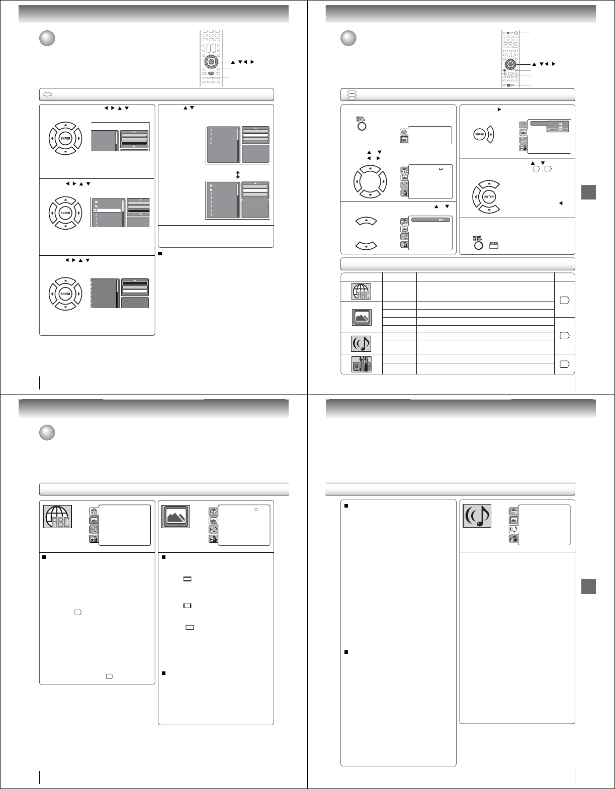
Advanced playback
56
JPEG Preview
Edit Mode
Browser View
Clear Program
MP3-1
MP3-2
MP3-3
WMA-3
In the fi le browser, press / / / to select
“Edit Mode”, then press ENTER.
Press
/ / /
to select fi le you want to
add into the program list.
Press
/ //
to select “Add To Program”.
Then press ENTER. All marked fi les are added
into the program list.
When you fi nish storing the fi les
which you want into the Program
list, select “Edit Mode” and press
ENTER to release edit mode.
CD
Folder-1
Folder-2
MP3-1
MP3-2
MP3 3
Repeat :Off
Mode :Off
Edit Mode
Folder-1
Folder-2
MP3-1
MP3-2
MP3-3
WMA-1
WMA 2
JPEG Previe
w
Repeat :Off
Mode :Off
Edit Mode
Folder-1
Folder-2
MP3-1
MP3-2
MP3-3
WMA-1
WMA 2
JPEG Preview
Edit Mode
Program View
Add To Program
Program playback (Audio CD/MP3/WMA/JPEG)
Press
/
to select “Program View”, then press
ENTER. Program View shows only the
programmed fi les that you have added in step 2.
Program View
In the Program View, press PLAY. The fi les
start to playback in programed order that were
added by you.
To remove fi le from program list in stop mode
In the Edit Mode, switch to Program View. Select fi le
you want to remove, then press ENTER. Select “Clear
Program” and press ENTER. Marked fi le is removed
from program list.
1
3
4
5
Browser View
JPEG Preview
Edit Mode
Program View
Add To Program
Folder-1
Folder-2
MP3-1
MP3-2
MP3-3
WMA-1
WMA-2
WMA-3
/ / /
PLAY
ENTER
When “Edit Mode” is black
color, you can mark the fi les
which you want to add into
Program list.
2
Press ENTER. Selected fi le
was marked.
Repeat this procedure to
select the other fi les.
Note:
•The program function is cancelled when you eject the disc
or turn the power off.
Repeat, random and program playback
using file browser (Continued)
Function setup
Function setup
57
Section Option Details Page
Menu Subtitle
Audio
To select the language of “Menu”, “Subtitle” and “Audio”
if more than one language are available on the disc.
58
TV Screen To select a picture size according to the aspect ratio of your TV.
Display To turn On or Off the operational status display on the TV screen.
Picture Mode To select a preferred picture mode from “Video”, “Film” or “Auto”.
59
JPEG Interval To select a preferred setting for the slide show playback.
Night Mode To select On or Off for Night Mode.
Digital Out To select a digital output sound format corresponding to your
system connection.
Parental
To select a preferred parental level for the parental setting.
60
Password To change the password.
• Repeat steps 3, 4 and 5 to
change other option.
• To select another section, go
back to step 2 by pressing
repeatedly.
Customizing the function settings
You can change the default settings of the DVD mode to customize
performance to your preference.
Press TV/DVD on the remote control to select DVD mode.
Setting procedure
DVD
VCD
CD
Press SETUP during stop mode.
The following on-screen display appears.
1
2
3
To clear SETUP screen, press SETUP once or
press RETURN repeatedly.
6
Press or to select the desired section, then
press or .
First option will be highlighted. Press or
to select the desired option.
4
Then press or ENTER. The selectable
settings will appear.
5
Change the selection using or , by referring
to the corresponding pages 57 ~ 60 .
Press ENTER to save the setting.
Parental : Off
Set Password
Output : Interlace
Di X(R) VOD
DRC : Off
QSound : On
E.B.L. : Off
TV Screen : 4:3
Display : On
Pi t M d A t
Menu : English
Subtitle : English
Audio : English
Parental : Off
Set Password
Output : Interlace
DivX(R) VOD
DRC : Off
QSound : On
Menu : English
Subtitle : English
Audio : English
TV Screen 4:3
Display
Picture Mode : Auto
JPEG Interval : Off
4:3
16:9
Parental : Off
Set Password
Output : Interlace
DivX(R) VOD
DRC : Off
QSound : On
Menu : English
Subtitle : English
Audio : English
TV Screen : 16:9
Display : On
Picture Mode : Auto
JPEG Interval : Off
Parental : Off
Set Password
Output : Interlace
DivX(R) VOD
DRC : Off
QSound : On
Menu : English
Subtitle : English
Audio : English
TV Screen : 16:9
Display : On
Picture Mode : Auto
JPEG Interval : Off
SETUP
/ / /
RETURN
ENTER
TV/DVD
Setting details
Function setup
58
Setting details
Menu, Subtitle, Audio
You can select the language of “Menu”, “Subtitle” and
“Audio” if more than one languages are recorded onto
the disc.
English, Francais, Espanol:
The selected language will be heard or seen.
Other:
Other language can be selected (see “Language
code list” 65 ).
Original (Audio):
The unit will select the fi rst priority language of
each disc.
Off (Subtitle):
Subtitles do not appear.
Note:
• If the selected language is not recorded on the disc, the
fi rst-priority language is selected.
• If you want to change the OSD language, you can perform
it by “Language” in the TV menu 21 .
TV Screen
You have the following screen sizes to choose from:
4:3 (Letter box):
When playing back a wide screen-DVD disc, it
displays the wide picture with black bands at the
top and bottom of screen.
4:3 (Pan & scan):
It displays the wide picture on the whole screen
with left and right edges automatically cut off.
16:9 (Wide):
A wide screen picture is displayed full size.
Display
On screen display can be switched on or off when you
press any buttons.
Off: On screen displays do not appear when you
press any buttons.
On: On screen displays appear when you press
the buttons (factory setting).
Parental : Off
Set Password
Output : Interlace
DivX(R) VOD
DRC : Off
QSound : On
E.B.L. : Off
TV Screen : 4:3
Display : On
Picture Mode : Auto
JPEG Interval : 5 Seconds
Screen Saver : On
Menu : English
Subtitle : English
Audio : English
Parental : Off
Set Password
Output : Interlace
DivX(R) VOD
DRC : Off
QSound : On
Menu : English
Subtitle : English
Audio : English
TV Screen : 16:9
Display : On
Picture Mode : Auto
JPEG Interval : Off
Customizing the function settings (Continued)
Note:
• If the DVD disc is not formatted in the Pan & scan style, it
will display 4:3 style.
Function setup
59
Picture Mode
There are two types of source content in pictures
recorded in DVD video discs: fi lm content (pictures
recorded from fi lms at 24 frames per second) and
video content (video signals recorded at 30 frames per
second). Make this selection according to the type of
content being viewed.
Auto: Select this selection normally.
The DVD player automatically detects
source content, fi lm or video of
playback source, and converts that
signal in an appropriate method.
Film: The DVD player converts fi lm content
pictures appropriately. Suitable for
playback of fi lm content pictures.
Video: The DVD player fi lters video signal and
converts it appropriately.
Suitable for playback of video content
pictures.
Note:
• Depending on the disc, pictures may be cut off or
doubled. In this case, select “Video”.
JPEG Interval
You can continuously playback all JPEG fi les
automatically.
After the selection below, the disc will start playback on
JPEG fi les which have been recorded.
Off:
Plays back one fi le at a time.
5 Seconds:
Plays back images in the form of a slide show at
5 second intervals.
10 Seconds:
Plays back images in the form of a slide show at
10 second intervals.
15 Seconds:
Plays back images in the form of a slide show at
15 second intervals.
Ϯ Night Mode
Night Mode enables you to control the dynamic range so as
to achieve a suitable sound for your equipment.
Off: It plays back at the recording level on the disc.
On: Loud sound such as explosion is toned down
slightly when played back. This is suitable when
it is connected to a stereo.
Note:
This function works only when the disc recorded with
Dolby Digital is played back.
The level of Night Mode may differ depending on DVD
video disc.
•
•
Parental : Off
Set Password
Output : Interlace
DivX(R) VOD
Menu : English
Subtitle : English
Audio : English
E.B.L. : Off
TV Screen : 4:3
Display : On
Picture Mode : Auto
JPEG Interval : 5 Seconds
Screen Saver : On
Night Mode : Off
Digital Out : Bitstream
Ϯ Digital Out
You can select the digital output sound format corresponding
to your system connection.
Off:
There is no sound output from DIGITAL AUDIO OUT
jack.
PCM:
Change Dolby Digital to PCM for the output.
Select when connected to a 2 channel digital stereo
amplifier.
Bitstream:
Disc audio bitstream data will be output.
Note:
Even if you select “Bitstream”, MPEG Audio will be output
in PCM format.
•
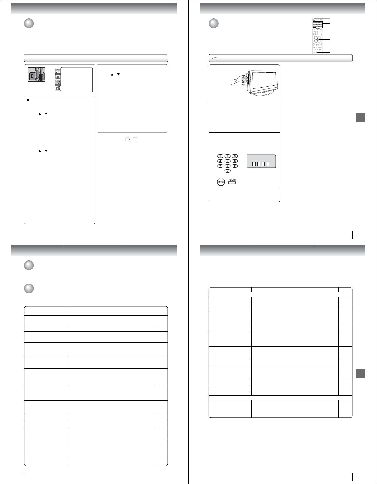
Function setup
60
DRC : Off
QSound : On
Menu : English
Subtitle : English
Audio : English
E.B.L. : Off
TV Screen : 4:3
Display : On
Picture Mode : Auto
JPEG Interval : 5 Seconds
Screen Saver : On
Parental : Off
Password : Change
Parental control setting
Some discs are specifi ed as not suitable for children. Such
discs can be limited not to playback with the unit.
1) Press or to select “Parental”, then press
ENTER. “Enter Password” screen will appear.
2) Press “0000” using Number buttons (0–9).
(Please note, this is pre-setting password of this
unit). Then press ENTER. The parental level list
will appear.
•Level Off: The parental control setting does not
function.
•Level 8:
Virtually all DVD software can be
played back.
•Level 1: DVD software for adults cannot be
played back.
3) Press or to select from the level 1 to level 8.
The limitation will be more severe as the level
number is lower. Then press ENTER.
Note:
• The parental control level is equivalent to the following
USA movie ratings.
Level 1: G Level 5:
Level 2: Level 6: R
Level 3: PG Level 7: NC-17
Level 4: PG-13 Level 8:
The parental control levels for other countries/area
than U.S. are included for future use. Check the
appropriate parental control level when you buy a DVD
video disc equipped with the parental control feature
in the future.
•
Depending on the discs, the unit cannot limit playback.
• Some discs may not be encoded with specifi c rating
level information though its disc jacket says “adult.”
For those discs, the age restriction will not work.
• The password is required every time when you
change the parental level.
• If you input a wrong number, press EXIT/CANCEL.
Setting details (continued)
Note:
• If each setup (pages 58 ~ 60 ) has completed, the unit
can always work under the same condition (especially with
DVD discs).
Each setup will be retained in the memory even if you turn
the power off.
QSet the new password
1) Press or to select “Password”, then press
ENTER. “Enter Current Password” screen will
appear.
2) Press Number buttons (0–9) to input the current
password (If the password has not been set yet
after you purchase this unit, it is “0000”).
3) Then press ENTER. “Enter New Password” screen
will appear. Press Number buttons (0–9) to input
the new password.
4) Press ENTER. Now your new password has been
set. Be sure to remember this number!
If you forget the password
1) Press EJECT to remove the disc.
2) While holding 7 down on the remote control and
then press STOP on the unit. “Password Clear”
appears on the screen. Now the password
has been returned to the initial value (“0000”).
Customizing the function settings (Continued)
Function setup
61
Enter the password with Number buttons (0–9).
Then press ENTER.
If the DVD disc has been designed to
temporarily cancel the Rating level, the screen
which follows the “Reading” screen will
change, depending on which disc is played.
If you select “YES” with the ENTER key,
password input screen will then appear.
• If “NO” is selected, press EJECT to remove
the disc.
Temporary cancel the rating level by DVD disc
Temporary cancel the rating level by DVD disc
Depending on the DVD disc, the disc may try to temporarily cancel the rating level
that you have set.
It is up to you to decide whether to cancel the rating level or not.
DVD
Load a DVD disc.
1
Playback will commence if the entered
password is correct.
2
4
3
Enter Password
To exit from the entry, press
RETURN.
0–9
RETURN
ENTER
EJECT
Note:
• This temporary cancellation of rating level will be kept until
the disc is ejected.
When the disc is ejected, the original rating level will be
set again automatically.
Others
SYMPTOMS POSSIBLE SOLUTIONS PAGE
POWER
TV/DVD does not operate.
• Make sure the connection of AC cord is secured.
• Try another AC outlet.
• Unplug unit, then plug it back in.
19
TV BROADCAST RECEPTION
Poor sound or No sound.
• Station or Cable TV may have problems, try another station.
• Check Volume adjustments or mute.
• Check for sources of possible interference.
25
25, 26
64
Poor picture or No picture.
• Station or Cable TV may have problems, try another station.
• Check antenna or Cable TV connections, reorient antenna.
• Check for sources of possible interference.
• Check Picture setting.
25
14, 15
64
35
Poor reception on some
channels.
• Station or Cable TV may have problems, try another station.
• Station signal is weak, reorient antenna to receive weaker station.
• Check for sources of possible interference.
25
14
64
Poor color or no color.
• Station or Cable TV may have problems, try another station.
• Make sure channels are set into memory.
• Check Picture setting.
• Check antenna or Cable TV connections, reorient antenna.
• Check for sources of possible interference.
25
22
35
14, 15
64
Picture wobbles or drifts.
• Station or Cable TV may have problems, try another station.
• Make sure channels are set into memory.
• Cable TV company is scrambling signal.
• Check antenna or Cable TV connections, reorient antenna.
25
22
-
14, 15
No CATV reception.
• Check all Cable TV connections.
• Set Air/Cable selection to the Cable position.
• Station or Cable TV system problems, try another station.
15
22
25
Horizontal or diagonal bars on
screen.
• Check antenna or Cable TV connections, reorient antenna.
• Check for sources of possible interference.
14, 15
64
No reception above channel 13. • Make sure Air/Cable selection is in the appropriate position.
• If antenna is used, check UHF antenna connections.
22
14
TV shuts off.
• Auto shut off feature worked.
• Sleep Timer is set.
• Power interrupted.
41
26
-
Closed - Caption is not
activated.
• TV station experiencing problems or program tuned is not closed
captioned. Try another channel.
• Check Cable TV connection or VHF/UHF antenna, reposition or
rotate antenna.
• Set “CC Setting” to “On” to turn on the closed caption decoder.
25
14, 15
33
Display is not shown in your
language. • Select proper language in the menu options. 21
Troubleshooting
Use the following check list for troubleshooting when you have problems with your unit. Consult your local dealer or
service outlet if problems persist.
Be sure all connections are properly made when using with other units.
Understanding the Power Return feature
If the power is cut off while you are viewing the TV/DVD and the power is resupplied, the Power Return feature will
turn the TV/DVD on automatically. If the power is going to be off for a long time or you are going to be away from the
TV/DVD for a long time, unplug the power cord from the wall outlet to prevent the TV/DVD from turning on in your
absence.
62
Others
SYMPTOMS POSSIBLE SOLUTIONS PAGE
DVD
Playback doesn·t start.
• No disc is loaded.
• The disc may be dirty. Clean up the disc.
• The unit cannot play CD-ROMs, etc.
42
7
8
No picture. • TV/DVD selector is not set correctly. 42
No sound.
• Check the input selector of the amplifi er is set properly.
• The unit is in the special playback mode.
• Select the correct Audio Input/Output position on AV amplifi er.
-
44
18, 19
Picture is distorted during fast
reverse/forward playback. • The picture will be distorted occasionally. -
Stopping playback, search,
slowmotion play, repeat play, or
program play, etc. cannot be
performed.
• Some discs may not do some of the functions. -
No on-screen display. • Set Display to On. 58
The unit or remote operation key
is not functioning.
• Turn off the unit and unplug the AC power cord for several minutes,
then replug it. -
Playback does not start when
the title is selected. • Check the Parental setup. 60
Audio soundtrack and/or subtitle
language is not changed when
you playback a DVD.
• Multilingual language is not recorded on the DVD disc. 50
No subtitle. • Some discs have no subtitles.
• Subtitles are cleared. Press SUBTITLE.50
Angle cannot be changed. • Multi-angles are not recorded on the DVD disc. 49
“” appears on the screen. • The function is prohibited with the unit or the disc. 44
REMOTE CONTROL
The remote control does not
function.
• Aim the remote control at the remote sensor.
• Operate within approx. 5 meters or reduce the light in the room.
• Clear the path of the beam.
• The batteries are weak. Replace the batteries.
• Check the batteries are inserted correctly.
13
63
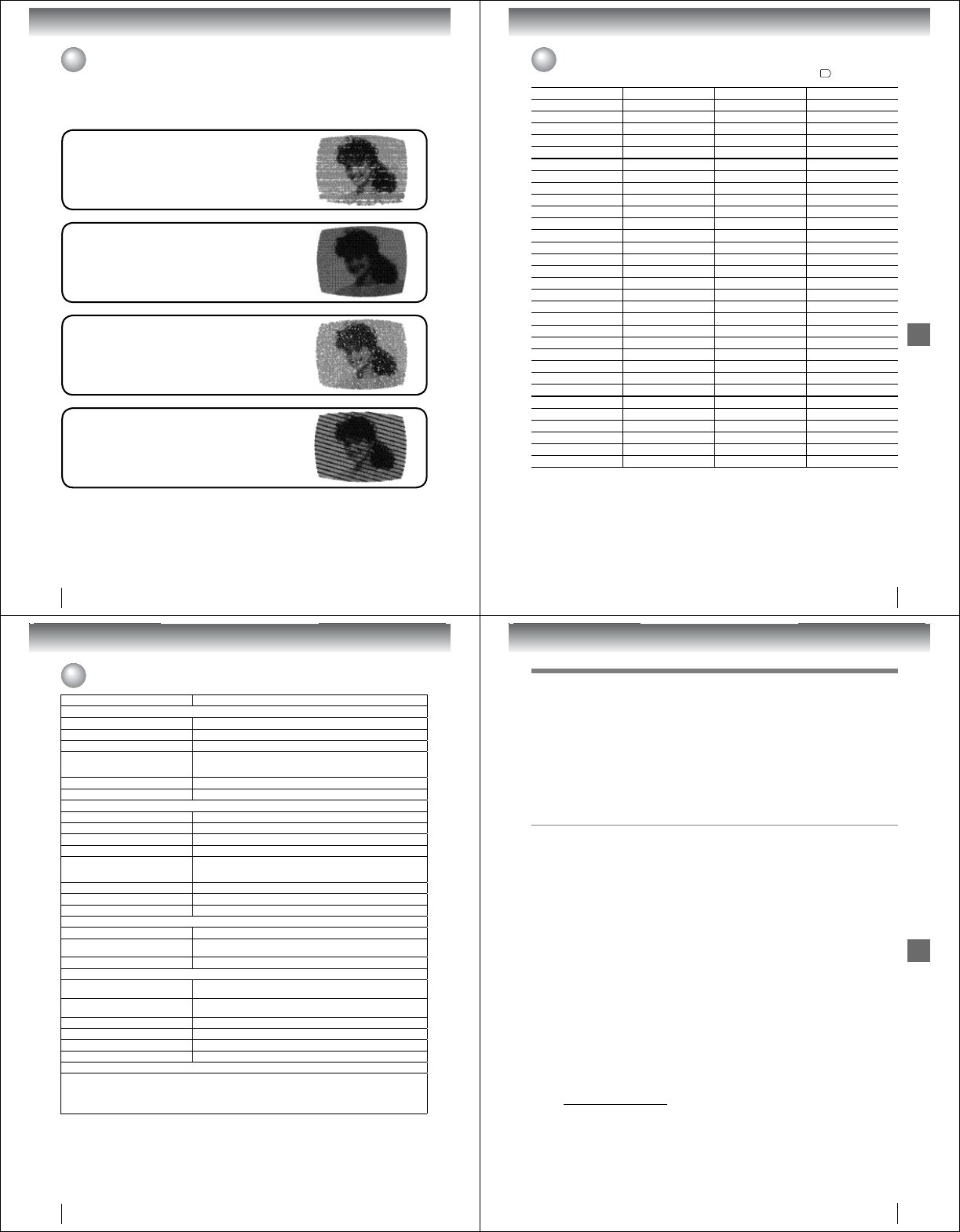
Others
GHOSTS
Ghosts are caused by the television signal following two paths. One is
the direct path and the other is refl ected by tall buildings, hills or other
large objects. Changing the direction or position of the antenna may
improve the reception.
IGNITION
Black spots or horizontal streaks may appear, the picture may fl utter or
drift. Usually caused by interference from automobile ignition systems,
neon lamps or AC powered tools and appliances such as drills or hair
dryers.
SNOW
If the TV/DVD is located far from the TV station, in a fringe reception
area where the signal is weak, small dots may appear in the picture.
If the signal is extremely weak, the installation of a larger external
antenna may be necessary.
RADIO FREQUENCY INTERFERENCE (RFI)
Caused by two-way radios, this type of interference produces moving
ripples or diagonal streaks in the picture. Some cases may cause a
loss of contrast in the picture. Changing the direction and position of
the antenna or installing an RFI fi lter may improve the picture.
CARE AND MAINTENANCE
To prevent fi re or shock hazard, disconnect the TV/DVD from the power source before cleaning.
Use caution when cleaning or wiping the plastic parts.
Reception disturbances
Most types of television interference can be remedied by adjusting the height and position of the VHF/UHF antenna.
Outdoor antennas are recommended for best results. The most common types of television interference are shown
below. If one of these symptoms appear when the TV/DVD is connected to a Cable TV system, the disturbance may
be caused by the local Cable TV company broadcast.
64
Others
Language Name Code Language Name Code Language Name Code Language Name Code
Abkhazian 1112 Fiji 1620 Lingala 2224 Singhalese 2919
Afar 1111 Finnish 1619 Lithuanian 2230 Slovak 2921
Afrikaans 1116 French 1628 Macedonian 2321 Slovenian 2922
Albanian 2927 Frisian 1635 Malagasy 2317 Somali 2925
Amharic 1123 Galician 1722 Malay 2329 Spanish 1529
Arabic 1128 Georgian 2111 Malayalam 2322 Sundanese 2931
Armenian 1835 German 1415 Maltese 2330 Swahili 2933
Assamese 1129 Greek 1522 Maori 2319 Swedish 2932
Aymara 1135 Greenlandic 2122 Marathi 2328 Tagalog 3022
Azerbaijani 1136 Guarani 1724 Moldavian 2325 Tajik 3017
Bashkir 1211 Gujarati 1731 Mongolian 2324 Tamil 3011
Basque 1531 Hausa 1811 Nauru 2411 Tatar 3030
Bengali; Bangla 1224 Hebrew 1933 Nepali 2415 Telugu 3015
Bhutani 1436 Hindi 1819 Norwegian 2425 Thai 3018
Bihari 1218 Hungarian 1831 Oriya 2528 Tibetan 1225
Breton 1228 Icelandic 1929 Panjabi 2611 Tigrinya 3019
Bulgarian 1217 Indonesian 1924 Pashto, Pushto 2629 Tonga 3025
Burmese 2335 Interlingua 1911 Persian 1611 Turkish 3028
Byelorussian 1215 Irish 1711 Polish 2622 Turkmen 3021
Cambodian 2123 Italian 1930 Portuguese 2630 Twi 3033
Catalan 1311 Japanese 2011 Quechua 2731 Ukrainian 3121
Chinese 3618 Javanese 2033 Rhaeto-Romance 2823 Urdu 3128
Corsican 1325 Kannada 2124 Romanian 2825 Uzbek 3136
Croatian 1828 Kashmiri 2129 Russian 2831 Vietnamese 3219
Czech 1329 Kazakh 2121 Samoan 2923 Volapük 3225
Danish 1411 Kirghiz 2135 Sanskrit 2911 Welsh 1335
Dutch 2422 Korean 2125 Scots Gaelic 1714 Wolof 3325
English 1524 Kurdish 2131 Serbian 2928 Xhosa 3418
Esperanto 1525 Laothian 2225 Serbo-Croatian 2918 Yiddish 2019
Estonian 1530 Latin 2211 Shona 2924 Yoruba 3525
Faroese 1625 Latvian, Lettish 2232 Sindhi 2914 Zulu 3631
Language code list
Enter the appropriate code number for the initial settings “Menu”, “Subtitle” and/or “Audio” 58 .
65
Others
66
Specifications
Model 15LV505
General
Power supply AC 120V 60Hz
Power consumption Operation: 35 W, Stand by: 0.8 W
Weight 7.7 lbs (3.5 kg)
Dimensions
Width: 15-13/16 inches (402 mm)
Height: 12-5/8 inches (320 mm)
Depth: 5-1/2 inches (140.1 mm)
Operating temperature 5°C-40°C (41°F-104°F)
Operating humidity Less than 80% RH (No condensation)
Television
LCD panel (Screen size is approximate.) 15-inch diagonal
Display method Color TFT LCD
Number of pixels 1366 (Horizontal) x 768 (Vertical)
Television system NTSC standard, ATSC standard (8VSB), QAM
Receiving channels
VHF: 2-13
UHF: 14-69
CATV: 1-125 (4A, A-5~A-1, A~I, J~W, W+1~W+84)
Antenna input VHF/UHF 75 ohm
Speaker 1-3/16 x 2-13/16 inches (30.5 x 71.1 mm), 8 ohm x 2
Audio output power 1.5W + 1.5W
DVD/CD player
Signal system NTSC
Applicable disc 1. DVD (12cm, 8cm)
2. CD (12cm, 8cm)
Pickup 1-Lens, 2-Beams System
Input/Output
S-Video input (Y) 1.0 V (p-p), 75 ohm, negative sync., Mini DIN 4-pin x 1
(C) 1.0 V (p-p), 75 ohm
ColorStream video input (Y) 1.0 V (p-p), 75 ohm, negative sync., pin jack x 1
(PB, PR) 0.7 V (p-p), 75 ohm, pin jack x 2
Video input 1.0 V (p-p), 75 ohm, negative sync., pin jack x 1
Audio input –8dBm, 50 kohm, negative sync., pin jack (L/R) x 2
Digital audio output (Coaxial) 0.5 V (p-p), 75 ohm, pin jack x 1
Headphone ø3.5mm stereo mini jack x 1
Accessories
Remote control (SE-R0305) ................................................................................................... 1
Batteries (R03/AAA) .............................................................................................................. 2
AC cord .................................................................................................................................. 1
Owner·s manual (this booklet) ..................................................... .......................................... 1
Quick setup guide (Spanish) .................................................................................................. 1
• This model complies with the above specifi cations.
• Designs and specifi cations are subject to change without notice.
• This model may not be compatible with features and/or specifi cations that may be added in the future.
Others
67
Limited One (1) Year Warranty on Parts and Labor
TACP warrants this LCD TV/DVD Combination
and its parts against defects in materials or
workmanship for a period of one (1) year after
the date of original retail purchase. DURING
THIS PERIOD, TACP WILL, AT TACP·S OPTION,
REPAIR OR REPLACE A DEFECTIVE PART WITH
A NEW OR REFURBISHED PART WITHOUT
CHARGE TO YOU.
Rental Units
The warranty for LCD TV/DVD Combination rental
units begins on the date of the fi rst rental or thirty
(30) days after the date of shipment to the rental
fi rm, whichever comes fi rst.
Commercial Units
LCD TV/DVD Combinations sold and used for
commercial purposes have a limited warranty for all
parts and labor, which warranty begins on the date
of original retail purchase and ends on the date that
is ninety (90) days thereafter.
Owner·s Manual and Product Registration Card
Read this owner·s manual thoroughly before operating
this LCD TV/DVD Combination.
Complete and mail the enclosed product registration
card or register your LCD TV/DVD Combination
online at www.tacp.toshiba.com/service as soon as
possible. By registering your LCD TV/DVD
Combination you will enable TACP to bring you
new products specifi cally designed to meet your
needs and help us to contact you in the unlikely
event a safety notifi cation is required under the
U.S. Consumer Product Safety Act. Failure to
complete and return the product registration card
does not diminish your warranty rights.
Your Responsibility
THE ABOVE WARRANTIES ARE SUBJECT TO
THE FOLLOWING CONDITIONS:
(1) You must retain your bill of sale or provide
other proof of purchase.
(2) All warranty servicing of this LCD TV/DVD
Combination must be made by the Depot
Warranty Repair Center specifi ed by the TACP
Consumer Solutions Center.
(3) The warranties from TACP are effective only
if the LCD TV/DVD Combination is purchased
and operated in the Continental U.S.A. or
Puerto Rico.
(4) Labor service charges for set installation,
setup, adjustment of customer controls, and
installation or repair of antenna systems are not
covered by this warranty. Reception problems
caused by inadequate antenna systems are
your responsibility.
(5) Warranties extend only to defects in materials
or workmanship as limited above, and do not
extend to any LCD TV/DVD Combination or
parts that have been lost or discarded by you
or to damage to the LCD TV/DVD Combination
or parts caused by fi res, misuse, accident,
Acts of God (such as lightning or fl uctuations in
electric power), improper installation, improper
maintenance, or use in violation of instructions
furnished by TACP; use or malfunction
through simultaneous use of this LCD TV/DVD
Combination and connected equipment; or to
units that have been modifi ed or had the serial
number removed, altered, defaced, or rendered
illegible.
Limited United States Warranty
LCD TV/DVD Combination - Depot Repair Warranty
Toshiba America Consumer Products, L.L.C. (“TACP”) makes the following limited warranties to original
consumers in the United States. THESE LIMITED WARRANTIES EXTEND TO THE ORIGINAL CONSUMER
PURCHASER OR ANY PERSON RECEIVING THIS LCD TV/DVD COMBINATION AS A GIFT FROM THE
ORIGINAL CONSUMER PURCHASER AND TO NO OTHER PURCHASER OR TRANSFEREE.
LCD TV/DVD COMBINATIONS PURCHASED IN THE U.S.A. AND USED ANYWHERE OUTSIDE
OF THE U.S.A., INCLUDING, WITHOUT LIMITATION, CANADA AND MEXICO, ARE NOT COVERED
BY THESE WARRANTIES.
LCD TV/DVD COMBINATIONS PURCHASED ANYWHERE OUTSIDE OF THE U.S.A., INCLUDING,
WITHOUT LIMITATION, CANADA AND MEXICO, AND USED IN THE U.S.A., ARE NOT COVERED
BY THESE WARRANTIES.
A1-1
CAUTION
THIS
LCD COLOR TELEVISION
EMPLOYS A LASER SYSTEM.
TO ENSURE PROPER USE OF THIS PRODUCT, PLEASE READ THIS SERVICE MANUAL CARE-
FULLY AND RETAIN FOR FUTURE REFERENCE. SHOULD THE UNIT REQUIRE MAINTENANCE,
CONTACT AN AUTHORIZED SERVICE LOCATION-SEE SERVICE PROCEDURE.
USE OF CONTROLS, ADJUSTMENTS OR THE PERFORMANCE OF PROCEDURES OTHER THAN
THOSE SPECIFIED HEREIN MAY RESULT IN HAZARDOUS LASER RADIATION EXPOSURE.
TO PREVENT DIRECT EXPOSURE TO LASER BEAM, DO NOT TRY TO OPEN THE ENCLOSURE.
VISIBLE LASER RADIATION MAY BE PRESENT WHEN THE ENCLOSURE IS OPENED. DO NOT
STARE INTO BEAM.
The laser diode used for a pickup head may be destroyed with external static electricity.
Moreover, even if it is operating normally after repair, when static electricity discharge is received at the
time of repair, the life of the product may be shortened.
Please perform the following measure against static electricity, be careful of destruction of a laser diode
at the time of repair.
• Place the unit on a workstation equipped to protect against static electricity, such as conductive mat.
• Soldering iron with ground wire or ceramic type is used.
• A worker needs to use a ground conductive wrist strap for body.
Location of the required Marking
The rating sheet and the safety caution are on the rear of the unit.
CERTIFICATION: COMPLIES WITH FDA
RADIATION PERFORMANCE STANDARDS,
21 CFR SUBCHAPTER J.
PREPARATION OF SERVICING

A1-2
SERVICING NOTICES ON CHECKING
1. KEEP THE NOTICES
As for the places which need special attentions,
they are indicated with the labels or seals on the
cabinet, chassis and parts. Make sure to keep the
indications and notices in the operation manual.
3. USE THE DESIGNATED PARTS
2. AVOID AN ELECTRIC SHOCK
There is a high voltage part inside. Avoid an
electric shock while the electric current is
flowing.
The parts in this equipment have the specific
characters of incombustibility and withstand
voltage for safety. Therefore, the part which is
replaced should be used the part which has
the same character.
Especially as to the important parts for safety
which is indicated in the circuit diagram or the
table of parts as a mark, the designated
parts must be used.
5. PUT PARTS AND WIRES IN THE
ORIGINAL POSITION AFTER
ASSEMBLING OR WIRING
There are parts which use the insulation
material such as a tube or tape for safety, or
which are assembled in the condition that
these do not contact with the printed board.
The inside wiring is designed not to get closer
to the pyrogenic parts and high voltage parts.
Therefore, put these parts in the original
positions.
PERFORM A SAFETY CHECK AFTER
SERVICING
6.
Confirm that the screws, parts and wiring which
were removed in order to service are put in the
original positions, or whether there are the
portions which are deteriorated around the
serviced places serviced or not. Check the
insulation between the antenna terminal or
external metal and the AC cord plug blades.
And be sure the safety of that.
(INSULATION CHECK PROCEDURE)
1.
2.
3.
4.
Unplug the plug from the AC outlet.
Remove the antenna terminal on TV and turn
on the TV.
Insulation resistance between the cord plug
terminals and the eternal exposure metal
[Note 2] should be more than 1M ohm by
using the 500V insulation resistance meter
[Note 1].
If the insulation resistance is less than 1M
ohm, the inspection repair should be
required.
[Note 1]
If you have not the 500V insulation
resistance meter, use a Tester.
[Note 2]
External exposure metal:
4. BE CAREFUL WITH THE
LCD PANEL
Avoid a shock to the panel while servicing.
Take enough care to deal with it.
Please include the following informations when you order parts. (Particularly the VERSION LETTER.)
1. MODEL NUMBER and VERSION LETTER
The MODEL NUMBER can be found on the back of each product and the VERSION LETTER can be
found at the end of the SERIAL NUMBER.
2. PART NO. and DESCRIPTION
You can find it in your SERVICE MANUAL.
HOW TO ORDER PARTS
Antenna terminal
Headphone jack

A1-3
IMPORTANT SAFEGUARDS
1) Read these instructions.
2) Keep these instructions.
3) Heed all warnings.
4) Follow all instructions.
5) Do not use this apparatus near water.
6) Clean only with dry cloth.
7) Do not block any ventilation openings. Install in accordance with the manufacturer's instructions.
8) Do not install near any heat sources such as radiators, heat registers, stoves, or other apparatus (including
amplifiers) that produce heat.
9) Do not defeat the safety purpose of the polarized or grounding-type plug. A polarized plug has two blades
with one wider than the other. A grounding type plug has two blades and a third grounding prong. The wide
blade or the third prong are provided for your safety. If the provided plug does not fit into your outlet,
consult an electrician for replacement of the obsolete outlet.
10) Protect the power cord from being walked on or pinched particularly at plugs, convenience receptacles, and
the point where they exit from the apparatus.
11) Only use attachments/accessories specified by the manufacturer.
12) Use only with the cart, stand, tripod, bracket, or table specified by the manu-
facturer, or sold with the apparatus. When a cart is used, use caution when
moving the cart/apparatus combination to avoid injury from tip-over.
13) Unplug this apparatus during lightning storms or when unused for long
periods of time.
14) Refer all servicing to qualified service personnel. Servicing is required when
the apparatus has been damaged in any way, such as power-supply cord or
plug is damaged, liquid has been spilled or objects have fallen into the
apparatus, the apparatus has been exposed to rain or moisture, does not operate normally, or has been
dropped.
15) Apparatus shall not be exposed to dripping or splashing and that no objects filled with liquids, such a vases,
shall be placed on the apparatus.
16) An outside antenna system should not be located in the vicinity of overhead power lines or other electric
light or power circuits, or where it can fall into such power lines or circuits. When installing an outside
antenna system, extreme care should be taken to keep from touching such power lines or circuits, as
contact with them might be fatal.
17) Do not overload wall outlets and extension cords, as this can result in a risk of fire or electric shock.
18) Do not push objects through any openings in this unit, as they may touch dangerous voltage points or short
out parts that could result in fire or electric shock. Never spill or spray any type of liquid into the unit.
S3126A
PORTABLE CART WARNING
(symbol provided by RETAC)
A1-4
IMPORTANT SAFEGUARDS (CONTINUED)
19) If an outside antenna or cable system is connected to the unit, be sure the antenna or cable system is
grounded to provide some protection against voltage surges and built-up static charges, Section 810 of the
National Electrical Code, ANSI/NFPA 70, provides information with respect to proper grounding of the mast
and supporting structure, grounding of the lead-in wire to an antenna discharge unit, size of grounding
conductors, location of antenna discharge unit, connection to grounding electrodes, and requirements for
the grounding electrode.
20) When replacement parts are required, be sure the service technician uses replacement parts specified by
the manufacturer or those that have the same characteristics as the original part.
Unauthorized substitutions may result in fire, electric shock or other hazards.
21) Upon completion of any service or repairs to this unit, ask the service technician to perform safety checks to
determine that the unit is in proper operating condition.
22) Keep your fingers clear of the disc slot as it is closing. It may cause injury.
23) When you connect the product to other equipment, turn off the power and unplug all of the equipment from
the wall outlet. Failure to do so may cause an electric shock and serious personal injury. Read the owner's
manual of the other equipment carefully and follow the instructions when making any connections.
24) Reduce the volume to the minimum level before you turn on the product. Otherwise, sudden high volume
sound may cause hearing or speaker damage.
EXAMPLE OF ANTENNA GROUNDING AS PER THE
NATIONAL ELECTRICAL CODE
ANTENNA
DISCHARGE UNIT
(NEC SECTION 810-20)
ANTENNA LEAD
IN WIRE
GROUNDING CONDUCTORS
(NEC SECTION 810-21)
GROUND CLAMPS
POWER SERVICE GROUNDING
ELECTRODE SYSTEM
(NEC ART 250, PART H)
GROUND
CLAMP
ELECTRIC SERVICE
EQUIPMENT
NEC-NATIONAL ELECTRICAL CODE
S2898A

A1-5
HOW TO HANDLE THE LCD PANEL
• Do not press hard or jolt the LCD panel. It may cause the LCD panel glass to break and injury may occur.
• If the LCD panel is broken, make absolutely sure that you do not touch the liquid in the panel. This may
cause skin inflammation.
If the liquid gets in your mouth, immediately gargle and consult with your doctor. Also, if the liquid gets in
your eyes or touches your skin, consult with your doctor after rinsing for at least 15 minutes or longer in clean
water.
CONDENSATION
Moisture will form in the operating section of the player if the player is brought from cool surroundings into a
warm room or if the temperature of the room rises suddenly. When this happens, player's performance will
be impaired.
To prevent this, let the player stand in its new surroundings for about an hour before switching it on, or
make sure that the room temperature rises gradually.
Condensation may also form during the summer if the player is exposed to the breeze from an air condi-
tioner. In such cases, change the location of the player.
25) Do not allow the product to output distorted sound for an extended period of time. It may cause speaker
overheating and fire.
26) When you use the headphones, keep the volume at a moderate level. If you use the headphones continu-
ously with high volume sound, it may cause hearing damage.
27) Do not look into the opening of the disc slot or ventilation opening of the product to see the source of the
laser beam. It may cause eye damage.
28) Do not use a cracked, deformed, or repaired disc. These discs are easily broken and may cause serious
personal injury and product malfunction.
29) This reminder is provided to call the cable TV system installer's attention to Article 820-40 of the NEC that
provides guidelines for proper grounding and, in particular, specifies that the cable ground shall be con-
nected to the grounding system of the building, as close to the point of cable entry as practical.
IMPORTANT SAFEGUARDS (CONTINUED)
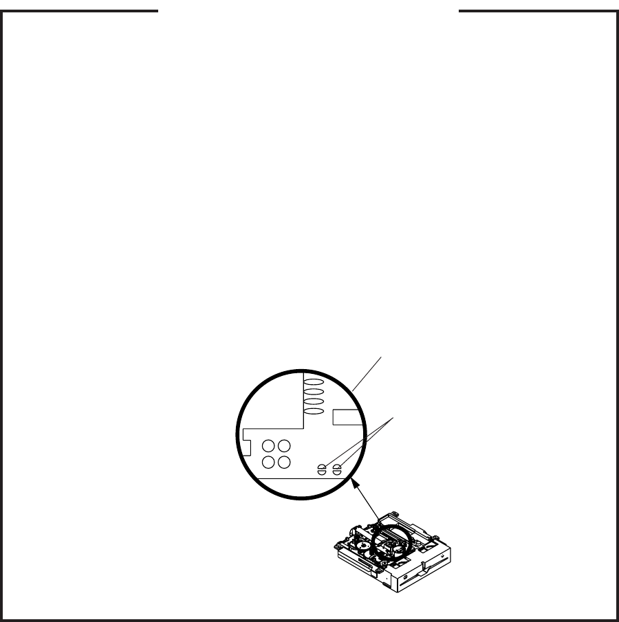
A1-6
Before removing Pick Up PCB and DVD MT PCB connector, the short circuit the position shown in Fig.
1 using a soldering iron. If you remove the DVD Deck with no soldering, the Laser may be damaged.
WHEN REPLACING DVD DECK
[ When removing the DVD Deck ]
[ When installing the DVD Deck ]
Remove all the soldering on the short circuit position after the connection of Pick Up PCB and DVD
MT PCB connector.
NOTE
Fig. 1
Before your operation, please read “PREPARATION OF SERVICING”.
Use the Lead Free solder.
Manual soldering conditions
• Soldering temperature: 320 ± 20oC
• Soldering time: Within 3 seconds
• Soldering combination: Sn-3.0Ag-0.5Cu
When Soldering/Removing of solder, use the draw in equipment over the Pick Up Unit to keep the
Flux smoke away from it.
•
•
•
•
Short circuit using a
soldering iron.
Pick Up PCB
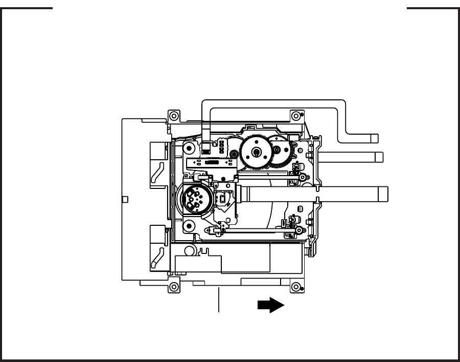
1.
2.
3.
Remove the Back Cabinet and Angle Deck. (Refer to item 1 of the DISASSEMBLY INSTRUCTIONS.)
Slide the Belt Loading toward the arrow direction by hand to release the lock. (Refer to Fig. 1)
Take out the Disc from the DVD Deck. Be careful not to scratch on the Disc.
DISC REMOVAL METHOD AT NO POWER SUPPLY
Fig. 1
DVD Deck
Belt Loading
A1-7
If the stored 4 digit password in the Rating Level menu needs to be cancelled, please follow the steps below.
Turn Unit ON.
Set the DVD to the Stop Mode.
Check that “No disc” is displayed on the screen.
Press and hold the “STOP” button on the top panel.
Simultaneously press and hold the “7” key on the remote control unit.
Hold both keys for more than 2 seconds.
The On Screen Display message “PASSWORD CLEAR” will appear.
The 4 digit password has now been cleared.
1.
2.
3.
4.
5.
6.
7.
8.
PARENTAL CONTROL - RATING LEVEL
4 DIGIT PASSWORD CANCELLATION
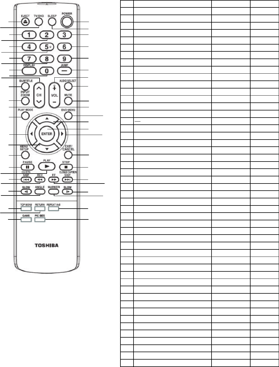
REMOTE CONTROL KEY CODE
NEC Format
Custom Code : 40-BF H, 44-BB H, 45-BA H, 45-BC H
No. Key Name Custom Code Key Code
1EJECT 45 BA F5
2TV/DVD 45 BC B3
3SLEEP 40 BF 15
4POWER 40 BF 12
5 1 40 BF 01
6 2 40 BF 02
7 3 40 BF 03
8 4 40 BF 04
9 5 40 BF 05
10 6 40 BF 06
11 7 40 BF 07
12 8 40 BF 08
13 9 40 BF 09
14 DISPLAY 40 BF 1C
15 0 40 BF 00
16 / JUMP 44 BB 9B
17 SUBTITLE 44 BB 87
18 CH UP 40 BF 1B
19 VOLUME + 40 BF 1A
20 AUDIO SELECT 44 BB 53
21 INPUT/ZOOM 40 BF 0F
22 CH DOWN 40 BF 1F
23 VOLUME - 40 BF 1E
24 MUTE 40 BF 10
25 PLAY MODE 40 BF 1D
26 DVD MENU 40 BF 19
27 UP 44 BB 80
28 LEFT 44 BB 51
29 ENTER 44 BB 4E
30 RIGHT 44 BB 4D
31 DOWN 44 BB 81
32 MENU/SETUP 40 BF 0E
33 EXIT/CANCEL 44 BB EF
34 PAUSE 44 BB 10
35 PLAY 44 BB 15
36 STOP 44 BB 14
37 CH RTN/|<<SKIP 40 BF 17
38 <<REV 44 BB 19
39 FF>> 44 BB 13
40 CLOSED CAPTION/SKIP>>| 40 BF 57
41 <|SLOW 45 BA 0E
42 ANGLE 44 BB 96
43 MARKER 45 BA EC
44 SLOW |> 44 BB 0D
45 TOP MENU 44 BB DF
46 RETURN 44 BB 5D
47 REPEAT A-B 44 BB 5C
48 GAME 40 BF 28
49 PICTURE SIZE 40 BF 59
1
24
3
5
67
10
13
16
20
19
23
24
26
27
29 30
33
36
40 39
44 43
47
49
8
911
1214
15
18
17
21
22
25
28
31
32
34
35 37
3841
42
45
4648
A1-8
GENERAL SPECIFICATIONS
G-1 TV LCD LCD Size / Visual Size 15.6 inch / 394.9mmV
System LCD Type Color TFT LCD
Number of Pixels 1366(H) x 768(V)
View Range Left/Right 85/85 degree
Up/Down 80/80 degree
Bright Dot n=0
Zero Bright Dot Ratio ---
Color System NTSC
Speaker 2 Speaker
Position Front
Size 1.2 x 2.8 inch
Impedance 8 ohm
Sound Output Max 1.5W + 1.5W
10%(Typical) ---
G-2 DVD System Color System NTSC
Disc
DVD, CD-
DVD-R/RW (Video Format Only)
Disc Diameter 120 mm , 80 mm
Drive DSM-2
Search speed Fwd 4 step
Actual 2-45 times (DVD)
4-40 times (CD)
Rev 4 step
Actual 2-45 times (DVD)
4-40 times (CD)
Slow speed Fwd 1/7 -1/2 times
Actual --
Rev 1/7 -1/2 times
Actual --
G-3 Tuning Broadcasting System Analog US System M
System Digital ATSC(8VSB)/QAM
Tuner and System 1Tuner
Receive CH Destination US (W/CABLE)
CH Coverage 2~69, 4A, A-5~A-1, A~I, J~W, W+1~W+84
Intermediate
Digital 44.00MHz
Frequency Analog Picture(FP) 45.75MHz
Sound(FS) 41.25MHz
FP-FS 4.50MHz
Preset CH No
Stereo/Dual TV Sound US-Stereo
Tuner Sound Muting Yes
G-4 Signal Video Signal Input Level 1 V p-p/75 ohm
Output Level --
S/N Ratio (Weighted) --
Horizontal Resolution at DVD Mode --
--
RGB Signal Output Level --
Audio Signal Input Level -8.0dBm/50k ohm
Output Level at DVD --
at TV --
--
Digital Output Level 0.5 V p-p/75 ohm
S/N Ratio at DVD (Weighted) --
Harmonic Distortion --
Frequency Response : at DVD --
at Video CD --
at SVCD --
at CD --
<
A2-1

GENERAL SPECIFICATIONS
G-5 Power Power Source AC 120V, 60Hz
DC --
Power Consumption at AC 35W at 120V 60Hz
at DC --
Stand by (at AC) 0.8W at 120V 60Hz
Energy Star Yes
Per Year -- kWh/Year
Protector Power Fuse Yes
Safety Circuit Yes
IC Protector(Micro Fuse) Yes
G-6 Regulation Safety UL(UL6500_2nd)
Radiation FCC
Laser DHHS
G-7 Temperature Operation
+5
o
C ~ +40
o
C
Storage
-20
o
C ~ +60
o
C
Space Around Unit 100 mm(4inch)
G-8 Operating Humidity Less than 80% RH
G-9 Clock and Clock (Only Broadcasting data) No
Timer Sleep Timer Max Time 120 Min
On Timer Program No
Off Timer Program No
Game Timer No
Wake Up Timer No
Timer Back-up (at Power Off Mode) more than -- Min Sec
A2-2

GENERAL SPECIFICATIONS
G-10 Remote Unit RC-LT
Control Glow in Dark Remocon Yes
Remocon Format TOSHIBA
Format TOSHIBA
Custom Code 40-BF h ,44-BB h ,45-BA h ,45-BC h
Power Source Voltage(D.C) 3V
UM size x pcs UM-4 x 2 pcs
Total Keys 49 Keys
Keys Power Yes
Eject Yes
Sleep Yes
TV/DVD Yes
1Yes
2Yes
3Yes
4Yes
5Yes
6Yes
7Yes
8Yes
9Yes
0Yes
Jump / - Yes
Display Yes
Subtitle Yes
Audio Select Yes
Input Select / Zoom Yes
Mute Yes
CH Up Yes
CH Down Yes
Vol Up Yes
Vol Down Yes
Play Mode Yes
DVD Menu Yes
Up Yes
Down Yes
Left Yes
Right Yes
Enter Yes
Menu / Setup Yes
Exit / Cancel Yes
Game Yes
Picture Size Yes
Pause Yes
Play Yes
Stop Yes
Skip+ / Closed Caption Yes
Skip- / CH Return Yes
Search+ Yes
Search- Yes
Slow+ Yes
Slow- Yes
Angle Yes
Marker Yes
Top Menu Yes
Return Yes
Closed Caption No
Repeat A-B Yes
Zoom/ Quick View No
Freeze frame No
A2-3
GENERAL SPECIFICATIONS
G-11 Features Auto Shut Off Yes
Auto Search No
Power On Memory Yes
Comb Filter Yes
3 -D
Game Position Yes
Auto Setup(Language/CH Program) Yes
Picture Setting(TV) Yes
Picture Preference Yes
Brightness , Contrast , Color Yes
Tint Yes
Sharpness Yes
Color Temperature Yes
DNR Yes
Cable Clear No
Picture Setting(PC) No
HOR Position , VER Position No
Phase, Clock No
Red, Green, Blue No
Auto Adjust No
Backlight No
Audio MTS Yes
Tone Control (Bass/Treble/Balance) Yes
Stable Sound No
Surround No
BBE No
SRS WOW (SRS 3D/Focus/Tru Bass) No
Variable Audio Out No
Tuning CH Program Yes
Air/Cable Yes
ADD/DELETE Yes
Label CH Label Yes
Video Label Yes
Favorite CH No
V-Chip Yes
Type USA Type
RRT Setup
Yes
Lock Hotel Lock No
Channel Lock No
Video Lock No
Panel Lock No
Menu Language
English
French
Spanish
Closed Caption
Yes
CC Advanced
Yes
Picture Size Yes
HD Zoom Yes
Picture Scroll
No
Film Mode Yes
Aspect Yes
Backlight Yes
PFC(Power Factor circuit)
No
Freeze frame No
PIP/POP No
Direct Input Selection Yes
Digital Out Dolby Digital Yes
MPEG No
PCM No
DTS
No
A2-4
GENERAL SPECIFICATIONS
PC Monitor Input No
VGA (640x480) No
VGA (720x400) No
WVGA (848x480) No
SVGA (800x600) No
XGA (1024x768) No
WXGA (1280x768) No
WXGA (1280x720) No
WXGA (1360x768) No
SXGA (1280x1024) No
HDMI Input No
VGA (640×480) No
720×480i (4:3) No
720×480i (16:9) No
720×480p (4:3) No
720×480p (16:9) No
720×576i (4:3) No
720×576i (16:9) No
720×576p (4:3) No
720×576p (16:9) No
1280×720p No
1920×1080i No
CEC (ORION Standard) No
Deep Color No
xvYCC No
Component Input Yes
720×480i (4:3) Yes (60Hz)
720×480i (16:9) Yes (60Hz)
720×480p (4:3) Yes (60Hz)
720×480p (16:9) Yes (60Hz)
720×576i (4:3) No
720×576i (16:9) No
720×576p (4:3) No
720×576p (16:9) No
1280×720p Yes (60Hz)
1920×1080i Yes (60Hz)
Wall Mount Size W x H(mm) No
Screw Size No
Features Video CD Playback Yes
(DVD) SVCD Playback
No
MP3 Playback Yes
JPEG Yes
WMA Yes
Divx Playback No
DMF Support No
Digital Out (Dolby Digital) Yes
(MPEG) Yes
(PCM) Yes
(DTS) Yes
Down Mix Out (Dolby Digital) Yes
(DTS) No
Closed Caption Yes
Screen Saver No
TV Screen 4:3 (Letter Box, Pan Scan) Yes
16:9 (Wide) Yes
Audio DAC 192kHz / 24bit
A2-5

GENERAL SPECIFICATIONS
G-12 Accessories Owner's Manual Language English
w/Guarantee Card Yes
Remote Control Unit Yes
Rod Antenna
No
Poles --
Terminal --
Loop Antenna
No
Terminal --
U/V Mixer
No
DC Car Cord (Center+)
No
Guarantee Card
No
Warning Sheet
No
Circuit Diagram
No
Antenna Change Plug
No
Service Facility List
No
Important Safeguard
No
Dew/AHC Caution Sheet
No
Quick Set-up Sheet(Spanish) Yes
Battery Yes
UM size x pcs UM-4 x 2 pcs
OEM Brand No
AC Adapter
No
AC Cord (for AC Adapter)
No
AC Cord Yes
AV Cord (2Pin-1Pin)
No
Registration Card (NDL Card) Yes
300 to 75ohm Antenna Adapter
No
Sheet Information (Return) Yes(USA version)
Sheet Information (HDMI) No
Cleaning Cloth No
A2-6
GENERAL SPECIFICATIONS
G-13 Interface Switch Top Power (Tact) Yes
Channel Up/Menu Up/Play Yes
Channel Down/Menu Down/Stop Yes
Volume Up/Menu > Yes
Volume Down/Menu < Yes
Menu Yes
Play No (CH+ Alternative)
Eject Yes
Skip+, Search+ No
Skip-, Search- No
Still/Pause No
Stop No (CH- Alternative)
Main Power SW No
Input Select/Enter Yes
Rear Main Power SW No
Indicator Power/Stand-By Yes (Blue / Red)
Power Wake Up No
On Timer No
Terminals Rear Video Input 1 RCA x 1
Audio Input 1 RCA x 2(L/MONO, R)
S - Input 1 Yes
Video Input 2 No
Audio Input 2 No
S - Input 2 No
Video Output No
Audio Output No
Component Input 1 RCA x 3
Analog Audio RCA x 2(L/MONO, R)
Component Input 2 No
Analog Audio No
HDMI Input 1 No
Analog Audio No
HDMI Input 2 No
Analog Audio No
Sub Woofer Out No
PC Monitor Input No
Analog Audio No
Digital Audio Output Coaxial
DC Jack (Center +) No
VHF/UHF Antenna Input F Type
Video Input 3 No
Audio Input 3 No
S - Input 3 No
Other Terminal Headphone
AC Inlet Yes
G-14 Set Size Approx. W x D x H (mm) 402.0 x 140.1 x 320.0
w/o Handle, Stand Approx. W x D x H (mm) 402.0 x 64.0 x 289.0
G-15 Weight Net (Approx.) 3.5kg (7.7 lbs)
Net w/o Handle, Stand (Approx.) 3.3kg (7.3 lbs)
Gross (Approx.) 5.0kg (11.0 lbs)
A2-7

GENERAL SPECIFICATIONS
G-16 Carton Master Carton No
Content --- Sets
Material --- / ---
Dimensions W x D x H(mm) ---
Description of Origin ---
Gift Box Material Double/Full Color
W/Color Photo Label No
W/Handle Yes
Dimensions W x D x H(mm) 474 x404 x 210
Description of Origin Yes
Drop Test Natural Dropping At 2 Corner / 2 Edges / 3 Surfaces
Height (cm) 80
Container Stuffing (40' container) 1551
Sets/40' container
w/Pallet No
w/Wrapping No
G-17 Material Cabinet Front PC+ABS 94V0 NON-HALOGEN
Rear PS 94V0 NON-DECABROM
Jack Panel --
PCB Non-Halogen Demand No
Eyelet Demand Yes
G-18 Environment Environmental standard requirement Green procurement of ORION
Pb-free Phase3(Phase3A)
Measures for Whisker Yes
A2-8
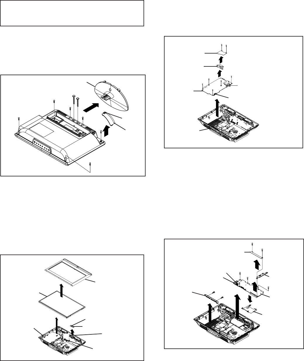
DISASSEMBLY INSTRUCTIONS
B1-1
1. REMOVAL OF MECHANICAL PARTS
AND P.C. BOARDS
1-3: POWER PCB (Refer to Fig. 1-3)
1.
2.
3.
4.
5.
6.
Remove the 2 screws (1).
Remove the Sheet Pc-1 in the direction of arrow (A).
Remove the Angle Lcd-R in the direction of arrow (B).
Disconnect the following connectors:
(CP501, CP2201 and CP8101).
Remove the 5 screws (2).
Remove the Power PCB in the direction of arrow (C).
CAUTION
Be careful not to remove the FFC cable forcibly, because
the FFC cable may be damaged.
1-1: STAND ASS'Y (Refer to Fig. 1-1)
1.
2.
3.
4.
5.
Remove the 2 screws (1).
Remove the Stand Ass'y in the direction of arrow (A).
Unlock the support (2).
Remove the Cover Back in the direction of arrow (B).
Remove the 6 screws (3).
1-2: FRONT CABINET ASS'Y, LCD PANEL AND
REMOCON PCB (Refer to Fig. 1-2)
Fig. 1-3
Power PCB
(1)
(1)
(A)
(C) CP501
(B) (2)
(2)
(2) (2)
(2)
1-4: DIGITAL PCB AND OPERATION PCB
(Refer to Fig. 1-4)
1.
2.
3.
4.
5.
6.
7.
8.
9.
Remove the 2 screws (1).
Remove the Sheet Pc-2 in the direction of arrow (A).
Remove the Angle Lcd-L in the direction of arrow (B).
Disconnect the following connectors:
(CP3001 and CP3002).
Remove the 4 screws (2).
Remove the Digital PCB in the direction of arrow (C).
Remove the Shield Digital in the direction of arrow (D).
Remove the 2 screws (3).
Remove the Operation PCB in the direction of arrow (E).
CP8101
CP2201
Stand Ass'y
Fig. 1-1
(3)
(1) (1)
(3)
(3)
(3)
(3)
(3)
Cover Back
Support
(B)
(A) (2)
Remove the Front Cabinet Ass'y in the direction of
arrow (A).
Disconnect the following connectors:
(CD7005 and CP2804).
Remove the LCD PANEL in the direction of arrow (B).
Disconnect the following connector: (CP7601).
Unlock the support (1).
Remove the Remocon PCB in the direction of arrow (C).
1.
2.
3.
4.
5.
6.
Fig. 1-2
Remocon PCB
LCD Panel (A)
(B)
CD7005 CP7601
CP2804
Front Cabinet Ass'y
Support
(C)
(1)
Sheet Pc-1
Angle Lcd-R
Fig. 1-4
(1)
(A)
(C) Digital PCB
Operation PCB
(D)
(B)
(2)
CP3002
Shield Digital
(3)
(3)
(E)
Sheet Pc-2
Angle Lcd-L
(1)
(2)
(2)
(2)
CP3001
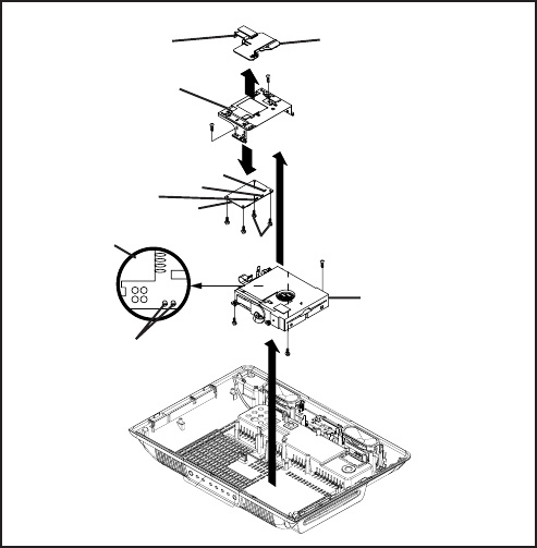
DISASSEMBLY INSTRUCTIONS
B1-2
1-5: DVD DECK (Refer to Fig. 1-5)
1.
2.
3.
4.
5.
6.
7.
8.
9.
10.
Short circuit the position shown in Fig. 1-5 using a
soldering iron. If you remove the DVD Deck with no
soldering, the Laser may be damaged.
Remove the 3 screws (1).
Remove the DVD Deck in the direction of arrow (A).
Disconnect the following connectors:
(CP2301, CP2302 and CP2303).
Remove the support (2).
Remove the Cover DVD in the direction of arrow (B).
Remove the 2 screws (3).
Remove the Angle Mpeg in the direction of arrow (C).
Remove the 4 screws (4).
Remove the DVD MT PCB in the direction of arrow (D).
Fig. 1-5
NOTE
Before your operation, please read "PREPARATION OF
SERVICING"
Use the Lead Free solder.
Manual soldering conditions
• Soldering temperature: 320 ± 20oC
• Soldering time: Within 3 seconds
• Soldering combination: Sn-3.0Ag-0.5Cu
When Soldering/Removing of solder, use the drawing
equipment over the Pick Up Unit to keep the Flux smoke
away from it.
When installing the DVD Deck, remove all the soldering
on the short circuit position after the connection of Pick Up
PCB and DVD MT PCB connector.
1.
2.
3.
4.
5.
Pick Up PCB
DVD Deck
Short circuit using a
soldering iron.
DVD MT PCB
(2)
(C)
(B)
(3)
(4)(4) (4)
Angle Mpeg (1)
(1)
(3)
(A)
CP2303
CP2302
CP2301
(1)
Support Cover DVD
(D)
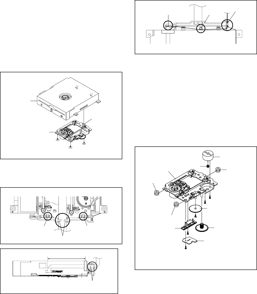
DISASSEMBLY INSTRUCTIONS
B2-1
2. REMOVAL OF DVD DECK PARTS
2-1: TRAVERSE ASS'Y (Refer to Fig. 2-1-A)
Remove the 3 screws (1).
Unlock the 2 supports (2).
Remove the Insulator (R) from the Loader Sub Ass'y.
Remove the Traverse Ass'y.
1.
2.
3.
4.
Fig. 2-1-A
Insulator (R)
NOTE
1. Disassemble only the DVD DECK PARTS parts listed
here. Minute adjustments are needed if the disassembly
is done. If the repair is needed except listed parts, replace
the DVD MECHA ASS'Y.
(1)
(2)
Loader Sub Ass'y
Traverse Ass'y
(2)
Fig. 2-1-B
• Screw Torque: 2.0 ± 0.3kgf•cm (1)
(1)
NOTE
1. In case of the Traverse Ass'y installation, hook the wire
on the Loader Ass'y as shown Fig. 2-1-B to Fig. 2-1-C.
Check Hook
Loader Ass'y (Bottom Side)
Check Lock Check Lock
Fig. 2-1-C
Loader Ass'y
80 ± 5mm
Check Hook
Fig. 2-1-D
Loader Ass'y (Top Side)
Check Hook Check Hook Check Hook
2-2:
Remove the Insulator (F).
Remove the Insulator (R).
Unlock the support (1).
Remove the Gear Middle.
Remove the screw (2).
Remove the Rack Feed Ass'y.
Remove the screw (3).
Remove the Switch PCB Ass'y.
Remove the screw (4).
Remove the Gear Feed.
Remove the 2 screws (5).
Remove the Feed Motor.
Remove the Gear Motor.
1.
2.
3.
4.
5.
6.
7.
8.
9.
10.
11.
12.
13.
SWITCH PCB ASS'Y/GEAR MIDDLE/GEAR FEED/RACK
FEED ASS'Y/FEED MOTOR (Refer to Fig. 2-2-A)
(3)
Gear Middle
Gear Motor
Feed Motor
• Screw Torque: 1.3 ± 0.3kgf•cm (Screw 2)
• Screw Torque: 3.0 ± 0.3kgf•cm (Screw 3)
• Screw Torque: 1.0 ± 0.3kgf•cm (Screw 4, 5)
Switch PCB Ass'y
(2)
(4)
Rack Feed Ass'y
Gear Feed
(5)
Fig. 2-2-A
Traverse Ass'y
(5)
(1)
Insulator (R)
Insulator (F)
Insulator (F)
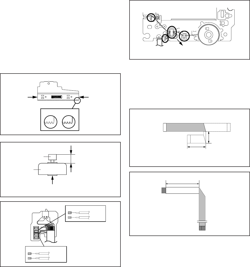
DISASSEMBLY INSTRUCTIONS
B2-2
~ FEED MOTOR ~
WHITE (4)
BROWN (3)
~ SPINDLE MOTOR ~
YELLOW (2)
GREEN (1)
Fig. 2-2-D
Switch PCB Ass'y
• Install wire from (1) to (4) in order.
Fig. 2-2-C
8.0 ± 0.2mm
Safety surface for pressing
of the insert.
Feed Motor
Gear Motor
NOTE
1.
2.
3.
4.
When installing the Rack Feed Ass'y, push both ends to
align the teeth as shown Fig. 2-2-B. Then install it.
In case of the Gear Motor installation, check if the value
of the Fig. 2-2-C is correct.
When installing the wire of the Switch PCB Ass'y, install it
correctly as Fig. 2-2-D.
Manual soldering conditions
• Soldering temperature: 320 ± 20oC
• Soldering time: Within 3 seconds
• Soldering combination: Sn-3.0Ag-0.5Cu
After the assembly of the Traverse Ass'y, hook the wire
on the Traverse Ass'y as shown Fig. 2-2-E.
[OK] [NG]
Fig. 2-2-B
Rack Feed Ass'y
Push
Push
When installing the FFC, fold it correctly and install it as
shown from Fig. 2-3-A to Fig. 2-3-B.
2-3: FFC WIRE HANDLING
1.
Do not make the folding lines except the specified
positions for the FFC.
1.
NOTE
Traverse Ass'y
Check Hook
Check Hook
Check Hook
Fig. 2-2-E
• Loosen the wire in the direction of the arrow.
Check Hook
Fold
40 ± 1mm
[ 6 pin FFC ]
Fig. 2-3-B
Printing Surface
To Pick Up PCB Printing Surface
Fold it by 90û
20 ± 1mm
[ 24 pin FFC ]
Fig. 2-3-A
30 ± 1mm
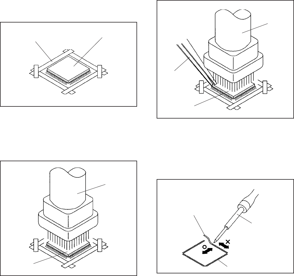
B3-1
Masking Tape
(Cotton Tape)
DISASSEMBLY INSTRUCTIONS
3.
REMOVAL
IC
Put Masking Tape (cotton tape) around the Flat Package
IC to protect other parts from any damage.
(Refer to Fig. 3-1.)
1.
Fig. 3-1
NOTE
REMOVAL AND INSTALLATION OF
FLAT PACKAGE IC
Some ICs on the PCB are affixed with glue, so be
careful not to break or damage the foil of each IC
leads or solder lands under the IC when removing it.
NOTE
Masking is carried out on all the parts located within
10 mm distance from IC leads.
Blower type IC
desoldering machine
IC
Heat the IC leads using a blower type IC desoldering
machine. (Refer to Fig. 3-2.)
2.
Fig. 3-2
NOTE
Do not rotate or move the IC back and forth , until IC
can move back and forth easily after desoldering the
leads completely.
When IC starts moving back and forth easily after
desoldering completely, pickup the corner of the IC using
tweezers and remove the IC by moving with the IC
desoldering machine. (Refer to Fig. 3-3.)
3.
Blower type IC
desoldering
machine
IC
Fig. 3-3
Tweezers
Peel off the Masking Tape.4.
Absorb the solder left on the pattern using the Braided
Shield Wire. (Refer to Fig. 3-4.)
5.
NOTE
Do not move the Braided Shield Wire in the vertical
direction towards the IC pattern.
Braided Shield Wire
Soldering Iron
Fig. 3-4
IC pattern
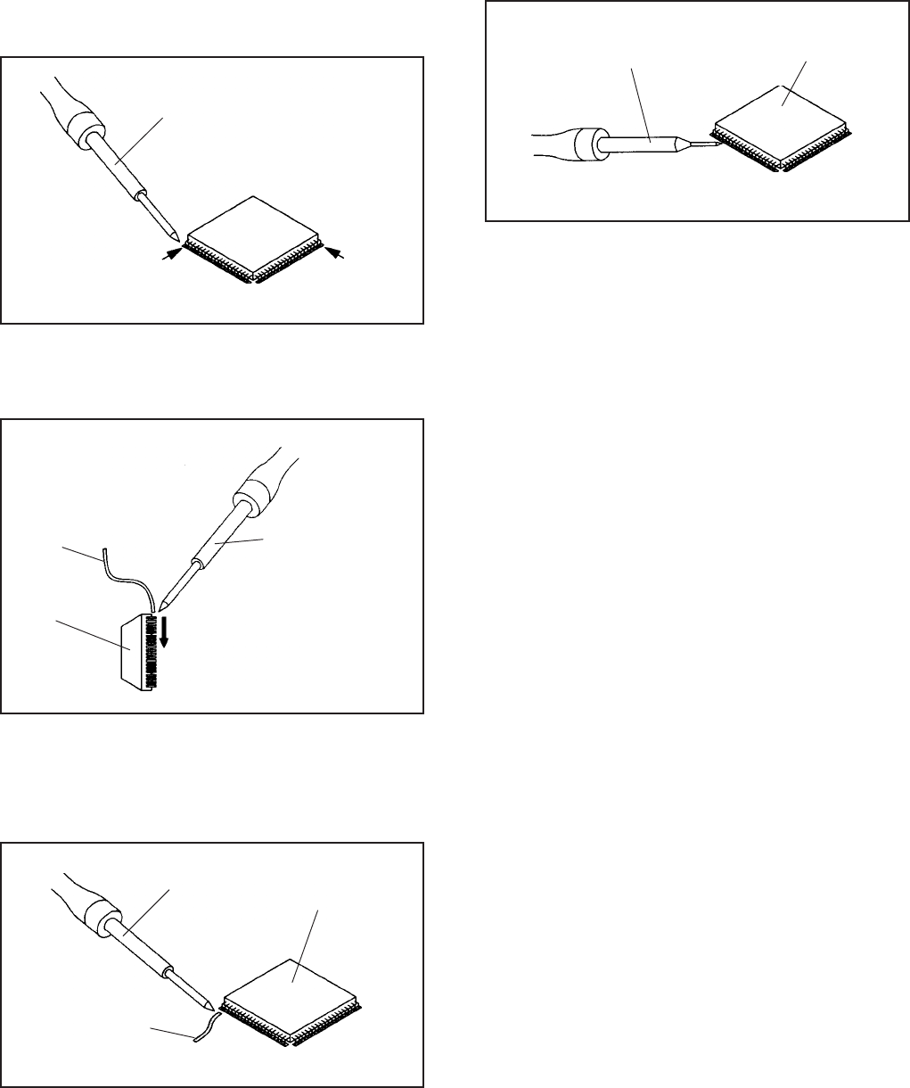
B3-2
DISASSEMBLY INSTRUCTIONS
Supply soldering
from upper position
to lower position
IC
Supply the solder from the upper position of IC leads
sliding to the lower position of the IC leads.
(Refer to Fig. 3-6.)
2.
Fig. 3-6
Soldering IronSolder
IC
Absorb the solder left on the lead using the Braided
Shield Wire. (Refer to Fig. 3-7.)
3.
Fig. 3-7
Soldering Iron
Braided Shield Wire
NOTE
Do not absorb the solder to excess.
IC
When bridge-soldering between terminals and/or the
soldering amount are not enough, resolder using a Thin-
tip Soldering Iron. (Refer to Fig. 3-8.)
4.
Fig. 3-8
Thin-tip Soldering Iron
NOTE
When the IC leads are bent during soldering and/or
repairing, do not repair the bending of leads. If the
bending of leads are repaired, the pattern may be
damaged. So, always be sure to replace the IC in this
case.
Finally, confirm the soldering status on four sides of the
IC using a magnifying glass.
Confirm that no abnormality is found on the soldering
position and installation position of the parts around the
IC. If some abnormality is found, correct by resoldering.
5.
Solder temporarily
Soldering Iron
INSTALLATION
Take care of the polarity of new IC and then install the
new IC fitting on the printed circuit pattern. Then solder
each lead on the diagonal positions of IC temporarily.
(Refer to Fig. 3-5.)
1.
Fig. 3-5
Solder temporarily

SERVICE MODE LIST
This unit is provided with the following SERVICE MODES so you can repair, examine and adjust easily.
To enter to the SERVICE MODE function, press and hold both buttons simultaneously on the main unit and on the remote
control for more than a the standard time in the appropriate condition. (See below chart.)
Releasing of V-CHIP PASSWORD.
Initialization of factory TV data.
NOTE: If you set factory initialization, the memories are reset such
as the channel setting, and the POWER ON total hours.
Initialization of factory DVD data.
Set Key Operations
VOL. DOWN
(Minimum)
Remocon
Key
0 2 sec.
VOL. DOWN
(Minimum) 1 2 sec.
Standard
Time
VOL. DOWN
(Minimum) 4 2 sec.
Set
Condition
TV mode
DVD mode
(No disc)
TV mode
POWER ON total hours are displayed on the screen.
Can be checked of the INITIAL DATA of MEMORY IC.
Refer to the "WHEN REPLACING EEPROM (MEMORY) IC".
VOL. DOWN
(Minimum) 6 2 sec.
VOL. DOWN
(Minimum) 9 2 sec.
ALL mode
ALL mode Display of the Adjustment MENU on the screen.
Refer to the "ELECTRICAL ADJUSTMENT" (On-Screen Display
Adjustment).
5 2 sec. DVD Write mode.
Refer to the "RE-WRITE FOR DVD FIRMWARE".
VOL. DOWN
(Minimum)
DVD mode
(No disc)
Check of the SUM DATA and MICON VERSION on the screen.
Refer to the "WHEN REPLACING EEPROM (MEMORY) IC".
VOL. DOWN
(Minimum) 2 sec.
ALL mode 8
DVD
Check of the firmware version.
Refer to the "RE-WRITE FOR DVD FIRMWARE".
STOP 12 sec.
DVD mode
(No disc)
C-1
STOP 72 sec.
DVD mode
(No disc)
Releasing of PARENTAL LOCK.
Refer to the "PARENTAL CONTROL - RATING LEVEL".
Turn on the power, and set the DVD mode.
Confirm that the "No Disc" will be appeared on the screen.
Press both VOL. DOWN button on the set and Channel button (5) on the remote control for more than 2 seconds.
Press VOL. UP/DOWN button on the unit to check if all the keys on the unit do not function.
NOTE: To check if DVD Write mode is set.
When inserting Up-Date Disc at Non DVD Write mode, the read error will happen.
Insert the Up-Date Disc. (Refer to SERVICING FIXTURE AND TOOLS)
Automatic read will start and "Firmware upgrade Please Wait" will be displayed on the screen.
At this time, the horizontal noise lines may appear. But no problem.
NOTE: Do not turn off the unit on the way or operate the keys on the unit and remocon.
Up-Date error will happen and can not be done with the Up-Date of Up-Date Disc.
After the Up-Date, Logo screen will appear.
Unplug the AC cord, then plug it in.
After the write, set to the initializing of shipping.
Turn on the power, and set the DVD mode.
Press both VOL. DOWN button on the set and Channel button (4) on the remote control for more than 2 seconds.
The "INITIALIZE 5 ---> COMPLETE" will appear on the screen.
Then unplug the AC cord, and plug it in.
CHECK FOR THE FIRMWARE VERSION
Turn on the power, and set the DVD mode.
Press both Channel button (1) on the remote control and the STOP button on the set for more than 2 seconds.
Firmware version will be displayed on the top left of the screen.
Turn off the power
RE-WRITE FOR DVD FIRMWARE
1.
2.
3.
4.
5.
6.
7.
8.
9.
10.
11.
12.
13.
14.
When the changed version displays, the Re-write will be completed.
SERVICING FIXTURES AND TOOLS
JG176 Up-Date Disc Ref. No.
JG176
Part No.
APJG176144
Parts Name
Up-Date Disc
Remarks
Up-Date of the Firmware
C-2
F/W Ver. ADLJD8718A
Initialize: Complete
Laser drive time
DVD LD: 0Hour
CD LD : 0Hour
A D L J D 8 7 1 8 A
Fixed
Release date (Example: 2008.07.18)
Released times on the same date
A = October
B = November
C = December
1.
2.
3.
4.
Turn on the POWER, and set to the ALL mode.
Set the VOLUME to minimum.
Press both VOL. DOWN button on the set and Channel button (8) on the remote control for more than 2 seconds.
After the confirmation of each check sum, turn off the power.
CONFIRMATION OF CHECK SUM, POWER ON TOTAL HOURS AND MICON VERSION
Initial total of MEMORY IC, POWER ON total hours and MICON VERSIONcan be checked on the screen. Total hours are
displayed in 16 system of notation.
NOTE:
WHEN REPLACING EEPROM (MEMORY) IC
If you set a factory initialization, the total hours is reset to "0".
Please refer to "CONFIRMATION OF INITIAL DATA" when SUM DATA is not corresponding.
NOTE:The each item value might be different according to each set.
1.
2.
3.
Turn on the POWER, and set to the ALL mode.
Set the VOLUME to minimum.
Press both VOL. DOWN button on the set and Channel button (6) on the remote control for more than 2 seconds.
ADDRESS and DATA should appear as FIG 2.
FIG. 1
If a service repair is undertaken where it has been required to change the MEMORY IC, the following steps should be taken
to ensure correct data settings while making reference to INITIAL SETTING TABLE (Attached "INITIAL DATA").
CONFIRMATION OF INITIAL DATA
CHECK SUM: 403F
LCD PWR ON: 0000
SUB: DA0E783212
DTV: CA01I85291
EEPROM: J51T01PM00
Picture: pic_CA01I0003
Initial setting data check sum.
Sub Micon check version
Main Micon check version
POWER ON total hours.
= (16 x 16 x 16 x thousands digit value)
+ (16 x 16 x hundreds digit value)
+ (16 x tens digit value)
+ (ones digit value)
EEPROM check version
Parameter
NOTE: No need to set data other position than 7200~79FF.
4.
5.
6.
7.
8.
9.
10.
11.
12.
13.
The unit will now have the correct DATA for the new MEMORY IC.
ADDRESS is now selected and should "blink". Using the UP/DOWN buton on the remote, step through the ADDRESS
until required ADDRESS to be changed is reached.
Press LEFT/RIGHT button to select DATA. When DATA is selected, it will "blink".
Again, step through the DATA using UP/DOWN button until required DATA value has been selected.
Pressing LEFT/RIGHT button will take you back to ADDRESS for further selection if necessary.
Repeat steps 4 to 6 until all data has been checked.
When satisfied correct DATA has been entered, turn POWER off (return to STANDBY MODE) to finish DATA input.
After the data input, set to the initializing of shipping.
Turn on the Power.
Set the VOLUME to minimum.
Press both VOL. DOWN button on the set and Channel button (1) on the remote control for more than 2 seconds.
After the finishing of the initializing of shipping, the unit will turn off automatically.
FIG. 2
ADDRESS DATA
INIT : 0001 0099
SUB: DA0E783212
DTV: CA01I85291
EEPROM: J51T01PM00
C-3
ELECTRICAL ADJUSTMENTS
D-1
1. ADJUSTMENT PROCEDURE
Read and perform these adjustments when repairing the
circuits or replacing electrical parts or PCB assemblies.
CAUTION
On-Screen Display Adjustment
1.
2. Set the VOLUME to minimum.
Press the VOL. DOWN button on the set and the
channel button (9) on the remote control for more than
2 seconds to display adjustment mode on the screen as
shown in Fig. 1-1.
Fig. 1-1
3.
4.
5.
6.
7.
8.
Use the CH. UP/DOWN button or Channel button (0-9)
on the remote control to select the options shown in
Fig. 1-2.
Press the MENU SETUP button on the remote control to
end the adjustments.
To display the adjustment screen for TV, AV, GAME,
COMPONENT and DVD mode, press the INPUT ZOOM
button on the remote control.
Receive the DIGITAL broadcasting.
To display the adjustment screen for DTV mode, select
the digital channel.
Press the VOL.DOWN button on the set and the channel
(9) on the remote control for more than 2 seconds.
•
•
•
Use an isolation transformer when performing any
service on this chassis.
When removing a PCB or related component, after
unfastening or changing a wire, be sure to put the wire
back in its original position.
When you exchange IC and Transistor with a heat sink,
apply silicon grease on the contact section of the heat
sink. Before applying new silicon grease, remove all the
old silicon grease. (Old grease may cause damages to
the IC and Transistor).
2. BASIC ADJUSTMENTS
Prepare the following measurement tools for electrical
adjustments.
1. Pattern Generator
03 R DRIVE (N) 14
TV
FULL
480i
Function Step No.
2-1: WHITE BALANCE
1.
2.
3.
4.
5.
6.
7.
8.
Place the set in Aging Test for more than 20 minutes.
Receive the gray scale pattern from the Pattern
Generator.
Press the INPUT ZOOM button on the remote control
to set to the AV mode.
Using the remote control, set the brightness and
contrast to normal position.
Activate the adjustment mode display of Fig. 1-2 and
press the channel button (03) on the remote control to
select "R DRIVE(N)".
Press the CH. UP/DOWN button on the remote control
to select the "R DRIVE (N)", "R CUT OFF (N)",
"B DRIVE (N)", "B CUT OFF (N)", "R DRIVE (C)",
"R CUT OFF (C)", "B DRIVE (C)", "B CUT OFF (C)",
"R DRIVE (W)","R CUT OFF (W), "B DRIVE (W)" or
"B CUTOFF(W)".
Adjust the LEFT/RIGHT button on the remote control
to whiten the R DRIVE (N), R CUT OFF (N),
B DRIVE (N), B CUT OFF (N), R DRIVE (C),
R CUT OFF (C), B DRIVE (C), B CUT OFF (C),
R DRIVE (W) ,R CUT OFF (W), B DRIVE (W) and
B CUTOFF(W) at each step tone sections equally.
Perform the above adjustments 6 and 7 until the white
color is achieved.
FUNCTION
R DRIVE(N)
R CUT OFF(N)
G DRIVE(N)
G CUT OFF(N)
B DRIVE(N)
B CUT OFF(N)
R DRIVE(C)
R CUT OFF(C)
G DRIVE(C)
G CUT OFF(C)
B DRIVE(C)
B CUT OFF(C)
R DRIVE(W)
R CUT OFF(W)
G DRIVE(W)
G CUT OFF(W)
B DRIVE(W)
B CUT OFF(W)
BAK LIGHT CENT
BAK LIGHT MAX
NO.
03
04
05
06
07
08
09
10
11
12
13
14
15
16
17
18
19
20
29
30
NO.
31
32
33
34
35
36
37
38
39
40
41
42
43
44
45
46
47
50
FUNCTION
BAK LIGHT MIN
BRIGHTNESS CENT
BRIGHTNESS MAX
BRIGHTNESS MIN
TINT
SHARP H1 MAX
SHARP H1 MIN
SHARP H2 MAX
SHARP H2 MIN
SHARP V1 MAX
SHARP V1 MIN
CONTRAST CENTER
CONTRAST MAX
CONTRAST MIN
COLOR CENTER
COLOR MAX
COLOR MIN
CONTRAST 40
Fig. 1-2
ELECTRICAL ADJUSTMENTS
D-2
2-2: BRIGHT CENT
1.
2.
3.
4.
5.
6.
7.
8.
9.
10.
11.
12.
13.
14.
15.
16.
17.
18.
19.
20.
21.
22.
23.
24.
25.
26.
27.
28.
29.
Receive the monoscope pattern. (RF Input)
Using the remote control, set the brightness and contrast
to normal position.
Activate the adjustment mode display of Fig. 1-1 and
press the channel button (32) on the remote control to
select "BRIGHTNESS CENT".
Press the LEFT/RIGHT button on the remote control until
the brightness cent step No. becomes "120".
Check if the picture is normal.
Receive the monoscope pattern. (VIDEO Input)
Press the INPUT ZOOM button on the remote control to
set to the AV mode.
Using the remote control, set the brightness and contrast
to normal position.
Activate the adjustment mode display of Fig. 1-1 and
press the channel button (32) on the remote control to
select "BRIGHTNESS CENT".
Press the LEFT/RIGHT button on the remote control until
the brightness cent step No. becomes "120".
Check if the picture is normal.
Receive the monoscope pattern. (S-VIDEO Input)
Press the INPUT ZOOM button on the remote control to
set to the AV(Y/C) mode. Then perform the above
adjustments 8~11.
Playback the DVD(480i) disc. (COMPONENT Input)
Press the INPUT ZOOM button on the remote control to
set to the COMPONENT mode.
Using the remote control, set the brightness and contrast
to normal position.
Activate the adjustment mode display of Fig. 1-1 and
press the channel button (32) on the remote control to
select "BRIGHTNESS CENT".
Press the LEFT/RIGHT button on the remote control
until the brightness cent step No. becomes "120".
Check if the picture is normal.
Playback the DVD(720p) disc. (COMPONENT Input)
Press the INPUT ZOOM button on the remote control to
set to the COMPONENT mode. Then perform the above
adjustments 16~19.
Playback the DVD(1080i) disc. (COMPONENT Input)
Press the INPUT ZOOM button on the remote control to
set to the COMPONENT mode. Then perform the above
adjustments 16~19.
Playback the DVD disc. (DVD Input)
Press the TV/DVD button on the remote control to set to
the DVD mode.
Using the remote control, set the brightness and contrast
to normal position.
Activate the adjustment mode display of Fig. 1-1 and
press the channel button (32) on the remote control to
select "BRIGHTNESS CENT".
Press the LEFT/RIGHT button on the remote control until
the brightness cent step No. becomes "110".
Check if the picture is normal.
2-3: CONTRAST MAX
1.
2.
3.
4.
5.
6.
7.
8.
9.
10.
11.
12.
13.
14.
15.
16.
17.
18.
19.
20.
21.
22.
23.
24.
25.
26.
27.
28.
29.
30.
31.
32.
33.
Receive the monoscope pattern. (RF Input)
Using the remote control, set the brightness and contrast
to normal position.
Activate the adjustment mode display of Fig. 1-1 and
press the channel button (43) on the remote control to
select "CONTRAST MAX".
Press the LEFT/RIGHT button on the remote control until
the contrast max step No. becomes "151".
Check if the picture is normal.
Receive the monoscope pattern. (VIDEO Input)
Press the INPUT ZOOM button on the remote control to
set to the AV mode.
Using the remote control, set the brightness and contrast
to normal position.
Activate the adjustment mode display of Fig. 1-1 and
press the channel button (43) on the remote control to
select "CONTRAST MAX".
Press the LEFT/RIGHT button on the remote control until
the contrast max step No. becomes "149".
Check if the picture is normal.
Receive the monoscope pattern. (S-VIDEO Input)
Press the INPUT ZOOM button on the remote control to
set to the AV(Y/C) mode.
Using the remote control, set the brightness and contrast
to normal position.
Activate the adjustment mode display of Fig. 1-1 and
press the channel button (43) on the remote control to
select "CONTRAST MAX".
Press the LEFT/RIGHT button on the remote control until
the contrast max step No. becomes "156".
Check if the picture is normal.
Playback the DVD(480i) disc. (COMPONENT Input)
Press the INPUT ZOOM button on the remote control to
set to the COMPONENT mode.
Using the remote control, set the brightness and contrast
to normal position.
Activate the adjustment mode display of Fig. 1-1 and
press the channel button (43) on the remote control to
select "CONTRAST MAX".
Press the LEFT/RIGHT button on the remote control
until the contrast max step No. becomes "126".
Check if the picture is normal.
Playback the DVD(720p) disc. (COMPONENT Input)
Press the INPUT ZOOM button on the remote control to
set to the COMPONENT mode. Then perform the above
adjustments 20~23.
Playback the DVD(1080i) disc. (COMPONENT Input)
Press the INPUT ZOOM button on the remote control to
set to the COMPONENT mode. Then perform the above
adjustments 20~23.
Playback the DVD disc. (DVD Input)
Press the TV/DVD button on the remote control to set to
the DVD mode.
Using the remote control, set the brightness and contrast
to normal position.
Activate the adjustment mode display of Fig. 1-1 and
press the channel button (43) on the remote control to
select "CONTRAST MAX".
Press the LEFT/RIGHT button on the remote control until
the contrast max step No. becomes "113".
Check if the picture is normal.
ELECTRICAL ADJUSTMENTS
D-3
2-4: CONTRAST CENTER
1.
2.
3.
4.
5.
6.
7.
8.
9.
10.
11.
12.
13.
14.
15.
16.
17.
18.
19.
20.
21.
22.
23.
24.
25.
26.
27.
28.
29.
30.
31.
32.
33.
Receive the monoscope pattern. (RF Input)
Using the remote control, set the brightness and contrast
to normal position.
Activate the adjustment mode display of Fig. 1-1 and
press the channel button (42) on the remote control to
select "CONTRAST CENTER".
Press the LEFT/RIGHT button on the remote control until
the contrast cent step No. becomes "112".
Check if the picture is normal.
Receive the monoscope pattern. (VIDEO Input)
Press the INPUT ZOOM button on the remote control to
set to the AV mode.
Using the remote control, set the brightness and contrast
to normal position.
Activate the adjustment mode display of Fig. 1-1 and
press the channel button (42) on the remote control to
select "CONTRAST CENTER".
Press the LEFT/RIGHT button on the remote control until
the contrast cent step No. becomes "111".
Check if the picture is normal.
Receive the monoscope pattern. (S-VIDEO Input)
Press the INPUT ZOOM button on the remote control to
set to the AV(Y/C) mode.
Using the remote control, set the brightness and contrast
to normal position.
Activate the adjustment mode display of Fig. 1-1 and
press the channel button (42) on the remote control to
select "CONTRAST CENTER".
Press the LEFT/RIGHT button on the remote control until
the contrast cent step No. becomes "116".
Check if the picture is normal.
Playback the DVD(480i) disc. (COMPONENT Input)
Press the INPUT ZOOM button on the remote control to
set to the COMPONENT mode.
Using the remote control, set the brightness and contrast
to normal position.
Activate the adjustment mode display of Fig. 1-1 and
press the channel button (42) on the remote control to
select "CONTRAST CENTER".
Press the LEFT/RIGHT button on the remote control
until the contrast cent step No. becomes "94".
Check if the picture is normal.
Playback the DVD(720p) disc. (COMPONENT Input)
Press the INPUT ZOOM button on the remote control to
set to the COMPONENT mode. Then perform the above
adjustments 19~23.
Playback the DVD(1080i) disc. (COMPONENT Input)
Press the INPUT ZOOM button on the remote control to
set to the COMPONENT mode. Then perform the above
adjustments 19~23.
Playback the DVD disc. (DVD Input)
Press the TV/DVD button on the remote control to set to
the DVD mode.
Using the remote control, set the brightness and contrast
to normal position.
Activate the adjustment mode display of Fig. 1-1 and
press the channel button (42) on the remote control to
select "CONTRAST CENTER".
Press the LEFT/RIGHT button on the remote control until
the contrast cent step No. becomes "111".
Check if the picture is normal.
2-5: CONTRAST 40
1.
2.
3.
4.
5.
6.
7.
8.
9.
10.
11.
12.
13.
14.
15.
16.
17.
18.
19.
20.
21.
22.
23.
24.
25.
26.
27.
28.
29.
30.
31.
32.
33.
Receive the monoscope pattern. (RF Input)
Using the remote control, set the brightness and contrast
to normal position.
Activate the adjustment mode display of Fig. 1-1 and
press the channel button (50) on the remote control to
select "CONTRAST 40".
Press the LEFT/RIGHT button on the remote control until
the contrast 40 step No. becomes "142".
Check if the picture is normal.
Receive the monoscope pattern. (VIDEO Input)
Press the INPUT ZOOM button on the remote control to
set to the AV mode.
Using the remote control, set the brightness and contrast
to normal position.
Activate the adjustment mode display of Fig. 1-1 and
press the channel button (50) on the remote control to
select "CONTRAST 40".
Press the LEFT/RIGHT button on the remote control until
the contrast 40 step No. becomes "141".
Check if the picture is normal.
Receive the monoscope pattern. (S-VIDEO Input)
Press the INPUT ZOOM button on the remote control to
set to the AV(Y/C) mode.
Using the remote control, set the brightness and contrast
to normal position.
Activate the adjustment mode display of Fig. 1-1 and
press the channel button (50) on the remote control to
select "CONTRAST 40".
Press the LEFT/RIGHT button on the remote control until
the contrast 40 step No. becomes "148".
Check if the picture is normal.
Playback the DVD(480i) disc. (COMPONENT Input)
Press the INPUT ZOOM button on the remote control to
set to the COMPONENT mode.
Using the remote control, set the brightness and contrast
to normal position.
Activate the adjustment mode display of Fig. 1-1 and
press the channel button (50) on the remote control to
select "CONTRAST 40".
Press the LEFT/RIGHT button on the remote control
until the contrast 40 step No. becomes "120".
Check if the picture is normal.
Playback the DVD(720p) disc. (COMPONENT Input)
Press the INPUT ZOOM button on the remote control to
set to the COMPONENT mode. Then perform the above
adjustments 20~23.
Playback the DVD(1080i) disc. (COMPONENT Input)
Press the INPUT ZOOM button on the remote control to
set to the COMPONENT mode. Then perform the above
adjustments 20~23.
Playback the DVD disc. (DVD Input)
Press the TV/DVD button on the remote control to set to
the DVD mode.
Using the remote control, set the brightness and contrast
to normal position.
Activate the adjustment mode display of Fig. 1-1 and
press the channel button (50) on the remote control to
select "CONTRAST 40".
Press the LEFT/RIGHT button on the remote control until
the contrast 40 step No. becomes "155".
Check if the picture is normal.

2-6: Confirmation of Fixed Value (Step No.)
Please check if the fixed values of each of the adjustment item is set correctly referring below. (TV/AV/GAME/COMPONENT/DVD/DTV)
CVBS Y/C 480i 480p 720p 1080i 480i 480p 720p 1080i
Step No. Step No. Step No. Step No. Step No. Step No. Step No. Step No. Step No. Step No. Step No. Step No. Step No.
3R.DRIVE (N) *************
4R.CUTOFF (N) *************
5
G DRIVE (N)
0000000000000
6
G CUTOFF (N)
0000000000000
7B DRIVE (N) *************
8B CUTOFF (N) *************
9R.DRIVE (C) *************
10 R CUTOFF (C) *************
11 G DRIVE (C) 0000000000000
12 G CUTOFF (C) 0000000000000
13 B DRIVE (C) *************
14 B CUTOFF (C) *************
15 R.DRIVE (W) *************
16 R CUTOFF (W) *************
17
G DRIVE (W)
0000000000000
18
G CUTOFF (W)
0000000000000
19 B RRIVE (W) *************
20 B CUTOFF (W) *************
29 BAK LIGHT CENT 65 65 65 65 65 65 65 65 65 65 65 65 65
30 BAK LIGHT MAX 89 89 89 89 89 89 89 89 89 89 89 89 89
31 BAK LIGHT MIN 30 30 30 30 30 30 30 30 30 30 30 30 30
32 BRIGHT CENT 120 120 120 120 120 120 120 120 110 128 128 128 128
33 BRIGHT MAX 180 180 180 180 180 180 180 180 180 180 180 180 180
34 BRIGHT MIN 50 50 50 50 50 50 50 50 50 50 50 50 50
35
TINT
128 122 122 122 121 122 129 129 122 115 118 115 122
36 SHARP H1 MAX 511 511 511 511 511 511 511 511 511 511 511 511 511
37 SHARP H1 MIN 0000000000000
38 SHARP H2 MAX 511 511 511 511 511 511 511 511 511 511 511 511 511
39 SHARP H2 MIN 0000000000000
40 SHARP V1 MAX 511 511 511 511 511 511 511 511 511 511 511 511 511
41 SHARP V1 MIN 0000000000000
42 CONT CENTER *************
43 CONT MAX *************
44 CONT MIN 50 50 50 50 50 50 50 50 50 50 50 50 50
45 COLOR CENT 130 140 140 140 170 175 186 186 140 140 140 140 140
46 COLOR MAX 255 255 255 255 255 255 255 255 255 255 255 255 255
47 COLOR MIN 0000000000000
50 CONT 40 *************
NOTE: For the step no. with * mark, please adjust it according to the situation of the set.
ELECTRICAL ADJUSTMENTS
COMPONENT
DVD
DTV
AV
GAMETV
NO. FUNCTION
D-4
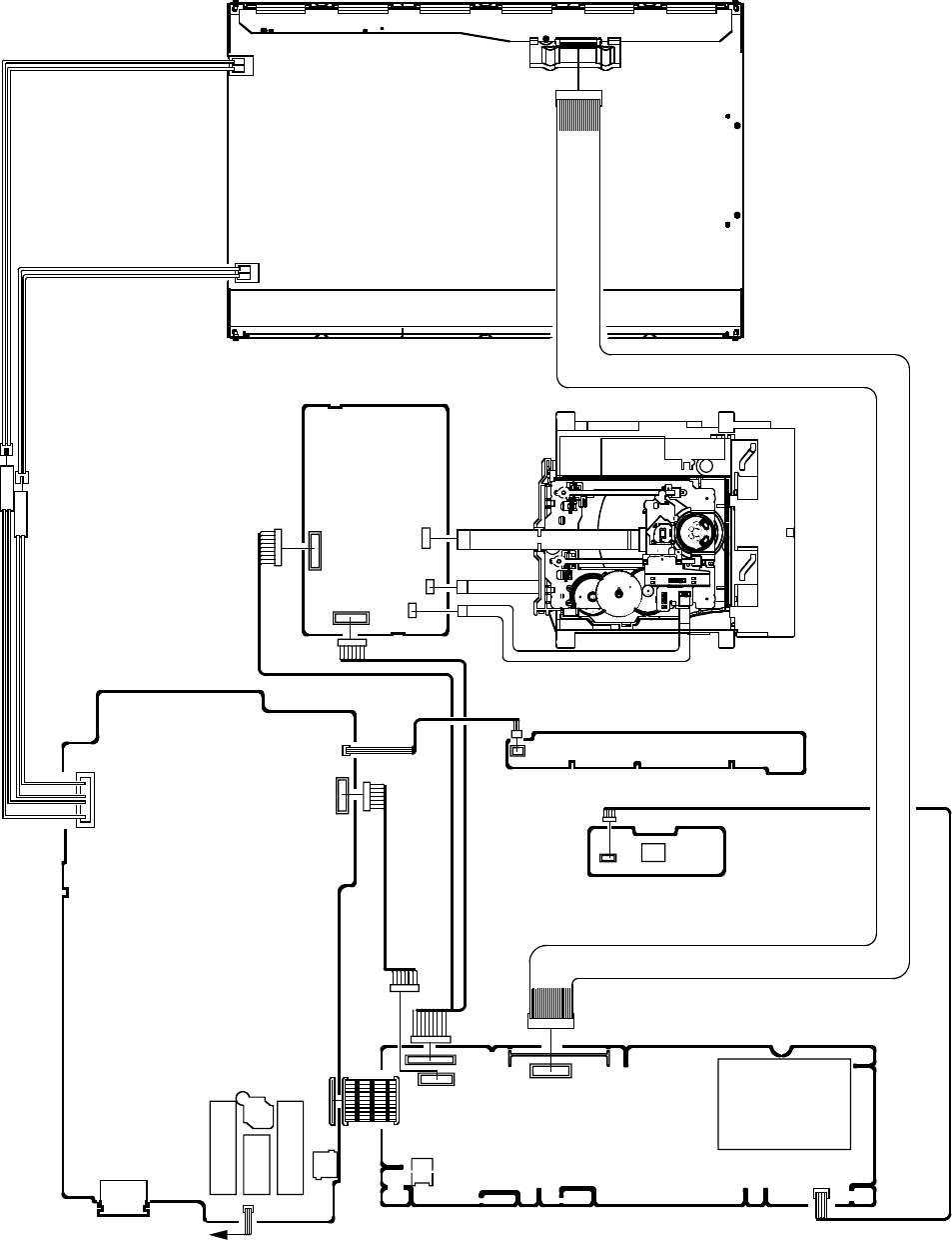
D-5
ELECTRICAL ADJUSTMENTS
3. ELECTRICAL ADJUSTMENT PARTS LOCATION GUIDE (WIRING CONNECTION)
LCD PANEL
DVD DECK
CD2001
CD2301
DVD MT PCB
CP2301
CP2303
CP2302
CP8501
CP8502
DIGITAL PCB
POWER PCB
REMOCON PCB
OPERATION PCB
CP7601 OS7601
CP2201
CP3001
SPEAKER
J4301
CP3002
CP2804
CD6203
TU5801
CP4301
J501
CD7005
J8104
J8103
J8101
J8102
CD301
CP501
CD502
J301 CP8101
TROUBLESHOOTING GUIDE
(LCD SECTION)
POWER DOES NOT TURN ON
Is F501 broken?
Is there voltage at pin
6 of IC501 21V?
Is R510 broken?
Change F501.
Check IC501 and peripheral
circuit.
Change POWER PCB.
No
Yes
Change R510.
No
No
Yes
Yes
E-1

TROUBLESHOOTING GUIDE
THE PICTURE APPEARS,
BUT THE AUDIO DOES NOT
APPEARS. (AT RF MODE)
Is CD301 connected?
Is there signal at pins
1 and 4 of CD301?
Is there signal at pins
2 and 4 of IC301?
Is there signal at pins
AA3 and AA4 of IC2801?
Connect CD301.
Change SP301 and SP302.
Change TU5801.
Is there signal at pins 1
and 2 of IC6551?
Is there signal at pin 6
of IC6552, IC6553?
Check IC301 and peripheral
circuit.
Check Connection of CP4301.
Check IC6551 and
peripheral circuit.
Check IC6552, IC6553 and
peripheral circuit.
Yes
Yes
Yes
Yes
Yes
Yes
No
No
No
No
No
No
Is there signal at pin
5 of TU5801? Check IC5801 and peripheral
circuit.
Yes
No
E-2
TROUBLESHOOTING GUIDE
THE PICTURE DOES NOT
APPEAR
Is there signal at pins
7,9,10,12,13,22,23,25,26
and 28 of CP2804? Change V2801(PANEL).
Change DIGITAL PCB.
Does backlight shine?
Is CD2804 connected? Connected CD2804.
Is CD7005 connected ? Connected CD7005
Yes
No
No
No No
Yes
Yes
Yes
Yes
No
Check Q3009 and peripheral
circuit.
Is there voltage at pins 1,2,3
and 16,17 of CP2804 5V?
Is the signal pin 16
and 18 of IC7001 ?
Is the voltage at pin
20 of IC7001 12V ?
Yes
Yes
Check IC7001 and
peripheral circuit.
Check F7001.
No
No
E-3
TROUBLESHOOTING GUIDE
Is setting of color
normal?
Is the color signal
received?
Is there color signal
at IC2801?
Adjust the color.
Receive the color signal.
Check IC2801 and
peripheral circuit.
Change DIGITAL PCB.
Yes
No
THE COLOR DOES NOT
APPEAR
Yes
No
Yes
No
E-4
TROUBLESHOOTING GUIDE
(DVD SECTION)
DOES NOT DISPLAY DVD
PICTURE
Does this display
logo picture?
Does IC4001 gets
P.CON+3.3V and
P.CON+1.8V?
Check P.CON+3.3V and
P.CON+1.8V line.
Check pins 8 and 10 of
CP8501 and peripheral circuit.
Yes
No
Yes
No
Change IC4001.
Check the disc.
Yes
No
Is there signal at pins 149
and 151 of IC4001?
E-5
TROUBLESHOOTING GUIDE
Does this eject disc at
change DVD DECK?
Change DVD DECK.
Does OSD appear
on the screen? Is remote key set
effectively?
Yes
No
No
Yes
Yes
DISC DOES NOT EJECT
Is there signal at pins 4
and 5 of CP2302?
Check IC4001 and
peripheral circuit.
No
Is there signal at pins 1
and 2 of CP2302?
No
Yes
Change IC4001.
Yes
Check pins 138 and 139
of IC4001 and peripheral
circuit.
Change IC2301.
E-6
TROUBLESHOOTING GUIDE
Does this display
"INCORRECT DISC"?
Does CD2001 connect
with CP2301 correctly?
Yes
No No
Yes
DOES NOT PLAY DVD
Does this display
reading mark?
No
Does disc rotate? No
Yes
Change IC4001.
Yes
Change DVD DECK.
Connect CD2301.
Change DVD DECK.
Is the voltage between
JG017 and JG018 less
than 3.3V?
Yes
No
Change IC4001.
E-7

TROUBLESHOOTING GUIDE
Does this display
"INCORRECT DISC"?
Does CD2001 connect
with CP2301 correctly?
Yes
No No
Yes
DOES NOT PLAY CD
Does this display
reading mark?
No
Does disc rotate? No
Yes
Change IC4001.
Yes
Change DVD DECK.
Connect CD2301.
Change DVD DECK.
Is the voltage between
JG019 and JG018 less
than 3.3V?
Yes
No
Change IC4001.
E-8

TROUBLESHOOTING GUIDE
Is there signal at pins
113, 114, 115 and
116 of IC4001?
Is there signal at pins 1
and 7 of IC8501?
Check pins 1 and 7 of IC8501
and peripheral circuit.
Yes
NO SOUND DVD/CD ANALOG
AUDIO
No
Change MAIN PCB.
Change IC4001.
Connected CD8501.
Is there signal at pin1
of CP8501?
Check line circuit IC4001
to CP8501.
Yes
NO SOUND DVD/CD DIGITAL
AUDIO
No
Change IC4001.
Yes
No
No
Yes
No
Yes
Change MAIN PCB.
Does CD8501 connected?
Is there signal at pin
122 of IC4001?
E-9
DVD BLOCK DIAGRAM
MPEG/MICON/DSP/RF_AMP
IC4001
ZR36966ELCG-D-G
OPU
SPINDLE/
STEPING/
SLED
MOTOR
FLASH 16M
IC4007
SST39VF1601-70-4C-EKE
RF, A, B, C, D, E, F
HOME, TIN_SW, TOUT_SW
DVD LOADER
DSM2
DVD_CD, DVD_LD, CD_LD
Motor Drive
IC2301
LA6565VR-TLM-E
TR+/-, FO+/-,
MOT_LD+/-,
MOT_SLED+/-
MOT_SPDL+/-
SPINDLE/SLED/
FOCUS/TRACK_PWM,
TRAY_CLOSE/OPEN
HA0~A19,
HD0~D15,
MEMCS0, RD, WR
SD_A0~A11
SD_D0~D15
LCD BLOCK
RX
START_SW
SPDIF-134
DVD RESET
DVD_A_OUT_L
DVD_A_OUT_R
AUDIO AMP
IC8501
NJM4565M(TE1)
Y_VIDEO
C_VIDEO
APWM_L+/-,
APWM_R+/-
SPDL_SENS+/-
MD_DVD, MD_CD TX
ZERO
64M SDRAM
IC4005
M12L64164A-7TG
RAMDQM, CLK, CKE, WE#,
CAS#, CS0#, CS1#, RAS#
SD_BA0
DVD_AUDIO_R
DVD_AUDIO_L
SYS_MUTE
RESET
DAC_VIDEO_A
DAC_VIDEO_C/D
SPDIF
TIN_SW
DUPTD1
DUPRD1
F-1 F-2
POWER BLOCK DIAGRAM
1
3
5
11
6
CP501__9.LIGHT_CTL
CP501__10.INVERTER_H
D523 CP501__4,5,14.
CP501__18. POWER FAIL
D505
TRANSFORMER
T501
FEED BACK
IC505
PS2561AL1-1-V(W)
REGULATOR
IC502 KIA431A-AT
C502
AC IN
CD501
J501
+
POWER CONTROL IC
IC501 FA5531P-A2
Vcc
IS
8
GND
1
3
2
4
F501
L501
4
3
1
213
CP501__12.POWER_ON_H
D515
D510
INVERTER
CONTROLLER
IC7001
BD9882FV-E2
Q505
VH
ZCD 1
OUT
FB
SOUND AMP
IC301
LA42052-E
D518
1
4
3
5
2
6
7
8
7
Q501
NC
12 CP501__3,13. AT+12V
1
7
DC-DC CONVERTER
IC503
LA5797M-TE-L-E
CP501__1.FILTER_MUTE
9
8
11
1
8
7
4
1
DRIVE
Q7005
DRIVE
Q7003
T7001
CD7005__1.HV
CD7005__7.LV
20 DRIVE
Q7004
FEED_BACK
IC7002 LM2902DR
CD7005__14.HV
13
14
1 2
17
18
16
6
5
4
CD7005__8.LV
5
CP501__8.P.CON+32V
2
F-3 F-4
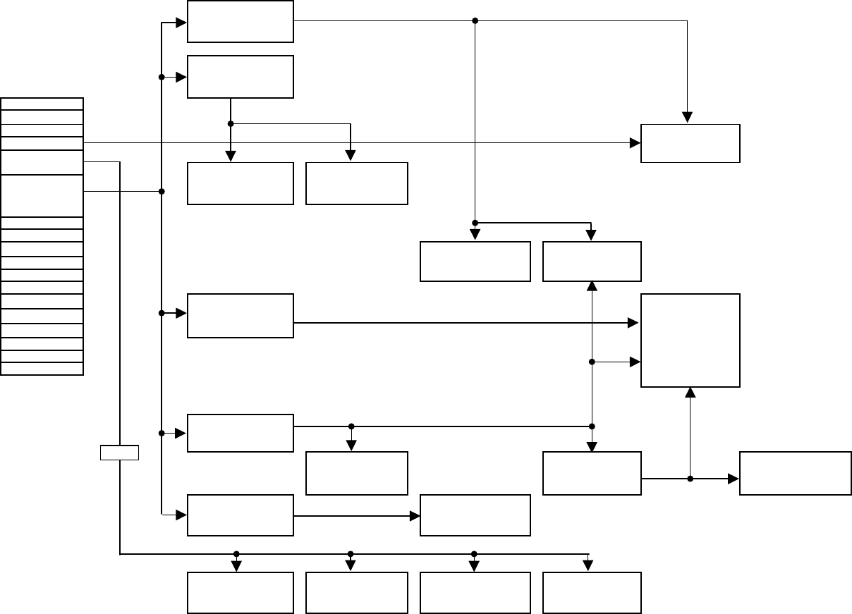
5.0V
CP3001
2
1FILTER MUTE AT3.3V
6
8TUNER+30V
4
5
14
7
11
12
13
15
16
17
9LIGHT_CTL 1V
10 INVERTER_H
18
POWER FAIL
20
KEY_B
19
KEY_A
3.3V
1.8V
1.8V REGULATOR
IC3003
PQ035ZN1HZPH
3
3.3V REGULATOR
IC3009
S-1170B33UC-OTSTFG
DIGITAL TUNER
TU5801
ENG36E18KRF
AUDIO Rch SW
IC6558
NJM2534V(TE2)
VDD CORE
IC3002
AL1015
LCD PANEL
V2801
M156B1-L02
VDD CORE 1V
IC3001
BD9130NV
LCD+B SW
Q3009
TPC6108(TE85L,F,M)
AUDIO Lch SW
IC6552
MM1501XNRE
AUDIO Rch SW
IC6553
MM1501XNRE
AUDIO Lch SW
IC6557
NJM2534V(TE2)
FLASH IC
IC2804
EN29LV320AB-70TCP
DDR SDRAM
IC2802
HYB18TC256160BF-3S
SCALER IC
IC2801
R8J66954BG
BTSC DEMODULATOR
IC5801
AN5832SA-E1V
POWER(DIGITAL PCB) BLOCK DIAGRAM
AUDIO ADC
IC6551
AK5358A
SUB MICON
IC6202
R5F21124FP
EEPROM
IC2805
M24256-BWMN6TP
5.0V REGULATOR
IC3007
BD7820FP-E2
AT+12V
AT+5.8V
SW
F-5 F-6
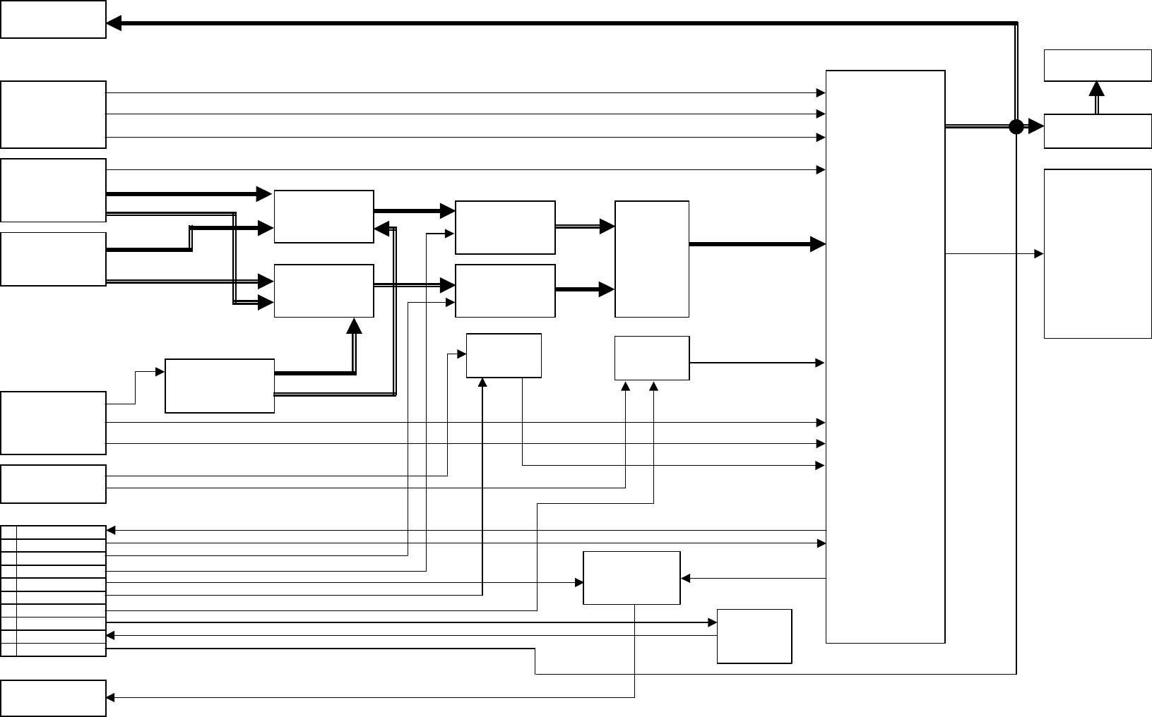
AMP L/R
AUDIO L/R
AV 1 CVBS
AV1_A_IN_L
AV1_A_IN_R
AUDIO L
YUV AUDIO_L
AUDIO DATA
AUDIO R
TUNER AUDIO R
SIF
DIGITAL RF (IF)
ANALOG RF(CVBS)
AV1_Y
IN
AV1_C
DVD CP3002
19 RX
7 TX
14 DVD_A_OUT_R
15 DVD_A_OUT_L SPDIF
1 SPDIF-134
16 [V]Y_VIDEO
17 [U]C_VIDEO
6 START_SW
4 DVD_RESET
2 ZERO
TUNER AUDIO L
COAXIAL
J4301
RCA-101HT(OR)
SPDIF_OUT
BTSC DEMODULATOR IC
IC5801
AN5832SA -E1V
SIGNAL BLOCK DIAGRAM
IN
LVDS DATA/CLK
SOUND AMP IC
IC301
LA42052-E
LCD PANEL
V2801
M156B1-L02
SCALER IC
IC2801
R8J66954BG
COMPONENT_VIDEO_IN
J8102
RCA-341H(NI)-09
AUDIO ADC IC
IC6551
AK5358A
HEADPHONE JACK
J301
PJ-364H
SPEAKER L/R
SP301, SP302
SO308F01
IN
IN
S-VIDEO-IN
J8101
DIN-417HA-01
TUNER
TU5801
ENG36E18KRF
IN
COMPONENT Y
AUDIO Rch SW IC
IC6553
MM1501XNRE
COMPONENT AUDIO IN
J8103
RCA-228H(3)NI-02
CVBS _AV_IN
J8104
RCA-341H(2)NI-06
AUDIO Rch SW IC
IC6558
NJM2534V(TE2)
AUDIO Lch SW IC
IC6557
NJM2534V(TE2)
AUDIO Lch SW IC
IC6552
MM1501XNRE
COMPONENT U
COMPONENT V
YUV AUDIO_R
DIGITAL_A_SW
IC6556
TC7PA53FU(T5L,FT)
Y SW
IC6554
MM1501XNRE
C SW
IC6555
MM1501XNRE
SUB MICON
IC6202
R5F21124FP
SW_C_IN
SW_Y_IN
F-7 F-8
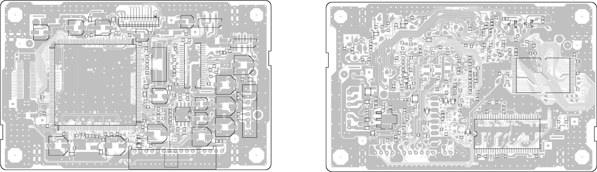
CP2301_1
CP2303
C2316
C2310
C2340
C8517
C2328
C8516
CP2302
B8501
C8518
C8515
C8539
C8538
C8519
C8529 C8530
C8514
R8510
CP8501
C2302
R2304
C2303 R2303
C2307
R2323
R2329
R2320
IC2301
R2321
R2326
R2327
R2319
C8534
C8533
R8534
R8532
R8530
C8532
R8533
R8531
R8529
C8531
IC8501
R8528
C8528
C8527
R8527
R2301
C2315
C8526
C8542
C8513
C8525
C4030
C4083
C4072
B4005
B4008
C4009
C4002
C4016
C4013
C4018
C4019
R4008
C4022
C4020
C4023
C4024
C4025
R4009
B4010
R4071
B4015
R4012
X4001
C4034
W836
R4001
C4085
R4042
C4035
IC4001
C4069
R8517
R8521
R8523
R8522
B4016
B2305
R2360
B4001
C4012
C4082
B4006
D8510
C4075
C4053
R2302
C2365
C4042
C4014
C4015
C2348
C4029
C4038
C2341
C2329
R2305
C4099
C4058
CP8502
DMG097A
IC8502
B8503
B8504
C8521
R8508
R8509 R8507
B8502
C8503
C8501
L8501
R8506
C8537 C8536
C8543
C8506
C8505
L8502
C8504
C8512
R8536
R8535
R8537
R8539
R4036
R4037
R4038
R4039
W825
W824
D4003
D4002
C2301
C2305
D2304
D2303
C2304
R2357
R2358
R2339
R2307
R2313
C2306
R2328
R2310 R2337
R2330
R2325
C2360
C2357
C2358
C2359
C2319 C4076
R8516
R2353
C2321
R2349
D4005
R2342
C8541
C4026
R2352
C2330
C2323
R2350
C2339
R2308
R2338
W818
C4105
R2309
R2334
W807
R2332
R4018
R4019 R4043
C4004
R4022
C4086
C4006
R2336
R2335 R4063
R4062
C4057
C4001
R4061
R4060
C4003
C4056
R4023
C4033
R4005
R4086
R4016
C4051
C4028
C4027
R4032
R4087
R4065
R4052
R4089
R4078
R4045
R4002
R4004
C4081
R4024 C4032
R4048
C4041C4040
R4014
C4050
C4045
C4077
C4047C4046
IC4005
R4040 C4062
C4064
W860
R4054 R4053
R2333
R2341
Q2302
R2340
Q2301
R2306
R2318
C2326
C2317C2309
C2350
C2331
C4005
C4039
R2355
C4095
C4091
R4003 C4008
C4010
C4096
D4008
R4067
R2324
W841
C4021
C8520
C4036
IC4007
B4003
B4002
C4007
C4037
C4011
C4049
C4052
C4054
C4079
C4044
C4055
C4059
C4060
W813
W812
W803
W804
DMG097A
PRINTED CIRCUIT BOARDS
DVD MT (TOP SIDE)
G-1 G-2
DVD MT (BOTTOM SIDE)
1
53 105
157
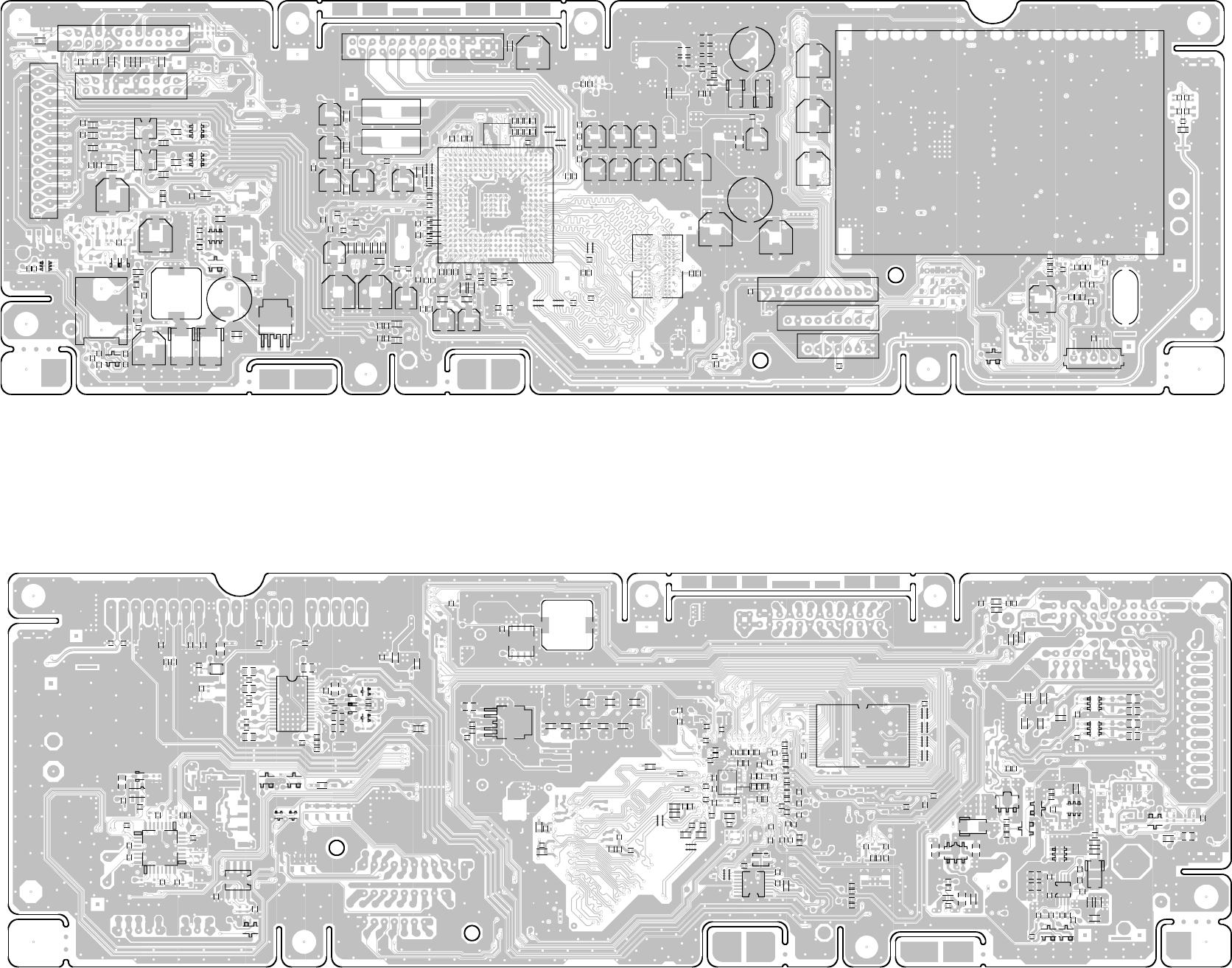
CEH420A
CEH420A
C3043
L3005
C3022
C3013
D3402
D3403
L3004
IC6556
C4302
R6551
R6552
J4301
C4301
R4301
Q4301
R4302
R4306
R4307
C4303
C4304
R4310
C4306
B4302
IC3007
Q3005
Q3009
W826
B3008
C3004
R3010
R3002
CP3001
IC6553
C6571
C6584
C6553
IC6552
C6570
C6579
R6581 R6584
C6581
IC6557
C6568
R6590
R6582
C6580
IC6558
CP3002
B4301
C6564
R6502
R6501 B6556
C6569
R3039
R3038
R4309
C2921
C2924 C2923
C2914
B2821 B2820
B2822
C2935
C2944
C2936
C2933
C2943
C2940
C2947
C2931
C2946
C2891
C2883
C2948
B2816
B2817
B2815
C2929 R2837
B2810
R2810
C2880
R2814
R2815
R2812
NR2811
NR2810
R2846 R2850
C2959 C2965
NR2808NR2807
NR2806
R2824
R2817
R2827
R2823
R2826
R2825
IC2801
R2800
R2830
IC2802
R2813
C2811
C2812
C2810
C2809
R2811
C2808
C2939
R2840
C2937
C2932
R5823
R2839
R2838
C5855
R5817
R5818
R5821
R5822
C5822C5821
B6553B6552
C6578
R6562
R6561
R6559 R6558
C5847
C2918
C6562
C6561
C3047
C2905
L3003
C3048
NR3602
NR3601
R2900
C2925
X2801
X2802
C2802
C2975
C2866
C2876
C2974
C2867
C2877
C2869
C2882
D3007
B3003
D3005
L3001
R3016R3018
C3027
C3026
C3024
C3029
C3031
C3056
R3009
C3016
R3008
C6559
C6555
R3007
C3023
C2806
R2806
B2800
C2800
CP2804
R2820
B6554
R5807
W854
W855
B2811
CD6203
C5819
TU5801
C6221
R5819
R5820
C5844
C5845
C5846
L5805
C2807
C5801 C5803
R6205
R6206
R6213
R6216
C6212
R6225 C6216
R6215
R6214
R6219
R6227
R6228
R6224
X6201
W807
Q6204
CP2803
CP2801
CP6201
R6223
C6205
C3049
R2852
R2851
CP4301
W827
W858
W846
W804
W802
W840
W847
W818
W817
W816
W815
W848
W849
Q3007
R3041
R3042
Q3008
Q3006
B3015
Q3010
R3040
R3035
Q3004
Q3003
B3005
B3004
D3004
Q3011
R3020
R3022 IC3002
B3006
B3007
B3017
Q3407
C3011
C3012
C3014
C3019
C3021
C3040
R3014
R3012
R3023
R3024
R3025
R3045
R3431
C6554
B6551
C3038
C3039
R3032
R3033
R3034
B3014
IC3009
C3054
C3055
D3006
C6566 C6565
C6572
C6573
IC6555
C6577
C6576
C6574_1
C6575
IC6554
C6551
C6563
C6582
R6585
R6583
C2938
C2934
R5824
R5825
C5853
C2902
C2903
C2917
C2920
C2912
C2908
C2911
C2907
C2919
C2922
C2906
C2910
C2901
C2941
C2942
C2949
C2904
C5852
W881
R2841
B2806
B2807
B2808 B2809
B2804
B2805
C2896
C2900
C2874
R2836
C2881
C2875
R2835 C2868
C2871
C2879
C2872
B2803
C2887
C2890
C2894
C2898
C2884
C2885
IC3003
C3018
R3013
R3015
R3017 R2807
R2809
C2841
C2843
C2848
C2850
C2847
C2851
C2846
C2853
C2856
C2854
C2858
C2852
C2822
C2821
C2814
C2813
C2842
C2849
C2855
C2861
C2857
C2859
C2815
C2816
R2828
R2829
R2819
R2818
NR2809
NR2805
C2913
C2909
C6556 C6560
C2950
R2872
C2951
R2873
R2874
C2926
C2927
C2957
R3005
L3002
C3015
IC6551
X6551
R6569
NR6551
C6557
R3631
R3630
R3629
R2805
R2802
NR2802
NR2803
NR2804
NR2801
R2801
IC2804
R2842
IC3001
C2945
C5811
C5812
B5801
B5803
B5802
IC5801
C5826
C5827
C5817
R5812
R5810
R5811
C5830
C5825
Q5801
Q5802
R5808
R5809
B5804
C5823
C5824R5813 C5818
C5841
C5839
C5840
C5838
C5837
C5835
C5834
C5833
C5809
C5804
C5806
C5814 L5801
R5802
R5801
R6236
Q6202 Q6201
C6209
R6210
C6218
W865
W863
R6217
R6203
R6204
D6205
IC6201
C6210
IC6202
IC2805
C2968
R2856
Q6203
Q3002Q3001
R5804
R5803
C6215 C6213
C5805
C3006
R3019
D5803
D5804
W878
W809
W856
W857 C3065
B3023
C3066
B3022
R3044
PRINTED CIRCUIT BOARDS
G-3 G-4
DIGITAL (TOP SIDE)
DIGITAL (BOTTOM SIDE)
A1
AA1 AA21
A21
A1 A9
R1 R9
17
25
1
9
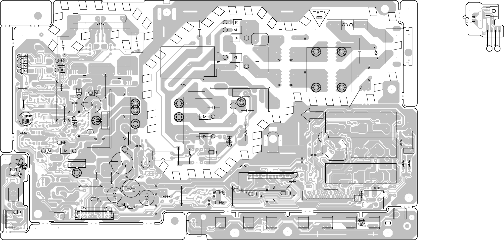
J501
FH501
FH502
F501
R503
R509
D504
C506
W810
W808
C517
IC501
Q501
D510
D508
D518
D507
B501
IC502
C522
W010
Q503
R510
L501
C507
C508
C510
T501
R501
C7030
C7033
W013
T7001
CD7005
C7017
C7018
R7038
R7039
R7011
R7014
W001
D512
R512
R508
C518
D511
C516
R511
J8104
J8103
J8101
J8102
J301
CD301
R308
R309
W845
W806
C304
C307
IC301
C310
C311
HS301
D515
D523
C525
R549
R504
D514
C504
C514
D7007
D7008
W026 W022
R518
D516
C520
D517
R529
L504
C512
C535_1
W018
C511
C7602
CP7601
W835
W012W011
W008
CP2201
SW2203
SW2204
SW2208
SW2202
SW2207
SW2205
SW2206
SW2201
C502
R505
W015
W807
D7006
R7036
D7003
R7035
CP501
D505
W828
R521
W023
W024
R8110
W002
W017
W832
W025
W819
CD502
C513
OS7601
TH501
D526
W014
W021
W833
SH501
R7033
W004
W007
W840
IC505
W824
W827 W803
W006
R7047
W823
C309
W820
D7001
D7002
D7004
D7005
D7015
CP8101
D7601_1
L503
W019
W809
W830
W822
HS501_1
HS502_1
PRINTED CIRCUIT BOARDS
SW
SOLDER SIDE
DED020A
BR
WH
YE
GR
SW2
CD2301
M2602 M2601
POWER/OPERATION/REMOCON (INSERTED PARTS)
SOLDER SIDE
G-5 G-6
CEH423A
CEH422A
CEH421A
RISK OF FIRE
-REPLACE
AS MARKED.
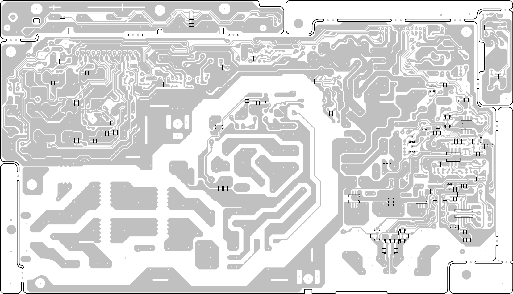
R544
R545
R546
R547
R506
R517
R525
R519
C521
R515
IC503
C531
R533
R536
R543
C538
C539D521
D522
C546
D519
D520
C545
R523
C543_1
C7032
D7018
R524
C526
D7019
D7023
D7024
R7046
D7020
R7045
D7013
C7031
D7014 D7017
C7026
C7022
IC7002
R7034
C7015
R7040
C7006 R7041
C7024
C7021
R7042
C7007
C7002
IC7001
C7003
R7013
R7007
R7010
C7004
R7012
R7009
Q7003
R7056
R7026
R7025
R7021
C7013
R7023
R7024
F7001
C505
R513
C509
C8107
C8111
C8106
C8104
C8108
R8106
C8102
R8103
R8104
C8109
R8107
R8108
C8110
C8105
R8105
C8103
C320
C303
C305
C308
R304
R305
C306
C301
C319
R307
R306
R302
D509
C501
C503
R7049
R7050
C7035
R7054
R7022
C7019
C7001
C7008
C7009
R7005
R7008
Q7002
R7016
R7015
C7012
C7011
R7020
Q505
R531
Q7001
R7602
R7605
R2203 R2202
R2206 R2204
R2205
R2201
D506
R507
R502
C7010
R7019
R7017
R7003
R7002
R7001
R535
R538
R7032 R7030
R7018
R7006
R7004
Q504
R8117
R8116
R8115
R8114
R8113
R8111
R8112
R8118
R8119
R8120
Q7004 Q7005
R7044
D7012
D7011
R7048
C7020
R7043
D7010
R310
R311
R7604_1
R7603_1
PRINTED CIRCUIT BOARDS
POWER/OPERATION/REMOCON (CHIP MOUNTED PARTS)
SOLDER SIDE
G-7 G-8
CEH423A
CEH422A
CEH421A
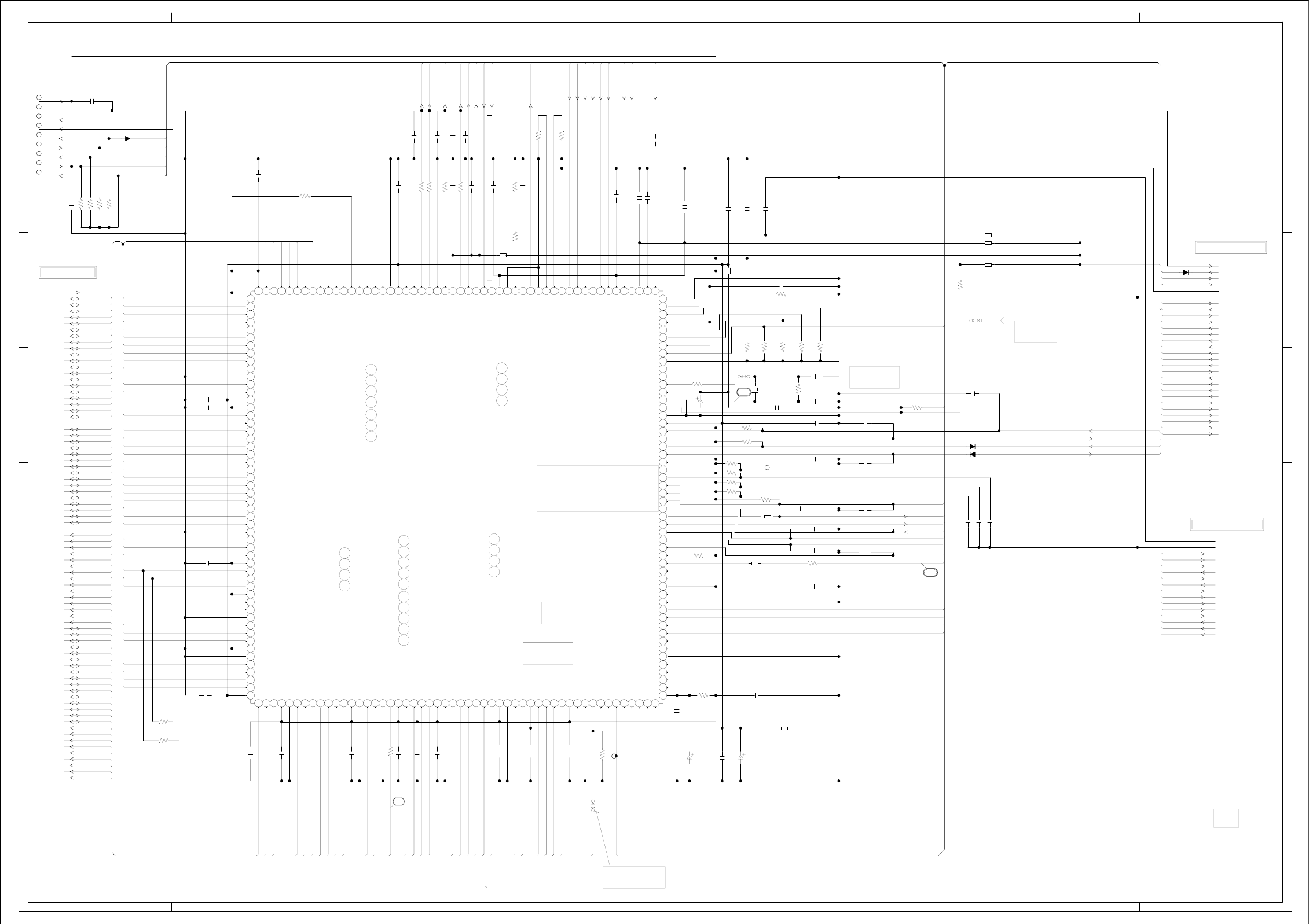
ABC D E F GH
ABC D E F GH
2
1
3
4
5
6
7
8
2
1
3
4
5
6
7
8
C4083
1006.3V SJV
C4030
2206.3V SJV
IC4001
ZR36966ELCG-D-G
MPEG/MICON/DSP/RF_AMP IC
101102103104
105106107108109110111112113114115116117118119120121122123124125126127128129130131132133134135136137138139140141142143144145146147148149150151152153154155156
157158159160161162163164165166167168169170171172173174175176177178179180181182183184185186187188189190191192193194195196197198199200201202203204205206207208
110
100
111213141516171819 22021222324
2526272829 3
30313233343536373839 4
40414243444546474849 5
50
5152
53 54 55 56 57 58 59
6
60 61 62 63 64 65 66 67 68 69
7
70 71 72 73 74 75 76 77 78 79
8
80 81 82 83 84 85 86 87 88 89
9
90 91 92 93 94 95 96 97 98 99
D4003 MA111
D4002 MA111
D4008 MA111
D4005
MA111
C4028 0.1 F
C4027 0.01 B
C4051 0.1 F
C4081 0.1 F
C4032 0.001 B
C4034 27P CH
C4035 27P CH
C4096 0.001 B
C4005 56P CH
C4079 0.001 B
C4091 100P CH
C4077 0.1 F
C4012
0.01 B
C4026 0.1 F
C4018 0.1 F
C4020 0.1 F
C4023 0.1 F
C4024 0.1 F
C4025 0.1 F
C4082
0.1 F
C4019 0.1 F
C4022 0.01 B
C4029 100P CH
C4013 0.1 F
C4016 0.1 F
C4014 0.1 F
C4008 0.1 F
C4010 0.1 F
C4055 0.001 B
C4004 0.1 F
C4033
0.1 F
C4007 0.1 F
C4049 68P CH
C4052 68P CH
C4054 68P CH
C4075 0.1 F
C4021 0.1 F
C4072 0.1 F
C4076 0.1 F
C4056 0.027 B
C4003 0.027 B
C4001 0.0039 B
C4057 180P CH
C4042
0.1 F
C4086 0.001 B
C4006 0.01 B
C4058 0.001 B
C4085 0.001 B
C4037 100P CH
C4011 100P CH
C4053
0.001 B
C4044
100P CH
C4038 0.01 B
C4105 10P CH
C4059 560PCH
C4002 0.1 F
C4015 0.1 F
C4069
476.3V
SJV
R4003
75 +-1%
R4042 100
R4012
1M
R4071 150
R4054
1K
R4053
1K
R4008 47
R4065 4.7K
R4087 4.7K
R4032 4.7K
R4052 4.7K
R4078 4.7K
R4089 4.7K
R4022 15K+-1% R4043 390 +-1%
R4014 4.7K
R4001 390 +-1%
R4086
75 +-1%
R4005
75 +-1%
R4004
75 +-1%
R4002
75 +-1%
R4023
4.7K
R4009
33
R4019 4.7K
R4018 4.7K
R4016 100
R4067 10K
R4045 4.7K
R4036 4.7K
R4037 4.7K
R4038 4.7K
R4039 4.7K
R4024 4.7K
R4062 39K
R4063 15K
R4060 11K
R4061 11K
B4016
EBMS160808A102_RDC45
B4010
EBMS160808A102_RDC45
B4001
EBMS160808A102_RDC45
B4002 EBMS160808A102_RDC45
B4003 EBMS160808A102_RDC45
B4005 EBMS160808A102_RDC45
B4006
EBMS160808A102_RDC45
B4015
EBMS160808A102_RDC45
W836
W841
W807
OF PRINTING AND SUBJECT TO CHANGE WITHOUT NOTICE
NOTE:THIS SCHEMATIC DIAGRAM IS THE LATEST AT THE TIME
DURING PLAYBACK.
MEASURED WITH THE DIGITAL TESTER
NOTE:THE DC VOLTAGE EACH PART WAS
JG029
JG002
JG003
JG004
JG005
JG007
JG008
JG009
JG001
JG006
TP4010
X4001
100GT02727
27MHz
VC
RF
CD_LD
MD_CD
OPU_F
OPU_E
OPU_D
OPU_C
OPU_B
OPU_A
DVD_LD
MD_DVD
SLED_PWM
TRACK_PWM
FOCUS_PWM
SPDL_SENS+
SPDL_SENS-
SPINDLE_PWM
BOOT2
BOOT1
TACT_OFFSET
FACT_OFFSET
DUPTD1
DUPRD1
DUPTD0
DUPRD0
P.CON+5V_D
RFINN
RFINP
VDDAFERF
RD
HD9
HD1
HD8
HD0
HA0
MEMCS0
+1.8V P.CON+3.3V_D VDDPWM3.3V
+3.3V TIN TIN_SW
TRAY_OPEN
TRAY_CLOSE
GND
+3.3V GND
HA0 HD2 HOME
HA1 HD10 DAC_VIDEO_C/D TOUT_SW
HA2 HD3 DVD_CD
HA3 DAC_VIDEO_D
HD11 DRVSB
HA4 DAC_VIDEO_A RF
HA5 HD4 OPU_A
HA6 HD12 OPU_B
HA7 HD5 OPU_C
HA8 HD13 OPU_D
HA9 OPU_E
HA10 HD6 OPU_F
HA11 HD14 VC
HA12 SPDL_SENS-
HA13 HD7 SPDL_SENS+
HA14 MD_DVD
HA15 HD15 MD_CD
HA16 DVD_LD
HA17 RESET CD_LD
HA18 HA16 SPINDLE_PWM
HA19 SLED_PWM
TRACK_PWM
HD0 HA15 DUPRD1 FOCUS_PWM
HD1 HA14 DUPTD1
HD2 HA13 DUPRD0
HD3
HD4 HA12 DUPTD0
HD5 HA11
HD6 HA10 IRRCV
HD7 HA9
HD8
HD9 HA8
HD10 WR
HD11 HA18
HD12 TIN
HA17
HD13
HD14 HA7 DVD_CD
HD15 HA6 DRVSB
TOUT_SW
MEMCS0 TRAY_CLOSE
HA5
RD GND
TRAY_OPEN
WR HA4 GND
SD_A0 SYS_MUTE
HA3 HOME
SD_A1 DAC_VIDEO_A
SPDIF
SD_A2 DAC_VIDEO_C/D
HA2
SD_A3 RESET
SD_A4 HA1 SPDIF
SD_A5 DUPRD1
HA19
SD_A6 DUPTD1
SD_A7 APWM_L+
SD_A8 APWM_L-
SD_A9 APWM_L- APWM_R+
SD_A10 APWM_R-
APWM_L+
SD_A11 P.CON+3.3V_D
SD_A4 APWM_R-
SD_D0 P.CON+5V_D
SD_A3 APWM_R+
SD_D1 P.CON+1.8V_D
SD_D2 SD_A5
SD_D3
SD_D4
SD_D5 SD_A2
SD_D6
SD_D7 SD_A6
SD_D8 SD_A1
SD_D9 SD_A7
SD_D10
SD_D11
SD_D12
SD_D13
SD_D14
SD_D15
RAMCS0#
RAMCS1#
RAMRAS#
RAMCAS#
SD_BA0
RAMDQM
RAMWE#
RAMCLK
RAMCKE
SYS_MUTE
RAMCS0#
RAMCS1#
RAMRAS#
RAMCAS#
SD_A10
SD_A11
SD_BA0
RAMWE#
RAMDQM
RAMCLK
SD_D10
SD_D11
SD_D12
SD_D13
SD_D14
SD_D15
RAMCKE
SD_A0
SD_A8
SD_A9
SD_D8
SD_D7
SD_D9
SD_D6
SD_D5
SD_D4
SD_D3
SD_D2
SD_D1
SD_D0
52
FROM/TO MOTOR DRIVE
FROM/TO MEMORY
H-2H-1
(DVD MT PCB)
MPEG/MICON/DSP/RF_AMP SCHEMATIC DIAGRAM
FROM/TO AUDIO/VIDEO
PCB130
DMG097
NCNC
NC
NC
BOOTSEL2
BOOTSEL1
NC
NC
NC
NC
SGND
GNDDACBS2
A
RFN
RFP
158
159
160
157
54
55
56
53 RAMADD(0)
RAMADD(8)
RAMADD(10)
VDDP
105 VDDAPWM
106 GPIO(19)/PWMCO(5)/APWM4+
107 GPIO(20)/APWM4-
108 GPIO(21)/APWM3+
109 GPIO(22)/AOUT(3)/APWM3-
103
102
101
100 APWM6+/GPIO(14)
APWM6-/GPIO(15)
APWM5+/GPIO(16)
APWM5-/GPIO(17)
104 AIN/SPDIFIN/GPIO(18)
110 GNDAPWM
111 IGPIO(23)/APWM2+
112
113
GPIO(24)/AOUT(2)/APWM2-
GPIO(25)/APWM1+
206
205
207
208
204
203
202 MEMCS0#
MEMRD#
MEMDAT(0)
GPIO(8)/MEMDAT(8)
MEMDAT(1)
GPIO(9)/MEMDAT(9)
VDDP VDD1AFE
MEMDAT(4)
MEMDAT(11)/GPIO(1)
MEMDAT(10)/GPIO(0)
MEMDAT(3)
MEMDAT(12)/GPIO(2)
MEMDAT(5)
MEMDAT(13)/GPIO(3)
MEMDAT(6)
MEMDAT(14)/GPIO(4)
GNDC
MEMDAT(7)
MEMDAT(15)
VDDC
VDDP
MEMADD(16)
MEMCS1#/GPIO(5)
MEMADD(15)
MEMADD(14)
MEMADD(13)
MEMADD(12)
MEMADD(11)
MEMADD(10)
MEMADD(9)
MEMADD(8)
MEMWR#
MEMADD(18)/GPIO(6)
MEMADD(17)
MEMADD(7)
MEMADD(6)
GNDC
VDDP
MEMADD(5)
MEMADD(4)
MEMADD(3)
MEMADD(2)
MEMADD(1)
MEMADD(19)/IGPIO(7)
USBVDD
USBDP/GPO(67)
USBDN/GPO(68)
USBGND
RAMADD(4)
RAMADD(3)
RAMADD(5)
VDDIP
GNDC
RAMADD(2)
RAMADD(6)
RAMADD(1)
RAMADD(7)
VDDC
GNDC
RAMADD(11)/GPO(64)
RAMADD(9)
RAMBA
RAMCS1#/GPO(65)
RAMRAS#
RAMCAS#
VDDP
RAMWE#
RAMCS0#
GNDC
RAMDQM
GNDPCLK
PCLK
VDDPCLK
RAMDAT(8)
RAMDAT(7)
RAMDAT(9)
RAMDAT(6)
VDDP
GNDC
RAMDAT(10)
RAMDAT(5)
RAMDAT(11)
RAMDAT(4)
RAMDAT(12)
RAMDAT(3)
VDDP
GNDC
RAMDAT(13)
RAMDAT(2)
VDDC
RAMDAT(14)
RAMDAT(1)
RAMDAT(15)
RAMDAT(0)
VDDP
RAMDQM2/RAMCKE/GPO(66)
GNDC
RAMCKE/SDI_PSC/GPIO(10)
GPAIO/IGPIO(11)
APWM7+/GPIO(12)
APWM7-/GPIO(13)
GPIO(41)/TDI/NMI SSCRXD
GPIO(40)
GPIO(39)
GPIO(38)
IGPIO(37)/TMS/NMI
GPIO(36)
GPIO(35)
GPIO(29)/AMCLK
VDDP
GPIO(30)/ALRCLK
GPIO(31)/ABCLK
GPIO(32)/SPDIFO
GPIO(33)/AIN/SPDIFIN
GPIO(34)/RAMCKE/SPDIFIN
GNDC
GPIO(28)/AOUT(0)/APWM0-
GPIO(27)/APWM0+
GPIO(26)/AOUT(1)/APWM1-
GPIO(42)/TCK SSCCLK
GPIO(43)/TDO SSCTXD
IGPIO(44)
VDDP
GPIO(45)/PWMCO(5)/DUPTD0
GPIO(46)/DUPRD0
GPIO(47)/DUPTD1
GPIO(48)/DUPRD1
VDDC
GNDC
RESET#
GNDPLL
VDDPLL
XIN
DAC5
GNDDAC_D
DAC4
VDDDAC
DAC3
DAC2
VDDDAC
XO
DAC1
RSET
IGPIO(55)/FCU_IRQ
GPIO(56)/FCU_RST
GPIO(57)/FCU_WAIT#
GPIO(58)/FCU_CS3#
GPIO(59)/FCU_CS2#
GPIO(60)/FCU_SCLK
GPIO(61)/FCU_IOWR#
GPIO(62)/FCU_IORD#
GPIO(63)/MEMCS2#
MEMADD(0)
CD_LD
DVD_LD
VDDPWM
GNDPWM
VDDC
GNDC
GPIO(49)/PWMCO(0)
GPIO(50)/PWMCO(1)
GPIO(51)/PWMCO(2)
GPIO(52)/PWMCO(3)
GPIO(53)/PWMCO(4)
IGPIO(54)/PWMCO(5)
VC
J
E
K
F
GNDAFE
G
H
GND1AFE
VREF
GNDREF
VDDSAFE
CD_MD
DVD_MD
B
VDDAFE
C
D
MEMDAT(2)
RESLOAD
NC
NC
NC NC
3.3
1.9
1.5
1.5
1.5
2.9
2.9
2.4
NC 0
0
0
0
3.3
0
0
0
0
0
1.8
0
0
1.7
1.0
0
1.6
3.3
1.8
2.4
3.3
0
0
3.3
0
0.9
1.7
2.1
0
0
0
0
2.1
2.7
2.1
2.3
2.2
2.3
3.3
2.3
2.3
3.3
1.6
1.6
0
1.3
1.3
3.3
1.2
1.2
3.3
1.1
0
1.1
1.4
1.6
1.8
0
3.3
0
3.3
3.3
3.3
3.3
3.3
3.3
3.3
3.3
3.3
0
0
3.3
3.3
0
0
3.3
3.3
1.6
0
0
3.3
0
0
1.6
1.6
1.6
1.6
0
0
0
0
3.3
0
0
3.3
0
0
0
1.00
0
3.30
0
0
3.30
3.3
3.3
3.3
3.30
3.3
1.90
0.5
3.3
1.8
1.3
1.2
1.2
3.30
1.0
1.2
2.3
1.7
1.8
2.2
3.30
1.7
0.8
1.8
1.2
1.2
1.2
1.3
3.3
3.30
1.0
0
03.3
0
0
2.4
2.4
2.2
2.2
1.7
2.0
2.2
1.2
1.9
1.50
2.5
1.9
1.8
3.3
2.5
3.3
0.7
0.6
0.6
1.0
2.5
0.7
1.0
2.4
3.30
2.8
1.70
0
1.7
1.7
1.7
3.3
1.0
2.60
3.3
0
00
1.6
1.6
1.6
3.30
0.7
1.6
1.2
1.6
1.8
104PIN FPCSTRB
FOR PLAYER
94PIN STBY_L
FOR PLAYER
VDDDAC
(VR_DVD)
(VR_CD)
(10mA)
Y/C
YUV W806
W807
54
(AFEGND) (RF_GND)
(185mA)
(120mA)
(21mA)
(130mA)
(250mA)
DEBUG MODE DEL
RELEASE MODE ADD
VDDPWM
W836 adjust
X’tal frequrcy
(MUTE-L)
(DVD-L/CD-H)
1.8
(D_GND)
(A_GND)
(D_GND)
53
(D_GND)
(RF_GND)
(A_GND)
(D_GND)
(D_GND)
(A_GND)
NC
NC NCNC
NC
NC
NC
NC
IAMCLK
IALRCLK
IABCLK
NC
NC
NC
NC
NC
NC
NC
NC
NC
(D1_2)
(D1_1)
(P-H/I-L)
(MD)
(MC)
(ML)
(I2CDAT)
(I2CCLK)
V_SW
5V TOLERANT
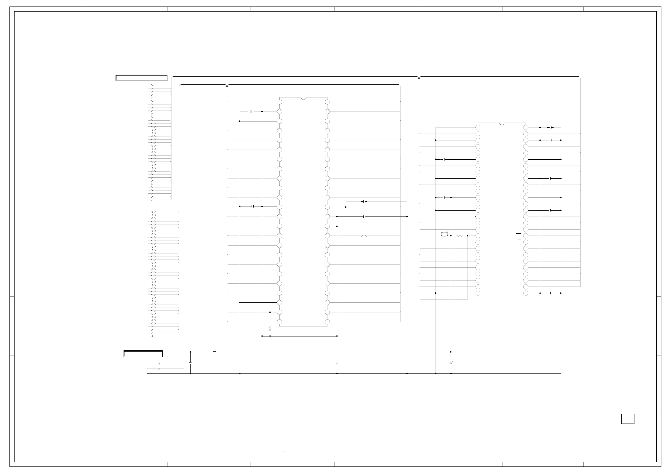
ABC D E F GH
ABC D E F GH
2
1
3
4
5
6
7
8
2
1
3
4
5
6
7
8
IC4007 SST39VF1601-70-4C-EKE
FLASH IC 16M
110111213141516171819 22021222324
25 26 27 28 29
3
30 31 32 33 34 35 36 37 38 39
4
40 41 42 43 44 45 46 47 48
56789
IC4005 M12L64164A-7TG
64M SDRAM IC
110111213141516171819 22021222324252627
28 29
3
30 31 32 33 34 35 36 37 38 39
4
40 41 42 43 44 45 46 47 48 49
5
50 51 52 53 54
6789
C4095
1B
C4062
0.1 F
C4064
0.1 F
C4045
0.1 F
C4046
0.1 F
C4047
0.1 F
C4050
0.01 B
C4040
0.01 B
C4041
0.01 B
C4039
0.1 F
C4060 330P CH
C4099
0.01 B
C4036
0.001 B
C4009
2206.3V SJV
R4040
4.7K
R4048
4.7K
B4008
EBMS160808A102_RDC45
W860
OF PRINTING AND SUBJECT TO CHANGE WITHOUT NOTICE
NOTE:THIS SCHEMATIC DIAGRAM IS THE LATEST AT THE TIME
DURING PLAYBACK.
MEASURED WITH THE DIGITAL TESTER
NOTE:THE DC VOLTAGE EACH PART WAS
SD_A0
SD_A1
SD_A2
SD_A3
SD_A4
SD_A5 HA16 HA15
SD_A6
SD_A7
SD_A8 HA14
SD_A9
SD_A10
SD_A11 HA13
SD_D0
SD_D1
SD_D2 HD15 HA12
SD_D3 SD_D15 SD_D0
SD_D4
SD_D5 HD7 HA11
SD_D6
SD_D7 SD_D14 SD_D1
SD_D8 HD14 HA10
SD_D9 SD_D13 SD_D2
SD_D10
SD_D11 HD6 HA9
SD_D12
SD_D13 SD_D12 SD_D3
SD_D14 HD13 HA8
SD_D15 SD_D11 SD_D4
RAMCS0#
RAMCS1# HD5 HA19
RAMRAS#
RAMCAS# SD_D10 SD_D5
SD_BA0 HD12
RAMDQM SD_D9 SD_D6
RAMWE#
RAMCLK HD4 WR
RAMCKE SD_D8 SD_D7
RESET
HA0
HA1 HD11 RAMDQM
HA2
HA3 RAMDQM RAMWE#
HA4 HD3
HA5 RAMCLK RAMCAS#
HA6
HA7 HD10 HA19 RAMRAS#
HA8
HA9 RAMCS1#
HA10 HD2 HA18
HA11 SD_A11 SD_BA0
HA12
HA13 HD9 HA17 SD_A9 RAMCS0#
HA14
HA15 SD_A8 SD_A10
HA16 HD1 HA7
HA17 SD_A7 SD_A0
HA18
HA19 HD8 HA6 SD_A6 SD_A1
HD0
HD1 SD_A5 SD_A2
HD2 HD0 HA5
HD3 SD_A4 SD_A3
HD4
HD5 RD HA4
HD6
HD7 RAMCKE
HD8 HA3
HD9
HD10
HD11 MEMCS0 HA2
HD12
HD13
HD14 HA0 HA1
HD15
MEMCS0
RD
WR
+3.3V
RESET
P.CON+3.3V_D
GND
FROM/TO AUDIO/VIDEO
FROM/TO MPEG/MICON/DSP/RF_AMP
H-4
H-3
PCB130
DMG097
(DVD MT PCB)
MEMORY SCHEMATIC DIAGRAM
D_GND
0
0
0
A16
VSS
DQ15
DQ7
DQ14
DQ6
DQ13
DQ5
DQ12
VDD
DQ11
DQ3
DQ10
DQ2
DQ9
DQ1
DQ8
DQ0
DE#
VSS
CE#
A0
DQ4
3.3
3.3
1.7
2.5
A7
A6
A5
A4
A3
A2
A1
VCCQ
A15
A14
A13
A12
A11
A9
A8
A18
A17
A10
A19
A20
RP#
VPP
WP#
A19 0
0
0
3.3
WE#
NC
2.5
1.9
2.5
1.5
1.9
1.2
2.2
2.0
1.7
2.2
0.7
0.6
0.6
1.0
0.7
1.0
2.4
3.3
3.3
0
2.8
1.7
0
1.7
1.7
1.0
2.6
2.2
2.4
2.4
1.9
1.5
1.5
1.5
2.9
2.9
2.4
55
VDD
DQ0
VDDQ
DQ1
DQ2
VSSQ
DQ3
DQ4
VDDQ
DQ5
VSSQ
DQ6
DQ7
VDD
LDQM
WE
CAS
RAS
CS
BA0
BA1
A10/AP
A0
A1
A2
A3
VDD
VSS
DQ15
VSSQ
DQ14
DQ13
VDDQ
DQ12
DQ11
VSSQ
DQ10
DQ9
VDDQ
DQ8
VSS
NC
UDQM
CLK
CKE
NC
A11
A9
A8
A7
A6
A5
A4
VSS
NC
0
NC
0
1.2
0
3.3
0
3.3
0
0
3.3
0
0
3.3
1.3
0
3.3
3.3
3.3
3.3
0
1.2
1.7
1.8
2.3
1.0
1.2
1.8
1.8
0.5
1.3
1.2
0.8
2.2
1.7
1.2
1.2
1.9
3.3
3.3
3.3
3.3
0
3.3
0
1.0
1.2
0.7
1.6
0
0
1.6
1.6
1.6
1.6
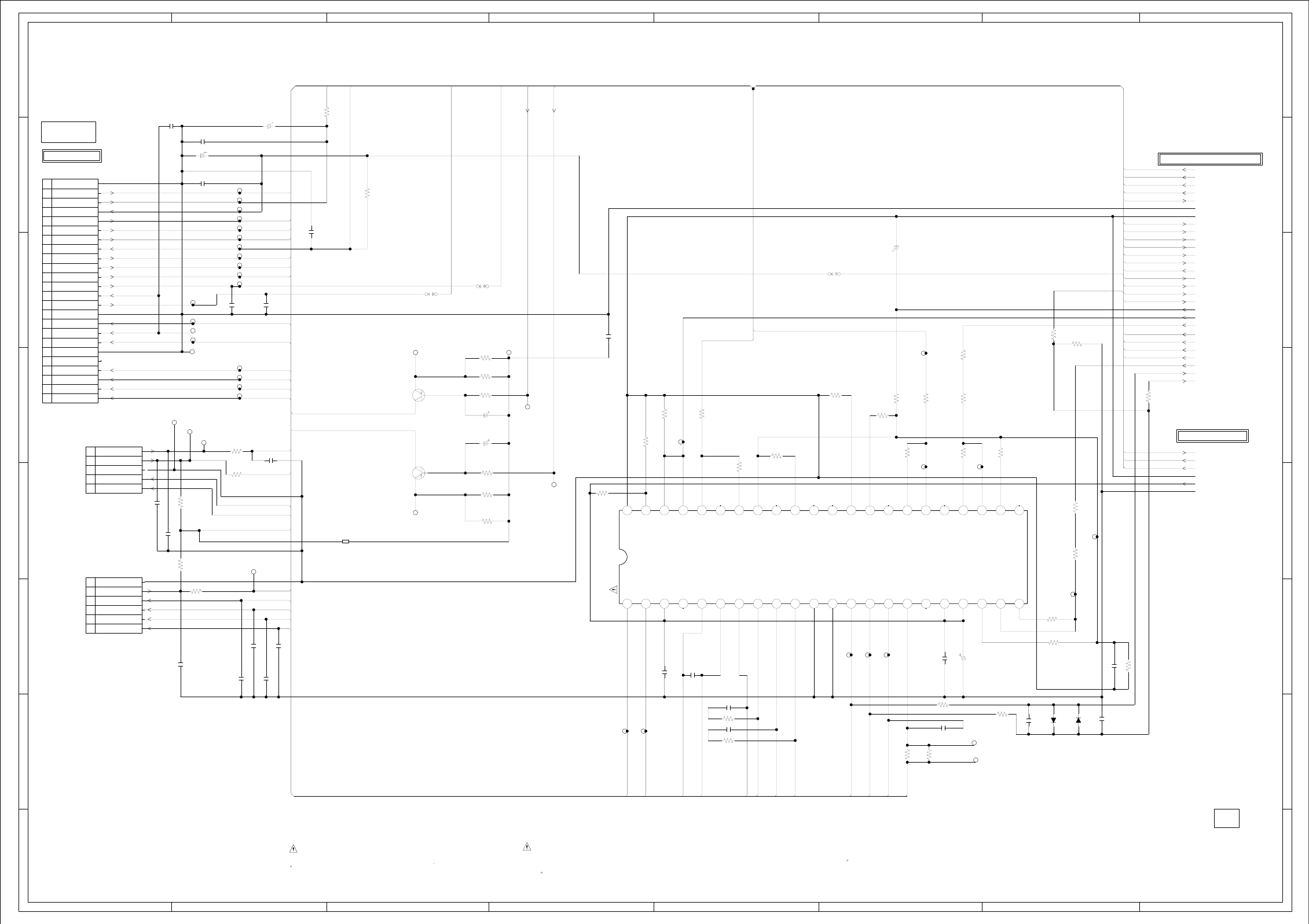
ABC D E F GH
ABC D E F GH
2
1
3
4
5
6
7
8
2
1
3
4
5
6
7
8
Q2302
KTA1505S-Y-RTK/P
CD LD CTL
Q2301
KTA1505S-Y-RTK/P
DVD LD CTL
:SINCE THESE PARTS MARKED BY
CAUTIONDESCRIBED IN PARTS LIST ONLY
CRITICAL FOR SAFETY,USE ONES ARE
DANS LA NOMENCLATURE DES PIECES
N’UTILISER QUE CELLS DECRITES
DANGEREUSES AN POINT DE VUE SECURITE
:LES PIECES REPAREES PAR UN ETANT
ATTENTION
CP2301_1
LD07T2-24ND-03
1
10
11
12
13
14
15
16
17
18
19
2
20
21
22
23
24
3
4
5
6
7
8
9
CP2303
04_6232_106_015_800+
1
2
3
4
5
6
IC2301 LA6565VR-TLM-E
MOTOR DRIVE IC
1 1011121314151617 18 192 20 21 22
23242526272829
3
30313233343536373839
4
4041424344
56789
CP2302
04_6232_105_015_800+
1
2
3
4
5
D2303
MA111
D2304
MA111
C2307 0.1 B
C2306 0.1 F
C2323
0.1 B
C2317
0.1 F
C2319
100PCH
C2339
100P CH
C2315
0.1 F
C2301
0.1 F
C2365 0.1 B
C2309
0.1 F
C2331 0.1 B
C2348 0.1 B
C2350
0.1 B
C2330
10P CH
C2360
100P CH
C2359
100PCH
C2358
100P CH
C2357
100PCH
C2304
0.022 B
C2305
0.1 B
C2321
100P CH
C2303 0.1 B
C2302 0.1 B
C2326
0.1 F
C2310
10016V SJV
C2316
476.3V SJV
C2328
226.3V SJV
C2329
226.3V SJV
C2341
476.3V SJV
C2340
476.3V SJV
R2319
33K
R2321
15K
R2337
10K
R2320
4.7K
R2310
4.7K
R2324
1K
R2309
100 +-1%
R2330
1K
R2326
5.6K
R2327
4.7K
R2313
4.7K
R2334
10K
R2358
120
R2323
1.2
R2329
1.2
R2355
3.3K
R2342
4.7K
R2352
100
R2353
100
R2360
33
R2340
6.8
R2333
220
R2332
220
R2318
6.8
R2306
6.8
R2338
4.7K
R2301
1K
R2307
75K
R2328
4.7K
R2302 100 +-1%
R2325
6.8K
R2349
100
R2336
390
R2339
1.2K
R2357 1K
R2335
3.3K
R2350
4.7K
R2341
6.8
R2304 2.2
R2303 2.2
R2305
27K
R2308
10K
B2305
EBMS160808A102_RDC45
W803
W813 W812
OF PRINTING AND SUBJECT TO CHANGE WITHOUT NOTICE
NOTE:THIS SCHEMATIC DIAGRAM IS THE LATEST AT THE TIME
DURING PLAYBACK.
MEASURED WITH THE DIGITAL TESTER
NOTE:THE DC VOLTAGE EACH PART WAS
JG056
TP2320
TP2317
TP2319
TP2318
JG057
JG058
TP2313
TP2315
TP2314
JG018JG017
JG034
JG035
JG037
JG036
JG014
JG013
JG040
JG025
JG016
JG011
JG010
JG015
JG012
JG027
JG026
TP2310
TP2311
TP2312
TP2309
JG019
TP2316
TP2322
TP2302
TP2301
TP2305
TP2303
TP2304
TP2306
TP2307
TP2308
VC
DVD_CD
MD_DVD
MD_CD
DVD_LD
CD_LD
VC
DVD_CD
DVD_LD
OPU_F CD_LD
RF
OPU_VREF GND
GND
OPU_E OPU_A
OPU_D OPU_B
OPU_C OPU_C
OPU_D
DVD_CD OPU_E
RF OPU_F
OPU_B HOME
P.CON+A5V_D
OPU_A TOUT_SW
DVD/VR TIN_SW
P.CON+3.3V_D MD_DVD
MD_CD
VDDPWM3.3V
DRVSB
CDLD SPINDLE_PWM
FOCUS_PWM FOCUS_PWM
TRACK_PWM
DVDLD TRACK_PWM
TRAY_CLOSE
TRAY_OPEN
SLED_PWM
TR+ SPDL_SENS+
TR- SPDL_SENS-
FO+
FO-
DVDLD
CDLD
TIN_SW TIN_SW
P.CON+A5V_D
P.CON+3.3V_D
TOUT_SW GND
P.CON+6V_D
M_GND
MOT_LD-
MOT_LD+
P.CON+3.3V_D
HOME
MOT_SLED-
MOT_SLED+
MOT_SPDL-
MOT_SPDL+
TRAY_CLOSE
TRAY_OPEN
MOT_SPDL+
MOT_SPDL-
MOT_SLED-
MOT_SLED+
MOT_LD-
MOT_LD+
TR+
TR-
FO+
FO-
DSM2(06SD)
FROM/TO AUDIO/VIDEO
H-6
H-5
PCB130
DMG097
0NC
00NCNCNCNCNC
NC
MOTOR DRIVE SCHEMATIC DIAGRAM
VC2
FWD
REV
VCC2
VLD-
VLD+
VD4+
VD4-
VD3+
VD3-
VD2+
VD2-
VD1-
VD1+
VCC1
VCCS
VIN1+A
VIN1-A
VIN 1
VO_OP
VIN3
VIN3-
VIN2
VIN2-
VIN2+
VIN-OP
VIN+OP
REG-IN
REG-OUT
VREF-OUT
VREF-IN
VIN4
VIN4-
MUTE234
MUTE1
VCONT
S-GND
NC
NC
NC
NC
NC
NC
PGND1
PGND2
0 0 6.0 0 1.9 1.9 2.6 2.7 2.6 2.8 0 0 3.7 1.7 2.6 2.7 6.0 6.0 1.6 1.6 1.6
01.61.61.801.61.60001.601.61.601.63.23.24.10
RF_A5V
NCNC
SP1-
SP1+
SLD+
SLD-
LIMIT SW
SW(GND)
LD-
LD+
OPEN
CLOSE
GND(D)
(VR_DVD)
(VR_CD)
0
1.9
3.0
2.6
2.3
F RTN
T RTN
T DRV
F DRV
NC
GND
GND
VR(CD)
VR COM
VR(DVD)
LD(DVD)
LD(CD)
PD/GND
GND
F
Vref
VCC
E
SW1(DVD/CD)
VRF(RF_OUT)
D
C
B
A
FROM/TO LOADER
NC
(D_GND)
(D_GND)
3.2
FROM/TO MPEG/MICON/DSP/RF_AMP
(RF_GND) (RF_GND)
(D_GND) (D_GND)
(DVD MT PCB)
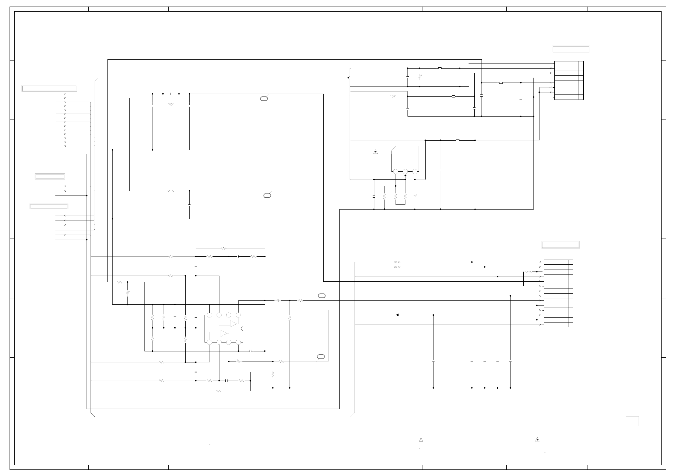
ABC D E F GH
ABC D E F GH
2
1
3
4
5
6
7
8
2
1
3
4
5
6
7
8
IC8501
NJM4565M(TE1)
AUDIO_AMP IC
1234
5678
L8502
1uHNLV25
L
IC8502
LD1117AL-ADJ-AA3-A-R
1.8V REG IC
123
CP8502
A2001WV2-8P
1
2
3
4
5
6
7
8
CP8501
A2001WR-14A
1
10
11
12
13
14
2
3
4
5
6
7
8
9
:SINCE THESE PARTS MARKED BY
CAUTIONDESCRIBED IN PARTS LIST ONLY
CRITICAL FOR SAFETY,USE ONES ARE
DANS LA NOMENCLATURE DES PIECES
N’UTILISER QUE CELLS DECRITES
DANGEREUSES AN POINT DE VUE SECURITE
:LES PIECES REPAREES PAR UN ETANT
ATTENTION
D8510
MA111
C8504
150P CH
C8506
150P CH
C8505
12P CH
C8539
0.001 B
C8519
0.001 B
C8537
560PCH
C8536
560PCH
C8543
0.01 B
C8503
0.1 B
C8518
0.001 B
C8515
0.1 B
C8531
47P CH
C8529
0.0012 B
C8528
150P CH
C8526
0.1 B
C8532
47P CH
C8530
0.0012 B
C8514
0.1 B
C8527
150P CH
C8520
2.2 B
C8538
0.001 B
C8541
0.01 B
C8542
0.01 B
C8521
0.1 B
C8512
150P CH
C8501
1F
C8517
10016V SJV
C8525
4716V SJV
C8513
4716V SJV
C8534
1016V SJV
C8533
1016V SJV
C8516
1006.3V SJV
R8536
1K
R8535
10K
R8529
2.2K R8531
47K
R8533
15K
R8510
24K
R8522
47K
R8523
47K
R8528
47K
R8521
47K
R8506
220
R8539
1K
R8537
10K
R8532
47K
R8517
47K
R8530
2.2K
R8534
15K
R8516
10K
R8527
47K
R8507
1K+-1%
R8509
68 +-1%
R8508
2.2K +-1%
B8501
BLM18PG121SN1D
B8503
BLM18PG121SN1D
B8504
EBMS160808A102_RDC45
B8502
EBMS160808A102_RDC45
W824
W825
W804
W818
OF PRINTING AND SUBJECT TO CHANGE WITHOUT NOTICE
NOTE:THIS SCHEMATIC DIAGRAM IS THE LATEST AT THE TIME
DURING PLAYBACK.
MEASURED WITH THE DIGITAL TESTER
NOTE:THE DC VOLTAGE EACH PART WAS
P.CON+6V_D
M_GND
P.CON+5V_D
DAC_VIDEO_C/D DAC_C[U]C_VIDEO P.CON+A5V_D
DAC_VIDEO_A
RESET
SYS_MUTE
DUPRD1
SPDIF
DUPTD1
APWM_L+
APWM_L-
APWM_R+
APWM_R-
P.CON+1.8V_D P.CON+3.3V_D
P.CON+3.3V_D
P.CON+5V_D
GND
GND
P.CON+1.8V_D
RESET
P.CON+3.3V_D DAC_A[Y]_VIDEO
GND
P.CON+A5V_D
P.CON+3.3V_D
P.CON+6V_D
M_GND
TIN_SW
GND
APWM_L-
DUPTD1
DUPRD1
APWM_L+ TIN_SW
RESET
SYS_MUTE
SPDIF
APWM_R+
APWM_R-
(CP3002)
(CP3002)
FROM/TO REGULATOR
FROM/TO REGULATOR
FROM/TO MPEG/MICON/DSP/RF_AMP
FROM/TO MEMORY
FROM/TO MOTOR DRIVE
PCB130
DMG097
H-8H-7
(A_GND)
(D_GND)
DAC_VIDEO_C/D
58
0
+
-
A_GND
VCC
-
+
4.3 4.3 6.9
4.3 4.3 6.9 10.9
SSCRXD/TX
SSCTXD/RX
GND
START_SW
[U]C_VIDEO
[V]Y_VIDEO
[Y]_VIDEO
DVD RESET
SPDIF-134
GND
GND
ZERO
DVD_A_OUT_R
DVD_A_OUT_L
56
57
GND(M)
P.CON+6V
P.CON+A5V
P.CON+3.3V
GND
P.CON+3.3V
GND
P.CON+12V
DAC_VIDEO_A
59
AUDIO/VIDEO SCHEMATIC DIAGRAM
INADJ OUT
0.6 1.8 3.2
(D_GND)
(D_GND)
(DVD MT PCB)
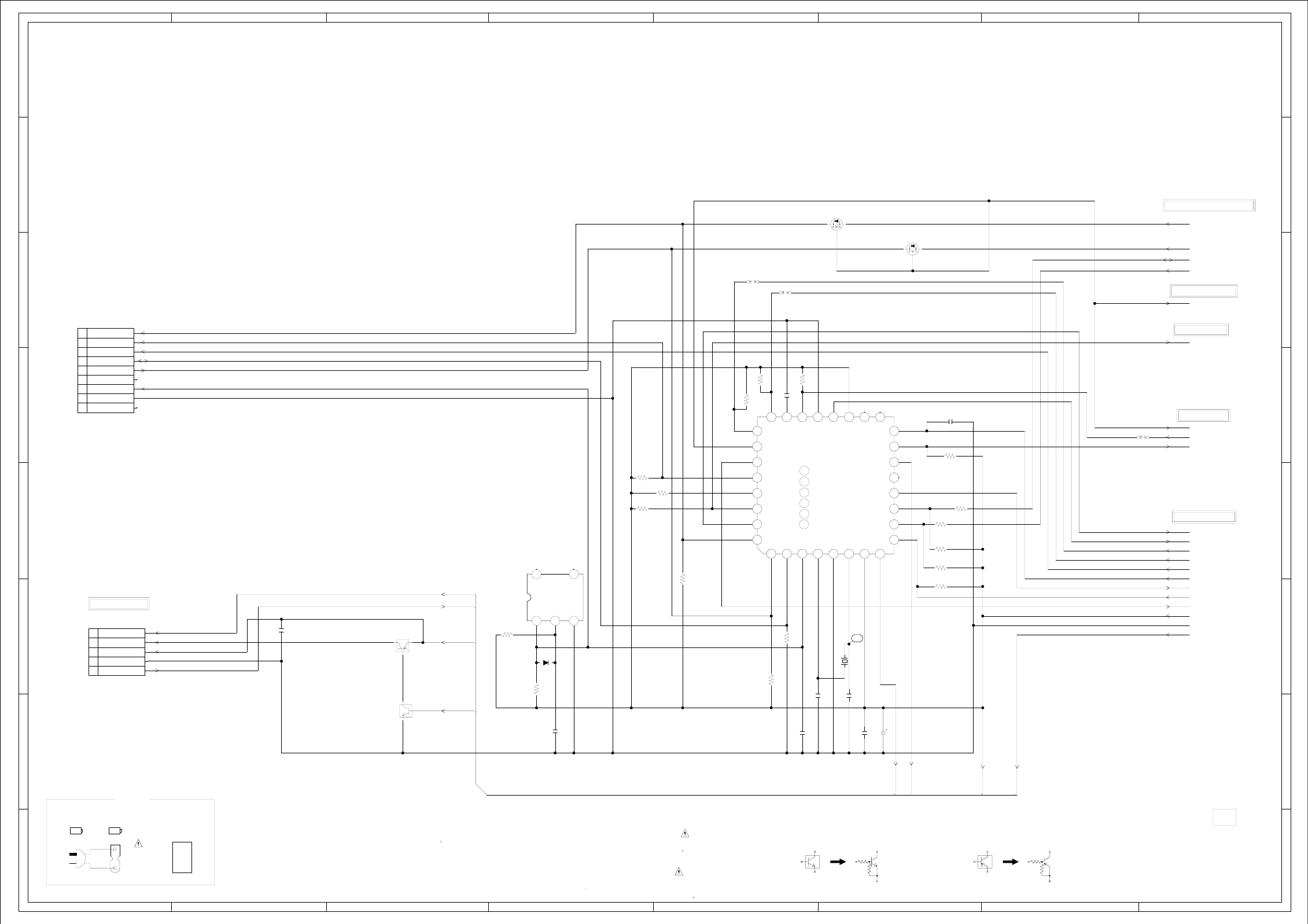
ABC D E F GH
ABC D E F GH
2
1
3
4
5
6
7
8
2
1
3
4
5
6
7
8
WAS RECEIVED IN GOOD CONDITION AND PICTURE IS NORMAL.
WITH THE DIGITAL TESTER WHEN THE COLOR BROADCAST
NOTE:THE DC VOLTAGE AT EACH PART WAS MEASURED
S
D
G
Q6201
2SK3019_TL
SW
S
D
G
Q6202
2SK3019_TL
SW
D6205
MA111
Q6203
KRA103SRTK
SW
IC6201 PST3229NR
RESET IC
123
45
Q6204
KRC102SRTK
SW
IC6202
R5F21124FP
SUB MICON IC 1
10 11 12 13 14 15 16
171819
2
2021222324
2526272829
3
303132
45678
9
TM101
000-103000530
BT001
MNAAA(R03) BT002
MNAAA(R03)
CD501
P201-2476-2
P201-2476-2
CAUTION: DIGITAL TRANSISTOR CAUTION: DIGITAL TRANSISTOR
CP6201 A2001WV2-9P
SUB MICON
1
2
3
4
5
6
7
8
9
:SINCE THESE PARTS MARKED BY
CAUTIONDESCRIBED IN PARTS LIST ONLY
CRITICAL FOR SAFETY,USE ONES ARE
DANS LA NOMENCLATURE DES PIECES
N’UTILISER QUE CELLS DECRITES
DANGEREUSES AN POINT DE VUE SECURITE
:LES PIECES REPAREES PAR UN ETANT
ATTENTION
CD6203
E8252002
1
2
3
4
5
C6205
1004V V-S
C6213
18P CH
C6215
20P CH
C6212
0.1 B
C6216
0.01 B
C6209
2.2
(1608)
B
C6218
0.1 B
C6210
0.1 B
C6221
0.1 B
R6203
10K
R6206
4.7K
R6205
33K R6210
4.7K
R6214
4.7K
R6236 4.7K
R6216
4.7K R6217
4.7K
R6215
4.7K
R6219
4.7K
R6213
4.7K
R6204
10K
R6227
100
R6224
4.7K
R6225
4.7K
R6228
4.7K
R6223
100
W807
W863
W865
OF PRINTING AND SUBJECT TO CHANGE WITHOUT NOTICE
NOTE:THIS SCHEMATIC DIAGRAM IS THE LATEST AT THE TIME
X6201
16MHz
100GT01615
MCU_SCITXD
MCU_SCIRXD
I2C_DATA
I2C_CLK
RESET_N
AUDIO_MUTE
RESET_N
IIC_OFF
ASEMD0
DVD_RESET
3.3V_POWER_H
KEY_A
KEY_B
AT+5.8V
POWER_FAIL
SYS_POWER_H
D5.0V START_SW
IR_REMO LV_CTL
AT+3.3V
GND
D5.0V
AT+3.3V
STBY-H
AT+3.3V
IR_REMO
STBY-H
D5.0V
FROM/TO REMOCON
(CP7601)
TO AV SWITCH
TO JACK
FROM/TO SCALER VIDEO/AUDIO
H-10H-9
FROM/TO FLASH
CEH420
PCBDH0
FROM/TO REGULATOR
MICON SCHEMATIC DIAGRAM
(DIGITAL PCB)
3.33.3
AT+3.3V
RESET
RX
TX
NCNC
SYS_POWER_H
RESET
XOUT
XIN
VCC
VREF
CNVSS IVCC
AVSS
EEPROM_SDA
EEPROM_SCL
KEY_B
VSS
MODE
EXT_MUTE
0
03.1 0 2.8 3.3
0
3.3
3.3
0
DVD_POWER
DTV_RESET
3.3V_POWER_H
STBY-HNC
NC
0
DVD_RESET
AUDIO_MUTE DISC_IN_DET9
32
KEY_A25
ASEMD015
MAIN_MICON_TXD
REMOCON_IN8
1 MAIN_MICON_RXD
3.3
3.3
3.3
3.3
3.3 3.3
3.3
3.3 3.3 3.3
3.3
3.3
3.3
3.3
003.33.33.32.83.3
3.3
3.3
3.3
3.3
3.3
2.5
3.3
1
ACCESSORY
0
0
DVD_SCL
DVD_SDA
DVD_CS
MODE
VCC
MODE
TX
RX
RESET
GND
NC
CNVSS
CNVSS
NC
NC
NC NC
0
00
GND
NC
IN
NC
OUT
3.3 3.3
REMOCON IN
POWER ON LED
STANDBY LED
AT+3.3V
GND
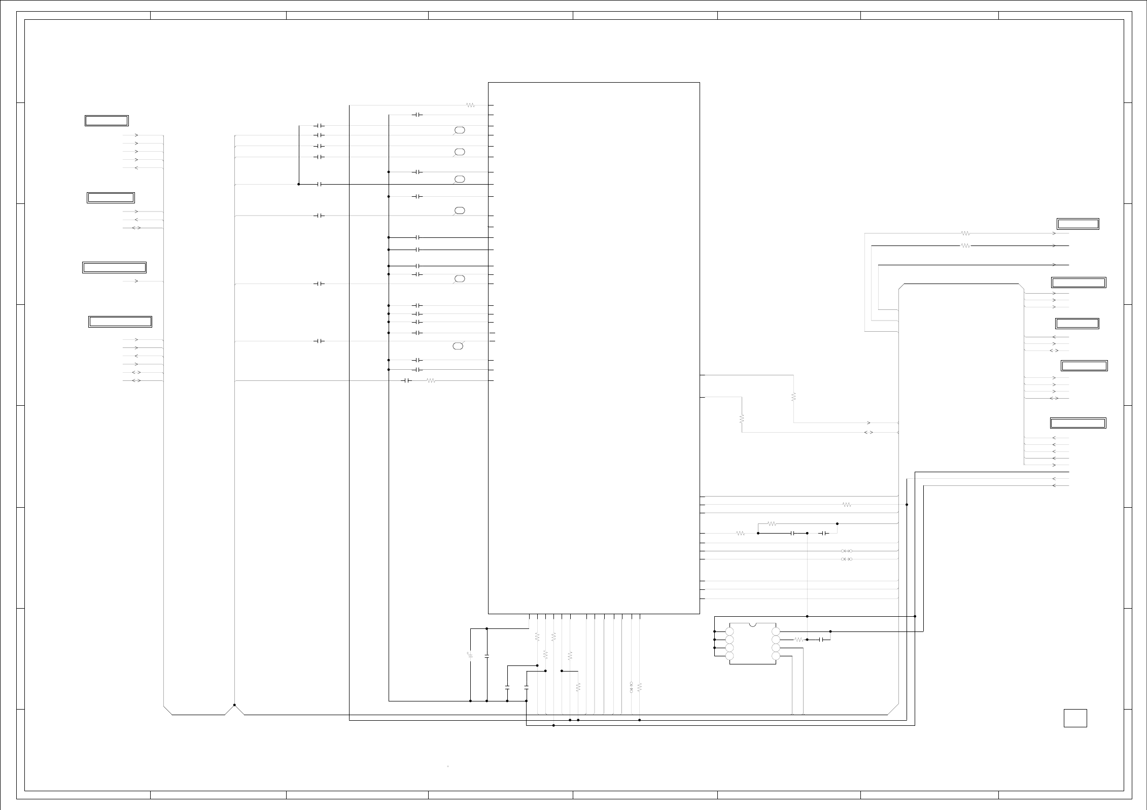
ABC D E F GH
ABC D E F GH
2
1
3
4
5
6
7
8
2
1
3
4
5
6
7
8
V8
V7
W7
AA8
Y8
W8
J21
J20
J19
J18
IC2801 R8J66954BGSCALER IC
J1
K1
K2
L1
L2
L3
M3
N2
P2
P1
P3
R1
R2
R3
U1
U2
V1
N4
N3
N1
M2
M1
T1
T2
W3
AA3
AA4
V4
W4
Y5
V5
W5
W6
Y6
AA6
V6
Y7
W9
V9
IC2805
M24256-BWMN6TP
EEP ROM
1234
5678
WAS RECEIVED IN GOOD CONDITION AND PICTURE IS NORMAL.
WITH THE DIGITAL TESTER WHEN THE COLOR BROADCAST
NOTE:THE DC VOLTAGE AT EACH PART WAS MEASURED
C2968
0.1 B
C2965
0.1 B
C2949
0.1 B
C2950
220P CH
C2951
220P CH
C2944 0.1 B
C2935 0.1 B
C2936 0.1 B
C2947 0.1 B
C2942 0.1 B
C2933 0.1 B
C2943 0.1 B
C2940 0.1 B
C2941 0.1 B
C2929
0.1 B
C2957 0.1 B
C2927 0.1 B
C2926 0.1 B
C2925 0.1 B
C2959
0.1 B
C2937 0.1 B
C2939 0.1 B
C2938 0.1 B
C2946 0.1 B
C2931 0.1 B
C2932 0.1 B
C2934 0.1 B
C2945 0.1 B
C2948
2210V V-S
R2874
4.7K
R2846
4.7K
R2839
4.7K R2840
10K
R2838
4.7K
R2856
10K
R2837
1K
R2900
10K
R2801
4.7K
R2850
4.7K
R2841
10K
R2852
10
R2851
10
R2842
10K
R2872 100K
R2873 100K
W855
W854
W881
OF PRINTING AND SUBJECT TO CHANGE WITHOUT NOTICE
NOTE:THIS SCHEMATIC DIAGRAM IS THE LATEST AT THE TIME
AV3/AV4_Y SW_Y_IN
AV1_CVBS TU_CVBS
AV3/AV4_PB AV1_CVBS
AV3/AV4_PR
SPDIF
AV3/AV4_Y
TU_CVBS SW_C_IN
I2C_CLK
I2C_DATA LOUT_FI
ROUT_FI
DVD-H
AD_A3.3V AV3/AV4_PB
DVD-H
ASW0
ASW2
DVD-H
ROUT
LOUT IIC_OFF
SW_Y_IN AV3/AV4_PR I2C_CLK
SW_C_IN I2C_DATA
MCLK
SDOUT
LRCK MCU_SCIRXD
BCLK AD_A3.3V MCU_SCITXD
I2C_CLK
I2C_DATA
I2C_CLK
I2C_DATA S1_DET
TWIRE_RXDC
TWIRE_TXDC
LIGHT_CTL
LCD-H
GND
D3.3V
AT+3.3V
ASW0
ASW2 ASW2
LIGHT_CTL
BL_PWM
LCD-H
TWIRE_RXDC
TWIRE_TXDC
MCU_SCIRXD
MCU_SCITXD
IIC_OFF
I2C_DATA
I2C_CLK
S1_DET
SPDIF
SDOUT
DVD-H
ROUT
LOUT
MCLK
LRCK
BCLK
FROM SCALER POWER
TO AV SWITCH
TO JACK
H-12H-11
CEH420
PCBDH0
FROM/TO REGULATOR
FROM/TO MICON
FROM/TO FLASH
FROM/TO AV SWITCH
FROM/TO TUNER
FROM/TO JACK
SCALER VIDEO/AUDIO SCHEMATIC DIAGRAM
NC
SCLK0(GPIO)
SRXD0(GPIO)
STXD0(GPIO)
QBLCB(GPIO)
QBLCC(RXD0)
QBLCA
PCVIN
SSIN1
SSIN2
VIN3A
VIN1A
VIN2A
VRPA
VIN6A
VRPB
VREFB
VIN3B
VREFC
VRMB
VIN4B
VRMC
VIN3C
LPF
VRMA
VIN5A
VIN2B
VIN4A
VREFA
VRPC
VIN2C
RFAGC(GPIO)
SCISCK(GPIO)
DAC_VREF
ROUT
LOUT
SPDIFO
ACLK
ADATAO
LRCKO
BCKO
SANT
SCIRXD
(DIGITAL PCB)
A0
A1
A2
Vss SDA
SCL
WP
Vcc
3
2
4
5
6
7
0
1.6
0.8
1.1
1.2
1.7
0
2.0
0
1.9
0
0
1.6
3.3
0.3
0.2
0.2
0.2
1.6
0
3.30
3.3
3.3
3.3
3.3
3.3
2.0
2.0
3.3
3.3
3.3
3.3
3.3
3.3
3.3
3.0
3.0
3.3
3.3
3.3
0
0
0
0
0
3.3
3.3
3.3
3.3
SICL 3.3
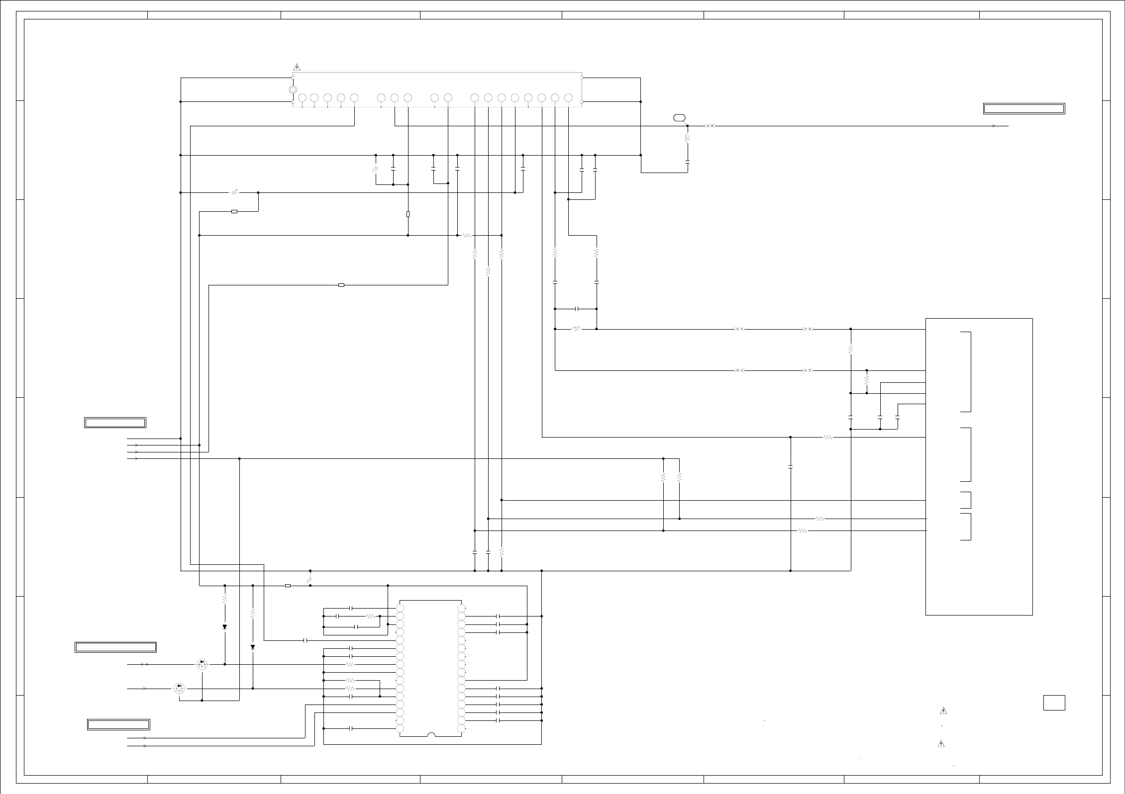
ABC D E F GH
ABC D E F GH
2
1
3
4
5
6
7
8
2
1
3
4
5
6
7
8
IC5801 AN5832SA-E1V
BTSC DEMODULATOR IC
1 10 11 12 13 14 15 16
171819
2
20212223242526272829
3
303132
45678 9
TU5801 ENG36E18KRF
1
11
12
14
15
16
17
18
19
2
20
21
22 23
24 25
3
4
5
7
8
9
AA9
W2
Y2
AA2
AA7
Y1
Y9
AA5
IC2801 R8J66954BG
SCALER IC
AA1
WAS RECEIVED IN GOOD CONDITION AND PICTURE IS NORMAL.
WITH THE DIGITAL TESTER WHEN THE COLOR BROADCAST
NOTE:THE DC VOLTAGE AT EACH PART WAS MEASURED
S
D
G
Q5801
2SK3019_TL
BUFFER
S
D
G
Q5802
2SK3019_TL
BUFFER
L5801
22uHNLV25
L5805
0.22uHLQW18AN
:SINCE THESE PARTS MARKED BY
CAUTIONDESCRIBED IN PARTS LIST ONLY
CRITICAL FOR SAFETY,USE ONES ARE
DANS LA NOMENCLATURE DES PIECES
N’UTILISER QUE CELLS DECRITES
DANGEREUSES AN POINT DE VUE SECURITE
:LES PIECES REPAREES PAR UN ETANT
ATTENTION
D5803
MA111
D5804
MA111
C5817
0.001 B
C5814
33P CH
C5812
22P CH
C5811
22P CH
C5805
1
50V(2125)
F
C5809
0.1 B
C5804
0.1 B
C5845
0.01 B
C5844
0.01 B
C5846
56P CH
C5806
0.1 B
C5822
47P CH
C5821
47P CH
C5841 10 C
C5840 0.33 B
C5839 3.3 B
C5838 0.1 B
C5837 0.022 B
C5835 0.1 B
C5834 0.033 B
C5833 2.2 B
C5818
0.22 B
C5825 4.7 B
C5826 2.2 B
C5827 2.2 B
C5830 2.2 B
C5823 0.33 B
C5847
0.1 B
C5824
0.1 B
C5853
0.1 B
C5855
0.1 B
C5852
0.1 B
C5803
2206.3V V-S
C5801
2206.3V V-S
C5819
2206.3V V-S
R5808
4.7K
R5809
4.7K
R5819
100
R5820
100
R5801
150K
R5802
47K
R5803
100
R5804
100
R5807
100K
R5811 180K
R5812 100
R5810 100
R5823
1K
R5821
47
R5822
47
R5825
47K
R5813
3.3K
R5824
47K
R5817
3.3K
R5818
3.3K
B5801
FCM1608KF-102T02
B5803
FCM1608KF-102T02
B5802
FCM1608KF-102T02
B5804
FCM1608KF-151T06
W878
W858
W846
W804
W802
OF PRINTING AND SUBJECT TO CHANGE WITHOUT NOTICE
NOTE:THIS SCHEMATIC DIAGRAM IS THE LATEST AT THE TIME
TU_CVBS
IF_OUT_1
IF_OUT_2
IF_AGC
GND
D5.0V
TUNER+30V
D3.3V
TU_AFT
I2C0C
I2C0D
SIF_OUT
I2C_DATA
I2C_CLK
TU_AUDIO_R
TU_AUDIO_L
TO AV SWITCH
H-14H-13
CEH420
PCBDH0
3.3 5.0
5.0
3.3
3.3
3.3
FROM/TO SCALER VIDEO/AUDIO
FROM/TO REGULATOR
FROM/TO SCALER VIDEO/AUDIO
(DIGITAL PCB)
TUNER SCHEMATIC DIAGRAM
8
NC(BB)
NC
NC
SDA
SCL
+5V
+30V
TU
V_OUT
SIF-out
AGC
IF_OUT
IF_AGC
IF_O
IF_OUT2
IF_OUT1
NC
AFT
+5V
NC
NC
NC
NC
1.0
NC
1.0
5.0
NC
30.0
5.0
5.0
2.5
5.0
NC
1.0
0.6
1.4
L-R RBF
NC
LOUT
ROUT SPE DELAGC DET SPE FILSCL/STID
PE
GND
SDA/SAPID
STEREO REF
SIF REF
INPUT
NC
VCC L+R REFPLL
PILOT DET
IIC/PARA
AGC SW
MODE
FOMO
MUTE
SIF/BB
NOISE DET
SAP DET
WB TIME
WB DET
SPE TIME
NC
3.5
3.5
0
2.2
2.2
0
2.4
2.4
0.5
2.9
0.5
5.0
2.9
2.8
2.2
5.0
3.3
5.0
1.7
2.2
2.2
1.3
NC
NC
NC
NC
NC
NC
NC
NC NC
NC NC
ADIN1
SIDA0
SICL0
IF_AGC
ADVREF0
ADVREF1
ADVREF2
ADIN0 VSB_ADC
TUNER_IF
MCUADIN0 MCU_ADC
IIC0
1.6
1.4
0.6
1.6
0.8
1.0
3.3
3.3
2.4
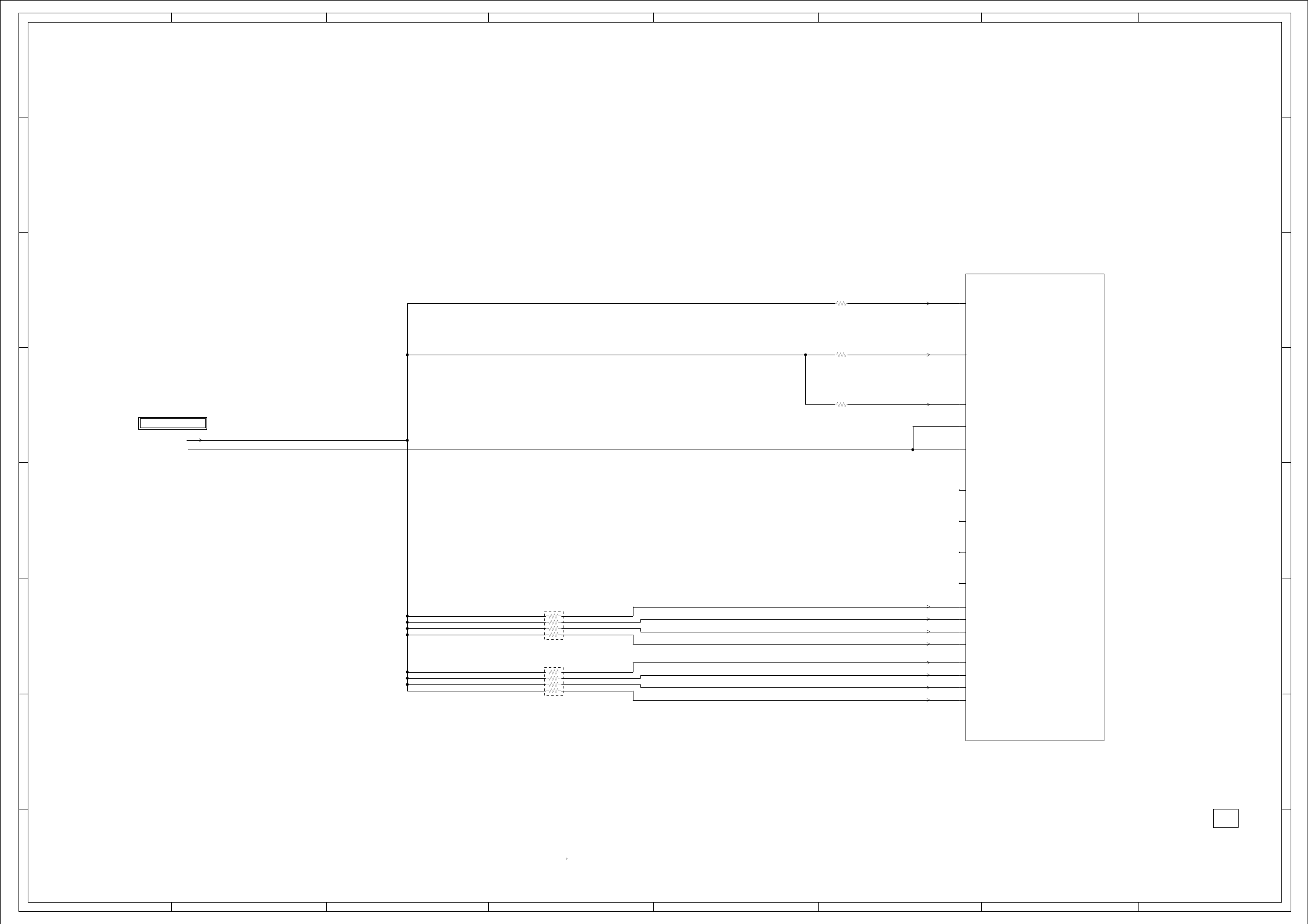
ABC D E F GH
ABC D E F GH
2
1
3
4
5
6
7
8
2
1
3
4
5
6
7
8
NR3602
4D02WGJ0472TCE
NR3601
4D02WGJ0472TCE
H3
IC2801 R8J66954BGSCALER IC
J2
F3
E3
G4
D2
D1
C1
E2
E1
H1
H2
G1
G2
F1
F2
G3
WAS RECEIVED IN GOOD CONDITION AND PICTURE IS NORMAL.
WITH THE DIGITAL TESTER WHEN THE COLOR BROADCAST
NOTE:THE DC VOLTAGE AT EACH PART WAS MEASURED
R3630
4.7K
R3631
4.7K
R3629
470
OF PRINTING AND SUBJECT TO CHANGE WITHOUT NOTICE
NOTE:THIS SCHEMATIC DIAGRAM IS THE LATEST AT THE TIME
D3.3V
GND
H-16H-15
CEH420
PCBDH0
FROM/TO REGULATOR
HDMI SCHEMATIC DIAGRAM
(DIGITAL PCB)
3.3
3.3
3.3
3.3
3.3
3.3
0
0
3.3
3.3
3.3
RX1P
EXT_RES
HDMI_SDA10
PWR0
HDMI_SCL10
HDMI_XIN
PLL_XFC_X
PLL_XFC_P
PLL_XFC_A
HDMI_XOUTNC
NC
NC
NC
3.3
3.3 RX2N
RX2P
RX0N
RX0P
RXCN
RXCP
RX1N
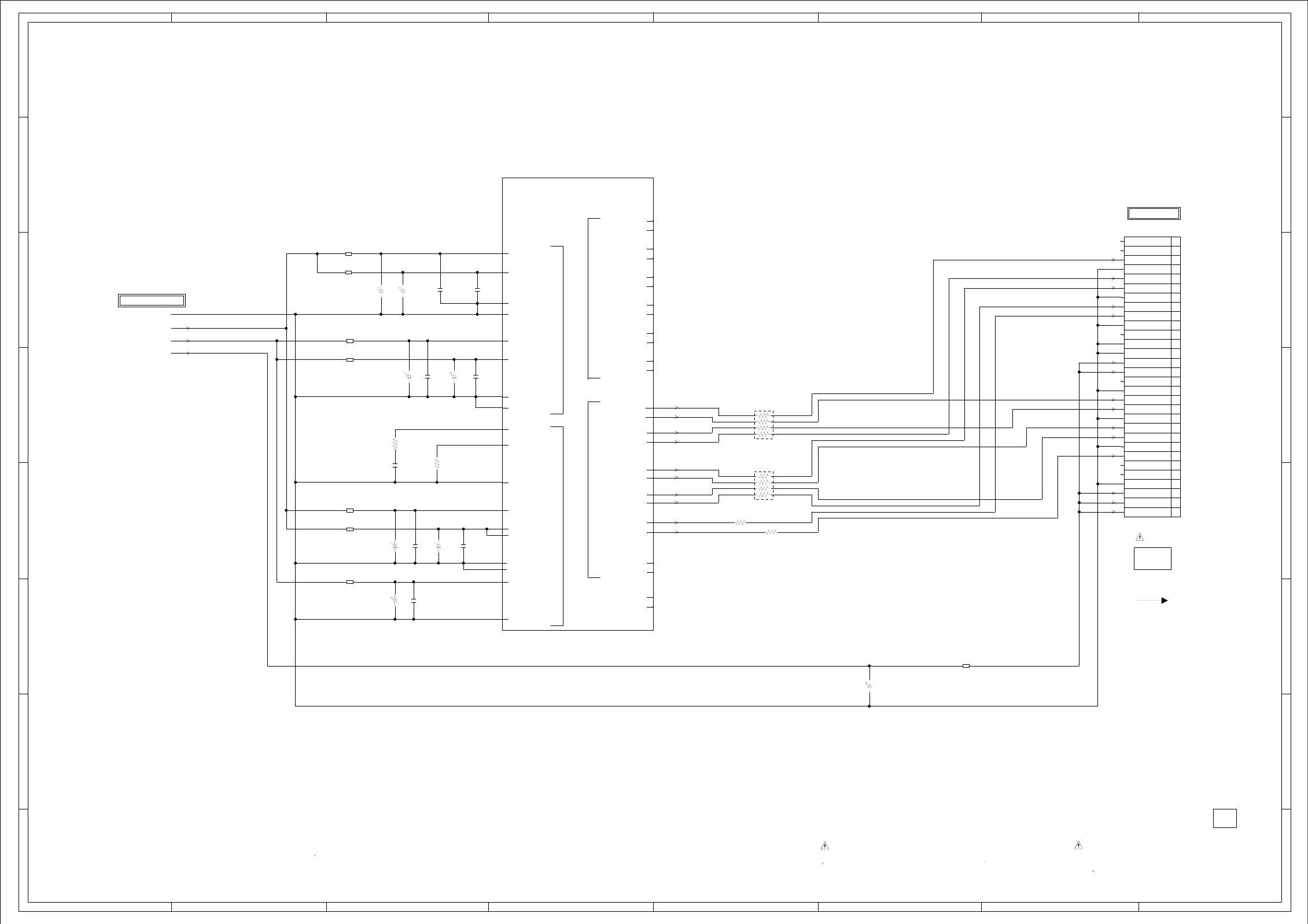
ABC D E F GH
ABC D E F GH
2
1
3
4
5
6
7
8
2
1
3
4
5
6
7
8
CD2804
CHRU1803
LVDS
LCD PANEL
V2801
M156B1-L02
CP2804
A2006WV0-2X15P
1
10
11
12
13
14
15
16
17
18
19
2
20
21
22
23
24
25
26
27
28
29
3
30
4
5
6
7
8
9
NR2811
CRA108220JV
NR2810
CRA108220JV
A17
D14
E13
A18
IC2801 R8J66954BGSCALER IC
C15
E14
D15
B17
E18
F17
E17
F18
H17
J17
D17
D18
A19
B19
H18
H19
A20
A21
B21
B20
D20
D21
C21
C20
D19
C19
H20
H21
G21
G20
G19
F20
F21
E19
F19
E20
E21
G18
G17
E16
WAS RECEIVED IN GOOD CONDITION AND PICTURE IS NORMAL.
WITH THE DIGITAL TESTER WHEN THE COLOR BROADCAST
NOTE:THE DC VOLTAGE AT EACH PART WAS MEASURED :SINCE THESE PARTS MARKED BY
CAUTIONDESCRIBED IN PARTS LIST ONLY
CRITICAL FOR SAFETY,USE ONES ARE
DANS LA NOMENCLATURE DES PIECES
N’UTILISER QUE CELLS DECRITES
DANGEREUSES AN POINT DE VUE SECURITE
:LES PIECES REPAREES PAR UN ETANT
ATTENTION
C2872
0.1 B C2875
0.1 B
C2868
0.01 B
C2874
0.1 B
C2871
0.1 B
C2880
0.1 B
C2881
0.1 B
C2879
0.1 B
C2869
474V V-S
C2867
474V V-S
C2866
2210V V-S
C2876
2210V V-S
C2974
1016V V-S
C2975
1016V V-S
C2877
474V V-S
C2800
2206.3V V-S
R2835
1K
R2836
5.6K
R2800
22 R2830
22
B2800
HCB1608KF-181T20
B2806
HCB1608KF-221T20
B2807
HCB1608KF-221T20
B2808
HCB1608KF-221T20
B2809
HCB1608KF-221T20
B2805
HCB1608KF-221T20
B2804
HCB1608KF-221T20
B2803
HCB1608KF-221T20
OF PRINTING AND SUBJECT TO CHANGE WITHOUT NOTICE
NOTE:THIS SCHEMATIC DIAGRAM IS THE LATEST AT THE TIME
GND
D3.3V
D1.0V
VDD_PANEL
CH0_TXOUT0-
CH0_TXOUT0+
CH0_TXOUT1-
CH0_TXOUT1+
CH0_TXOUT2-
CH0_TXOUT2+
CH0_TXCLKOUT-
CH0_TXCLKOUT+
CH0_TXOUT3-
CH0_TXOUT3+
H-18H-17
CEH420
PCBDH0
FROM/TO PANEL
FROM/TO REGULATOR
(DIGITAL PCB)
LVDS SCHEMATIC DIAGRAM
PLLDVDD_1
PLLAVSS
PLLAVSS
PLLAVCC_2
PLLAVCC_1
PLLDVSS
PLLDVSS
PLLDVDD_2
LPFP
VCC33BIAS
VCC33LVDS
VCC33LVDS
VCC10LVDS
VSS10LVDS
VSS33LVDS
VSS33LVDS
VSS33BIAS
REFR
LVDS POWER/REF PLL POWER
LVDS1OUT0M
LVDS1OUT0P
LVDS_CH1
RSDSA
RSDSB
LVDS_CH0
LVDS1OUT1M
LVDS1OUT1P
LVDS1OUT2P
LVDS1OUT2M
LVDS1OUT4M
LVDS1OUT4P
LVDS1OUT3P
LVDS1OUT3M
LVDS1CLKOUTP
LVDS1CLKOUTM
LVDS0OUT4M
LVDS0OUT4P
LVDS0OUT3P
LVDS0OUT3M
LVDS0CLKOUTP
LVDS0OUT2M
LVDS0OUT2P
LVDS0OUT0M
LVDS0OUT0P
LVDS0OUT1M
LVDS0OUT1P
LVDS0CLKOUTM
NC
NC
NC
NC
1.0
1.0
0
0
3.3
3.3
0
0
1.4
0
3.3
3.3
3.3
0
0
1.0
0
0
1.6
1.6
1.6
1.6
1.6
1.6
1.6
1.6
1.6
1.6
NC
NC
NC
NC
NC
NC
NC
NC
NC
NC
NC
NC
GND
NC
GND
GND
GND
NC
VDD+5V
VDD+5V
VDD+5V
VDD+5V
GND
GND
NC
GND
RXCLK-
VDD+5V
RX3+
RX2+
RX0+
RX1-
RX3-
RXCLK+
GND
GND
NC
NC
RX0-
RX1+
RX2-
NC
NC
NC
NC
NC
NC
NC
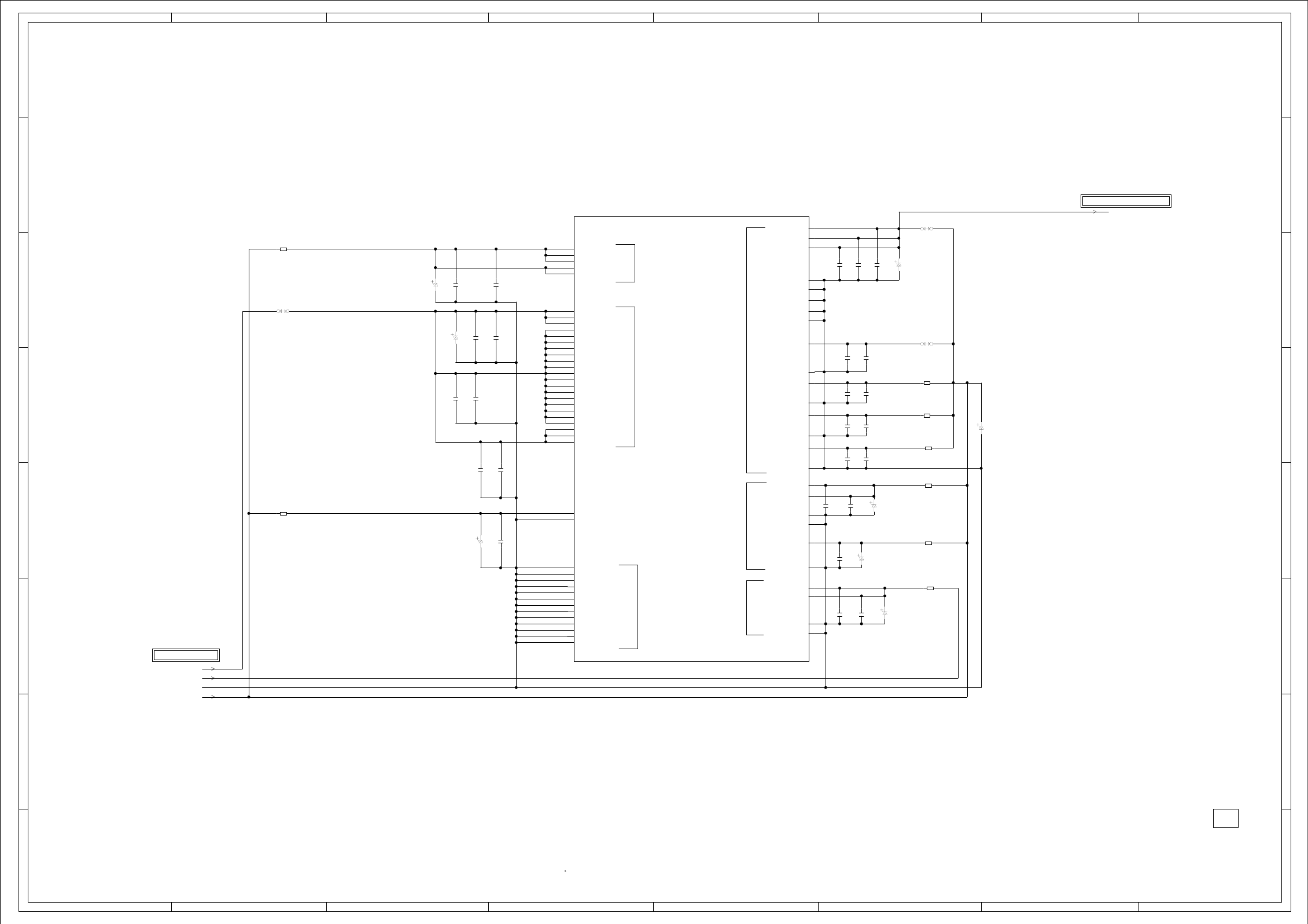
ABC D E F GH
ABC D E F GH
2
1
3
4
5
6
7
8
2
1
3
4
5
6
7
8
M4
M5
E8
E10
E12
K10
K11
K12
L10
L11
L12
M10
M11
M12
U7
E6
E11
U5
U8
E5
E7
E9
E15
J9
J10
J11
J12
J13
K9
K13
L9
L13
M9
M13
N9
N10
N11
N12
N13
T5
U6
U9
IC2801 R8J66954BG
SCALER IC
J4
K4
L4
F5
G5
H4
J5
L5
P4
N5
T4
P5
V3
W1
Y3
Y4
J3
U4
H5
R5
K3
U3
V2
T3
K5
R4
WAS RECEIVED IN GOOD CONDITION AND PICTURE IS NORMAL.
WITH THE DIGITAL TESTER WHEN THE COLOR BROADCAST
NOTE:THE DC VOLTAGE AT EACH PART WAS MEASURED
C2885
0.1 B
C2884
1B
C2902
0.1 B
C2907
0.1 B
C2908
0.1 B C2911
1B
C2913
1B
C2909
0.1 B
C2920
0.1 B
C2906
0.1 B
C2910
1B
C2912
1B
C2918
0.1 B
C2919
0.1 B
C2922
0.1 B
C2887
0.1 B
C2917
0.1 B
C2903
0.1 B
C2904
0.1 B
C2890
1B
C2898
1B
C2894
0.1 B
C2901
0.1 B
C2896
1B
C2900
0.1 B
C2921
2210V V-S C2923
2210V V-S
C2924
2210V V-S C2905
3304V V-S
C2914
3304V V-S
C2883
2210V V-S
C2882
1004V V-S
C2891
2210V V-S
B2811
HCB1608KF-221T20
B2810
HCB1608KF-221T20
B2815
HCB1608KF-121T20
B2816
HCB1608KF-121T20
B2817
HCB1608KF-121T20
B2820
HCB1608KF-121T20
B2821
HCB1608KF-121T20
B2822
HCB1608KF-121T20
W849
W848
W809
OF PRINTING AND SUBJECT TO CHANGE WITHOUT NOTICE
NOTE:THIS SCHEMATIC DIAGRAM IS THE LATEST AT THE TIME
AD_A3.3V
D1.0V
D1.8V
GND
D3.3V
TO SCALER VIDEO/AUDIO
H-20H-19
CEH420
PCBDH0
FROM/TO REGULATOR
SCALER POWER SCHEMATIC DIAGRAM
(DIGITAL PCB)
AVDDA
AVDDB
AVDDC
ADVSS
ADVSS
ADVSS
ADVSS
ADVSS
VCC33AD_A
VSS33AD_A
VCC33DA_A
DLLVSS
PLLVSS
DLLVDD
PLLVDD
VDD33
VDD33
VDD18
VSS33
VSS33
A3.3V
D3.3V
D1.8V
VSS33ADDA
VDD33ADDA
VDD18
VSS18
VSS18
VCCQ33
VCCQ33
VCCQ33
VCCQ33
VCCQ33
VDD
VDD
VDD
VDD
VDD
VDD
VDD
VDD
VDD
VDD
VDD
VDD
VDD
VDD
VDD
VDD
VDD
VDD
VDD
VDD
VDD
VDD
DVDDABC
DVSSABC
VSS
VSS
VSS
VSS
VSS
VSS
VSS
VSS
VSS
VSS
VSS
VSS
VSS
GND
Core_Power
Io_Power
A3.3V
1.0
1.0
1.0
1.0
1.0
1.0
1.0
1.0
1.0
1.0
1.0
1.0
1.0
1.0
1.0
1.0
1.0
1.0
1.0
1.0
1.0
1.0
3.3
3.3
3.3
3.3
3.3
0
0
0
0
0
0
0
0
0
0
0
0
0
0
3.3
VSS33DA_A
3.3
3.3
3.3
0
0
0
0
0
3.3
0
3.3
0
3.3
0
3.3
0
3.3
3.3
0
0
3.3
0
1.8
1.8
0
0
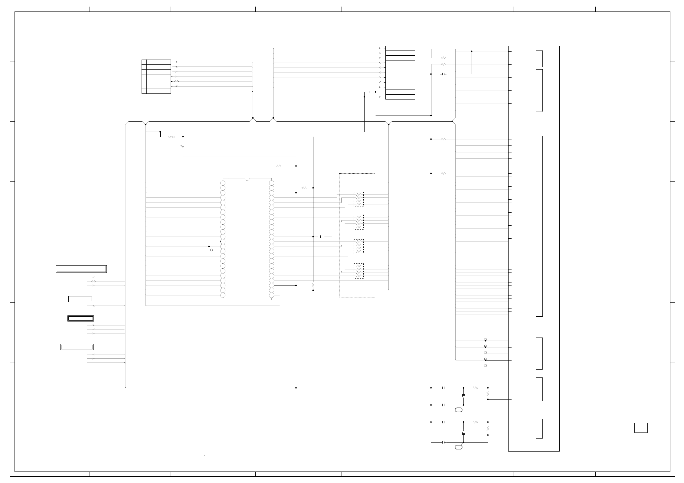
ABC D E F GH
ABC D E F GH
2
1
3
4
5
6
7
8
2
1
3
4
5
6
7
8
IC2804 EN29LV320AB-70TCP
NOR FLASH IC
110111213141516171819 22021222324
25 26 27 28 29
3
30 31 32 33 34 35 36 37 38 39
4
40 41 42 43 44 45 46 47 48
56789
CP2803 A2001WV2-11P
1
10
11
2
3
4
5
6
7
8
9
CP2801 A2001WV2-7P
1
2
3
4
5
6
7
NR2802
CRA108100JV
NR2803
CRA108100JV
NR2804
CRA108100JV
NR2801
CRA108100JV
C14
A16
C16
D16
C17
C18
B18
A7
B7
B5
C5
B8
C8
D8
C9
D9
A8
B14
C13
A13
A12
A10
C11
A11
C12
C10
D12
B12
D13
B13
B11
B10
D11
D10
C4
D7
A5
D6
A3
B3
A14
C7
D5
A4
B4
B6
A9
A6
C6
B9
D4
B2
C3
D3
B1
C2
A2
IC2801 R8J66954BGSCALER IC
A1
F4
E4
B16
B15
A15
WAS RECEIVED IN GOOD CONDITION AND PICTURE IS NORMAL.
WITH THE DIGITAL TESTER WHEN THE COLOR BROADCAST
NOTE:THE DC VOLTAGE AT EACH PART WAS MEASURED
C2808
0.01 B
C2806
0.1 B
C2809
5P CH
C2810
7P CH
C2811
20P CH
C2812
22P CH
C2807
0.1 B
C2802
2210V V-S
R2807 10K
R2809 10K
R2811
10K
R2806
10K
R2802
10K
R2805
10K
R2815
1M
R2814
1M
R2810
10K
R2812
1.8K
R2813
1.8K
W827
OF PRINTING AND SUBJECT TO CHANGE WITHOUT NOTICE
NOTE:THIS SCHEMATIC DIAGRAM IS THE LATEST AT THE TIME
JG2803
JG2804
JG2805
JG2806
JG2802
JG2801
X2801
27MHz
100GT02728
X2802
25MHz
100GT02509
TCK D3.3V RESET_N
TRST_N
TDO
D3.3V ASEBRKAK_N
PC_TOOL_TX TMS ASEMD0
PC_TOOL_RX TDI
IIC_OFF RESET_N ASEBRKAK_N
I2C_DATA FLASH_WP TDO
I2C_CLK ASEMD0 TDI
GND
TMS
TCK
TRST_N
D3.3V D3.3V_FLASH USB_CS
WE0_N
CS0_N
RD_N
A21
A20
A16 A17 A19
A18
A15 A17
A14 A16
D15 A15
A13 D7 A14
D14
A12 A13
D6 A12
A11 A11
A10 A10
A9
A9 D13 A8
D5
A20 A7
D12 A6
A21 D4 A5
WE0_N A4
A3
RESET_N A2
D11 A1
D3
FLASH_WP D10
D2 INVERTER_H
A19
A18
A8 D9 D15
D1 D14
A7 D8 D13
A6 D0 D12
IIC_OFF D11
A5 RD_N
I2C_DATA D10
I2C_CLK A4 D9
D8
A3 CS0_N D7
A2 D6
D5
D4
D3
A_MUTE A1 D2
D1
D0
ASEMD0
IIC_OFF
RESET_N
PC_TOOL_RX
PC_TOOL_TX
INVERTER_H
D3.3V A_MUTE
GND
GND
H-22H-21
CEH420
PCBDH0
FROM/TO REGULATOR
FROM/TO MICON
FROM/TO JACK
FROM/TO SCALER VIDEO/AUDIO
(DIGITAL PCB)
FLASH SCHEMATIC DIAGRAM
IIC_OFF
D_GND
SDA
SCL
PC_TOOL_RX
A16
BYTE#
VSS
DQ15/A-1
DQ7
DQ14
DQ6
DQ13
DQ5
DQ4
VCC
DQ3
DQ10
DQ2
DQ9
DQ1
DQ8
DQ0
VSS
CE#
A0
OE#
DQ11
DQ12
A15
A14
A13
A12
A11
A10
A9
A19
A20
WE#
RESET#
A21/NC
WP#/ACC
RY/BY#
A18
A17
A6
A5
A4
A3
A2
A1
A7
A8
NEAR FLASH
D3.3V
PC_TOOL_TX
M32TDI
M32TDO
M32TCK
M32TMS
M32TRST_N
VCNT(GPIO)
XOUT
A10
A9
A8
A7
A6
A5
A4
A3
A2
A1
(GPIO)
D15
D14
D13
D12
D10
D7
D6
D5
D4
D3
D2
D1
D0
D8
D9
D11
WAIT_N(GPIO)
WE0_N
CS0_N
RD_N
A22(GPIO)
A21
A20
A19
A18
A17
A16
A15
A14
A13
A12
A11
ASEBRKAK_N
TDO
TDI
TMS
TCK
TRST_N
ASEMD0
RESET_N
MODE1
MODE0
XIN
XIN25
XOUT25
RESET/MODEE10A DEBUGFLASH I/FM32R DEBUG27MHz CLK25MHz CLK
TRST_N
TDI
RESET_N
TMS
TDO
TCK
ASEBRKAK_N
ASEMD0
FLASH_WP
VDD33
GND
9
10
NC
0
NC
3.3
3.3
3.3
3.3
3.3
3.3
3.3
3.3
3.3
3.3
3.3
3.3
3.3
3.3
3.3
3.3
3.3
3.3
3.3
3.3
3.3
0
0
3.3
3.3
3.3
3.3
3.3
3.3
3.3
3.3
3.3
3.3
3.3
3.3
3.3
3.3
3.3
3.3
3.3
3.3
3.3
3.3
3.3
3.3
3.3
3.3
0
3.3
3.3
0
0
0
0
0
3.3
3.3
3.3
0
3.3
0
3.3
3.3
3.3
3.3
3.3
3.3
3.3
3.3
3.3
3.3
3.3
3.3
3.3
3.3
3.3
3.3
3.3
3.3
3.3
3.3
3.3
3.3
3.3
3.3
3.3
3.3
3.3
3.3
3.3
3.3
3.3
3.3
3.3
3.3
3.3
3.3
3.3
3.3
0
0
0
0
1.2
1.2
1.2
1.2
EEP/PC_TOOL_JIG_CON
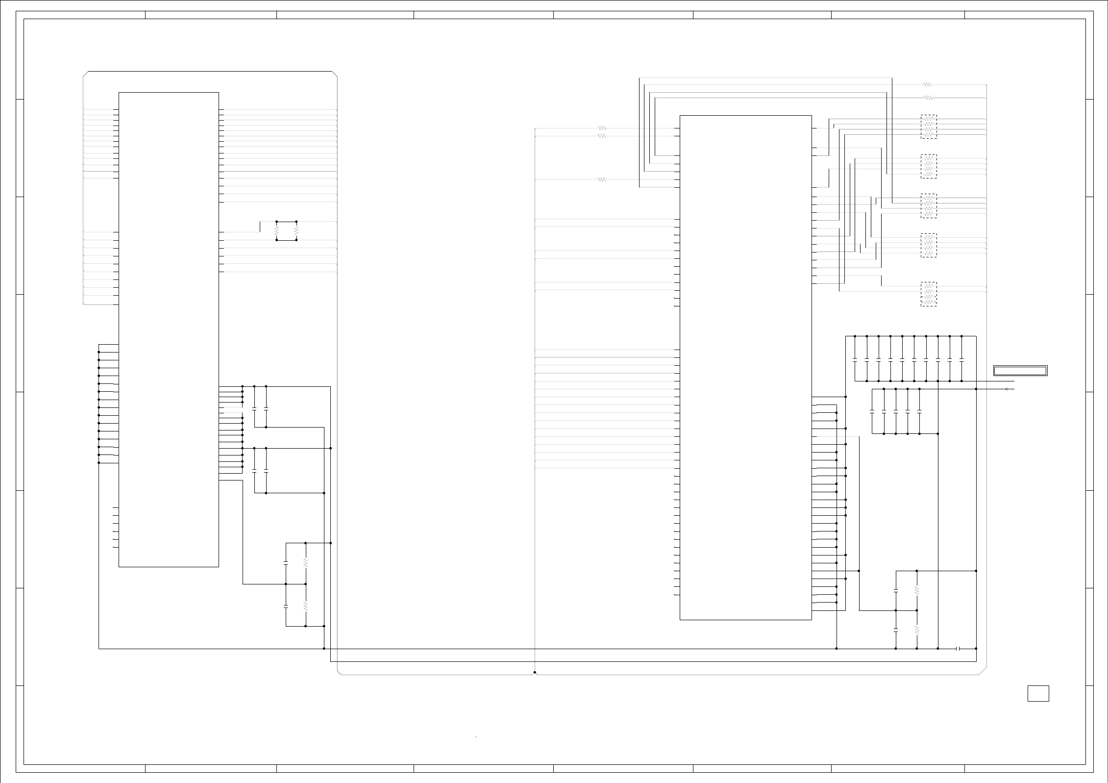
ABC D E F GH
ABC D E F GH
2
1
3
4
5
6
7
8
2
1
3
4
5
6
7
8
NR2805
CRA108270JV
NR2806
CRA108270JV
NR2807
CRA108270JV
NR2808
CRA108270JV
NR2809
CRA108270JV
V18
AA19
V17
V16
T18
W16
Y18
Y17
T20
Y16
U21
U18
AA17
AA20
AA18
U10
Y10
U11
U12
W12
U13
W14
U14
U16
U15
AA21
W17
W18
W19
V20
U17
U19
T17
T19
R17
P17
P19
N17
M17
M19
L17
K17
K20
U20
IC2801 R8J66954BGSCALER IC
W20
W21
Y21
V19
V21
Y20
Y19
W10
W13
K19
N19
P21
V10
V13
K18
N18
AA11
AA14
L21
AA12
AA10
Y12
AA13
V12
Y11
W11
V11
Y13
AA15
Y15
AA16
V14
V15
W15
Y14
M21
K21
N21
L19
M18
L20
L18
M20
P20
N20
R19
P18
R18
T21
R21
R20
M7
N2
N8
IC2802 HYB18TC256160BF-3S
DDR_SDRAM IC
M8
M3
N3
N7
P2
P7
M2
P3
P8
R2
F7
E8
B7
A8
F3
B3
K2
K3
A3
E3
J3
N1
P9
A7
B2
B8
D2
L2
L3
D8
E7
F2
F8
H2
H8
J7
R8
R7
R3
L1
E2
A2
G8
G2
H7
H3
H1
H9
F1
F9
D1
C8
C2
D7
D3
D9
B1
B9
A1
E1
J9
M9
R1
A9
C1
C3
G3
C7
C9
E9
G1
G7
J2
J1
G9
J8
K8
L8
K7
L7
K9
WAS RECEIVED IN GOOD CONDITION AND PICTURE IS NORMAL.
WITH THE DIGITAL TESTER WHEN THE COLOR BROADCAST
NOTE:THE DC VOLTAGE AT EACH PART WAS MEASURED
C2859
1
6.3V(2125)
B
C2851
0.1 B
C2850
0.1 B
C2841 0.1 B
C2842 1 B
C2853 0.1 B
C2846 0.1 B
C2849 1 B
C2855 1 B
C2856 0.1 B
C2857 1 B
C2861 1 B
C2858 0.1 B
C2814 0.1 B
C2816 1 B
C2813 0.1 B
C2815 1 B
C2822
0.1 B
C2821
0.1 B
C2843 0.1 B
C2847 0.1 B
C2848 0.1 B
C2852 0.1 B
C2854 0.1 B
R2829
1K +-1%
R2828
1K +-1%
R2823 27
R2824 27
R2826 5.1
R2825 5.1
R2827
27
R2819
1K +-1%
R2818
1K +-1%
R2817
160
R2820
160
OF PRINTING AND SUBJECT TO CHANGE WITHOUT NOTICE
NOTE:THIS SCHEMATIC DIAGRAM IS THE LATEST AT THE TIME
DARAS_N
DACKE
DAA0 DAQ0
DAA1 DAQ1 DABA1
DAA2 DAQ2 DAODT
DAA3 DAQ3 DACLK DAA4
DAA4 DAQ4 DAA12
DAA5 DAQ5 DACLK_N
DAA6 DAQ6
DAA7 DAQ7
DAA8 DAQ8
DAA9 DAQ9 DAA8
DAA6
DAA10 DAQ10 DAA0
DAA11 DAQ11 DACS_N
DAA12 DAQ12 DACAS_N
DAQ13
DAQ14 DAA2
DAQ15 DAWE_N
DABA0
DAA10
DAQM0
DACLK DAQM1
DADQS0 DAA1
DADQS0_N DACLK_N DAA9
DADQS1 DACS_N DAA3
DADQS0 DAA7
DADQS1_N DARAS_N DADQS1
DAQM0 DACAS_N
DAQM1 DAODT
DACKE DADQS0_N DAA11
DAWE_N DADQS1_N DAA5
DABA0
DABA1
DAQ3
DAQ1
DAQ4
DAQ5
DAQ0 GND
DAQ2 D1.8V
DAQ7
DAQ6
DAQ12
DAQ8
DAQ14
DAQ10
DAQ13
DAQ11
DAQ15
DAQ9
D1.8V
H-24H-23
CEH420
PCBDH0
FROM/TO REGULATOR
DDR SCHEMATIC DIAGRAM
(DIGITAL PCB)
SDCLK
SDCLK_N
SDCKE
SDCS_N
SDRAS_N
SDCAS_N
SDWE_N
SDODT
SDBA0
SDBA1
SDA0
SDA1
SDDM0
SDDM1
SDDM2
SDDM3
SDDQS0
SDDQS1
SDDQS2
SDDQS3
SDDQS0_N
SDDQS1_N
SDDQS2_N
SDA2
SDA3
SDA4
SDA5
SDA6
SDA7
SDA8
SDA9
SDA10
SDA11
SDA12
VCCQ18
VSS
VSS
VSS
VCCQ18
SDVREF0
VCCCQ18
VSS
VSS
VCCQ18
VCCQ18
VSS
VSS
VCCQ18
VCCQ18
VCCQ18
VSS
VSS
VSS
VSS
VCCQ18
VSS
SDVREF1
VCCQ18
VSS
VSS
VSS
VCCQ18
SDDQ0
SDDQ1
SDDQ2
SDDQ3
SDDQ4
SDDQ5
SDDQ6
SDDQ7
SDDQ8
SDDQ9
SDDQ10
SDDQ11
SDDQ12
SDDQ13
SDDQ14
SDDQ15
SDDQ16
SDDQ17
SDDQ18
SDDQ19
SDDQ20
SDDQ21
SDDQ22
SDDQ23
SDDQ24
SDDQ25
SDDQ26
SDDQ27
SDDQ28
SDDQ29
SDDQ30
SDDQ31
SDDQS3_N
NC
NC NC
NC
1.8
1.6
1.6
1.8
1.8
1.8
1.8
1.8
1.8
1.8
1.8
1.8
0
0
0
0
0
0
1.8
1.8
1.8
1.8
1.8
1.8
1.8
1.8
1.8
1.8
1.8
1.8
1.8
1.8
1.8
1.8
1.8
1.8
1.8
1.8
1.8
1.8
1.8
1.8
1.8
1.8
1.8
1.8
1.8
1.8
1.8
1.8
1.8
1.8
0
0
0
1.8
1.8
0
0
1.8
1.8
0
0
1.8
1.8
1.8
0
0
0
0
1.8
0
1.8
0
0
0
1.8
0.9
0.9
1.8
1.8
1.8
1.8
1.8
1.8
1.8
1.8
1.8
1.8
1.8
1.8
1.8
1.8
1.8
1.8
NC
NC
NC
NC
NC
NC
NC
NC
NC
NC
NC
NC
NC
NC
NC
NC
NC
NC
NC
NC
NC
NC
A2
A4
A0
A1
A3
A5
A6
A7
A9
A8
A10
A11
A12
LDQS
LDQS
UDQS
UDQS
LDM
CKE
WE
BA0
BA1
VSS
VSS
VSS
VSS
VSS
VSSQ
VSSQ
VSSQ
VSSQ
VSSQ
VSSQ
VSSQ
VSSQ
VSSQ
VSSQ
VSSDL
UDM
NC6
NC5
NC4
NC3
NC2
NC1
NC
NC
NC
NC
NC
NC
DQ0
DQ1
DQ2
DQ3
DQ4
DQ5
DQ6
DQ7
DQ8
DQ9
DQ10
DQ11
DQ12
DQ13
DQ14
DQ15
CK
CK
CS
RAS
CAS
ODT
VDD
VDD
VDD
VDD
VDD
VDDQ
VDDQ
VDDQ
VDDQ
VDDQ
VDDQ
VDDQ
VDDQ
VDDQ
VDDQ
VDDL
VREF
1.8
1.8
1.8
1.8
1.8
1.8
1.8
1.8
1.8
1.8
1.8
1.8
1.8
1.8
1.8
1.8
1.8
1.8
1.8
1.8
1.8
1.8
1.8
0
0
0
0
0
0
0
0
0
0
0
0
0
0
0
0
0.9
1.8
1.8
1.8
1.8
1.8
1.8
1.8
1.8
1.8
1.8
1.8
1.8
1.8
1.8
1.8
1.8
1.8
1.6
1.6
1.8
1.8
1.8
1.8
1.8
1.8
1.8
1.8
1.8
1.8
1.8
1.8
1.8
1.8
1.8
1.8
1.8
1.8
1.8
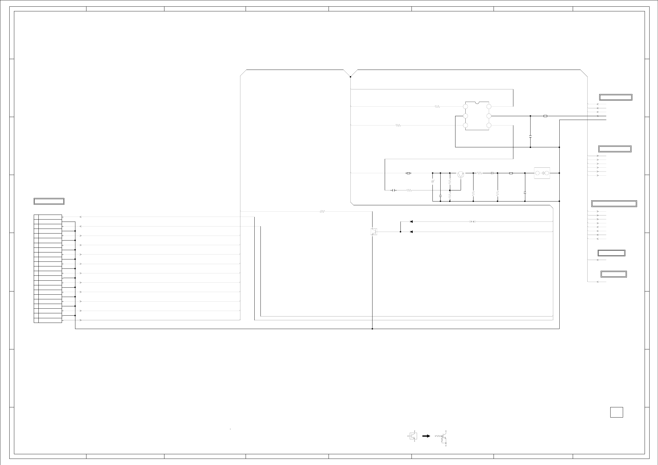
ABC D E F GH
ABC D E F GH
2
1
3
4
5
6
7
8
2
1
3
4
5
6
7
8
Q4301
KTC3875S_Y_RTK
D AUDIO DRIVER
IC6556
TC7PA53FU
DIGITAL AUDIO SW IC
123
456
H
E
J4301
RCA-101HT(OR)
COAXIAL
1
2
CP4301 TWG-P23P-A1
1
10
11
12
13
14
15
16
17
18
19
2
20
21
22
23
3
4
5
6
7
8
9
WAS RECEIVED IN GOOD CONDITION AND PICTURE IS NORMAL.
WITH THE DIGITAL TESTER WHEN THE COLOR BROADCAST
NOTE:THE DC VOLTAGE AT EACH PART WAS MEASURED
Q3407
KRC102SRTK
MUTE SW
CAUTION: DIGITAL TRANSISTOR
D3402
MA111
D3403
MA111
C4306
100P CH
C4304
0.1 B
C4301
0.1 B
C6554
4.7
6.3V(2125)
B
C4303
0.022 B
C4302
10010V V-S
R6551
100
R4307
220
R4310
100K
R4309
68
1/10W
R6552
100
R4301
2.2K
R4302
1.5K
R4306
3.3K
R3431
470
B4302
FCM1608CF-600T06
B4301
FCM1608CF-600T06
B6551
HCB1608KF-121T20
W840
OF PRINTING AND SUBJECT TO CHANGE WITHOUT NOTICE
NOTE:THIS SCHEMATIC DIAGRAM IS THE LATEST AT THE TIME
DVD-H
FILTER_MUTE
DVD_SPDIF DVD_SPDIF
D5.0V
D3.3V
GND
SPDIF
AV1_Y
AV1_C
AV1_A_IN_L
AV1_A_IN_R
YUV_A_IN_L
D5.0V YUV_A_IN_R
FILTER_MUTE AV1_CVBS
AV3/AV4_Y
AV3/AV4_PB
A_MUTE AV3/AV4_PR
SPDIF
DVD-H
AUDIO_MUTE LOUT_FI
AV3/AV4_PR ROUT_FI
AV3/AV4_PB
AV3/AV4_Y
A_MUTE
AV1_C
AV1_Y
AUDIO_MUTE
YUV_A_IN_L
YUV_A_IN_R
AV1_CVBS
AV1_A_IN_L
ROUT_FI
AV1_A_IN_R LOUT_FI
FROM MICON
FROM FLASH
TO AV SWITCH
H-26H-25
FROM/TO SCALER VIDEO/AUDIO
FROM/TO REGULATOR
CEH420
PCBDH0
FROM/TO JACK/OUTFROM/TO
JACK SCHEMATIC DIAGRAM
(DIGITAL PCB)
5.8
LOUT_SOUND
ROUT_SOUND
SWB2
B1
GND
A
VCC 3.3
3.3
3.3
0
2.9
2.9
2.85.0 3.2
0
0
ROUT_SOUND
LOUT_SOUND
(CP8101)
SPDIF_OUT
CVBS1
AV1 L IN
AV1 R IN
YUV R IN
YUV L IN
AV1_C
AV1_Y
AV3_V
AV3_U
AV3_Y
LOUT
ROUT
GND
GND
GND
GND
GND
GND
GND
GND
GND
GND
GND
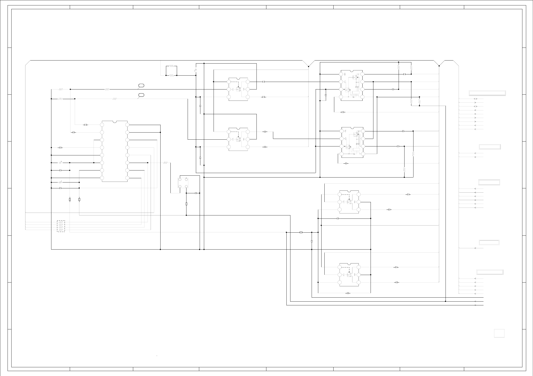
ABC D E F GH
ABC D E F GH
2
1
3
4
5
6
7
8
2
1
3
4
5
6
7
8
X6551
12.288MHz
100DT01217
12
34
IC6551 AK5358A
AUDIO_ADC IC
1
10 11 12 13 14 15 16
2345678
9
IC6555 MM1501XNRE
C SW IC
123
456
IC6554 MM1501XNRE
Y SW IC
123
456
IC6552 MM1501XNRE
Lch SW IC
123
456
IC6553 MM1501XNRE
Rch SW IC
123
456
NR6551
CRA108470JV
WAS RECEIVED IN GOOD CONDITION AND PICTURE IS NORMAL.
WITH THE DIGITAL TESTER WHEN THE COLOR BROADCAST
NOTE:THE DC VOLTAGE AT EACH PART WAS MEASURED
IC6557 NJM2534V
Lch SW IC
1234
5678
IC6558 NJM2534V
Rch SW IC
1234
5678
C6574_1
10
2125
B
C6584
1
16V(1608)
B
C6553
1
16V(1608)
B
C6582
1
16V(1608)
B
C6578
1B
C6551
1
16V(1608)
B
C6562
1
16V(1608)
B
C6561
1
16V(1608)
B
C6573
1B
C6572
1B
C6563
1
16V(1608)
B
C6570
1
16V(1608)
B
C6565
1
16V(1608)
B
C6566
1
16V(1608)
B
C6571
1
16V(1608)
B
C6575
10
2125
C
C6576
10
2125
C
C6577
10
2125
C
C6568
1
16V(1608)
B
C6580
1
16V(1608)
B
C6579
1
16V(1608)
B
C6581
1
16V(1608)
B
C6569
1B
C6557 2.2 (1608)B
C6560
0.1 B
C6556
0.1 B
C6564
22016V V-S
C6555
1016V V-S
C6559
1016V V-S
R6502
330
R6590
56K
R6582
56K R6584
56K
R6581
56K
R6562
2.7K
R6561
2.7K
R6559
3.3K
R6558
3.3K
R6569
100
R6585
10K
R6583
10K
R6501
330
B6553
FCM1608KF-102T02
B6552
FCM1608KF-102T02
B6554
FCM1608CF-600T06
B6556
HCB1608KF-181T20
OF PRINTING AND SUBJECT TO CHANGE WITHOUT NOTICE
NOTE:THIS SCHEMATIC DIAGRAM IS THE LATEST AT THE TIME
SW+12V
DVD-H
AV1_A_IN_L
SW_L ASW2
AUDIO_L YUV_A_IN_L
DVD_L ASW0
AUDIO_R LRCK
SDOUT
BCLK
MCLK
TU_AUDIO_L ASW0
SW_Y_IN
SW_C_IN
ASW2
DVD-H
AV1_A_IN_R
SW_R
YUV_A_IN_R
DVD_R
TU_AUDIO_L
TU_AUDIO_R
TU_AUDIO_R
SW_Y_IN
AV1_Y
AV1_C
AV1_Y AV1_A_IN_L
AV1_A_IN_R
YUV_A_IN_L
YUV_A_IN_R
DVD_Y
RESET_N
MCLK
SDOUT DVD-H
LRCK
BCLK D5.0V
RESET_N
SW_C_IN
AV1_C
DVD_Y
DVD_C DVD_C
DVD_L
DVD_R
SW+12V
GND
D3.3V
D5.0V
FROM TUNER
FROM JACK
FROM MICON
H-28H-27
CEH420
PCBDH0
FROM/TO REGULATOR
FROM/TO SCALER VIDEO/AUDIO
AV SWITCH SCHEMATIC DIAGRAM
(DIGITAL PCB)
0/3.3
BAIAS
BUFFER
BAIAS
BUFFER
NC
OUT VCC
VCC H
BUFFER
L4.5
4.5
4.5 0
5.0
0/3.3
6.6
3.3
6.5
3.36.5
12.0
6.5
0
6.5
3.3
6.6
3.3
0
6.5
12.0
6.5
AINR
AINL
CKS1
VCOM
AGND
VA
VD
DGND SDTO
LRCK
2.5
0
3.3
0
3.8
3.8
5.0
5.0
3.3
3.3
CKS2
DIF
PDN
SCLK
MCLK
CKS0 0
0
3.3
3.3
1.2
3.3
VCC H
BUFFER
L4.5
4.5
4.5 0
5.0
4.5
4.5
0
VCC H
BUFFER
L
4.5
4.5
0
VCC H
BUFFER
L
4.5
13
14 12.0
3.3
4.5
3.3
12.0
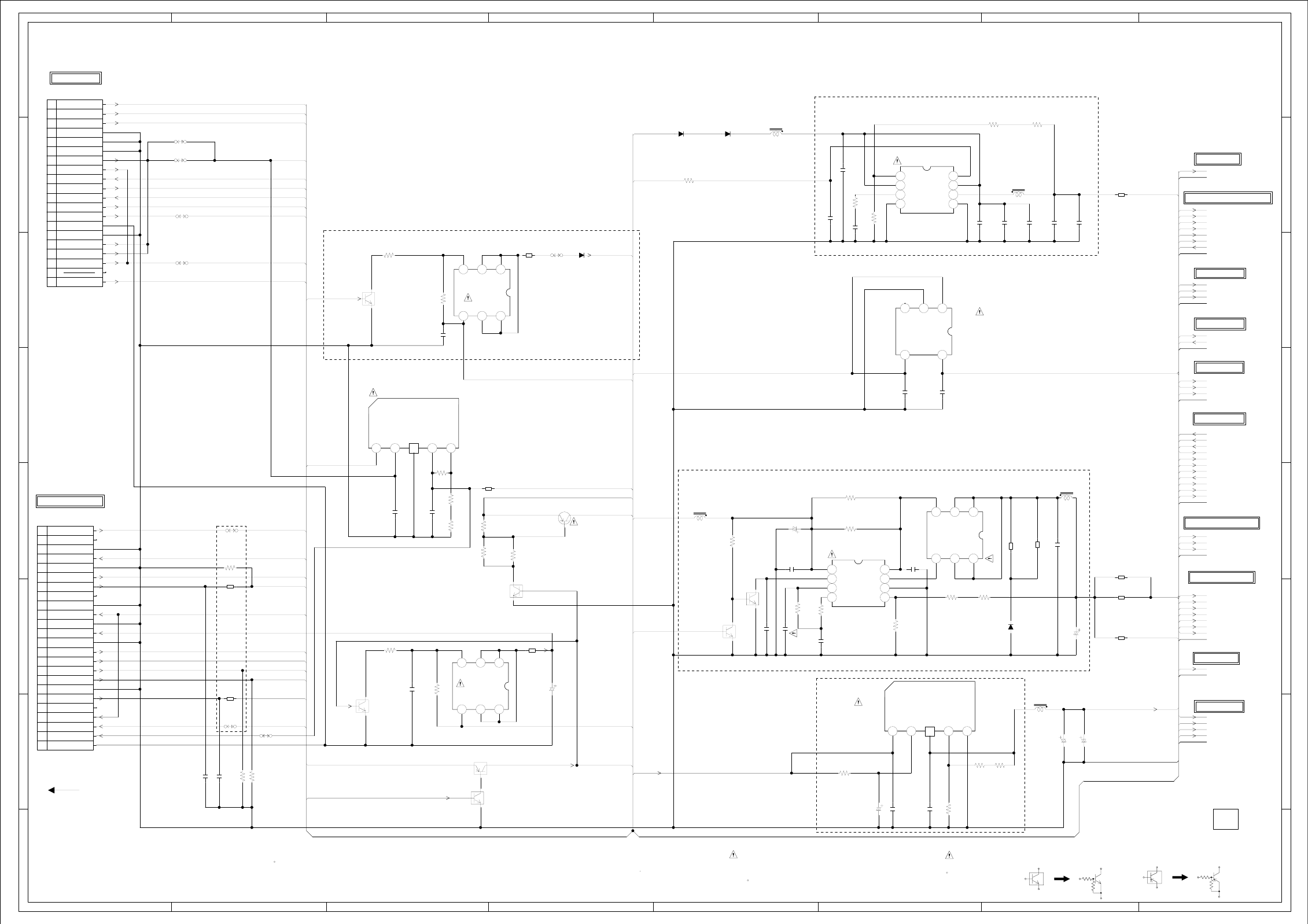
ABC D E F GH
ABC D E F GH
2
1
3
4
5
6
7
8
2
1
3
4
5
6
7
8
IC3007 BD7820FP
5.0V REGULATOR IC
12 456
IC3003
PQ035ZN1HZPH
1.8V_REGULATOR IC
12 456
L3001
22uH
TSL0808
L3002
5.2uHCDRH104R
L3005
22uH
TSL0808
L3004
22uHCDRH104R
L3003
22uH
TSL0808
CP3001
A2006WV0-2x10P
1
10
11
12
13
14
15
16
17
18
19
2
20
3
4
5
6
7
8
9
Q3009
TPC6108
LCD+B_SW
123
456
Q3011 TPC6108
DC DC FET
123
456
Q3010
RTQ035P02
MOTOR+6V_SW
123
456
CD3002
E82O1101
TO DVD PCB
IC3001 BD9130NV
VDD CORE 1.05V IC
1234
5678
IC3002 AL1015
VDD CORE 1.8V IC
1234
5678
WAS RECEIVED IN GOOD CONDITION AND PICTURE IS NORMAL.
WITH THE DIGITAL TESTER WHEN THE COLOR BROADCAST
NOTE:THE DC VOLTAGE AT EACH PART WAS MEASURED
Q3002
KRA101SRTK
SW
IC3009
S-1170B33UC-OTSTFG
3.3V REGULATOR IC
12
3
45
Q3005
KRC102SRTK
LCD+B_SW
Q3001
KRC102SRTK
SW
Q3004
KRC103SRTK
SW
Q3008
KRC102SRTK
SW
Q3003
KRC103SRTK
SW
Q3006
KRC101S-RTK
LCD+B_SW
CAUTION: DIGITAL TRANSISTOR CAUTION: DIGITAL TRANSISTOR
Q3007
KTA1664-Y-RTF/P
SW
:SINCE THESE PARTS MARKED BY
CAUTIONDESCRIBED IN PARTS LIST ONLY
CRITICAL FOR SAFETY,USE ONES ARE
DANS LA NOMENCLATURE DES PIECES
N’UTILISER QUE CELLS DECRITES
DANGEREUSES AN POINT DE VUE SECURITE
:LES PIECES REPAREES PAR UN ETANT
ATTENTION
CP3002
A2006WV0-2X12P
1
10
11
12
13
14
15
16
17
18
19
2
20
21
22
23
24
3
4
5
6
7
8
9
C3022
824V CD
C3043
2206.3V V-S
C3013
686.3V CD
D3007
EC11FS4
D3005
EC11FS4
D3006
EC31QS04
D3004
EC31QS04
C3066 10P CH
C3065 10P CH
C3016
680P CH
C3056
1B
C3054
4.7 B
C3015
0.1 B
C3024
10
10V(2125)
C
C3026
10
10V(2125)
C
C3027
10
10V(2125)
C
C3029
22
6.3V(2125)
B
C3031
22
6.3V(2125)
B
C3039
10
2125
B
C3038
1B
C3014
0.1 B
C3019
0.1 B
C3021 0.001 B
C3018 2.2 B
C3023 2.2 B
C3055
4.7 B
C3004
1B
C3011
0.1 B
C3040 0.33 B
C3012 0.1 B
C3006
0.033 B
C3047 474V V-S
C3049
3306.3V TZV
C3048
3304V V-S
R3013 3.3K
R3044
10K
R3008
10K
R3009
4.7K +-1%
R3016
1.8K +-1%
R3018
150 +-1%
R3002
6.8K
R3010
8.2K
R3032
3.9K
+-1%
R3034
220
+-1%
R3033
470
+-1%
R3041
22K
R3045
4.7K
R3005
1K
R3014
3.3K
R3020
0.047 1/4W 2125
R3022
0.047 1/4W 2125
R3023
1K +-1%
R3015
6.8K
+-1%
R3038 75
R3039 75
R3042
4.7K
R3040 8.2K
R3025
220
+-1%
R3024
1.5K
+-1%
R3007
330
R3019 12K
R3012 1K
R3017
150
+-1%
R3035
6.8K
B3003
HCB1608KF-181T20
B3008
HCB1608KF-181T20
B3014
HCB1608KF-181T20
B3004
HCB1608KF-181T20
B3005
HCB1608KF-181T20
B3007
HCB1608KF-181T20
B3023
FCM1608KF-102T02
B3022
FCM1608KF-102T02
B3015
HCB1608KF-181T20
B3006
HCB1608KF-181T20
B3017
HCB1608KF-181T20
W856
W857
W826
W818
W817
W815
W816
W847
OF PRINTING AND SUBJECT TO CHANGE WITHOUT NOTICE
NOTE:THIS SCHEMATIC DIAGRAM IS THE LATEST AT THE TIME
KEY_B
KEY_A
POWER_FAIL
AT+5.8V
AT+5.8V
D3.3V
GND
POWER_ON_H LV_CTL
S1_DET D1.0V
INVERTER_H
LIGHT_CTL S1_DET
TUNER+30V AT+3.3V
LIGHT_CTL
D3.3V
TWIRE_TXDC
GND TWIRE_RXDC
LCD-H
GND
VDD_PANEL
AT+12V
FILTER_MUTE TUNER+30V
D3.3V
D5.0V
LCD-H GND
D3.3V
INVERTER_H
GND
AT+5.8V AT+3.3V
AT+5.8V D3.3V
D1.0V
VDD_PANEL
GND
LV_CTL
SYS_POWER_H
3.3V_POWER_H
AT+3.3V
KEY_A
POWER_ON_H KEY_B
POWER_FAIL
DVD_RESET
START_SW
D5.0V AT+5.8V
D5.0V
AT+12V GND
SW+12V AT+5.8V
DVD_SPDIF D3.3V
D1.8V
D1.0V
GND
DVD_RESET
START_SW
TWIRE_TXDC
SW+12V
D3.3V DVD_R
DVD_L
DVD+3.3V DVD_Y
DVD_C
D5.0V
3.3V_POWER_H
MOTOR+6V D3.3V
DVD+3.3V GND
DVD_R
DVD_L
D1.8V
DVD_Y GND
DVD_C
TWIRE_RXDC
D1.8V
D3.3V
D5.0V
SW+12V AT+5.8V DVD_SPDIF
FILTER_MUTE
GND
MOTOR_GND
GND
AT+5.8V POWER_ON_H
D3.3V
SYS_POWER_H
H-30H-29
CEH420
PCBDH0
FROM/TO JACK
FROM/TO DDR
FROM/TO AV SWITCH
FROM/TO SCALER POWER
FROM/TO HDMI
FROM/TO SCALER VIDEO/AUDIO
FROM/TO TUNER
FROM/TO FLASH
FROM/TO LVDS
FROM/TO MICON
FROM/TO AUDIO/VIDEO
REGULATOR SCHEMATIC DIAGRAM
(DIGITAL PCB)
5.8
6.06.0
6.06.0
5.8
0
12.0
NC
NC
NC
NC
(DDR2:typ 1095mA)
ADJ
VCC
ITH
GND
EN
PVCC
SW
PGND
(typ 1.8A)
(1608)
VCC1.0V DC/DC
IC
IC
GND
5.8 3.3
OUTIN
SWGNDNC
NC 0 5.8
0.8
0
3.3
0.3 0
3.0
3.3
1.0
0
0DDG
SDD
05.2 5.2
5.8 5.2 5.2
for LCD PANEL
ADJ
OUT
GND
IN
CTL
05.85.8 5.0 0.8
0
3.3
0
0
5.8 5.8
0
1.2
4.5
1.2
5.8 CS
EXT
GND
FB
V5/PWON
Vref/SS
VIN
CC
5.8
1.2
0
1.3
DD
DD
S
G
3.3
3.3
6.2 5.8
3.3
3.3
VCC+3.3V DC/DC
for CORE
VB GND
3.0
SPDIF-134
DVD_RESET
V_IN V_OUT V_ADJ
12.0
0
0
(CP501)
FROM/TO POWER
POWER_FAIL
KEY-A
KEY-B
GND
GND
GND
AT+5.8V
AT+12V
POWER_ON-H
S_DET
INVERTER_H
LIGHT_CTL
GND
AT+5.8V
AT+5.8V
AT+12V
FILTER_MUTE
P.CON+32V
M_GND
0
0
3.3
4.5
0
0
0
0
5.8
GDD
SDD
3.3
1.8
1.3
0
(CP8501,CP8502)
GND
GND
ZERO
START_SW
TX
DVD_STATUS_1
GND
P.CON+3.3V
GND
P.CON+6V
GND
DVD_A_OUT_R
DVD_A_OUT_L
[V]Y_VIDEO
[U]C_VIDEO
GND
RX
CS
P.CON+3.3V
P.CON+12V
P.CON+A5V
GND(M)
3.0
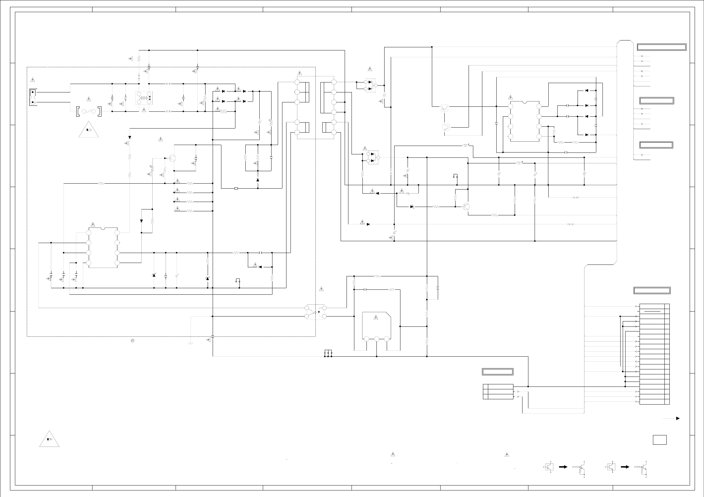
ABC D E F GH
ABC D E F GH
2
1
3
4
5
6
7
8
2
1
3
4
5
6
7
8
N’UTILISER QUE DES FUSIBLE DE MEME TYPE
:POUR UNE PROTECTION CONTINUE LES RISQUES D’INCEIE
ATTENTION
REPLACE ONLY WITH THE SAME TYPE FUSE
:FOR CONTINUED PROTECTION AGAINST FIRE HAZARD,
CAUTION
TH501
5D2-08LCS
D504
ENE241D-10A-Q6
D515
FCHS10A08
1
2
3
D523
FCQ10A04
1
2
3
IS THE LIVE CONNECTIONCAUTION:
L501
SS24H-10100
COIL,LINE FILTER
12
34
IC505
PS2561AL1-1-V(W)
FEED BACK
1
2
34
R505
33 1/4W
R510 0.22 1W
IC502
KIA431A-AT
REGULATOR
123
D509
UDZSNP33B
D517
MTZJ12B
D526
MTZJ22B
4A 125V
4A 125V
T501 81240018
SMALL
1
10
11
12
2
3
5
67
8
9
J501
CCT2302-0901C
12
F501
4A125V
51MS040L
FH502
EYF-52BCY
FH501
EYF-52BCY
L504
10uH
TSL0808
L503
22uH
TSL0808
CD502
E8231001
1
2
3
S
D
G
Q501
STF10NK50Z
SWITCHING
IS NON POLAR ONE.
THE ALUMI ELECTROLYTIC CAPACITOR MARKED NP
THE RESISTOR MARKED F IS FUSE RESISTOR.NOTE:
HS501_1
763WSA0068
HS502_1
763WSA0068
SH501
YQ-12
CP501
A2006WV0-2X10P 1
10
11
12
13
14
15
16
17
18
19
2
20
3
4
5
6
7
8
9
CD3001
E82K1701
TO/USA
WAS RECEIVED IN GOOD CONDITION AND PICTURE IS NORMAL.
WITH THE DIGITAL TESTER WHEN THE COLOR BROADCAST
NOTE:THE DC VOLTAGE AT EACH PART WAS MEASURED
Q503
KRA103MAT
SW
Q504
KRC103SRTK
SW
CAUTION: DIGITAL TRANSISTORCAUTION: DIGITAL TRANSISTOR
IC501
FA5531P-A2
POWER CONTORL
1234
5678
IC503
LA5797M-TE-L-E
DC-DC CONVERTER
1234
5678
Q505
KTA1504S_Y_RTK
POWER FAIL SW
:SINCE THESE PARTS MARKED BY
CAUTIONDESCRIBED IN PARTS LIST ONLY
CRITICAL FOR SAFETY,USE ONES ARE
DANS LA NOMENCLATURE DES PIECES
N’UTILISER QUE CELLS DECRITES
DANGEREUSES AN POINT DE VUE SECURITE
:LES PIECES REPAREES PAR UN ETANT
ATTENTION
C522
100016V HD
C504
220010V HD
C511
22016V MHE
C512
22016V MHE
C525
100016V HD
D520
MA111
D519
MA111
D522
MA111
D521
MA111
D516
1H3-E
D512
SARS01-V1
D514
RU3AM-EIC
D510
RM11C-EIC
D508
RM11C-EIC
D511
1H3-E
D518
RM11C-EIC
D507
RM11C-EIC
D505
1N4005-EIC
D506
EC11FS2-TE12L
C505
22P CH
C503
330PCH
C501
0.001 B
C521
0.1 B
C545
0.1525V B
C543_1 1 50V(21-25)B
C538
0.1525V B
C539
0.1525V B
C510
0.001250V KX
C507
0.001250V KX
C509
0.1 B
C513
470P2KV R
C526
0.001 B
C514
470P250V KX
C531
125V B
C518
0.022400V PP
C517
330P B
C546
0.1525V B
C508
0.1275V ECQUL
C506
0.22275V ECQUL
C535_1
10016V MHE
C520
4.750V MHE_P
C502 270200V KXW
C516
4750V MHE_P
R517
1K
R543
22K
R515
1K
R502
150
R531
10K
R524
360 +-1%
R525
2.2K +-1%
R523
2.7K +-1%
R503
12M 1W
R533
10K+-1%
R519
10K
R506
33K
R512
100K 1/2W
R508
100K 1/2W
R535
8.2K
R536
220K +-1%
R529
2.2K 1/4W
R521
100 1/4W
R538
10K
R513
82K
R511
33 1/4W
R509
1.2M 1WRCR
R501
22K 1/2W
R504
22K 1/2W
R544 2 1/4W +-1%
R545 2 1/4W
(21-25) +-1%
R546 2 1/4W
(21-25) +-1%
R547 2 1/4W
(21-25) +-1%
R507
100
R518
100 1/4W
R549
1K 1/4W
B501
W4BRH3.5X6X1.0
W835
W808
W828
W807
W840
W810
OF PRINTING AND SUBJECT TO CHANGE WITHOUT NOTICE
NOTE:THIS SCHEMATIC DIAGRAM IS THE LATEST AT THE TIME
INV+B
POWER_ON_H
INV_GND
INV+B
POWER_ON_H INV_GND
INV_SGND LIGHT_CTL
INVERTER_H
INV_SGND
GND
POWER_ON_H
SOUND+B
SOUND_GND
FILTER_MUTE
GND
P.CON+32V
S_DET
AT+12V GND
AT+5.8V
GND
M_GND
POWER_FAIL
SOUND+B
SOUND_GND
FILTER_MUTE
AT+12V
M_GND
P.CON+32V
LIGHT_CTL
INVERTER_H
S_DET
POWER_ON_H
AT+5.8V
GND
POWER_FAIL
KEY-A
KEY-B
KEY-B
KEY-A
H-32H-31
(CP2201)
4A 125V (F501)
4A 125V (F501)
PCB240
CEH421
FROM/TO JACK/OUT
FROM/TO REGULATOR
(CP3001)
NC FILTER_MUTE
AT+5.8V
AT+5.8V
GND
GND
POWER_ON-H
AT+12V
GND
POWER_FAIL
KEY-A
KEY-B
AT+12V
GND
M_GND
INVERTER_H
LIGHT_CTL
P.CON+32V
S_DET
AT+5.8V
FROM/TO JACK OUT
FROM/TO SOUND AMP
FROM/TO BACKLIGHT INVERTER
POWER SCHEMATIC DIAGRAM
(POWER PCB)
1.8
169.0
21.0
21.3
NC
12.012.0
NC
NC
REF
NC
CA
11.0 0 2.5
0
0
0
12.0
0
0
2.8
0
12.0
11.0
169.0
169.0
12.0
5.8
ZCD
FB
IS
GND
VH
NC
VCC
OUT
5.7
2.8
0
4.0
5.8
20.0
1.8
169.0
5.8
NC
V_IN
EN
GND
CPOUT
FB
VRET
NC
NC
NC
NC
0
0
0
1.3
0
12.0
0
0
03.0
KEY-B
KEY-A
GND
NC
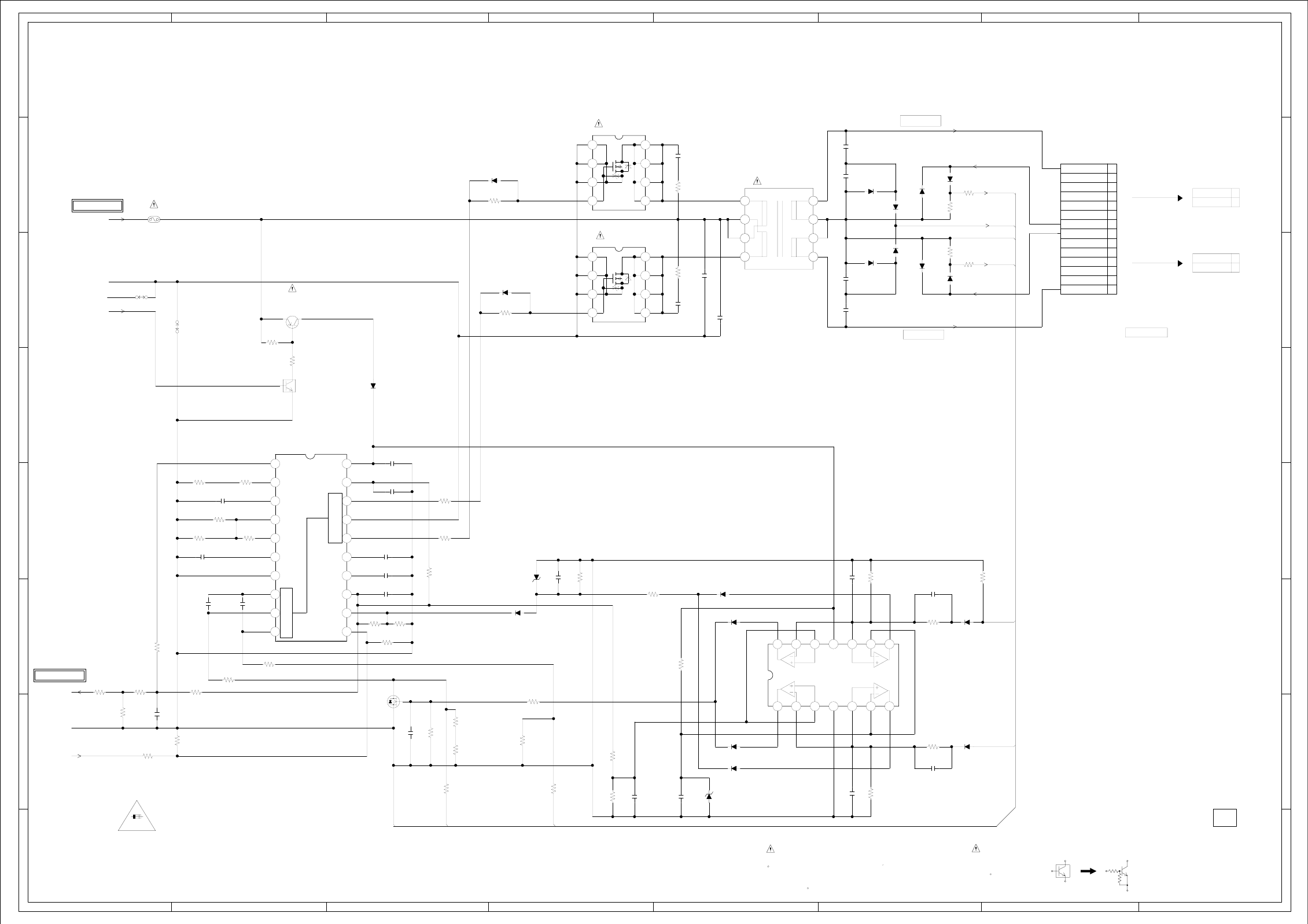
ABC D E F GH
ABC D E F GH
2
1
3
4
5
6
7
8
2
1
3
4
5
6
7
8
IC7001 BD9882FV-E2
INVERTER COTROL IC
110
11 12 13 14 15 16 17 18 19
2
20
3456789
T7001
8135109G
1
2
3
45
6
7
8
IC7002 LM2902DR
FEED_BACK IC
1
1011121314
234567
89
F7001
1206FA5A-T
5A 32V
CD7005 E82E0604
1
14
7
8
N’UTILISER QUE DES FUSIBLE DE MEME TYPE
:POUR UNE PROTECTION CONTINUE LES RISQUES D’INCEIE
ATTENTION
REPLACE ONLY WITH THE SAME TYPE FUSE
:FOR CONTINUED PROTECTION AGAINST FIRE HAZARD,
CAUTION
D7010
UDZSNP5.6B
D7011
UDZSNP3.9B
WAS RECEIVED IN GOOD CONDITION AND PICTURE IS NORMAL.
WITH THE DIGITAL TESTER WHEN THE COLOR BROADCAST
NOTE:THE DC VOLTAGE AT EACH PART WAS MEASURED
S
DGQ7003
2SK3018T106
FEED BACK
Q7001
KRC103SRTK
POWER ON SW
CAUTION: DIGITAL TRANSISTOR
Q7005 FSS275-TL-E
1234
5678
Q7004 FSS275-TL-E
1234
5678
Q7002
KTA1505S-Y-RTK/P
POWER ON SW
:SINCE THESE PARTS MARKED BY
CAUTIONDESCRIBED IN PARTS LIST ONLY
CRITICAL FOR SAFETY,USE ONES ARE
DANS LA NOMENCLATURE DES PIECES
N’UTILISER QUE CELLS DECRITES
DANGEREUSES AN POINT DE VUE SECURITE
:LES PIECES REPAREES PAR UN ETANT
ATTENTION
D7012
MA111
D7006
1SS133
D7003
1SS133
D7018
MA111
D7020
MA111
D7017
MA111
D7023
MA111
D7019
MA111
D7005
1SS133
D7001
1SS133
D7004
1SS133
D7015
1SS133
D7024
MA111
D7014
MA111
D7013
MA111
D7008
1SS133
D7007
1SS133
D7002
1SS133
C7002
0.0047
B
C7007
0.0047
B
C7001
0.1 B
C7011
125V B
C7012
0.01 B
C7009
0.1 B
C7003
330P CH
C7004
0.047 B
C7015
2.2 B
C7010
0.1 B
C7013
0.001 B
C7018
0.0022500V B
C7026
10
25V(32-16)
B
C7019
0.001 B
C7006
0.047 B
C7017
0.0022500V B
C7020
0.001 B
C7021
0.001 B
C7022
10
25V(32-16)
B
C7033
10P6KV SL
C7032
0.01 B
C7031
0.01 B
C7030
10P6KV SL
C7035
0.001 B
C7024
0.001 B
C7008
0.47 B
R7012
220 +-1%
R7018
10K
R7017
10K
R7020
100K
R7003
4.7K
R7008
47K
R7011
100K 1/4W
R7014
15K 1/4W
R7004
1K
R7006
5.6K
R7022
220
R7015
22K
R7016
4.7K
R7005
100
R7002
18K
R7001
2.7K
R7009
47K +-1%
R7025
1K+-1%
R7026
270 +-1%
R7010
33K +-1%
R7039
33 1/4W
R7034
56K
R7042
470K
R7013
82K +-1%
R7056
4.7K
R7032
100K +-1%
R7023
10
R7007
150K +-1%
R7021
4.7K
R7035
22 1/4W
R7036
22 1/4W
R7038
33 1/4W
R7046
680
R7050
10
R7045
680
R7049
10
R7040
470K
R7043
6.8K
R7041
470K
R7019
10K
R7047
4.7K 1/4W
R7044
1.5K
R7048
4.7K
R7024
10
R7054
470K
R7033
560K 1/4W
R7030
68K +-1%
W809
W819
OF PRINTING AND SUBJECT TO CHANGE WITHOUT NOTICE
NOTE:THIS SCHEMATIC DIAGRAM IS THE LATEST AT THE TIME
IS_DET1
INV+B VS_DET
INV_SGND
IS_DET2
INV_GND
GND
POWER_ON_H
IS_DET2
LIGHT_CTL
INV_SGND
IS_DET1
INVERTER_H
INV_SGND
IS_DET1
VS_DET
H-34H-33
5A 32V
5A 32V(F7001)
5A 32V(F7001) CAUTION:F7001 IS MANUFACTURED BY SKYGATE CO.,LTD., TYPE 20N.
PCB240
CEH421
FROM/TO POWER
FROM/TO POWER
(POWER PCB)
BACKLIGHT INVERTER SCHEMATIC DIAGRAM
0
3.1
12.8
DUTY
BRT
RT
SRT
CT
BCT
FB
IS
VS STB
SCP
PGND
FAIL
VCC
N1
N2
COMP
SS
REG
INV GND
2.1
1.5
1.3
1.5
1.7
1.1
0
0
0.1
0.1
5.1
1.5
3.1
0
0
0
0
0
0
3.7
1
2
1
2
HIGH VOLTAGE
0
3.1
12.4
12.6
D
D
D
DG
S
S
S
D
D
D
DG
S
S
S
GND
Vcc
9.1 4.8 2.8 10.3 2.8 4.8 9.1
9.1 4.8 2.8 0 2.8 4.8 9.1
HIGH VOLTAGE
HIGH VOLTAGE
12.4
2.6
0
0
0
12.4
12.4
12.4
12.4
12.4
12.4
12.4
0
0
0
2.6
NC
NC
NC
NC
NC
NC
NC
NC
NC
NC
12.4
12.6
3.1
0
LV
LV
NC
NC
NC
NC
NC
HV
NC
NC
NC
NC
NC
HV
LV
LV
HV
HV
CN2
CN1
5.9
0
0
12.9 12.8
12.2
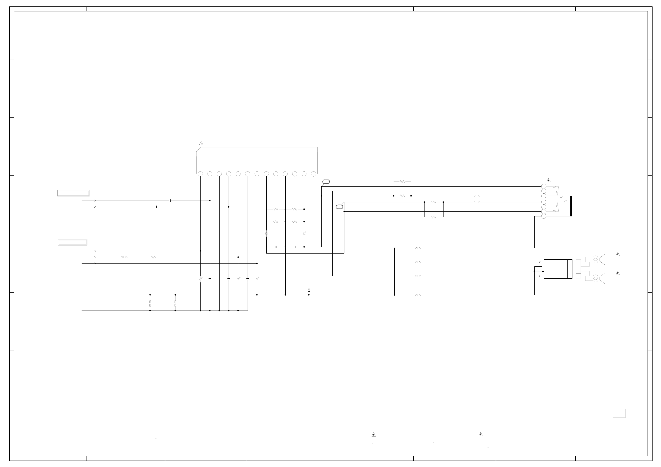
ABC D E F GH
ABC D E F GH
2
1
3
4
5
6
7
8
2
1
3
4
5
6
7
8
CD301 E8141801
1
2
3
4
SPEAKER
SP301
S0308F01
SPEAKER
SP302
S0308F01
IC301 LA42052-E
SOUND AMP IC
110
11 12 1323456789J301
PJ-364H
HEADPHONE JACK
1
2
3
4
5
6
7
HS301
763WSA0064
WAS RECEIVED IN GOOD CONDITION AND PICTURE IS NORMAL.
WITH THE DIGITAL TESTER WHEN THE COLOR BROADCAST
NOTE:THE DC VOLTAGE AT EACH PART WAS MEASURED :SINCE THESE PARTS MARKED BY
CAUTIONDESCRIBED IN PARTS LIST ONLY
CRITICAL FOR SAFETY,USE ONES ARE
DANS LA NOMENCLATURE DES PIECES
N’UTILISER QUE CELLS DECRITES
DANGEREUSES AN POINT DE VUE SECURITE
:LES PIECES REPAREES PAR UN ETANT
ATTENTION
C304
10016V MHE_P
C311
47016V MHE_P
C310
47016V MHE_P
C307
2206.3V MHE_P
C309
47016V MHE
C320
0.1 B
C319
0.1 B
C303
1B
C301
1B
C308
4.7 B
C306 470P CH
C305 470P CH
R302
2.2K
R304
2.2K
R306
2.2K
R305
2.2K
R307
2.2K
R310
1K
R311
1K
R309
1K 1/4W
R308
1K 1/4W
W830
W803
W824
W827
W845
W820
W823
W806
W832
OF PRINTING AND SUBJECT TO CHANGE WITHOUT NOTICE
NOTE:THIS SCHEMATIC DIAGRAM IS THE LATEST AT THE TIME
LOUT
ROUT
FILTER_MUTE
POWER_ON_H
SOUND+B
SOUND_GND
GND
SOUND AMP SCHEMATIC DIAGRAM
(POWER PCB)
15
16
H-36H-35
PCB240
CEH421
FROM/TO POWER
FROM/TO JACK OUT
W030
Ripple
Filter NCOUT1NCGNDNCOUT2VccP.PSTBIN2GNDIN1
7.4 1.6 1.6 1.6 10.3 14.0 7.4 7.400NCNCNC
SP OUT L
SP OUT R
GND
GND
R
L
4
3
2
1
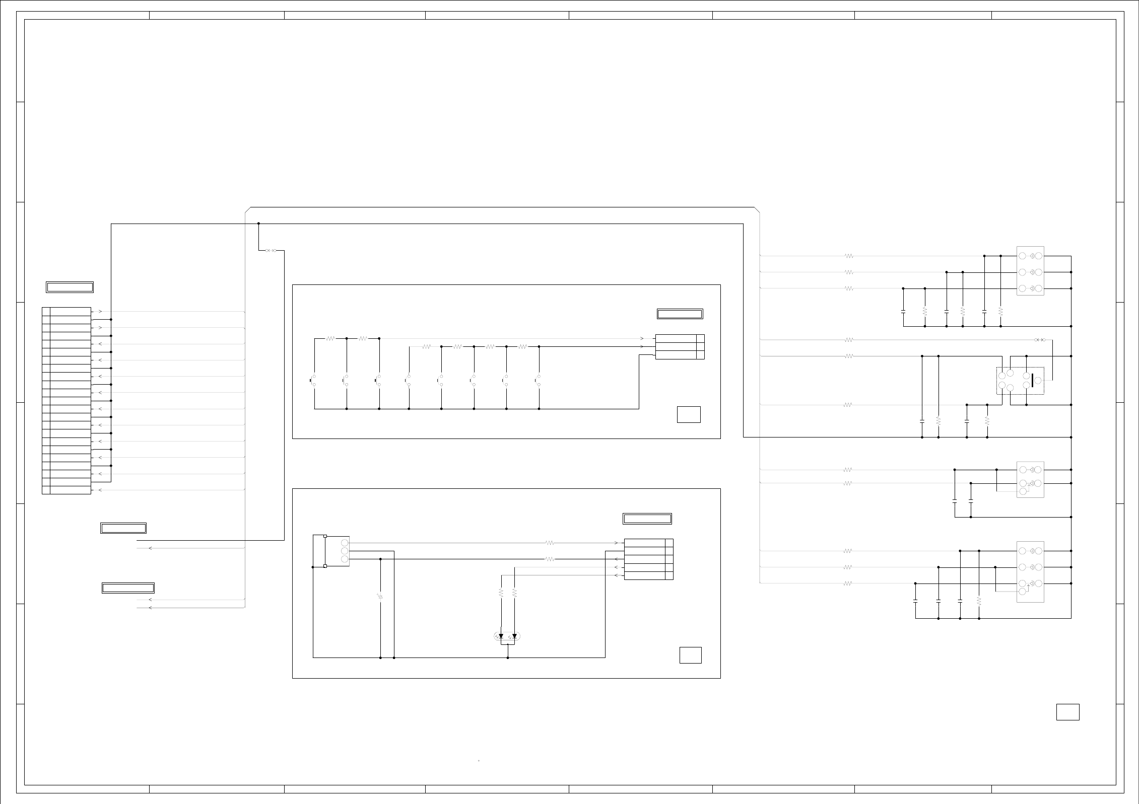
ABC D E F GH
ABC D E F GH
2
1
3
4
5
6
7
8
2
1
3
4
5
6
7
8
SW2202
EVQ21505R
CH DOWN/STOP
SW2203
EVQ21505R
POWER
SW2201
EVQ21505R
EJECT
SW2208
EVQ21505R
MENU
SW2207
EVQ21505R
CH UP/PLAY
SW2206
EVQ21505R
VOL UP
SW2205
EVQ21505R
VOL DOWN
SW2204
EVQ21505R
INPUT
Vout
B+
GND
OS7601
KSM-2003TC2P
1
2
3
H
EE
H
J8103
RCA-228H(3)NI-02
COMPONENT_AUDIO_IN
1
2
3
4
5
J8101
DIN-417HA-01
S-VIDEO-IN
12 34
56
7
NC H
E
H
E
H
E
J8104
RCA-341H(2)NI-06
CVBS_AV_IN
1
2
3
4
5
6
7
E
HH
E
H
E
J8102
RCA-341H(NI)-09
COMPONENT_VIDEO_IN
1
2
3
4
5
6
R
B
D7601_1
LTL1BECBEK5
ST-BY/POWER
CP2201
A2001WR2-3P
1
2
3
CP8101
127301123K2
1
10
11
12
13
14
15
16
17
18
19
2
20
21
22
23
3
4
5
6
7
8
9
WAS RECEIVED IN GOOD CONDITION AND PICTURE IS NORMAL.
WITH THE DIGITAL TESTER WHEN THE COLOR BROADCAST
NOTE:THE DC VOLTAGE AT EACH PART WAS MEASURED
CP7601
A2001WV2-5P 1
2
3
4
5
C8103
100P CH
C8110
100P CH
C8105
100P CH
C8102
100P CH
C8111
470P CH
C8107
470P CH C8109
100P CH
C8108
470PCH
C8106
470PCH
C8104
470PCH
C7602
1006.3V KA
R8114 1K
R8113 1K
R8115 100
R8116 1K
R8117 1K
R8104
75
R8107
75 R8108
75
R8105
75
R8103
75
R2203
15K
R2204
5.6K
R2205
5.6K
R2206
820
R7602 47
R7605 100
R7603_1 220
R7604_1 220
R2201
1K
R2202
820
R8106
75
R8118
100
R8119
100
R8120
100
R8111 100
R8112 100
R8110 1K 1/4W
W833
W822
OF PRINTING AND SUBJECT TO CHANGE WITHOUT NOTICE
NOTE:THIS SCHEMATIC DIAGRAM IS THE LATEST AT THE TIME
AV3_Y
AV3_U/AV1_Y[J]
AV3_V/AV1_C[J]
LOUT
ROUT
S_DET
AV3_V/AV1_C[J]
AV1_Y/CBVS1[J]
AV3_U/AV1_Y[J]
AV3_Y
AV1_C
AV1_C
AV1_Y/CBVS1[J]
YUV_L_IN
YUV_R_IN
CVBS1
YUV_L_IN
AV1_L_IN
YUV_R_IN
AV1_R_IN
GND
S_DET CVBS1
AV1_L_IN
AV1_R_IN
LOUT
ROUT
JACK OUT SCHEMATIC DIAGRAM
H-38H-37
PCB240
CEH421
CEH423
PCBDA0
(CD6203)
FROM/TO MICON
(REMOCON PCB)
(OPERATION PCB)
PCB270
CEH422
(CD502)
FROM/TO POWER
TO SOUND AMP
FROM/TO POWER
(POWER PCB)
(CP4301)
FROM/TO JACK
MAIN_GND
GND
AT+3.3V
POWER ON LED
STANDBY LED
R
V
C
Y
S-DET
L
KEY_A
KEY_B
GND
REMOCON IN
YUV L IN
YUV R IN
AV1 L IN
AV1 R IN
GND
GND
GND
GND
GND
GND
GND
AV3_V
AV3_U
AV3_Y
GND
AV1_C
GND
AV1_Y
ROUT
GND
GND
LOUT
CVBS1
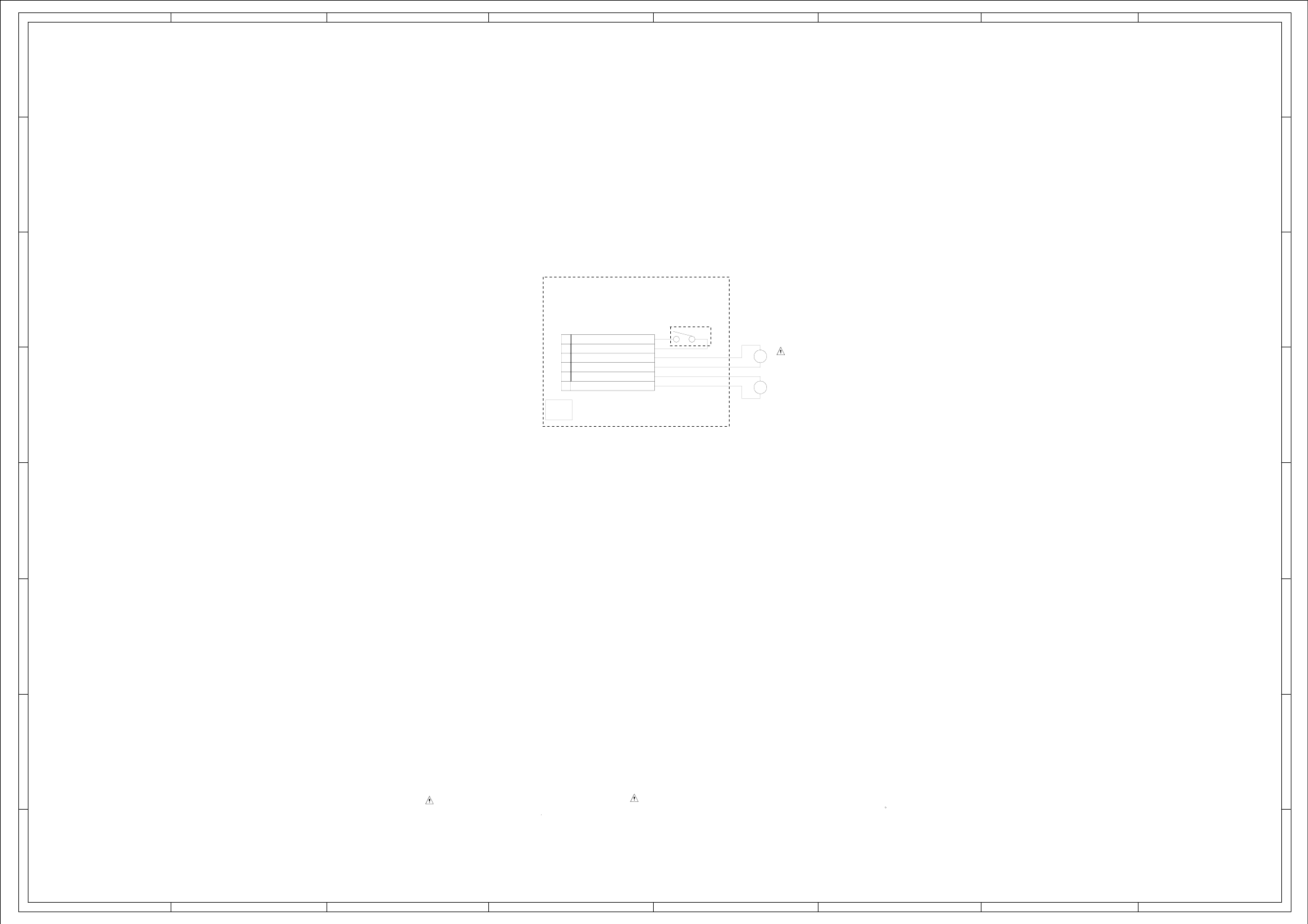
ABC D E F GH
ABC D E F GH
2
1
3
4
5
6
7
8
2
1
3
4
5
6
7
8
OF PRINTING AND SUBJECT TO CHANGE WITHOUT NOTICE
NOTE:THIS SCHEMATIC DIAGRAM IS THE LATEST AT THE TIME
H-40H-39
(SW PCB)
BCZ3B05
JCV9B12
M2601
M2602
ESE22MH22
SW2
M
M
2H061605
CD2301
DED020
PCB640
SPINDLE MOTOR(+)
SPINDLE MOTOR(-)
FEED MOTOR(-)
GND(SW)
FEED MOTOR(+)
PICK UO INNER LIMIT SWITCH
6
5
4
3
2
1
SW SCHEMATIC DIAGRAM
:SINCE THESE PARTS MARKED BY
CAUTIONDESCRIBED IN PARTS LIST ONLY
CRITICAL FOR SAFETY,USE ONES ARE
DANS LA NOMENCLATURE DES PIECES
N’UTILISER QUE CELLS DECRITES
DANGEREUSES AN POINT DE VUE SECURITE
:LES PIECES REPAREES PAR UN ETANT
ATTENTION
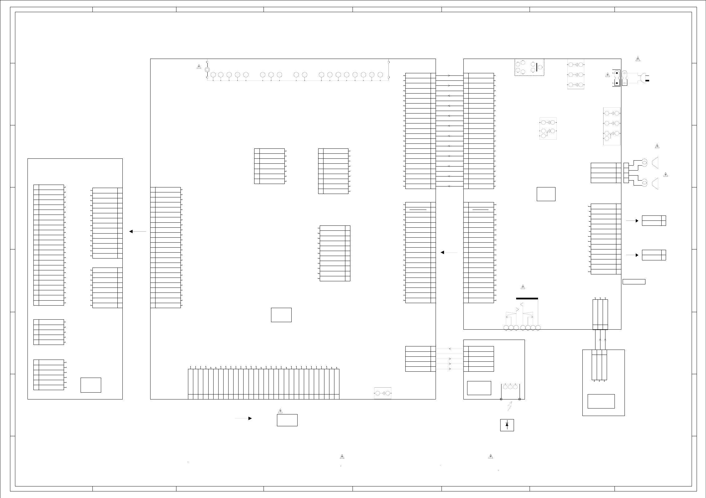
ABC D E F GH
ABC D E F GH
2
1
3
4
5
6
7
8
2
1
3
4
5
6
7
8
TU5801
1
11
12
14
15
16
17
18
19
2
20
21
22 23
24 25
3
4
5
7
8
9
OF PRINTING AND SUBJECT TO CHANGE WITHOUT NOTICE
THE TIMETHIS INTERCONNECTION DIAGRAM IS THE LATEST ATNOTE:
4
3
2
1
CD301
5
4
3
2
1
CP7601
5
4
3
2
1
CD6203
4
3
2
1
Vout
B+
GND
OS7601
1
2
3
H
EE
H
J8103
COMPONENT_AUDIO_IN
1
2
3
4
5
J8101
S-VIDEO-IN
12 34
56
7
NC H
E
H
E
H
E
J8104
CVBS_AV_IN
1
2
3
4
5
6
7
E
HH
E
H
E
J8102
COMPONENT_VIDEO_IN
1
2
3
4
5
6
SPEAKER
SP302
SPEAKER
SP301
J301
HEADPHONE JACK
1
2
3
4
5
6
7
J501
1 2
CP2201 1
2
3
CD502
1
2
3
CP501
1
10
11
12
13
14
15
16
17
18
19
2
20
3
4
5
6
7
8
9
CP3001
1
10
11
12
13
14
15
16
17
18
19
2
20
3
4
5
6
7
8
9
H
E
J4301
COAXIAL
1
2
CP8101
1
10
11
12
13
14
15
16
17
18
19
2
20
21
22
23
3
4
5
6
7
8
9
CP4301
1
10
11
12
13
14
15
16
17
18
19
2
20
21
22
23
3
4
5
6
7
8
9
CP2803
1
10
11
2
3
4
5
6
7
8
9
CP2801
1
2
3
4
5
6
7
CD3002
CD2804
LVDS
CD3001
LCD PANEL
V2801
CP2804
1
10
11
12
13
14
15
16
17
18
19
2
20
21
22
23
24
25
26
27
28
29
3
30
4
5
6
7
8
9
CD501
P201-2476-2
CP6201
SUB MICON
1
2
3
4
5
6
7
8
9
CP8502
1
2
3
4
5
6
7
8
CD7005
1
10
11
12
13
14
2
3
4
5
6
7
8
9
CP8501
1
10
11
12
13
14
2
3
4
5
6
7
8
9
:SINCE THESE PARTS MARKED BY
CAUTIONDESCRIBED IN PARTS LIST ONLY
CRITICAL FOR SAFETY,USE ONES ARE
DANS LA NOMENCLATURE DES PIECES
N’UTILISER QUE CELLS DECRITES
DANGEREUSES AN POINT DE VUE SECURITE
:LES PIECES REPAREES PAR UN ETANT
ATTENTION
CP2301_1
1
10
11
12
13
14
15
16
17
18
19
2
20
21
22
23
24
3
4
5
6
7
8
9
CP3002
1
10
11
12
13
14
15
16
17
18
19
2
20
21
22
23
24
3
4
5
6
7
8
9
CP2303
1
2
3
4
5
6
CP2302
1
2
3
4
5
INTERCONNECTION DIAGRAM
HIGH VOLTAGE
HV 2
1
LV
CN2
CN1
HV 2
1
LV
LV
LV
NC
NC
NC
NC
NC
NC
NC
NC
NC
NC
HV
HV
SP OUT L
SP OUT R
GND
GND
L
R
KEY A
KEY B
GND
CEH422
OPERATION PCB
PCB270
KEY A
KEY B
GND
SW(GND)
LIMIT SW
SLD-
SLD+
SP1+
SP1-
GND(D)
CLOSE
OPEN
LD+
LD-
F DRV
T DRV
T RTN
F RTN
GND
NC
VR(DVD)
VR COM
VR(CD)
GND
VRF(RF_OUT)
SW1(DVD/CD)
C
D
E
A
B
VCC
Vref
F
GND
PD/GND
LD(CD)
LD(DVD)
GND(M)
P.CON+6V
P.CON+A5V
P.CON+3.3V
GND
P.CON+3.3V
GND
P.CON+12V
GND
DVD_A_OUT_L
SPDIF-134
SSCRXD/TX
SSCTXD/RX
START_SW
[U]C_VIDEO
[V]Y_VIDEO
[Y]_VIDEO
DVD RESET
GND
GND
ZERO
DVD_A_OUT_R
SPDIF-134
DVD_RESET
GND
GND
ZERO
START_SW
TX
DVD_STATUS_1
GND
P.CON+3.3V
GND
P.CON+6V
GND
DVD_A_OUT_R
DVD_A_OUT_L
[V]Y_VIDEO
[U]C_VIDEO
GND
RX
CS
P.CON+3.3V
P.CON+12V
P.CON+A5V
GND(M)
+5V
AFT
NC
IF_OUT1
IF_OUT2
IF_O
IF_AGC
IF_OUT
AGC
SIF-out
V_OUT
TU
+30V
+5V
SCL
SDA
NC
NC
NC(BB)
D_GND
IIC_OFF
SCL
SDA
PC_TOOL_RX
PC_TOOL_TX
D3.3V
CNVSS
CNVSS
NC
GND
RESET
RX
TX
MODE
VCC
GND
VDD33
FLASH_WP
ASEMD0
ASEBRKAK_N
TCK
TDO
TMS
RESET_N
TDI
TRST_N
RX0-
RX2-
RX1+
RXCLK+
RX3-
RX3+
RX2+
RXCLK-
NC
NC
NC
GND
GND
RX1-
RX0+
VDD+5V
GND
NC
GND
GND
VDD+5V
VDD+5V
VDD+5V
VDD+5V
NC
GND
GND
GND
NC
GND
FILTER_MUTE
AT+5.8V
AT+5.8V
GND
GND
POWER_ON-H
AT+12V
GND
POWER_FAIL
KEY-A
KEY-B
AT+12V
GND
M_GND
INVERTER_H
LIGHT_CTL
P.CON+32V
S_DET
AT+5.8V
YUV L IN
YUV R IN
AV1 L IN
AV1 R IN
GND
GND
GND
GND
GND
GND
GND
AV3_V
AV3_U
AV3_Y
GND
AV1_C
GND
AV1_Y
ROUT
GND
GND
LOUT
CVBS1
POWER_FAIL
KEY-A
KEY-B
GND
GND
GND
AT+5.8V
AT+12V
POWER_ON-H
S_DET
INVERTER_H
LIGHT_CTL
GND
AT+5.8V
AT+5.8V
AT+12V
FILTER_MUTE
P.CON+32V
M_GND
CVBS1
AV1 L IN
AV1 R IN
YUV R IN
YUV L IN
AV1_C
AV1_Y
AV3_V
AV3_U
AV3_Y
LOUT
ROUT
GND
GND
GND
GND
GND
GND
GND
GND
GND
GND
GND
GND
POWER ON LED
STANDBY LED
AT+3.3V
GND
REMOCON IN
AT+3.3V
CEH423
CEH421
DIGITAL PCB
CEH420
PCBDH0
DVD MT PCB
DMG097
PCB130
PCB240
POWER PCB
PCBDA0
REMOCON PCB
COMMAND TRANSMITTER
TM101
STANDBY LED
REMOCON IN
POWER ON LED
H-42H-41
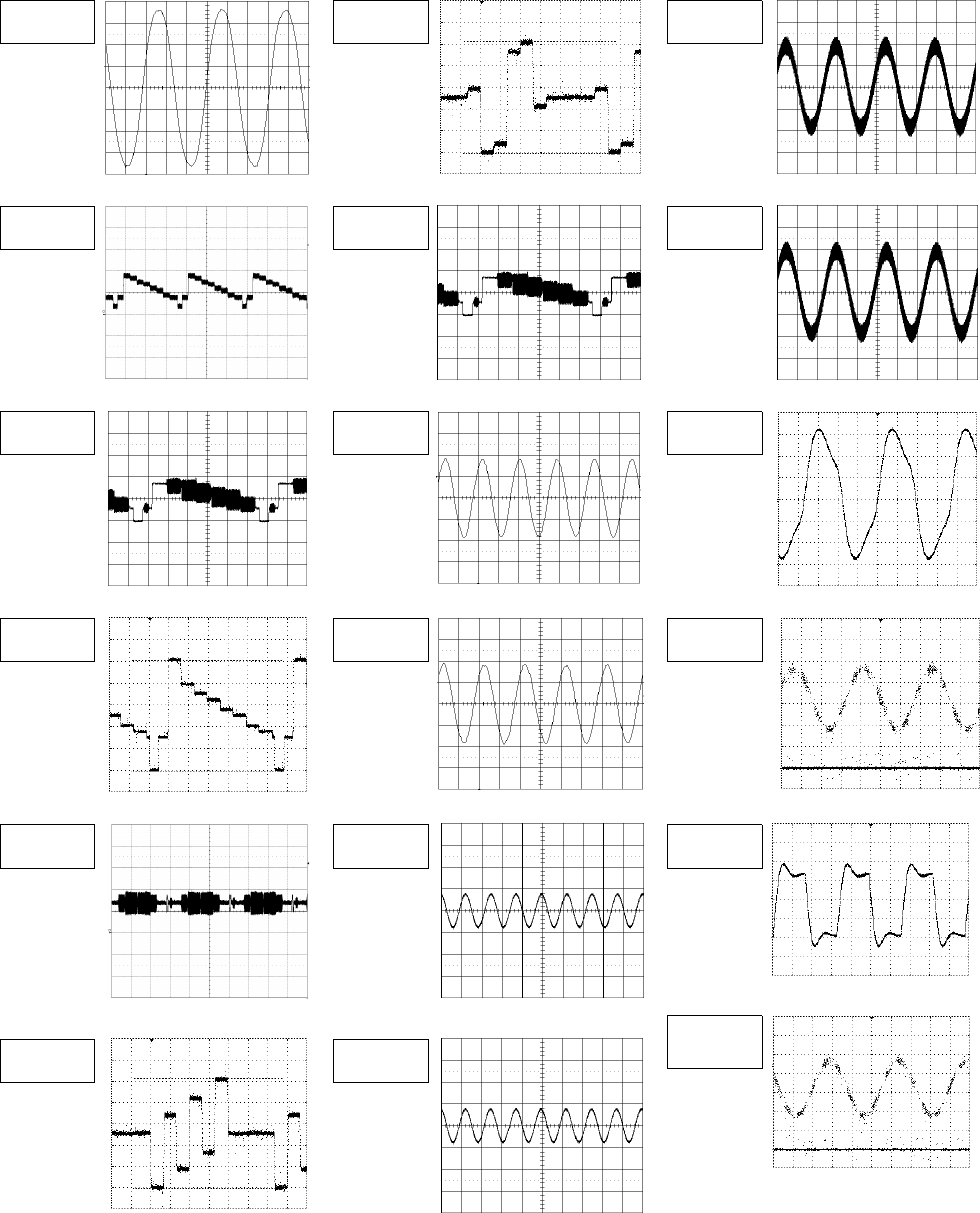
WAVEFORMS
MICON SOUND AMP
20ns 10us 1ms
200mV 100mV 200mV
1 7 15
SCALER VIDEO/AUDIO TUNER
20us 10us 1ms
500mV 0.5V 200mV
2 8 16
FLASH MPEG/MICON/DSP/RF_AMP
10us 20ns 10ns
0.5V 200mV 500mV
3 9 52
10us 20ns
100
µ
s
200mV 200mV 500mV
4 10 53
AV SWITCH
20us 2ms 200ns
500mV 100mV 1.0V
5 13 54
MEMORY
100µs
10us 2ms 500mV
100mV 100mV
55
6 14
The following waveforms were measured at
the point of the corresponding balloon
number in the schemtic diagram.
NOTE:
I-1
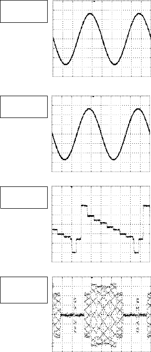
WAVEFORMS
AUDIO/VIDEO
200
µ
s
1.0V
56
200
µ
s
1.0V
57
10
µ
s
200mV
58
10µs
100mV
59
The following waveforms were measured
at the point of the corresponding balloon
number in the schematic diagram.
NOTE:
I-2
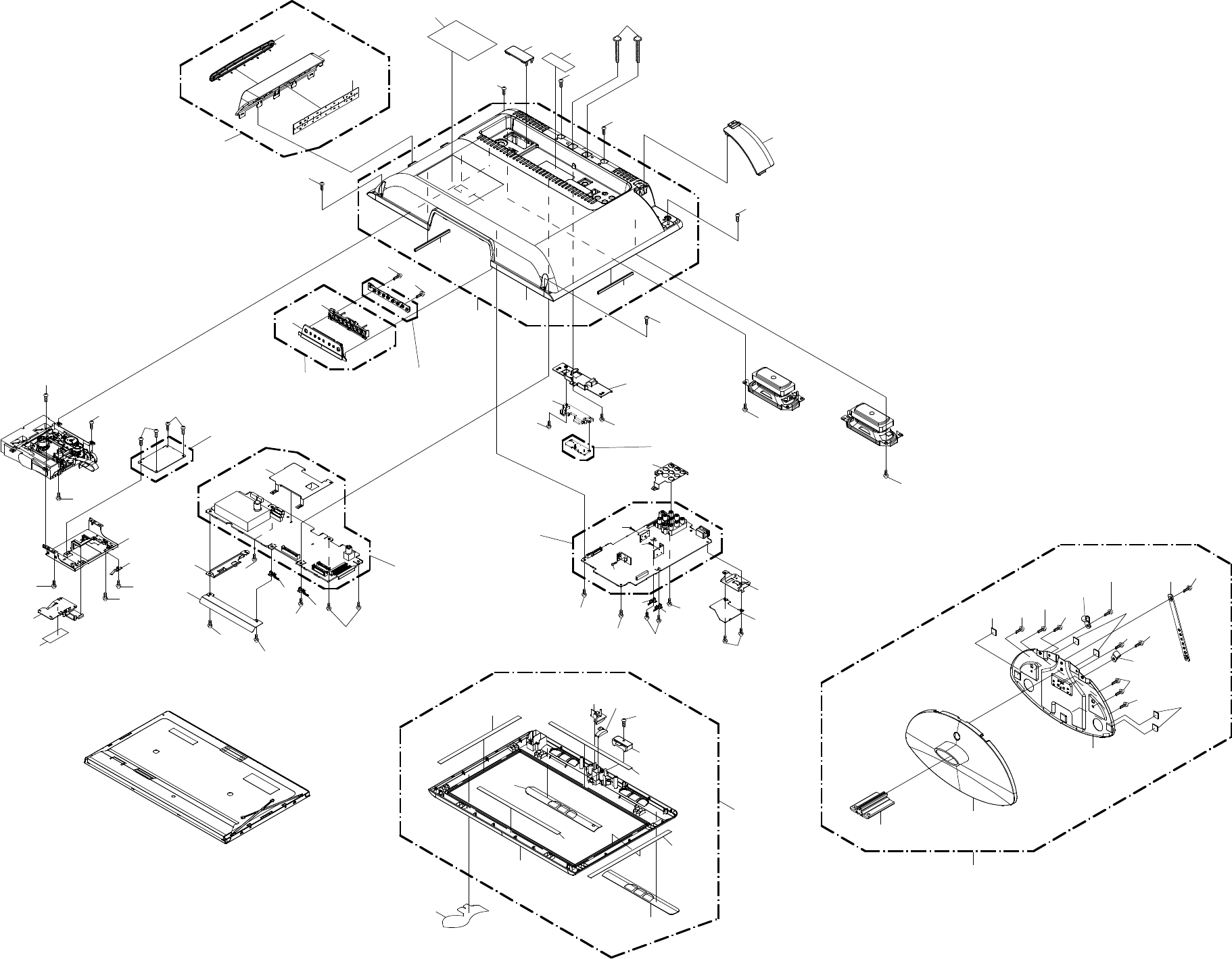
MECHANICAL EXPLODED VIEW
J1-1 J1-2
105A
105B
105C
105D
201
201
105D 203 203
203
203
204
202
202
105E
105E
105F
105D
105
205
205
208
104
104A
104B
PCB270
(OPERATION PCB ASS'Y)
208
208
122
205
208
120
PCBDA0
(REMOCON PCB ASS'Y)
208
208
PCB130
(DVD MT PCB ASS'Y)
202 202
118
PCBDH0
(DIGITAL PCB ASS'Y)
112
101C
101B
101G
101G
101G
101G
101A
101D
208
101F
101E
101
107
208
115
121
208
119
202
103
103A
103B
103C
106
117
208
208
208
117
123
208
208
114
PCB240
(POWER PCB ASS'Y) 206
206
206
208208
208
208 116
116 208
113
208
124
207
207
207
207
109
209
108
111
207
110
207
102A
102
102B
102B
125
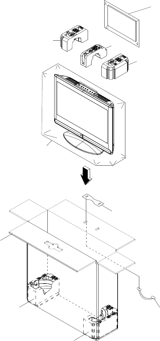
MECHANICAL EXPLODED VIEW
(PACKING DIAGRAM)
133, 134, 135, 136,137,
CD501, TM101
126
J1-3
127
127
129
131
132
128
128
130
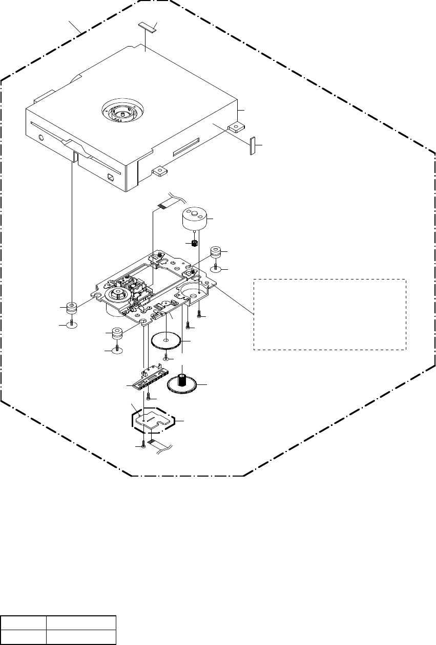
DVD DECK EXPLODED VIEW
J2-1
Applying positions AA for the grease are displayed for this section.
Check if the correct grease is applied for each position.
NOTE:
Do not replace the parts. Because,
minute adjustments are needed if
this condition is disassembled
further more.
If the repair is needed, replace the
DVD MECHA ASS'Y.
PCB640
(SW PCB ASS'Y)
701
702
702
607
604
CD2001
603
M2602
606
602
704
703
605
SW2
705 CD2301
AA
703
703
605
601
608
608
600
CLASS
GREASE
MARK
AA
MECHANICAL REPLACEMENT PARTS LIST
Location No.
TSB P/N
Reference No.
Description
101 AE009877 7A7080011A FRONT CABI ASS'Y
101A AE009878 708WPD0010 CABINET FRONT
101B AE009879 702WNA0010 SHEET SPEAKER-R
101C AE009880 702WNA0009 SHEET SPEAKER-L
101D AE009881 713WPA0426 GLASS LED
101E AE009882 713WPA0431 GLASS LED-2
101F AE009883 761WPA0533 HOLDER PANEL
101G AE003760 800WQ0A046 FELT SHEET
102 AE009884 7A7020296A BACK CABI ASS'Y
102A AE009885 702WPA1420 CABINET BACK
102B AE009955 800WQ00122 FELT SHEET
103 AE009887 7A7110048A PANEL SIDE ASS'Y
103A AE009888 711WPD0768 PANEL SIDE
103B AE009581 711WPEA001 SLOT DVD
103C AE008459 800WQ00105 FELT SHEET
104 AE009889 7A7110049A PLATE BUTTON ASS'Y
104A AE009890 711WPD0769 PLATE BUTTON
104B AE009582 735WPAB101 BUTTON FRAME
105 AE009891 7A7040071A STAND ASS'Y
105A AE009892 704WPA0117 STAND
105B AE009893 761WEA0039 FRAME STAND
105C AE009894 761WSB0072 ANGLE STAND
105D AE009624 800SRA0002 CUSHION LEG VEB1349-A
105E AE008947 899NAGCL14 CABLE CLAMP
105F AE007710 89900FB118 BAND
106 AE009895 752WSA0728 SHIELD DIGITAL
107 AE009790 761WSA0679 ANGLE MPEG
108 AE009896 702WPA1421 COVER BACK
109 75006982 706WPAA007 COVER CONNECTOR
110 AE009897 7225490281 SHEET RATING
111 AE009898 7230008445 SHEET JACK
112 AE009899 7235490100 POP LABEL
113 AE009900 724WND0001 SHEET PC-1
114 AE009901 724WND0002 SHEET PC-2
115 AE005122 726000A073 SHEET CAUTION
116 AE009597 744WUA0029 SPRING EARTH-2
117 AE009784 744WUA0038 SPRING EARTH-3
118 AE009902 752WSA0727 SHIELD JACK
119 AE009816 753WUAA017 SPRING EARTH
120 AE009904 761WPA0532 HOLDER REMOCON
121 AE009905 761WPA0534 COVER DVD
122 AE009906 761WSA0686 ANGLE HINGE
123 AE009907 761WSA0687 ANGLE LCD-L
124 AE009908 761WSA0688 ANGLE LCD-R
125 72782476 800WQ0A100 FELT SHEET
126 AE009909 791WHA0171 LAMIFILM BAG 650*700*0.5MM
127 AE009910 792WHA0759 PACKAGE TOP
128 AE009911 792WHA0760 PACKAGE BOTTOM
129 AE009912 792WHA0766 PACKAGE TOP CENTER
130 AE009913 793WCD1868 GIFT BOX
131 AE009603 794WHA0003 HANDLE
132 AE009604 794WHA0004 HANDLE STOPPER
133 AE009914 J51T0101A INSTRUCTION BOOK(TOSHIBA)
134 AE009609 JB5ND000 POLYBAG,INSTRUCTION(RED CAUTION)
135 AE007451 J3N51617A REGISTRATION CARD
136 AE007627 J5S10229A INFORMATION SHEET(RETURN)USA
137 AE009915 J51T0107A QUICK SET-UP SHEET(SPANISH)
201 72784217 810B140A0U SCREW SEMS(B) 4*10 CH
202 AE005675 810923060U SCREW TAP TITE(B) BIND 3*6 CH
203 AE009612 8110K3080U SCREW TAP TITE(P) LAMI HEAD 3*8 CH
204 AE007747 814623080U SCREW TAP TITE(B) BIND 3*5.7+4*2.3 CH
205 AE003526 810923080U SCREW TAP TITE(B) BIND 3*8 CH
206 AE003524 8109I30A0U SCREW TAP TITE(B) WH7 3*10 CH
207 AE009613 8109230A0S SCREW TAP TITE(B) BIND 3*10 BK
208 AE004849 8109230A0U SCREW TAP TITE(B) BIND 3*10 CH
209 AE009916 8117540C0S SCREW TAPPING(B0) TRUSS 4*30 BK
K1-1

DVD DECK REPLACEMENT PARTS LIST
Location No. TSB P/N Reference No. Description
! 600 AE009615 A50N01P650 DVD MECHA ASS'Y A50N01P650
601 AE008499 92SBB0033A LOADER SUB ASS'Y DLM1D29-31
602 AE005815 92AAA0017A FEED RACK ASS'Y
603 AE003551 92P100088A GEAR,MOTOR
604 AE005805 92P100117A GEAR,MIDDLE
605 AE008500 92P200017A INSULATOR, F
606 AE008501 92P200018A INSULATOR, R
607 AE005816 92P100116A GEAR,FEED
608 BZ710149 800WFAA008 CUSHION C
701 AE005817 92P700007A SCREW,GEAR FEED
702 AE003554 814011723U SCREW,PAN M1.7*2.3 P3 CH
703 AE003555 816112080U SEMS.TAP TITE(P) PAN W10 2*8 CH
704 AE005006 813381750U SCREW,T-TITE(B)CAMERA PAN M1.7*5.0 P3 CH
705 AE003557 811022080U SCREW,TAP TITE(P) BIND 2*8 CH
CD2001 AE009434 12C14O1602 CORD JUMPER FFC05241600408T1-A04
CD2301 AE003558 122H062102 CORD JUMPER 2H062102
M2602 AE009616 1515T98006 MOTOR WRF-300CA-10460A
PCB640 AE008503 A5X002C640 SW PCB ASS'Y DED020A
SW2 AE001158 0500101036 PUSH SWITCH ESE22MH22
K2-1

ELECTRICAL REPLACEMENT PARTS LIST
Location No. TSB P/N
Reference No.
Description
RESISTORS
! R503 75006901 RC31X1126J RC 12M OHM 1W
! R505 AE009485 R63884330J R,FUSE 33 OHM 1/4W
! R506 AE002150 R803R9333J RC 33K OHM 1/16W
! R509 AE009486 RC31X1125J RC 1.2M OHM 1W
! R510 AE005735 R63881R22J R,FUSE 0.22 OHM 1W
! R512 AD301018 R002T2104J RC 100K OHM 1/2W
! R544 AE009808 R861R42R0F RC 2 OHM 1/4W
! R545 AE009808 R861R42R0F RC 2 OHM 1/4W
! R546 AE009808 R861R42R0F RC 2 OHM 1/4W
! R547 AE009808 R861R42R0F RC 2 OHM 1/4W
! R3019 AE009917 R808R9123J RC 12K OHM 1/16W
CAPACITORS
! C501 AE001725 CS0PB0413K CC 0.001 UF 50V B
! C502 AE009490 E8E52C271D CE 270 UF 200V
! C503 79091384 CS0PCH4L2J CC 330 PF 50V CH
! C504 AE009918 E83YF1222D CE 2200 UF 10V
! C505 AE001732 CS0PCH4H1J CC 22 PF 50V CH
! C506 BZ110025 P2122B224M CMP 0.22 UF 275V ECQUL
! C507 AD301026 CD39E0M13M CC 0.001 UF 250V
! C508 BZ110035 P2122B104M CMP 0.1 UF 275V ECQUL
! C510 AD301026 CD39E0M13M CC 0.001 UF 250V
! C513 BZ110176 C03L0R7Q2K CC 470 PF 2KV R
! C514 AE000308 CD39B0MQ2K CC 470 PF 250V
C518 AE009492 P332E4223J CPP 0.022 UF 400V
! C520 AE009919 E7ESU54R7M CE 4.7 UF 50V
! C522 AE009920 E83YF2102D CE 1000 UF 16V
! C525 AE009920 E83YF2102D CE 1000 UF 16V
C7030 AE009700 C234SLB11J CC 10 PF 6KV SL
C7033 AE009700 C234SLB11J CC 10 PF 6KV SL
DIODES
! D504 BZ410031 D6CE24110A DIODE VARISTA ENE241D-10A-Q6
! D505 BZ410085 D2WXN40050 DIODE SILICON 1N4005-EIC
D506 AE008906 D28R11FS20 DIODE EC11FS2-TE12L
! D507 BZ410062 D2WTRM11C0 DIODE SILICON RM11C-EIC
! D508 BZ410062 D2WTRM11C0 DIODE SILICON RM11C-EIC
D509 AE009494 DE7RB3302B DIODE ZENER UDZSNP33B TE-17
! D510 BZ410062 D2WTRM11C0 DIODE SILICON RM11C-EIC
! D511 AE008319 D4AT01H3E0 DIODE RECTIFIER 1H3-E
D512 AE002133 D2BXARS010 DIODE SILICON SARS01-V1
! D514 BZ410126 D2WXRU3AM0 DIODE SILICON RU3AM-EIC
! D515 AE009803 D28A10A080 DIODE SCHOTTKY BARRIER FCHS10A08
! D516 AE008319 D4AT01H3E0 DIODE RECTIFIER 1H3-E
D517 AD300070 D97U01201B DIODE,ZENER MTZJ12B T-77
! D518 BZ410062 D2WTRM11C0 DIODE SILICON RM11C-EIC
D519 AE009006 DGERMA1110 DIODE SILICON MA111-(TX)
D520 AE009006 DGERMA1110 DIODE SILICON MA111-(TX)
D521 AE009006 DGERMA1110 DIODE SILICON MA111-(TX)
D522 AE009006 DGERMA1110 DIODE SILICON MA111-(TX)
! D523 AE009829 D28A10A040 DIODE SCHOTTKY BARRIER FCQ10A04
D526 BZ410113 D97U02201B DIODE ZENER MTZJ22B T-77
D2303 AE009006 DGERMA1110 DIODE SILICON MA111-(TX)
D2304 AE009006 DGERMA1110 DIODE SILICON MA111-(TX)
D3004 AE004643 D28R1QS040 DIODE EC31QS04-TE12L
D3005 AE009496 D28R11FS40 DIODE SCHOTTKY EC11FS4-TE12L
D3006 AE004643 D28R1QS040 DIODE EC31QS04-TE12L
D3007 AE009496 D28R11FS40 DIODE SCHOTTKY EC11FS4-TE12L
D3402 AE009006 DGERMA1110 DIODE SILICON MA111-(TX)
D3403 AE009006 DGERMA1110 DIODE SILICON MA111-(TX)
D4002 AE009006 DGERMA1110 DIODE SILICON MA111-(TX)
D4003 AE009006 DGERMA1110 DIODE SILICON MA111-(TX)
D4005 AE009006 DGERMA1110 DIODE SILICON MA111-(TX)
D4008 AE009006 DGERMA1110 DIODE SILICON MA111-(TX)
D5803 AE009006 DGERMA1110 DIODE SILICON MA111-(TX)
D5804 AE009006 DGERMA1110 DIODE SILICON MA111-(TX)
D6205 AE009006 DGERMA1110 DIODE SILICON MA111-(TX)
D7001 BZ410006 D1VT001330 DIODE,SILICON 1SS133T-77
D7002 BZ410006 D1VT001330 DIODE,SILICON 1SS133T-77
D7003 BZ410006 D1VT001330 DIODE,SILICON 1SS133T-77
D7004 BZ410006 D1VT001330 DIODE,SILICON 1SS133T-77
D7005 BZ410006 D1VT001330 DIODE,SILICON 1SS133T-77
D7006 BZ410006 D1VT001330 DIODE,SILICON 1SS133T-77
D7007 BZ410006 D1VT001330 DIODE,SILICON 1SS133T-77
D7008 BZ410006 D1VT001330 DIODE,SILICON 1SS133T-77
D7010 AE004795 DE7RB5R62B DIODE ZENER UDZSNP5.6B TE-17
D7011 AE009922 DE7RB3R92B DIODE ZENER UDZSNP3.9B TE-17
DIODES
D7012 AE009006 DGERMA1110 DIODE SILICON MA111-(TX)
D7013 AE009006 DGERMA1110 DIODE SILICON MA111-(TX)
D7014 AE009006 DGERMA1110 DIODE SILICON MA111-(TX)
D7015 BZ410006 D1VT001330 DIODE,SILICON 1SS133T-77
D7017 AE009006 DGERMA1110 DIODE SILICON MA111-(TX)
D7018 AE009006 DGERMA1110 DIODE SILICON MA111-(TX)
D7019 AE009006 DGERMA1110 DIODE SILICON MA111-(TX)
D7020 AE009006 DGERMA1110 DIODE SILICON MA111-(TX)
K3-1

ELECTRICAL REPLACEMENT PARTS LIST
Location No. TSB P/N
Reference No.
Description
DIODES
D7023 AE009006 DGERMA1110 DIODE SILICON MA111-(TX)
D7024 AE009006 DGERMA1110 DIODE SILICON MA111-(TX)
D7601 AE009923 0021E91030 LED LTL1BECBEK5
D8510 AE009006 DGERMA1110 DIODE SILICON MA111-(TX)
ICS
! IC301 AE008430 I03SP20520 SOUND AMP 5W 2CH LA42052-E
! IC501 AE009499 ICAD055310 LOW STANDBY POWER IC CONTROL FA5531P-A2
! IC502 AD302211 I1KJ9A431A VARIABLE SHUNT REGULATOR TAPE KIA431A-AT
! IC503 AE009500 I03F9797M0 CHARGE POMP CONTROL LA5797M-TE-L-E
! IC505 AE002809 000220002W PHOTO COUPLER PS2561AL1-1-V(W)
! IC2301 AE008194 I03FV65650 5CH MOTOR DRIVER IC LA6565VR-TLM-E
IC2801 AE009656 I56M069540 SCALER R8J66954BG
IC2802 AE009502 IGGM061600 DDR2-667 256M CL=5 HYB18TC256160BF-3S
IC2804 AE009924 S51T01PF01 MEMORY DATA NOR FLASH 32M BOOT EN29LV320AB-70TCP
IC2805 AE009925 S51T01PE01 MEMORY DATA EEPROM 256K 12C M24256-BWMN6TP
! IC3001 AE009505 I07F091300 1CH DC-DC CONVERTER BD9130NV
! IC3002 AE008435 I1LF010150 DC-DC CONVERTER CONTROLLER AL1015
! IC3003 AE008916 I0GF95ZN10 VO=0.8-3.5V I=1.5A TAPING PQ035ZN1HZPH
! IC3007 AE008431 I07F078200 VARIABLE REG LOW INPUT IO=1A BD7820FP-E2
! IC3009 AE009506 I5HJ0170B0 REGULATOR VO=3.3V IO=800MA S-1170B33UC-OTSTFG
IC4001 AE009720 ICQK06966A VADDIS9 MPEG/MICON/DSP/RF-AMP ZR36966ELCG-D-G
IC4005 AE008324 IF9J0164AG 1M*16*4BANK(64M) 143MHZ SDRAM M12L64164A-7TG
IC4007 AE009926 S51T01PF02 MEMORY DATA NOR FLASH 16M B00T SST39VF1601-70-4C-EKE
IC5801 AE004647 I01FF58320 USA STEREO AN5832SA-E1V
IC6201 79097849 I9UF032290 RESET IC 2.9V TYPE PST3229NR
IC6202 AE009927 S34L01PM02 MEMORY DATA FLASH MICOM ROM16K 2KX2 RAM1 R5F21124FP
IC6551 AE009511 IC1J053580 A/D CONVERTER AK5358A
IC6552 AD301988 I0UF015010 A/V SW 2INPUT 1OUTPUT MM1501XNRE
IC6553 AD301988 I0UF015010 A/V SW 2INPUT 1OUTPUT MM1501XNRE
IC6554 AD301988 I0UF015010 A/V SW 2INPUT 1OUTPUT MM1501XNRE
IC6555 AD301988 I0UF015010 A/V SW 2INPUT 1OUTPUT MM1501XNRE
IC6556 AE009928 I55F0A53FU A/V SW 2IN 1OUT TC7PA53FU(T5L,F,T)
IC6557 BZ611139 I0QF02534V A/V SW 3INPUT 1OUTPUT NJM2534V(TE2)
IC6558 BZ611139 I0QF02534V A/V SW 3INPUT 1OUTPUT NJM2534V(TE2)
IC7001 AE009512 I07F098820 19WLCD INVERTER IC BD9882FV-E2
IC7002 AE009513 I0CF0902D0 QUAND OPERATIONNAL AMPLIFILE LM2902DR
IC8501 AE009365 I0QF045650 DUAL OPEAMP NJM4565M(TE1)
! IC8502 AE009805 I1YF9117A0 VO=ADJ IO=1A TAPING LD1117AL-ADJ-AA3-A-R
TRANSISTORS
! Q501 72783392 TJXG10NK50 FET STF10NK50Z
Q503 79097796 TPATC03002 COMPOUND TRANSISTOR KRA103MAT
Q504 BZ510067 TNAAC05002 COMPOUND TRANSISTOR KRC103SRTK
Q505 BZ510108 TAAA1504SY TRANSISTOR SILICON KTA1504S_Y_RTK
Q2301 AE008330 TAAA1505SY TRANSISTOR SILICON KTA1505S-Y-RTK/P
Q2302 AE008330 TAAA1505SY TRANSISTOR SILICON KTA1505S-Y-RTK/P
Q3001 BZ510071 TNAAB05003 COMPOUND TRANSISTOR KRC102SRTK
Q3002 BZ510107 TPAAA05001 COMPOUND TRANSISTOR KRA101SRTK
Q3003 BZ510067 TNAAC05002 COMPOUND TRANSISTOR KRC103SRTK
Q3004 BZ510067 TNAAC05002 COMPOUND TRANSISTOR KRC103SRTK
Q3005 BZ510071 TNAAB05003 COMPOUND TRANSISTOR KRC102SRTK
Q3006 AE005049 TNAAA05001 COMPOUND TRANSISTOR KRC101S-RTK
! Q3007 AE008441 TAAA01664Y TRANSISTOR SILICON KTA1664-Y-RTF/P
Q3008 BZ510071 TNAAB05003 COMPOUND TRANSISTOR KRC102SRTK
! Q3009 AE008933 TJ5MC61080 FET TPC6108
! Q3010 AE009514 TJ7T35P020 FET RTQ035P02-TR
! Q3011 AE008933 TJ5MC61080 FET TPC6108
Q3407 BZ510071 TNAAB05003 COMPOUND TRANSISTOR KRC102SRTK
Q4301 BZ510109 TCAA3875SY TRANSISTOR SILICON KTC3875S_Y_RTK
Q5801 AE009515 T27T030190 FET 2SK3019_TL
Q5802 AE009515 T27T030190 FET 2SK3019_TL
Q6201 AE009515 T27T030190 FET 2SK3019_TL
Q6202 AE009515 T27T030190 FET 2SK3019_TL
Q6203 BZ510072 TPAAC05002 COMPOUND TRANSISTOR KRA103SRTK
Q6204 BZ510071 TNAAB05003 COMPOUND TRANSISTOR KRC102SRTK
Q7001 BZ510067 TNAAC05002 COMPOUND TRANSISTOR KRC103SRTK
! Q7002 AE008330 TAAA1505SY TRANSISTOR SILICON KTA1505S-Y-RTK/P
Q7003 BZ510113 T27T030180 FET 2SK3018T106
! Q7004 AE009929 TJ3MSS2750 FET FSS275-TL-E
! Q7005 AE009929 TJ3MSS2750 FET FSS275-TL-E
COILS &TRANSFORMERS
! L501 AE005143 029X000416 COIL,LINE FILTER SS24H-10100
L503 BZ310150 02167E220K COIL 22 UH
L504 AD301785 02167E100K COIL 10 UH
L3001 BZ310150 02167E220K COIL 22 UH
L3002 AE009517 0218MG5R2P COIL 5.2 UH
L3003 BZ310150 02167E220K COIL 22 UH
L3004 AE009518 0218MG220P COIL 22 UH
L3005 BZ310150 02167E220K COIL 22 UH
L5801 72784092 0216SD220J COIL 22 UH
L5805 AE009260 021AS9224J COIL 0.22 UH
L8501 AE008874 0216SD2R2J COIL 2.2 UH
L8502 AE006570 0216SD1R0J COIL 1 UH
! T501 AE009520 0481240018 TRANSFORMER,SWITCHING 81240018
K3-2

ELECTRICAL REPLACEMENT PARTS LIST
Location No. TSB P/N
Reference No.
Description
COILS &TRANSFORMERS
! T7001 AE009521 048135109G TRANSFORMER,SWITCHING 8135109G
JACKS
! J301 AE009522 060R131024 HEADPHONE JACK PJ-364H
! J501 AE009523 064Q1A0010 JACK,AC CCT2302-0901C
J4301 AE009524 060R401140 RCA JACK RCA-101HT(OR)
J8101 AE009526 062R750007 PLUG DIN-417HA-01
J8102 AE009527 060R411058 RCA JACK RCA-341H(NI)-09
J8103 AE009528 060R431039 RCA JACK RCA-228H(3)NI-02
J8104 AE009529 060R431040 RCA JACK RCA-341H(2)NI-06
SWITCHES
SW2201 BZ612010 0504101T34 SWITCH,TACT EVQ21505R
SW2202 BZ612010 0504101T34 SWITCH,TACT EVQ21505R
SW2203 BZ612010 0504101T34 SWITCH,TACT EVQ21505R
SW2204 BZ612010 0504101T34 SWITCH,TACT EVQ21505R
SW2205 BZ612010 0504101T34 SWITCH,TACT EVQ21505R
SW2206 BZ612010 0504101T34 SWITCH,TACT EVQ21505R
SW2207 BZ612010 0504101T34 SWITCH,TACT EVQ21505R
SW2208 BZ612010 0504101T34 SWITCH,TACT EVQ21505R
P.C.BOARD ASSEMBLIES
PCB130 AE009931 A51T01P130 DVD MT PCB ASS'Y DMG097A
PCB240 AE009932 A51T01P240 POWER PCB ASS'Y CEH421A
PCB270 AE009933 A51T01P270 OPERATION PCB ASS'Y CEH422A
PCBDA0 AE009934 A51T01PDA0 REMOCON PCB ASS'Y CEH423A
PCBDH0 AE009935 A51T01PDH0 DIGITAL PCB ASS'Y CEH420A
MISCELLANEOUS
B501 BZ310129 024HT03564 CORE,BEADS W4BRH3.5X6X1.0
B2305 AE008552 024NC51021 CORE,BEADS EBMS160808A102_RDC45
B2800 AE008878 024HC51816 CORE,BEADS HCB1608KF-181T20
B2803 AE009536 024HC52216 CORE,BEADS HCB1608KF-221T20
B2804 AE009536 024HC52216 CORE,BEADS HCB1608KF-221T20
B2805 AE009536 024HC52216 CORE,BEADS HCB1608KF-221T20
B2806 AE009536 024HC52216 CORE,BEADS HCB1608KF-221T20
B2807 AE009536 024HC52216 CORE,BEADS HCB1608KF-221T20
B2808 AE009536 024HC52216 CORE,BEADS HCB1608KF-221T20
B2809 AE009536 024HC52216 CORE,BEADS HCB1608KF-221T20
B2810 AE009536 024HC52216 CORE,BEADS HCB1608KF-221T20
B2811 AE009536 024HC52216 CORE,BEADS HCB1608KF-221T20
B2815 AE009374 024HC51216 CORE,BEADS HCB1608KF-121T20
B2816 AE009374 024HC51216 CORE,BEADS HCB1608KF-121T20
B2817 AE009374 024HC51216 CORE,BEADS HCB1608KF-121T20
B2820 AE009374 024HC51216 CORE,BEADS HCB1608KF-121T20
B2821 AE009374 024HC51216 CORE,BEADS HCB1608KF-121T20
B2822 AE009374 024HC51216 CORE,BEADS HCB1608KF-121T20
B3003 AE008878 024HC51816 CORE,BEADS HCB1608KF-181T20
B3004 AE008878 024HC51816 CORE,BEADS HCB1608KF-181T20
B3005 AE008878 024HC51816 CORE,BEADS HCB1608KF-181T20
B3006 AE008878 024HC51816 CORE,BEADS HCB1608KF-181T20
B3007 AE008878 024HC51816 CORE,BEADS HCB1608KF-181T20
B3008 AE008878 024HC51816 CORE,BEADS HCB1608KF-181T20
B3014 AE008878 024HC51816 CORE,BEADS HCB1608KF-181T20
B3015 AE008878 024HC51816 CORE,BEADS HCB1608KF-181T20
B3017 AE008878 024HC51816 CORE,BEADS HCB1608KF-181T20
B3022 AE008609 024HC51023 CORE,BEADS FCM1608KF-102T02
B3023 AE008609 024HC51023 CORE,BEADS FCM1608KF-102T02
B4001 AE008552 024NC51021 CORE,BEADS EBMS160808A102_RDC45
B4002 AE008552 024NC51021 CORE,BEADS EBMS160808A102_RDC45
B4003 AE008552 024NC51021 CORE,BEADS EBMS160808A102_RDC45
B4005 AE008552 024NC51021 CORE,BEADS EBMS160808A102_RDC45
B4006 AE008552 024NC51021 CORE,BEADS EBMS160808A102_RDC45
B4008 AE008552 024NC51021 CORE,BEADS EBMS160808A102_RDC45
B4010 AE008552 024NC51021 CORE,BEADS EBMS160808A102_RDC45
B4015 AE008552 024NC51021 CORE,BEADS EBMS160808A102_RDC45
B4016 AE008552 024NC51021 CORE,BEADS EBMS160808A102_RDC45
B4301 AE008395 024HC56005 CORE,BEADS FCM1608CF-600T06
B4302 AE008395 024HC56005 CORE,BEADS FCM1608CF-600T06
B5801 AE008609 024HC51023 CORE,BEADS FCM1608KF-102T02
B5802 AE008609 024HC51023 CORE,BEADS FCM1608KF-102T02
B5803 AE008609 024HC51023 CORE,BEADS FCM1608KF-102T02
B5804 AE008610 024HC51513 CORE,BEADS FCM1608KF-151T06
B6551 AE009374 024HC51216 CORE,BEADS HCB1608KF-121T20
B6552 AE008609 024HC51023 CORE,BEADS FCM1608KF-102T02
B6553 AE008609 024HC51023 CORE,BEADS FCM1608KF-102T02
B6554 AE008395 024HC56005 CORE,BEADS FCM1608CF-600T06
B6556 AE008878 024HC51816 CORE,BEADS HCB1608KF-181T20
B8501 AE008394 024BC5121J CORE,BEADS BLM18PG121SN1D
B8502 AE008552 024NC51021 CORE,BEADS EBMS160808A102_RDC45
B8503 AE008394 024BC5121J CORE,BEADS BLM18PG121SN1D
B8504 AE008552 024NC51021 CORE,BEADS EBMS160808A102_RDC45
BT001 AE008217 141U004016 BATTERY,MANGAN MNAAA(R03)
BT002 AE008217 141U004016 BATTERY,MANGAN MNAAA(R03)
CD301 AE009733 06E8141801 CORD CONNECTOR E8141801
! CD501 AE009538 120Q119905 CORD SET AC P201-2476-2
CD502 AE009936 06E8231001 CORD CONNECTOR E8231001
K3-3

ELECTRICAL REPLACEMENT PARTS LIST
Location No. TSB P/N
Reference No.
Description
MISCELLANEOUS
CP501 AE009937 069S2K0739 CONNECTOR PCB SIDE A2006WV0-2X10P
CD2804 AE009938 06CHRU1803 CORD CONNECTOR CHRU1803
CD3001 AE009939 06E82K1701 CORD CONNECTOR E82K1701
CD3002 AE009940 06E82O1101 CORD CONNECTOR E82O1101
CD6203 AE009941 06E8252002 CORD CONNECTOR E8252002
CD7005 AE009942 06E82E0604 CORD CONNECTOR E82E0604
CP2201 AD301795 069S230639 CONNECTOR PCB SIDE A2001WR2-3P
CP2301 AE008156 069KYOT159 CONNECTOR PCB SIDE LD07T2-24ND-03
CP2302 AE009544 069EV5T060 CONNECTOR PCB SIDE 04_6232_105_015_800+
CP2303 AE009545 069EV6T060 CONNECTOR PCB SIDE 04_6232_106_015_800+
CP2801 BZ614485 069S270629 CONNECTOR PCB SIDE A2001WV2-7P
CP2803 BZ614214 069S2B0629 CONNECTOR PCB SIDE A2001WV2-11P
CP2804 AE009548 069S2U0739 CONNECTOR PCB SIDE A2006WV0-2X15P
CP3001 AE009937 069S2K0739 CONNECTOR PCB SIDE A2006WV0-2X10P
CP3002 AE009944 069S2O0739 CONNECTOR PCB SIDE A2006WV0-2X12P
CP4301 AE008886 06CK7N0301 CORD CONNECTOR TWG-P23P-A1
CP6201 BZ614458 069S290629 CONNECTOR PCB SIDE A2001WV2-9P
CP7601 AD300752 069S250629 CONNECTOR PCB SIDE A2001WV2-5P
CP8101 AE008882 06977NM020 CONNECTOR PCB SIDE 127301123K2
CP8501 AE009553 06GG2E0019 CONNECTOR PCB SIDE A2001WR-14A
CP8502 AD301796 069S280629 CONNECTOR PCB SIDE A2001WV2-8P
CUS151 BZ710279 800WFAA006 CUSHION A
EL2401 BZ614043 124116281A EYE LET XRY16X28BD
! F501 79101691 081PC04005 FUSE 51MS040L
! F7001 AE004626 083LA05007 FUSE 1206FA5A-T
FH501 AE002634 06710T0009 HOLDER,FUSE EYF-52BCY
FH502 AE002634 06710T0009 HOLDER,FUSE EYF-52BCY
NR2801 AE009554 11074100M7 R,NETWORK CRA108100JV
NR2802 AE009554 11074100M7 R,NETWORK CRA108100JV
NR2803 AE009554 11074100M7 R,NETWORK CRA108100JV
NR2804 AE009554 11074100M7 R,NETWORK CRA108100JV
NR2805 AE009555 11074270M7 R,NETWORK CRA108270JV
NR2806 AE009555 11074270M7 R,NETWORK CRA108270JV
NR2807 AE009555 11074270M7 R,NETWORK CRA108270JV
NR2808 AE009555 11074270M7 R,NETWORK CRA108270JV
NR2809 AE009555 11074270M7 R,NETWORK CRA108270JV
NR2810 AE009556 11074220M7 R,NETWORK CRA108220JV
NR2811 AE009556 11074220M7 R,NETWORK CRA108220JV
NR3601 AE009945 110P4472M5 R,NETWORK 4D02WGJ0472TCE
NR3602 AE009945 110P4472M5 R,NETWORK 4D02WGJ0472TCE
NR6551 AE009557 11074470M7 R,NETWORK CRA108470JV
OS7601 AE009947 077Q038007 REMOTE RECEIVER KSM-2003TC2P
SH501 AE009776 126D000045 TERMINAL PIN YQ-12
! SP301 AE009558 070Y433004 SPEAKER S0308F01
! SP302 AE009558 070Y433004 SPEAKER S0308F01
! TH501 AE009559 DSQDNE5R0L THERMISTOR 5D2-08LCS
TM101 AE009560 076D0LT030 TRANSMITTER 000-103000530
! TU5801 AE009623 0164100027 DIGITAL TUNER ENG36E18KRF
! V2801 AE009948 09EV115008 LCD M156B1-L02
X2801 AE009563 100GT02728 CRYSTAL SMD-49 C27000B030
X2802 AE009564 100GT02509 CRYSTAL SMD-49 C25000H025
X4001 AE009566 100GT02727 CRYSTAL SMD-49 C27000J029
X6201 75006971 100GT01615 CRYSTAL B16000E007
X6551 AE009567 100DT01217 CRYSTAL DS0321SRAB
RESISTOR
RC...............
CARBON RESISTOR
CAPACITORS
CC...............
CERAMIC CAPACITOR
CE...............
ALUMI ELECTROLYTIC CAPACITOR
CP...............
POLYESTER CAPACITOR
CPP.............
POLYPROPYLENE CAPACITOR
CPL.............
PLASTIC CAPACITOR
CMP............
METAL POLYESTER CAPACITOR
CMPL..........
METAL PLASTIC CAPACITOR
CMPP..........
METAL POLYPROPYLENE CAPACITOR
K3-4

TOSHIBA CORPORATION
1-1, SHIBAURA 1-CHOME, MINATO-KU, TOKYO 105-8001, JAPAN
