Toshiba C Dr0101 Users Manual DR0100 英2 NTSC
C-DR0101 C-DR0100_NT
2014-12-13
: Toshiba Toshiba-C-Dr0101-Users-Manual-129090 toshiba-c-dr0101-users-manual-129090 toshiba pdf
Open the PDF directly: View PDF ![]() .
.
Page Count: 56
Please follow the instructions in this manual to obtain the optimum results from this unit. We also
recommend that you keep this manual handy for future reference.
1CH DIGITAL VIDEO RECORDER
(NTSC SYSTEM )
C-DR0100
C-DR0101
C-DR0105
INSTRUCTION MANUAL
DIGITAL VIDEO RECORDER
DISK FULL/
FAILURE
ALARM
RESET
BUZZER
STOP
SEARCH
MENU
SELECT
BLOCK
PLAY
STOP
PLAY
PAU SE
REVERSE
PLAY
REC
TIMER
FRAME FRAME
OUTPUT
VIDEO AUDIO

2
TABLE OF CONTENTS
1. SAFETY PRECAUTIONS ............................................................................... 5
2. GENERAL DESCRIPTION ............................................................................. 6
3. FEATURES .......................................................................................................... 6
4. HANDLING PRECAUTIONS .......................................................................... 7
5. NOMENCLATURE AND FUNCTIONS
Front Panel ................................................................................................................ 8
Rear Panel .............................................................................................................. 10
6. SETTING ITEM CHART AND SETTING PROCEDURES
6.1. Basic Setting Procedures ................................................................................. 11
6.2. Setting Item Chart ............................................................................................ 12
7. INDIVIDUAL ITEM SETTINGS
7.1. Main Menu Screen ........................................................................................... 13
7.2. Playback Settings ............................................................................................ 13
7.3. Clock Settings .................................................................................................. 14
7.3.1. Summer Time (Daylight Saving Time) Settings ..................................... 15
7.4. Disk Settings .................................................................................................... 15
7.5. Recording Settings ........................................................................................... 16
7.5.1. General Recording Settings ................................................................... 17
7.5.2. Internal Timer Recording Settings ......................................................... 17
7.5.3. Alarm Recording Settings ...................................................................... 19
7.5.4. About the Alarm Input Mode .................................................................. 20
7.6. Screen Display Settings ................................................................................... 21
7.7. Key Lock .......................................................................................................... 22
7.7.1. Key Lock Release .................................................................................. 22
7.8. Communication Settings .................................................................................. 23
7.8.1. Network Settings .................................................................................... 23
7.9. Log Display ...................................................................................................... 24
7.9.1. General/Timer Recording Logs .............................................................. 24
7.9.2. Alarm Recording Logs ........................................................................... 24
7.9.3. Failure Logs ........................................................................................... 25
7.10. System Maintenance ..................................................................................... 25
7.10.1. Menu Default Settings .......................................................................... 25
7.10.2. Disk Formatting .................................................................................... 26
SETTING BASICS
SUMMARY

3
8. DIGITAL VIDEO RECORDER ACTIVATION AND TERMINATION
8.1. Recorder’s Activation ....................................................................................... 27
8.2. When the Failure Screen Is Displayed ............................................................. 28
8.3. Recorder’s Termination .................................................................................... 28
9. OPERATION AFTER POWER FAILURE RESTORATION
9.1. When the Power Fails during Recording ......................................................... 28
10. RECORDING
10.1. Type of Recording .......................................................................................... 29
10.1.1. Recording Priorities ............................................................................ 29
10.2. Screen Display During Recording .................................................................. 29
10.3. The Keys to Be Used in Recording ................................................................ 31
10.4. Performing General Recording ...................................................................... 31
10.5. Performing Internal Timer Recording ............................................................. 31
10.6. Performing Alarm Recording .......................................................................... 32
11. PLAYBACK
11.1. Type of Playback ........................................................................................... 33
11.2. Screen Display During Playback .................................................................... 33
11.3. The Keys to Be Used in Playback .................................................................. 34
11.4. Performing Playback ...................................................................................... 34
11.5. Performing Various Playback Functions
11.5.1. Reverse Playback .............................................................................. 34
11.5.2. Fast Forward Playback And Fast Reverse Playback ......................... 34
11.5.3. Playback Pause (Still Picture) ............................................................ 34
11.5.4. Forward Frame Playback And Reverse Frame Playback .................. 35
11.5.5. Forward Block Playback And Reverse Block Playback ..................... 35
11.6. About the Playback Start Position .................................................................. 36
12. SEARCH FUNCTIONS
12.1. The Keys to Be Used in Searching ................................................................ 37
12.2. Date/Time and Block Searches ..................................................................... 37
12.2.1. Basic Date/Time and Block Search Operations ................................. 37
12.2.2. Date/Time Search Operation ............................................................. 37
12.2.3. Block Search Operation ..................................................................... 38
12.3. Time Shift Search .......................................................................................... 39
13. CONNECTIONS
13.1. Preparations for Connections ........................................................................ 40
13.1.1. Control Input/Output Terminal Connections ....................................... 40
13.2. When Using the 24 V AC or 12 V DC or AC Mains Camera .......................... 40
13.3. Connection to The Monitor TV ....................................................................... 40
13.4. Combination With The Digital Video Recorder/Multi-switchers
(C-MS91D, C-MS161D) ................................................................................. 41
13.4.1. Basic System ..................................................................................... 41
13.4.2. Expansion System (Series Recording) .............................................. 41
CONNECTIONS
FUNCTIONS
OPERATION

4
14. CONNECTION EXAMPLES
14.1. Connection to the 24 V AC or 12 V DC or AC Mains Camera ....................... 42
14.2. Connection to the Multi-switcher
14.2.1. Basic System
(Combined Example with the C-MS91D, Multi-switcher) ................... 43
14.2.2. Expansion System
(Combined Example with the C-MS91D, Multi-switcher) ................... 44
15. RECORDING TIME TABLE
15.1. Recording Picture Quality Setting .................................................................. 45
15.2. When using the C-DR0100 ............................................................................ 45
15.3. When using the C-DR0101 ............................................................................ 45
15.4. When using the C-DR0105 ............................................................................ 46
16. EXTERNAL TERMINAL SPECIFICATIONS
16.1. RS-232C Communication Specifications ....................................................... 47
16.1.1. The Rules of Overall Communications .............................................. 47
16.1.2. Communication Protocol .................................................................... 47
16.1.3. RS-232C Connector Pin Assignment ................................................. 47
16.1.4. RS-232C Communication Format
(Controller to Digital Video Recorder) ................................................ 48
16.1.5. RS-232C Communication Command
(Controller to Digital Video Recorder) ................................................ 48
16.1.6. RS-232C Communication Format
(Digital Video Recorder to Controller) ................................................ 51
16.1.7. RS-232C Communication Command
(Digital Video Recorder to Controller) ................................................ 51
16.2. About the Ethernet Terminal .......................................................................... 53
17. RACK MOUNTING ........................................................................................... 54
18. IF YOU THINK THERE IS A FAILURE: (TROUBLESHOOTING) .... 55
19. SPECIFICATIONS ........................................................................................... 56
WHEN YOU NEED HELP
ADDITIONAL INFORMATION
Note
This equipment has been tested and found to comply with the limits for a Class A digital device,
pursuant to Part 15 of the FCC Rules. These limits are designed to provide reasonable protection
against harmful interference when the equipment is operated in a commercial environment. This
equipment generates, uses, and can radiate radio frequency energy and, if not installed and used in
accordance with the instruction manual, may cause harmful interference to radio communications.
Operation of this equipment in a residential area is likely to cause harmful interference in which case the
user will be required to correct the interference at his own expense.
Modifications
Any modifications made to this device that are not approved by TOA Corporation may void the authority
granted to the user by the FCC to operate this equipment.
NTSC version complies with Part 15 of the FCC Rules.
5
1. SAFETY PRECAUTIONS
• Be sure to read this safety instructions in this section carefully in prior to use.
• Make sure to observe the instructions in this manual as the conventions of safety symbols and messages
regarded as very important precautions are included.
• Keep this instructions handy for future reference.
Safety Symbol and Message Conventions
Safety messages described below are used to prevent bodily injury and property damage that could result
from mishandling. Before operating your product, read this manual first and understand messages so you are
thoroughly aware of the potential safety hazards.
When installing the Recorder
• This is a class A product. In a domestic environment this product may cause radio interference in which case
the user may be required to take adequate measures.
• Do not expose the unit to rain or an environment where it may be splashed by water or other liquids, as
doing so may result in fire or electric shock.
• Use the unit only with the voltage specified on the unit. Using a voltage higher than specified one may result
in fire or electric shock.
• Do not damage, modify nor put the power supply cord in close to heaters. Never place heavy objects on the
power supply cord, as doing so may result in fire or electric shock.
• Do not install nor place the unit in unstable locations, such as on a rickety table or a slanted surface. Doing
so may result in the unit falling down or dropping and causing personal injury.
When Using the Recorder
• Should the following irregularity be found during use, immediately switch off the main power, disconnect the
power supply plug from the AC outlet and contact your nearest TOA dealer. Make no further attempt to
operate the unit in this condition as this may cause fire or electric shock.
• If you detect smoke or a strange smell coming form the unit
• If water or any metallic object gets into the unit
• If the unit falls or the unit case breaks
• If the power supply cord is damaged (exposure of the core, disconnection, etc.)
• When the Screen is not Displayed
• Do not open the unit case nor modify the unit. As doing so may result in fire or electric shock as there are
high voltage components inside the unit. Refer any needed servicing to authorized TOA dealers.
• Do not put containers of liquid or metallic objects on top of the unit. If they accidentally spill into the unit, this
may cause a fire or electric shock.
• Do not insert nor drop metallic objects or flammable materials from ventilation slots of the unit, as this may
result in fire or electric shock.
• Do not touch power supply plug during thunder and lightning, as this may result in electric shock.
Indicates a potentially hazardous situation which could result in death or
serious personal injury if ignored or mishandled.
WARNING
Indicates a potentially hazardous situation which could result in
moderate or minor personal injury, and/or property damage if ignored
or mishandled.
CAUTION
When installing the Recorder
• Do not plug in nor remove the power supply plug with wet hands, as doing so may cause electric shock.
• When unplugging the power supply cord, be sure to grasp the power supply plug; never pull the cord itself,
as doing so may result in damage the cord, causing fire or electric shock.
• Moving the unit with the power supply cord connected to the wall outlet may cause damage to the power
supply cord, resulting in fire or electric shock.
• Do not block the ventilation slots as this may cause inside of the unit filled with heat, as doing so may result
in fire.
• Do not install the unit in humid or dusty locations, in locations exposed to the direct sunlight, near the
heaters, nor in locations generating soot or steam as doing so may result in fire or electric shock.

3. FEATURES
High Picture Quality
Digital compression system ensures high-quality picture, audio recording, and playback.
Extended-Time Recording
Built-in 120 GB (C-DR0100), 240 GB (C-DR0101) and 500 GB (C-DR0105) large-capacity hard disks permit
extended-time recording.
Can Be Used In Conjunction With Switchers
Can be connected to TOA’s switcher system and used in place of analog time-lapse VCRs. In systems that
use a Multi-switcher (C-MS91D and C-MS161D), the Series Recording function that permits continuous
recording with the connection of two Digital Video Recorders can be enabled, and the switcher’s motion
detection function can be used as an alarm input to provide efficient surveillance by means of Alarm
Recording.
Simultaneous Recording/Playback
Recorded images can be played back without interrupting recording.
Pre-Alarm Recording
Pre-Alarm function performs retroactive recording to a maximum of 5 minutes before alarm activation.
Search Function
Three search functions Date/Time Search, Block Search, and Time Shift Search permit desired scenes to be
quickly found and viewed.
Mirroring Recording (C-DR0101, C-DR0105)
The C-DR0101 and C-DR0105 has two built-in hard disk drives. Mirroring refers to the simultaneous recording
of data onto the two hard disks. Even if one of the disks fails, recording and playback can still be performed
using the other disk. The possibility of data loss due to hard disk failure is greatly reduced, increasing
reliability.
Networking Function
An RS-232C interface and a 100BASE-TX Ethernet port are standard.
Note: The RS-232C control software is not standard.
6
Indicates a potentially hazardous situation which could result in
moderate or minor personal injury, and/or property damage if ignored
or mishandled.
CAUTION
When Using the Recorder
• Do not place heavy objects on the unit. Such object may fall or the unit may tip over, possibly resulting in
personal injury.
• Clean the unit periodically. Contact your TOA dealer regarding the cleaning. If dust is allowed to accumulate
in the unit over a long period of time, a fire may result.
• Clean the power supply plug and wall AC outlet periodically. If dust accumulates on them, a fire may result.
Insert the power supply plug into the AC outlet securely.
• Switch off the main power and unplug the power supply plug from the AC outlet for the safety purposes
when cleaning or leaving the unit unused for long periods of time. Doing otherwise could cause fire or
electric shock.
2. GENERAL DESCRIPTION
The TOA C-DR0100 (C-DR0101, C-DR0105) is a single-channel Digital Video Recorder with 1 channel of
video input, and permits connected camera images to be recorded onto its large-capacity internal hard disks
using a digital compression system. It can simultaneously play back recorded camera images while continuing
to record images onto the hard disk. The Digital Video Recorder can also be easily connected to an existing
switcher system, replacing previously installed analog time-lapse VCRs. Mounting in EIA-Standard equipment
racks can also be easily performed with the addition of optional rack mounting brackets.

7
4. HANDLING PRECAUTIONS
• Use the Digital Video Recorder in locations with ambient temperature of between +5°C and +40°C, and
humidity levels of less than 80% to ensure that no condensation is formed.
• When moving the Recorder, first switch off the main power and then wait at least 30 seconds before moving.
• Avoid moving the Recorder suddenly from a cold location to a warm location, or installing it in close proximity
to an air-conditioner outlet, as internal condensation could result. When condensation occurs, do not switch
on the power until the Recorder has sufficiently dried.
• Avoid installing the Recorder in humid or dusty locations, or in locations exposed to direct sunlight, sooty
smoke or steam. Note that even in locations which are not particularly dusty, dust may accumulate at the
Recorder’s ventilation slots. Because this could cause an extreme rise in temperature inside the Recorder,
be sure to clean the ventilation slots periodically after switching off the main power and disconnecting the
power supply cord from the AC outlet. It is highly recommended that the ventilation slots be cleaned once a
year.
• The socket-outlet shall be installed near the equipment and the plug (disconnecting device) shall be easily
accessible.
• To clean, be sure to first switch off the main power and then wipe with a dry cloth. If the Recorder is
particularly dirty, use a cloth damped in a neutral detergent. Never use benzene, thinner or chemically-
impregnated towels, which may damage the Recorder’s surface.
• Do not block the ventilation slots or cooling fan, which could cause the temperature inside the Recorder to
rise, possibly resulting in unit failure. Install the Recorder at least 100 mm away from the nearest wall
surface.
• Since the Recorder is equipped with a cooling fan, a motor sound is generated.
• Do not install the Recorder in locations influenced by strong electrical or magnetic fields, as monitor screen
pictures may become distorted or the Recorder could fail.
• Avoid jarring or striking the Recorder. The Recorder is a piece of precision equipment and accidentally
dropping it or subjecting it to strong impacts could cause its failure. When transporting the Recorder,
carefully pack it in the supplied carton to protect it from shock.
• Do not use the Recorder in locations exposed to vibration to avoid failure. Avoid installing the Recorder
vertically or tilting it at extreme angles, since it is designed to be used in a horizontal position only.
• About the hard disks
Hard disks other than those specified by TOA cannot be used. Since the hard disks are pieces of precision
equipment, take special care in handling not to accidentally drop, bump or jar them, lest they should fail.
If a hard disk on which condensation is formed is used, it could fail. Therefore, when brought into a warm
room from the cold outdoors, be sure to leave it unused for at least half a day before using it. If the hard disk
fails, recorded data cannot be restored.
• TOA takes no responsibility for any incidental damage, such as loss of sales opportunities, that may result
from the Digital Video Recorder’s failure.
• The standby function is used to enable transportation of the unit from one place to another when
circumstances do not permit its main power supply to be turned off. While in standby mode, power continues
to be supplied to the unit, but its hard disk and fan are stopped. If the unit is left in standby mode for long
periods of time, heat can build-up inside the unit, potentially shortening its operating life. To avoid this, be
sure to turn off the main power supply when the unit is not in use.
Underwriters Laboratories Inc. (UL) has not tested the performance or reliability of the security aspects
of this product. UL has only tested for fire, shock or casualties as outlined in UL's Standard(s) for
Safety. UL Certification does not cover the performance or reliability of the security hardware and
security operating software. UL MAKES NO REPRESENTATIONS, WARRANTIES OR
CERTIFICATIONS WHATSOEVER REGARDING THE PERFORMANCE OR RELIABILITY OF ANY
SECURITY RELATED FUNCTIONS OF THIS PRODUCT.
8
DIGITAL VIDEO RECORDER
DISK FULL/
FAILURE
ALARM
RESET
BUZZER
STOP
SEARCH
MENU
SELECT
BLOCK
PLAY
STOP
PLAY
PAU S E
REVERSE
PLAY
REC
TIMER
FRAME FRAME
OUTPUT
VIDEO AUDIO
12 3 4 5 6 7 8 910 11 12 13 1415 16
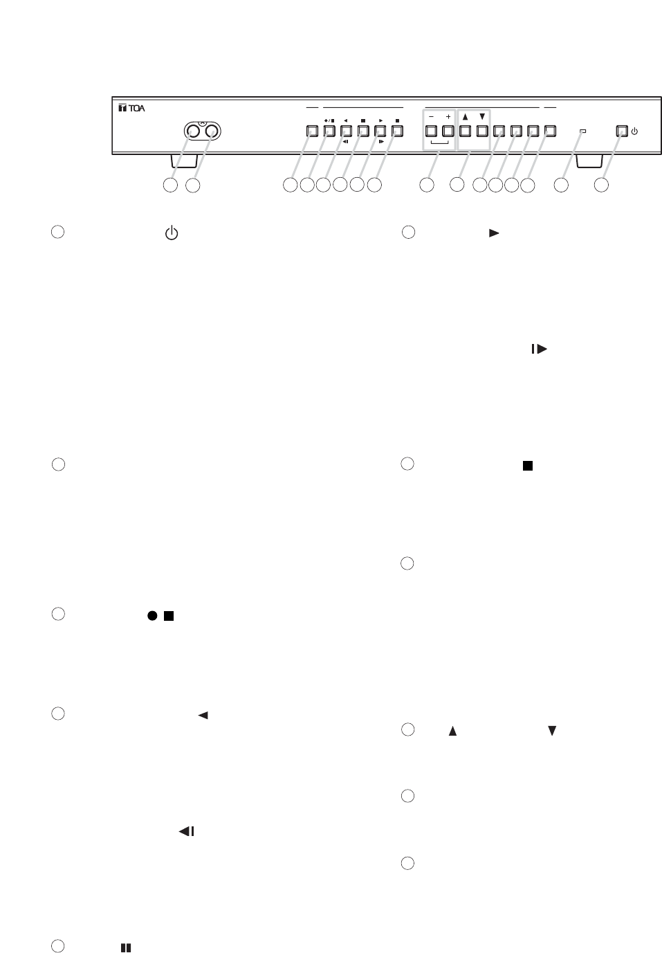
5. NOMENCLATURE AND FUNCTIONS
[Front Panel]
Standby Key [ ]
Pressing this switch while the main power is
supplied initiates a system check (the switch
flashes green) and activates the Digital Video
Recorder (the switch lights green). Holding down
this switch for 1 second or more places the
Recorder in standby mode, indicated by the
switch flashing every 5 seconds.
Note
Some time is required before the Recorder is
placed in standby mode after the main power has
been switched on. Ensure that the Recorder is in
standby mode before operating the standby key.
Timer Key
This key lights green when pressed, indicating
that the Recorder is in Internal Timer Recording
standby mode, which permits Internal Timer
Recording to be performed at preset times. To
cancel Internal Timer Recording, hold down the
Timer key for at least 1 second until its light
extinguishes.
Recording [ /] Key
This key lights red when pressed, indicating that
camera recording is in progress. To stop the
recording, hold down the Recording key for at
least 1 second until its light extinguishes.
Reverse Playback [ ] Key
Plays back recorded images in the reverse
direction. This key continuously lights green
during reverse playback. The playback speed
cycles through x1, x2, x4, and x8 with each
depression of this key.
Frame Reverse [ ] Key
Pressing this key while the Recorder is in
Playback Pause mode initiates a frame-by-frame
reverse playback of the recorded image. Holding
down this key performs a continuous frame-by-
frame playback in the reverse direction.
Pause [ ] Key
Temporary stops playback. This key continuously
lights green while in Playback Pause mode. If
pressed again, images are played back in the
same direction as before. (Playback speed
reverts to normal x1 speed.) When the Pause key
flashes green, this indicates that the Recorder is
in Time Shift Search mode.
Playback [ ] Key
Plays back recorded images in the forward
direction, and continuously lights green during
playback. The playback speed cycles through x1,
x2, x4, and x8 with each depression of the
Playback key.
Frame Advance [ ] Key
Pressing this key while the Recorder is in
Playback Pause mode initiates a frame-by-frame
playback of the recorded image. Holding down
this key performs a continuous frame-by-frame
playback in the forward direction.
Playback Stop [ ] Key
Stops playback operation.
Note
Current recording in progress does not stop even
if this key is pressed.
[ +] and [ –] Set Keys
Used to change setting values on the menu or
search screen.
Block Shift Key
Pressing the (+) key during playback shifts the
recorded image block to the next block in the
forward direction, while the (–) key shifts to the
preceding block.
Up [ ] and Down [ ] Shift Keys
Used to move the cursor on the menu or search
screen.
Select Key
Selects items or choices on the menu or search
screen.
Menu Key
Hold down this key for 1 second or more to
display the main menu screen on the monitor.
Pressing this key during playback stops playback
operation to display the main menu screen. The
main menu screen can also be displayed even
while recording is in progress, however some
items cannot be set during recording. If this key is
pressed during item selection, the displayed
setting contents are set and confirmed, returning
the display to the previous screen.
11
10
9
8
7
6
5
4
3
2
1

9
Search Key
Displays the search screen on the monitor.
Pressing this key during playback stops playback
operation to display the search screen. If pressed
while in Playback Pause mode, the Time Shift
Search screen is displayed. To exit the search
screen, press this key again.
Buzzer Stop Key
This key flashes red when an alarm is activated,
and the Recorder’s built-in buzzer is sounded to
provide both visual and audio alarm warnings.
After Alarm Recording completion, the key
changes to steady ON (red). Press this key to
stop the buzzer. The buzzer can be disabled by
selecting "OFF" for Buzzer in the Alarm
Recording Settings. (Refer to p. 19.)
Alarm Reset Key
Hold down this key for 1 second or more to reset
alarm operation and stop Alarm Recoding.
Disk Full/Failure Indicator
Disk Full Indicator
When the Recording mode is set to "STOP" or
"SERIES" in the Disk Setting, the indicator
flashes whenever less than 1 hour of available
hard disk time remains, and changes to steady
ON if no available time remains.
Failure Indicator
This indicator lights red when the Recorder fails,
and extinguishes when the cause of the failure is
removed. This failure indication takes precedence
over the Disk Full indication, should both be
enabled at the same time. Possible Failure
Causes: Hard disk failure, fan failure, and video
loss.
Note
If the Recorder should indicate a failure, first
check for the cause by switching the power OFF,
then contact your TOA dealer if unable to solve
the problem.
Video Output Terminal
Used for dubbing recorded video images. This
terminal is the same as the Video Output
Terminal located on the rear panel.
Audio Output Terminal
Used for dubbing recorded audio signals. This
terminal is the same as the Audio Output
Terminal located on the rear panel.
16
15
14
13
12
10
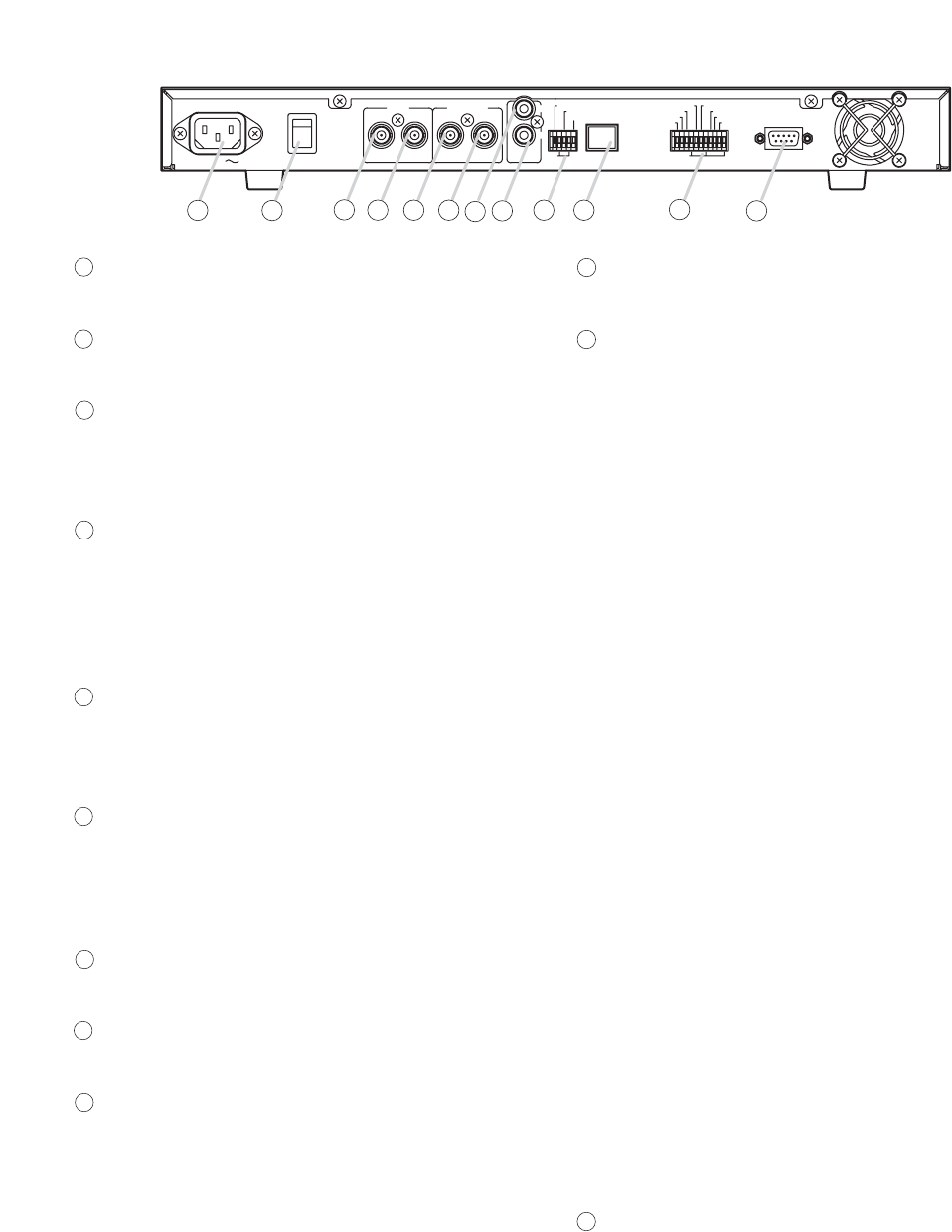
AC MAINS MAIN POWER
ON
OFF
IN OUT IN OUT
VIDEO SW VIDEO IN
OUT
AUDIO
GND GND
100BASE–TX
ALARM RESET OUT
ALARM IN
SW CTRL OUT
TIME SYNC IN
REC STOP IN
REC START IN
ALARM RESET IN
TIME SYNC OUT
ALARM OUT
FAILURE OUT
DISK FULL OUT
RS–232C
21 22 23 24 25 26 27 28
18 19
17
20
AC Inlet
Connect the supplied power cord to this socket.
Main Power Switch
Power switch for the Digital Video Recorder.
Video Input Terminal
Receives video signals. Connect the Multi-
switcher’s VCR output to this terminal when
connecting the Multi-switcher.
Video Output Terminal
Sends out video signals. Connect this terminal to
the Multi-switcher’s VCR input when connecting
the Multi-switcher. If the Multi-switcher is not
used, connect this terminal to the monitor to
transmit video signals to the monitor.
Switcher Video Input Terminal
Connect the Multi-Switcher’s monitor output to
this terminal. This terminal is not used if the Multi-
switcher is not connected.
Switcher Video Output Terminal
In the system in which the Multi-switcher is
connected, connect this terminal to the monitor to
transmit video signals to the monitor. Do not use
this terminal if the Multi-switcher is not connected.
Audio Input Terminal
Receives audio signals from the drive unit, etc.
Audio Output Terminal
Sends out audio signals to the monitor, etc.
Control Input/Output Terminal
Alarm Reset Output Terminal
Shorts to the ground terminal when the
Recorder’s alarm is reset.
Alarm Input Terminal
Activates an alarm by way of external sensors.
Alarm Input mode can be changed by the
Recording Setting’s Alarm Recording Setting.
Ground Terminal
Switcher Control Output Terminal
Connect this terminal to the Multi-switcher’s
switcher control input terminal.
100BASE-TX Terminal
RJ-45 terminal for Ethernet.
Control Input/Output Terminal
Alarm Reset Input Terminal
Used to permit external equipment to reset the
Recorder’s alarm operation. This terminal
provides the same operation as the front panel-
mounted Alarm Reset key.
Recording Start Input Terminal
Used to permit external equipment to initiate
recording. When the Disk Setting’s Disk Mode is
set to "SERIES," even if the Recorder’s disk is
full, the Disk Full status is reset and recording is
started.
Recording Stop Input Terminal
Used to stop recording at external equipment.
This terminal provides the same operation as the
front panel-mounted Recording key.
Time Sync Input/Output Terminals
Synchronize multiple Digital Video Recorders with
that of a specified recorder (master unit) when
two or more recorders are used. Connect the
master unit’s output to the slave unit’s input.
Alarm Output Terminal
Shorts to the ground terminal when an alarm is
activated.
System Failure Output Terminal
Shorts to the ground terminal when the hard disk
or fan failure or Video Loss occurs.
Disk Full Output Terminal
Shorts to the ground terminal when no available
hard disk time remains.
RS-232C Terminal
Connect this terminal to a computer’s RS-232C
terminal when controlling the Recorder at the
computer. Connect this terminal to the Multi-
switcher’s RS-232C terminal to synchronize the
Recorder with the Multi-switcher. (This terminal
can be connected to any of the C-MS91D, C-
MS161D Multi-switchers.)
*Ratings and serial numbers are indicated on the
bottom surface.
28
27
26
25
24
23
22
21
20
19
18
17
[Rear Panel]
ALARM REC SETTING
ALARM SETTING
[ VALID]
ALARM IN MODE [ EDGE]
PRE–ALARM [20SEC]
ALARM PERIOD [10SEC]
POST–ALARM [10SEC]
PICTURE [LEVEL3]
AUDIO [ ON]
REC INTERVAL [1/30SEC]
BUZZER [ ON]
ALARM OUT [DURING REC]
11
MAIN MENU
•
PLAY SETTING
CLOCK SETTING
DISK SETTING
REC SETTING
ON–SCREEN DISP SETTING
KEY LOCK
COMMUNICATION SETTING
LOG DISPLAY
SYSTEM MAINTENANCE
MAIN MENU
PLAY SETTING
CLOCK SETTING
DISK SETTING
•
REC SETTING
ON–SCREEN DISP SETTING
KEY LOCK
COMMUNICATION SETTING
LOG DISPLAY
SYSTEM MAINTENANCE
REC SETTING
•
GENERAL REC SETTING
TIMER REC SETTING
ALARM REC SETTING
REC SETTING
GENERAL REC SETTING
TIMER REC SETTING
•
ALARM REC SETTING
REC SETTING
•
GENERAL REC SETTING
TIMER REC SETTING
ALARM REC SETTING
MAIN MENU
•
PLAY SETTING
CLOCK SETTING
DISK SETTING
REC SETTING
ON–SCREEN DISP SETTING
KEY LOCK
COMMUNICATION SETTING
LOG DISPLAY
SYSTEM MAINTENANCE
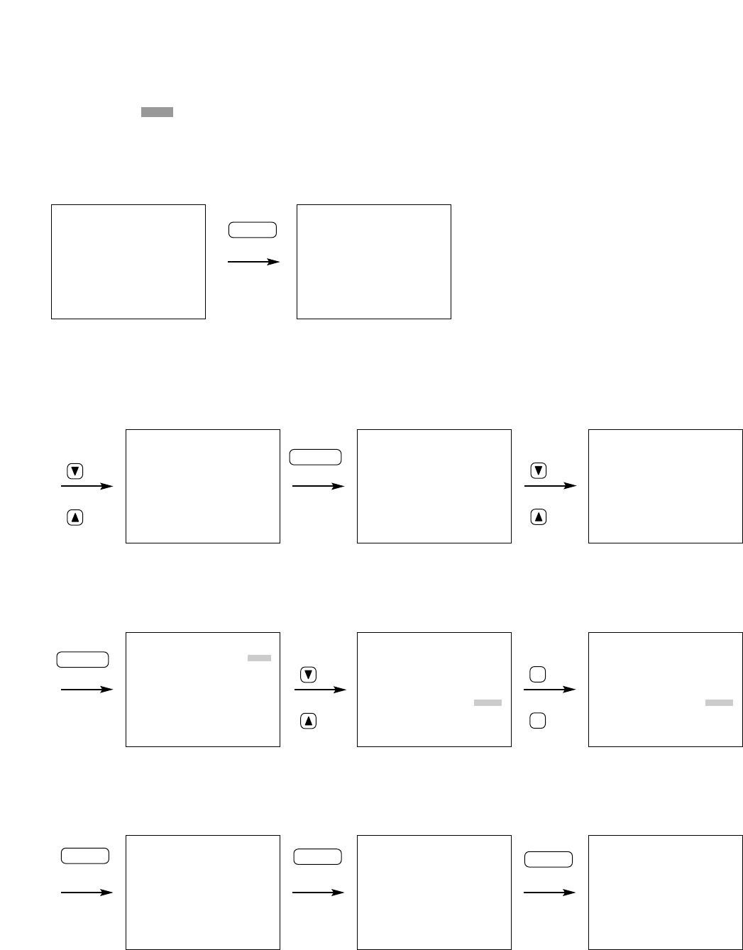
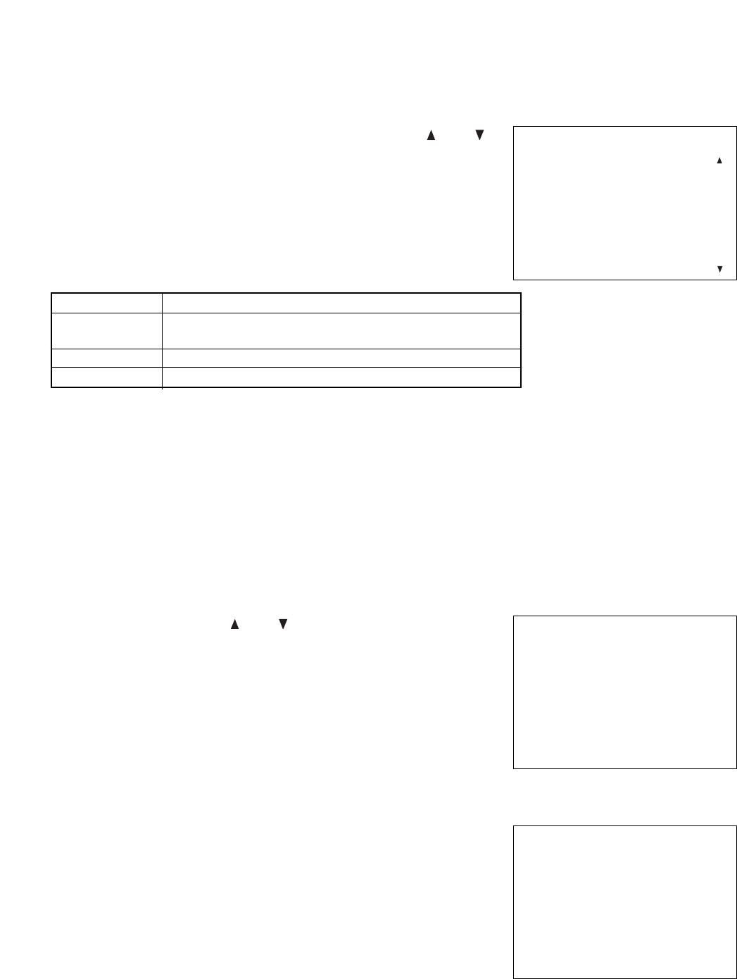
2. Enter the setting screen.
3. Select the setting value.
4. Confirm the selected setting value and return to the camera display screen.
Camera Display Screen Main Menu Screen
Setting screen
Camera Display Screen
ALARM REC SETTING
ALARM SETTING
[ VALID]
ALARM IN MODE [ EDGE]
PRE–ALARM [20SEC]
ALARM PERIOD [10SEC]
POST–ALARM [10SEC]
PICTURE [LEVEL1]
AUDIO [ ON]
REC INTERVAL [1/30SEC]
BUZZER [ ON]
ALARM OUT [DURING REC]
Press key for 1
second or more
MENU
key
+key
key
SELECT
key
THU JAN/01/04
00:00:00
THU JAN/ 01/ 04
00:00:00
or
key
or
-
key
ALARM REC SETTING
ALARM SETTING
[ VALID]
ALARM IN MODE [ EDGE]
PRE–ALARM [20SEC]
ALARM PERIOD [10SEC]
POST–ALARM [10SEC]
PICTURE [LEVEL3]
AUDIO [ ON]
REC INTERVAL [1/30SEC]
BUZZER [ ON]
ALARM OUT [DURING REC]
6. SETTING ITEM CHART AND SETTING PROCEDURES
6.1. Basic Setting Procedures
• The shaded item in the figure refers to the cursor position.
1. Enter the main menu screen.
SELECT
key
key
or
key
key
or
key
MENU
key
MENU
key
MENU
key
12
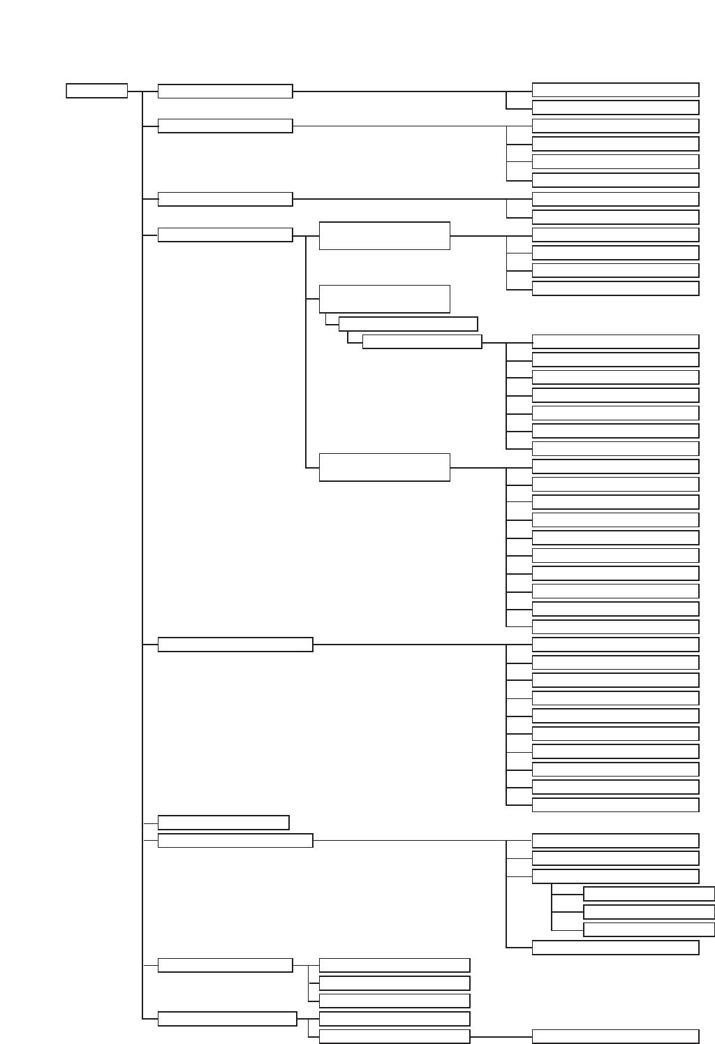
Main Menu
Playback Settings (p. 13)
Clock Settings (p. 14)
Disk Settings (p. 15)
Recording Settings (p. 16)
Screen Display Settings (p. 21)
Key Lock (p. 22)
Communication Settings (p. 23)
Log Display (p. 24)
Playback Mode
Simultaneous Recording/Playback
Year/Month/Day
Main Menu Item Menu Item Setting Item
Disk Mode
Recording Mode
Picture Quality
Audio
Recording Intervals
Switcher Control Period
Recoding Start Date
Preset Time
Picture Quality
Audio
Recording Intervals
Recording Pattern
Motion Detection Pattern
Alarm Settings
Alarm Input Mode
Pre-Alarm Recording Periods
Alarm Recording Periods
Post-Alarm Recording Periods
Picture Quality
Audio
Recording Intervals
Buzzer Sound
Alarm Output Time
Picture Quality Indication
Audio ON/OFF Indication
Recording Mode Indication
Recording Indication
Playback Indication
Remaining Time Indication
Date Indication
Time Indication
Date/Time Display Position
Disk Mode Indication
RS232C Baud Rate
RS232C Flow Control
Network Settings
Switcher Synchronization
Disk Selection
IP Address
Subnet Mask
Default Gateway
General Recording
Settings (p. 17)
Internal Timer Recording
Settings (p. 17)
General/Timer Recording Log
Alarm Recording Log
Failure Log
Menu Default Settings
Disk Formatting
Timer Setting List
Timer Setting 01–10
Time Synchronization
Synchronization Time
Alarm Recording Settings
(p. 19)
System Maintenance (p. 25)
*
*
*
Summer Time
6.2. Setting Item Chart
* This setting item is applicable to the C-DR0101 and C-DR0105 Recorder, and not displayed on the screen
when the C-DR0100 Recorder is used.
13
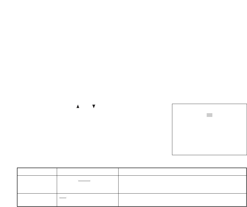
Setting Value ContentsSetting Item
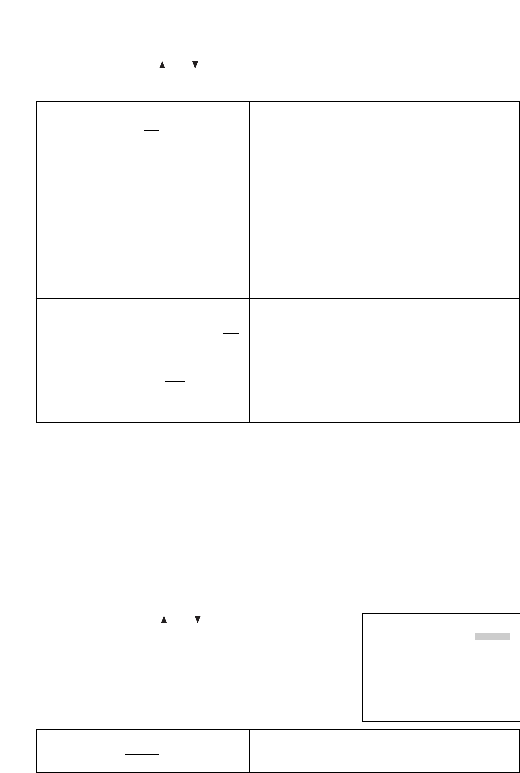
7.2. Playback Settings
Playback mode settings are only available to the C-DR0101 and C-DR0105, and not displayed when the C-
DR0100 is used.
PLAY MODE : Sets the hard disk to be used for playback and search functions.
SIMUL REC/PLAY : Selects "ALLOW" or "DISALLOW" for simultaneous recording and playback operations.
• Move the cursor with the ( ) or ( ) key, and change setting values
with the (–) or (+) key.
• Confirm the setting with the Menu key, and return to the previous
screen.
• Each setting item and its setting value and contents are as shown in
the table below.
PLAY MODE
(Playback Mode)
(C-DR0101, DR0105)
SIMUL REC/PLAY
(Playback during
Recording)
ALL : All set hard disks are used for playback.
HDD-A : Hard disk drive A is used for playback.
HDD-B : Hard disk drive B is used for playback.
ALLOW : Allows playback while recording.
DISALLOW : Disallows playback while recording.
ALL / HDD-A / HDD-B
ALLOW / DISALLOW
PLAY SETTING
PLAY MODE [ ALL]
SIMUL REC/ PLAY
[ ALLOW]
* The underlined contents are factory-preset values.
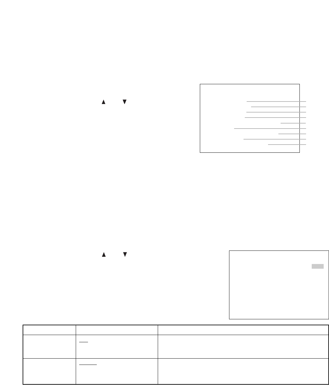
• Select the desired item from 9 main menu items on the
main menu screen.
• Move the cursor with the ( ) or ( ) key, and display each
setting screen with the Select key.
MAIN MENU
•
PLAY SETTING
CLOCK SETTING
DISK SETTING
REC SETTING
ON–SCREEN DISP SETTING
KEY LOCK
COMMUNICATION SETTING
LOG DISPLAY
SYSTEM MAINTENANCE
Refer to P.13
Refer to P.14
Refer to P.15
Refer to P.16
Refer to P.21
Refer to P.22
Refer to P.23
Refer to P.24
Refer to P.25
Note
Be sure to first perform Clock Settings (Refer to p. 14) before performing each setting.
7. INDIVIDUAL ITEM SETTINGS
7.1. Main Menu Screen
Hold down the Menu key for 1 second or more on the screen displaying the camera to display the Main
Menu screen.
CLOCK SETTING
THU JAN / 01 / 04 00:00:00
TIME SETTING : SELECT KEY
TIME SYNC [ SLAVE]
SYNC TIME [00H]
SUMMER TIME SETTING
<CURRENT TIME>
THU JAN / 01 / 04 00:00:00
14
7.3. Clock Settings
Set the date and time. Perform this setting when the Recorder is used for the first time or when the date and
time indication has been deleted because the power was switched off for a long period of time.
Note
• Previously logged data times are not updated even if the Clock Settings are changed during use.
• The data times will be lost if the power was switched off for 30 days or more. Set the date and time again.
Memory backup: 720 hours (fully charged)
TIME SYNC : Synchronizes the times of other Recorders (slave units) with that of a specified Recorder
(master unit) when multiple Recorders are used.
SYNC TIME : Sets the synchronization time.
Note
The Time Sync function cannot be operated during recording.
• Move the cursor with the ( ) or ( ) key, and change setting values
with the (–) or (+) key.
• After completing the settings of time (hour, minute, second), confirm
the time with the Select key.
• The indication "Clock Setting Completed" is displayed on the screen
after setting completion.
• Current time is displayed in the lowest part of the screen.
• Confirm the setting with the Menu key, and return to the previous
screen.
• Each setting item and its setting value and contents are as shown in
the table below.
Setting Value Contents
Setting Item
TIME SYNC
(Time
Synchronization)
SYNC TIME (Synch-
ronization Time)
MASTER: Designates the master unit.
SLAVE: Designates the slave unit.
Select and set the synchronization time.
MASTER / SLAVE
00H / 01H / 02H / 03H / 04H / ...
up to 23H
* The underlined contents are factory-preset values.
Note
Setting the Time Sync settings to "SLAVE," and the Disk Setting’s Disk Mode to "SERIES" places the
Recorder in Disk Full mode, causing the Disk Full indicator to light. Perform this setting when using Series
Recording. Refer to p. 41; Expansion System (Series Recording).
15
Setting Value Contents
Setting Item
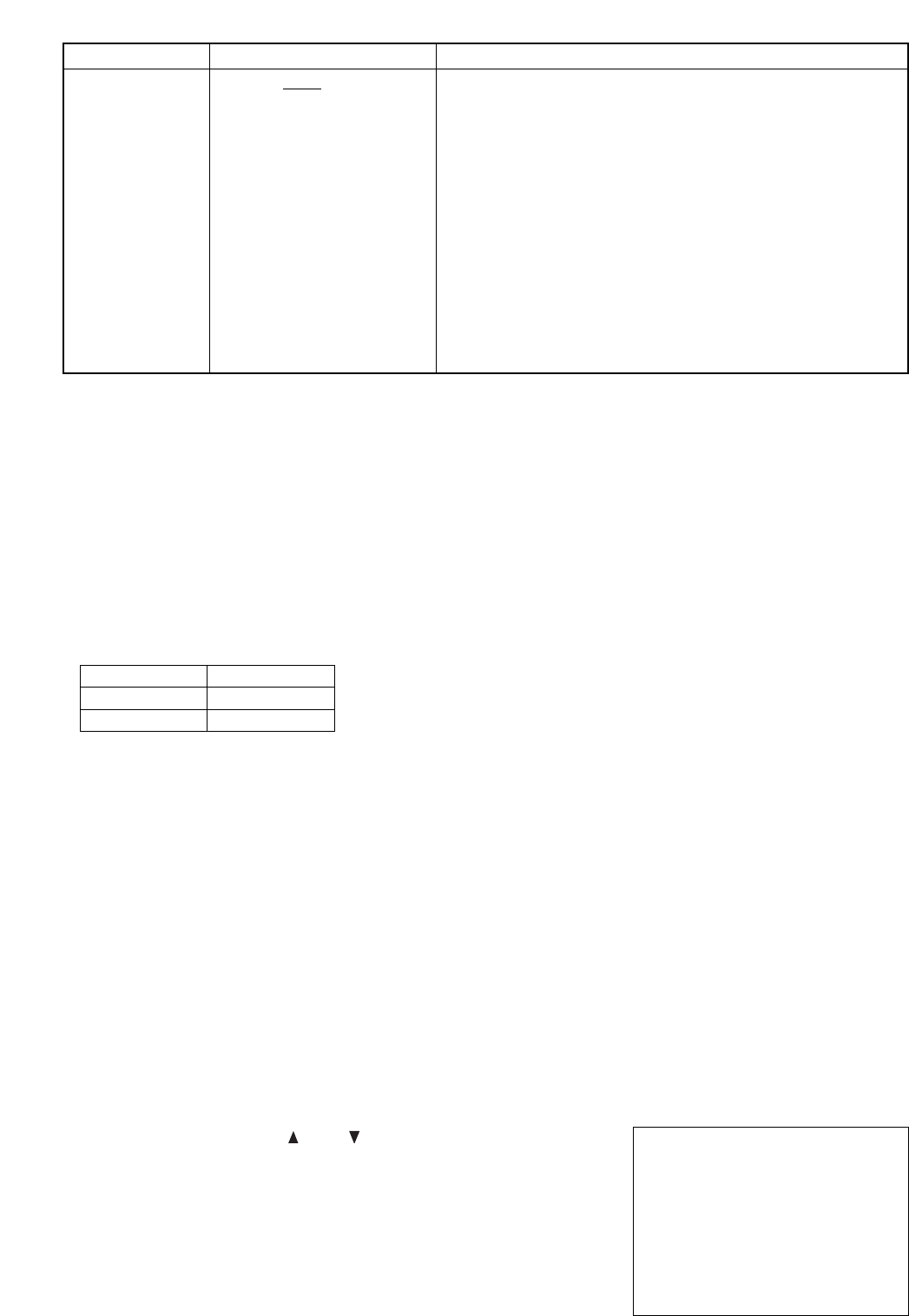
7.4. Disk Settings
Disk Mode Settings are only available to the C-DR0101, and not displayed when the C-DR0100 is used.
DISK MODE : Sets the hard disk recording method.
REC MODE : Selects "RE-REC","STOP," or "SERIES" for hard disks.
• Move the cursor with the ( ) or ( ) key, and change setting values
with the (–) or (+) key.
• Confirm the setting with the Menu key, and return to the previous
screen.
• Each setting item and its setting value and contents are as shown in
the table below.
DISK MODE
(C-DR0101, C-DR0105)
NORMAL : Records continuously on each hard disk.
MIRRORING: Recording is performed simultaneously on the 2 hard disks.
NORMAL /
MIRRORING
DISK SETTING
DISK MODE [ NORMAL]
REC MODE [ STOP]
PLAY CHANGED TO " ALL "
7.3.1. Summer Time (Daylight Saving Time) Setting
Summer Time Setting screen is displayed if Summer Time Setting is selected on the Clock Setting screen.
• Move the cursor with the ( ) or ( ) key, and change setting values with the (–) or (+) key.
• Confirm the setting with the Menu key, and return to the previous screen.
• Each setting item and its setting value and contents are as shown in the table below.
Setting Value Contents
Setting Item
SUMMER TIME
SETTING
SUMMER TIME
FIRST DAY
SUMMER TIME
LAST DAY
ON : Displays the current date and time by automatically shifting the time
from standard local time to summer time and from summer to
standard time.
OFF : Displays the current date and time having nothing to do with the
summer time.
Sets the time to shift to the summer time.
Select the "Month" and "Which Sunday" and "What time"
Sets the time to shift back to the standard local time.
Select the "Month" and "Which Sunday" and "What time"
ON / OFF
Month :
JAN / FEB / MAR / APR / MAY /
JUN / JUL / AUG / SEP / OCT /
NOV / DEC
Which Sunday :
FIRST / SECOND / THIRD /
FOURTH / LAST
What time :
00H / 01H / 02H / 03H / 04H / ...
up to 23H
Month :
JAN / FEB / MAR / APR / MAY /
JUN / JUL / AUG / SEP / OCT /
NOV / DEC
Which Sunday :
FIRST / SECOND / THIRD /
FOURTH / LAST
What time :
00H / 01H / 02H / 03H / 04H / ...
up to 23H
*The underlined contents are factory-preset values.
Example
(1) If the FIRST DAY time is set to "02H", then at 2:00 AM on the first day of summer time the clock will be
advanced one hour to 3:00 AM.
(2) If the LAST DAY time is set to "02H", then at 2:00 AM on the first day of summer time the clock will be
setback one hour to 1:00 AM.
16
Note
• Avoid mixing both Normal Recordings and Mirroring Recordings on the hard disk. If mixed, block advance
during playback or search operations cannot be correctly performed during playback. Be sure to re-format
the disk when changing the Disk Mode Setting. Note that all recording data are deleted when formatted.
(Refer to p. 26; "Disk Formatting.")
• Setting the Clock Setting’s Time Sync to "SLAVE" and the Recording Mode to "SERIES" places the
Recorder in Disk Full mode and causes the Disk Full indicator to light. Perform this setting when using the
Series Recording function. (Refer to p. 41; "Expansion System (Series Recording).")
• When the Recording mode is set to "SERIES," timer program cannot be perfomed.
• If the Disk Mode is changed, the Playback Mode changes as follows and the screen indicates that the
Playback Mode has changed. (C-DR0101, C-DR0105)
DISK MODE
NORMAL
MIRRORING
PLAY MODE
ALL
HDD-A
The disk to be used is set to HDD-B if "HDD-B" is selected in the Playback Mode settings. To set to the
"HDD-A" disk again, set the Disk mode to "MIRRORING."
• About Mirroring Recording. (C-DR0101, C-DR0105)
Setting the Disk Mode to "MIRRORING" permits the same recording to be performed simultaneously on the
two built-in hard disks. Should one of the two disks fail, the other disk will continue recording or playing back
to ensure automatic backup. Be sure to first format both disks before performing Mirroring Recording to
make their available recording times equal.
When a difference in available recording time between the two disk drives exists, recording can continue if
one of the two disks becomes full, provided recording time remains available on the other disk. However,
this will no longer be Mirroring Recording. The maximum available Mirroring Recording time can be checked
by setting the remaining time display to "MIN."
7.5. Recording Settings
Set individual recording conditions for General Recording, Internal Timer Recording, and Alarm Recording.
• Move the cursor with the ( ) or ( ) key, and display the selected
setting screen with the Select key.
• Confirm the selected setting with the Menu key, and return to the
previous screen.
REC SETTING
•
GENERAL REC SETTING
TIMER REC SETTING
ALARM REC SETTING
Setting Value Contents
Setting Item
REC MODE
(Recording Mode)
RE-REC: Automatically deletes old recordings in chronological order to
overwrite the hard disk.
STOP: Performs no further recording to save previously recorded data
if no available hard disk time remains.
The Disk Full indicator flashes red whenever less than 1 hour of
available hard disk time remains, and changes to steady ON
(Indecator lights red) if no available time remains.
Selecting "RE-REC" in the menu resets the Disk Full mode and
causes the Disk Full indicator to extinguish.
SERIES: The Recorder stops and sends out a signal from its rear panel-
mounted Disk Full Output terminal if no available hard disk time
remains. If the Recorder receives a signal at its Recording Start
input terminal when it is in Disk Full mode, the Disk Full mode is
reset, causing the Disk Full indicator to extinguish.
RE-REC / STOP / SERIES
* The underlined contents are factory-preset values.
17
• Move the cursor with the ( ) or ( ) key, and press the Select Key.
The Timer Schedule Screen is displayed.
• Confirm the setting with the Menu key, and return to the previous
screen.
7.5.2. Internal Timer Recording Settings
If Internal Timer Recording Settings is selected, the Timer Setting List screen is displayed.
Up to 10 timer programs can be set individually.
Move the cursor to the desired program and press the Select key. The Timer Schedule screen is then
displayed.
* The underlined contents are factory-preset values.
• Move the cursor with the ( ) or ( ) key, and change setting values
with the (–) or (+) key.
• Confirm the setting with the Menu key, and return to the previous
screen.
• Each setting item and its setting value and contents are as shown in
the table below.
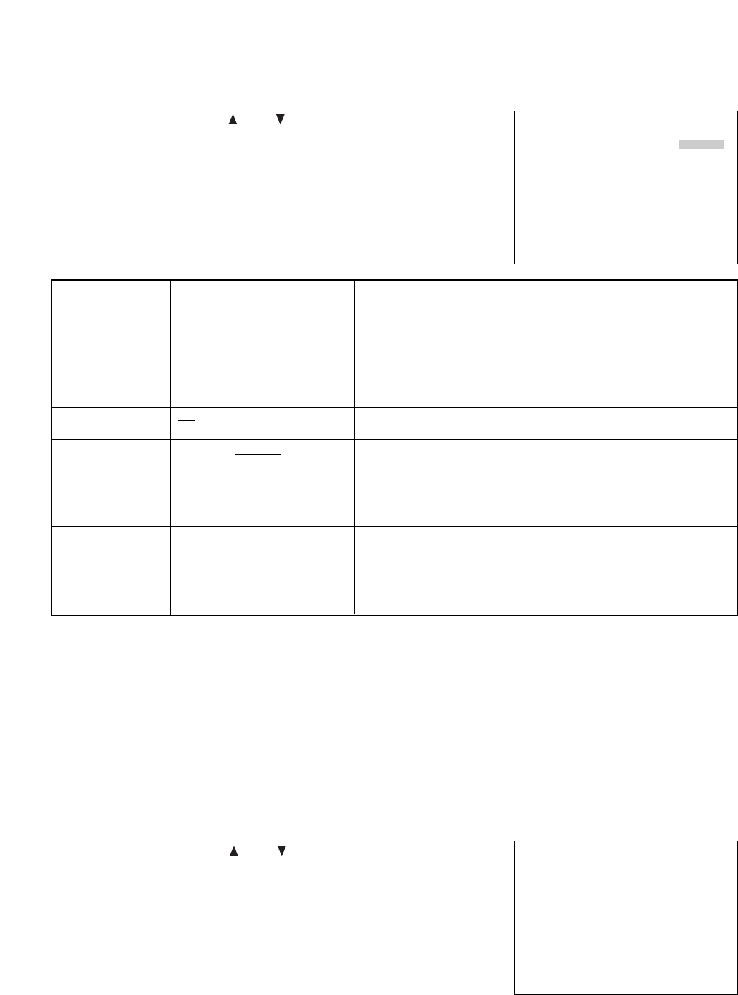
7.5.1. General Recording Settings
Set the recording conditions for General Recording.
GENERAL REC SETTING
PICTURE QUALITY [LEVEL3]
AUDIO [ ON]
REC INTERVAL [1/30SEC]
SW CTRL PERIOD [01]
Setting Value Contents
Setting Item
PICTURE QUALITY
AUDIO
REC INTERVAL
(Recording Intervals)
SW CTRL PERIOD
(Used for switching
cameras by means
of the sequential
switcher, etc.)
LEVEL1 : Angle of view 720 x 240 file size : 64KB (High Picture Quality )
LEVEL2 : Angle of view 720 x 240 file size : 40KB
LEVEL3 : Angle of view 720 x 240 file size : 32KB
LEVEL4 : Angle of view 720 x 240 file size : 24KB
LEVEL5 : Angle of view 720 x 240 file size : 16KB
(Standard Picture Quality)
ON: Records audio sound simultaneously during recording.
OFF: Records no audio sound during recording.
Sets recording intervals.
Setting the Disk Setting’s Disk Mode to "MIRRORING" limits the
maximum recording interval to 1/30 second. Even if set to "1/60 SEC," the
actual recording interval is 1/30 second, and the "1/30 SEC" indication is
displayed on the screen. (C-DR0101, C-DR0105)
Set the camera switching signal period.
The camera switching signal is provided from the Switcher Control Output
at time intervals of recording interval x switching period to switch
cameras. This setting is common to all Recording Modes of General
Recording, Internal Timer Recording, and Alarm Recording.
LEVEL1 / LEVEL2 / LEVEL3 /
LEVEL4 / LEVEL5
ON / OFF
1/60SEC / 1/30SEC / 1/15SEC /
1/10SEC / 1/5SEC / 1/3SEC /
1/2SEC / 1SEC / 2SEC / 3SEC /
5SEC /10SEC / 20SEC / 30SEC /
60SEC
01 / 02 / 03 / 04 / 05 / 10 / 15 / 20/
30 / 60
TIMER SETTING LIST
START – END
•
JAN / 01 / 04 00 : 00 ~ 10 : 00
SM – W – F – 12 : 34 ~ 23 : 45
––– / –– / –– –– : –– ~ –– : ––
––– / –– / –– –– : –– ~ –– : ––
––– / –– / –– –– : –– ~ –– : ––
––– / –– / –– –– : –– ~ –– : ––
––– / –– / –– –– : –– ~ –– : ––
––– / –– / –– –– : –– ~ –– : ––
––– / –– / –– –– : –– ~ –– : ––
––– / –– / –– –– : –– ~ –– : ––
18
* The underlined contents are factory-preset values.
• Move the cursor with the ( ) or ( ) key, and change setting values
with the (–) or (+) key.
• Confirm the setting with the Menu key, and return to the previous
screen.
• Each setting item and its setting value and contents are as shown in
the table below.
Setting Value Contents
Setting Item
DATE
(Recording Start
Date)
TIME
(Preset Times)
PICTURE QUALITY
AUDIO
REC INTERVAL
(Recording Intervals)
REC PATTERN
(Recording Pattern)
MOTION DETECT
PTN (Motion
Detection Pattern)
DAILY : Designates the Internal Timer Recording date. Timer
schedules can be set for any time between the current time to
one year ahead. The day of the week is automatically
displayed. Programs are automatically deleted after their
preset times are reached.
WEEKLY: Designates two or more days of the week. If all days from
Sunday to Saturday are designated, recording is performed
every day.
CANCEL : Cancels preprogrammed settings.
Designates the timer operating period in minutes. If the same timer preset
time is duplicated, the "TIME SETTING ERROR" indication is displayed
on the screen to the right side of the program number, invalidating the
date setting. In such cases, correctly reset the time. Note that the timer
operating period cannot be set unless the complete time (hour and
minute) is entered.
LEVEL1 : Angle of view 720 x 240 file size : 64KB (High Picture Quality)
LEVEL2 : Angle of view 720 x 240 file size : 40KB
LEVEL3 : Angle of view 720 x 240 file size : 32KB
LEVEL4 : Angle of view 720 x 240 file size : 24KB
LEVEL5 : Angle of view 720 x 240 file size : 16KB
(Standard Picture Quality)
ON: Records audio sound simultaneously during recording.
OFF: Records no audio sound during recording.
Designates the Recording intervals.
Setting the Disk Setting’s Disk Mode to "MIRRORING" limits the
maximum recording interval to 1/30 second. Even if set to "1/60 SEC," the
actual recording interval is 1/30 second, and the "1/30 SEC" indication is
displayed on the screen (C-DR0101, C-DR0105)
Transmits a Pattern Selection command from the RS-232C connector
when the preset timer operating time is reached.
Transmits a Pattern Selection command from the RS-232C connector
when the preset timer operating time is reached.
DAILY / WEEKLY / CANCEL
LEVEL1 / LEVEL2 / LEVEL3 /
LEVEL4 / LEVEL5
ON / OFF
1/60SEC / 1/30SEC / 1/15SEC /
1/10SEC / 1/5SEC / 1/3SEC /
1/2SEC / 1SEC / 2SEC / 3SEC /
5SEC /10SEC / 20SEC / 30SEC /
60SEC
1/ 2
1/ 2
TIMER SETTING 01
DATE
[DAILY] THU JAN / 01 / 04
TIME 00 : 00 – 10 : 00
PICTURE QUALITY [LEVEL3]
AUDIO [ON]
REC INTERVAL [1/30SEC]
REC PATTERN [1]
MOTION DETECT PTN [1]
Timer Schedule Screen Settings
Note
Pattern 1 command of both the Recording Pattern and Motion Detection Pattern is transmitted from the RS-
232C connector at times other than timer set times such as power-on, after Internal Timer Recording
completion, and during General Recording.
Recording Pattern and Motion Detection Pattern are functions available to the Multi-switcher (C-MS91D, C-
MS161D). For more information on these functions, refer to the instruction manual for the Multi-switcher.
Program No
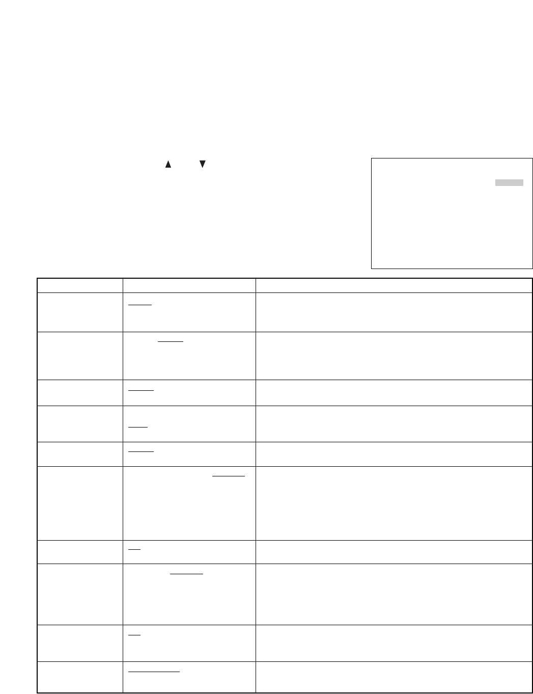
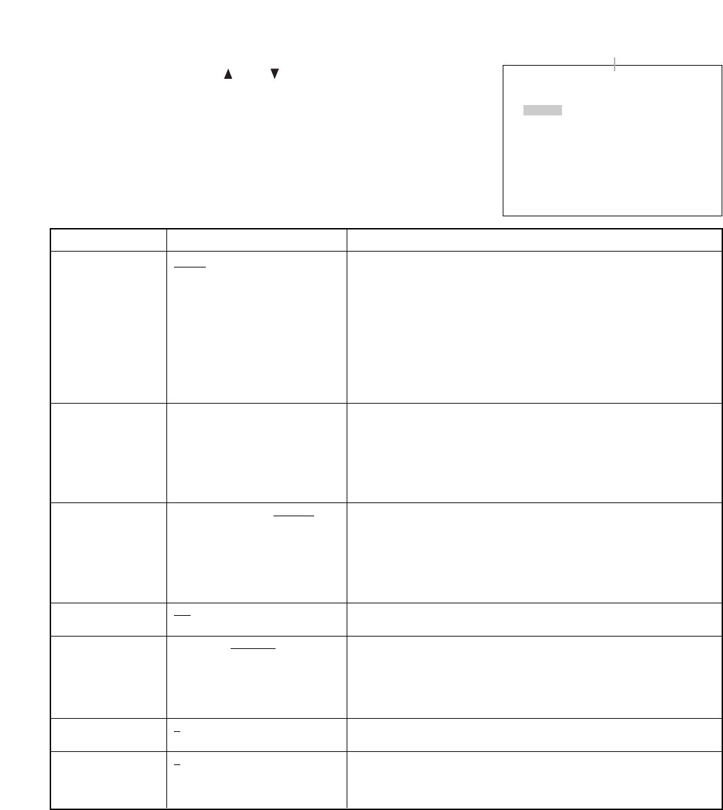
ALARM REC SETTING
ALARM SETTING [ VALID]
ALARM IN MODE [LEVEL]
PRE–ALARM [00SEC]
ALARM PERIOD [ 1MIN]
POST–ALARM [00SEC]
PICTURE QUALITY [LEVEL3]
AUDIO [ ON]
REC INTERVAL [1/30SEC]
BUZZER [ ON]
ALARM OUT [DURING REC]
19
Setting Value Contents
Setting Item
ALARM SETTING
ALARM IN MODE
(Alarm Input Mode)
PRE-ALARM
ALARM PERIOD
POST-ALARM
PICTURE QUALITY
AUDIO
REC INTERVAL
(Recording Interval)
BUZZER
ALARM OUT (Alarm
Output Periods )
VALID : Validates alarm settings. (Alarm standby mode)
VAL REC : Validates alarm settings only during recording.
INVALID : Invalidates alarm settings. (Rejects alarm inputs.)
EDGE : Performs recording during preset Pre-alarm and Alarm
Recording periods
LEVEL : Performs recording during preset Pre-alarm Recording, Alarm
input, and Post-alarm Recording periods.
Performs retroactive recording to a preset time period before alarm
activation.
Performs recording during a preset alarm input period following alarm
activation when the Alarm Input Mode is set to EDGE. (Refer to p. 20;
"About the Alarm Input Mode")
Performs recording during a preset Post-alarm recording period following
the end of alarm activation when the alarm input mode is set to "LEVEL."
LEVEL1 : Angle of view 720 x 240; file size : 64KB (High Picture Quality)
LEVEL2 : Angle of view 720 x 240; file size : 40KB
LEVEL3 : Angle of view 720 x 240; file size : 32KB
LEVEL4 : Angle of view 720 x 240; file size : 24KB
LEVEL5 : Angle of view 720 x 240; file size : 16KB
(Standard Picture Quality)
ON: Records audio sound simultaneously during recording.
OFF: Records no audio sound during recording.
Sets the Recording intervals.
Setting the Disk Mode of Disk Settings to "MIRRORING" limits the
maximum recording interval to 1/30 second. Even if set to "1/60 SEC", the
actual recording interval is 1/30 second, and the "1/30 SEC "indication is
displayed on the screen (C-DR0101, C-DR0105)
ON: Sounds a buzzer when an alarm is activated. Pressing the Buzzer
Reset key stops buzzer operation.
OFF: Sounds no buzzer during alarm activation.
The Alarm Output terminal shorts to ground during a set period of time
following alarm activation.
VALID / VAL REC / INVALID
EDGE / LEVEL
00SEC/ 10SEC/ 15SEC/ 20SEC /
30SEC/ 1MIN/ 2MIN/ 5MIN
10SEC/ 15SEC/ 20SEC/ 30SEC/
1MIN/ 2MIN/ 3MIN/ 4MIN/ 5MIN/
10MIN
00SEC/ 10SEC/ 15SEC/ 20SEC/
30SEC/ 1MIN/ 2MIN/ 5MIN
LEVEL1 / LEVEL2 / LEVEL3 /
LEVEL4 / LEVEL5
ON / OFF
1/60SEC / 1/30SEC / 1/15SEC /
1/10SEC / 1/5SEC / 1/3SEC /
1/2SEC / 1SEC /
ON / OFF
DURING REC / 1SEC
• Move the cursor with the ( ) or ( ) key, and change setting values
with the (–) or (+) key.
• Confirm the setting with the Menu key, and return to the previous
screen.
• Each setting item and its setting value and contents are as shown in
the table below.
7.5.3. Alarm Recording Settings
Alarm Recording has two Alarm Input modes "EDGE" and "LEVEL" and valid setting items differ depending on
each mode.
Alarm Mode set to "EDGE" : Alarm recording time settings are valid.
Post-alarm time settings are invalid.
Alarm Mode set to "LEVEL" : Alarm recording time settings are invalid.
Post-alarm time settings are valid.
(For more information, Refer to p. 20; "About the Alarm Input Mode.")
* The underlined contents are factory-preset values.
20
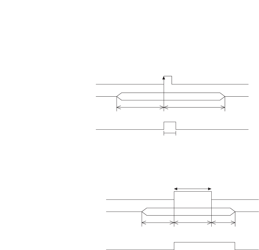
Alarm Input
Recording Status
Alarm Output
ON
Recording
When an alarm output duration is set to 1 second:
1 Sec
Pre-alarm Period Alarm Recording Period
Alarm Input
Recording Status
Alarm Output
ON
Recording
Pre-alarm Period
When an alarm output is provided durin
g
alarm recordin
g
:
Recording Period Post-alarm Period
7.5.4. About the Alarm Input Mode
The Alarm Input mode for Alarm Recording can be set to "EDGE" or "LEVEL."
Each input mode operates as follows:
[Recording period when input mode is set to "EDGE"]
Performs continuous recording during Pre-alarm Recording and Alarm Recording Periods.
[Recording period when input mode is set to "LEVEL"]
Provides continuous recording during periods of time of Pre-alarm Recording, alarm activation, and Post-
alarm Recording.
Note
Pre-alarm recording is operated by the Alarm Recording Setting. It does not operate even if an alarm is
activated during General Recording or Internal Timer Recording since they are operated by their own settings.
21
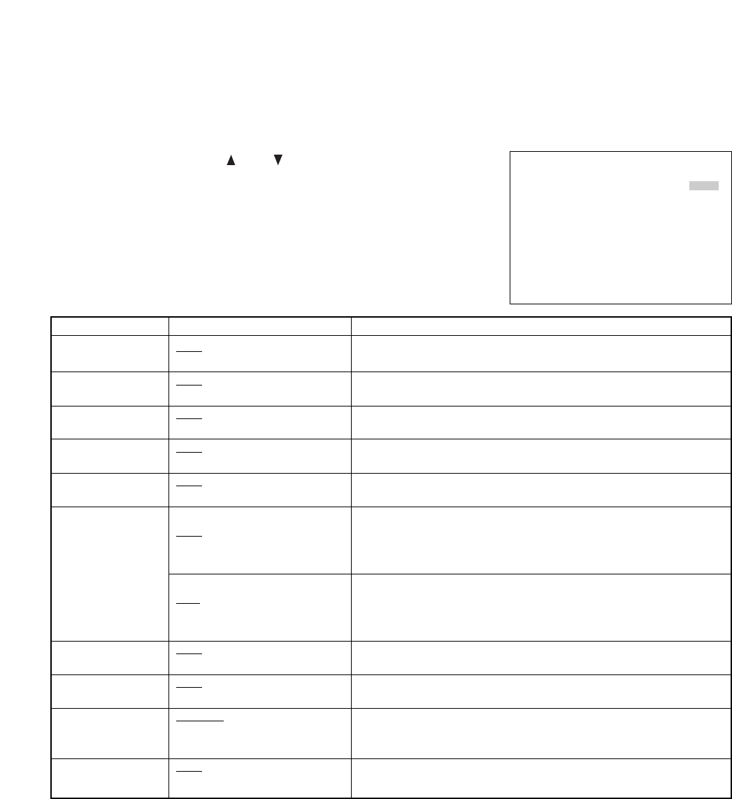
7.6. Screen Display Settings
The Disk Mode Display item is displayed when the C-DR0101 and C-DR0105 is used.
Set whether to display or hide on-screen characters during playback or recording.
• Move the cursor with the ( ) or ( ) key, and change setting values
with the (–) or (+) key.
• Confirm the setting with the Menu key, and return to the previous
screen.
• Each setting item and its setting value and contents are as shown in
the table below.
ON–SCREEN DISP SETTING
PICTURE QUALITY [DISP]
AUDIO [DISP]
REC MODE [DISP]
RECORDING [DISP]
PLAYING [DISP]
REMAINING TIME [ DISP]
DATE [DISP]
TIME [DISP]
TIME DISP POS [UPPER L]
DISK MODE [DISP]
Setting Value ContentsSetting Item
PICTURE QUALITY
AUDIO
REC MODE
(Recording Mode)
RECORDING
(Recording Display)
PLAYING (Playing
back Display)
REMAINING TIME
(Remaining Time
Display)
DATE
(Date Display)
TIME
(Time Display)
TIME DISP POS
(Date/Time Display
Position)
DISK MODE
(Disk Mode Display)
Displays or hides the picture quality indicator during recording or
playback.
Displays or hides the audio indicator when Audio is set to ON during
recording.
Displays or hides the overwrite recording setting status indicator during
recording.
Displays or hides the recording mode status indicator during recording.
Displays or hides the playback speed, playback direction, and pause
status during playback.
Displays or hides Digital Video Recorder's remaining time. The remaining
hard disk time is calculated from the currently recorded picture quality and
recording interval when the Disk Settings Recording Mode is set to
"STOP" or "SERIES."
Displays or hides Digital Video Recorder's remaining time. The remaining
hard disk time designated is calculated from the currently recorded picture
quality and recording interval when the Disk Settings Recording Mode is
set to "STOP" or "SERIES." (C-DR0101, C-DR0105)
Displays or hides the current date during recording, and the recorded date
during playback.
Displays or hides the current time during recording, and the recorded time
during playback.
Sets the date/time display position. Other display positions also change
depending on the date/time display position.
Displays or hides the disk connection status indicator. (C-DR0101, C-
DR0105)
DISP / HIDE
DISP / HIDE
DISP / HIDE
DISP / HIDE
DISP / HIDE
Disk Mode set to "NORMAL":
DISP / HIDE
Disk Mode set to "MIRRORING":
MAX / MIN / HDD-A /
HDD-B / HIDE
DISP / HIDE
DISP / HIDE
UPPER L/ UPPER C/ UPPER R/
LOWER L/ LOWER C/ LOWER R
DISP / HIDE
* The underlined contents are factory-preset values.

22
• Pressing the Menu key returns the display to the normal operation screen if the password is entered
correctly. If the wrong password is entered, the display returns to the Main Menu screen. In such cases,
perform the settings again.
• Entering the password correctly displays the following screen and
validates key locking. KEY LOCK
KEY LOCK VALIDATED.
• The following screen is displayed if the wrong password is entered. KEY LOCK
INVALID PASSWORD
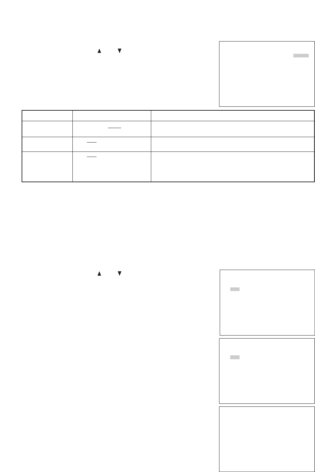
7.7.1 Key Lock Release
• Hold down the Menu key for at least 1 second on the normal
operation screen.
• The Key Lock Release screen is displayed.
KEY LOCK RELEASE
ENTER A PASSWORD.
[_]
• Entering the password correctly returns the display to the Main Menu
screen.
• If the wrong password is entered, the "INVALID PASSWORD"
indication is displayed as in the case of the Key Lock setting. Since
the display returns to the normal screen if the Menu key is pressed,
perform release operation.
MAIN MENU
•
PLAY SETTING
CLOCK SETTING
DISK SETTING
REC SETTING
ON–SCREEN DISP SETTING
KEY LOCK
COMMUNICATION SETTING
LOG DISPLAY
SYSTEM MAINTENANCE
7.7. Key Lock
This function validates key locking.
If validated, any key other than the Menu key is not accepted. Pressing keys other than the Menu key sounds
a warning tone.
KEY LOCK
ENTER A PASSWORD.
[_]
• The password input screen is displayed if Key Lock is selected on the
main menu screen. Press the (–), (+), ( ), and ( ) keys (in that
order) as a password. The " " indication is displayed on the screen
to confirm each key entry as the keys are pressed.
Note
The password and the key entry order cannot be changed.
NETWORK SETTING
IP ADDRESS
192. 168. 000. 001
SUBNET MASK
255. 255. 255. 000
DEFAULT GATEWAY
000. 000. 000. 000
COMMUNICATION SETTING
RS232C BAUD RATE [38400]
RS232C FLOW CTRL [OFF]
NETWORK SETTING
SWITCHER SYNC
[ OFF]
23
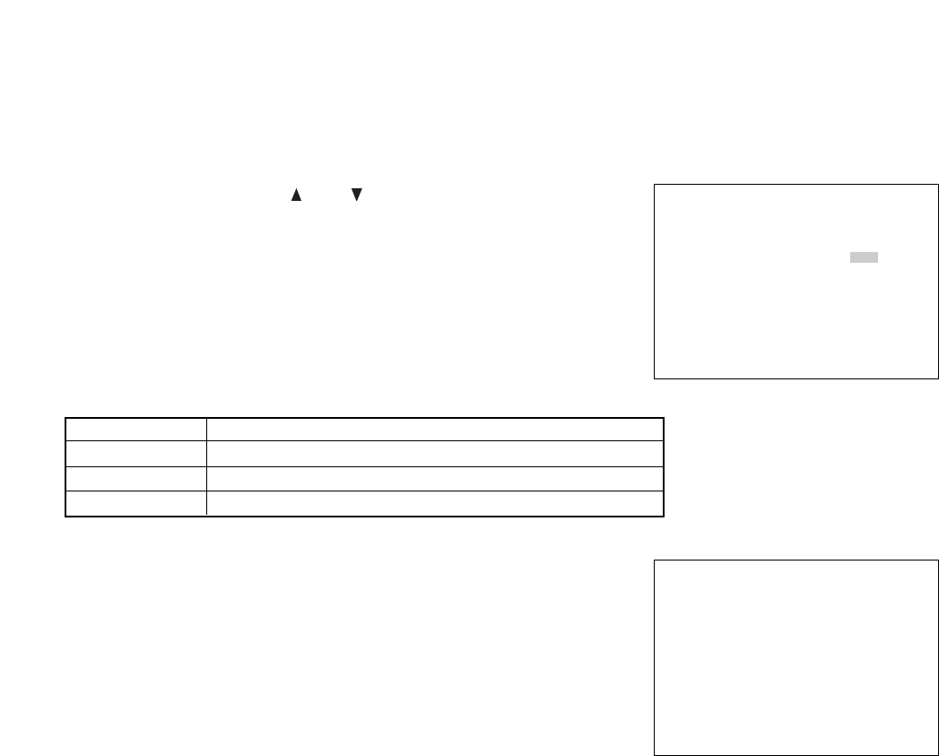
• Pressing the Menu key after the setting displays the confirmation
message in the lower part of the screen if the entered IP address is
different from the current IP address.
• Holding down the Select key for at least 1 second on the confirmation
message display screen displays the setting save screen.
• Press the Menu key if performing no setting. The display returns to
the normal communication setting screen.
NETWORK SETTING
IP ADDRESS
192. 168. 000. 001
SUBNET MASK
255. 255. 255. 000
DEFAULT GATEWAY
000. 000. 000. 000
SET THIS SETTING. OK?
YES : SELECT KEY 1SEC
NO : MENU KEY
NETWORK SETTING
SAVING SET DATA NOW.
PLEASE WAIT FOR A WHILE.
Setting Value Contents
Setting Item
RS232C BAUD
RATE
RS232C FLOW
CTRL
SWITCHER SYNC
(Switcher
Synchronization) *1
Sets the transmission rate.
Sets Flow Control RTS or CTS
ON : Controls the switcher through the RS-232C interface.
OFF : Controls no switcher
TIME SYNC : Only Time Synchronization can be controlled through the
RS-232C interface.
9600 / 19200 / 38400 (bps)
ON / OFF
ON / OFF / TIME SYNC
7.8.1. Network Settings
The Network Setting screen is displayed if Network Settings is selected on the communication setting screen.
Perform settings that are appropriate for the network.
• Move the cursor with the ( ) or ( ) key, and change setting values
with the (–) or (+) key.
* The underlined contents are factory-preset values.
7.8. Communication Settings
Set the transmission rate and whether or not to use flow control in RS-232C communications. Also set the IP
address, etc. to be used in the Ethernet network.
• Move the cursor with the ( ) or ( ) key, and change setting values
with the (–) or (+) key.
• Confirm the setting with the Menu key, and return to the previous
screen.
Note
*1Recording Pattern, Motion Detection Pattern, Camera/ VCR mode selection, and Time Synchronization
switcher functions can all be controlled by the Digital Video Recorder. However, when syncronizing the
switcher's clock from the Recorder, set the Recorder's clock Time Synchronization setting to "MASTER."
Time synhronization cannot be performed if set to "SLAVE."

24
7.9.2 Alarm Recording Logs (Alarm Rec Log)
Logs Alarm Recording start and end times, and displays from the latest log. Up to 500 logs are saved and old
logs are deleted in chronological order when this limit is exceeded.
• The display scrolls in page units (1 screen units) as the ( ) or ( )
key is pressed.
• Return to the previous screen with the Menu key.
ALARM REC LOG
JAN/ 02/ 04 07: 00: 00
END
JAN/ 02/ 04 00: 00: 00
START
JAN/ 01/ 04 18: 00: 00
END
JAN/ 01/ 04 09: 00: 00
START
JAN/ 01/ 04 07: 00: 00
END
7.9. Log Display
Log indications include General Recording Log, Alarm Recording Log, and Failure Log.
• Move the cursor with the ( ) or ( ) key, and display Log Screen
with the Select key.
• Return to the previous screen with the Menu key.
7.9.1. General/ Timer Recording Logs (General/ Timer Rec Log)
Logs start and end times of both General and Internal Timer Recordings, and displays from the latest log. Up
to 100 logs are saved, and old logs are deleted in chronological order when this limit is exceeded.
• The display scrolls in page units (1 screen units) as the ( ) or ( )
key is pressed.
• Return to the previous screen with the Menu key.
LOG DISPLAY
•GENERAL/ TIMER REC LOG
ALARM REC LOG
FAILURE LOG
GENERAL/ TIMER REC LOG
JAN/ 02/ 04 07: 00: 00
TIMER REC END
JAN/ 02/ 04 00: 00: 00
TIMER REC START
JAN/ 01/ 04 18: 00: 00
REC END
JAN/ 01/ 04 09: 00: 00
REC START
JAN/ 01/ 04 07: 00: 00
TIMER REC END
• The figure at right is displayed after saving completion.
• Pressing the Menu key returns the display to the communication
setting menu screen.
• Switch the power OFF and back ON again to validate the network
setting. (Turn off and on the rear-panel mounted Main Power switch.)
Note
Network camera’s settings are not enabled at the front-mounted
Standby Key operation.
NETWORK SETTING
NETWORK SETTING CHANGED.
TURN POWER OFF AND ON TO
VALIDATE THE SETTING.
PRESS MENU KEY
TO RETURN.
25
7.10.1. Menu Default Settings
• Holding down the Select key for at least 1 second clears saved menu
setting contents and log information, initializing settings to factory-
preset status. However, clock settings and network settings are
retained.
• Return to the previous screen with the Menu key.
MENU DEFAULT SETTING
SET TO DEFAULT?
YES : SELECT KEY 1SEC
NO : MENU KEY
7.9.3. Failure Logs
Logs detection times and contents for the various different failure modes that can occur in the Digital Video
Recorder, and displays from the latest log. Up to 100 logs are saved and old logs are deleted in chronological
order when this limit is exceeded.
• The display scrolls in page units (1 screen units) as the ( ) or ( )
key is pressed.
• Return to the previous screen with the Menu key.
Note
The current log display does not change even if a new log is added during display.
To confirm the added log, change the page or return to the log item selection screen to display the log again.
All logs are deleted if Menu Default Settings of System Maintenance is performed.
7.10. System Maintenance
Performs menu default settings or format the hard disk.
• Move the cursor with the ( ) or ( ) key, and confirm the Item with
the Select key.
• Return to the previous screen with the Menu key.
FAILURE LOG
JAN/ 02/ 04 07: 00: 00
VIDEO FAILURE
JAN/ 02/ 04 00: 00: 00
DISK FAILURE
JAN/ 01/ 04 18: 00: 00
VIDEO FAILURE
JAN/ 01/ 04 09: 00: 00
FAN FAILURE
JAN/ 01/ 04 07: 00: 00
DISK FAILURE
SYSTEM MAINTENANCE
•MENU DEFAULT SETTING
DISK FORMATTING
ContentsDisplay Item
VIDEO FAILURE
DISK FAILURE
FAN FAILURE
Displays this indication when a video signal cutoff (Video Loss) is
detected during recording.
Displays this indication when a disk error is detected.
Displays this indication when fan operation stops.
26
7.10.2. Disk Formatting
This function initializes the hard disk. If initialized, all previously recorded contents are deleted. However,
setting contents and logs are retained. Hard disks to be formatted can be selected when the C-DR0101 and
C-DR0105 is used.
• Move the cursor with the ( ) or ( ) key, and change setting values
with the (–) or (+) key.
• Hold down the Select key for at least 1 second to start formatting.
• Return to the previous screen with the Menu key.
Formatting is started by holding down the Select key for at least 1
second again after the reconfirmation message is displayed. Pressing
the Menu key returns the display to the system maintenance screen
without formatting.
The disk error message is displayed if a disk error occurs during formatting.
DISK FORMATTING
DISK FORMATTING [ ALL]
FORMAT DISKS?
YES : SELECT KEY 1SEC
NO : MENU KEY
DISK FORMATTING
ARE YOU SURE?
YES : SELECT KEY 1SEC
NO : MENU KEY
(C-DR0101, C-DR0105)
ContentsSetting Items
HDD-A
HDD-B
ALL
Formats Hard Disk A
Formats Hard Disk B
Formats all set hard disks.
27
After system check completion, the Standby key changes from flashing to steady ON, allowing camera images
to be displayed.
Note
When the Recorder is used for the first time or when the power was switched off for a long period of time, the
date and time could not be correctly displayed. Perform the clock setting before use. (Refer to p. 14; "Clock
Settings.")
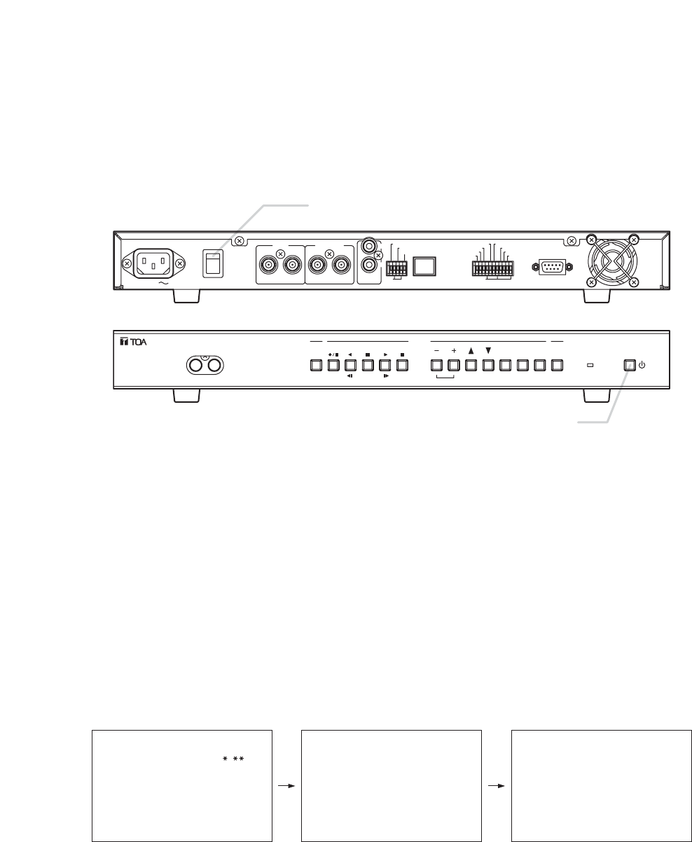
8. DIGITAL VIDEO RECORDER ACTIVATION AND TERMINATION
8.1. Recorder's Activation
The switch and key shown in the following figures are used in operation.
1. Connect each component correctly. (Refer to p. 40; "Connections.")
2. Set the rear-panel mounted Main Power switch to the ON position.
The Standby key flashes green for 5 seconds while settings are initialized. Thereafter, the Recorder is
placed in standby mode. The Standby key flashes every 5 seconds while in standby mode.
Note
Do not turn off the Main Power switch while the Standby key is flashing. Ensure that the Recorder is in the
standby mode when turning off the Main Power switch.
Logged data could be damaged or lost if the main power is switched off during initialization (while accessing
the hard disk).
3. Press the Standby key while the Recorder is in standby mode.
The screen automatically changes as shown below.
The Standby key flashes green during a system check.
AC MAINS MAIN POWER
ON
OFF
IN OUT IN OUT
VIDEO SW VIDEO IN
OUT
AUDIO
GND GND
100BASE–TX
ALARM RESET OUT
ALARM IN
SW CTRL OUT
TIME SYNC IN
REC STOP IN
REC START IN
ALARM RESET IN
TIME SYNC OUT
ALARM OUT
FAILURE OUT
DISK FULL OUT
RS–232C
Main Power Switch
DIGITAL VIDEO RECORDER
DISK FULL/
FAILURE
ALARM
RESET
BUZZER
STOP
SEARCH
MENU
SELECT
BLOCK
PLAY
STOP
PLAY
PAU S E
REVERSE
PLAY
REC
TIMER
FRAME FRAME
OUTPUT
VIDEO AUDIO
Standby Key
SYSTEM CHECK COMPLETED
V e r .
SYSTEM CHECK IN PROGRESS
PLEASE WAIT

28
8.2. When the Failure Screen Is Displayed:
Note
• Avoid operating any key during a system check after the Standby key
has been pressed. The failure indication shown in the figure at right
could be displayed. In such cases, switch the power OFF and back
ON again.
• If the failure indication is still displayed even though the power is
reactivated, format the hard disk. (Refer to p. 26; "Disk Formatting.")
• If the failure indication does not disappear even though the disk is
formatted, the disk ‘s failure may be the cause. Please contact your
TOA dealer.
DISKS MAY HAVE FAILED.
PLEASE TURN POWER SWITCH
OFF AND ON AGAIN.
8.3. Recorder’s Termination
1. Hold down the Standby key for at least 1 second.
All operations stop, placing the Recorder in standby mode.
Note
The Recorder’s operation can be terminated by holding down the Standby key for at least 1 second even
while in General Recording mode. However, when the Recorder is next reactivated, the previous recording is
not retained and the Recorder is put into Pause mode. Preprogrammed timer times are set revised even if the
Recorder is terminated during the timer setting and activated again.
2. Set the Main Power switch to the OFF position.
The Recorder’s power is switched off.
9. OPERATION AFTER POWER FAILURE RESTORATION
The Recorder’s set contents are never reset by power failures.
However, since the date and time are backed up by the built-in battery, if no power is supplied for a long
period of time (1 month), they are reset. In such cases, perform the clock setting again.
9.1. When the Power Fails during Recording;
• During General Recording
Recording is restarted when the power is restored.
• During Alarm Recording
If an alarm input still continues when the power is restored, it is recognized as a new alarm input and
recording is restarted. However, if no alarm exists, recording is not performed. Also, even if the power is
restored within the set Alarm Recording time period or Post-alarm time period, recording is not restarted
because there is no alarm signal.
• During Internal Timer Recording
Timer operation is restarted if the power is restored within the set time period. If restored during Internal
Timer Recording, the recording is restarted.
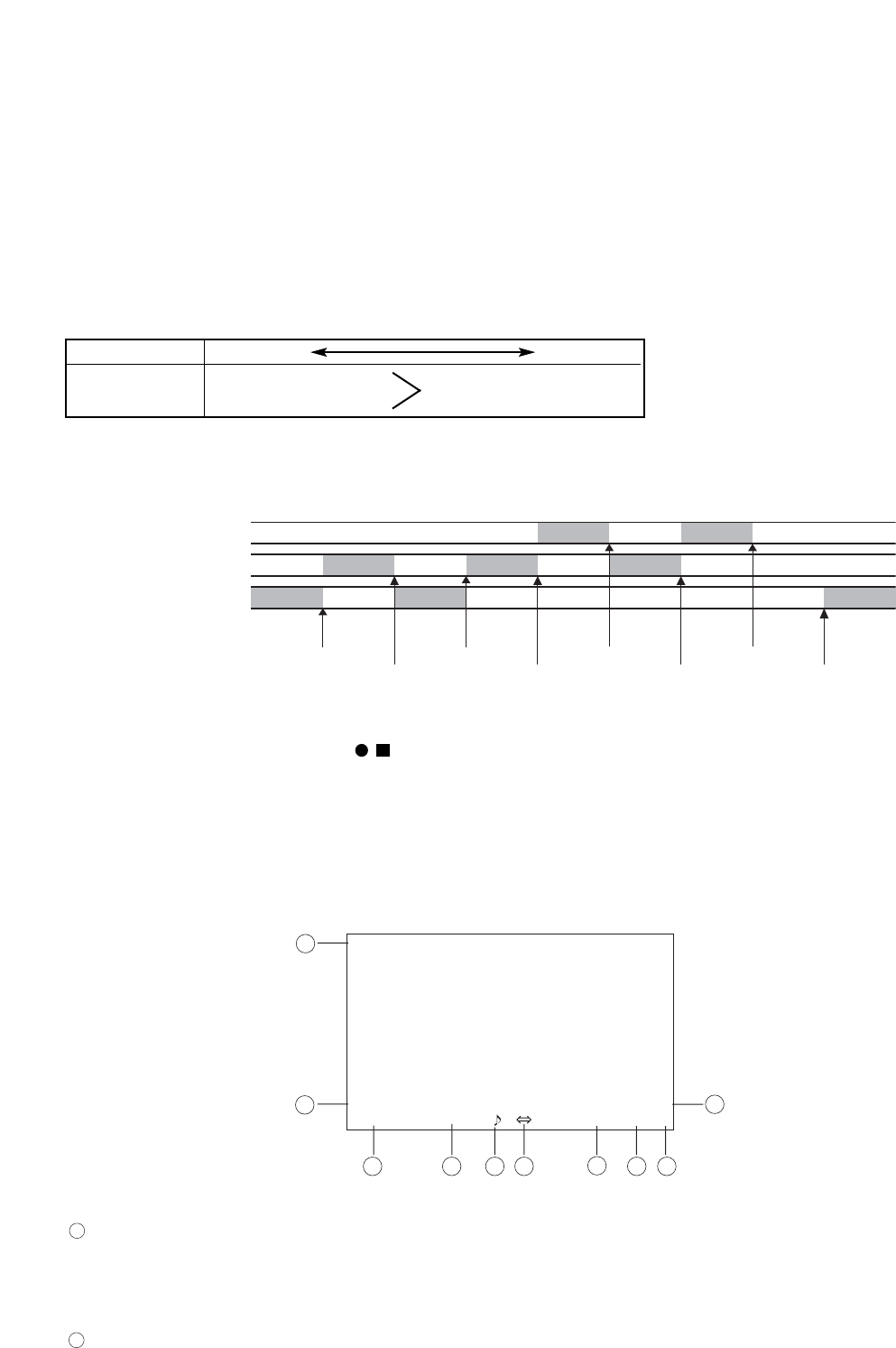
29
10. RECORDING
10.1. Type of Recording
Recording modes include General Recording, Internal Timer Recording, and Alarm Recording. Each recording
mode permits the picture quality and recording interval to be set individually. (Refer to p. 17; "General
Recording Settings.") In the Digital Video Recorder, recorded data from the start to the end of each recording
is handled as a single recorded block.
10.1.1. Recording Priorities
The order of Recording Priority is as shown below.
Recording End
General Recording
Alarm Recording
Internal Timer Recording
Timer Key pressed
Alarm Input Alarm Input Alarm Input
Alarm End Rec. key pressed Alarm End
• REC
LEVEL3 1 / 60
THU JAN / 01 / 04
00 : 00 : 00
00 : 00 : 00
M AB F
1
2 3 4 5 67
8
9
10
**
10.2. Screen Display during Recording
The screen display setting is factory-preset to "DISP." (Refer to p. 21; "Screen Display Settings".)
* C-DR0101, C-DR0105
High Low
Order of Priority
Type of Recording General Recoding
Alarm Recoding Internal Timer Recording
Lower-priority recording stops whenever higher-priority recording is commenced. The following figure shows
an example of recording operation that varies whenever recording of different priority levels is commenced.
Note
Internal Timer Recording does not operate even if the Timer key is pressed during General or Alarm
recording. Pressing the Recording ( /) key during a timer setting cancels the timer setting. To resume the
timer setting, first stop recording and press the Timer key.
Indicates the recording status. (Refer to p. 17; "General Recording Settings".)
•REC: Represents General Recording is in progress.
•TIMER: Represents Internal Timer Recording is in progress.
•ALARM: Represents Alarm Recording is in progress.
Indicates the recording picture quality.
Can be set to Levels 1 – 5.
LEVEL 1 provides the highest resolution display.
2
1

30
Indicates the recording interval.
General Recording and Internal Timer Recording : 1/60 – 60 seconds
Alarm Recording : 1/60 – 1 seconds
Note
• Even if the Recording Setting’s Recording Interval is set to "1/60 SEC," Mirroring Recording is performed at
the recording interval of 1/30 second. (The on-screen interval indication is also "1/30 SEC" in Mirroring
Recording.) (Refer to p. 17; "General Recording Settings.")
• The higher the picture quality (resolution) and the shorter the recording interval, the shorter the possible
recording time. Conversely, the lower the picture quality and the longer the recording interval, the longer the
possible recording time. (Refer to p. 45; "Recording Time Table.")
Indicates whether or not to use the Audio recording function.
: Audio recording ON (enabled)
No indication : Audio recording OFF (disabled)
Indicates the hard disk Recording Mode. (Refer to p. 15; "Disk Settings.")
Re-Rec Mode
Stop Mode
Series Mode
• Re-Rec Mode : Overwrites old hard disk recordings in chronological order even when no available hard disk
time remains.
• Stop Mode : Stops video recording when no available hard disk time remains.
• Series Mode : Stops video recording when no available hard disk time remains, and sends out a signal
from the Control Terminal’s Disk Full output, allowing other series-connected Digital Video
Recorder to start recording. The slave Digital Video Recorder starts recording when it
receives a signal at its Recording Start input terminal even if its hard disk becomes full.
(Refer to p. 41; "Expansion System (Series Recording).")
Indicates the Disk Mode. (C-DR0101, C-DR0105) (Refer to p. 15, "Disk Settings".)
No indication : Normal Recording
M : Mirroring Recording
• About Normal and Mirroring recordings
The C-DR0101 and C-DR0105 has two built-in hard disks.
Setting the Disk Mode to "NORMAL" permits camera images to be recorded on the second hard disk when
the first hard disk becomes full.
Setting the Disk Mode to "MIRRORING" permits the same recording to be simultaneously performed on the
two hard disks. Even if one of the two disks fails, recording and playback can still be performed using the
other disk.
Indicates the hard disk recognition status. (C-DR0101, C-DR0105)
Characters are reversed for the hard disk in recording mode.
The "X" indication is displayed when the hard disk fails.
Note
Even if the Screen Display Setting’s Disk Mode Indication is set to "HIDE," the "X" indication is
displayed when the hard disk fails.
Indicates the remaining hard disk recording time calculated from the picture quality and recording interval
of current recording.
If the Disk Setting’s Recording Mode is set to "RE-REC", the remaining hard disk recording time is not
displayed.(Refer to p. 15; "Disk Settings".)
Indicates the current date and time.
The "F" indication flashes when the fan fails.
Cannot be set to "HIDE" in Screen Display Settings.
10
9
8
7
6
5
4
3
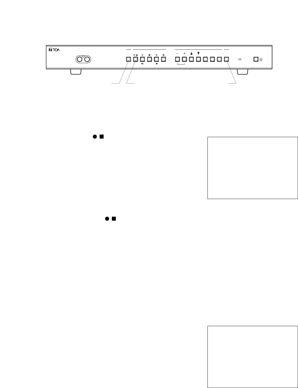
31
10.5. Performing Internal Timer Recording (Refer to p. 17; "Internal Timer Recording Settings)
Note
Be sure to perform date and time settings before recording. (Refer to p. 14; "Clock Settings".)
1. Press the Timer key.
The Digital Video Recorder is placed in Internal Timer Recording
standby mode, and the Timer key lights green.
2. When the preset time is reached or if the key is pressed within the
preset period, the Recording key lights red and recording is started.
If "DISP" has been selected in Screen Display Settings, setting data
is displayed on the monitor, and the "TIMER" indication is displayed
for recording status.
10.4. Performing General Recording (Refer to p. 17; "General Recording Settings)
Note
Be sure to perform time and date settings before recording. (Refer to p. 14; "Clock Settings")
1. Press the Recording key ( /) to start General Recording.
When recording is started, the Recording key lights red.
If "DISP" has been selected in Screen Display Settings, setting data
is displayed on the monitor and the Recording indication is displayed
for recording status.
Note
When the Disk Setting Recording Mode has been set to "STOP" or
"SERIES," the Disk Full indicator flashes if less than 1 hour of available
hard disk time remains. If no available hard disk time remains, the Disk
Full indicator changes to steady ON and recording stops.
2. Hold down the Recording key ( /) for at least 1 second to stop recording.
The illuminated Recording key extinguishes.
Note
If an alarm is activated during General Recording performance while in alarm standby mode, the General
Recording is interrupted and switched over to Alarm Recording. The General Recording is automatically
restored after Alarm Recording completion.
THU JAN/ 01/ 04
00 : 00 : 00
•
REC
LEVEL3 1/60 M : AB F
THU JAN/ 01/ 04
00 : 00 : 00
•
TIMER
LEVEL3 1/60 M : AB F
10.3. The Keys to Be Used in Recording
The following keys are used in recording:
DIGITAL VIDEO RECORDER
DISK FULL/
FAILURE
ALARM
RESET
BUZZER
STOP
SEARCH
MENU
SELECT
BLOCK
PLAY
STOP
PLAY
PAU S E
REVERSE
PLAY
REC
TIMER
FRAME FRAME
OUTPUT
VIDEO AUDIO
Timer Key Recording Key Buzzer Stop Key

32
10.6. Performing Alarm Recording (Refer to p. 19; "Alarm Recording Settings)
Note
• Be sure to perform date and time settings before recording. (Refer to p. 14; "Clock Settings".)
• Be sure to set the Alarm Recording Setting’s Alarm Setting to "VALID" when performing Alarm Recording.
This places the Digital Video Recorder in alarm standby mode.
• The setting is factory-preset to "VALID."
1. A buzzer is sounded and the Buzzer stop key flashes red when an alarm signal is received. At the same
time, the Recording key lights red and recording is started. The
Buzzer stop key continues flashing red during Alarm Recording.
• If "DISP" has been selected in Screen Display Settings, setting data is
displayed on the monitor, and the "ALARM" indication is displayed for
recording status.
• Pressing the Buzzer stop key during buzzer output stops the buzzer.
Whether or not to sound a buzzer can be set by selecting ON or OFF
in Alarm Recording Settings.
• Alarm Recording provides an open collector signal from the Alarm
Output Terminal. An alarm output duration can be set to "1 SEC" or
"DURING REC" in Alarm Recording Settings.
2. Recording stops when the end of the Preset Alarm Recording Period is reached. The illuminated Recording
key extinguishes, however the Alarm Reset key remains lit. To reset Alarm Recording before the Preset
Alarm Dcording Period is started, hold down the Alarm Reset key for at least 1 second.
Note
• Pressing the Recording key ( /) during Alarm Recording resets Alarm Recording, and switches it over to
General Recording. However, the Alarm Reset key continuously lights red to indicate that an alarm has been
activated.
• To extinguish the illuminated Alarm Reset key, hold down the Alarm Reset key for at least 1 second.
• If the Alarm Recording’s Alarm Settings is set to "VAL REC," alarm signals are only accepted while
recording is in progress. Alarm inputs can be only accepted during the necessary surveillance period by
combining both Alarm and Internal Timer recordings.
• If the Alarm Recording’s Alarm Settings is set to "INVALID," any alarm input is not accepted.
• If other alarms are activated during Alarm Recording, the preset alarm time is initialized to make the
recording period longer. In this case, the number of recorded blocks is one.
THU JAN/ 01/ 04
00 : 00 : 00
•
ALARM
LEVEL3 1/60 M : AB F
3. Recording stops when the end of the preset recording period is reached.
The illuminated Recording key extinguishes.
Note
• When the Disk Setting Recording Mode is set to "STOP," recording stops if no available hard disk time
remains.
• When the Recording mode is set to "SERIES," timer program cannot be perfomed.
• When an alarm is activated during Internal Timer Recording, the Internal Timer Recording is interrupted, and
automatically restored after Alarm Recording completion.
• Pressing the Recording key ( /) during Internal Timer Recording resets Internal Timer Recording, and
switches it over to General Recording.
4. To cancel Internal Timer Recording, hold down the Timer key for at least 1 second. The illuminated Timer
key extinguishes.
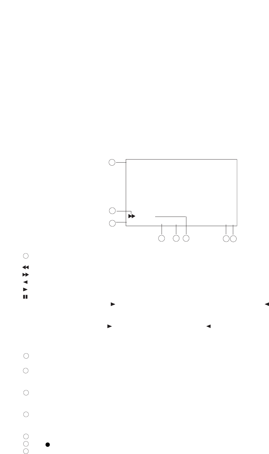
33
11. PLAYBACK
11.1. Type of Playback
The Digital Video Recorder features the simultaneous recording/playback function that permits recorded
images to be played back without stopping recording. The types of playback include Playback, Reverse
Playback, Fast Forward Playback, Fast Reverse Playback, Forward Frame Playback, and Reverse Frame
Playback.
Note
• When the Playback Setting’s Simultaneous Recording/Playback is set to "DISALLOW," playback cannot be
performed during recording. Only recording or playback can be performed.
• Playback performance could be degraded during simultaneous recording/playback operation.
x 2 •
LEVEL3 1 / 60
THU JAN / 01 / 04
00 : 00 : 00
M A F
1
2
3 4 5
6
78
**
Indicates playback mode.
: Fast Reverse Playback
: Fast Forward Playback
: Reverse Playback
: Playback
: Pause
• Pressing the Playback key ( ) during playback (or the Reverse Playback key ( ) during Reverse
playback) changes the mode to Fast Forward playback (Fast Reverse playback during Reverse playback).
The "x2", "x4" or "x8" indication is displayed on the screen to indicate the playback speed.
• Pressing the Playback key ( ) or the Reverse Playback key ( ) during still picture playback (while in
pause mode) changes the mode to Forward or Reverse Frame playback. Holding down the key performs a
continuous frame-by-frame playback of the recorded image.
Indicates the recording picture quality.
Can be set to Levels 1 – 5. Quality increases as the number decreases.
Indicates the recording interval.
General Recording, Internal Timer Recording : 1/60 – 60 seconds
Alarm Recording : 1/60 – 1 seconds
Indicates an attribute of Mirroring Recording. (C-DR0101, C-DR0105)
No indication : Data other than Mirroring Recording data
M : Mirroring Recording data
Indicates the currently-used hard disk. (C-DR0101, C-DR0105)
A : Playback of Hard disk A
B : Playback of Hard disk B
Indicates recording dates and times.
The ( ) indication is displayed when recording is also performed simultaneously with playback.
The "F" indication flashes when the fan fails.
This indication cannot be set to "HIDE" in Screen Display Settings.
8
7
6
5
4
3
2
1
11.2. Screen Display during Playback
Screen Display Settings is factory-preset to "DISP." (Refer to p. 21; "Screen Display Settings.")
* C-DR0101, C-DR0105
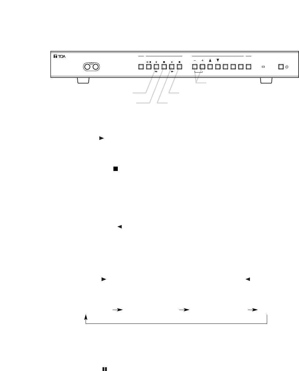
34
11.4. Performing Playback
1. Press the Playback key ( ) to start playback.
The Playback key lights green when playback is started.
If Screen Display Settings has been set to "DISP," setting data is displayed on the monitor, and the
"Playback" indication is displayed for playback status.
2. Press the Playback Stop key ( )to stop playback. The illuminated Playback key extinguishes.
11.5. Performing Various Playback Fanctions
11.5.1. Reverse Playback
Press the Reverse Playback key ( ) to perform playback in the reverse direction.
The Reverse Playback key lights green when Reverse playback is started.
If Screen Display Settings has been set to "DISP," setting data is displayed on the monitor, and the "Reverse
Playback" indication is displayed for playback status.
11.5.2. Fast Forward Playback and Fast Reverse Playback
Pressing the Playback key ( ) during playback (or the Reverse Playback key ( ) during Reverse playback)
changes the playback mode to Fast Forward (or to Fast Reverse playback if pressed during Reverse
playback). The playback speed changes as the key is pressed.
Playback speed: Original speed Twofold speed (x2) Fourfold speed (x4) Eightfold speed (x8)
Note
Playback may not be performed at the indicated speed depending on the hard disk performance, such as
access times.
11.5.3. Playback Pause (Still Picture)
1. Pressing the Pause key ( ) during playback or Reverse playback suspends playback operation, causing
the Pause key to light green.
If Screen Display Settings has been set to "DISP," setting data is displayed on the monitor, and the "Pause"
indication is displayed while in pause mode.
DIGITAL VIDEO RECORDER
DISK FULL/
FAILURE
ALARM
RESET
BUZZER
STOP
SEARCH
MENU
SELECT
BLOCK
PLAY
STOP
PLAY
PAUSE
REVERSE
PLAY
REC
TIMER
FRAME FRAME
OUTPUT
VIDEO AUDIO
Reverse Playback key
Pause key Playback key
Playback Stop key
Block Shift key
11.3. The Keys to Be Used in Playback
The following keys are used in playback.
Reverse Playback key, Pause key, Playback key, Playback Stop key, Block Shift key
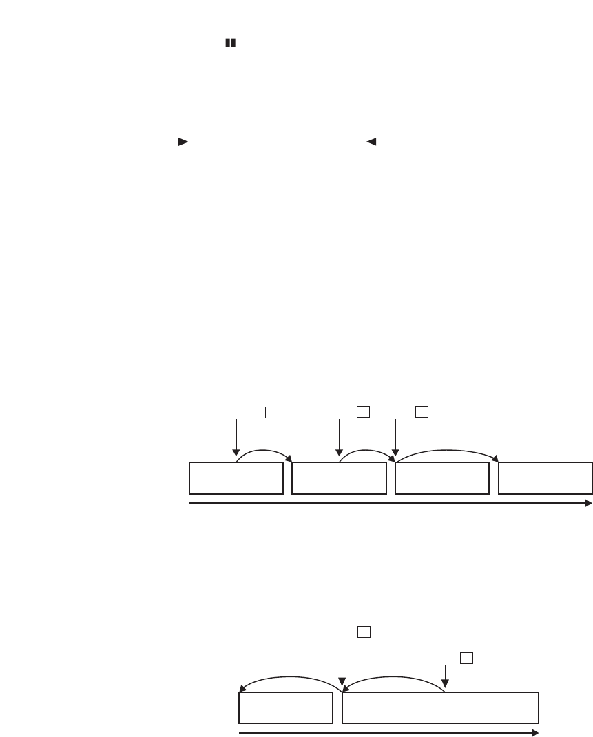
35
Press +Press +Press +
Block Block Block Block
Playback
Block Block
Playback direction
Press
-
Press
-
while in Playback Pause mode.
2. Pressing the Pause key ( ) again returns the Digital Video Recorder to the playback mode it was last in
before playback was suspended.
The illuminated Pause key extinguishes and the Playback key lights.
11.5.4. Forward Frame Playback and Reverse Frame Playback
If the Playback key ( ) or Reverse Playback key ( ) is pressed while in Playback Pause mode, Forward or
Reverse Frame playback can be performed.
Pressing the key once performs a single-frame playback per screen, while holding down the key provides a
continuous frame-by-frame playback.
11.5.5. Forward Block Playback and Reverse Block Playback
In the Digital Video Recorder, recorded data from the start to the end of each recording is handled as a single
recorded block. Since both the Forward Block Playback and Reverse Block Playback functions shift playback
images on a block basis, desired scenes can be searched while viewing playback images.
Pressing the (+) Block Shift key during playback shifts the recorded image to the head of the next block,
temporarily stopping playback for 1 second before it is restarted. If the (+) Block Shift key is pressed again
while in Playback Pause mode, the recorded image is shifted to the next block, providing the same operation.
Pressing the (–) Block Shift key during playback shifts the recorded image to the head of the block currently
played back, temporarily stopping playback for 1 second before it is restarted. If the (–) Block Shift key is
pressed again while in Playback Pause mode, the recorded image is shifted to the head of the preceding
block and then it is played back.
Block shift is also possible during Reverse Playback operation, however playback resumes in the forward
direction after the recorded image has been shifted to the head of the desired block.
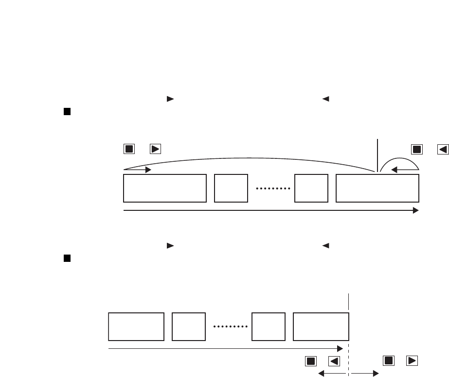
36
11.6. About the Playback Start Position
• If playback is initiated from the camera display screen, the playback begins from the position at which it was
last stopped. When the power is switched on or when the position previously played back has been
overwritten, playback is started from the oldest recorded image. During recording, playback is started from
the most recent data in the currently recorded block.
• Pressing the Playback key ( ) (or the Reverse Playback key ( )) while holding down the Playback Stop
key ( )while in Stop or Playback mode shifts the recorded image to the following position for playback.
Current position
Oldest block
Playback direction
Most recent block
Press +Press +
Block Block
Playback direction
Current position
(recording is in progress)
(playback from the
most recent data)
Press + Press +
• Pressing the Playback key ( ) (or the Reverse Playback key ( )) while holding down the Playback Stop
key ( )during recording causes playback to be started from the following position.
Note
When playing back in the forward direction, if the Pre-alarm time has been set to 10 second or more and the
Digital Video Recorder is in alarm standby mode, playback is started from 10 minutes before the most recent
block is played back.
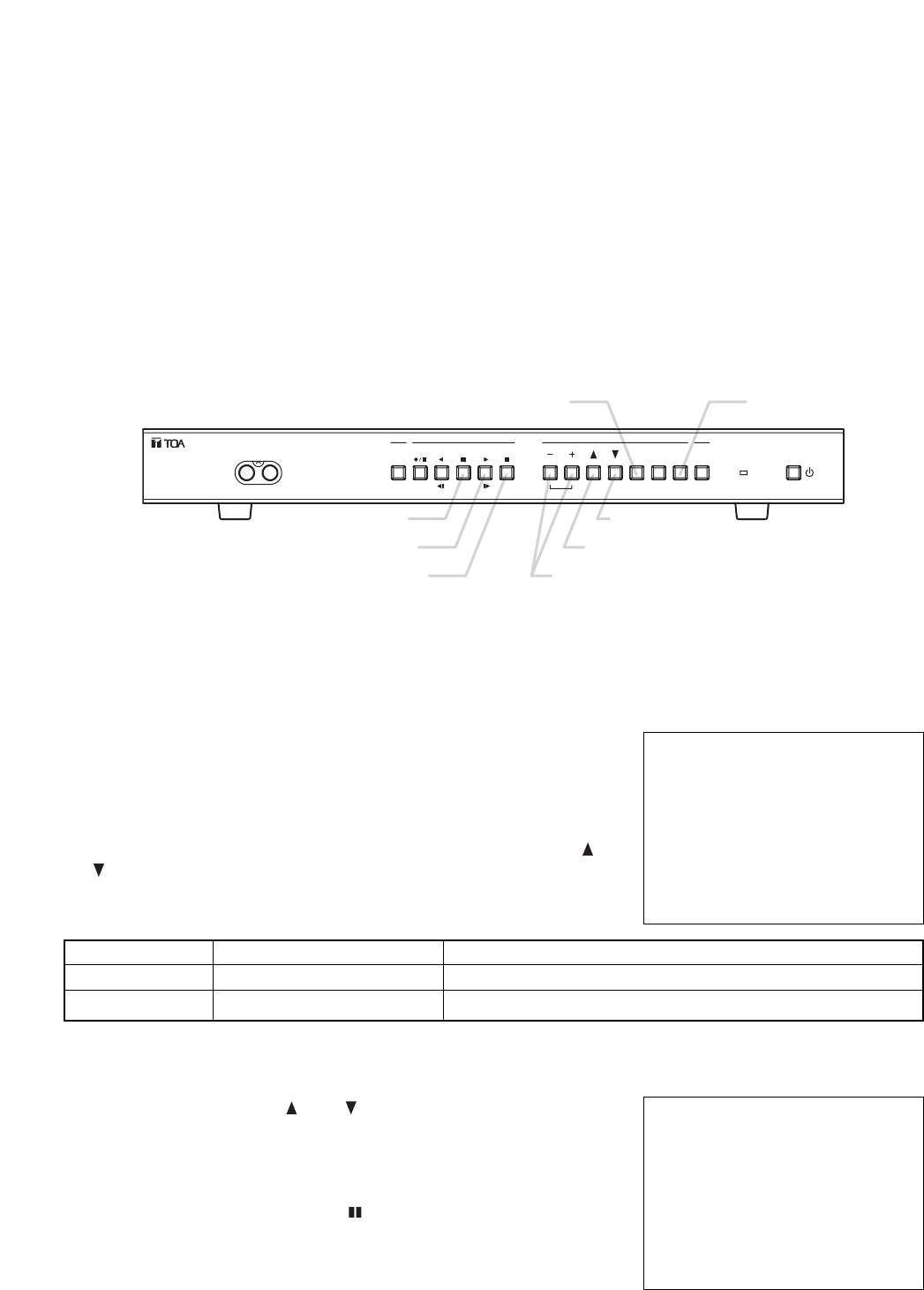
37
Note
• When no recording exists at the designated time, the first image of
the recorded block following the designated time is displayed.
• Attempting to perform searches beyond the current time results in a
display of the "INVALID SEARCH" indication on the Date/Time
Search screen.
12. SEARCH FUNCTIONS
The following three methods are available to search recorded data (images):
1. Date/Time Search : Playback can be initiated by designating the date and time.
2. Block Search : Playback can be initiated by selecting the recorded block.
3. Time Shift Search : Playback can be initiated by increasing or decreasing times from the designated time.
The Digital Video Recorder handles recorded data from the start to the end of each recording as a single
recorded block.
The above three search methods differ in operation.
DATE / TIME SEARCH
JAN / 01 / 04 00 : 00
12.2. Date/Time and Block Searches
12.2.1. Basic Date/Time Search and Block Search Operations
1. Press the Search key.
The Search menu screen is displayed.
Playback stops if the key is pressed during playback.
Pressing the Search key again returns the display to the camera
image screen.
2. Move the cursor to select the desired search function with the ( ) or
( ) key, then confirm the selection with the Select key.
Setting Value ContentsSetting Items
DATE/ TIME SEARCH
BLOCK SEARCH
Recorded images are searched by directly entering the date and time
Recorded images are searched by selecting the recorded block.
Date/ time data entry
–
SEARCH
•
DATE / TIME SEARCH
BLOCK SEARCH
12.2.2. Date/Time Search Operation
• Move the cursor with the ( ) or ( ) key, and change setting values
with the (–) or (+) key.
• Executing searches with the Select key displays the image of the
designated time on the still picture mode screen. The Pause key
lights green.
• Playback begins if the Pause key ( ) is pressed.
DIGITAL VIDEO RECORDER
DISK FULL/
FAILURE
ALARM
RESET
BUZZER
STOP
SEARCH
MENU
SELECT
BLOCK
PLAY
STOP
PLAY
PAU S E
REVERSE
PLAY
REC
TIMER
FRAME FRAME
OUTPUT
VIDEO AUDIO
Pause key
Playback key
Playback Stop key
Select key Search key
Block Shift key
Up Shift key
Down Shift key
12.1. The Keys to Be Used in Searching
The following keys are used in search operation:
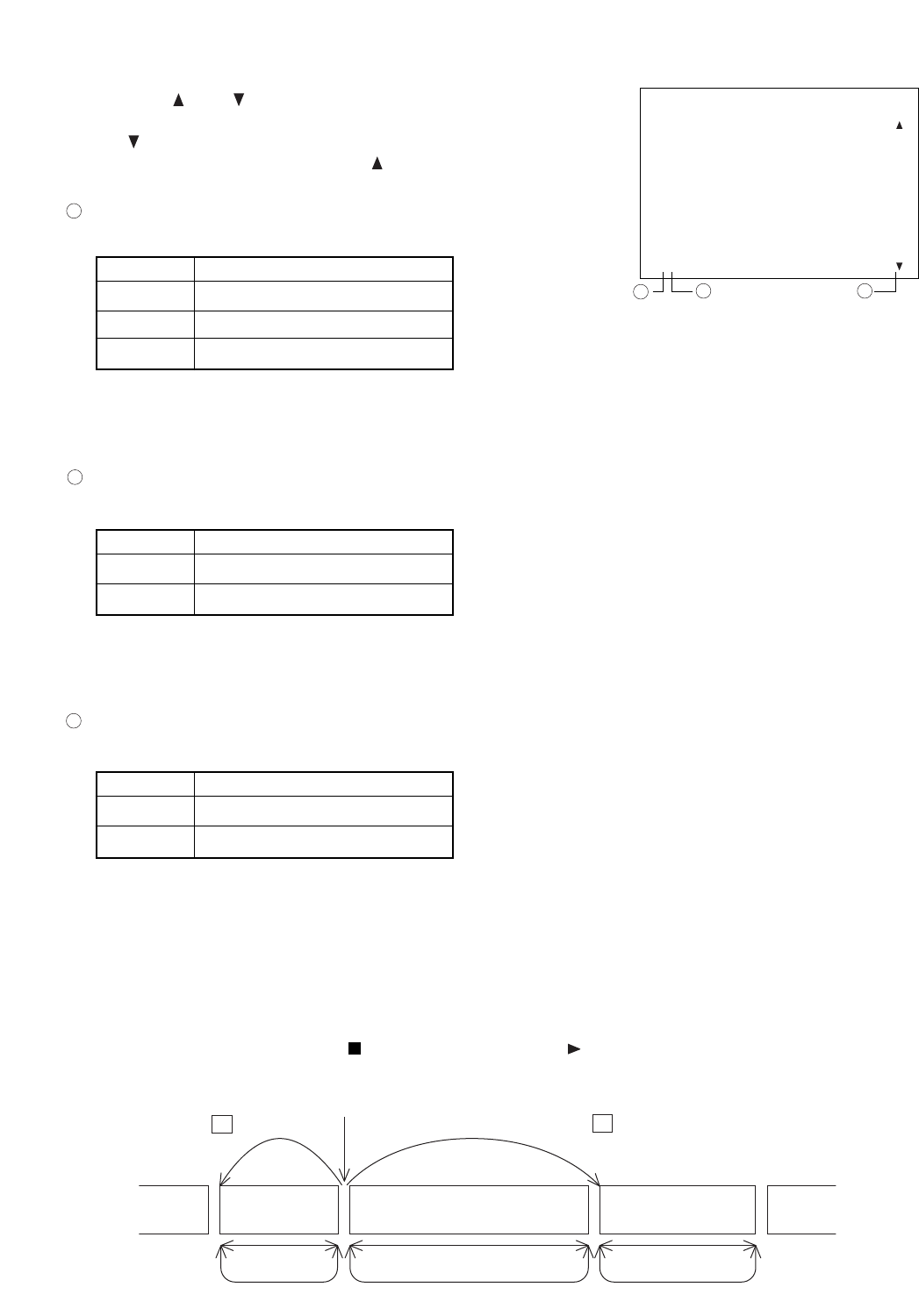
38
BLOCK SEARCH
N JAN / 01 / 04 21 : 35 : 27
AMJAN / 01 / 04 21 : 35 : 27
––––– / –– / –– –– : –– : ––
––––– / –– / –– –– : –– : ––
––––– / –– / –– –– : –– : ––
––––– / –– / –– –– : –– : ––
––––– / –– / –– –– : –– : ––
––––– / –– / –– –– : –– : ––
––––– / –– / –– –– : –– : ––
––––– / –– / –– –– : –– : ––
––––– / –– / –– –– : –– : ––
––––– / –– / –– –– : –– : ––
––––– / –– / –– –– : –– : ––
––––– / –– / –– –– : –– : ––
[Recorded block types]
Recorded block types are classified by characters "N," "T," and "A."
1
ContentsItem
N
T
A
General Recording block
Internal Timer Recording block
Alarm Recording block
[Recorded block attribute]
Character M represents data attribute types.
2
[Hard disk types]
Characters A and B represent built-in hard disk drives.
3
ContentsItem
A
B
Data contained in Hard Disk A
Data contained in Hard Disk B
12.2.3. Block Search Operation
• Using the ( ) or ( ) key, move the cursor to scroll the screen and
select the desired block.
The ( ) indication is displayed when data exists before the currently
displayed search screen, while the ( ) indication is displayed when
data exists after the currently-displayed search screen.
Block Block Block
“Loop” playback
“Loop” playback
“Loop” playback
Press +
Press
-
Head of the selected block
• Executing searches with the Select key displays the first image of the block on the still picture screen. The
image is played back if the Pause key is pressed. Pressing the (+) or (–) key while in the Pause mode
displays the first image of the block, performing playback from one block to another. After the block has
switched over to another block, playback can be performed even without pressing the Pause key.
• "Loop" playback is performed for all playback operations after Block Shift search.
Note
• "Loop" playback: Repeats playback of each recorded block.
• Pressing the Playback Stop key ( ) and the Playback key ( ) again during "Loop" playback resets the
"Loop" playback, causing playback to be performed on a time basis.
12 3
Note
The Alarm Recording block time represents the time that an alarm was received. If the Pre-alarm function has
been set, Alarm Recording begins from the image recorded before the indicated alarm time.
Note
Avoid mixing both Normal Recordings and Mirroring Recordings on the hard disk. If mixed, block shift or
search operations cannot be correctly performed during playback. (Refer to p. 15; "Disk Settings.")
ContentsItem
No Indication
M
Normal Recordung data
Mirroring Recording data
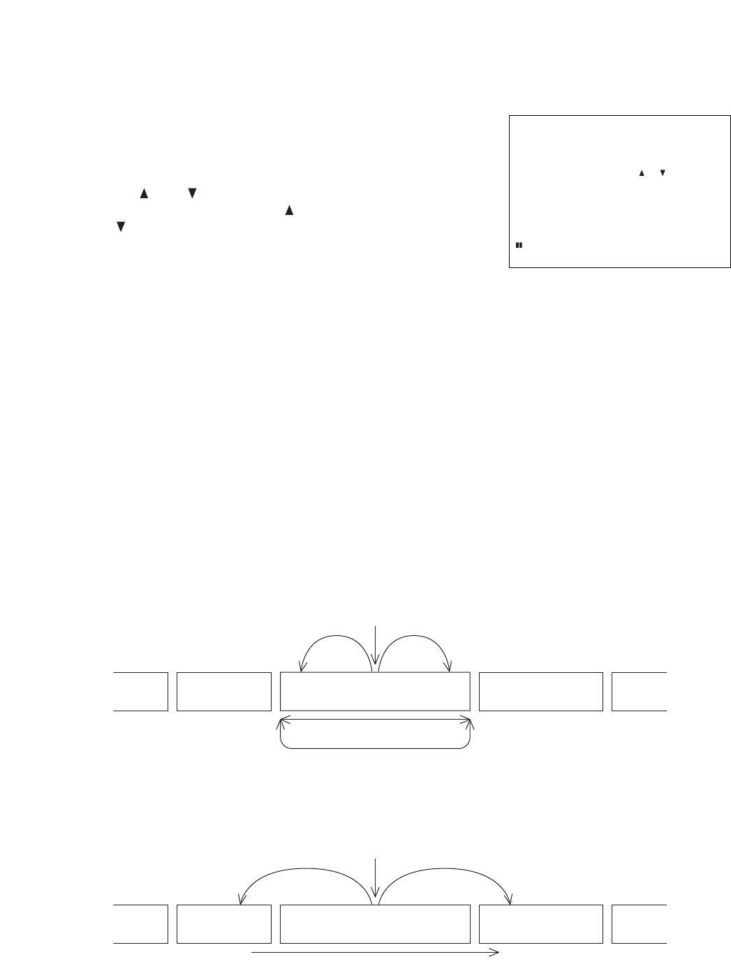
39
Note
• Continuous or normal forward/reverse frame playback can also be performed even when the Time Shift
Search screen is displayed (even while the Pause key is flashing).
• If Time Shift Search operation exceeds the range of "Loop" playback during "Loop" playback, the "Loop"
playback is reset, reverting to normal playback.
12.3. Time Shift Search
1. Press the Pause key on the playback screen to suspend playback.
2. Press the Search key.
The Time Shift Search screen is displayed, and the Pause key
flashes.Pressing the Search key again returns the display to the
playback pause screen.
3. Using the ( ) or ( ) key, change the time period to be shifted.The
shift time period increases as the ( ) key is pressed, and decreases
as the ( ) key is pressed. It can be set to a variable period of 1 – 60
minutes.
4. Press the (+) or (–) key.
The (+) key advances the shift time period by the designated length of time, while the (–) key reverses the
time period by the same designated length of time. If no image exists at the designated time, pressing the
(+) key displays the image following the designated time, while the image preceding the designated time is
displayed if the (–) key is pressed.
5. Press the Search key to reset the Time Shift Search.
The display is temporarily stopped at the searched Time Shift screen.
6. Press the Pause key to begin playback of the searched image.
THU JAN / 01 / 04
00 : 00 : 00
SHIFT TIME CHANGE : /
SHIFTING : – / +
CANCEL : SEARCH
SHIFT: 10MIN
LEVEL3 1/60 A
Pause
“Loop” playback
Time Shift Time Shift
Block Block
Block
Block Block Block
Pause
Time Shift Time Shift
Playback operation on a time basis
When the Time Shift Search function is operated within the "Loop" playback range:
When the Time Shift Search function is operated beyond the "Loop" playback range:

40
13. CONNECTIONS
13.1. Preparations for Connections
Switch off the power to the Digital Video Recorder and all connected equipment before performing
connections. The Digital Video Recorder has built-in hard disks. To avoid damage to them, when moving the
Digital Video Recorder, be sure to leave the Recorder’s Main Power switch turned off for at least 30 seconds
before moving.
13.1.1. Control Input/Output Terminal Connections
Applicable cables are as follows:
• Solid cable : AWG28 (ø 0.32mm) – AWG22(ø 0.65mm)
• Twisted cable: AWG28 (0.08mm2) – AWG22(0.32mm2)
To connect, remove the cable sheath 10 mm from the cable end, and then insert the cable into the terminal
pressing on the tab on the terminal using a screwdriver.
13.2. When Using the 24V AC or 12V DC or AC Mains Camera:
Connect the Digital Video Recorder’s Video Input terminal to the camera’s video output terminal.
13.3. Connections to the Monitor TV
The Digital Video Recorder’s terminals to be connected to the monitor differ depending on the type of
connected equipment.
• When the Digital Video Recorder is not connected to the Multi-switcher:
Connect the Recorder’s Video Output terminal to the monitor’s video input terminal, and the Recorder’s
Audio Output terminal to the monitor’s audio input terminal.
• When the Digital Video Recorder is connected to the Multi-switcher:
Connect the Recorder’s Switcher Video Output terminal to the monitor’s video input terminal, and the
Recorder’s Audio Output terminal to the monitor’s audio input terminal.
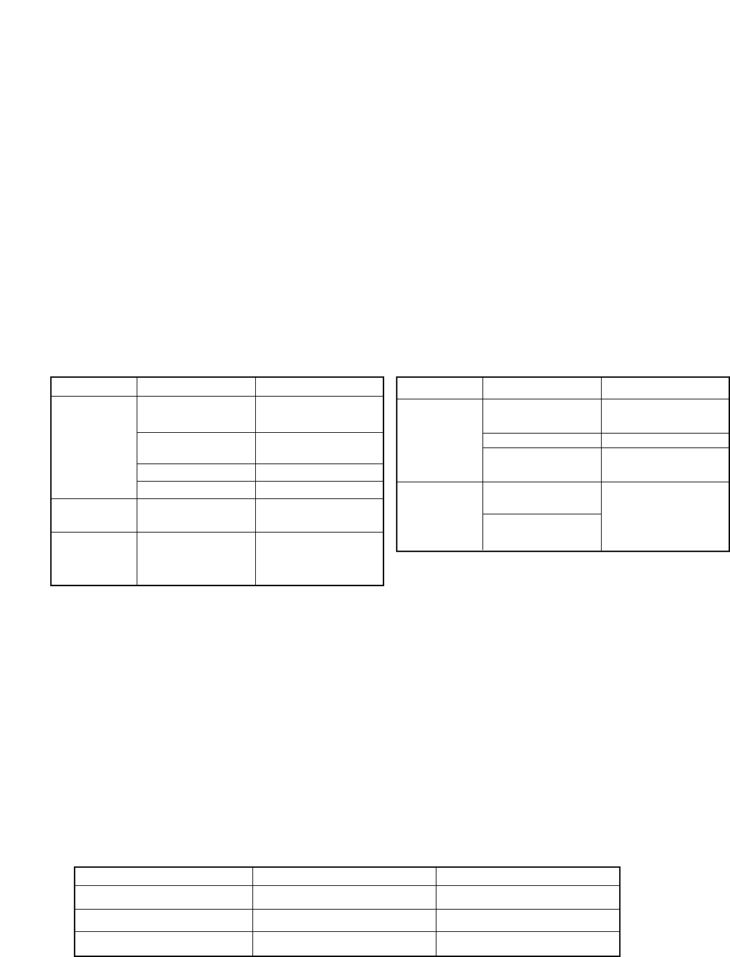
41
13.4. Combination With The Digital Video Recorder/ Multi-switchers (C-MS91D and C-MS161D)
The Digital Video Recorder has been designed with an emphasis on the synchronization with the TOA Multi-
switchers (C-MS91D, C-MS161D).
By synchronizing the Digital Video Recorder with the Multi-switcher, the following advantages – unavailable to
conventional systems using analog time-lapse VCRs – can be realized.
1. The Multi-switcher does not need to be operated when operating the Digital Video Recorder.
2. The Digital Video Recorder’s main menu screen or search screen can be easily displayed, facilitating
settings and search operations.
The combined Digital Video Recorder/Multi-switcher system is called a basic system in this manual.
Since the Multi-switcher has 2 VCR output terminals, hard disk space can be doubled by connecting two
Digital Video Recorders. This system is called an expansion system. The expansion system does not permit
the synchronization between the Digital Video Recorder and the Multi-switcher.
13.4.1. Basic System
Perform connections as shown in connection examples. (Refer to p. 43)
Set the Multi-switcher (C-MS91D and C-MS161D) and the Digital Video Recorder as follows:
13.4.2. Expansion System (Series Recording)
Perform connections as shown in connection examples. (Refer to p. 44)
The Digital Video Recorder settings are as follows:
• Operation
If the first Digital Video Recorder’s hard disk space becomes full, a signal is provided from the Disk Full Output
terminal. When the signal is received at the second Digital Video Recorder’s Recording Start Input terminal, its
Disk Full mode is reset, allowing recording to be started in the second unit.
Note
• Recording operation and Internal Timer Recording cannot be performed at the front panel of the Digital
Video Recorder set to Disk Full mode.
• Multi-switcher can be synchronized from the unit set to master through the RS-232C interface.Set
Communication Setting’s Switcher Synchronization to “TIME SYNC.”
• Multi-switcher settings
Perform remote and recording settings as follows:
• Digital Video Recorder settings
Perform communication settings as follows:
ContentsSetting Items
Remote
Settings
RS-232C
RS-232C
38.4kbps (Default)
1 (Default)
2
OFF*1
Recording Pattern
Operation
Motion Detection
Pattern Operation
RS-232C
RS-232C Protocol
Recording Device
Date/Time (VCR)
ContentsSetting Items
Communication
Settings
38400bps (Default)
OFF (Default)
ON
RS-232C
Transmission Rate
RS-232C Flow Control
Switcher
Synchronization*2
Recording Pattern
Motion Detection
Pattern
Recording
Settings
Buzzer/
Character
Display Settings
When perform-
ing Internal
Timer Recording
settings
Match the Recorder’s
settings to those of the
Multi-switcher
Note
*1Use the Digital Video Recorder’s date/time display function for date/time display. If set at both the Multi-
switcher and Digital Video Recorder, characters overlap and cannot be seen clearly.
*2Recording Pattern, Motion Detection Pattern, Camera/ VCR mode selection, and Time Synchronization
switcher functions can all be controlled by the Digital Video Recorder. However, when syncronizing the
switcher's clock from the Recorder, set the Recorder's clock Time Synchronization setting to "MASTER."
Time synhronization cannot be performed if set to "SLAVE."
When only performing time synchronization, set the communication swither synchronization setting to
"TIME SYNC." Please note that in this mode Recording Pattern,Motion Detection Pattern, and Camera/
VCR mode selection functions cannot be controlled.
• For more information on the Multi-switcher’s settings, refer to the instruction manual for the Multi-switcher.
First Digital Video Recorder
Setting Items
Recording Mode
Time Synchronization
Disk Full indicator status
SERIES
MASTER
OFF
Second Digital Video Recorder
SERIES
SLAVE
ON
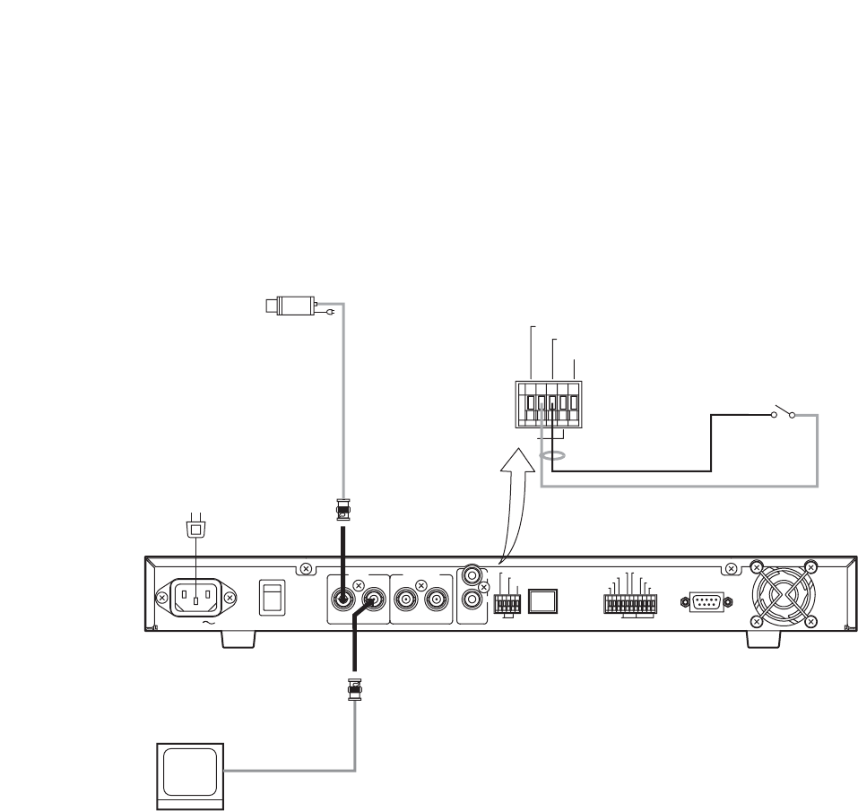
42
VIDEO OUT
GND
Sensor etc.
Video Input
Video Output
Video Input
1CH Digital Video Recorder
Monitor TV
Camera
AC MAINS MAIN POWER
ON
OFF
IN OUT IN OUT
VIDEO SW VIDEO IN
OUT
AUDIO
GND GND
100BASE–TX
ALARM RESET OUT
ALARM IN
SW CTRL OUT
TIME SYNC IN
REC STOP IN
REC START IN
ALARM RESET IN
TIME SYNC OUT
ALARM OUT
FAILURE OUT
DISK FULL OUT
RS–232C
GND
ALARM RESET OUT
ALARM IN
SW CTRL OUT
14. CONNECTION EXAMPLES
14.1. Connection to the 24V AC or 12V DC or AC Mains Camera.
Note
Power Sync cameras cannot be used.
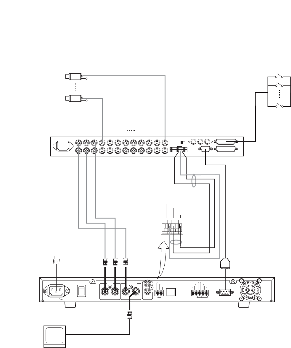
43
VTR1
1
9
D-Sub9 Pin
GND
RS-232CRS-232C
1CH Digital Video Recorder
AC MAINS MAIN POWER
ON
OFF
IN OUT IN OUT
VIDEO SW VIDEO IN
OUT
AUDIO
GND GND
100BASE–TX
ALARM RESET OUT
ALARM IN
SW CTRL OUT
TIME SYNC IN
REC STOP IN
REC START IN
ALARM RESET IN
TIME SYNC OUT
ALARM OUT
FAILURE OUT
DISK FULL OUT
RS–232C
Monitor TV
Video Input
Video Output
Video Input
GND
ALARM RESET OUT
ALARM IN
SW CTRL OUT
Video Input
1 – 9
Sensor etc.
Multi-switcher (C-MS91D)
Alarm Output
Alarm Input/Output
Monitor Output1
VCR Output1
VCR Input1
Switcher Control Input
Switcher
Video Output
Switcher Video Input
Camera
Camera
14.2. Connection to the Multi-switcher
14.2.1. Basic System (Combined with the C-MS91D Multi-switcher)
Note
Power Sync cameras cannot be used.
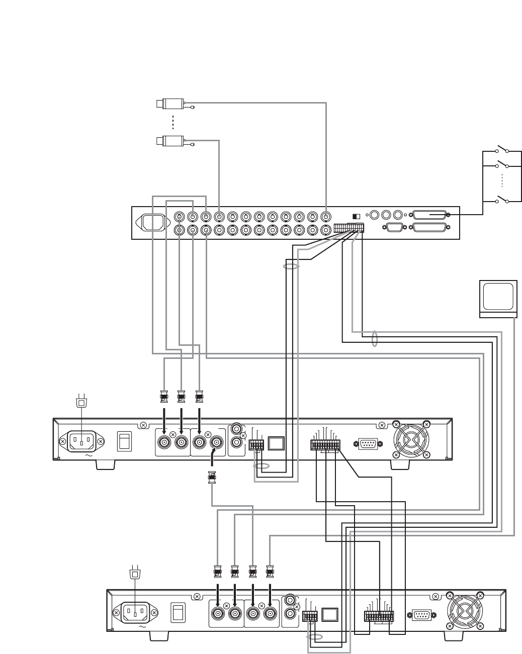
44
VTR1 VTR2
AC MAINS MAIN POWER
ON
OFF
IN OUT IN OUT
VIDEO SW VIDEO IN
OUT
AUDIO
GND GND
100BASE–TX
ALARM RESET OUT
ALARM IN
SW CTRL OUT
TIME SYNC IN
REC STOP IN
REC START IN
ALARM RESET IN
TIME SYNC OUT
ALARM OUT
FAILURE OUT
DISK FULL OUT
RS–232C
AC MAINS MAIN POWER
ON
OFF
IN OUT IN OUT
VIDEO SW VIDEO IN
OUT
AUDIO
GND GND
100BASE–TX
ALARM RESET OUT
ALARM IN
SW CTRL OUT
TIME SYNC IN
REC STOP IN
REC START IN
ALARM RESET IN
TIME SYNC OUT
ALARM OUT
FAILURE OUT
DISK FULL OUT
RS–232C
GND
GND
GND
GND
VCR Input 1
VCR Input 2
Monitor Output 1
VCR Output 1
VCR Output 2
Alarm Output
Switcher Control Input
Alarm Output
Switcher Control Input
Switcher Control
Output
Switcher Video
Input
Video Input
Video Output
Switcher
Video Output
Switcher Video
Input
Video Input
Video Output
Switcher Video Output
Alarm Input
Alarm Input
Switcher Control
Output
Recording Start
Input
Recording Start
Input
Diskfull Output
Diskfull Output
GND
GND
Monitor TV
Video Input
Sensor etc.
Multi-switcher (C-MS91D)
1CH Digital Video Recorder (1)
1CH Digital Video Recorder (2)
1
9
Video Input
1 – 9
Camera
Camera
Time Sync Input
Time Sync
Output
Slave
Master
14.2.2. Expansion System (Combined with the C-MS91D Multi-switcher)
Note
Power Sync cameras cannot be used.
45
15.2. When using the C-DR0100
Disk Mode : NORMAL Audio Record : ON
1/60
8
13
17
22
32
1/30
17
26
33
43
62
1/15
33
52
64
84
120
1/10
50
78
95
124
176
1/5
97
150
183
234
325
1/3
158
239
289
364
494
1/2
227
337
402
498
654
1
409
580
674
804
996
2
681
901
1011
1150
1334
3
878
1112
1220
1352
1516
5
1134
1356
1450
1558
1684
10
1460
1631
1697
1769
1848
20
1704
1815
1855
1898
1942
30
1803
1884
1913
1943
1973
60
1916
1961
1976
1992
2008
Level 1
Level 2
Level 3
Lebel 4
Level 5
Picture
quality
64KB
40KB
32KB
24KB
16KB
File
Size
Recording Time Intervals (Sec), Recording Time Period
Disk Mode : NORMAL Audio Record : OFF
1/60
9
14
17
22
33
1/30
17
27
34
44
65
1/15
34
54
67
89
131
1/10
51
81
101
133
196
1/5
103
163
202
267
392
1/3
171
271
337
445
654
1/2
257
407
505
667
981
1
513
813
1011
1334
1962
2
1026
1627
2021
2668
3924
3
1539
2440
3032
4002
5885
5
2565
4067
5053
6670
9809
10
5131
8134
10106
13340
19618
20
10262
16268
20212
26680
39236
30
15392
24403
30318
40020
58853
60
30785
48805
60637
80041
117707
Level 1
Level 2
Level 3
Lebel 4
Level 5
Picture
quality
64KB
40KB
32KB
24KB
16KB
File
Size
Recording Time Intervals (Sec), Recording Time Period
15. RECORDING TIME TABLE
15.1. Recording Picture Quality Setting
The Digital Video Recorder is designed to be used as a hard disk recorder for surveillance applications, and
its picture quality can be set to Levels 1 – 5. Whether emphasis is placed on picture quality or on recording
interval can be selected depending on surveillance conditions. When setting the picture quality, carefully
consider recording times, recording intervals, recording types and other surveillance conditions, and be sure
to carry out test recordings in advance to ensure that the required picture quality is maintained.
Note: Recording time is given as a guideline reference.
Disk Mode : NORMAL Audio Record : ON
1/60
17
27
33
44
64
1/30
34
53
65
86
124
1/15
67
105
129
168
240
1/10
100
155
191
247
351
1/5
195
300
365
468
651
1/3
315
478
577
729
988
1/2
454
674
804
996
1308
1
818
1160
1347
1607
1991
2
1361
1803
2021
2300
2668
3
1755
2223
2440
2704
3032
5
2269
2711
2900
3117
3369
10
2919
3262
3394
3538
3695
20
3407
3630
3711
3795
3884
30
3605
3768
3826
3885
3947
60
3832
3922
3953
3984
4016
Level 1
Level 2
Level 3
Lebel 4
Level 5
Picture
quality
64KB
40KB
32KB
24KB
16KB
File
Size
Recording Time Intervals (Sec), Recording Time Period
Disk Mode : NORMAL Audio Record : OFF
1/60
17
27
34
44
65
1/30
34
54
67
89
131
1/15
68
108
135
178
262
1/10
103
163
202
267
392
1/5
205
325
404
534
785
1/3
342
542
674
889
1308
1/2
513
813
1011
1334
1962
1
1026
1627
2021
2668
3924
2
2052
3254
4042
5336
7847
3
3078
4881
6064
8004
11771
5
5131
8134
10106
13340
19618
10
10262
16268
20212
26680
39236
20
20523
32537
40425
53360
78471
30
30785
48805
60637
80041
117707
60
61570
97610
121274
160081
235413
Level 1
Level 2
Level 3
Lebel 4
Level 5
Picture
quality
64KB
40KB
32KB
24KB
16KB
File
Size
Recording Time Intervals (Sec), Recording Time Period
15.3. When using the C-DR0101
46
Disk Mode : MIRRORING Audio Record : ON
1/60
–
–
–
–
–
1/30
17
26
33
43
62
1/15
33
52
64
84
120
1/10
50
78
95
124
176
1/5
97
150
183
234
325
1/3
158
239
289
364
494
1/2
227
337
402
498
654
1
409
580
674
804
996
2
681
901
1011
1150
1334
3
878
1112
1220
1352
1516
5
1134
1356
1450
1558
1684
10
1460
1631
1697
1769
1848
20
1704
1815
1855
1898
1942
30
1803
1884
1913
1943
1973
60
1916
1961
1976
1992
2008
Level 1
Level 2
Level 3
Lebel 4
Level 5
Picture
quality
64KB
40KB
32KB
24KB
16KB
File
Size
Recording Time Intervals (Sec), Recording Time Period
Disk Mode : MIRRORING Audio Record : OFF
1/60
–
–
–
–
–
1/30
17
27
34
44
65
1/15
34
54
67
89
131
1/10
51
81
101
133
196
1/5
103
163
202
267
392
1/3
171
271
337
445
654
1/2
257
407
505
667
981
1
513
813
1011
1334
1962
2
1026
1627
2021
2668
3924
3
1539
2440
3032
4002
5885
5
2565
4067
5053
6670
9809
10
5131
8134
10106
13340
19618
20
10262
16268
20212
26680
39236
30
15392
24403
30318
40020
58853
60
30785
48805
60637
80041
117707
Level 1
Level 2
Level 3
Lebel 4
Level 5
Picture
quality
64KB
40KB
32KB
24KB
16KB
File
Size
Recording Time Intervals (Sec), Recording Time Period
Note
Setting the Disk Setting’s Disk Mode to "MIRRORING" limits the maximum recording interval to 1/30 second.
(Refer to p. 15;"Disk Setting.")
15.4. When using the C-DR0105
Disk Mode : NORMAL Audio Record : ON
1/60
34
54
67
89
129
1/30
68
108
133
174
252
1/15
136
213
263
342
490
1/10
203
316
389
504
716
1/5
397
612
746
955
1328
1/3
643
976
1179
1488
2017
1/2
926
1375
1640
2032
2670
1
1670
2368
2751
3281
4064
2
2779
3680
4126
4695
5447
3
3583
4539
4982
5520
6189
5
4631
5535
5920
6363
6877
10
5959
6658
6930
7224
7544
20
6956
7410
7575
7748
7928
30
7360
7693
7811
7932
8057
60
7822
8006
8069
8133
8199
Level 1
Level 2
Level 3
Lebel 4
Level 5
Picture
quality
64KB
40KB
32KB
24KB
16KB
File
Size
Recording Time Intervals (Sec), Recording Time Period
Disk Mode : NORMAL Audio Record : OFF
1/60
34
55
68
90
133
1/30
69
110
137
181
267
1/15
139
221
275
363
534
1/10
209
332
412
544
801
1/5
419
664
825
1089
1602
1/3
698
1107
1375
1815
2670
1/2
1047
1660
2063
2723
4005
1
2095
3321
4126
5447
8010
2
4190
6642
8253
10894
16020
3
6285
9964
12379
16341
24031
5
10475
16606
20632
27235
40051
10
20950
33213
41265
55470
80103
20
41900
66427
82531
108941
160207
30
62850
99641
123796
163411
240311
60
125701
199282
247593
326823
480622
Level 1
Level 2
Level 3
Lebel 4
Level 5
Picture
quality
64KB
40KB
32KB
24KB
16KB
File
Size
Recording Time Intervals (Sec), Recording Time Period
Disk Mode : MIRRORING Audio Record : ON
1/60
–
–
–
–
–
1/30
34
54
66
87
126
1/15
68
106
131
171
245
1/10
101
158
194
252
358
1/5
198
306
373
477
664
1/3
321
488
589
744
1008
1/2
463
687
820
1016
1335
1
835
1184
1375
1640
2032
2
1389
1840
2063
2347
2723
3
1791
2269
2491
2760
3094
5
2315
2767
2960
3181
3438
10
2979
3329
3465
3612
3772
20
3478
3705
3787
3874
3964
30
3680
3846
3905
3966
4028
60
3911
4003
4034
4066
4099
Level 1
Level 2
Level 3
Lebel 4
Level 5
Picture
quality
64KB
40KB
32KB
24KB
16KB
File
Size
Recording Time Intervals (Sec), Recording Time Period
Disk Mode : MIRRORING Audio Record : OFF
1/60
–
–
–
–
–
1/30
34
55
68
90
133
1/15
69
110
137
181
267
1/10
104
166
206
272
400
1/5
209
332
412
544
801
1/3
349
553
687
907
1335
1/2
523
830
1031
1361
2002
1
1047
1660
2063
2723
4005
2
2095
3321
4126
5447
8010
3
3142
4982
6189
8170
12015
5
5237
8303
10316
13617
20025
10
10475
16606
20632
27235
40051
20
20950
33213
41265
54470
80103
30
31425
49820
61898
81705
120155
60
62850
99641
123796
163411
240311
Level 1
Level 2
Level 3
Lebel 4
Level 5
Picture
quality
64KB
40KB
32KB
24KB
16KB
File
Size
Recording Time Intervals (Sec), Recording Time Period

47
16. EXTERNAL TERMINAL SPECIFICATIONS
16.1. RS-232C Communication Specifications
The Digital Video Recorder’s RS-232C interface permits remote control using a connected PC.
Note
• Control software is not supplied as standard.
• Communication specifications are those set when the Switcher Synchronization selection on the
Communication Setting Screen is set to "OFF."
• TOA takes no responsibility for any inconvenience or damage to customer hardware or software which may
result from the use of control software based on the specifications described in this section.
16.1.1. The Rules of Overall Communications
1. All communications are established by means of a command from the controller.
2. Responses are always present in mutual communications.
3. The response timeout period is 1 second, and the timeout period between continuous data is 100
milliseconds. When the timeout occurs, the corresponding communications are regarded as failed.
4. Data is only updated when a communication setting content update command is received while in Standby
mode or in Idle and Recording Pause mode. No setting content update commands are accepted during
system activation, error message indication, menu screen display, search screen display, playback,
recording (Include Alarm Recording Setting’s Alarm is set to “VALID.”) or while in timer mode (DEL is
returned).
5. When command operation cannot be performed, received data is discarded and any commands are
regarded as invalid.
16.1.2. Communication Protocol
Transfer System : Start/stop system (asynchronous system), duplex
Parity Bit : Even
Transfer Rate : 9,600, 19,200, 38,400 bps
Code : Binary code
Bit Length : 8 bits
Flow Control : CTS/RTS handshaking, none
Stop Bit : 1
Error Control : None
16.1.3. RS-232C Connector Pin Arrangement
The following table shows the signal name of each pin of the RS-232C D-sub 9P connector.
Signal Name
Pin No.
Unconnected
RXD (Received Data)
TXD (Transmitted Data)
Unconnected
GND
Unconnected
RTS (Request to send)
CTS (Clear to send)
Unconnected
1
2
3
4
5
6
7
8
9
Note: The plug for the RS-232C connector is not supplied with the Digital Video Recorder.
Use a cross cable for the RS-232C interface connection.
48
STX LEN COMMAND PARA DATA ETX
Item
1 1 2 2 Variable 1No. of Byte
STX : Fixed to A0H.
LEN : The number of bytes from command to DATA
COMMAND : BT, MS, MV, LG, SE*1
PARA : Parameter*1
DATA : DATA section (variable depending on a command and parameter)
ETX : Fixed to AFH.
*1If communication data is transmitted, an ACK, NAK, or DEL signal is returned immediately after the data is
received.
ACK (06H) : Correct reception
NAK (15H) : Reception error
DEL (7FH) : Invalid operation
16.1.5. RS-232C Communication Command (Controller Digital Recorder)
Commands are 2 bytes in length. Parameters (PARA) are also 2 bytes. They are followed by the multi-byte
DATA section. If DATA LEN is "0," no DATA section follows.
Key's Commands
Command
BT
PARA
PL
ST
RV
PS
RD
DC
MN
ON
PO
PF
SC
QT
AL
RS
KH
UP
DW
LF
RT
SL
DATA LEN
0
0
0
0
0
0
0
0
0
0
0
0
0
0
0
0
0
0
0
0
Operation
Playback Key
Playback Stop Key
Reverse Playback Key
Pause Key
Recording Key
Buzzer Stop Key
Menu Key (Press Menu Key for 1 second or more)
Start Internal Timer Recording (Press Timer key for 1 second or more)
Standby Key ON
Standby Key OFF
Search Key
Periodical Status Inquiry (Response returned)
Alarm Operation
Recording Stop Key (Press Recording Key for 1 second or more)
Recording Start Operation
Up Shift Key
Down Shift Key
– Key
+ Key
Select Key
16.1.4. RS-232C Communication Format (Controller Digital Recorder)

49
Operation
0 – 4 (Level 5 – Level 1)
0 : OFF, 1 : ON
0:1/60, 1:1/30, 2:1/15, 3:1/10, 4:1/5, 5:1/3, 6:1/2, 7:1, 8:2, 9:3, A:5,
B:10, C:20, D:30, E:60
0 – 9 (1,2,3,4,5,10,15,20,30,60)
0 – 9: Setting No.01 – 10
0:Cancel, 1:Daily, 2:Weekly
First byte MM:1 – C, Second byte DD:1 – 1F
BIT0:Sun, BIT1:Mon, BIT2:Tue, BIT3:Wed, BIT4:Thu, BIT5:Fri,
BIT6:Sat
First byte HH:0 – 17, Second byte MM:0 – 3B
First byte HH:0 – 17, Second byte MM:0 – 3B
0 – 4 (Level 5 – Level 1)
0:OFF, 1:ON
0:1/60, 1:1/30, 2:1/15, 3:1/10, 4:1/5, 5:1/3, 6:1/2, 7:1, 8:2, 9:3, A:5,
B:10, C:20, D:30, E:60
0:1, 1:2
0:1, 1:2
0: Invalid, 1:Valid, 2:Valid during recording (Val Rec)
0:Edge, 1:Level
0 – 7 (0Sec, 10Sec, 15Sec, 20Sec, 30Sec, 1Min, 2Min, 5Min)
0 – 9 (10Sec, 15Sec, 20Sec, 30Sec, 1Min, 2Min,, 3Min, 4Min, 5Min,
10Min)
0 – 7 (0Sec, 10Sec, 15Sec, 20Sec, 30Sec, 1Min, 2Min, 5Min)
0 – 4 (Level 5 – Level 1)
0:OFF, 1:ON
0:1/60, 1:1/30, 2:1/15, 3:1/10, 4:1/5, 5:1/3, 6:1/2, 7:1
0:OFF, 1:ON
0:During Alarm Recording, 1:1Second
0:Nomal, 1:Mirroring
0:Stop, 1:Re-Rec, 2:Series
YYYY:7D0 – 833 (2000 – 2099 Year)
MM: 1 – C (Jan – Dec Month)
DD: 1 – 1F (1 – 31 Date)
HH: 0 – 17 (00:00 – 23:00 Hour)
MM: 0 – 3B (0 – 59 Minute)
SS: 0 – 3B (0 – 59 Second)
0: Hide, 1:Display
0: Hide, 1:Display
0: Hide, 1:Display
0: Hide, 1:Display
0: Hide, 1:Display
Disk Mode set to Nomal : 0:Hide, 1:Display
Disk Mode set to Mirroring: 0:Hide, 1:Max, 2:Min, 3:HDD-A, 4:HDD-B
0: Hide, 1:Display
0: Hide, 1:Display
0:Upper Left, 1: Upper Center, 2:Upper Right, 3: Lower Left,
4: Lower Center, 5: Lower Right
0: Hide, 1:Display
0: 9600, 1: 19200, 2: 38400 bps
0:OFF, 1:ON
0:Master, 1:Slave
0 – 23
0:OFF, 1:ON, 2:Time Sync
0:All, 1:HDD-A, 2:HDD-B
0:Disallow, 1:Allow
0:OFF, 1:ON
1 – C:Jan – Dec Month
1:Fast, 2:Second, 3:Third, 4:Fourth, 5:Last
0 – 17:00 – 23 Hour
1 – C:Jan – Dec Month
1:Fast, 2:Second, 3:Third, 4:Fourth, 5:Last
0 – 17:00 – 23 Hour
Command
MS
PARA
RQ
RD
RI
RC
TM
AS
AN
AP
AT
AF
AQ
AD
AI
AB
AO
WD
WM
DT
VQ
VD
VW
VR
VP
VG
VH
VT
VC
VM
TR
TF
TS
TT
TC
PM
PR
SU
SM
SW
SH
EM
EW
EH
DATA LEN
1
1
1
1
1
1
2
1
2
2
1
1
1
1
1
1
1
1
2
2
1
1
1
1
1
1
1
2
1
1
1
1
1
1
1
1
1
1
1
1
1
1
1
1
1
1
1
1
1
1
1
1
1
1
1
1
1
Contents
General Recording Setting Picture
Quality
General Recording Setting Audio
General Recording Setting Recording
Interval
Switcher Control Period
Setting Frame No.
Timer Setting Mode
Date
Day of the week
Timer Start Time
Timer End Time
Internal Timer Recording Setting
Picture Quality
Internal Timer Recording Setting
Audio
Internal Timer Recording Setting
Recording Interval
Recording Pattern
Motion Detection Pattern
Alarm Setting
Alarm Input Mode
Pre-Alarm Period
Alarm Recording Period
Post-Alarm Period
Alarm Recording Picture Quality
Alarm Recording Audio
Alarm Recording Recording Interval
Buzzer Sound Output
Alarm Output Period
Disk Mode (C-DR0101, C-DR0105)
Recording Mode
Date/Time Setting Year
Date/Time Setting Month
Date/Time Setting Date
Date/Time Setting Hour
Date/Time Setting Minute
Date/Time Setting Sec
Picture Quality Display
Audio ON/OFF Display
Re-Recording Mode
Recording Mode Display
Playback Display
Remaining Time Display
Date Display
Time Display
Date/Time Display Position
Disk Mode Indication
(C-DR0101, C-DR0105)
Communication Rate
Flow Control
Time Synchronization
Synchronized Time
Switcher Synchronization
Playback Mode
Simultaneous Recording/Playback
Summer Time Setting
Summer Time First day Month
Summer Time First day Sunday
Summer Time First day Time
Summer Time Last day Month
Summer Time Last day Sunday
Summer Time Last day Time
Menu Setting Commands
50
Note: Date/Time search is performed using setting data.
Operation
Request to send setting contents
Request to send setting contents
Request to send setting contents
Request to send setting contents
0 – 9: Setting No., Request to send setting contents
Request to send setting contents
Request to send setting contents
Request to send setting contents
Request to send setting contents
Request to send setting contents
Request to send setting contents
Request to send setting contents
Request to send setting contents
Request to send setting contents
Request to send setting contents
Request to send setting contents
Request to send setting contents
Request to send setting contents (current time)
Request to send setting contents
Request to send setting contents
Request to send setting contents
Request to send setting contents
Request to send setting contents
Request to send setting contents
Request to send setting contents
Request to send setting contents
Request to send setting contents
Request to send setting contents
Request to send setting contents
Request to send setting contents
Request to send setting contents
Request to send setting contents
Request to send setting contents
Request to send setting contents
Request to send setting contents
Request to send setting contents
Request to send setting contents
Request to send setting contents
Request to send setting contents
Request to send setting contents
Request to send setting contents
Request to send setting contents
Command
MV
PARA
RQ
RD
RI
RC
TM
AS
AN
AP
AT
AF
AQ
AD
AI
AB
AO
WD
WM
DT
VQ
VD
VW
VR
VP
VG
VH
VT
VC
VM
TR
TF
TS
TT
TC
PM
PR
SU
SM
SW
SH
EM
EW
EH
DATA LEN
0
0
0
0
1
0
0
0
0
0
0
0
0
0
0
0
0
0
0
0
0
0
0
0
0
0
0
0
0
0
0
0
0
0
0
0
0
0
0
0
0
0
Contents
General Recording Setting Picture
Quality
General Recording Setting Audio
General Recoding Setting Recording
Interval
Switcher Control Period
Timer Setting Data
Alarm Setting
Alarm Input Mode
Pre-Alarm Period
Alarm Recording Period
Post-Alarm Period
Alarm Recording Picture Quality
Alarm Recording Audio
Alarm Recording Recording Interval
Buzzer Sound Output
Alarm Output Period
Disk Mode (C-DR0101, C-DR0105)
Recording Mode
Clock Setting Data
Picture Quality Display
Audio Display
Recording Mode Display
Recording Display
Playback Display
Remaining Time Display
Daily Display
Time Display
Date/Time Display Position
Disk Mode Indication (C-DR0101,C-DR0105)
Transmission Rate
Flow Control
Time Synchronization
Synchronized Time
Switcher Synchronization
Playback Mode
Playback during Recording
Summer Time Setting
Summer Time First day Month
Summer Time First day Sunday
Summer Time First day Time
Summer Time Last day Month
Summer Time Last day Sunday
Summer Time Last day Time
Menu Setting Content Request Command
Operation
Request for sending from the head of the most recent data
Request for continued data
Request for sending from the head of the most recent data
Request for continued data
Request for sending from the head of the most recent data
Request for continued data
Command
LG
PARA
RD
RQ
AL
AQ
TR
TQ
DATA LEN
0
0
0
0
0
0
Contents
Request for Recording Log
Next Request for Recording Log
Request for Alarm Recording Log
Next Request for Alarm Recording Log
Request for Failure Logs
Next Request for Failure Logs
Log Request Command
Operation
YYYY: 7D0 – 833 (2000 – 2099 Year)
MM: 1 – C (Jan – Dec Month)
DD: 1 – 1F (1 – 31 Date)
HH: 0 – 17 (00:00 – 23:00 Hour)
MM: 0 – 3B (0 – 59 Minute)
Command
SE
PARA
SD
DATA LEN
2
1
1
1
1
Contents
Date/Time Search Year
Date/Time Search Month
Date/Time Search Date
Date/Time Search Hour
Date/Time Search Minute
Search Menu Execution Command
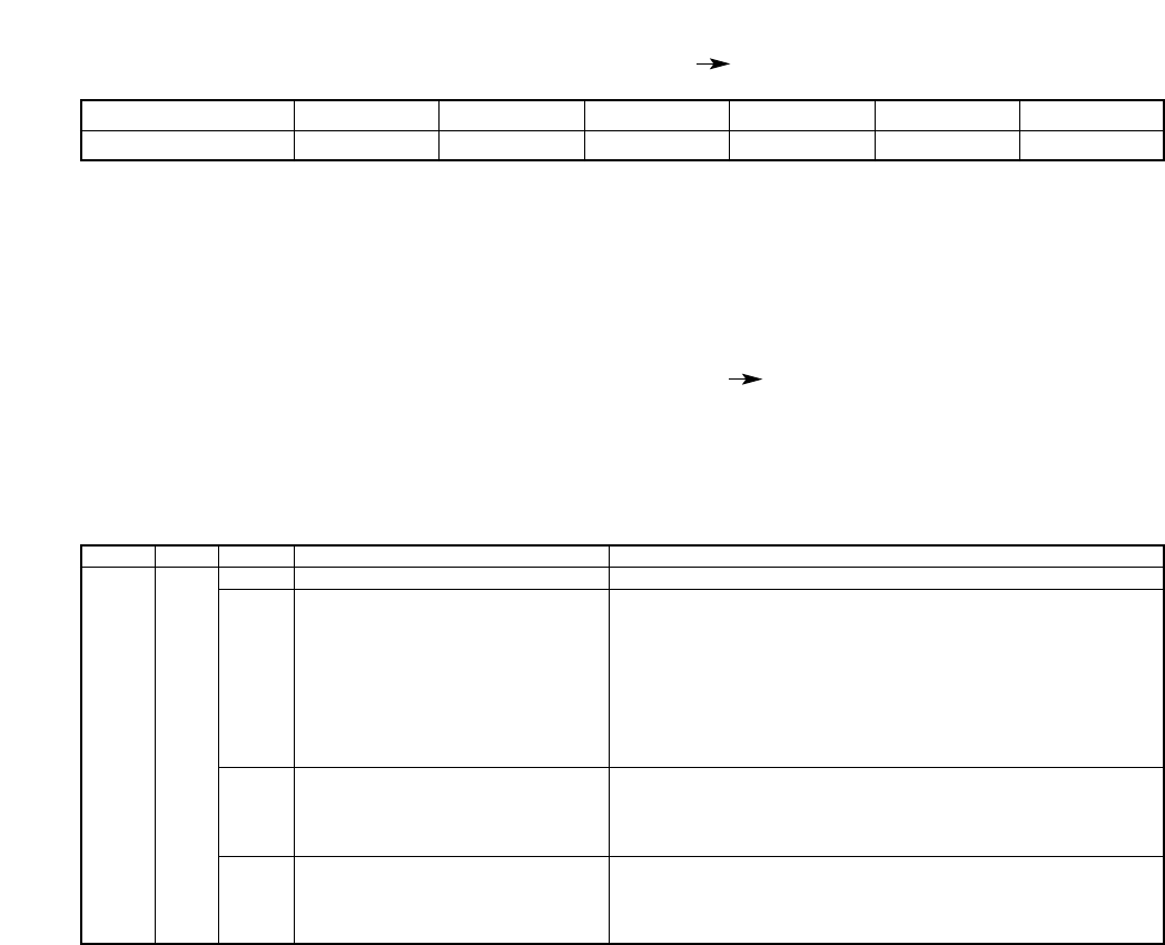
51
Command
BT
16.1.7. RS-232C Communication Command (Digital Recorder Controller)
Commands are 2 bytes in length. Parameters (PARA) are also 2 bytes. They are followed by the multi-byte
DATA section.
Key response command
Operation
0:Power OFF, 1:Power ON
0:Standby or Stop
1:Pause
2:Playback
3:Fast Forward Playback
4 Reverse Playback
5:Rewind
6.Menu or Search Screen Display
7:Disk Error or disk operation such as disk recognition
0:Standby or Stop
1:Recording
2:Alarm Recording
3:Internal Timer Recording
0: No failure
1: Hard disk failure
2: Video loss failure
3: Fan failure
PARA
QT
DATA LEN
1
1
1
1
Contents
Operation Status
Status
Recording Status
Failure
16.1.6. RS-232C Communication Format (Digital Recorder Controller)
STX : Fixed to A0H.
LEN : The number of bytes from command to DATA
COMMAND : BT, MV, LG
PARA : Parameter
DATA : DATA section (variable depending on a command and parameter)
ETX : Fixed to AFH.
STX LEN COMMAND PARA DATA ETX
Item
1 1 2 2 Variable 1No. of Byte

52
Menu Setting Content Response Command
Operation
0 – 4 (Level 5 – Level 1)
0 : OFF, 1 : ON
0:1/60, 1:1/30, 2:1/15, 3:1/10, 4:1/5, 5:1/3, 6:1/2, 7:1, 8:2, 9:3, A:5,
B:10, C:20, D:30, E:60
0 – 9 (1,2,3,4,5,10,15,20,30,60)
0 – 9: Setting No.01 – 10
0:Cancel, 1:Daily, 2:Weekly
First byte MM:1 – C, Second byte DD:1 – 1F
BIT0:Sun, BIT1:Mon, BIT2:Tue, BIT3:Wed, BIT4:Thu, BIT5:Fri,
BIT6:Sat
First byte HH:0 – 17, Second byte MM:0 – 3B
First byte HH:0 – 17, Second byte MM:0 – 3B
0 – 4 (Level 5 – Level 1)
0:OFF, 1:ON
0:1/60, 1:1/30, 2:1/15, 3:1/10, 4:1/5, 5:1/3, 6:1/2, 7:1, 8:2, 9:3, A:5,
B:10, C:20, D:30, E:60
0:1, 1:2
0:1, 1:2
0: Invalid, 1:Valid, 2:Valid during recording (Val Rec)
0:Edge, 1:Level
0 – 7 (0Sec, 10Sec, 15Sec, 20Sec, 30Sec, 1Min, 2Min, 5Min)
0 – 9 (10Sec, 15Sec, 20Sec, 30Sec, 1Min, 2Min,, 3Min, 4Min, 5Min,
10Min)
0 – 7 (0Sec, 10Sec, 15Sec, 20Sec, 30Sec, 1Min, 2Min, 5Min)
0 – 4 (Level 5 – Level 1)
0:OFF, 1:ON
0:1/60, 1:1/30, 2:1/15, 3:1/10, 4:1/5, 5:1/3, 6:1/2, 7:1
0:OFF, 1:ON
0:During Alarm Recording, 1:1Second
0:Nomal, 1:Mirroring
0:Stop, 1:Re-Rec, 2:Series
YYYY:7D0 – 833 (2000 – 2099 Year)
MM: 1 – C (Jan – Dec Month)
DD: 1 – 1F (1 – 31 Date)
HH: 0 – 17 (00:00 – 23:00 Hour)
MM: 0 – 3B (0 – 59 Minute)
SS: 0 – 3B (0 – 59 Second)
0: Hide, 1:Display
0: Hide, 1:Display
0: Hide, 1:Display
0: Hide, 1:Display
0: Hide, 1:Display
Disk Mode set to Nomal : 0:Hide, 1:Display
Disk Mode set to Mirroring: 0:Hide, 1:Max, 2:Min, 3:HDD-A, 4:HDD-B
0: Hide, 1:Display
0: Hide, 1:Display
0:Upper Left, 1: Upper Center, 2:Upper Right, 3: Lower Left,
4: Lower Center, 5: Lower Right
0: Hide, 1:Display
0: 9600, 1: 19200, 2: 38400 bps
0:OFF, 1:ON
0:Master, 1:Slave
0 – 23
0:OFF, 1:ON, 2:Time Sync
0:All, 1:HDD-A, 2:HDD-B
0:Disallow, 1:Allow
0:OFF, 1:ON
1 – C:Jan – Dec Month
1:Fast, 2:Second, 3:Third, 4:Fourth, 5:Last
0 – 17:00 – 23 Hour
1 – C:Jan – Dec Month
1:Fast, 2:Second, 3:Third, 4:Fourth, 5:Last
0 – 17:00 – 23 Hour
Command
MV
PARA
RQ
RD
RI
RC
TM
AS
AN
AP
AT
AF
AQ
AD
AI
AB
AO
WD
WM
DT
VQ
VD
VW
VR
VP
VG
VH
VT
VC
VM
TR
TF
TS
TT
TC
PM
PR
SU
SM
SW
SH
EM
EW
EH
DATA LEN
1
1
1
1
1
1
2
1
2
2
1
1
1
1
1
1
1
1
2
2
1
1
1
1
1
1
1
2
1
1
1
1
1
1
1
1
1
1
1
1
1
1
1
1
1
1
1
1
1
1
1
1
1
1
1
1
1
Contents
General Recording Setting Picture
Quality
General Recording Setting Audio
General Recording Setting Recording
Interval
Switcher Control Period
Setting Frame No.
Timer Setting Mode
Date
Day of the week
Timer Start Time
Timer End Time
Internal Timer Recording Setting
Picture Quality
Internal Timer Recording Setting
Audio
Internal Timer Recording Setting
Recording Interval
Recording Pattern
Motion Detection Pattern
Alarm Setting
Alarm Input Mode
Pre-Alarm Period
Alarm Recording Period
Post-Alarm Period
Alarm Recording Picture Quality
Alarm Recording Audio
Alarm Recording Recording Interval
Buzzer Sound Output
Alarm Output Period
Disk Mode (C-DR0101, C-DR0105)
Recording Mode
Date/Time Setting Year
Date/Time Setting Month
Date/Time Setting Date
Date/Time Setting Hour
Date/Time Setting Minute
Date/Time Setting Sec
Picture Quality Display
Audio ON/OFF Display
Re-Recording Mode
Recording Mode Display
Playback Display
Remaining Time Display
Date Display
Time Display
Date/Time Display Position
Disk Mode Indication
(C-DR0101, C-DR0105)
Communication Rate
Flow Control
Time Synchronization
Synchronized Time
Switcher Synchronization
Playback Mode
Simultaneous Recording/Playback
Summer Time Setting
Summer Time First day Month
Summer Time First day Sunday
Summer Time First day Time
Summer Time Last day Month
Summer Time Last day Sunday
Summer Time Last day Time
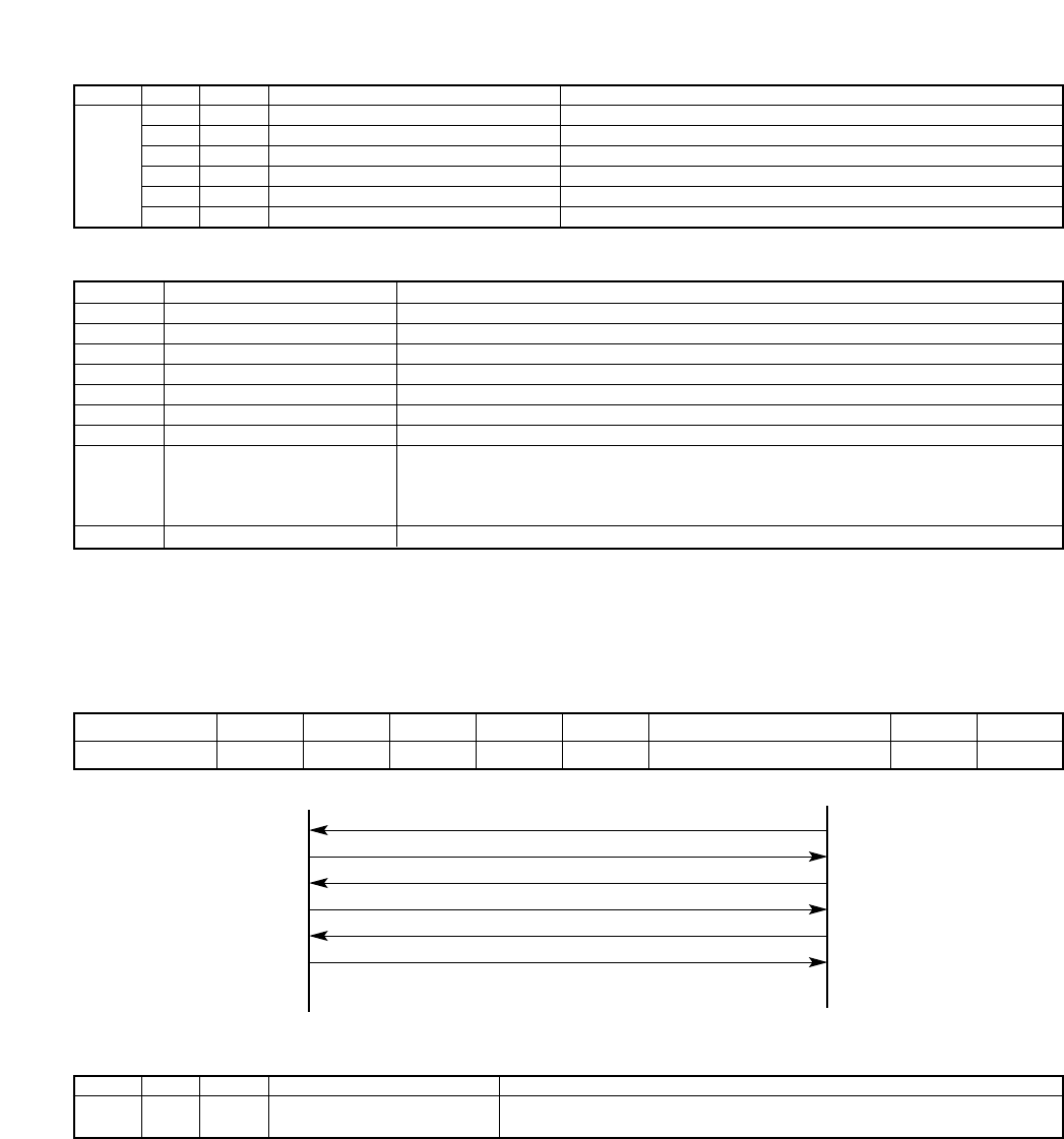
53
Unit Host
Request for recording log
Transmission of recording log (DATA follows)
Request for next recording log
Transmission of next recording log (DATA follows)
Request for next recording log
Transmission of next recording log (No DATA follows)
Contents
Data valid/invalid
Year
Month
Date
Time
Minute
Second
Detailed Code
Continuation sign
Log Content Response Command
Shown below are log information DATA section (13 bytes) formats.
DATA LEN
1
2
1
1
1
1
1
4
1
Description of Data
0: Invalid, 1: Valid
YYYY: 7D0 – 833 (2000 – 2099 Year)
MM: 1 – C (Jan – Dec Month)
DD: 1 – 1F (1 – 31 Date)
HH: 0 – 17 (00:00 – 23:00 Hour)
MM: 0 – 3B (0 – 59 Minute)
SS: 0 – 3B (0 – 59 Second)
RD/RQ mode: 0: Recording Start, 1:Recording End, 2:Internal Timer Recording Start,
3: Internal Timer Recording End
AL/AQ mode: 0: Alarm Recording Start, 1: Alarm Recording End
TR/TQ mode: 65 – C8 Video Failure, C9 – 12C: HDD Failure, 12D: Fan Failure
FE:DATA follows, FF: No DATA follows
When transmitting log data, DATA contained in LEN (up to 255 bytes) is set in 13-byte units. If DATA’s 13th
byte is a continuation sign (0xFE), DATA follows. If last DATA is a continuation sign, a continued log
acquisition command becomes valid. Transmission format and transmitting/receiving sequence are as follows:
STX LEN COMMAND PARA DATA DATA ...........
13 ...........
ETXItem
112213 1
DATA
13No. of Byte
Operation
0 : No corresponding Data is present.
1 : Corresponding Data is present.
Command
SV
PARA
SD
DATA LEN
1
Contents
Time Search
Execution Result
Search menu result command
Note
This response is transmitted to a controller when an ACK signal has been returned in response to a SE
command.
16.2. About the Ethernet Terminal
The Digital Video Recorder is equipped the Ethernet terminal (100BASE-TX). Use the LAN (crossing) cable to
connect the Ethernet terminal to the PC.
Operation
Request for sending from the head of the most recent data
Request for continued data
Request for sending from the head of the most recent data
Request for continued data
Request for sending from the head of the most recent data
Request for continued data
Command
LG
PARA
RD
RQ
AL
AQ
TR
TQ
DATA LEN
13
13
13
13
13
13
Contents
Request for Recording Log
Next Request for Recording Log
Request for Alarm Recording Log
Next Request for Alarm Recording Log
Request for Failure Logs
Next Request for Failure Logs
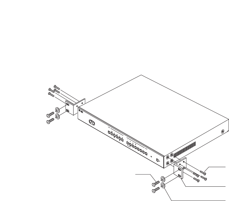
54
17. RACK MOUNTING
Use the optional MB-15B Rack Mounting Bracket when mounting the Digital Video Recorder in an equipment
rack. Remove 4 rubber feet on the bottom surface by loosening their respective fixing screws with a standard
screwdriver.
DIGITAL RECORDER
DISK FULL/
FAILURE
ALARM
RESET
BUZZER
STOP
SEARCH
MENU
SELECT
BLOCK
PLAY
STOP
PLAY
P
AUSE
REVERSE
PLAY
REC
TIMER
FRAMEFRAME
OUTPUT
VIDEO AUDIO
5 x 12 mm rack mounting screw
(supplied with the MB-15B)
3 x 14 mm tapping screw
(supplied with the MB-15B)
MB-15B (optional)
M5 fiber washer
(supplied with the MB-15B)
Note
• Use the Digital Video Recorder in locations with ambient temperature of between +5°C and +40°C
• Be sure to mount the Digital Video Recorder below the heat generating components, and mount the
perforated panel between the Recorder and such a heat generating component as required.
• The Digital Video Recorder has a built-in cooling fan. Never block the Recorder’s ventilation slot.
• Avoid installing the Digital Video Recorder in locations exposed to vibration.

55
Symptom
Cannot switch on the power.
Cannot operate the front panel-
mounted keys.
No picture is displayed.
The Recorder is not activated
even if the Standby key is
pressed.
The Recorder is not terminated
even if the Standby key is
pressed.
Cannot record.
Cannot stop recording.
Cannot perform Internal Timer
recording.
Cannot perform Alarm
recording.
No voice or sound recorded.
Cannot perform search and
playback.
No screen indication displayed.
On-screen time is not accurate.
System failure indicator does not
extinguish.
The indication "Disk may have
failed" is displayed on the
screen.
Possible Cause
• The supplied power cord is not
connected to the Digital Video Recorder’s
Power inlet and wall AC outlet.
• Keys are locked.
• Power is not switched on.
• Cables are not correctly connected.
• Main power is not switched on.
• The Standby key is not continuously
pressed for 1 second or more.
• Recording mode is set to "STOP" and
no available hard disk time remains.
• Key Lock is set to ON.
• The Recorder is in General recording
mode.
• Incorrect timer setting.
• Recording mode is set to "SERIES."
• Alarm input cord not correctly
connected.
• Alarm not set to "VALID."
• Each Recording Mode Audio Setting
selection not set to ON.
• Hard disk is initialized.
• Not recorded on the hard disk.
• Playback during Recording is set to
"OFF."
• Display setting set to "HIDE."
• Time not adjusted.
• Power was switched off for a long period
of time.
• Check to confirm the contents of failure
log (refer to p. 25).
• Hard disk format data may have been
damaged.
• Hard disk may have failed. Referring to
p. 28; "When the Failure Screen is
displayed," check the symptom.
• Connect the power cord.
• Release Key Lock.
• Switch on the power.
• Connect the cable correctly.
• Switch on the main power.
• Hold down the Standby key for 1
second or more.
• Change the Overwrite Recording
setting to "RE-REC" or "SERIES."
• Reset Key Lock
• Stop General recording and press the
Timer key.
• Set timer operating times correctly.
• Change the Recording mode to
"STOP" or "RE-REC."
• Connect cords correctly.
• Set the Alarm setting to "VALID."
• Set Audio setting to "ON."
• Search and playback cannot be
performed without recording data.
Perform recording.
• Playback cannot be performed during
recording. Set the Playback during
Recording selection to "ON"
• Set Display setting to "DISP."
• Adjust times.
• If no main power is supplied
continuously for 30 days or more,
clock data will be lost. In such cases,
update times again.
• Remove the cause of the failure.
• If the situation cannot be improved,
contact your TOA dealer.
Remedy
18. IF YOU THINK THERE IS A FAILURE: (TROUBLESHOOTING)
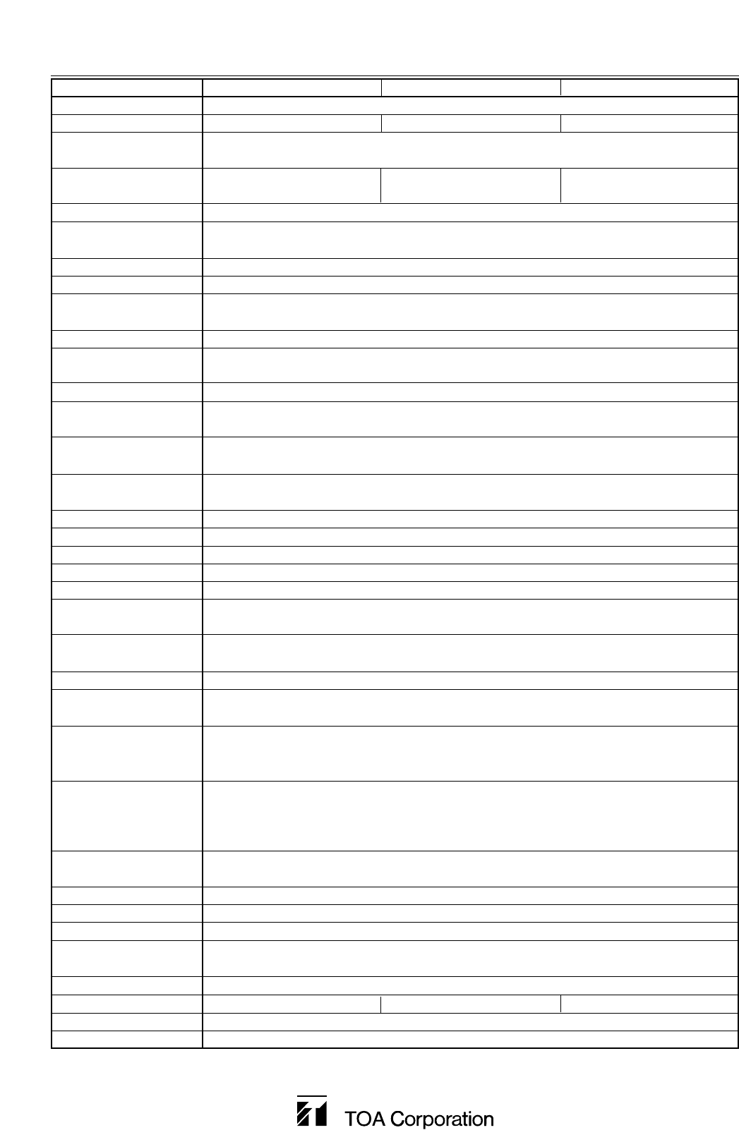
Model
Power Source
Power Consumption
Image Compression
System
Recording Medium
Video Input
Video Output
Switcher Video Input
Switcher Video Output
Audio Recording
System
Audio Input
Audio Output
Frequency Response
Alarm Input
Alarm Output
Picture Quality
Pixels
Recording Intervals
Pre-Alarm Recording
Alarm Recording
Post Alarm Recording
Date/Time
Internal Timer
Recording
Search Function
System Failure Output
Control Input Terminal
Control Output Terminal
Communication
Function
Memory Backup
Operating Temperature
Operating Humidity
Finish
Dimensions
Weight
Accessories
Optional Equipment
C-DR0100 C-DR0101 C-DR0105
110 – 120 V AC 50/60 Hz
24 W (450 mA) 35 W (640 mA) 37 W (670 mA)
Motion JPEG
E-IDE Hard Disk E-IDE Hard Disk E-IDE Hard Disk
120 GB (120 GB x 1)
240 GB (120 GB x 2) 500 GB (250 GB x 2)
1 Input VBS1.0 V(p-p), 75Ω, BNC
Front: 1 Output VBS1.0V(p-p), 75Ω, RCA pin jack
Rear: 1 Output VBS1.0V(p-p), 75Ω, BNC
1 Input VBS1.0V(p-p), 75Ω, BNC
1 Output VBS1.0V(p-p), 75Ω, BNC
8 bits, Linear PCM, sampling frequency: 16 KHz
1 Input, –10 dB*, 10 kΩ, RCA pin jack
Front: 1 Output, –10 dB*, 600 Ω, RCA pin jack
Rear: 1 Output, –10 dB*, 600 Ω, RCA pin jack
300 – 6,000 Hz
1 Input (EDGE, LEVEL), no-voltage make contact input, open voltage: 2 VDC,
short-circuit current: 0.5 mA, loop resistance: under 100Ω, screwless connector
1 output, open collector output, withstand voltage: 30 VDC, control current : 20 mA,
screwless connector
Changeable in 5 steps, File size: 64 KB (LEVEL1), 40 KB (LEVEL2), 32 KB (LEVEL3),
24 KB (LEVEL4), 16 KB (LEVEL5)
720 x 240 (fixed)
15 steps (1/60, 1/30, 1/15, 1/10, 1/5, 1/3, 1/2, 1, 2, 3, 5, 10, 20, 30, 60 sec)
0 sec, 10 sec, 15 sec, 20 sec, 30 sec, 1 min, 2 min, 5 min
10 sec, 15 sec, 20 sec, 30 sec, 1 min, 2 min, 3 min, 4 min, 5 min, 10 min (Edge mode)
0 sec, 10 sec, 15 sec, 20 sec, 30 sec, 1 min, 2 min, 5 min (Level mode)
Year/ month/ date/ hour/ minute/ sec, 24-hours format display, monthly deviation of within
±30 seconds (25°C), can be operated until the leap year 2099, summer time settings
10 independent programs (date, daily, weekly, designated day-of-the-week)
recording interval, start and end times, picture quality, and audio on-off can be set.
Date/Time search, Block search, Time Shift search
1 output (HDD failure, Video loss, Fan failure) open collector output
withstand voltage: 30 VDC, control current: 20 mA, screwless connector
alarm reset, recording start, recording stop, clock synchronization
no-voltage make contact input, open voltage: 2 VDC, short-circuit current: 0.5 mA, loop
resistance: under 100 Ω, screwless connector
alarm reset, clock synchronization, disk full : open collector output,
withstand voltage: 30 VDC, control current: 20 mA, screwless connector
switcher control: TTL level negative logic pulse, pulse width over 17 ms, screwless
connector
RS-232C (External control function) D-sub connector (9 pin, male)
100 BASE-TX Ethernet terminal
720 hours (fully charged), clock data retention
+5°C to +40°C
Under 80% RH (no dew condensation)
Panel: Aluminum extrusion, black, 30% gloss
Case: Surface treated steel plate, black, 30% gloss
420 (W) x 53.8 (H) x 331 (D) mm
4.5 kg 5.3 kg 5.3 kg
Power supply cord (2 m) … 1
Rack mounting bracket: MB-15B
Note: The Digital Video Recorder’s specifications and external designs are subject to change without notice.
* 0dB = 1V
19. SPECIFICATIONS
Printed in Japan
133-12-914-0B
