Toshiba Dehumidifier Tranquility 20 Application Guide
2014-12-13
: Toshiba Toshiba-Dehumidifier-Tranquility-20-Application-Guide-128684 toshiba-dehumidifier-tranquility-20-application-guide-128684 toshiba pdf
Open the PDF directly: View PDF ![]() .
.
Page Count: 14

ClimaDry Whole House
noitpO noitacfiidimuheD
Tranquility 27
Tranquility 20
Applications Guide
97B0051N01
Revision: 18 April, 2008B
ClimaDry
Table of Contents
Model Nomenclature Example 2
ClimaDry Overview 3
ClimaDry Benefits 3
ClimaDry Features 3
ClimaDry Applications 3
ClimaDry Sequence of Operation 5
ClimaDry Component Functions 6
ClimaDry Application Considerations 6
ClimaDry Schematic 7
TT Blower Data 8
TS ECM Blower Data 9
TS PSC Blower Data 10
Reheat Coil Pressure Drop Table 11
TS Air Coil Face Area Table 11
Wiring Diagram 12
Flushing/Purging Units 13
Revision History 14
TM
ClimaDry Whole House Dehumidication - ClimateMaster Geothermal Heat Pumps - Rev.: 18 April, 2008B
2
Notes:
1. ClimaDry reheat option must be ordered with original equipment (cannot be eld added). Unit must have DXM
control. Not available for units with internal water valve, or ow regulator options. Check unit product catalog for
limitations and specic requirements.
2. ClimaDry cannot be used on open loop systems, only closed loop systems.
3. ClimaDry systems must use appropriate antifreeze solutions.
4. ClimaDry is not recommended for applications with poor water quality (see water quality guidelines in unit IOM).
The copper heat exchanger with cast iron pump (standard ClimaDry option) are designed for closed loop sys-
tems.
5. Max working water pressure for the ClimaDry option is 145psig.
6. Available with TT, TS models. Check unit product catalog data nomenclature for models with ClimaDry reheat
option.
7. Thermostat must be either:
1. Thermostat with dehumidication mode (similar to ATA32U02)
2. Thermostat and separate humidistat or dehumidistat controller (see Table 3 for DXM DIP settings).
8. ClimaDry units must have minimum entering air temperature of 70°F DB / 61°F WB
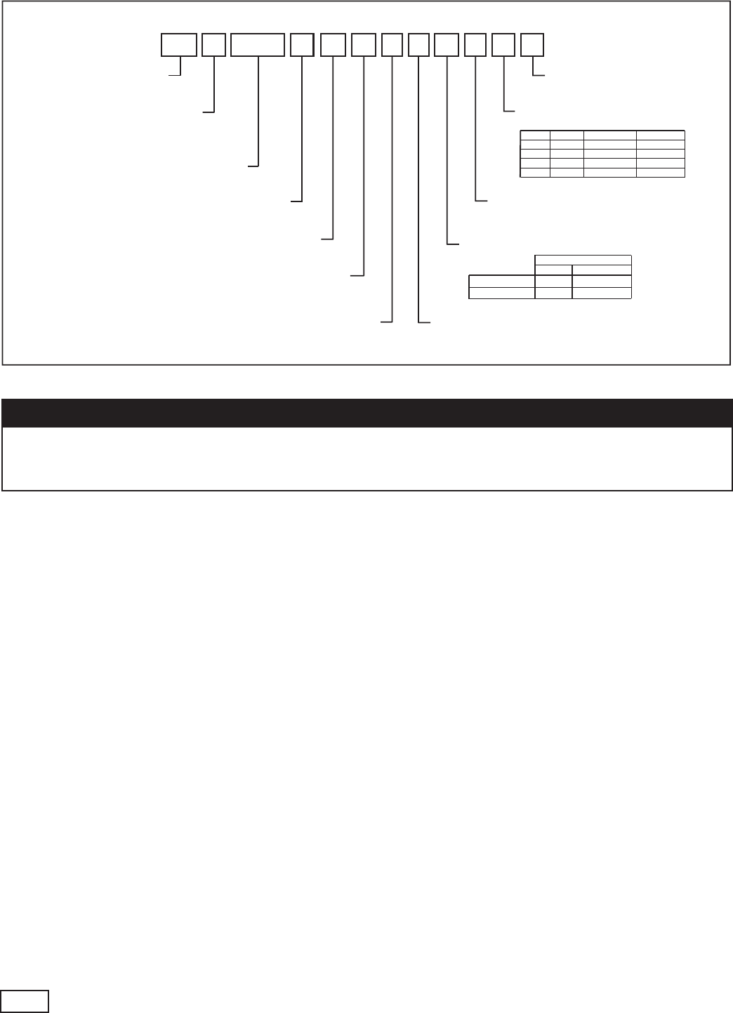
A0 7 2 DG 0 1 D L K
4 5 6 7
8
9 10 12 13 14
026, 038, 049, 064, 072
Unit Size
Return Air Flow Configuration
Voltage
C = CXM
Controls
D = DXM+
A = Current Revision
Revision Level
Heat Exchanger Options
Cabinet
Supply Air Flow &
Motor Configuration
TT
1 2
TT = Tranquility Two-Stage Scroll
Series
V
3
V = Vertical Up
Configuration
L = Left Return
R = Right Return
0 = None
Water Circuit Options
S
15
S = Standard
Standard
H = Horizontal
D = Vertical Down
0 = Residential
1 = HWG w/Internal Pump
Supply Configuration Motor
K TTV
N TTD
P TTH
W TTH
Top
Down
Back
Straight
ECM
ECM
ECM
ECM
Standard
Coated Air Coil
Copper Cupro-Nickel
A J
Rev.: 18 April, 2008B
ClimaDry*D N/A
G = 208-230/60/1
11
Notes
+= Only Available With ClimaDry Option
*= Not Available On DownFlow Units
� CAUTION! �
Water Source Heat Pump systems (including Water Loop Heat Pump systems) must have antifreeze protec-
tion to 20°F [-6.7°C] for ClimaDry applications. The ClimaDry option MUST NOT be used on open water loop
systems, or any system without antifreeze protection.

ClimaDry Whole House Dehumidication - ClimateMaster Geothermal Heat Pumps - Rev.: 18 April, 2008B 3
Overview
ClimaDry™ Whole House Dehumidication Overview
Indoor Air Quality (IAQ) and Relative Humidity (RH)
are increasingly becoming design issues that must be
addressed by selecting heating and cooling equipment
with advanced capabilities. The ClimateMaster
ClimaDry™ reheat option (patent pending) offers unique
features unlike anything currently available today.
ClimateMaster’s ClimaDry reheat option is an innovative
means of providing modulating reheat without the
complication of refrigeration controls. ClimaDry is Hot
Gas Generated Reheat, which utilizes one of the biggest
advantages of a water source heat pump (WSHP), the
transfer of energy through the loop piping system.
ClimaDry simply diverts condenser water through a
water-to-air coil that is placed after the evaporator coil.
If condenser water is not warm enough, the internal
“run-around” loop increases the water temperature with
each pass through the condenser coil.
ClimaDry Benets
ClimaDry is like no other reheat option on the market.
Proportional reheat is controlled to the desired leaving
air temperature set point (factory set point of 72°F,
[22°C}), no matter what the loop temperature is. Since
dehumidication operation will occur under less than full
load cooling conditions a good percentage of the time,
it is important to have a reheat function that provides
100% reheat in the spring and fall when the loop is cool.
Supply air temperature is eld adjustable to +/- 3°F
[+/- 1.7°C] for even greater exibility with an optional
potentiometer.
Competitors without ClimaDry typically use an on/off
(non-modulating) refrigeration based reheat circuit,
typically referred to as “Hot gas reheat” (HGR). HGR
needs higher condensing temperatures to work well,
typically 85°F [29°C] entering water temperature (EWT).
With HGR, cooler water temperatures produce cooler
supply air temperatures, which could overcool the
space, requiring additional space heating from another
source or a special auto-change-over relay to allow
the unit to switch back and forth between reheat and
heating. Rarely does HGR provide 100% reheat, like
ClimaDry.
A key benet to ClimaDry is a simple and easy to
troubleshoot refrigerant circuit. No switching valves or
hard to diagnose leaky check valves are utilized. No
unusual refrigerant pressures occur during the reheat
mode. The ClimaDry refrigerant circuit is like every other
ClimateMaster unit (without reheat), so everything the
technician already knows applies to troubleshooting
the ClimaDry refrigeration circuit. Plus, the water loop
portion of the ClimaDry option is easy to understand
and diagnose.
Features Include:
• Modulating reheat for precise control of supply
air temperatures
• 100% reheat (operates as a whole house
dehumidier)
• “Neutral” supply air temperature even at part load
(non-design) conditions
• Supply air temperature adjustment, +/- 3°F
[+/-1.7°C] from 72°F [22°C] factory setpoint with
optional potentiometer
• Integrated factory supplied reheat controls – simply
attach a humidistat or dehumidistat
• Microprocessor (DXM) controls standard
• Ultra simple refrigeration circuit
• All water system eliminates refrigeration circuit
modications (same refrigeration circuit as units
without ClimaDry)
• Stable refrigeration pressures, even at low EWTs
• All components located inside the cabinet
•
Moves heat of rejection from ground loop to supply
air stream
Availability
ClimaDry is currently available on ClimateMaster
residential Tranquility
27™ (TT) and Tranquility
20™ (TS)
series units (vertical and horizontal units only).
ClimaDry Applications
With the ClimaDry option, return air from the space is
conditioned by the air-to-refrigerant (evaporator) coil, then
reheated by the water-to-air (reheat) coil to dehumidify
the air, but maintain the same space temperature (thus
operating as a whole house dehumidier). The moisture
removal capability of the heat pump is determined by
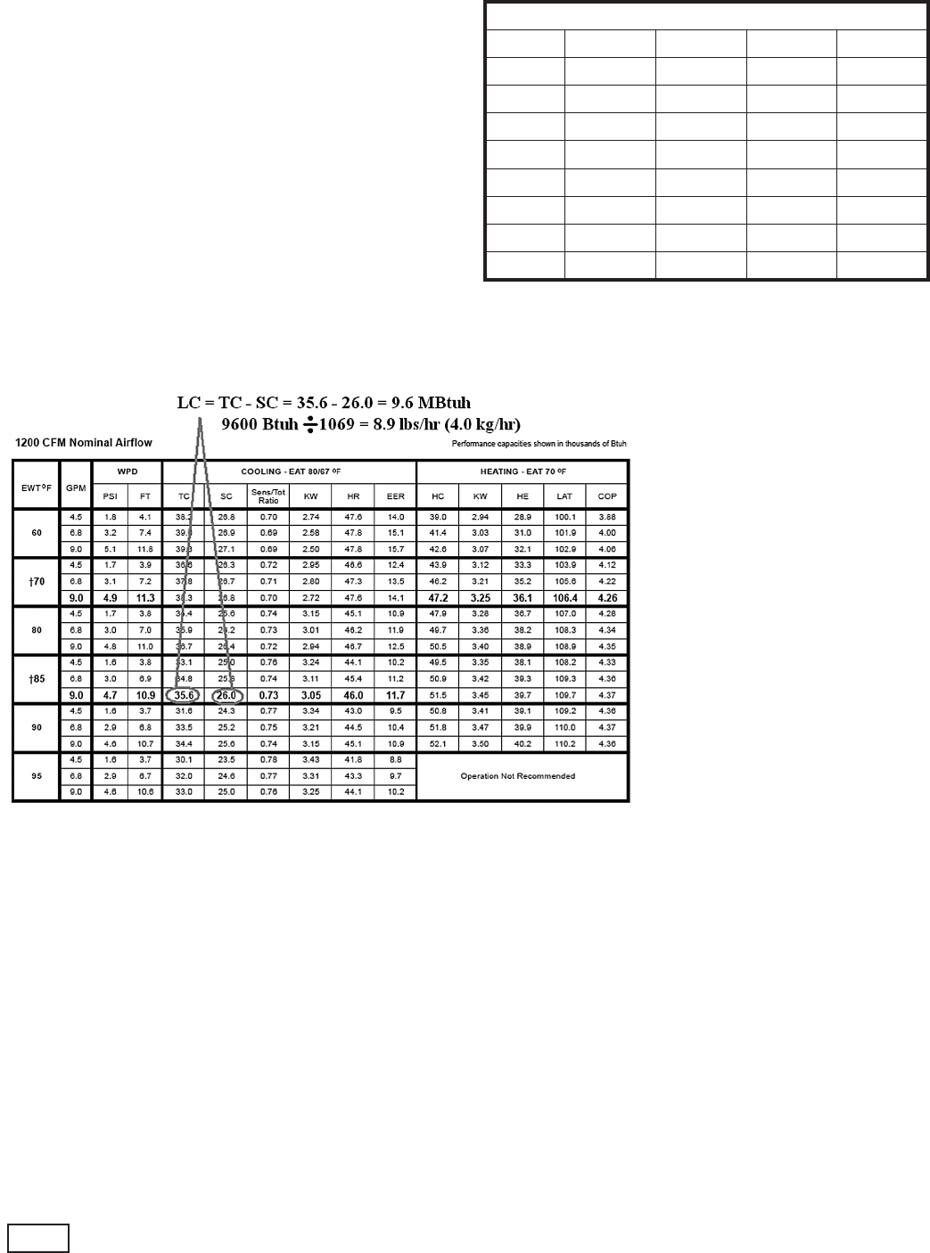
the unit’s latent capacity rating. Latent Capacity (LC)
equals Total Capacity (TC) minus Sensible Capacity (SC).
For example, at 85°F [29°C] EWT, the moisture removal
capability (latent capacity) of a ClimateMaster size 036
heat pump is 9.6 MBtuh [2.8kW] as shown in gure 1.
Dividing the latent capacity by 1,069 BTU/LB of water
vapor at 80°F DB and 67°F WB [26.7°C DB and 19.4°C
WB] moist air enthalpy, converts the amount of moisture
removal to pounds per hour (multiply pounds per hour
by 0.4536 to obtain kg/hr). Calculations are shown
in gure 1. Most ClimateMaster heat pumps have a
sensible-to-total (S/T) ratio of 0.72 to 0.76. Therefore,
approximately, 25% of the cooling capacity is dedicated
to latent cooling capacity (moisture removal). When
selecting a unit with ClimaDry, the space sensible
and latent loads should be calculated. If the unit will
be used for space cooling, a unit with at least enough
capacity to satisfy the building sensible load should be
selected. If the latent cooling load is not satised by
the selection, a larger unit with enough latent capacity
will be required. The ClimaDry Option can be used for
the additional moisture load. If the unit will be used for
dehumidication purposes only, the latent capacity is
ClimaDry Whole House Dehumidication - ClimateMaster Geothermal Heat Pumps - Rev.: 18 April, 2008B
4
the only consideration necessary. In this case, sensible
load is immaterial. Example latent capacities for a
typical ClimateMaster heat pump are shown in table 1.
ClimaDry is especially useful in Northern Climates,
where the heat pump may be oversized in the cooling
mode to provide enough heating capacity. Units with
ClimaDry will compensate for these applications
by operating as a whole house dehumidier when
necessary to maintain space Relative Humidity (RH).
Since the ClimaDry option is internal to the unit,
installation is much easier than a separate whole house
dehumidier. Plus, an additional compressor and
controls can be eliminated, simplifying the system and
lowering operating and installation costs.
Table 1: Typical Unit Latent capacity
Latent Capacity at 85°F [29.4°C] EWT
Size MBtuh lbs/hr kW kg/hr
18 4.7 4.4 1.4 2.0
24 6.1 5.7 1.8 2.6
30 6.8 6.4 2.0 2.9
36 9.6 9.0 2.8 4.1
42 11.0 10.3 3.2 4.7
48 12.7 11.9 3.7 5.4
60 15.2 14.2 4.5 6.4
70 16.9 15.8 5.0 7.2
Figure 1: Example Size 036 Performance
Dividing the latent capacity by
1,069 BTU/LB of water vapor at
80°F DB and 67°F WB [26.7°C
DB and 19.4°C WB] moist air
enthalpy, converts the amount
of moisture removal to pounds
per hour (multiply pounds per
hour by 0.4536 to obtain kg/hr).
Calculations are shown in gure 1.
Performance Data
Model 036
ClimaDry Whole House Dehumidication - ClimateMaster Geothermal Heat Pumps - Rev.: 18 April, 2008B 5
ClimaDry Sequence Of Operation
A heat pump equipped with ClimaDry can operate
in three modes; cooling, cooling with reheat, and
heating. The cooling/heating modes are like any other
ClimateMaster WSHP. The reversing valve (“O” signal)
is energized in cooling, along with the compressor
contactor(s) and blower relay. In the heating mode the
reversing valve is de-energized. Almost any thermostat
will activate the heat pump in heating or cooling modes.
The DXM microprocessor board, which is standard with
the ClimaDry option, will accept either heat pump (Y,O)
thermostats or non-heat pump (Y,W) thermostats (see
CXM/DXM AOM for detailed DXM information).
The reheat mode requires either a separate humidistat/
dehumidistat or a thermostat that has an integrated
dehumidication function for activation. The DXM
board is congured to work with either a humidistat or
dehumidistat input to terminal “H” (DIP switch settings
for the DXM board are shown below in table 2). Upon
receiving an “H” input, the DXM board will activate the
cooling mode and engage reheat. Table 3 shows the
relationship between thermostat input signals to the DXM
board and unit operation.
There are ve operational inputs for single stage units
and seven operational inputs for two stage units:
-Fan Only
-1st Stage Cooling
-2nd Stage Cooling
-1st Stage Heating
-2nd Stage Heating
-3rd Stage Heating (If applicable)
-Reheat Mode
• Fan Only: A (G) call from the thermostat to the (G)
terminal of the DXM control board will bring the unit
on in fan only mode.
•
1st Stage Cooling: A simultaneous call from (G),
(Y1), and (O) to the (G), (Y1), (O/W2) terminals of the
DXM control board will bring the unit on in 1st Stage
Cooling.
Table 2: Humidistat/Dehumidistat Logic and DXM 2.1, 2.2., 2.3 DIP settings
Sensor 2.1 2.2 2.3 Logic Reheat (ON) - H Reheat (OFF) - H
Humidistat OFF OFF OFF Reverse 0 VAC 24 VAC
Dehumidistat OFF ON OFF Standard 24 VAC 0 VAC
1Cooling input takes priority over dehumidify input.
2DXM is programmed to ignore the H demand when the unit is in heating mode.
3N/A for single stage units; Full load operation for dual capacity units.
4Single stage unit: W = 2nd Stage backup elec. heat; Two-Stage units: W = 3rd stage backup elec. heat.
5ON/OFF = Either ON or OFF.
Mode
Input Output
O G Y1 Y23W H O G Y1 Y23Backup
Elec Heat Reheat
No Demand ON/OFF5OFF OFF OFF OFF OFF ON/OFF5OFF OFF OFF OFF OFF
Fan Only ON/OFF5ON OFF OFF OFF OFF ON/OFF5ON OFF OFF OFF OFF
Cooling 1st Stage ON ON ON OFF OFF OFF ON ON ON OFF OFF OFF
Cooling 2nd Stage ON ON ON ON OFF OFF ON ON ON ON OFF OFF
Cooling & Dehumidistat1ON ON ON ON/OFF5OFF ON ON ON ON ON/OFF5OFF OFF
Dehumidistat Only ON/OFF5OFF OFF OFF OFF ON ON ON ON ON OFF ON
Heating 1st Stage OFF ON ON OFF OFF OFF OFF ON ON OFF OFF OFF
Heating 2nd Stage OFF ON ON ON ON/OFF5OFF OFF ON ON ON ON/OFF5OFF
Heating 3rd Stage4OFF ON ON ON ON4OFF OFF ON ON ON ON4OFF
Heating & Dehumidistat2OFF ON ON ON/OFF5ON/OFF5ON OFF ON ON ON/OFF5ON/OFF5OFF
Table 3: ClimaDry Operating Modes

ClimaDry Whole House Dehumidication - ClimateMaster Geothermal Heat Pumps - Rev.: 18 April, 2008B
6
• 2nd Stage Cooling: A simultaneous call from (G),
(Y1), (Y2), and (O) to the (G), (Y1), (Y2), and (O/W2)
terminals of the DXM control board will bring the unit
on in 2nd Stage Cooling. When the call is satised
at the thermostat the unit will continue to run in 1st
Stage Cooling until the 1st Stage Cooling call is
removed or satised, shutting down the unit.
NOTE: Not all units have two-stage cooling
functionality.
• 1st Stage Heating: A simultaneous call from (G) and
(Y1) to the (G) and (Y1) terminals of the DXM control
board will bring the unit on in 1st Stage Heating.
• 2nd Stage Heating: A simultaneous call from (G), (Y1),
and (Y2) to the (G), (Y1), and (Y2) terminals of the
DXM control board will bring the unit on in 2nd Stage
Heating. When the call is satised at the thermostat
the unit will continue to run in 1st Stage Heating until
the call is removed or satised, shutting down the
unit.
NOTE: Not all units have two-stage heating
functionality. 2nd stage heating for units with
PSC fan and single stage compressor is auxiliary
electric heat (Y, W1, G).
• 3rd Stage Heating (ECM fan models only): A
simultaneous call from (G), (Y1), (Y2), and (W)
terminals to the (G), (Y1), (Y2), and (W1) terminals
of the DXM board will bring the unit on in 3rd Stage
Heating (compressor plus auxiliary electric heat).
• Reheat Mode: A call from the Humidistat/
Dehumidistat to the (H) terminal of the DXM control
board will bring the unit on in Reheat Mode if
there is no call for cooling. When the Humidistat/
Dehumidication call is removed or satised the unit
will shut down.
NOTE: Cooling always overrides Reheat
Mode. In the Cooling mode, the unit cools and
dehumidies. If the cooling thermostat is satised
but there is still a call for dehumidication, the
unit will continue to operate in Reheat Mode.
ClimaDry Component Functions
The ClimaDry option consists of the
following components:
• Proportional Controller
• Supply Air Sensor
• Motorized Valve
• Internal Loop Pump
• Hydronic Reheat Coil
The Proportional Controller operates on a 24 VAC
power supply and automatically adjusts the water valve
based upon the Supply Air Sensor. The Supply Air
Sensor senses supply air temperature at the blower inlet
providing the input signal necessary for the proportional
control to drive the motorized valve during the reheat
mode of operation. The Motorized Valve is a proportional
actuator/three-way valve combination used to divert
the condenser water from the coax to the hydronic
reheat coil during the reheat mode of operation. The
proportional controller sends a signal to the motorized
valve based on the supply air temperature.
The internal loop pump circulates condenser water
through the hydronic reheat coil during the reheat mode
of operation. In this application, the internal loop pump
is only energized during the reheat mode. The Hydronic
Coil is utilized to reheat the air to the setpoint of the
proportional controller. Condenser water is diverted by
the motorized valve and pumped through the hydronic
reheat coil by the internal loop pump in proportion to the
control setpoint. The amount of reheating is dependent
on the setpoint and how far from setpoint the supply
air temperature is. The factory setpoint is 72°F [22°C],
generally considered “neutral” air.
ClimaDry Application Considerations
The reheat coil adds a small amount of resistance to the
air stream. Consult the correction tables on page 8 of
this manual for details.
Unlike most hot gas reheat options, the ClimaDry option
will operate over a wide range of EWTs. Special ow
regulation (water regulating valve) is not required for
low EWT conditions. Temporary, slight overcooling of
the space may result on rare occasions with ground
loop (geothermal) systems during extremely low EWT
conditions. Since dehumidication is generally only
required in cooling, most ground loop systems will not
experience these conditions.
Water-Source Heat Pumps with ClimaDry should not be
used as make-up air units. These applications require
equipment specically designed for make-up air.
� CAUTION! �
Water Source Heat Pump systems (including Wa-
ter Loop Heat Pump systems) must have antifreeze
protection to 20°F [-6.7°C] for ClimaDry applications.
The ClimaDry option MUST NOT be used on open
water loop systems, or any system without antifreeze
protection.
ClimaDry Whole House Dehumidication - ClimateMaster Geothermal Heat Pumps - Rev.: 18 April, 2008B 7
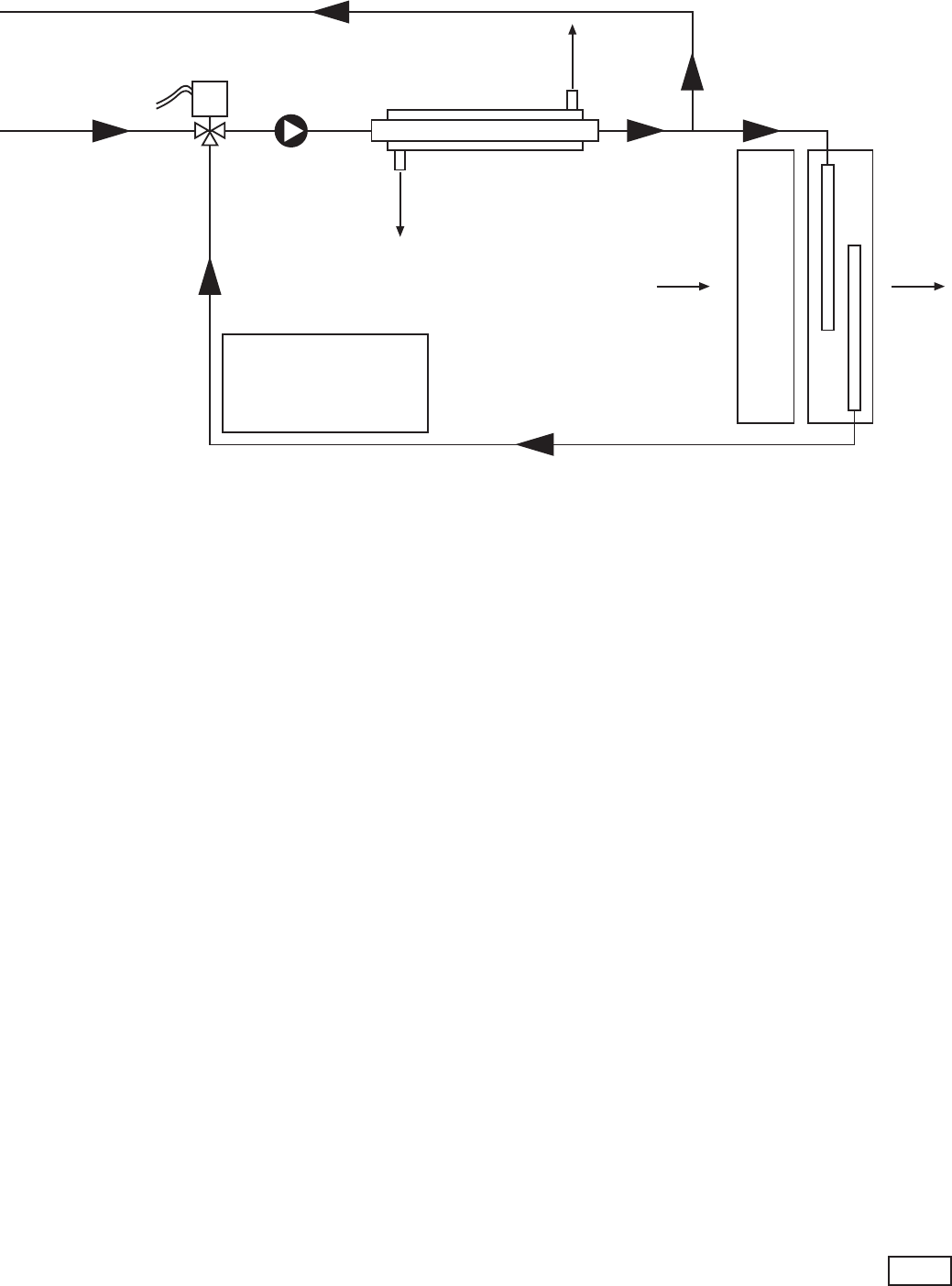
Figure 2: ClimaDry Schematic
Water Out
(To Water Loop)
Water In
(From Water Loop)
Mixing Valve
COAX
Evaporator Coil
Reheat
Coil
Refrigerant Out
(Cooling)
Refrigerant In
(Cooling)
Entering Air
Leaving
Air
Note:
All components shown
are internal to the heat
pump unit.
Internal Pump
ClimaDry Whole House Dehumidication - ClimateMaster Geothermal Heat Pumps - Rev.: 18 April, 2008B
8
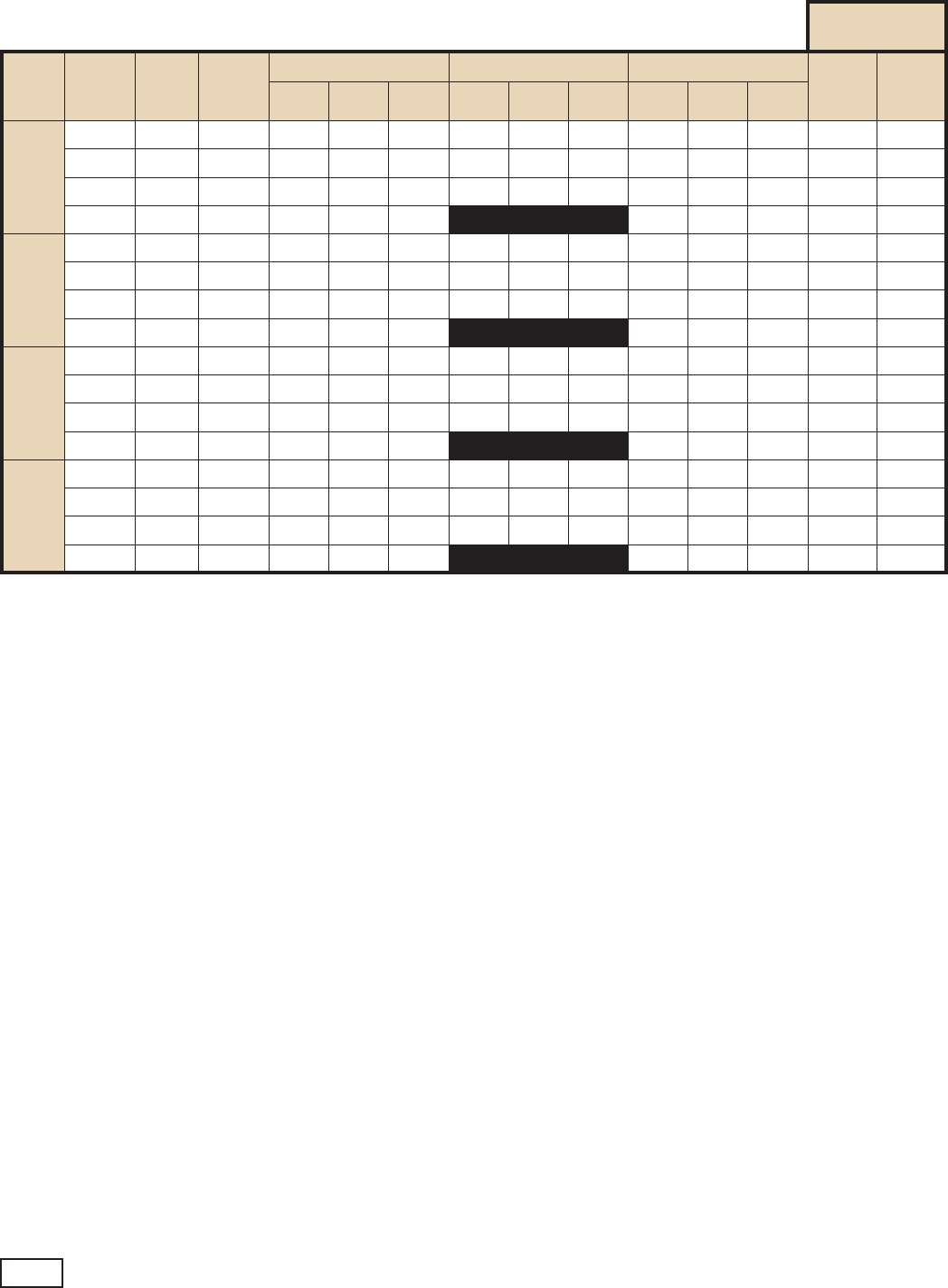
Table 4: Tranquility
27™ Blower Performance Data
Tranquility
27™ (TT) Series with ClimaDry Reheat Option
All Tranquility 27™ (TT) units have an ECM fan motor as a standard feature. The small
additional pressure drop of the reheat coil causes the ECM motor to slightly increase RPM to
overcome the added pressure drop, and maintain selected CFM up to the maximum ESP.
Airow in CFM with wet coil and clean air lter
Residential
Units Only
Model
Max
ESP
(in. wg)
Fan
Motor
(hp)
Tap
Setting
Cooling Mode Dehumid Mode Heating Mode AUX
CFM
Aux/
Emerg
Mode
Stg 1 Stg 2 Fan Stg 1 Stg 2 Fan Stg 1 Stg 2 Fan
026
0.50 1/2 4 810 950 475 630 740 475 920 1060 475 4 1060
0.50 1/2 3 725 850 425 560 660 425 825 950 425 3 950
0.50 1/2 2 620 730 370 490 570 370 710 820 370 2 820
0.50 1/2 1 520 610 300 600 690 300 1 690
038
0.50 1/2 4 1120 1400 700 870 1090 700 1120 1400 700 4 1400
0.50 1/2 3 1000 1250 630 780 980 630 1000 1250 630 3 1350
0.50 1/2 2 860 1080 540 670 840 540 860 1080 540 2 1350
0.50 1/2 1 730 900 450 730 900 450 1 1350
049
0.75 1 4 1460 1730 870 1140 1350 870 1560 1850 870 4 1850
0.75 1 3 1300 1550 780 1020 1210 780 1400 1650 780 3 1660
0.75 1 2 1120 1330 670 870 1040 670 1200 1430 670 2 1430
0.75 1 1 940 1120 560 1010 1200 560 1 1350
064
0.75 1 4 1670 2050 1020 1300 1600 1020 1860 2280 1020 4 2280
0.75 1 3 1500 1825 920 1160 1430 920 1650 2050 920 3 2040
0.75 1 2 1280 1580 790 1000 1230 790 1430 1750 790 2 1750
0.75 1 1 1080 1320 660 1200 1470 660 1 1470
Factory shipped on Tap Setting 2
During Auxiliary operation (residential units only) the CFM will run at the higher of the heating or AUX settings
Airow is controlled within +/- 5% up to Max ESP shown with wet coil and standard lter

ClimaDry Whole House Dehumidication - ClimateMaster Geothermal Heat Pumps - Rev.: 18 April, 2008B 9
Table 5: Tranquility
20™ ECM Blower Performance Data
Tranquility
20™ (TS) Series with ClimaDry Reheat Option (ECM Motor)
All Tranquility 20™ (TS) units with optional ECM fan motor automatically adjust for the reheat coil. The
small additional pressure drop of the reheat coil causes the ECM motor to slightly increase RPM to
overcome the added pressure drop, and maintain selected CFM up to the maximum ESP.
Residential
Units Only
Model
Max
ESP
(in. wg)
Fan
Motor
(hp)
Tap
Setting
Cooling Mode Dehumid Mode Heating Mode AUX
CFM
Aux/
Emerg
Mode
Stg 1 Stg 2 Fan Stg 1 Stg 2 Fan Stg 1 Stg 2 Fan
018 0.50 1/2
4 620 750 380 480 590 380 620 750 380 4 750
3 570 700 350 450 550 350 570 700 350 3 700
2 510 620 310 400 480 310 510 620 310 2 650
1 430 530 270 430 530 270 1 650
024 0.50 1/2
4 780 950 470 610 740 470 870 1060 470 4 1060
3 700 850 420 540 660 420 780 950 420 3 950
2 630 770 360 490 600 360 670 820 390 2 820
1 550 670 300 570 690 340 1 690
030 0.50 1/2
4 920 1130 560 720 880 560 1000 1230 560 4 1230
3 820 1000 500 640 780 500 900 1100 500 3 1100
2 740 900 450 580 700 450 800 980 450 2 980
1 660 800 400 700 850 400 1 850
036 0.50 1/2
4 1150 1400 700 900 1090 700 1150 1400 700 4 1400
3 1020 1250 630 800 980 630 1020 1250 630 3 1350
2 890 1080 540 690 840 540 890 1080 540 2 1350
1 740 900 450 750 920 450 1 1350
042 0.50 1/2
4 1290 1580 790 1010 1230 790 1290 1580 790 4 1580
3 1150 1400 700 900 1090 700 1150 1400 700 3 1400
2 1050 1280 640 820 1000 640 1020 1240 640 2 1350
1 920 1120 560 900 1080 560 1 1350
048 0.75 1
4 1420 1730 870 1110 1350 870 1520 1850 865 4 1850
3 1270 1550 780 990 1210 780 1350 1650 775 3 1650
2 1180 1440 720 920 1120 720 1190 1450 720 2 1450
1 1050 1280 640 1020 1250 640 1 1350
060 0.75 1
4 1680 2050 1030 1310 1600 1030 1870 2280 1030 4 2280
3 1500 1830 910 1170 1420 910 1680 2050 910 3 2050
2 1400 1700 850 1090 1330 850 1480 1800 850 2 1800
1 1300 1580 790 1270 1550 790 1 1550
070 0.75 1
4 1830 2230 1100 1420 1740 1100 1830 2230 1100 4 2230
3 1600 1950 980 1250 1520 980 1720 2100 980 3 2100
2 1440 1750 880 1120 1360 880 1670 1950 880 2 1950
1 1200 1580 790 1460 1780 790 1 1780
See ECM control section for details on setting taps.
Airow in CFM with wet coil and clean air lter
ClimaDry Whole House Dehumidication - ClimateMaster Geothermal Heat Pumps - Rev.: 18 April, 2008B
10
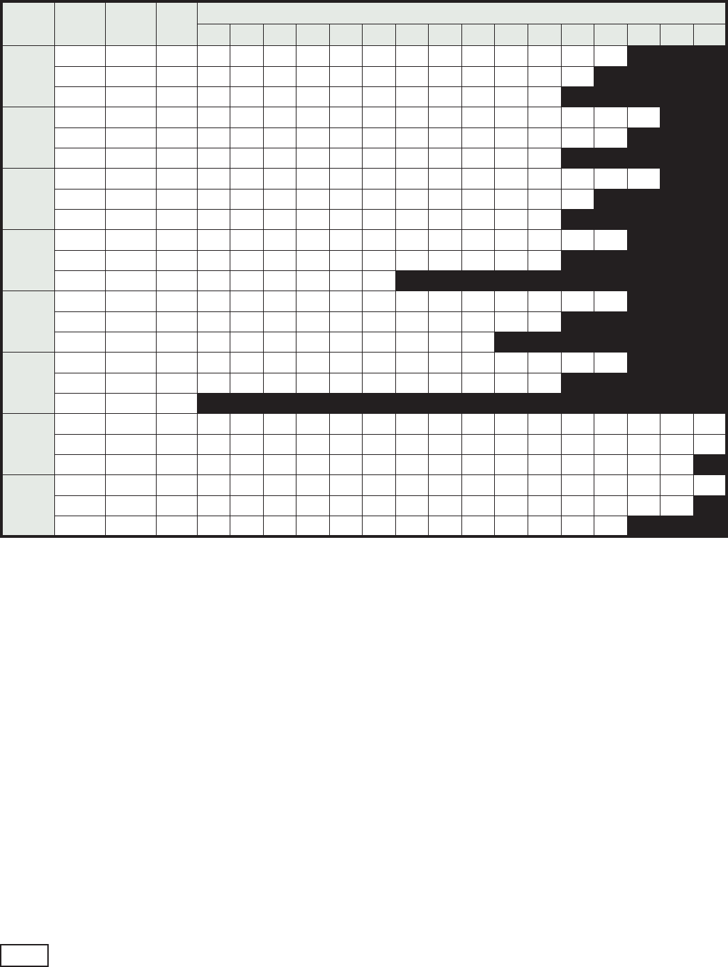
Table 6: Tranquility
20™ (TS) Series PSC Blower Performance Data
(Without ClimaDry)
Model Fan
Speed
Rated
Airow
Min
CFM
Airow (cfm) at External Static Pressure (in. wg)
0.00 0.05 0.10 0.15 0.20 0.25 0.30 0.35 0.40 0.45 0.50 0.60 0.70 0.80 0.90 1.00
018
HI 600 450 704 708 711 702 693 692 690 683 675 658 640 598 515
MED 600 450 602 601 599 590 581 583 585 579 573 560 547 492
LOW 600 450 531 529 527 522 517 512 506 501 495 479 462
024
HI 850 600 965 960 954 943 931 923 914 898 882 862 842 794 725 635
MED 850 600 841 833 825 817 809 800 790 777 763 747 731 686 623
LOW 850 600 723 715 707 703 698 689 680 668 656 642 627
030
HI 950 750 1271 1250 1229 1207 1185 1164 1143 1118 1093 1061 1029 953 875 753
MED 950 750 1048 1037 1025 1016 1007 994 981 962 943 915 886 822
LOW 950 750 890 887 884 879 874 865 855 842 829 809 789
036
HI 1250 900 1411 1407 1402 1390 1378 1370 1361 1326 1290 1248 1205 1083 942
MED 1250 900 1171 1164 1156 1145 1133 1113 1092 1064 1035 997 958
LOW 1250 900 983 967 950 943 936 936
042
HI 1400 1050 1634 1626 1618 1606 1594 1583 1571 1539 1507 1464 1420 1265 1078
MED 1400 1050 1332 1323 1314 1298 1282 1263 1243 1206 1169 1115 1060
LOW 1400 1050 1130 1109 1088 1086 1084 1066 1048 1052 1055
048
HI 1600 1200 1798 1781 1764 1738 1711 1688 1665 1630 1595 1555 1514 1420 1239
MED 1600 1200 1384 1382 1379 1375 1371 1356 1341 1318 1294 1261 1227
LOW 1600 1200
060
HI 1950 1500 2311 2306 2300 2290 2279 2268 2257 2233 2209 2175 2140 2088 1990 1901 1856 1752
MED 1950 1500 2058 2049 2039 2028 2016 2000 1983 1966 1949 1935 1920 1874 1807 1750 1670 1582
LOW 1950 1500 1868 1863 1858 1858 1858 1848 1838 1822 1806 1799 1792 1749 1699 1636 1570
070
HI 2100 1800 2510 2498 2486 2471 2455 2440 2424 2401 2377 2348 2318 2247 2161 2078 1986 1855
MED 2100 1800 2171 2167 2162 2162 2162 2158 2153 2135 2117 2101 2085 2024 1971 1891 1823
LOW 2100 1800 2010 2008 2006 2006 2006 2006 2006 1992 1977 1962 1947 1892 1851
Black areas denote ESP where operation is not recommended.
Units factory shipped on medium speed. Other speeds require eld selection.
All airow is rated and shown above at the lower voltage if unit is dual voltage rated, e.g. 208V for 208-230V units.
ClimaDry Whole House Dehumidication - ClimateMaster Geothermal Heat Pumps - Rev.: 18 April, 2008B 11
Table 7: ClimaDry Reheat Coil Pressure Drop - TS Units (PSC Motor)
Coil Face
Velocity
FPM
TSH/V/D with Reheat ESP Loss
TSH/V/D
018
In. of Water
TSH/V/D
024, 030
In. of Water
TSH/V/D
036
In. of Water
TSH/V/D
042, 048
In. of Water
TSH/V/D
060, 070
In. of Water
200 0.037 0.033 0.031 0.028 0.026
250 0.052 0.046 0.042 0.038 0.034
300 0.077 0.066 0.059 0.051 0.044
350 0.113 0.096 0.085 0.073 0.061
400 0.181 0.160 0.145 0.131 0.117
450 0.242 0.226 0.215 0.205 0.194
500 0.360 0.345 0.335 0.326 0.316
For TS units with ClimaDry Reheat coil applications, calculate face velocity of the entering air. From the table above, nd ESP for Reheat application.
The loss includes wet coil loss.
Example:
Reheat coil pressure drop can be determined from the above table. Coil velocity (FPM) = Airow (CFM) / Face Area (sq. ft.).
1) TSH036 has a face area of 4.86 sq. ft. (see physical data table in I.O.M.).
2) At 1,100 cfm, coil velocity (FPM) = 1,100 / 4.86 = 226 FPM.
3) From above table, it will be necessary to subtract 0.037 from the blower performance ESP.
4) On medium speed, the TSH036 (without reheat - see blower table) can deliver 1,100 CFM at 0.28 in. wg. with the
standard PSC motor; with the reheat coil, it now delivers 1,085 CFM at 0.28 in. wg. or 1,100 CFM at 0.24 in. wg.
5) If the decrease in airow is acceptable, no changes are necessary. Otherwise, high speed fan should be used
to overcome the pressure drop of the reheat coil.
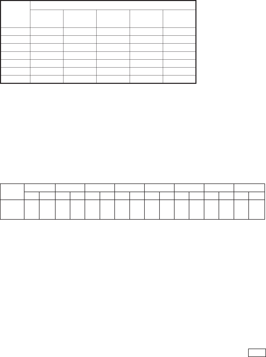
Table 8: TS Air Coil Face Area
Model
018 024 030 036 042 048 060 070
Horiz. Vert. Horiz. Vert. Horiz. Vert. Horiz. Vert. Horiz. Vert. Horiz. Vert. Horiz. Vert. Horiz. Vert.
Coil Face
Area, sq. ft.
(sq. m)
3.38
(0.3135)
3.33
(0.3097)
3.88
(0.3600)
3.89
(0.3613)
3.88
(0.3600)
3.89
(0.3613)
4.86
(0.4516)
4.86
(0.4516)
5.56
(0.5161)
5.56
(0.5161)
5.56
(0.5161)
5.56
(0.5161)
6.25
(0.5806)
6.25
(0.5806)
6.25
(0.5806)
6.25
(0.5806)
ClimaDry Whole House Dehumidication - ClimateMaster Geothermal Heat Pumps - Rev.: 18 April, 2008B
12
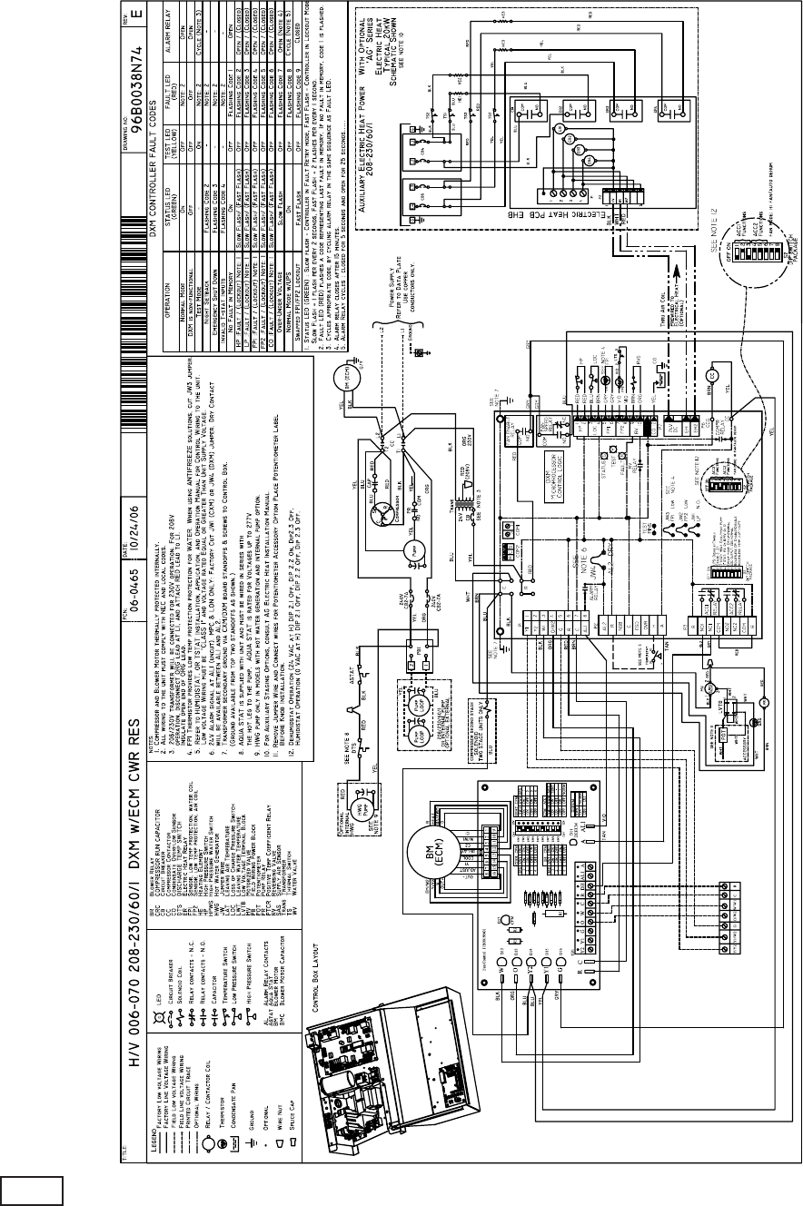
Tranquility
27™ with ClimaDry™ Electrical Wiring Diagram - 96B0037N74
ClimaDry Whole House Dehumidication - ClimateMaster Geothermal Heat Pumps - Rev.: 18 April, 2008B 13
Units equipped with ClimaDry must be ushed/purged
with a ush cart. Detailed general ushing /purging
instruction can be found in the Flow Controller III IOM.
The unit must be powered (but not operating) during
ushing/purging. Unit power is required to operate
the three-way modulating valve during ushing.
When ushing/purging units equipped with ClimaDry
the earth loop should be fully ushed/purged before
attempting to ush/purge the heat pump. Once the
earth loop is ushed, position the ushing valves to
ush the heat pump. Then with ushing ow re-directed
through the unit, energize the modulating three-way
dehumidication valve to allow ow through the
dehumidication hydronic circuit.
Energize the modulating three-way dehumidication
valve by removing the red wire from the ACC1 ‘N.O.’
terminal on the DXM board. Connect this wire to the
ACC1 ‘NC’ terminal of the DXM controller, as shown
in gure 1, to energize the modulating three-way
dehumidication valve. Once energized, the valve will
take 45 – 75 seconds to fully shift. Continue ushing
during this time. After the valve has completed its shift,
use the air bleed from the top of the reheat coil to purge
air from the coil.
Note, if the ClimaDry sensor, located in the supply
air stream is above 70°F it must be disabled to allow
the modulating valve to shift. Disable this sensor by
removing the white wire from the Low Voltage Terminal
Block (LVTB) shown in gure 1.
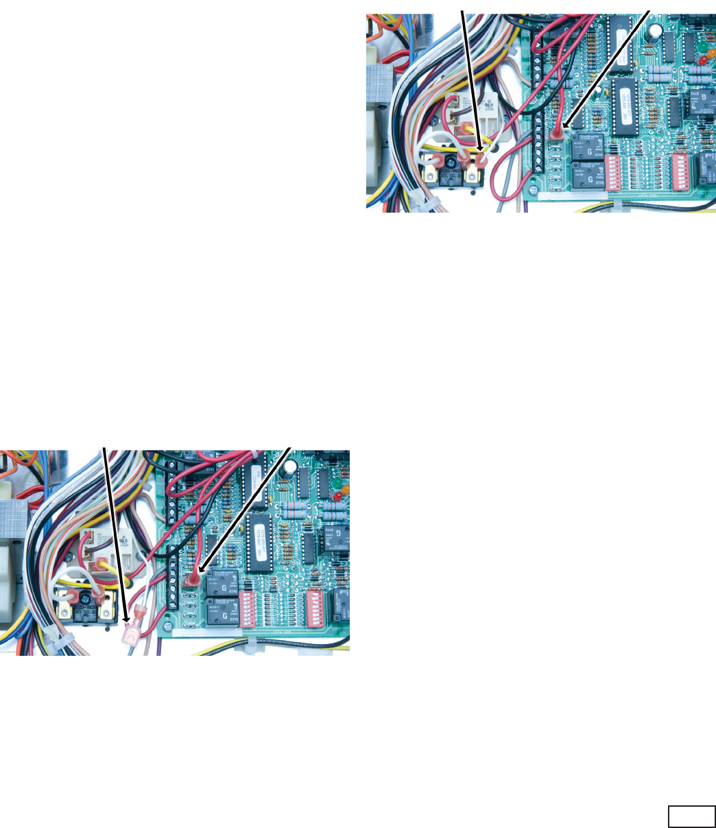
Figure 1. Flushing/Purging Wiring
De-energize the valve by removing the red wire from the
ACC1 ‘NC’ terminal on the DXM board. The valve will
spring return to its normal position in just a few seconds.
After the valve has fully returned, repeat the process of
running the valve through its cycle and purging air from
the reheat coil.
Flushing/Purging Units with ClimaDry
Under extreme circumstances this procedure may be
required multiple times to purge all air from the circuit.
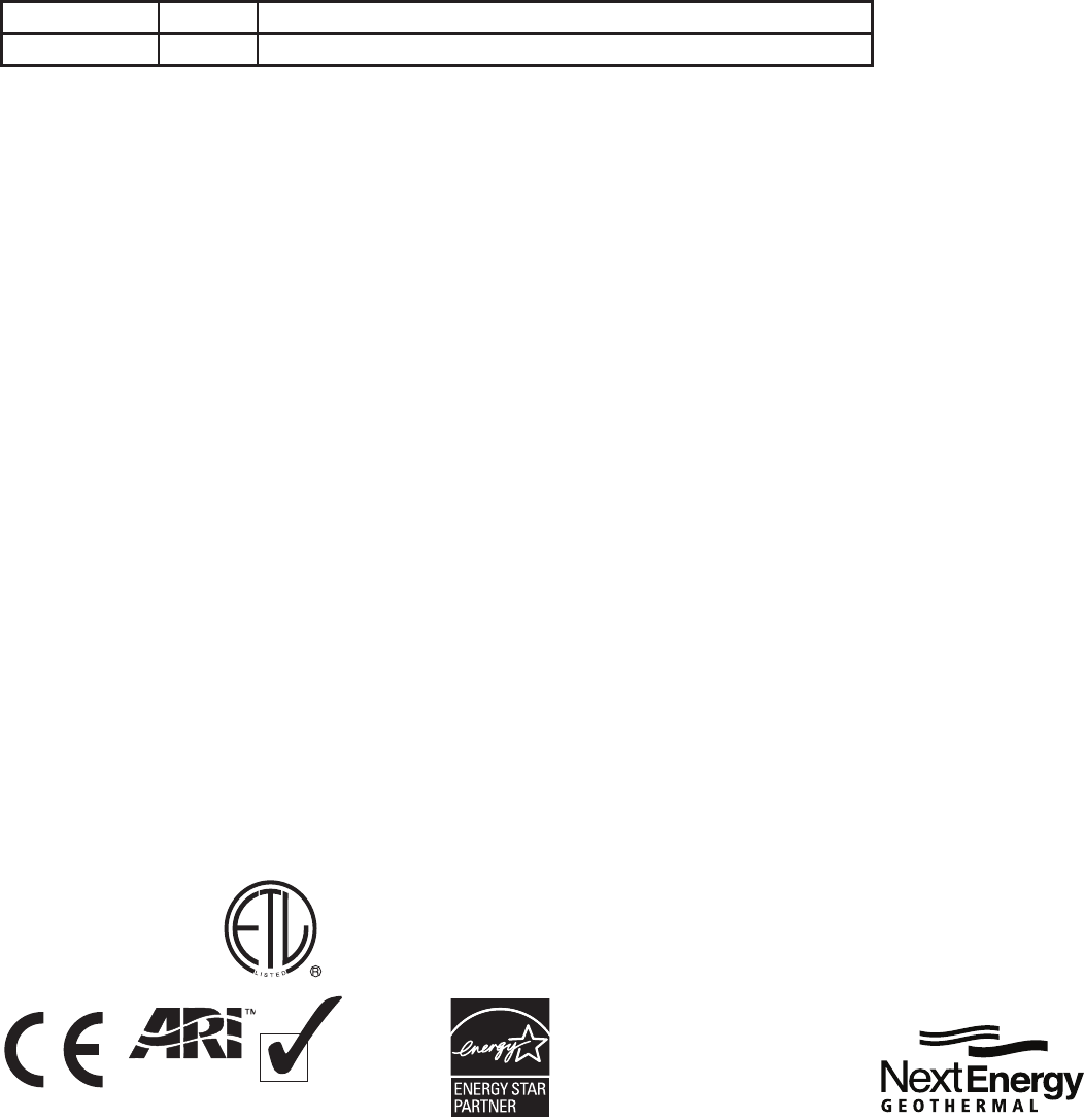
After completing the ushing/purging procedure, restore
the red wire to the ACC1 ‘N.O.’ terminal on the DXM for
normal operation. Return the white sensor wire to the
LVTB, if it was removed, as shown in gure 2.
Figure 2. Normal Unit Wiring
Extra care must be taken when using non-pressurized
ow centers to ensure all air is removed from the unit
and no additional air is allowed into the system. If air is
allowed to collect in the ClimaDry piping, nuisance trips
may occur. Additional ush/purge cycles may be used
when required.
White Thermistor Wire Red Three-Way Valve Wire
White Thermistor Wire Red Three-Way Valve Wire
97B0051N01
ClimateMaster works continually to improve its products. As a result, the design and specifications of each product at the time for order may be
changed without notice and may not be as described herein. Please contact ClimateMaster’s Customer Service Department at 1-405-745-6000 for
specific information on the current design and specifications. Statements and other information contained herein are not express warranties and do
not form the basis of any bargain between the parties, but are merely ClimateMaster’s opinion or commendation of its products.
The management system governing the manufacture of ClimateMaster’s products is ISO 9001:2000 certified.
*97B0051N01*
35 Earl Martin Dr.
Elmira, ON N3B 3L4
Phone: 800-367-9810
Fax: 877-684-3112
www.nextenergy.ca
Date Page # Description
18 April, 2008 All First Published
Revision Log:
ISO 9001:2000
Certified
Quality: First & Always
AIR CONDITIONING &
REFRIGERATION
INSTITUTE
© ClimateMaster, Inc. 2008
TM
