Toshiba Printer 281C Troubleshooting FC 451C_SH_EN_0004
2014-12-13
: Toshiba Toshiba-Printer-281C-Troubleshooting-127878 toshiba-printer-281c-troubleshooting-127878 toshiba pdf
Open the PDF directly: View PDF ![]() .
.
Page Count: 200 [warning: Documents this large are best viewed by clicking the View PDF Link!]
© June 2005 TOSHIBA TECe-STUDIO281c/351c/451c ERROR CODE AND SELF-DIAGNOSTIC MODE
2 - 1
2
2.ERROR CODE AND SELF-DIAGNOSTIC MODE
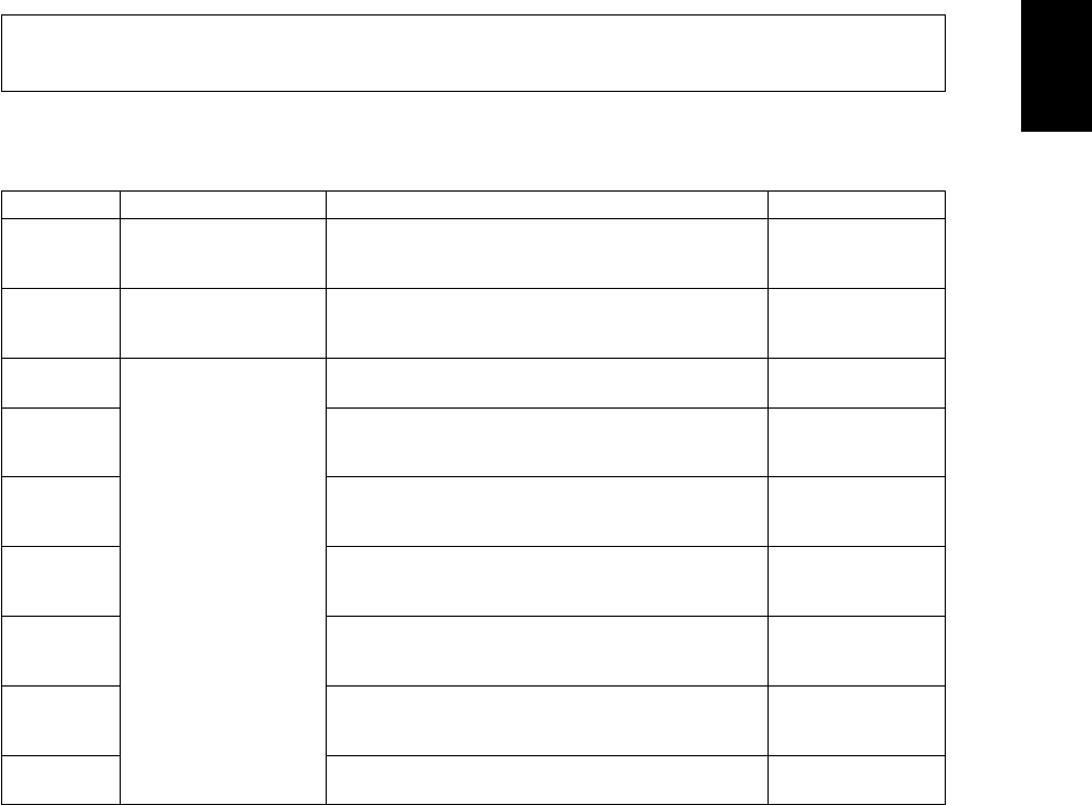
2.1Error Code List
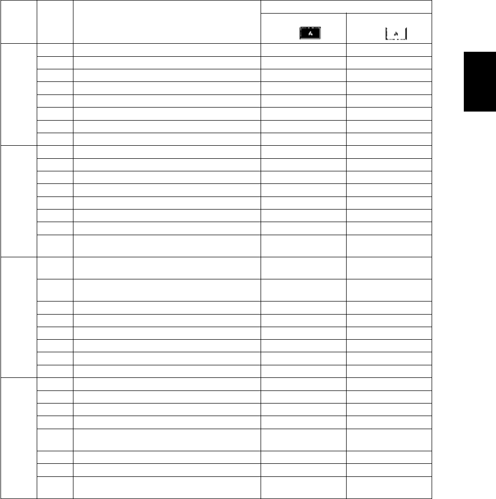
2.1.1Jam
The following error codes is displayed at the upper right of the screen when the CLEAR PAPER! or CALL
SERVICE! symbol is blinking.
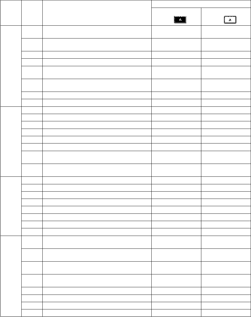
Error codeClassificationContentsTroubleshooting
E010Paper exit jamJam not reaching the exit sensor : The paper which
has passed through the fuser unit does not reach
the exit sensor.
P. 5-1
E020Paper exit jamStop jam at the exit sensor: The trailing edge of the
paper does not pass the exit sensor after its leading
edge has reached this sensor.
P. 5-2
E030Other paper jamPower-ON jam: The paper is remaining on the
paper transport path when power is turned ON.
P. 5-18
E061Incorrect paper size setting for upper drawer: The
size of paper in the 1st drawer differs from size set-
ting of the equipment.
P. 5-18
E062Incorrect paper size setting for lower drawer: The
size of paper in the 2nd drawer differs from size set-
ting of the equipment.
P. 5-18
E063Incorrect paper size setting for PFP upper drawer:
The size of paper in the 3rd drawer differs from size
setting of the equipment.
P. 5-18
E064Incorrect paper size setting for PFP lower drawer:
The size of paper in the 4th drawer differs from size
setting of the equipment.
P. 5-18
E065Incorrect paper size setting for bypass tray: The
size of paper in the bypass tray differs from size
setting of the equipment.
P. 5-18
E090Image data delay jam: Image data to be printed
cannot be prepared.
P. 5-19

e-STUDIO281c/351c/451c ERROR CODE AND SELF-DIAGNOSTIC MODE© June 2005 TOSHIBA TEC
2 - 2
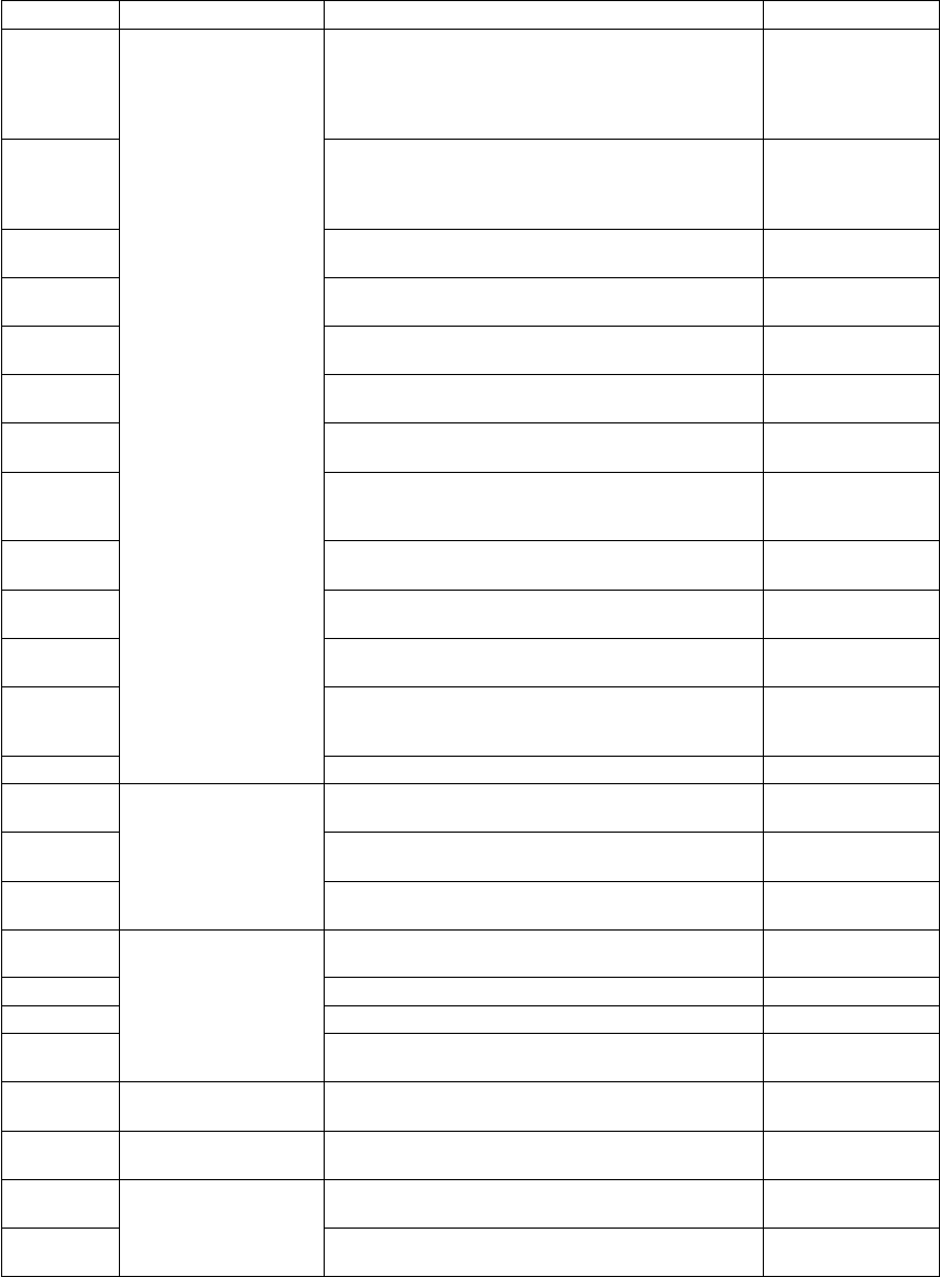
E110Paper misfeedingADU misfeeding (Paper not reaching the registra-
tion sensor): The paper which has passed through
ADU does not reach the registration sensor during
duplex printing.
P. 5-3
E120Bypass misfeeding (Paper not reaching the regis-
tration sensor): The paper fed from the bypass tray
does not reach the registration sensor.
P. 5-4
E130Upper drawer misfeeding (Paper not reaching the
upper drawer feed sensor): The paper fed from the
upper drawer does not reach the upper drawer feed
sensor.
P. 5-5
E140Lower drawer misfeeding (Paper not reaching the
lower drawer feed sensor): The paper fed from the
lower drawer does not reach the lower drawer feed
sensor.
P. 5-6
E150PFP upper drawer misfeeding (Paper not reaching
the PFP upper drawer feed sensor): The paper fed
from the PFP upper drawer does not reach the PFP
upper drawer feed sensor.
P. 5-7
E160PFP lower drawer misfeeding (Paper not reaching
the PFP lower drawer feed sensor): The paper fed
from the PFP lower drawer does not reach the PFP
lower drawer feed sensor.
P. 5-8
E190LCF misfeeding (Paper not reaching the LCF feed
sensor): The paper fed from the LCF does not
reach the LCF feed sensor.
P. 5-9
E200Paper transport jamUpper drawer transport jam (Paper not reaching the
registration sensor): The paper does not reach the
registration sensor after it has passed the upper
drawer feed sensor.
P. 5-10
Error codeClassificationContentsTroubleshooting

© June 2005 TOSHIBA TECe-STUDIO281c/351c/451c ERROR CODE AND SELF-DIAGNOSTIC MODE
2 - 3
2
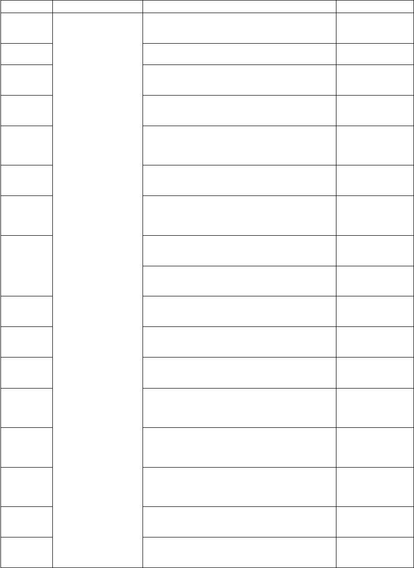
E210Paper transport jamLower drawer transport jam (Paper not reaching the
registration sensor): The paper does not reach the
registration sensor after it has passed the upper
drawer feed sensor.
P. 5-10
E220Lower drawer transport jam (Paper not reaching the
upper drawer feed sensor): The paper does not
reach the upper drawer feed sensor after it has
passed the lower drawer feed sensor.
P. 5-11
E300PFP upper drawer transport jam (Paper not reach-
ing the registration sensor): The paper does not
reach the registration sensor after it has passed the
upper drawer feed sensor.
P. 5-10
E310PFP upper drawer transport jam (Paper not reach-
ing the upper drawer feed sensor): The paper does
not reach the upper drawer feed sensor after it has
passed the lower drawer feed sensor.
P. 5-11
E320PFP upper drawer transport jam (Paper not reach-
ing the lower drawer feed sensor): The paper does
not reach the lower drawer feed sensor after it has
passed the PFP upper drawer feed sensor.
P. 5-12
E330PFP lower drawer transport jam (Paper not reach-
ing the registration sensor): The paper does not
reach the registration sensor after it has passed the
upper drawer feed sensor.
P. 5-10
E340PFP lower drawer transport jam (Paper not reach-
ing the upper drawer feed sensor): The paper does
not reach the upper drawer feed sensor after it has
passed the lower drawer feed sensor.
P. 5-11
E350PFP lower drawer transport jam (Paper not reach-
ing the lower drawer feed sensor): The paper does
not reach the lower drawer feed sensor after it has
passed the PFP upper drawer feed sensor.
P. 5-12
E360PFP lower drawer transport jam (Paper not reach-
ing the PFP upper drawer feed sensor): The paper
does not reach the PFP upper drawer feed sensor
after it has passed the PFP lower drawer feed sen-
sor.
P. 5-13
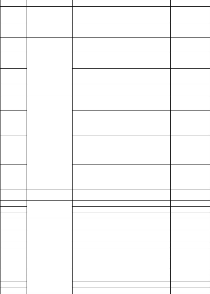
E400Cover open jamJam access cover open jam: The jam access cover
has opened during printing.
P. 5-20
E410Front cover open jam: The front cover has opened
during printing.
P. 5-20
E420Cover open jamPFP side cover open jam: The PFP side cover has
opened during printing.
P. 5-21
E430ADU open jam: The ADU has opened during print-
ing.
P. 5-21
E440Side cover open jam: The side cover has opened
during printing.
P. 5-22
E450LCF side cover open jam: The LCF side cover has
opened during printing.
P. 5-22
E480Bridge unit open jam: The bridge unit has opened
during printing.
P. 5-23
E510Paper transport jam
(ADU section)
Jam not reaching the ADU entrance sensor: The
paper does not reach the ADU entrance sensor
after it is switchbacked in the exit section.
P. 5-14
E520Stop jam in the ADU: The paper does not reach the
ADU exit sensor after it has passed the ADU
entrance sensor.
P. 5-15
Error codeClassificationContentsTroubleshooting

e-STUDIO281c/351c/451c ERROR CODE AND SELF-DIAGNOSTIC MODE© June 2005 TOSHIBA TEC
2 - 4
E550Other paper jamPaper remaining jam on the transport path: The
paper is remaining on the transport path when print-
ing is finished (caused by a multiple paper feeding).
P. 5-19
E712RADF jamJam not reaching the original registration sensor:
The original fed from the original feeding tray does
not reach the original registration sensor.
P. 5-24
E713Cover open jam in the read ready status: Jam
caused by opening of the RADF jam access cover
or front cover while the RADF is waiting for the
scanning start signal from the equipment.
P. 5-24
E714Feed signal reception jam: The feed signal is
received even no original exists on the original
feeding tray.
P. 5-25
E721Jam not reaching the read sensor: The original
does not reach the read sensor after it has passed
the registration sensor (when scanning obverse
side) or the reverse sensor (when scanning reverse
side).
P. 5-25
E722Jam not reaching the original exit/reverse sensor
(during scanning): The original which passed the
read sensor does not reach the original exit/reverse
sensor when it is transported from the scanning
section to exit section.
P. 5-26
E724Stop jam at the original registration sensor: The
trailing edge of the original does not pass the origi-
nal registration sensor after its leading edge has
reached this sensor.
P. 5-26
E725Stop jam at the read sensor: The trailing edge of the
original does not pass the read sensor after its lead-
ing edge has reached this sensor.
P. 5-27
E731Stop jam at the original exit/reverse sensor: The
trailing edge of the original does not pass the origi-
nal exit/reverse sensor after its leading edge has
reached this sensor.
P. 5-27
E860RADF jam access cover open: The RADF jam
access cover has opened during RADF operation.
P. 5-27
E870RADF open jam: RADF has opened during RADF
operation.
P. 5-28
E910Finisher jam
(Bridge unit)
Jam at the bridge unit transport sensor 1: The
paper does not reach the bridge unit transport sen-
sor 1 after it has passed the exit sensor.
P. 5-29
E920Stop jam at the bridge unit transport sensor 1: The
trailing edge of the paper does not pass the bridge
unit transport sensor 1 after its leading edge has
reached the sensor.
P. 5-29
E930Jam at the bridge unit transport sensor 2: The trail-
ing edge of the paper does not reach the bridge unit
transport sensor 2 after its leading edge has
reached the bridge unit transport sensor 1.
P. 5-29
E940Stop jam at the bridge unit transport sensor 2: The
trailing edge of the paper does not pass the bridge
unit transport sensor 2 after its leading edge has
reached the bridge unit transport sensor 2.
P. 5-29
E9F0Finisher jam
(Punch unit)
Punching jam: Punching is not performed properly.
[MJ-1023/1024 (when MJ-6004 is installed)]
[MJ-1101 (when MJ-6101 is installed)]
P. 5-46
Error codeClassificationContentsTroubleshooting
06/08

© June 2005 TOSHIBA TECe-STUDIO281c/351c/451c ERROR CODE AND SELF-DIAGNOSTIC MODE
2 - 5
2
EA10Finisher jam
(Finisher section)
Paper transport delay jam: The paper which has
passed the bridge
unit does not reach the inlet sensor. [MJ-1022/
1023/1024/1101]
P. 5-30
EA20 Paper transport stop jam:
(1) The paper does not pass through the inlet sen-
sor.
[MJ-1022/1023/1024]
(2) The paper has passed through the inlet sensor
but does not reach or pass the feed path sensor
or processing tray sensor.
[MJ-1023/1024]
(3)The paper which has passed through the inlet
sensor does not reach the transport sensor.
[MJ-1101]
P. 5-32
EA21Paper size error jam: Paper does not reach the sen-
sor because the paper is shorter than spec. [MJ-
1101]
P. 5-33
EA30Power-ON jam:
(1) Paper exists at the inlet sensor when power is
turned ON.
[MJ-1022/1023/1024]
(2) Paper exists at the feed path sensor or pro-
cessing tray sensor when power is turned ON.
[MJ-1023/1024]
P. 5-34
EA31Transport path paper remaining jam: The paper
which has passed through the inlet sensor does not
reach the transport sensor. [MJ-1101]
P. 5-35
EA32Exit paper remaining jam: The paper is remaining
on the finishing tray when the power is turned ON.
[MJ-1101]
P. 5-35
EA40Finisher jam
(Finisher section)
Door open jam:
1)The finisher has been released from the equip-
ment during printing. [MJ-1022]
2)The upper/front cover of the finisher section or
the upper/ front door of the puncher section has
opened during printing. [MJ-1023/1024]
3)The front cover or stationary tray cover is
opened during paper transport. [MJ-1101]
P. 5-36
EA50Stapling jam: Stapling is not performed properly.
[MJ-1022/1023/1024/1101]
P. 5-38
EA60Early arrival jam: The inlet sensor detects the paper
earlier than a specified timing. [MJ-1022/1023/
1024/1101]
P. 5-40
EA70Stack delivery jam: It cannot deliver the stack of
paper on the intermediary process tray to the stack
tray. [MJ-1022]
P. 5-41
Stack exit belt home position error: The stack exit
belt is not at the home position. [MJ-1101]
Error codeClassificationContentsTroubleshooting
06/08

e-STUDIO281c/351c/451c ERROR CODE AND SELF-DIAGNOSTIC MODE© June 2005 TOSHIBA TEC
2 - 6
EA80Finisher jam
(Saddle stitcher sec-
tion)
Stapling jam: Stapling is not performed properly.
[MJ-1024]
P. 5-43
EA90Door open jam: The delivery cover or inlet cover
has opened dur-ing printing [MJ-1024].
P. 5-43
EAA0Power-ON jam: Paper exists at No.1 paper sensor,
No. 2 paper sensor, No.3 paper sensor, vertical
path paper sensor or delivery sensor when power is
turned ON. [MJ-1024]
P. 5-44
EAB0Transport stop jam: The paper which passed
through the inlet sensor does not reach or pass
No.1 paper sensor, No. 2 paper sensor, No.3 paper
sensor or delivery sensor. [MJ-1024]
P. 5-44
EAC0Transport delay jam: The paper which has reached
the inlet sensor does not pass through the inlet sen-
sor. [MJ-1024]
P. 5-45
EAD0Other paper jamPrint end command time-out jam: The printing has
not finished normally because of the communica-
tion error between the SYS board and LGC board
at the end of printing.
P. 5-47
EAE0Finisher jamReceiving time time-out jam: The printing has been
interrupted because of the communication error
between the equipment and finisher when the
paper is transported from the equipment to the fin-
isher.
P. 5-47
EAF0Finisher jam
(Finisher section)
Stack return jam: It cannot load the paper which
passed through the delivery roller on the intermedi-
ary process tray. [MJ-1022]
P. 5-42
EB30Finisher jamReady time time-out jam: The equipment judges
that the paper transport to the finisher is disabled
because of the communication error between the
equipment and finisher at the start of printing.
P. 5-47
EB50Paper transport jamPaper remaining on the transport path: The multiple
feeding of preceding paper caused the misfeeding
of upcoming paper.
P. 5-16
EB60Paper remaining on the transport path: The multiple
feeding of preceding paper caused the misfeeding
of upcoming paper (redetection after no jam is
detected at [EB50]).
P. 5-17
ED10Finisher jamSideways adjustment motor (M2) home position
detection error: The Sideways adjustment motor is
not at the home position. [MJ-1101 (when MJ-6101
is installed)]
P. 5-48
ED11Skew adjustment motor (M1) home position detec-
tion abnormality: The Skew adjustment motor is not
at the home position. [MJ-1101 (when MJ-6101 is
installed)]
P. 5-48
ED12Shutter home position error: The shutter is not at
the home position. [MJ-1101]
P. 5-49
ED13Front alignment plate home position error: The front
alignment plate is not at the home position. [MJ-
1101]
P. 5-49
ED14Rear alignment plate home position error: The rear
alignment plate is not at the home position. [MJ-
1101]
P. 5-50
ED15Paddle home position error: The paddle is not at the
home position. [MJ-1101]
P. 5-50
ED16Buffer tray home position error: The buffer tray is
not at the home position. [MJ-1101]
P. 5-51
Error codeClassificationContentsTroubleshooting
06/08

© June 2005 TOSHIBA TECe-STUDIO281c/351c/451c ERROR CODE AND SELF-DIAGNOSTIC MODE
2 - 7
2
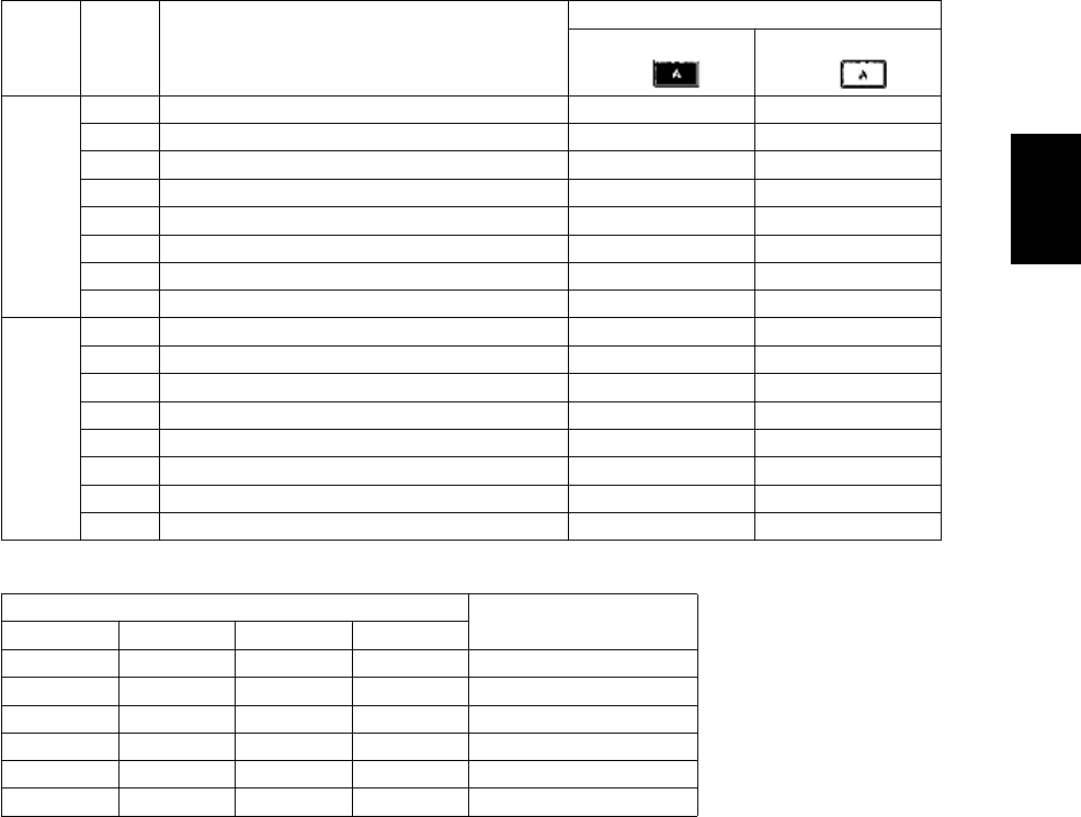
2.1.2Service call
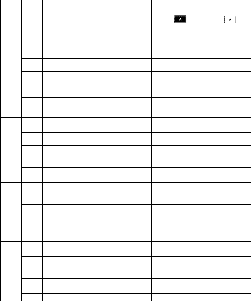
Error codeClassificationContentsTroubleshooting
C010Drive system related
service call
Main motor abnormality: The main motor is not
rotating normally.
P. 5-52
C020Developer motor abnormality: The developer motor
is not rotating normally.
P. 5-52
C030Transport motor abnormality: The transport motor is
not rotating normally.
P. 5-52
C040Paper feeding system
related service call
PFP motor abnormality: The PFP motor is not rotat-
ing normally. (the case that paper can be fed from
any drawer except the PFP)
P. 5-53
C130Upper drawer tray abnormality: The upper drawer
tray-up motor is not rotating or the upper drawer
tray is not moving normally. (the case that paper
can be fed from any drawer except the upper
drawer)
P. 5-54
C140Lower drawer tray abnormality: The lower drawer
tray-up motor is not rotating or the lower drawer tray
is not moving normally. (the case that paper can be
fed from any drawer except the lower drawer)
P. 5-54
C150PFP upper drawer tray abnormality: The PFP upper
drawer tray-up motor is not rotating or the PFP
upper drawer tray is not moving normally. (the case
that paper can be fed from any drawer except the
PFP upper drawer)
P. 5-55
C160PFP lower drawer tray abnormality: The PFP lower
drawer tray-up motor is not rotating or the PFP
lower drawer tray is not moving normally. (the case
that paper can be fed from any drawer except the
PFP lower drawer)
P. 5-55
C180LCF tray-up motor abnormality: The LCF tray-up
motor is not rotating or the LCF tray is not moving
normally. (the case that paper can be fed from any
drawer except the LCF)
P. 5-56
C1A0LCF end fence motor abnormality: The LCF end
fence motor is not rotating or the LCF end fence is
not moving normally. (the case that paper can be
fed from any drawer except the LCF)
P. 5-57
C1B0LCF transport motor abnormality: The LCF trans-
port motor is not rotating normally. (the case that
paper can be fed from any drawer except the LCF)
P. 5-58
C260Scanning system
related service call
Peak detection error: Lighting of the exposure lamp
(white reference) is not detected when power is
turned ON.
P. 5-59
C270Carriage home position sensor not turning OFF
within a specified period of time: The carriage does
not shift from its home position in a specified time.
P. 5-59
C280Carriage home position sensor not turning ON
within a specified period of time: The carriage does
not reach to its home position in a specified period
of time.
P. 5-59
C360Copy process related
service call
Charger cleaner motor abnormality: Charger
cleaner motor is not rotating or wire cleaner is not
moving normally.
P. 5-89
e-STUDIO281c/351c/451c ERROR CODE AND SELF-DIAGNOSTIC MODE© June 2005 TOSHIBA TEC
2 - 8
C411Fuser unit related ser-
vice call
Thermistor or heater abnormality at power-ON:
Abnormality of the thermistor is detected when
power is turned ON or the temperature of the fuser
roller does not rise in a specified period of time after
power is turned ON.
P. 5-60
C412Thermistor/heater abnormality at power-ON: Ther-
mistor abnormality is detected at power-ON or the
fuser roller temperature does not rise within a spec-
ified period of time after power-ON.
P. 5-60
C443Heater abnormality after abnormality judgment (not
reaching to intermediate temperature)
P. 5-61
C445Heater abnormality after abnormality judgment
(pre-running end temperature abnormality)
P. 5-61
C446Heater abnormality after abnormality judgment
(pre-running end temperature abnormality)
P. 5-61
C447Heater abnormality after abnormality judgment
(temperature abnormality at ready status)
P. 5-61
C449Heater abnormality after abnormality judgment
(overheating)
P. 5-61
C471IH power voltage abnormality or IH initial abnormal-
ity
(IH board initial abnormality)
P. 5-61
C472IH power voltage abnormality (power supply abnor-
mality)
P. 5-61
C475IH power voltage abnormality (power supply abnor-
mality when door is opened)
P. 5-61
C480Overheating of IGBT: The temperature of the IGBT
rises abnormally.
P. 5-61
C490IH control circuit or IH coil abnormality: Abnormality
is detected in IH control circuit or IH coil is broken/
shorted.
P. 5-62
C4B0Fuser unit counter abnormalityP. 5-62
C550Optional communica-
tion related service call
RADF I/F error: Communication error has occurred
between the RADF and the scanner.
P. 5-63
C570Communication error between Engine-CPU and
IPC board
P. 5-63
C580Communication error between IPC board and fin-
isher
P. 5-63
C900Circuit related service
call
Connection error between SYS board and LGC
board
P. 5-64
C940Engine-CPU abnormalityP. 5-64
C950LGC board memory abnormalityP. 5-64
C960Connection error between LGC board and DRV
board, ID abnormality
P. 5-64
C970Process related ser-
vice call
High-voltage transformer abnormality: Leakage of
the main charger is detected.
P. 5-89
C9E0Circuit related service
call
Connection error between SLG board and SYS
board, ID abnormality
P. 5-65
CA10Laser optical unit
related service call
Polygonal motor abnormality: The polygonal motor
is not rotating normally.
P. 5-66
CA20H-Sync detection error: H-Sync signal detection PC
board cannot detect laser beams.
P. 5-66
Error codeClassificationContentsTroubleshooting

© June 2005 TOSHIBA TECe-STUDIO281c/351c/451c ERROR CODE AND SELF-DIAGNOSTIC MODE
2 - 9
2
CB10Finisher related
service call
Entrance motor abnormality: The entrance motor is
not rotating normally. [MJ-1101]
P. 5-67
CB11Buffer tray guide motor abnormality: The buffer tray
guide motor is not rotating or the buffer tray guide is
not moving normally. [MJ-1101]
P. 5-67
CB12Buffer roller drive motor abnormality: The buffer
roller drive motor is not rotating or the buffer roller is
not moving normally. [MJ-1101]
P. 5-67
CB20Delivery motor abnormality: Delivery motor or deliv-
ery roller is not rotating normally. [MJ-1022]
P. 5-68
CB30Tray 1/Tray 2 shift motor abnormality: Tray 1/Tray 2
shift motor is not rotating or delivery tray is not mov-
ing normally. [MJ-1023/1024]
P. 5-68
Movable tray shift motor abnormality: The movable
tray shift motor is not rotating or the movable tray is
not moving normally. [MJ-1101]
P. 5-68
CB31Movable tray paper-full detection error: The actua-
tor of the movable tray paper-full detection sensor
does not move smoothly. [MJ-1101]
P. 5-69
CB40Rear aligning plate motor abnormality: Rear align-
ing plate motor is not rotating or aligning plate is not
moving normally. [MJ-1023/1024]
P. 5-69
Front alignment motor abnormality: The front align-
ment motor is not rotating or the front alignment
plate is not moving normally. [MJ-1101]
P. 5-69
CB50Staple motor abnormality: Staple motor is not rotat-
ing or stapler is not moving normally. [MJ-1022/
1023/1024]
P. 5-70
Stapler home position error: The stapler home posi-
tion sensor does not work. [MJ-1101]
P. 5-70
CB51Stapler shift home position error: The stapler is not
at the home position. [MJ-1101]
P. 5-70
CB60Stapler shift motor abnormality: Stapler shift motor
is not rotating or staple unit is not moving normally.
[MJ-1023/1024/1101]
P. 5-71
CB80Backup RAM data abnormality:
1)Abnormality of checksum value on finisher con-
troller PC board is detected when the power is
turned ON. [MJ-1023/1024]
2)Abnormality of checksum value on punch con-
troller PC board is detected when the power is
turned ON. [MJ-1023/1024 (when MJ-6004 is
installed)]
P. 5-71
RAM abnormality: Abnormality of checksum value
on finisher controller PC board is detected when the
power is turned on. [MJ-1101]
P. 5-71
CB81Flash ROM abnormality: Abnormality of checksum
value on finisher controller PC board is detected
when the power is turned on. [MJ-1101]
P. 5-72
CB90Paper pushing plate motor abnormality: Paper
pushing plate motor is not rotating or paper pushing
plate is not moving normally. [MJ-1024]
P. 5-72
CBA0Stitch motor (front) abnormality: Stitch motor (front)
is not rotating or rotary cam is not moving normally.
[MJ-1024]
P. 5-72
CBB0Stitch motor (rear) abnormality: Stitch motor (rear)
is not rotating or rotary cam is not moving normally.
[MJ-1024]
P. 5-72
Error codeClassificationContentsTroubleshooting
06/08
e-STUDIO281c/351c/451c ERROR CODE AND SELF-DIAGNOSTIC MODE© June 2005 TOSHIBA TEC
2 - 10
CBC0Finisher related
service call
Alignment motor abnormality: Alignment motor is
not rotating or aligning plate is not moving normally.
[MJ-1024]
P. 5-72
CBD0Guide motor abnormality: Guide motor is not rotat-
ing or guide is not moving normally. [MJ-1024]
P. 5-73
CBE0Paper folding motor abnormality: Paper folding
motor or paper folding roller is not rotating normally.
[MJ-1024]
P. 5-73
CBF0Paper positioning plate motor abnormality: Paper
positioning plate motor is not rotating or paper posi-
tioning plate is not moving normally. [MJ-1024]
P. 5-73
CC00Sensor connector abnormality: Connector of guide
home position sensor, paper pushing plate home
position sensor or paper pushing plate top position
sensor is disconnected. [MJ-1024]
P. 5-74
CC10Micro switch abnormality: With all covers closed,
inlet door switch, delivery door switch or front cover
switch is open. [MJ-1024]
P. 5-74
CC20Communication error between finisher and saddle
stitcher: Communication error between finisher con-
troller PC board and saddle stitcher controller board
[MJ-1023/1024]
P. 5-74
CC30Stack processing motor abnormality: The stack pro-
cessing motor is not rotating or the stack delivery
belt is not moving normally. [MJ-1022]
P. 5-75
Stack transport motor abnormality: The stack trans-
port motor is not rotating or the stack transport belt
is not moving normally. [MJ-1101]
P. 5-76
CC31Transport motor abnormality: The transport motor is
not rotating or the stack transport roller -1 and -2 is
not rotating normally. [MJ-1101]
P. 5-76
CC40Swing motor abnormality: Swing motor is not rotat-
ing or swing unit is not moving normally. [MJ-1023/
1024]
P. 5-76
CC41Paper holder cam home position abnormality: The
paper holder cam is not at the home position. [MJ-
1101]
P. 5-77
CC50Horizontal registration motor abnormality: Horizon-
tal registration motor is not rotating or puncher is
not shifting normally. [MJ-1023/1024 (when MJ-
6004 is installed)]
P. 5-77
CC51Sideways adjustment motor (M2) abnormality:
Sideways adjustment motor is not rotating or
puncher is not shifting normally. [MJ-1101 (when
MJ-6101 is installed)
P. 5-77
CC52Skew adjustment motor (M1) abnormality: Skew
adjustment motor is not rotating or puncher is not
shifting normally. [MJ-1101 (when MJ-6101 is
installed)]
P. 5-78
CC60Punch motor abnormality: Punch motor is not rotat-
ing or puncher is not shifting normally. [MJ-1023/
1024 (when MJ-6004 is installed)]
P. 5-78
CC61Punch motor (M3) home position detection error:
Punch motor is not rotating or puncher is not shift-
ing normally. [MJ-1101 (when MJ-6101 is installed)]
P. 5-79
Error codeClassificationContentsTroubleshooting
06/08

© June 2005 TOSHIBA TECe-STUDIO281c/351c/451c ERROR CODE AND SELF-DIAGNOSTIC MODE
2 - 11
2
CC71Finisher related
service call
Punch ROM checksum error: Abnormality of check-
sum value on Hole punch controller PC board is
detected when the power is turned on. [MJ-1101
(when MJ-6101 is installed)]
P. 5-79
CC72Punch RAM read/write error: Abnormality of check-
sum value on Hole punch controller PC board is
detected when the power is turned on. [MJ-1101
(when MJ-6101 is installed)]
P. 5-79
CC80Front alignment motor abnormality: Front alignment
motor is not rotating or front aligning plate is not
moving normally. [MJ-1022]
Front aligning plate motor abnormality: Front align-
ing plate motor is not rotating or aligning plate is not
moving normally. [MJ-1023/1024]
P. 5-80
Rear alignment motor abnormality: The rear align-
ment motor is not rotating or the rear alignment
plate is not moving normally. [MJ-1101]
P. 5-80
CC90Upper stack tray lift motor abnormality: The upper
stack tray lift motor is not rotating or the upper stack
tray is not moving normally. [MJ-1022]
P. 5-81
CCA0Lower stack tray lift motor abnormality: The lower
stack tray lift motor is not rotating or the lower stack
tray is not moving normally. [MJ-1022]
P. 5-82
CCB0Rear jogging motor abnormality: The rear jogging
motor is not rotating or the rear jogging plate is not
moving normally. [MJ-1022]
P. 5-82
CCD0Stack ejection motor abnormality: Stack ejection
motor or stack ejection roller is not rotating nor-
mally. [MJ-1023/1024]
P. 5-83
CCE0Paper trailing edge assist motor abnormality: Paper
trailing edge assist motor is not rotating or paper
trailing edge assist is not moving normally. [MJ-
1023/1024]
P. 5-83
CCF0Gear changing motor abnormality: Gear changing
motor is not rotating normally. [MJ-1023/1024]
P. 5-83
CDE0Paddle motor abnormality: The paddle motor is not
rotating or the paddle is not rotating normally. [MJ-
1101]
P. 5-84
CE00Communication error between finisher and punch
unit: Communication error between finisher control-
ler PC board and punch controller PC board [MJ-
1023/1024 (when MJ-6004 is installed)]
[MJ-1101 (when MJ-6101 is installed)]
P. 5-84
CE10Image control related
service call
Image quality sensor abnormality (OFF level): The
output value of this sensor is out of a specified
range when sensor light source is OFF.
P. 5-85
CE20Image quality sensor abnormality (no pattern level):
The output value of this sensor is out of a specified
range when the image quality control test pattern is
not formed.
P. 5-86
CE40Image quality control test pattern abnormality: The
test pattern is not formed normally.
P. 5-87
CE50Temperature/humidity sensor abnormality: The out-
put value of this sensor is out of a specified range.
P. 5-88
CE90Drum thermistor abnormality: The output value of
the drum thermistor is out of a specified range.
P. 5-88
Error codeClassificationContentsTroubleshooting
06/08
e-STUDIO281c/351c/451c ERROR CODE AND SELF-DIAGNOSTIC MODE© June 2005 TOSHIBA TEC
2 - 12
CEA0Copy process related
service call
Revolver home position detection abnormality: It
cannot detect that the revolver is at its home posi-
tion.
P. 5-89
CEB0Black developer unit lifting movement abnormality:
The black developer unit does not move up or down
normally (lifting cam does not operate normally).
P. 5-90
CEC0Copy process related
service call
2nd transfer roller position detection abnormality:
The 2nd transfer roller does not contact/release
normally.
P. 5-91
CEE0Transfer belt position detection abnormality (normal
speed): The home position of the transfer belt can-
not be detected.
P. 5-92
CEE1Transfer belt position detection abnormality (when
decelerating): Reference position of the transfer
belt cannot be detected.
P. 5-92
CEF0Revolver motor abnormality: Revolver motor is not
rotating or revolver is not moving normally.
P. 5-92
CF20Toner density control
related service call
Toner density detection voltage abnormality: The
output value of the color auto-toner sensor in print-
ing is out of a specified range.
P. 5-93
CF30Reference plate detection voltage abnormality: The
output value of the color auto-toner sensor against
the reference plate is out of a specified range at the
light amount correction during an auto-toner adjust-
ment or when a print job has finished.
P. 5-94
CF40Light amount correction voltage abnormality: The
light amount correction is not finished normally dur-
ing an auto-toner adjustment or when a print job
has finished, or the output value of the sensor is out
of a specified range when the light amount correc-
tion has finished.
P. 5-95
CF50Color auto-toner sensor abnormality: The connec-
tion of the color auto-toner sensor cannot be
detected at the initialization, or the output value of
color auto-toner sensor when the revolver starts
rotating for initialization is out of a specified range.
P. 5-96
F070Communication
related service call
Communication error between System-CPU and
Engine-CPU
P. 5-63
F090Circuit related service
call
SRAM abnormality on the SYS boardP. 5-65
F091NVRAM abnormality on the SYS boardP. 5-65
F092SRAM and NVRAM abnormality on the SYS boardP. 5-65
F100Other service callHDD format error: HDD cannot be initialized nor-
mally.
P. 5-97
F101HDD unmounted: Connection of HDD cannot be
detected.
P. 5-97
F102HDD start error: HDD cannot become "Ready# state.P. 5-97
F103HDD transfer time-out: Reading/writing cannot be
performed in the specified period of time.
P. 5-97
F104HDD data error: Abnormality is detected in the data
of HDD.
P. 5-97
F105HDD other errorP. 5-97
F106Point and Print partition damageP. 5-97
F107/BOX partition damageP. 5-97
F108/SHA partition damageP. 5-97
Error codeClassificationContentsTroubleshooting

© June 2005 TOSHIBA TECe-STUDIO281c/351c/451c ERROR CODE AND SELF-DIAGNOSTIC MODE
2 - 13
2
F110Communication
related service call
Communication error between System-CPU and
Scanner-CPU
P. 5-63
F111Scanner response abnormalityP. 5-63
F120Other service callDatabase abnormality: Database is not operating
normally.
P. 5-97
F130Invalid MAC addressP. 5-97
F200Data overwrite kit (GP-1060) is taken offP. 5-98
F350Circuit related service
call
SLG board abnormalityP. 5-65
Error codeClassificationContentsTroubleshooting
05/11

e-STUDIO281c/351c/451c ERROR CODE AND SELF-DIAGNOSTIC MODE© June 2005 TOSHIBA TEC
2 - 14
2.1.3Error in Internet FAX / Scanning Function
1)Internet FAX related error
Error codeClassificationTroubleshooting
1C10System access abnormalityP. 5-98
1C11Insufficient memoryP. 5-98
1C12Message reception errorP. 5-98
1C13Message transmission errorP. 5-98
1C14Invalid parameterP. 5-98
1C15Exceeding file capacityP. 5-98
1C20System management module access abnormalityP. 5-98
1C21Job control module access abnormalityP. 5-98
1C22Job control module access abnormalityP. 5-98
1C30Directory creation failureP. 5-99
1C31File creation failureP. 5-99
1C32File deletion failureP. 5-98
1C33File access failureP. 5-99
1C40Image conversion abnormalityP. 5-99
1C60HDD full failure during processingP. 5-99
1C61Address Book reading failureP. 5-99
1C62Memory acquiring failureP. 5-99
1C63Terminal IP address unsetP. 5-99
1C64Terminal mail address unsetP. 5-99
1C65SMTP address unsetP. 5-99
1C66Server time time-out errorP. 5-99
1C67NIC time time-out errorP. 5-99
1C68NIC access errorP. 5-99
1C69SMTP server connection errorP. 5-99
1C6AHOST NAME errorP. 5-99
1C6BTerminal mail address errorP. 5-100
1C6CDestination mail address errorP. 5-100
1C6DSystem errorP. 5-99
1C70SMTP client OFFP. 5-100
1C71SMTP authentication errorP. 5-100
1C72POP before SMTP errorP. 5-100
1C80Internet FAX transmission failure when processing E-mail job receivedP. 5-100
1C81Onramp Gateway transmission failureP. 5-100
1C82Internet FAX transmission failure when processing FAX job receivedP. 5-100
1CC0Job canceling -
1CC1Power failureP. 5-100

© June 2005 TOSHIBA TECe-STUDIO281c/351c/451c ERROR CODE AND SELF-DIAGNOSTIC MODE
2 - 15
2
2)RFC related error
Error code Message displayed in
the TopAccess screen ContentsTroubleshooting
2500Syntax error, command unrecog-
nized
HOST NAME error(RFC: 500)
Destination mail address error
(RFC: 500)
Terminal mail address error
(RFC: 500)
P. 5-101
2501Syntax error in parameters or argu-
ments
HOST NAME error(RFC: 501)
Destination mail address error
(RFC: 501)
Terminal mail address error
(RFC: 501)
P. 5-101
2503Bad sequence of commandsDestination mail address error
(RFC: 503)
P. 5-101
2504Command parameter not imple-
mented
HOST NAME error
(RFC: 504)
P. 5-101
2550Mailbox unavailableDestination mail address error
(RFC: 550)
P. 5-101
2551User not localDestination mail address error
(RFC: 551)
P. 5-101
2552Insufficient system storageTerminal/Destination mail address
error
(RFC: 552)
P. 5-101
2553Mailbox name not allowedDestination mail address error
(RFC: 553)
P. 5-101

e-STUDIO281c/351c/451c ERROR CODE AND SELF-DIAGNOSTIC MODE© June 2005 TOSHIBA TEC
2 - 16
3)Electronic Filing related error
Error code Message displayed in
the TopAccess screen ContentsTroubleshooting
2B10There was no applicable job.No applicable job error in job control
module
P. 5-102
2B11Job status failed.JOB status abnormalityP. 5-102
2B20Failed to access file.File library function errorP. 5-102
2B30Insufficient disk space.Insufficient disk space in /BOX parti-
tion
P. 5-102
2B31Failed to access Electronic Filing.Status of specified Electronic Filing
or folder is undefined or being cre-
ated/deleted
P. 5-102
2B32Failed to print Electronic Filing docu-
ment.
Electronic Filing printing failure:
Specified document can not be
printed because of client#s access
(being edited, etc.).
P. 5-102
2B50Failed to process image.Image library errorP. 5-102
2B51Failed to process print image.List library errorP. 5-102
2B71Document(s) expire(s) in a few daysDocuments expiring in a few days
exist
-
2B80Hard Disk space for Electronic Filing
nearly full.
Hard disk space in /BOX partition is
nearly full (90%).
-
2B90Insufficient Memory.Insufficient memory capacityP. 5-102
2BA0Invalid Box password specified.Invalid Box passwordP. 5-102
2BB0Job canceledJob canceling-
2BB1Power failure occurredPower failureP. 5-102
2BC0System fatal error.Fatal failure occurredP. 5-102
2BC1Failed to acquire resource.System management module
resource acquiring failure
P. 5-102
2BD0Power failure occurred during e-Fil-
ing restoring.
Power failure occurred during restor-
ing of Electronic Filing
P. 5-102
2BE0Failed to get machine parameter.Machine parameter reading failureP. 5-103
2BF0Maximum number of page range is
reached.
Exceeding maximum number of
pages
P. 5-103
2BF1Maximum number of document
range is reached.
Exceeding maximum number of doc-
uments
P. 5-103
2BF2Maximum number of folder range is
reached.
Exceeding maximum number of fold-
ers
P. 5-103

© June 2005 TOSHIBA TECe-STUDIO281c/351c/451c ERROR CODE AND SELF-DIAGNOSTIC MODE
2 - 17
2
4)E-mail related error
Error code Message displayed in
the TopAccess screen ContentsTroubleshooting
2C10Illegal Job statusSystem access abnormalityP. 5-104
2C11Not enough memoryInsufficient memoryP. 5-104
2C12Illegal Job statusMessage reception errorP. 5-104
2C13Illegal Job statusMessage transmission errorP. 5-104
2C14Invalid parameter specifiedInvalid parameterP. 5-104
2C15Message size exceeded limit or max-
imum size
Exceeding file capacityP. 5-104
2C20Illegal Job statusSystem management module access
abnormality
P. 5-104
2C21Illegal Job statusJob control module access abnor-
mality
P. 5-104
2C22Illegal Job statusJob control module access abnor-
mality
P. 5-104
2C30Failed to create directoryDirectory creation failureP. 5-104
2C31Failed to create fileFile creation failureP. 5-104
2C32Failed to delete fileFile deletion failureP. 5-104
2C33Failed to create fileFile access failureP. 5-104
2C40Failed to convert image file formatImage conversion abnormalityP. 5-104
2C60Failed to process your Job. Insuffi-
cient disk space.
HDD full failure during processingP. 5-104
2C61Failed to read AddressBookAddress Book reading failureP. 5-104
2C62Not enough memoryMemory acquiring failureP. 5-104
2C63Invalid Domain AddressTerminal IP address unsetP. 5-104
2C64Invalid Domain AddressTerminal mail address unsetP. 5-105
2C65Failed to connect to SMTP serverSMTP address unsetP. 5-105
2C66Failed to connect to SMTP serverServer time time-out errorP. 5-105
2C67Failed to send E-Mail messageNIC time time-out errorP. 5-105
2C68Failed to send E-Mail messageNIC access errorP. 5-105
2C69Failed to connect to SMTP serverSMTP server connection errorP. 5-105
2C6AFailed to send E-Mail messageHOST NAME error (No RFC error)P. 5-105
2C6BInvalid address specified in From:
field
Terminal mail address errorP. 5-105
2C6CInvalid address specified in To: fieldDestination mail address error (No
RFC error)
P. 5-105
2C6DNIC system errorSystem errorP. 5-105
2C70SMTP service is not availableSMTP client OFFP. 5-105
2C71Failed SMTP AuthenticationSMTP authentication errorP. 5-105
2C72POP Before SMTP Authentication
Failed
POP before SMTP errorP. 5-105
2C80Failed to process received E-mail jobE-mail transmission failure when pro-
cessing E-mail job received
P. 5-105
2C81Failed to process received Fax jobProcess failure of FAX job receivedP. 5-105
2CC0Job canceledJob canceling-
2CC1Power failure occurredPower failureP. 5-106

e-STUDIO281c/351c/451c ERROR CODE AND SELF-DIAGNOSTIC MODE© June 2005 TOSHIBA TEC
2 - 18
5)File sharing related error
Error code Message displayed in
the TopAccess screen ContentsTroubleshooting
2D10Illegal Job statusSystem access abnormalityP. 5-107
2D11Not enough memoryInsufficient memoryP. 5-107
2D12Illegal Job statusMessage reception errorP. 5-107
2D13Illegal Job statusMessage transmission errorP. 5-107
2D14Invalid parameter specifiedInvalid parameterP. 5-107
2D15There are too many documents in the
folder. Failed in creating new docu-
ment.
Exceeding document numberP. 5-107
2D20Illegal Job statusSystem management module access
abnormality
P. 5-107
2D21Illegal Job statusJob control module access abnor-
mality
P. 5-107
2D22Illegal Job statusJob control module access abnor-
mality
P. 5-107
2D30Failed to create directoryDirectory creation failureP. 5-107
2D31Failed to create fileFile creation failureP. 5-107
2D32Failed to delete fileFile deletion failureP. 5-107
2D33Failed to create fileFile access failureP. 5-107
2D40Failed to convert image file formatImage conversion abnormalityP. 5-107
2D60Failed to copy fileFile library access abnormalityP. 5-107
2D62Failed to connect to network destina-
tion. Check destination path
File server connection errorP. 5-107
2D63Specified network path is invalid.
Check destination path
Invalid network pathP. 5-107
2D64Logon to file server failed. Check
username and password
Login failureP. 5-108
2D65There are too many documents in the
folder. Failed in creating new docu-
ment.
Exceeding documents in folder:
Creating new document is failed.
P. 5-108
2D66Failed to process your Job. Insuffi-
cient disk space.
HDD full failure during processingP. 5-108
2D67FTP service is not availableFTP service not availableP. 5-108
2D68File Sharing service is not availableFile sharing service not availableP. 5-108
2DA0Expired scan documents deleted
from share folder.
Periodical deletion of scanned docu-
ments completed properly.
-
2DA1Expired Sent Fax documents deleted
from shared folder.
Periodical deletion of transmitted
FAX documents completed properly.
-
2DA2Expired Received Fax documents
deleted from shared folder.
Periodical deletion of received FAX
documents completed properly.
-
2DA3Scanned documents in shared folder
deleted upon user#s request.
Manual deletion of scanned docu-
ments completed properly.
-
2DA4Sent Fax Documents in shared folder
deleted upon user#s request.
Manual deletion of transmitted FAX
documents completed properly.
-
2DA5Received Fax Documents in shared
folder deleted upon user#s request.
Manual deletion of received FAX
documents completed properly.
-
2DA6Failed to delete file.File deletion failureP. 5-107
2DA7Failed to acquire resource.Resource acquiring failureP. 5-107
2DC0Job canceledJob canceling-
2DC1Power failure occurredPower failureP. 5-108
06/08

© June 2005 TOSHIBA TECe-STUDIO281c/351c/451c ERROR CODE AND SELF-DIAGNOSTIC MODE
2 - 19
2
6)E-mail reception related error
Error code Message displayed in
the TopAccess screen ContentsTroubleshooting
3A10MIME Error has been detected in the
received mail.
E-mail MIME errorP. 5-109
3A11MIME Error has been detected in the
received mail. This mail has been
transferred to the administrator.
P. 5-109
3A12MIME Error has been detected in the
received mail. This mail could not be
transferred to the administrator.
P. 5-109
3A20Analyze Error has been detected in
the received mail.
E-mail analysis errorP. 5-109
3A21Analyze Error has been detected in
the received mail. This mail has been
transferred to the administrator.
P. 5-109
3A22Analyze Error has been detected in
the received mail. This mail could not
be transferred to the administrator.
P. 5-109
3A30Whole partial mails were not reached
by timeout.
Partial mail time-out errorP. 5-109
3A40Partial Mail Error has been detected
in the received mail.
Partial mail related errorP. 5-109
3A50HDD Full Error has been occurred in
this mail.
Insufficient HDD capacity errorP. 5-109
3A51HDD Full Error has been occurred in
this mail. This mail has been trans-
ferred to the administrator.
P. 5-109
3A52HDD Full Error has been occurred in
this mail. This mail could not be
transferred to the administrator.
P. 5-109
3A60HDD Full Warning has been occurred
in this mail.
Warning of insufficient HDD capacityP. 5-109
3A61HDD Full Warning has been occurred
in this mail. This mail could not be
transferred to the administrator.
P. 5-109
3A62HDD Full Warning has been occurred
in this mail. This mail could not be
transferred to the administrator.
P. 5-109
3A70Receiving partial mail was aborted
since the partial mail setting has
been changed to Disable.
Warning of partial mail interruptionP. 5-109
3A80Partial mail was received during the
partial mail setting is disabled.
Partial mail reception setting OFFP. 5-109
3A81Partial mail was received during the
partial mail setting is disabled. This
mail has been transferred to the
administrator.
P. 5-109
3A82Partial mail was received during the
partial mail setting is disabled. This
mail could not be transferred to the
administrator.
P. 5-109
3B10Format Error has been detected in
the received mail.
E-mail format errorP. 5-109
3B11Format Error has been detected in
the received mail. This mail has been
transferred to the administrator.
P. 5-109
3B12Format Error has been detected in
the received mail. This mail could not
be transferred to the administrator.
P. 5-109

e-STUDIO281c/351c/451c ERROR CODE AND SELF-DIAGNOSTIC MODE© June 2005 TOSHIBA TEC
2 - 20
3B20Content-Type Error has been
detected in the received mail.
Content-Type errorP. 5-109
3B21Content-Type Error has been
detected in the received mail. This
mail has been transferred to the
administrator.
P. 5-109
3B22Content-Type Error has been
detected in the received mail. This
mail could not be transferred to the
administrator.
P. 5-109
3B30Charset Error has been detected in
the received mail.
Charset errorP. 5-109
3B31Charset Error has been detected in
the received mail. This mail has been
transferred to the administrator.
P. 5-109
3B32Charset Error has been detected in
the received mail. This mail could not
be transferred to the administrator.
P. 5-109
3B40Decode Error has been detected in
the received mail.
E-mail decode errorP. 5-109
3B41Decode Error has been detected in
the received mail. This mail has been
transferred to the administrator.
P. 5-109
3B42Decode Error has been detected in
the received mail. This mail could not
be transferred to the administrator.
P. 5-109
3C10Tiff Analyze Error has been detected
in the received mail.
TIFF analysis errorP. 5-109
3C11Tiff Analyze Error has been detected
in the received mail. This mail has
been transferred to the administrator.
P. 5-109
3C12Tiff Analyze Error has been detected
in the received mail. This mail could
not be transferred to the administra-
tor.
P. 5-109
3C13Tiff Analyze Error has been detected
in the received mail.
P. 5-109
3C20Tiff Compression Error has been
detected in the received mail.
E-mail format errorP. 5-109
3C21Tiff Compression Error has been
detected in the received mail. This
mail has been transferred to the
administrator.
P. 5-109
3C22Tiff Compression Error has been
detected in the received mail. This
mail could not be transferred to the
administrator.
P. 5-109
3C30Tiff Resolution Error has been
detected in the received mail.
Content-Type errorP. 5-110
3C31Tiff Resolution Error has been
detected in the received mail. This
mail has been transferred to the
administrator.
P. 5-110
3C32Tiff Resolution Error has been
detected in the received mail. This
mail could not be transferred to the
administrator.
P. 5-110
Error code Message displayed in
the TopAccess screen ContentsTroubleshooting
© June 2005 TOSHIBA TECe-STUDIO281c/351c/451c ERROR CODE AND SELF-DIAGNOSTIC MODE
2 - 21
2
3C40Tiff Paper Size Error has been
detected in the received mail.
Charset errorP. 5-110
3C41Tiff Paper Size Error has been
detected in the received mail. This
mail has been transferred to the
administrator.
P. 5-110
3C42Tiff Paper Size Error has been
detected in the received mail. This
mail could not be transferred to the
administrator.
P. 5-110
3C50Offramp Destination Error has been
detected in the received mail.
E-mail decode errorP. 5-110
3C51Offramp Destination Error has been
detected in the received mail. This
mail has been transferred to the
administrator.
P. 5-110
3C52Offramp Destination Error has been
detected in the received mail. This
mail could not be transferred to the
administrator.
P. 5-110
3C60Offramp Security Error has been
detected in the received mail.
TIFF analysis errorP. 5-110
3C61Offramp Security Error has been
detected in the received mail. This
mail has been transferred to the
administrator.
P. 5-110
3C62Offramp Security Error has been
detected in the received mail. This
mail could not be transferred to the
administrator.
P. 5-110
3C70Power Failure has been occurred in
Email receiving.
Power failure errorP. 5-110
3D10SMTP Destination Error has been
detected in the received mail. This
mail was deleted.
Destination address errorP. 5-110
3D20Offramp Destination limitation Error
has been detected in the received
mail.
Offramp destination limitation errorP. 5-110
3D30Fax Board Error has been occurred
in the received mail.
FAX board errorP. 5-110
3E10POP3 Connection Error has been
occurred in the received mail.
POP3 server connection errorP. 5-110
3E20POP3 Connection Timeout Error has
been occurred in the received mail.
POP3 server connection time-out
error
P. 5-110
3E30POP3 Login Error has been occurred
in the received mail.
POP3 login errorP. 5-110
3E40POP3 Login Error occurred in the
received mail.
POP3 login method errorP. 5-110
3F00File I/O Error has been occurred in
this mail. The mail could not be
received until File I/O is recovered.
File I/O errorP. 5-110
3F10 P. 5-110
3F20 P. 5-110
3F30 P. 5-110
3F40 P. 5-110
Error code Message displayed in
the TopAccess screen ContentsTroubleshooting

e-STUDIO281c/351c/451c ERROR CODE AND SELF-DIAGNOSTIC MODE© June 2005 TOSHIBA TEC
2 - 22
2.1.4Printer function error
Following codes are displayed at the end of the user name on the print job log screen.
Error codeContentsTroubleshooting
402FPage memory size error - 1200 dpi network print is performed by the equip-
ment with 128 MB (standard) memory.
P. 5-111
4031HDD full during print - Large quantity image data by private print or invalid
network print are saved in HDD.
P. 5-111
4032Private-print-only error: Jobs other than Private print jobs cannot be per-
formed.
P. 5-111
4033Printing data storing limitation error: Printing with its data being stored to the
HDD temporarily (Proof print, Private print, Scheduled print, etc.) cannot be
performed.
P. 5-111
4034e-Filing storing limitation error: Printing with its data being stored to the HDD
(print and e-Filing, print to e-Filing, etc.) cannot be performed.
P. 5-111
4035Local file storing limitation error: Network FAX or Internet FAX cannot be sent
when "Local" is selected for the destination of the file to save.
P. 5-111
4036User authentication error: The user who intended to print a document is not
registered as a user.
P. 5-111
A221Print job cancellation - Print job (copy, list print, network print) is deleted from
the print job screen.
P. 5-111
A222Print job power failure - The power of the equipment is turned OFF during
print job (copy, list print, network print).
P. 5-111
A290Limit over error (Black): The numbers of output pages have exceeded those
specified with both of the department code and the user code at the same
time.
P. 5-111
A291Limit over error (Black): The number of output pages has exceeded the one
specified with the user code.
P. 5-111
A292Limit over error (Black): The number of output pages has exceeded the one
specified with the department code.
P. 5-111
A2A0Limit over error (Color): The numbers of output pages have exceeded those
specified with both of the department code and the user code at the same
time.
P. 5-111
A2A1Limit over error (Color): The number of output pages has exceeded the one
specified with the user code.
P. 5-111
A2A2Limit over error (Color): The number of output pages has exceeded the one
specified with the department code.
P. 5-111
© June 2005 TOSHIBA TECe-STUDIO281c/351c/451c ERROR CODE AND SELF-DIAGNOSTIC MODE
2 - 23
2
<<Error history>>
In the setting mode (08-253), the latest twenty groups of error data will be displayed.
Display example
EA10 99999999 05 06 14 17 57 32 064 064 23621000000
Error codeTotal counterYY MM DD HH MM SSMMMNNNABCDEFHIJLO
4 digits8 digits12 digits (Year is indicated
with its last two digits.)
3 digits3 digits11 digits
APaper source
0: Not selected 1: Bypass feed 2: LCF 3: Upper drawer 4: Lower drawer 5: PFP upper drawer
6: PFP lower drawer 7: Unused 8: Unused
BPaper size code
0: A5/ST 1: A5-R 2: ST-R 3: LT, 4: A4 5: B5-R 6: LT-R 7: A4-R 8: OTHER/UNIV 9: B5,
A: FOLIO/COMP B: LG C: B4 D: LD E: A3 F: 13"LG G: Unsed H: A6-R I: Post card J: 8.5"SQ
K: A3-wide L: 305×457 mm M: 8K N: 16K-R O: 16K Z: Not selected
CSort mode/staple mode
0: Non-sort/Non-staple 1: Group 2: Sort 7: Front staple
8: Double staple 9: Rear staple A: Saddle stitch
DADF mode
0: Unused 1: AUTO FEED (SADF) 2: STACK FEED
EAPS/AMS mode
0: Not selected 1: APS 2: AMS
FDuplex mode
0: Not selected 1: Book 2: Double-sided/Single-sided 4: Double-sided/Duplex copying
8: Single-sided/Duplex copying
GUnused
HImage shift
0: Unused 1: Book 2: Left 4: Right
IEditing
0: Unused 1: Masking 2: Trimming 3: Mirror image 4: Unused
JEdge erase/Dual-page
0: Unused 1: Edge erase 2: Dual-page 3: Edge erase & Dual-page
KUnused
LFunction
0: Unused 1: Copying 2: FAX/Internet FAX transmission 3: FAX/Internet FAX/E-mail reception printing
4: Unused 5: Printing/List print 6: Scan/E-mail transmission
MMMPrimary scanning reproduction ratio (Display in hexadecimal)
(Mx256)+(Mx16)+M
NNNSecondary scanning reproduction ratio (Display in hexadecimal)
(Nx256)+(Nx16)+N
OColor mode
0: Auto color 1: Full color 2: Black 3: Unused 4: Twin color copy 5: Gray scale
6: Unused 7: Image smoothing
e-STUDIO281c/351c/451c ERROR CODE AND SELF-DIAGNOSTIC MODE© June 2005 TOSHIBA TEC
2 - 24
2.2Self-diagnosis Modes
Notes:
1.To enter the desired mode, turn ON the power while two digital keys designated to each mode
(e.g. [0] and [5]) are pressed simultaneously.
2.When the optional FAX unit is installed, Faxes received automatically during the self-diagno-
sis mode may not be printed out. Be sure to disconnect the modular code from the line con-
nectors (LINE1, LINE2) of the equipment before starting the self-diagnosis mode. Also, be
sure to finish the self-diagnosis mode by turning the power OFF and back ON before connect-
ing the modular code.
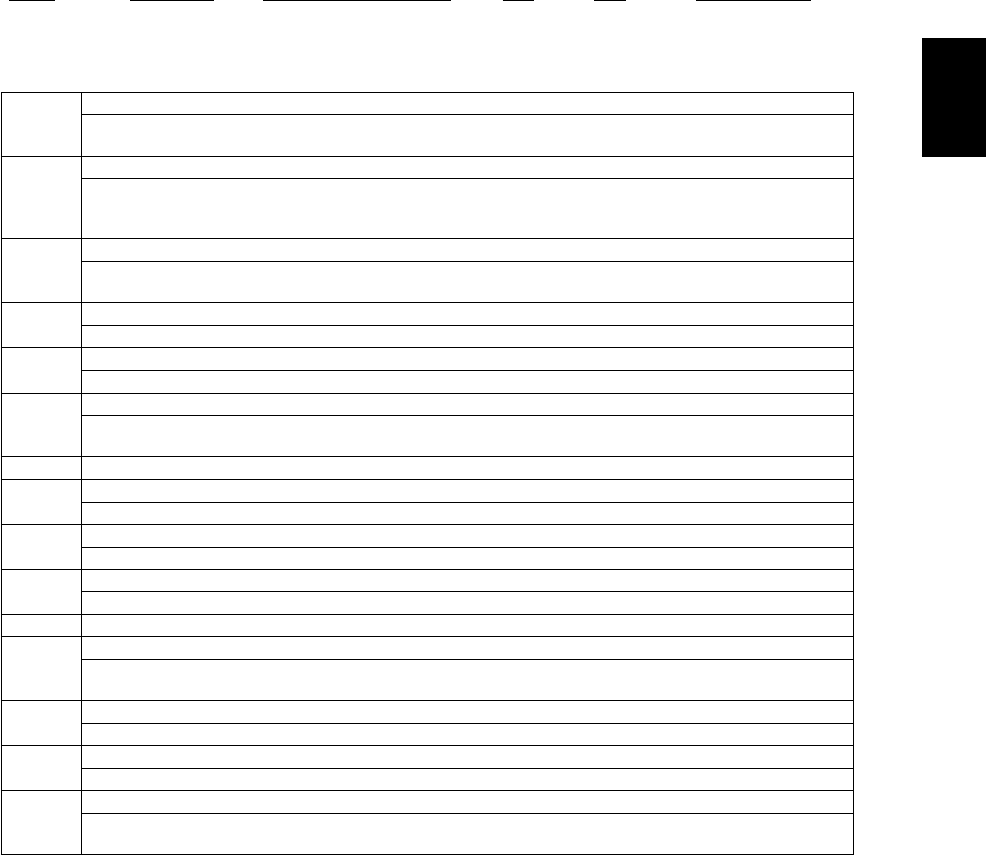
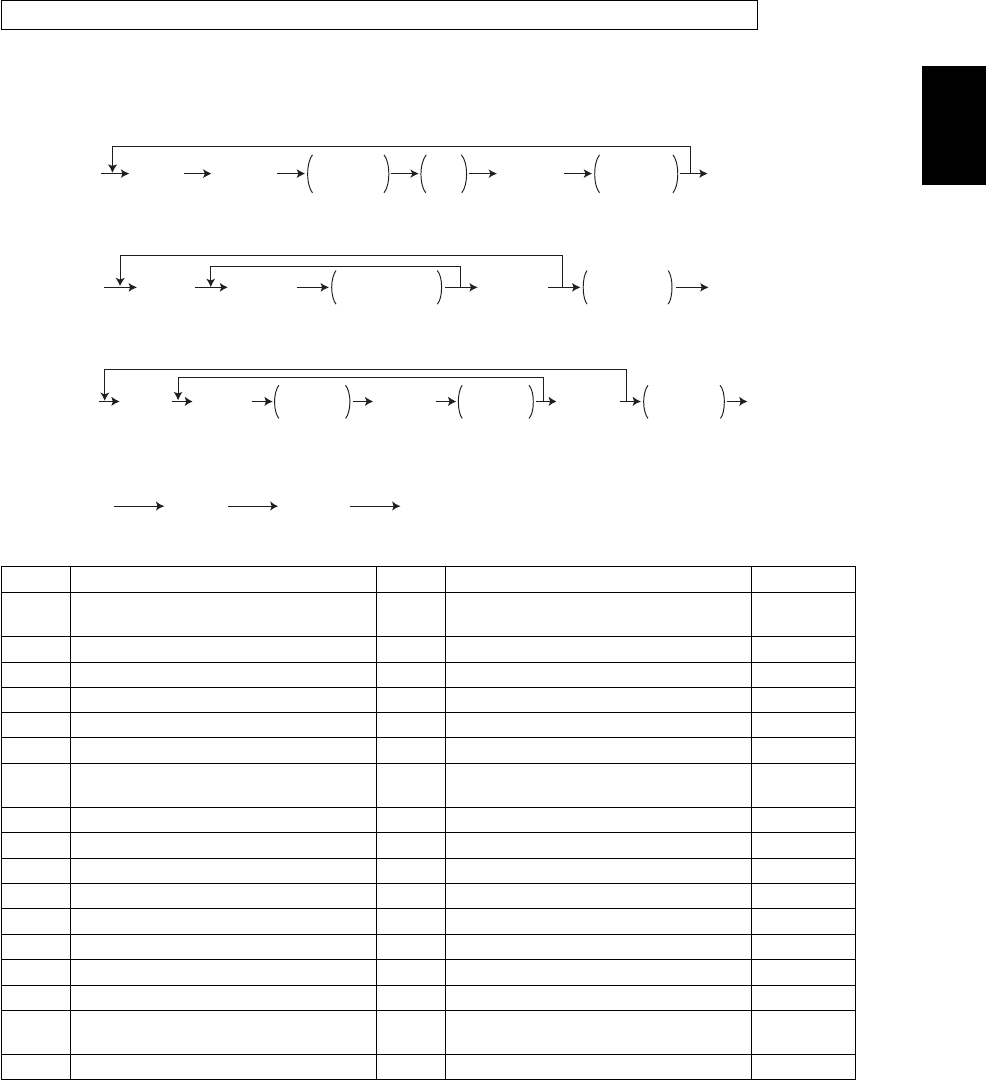
<Operation procedure>
$Control panel check mode (01):
Notes:
1.A mode can be canceled by [POWER] OFF/ON when the LED is lit and the LCD is blinking.
2.Button Check
Buttons with LED(Press to turn OFF the LED.)
Buttons without LED(Press to display the message on the control panel.)
Button on touch panel(Press to display the screen on the control panel at power-ON.)
$Test mode (03): Refer to 2.2.1. Input check (test mode 03)! and 2.2.2. Output check (test mode
03)!.
$Test print mode (04): Refer to 2.2.3. Test print mode (04)!.
$Adjustment mode (05): Refer to 2.2.4. Adjustment mode (05)!.
$Setting mode (08): Refer to 2.2.5. Setting mode (08)!.
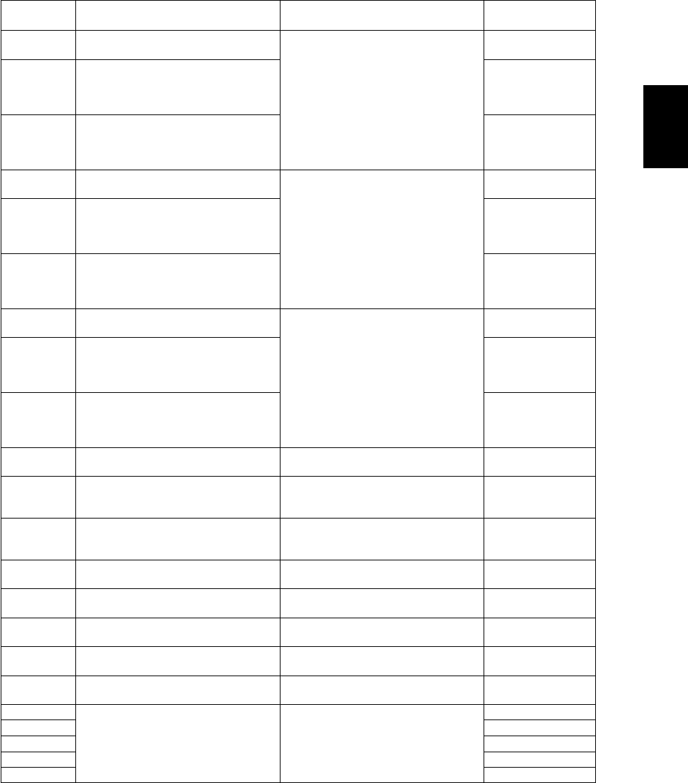
ModeFor startContentsFor exitDisplay
Control panel
check mode
[0]+[1]+
[POWER]
All LEDs on the control panel are lit, and all
the LCD pixels blink.
[POWER]
OFF/ON
-
Test mode[0]+[3]+
[POWER]
Checks the status of input/output signals.[POWER]
OFF/ON
100% C A4
TEST MODE
Test print mode[0]+[4]+
[POWER]
Outputs the test patterns.[POWER]
OFF/ON
100% P A4
TEST PRINT
Adjustment
mode
[0]+[5]+
[POWER]
Adjusts various items.[POWER]
OFF/ON
100% A A4
TEST MODE
Setting mode[0]+[8]+
[POWER]
Sets various items.[POWER]
OFF/ON
100% D
TEST MODE
List print mode[9]+[START]+
[POWER]
Prints out the data lists of the codes 05 and
08, PM support mode and pixel counter.
[POWER]
OFF/ON
100% UA A4
LIST PRINT
PM support
mode
[6]+[START]+
[POWER]
Clears each counter.[POWER]
OFF/ON
100% K
TEST MODE
Firmware
update mode
[8]+[9]+
[POWER]
Performs updating of the system firmware.[POWER]
OFF/ON
-
To exit from Adjustment mode and Setting mode:
Shut down the equipment. When the power should be turned OFF, be sure to shut down the equip-
ment by pressing the [ENERGY SAVER] button for a few seconds.
ÅðÃÅïÃ
ÅÐÑÉÛÎÃ
ÔÛÜ ´·¬ñ
ÔÝÜ ¾´·²µ·²¹ ÅÍÌßÎÌÃ
ÅÍÌßÎÌÃ
øÞ«¬¬±² ½¸»½µ÷
ÅÐÑÉÛÎà ÑÚÚñÑÒ
øÛ¨·¬÷
06/08

© June 2005 TOSHIBA TECe-STUDIO281c/351c/451c ERROR CODE AND SELF-DIAGNOSTIC MODE
2 - 25
2
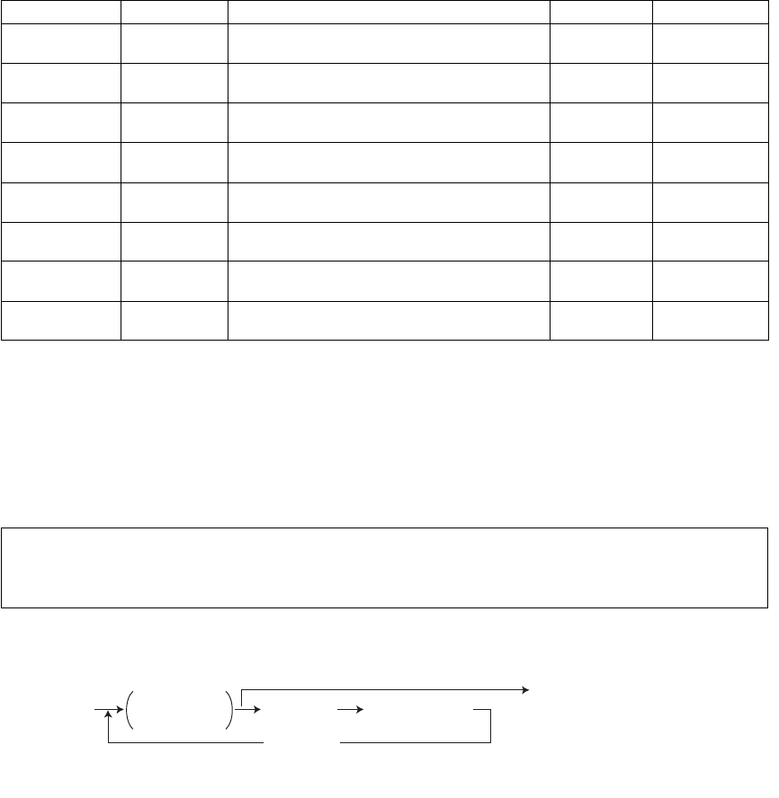
$List print mode (9S): The procedure varies depending on the code.
$PM support mode (6S):
$Firmware update mode (89): Refer to 6. FIRMWARE UPDATING!.
Fig. 2-1
*1Turn OFF the power after using the self-diagnosis mode, and leave the equipment to the user.
ÅçÃÅÍÌßÎÌÃ
ÅÐÑÉÛÎà øݱ¼»÷
ïðïæ ß¼¶«-¬³»²¬ ³±¼» øðë÷
ïðîæ Í»¬¬·²¹ ³±¼» øðè÷
øݱ¼»÷
ïðíæ ÐÓ -«°°±®¬ ³±¼»
ïðìæ ͬ±®»¼ ·²º±®³¿¬·±² ±º °·¨»´ ½±«²¬»® ø¬±²»® ½¿®¬®·¼¹» ®»º»®»²½»÷
ïðëæ ͬ±®»¼ ·²º±®³¿¬·±² ±º °·¨»´ ½±«²¬»® ø-»®ª·½» ¬»½¸²·½·¿² ®»º»®»²½»÷
ïðêæ Û®®±® ¸·-¬±®§ øÓ¿¨·³«³ ïððð ·¬»³-÷
ïðéæ Û®®±® ¸·-¬±®§ øÔ¿¬»-¬ èð ·¬»³-÷
ÅÜ·¹·¬¿´ µ»§-Ã
Õ»§ ·² ¬¸» º·®-¬
½±¼» ¬± ¾» °®·²¬»¼
ÅÜ·¹·¬¿´ µ»§-Ã
Õ»§ ·² ¬¸» ´¿-¬
½±¼» ¬± ¾» °®·²¬»¼
ÅÐÑÉÛÎÃ
ÑÚÚñÑÒ
øÛ¨·¬÷
ÅÍÌßÎÌÃ
Ô·-¬ -¬¿®¬- ¬±
¾» °®·²¬»¼
ÅÍÌßÎÌÃÅÍÌßÎÌÃ
ÅêÃÅÍÌßÎÌÃ
ÅÐÑÉÛÎà øݱ¼»÷
îæ ÐÓ Í«°°±®¬ ͽ®»»²
ÅÍÌßÎÌÃ
øÑ°»®¿¬·±² -¬¿®¬»¼÷
ÅÐÑÉÛÎà ÑÚÚñÑÒ
øÛ¨·¬÷
É¿®³·²¹ «° ݱ²¬®±´ °¿²»´
½¸»½µ ³±¼» Ì»-¬ ³±¼» Ì»-¬ °®·²¬
³±¼»
ß¼¶«-¬³»²¬
³±¼» Í»¬¬·²¹
³±¼»
Ô·-¬ °®·²¬
³±¼» ÐÓ -«°°±®¬
³±¼»
Ú·®³©¿®»
«°¼¿¬» ³±¼»
ÅÐÑÉÛÎÃ
ÑÒ
Ò±®³¿´
λ¿¼§
ÅÐÑÉÛÎÃ
ÑÚÚ
̱ «-»®
öï
ÅðÃÅïÃÅðÃÅíÃÅðÃÅìÃÅðÃÅëÃÅðÃÅèÃÅçÃÅÍÌßÎÌÃÅêÃÅÍÌßÎÌÃÅèÃÅçÃ
ͬ¿¬» ¬®¿²-·¬·±² ¼·¿¹®¿³ ±º -»´ºó¼·¿¹²±-·- ³±¼»-
e-STUDIO281c/351c/451c ERROR CODE AND SELF-DIAGNOSTIC MODE© June 2005 TOSHIBA TEC
2 - 26
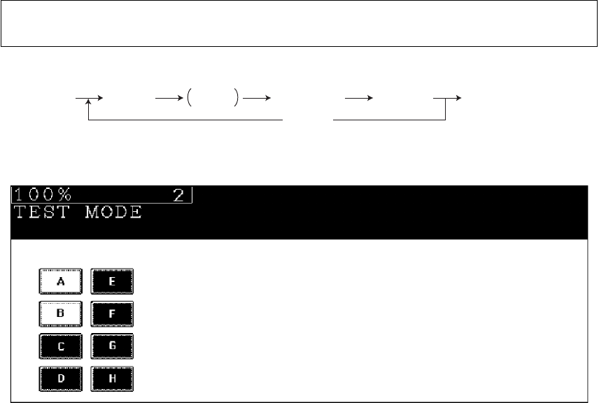
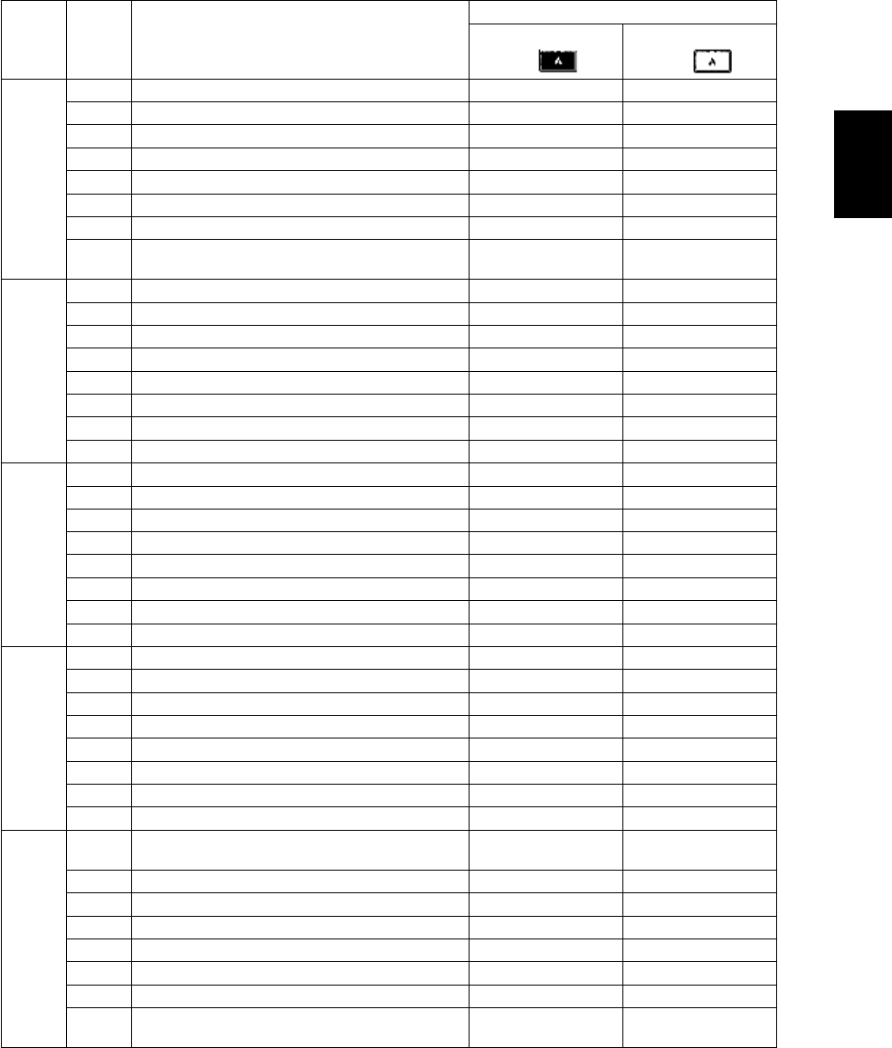
2.2.1Input check (Test mode 03)
<Operation procedure>
Note: Note:
Initialization is performed before the equipment enters the test mode.
Fig. 2-2 Example of display during input check
Items to be checked and the condition of the equipment when the buttons [A] to [H] are highlighted are
listed in the following pages.
The status of each input signal can be checked by pressing the [FAX] button, [COPY] button and
the digital keys in the test mode (03).
ÅðÃÅíÃ
ÅÐÑÉÛÎà ÅÍÌßÎÌà ÅÚßÈÃ
±®
ÅÝÑÐÇÃ
ÅÜ·¹·¬¿´ µ»§-Ã
ÅÝÔÛßÎÃ
øÔÝÜ ÑÒ÷ ÅÐÑÉÛÎà ÑÚÚñÑÒ
øÛ¨·¬÷
© June 2005 TOSHIBA TECe-STUDIO281c/351c/451c ERROR CODE AND SELF-DIAGNOSTIC MODE
2 - 27
2
[FAX] button: OFF/[COPY] button: OFF ([FAX] LED: OFF/[COPY] LED: OFF)
Digital
key ButtonItems to check
Contents
Highlighted display
e.g.
Normal display
e.g.
[1]
ABypass unit connectionNot connectedConnected
BADU connectionNot connectedConnected
C---
DLCF connectionNot connectedConnected
E---
F---
G---
HLCF drawer detection switchDrawer not installedDrawer present
[2]
APFP upper drawer detection switchDrawer not installedDrawer present
B---
CPFP upper drawer paper stock sensorPaper almost emptyPaper present
DPFP upper drawer feed sensorPaper presentNo paper
EPFP connectionNot connectedConnected
FPFP side cover open/close switchCover openedCover closed
GPFP upper drawer empty sensorNo paperPaper present
HPFP upper drawer tray-up sensorTray at upper limit
position
Other than upper
limit position
[3]
ALCF tray bottom sensorTray at bottom posi-
tion
Other than upper
limit position
BLCF standby side paper misload detection sen-
sor
Properly loadedPaper misload
C---
D---
E---
F---
G---
HPaper stock sensor at LCF feed sidePaper presentNo paper
[4]
APFP lower drawer detection switchDrawer not installedDrawer present
B---
CPFP lower drawer paper stock sensorPaper almost emptyPaper present
DPFP lower drawer feed sensorPaper presentNo paper
EPFP motor rotation status (Motor is rotating at
output mode (03))
Abnormal rotationNormal rotation
F---
GPFP lower drawer empty sensorNo paperPaper present
HPFP lower drawer tray-up sensorTray at upper limit
position
Other than upper
limit position
e-STUDIO281c/351c/451c ERROR CODE AND SELF-DIAGNOSTIC MODE© June 2005 TOSHIBA TEC
2 - 28
[5]
ALCF end fence home position sensorFence home posi-
tion
Other than home
position
BLCF end fence stop position sensorFence stop positionOther than stop
position
CEmpty sensor at LCF standby sideNo paperPaper present
DLCF side cover open/close switchCover closedCover opened
ELCF motor rotation status (Motor is rotating at
output mode (03))
Abnormal rotationNormal rotation
FLCF tray-up sensorTray at upper limit
position
Other than upper
limit position
GLCF feed sensorNo paperPaper present
HEmpty sensor at LCF feed sideNo paperPaper present
[6]
ALower drawer detection switchDrawer not installedDrawer present
BUpper drawer detection switchDrawer not installedDrawer present
CLower drawer paper stock sensorPaper almost emptyPaper present
DUpper drawer paper stock sensorPaper almost emptyPaper present
ELower drawer empty sensorNo paperPaper present
FUpper drawer empty sensorNo paperPaper present
GLower drawer tray-up sensorTray at upper limit
position
Other than upper
limit position
HUpper drawer tray-up sensorTray at upper limit
position
Other than upper
limit position
[7]
A---
B---
C---
D---
ESide cover open/close switchCover openedCover closed
FFront cover opening/closing switchCover openedCover closed
G---
HExit sensorPaper presentNo paper
[8]
ABypass feed paper width sensor 3
(Refer to table1)
Bit 1Bit 0
BBypass feed paper width sensor 2
(Refer to table1)
Bit 1Bit 0
CBypass feed paper width sensor 1
(Refer to table1)
Bit 1Bit 0
DBypass feed paper width sensor 0
(Refer to table1)
Bit 1Bit 0
EBypass sensorNo paperPaper present
FADU opening/closing switchADU openedADU closed
GADU exit sensorPaper presentNo paper
HADU entrance sensorPaper presentNo paper
Digital
key ButtonItems to check
Contents
Highlighted display
e.g.
Normal display
e.g.
© June 2005 TOSHIBA TECe-STUDIO281c/351c/451c ERROR CODE AND SELF-DIAGNOSTIC MODE
2 - 29
2
Table 1. Relation between the status of the bypass paper width sensor and paper size (width).
[9]
A---
B---
C---
D---
E---
FKey copy counter connectionNot connectedConnected
G---
H---
[0]
A---
B---
C---
D---
E---
F---
G---
H---
Bypass paper width sensor Paper width size
3210
0111A3/LD
1011A4-R/LT-R
1101A5-R/ST-R
1110Card size
0011B4-R/LG
1001B5-R
Digital
key ButtonItems to check
Contents
Highlighted display
e.g.
Normal display
e.g.
e-STUDIO281c/351c/451c ERROR CODE AND SELF-DIAGNOSTIC MODE© June 2005 TOSHIBA TEC
2 - 30
[FAX] button: ON/[COPY] button: OFF ([FAX] LED: ON/[COPY] LED: OFF)
Digital
key ButtonItems to check
Contents
Highlighted display
e.g.
Normal display
e.g.
[1]
A2nd transfer roller position detection sensorReleasedContacted
BBlack developer contact timing detection sensorReleasing move-
ment
Contacting move-
ment
CBlack developer contact position detection sen-
sor
Released positionContacted position
DMain motor rotation status
(Motor is rotating at Output Mode (03))
Abnormal rotationNormal rotation
EDeveloper motor rotation status
(Motor is rotating at Output Mode (03))
Abnormal rotationNormal rotation
FTransport motor rotation status
(Motor is rotating at Output Mode (03))
Abnormal rotationNormal rotation
GPolygonal motor rotation status
(Motor is rotating at Output Mode (03))
Abnormal rotationNormal rotation
H24V Power supplyPower OFFPower ON
[2]
AIPC board connectionNot connectedConnected
BColor toner cartridge sensorNormallyInstallation fault
CRevolver home position sensorHome positionOther than home
position
D---
E---
FToner bag full detection sensorToner bag fullNot full
GBlack auto-toner sensor connectionNot connectedConnected
H---
[3]
A---
B---
C---
D---
E---
F---
GLower drawer feed sensorNo paperPaper present
HUpper drawer feed sensorPaper presentNo paper
[4]
A---
B---
C---
D---
EBridge unit connectionNot connectedConnected
FColor auto-toner sensor connectionNot connectedConnected
G---
H---
© June 2005 TOSHIBA TECe-STUDIO281c/351c/451c ERROR CODE AND SELF-DIAGNOSTIC MODE
2 - 31
2
[5]
A---
B---
C---
D---
E---
FRADF connectionRADF connectedNot connected
GPlaten sensorPlaten cove openedPlaten cover closed
HCarriage home position sensorHome positionOther than home
position
[6]
A---
B---
C---
DAPS sensor (APS-R)No originalOriginal present
EAPS sensor (APS-C)No originalOriginal present
FAPS sensor (APS-3)No originalOriginal present
GAPS sensor (APS-2)No originalOriginal present
HAPS sensor (APS-1)No originalOriginal present
[7]
ARADF tray sensorOriginal presentNo original
BRADF empty sensorOriginal presentNo original
CRADF jam access cover sensorCover openedCover closed
DRADF open/close sensorRADF openedRADF closed
ERADF exit sensorOriginal presentNo original
FRADF intermediate sensorOriginal presentNo original
GRADF read sensorOriginal presentNo original
HRADF registration sensorOriginal presentNo original
[8]
A---
B---
C---
D---
ERADF original length sensorOriginal presentNo original
FRADF original width sensor 1Original presentNo original
GRADF original width sensor 2Original presentNo original
H---
[9]
ABlack toner cartridge switchCartridge not
installed
Cartridge installed
B---
C---
DBypass feed sensorNo paperPaper present
ERegistration sensorPaper presentNo paper
F---
G---
HTransfer belt home position sensorHome positionOther tha home
position
Digital
key ButtonItems to check
Contents
Highlighted display
e.g.
Normal display
e.g.
e-STUDIO281c/351c/451c ERROR CODE AND SELF-DIAGNOSTIC MODE© June 2005 TOSHIBA TEC
2 - 32
[0]
ABridge unit transport sensor 2Paper presentNo paper
BBridge unit cover open/close detection switchCover openedCover closed
CBridge unit transport sensor 1Paper presentNo paper
DBridge unit paper full detection sensorPaper not fullPaper full
E---
FCharger cleaner front position detection switchCleaner home posi-
tion
Other than home
position
GCharger cleaner rear position detection switchCleaner rear posi-
tion
Other than rear posi-
tion
H---
Digital
key ButtonItems to check
Contents
Highlighted display
e.g.
Normal display
e.g.

© June 2005 TOSHIBA TECe-STUDIO281c/351c/451c ERROR CODE AND SELF-DIAGNOSTIC MODE
2 - 33
2
[FAX] button: OFF/[COPY] button: ON ([FAX] LED: OFF/[COPY] LED: ON)
Digital
key ButtonItems to check
Contents
Highlighted display
e.g.
Normal display
e.g.
[1] -Temperature/humidity sensor (displays temper-
ature inside of the equipment)
-Temperature [°C]
[2] -Temperature/humidity sensor (displays humidity
inside of the equipment)
-Humidity [%RH]
[3] -Drum thermistor (displays drum surface temper-
ature)
-Temperature [°C]
[4]
A---
B---
C---
D---
E---
F---
G---
H---
[5]
A---
B---
C---
D---
E---
F---
G---
H---
[6]
A---
B---
C---
D---
E---
F---
G---
H---
[7]
A---
B---
C---
D---
E---
F---
G---
H---
[8]
A---
B---
C---
D---
E---
F---
G---
H---
e-STUDIO281c/351c/451c ERROR CODE AND SELF-DIAGNOSTIC MODE© June 2005 TOSHIBA TEC
2 - 34
*1
$Be sure to install the USB storage device to the equipment and check if the device can be used with
this code.
$Be sure to turn OFF the write protection (the function to prevent data from erasure by the accidental
recording or deleting) of the USB storage device before performing the check, otherwise this code
cannot be used.
$It may take some time (2 sec. to 10 sec.) before this check is completed depending on the USB stor-
age device.
[9]
A---
B---
C---
D---
E---
F---
G---
H---
[0]
A---
B---
C---
DDongles for other equipments / Other USB
devices
ConnectableNot connectable
EJudgement for acceptable USB storage device
(*1)
AcceptableNot acceptable
F---
G---
H---
Digital
key ButtonItems to check
Contents
Highlighted display
e.g.
Normal display
e.g.
05/11
© June 2005 TOSHIBA TECe-STUDIO281c/351c/451c ERROR CODE AND SELF-DIAGNOSTIC MODE
2 - 35
2
2.2.2Output check (test mode 03)
<Operation procedure>
Procedure 1
Procedure 2
Procedure 3
Procedure 4
Status of the output signals can be checked by entering the following codes in the test mode 03.
CodeFunctionCodeFunctionProcedure
101Main motor ON (Operational without
black developer unit)
151Code No.101 function OFF1
102Toner motor K (normal rotation) ON152Code No.102 function OFF1
103Polygonal motor (600dpi) ON153Code No.103 function OFF1
108Registration clutch ON158Code No.108 function OFF1
109PFP motor ON159Code No.109 function OFF1
110ADU motor ON160Code No.110 function OFF1
112Developer motor ON (Operational with
black developer unit)
162Code No.112 function OFF1
115Drum cleaning brush motor ON165Code No.115 function OFF1
116Transfer belt cleaner auger motor ON166Code No.116 function OFF1
118Laser ON168Code No.118 function OFF1
120Exit motor (normal rotation) ON170Code No.120 function OFF1
121Exit motor (reversal rotation) ON171Code No.121 function OFF1
122LCF motor ON172Code No.122 function OFF1
123Transport motor ON173Code No.123 function OFF1
124Toner motor K (reversal rotation) ON174Code No.124 function OFF1
125Color auto-toner sensor shutter sole-
noid ON (open)
175Code No.125 function OFF1
126Color auto-toner sensor LED ON176Code No.126 function OFF1
ÅðÃÅíÃ
ÅÐÑÉÛÎÃ
ÅÐÑÉÛÎà ÑÚÚñÑÒ
øÛ¨·¬÷
ÅÍÌßÎÌÃ
øݱ¼»÷ Ñ°»®¿¬·±²
ÑÒ
ͬ±°
½±¼»
Ñ°»®¿¬·±²
ÑÚÚ
ÅÍÌßÎÌÃ
ÅðÃÅíÃ
ÅÐÑÉÛÎÃ
ÅÐÑÉÛÎà ÑÚÚñÑÒ
øÛ¨·¬÷
ÅÍÌßÎÌÃÅÝÔÛßÎÃ
Ñ°»®¿¬·±²
Ѳ» ¼·®»½¬·±²
Ì»-¬ ³±¼»
-¬¿²¼¾§
øݱ¼»÷
ÅðÃÅíÃ
ÅÐÑÉÛÎÃ
ÅÐÑÉÛÎÃ
ÑÚÚñÑÒ
øÛ¨·¬÷
øݱ¼»÷ ÅÍÌßÎÌà ÅÍÌßÎÌÃ
Ñ°»®¿¬·±²
ÑÒ
Ì»-¬ ³±¼»
-¬¿²¼¾§
ÅÝÔÛßÎÃ
Ñ°»®¿¬·±²
ÑÚÚ
ÅðÃÅíÃ
ÅÐÑÉÛÎÃ ÅÐÑÉÛÎÃ ÑÚÚ
ÅÍÌßÎÌÃ
øݱ¼»÷

e-STUDIO281c/351c/451c ERROR CODE AND SELF-DIAGNOSTIC MODE© June 2005 TOSHIBA TEC
2 - 36
CodeFunctionProcedure
201Upper drawer feed clutch ON/OFF3
202Lower drawer feed clutch ON/OFF3
203Lower transport clutch (high speed) ON/OFF3
204Bypass feed clutch ON/OFF3
205Lower transport clutch (low speed) ON/OFF3
206LCF pickup solenoid ON/OFF3
207LCF end fence reciprocating movement2
208LCF end fence motor ON/OFF3
209LCF feed clutch ON/OFF3
210LCF transport clutch ON/OFF3
218Key copy counter count up2
225PFP transport clutch ON/OFF3
226PFP upper drawer feed clutch ON/OFF3
228PFP lower drawer feed clutch ON/OFF3
232Bridge unit gate solenoid ON/OFF3
235Discharge LED ON/OFF3
241IH board cooling fan (low speed) ON/OFF3
242Upper drawer tray-up motor ON (tray up)2
243Lower drawer tray-up motor ON (tray up)2
248Developer bias (Black) [+DC] ON/OFF3
249Developer bias (Black) [-DC] ON/OFF3
252Main charger ON/OFF 3
261Scan motor ON (Automatically stops at limit position, speed can be changed by using
ZOOM button)
2
264SLG board cooling fan / Scanner unit cooling fan ON (high/low speed)1
265SLG board cooling fan / Scanner unit cooling fan OFF1
267Scanner exposure lamp ON/OFF3
268Laser unit cooling fan (high speed) ON/OFF3
271LCF tray-up motor UP/DOWN2
278PFP upper drawer tray-up motor ON (tray up)2
280PFP lower drawer tray-up motor ON (tray up)2
281RADF feed motor ON/OFF (normal rotation)3
282RADF feed motor ON/OFF (reverse rotation)3
283RADF read motor ON/OFF3
284RADF exit/reverse motor ON/OFF (normal rotation)3
285RADF exit/reverse motor ON/OFF (reverse rotation)3
294RADF reverse solenoid ON/OFF3
295Power OFF mode (for 200V series)4
297RADF fan motor ON/OFF3
410Power supply cooling fan (low speed) ON/OFF3
411Power supply cooling fan (high speed) ON/OFF3
412Internal cooling fan ON/OFF (low speed)3
06/08

© June 2005 TOSHIBA TECe-STUDIO281c/351c/451c ERROR CODE AND SELF-DIAGNOSTIC MODE
2 - 37
2
413Internal cooling fan ON/OFF (high speed)3
416IH board cooling fan (high speed) ON/OFF3
417Ozone exhaust fan (low speed) ON/OFF3
418Ozone exhaust fan (high speed) ON/OFF3
419Developer bias (Black) [AC] ON/OFF3
420Developer bias (Color) [+DC] ON/OFF3
421Developer bias (Color) [-DC1] ON/OFF3
422Developer bias (Color) [AC] ON/OFF3
4241st transfer roller bias [+] ON/OFF3
4251st transfer roller bias [-] ON/OFF3
4262nd transfer roller bias [+] ON/OFF3
4272nd transfer roller bias [-] ON/OFF3
428Drum cleaning blade bias ON/OFF3
430Image quality sensor shutter solenoid ON/OFF3
431Color developer drive clutch ON/OFF3
432Black developer drive clutch ON/OFF3
433Black developer lifting clutch ON/OFF3
4352nd transfer roller contact clutch ON/OFF3
437Transfer belt cleaner clutch ON/OFF3
439Upper transport clutch (high speed) ON/OFF3
440Upper transport clutch (low speed) ON/OFF3
442Color developer toner supply clutch ON/OFF3
450Revolver motor ON/OFF (printing operation)3
451Revolver motor operation (at standby position)2
452Revolver motor operation (at toner cartridge Y access position)2
453Revolver motor operation (at toner cartridge M access position)2
454Revolver motor operation (at toner cartridge C access position)2
455Revolver motor operation (at developer unit Y access position)2
456Revolver motor operation (at developer unit M access position)2
457Revolver motor operation (at developer unit C access position)2
458Revolver motor operation (at home position)2
459Revolver motor operation (at developing position)2
460Black developer unit lifting movement ON/OFF (continuous lifting movement)3
461Charger cleaner motor movement (one reciprocating movement)2
CodeFunctionProcedure
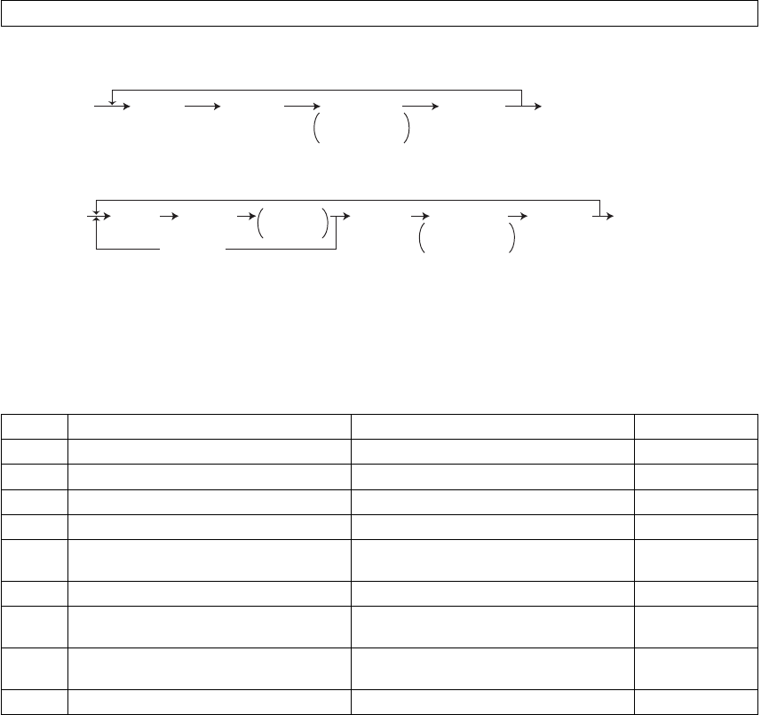
e-STUDIO281c/351c/451c ERROR CODE AND SELF-DIAGNOSTIC MODE© June 2005 TOSHIBA TEC
2 - 38
2.2.3Test print mode (test mode 04)
<Procedure 1>
<Procedure 2>
Notes:
1.When an error occurs, it is indicated on the panel, but the recovery operation is not per-
formed.
Turn OFF the power and then back ON to clear the error.
2.During test printing, the [CLEAR] button is disabled when Wait adding toner! is displayed.
The embedded test pattern can be printed out by keying in the following codes in the test print mode (04).
CodeTypes of test patternRemarksRemarks
142Grid pattern (black)Pattern width: 2 dots, Pitch: 10 mm1
204Grid pattern (color)Pattern width: 1 dot, Pitch: 10 mm2
2196% test pattern 2
2208% test pattern 2
231Secondary scanning direction 33 grada-
tion steps
3 pixels standard, Width: 10 mm2
237Halftone 2
250Test pattern for KCMY secondary scan-
ning position adjustment
For color deviation check1
262Pattern for jitter evaluation
(4 lines ON / 4 lines OFF)
1 pixel standard, for color deviation cor-
rection
2
270Image quality control test patternFor checking the image quality control2
ÅðÃÅìÃ
ÅÐÑÉÛÎà ÅÐÑÉÛÎà ÑÚÚñÑÒ
øÛ¨·¬÷
øݱ¼»÷ ÅÍÌßÎÌà ÅÝÔÛßÎÃÑ°»®¿¬·±²
ݱ²¬·²«±«-
Ì»-¬ Ю·²¬·²¹
ÅðÃÅìÃ
ÅÐÑÉÛÎà ÅÐÑÉÛÎà ÑÚÚñÑÒ
øÛ¨·¬÷
øݱ¼»÷ ÅÍÌßÎÌà ÅÍÌßÎÌà ÅÝÔÛßÎÃ
ÅÝÔÛßÎÃ
Ñ°»®¿¬·±²
ݱ²¬·²«±«-
Ì»-¬ Ю·²¬·²¹
ݱ´±®
-»´»½¬·±²
06/08
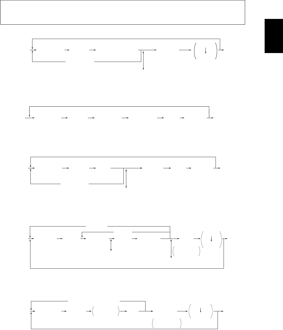
© June 2005 TOSHIBA TECe-STUDIO281c/351c/451c ERROR CODE AND SELF-DIAGNOSTIC MODE
2 - 39
2
2.2.4Adjustment mode (05)
Procedure 1
Procedure 2
Procedure 3
Procedure 4
Procedure 5
Items in the adjustment mode list in the following pages can be corrected or changed in this adjustment mode
(05). Turn ON the power with pressing the digital keys [0] and [5] simultaneously in order to enter this mode.
When the power should be turned OFF, be sure to shut down the equipment by pressing the [ENERGY SAVER]
button for a few seconds.
ÅðÃÅëÃ
ÅÐÑÉÛÎÃ
ÅÐÑÉÛÎÃ
ÑÚÚñÑÒ
øÛ¨·¬÷
ÅÜ·¹·¬¿´ µ»§Ã
øݱ¼»÷ ÅÍÌßÎÌÃ
ÅÝßÒÝÛÔÃ
ÅÜ·¹·¬¿´ µ»§Ã
ö
ÅÚËÒÝÌ×ÑÒ ÝÔÛßÎÃ
øÕ»§ ·² ¿ ª¿´«»÷
ÅÝÔÛßÎÃ
øݱ®®»½¬- ª¿´«»÷
ÅÛÒÌÛÎÃ
±®
Å×ÒÌÛÎÎËÐÌÃ
øͬ±®»- ª¿´«» ·² ÎßÓ÷
ÅÚßÈÃ
ÅÍÌßÎÌÃ
øÌ»-¬ ½±°§÷
öЮ»-- Å
ÚËÒÝÌ×ÑÒ ÝÔÛßÎ
à ¬± »²¬»® ³·²«- øó÷ò
øÅÚßÈà ÅÍÌßÎÌÃ÷
øÌ»-¬ ½±°§÷
ÅðÃÅëÃ
ÅÐÑÉÛÎÃ
ÅÐÑÉÛÎÃ
ÑÚÚñÑÒ
øÛ¨·¬÷
ÅÜ·¹·¬¿´ µ»§Ã
øݱ¼»÷
ÅÍÌßÎÌÃ
ÅÛÒÌÛÎÃ
±®
Å×ÒÌÛÎÎËÐÌÃ
øÊ¿´«» «²½¸¿²¹»¿¾´»÷
Ê¿´«»
¼·-°´¿§»¼
ø÷
øÅÚßÈà ÅÍÌßÎÌÃ÷
øÌ»-¬ ½±°§÷
ÅðÃÅëÃ
ÅÐÑÉÛÎÃ
ÅÐÑÉÛÎÃ
ÑÚÚñÑÒ
øÛ¨·¬÷
ÅÜ·¹·¬¿´ µ»§Ã
øݱ¼»÷ ÅÍÌßÎÌÃ
ÅÝßÒÝÛÔÃ
ÅËÐÃ
±®
ÅÜÑÉÒÃ
øß¼¶«-¬ ¿ ª¿´«»÷
ÅÝÔÛßÎÃ
øݱ®®»½¬- ª¿´«»÷
ÅÛÒÌÛÎÃ
±®
Å×ÒÌÛÎÎËÐÌÃ
øͬ±®»- ª¿´«» ·² ÎßÓ÷
ÅðÃÅëÃ
ÅÐÑÉÛÎÃ
ÅÜ·¹·¬¿´ µ»§Ã
øݱ¼»÷
ÅÜ·¹·¬¿´ µ»§Ã
øÍ«¾ ½±¼»÷
ÅÝÔÛßÎÃ
øݱ®®»½¬- ª¿´«»÷
ÅÛÒÌÛÎÃ
±®
Å×ÒÌÛÎÎËÐÌÃ
öЮ»-- ÅÚËÒÝÌ×ÑÒ ÝÔÛßÎà ¬± »²¬»® ³·²«- øó÷ò
øÅÚßÈÃ
ÅÍÌßÎÌÃ÷
øÌ»-¬ ½±°§÷
ÅÝßÒÝÛÔÃ
ÅÍÌßÎÌÃ
ÅÍÌßÎÌÃ
ÅÍÌßÎÌà ÅÜ·¹·¬¿´ µ»§Ã
öÅÚËÒÝÌ×ÑÒ ÝÔÛßÎÃ
øÕ»§ ·² ¿ ª¿´«»÷
ÅÝÔÛßÎÃ
øݱ®®»½¬- ª¿´«»÷
ͬ±®»- ª¿´«»
·² ÎßÓ
ÅÐÑÉÛÎÃ
ÑÚÚñÑÒ
øÛ¨·¬÷
ÅðÃÅëÃ
ÅÐÑÉÛÎÃ
ÅÝßÒÝÛÔà ±® ÅÝÔÛßÎÃ
ÅÜ·¹·¬¿´ µ»§Ã
øݱ¼»÷
ÅÍÌßÎÌà ߫¬±³¿¬·½
¿¼¶«-¬³»²¬
ÅËÐÃ
±®
ÅÜÑÉÒÃ
øß¼¶«-¬ ¿ ª¿´«»÷
ÅÛÒÌÛÎÃ
±®
Å×ÒÌÛÎÎËÐÌÃ
ͬ±®»- ª¿´«»
·² ÎßÓ
ÅÚßÈÃ
ÅÍÌßÎÌÃ
øÌ»-¬ ½±°§÷
ÅÐÑÉÛÎÃ
ÑÚÚñÑÒ
øÛ¨·¬÷
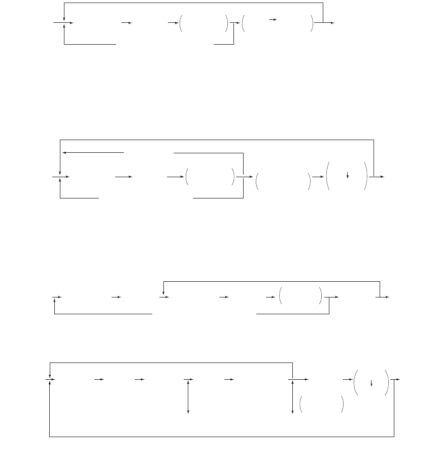
e-STUDIO281c/351c/451c ERROR CODE AND SELF-DIAGNOSTIC MODE© June 2005 TOSHIBA TEC
2 - 40
Procedure 6
*When the automatic adjustment ends abnormally, an error message is
displayed.
*Return to standby screen by pressing the [CANCEL] or [CLEAR]
button.
Procedure 7
*When the automatic adjustment ends abnormally, an error message is
displayed.
*Return to standby screen by pressing the [CANCEL] or [CLEAR] button.
Procedure 10
Procedure 14
Note: Note:
The fuser roller temperature control at the adjustment mode is different from that at the normal
state.
Therefore, the problem of fusing efficiency may be occurred in the test copy at the adjustment
mode.
In that case, turn ON the power normally, leave the equipment for approx. 3 minutes after it has
become ready state and then start up the adjustment mode again.
ÅðÃÅëÃ
ÅÐÑÉÛÎÃ
ÅÐÑÉÛÎÃÑÚÚñÑÒ
øÛ¨·¬÷
ÅÜ·¹·¬¿´ µ»§Ã
øݱ¼»÷ ÅÍÌßÎÌà ÅÚßÈà ÅÝÑÐÇÃ÷
øÌ»-¬ ½±°§÷
öÅÝßÒÝÛÔà ±® ÅÝÔÛßÎÃ
ß«¬±³¿¬·½
¿¼¶«-¬³»²¬
ÅðÃÅëÃ
ÅÐÑÉÛÎÃ
ÅÐÑÉÛÎÃ
ÑÚÚñÑÒ
øÛ¨·¬÷
ÅÜ·¹·¬¿´ µ»§Ã
øݱ¼»÷ ÅÍÌßÎÌà ߫¬±³¿¬·½
¿¼¶«-¬³»²¬
ÅÚßÈÃ
ÅÍÌßÎÌÃ
øÌ»-¬ ½±°§÷
öÅÝßÒÝÛÔà ±® ÅÝÔÛßÎÃ
ÅÝßÒÝÛÔÃ
ÅÛÒÌÛÎÃ
ͬ±®»- ª¿´«»
·² ÎßÓ
ÅðÃÅëÃ
ÅÐÑÉÛÎÃ
ÅÐÑÉÛÎÃ
ÑÚÚñÑÒ
øÛ¨·¬÷
ÅÜ·¹·¬¿´ µ»§Ã
øݱ¼»÷
ÅÜ·¹·¬¿´ µ»§Ã
øÍ«¾ ½±¼»÷
ÅÍÌßÎÌÃÅÍÌßÎÌÃÅÍÌßÎÌÃ
ÅÛÒÌÛÎà ±® Å×ÒÌÛÎÎËÐÌÃ
øÊ¿´«» «²½¸¿²¹»¿¾´»÷
Ê¿´«»
¼·-°´¿§»¼
ÅðÃÅëÃ
ÅÐÑÉÛÎÃ
ÅÐÑÉÛÎÃ
ÑÚÚñÑÒ
øÛ¨·¬÷
ÅÜ·¹·¬¿´ µ»§Ã
øݱ¼»÷
ÅÍÌßÎÌà ÅÍÌßÎÌÃ
ÅÜ·¹·¬¿´ µ»§Ã
øÍ«¾ ½±¼»÷
ÅÝßÒÝÛÔÃ
øݱ®®»½¬- ª¿´«»÷
ÅÝÔÛßÎÃ
øݱ®®»½¬- ª¿´«»÷
ÅÛÒÌÛÎÃ
±®
Å×ÒÌÛÎÎËÐÌÃ
ÅÚßÈÃ
ÅÍÌßÎÌÃ
øÌ»-¬ ½±°§÷
ÅËÐÃ ±® ÅÜÑÉÒÃ
øß¼¶«-¬ ¿ ª¿´«»÷
ͬ±®»- ª¿´«»
·² ÎßÓ

© June 2005 TOSHIBA TECe-STUDIO281c/351c/451c ERROR CODE AND SELF-DIAGNOSTIC MODE
2 - 41
2
Test print pattern in Adjustment Mode (05)
Operation:
One test print is printed out when the [FAX] button is pressed after the code is keyed in at Standby
Screen.
CodeTypes of test patternRemarks
1Grid pattern (Black)Refer to 3.4.3 Printer related adjustment
3Grid pattern (Black/Duplex printing)Refer to 3.4.3 Printer related adjustment
4For gamma adjustment (Color/Black integrated
pattern)
Refer to 3.5.1 Automatic gamma adjustment
5For gamma adjustment (Color)Refer to 3.5.1 Automatic gamma adjustment
6For gamma adjustment (Black)For checking the gradation reproduction
7For gamma adjustment (Color)For checking the gradation reproduction
10For gamma adjustment (Black)Refer to 3.5.1 Automatic gamma adjustment
12Secondary scanning direction 33 gradation
steps (Y)
For checking the image of printer section
13Secondary scanning direction 33 gradation
steps (M)
For checking the image of printer section
14Secondary scanning direction 33 gradation
steps (C)
For checking the image of printer section
15Secondary scanning direction 33 gradation
steps (K)
For checking the image of printer section
47Gamma adjustment for printer (PS/ 600 x 600
dpi)
Refer to 3.6.1 Automatic gamma adjustment
48Gamma adjustment for printer (PS/ 1,200 x 600
dpi)
Refer to 3.6.1 Automatic gamma adjustment
49Gamma adjustment for printer (PCL/ 600 x 600
dpi)
Refer to 3.6.1 Automatic gamma adjustment
50Gamma adjustment for printer (PCL/ 1,200 x
600 dpi)
Refer to 3.6.1 Automatic gamma adjustment
51Gamma checking for printer (PS/ 600 x 600 dpi)For checking the gradation reproduction
52Gamma checking for printer (PS/ 1,200 x 600
dpi)
For checking the gradation reproduction
55Grid pattern (Full Color / Thick paper 2)Refer to 3.4.2 Paper alignment at the registration
roller
56Grid pattern (Full Color / Thick paper 3)Refer to 3.4.2 Paper alignment at the registration
roller
57Grid pattern (Full Color / OHP)Refer to 3.4.2 Paper alignment at the registration
roller
58Grid pattern (Black / Thick paper 2)Refer to 3.4.2 Paper alignment at the registration
roller
59Grid pattern (Black / Thick paper 3)Refer to 3.4.2 Paper alignment at the registration
roller
60Grid pattern (Black / OHP)Refer to 3.4.2 Paper alignment at the registration
roller
62For color deviation correction (Full Color)Only for A3/LD size
63For color deviation correction (Full Color)Only for A3/LD size
64For color deviation correction (Full Color)Only for A3/LD size
68For color deviation correction (Full Color)Only for A4/LT size
69For color deviation correction (Full Color)Only for A4/LT size
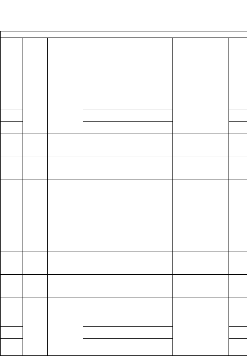
e-STUDIO281c/351c/451c ERROR CODE AND SELF-DIAGNOSTIC MODE© June 2005 TOSHIBA TEC
2 - 42
Notes:
1.The digit after the hyphen in Code! of the following table is a sub code.
2.In RAM!, the NVRAM of the board in which the data of each code is stored is indicated. M!
stands for the LGC board and SYS! stands for the SYS board.
Adjustment mode (05)
Code Classifi-
cation Items Func-
tion
Default
<Accept-
able
value>
RAMContents
Pro-
cedur
e
200Develop-
ment
Initialization of
color auto-
toner sensor
light amount
correction tar-
get value
All
(Y,M,C,K)
ALL-
<0-255>
MThe value starts chang-
ing approx. 3 minutes
after this adjustment
started.
The value is automati-
cally set during this
adjustment (approx. 2
minutes).
(As the value increases,
the sensor output
increases correspond-
ingly.) (Chap. 3.2)
5
201YALL-
<0-255>
M5
202MALL-
<0-255>
M5
203CALL-
<0-255>
M5
204KALL-
<0-255>
M5
206YMCALL-
<0-255>
M5
207Develop-
ment
Initialization of color auto-
toner sensor light amount
correction target value
ALL
(color)
-MInitializes the color
auto-toner sensor light
amount correction tar-
get value.
6
208Develop-
ment
Enforced correction of
color auto-toner sensor
light amount
ALL
(color)
-MPerforms the color
auto-toner sensor light
amount correction forc-
ibly.
6
210Transfer1st transfer roller bias out-
put adjustment (When not
transferred)
ALL225
<0-225>
MWhen the value
decreases, the 1st
transfer roller bias out-
put increases.
The adjustment value
becomes effective
when the Setting Mode
(08- 541, 549 and 551)
is 0 (invalid).
3
224Transfer2nd transfer roller bias out-
put adjustment (When
cleaning the roller [+] )
ALL147
<0-187>
MWhen the value
decreases, the 2nd
transfer roller bias out-
put increases.
3
225Transfer2nd transfer roller bias out-
put adjustment (When
cleaning the roller [-] )
ALL229
<188-
255>
MWhen the value
decreases, the 2nd
transfer roller bias out-
put increases.
3
226Transfer2nd transfer roller bias out-
put adjustment (Paper
interval/When not trans-
ferred)
ALL191
<188-
255>
MWhen the value
decreases, the 2nd
transfer roller bias out-
put increases.
3
227-0Transfer2nd transfer
roller bias out-
put adjust-
ment
(Plain paper)
Single
side
ALL
(black)
159
<0-187>
MWhen the value
decreases, the 2nd
transfer roller bias out-
put increases.
The adjustment value
becomes effective
when the Setting Mode
(08- 544, 549 and 551)
is 0 (invalid).
14
227-1Reverse
side at
duplexing
ALL
(black)
134
<0-187>
M14
227-2Single
side
ALL
(color)
147
<0-187>
M14
227-3Reverse
side at
duplexing
ALL
(color)
128
<0-187>
M14

© June 2005 TOSHIBA TECe-STUDIO281c/351c/451c ERROR CODE AND SELF-DIAGNOSTIC MODE
2 - 43
2
229-0Transfer2nd transfer
roller bias out-
put adjust-
ment
(Thick paper
1)
Single
side
ALL
(black)
144
<0-187>
MWhen the value
decreases, the 2nd
transfer roller bias out-
put increases.
The adjustment value
becomes effective
when the Setting Mode
(08-544, 549 and 551)
is 0 (invalid).
14
229-1Reverse
side at
duplexing
ALL
(black)
119
<0-187>
M14
229-2Single
side
ALL
(color)
125
<0-187>
M14
229-3Reverse
side at
duplexing
ALL
(color)
112
<0-187>
M14
230-0Transfer2nd transfer roller bias out-
put (Thick paper 2)
ALL
(black)
153
<0-187>
MWhen the value
decreases, the 2nd
transfer roller bias out-
put increases.
The adjustment value
becomes effective
when the Setting Mode
(08- 544, 549 and 551)
is 0 (invalid).
14
230-1ALL
(color)
150
<0-187>
M14
231-0Transfer2nd transfer roller bias out-
put (Thick paper 3)
ALL
(black)
131
<0-187>
MWhen the value
decreases, the 2nd
transfer roller bias out-
put increases.
The adjustment value
becomes effective
when the Setting Mode
(08- 544, 549 and 551)
is 0 (invalid).
14
231-1ALL
(color)
131
<0-187>
M14
232-0Transfer2nd transfer roller bias out-
put (OHP film)
ALL
(black)
119
<0-187>
MWhen the value
decreases, the 2nd
transfer roller bias out-
put increases.
The adjustment value
becomes effective
when the Setting Mode
(08- 544, 549 and 551)
is 0 (invalid).
14
232-1ALL
(color)
119
<0-187>
M14
234-0Transfer2nd transfer
roller bias off-
setting adjust-
ment
(Plain paper)
Single
side
ALL
(black)
5
<0-10>
MSets the offset amount
of 2nd transfer roller
bias.
0: -500V1: -400V
2: -300V3: -200V
4: -100V5: 0V
6: +100V7: +200V
8: +300V9: +400V
10: +500V
4
234-1Reverse
side at
duplexing
ALL
(black)
5
<0-10>
M4
234-2Single
side
ALL
(color)
5
<0-10>
M4
234-3Reverse
side at
duplexing
ALL
(color)
5
<0-10>
M4
236-0Transfer2nd transfer
roller bias off-
setting adjust-
ment (Thick
paper 1)
Single
side
ALL
(black)
5
<0-10>
MSets the offset amount
of 2nd transfer roller
bias.
0: -500V1: -400V
2: -300V3: -200V
4: -100V5: 0V
6: +100V7: +200V
8: +300V9: +400V
10: +500V
4
236-1Reverse
side at
duplexing
ALL
(black)
5
<0-10>
M4
236-2Single
side
ALL
(color)
5
<0-10>
M4
236-3Reverse
side at
duplexing
ALL
(color)
5
<0-10>
M4
Adjustment mode (05)
Code Classifi-
cation Items Func-
tion
Default
<Accept-
able
value>
RAMContents
Pro-
cedur
e

e-STUDIO281c/351c/451c ERROR CODE AND SELF-DIAGNOSTIC MODE© June 2005 TOSHIBA TEC
2 - 44
237-0Transfer2nd transfer roller bias off-
setting adjustment
(Thick paper 2)
ALL
(black)
5
<0-10>
MSets the offsetting
amount of 2nd transfer
roller bias.
0: -1,000V1: -800V
2: -600V3: -400 V
4: -200V5: 0 V
6: +200V7: +400V
8: +600V9: +800 V
10: +1,000V
4
237-1ALL
(color)
5
<0-10>
M4
238-0Transfer2nd transfer roller bias off-
setting adjustment
(Thick paper 3)
ALL
(black)
5
<0-10>
M4
238-1ALL
(color)
5
<0-10>
M4
239-0Transfer2nd transfer roller bias off-
setting adjustment
(OHP film)
ALL
(black)
5
<0-10>
M4
239-1ALL
(color)
5
<0-10>
M4
241Main
charger
Main charger
grid bias
adjustment
YALL78
<0-255>
MAs the value increases,
the transformer output
increases. The adjust-
ment value becomes
effective only when the
setting mode (08-549,
551, 556, 557) is 0
(invalid).
3
242MALL84
<0-255>
M3
243CALL87
<0-255>
M3
244KALL94
<0-255>
M3
245Transfer1st transfer roller bias off-
setting
ALL
(black)
5
<0-10>
MSets the offsetting
amount of 1st transfer
roller bias.
0: -500 V1: -400 V
2: -300 V3: -200 V
4: -100 V5: 0 V
6: +100 V7: +200 V
8: +300 V9: +400 V
10: +500 V
1
247TransferTemperature/humidity sen-
sor Humidity display
ALL50
<0-100>
MThe humidity of the
inside of the equipment
is displayed.
[Unit: RH%]
2
248TransferDrum thermistor Tempera-
ture displa
ALL23
<0-100>
MThe ambient tempera-
ture of the drum surface
is displayed.
[Unit: °C]
2
250Transfer1st transfer
roller bias out-
put voltage
+LowALL4000
<3600-
4400>
MTransformer output set-
ting of the 1st transfer
roller bias.
When replacing the
high-voltage trans-
former, the values listed
in attached data sheet
are entered.
(Unit: V)
1
251+HighALL400
<280-
520>
M1
252Transfer2nd transfer
roller bias out-
put voltage
+LowALL6000
<5400-
6600>
MTransformer output set-
ting of the 2nd transfer
roller bias (plus output).
When replacing the
high-voltage trans-
former, the values listed
in attached data sheet
are entered.
(Unit: V)
1
253+HighALL500
<350-
650>
M1
Adjustment mode (05)
Code Classifi-
cation Items Func-
tion
Default
<Accept-
able
value>
RAMContents
Pro-
cedur
e

© June 2005 TOSHIBA TECe-STUDIO281c/351c/451c ERROR CODE AND SELF-DIAGNOSTIC MODE
2 - 45
2
254Transfer2nd transfer
roller bias out-
put voltage
-LowALL-500
<-9999-
0>
MTransformer output set-
ting of the 2nd transfer
roller bias (minus out-
put).
When replacing the
high-voltage trans-
former, the values listed
in attached data sheet
are entered.
(Unit: V)
1
255-HighALL-2000
<-9999-
0>
M1
270TransferTemperature/humidity sen-
sor Temperature display
ALL23
<0-100>
MThe temperature of the
inside of the equipment
is displayed.
[Unit: °C]
2
275Transfer2nd transfer
roller bias
actual value
(When clean-
ing the roller)
(+)ALL147
<0-255>
MDisplays the value of
2nd transfer roller bias
when printing is oper-
ated.
2
276(-)ALL229
<0-255>
M2
277-0Transfer2nd transfer
roller bias
actual value
display (Plain
paper)
Single
side
ALL
(black)
159
<0-187>
MDisplays the value of
2nd transfer roller bias
when printing is oper-
ated.
10
277-1Reverse
side at
duplexing
ALL
(black)
134
<0-187>
M10
277-2Single
side
ALL
(color)
147
<0-187>
M10
277-3Reverse
side at
duplexing
ALL
(color)
128
<0-187>
M10
279-0Transfer2nd transfer
roller bias
actual value
display (Thick
paper 1)
Single
side
ALL
(black)
144
<0-187>
MDisplays the value of
2nd transfer roller bias
when printing is oper-
ated.
10
279-1Reverse
side at
duplexing
ALL
(black)
119
<0-187>
M10
279-2Single
side
ALL
(color)
125
<0-187>
M10
279-3Reverse
side at
duplexing
ALL
(color)
112
<0-187>
M10
281Transfer1st transfer roller bias
resistance detection con-
trol
ALL-
<0-255>
MThe RMS value of the
main charger grid bias
is displayed..
2
284TransferTransfer belt cleaning unit
contact timing adjustment
ALL141
<88-168>
MWhen the value
increases, the contact
timing of transfer belt
cleaning unit is delayed.
1
285TransferTransfer belt cleaning unit
release timing adjustment
ALL121
<88-168>
MWhen the value
increases, the release
timing of transfer belt
cleaning unit is delayed.
1
290-0Transfer2nd transfer roller bias off-
setting adjustment
(Thick paper 2)
ALL
(black)
153
<0-187>
MDisplays the value of
2nd transfer roller bias
when printing is oper-
ated.
10
290-1ALL
(color)
150
<0-187>
M10
Adjustment mode (05)
Code Classifi-
cation Items Func-
tion
Default
<Accept-
able
value>
RAMContents
Pro-
cedur
e
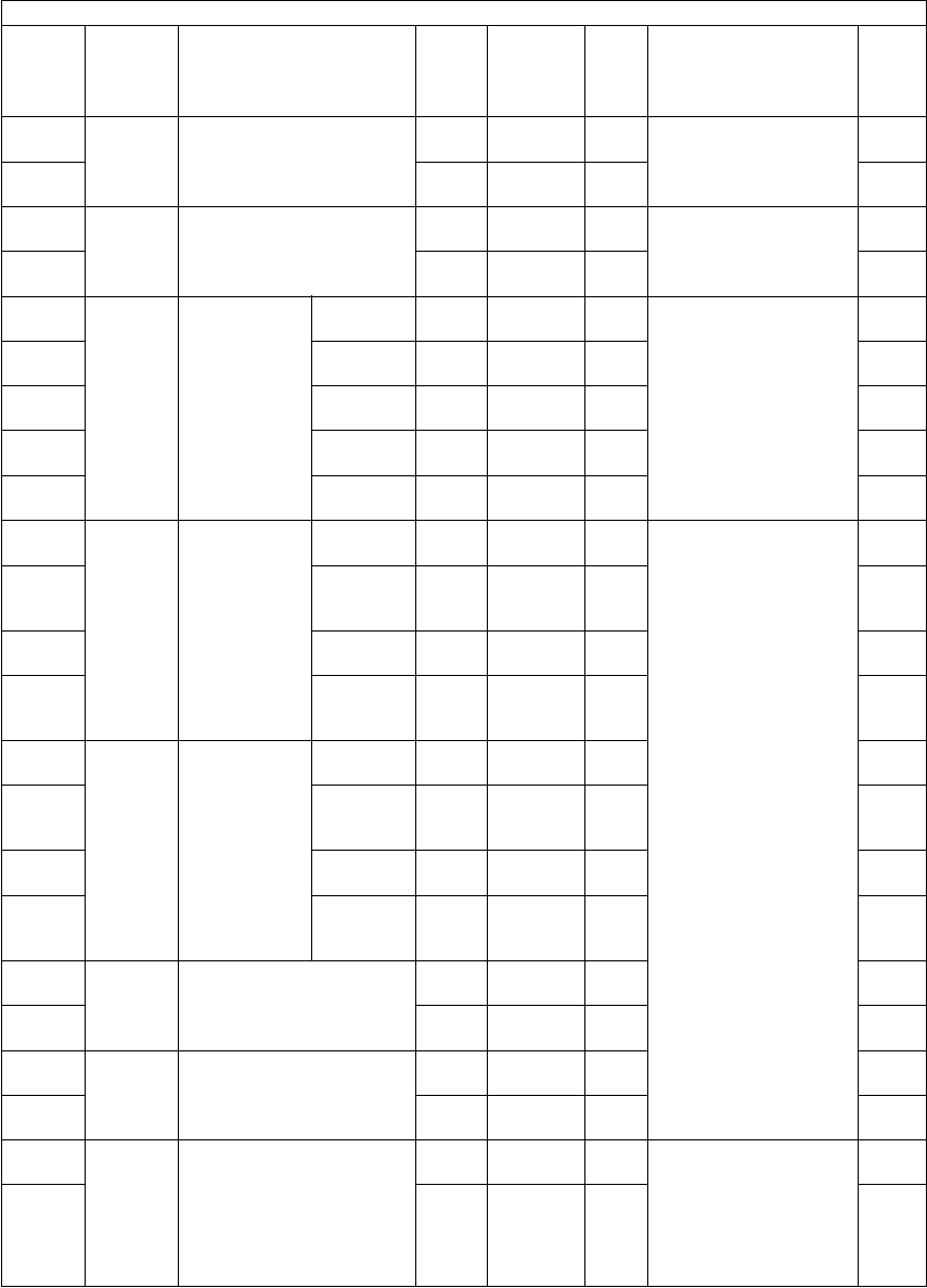
e-STUDIO281c/351c/451c ERROR CODE AND SELF-DIAGNOSTIC MODE© June 2005 TOSHIBA TEC
2 - 46
291-0Transfer2nd transfer roller bias off-
setting adjustment
(Thick paper 3)
ALL
(black)
131
<0-187>
MDisplays the value of
2nd transfer roller bias
when printing is oper-
ated.
10
291-1ALL
(color)
131
<0-187>
M10
292-0Transfer2nd transfer roller bias off-
setting adjustment
(OHP film)
ALL
(black)
119
<0-187>
MDisplays the value of
2nd transfer roller bias
when printing is oper-
ated.
10
292-1ALL
(color)
119
<0-187>
M10
293-0Transfer2nd transfer
roller bias cor-
rection of
leading/trail-
ing edge of
paper
Plain
paper
ALL85
<0-255>
MCorrects the 2nd trans-
fer roller bias output of
leading/trailing edge of
paper (05-227, 229,
230, 231 and 232).
Correcting factor: %
14
293-1Thick
paper 1
ALL75
<0-255>
M14
293-2Thick
paper 2
ALL80
<0-255>
M14
293-3Thick
paper 3
ALL80
<0-255>
M14
293-4OHP filmALL80
<0-255>
M14
294-0TransferActual value
display of 2nd
transfer roller
bias of lead-
ing/trailing
edge of paper
(Plain paper)
Single
side
ALL
(black)
164
<0-255>
MDisplays the value of
2nd transfer roller bias
on the leading/trailing
edge of paper when
printing is performed.
(The value corrected in
05-293 is displayed.)
10
294-1Reverse
side at
duplexing
ALL
(black)
142
<0-255>
M10
294-2Single
side
ALL
(color)
153
<0-255>
M10
294-3Reverse
side at
duplexing
ALL
(color)
137
<0-255>
M10
296-0TransferActual value
display of 2nd
transfer roller
bias of lead-
ing/trailing
edge of paper
(Thick paper
1)
Single
side
ALL
(black)
155
<0-255>
M10
296-1Reverse
side at
duplexing
ALL
(black)
136
<0-255>
M10
296-2Single
side
ALL
(color)
141
<0-255>
M10
296-3Reverse
side at
duplexing
ALL
(color)
131
<0-255>
M10
297-0TransferActual value display of 2nd
transfer roller bias of lead-
ing/trailing edge of paper
(Thick paper 2)
ALL
(black)
160
<0-255>
M10
297-1ALL
(color)
158
<0-255>
M10
298-0TransferActual value display of 2nd
transfer roller bias of lead-
ing/trailing edge of paper
(Thick paper 3)
ALL
(black)
142
<0-255>
M10
298-1ALL
(color)
143
<0-255>
M10
299-0TransferActual value display of 2nd
transfer roller bias of lead-
ing/trailing edge of paper
(OHP film)
ALL
(black)
133
<0-255>
MDisplays the value of
2nd transfer roller bias
on the leading/trailing
edge of paper when
printing is performed.
(The value corrected in
05-293 is displayed.)
10
299-1ALL
(color)
133
<0-255>
M10
Adjustment mode (05)
Code Classifi-
cation Items Func-
tion
Default
<Accept-
able
value>
RAMContents
Pro-
cedur
e

© June 2005 TOSHIBA TECe-STUDIO281c/351c/451c ERROR CODE AND SELF-DIAGNOSTIC MODE
2 - 47
2
305ScannerImage location adjustment
of secondary scanning
direction
(scanner section)
ALL124
<92-164>
SYSWhen the value
increases by 1!, the
image shifts by approx.
0.137 mm toward the
trailing edge of the
paper.
1
306ScannerImage location adjustment
of secondary scanning
direction
(scanner section)
ALL113
<0-255>
SYSWhen the value
increases by 1!, the
image shifts by approx.
0.0423 mm toward the
front side of the paper.
1
308ScannerDistortion modeALL--Moves carriages to the
adjusting position.
(Chap. 3.4.4)
6
330-0Image
control
Image quality
closed-loop
control con-
trast voltage
correction/
Mode 2 maxi-
mum number
of time cor-
rected
YALL3
<0-255>
MSets the maximum cor-
rection number of time
of the contrast voltage
in the closed-loop con-
trol mode 2.
4
330-1MALL3
<0-255>
M4
330-2CALL3
<0-255>
M4
330-3KALL3
<0-255>
M4
331-0Image
control
Image quality
closed-loop
control laser
power correc-
tion/Mode 2
maximum
number of
time corrected
YALL2
<0-255>
MSets the maximum cor-
rection number of time
of the laser power in the
closed-loop control
mode 2.
4
331-1MALL2
<0-255>
M4
331-2CALL2
<0-255>
M4
331-3KALL2
<0-255>
M4
332-0Image
control
Image quality
closed-loop
control con-
trast voltage
correction/
Mode 1 maxi-
mum number
of time cor-
rected
YALL1
<0-255>
MSets the maximum cor-
rection number of time
of the contrast voltage
in the closed-loop con-
trol mode 1.
4
332-1MALL1
<0-255>
M4
332-2CALL1
<0-255>
M4
332-3KALL1
<0-255>
M4
333-0Image
control
Image quality
closed-loop
control laser
power correc-
tion/Mode 1
maximum
number of
time corrected
YALL1
<0-255>
MSets the maximum cor-
rection number of time
of the laser power in the
closed-loop control
mode 1.
4
333-1MALL1
<0-255>
M4
333-2CALL1
<0-255>
M4
333-3KALL1
<0-255>
M4
334Image
control
Main charger grid calibra-
tion voltage 1 (low)
ALL300
<210-
390>
MTransformer output cali-
bration of the main
charger grid bias. When
replacing the high-volt-
age transformer, the
values listed in attached
data sheet are entered.
(Unit: V)
1
335Image
control
Main charger grid calibra-
tion voltage 2 (high)
ALL1000
<900-
1100>
M1
Adjustment mode (05)
Code Classifi-
cation Items Func-
tion
Default
<Accept-
able
value>
RAMContents
Pro-
cedur
e

e-STUDIO281c/351c/451c ERROR CODE AND SELF-DIAGNOSTIC MODE© June 2005 TOSHIBA TEC
2 - 48
338Image
control
Color developer bias DC
(-) calibration voltage 1
(low)
ALL100
<70-130>
MTransformer output cali-
bration of the color
developer bias. When
replacing the high-volt-
age transformer, the
values listed in attached
data sheet are entered.
(Unit: V)
1
339Image
control
Color developer bias DC
(-) calibration voltage 2
(high)
ALL900
<810-
990>
M1
340ScannerReproduction ratio adjust-
ment of secondary scan-
ning direction (scanner
section)
ALL127
<0-255>
SYSWhen the value
increases by 1!, the
reproduction ratio in the
secondary scanning
direction (vertical to
paper feeding direc-
tion) increases by
approx. 0.223%.
1
350ScannerShading posi-
tion adjust-
ment
Original
glass
ALL128
<118-
138>
SYS0.1369 mm/step1
351RADFALL128
<118-
138>
SYS0.1369 mm/step1
354RADFAdjustment of
RADF paper
alignment
for single-
sided orig-
inal
ALL10
<0-20>
SYSWhen the value
increases by 1!, the
aligning amount
increases by approx.
0.5 mm.
1
355for double
sided orig-
inal
ALL10
<0-20>
SYS1
357RADFFine adjustment of RADF
transport speed
ALL50
<0-100>
SYSWhen the value
increases by 1!, the
reproduction ratio of the
secondary scanning
direction on original (fed
from the RADF)
increases by approx.
0.1%.
1
358RADFRADF sideways deviation
adjustment
ALL128
<0-255>
SYSWhen the value
increases by 1!, the
image of original fed
from the RADF shifts
toward the rear side of
paper by approx.
0.0423 mm.
1
359ScannerCarriage position adjust-
ment during scanning from
RADF
ALL
(black)
128
<0-255>
SYSWhen the value
increases by 1!, the
carriage position shifts
by approx. 0.1 mm
toward the exit side
when using the RADF.
1
360ALL
(color)
128
<0-255>
SYS1
Adjustment mode (05)
Code Classifi-
cation Items Func-
tion
Default
<Accept-
able
value>
RAMContents
Pro-
cedur
e
06/08
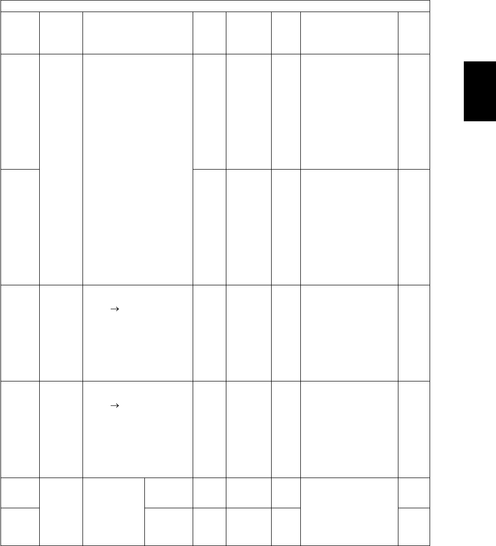
© June 2005 TOSHIBA TECe-STUDIO281c/351c/451c ERROR CODE AND SELF-DIAGNOSTIC MODE
2 - 49
2
361ScannerLog table switching for
RADF copying
ALL
(color)
0
<0-4>
SYS0: Same log table as
the one used at
copying with original
glass
1: Background repro-
duction - Light 2
2: Background repro-
duction - Light 1
3: Background repro-
duction - Dark 1
4: Background repro-
duction - Dark 2
1
362ALL
(black)
0
<0-4>
SYS0: Same log table as
the one used at
copying with original
glass
1: Background repro-
duction - Light 2
2: Background repro-
duction - Light 1
3: Background repro-
duction - Dark 1
4: Background repro-
duction - Dark 2
1
363ScannerData transfer of character-
istic value of scanner / SYS
board SLG board
SCN-SYSTransfers the character-
istic values of the scan-
ner (shading correction
factor / RGB color cor-
rection / reproduction
ratio color aberration
correction) from the
NVRAM of the SYS
board to the NVRAM of
the SLG board.
6
364ScannerData transfer of character-
istic value of scanner / SLG
board SYS board
SCN-SYSTransfers the character-
istic values of the scan-
ner (shading correction
factor / RGB color cor-
rection / reproduction
ratio color aberration
correction) from the
NVRAM of the SLG
board to the NVRAM of
the SYS board.
6
365RADFRADF lead-
ing edge posi-
tion 1
adjustment
for single-
sided orig-
inal
ALL50
<0-100>
SYSWhen the value
increases by 1!, the
copied image of original
fed from the RADF
shifts toward the trail-
ing edge of paper by
approx. 0.1 mm.
1
366for double
sided orig-
inal
ALL50
<0-100>
SYS1
Adjustment mode (05)
Code Classifi-
cation Items Func-
tion
Default
<Accept-
able
value>
RAMContents
Pro-
cedur
e
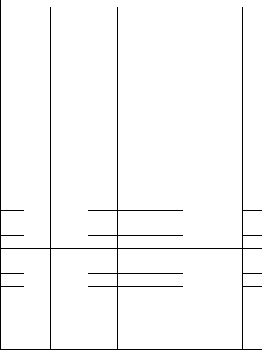
e-STUDIO281c/351c/451c ERROR CODE AND SELF-DIAGNOSTIC MODE© June 2005 TOSHIBA TEC
2 - 50
367RADFRADF original guide width
adjustment
(Minimum)
ALL--Stores the current width
of RADF original guide
by keying in this code
with the guide set at the
minimum width. Per-
form this adjustment
when the RADF board
or volume is replaced,
or when the code (05-
356) is performed.
6
368RADFRADF original guide width
adjustment
(Maximum)
ALL--Stores the current width
of RADF original guide
by keying in this code
with the guide set at the
maximum width. Per-
form this adjustment
when the RADF board
or volume is replaced,
or when the code (05-
356) is performed.
6
372Image
control
Black developer bias DC
(-) calibration voltage 1
(low)
ALL100
<70-130>
MTransformer output cali-
bration of the black
developer bias. When
replacing the high-volt-
age transformer, the
values listed in attached
data sheet are entered.
(Unit: V)
1
373Image
control
Black developer bias DC
(-) calibration voltage 2
(high)
ALL900
<810-
990>
M1
380-0Image
control
Image quality
open-loop
control/ con-
trast voltage
initial value
display
YALL320
<0-999>
MDisplays the contrast
voltage initial value set
by the open-loop con-
trol. (Unit: V)
10
380-1MALL330
<0-999>
M10
380-2CALL340
<0-999>
M10
380-3KALL375
<0-999>
M10
381-0Image
control
Contrast volt-
age actual
value display
YALL320
<0-999>
MDisplays the contrast
voltage when printing is
operated. (Unit: V)
10
381-1MALL330
<0-999>
M10
381-2CALL340
<0-999>
M10
381-3KALL375
<0-999>
M10
382-0Image
control
Image quality
open-loop
control/ laser
power initial
value display
YALL408
<0-999>
MDisplays the laser
power initial value set
by the open-loop con-
trol. (Unit: µW)
10
382-1MALL408
<0-999>
M10
382-2CALL408
<0-999>
M10
382-3KALL408
<0-999>
M10
Adjustment mode (05)
Code Classifi-
cation Items Func-
tion
Default
<Accept-
able
value>
RAMContents
Pro-
cedur
e

© June 2005 TOSHIBA TECe-STUDIO281c/351c/451c ERROR CODE AND SELF-DIAGNOSTIC MODE
2 - 51
2
383-0Image
control
Laser power
actual value
display
YALL92
<0-255>
MDisplays the laser
power when printing is
operated. (bit value)
10
383-1MALL92
<0-255>
M10
383-2CALL92
<0-255>
M10
383-3KALL92
<0-255>
M10
384-0Image
control
Laser power
actual value
display
YALL408
<0-999>
MDisplays the laser
power when printing is
operated. (Unit: µW)
10
384-1MALL408
<0-999>
M10
384-2CALL408
<0-999>
M10
384-3KALL408
<0-999>
M10
385-0Image
control
Main charger
grid bias
actual value
display
YALL78
<0-255>
MDisplays the main
charger grid bias when
printing is operated. (bit
value)
10
385-1MALL84
<0-255>
M10
385-2CALL87
<0-255>
M10
385-3KALL94
<0-255>
M10
386-0Image
control
Developer
bias DC (-)
actual value
display
YALL135
<0-255>
MDisplays the developer
bias when printing is
operated. (bit value)
10
386-1MALL137
<0-255>
M10
386-2CALL139
<0-255>
M10
386-3KALL146
<0-255>
M10
388Image
control
Output value
display of
image quality
sensor
When the
light
source is
OFF
ALL0
<0-1023>
MDisplays the output
value of image quality
sensor when the sensor
light source is OFF.
2
389Transfer
belt sur-
face
ALL0
<0-1023>
MDisplays the output
value of image quality
sensor (when there is
no test pattern) on the
transfer belt.
2
390-0Highden-
sity pat-
tern Y
ALL0
<0-1023>
MDisplays the output
value of image quality
sensor when a high-
density test pattern is
written.
The larger the value is,
the smaller the toner
amount adhered
becomes.
10
390-1Highden-
sity pat-
tern M
ALL0
<0-1023>
M10
390-2Highden-
sity pat-
tern C
ALL0
<0-1023>
M10
390-3Highden-
sity pat-
tern K
ALL0
<0-1023>
M10
Adjustment mode (05)
Code Classifi-
cation Items Func-
tion
Default
<Accept-
able
value>
RAMContents
Pro-
cedur
e

e-STUDIO281c/351c/451c ERROR CODE AND SELF-DIAGNOSTIC MODE© June 2005 TOSHIBA TEC
2 - 52
391-0Image
control
Output value
display of
image quality
sensor
Lowden-
sity pat-
tern Y
ALL0
<0-1023>
MDisplays the output
value of image quality
sensor when a low-den-
sity test pattern is writ-
ten.
The larger the value is,
the smaller the toner
amount adhered
becomes.
10
391-1Lowden-
sity pat-
tern M
ALL0
<0-1023>
M10
391-2Lowden-
sity pat-
tern C
ALL0
<0-1023>
M10
391-3Lowden-
sity pat-
tern K
ALL0
<0-1023>
M10
392Image
control
Light amount adjustment
result of image quality sen-
sor
ALL0
<0-255>
MThe LED light amount
adjustment value of this
sensor is the reference
value to set the
reflected light from the
belt surface.
2
393Image
control
Relative humidity display
during latest closed-loop
control
ALL0
<0-100>
MDisplays the relative
humidity at the latest
performing of the
closed-loop
control.
2
394Image
control
Enforced performing of
image quality open-loop
control
ALL--Performs the image
quality open-loop con-
trol.
6
395Image
control
Enforced performing of
image quality closed-loop
control
ALL-MPerforms the image
quality closedloop con-
trol.
6
396Image
control
Image quality control initial-
ization
ALL-MPerforms the image
quality control, initialize
each control value.
6
398-0Image
control
Target value
of the high
image den-
sity control
YALL265
<220-
360>
MSets the target value of
high image density con-
trol at the time of the
image quality control.
4
398-1MALL300
<220-
360>
M4
398-2CALL320
<220-
360>
M4
398-3KALL370
<300-
420>
M4
401LaserFine adjustment of polygo-
nal motor rotation speed
(reproduction ratio adjust-
ment)
PRT134
<0-255>
MWhen the value
increases by 1!, the
reproduction ratio of pri-
mary scanning direction
increases by approx.
0.07%. (approx. 0.1
mm/step)
1
405PPC135
<0-255>
M1
410LaserAdjustment of primary
scanning laser writing start
position
PPC128
<0-255>
MWhen the value
increases by 1!, the
writing start position
shifts to the front side
by approx. 0.0423 mm.
1
411PRT120
<0-255>
M1
Adjustment mode (05)
Code Classifi-
cation Items Func-
tion
Default
<Accept-
able
value>
RAMContents
Pro-
cedur
e

© June 2005 TOSHIBA TECe-STUDIO281c/351c/451c ERROR CODE AND SELF-DIAGNOSTIC MODE
2 - 53
2
417-0ImageColor devia-
tion correc-
tion 1
(A3/LD)
KALL128
<118-
138>
MWhen the value
increases by 1!, the
image shifts toward the
trailing edge of the
paper by 0.0423 mm.
4
417-1CALL128
<118-
138>
M4
417-2MALL128
<118-
138>
M4
417-3YALL128
<118-
138>
M4
418-0ImageColor devia-
tion correc-
tion 2
(A3/LD)
KALL128
<118-
138>
MWhen the value
increases by 1!, the
image shifts toward the
trailing edge of the
paper by 0.0423 mm.
4
418-1CALL128
<118-
138>
M4
418-2MALL128
<118-
138>
M4
418-3YALL128
<118-
138>
M4
421DriveAdjustment of secondary
scanning direction repro-
duction ratio (fine adjust-
ment of main motor speed)
PPC/
PRT
127
<0-255>
MWhen the value
increases by 1!, the
reproduction ratio of
secondary scanning
direction increases by
approx. 0.04%.
1
422FAX144
<0-255>
M1
424DriveFine adjustment of exit
motor speed
PPC/
PRT
JPN: 140
Others:
128
<0-255>
MWhen the value
increases by 1!, the
rotation becomes faster
by approx.
0.05%.
1
425FAX128
<0-255>
M1
426DriveAdjustment of secondary
scanning direction repro-
duction ratio (fine adjust-
ment of transport motor
speed)
PPC/
PRT
153
<0-255>
MWhen the value
increases by 1!, the
reproduction ratio of
secondary scanning
direction increases by
approx. 0.04%.
1
427FAX128
<0-255>
M1
Adjustment mode (05)
Code Classifi-
cation Items Func-
tion
Default
<Accept-
able
value>
RAMContents
Pro-
cedur
e
06/10

e-STUDIO281c/351c/451c ERROR CODE AND SELF-DIAGNOSTIC MODE© June 2005 TOSHIBA TEC
2 - 54
430ImageTop margin adjustment
(blank area at the leading
edge of the paper))
PPC26
<0-255>
MWhen the value
increases by 1!, the
blank area becomes
wider by approx.
0.0423 mm.
1
431ImageLeft margin adjustment
(blank area at the left of the
paper along the paper
feeding direction)
PPC0
<0-255>
M1
432ImageRight margin adjustment
(blank area at the right of
the paper along the paper
feeding direction)
PPC15
<0-255>
M1
433ImageBottom margin adjustment
(blank area at the trailing
edge of the paper)
PPC43
<0-255>
M1
434-0ImageBottom margin adjustment
(blank area at the trailing
edge of the paper)
/Reverse side at duplexing
PPC/
PRT
EUR: 45
UC: 28
JPN: 28
Others:
45
<0-255>
M4
434-1ImageRight margin adjustment
(blank area at the right of
the paper along the paper
feeding direction)
/Reverse side at duplexing
PPC/
PRT
18
<0-255>
M4
435ImageTop margin adjustment
(blank area at the leading
edge of the paper)
PRT24
<0-255>
M1
436ImageLeft margin adjustment
(blank area at the left of the
paper along the paper
feeding direction)
PRT0
<0-255>
MWhen the value
increases by 1!, the
blank area becomes
wider by approx.
0.0423 mm.
1
437ImageRight margin adjustment
(blank area at the right of
the paper along the paper
feeding direction)
PRT0
<0-255>
M1
438ImageBottom margin adjustment
(blank area at the trailing
edge of the paper)
PRT0
<0-255>
M1
439ImageBottom margin adjustment
(blank area at the trailing
edge of the paper along
the paper feeding direc-
tion) when paper size is not
specified at bypass feed
ALL128
<0-255>
MWhen the value
increases by 1!, the
margin increases by
approx. 0.2 mm.
1
440LaserSecondary
scanning
laser writing
start position
Upper
drawer
ALL21
<0-40>
MWhen the value
increases by 1!, the
image shifts toward the
trailing edge of the
paper by approx.
0.2 mm.
1
441Lower
drawer
ALL47
<0-80>
M1
442Bypass
feeding
ALL22
<0-40>
M1
443LCFALL20
<0-40>
M1
444PFPALL20
<0-40>
M1
445Duplex
feeding
ALL21
<0-40>
M1
Adjustment mode (05)
Code Classifi-
cation Items Func-
tion
Default
<Accept-
able
value>
RAMContents
Pro-
cedur
e
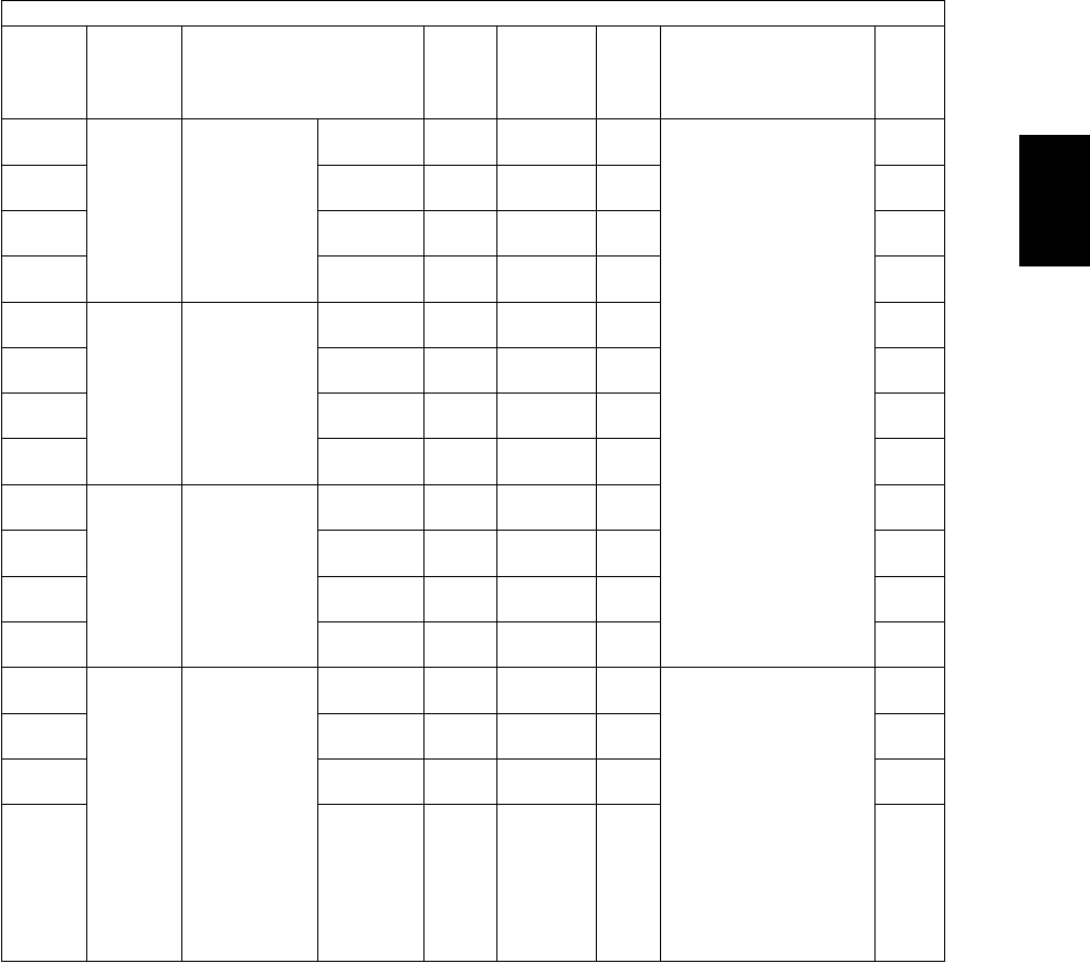
© June 2005 TOSHIBA TECe-STUDIO281c/351c/451c ERROR CODE AND SELF-DIAGNOSTIC MODE
2 - 55
2
448-0Paper
feeding
Paper aligning
amount
adjustment at
the registra-
tion section
(PFP upper
drawer / Plain
paper)
Long
size
ALL15
<0-63>
MWhen the value
increases by 1!, the
aligning amount
increases by approx.
0.8 mm.
<Paper length>
Long size:
330 mm or longer
Middle size:
220 mm to 329 mm
Short size 1:
205 mm to 219 mm
Short size 2:
204 mm or shorter
4
448-1Middle
size
ALL15
<0-63>
M4
448-2Short
size 1
ALL15
<0-63>
M4
448-3Short
size 2
ALL15
<0-63>
M4
449-0Paper
feeding
Paper aligning
amount
adjustment at
the registra-
tion section
(PFP lower
drawer / Plain
paper)
Long
size
ALL15
<0-63>
M4
449-1Middle
size
ALL15
<0-63>
M4
449-2Short
size 1
ALL15
<0-63>
M4
449-3Short
size 2
ALL15
<0-63>
M4
450-0Paper
feeding
Paper aligning
amount
adjustment at
the registra-
tion section
(Upper drawer
/ Plain paper)
Long
size
ALL18
<0-63>
M4
450-1Middle
size
ALL18
<0-63>
M4
450-2Short
size 1
ALL18
<0-63>
M4
450-3Short
size 2
ALL18
<0-63>
M4
452-0Paper
feeding
Paper aligning
amount
adjustment at
the registra-
tion section
(Lower drawer
/ Plain paper)
Long
size
ALL18
<0-63>
MWhen the value
increases by 1!, the
aligning amount
increases by approx.
0.8 mm.
<Paper length>
Long size:
330 mm or longer
Middle size:
220 mm to 329 mm
Short size 1:
205 mm to 219 mm
Short size 2:
204 mm or shorter
4
452-1Middle
size
ALL18
<0-63>
M4
452-2Short
size 1
ALL15
<0-63>
M4
452-3Short
size 2
ALL15
<0-63>
M4
Adjustment mode (05)
Code Classifi-
cation Items Func-
tion
Default
<Accept-
able
value>
RAMContents
Pro-
cedur
e
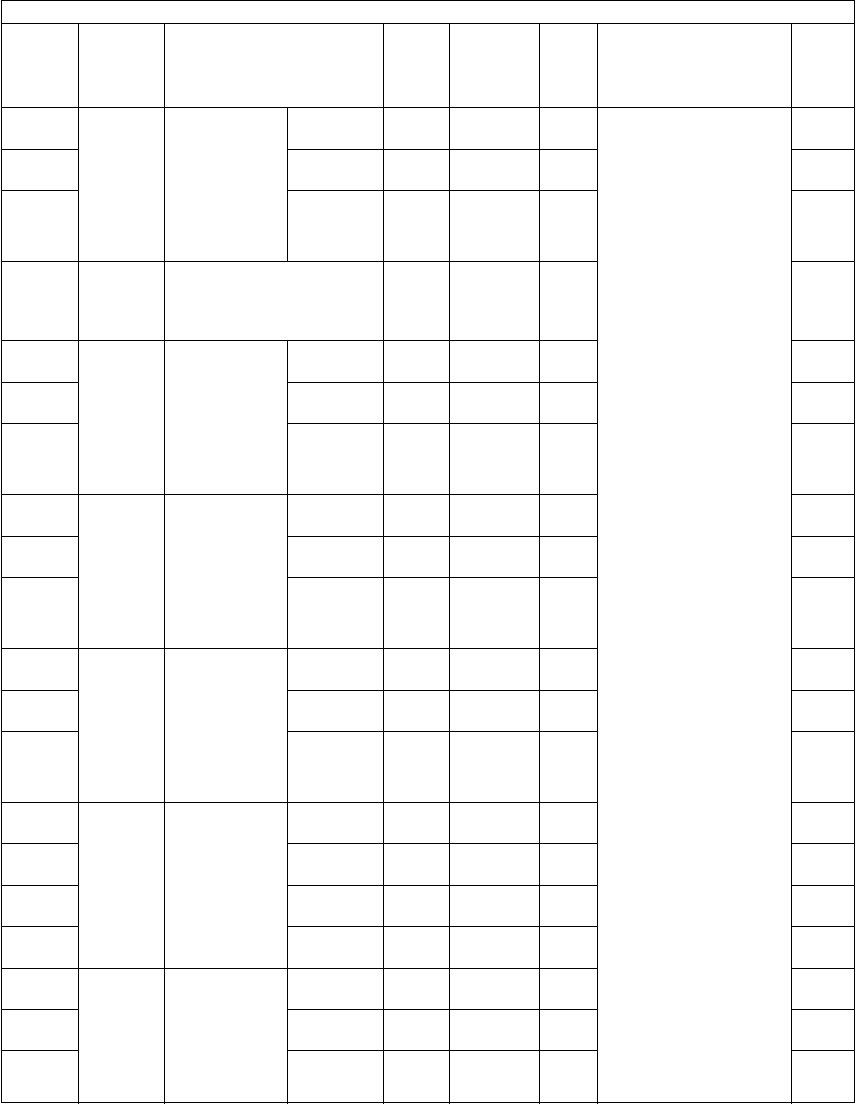
e-STUDIO281c/351c/451c ERROR CODE AND SELF-DIAGNOSTIC MODE© June 2005 TOSHIBA TEC
2 - 56
455-0Paper
feeding
Paper aligning
amount
adjustment at
the registra-
tion section
(Duplex feed-
ing / Plain
paper)
Long
size
ALL8
<0-63>
MWhen the value
increases by 1!, the
aligning amount
increases by approx.
0.8 mm.
<Paper length>
Long size:
330 mm or longer
Middle size:
220 mm to 329 mm
Short size:
219 mm or shorter
*Postcard is sup-
ported only for JPN
model.
4
455-1Middle
size
ALL8
<0-63>
M4
455-2Short
size
ALL12
<0-63>
M4
457Paper
feeding
Paper aligning amount
adjustment at the registra-
tion section (LCF / Plain
paper)
ALL15
<0-63>
M1
458-0Paper
feeding
Paper aligning
amount
adjustment at
the registra-
tion section
(Bypass feed-
ing/Plain
paper)
Long
size
ALL14
<0-63>
M4
458-1Middle
size
ALL14
<0-63>
M4
458-2Short
size
ALL14
<0-63>
M4
460-0Paper
feeding
Paper aligning
amount
adjustment at
the registra-
tion section
(Bypass feed-
ing/Thick
paper 1)
Long
size
ALL16
<0-63>
M4
460-1Middle
size
ALL16
<0-63>
M4
460-2Short
size
ALL16
<0-63>
M4
461-0Paper
feeding
Paper aligning
amount
adjustment at
the registra-
tion section
(Bypass feed-
ing/Thick
paper 2)
Long
size
ALL17
<0-63>
M4
461-1Middle
size
ALL17
<0-63>
M4
461-2Short
size
ALL17
<0-63>
M4
462-0Paper
feeding
Paper aligning
amount
adjustment at
the registra-
tion section
(Bypass feed-
ing/Thick
paper 3)
Long
size
ALL17
<0-63>
M4
462-1Middle
size
ALL17
<0-63>
M4
462-2Short
size
ALL17
<0-63>
M4
462-3Post
card
ALL16
<0-63>
M4
463-0Paper
feeding
Paper aligning
amount
adjustment at
the registra-
tion section
(Bypass feed-
ing/OHP film)
Long
size
ALL16
<0-63>
M4
463-1Middle
size
ALL16
<0-63>
M4
463-2Short
size
ALL16
<0-63>
M4
Adjustment mode (05)
Code Classifi-
cation Items Func-
tion
Default
<Accept-
able
value>
RAMContents
Pro-
cedur
e

© June 2005 TOSHIBA TECe-STUDIO281c/351c/451c ERROR CODE AND SELF-DIAGNOSTIC MODE
2 - 57
2
466-0Paper
feeding
Adjustment of
paper push-
ing amount /
Bypass feed-
ing
Plain
paper
ALL143
<0-255>
MWhen the value
increases by 1!, the
driving speed of bypass
feed roller increases by
approx. 2 ms when the
paper transport is
started from the regis-
tration section.
*Post card is sup-
ported only for JPN
model.
4
466-1Post cardALL170
<0-255>
M4
466-4Thick
paper 1
ALL143
<0-255>
M4
466-5Thick
paper 2
ALL143
<0-255>
M4
466-6Thick
paper 3
ALL143
<0-255>
M4
466-7OHP filmALL143
<0-255>
M4
467Paper
feeding
Adjustment of paper push-
ing amount/Duplex feed-
ing (short size)
ALL128
<0-255>
MWhen the value
increases by 1!, the
driving speed of ADU
transport roller
increases by approx.
2 ms when the paper
transport is started from
the registration section.
1
468-0FinisherFine adjust-
ment of bind-
ing position/
folding posi-
tion
A4-R
/LT-R
ALL0
<-14-14>
MWhen the value
increases by 1!, the
binding/folding position
shifts toward the right
page by 0.25 mm.
4
468-1B4ALL0
<-14-14>
M4
468-2A3/LDALL0
<-14-14>
M4
469-0Paper
feeding
Paper aligning
amount
adjustment at
the registra-
tion section
(Upper drawer
/ Thick paper
1)
Long
size
ALL18
<0-63>
MWhen the value
increases by "1", the
aligning amount
increases by approx.
0.8 mm.
<Paper length>
Long size:
330 mm or longer
Middle size:
220 mm to 329 mm
Short size 1:
205 mm to 219 mm
Short size 2:
204 mm or shorter
4
469-1Middle
size
ALL18
<0-63>
M4
469-2Short
size 1
ALL18
<0-63>
M4
469-3Short
size 2
ALL18
<0-63>
M4
470-0Paper
feeding
Paper aligning
amount
adjustment at
the registra-
tion section
(Lower drawer
/ Thick
paper 1)
Long
size
ALL15
<0-63>
M4
470-1Middle
size
ALL15
<0-63>
M4
470-2Short
size 1
ALL15
<0-63>
M4
470-3Short
size 2
ALL15
<0-63>
M4
471-0Paper
feeding
Paper aligning
amount
adjustment at
the registra-
tion section
(PFP upper
drawer / Thick
paper 1)
Long
size
ALL15
<0-63>
M4
471-1Middle
size
ALL15
<0-63>
M4
471-2Short
size 1
ALL15
<0-63>
M4
471-3Short
size 2
ALL15
<0-63>
M4
Adjustment mode (05)
Code Classifi-
cation Items Func-
tion
Default
<Accept-
able
value>
RAMContents
Pro-
cedur
e
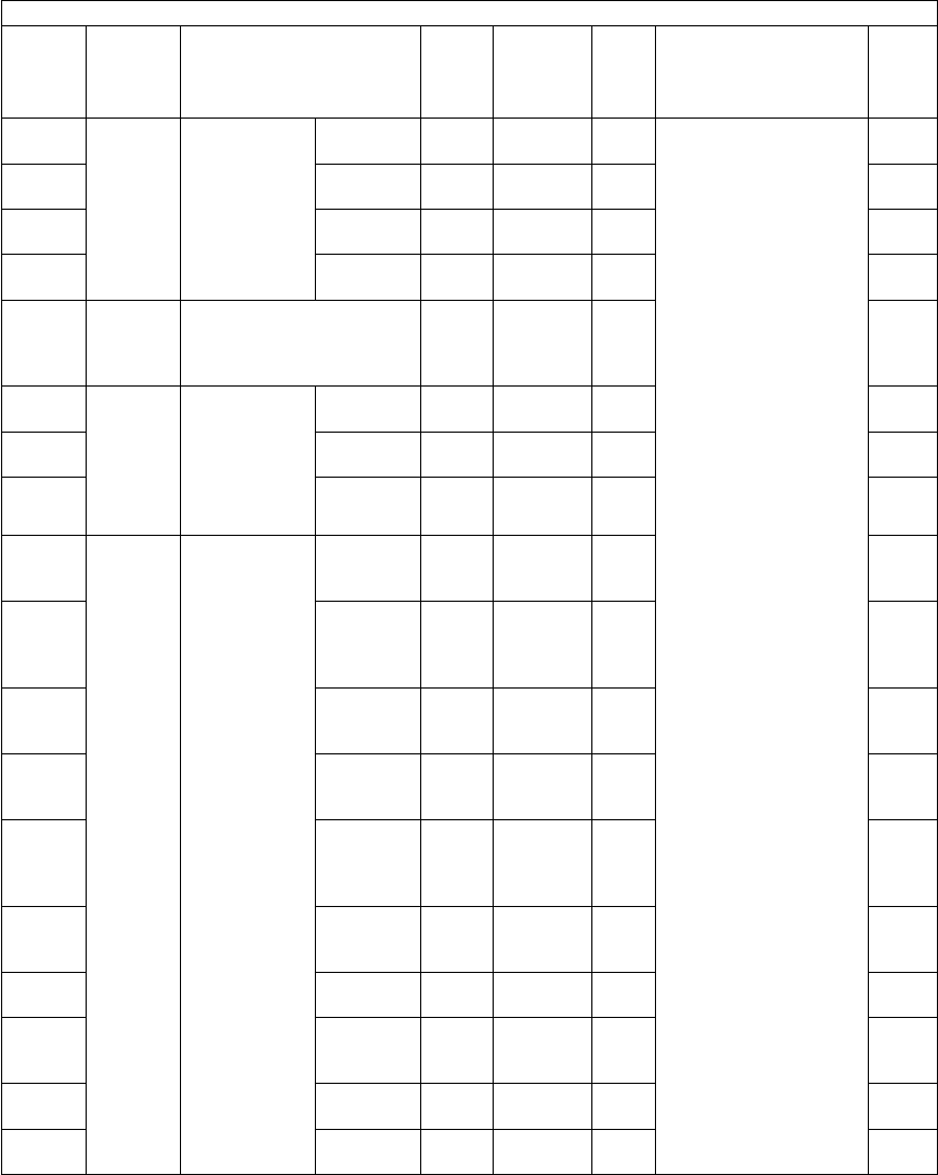
e-STUDIO281c/351c/451c ERROR CODE AND SELF-DIAGNOSTIC MODE© June 2005 TOSHIBA TEC
2 - 58
472-0Paper
feeding
Paper aligning
amount
adjustment at
the registra-
tion section
(PFP lower
drawer / Thick
paper 1)
Long
size
ALL15
<0-63>
MWhen the value
increases by "1", the
aligning amount
increases by approx.
0.8 mm.
<Paper length>
Long size:
330 mm or longer
Middle size:
220 mm to 329 mm
Short size:
219 mm or shorter
Short size 1:
205 mm to 219 mm
Short size 2:
204 mm or shorter
*Post card is sup-
ported only for JPN
model.
4
472-1Middle
size
ALL15
<0-63>
M4
472-2Short
size 1
ALL15
<0-63>
M4
472-3Short
size 2
ALL15
<0-63>
M4
473Paper
feeding
Paper aligning amount
adjustment at the registra-
tion section (LCF / Thick
paper 1)
ALL15
<0-63>
M1
474-0Paper
feeding
Paper aligning
amount
adjustment at
the registra-
tion section
(ADU / Thick
paper 1)
Long
size
ALL8
<0-63>
M4
474-1Middle
size
ALL8
<0-63>
M4
474-2Short
size
ALL12
<0-63>
M4
475-0Paper
feeding
Paper aligning
amount
adjustment at
the registra-
tion section
(Bypass feed-
ing)
Thick
paper 2
Long size
ALL28
<0-63>
M4
475-1Thick
paper 2
Middle
size
ALL28
<0-63>
M4
475-2Thick
paper 2
Short size
ALL28
<0-63>
M4
475-3Thick
paper 3
Long size
ALL28
<0-63>
M4
475-4Thick
paper 3
Middle
size
ALL28
<0-63>
M4
475-5Thick
paper 3
Short size
ALL28
<0-63>
M4
475-6OHP film
Long size
ALL24
<0-63>
M4
475-7OHP film
Middle
size
ALL24
<0-63>
M4
475-8OHP film
Short size
ALL24
<0-63>
M4
475-9Post cardALL28
<0-63>
M4
Adjustment mode (05)
Code Classifi-
cation Items Func-
tion
Default
<Accept-
able
value>
RAMContents
Pro-
cedur
e

© June 2005 TOSHIBA TECe-STUDIO281c/351c/451c ERROR CODE AND SELF-DIAGNOSTIC MODE
2 - 59
2
494LaserSecondary
scanning data
laser writing
start position
When
decelerat-
ing to 1/2
ALL135
<0-255>
MWhen the value
increases by 1!, the
image shifts by approx.
0.2 mm toward the
trailing edge of the
paper.
1
495When
decelerat-
ing to 1/3
ALL135
<0-255>
M1
496When
decelerat-
ing to 1/4
ALL140
<0-255>
M1
497-0LaserAdjustment of
drawer side-
ways devia-
tion
Upper
drawer
ALL128
<0-255>
MWhen the value
increases by 1!, the
image shifts toward the
front side by 0.0423
mm.
4
497-1Lower
drawer
ALL128
<0-255>
M4
497-2PFP upper
drawer
ALL128
<0-255>
M4
497-3PFP lower
drawer
ALL128
<0-255>
M4
497-4LCFALL128
<0-255>
M4
497-5Bypass
feeding
ALL128
<0-255>
M4
498-0LaserAdjustment of
duplex feed-
ing sideways
deviation
Long sizeALL131
<0-255>
MWhen the value
increases by 1!, the
image shifts toward the
front side by 0.0423
mm.
4
498-1Short size
(A4/LT or
smaller)
ALL131
<0-255>
M4
499Develop-
ment
Black developer unit lift up/
down timing adjustment
ALL2
<0-255>
MChange the lift up/down
timing of the black
developer unit when a
CEB0 error occurs.
(Chap. 3.11.3)
1
501ImageDensity
adjustment
Fine adjust-
ment of man-
ual density!
/Center value
PhotoPPC
(black)
128
<0-255>
SYSWhen the value
increases, the image of
the center step density
becomes darker.
1
503Text/PhotoPPC
(black)
128
<0-255>
SYS1
504TextPPC
(black)
128
<0-255>
SYS1
505ImageDensity
adjustment
Fine adjust-
ment of man-
ual density!
/Light step
value
Text/PhotoPPC
(black)
20
<0-255>
SYSSets the changing
amount by 1 step at the
density adjustment.
When the value
increases, the image of
the light! steps
becomes lighter.
1
506PhotoPPC
(black)
20
<0-255>
SYS1
507TextPPC
(black)
20
<0-255>
SYS1
508ImageDensity
adjustment
Fine adjust-
ment of man-
ual density!
/Dark step
value
Text/PhotoPPC
(black)
20
<0-255>
SYSSets the changing
amount by 1 step at the
density adjustment.
When the value
increases, the image of
the dark! steps
becomes darker.
1
509PhotoPPC
(black)
20
<0-255>
SYS1
510TextPPC
(black)
20
<0-255>
SYS1
Adjustment mode (05)
Code Classifi-
cation Items Func-
tion
Default
<Accept-
able
value>
RAMContents
Pro-
cedur
e
06/10
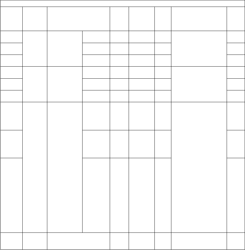
e-STUDIO281c/351c/451c ERROR CODE AND SELF-DIAGNOSTIC MODE© June 2005 TOSHIBA TEC
2 - 60
512ImageDensity
adjustment
Fine adjust-
ment of auto-
matic density!
PhotoPPC
(black)
128
<0-255>
SYSWhen the value
increases, the image
becomes darker.
1
514Text/PhotoPPC
(black)
128
<0-255>
SYS1
515TextPPC
(black)
128
<0-255>
SYS1
532ImageRange correc-
tion Back-
ground peak
adjustment
Text/PhotoPPC
(black)
40
<0-255>
SYSWhen the value
increases, the back-
ground of the image
(low density area)
becomes harder to be
printed out.
1
533PhotoPPC
(black)
16
<0-255>
SYS1
534TextPPC
(black)
40
<0-255>
SYS1
570ImageRange correc-
tion on origi-
nal manually
set on the
original glass
Text/PhotoPPC
(black)
22
<11-14,
21-24,
31-34,
41-44>
SYSSets whether the values
of the background peak
and text peak are fixed
or not. One#s place is
an adjustment for auto-
matic density! and ten#s
place is for manual
density!. Once they are
fixed, the range correc-
tion is performed with
standard values. The
values of the back-
ground peak and text
peak affect the repro-
duction of the back-
ground density and text
density respectively.
1: fixed/fixed
2: varied/fixed
3: fixed/varied
4: varied/varied
*Background peak/
Text peak
1
571PhotoPPC
(black)
12
<11-14,
21-24,
31-34,
41-44>
SYS1
572TextPPC
(black)
22
<11-14,
21-24,
31-34,
41-44>
SYS1
580ImageAutomatic gamma adjust-
ment
PPC
(black)
--Adjusts the gradation
reproduction automati-
cally.
7
Adjustment mode (05)
Code Classifi-
cation Items Func-
tion
Default
<Accept-
able
value>
RAMContents
Pro-
cedur
e

© June 2005 TOSHIBA TECe-STUDIO281c/351c/451c ERROR CODE AND SELF-DIAGNOSTIC MODE
2 - 61
2
590-0ImageAdjustment of
gamma bal-
ance (Text/
Photo)
LPPC
(black)
128
<0-255>
SYSWhen the value
increases, the density
in the target area
becomes higher.
L : Low density area
M : Medium density
area
H : High density area
4
590-1MPPC
(black)
128
<0-255>
SYS4
590-2HPPC
(black)
128
<0-255>
SYS4
591-0ImageAdjustment of
gamma bal-
ance (Text)
LPPC
(black)
128
<0-255>
SYS4
591-1MPPC
(black)
128
<0-255>
SYS4
591-2HPPC
(black)
128
<0-255>
SYS4
592-0ImageAdjustment of
gamma bal-
ance (Photo)
LPPC
(black)
128
<0-255>
SYS4
592-1MPPC
(black)
128
<0-255>
SYS4
592-2HPPC
(black)
128
<0-255>
SYS4
596-0ImageAdjustment of
gamma bal-
ance (PS/
Smooth)
LPRT
(black)
128
<0-255>
SYS4
596-1MPRT
(black)
128
<0-255>
SYS4
596-2HPRT
(black)
128
<0-255>
SYS4
597-0ImageAdjustment of
gamma bal-
ance
(PS/Detail)
LPRT
(black)
128
<0-255>
SYSWhen the value
increases, the density
in the target area
becomes higher.
L: Low density area
M: Medium density
area
H : High density area
4
597-1MPRT
(black)
128
<0-255>
SYS4
597-2HPRT
(black)
128
<0-255>
SYS4
598-0ImageAdjustment of
gamma bal-
ance
(PCL/Smooth)
LPRT
(black)
128
<0-255>
SYS4
598-1MPRT
(black)
128
<0-255>
SYS4
598-2HPRT
(black)
128
<0-255>
SYS4
599-0ImageAdjustment of
gamma bal-
ance
(PCL/Detail)
LPRT
(black)
128
<0-255>
SYS4
599-1MPRT
(black)
128
<0-255>
SYS4
599-2HPRT
(black)
128
<0-255>
SYS4
600ImageBackground
adjustment
Text/PhotoPPC
(black)
5
<1-9>
SYSWhen the value
decreases, the back-
ground becomes
darker. When the value
increases, the back-
ground becomes
lighter.
1
601TextPPC
(black)
5
<1-9>
SYS1
602PhotoPPC
(black)
5
<1-9>
SYS1
Adjustment mode (05)
Code Classifi-
cation Items Func-
tion
Default
<Accept-
able
value>
RAMContents
Pro-
cedur
e
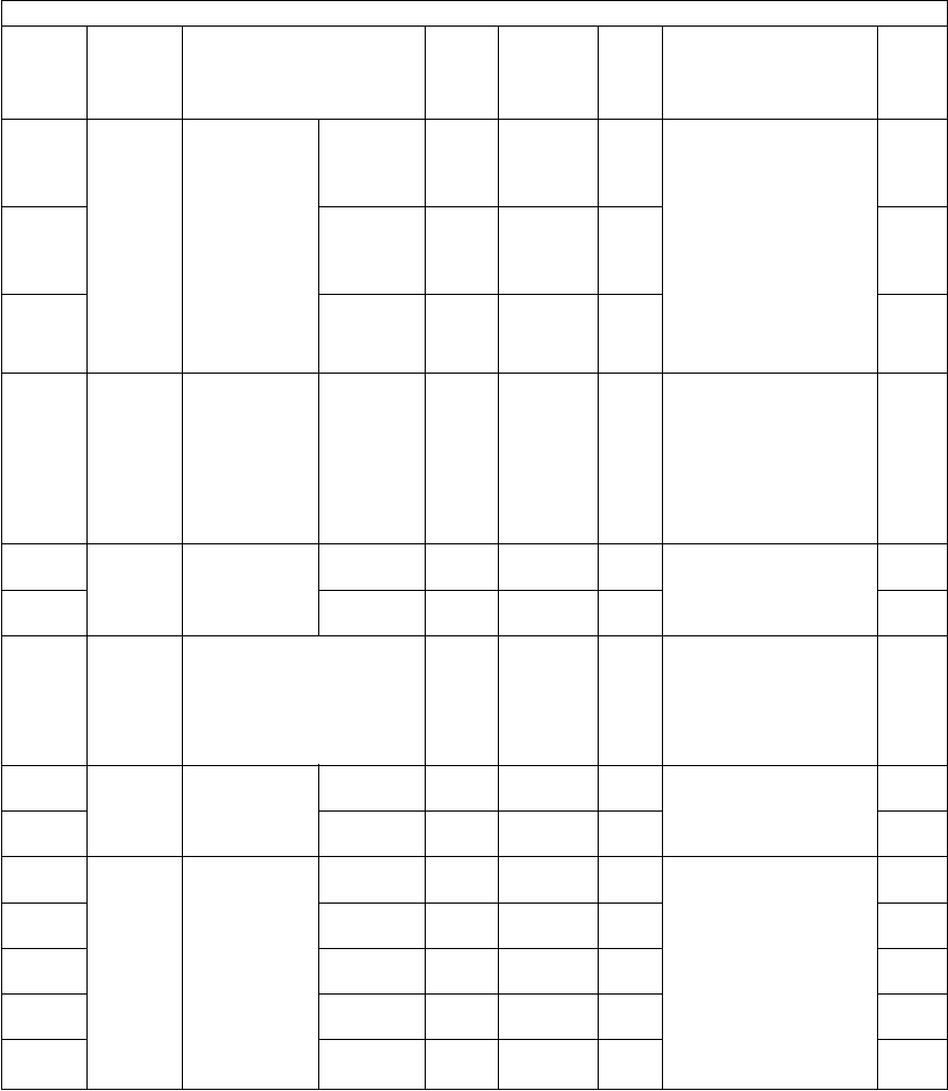
e-STUDIO281c/351c/451c ERROR CODE AND SELF-DIAGNOSTIC MODE© June 2005 TOSHIBA TEC
2 - 62
604ImageSharpness
adjustment
Text/PhotoPPC
(black)
0
<0-31>
SYSWhen the value
increases, the image
becomes sharper.
When the value
decreases, the image
becomes softer.
The smaller the value
is, the less the moire
becomes.
*The default value 0
is equivalent to 16
(center value).
1
605TextPPC
(black)
0
<0-31>
SYS1
606PhotoPPC
(black)
0
<0-31>
SYS1
648ImageAdjustment of
smudged/faint
text
Text/PhotoPPC
(black)
30
<0-255>
SYSAdjustment of the
smudged/faint text.
With increasing the
value, the faint text is
suppressed, and with
decreasing it, the
smudged text is sup-
pressed.
1
654ImageAdjustment of
smudged/faint
text
PSPRT
(black)
5
<0-9>
SYSWhen the value
decreases, the width of
text becomes wider.
1
655PCLPRT
(black)
5
<0-9>
SYS1
663ImageDot size adjustment in
black printing
PRT
(black)
255
<0-255>
SYSAdjusts the dot size of
primary scanning direc-
tion in black printing.
The smaller the value
is, the dot becomes
smaller.
1
664ImageUpper limit in
toner saving
mode
PSPRT
(black)
176
<0-255>
SYSWhen the value
decreases, the printing
density becomes
lighter.
1
665PCLPRT
(black)
176
<0-255>
SYS1
667-0ImageSetting beam
level conver-
sion
Beam
level 0/4
PPC
(black)
0
<0-255>
MSets the beam level for
4 divided smoothing.
The primary scanning
direction is divided into
4 and the dot width is
set at the 5 levels (incl.
level 0!). The smaller
the value is, the smaller
the primary scanning
direction of the dot
becomes.
4
667-1Beam
level 1/4
PPC
(black)
63
<0-255>
M4
667-2Beam
level 2/4
PPC
(black)
127
<0-255>
M4
667-3Beam
level 3/4
PPC
(black)
191
<0-255>
M4
667-4Beam
level 4/4
PPC
(black)
255
<0-255>
M4
Adjustment mode (05)
Code Classifi-
cation Items Func-
tion
Default
<Accept-
able
value>
RAMContents
Pro-
cedur
e

© June 2005 TOSHIBA TECe-STUDIO281c/351c/451c ERROR CODE AND SELF-DIAGNOSTIC MODE
2 - 63
2
693ImageRange correc-
tion on origi-
nal set on the
RADF
Text/PhotoPPC
(black)
22
<11-14,
21-24,
31-34,
41-44>
SYSSets whether the values
of the background peak
and text peak are fixed
or not. One#s place is
an adjustment for auto-
matic density! and ten#s
place is for manual
density!. Once they are
fixed, the range correc-
tion is performed with
standard values.
The values of the back-
ground peak and text
peak affect the repro-
duction of the back-
ground density and text
density respectively.
1: fixed/fixed
2: varied/fixed
3: fixed/varied
4: varied/varied
*Background peak/
Text peak
1
694PhotoPPC
(black)
12
<11-14,
21-24,
31-34,
41-44>
SYS1
695TextPPC
(black)
22
<11-14,
21-24,
31-34,
41-44>
SYS1
700ImageAdjustment of
binarized
threshold
(Text)
Center
value
FAX
(black)
125
<0-255>
SYSWhen the value
increases, the image of
center value density
becomes darker.
1
701Light step
value
FAX
(black)
20
<0-255>
SYSSets the changing
amount by 1 step at the
density adjustment.
When the value
increases, the image of
light! side becomes
lighter.
1
702Dark step
value
FAX
(black)
20
<0-255>
SYSSets the changing
amount by 1 step at the
density adjustment.
1
710ImageDensity
adjustment
manual den-
sity! fine
adjustment/
Center value
PhotoFAX
(black)
128
<0-255>
SYSWhen the value
increases, the image of
the center step density
becomes darker.
1
714Text/PhotoFAX
(black)
128
<0-255>
SYS1
715ImageDensity
adjustment
manual den-
sity! fine
adjustment/
Light step
value
PhotoFAX
(black)
20
<0-255>
SYSSets the changing
amount by 1 step at the
density adjustment.
When the value
increases, the image of
the light! steps
becomes lighter.
1
719Text/PhotoFAX
(black)
20
<0-255>
SYS1
720ImageDensity
adjustment
manual den-
sity! fine
adjustment/
Dark step
value
PhotoFAX
(black)
20
<0-255>
SYSSets the changing
amount by 1 step at the
density adjustment.
When the value
increases, the image of
the dark! steps
becomes darker.
1
724Text/PhotoFAX
(black)
20
<0-255>
SYS1
Adjustment mode (05)
Code Classifi-
cation Items Func-
tion
Default
<Accept-
able
value>
RAMContents
Pro-
cedur
e
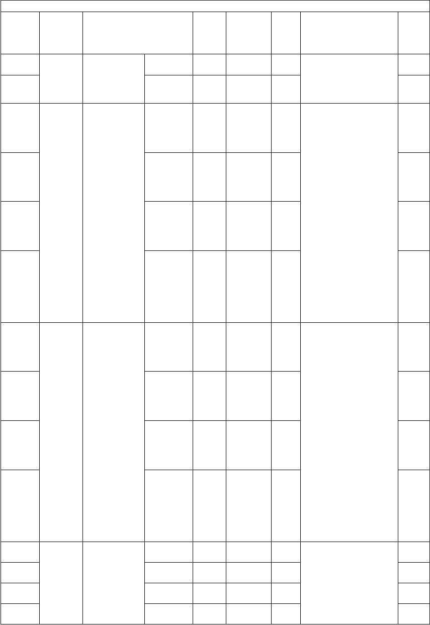
e-STUDIO281c/351c/451c ERROR CODE AND SELF-DIAGNOSTIC MODE© June 2005 TOSHIBA TEC
2 - 64
725ImageDensity
adjustment
automatic
density! fine
adjustment
PhotoFAX
(black)
128
<0-255>
SYSWhen the value
increases, the image
becomes darker.
1
729Text/PhotoFAX
(black)
128
<0-255>
SYS1
825ImageRange correc-
tion on origi-
nal manually
set on the
original glass
Text/PhotoSCN
(black)
12
<11-14,
21-24,
31-34,
41-44>
SYSSets whether the values
of the background peak
and text peak are fixed
or not. One#s place is
an adjustment for auto-
matic density! and ten#s
place is for manual
density!. Once they are
fixed, the range correc-
tion is performed with
standard values. The
values of the back-
ground peak and text
peak affect the repro-
duction of the back-
ground density and text
density respectively.
1: fixed/fixed
2: varied/fixed
3: fixed/varied
4: varied/varied
*Background peak/
Text peak
1
826TextSCN
(black)
12
<11-14,
21-24,
31-34,
41-44>
SYS1
827PhotoSCN
(black)
12
<11-14,
21-24,
31-34,
41-44>
SYS1
828Gray scaleSCN
(black)
12
<11-14,
21-24,
31-34,
41-44>
SYS1
830ImageRange correc-
tion on origi-
nal set on the
RADF
Text/PhotoSCN
(black)
12
<11-14,
21-24,
31-34,
41-44>
SYSSets whether the values
of the background peak
and text peak are fixed
or not. One#s place is
an adjustment for auto-
matic density! and ten#s
place is for manual
density!. Once they are
fixed, the range correc-
tion is performed with
standard values.
The values of the back-
ground peak and text
peak affect the repro-
duction of the back-
ground density and text
density respectively.
1: fixed/fixed
2: varied/fixed
3: fixed/varied
4: varied/varied
*Background peak/
Text peak
1
831TextSCN
(black)
12
<11-14,
21-24,
31-34,
41-44>
SYS1
832PhotoSCN
(black)
12
<11-14,
21-24,
31-34,
41-44>
SYS1
833Gray scaleSCN
(black)
12
<11-14,
21-24,
31-34,
41-44>
SYS1
835ImageRange correc-
tion Back-
ground peak
adjustment
Text/PhotoSCN
(black)
56
<0-255>
SYSWhen the value
increases, the back-
ground of the image
(low density area)
becomes harder to be
printed out.
1
836TextSCN
(black)
48
<0-255>
SYS1
837PhotoSCN
(black)
16
<0-255>
SYS1
838Gray scaleSCN
(black)
32
<0-255>
SYS1
Adjustment mode (05)
Code Classifi-
cation Items Func-
tion
Default
<Accept-
able
value>
RAMContents
Pro-
cedur
e

© June 2005 TOSHIBA TECe-STUDIO281c/351c/451c ERROR CODE AND SELF-DIAGNOSTIC MODE
2 - 65
2
840ImageSharpness
adjustment
Text/PhotoSCN
(black)
0
<0-31>
SYSWhen the value
increases, the image
becomes sharper.
When the value
decreases, the image
becomes softer.
The smaller the value
is, the less the moire
becomes.
*The default value 0
is equivalent to 16
(center value).
1
841TextSCN
(black)
0
<0-31>
SYS1
842PhotoSCN
(black)
0
<0-31>
SYS1
843Gray scaleSCN
(black)
0
<0-31>
SYS1
845ImageDensity
adjustment
manual den-
sity! fine
adjustment/
Center value
Text/PhotoSCN
(black)
128
<0-255>
SYSWhen the value
increases, the image
becomes darker.
1
846TextSCN
(black)
128
<0-255>
SYS1
847PhotoSCN
(black)
128
<0-255>
SYS1
848ImageFine adjustment of back-
ground / Center value
SCN
(black)
128
<0-255>
SYSWhen the value
increases, the back-
ground becomes
darker.
1
850ImageDensity
adjustment
manual den-
sity! fine
adjustment/
Light step
value
Text/PhotoSCN
(black)
20
<0-255>
SYSWhen the value
increases, the image of
the light! steps
becomes lighter.
1
851TextSCN
(black)
20
<0-255>
SYS1
852PhotoSCN
(black)
20
<0-255>
SYS1
853ImageFine adjustment of back-
ground / Light step value
(Image smoothing)
SCN
(black)
50
<0-255>
SYSSets the changing
amount by 1 step at
background adjust-
ment. When the value
increases, the back-
ground of the light!
steps becomes lighter.
1
855ImageDensity
adjustment
manual den-
sity! fine
adjustment/
Dark step
value
Text/PhotoSCN
(black)
20
<0-255>
SYSWhen the value
increases, the image of
the dark! steps
becomes darker.
1
856TextSCN
(black)
20
<0-255>
SYS1
857PhotoSCN
(black)
20
<0-255>
SYS1
858ImageFine adjustment of back-
ground / Dark step value
(Image smoothing)
SCN
(black)
50
<0-255>
SYSSets the changing
amount by 1 step at
background adjust-
ment. When the value
increases, the back-
ground of the dark!
steps becomes darker.
1
860ImageDensity
adjustment
automatic
density! fine
adjustment
Text/PhotoSCN
(black)
128
<0-255>
SYSWhen the value
increases, the image
becomes darker.
1
861TextSCN
(black)
128
<0-255>
SYS1
862PhotoSCN
(black)
128
<0-255>
SYS1
Adjustment mode (05)
Code Classifi-
cation Items Func-
tion
Default
<Accept-
able
value>
RAMContents
Pro-
cedur
e
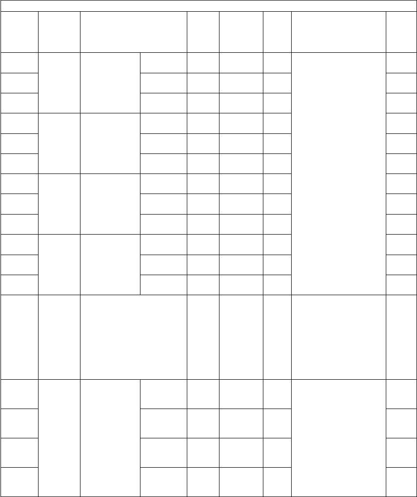
e-STUDIO281c/351c/451c ERROR CODE AND SELF-DIAGNOSTIC MODE© June 2005 TOSHIBA TEC
2 - 66
880-0ImageAdjustment of
gamma bal-
ance (Text/
Photo)
LSCN
(black)
128
<0-255>
SYSWhen the value
increases, the density
in the target area
becomes higher.
L: Low density area
M: Medium density area
H: High density area
4
880-1MSCN
(black)
128
<0-255>
SYS4
880-2HSCN
(black)
128
<0-255>
SYS4
881-0ImageAdjustment of
gamma bal-
ance (Text)
LSCN
(black)
128
<0-255>
SYS4
881-1MSCN
(black)
128
<0-255>
SYS4
881-2HSCN
(black)
128
<0-255>
SYS4
882-0ImageAdjustment of
gamma bal-
ance (Photo)
LSCN
(black)
128
<0-255>
SYS4
882-1MSCN
(black)
128
<0-255>
SYS4
882-2HSCN
(black)
128
<0-255>
SYS4
883-0ImageAdjustment of
gamma bal-
ance (Gray
scale)
LSCN
(black)
128
<0-255>
SYS4
883-1MSCN
(black)
128
<0-255>
SYS4
883-2HSCN
(black)
128
<0-255>
SYS4
884ImageReproduction ratio fine
adjustment of primary
scanning direction
SCN
(black)
128
<0-255>
SYSWhen the value
increases by 1!, the
reproduction ratio of pri-
mary scanning direction
increases by approx.
0.1%.
Effective with the reso-
lution other than 600
dpi.
1
953-0ImageColor devia-
tion correc-
tion 3
(A4/LT)
KALL128
<118-
138>
MWhen the value
increases by "1", the
image shifts toward the
trailing edge of the
paper by 0.0423 mm.
4
953-1CALL128
<118-
138>
M4
953-2MALL128
<118-
138>
M4
953-3YALL128
<118-
138>
M4
Adjustment mode (05)
Code Classifi-
cation Items Func-
tion
Default
<Accept-
able
value>
RAMContents
Pro-
cedur
e

© June 2005 TOSHIBA TECe-STUDIO281c/351c/451c ERROR CODE AND SELF-DIAGNOSTIC MODE
2 - 67
2
954-0ImageColor devia-
tion correc-
tion 4
(A4/LT)
KALL128
<118-
138>
MWhen the value
increases by "1", the
image shifts toward the
trailing edge of the
paper by 0.0423 mm.
4
954-1CALL128
<118-
138>
M4
954-2MALL128
<118-
138>
M4
954-3YALL128
<118-
138>
M4
955-0ImageColor devia-
tion correc-
tion 5
(A4/LT)
KALL128
<118-
138>
MWhen the value
increases by "1", the
image shifts toward the
trailing edge of the
paper by 0.0423 mm.
4
955-1CALL128
<118-
138>
M4
955-2MALL128
<118-
138>
M4
955-3YALL128
<118-
138>
M4
956-0ImageColor devia-
tion correc-
tion 6
(A4/LT)
KALL128
<118-
138>
MWhen the value
increases by "1", the
image shifts toward the
trailing edge of the
paper by 0.0423 mm.
4
956-1CALL128
<118-
138>
M4
956-2MALL128
<118-
138>
M4
956-3YALL128
<118-
138>
M4
976Mainte-
nance
Equipment number (serial
number) display
ALL-SYSWhen this adjustment is
performed with this
code, the setting code
(08-995) is also per-
formed automatically.
(10 digits)
1
1000ImageAutomatic
gamma
adjustment
PS/
600x600
dpi
PRT
(color)
-SYSAdjusts the gradation
reproduction for each
color, Y, M, C and K.
7
1001PS/
1200x600
dpi
PRT
(color)
-SYS7
1002PCL/
600x600
dpi
PRT
(color)
-SYS7
1003PCL/
1200x600
dpi
PRT
(color)
-SYS7
Adjustment mode (05)
Code Classifi-
cation Items Func-
tion
Default
<Accept-
able
value>
RAMContents
Pro-
cedur
e

e-STUDIO281c/351c/451c ERROR CODE AND SELF-DIAGNOSTIC MODE© June 2005 TOSHIBA TEC
2 - 68
1010-0ImageColor bal-
ance adjust-
ment for Y!
(PS/
600x600dpi/
Smooth)
LPRT
(color)
128
<0-255>
SYSThe target color, mode
and density area
become darker as the
value increases.
L: Low density area
M: Medium density
area
H: High density area
4
1010-1MPRT
(color)
128
<0-255>
SYS4
1010-2HPRT
(color)
128
<0-255>
SYS4
1011-0ImageColor bal-
ance adjust-
ment for M!
(PS/
600x600dpi/
Smooth)
LPRT
(color)
128
<0-255>
SYS4
1011-1MPRT
(color)
128
<0-255>
SYS4
1011-2HPRT
(color)
128
<0-255>
SYS4
1012-0ImageColor bal-
ance adjust-
ment for C!
(PS/
600x600dpi/
Smooth)
LPRT
(color)
128
<0-255>
SYS4
1012-1MPRT
(color)
128
<0-255>
SYS4
1012-2HPRT
(color)
128
<0-255>
SYS4
1013-0ImageColor bal-
ance adjust-
ment for K!
(PS/
600x600dpi/
Smooth)
LPRT
(color)
128
<0-255>
SYS4
1013-1MPRT
(color)
128
<0-255>
SYS4
1013-2HPRT
(color)
128
<0-255>
SYS4
1014-0ImageColor bal-
ance adjust-
ment for Y!
(PS/
600x600dpi/
Detail)
LPRT
(color)
128
<0-255>
SYS4
1014-1MPRT
(color)
128
<0-255>
SYS4
1014-2HPRT
(color)
128
<0-255>
SYS4
1015-0ImageColor bal-
ance adjust-
ment for M!
(PS/
600x600dpi/
Detail)
LPRT
(color)
128
<0-255>
SYS4
1015-1MPRT
(color)
128
<0-255>
SYS4
1015-2HPRT
(color)
128
<0-255>
SYS4
1016-0ImageColor bal-
ance adjust-
ment for C!
(PS/
600x600dpi/
Detail)
LPRT
(color)
128
<0-255>
SYS4
1016-1MPRT
(color)
128
<0-255>
SYS4
1016-2HPRT
(color)
128
<0-255>
SYS4
1017-0ImageColor bal-
ance adjust-
ment for K!
(PS/
600x600dpi/
Detail)
LPRT
(color)
128
<0-255>
SYS4
1017-1MPRT
(color)
128
<0-255>
SYS4
1017-2HPRT
(color)
128
<0-255>
SYS4
1018-0ImageColor bal-
ance adjust-
ment for Y!
(PS/
1200x600dpi/
Smooth)
LPRT
(color)
128
<0-255>
SYS4
1018-1MPRT
(color)
128
<0-255>
SYS4
1018-2HPRT
(color)
128
<0-255>
SYS4
Adjustment mode (05)
Code Classifi-
cation Items Func-
tion
Default
<Accept-
able
value>
RAMContents
Pro-
cedur
e

© June 2005 TOSHIBA TECe-STUDIO281c/351c/451c ERROR CODE AND SELF-DIAGNOSTIC MODE
2 - 69
2
1019-0ImageColor bal-
ance adjust-
ment for M!
(PS/
1200x600dpi/
Smooth)
LPRT
(color)
128
<0-255>
SYSThe target color, mode
and density area
become darker as the
value increases.
L: Low density area
M: Medium density
area
H: High density area
4
1019-1MPRT
(color)
128
<0-255>
SYS4
1019-2HPRT
(color)
128
<0-255>
SYS4
1020-0ImageColor bal-
ance adjust-
ment for C!
(PS/
1200x600dpi/
Smooth)
LPRT
(color)
128
<0-255>
SYS4
1020-1MPRT
(color)
128
<0-255>
SYS4
1020-2HPRT
(color)
128
<0-255>
SYS4
1021-0ImageColor bal-
ance adjust-
ment for K!
(PS/
1200x600dpi/
Smooth)
LPRT
(color)
128
<0-255>
SYS4
1021-1MPRT
(color)
128
<0-255>
SYS4
1021-2HPRT
(color)
128
<0-255>
SYS4
1022-0ImageColor bal-
ance adjust-
ment for Y!
(PS/
1200x600dpi/
Detail)
LPRT
(color)
128
<0-255>
SYS4
1022-1MPRT
(color)
128
<0-255>
SYS4
1022-2HPRT
(color)
128
<0-255>
SYS4
1023-0ImageColor bal-
ance adjust-
ment for M!
(PS/
1200x600dpi/
Detail)
LPRT
(color)
128
<0-255>
SYS4
1023-1MPRT
(color)
128
<0-255>
SYS4
1023-2HPRT
(color)
128
<0-255>
SYS4
1024-0ImageColor bal-
ance adjust-
ment for C!
(PS/
1200x600dpi/
Detail)
LPRT
(color)
128
<0-255>
SYS4
1024-1MPRT
(color)
128
<0-255>
SYS4
1024-2HPRT
(color)
128
<0-255>
SYS4
1025-0ImageColor bal-
ance adjust-
ment for K!
(PS/
1200x600dpi/
Detail)
LPRT
(color)
128
<0-255>
SYS4
1025-1MPRT
(color)
128
<0-255>
SYS4
1025-2HPRT
(color)
128
<0-255>
SYS4
1026-0ImageColor bal-
ance adjust-
ment for Y!
(PCL/
600x600dpi/
Smooth)
LPRT
(color)
128
<0-255>
SYS4
1026-1MPRT
(color)
128
<0-255>
SYS4
1026-2HPRT
(color)
128
<0-255>
SYS4
1027-0ImageColor bal-
ance adjust-
ment for M!
(PCL/
600x600dpi/
Smooth)
LPRT
(color)
128
<0-255>
SYS4
1027-1MPRT
(color)
128
<0-255>
SYS4
1027-2HPRT
(color)
128
<0-255>
SYS4
Adjustment mode (05)
Code Classifi-
cation Items Func-
tion
Default
<Accept-
able
value>
RAMContents
Pro-
cedur
e
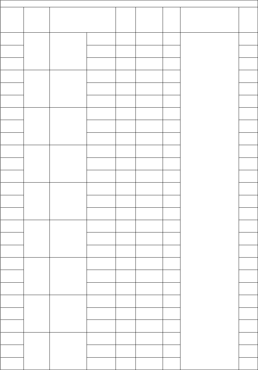
e-STUDIO281c/351c/451c ERROR CODE AND SELF-DIAGNOSTIC MODE© June 2005 TOSHIBA TEC
2 - 70
1028-0ImageColor bal-
ance adjust-
ment for C!
(PCL/
600x600dpi/
Smooth)
LPRT
(color)
128
<0-255>
SYSThe target color, mode
and density area
become darker as the
value increases.
L: Low density area
M: Medium density
area
H: High density area
4
1028-1MPRT
(color)
128
<0-255>
SYS4
1028-2HPRT
(color)
128
<0-255>
SYS4
1029-0ImageColor bal-
ance adjust-
ment for K!
(PCL/
600x600dpi/
Smooth)
LPRT
(color)
128
<0-255>
SYS4
1029-1MPRT
(color)
128
<0-255>
SYS4
1029-2HPRT
(color)
128
<0-255>
SYS4
1030-0ImageColor bal-
ance adjust-
ment for Y!
(PCL/
600x600dpi/
Detail)
LPRT
(color)
128
<0-255>
SYS4
1030-1MPRT
(color)
128
<0-255>
SYS4
1030-2HPRT
(color)
128
<0-255>
SYS4
1031-0ImageColor bal-
ance adjust-
ment for M!
(PCL/
600x600dpi/
Detail)
LPRT
(color)
128
<0-255>
SYS4
1031-1MPRT
(color)
128
<0-255>
SYS4
1031-2HPRT
(color)
128
<0-255>
SYS4
1032-0ImageColor bal-
ance adjust-
ment for C!
(PCL/
600x600dpi/
Detail)
LPRT
(color)
128
<0-255>
SYS4
1032-1MPRT
(color)
128
<0-255>
SYS4
1032-2HPRT
(color)
128
<0-255>
SYS4
1033-0ImageColor bal-
ance adjust-
ment for K!
(PCL/
600x600dpi/
Detail)
LPRT
(color)
128
<0-255>
SYS4
1033-1MPRT
(color)
128
<0-255>
SYS4
1033-2HPRT
(color)
128
<0-255>
SYS4
1034-0ImageColor bal-
ance adjust-
ment for Y!
(PCL/
1200x600dpi/
Smooth)
LPRT
(color)
128
<0-255>
SYS4
1034-1MPRT
(color)
128
<0-255>
SYS4
1034-2HPRT
(color)
128
<0-255>
SYS4
1035-0ImageColor bal-
ance adjust-
ment for M!
(PCL/
1200x600dpi/
Smooth)
LPRT
(color)
128
<0-255>
SYS4
1035-1MPRT
(color)
128
<0-255>
SYS4
1035-2HPRT
(color)
128
<0-255>
SYS4
1036-0ImageColor bal-
ance adjust-
ment for C!
(PCL/
1200x600dpi/
Smooth)
LPRT
(color)
128
<0-255>
SYS4
1036-1MPRT
(color)
128
<0-255>
SYS4
1036-2HPRT
(color)
128
<0-255>
SYS4
Adjustment mode (05)
Code Classifi-
cation Items Func-
tion
Default
<Accept-
able
value>
RAMContents
Pro-
cedur
e

© June 2005 TOSHIBA TECe-STUDIO281c/351c/451c ERROR CODE AND SELF-DIAGNOSTIC MODE
2 - 71
2
1037-0ImageColor bal-
ance adjust-
ment for K!
(PCL/
1200x600dpi/
Smooth)
LPRT
(color)
128
<0-255>
SYSThe target color, mode
and density area
become darker as the
value increases.
L: Low density area
M: Medium density
area
H: High density area
4
1037-1MPRT
(color)
128
<0-255>
SYS4
1037-2HPRT
(color)
128
<0-255>
SYS4
1038-0ImageColor bal-
ance adjust-
ment for Y!
(PCL/
1200x600dpi/
Detail)
LPRT
(color)
128
<0-255>
SYS4
1038-1MPRT
(color)
128
<0-255>
SYS4
1038-2HPRT
(color)
128
<0-255>
SYS4
1039-0ImageColor bal-
ance adjust-
ment for M!
(PCL/
1200x600dpi/
Detail)
LPRT
(color)
128
<0-255>
SYS4
1039-1MPRT
(color)
128
<0-255>
SYS4
1039-2HPRT
(color)
128
<0-255>
SYS4
1040-0ImageColor bal-
ance adjust-
ment for C!
(PCL/
1200x600dpi/
Detail)
LPRT
(color)
128
<0-255>
SYS4
1040-1MPRT
(color)
128
<0-255>
SYS4
1040-2HPRT
(color)
128
<0-255>
SYS4
1041-0ImageColor bal-
ance adjust-
ment for K!
(PCL/
1200x600dpi/
Detail)
LPRT
(color)
128
<0-255>
SYS4
1041-1MPRT
(color)
128
<0-255>
SYS4
1041-2HPRT
(color)
128
<0-255>
SYS4
1046-0ImageAdjustment of
maximum
toner amount
(Plain paper)
PSPRT
(color)
255
<0-255>
SYSWhen the value
decreases, the image
becomes lighter.
Note:
Note:
When the value
increases, the
image offsetting
may occur.
4
1046-1PCLPRT
(color)
255
<0-255>
SYS4
1047-0ImageAdjustment of
maximum
toner amount
(Thick paper
1)
PSPRT
(color)
255
<0-255>
SYS4
1047-1PCLPRT
(color)
255
<0-255>
SYS4
1048-0ImageAdjustment of
maximum
toner amount
(Thick paper
2)
PSPRT
(color)
255
<0-255>
SYS4
1048-1PCLPRT
(color)
255
<0-255>
SYS4
1049-0ImageAdjustment of
maximum
toner amount
(Thick paper
3)
PSPRT
(color)
255
<0-255>
SYS4
1049-1PCLPRT
(color)
255
<0-255>
SYS4
1050-0ImageAdjustment of
maximum
toner amount
(OHP film)
PSPRT
(color)
200
<0-255>
SYS4
1050-1PCLPRT
(color)
200
<0-255>
SYS4
Adjustment mode (05)
Code Classifi-
cation Items Func-
tion
Default
<Accept-
able
value>
RAMContents
Pro-
cedur
e

e-STUDIO281c/351c/451c ERROR CODE AND SELF-DIAGNOSTIC MODE© June 2005 TOSHIBA TEC
2 - 72
1055ImageUpper limit in toner saving
mode
PRT
(color)
176
<0-255>
SYSWhen the value
decreases, the printing
density becomes
lighter.
1
1056PRT
(color)
176
<0-255>
SYS1
1057PRT
(color)
176
<0-255>
SYS1
1058PRT
(color)
176
<0-255>
SYS1
1060ImageReproduction ratio fine
adjustment of primary
scanning direction
SCN
(color)
128
<0-255>
SYSWhen the value
increases by 1!, the
reproduction ratio of pri-
mary scanning direction
increases by approx.
0.1%.
Effective with the reso-
lution other than 600
dpi.
1
1065ImageJudgment threshold for
ACS
SCN
(color)
70
<0-255>
SYSWhen the value
increases, originals
tend to be judged as
monochrome, and
when the value
decreases, they tend to
be judged as color in
autocolor mode.
1
1066ImageJudgment threshold for
ACS on original set on the
RADF
SCN
(color)
70
<0-255>
SYS1
1070ImageFine adjust-
ment of back-
ground
TextSCN
(color)
0
<0-50>
SYSAdjusts the level of
background. When the
value increases, the
background becomes
more brightened.
1
1071Printed
image
SCN
(color)
0
<0-50>
SYS1
1072PhotoSCN
(color)
0
<0-50>
SYS1
1075ImageFine adjust-
ment of black
density
TextSCN
(color)
0
<0-4>
SYSAdjusts the black den-
sity of the scanned
image. When the value
increases, the black
density becomes
darker.
1
1076Printed
image
SCN
(color)
0
<0-4>
SYS1
1077PhotoSCN
(color)
0
<0-4>
SYS1
1080ImageRGB conver-
sion method
selection
TextSCN
(color)
0
<0-3>
SYSSets the color space
format of the output
image.
0:sRGB
1: AppleRGB
2:ROMMRGB
3: AdobeRGB
1
1081Printed
image
SCN
(color)
0
<0-3>
SYS1
1082PhotoSCN
(color)
0
<0-3>
SYS1
1086ImageSharpness
adjustment
TextSCN
(color)
0
<0-31>
SYSWhen the value
increases, the image
becomes sharper.
When the value
decreases, the image
becomes softer.
The smaller the value
is, the less the moire
becomes.
*The default value 0
is equivalent to 16
(center value).
1
1087Printed
image
SCN
(color)
0
<0-31>
SYS1
1088PhotoSCN
(color)
0
<0-31>
SYS1
Adjustment mode (05)
Code Classifi-
cation Items Func-
tion
Default
<Accept-
able
value>
RAMContents
Pro-
cedur
e

© June 2005 TOSHIBA TECe-STUDIO281c/351c/451c ERROR CODE AND SELF-DIAGNOSTIC MODE
2 - 73
2
1550ImageDensity
adjustment
manual den-
sity! fine
adjustment/
Center value
Text/PhotoPPC
(color)
128
<0-255>
SYSWhen the value
increases, the image
becomes darker.
1
1551TextPPC
(color)
128
<0-255>
SYS1
1552Printed
image
PPC
(color)
128
<0-255>
SYS1
1553PhotoPPC
(color)
128
<0-255>
SYS1
1554MapPPC
(color)
128
<0-255>
SYS1
1560ImageDensity
adjustment
manual den-
sity! fine
adjustment/
Dark step
value
Text/PhotoPPC
(color)
20
<0-255>
SYSSets the changing
amount by 1 step at the
density adjustment.
When the value
increases, the image of
the dark! steps
becomes darker.
1
1561TextPPC
(color)
20
<0-255>
SYS1
1562Printed
image
PPC
(color)
20
<0-255>
SYS1
1563PhotoPPC
(color)
20
<0-255>
SYS1
1564MapPPC
(color)
20
<0-255>
SYS1
1570ImageDensity
adjustment
manual den-
sity! fine
adjustment/
Light step
value
Text/PhotoPPC
(color)
20
<0-255>
SYSSets the changing
amount by 1 step at the
density adjustment.
When the value
increases, the image of
the light! steps
becomes lighter.
1
1571TextPPC
(color)
20
<0-255>
SYS1
1572Printed
image
PPC
(color)
20
<0-255>
SYS1
1573PhotoPPC
(color)
20
<0-255>
SYS1
1574MapPPC
(color)
20
<0-255>
SYS1
1580ImageDensity
adjustment
automatic
density! fine
adjustment
Text/PhotoPPC
(color)
128
<0-255>
SYSWhen the value
increases, the image
becomes darker.
1
1581TextPPC
(color)
128
<0-255>
SYS1
1582Printed
image
PPC
(color)
128
<0-255>
SYS1
1583PhotoPPC
(color)
128
<0-255>
SYS1
1584MapPPC
(color)
128
<0-255>
SYS1
1612ImageAdjustment of
maximum
toner amount
Plain
paper
PPC
(color)
255
<0-255>
SYSWhen the value
decreases, the image
becomes lighter.
Note:
Note:
When the value
increases,
image offsetting
may occur.
1
1613Thick
paper 1
PPC
(color)
249
<0-255>
SYS1
1614Thick
paper 2
PPC
(color)
237
<0-255>
SYS1
1615Thick
paper 3
PPC
(color)
237
<0-255>
SYS1
1616OHP filmPPC
(color)
249
<0-255>
SYS1
Adjustment mode (05)
Code Classifi-
cation Items Func-
tion
Default
<Accept-
able
value>
RAMContents
Pro-
cedur
e

e-STUDIO281c/351c/451c ERROR CODE AND SELF-DIAGNOSTIC MODE© June 2005 TOSHIBA TEC
2 - 74
1630ImageMaximum text
density
adjustment
YPPC
(color)
5
<0-10>
SYSWhen the value
increases by 1!, the
maximum text density
of each color becomes
darker.
1
1631MPPC
(color)
5
<0-10>
SYS1
1632CPPC
(color)
5
<0-10>
SYS1
1633KPPC
(color)
5
<0-10>
SYS1
1642ImageAutomatic
gamma
adjustment
Color/
Black
PPC-SYSAutomatic adjustment
of gradation reproduc-
tion in the Full Color
Mode (each color of Y,
M, C and K) and Black
Mode.
7
1643ColorPPC-SYSAutomatic adjustment
of gradation reproduc-
tion in the Full Color
Mode (each color of Y,
M, C and K).
7
1675ImageJudgment threshold for
ACS
PPC
(color)
70
<0-255>
SYSWhen the value
increases, originals
tend to be judged as
black, and when the
value decreases, they
tend to be judged as
color in auto-color
mode.
1
1676ImageJudgment threshold for
ACS on original set on the
RADF
PPC
(color)
70
<0-255>
SYS1
1688ImageAutomatic off-
setting adjust-
ment for
background
processing
(background
density)
Text/PhotoPPC
(color)
128
<0-255>
SYSWhen the value
increases, the back-
ground becomes
darker.
1
1689TextPPC
(color)
128
<0-255>
SYS1
1690Printed
image
PPC
(color)
128
<0-255>
SYS1
1691PhotoPPC
(color)
128
<0-255>
SYS1
1692MapPPC
(color)
128
<0-255>
SYS1
1693ImageAutomatic off-
setting adjust-
ment for
background
processing
(text density)
Text/PhotoPPC
(color)
128
<0-255>
SYSWhen the value
increases, the text
becomes darker.
1
1694TextPPC
(color)
128
<0-255>
SYS1
1695Printed
image
PPC
(color)
128
<0-255>
SYS1
1696PhotoPPC
(color)
128
<0-255>
SYS1
1697MapPPC
(color)
128
<0-255>
SYS1
Adjustment mode (05)
Code Classifi-
cation Items Func-
tion
Default
<Accept-
able
value>
RAMContents
Pro-
cedur
e
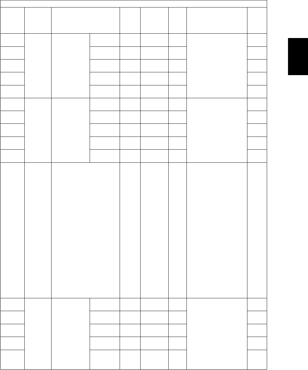
© June 2005 TOSHIBA TECe-STUDIO281c/351c/451c ERROR CODE AND SELF-DIAGNOSTIC MODE
2 - 75
2
1698ImageManual offset-
ting adjust-
ment for
background
processing
(background
density)
Text/PhotoPPC
(color)
128
<0-255>
SYSWhen the value
increases, the back-
ground becomes
darker.
1
1699TextPPC
(color)
128
<0-255>
SYS1
1700Printed
image
PPC
(color)
128
<0-255>
SYS1
1701PhotoPPC
(color)
128
<0-255>
SYS1
1702MapPPC
(color)
128
<0-255>
SYS1
1708ImageManual offset-
ting adjust-
ment for
background
processing
(text density)
Text/PhotoPPC
(color)
128
<0-255>
SYSWhen the value
increases, the text
becomes darker.
1
1709TextPPC
(color)
128
<0-255>
SYS1
1710Printed
image
PPC
(color)
128
<0-255>
SYS1
1711PhotoPPC
(color)
128
<0-255>
SYS1
1712MapPPC
(color)
128
<0-255>
SYS1
1725ImageText/Photo reproduction
level adjustment
PPC
(color)
0
<0-5>
SYS0:Default
1: Photo oriented 2
(The printed image
reproduction level
higher than that of
the Photo oriented
1)
2: Photo oriented 1
(The printed image
reproduction level
higher than that of
the Default)
3: Equivalent to the
Default
4: Text oriented 1 (The
text reproduction
level higher than
that of the Default)
5: Text oriented 2 (The
text reproduction
level higher than
that of the Text ori-
ented 1)
1
1737ImageSharpness
adjustment /
Full Color
Mode
Text/PhotoPPC
(color)
0
<0-31>
SYSWhen the value
increases, the image
becomes sharper.
When the value
decreases, the image
becomes softer.
The smaller the value
is, the less the moire
becomes.
*The default value 0
is equivalent to 16
(center value).
1
1738TextPPC
(color)
0
<0-31>
SYS1
1739Printed
image
PPC
(color)
0
<0-31>
SYS1
1740PhotoPPC
(color)
0
<0-31>
SYS1
1741MapPPC
(color)
0
<0-31>
SYS1
Adjustment mode (05)
Code Classifi-
cation Items Func-
tion
Default
<Accept-
able
value>
RAMContents
Pro-
cedur
e
e-STUDIO281c/351c/451c ERROR CODE AND SELF-DIAGNOSTIC MODE© June 2005 TOSHIBA TEC
2 - 76
1757ImageSharpness adjustment /
Auto Color Mode (Text/
Photo)
PPC
(color)
EUR: 0
UC: 0
JAPN: 22
<0-31>
SYSWhen the value
increases, the image
becomes sharper.
When the value
decreases, the image
becomes softer. The
smaller the value is, the
less the moire
becomes.
*The default value 0
is equivalent to
16(center value).
1
1761ImageBlack reproduction switch-
ing
PPC
(color)
0
<0-1>
SYS0:Default
1:Black reproduction
oriented
1
1769ImageSetting for
highlighter
VividPPC
(color)
0
<0-2>
SYSSets the reproduction
mode for highlighter for
four types of one touch
adjustment.
0:Default
1:Highlighter 1
2:Highlighter 2
1
1770ClearPPC
(color)
0
<0-2>
SYS1
1771WarmPPC
(color)
0
<0-2>
SYS1
1772CoolPPC
(color)
0
<0-2>
SYS1
1779-0ImageColor bal-
ance adjust-
ment for Y!
(Text/Photo)
LPPC
(color)
128
<0-255>
SYSThe target color, mode
and density area
become darker as the
value increases.
L: Low density area
M: Medium density
area
H: High density area
4
1779-1MPPC
(color)
128
<0-255>
SYS4
1779-2HPPC
(color)
128
<0-255>
SYS4
1780-0ImageColor bal-
ance adjust-
ment for Y!
(Text)
LPPC
(color)
128
<0-255>
SYS4
1780-1MPPC
(color)
128
<0-255>
SYS4
1780-2HPPC
(color)
128
<0-255>
SYS4
1781-0ImageColor bal-
ance adjust-
ment for Y!
(Printed
image)
LPPC
(color)
128
<0-255>
SYS4
1781-1MPPC
(color)
128
<0-255>
SYS4
1781-2HPPC
(color)
128
<0-255>
SYS4
1782-0ImageColor bal-
ance adjust-
ment for Y!
(Photo)
LPPC
(color)
128
<0-255>
SYS4
1782-1MPPC
(color)
128
<0-255>
SYS4
1782-2HPPC
(color)
128
<0-255>
SYS4
1783-0ImageColor bal-
ance adjust-
ment for Y!
(Map)
LPPC
(color)
128
<0-255>
SYS4
1783-1MPPC
(color)
128
<0-255>
SYS4
1783-2HPPC
(color)
128
<0-255>
SYS4
Adjustment mode (05)
Code Classifi-
cation Items Func-
tion
Default
<Accept-
able
value>
RAMContents
Pro-
cedur
e
© June 2005 TOSHIBA TECe-STUDIO281c/351c/451c ERROR CODE AND SELF-DIAGNOSTIC MODE
2 - 77
2
1784-0ImageColor bal-
ance adjust-
ment for M!
(Text/Photo)
LPPC
(color)
128
<0-255>
SYSThe target color, mode
and density area
become darker as the
value increases.
L:Low density area
M:Medium density
area
H:High density area
4
1784-1MPPC
(color)
128
<0-255>
SYS4
1784-2HPPC
(color)
128
<0-255>
SYS4
1785-0ImageColor bal-
ance adjust-
ment for M!
(Text)
LPPC
(color)
128
<0-255>
SYS4
1785-1MPPC
(color)
128
<0-255>
SYS4
1785-2HPPC
(color)
128
<0-255>
SYS4
1786-0ImageColor bal-
ance adjust-
ment for M!
(Printed
image)
LPPC
(color)
128
<0-255>
SYS4
1786-1MPPC
(color)
128
<0-255>
SYS4
1786-2HPPC
(color)
128
<0-255>
SYS4
1787-0ImageColor bal-
ance adjust-
ment for M!
(Photo)
LPPC
(color)
128
<0-255>
SYS4
1787-1MPPC
(color)
128
<0-255>
SYS4
1787-2HPPC
(color)
128
<0-255>
SYS4
1788-0ImageColor bal-
ance adjust-
ment for M!
(Map)
LPPC
(color)
128
<0-255>
SYS4
1788-1MPPC
(color)
128
<0-255>
SYS4
1788-2HPPC
(color)
128
<0-255>
SYS4
1789-0ImageColor bal-
ance adjust-
ment for C!
(Text/Photo)
LPPC
(color)
128
<0-255>
SYS4
1789-1MPPC
(color)
128
<0-255>
SYS4
1789-2HPPC
(color)
128
<0-255>
SYS4
1790-0ImageColor bal-
ance adjust-
ment for C!
(Text)
LPPC
(color)
128
<0-255>
SYS4
1790-1MPPC
(color)
128
<0-255>
SYS4
1790-2HPPC
(color)
128
<0-255>
SYS4
1791-0ImageColor bal-
ance adjust-
ment for C!
(Printed
image)
LPPC
(color)
128
<0-255>
SYS4
1791-1MPPC
(color)
128
<0-255>
SYS4
1791-2HPPC
(color)
128
<0-255>
SYS4
1792-0ImageColor bal-
ance adjust-
ment for C!
(Photo)
LPPC
(color)
128
<0-255>
SYS4
1792-1MPPC
(color)
128
<0-255>
SYS4
1792-2HPPC
(color)
128
<0-255>
SYS4
Adjustment mode (05)
Code Classifi-
cation Items Func-
tion
Default
<Accept-
able
value>
RAMContents
Pro-
cedur
e
e-STUDIO281c/351c/451c ERROR CODE AND SELF-DIAGNOSTIC MODE© June 2005 TOSHIBA TEC
2 - 78
1793-0ImageColor bal-
ance adjust-
ment for C!
(Map)
LPPC
(color)
128
<0-255>
SYSThe target color, mode
and density area
become darker as the
value increases.
L:Low density area
M:Medium density
area
H:High density area
4
1793-1MPPC
(color)
128
<0-255>
SYS4
1793-2HPPC
(color)
128
<0-255>
SYS4
1794-0ImageColor bal-
ance adjust-
ment for K!
(Text/Photo)
LPPC
(color)
128
<0-255>
SYS4
1794-1MPPC
(color)
128
<0-255>
SYS4
1794-2HPPC
(color)
128
<0-255>
SYS4
1795-0ImageColor bal-
ance adjust-
ment for K!
(Text)
LPPC
(color)
128
<0-255>
SYS4
1795-1MPPC
(color)
128
<0-255>
SYS4
1795-2HPPC
(color)
128
<0-255>
SYS4
1796-0ImageColor bal-
ance adjust-
ment for K!
(Printed
image)
LPPC
(color)
128
<0-255>
SYS4
1796-1MPPC
(color)
128
<0-255>
SYS4
1796-2HPPC
(color)
128
<0-255>
SYS4
1797-0ImageColor bal-
ance adjust-
ment for K!
(Photo)
LPPC
(color)
128
<0-255>
SYS4
1797-1MPPC
(color)
128
<0-255>
SYS4
1797-2HPPC
(color)
128
<0-255>
SYS4
1798-0ImageColor bal-
ance adjust-
ment for K!
(Map)
LPPC
(color)
128
<0-255>
SYS4
1798-1MPPC
(color)
128
<0-255>
SYS4
1798-2HPPC
(color)
128
<0-255>
SYS4
1800-0Image
control
Upper limit
value of con-
trast voltage
YALL650
<0-999>
MSets the upper limit
value of the contrast
voltage at the image
quality control. (Unit: V)
4
1800-1MALL650
<0-999>
M4
1800-2CALL650
<0-999>
M4
1800-3KALL600
<0-999>
M4
1801-0Image
control
Lower limit
value of con-
trast voltage
YALL120
<0-999>
MSets the lower limit
value of the contrast
voltage at the image
quality control. (Unit: V)
4
1801-1MALL120
<0-999>
M4
1801-2CALL120
<0-999>
M4
1801-3KALL120
<0-999>
M4
Adjustment mode (05)
Code Classifi-
cation Items Func-
tion
Default
<Accept-
able
value>
RAMContents
Pro-
cedur
e

© June 2005 TOSHIBA TECe-STUDIO281c/351c/451c ERROR CODE AND SELF-DIAGNOSTIC MODE
2 - 79
2
1802-0Image
control
Upper limit
value of laser
power
YALL800
<0-999>
MSets the upper limit
value of the laser power
at the image quality
control.(Unit: µW)
4
1802-1MALL800
<0-999>
M4
1802-2CALL800
<0-999>
M4
1802-3KALL800
<0-999>
M4
1803-0Image
control
Lower limit
value of laser
power
YALL350
<0-999>
MSets the lower limit
value of the laser power
at the image quality
control.(Unit: µW)
4
1803-1MALL350
<0-999>
M4
1803-2CALL350
<0-999>
M4
1803-3KALL350
<0-999>
M4
1804-0Image
control
Background
voltage actual
value display
YALL125
<0-999>
MDisplays the back-
ground voltage when
printing is operated.
(Unit: V)
10
1804-1MALL125
<0-999>
M10
1804-2CALL125
<0-999>
M10
1804-3KALL125
<0-999>
M10
1805-0Image
control
Drum surface
potential char-
acteristic/
slope factor
display
YALL979
<0-999>
MDisplays the slope fac-
tor of the approximate
expression of the drum
surface potential to the
main charger grid volt-
age at the open-loop
control.
10
1805-1MALL979
<0-999>
M10
1805-2CALL979
<0-999>
M10
1805-3KALL990
<0-999>
M10
1806-0Image
control
Drum surface
potential char-
acteristic/off-
set factor
display
YALL-6
<-999-
999>
MDisplays the offset fac-
tor of the approximate
expression of the drum
surface potential to the
main charger grid volt-
age at the open-loop
control.
10
1806-1MALL-6
<-999-
999>
M10
1806-2CALL-6
<-999-
999>
M10
1806-3KALL-4
<-999-
999>
M10
1807-0Image
control
Drum expo-
sure voltage
characteristic/
slope factor
display (main
charger grid
low voltage
area)
YALL58
<0-999>
MDisplays the slope fac-
tor of the approximate
expression of the drum
exposure voltage to the
main charger grid volt-
age at the open-loop
control.
10
1807-1MALL58
<0-999>
M10
1807-2CALL58
<0-999>
M10
1807-3KALL60
<0-999>
M10
Adjustment mode (05)
Code Classifi-
cation Items Func-
tion
Default
<Accept-
able
value>
RAMContents
Pro-
cedur
e
e-STUDIO281c/351c/451c ERROR CODE AND SELF-DIAGNOSTIC MODE© June 2005 TOSHIBA TEC
2 - 80
1808-0Image
control
Drum expo-
sure voltage
characteristic/
offset factor
display (main
charger grid
low voltage
area)
YALL35
<-999-
999>
MDisplays the offset fac-
tor of the approximate
expression of the drum
exposure voltage to the
main charger grid volt-
age at the open-loop
control.
10
1808-1MALL35
<-999-
999>
M10
1808-2CALL35
<-999-
999>
M10
1808-3KALL42
<-999-
999>
M10
1809-0Image
control
Drum expo-
sure voltage
characteristic/
slope factor
display (main
charger grid
high voltage
area)
YALL49
<0-999>
MDisplays the slope fac-
tor of the approximate
expression of the drum
exposure voltage to the
main charger grid volt-
age at the open-loop
control.
10
1809-1MALL49
<0-999>
M10
1809-2CALL49
<0-999>
M10
1809-3KALL53
<0-999>
M10
1810-0Image
control
Drum expo-
sure voltage
characteristic/
offset factor
display (main
charger grid
high voltage
area)
YALL41
<-999-
999>
MDisplays the offset fac-
tor of the approximate
expression of the drum
exposure voltage to the
main charger grid volt-
age at the open-loop
control.
10
1810-1MALL41
<-999-
999>
M10
1810-2CALL41
<-999-
999>
M10
1810-3KALL47
<-999-
999>
M10
1811-0Image
control
Contrast volt-
age/upper
limit actual
value display
YALL500
<0-999>
MDisplays the upper limit
value of the contrast
voltage when printing is
operated. (Unit: V)
10
1811-1MALL500
<0-999>
M10
1811-2CALL500
<0-999>
M10
1811-3KALL600
<0-999>
M10
1812-0Image
control
Contrast volt-
age/lower limit
actual value
display
YALL120
<0-999>
MDisplays the lower limit
value of the contrast
voltage when printing is
operated. (Unit: V)
10
1812-1MALL120
<0-999>
M10
1812-2CALL120
<0-999>
M10
1812-3KALL120
<0-999>
M10
Adjustment mode (05)
Code Classifi-
cation Items Func-
tion
Default
<Accept-
able
value>
RAMContents
Pro-
cedur
e

© June 2005 TOSHIBA TECe-STUDIO281c/351c/451c ERROR CODE AND SELF-DIAGNOSTIC MODE
2 - 81
2
1813-0Image
control
Display of
background
voltage/upper
limit actual
value
YALL170
<0-999>
MDisplays the upper limit
value of the background
voltage when printing is
operated. (Unit: V)
10
1813-1MALL170
<0-999>
M10
1813-2CALL170
<0-999>
M10
1813-3KALL170
<0-999>
M10
1814-0Image
control
Background
voltage/lower
limit actual
value display
YALL80
<0-999>
MDisplays the lower limit
value of the background
voltage when printing is
operated. (Unit: V)
10
1814-1MALL80
<0-999>
M10
1814-2CALL80
<0-999>
M10
1814-3KALL80
<0-999>
M10
1815-0Image
control
Contrast volt-
age/correc-
tion number of
time display
YALL0
<0-255>
MDisplays the actual
number of time the con-
trast voltage has been
corrected at the closed-
loop control.
10
1815-1MALL0
<0-255>
M10
1815-2CALL0
<0-255>
M10
1815-3KALL0
<0-255>
M10
1816-0Image
control
Laser power
correction/
number of
time display
YALL0
<0-255>
MDisplays the actual
number of time the
laser power has been
corrected at the closed-
loop control.
10
1816-1MALL0
<0-255>
M10
1816-2CALL0
<0-255>
M10
1816-3KALL0
<0-255>
M10
1817Image
control
Laser power actual value
display
PPC
(black)
92
<0-255>
MDisplays the laser
power value when
copying in the Black
Mode. (Bit value)
2
1819Image
control
Laser power correcting fac-
tor
PPC
(black)
100
<100-
255>
MPerform the correction
of the setting 05-1817.
(Unit: %)
1
1820Image
control
Laser power actual value
display
PRT
(black)
92
<0-255>
MDisplays the laser
power value when print-
ing in the Black Mode.
(Bit value)
2
1821Image
control
Laser power correcting fac-
tor
PRT
(black)
100
<100-
255>
MPerform the correction
of the setting 05-1820.
(Unit: %)
1
Adjustment mode (05)
Code Classifi-
cation Items Func-
tion
Default
<Accept-
able
value>
RAMContents
Pro-
cedur
e
e-STUDIO281c/351c/451c ERROR CODE AND SELF-DIAGNOSTIC MODE© June 2005 TOSHIBA TEC
2 - 82
1822-0Transfer2nd transfer
roller bias cor-
rection of trail-
ing edge of
paper
Plain
paper
ALL92
<0-255>
MCorrects the 2nd trans-
fer roller bias output of
the trailing edge of
paper (05-227, 229,
230, 231 and 232).
Correction factor: %
14
1822-1Thick
paper 1
ALL88
<0-255>
M14
1822-2Thick
paper 2
ALL90
<0-255>
M14
1822-3Thick
paper 3
ALL90
<0-255>
M14
1822-4OHP filmALL90
<0-255>
M14
1823-0TransferDisplay of
intermediate
level of 2nd
transfer roller
bias actual
value of trail-
ing edge of
paper
(Plain paper)
Single
side
ALL
(black)
162
<0-255>
MDisplays the value of
2nd transfer roller bias
when the actual printing
is operated.
(The value corrected in
05-1822 is displayed.)
10
1823-1Reverse
side at
duplexing
ALL
(black)
139
<0-255>
M10
1823-2Single
side
ALL
(color)
150
<0-255>
M10
1823-3Reverse
side at
duplexing
ALL
(color)
133
<0-255>
M10
1825-0TransferDisplay of
intermediate
level of 2nd
transfe rroller
bias actual
value of trail-
ing edge of
paper
(Thick paper
1)
Single
side
ALL
(black)
149
<0-255>
M10
1825-1Reverse
side at
duplexing
ALL
(black)
127
<0-255>
M10
1825-2Single
side
ALL
(color)
133
<0-255>
M10
1825-3Reverse
side at
duplexing
ALL
(color)
121
<0-255>
M10
1826-0TransferDisplay of intermediate
level of 2nd transfer roller
bias actual value of trailing
edge of paper
(Thick paper 2)
ALL
(black)
157
<0-255>
M10
1826-1ALL
(color)
154
<0-255>
M10
1827-0TransferDisplay of intermediate
level of 2nd transfer roller
bias actual value of trailing
edge of paper
(Thick paper 3)
ALL
(black)
137
<0-255>
M10
1827-1ALL
(color)
137
<0-255>
M10
1828-0TransferDisplay of intermediate
level of 2nd transfer roller
bias actual value of trailing
edge of paper (OHP film)
ALL
(black)
126
<0-255>
M10
1828-1ALL
(color)
126
<0-255>
M10
1829-0Transfer1st transfer
roller bias cor-
rection at
deceleration
Thick
paper 2
ALL80
<0-100>
MCorrects the 1st trans-
fer roller bias output.
Correction factor: %
14
1829-1Thick
paper 3
ALL80
<0-100>
M14
1829-2OHP filmALL80
<0-100>
M14
Adjustment mode (05)
Code Classifi-
cation Items Func-
tion
Default
<Accept-
able
value>
RAMContents
Pro-
cedur
e

© June 2005 TOSHIBA TECe-STUDIO281c/351c/451c ERROR CODE AND SELF-DIAGNOSTIC MODE
2 - 83
2
1831Transfer1st transfer roller bias
actual value display at
deceleration
(Thick paper 2)
ALL
(black)
187
<0-255>
MDisplays the value of
1st transfer roller bias
at deceleration when
the actual printing is
operated.
(The value corrected in
05-1829 is displayed.)
2
1832Transfer1st transfer roller bias
actual value display at
deceleration
(Thick paper 3)
ALL
(black)
187
<0-255>
M2
1833Transfer1st transfer roller bias
actual value display at
deceleration
(OHP film)
ALL
(black)
187
<0-255>
M2
1836Transfer1st transfer roller bias
actual value display in low-
speed color printing
(Plain paper / Thick paper
1)
ALL
(color)
178
<0-255>
MDisplays the actual
value of the 1st transfer
roller bias when the
transfers of all colors (Y,
M, C and K) have fin-
ished.
This adjustment is valid
only when the value of
the code 08-497 is 1!
(6 pages/minute).
2
1839-0Transfer2nd transfer
roller bias cor-
rection of
leading/trail-
ing edge of
paper
(Tab paper)
Intermedi-
ate level
bias of
trailing
edge
ALL100
<0-100>
MCorrects the 2nd trans-
fer roller bias output of
leading/trailing edge of
paper (05-1840).
(Correcting factor: %)
14
1839-1Bias of
leading/
trailing
edge
ALL90
<0-100>
M14
1840-0Transfer2nd transfer roller bias
output adjustment
(Tab paper)
ALL
(black)
153
<0-187>
MAs the value decreases,
the 2nd transfer roller
bias output increases
correspondingly.
The adjustment value
becomes effective
when the Setting Mode
(08-544, 549 and 551)
is 0 (invalid).
14
1840-1ALL
(color)
150
<0-187>
M14
1841-0Transfer2nd transfer roller bias
offsetting adjustment
(Tab paper)
ALL
(black)
5
<0-10>
MSets the offset amount
of 2nd transfer roller
bias.
0: -500V 1: -400V
2: -300V3: -200V
4: -100V5: 0V
6: +100V 7: +200V
8: +300V9: +400V
10: +500V
4
1841-1ALL
(color)
5
<0-10>
M4
Adjustment mode (05)
Code Classifi-
cation Items Func-
tion
Default
<Accept-
able
value>
RAMContents
Pro-
cedur
e
e-STUDIO281c/351c/451c ERROR CODE AND SELF-DIAGNOSTIC MODE© June 2005 TOSHIBA TEC
2 - 84
1842-0TransferActual value
display of 2nd
transfer roller
bias
of leading/
trailing
edge of paper
(Tab paper)
Intermedi-
ate level
bias of
trailing
edge
ALL
(black)
153
<0-225>
MDisplays the value of
2nd transfer roller bias
on the leading/trailing
edge of paper when
printing is performed.
(The value corrected in
05-1839 is displayed.)
10
1842-1Bias of
leading/
trailing
edge
ALL
(black)
157
<0-225>
M10
1842-2Intermedi-
ate level
bias of
trailing
edge
ALL
(color)
150
<0-225>
M10
1842-3Bias of
leading/
trailing
edge
ALL
(color)
154
<0-225>
M10
1845-0Transfer2nd transfer roller bias
actual value display
(Tab paper)
ALL
(black)
153
<0-187>
MDisplays the value of
2nd transfer roller bias
when printing is oper-
ated.
10
1845-1ALL
(color)
150
<0-187>
M10
1847Transfer1st transfer roller bias
actual value display
(Tab paper)
ALL400
<300-
800>
MThe drum surface
potential at the 1st
transfer bias resistance
detection control is
adjusted.
[Unit: V]
1
1848Transfer1st transfer bias resis-
tance detection control
Result value display
ALL-
<0-9999>
MThe result value of the
1st transfer bias resis-
tance detection control
is displayed.
[Unit: V]
2
1849Transfer1st transfer roller bias out-
put adjustment
ALL
(black)
154
<0-225>
MWhen the value
decreases, the 1st
transfer roller bias out-
put increases.
This setting is enabled
when "0" (disabled) is
set at the codes 08-
541, -549 and -551.
1
1850-0Transfer1st transfer
roller bias out-
put adjust-
ment
YALL
(color)
138
<0-225>
MWhen the value
decreases, the 1st
transfer roller bias out-
put increases.
This setting is enabled
when "0" (disabled) is
set at the codes 08-
541, -549 and -551.
4
1850-1MALL
(color)
143
<0-225>
M4
1850-2CALL
(color)
154
<0-225>
M4
1850-3KALL
(color)
154
<0-225>
M4
1861Transfer1st transfer roller bias RMS
value display
ALL
(black)
154
<0-225>
MThe RMS value of the
1st transfer roller bias
at the time of printing is
displayed.
2
Adjustment mode (05)
Code Classifi-
cation Items Func-
tion
Default
<Accept-
able
value>
RAMContents
Pro-
cedur
e
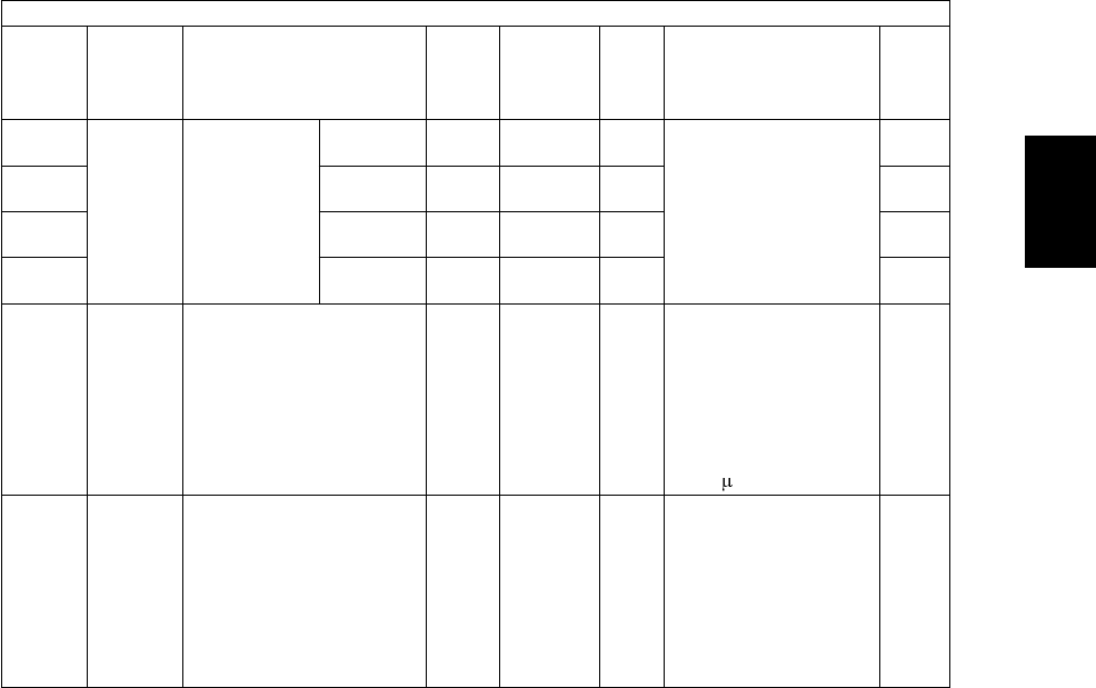
© June 2005 TOSHIBA TECe-STUDIO281c/351c/451c ERROR CODE AND SELF-DIAGNOSTIC MODE
2 - 85
2
1862-0Transfer1st transfer
roller bias
RMS value
display
YALL
(color)
138
<0-225>
MThe RMS value of the
1st transfer roller bias
at the time of printing is
displayed.
10
1862-1MALL
(color)
143
<0-225>
M10
1862-2CALL
(color)
154
<0-225>
M10
1862-3KALL
(color)
154
<0-225>
M10
1863Transfer1st transfer roller bias
resistance detection Cur-
rent offset adjustment
ALL5
<0-10>
MThe current offset
amount of the 1st trans-
fer roller bias resistance
detection is adjusted.
0: -10 1: -8 2: -6
3: -4 4: -2 5: 0
6: +2 7: +4 8: +6
9: +8 10: +10
[Unit: A]
1
1864Transfer1st transfer roller bias cor-
rection at low-speed color
printing
ALL
(color)
100
<0-100>
MThe 1st transfer roller
bias output after the
completion of transfer
of all colors (Y, M, C
and K) is corrected.
This setting is enabled
when "1" (6 sheets/
minute) is set at the
code 08-497.
1
Adjustment mode (05)
Code Classifi-
cation Items Func-
tion
Default
<Accept-
able
value>
RAMContents
Pro-
cedur
e
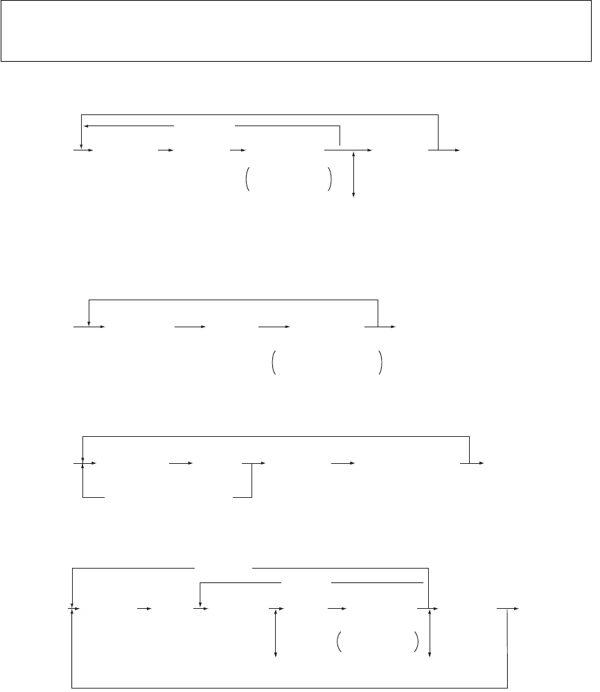
e-STUDIO281c/351c/451c ERROR CODE AND SELF-DIAGNOSTIC MODE© June 2005 TOSHIBA TEC
2 - 86
2.2.5Setting mode (08)
Procedure 1
*Press [FUNCTION CLEAR] to enter minus (-).
Procedure 2
Procedure 3
Procedure 4
*Press [FUNCTION CLEAR] to enter minus (-).
The items in the setting code list can be set or changed in this setting mode (08).
When the power should be turned OFF, be sure to shut down the equipment by pressing the
[ENERGY SAVER] button for a few seconds.
øͬ±®»- ª¿´«» ·² ÎßÓ÷
ÅðÃÅèÃ
ÅÐÑÉÛÎÃ
ÅÐÑÉÛÎà ÑÚÚñÑÒ
øÛ¨·¬÷
ÅÜ·¹·¬¿´µ»§Ã
øݱ¼»÷ ÅÍÌßÎÌà ÅÜ·¹·¬¿´µ»§Ã
ö
ÅÚËÒÝÌ×ÑÒ ÝÔÛßÎÃ
ÅÛÒÌÛÎÃ
±®
Å×ÒÌÛÎÎËÐÌÃ
Í»¬- ±®
½¸¿²¹»- ª¿´«»
ÅÝÔÛßÎÃ
øݱ®®»½¬- ª¿´«»÷
ÅÝßÒÝÛÔÃ
ÅðÃÅèÃ
ÅÐÑÉÛÎÃ
ÅÐÑÉÛÎÃÑÚÚñÑÒ
øÛ¨·¬÷
ÅÜ·¹·¬¿´µ»§Ã
øݱ¼»÷ ÅÍÌßÎÌÃ
ÅÛÒÌÛÎÃ
±®
Å×ÒÌÛÎÎËÐÌÃ
ß¼¶«-¬³»²¬ ª¿´«»
½¿²²±¬ ¾» ½¸¿²¹»¼
ÅðÃÅèÃ
ÅÐÑÉÛÎÃ
ÅÐÑÉÛÎà ÑÚÚñÑÒ
øÛ¨·¬÷
ÅÜ·¹·¬¿´µ»§Ã
øݱ¼»÷ ÅÍÌßÎÌÃ
ÅÝßÒÝÛÔà ±® ÅÝÔÛßÎÃ
øß«¬±³¿¬·½ -»¬¬·²¹÷
ÅÛÒÌÛÎÃ
±®
Å×ÒÌÛÎÎËÐÌÃ
øͬ±®»- ª¿´«» ·² ÎßÓ÷
ÅðÃÅèÃ
ÅÐÑÉÛÎÃ
ÅÐÑÉÛÎÃ
ÑÚÚñÑÒ
øÛ¨·¬÷
ÅÜ·¹·¬¿´µ»§Ã
øݱ¼»÷
ÅÜ·¹·¬¿´µ»§Ã
øÍ«¾ó½±¼»÷ ÅÜ·¹·¬¿´µ»§Ã
ö
ÅÚËÒÝÌ×ÑÒ ÝÔÛßÎÃ
Í»¬- ±®
½¸¿²¹»- ª¿´«»
ÅÍÌßÎÌÃÅÍÌßÎÌÃ
ÅÛÒÌÛÎÃ
±®
Å×ÒÌÛÎÎËÐÌÃ
øͬ±®»- ª¿´«»
·² ÎßÓ÷
ÅÝÔÛßÎÃ
øݱ®®»½¬- ª¿´«»÷
ÅÝÔÛßÎÃ
øݱ®®»½¬- ª¿´«»÷
ÅÍÌßÎÌÃ
ÅÝßÒÝÛÔÃ
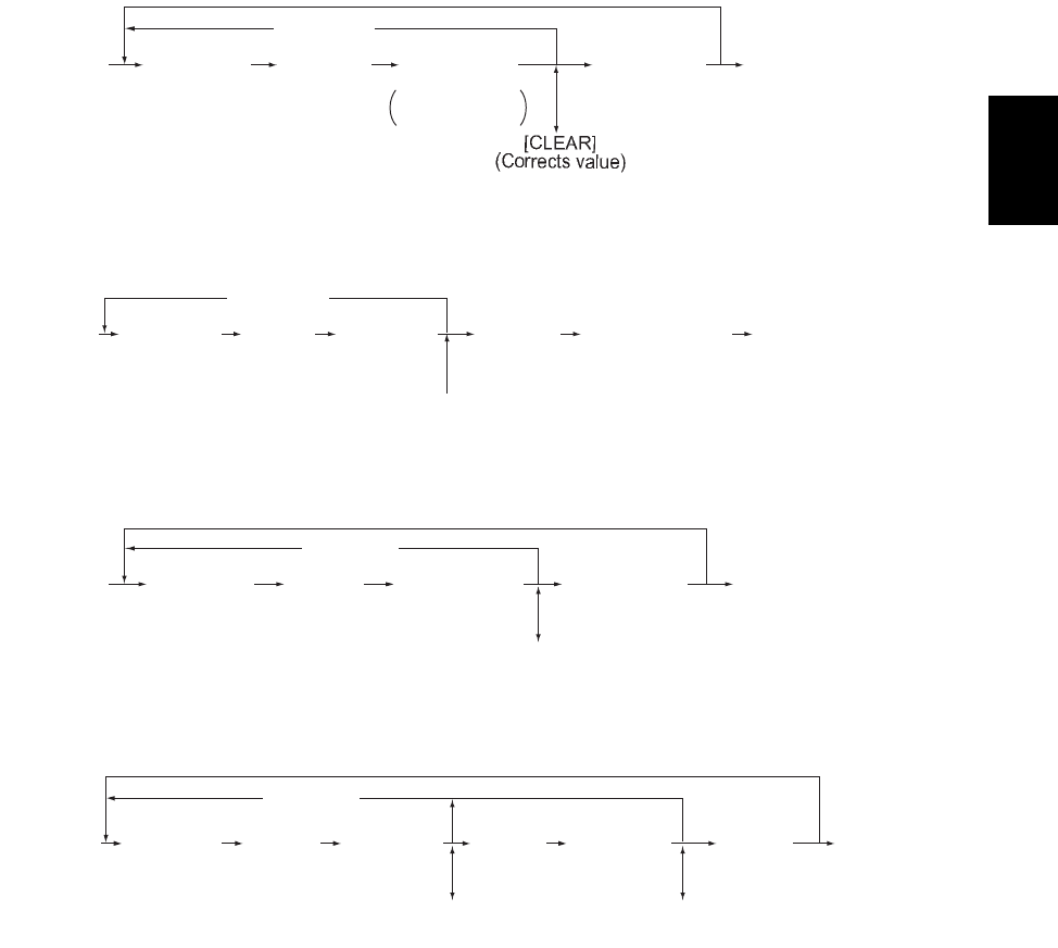
© June 2005 TOSHIBA TECe-STUDIO281c/351c/451c ERROR CODE AND SELF-DIAGNOSTIC MODE
2 - 87
2
Procedure 5
*Press [HELP] to enter "-".
Procedure 7
Procedure 9
Procedure 10
ÅðÃÅèÃ
ÅÐÑÉÛÎÃ
ÅÐÑÉÛÎà ÑÚÚñÑÒ
øÛ¨·¬÷
ÅÜ·¹·¬¿´µ»§Ã
øݱ¼»÷
ÅÜ·¹·¬¿´ µ»§Ã
öÅØÛÔÐÃ
ÅÍÌßÎÌÃ
ÅÝßÒÝÛÔÃ ÅÛÒÌÛÎÃ
±®
Å×ÒÌÛÎÎËÐÌÃ
øͬ±®»- ª¿´«» ·² ÎßÓ÷
Í»¬- ±®
½¸¿²¹»- ª¿´«»
ÅðÃÅèÃ
ÅÐÑÉÛÎà ÅÐÑÉÛÎà ÑÚÚñÑÒ
øÛ¨·¬÷
ÅÜ·¹·¬¿´µ»§Ã
øݱ¼»÷
ÅÜ·¹·¬¿´µ»§Ã
øÍ»¬¬·²¹÷
ÅÝÔÛßÎÃ
øݱ®®»½¬- ª¿´«»÷
ÅÍÌßÎÌà øØÜÜ º±®³¿¬¬·²¹÷
ÅÝßÒÝÛÔÃ ÅÛÒÌÛÎÃ
±®
Å×ÒÌÛÎÎËÐÌÃ
øͬ±®»- ª¿´«» ·² ÎßÓ÷
ÅðÃÅèÃ
ÅÐÑÉÛÎÃ
ÅÐÑÉÛÎà ÑÚÚñÑÒ
øÛ¨·¬÷
ÅÜ·¹·¬¿´µ»§Ã
øݱ¼»÷ ÅÍ»´»½¬ ¾«¬¬±²Ã
ÅÍÌßÎÌÃ
ÅÝßÒÝÛÔÃ ÅÛÒÌÛÎÃ
±®
Å×ÒÌÛÎÎËÐÌÃ
ÅÝÔÛßÎÃ
øݱ®®»½¬- ª¿´«»÷
øͬ±®»- ª¿´«» ·² ÎßÓ÷
ÅðÃÅèÃ
ÅÐÑÉÛÎÃ
ÅÐÑÉÛÎÃ
ÑÚÚñÑÒ
øÛ¨·¬÷
ÅÜ·¹·¬¿´µ»§Ã
øݱ¼»÷
ÅÜ·¹·¬¿´µ»§Ã
øï-¬ -»¬¬·²¹÷
ÅÜ·¹·¬¿´µ»§Ã
øî²¼ -»¬¬·²¹÷
ÅÍÌßÎÌÃÅÍÌßÎÌÃ
ÅÝßÒÝÛÔÃ
ÅÛÒÌÛÎÃ
±®
Å×ÒÌÛÎÎËÐÌÃ
ÅÝÔÛßÎÃ
øݱ®®»½¬- ª¿´«»÷
ÅÝÔÛßÎÃ
øݱ®®»½¬- ª¿´«»÷
øͬ±®»- ª¿´«» ·² ÎßÓ÷
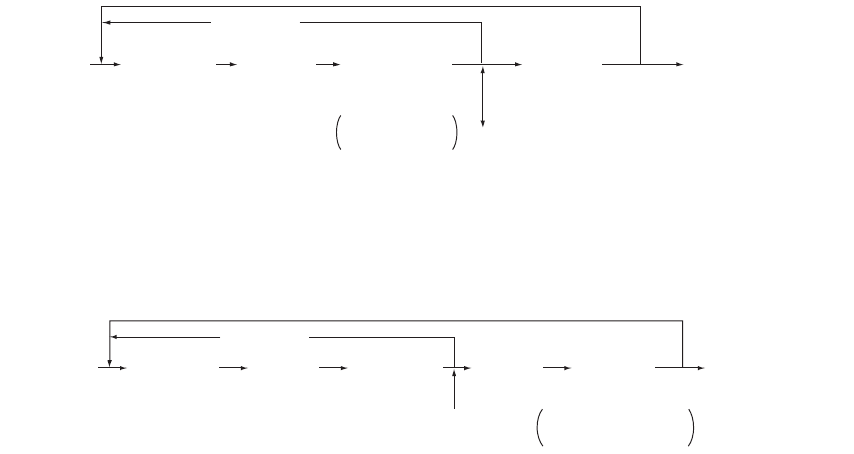
e-STUDIO281c/351c/451c ERROR CODE AND SELF-DIAGNOSTIC MODE© June 2005 TOSHIBA TEC
2 - 88
Procedure 11 and 12
*1Press [MONITOR/PAUSE] to enter "-", when entering telephone number.
*2The data are stored in SYS-RAM in procedure 11 and stored in NIC-RAM
in procedure 12.
Procedure 14
ÅðÃÅèÃ
ÅÐÑÉÛÎÃ
ÅÐÑÉÛÎà ÑÚÚñÑÒ
øÛ¨·¬÷
ÅÜ·¹·¬¿´ µ»§Ã
øݱ¼»÷
ÅÜ·¹·¬¿´µ»§Ã
±®
Åͱº¬©¿®» µ»§¾±¿®¼Ã
ÅÍÌßÎÌÃ
ÅÝßÒÝÛÔÃ
ÅÝÔÛßÎÃ
øݱ®®»½¬- ª¿´«»÷
öîøͬ±®»- ª¿´«» ·² ÎßÓ÷
öï
ÅÓÑÒ×ÌÑÎñÐßËÍÛÃ
Í»¬- ±®
½¸¿²¹»- ª¿´«»
ÅÛÒÌÛÎÃ
ÅðÃÅèÃ
ÅÐÑÉÛÎÃ
ÅÐÑÉÛÎÃ
ÑÚÚñÑÒ
øÛ¨·¬÷
ÅÜ·¹·¬¿´µ»§Ã
øݱ¼»÷
ÅÜ·¹·¬¿´µ»§Ã
øÍ«¾ó½±¼»÷
ÅÝÔÛßÎÃ
øݱ®®»½¬- ª¿´«»÷
ÅÍÌßÎÌÃÅÍÌßÎÌÃ
ÅÝßÒÝÛÔÃ ÅÛÒÌÛÎÃ
±®
Å×ÒÌÛÎÎËÐÌÃ
ß¼¶«-¬³»²¬ ª¿´«»
½¿²²±¬ ¾» ½¸¿²¹»¼

© June 2005 TOSHIBA TECe-STUDIO281c/351c/451c ERROR CODE AND SELF-DIAGNOSTIC MODE
2 - 89
2
Notes:
1.The digit after the hyphen in Code! of the following table is a sub code.
2.In RAM!, the NVRAM of the board in which the data of each code is stored is indicated. M!
stands for the LGC board, SYS!, NIC! and UTY! stands for the SYS board.
Setting mode (08)
Code Classifi-
cation Items Func-
tion
Default
<Accept-
able
value>
RAMContents
Pro-
cedur
e
200GeneralDate and time settingALL-
<13 dig-
its>
-Year/month/date/day/
hour/minute/second
Example:
03 07 0 13 13 27 48
Day! - 0! is for Sun-
day!. Proceeds Monday
through Saturday from
1! to 6!.
5
201GeneralDestination selectionALLEUR: 0
UC: 1
JPN: 2
<0-3>
M0: EUR
1: UC
2: JPN
3: Other
1
202User
interface
Counter installed externallyALL0
<0-4>
M0: No external counter
1: Coin controller
2: Copy key card
3: Key copy counter
4: Key card for OEM1
1
203GeneralLine adjustment modeALL0
<0-1>
M0: For factory ship-
ment
1: For line
*Field: 0! must be
selected
1
204User
interface
Auto-clear timer settingALL3
<0-10>
SYSTimer to return the
equipment to the
default settings when
the [START] button is
not pressed after the
function and the mode
are set
0: Not cleared
1 to 10:
Set number x 15
sec.
1
205User
interface
Auto power save mode
timer setting
ALL11
<0, 6-15>
SYSTimer to automatically
switch to the energy
saving mode when the
equipment has not
been used
0: Invalid 6: 3min.
7: 4min. 8: 5min.
9: 7min.
10:10min.
11: 15min.
12: 20min.
13: 30min.
14: 45min.
15: 60min.
1

e-STUDIO281c/351c/451c ERROR CODE AND SELF-DIAGNOSTIC MODE© June 2005 TOSHIBA TEC
2 - 90
206User
interface
Auto Shut Off Mode timer
setting (Sleep Mode)
ALLRefer to
content
<0-20>
SYSTimer to enter the Sleep
Mode automatically
when the equipment
has not been used
0: 3min. 1: 5min.
2: 10min. 3: 15min.
4: 20min. 5: 25min.
6: 30min. 7: 40min.
8: 50min. 9: 60min.
10: 70min.
11: 80min.
12: 90min.
13: 100min.
14: 110min.
15: 120min.
16: 150min.
17:180min.
18: 210min.
19:240min.
20: Not used
<Default value>
e-STUDIO281c: 9
e-STUDIO351c: 9
e-STUDIO451c: 12
1
207User
interface
Highlighting display on
LCD
ALL0
<0-1>
SYS0:Black letter on white
background
1:White letter on black
background
1
209User
interface
Default setting of filing for-
mat when E-mailing (com-
mon in all color modes)
ALL
(color)
1
<0-4>
SYS0:TIFF (Multi)
1:PDF (Multi)
2:Not used
3:TIFF (Single)
4:PDF (Single)
1
210Paper
feeding
Paper size (A6-R)
feeding/widthwise direction
PRT148/105
<148-
432/105-
297>
-10
218User
interface
Default setting of filing for-
mat when storing files
(at color/ACS modes)
SCN
(color)
1
<0-4>
SYS0: TIFF (Multi)
1: PDF (Multi) 2: JPG
3: TIFF (Single)
4:PDF (Single)
1
219User
interface
Default setting of filing for-
mat when storing files
(at black mode)
ALL
(black)
0
<0-4>
SYS0: TIFF (Multi)
1:PDF (Multi) 2: JPG
3: TIFF (Single)
4:PDF (Single)
1
220User
interface
Language displayed at
power-ON
ALLEUR: 0
UC: 0
JPN: 5
<0-6>
SYS0: Language 1
1: Language 2
2: Language 3
3: Language 4
4: Language 5
5: Language 6
6: Language 7
1
221User
interface
Language selection in UI
data at Web power ON
ALLEUR: 0
UC: 0
JPN: 5
<0-6>
SYS0:Language 1
1: Language 2
2: Language 3
3: Language 4
4: Language 5
5: Language 6
6: Language 7
1
Setting mode (08)
Code Classifi-
cation Items Func-
tion
Default
<Accept-
able
value>
RAMContents
Pro-
cedur
e
05/11

© June 2005 TOSHIBA TECe-STUDIO281c/351c/451c ERROR CODE AND SELF-DIAGNOSTIC MODE
2 - 91
2
223Mainte-
nance
Switching of output pages/
driving counts at PM
ALL0
<0-1>
MSelects the reference to
notify the PM timing.
(The message is dis-
played on the LCD
screen.)
0: PM counter (The
number of output
pages is set at 08-
251.)
1: PM time counter
(The timing is set at
08-375.)
1
224Paper
feeding
Paper size for bypass feedPPCUNDEFSYSPress the button on the
LCD to select the size.
9
225Paper
feeding
Paper size for upper
drawer
ALLEUR: A4
UC: LT
JPN: A4
MPress the button on the
LCD to select the size.
9
226Paper
feeding
Paper size for lower
drawer
ALLEUR: A3
UC: LD
JPN: A3
MPress the button on the
LCD to select the size.
9
227Paper
feeding
Paper size for PFP upper
drawer
ALLEUR:
A4-R
UC:
LT-R
JPN:
A4-R
MPress the button on the
LCD to select the size.
9
228Paper
feeding
Paper size for PFP lower
drawer
ALLEUR: A4
UC: LG
JPN: B4
MPress the button on the
LCD to select the size.
9
229Paper
feeding
Paper size (A3)
feeding/widthwise direction
ALL420/297
<182-
432/140-
297>
M10
230Paper
feeding
Paper size (A4-R)
feeding/widthwise direction
ALL297/210
<182-
432/140-
297>
M10
231Paper
feeding
Paper size (A5-R)
feeding/widthwise direction
ALL210/148
<182-
432/140-
297>
M10
232Paper
feeding
Paper size (B4)
feeding/widthwise direction
ALL364/257
<182-
432/140-
297>
M10
233Paper
feeding
Paper size (B5-R)
feeding/widthwise direction
ALL257/182
<182-
432/140-
297>
M10
234Paper
feeding
Paper size (LT-R)
feeding/widthwise direction
ALL279/216
<182-
432/140-
297>
M10
235Paper
feeding
Paper size (LD)
feeding/widthwise direction
ALL432/279
<182-
432/140-
297>
M10
Setting mode (08)
Code Classifi-
cation Items Func-
tion
Default
<Accept-
able
value>
RAMContents
Pro-
cedur
e

e-STUDIO281c/351c/451c ERROR CODE AND SELF-DIAGNOSTIC MODE© June 2005 TOSHIBA TEC
2 - 92
236Paper
feeding
Paper size (LG)
feeding/widthwise direction
ALL356/216
<182-
432/140-
297>
M10
237Paper
feeding
Paper size (ST-R)
feeding/widthwise direction
ALL216/140
<182-
432/140-
297>
M10
238Paper
feeding
Paper size (COMPUTER)
feeding/widthwise direction
ALL356/257
<182-
432/140-
297>
M10
239Paper
feeding
Paper size (FOLIO)
feeding/widthwise direction
ALL330/210
<182-
432/140-
297>
M10
240Paper
feeding
Paper size (13!LG)
feeding/widthwise direction
ALL330/216
<182-
432/140-
297>
M10
241Paper
feeding
Paper size (8.5!X8.5!)
feeding/widthwise direction
ALL216/216
<182-
432/140-
297>
M10
242Paper
feeding
Paper size (Non-standard)
feeding/widthwise direction
ALL432/279
<148-
432/105-
297>
SYS10
243Paper
feeding
Memory 1
Paper size (bypass feed-
ing/non-standard type)
feeding/widthwise direction
ALL148/100
<148-
432/100-
297>
SYSRegisters the paper
size of bypass feed
(non-standard type) into
[MEMORY 1].
10
244Paper
feeding
Paper size (8K)
feeding/widthwise direction
ALL390/270
<182-
432/140-
297>
M10
245Paper
feeding
Paper size (16K-R)
feeding/widthwise direction
ALL270/195
<182-
432/140-
297>
M10
246Paper
feeding
Paper size (A3-wide)
feeding/widthwise direction
ALL457/305
<182-
457/140-
305>
M10
247Paper
feeding
Memory 2
Paper size (bypass feed-
ing/non-standard type)
feeding/widthwise direction
ALL148/100
<148-
432/100-
297>
SYSRegisters the paper
size of bypass feed
(non-standard type) into
[MEMORY 2].
10
248Paper
feeding
Memory 3
Paper size (bypass feed-
ing/non-standard type)
feeding/widthwise direction
ALL148/100
<148-
432/100-
297>
SYSRegisters the paper
size of bypass feed
(non-standard type) into
[MEMORY 3].
10
249Paper
feeding
Memory 4
Paper size (bypass feed-
ing/non-standard type)
feeding/widthwise direction
ALL148/100
<148-
432/100-
297>
SYSRegisters the paper
size of bypass feed
(non-standard type) into
[MEMORY 4].
10
Setting mode (08)
Code Classifi-
cation Items Func-
tion
Default
<Accept-
able
value>
RAMContents
Pro-
cedur
e

© June 2005 TOSHIBA TECe-STUDIO281c/351c/451c ERROR CODE AND SELF-DIAGNOSTIC MODE
2 - 93
2
250Mainte-
nance
Service technician tele-
phone number
ALL0
<32 dig-
its>
SYSA telephone number
can be entered up to 32
digits. Use the [MONI-
TOR/PAUSE] button to
enter a hyphen(-).
11
251Mainte-
nance
Setting value of PM
counter
ALLRefer to
content
<8 digits>
M<Default>
e-STUDIO281c
UC, EUR:
100,000 JPN: 0
e-STUDIO351c
UC, EUR:
120,000 JPN: 0
e-STUDIO451c
UC, EUR:
150,000 JPN: 0
1
252Mainte-
nance
Current value of PM
counter Display/0 clearing
ALL0
<8 digits>
MCounts up when the
registration sensor is
ON.
1
253Mainte-
nance
Error history displayALL-SYSDisplays the latest 20
errors data
2
254Paper
feeding
LT A4/LD A3PRT0
<0-1>
SYSSets whether the data is
printed on the different
but similar size paper or
not when the paper of
corresponding size is
not available.
0: Valid (The data is
printed on A4/A3
when LT/LD is
selected or vice
versa.)
1: Invalid (The mes-
sage to use the
selected paper size
is displayed.)
1
255Paper
feeding
PFP/LCF installationALL0
<0-4>
M0: Automatic
1: PFP single-drawer
type installed
2: PFP dual-drawer
type installed
3: LCF installed
4: Not installed
1
256Paper
feeding
Paper size setting /LCFALLEUR: A4
UC: LT
JPN: A4
MPress the icon on the
LCD to select the size.
9
257CounterCounter copyALL-
<1-2>
-1: Electrical counter Æ
Backup counter
(NVRAM SRAM)
2: Backup counter Æ
Electrical counter
(SRAM NVRAM)
(P. 2-207)
-
Setting mode (08)
Code Classifi-
cation Items Func-
tion
Default
<Accept-
able
value>
RAMContents
Pro-
cedur
e
06/08

e-STUDIO281c/351c/451c ERROR CODE AND SELF-DIAGNOSTIC MODE© June 2005 TOSHIBA TEC
2 - 94
258Mainte-
nance
FSMS acceptanceALL1
<0-2>
SYSSets whether the FSMS
connection is accepted
or not.
0: Prohibited
1: Accepted (serial
connection only)
2: Accepted (both
serial and USB con-
nections)
1
259NetworkStorage period at trail and
private
PRT14
<0-35>
SYS0:No limits
1 to 30: 1 to 30 days
31:1 hour
32:2 hours
33:4 hours
34:8 hours
35:12 hours
1
260NetworkWeb data retention periodALL10
<3 digits>
SYSWhen a certain period
of time has passed
without operation after
accessing TopAccess,
the data being regis-
tered is automatically
reset. This period is set
at this code.
(Unit: Minute)
1
263User
interface
Administrator's password
(Maximum 10 digits)
ALL123456
<10 dig-
its>
-The password can be
entered in alphabets
and figures (A-Z, a-z
and 0-9) within 10 dig-
its.
11
264NetworkFile retention periodALL30
<0-999>
SYS0: No limits
1 to 999: 1 to 999 days
1
265NetworkMaximum data capacity at
E-mailing
ALL30
<2-30>
SYS2 to 30 M bytes1
266NetworkMaximum data capacity at
Internet FAX
ALL30
<2-30>
SYS2 to 30 M bytes1
267Elec-
tronic
filing
Full guarantee of docu-
ments in Electronic Filing
when HDD is full
ALL1
<0-1>
SYSSets the file retention
level when editing the
files in the Electronic
Filing (at CutDoc/Save-
Doc command execu-
tion).
0: Not full retained
1: Fully retained
$Retains the source
file until CutDoc/
SaveDoc command
is completed.
*The file is not
deleted even if the
HDD has become
full during the exe-
cution of command
when 1! is set.
1
Setting mode (08)
Code Classifi-
cation Items Func-
tion
Default
<Accept-
able
value>
RAMContents
Pro-
cedur
e
06/08

© June 2005 TOSHIBA TECe-STUDIO281c/351c/451c ERROR CODE AND SELF-DIAGNOSTIC MODE
2 - 95
2
268User
interface
Binarizing level selection
(When judging as black in
the ACS Mode)
ALL3
<1-5>
SYS0: Step -2
1: Step -1
2: Step 0 (center)
3: Step 1
4: Step 2
*The binarizing level
of each step is set
at 08-609.
1
270Elec-
tronic
filing
Default setting of user box
retention period
ALL0
<0-999>
SYSSets the data retention
period when creating a
user box.
0: Not deleted
1 to 999:
Retention period
(Unit: Day)
1
271GeneralWarning notification of the
File Share and e-Filling
partitions are filled
ALL90
<0-100>
SYSSets the percentage of
HDD partition filled
when warning notifica-
tion is sent.
0 to 100: 0 to 100%
*Related code
08-288
1
272ScanningNotification setting of E-
mail saving time limit
ALL3
<0-99>
SYSSets the days left the
notification of E-mail
saving time limit
appears
0 to 99: 0 to 99 days
1
273ScanningDefault setting of partial
size when transmitting E-
mail
ALL0
<0-6>
SYSSets the default value
for the partial size of E-
mail to be transmitted
when creating a tem-
plate.
0: Not divided
1: 64 2:128
3: 2564:512
5: 1024
6: 2048 (Unit: KB)
1
274FAXDefault setting of page by
page when transmitting
Internet FAX
ALL0
<0-4>
SYSSets the default value
for the page by page of
Internet FAX to be
transmitted when creat-
ing a template.
0: Not divided
1: 256
2: 512
3: 1024
4: 2048 (Unit: KB)
1
Setting mode (08)
Code Classifi-
cation Items Func-
tion
Default
<Accept-
able
value>
RAMContents
Pro-
cedur
e
05/11

e-STUDIO281c/351c/451c ERROR CODE AND SELF-DIAGNOSTIC MODE© June 2005 TOSHIBA TEC
2 - 96
276User
interface
Default setting of density
adjustment (Black)
SCN
(black)
0
<0-11>
SYS0: Automatic density
1: Step -5
2: Step -4
3: Step -3
4: Step -2
5: Step -1
6: Step 0 (center)
7: Step +1
8: Step +2
9: Step +3
10: Step +4
11: Step +5
(1 to 11: Manual den-
sity)
1
277User
interface
Default setting of back-
ground adjustment
(Full Color)
SCN
(color)
3
<1-5>
SYS1: Step -2
2: Step -1
3: Step 0 (center)
4: Step +1
5: Step +2
1
278User
interface
Default setting of color
mode
SCN0
<0-4>
SYS0: Black
1: Gray Scale
2: Unused
3: Full Color
4: Auto Color
1
279User
interface
Default setting of resolution
(Full Color)
SCN
(color)
2
<0-3>
SYS0: 100 dpi
1: 150 dpi
2: 200 dpi
3: 300dpi
1
280User
interface
Default setting of resolution
(Gray Scale)
SCN
(black)
2
<0-4>
SYS0: 100 dpi
1: 150 dpi
2: 200 dpi
3: 300dpi
4: 400 dpi
1
281User
interface
Default setting of resolution
(Black)
SCN
(black)
1
<0-4>
SYS0: 150 dpi
1: 200 dpi
2: 300 dpi
3: 400dpi
4: 600 dpi
1
282User
interface
Default setting of original
mode (Full Color)
SCN
(color)
0
<0-2>
SYS0: Text
1: Photo
2: Printed Image
1
283User
interface
Default setting of original
mode (Black)
SCN
(black)
0
<0-2>
SYS0: Text
1: Text/Photo
2: Photo
1
284User
interface
Default setting of scanning
mode
SCN0
<0-2>
SYS0: Single
1: Book
2: Tablet
1
285User
interface
Default setting of rotation
mode
SCN0
<0-3>
SYS0: 0 degree
1: 90 degrees
2: 180 degrees
3: 270 degrees
1
Setting mode (08)
Code Classifi-
cation Items Func-
tion
Default
<Accept-
able
value>
RAMContents
Pro-
cedur
e

© June 2005 TOSHIBA TECe-STUDIO281c/351c/451c ERROR CODE AND SELF-DIAGNOSTIC MODE
2 - 97
2
286User
interface
Default setting of original
paper size
ALL0
<0-22>
SYS0: Automatic
1: A3 2: A4
3: LD 4: LT
5: A4-R6: A5-R
7: LT-R 8: LG
9: B4 10: B5
11: ST-R12: COMP
13: B5-R 14: FOLIO
15: 13"LG 16: 8.5"x 8.5"
18: A6-R
19: Size mixed
20: 8K 21: 16K
22: 16K-R
1
288GeneralSearching interval of delet-
ing expired files and check-
ing capacity of HDD
partitions
ALL12
<1-24>
SYSSets the search inter-
val of deleting expired
files and checking
capacity of HDD parti-
tions.
(Unit: Hour)
*Related code
08-271
1
289User
interface
Default setting of back-
ground adjustment
(Gray Scale)
ALL3
<1-5>
SYS1: Step -2
2: Step -1
3: Step 0 (center)
4: Step +1
5: Step +2
1
290NetworkRaw printing job (Duplex)PRT1
<0-1>
SYS0:Valid
1: Invalid
1
291NetworkRaw printing job
(Paper size)
PRTEUR: 6
UC: 2
JPN: 6
<0 -13>
SYS0: LD 1: LG
2: LT3: COMP
4: ST 5: A3
6: A4 7: A5
8: A6 9: B4
10: B5 11: FOLIO
12: 13 "LG
13: 8.5" x 8.5"
1
292NetworkRaw printing job
(Paper type)
PRT0
<0-5>
SYS0: Plain paper
1: Thick paper 1
2: Thick paper 2
3: Thick paper 3
4: OHP film
5:Tab paper
1
293NetworkRaw printing job
(Paper direction)
PRT0
<0-1>
SYS0: Portrait
1: Landscape
1
294NetworkRaw printing job (Staple)PRT1
<0-1>
SYS0: Valid
1: Invalid
1
295NetworkRaw printing job (Exit tray)PRT0
<0-6>
SYS0:Inner tray
1: Finisher tray 1
2: Finisher tray 2
3:Unused
4: Unused
5: Unused
6: Unused
1
Setting mode (08)
Code Classifi-
cation Items Func-
tion
Default
<Accept-
able
value>
RAMContents
Pro-
cedur
e
05/11
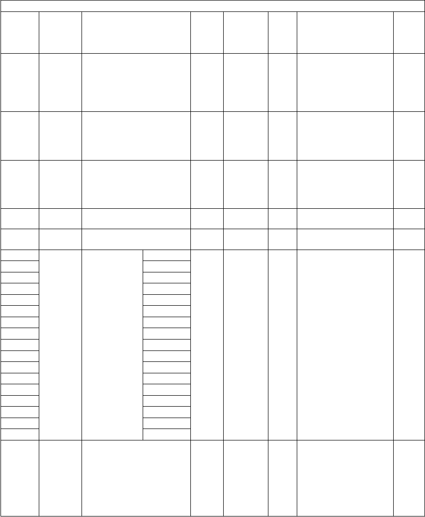
e-STUDIO281c/351c/451c ERROR CODE AND SELF-DIAGNOSTIC MODE© June 2005 TOSHIBA TEC
2 - 98
296NetworkRaw printing job
(Number of form lines)
PRT1200
<500-
12800>
SYSSets the number of
form lines from 5 to
128. (A hundredfold of
the number of form
lines is defined as the
setting value.)
1
297NetworkRaw printing job
(PCL font pitch)
PRT1000
<44-
9999>
SYSSets the font pitch from
0.44 to 99.99. (A hun-
dredfold of the font
pitch is defined as the
setting value.)
1
298NetworkRaw printing job
(PCL font size)
PRT1200
<400-
99975>
SYSSets the font size from
4 to 999.75.
(A hundredfold of the
font size is defined as
the setting value.)
1
299NetworkRaw printing job
(PCL font number)
PRT0
<0-79>
SYSSets the PCL font num-
ber.
1
300User
interface
Maximum number of copy
volume (MAX9)
PPC0
<0-2>
SYS0: 999 1: 99 2: 91
301-0CounterNumber of
output pages
at Full Color
Mode in
Copier Func-
tion
A3PPC
(color)
0
<8 digits>
SYSCounts the output
pages at the Full Color
Mode in the Copier
Function for each paper
size according to the
setting for the count
setting of largesized
paper (08-352) and the
definition setting of
large-sized paper (08-
353).
4
301-1A4
301-2A5
301-3A6
301-4B4
301-5B5
301-6FOLIO
301-7LD
301-8LG
301-9LT
301-10ST
301-11COMP
301-1213!LG
301-138.5! x 8.5!
301-1416K
301-158K
301-16Others
302User
interface
Original counter displayPPCEUR: 2
UC: 0
JPN: 0
<0, 2, 4>
SYSSets whether the origi-
nal counter is dis-
played or not.
0: Not displayed
2: Displayed
4:Displayed (Double-
sized original is
counted as 2.)
1
Setting mode (08)
Code Classifi-
cation Items Func-
tion
Default
<Accept-
able
value>
RAMContents
Pro-
cedur
e
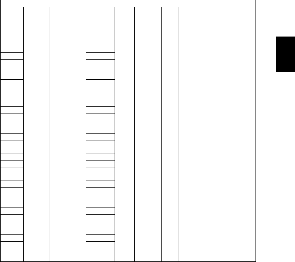
© June 2005 TOSHIBA TECe-STUDIO281c/351c/451c ERROR CODE AND SELF-DIAGNOSTIC MODE
2 - 99
2
303-0CounterNumber of
output pages
at Full Color
Mode in
Printer Func-
tion
A3PRT
(color)
0
<8 digits>
SYSCounts the output
pages at the Full Color
Mode in the Printer
Function for each paper
size according to the
setting for the count
setting of largesized
paper (08-352) and the
definition setting of
large-sized paper (08-
353).
4
303-1A4
303-2A5
303-3A6
303-4B4
303-5B5
303-6FOLIO
303-7LD
303-8LG
303-9LT
303-10ST
303-11COMP
303-1213!LG
303-138.5! x 8.5!
303-1416K
303-158K
303-16Others
304-0CounterNumber of
output pages
at Twin Color
Mode in
Copier Func-
tion
A3PPC
(color)
0
<8 digits>
SYSCounts the output
pages at the Twin Color
Mode in the Copier
Function for each paper
size according to the
setting for the count
setting of largesized
paper (08-352) and the
definition setting of
large-sized paper (08-
353).
4
304-1A4
304-2A5
304-3A6
304-4B4
304-5B5
304-6FOLIO
304-7LD
304-8LG
304-9LT
304-10ST
304-11COMP
304-1213!LG
304-138.5! x 8.5!
304-1416K
304-158K
304-16Others
Setting mode (08)
Code Classifi-
cation Items Func-
tion
Default
<Accept-
able
value>
RAMContents
Pro-
cedur
e

e-STUDIO281c/351c/451c ERROR CODE AND SELF-DIAGNOSTIC MODE© June 2005 TOSHIBA TEC
2 - 100
305-0CounterNumber of
output pages
at Black Mode
in Copier
Function
A3PPC
(black)
0
<8 digits>
SYSCounts the output
pages at the Black
Mode in the Copier
Function for each paper
size according to the
setting for the count
setting of large-sized
paper (08-352) and the
definition setting of
large-sized paper (08-
353).
4
305-1A4
305-2A5
305-3A6
305-4B4
305-5B5
305-6FOLIO
305-7LD
305-8LG
305-9LT
305-10ST
305-11COMP
305-1213!LG
305-138.5! x 8.5!
305-1416K
305-158K
305-16Others
306-0CounterNumber of
output pages
at Black Mode
in Printer
Function
A3PRT
(black)
0
<8 digits>
SYSCounts the output
pages at the Black
Mode in the Printer
Function for each paper
size according to the
setting for the count
setting of large-sized
paper (08-352) and the
definition setting of
large-sized paper (08-
353).
4
306-1A4
306-2A5
306-3A6
306-4B4
306-5B5
306-6FOLIO
306-7LD
306-8LG
306-9LT
306-10ST
306-11COMP
306-1213!LG
306-138.5! x 8.5!
306-1416K
306-158K
306-16Others
Setting mode (08)
Code Classifi-
cation Items Func-
tion
Default
<Accept-
able
value>
RAMContents
Pro-
cedur
e

© June 2005 TOSHIBA TECe-STUDIO281c/351c/451c ERROR CODE AND SELF-DIAGNOSTIC MODE
2 - 101
2
307-0CounterNumber of
output pages
at List Print
Mode
A3PRT
(black)
0
<8 digits>
SYSCounts the output
pages at the List Print
Mode for each paper
size according to the
setting for the count
setting of large-sized
paper (08-352) and the
definition setting of
largesized paper (08-
353).
4
307-1A4
307-2A5
307-3A6
307-4B4
307-5B5
307-6FOLIO
307-7LD
307-8LG
307-9LT
307-10ST
307-11COMP
307-1213!LG
307-138.5! x 8.5!
307-1416K
307-158K
307-16Others
308-0CounterNumber of
output pages
in FAX Func-
tion
A3FAX0
<8 digits>
SYSCounts the output
pages in the FAX Func-
tion for each paper size
according to the setting
for the count setting of
large-sized paper (08-
352) and the definition
setting of large-sized
paper (08-353).
4
308-1A4
308-2A5
308-3A6
308-4B4
308-5B5
308-6FOLIO
308-7LD
308-8LG
308-9LT
308-10ST
308-11COMP
308-1213!LG
308-138.5! x 8.5!
308-1416K
308-158K
308-16Others
Setting mode (08)
Code Classifi-
cation Items Func-
tion
Default
<Accept-
able
value>
RAMContents
Pro-
cedur
e

e-STUDIO281c/351c/451c ERROR CODE AND SELF-DIAGNOSTIC MODE© June 2005 TOSHIBA TEC
2 - 102
309-0CounterNumber of
scanning
pages at Full
Color Mode in
Copier Func-
tion
A3PPC
(color)
0
<8 digits>
SYSCounts the scanning
pages at the Full Color
Mode in the Copier
Function for each paper
size according to the
setting for the count
setting of large-sized
paper (08-352) and the
definition setting of
large-sized paper (08-
353).
4
309-1A4
309-2A5
309-3A6
309-4B4
309-5B5
309-6FOLIO
309-7LD
309-8LG
309-9LT
309-10ST
309-11COMP
309-1213!LG
309-138.5! x 8.5!
309-1416K
309-158K
309-16Others
310-0CounterNumber of
scanning
pages at Full
Color Mode in
Scanning
Function
A3SCN
(color)
0
<8 digits>
SYSCounts the scanning
pages at the Full Color
Mode in the Scanning
Function for each paper
size according to the
setting for the count
setting of large-sized
paper (08-352) and the
definition setting of
large-sized paper (08-
353).
4
310-1A4
310-2A5
310-3A6
310-4B4
310-5B5
310-6FOLIO
310-7LD
310-8LG
310-9LT
310-10ST
310-11COMP
310-1213!LG
310-138.5! x 8.5!
310-1416K
310-158K
310-16Others
Setting mode (08)
Code Classifi-
cation Items Func-
tion
Default
<Accept-
able
value>
RAMContents
Pro-
cedur
e

© June 2005 TOSHIBA TECe-STUDIO281c/351c/451c ERROR CODE AND SELF-DIAGNOSTIC MODE
2 - 103
2
311-0CounterNumber of
scanning
pages at Twin
Color Mode in
Copier Func-
tion
A3PPC
(color)
0
<8 digits>
SYSCounts the scanning
pages at the Twin Color
Mode in the Copier
Function for each paper
size according to the
setting for the count
setting of large-sized
paper (08-352) and the
definition setting of
large-sized paper (08-
353).
4
311-1A4
311-2A5
311-3A6
311-4B4
311-5B5
311-6FOLIO
311-7LD
311-8LG
311-9LT
311-10ST
311-11COMP
311-1213!LG
311-138.5! x 8.5!
311-1416K
311-158K
311-16Others
312-0CounterNumber of
scanning
pages at
Black Mode in
Copier Func-
tion
A3PPC
(black)
0
<8 digits>
SYSCounts the scanning
pages at the Black
Mode in the Copier
Function for each paper
size according to the
setting for the count
setting of largesized
paper (08-352) and the
definition setting of
large-sized paper (08-
353).
4
312-1A4
312-2A5
312-3A6
312-4B4
312-5B5
312-6FOLIO
312-7LD
312-8LG
312-9LT
312-10ST
312-11COMP
312-1213!LG
312-138.5! x 8.5!
312-1416K
312-158K
312-16Others
Setting mode (08)
Code Classifi-
cation Items Func-
tion
Default
<Accept-
able
value>
RAMContents
Pro-
cedur
e
e-STUDIO281c/351c/451c ERROR CODE AND SELF-DIAGNOSTIC MODE© June 2005 TOSHIBA TEC
2 - 104
313-0CounterNumber of
scanning
pages in
Scanning
Function
A3SCN
(black)
0
<8 digits>
SYSCounts the scanning
pages at the Black
Mode in the Scanning
Function for each paper
size according to the
setting for the count
setting of largesized
paper (08-352) and the
definition setting of
large-sized paper (08-
353).
4
313-1A4
313-2A5
313-3A6
313-4B4
313-5B5
313-6FOLIO
313-7LD
313-8LG
313-9LT
313-10ST
313-11COMP
313-1213!LG
313-138.5! x 8.5!
313-1416K
313-158K
313-16Others
314-0CounterNumber of
scanning
pages in FAX
Function
A3FAX0
<8 digits>
SYSCounts the scanning
pages in the FAX Func-
tion for each paper size
according to the setting
for the count setting of
large-sized paper (08-
352) and the definition
setting of largesized
paper (08-353).
4
314-1A4
314-2A5
314-3A6
314-4B4
314-5B5
314-6FOLIO
314-7LD
314-8LG
314-9LT
314-10ST
314-11COMP
314-1213!LG
314-138.5! x 8.5!
314-1416K
314-158K
314-16Others
Setting mode (08)
Code Classifi-
cation Items Func-
tion
Default
<Accept-
able
value>
RAMContents
Pro-
cedur
e

© June 2005 TOSHIBA TECe-STUDIO281c/351c/451c ERROR CODE AND SELF-DIAGNOSTIC MODE
2 - 105
2
315-0CounterNumber of
transmitted
pages in FAX
Function
A3FAX0
<8 digits>
SYSCounts the transmitted
pages in the FAX Func-
tion for each paper size
according to the setting
for the count setting of
large-sized paper (08-
352) and the definition
setting of largesized
paper (08-353).
4
315-1A4
315-2A5
315-3A6
315-4B4
315-5B5
315-6FOLIO
315-7LD
315-8LG
315-9LT
315-10ST
315-11COMP
315-1213!LG
315-138.5! x 8.5!
315-1416K
315-158K
315-16Others
316-0CounterNumber of
received
pages in FAX
Function
A3FAX0
<8 digits>
SYSCounts the received
pages in the FAX Func-
tion for each paper size
according to the setting
for the count setting of
large-sized paper (08-
352) and the definition
setting of largesized
paper (08-353).
4
316-1A4
316-2A5
316-3A6
316-4B4
316-5B5
316-6FOLIO
316-7LD
316-8LG
316-9LT
316-10ST
316-11COMP
316-1213!LG
316-138.5! x 8.5!
316-1416K
316-158K
316-16Others
Setting mode (08)
Code Classifi-
cation Items Func-
tion
Default
<Accept-
able
value>
RAMContents
Pro-
cedur
e
e-STUDIO281c/351c/451c ERROR CODE AND SELF-DIAGNOSTIC MODE© June 2005 TOSHIBA TEC
2 - 106
317-0CounterDisplay of
number of
output pages
at Full Color
Mode in
Copier Func-
tion
LargePPC
(color)
0
<8 digits>
SYSCounts the number of
output pages at the Full
Color Mode in the
Copier Function
according to its size
(large/small).
Large:
Number of output
pages of large-sized
paper defined at 08-
353
Small:
Number of output
pages other than
set as large-sized
paper
Total:
Total number out-
put pages of all
paper sizes.
14
317-1CounterSmallPPC
(color)
0
<8 digits>
SYS14
317-2CounterTotalPPC
(color)
0
<8 digits>
SYS14
318-0CounterDisplay of
number of
output pages
at Full Color
Mode in
Printer Func-
tion
LargePRT
(color)
0
<8 digits>
SYSCounts the number of
output pages at the Full
Color Mode in the
Printer Function
according to its size
(large/small).
Large:
Number of output
pages of large-sized
paper defined at 08-
353
Small:
Number of output
pages other than
set as large-sized
paper
Total:
Total number out-
put pages of all
paper sizes.
14
318-1CounterSmallPRT
(color)
0
<8 digits>
SYS14
318-2CounterTotalPRT
(color)
0
<8 digits>
SYS14
319-0CounterDisplay of
number of
output pages
at Twin Color
Mode in
Copier Func-
tion
LargePPC
(color)
0
<8 digits>
SYSCounts the number of
output pages at the
Twin Color Mode in the
Copier Function
according to its size
(large/small).
Large:
Number of output
pages of large-sized
paper defined at 08-
353
Small:
Number of output
pages other than
set as large-sized
paper
Total:
Total number out-
put pages of all
paper sizes.
14
319-1CounterSmallPPC
(color)
0
<8 digits>
SYS14
319-2CounterTotalPPC
(color)
0
<8 digits>
SYS14
Setting mode (08)
Code Classifi-
cation Items Func-
tion
Default
<Accept-
able
value>
RAMContents
Pro-
cedur
e
© June 2005 TOSHIBA TECe-STUDIO281c/351c/451c ERROR CODE AND SELF-DIAGNOSTIC MODE
2 - 107
2
320-0CounterDisplay of
number of
output pages
at Black Mode
in Copier
Function
LargePPC
(black)
0
<8 digits>
SYSCounts the number of
output pages at the
Black Mode in the
Copier Function
according to its size
(large/small).
Large:
Number of output
pages of large-sized
paper defined at 08-
353
Small:
Number of output
pages other than
set as large-sized
paper
Total:
Total number out-
put pages of all
paper sizes.
14
320-1CounterSmallPPC
(black)
0
<8 digits>
SYS14
320-2CounterTotalPPC
(black)
0
<8 digits>
SYS14
321-0CounterDisplay of
number of
output pages
at Black Mode
in Printer
Function
LargePRT
(black)
0
<8 digits>
SYSCounts the number of
output pages at the
Black Mode in the
Printer Function
according to its size
(large/small).
Large:
Number of output
pages of large-sized
paper defined at 08-
353
Small:
Number of output
pages other than
set as large-sized
paper
Total:
Total number out-
put pages of all
paper sizes.
14
321-1CounterSmallPRT
(black)
0
<8 digits>
SYS14
321-2CounterTotalPRT
(black)
0
<8 digits>
SYS14
322-0CounterDisplay of
number of
output pages
at List Print
Mode
LargePRT
(black)
0
<8 digits>
SYSCounts the number of
output pages at the List
Print Mode Function
according to its size
(large/small).
Large:
Number of output
pages of large-sized
paper defined at 08-
353
Small:
Number of output
pages other than
set as large-sized
paper
Total:
Total number out-
put pages of all
paper sizes.
14
322-1CounterSmallPRT
(black)
0
<8 digits>
SYS14
322-2CounterTotalPRT
(black)
0
<8 digits>
SYS14
Setting mode (08)
Code Classifi-
cation Items Func-
tion
Default
<Accept-
able
value>
RAMContents
Pro-
cedur
e

e-STUDIO281c/351c/451c ERROR CODE AND SELF-DIAGNOSTIC MODE© June 2005 TOSHIBA TEC
2 - 108
323-0CounterDisplay of
number of
output pages
in FAX Func-
tion
LargeFAX0
<8 digits>
SYSCounts the number of
output pages in the FAX
Function according to
its size (large/small).
Large:
Number of output
pages of large-sized
paper defined at 08-
353
Small:
Number of output
pages other than
set as large-sized
paper
Total:
Total number out-
put pages of all
paper sizes.
14
323-1CounterSmallFAX0
<8 digits>
SYS14
323-2CounterTotalFAX0
<8 digits>
SYS14
324-0CounterDisplay of
number of
scanning
pages at Full
Color Mode in
Copier Func-
tion
LargePPC
(color)
0
<8 digits>
SYSCounts the number of
scanning pages at the
Full Color Mode in the
Copier Function
according to its size
(large/small).
Large:
Number of output
pages of large-sized
paper defined at 08-
353
Small:
Number of output
pages other than
set as large-sized
paper
Total:
Total number out-
put pages of all
paper sizes.
14
324-1CounterSmallPPC
(color)
0
<8 digits>
SYS14
324-2CounterTotalPPC
(color)
0
<8 digits>
SYS14
325-0CounterDisplay of
number of
scanning
pages at Full
Color Mode in
Scanning
Function
LargeSCN
(color)
0
<8 digits>
SYSCounts the number of
scanning pages at the
Full Color Mode in the
Scanning Function
according to its size
(large/small).
Large:
Number of output
pages of large-sized
paper defined at 08-
353
Small:
Number of output
pages other than
set as large-sized
paper
Total:
Total number out-
put pages of all
paper sizes.
14
325-1CounterSmallSCN
(color)
0
<8 digits>
SYS14
325-2CounterTotalSCN
(color)
0
<8 digits>
SYS14
Setting mode (08)
Code Classifi-
cation Items Func-
tion
Default
<Accept-
able
value>
RAMContents
Pro-
cedur
e

© June 2005 TOSHIBA TECe-STUDIO281c/351c/451c ERROR CODE AND SELF-DIAGNOSTIC MODE
2 - 109
2
326-0CounterDisplay of
number of
scanning
pages at Twin
Color Mode in
Copier Func-
tion
LargePPC
(color)
0
<8 digits>
SYSCounts the number of
scanning pages at the
Twin Color Mode in the
Copier Function
according to its size
(large/small).
Large:
Number of output
pages of large-sized
paper defined at 08-
353
Small:
Number of output
pages other than
set as large-sized
paper
Total:
Total number out-
put pages of all
paper sizes.
14
326-1CounterSmallPPC
(color)
0
<8 digits>
SYS14
326-2CounterTotalPPC
(color)
0
<8 digits>
SYS14
327-0CounterDisplay of
number of
scanning
pages at
Black Mode in
Copier Func-
tion
LargePPC
(black)
0
<8 digits>
SYSCounts the number of
scanning pages at the
Black Mode in the
Copier Function
according to its size
(large/small).
Large:
Number of output
pages of large-sized
paper defined at 08-
353
Small:
Number of output
pages other than
set as large-sized
paper
Total:
Total number out-
put pages of all
paper sizes.
14
327-1CounterSmallPPC
(black)
0
<8 digits>
SYS14
327-2CounterTotalPPC
(black)
0
<8 digits>
SYS14
328-0CounterDisplay of
number of
scanning
pages in FAX
Function
LargeFAX0
<8 digits>
SYSCounts the number of
scanning pages in the
FAX Function according
to its size (large/small).
Large:
Number of output
pages of large-sized
paper defined at 08-
353
Small:
Number of output
pages other than
set as large-sized
paper
Total:
Total number out-
put pages of all
paper sizes.
14
328-1CounterSmallFAX0
<8 digits>
SYS14
328-2CounterTotalFAX0
<8 digits>
SYS14
Setting mode (08)
Code Classifi-
cation Items Func-
tion
Default
<Accept-
able
value>
RAMContents
Pro-
cedur
e
e-STUDIO281c/351c/451c ERROR CODE AND SELF-DIAGNOSTIC MODE© June 2005 TOSHIBA TEC
2 - 110
329-0CounterDisplay of
number of
scanning
pages in
Scanning
Function
LargeSCN
(black)
0
<8 digits>
SYSCounts the number of
scanning pages in the
Scanning Function
according to its size
(large/small).
Large:
Number of output
pages of large-sized
paper defined at 08-
353
Small:
Number of output
pages other than
set as large-sized
paper
Total:
Total number out-
put pages of all
paper sizes.
14
329-1CounterSmallSCN
(black)
0
<8 digits>
SYS14
329-2CounterTotalSCN
(black)
0
<8 digits>
SYS14
330-0CounterDisplay of
number of
transmitted
pages in FAX
Function
LargeFAX0
<8 digits>
SYSCounts the number of
transmitted pages in the
FAX Function according
to its size (large/small).
Large:
Number of output
pages of large-sized
paper defined at 08-
353
Small:
Number of output
pages other than
set as large-sized
paper
Total:
Total number out-
put pages of all
paper sizes.
14
330-1CounterSmallFAX0
<8 digits>
SYS14
330-2CounterTotalFAX0
<8 digits>
SYS14
331User
interface
Default setting of screenALL0
<0-6>
SYSSets the screen to be
displayed after the
auto-clear time has
passed or it has recov-
ered from the energy
saving mode or sleep
mode.
0: Copier 1: Fax
2: Scan3: Box
4: Job Status
5: Template
6: Custom
1
Setting mode (08)
Code Classifi-
cation Items Func-
tion
Default
<Accept-
able
value>
RAMContents
Pro-
cedur
e
06/08

© June 2005 TOSHIBA TECe-STUDIO281c/351c/451c ERROR CODE AND SELF-DIAGNOSTIC MODE
2 - 111
2
332-0CounterDisplay of
number of
received
pages in FAX
Function
LargeFAX0
<8 digits>
SYSCounts the number of
received pages in the
FAX Function according
to its size (large/small).
Large:
Number of output
pages of large-sized
paper defined at 08-
353
Small:
Number of output
pages other than
set as large-sized
paper
Total:
Total number out-
put pages of all
paper sizes.
14
332-1CounterSmallFAX0
<8 digits>
SYS14
332-2CounterTotalFAX0
<8 digits>
SYS14
333-0CounterDisplay of
total number
of pages at
Full Color
Mode
LargeALL
(color)
0
<8 digits>
SYSDisplays the total num-
ber of pages at Full
Color Mode in the
Copier/Printer/Scan-
ning Functions.
14
333-1CounterSmallALL
(color)
0
<8 digits>
SYS14
333-2CounterTotalALL
(color)
0
<8 digits>
SYS14
334-0CounterDisplay of
total number
of pages at
Twin Color
Mode
LargeALL
(color)
0
<8 digits>
SYSDisplays the total num-
ber of pages at Twin
Color Mode in the
Copier Function.
14
334-1CounterSmallALL
(color)
0
<8 digits>
SYS14
334-2CounterTotalALL
(color)
0
<8 digits>
SYS14
335-0CounterDisplay of
total number
of pages at
Black Mode
LargeALL
(black)
0
<8 digits>
SYSDisplays the total num-
ber of pages at Black
Mode in the Copier/
Printer/Scanning/FAX
Functions.
14
335-1CounterSmallALL
(black)
0
<8 digits>
SYS14
335-2CounterTotalALL
(black)
0
<8 digits>
SYS14
342User
interface
Displaying number of
original pages placed on
original glass
PPC0
<0-1>
SYSThis setting is whether
the number of pages of
originals placed on the
original glass is dis-
played or not.
0: Not displayed
1: Displayed
1
343User
interface
Black-free functionALL0
<0-1>
SYS0:Disabled
1:Enabled
When "1" (enabled) is
set at this code, "1"
(black) is automatically
set at the code 08-588.
1
344CounterCount setting of tab paper
(PM)
ALL1
<0-1>
M0:Counted as 1
1:Counted as 2
1
346CounterCount setting of large-
sized paper (PM)
ALL1
<0-1>
M0:Counted as 1
1:Counted as 2
1
347CounterDefinition setting of large-
sized paper (PM)
ALL1
<0-1>
M0: A3/LD
1: A3/LD/B4/LG/
FOLIO/COMP
1
Setting mode (08)
Code Classifi-
cation Items Func-
tion
Default
<Accept-
able
value>
RAMContents
Pro-
cedur
e

e-STUDIO281c/351c/451c ERROR CODE AND SELF-DIAGNOSTIC MODE© June 2005 TOSHIBA TEC
2 - 112
348CounterCount setting of thick paper
(PM)
ALL1
<0-1>
M0:Counted as 1
1:Counted as 2
1
349CounterCount setting of OHP film
(PM)
ALL1
<0-1>
M0: Counted as 1
1: Counted as 2
1
352CounterCount setting of large-
sized paper (Fee charging
system counter)
ALLJPN: 0
OTHER:
1
<0-2>
M0: Counted as 1
1: Counted as 2
2: Counted as 1
(Mechanical counter
is double counter)
1
353CounterDefinition setting of large-
sized paper (Fee charging
system counter)
ALL0
<0-1>
M0:A3/LD
1:A3/LD/B4/LG/
FOLIO/COMP/8k
1
356CounterCounter for upper drawer
feeding
ALL0
<8 digits>
MCounts the number of
sheets fed from upper
drawer
2
357CounterCounter for lower drawer
feeding
ALL0
<8 digits>
MCounts the number of
sheets fed from lower
drawer
2
358CounterCounter for bypass feedingALL0
<8 digits>
MCounts the number of
sheets fed from bypass
feed
2
359CounterCounter for LCF feedingALL0
<8 digits>
MCounts the number of
sheets fed from LCF
2
360CounterCounter for PFP upper
drawer feeding
ALL0
<8 digits>
MCounts the number of
sheets fed from PFP
upper drawer
2
370CounterCounter for PFP lower
drawer feeding
ALL0
<8 digits>
MCounts the number of
sheets fed from PFP
lower drawer
2
372CounterCounter for ADUALL0
<8 digits>
MCounts the number of
output pages of duplex
printing.
2
374CounterCounter for RADFALL0
<8 digits>
SYSCounts the number of
originals fed from RADF
2
375Mainte-
nance
Setting value of PM time
counter display/0 clearing
ALLRefer to
content
<8 digits>
M<Default>
e-STUDIO281c
JPN:0
UC, EUR: 315,000
e-STUDIO351c
JPN:0
UC, EUR: 315,000
e-STUDIO451c
JPN: 0
UC, EUR: 315,000
1
376Mainte-
nance
Current value of PM time
counter
ALL0
<8 digits>
MCounts the drum driving
time (main motor ON).
1
381CounterSetting for counter installed
externally
ALL1
<0-7>
MSelects the job to count
up for the external
counter.
0: Not selected
1: Copier
2: FAX
3: Copier/FAX
4: Printer
5: Copier/Printer
6: Printer/FAX
7: Copier/Printer/FAX
1
Setting mode (08)
Code Classifi-
cation Items Func-
tion
Default
<Accept-
able
value>
RAMContents
Pro-
cedur
e

© June 2005 TOSHIBA TECe-STUDIO281c/351c/451c ERROR CODE AND SELF-DIAGNOSTIC MODE
2 - 113
2
390CounterNumber of errors in HDD
(Copying)
PPC0
<8 digits>
SYSThe number of error is
reset at HDD format-
ting.
2
391CounterNumber of errors in HDD
(FAX)
FAX0
<8 digits>
SYS2
392CounterNumber of errors in HDD
(Scanning)
SCN0
<8 digits>
SYS2
393CounterNumber of errors in HDD
(Printer)
PRT0
<8 digits>
SYS2
398LaserNumber of polygonal motor
rotational speed switching
ALL0
<8 digits>
MCounts the number of
time the polygonal
motor has switched its
rotational speed
between normal rota-
tion and standby rota-
tion
2
399LaserAccumulated time of polyg-
onal motor at normal rota-
tion
ALL0
<8 digits>
MAccumulates the time
the polygonal motor has
rotated at normal rota-
tion.
2
400FuserFuser unit error status
counter
ALL0
<0-29>
M0: No error
1:C4112: C412
3:C4334:-
5: C4456: C446
7:C447 8: -
9: C449 10: C475
11: C47112: C472
13: - 14: -
15: C480 16: -
17: C49018: -
19: C44920: -
21: C44922: C449
23: C44924: C447
25: C44926: -
27: C44928: -
29: C449
1
409FuserFuser roller temperature at
a energy saver mode
(Center thermistor)
ALL13
<0-16>
M0: OFF 1:40°C
2: 45°C3: 50°C
4: 55°C 5:60°C
6: 65°C 7: 70°C
8: 75°C9: 80°C
10: 85°C 11: 90°C
12: 95°C 13: 100°C
14: 105°C15: 110°C
16:115°C
1
410-0FuserFuser roller temperature
during printing (Center
thermistor/Plain paper)
ALL
(black)
12
<0-16>
M0: 120°C1: 125°C
2: 130°C3: 135°C
4: 140°C 5: 145°C
6: 150°C 7: 155°C
8: 160°C9: 165°C
10: 170°C11: 175°C
12: 180°C13: 185°C
14: 190°C15: 195°C
16: 200°C
4
410-1FuserALL
(color)
11
<0-16>
M4
Setting mode (08)
Code Classifi-
cation Items Func-
tion
Default
<Accept-
able
value>
RAMContents
Pro-
cedur
e

e-STUDIO281c/351c/451c ERROR CODE AND SELF-DIAGNOSTIC MODE© June 2005 TOSHIBA TEC
2 - 114
411FuserFuser roller temperature on
standby (Center ther-
mistor)
ALL12
<0-16>
M0: 120°C1: 125°C
2: 130°C3: 135°C
4: 140°C5: 145°C
6: 150°C7: 155°C
8: 160°C9: 165°C
10: 170°C 11: 175°C
12: 180°C 13: 185°C
14: 190°C15: 195°C
16: 200°C
1
412-0FuserFuser roller temperature
during printing
(Center thermistor/Thick
paper 3)
ALL
(black)
12
<0-16>
M0: 120°C1: 125°C
2: 130°C3: 135°C
4: 140°C5: 145°C
6: 150°C7: 155°C
8: 160°C9: 165°C
10: 170°C11: 175°C
12: 180°C 13: 185°C
14: 190°C15: 195°C
16: 200°C
4
412-1ALL
(color)
12
<0-16>
M4
413-0FuserFuser roller temperature
during printing
(Center thermistor/Thick
paper 1)
ALL
(black)
12
<0-16>
M0:120°C1: 125°C
2:130°C3: 135°C
4:140°C 5: 145°C
6: 150°C 7: 155°C
8: 160°C9: 165°C
10: 170°C11: 175°C
12: 180°C13: 185°C
14: 190°C15: 195°C
16: 200°C
4
413-1ALL
(color)
12
<0-16>
M4
415-0FuserPeriod of time retaining
print-start temperature
(Thick paper 3)
ALL
(black)
3
<0-10>
M0: Invalid 1: 1 sec.
2: 2 sec3: 3 sec
4: 4 sec. 5: 5 sec.
6: 6 sec. 7: 7 sec.
8: 8 sec.9: 9 sec.
10: 10 sec.
4
415-1ALL
(color)
2
<0-10>
M4
416FuserTemperature setting to
start solving abnormality
(Center/Side thermistor/
Thick paper 3)
ALL9
<0-12>
M0: 120°C1: 125°C
2: 130°C3: 135°C
4: 140°C5: 145°C
6: 150°C7: 155°C
8: 160°C9: 165°C
10: 170°C11: 175°C
12: Invalid
1
417-0FuserPre-running time for first
printing (Thick paper 3)
ALL
(black)
16
<0-16>
M0: Invalid1: 0 sec.
2: 2 sec.3: 3 sec.
4: 4 sec.5: 5 sec.
6: 6 sec.7: 7 sec.
8: 8 sec.9: 10 sec.
10: 12 sec. 11: 14 sec.
12: 16 sec. 13: 18 sec.
14: 20 sec. 15: 25 sec.
16: 30 sec.
4
417-1ALL
(color)
0
<0-16>
M4
422FuserFuser roller temperature
setting at the end of pre-
running during warming-up
ALL4
<0-16>
M0: 120°C1: 125°C
2: 130°C3: 135°C
4: 140°C5: 145°C
6: 150°C7: 155°C
8: 160°C9: 165°C
10: 170°C11: 175°C
12: 180°C13: 185°C
14: 190°C15: 195°C
16: 200°C
1
Setting mode (08)
Code Classifi-
cation Items Func-
tion
Default
<Accept-
able
value>
RAMContents
Pro-
cedur
e

© June 2005 TOSHIBA TECe-STUDIO281c/351c/451c ERROR CODE AND SELF-DIAGNOSTIC MODE
2 - 115
2
428-0FuserPeriod of time retaining
print-start temperature
(Thick paper 2)
ALL
(black)
3
<0-10>
M0: Invalid1: 1 sec.
2: 2 sec.3: 3 sec.
4: 4 sec. 5: 5 sec.
6: 6 sec.7: 7 sec.
8: 8 sec. 9: 9 sec.
10: 10 sec.
4
428-1 ALL
(color)
2
<0-10>
M4
430FuserTransport motor speed
deceleration (OHP film)
ALL
(color)
1
<0-3>
MSets deceleration ratio
of paper transport
speed.
0: 1/1 1: 1/2
2: 1/3 3: 1/4
1
431Transport motor speed
deceleration
(Thick paper 2)
ALL
(color)
1
<0-3>
M1
432Transport motor speed
deceleration
(Thick paper 3)
ALL
(color)
2
<0-3>
M1
436FuserTemperature setting to
start solving abnormal-
ity(Center/Side thermistor/
Thick paper2)
ALL9
<0-12>
M0: 120°C1: 125°C
2: 130°C3: 135°C
4: 140°C5: 145°C
6: 150°C7: 155°C
8: 160°C9: 165°C
10: 170°C 11: 175°C
12: Invalid
1
437-0FuserFuser roller temperature
during printing
(Center thermistor /Thick
paper 2)
ALL
(black)
12
<0-16>
M0: 120°C1: 125°C
2: 130°C3: 135°C
4: 140°C5: 145°C
6: 150°C7: 155°C
8: 160°C9: 165°C
10: 170°C11: 175°C
12: 180°C13: 185°C
14: 190°C15: 195°C
16: 200°C
4
437-1ALL
(color)
12
<0-16>
M4
438-0FuserFuser roller temperature
during printing (Center
thermistor/OHP film)
ALL
(black)
12
<0-16>
M0: 120°C1: 125°C
2: 130°C3: 135°C
4: 140°C5: 145°C
6: 150°C7: 155°C
8: 160°C9: 165°C
10: 170°C11: 175°C
12: 180°C13: 185°C
14: 190°C15: 195°C
16: 200°C
4
438-1ALL
(color)
10
<0-16>
M4
439-0FuserPre-running time for first
printing (Thick paper 2)
ALL
(black)
14
<0-16>
M0: Invalid1: 0 sec.
2: 2 sec.3: 3 sec.
4: 4 sec. 5: 5 sec.
6: 6 sec. 7: 7 sec.
8: 8 sec.9: 10 sec.
10: 12 sec.
11: 14 sec.
12: 16 sec.
13: 18 sec.
14: 20 sec.
15: 25 sec.
16: 30 sec.
4
439-1ALL
(color)
0
<0-16>
M4
Setting mode (08)
Code Classifi-
cation Items Func-
tion
Default
<Accept-
able
value>
RAMContents
Pro-
cedur
e

e-STUDIO281c/351c/451c ERROR CODE AND SELF-DIAGNOSTIC MODE© June 2005 TOSHIBA TEC
2 - 116
440-0FuserPre-running time for first
printing
(Plain paper/Low tempera-
ture environment)
ALL
(black)
12
<0-16>
M0: Invalid1: 0 sec.
2: 2 sec.3: 3 sec.
4: 4 sec.5: 5 sec.
6: 6 sec.7: 7 sec.
8: 8 sec.9: 10 sec.
10: 12 sec.
11: 14 sec.
12: 16 sec.
13: 18 sec.
14: 20 sec.
15: 25 sec.
16: 30 sec.
4
440-1ALL
(color)
0
<0-16>
M4
441-0FuserPre-running time for first
printing (Thick paper 1)
ALL
(black)
9
<0-16>
M0: Invalid1: 0 sec.
2: 2 sec.3: 3 sec.
4: 4 sec.5: 5 sec.
6: 6 sec.7: 7 sec.
8: 8 sec.9: 10 sec.
10: 12 sec.
11: 14 sec.
12: 16 sec.
13: 18 sec.
14: 20 sec.
15: 25 sec.
16: 30 sec.
4
441-1ALL
(color)
5
<0-16>
M4
449Paper
feeding
Switching for incorrect
paper size jam detection
ALL0
<0-1>
M0:Enabled
1:Disabled
1
458FuserThreshold for warming-up
temperature(Low-tempera-
ture environment)
ALL6
<0-11>
M0:0°C 1: 5°C
2: 9°C 3: 10°C
4: 12°C5: 14°C
6: 15°C 7: 16°C
8: 17°C 9: 18°C
10: 19°C 11: 20°C
1
459FuserWarming-up time(Low-tem-
perature environment)
ALL7
<0-11>
M0: No warming-up
1: 30 sec.2: 40 sec.
3: 50 sec. 4: 60 sec.
5: 70 sec. 6: 80 sec.
7: 90 sec.
8:100 sec.
9: 120 sec.
10:180 sec.
11:300 sec.
1
460FuserThreshold of temperature
for pre-running time for first
printing(Low-temperature
environment)
ALL9
<0-11>
M0: 0°C 1: 5°C
2: 9°C 3: 10°C
4: 12°C 5: 14°C
6: 15°C 7: 16°C
8: 17°C 9: 18°C
10: 19°C 11: 20°C
1
461FuserPre-running time for first
printing(Plain paper/Low-
temperature environment)
ALL8
<0-11>
M0: Invalid (always)
1: 0 min. 2: 0.5 min.
3: 1 min. 4: 2 min.
5: 3 min. 6: 5 min.
7:7 min. 8: 10 min.
9: 15 min. 10: 30 min.
11: 60 min.
1
Setting mode (08)
Code Classifi-
cation Items Func-
tion
Default
<Accept-
able
value>
RAMContents
Pro-
cedur
e

© June 2005 TOSHIBA TECe-STUDIO281c/351c/451c ERROR CODE AND SELF-DIAGNOSTIC MODE
2 - 117
2
462RADFSetting for switchback
operation in mixed-size
copying using RADF
ALL0
<0-2>
SYSThis setting is whether
the original length is
detected or not by
transporting without
scanning in reverse
when A4-R/FOLIO
paper or LT-R/LG paper
is detected in a mixed-
size copying.
0: Disabled -
AMS:
A series - Judges as
A4-R without trans-
porting in reverse
with no scanning.
LT series - Judges
whether it is LT-R or
LG by its length
without transporting
in reverse with no
scanning.
APS:
A series - Judges
whether it is A4-R or
FOLIO without
transporting in
reverse with no
scanning.
LT series - Judges
whether it is LT-R or
LG without trans-
porting in reverse
with no scanning.
1: Enable 1
AMS:
A series - Judges
whether it is A4-R or
FOLIO by transport-
ing without scanning
in reverse to detect
its length.
LT series - Judges
whether it is LT-R or
LG by transporting
without scanning in
reverse to detect its
length.
APS:
The same as that of
APS in 0: Disabled.
2: Enable 2
AMS/APS:
The same as that of
AMS in 1: Enable 1.
1
463-0Paper
feeding
Feeding retry
number set-
ting (upper
drawer)
Plain
paper
ALL5
<0-5>
MSets the number of
times of the feeding
retry from the upper
drawer.
4
463-1OthersALL5
<0-5>
M4
Setting mode (08)
Code Classifi-
cation Items Func-
tion
Default
<Accept-
able
value>
RAMContents
Pro-
cedur
e
06/08
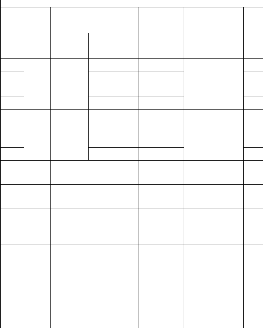
e-STUDIO281c/351c/451c ERROR CODE AND SELF-DIAGNOSTIC MODE© June 2005 TOSHIBA TEC
2 - 118
464-0Paper
feeding
Feeding retry
number set-
ting (lower
drawer)
Plain
paper
ALL5
<0-5>
MSets the number of
times of the feeding
retry from the lower
drawer.
4
464-1OthersALL5
<0-5>
M4
465-0Paper
feeding
Feeding retry
number set-
ting (PFP
upper drawer)
Plain
paper
ALL5
<0-5>
MSets the number of
times of the feeding
retry from the PFP
upper drawer.
4
465-1OthersALL5
<0-5>
M4
466-0Paper
feeding
Feeding retry
number set-
ting (PFP
lower drawer)
Plain
paper
ALL5
<0-5>
MSets the number of
times of the feeding
retry from the PFP
lower drawer.
4
466-1OthersALL5
<0-5>
M4
467-0Paper
feeding
Feeding retry
number set-
ting (bypass
feed)
Plain
paper
ALL5
<0-5>
MSets the number of
times of the feeding
retry from the bypass
tray.
4
467-1OthersALL5
<0-5>
M4
468-0Paper
feeding
Feeding retry
number set-
ting (LCF)
Plain
paper
ALL5
<0-5>
MSets the number of
times of the feeding
retry from the LCF.
4
468-1OthersALL5
<0-5>
M4
470Paper
feeding
Paper size (305x457 mm)
feeding/widthwise direction
ALL457/305
<148-
457/105-
305>
M10
471Paper
feeding
Paper size (Post card)
feeding/widthwise direction
ALL148/100
<148-
432/100-
297>
M*Post card is sup-
ported only for JPN
model.
10
478LaserJudged number of polygo-
nal motor rotation error
(Normal rotation)
ALL0
<0-1>
MDisplays the error
[CA10] when the set
number of rotation error
has been detected.
0: 2 times
1: 12 times
1
479LaserJudged number of polygo-
nal motor rotation error (At
acceleration/deceleration)
ALL0
<0-1>
M0: Waiting time for
polygonal motor
rotation overshoot-
ing 0.6 sec.
1: Waiting time for
polygonal motor
rotation overshoot-
ing 2.2 sec.
1
480Paper
feeding
Default setting of paper
source
PPC0
<0-5>
SYS0: A4/LT
1:LCF
2:Upper drawer
3: Lower drawer
4: PFP upper drawer
5: PFP lower drawer
1
Setting mode (08)
Code Classifi-
cation Items Func-
tion
Default
<Accept-
able
value>
RAMContents
Pro-
cedur
e

© June 2005 TOSHIBA TECe-STUDIO281c/351c/451c ERROR CODE AND SELF-DIAGNOSTIC MODE
2 - 119
2
481Paper
feeding
Automatic change of paper
source
PPC1
<0-2>
SYSSets whether or not
changing the drawer
automatically to the
other drawer with the
paper of the same size
when paper in the
selected drawer has run
out.
0: OFF
1: ON (Changes to the
drawer with the
same paper direc-
tion and size: ex. A4
to A4)
2: ON (Changes to the
drawer with the
same paper size.
Paper with the dif-
ferent direction is
acceptable as long
as the size is the
same: ex., A4 to A4-
R, LT-R to LT. 1! is
applied when the
staple/holepunch is
specified.)
1
482Paper
feeding
Feeding retry settingALL0
<0-1>
M0: ON
1: OFF
1
483LaserPre-running rotation of
polygonal motor
ALL0
<0-2>
SYSSets whether or not
switching the polygonal
motor from the standby
rotation to the normal
rotation when the origi-
nal is set on the RADF
or the platen cover is
opened.
0: Valid (when using
RADF and the origi-
nal is set manually)
1: Invalid
2: Valid (when using
RADF only)
1
484LaserPolygonal motor rotational
status switching at the Auto
Clear Mode
ALL0
<0-1>
SYSSets whether or not
switching the polygonal
motor from the normal
rotation to the standby
rotation at the Auto
Clear Mode.
0: Valid
1: Invalid
1
485LaserRotational status of polygo-
nal motor on standby
ALL0
<0-1>
SYSSets the rotational sta-
tus of polygonal motor
on standby.
0: Rotated (The rota-
tional speed is set at
08-490.)
1: Stopped
1
Setting mode (08)
Code Classifi-
cation Items Func-
tion
Default
<Accept-
able
value>
RAMContents
Pro-
cedur
e

e-STUDIO281c/351c/451c ERROR CODE AND SELF-DIAGNOSTIC MODE© June 2005 TOSHIBA TEC
2 - 120
486LaserTiming of auto-clearing of
polygonal motor pre-run-
ning rotation
ALL0
<0-2>
SYSSwitches the polygonal
motor to the standby
rotation when a certain
period of time has
passed from the pre-
running. At this code,
the period to switch the
status to the standby
rotation is set.
0: 15 sec.
1: 30 sec.
2: 45 sec.
*This setting is effec-
tive when 0! or 2!
is set at 08-483.
1
487TransferSelection of performing the
2nd transfer roller cleaning
(Bypass feed)
ALL0
<0-1>
M0: Performs only at no
paper size is desig-
nated
1: Performs regardless
of designation of
paper size
1
488LaserSetting of polygonal motor
type
ALL3
<2-3>
MSet the type of polygo-
nal motor.
2: 2 clock type
3: 3 clock type
1
489LaserPolygonal motor rotation
number on standby
ALL5
<0-5>
M0: 38090.55rpm
1: 35000rpm
2: 30000rpm
3: 25000rpm
4: 20000rpm
5: 10000rpm
1
490LaserPolygonal motor rotation in
the energy saving mode
ALL0
<0-1>
M0: Stopped
1: 10000rpm.
1
497GeneralSpeed switching for color
printing
ALL
(color)
0
<0-1>
MSets the speed for color
printing.
0: 11 pages/minute
1: 6 pages/minute
1
502ImageError diffusion and dither
setting at photo mode
PPC
(black)
0
<0-1>
SYSSets the image repro-
duction method at
photo mode.
0: Error diffusion
1: Dither
1
503User
interface
Default setting of density
adjustment
PPC
(black)
0
<0-1>
SYS0: Automatic
1: Manual (Center)
1
511Main
charger
Main charger wire auto-
cleaning setting
ALL1
<0-1>
M0: Invalid
1: Valid
1
526-0FuserPre-running time for first
printing
(OHP film)
ALL
(black)
16
<0-16>
M0: Invalid 1: 0 sec.
2: 2 sec.3: 3 sec.
4: 4 sec. 5: 5 sec.
6: 6 sec. 7: 7 sec.
8: 8 sec.9: 10 sec.
10: 12 sec.
11: 14 sec.
12: 16 sec.
13: 18 sec.
14: 20 sec.
15: 25 sec.
16: 30 sec.
4
526-1ALL
(color)
0
<0-16>
M4
Setting mode (08)
Code Classifi-
cation Items Func-
tion
Default
<Accept-
able
value>
RAMContents
Pro-
cedur
e

© June 2005 TOSHIBA TECe-STUDIO281c/351c/451c ERROR CODE AND SELF-DIAGNOSTIC MODE
2 - 121
2
544Image
control
Environment correction
control of 2nd transfer
roller bias
ALL1
<0-1>
MSets whether or not cor-
recting the 2nd transfer
roller bias depending on
the environment.
0: Invalid
1: Valid
1
545Image
control
Transfer belt life correction
of 2nd transfer roller bias
ALL1
<0-1>
MSets whether or not cor-
recting the 2nd transfer
roller bias depending on
the transfer belt life.
0: Invalid
1: Valid
1
546Image
control
2nd transfer roller life cor-
rection of 2nd transfer
roller bias
ALL1
<0-1>
MSets whether or not cor-
recting the 2nd transfer
roller bias depending on
the 2nd transfer roller
life.
0:Invalid
1: Valid
1
548TransferSetting of 2nd transfer
roller bias table (for each
destination/paper thick-
ness)
ALLEUR:0
UC:1
JPN:2
<0-2>
M0:80 g/m2 (21.3 lb.)/
EUR
1:75 g/m2 (20 lb.)/UC
2:64 g/m2 (17.1 lb.)/
JPN
1
549Image
control
Image quality control/open-
loop control 1
ALL1
<0-1>
MSets whether or not
performing the open-
loop control 1.The
open-loop control 1 is
performed in advance
of the closed-loop con-
trol.
0:Invalid
1: Valid
1
550ImageDefault setting of Original
mode
PPC
(black)
0
<0-3>
SYS0: Text/Photo
1: Photo
2: Text
3: Gray Scale
1
551Image
control
Image quality control/open-
loop control 2
ALL1
<0-1>
MSets whether or not
performing the open-
loop control 2.The
open-loop control 2 is
performed before or
during printing.
0:Invalid
1: Valid
1
552Image
control
Drum life correction controlALL1
<0-1>
MSets whether or not cor-
recting the drum volt-
age depending on the
drum life in open-loop
control.
0:Invalid
1:Valid
1
Setting mode (08)
Code Classifi-
cation Items Func-
tion
Default
<Accept-
able
value>
RAMContents
Pro-
cedur
e

e-STUDIO281c/351c/451c ERROR CODE AND SELF-DIAGNOSTIC MODE© June 2005 TOSHIBA TEC
2 - 122
553Image
control
Drum temperature correc-
tion control
ALL1
<0-1>
MSets whether or not cor-
recting the drum volt-
age depending on the
drum surface tempera-
ture in open-loop con-
trol.
0: Invalid
1: Valid
1
554Image
control
Image quality open-loop
control/Contrast voltage
initial value
ALL1
<0-1>
MSets whether or not
deciding the initial value
of contrast voltage in
open-loop control.
0: Invalid
1: Valid
1
555Image
control
Drum life correction of
laser power initial value
ALL1
<0-1>
MSets whether or not cor-
recting the laser power
depending on the drum
life when the laser
power initial value is set
in open-loop control.
0: Invalid
1: Valid
1
556Image
control
Image quality closed-loop
control/Contrast voltage
ALL1
<0-1>
MSets whether or not cor-
recting the contrast volt-
age in closed-loop
control.
0: Invalid
1: Valid
1
557Image
control
Image quality closed-loop
control/Laser power
ALL1
<0-1>
MSets whether or not cor-
recting the laser power
in closed-loop control.
0: Invalid
1: Valid
1
558Image
control
Contrast voltage/Correc-
tion gain environment set-
ting
ALL1
<0-1>
MSets whether or not
switching the correc-
tion amount once at
contrast voltage correc-
tion depending on the
environment.
0: Invalid
1: Valid
1
559Image
control
Image quality closed-loop
control automatic start-up/
At power-ON
ALL
(color)
1
<0-2>
MSets whether perform-
ing closed-loop control
automatically at power-
ON when the fuser
roller temperature
becomes below the
specified level.
0: Invalid
1: Valid (at mode 1)
2: Valid (at mode 2)
1
560ImagelProcess switching for
image smoothing (Text/
Photo)
PPC
(black)
1
<0-1>
MSets whether or not
performing a smooth-
ing process (primary
scanning direction,
2,400 dpi or equiva-
lent).
0: Invalid
1: Valid
1
Setting mode (08)
Code Classifi-
cation Items Func-
tion
Default
<Accept-
able
value>
RAMContents
Pro-
cedur
e

© June 2005 TOSHIBA TECe-STUDIO281c/351c/451c ERROR CODE AND SELF-DIAGNOSTIC MODE
2 - 123
2
561ImageProcess switching for
image smoothing (Photo)
PPC
(black)
0
<0-1>
MSets whether or not
performing a smooth-
ing process (primary
scanning direction,
2,400 dpi or equiva-
lent).
0: Invalid
1: Valid
1
562ImageProcess switching for
image smoothing (Text)
PPC
(black)
1
<0-1>
M1
565Image
control
Image quality closed-loop
control automatic start-up/
Relative humidity variation
ALL
(color)
1
<0-2>
MSets whether or not
performing closed-loop
control automatically
when the relative
humidity becomes
below the specified
level from the previous
control.
0: Invalid
1: Valid (at mode 1)
2: Valid (at mode 2)
1
566Image
control
Image quality closed-loop
control automatic start-up/
Period of time unattended
ALL
(color)
1
<0-2>
MSets whether or not
performing closed-loop
control automatically
when the equipment
has not been used for a
specified period of time.
0: Invalid
1: Valid (at mode 1)
2: Valid (at mode 2)
1
567Image
control
Image quality closed-loop
control automatic start-up/
Accumulated print volume
ALL
(color)
2
<0-2>
MSets whether or not
performing closed-loop
control automatically
when the specified
number of sheets has
been printed out from
the previous control.
0: Invalid
1: Valid (at mode 1)
2: Valid (at mode 2)
1
568Image
control
Image quality closed-loop
control automatic start-up/
When recovered from
Toner empty!
ALL
(color)
2
<0-2>
MSets whether or not
performing closed-loop
control automatically
when recovered from
Toner empty!.
0: Invalid
1: Valid (at mode 1)
2: Valid (at mode 2)
1
Setting mode (08)
Code Classifi-
cation Items Func-
tion
Default
<Accept-
able
value>
RAMContents
Pro-
cedur
e

e-STUDIO281c/351c/451c ERROR CODE AND SELF-DIAGNOSTIC MODE© June 2005 TOSHIBA TEC
2 - 124
569Image
control
Image quality closed-loop
control automatic start-up/
Temperature setting of
fuser roller at power-ON
ALL
(color)
8
<0-20>
MSets the fuser roller
temperature to perform
closed-loop control
when 1! or 2! (valid) is
set in 08-559.
0:20°C1: 25°C
2:30°C3: 35°C
4:40°C5: 45°C
6:50°C7: 55°C
8:60°C9: 65°C
10: 70°C11: 75°C
12: 80°C13: 85°C
14: 90°C15: 95°C
16: 100°C17: 105°C
18: 110°C19: 115°C
20: 120°C
1
570Image
control
Image quality closed-loop
control automatic start-up/
Relative humidity differ-
ence setting
ALL
(color)
4
<0-6>
MSets the relative humid-
ity difference to per-
form the closed-loop
control when 1! or 2!
(valid) is set in 08-565.
0: 0% 1: 5%
2: 10% 3: 15%
4: 20%5: 25%
6: 30%
1
571Image
control
Image quality closed-loop
control automatic start-up/
Setting of period of time
unattended
ALL
(color)
4
<0-24>
MSets the period of time
unattended to perform
closed-loop control
when 1! or 2! (valid) is
set in 08-566.
Setting value x 1 (hour)
1
572Image
control
Image quality closed-loop
control automatic start-up/
Setting of accumulated
print volume
ALL
(color)
10
<0-30>
MSets the number of
accumulated print vol-
ume to perform closed-
loop control when 1! or
2! (valid) is set in 08-
567.
Setting value x 100
(pages)
1
573Image
control
Abnormality detection
count (Y)
Display/0 clearing
ALL0
<0-16>
MCounts the abnormality
detection of image qual-
ity control. Accumulat-
ing total of [CE10],
[CE20] and [CE40]
1
574Image
control
Abnormality detection
count (M)
Display/0 clearing
ALL0
<0-16>
MCounts the abnormality
detection of image qual-
ity control. Accumulat-
ing total of [CE10],
[CE20] and [CE40]
1
575Image
control
Abnormality detection
count (C)
Display/0 clearing
ALL0
<0-16>
MCounts the abnormality
detection of image qual-
ity control. Accumulat-
ing total of [CE10],
[CE20] and [CE40]
1
576Image
control
Abnormality detection
count (K)
Display/0 clearing
ALL0
<0-16>
MCounts the abnormality
detection of image qual-
ity control. Accumulat-
ing total of [CE10],
[CE20] and [CE40]
1
Setting mode (08)
Code Classifi-
cation Items Func-
tion
Default
<Accept-
able
value>
RAMContents
Pro-
cedur
e

© June 2005 TOSHIBA TECe-STUDIO281c/351c/451c ERROR CODE AND SELF-DIAGNOSTIC MODE
2 - 125
2
583-0FuserPre-running
time at power-
ON and ready
status
Transport
motor
speed 1/1
ALL1
<0-10>
M0:3 sec. 1: 6 sec.
2:9 sec.3: 12 sec.
4: 15 sec. 5: 18 sec.
6:21 sec. 7: 24 sec.
8: 27 sec.9: 30 sec.
10: 33 sec.
4
583-1Transport
motor
speed 1/2
ALL4
<0-10>
M4
583-2Transport
motor
speed 1/3
ALL7
<0-10>
M4
584FuserTransport motor speed of
pre-running at ready status
ALL0
<0-2>
M0: Decelerating to 1/1
1: Decelerating to 1/2
2: Decelerating to 1/3
1
585User
interface
Default setting of Original
mode
PPC
(color)
0
<0-4>
SYS0: Text/Photo
1: Text
2: Printed image
3: Photo
4:Map
1
586ImageImage quality switching
when selecting the Image
Smoothing Mode
PPC
(black)
0
<0-1>
SYSSelects the method of
image processing when
the Image Smoothing is
selected in the original
modes.
0:Processing for
Image Smoothing
1: Processing when
judging as black in
the ACS Mode
1
587User
interface
Default setting of Density
mode
PPC
(color)
1
<0-1>
SYS0: Automatic
1: Manual (Center)
1
588User
interface
Default setting of Color
mode
PPC1
<0-2>
SYS0: Auto color
1: Black
2: Full color
1
589ImageImage quality switching
when judging as black in
the ACS Mode
PPC
(black)
1
<0-1>
SYSSelects the method of
image processing when
the original is judged as
black in the ACS Mode.
0: Processing for
Image Smoothing
1: Processing when
judging as black in
the ACS Mode
1
595ImageScanning operation switch-
ing at automatic calibration
PPC
(color)
0
<0-1>
SYS0: Scanning color/
black integrated pat-
tern
1: Scanning color pat-
tern only
1
597ImageGamma correction table all
clearing
PRT
(color)
-SYSInitializes the status of
automatic gamma
adjustment in color
printing.
3
602User
interface
Screen setting for auto-
matic energy saver/auto-
matic power OFF
ALLEUR:0
UC:1
JPN:1
<0-1>
SYS0: OFF
1: ON
1
Setting mode (08)
Code Classifi-
cation Items Func-
tion
Default
<Accept-
able
value>
RAMContents
Pro-
cedur
e
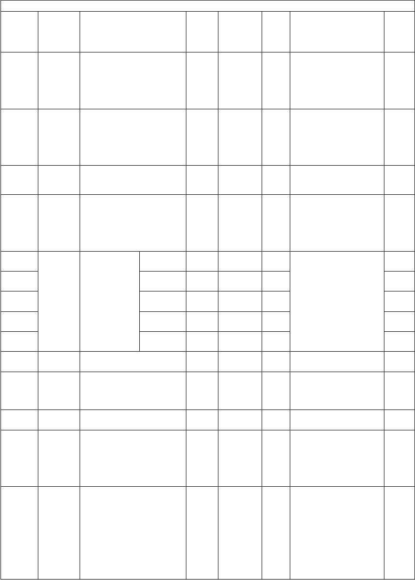
e-STUDIO281c/351c/451c ERROR CODE AND SELF-DIAGNOSTIC MODE© June 2005 TOSHIBA TEC
2 - 126
603User
interface
Setting for automatic
duplexing mode
ALL0
<0-3>
SYS0: Invalid
1: Single-sided to
duplex copying
2: Two-sided to duplex
copying
3: User selection
1
604User
interface
Default setting for APS/
AMS
ALL0
<0-2>
SYS0: APS (Automatic
Paper Selection)
1: AMS (Automatic
Magnification Selec-
tion)
2:Not selected
1
605User
interface
Centering printing of pri-
mary/secondary direction
at AMS
PPC1
<0-1>
SYS0: Invalid
1: Valid
1
607User
interface
Default setting of RADF
mode
PPC0
<0-1>
SYS0: Continuous feeding
(by pressing the
[START] button)
1: Single feeding
(by setting original
on the tray)
1
609-0ImageBinarizing
level setting
(When judg-
ing as black in
the ACS
Mode)
Step -2ALL88
<0-255>
SYSSets the binarizing level
of each step.
When the value
increases, the image
becomes darker. When
the value decreases,
the image becomes
lighter.
*Refer to 08-268.
4
609-1Step -1ALL108
<0-255>
SYS4
609-2Step 0
(center)
ALL148
<0-255>
SYS4
609-3Step +1ALL178
<0-255>
SYS4
609-4Step +2ALL208
<0-255>
SYS4
610User
interface
Key touch sound of control
panel
ALL1
<0-1>
SYS0: OFF
1: ON
1
611User
interface
Book type original priorityPPC0
<0-1>
SYS0:Left page to right
page
1: Right page to left
page
1
612GeneralSummer time modeALL0
<0-1>
SYS0: Not summer time
1: Summer time
1
613User
interface
Paper size selection for
[OTHER] button
PPCEUR:
FOLIO
UC:
COMP
JPN:
A5-R
SYSPress the icon on the
LCD to select the size.
9
614NetworkLocal I/F time-out periodALL6
<1-50>
SYSSets the period of time
when the job is judged
as completed in local I/
F printing (USB or par-
allel).
1: 1.0 sec.
2: 1.5 sec.
50: 25.5 sec.
(in increments of 0.5
sec.)
1
Setting mode (08)
Code Classifi-
cation Items Func-
tion
Default
<Accept-
able
value>
RAMContents
Pro-
cedur
e

© June 2005 TOSHIBA TECe-STUDIO281c/351c/451c ERROR CODE AND SELF-DIAGNOSTIC MODE
2 - 127
2
615GeneralSize information of main
memory and page memory
ALL-SYSDisplays the sizes of
the main memory and
page memory. Enables
to check if each mem-
ory is properly recog-
nized.
2
616CounterCounting method in Twin
Color Mode
(Limitation Function)
ALLJPN: 1
UC: 0
EUR: 0
<0-1>
SYSSets the counting
method in Twin Color
Mode with the Limita-
tion Function.
0: Count as color
1: Count as black
1
617User
interface
Print setting without
department code
ALL1
<0-2>
SYS0: Printed forcibly
1:Not printed
2:Deleted forcibly
1
618User
interface
Default setting of RADF
original size
PPC0
<0-1>
SYS0: Same size originals
1: Mixed size originals
1
619Paper
feeding
Time lag before auto-start
of bypass feeding
ALL4
<0-10>
SYSSets the time taken to
add paper feeding
when paper in the
bypass tray has run out
during the bypass feed
copying.
0:Paper is not drawn
in unless the
[START] button is
pressed.
1-10: Setting value x
0.5sec.
1
620User
interface
Department management
setting (Copier)
PPC1
<0-1>
SYS0: Invalid
1: Valid
1
621User
interface
Department management
setting (FAX)
FAX1
<0-1>
SYS0: Invalid
1: Valid
1
622User
interface
Department management
setting (Printer)
PRT1
<0-1>
SYS0: Invalid
1: Valid
1
623User
interface
Department management
setting (Scanner)
SCN1
<0-1>
SYS0: Invalid
1: Valid
1
624User
interface
Department management
setting (List print)
PRT1
<0-1>
SYS0: Invalid
1: Valid
1
625User
interface
Blank copying prevention
mode during RADF jam-
ming
PPC0
<0-1>
SYS0:OFF
1: ON (Start printing
when the scanning
of each page is fin-
ished)
1
627User
interface
Rotation printing at the
nonsorting
ALL0
<0-1>
SYS0: Not rotating
1: Rotating
1
628User
interface
Direction priority of original
image
PPC0
<0-1>
SYS0:Automatic
1:Portrait
1
629User
interface
Department management
setting
ALL0
<0-1>
SYS0: Invalid
1: Valid
1
632User
interface
Automatic calibration dis-
closure level
PPC1
<0-2>
SYSSets the disclosing level
of automatic calibration.
0:Service technician
1:Administrator
2:User
1
Setting mode (08)
Code Classifi-
cation Items Func-
tion
Default
<Accept-
able
value>
RAMContents
Pro-
cedur
e

e-STUDIO281c/351c/451c ERROR CODE AND SELF-DIAGNOSTIC MODE© June 2005 TOSHIBA TEC
2 - 128
633Data
overwrite
kit
Releasing F200 service
call
ALL0
<0-2>
SYS0: Not used
1: Board installed
2: Service call
1
634User
interface
Inner receiving tray priority
at Non-sort Mode
ALL0
<0-1>
SYS0: Normal
1: Inner receiving tray
1
636User
interface
Width setting for image
shift copying (linkage of
front side and back side)
PPC0
<0-1>
SYS0: ON
1: OFF
1
638GeneralTime differencesALLEUR: 24
UC: 40
JPN: 6
<0-47>
SYS0:+12.0h 1: +11.5h
2:+11.0h 3: +10.5h
4: +10.0h 5: 9.5h
6:+9.0h 7: +8.5h
8:+8.0h 9: +7.5h
10: +7.0h 11: +6.5h
12: +6.0h 13: +5.5h
14: +5.0h 15: +4.5h
16: +4.0h 17: +3.5h
18: +3.0h 19: +2.5h
20: +2.0h 21: +1.5h
22: +1.0h 23: +0.5h
24: 0.0h 25:-0.5h
26: -1.0h 27: -1.5h
28: -2.0h 29: -2.5h
30: -3.0h 31: -3.5h
32: -4.0h 33: -4.5h
34: -5.0h 35: -5.5h
36: -6.0h 37: -6.5h
38: -7.0h 39: -7.5h
40: -8.0h 41: -8.5h
42: -9.0h 43: -9.5h
44: -10.0h 45: -10.5h
46: -11.0h 47: -11.5h
1
640User
interface
Date display formatALLEUR:1
UC:2
JPN:0
<0-2>
SYS0: YYYY.MM.DD.
1: DD.MM.YYYY
2: MM.DD.YYYY
1
641User
interface
Automatic Sorting Mode
setting (RADF)
PPC2
<0-4>
SYS0: Invalid
1: STAPLE
2:SORT
3: GROUP
4: ROTATE SORT
1
642User
interface
Default setting of Sorter
Mode
PPC0
<0-4>
SYS0: NON-SORT
1: STAPLE
2: SORT
3: GROUP
4: ROTATE SORT
1
643User
interface
Color 1 at twin color selec-
tion (Select what color
black in original is copied)
PPC
(color)
0
<0-6>
SYS0: K 1: Y 2: M
3: C4: R 5: G
6: B
1
644User
interface
Color 2 at twin color selec-
tion (Select what color
other than black in original
is copied)
PPC
(color)
4
<0-6>
SYS0: K 1: Y 2: M
3: C4: R 5: G
6: B
1
Setting mode (08)
Code Classifi-
cation Items Func-
tion
Default
<Accept-
able
value>
RAMContents
Pro-
cedur
e
05/11

© June 2005 TOSHIBA TECe-STUDIO281c/351c/451c ERROR CODE AND SELF-DIAGNOSTIC MODE
2 - 129
2
645User
interface
Correction of reproduction
ratio in editing copy
PPC10
<0-10>
SYSSets the reproduction
ratio for the X in 1!
printing (including mag-
azine sort) to the
Reproduction ratio x
Correction ratio!.
0: 90%1: 91%
2: 92%3: 93%
4: 94%5: 95%
6: 96%7: 97%
8: 98%9: 99%
10: 100%
1
646User
interface
Image position in editingPPC0
<0-1>
SYSSets the page pasted
position for X in 1! to
the upper left corner/
center.
0: Cornering
1: Centering
1
648User
interface
Returning finisher tray
when printing is finished
ALL0
<0-1>
SYSSets whether or not
returning the finisher
tray to the bin 1 when
printing is finished.
0: Not returned
1: Returned
1
649User
interface
Magazine sort settingPPC0
<0-1>
SYS0: Left page to right
page
1: Right page to left
page
1
650User
interface
2 in 1/4 in 1 page allocating
order setting
PPC0
<0-1>
SYS0: Horizontal
1: Vertical
1
651User
interface
Printing format setting for
Time Stamp and Page
Number
PPC2
<0-3>
SYSHyphen
(with page number)
/Dropout
(with date, time and
page number)
0: OFF/OFF
1: ON/OFF
2: OFF/ON
3: ON/ON
Note:
Note:
Hyphen printing
format
ON: -1- OFF: 1
1
652User
interface
Cascade operation settingPPC0
<0-1>
SYS0: OFF
1: ON
1
653User
interface
Cascade operation settingPRT0
<0-1>
SYS0: OFF
1: ON
1
657User
interface
Default setting of printing
direction for Time Stamp
and Page Number
PPC0
<0-1>
SYS0: Short edge
1: Long edge
1
Setting mode (08)
Code Classifi-
cation Items Func-
tion
Default
<Accept-
able
value>
RAMContents
Pro-
cedur
e
05/07

e-STUDIO281c/351c/451c ERROR CODE AND SELF-DIAGNOSTIC MODE© June 2005 TOSHIBA TEC
2 - 130
658User
interface
Auto-start setting for
bypass feed printing
PRT0
<0-1>
SYSSets whether or not
feeding a paper auto-
matically into the copier
when it is placed on the
bypass tray.
0:OFF (Press the
[START] button to
start feeding.)
1: ON (Automatical
feeding)
1
659User
interface
Auto-start setting for
bypass feed printing
PPC1
<0-1>
SYSSets whether or not
feeding a paper auto-
matically into the copier
when it is placed on the
bypass tray.
0: OFF (Press the
[START] button to
start feeding.)
1: ON (Automatical
feeding)
1
660NetworkAuto-forwarding setting of
received FAX
ALL0
<0-1>
SYS0: Invalid
1:Valid
1
661NetworkAuto-forwarding setting of
received E-mail
ALL0
<0-1>
SYS0:Invalid
1: Valid
1
662GeneralClearing of SMS partitionALL-SYSClears SMS partition.
(Performs when the
service call [F106] has
occurred.)
3
663CounterCounting method in Twin
Color Mode
PPC0
<0-2>
SYSSets the counting
method of fee charging
or department count in
Twin Color Mode.
0: Count as Twin Color
Mode
1: Count as Black
Mode
2:Count as Full Color
Mode
1
665GeneralM/SYS all clearingALL-M/
SYS
Initializes all the adjust-
ment modes and setting
modes.
3
666GeneralBOX partition clearingALL-SYSInitializes the Elec-
tronic Filing.
3
667General/SHA partition clearingALL-SYSInitializes the shared
folder.
3
669GeneralSystem all clearingALL-SYSInitializes system
NVRAM area.
3
670GeneralHDD diagnostic menu dis-
play
ALL-SYSDisplay the HDD infor-
mation
(Chap. 5.3.6)
2
671User
interface
Size indicatorALL0
<0-1>
SYS0: Invalid 1: Valid1
Setting mode (08)
Code Classifi-
cation Items Func-
tion
Default
<Accept-
able
value>
RAMContents
Pro-
cedur
e
05/11

© June 2005 TOSHIBA TECe-STUDIO281c/351c/451c ERROR CODE AND SELF-DIAGNOSTIC MODE
2 - 131
2
672GeneralInitialization of department
management information
--SYSInitializing of the depart-
ment management
information
*Enter the code with
the digital keys and
press the [INITIAL-
IZE] button to per-
form the
initialization.
If the area storing
the department
management infor-
mation is destroyed
for some reason,
Enter Department
Code! is displayed
on the control panel
even if the depart-
ment management
function is not set
on. In this case, ini-
tialize the area with
this code. This area
is normally initial-
ized at the factory.
3
675-0Paper
feeding
Coated Paper
Mode setting
for paper
source
Upper
drawer
ALL0
<0-1>
SYSSets whether or not
applying the Coated
Paper Mode to each
paper source.
0: Normal mode
1: Coated Paper Mode
*Coated Paper Mode
- This mode is
selected when the
paper which often
causes the misfeed-
ing (ex. coated
paper) is used. The
occurrence of mis-
feeding is reduced
by lengthening the
jam detection time.
However, the print-
ing speed is low-
ered since the
printing cycle is also
lengthened with the
lengthened jam
detection time.
4
675-1Lower
drawer
ALL0
<0-1>
SYS4
675-2PFP upper
drawer
ALL0
<0-1>
SYS4
675-3PFP lower
drawer
ALL0
<0-1>
SYS4
675-4LCFALL0
<0-1>
SYS4
Setting mode (08)
Code Classifi-
cation Items Func-
tion
Default
<Accept-
able
value>
RAMContents
Pro-
cedur
e
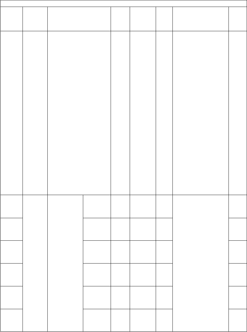
e-STUDIO281c/351c/451c ERROR CODE AND SELF-DIAGNOSTIC MODE© June 2005 TOSHIBA TEC
2 - 132
676Paper
feeding
Bypass copy printing
[COATED] button display
PPC0
<0-1>
SYSSets whether or not dis-
playing the [COATED]
button on the LCD
screen at bypass feed-
ing.
0: Not displayed
1: Displayed (The
Coated Paper Mode
is applied by press-
ing the [COATED]
button at bypass
feeding.)
*Coated Paper Mode
- This mode is
selected when the
paper which often
causes the misfeed-
ing (ex. coated
paper) is used. The
occurrence of mis-
feeding is reduced
by lengthening the
jam detection time.
However, the print-
ing speed is low-
ered since the
printing cycle is also
lengthened with the
lengthened jam
detection time.
1
677-0Paper
feeding
Coated Paper
Mode setting
at bypass
feeding
Plain
paper
PRT0
<0-1>
SYSSets whether or not
applying the Coated
Paper Mode on each
paper type at bypass
printing.
0: Normal mode
1: Coated Paper Mode
*Coated Paper Mode
- This mode is
selected when the
paper which often
causes the misfeed-
ing (ex. coated
paper) is used. The
occurrence of mis-
feeding is reduced
by lengthening the
jam detection time.
However, the print-
ing speed is low-
ered since the
printing cycle is also
lengthened with the
lengthened jam
detection time.
4
677-1Thick
paper 1
PRT0
<0-1>
SYS4
677-2Thick
paper 2
PRT0
<0-1>
SYS4
677-3Thick
paper 3
PRT0
<0-1>
SYS4
677-4OHP filmPRT0
<0-1>
SYS4
677-5EnvelopPRT0
<0-1>
SYS4
Setting mode (08)
Code Classifi-
cation Items Func-
tion
Default
<Accept-
able
value>
RAMContents
Pro-
cedur
e

© June 2005 TOSHIBA TECe-STUDIO281c/351c/451c ERROR CODE AND SELF-DIAGNOSTIC MODE
2 - 133
2
678GeneralSetting of banner advertis-
ing display
ALL0
<0-1>
SYSSets whether or not dis-
playing the banner
advertising. The setting
contents of 08-679 and
08-680 are displayed at
the time display section
on the right top of the
screen. When both are
set, each content is dis-
played alternately.
0: Not displayed
1: Displayed
1
679GeneralBanner advertising display
1
ALL-SYSMaximum 27 letters
(one-byte character)
11
680GeneralBanner advertising display
2
ALL-SYSMaximum 27 letters
(one-byte character)
11
681GeneralDisplay of [BANNER MES-
SAGE] button
ALL0
<0-1>
SYS0: Not displayed
1: Displayed
*This button enables
the entry of Banner
advertising display 1
(08-679)! and Ban-
ner advertising dis-
play 2 (08-680)! on
the control panel.
1
682Use
interface
Offsetting between jobsALL1
<0-1>
SYS0: Invalid
1: Valid
1
683GeneralDuplex printing setting
when coin controller is
used
ALL1
<0-1>
SYSWhen the duplex print-
ing is short paid with a
coin controller, reverse
side of the original is
not printed and is con-
sidered as a defect
(printing job may be
cleared). To solve this
problem, the selection
of printing method is
enabled with this set-
ting.
0: Invalid (Both sides
printed)
1: Valid (Only one side
printed)
1
684GeneralRebuilding all databasesALL-SYSRebuilds all databases.3
685GeneralRebuilding all databases
related to Address Book
ALL-SYSRebuilds all databases
related to the Address
Book.
3
686GeneralRebuilding all databases
related to log
ALL-SYSRebuilds all databases
related to the logs.
3
689FAXAdaptation of paper source
priority selection
FAX0
<0-1>
SYS0: Not subjected for
APS judgment
1: Subjected for APS
judgment
1
690GeneralHDD formattingALL-
<2>
SYS2: Normal formatting7
691GeneralHDD type displayALL-
<0-2>
SYS0: Not formatted
1:Not used
2: Normal format
7
Setting mode (08)
Code Classifi-
cation Items Func-
tion
Default
<Accept-
able
value>
RAMContents
Pro-
cedur
e
06/08

e-STUDIO281c/351c/451c ERROR CODE AND SELF-DIAGNOSTIC MODE© June 2005 TOSHIBA TEC
2 - 134
692Mainte-
nance
Performing panel calibra-
tion
ALL-SYSPerforms the calibration
of the pressing position
on the touch panel
(LCD screen). The cali-
bration is performed by
pressing 2 reference
positions after this code
is started up.
1
693GeneralInitialization of NIC infor-
mation
ALL-SYSReturns the value to the
factory shipping default
value.
3
694GeneralPerforming HDD testingALL-SYSChecks the bad sector.3
696Scram-
bler
board
Installation of scrambler
board (Option)
ALL0
<0-1>
-0: Not installed
1: Installed
2
697Paper
feeding
Paper type priorityPPC1
<1-2>
SYSSets the paper type pri-
ority during copying.
1: Normal paper
2: Thick paper 1
1
698Scram-
bler
board
Entering the key code for
scrambler board
ALL--Start up this code and
have the user enter the
key code.
Once the key code has
been set, this code can-
not be set again on
security grounds.
5
699Scram-
bler
board
Erasing all data in HDDALL--This setting is effective
only when the scram-
bler board is installed.
3
701FAXDestination setting for FAXFAXEUR: 5
UC: 4
JPN: 0
Other: 1
<0-25>
SYS0: Japan
1: Asia
2: Australia
3: Hong Kong
4: U.S.A./Canada
5: Germany
6: U.K.
7: Italy
8: Belgium
9: Netherlands
10: Finland
11: Spain
12: Austria
13: Switzerland
14: Sweden
15: Denmark
16: Norway
17: Portugal
18: France
19: Greece
20: Poland
21: Hungary
22: Czech
23: Turkey
24: South Africa
25: Taiwan
1
Setting mode (08)
Code Classifi-
cation Items Func-
tion
Default
<Accept-
able
value>
RAMContents
Pro-
cedur
e

© June 2005 TOSHIBA TECe-STUDIO281c/351c/451c ERROR CODE AND SELF-DIAGNOSTIC MODE
2 - 135
2
702Mainte-
nance
Remote-controlled service
function
ALL2
<0-2>
SYS0: Valid (Remote-con-
trolled server)
1: Valid (L2)
2: Invalid
1
703Mainte-
nance
Remote-controlled service
HTTP server
URL setting
ALL-SYSMaximum 256 Bytes11
704-0Interruption of
stapling oper-
ation (no sta-
ple)
CopyingALL1
<0-1>
SYS0: Continues printing
by switching sort
setting
1: Interrupts printing
4
704-1Printing /
BOX print-
ing
ALL0
<0-1>
SYS0: Continues printing
by switching sort
setting
1: Interrupts printing
4
707Mainte-
nance
Remote-controlled service
HTTP initially-registered
server
URL setting
ALLhttps://
device.mf
p-sup-
port.com:
443/
device/fir-
streg-
ist.ashx
SYSMaximum 256 Bytes11
710Mainte-
nance
(Remote)
Short time interval setting
of recovery from Emer-
gency Mode
ALL24
<1-48>
SYSSets the time interval to
recover from the Emer-
gency Mode to the Nor-
mal Mode.
(Unit: Hour)
1
711Mainte-
nance
Short time interval setting
of Emergency Mode
ALL60
<30-360>
SYSUnit: Minute1
715Mainte-
nance
Remote-controlled service
periodical polling timing
(Hour/Hour/Minute/Minute)
ALL1230SYS0 (0:00) to 2359 (23:59)1
716Mainte-
nance
Remote-controlled service
Writing data of self-diag-
nostic code
ALL0
<0-1>
SYS0: Prohibited
1: Accepted
1
717Mainte-
nance
Remote-controlled service
response waiting time
(Timeout)
ALL3
<1-30>
SYSUnit: Minute1
718Mainte-
nance
Remote-controlled service
initial registration
ALL0
<0-2>
SYS0: OFF
1: Start
2: Only certification is
scanned
1
719Mainte-
nance
Remote-controlled service
tentative password
ALL-SYSMaximum 10 letters11
720Mainte-
nance
Status of remote-con-
trolled service initial regis-
tration (Display only)
ALL0
<0-1>
SYS0: Not registered
1: Registered
2
721Mainte-
nance
Service center call functionALL2
<0-2>
SYS0:OFF
1: Notifies all service
calls
2:Notifies all but
paper jams
1
723Mainte-
nance
Service center call HTTP
server URL setting
ALL-SYSMaximum 256 letters11
726Mainte-
nance
HTTP proxy settingALL1
<0-1>
SYS0: Valid
1: Invalid
1
Setting mode (08)
Code Classifi-
cation Items Func-
tion
Default
<Accept-
able
value>
RAMContents
Pro-
cedur
e
06/08

e-STUDIO281c/351c/451c ERROR CODE AND SELF-DIAGNOSTIC MODE© June 2005 TOSHIBA TEC
2 - 136
727Mainte-
nance
HTTP proxy IP address
setting
ALL-SYS000.000.000.000 -
255.255.255.255
(Default value
000.000.000.000)
11
728Mainte-
nance
HTTP proxy port number
setting
ALL0
<0-
65535>
SYS1
729Mainte-
nance
HTTP proxy ID settingALL-SYSMaximum 30 letters11
730Mainte-
nance
HTTP proxy password set-
ting
ALL-SYSMaximum 30 letters11
731Mainte-
nance
HTTP proxy panel displayALL1
<0-1>
SYS0:Valid
1: Invalid
1
732Mainte-
nance
(Remote)
Automatic ordering func-
tion of supplies
ALL3
<0-3>
SYS0: Ordered by FAX
1: Ordered by E-mail
2: Ordered by HTTP
3: OFF
1
733Mainte-
nance
(Remote)
Automatic ordering func-
tion of supplies
FAX number
ALL-SYSMaximum 32 digits
Enter hyphen with the
[Monitor/Pause] button
11
734Mainte-
nance
(Remote)
Automatic ordering func-
tion of supplies
E-mail address
ALL-SYSMaximum 192 letters
List: 256 digits
11
738Mainte-
nance
(Remote)
Automatic ordering func-
tion of supplies
User's name
ALLSYSMaximum 50 letters11
739Mainte-
nance
(Remote)
Automatic ordering func-
tion of supplies
User's telephone number
ALLSYSMaximum 32 digits
Enter hyphen with the
[Monitor/Pause] button
11
740Mainte-
nance
(Remote)
Automatic ordering func-
tion of supplies
User's E-mail address
ALLSYSMaximum 192 letters
List: 256 digits
11
741Mainte-
nance
(Remote)
Automatic ordering func-
tion of supplies
User's address
ALLSYSMaximum 100 letters11
742Mainte-
nance
(Remote)
Automatic ordering func-
tion of supplies
Service number
ALLSYSMaximum 5 digits11
743Mainte-
nance
(Remote)
Automatic ordering func-
tion of supplies
Service technician's name
ALLSYSMaximum 50 letters11
744Mainte-
nance
(Remote)
Automatic ordering func-
tion of supplies
Service technician's tele-
phone number
ALLSYSMaximum 32 digits
Enter hyphen with the
[Monitor/Pause] button
11
745Mainte-
nance
(Remote)
Automatic ordering func-
tion of supplies
Service technician's E-mail
address
ALLSYSMaximum 192 letters
List: 256 digits
11
746Mainte-
nance
(Remote)
Automatic ordering func-
tion of supplies
Supplier's name
ALLSYSMaximum 50 letters11
747Mainte-
nance
(Remote)
Automatic ordering func-
tion of supplies
Supplier's address
ALLSYSMaximum 100 letters11
Setting mode (08)
Code Classifi-
cation Items Func-
tion
Default
<Accept-
able
value>
RAMContents
Pro-
cedur
e

© June 2005 TOSHIBA TECe-STUDIO281c/351c/451c ERROR CODE AND SELF-DIAGNOSTIC MODE
2 - 137
2
748Mainte-
nance
(Remote)
Automatic ordering func-
tion of supplies
Notes
ALLSYSMaximum 128 letters11
749Mainte-
nance
(Remote)
Information about supplies
Part number of toner car-
tridge C
ALLSYSMaximum 20 digits11
750Mainte-
nance
(Remote)
Information about supplies
Order quantity of toner car-
tridge C
ALL1
<1-99>
SYS1
751Mainte-
nance
(Remote)
Information about supplies
Condition number of toner
cartridge C
ALL1
<1-99>
SYS1
752Mainte-
nance
(Remote)
Information about supplies
Part number of toner car-
tridge M
ALLSYSMaximum 20 digits11
753Mainte-
nance
(Remote)
Information about supplies
Order quantity of toner car-
tridge M
ALL1
<1-99>
SYS1
754Mainte-
nance
(Remote)
Information about supplies
Condition number of toner
cartridge M
ALL1
<1-99>
SYS1
755Mainte-
nance
(Remote)
Information about supplies
Part number of toner car-
tridge Y
ALL-SYSMaximum 20 digits11
756Mainte-
nance
(Remote)
Information about supplies
Order quantity of toner car-
tridge Y
ALL1
<1-99>
SYS1
757Mainte-
nance
(Remote)
Information about supplies
Condition number of toner
cartridge Y
ALL1
<1-99>
SYS1
758Mainte-
nance
(Remote)
Information about supplies
Part number of toner car-
tridge K
ALL-SYSMaximum 20 digits11
759Mainte-
nance
(Remote)
Information about supplies
Order quantity of toner car-
tridge K
ALL1
<1-99>
SYS1
760Mainte-
nance
(Remote)
Information about supplies
Condition number of toner
cartridge K
ALL1
<1-99>
SYS1
761Mainte-
nance
(Remote)
Information about supplies
Part number of toner bag
ALL-SYSMaximum 20 digits11
762Mainte-
nance
(Remote)
Information about supplies
Order quantity of toner bag
ALL1
<1-99>
SYS1
763Mainte-
nance
(Remote)
Information about supplies
Condition number of toner
bag
ALL1
<1-99>
SYS1
764Mainte-
nance
(Remote)
Automatic ordering sup-
plies
Result table printout
ALL1
<0-2>
SYS0: OFF
1: Always
2: ON Error
1
765Mainte-
nance
(Remote)
Automatic ordering sup-
plies
Display
ALL2
<0-2>
SYS0: Valid
(FAX/Internet FAX)
1: Valid
(FAX/Internet FAX/
HTTP)
2: Invalid
1
Setting mode (08)
Code Classifi-
cation Items Func-
tion
Default
<Accept-
able
value>
RAMContents
Pro-
cedur
e

e-STUDIO281c/351c/451c ERROR CODE AND SELF-DIAGNOSTIC MODE© June 2005 TOSHIBA TEC
2 - 138
767Mainte-
nance
(Remote)
Service Notification settingALL0
<0-2>
SYSEnables to set up to 3
E-mail
addresses to be sent.
(08-768, 777, 778)
0: Invalid
1: Valid (E-mail)
2:Valid (FAX)
1
768Mainte-
nance
(Remote)
Destination E-mail address
1
ALL-SYSMaximum 192 letters11
769Mainte-
nance
(Remote)
Total counter information
transmission setting
ALL0
<0-1>
SYS0: Invalid
1: Valid
1
770Mainte-
nance
(Remote)
Total counter transmission
date setting
ALL1
<1-31>
SYS1 to 311
771Mainte-
nance
(Remote)
PM counter notification set-
ting
ALL0
<0-1>
SYS0: Invalid
1: Valid
1
772Mainte-
nance
Dealer's nameALL-SYSMaximum 100 letters
Needed at initial regis-
tration
11
773Mainte-
nance
Login nameALL-SYSMaximum 20 letters
Needed at initial regis-
tration
11
774Mainte-
nance
(Remote)
Display setting of [Service
Notification] button
ALL0
<0-1>
SYS0: Not displayed
1: Displayed
1
775Mainte-
nance
(Remote)
Sending error contents of
equipment
ALL0
<0-1>
SYS0:Invalid
1: Valid
1
776Mainte-
nance
(Remote)
Setting total counter trans-
mission interval
(Hour/Hour/Minute/Minute)
ALL-SYS1
777Mainte-
nance
(Remote)
Destination E-mail address
2
ALL-SYSMaximum 192 letters11
778Mainte-
nance
(Remote)
Destination E-mail address
3
ALL-SYSMaximum 192 letters11
780Mainte-
nance
Remote-controlled service
polling day selection Day-1
ALL0
<0-31>
SYS0: OFF
1 to 31:
1st to 31st of a
month
1
781Mainte-
nance
Remote-controlled service
polling day selection Day-2
ALL0
<0-31>
SYS0: OFF
1 to 31:
1st to 31st of a
month
1
782Mainte-
nance
Remote-controlled service
polling day selection Day-3
ALL0
<0-31>
SYS0: OFF
1 to 31:
1st to 31st of a
month
1
783Mainte-
nance
Remote-controlled service
polling day selection Day-4
ALL0
<0-31>
SYS0: OFF
1 to 31:
1st to 31st of a
month
1
Setting mode (08)
Code Classifi-
cation Items Func-
tion
Default
<Accept-
able
value>
RAMContents
Pro-
cedur
e
06/08

© June 2005 TOSHIBA TECe-STUDIO281c/351c/451c ERROR CODE AND SELF-DIAGNOSTIC MODE
2 - 139
2
784Mainte-
nance
Remote-controlled service
polling day selection Sun-
day
ALL0
<0-1>
SYS0: Invalid
1: Valid
1
785Mainte-
nance
Remote-controlled service
polling day selection Mon-
day
ALL0
<0-1>
SYS0: Invalid
1: Valid
1
786Mainte-
nance
Remote-controlled service
polling day selection Tues-
day
ALL0
<0-1>
SYS0: Invalid
1: Valid
1
787Mainte-
nance
Remote-controlled service
polling day selection
Wednesday
ALL0
<0-1>
SYS0: Invalid
1: Valid
1
788Mainte-
nance
Remote-controlled service
polling day selection
Thursday
ALL0
<0-1>
SYS0: Invalid
1: Valid
1
789Mainte-
nance
Remote-controlled service
polling day selection Friday
ALL0
<0-1>
SYS0: Invalid
1: Valid
1
790Mainte-
nance
Remote-controlled service
polling day selection Satur-
day
ALL0
<0-1>
SYS0: Invalid
1: Valid
1
791Mainte-
nance
Information of supplies set-
ting of toner cartridge C
ALL0
<0-1>
SYS0: Invalid
1:Valid
1
792Mainte-
nance
Information of supplies set-
ting of toner cartridge M
ALL0
<0-1>
SYS0: Invalid
1: Valid
1
793Mainte-
nance
Information of supplies set-
ting of toner cartridge Y
ALL0
<0-1>
SYS0: Invalid
1: Valid
1
794Mainte-
nance
Information of supplies set-
ting of toner cartridge K
ALL0
<0-1>
SYS0: Invalid
1: Valid
1
795Mainte-
nance
Information of supplies set-
ting of toner bag
ALL0
<0-1>
SYS0: Invalid
1: Valid
1
796Mainte-
nance
Remote-controlled service
lengthened interval polling
(End of month)
ALL0
<0-1>
SYS0: Invalid
1: Valid
1
797Mainte-
nance
Firmware downloadALL0
<0-1>
SYS0: Accepted
1: Prohibited
1
816Transfer1st transfer roller bias
resistance detection con-
trol
ALL1
<0-1>
M0: Disabled
1: Enabled
1
817Transfer2nd transfer roller bias
temperature detection con-
trol
ALL1
<0-1>
M0: Disabled
1: Enabled
1
818TransferTemperature correction
factor table setting
ALLJPN: 1
UC: 0
EUR: 0
Others: 1
<0-1>
M0: No Damp Heater
1: Damp Heater
installed
1
819-0Develop-
ment
Color auto-
toner sensor
output setting
for initial
developer
material
YALL
(color)
256
<0-1023>
MSets the target output
value of color auto-
toner sensor to the
sleeve in the auto-toner
control. (This is set
when performing the
automatic adjustment of
auto-toner sensor.)
4
819-1MALL
(color)
256
<0-1023>
M4
819-2CALL
(color)
256
<0-1023>
M4
Setting mode (08)
Code Classifi-
cation Items Func-
tion
Default
<Accept-
able
value>
RAMContents
Pro-
cedur
e
06/08
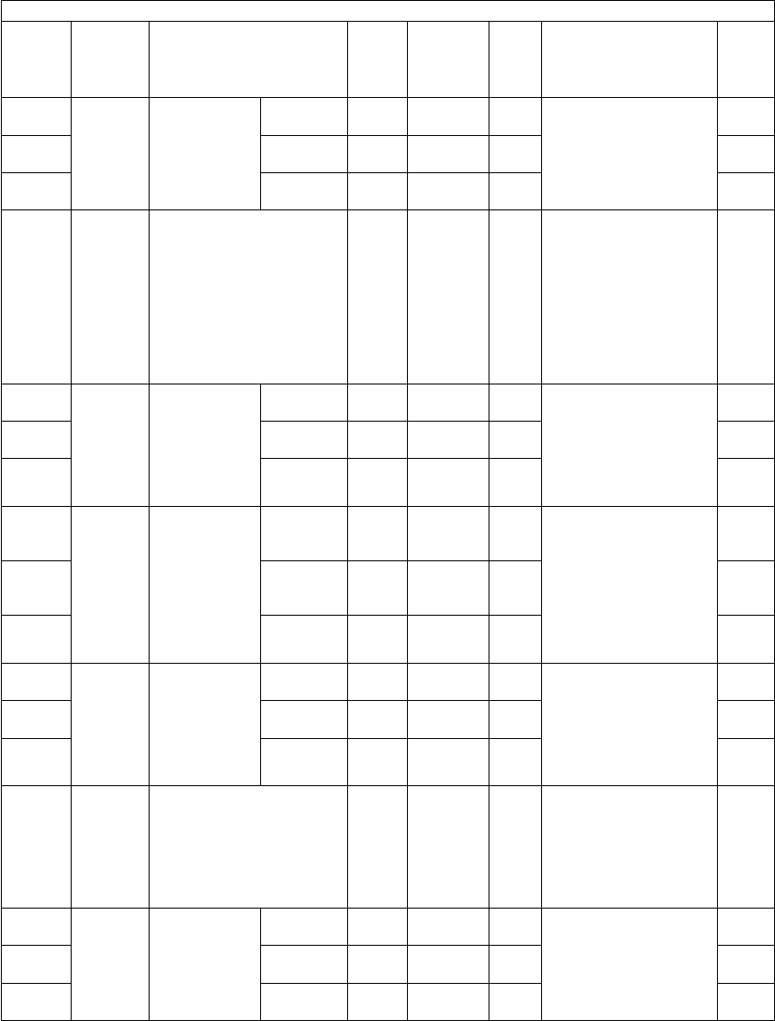
e-STUDIO281c/351c/451c ERROR CODE AND SELF-DIAGNOSTIC MODE© June 2005 TOSHIBA TEC
2 - 140
820-0Develop-
ment
Color auto-
toner sensor
output
display for
developer
material
YALL
(color)
-
<0-1023>
MDisplays the output
value of the color auto-
toner sensor to the
sleeve in color printing.
4
820-1MALL
(color)
-
<0-1023>
M4
820-2CALL
(color)
-
<0-1023>
M4
821Develop-
ment
ON/OFF of the mode for
developer material stabili-
zation
ALL
(color)
0
<0-1>
MSets whether or not
performing an aging to
stabilize the status of
developer material
when the toner density
is uneven or the toner
charging amount is low-
ered.
0: ON
1: OFF
1
822-0Develop-
ment
Number of
times the
mode for
developer
material stabi-
lization is per-
formed
YALL
(color)
0
<0-255>
MDisplays the number of
times the developer
material stabilization is
performed.
4
822-1MALL
(color)
0
<0-255>
M4
822-2CALL
(color)
0
<0-255>
M4
823-0Develop-
ment
Color auto-
toner sensor/
light amount
correction
voltage abnor-
mal detection
YALL
(color)
0
<0-1>
MDisplays 1! when the
abnormal output volt-
age is detected for the
color auto-toner sensor
light amount correction.
([CF40] error)
0: Normal
1: Abnormality
detected
4
823-1MALL
(color)
0
<0-1>
M4
823-2CALL
(color)
0
<0-1>
M4
824-0Develop-
ment
Color auto-
toner sensor/
toner density
detection volt-
age abnormal
detection
YALL
(color)
0
<0-1>
MDisplays 1! when the
abnormal toner density
detection voltage is
detected. ([CF20] error)
0: Normal
1: Abnormality
detected
4
824-1MALL
(color)
0
<0-1>
M4
824-2CALL
(color)
0
<0-1>
M4
849FuserFusing control switching for
TWD and SAD models
ALLOther
than
TWD and
SAD: 0
TWD and
SAD: 1
<0-1>
M1
858-0Develop-
ment
Color toner
forced supply
level display
YALL
(color)
0
<0-1>
MBecomes 1! when the
toner density decreases
and it is judged forced
toner supply is needed.
0: Normal level
1: Forced supply level
14
858-1MALL
(color)
0
<0-1>
M14
858-2CALL
(color)
0
<0-1>
M14
Setting mode (08)
Code Classifi-
cation Items Func-
tion
Default
<Accept-
able
value>
RAMContents
Pro-
cedur
e

© June 2005 TOSHIBA TECe-STUDIO281c/351c/451c ERROR CODE AND SELF-DIAGNOSTIC MODE
2 - 141
2
859-0Develop-
ment
Toner empty
detection
YALL
(color)
0
<0-1>
MBecomes 1! when
detecting the toner
empty.
0: Normal
1: Empty detected
14
859-1MALL
(color)
0
<0-1>
M14
859-2CALL
(color)
0
<0-1>
M14
860-0Develop-
ment
Color auto-
toner sensor/
proper range
setting of OFF
level voltage
Upper limitALL
(color)
20
<0-1023>
MSets the range for judg-
ing whether the sensor
output value when the
sensor light source is
OFF is correct
or not.
4
860-1Lower limitALL
(color)
0
<0-1023>
M4
861-0Develop-
ment
Color auto-
toner sensor/
proper range
setting of
standard light
amount volt-
age
Upper limitALL
(color)
205
<0-255>
MSets the range for judg-
ing whether the adjust-
ment result of sensor
light amount is correct
or not.
4
861-1Lower limitALL
(color)
40
<0-255>
M4
862-0Develop-
ment
Color auto-
toner sensor/
proper range
setting of ref-
erence plate
output
Upper limitALL
(color)
950
<0-1023>
MSets the range for judg-
ing whether the sensor
output value for the ref-
erence plate is correct
or not.
4
862-1Lower limitALL
(color)
205
<0-1023>
M4
863-0Develop-
ment
Color auto-
toner sensor/
proper range
setting of
developer out-
put
Upper limitALL
(color)
450
<0-1023>
MSets the range for judg-
ing whether the sensor
output value for the
sleeve is correct or not.
4
863-1Lower limitALL
(color)
155
<0-1023>
M4
864Develop-
ment
Color auto-toner sensor/
sensor OFF output value
display at power ON
ALL
(color)
-
<0-1023>
MDisplays the sensor
output value when the
sensor light source is
OFF at power ON.
2
865Develop-
ment
Color auto-toner sensor/
reference plate output
value display at power ON
ALL
(color)
-
<0-1023>
MDisplays the sensor
output value with the
standard light amount
for the reference plate
at power ON.
2
866-0Develop-
ment
Color auto-
toner sensor/
abnormal
detection
potential dif-
ference set-
ting of
reference
plate output
Upper limitALL
(color)
820
<0-1023>
MSets the range for judg-
ing whether the differ-
ence between the
sensor output when the
sensor light source is
OFF and the sensor
output for the reference
plate is correct or not.
4
866-1Develop-
ment
Lower limitALL
(color)
205
<0-1023>
M4
867Develop-
ment
Color auto-toner control
environment and life light
amount correction setting
ALL
(color)
0
<0-1>
MSets whether the sen-
sor light amount is cor-
rected or not depending
on the environment and
life.
0: Correction
1: No correction
1
Setting mode (08)
Code Classifi-
cation Items Func-
tion
Default
<Accept-
able
value>
RAMContents
Pro-
cedur
e
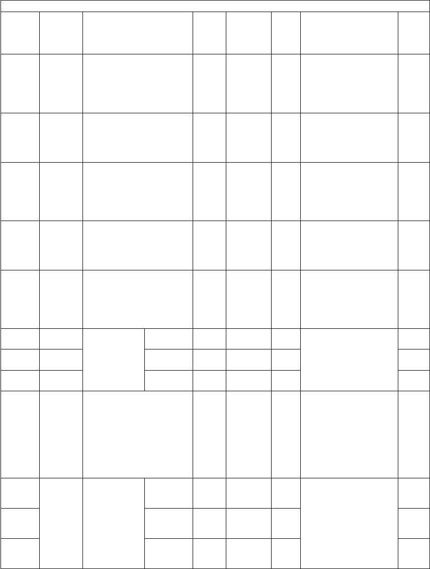
e-STUDIO281c/351c/451c ERROR CODE AND SELF-DIAGNOSTIC MODE© June 2005 TOSHIBA TEC
2 - 142
868Develop-
ment
Color auto-toner adjust-
ment finishing range set-
ting
ALL
(color)
4
<0-255>
MSets the difference from
the target value for
judging whether the
color auto-toner adjust-
ment finishes correctly
or not.
1
869Develop-
ment
Color auto-toner control
environment and life light
amount correction/correc-
tion finishing range setting
ALL
(color)
5
<0-255>
MSets the difference from
the target value for
judging whether the
light amount correction
finishes correctly or not.
1
870Develop-
ment
Color auto-toner sensor/
setting of number of times
of error detection at light
amount correction
ALL
(color)
3
<0-255>
MSets the number of
times of continuous
error detection before
the light amount correc-
tion abnormality is dis-
played.
1
871Develop-
ment
Color auto-toner control
environment and life light
amount correction/display
of number of times of refer-
ence plate detection error
ALL
(color)
0
<0-255>
MDisplays the number of
times of the reference
plate detection error for
the environment and life
light amount correction.
2
872Develop-
ment
Color auto-toner control
environment and life light
amount correction/display
of number of times of light
amount control voltage
adjustment error
ALL
(color)
0
<0-255>
MDisplays the number of
times of the light
amount control voltage
adjustment error for the
environment and life
light amount correction.
2
873-0Develop-
ment
Color auto-
toner control/
developer ini-
tial output set-
ting
YALL
(color)
256
<0-1023>
MSets the initial devel-
oper output target
value.
4
873-1Develop-
ment
MALL
(color)
256
<0-1023>
M4
873-2Develop-
ment
CALL
(color)
256
<0-1023>
M4
874Develop-
ment
Color developer life correc-
tion
ALL
(color)
0
<0-1>
MSets whether the toner
density detection volt-
age correction is per-
formed or not
depending on the
developer life in the
color auto-toner control.
0: Corrected
1: Not corrected
1
875-0Develop-
ment
Color devel-
oper life cor-
rection value
(segment 0)
YALL
(color)
0
<-512-
511>
MSets the correction
amount of the toner
density detection volt-
age depending on the
developer life. In this
code, the life count
within 0-2000 is set as
the correction amount.
4
875-1MALL
(color)
0
<-512-
511>
M4
875-2CALL
(color)
0
<-512-
511>
M4
Setting mode (08)
Code Classifi-
cation Items Func-
tion
Default
<Accept-
able
value>
RAMContents
Pro-
cedur
e

© June 2005 TOSHIBA TECe-STUDIO281c/351c/451c ERROR CODE AND SELF-DIAGNOSTIC MODE
2 - 143
2
876-0Develop-
ment
Color devel-
oper life cor-
rection value
(segment 1)
YALL
(color)
-4
<-512-
511>
MSets the correction
amount of the toner
density detection volt-
age depending on the
developer life. In this
code, the life count
within 2001-5000 is set
as the correction
amount.
4
876-1MALL
(color)
-2
<-512-
511>
M4
876-2CALL
(color)
-2
<-512-
511>
M4
877-0Develop-
ment
Color devel-
oper life cor-
rection value
(segment 2)
YALL
(color)
-6
<-512-
511>
MSets the correction
amount of the toner
density detection volt-
age depending on the
developer life. In this
code, the life count
within 5001-10000 is
set as the correction
amount.
4
877-1MALL
(color)
-3
<-512-
511>
M4
877-2CALL
(color)
-3
<-512-
511>
M4
878-0Develop-
ment
Color devel-
oper life cor-
rection value
(segment 3)
YALL
(color)
-8
<-512-
511>
MSets the correction
amount of the toner
density detection volt-
age depending on the
developer life. In this
code, the life count
within 10001-20000 is
set as the correction
amount.
4
878-1MALL
(color)
-4
<-512-
511>
M4
878-2CALL
(color)
-4
<-512-
511>
M4
879-0Develop-
ment
Color devel-
oper life cor-
rection value
(segment 4)
YALL
(color)
-10
<-512-
511>
MSets the correction
amount of the toner
density detection volt-
age depending on the
developer life. In this
code, the life count
within 20001-30000 is
set as the correction
amount.
4
879-1MALL
(color)
-5
<-512-
511>
M4
879-2CALL
(color)
-5
<-512-
511>
M4
880-0Develop-
ment
Color devel-
oper life cor-
rection value
(segment 5)
YALL
(color)
-12
<-512-
511>
MSets the correction
amount of the toner
density detection volt-
age depending on the
developer life. In this
code, the life count
within 30001-37500 is
set as the correction
amount.
4
880-1MALL
(color)
-6
<-512-
511>
M4
880-2CALL
(color)
-6
<-512-
511>
M4
881-0Develop-
ment
Color devel-
oper life cor-
rection value
(segment 6)
YALL
(color)
-12
<-512-
511>
MSets the correction
amount of the toner
density detection volt-
age depending on the
developer life. In this
code, the life count
37501 or more is set as
the correction amount.
4
881-1MALL
(color)
-6
<-512-
511>
M4
881-2CALL
(color)
-6
<-512-
511>
M4
Setting mode (08)
Code Classifi-
cation Items Func-
tion
Default
<Accept-
able
value>
RAMContents
Pro-
cedur
e

e-STUDIO281c/351c/451c ERROR CODE AND SELF-DIAGNOSTIC MODE© June 2005 TOSHIBA TEC
2 - 144
900VersionSystem firmware ROM ver-
sion
ALL--JPN: T410SY0JXXX
UC: T410SY0UXXX
EUR: T410SY0EXXX
Others: T410SY0XXXX
2
903VersionEngine ROM versionALL--410M-XXX2
905VersionScanner ROM versionALL--410S-XXX2
907VersionRADF ROM versionALL--DF-XXXX2
908VersionFinisher ROM versionALL--SDL-XX FIN-XX2
911VersionFinisher punch ROM ver-
sion
ALL--PUN-XXX2
915VersionFAX board ROM versionFAX--F562-XXX2
920VersionFROM basic section soft-
ware version
ALL--VX.XX/X.XX2
921VersionFROM internal programALL--VXXX.XXX X2
922VersionUI data fixed section ver-
sion
ALL--VXXX.XXX X2
923VersionUI data common section
version
ALL--VXXX.XXX X2
924VersionVersion of UI data lan-
guage 1 in HDD
ALL--VXXX.XXX X2
925VersionVersion of UI data lan-
guage 2 in HDD
ALL--VXXX.XXX X2
926VersionVersion of UI data lan-
guage 3 in HDD
ALL--VXXX.XXX X2
927VersionVersion of UI data lan-
guage 4 in HDD
ALL--VXXX.XXX X2
928VersionVersion of UI data lan-
guage 5 in HDD
ALL--VXXX.XXX X2
929VersionVersion of UI data lan-
guage 6 in HDD
ALL--VXXX.XXX X2
930VersionVersion of UI data in
FROM displayed at power-
ON
ALL--VXXX.XXX X2
931VersionVersion of UI data lan-
guage 7 in HDD
ALL--VXXX.XXX X2
933VersionWeb data whole versionALL--VXXX.XXX X2
934VersionWeb UI data in HDD
Version: Language 1
ALL--VXXX.XXX X2
935VersionWeb UI data in HDD
Version: Language 2
ALL--VXXX.XXX X2
936VersionWeb UI data in HDD
Version: Language 3
ALL--VXXX.XXX X2
937VersionWeb UI data in HDD
Version: Language 4
ALL--VXXX.XXX X2
938VersionWeb UI data in HDD
Version: Language 5
ALL--VXXX.XXX X2
939VersionWeb UI data in HDD
Version: Language 6
ALL--VXXX.XXX X2
944VersionHD versionALL--JPN: T410HD0JXXX
UC: T410HD0UXXX
EUR: T410HD0EXXX
Others: T410HD0XXXX
2
945NetworkTwo-way setting of Raw-
Port 9100
ALL2
<1-2>
UTY1: Valid
2: Invalid
12
Setting mode (08)
Code Classifi-
cation Items Func-
tion
Default
<Accept-
able
value>
RAMContents
Pro-
cedur
e
06/08

© June 2005 TOSHIBA TECe-STUDIO281c/351c/451c ERROR CODE AND SELF-DIAGNOSTIC MODE
2 - 145
2
947GeneralInitialization after software
version upgrade
ALL--Perform this code when
the software in this
equipment has been
upgraded.
3
949GeneralAutomatic interruption
page setting during black
printing
ALL0
<0-100>
SYSSets the number of
pages to interrupt the
printing automatically.
0-100: 0 to 100 pages
1
950Elec-
tronic
filing
Start-up method of Elec-
tronic Filing
ALL0
<0-2>
SYSSets the start-up
method of the Elec-
tronic Filing.
0: Standard
1: Forced start-up
(Not recovered)
2: Forced start-up
(Recovered)
1
951User
interface
Image setting for Electronic
Filing printing (Only for
color image)
ALL0
<0-3>
SYS0: General
1: Photograph
2:Presentation
3: Line art
1
953User
interface
Access code entry for
Electronic Filing printing
ALL0
<0-1>
SYS0:Renewed automati-
cally
1: Enter every time
1
954User
interface
Clearing timing for files and
Electronic Filing Agent
ALL1
<0-1>
SYS0: Immediately after
the completion of
scanning
1: Cleared by Auto
Clear
1
969User
interface
Error soundALL1
<0-1>
SYS0: OFF
1: ON
1
970User
interface
Sound setting when
switching to Energy Saving
Mode
ALLEUR: 1
UC: 1
JPN: 0
<0-1>
SYS0: OFF
1:ON
1
973NetworkPCL line feed code settingPRT0
<0-3>
SYSSets the PCL line feed
code.
0: Automatic setting
1: CR=CR, LF=LF
2: CR=CR+LF, LF=LF
3: CR=CR, LF=CR+LF
1
975GeneralJob handling when print-
ing is short paid with coin
controller
ALL1
<0-1>
SYSSets whether pause or
stop the printing job
when it is short paid
using a coin controller.
0: Pause the job
1: Stop the job
1
976ScanningEquipment name and user
name setting to a folder
when saving files
ALL0
<0-2>
SYSSets whether or not
adding the equipment
name and user name to
the folder when saving
files.
0: Not add
1: Add the equipment
name
2:Add the user name
1
Setting mode (08)
Code Classifi-
cation Items Func-
tion
Default
<Accept-
able
value>
RAMContents
Pro-
cedur
e
06/08
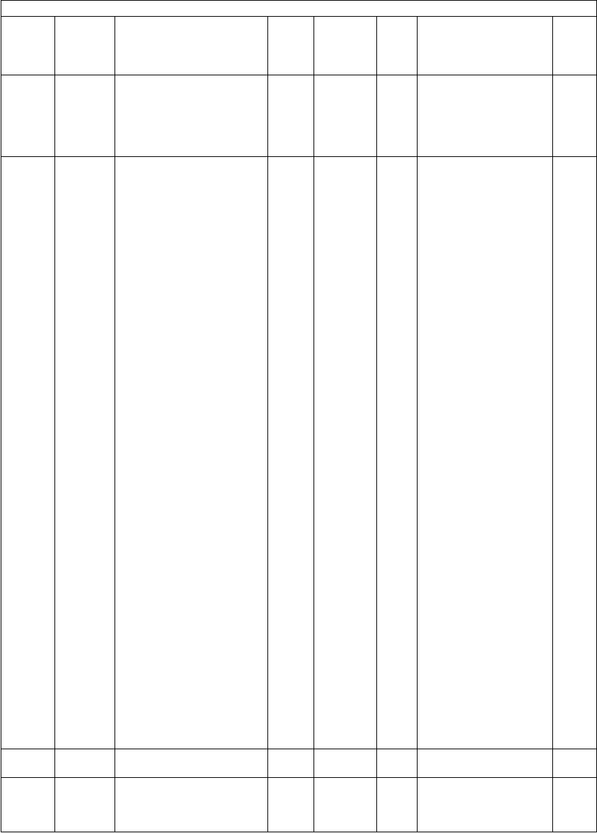
e-STUDIO281c/351c/451c ERROR CODE AND SELF-DIAGNOSTIC MODE© June 2005 TOSHIBA TEC
2 - 146
978NetworkRaw printing job
(Paper feeding drawer)
PRT0
<0-5>
SYS0: AUTO
1: Upper drawer
2: Lower drawer
3: PFP upper drawer
4: PFP lower drawer
5: LCF
1
979NetworkRaw printing job
(PCL symbol set)
PRT0
<0-39>
SYS0: Roman-8
1:ISO 8859/1 Latin 1
2: ISO 8859/2 Latin 2
3:ISO 8859/9 Latin 5
4: PC-8, Code Page
437
5: PC-8 D/N, Danish/
Norwegian
6: PC-850, Multilingual
7: PC-852, Latin2
8: PC-8 Turkish
9: Windows 3.1 Latin 1
10: Windows 3.1 Latin 2
11: Windows 3.1 Latin 5
12: DeskTop
13: PS Text
14: Ventura Interna-
tional
15: Ventura US
16: Microsoft Publishing
17: Math-8
18: PS Math
19: Ventura Math
20: Pi Font
21: Legal
22: ISO 4: United King-
dom
23: ISO 6: ASCII
24: ISO 11
25: ISO 15: Italian
26: ISO 17
27: ISO 21: German
28: ISO 60: Danish/Nor-
wegian
29: ISO 69: French
30: Windows 3.0 Latin 1
31: MC Text
32: PC Cyrillic
33: ITC Zapf Dingbats
34: ISO 8859/10 Latin 6
35: PC-775
36: PC-1004
37: Symbol
38: Windows Baltic
39: Wingdings
1
983User
interface
JOB STATUS initial screen
setting
ALL0
<0-1>
SYS0:Print
1:Private
1
986GeneralCopy function settingPPC0
<0-1>
SYSSets the copy function
to be invalid.
0: Valid
1: Invalid
1
Setting mode (08)
Code Classifi-
cation Items Func-
tion
Default
<Accept-
able
value>
RAMContents
Pro-
cedur
e
06/08

© June 2005 TOSHIBA TECe-STUDIO281c/351c/451c ERROR CODE AND SELF-DIAGNOSTIC MODE
2 - 147
2
988Paper
feeding
Setting of paper size
switching to 13" LG
ALL0
<0-2>
SYS0: Not switched
1: LG 13"LG
2: FOLIO 13"LG
1
995Mainte-
nance
Equipment number
(serial number) display
ALL0
<10 dig-
its>
SYSThis code can be also
keyed in from the
adjustment mode (05-
976).
10 digits
11
999Mainte-
nance
FSMS total counterALL0
<8 digits>
SYSRefer to values of total
counter.
1
1002NetworkSelection of NIC board sta-
tus information
ALL1
<1-2>
NIC1: Not printed out
when the copier is
restarted
2: Printed out when
the copier is
restarted
12
1003NetworkCommunication speed and
settings of Ethernet
ALL1
<1-5>
NIC1:Auto
2:10MBPS Half
Duplex
3:10MBPS Full
Duplex
4:100MBPS Half
Duplex
5:100MBPS Full
Duplex
12
1006NetworkAddress ModeALL2
<1-3>
NIC1: Fixed IP address
2: Dynamic IP address
3: Dynamic IP address
without AutoIP
12
1007NetworkDomain nameALL-NICMaximum 96 letters12
1008NetworkIP addressALL-NIC000.000.000.000-
255.255.255.255
(Default value
000.000.000.000)
12
1009NetworkSubnet maskALL-NIC000.000.000.000-
255.255.255.255
(Default value
000.000.000.000)
12
1010NetworkGatewayALL-NIC000.000.000.000-
255.255.255.255
(Default value
000.000.000.000)
12
1011NetworkAvailability of IPXALL1
<1-2>
NIC1: Available
2: Not available
12
1012NetworkNetwork frame typeALL1
<1-5>
NIC1: Automatic
2: IEEE802.3
3: Ethernet II
4: IEEE802.3 SNAP
5: IEEE802.2
12
1014NetworkAvailability of AppleTalkALL1
<1-2>
NIC1: Available
2: Not available
12
1015NetworkZone setting of AppleTalkALL*NICMaximum 32 letters
*: Wildcard character
12
1016NetworkAvailability of LDAPALL1
<1-2>
NIC1: Available
2: Not available
12
1017NetworkAvailability of DNSALL1
<1-2>
NIC1: Available
2: Not available
12
Setting mode (08)
Code Classifi-
cation Items Func-
tion
Default
<Accept-
able
value>
RAMContents
Pro-
cedur
e

e-STUDIO281c/351c/451c ERROR CODE AND SELF-DIAGNOSTIC MODE© June 2005 TOSHIBA TEC
2 - 148
1018NetworkIP address to DNS server
(Primary)
ALL-NIC000.000.000.000-
255.255.255.255
(Default value
000.000.000.000)
12
1019NetworkIP address to DNS server
(Secondary)
ALL-NIC000.000.000.000-
255.255.255.255
(Default value
000.000.000.000)
12
1020NetworkDDNS Desired levelALL1
<1-5>
NIC1: Invalid
2: Via DHCP
3: Insecure DDNS
4: Secure DDNS
5: Multi-secure DDNS
12
1022NetworkFrom Name Creation set-
ting in SMTP authentica-
tion
ALL0
<0-1>
SYS0:Not edited
1: Account name of
From Address
+Device name
1
1023NetworkNetBios nameALLMFP_
serial
UTYMaximum 15 letters
The network-related
serial number of the
equipment appears at
"serial"
12
1024NetworkName of WINS server or IP
address (Primary)
ALL-UTY000.000.000.000-
255.255.255.255
(Default value
000.000.000.000)
12
1025NetworkName of WINS server or IP
address (Secondary)
ALL-UTY000.000.000.000-
255.255.255.255
(Default value
000.000.000.000)
12
1026NetworkAvailability of BinderyALL1
<1-2>
NIC1: Available
2: Not available
12
1027NetworkAvailability of NDSALL1
<1-2>
NIC1: Available
2: Not available
12
1028NetworkDirectory service contextALL-NICMaximum 127 letters12
1029NetworkDirectory service treeALL-NICMaximum 47 letters12
1030NetworkAvailability of HTTP serverALL1
<1-2>
NIC1: Available
2: Not available
12
1031NetworkPort number to NIC HTTP
server
ALL80
<1-
65535>
NIC12
1032NetworkPort number to system
HTTP server
ALL8080
<1-
65535>
NIC12
1037NetworkAvailability of SMTP clientALL1
<1-2>
NIC1: Available
2: Not available
12
1038NetworkFQDN or IP address to
SMTP server
ALL-NICMaximum 128 Bytes12
1039NetworkTCP port number of SMTP
client
ALL25
<1-
65535>
NIC12
1040NetworkAvailability of SMTP serverALL1
<1-2>
UTY1: Available
2: Not available
12
1041NetworkTCP port number of SMTP
server
ALL25
<1-
65535>
UTY12
Setting mode (08)
Code Classifi-
cation Items Func-
tion
Default
<Accept-
able
value>
RAMContents
Pro-
cedur
e
05/11

© June 2005 TOSHIBA TECe-STUDIO281c/351c/451c ERROR CODE AND SELF-DIAGNOSTIC MODE
2 - 149
2
1042NetworkE-mail box name to SMTP
server
ALL-UTYMaximum 192 letters12
1043NetworkAvailability of OfframpALL2
<1-2>
UTY1: Available
2: Not available
12
1044NetworkOfframp securityALL1
<1-2>
UTY1: Available
2: Not available
12
1045NetworkPrinting at OfframpALL1
<1-2>
UTY1: Available
2: Not available
12
1046NetworkAvailability of POP3 clientsALL1
<1-2>
NIC1: Available
2: Not available
12
1047NetworkFQDN or IP address to
POP3 server
ALL-NICMaximum 128 Bytes12
1048NetworkTypes of POP3 serverALL1
<1-3>
NIC1: Automatic
2: POP3
3: APOP
12
1049NetworkLogin name to POP3
server
ALL-NICMaximum 96 letters12
1050NetworkLogin password to POP3ALL-NICMaximum 96 letters12
1051NetworkE-mail reception intervalALL5
<0-4096>
NICUnit: Minute12
1052NetworkTCP port number of POP3
client
ALL110
<1-
65535>
NIC12
1055NetworkTCP port number of FTP
client
ALL21
<1-
65535>
UTY12
1059NetworkAvailability of FTP serverALL1
<1-2>
NIC1: Available
2: Not available
12
1060NetworkTCP port number of FTP
server
ALL21
<1-
65535>
UTY12
1063NetworkMIB functionALL1
<1-2>
NIC1: Valid
2: Invalid
12
1065NetworkSetting of read CommunityALLpublicNICMaximum 31 letters12
1066NetworkSetting of read/Write Com-
munity
ALLprivateNICMaximum 31 letters12
1069NetworkTRAP destination IP
address
ALL-UTY000.000.000.000-
255.255.255.255
(Default value
000.000.000.000)
12
1070NetworkCommunity setting of
TRAP (via IP)
ALLpublicNICMaximum 31 letters12
1073NetworkAvailability of Raw/TCPALL1
<1-2>
NIC1:Valid
2:Invalid
12
1074NetworkTCP port number of RawALL9100
<1-
65535>
NIC12
1075NetworkAvailability of LPD clientALL1
<1-2>
NIC1: Valid
2: Invalid
12
1076NetworkTCP port number of LPDALL515
<1-
65535>
NIC12
1077NetworkLPD queue nameALL-NICMaximum 31 letters12
1078NetworkAvailability of IPPALL1
<1-2>
NIC1: Valid
2: Invalid
12
Setting mode (08)
Code Classifi-
cation Items Func-
tion
Default
<Accept-
able
value>
RAMContents
Pro-
cedur
e

e-STUDIO281c/351c/451c ERROR CODE AND SELF-DIAGNOSTIC MODE© June 2005 TOSHIBA TEC
2 - 150
1079NetworkAvailability of IPP port
number 80!
ALL1
<1-2>
NIC1: Valid
2: Invalid
12
1080NetworkTCP port number of IPPALL631
<1-
65535>
NIC12
1081NetworkIPP printer nameALLMFP_
serial
NICMaximum 127 letters
The network-related
serial number of the
equipment appears at
"serial"
12
1082NetworkIPP printer locationALL-NICMaximum 127 letters12
1083NetworkIPP printer informationALL-NICMaximum 127 letters12
1084NetworkIPP printer information
(more)
ALL-NICMaximum 127 letters12
1085NetworkInstaller of IPP printer
driver
ALL-NICMaximum 127 letters12
1086NetworkIPP printer Make and
Model!
ALL-NICMaximum 127 letters12
1087NetworkIPP printer information
(more)
MFGR
ALL-NICMaximum 127 letters12
1088NetworkIPP message from opera-
tor
ALL-NICMaximum 127 letters12
1089NetworkAvailability of FTP printALL1
<1-2>
NIC1: Available
2: Not available
12
1090NetworkPrinter user name of FTPALLprintNICMaximum 31 letters12
1091NetworkPrinter user password of
FTP
ALL-NICMaximum 31 letters12
1092NetworkTCP port number to FTP
print server
ALL21
<1-
65535>
NIC12
1093NetworkLogin name to Novell print
server
ALLMFP_
serial
NICMaximum 47 letters
The network-related
serial number of the
equipment appears at
"serial"
12
1094NetworkLogin password to Novell
print server
ALL-NICMaximum 31 letters12
1095NetworkName of SearchRoot
server
ALL-NICMaximum 31 letters12
1096NetworkScan rate setting of print
queue
ALL5
<1-255>
NICUnit: Second12
1097NetworkPage number limitation for
printing text of received
Email
ALL5
<1-99>
UTY12
1098NetworkMDN return mail setting
when receiving E-mail
ALL2
<1-2>
UTY1: Valid
2: Invalid
12
1099NetworkTrap destination of IPXALL-UTY24 letters
(Valid from 0 to 9 and
from A to F)
12
Setting mode (08)
Code Classifi-
cation Items Func-
tion
Default
<Accept-
able
value>
RAMContents
Pro-
cedur
e
05/11

© June 2005 TOSHIBA TECe-STUDIO281c/351c/451c ERROR CODE AND SELF-DIAGNOSTIC MODE
2 - 151
2
1100NetworkMethod of SMTP server
authentication
ALL1
<1-7,10>
NIC1: Disable
2: Plain
3: Login
4; Cram-MD5
5: Digest MD5
6: Kerberos
7:NTLM
10:Auto
12
1101NetworkLogin name for SMTP
server authentication
ALL-NICMaximum 64 letters12
1102NetworkLogin password for SMTP
server authentication
ALL-NICMaximum 64 letters12
1103NetworkRendezvous settingALL1
<1-2>
NIC1: Valid
2: Invalid
12
1104NetworkLink local host nameALLMFP_
serial
NICMaximum 127 letters
The network-related
serial number of the
equipment appears at
"serial"
12
1105NetworkService name settingALLRefer to
contents
NICMaximum 63 letters
The network-related
serial number of the
equipment appears at
"serial"
<Default value>
e-STUDIO281C:
TOSHIBA
e-STUDIO281C_serial
e-STUDIO351C:
TOSHIBA
e-STUDIO351C_serial
e-STUDIO451C:
TOSHIBA
e-STUDIO451C_serial
12
1111NetworkPOP Before SMTP settingALL2
<1-2>
NIC1: Valid
2: Invalid
12
1112NetworkHost nameALLMFP_
serial
NICMaximum 63 letters
The network-related
serial number of the
equipment appears at
"serial"
12
1113NetworkWindows domain No.1 of
user authentication
ALL-UTYMaximum 128 letters12
1114NetworkSending mail text of Inter-
netFAX
ALL1
<0-1>
SYS0: Invalid
1: Valid
1
1117NetworkSMB time-out periodALL300
<1-9999>
SYSUnit: Second1
1118GeneralClearing of TAT partitionALL-SYS3
1119NetworkInitialization of NIC infor-
mation
ALL--Initializes only the infor-
mation of the Network
setting items.
3
1121NetworkPDC (Primary Domain
Controller) name No.1 of
authentication
ALL-UTYMaximum 128 letters12
1122NetworkBDC (Backup Domain
Controller) name No.1 of
authentication
ALL-UTYMaximum 128 letters12
Setting mode (08)
Code Classifi-
cation Items Func-
tion
Default
<Accept-
able
value>
RAMContents
Pro-
cedur
e
06/08

e-STUDIO281c/351c/451c ERROR CODE AND SELF-DIAGNOSTIC MODE© June 2005 TOSHIBA TEC
2 - 152
1123NetworkWindows domain of device
authentication
ALL4
<3-4>
UTY3: ON
(Domain selected)
4: OFF
(Work group
selected)
12
1124NetworkWorkgroup nameALLwork-
group
UTYMaximum 15 letters12
1125GeneralData writing of address
book data import
(overwriting method)
ALL0
<0-1>
SYS0: Invalid
1: Valid
1
1126CounterValidity of interrupt copy-
ing when external counters
are installed
ALL0
<0-1>
SYS0: Invalid
1: Valid
1
1128NetworkNetwareUserAuthTree
Name1
ALL-UTYMaximum 47 letters12
1129NetworkNetwareUserAuthContext
Name1
ALL-UTYMaximum 127 letters12
1130User
interface
Job Build FunctionALL1
<0-1>
SYSSets the Job Build
Function.
0: Invalid
1: Valid
1
1131User
interface
Maximum number of time
job build performed
ALL1000
<5-1000>
SYSSets the maximum
number of time a job
build has been per-
formed.
5-1000: 5 to 1000 times
1
1132GeneralDefault screen selection of
the User Function menu
ALL1
<0-1>
SYSSelects the default
screen when entering
the User Function menu
by pressing the [USER
FUNCTIONS] button.
0: ADDRESS
1: COUNTER
1
1134NetworkNetwareUserAuthTree
Name2
ALL-UTYMaximum 47 letters12
1135Paper
feeding
Default setting of drawers
(Printer/BOX)
ALL1
<1-5>
SYS1: LCF
2: Upper drawer
3: Lower drawer
4: PFP upper drawer
5: PFP lower drawer
1
1138NetworkLDAP search method set-
ting
ALL0
<0-3>
SYSSets the search method
when performing a
LDAP search.
0: Partial match
1: Prefix match
2: Suffix match
3: Full match
1
1139NetworkLDAP authentication set-
ting
ALL0
<0-1>
SYS0: Not authenticated
1:Authenticated
1
1140User
interface
Restriction of the template
function with the adminis-
trator privilege
ALL0
<0-1>
SYSSelects the restriction of
the template function
usage setting.
0: No restriction
1: Only available with
the administrator
privilege.
1
Setting mode (08)
Code Classifi-
cation Items Func-
tion
Default
<Accept-
able
value>
RAMContents
Pro-
cedur
e
06/08

© June 2005 TOSHIBA TECe-STUDIO281c/351c/451c ERROR CODE AND SELF-DIAGNOSTIC MODE
2 - 153
2
1141NetworkDisplay of MAC addressALL-SYS(**:**:**:**:**:**)
The address is dis-
played as above (6-byte
data is divided by a
colon at every 2 bytes).
2
1143NetworkNetwareUserAuthContext
Name2
ALL-UTYMaximum 127 letters12
1144NetworkNetwareUserAuthTree
Name3
ALL-UTYMaximum 47 letters12
1145Mainte-
nance
(Remote)
Counter notification
Remote FAX setting
ALL-SYSMaximum 32 digits
Enter a hyphen with the
[MONITOR/PAUSE]
button.
11
1148NetworkNetwareUserAuthContext
Name3
ALL-UTYMaximum 127 letters12
1370Image
process-
ing
Image quality control time
accumulating counter
ALL0
<8 digits>
MCounts driving count of
the drum (image qual-
ity control time).
Counts up when drum
motor and image quality
control are ON.
1
1371Image
process-
ing
Accumulated counter of
output pages since the per-
forming of image quality
control
ALL0
<4 digits>
MCleared to 0! by the
image quality closed-
loop control. Counts up
with the number of
printing job received
after this control.
2
1372Image
process-
ing
Heater and energizing time
accumulating counter Dis-
play/0 clearing
ALL0
<8 digits>
MCounts up the heater
control time accumu-
lated (when power of
the copier is ON) but
does not count at the
Sleep Mode. When the
counter value of the
fuser belt is cleared,
this counter value is
also cleared in sync at
PM support mode.
1
1378Image
process-
ing
Fuser roller ready tempera-
ture time accumulating
counter
ALL0
<8 digits>
MCounts up the heater
control time accumu-
lated (on standby).
When the counter value
of the fuser belt is
cleared, this counter
value is also cleared in
sync at PM support
mode.
2
1380Image
process-
ing
Fuser roller printing tem-
perature time accumulating
counter
ALL0
<8 digits>
MCounts up the heater
control time accumu-
lated (during printing).
When the counter value
of the fuser belt is
cleared, this counter
value is also cleared in
sync at PM support
mode.
2
Setting mode (08)
Code Classifi-
cation Items Func-
tion
Default
<Accept-
able
value>
RAMContents
Pro-
cedur
e
05/11

e-STUDIO281c/351c/451c ERROR CODE AND SELF-DIAGNOSTIC MODE© June 2005 TOSHIBA TEC
2 - 154
1382Image
process-
ing
Fuser roller energy saving
temperature time accumu-
lating counter Display/0
clearing
ALL0
<8 digits>
MCounts up the heater
control time accumu-
lated (at energy saving
mode). When the
counter value of the
fuser belt is cleared,
this counter value is
also cleared in sync at
PM support mode.
2
1385Image
process-
ing
Number of output pages
(Thick paper 1)
ALL0
<8 digits>
MCounts up when the
registration sensor is
ON. When the counter
value of the fuser belt is
cleared, this counter
value is also cleared in
sync at PM support
mode.
1
1386Image
process-
ing
Number of output pages
(Thick paper 2)
ALL0
<8 digits>
MCounts up when the
registration sensor is
ON. When the counter
value of the fuser belt is
cleared, this counter
value is also cleared in
sync at PM support
mode.
1
1387Image
process-
ing
Number of output pages
(Thick paper 3)
ALL0
<8 digits>
MCounts up when the
registration sensor is
ON. When the counter
value of the fuser belt is
cleared, this counter
value is also cleared in
sync at PM support
mode.
1
1388Image
process-
ing
Number of output pages
(OHP film)
ALL0
<8 digits>
MCounts up when the
registration sensor is
ON. When the counter
value of the fuser belt is
cleared, this counter
value is also cleared in
sync at PM support
mode.
1
1389Main
charger
Main charger wire clean-
ing counter display/0 clear-
ing
ALL0
<5 digits>
MDoes not count up
when cleaning is not
effective.
1
1390Paper
feeding
Feeding retry counter
(upper drawer)
ALL0
<8 digits>
MCounts the number of
times of the feeding
retry from the upper
drawer.
1
1391Paper
feeding
Feeding retry counter
(lower drawer)
ALL0
<8 digits>
MCounts the number of
times of the feeding
retry from the lower
drawer.
1
1392Paper
feeding
Feeding retry counter
(PFP upper drawer)
ALL0
<8 digits>
MCounts the number of
times of the feeding
retry from the PFP
upper drawer.
1
Setting mode (08)
Code Classifi-
cation Items Func-
tion
Default
<Accept-
able
value>
RAMContents
Pro-
cedur
e

© June 2005 TOSHIBA TECe-STUDIO281c/351c/451c ERROR CODE AND SELF-DIAGNOSTIC MODE
2 - 155
2
1393Paper
feeding
Feeding retry counter
(PFP lower drawer)
ALL0
<8 digits>
MCounts the number of
times of the feeding
retry from the PFP
lower drawer.
1
1394Paper
feeding
Feeding retry counter
(bypass feed)
ALL0
<8 digits>
MCounts the number of
times of the feeding
retry from the bypass
tray.
1
1395Paper
feeding
Feeding retry counter
(LCF)
ALL0
<8 digits>
MCounts the number of
times of the feeding
retry from the LCF.
1
1396Paper
feeding
Feeding retry counter
upper limit value
(upper drawer)
ALL10
<8 digits>
MWhen the number of
feeding retry (08-1390
to 08-1395) exceeds
the setting value, the
feeding retry will not be
performed subse-
quently. In case 0! is
set as a setting value,
however, the feeding
retry continues regard-
less of the counter set-
ting value.
Refer to (Note 1).
1
1397Paper
feeding
Feeding retry counter
upper limit value
(lower drawer)
ALL10
<8 digits>
M1
1398Paper
feeding
Feeding retry counter
upper limit value
(PFP upper drawer)
ALL10
<8 digits>
M1
1399Paper
feeding
Feeding retry counter
upper limit value
(PFP lower drawer)
ALL10
<8 digits>
M1
1400Paper
feeding
Feeding retry counter
upper limit value
(bypass feed)
ALL10
<8 digits>
M1
1401Paper
feeding
Feeding retry counter
upper limit value (LCF)
ALL10
<8 digits>
M1
1410CounterBlack toner cartridge drive
counts/0 clearing
ALL0
<8 digits>
M1
1412CounterCounter for tab paperALL0
<8 digits>
MCounts up when the
registration sensor is
ON. When the counter
value of the fuser roller
is reset, this counter is
reset in sync at the PM
support mode.
1
1414Image
process-
ing
Toner cartridge wrong
installation detection ON/
OFF setting
ALL0
<0-1>
M0: ON
1: OFF
1
1415Image
process-
ing
Detection/control that the
toner cartridge is nearly
empty
ALL0
<0-2>
MSets ON or OFF of the
detection/control that
the toner cartridge is
nearly empty.
0: All colors (Y/M/C/K)
OFF
1: Black (K) ON
2: All colors (Y/M/C/K)
ON
1
1416Image
process-
ing
Threshold for detecting
that black toner cartridge is
nearly empty
ALL322500
<8 digits>
M1
Setting mode (08)
Code Classifi-
cation Items Func-
tion
Default
<Accept-
able
value>
RAMContents
Pro-
cedur
e
05/11

e-STUDIO281c/351c/451c ERROR CODE AND SELF-DIAGNOSTIC MODE© June 2005 TOSHIBA TEC
2 - 156
1422Data
over-
write kit
HDD data overwriting type
setting
ALL0
<0-2>
SYSSelect the type of the
overwriting level; LOW,
MEDIUM, or HIGH for
deleting HDD data.
(This setting is enabled
only when the GP-1060
is installed.)
0:LOW
1:MEDIUM
2:HIGH
1
1424Data
over-
write kit
HDD data clearing type
setting (forcible clearing)
ALL0
<0-2>
SYSSelect the type of the
overwriting level; LOW,
MEDIUM, or HIGH for
deleting HDD data.
(This setting is enabled
only when the GP-1060
is installed.)
0:LOW
1:MEDIUM
2:HIGH
1
1426Data
over-
write kit
Forcible HDD data clearingALL--HDD data is cleared in
the procedure set in 08-
1424.
*This setting is
enabled only when
the GP-1060 is
installed.
3
1427Data
over-
write kit
Forcible NVRAM data all
clearing
ALL--When this code is per-
formed, the equipment
cannot be started up.
*This setting is
enabled only when
the GP-1060 is
installed.
3
1428Data
over-
write kit
Forcible SRAM backup
data all clearing
ALL--When this code is per-
formed, the equipment
cannot be started up.
*This setting is
enabled only when
the GP-1060 is
installed.
3
1429User
interface
Margin width
(Top/Bottom, Left/Right)
ALLFront: 7/
Back: 7
<2-100/-
100-100>
SYSThis setting is not
reflected in "Right",
even if the value less
than 2 is set for "Back".
10
1430User
interface
Margin width
(Bookbinding margin)
ALL14
<2-30>
SYS1
1431NetworkACC
(AT_CASETTE_CHANGE)
for Printer/Box printing
ALL1
<0-2>
SYS0: ACC prohibited
1: Only in the same
paper direction
2: In both same direc-
tion and different
directions
1
1432NetworkPrivate-print-only modeALL0
<0-1>
SYS0:Normal
1:Private-print-only
mode
1
Setting mode (08)
Code Classifi-
cation Items Func-
tion
Default
<Accept-
able
value>
RAMContents
Pro-
cedur
e
05/11

© June 2005 TOSHIBA TECe-STUDIO281c/351c/451c ERROR CODE AND SELF-DIAGNOSTIC MODE
2 - 157
2
1435Network"Disable private and proof
print save" function
ALL0
<0-1>
SYS0: Function OFF (no
restriction on data
saving or other
operations)
1: Function ON (Data
saving or other
operations are
restricted)
1
1436Network"Disable fax save" functionALL0
<0-1>
SYS0: Function OFF (no
restriction on data
saving or other
operations)
1: Function ON (Data
saving or other
operations are
restricted
1
1440NetworkIP Conflict DetectALL1
<1-2>
-OFF/ON
1: Valid
2: Invalid
12
1441NetworkSNTP EnableALL2
<1-2>
-OFF/ON
1: Valid
2: Invalid
12
1442NetworkSNTP Polling rateALL24
<1-168>
-Data obtaining interval
(Unit: Hour)
12
1444NetworkPrimary SNTP AddressALL--SNTP server IP
Address (Primary)
12
1445NetworkSecondary SNTP AddressALL--SNTP server IP
Address (Secondary)
12
1446NetworkPort number to SNTPALL123
<1-
65535>
-12
1447NetworkIPP administrator nameALL--This should be an
account which can con-
trol all IPP jobs.
12
1448NetworkIPP administrator pass-
word
ALL--This should be the
password of an account
which can control all
IPP jobs.
12
1449NetworkIPP authentication methodALL1
<1-4>
-1: Disabled
2: Basic
3: Digest
4: Basic Digest
12
1450NetworkUser name for IPP authen-
tication
ALL--This should be the
account at the time IPP
authentication was per-
formed.
12
1451NetworkPassword for IPP authenti-
cation
ALL--This should be the
password of the
account at the time IPP
authentication was per-
formed.
12
1464NetworkSamba server ON/OFF
setting
ALL1
<1-4>
NIC1: Samba enabled
2: Samba disabled
3: Print Share disabled
4: File Share disabled
12
1468GeneralUser data management
limitation setting
ALL
(color)
0
<0-1>
SYS0: Disabled
1: Enabled
1
Setting mode (08)
Code Classifi-
cation Items Func-
tion
Default
<Accept-
able
value>
RAMContents
Pro-
cedur
e
06/08

e-STUDIO281c/351c/451c ERROR CODE AND SELF-DIAGNOSTIC MODE© June 2005 TOSHIBA TEC
2 - 158
1469GeneralUser data management
limitation Setting by num-
ber of printouts
ALL
(color)
0
<7 digits>
SYS0-9,999,999:
0-9,999,999 sheets
1
1470GeneralDevice authentication func-
tion setting
ALL0
<0-1>
SYS0: OFF
1: ON
1
1471GeneralUser authentication
method
ALL0
<0-5>
SYS0: Local
1: NTLM (NT Domain)
2: LDAP
3: Kerberos (Active
Directory)
4: Netware
1
1472GeneralUser data management
automatic registration func-
tion setting
ALL0
<0-1>
SYS0: Disabled
1: Enabled
1
1473GeneralUser data management
limitation setting
ALL
(black)
0
<0-1>
SYS0: Disabled
1: Enabled
1
1474GeneralUser data management
limitation Setting by num-
ber of printouts
ALL
(black)
0
<7 digits>
SYS0-9,999,999:
0-9,999,999 sheets
1
1476NetworkRestriction on Address
book operation by adminis-
trator
ALL0
<0-1>
SYSSome restrictions can
be given on the admin-
istrator for operating the
Address book.
0: No restriction
1:Can be operated
only under the
administrator's
authorization
1
1477NetworkRestriction on "To" ("cc")
address
ALL0
<0-3>
SYS0: No restriction
1: Can be set from
both of the Address
book and LDAP
server
2: Can be set only
from the Address
book
3: Can be set only
from the LDAP
server
1
1478User
interface
Display of paper size set-
ting by installation opera-
tion of drawers
ALLJPN: 0
UC: 1
<0-1>
SYS0: Not displayed
1: Displayed
1
1479User
interface
Default setting of sharp-
ness
ALL5
<1-9>
SYS1: -42: -3
3: -24: -1
5: 0 6: +1
7: +2 8: +3 9: +4
1
1481GeneralUser data management
clearing
ALL--All the user data in the
database and backup
files can be deleted.
3
1482GeneralUser data department
management
ALL0
<0-1>
SYS0: Disabled
1: Enabled
1
1483GeneralUser data recoveryALL--The data in the data-
base is overwritten with
the data in the backup
file.
3
Setting mode (08)
Code Classifi-
cation Items Func-
tion
Default
<Accept-
able
value>
RAMContents
Pro-
cedur
e
05/11

© June 2005 TOSHIBA TECe-STUDIO281c/351c/451c ERROR CODE AND SELF-DIAGNOSTIC MODE
2 - 159
2
1484NetworkAuthentication method of
"Scan to Email"
ALL0
<0-2>
SYS0:Disabled
1: SMTP authentica-
tion
2: LDAP authentica-
tion
1
1485NetworkSetting whether use of the
Internet FAX is permitted at
the time of authentication
ALL0
<0-1>
SYS0:Not permitted
1:Permitted
1
1487Network"From" address assign-
ment method at the time of
authentication
ALL0
<0-2>
SYS0:User name + @ +
Domain name
1: LDAP searching
2: Use the address
registered at "From"
field of E-mail set-
ting
1
1489NetworkSetting for "From" address
edit at "Scan to Email"
ALL0
<0-1>
SYS0:Not permitted
1:Permitted
1
1491NetworkE-mail domain nameALL-SYS96 + 2 (delimiter) char-
acter
*ASCll sequence
only
11
1492Paper
feeding
Detection method of 13"
LG for single-size docu-
ment
ALL0
<0-1>
SYS0: Disabled
1: Enabled
1
1493NetworkRole Base Access Func-
tion
ALL0
<0-1>
SYS0: Function off (No
restriction on data
saving and other
operations)
1: Function on (Data
saving and other
operations have
some restrictions)
1
1494GeneralLimitation check methodALL0
<0-1>
SYS0: Checked at every
page printed
1: Checked at every
job printed
1
1495Mainte-
nance
Service call checking
period setting
ALL6
<0-12>
-0: No checking period
specified (= Calls
service technician
immediately)
0: 10 minutes
1: 30 minutes
3: 1 hour
4: 6 hours
5: 12 hours
6: 24 hours
7: 48 hours
8: 7 days
9: 1 month
10: 1 year
11: 5 years
12: Not limited (= Calls
service technician if
such error has
occurred in the past
even once or more)
1
Setting mode (08)
Code Classifi-
cation Items Func-
tion
Default
<Accept-
able
value>
RAMContents
Pro-
cedur
e
06/08

e-STUDIO281c/351c/451c ERROR CODE AND SELF-DIAGNOSTIC MODE© June 2005 TOSHIBA TEC
2 - 160
1496GeneralOperation setting for User
authentication/registration
ALL1
<0-1>
SYS0 : Disables operation
setting for User
authentication/regis-
tration
1 : Enables operation
setting for User
authentication/regis-
tration
1
1497Elec-
tronic Fil-
ing
e-Filing Access Mode (for
Client)
ALL0
<0-2>
SYS0: Mode 1
1: Mode 2
2: Mode 3
1
1498FAXInbound FAX function
(Forwarding by TSI)
FAX1
<0-1>
SYS0:OFF
(Function disabled)
1:ON
(Function enabled)
1
1530-0CounterNumber of
output pages
in black mode
1-UP /
Duplex
printing
PPC
(black)
0
<8 digits>
SYSCounts the number of
output pages printed
only in the black mode.
4
1530-12-UP /
Duplex
printing
PPC
(black)
0
<8 digits>
SYSCounts the number of
output pages printed in
the black mode using
[2IN1] or [MAGAZINE
SORT].
4
1530-22-UP /
Simplex
printing
PPC
(black)
0
<8 digits>
SYSCounts the number of
sheets printed in the
black mode using
[2IN1] or [MAGAZINE
SORT].
4
1530-34-UP /
Duplex
printing
PPC
(black)
0
<8 digits>
SYSCounts the number of
output pages printed in
the black mode using
[4IN1].
4
1530-44-UP /
Simplex
printing
PPC
(black)
0
<8 digits>
SYSCounts the number of
sheets printed in the
black mode using
[4IN1].
4
1530-71-UP /
Simplex
printing
PPC
(black)
0
<8 digits>
SYSCounts the number of
sheets printed only in
the black mode.
4
Setting mode (08)
Code Classifi-
cation Items Func-
tion
Default
<Accept-
able
value>
RAMContents
Pro-
cedur
e
06/08

© June 2005 TOSHIBA TECe-STUDIO281c/351c/451c ERROR CODE AND SELF-DIAGNOSTIC MODE
2 - 161
2
1531-0CounterNumber of
output pages
in full color
mode
1-UP /
Duplex
printing
PPC
(color)
0
<8 digits>
SYSCounts the number of
output pages printed
only in the full color
mode.
4
1531-12-UP /
Duplex
printing
PPC
(color)
0
<8 digits>
SYSCounts the number of
output pages printed in
the full color mode
using [2IN1] or [MAGA-
ZINE SORT].
4
1531-22-UP /
Simplex
printing
PPC
(color)
0
<8 digits>
SYSCounts the number of
sheets printed in the full
color mode using [2IN1]
or [MAGAZINE SORT].
4
1531-34-UP /
Duplex
printing
PPC
(color)
0
<8 digits>
SYSCounts the number of
output pages printed in
the full color mode
using [4IN1].
4
1531-44-UP /
Simplex
printing
PPC
(color)
0
<8 digits>
SYSCounts the number of
sheets printed in the full
color mode using
[4IN1].
4
1531-71-UP /
Simplex
printing
PPC
(color)
0
<8 digits>
SYSCounts the number of
sheets printed only in
the full color mode.
4
1532-0CounterNumber of
output pages
in twin color
mode
1-UP /
Duplex
printing
PPC
(color)
0
<8 digits>
SYSCounts the number of
output pages printed
only in the twin color
mode.
4
1532-12-UP /
Duplex
printing
PPC
(color)
0
<8 digits>
SYSCounts the number of
output pages printed in
the twin color mode
using [2IN1] or [MAGA-
ZINE SORT].
4
1532-22-UP /
Simplex
printing
PPC
(color)
0
<8 digits>
SYSCounts the number of
sheets printed in the
twin color mode using
[2IN1] or [MAGAZINE
SORT].
4
1532-34-UP /
Duplex
printing
PPC
(color)
0
<8 digits>
SYSCounts the number of
output pages printed in
the twin color mode
using [4IN1].
4
1532-44-UP /
Simplex
printing
PPC
(color)
0
<8 digits>
SYSCounts the number of
sheets printed in the
twin color mode using
[4IN1].
4
1532-71-UP /
Simplex
printing
PPC
(color)
0
<8 digits>
SYSCounts the number of
sheets printed only in
the twin color mode.
4
Setting mode (08)
Code Classifi-
cation Items Func-
tion
Default
<Accept-
able
value>
RAMContents
Pro-
cedur
e
06/08

e-STUDIO281c/351c/451c ERROR CODE AND SELF-DIAGNOSTIC MODE© June 2005 TOSHIBA TEC
2 - 162
1533-0CounterNumber of
output pages
of the printer
or BOX
1-UP /
Duplex
printing
PRT
(black)
0
<8 digits>
SYSCounts the number of
output pages printed in
the black mode.
4
1533-12-UP /
Duplex
printing
PRT
(black)
0
<8 digits>
SYSCounts the number of
output pages printed in
the black mode using
[2IN1] or [MAGAZINE
SORT].
*When printing is
performed using a
Windows driver, the
1-UP image will be
output.
4
1533-22-UP /
Simplex
printing
PRT
(black)
0
<8 digits>
SYSCounts the number of
sheets printed in the
black mode using
[2IN1] or [MAGAZINE
SORT].
4
1533-34-UP /
Duplex
printing
PRT
(black)
0
<8 digits>
SYSCounts the number of
output pages printed in
the black mode using
[4IN1].
4
1533-44-UP /
Simplex
printing
PRT
(black)
0
<8 digits>
SYSCounts the number of
sheets printed in the
black mode using
[4IN1].
4
1533-5N-UP /
Duplex
printing
PRT
(black)
0
<8 digits>
SYSCounts the number of
output pages printed in
the black mode using
[N IN1].
4
1533-6N-UP /
Simplex
printing
PRT
(black)
0
<8 digits>
SYSCounts the number of
sheets printed in the
black mode using [N
IN1].
4
1533-71-UP /
Simplex
printing
PRT
(black)
0
<8 digits>
SYSCounts the number of
sheets printed only in
the black mode.
4
Setting mode (08)
Code Classifi-
cation Items Func-
tion
Default
<Accept-
able
value>
RAMContents
Pro-
cedur
e
06/08

© June 2005 TOSHIBA TECe-STUDIO281c/351c/451c ERROR CODE AND SELF-DIAGNOSTIC MODE
2 - 163
2
1534-0CounterNumber of
output pages
of the printer
or BOX
(Full color)
1-UP /
Duplex
printing
PRT
(color)
0
<8 digits>
SYSCounts the number of
output pages printed
only in the full color
mode.
4
1534-12-UP /
Duplex
printing
PRT
(color)
0
<8 digits>
SYSCounts the number of
output pages printed in
the full color mode
using [2IN1] or [MAGA-
ZINE SORT].
*When printing is
performed using a
Windows driver, the
1-UP image will be
output.
4
1534-22-UP /
Simplex
printing
PRT
(color)
0
<8 digits>
SYSCounts the number of
sheets printed in the full
color mode using [2IN1]
or [MAGAZINE SORT].
4
1534-34-UP /
Duplex
printing
PRT
(color)
0
<8 digits>
SYSCounts the number of
output pages printed in
the full color mode
using [4IN1].
4
1534-44-UP /
Simplex
printing
PRT
(color)
0
<8 digits>
SYSCounts the number of
sheets printed in the full
color mode using
[4IN1].
4
1534-5N-UP /
Duplex
printing
PRT
(color)
0
<8 digits>
SYSCounts the number of
output pages printed in
the full color mode
using [N IN1].
4
1534-6N-UP /
Simplex
printing
PRT
(color)
0
<8 digits>
SYSCounts the number of
sheets printed in the full
color mode using [N
IN1].
4
1534-71-UP /
Simplex
printing
PRT
(color)
0
<8 digits>
SYSCounts the number of
sheets printed only in
the full color mode.
4
1535-0CounterNumber of
output pages
of the FAX
printing
(1-UP /
Duplex print-
ing)
1-UP /
Duplex
printing
FAX
(black)
0
<8 digits>
SYSCounts the number of
sheets in the default
settings.
4
1535-71-UP /
Simplex
printing
FAX
(black)
0
<8 digits>
SYS4
1661Wireless
LAN
Wireless LAN driver
SSID
ALL--Maximum 32 letters12
1662Wireless
LAN
Wireless LAN driver
Network type
ALL1
<1-2>
-1: Infrared wireless LAN
2: Ad-hoc network
12
1663Wireless
LAN
Wireless LAN driver
Security
ALL4
<1-7>
-1: 802.1x 2: WPA-PSK
3: WEP 4: NONE
5: WPA6: WPA2
7: WPA2PSK
12
1664Wireless
LAN
Wireless LAN driver
Encryption system
ALL1
<1-3>
-1: TKIP 2: AES
3: Dynamic WEP
12
1665Wireless
LAN
Wireless LAN driver
Transmission output power
ALL1
<1-5>
-1: 100%2: 50%
3: 25%4: 12.5%
5: min
12
Setting mode (08)
Code Classifi-
cation Items Func-
tion
Default
<Accept-
able
value>
RAMContents
Pro-
cedur
e
06/08

e-STUDIO281c/351c/451c ERROR CODE AND SELF-DIAGNOSTIC MODE© June 2005 TOSHIBA TEC
2 - 164
1666Wireless
LAN
Wireless LAN driver
Transmission rate
ALL1
<1-2>
-1: Auto2: Manual12
1667Wireless
LAN
Wireless LAN driver
Transmission rate value
ALL1
<1-12>
-1: 12: 2
3: 5.54: 11
5: 66: 9
7: 128: 18
9: 24
10: 36
11: 48
12: 54
12
1668Wireless
LAN
Wireless LAN driver
Operation channel
ALL1
<1-2>
-1: Auto2: Manual12
1669Wireless
LAN
Wireless LAN driver
Operation channel value
ALL1
<1-11>
-12
1670Wireless
LAN
Wireless LAN driver
WEP bit number
ALL1
<1-3>
-1:642: 128
3: 152
12
1671Wireless
LAN
Wireless LAN driver
WEP key entry system
ALL2
<1-2>
-1: Hex2: ASCII12
1672Wireless
LAN
Wireless LAN driver
WEP key value
ALL--Maximum 32 letters12
1673Wireless
LAN
Wireless LAN driver
WPA-PSK passphrase
ALL--Maximum 64 letters12
1674Wireless
LAN
Wireless LAN driver
Sleep mode setting
ALL1
<1-3>
-1: Off2: Max
3: Normal
12
1675Wireless
LAN
Wireless LAN driver
Slot-time limitation
ALL1
<1-2>
-1: Long2: Short12
1676Wireless
LAN
Wireless LAN driver
Number of times of soft-
ware retry
ALL5
<0-1000>
-12
1677Wireless
LAN
Wireless LAN driver
Preamble
ALL1
<1-2>
-1: Long2: Longshort12
1678Wireless
LAN
Wireless LAN driver
Operation mode
ALL1
<1-3>
-1: All2: 11b
3: 11g
12
1679Wireless
LAN
Wireless LAN supplicant
Wireless LAN setting
ALL1
<1-3>
-This setting is whether
the wireless LAN con-
nection is enabled or
disabled.
1: Unset2: Enabled
3: Disabled
12
1681Wireless
LAN
Wireless LAN supplicant
Path name for client certifi-
cate
ALL--This should be the path
name in full where the
client certificate is
located.
(Maximum 255 letters)
12
1682Wireless
LAN
Wireless LAN supplicant
Path name for secret key
of client certificate
ALL--This should be the path
name in full where the
client certificate is
located.
(Maximum 255 letters)
12
1684Wireless
LAN
Wireless LAN supplicant
Path name for CA self-cer-
tificate
ALL--This should be the path
name in full where the
CA self-certificate is
located.
(Maximum 255 letters)
12
1685Wireless
LAN
Wireless LAN supplicant
EAP user name
ALL--This should be the user
name when the EAP-
TLS is used.
12
Setting mode (08)
Code Classifi-
cation Items Func-
tion
Default
<Accept-
able
value>
RAMContents
Pro-
cedur
e
06/08

© June 2005 TOSHIBA TECe-STUDIO281c/351c/451c ERROR CODE AND SELF-DIAGNOSTIC MODE
2 - 165
2
1686Wireless
LAN
Wireless LAN supplicant
EAP user name
ALL--This should be the user
name when the PEAP
is used.
12
1689Wireless
LAN
Wireless LAN supplicant
Authentication interval
ALL30
<30-
65535>
-This should be the time-
out interval between
EAP responses.
30: 30 seconds
12
1690Wireless
LAN
Wireless LAN supplicant
Holding interval
ALL60
<60-
65535>
MThe EAP authentica-
tion will start after hav-
ing been waited in this
period when an EAP
failure was received.
60: 60 seconds
12
1691Wireless
LAN
Wireless LAN supplicant
EAPOL-Start
Number of times of packet
retry
ALL3
<1-
65535>
MWhen an EAPOL-Start
packet has been sent
and the request ID can-
not be received, this
EAPOL-Start packet will
be re-sent for the num-
ber of times set in this
code.
3: 3 times
12
1692Wireless
LAN
Wireless LAN supplicant
Session resume
ALL2
<1-2>
-This setting is whether
the pre-master key
should be updated or
not upon a TLS re-
negotiation.
1: Session is resumed
2: Session is not
resumed
12
1693Wireless
LAN
Wireless LAN supplicant
MAC Frame size
ALL1398
<1-1398>
-This is a MAC frame
size used in the wire-
less LAN connection.
The data is fragmented
into this size.
1398: 1398 bytes
12
1696Wireless
LAN
Wireless LAN supplicant
Device file setting for
obtaining random number
ALL/dev/
urandom
-This should be the
device file name which
can obtain a seed to ini-
tialize the WEP PRNG
for xsupplicant.
(Maximum 255 letters)
12
1697Wireless
LAN
Wireless LAN supplicant
CRL directory designation
ALL--This should be the path
name of the directory in
full where the CRL file
is located.
(Maximum 255 letters)
12
1699Wireless
LAN
Wireless LAN supplicant
EAP authentication type
ALL1
<1-3>
-This setting is for the
EAP authentication
type which xsupplicant
can authenticate.
1: EAP-TLS2: PEAP
3: EAP-TLS and PEAP
12
1700Wireless
LAN
Wireless LAN supplicant
CN name
ALL--This should be an
authentication server
name (basically a
domain name in full).
(Maximum 255 letters)
12
Setting mode (08)
Code Classifi-
cation Items Func-
tion
Default
<Accept-
able
value>
RAMContents
Pro-
cedur
e
06/08

e-STUDIO281c/351c/451c ERROR CODE AND SELF-DIAGNOSTIC MODE© June 2005 TOSHIBA TEC
2 - 166
1701Wireless
LAN
Wireless LAN supplicant
CN name check
ALL1
<1-2>
-1: NO2: YES12
1704Wireless
LAN
Wireless LAN supplicant
Update interval of PTK
(Pairwise Transient Key)
ALL0
<0-720>
-The update interval of a
secret key across AP
(Access Point) and STA
(Station) can be set.
This interval is for
updating the secret key
from STA.
0: Not updated
1-720: 1-720 minutes of
interval
12
1705Wireless
LAN
Wireless LAN supplicant
Strict packet check
ALL1
<1-2>
-The Ack bit and request
bit of EAPOL-Key is
checked.
1: Not checked
2: Checked
12
1706Wireless
LAN
Wireless LAN supplicant
Priority change at 4-way
handshake
ALL1
<1-2>
-A higher priority is given
to the xsupplicant task
when a 4-way hand-
shake is started.
1: Priority not changed
2: Priority changed
12
1707Wireless
LAN
Wireless LAN supplicant
Security level
ALL1
<1-3>
-The encryption capabil-
ity output in TLS clien-
tHello message can be
selected.
1: LOW2: MIDDLE
3: HIGH
12
1708Selectable security level
(EAP-TLS)
ALL1
<1-3>
-These are the security
level which can be
selected from the user
interface. This setting is
not applied in case of
PEAP. ("LOW" and
"MIDDLE" is manda-
tory for PEAP)
1: LOW + MIDDLE +
HIGH
2: MIDDLE + HIGH
3: HIGH
12
1710Blue-
tooth
Bluetooth
ON/OFF setting
ALL1
<0-1>
SYS0: OFF
1: ON
1
1711Blue-
tooth
Bluetooth
Device name
ALLMFPSYSMaximum 32 letters11
1712Blue-
tooth
Bluetooth
Discovery
ALL1
<0-1>
SYS0: Not allowed
1: Allowed
1
1713Blue-
tooth
Bluetooth
Security
ALL1
<0-1>
SYS0:Security function
OFF
1: Security function
ON
1
1714Blue-
tooth
Bluetooth
PIN
ALL0000SYSMaximum 8 digits
(8-digit sequence)
This setting is valid only
when the bluetooth
security function is ON.
11
Setting mode (08)
Code Classifi-
cation Items Func-
tion
Default
<Accept-
able
value>
RAMContents
Pro-
cedur
e
06/08

© June 2005 TOSHIBA TECe-STUDIO281c/351c/451c ERROR CODE AND SELF-DIAGNOSTIC MODE
2 - 167
2
1715Blue-
tooth
Bluetooth
Data encryption
ALL1
<0-1>
SYS0: Not encrypted
1: Encrypted
This setting is valid only
when the bluetooth
security function is ON.
1
1719Blue-
tooth
Bluetooth
BIP Paper type
ALL0
<0-3>
SYS0: Fit page
1: 1/2 size
2: 1/4 size
3: 1/8 size
1
1720NetworkIP address range for IP fil-
ter
(Minimum area 1)
ALL--IP filter minimum area 1
000.000.000.000-
255.255.255.255
(Default value:
000.000.000.000)
12
1721NetworkIP address range for IP fil-
ter
(Maximum area 1)
ALL--IP filter maximum area
1
000.000.000.000-
255.255.255.255
(Default value:
000.000.000.000)
12
1722NetworkIP address range for IP fil-
ter I
(Minimum area 2)
ALL--IP filter minimum area 2
000.000.000.000-
255.255.255.255
(Default value:
000.000.000.000)
12
1723NetworkIP address range for IP fil-
ter
(Maximum area 2)
ALL--IP filter maximum area
2
000.000.000.000-
255.255.255.255
(Default value:
000.000.000.000)
12
1724NetworkIP address range for IP fil-
ter
(Minimum area 3)
ALL--IP filter minimum area 3
000.000.000.000-
255.255.255.255
(Default value:
000.000.000.000)
12
1725NetworkIP address range for IP fil-
ter
(Maximum area 3)
ALL--IP filter maximum area
3
000.000.000.000-
255.255.255.255
(Default value:
000.000.000.000)
12
1726NetworkIP address range for IP fil-
ter
(Minimum area 4)
ALL--IP filter minimum area 4
000.000.000.000-
255.255.255.255
(Default value:
000.000.000.000)
12
1727NetworkIP address range for IP fil-
ter
(Maximum area 4)
ALL--IP filter maximum area
4
000.000.000.000-
255.255.255.255
(Default value:
000.000.000.000)
12
1728NetworkIP address range for IP fil-
ter
(Minimum area 5)
ALL--IP filter minimum area 5
000.000.000.000-
255.255.255.255
(Default value:
000.000.000.000)
12
Setting mode (08)
Code Classifi-
cation Items Func-
tion
Default
<Accept-
able
value>
RAMContents
Pro-
cedur
e
06/08

e-STUDIO281c/351c/451c ERROR CODE AND SELF-DIAGNOSTIC MODE© June 2005 TOSHIBA TEC
2 - 168
1729NetworkIP address range for IP fil-
ter
(Maximum area 5)
ALL--IP filter maximum area
5
000.000.000.000-
255.255.255.255
(Default value:
000.000.000.000)
12
1730NetworkIP address range for IP fil-
ter
(Minimum area 6)
ALL--IP filter minimum area 6
000.000.000.000-
255.255.255.255
(Default value:
000.000.000.000)
12
1731NetworkIP address range for IP fil-
ter
(Maximum area 6)
ALL--IP filter maximum area
6
000.000.000.000-
255.255.255.255
(Default value:
000.000.000.000)
12
1732NetworkIP address range for IP fil-
ter
(Minimum area 7)
ALL--IP filter minimum area 7
000.000.000.000-
255.255.255.255
(Default value:
000.000.000.000)
12
1733NetworkIP address range for IP fil-
ter
(Maximum area 7)
ALL--IP filter maximum area
7
000.000.000.000-
255.255.255.255
(Default value:
000.000.000.000)
12
1734NetworkIP address range for IP fil-
ter
(Minimum area 8)
ALL--IP filter minimum area 8
000.000.000.000-
255.255.255.255
(Default value:
000.000.000.000)
12
1735NetworkIP address range for IP fil-
ter
(Maximum area 8)
ALL--IP filter maximum area
8
000.000.000.000-
255.255.255.255
(Default value:
000.000.000.000)
12
1736NetworkIP address range for IP fil-
ter
(Minimum area 9)
ALL--IP filter minimum area 9
000.000.000.000-
255.255.255.255
(Default value:
000.000.000.000)
12
1737NetworkIP address range for IP fil-
ter
(Maximum area 9)
ALL--IP filter maximum area
9
000.000.000.000-
255.255.255.255
(Default value:
000.000.000.000)
12
1738NetworkIP address range for IP fil-
ter
(Minimum area 10)
ALL--IP filter minimum area
10
000.000.000.000-
255.255.255.255
(Default value:
000.000.000.000)
12
Setting mode (08)
Code Classifi-
cation Items Func-
tion
Default
<Accept-
able
value>
RAMContents
Pro-
cedur
e

© June 2005 TOSHIBA TECe-STUDIO281c/351c/451c ERROR CODE AND SELF-DIAGNOSTIC MODE
2 - 169
2
1739NetworkIP address range for IP fil-
ter
(Maximum area 10)
ALL--IP filter maximum area
10
000.000.000.000-
255.255.255.255
(Default value:
000.000.000.000)
12
1740NetworkSSL setting
SSL ftp server OFF/ON
ALL2
<1-2>
-1: Enabled
2: Disabled
12
1741NetworkSSL setting
HTTP server port number
ALL10443
<1-
65535>
-SSL HTTP server port
number
12
1742NetworkSSL setting
IPP server OFF/ON setting
ALL2
<1-2>
-1: Enabled
2: Disabled
12
1743NetworkSSL setting
IPP server port number
ALL443
<1-
65535>
-SSL IPP server port
number
12
1744NetworkSSL setting
SSL ftp server OFF/ON
ALL2
<1-2>
-OFF/ON
1: Valid
2: Invalid
12
1745NetworkSSL setting
SSL ftp server Port
ALL990
<1-
65535>
-Port number to FTP
Server
12
1746NetworkSSL setting
SSL LDAP Client OFF/ON
ALL2
<1-3>
-OFF/ON
1: Valid
2: Invalid
3:Use imported certifi-
cate
12
1747NetworkSSL setting
SSL LDAP Client Port
ALL636
<1-
65535>
-Port number to LDAP
Server
12
1748NetworkSSL setting
SSL POP3 Client OFF/ON
ALL2
<1-3>
-OFF/ON
1: Valid
2: Invalid
3:Use imported certifi-
cate
12
1749NetworkSSL setting
SSL POP3 Client Port
ALL995
<1-
65535>
-Port number to POP3
Server
12
1750NetworkSSL setting
SSL SMTP Client OFF/ON
ALL2
<2-6>
-2:Invalid
3:Accept all certifi-
cates of SMTP with
TLS (STARTTLS)
server
4:Accept all certifi-
cates of SMTPS
(SMTP OverSSL)
server
5:Use imported certifi-
cates of SMTP with
TLS (STARTTLS)
server
6:Use imported certifi-
cates of SMTPS
(SMTP OverSSL)
server
12
1751NetworkSSL setting
SSL SMTP Client Port
ALL465
<1-
65535>
-Port number to SMTP
Server
12
Setting mode (08)
Code Classifi-
cation Items Func-
tion
Default
<Accept-
able
value>
RAMContents
Pro-
cedur
e
06/08

e-STUDIO281c/351c/451c ERROR CODE AND SELF-DIAGNOSTIC MODE© June 2005 TOSHIBA TEC
2 - 170
1755NetworkEnabling server's IP
address acquired by DHCP
ALL2
<1-2>
-Domain Name Server
option (6)
1: Enabled
2:Disabled
*This value is used
only when DHCP is
enabled.
12
1756NetworkEnabling server's IP
address acquired by DHCP
ALL2
<1-2>
-NetBIOS over TCP/IP
Name Server option
(44) = Primary and
Secondary Wins NAME
1: Enabled
2: Disabled
*This value is used
only when DHCP is
enabled.
12
1757NetworkEnabling server's IP
address acquired by DHCP
ALL1
<1-2>
-The Host Name Ven-
dor Extension option
(12)
1: Enabled
2: Disabled
This value is used only
when DHCP is enabled.
12
1762NetworkEnabling server's IP
address acquired by DHCP
ALL2
<1-2>
-SNTP Server Option
(42) NTP Server
Address
1: Enabled
2: Disabled
*This value is used
only when DHCP is
enabled.
12
1764Wireless
LAN
Wireless LAN supplicant
Control sequence setting
of "Cipher Suite"
ALL--Maximum 255 letters12
1765Wireless
LAN
Wireless LAN supplicant
Path name for user certifi-
cate
ALL--Maximum 63 letters12
1766Wireless
LAN
Wireless LAN supplicant
Path name entered for CA
self-certificate
ALL--Maximum 63 letters12
1767NetworkEnabling server's IP
address acquired by DHCP
ALL2
<1-2>
SYSDNS domain name
Option (15) DNS
domain name of the cli-
ent
1: Enabled
2: Disabled
*This value is used
only when DHCP is
enabled.
12
1768NetworkPrevious IP addressALL--000.000.000.000-
255.255.255.255
(Default value:
000.000.000.000)
12
Setting mode (08)
Code Classifi-
cation Items Func-
tion
Default
<Accept-
able
value>
RAMContents
Pro-
cedur
e
06/08

© June 2005 TOSHIBA TECe-STUDIO281c/351c/451c ERROR CODE AND SELF-DIAGNOSTIC MODE
2 - 171
2
1778GeneralHang-up period of control
panel at the 3rd misentry of
administrator's password
ALL1
<0-7>
SYS0: No hang-up
1: 0.5 minutes (= 30
seconds)
2: 1 minute
3: 3 minutes
4: 5 minutes
5: 10 minutes
6: 15 minutes
7: 30 minutes
1
1779NetworkDefault data saving direc-
tory of "Scan to File"
ALL0
<0-2>
SYS0: Local directory
1: REMOTE 1
2: REMOTE 2
1
1781-0NetworkNotification of
scan job
When job
completed
ALL0
<0-1>
SYSSets the notification
method of scan job
completion.
0: Invalid
1: Valid
4
1781-1On errorALL0
<0-1>
SYS4
1782NetworkFile name format of "Save
as file" and Email transmis-
sion
ALL0
<0-6>
SYSSets the naming
method of the file of
"Save as file" and Email
transmission.
0: [FileName]-[Data]-
[Page]
1: [FileName]-[Page]-
[Data]
2: [Data]-[FileName]-
[Page]
3: [Data]-[Page]-[File-
Name]
4: [Page]-[FileName]-
[Data]
5: [Page]-[Data]-[File-
Name]
6: [HostName]_[Data]-
[Page]
1
1783NetworkDate display format of the
file name of "Save as file"
and Email transmission
ALL0
<0-5>
SYSSets the data display
format of the file of
"Save as file" and Email
transmission.
0: [YYYY][MM][DD]
[HH][mm][SS]
1: [YY][MM][DD]
[HH][mm][SS]
2: [YYYY][MM][DD]
3: [YY][MM][DD]
4: [HH][mm][SS]
5: [YYYY][MM][DD]
[HH][mm][SS][mm0]
The order of [YY], [MM]
and [DD] varies
depending on the set-
ting of the code 08-640
(Data display format).
1
Setting mode (08)
Code Classifi-
cation Items Func-
tion
Default
<Accept-
able
value>
RAMContents
Pro-
cedur
e
06/08
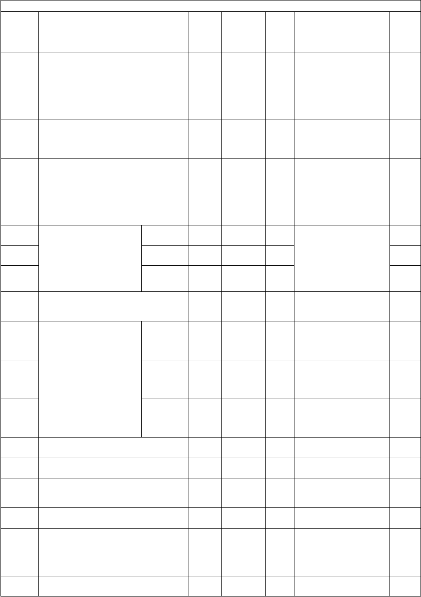
e-STUDIO281c/351c/451c ERROR CODE AND SELF-DIAGNOSTIC MODE© June 2005 TOSHIBA TEC
2 - 172
1784NetworkSingle page data saving
directory at "Save as file"
ALL0
<0-1>
SYSSets the directory
where the file of "Save
as file" is saved.
0: Save it under a sub-
folder
1: Save it without cre-
ating a subfolder
1
1785NetworkPage number display for-
mat of the file of "Save as
file" and Email transmis-
sion
ALL4
<3-6>
SYSSets the digit of a page
number attached on the
file.
3-6: 3-6 digits
1
1786NetworkExtension (suffix) format of
the file of "Save as file"
ALL3
<3-6>
SYSSets the extension dig-
its of the file to be
saved.
3: Auto
4: 4 digits
5: 5 digits
6: 6 digits
1
1800-0Image
process-
ing
Color toner
forced supply
time setting
YALL
(color)
70
<0-255>
MSets the motor driving
time of the developer
unit at the time of the
color toner forced sup-
ply.
0-255: Setting value x
0.1 seconds
4
1800-1MALL
(color)
70
<0-255>
M4
1800-2CALL
(color)
70
<0-255>
M4
1801Image
process-
ing
Color toner forced supply
count setting
ALL
(color)
7
<1-10>
MSets the number of
times of the color toner
forced supply.
1
1802-0Image
process-
ing
Start up set-
ting of the
developer
material stabi-
lizing mode.
LevelALL3
<2-8>
MSets the performing
level of the developer
material stabilizing
operation.
4
1802-1Pattern
interval
ALL50
<0-100>
MSet the interval time
between performances
of developer material
stabilizing operation.
4
1802-2Number of
repeating
time
ALL10
<0-20>
MSet the number of
repeating times of the
developer material sta-
bilizing operation.
4
1911FinisherManual stapling time-out
period
ALL15
<3-30>
M3-30sec.
(In increments of 1sec.)
1
1912FinisherFinisher model switching
setting value
ALL0
<0-1>
M0: MJ-1023
1: MJ-1101
1
1913GeneralPage number addition on
multipage file names of
"File/Email"
ALL0
<0-1>
SYS1
1914GeneralMaximum number of deci-
mals in extension fields
ALL2
<0-255>
SYS1
1915NetworkFiling size for Network
scanning function
ALL0
<0-1>
SYS0: Eliminates 2 mm
from circumference
(Void: 2 mm)
1: No space eliminated
(Void: 0 mm)
1
1916GeneralDefault saving/attachment
files of "File/Email"
ALL0
<0-1>
SYS1
Setting mode (08)
Code Classifi-
cation Items Func-
tion
Default
<Accept-
able
value>
RAMContents
Pro-
cedur
e
06/08

© June 2005 TOSHIBA TECe-STUDIO281c/351c/451c ERROR CODE AND SELF-DIAGNOSTIC MODE
2 - 173
2
1920NetworkDevice domain name of
device authentication
ALL-UTYMaximum 128 letters12
1921NetworkWindows domain No. 2 of
user authentication
ALL-UTYMaximum 128 letters12
1922NetworkWindows domain No. 3 of
user authentication
ALL-UTYMaximum 128 letters12
1923NetworkLDAP authentication
Server type
ALL1
<1-2>
NIC1: Windows Server
2: Not Windows Server
12
1924NetworkLDAP authentication
User attribute
ALL-NICSets a user attribute
name.
12
1925NetworkExecution of user authenti-
cation when the user ID is
not entered
ALL2
<0-2>
SYS0: Forcible execution
1: Execution impossi-
ble (pooled in the
invalid queue)
2: Forcible deletion
1
1926FAXTab/cover sheet printing at
FAX reception
Printing stop function
ALL0
<0-1>
SYSSets on or off of the
printing function of spe-
cial sheets such as tab
or cover sheet of FAX,
Email or list print.
0: Function off
1: Function on
1
1928NetworkRole Based Access
LDAP search index
ALL0
<0-
4294967
295>
SYS5
1929User
interface
Key arrangement for lan-
guage 1
ALL0
<0-2>
SYS0:QWERTY layout
(for EUR)
1:QWERTZ layout
2:AZERTY layout
1
1930User
interface
Key arrangement for lan-
guage 2
ALL1
<0-2>
SYS0:QWERTY layout
(for EUR)
1:QWERTZ layout
2:AZERTY layout
1
1931User
interface
Key arrangement for lan-
guage 3
ALLEUR: 2
UC: 0
JPN: 0
<0-2>
SYS0:QWERTY layout
(for EUR)
1:QWERTZ layout
2:AZERTY layout
1
1932User
interface
Key arrangement for lan-
guage 4
ALL0
<0-2>
SYS0:QWERTY layout
(for EUR)
1:QWERTZ layout
2:AZERTY layout
1
1933User
interface
Key arrangement for lan-
guage 5
ALL0
<0-2>
SYS0:QWERTY layout
(for EUR)
1:QWERTZ layout
2:AZERTY layout
1
1934User
interface
Key arrangement for lan-
guage 6
ALL0
<0-2>
SYS0:QWERTY layout
(for EUR)
1:QWERTZ layout
2:AZERTY layout
1
1935User
interface
Key arrangement for lan-
guage 7
ALL0
<0-2>
SYS0:QWERTY layout
(for EUR)
1:QWERTZ layout
2:AZERTY layout
1
Setting mode (08)
Code Classifi-
cation Items Func-
tion
Default
<Accept-
able
value>
RAMContents
Pro-
cedur
e
06/08

e-STUDIO281c/351c/451c ERROR CODE AND SELF-DIAGNOSTIC MODE© June 2005 TOSHIBA TEC
2 - 174
1936NetworkAppleTalk device nameALLMFP-
serial
UTYMaximum 32 letters
The Network-related
serial number of the
equipment appears at
"serial".
12
1937NetworkUser name and password
at user authentication or
"Save as file"
ALL0
<0-2>
SYS0: User name and
password of the
device
1: User name and
password at the
user authentication
(Template registra-
tion information
comes first when a
template is
retrieved.)
2: User name and
password at the
user authentication
(User information of
the authentication
comes first when a
template is
retrieved.)
1
1938GeneralReformatting process due
to a version change of SYS
ROM
ALL-
<0-2>
-Use this setting to refor-
mat the specific parti-
tion whose file system
has been changed in
Ver.2, at the version up/
downgrade of the SYS
ROM.
No reformatting pro-
cess shall be used in
any cases other than
this version change.
0: Waiting (No refor-
matting)
1: dosFs to catFs (Ver-
sion upgrade from
Ver.1 to Ver.2 or
later)
2: catFs to dosFs (Ver-
sion downgrade
from Ver.2 or later to
Ver.1)
7
1941Blue-
tooth
Bluetooth
BIP Paper size
ALLEUR: 6
UC: 2
JPN: 6
<0-13>
SYS0: Ledger1: Legal
2: Letter3: Computer
4: Statement5: A3
6: A47: A5
8: A69: B4
10: B511: Folio
12: Legal13"
13: LetterSquare
1950NetworkSMB signature for SMB
server
ALL1
<0-3>
UTY1: Auto
2: Valid
3: Invalid
12
1951NetworkSMB signature for SMB cli-
ent
ALL1
<0-3>
UTY1: Auto
2: Valid
3: Invalid
12
Setting mode (08)
Code Classifi-
cation Items Func-
tion
Default
<Accept-
able
value>
RAMContents
Pro-
cedur
e
06/08

© June 2005 TOSHIBA TECe-STUDIO281c/351c/451c ERROR CODE AND SELF-DIAGNOSTIC MODE
2 - 175
2
1952NetworkDevice name for device
authentication
ALL-UTYMaximum 128 letters12
1953NetworkPassword for the device
name used for device
authentication
ALL-UTYMaximum 128 letters12
1954NetworkPDC2 of user authentica-
tion
ALL-UTYMaximum 128 letters12
1955NetworkBDC2 of user authentica-
tion
ALL-UTYMaximum 128 letters12
1956NetworkPDC3 of user authentica-
tion
ALL-UTYMaximum 128 letters12
1957NetworkBDC3 of user authentica-
tion
ALL-UTYMaximum 128 letters12
1958NetworkPDC of device authentica-
tion
ALL-UTYMaximum 128 letters12
1959NetworkBDC of device authentica-
tion
ALL-UTYMaximum 128 letters12
1960GeneralKS Filter operation modeALL0
<0-1>
SYS0: Disabled
1: Enabled
1
1961GeneralKS/KSSM setting all clear-
ing
ALL--Does not reset the
value of the code 08-
1960 but resets those
of the codes 08-1963 to
1994.
3
1963GeneralKS Filter Emulation ModeALL0
<0-2>
SYS0: Auto
1: KS
2: KSSM
1
1964GeneralKS Filter Paper SizeALL1
<0-5>
SYS0: A3
1: A4
2: B4
3: B5
4: Letter
5: Legal
1
1965GeneralKS Filter OrientationALL0
<0-1>
SYS0: Portrait
1: Landscape
1
1966GeneralKS Filter CopiesALL1
<1-999>
SYS1
1967GeneralKS Paper SourceALL0
<0-1>
SYS1
1968GeneralKS Duplex ModeALL0
<0-2>
SYS1
1970GeneralKS CPI (English CPI/
Hangle CPI)
ALL1
<0-10>
SYS0:(5/10)
1:(6/12)
2:(6.7/13.3)
3:(6.9/13.8)
4:(7.5/15)
5:(8.3/16.7)
6:(9/18)
7:(10/10)
8:(10/20)
9:(12/24)
10: (15/30)
1
1971GeneralKS LPIALL60
<30-160>
SYSKey in the value 10
times as the desired
font size.
(e.g.: Key in "45" for a
font size 4.5.)
1
Setting mode (08)
Code Classifi-
cation Items Func-
tion
Default
<Accept-
able
value>
RAMContents
Pro-
cedur
e
06/08

e-STUDIO281c/351c/451c ERROR CODE AND SELF-DIAGNOSTIC MODE© June 2005 TOSHIBA TEC
2 - 176
1972GeneralKS Type FaceALL0
<0-5>
SYS0: MYUNGJO
1: GOTHIC
2: GUNGSEO
3: GULLIM
4: GRAPH
5: SAMMUL
1
1973GeneralKS Font SizeALL96
<96-160>
SYSKey in the value 10
times as the desired
font size.
(e.g.: Key in "100" for a
font size 10.0.)
1
1974GeneralKS ZoomALL100
<20-400>
SYS1
1975GeneralKS CR/LF ModeALL2
<0-3>
SYS0:CR->CR,
LF->LF
1:CR->CR+LF,
LF->LF
2:CR->CR,
LF->CR+LF
3:CR->CR+LF,
LF->CR+LF
1
1976GeneralKS Top MarginALL0
<0-50>
SYSKey in the value 10
times as the desired
font size.
(e.g.: Key in "40" for a
font size 4.0.)
1
1977GeneralKS Left MarginALL0
<0-50>
SYSKey in the value 10
times as the desired
font size.
(e.g.: Key in "40" for a
font size 4.0.)
1
1978GeneralKS Auto WrapALL0
<0-1>
SYS0: OFF
1: ON
1
1979GeneralKS Han ModeALL1
<0-1>
SYS0: OFF
1: ON
1
1980GeneralKS Han CodeALL0
<0-1>
SYS0: Wansung
1: Johap
1
1984GeneralKSSM CPI
(English CPI/ Hangle CPI)
ALL1
<0-10>
SYS0:(5/10)
1:(6/12)
2:(6.7/13.3)
3:(6.9/13.8)
4:(7.5/15)
5:(8.3/16.7)
6:(9/18)
7:(10/10)
8:(10/20)
9:(12/24)
10: (15/30)
1
1985GeneralKSSM LPIALL60
<30-160>
SYSKey in the value 10
times as the desired
font size.
(e.g.: Key in "45" for a
font size 4.5.)
1
Setting mode (08)
Code Classifi-
cation Items Func-
tion
Default
<Accept-
able
value>
RAMContents
Pro-
cedur
e
06/08

© June 2005 TOSHIBA TECe-STUDIO281c/351c/451c ERROR CODE AND SELF-DIAGNOSTIC MODE
2 - 177
2
1986GeneralKSSM Type FaceALL0
<0-5>
SYS0:MYUNGJO
1:GOTHIC
2:GUNGSEO
3:GULLIM
4:GRAPH
5:SAMMUL
1
1987GeneralKSSM Font SizeALL96
<96-160>
SYSKey in the value 10
times as the desired
font size.
(e.g.: Key in "100" for a
font size 10.0.)
1
1988GeneralKSSM ZoomALL100
<20-400>
SYS1
1989GeneralKSSM CR/LF ModeALL2
<0-3>
SYS0:CR->CR,
LF->LF
1:CR->CR+LF,
LF->LF
2:CR->CR,
LF->CR+LF
3:CR->CR+LF,
LF->CR+LF
1
1990GeneralKSSM Top MarginALL0
<0-50>
SYSKey in the value 10
times as the desired
font size.
(e.g.: Key in "40" for a
font size 4.0.)
1
1991GeneralKSSM Left MarginALL0
<0-50>
SYSKey in the value 10
times as the desired
font size.
(e.g.: Key in "40" for a
font size 4.0.)
1
1992GeneralKSSM Auto WrapALL0
<0-1>
SYS0: OFF
1: ON
1
1993GeneralKSSM Han ModeALL1
<0-1>
SYS0: OFF
1: ON
1
1994GeneralKSSM Han CodeALL0
<0-1>
SYS0: Wansung
1: Johap
1
3722NetworkDevice authentication
PDC/BDC time-out period
(Unit: Seconds)
ALL60
<1-180>
NICApplied to the device
authentication
12
3723NetworkUser authentication PDC/
BDC time-out period (Unit:
Seconds)
ALL30
<1-180>
NICApplied to the user
authentication
12
3724NetworkWindows domain authenti-
cation of device/user
authentication
ALL1
<1-3>
NIC1:Auto
2:Kerberos
3:NTLMv2
12
3725NetworkIPP max connectionALL16
<1-16>
NIC12
3726NetworkIPP active connectionALL10
<1-16>
NIC12
3727NetworkLPD max connectionALL10
<1-16>
NIC12
3728NetworkLPD active connectionALL10
<1-16>
NIC12
3729NetworkATalk PS max ConnectionALL10
<1-16>
NIC12
Setting mode (08)
Code Classifi-
cation Items Func-
tion
Default
<Accept-
able
value>
RAMContents
Pro-
cedur
e
06/08

e-STUDIO281c/351c/451c ERROR CODE AND SELF-DIAGNOSTIC MODE© June 2005 TOSHIBA TEC
2 - 178
3730NetworkATalk PS active Connec-
tion
ALL10
<1-16>
NIC12
3731NetworkRaw TCP max connectionALL10
<1-16>
NIC12
3732NetworkRaw TCP active connec-
tion
ALL10
<1-16>
NIC12
3736NetworkDNS Client Time OutALL60
<1-180>
NICUse when a timeout
occurred at DNS client
connection
12
3737NetworkDDNS Client Time OutALL60
<1-180>
NICUse when a timeout
occurred at DDNS cli-
ent connection
12
3738NetworkHTTP Client Time OutALL60
<1-180>
NICUse when a timeout
occurred at HTTP cli-
ent connection
12
3739NetworkFTP Client Time Out
(SCAN)
ALL30
<1-180>
NICUse when a timeout
occurred at FTP client
connection
12
3740NetworkSNTP Client Time OutALL30
<1-180>
NICUse when a timeout
occurred at SNTP client
connection
12
3741NetworkSMTP Client Time OutALL30
<1-180>
NICUse when a timeout
occurred at SMTP client
connection
12
3742NetworkPOP3 Client Time OutALL30
<1-180>
NICUse when a timeout
occurred at POP3 client
connection
12
3743NetworkLDAP Client Time OutALL30
<1-180>
NICUse when a timeout
occurred at LDAP cli-
ent connection
12
3744NetworkPOP3 Authentication
method
ALL1
<1-3>
NICPOP3 authentication
method setting
1: Disable (Default)
2: NTLM
3: Kerberos
12
Setting mode (08)
Code Classifi-
cation Items Func-
tion
Default
<Accept-
able
value>
RAMContents
Pro-
cedur
e
06/08

© June 2005 TOSHIBA TECe-STUDIO281c/351c/451c ERROR CODE AND SELF-DIAGNOSTIC MODE
2 - 179
2
6810-0CounterNumber of
output pages
in black mode
/ Large size
1-UP /
Duplex
printing
PPC
(black)
0
<8 digits>
SYSCounts the number of
output pages printed
only in the black mode.
4
6810-12-UP /
Duplex
printing
PPC
(black)
0
<8 digits>
SYSCounts the number of
output pages printed in
the black mode using
[2IN1] or [MAGAZINE
SORT].
4
6810-22-UP /
Simplex
printing
PPC
(black)
0
<8 digits>
SYSCounts the number of
sheets printed in the
black mode using
[2IN1] or [MAGAZINE
SORT].
4
6810-34-UP /
Duplex
printing
PPC
(black)
0
<8 digits>
SYSCounts the number of
output pages printed in
the black mode using
[4IN1].
4
6810-44-UP /
Simplex
printing
PPC
(black)
0
<8 digits>
SYSCounts the number of
sheets printed in the
black mode using
[4IN1].
4
6810-71-UP /
Simplex
printing
PPC
(black)
0
<8 digits>
SYSCounts the number of
sheets printed only in
the black mode.
4
6811-0CounterNumber of
output pages
in full color
mode / Large
1-UP /
Duplex
printing
PPC
(color)
0
<8 digits>
SYSCounts the number of
output pages printed
only in the full color
mode.
4
6811-12-UP /
Duplex
printing
PPC
(color)
0
<8 digits>
SYSCounts the number of
output pages printed in
the full color mode
using [2IN1] or [MAGA-
ZINE SORT].
4
6811-22-UP /
Simplex
printing
PPC
(color)
0
<8 digits>
SYSCounts the number of
sheets printed in the full
color mode using [2IN1]
or [MAGAZINE SORT].
4
6811-34-UP /
Duplex
printing
PPC
(color)
0
<8 digits>
SYSCounts the number of
output pages printed in
the full color mode
using [4IN1].
4
6811-44-UP /
Simplex
printing
PPC
(color)
0
<8 digits>
SYSCounts the number of
sheets printed in the full
color mode using
[4IN1].
4
6811-71-UP /
Simplex
printing
PPC
(color)
0
<8 digits>
SYSCounts the number of
sheets printed only in
the full color mode.
4
Setting mode (08)
Code Classifi-
cation Items Func-
tion
Default
<Accept-
able
value>
RAMContents
Pro-
cedur
e
06/08

e-STUDIO281c/351c/451c ERROR CODE AND SELF-DIAGNOSTIC MODE© June 2005 TOSHIBA TEC
2 - 180
6812-0CounterNumber of
output pages
in twin color
mode / Large
1-UP /
Duplex
printing
PPC
(color)
0
<8 digits>
SYSCounts the number of
output pages printed
only in the twin color
mode.
4
6812-12-UP /
Duplex
printing
PPC
(color)
0
<8 digits>
SYSCounts the number of
output pages printed in
the twin color mode
using [2IN1] or [MAGA-
ZINE SORT].
4
6812-22-UP /
Simplex
printing
PPC
(color)
0
<8 digits>
SYSCounts the number of
sheets printed in the
twin color mode using
[2IN1] or [MAGAZINE
SORT].
4
6812-34-UP /
Duplex
printing
PPC
(color)
0
<8 digits>
SYSCounts the number of
output pages printed in
the twin color mode
using [4IN1].
4
6812-44-UP /
Simplex
printing
PPC
(color)
0
<8 digits>
SYSCounts the number of
sheets printed in the
twin color mode using
[4IN1].
4
6812-71-UP /
Simplex
printing
PPC
(color)
0
<8 digits>
SYSCounts the number of
sheets printed only in
the twin color mode.
4
6813-0CounterNumber of
output pages
of the printer
or BOX /
Large
1-UP /
Duplex
printing
PRT
(black)
0
<8 digits>
SYSCounts the number of
output pages printed in
the black mode.
4
6813-12-UP /
Duplex
printing
PRT
(black)
0
<8 digits>
SYSCounts the number of
output pages printed in
the black mode using
[2IN1] or [MAGAZINE
SORT].
4
6813-22-UP /
Simplex
printing
PRT
(black)
0
<8 digits>
SYSCounts the number of
sheets printed in the
black mode using
[2IN1] or [MAGAZINE
SORT].
4
6813-34-UP /
Duplex
printing
PRT
(black)
0
<8 digits>
SYSCounts the number of
output pages printed in
the black mode using
[4IN1].
4
6813-44-UP /
Simplex
printing
PRT
(black)
0
<8 digits>
SYSCounts the number of
sheets printed in the
black mode using
[4IN1].
4
6813-5N-UP /
Duplex
printing
PRT
(black)
0
<8 digits>
SYSCounts the number of
output pages printed in
the black mode using
[N IN1].
4
6813-6N-UP /
Simplex
printing
PRT
(black)
0
<8 digits>
SYSCounts the number of
sheets printed in the
black mode using [N
IN1].
4
6813-71-UP /
Simplex
printing
PRT
(black)
0
<8 digits>
SYSCounts the number of
sheets printed only in
the black mode.
4
Setting mode (08)
Code Classifi-
cation Items Func-
tion
Default
<Accept-
able
value>
RAMContents
Pro-
cedur
e
06/08

© June 2005 TOSHIBA TECe-STUDIO281c/351c/451c ERROR CODE AND SELF-DIAGNOSTIC MODE
2 - 181
2
6814-0CounterNumber of
output pages
of the printer
or BOX /
Large
(Full color)
1-UP /
Duplex
printing
PRT
(color)
0
<8 digits>
SYSCounts the number of
output pages printed
only in the full color
mode.
4
6814-12-UP /
Duplex
printing
PRT
(color)
0
<8 digits>
SYSCounts the number of
output pages printed in
the full color mode
using [2IN1] or [MAGA-
ZINE SORT].
4
6814-22-UP /
Simplex
printing
PRT
(color)
0
<8 digits>
SYSCounts the number of
sheets printed in the full
color mode using [2IN1]
or [MAGAZINE SORT].
4
6814-34-UP /
Duplex
printing
PRT
(color)
0
<8 digits>
SYSCounts the number of
output pages printed in
the full color mode
using [4IN1].
4
6814-44-UP /
Simplex
printing
PRT
(color)
0
<8 digits>
SYSCounts the number of
sheets printed in the full
color mode using
[4IN1].
4
6814-5N-UP /
Duplex
printing
PRT
(color)
0
<8 digits>
SYSCounts the number of
output pages printed in
the full color mode
using [N IN1].
4
6814-6N-UP /
Simplex
printing
PRT
(color)
0
<8 digits>
SYSCounts the number of
sheets printed in the full
color mode using [N
IN1].
4
6814-71-UP /
Simplex
printing
PRT
(color)
0
<8 digits>
SYSCounts the number of
sheets printed only in
the full color mode.
4
6815-0CounterNumber of
output pages
of the FAX
printing /
Large
1-UP /
Simplex
printing
FAX0
<8 digits>
SYSCounts the number of
output pages in the
default settings.
4
6815-71-UP /
Duplex
printing
FAX0
<8 digits>
SYS4
9047GeneralProcess control flag setting
of easy setup (manual
unpacking adjustment)
ALL0
<0-2>
SYS0:No change of man-
ual unpacking
adjustment
1:OFF status of man-
ual unpacking
adjustment flag
2:Returns to the initial
unpacking mode
1
9117NetworkRaw printing job
(Blank page will not be
printed)
PRT0
<0-1>
SYS0:OFF
1:ON
1
9359User
interface
Printing resume after jam
releasing
ALL0
<0-1>
SYS0:Auto resume
1:Resume by users
1
9394NetworkSingle-page option for stor-
ing File and sending Email
ALL0
<0-1>
SYS0:Sets 1 page as 1 file
1:Makes a file based
on the original
1
9629NetworkAttribute name for LDAP
Role Based Access
ALLeBMUser
R
<->
SYS11
Setting mode (08)
Code Classifi-
cation Items Func-
tion
Default
<Accept-
able
value>
RAMContents
Pro-
cedur
e
06/08

e-STUDIO281c/351c/451c ERROR CODE AND SELF-DIAGNOSTIC MODE© June 2005 TOSHIBA TEC
2 - 182
9739Mainte-
nance
Remote service
Toner-end notification
ALL0
<0-2>
SYS0:RDMS toner empty
notified immediately
1:RDMS toner empty
notified once a day
2:RDMS toner empty
not notified
1
9828GeneralRemote scanning modeALL0
<0-1>
SYS0:Batch
1:Sequential
1
9829GeneralDepartment management
limitation setting
ALL0
<0-3>
SYSDecide the default limi-
tation setting when the
new department code is
created.
0:No limit
1:Limited only in the
black mode
2:Limited in the color
mode
3:Limited in the black/
color mode
1
9847FinisherHole punching settingALL0
<0-1>
SYS0:Invalid
1:Valid
1
9880GeneralTotal counter transmission
date setting (2)
ALL1
<1-31>
SYS1 to 311
9881GeneralDay of total counter data
transmission
ALL0
<0-127>
-1 byte 00000000(0)-
01111111(127)
From the 2nd bit -
Sunday, Monday,
Tuesday, Wednesday,
Thursday, Friday,
Saturday
1
9882GeneralDisplay mode of the used
capacity on the e-Filing
administrator page
ALL1
<0-1>
SYS0:All files search
mode
1:Performance priority
mode
1
9885GeneralNew/Old FROM identifica-
tion
ALL-
<-1-1>
-0: Old FROM
1: New FROM
-1: Error
2
9886ScannerDecimal point indication for
Enhanced Scan Template
SCNEUR: 0
UC: 1
JPN: 1
<0-1>
SYS0: Comma
1: Period
1
9888ScannerPermission setting for
changing the scan parame-
ter when recalling an
extension
SCN0
<0-1>
SYS0:Prohibited
1:Accepted
1
9891User
interface
Warning message on the
touch panel when PM
(Periodic Maintenance)
time has come
ALL1
<0-1>
SYS0:No warning notifica-
tion
1:Warning notification
1
Setting mode (08)
Code Classifi-
cation Items Func-
tion
Default
<Accept-
able
value>
RAMContents
Pro-
cedur
e
06/08

© June 2005 TOSHIBA TECe-STUDIO281c/351c/451c ERROR CODE AND SELF-DIAGNOSTIC MODE
2 - 183
2
Note: Note:
In this equipment, a toner image is formed on the transfer belt prior to a paper feeding.
When the feeding retry occurs and the transport timing is delayed, the toner image on the trans-
fer belt is cleaned off without the 2nd transfer since the paper cannnot be reached for the 2nd
transfer proccess.
After that, the toner image fomation is retried while the paper is waited.
In this case, the toner for this image formation is consumed wastefully since the toner image on
the transfer belt is already cleaned off, even though the printing is normally completed.
Therefore, note that the excessive toner will be consumed consequently when the upper limit
value of feeding retry counter is set larger or set as "0" (no limit).
The toner is also consumed wastefully when the paper misfeeding occurs. Replace the roller at
earlier timing if the paper misfeedings have occurred frequently.

e-STUDIO281c/351c/451c ERROR CODE AND SELF-DIAGNOSTIC MODE© June 2005 TOSHIBA TEC
2 - 184
<<Pixel counter related code>>(Chap. 2.2.6)
Note: Note:
In the pixel counter function, the twin color copy mode is regarded as the full color mode.
Setting mode (08)
Code Classifi-
cation Items Func-
tion
Default
<Accept-
able
value>
RAMContents
Pro-
cedur
e
1500Pixel
counter
Standard paper size settingALLEUR: 0
UC: 1
JPN: 0
<0-1>
SYSSelects the standard
paper size to convert it
into the pixel count (%).
0: A4
1: LT
1
1501Pixel
counter
Pixel counter all clearingALL-SYSClears all information
related to the pixel
counter.
3
1502Pixel
counter
Service technician refer-
ence counter clearing
ALL-SYSClears all information
related to the service
technician reference
pixel counter.
3
1503Pixel
counter
Toner cartridge reference
counter clearing
ALL-SYSClears all information
related to the toner car-
tridge reference pixel
counter.
3
1504Pixel
counter
Pixel counter display set-
ting
ALL1
<0-1>
SYSSelects whether or not
to display the pixel
counter on the LCD
screen.
0: Displayed
1: Not displayed
1
1505Pixel
counter
Displayed reference set-
ting
ALL0
<0-1>
SYSSelects the reference
when displaying the
pixel counter on the
LCD screen.
0: Service technician
reference
1: Toner cartridge ref-
erence
1
1506Pixel
counter
Toner empty determination
counter setting
ALL0
<0-1>
SYSSelects the counter to
determine toner empty.
0: Output pages
1: Pixel counter
1
1507Pixel
counter
Threshold setting for toner
empty determination (Out-
put pages)
ALL500
<0-999>
SYSSets the number of out-
put pages to determine
toner empty. This set-
ting is valid when 0! is
set at 08-1506.
1
1508Pixel
counter
Threshold setting for toner
empty determination (Pixel
counter)
ALL21500
<0-
60000>
SYSSets the number of out-
put pages to determine
toner empty. This set-
ting is valid when 1! is
set at 08-1506.
1
1509Pixel
counter
Pixel counter clear flag/
Service technician refer-
ence
ALL0
<0-1>
SYSBecomes 1! when 08-
1502 is performed.
2
1510Pixel
counter
Service technician refer-
ence cleared date
ALL-SYSDisplays the date on
which 08-1502 was per-
formed.
2
1511Pixel
counter
Toner cartridge reference
cleared date (Y)
ALL
(color)
-SYSDisplays the date on
which 08-1503 was per-
formed.
2

© June 2005 TOSHIBA TECe-STUDIO281c/351c/451c ERROR CODE AND SELF-DIAGNOSTIC MODE
2 - 185
2
1512Pixel
counter
Toner cartridge reference
cleared date (M)
ALL
(color)
-SYSDisplays the date on
which 08-1503 was per-
formed.
2
1513Pixel
counter
Toner cartridge reference
cleared date (C)
ALL
(color)
-SYSDisplays the date on
which 08-1503 was per-
formed.
2
1514Pixel
counter
Toner cartridge reference
cleared date (K)
ALL-SYSDisplays the date on
which 08-1503 was per-
formed.
2
1515Pixel
counter
Toner cartridge reference
count started date (Y)
ALL
(color)
-SYSDisplays the date on
which 08-1503 was per-
formed.
2
1516Pixel
counter
Toner cartridge reference
count started date (M)
ALL
(color)
-SYSDisplays the date on
which 08-1503 was per-
formed.
2
1517Pixel
counter
Toner cartridge reference
count started date (C)
ALL
(color)
-SYSDisplays the date on
which 08-1503 was per-
formed.
2
1518Pixel
counter
Toner cartridge reference
count started date (K)
ALL-SYSDisplays the date on
which 08-1503 was per-
formed.
2
1547Pixel
counter
Number of output pages/
fullcolor
(Service technicianrefer-
ence)
PPC
(color)
<8 digits>SYSCounts the number of
output pagesconverted
to the standard paper
sizein the copy function,
full color modeand ser-
vice technician refer-
ence.
[Unit. page]
2
1548Pixel
counter
Number of output pages/
black (Service technician
reference)
PPC
(black)
<8 digits>SYSCounts the number of
output pages con-
verted to the standard
paper sizein the copy
function, black mode
and service technician
reference.
[Unit. page]
2
1549Pixel
counter
Number of output pages/
fullcolor (Service techni-
cian reference)
PRT
(color)
<8 digits>SYSCounts the number of
output pages con-
verted to the standard
paper size in the printer
function, full color mode
and service technician
reference.
[Unit. page]
2
1550Pixel
counter
Number of output pages/
black (Service technician
reference)
PRT
(black)
<8 digits>SYSCounts the number of
output pages con-
verted to the standard
paper size in the printer
function, black mode
and service technician
reference.
[Unit. page]
2
Setting mode (08)
Code Classifi-
cation Items Func-
tion
Default
<Accept-
able
value>
RAMContents
Pro-
cedur
e

e-STUDIO281c/351c/451c ERROR CODE AND SELF-DIAGNOSTIC MODE© June 2005 TOSHIBA TEC
2 - 186
1551Pixel
counter
Number of output pages/
black (Service technician
reference)
FAX
(black)
<8 digits>SYSCounts the number of
output pages con-
verted to the standard
paper size in the FAX
function, black mode
and service technician
reference.
[Unit. page]
2
1552Pixel
counter
Number of output pages/
full color (K) (Toner car-
tridge reference)
PPC
(color)
<8 digits>SYSCounts the number of
output pages con-
verted to the standard
paper size in the copy
function, full color
mode, toner K and
toner cartridge refer-
ence.
[Unit. page]
2
1553Pixel
counter
Number of output pages/
black (Toner cartridge ref-
erence)
PPC
(black)
<8 digits>SYSCounts the number of
output pages con-
verted to the standard
paper size in the copy
function, black mode
and toner cartridge ref-
erence.
[Unit. page]
2
1554Pixel
counter
Number of output pages/
full color (K) (Toner car-
tridge reference)
PRT
(color)
<8 digits>SYSCounts the number of
output pages con-
verted to the standard
paper size in the printer
function, full color
mode, toner K and
toner cartridge refer-
ence.
[Unit. page]
2
1555Pixel
counter
Number of output pages/
black (Toner cartridge ref-
erence)
PRT
(black)
<8 digits>SYSCounts the number of
output pages con-
verted to the standard
paper size in the printer
function, black mode
and toner cartridge ref-
erence.
[Unit. page]
2
1556Pixel
counter
Number of output pages/
black (Toner cartridge ref-
erence)
FAX
(black)
<8 digits>SYSCounts the number of
output pages con-
verted to the standard
paper size in the FAX
function, black mode
and toner cartridge ref-
erence.
[Unit. page]
2
1557Pixel
counter
Number of output pages/
full color (Y) (Toner car-
tridge reference)
PPC
(color)
<8 digits>SYSCounts the number of
output pages con-
verted to the standard
paper size in the copy
function, full color
mode, toner Y and
toner cartridge refer-
ence.
[Unit. page]
2
Setting mode (08)
Code Classifi-
cation Items Func-
tion
Default
<Accept-
able
value>
RAMContents
Pro-
cedur
e

© June 2005 TOSHIBA TECe-STUDIO281c/351c/451c ERROR CODE AND SELF-DIAGNOSTIC MODE
2 - 187
2
1558Pixel
counter
Number of output pages/
full color (Y) (Toner car-
tridge reference)
PRT
(color)
<8 digits>SYSCounts the number of
output pages con-
verted to the standard
paper size in the printer
function, full color
mode, toner Y and
toner cartridge refer-
ence.
[Unit. page]
2
1559Pixel
counter
Number of output pages/
full color (M) (Toner car-
tridge reference)
PPC
(color)
<8 digits>SYSCounts the number of
output pages con-
verted to the standard
paper size in the copy
function, full color
mode, toner M and
toner cartridge refer-
ence.
[Unit. page]
2
1560Pixel
counter
Number of output pages/
full color (M) (Toner car-
tridge reference)
PRT
(color)
<8 digits>SYSCounts the number of
output pages con-
verted to the standard
paper size in the printer
function, full color
mode, toner M and
toner cartridge refer-
ence.
[Unit. page]
2
1561Pixel
counter
Number of output pages/
full color (C) (Toner car-
tridge reference)
PPC
(color)
<8 digits>SYSCounts the number of
output pages con-
verted to the standard
paper size in the copy
function, full color
mode, toner C and
toner cartridge refer-
ence.
[Unit. page]
2
1562Pixel
counter
Number of output pages/
full color (C) (Toner car-
tridge reference)
ALL
(color)
<8 digits>SYSCounts the number of
output pages con-
verted to the standard
paper size in the printer
function, full color
mode, toner C and
toner cartridge refer-
ence.
[Unit. page]
2
1563Pixel
counter
Toner cartridge Y replace-
ment counter
ALL
(color)
<3 digits>SYSCounts the number of
time of the toner car-
tridge Y replacement.
2
1564Pixel
counter
Toner cartridge M replace-
ment counter
ALL
(color)
<3 digits>SYSCounts the number of
time of the toner car-
tridge M replacement.
2
1565Pixel
counter
Toner cartridge C replace-
ment counter
ALL
(color)
<3 digits>SYSCounts the number of
time of the toner car-
tridge C replacement.
2
1566Pixel
counter
Toner cartridge K replace-
ment counter
ALL<3 digits>SYSCounts the number of
time of the toner car-
tridge K replacement.
2
Setting mode (08)
Code Classifi-
cation Items Func-
tion
Default
<Accept-
able
value>
RAMContents
Pro-
cedur
e

e-STUDIO281c/351c/451c ERROR CODE AND SELF-DIAGNOSTIC MODE© June 2005 TOSHIBA TEC
2 - 188
1577Pixel
counter
Average pixel count/full
color (Y+M+C+K) (Service
technician reference)
PPC
(color)
0
<0-
10000>
SYSDisplays the average
pixel count in the copy
function, full color
mode, all toner and ser-
vice technician refer-
ence.
[Unit: 0.01%]
2
1578Pixel
counter
Average pixel count/full
color (Y) (Service techni-
cian reference)
PPC
(color)
0
<0-
10000>
SYSDisplays the average
pixel count in the copy
function, full color
mode, toner Y and ser-
vice technician refer-
ence.
[Unit: 0.01%]
2
1579Pixel
counter
Average pixel count/full
color (M) (Service techni-
cian reference)
PPC
(color)
0
<0-
10000>
SYSDisplays the average
pixel count in the copy
function, full color
mode, toner M and ser-
vice technician refer-
ence.
[Unit: 0.01%]
2
1580Pixel
counter
Average pixel count/full
color (C) (Service techni-
cian reference)
PPC
(color)
0
<0-
10000>
SYSDisplays the average
pixel count in the copy
function, full color
mode, toner C and ser-
vice technician refer-
ence.
[Unit: 0.01%]
2
1581Pixel
counter
Average pixel count/full
color (K) (Service techni-
cian reference)
PPC
(color)
0
<0-
10000>
SYSDisplays the average
pixel count in the copy
function, full color
mode, toner K and ser-
vice technician refer-
ence.
[Unit: 0.01%]
2
1582Pixel
counter
Average pixel count/full
color (Y+M+C+K) (Service
technician reference)
PRT
(color)
0
<0-
10000>
SYSDisplays the average
pixel count in the printer
function, full color
mode, all toner and ser-
vice technician refer-
ence.
[Unit: 0.01%]
2
1583Pixel
counter
Average pixel count/full
color (Y) (Service techni-
cian reference)
PRT
(color)
0
<0-
10000>
SYSDisplays the average
pixel count in the printer
function, full color
mode, toner Y and ser-
vice technician refer-
ence.
[Unit: 0.01%]
2
1584Pixel
counter
Average pixel count/full
color (M) (Service techni-
cian reference)
PRT
(color)
0
<0-
10000>
SYSDisplays the average
pixel count in the printer
function, full color
mode, toner M and ser-
vice technician refer-
ence.
[Unit: 0.01%]
2
Setting mode (08)
Code Classifi-
cation Items Func-
tion
Default
<Accept-
able
value>
RAMContents
Pro-
cedur
e

© June 2005 TOSHIBA TECe-STUDIO281c/351c/451c ERROR CODE AND SELF-DIAGNOSTIC MODE
2 - 189
2
1585Pixel
counter
Average pixel count/full
color (C) (Service techni-
cian reference)
PRT
(color)
0
<0-
10000>
SYSDisplays the average
pixel count in the printer
function, full color
mode, toner C and ser-
vice technician refer-
ence.
[Unit: 0.01%]
2
1586Pixel
counter
Average pixel count/full
color (K) (Service techni-
cian reference)
PRT
(color)
0
<0-
10000>
SYSDisplays the average
pixel count in the printer
function, full color
mode, toner K and ser-
vice technician refer-
ence.
[Unit: 0.01%]
2
1587Pixel
counter
Average pixel count/full
color (Y+M+C+K) (Service
technician reference)
PPC/
PRT
(color)
0
<0-
10000>
SYSDisplays the average
pixel count in the copy/
printer function, full
color mode, all toner
and service technician
reference.
[Unit: 0.01%]
2
1588Pixel
counter
Average pixel count/full
color (Y) (Service techni-
cian reference)
PPC/
PRT
(color)
0
<0-
10000>
SYSDisplays the average
pixel count in the copy/
printer function, full
color mode, toner Y and
service technician refer-
ence.
[Unit: 0.01%]
2
1589Pixel
counter
Average pixel count/full
color (M) (Service techni-
cian reference)
PPC/
PRT
(color)
0
<0-
10000>
SYSDisplays the average
pixel count in the copy/
printer function, full
color mode, toner M
and service technician
reference.
[Unit: 0.01%]
2
1590Pixel
counter
Average pixel count/full
color (C) (Service techni-
cian reference)
PPC/
PRT
(color)
0
<0-
10000>
SYSDisplays the average
pixel count in the copy/
printer function, full
color mode, toner C
and service technician
reference.
[Unit: 0.01%]
2
1591Pixel
counter
Average pixel count/full
color (K) (Service techni-
cian reference)
PPC/
PRT
(color)
0
<0-
10000>
SYSDisplays the average
pixel count in the copy/
printer function, full
color mode, toner K and
service technician refer-
ence.
[Unit: 0.01%]
2
1592Pixel
counter
Average pixel count/black
(Service technician refer-
ence)
PPC
(black)
0
<0-
10000>
SYSDisplays the average
pixel count in the copy
function, black mode
and service technician
reference.
[Unit: 0.01%]
2
Setting mode (08)
Code Classifi-
cation Items Func-
tion
Default
<Accept-
able
value>
RAMContents
Pro-
cedur
e

e-STUDIO281c/351c/451c ERROR CODE AND SELF-DIAGNOSTIC MODE© June 2005 TOSHIBA TEC
2 - 190
1593Pixel
counter
Average pixel count/black
(Service technician refer-
ence)
PRT
(black)
0
<0-
10000>
SYSDisplays the average
pixel count in the printer
function, black mode
and service technician
reference.
[Unit: 0.01%]
2
1594Pixel
counter
Average pixel count/black
(Service technician refer-
ence)
FAX
(black)
0
<0-
10000>
SYSDisplays the average
pixel count in the FAX
function, black mode
and service technician
reference.
[Unit: 0.01%]
2
1595Pixel
counter
Average pixel count/black
(Service technician refer-
ence)
PPC/
PRT/
FAX
(black)
0
<0-
10000>
SYSDisplays the average
pixel count in the copy/
printer/FAX function,
black mode and ser-
vice technician refer-
ence.
[Unit: 0.01%]
2
1596Pixel
counter
Latest pixel count/full color
(Y+M+C+K) (Service tech-
nician reference)
PPC
(color)
0
<0-
10000>
SYSDisplays the latest pixel
count in the copy func-
tion, full color mode, all
toner and service tech-
nician reference.
[Unit: 0.01%]
2
1597Pixel
counter
Latest pixel count/full color
(Y) (Service technician ref-
erence)
PPC
(color)
0
<0-
10000>
SYSDisplays the latest pixel
count in the copy func-
tion, full color mode,
toner Y and service
technician reference.
[Unit: 0.01%]
2
1598Pixel
counter
Latest pixel count/full color
(M) (Service technician ref-
erence)
PPC
(color)
0
<0-
10000>
SYSDisplays the latest pixel
count in the copy func-
tion, full color mode,
toner M and service
technician reference.
[Unit: 0.01%]
2
1599Pixel
counter
Latest pixel count/full color
(C) (Service technician ref-
erence)
PPC
(color)
0
<0-
10000>
SYSDisplays the latest pixel
count in the copy func-
tion, full color mode,
toner C and service
technician reference.
[Unit: 0.01%]
2
1600Pixel
counter
Latest pixel count/full color
(K) (Service technician ref-
erence)
PPC
(color)
0
<0-
10000>
SYSDisplays the latest pixel
count in the copy func-
tion, full color mode,
toner K and service
technician reference.
[Unit: 0.01%]
2
1601Pixel
counter
Latest pixel count/full color
(Y+M+C+K) (Service tech-
nician reference)
PRT
(color)
0
<0-
10000>
SYSDisplays the latest pixel
count in the printer
function, full color
mode, all toner and ser-
vice technician refer-
ence.
[Unit: 0.01%]
2
Setting mode (08)
Code Classifi-
cation Items Func-
tion
Default
<Accept-
able
value>
RAMContents
Pro-
cedur
e

© June 2005 TOSHIBA TECe-STUDIO281c/351c/451c ERROR CODE AND SELF-DIAGNOSTIC MODE
2 - 191
2
1602Pixel
counter
Latest pixel count/full color
(Y) (Service technician ref-
erence)
PRT
(color)
0
<0-
10000>
SYSDisplays the latest pixel
count in the printer
function, full color
mode, toner Y and ser-
vice technician refer-
ence.
[Unit: 0.01%]
2
1603Pixel
counter
Latest pixel count/full color
(M) (Service technician ref-
erence)
PRT
(color)
0
<0-
10000>
SYSDisplays the latest pixel
count in the printer
function, full color
mode, toner M and ser-
vice technician refer-
ence.
[Unit: 0.01%]
2
1604Pixel
counter
Latest pixel count/full color
(C) (Service technician ref-
erence)
PRT
(color)
0
<0-
10000>
SYSDisplays the latest pixel
count in the printer
function, full color
mode, toner C and ser-
vice technician refer-
ence.
[Unit: 0.01%]
2
1605Pixel
counter
Latest pixel count/full color
(K) (Service technician ref-
erence)
PRT
(color)
0
<0-
10000>
SYSDisplays the latest pixel
count in the printer
function, full color
mode, toner K and ser-
vice technician refer-
ence.
[Unit: 0.01%]
2
1606Pixel
counter
Latest pixel count/black
(Service technician refer-
ence)
PPC
(black)
0
<0-
10000>
SYSDisplays the latest pixel
count in the copy func-
tion, black mode and
service technician refer-
ence.
[Unit: 0.01%]
2
1607Pixel
counter
Latest pixel count/black
(Service technician refer-
ence)
PRT
(black)
0
<0-
10000>
SYSDisplays the latest pixel
count in the printer
function, black mode
and service technician
reference.
[Unit: 0.01%]
2
1608Pixel
counter
Latest pixel count/black
(Service technician refer-
ence)
FAX
(black)
0
<0-
10000>
SYSDisplays the latest pixel
count in the FAX func-
tion, black mode and
service technician refer-
ence.
[Unit: 0.01%]
2
1609Pixel
counter
Average pixel count/full
color (Y) (Toner cartridge
reference)
PPC
(color)
0
<0-
10000>
SYSDisplays the average
pixel count in the copy
function, full color
mode, toner Y and
toner cartridge refer-
ence.
[Unit: 0.01%]
2
Setting mode (08)
Code Classifi-
cation Items Func-
tion
Default
<Accept-
able
value>
RAMContents
Pro-
cedur
e

e-STUDIO281c/351c/451c ERROR CODE AND SELF-DIAGNOSTIC MODE© June 2005 TOSHIBA TEC
2 - 192
1610Pixel
counter
Average pixel count/full
color (M) (Toner cartridge
reference)
PPC
(color)
0
<0-
10000>
SYSDisplays the average
pixel count in the copy
function, full color
mode, toner M and
toner cartridge refer-
ence.
[Unit: 0.01%]
2
1611Pixel
counter
Average pixel count/full
color (C) (Toner cartridge
reference)
PPC
(color)
0
<0-
10000>
SYSDisplays the average
pixel count in the copy
function, full color
mode, toner C and
toner cartridge refer-
ence.
[Unit: 0.01%]
2
1612Pixel
counter
Average pixel count/full
color (K) (Toner cartridge
reference)
PPC
(color)
0
<0-
10000>
SYSDisplays the average
pixel count in the copy
function, full color
mode, toner K and
toner cartridge refer-
ence.
[Unit: 0.01%]
2
1613Pixel
counter
Average pixel count/black
(Toner cartridge reference)
PPC
(black)
0
<0-
10000>
SYSDisplays the average
pixel count in the copy
function, black mode
and toner cartridge ref-
erence.
[Unit: 0.01%]
2
1614Pixel
counter
Average pixel count/full
color (K)+black (Toner car-
tridge reference)
PPC0
<0-
10000>
SYSDisplays the average
pixel count in the copy
function, full color/black
mode, toner K and
toner cartridge refer-
ence.
[Unit: 0.01%]
2
1615Pixel
counter
Average pixel count/full
color (Y) (Toner cartridge
reference)
PRT
(color)
0
<0-
10000>
SYSDisplays the average
pixel count in the printer
function, full color
mode, toner Y and
toner cartridge refer-
ence.
[Unit: 0.01%]
2
1616Pixel
counter
Average pixel count/full
color (M) (Toner cartridge
reference)
PRT
(color)
0
<0-
10000>
SYSDisplays the average
pixel count in the printer
function, full color
mode, toner M and
toner cartridge refer
ence.
[Unit: 0.01%]
2
1617Pixel
counter
Average pixel count/full
color (C) (Toner cartridge
reference)
PRT
(color)
0
<0-
10000>
SYSDisplays the average
pixel count in the printer
function, full color
mode, toner C and
toner cartridge refer-
ence.
[Unit: 0.01%]
2
Setting mode (08)
Code Classifi-
cation Items Func-
tion
Default
<Accept-
able
value>
RAMContents
Pro-
cedur
e

© June 2005 TOSHIBA TECe-STUDIO281c/351c/451c ERROR CODE AND SELF-DIAGNOSTIC MODE
2 - 193
2
1618Pixel
counter
Average pixel count/full
color (K) (Toner cartridge
reference)
PRT
(color)
0
<0-
10000>
SYSDisplays the average
pixel count in the printer
function, full color
mode, toner K and
toner cartridge refer-
ence.
[Unit: 0.01%]
2
1619Pixel
counter
Average pixel count/black
(Toner cartridge reference)
PRT
(black)
0
<0-
10000>
SYSDisplays the average
pixel count in the printer
function, black mode
and toner cartridge ref-
erence.
[Unit: 0.01%]
2
1620Pixel
counter
Average pixel count/full
color (K)+black (Toner car-
tridge reference)
PRT0
<0-
10000>
SYSDisplays the average
pixel count in the printer
function, full color/black
mode, toner K and
toner cartridge refer-
ence.
[Unit: 0.01%]
2
1621Pixel
counter
Average pixel count/full
color (Y) (Toner cartridge
reference)
PPC/
PRT
(color)
0
<0-
10000>
SYSDisplays the average
pixel count in the copy/
printer function, full
color mode, toner Y and
toner cartridge refer-
ence.
[Unit: 0.01%]
2
1622Pixel
counter
Average pixel count/full
color (M) (Toner cartridge
reference)
PPC/
PRT
(color)
0
<0-
10000>
SYSDisplays the average
pixel count in the copy/
printer function, full
color mode, toner M
and toner cartridge ref-
erence.
[Unit: 0.01%]
2
1623Pixel
counter
Average pixel count/full
color (C) (Toner cartridge
reference)
PPC/
PRT
(color)
0
<0-
10000>
SYSDisplays the average
pixel count in the copy/
printer function, full
color mode, toner C
and toner cartridge ref-
erence.
[Unit: 0.01%]
2
1624Pixel
counter
Average pixel count/full
color (K)+black (Toner car-
tridge reference)
PPC/
PRT/
FAX
0
<0-
10000>
SYSDisplays the average
pixel count in the copy/
printer/FAX function,
black mode, toner K
and toner cartridge ref-
erence.
[Unit: 0.01%]
2
1625Pixel
counter
Average pixel count/black
(Toner cartridge reference)
FAX
(black)
0
<0-
10000>
SYSDisplays the average
pixel count in the FAX
function, black mode
and toner cartridge ref-
erence.
[Unit: 0.01%]
2
Setting mode (08)
Code Classifi-
cation Items Func-
tion
Default
<Accept-
able
value>
RAMContents
Pro-
cedur
e

e-STUDIO281c/351c/451c ERROR CODE AND SELF-DIAGNOSTIC MODE© June 2005 TOSHIBA TEC
2 - 194
1626Pixel
counter
Latest pixel count/full color
(Y) (Toner cartridge refer-
ence)
PPC
(color)
0
<0-
10000>
SYSDisplays the latest pixel
count in the copy func-
tion, full color mode,
toner Y and toner car-
tridge reference.
[Unit:0.01%]
2
1627Pixel
counter
Latest pixel count/full color
(M) (Toner cartridge refer-
ence)
PPC
(color)
0
<0-
10000>
SYSDisplays the latest pixel
count in the copy func-
tion, full color mode,
toner M and toner car-
tridge reference.
[Unit: 0.01%]
2
1628Pixel
counter
Latest pixel count/full color
(C) (Toner cartridge refer-
ence)
PPC
(color)
0
<0-
10000>
SYSDisplays the latest pixel
count in the copy func-
tion, full color mode,
toner C and toner car-
tridge reference.
[Unit: 0.01%]
2
1629Pixel
counter
Latest pixel count/full color
(K) (Toner cartridge refer-
ence)
PPC
(color)
0
<0-
10000>
SYSDisplays the latest pixel
count in the copy func-
tion, full color mode,
toner K and toner car-
tridge reference.
[Unit: 0.01%]
2
1630Pixel
counter
Latest pixel count/full color
(Y) (Toner cartridge refer-
ence)
PRT
(color)
0
<0-
10000>
SYSDisplays the latest pixel
count in the printer
function, full color
mode, toner Y and
toner cartridge refer-
ence.
[Unit: 0.01%]
2
1631Pixel
counter
Latest pixel count/full color
(M) (Toner cartridge refer-
ence)
PRT
(color)
0
<0-
10000>
SYSDisplays the latest pixel
count in the printer
function, full color
mode, toner M and
toner cartridge refer-
ence.
[Unit: 0.01%]
2
1632Pixel
counter
Latest pixel count/full color
(C) (Toner cartridge refer-
ence)
PRT
(color)
0
<0-
10000>
SYSDisplays the latest pixel
count in the printer
function, full color
mode, toner C and
toner cartridge refer-
ence.
[Unit: 0.01%]
2
1633Pixel
counter
Latest pixel count/full color
(K) (Toner cartridge refer-
ence)
PRT
(color)
0
<0-
10000>
SYSDisplays the latest pixel
count in the printer
function, full color
mode, toner K and
toner cartridge refer-
ence.
[Unit: 0.01%]
2
1634Pixel
counter
Latest pixel count/black
(Toner cartridge reference)
FAX
(black)
0
<0-
10000>
SYSDisplays the latest pixel
count in the FAX func-
tion, black mode and
toner cartridge refer-
ence. [Unit: 0.01%]
2
Setting mode (08)
Code Classifi-
cation Items Func-
tion
Default
<Accept-
able
value>
RAMContents
Pro-
cedur
e

© June 2005 TOSHIBA TECe-STUDIO281c/351c/451c ERROR CODE AND SELF-DIAGNOSTIC MODE
2 - 195
2
1639Pixel
counter
Latest pixel count/black
(Toner cartridge reference)
PPC
(black)
0
<0-
10000>
SYSDisplays the latest pixel
count in the copy func-
tion, black mode and
toner cartridge refer-
ence.
[Unit: 0.01%]
2
1640Pixel
counter
Latest pixel count/black
(Toner cartridge reference)
PRT
(black)
0
<0-
10000>
SYSDisplays the latest pixel
count in the printer
function, black mode
and toner cartridge ref-
erence.
[Unit: 0.01%]
2
1641-0Pixel
counter
Pixel count
distribution/
full color (Y)
0-5%PPC
(color)
<8 digits>SYSThe pixel count data
are divided into 10
ranges. The number of
output pages in each
range is displayed. In
this code, the distribu-
tions in the copy func-
tion, full color mode and
toner Y are displayed.
[Unit: page]
14
1641-15.1-10%PPC
(color)
<8 digits>SYS14
1641-210.1-15%PPC
(color)
<8 digits>SYS14
1641-315.1-20%PPC
(color)
<8 digits>SYS14
1641-420.1-25%PPC
(color)
<8 digits>SYS14
1641-525.1-30%PPC
(color)
<8 digits>SYS14
1641-630.1-40%PPC
(color)
<8 digits>SYS14
1641-740.1-60%PPC
(color)
<8 digits>SYS14
1641-860.1-80%PPC
(color)
<8 digits>SYS14
1641-980.1-
100%
PPC
(color)
<8 digits>SYS14
1642-0Pixel
counter
Pixel count
distribution/
full color (M)
0-5%PPC
(color)
<8 digits>SYSThe pixel count data
are divided into 10
ranges. The number of
output pages in each
range is displayed. In
this code, the distribu-
tions in the copy func-
tion, full color mode and
toner M are displayed.
[Unit: page]
14
1642-15.1-10%PPC
(color)
<8 digits>SYS14
1642-210.1-15%PPC
(color)
<8 digits>SYS14
1642-315.1-20%PPC
(color)
<8 digits>SYS14
1642-420.1-25%PPC
(color)
<8 digits>SYS14
1642-525.1-30%PPC
(color)
<8 digits>SYS14
1642-630.1-40%PPC
(color)
<8 digits>SYS14
1642-740.1-60%PPC
(color)
<8 digits>SYS14
1642-860.1-80%PPC
(color)
<8 digits>SYS14
1642-980.1-
100%
PPC
(color)
<8 digits>SYS14
Setting mode (08)
Code Classifi-
cation Items Func-
tion
Default
<Accept-
able
value>
RAMContents
Pro-
cedur
e

e-STUDIO281c/351c/451c ERROR CODE AND SELF-DIAGNOSTIC MODE© June 2005 TOSHIBA TEC
2 - 196
1643-0Pixel
counter
Pixel count
distribution/
full color (C)
0-5%PPC
(color)
<8 digits>SYSThe pixel count data
are divided into 10
ranges. The number of
output pages in each
range is displayed. In
this code, the distribu-
tions in the copy func-
tion, full color mode and
toner C are displayed.
[Unit: page]
14
1643-15.1-10%PPC
(color)
<8 digits>SYS14
1643-210.1-15%PPC
(color)
<8 digits>SYS14
1643-315.1-20%PPC
(color)
<8 digits>SYS14
1643-420.1-25%PPC
(color)
<8 digits>SYS14
1643-525.1-30%PPC
(color)
<8 digits>SYS14
1643-630.1-40%PPC
(color)
<8 digits>SYS14
1643-740.1-60%PPC
(color)
<8 digits>SYS14
1643-860.1-80%PPC
(color)
<8 digits>SYS14
1643-980.1-
100%
PPC
(color)
<8 digits>SYS14
1644-0Pixel
counter
Pixel count
distribution/
full color (K)
0-5%PPC
(color)
<8 digits>SYSThe pixel count data
are divided into 10
ranges. The number of
output pages in each
range is displayed. In
this code, the distribu-
tions in the copy func-
tion, full color mode and
toner K are displayed.
[Unit: page]
14
1644-15.1-10%PPC
(color)
<8 digits>SYS14
1644-210.1-15%PPC
(color)
<8 digits>SYS14
1644-315.1-20%PPC
(color)
<8 digits>SYS14
1644-420.1-25%PPC
(color)
<8 digits>SYS14
1644-525.1-30%PPC
(color)
<8 digits>SYS14
1644-630.1-40%PPC
(color)
<8 digits>SYS14
1644-740.1-60%PPC
(color)
<8 digits>SYS14
1644-860.1-80%PPC
(color)
<8 digits>SYS14
1644-980.1-
100%
PPC
(color)
<8 digits>SYS14
Setting mode (08)
Code Classifi-
cation Items Func-
tion
Default
<Accept-
able
value>
RAMContents
Pro-
cedur
e

© June 2005 TOSHIBA TECe-STUDIO281c/351c/451c ERROR CODE AND SELF-DIAGNOSTIC MODE
2 - 197
2
1645-0Pixel
counter
Pixel count
distribution/
full color (Y)
0-5%PRT
(color)
<8 digits>SYSThe pixel count data
are divided into 10
ranges. The number of
output pages in each
range is displayed. In
this code, the distribu-
tions in the printer func-
tion, full color mode and
toner Y are displayed.
[Unit: page]
14
1645-15.1-10%PRT
(color)
<8 digits>SYS14
1645-210.1-15%PRT
(color)
<8 digits>SYS14
1645-315.1-20%PRT
(color)
<8 digits>SYS14
1645-420.1-25%PRT
(color)
<8 digits>SYS14
1645-525.1-30%PRT
(color)
<8 digits>SYS14
1645-630.1-40%PRT
(color)
<8 digits>SYS14
1645-740.1-60%PRT
(color)
<8 digits>SYS14
1645-860.1-80%PRT
(color)
<8 digits>SYS14
1645-980.1-
100%
PRT
(color)
<8 digits>SYS14
1646-0Pixel
counter
Pixel count
distribution/
full color (M)
0-5%PRT
(color)
<8 digits>SYSThe pixel count data
are divided into 10
ranges. The number of
output pages in each
range is displayed. In
this code, the distribu-
tions in the printer func-
tion, full color mode and
toner M are displayed.
[Unit: page]
14
1646-15.1-10%PRT
(color)
<8 digits>SYS14
1646-210.1-15%PRT
(color)
<8 digits>SYS14
1646-315.1-20%PRT
(color)
<8 digits>SYS14
1646-420.1-25%PRT
(color)
<8 digits>SYS14
1646-525.1-30%PRT
(color)
<8 digits>SYS14
1646-630.1-40%PRT
(color)
<8 digits>SYS14
1646-740.1-60%PRT
(color)
<8 digits>SYS14
1646-860.1-80%PRT
(color)
<8 digits>SYS14
1646-980.1-
100%
PRT
(color)
<8 digits>SYS14
Setting mode (08)
Code Classifi-
cation Items Func-
tion
Default
<Accept-
able
value>
RAMContents
Pro-
cedur
e
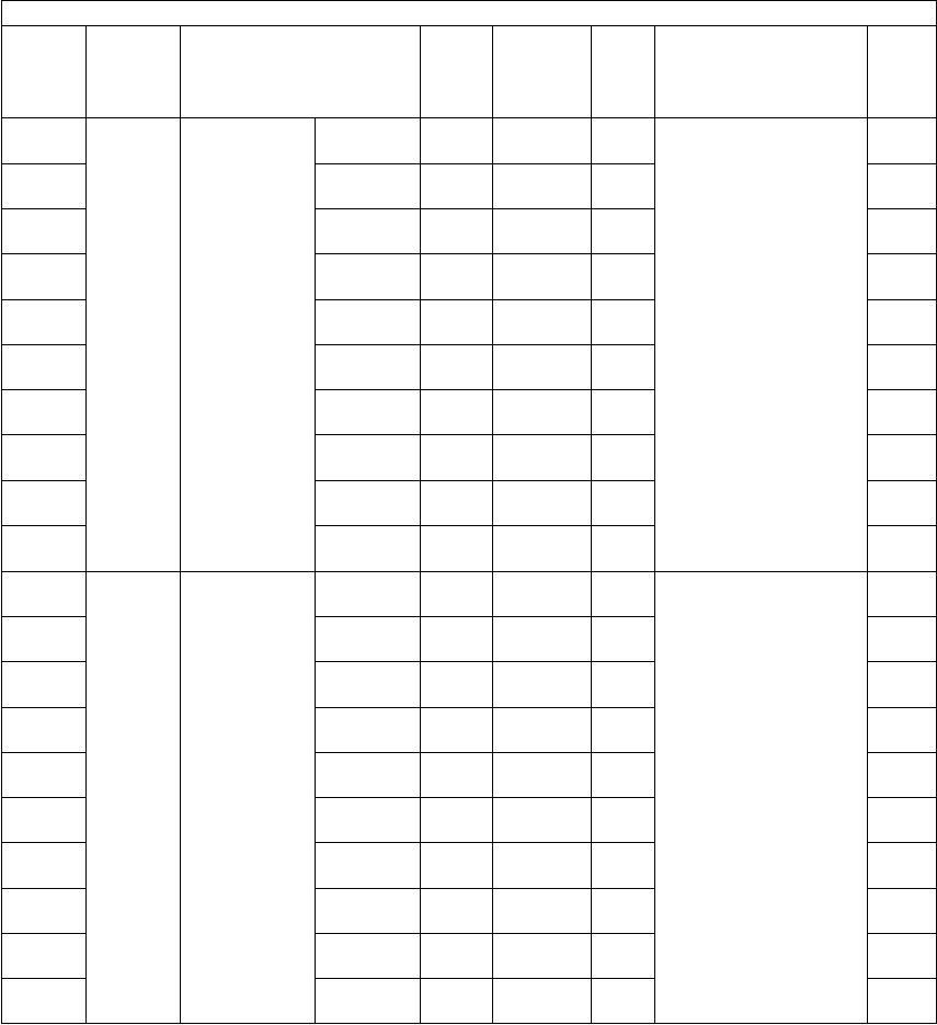
e-STUDIO281c/351c/451c ERROR CODE AND SELF-DIAGNOSTIC MODE© June 2005 TOSHIBA TEC
2 - 198
1647-0Pixel
counter
Pixel count
distribution/
full color (C)
0-5%PRT
(color)
<8 digits>SYSThe pixel count data
are divided into 10
ranges. The number of
output pages in each
range is displayed. In
this code, the distribu-
tions in the printer func-
tion, full color mode and
toner C are displayed.
[Unit: page]
14
1647-15.1-10%PRT
(color)
<8 digits>SYS14
1647-210.1-15%PRT
(color)
<8 digits>SYS14
1647-315.1-20%PRT
(color)
<8 digits>SYS14
1647-420.1-25%PRT
(color)
<8 digits>SYS14
1647-525.1-30%PRT
(color)
<8 digits>SYS14
1647-630.1-40%PRT
(color)
<8 digits>SYS14
1647-740.1-60%PRT
(color)
<8 digits>SYS14
1647-860.1-80%PRT
(color)
<8 digits>SYS14
1647-980.1-
100%
PRT
(color)
<8 digits>SYS14
1648-0Pixel
counter
Pixel count
distribution/
full color (K)
0-5%PRT
(color)
<8 digits>SYSThe pixel count data
are divided into 10
ranges. The number of
output pages in each
range is displayed. In
this code, the distribu-
tions in the printer func-
tion, full color mode and
toner K are displayed.
[Unit: page]
14
1648-15.1-10%PRT
(color)
<8 digits>SYS14
1648-210.1-15%PRT
(color)
<8 digits>SYS14
1648-315.1-20%PRT
(color)
<8 digits>SYS14
1648-420.1-25%PRT
(color)
<8 digits>SYS14
1648-525.1-30%PRT
(color)
<8 digits>SYS14
1648-630.1-40%PRT
(color)
<8 digits>SYS14
1648-740.1-60%PRT
(color)
<8 digits>SYS14
1648-860.1-80%PRT
(color)
<8 digits>SYS14
1648-980.1-
100%
PRT
(color)
<8 digits>SYS14
Setting mode (08)
Code Classifi-
cation Items Func-
tion
Default
<Accept-
able
value>
RAMContents
Pro-
cedur
e

© June 2005 TOSHIBA TECe-STUDIO281c/351c/451c ERROR CODE AND SELF-DIAGNOSTIC MODE
2 - 199
2
1649-0Pixel
counter
Pixel count
distribution/
black
0-5%PPC
(black)
<8 digits>SYSThe pixel count data
are divided into 10
ranges. The number of
output pages in each
range is displayed. In
this code, the distribu-
tions in the copy func-
tion and black mode
aredisplayed.
[Unit: page]
14
1649-15.1-10%PPC
(black)
<8 digits>SYS14
1649-210.1-15%PPC
(black)
<8 digits>SYS14
1649-315.1-20%PPC
(black)
<8 digits>SYS14
1649-420.1-25%PPC
(black)
<8 digits>SYS14
1649-525.1-30%PPC
(black)
<8 digits>SYS14
1649-630.1-40%PPC
(black)
<8 digits>SYS14
1649-740.1-60%PPC
(black)
<8 digits>SYS14
1649-860.1-80%PPC
(black)
<8 digits>SYS14
1649-980.1-
100%
PPC
(black)
<8 digits>SYS14
1650-0Pixel
counter
Pixel count
distribution/
black
0-5%PRT
(black)
<8 digits>SYSThe pixel count data
are divided into 10
ranges. The number of
output pages in each
range is displayed. In
this code, the distribu-
tions in the printer func-
tion and black mode are
displayed.
[Unit: page]
14
1650-15.1-10%PRT
(black)
<8 digits>SYS14
1650-210.1-15%PRT
(black)
<8 digits>SYS14
1650-315.1-20%PRT
(black)
<8 digits>SYS14
1650-420.1-25%PRT
(black)
<8 digits>SYS14
1650-525.1-30%PRT
(black)
<8 digits>SYS14
1650-630.1-40%PRT
(black)
<8 digits>SYS14
1650-740.1-60%PRT
(black)
<8 digits>SYS14
1650-860.1-80%PRT
(black)
<8 digits>SYS14
1650-980.1-
100%
PRT
(black)
<8 digits>SYS14
Setting mode (08)
Code Classifi-
cation Items Func-
tion
Default
<Accept-
able
value>
RAMContents
Pro-
cedur
e

e-STUDIO281c/351c/451c ERROR CODE AND SELF-DIAGNOSTIC MODE© June 2005 TOSHIBA TEC
2 - 200
1651-0Pixel
counter
Pixel count
distribution/
black
0-5%FAX
(black)
<8 digits>SYSThe pixel count data
are divided into 10
ranges. The number of
output pages in each
range is displayed. In
this code, the distribu-
tions in the FAX func-
tion and black mode are
dis-played.
[Unit: page]
14
1651-15.1-10%FAX
(black)
<8 digits>SYS14
1651-210.1-15%FAX
(black)
<8 digits>SYS14
1651-315.1-20%FAX
(black)
<8 digits>SYS14
1651-420.1-25%FAX
(black)
<8 digits>SYS14
1651-525.1-30%FAX
(black)
<8 digits>SYS14
1651-630.1-40%FAX
(black)
<8 digits>SYS14
1651-740.1-60%FAX
(black)
<8 digits>SYS14
1651-860.1-80%FAX
(black)
<8 digits>SYS14
1651-980.1-
100%
FAX
(black)
<8 digits>SYS14
Setting mode (08)
Code Classifi-
cation Items Func-
tion
Default
<Accept-
able
value>
RAMContents
Pro-
cedur
e
05/07
