Toshiba Rav Sm1102Ct E Service Manual
RAV-SM802BT-E to the manual 3f028d7d-87e6-42ca-9e31-e3f65a9c9014
2014-12-13
: Toshiba Toshiba-Rav-Sm1102Ct-E-Service-Manual-127383 toshiba-rav-sm1102ct-e-service-manual-127383 toshiba pdf
Open the PDF directly: View PDF ![]() .
.
Page Count: 195 [warning: Documents this large are best viewed by clicking the View PDF Link!]
R410A
FILE NO. A06-010
Revised : Mar. 2007
SERVICE MANUAL/INTEGRATION
AIR-CONDITIONER
SPLIT TYPE
INDOOR UNIT
<DIGITAL INVERTER>
RAV-SM563UT-E RAV-SM562BT-E RAV-SM562CT-E
RAV-SM803UT-E RAV-SM802BT-E RAV-SM802CT-E
RAV-SM1103UT-E RAV-SM1102BT-E RAV-SM1102CT-E
RAV-SM1403UT-E RAV-SM1402BT-E RAV-SM1402CT-E
<SUPER DIGITAL INVERTER>
RAV-SP1102UT-E
OUTDOOR UNIT
<DIGITAL INVERTER>
RAV-SM563AT-E RAV-SM803AT-E RAV-SM1103AT-E RAV-SM1403AT-E
<SUPER DIGITAL INVERTER>
RAV-SP562AT-E RAV-SP802AT-E RAV-SP1102AT-E RAV-SP1402AT-E
PRINTED IN JAPAN, Mar.,2007 ToMo

– 2 –
ADOPTION OF NEW REFRIGERANT
This Air Conditioner is a new type which adopts a new refrigerant HFC (R410A) instead of the conventional
refrigerant R22 in order to prevent destruction of the ozone layer.
WARNING
Cleaning of the air filter and other parts of the air filter involves dangerous work in high places, so be sure to
have a service person do it. Do not attempt it yourself. The cleaning diagram for the air filter is there for the
service person, and not for the customer.
NOTE
A direct current motor is adopted for indoor fan motor in the Concealed Duct Standard Type air conditioner.
Caused from its characteristics, a current limit works on the direct current motor. When replacing the high-
performance filter or when opening the service board, be sure to stop the fan. If an above action is executed
during the fan operation, the protective control works to stop the unit operation, and the check code “P12”
may be issued. However it is not a trouble. When the desired operation has finished, be sure to reset the
system to clear “P12” error code using the leak breaker of the indoor unit. Then push the operation stop
button of the remote controller to return to the usual operation.
CONTENTS
SAFETY CAUTION ............................................................................................ 4
1. SPECIFICATIONS......................................................................................... 9
1-1. Indoor Unit........................................................................................................... 9
1-2. Outdoor Unit...................................................................................................... 17
1-3. Operation Characteristic Curve....................................................................... 19
2. AIR DUCTING WORK ................................................................................. 22
2-1. Static Pressure Characteristics of Each Model ............................................. 22
3. CONSTRUCTION VIEWS (EXTERNAL VIEWS)......................................... 24
3-1. Indoor Unit......................................................................................................... 24
3-2. Outdoor Unit...................................................................................................... 28
4. SYSTEMATIC REFRIGERATING CYCLE DIAGRAM ................................ 31
4-1. Indoor Unit/Outdoor Unit ................................................................................. 31
5. WIRING DIAGRAM ..................................................................................... 39
5-1. Indoor Unit......................................................................................................... 39
5-2. Outdoor Unit (Wiring Diagram)........................................................................ 42
6. SPECIFICATIONS OF ELECTRICAL PARTS............................................. 46
6-1. Indoor Unit......................................................................................................... 46
6-2. Outdoor Unit...................................................................................................... 48
6-3. Accessory Separate Soldparts ........................................................................ 50
– 3 –
7. REFRIGERANT R410A .............................................................................. 51
7-1. Safety During Installation/Servicing ............................................................... 51
7-2. Refrigerant Piping Installation....................................................................... 51
7-3. Tools .................................................................................................................. 55
7-4. Recharging of Refrigerant................................................................................ 55
7-5. Brazing of Pipes................................................................................................ 56
7-6. Instructions for Re-use Piping of R22 or R407C ............................................ 58
8. CONTROL BLOCK DIAGRAM ................................................................... 61
8-1. Indoor Control Circuit....................................................................................... 61
8-2. Control Specifications...................................................................................... 62
8-3. Indoor Print Circuit Board ................................................................................ 70
9. CIRCUIT CONFIGURATION AND CONTROL SPECIFICATIONS ............. 71
9-1. Indoor Control Circuit....................................................................................... 71
9-2. Outdoor Controls .............................................................................................. 71
10. TROUBLESHOOTING............................................................................... 80
10-1. Summary of Troubleshooting........................................................................... 80
10-2. Check Code List................................................................................................ 82
10-3. Error Mode Detected by LED on Outdoor P.C. Board .................................... 85
10-4. Troubleshooting Procedure for Each Check Code......................................... 86
11. REPLACEMENT OF SERVICE INDOOR P.C. BOARD .......................... 102
12. SETUP AT LOCAL SITE AND OTHERS ................................................ 106
12-1. Indoor Unit....................................................................................................... 106
12-2. Setup at Local Site / Others ........................................................................... 113
12-3. How to set up central control address number............................................ 115
13. ADDRESS SETUP .................................................................................. 116
13-1. Address Setup ................................................................................................ 116
13-2. Address Setup & Group Control.................................................................... 117
13-3. Address Setup ................................................................................................ 118
14. DETACHMENTS..................................................................................... 120
14-1. Indoor Unit...................................................................................................... 120
14-2. Outdoor Unit.................................................................................................... 134
15. EXPLODED VIEWS AND PARTS LIST ................................................. 159
15-1. Indoor Unit....................................................................................................... 159
15-2. Outdoor Unit.................................................................................................... 173
15-3. Replacement of Main Parts (Sold Separately).............................................. 181
16. CORD HEATER INSTALLATION WORK ................................................ 183
16-1. Required parts for installation work (Recommendation) ............................ 183
16-2. Base Plate ....................................................................................................... 192
– 4 –
SAFETY CAUTION
The important contents concerned to the safety are described on the product itself and on this Service Manual.
Please read this Service Manual after understanding the described items thoroughly in the following contents
(Indications/Illustrated marks), and keep them.
[Explanation of indications]
∗Property damage : Enlarged damage concerned to property, furniture, and domestic animal/pet
[Explanation of illustrated marks]
[Confirmation of warning label on the main unit]
Confirm that labels are indicated on the specified positions
(Refer to the Parts disassembly diagram (Outdoor unit).)
If removing the label during parts replace, stick it as the original.
Indication
DANGER
WARNING
CAUTION
Explanation
Indicates contents assumed that an imminent danger causing a death or serious injury of
the repair engineers and the third parties when an incorrect work has been executed.
Indicates possibilities assumed that a danger causing a death or serious injury of the
repair engineers, the third parties, and the users due to troubles of the product after work
when an incorrect work has been executed.
Indicates contents assumed that an injury or property damage (∗) may be caused on the
repair engineers, the third parties, and the users due to troubles of the product after work
when an incorrect work has been executed.
Mark Explanation
Indicates prohibited items (Forbidden items to do)
The sentences near an illustrated mark describe the concrete prohibited contents.
Indicates mandatory items (Compulsory items to do)
The sentences near an illustrated mark describe the concrete mandatory contents.
Indicates cautions (Including danger/warning)
The sentences or illustration near or in an illustrated mark describe the concrete cautious contents.
Turn “OFF” the breaker before removing the front panel and cabinet, otherwise an electric
shock is caused by high voltage resulted in a death or injury.
During operation, a high voltage with 400V or higher of circuit (∗) at secondary circuit of the high-
voltage transformer is applied.
If touching a high voltage with the naked hands or body, an electric shock is caused even if using an
electric insulator.
∗ : For details, refer to the electric wiring diagram.
When removing the front panel or cabinet, execute short-circuit and discharge between high-
voltage capacitor terminals.
If discharge is not executed, an electric shock is caused by high voltage resulted in a death or injury.
After turning off the breaker, high voltage also keeps to apply to the high-voltage capacitor.
Do not turn on the breaker under condition that the front panel and cabinet are removed.
An electric shock is caused by high voltage resulted in a death or injury.
DANGER
Turn off breaker.
Execute discharge
between terminals.
Prohibition
– 5 –
Before troubleshooting or repair work, check the earth wire is connected to the earth
terminals of the main unit, otherwise an electric shock is caused when a leak occurs.
If the earth wire is not correctly connected, contact an electric engineer for rework.
Do not modify the products.
Do not also disassemble or modify the parts. It may cause a fire, electric shock or injury.
For spare parts, use those specified (∗∗
∗∗
∗).
If unspecified parts are used, a fire or electric shock may be caused.
∗: For details, refer to the parts list.
Before troubleshooting or repair work, do not bring a third party (a child, etc.) except
the repair engineers close to the equipment.
It causes an injury with tools or disassembled parts.
Please inform the users so that the third party (a child, etc.) does not approach the equipment.
Connect the cut-off lead cables with crimp contact, etc, put the closed end side
upward and then apply a water-cut method, otherwise a leak or production of fire is
caused at the users’ side.
When repairing the refrigerating cycle, take the following measures.
1) Be attentive to fire around the cycle. When using a gas stove, etc, be sure to put out fire
before work; otherwise the oil mixed with refrigerant gas may catch fire.
2) Do not use a welder in the closed room. When using it without ventilation, carbon
monoxide poisoning may be caused.
3) Do not bring inflammables close to the refrigerant cycle, otherwise fire of the welder may
catch the inflammables.
Check the used refrigerant name and use tools and materials of the parts which
match with it.
For the products which use R410A refrigerant, the refrigerant name is indicated at a
position on the outdoor unit where is easy to see. To prevent miss-charging, the route of the
service port is changed from one of the former R22.
For an air conditioner which uses R410A, never use other refrigerant than R410A.
For an air conditioner which uses other refrigerant (R22, etc.), never use R410A.
If different types of refrigerant are mixed, abnormal high pressure generates in the refriger-
ating cycle and an injury due to breakage may be caused.
Do not charge refrigerant additionally.
If charging refrigerant additionally when refrigerant gas leaks, the refrigerant composition in
the refrigerating cycle changes resulted in change of air conditioner characteristics or
refrigerant over the specified standard amount is charged and an abnormal high pressure is
applied to the inside of the refrigerating cycle resulted in cause of breakage or injury.
Therefore if the refrigerant gas leaks, recover the refrigerant in the air conditioner, execute
vacuuming, and then newly recharge the specified amount of liquid refrigerant. In this time,
never charge the refrigerant over the specified amount.
When recharging the refrigerant in the refrigerating cycle, do not mix the refrigerant
or air other than R410A into the specified refrigerant.
If air or others is mixed with the refrigerant, abnormal high pressure generates in the
refrigerating cycle resulted in cause of injury due to breakage.
After installation work, check the refrigerant gas does not leak.
If the refrigerant gas leaks in the room, poisonous gas generates when gas touches to fire
such as fan heater, stove or cocking stove though the refrigerant gas itself is innocuous.
Never recover the refrigerant into the outdoor unit.
When the equipment is moved or repaired, be sure to recover the refrigerant with recover-
ing device. The refrigerant cannot be recovered in the outdoor unit; otherwise a serious
accident such as breakage or injury is caused.
After repair work, surely assemble the disassembled parts, and connect and lead the
removed cables as before. Perform the work so that the cabinet or panel does not
catch the inner cables.
If incorrect assembly or incorrect cable connection was done, a disaster such as a leak or
fire is caused at user’s side.
WARNING
Check earth wires.
Prohibition of modification.
Use specified parts.
Do not bring a child
close to the equipment.
Insulating measures
No fire
Refrigerant
Assembly/Cabling
– 6 –
After the work has finished, be sure to use an insulation tester set (500V mugger) to
check the resistance is 2MΩΩ
ΩΩ
Ω or more between the charge section and the non-charge
metal section (Earth position).
If the resistance value is low, a disaster such as a leak or electric shock is caused at user’s
side.
When the refrigerant gas leaks during work, execute ventilation.
If the refrigerant gas touches to a fire, poisonous gas generates. A case of leakage of the
refrigerant and the closed room full with gas is dangerous because a shortage of oxygen
occurs. Be sure to execute ventilation.
When checking the circuit inevitably under condition of the power-ON, use rubber
gloves and others not to touch to the charging section.
If touching to the charging section, an electric shock may be caused.
When the refrigerant gas leaks, find up the leaked position and repair it surely.
If the leaked position cannot be found up and the repair work is interrupted, pump-down
and tighten the service valve, otherwise the refrigerant gas may leak into the room.
The poisonous gas generates when gas touches to fire such as fan heater, stove or cocking
stove though the refrigerant gas itself is innocuous.
When installing equipment which includes a large amount of charged refrigerant such
as a multi air conditioner in a sub-room, it is necessary that the density does not the
limit even if the refrigerant leaks.
If the refrigerant leaks and exceeds the limit density, an accident of shortage of oxygen is
caused.
For the installation/moving/reinstallation work, follow to the Installation Manual.
If an incorrect installation is done, a trouble of the refrigerating cycle, water leak, electric
shock or fire is caused.
After repair work has finished, check there is no trouble.
If check is not executed, a fire, electric shock or injury may be caused. For a check, turn off
the power breaker.
After repair work (installation of front panel and cabinet) has finished, execute a test
run to check there is no generation of smoke or abnormal sound.
If check is not executed, a fire or an electric shock is caused. Before test run, install the
front panel and cabinet.
Check the following items after reinstallation.
1) The earth wire is correctly connected.
2) The power cord is not caught in the product.
3) There is no inclination or unsteadiness and the installation is stable.
If check is not executed, a fire, an electric shock or an injury is caused.
Insulator check
Ventilation
Be attentive to
electric shock
Compulsion
Check after rerair
Check after reinstallation
Put on gloves
Cooling check
WARNING
Be sure to put on gloves (∗∗
∗∗
∗) during repair work.
If not putting on gloves, an injury may be caused with the parts, etc.
(∗) Heavy gloves such as work gloves
When the power was turned on, start to work after the equipment has been
sufficiently cooled.
As temperature of the compressor pipes and others became high due to cooling/heating
operation, a burn may be caused.
CAUTION

– 7 –
•New Refrigerant (R410A)
This air conditioner adopts a new HFC type refrigerant (R410A) which does not deplete the ozone layer.
1. Safety Caution Concerned to New Refrigerant
The pressure of R410A is high 1.6 times of that of the former refrigerant (R22). Accompanied with change of
refrigerant, the refrigerating oil has been also changed. Therefore, be sure that water, dust, the former
refrigerant or the former refrigerating oil is not mixed into the refrigerating cycle of the air conditioner with
new refrigerant during installation work or service work. If an incorrect work or incorrect service is per-
formed, there is a possibility to cause a serious accident. Use the tools and materials exclusive to R410A to
purpose a safe work.
2. Cautions on Installation/Service
1) Do not mix the other refrigerant or refrigerating oil.
For the tools exclusive to R410A, shapes of all the joints including the service port differ from those of the
former refrigerant in order to prevent mixture of them.
2) As the use pressure of the new refrigerant is high, use material thickness of the pipe and tools which are
specified for R410A.
3) In the installation time, use clean pipe materials and work with great attention so that water and others do
not mix in because pipes are affected by impurities such as water, oxide scales, oil, etc. Use the clean
pipes.
Be sure to brazing with flowing nitrogen gas. (Never use gas other than nitrogen gas.)
4) For the earth protection, use a vacuum pump for air purge.
5) R410A refrigerant is azeotropic mixture type refrigerant. Therefore use liquid type to charge the refriger-
ant. (If using gas for charging, composition of the refrigerant changes and then characteristics of the air
conditioner change.)
3. Pipe Materials
For the refrigerant pipes, copper pipe and joints are mainly used. It is necessary to select the most appropri-
ate pipes to conform to the standard. Use clean material in which impurities adhere inside of pipe or joint to a
minimum.
1) Copper pipe
<Piping>
The pipe thickness, flare finishing size, flare nut and others differ according to a refrigerant type.
When us#ing a long copper pipe for R410A, it is recommended to select “Copper or copper-base pipe
without seam” and one with bonded oil amount 40mg/10m or less. Also do not use crushed, deformed,
discolored (especially inside) pipes. (Impurities cause clogging of expansion valves and capillary tubes.)
<Flare nut>
Use the flare nuts which are attached to the air conditioner unit.
2) Joint
The flare joint and socket joint are used for joints of the copper pipe. The joints are rarely used for installa-
tion of the air conditioner. However clear impurities when using them.
– 8 –
4. Tools
1. Required Tools for R410A
Mixing of different types of oil may cause a trouble such as generation of sludge, clogging of capillary,
etc. Accordingly, the tools to be used are classified into the following three types.
1) Tools exclusive for R410A (Those which cannot be used for conventional refrigerant (R22))
2) Tools exclusive for R410A, but can be also used for conventional refrigerant (R22)
3) Tools commonly used for R410A and for conventional refrigerant (R22)
The table below shows the tools exclusive for R410A and their interchangeability.
Tools exclusive for R410A (The following tools for R410A are required.)
Tools whose specifications are changed for R410A and their interchangeability
No.
Used tool
Flare tool
Copper pipe gauge for
adjusting projection margin
Torque wrench
Gauge manifold
Charge hose
Vacuum pump adapter
Electronic balance for
refrigerant charging
Refrigerant cylinder
Leakage detector
Charging cylinder
Usage
Pipe flaring
Flaring by conventional
flare tool
Connection of flare nut
Evacuating, refrigerant
charge, run check, etc.
Vacuum evacuating
Refrigerant charge
Refrigerant charge
Gas leakage check
Refrigerant charge
R410A
air conditioner installation
Existence of Whether conven-
new equipment tional equipment
for R410A can be used
Yes *(Note 1)
Yes *(Note 1)
Ye s N o
Ye s N o
Ye s N o
Ye s Ye s
Ye s N o
Ye s N o
(Note 2) No
Conventional air
conditioner installation
Whether conventional
equipment can be used
Ye s
*(Note 1)
No
No
Ye s
Ye s
No
Ye s
No
1) Vacuum pump
Use vacuum pump by
attaching vacuum pump adapter.
2) Torque wrench
3) Pipe cutter
4) Reamer
5) Pipe bender
6) Level vial
7) Screwdriver (+, –)
8) Spanner or Monkey wrench
9) Hole core drill
10) Hexagon wrench (Opposite side 4mm)
11) Tape measure
12) Metal saw
Also prepare the following equipments for other installation method and run check.
1) Clamp meter
2) Thermometer
(Note 1) When flaring is carried out for R410A using the conventional flare tools, adjustment of projec-
tion margin is necessary. For this adjustment, a copper pipe gauge, etc. are necessary.
(Note 2) Charging cylinder for R410A is being currently developed.
General tools (Conventional tools can be used.)
In addition to the above exclusive tools, the following equipments which serve also for R22 are necessary
as the general tools.
3) IInsulation resistance tester
4) Electroscope
– 9 –
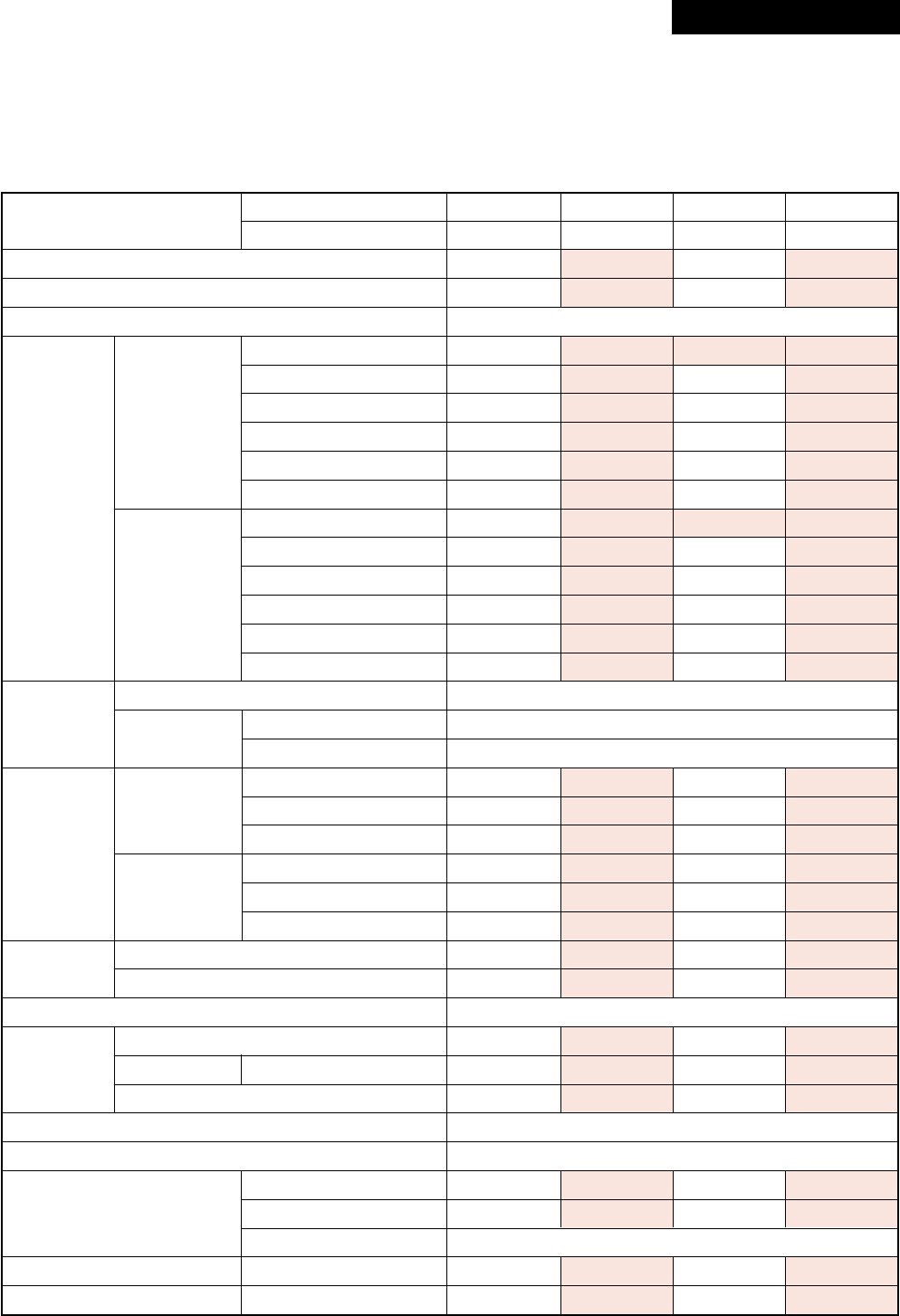
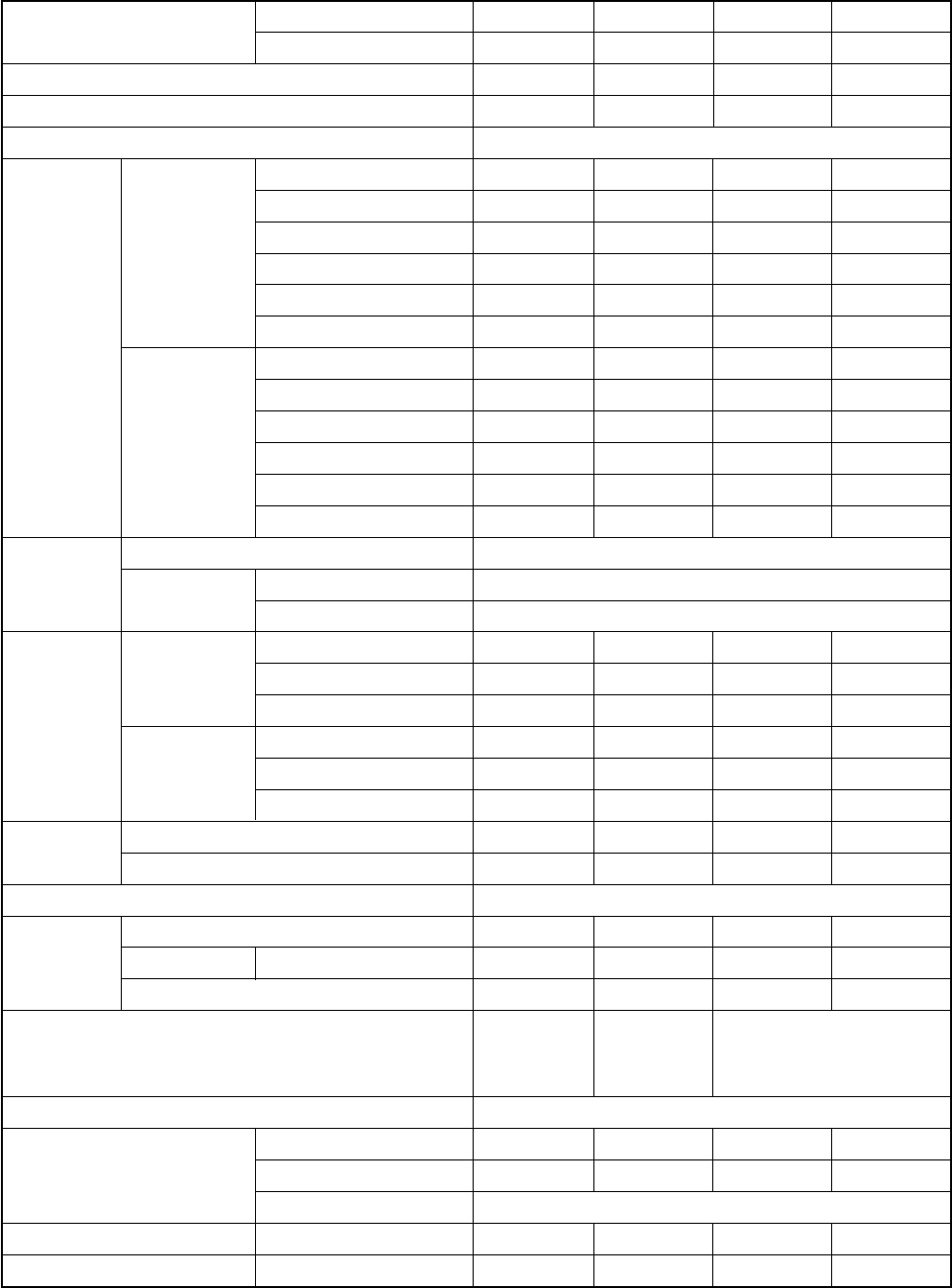
1. SPECIFICATIONS
1-1. Indoor Unit
1-1-1. 4-Way Air Discharge Cassette Type
<Digital Inverter>
* : IEC standard, ** : AS standard
Model Indoor unit RAV-
Outdoor unit RAV-
Cooling capacity (kW)
Heating capacity (kW)
Power supply
Running current (A)
Power consumption (kW)
Cooling Power factor (%)
EER (W/W)
Energy efficiency class *
Electrical Energy rating **
characteristics Running current (A)
Power consumption (kW)
Heating Power factor (%)
COP (W/W)
Energy efficiency class *
Energy rating **
Main unit
Appearance Ceiling panel Model
(Sold separately) Panel color
Height (mm)
Main unit Width (mm)
Outer Depth (mm)
dimension
Ceiling panel
Height (mm)
Width (mm)
(Sold separately)
Depth (mm)
Total weight Main unit (kg)
Ceiling panel (Sold separately) (kg)
Heat exchanger
Fan
Fan unit Standard air flow H/M/L (m³/min)
Motor (W)
Air filter
Controller (Sold separately)
Gas side (mm)
Connecting pipe Liquid side (mm)
Drain port (mm)
Sound pressure level H/M/L (dB•A)
Sound power level H/M/L (dB•A)
SM563UT-E SM803UT-E SM1103UT-E SM1403UT-E
SM563AT-E SM803AT-E SM1103AT-E SM1403AT-E
5.3 6.7 10.0 12.1
5.6 8.0 11.2 14.0
1 phase 230V (220 – 240V) 50Hz
7.89 – 7.24 10.11 – 9.26 14.42 – 13.21 7.67 – 16.19
1.65 2.09 3.11 3.77
95 94 98 97
3.21 3.21 3.22 3.21
AAAA
4.5 4.0 4.5 4.0
6.89 – 6.32 10.69 – 9.80 14.38 – 13.18 18.18 – 16.67
1.44 2.21 3.10 3.88
95 94 98 97
3.89 3.62 3.61 3.61
AAAA
6.0 4.5 5.0 4.0
Zinc hot dipping steel plate
RBC-U21PG (W)-E2
Moon-white (Muncel 2.5GY 9.0/0.5)
256 256 319 319
840 840 840 840
840 840 840 840
35 35 35 35
950 950 950 950
950 950 950 950
21 22 26 26
4.5 4.5 4.5 4.5
Finned tube
Turbo fan Turbo fan Turbo fan Turbo fan
17.5/13.9/12.1 20.0/15.7/13.6 28.0/22.0/18.0 34.0/25.0/20.0
60 60 90 90
TCB-LF1601UE2, UFM1601UE, UFH1601UE
RBC-AMT31E, AS21E2, TCB-SC642TLE2, AX21U(W)-E2
12.7 15.9 15.9 15.9
6.4 9.5 9.5 9.5
VP25
32/29/27 37/31/28 39/36/33 47/38/34
47/44/42 52/46/43 54/51/48 62/53/49
Revised : Mar. 2007
– 10 –
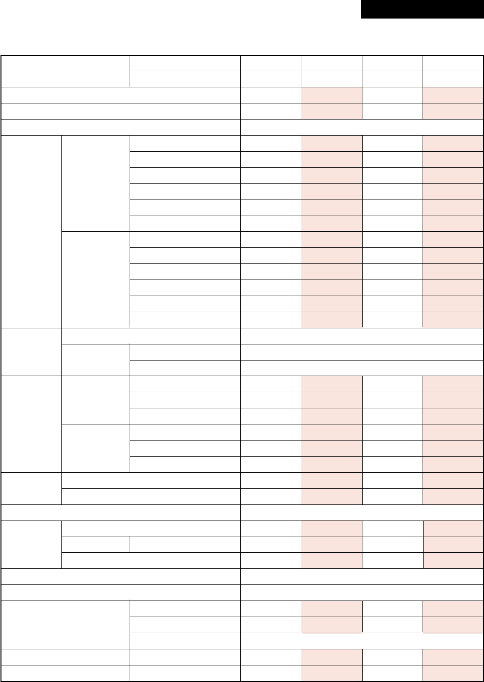
<Super Digital Inverter>
* : IEC standard, ** : AS standard
Model Indoor unit RAV-
Outdoor unit RAV-
Cooling capacity (kW)
Heating capacity (kW)
Power supply
Running current (A)
Power consumption (kW)
Cooling Power factor (%)
EER (W/W)
Energy efficiency class *
Electrical Energy rating **
characteristics Running current (A)
Power consumption (kW)
Heating Power factor (%)
COP (W/W)
Energy efficiency class *
Energy rating **
Main unit
Appearance Ceiling panel Model
(Sold separately) Panel color
Height (mm)
Main unit Width (mm)
Outer Depth (mm)
dimension
Ceiling panel
Height (mm)
Width (mm)
(Sold separately)
Depth (mm)
Total weight Main unit (kg)
Ceiling panel (Sold separately) (kg)
Heat exchanger
Fan
Fan unit Standard air flow H/M/L (m³/min)
Motor (W)
Air filter
Controller (Sold separately)
Gas side (mm)
Connecting pipe Liquid side (mm)
Drain port (mm)
Sound pressure level H/M/L (dB•A)
Sound power level H/M/L (dB•A)
SM563UT-E SM803UT-E SP1102UT-E SM1403UT-E
SP562AT-E SP802AT-E SP1102AT-E SP1402AT-E
5.3 7.1 10.0 12.5
5.6 8.0 11.2 14.0
1 phase 230V (220 – 240V) 50Hz
7.17 – 6.57 8.95 – 8.21 11.24 – 10.31 16.51 – 15.14
1.53 1.93 2.40 3.56
97 98 97 98
3.46 3.68 4.17 3.51
AAAA
————
5.62 – 5.15 9.42 – 8.63 12.28 – 11.25 16.60 – 15.22
1.20 2.03 2.62 3.58
97 98 97 98
4.67 3.94 4.27 3.91
AAAA
————
Zinc hot dipping steel plate
RBC-U21PG (W)-E2
Moon-white (Muncel 2.5GY 9.0/0.5)
256 256 319 319
840 840 840 840
840 840 840 840
35 35 35 35
950 950 950 950
950 950 950 950
21 22 26 26
4.5 4.5 4.5 4.5
Finned tube
Turbo fan Turbo fan Turbo fan Turbo fan
17.5/13.9/12.1 20.0/15.7/13.6 28.0/22.0/18.0 33.0/25.0/20.0
60 60 90 90
TCB-LF1601UE2, UFM1601UE, UFH1601UE
RBC-AMT31E, AS21E2, TCB-SC642TLE2, AX21U (W)-E2
12.7 15.9 15.9 15.9
6.4 9.5 9.5 9.5
VP25
32/29/27 37/31/28 39/36/33 42/38/34
47/44/42 52/46/43 54/51/48 57/53/49
Revised : Mar. 2007
– 11 –
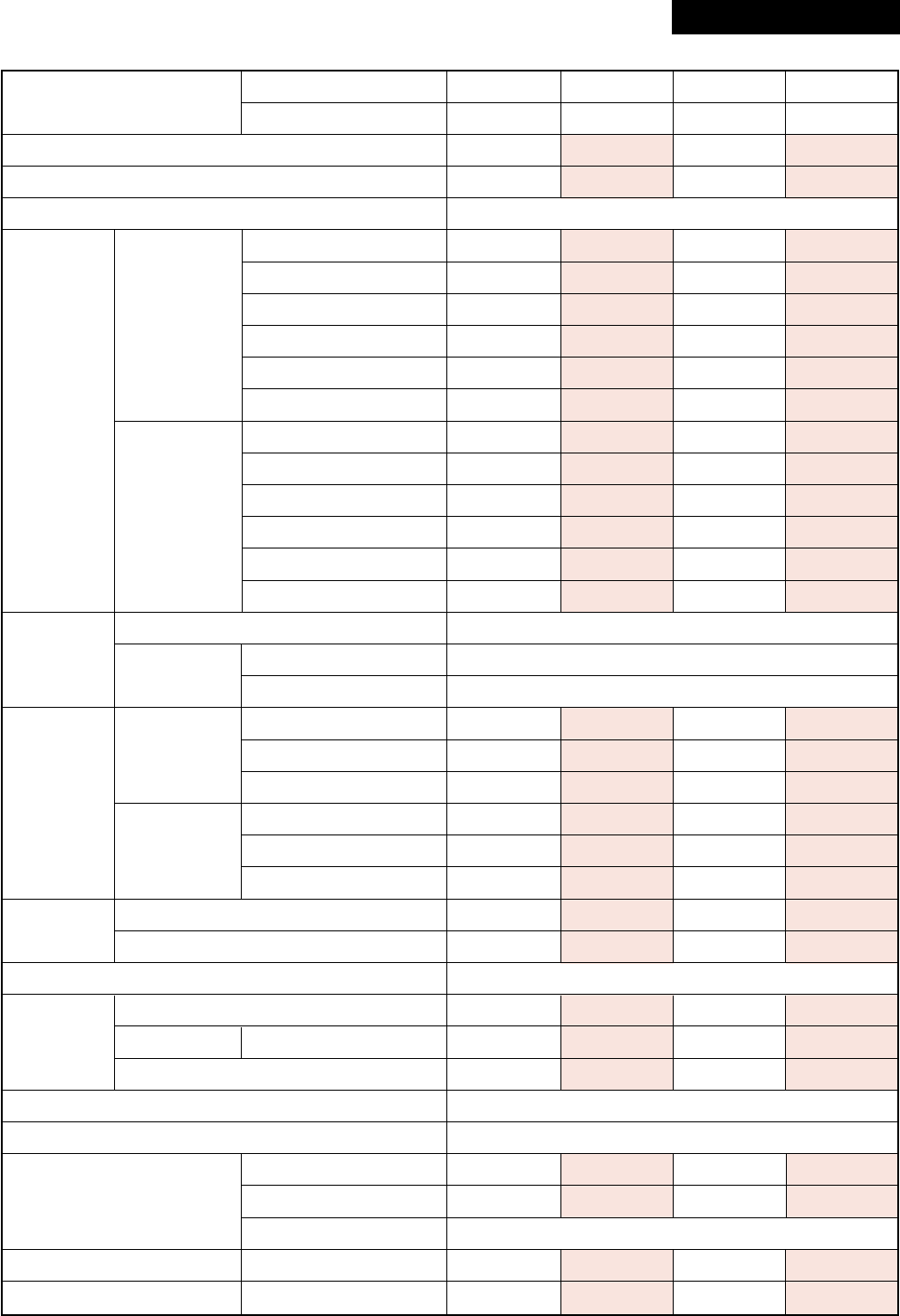
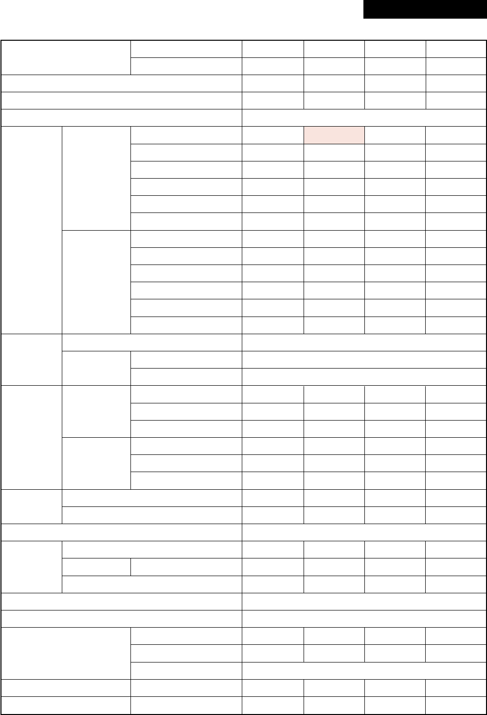
1-1-2. Concealed Duct Type
<Digital Inverter>
* : IEC standard, ** : AS standard
Model Indoor unit RAV-
Outdoor unit RAV-
Cooling capacity (kW)
Heating capacity (kW)
Power supply
Running current (A)
Power consumption (kW)
Cooling Power factor (%)
EER (W/W)
Energy efficiency class *
Electrical Energy rating **
characteristics Running current (A)
Power consumption (kW)
Heating Power factor (%)
COP (W/W)
Energy efficiency class *
Energy rating **
Main unit
Appearance Ceiling panel Model
(Sold separately) Panel color
Height (mm)
Main unit Width (mm)
Outer Depth (mm)
dimension
Ceiling panel
Height (mm)
Width (mm)
(Sold separately)
Depth (mm)
Total weight Main unit (kg)
Ceiling panel (Sold separately) (kg)
Heat exchanger
Fan
Fan unit Standard air flow H/M/L (m³/min)
Motor (W)
Air filter TCB-
Controller (Sold separately)
Gas side (mm)
Connecting pipe Liquid side (mm)
Drain port (mm)
Sound pressure level H/M/L (dB•A)
Sound power level H/M/L (dB•A)
SM562BT-E SM802BT-E SM1102BT-E SM1402BT-E
SM563AT-E SM803AT-E SM1103AT-E SM1403AT-E
5.0 7.1 10.0 12.5
5.6 8.0 11.2 14.0
1 phase 230V (220 – 240V) 50Hz
8.52 – 7.81 12.23 – 11.21 16.50 – 15.10 20.70 – 19.00
1.78 2.53 3.56 4.42
95 94 98 97
2.81 2.81 2.81 2.83
CCCC
3.0 3.0 3.5 3.0
8.18 – 7.50 11.65 – 10.68 14.56 – 13.35 18.88 – 17.31
1.71 2.41 3.14 4.03
95 94 98 97
3.27 3.32 3.57 3.47
CCBB
3.0 3.5 5.0 4.0
Zinc hot dipping steel plate
—
—
320 320 320 320
700 1000 1350 1350
800 800 800 800
————
————
————
30 39 54 54
————
Finned tube
Centrifugal Centrifugal Centrifugal Centrifugal
13.0/11.9/9.8 19.0/16.2/13.3 27.0/23.0/18.9 33.0/28.0/23.1
120 120 120 120
UFM11BFCE UFM21BFCE
UFM21BE UFM31BE UFM41BE
UFM61BE UFH51BFCE UFH61BFCE
UFM71BE UFH81BE
RBC-AMT31E, AS21E2, TCB-SC642TLE2, AX21E2
12.7 15.9 15.9 15.9
6.4 9.5 9.5 9.5
VP25
40/37/33 40/37/34 42/39/36 44/41/38
55/52/48 55/52/49 57/54/51 59/56/53
Revised : Mar. 2007
– 12 –
<Super Digital Inverter>
* : IEC standard, ** : AS standard
Model Indoor unit RAV-
Outdoor unit RAV-
Cooling capacity (kW)
Heating capacity (kW)
Power supply
Running current (A)
Power consumption (kW)
Cooling Power factor (%)
EER (W/W)
Energy efficiency class *
Electrical Energy rating **
characteristics Running current (A)
Power consumption (kW)
Heating Power factor (%)
COP (W/W)
Energy efficiency class *
Energy rating **
Main unit
Appearance Ceiling panel Model
(Sold separately) Panel color
Height (mm)
Main unit Width (mm)
Outer Depth (mm)
dimension
Ceiling panel
Height (mm)
Width (mm)
(Sold separately)
Depth (mm)
Total weight Main unit (kg)
Ceiling panel (Sold separately) (kg)
Heat exchanger
Fan
Fan unit Standard air flow H/M/L (m³/min)
Motor (W)
Air filter TCB-
Controller (Sold separately)
Gas side (mm)
Connecting pipe Liquid side (mm)
Drain port (mm)
Sound pressure level H/M/L (dB•A)
Sound power level H/M/L (dB•A)
SM562BT-E SM802BT-E SM1102BT-E SM1402BT-E
SP562AT-E SP802AT-E SP1102AT-E SP1402AT-E
5.0 7.1 10.0 12.5
5.6 8.0 11.2 14.0
1 phase 230V (220 – 240V) 50Hz
6.51 – 5.97 9.74 – 8.93 11.72 – 10.74 18.09 – 16.58
1.39 2.10 2.50 3.90
97 98 97 98
3.60 3.38 4.00 3.21
AAAA
————
7.26 – 6.66 9.74 – 8.93 11.72 – 10.74 16.70 – 15.31
1.55 2.10 2.50 3.60
97 98 97 98
3.61 3.81 4.48 3.89
AAAA
————
Zinc hot dipping steel plate
—
—
320 320 320 320
700 1000 1350 1350
800 800 800 800
————
————
————
30 39 54 54
————
Finned tube
Centrifugal Centrifugal Centrifugal Centrifugal
13.0/11.9/9.8 19.0/16.2/13.3 27.0/23.0/18.9 33.0/28.0/23.1
120 120 120 120
UFM11BFCE UFM21BFCE
UFM21BE UFM31BE UFM 41BE
UFM61BE UFH51BFCE UFH61BFCE
UFM71BE UFH 81BE
RBC-AMT31E, AS21E2, TCB-SC642TLE2, AX21E2
12.7 15.9 15.9 15.9
6.4 9.5 9.5 9.5
VP25
40/37/33 40/37/34 42/39/36 44/41/38
55/52/48 55/52/49 57/54/51 59/56/53
– 13 –
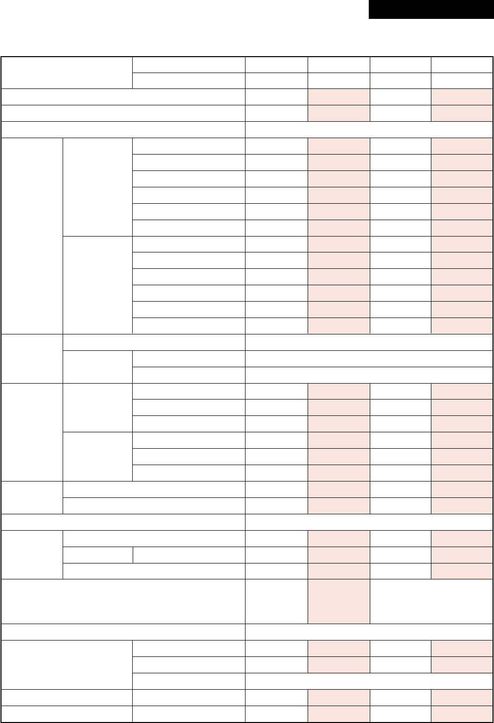
1-1-3. Under Ceiling Type
<Digital Inverter>
* : IEC standard, ** : AS standard
Model Indoor unit RAV-
Outdoor unit RAV-
Cooling capacity (kW)
Heating capacity (kW)
Power supply
Running current (A)
Power consumption (kW)
Cooling Power factor (%)
EER (W/W)
Energy efficiency class *
Electrical Energy rating **
characteristics Running current (A)
Power consumption (kW)
Heating Power factor (%)
COP (W/W)
Energy efficiency class *
Energy rating **
Main unit
Appearance Ceiling panel Model
(Sold separately) Panel color
Height (mm)
Main unit Width (mm)
Outer Depth (mm)
dimension
Ceiling panel
Height (mm)
Width (mm)
(Sold separately)
Depth (mm)
Total weight Main unit (kg)
Ceiling panel (Sold separately) (kg)
Heat exchanger
Fan
Fan unit Standard air flow H/M/L (m³/min)
Motor (W)
Air filter
Controller (Sold separately)
Gas side (mm)
Connecting pipe Liquid side (mm)
Drain port (mm)
Sound pressure level H/M/L (dB•A)
Sound power level H/M/L (dB•A)
SM562CT-E SM802CT-E SM1102CT-E SM1402CT-E
SM563AT-E SM803AT-E SM1103AT-E SM1403AT-E
5.0 7.0 10.0 12.3
5.6 8.0 11.2 14.0
1 phase 230V (220 – 240V) 50Hz
8.71 – 7.98 12.23 – 11.21 16.20 – 14.90 21.18 – 19.40
1.82 2.53 3.51 4.52
95 94 98 97
2.75 2.77 2.85 2.72
DDCD
2.5 2.5 3.0 2.5
7.85 – 7.19 11.94 – 10.95 14.84 – 13.61 19.40 – 17.78
1.64 2.47 3.20 4.14
95 94 98 97
3.41 3.24 3.50 3.38
BCBC
4.0 4.0 5.0 3.5
Shine white
—
—
210 210 210 210
910 1180 1595 1595
680 680 680 680
————
————
————
21 25 33 33
————
Finned tube
Centrifugal Centrifugal Centrifugal Centrifugal
13.0/11.2/10.0 18.5/16.7/14.6 27.5/24.0/21.2 30.0/26.0/23.1
60 60 120 120
Attached main unit
RBC-AMT31E, AS21E2, TCB-SC642TLE2, AX21E2
12.7 15.9 15.9 15.9
6.4 9.5 9.5 9.5
VP25
36/33/30 38/36/33 41/38/35 43/40/37
51/48/45 53/51/48 56/53/50 58/55/52
Revised : Mar. 2007
– 14 –
<Super Digital Inverter>
* : IEC standard, ** : AS standard
Model Indoor unit RAV-
Outdoor unit RAV-
Cooling capacity (kW)
Heating capacity (kW)
Power supply
Running current (A)
Power consumption (kW)
Cooling Power factor (%)
EER (W/W)
Energy efficiency class *
Electrical Energy rating **
characteristics Running current (A)
Power consumption (kW)
Heating Power factor (%)
COP (W/W)
Energy efficiency class *
Energy rating **
Main unit
Appearance Ceiling panel Model
(Sold separately) Panel color
Height (mm)
Main unit Width (mm)
Outer Depth (mm)
dimension
Ceiling panel
Height (mm)
Width (mm)
(Sold separately)
Depth (mm)
Total weight Main unit (kg)
Ceiling panel (Sold separately) (kg)
Heat exchanger
Fan
Fan unit Standard air flow H/M/L (m³/min)
Motor (W)
Air filter
Controller (Sold separately)
Gas side (mm)
Connecting pipe Liquid side (mm)
Drain port (mm)
Sound pressure level H/M/L (dB•A)
Sound power level H/M/L (dB•A)
SM562CT-E SM802CT-E SM1102CT-E SM1402CT-E
SP562AT-E SP802AT-E SP1102AT-E SP1402AT-E
5.0 7.1 10.0 12.5
5.6 8.0 11.2 14.0
1 phase 230V (220 – 240V) 50Hz
6.61 – 6.06 9.74 – 8.93 11.24 – 10.31 18.09 – 16.58
1.41 2.10 2.40 3.90
97 98 97 98
3.55 3.38 4.17 3.21
AAAA
————
7.03 – 6.44 10.20 – 9.35 11.72 – 10.74 17.39 – 15.94
1.50 2.20 2.50 3.75
97 98 97 98
3.73 3.64 4.48 3.73
AAAA
————
Shine white
—
—
210 210 210 210
910 1180 1595 1595
680 680 680 680
————
————
————
21 25 33 33
————
Finned tube
Centrifugal Centrifugal Centrifugal Centrifugal
13.0/11.2/10.0 18.5/16.7/14.6 27.5/24.0/21.2 30.0/26.0/23.1
60 60 120 120
Attached main unit
RBC-AMT31E, AS21E2, TCB-SC642TLE2, AX21E2
12.7 15.9 15.9 15.9
6.4 9.5 9.5 9.5
VP25
36/33/30 38/36/33 41/38/35 43/40/37
51/48/45 53/51/48 56/53/50 58/55/52
Revised : Mar. 2007
– 15 –
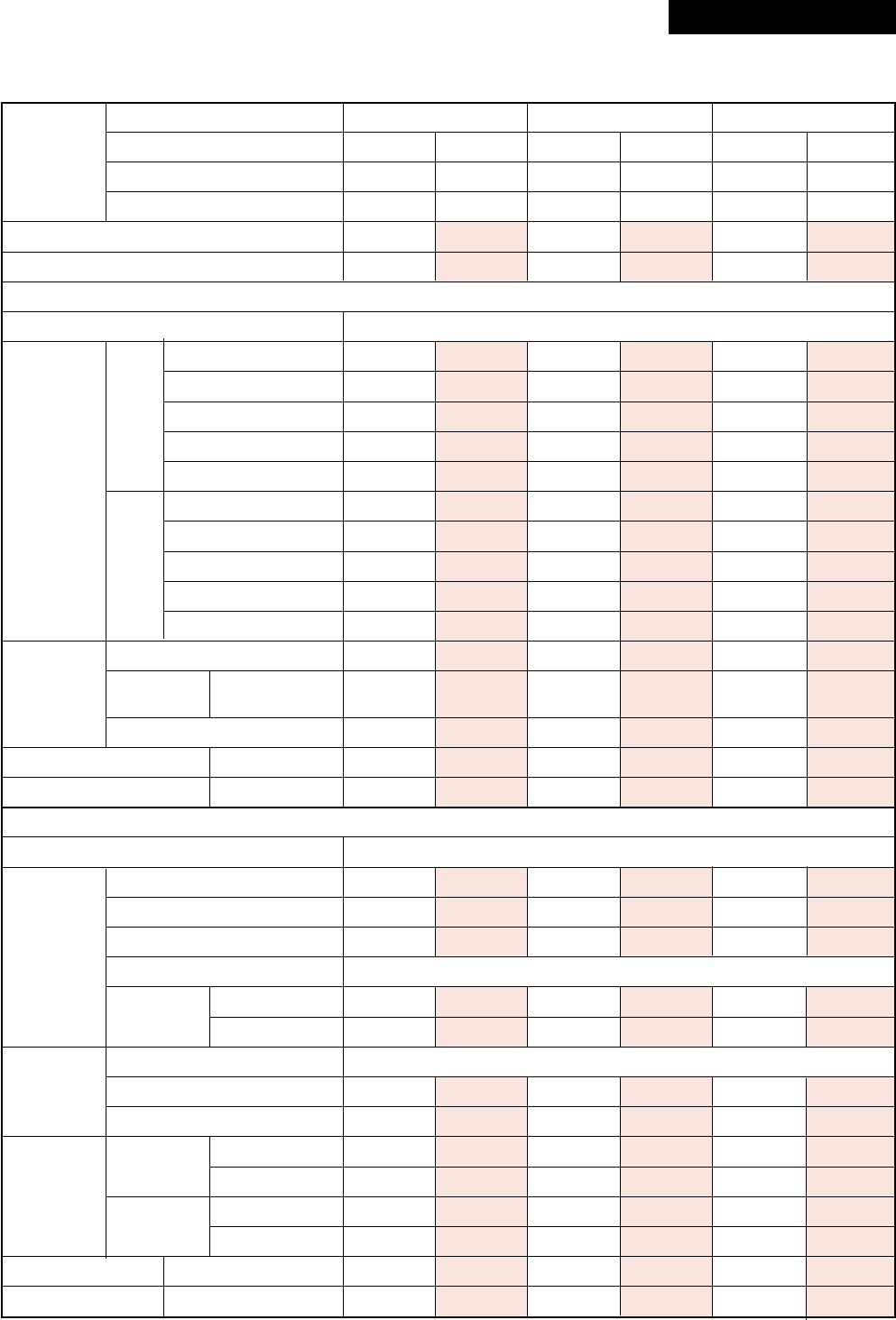
1-1-4. Twin Type
<Digital Inverter>
* : IEC standard
Type
Model Indoor unit 1 RAV-
Indoor unit 2 RAV-
Outdoor unit RAV-
Cooling capacity (kW)
Heating capacity (kW)
Indoor unit
Power supply
Running current (A)
Power consumption (kW)
Cooling Power factor (%)
EER (W/W)
Electrical Energy efficiency class *
characteristics Running current (A)
Power consumption (kW)
Heating Power factor (%)
COP (W/W)
Energy efficiency class *
Fan
Fan unit Standard H/M/L (m³/min)
air flow
Motor (W)
Sound pressure level H/M/L (dB•A)
Sound power level H/M/L (dB•A)
Outdoor unit
Power supply
Standard length (m)
Inter
Min. length (m)
connecting Max. total length (m)
Over 30m
pipes
Height Outdoor lower (m)
difference Outdoor high (m)
Fan
Fan unit Standard air flow high (m³/min)
Motor (W)
Gas side Main (mm)
Connecting Sub (mm)
pipe
Liquid side Main (mm)
Sub (mm)
Sound pressure level Cooling/Heating (dB•A)
Sound power level Cooling/Heating (dB•A)
4-Way Air Cassette Concealed Duct Under Ceiling
SM563UT-E SM803UT-E SM562BT-E SM802BT-E SM562CT-E SM802CT-E
SM563UT-E SM803UT-E SM562BT-E SM802BT-E SM562CT-E SM802CT-E
SM1103AT-E SM1403AT-E SM1103AT-E SM1403AT-E SM1103AT-E SM1403AT-E
10.0 12.5 10.0 12.5 10.0 12.3
11.2 14.0 11.2 14.0 11.2 14.0
Indoor unit
1 phase 230V (220 – 240V) 50Hz
14.40–13.20 19.17–17.57 16.51–15.14 20.71–18.99 16.28–14.92 21.18–19.42
3.11 4.09 3.56 4.42 3.51 4.52
98 97 98 97 98 97
3.22 3.06 2.81 2.83 2.85 2.72
ABCCCD
14.40–13.20 18.74–17.18 14.56–13.35 18.88–17.31 14.84–13.61 19.40–7.78
3.10 4.00 3.14 4.03 3.20 4.14
98 97 98 97 98 97
3.61 3.50 3.57 3.47 3.50 3.38
ABBBBC
Turbo fan Turbo fan Centrifugal Centrifugal Centrifugal Centrifugal
17.5/ 20.0/ 13.0/ 19.0/ 13.0/ 18.5/
13.9/12.1 15.7/13.6 11.9/9.8 16.2/13.3 11.2/10.0 16.7/14.6
60 60 120 120 60 60
32/29/27 34/31/28 40/37/33 40/37/34 36/33/30 38/36/33
47/44/42 49/46/43 55/52/48 55/52/49 51/48/45 53/51/48
Outdoor unit
1 phase 230V (220 – 240V) 50Hz (Power exclusive to outdoor is required.)
7.5 7.5 7.5 7.5 7.5 7.5
5.0 5.0 5.0 5.0 5.0 5.0
50 50 50 50 50 50
40g/m (31m to 50m)
30 30 30 30 30 30
30 30 30 30 30 30
Propeller fan
75 75 75 75 75 75
100 100 100 100 100 100
15.9 15.9 15.9 15.9 15.9 15.9
12.7 12.7 12.7 15.9 12.7 15.9
9.5 9.5 9.5 9.5 9.5 9.5
6.4 6.4 6.4 9.5 6.4 9.5
53/54 53/54 53/54 53/54 53/54 53/54
70/71 70/71 70/71 70/71 70/71 70/71
Revised : Mar. 2007
– 16 –
<Super Digital Inverter>
* : IEC standard
Type
Model Indoor unit 1 RAV-
Indoor unit 2 RAV-
Outdoor unit RAV-
Cooling capacity (kW)
Heating capacity (kW)
Indoor unit
Power supply
Running current (A)
Power consumption (kW)
Cooling Power factor (%)
EER (W/W)
Electrical Energy efficiency class *
characteristics Running current (A)
Power consumption (kW)
Heating Power factor (%)
COP (W/W)
Energy efficiency class *
Fan
Fan unit Standard H/M/L (m³/min)
air flow
Motor (W)
Sound pressure level H/M/L (dB•A)
Sound power level H/M/L (dB•A)
Outdoor unit
Power supply
Standard length (m)
Inter
Min. length (m)
connecting Max. total length (m)
Over 30m
pipes
Height Outdoor lower (m)
difference Outdoor high (m)
Fan
Fan unit Standard air flow high (m³/min)
Motor (W)
Gas side Main (mm)
Connecting Sub (mm)
pipe
Liquid side Main (mm)
Sub (mm)
Sound pressure level Cooling/Heating (dB•A)
Sound power level Cooling/Heating (dB•A)
4-Way Air Cassette Concealed Duct Under Ceiling
SM563UT-E SM803UT-E SM562BT-E SM802BT-E SM562CT-E SM802CT-E
SM563UT-E SM803UT-E SM562BT-E SM802BT-E SM562CT-E SM802CT-E
SP1102AT-E SP1402AT-E SP1102AT-E SP1402AT-E SP1102AT-E SP1402AT-E
10.0 12.5 10.0 12.5 10.0 12.3
11.2 14.0 11.2 14.0 11.2 14.0
Indoor unit
1 phase 230V (220 – 240V) 50Hz
11.24–10.31 16.51–15.14 11.72–10.74 18.09–16.58 11.24–10.31 18.09–16.58
2.40 3.56 2.50 3.90 2.40 3.90
97 98 97 98 97 98
4.17 3.51 4.00 3.21 4.17 3.21
AAAAAA
11.95–10.95 16.60–15.22 11.95–10.95 16.70–15.31 11.95–10.95 17.39–15.94
2.55 3.58 2.55 3.60 2.55 3.75
97 98 97 98 97 98
4.39 3.91 4.39 3.89 4.39 3.79
AAAAAA
Turbo fan Turbo fan Centrifugal Centrifugal Centrifugal Centrifugal
17.5/ 20.0/ 13.0/ 19.0/ 13.0/ 18.5/
13.9/12.1 15.7/13.6 11.9/9.8 16.2/13.3 11.2/10.0 16.7/14.6
60 60 120 120 60 60
32/29/27 34/31/28 40/37/33 40/37/34 36/33/30 38/36/33
47/44/42 49/46/43 55/52/48 55/52/49 51/48/45 53/51/48
Outdoor unit
1 phase 230V (220 – 240V) 50Hz (Power exclusive to outdoor is required.)
7.5 7.5 7.5 7.5 7.5 7.5
5.0 5.0 5.0 5.0 5.0 5.0
50 50 50 50 50 50
40g/m (31m to 50m)
30 30 30 30 30 30
30 30 30 30 30 30
Propeller fan
125 125 125 125 125 125
63 + 63 63 + 63 63 + 63 63 + 63 63 + 63 63 + 63
15.9 15.9 15.9 15.9 15.9 15.9
12.7 15.9 12.7 15.9 12.7 15.9
9.5 9.5 9.5 9.5 9.5 9.5
6.4 9.5 6.4 9.5 6.4 9.5
49/51 53/54 49/51 53/54 49/51 53/54
66/68 70/71 66/68 70/71 66/68 70/71
Revised : Mar. 2007
– 17 –
1-2. Outdoor Unit
<Digital Inverter>
Model name RAV-
Power supply
Type
Compressor Motor (kW)
Pole
Refrigerant charged (kg)
Refrigerant control
Standard length (m)
Min. length (m)
Max. total length (m)
Inter connecting pipe Additional refrigerant charge
under long piping connector
Height Outdoor lower (m)
difference Outdoor higher (m)
Height (mm)
Outer dimension Width (mm)
Depth (mm)
Appearance
Total weight (kg)
Heat exchanger
Fan
Fan unit Standard air flow (m³/h)
Motor (W)
Connecting pipe Gas side (mm)
Liquid side (mm)
Sound pressure level Cooling/Heating (dB•A)
Sound power level Cooling/Heating (dB•A)
Outside air temperature, Cooling (°C)
Outside air temperature, Heating (°C)
SM563AT-E SM803AT-E SM1103AT-E SM1403AT-E
1 phase 230V (220 – 240V)
50Hz (Power exclusive to outdoor is required.)
Hermetic compressor
1.1 1.6 2.5 3.0
4444
1.0 1.7 2.8 2.8
Pulse motor valve
7.5 7.5 7.5 7.5
5.0 5.0 5.0 5.0
30 30 50 50
20g/m 40g/m 40g/m 40g/m
(21m to 30m) (21m to 30m) (31m to 50m) (31m to 50m)
30 30 30 30
30 30 30 30
550 550 795 795
780 780 900 900
290 290 320 320
Silky shade (Muncel 1Y8.5/0.5)
38 44 77 77
Finned tube
Propeller fan
40 45 75 75
43 43 100 100
12.7 15.9 15.9 15.9
6.4 9.5 9.5 9.5
46/48 48/50 53/54 54/54
63/65 65/67 70/71 71/71
43 to –15
15 to –15
Revised : Mar. 2007
– 18 –
<Super Digital Inverter>
Model name RAV-
Power supply
Type
Compressor Motor (kW)
Pole
Refrigerant charged (kg)
Refrigerant control
Standard length (m)
Min. length (m)
Max. total length (m)
Inter connecting pipe Additional refrigerant charge
under long piping connector
Height Outdoor lower (m)
difference Outdoor higher (m)
Height (mm)
Outer dimension Width (mm)
Depth (mm)
Appearance
Total weight (kg)
Heat exchanger
Fan
Fan unit Standard air flow (m³/h)
Motor (W)
Connecting pipe Gas side (mm)
Liquid side (mm)
Sound pressure level Cooling/Heating (dB•A)
Sound power level Cooling/Heating (dB•A)
Outside air temperature, Cooling (°C)
Outside air temperature, Heating (°C)
SP562AT-E SP802AT-E SP1102AT-E SP1402AT-E
1 phase 230V (220 – 240V)
50Hz (Power exclusive to outdoor is required.)
Hermetic compressor
2.0 2.0 3.75 3.75
4444
1.5 2.1 2.95 2.95
Pulse motor valve
7.5 7.5 7.5 7.5
5.0 5.0 5.0 5.0
50 50 70 70
20g/m 40g/m 40g/m 40g/m
(21m to 50m) (31m to 50m) (31m to 70m) (31m to 70m)
30 30 30 30
30 30 30 30
795 795 1340 1340
900 900 900 900
320 320 320 320
Silky shade (Muncel 1Y8.5/0.5)
55 62 95 95
Finned tube
Propeller fan
57 57 125 125
63 63 63 + 63 63 + 63
12.7 15.9 15.9 15.9
6.4 9.5 9.5 9.5
46/47 47/49 49/51 53/54
63/64 64/66 66/68 70/71
43 to –15
15 to –15
– 19 –
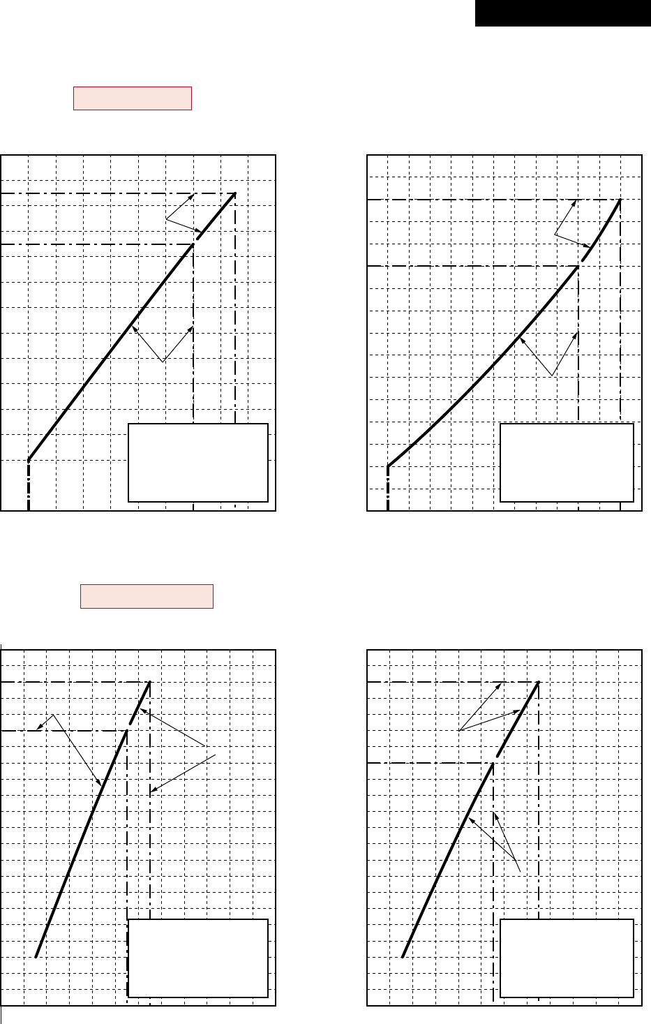
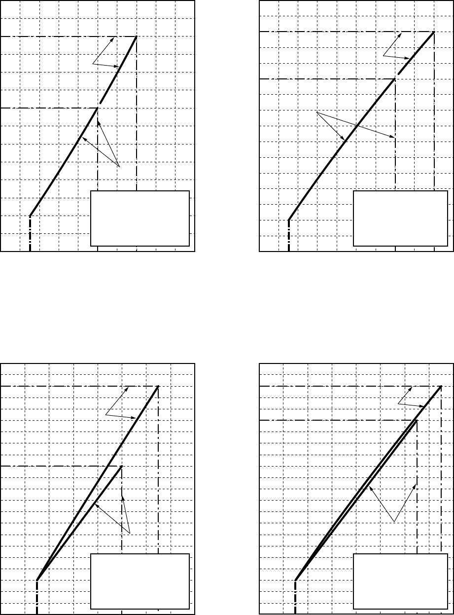
1-3. Operation Characteristic Curve
• Operation characteristic curve <Digital Inverter>
RAV-SM563AT-E, RAV-SM803AT-E
<Cooling> <Heating>
00 20 40 60708090100
2
4
6
8
10
12
14
Compressor speed (rps)
Current (A)
00 20406080100120
2
4
6
8
10
12
16
14
Compressor speed (rps)
Current (A)
20
18
16
14
12
10
0204060
Compressor speed (rps)
80 100 120
8
6
4
2
0
Current (A)
20
22 22
18
16
14
12
10
0 204060
Compressor speed (rps)
80 100 120
8
6
4
2
0
Current (A)
• Conditions
Indoor : DB27˚C/WB19˚C
Outdoor : DB35˚C
Air flow : High
Pipe length : 7.5m
230V
• Conditions
Indoor : DB20˚C
Outdoor : DB7˚C/WB6˚C
Air flow : High
Pipe length : 7.5m
230V
• Conditions
Indoor : DB27˚C/WB19˚C
Outdoor : DB35˚C
Air flow : High
Pipe length : 7.5m
230V
• Conditions
Indoor : DB20˚C
Outdoor : DB7˚C/WB6˚C
Air flow : High
Pipe length : 7.5m
230V
RAV-SM1403AT-E
RAV-SM803AT-E RAV-SM803AT-E
RAV-SM1403AT-E
RAV-SM1403AT-E RAV-SM1403AT-E
RAV-SM803AT-E RAV-SM803AT-E
RAV-SM1103AT-E
RAV-SM1103AT-E
RAV-SM563AT-E RAV-SM563AT-E
RAV-SM1103AT-E
RAV-SM1103AT-E
RAV-SM563AT-E RAV-SM563AT-E
RAV-SM1103AT-E, RAV-SM1403AT-E
<Cooling> <Heating>
Revised : Mar. 2007
– 20 –
•Operation characteristic curve <Super Digital Inverter>
RAV-SP562AT-E, RAV-SP802AT-E
<Cooling> <Heating>
00 20406050 70 80 100
2
4
6
8
10
12
14
Compressor speed (rps) Compressor speed (rps)
Current (A)
020406080
Compressor speed (rps)
0
22
20
18
16
14
12
8
10
6
4
2
0
22
20
18
16
14
12
8
10
6
4
2
Current (A)
Current (A)
020406080
Compressor speed (rps)
• Conditions
Indoor : DB27˚C/WB19˚C
Outdoor : DB35˚C
Air flow : High
Pipe length : 7.5m
230V
• Conditions
Indoor : DB20˚C
Outdoor : DB7˚C/WB6˚C
Air flow : High
Pipe length : 7.5m
230V
RAV-SP1102AT-E
RAV-SP1402AT-E
RAV-SP1102AT-E
RAV-SP1402AT-E
RAV-SP802AT-E
RAV-SP562AT-E
RAV-SP802AT-E
RAV-SP1102AT-E
RAV-SP1402AT-E
RAV-SP1102AT-E
RAV-SP1402AT-E
RAV-SP802AT-E
RAV-SP562AT-E
RAV-SP802AT-E
00 204060 908070 100
2
4
6
8
10
12
14
16
Current (A)
• Conditions
Indoor : DB27˚C/WB19˚C
Outdoor : DB35˚C
Air flow : High
Pipe length : 7.5m
230V
• Conditions
Indoor : DB20˚C
Outdoor : DB7˚C/WB6˚C
Air flow : High
Pipe length : 7.5m
230V
RAV-SP562AT-ERAV-SP562AT-E
RAV-SP1102AT-E, RAV-SP1402AT-E
<Cooling> <Heating>
– 21 –
•Capacity variation ratio according to temperature
RAV-SM563AT-E, RAV-SM803AT-E, RAV-SM1103AT-E, RAV-SM1403AT-E
RAV-SP562AT-E, RAV-SP802AT-E, RAV-SP1102AT-E, RAV-SP1402AT-E
<Cooling> <Heating>
50
55
60
65
70
75
80
85
90
95
100
105
32 33 34 35 36 37 38 39 40 41 42 43
Outdoor temp. (˚C)
Capacity ratio (%)
0
10
20
30
40
50
60
70
80
90
100
110
120
-14-12-10-8-6-4-20246810
Outdoor temp. (˚C)
Capacity ratio (%)
• Conditions
Indoor : DB20˚C
Indoor air flow : High
Pipe length : 7.5m
• Conditions
Indoor : DB27˚C/WB19˚C
Indoor air flow : High
Pipe length : 7.5m
Revised : Mar. 2007
– 22 –
140
120
100
80
60
40
20
0
500 700 780 900
Standard air volume 780m³/h
Static pressure (Pa)
Air volume m³/h
140
120
108
100
80
60
40
20
0
500 700 780 900
Standard air volume 780m³/h
Static pressure (Pa)
Air volume m³/h
140
120
100
80
60
40
20
0
800 1000
12001140 1300
Standard air volume 1140m³/h
Static pressure (Pa)
Air volume m³/h
140
120
100
80
60
40
20
0
800 1000
12001140 1300
Standard air volume 1140m³/h
Static pressure (Pa)
Air volume m³/h
Air volume limit (Max.)
Usable limit
Usable limit
Usable limit
Usable limit
High static pressure 2H tap
High static pressure 2H tap
High static pressure 2H tap
High static pressure 2H tap
Low static pressure H tap
Standard L tap
High static pressure 1H tap
Standard H tap
Low static pressure H tap
Standard L tap
High static pressure 1H tap
Standard H tap
Low static pressure H tap
Standard L tap
High static pressure 1H tap
Standard H tap
Low static pressure H tap
Standard L tap
High static pressure 1H tap
Standard H tap
Air volume limit (Min.)
Air volume limit (Max.)
Air volume limit (Min.)
Air volume limit (Max.)
Air volume limit (Min.)
Air volume limit (Max.)
Air volume limit (Min.)
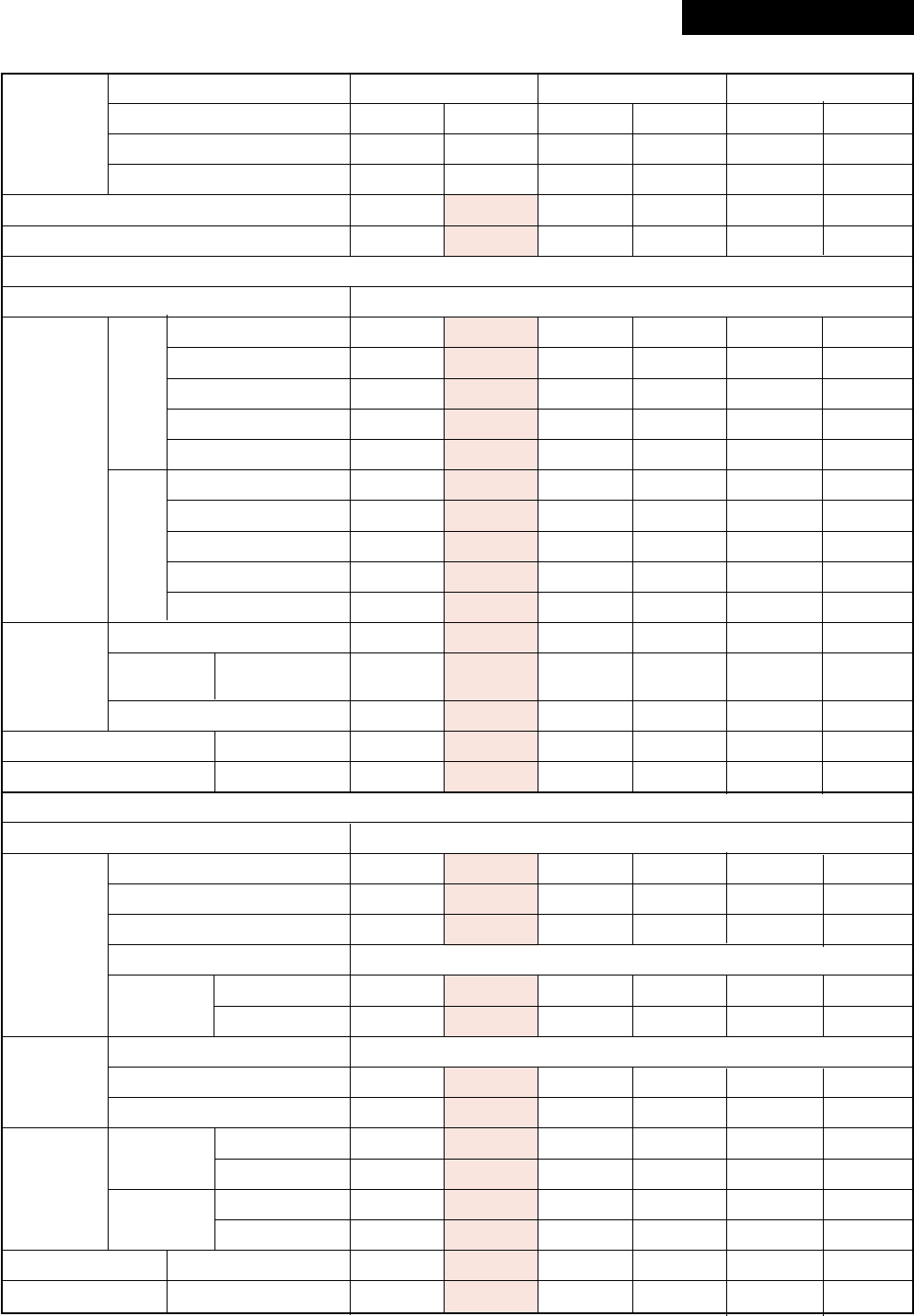
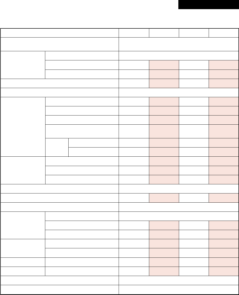
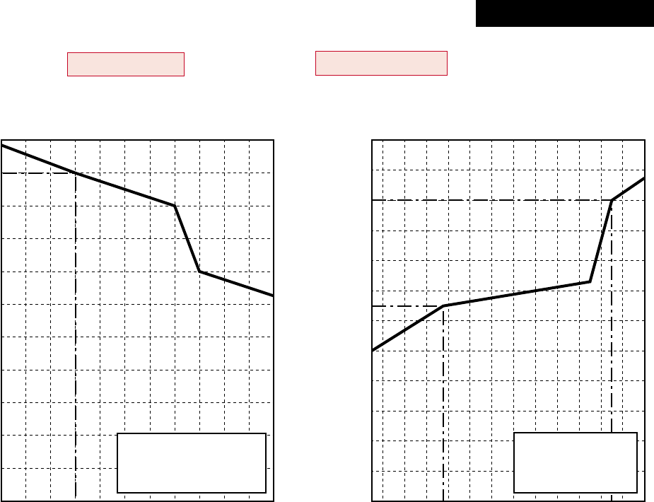
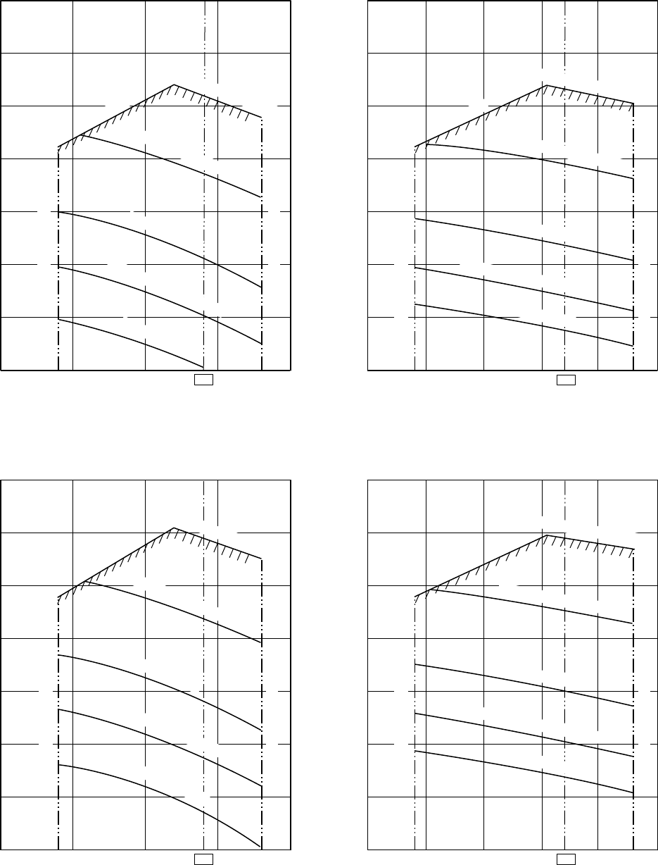
2. AIR DUCTING WORK
2-1. Static Pressure Characteristics of Each Model
RAV-SM562BT-E, RAV-SM802BT-E, RAV-SM1102BT-E, RAV-SM1402BT-E
Fig. 1 RAV-SM562BT-E (Round duct)
Fig. 2 RAV-SM562BT-E (Square duct)
Fig. 3 RAV-SM802BT-E (Round duct)
Fig. 4 RAV-SM802BT-E (Square duct)
– 23 –
140
120
100
80
60
40
20
0
1200 1620 2000
Standard air volume 1620m³/h
Static pressure (Pa)
Air volume m³/h
140
120
100
80
60
40
20
0
1200 1620 2000
Standard air volume 1620m³/h
Static pressure (Pa)
Air volume m³/h
140
120
100
80
60
40
20
0
1200 1800 1980 2200 2400
Standard air volume 1980m³/h
Static pressure (Pa)
Air volume m³/h
140
120
100
80
60
40
20
0
1200 1800 1980 2200 240
0
Standard air volume 1980m³/h
Static pressure (Pa)
Air volume hm³/h
Usable limit
Usable limit
Usable limit
Usable limit
High static pressure 2H tap
High static pressure 2H tap
High static pressure 2H tap
High static pressure 2H tap
Low static pressure H tap
Standard L tap
High static pressure 1H tap
Standard H tap
Low static pressure H tap
Standard L tap
High static pressure 1H tap
Standard H tap
Low static pressure H tap
Standard L tap
High static pressure 1H tap
Standard H tap
Low static pressure H tap
Standard L tap
High static pressure 1H tap
Standard H tap
Air volume limit (Max.)
Air volume limit (Min.)
Air volume limit (Max.)
Air volume limit (Min.)
Air volume limit (Max.)
Air volume limit (Min.)
Air volume limit (Max.)
Air volume limit (Min.)
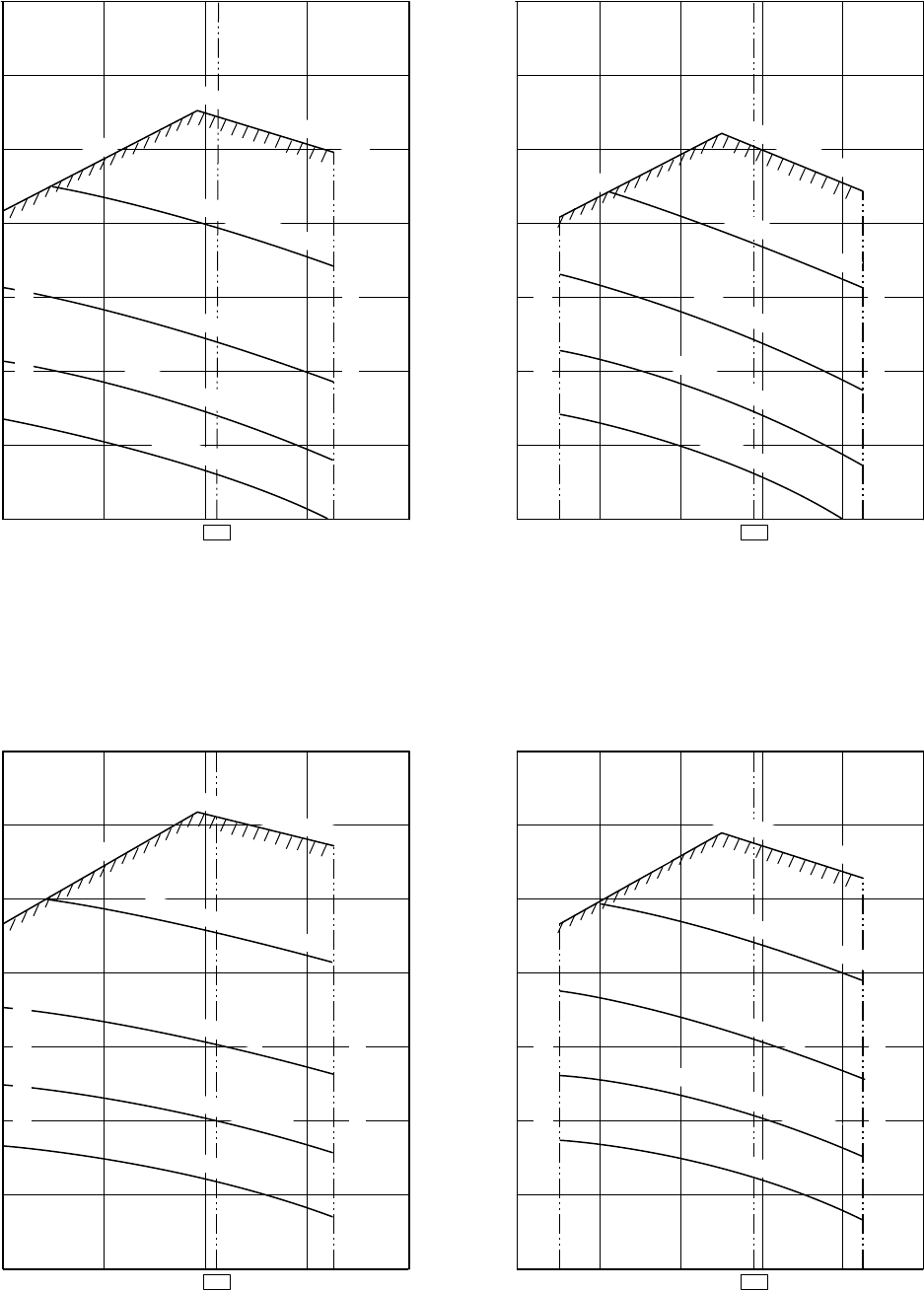
Fig. 5 RAV-SM1102BT-E (Round duct)
Fig. 6 RAV-SM1102BT-E (Square duct)
Fig. 7 RAV-SM1402BT-E (Round duct)
Fig. 8 RAV-SM1402BT-E (Square duct)
– 24 –
3. CONSTRUCTION VIEWS (EXTERNAL VIEWS)
3-1. Indoor Unit
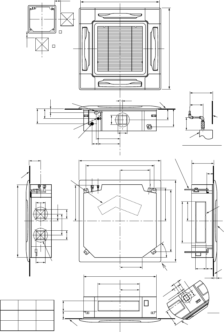
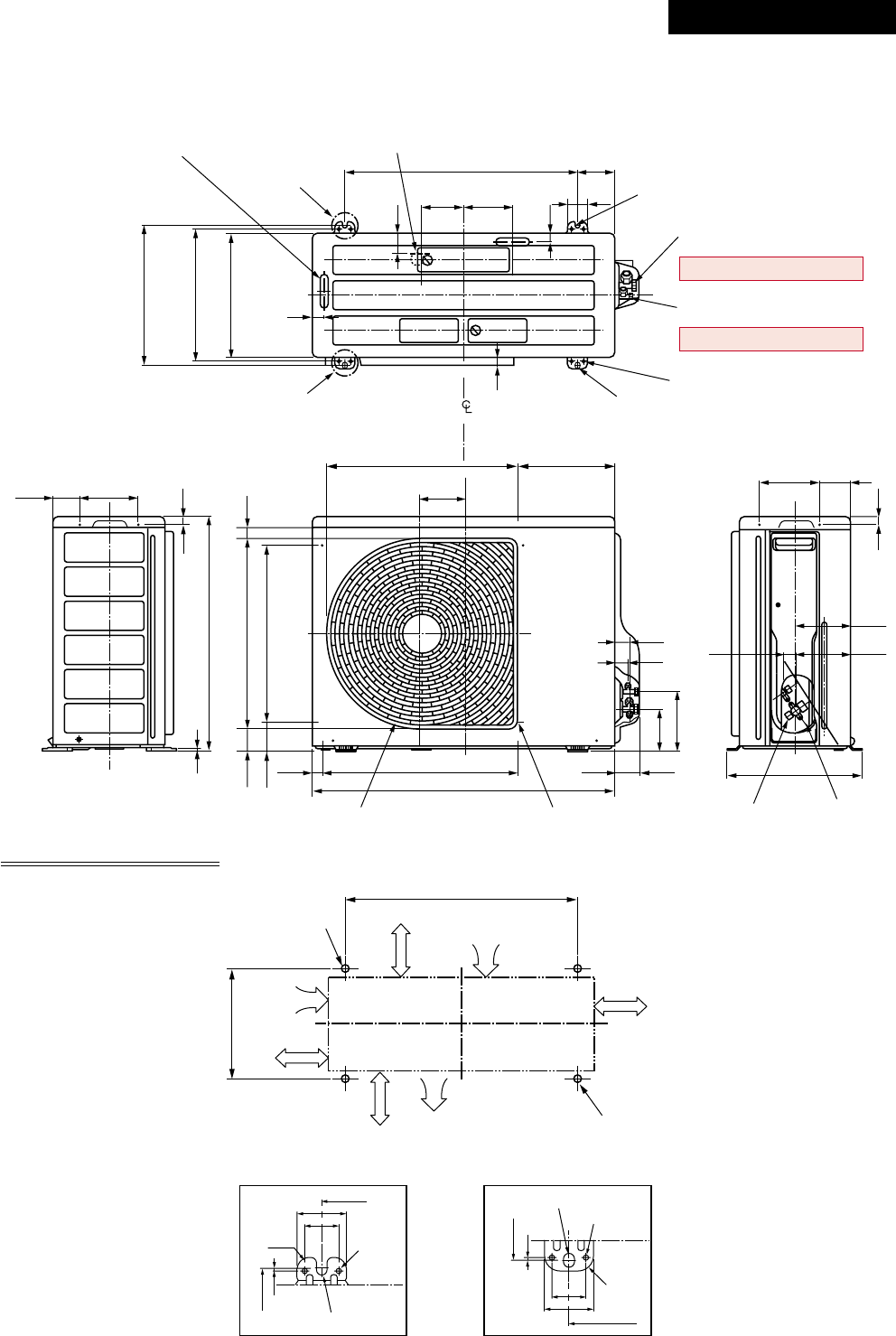
3-1-1. 4-Way Air Discharge Cassette Type
RAV-SM563UT-E, RAV-SM803UT-E
200 860 to 910 Recommended external size
200
860 to 910 Recommended external size
173
113
45
105
130
210
360
30
270 105
25070
130
105 254.5
480
227
120
57.5
25
64
188
57
35˚
256
346.5
97
35
88
415.0
381.6
227
480
240
Ø162 80
105105
12097
Surface under ceiling
Surface
under ceiling
Surface under ceiling
Surface
under ceiling
Surface
under ceiling
Standing
850 or less
Standing
640 or less
Surface
under ceiling
840 Hanging bolt
Z view
Z
Drain up standing size
Ceiling
panel
(Sold
separately)
Knockout
for
humidifier
723 Hanging bolt pitch
950 Panel external dimension
840 Unit external dimension
790 Hanging bolt pitch
950 Panel external dimension
Electric
parts box
Refrigerant pipe
connecting port A
Cable draw-in port
Refrigerant pipe
connecting port B
Indoor unit
Hanging bolt M10 or W3/8
Procured locally
Check port
( 450)
Check port
( 450)
SM563
SM803 Ø9.5
Ø6.4
A
Ø15.9
Ø12.7
B
150
– 25 –
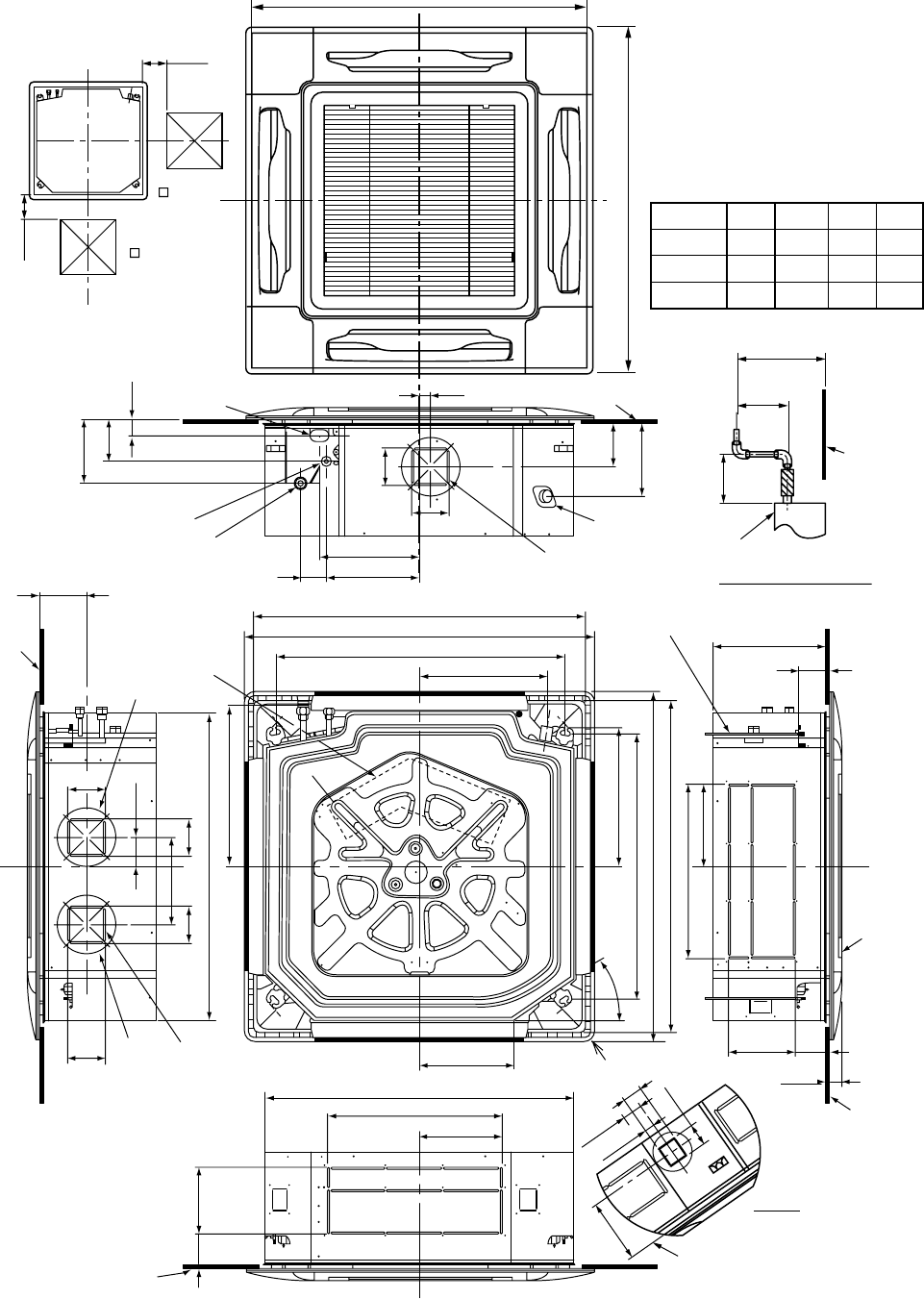
RAV-SM1103UT-E, RAV-SM1403UT-E, RAV-SP1102UT-E
35˚
415.0
80
240
840 Unit external dimension
Ceiling
bottom
surface
Ceiling bottom surface
Hanging bolt
M10 or Ø3/8
(To be procured locally)
Refrigerant pipe connecting port
A
Take-in port of pipes
Refrigerant pipe connecting port
B
105 105
381.6
346.5
254.5
790 Hanging bolt pitch
950 Panel external dimension
860 to 910 Ceiling opening dimension
480
723 Hanging bolt pitch
Ceiling bottom
surface
Ceiling panel
(sold separately)
950 Panel external dimension
860 to 910 Ceiling opening dimension
Electric parts box
227
D
88
C97
35
227
480
840 Unit external dimension
C97
105
105
Ø162
Ø162
130
105
250
270
70
30
173
113
45
105
130
210
Ceiling bottom surface
Knockout square
hole for divide duct
for Ø150
(2 positions)
Knockout square hole
for divide duct
For Ø150
Drain pipe
connecting port
SM1103
SM1403 Ø9.5
Ø9.5
A
319
319
D
183
183
C
Ø15.9
SP1102 Ø9.5 319183Ø15.9
Ø15.9
B
360
Standing
850 or less
Standing
640 or less
Surface
under ceiling
Drain up standing size
Indoor unit
57.5
25
64
188
57
Surface under ceiling
Z view
200
860 to 910 Recommended external size
200
860 to 910 Recommended external size
Check port
( 450)
Check port
( 450)
Z
– 26 –
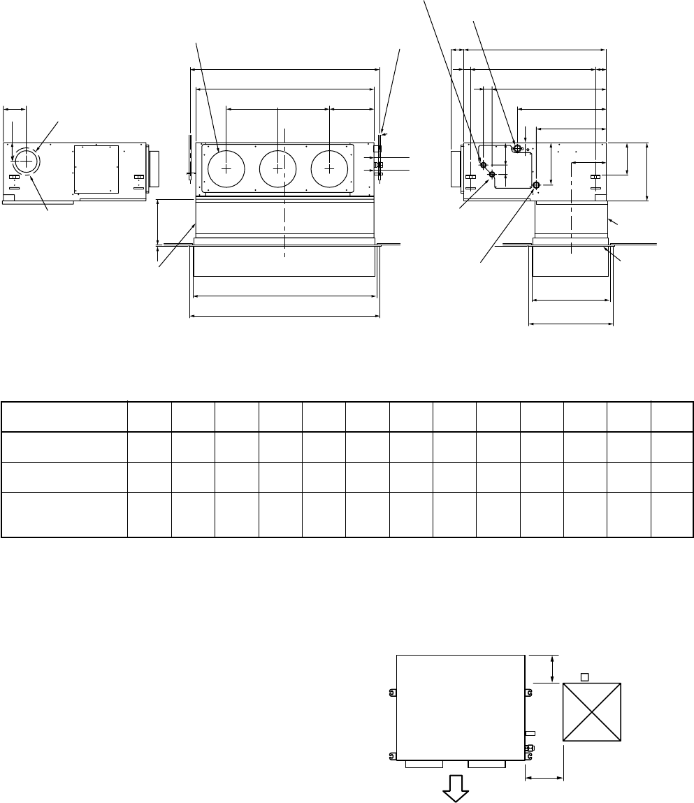
110
129
44
49
Knock-out hole Ø125
(Air take-in port)
6-Ø4 Tapping screw
undersized hole Ø160
Hanging bolt pitch 700 5941
Main unit dimension 800
75
Hanging bolt pitch B
Main unit dimension A
J = M x K H
Discharge port flange
N-Ø200
Hanging bolt
4-M10 screw
(Arranged locally)
60 to 260
9
Suction port canvas
(Separate sold)
C
Ceiling open size D
Panel external dimension E
Ceiling open size
470
Panel external
dimension 500
Panel C.L
410
Ø26 Power supply,
remote controller
cable take-out port
Refrigerant pipe
connecting port
(Liquid side ØG)
Suction port
flange
(Separate sold)
Suction port
panel
(Separate sold)
Drain pipe connecting port
for vinyl chloride pipe
(Inner dia. 32, VP. 25)
41
196
393
498
638
50
131
243
50
Refrigerant pipe connecting port
(Gas side ØF)
174
320
450
Plane view of main unit
Check port A
100
300
(Pipe side)
Discharge side
NOTE 1 :
For maintenance of the equipment, be sure to install
a check port A at the position as shown below.
NOTE 2 :
Using the drain up kit sold separately, drain-up by 300 (mm)
from drain pipe draw-out port of the main unit is necessary.
The drain-up over 300mm or more is impossible.
3-1-2. Concealed Duct Type
RAV-SM562BT-E, RAV-SM802BT-E, RAV-SM1102BT-E, RAV-SM1402BT-E
•Dimension
RAV-SM562BT
RAV-SM802BT
RAV-SM1102BT
RAV-SM1402BT
ABCDEFGHJKMNO
700 766 690 750 780 12.7 6.4 252 280 280 1 2 410
1000 1066 990 1050 1080 15.9 9.5 252 580 290 2 3 410
1350 1416 1340 1400 1430 15.9 9.5 252 930 310 3 4 410
– 27 –
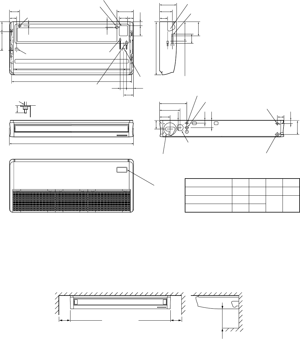
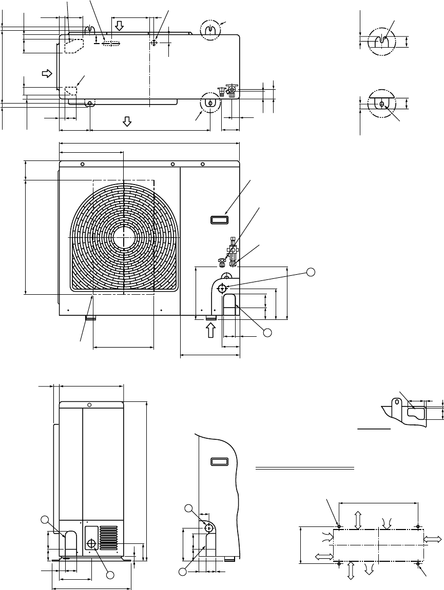
3-1-3. Under Ceiling Type
RAV-SM562CT-E, RAV-SM802CT-E, RAV-SM1102CT-E, RAV-SM1402CT-E
Upper pipe draw-out port (Knockout hole)
Power supply cable take-in port (Knockout)
Remote controller cable take- in port
(Knockout hole)
Left drain size
B (Hanging position)
A
Refrigerant pipe
(Liquid side ØC)
Refrigerant pipe (Gas side ØD)
Drain pipe connecting port
Drain port VP20
(Inner dia. Ø26, hose attached)
Pipe draw-out port (Knockout hole)
200 (Liquid pipe)
216 (Gas pipe)
Power supply cable take-in port (Knockout hole)
Remote controller cable take- in port
Remote controller cable take- in port
(Knockout hole)
Outside air take-in port
(Duct sold separately)(Knockout hole Ø92)
Pipe hole on wall (Ø100 hole) Drain left pipe draw-out port (Knockout hole)
Wireless sensor
mounting section
562CT
802CT
1102CT, 1402CT
Model name A B C D
910
1180
1595
855
1125
1540
Ø6.4 Ø12.7
Ø9.5 Ø15.9
(Hanging position)
84
135 84
262
347
171
145
32
32
90
92
53
70
130
680
41
114
50
170320
128
110
146
75 97
76
216 167
105
210
Hanging bolt Ceiling surface
Unit
Within
50
250 or more250 or more
500 or more
– 28 –
3-2. Outdoor Unit
RAV-SM563AT-E, RAV-SM803AT-E
( )
( )
Drain hole (Ø25)
Drain hole
(2-Ø20 × 88 long hole)
2-Ø11-14 U-shape hole
(For Ø8-Ø10 anchor bolts)
8-Ø6 hole
(For fixing outdoor unit)
2-Ø11 × L14 long hole
(For Ø8-Ø10 anchor bolts)
54
30
600
108 125
90
30
60
20
320
(Long hole pitch
For anchor bolt)
306
Ø6 hole pitch
290
A legs
B legs
Space required for service
25 31 143
342
54
22
108
69.5 147
48335
93
137
550
821
6
Discharge guard Discharge guide mounting hole
(4-Ø4.5 embossing)
500
780
32 71
21
157 79
Charge port Earth
terminal
320
600
483 257
2-Ø11 × 14 U-shape holes
(For Ø8–Ø10 anchor bolt)
Suction port
Discharge
port
Discharge
port (Minimum
distance up to wall)
2-Ø11 × 14 long hole
(For Ø8–Ø10 anchor bolt)
500
or more
150
or more
300
or more
150
or more
600
320
320
3
3
54
38
54
38
R15 2-Ø6 hole
Product
external line
Product
external
line
Ø11 × 14 U-shape hole
Ø11 × 14 U-shape holes
2-Ø6 hole
R15
600
Details of A legs Details of B legs
44952
145
Connecting pipe port
Gas flare side
RAV-SM563AT-E: Ø12.7
RAV-SM803AT-E: Ø15.9
Connecting pipe port
Liquid flare side
RAV-SM563AT-E: Ø6.4
RAV-SM803AT-E: Ø9.5
Revised : Mar. 2007
– 29 –
RAV-SM1103AT-E, RAV-SM1403AT-E / RAV-SP562AT-E, RAV-SP802AT-E
365 17.517.5
21
21
40 70
29 90 191 20
40
39
47
43
43
95
300150
6026
Knockout
(For draining)
Knockout
(For draining)
Drain hole (Ø20 × 88 Burring hole)
Drain hole (Ø25 Burring hole)
Part A
Part B
(Long hole pitch
for anchor bolt)
Suction
port
Suction
port
Discharge
port
Z1
2
6760
264
264
565 101
154
900
2760
96
307
300
314
Handles
(Both sides)
Refrigerant pipe connecting port
Flare at liquid side
Ø6.4: RAV-SP562AT-E
Ø9.5: RAV-SP802AT-E
Refrigerant pipe connecting port
Flare at gas side
Ø12.7: RAV-SP562AT-E
Ø15.9: RAV-SP802AT-E
Discharge guide
mounting hole
(4-Ø4 Embossing)
1
1
2
2
795
85
165
60 80
25
60 90
32028
400
161
58
46
30 45
27
Space required for service
365
600
2-Ø12 × 17 U-shape holes
(For Ø8–Ø10 Anchor bolt)
Suction port
Discharge
port
Discharge
port
(Minimum
distance up to wall)
2-Ø12 × 17 long hole
(For Ø8–Ø10 Anchor bolt)
500
or more
150
or more
150
or more
150
or more
58 7
86 7
Knockout for lower piping
Z views
17.5
4040
17.5
Installation bolt hole
(Ø12 × 17 U-shape holes)
Installation bolt hole
(Ø12 × 17 U-shape holes)
Details of B part
Details of A part
( )
( )
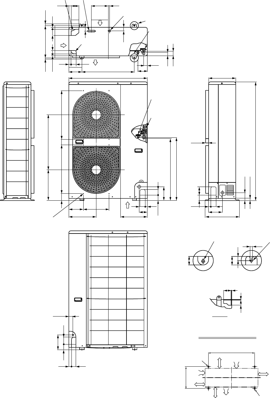
– 30 –
RAV-SP1102AT-E, RAV-SP1402AT-E
Space required for service
350 625
56567 60 565
314
164 300
307 400
161
60 27 27
60 90
58
95
60 67
154
706
715
900
600
60 43
26
9029
150 108
89
25 1340
320
28
z
40
54
40
43
21 40
365 17.517.5
70 21
191 20
40
40
20
12
165 8060
32 45
46
86 7
58 7
Z view
Refrigerant pipe
connecting port
(Ø9.5 flare at liquid side)
Details of A legs Details of B legs
Mountig bolt hole
(Ø12 x 17 long hole)
Discharge guide
mounting port
(8-Ø3 embossing)
Mountig bolt hole
(Ø12 x 17 U-shape hole)
B legs
Drain hole (Ø20 x 88)
Suction
port
Suction
port
Drain hole (Ø25)
Knockout (Drain)
Knockout (Drain)
Discharge port
A legs
Refrigerant pipe
connecting port
(Ø15.9 flare at gas side)
365
600
2-Ø12 x 17 U-shape holes
(For Ø8–Ø10 anchor bolt) Suction port
Discharge
port
Discharge
port
(Minimum
distance up to wall)
2-Ø12 x 17 long hole
(For Ø8–Ø10 anchor bolt)
500
or more
150
or more
150
or more
150
or more
– 31 –
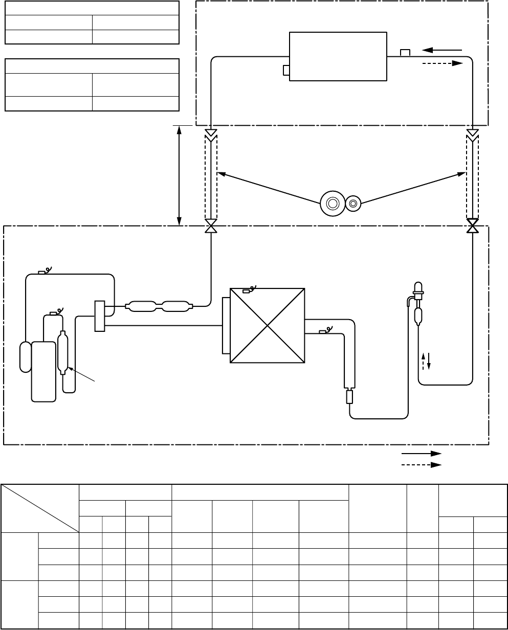
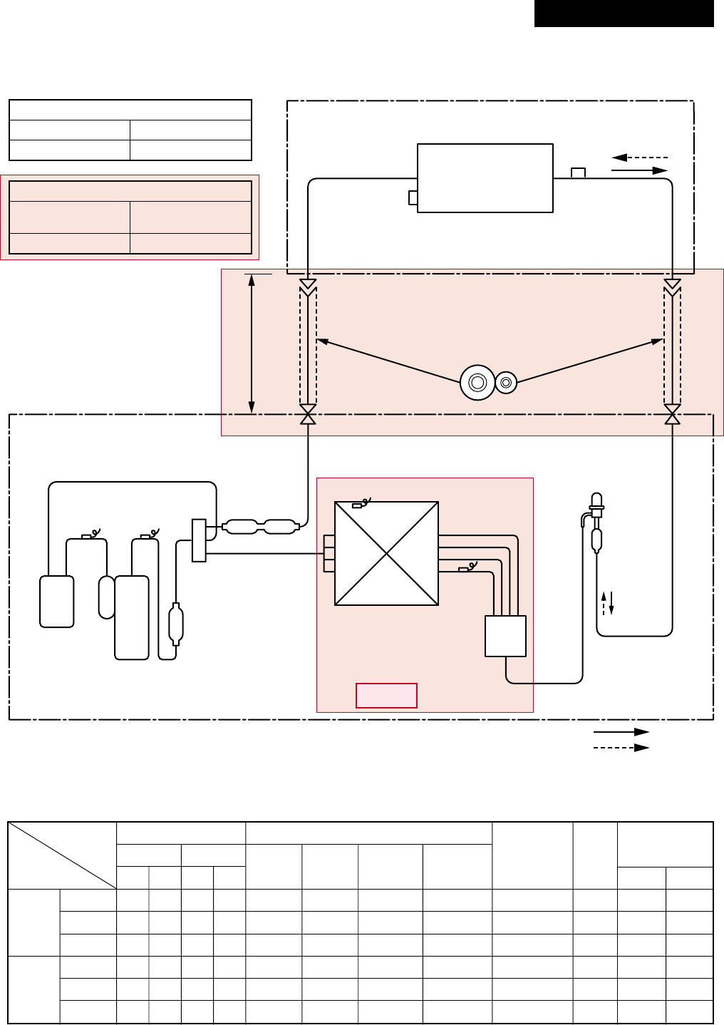
4. SYSTEMATIC REFRIGERATING CYCLE DIAGRAM
4-1. Indoor Unit/Outdoor Unit
RAV-SM563UT-E, RAV-SM562BT-E, RAV-SM562CT-E / RAV-SM563AT-E
*4 poles are provided to this compressor.
The compressor frequency (Hz) measured with a clamp meter is 2 times of revolutions (rps) of the compressor.
Indoor unit
Outdoor unit
Outer diameter of refrigerant pipe
Gas side ØA Liquid side ØB
12.7mm 6.4mm
Height difference (m)
Outdoor unit
at upper side Outdoor unit
at lower side
30 30
TCJ
sensor
Air heat exchanger
Strainer
TC sensor
Refrigerant pipe
at gas side
Ø12.7
Refrigerant pipe
at liquid side
Ø6.4
Packed valve
Outer dia. ØA
Packed valve
Outer dia. ØB
Max.
30m
Min.
5m
TS sensor
TD sensor
TO sensor
TE
sensor
Distributor
4-way valve
(STF-0108Z)
Muffler
Ø19 × L160
2-step muffler
Ø19 .05 × 200L
Rotary compressor
(DA150A1F-20F)
Heat exchanger
Ø8 ripple, 2 rows,
14 steps
FP1.3 flat fin
PMV
(Pulse Motor Valve)
(CAM-B30YGTF-2)
R410A 1.0 kg
Cooling
Heating
Height difference
Section shape
of heat insulator
Standard
Cooling Overload
Low load
Standard
Heating Overload
Low load
Pressure
(MPa) (kg/cm²G)
Pd Ps Pd Ps
3.50 0.97 35.7 9.9
3.90 1.08 39.8 11.0
1.90 0.70 19.4 7.1
2.31 0.61 13.6 6.2
2.86 0.89 29.2 9.1
1.86 0.25 19.0 2.6
Pipe surface temperature (°C)
Discharge
(TD)
85
93
48
87
86
69
Suction
(TS)
14
26
7
5
17
–14
Indoor heat
exchanger
(TC)
12
17
5
40
47
31
Outdoor heat
exchanger
(TE)
48
54
30
1
11
–15
Compressor
revolutions per
second (rps)
*
70
70
50
97
95
98
Indoor
fan
HIGH
HIGH
LOW
HIGH
LOW
HIGH
Indoor/Outdoor
temp. conditions
(DB/WB) (°C)
Indoor Outdoor
27/19 35/–
32/24 43/–
18/15.5 –5/–
20/–7/6
28/–24/18
15/–
–10/(70%)
– 32 –
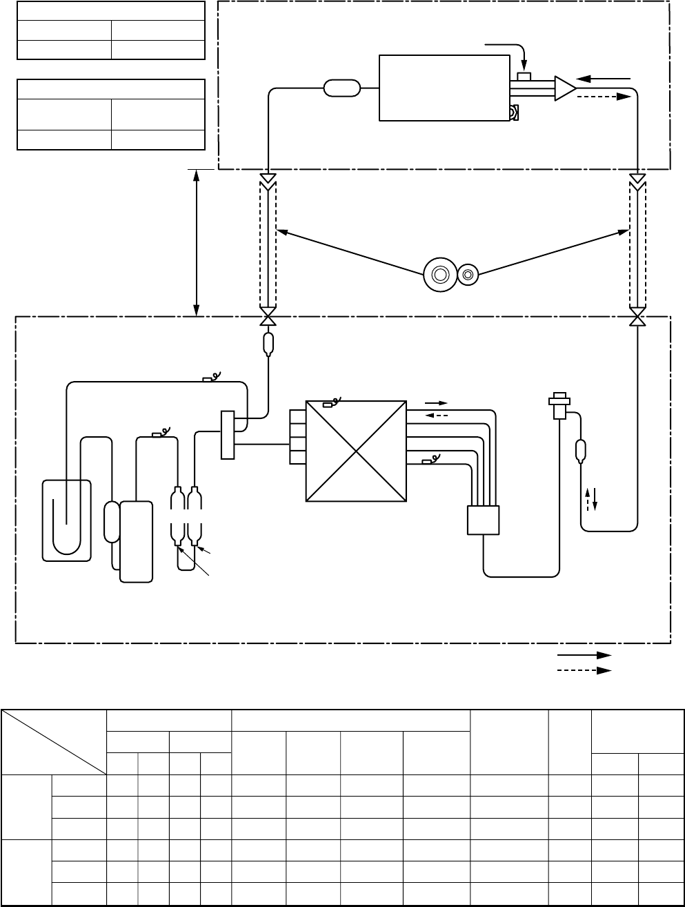
RAV-SM803UT-E, RAV-SM802BT-E, RAV-SM802CT-E / RAV-SM803AT-E
Standard
Cooling Overload
Low load
Standard
Heating Overload
Low load
Pressure
(MPa) (kg/cm²G)
Pd Ps Pd Ps
3.28 0.86 33.4 8.8
3.59 1.00 33.6 10.2
1.85 0.83 18.9 8.5
2.53 0.62 25.8 6.3
3.42 1.07 34.9 10.9
1.99 0.23 20.3 2.3
Pipe surface temperature (°C)
Discharge
(TD)
84
82
42
75
80
89
Suction
(TS)
11
17
8
3
20
–19
Indoor heat
exchanger
(TC)
10
16
6
42
54
34
Outdoor heat
exchanger
(TE)
45
51
23
2
17
–18
Compressor
revolutions per
second (rps)
*
83
76
35
95
50
120
Indoor
fan
HIGH
HIGH
LOW
HIGH
LOW
HIGH
Indoor/Outdoor
temp. conditions
(DB/WB) (°C)
Indoor Outdoor
27/19 35/–
32/24 43/–
18/15.5 –5/–
20/–7/6
28/–24/18
15/–
–10/(70%)
*4 poles are provided to this compressor.
The compressor frequency (Hz) measured with a clamp meter is 2 times of revolutions (rps) of the compressor.
Indoor unit
Outdoor unit
TCJ
sensor
Air heat exchanger
Strainer
TC sensor
TD
sensor
TS
sensor
TO sensor
TE
sensor
Distributor
4-way valve
(STF-0213Z)
2-step
muffler
Ø25 × 200L
Rotary
compressor
(DA150A1F-20F)
Accumulator
(1000cc)
Heat exchanger
Ø8 ripple, 2 rows,
20 steps
FP1.3 flat fin
PMV
(Pulse Motor Valve)
(CAM-B30YGTF-1)
R410A 1.6 kg
Cooling
Heating
Outer diameter of refrigerant pipe
Gas side ØA Liquid side ØB
15.9mm 9.5mm
Height difference (m)
Outdoor unit
at upper side Outdoor unit
at lower side
30 30
Refrigerant pipe
at gas side
Ø15.9
Refrigerant pipe
at liquid side
Ø9.5
Packed valve
Outer dia. ØA
Packed valve
Outer dia. ØB
Max.
30m
Min.
5m
Muffler
Ø19 × L160
4 pass
Height difference
Section shape
of heat insulator
Revised : Mar. 2007
– 33 –
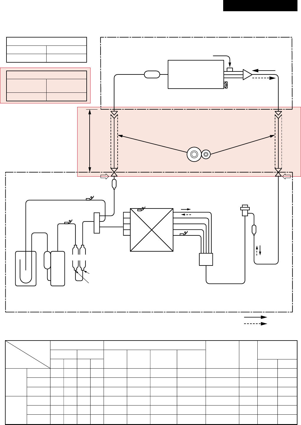
RAV-SM1103UT-E, RAV-SM1102BT-E, RAV-SM1102CT-E / RAV-SM1103AT-E
*4 poles are provided to this compressor.
The compressor frequency (Hz) measured with a clamp meter is 2 times of revolutions (rps) of the compressor.
Indoor unit
Outdoor unit
Distributor
(Strainer incorporated)
TCJ sensor
Air heat exchanger
Strainer
Strainer
TC sensor
Strainer
Ball valve
Outer dia. ØA
Packed valve
Outer dia. ØB
Max.
50m
Min.
5m
TS sensor
TD sensor
TO sensor
TE
sensor
Distributor
4-way valve
(STF-0213Z)
Ø25 × L210
Ø25 × L180
Rotary
compressor
(DA420A3F – 21M)
Accumulator
(2500cc)
Heat exchanger
Outer side
Ø8, 2 rows, 20 steps
FP1.3 flat fin
Inner side
Ø9.52 row, 30 steps
FP1.5 flat fin
R410A 2.8kg
Cooling
Heating
Muffler
Refrigerant pipe
at gas side Ø15.9 Refrigerant pipe
at liquid side Ø9.5
PMV
(Pulse Motor Valve)
(UKV-25D22)
Height difference
Section shape
of heat insulator
Outer diameter of refrigerant pipe
Gas side ØA Liquid side ØB
15.9mm 9.5mm
Height difference (m)
Outdoor unit
at upper side Outdoor unit
at lower side
30 30
Standard
Cooling Overload
Low load
Standard
Heating Overload
Low load
Pressure
(MPa) (kg/cm²G)
Pd Ps Pd Ps
3.44 0.92 35.1 9.4
3.73 1.18 38.1 12.0
1.49 0.70 15.2 7.1
2.80 0.61 28.6 6.2
3.43 1.08 35.0 11.0
2.20 0.25 22.4 2.6
Pipe surface temperature (°C)
Discharge
(TD)
82
82
39
80
82
76
Suction
(TS)
8
15
8
0
14
–19
Indoor heat
exchanger
(TC)
10
17
3
46
55
36
Outdoor heat
exchanger
(TE)
39
48
22
1
13
–16
Compressor
revolutions per
second (rps)
*
47
42
30
48
24
55
Indoor
fan
HIGH
HIGH
LOW
HIGH
LOW
HIGH
Indoor/Outdoor
temp. conditions
(DB/WB) (°C)
Indoor Outdoor
27/19 35/–
32/24 43/–
18/15.5 –5/–
20/–7/6
30/–24/18
15/–
–10/(70%)
– 34 –
RAV-SM1403UT-E, RAV-SM1402BT-E, RAV-SM1402CT-E / RAV-SM1403AT-E
Indoor unit
Outdoor unit
Distributor
(Strainer incorporated)
TCJ sensor
Air heat exchanger
Strainer
Strainer
TC sensor
Strainer
TS sensor
TD sensor
TO sensor
TE
sensor
Distributor
4-way valve
(STF-0213Z)
Ø25 × L210
Ø25 × L180
Rotary
compressor
(DA420A3F – 21M)
Accumulator
(2500cc)
Heat exchanger
Outer side
Ø8, 2 rows, 20 steps
FP1.3 flat fin
Inner side
Ø9.52 row, 30 steps
FP1.5 flat fin
R410A 3.0kg
Cooling
Heating
Muffler
PMV
(Pulse Motor Valve)
(UKV-25D22)
Ball valve
Outer dia. ØA
Packed valve
Outer dia. ØB
Max.
50m
Min.
5m
Refrigerant pipe
at gas side Ø15.9 Refrigerant pipe
at liquid side Ø9.5
Height difference
Section shape
of heat insulator
Outer diameter of refrigerant pipe
Gas side ØA Liquid side ØB
15.9mm 9.5mm
Height difference (m)
Outdoor unit
at upper side Outdoor unit
at lower side
30 30
Standard
Cooling Overload
Low load
Standard
Heating Overload
Low load
Pressure
(MPa) (kg/cm²G)
Pd Ps Pd Ps
3.52 0.85 35.9 8.7
3.78 1.12 38.6 11.4
1.51 0.71 15.4 7.2
2.88 0.60 29.4 6.1
3.41 1.08 34.8 11.0
2.35 0.24 24.0 2.4
Pipe surface temperature (°C)
Discharge
(TD)
87
84
40
85
81
80
Suction
(TS)
8
15
7
1
14
–19
Indoor heat
exchanger
(TC)
9
17
3
47
54
40
Outdoor heat
exchanger
(TE)
39
47
23
1
13
–16
Compressor
revolutions per
second (rps)
*
54
45
30
61
24
73
Indoor
fan
HIGH
HIGH
LOW
HIGH
LOW
HIGH
Indoor/Outdoor
temp. conditions
(DB/WB) (°C)
Indoor Outdoor
27/19 35/–
32/24 43/–
18/15.5 –5/–
20/–7/6
30/–24/18
15/–
–10/(70%)
*4 poles are provided to this compressor.
The compressor frequency (Hz) measured with a clamp meter is 2 times of revolutions (rps) of the compressor.
Revised : Mar. 2007
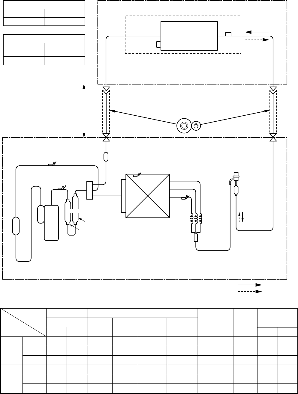
– 35 –
Indoor unit
Outdoor unit
TCJ
sensor
Air heat exchanger
Strainer
Strainer
TC sensor
Packed valve
Outer dia. ØA
Packed valve
Outer dia. ØB
Max.
50m
Min.
5m
TS sensor
Accumulator
(1500cc)
TD sensor
TO sensor
TE
sensor
4-way valve
(STF-0213Z)
Ø25 × L160
Rotary compressor
(DA220A2F-20L1)
Heat exchangerØ8
1 row 30 stages
FP1.3 flat fin
Capillary
Ø3×Ø2×
L530
Ø25 × L210
Muffler
R410A 1.5 kg
Cooling
Heating
Modulating
(PMV)
(CAM-B30YGTF-2)
Refrigerant pipe
at gas side
Outer dia. ØA
Refrigerant pipe
at liquid side
Outer dia. ØB
* The refrigerating cycle of the indoor units differs according to
the models to be combined. For the refrigerating cycles of the
other indoor units, refer to the corresponding Service Manuals
described in the list on the cover.
Outer diameter of refrigerant pipe
Gas side ØA Liquid side ØB
12.7mm 6.4mm
Height difference (m)
Outdoor unit
at upper side Outdoor unit
at lower side
30 15
Height
difference
Section shape
of heat insulator
RAV-SM563UT-E, RAV-SM562BT-E, RAV-SM562CT-E / RAV-SP562AT-E
*4 poles are provided to this compressor.
The compressor frequency (Hz) measured with a clamp meter is 2 times of revolutions (rps) of the compressor.
Standard
Cooling Overload
Low load
Standard
Heating Overload
Low load
Pressure
(MPa)
Pd Ps
2.71 1.03
3.48 1.16
1.92 0.74
2.22 0.72
3.47 1.16
1.79 0.25
Pipe surface temperature (°C)
Discharge
(TD)
75
81
34
32
81
71
Suction
(TS)
15
20
5
6
20
–16
Indoor heat
exchanger
(TC)
10
16
2
38
55
30
Outdoor heat
exchanger
(TE)
38
51
11
2
15
–18
Compressor
revolutions per
second (rps)
*
43
44
24
41
41
70
Indoor
fan
HIGH
HIGH
LOW
HIGH
LOW
HIGH
Indoor/Outdoor
temp. conditions
(DB/WB) (°C)
Indoor Outdoor
27/19 35/–
32/24 43/–
18/15.5 –5/–
20/–7/6
30/–24/18
15/–
–15/(70%)
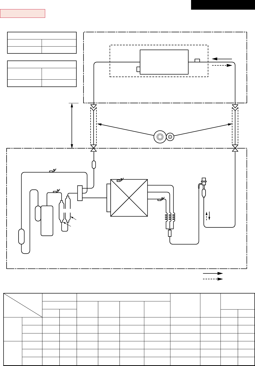
– 36 –
RAV-SM803UT-E, RAV-SM802BT-E, RAV-SM802CT-E / RAV-SP802AT-E
*4 poles are provided to this compressor.
The compressor frequency (Hz) measured with a clamp meter is 2 times of revolutions (rps) of the compressor.
Indoor unit
Outdoor unit
TCJ
sensor
Air heat exchanger
Strainer
Strainer
TC sensor
Packed valve
Outer dia. ØA
Packed valve
Outer dia. ØB
Max.
50m
Min.
5m
TS sensor
Accumulator
(1500cc)
TD sensor
TO sensor
TE
sensor
4-way valve
(STF-0213Z)
Ø25 × L160
Rotary compressor
(DA220A2F-20L1)
Heat exchangerØ8
1 row 30 stages
FP1.3 flat fin
Capillary
Ø3×Ø2×
L530
Ø25 × L210
Muffler
R410A 2.1 kg
Cooling
Heating
Modulating
(PMV)
(CAM-B30YGTF-2)
Refrigerant pipe
at gas side
Outer dia. ØA
Refrigerant pipe
at liquid side
Outer dia. ØB
* The refrigerating cycle of the indoor units differs according to
the models to be combined. For the refrigerating cycles of the
other indoor units, refer to the corresponding Service Manuals
described in the list on the cover.
Outer diameter of refrigerant pipe
Gas side ØA Liquid side ØB
15.9mm 9.5mm
Height difference (m)
Outdoor unit
at upper side Outdoor unit
at lower side
30 15
Height difference
Section shape
of heat insulator
Standard
Cooling Overload
Low load
Standard
Heating Overload
Low load
Pressure
(MPa)
Pd Ps
2.72 0.93
3.57 1.10
1.89 0.74
2.58 0.68
3.49 1.22
2.30 0.25
Pipe surface temperature (°C)
Discharge
(TD)
74
80
34
72
79
91
Suction
(TS)
12
21
7
4
19
–17
Indoor heat
exchanger
(TC)
11
17
2
41
55
37
Outdoor heat
exchanger
(TE)
40
52
12
2
16
–19
Compressor
revolutions per
second (rps)
*
55
47
24
62
28
90
Indoor
fan
HIGH
HIGH
LOW
HIGH
LOW
HIGH
Indoor/Outdoor
temp. conditions
(DB/WB) (°C)
Indoor Outdoor
27/19 35/–
32/24 43/–
18/15.5 –5/–
20/–7/6
30/–24/18
15/–
–15/(70%)
Revised : Mar. 2007
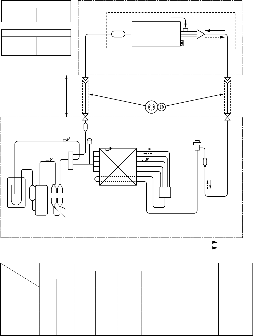
– 37 –
RAV-SP1102UT-E, RAV-SM1102BT-E, RAV-SM1102CT-E / RAV-SP1102AT-E
*4 poles are provided to this compressor.
The compressor frequency (Hz) measured with a clamp meter is 2 times of revolutions (rps) of the compressor.
Indoor unit
Outdoor unit
Distributor
(Strainer incorporated)
TCJ sensor
Air heat exchanger
Strainer
Strainer
TC sensor
Strainer
Refrigerant pipe at gas side
Outer dia. ØARefrigerant pipe at liquid side
Outer dia. ØB
Ball valve
Outer dia. ØA
Packed valve
Outer dia. ØB
Max.
70m
Min.
5m
TS sensor Check joint
TD sensor
TO sensor
TE sensor
Distributor
4-way valve
(STF-0401G)
Ø25 × L210
Ø25 × L180
Rotary
compressor
(DA420A3F – 21M)
Accumulator
(2500cc)
Heat exchanger
2 row 52 stages
Outside :
Ø8 FP1.3 flat fin
Inside :
Ø9.52 FP1.5 flat fin
PMV
(UKV-25D22)
R410A 2.95kg
Cooling
Heating
Muffler
* The refrigerating cycle of the indoor units differs according to
the models to be combined. For the refrigerating cycles of the
other indoor units, refer to the corresponding Service Manuals
described in the list on the cover.
Outer diameter of refrigerant pipe
Gas side ØA Liquid side ØB
15.9mm 9.5mm
Height difference (m)
Outdoor unit
at upper side Outdoor unit
at lower side
30 15
Height
difference
Section shape
of heat insulator
Standard
Cooling Overload
Low load
Standard
Heating Overload
Low load
Pressure
(MPa)
Pd Ps
2.55 0.98
3.28 1.08
1.76 0.76
2.58 0.73
3.43 1.18
2.10 0.32
Pipe surface temperature (°C)
Discharge
(TD)
69
82
47
68
75
88
Suction
(TS)
12
17
8
3
20
–14
Indoor heat
exchanger
(TC)
10
16
5
40
56
34
Outdoor heat
exchanger
(TE)
40
48
27
3
16
–13
Compressor
revolutions per
second (rps)
*
40
50
24
44
24
63
Indoor
fan
HIGH
HIGH
LOW
HIGH
LOW
HIGH
Indoor/Outdoor
temp. conditions
(DB/WB) (°C)
Indoor Outdoor
27/19 35/–
32/24 43/–
18/15.5 –5/–
20/–7/6
30/–24/18
15/–
–15/(70%)
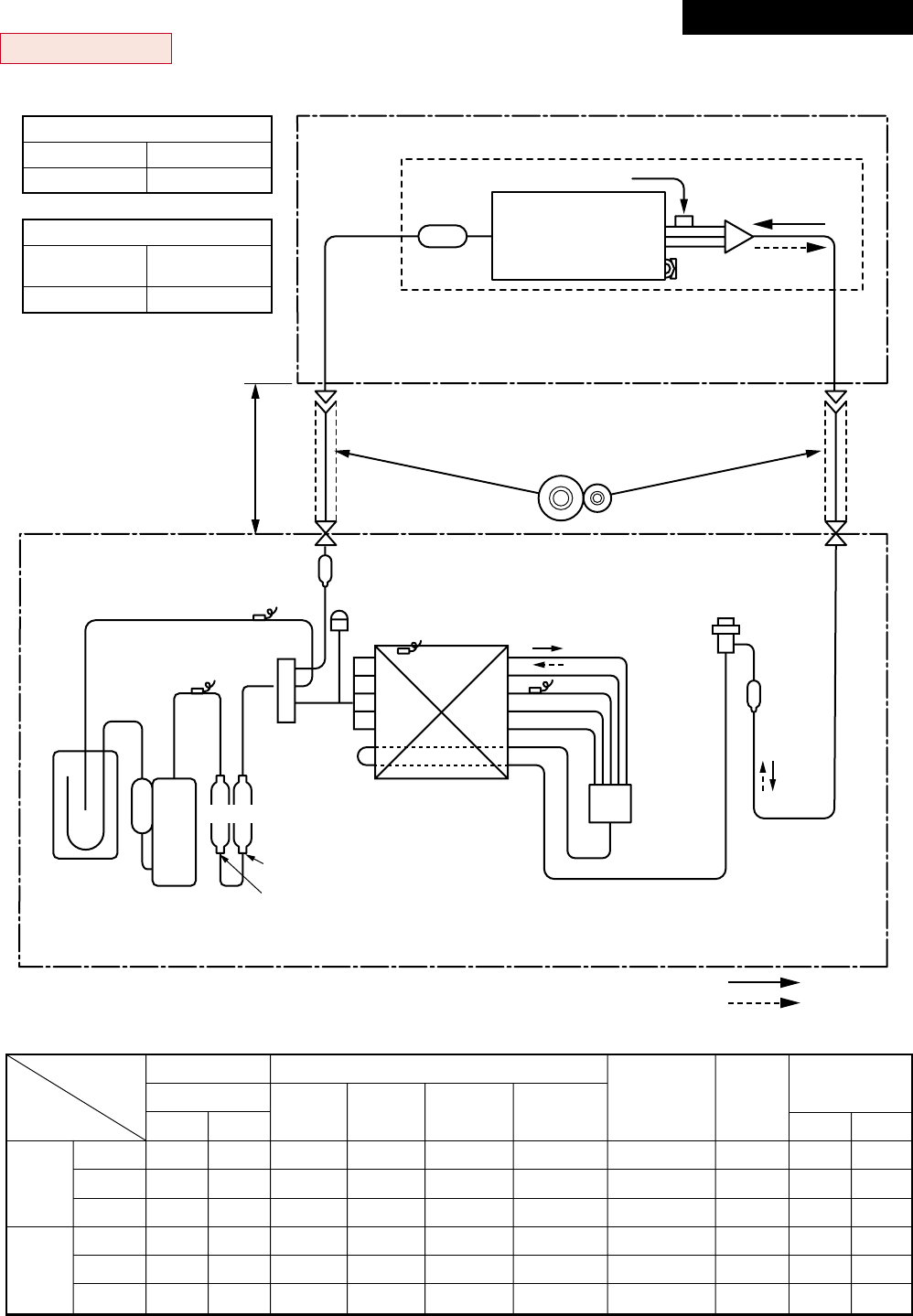
– 38 –
RAV-SM1403UT-E, RAV-SM1402BT-E, RAV-SM1402CT-E / RAV-SP1402AT-E
*4 poles are provided to this compressor.
The compressor frequency (Hz) measured with a clamp meter is 2 times of revolutions (rps) of the compressor.
Indoor unit
Outdoor unit
Distributor
(Strainer incorporated)
TCJ sensor
Air heat exchanger
Strainer
Strainer
TC sensor
Strainer
Refrigerant pipe
at gas side
Outer dia. ØA
Refrigerant pipe
at liquid side
Outer dia. ØB
Ball valve
Outer dia. ØA
Packed valve
Outer dia. ØB
Max.
70m
Min.
5m
TS sensor Check joint
TD sensor
TO sensor
TE sensor
Distributor
4-way valve
(STF-0401G)
Ø25 × L210
Ø25 × L180
Rotary
compressor
(DA420A3F – 21M)
Accumulator
(2500cc)
Heat exchanger
2 row 52 stages
Outside :
Ø8 FP1.3 flat fin
Inside :
Ø9.52 FP1.5 flat fin
PMV
(UKV-25D22)
R410A 2.95kg
Cooling
Heating
Muffler
* The refrigerating cycle of the indoor units differs according to
the models to be combined. For the refrigerating cycles of the
other indoor units, refer to the corresponding Service Manuals
described in the list on the cover.
Outer diameter of refrigerant pipe
Gas side ØA Liquid side ØB
15.9mm 9.5mm
Height difference (m)
Outdoor unit
at upper side Outdoor unit
at lower side
30 15
Height
difference
Section shape
of heat insulator
Standard
Cooling Overload
Low load
Standard
Heating Overload
Low load
Pressure
(MPa)
Pd Ps
2.76 0.91
3.46 1.03
1.77 0.78
2.65 0.69
3.33 1.08
2.50 0.22
Pipe surface temperature (°C)
Discharge
(TD)
74
82
48
75
74
98
Suction
(TS)
11
17
9
3
19
–22
Indoor heat
exchanger
(TC)
9
16
6
43
55
43
Outdoor heat
exchanger
(TE)
39
48
27
3
15
–18
Compressor
revolutions per
second (rps)
*
53
51
24
55
24
73
Indoor
fan
HIGH
HIGH
LOW
HIGH
LOW
HIGH
Indoor/Outdoor
temp. conditions
(DB/WB) (°C)
Indoor Outdoor
27/19 35/–
32/24 43/–
18/15.5 –5/–
20/–7/6
30/–24/18
15/–
–15/(70%)
Revised : Mar. 2007
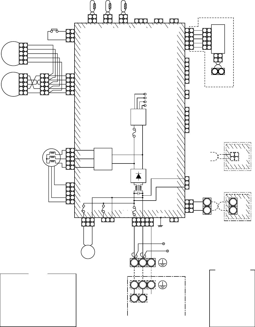
– 39 –
5. WIRING DIAGRAM
5-1. Indoor Unit
5-1-1. 4-Way Air Discharge Cassette Type
RAV-SM563UT-E, RAV-SM803UT-E, RAV-SM1103UT-E, RAV-SM1403UT-E, RAV-SP1102UT-E
FM
TA
TC
TCJ
LM1,LM2
DP
FS
RY302
: Fan motor
: Indoor temp. sensor
: Temp. sensor
: Temp. sensor
: Louver motor
: Drain pump motor
: Float switch
: Drain control relay
NOTE
Color
Identification
BLK
BLU
RED
GRY
PNK
GRN
WHI
BRN
ORN
YEL
:
:
:
:
:
:
:
:
:
:
BLACK
BLUE
RED
GRAY
PINK
GREEN
WHITE
BROWN
ORANGE
YELLOW
1 2
1 2
1 1
2 2
3 3
TA
FS
CN104
(YEL)
CN34
(RED)
CN33
(WHI)
CN102
(RED) CN101
(BLK)
1 2
1 2
TCJ
1 2
CN73
(RED)
1 2
CN70
(WHI)
1 2
1 2
1 2
CN80
(GRN)
1 2 3
1 2
TC
(EXCT)
1 1
2 2
3 3
4 4
5 5
1 1
2 2
3 3
4 4
5 5
1 1
2 2
3 3
4 4
5 5
5 5
4 4
3 3
2 2
1 1
1 1
2 2
3 3
4 4
5 5
1 1
2 2
3 3
4 4
5 5
LM2
FM
LM1
Motor
drive
circuit
Power
supply
circuit
DC20V
DC15V
DC12V
DC7V
Fuse
F302
T3.15A
250V~
12
123
3
12
123
3 1 234
45
5
DP
CN333
(WHI)
CN334
(WHI)
CN68
(BLU) CN304
(GRY)
1 2
CN66
(WHI)
CN41
(BLU)
CN309
(YEL)
CN60
(WHI)
1
2
CN32
(WHI)
1
2
3
4
5
6
1
2
3
4
5
CN50
(WHI)
1
2
3
4
5
1
2
3
4
5
CN51
(RED)
CN40
(BLU)
Terminal for
central remote
controller
Connection interface (option)
P.C.
Board
1
2
3
4
5
1
2
3
4
5
6
CN61
(YEL)
CN67
(BLK)
RED WHI BLK
BLK
BLK
BLK
P301
1 1
2 2
3
1
2
3
3
B
A
(FAN DRIVE)
Wired Renote
Controller
WHI
BLK
1 1
2 2
Adapter for
Wireless Remote
Controller
WHI
BLK
MCC-1402
Control P.C. Board for
Indoor Unit
Indoor unit
earth screw
CN001
(WHI)
RY
302
Fuse
F301
250V~
T6.3A
RY
303
WHI
321
321
NL
Single phase
220 to 240V
50Hz
Serial
signal
Outdoor unit
earth screw
RED Closed-end
connector
U4U3
B
A
+ –
~~
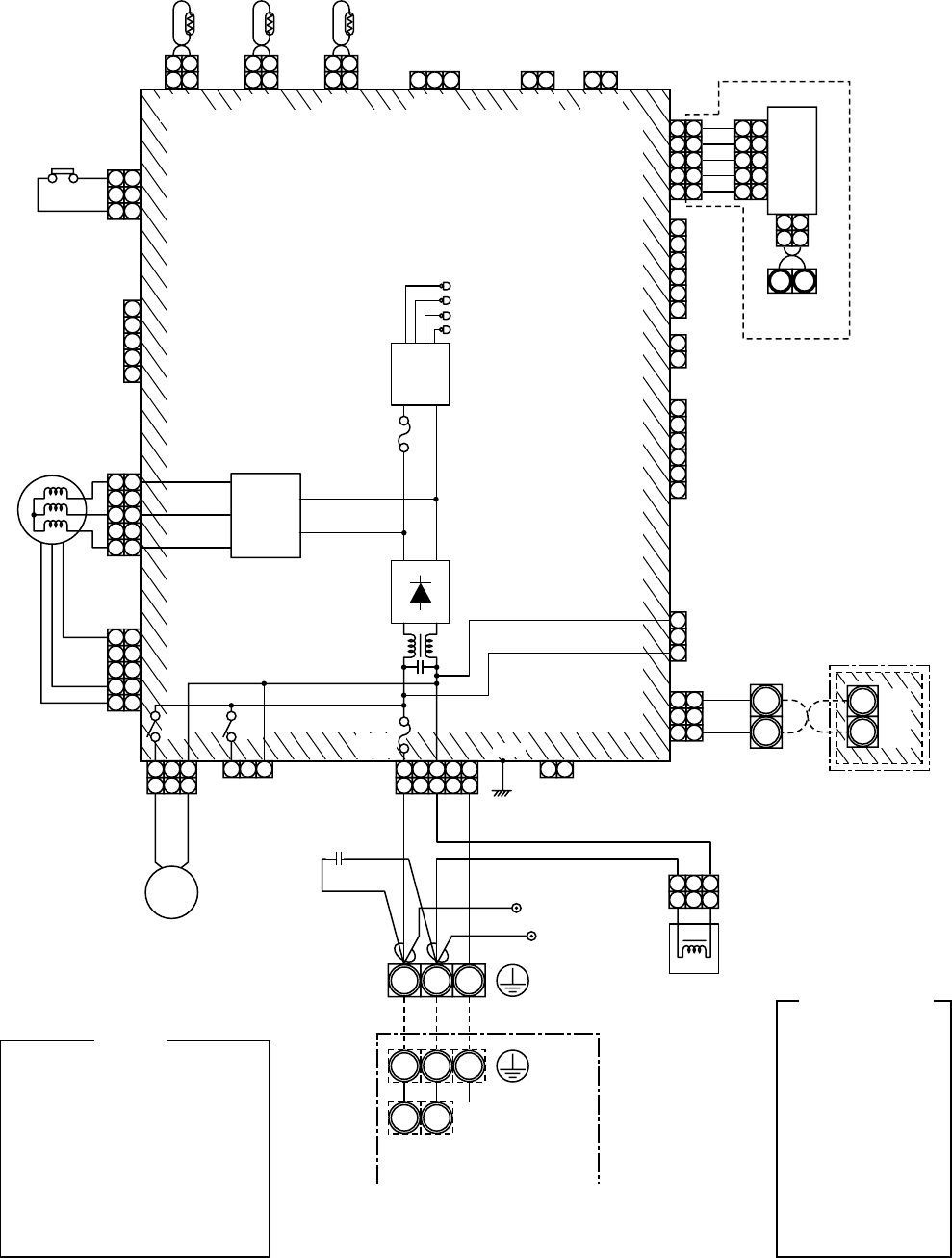
– 40 –
5-1-2. Concealed Duct Type
RAV-SM562BT-E, RAV-SM802BT-E, RAV-SM1102BT-E, RAV-SM1402BT-E
FM
TA
TC
TCJ
DP
FS
RY302
: Fan motor
: Indoor temp. sensor
: Temp. sensor
: Temp. sensor
: Drain pump motor
: Float switch
: Drain control relay
NOTE
Color
Identification
BLK
BLU
RED
GRY
PNK
GRN
WHI
BRN
ORN
YEL
:
:
:
:
:
:
:
:
:
:
BLACK
BLUE
RED
GRAY
PINK
GREEN
WHITE
BROWN
ORANGE
YELLOW
1 2
1 2
1 1
2 2
3 3
TA
FS
CN104
(YEL)
CN34
(RED)
CN33
(WHI)
CN102
(RED) CN101
(BLK)
1 2
1 2
TCJ
1 2
CN73
(RED)
1 2
CN70
(WHI)
1 2
CN80
(GRN)
1 2 3
1 2
TC
(EXCT)
1
2
3
4
5
1 1
2 2
3 3
4 4
5 5
5 5
4 4
3 3
2 2
1 1
FM
Motor
drive
circuit +
~~
Power
supply
circuit
DC20V
DC15V
DC12V
DC7V
Fuse
F302
T3.15A
250V~
12
123
3
12
123
3 1 234
45
5
DP
CN333
(WHI)
CN334
(WHI)
CN68
(BLU) CN304
(GRY)
1 2
CN66
(WHI)
Reactor
Capacitor
CN41
(BLU)
CN309
(YEL)
CN60
(WHI)
1
2
CN32
(WHI)
1
2
3
4
5
6
1
2
3
4
5
6
CN61
(YEL)
CN67
(BLK)
RED WHI BLK
BLK
BLK
BLK
P301
1 1
2 2
3
1
2
3
3
B
A
(FAN DRIVE)
MCC-1402
Control P.C. Board for
Indoor Unit
Indoor unit
earth screw
RY
302
Fuse
F301
250V~
T6.3A
RY
303
WHI
321
321
NL
Single phase 220V, 50Hz
Serial
signal
Outdoor unit
earth screw
RED Closed-end
connector
12
123
3
1 2
1 2
CN50
(WHI)
1
2
3
4
5
1
2
3
4
5
CN51
(RED)
CN40
(BLU)
Terminal for
central remote
controller
Connection interface (option)
P.C.
Board
1
2
3
4
5
1
2
3
4
5
U4U3
Wired Renote
Controller
WHI
BLK
B
A
–
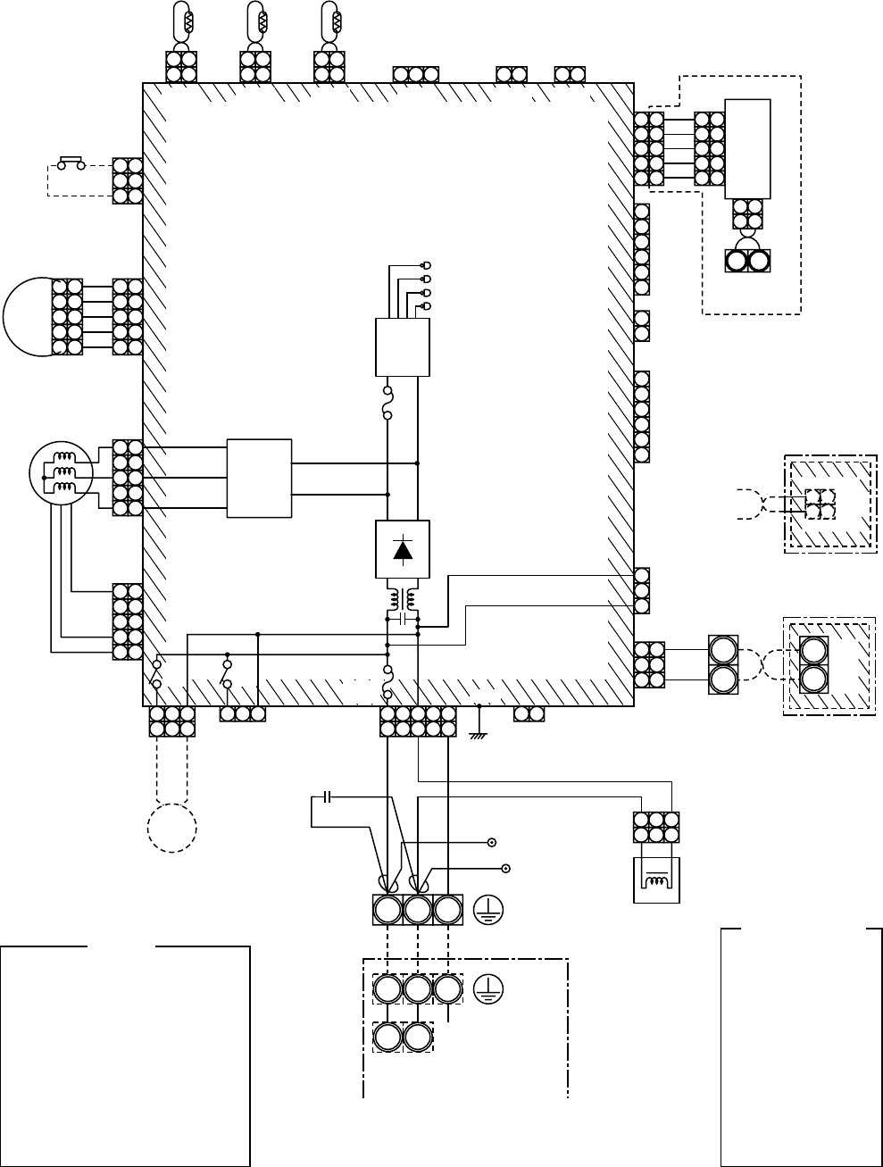
– 41 –
5-1-3. Under Ceiling Type
RAV-SM562CT-E, RAV-SM802CT-E, RAV-SM1102CT-E, RAV-SM1402CT-E
FM
TA
TC
TCJ
LM
DP
FS
RY302
: Fan motor
: Indoor temp. sensor
: Temp. sensor
: Temp. sensor
: Louver motor
: Drain pump motor
: Float switch
: Drain control relay
NOTE
Color
Identification
BLK
BLU
RED
GRY
PNK
GRN
WHI
BRN
ORN
YEL
:
:
:
:
:
:
:
:
:
:
BLACK
BLUE
RED
GRAY
PINK
GREEN
WHITE
BROWN
ORANGE
YELLOW
1 2
1 2
1 1
22
3 3
TA
FS
CN104
(YEL)
CN34
(RED)
CN33
(WHI)
CN102
(RED) CN101
(BLK)
1 2
1 2
TCJ
12
CN73
(RED)
12
CN70
(WHI)
12
CN80
(GRN)
123
1 2
TC
(EXCT)
1
2
3
4
5
1
2
3
4
5
1
2
3
4
5
1
2
3
4
5
1 1
22
3 3
44
5 5
5 5
4 4
33
2 2
1 1
FM
Motor
drive
circuit +–
~ ~
Power
supply
circuit
DC20V
DC15V
DC12V
DC7V
Fuse
F302
T3.15A
250V~
12
123
3
12
123
3 1 234
45
5
DP
CN333
(WHI)
CN334
(WHI)
CN68
(BLU) CN304
(GRY)
12
CN66
(WHI)
Reactor
Capacitor
CN41
(BLU)
CN309
(YEL)
CN60
(WHI)
1
2CN32
(WHI)
1
2
3
4
5
6
1
2
3
4
5
6
CN61
(YEL)
CN67
(BLK)
RED WHI BLK
BLK
BLK
BLK
P301 1 1
22
3
1
2
3
3B
A
(FAN DRIVE)
MCC-1402
Control P.C. Board for
Indoor Unit
Indoor unit
earth screw
RY
302
Fuse
F301
250V~
T6.3A
RY
303
WHI
321
32
1
NL
Single phase 220V, 50Hz
Serial
signal
Outdoor unit
earth screw
RED Closed-end
connector
12
123
3
LM
1 1
2 2
Adapter for
Wireless Remote
Controller
WHI
BLK
CN001
(WHI)
1 2
12
CN50
(WHI)
1
2
3
4
5
1
2
3
4
5
CN51
(RED)
CN40
(BLU)
Terminal for
central remote
controller
Connection interface (option)
P.C.
Board
1
2
3
4
5
1
2
3
4
5
U4U3
Wired Renote
Controller
WHI
BLK B
A
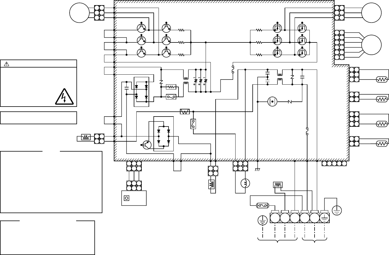
– 42 –
5-2. Outdoor Unit (Wiring Diagram)
RAV-SM563AT-E, RAV-SM803AT-E
Color Identification
BLK
BLU
RED
GRY
PNK
:
:
:
:
:
BLACK
BLUE
RED
GRAY
PINK
WHI
BRN
ORN
YEL
PUR
:
:
:
:
:
WHITE
BROWN
ORANGE
YELLOW
PURPLE
NOTE
CM
PMV
FM
TE
TD
TO
TS
IGBT
DB
CT
:
:
:
:
:
:
:
:
:
:
Compressor
Pulse motor valve
Fan motor
Heat exchanger Temp. Sensor
Discharge Temp. Sensor
Outdoor Temp. Sensor
Suction Temp. Sensor
Insulated Gate Bipolar Transistor
Rectifier
Curreut Transformer
6
5
4
3
2
1
6
5
4
3
2
1
PMV
CN700
CN603
L01 Varistor
Varistor
Surge
absorber
Q300~305
MOS-FET
Q200~205
IGBT
CN602
CN601
CN600
P02
WHI CN806
WHI
BLK
ORN
WHI
WHI
RED
CN300 BLK
WHI
RED
Fan motor
Pulse motor valve
3
2
1
3
2
1
3
2
1
3
1
FM
TS
(Suction pipe
temp. sensor)
3
2
1
3
1
TD
(Discharge pipe
temp. sensor)
2
12
1
TO
(Outdoor
temp. sensor)
2
12
1
4 52 312
23
3
1
1
2
23
3
1
1
1
1
2
2
3
3
1
1
TE
(Condenser pipe
temp. sensor)
For optional P.C. Board
Reactor
Reactor
Coil for
4-WAY
VALVE
F01
Fuse
T25A
AC250V
F03
Fuse
T3.15A
AC250V
Fuse 250V~
T6.3A
To indoor Power supply
220-240V~ 50Hz
RED
BLKP30P31CN605
BLK
P11
RED
Compressor
WHI
BLK
P04
P05
P06
P19
P34 DB01
DB02
C12 C14
L03 C13
P35
P20
P21
P22
P23
P24
P25
ORN
YEL
YEL
BRN
YEL
P18
P08
SW802
MCC-1530
Sub P.C. Board
P.C. Board
(MCC-5009)
RED
Q404
P7P32P33
PUR
CN701 P03
ORN P10
BLK
GRN/YEL
NL321
2
12
1
2
12
3 3
1
Reactor
Power
relay
Relay
CT
R219
R220
R221
R319
R320
R321
CM
WHI
BLK
CAUTION : HIGH VOLTAGE
The high voltage circuit is
incorporated.
Be careful to do the check service,
as the electric shock may be
caused in case of touching
parts on the
P.C. board by hand
The 4-way valve coil is turned on
while the cooling operation
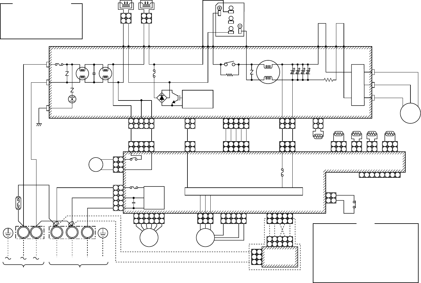
– 43 –
RAV-SM1103AT-E, RAV-SM1403AT-E
Color Identification
BLK
BLU
RED
GRY
PNK
:
:
:
:
:
BLACK
BLUE
RED
GRAY
PINK
WHI
BRN
ORN
YEL
PUR
:
:
:
:
:
WHITE
BROWN
ORANGE
YELLOW
PURPLE
P.C. board
(MCC-1438)
SUB P.C. board
(MCC-1531)
4
45
5
2
23
3
1
1
21
1
2
2
1
1
2
1
14
45
5
2
23
3
1
1
PNK
ORN
RED
BLU
WHI
3
3
1
1
3
3
1
1 2 3
3
1
1
YEL
BLU
BLK
CN06
RED CN04
WHI
2
2
1
1
CN600
BLK
TH
TS TE TO
CN09 RED
YEL BLU
CN10 WHI
CN11 BLK WV U
TD
CN800
RED CN03
WHI
CN605
WHI
23
3
1
1
2 31 5 64 87
CN600
WHI
CN801
CN500
BLU Thermostat for
compressor
2
2
1
1
CN604
WHI
2
2
1
1
CN601
WHI
5
5
31
1
5
53
1
1
RED
BLK
CN13
RED
F02
Fuse
T25A, 250V~
CN01
RED
F01 Fuse
T25A, 250V~
CN01
CN02
CN03
CN05
WHI
Power factor
control
CN04
WHI
CN702
WHI CN301
WHI CN300
WHI CN804
BLU
IGBT MODULE
P17
P18
P19
P28 GRY
P29 ORN
P21 BRN
P24 RED
P20
CM
Compressor
~
~
~
RY01
GRY
GRY
P13
P12
2
2
1
1
WHI
WHI
RED
WHI
BLK
P09
P08
Reactor Reactor
RED
GRY
PNK
YEL
Fuse
T6.3A,
250V~
To indoor unitPower supply
220-240V~ 50Hz
NL 1 2 3
1
3 3
1
1
3 3
1
5 5
4
45
56
6
2
23
3
1
14
45
5
2
23
3
1
14
45
5
2
23
3
1
1
4
45
5
2
23
3
1
1
PMV
2
23
3
1
1
FM
RED RED
Coil for
4-WAY
Valve
WHI
BLK
RED
WHI
BLK
CN02 BLK
Serial
commu-
nication
circuit
Pulse motor valve Fan motor
F01 Fuse
T3.15A 250V~
RY300
CN700 YEL
BLU
WHI
BLU
20SF
1
3 3
1
1 1
2 2
Optional
P.C. board
MCC-1522
49C
ORN
ORN
Fuse
F300
T5A,
250V
Fan motor drive circuit
CM
PMV
FM
TE
TH
TD
TO
TS
IGBT
:
:
:
:
:
:
:
:
:
Compressor
Pulse motor valve
Fan motor
Heat exchanger Temp. Sensor
Temp. Sensor
Discharge Temp. Sensor
Outdoor Temp. Sensor
Suction Temp. Sensor
Insulated Gate Bipolar Transistor
NOTE
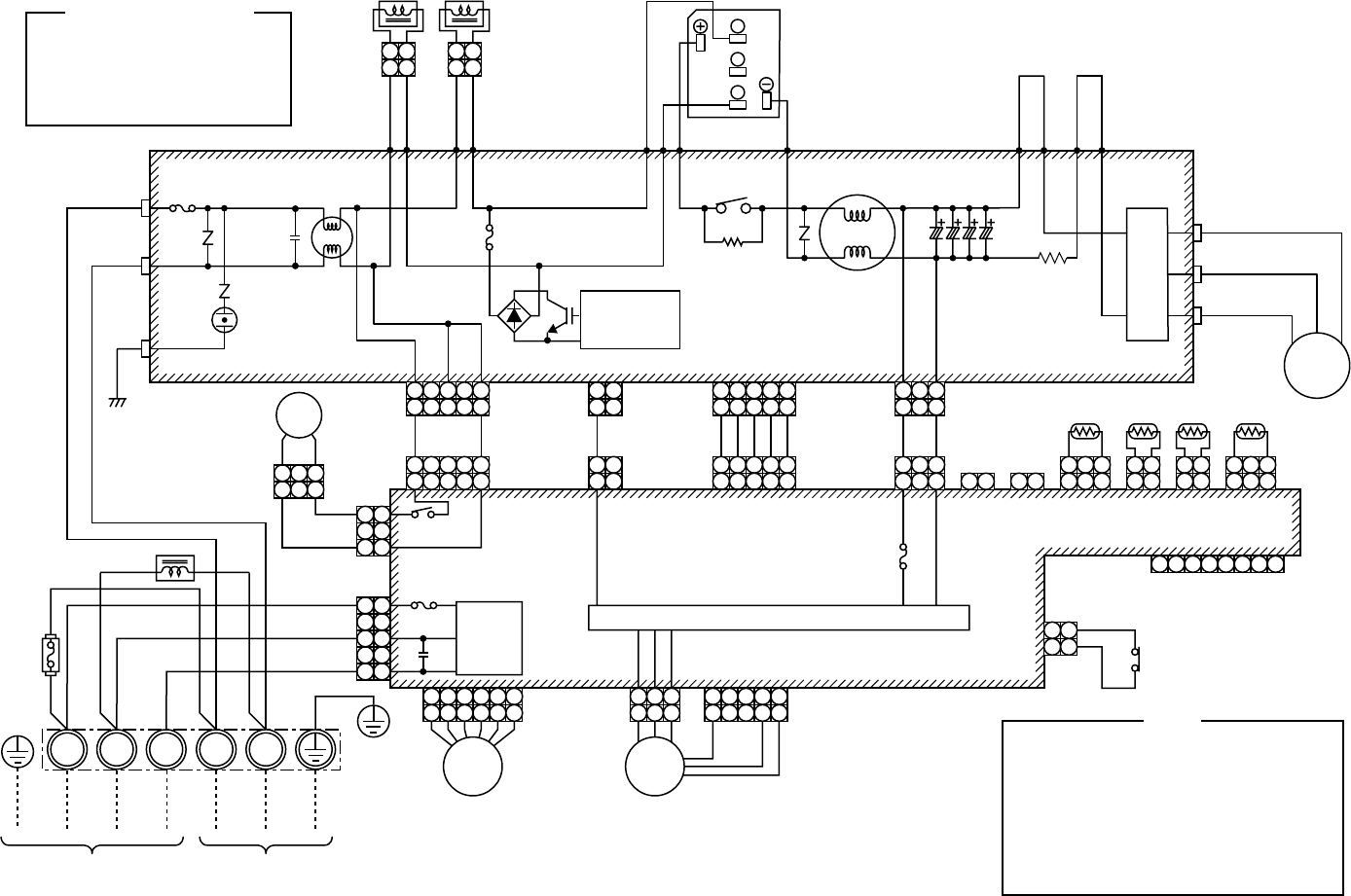
– 44 –
RAV-SP562AT-E, RAV-SP802AT-E
Color Identification
BLK
BLU
RED
GRY
PNK
:
:
:
:
:
BLACK
BLUE
RED
GRAY
PINK
WHI
BRN
ORN
YEL
PUR
:
:
:
:
:
WHITE
BROWN
ORANGE
YELLOW
PURPLE
P.C. board
(MCC-1438)
SUB P.C. board
(MCC-1531)
4
45
5
2
23
3
1
1
21
1
2
2
1
1
2
1
14
45
5
2
23
3
1
1
PNK
ORN
RED
BLU
WHI
3
3
1
1
3
3
1
1 2 3
3
1
1
YEL
BLU
BLK
CN06
RED CN04
WHI TS TE TO
CN20 RED
YEL BLU
CN21 WHI
CN22 BLK WV U
TD
CN800
RED CN03
WHI
CN605
WHI
CN606
RED
CN607
YEL
23
3
1
1
2 31 5 64 87
CN600
WHI
CN801
CN500
BLU Thermostat for
compressor
2
2
1
12121
CN604
WHI
2
2
1
1
CN601
WHI
5
5
31
1
5
53
3
3
1
1
1
1
RED
BLK
CN13
RED
F02
Fuse
T25A, 250V~
CN01
RED
F01 Fuse
T25A, 250V~
CN01
CN02
CN03
CN05
WHI
Power factor
control
CN04
WHI
CN702
WHI CN301
WHI CN300
WHI
IGBT MODULE
P17
P18
P19
P28 GRY
P29 ORN
P21 BRN
P24 RED
P20
CM
Compressor
~
~
~
RY01
GRY
GRY
P13
P12
2
2
1
1
WHI
WHI
RED
WHI
BLK
P09
P08
Reactor Reactor
Fuse
F300
T5A,
250V
RED RED
GRY
PNK
YEL
Fuse
T6.3A,
250V~
To indoor unit Power supply
220-240V~ 50Hz
NL1 2 3
1
3 3
1
1
3 3
1
5 5
4
45
56
6
2
23
3
1
14
45
5
2
23
3
1
1
PMV
2
23
3
1
1
FM
Coil for
4-WAY
Valve
GRN/YEL
WHI
RED
RED
WHI
WHI
BLK
WHI
RED
RED
WHI
BLK
CN02
BLK
Serial
commu-
nication
circuit
Fan motor drive circuit
Pulse motor valve Fan motor
F01 Fuse
T3.15A 250V~
RY300
CN700
YEL
RED
BLU
BLU
RED
1 1
2 2
49C
ORN
ORN
Reactor
20SF
CM
PMV
FM
TE
TD
TO
TS
IGBT
:
:
:
:
:
:
:
:
Compressor
Pulse motor valve
Fan motor
Heat exchanger Temp. Sensor
Discharge Temp. Sensor
Outdoor Temp. Sensor
Suction Temp. Sensor
Insulated Gate Bipolar Transistor
NOTE
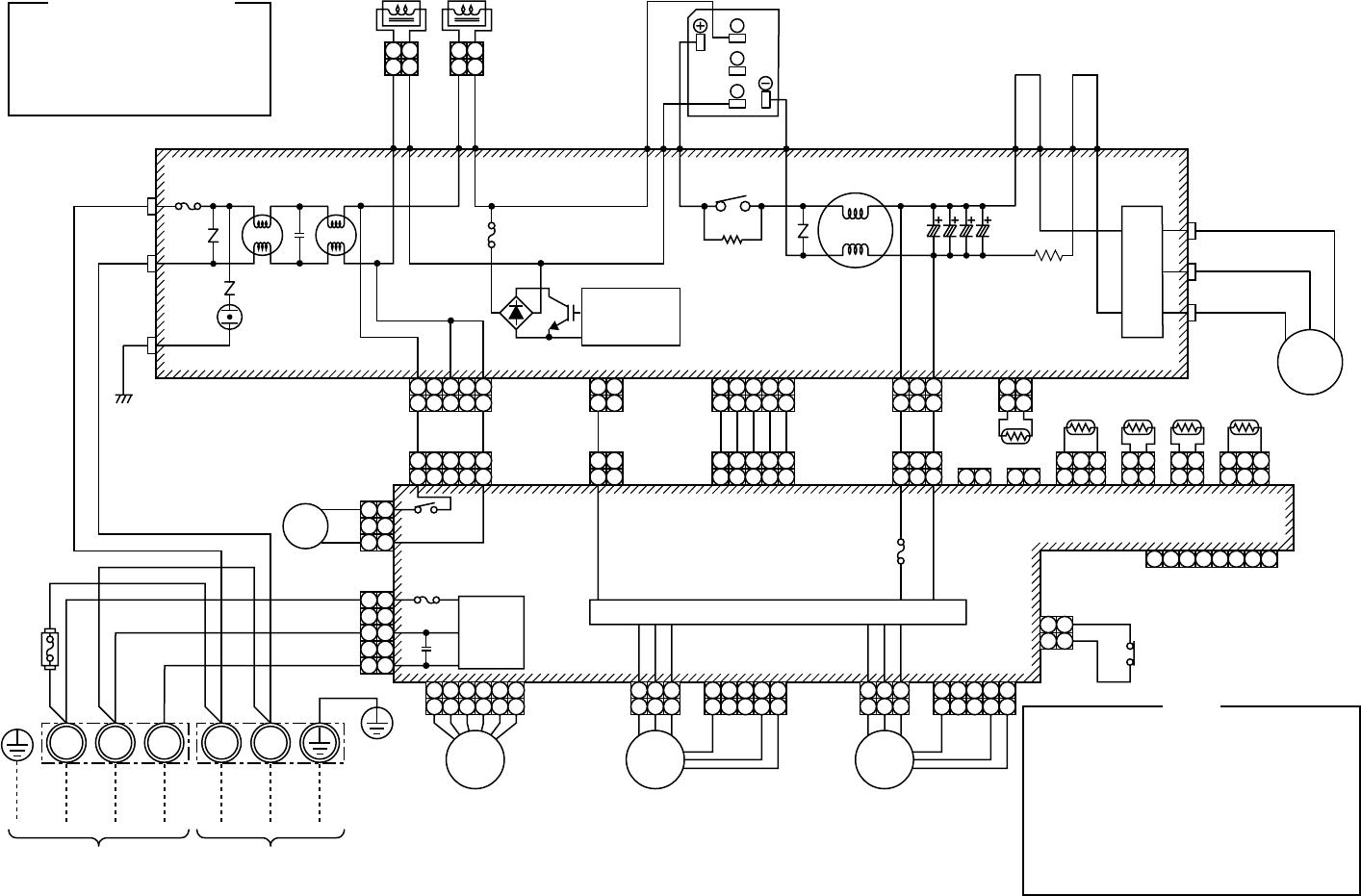
– 45 –
RAV-SP1102AT-E, RAV-SP1402AT-E
Color Identification
BLK
BLU
RED
GRY
PNK
:
:
:
:
:
BLACK
BLUE
RED
GRAY
PINK
WHI
BRN
ORN
YEL
PUR
:
:
:
:
:
WHITE
BROWN
ORANGE
YELLOW
PURPLE
P.C. board
(MCC-1438)
SUB P.C. board
(MCC-1531)
4
45
5
2
23
3
1
1
21
1
2
2
1
1
2
1
14
45
5
2
23
3
1
1
PNK
ORN
RED
BLU
WHI
3
3
1
1
3
3
1
1 2 3
3
1
1
YEL
BLU
BLK
CN06
RED CN04
WHI TS TE TO
CN09 RED
YEL BLU
CN10 WHI
CN11 BLK WV U
TD
CN800
RED CN03
WHI
CN605
WHI
CN606
RED
CN607
YEL
23
3
1
1
2 31 5 64 87
CN600
WHI
CN801
CN500
BLU Thermostat for
compressor
2
2
1
12121
CN604
WHI
2
2
1
1
CN601
WHI
5
5
31
1
5
53
1
1
RED
BLK
CN13
RED
F02
Fuse
T25A, 250V~
CN01
RED
F01 Fuse
T25A, 250V~
CN01
CN02
CN03
CN05
WHI
Power factor
control
CN04
WHI
CN702
WHI CN301
WHI
CN300
WHI
IGBT MODULE
P17
P18
P19
P28 GRY
P29 ORN
P21 BRN
P24 RED
P20
CM
Compressor
~
~
~
RY01
GRY
GRY
P13
P12
2
2
1
1
WHI
WHI
RED
WHI
BLK
P09
P08
Reactor Reactor
Fuse
F300
T5A,
250V
RED RED
GRY
PNK
YEL
Fuse
T6.3A,
250V~
To indoor unit Power supply
220-240V~ 50Hz
NL1 2 3
1
3 3
1
1
3 3
1
5 5
4
45
56
6
2
23
3
1
14
45
5
2
23
3
1
1
PMV
2
23
3
1
1
FM
Coil for
4-WAY
Valve
GRN/YEL
WHI
RED
RED
WHI
WHI
BLK
WHI
RED
RED
WHI
BLK
CN02
BLK
Serial
commu-
nication
circuit
Fan motor drive circuit
Pulse motor valve Fan motor
F01 Fuse
T3.15A 250V~
RY300
CN700 YEL
BLU
BLU
20SF
1 1
2 2
CN303
WHI
CN302
WHI
GRY
PNK
YEL
4
45
5
2
23
3
1
1
2
23
3
1
1
FM
RED
WHI
BLK
Fan motor
49C
ORN
ORN
2
2
1
1
CN600
BLK
TH
CM
PMV
FM
TE
TH
TD
TO
TS
IGBT
:
:
:
:
:
:
:
:
:
Compressor
Pulse motor valve
Fan motor
Heat exchanger Temp. Sensor
Temp. Sensor
Discharge Temp. Sensor
Outdoor Temp. Sensor
Suction Temp. Sensor
Insulated Gate Bipolar Transistor
NOTE

– 46 –
6. SPECIFICATIONS OF ELECTRICAL PARTS
6-1. Indoor Unit
6-1-1. 4-Way Air Discharge Cassette Type
RAV-SM563UT-E, RAV-SM803UT-E
RAV-SM1103UT-E, RAV-SM1403UT-E, RAV-SP1102UT-E
No.
1
2
3
4
5
6
Parts name
Fan motor (for indoor)
Thermo. sensor (TA-sensor)
Heat exchanger sensor (TCJ-sensor)
Heat exchanger sensor (TC-sensor)
Float switch
Drain pump motor
Type
SWF-230-60-1R
155 mm
Ø6 mm, 1200 mm
Ø6 mm, 1200 mm
FS-0218-102
ADP-1409
Specifications
Output (Rated) 60 W, 220–240 V
10 kΩ at 25°C
10 kΩ at 25°C
10 kΩ at 25°C
No.
1
2
3
4
5
6
Parts name
Fan motor
Thermo. sensor (TA-sensor)
Heat exchanger sensor (TCJ-sensor)
Heat exchanger sensor (TC-sensor)
Float switch
Drain pump motor
Type
SWF-200-90-1R
155 mm
Ø6 mm, 1200 mm
Ø6 mm, 1200 mm
FS-0218-102
ADP-1409
Specifications
Output (Rated) 90 W
10 kΩ at 25°C
10 kΩ at 25°C
10 kΩ at 25°C
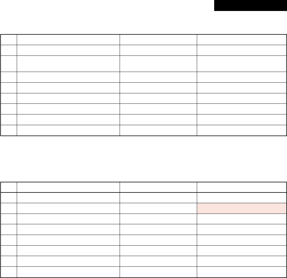
– 47 –
6-1-2. Concealed Duct Type
RAV-SM562BT-E, RAV-SM802BT-E, RAV-SM1102BT-E, RAV-SM1402BT-E
6-1-3. Under Ceiling Type
RAV-SM562CT-E, RAV-SM802CT-E, RAV-SM1102CT-E, RAV-SM1402CT-E
No.
1
2
3
4
5
6
7
8
Parts name
Fan motor (SM802BT-E)
Fan motor
(SM562BT-E/SM1102BT-E/SM1402BT-E)
Thermo. sensor (TA-sensor)
Heat exchanger sensor (TCJ-sensor)
Heat exchanger sensor (TC-sensor)
Float switch
Drain pump motor
Reactor
Type
ICF-280-120-1B
ICF-280-120-2B
618 mm
Ø6 mm, 1200 mm
Ø6 mm, 1200 mm
FS-0218-102
ADP-1409
CH-43-2Z-T
Specifications
Output (Rated) 120 W, 220–240 V
Output (Rated) 120 W, 220–240 V
10 kΩ at 25°C
10 kΩ at 25°C
10 kΩ at 25°C
10 mH, 1 A
No.
1
2
3
4
5
6
7
8
Parts name
Fan motor (SM562CT-E)
Fan motor (SM802CT-E)
Fan motor (SM1102CT-E/SM1402CT-E)
Thermo. sensor (TA-sensor)
Heat exchanger sensor (TCJ-sensor)
Heat exchanger sensor (TC-sensor)
Louver motor
Reactor
Type
SWF-280-60-1R
SWF-280-60-2R
SWF-280-120-2R
155 mm
Ø6 mm, 1200 mm
Ø6 mm, 1200 mm
MP24Z2N
CH-43-2Z-T
Specifications
Output (Rated) 60 W, 220–240 V
Output (Rated) 60 W, 220–240 V
Output (Rated) 120 W, 220–240 V
10 kΩ at 25°C
10 kΩ at 25°C
10 kΩ at 25°C
DC 15 V
10 mH, 1 A
Revised : Mar. 2007
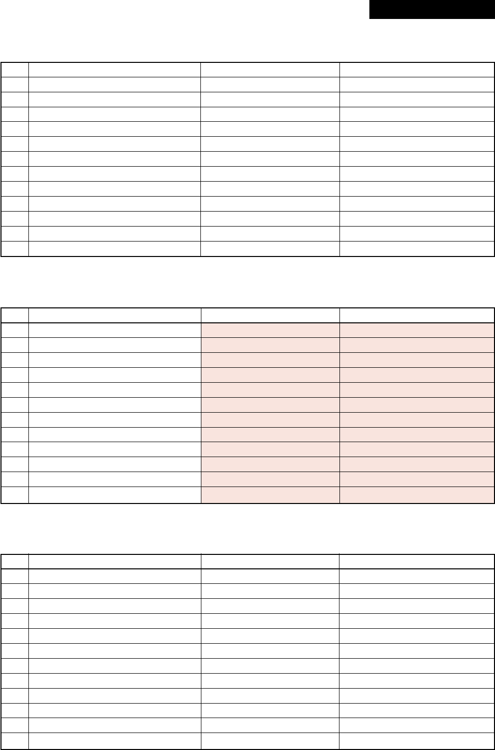
– 48 –
RAV-SM1103AT-E
No.
1
2
3
4
5
6
7
8
9
10
11
12
Parts name
Fan motor
Compressor
Reactor
Outdoor temp. sensor (To-sensor)
Heat exchanger sensor (Te-sensor)
Suction temp. sensor (Ts-sensor)
Discharge temp. sensor (Td-sensor)
Fuse (Switching power (Protect))
Fuse (Inverter, input (Current protect)
4-way valve solenoid coil
Compressor thermo. (Protection)
Coil (Pulse Motor Valve)
Type
ICF-280-100-1R
DA420A3F-21M
CH-62
—
—
—
—
—
—
STF-01AJ502E1
US-622
UKV-U048E
Specifications
Output (Rated) 100 W
3 phase, 4P, 2000 W
6 mH, 18.5 A
10 kΩ at 25°C
10 kΩ at 25°C
10 kΩ at 25°C
50 kΩ at 25°C
T3.15 A, AC 250 V
25 A, AC 250 V
AC 220 – 240 V
OFF : 125 ± 4°C, ON : 90 ± 5°C
—
RAV-SM803AT-E
No.
1
2
3
4
5
6
7
8
9
10
11
12
Parts name
Fan motor
Compressor
Reactor
Outdoor temp. sensor (To-sensor)
Heat exchanger sensor (Te-sensor)
Suction temp. sensor (Ts-sensor)
Discharge temp. sensor (Td-sensor)
Fuse (Switching power (Protect))
Fuse (Inverter, input (Current protect))
4-way valve solenoid coil
Compressor thermo. (Protection)
Coil (Pulse Motor Valve)
Type
ICF-140-43-4R
DA150A1F-20F
CH-57
—
—
—
—
—
—
STF-01AJ502E1
US-622
CAM-MD12TF-6
Specifications
Output (Rated) 43 W
3 phase, 4P, 1100 W
10 mH, 16 A
10 kΩ at 25°C
10 kΩ at 25°C
10 kΩ at 25°C
50 kΩ at 25°C
T3.15 A, AC 250 V
25 A, AC 250 V
AC 220 – 240 V
OFF : 125 ± 4°C, ON : 90 ± 5°C
—
6-2. Outdoor Unit
RAV-SM563AT-E
No.
1
2
3
4
5
6
7
8
9
10
11
12
Parts name
Fan motor
Compressor
Reactor
Outdoor temp. sensor (To-sensor)
Heat exchanger sensor (Te-sensor)
Suction temp. sensor (Ts-sensor)
Discharge temp. sensor (Td-sensor)
Fuse (Switching power (Protect))
Fuse (Inverter, input (Current protect)
4-way valve solenoid coil
Compressor thermo. (Protection)
Coil (Pulse Motor Valve)
Type
ICF-140-43-4R
DA150A1F-20F
CH-57
—
—
—
—
—
—
STF-01AJ502E1
US-622
CAM-MD12TF-6
Specifications
Output (Rated) 43 W
3 phase, 4P, 1100 W
10 mH, 16A
10 kΩ at 25°C
10 kΩ at 25°C
10 kΩ at 25°C
50 kΩ at 25°C
T3.15 A, AC 250 V
25 A, AC 250 V
—
OFF : 125 ± 4°C, ON : 90 ± 5°C
—
Revised : Mar. 2007
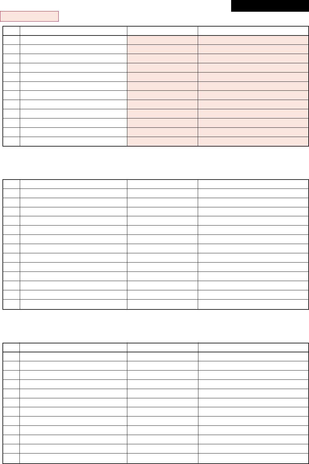
– 49 –
RAV-SM1403AT-E
No.
1
2
3
4
5
6
7
8
9
10
11
12
Parts name
Fan motor
Compressor
Reactor
Outdoor temp. sensor (To-sensor)
Heat exchanger sensor (Te-sensor)
Suction temp. sensor (Ts-sensor)
Discharge temp. sensor (Td-sensor)
Fuse (Switching power (Protect))
Fuse (Inverter, input (Current protect))
4-way valve solenoid coil
Compressor thermo. (Protection)
Coil (Pulse Motor Valve)
Type
ICF-280-100-1R
DA420A3F-21M
CH-62
—
—
—
—
—
—
VHV-01AJ503C1
US-622
UKV-U048E
Specifications
Output (Rated) 100 W
3 phase, 4P, 3500 W
6 mH, 18.5 A
10 kΩ at 25°C
10 kΩ at 25°C
10 kΩ at 25°C
50 kΩ at 25°C
T3.15 A, AC 250 V
25 A, AC 250 V
AC 220 – 240 V
OFF : 125 ± 4°C, ON : 90 ± 5°C
—
RAV-SP1102AT-E, RAV-SP1402AT-E
No.
1
2
3
4
5
6
7
8
9
10
11
12
Parts name
Fan motor
Compressor
Reactor
Outdoor temp. sensor (To-sensor)
Heat exchanger sensor (Te-sensor)
Suction temp. sensor (Ts-sensor)
Discharge temp. sensor (Td-sensor)
Fuse (Switching power (Protect))
Fuse (Inverter, input (Current protect))
4-way valve solenoid coil
Compressor thermo. (Protection)
Coil (Pulse Motor Valve)
Type
ICF-140-63-2R
DA420A3F-21M
CH-62
—
—
—
—
—
—
VHV-01AJ502E1
US-622
UKV-U011E
Specifications
Output (Rated) 63 W
3 phase, 4P, 3500 W
6 mH, 18.5 A
10 kΩ at 25°C
10 kΩ at 25°C
10 kΩ at 25°C
50 kΩ at 25°C
T3.15 A, AC 250 V
25 A, AC 250 V
AC 220 V
OFF : 125 ± 4°C, ON : 90 ± 5°C
—
RAV-SP562AT-E, RAV-SP802AT-E
No.
1
2
3
4
5
6
7
8
9
10
11
12
13
Parts name
Fan motor
Compressor
Reactor
Outdoor temp. sensor (To-sensor)
Heat exchanger sensor (Te-sensor)
Suction temp. sensor (Ts-sensor)
Discharge temp. sensor (Td-sensor)
Fuse (Switching power (Protect))
Fuse (Inverter, input (Current protect))
4-way valve solenoid coil
Compressor thermo. (Protection)
Coil (Pulse Motor Valve)
Reactor
Type
ICF-140-63-2R
DA220A2F-20L1
CH-47
—
—
—
—
—
—
VHV-01AJ503C1
US-622
CAM-MD12TF-8
CH-43
Specifications
Output (Rated) 63 W
3 phase, 4P, 2000 W
8 mH, 16 A
10 kΩ at 25°C
10 kΩ at 25°C
10 kΩ at 25°C
50 kΩ at 25°C
T3.15 A, AC 250 V
25 A, AC 250 V
OFF : 125 ± 4°C, ON : 90 ± 5°C
10 mH, 1 A
Revised : Mar. 2007
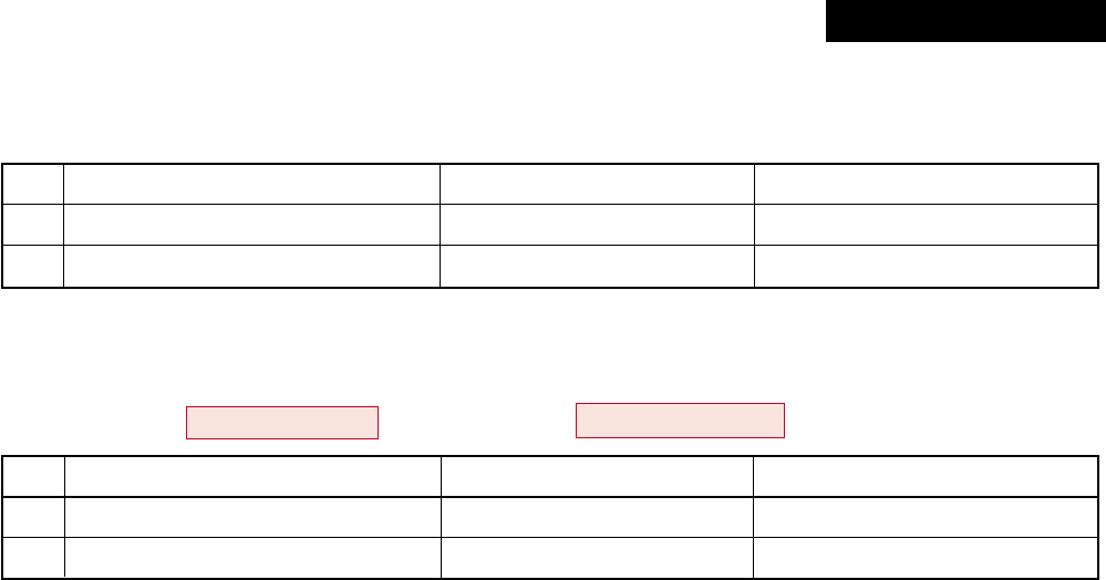
– 50 –
6-3. Accessory Separate Soldparts
TCB-DP22CE2 (Drain up kit)
RAV-SM562CT-E, RAV-SM802CT-E, RAV-SM1102CT-E, RAV-SM1402CT-E
RBC-U21PG (W) -E2 (Ceiling panel)
RAV-SM563UT-E, RAV-SM803UT-E, RAV-SM1103UT-E, RAV-SM1403UT-E / RAV-SP1102UT-E
No.
1
2
Parts name
Float switch
Drain pump motor
Type
FS-0218-102
ADP-1415
Specifications
No.
1
2
Parts name
Motor-louver
Type
MP24ZN
Specifications
DC 12 V
Revised : Mar. 2007
– 51 –
7. REFRIGERANT R410A
This air conditioner adopts the new refrigerant HFC
(R410A) which does not damage the ozone layer.
The working pressure of the new refrigerant R410A
is 1.6 times higher than conventional refrigerant
(R22). The refrigerating oil is also changed in
accordance with change of refrigerant, so be careful
that water, dust, and existing refrigerant or refriger-
ating oil are not entered in the refrigerant cycle of
the air conditioner using the new refrigerant during
installation work or servicing time.
The next section describes the precautions for air
conditioner using the new refrigerant. Conforming to
contents of the next section together with the
general cautions included in this manual, perform
the correct and safe work.
7-1. Safety During Installation/Servicing
As R410A’s pressure is about 1.6 times higher than
that of R22, improper installation/servicing may
cause a serious trouble. By using tools and materi-
als exclusive for R410A, it is necessary to carry out
installation/servicing safely while taking the following
precautions into consideration.
1. Never use refrigerant other than R410A in an air
conditioner which is designed to operate with
R410A.
If other refrigerant than R410A is mixed, pressure
in the refrigeration cycle becomes abnormally
high, and it may cause personal injury, etc. by a
rupture.
2. Confirm the used refrigerant name, and use tools
and materials exclusive for the refrigerant R410A.
The refrigerant name R410A is indicated on the
visible place of the outdoor unit of the air condi-
tioner using R410A as refrigerant. To prevent
mischarging, the diameter of the service port
differs from that of R22.
3. If a refrigeration gas leakage occurs during
installation/servicing, be sure to ventilate fully.
If the refrigerant gas comes into contact with fire,
a poisonous gas may occur.
4. When installing or removing an air conditioner,
do not allow air or moisture to remain in the
refrigeration cycle. Otherwise, pressure in the
refrigeration cycle may become abnormally high
so that a rupture or personal injury may be
caused.
5. After completion of installation work, check to
make sure that there is no refrigeration gas
leakage.
If the refrigerant gas leaks into the room, coming
into contact with fire in the fan-driven heater,
space heater, etc., a poisonous gas may occur.
6. When an air conditioning system charged with a
large volume of refrigerant is installed in a small
room, it is necessary to exercise care so that,
even when refrigerant leaks, its concentration
does not exceed the marginal level.
If the refrigerant gas leakage occurs and its
concentration exceeds the marginal level, an
oxygen starvation accident may result.
7. Be sure to carry out installation or removal
according to the installation manual.
Improper installation may cause refrigeration
trouble, water leakage, electric shock, fire, etc.
8. Unauthorized modifications to the air conditioner
may be dangerous. If a breakdown occurs please
call a qualified air conditioner technician or
electrician.
Improper repair’s may result in water leakage,
electric shock and fire, etc.
7-2. Refrigerant Piping Installation
7-2-1. Piping Materials and Joints Used
For the refrigerant piping installation, copper pipes
and joints are mainly used. Copper pipes and joints
suitable for the refrigerant must be chosen and
installed. Furthermore, it is necessary to use clean
copper pipes and joints whose interior surfaces are
less affected by contaminants.
1. Copper Pipes
It is necessary to use seamless copper pipes
which are made of either copper or copper alloy
and it is desirable that the amount of residual oil
is less than 40 mg/10 m. Do not use copper
pipes having a collapsed, deformed or discolored
portion (especially on the interior surface).
Otherwise, the expansion valve or capillary tube
may become blocked with contaminants.
As an air conditioner using R410A incurs pres-
sure higher than when using R22, it is necessary
to choose adequate materials.
Thicknesses of copper pipes used with R410A
are as shown in Table 7-2-1. Never use copper
pipes thinner than 0.8 mm even when it is
available on the market.
NOTE:
Refer to the “7-6. Instructions for Re-use Piping
of R22 or R407C”.
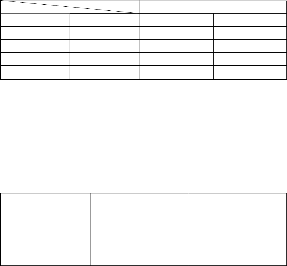
– 52 –
Table 7-2-1 Thicknesses of annealed copper pipes
1. Joints
For copper pipes, flare joints or socket joints are used. Prior to use, be sure to remove all contaminants.
a) Flare Joints
Flare joints used to connect the copper pipes cannot be used for pipings whose outer diameter exceeds
20 mm. In such a case, socket joints can be used.
Sizes of flare pipe ends, flare joint ends and flare nuts are as shown in Tables 7-2-3 to 7-2-6 below.
b) Socket Joints
Socket joints are such that they are brazed for connections, and used mainly for thick pipings whose
diameter is larger than 20 mm. Thicknesses of socket joints are as shown in Table 7-2-2.
Table 7-2-2 Minimum thicknesses of socket joints
7-2-2. Processing of Piping Materials
When performing the refrigerant piping installation, care should be taken to ensure that water or dust does not
enter the pipe interior, that no other oil other than lubricating oils used in the installed air conditioner is used,
and that refrigerant does not leak. When using lubricating oils in the piping processing, use such lubricating oils
whose water content has been removed. When stored, be sure to seal the container with an airtight cap or any
other cover.
1. Flare Processing Procedures and Precautions
a) Cutting the Pipe
By means of a pipe cutter, slowly cut the pipe so that it is not deformed.
b) Removing Burrs and Chips
If the flared section has chips or burrs, refrigerant leakage may occur.
Carefully remove all burrs and clean the cut surface before installation.
Nominal diameter
1/4
3/8
1/2
5/8
Outer diameter (mm)
6.4
9.5
12.7
15.9
Thickness (mm)
R410A R22
0.80 0.80
0.80 0.80
0.80 0.80
1.00 1.00
Nominal diameter
1/4
3/8
1/2
5/8
Reference outer diameter of
copper pipe jointed (mm)
6.4
9.5
12.7
15.9
Minimum joint thickness
(mm)
0.50
0.60
0.70
0.80
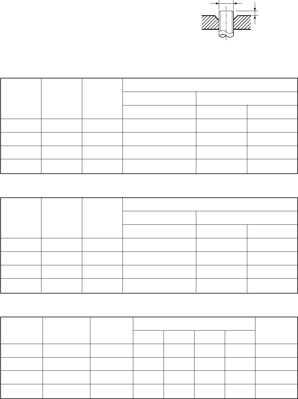
– 53 –
c) Insertion of Flare Nut
d) Flare Processing
Make certain that a clamp bar and copper pipe have been cleaned.
By means of the clamp bar, perform the flare processing correctly.
Use either a flare tool for R410A or conventional flare tool.
Flare processing dimensions differ according
to the type of flare tool.
When using a conventional flare tool, be sure
to secure “dimension A” by using a gauge for
size adjustment.
Fig. 7-2-1 Flare processing dimensions
Table 7-2-3 Dimensions related to flare processing for R410A
Table 7-2-4 Dimensions related to flare processing for R22
Table 7-2-5 Flare and flare nut dimensions for R410A
A
ØD
Nominal
diameter
1/4
3/8
1/2
5/8
Outer
diameter
(mm)
6.4
9.5
12.7
15.9
Thickness
(mm)
0.8
0.8
0.8
1.0
A (mm)
Flare tool for
R410A clutch type
0 to 0.5
0 to 0.5
0 to 0.5
0 to 0.5
Conventional flare tool
Clutch type Wing nut type
1.0 to 1.5 1.5 to 2.0
1.0 to 1.5 1.5 to 2.0
1.0 to 1.5 2.0 to 2.5
1.0 to 1.5 2.0 to 2.5
Nominal
diameter
1/4
3/8
1/2
5/8
Outer
diameter
(mm)
6.4
9.5
12.7
15.9
Thickness
(mm)
0.8
0.8
0.8
1.0
A (mm)
Flare tool for
R22 clutch type
0 to 0.5
0 to 0.5
0 to 0.5
0 to 0.5
Conventional flare tool
Clutch type Wing nut type
0.5 to 1.0 1.0 to 1.5
0.5 to 1.0 1.0 to 1.5
0.5 to 1.0 1.5 to 2.0
0.5 to 1.0 1.5 to 2.0
Nominal
diameter
1/4
3/8
1/2
5/8
Outer diameter
(mm)
6.4
9.5
12.7
15.9
Thickness
(mm)
0.8
0.8
0.8
1.0
Dimension (mm)
ABCD
9.1 9.2 6.5 13
13.2 13.5 9.7 20
16.6 16.0 12.9 23
19.7 19.0 16.0 25
Flare nut
width (mm)
17
22
26
29
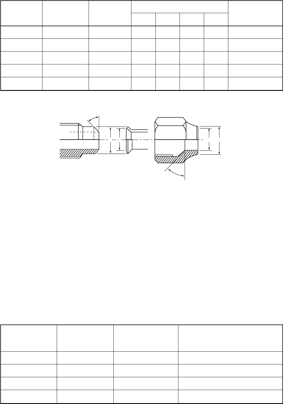
– 54 –
43˚to 45˚
45˚to 46˚
B A CD
Table 7-2-6 Flare and flare nut dimensions for R22
Fig. 7-2-2 Relations between flare nut and flare seal surface
2. Flare Connecting Procedures and Precautions
a) Make sure that the flare and union portions do not have any scar or dust, etc.
b) Correctly align the processed flare surface with the union axis.
c) Tighten the flare with designated torque by means of a torque wrench. The tightening torque for R410A is
the same as that for conventional R22. Incidentally, when the torque is weak, the gas leakage may occur.
When it is strong, the flare nut may crack and may be made non-removable. When choosing the tighten-
ing torque, comply with values designated by manufacturers. Table 7-2-7 shows reference values.
NOTE:
When applying oil to the flare surface, be sure to use oil designated by the manufacturer. If any other oil is used,
the lubricating oils may deteriorate and cause the compressor to burn out.
Table 7-2-7 Tightening torque of flare for R410A [Reference values]
Nominal
diameter
1/4
3/8
1/2
5/8
3/4
Outer diameter
(mm)
6.4
9.5
12.7
15.9
19.0
Thickness
(mm)
0.8
0.8
0.8
1.0
1.0
Dimension (mm)
ABCD
9.0 9.2 6.5 13
13.0 13.5 9.7 20
16.2 16.0 12.9 20
19.4 19.0 16.0 23
23.3 24.0 19.2 34
Flare nut width
(mm)
17
22
24
27
36
Nominal
diameter
1/4
3/8
1/2
5/8
Outer diameter
(mm)
6.4
9.5
12.7
15.9
Tightening torque
N•m (kgf•m)
14 to 18 (1.4 to 1.8)
33 to 42 (3.3 to 4.2)
50 to 62 (5.0 to 6.2)
63 to 77 (6.3 to 7.7)
Tightening torque of torque
wrenches available on the market
N•m (kgf•m)
16 (1.6), 18 (1.8)
42 (4.2)
55 (5.5)
65 (6.5)
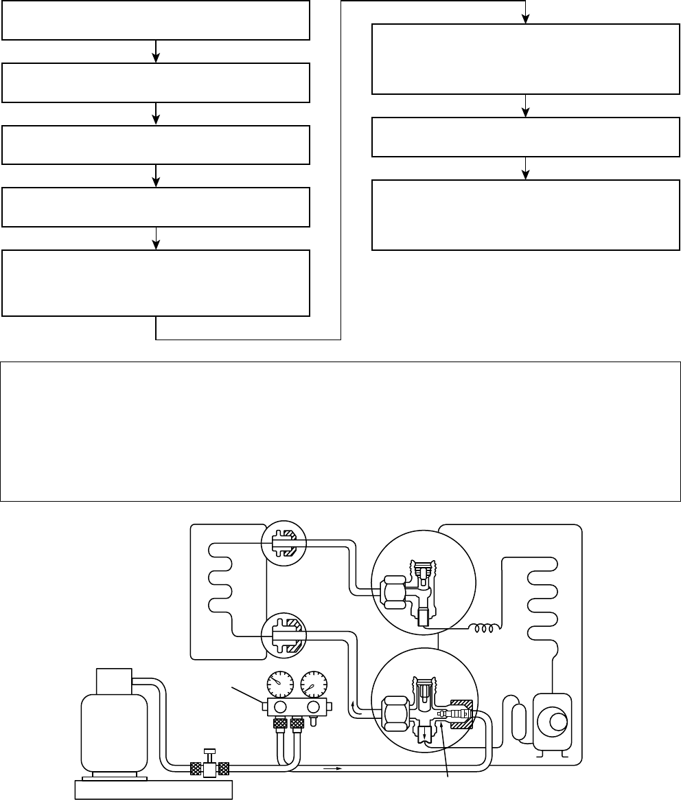
– 55 –
7-3. Tools
7-3-1. Required Tools
Refer to the “4. Tools” (Page 8)
7-4. Recharging of Refrigerant
When it is necessary to recharge refrigerant, charge the specified amount of new refrigerant according to the
following steps.
(INDOOR unit) (Liquid side)
Refrigerant cylinder
(With siphon pipe)
Check valve
(Gas side)
Open/Close valve
for charging
Electronic balance for refrigerant charging
Opened
(OUTDOOR unit)
Closed
Service port
Connect the charge hose to packed valve service
port at the outdoor unit’s gas side.
Recover the refrigerant, and check no refrigerant
remains in the equipment.
(For refrigerant charging, see the figure below.)
Connect the charge hose of the vacuum pump
adapter.
Open fully both packed valves at liquid and gas
sides.
Place the handle of the gauge manifold Low in the
fully opened position, and turn on the vacuum pump’s
power switch. Then, evacuating the refrigerant in the
cycle.
When the compound gauge’s pointer has indicated
–0.1 Mpa (–76 cmHg), place the handle Low in the
fully closed position, and turn off the vacuum pump’s
power switch.
Keep the status as it is for 1 to 2 minutes, and ensure
that the compound gauge’s pointer does not return.
Set the refrigerant cylinder to the electronic balance,
connect the connecting hose to the cylinder and the
connecting port of the electronic balance, and charge
liquid refrigerant.
1) Never charge refrigerant exceeding the specified amount.
2) If the specified amount of refrigerant cannot be charged, charge refrigerant bit by bit in COOL mode.
3) Do not carry out additional charging.
When additional charging is carried out if refrigerant leaks, the refrigerant composition changes in the
refrigeration cycle, that is characteristics of the air conditioner changes, refrigerant exceeding the
specified amount is charged, and working pressure in the refrigeration cycle becomes abnormally high
pressure, and may cause a rupture or personal injury.
Fig. 7-4-1 Configuration of refrigerant charging
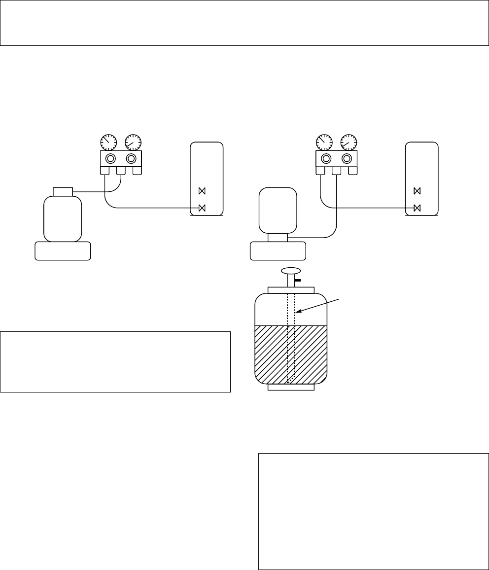
– 56 –
Gauge manifold
[ Cylinder with siphon ] [ Cylinder without siphon ]
OUTDOOR unit Gauge manifold OUTDOOR unit
Refrigerant
cylinder
Electronic
balance
Refrigerant
cylinder
Electronic
balance
Siphon
1) Be sure to make setting so that liquid can be charged.
2) When using a cylinder equipped with a siphon, liquid can be charged without turning it upside down.
It is necessary for charging refrigerant under condition of liquid because R410A is mixed type of refrigerant.
Accordingly, when charging refrigerant from the refrigerant cylinder to the equipment, charge it turning the
cylinder upside down if cylinder is not equipped with siphon.
R410A refrigerant is HFC mixed refrigerant.
Therefore, if it is charged with gas, the composi-
tion of the charged refrigerant changes and the
characteristics of the equipment varies.
Fig. 7-4-2
7-5. Brazing of Pipes
7-5-1. Materials for Brazing
1. Silver brazing filler
Silver brazing filler is an alloy mainly composed
of silver and copper. It is used to join iron, copper
or copper alloy, and is relatively expensive though
it excels in solderability.
2. Phosphor bronze brazing filler
Phosphor bronze brazing filler is generally used
to join copper or copper alloy.
3. Low temperature brazing filler
Low temperature brazing filler is generally called
solder, and is an alloy of tin and lead. Since it is
weak in adhesive strength, do not use it for
refrigerant pipes.
1) Phosphor bronze brazing filler tends to react
with sulfur and produce a fragile compound
water solution, which may cause a gas
leakage. Therefore, use any other type of
brazing filler at a hot spring resort, etc., and
coat the surface with a paint.
2) When performing brazing again at time of
servicing, use the same type of brazing filler.
7-5-2. Flux
1. Reason why flux is necessary
•By removing the oxide film and any foreign
matter on the metal surface, it assists the flow
of brazing filler.
•In the brazing process, it prevents the metal
surface from being oxidized.
•By reducing the brazing filler's surface tension,
the brazing filler adheres better to the treated
metal.
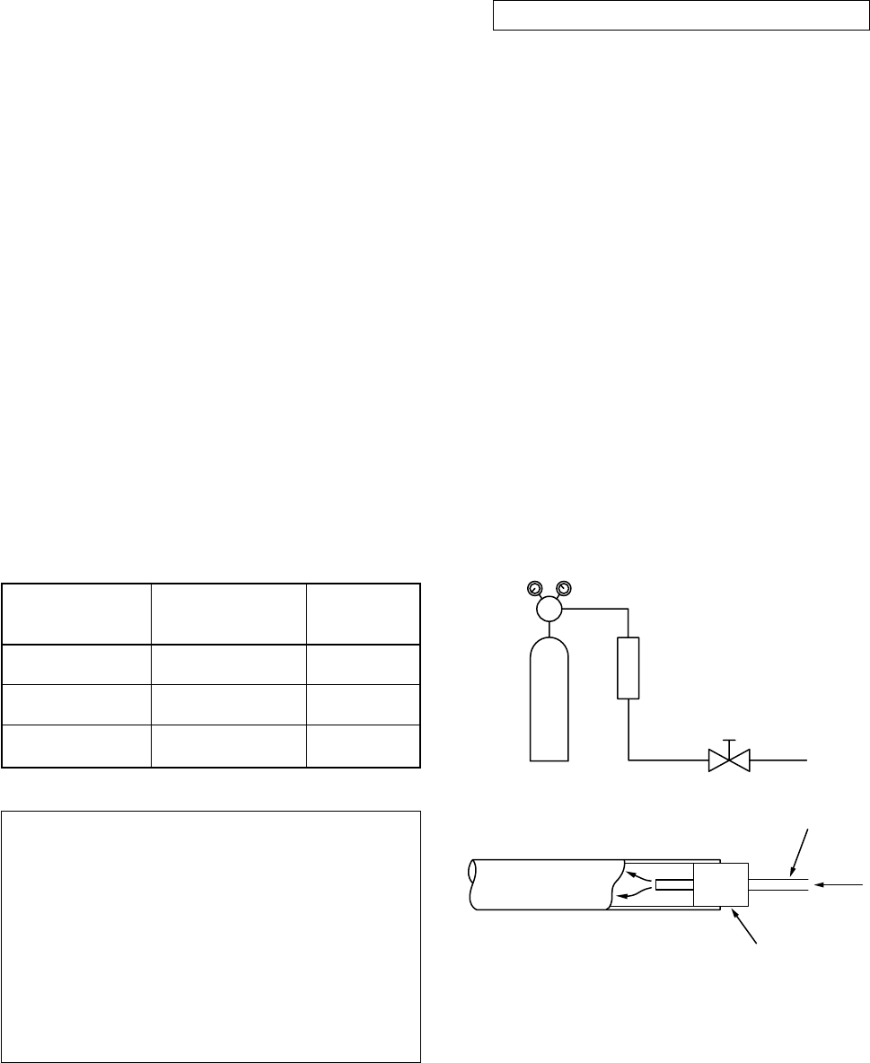
– 57 –
Nitrogen gas
cylinder
Pipe
Flow meter
M
Stop valve
From Nitrogen cylinder
Nitrogen
gas
Rubber plug
2. Characteristics required for flux
•Activated temperature of flux coincides with the
brazing temperature.
•Due to a wide effective temperature range, flux
is hard to carbonize.
•It is easy to remove slag after brazing.
•The corrosive action to the treated metal and
brazing filler is minimum.
•It excels in coating performance and is harm-
less to the human body.
As the flux works in a complicated manner as
described above, it is necessary to select an
adequate type of flux according to the type and
shape of treated metal, type of brazing filler and
brazing method, etc.
3. Types of flux
•Noncorrosive flux
Generally, it is a compound of borax and boric
acid.
It is effective in case where the brazing tem-
perature is higher than 800°C.
•Activated flux
Most of fluxes generally used for silver brazing
are this type.
It features an increased oxide film removing
capability due to the addition of compounds
such as potassium fluoride, potassium chloride
and sodium fluoride to the borax-boric acid
compound.
4. Piping materials for brazing and used
brazing filler/flux
1) Do not enter flux into the refrigeration cycle.
2) When chlorine contained in the flux remains
within the pipe, the lubricating oil deteriorates.
Therefore, use a flux which does not contain
chlorine.
3) When adding water to the flux, use water
which does not contain chlorine (e.g. distilled
water or ion-exchange water).
4) Remove the flux after brazing.
7-5-3. Brazing
As brazing work requires sophisticated techniques,
experiences based upon a theoretical knowledge, it
must be performed by a person qualified.
In order to prevent the oxide film from occurring in
the pipe interior during brazing, it is effective to
proceed with brazing while letting dry Nitrogen gas
flow.
Never use gas other than Nitrogen gas.
1. Brazing method to prevent oxidation
1) Attach a reducing valve and a flow-meter to
the Nitrogen gas cylinder.
2) Use a copper pipe to direct the piping mate-
rial, and attach a flow-meter to the cylinder.
3) Apply a seal onto the clearance between the
piping material and inserted copper pipe for
Nitrogen in order to prevent backflow of the
Nitrogen gas.
4) When the Nitrogen gas is flowing, be sure to
keep the piping end open.
5) Adjust the flow rate of Nitrogen gas so that it
is lower than 0.05 m³/Hr or 0.02 MPa
(0.2kgf/cm²) by means of the reducing valve.
6) After performing the steps above, keep the
Nitrogen gas flowing until the pipe cools down
to a certain extent (temperature at which
pipes are touchable with hands).
7) Remove the flux completely after brazing.
Fig. 7-5-1 Prevention of oxidation during brazing
Piping
material
Copper - Copper
Copper - Iron
Iron - Iron
Used brazing
filler
Phosphor copper
Silver
Silver
Used
flux
Do not use
Paste flux
Vapor flux
– 58 –
7-6. Instructions for Re-use Piping of R22 or R407C
Instruction of Works:
The existing R22 and R407C piping can be
reused for our digital inverter R410A products
installations.
NOTE)
Confirmation of existence of scratch or dent of the
former pipes to be applied and also confirmation of
reliability of the pipe strength are conventionally
referred to the local site.
If the definite conditions can be cleared,
it is possible to update the existing R22 and
R407C pipes to those for R410A models.
7-6-1. Basic conditions need to reuse the
existing pipe
Check and observe three conditions of the refrigerant
piping works.
1. Dry (There is no moisture inside of the pipes.)
2. Clean (There is no dust inside of the pipes.)
3. Tight (There is no refrigerant leak.)
7-6-2. Restricted items to use the existing pipes
In the following cases, the existing pipes cannot be
reused as they are. Clean the existing pipes or ex-
change them with new pipes.
1. When a scratch or dent is heavy, be sure to use the
new pipes for the works.
2. When the thickness of the existing pipe is thinner
than the specified “Pipe diameter and thickness” be
sure to use the new pipes for the works.
•The operating pressure of R410A is high
(1.6 times of R22 and R407C). If there is a scratch
or dent on the pipe or thinner pipe is used, the
pressure strength is poor and may cause break-
age of the pipe at the worst.
* Pipe diameter and thickness (mm)
6. Check the oil when the existing air conditioner was
removed after refrigerant had been recovered.
In this case, if the oil is judged as clearly different
compared with normal oil
•The refrigerator oil is copper rust green :
There is possibility that moisture is mixed with the
oil and rust generates inside of the pipe.
•There is discolored oil, a large quantity of the
remains, or bad smell.
•A large quantity of sparkle remained wear-out
powder is observed in the refrigerator oil.
7. The air conditioner which compressor was ex-
changed due to a faulty compressor.
When the discolored oil, a large quantity of the
remains, mixture of foreign matter, or a large
quantity of sparkle remained wear-out powder is
observed, the cause of trouble will occur.
8. Installation and removal of the air conditioner are
repeated with temporary installation by lease and
etc.
9. In case that type of the refrigerator oil of the
existing air conditioner is other than the following oil
(Mineral oil), Suniso, Freol-S, MS (Synthetic oil),
alkyl benzene (HAB, Barrel-freeze), ester series,
PVE only of ether series.
•Winding-insulation of the compressor may
become inferior.
NOTE)
The above descriptions are results of confirmation by
our company and they are views on our air condition-
ers, but they do not guarantee the use of the existing
pipes of the air conditioner that adopted R410A in
other companies.
7-6-3. Branching pipe for simultaneous
operation system
•In the concurrent twin system, when TOSHIBA-
specified branching pipe is used, it can be reused.
Branching pipe model name:
RBC-TWP30E-2, RBC-TWP50E-2
On the existing air conditioner for simultaneous
operation system (twin system), there is a case of
using branch pipe that has insufficient compressive
strength.
In this case please change it to the branch pipe for
R410A.
7-6-4. Curing of pipes
When removing and opening the indoor unit or outdoor
unit for a long time, cure the pipes as follows:
•Otherwise rust may generate when moisture or
foreign matter due to dewing enters in the pipes.
•The rust cannot be removed by cleaning, and a new
piping work is necessary.
Pipe outer diameter
R410A
Thickness R22
(R407C)
Ø6.4 Ø9.5 Ø12.7 Ø15.9 Ø19.0
0.8 0.8 0.8 1.0 1.0
•In case that the pipe diameter is Ø12.7 mm or less
and the thickness is less than 0.7 mm, be sure to use
the new pipes for works.
3. The pipes are left as coming out or gas leaks.
(Poor refrigerant)
•There is possibility that rain water or air including
moisture enters in the pipe.
4. Refrigerant recovery is impossible.
(Refrigerant recovery by the pump-down operation
on the existing air conditioner)
•There is possibility that a large quantity of poor
oil or moisture remains inside of the pipe.
5. A dryer on the market is attached to the existing
pipes.
•There is possibility that copper green rust gener-
ated.
Place position
Outdoors
Indoors
Term
1 month or more
Less than 1 month
Every time
Curing manner
Pinching
Pinching or taping
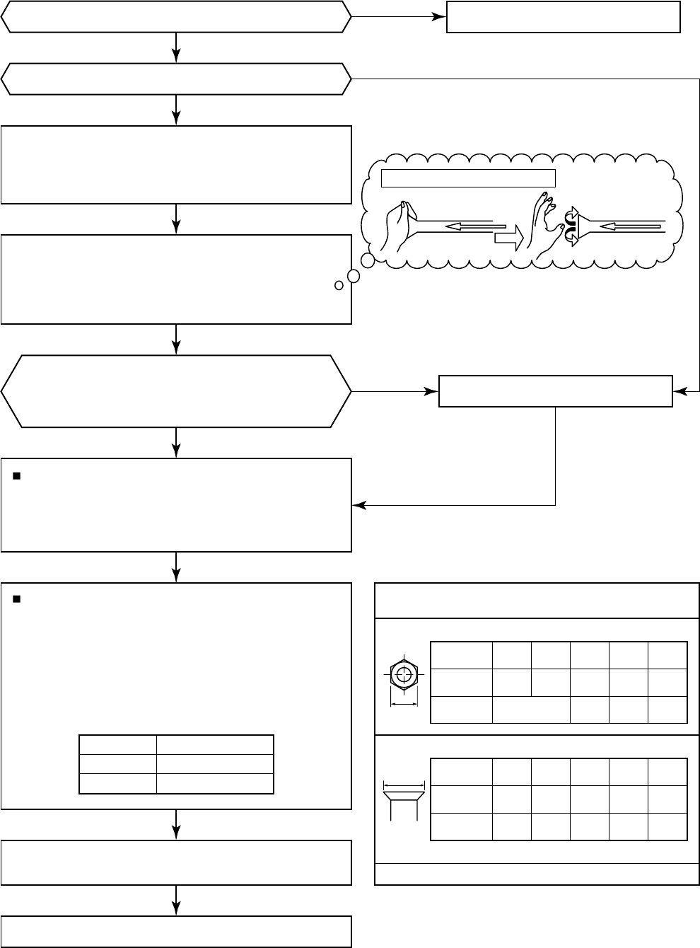
– 59 –
7-6-5. Final Installation Checks
Do not apply the refrigerator oil to the flare surface.
Existing pipe: NO * Use a new pipes.
Clean the pipes or use the new pipes.
Trial run
Is it possible to operate the existing air conditioner?
Was not largely discolored oil or
a large quantity of remains discharged?
(When the oil deteriorates, the color of the
oil changes to muddy and black color.)
* After the existing air conditioner operated in cooling mode
for approx. 30 minutes or longer*, recover the refrigerant.
* For cooling the pipes and recovering of oil
•Refrigerant recovery: Pump down method
* Remove the existing air conditioner from the piping and
carry out flashing (nitrogen pressure 0.5 Mpa) to remove
the remains inside of the pipe.
Note] In case of twin, also be sure to flash the
branching pipe.
Connect the indoor/outdoor units to the existing pipe.
•Use a flare nut attached to the main unit for the
indoor/outdoor units.
(Do not use the flare nut of the existing pipe.)
•Re-machine the flare machining size to size for R410A.
* (Airtight test), Vacuum dry, Refrigerant charge,
Gas leak check
In case that the gas pipe Ø19 mm is used for the
outdoor unit of SM803 (3 HP) or higher:
(Gas pipe size of our R410A model 3 to 5 HP is Ø15.9 mm)
→Turn the existing pipe switch on the cycle control
P.C board of the outdoor unit to ON side.
At shipment from factory OFF → ON for existing pipe
(Refer to the table below.) (Be sure to set the contents
in the table below in order to restrict the refrigerating
cycle pressure of the equipment in the pipe standard.)
Existing pipe SW
Nitrogen gas pressure 0.5 Mpa
H
A
(If there is discharge of remains,
it is judged that there is a large quantity of remains.)
If you are in trouble of
pipe cleaning, please contact us.
Piping necessary to change the flare nut/
machining size due to pipe compression.
1) Flare nut width: H
2) Flare machining size: A
(mm)
36
Ø19.0
29
Ø15.9
26
2724
Ø12.7
22
Ø9.5
17
Ø6.4
Same
as above
Copper pipe
outer dia.
For R22
For R410A
Same as above
(mm)
24.0
Ø19.0
19.7
Ø15.9
16.6
Ø12.7
13.2
Ø9.5
9.1
23.319.416.213.09.0
Ø6.4
Copper pipe
outer dia.
For R22
For R410A
Becomes large a little for R410A
3 HP
4, 5 HP
Switch
Bit 3 of SW801
Bit 5 of SW801
Is there no scratch or dent on the existing pipes?
YES
YES
NO
NO
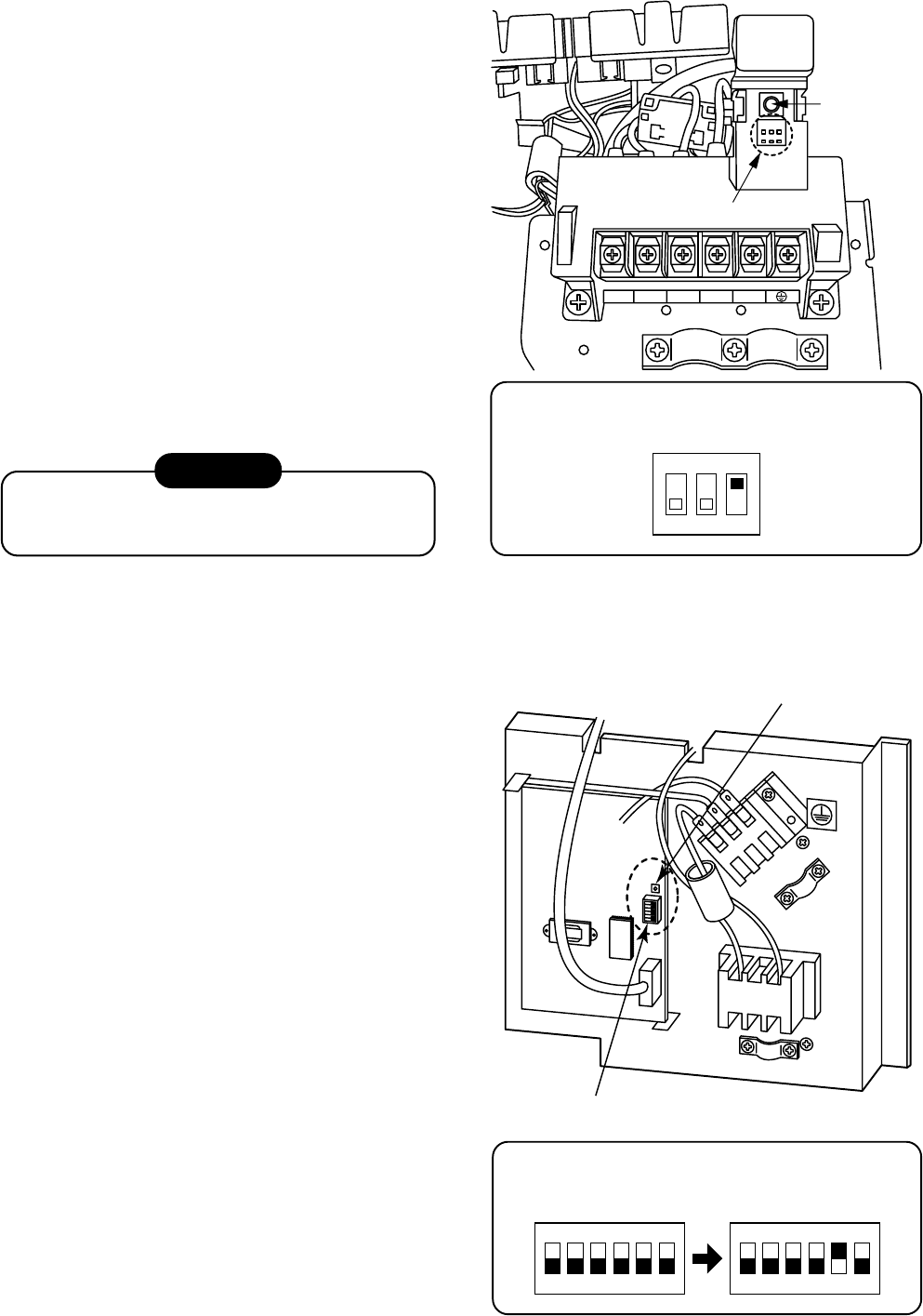
– 60 –
7-6-6. Recovery method of refrigerant for RAV-SM563AT-E, SM803AT-E
123LN
2 31
ON
Refrigerant
recovery switch
Existing pipe switch SW801
Only when the existing gas pipe Ø19 mm is used on
RAV-SM803AT-E model, change the setting of
SW801 No. 3.
ON
123
• When recovering refrigerant in case of reinstalla-
tion of the indoor or outdoor unit, etc., use the
refrigerant recovery switch on the terminal block
of the outdoor unit.
Work procedure
1. Turn on the power supply.
2. Using the remote controller, set FAN operation to
the indoor unit.
3. Pushing the refrigerant recovery switch on the
terminal block of the outdoor unit starts the
forced cooling operation. (Max. 10 minutes), and
then the refrigerant is recovered by operation of
the valve.
4. After recovery of the refrigerant, push the
refrigerant recovery switch together with closing
the valve. The operation stops.
5. Turn off the power supply.
DANGER
Take care for an electric shock because the
control P.C. board is electrified.
7-6-7. Recovery method of refrigerant for RAV-SM1103AT-E, SM1403AT-E
• When recovering refrigerant in case of reinstalla-
tion of the indoor or outdoor unit, etc., use the
refrigerant recovery switch SW802 on the cycle
control P.C. board of the outdoor unit.
Work procedure
1. Turn on the power supply.
2. Using the remote controller, set FAN operation to
the indoor unit.
3. Pushing the refrigerant recovery switch SW802
on the cycle control P.C. board of the outdoor
unit starts the forced cooling operation.
(Max. 10 minutes), and then the refrigerant is
recovered by operation of the valve.
4. After recovery of the refrigerant, push the
refrigerant recovery switch SW802 together with
closing the valve. The operation stops.
5. Turn off the power supply.
Only when the existing gas pipe Ø19 mm is used on
RAV-SM1103AT-E model, change the setting of
SW801 No. 5.
Existing pipe switch SW801
Refrigerant recovery switch SW802
ON
123456
ON
123456
LN
123
MCC-1531
SW801SW802
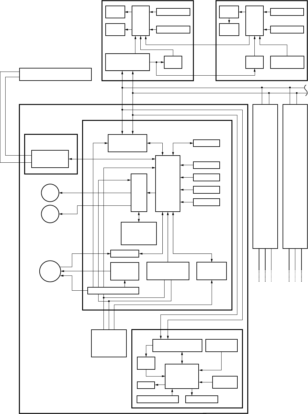
– 61 –
8. CONTROL BLOCK DIAGRAM
8-1. Indoor Control Circuit
Connection Interfase
(Option)
Indoor control P.C. board
(MCC-1402)
Duct type nothing
Separately sold parts
for Ceiling type
Separately sold parts
for Ceiling type
TA sensor
#1
#3AB
Indoor unit
Main (Sub) master remote controller
Fan motor
control
circuit
AC
synchronous
signal input circuit
Serial
send/receive
circuit
Run
Warning Ready
Thermo. ON
Cool/Heat Fan
Outside output
Driver
Remote controller
communication
circuit
CPU
Remote controller
communication
circuit
TCC-LINK
communication
circuit
TC sensor
TCJ sensor
Float input
Louver
motor
Drain
pump
Indoor
fan
motor
Outdoor unit
123
123
DC5V
CPU
LCD
driver
Display
LCD
Weekly timer
Secondary
battery
DC5V
*
2
CN2
CN1
AB
123
Outdoor
unit
Same as
the left
*1
#2AB
123
Outdoor
unit
Same as
the left
*1
*1 Connection Interface is attached to
master unit.
(In case of group control operation)
*2 Weekly timer is not connectable to
the sub remote controller.
P.C. board
(MCC-1440)
Central control remote controller
(Option)
CPU
EEPROM
Power
circuit
Power
circuit
Power
circuit
Function
setup SW
Power circuit
Remote controller
communication circuit Temporary
operation SW
Receive circuit Display LED
Buzzer
CPU
DC5V
Receiver P.C. board
Wireless remote controller kit
Option Option
Optional only for
4-way Air Discharge Cassette
and Under Ceiling type models
DC280V
U3
U4
DC20V
DC12V
DC5V
Function setup
Key switch
CPU
Display
LCD
Display
LED
Function setup
Key switch
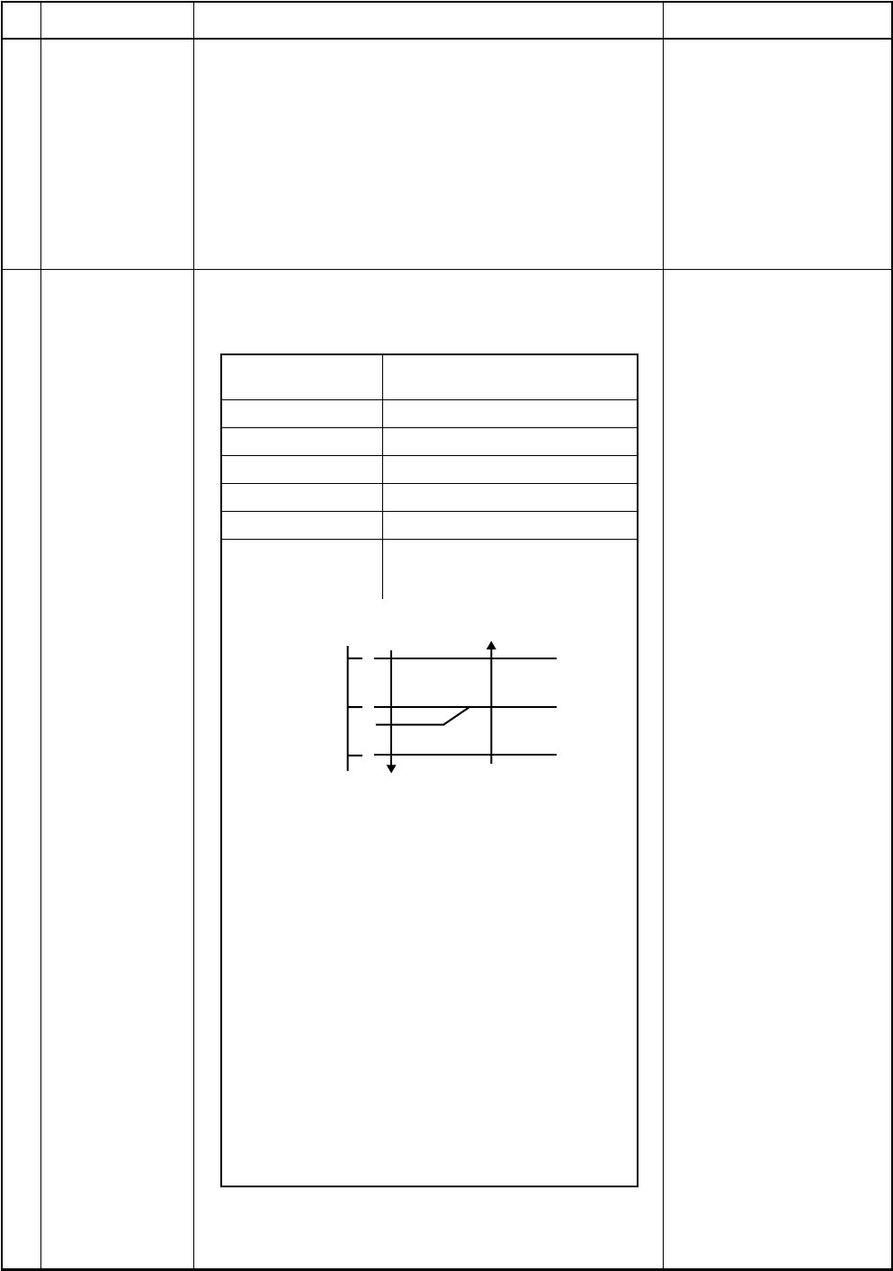
– 62 –
+1.5
Tsc
or Tsh
-1.5
Ta
(˚C) COOL
(COOL ON)
(COOL OFF)
HEAT
8-2. Control Specifications
No.
1
2
Item
When power
supply is reset
Operation mode
selection
Outline of specifications
1) Distinction of outdoor units
When the power supply is reset, the outdoors are
distinguished, and control is exchanged according to
the distinguished result.
2) Setting of speed of the indoor fan/setting whether to
adjust air direction or not.
(Only 4-way models)
Based on EEPROM data, speed of the indoor fan or
setting whether to adjust air direction or not is
selected.
1) Based on the operation mode selecting command
from the remote controller, the operation mode is
selected.
Remote controller
command
STOP
FAN
COOL
DRY
HEAT
AUTO
Outline of control
Air conditioner stops.
Fan operation
Cooling operation
Dry operation
Heating operation
•COOL/HEAT operation mode is
automatically selected by Ta
and Ts for operation.
1) Judge the selection of COOL/HEAT mode as shown
in the figure above.
When 10 minutes passed after thermostat had been
turned off, the heating operation (Thermo OFF) is
exchanged to cooling operation if Tsh exceeds +1.5
or more.
(COOL OFF) and (COOL ON) in the figure indicate
an example.
When 10 minutes passed after thermostat had been
turned off, the cooling operation (Thermo OFF) is
exchanged to heating operation if Tsc exceeds –1.5
or less.
2) For the automatic capacity control after judgment of
COOL/HEAT, refer to item 4.
3) For the temperature correction of room temperature
control in automatic heating operation, refer to item 3.
Remarks
Air speed/
Air direction adjustment
Ta : Room temperature
Ts : Setup temperature
Tsc : Setup temperature in
cooling operation
Tsh : Setup temperature
+ Room temperature
control temperature
compensation
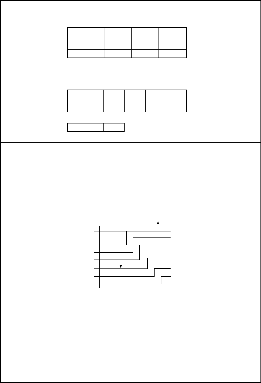
– 63 –
+3.0
Ta (˚C)
E
D
C
B
F
G
A
HH
(HH)
H (HH)
H (HH)
L(H)
L(H)
L(H)
L(L)
+2.0
+2.5
+1.5
+0.5
Tsc
-0.5
+1.0
No.
3
4
5
Item
Room
temperature
control
Automatic
capacity control
(GA control)
Air speed
selection
Outline of specifications
1) Adjustment range Remote controller setup tem-
perature (°C)
Wired type
Wireless type*
COOL/
DRY
18 to 29
18 to 30
Heating
operation
18 to 29
16 to 30
Auto
operation
18 to 29
17 to 27
* : Only for 4-way air discharge cassette type and
Under ceiling type
2) Using the item code 06, the setup temperature in
heating operation can be compensated.
Setup data
Setup temp.
compensation
0246
+0°C +2°C +4°C +6°C
Setting at shipment
Setup data 2
1) Based on the difference between Ta and Ts, the
operation frequency is instructed to the outdoor
unit.
1) Operation with (HH), (H), (L), or [AUTO] mode is
performed by the command from the remote control-
ler.
2) When the air speed mode [AUTO] is selected, the air
speed varies by the difference between Ta and Ts.
<COOL>
•Controlling operation in case when thermo of remote
controller works is same as a case when thermo of
the body works.
•If the air speed has been changed once, it is not
changed for 3 minutes. However when the air volume
is exchanged, the air speed changes.
•When cooling operation has started, the air speed
selects a downward slope, that is, the high position.
•If the temperature is just on the difference boundary,
the air speed does not change.
•Mode in the parentheses indicates one in automatic
cooling operation.
Remarks
Shift of suction tempera-
ture in heating operation
HH > H > L > LL
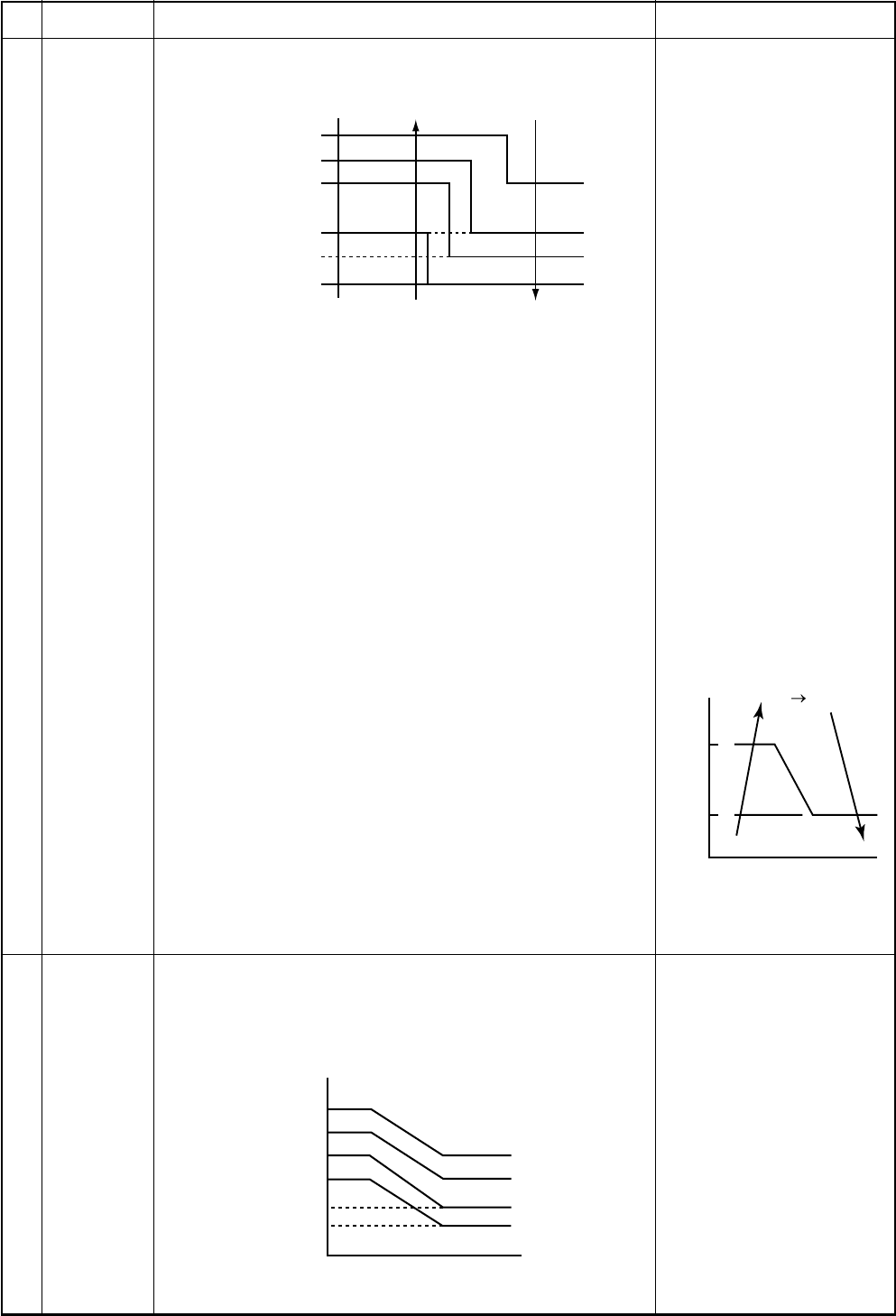
– 64 –
–1.0
Ta (˚C)
E
D
C
B
A
(-0.5) L(L)
L(H)
H(H)
H
HH
(HH)
(HH)
+1.0
(+0.5)
+2.0
(+1.0)
+3.0
(+1.5)
+4.0
(+2.0)
Tsh
(0)
F5 F4
47
42
F5
Tc
(˚C)
(˚C)
32
30
28
26
20
16
Tc
Tcj
HH
H
L
UL
OFF
E zone
D zone
C zone
B zone
A zone
No.
5
6
Item
Air speed
selection
(Continued)
Cool air
discharge
preventive
control
Outline of specifications
<HEAT>
Value in the parentheses indicates one when thermostat of
the remote controller works.
Value without parentheses indicates one when thermostat
of the body works.
•If the air speed has been changed once, it is not changed
for 1 minute. However when the air speed is exchanged,
the air speed changes.
•When heating operation has started, the air speed selects
a upward slope, that is, the high position.
•If the temperature is just on the difference boundary, the
air speed does not change.
•Mode in the parentheses indicates one in automatic
heating operation.
•In Tc ≥ 60°C, the air speed increases by 1 step.
•In heating operation, the mode changes to [LL] if thermo-
stat is turned off.
•If Ta ≥ 25°C when heating operation has started and when
defrost operation has been cleared, it operates with HIGH
(H) mode or (HH) for 1 minute from when Tc has entered
in E zone of cool air discharge preventive control (Item 6).
•In automatic cooling/heating operation, the revolution
frequency of [HH] is set larger than that in the standard
cooling/heating operation. However the revolution fre-
quency is restricted in the automatic heating operation as
shown in the following figure.
1) In heating operation, the indoor fan is controlled based
on the detected temperature of Tc sensor or Tcj sensor.
As shown below, the upper limit of the revolution fre-
quency is determined.
Remarks
Tc: Indoor heat exchanger
sensor temperature
[PRE-HEAT] display
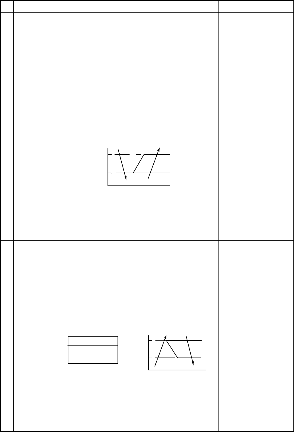
– 65 –
5
2
A
J
K
I
(˚C)
A
B
L
N
M
(˚C)Tc
Tcj
No.
7
8
Item
Freeze
preventive
control
(Low
temperature
release)
High-temp
release control
Outline of specifications
1) The cooling operation (including Dry operation) is
performed as follows based on the detected tempera-
ture of Tc sensor or Tcj sensor.
When [J] zone is detected for 6 minutes (Following
figure), the commanded frequency is decreased from
the real operation frequency. After then the com-
manded frequency changes every 30 seconds while
operation is performed in [J] zone.
In [K] zone, time counting is interrupted and the
operation is held.
When [I] zone is detected, the timer is cleared and the
operation returns to the normal operation.
If the commanded frequency becomes S0 because the
operation continues in [J] zone, the return temperature
A is raised from 5°C to 12°C until [I] zone is detected
and the indoor fan
operates with [M] mode.
In heating operation, the freeze-preventive control
works if 4-way valve is not exchanged and the condi-
tion is satisfied. (However the temperature for J zone
dashing control is changed from 2°C to –5°C.)
1) The heating operation is performed as follows based on
the detected temperature of Tc sensor or Tcj sensor.
•When [M] zone is detected, the commanded fre-
quency is decreased from the real operation fre-
quency. After then the commanded frequency
changes every 30 seconds while operation is per-
formed in [M] zone.
•In [N] zone, the commanded frequency is held.
•When [L] zone is detected, the commanded fre-
quency is returned to the original value by approx.
6Hz every 60 seconds.
Setup at shipment
Control temp (°C)
AB
56 (54) 52 (52)
NOTE :
When the operation has started or when Tc or Tcj became
lower than 30°C after start of the operation, temperature
is controlled between values in parentheses of A and B.
Remarks
Tcj : Indoor heat ex-
changer sensor
temperature
Same when thermostat is
turned off.
– 66 –
No.
9
10
11
Item
Drain pump control
After-heat
elimination
Louver control
(For 4-way air
discharge cassette
type only)
Outline of specifications
1) In cooling operation (including Dry operation), the
drain pump is usually operated.
2) If the float switch operates while drain pump
operates, the compressor stops, the drain pump
continues the operation, and a check code is
output.
3) If the float switch operates while drain pump stops,
the compressor stops and the drain pump oper-
ates. If the float switch keeps operating for approx.
4 minutes, a check code is output.
When heating operation stops, the indoor fan oper-
ates with LOW mode for approx. 30 seconds.
1) Louver position setup
•When the louver position is changed, the
position moves necessarily to downward dis-
charge position once to return to the set posi-
tion.
•The louver position can be set up in the follow-
ing operation range.
In cooling/dry operation In heating/fan operation
•In group twin/triple operation, the louver posi-
tions can be set up collectively or individually.
2) Swing setup
•The swinging position can be moved in the
following operation range.
All modes
•In group twin/triple operation, the swinging
positions can be set up collectively or individu-
ally.
3) When the unit stops or when a warning is output,
the louver automatically moves downward.
4) While the heating operation is ready, the louver
automatically moves upward.
Remarks
Check code [P10]
W arning :
A check code is displayed
on the remote controller,
and the indoor unit stops.
(Excluding [F08] and
[L31])

– 67 –
No.
12
13
Item
Frequency fixed
operation
(Test run)
Filter sign display
(Except wireless
type)
Outline of specifications
<In case of wired remote controller>
1. When pushing [CHECK] button for 4 seconds or more,
[TEST] is displayed on the display screen and the
mode enters in Test run mode.
2. Push [ON/OFF] button.
3. Using [MODE] button, change the mode from [COOL]
to [HEAT].
•Do not use other mode than [COOL]/[HEAT] mode.
•During test run operation, the temperature cannot be
adjusted.
•An error is detected as usual.
•A frequency fixed operation is performed.
4. After the test run, push [ON/OFF] button to stop the
operation. (Display in the display part is same as the
procedure in item 1).)
5. Push [CHECK] button to clear the test run mode.
([TEST] display in the display part disappears and the
status returns to the normal stop status.)
<In case of wireless remote controller>
(Option for 4-way air discharge cassette type only)
1. Turn off the power of the set.
Remove the adjuster with sensors from the ceiling
panel.
2. Turn Bit [1: TEST] of sensor P.C. board switch [S003]
from OFF to ON.
Attach the sensor P.C. board cover and mount the
adjuster with sensors to the ceiling panel.
Turn on the power of the set.
3. Push [ON/OFF] button of the wireless remote control-
ler and set the operation mode to [COOL] or [HEAT]
using [MODE] button.
(During test run operation, all the display lamps of
wireless remote controller sensors flash.)
•Do not use other mode than [COOL]/[HEAT] mode.
•An error is detected as usual.
•A frequency fixed operation is performed.
4. After the test run, push [ON/OFF] button to stop the
operation.
5. Turn off the power of the set.
Turn Bit [1: TEST] of sensor P.C. board switch [S003]
from ON to OFF.
Mount the adjuster with sensors to the ceiling panel.
1) The operation time of the indoor fan is calculated, the
filter reset signal is sent to the remote controller when
the specified time (2500H) has passed, and it is
displayed on LCD.
2) When the filter reset signal has been received from the
remote controller, time of the calculation timer is
cleared. In this case, the measurement time is reset if
the specified time has passed, and display on LCD
disappears.
Remarks
[FILTER] goes on.
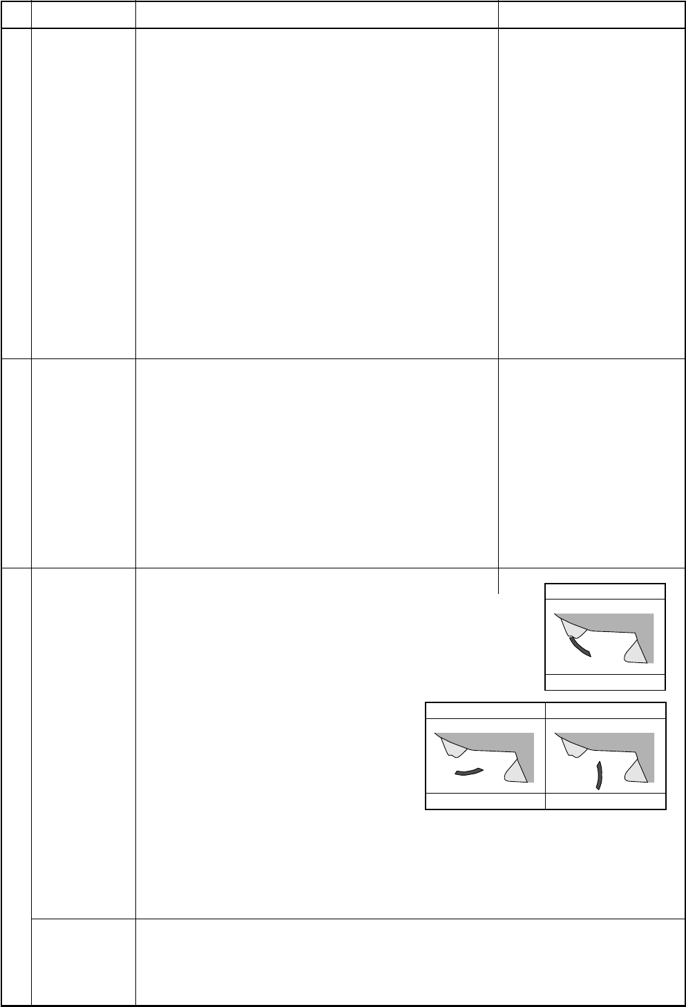
– 68 –
0˚
Full close
45˚103˚
Cooling Heating
No.
14
15
16
Item
Central control
mode selection
Energy-save
control
(By connected
outdoor unit)
Louver control
1) Louver
position
Outline of specifications
1) Setting at the central controller side enables to select
the contents which can be operated on the remote
controller at indoor unit side.
2) RBC-AMT31E
[Last push priority] :
The operation contents can be selected from both
remote controller and central controller of the indoor
unit side, and the operation is performed with the
contents selected at the last.
[Center] :
Start/Stop operation only can be handled on the remote
controller at indoor unit side.
[Operation Prohibited] :
It cannot be operated on the remote controller at indoor
unit side. (Stop status is held.)
2) Air direction
adjustment
(Swing
operation)
1) Selecting [AUTO] mode enables an energy-saving to be
operated.
2) The setup temperature is shifted (corrected) in the
range not to lose the comfort ability according to input
values of various sensors.
3) Data (Input value room temp. Ta, Outside temp. To, Air
volume, Indoor heat exchanger sensor temp. Tc) for 20
minutes are taken the average to calculate correction
value of the setup temperature.
4) The setup temperature is shifted every 20 minutes, and
the shifted range is as follows.
In cooling time : +1.5 to –1.0K
In heating time : –1.5 to +1.0K
The louver angle is displayed setting 0° as “Full close”.
1) In the initial operation after power-ON, the position is
automatically controlled according to the operating
status (COOL/HEAT).
2) After then a louver position is stored in the microcomputer every time when position
is operated on the remote controller, and the louver operates at the position stored
in memory in the next operation and after.
* If the operation mode has been changed from COOL to HEAT, from HEAT to
COOL, or the power has turned off, the stored louver position is cleared and the
status returns to one in item 1).
1) When pushing [LOUVER] button during operation, the louver starts swinging.
2) When the louver has arrived at the desired position, push [LOUVER] again.
The louver stops at that position.
Remarks
(No display)
[CENTER] goes on.
[CENTER] goes on.
In a case of wireless type, the
display lamp does not change.
However, contents which can
be operated are same.
The status set in [CENTER]/
[Operation Prohibited] mode is
notified with the receiving sound
“Pi, Pi, Pi, Pi, Pi” (5 times).
– 69 –
+4
+3
Tsc
Ta(˚C) Normal control
Max. frequency is restricted
to approximately the rated
cooling frequency
Tsh
–3
–4
Ta(˚C)
Normal control
Max. frequency is restricted
to approximately the rated
heating frequency
No.
17
18
Item
Max. frequency
cut control
DC motor
Outline of specifications
1) This control is operated by selecting [AUTO] operation
mode.
2) COOL operation mode: the frequency is controlled
according to the following figure if To < 28°C.
3) HEAT operation mode: the frequency is controlled
according to the following figure if To > 15°C.
It cannot be operated on the remote controller at indoor
unit side. (Stop status is held.)
1) When the fan operation has started, positioning of the
stator and the rotor are performed.
(Moves slightly with tap sound)
2) The motor operates according to the command from the
indoor controller.
NOTES :
•When the fan rotates while the air conditioner stops due to
entering of outside air, etc, the air conditioner may oper-
ated while the fan motor stops.
•When a fan locking is found, the air conditioner stops, and
an error is displayed.
Remarks
Check code [P12]
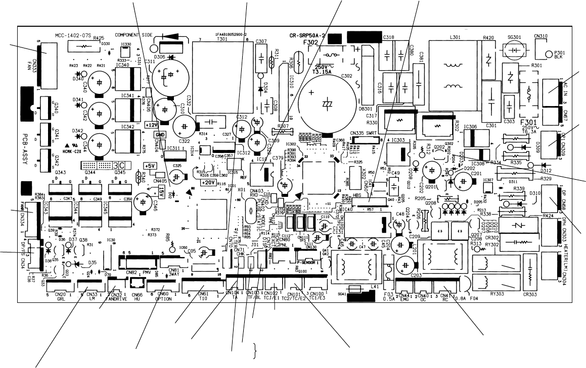
– 70 –
8-3. Indoor Print Circuit Board
8-3-1. 4-W ay Air Discharge Cassette Type / Concealed Duct Type / Under Ceiling Type
<MCC-1402>
DC fan output
DC fan return
Float SW
Louver
(Used only for 4-way Air
Discharge Cassette Type,Under ceiling type)
Fan output
Optional output TC sensor
HA (T10)
CHK
DISP
TA sensor Remote controller inter-unit cable
EXCT
Used for
servicing
TCJ sensor
*1
Drain pump output
Remote controller
power supply LED
Optional
power supply
Indoor/Outdoor
inter-unit cable
Filter/Option error input EEPROM Connection interface
Microcomputer operation LED
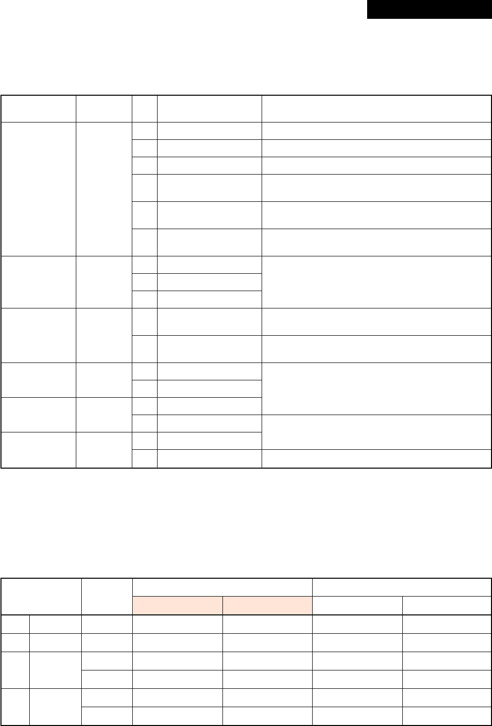
– 71 –
9. CIRCUIT CONFIGURATION AND CONTROL SPECIFICATIONS
9-1. Indoor Control Circuit
9-1-1. Indoor P.C. Board Optional Connector Specifications
9-2. Outdoor Controls
9-2-1. Print Circuit Board
P.C. Board Comparison Table for Digital Inverter
1: Applied
Function
Option output
Outside error
input
Filter option
error
CHK
Operation check
DISP display
mode
EXCT demand
Connector
No.
CN60
CN80
CN70
CN71
CN72
CN73
Pin
No.
1
2
3
4
5
6
1
2
3
1
2
1
2
1
2
1
2
Specifications
DC12V (COM)
Defrost output
Thermo. ON output
Cooling output
Heating output
Fan output
DC12V (COM)
DC12V (COM)
Outside error input
Filter/Option/Humidifier
setup input
0V
Check mode input
0V
Display mode input
0V
Demand input
0V
Remarks
ON during defrost operation of outdoor unit
ON during Real thermo-ON (Comp ON)
ON when operation mode is in cooling system
(COOL, DRY, COOL in AUTO cooling/heating)
ON when operation mode is in heating system
(HEAT, HEAT in AUTO cooling/heating)
ON during indoor fan ON
(Air purifier is used/Interlock cable)
(When continued for 1 minute)
Check code “L30” is output and forced operation stops.
Option error input is controlled. (Protective operation
for device attached to outside is displayed.)
* Setting of option error input is performed from remote
controller. (DN=2A)
Used for operation check of indoor unit.
(Communication with outdoor unit or remote controller
is not performed, but the specified operation such as
indoor fan “H” or drain pump ON is output.)
Display mode enables indoor unit and remote controller
to communicate. (When power is turned on)
Forced thermo-OFF operation in indoor unit
P.C. board
Main MCC-5009
Sub MCC-1530
CDB MCC-1531
IPDU MCC-1438
Part No.
4316V284
4316V293
4316V283
4316V282
4316V291
4316V278
Model name RAV -SM
563AT-E/803AT-E 1103AT-E/1403AT-E
1
1
1
1
Model name RAV -SP
562AT-E/802AT-E 1102AT-E/1402AT-E
11
1
1
Revised : Mar. 2007
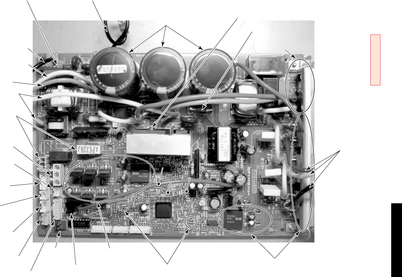
– 72 –
F01, 02, 25A fuse P.C. board earth lead
(Black)
DB01:
Single-phase rectifier diode
Comp. lead
(Red) (White) (Black)
DB02:
High power factor diode
Q404:
High power factor circuit IGBT
F03: 3.15A fuse
C12, 13, 14
electrolytic capacitor
CN500:
Case thermo
connector
Fan drive circuit
Q300 to Q305:
FET (QTY: 6P)
12V12V
5V5V
GNDGND
IC800: MCU
CN700:
PMV connector CN605:
Sub SW board connector J800 to 803, 806
Model switch jumper line
Comp. drive circuit
Q200 to Q205: IGBT (QTY: 6P)
IC200: Drive IG (QTY: 1P)
L-phase power supply lead
(Black)
N-phase power supply lead
(White)
Serial lead (Orange)
Reactor lead connector
(White)
CN300:
Fan motor connector
CN602:
Outdoor temperature
(TO) sensor connector
CN806:
Optional connector
CN600:
Heat exchange temperature
(TE) sensor connector
CN603:
Suction temperature
(TS) sensor connector
CN601:
Discharge temperature
(TD) sensor connector
CN701:
4-way valve connector
RY701:
4-way valve relay
IC800: MCU
DB01:
Single-phase rectifier diode
F03: 3.15A fuse
C12, 13, 14
electrolytic capacitor
<V iewed from parts of P.C board>
RAV -SM563AT-E, RAV -SM803AT-E
<MCC-5009>
Revised : Mar. 2007
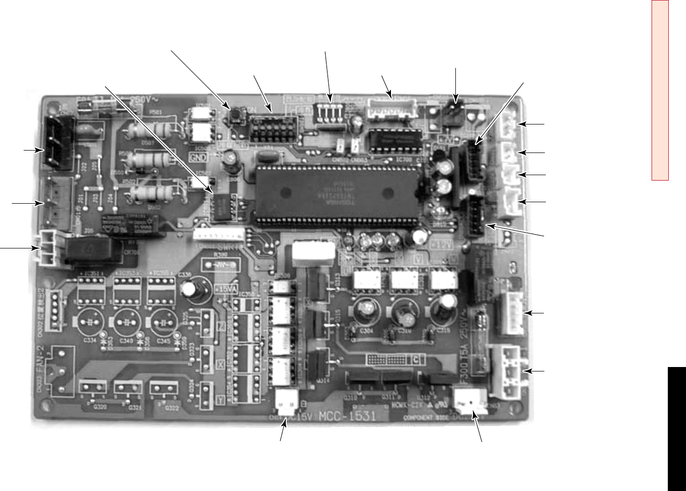
– 73 –
EEPROM-IC
IC801
Refrigerant recovery Switch
SW802
Model selection jumpers
(Available only service P.C. board)
J800 to J803
Dip switch
SW801 P.M.V. CN702 Case thermo. switch
CN500 Communication signal
(To MCC-1438)
CN800
TS sensor
CN605
Optional connector
CN804
TE sensor
CN604
TO sensor
CN601
TD sensor
CN600
Fan motor output
CN301
Fan motor revolution
CN300
DC15V input
(To MCC-1438)
CN04
DC320V input
(To MCC-1438)
CN03
Serial signal
(To terminal block)
CN02
AC input
(To MCC-1438)
CN01
4-way valve
CN700
RAV -SM1103AT-E, RAV -SM1403AT-E / RAV -SP562AT-E, RAV -SP802AT-E
<MCC-1531>
Revised : Mar. 2007
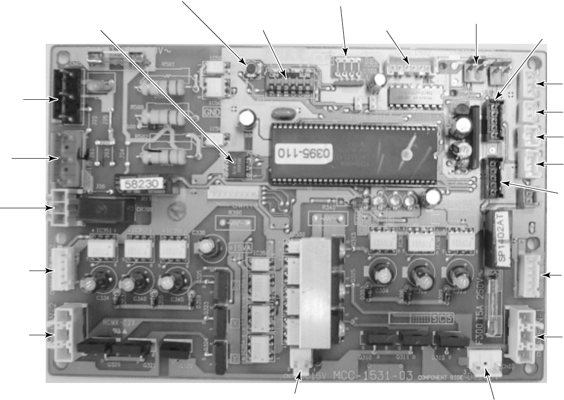
– 74 –
Model selection jumpers
(Available only service P.C. board)
J800 to J803
Refrigerant recovery Switch
SW802
Dip switch for service
SW801
EEPROM-IC
IC801 P.M.V. CN702 Case thermo. switch
CN500 Communication signal
(To MCC-1438)
CN800
TS sensor
CN605
Not use
CN804
TE sensor
CN604
TO sensor
CN601
TD sensor
CN600
Fan motor 1 (Upper)
output
CN301
Fan motor 1 (Upper)
revolution
CN300
DC15V input
(To MCC-1438)
CN04
DC320V input
(To MCC-1438)
CN03
Serial signal
(To terminal block)
CN02
AC input
(To MCC-1438)
CN01
4-way valve
CN700
Fan motor 2 (Lower)
revolution
CN302
Fan motor 2 (Lower)
output
CN303
RAV -SP1102AT-E, RAV -SP1402AT-E
<MCC-1531>
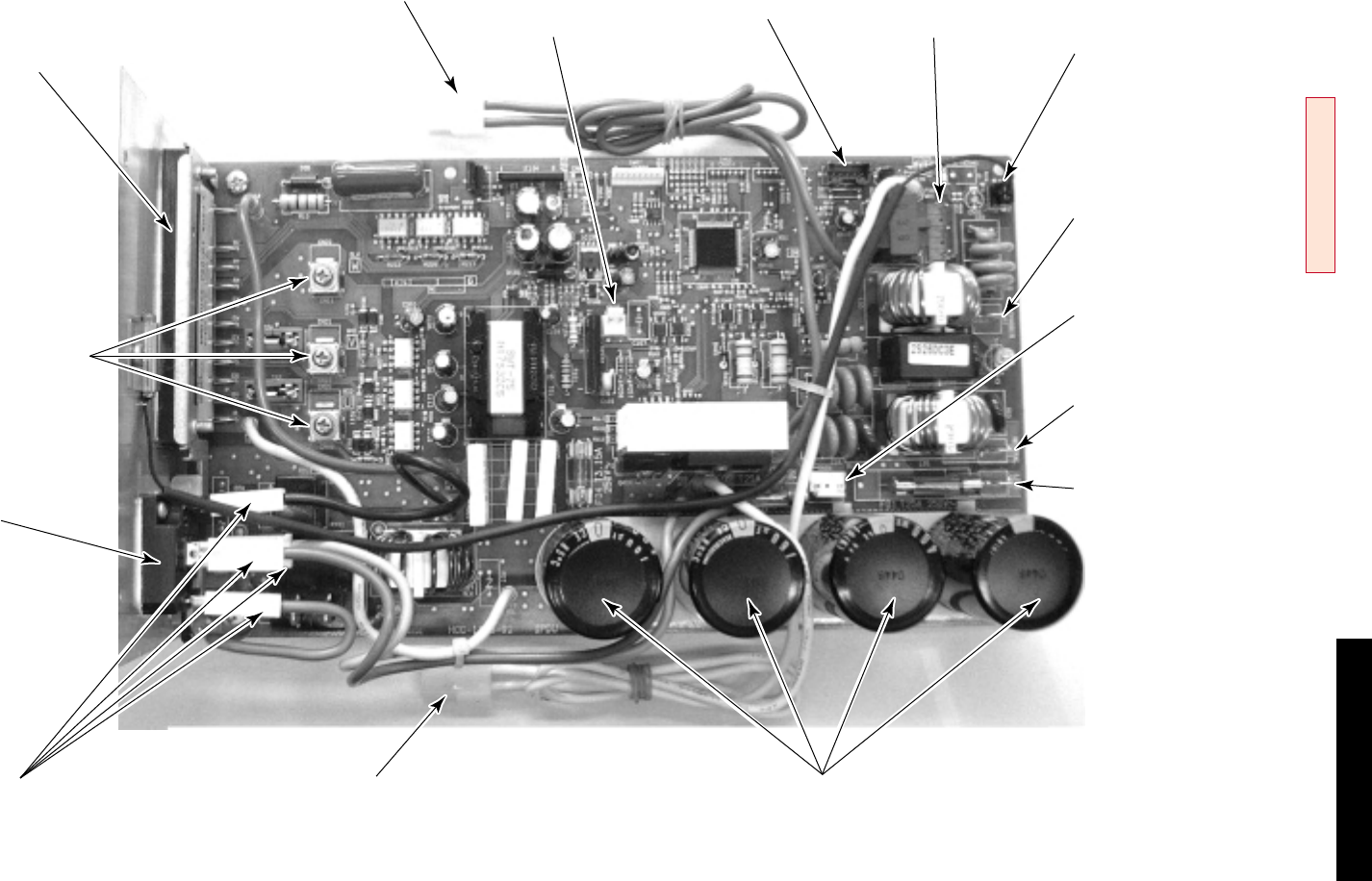
– 75 –
IGBT
(Compressor drive device)
Compressor output
CN09, CN10, CN11
Reactor connector DC15V output
(To MCC-1531)
CN05
Communication signal
(To MCC-1531)
CN06
AC output
(To MCC-1531)
CN13
Rectifier connectors
P29 (Red), P28 (Black),
P21 (Orange), P24 (Brown)
Reactor Connector Capacitor
Mains (Neutral) input
CN02
Mains (Live) input
CN01
DC320V output
(To MCC-1531)
CN04
Earth ground
CN03
TH sensor
CN600
Rectifier
RAV -SM1103AT-E, RAV -SM1403AT-E /
RAV -SP562AT-E, RAV -SP802AT-E, RAV -SP1102AT-E, RAV -SP1402AT-E
<IPDU : MCC-1438>
Revised : Mar. 2007
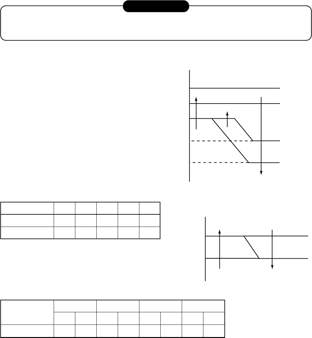
– 76 –
9-2-2. Outline of Main Controls
1. Pulse Modulating V alve (PMV ) control
1) For PMV with 50 to 500 pulses during operation, respectively.
2) In cooling operation, PMV is controlled with the temperature difference between TS sensor and TC
sensor.
3) In heating operation, PMV is controlled with the temperature difference between TS sensor and TE
sensor.
4) For the temperature difference in items 2) and 3), 1 to 5K is aimed as the target in both cooling and
heating operations.
5) When the cycle excessively rose in both cooling and heating operations, PMV is controlled by TD
sensor.
The aimed value is usually 103°C for SM56, SM80 and 100°C for SM110, SM140 in both cooling and
heating operations.
REQUIREMENT
A sensor trouble may cause a liquid back-flow or abnormal overheat resulting in excessive shortening of the
compressor life. In a case of trouble on the compressor, be sure to check there is no error in the resistance
value an the refrigerating cycle of each sensor after repair and then start the operation.
2. Discharge temperature release control
1) This function controls the operation frequency, that
is, lowers the operation frequency when the
discharge temperature has not lower or the
discharge temperature has rapidly risen during
PMV control. It subdivides the frequency control
up to a unit of 0.6 Hz to stabilize the cycle.
2) When the discharge temperature is detected in an
abnormal stop zone, the unit stops the compres-
sor and restarts after 2 minutes 30 seconds. The
error counter is cleared when it has continued the
operation for 10 minutes.
If the abnormal stop zone has been detected by 4
times without clearing of counter, an error “P03” is
displayed.
* The cause is considered as excessively little
amount of refrigerant, defective PMV, or clogging
of cycle.
[°C]
3. Current release control
The output frequency and the output voltage are
controlled by AC current value detected by T02 on the
outdoor P.C. board so that input current of the inverter
does not exceed the specified value.
Objective model
I1 value [A]
SM56 SM80 SM110 SM140
COOL HEAT COOL HEAT COOL HEAT COOL HEAT
10.1 12.0 12.2 14.0 18.9 19.7 19.7 19.7
SM56, SM80
SM110, SM140
abcde
117 107 103 100 93
111 106 100 95 90
a
b
c
d
e
TD [˚C]
Error stop ("P03" display with 4 times of error counts)
As command is
Frequency down
Frequency holding
Frequency slow-up
(Up to command)
I1
I1–0.5
Current [A]
Frequency down
Normal operation
Hold
Hold
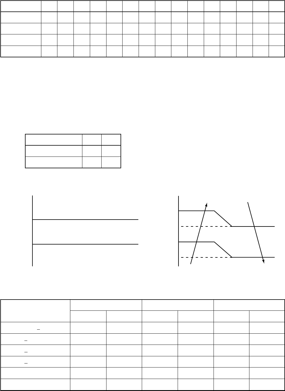
– 77 –
4. Outdoor fan control
Allocations of fan tap revolutions [rpm]
SM56
SM80
SM110
SM140
W1 W2 W3 W4 W5 W6 W7 W8 W9 WA WB WC WD WE WF
200 300 350 410 480 500 530 560 640 670 700 750 800 840 840
200 300 350 410 480 500 530 560 640 670 700 750 840 940 980
250 280 320 360 410 460 520 580 640 700 760 860 860 900 930
250 280 320 360 410 460 520 580 640 700 760 860 860 900 970
1) Cooling fan control
QThe outdoor fan is controlled by TE, TD, and TO sensors and also revolution frequency of the opera-
tion. The outdoor is controlled by every 1 tap of DC fan control (15 taps).
ROnly during 60 seconds after the operation has started, the fan is fixed with the maximum fan tap
which corresponds to the zone in the following table.
After then the fan is controlled by TE sensor temperature.
SConsidering a case that TE sensor has come out of the holder, the fan is controlled so that revolution
frequency of the fan increases regardless of TE if temperature of TD sensor has risen.
(The operation frequency differs according to the model type.)
SM56, SM80
SM110, SM110
ab
36 32
29 26
Temp. range
29°C < TO
15 < TO < 29°C
5 < TO < 15°C
0 < TO < 5°C
TO < 0°C
TO error
Below 30Hz Above 30 Hz below 45 Hz Above 45 Hz
Min. Max. Min. Max. Min. Max.
W5 WA W7 WC W9 WF
W3 W7 W5 W9 W7 WB
W2 W5 W4 W7 W6 W9
W1 W3 W3 W5 W4 W7
W1 W2 W2 W4 W3 W5
W1 WF W1 WF W1 WF
+1 tap/20 seconds
rpm hold
–1 tap/20 seconds
Operation with
maximum tap in
each zone
Usual fan control
a
b
TE [˚C]
TD [˚C]
85
80
75
65
Operation with WE
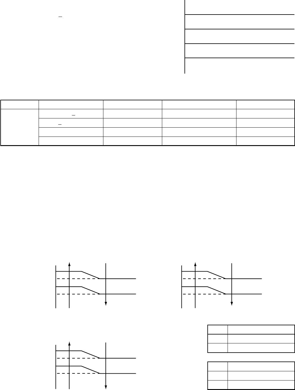
– 78 –
2) Heating fan control
QThe outdoor fan is controlled by TE sensor, TO sensor and the operation frequency.
(From Min. W1 to Max. are controlled according to the following table.)
RDuring 3 minutes after start-up, the fan is fixed
with the maximum fan tap corresponding to
zone in the following table. After then the fan is
controlled by temperature of TE sensor.
SIf status, TE > 24°C continues for 5 minutes, the
operation stops. This status is same to the
usual Thermo-OFF which has no alarm display,
and the fan restarts after 2 minutes and 30
seconds. This intermittent operation is not
abnormal.
TWhen the above status R occurs frequently, it
is considered that the filter of suction part of the
indoor unit is stain. Clean the filter and then
restart the operation.
(The operation frequency differs according to the model type. The case of SM110 is shown in the table below.)
5. Coil heating control
1) This control function heats the compressor by turning on the stopped compressor instead of a case
heater. It purposes to prevent slackness of the refrigerant inside of the compressor.
2) As usual, turn on power of the compressor for the specified time before a test run after installation,
otherwise a trouble of the compressor may be caused. As same as a test run, it is recommended to turn
on power of the compressor beforehand when starting operation after power of the compressor has been
interrupted for a long time.
3) A judgment for electricity is performed by TD and TO sensors. If TO sensor is defective, a backup control
is automatically performed by TE sensor. For a case of defective TO sensor, judge it with the outdoor LED
display.
4) Coil heating is controlled by TD and TE sensor.
5) For every model, the power is turned off when TD is 30°C or more.
Maximum
Temp. range
10°C < TO
5 < TO < 10°C
TO < 5°C
TO error
Below 33 Hz
W7
WA
WF
WF
Above 33 Hz below 51 Hz
W8
WB
WF
WF
Above 51 Hz
W9
WF
WF
WF
L
M
L
H
SM110, SM140
20W and equivalent
40W and equivalent
SM56, SM80
10W and equivalent
30W and equivalent
–2 tap/20 seconds
–1 tap/20 seconds
rpm hold
+1 tap/20 seconds
–2 tap/20 seconds
STOP timer count
24
21
18
15
TE [˚C]
* TD sensor is read in once per 15 minutes * TO sensor is read in once per 15 minutes.
No power-ON
Continuous ON (L)
Continuous ON (M)
No power-ON
Continuous ON (L)
Continuous ON (H)
No power-ON
Continuous ON (L)
Continuous ON (M)
Power-ON condition
TD < 30˚C
(In trouble of TE sensor)
(Object: SM56, SM80)
TO [˚C] TE [˚C]
TE [˚C]
20
18
12
10
18
15
10
8
0
–1
–6
–7
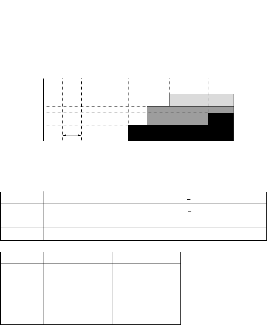
– 79 –
6. Defrost control
QIn heating operation, defrost operation is performed when TE sensor temperature satisfies any condition
in A zone to D zone.
RThe defrost operation is immediately finished if TE sensor temperature has become 12°C or more, or it
also is finished when condition of 7°C < TE < 12°C has continued for 1 minute. The defrost operation is
also finished when defrost operation has continued for 10 minutes even if TE sensor temperature has
become 7°C or lower.
SAfter defrost operation has finished, the compressor and the outdoor fan start heating operation after
stopped for approx. 50 seconds.
Start of heating operation
* The minimum TE value between 10 and 15 minutes after heating operation has started is stored in memory as TE0.
0 10 15 c b a d [min.]
*
TE [ºC]
–4 (–5)
–6 (–10)
–10 (–13)
–25 (–18)
Numerals enclosed with parentheses represent numeral values of SM110 and SM140.
A z
A z
one
one
B z
B z
one
one
C z
C z
one
one
D z
D z
one
one
A zone
B zone
C zone
D zone
A zone
B zone
C zone
D zone
Defrost operation is performed in this zone when TE0-TE > 3 continued for T seconds.
Defrost operation is performed in this zone when TE0-TE > 3 continued for T seconds.
Defrost operation is performed when this zone continued for T seconds.
Defrost operation is performed when this zone continued for T seconds.
a
b
c
d
T
SM56, SM80 SM110, SM140
35 50
29 35
29 30
90 90
20 20

– 80 –
10. TROUBLESHOOTING
10-1. Summary of Troubleshooting
<W ired remote controller type>
1. Before troubleshooting
1) Required tools/instruments
•
+
and
–
screwdrivers, spanners, radio cutting pliers, nippers, push pins for reset switch
•Tester, thermometer, pressure gauge, etc.
2) Confirmation points before check
a) The following operations are normal.
1. Compressor does not operate.
•Is not 3-minutes delay (3 minutes after compressor OFF)?
•Does not thermostat turn off?
•Does not timer operate during fan operation?
•Is not outside high-temperature operation controlled in heating operation?
2. Indoor fan does not rotate.
•Does not cool air discharge preventive control work in heating operation?
3. Outdoor fan does not rotate or air volume changes.
•Does not high-temperature release operation control work in heating operation?
•Does not outside low-temperature operation control work in cooling operation?
•Is not defrost operation performed?
4. ON/OFF operation cannot be performed from remote controller.
•Is not the control operation performed from outside/remote side?
•Is not automatic address being set up?
(When the power is turned on at the first time or when indoor unit address setting is changed, the
operation cannot be performed for maximum approx. 5 minutes after power-ON.)
b) Did you return the cabling to the initial positions?
c) Are connecting cables of indoor unit and remote controller correct?
2. Troubleshooting procedure
When a trouble occurred, check the parts along with the following procedure.
Trouble Confirmation of check code display Check defective position and parts.
→→
NOTE :
For cause of a trouble, power conditions or malfunction/erroneous diagnosis of microcomputer due to outer
noise is considered except the items to be checked. If there is any noise source, change the cables of the
remote controller to shield cables.

– 81 –
<W ireless remote controller type> (For 4-way air discharge cassette type only models)
1. Before troubleshooting
1) Required tools/instruments
•
+
and
–
screwdrivers, spanners, radio cutting pliers, nippers, etc.
•Tester, thermometer, pressure gauge, etc.
2) Confirmation points before check
a) The following operations are normal.
1. Compressor does not operate.
•Is not 3-minutes delay (3 minutes after compressor OFF)?
•Does not thermostat turn off?
•Does not timer operate during fan operation?
•Is not outside high-temperature operation controlled in heating operation?
2. Indoor fan does not rotate.
•Does not cool air discharge preventive control work in heating operation?
3) Outdoor fan does not rotate or air volume changes.
•Does not high-temperature release operation control work in heating operation?
•Does not outside low-temperature operation control work in cooling operation?
•Is not defrost operation performed?
4) ON/OFF operation cannot be performed from remote controller.
•Is not forced operation performed?
•Is not the control operation performed from outside/remote side?
•Is not automatic address being set up?
a) Did you return the cabling to the initial positions?
b) Are connecting cables between indoor unit and receiving unit correct?
2. Troubleshooting procedure
(When the power is turned on at the first time or when indoor unit address setting is changed, the operation
cannot be performed for maximum approx. 5 minutes after power-ON.)
When a trouble occurred, check the parts along with the following procedure.
1) Outline of judgment
The primary judgment to check where a trouble occurred in indoor unit or outdoor unit is performed with
the following method.
Method to judge the erroneous position by flashing indication on the display part of indoor unit
(sensors of the receiving unit)
The indoor unit monitors operating status of the air conditioner, and the blocked contents of self-diagnosis
are displayed restricted to the following cases if a protective circuit works.
Trouble →→
Confirmation of lamp display
(When 4-way air discharge cassette type
wireless remote controller is connected)
Check defective
position and parts.

– 82 –
10-2. Check Code List
Error mode detected by indoor and outdoor units ¥: Flash, ¡: Go on, l: Go off
Wireless sensor
lamp display
Operation
Timer Ready
¥ll
ll
¥
¥ll
¥ll
¥ll
¥¥
l
¥¥
l
¥¥¡
¥¥¡
¥¥¡
¥¥
l
¥¥
l
¥ll
l¥l
l¥l
¥l¥
¥l¥
¥l¥
Wired remote
controller
Check code
E03
E04
E08
E10
E18
F01
F02
F04
F06
F08
F10
F29
H01
H02
H03
L03
L07
L08
Diagnostic function
Cause of operation
No communication from remote controller (including wireless)
and communication adapters
The serial signal is not output from outdoor unit to indoor unit.
• Miscabling of inter-unit cables
• Defective serial sensing circuit on outdoor P.C. board
• Defective serial receiving circuit on indoor P.C. board
Duplicated indoor unit addresses
Communication error between indoor MCU
• Communication error between fan driving MCU and main
MCU
Regular communication error between master and sub indoor
units or between main and sub indoor units
Coming-off, disconnection or short of indoor heat exchanger
sensor (TCJ)
Coming-off, disconnection or short of indoor heat exchanger
sensor (TC)
Coming-off, disconnection or short of outdoor temperature
sensor (TD)
Coming-off, disconnection or short of outdoor temperature
sensor (TE/TS)
Coming-off, disconnection or short of outdoor temperature
sensor (TO)
Coming-off, disconnection or short of indoor heat exchanger
sensor (TA)
Indoor EEPROM error
• EEPROM access error
Breakdown of compressor
• Displayed when error is detected
Compressor does not rotate.
• Over-current protective circuit operates after specified time
passed when compressor had been activated.
Current detection circuit error
• Current value at AC side is high even during compressor-OFF.
• Phase of power supply is missed.
Duplicated indoor master units
There is group line in individual indoor units.
Unsetting of indoor group address
Status of air
conditioner
Stop
(Automatic reset)
S top
(Automatic reset)
Stop
Stop
(Automatic reset)
Stop
(Automatic reset)
Stop
(Automatic reset)
Stop
(Automatic reset)
Stop
Stop
Operation
continues.
Stop
(Automatic reset)
Stop
(Automatic reset)
Stop
Stop
Stop
Stop
Stop
Stop
Condition
Displayed when
error is detected
Displayed when
error is detected
Displayed when
error is detected
Displayed when
error is detected
Displayed when
error is detected
Displayed when
error is detected
Displayed when
error is detected
Displayed when
error is detected
Displayed when
error is detected
Displayed when
error is detected
Displayed when
error is detected
Displayed when
error is detected
Displayed when
error is detected
Displayed when
error is detected
Displayed when
error is detected
Displayed when
error is detected
Displayed when
error is detected
Displayed when
error is detected
Judgment and measures
1. Check cables of remote controller and communication adapters.
• Handy remote controller LCD display OFF (Disconnection)
• Central remote controller [97] check code
1. Outdoor unit does not completely operate.
• Inter-unit cable check, correction of miscabling, case thermo operation
• Outdoor P.C. board check, P.C. board cables check
2. In normal operation
P.C. board (Indoor receiving/Outdoor sending) check
1. Check whether there is modification of remote controller connection (Group/
Individual) or not after power has been turned on (finish of group configuration/
address check).
* If group configuration and address are not normal when the power has been turned
on, the mode automatically shifts to address setup mode. (Resetting of address)
1. Check cables of remote controller.
2. Check power cables of indoor unit.
3. Check indoor P.C. board.
1. Check cables of remote controller.
2. Check indoor power cable.
3. Check indoor P.C. board.
1. Check indoor heat exchanger temperature sensor (TCJ).
2. Check indoor P.C. board.
1. Check indoor heat exchanger temperature sensor (TC).
2. Check indoor P.C. board.
1. Check outdoor temperature sensor (TD).
2. Check outdoor CDB P.C. board.
1. Check outdoor temperature sensor (TE/TS).
2. Check outdoor CDB P.C. board.
1. Check outdoor temperature sensor (TO).
2. Check outdoor CDB P.C. board.
1. Check indoor heat exchanger temperature sensor (TA).
2. Check indoor P.C. board.
1. Check indoor EEPROM. (including socket insertion)
2. Check indoor P.C. board.
1. Check power voltage. AC230V ±20V
2. Overload operation of refrigerating cycle
3. Check current detection circuit at AC side.
1. Trouble of compressor (Compressor lock, etc.) : Replace compressor.
2. Defective cabling of compressor (Phase missing)
3. Phase-missing operation of power supply (3-phase model)
1. Compressor immediately stops even if restarted. : Check IPDU.
2. Phase-missing operation of power supply
Check 3-phase power voltage and cables.
1. Check whether there is modification of remote controller connection (Group/
Individual) or not after power has been turned on (finish of group configuration/
address check).
* If group configuration and address are not normal when the power has been turned
on, the mode automatically shifts to address setup mode. (Resetting of address)

– 83 –
¥: Flash, ¡: Go on, l: Go off
For an error mode detected in outdoor unit, the fan operates because sub unit of a group operation does not communicate with the outdoor unit.
Wireless sensor
lamp display
Operation
Timer Ready
¥l¥
l¥l
¥¡¥
¥¡¥
¥l¥
¥l¥
l¥¥
l¥¥
¥l¥
¥l¥
¥l¥
¥l¥
¥l¥
Wired remote
controller
Check code
L09
L29
L30
L31
P03
P04
P10
P12
P19
P22
P26
P29
P31
No check code is displayed.
Diagnostic function
Cause of operation
Unset indoor capacity
Outdoor unit and other errors
•Communication error between CDB and IPDU
(Coming-off of connector)
•Heat sink temperature error
(Detection of temperature over specified value)
Abnormal outside interlock input
Phase detection protective circuit operates. (Normal models)
Fan motor thermal protection
Discharge temperature error
•Discharge temperature over specified value was detected.
High-pressure protection error by TE sensor
(Temperature over specified value was detected.)
Float switch operation
•Disconnection, coming-off, defective float switch contactor of float
circuit
Indoor DC fan error
Error in 4-way valve system
•Indoor heat exchanger temperature lowered after start of heating
operation.
Outdoor DC fan error
Inverter over-current protective circuit operates. (For a short time)
Short voltage of main circuit operates.
IPDU position detection circuit error
Own unit stops while warning is output to other indoor units.
Status of air
conditioner
Stop
Stop
Stop
Operation continues.
(Compressor stops.)
Stop
Stop
Stop
Stop
Stop
Stop
(Automatic reset)
Stop
Stop
Stop
Stop (Sub unit)
(Automatic reset)
Condition
Displayed when
error is detected
Displayed when
error is detected
Displayed when
error is detected
Displayed when
error is detected
Displayed when
error is detected
Displayed when
error is detected
Displayed when
error is detected
Displayed when
error is detected
Displayed when
error is detected
Displayed when
error is detected
Displayed when
error is detected
Displayed when
error is detected
Displayed when
error is detected
Displayed when
error is detected
Judgment and measures
1. Set the indoor capacity. (DN=I1)
1. Check cables of CDB and IPDU.
2. Abnormal overload operation of refrigerating cycle
1. Check outside devices.
2. Check indoor P.C. board.
1. Check power phase order (Reversed phase)/phase missing.
2. Check outdoor P.C. board.
1. Check thermal relay of fan motor.
2. Check indoor P.C. board.
1. Check refrigerating cycle. (Gas leak)
2. Trouble of PMV
3. Check Td sensor.
1. Overload operation of refrigerating cycle
2. Check outdoor temperature sensor (TE).
3. Check outdoor CDB P.C. board.
1. Defect of drain pump
2. Clogging of drain pump
3. Check float switch.
4. Check indoor P.C. board.
1. Defective detection of position
2. Over-current protective circuit of indoor fan driving unit operates.
3. Lock of indoor fan
4. Check indoor P.C. board.
1. Check 4-way valve.
2. Check indoor heat exchanger (TC/TCJ) sensor.
3. Check indoor P.C. board.
1. Defective detection of position
2. Over-current protective circuit of outdoor fan driving unit operates.
3. Lock of outdoor fan
4. Check outdoor CDB P.C. board.
1. Inverter immediately stops even if restarted. : Compressor motor rare short
2. Check IPDU. : Cabling error
1. Position detection circuit operates even if operating compressor by
removing 3P connector. : Replace IPDU.
1. Judge sub unit while master unit is in [E03], [L03], [L07], [L08].
2. Check indoor P.C. board.
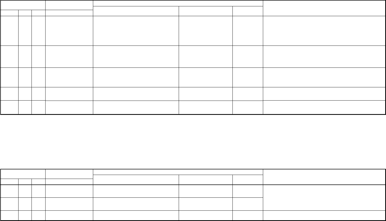
– 84 –
Error mode detected by remote controller
Error mode detected by central remote controller
¥: Flash, ¡: Go on, l: Go off
¥: Flash, ¡: Go on, l: Go off
Wireless sensor
lamp display
Operation
Timer Ready
———
———
———
Wired remote controller
Check code
C05
C06
P30
Diagnostic function
Cause of operation
Sending error central remote controller
Receiving error in central remote controller
Differs according to error contents of unit with
occurrence of alarm.
Status of
air conditioner
Operation continues
Operation continues
Continuation/Stop
(Based on a case)
Condition
Displayed when
error is detected
Displayed when
error is detected
Displayed when
error is detected
Judgment and measures
1. Check communication line/miscabling/ Check power of indoor unit.
2. Check communication. (U3, U4 terminals)
3. Check network adapter P.C. board.
4. Check central controller
(such as central control remote controller, etc.).
5. Terminal resistance check (connection interface SW01)
Check the check code of corresponding unit by remote controller
Wireless sensor
lamp display
Operation
Timer Ready
———
¥ll
¥ll
¥ll
¥¡¥
Wired remote controller
Check code
No check code is displayed.
(Remote controller does
not operate.)
E01*2
E02
E09
L20
Diagnostic function
Cause of operation
No communication with master indoor unit
•Remote controller cable is not correctly
connected.
•Power of indoor unit is not turned on.
•Automatic address cannot be completed.
No communication with indoor master unit
•Disconnection of inter-unit cable between remote
controller and master indoor unit
(Detected at remote controller side)
Signal sending error to indoor unit
(Detected at remote controller side)
Multiple master remote controllers are recognized.
(Detected at remote controller side)
Duplicated indoor central addresses on
communication of central control system
(Detected by central controller side)
Status of
air conditioner
Stop
Stop
(Automatic restart)
* When there is center,
operation continues
Stop
(Automatic restart)
* When there is center,
operation continues.
Stop
(Sub unit continues operation.)
Stop
(Automatic restart)
Condition
—
Displayed when
error is detected
Displayed when
error is detected
Displayed when
error is detected
Displayed when
error is detected
Judgment and measures
Remote controller power error, Defective indoor EEPROM
1. Check remote controller inter-unit cables.
2. Check remote controller.
3. Check indoor power cables.
4. Check indoor P.C. board.
5. Check indoor EEPROM. (including socket insertion)
: Phenomenon of automatic address repetition occurred.
Signal receiving of remote controller is defective.
1. Check remote controller inter-unit cables.
2. Check remote controller.
3. Check indoor power cables.
4. Check indoor P.C. board.
Signal sending of remote controller is defective.
1. Check sending circuit inside of remote controller.
: Replace remote controller.
1. Check there are multiple master units for 2 remote controllers
(including wireless).
: Master unit is one and others are sub units.
1. Check address setup of central control system network. (DN = 03)
*2 Check code is not displayed by wired remote controller. (Usual operation of air conditioner is disabled.)
For wireless type models, E01 is notified by the display lamp.
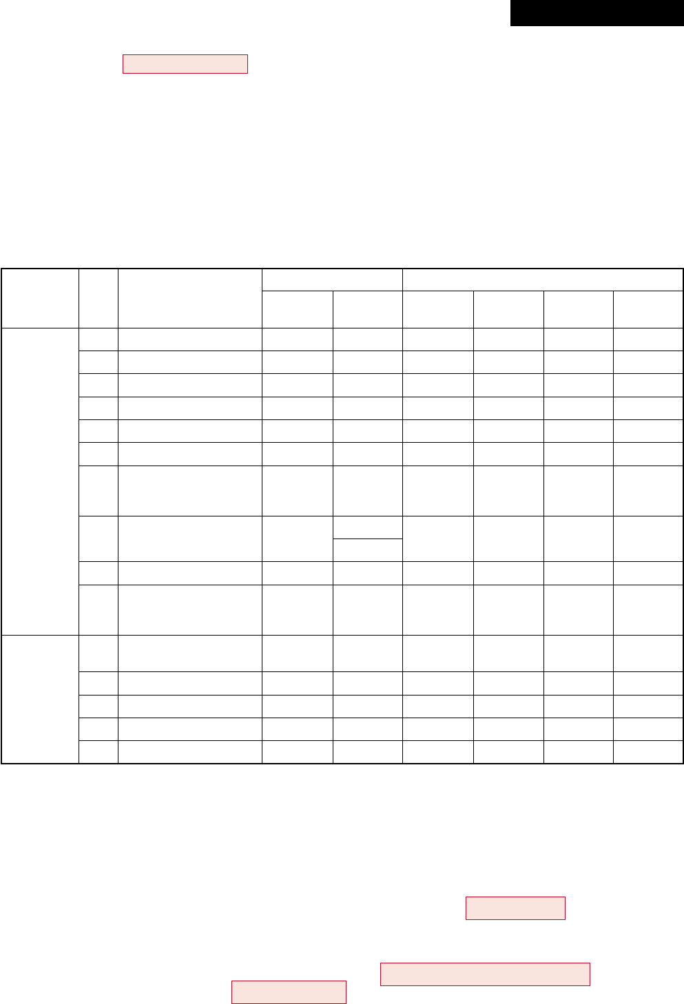
– 85 –
¡ : Go on l : Go off ¥ : Flash (5Hz)
<<Check code>>
The check codes are classified into Type A and Type B according to the used remote controller.
Be sure to check the remote controller which you use.
Type A :
Neutral 2-cores type wired remote controller such as RBC-AMT31E, RBC-AS21E2, and wireless
remote controller kit such as TCB-AX21U (W)-E2.
Type B :
Polarized 3-cores type wired remote controller such as RBC-SR1-PE2, RBC-SR2-PE2, and central
control remote controller such as RBC-CR64-PE2.
CDB side
IPDU side
No.
1
2
3
4
5
6
7
8
9
10
11
12
13
14
15
Item
TE sensor error
TD sensor error
TS sensor error
TO sensor error
Discharge temp. error
DC outdoor fan error
Communication error
between IPDU
(Abnormal stop)
High-pressure release
operation
EEPROM error
Communication error
between IPDU
(No abnormal stop)
IGBT short-circuit
protection
Detection circuit error
Current sensor error
Comp. lock error
Comp. breakdown
Check code
Type A Type B
F06 18
F04 19
F06 18
F08 1B
P03 1E
P22 1A
L29 1C
P04 21
—
——
——
P26 14
P29 16
H03 17
H02 1D
H01 1F
LED display
D800 D801 D802 D803
(Red) (Yellow) (Yellow) (Yellow)
¡lll
¡¡ll
ll¡l
l¡ll
l¡¡
l
¡¡¡
l
¡ll
¡
l¡l¡
¡¡l¡
ll¡¡
¥lll
l¥ll
¥¥ll
ll¥l
¥l¥l
10-3. Error Mode Detected by LED on Outdoor P.C. Board
RAV-SM1103AT-E, RAV-SM1403AT-E /
RAV-SP562AT-E, RAV-SP802AT-E, RAV-SP1102AT-E, RAV-SP1402AT-E
<SW801: LED display in bit 1, bit 2 OFF>
• When multiple errors are detected, the latest error is displayed.
• When LED display is ¡ (Go on), there is the main cause of trouble on the objective part of control at CDB
side and the unit stops.
• When LED display is ¥ (Flash), there is the main cause of trouble on the objective part of control at IPDU
side and the unit stops.
• When case thermostat operates, the communication is interrupted on the serial circuit. If continuing the case
thermostat operation, a serial communication error occurs because serial sending to the indoor unit is
interrupted.
Revised : Mar. 2007
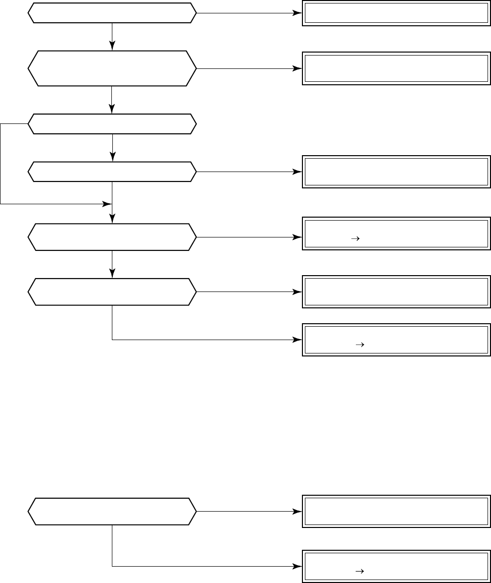
– 86 –
Is inter-unit cable of A and B normal?
Is there no disconnection
or contact error of connector on harness
from terminal block of indoor unit?
Is group control operation?
Is power of all indoor units turned on?
Is power supplied to remote controller?
AB terminal: Approx. DC18V
Are two remote controllers
set without master unit?
Are two remote controllers
set without master unit?
Correct inter-unit cable of remote controller.
Correct connection of connector.
Check circuit cables.
Check power connection of indoor unit.
(Turn on power again.)
Check indoor P.C. board (MCC-1402).
Defect Replace
Correct as a master unit/a sub unit
(Remote controller address connector)
Check remote controller P.C. board.
Defect Replace
Correct as a master unit/a sub unit
(Remote controller address connector)
Check remote controller P.C. board.
Defect Replace
NO
YES
NO
NO
NO
YES
YES
YES
NO
YES
YES
YES
NO
NO
10-4. Troubleshooting Procedure for Each Check Code
10-4-1. Check Code
[E01 error]
[E09 error]
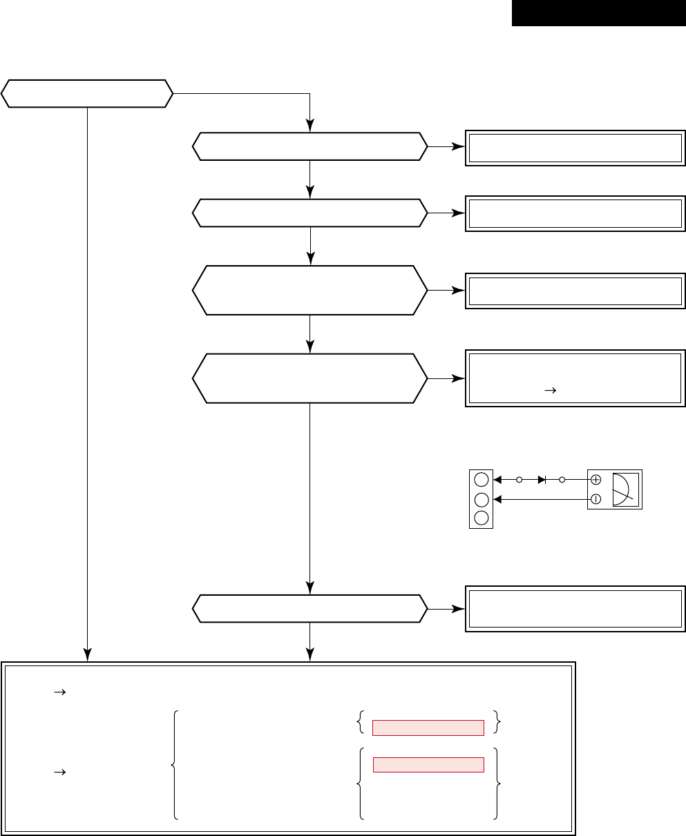
– 87 –
Check item code [14].
Correct inter-unit cable.
Correct connection of connector.
Check/Correct charged
refrigerant amount.
Check indoor P.C. board (MCC-1402).
Defect Replace
Check outdoor P.C. board
Defect Replace
MCC-5009
MCC-1531 and MCC-1438
RAV-SM563AT-E
RAV-SM803AT-E
RAV-SM1103AT-E
RAV-SM1403AT-E
RAV-SP562AT-E
RAV-SP802AT-E
RAV-SP1102AT-E
RAV-SP1402AT-E
Does outdoor unit operate?
Is setup of group address correct?
Does case thermo. operate?
Are 1, 2, 3 inter-unit cables normal?
Are connections from connectors
of inter-terminal blocks (1, 2, 3)
of indoor/outdoor units normal?
Does voltage between
2 and 3 of inter-terminal blocks (1, 2, 3)
of indoor unit vary?*
Check indoor P.C. board
(MCC-1402).
Defect Replace
*As shown in the following figure, perform measurement
within 20 seconds after power ON.
Black
White
3
2
1
Inter-terminal block
S5277G
NO
NO
NO
NO
NO
YES
YES
YES
YES
YES
NO
YES
[E04 error]
Revised : Mar. 2007
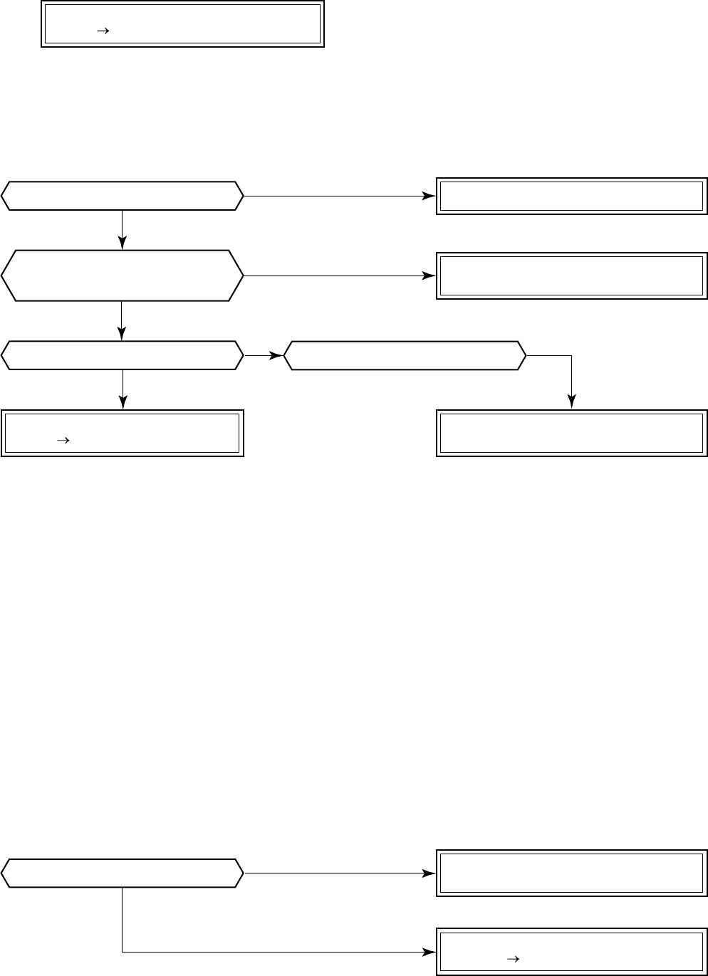
– 88 –
Is inter-unit cable of A and B normal?
Is there no disconnection
or contact error of connector on harness
from terminal block of indoor unit?
Is group control operation? Is power of all indoor units turned on?
Correct inter-unit cable of remote controller.
Correct connection of connector.
Check circuit cables.
Check power connection of indoor unit.
(Turn on power again.)
Check indoor P.C. board (MCC-1402).
Defect Replace
Set capacity data of indoor unit.
(Setup item code (DN) = 11)
Check indoor P.C. board (MCC-1402).
Defect Replace
Check indoor control P.C. board (MCC-1402).
Defect Replace
NO
NO
YES
YES
YES
NO
NO
Is capacity of indoor unit unset? YES
NO
[E10 error]
[E18 error]
[E08, L03, L07, L08 error]
E08 : Duplicated indoor unit numbers
L03 : Two or more master units in a group control
L07 : One or more group addresses of [Individual] in a group control
L08 : Unset indoor group address (99)
If the above is detected when power has been turned on, the mode automatically enters in automatic ad-
dress setup mode. (Check code is not displayed.)
However, if the above is detected during automatic address setup mode, the check code may be displayed.
[L09 error]
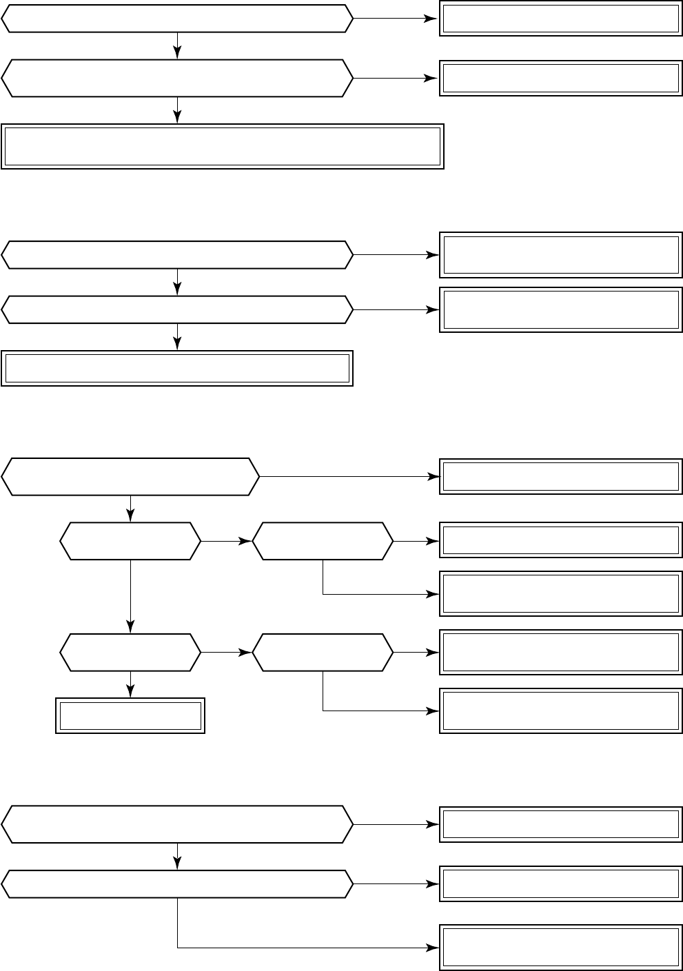
– 89 –
Correct cable connection
Correct central control network address.
Check operation cause.
Check outside devices.
Defect → Replace
Check indoor P.C. board (MCC-1402).
Defect → Replace
Check central controller (including connection interface) indoor P.C. board.
Defect → Replace.
NO
YES
NO
NO
YES
NO
YES
YES
Are not multiple same central
control network addresses connected?
Do outside devices normally operate?
Are outside devices of connector CN80 connected?
Are characteristics of TA sensor resistance value normal?
Are cable connections to communication line U3, U4 normal?
Correct connection of connector.
Replace TA sensor.
* Refer to Characteristics-1.
Correct connection of connector.
Check drain pipe, etc.
Check and correct cabling/wiring.
Check indoor P.C. board (MCC-1402).
Defect → Replace
Check indoor P.C. board (MCC-1402).
Defect → Replace
Check indoor P.C. board (MCC-1402).
Defect → Replace
Replace drain pump.
Check cabling.
NO
NONO
NONO
YES
YES
YES YES
YES
Is connection of float switch connector
(Indoor control P.C. board CN34) normal?
Does float switch
operate? Is circuit
cabling normal?
Does drain pump
operate? Is power of drain
pump turned on?
NO
YES
Is connection of TA sensor connector
(indoor P.C. board CN104) normal?
NO
YES
[L20 error]
[L30 error]
[P10 error]
[F10 error]
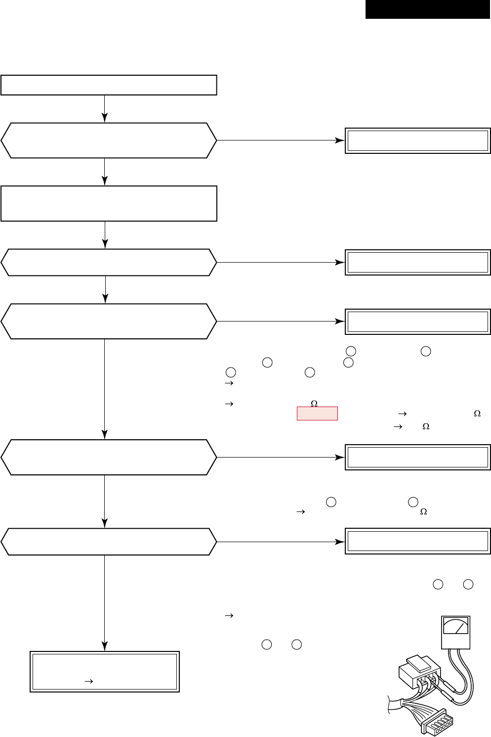
– 90 –
Correct connection of connector.
Replace indoor fan motor.
*1
• Are not coil windings between
(Red lead) and (White lead),
between
(White lead) and (Black lead), between
(Black lead) and (Red lead) opened or shorted?
For resistance, see the following values.
RAV-SM56, SM80, SM1102, SP56, SP80
Approx. 70 to 100
RAV-SM1103, SM1403, SP110, SP140 Approx. 35 to 50
• Is not earthed between cabinet and 1, 3, 5 10M or more
*2
Check resistance of fan motor position detection circuit.
Is not coil winding between (Yellow lead) and (Pink lead)
opened or shorted? Resistance: Approx. 5 to 20k
*3
Check fan motor position detection signal.
• Using a tester, measure the voltage between CN334 and of
indoor P.C. board (MCC-1402) under condition that CN333 and
CN334 are mounted and the power is turned on.
Rotate the fan slowly with hands,
and check the pin voltage
swings between 0 to 5V voltage.
• Between and : 5V
Check indoor P.C. board
(MCC-1402).
Defect Replace
Remove connectors CN333 and
CN334 of indoor unit P.C. board
(MCC-1402).
Replace indoor fan motor.
Replace indoor fan motor.
Replace indoor fan motor.
YES
NO
NO
NO
NO
NO
YES
YES
YES
YES
Turn off the power.
Is resistance value of fan motor connector
CN333 at motor side of indoor P.C. board
(MCC-1402) correct? *2
Are not there connections errors or
disconnection on connectors CN333 and CN334
of indoor unit P.C. board (MCC-1402)?
Are resistance values between phases
at fan motor connector CN333 motor side of
indoor P.C. board (MCC-1402) correct? *1
Is signal output of indoor fan motor
position detection correct? *3
Does the fan rotate without trouble
when handling the fan with hands?
1 3
3 5
5
1
1 5
4 5
4
1
CN333
CN334
[P12 error]
<Only for 4-way air discharge cassette type models>
Revised : Mar. 2007
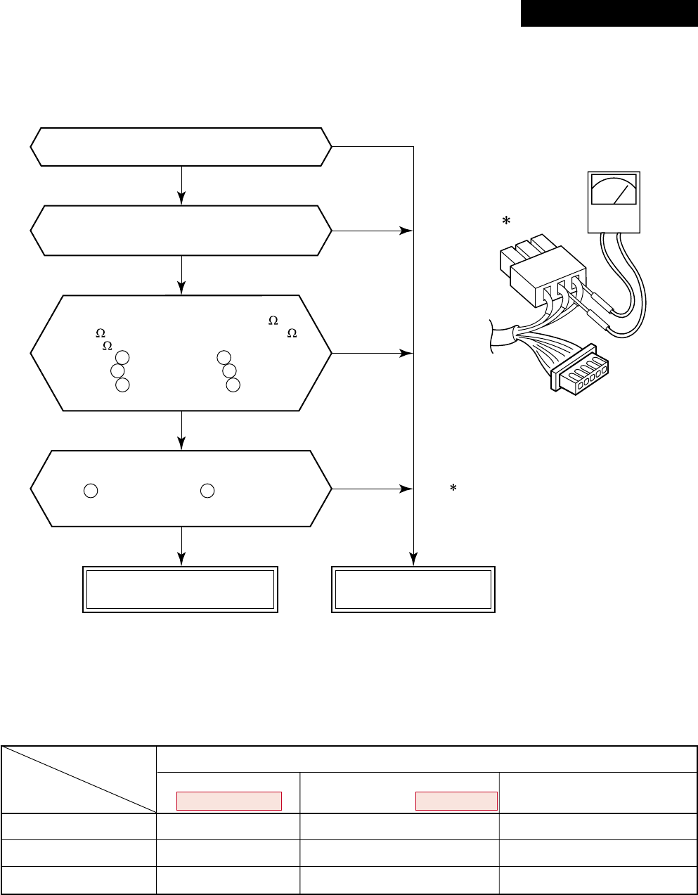
– 91 –
CN300 : Motor coil winding
CN301 : Motor position detection
CN301, CN303 : Motor coil winding
CN300, CN302 : Motor position detection
SM110, SM140, SP56, SP80, SP110, SP140
Are connections of CN301 and
CN300 of P.C. board correct?
Does the fan rotate without trouble
when handling the fan with hands under condition
of removing CN301 and CN300 from P.C. board?
The status that the resistance values
between leads below are 50 to 80
for 40 motor (ICF-140-40) and 25 to 55
for 60 motor (ICF-140-60-1) is normal.
Between (Red lead) and (White lead)
Between (White lead) and (Black lead)
Between (Black lead) and (Red lead)
of motor winding of connector (CN301)
The status that there is
5k to 20kΩ resistance values between
(Yellow lead) and (Pink lead)
of motor position detection of
connector (CN300) is normal.
Normal fan motor
(Control or CDB P.C. board) Defective fan motor
NOTE :
However, GND circuit error inside of the motor is rarely detected even if the above check is carried out.
When the circuit does not become normal even if P.C. board has been replaced, replace outdoor fan motor.
1 2
2 3
3 1
1 4
(Control P.C. board or CDB P.C. board)
NO
NO
NO
YES
YES
YES
YES
CN301, CN303
CN300
[P22 error]
Objective P.C. board
Fan motor winding
Motor position detection
Single phase
RAV-SM563AT-E RAV-SP562AT-E, SP802AT-E RAV-SP1102AT-E, SP1402AT-E
RAV-SM803AT-E RAV-SM1103AT-E, SM1403AT-E
Control P.C. board CDB P.C. board CDB P.C. board
CN300 CN301 CN301/CN303
CN301 CN300 CN300/CN302
Revised : Mar. 2007
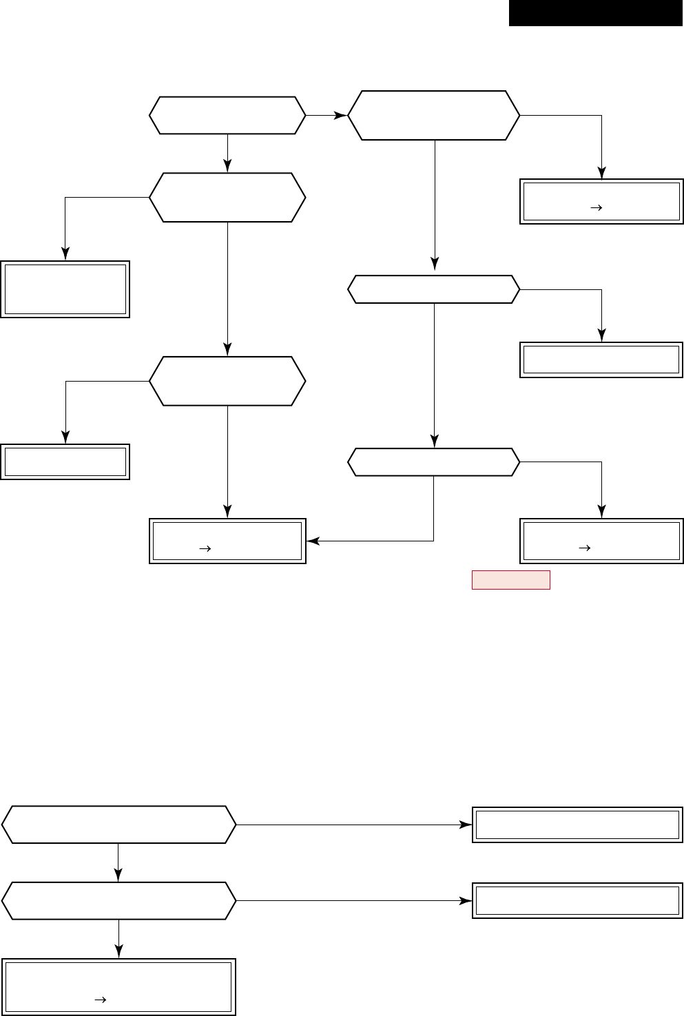
– 92 –
NO
NO
YES
YES
* Refer to Characteristics-2.
* Refer to Characteristics-2.
Check 4-way valve
Defect Replace
Check CDB P.C. board.
Defect Replace
* For RAV-SM563AT-E, SM803AT-E, check control P.C. board.
Check and replace
electron expansion
valve.
Check indoor P.C. board.
Defect Replace
Replace TC sensor.
Is operation of
4-way valve normal?
Is voltage applied
to 4-way valve coil terminal
in heating operation?
Is circuit cable normal?
Check CDB P.C. board.
Is flow of refrigerant
by electron expansion
valve normal?
Are characteristics
of TC sensor resistance
value normal?
Check and correct circuit.
Correct connection of connector.
Replace TC sensor.
NO
NO
NO
YES
YES
YES
NO
NO
YES
NO
YES
YES
Check indoor P.C. board
(MCC-1402).
Defect Replace
Is connection of TC sensor connector
(Indoor P.C. board CN101) normal?
Are characteristics of
TC sensor resistance value normal?
[P19 error]
•In cooling operation, if high pressure is abnormally raised, [P19 error] / [08 error] may be displayed.
In this case, remove cause of pressure up and then check again referring to the item [P04 error] / [21 error].
[F02 error]
Revised : Mar. 2007
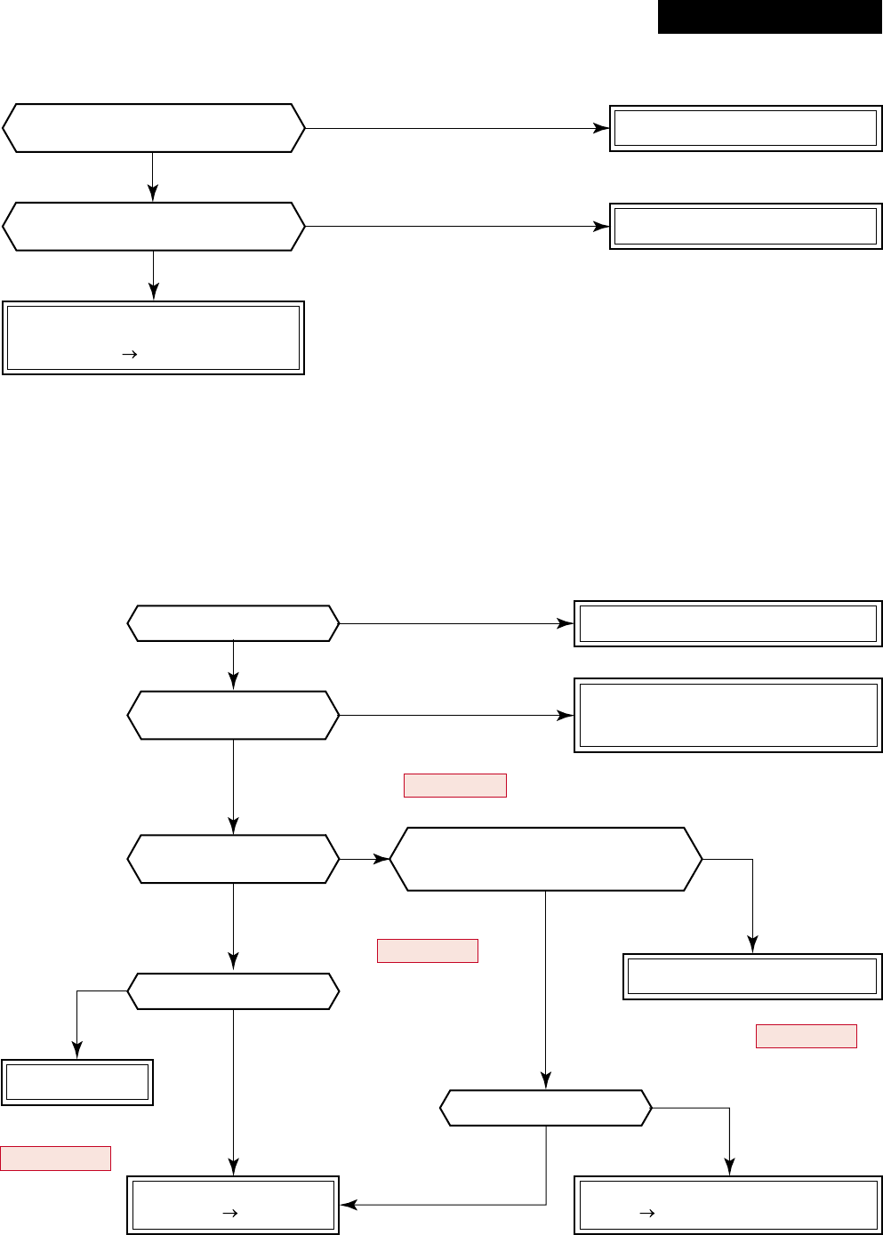
– 93 –
NO
NO
NO
NO
NO
YES
YES
NO
YES
YES
YES
NO
YES
YES
NO
YES
Correct connection of connector.
Replace TCJ sensor.
Improve the power supply line.
Replace IPDU.
Check indoor P.C. board
(MCC-1402).
Defect Replace
Is connection of TCJ sensor connector
(Indoor P.C. board CN102) normal?
Are characteristics of
TCJ sensor resistance value normal?
* Refer to Characteristics-2.
* For RAV-SM563AT-E, SM803AT-E,
check RY01 on the control P.C. board.
* Single-phase type is not provided to
RAV-SM563AT-E, SM803AT-E.
* Replace control P.C. board of
RAV-SM563AT-E, SM803AT-E.
Is power voltage normal?
Is not AC fuse fused?
Check and correct circuit cables.
Correct connection of connector.
Check and correct reactor connection.
Are connections of
cabling/connector normal?
Does RY01 relay of
IPDU operate?
Are not “P26” and “14” errors output
when an operation is performed by
removing 3P connector of compressor?
Replace IPDU.
* Replace control P.C. board
of RAV-SM563AT-E,
SM803AT-E.
Is compressor normal?
Check rare short of compressor trouble.
Defect Replace
Check IPDU.
Defect Replace
[F01 error]
[P26 error]
Revised : Mar. 2007
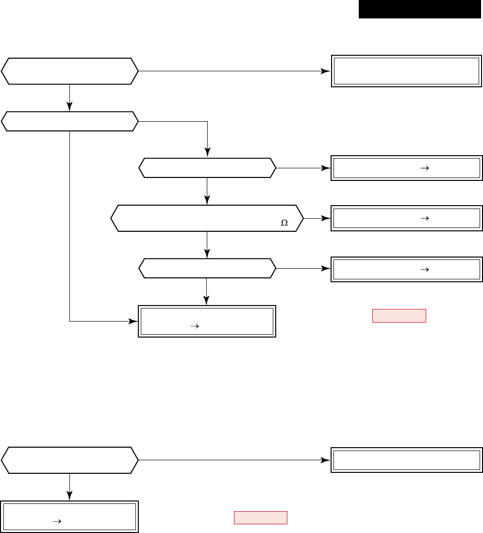
– 94 –
NO
NO
YES
NO
YES
YES
* For RAV-SM563AT-E, SM803AT-E,
replace control P.C. board.
Are connections of
cable/connector normal?
Are cablings of power and
current sensor normal?
Is not winding shorted?
(Is resistance between windings 0.6 to 1.2 ?)
Is compressor normal?
Is not earthed?
Is not winding opened?
Compressor error Replace
Compressor error Replace
Compressor error Replace
Check and correct circuit cables.
Check and correct circuit cabling
such as cabling to compressor.
Check IPDU P.C. board.
Defect Replace
Check IPDU.
Defect Replace * For RAV-SM563AT-E, SM803AT-E, replace control P.C. board.
YES
YES
NO
NO
NO
YES
[P29 error]
[H03 error]
Revised : Mar. 2007
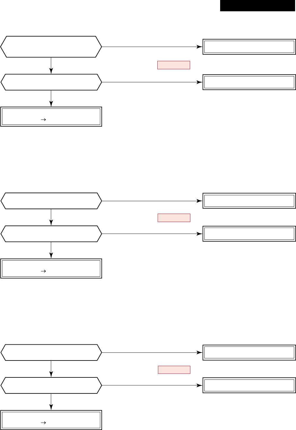
– 95 –
NO Correct connection of connector.
Check CDB.
Defect Replace * Refer to Characteristics-3.
YES
NO
Are characteristics of TE/TS sensor
resistance values normal? Replace TE and TS sensors.
YES
NO
Is connection of TD sensor connector
of CDB CN600 normal? Correct connection of connector.
Check control P.C. board.
Defect Replace * Refer to Characteristics-4.
YES
NO
Are characteristics of TD sensor
resistance value normal? Replace TD sensor.
YES
NO
Is connection of TO sensor connector
of CDB CN601 normal? Correct connection of connector.
Check CDB.
Defect Replace * Refer to Characteristics-5.
* (For RAV-SM563AT-E, SM803AT-E, CN602 TO sensor)
YES
NO
Are characteristics of TO sensor
resistance value normal? Replace TO sensor.
YES
* (For RAV-SM563AT-E, SM803AT-E, CN600 TE sensor and CN603 TS sensor)
* (For RAV-SM563AT-E, SM803AT-E, CN601 TD sensor)
Are connections of
TE/TS sensor connectors of
CDB CN604/CN605 normal?
[F06 error]
[F04 error]
[F08 error]
Revised : Mar. 2007
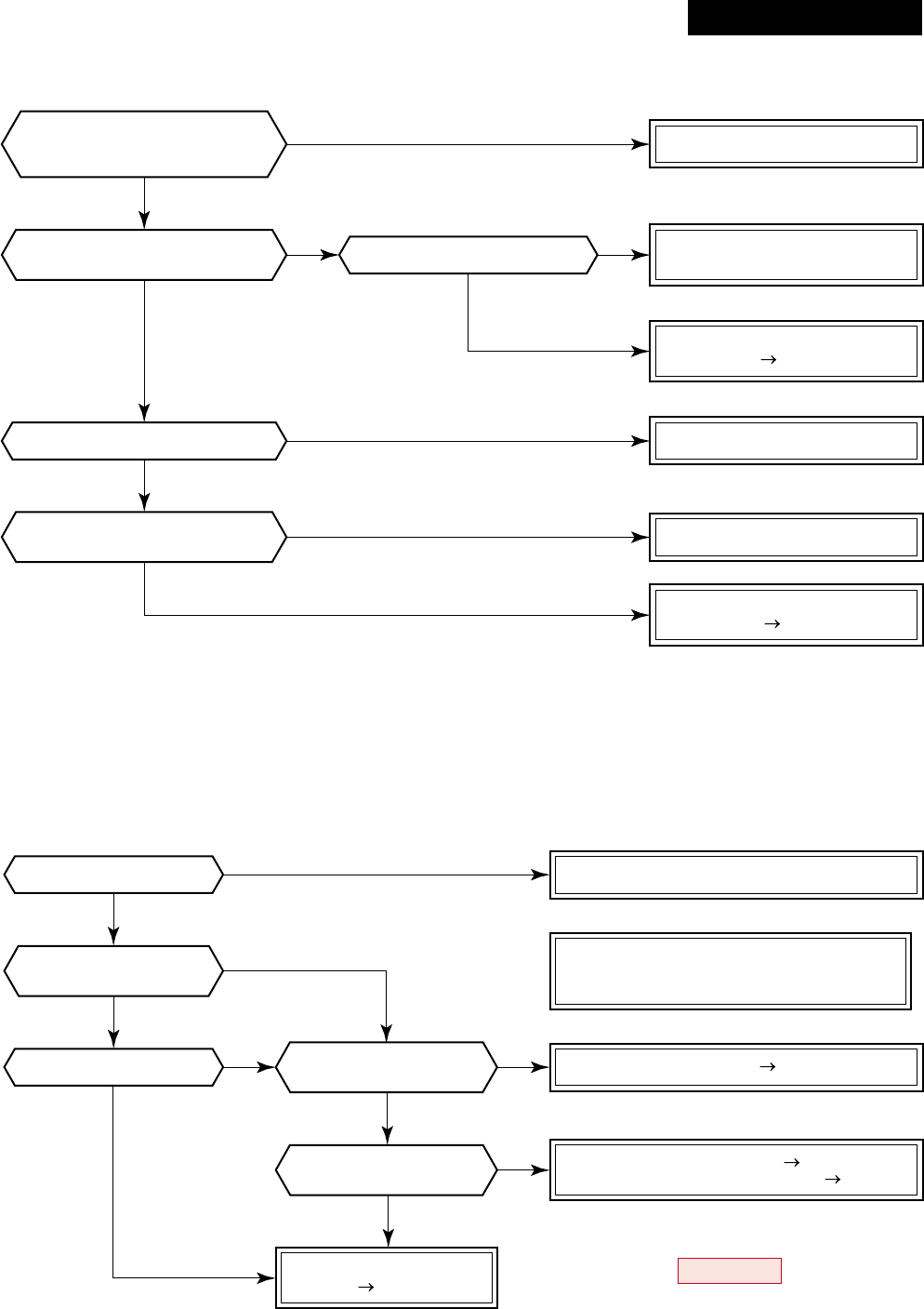
– 96 –
* For RAV-SM563AT-E, SM803AT-E,
replace control P.C. board.
Is there no abnormal overload?
Are cabling/connector normal?
Was the error just after
power ON determined?
Is IPDU P.C. board come to
closely contact with heat sink?
Are connections of
CDB CN800 and CDB IPDU CN06
connectors normal?
Improve and eliminate the cause.
Correct connection of connector.
Correct mounting.
Improve power line.
Compressor lock Replace
Check cabling between IPDU
and CDB and connector.
IPDU P.C. board error
Defect Replace
IPDU P.C. board error
Defect Replace
Check TE and TS sensors. Replace
Check electron expansion valve. Replace
Is there no
slackened refrigerant?
Does electron expansion
valve normally operate?
Is power voltage normal?
Is compressor normal?
Are connections of
cable/connector normal?
Check and correct circuit cabling such
as cabling to compressor
(phase missing) and connector.
Check IPDU and CDB.
Defect Replace
NO
NO
NO
NO
NO NO
NO
NO
NO
YES
YES
YES YES
YES
YES
YES
YES
NO
YES
YES
[L29 error]
[H02 error]
Revised : Mar. 2007
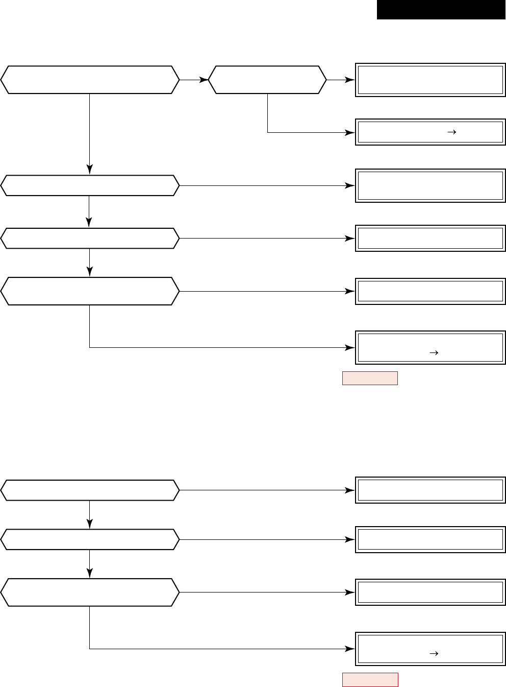
– 97 –
Check parts. Defect Replace
* Refer to Characteristics-4.
Is not abnormal overload?
Is power voltage normal?
Is not abnormal overload?
Is charged refrigerant amount normal?
Are characteristics of
TD sensor resistance value normal?
Is the circuit detected by
current sensor normal?
Is protective control such as
discharge temprelease control normal? Are connections of
cable/connector normal? Correct the cabling and
connection of connector.
Improve and delete the cause
Replace TD sensor.
Improve power line.
Improve and delete the cause.
Check and correct circuit cables.
Check CDB.
Defect Replace
Check and correct the charged
refrigerant amount.
* For RAV-SM563AT-E, SM803AT-E, replace control P.C. board.
Check IPDU.
Defect Replace
* For RAV-SM563AT-E, SM803AT-E, replace control P.C. board.
NO
NO
NO
NO
NO
NO
NO NO
YES
YES
YES
YES
YES
YES
YES YES
[P03 error]
[H01 error]
Revised : Mar. 2007
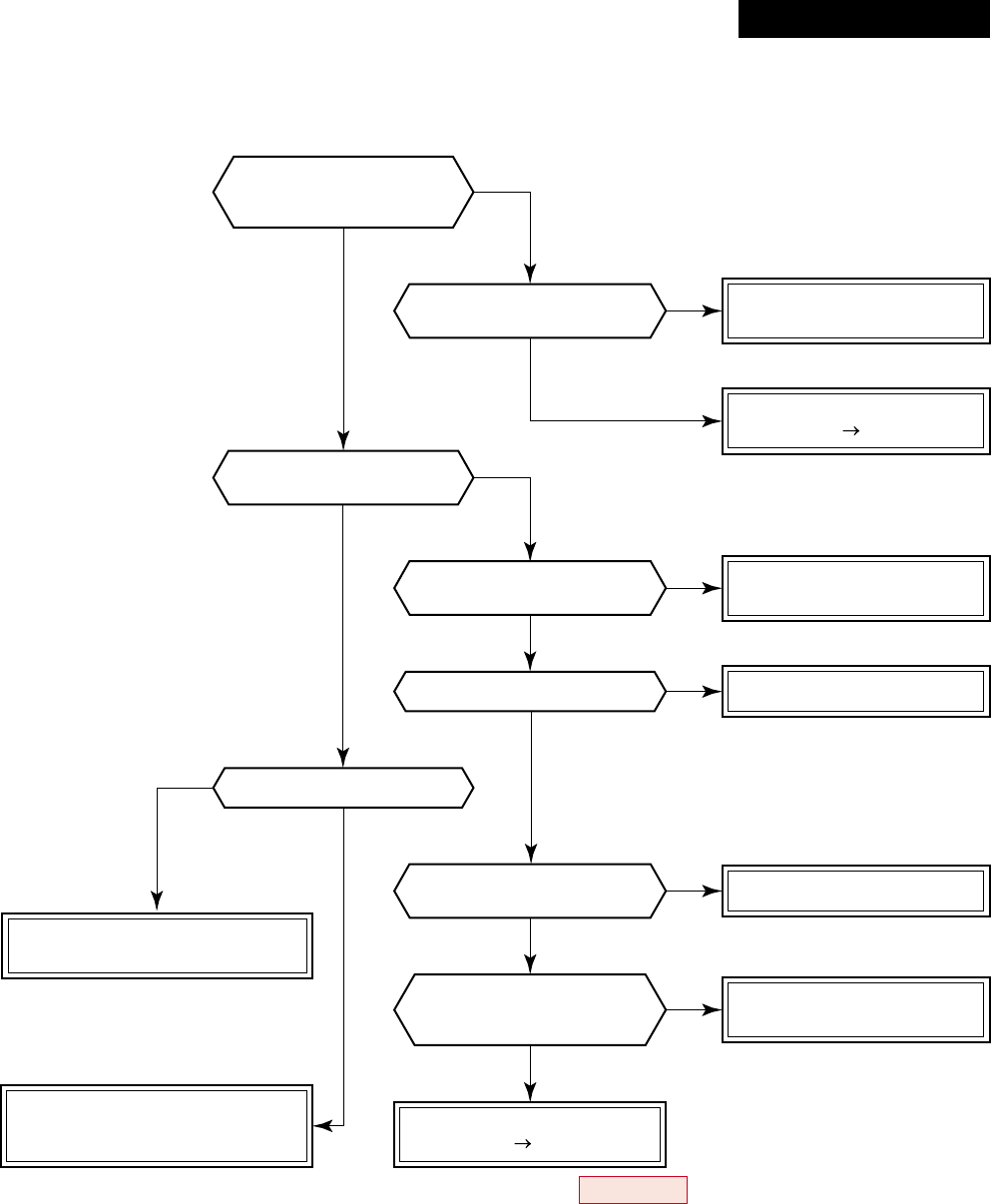
– 98 –
* Refer to Characteristics-3 and 4.
* For RAV-SM563AT-E, SM803AT-E, replace control P.C. board.
Is high-voltage
protective operation by
TE sensor normal?
Is connection of cabling
connector normal?
Do not TD and TO sensors
come off the detection part?
Is connection of
connector normal?
Correct connection of
cabling connector.
Check TE sensor.
Defect Replace
Correct connection of
connector.
Check TE, TC, TS sensors.
Replace electron expansion valve.
Replace TD, TO,
and TC sensors.
Check CDB.
Defect Replace
Does cooling outdoor fan
normally operate?
Does PMV normally operate?
Is fan motor normal? Replace fan motor.
Correct coming-off.
Are characteristics of
TD, TO, TC sensor resistance
values normal?
Check charged refrigerant amount.
Check liquid/gas valves.
Check abnormal overload.
NO
NO
NO
NO
NO
NO
NO
NO
YES
YES
YES
YES
YES
YES
YES
YES
[P04 error]
Revised : Mar. 2007
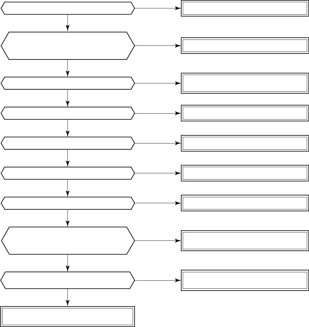
– 99 –
Correct communication line.
Correct connection of connector.
Correct power cable.
Turn on the source power supply.
Clear the check code.
Eliminate noise, etc.
NO
NO
NO
YES
YES
YES
YES
NO
Is U3, U4 communication line normal?
Is A, B communication line normal?
Is there no connection error of power line?
Is there no noise source, etc.?
Is not power of source power supply turned on?
Did a power failure occur?
NO
(Same as others)
Are connections between connectors
CN51 of connection interface P.C. board
and connectors CN51 of indoor P.C. board
normal?
Check connections of A, B terminal blocks.
Correct communication line of remote controller.
Check central controller.
Defect → Replace
Check indoor P.C. board (MCC-1402).
Defect → Replace
Check connection interface P.C. board.
Defect → Replace
Can handy remote controller control
normally other indoor units?
Can central remote controller
control normally other indoor units?
Is handling of central remote controller reflected
on the operation status of indoor unit?
YES
YES
YES
NO
NO
NO
NO
YES
YES
[C06 error] (Central controller)
– 100 –
(Power ON)
[SET] is displayed on
main remote controller.
[SET] goes off.
LED (D02) on
indoor unit P.C. board flashes
with 1Hz for approx. 10 seconds.
Reboot
(Reset)
(Approx. 3 minutes)
(Approx. 1 minute)
(Repetition)
[E03 error] (Master indoor unit)
[E03 error] is detected when the indoor unit cannot receive a signal sent from the main remote controller (and
central controller).
In this case, check the communication cables of the remote controllers A and B, the central control system X
and Y. As communication is disabled, [E03] is not displayed on the main remote controller and the central
controller. [E01] is displayed on the main remote controller and [97 error] on the central controller, respectively.
If [E03] occurs during an operation, the air conditioner stops.
[F29 error] / [12 error]
[F29 error] or [12 error] indicates detection of trouble which occurred on IC10 non-volatile memory (EEPROM)
on the indoor unit P.C. board during operation of the air conditioner. Replace the service P.C. board.
* If EEPROM has not been inserted when the power was turned on or if EEPROM data never be read/written,
the automatic address mode is repeated. In this time, the central controller displays [97 error].
[P31 error] (Sub indoor unit)
When the master unit of a group operation has detected [E03], [L03], [L07], or [L08] error, the sub unit of the
group operation detects [P31 error] and then it stops. There is no display of the check code or alarm history of
the main remote controller.
(In this model, the mode enters in automatic address set mode when the master unit has detected [E03], [L03],
[L07], or [L08] error.)
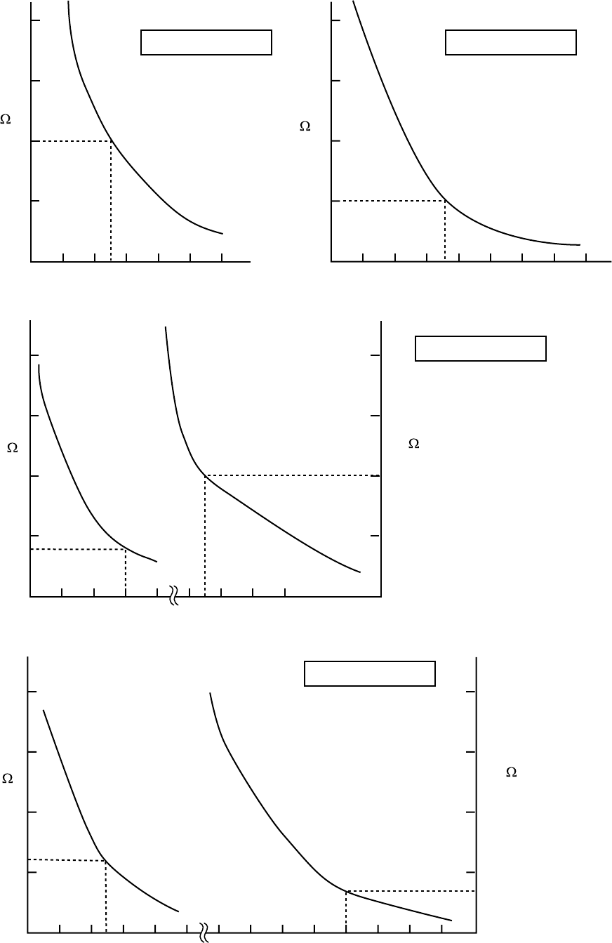
– 101 –
Caracteristics-1
Resistance
(k ) Resistance
(k )
Caracteristics-3
Caracteristics-2
Temperature [˚C] Temperature [˚C]
Resistance
(k )
(10˚C or lower)
Resistance
(k )
(50˚C or lower)
Temperature [˚C]
Resistance
(k )
(50˚C or higher)
Resistance
(k )
(10˚C or higher)
Caracteristics-4
Temperature [˚C]
TC, TCJ sensor
TE, TO, TS sensor
TD sensor
TA sensor
20
10
010 20 4030 50
200
100
20
10
0
0100-10 20 4030 50 60 70
40
30
20
10
00
–
10 10 3020 40 50 60 70
200
100
20
10
0
050 100
10-4-2. Relational Graph of Temperature Sensor Resistance Value and Temperature
– 102 –
11. REPLACEMENT OF SERVICE INDOOR P.C. BOARD
[Requirement when replacing the service indoor P.C. board assembly]
In the non-volatile memory (Hereinafter said EEPROM, IC10) installed on the indoor P.C. board before replace-
ment, the type and capacity code exclusive to the corresponding model have been stored at shipment from the
factory and the important setup data such as system/indoor/group address set in (AUTO/MANUAL) mode or
setting of high ceiling selection have been stored at installation time. Replace the service indoor P.C. board
assembly according to the following procedure.
After replacement, check the indoor unit address and also the cycle by a test run.
<REPLACEMENT PROCEDURE>
CASE 1
Before replacement, power of the indoor unit can be turned on and the setup data can be readout
from the wired remote controller.
Read EEPROM data *1
ò
Replace service P.C. board & power ON *2
ò
Write the read data to EEPROM *3
ò
Power reset (All indoor units in the group when group operation)
CASE 2
Before replacement the setup data can not be readout from the wired remote controller.
Replace service P.C. board & power ON *2
ò
Write the data such as high ceiling setup to EEPROM (According to the customers’ information) *3
ò
Power reset (All indoor units in the group when group operation)
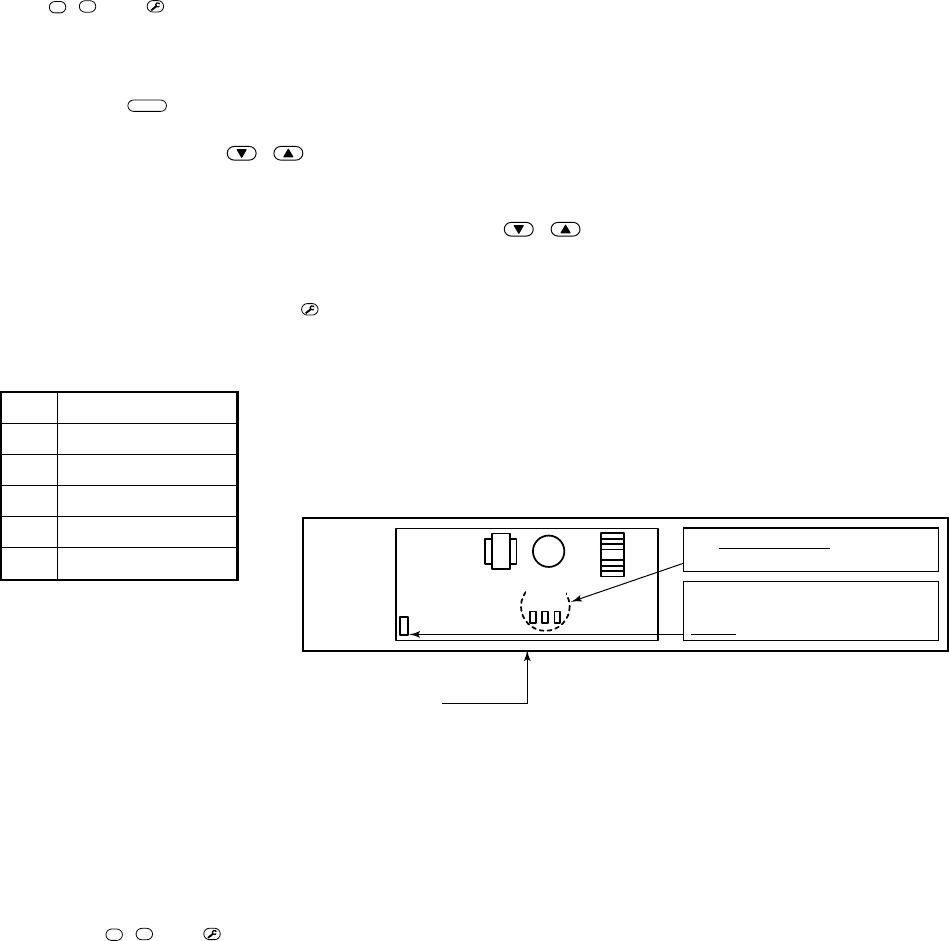
– 103 –
CN34
MCC-1402 Set Short-circuit-plug on the same
position as the P. C. board to replace.
Notes)
When
replacement
If short-circuit-plug is inserted in
CN34 of the P. C. board to replace,
re-use it in service P. C. board.
CN112
CN111
CN110
r1 Readout of the setup data from EEPROM
(Data in EEPROM contents, which have been changed at the local site, are read out together with data in EEPROM
set at shipment from the factory.)
1. Push
SET
,
CL
, and
TEST
buttons of the remote controller at the same time for 4 seconds or more. 1
(Corresponded with No. in Remote controller)
When group operation, the master indoor unit address is displayed at the first time. In this time, the item code
(DN) 10 is displayed. The fan of the selected indoor unit operates and the louver starts swinging if any.
2. Every pushing
UNIT
button, the indoor unit address in the group are displayed successively. 2
Specify the indoor unit No. to be replaced.
3. Using the set temperature / buttons, the item code (DN) can be moved up and down one by one. 3
4. First change the item code (DN) from 10 to 01.
(Setting of filter sign lighting time) Make a note of the set data displayed in this time.
5. Next change the item code (DN) using the set temperature / buttons. Also make a note of the set data.
6. Repeat item 5. and make a note of the important set data as shown in the later table (Ex.).
•01 to FF are provided in the item code (DN). On the way of operation, DN No. may come out.
7. After finishing making a note, push
TEST
button to return the status to usual stop status. 6
(Approx. 1 minute is required to start handling of the remote controller.)
Minimum requirements for item code
DN
10
11
12
13
14
Contents
Type
Indoor unit capacity
Line address
Indoor address
Group address
1) Type and capacity of the indoor unit is necessary to set the revolutions
frequency of the fan.
2) If Line/Indoor/Group addresses differ from those before replacement, the
mode enters in automatic address setup mode and a manual resetting
may be required.
r2 Replacement of service P.C. board
1. Replace the P.C. board with a service P.C. board.
In this time, setting of jumper line (cut) or setting of (short-circuit) connecting connectors on the former P.C. board
should be reflected on the service P.C. board. (See Appendix 1, page 4)
2. According to the system configuration, turn on power of the indoor unit with any method in the following items.
a) In case of single (individual) operation
Turn on the power supply.
1) Wait for completion of automatic address setup mode (Required time: Approx. 5 minutes) and then
proceed to r3.
(Line address = 1, Indoor address = 1, Group address = 0 (Individual) are automatically set.)
2) Push
SET
,
CL
, and
TEST
buttons of the remote controller at the same time for 4 seconds or more
(1 operation), interrupt the automatic address setup mode, and then proceed to r3.
(Unit No. ALL is displayed.)
b) In case of group operation
Turn on power of the indoor unit of which P.C. board has been replaced with the service P.C. board with any
method in the following items.
1) Turn on power of the replaced indoor unit only.
(However, the remote controller is also connected.
Otherwise r3 operation cannot be performed.)
Same as 1) and 2) in item a).
2) Turn on power of the multiple indoor units including replaced indoor unit.
•Only 1 system for twin, triple, double twin
•For all units in the group
Wait for completion of automatic address setup mode (Required time: Approx. 5 minutes) and then proceed to
r3.
* The master unit of a group may change by setup of automatic address. The line address/indoor address of the
replaced indoor unit are automatically set to the vacant addresses except addresses belonging to other indoor
units which have not been replaced. It is recommended to make a note that the refrigerant line which includes the
corresponding indoor unit and that the corresponding indoor unit is master or sub in the group control.
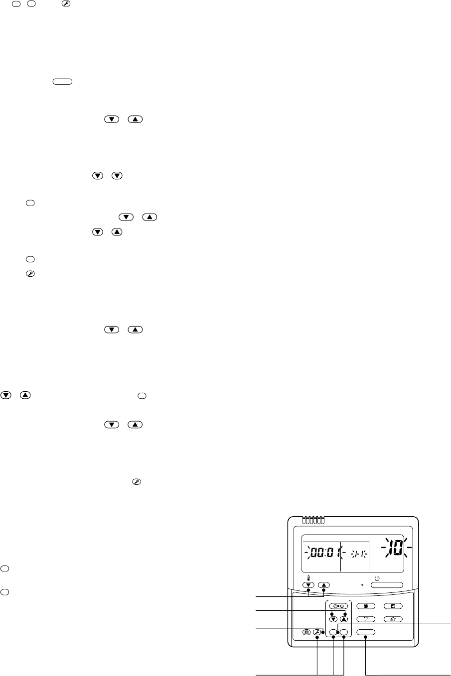
– 104 –
r3 Writing of the setup contents to EEPROM
(The contents of EEPROM installed on the service P.C. board have been set up at shipment from the factory.)
1. Push
SET
,
CL
, and
TEST
buttons of the remote controller at the same time for 4 seconds or more. 1
(Corresponded with No. in Remote controller )
In group operation control, the master indoor unit No. is displayed at the first time. (If the automatic address
setup mode is interrupted in item 2. - a) - 2) in the previous page, the unit No. ALL is displayed.) In this time,
the item code (DN) 10 is displayed. The fan of the selected indoor unit operates and the louver starts
swinging if any.
2. Every pushing
UNIT
button, the indoor unit numbers in the group control are displayed successively. 2
Specify the indoor unit No. of which P.C. board has been replaced with a service P.C. board.
(When the unit No. ALL is displayed, this operation cannot be performed.)
3. Using the set temperature / buttons, the item code (DN) can be moved up and down one by one. 3
4. First set a type and capacity of the indoor unit.
(Setting the type and capacity writes the data at shipment from the factory in EEPROM.)
1) Set the item code (DN) to 10. (As it is)
2) Using the timer time / buttons, set up a type. 4
(For example, 4-way air discharge cassette type is 0001) Refer to the attached table.
3) Push
SET
button. (OK when the display goes on.) 5
4) Using the set temperature / buttons, set 11 to the item code (DN).
5) Using the timer time / buttons, set the capacity.
(For example, 0012 for class 80) Refer to the attached table.
6) Push
SET
button. (OK when the display goes on.)
7) Push
TEST
button to return the status to usual stop status. 6
(Approx. 1 minute is required to start handling of the remote controller.)
5. Next write the contents which have been set up at the local site such as the address setup in EEPROM.
Repeat the above procedure 1. and 2.
6. Using the set temperature / buttons, set 01 to the item code (DN).
(Setup of lighting time of filter sign)
7. The contents of the displayed setup data in this time should be agreed with the contents in the previous
memorandum in r1.
1) If data disagree, change the displayed setup data to that in the previous memorandum by the timer time
/ buttons, and then push
SET
button. (OK when the display goes on.)
2) There is nothing to do when data agrees.
8. Using the set temperature / buttons, change the item code (DN).
As same as the above, check the contents of the setup data and then change them to data contents in the
previous memorandum.
9. Then repeat the procedure 7. and 8.
10. After completion of setup, push
TEST
button to return
the status to the usual stop status. 6
(Approx. 1 minute is required to start handling of
the remote controller.)
*01 to 9F are provided in the item code (DN).
On the way of operation, DN No. may come out.
When data has been changed by mistake and
SET
, button has been pushed, the data can be
returned to the data before change by pushing
CL
button if the item code (DN) was not yet
changed.
<REMOTE CONTROLLER>
1
4
6
3
2
5
ON / OFF
FAN
TEMP.
SWING/FIXTIME
MODE
VENT
UNITSET CL
FILTER
RESET
TEST
TIMER SET
UNIT No.
DATA
SET
R.C. No.
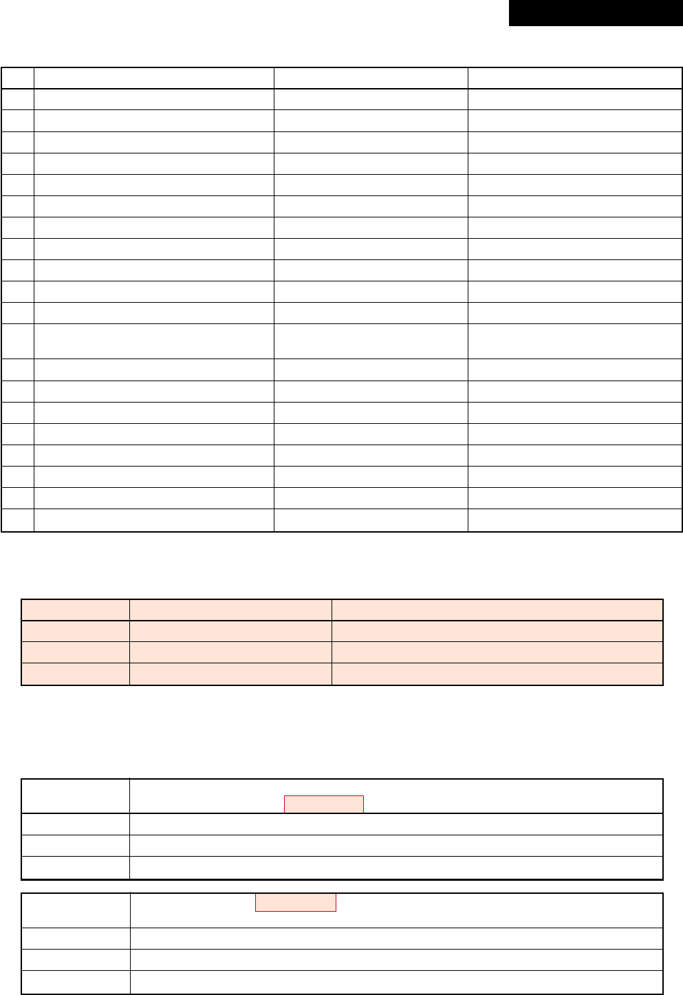
– 105 –
Memorandum for setup contents (Item code table (Example))
Type
Item code [10]
Setup data
0001*
0004
0007
Type
4-way air discharge cassette
Concealed duct
Under ceiling
Abbreviated name
RAV-SM563/803/1103/1403UT-E, RAV-SP1102UT-E
RAV-SM562/802/1102/1402BT-E
RAV-SM562/802/1102/1402CT-E
* Initial setup value of EEPROM installed on the service P.C. board
Indoor unit capacity
Item code [11]
DN
01
02
03
06
0F
10
11
12
13
14
19
1E
28
2A
2b
2E
32
5d
60
8b
Item
Filter sign lighting time
Dirty state of filter
Central control address
Heating suction temp shift
Cooling only
Type
Indoor unit capacity
Line address
Indoor unit address
Group address
Louver type (Adjustment of air direction)
Temp difference of automatic cooling/
heating selecting control points
Automatic reset of power failure
Option
Thermo output selection (T10 ‡B)
Option
Sensor selection
High ceiling selection
Timer set (Wired remote controller)
Correction of high heat feeling
Memo At shipment
According to type
0000: Standard
0099: Unfixed
0002: +2°C (Floor type: 0)
0000: Shared for cooling/heating
According to model type
According to capacity type
0099: Unfixed
0099: Unfixed
0099: Unfixed
According to type
0003: 3 deg (Ts ± 1.5)
0000: None
0002:
0000: Thermo ON
0000:
0000: Body sensor
0000: Standard
0000: Available
0000: None
Setup data
0000*
0009
0012
SM563UT-E, SM562BT-E, SM562CT-E
SM803UT-E, SM802BT-E, SM802CT-E
Invalid
56
80
Setup data
0000*
0015
0017
RAV-SM1103UT-E, SM1403UT-E, SM1102BT-E, SM1402BT-E, SM1102CT-E, SM1402CT-E
RAV-SP1102UT-E
Invalid
110
140
* Initial setup value of EEPROM installed on the service P.C. board
Revised : Mar. 2007
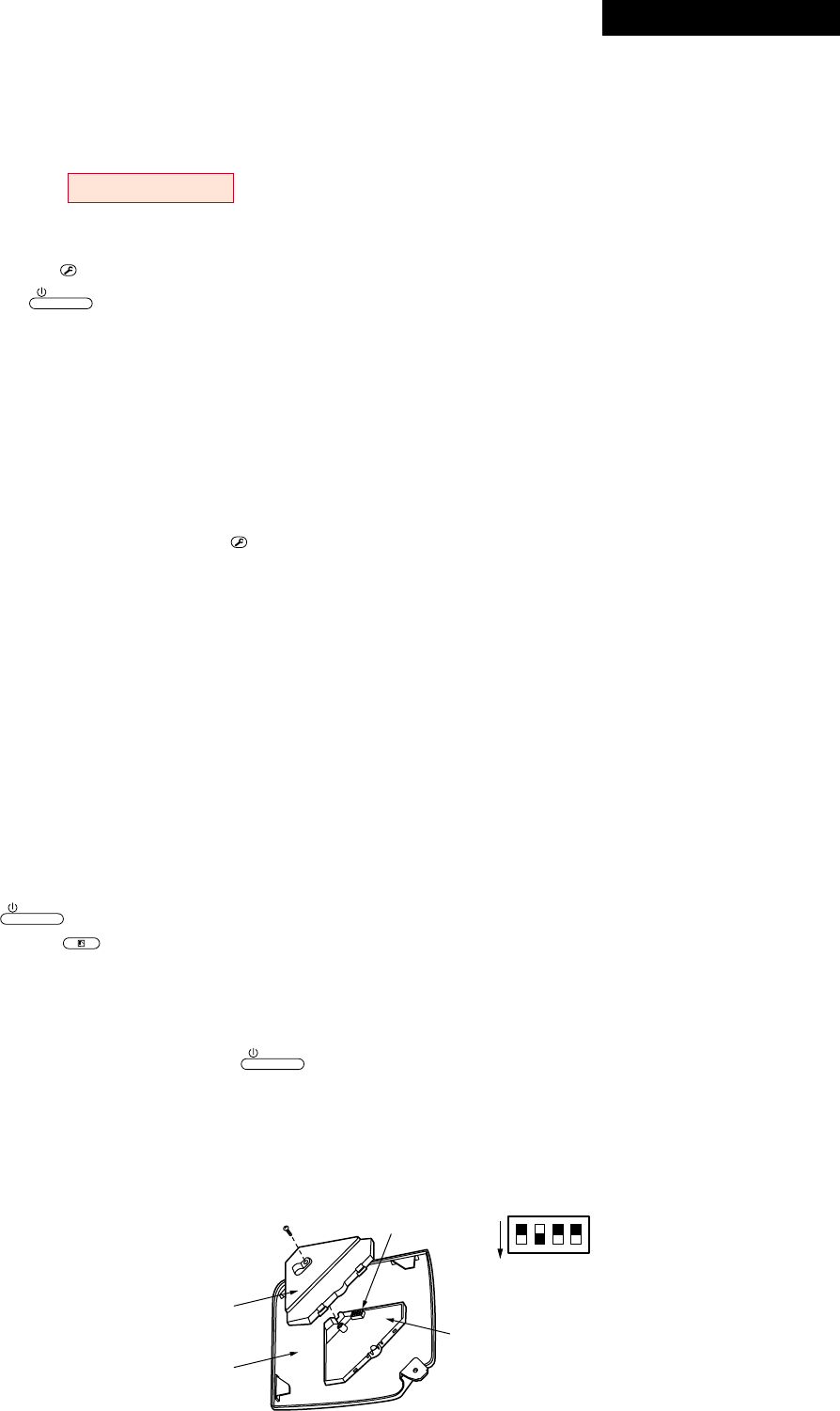
– 106 –
Sensor cover
Adjust corner cap
1
2
3
4
ON
Sensor P.C. board
S003
Bit 1 : OFF to ON
12. SETUP AT LOCAL SITE AND OTHERS
12-1. Indoor Unit
12-1-1. Test Run Setup on Remote Controller
RAV-SM563UT-E, RAV-SM803UT-E, RAV-SM562BT-E, RAV-SM802BT-E
<Wired remote controller>
1. When pushing
TEST
button on the remote controller for 4 seconds or more, “TEST” is displayed on LC display.
Then push
ON / OFF
button.
•“TEST” is displayed on LC display during operation of Test Run.
•During Test Run, temperature cannot be adjusted but air volume can be selected.
•In heating and cooling operation, a command to fix the Test Run frequency is output.
•Detection of error is performed as usual. However, do not use this function except case of Test Run be-
cause it applies load on the unit.
2. Use either heating or cooling operation mode for [TEST].
NOTE : The outdoor unit does not operate after power has been turned on or for approx. 3 minutes after
operation has stopped.
3. After a Test Run has finished, push
TEST
button again and check that [TEST] on LC display has gone off.
(To prevent a continuous test run operation, 60-minutes timer release function is provided to this remote
controller.)
<Wireless remote controller>
(4-way Air Discharge Cassette Type only)
1Turn off power of the unit.
Remove the adjuster attached with sensors from the ceiling panel. For removing, refer to the Installation
manual attached to the ceiling panel. (Be careful to handle the adjuster because cables are connected to
the sensor.) Remove the sensor cover from the adjuster. (1 screw)
2Change ON of Bit [1: TEST] of the sensor P.C. board switch [S003] to OFF.
Mount the sensor cover and mount the adjuster with sensor to the ceiling panel.
Turn on power of the unit.
3Push
ON / OFF
button on the wireless remote controller and select [COOL] or [HEAT] operation
mode using
MODE
button.
(All the display lamps of sensors on the wireless remote controller flash during Test Run.)
•Do not perform Test Run operation in other modes than [HEAT] / [COOL] mode.
•Detection of error is performed as usual.
4After Test Run operation, push
ON / OFF
button to stop the operation.
5Turn off power of the unit.
Return Bit [1] of the sensor P.C. board switch [S003] to the original position. (ON ® OFF)
Mount the adjuster with sensors to the ceiling panel.
Revised : Mar. 2007
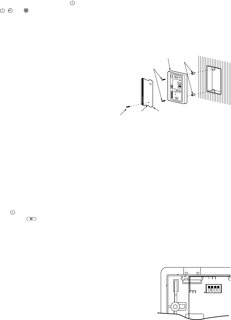
– 107 –
(Except 4-way Air Discharge Cassette Type and Under Ceiling Type)
1Remove a screw which fixes the serial olate of the receiver part on the wireless remote
controller.
Remove the nameplate of the reciver section by inserting a minus screwdriver, etc. into the notch at the
bottom of the plate, and set the Dip switch to [TEST RUN ON].
2Execute a test operation with button on the wireless remote controller.
•, and LED flash during test operation.
•Under status of [TEST RUN ON], the temperature adjustment from the wireless remote controller is
invalid.
Do not use this method in the operation other than test operation because the equipment is damaged.
3Use either [COOL] or [HEAT] operation mode for test operation.
•The outdoor unit does not operate approx. 3 minutes
after power-ON and operation stop.
4After the test operation finished, stop the air
conditioner from the wireless remote controller,
and return Dip switch of the sensor section as before.
(A 60 minutes timer clearing function is attached to the sensor
section in order to prevent a continuous test operation.)
Receiver unit
M4 × 25 screw
(2 pieces)
Small screw
Spacer
Notch Nameplate
(Under Ceiling Type only)
1Turn off power of the air conditioner.
Remove the adjust corner cap attached with sensor section from the ceiling panel. For removing method,
follow to the installation manual attached to the ceiling panel. (Be careful to handle the sensor section
because cables are connected to the sensor section.)
Remove the sensor cover from the adjust corner cap. (1 screw)
2Change Bit [1: TEST] of the switch [S003] on the sensor P.C. board from OFF to ON.
Mount the sensor cover and attach the adjust corner cap with with sensors to the ceiling panel.
Turn on power of the air conditioner.
3Push button of the wireless remote controller and select an operation mode [COOL] or
[HEAT] with
MODE
button. (All the display lamps of the wireless remote controller sensor
section flash during the tst operation.)
•Do not use operation mode other than [COOL] or [HEAT].
•Error is detected as usual.
4When the test operation has finished, push button to stop the operation.
5Turn off power of the air conditioner.
Change Bit [1] of the switch [S003] on the sensor
P.C. board from ON to OFF. Attach the adjust
corner cap with sensors to the ceiling panel.
ON
12 3 4
2
3
4
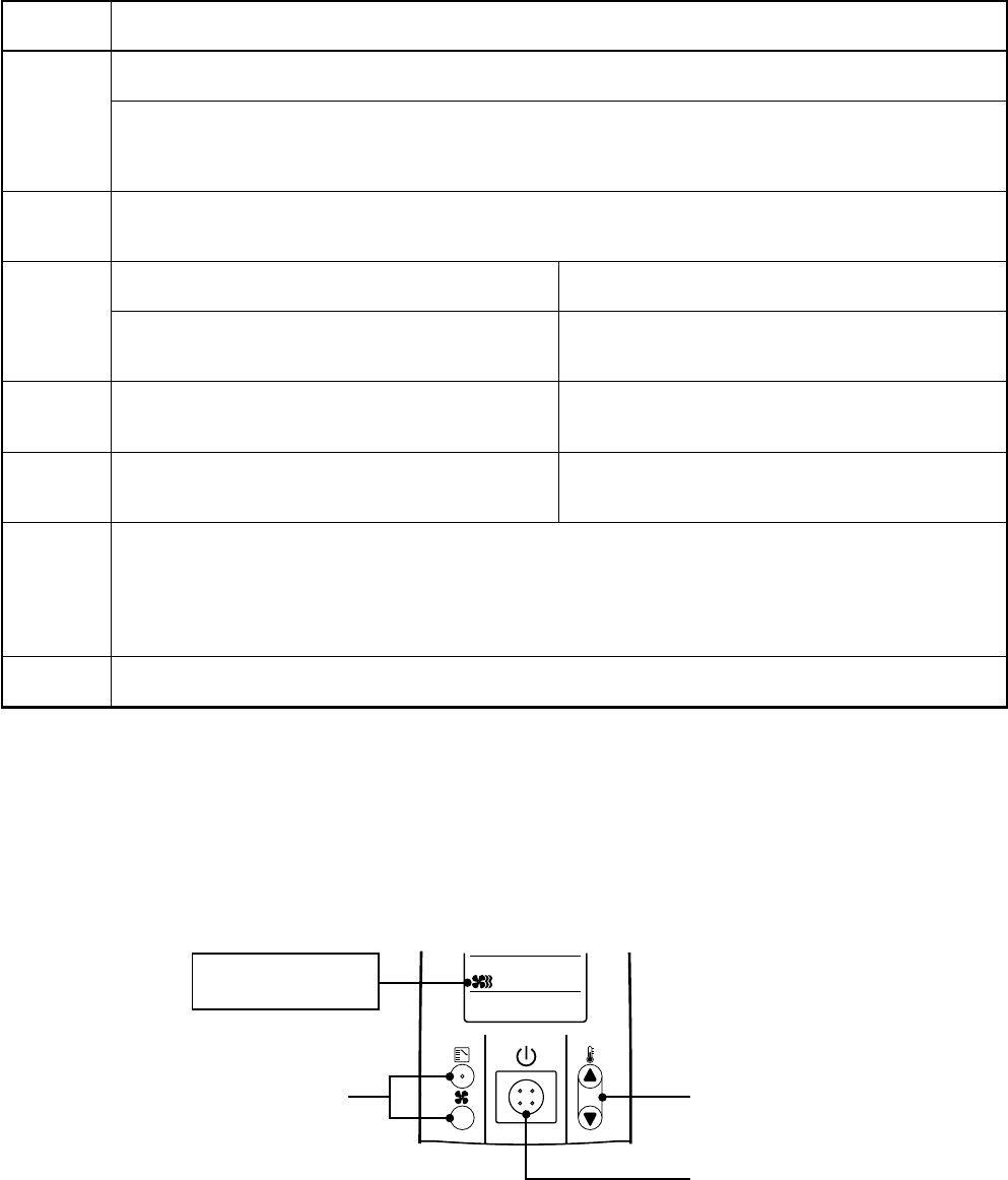
– 108 –
<In case of wireless remote controller>
Procedure
1
2
3
4
5
6
7
Description
Turn on power of the air conditioner.
The operation is not accepted for 5 minutes when power has been turned on at first time after installation,
and 1 minute when power has been turned on at the next time and after. After the specified time has
passed, perform a test operation.
Push [Start/Stop] button and change the operation mode to [COOL] or [HEAT] with [Mode] button.
Then change the fan speed to [High] using [Fan] button.
Test cooling operation Test heating operation
Set temperature to [18°C] using [Temperature set] Set temperature to [30°C] using [Temperature set]
button. button.
After checking the receiving sound “Pi”, immediately After checking the receiving sound “Pi”, immediately
push [Temperature set] button to set to [19°C] push [Temperature set] button to set to [29°C].
After checking the receiving sound “Pi”, immediately After checking the receiving sound “Pi”, immediately
push [Temperature set] button to set to [18°C]. push [Temperature set] button to set to [30°C].
Then repeat the procedure 4 → 5 → 4 → 5 .
After approx. 10 seconds, all the display lamps on the sensor part of wireless remote controller,
[Operation] (Green), [Timer] (Green), and [Ready] (Yellow) flash and the air conditioner starts operation.
If the lamps do not flash, repeat the procedure 2 and after.
After the test operation, push [Start/Stop] button to stop the operation.
<Outline of test operation from the wireless remote controller>
Test cooling operation:
Start → 18°C → 19°C → 18°C → 19°C → 18°C → 19°C → 18°C → (Test operation) → Stop
Test heating operation:
Start → 30°C → 29°C → 30°C → 29°C → 30°C → 29°C → 30°C → (Test operation) → Stop
23, 4, 5,
6
2, 7
Be sure to set the
air speed to [High]

– 109 –
Item No. (DN) table (Selection of function)
DN
01
02
03
06
0F
10
11
12
13
14
19
1E
28
2A
2b
2E
30
31
32
33
40
5d
60
8b
Item
Filter sign lighting
time
Dirty state of filter
Central control
address
Heating suction temp
shift
Cooling only
Type
Indoor unit capacity
Line address
Indoor unit address
Group address
Temp difference of
automatic cooling/
heating mode
selection COOL →
HEAT, HEAT →COOL
Automatic restart of
power failure
Option
Thermo output
selection (T10 )
Option
Option
Option
Sensor selection
Temperature
indication
Option
High ceiling selection
(Air volume selection)
Timer set
(Wired remote
controller)
Correction of high
heat feeling
Description
0000 : None
0002 : 2500H (4-Way/Duct/Ceiling Type)
0000 : Standard 0001 : High degree of dirt
(Half of standard time)
0001 : No.1 unit to 0064 : No.64 unit
0099 : Unfixed
0000 : No shift 0001 : +1°C
0002 : +2°C to 0010 : -10°C
(Up to recommendation + 6)
0000 : Heat pump 0001 : Cooling only
(No display of [AUTO] [HEAT])
0001 : SM563/803/1103/1403UT, SP1102UT type
0004 : SM562/802/1102/1402BT type
0007 : SM562/802/1102/1402CT type
0000 : Unfixed
0009 : 56 type 0012 : 80 type
0015 : 110 type 0017 : 140 type
0001 : No.1 unit to 0030 : No.30 unit
0001 : No.1 unit to 0064 : No.64 unit
0000 : Individual 0001 : Master of group
0002 : Sub of group
0000 : 0 deg to 0010 : 10 deg
(For setup temperature, reversal of COOL/HEAT by ± (Data value)/2)
0000 : None 0001 : Restart
0000 : Indoor thermo ON
0001 : Output of outdoor comp-ON receiving
0000 : Body TA sensor 0001 : Remote controller sensor
0000 : °C (celsius) 0001 : °F (Fahrenheit)
0000 : Standard filter
0001 : Oil guard, Super-long life, Optical regenerative deodorization
0003 : High performance (65%), High performance (90%),
High antibacterial performance (65%)
0000 : Available (Operable) 0001 : Unavailable (Operation prohibited)
0000 : None 0001 : Correction
At shipment
0002 for D.I. and S.D.I.
models
0000 : Standard
0099 : Unfixed
0002 : +2°C
(Floor type 0000: 0°C)
0000 : Shared for cooling/
heating
According to model type
According to capacity type
0099 : Unfixed
0099 : Unfixed
0099 : Unfixed
0003 : 3 deg
(Ts±1.5)
0000 : None
0002 : Default
0000: Thermo. ON
0000 : Default
0000 : Default
0000 : Default
0000 : Body sensor
0000 : °C
0003 : Default
0000 : Standard
0000 : Available
0000 : None
Revised : Mar. 2007
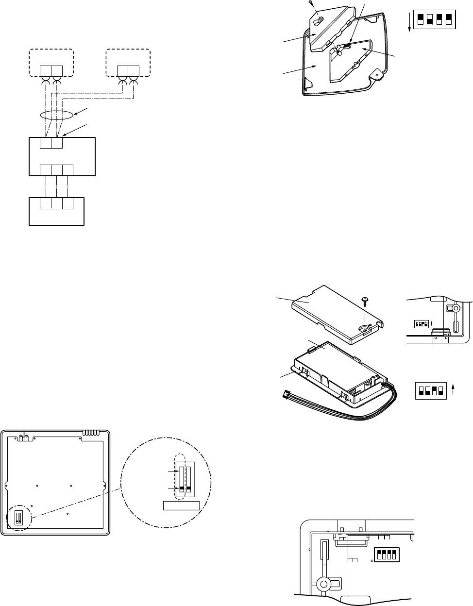
– 110 –
12-1-2. Cabling and Setting of Remote Controller Control
(Setup method)
One or multiple indoor units are controlled by two
remote controllers.
(Max. 2 remote controllers are connectable.)
<Wired remote controller>
How to set wired remote controller
as sub remote controller
Change DIP switch inside of the rear side of the
remote controller switch from remote controller
master to sub. (In case of RBC-AMT31E)
[Operation]
1. The operation contents can be changed by Last-
push-priority.
2. Use a timer on either Master remote controller or
Sub remote controller.
<Wireless remote controller>
(Except 4-Way Air Discharge Cassette Type and
Under Ceiling Type)
How to set wireless remote controller as sub
remote controller
Turn Bit [3: Remote controller Sub/Master] of the
switch S003 from OFF to ON.
Terminal block for
remote controller cables
Remote controller
cables (Procured locally)
Indoor unit
Outdoor unit
Remote controller
switch (Sub)
Remote controller
switch (Master)
Sold separately
213
213
BA
BABA
Sold separately
1 2
1 2
12
Remote controller (Inside of the rear side)
Sub remote
controller
Master remote
controller
DIP switch
Sensor
cover
Adjust
corner cap
1
2
3
4
ON
Sensor P.C. board
S003 Bit 1 : OFF to ON
ON
12 3 4
2
3
4
<Wireless remote controller>
(Under Ceiling Type only)
How to set wireless remote controller to sub
remote controller
Change OFF of Bit [3: Remote controller Sub/Master]
of switch S003 to ON.
2-remote controller control
(Controlled by two remote controllers)
One or multiple indoor units are controlled by two
remote controllers.
(Max. 2 remote controllers are connectable.)
• 1 indoor unit is controlled by 2
remote controllers
<Wireless remote controller>
(4-Way Air Discharge Cassette Type only)
How to set wireless remote controller to sub
remote controller
Change OFF of Bit [3: Remote controller Sub/Master]
of switch S003 to ON.
1 2 3 4
ON
ON
S003
Bit 3 : OFF → ON
1 2 3 4
ON
ON
Rear cover
Sensor P.C. board
Upper case
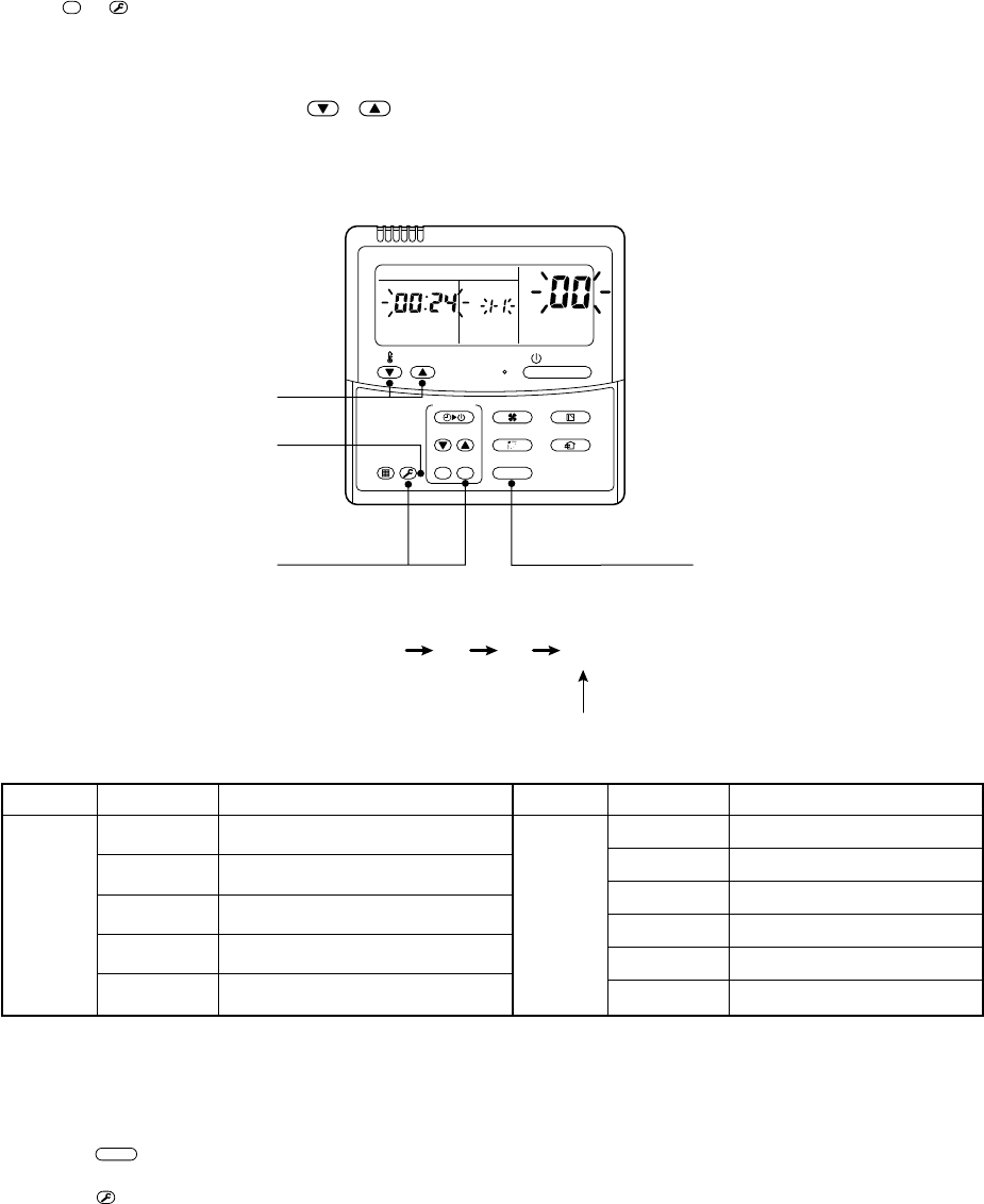
– 111 –
12-1-3. Monitor Function of Remote Controller Switch
nCall of sensor temperature display
<Contents>
Each sensor temperature of the remote controller, indoor unit, and outdoor unit can become known by calling
the service monitor mode from the remote controller.
<Procedure>
1Push
CL
+
TEST
buttons simultaneously for 4 seconds or more to call the service monitor mode.
The service monitor goes on, the master indoor unit No. is displayed, and then temperature of the item
code 00 is displayed.
2Push the temperature setup / buttons to select the sensor No. (Item code) of the sen-
sor to be monitored.
The sensor numbers are described below:
3The temperature of indoor units and outdoor unit in a group control can be monitored by
pushing
UNIT
button to select the indoor unit to be monitored.
4Pushing
TEST
button returns the display to usual display.
*1 Only master unit in group control
1 2 3 4
<Operation procedure>
Returned to usual display
1
4
2
3
ON / OFF
FAN
TEMP.
SWING/FIXTIME
MODE
VENT
UNITSET CL
FILTER
RESET
TEST
TIMER SET
UNIT No.
DATA
SET
R.C. No.
Indoor
unit data
Item code
00
01
02
03
04
Data name
Room temp. (control temp.) *1
Room temp. (remote controller)
Room temp. (TA)
Heat exchanger temp. (TCJ)
Heat exchanger temp. (TC)
Outdoor
unit data
Item code
60
61
62
63
64
65
Data name
Heat exchanger temp. TE
Outside temp. TO
Discharge temp. TD
Suction temp. TS
—
Heat sink temp. THS
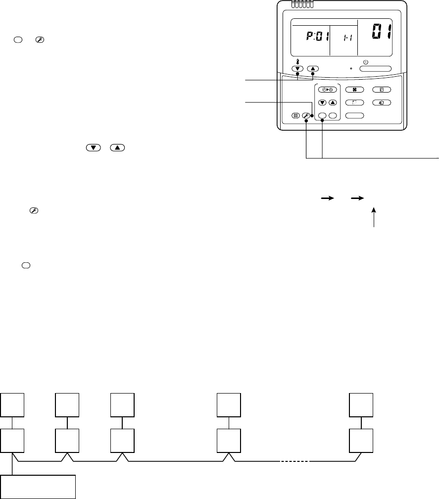
– 112 –
nCalling of error history
<Contents>
The error contents in the past can be called.
<Procedure>
1Push
CL
+
TEST
buttons simultaneously for 4
seconds or more to call the service check
mode.
Service Check goes on, the item code 01 is
displayed, and then the content of the latest alarm is
displayed. The number and error contents of the
indoor unit in which an error occurred are displayed.
2In order to monitor another error history, push
the set temperature / buttons to
change the error history No. (Item code).
Item code 01 (Latest) → Item code 04 (Old)
NOTE : Four error histories are stored in memory.
3Pushing
TEST
button returns the display to usual
display.
<Requirement>
Do not push
CL
button, otherwise all the error histories of
the indoor unit are deleted.
(Group control operation)
In a group control, operation of maximum 8 indoor units can be controlled by a remote controller.
The indoor unit connected with outdoor unit (Individual/Master of twin) controls room temperature according to
setting on the remote controller.
<System example>
1. Display range on remote controller
The setup range (Operation mode/Air volume select/Setup temp) of the indoor unit which was set to the
master unit is reflected on the remote controller.
2. Address setup
Turn on power of the indoor unit to be controlled in a group within 3 minutes after setting of automatic
address.
If power of the indoor unit is not turned on within 3 minutes (completion of automatic address setting), the
system is rebooted and the automatic address setting will be judged again.
1) Connect 3 In/Out cables surely.
2) Check line address/indoor address/group address of the unit one by one.
3) The unit No. (line/indoor gout address) which have been set once keep the present status as a rule if the
unit No. is not duplicated with one of another unit.
1 2 3
<Operation procedure>
Returned to usual display
3
2
1
ON / OFF
FAN
TEMP.
SWING/FIXTIME
MODE
VENT
UNITSET CL
FILTER
RESET
TEST
TIMER SET
UNIT No.
DATA
SET
R.C. No.
OUT
IN
Remote controller
1-1
OUT
IN 2-1
Master
OUT
IN 3-1
OUT
IN 4-1
OUT
IN 7-1
Max. 8 units
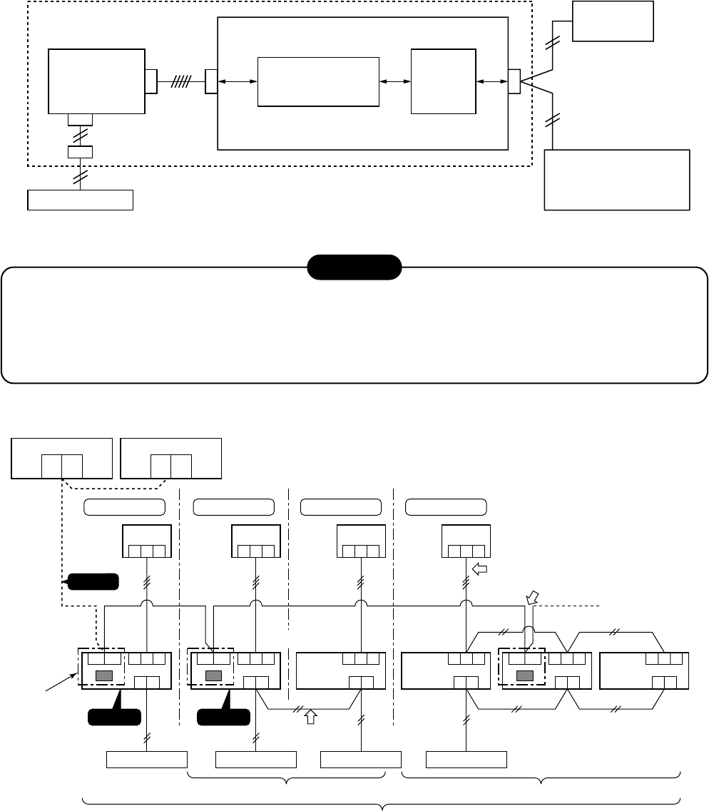
– 113 –
12-2. Setup at Local Site / Others
Model name: TCB-PCNT30TLE2
12-2-1. TCC-LINK Adapter (For TCC-LINK Central Control)
1. Function
This model is an optional P.C. board to connect the indoor unit to TCC-LINK (Central controller).
2. Microprocessor Block Diagram
3. TCC-LINK Wiring Connection
CAUTION
1) When controlling customized setup collectively, TCC-LINK adapter (This option) is required.
2) In case of group operation or twin/triple operation, the adapter is necessary to be connected to the main unit.
3) Connect the central control devices to the central control system wiring.
4) When controlling collectively customized setup only, turn on only Bit 1 of SW01 of the least line of the system
address No. (OFF when shipped from the factory)
∗∗
∗∗
∗In case of customized setup, the address is necessary to be set up again from the wired remote
controller after automatic addressing.
CN51
CN40
SW01
Remote controller
Indoor control
P.C. board TCC-LINK
communication circuit Terminal
resistance
TCC-LINK adapter P.C. board
MCC-1440
Indoor unit
TCC-LINK
Communication units:
Total 64 units
Communication distance:
2000 m
CN050
CN041
Terminal block
(A, B)
Central
controller
Indoor units in all refrigerant lines: Max. 64 units
[If mixed with multi model (Link wiring), multi indoor units are included.]
* However group sub units and twin/triple sub units of customized setup are not included in number of the units.
Central control device
U1
U3 U2
U4
Central control device
U1
U3
123
U2
U4
Central control devices: Max. 10 units
Refrigerant line 1
Outdoor unit
Indoor unit
123
Refrigerant line 2
123
Refrigerant line 3
123
Refrigerant line 4
123
AB
U3 U4
Caution 3
123
AB
U3 U4 123
AB
123
AB
123
AB
123
AB
U3 U4
TCC-LINK adapter
This product
sold separately
( )
Caution 1
Remote controller
Indoor/outdoor inter-unit wire (AC230V serial)
Central control system wiring
Maater unit
Maater
unit Sub unit Sub unit
Sub
unit
* Wiring for No.1 and 2 only
Caution 2
Remote controller Remote controller Remote controller
Remote controller
wiring
Group operation (Max. 8 units) Twin/Triple operation (Example of triple)
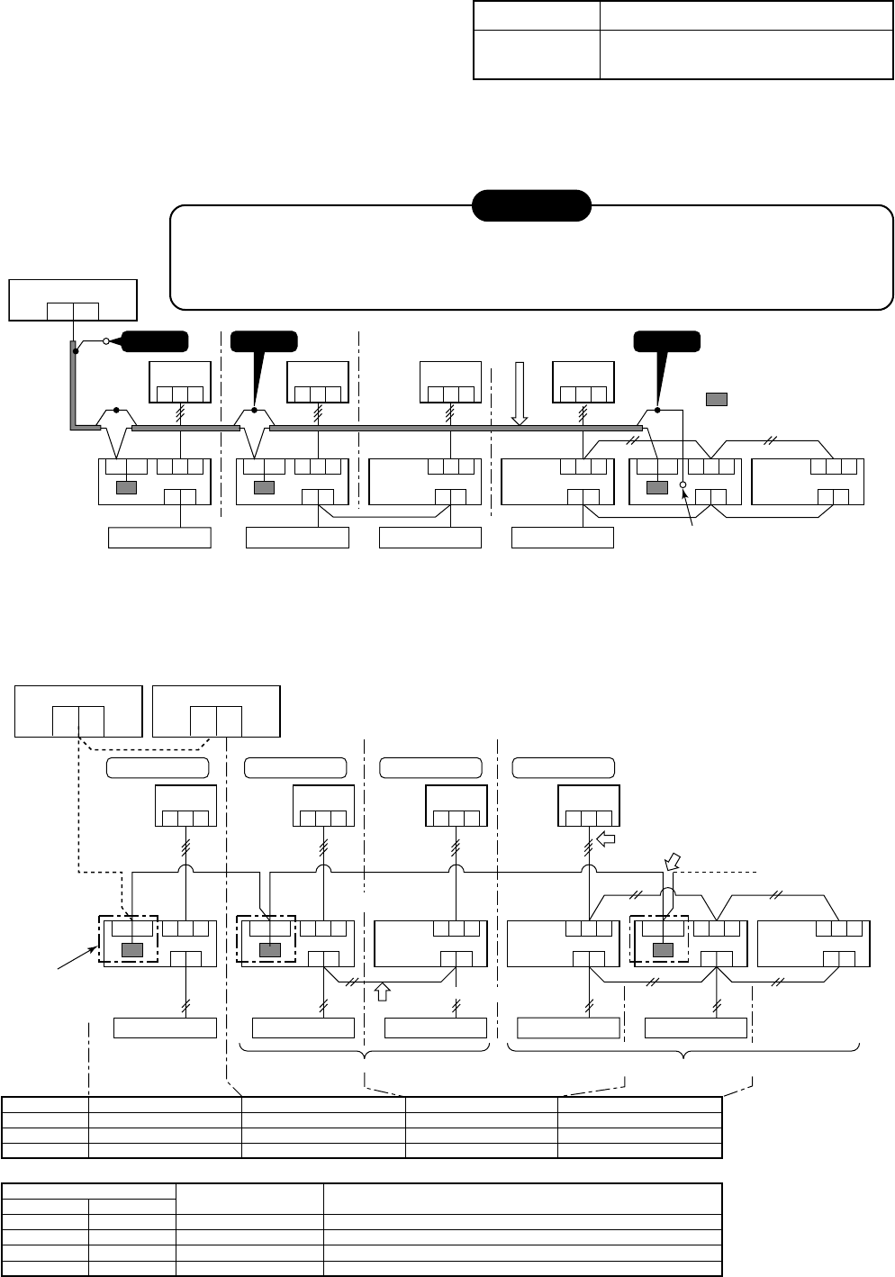
– 114 –
4. Wiring Specifications
•Use 2-core with no polar wire.
•Match the length of wire to wire length of the central
control system.
If mixed in the system, the wire length is
lengthened with all indoor/outdoor inter-unit wire length at side.
•To prevent noise trouble, use 2-core shield wire.
•Connect the shield wire by closed-end connection and apply open process (insulating process) to the last terminal.
Ground the earth wire to 1 point at indoor unit side. (In case of central controlling of digital inverter unit setup)
No. of wires
2
Size
Up to 1000m: twisted wire 1.25mm2
Up to 2000m: twisted wire 2.0mm2
5. P.C. Board Switch (SW01) Setup
When performing collective control by customized setup only, the setup of terminator is necessary.
•Using SW01, set up the terminator.
•Set up the terminator to only the adapter connected to the indoor unit of least line address No.
Central control device
U1
U3 U2
U4
Central control device
U1
U3
123
U2
U4
Central control devices: Max. 10 units
Refrigerant line 1
Outdoor unit
Indoor unit
123
Refrigerant line 2
123
Refrigerant line 3
123
Refrigerant line 4
123
AB
U3 U4 123
AB
U3 U4 123
AB
123
A B
123
A B
123
A B
U3 U4
TCC-LINK adapter
This product
sold separately
( )
Remote controller
Indoor/outdoor inter-unit wire (AC230V serial)
Central control system wiring
Master unit
Master
unit Sub unit Sub unit
Sub
unit
* Wiring for No.1 and 2 only
Remote controller Remote controller Remote controller Remote controller
Remote controller wiring
Group operation (Max. 8 units) Twin/Triple operation (Example of triple)
(OFF at shipment from factory)
(OFF at shipment from factory)
Line address
SW01 Bit 1
SW01 Bit 2
Remarks
1
ON
OFF
Turn SW01 Bit 1 to ON.
2
OF
OFF
As status shipped from factory
4
OF
OFF
As status shipped from factory
(Reference) Setup contents of switch
SW01
Bit 1
OFF
ON
OFF
ON
Bit 1
OFF
OFF
ON
ON
Terminator
None
100Ω
75Ω
43Ω
Remarks
Mixed with multi (Link wiring) at shipment from factory
Central control by digital inverter only
Spare
Spare
Central control device
U1 U2
123
Outdoor unit
Indoor unit
123123123
123
AB
U3 U4 123
AB
U3 U4 123
AB
123
A B
123
A B
123
A B
U3 U4
Caution 1
Remote controller
Central control system wiring
Master unit
Master
unit Sub unit Sub unit
Sub unit
Caution 2
Remote controller Remote controller Remote controller
(Group operation) (Triple operation)
Caution 3
: TCC-LINK adapter
(This option)
Earth terminal
CAUTION
1) Closed-end connection of shield wire (Connect all the connecting parts of each indoor unit)
2) Apply open process to the last terminal (insulating process).
3) Ground earth wire to 1 point at indoor unit side.
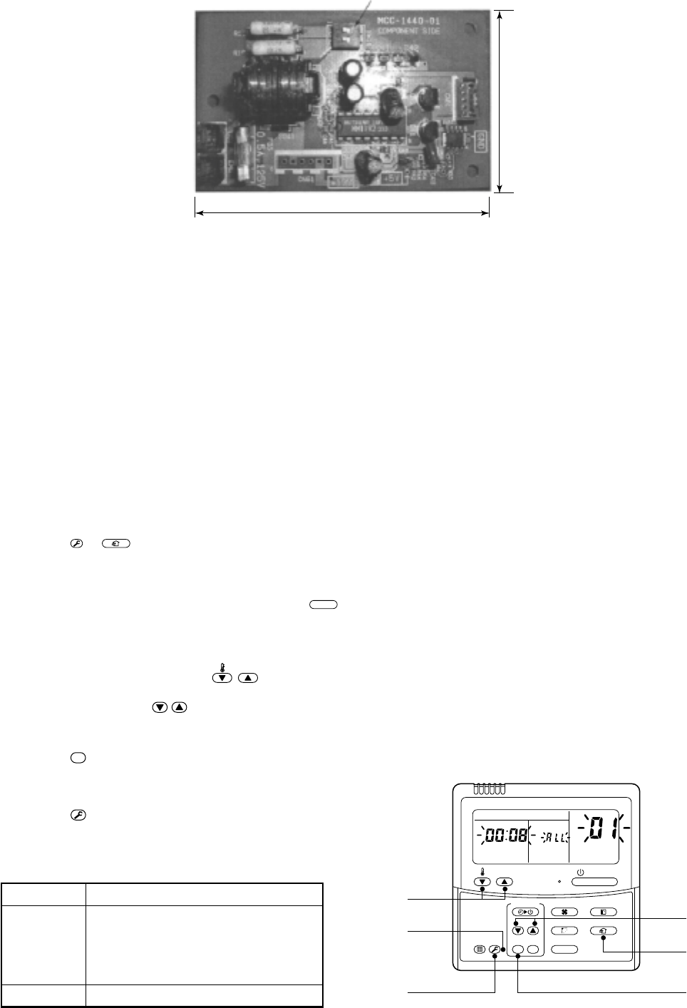
– 115 –
6. External View of P.C. Board
7. Address Setup
In addition to set up the central control address, it is necessary to change the indoor unit number.
(Line/Indoor/Group address).
For details, refer to TCC-LINK Adapter Installation Manual.
12-3. How to set up central control address number
When connecting the indoor unit to the central control remote controller using TCC-LINK adapter, it is neces-
sary to set up the central control address number.
•The central control address number is displayed as the line No. of the central control remote controller.
1. Setup from remote controller at indoor unit side
* If you use the network adapter P.C. board, it is effective only when No. 7 of setup switch SW01 on P.C.
board is turned off.
<Procedure> Perform setup while the unit stops.
1Push
TEST
+
VENT
buttons for 4 seconds or more.
When group control is executed, first the unit No. RLL is displayed and all the indoor units in the group
control are selected. In this time, fans of all the selected indoor units are turned on. (Fig. 1)
(Keep RLL displayed status without pushing
UNIT
button.)
In case of individual remote controller which is not group-controlled, Line address and Indoor unit address
are displayed.
2Using temperature setup
TEMP.
buttons, specify item code 03.
3Using timer time
TIME
buttons, select the setup data. The setup data is shown in the right
table (Table 1).
4Push
SET
button. (OK if display goes on.)
•To change the item to be set up, return to Procedure 2.
5Push
TEST
button.
The status returns to usual stop status.
5
2
11
3
4
ON / OFF
FAN
TEMP.
SWING/FIXTIME
MODE
VENT
UNITSET CL
FILTER
RESET
TEST
TIMER SET
UNIT No.
DATA
SET
R.C. No.
(Table 1)
Setup data
0001
0002
0003
:
0064
0099
Central control address No.
1
2
3
:
64
Unset (Setup at shipment from factory)
(Fig.1)
Terminator (SW01)
52
85
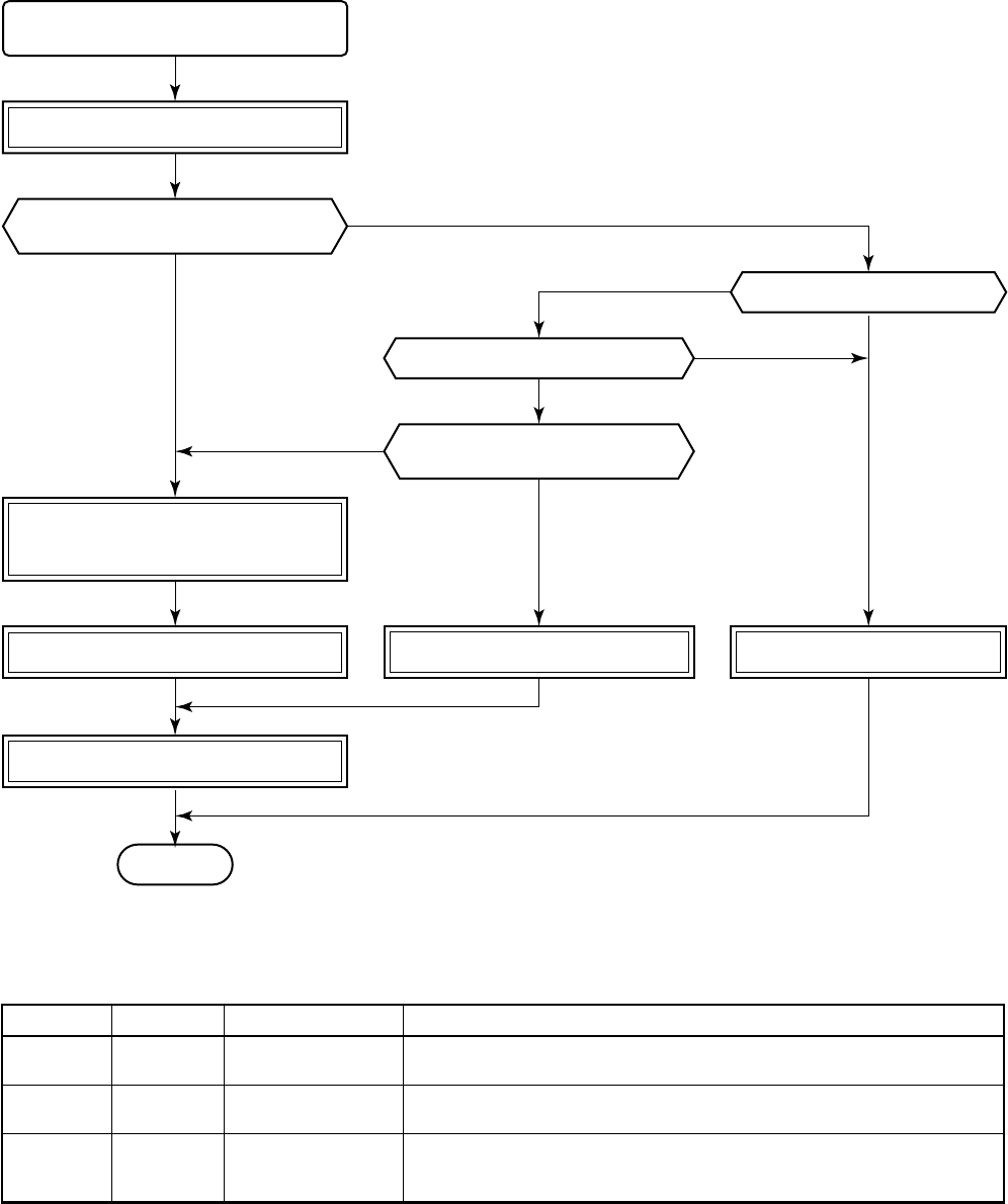
– 116 –
Setup of line address of outdoor unit,
indoor unit address, and group address
Completion of cabling work
Turn on power of outdoor unit. Turn on power of outdoor unit.
Connect one remote controller with
one indoor unit (1 : 1) tentatively with
communication cable.
END
Turn on power of outdoor unit.
Set to all indoor units one by one.
Do you arbitrarily set the
indoor unit address?
Do you change setting after
automatic setting at the first time?
Is refrigerant line 1 line?
Is group control performed?
Setup of automatic
address finishes within
4 to 5 minutes.
After completion of address
setup, change is to arbitral
address/group manually.
(To AUTO address mode)
(MANUAL)
( ) ( )
YES
YES
YES
YES
NO
NO
NO
13. ADDRESS SETUP
13-1. Address Setup
<Address setup procedure>
When an outdoor unit and an indoor unit are connected, or when an outdoor unit is connected to each indoor
unit respectively in the group operation even if multiple refrigerant lines are provided, the automatic address
setup completes with power-ON of the outdoor unit. The operation of the remote controller is not accepted while
automatic address works. (Approx. 4 to 5 minutes)
•When the following addresses are not stored in the neutral memory (IC10) on the indoor P.C. board, a test run
operation cannot be performed. (Unfixed data at shipment from factory)
Line
address
Indoor unit
address
Group
address
Item code
12
13
14
Data at shipment
0099
0099
0099
Setup data range
0001 (No. 1 unit) to 0030 (No. 30 unit)
0001 (No. 1 unit) to 0030 (No. 30 unit)
Max. value of indoor units in the identical refrigerant line (Double twin = 4)
0000 : Individual (Indoor units which are not controlled in a group)
0001 : Master unit (1 indoor unit in group control)
0002 : Sub unit (Indoor units other than master unit in group control)
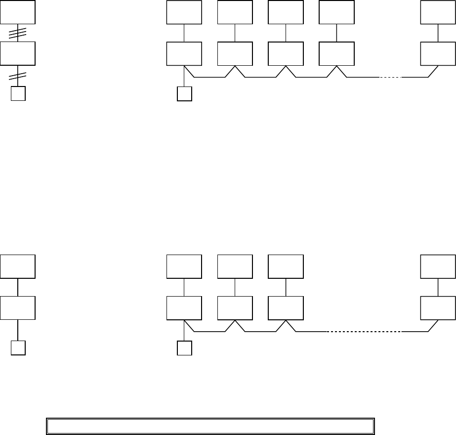
– 117 –
Outdoor
1-1
Individual
Indoor (Master/Sub)
Remote
controller
2-1
Sub 1-1
Sub 4-1
Master 3-1
Sub 8-1
Sub
1-1
Individual
(Master/Sub)
Max. 8 units
2-1
Sub 1-1
Sub 4-1
Master 8-1
Sub
13-2. Address Setup & Group Control
<Terminology>
Indoor unit No. : N - n = Outdoor unit line address N (Max. 30) - Indoor unit address n (Max. 64)
Group address : 0 = Individual (Not group control)
1 = Master unit in group control
2 = Sub unit in group control
Master unit (= 1) : The representative of multiple indoor units in group operation sends/receives signals to/from
the remote controllers and sub indoor units. (* It has no relation with an indoor unit which
communicates serially with the outdoor units.)
The operation mode and setup temperature range are displayed on the remote controller
LCD. (Except sir direction adjustment of louver)
Sub unit (= 2) : Indoor units other than master unit in group operation
Basically, sub units do not send/receive signals to/from the remote controllers.
(Except errors and response to demand of service data)
13-2-1. System configuration
1. Single 2. Single group operation
13-2-2. Automatic address example from unset address (No miscabling)
1. Standard (One outdoor unit)
1) Single 2) Gr operation
(Multiple outdoor units = Miltiple indoor units only with serial
communication)
Only turning on source power supply (Automatic completion)
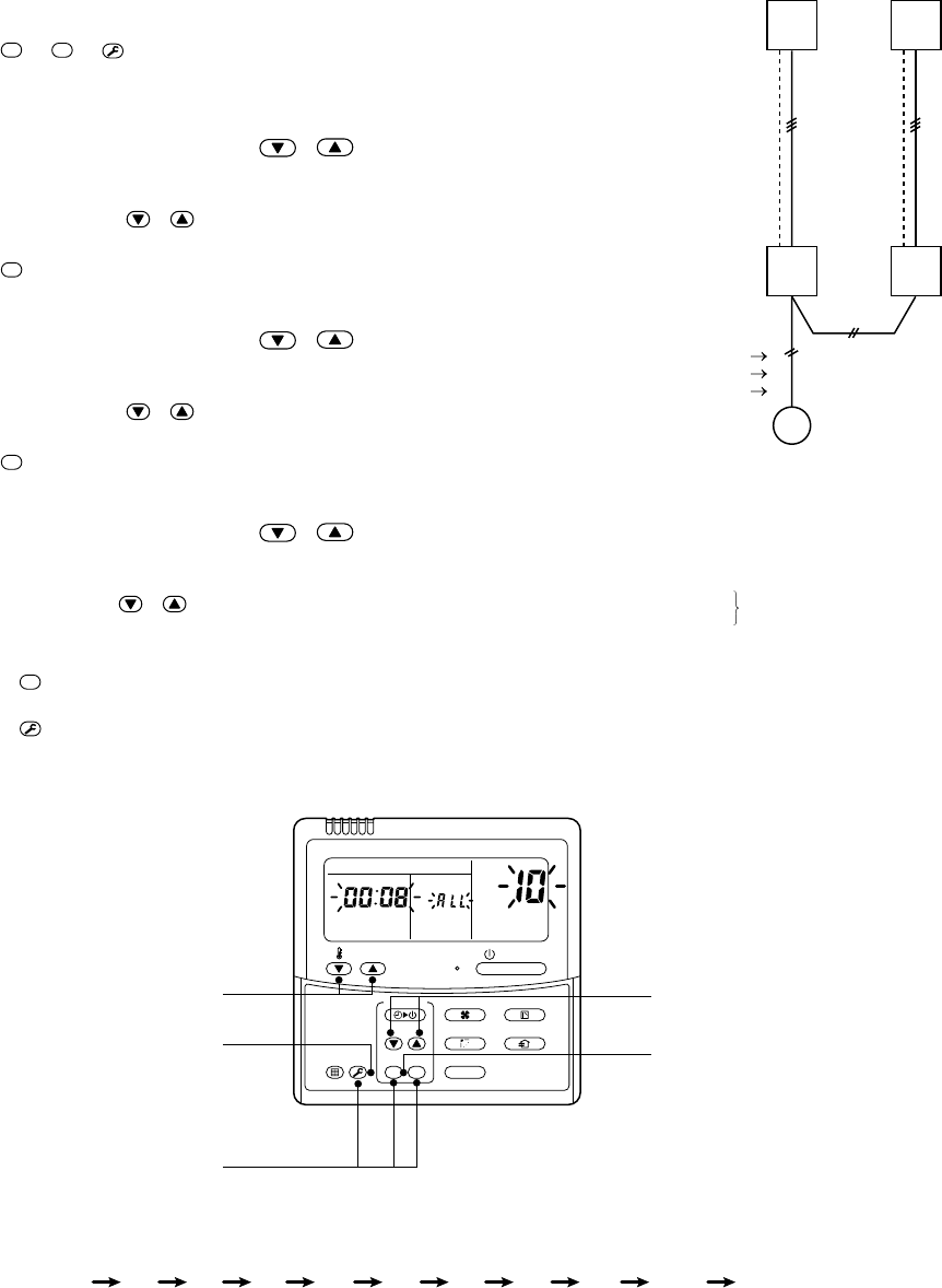
– 118 –
(Example of 2-lines cabling)
(Real line: Cabling, Broken line: Refrigerant pipe)
Line address 1
Indoor unit address 1
Group address 1
For the above example, perform setting by connecting
singly the wired remote controller without remote
controller inter-unit cable.
Group address
Individual : 0000
Master unit : 0001
Sub unit : 0002 In case of group control
OUT
IN
OUT
IN
2
1
2
1 2 3 4 5 6 7 8 9 10 11
END
<Operation procedure>
1
3, 6, 9
END
11
2, 5, 8
4, 7, 10
ON / OFF
FAN
TEMP.
SWING/FIXTIME
MODE
VENT
UNITSET CL
FILTER
RESET
TEST
TIMER SET
UNIT No.
DATA
SET
R.C. No.
13-3. Address Setup
In case that addresses of the indoor units will be determined prior to piping work after cabling work
(Manual setting from remote controller)
<Address setup procedure>
•Set an indoor unit per a remote controller.
•Turn on power supply.
1Push
SET
+
CL
+
TEST
buttons simultaneously
for 4 seconds or more.
2(←←
←←
← Line address)
Using the temperature setup / buttons,
set 12 to the item code.
3Using timer time / buttons, set the line address.
4Push
SET
button. (OK when display goes on.)
5(←←
←←
← Indoor unit address)
Using the temperature setup / buttons,
set 13 to the item code.
6Using timer time / buttons, set 1 to the line address.
7Push
SET
button. (OK when display goes on.)
8(←←
←←
← Group address)
Using the temperature setup / buttons,
set 14 to the item code.
9Using timer time / buttons, set 0000 to Individual,
0001 to Master unit, and 0002 to sub unit.
10 Push
SET
button. (OK when display goes on.)
11 Push
TEST
button.
Setup completes. (The status returns to the usual stop status.)
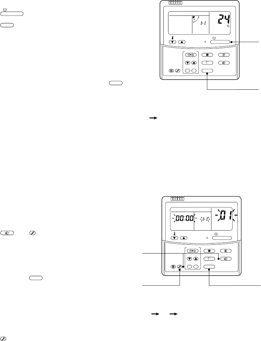
– 119 –
1 2
END
Operation
<Operation procedure>
2
1
ON / OFF
FAN
TEMP.
SWING/FIXTIME
MODE
VENT
UNITSET CL
FILTER
RESET
TEST
TIMER SET
UNIT No.
1 2 3
END
<Operation procedure>
3
1
2
ON / OFF
FAN
TEMP.
SWING/FIXTIME
MODE
VENT
UNITSET CL
FILTER
RESET
TEST
TIMER SET
UNIT No.
DATA
SET
R.C. No.
nConfirmation of indoor unit No. position
1. To know the indoor unit addresses though position of the indoor unit body is recognized
•In case of individual operation (Wired remote controller : indoor unit = 1 : 1)
(Follow to the procedure during operation)
<Procedure>
1Push
ON / OFF
button if the unit stops.
2Push
UNIT
button.
Unit No. 1-1 is displayed on LCD.
(It disappears after several seconds.)
The displayed unit No. indicate line address and
indoor unit address.
(When other indoor units are connected to the
identical remote controller (Group control unit), other
unit numbers are also displayed every pushing
UNIT
button.
2. To know the position of indoor unit body by address
•To confirm the unit No. in the group control
(Follow to the procedure during operation) (in this procedure, the indoor units in group control stop.)
<Procedure>
The indoor unit numbers in the group control are succes-
sively displayed, and fan, louver, and drain pump of the
corresponding indoor unit are turned on.
(Follow to the procedure during operation)
1Push
VENT
and
TEST
buttons simultaneously for
4 seconds or more.
•Unit No. ALL is displayed.
•Fans and louvers of all the indoor units in the
group control operate.
2Every pushing
UNIT
button, the unit numbers
in the group control are successively dis-
played.
•The unit No. displayed at the first time indicates the
master unit address.
•Fan and louver of the selected indoor unit only
operate.
3Push
TEST
button to finish the procedure.
All the indoor units in the group control stop.
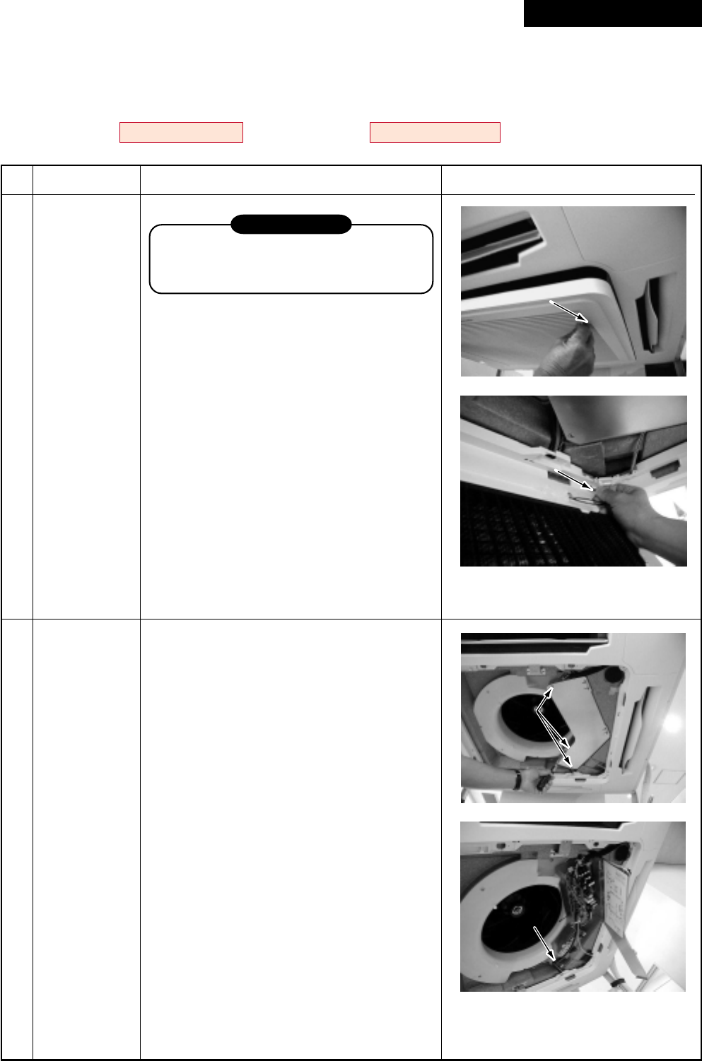
– 120 –
14. DETACHMENTS
14-1. Indoor Unit
14-1-1. 4-Way Air Discharge Cassette Type
RAV-SM563UT-E, RAV-SM803UT-E, RAV-SM1103UT-E, RAV-SM1403UT-E
RAV-SP1102UT-E
Knob of suction g
Knob of suction g
rille
Remo
Remo
ve the str
e the str
ap
ap
.
Knob of suction grille
Remove the strap.
3 screws
ws
T
T
entative hook
3 screws
Tentative hook
No.
Part name
Suction grille
Electric parts
cover
Procedure
REQUIREMENT
Never forget to put on the gloves at
disassembling work, otherwise an injury
will be caused.
1. Detachment
1) Stop operation of the air conditioner,
and then turn off switch of the breaker.
2) Hang down the suction grille while
sliding two knobs of the suction grille
inward.
3) Remove a strap connecting the panel
and the suction grille to remove the
suction grille.
2. Attachment
1) Hang the suction grille to the panel.
2) Attach the strap of the suction grille to
the panel as before.
3) Close the suction grille, slide the knobs
outward, and then fix it.
1. Detachment
1) Perform work of item 1. of .
2) Remove screws fixing the electric parts
cover. (Ø4 × 10, 3 pcs.)
3) Remove the electric parts cover from
the tentative hook, and then open the
cover.
2. Attachment
1) Close the electric parts cover and hang
the cover hole to the tentative hook.
2) Tighten the fixing screws.
(Ø4 × 10, 3 pcs.)
Remarks
Revised : Mar. 2007
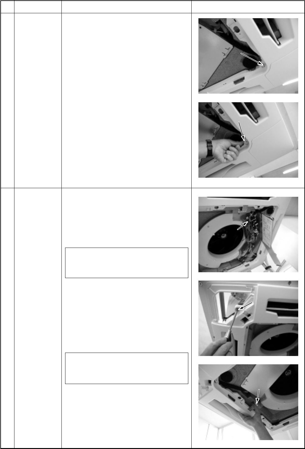
– 121 –
Scre
Scre
w
Push outw
Push outw
ard
Screw
Push outward
Fixing screw
Push the tentative
hook outward
Remove the
louver connector
Fixing screw
Push the tentative
hook outward
Remove the
louver connector
No.
Part name
Adjust corner
cap
Ceiling panel
Procedure
1. Detachment
1) Perform work of item 1. of .
2) Remove screws at 4 corners of the
suction port. (Ø4 × 10, 4 pcs.)
3) Push the knob outward and remove the
adjust corner cap by sliding it.
2. Attachment
1) Mount the adjust corner cap by sliding
it inward.
2) Tighten screws at 4 corners of the
suction port. (Ø4 × 10, 4 pcs.)
1. Detachment
1) Perform works of items 1 of , 1 of
and 1 of .
2) Remove the louver connector (CN33,
White, 5P) connected to the control
P.C. board, and then remove the lead
wire from the clamp.
NOTE :
Remove the connector by releasing
locking of the housing.
3) Remove screws fixing the ceiling panel.
(M5, 4 pcs.)
4) Push the tentative hook outward to
remove the ceiling panel.
2. Attachment
1) Hang the tentative hook of the main
body drain pan to the tentative hook of
the ceiling panel.
NOTE :
A panel has directional property, so mount
a panel with attention to the marks.
2) Tighten fixing screws. (M5, 4 pcs.)
3) Connect louver connector of the ceiling
panel to connector (CN33, White, 5P)
on the control P.C. board.
Remarks
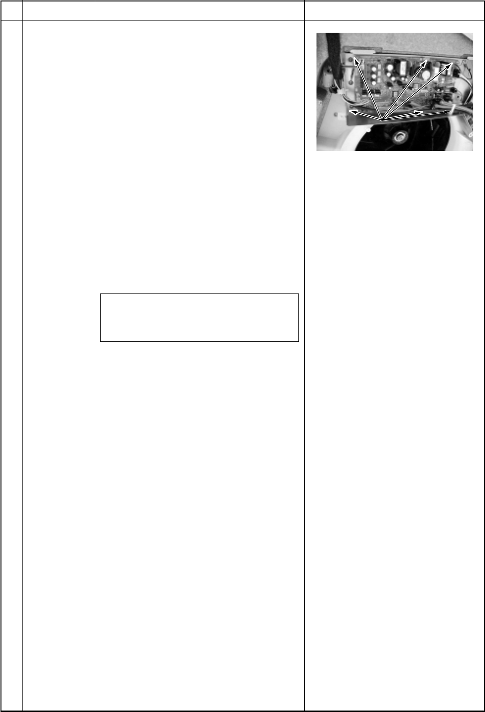
– 122 –
Card-edge spacer
Card-edge spacer
Card-edge spacer
No.
Part name
Control P.C.
board
Procedure
1. Detachment
1) Perform works of items 1 of and 1 of
.
2) Remove connectors which are con-
nected from the control P.C. board to
other parts.
CN33 : Louver motor (5P: White)
CN34 : Float switch (3P: Red)
CN41 : Terminal block of remote
controller (3P: Blue)
CN68 : Drain pump (3P: Blue)
CN67 : Terminal block of power supply
(5P: Black)
CN101: TC sensor (2P: Black)
CN102: TCJ sensor (2P: Red)
CN104: Room temperature sensor
(2P: Yellow)
CN333: Power supply of fan motor
(5P: White)
CN334: Position detection of fan motor
(5P: White)
NOTE :
Remove the connector by releasing
locking of the housing.
3) Unlock locking of the card-edge spacer
at 6 positions to remove the control P.C.
board.
2. Attachment
1) Fix the control P.C. board to the card-
edge spacer at 6 positions.
2) Connect the connectors removed in
item 1 to the original positions.
Remarks
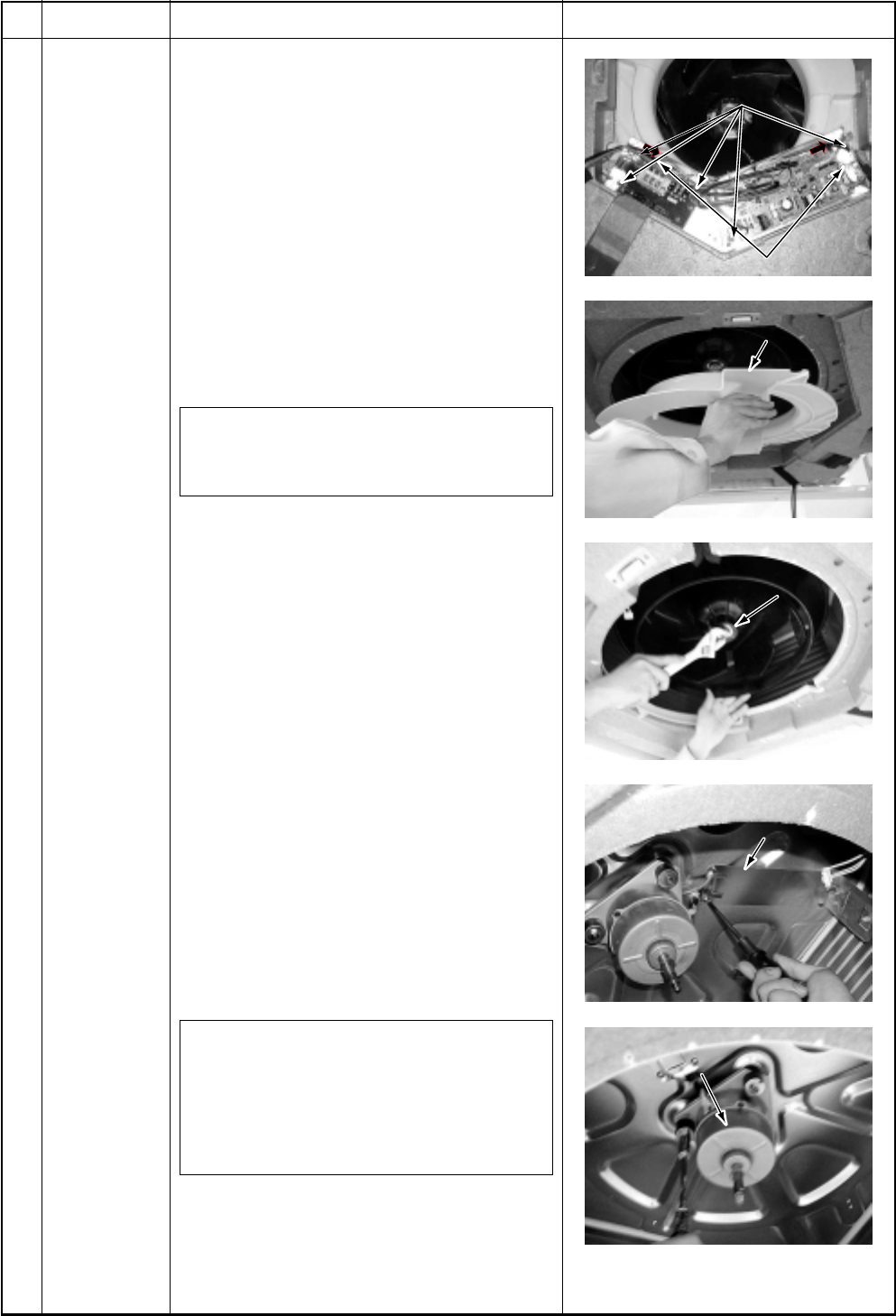
– 123 –
Screws fixing earth lead wires
Screws fixing electric parts box
Bell mouth
Turbo fan
Motor lead holder
Motor lead holder
Fan motor
an motor
Screws fixing earth lead wires
Screws fixing electric parts box
Bell mouth
Turbo fan
Motor lead holder
Fan motor
No.
Part name
Fan motor
Procedure
1. Detachment
1) Perform works of items 1 of and 1 of
.
2) Remove clamps of the lead wires
connected to the following connectors of
the control P.C. board.
CN33 : Louver motor (5P: White)
CN34 : Float switch (3P: Red)
CN68 : Drain pump (3P: Blue)
CN101 : TC sensor (2P: Black)
CN102 : TCJ sensor (2P: Red)
CN333 : Power supply of fan motor
(5P: White)
CN334 : Position detection of fan motor
(5P: White)
NOTE :
Remove the connector by releasing locking
of the housing.
3) Remove screws fixing earth lead wire in
the electric parts box. (Ø4 × 6, 2 pcs.)
4) Remove indoor/outdoor inter-unit cable
and remote controller cable of the
terminal block.
5) Remove screws fixing the electric parts
box. (Ø4 × 10, 5 pcs.)
6) Remove screws fixing the bell mouth.
(Ø4 × 10, 6 pcs.)
7) Remove nuts fixing the turbo fan.
(M6, 1 pc.)
8) Remove screws fixing holder of the
motor lead wires to remove the motor
lead wires from the clamp. (Ø4 × 8, 3
pcs.)
9) Remove nuts fixing the fan motor to
remove it.
2. Attachment
1) Fix the parts, fan motor, holder of the
motor lead, turbo fan, bell mouth, and
electric parts box successively to their
original positions.
NOTE 1 :
When fixing the turbo fan, be sure to match
the fan boss with D-cut of the motor shaft.
NOTE 2 :
Fix the turbo fan with torque wrench
5.9 ± 0.6Nm.
2) Connect connectors, earth lead wire,
indoor/outdoor inter-unit cable, and
remote controller cable which have been
disconnected in the above item 1 as
before.
Remarks
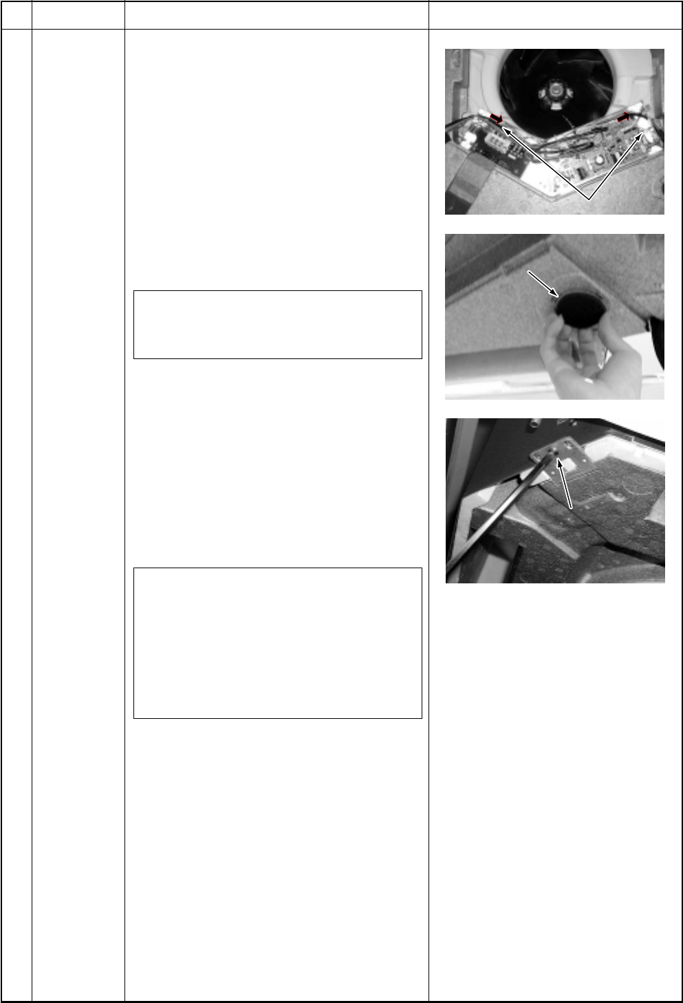
– 124 –
Screws fixing earth lead wires
Drain cap
Screws fixing drain pan
Screws fixing earth lead wires
Drain cap
Screws fixing drain pan
No.
Part name
Drain pan
Procedure
1. Detachment
1) Perform works of items 1 of , 1 of , 1
of and 1 of .
2) Remove clamps of the lead wires con-
nected to the following connectors of the
control P.C. board.
CN34 : Float switch (3P: Red)
CN68 : Drain pump (3P: Blue)
CN101 : TC sensor (2P: Black)
CN102 : TCJ sensor (2P: Red)
CN333 : Power supply of fan motor
(5P: White)
CN334 : Position detection of fan motor
(5P: White)
NOTE :
Remove the connector by releasing locking
of the housing.
3) Remove screws fixing earth lead wire in
the electric parts box. (Ø4 × 6, 2 pcs.)
4) Remove indoor/outdoor inter-unit cable
and remote controller cable of the
terminal block.
5) Remove screws fixing the electric parts
box. (Ø4 × 10, 5 pcs.)
6) Remove screws fixing the bell mouth.
(Ø4 × 10, 6 pcs.)
7) Remove the drain cap, and drain water
accumulated in the drain pan.
NOTE 1 :
When removing the drain cap, be sure to
prepare a bucket to catch the drained water.
NOTE 2 :
Thermal insulator is adhered to the drain
cap. Be careful not to peel off the insulator.
If the insulator has been peeled, adhere it
with double-face tape, etc. as before.
8) Remove screws fixing the drain pan.
(Ø4 × 8, 4 pcs.)
2. Attachment
1) Fix the parts, drain cap, drain pan, bell
mouth, and electric parts box succes-
sively to their original positions.
2) Connect connectors, earth lead wire,
indoor/outdoor inter-unit cable, and
remote controller cable which have been
disconnected in the above item 1 as
before.
Remarks
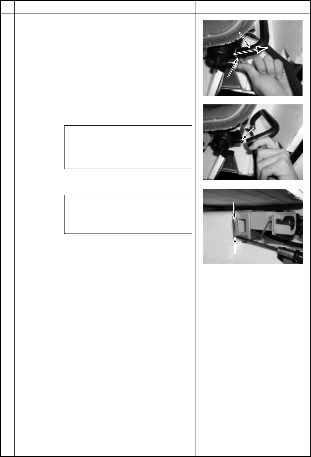
– 125 –
Hose band
Slide to hose side.
Pump connecting par
Pump connecting par
t
Hooking cla
Hooking cla
w
Fixing scre
Fixing scre
w
Hose band
Slide to hose side.
Pump connecting part
Hooking claw
Fixing screw
No.
Part name
Drain pump
assembly
Procedure
1. Detachment
1) Perform works of items 1 of , 1 of ,
1 of , 1 of and 1 of .
2) Picking the hose band, slide it from
pump connecting part to remove the
drain hose.
3) Remove screw fixing the drain pump
assembly, slide hooking claws of the
drain pump assembly and the main
body (1 position), and then remove the
assembly. (Ø4 × 8, 3 pcs.)
3. Attachment
1) Fix the drain pump assembly as before.
NOTE :
The drain pump is fixed with a hook and 3
screws. In screwing, be sure that screws
do not to run on hooking claw at the main
body side.
2) Attach the drain hose and hose band as
before.
NOTE :
Insert the drain hose up to the end of
pump connecting part, and bind the white
mark position of the hose with band.
Remarks
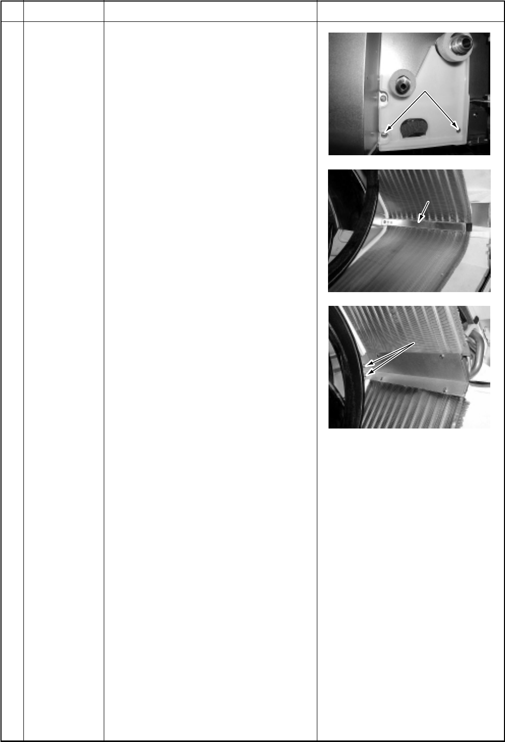
– 126 –
Fixing screws
Fixing band
Fixing band
Fixing screws
Fixing screws
Fixing band
Fixing screws
No.
Part name
Heat
exchanger
Procedure
1. Detachment
1) Recover refrigerant gas.
2) Remove refrigerant pipe at the indoor
unit side.
3) Perform works of items 1 of , 1 of
, 1 of , 1 of and 1 of .
4) Remove screws fixing the pipe cover.
(Ø4 × 8, 2 pcs.)
5) Remove the heat exchanger by
removing fixing band and fixing screws
while holding the heat exchanger.
(Ø4 × 8, 3 pcs.)
2. Attachment
1) Fix the parts, heat exchanger, fixing
band, pipe cover, drain cap, drain pan,
bell mouth, and electric parts box
successively to their original positions.
2) Connect connectors, earth lead wire,
indoor/outdoor inter-unit cable, and
remote controller cable which have
been disconnected in the above item 1
as before.
3) Connect the refrigerant pipe as before,
and then perform vacuuming.
Remarks
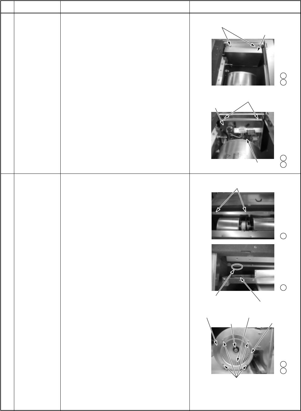
– 127 –
Electrical parts cover
Screws
(Fixing electrical parts box and main unit)
Electrical parts box
Claw (Reverse side)
Fixing claw (Main unit)
Multi blade fan
Fan case
Screws (Fixing fan case cover)
Fan case cover
Set screw
Fixing hole (Fan assembly)
Hexagon head screws
(Fixing fan assembly and main unit)
Screws
(Fixing electrical parts cover and box)
1 -2
1 -3
1 -4
1 -5
2 -3
2 -4
2 -5
2 -6
14-1-2. Concealed Duct Type
RAV-SM562BT-E, RAV-SM802BT-E, RAV-SM1102BT-E, RAV-SM1402BT-E
Be sure to turn off the power supply or circuit breaker before disassembling work
No.
Part name
Electrical parts
box
Multi blade fan
Procedure
1. Remove the air filter.
2. Remove the set screws (2 positions) of
the electrical parts cover.
3. Remove the electrical parts cover.
4. Remove the set screws (2 positions) of
the electrical parts box.
5. Remove the electrical parts box.
The electrical parts box is fixed to the
main unit with claws at the right side.
Lift up it once and pull toward you.
Then claws come off.
In this time, remove connectors of TA sensor,
TC sensor and TCJ sensor if necessary.
1. Remove the air filter.
2. Remove the connector of the fan motor
P.C. board.
3. Remove the hexagon head screw (562: 2,
802, 1102, 1402 : 3 positions) of fixing fan
assembly and main unit.
4. Remove the fan assembly from main unit.
The fan assembly is fixed to the main unit
with claws (3 positions) at the upper side.
Lift up it once and pull toward rear side.
Then claws come off.
5. Remove the set screws (4 positions) of
fixing fan case and fan cover.
6. Remove the fan cover.
7. Loosen the sets crew of the Multi blade
fan using hexagon wrench.
8. Pull the Multi blade fan towered fan case
side.
Then fans come off.
Remarks
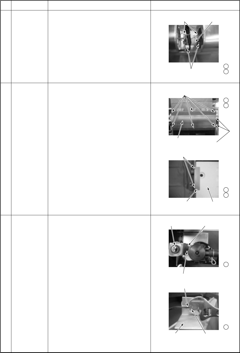
– 128 –
Fan motor holder
Screws
(Fixing fan motor holder)
Fan motor
Screws (Fixing lower plate)
Screws
(Fixing drain pan holder)
Lower plate
Screws (Fixing drain pan holder)
Drain pan holder Drain pan
Float switch holder
Float switch
Screw
(Fixing float switch holder)
Float switch holder
Float switch (View from reverse side)
Plastic nut
3 -2
3 -3
4 -2
4 -3
4 -4
4 -5
5 -2
5 -3
No.
Part name
Fan motor
Drain pan
Float switch
Procedure
1. Remove the Multi blade fan.
2. Remove the hexagon head screw of fixing
fan motor holder.
3. Remove the fan motor holder
(2 positions).
1. Take down the main unit and then treat
the drain pan on the floor.
2. Remove the set screws (562 : 7, 802,
1102, 1402 : 9 positions) of fixing lower
plate.
3. Remove the lower plate from main unit.
4. Remove the set screws (562 : Nothing,
802 : 2 positions, 1102, 1402 : 4 positions)
of fixing drain pan holder and main unit.
5. Remove the drain pan holder (562 :
Nothing, 802 : 1 position, 1102, 1402 : 2
positions) from main unit.
6. Remove the drain pan.
Pull it lower side.
1. Remove the drain pan.
2. Remove the set screw (1 position) of
fixing float switch holder.
3. Remove the plastics nut of foxing float
switch.
4. Remove the float switch.
Remarks
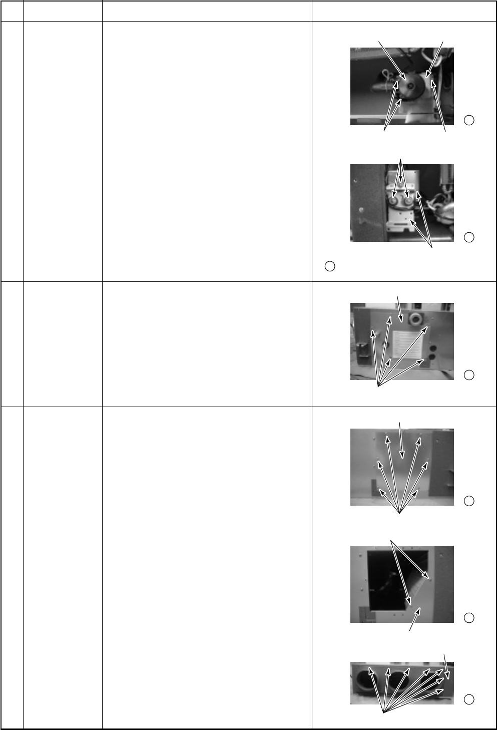
– 129 –
Drain pump holder
Screws (Fixing drain pump holder)
Drain pump
Screws (Fixing plate and drain pump)
Drain pump holder
(6) -3. View from reverse side of drain pump
Checking port cover (Right side)
Screws (Fixing check port cover (Right side))
Check port cover (Left side)
Screws (Fixing check port cover (Left side))
Main unit (Left side)
Screws (Fixing heat exchanger)
Screws
Main unit (Front side)
6
6 -2
6 -3
7 -1
8 -4
8 -5
8 -6
No.
Part name
Drain pump
TC, TCJ sensor
Heat
exchanger
Procedure
1. Remove the drain pan and float switch.
2. Remove the set screws (3 positions) of
fixing drain pump plate and main unit.
3. Remove the set screws (3 positions) of
fixing drain pump plate and drain pump.
1. Remove the set screws (5 positions) and
check port cover (right side).
2. Pull out the sensor is inserted into pipe of
the heat exchanger.
1. Take down the main unit and then treat
the heat exchanger on the floor.
2. Remove the drain pan.
3. Remove the check port cover (right side).
4. Remove the set screws (6 positions) and
check port cover (left side).
5. Remove the set screws (2 positions) of
fixing heat exchanger and main unit
(left side).
6. Remove the set screws (7 positions) of
fixing heat exchanger and main unit
(front right side).
Remarks
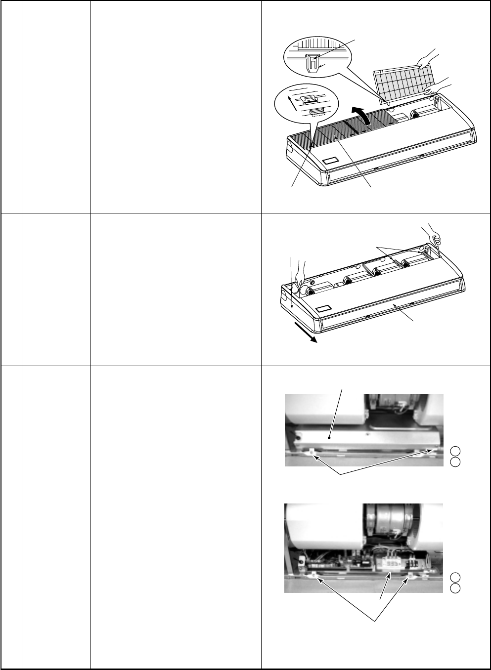
– 130 –
Suction grille
Pull out suction grille
while pushing hook.
Suction grille
fixing knob
Hinge
Slide
Slide forward.
Side panel
Level flap
Protector
3 -2
3 -3
3 -4
3 -5
Screws
(Fixing electrical parts cover and box)
Electrical parts cover
Screws
(Fixing electrical parts box and main unit)
Electr
Electr
ical par
ical par
ts bo
ts bo
xElectrical parts box
14-1-3. Under Ceiling Type
RAV-SM562CT-E, RAV-SM802CT-E, RAV-SM1102CT-E, RAV-SM1402CT-E
Be sure to turn off the power supply or circuit breaker before disassembling work
No.
Part name
Suction grille
Side panel
Electrical
parts box
Procedure
1. Slide the suction grille fixing
knobs (2 positions) toward the
arrow direction of left figure, and
open the suction grille.
2. Under the condition of the
suction grille opened, push the
hook section of hinges (2 posi-
tions) at the rear side, and then
pull out the suction grille.
1. Open the suction grille.
2. After removing the side panel
screws (2 positions), slide the
side panel forward and then
remove it.
1. Remove the suction grille.
2. Loosen the set screws (2 posi-
tions) of the electrical parts
cover.
3. Remove the electrical parts
cover.
4. Remove the set screws
(2 positions) of the electrical
parts box.
5. Remove the electrical parts box.
In this time, remove connectors of
TA sensor, TC sensor and TCJ
sensor if necessary.
Remarks
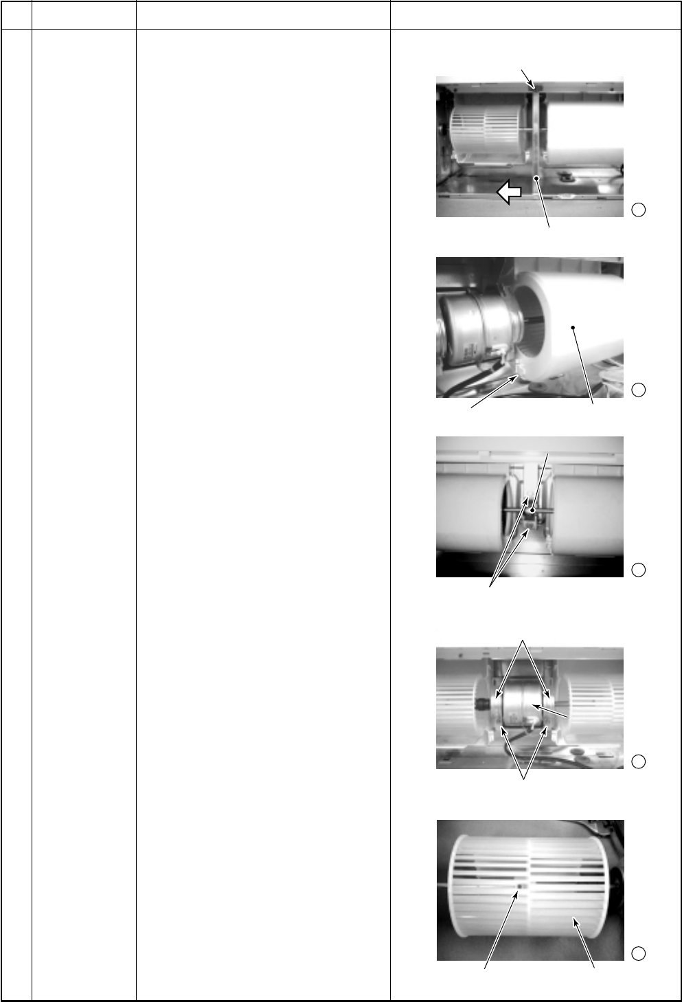
– 131 –
4 -3
4 -4
4 -5
4 -6
4 -7
Reinforcing bar
Screws
(Fixing reinforcing bar and main unit)
Fan cover (Lower side)Fan cover fixing hook
Bearing
Hexagon head screws
(Fixing bearing and main unit)
Hexagon screws
(Fixing fan motor and main unit)
Fan motor holder
Set screw of multi blade fan Multi blade fan
Fan motor
Bearing
Fan motor
No.
Part name
Multi blade fan
motor
Procedure
1. Remove the suction grille.
2. Remove the connector of the fan
motor from P.C. board.
3. (SM802, SM1102, SM1402CT-E
only)
Remove the set screw (1 position)
to fixing and reinforcing bar.
(Slide the reinforcing bar toward
arrow side on the left figure.)
4. Push the fan cover fixing hooks
(2 positions) forward fan cover side
and remove the fan cover.
5. (SM1102, SM1402CT-E only)
Remove the hexagon head screws
(2 positions) to fix bearing and the
bearing.
6. Remove the hexagon head screw of
fixing fan motor and fan motor
holder then the assembly removed
from the main unit.
7. Loosen the sets crew of the multi
blade fan using hexagon wrench.
8. Pull the multi blade fan towered fan
case side. Then fans come off.
Remarks
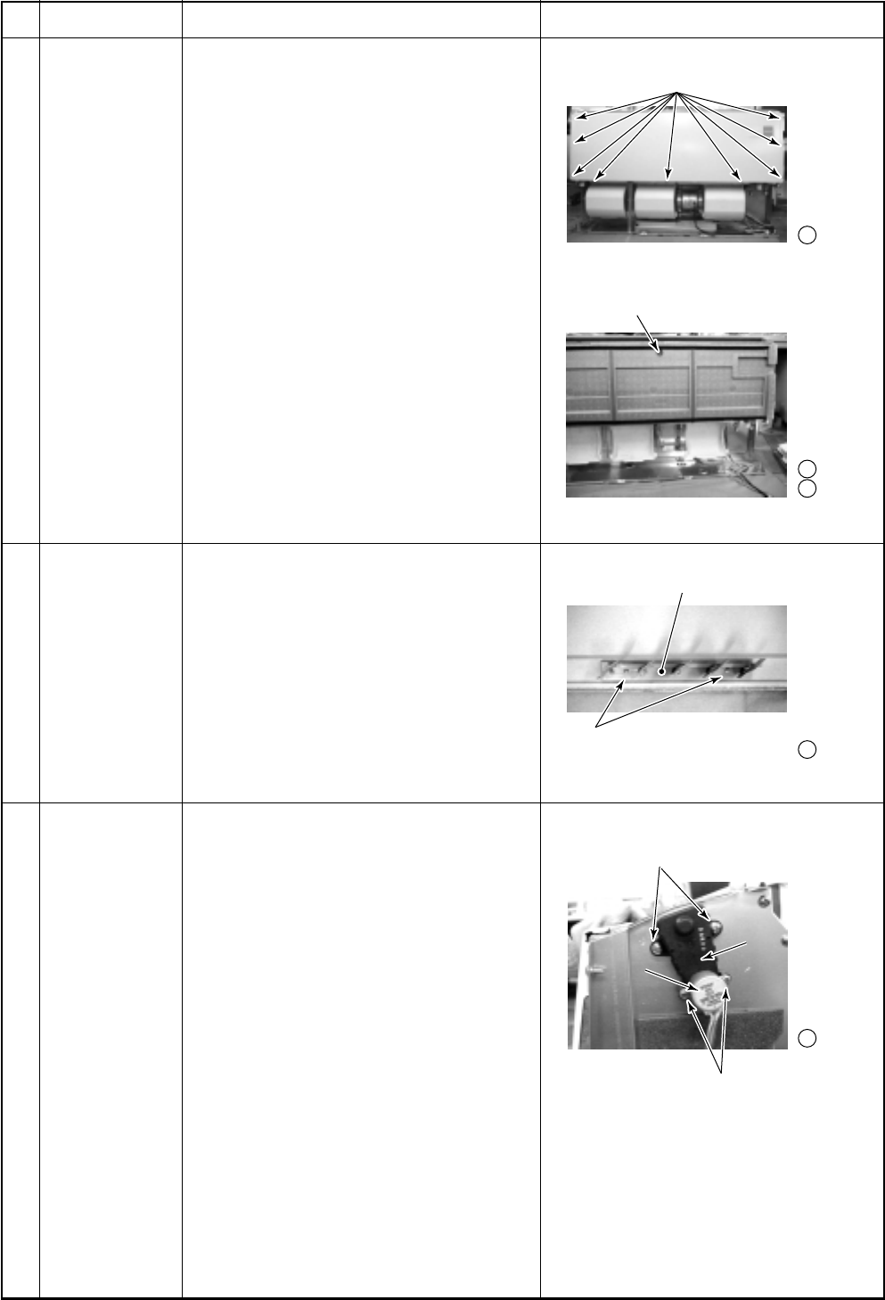
– 132 –
5 -5
5 -6
5 -4
6 -2
7 -3
Screws
(Fixing lower plate and main unit)
Heat insulation
The screw that fixed drain pan and
main unit is under this insulation.
Vertical grille
Screws
(Fixing drain pan and vertical grille)
Louver drive
member
Louver
motor
Louver drive
member
Louver
motor
Screws
(Fixing louver motor and louver drive member)
Screws
(Fixing louver drive member and main unit)
No.
Part name
Drain pan
Vertical grille
Louver motor,
Lover drive
member
Procedure
1. Take down the main unit and then treat
the drain pan on the floor.
2. Remove the both side panels and
suction grilles.
3. (SM802, SM1102, SM1402CT-E only)
Remove the set screw (1 position) to
fixing and reinforcing bar.
(Slide the reinforcing bar toward arrow
side on the right figure.)
4. Remove the set screws (9 positions) of
fixing lower plate.
5. Remove the heat insulation on the
drain pan.
(SM562, SM802 : 1 position, SM1102,
SM1402 : 2 positions)
6. Remove the set screws
(SM562, SM802 : 1 position, SM1102,
SM1402 : 2 positions) of fixing drain
pan and main unit.
7. Remove the drain pan.
Pull it lower side.
1. Remove the drain pan.
2. Remove the set screws (2 positions) of
fixing vertical grille.
3. Remove the vertical grille.
1. Remove the side cover (right side only).
2. Remove the set screws (2 positions)
and louver motor.
3. Remove the set screws (2 positions)
and louver drive member.
Remarks
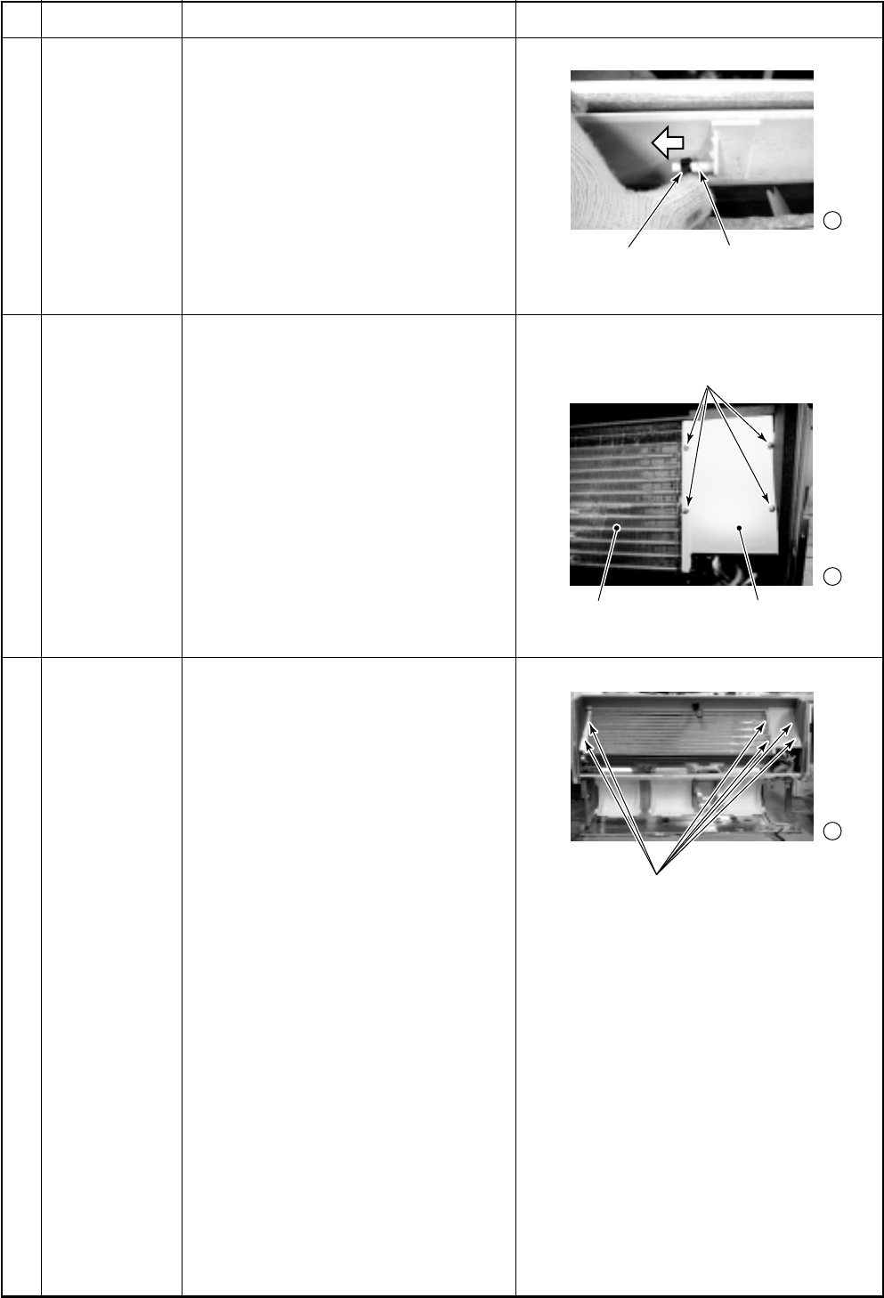
– 133 –
8 -1
9 -3
10
-3
Screws
(Fixing heat exchanger and main unit)
Louver holder Shaft of
horizontal louver
Screws
(Fixing heat exchanger support)
Heat exchanger Heat exchanger support
No.
Part name
Horizontal
louver
TC, TCJ sensor
Heat
exchanger
Procedure
1. Push the louver holder toward arrow
direction of right figure, and pull out
the center shaft (SM562, SM802 :
1 position, SM1102, SM1402 :
2 positions) from louver holder.
2. Pull off the left and right chaft of
horizontal louver.
1. Remove the drain pan.
2. Remove the set screws (4 positions)
and heat exchanger support.
3. Pull out the sensor is inserted into
pipe of the heat exchanger.
1. Take down the main unit and then
treat the heat exchanger on the
floor.
2. Remove the drain pan.
3. Remove the set screws (6 positions)
of fixing heat exchanger and main
unit.
Remarks
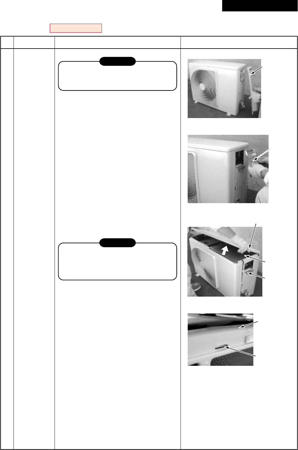
– 134 –
Valve
cover
Wiring
cover
Upper cabinet
Water-proof
cover
Cord clamp
Rear cabinet
Claw
14-2. Outdoor Unit
RAV-SM563AT-E, RAV-SM803AT-E
No.
Part name
Common
procedure
Procedure
CAUTION
Never forget to put on the gloves at
working time, otherwise an injury will be
caused by the parts, etc.
1. Detachment
1) Stop operation of the air conditioner, and
turn off the main switch of the breaker for
air conditioner.
2) Remove the valve cover.
(ST1T Ø4 × 10L, 1 pc.)
•After removing screw, remove the valve
cover pulling it downward.
3) Remove wiring cover (ST1T Ø4 × 10L, 2
pcs.), and then remove connecting cable.
4) Remove the upper cabinet.
(ST1T Ø4 × 10L, 2 pcs.)
•After taking off screws, remove the
upper cabinet pulling it upward.
2. Attachment
1) Attach the waterproof cover.
CAUTION
Be sure to attach a waterproof cover.
If it is not attached, there is a possibility
that water enters inside of the outdoor
unit.
2) Attach the upper cabinet.
(ST1T Ø4 × 10L, 2 pcs.)
•Hook the rear side of the upper cabinet
to claw of the rear cabinet, and then put
it on the front cabinet.
3) Perform cabling of connecting cables,
and fix with cord clamp.
(ST1T Ø4 × 10L 3 pcs.)
4) Attach the wiring cover.
(ST1T Ø4 × 10L, 2 pcs.)
5) Attach the valve cover.
(ST1T Ø4 × 10L, 1 pc.)
•Insert the upper part of the upper
cabinet, set hooking claw of the valve
cover to the slit (at three positions) of
the main body, and then attach it
pushing upward.
Remarks
Revised : Mar. 2007
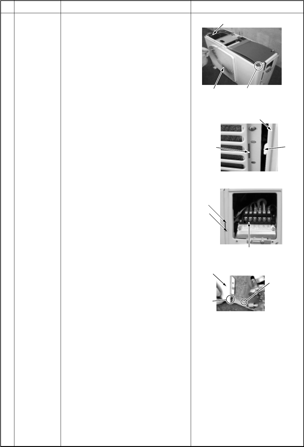
– 135 –
For single-phase type models,
also take off this screw
Motor support
Front cabinet
Front cabinet (Left side)
Slit Claw
Cord clamp
Slit
Hook
Front cabinet
Lower
slit
Concavity at
bottom plate
No.
Part name
Front cabinet
Procedure
1. Detachment
1) Perform work of item 1 of .
2) Remove screws (ST1T Ø4 × 10L, 2 pcs.)
of the front cabinet and the inverter cover.
3) Take off screws of the front cabinet and
the bottom plate. (ST1T Ø4 × 10L 3 pcs.)
4) Take off screws of the front cabinet and
the motor support.
(ST1T Ø4 × 10L, 2 pcs.)
•The left side of the front side if made to
insert to the rear cabinet, so remove it
pulling upward.
3. Attachment
1) Insert hook at the left side of the front side
into the rear cabinet.
2) Hook the lower part at the right side of the
front to concavity of the bottom plate.
Insert the hook of the rear cabinet into the
slit of the front cabinet.
3) Attach the removed screws to the original
positions.
Remarks
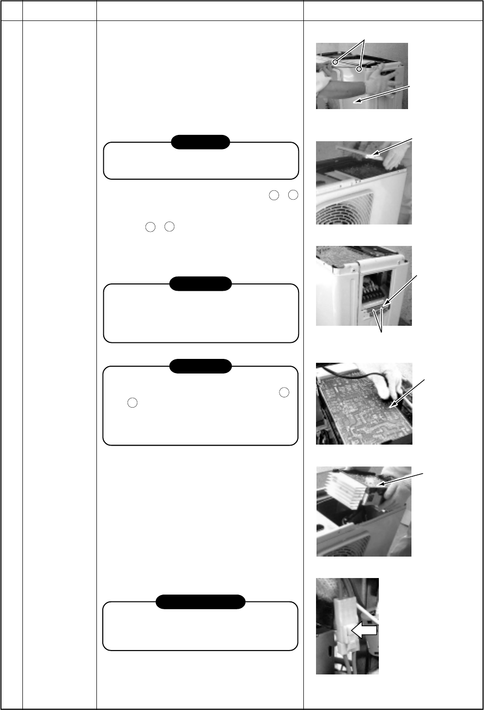
– 136 –
Screws
Front cabinet
Inverter cover
Cord clamp
Screws
(Discharging
period
10 seconds
or more)
Plug of
soldering iron
Discharging
position
Inverter
assembly
Remove the connectors
with locking function by
pushing the part indicated
by the arrow mark.
No.
Part name
Inverter
assembly
Procedure
1. Detachment
1) Perform work of item 1 of .
2) Take off screws of the upper part of the
front cabinet.
•If removing the inverter cover under this
condition, P.C. board can be checked.
•If there is no space in the upper part of
the upper cabinet, perform work of .
CAUTION
Be careful to check the inverter because
high-voltage circuit is incorporated in it.
3) Perform discharging by connecting
+
,
–
polarities by discharging resistance
(approx. 100Ω, 40W) or plug of soldering
iron to
+
,
–
terminals of the C14
(printed as “CAUTION HIGH VOLTAGE”)
electrolytic capacitor (500µF) of P.C.
board.
WARNING
The electrolytic capacitor may not nor-
mally discharge according to error con-
tents and the voltage may remain. There-
fore, be sure to discharge the capacitor.
WARNING
For discharging, never use a screwdriver
and others for short-circuiting between
+
and
–
electrodes. As the electrolytic
capacitor is one with a large capacity, it is
very dangerous because a large electric
spark will occur.
4) Take off screws (ST1T Ø4 × 10L, 2 pcs.)
fixing the main body and the inverter box.
5) Remove various lead wires from the
holder at upper part of the inverter box
and wiring holder at right side of the
terminal block.
6) Remove the lead wire from the bundled
part at left side of the terminal block.
7) Pull the inverter box upward.
8) Disconnect connectors of various lead
wires.
REQUIREMENT
As each connector has a lock mechanism,
avoid to remove the connector by holding
the lead wire, but by holding the connector.
Remarks
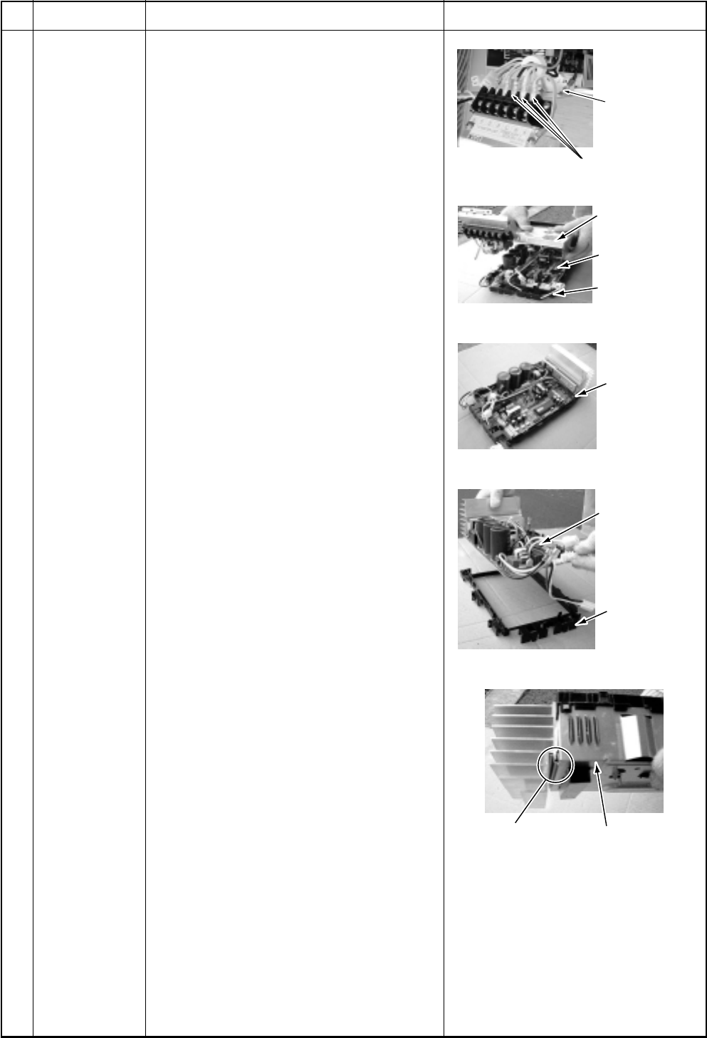
– 137 –
Take off
earth screws.
Power line
Inverter box
(Metal sheet)
Control P.C.
board assembly
P.C. board base
Hooking claws
(4 positions)
Control P.C.
board assembly
P.C. board base
Inverter box
(Metal sheet)
Heat sink
No.
Part name
Control P.C.
board assembly
Procedure
1) Disconnect lead wires and connectors
connected from the control P.C. board
assembly to other parts.
1. Lead wires
•Connection with the power terminal
block: 3 wires (Black, White, Orange)
•Earth wire: 1 wire (Black)
2. Connectors
•Connection with compressor:
Remove 3P connector.
•Connection with reactor:
Remove the relay connectors from
P07, 08 (2P, White) and P12, 13 (2P,
Yellow)
CN300 : Outdoor fan (3P, White)
CN301 : Position detection (5P, White)
CN701 : 4-way valve (3P, Yellow)
CN600 : TE sensor (2P, White)
CN601 : TD sensor (3P, White)
CN603 : TS sensor (3P, White)
CN602 : TO sensor (3P, White)
CN500 : Case thermo. (2P, White)
CN703 : PMV (6P, White)
2) Remove the inverter box (Metal plate).
3) Remove the control board assembly from
P.C. board base.
(Remove the heat sink and the control
board assembly as they are screwed.)
NOTES:
1. CN300, CN301 and CN701, etc. at the
control board assembly side are connec-
tors with locking function. Therefore,
remove the connector while pushing the
part indicated by an arrow mark.
2. Remove 4 hooking claws of P.C. board
base, and remove upward the heat sink
with hands.
4) Take off 3 screws fixing the heat sink and
main control board assembly side, and
replace the board with a new one.
NOTE:
When mounting a new board, check that the
board is correctly set in the groove of the
base holder of P.C. board base.
Attach the P.C. board so that the heat sink
comes securely contact with the metal
sheet.
Remarks
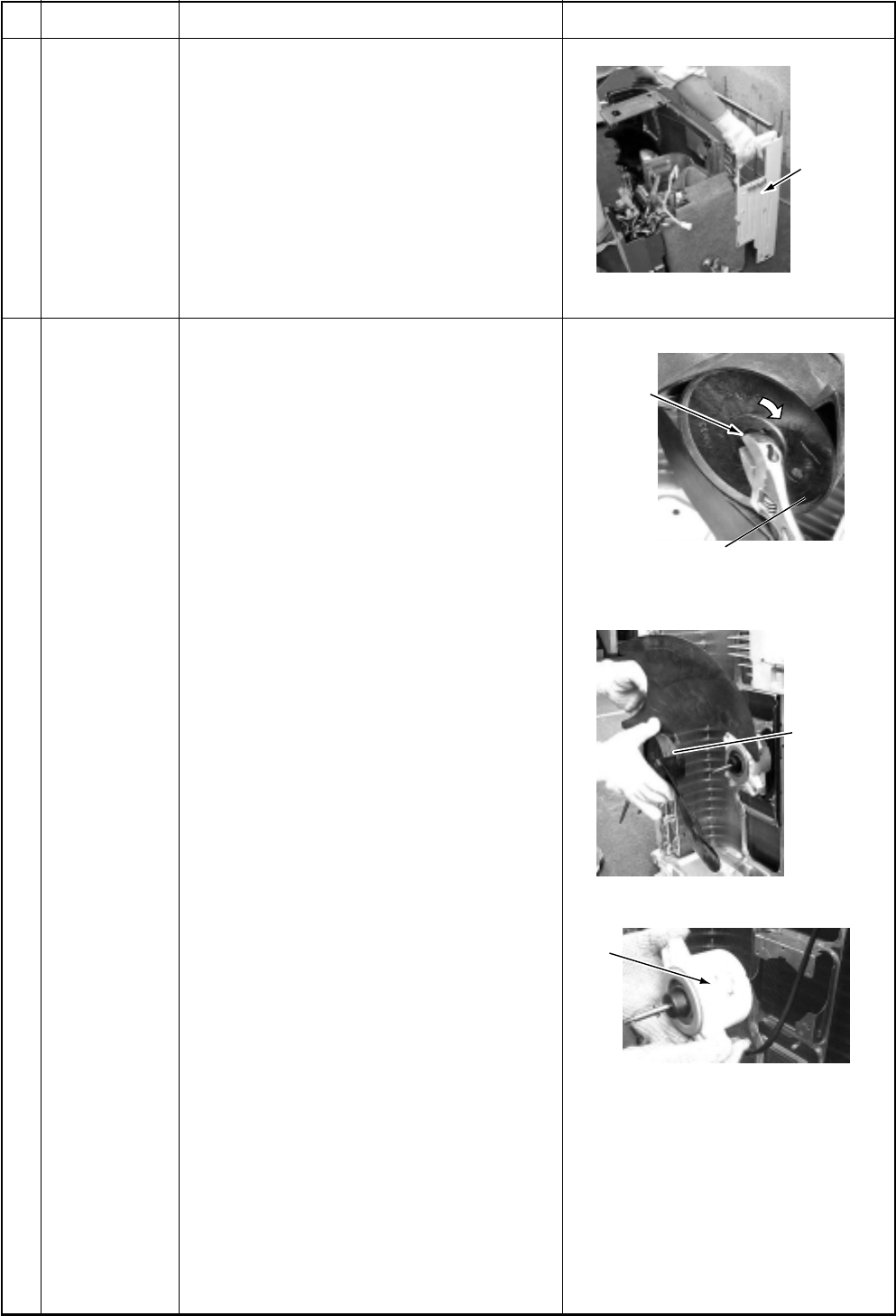
– 138 –
Rear cabinet
Flange nut
Loosen the nut by
turning clockwise
Propeller fan
Fan
motor
No.
Part name
Rear cabinet
Fan motor
Procedure
1) Perform works of items 1 of and , .
2) Take off fixed screws for the bottom plate.
(ST1T Ø4 × 10L, 3 pcs.)
3) Take off fixed screws for the heat ex-
changer. (ST1T Ø4 × 10L, 2 pcs.)
4) Take off fixed screw for the valve mounting
plate. (ST1T Ø4 × 10L, 1 pc.)
1) Perform works of items 1 of and .
2) Take off the flange nut fixing the fan motor
and the propeller.
•Turning it clockwise, the flange nut can
be loosened.
(To tighten the flange nut, turn counter-
clockwise.)
3) Remove the propeller fan.
4) Disconnect the connector for fan motor
from the inverter.
5) Take off the fixing screws (3 pcs.) holding
by hands so that the fan motor does not
fall.
NOTE:
Tighten the flange nut with torque 4.9Nm
(50kgf/cm).
Remarks
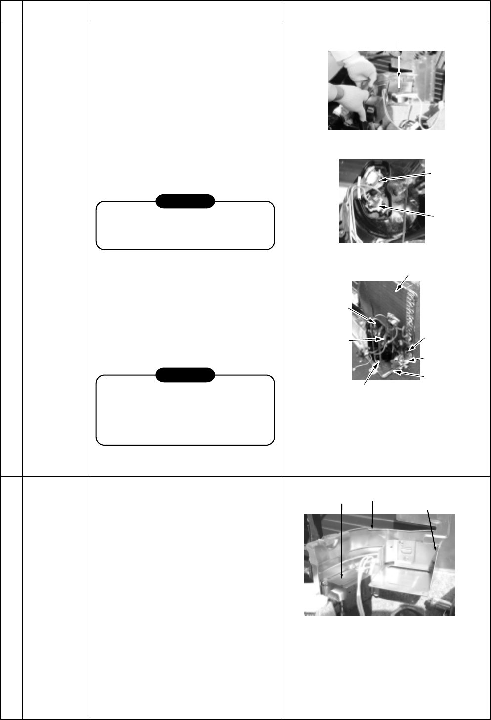
– 139 –
Partition plate
Compressor
Case thermo
lead
Heat exchanger
Screw
Valve
support board
Screws (2 pcs.)
Compressor bolt (3 pcs.)
Remove
(Suction pipe)
Remove
(Discharge pipe)
Reactor
Partition
plate Reactor
support board
No.
Part name
Compressor
Reactor
Procedure
1) Perform works of items 1 of and
, , , .
2) Discharge refrigerant gas.
3) Remove the partition plate.
(ST1T Ø4 × 10L, 2 pcs.)
4) Remove the noise-insulator.
5) Remove the terminal covers of the
compressor, and disconnect lead
wires of the compressor and the
compressor thermo assembly from
the terminal.
6) Remove pipes connected to the
compressor with a burner.
CAUTION
Pay attention to that flame does not
involve 4-way valve or PMV. (If doing
so, a malfunction may be caused.)
7) Take off the fixing screws of the
bottom plate and heat exchanger.
(ST1T Ø4 × 10L, 2 pcs.)
8) Take off the fixing screws of the valve
clamping plate to the bottom plate.
9) Pull upward he refrigerating cycle.
10) Take off nut fixing the compressor to
the bottom place.
CAUTION
When reconnecting the lead wires to
the compressor terminals after
replacement of the compressor, be
sure to caulk the Faston terminal
without loosening.
1) Perform works of item 1 of and .
2) First take off two screws
(ST1T Ø4 × 10L) of the reactor fixed
to the reactor support.
3) Remove the reactor support from the
partition plate.
(ST1T Ø4 × 10L, 4 pcs.)
4) Take off two screws
(ST1T Ø4 × 10L) directly attached to
the partition plate.
Remarks
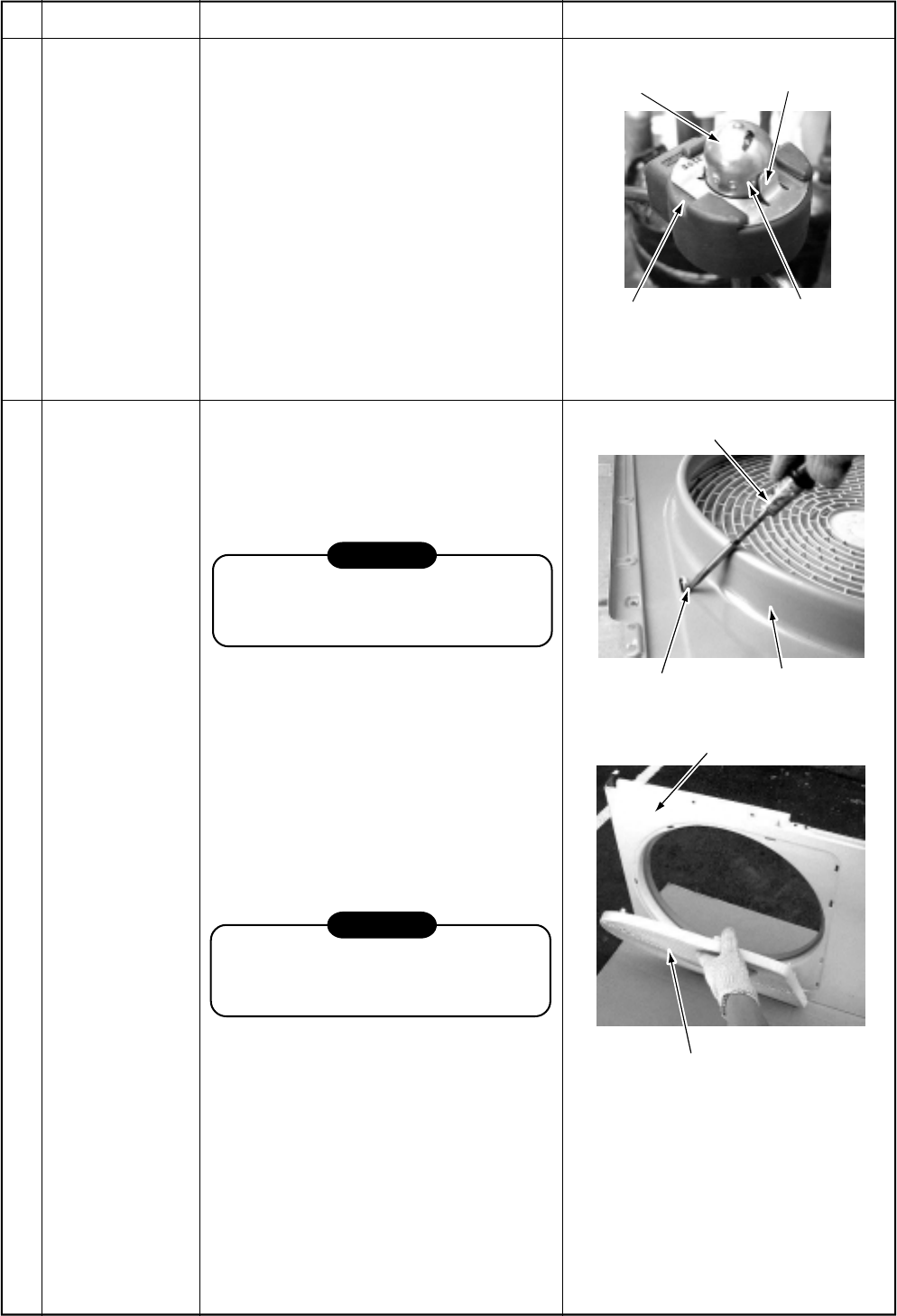
– 140 –
Positioning extrusion
PMV body
Concavity
PMV coil
Minus screwdriver
Front cabinet
Hooking claw
Front cabinet
Fan guard
No.
Part name
Pulse Modulating
Valve (P.M.V.) coil
Fan guard
Procedure
1. Detachment
1) Perform works of items and .
2) Release the coil from the concavity by
turning it, and remove coil from the
P.M.V.
2. Attachment
1) Put the coil deep into the bottom
position.
2) Fix the coil firmly by turning it to the
concavity.
1. Detachment
1) Perform works of items 1 of , and .
2) Remove the front cabinet, and put it
down so that fan guard side directs
downward.
CAUTION
Perform works on a corrugated card-
board, cloth, etc. to prevent flaw on the
product.
3) Remove the hooking claws by pushing
with minus screwdriver along with the
arrow mark in the right figure, and
remove the fan guard.
2. Attachment
1) Insert claws of the fan guard in the hole
of the front cabinet. Push the hooking
claws (10 positions) with hands and
then fix the claws.
CAUTION
All the attaching works have completed.
Check that all the hooking claws are
fixed to the specified positions.
Remarks
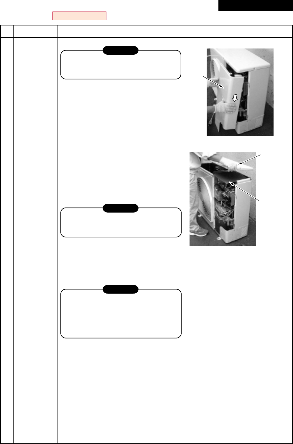
– 141 –
Front
cabinet
Upper plate
of cabinet
Water-proof
cove
RAV-SM1103AT-E, RAV-SM1403AT-E / RAV-SP562AT-E, RAV-SP802AT-E
No.
Part name
Common
procedure
Procedure
CAUTION
Never forget to put on the gloves at
working time, otherwise an injury will be
caused by the parts, etc.
1. Detachment
1) Stop operation of the air conditioner, and
also turn off switch of the breaker.
2) Remove the front panel.
(ST1T Ø4 × 10L, 3 pcs.)
•After taking off screws, remove the front
panel by pulling it downward.
3) Disconnect the connecting cables and
power cord from the terminals and cord
clamp.
4) Remove the upper cabinet.
(ST1T Ø4 × 10L, 6 pcs.)
2. Attachment
1) Attach the waterproof cover.
CAUTION
Be sure to attach a waterproof cover.
If it is not attached, there is a possibility
that water enters inside of the outdoor unit.
2) Attach the upper cabinet.
(ST1T Ø4 × 10L, 6 pcs.)
3) Connect the connecting cable and power
cord at the terminal and fix them with cord
clamp.
CAUTION
Using bundling band sold at a market, be
sure to fix the power cables and indoor/
outdoor connecting cables along the inter-
unit cable so that they do not come to
contact with the compressor, valves and
cables at gas side, and the discharge pipe.
4) Attach the front cabinet.
(ST1T Ø4 × 10L, 3 pcs.)
Remarks
Revised : Mar. 2007
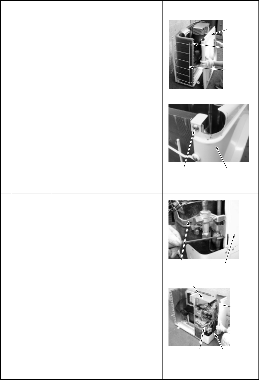
– 142 –
Side cabinet
Inverter
Fin guard
End plate of the
heat exchanger Discharge port
Valve support plate Side cabinet
Inverter
Side cabinet
Cabling panel
(Rear)
Valve support
plate
No.
Part name
Discharge port
cabinet
Side cabinet
Procedure
1. Detachment
1) Perform work of item 1 of .
2) Take off screws (ST1T Ø4 × 10L, 3 pcs.)
of discharge port cabinet for the partition
plate.
3) Take off screws (ST1T Ø4 × 10L, 2 pcs.)
of discharge port cabinet for the bottom
plate.
4) Take off screw (ST1T Ø4 × 10L, 1 pc.) of
discharge port cabinet for the heat
exchanger.
5) Take off screws (ST1T Ø4 × 10L, 2 pcs.)
of discharge port cabinet for the fin guard.
2. Attachment
1) Put the upper left side of the discharge
port cabinet on the end plate of the heat
exchanger, and then fix it with screw.
(ST1T Ø4 × 10L, 1 pc.)
2) Attach the removed screws to the original
positions.
1) Perform work of item 1 of .
2) Remove screw fixing the inverter and the
side cabinet. (ST1T Ø4 × 10, 1 pc.)
3) Remove screws of the side cabinet and
the valve support plate.
(ST1T Ø4 × 10, 2 pcs.)
4) Remove screw of the side cabinet and the
cabling panel (Rear).
(ST1T Ø4 × 10, 1 pc.)
5) Remove screw of the side cabinet and the
bottom plate. (ST1T Ø4 × 10, 1 pc.)
6) Remove screw of the side cabinet and the
fin guard (Heat exchanger).
(ST1T Ø4 × 10, 2 pcs.)
Remarks
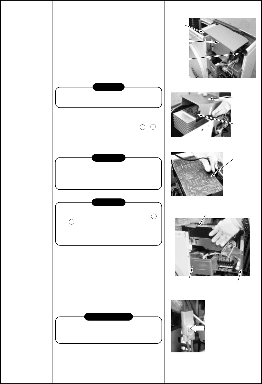
– 143 –
Screw
Inverter
assembly
Holder
Inverter
cover
Inverter
assembly
Plug of
soldering iron
Left time:
10 sec. or more
Screw
Hook for the side
cabinet (lower left side)
Inverter assembly
Remove the connectors
with locking function by
pushing the part indicated
by the arrow mark.
No.
Part name
Inverter
assembly
Procedure
1) Perform works of items of 1) to 5) of .
2) Take off screw (ST1T Ø4 × 10L, 1 pc.) of
the upper left part of the inverter cover.
•If removing the inverter cover under this
condition, P.C. board can be checked.
•If there is no space in the upper part of
the upper cabinet, perform works of
items 6) to 7) of (1) and remove the
partition fixing plate.
(ST1T Ø4 × 10L, 1 pc.)
CAUTION
Be careful to check the inverter because
high-voltage circuit is incorporated in it.
3) Perform discharging by connecting the
discharging resistance (approx. 100Ω,
40W) or plug of soldering iron to
+
,
–
terminals of the C10 too 13 (printed as
“CAUTION HIGH VOLTAGE”) electrolytic
capacitor (760µF) of P.C. board.
WARNING
The electrolytic capacitor may not nor-
mally discharge according to error con-
tents and the voltage may remain. There-
fore, be sure to discharge the capacitor.
WARNING
For discharging, never use a screwdriver
and others for short-circuiting between
+
and
–
electrodes.
As the electrolytic capacitor is one with a
large capacity, it is very dangerous
because a large electric spark will occur.
4) Remove various lead wires from the
holder at upper part of the inverter box.
5) Remove the hook for the partition plate
(lower left side).
6) Remove the hook for the side cabinet
(lower left side) and the screw, and lift up
the inverter assembly upward. (ST1T Ø4
× 10L, 1 pc.) In this time, cut off the band
bundling each lead wire.
REQUIREMENT
As each connector has a lock mechanism,
avoid to remove the connector by holding
the lead wire, but by holding the connector.
Remarks
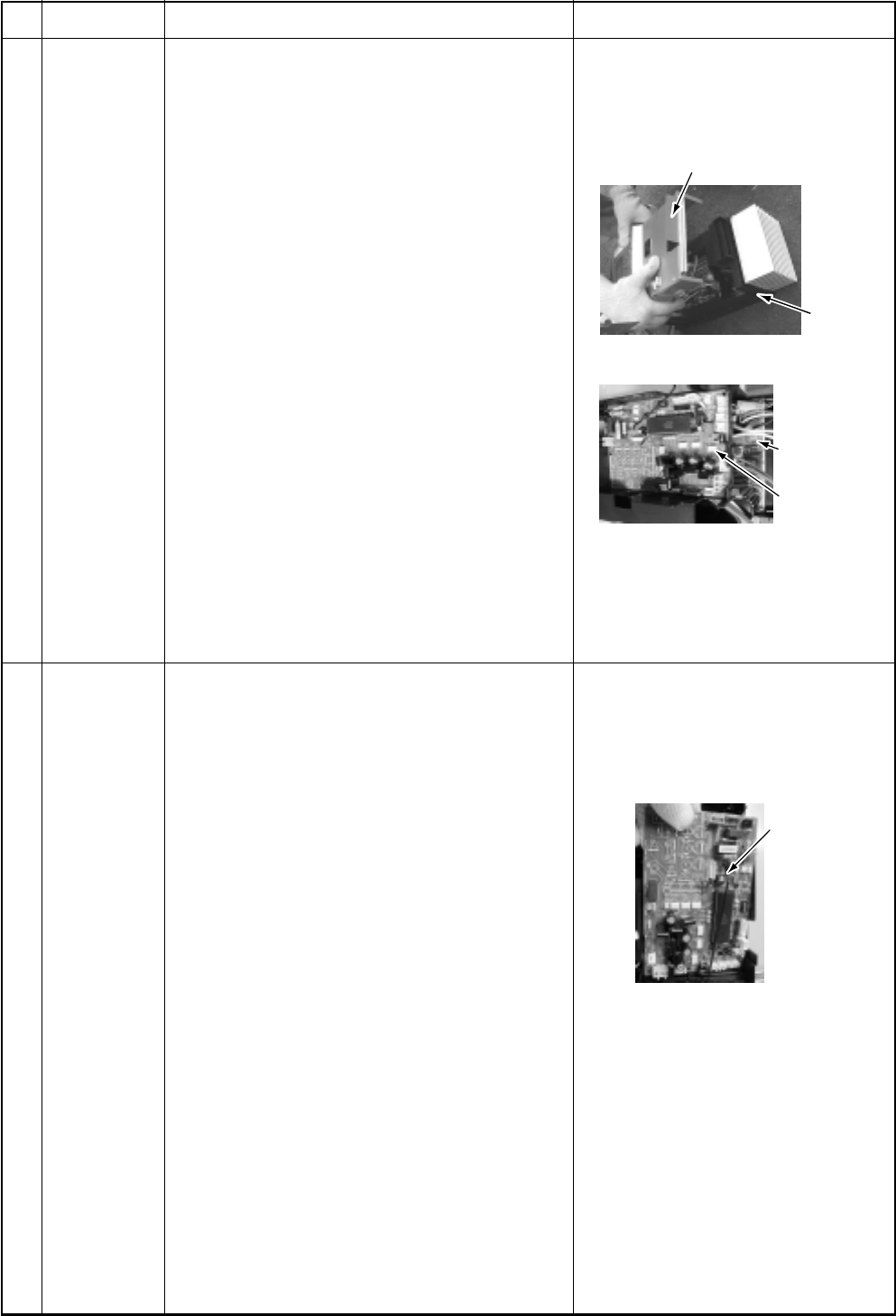
– 144 –
P.C. board
base
Inverter box (Metal sheet)
Inverter
control
P.C. board
assembly
Cycle control
P.C. board
assembly
Cycle control
P.C. board
assembly
No.
Part name
Inverter
assembly
(Continued)
Cycle P.C.
board
Procedure
7) Remove connectors which are connected
from the cycle P.C. board to other parts.
CN600: TD sensor (3P: White)
CN601: TO sensor (2P: White)
CN604: TE sensor (2P: White) *Note 1)
CN605: TS sensor (3P: White) *(Note 1)
CN301: Outdoor fan (3P: White) *(Note 1)
CN300: Position detection (5P: White)
CN500: Case thermo. (2P: Blue) *(Note 1)
CN702: P.M.V. (Pulse Motor Valve)
coil (6P: White) *(Note 1)
Relay connector:
4-way valve (3P: Yellow) *(Note 1)
Relay connector:
Reactor 2 pcs. (2P: White) *(Note 1)
Compressor lead: Remove terminal cover of
the compressor, and remove the lead wire
from terminal of the compressor.
*(Note 1)
Remove the connectors by releasing lock of the
housing.
8) Remove various lead wires.
9) Cut off tie lap which fixes various lead wires
to the inverter assembly.
1) Remove connectors and lead wires which
are connected from the cycle P.C. board to
other parts.
1. Connector
CN01 : Connection with IPDU P.C. board
(5P, Red) *(Note 1)
CN02 : Indoor/Outdoor connection
terminal block (5P, Black)
CN03 : Connection with IPDU P.C. board
(3P, White) *(Note 1)
CN04 : Connection with IPDU P.C. board
(2P, White) *(Note 1)
CN700 : 4-way valve (3P, Yellow) *(Note 1)
CN800 : Connection with IPDU P.C. board
(5P, Red) *(Note 1)
*(Note 1)
Remove the connector while releasing locking of
the housing.
2) Mount a new cycle P.C. board.
Remarks
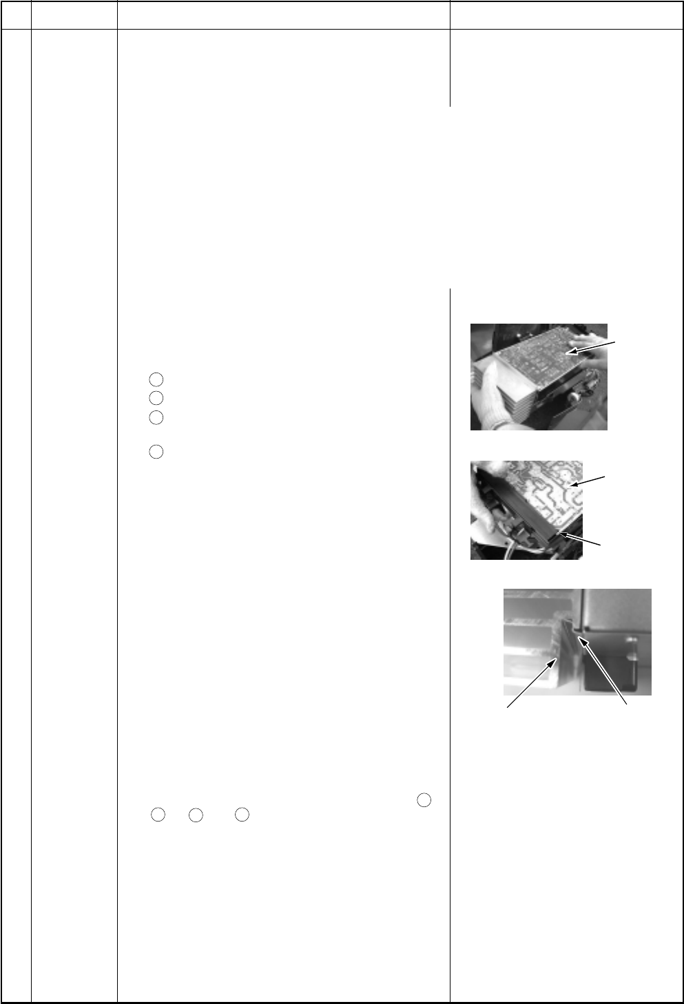
– 145 –
Inverter
control
P.C. board
assembly
Inverter
control
P.C. board
assembly
Groove for
P.C. boaed
Heat sink Inverter box
(Metal sheet)
No.
Part name
IPDU P.C.
board
Procedure
1) Perform the works in and .
2) Remove the connectors and the lead wires
which are connected from IPDU P.C. board to
the other parts.
1. Connector
CN04 :Connection with cycle P.C. board (3P: White) *(Note 1)
CN05 :Connection with cycle P.C. board (2P: White) *(Note 1)
CN06 :Connection with cycle P.C. board (5P: Red) *(Note 1)
CN13 :Connection with cycle P.C. board (5P: Red) *(Note 1)
2. Lead wire
CN01 :Connection with power terminal block (Red)
CN02 :Connection with power terminal block (White)
CN03 :Connection with inverter box (Black)
CN09 :Connection with compressor (Red)
CN10 :Connection with compressor (White)
CN11 :Connection with compressor (Black)
Rectifier diode
+
: Orange lead wire *(Note 2)
–
: Gray lead wire *(Note 2)
~
: Red lead wire
(Top)
~
: Brown lead wire
(Bottom)
*(Note 1)
Remove the connectors by releasing lock of the
housing.
3) Remove the control P.C. board assembly from
P.C. board base. (Remove the heat sink and the
inverter control P.C. board assembly as they are
screwed.)
*(Note 2)
Remove the heat sink upward by taking off two
claws of P.C. base and holding the heat sink.
4) Take off two screws which fix the heat sink and
IGBT and also take off support hooks of the P.C.
board (5 positions) to remove IPDU P.C. board.
5) Mount a new IPDU P.C. board.
*(Note 3)
The rectifier diode has polarity, so be careful to
+
and
–
. If
+
and
–
are mistaken, a trouble is
caused.
*(Note 4)
When mounting a new board, check that it is
correctly set in the groove of the base holder of P.C.
board base.
Remarks
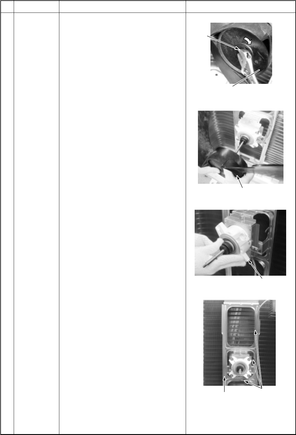
– 146 –
Flange
nut
Loosen by turning
clockwise
Propeller fan
Fan motor
Fixing claws for
fan motor lead
wires (3 positions)
Motor base
No.
Part name
Fan motor
Procedure
1) Perform works of items 1) to 5), 7) of
2) Remove the flange nut fixing the fan
motor and the propeller fan.
•Loosen the flange nut by turning clock-
wise. (To tighten the flange nut, turn it
counterclockwise.)
3) Remove the propeller fan.
4) Remove the lead wire from the hook fixing
the fan motor lead wires on the motor
base. (Three positions)
5) Disconnect the connector for fan motor
from the inverter.
6) Take off the fixing screws (4 pcs.) while
holding by hands so that the fan motor
does not fall.
*(Note)
Tighten the flange nut with torque 9.8N•m
(100kgf/cm).
Remarks
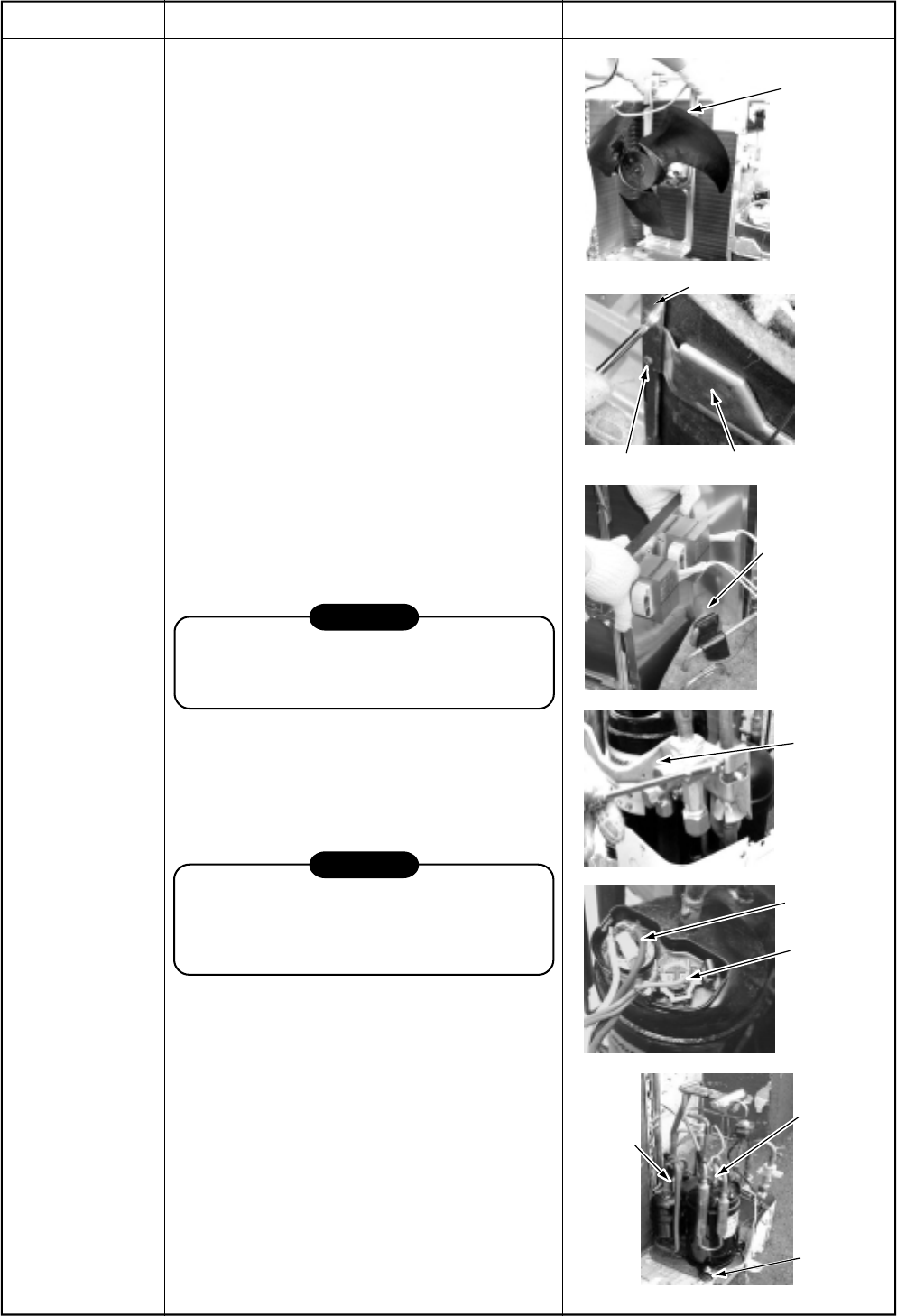
– 147 –
Motor
base
Partition plate
Valve support
Screw
Partition
plate
Valve
support
Compressor
lead wire
Case thermo
Compressor
nut (3 pcs.)
Remove
(Suction
pipe)
Remove
(Discharge
pipe)
No.
Part name
Compressor
Procedure
1) Perform works of items , , , and .
2) Evacuate refrigerant gas.
3) Disconnect the connector for fan motor from
the inverter.
4) Take off screws fixing the motor base to the
bottom plate. (ST1T Ø4 × 10L, 2 pcs.)
5) Remove the motor base together with the
fan motor and the propeller fan.
6) Take off screws fixing the partition plate to
the valve support plate.
(ST1T Ø4 × 10L, 2 pcs.)
7) Remove the valve support plate.
(M6 × 4 pcs.)
8) Take off screws of the partition plate and the
bottom plate. (ST1T Ø4 × 10L, 2 pcs.)
9) Take off screws of the partition plate and the
heat exchanger. (ST1T Ø4 × 10L, 2 pcs.)
10) Remove the noise-insulator.
11) Remove the terminal covers of the com-
pressor, and disconnect lead wires of the
compressor and the compressor thermo
assembly from the terminal.
12) Remove pipes connected to the compres-
sor with a burner.
CAUTION
Pay attention to that flame does not involve
4-way valve or PMV.
(If doing so, a malfunction may be caused.)
13) Pull the refrigerating cycle upward.
14) Take off nut fixing the compressor on the
bottom plate. (3 pcs.)
15) Pull the compressor toward you.
CAUTION
When reconnecting the lead wires to the
compressor terminals after replacement of
the compressor, be sure to caulk the Faston
terminal without loosening.
Remarks
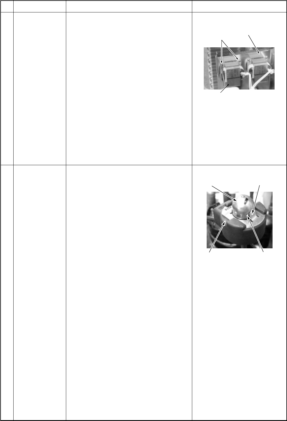
– 148 –
Reactor
Partition plate
Screws
Positioning extrusion
PMV body
PMV coil Concavity
No.
Part name
Reactor
Pulse Modulating
Valve (PMV) coil
Procedure
1) Perform works of items 1 of and .
2) Take off screws fixing the reactor.
(Ø4 x 10L , 2 pcs. per one reactor.
An outdoor unit has two reactors on the
partition plate.)
1. Detachment
1) Perform works of items 1 of and .
2) Remove the coil from PMV body while
pulling it upward.
2. Attachment
1) Match the positioning extrusion of the coil
surely to the concavity of PMV body to fix
it.
Remarks
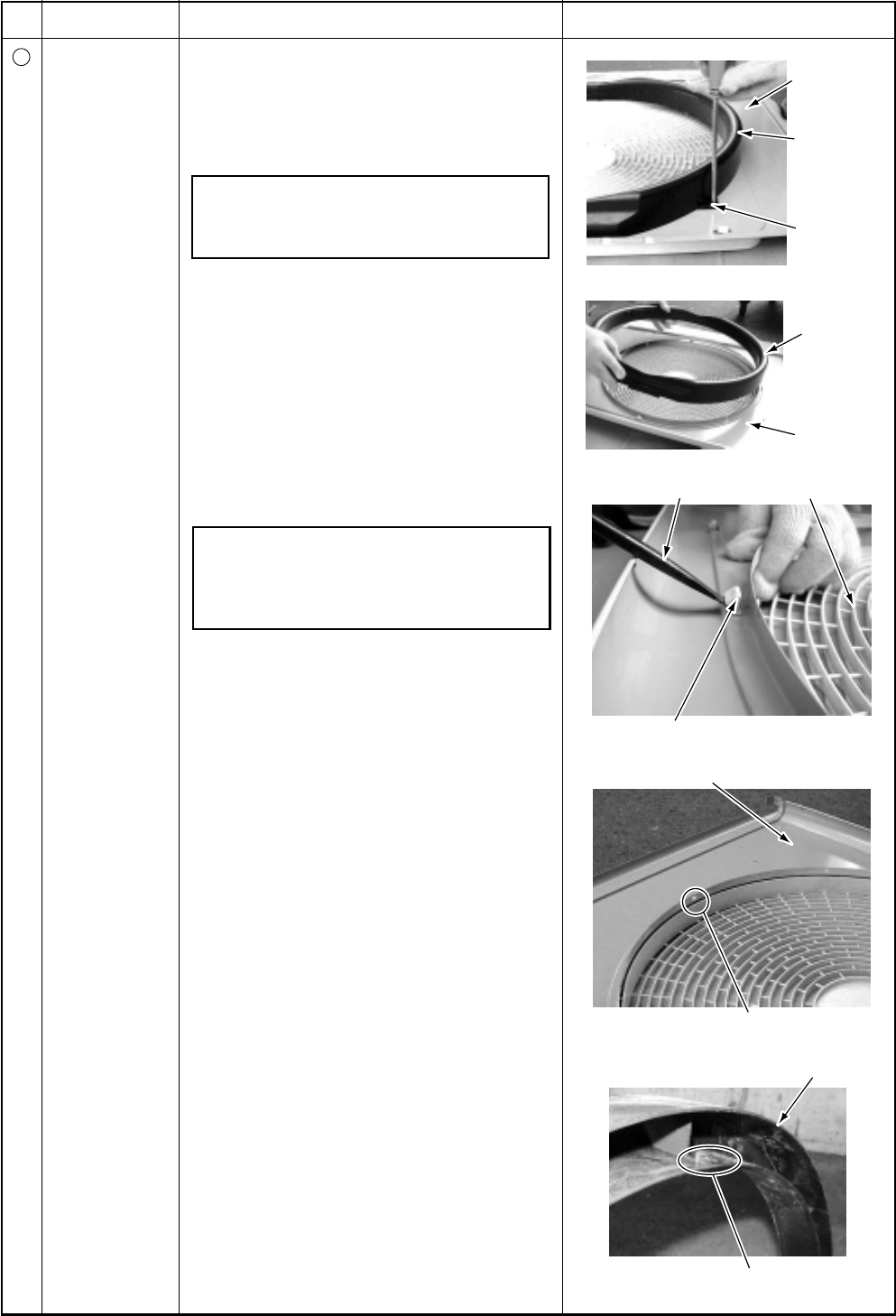
– 149 –
Discharge
port cabinet
Bell mouth
Remove
two screws
Discharge
port cabinet
Bell mouth
Minus screwdriver Fan guard
Hooking claw
Discharge port cabinet
Slit (3 positions)
Claw (3 positions)
Bell mouth
No.
11
Part name
Fan guard
Procedure
1. Detachment
1) Perform works of items 1 of and .
2) Remove the air flow cabinet, and put it
down so that the fan guard side directs
downward.
Perform work on a corrugated card-
board, cloth, etc. to prevent flaw to the
product.
3) Take off screws fixing the bell mouth.
(ST1T Ø4 × 10L, 2 pcs.)
4) Remove the bell mouth.
5) Remove the hooking claws by pushing
with minus screwdriver along with the
arrow mark as shown in right figure.
2. Attachment
1) Insert claw of the fan guard in hole of the
discharge panel. Push the hooking claws
(5 positions) with hands and fix the claws.
After all the attachment works are
completed, check that all the hooking
claws are fixed to the specified posi-
tions.
2) Mount the bell mouth by hooking three
claws at upper side of the bell mouth in
the slits on the discharge cabinet.
3) After attachment, fix the bell mouth with
screws. (ST1T Ø4 × 10L, 2 pcs.)
Remarks
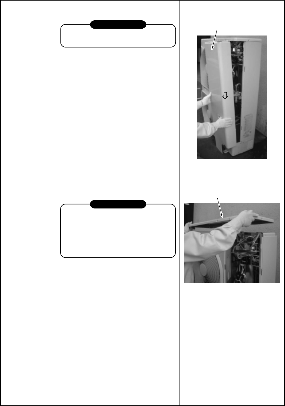
– 150 –
Front panel
Roof plate
RAV-SP1102AT-E, RAV-SP1402AT-E
No.
Part name
Common
procedure
Procedure
REQUIREMENT
Before works, put on gloves, otherwise an
injury may be caused by parts, etc.
1. Detachment
1) Stop operation of the air conditioner, and
turn off switch of the breaker.
2) Remove the front panel.
(ST1T Ø4 × 10, 3 pcs.)
•After removing the screws, remove the
front panel while drawing it downward.
3) Remove the power cable and the indoor/
outdoor connecting cable from cord clamp
and terminal.
4) Remove the roof plate.
(ST1T Ø4 × 10, 6 pcs.)
2. Attachment
1) Mount the roof plate.
(ST1T Ø4 × 10, 6 pcs.)
2) Connect the power cable and the indoor/
outdoor connecting cable to terminal, and
then fix them with cord clamp.
REQUIREMENT
Be sure to fix the power cable and the
indoor/outdoor connecting cable with
bundling band on the market along the
inter-unit cable so that they do not come
to contact with the compressor, the valve
and the cable at gas side, and the dis-
charge pipe.
3) Attach the front panel.
(ST1T Ø4 × 10, 3 pcs.)
Remarks
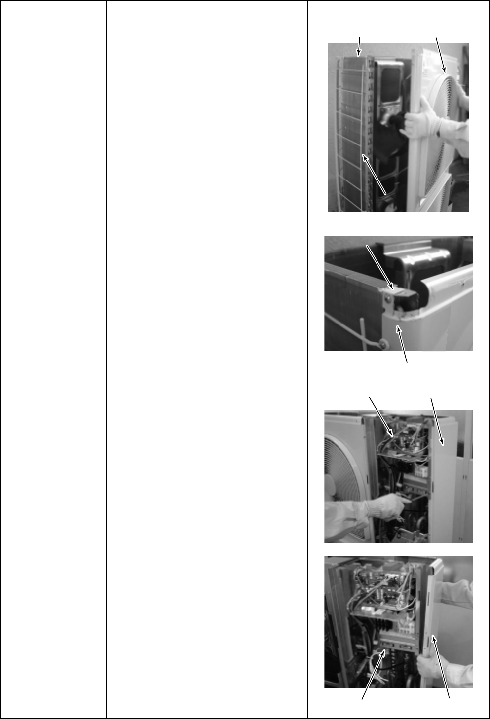
– 151 –
Heat exchanger
FinguardFinguard
Air-outlet cabinet
Inverter Side cabinet
Valve fixed plate Side cabinet
Upper side of the end
plate of heat exchanger
Upper side of the end
plate of heat exchanger
Air-outlet cabinet
No.
Part name
Air-outlet cabinet
Side cabinet
Procedure
1. Detachment
1) Perform the work in 1 of .
2) Take off screws for the air-outlet cabinet
and the partition plate.
(ST1T Ø4 × 10, 3 pcs.)
3) Take off screws for the air-outlet cabinet
and the base plate.
(ST1T Ø4 × 10, 2 pcs.)
4) Take off screw for the air-outlet cabinet
and the heat exchanger.
(ST1T Ø4 × 10, 1 pc.)
5) Take off screws for the air-outlet cabinet
and the fin guard.
(ST1T Ø4 × 10, 2 pcs.)
2. Attachment
1) Put the upper left side of the air-outlet
cabinet on the end plate of heat ex-
changer, and fix it with screw.
(ST1T Ø4 × 10, 1 pc.)
2) Attach the taken-off screws to the
original positions.
1) Perform the work in 1 of .
2) Take off screws fixing the inverter and
the side cabinet.
(ST1T Ø4 × 10, 2 pcs.)
3) Take off screws for the side cabinet and
the valve fixed plate.
(ST1T Ø4 × 10, 2 pcs.)
4) Take off screw for the side cabinet and
the piping panel (Rear).
(ST1T Ø4 × 10, 1 pc.)
5) Take off screw for the side cabinet and
the base plate.
(ST1T Ø4 × 10, 1 pc.)
6) Take off screws for the side cabinet and
the fin guard.
(ST1T Ø4 × 10, 4 pcs.)
Remarks
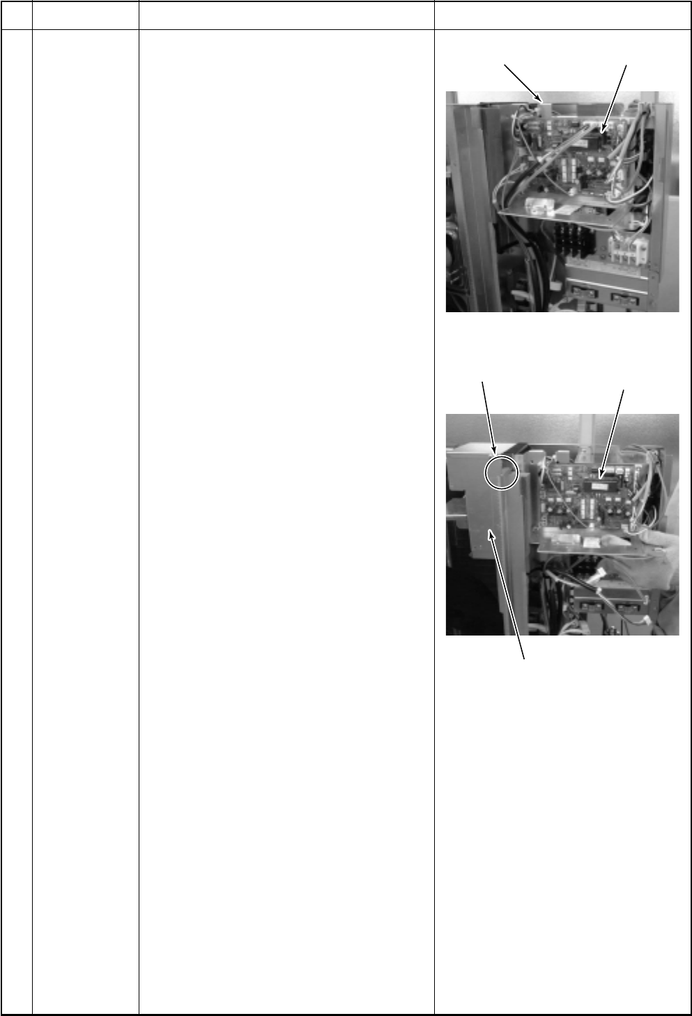
– 152 –
Inverter assembly
Inverter assembly
Heat sink cover
Hooks of heat sink cover
(2 positions)
Cycle P.C. board
No.
Part name
Inverter
assembly
Procedure
1) Perform the works in 1 of and .
2) Remove connectors which are connected
from the cycle P.C. board to other parts.
CN600: TD sensor (3P: White)
CN601: TO sensor (2P: White)
CN604: TE sensor (2P: White) *(Note 1)
CN605: TS sensor (3P: White) *(Note 1)
CN301: Upper outdoor fan (3P: White)
*(Note 1)
CN300: Detection of upper position
(5P: White)
CN303: Lower outdoor fan (3P: White)
*(Note 1)
CN302: Detection of lower position
(5P: White)
CN500: Case thermo. (2P: Blue)
*(Note 1)
CN700: 4-way valve (3P: Yellow)
*(Note 1)
CN702: PMV (Pulse Motor Valve) coil
(6P: White) *(Note 1)
Relay connector:
Reactor 2 pcs. (2P: White)
Compressor lead: Remove terminal cover
of the compressor, and remove the lead
wire from terminal of the compressor.
*(Note 1)
Remove the connectors by releasing lock of
the housing.
3) Remove various lead wires from the
holder at upper part of the inverter.
4) Cut off tie lap which fixes various lead
wires to the inverter assembly.
5) Lift up the hook (upper left) with the
partition plate upward just removing.
* Caution to mount the inverter assembly
Mount the inverter assembly to the partition
plate so that hooks of the heat sink cover
do not come near the partition plate but
also near the fan side.
Remarks
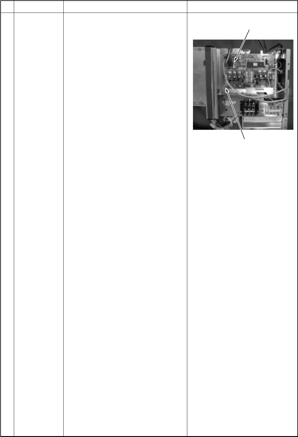
– 153 –
P.C. board fixing hooks
(4 positions)
Cycle control P.C. board assembly
No.
Part name
Cycle P.C. board
Procedure
1) Perform the works in 1 of and .
2) Remove connectors and lead wires
which are connected from the cycle P.C.
board to other parts.
1. Connector
CN800: Connection with IPDU P.C.
board (5P: Red) *(Note 1)
CN01: Connection with IPDU P.C.
board (5P: Red) *(Note 1)
CN02: Indoor/Outdoor connection
terminal block (5P: Black)
*(Note 1)
CN03: Connection with IPDU P.C.
board (3P: White) *(Note 1)
CN04: Connection with IPDU P.C.
board (2P: White) *(Note 1)
*(Note 1)
Remove the connectors by releasing lock of
the housing.
3) Remove the supporting hooks at 4
corners to remove the cycle P.C. board.
4) Mount a new cycle P.C. board.
5) Lift up the hook (upper left) with the
partition plate upward just removing.
Remarks
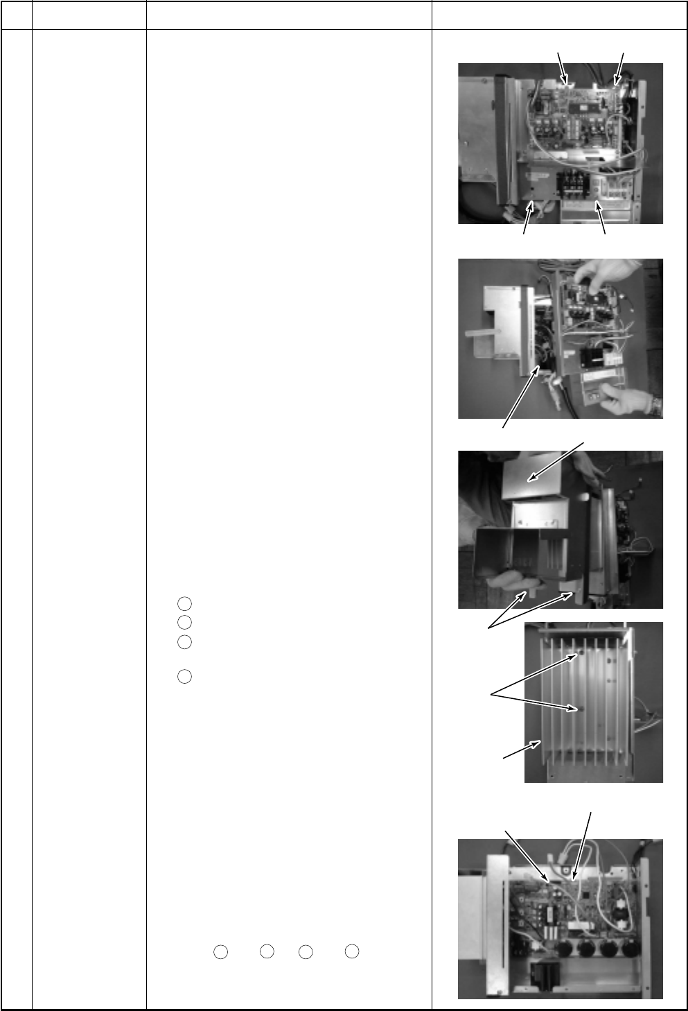
– 154 –
Screw Screw
Screw Screw
Heat sink
P.C. board fixing hooks (5 positions)
IPDU P.C. board
Screw
Screw
IPDU P.C. board Heat sink cover
No.
Part name
IPDU P.C. board
Procedure
1) Perform the works in and .
2) Take off screws of the inverter assembly
to separate the inverter assembly.
(M4 × 8, 4 pcs)
3) Remove the connectors and the lead
wires which are connected from IPDU
P.C. board to the other parts.
1. Connector
CN04: Connection with cycle P.C.
board (3P: White) *(Note 1)
CN05: Connection with cycle P.C.
board (2P: White) *(Note 1)
CN06: Connection with cycle P.C.
board (5P: Red) *(Note 1)
CN13: Connection with cycle P.C.
board (5P: Red) *(Note 1)
CN600: Heat sink sensor (2P: Black)
2. Lead wire
CN01: Connection with power
terminal block (Red)
CN02: Connection with power
terminal block (White)
CN03: Connection with inverter box
(Black)
CN09: Connection with compressor
(Red)
CN10: Connection with compressor
(White)
CN11: Connection with compressor
(Black)
Rectifier diode
+
: Orange lead wire *Note 2
–
: Gray lead wire *Note 2
~
: Red lead wire
(Top)
~
: Brown lead wire
(Bottom)
*(Note 1)
Remove the connectors by releasing lock of
the housing.
4) Remove the heat sink cover.
(M4 × 8, 2pcs)
5) Take off two screws which fix the heat
sink and IGBT and also take off support
hooks of the P.C. board (5 positions) to
remove IPDU P.C. board.
6) Mount a new IPDU P.C. board.
*(Note 2)
The rectifier diode has polarity, so be
careful to
+
and
–
. If
+
and
–
are
mistaken, a trouble is caused.
Remarks
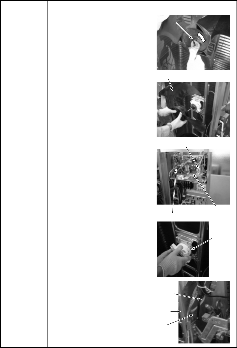
– 155 –
Flange nut
Propeller fan
Fan motor connector at upper side
Cycle P.C. board
Fan motor
Fan motor
lead
Partition
plate
Motor lead
fixed plate
Fan motor connector at lower side
Loosen by
turning clockwise
kwise
.
Flange nut Loosen by
turning clockwise.
No.
Part name
Fan motor
Procedure
1) Perform the works in 1 of and 1 of .
2) Take off flange nut fixing the fan motor
with the propeller fan.
•Loosen the flange nut by turning clock-
wise. (When tightening, turn it counter-
clockwise.)
3) Remove the propeller fan.
4) Remove connector for the fan motor from
the inverter.
5) Take off fixing screws (4 pcs) with sup-
porting the fan motor so that it does not
fall down.
6) When replacing the fan motor at lower
side, remove the motor lead fixed plate
which is fixed to the partition plate with
screw (ST1T Ø4 × 10, 1 pc), pull the fan
motor lead out of the partition plate, and
then remove the fan motor.
* Cautions in assembling fan motor
<In case of RAV-SP1102AT-E>
•Be sure to mount the propeller fan and the
fan motor at upper and lower sides be-
cause they are different.
•Tighten the flange nut with the following
torque.
Upper side: 9.8N·m (100kgf·cm)
Lower side: 4.9N·m (50kgf·cm)
<In case of RAV-SP1402AT-E>
•The same propeller fan and the fan motor
are used at upper and lower sides.
•Tighten the flange nut with the following
torque.
Upper side: 9.8N·m (100kgf·cm)
Lower side: 9.8N·m (100kgf·cm)
•Be sure to mount the motor lead fixed plate
so that the fan motor lead is not caught in.
•Be sure that the propeller fan does not
come to contact with the fan motor lead.
Remarks
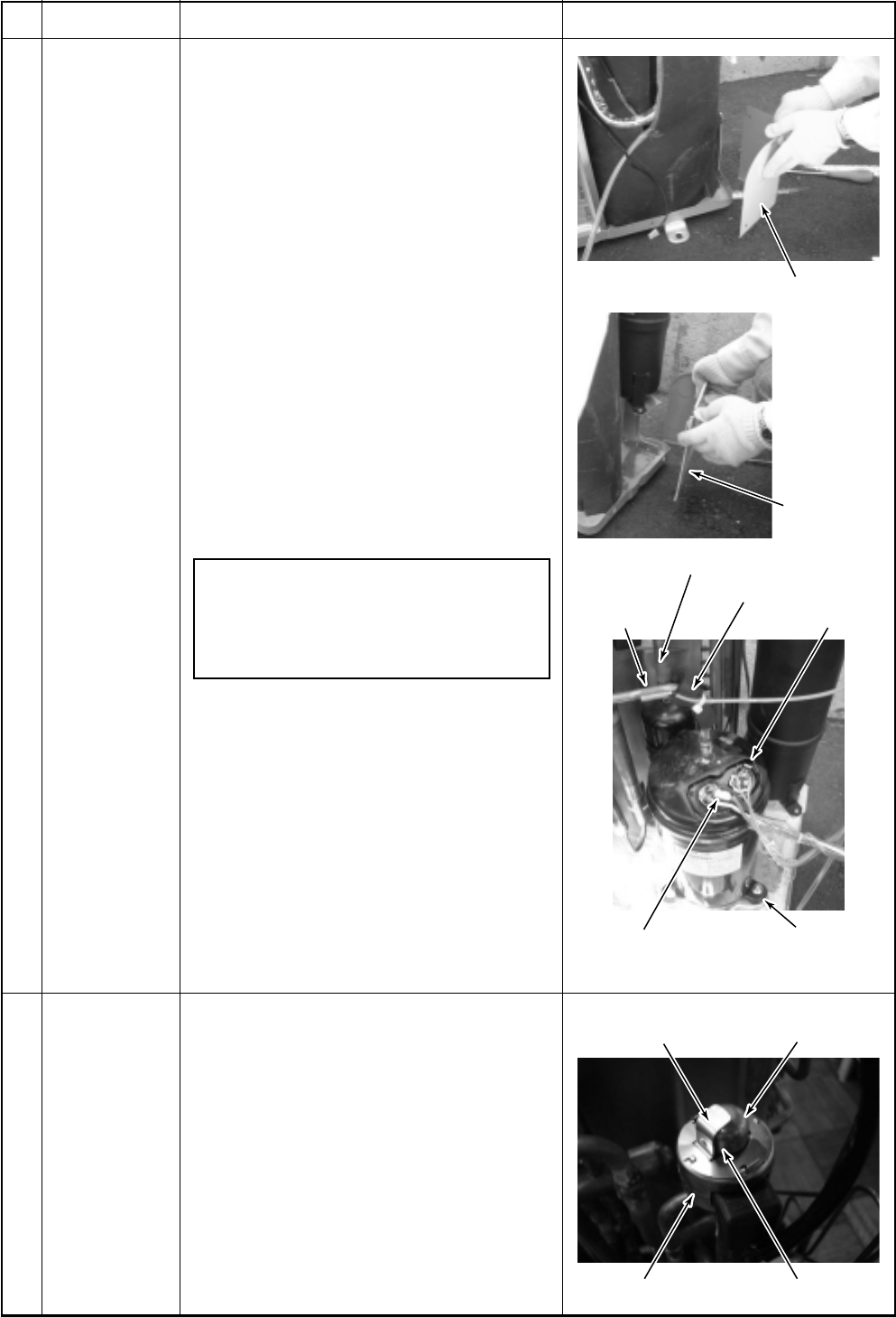
– 156 –
Piping panel (Front)
Remove (Suction pipe)
Remove (Discharge pipe)
Case thermo.
PMV coil
PMV bodyPositioning extrusion
Concave part
TD sensor
Compressor nuts
(3 pcs)
Compressor lead
Piping panel
(Rear)
No.
Part name
Compressor
PMV coil
Procedure
1) Recover refrigerant gas.
2) Perform the works in 1 of and in .
3) Remove the piping panel (Front).
Take off screws of the piping panel (Front)
and the base plate.
(ST1T Ø4 × 10, 2 pcs)
Take off screws of the piping panel (Front)
and the piping panel (Rear).
(ST1T Ø4 × 10, 2 pcs)
4) Remove the piping panel (Rear).
Take off screws of the piping panel (Rear)
and the base plate.
(ST1T Ø4 × 10, 2 pcs)
5) Remove the sound-insulation plate.
6) Remove terminal cover of the compressor,
and then remove compressor lead and
case thermo. of the compressor.
(ST1T Ø4 × 10, 2 pcs)
7) Remove TD sensor fixed to the discharge
pipe.
8) Using a burner, remove pipe connected to
the compressor.
NOTE)
Pay attention that 4-way valve or PMV is
not exposed to a flame.
(Otherwise, a malfunction may be
caused.)
9) Pull out discharge pipe and suction pipe
of the refrigerating cycle upward.
10) Take off the compressor nuts (3 pcs)
fixing the compressor to the base plate.
11) Draw out the compressor toward you.
1. Detachment
1) Perform the works in 1 of and in .
2) Hold outside of the coil by hands and turn
it while lifting upward. The fixing hooks
come off the fixing concavities and then
the coil can be removed from PMV body.
2. Attachment
1) Match the positioning extrusion of the coil
surely to the concave part of PMV body,
and then fix it.
Remarks
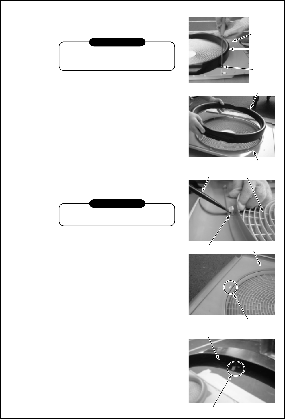
– 157 –
Air-outlet
cabinet
Bell-mouth
Bell-mouth
Air-outlet cabinet
Minus screwdriver
Square holes (3 positions)
Bell-mouth
Hooks (3 positions)
Hanging hook Air-outlet cabinet
Fan guard
Screws
(2 pcs)
Remove
No.
Part name
Fan guard
Procedure
1. Detachment
1) Perform the works in 1 of and in 1 of .
REQUIREMENT
To prevent damage on the products, treat
component on a corrugated paper, cloth,
etc.
2) Remove the air-outlet cabinet, and then
put down it directing the fan guard side
downward.
3) Take off screws fixing the bell-mouth.
(ST1T Ø4 × 10, 2 pcs)
4) Remove the bell-mouth.
5) Take off screws fixing the fan guard.
(ST1T Ø4 × 10, 2 pcs)
6) Remove hanging hook of the fan guard by
pushing with a minus screwdriver.
2. Attachment
1) Insert the extrusion at the upper side of
the fan guard into the square hole of the
air-outlet cabinet, and then insert the
hanging hook. Fix the hanging hooks
(5 positions) by pushing with hands.
REQUIREMENT
Check that all the hanging hooks are fixed
to the specified positions.
2) After attachment, fix it with screws.
(ST1T Ø4 × 10, 2 pcs)
3) Mount the bell-mouth by hanging hooks
(3 positions) at upper side of the bell-
mouth to the square holes of the air-outlet
cabinet.
4) After attachment, fix it with screws.
(ST1T Ø4 × 10, 2 pcs)
* Caution in assembling bell-mouth
•The size (color) of the bell-mouth at
upper side differs from that at lower side.
(Only for RAV-SP1102AT-E)
<In case of RAV-SP1102AT-E>
Upper side: Black
Lower side: Gray
<In case of RAV-SP1402AT-E>
Upper side: Black
Lower side: Black
Remarks
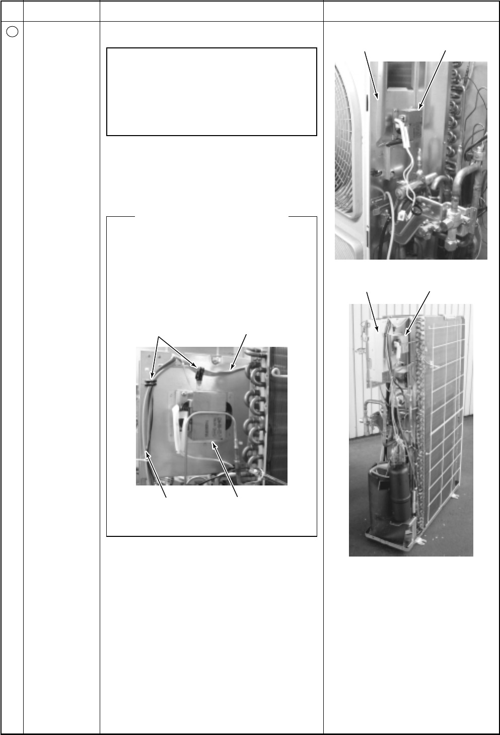
– 158 –
Cord holder Fan motor lead wire
Various sensor
lead wires Reactor
Partition board Reactor
Electric parts box Reactor
No.
11
Part name
Reactor
Procedure
1) Perform works of items to .
NOTE)
The same two reactors are installed to this
outdoor unit though each installation place
is different.
One is attached to a partition board, and the
other is attached to an electric parts box.
2) Remove the connector of the reactor lead
wire connected to the inverter assembly.
3) Remove fixing screws of the reactor.
<Cautions for assembling>
The temperature of the reactor becomes
high during operation of the outdoor unit.
Using a cord holder, fix various sensor lead
wires or fan motor lead wires in the sur-
roundings of the reactor to be fixed to the
electric parts box as shown below so that
they do not come to contact with the reac-
tor.
Remarks
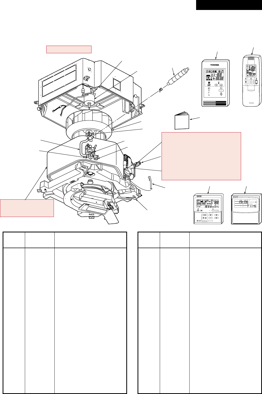
– 159 –
208
225
202
226
211, 213, 219 (SM563UT-E)
212, 214, 220 (SM803UT-E)
215, 217, 221 (SM563UT-E)
216, 218, 222 (SM803UT-E)
227 (SM563UT-E)
228 (SM803UT-E)
206
201
207
223
209
203 (SM563UT-E)
204 (SM803UT-E)
210
224
ON / OFF
FAN
TEMP.
SWING/FIXTIME
MODE
VENT
UNITSET CL
FILTER
RESET
TEST
TIMER SET
CODE No.
UNIT No.
TEST
SETTING
DATA
SET
R.C. No.
H
205
233
ADR
231
˚C
TEST
SETTING
230 232
WEEKLY TIMER
ERROR
SuMoTuWeTh Fr Sa
PROGRAM1
PROGRAM2
PROGRAM3
15. EXPLODED VIEWS AND PARTS LIST
15-1. Indoor Unit
15-1-1. 4-Way Air Discharge Cassette Type
RAV-SM563UT-E, RAV-SM803UT-E
Location
Part Description
No. No.
201 43121736 Pump, Drain, ADP-1409,
220-240V
202 43120215 Fan, Ass’y Turbo, TJ461
203 4314J265 Refrigeration Cycle Ass’y
204 4314J266 Refrigeration Cycle Ass’y
205 431S8055 Owner’s Manual
206 43172187 Pan Ass’y, Drain,
PS-F+ABS, Sheet
207 43151290 Switch, Float, FS-0218-102
208 43121738 Motor, Fan, SWF-230-60-1R
209 43170244 Hose, Drain, 25A
210 43079249 Band, Hose
211 43047685 Nut, Flare, 1/4 IN, Ø6.35
212 43047686 Nut, Flare, 3/8 IN, Ø9.52
213 43149351 Socket, Ø6.35
214 43049776 Socket, Ø9.52
215 43047688 Nut, Flare, 1/2 IN, Ø12.7
216 43149352 Nut, Flare, 5/8 IN, Ø15.88
217 43149353 Socket, 1/2 IN, Ø12.7
Location
Part Description
No. No.
218 43149354 Socket, 5/8 IN, Ø15.88
219 43049697 Bonnet, Ø6.35
220 43047609 Bonnet, Ø9.52
221 43147195 Bonnet, 1/2 IN, Ø12.7
222 43194029 Bonnet, Ø15.88
223 43019904 Holder, Sensor, SUS
224 43170245 Hose, Drain
225 43139137 Rubber, Cushion
226 43097212 Nut
227 4314Q009 Distributor Ass’y
228 4314Q010 Distributor Ass’y
230 43166002 Remote Controller,
SX-A1EE (RBC-AMT31E)
231 43166004 Remote Controller,
SX-A11JE2 (RBC-AS21E2)
232 43166005 Remote Controller,
EX-W2JE2 (RBC-EXW21E2)
233 43166006 Remote Controller,
WH-H1JE2 (RBC-AX22CE2)
Revised : Mar. 2007
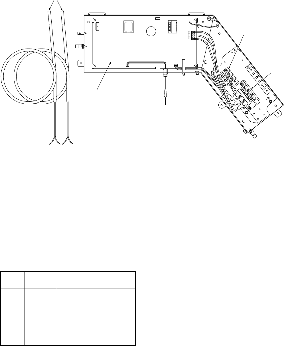
– 160 –
AB
405
403
404
402
401
Location
Part Description
No. No.
401 43160565 Terminal Block, 3P, 20A
402 43050425 Sensor, TC (F6)
403 43050426 Sensor, TA
404 43160568 Terminal Block, 2P,
1A, AC30V
405 4316V323 P.C. Board Ass’y, MCC-1402
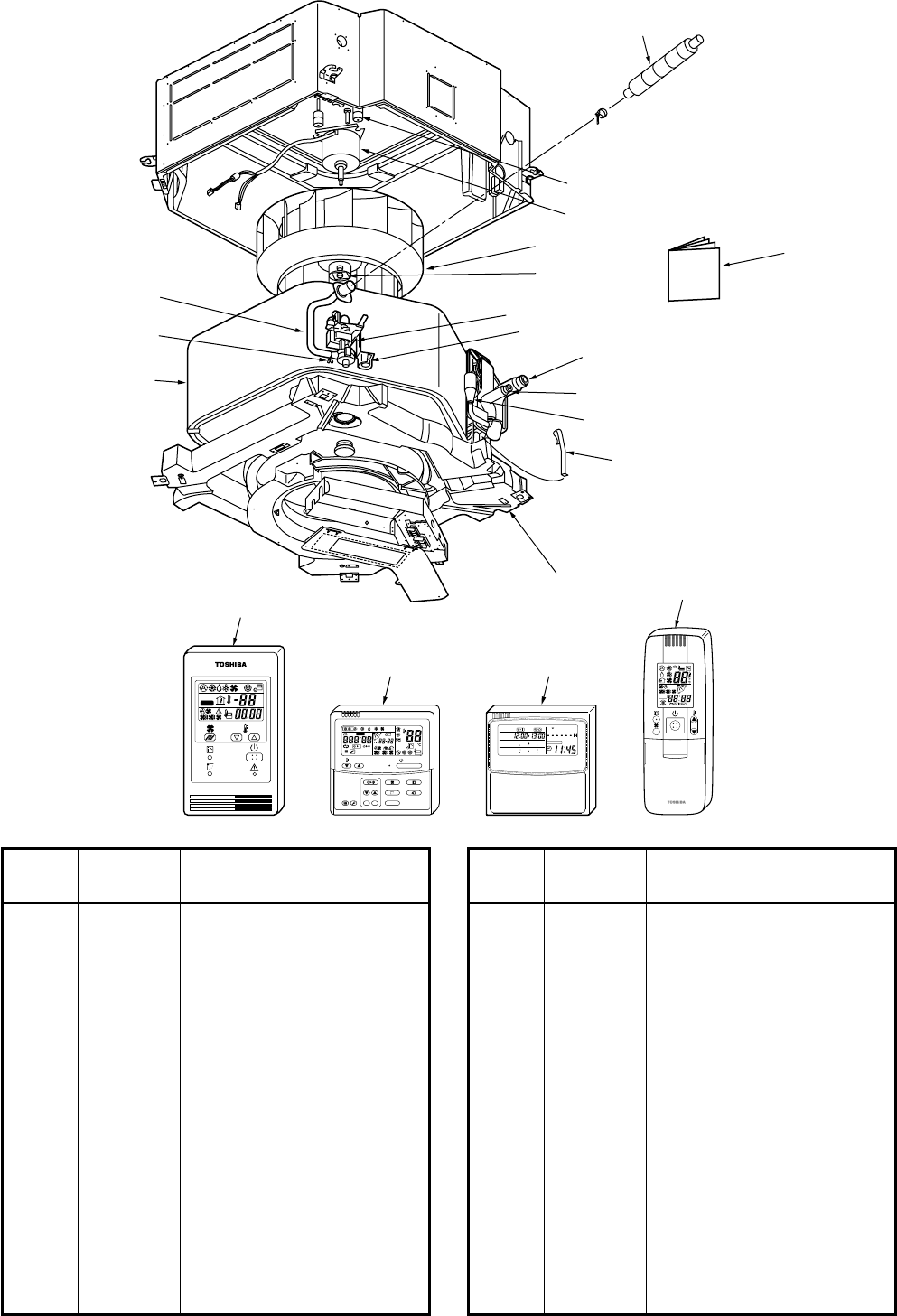
– 161 –
209
225
202 206
226
216, 218, 222
213, 214, 220
228
207
201
208
223
211
205
212
224
ON / OFF
FAN
TEMP.
SWING/FIXTIME
MODE
VENT
UNITSET CL
FILTER
RESET
TEST
TIMER SET
CODE No.
UNIT No.
TEST
SETTING
DATA
SET
R.C. No.
H
230 232
231 233
ADR
˚C
TEST
SETTING
WEEKLY TIMER
ERROR
SuMoTuWeTh Fr Sa
PROGRAM1
PROGRAM2
PROGRAM3
RAV-SP1102UT-E
Location
Part Description
No. No.
201 43121736 Pump, Drain, ADP-1409,
220-240V
202 43120214 Fan Ass’y Turb, TY461
205 4314J267 Refrigeration Cycle Ass’y
206 4318T681 Owner’s Manual
207 43172187 Pan Ass’y, Drain,
PS-F+ABS, Sheet
208 43151290 Switch, Float, FS-0218-102
209 43121737 Motor, Fan, SWF-200-90-1R
211 43170244 Hose, Drain, 25A
212 43079249 Band, Hose
213 43047686 Nut, Flare, 3/8 IN, Ø9.6
214 43049776 Socket, Ø9.6
216 43149352 Nut, Flare, 5/8 IN, Ø15.9
218 43149354 Socket, 5/8 IN, Ø15.9
Location
Part Description
No. No.
220 43047609 Bonnet, Ø9.6
222 43194029 Bonnet, Ø15.9
223 43019904 Holder, Sensor, SUS
224 43170245 Hose, Drain
225 43139137 Rubber, Cushion
226 43097212 Nut
228 434Q011 Distributor Ass’y
230 43166002 Remote Controller,
SX-A1EE (RBC-AMT31E)
231 43166004 Remote Controller,
SX-A11JE2 (RBC-AS21E2)
232 43166005 Remote Controller,
EX-W2JE2 (RBC-EXW21E2)
233 43166006 Remote Controller,
WH-H1JE2 (RBC-AX22CE2)

– 162 –
AB
405
403
404
402
401
Location
Part Description
No. No.
401 43160565 Terminal Block, 3P, 20A
402 43050425 Sensor, TC (F6)
403 43050426 Sensor, TA
404 43160568 Terminal Block, 2P,
1A, AC30V
405 4316V280 P.C. Board Ass’y, MMC-1402
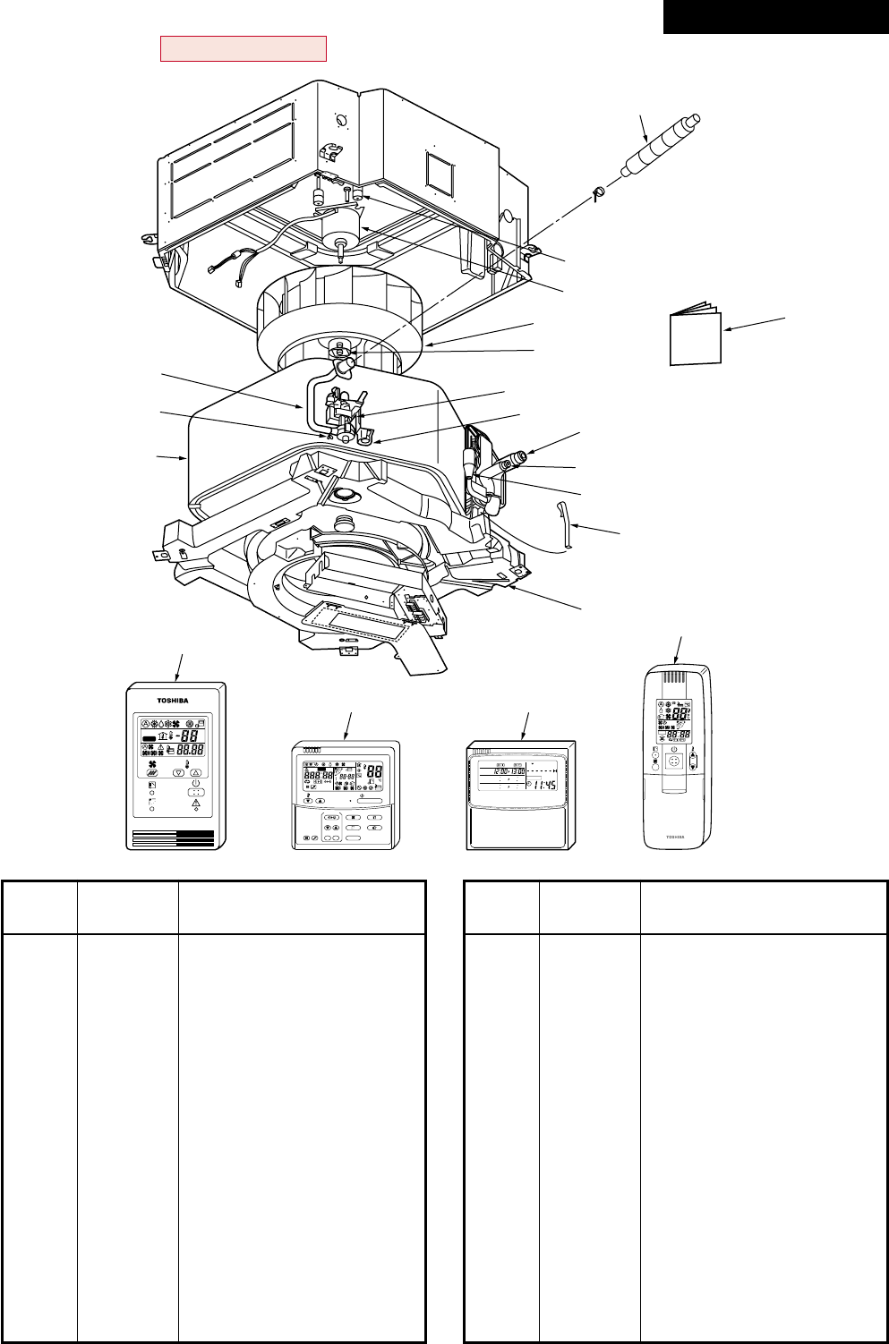
– 163 –
209
225
202
226
216, 218, 222
213, 214, 220
227
207
201
208
223
211
205
212
224
206
ON / OFF
FAN
TEMP.
SWING/FIXTIME
MODE
VENT
UNITSET CL
FILTER
RESET
TEST
TIMER SET
CODE No.
UNIT No.
TEST
SETTING
DATA
SET
R.C. No.
H
229 231
230 232
ADR
˚C
TEST
SETTING
WEEKLY TIMER
ERROR
SuMoTuWeTh Fr Sa
PROGRAM1
PROGRAM2
PROGRAM3
RAV-SM1103UT-E, RAV-SM1403UT-E
Location
Part Description
No. No.
201 43121736 Pump, Drain, ADP-1409,
220-240V
202 43120214 Fan Ass’y Turb, TY461
205 4314J366 Refrigeration Cycle Ass’y
206 431S8055 Owner’s Manual
207 431172187 Pan Ass’y, Drain,
PS-F+ABS, Sheet
208 43151290 Switch, Float, FS-0218-102
209 43121737 Motor, Fan, SWF-200-90-1R
211 43170244 Hose, Drain, 25A
212 43079249 Band, Hose
213 43047686 Nut, Flare, 3/8 IN, Ø9.62
214 43049776 Socket, Ø9.62
216 43149352 Nut, Flare, 5/8 IN, Ø15.88
218 43149354 Socket, 5/8 IN, Ø15.88
Location
Part Description
No. No.
220 43047609 Bonnet, Ø9.62
222 43194029 Bonnet, Ø15.88
223 43019904 Holder, Sensor, SUS
224 43170245 Hose, Drain
225 43139137 Rubber, Cushion
226 43097212 Nut
227 4314Q061 Distributor Ass’y
229 43166002 Remote Controller,
SX-A1EE (RBC-AMT31E)
230 43166004 Remote Controller,
SX-A11JE2 (RBC-AS21E2)
231 43166005 Remote Controller,
EX-W2JE2 (RBC-EXW21E2)
232 43166006 Remote Controller,
WH-H1JE2 (RBC-AX22CE2)
Revised : Mar. 2007

– 164 –
AB
405
403
404
402
401
Location
Part Description
No. No.
401 43160565 Terminal Block, 3P, 20A
402 43050425 Sensor, TC (F6)
403 43050426 Sensor, TA
404 43160568 Terminal Block, 2P,
1A, AC30V
405 4316V323 P.C. Board Ass’y, MMC-1402
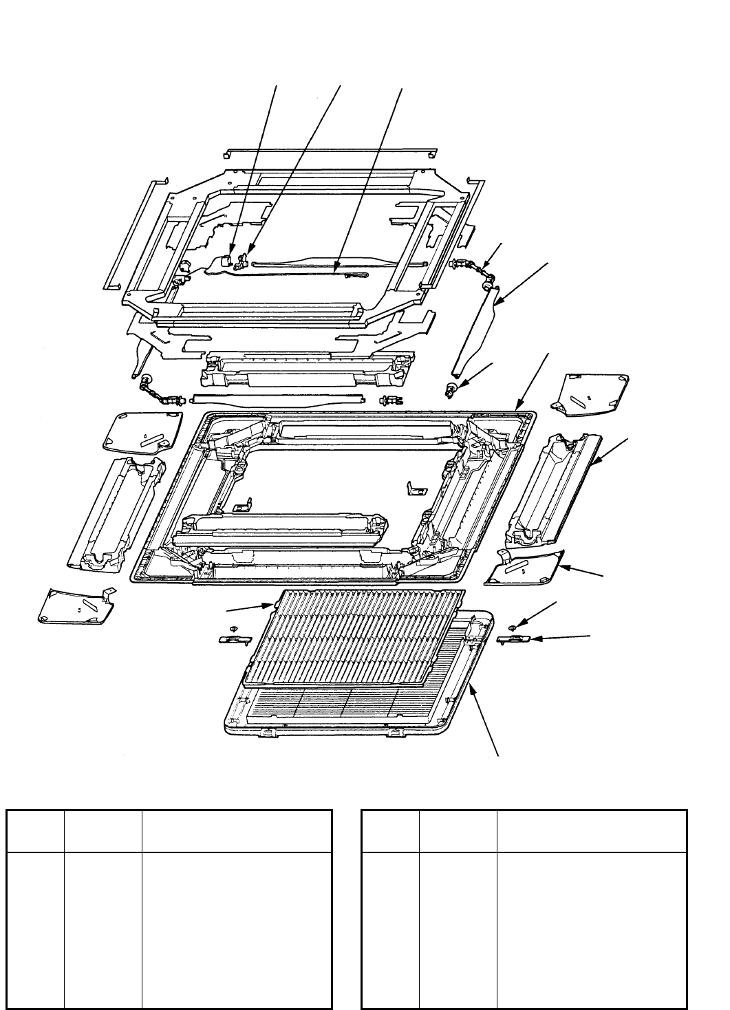
– 165 –
304 311
306
312
305
307
303
301
313
309
302
308
310
RBC-U21PG (W) - E2
Location
Part Description
No. No.
301 43409164 Panel, PS-HI100
302 43480010 Air Filter, ABS
303 43407120 Outlet, Air Form, PS-F
304 4302C063 Motor, Louver, MP24ZN
305 43409173 Louver, ABS
306 43422001 Joint, Kit
307 43422002 Joint, Kit
Location
Part Description
No. No.
308 43407116 Grille, Catch, ABS
309 43409168 Grille, Air, Inlet
310 43409182 Cover, Panel Ass’y,
PS-HI100
311 43407123 Fix, Motor, ABS
312 43160573 Lead, Motor
313 43182002 Washer, SPCC
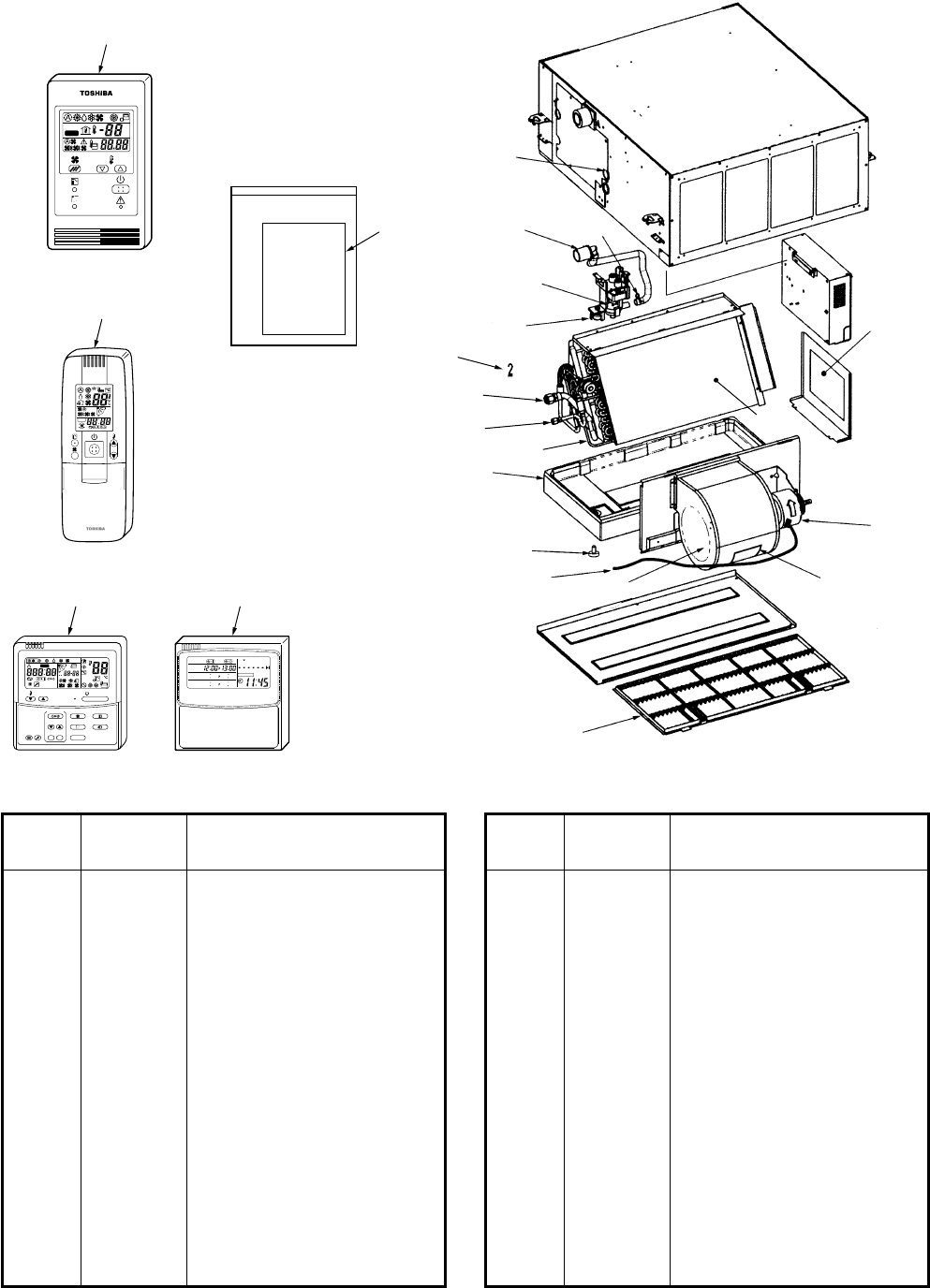
– 166 –
34
15
28
32
2
3, 902, 905
4, 6, 906 23
26
31
27
16
29
42
14
17
12, 13,
9, 10, 11
7
41
37
39
ADR
˚C
TEST
SETTING
ON / OFF
FAN
TEMP.
SWING/FIXTIME
MODE
VENT
UNITSET CL
FILTER
RESET
TEST
TIMER SET
CODE No.
UNIT No.
TEST
SETTING
DATA
SET
R.C. No.
H
36 38
WEEKLY TIMER
ERROR
SuMoTuWeTh Fr Sa
PROGRAM1
PROGRAM2
PROGRAM3
15-1-2. Concealed Duct Type
RAV-SM562BT-E
Location
Part Description
No. No.
2 43019904 Holder, Sensor
3 43047303 Bonnet
4 43047685 Nut, Flare, 1/4 IN
6 43049697 Bonnet
7 43079249 Band, Hose
15 43120226 Fan, Multi Blade
16 43121747 Pump Ass’y, Drain
17 43121740 Motor, Fan
23 4314Q015 Distributor Ass’y
26 4314J268 Refrigeration cycle Ass’y
28 43160553 Lead, Motor, Fan
29 43170233 Hose, Drain
31 43172168 Pan Ass’y, Drain
32 43179110 Plug
Location
Part Description
No. No.
34 43180311 Air Filter
36 43166002 Remote Controller,
SX-A1EE (RBC-AMT31E)
37 43166004 Remote Controller,
SX-A11JE2 (RBC-AS21E2)
38 43166005 Remote Controller,
EX-W2JE2 (RBC-EXW21E2)
39 43166006 Remote Controller,
WH-H1JE2 (RBC-AX22CE2)
41 4318T683 Owner’s Manual
42 43196012 Bushing
902 43149351 Soket
905 43047688 Nut, Flare, 1/2, IN
906 43149353 Soket
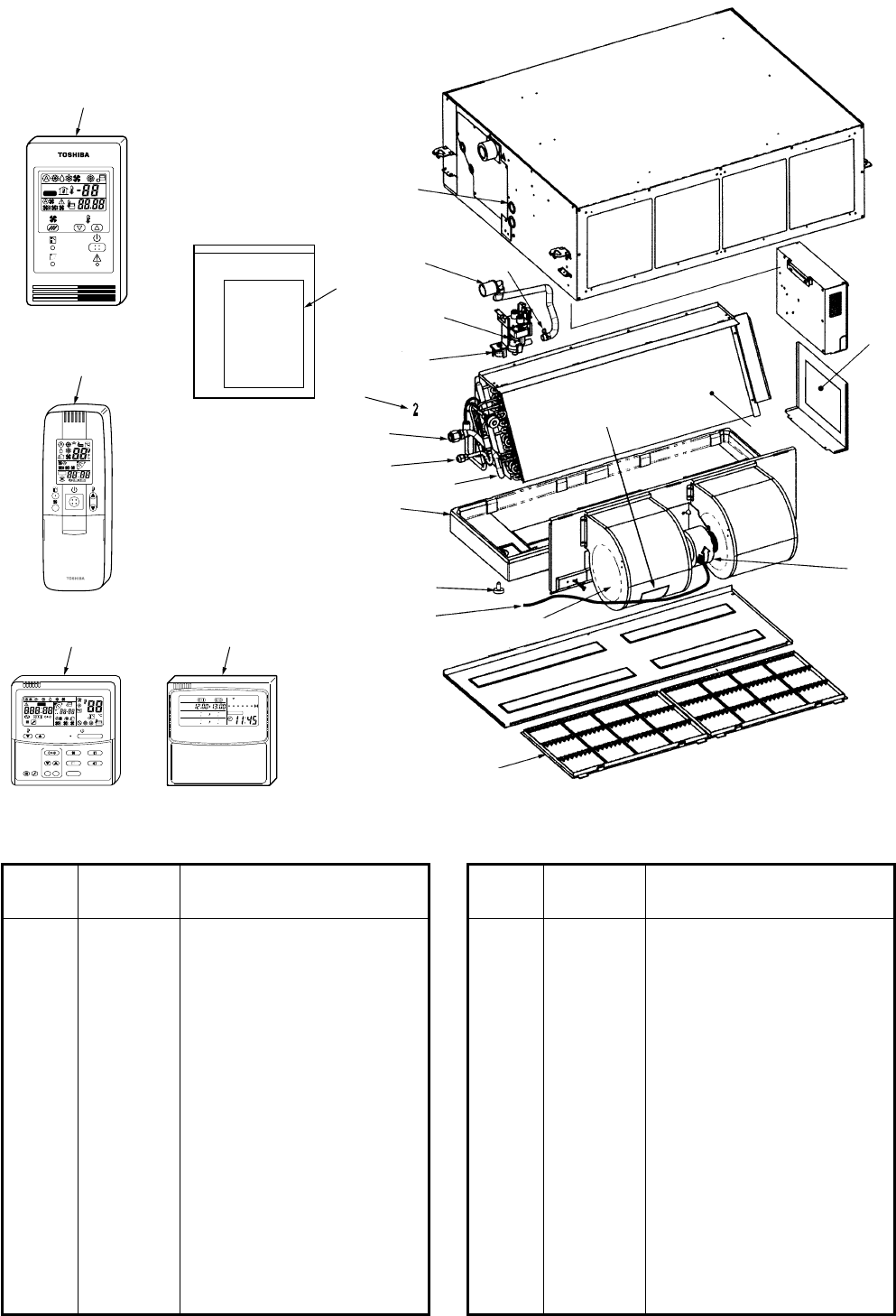
– 167 –
24
10
20
23
22
19
11
9
12
21
30
4
6, 7, 8 18
2
3, 904, 905
901, 902, 903 16
29
33
35
ADR
˚C
TEST
SETTING
ON / OFF
FAN
TEMP.
SWING/FIXTIME
MODE
VENT
UNITSET CL
FILTER
RESET
TEST
TIMER SET
CODE No.
UNIT No.
TEST
SETTING
DATA
SET
R.C. No.
H
32 34
WEEKLY TIMER
ERROR
SuMoTuWeTh Fr Sa
PROGRAM1
PROGRAM2
PROGRAM3
RAV-SM802BT-E
Location
Part Description
No. No.
2 43019904 Holder, Sensor
3 43047609 Bonnet
4 43079249 Band, Hose
10 43120226 Fan, Multi Blade
11 43121747 Pump Ass’y, Drain
12 43121739 Motor, Fan
16 4314Q016 Distributor Ass’y
18 4314J269 Refrigeration cycle Ass’y
20 43160553 Lead, Motor, Fan
21 43170233 Hose, Drain
22 43172167 Pan Ass’y, Drain
23 43179110 Plug
24 43180312 Air Filter
29 4318T683 Owner’s Manual
Location
Part Description
No. No.
30 43196012 Bushing
32 43166002 Remote Controller,
SX-A1EE (RBC-AMT31E)
33 43166004 Remote Controller,
SX-A11JE2 (RBC-AS21E2)
34 43166005 Remote Controller,
EX-W2JE2 (RBC-EXW21E2)
35 43166006 Remote Controller,
WH-H1JE2 (RBC-AX22CE2)
901 43049776 Soket
902 43194029 Bonnet
903 43149355 Nut, Flare, 3/8, IN
904 43149352 Nut, Flare, 5/8, IN
905 43149354 Soket
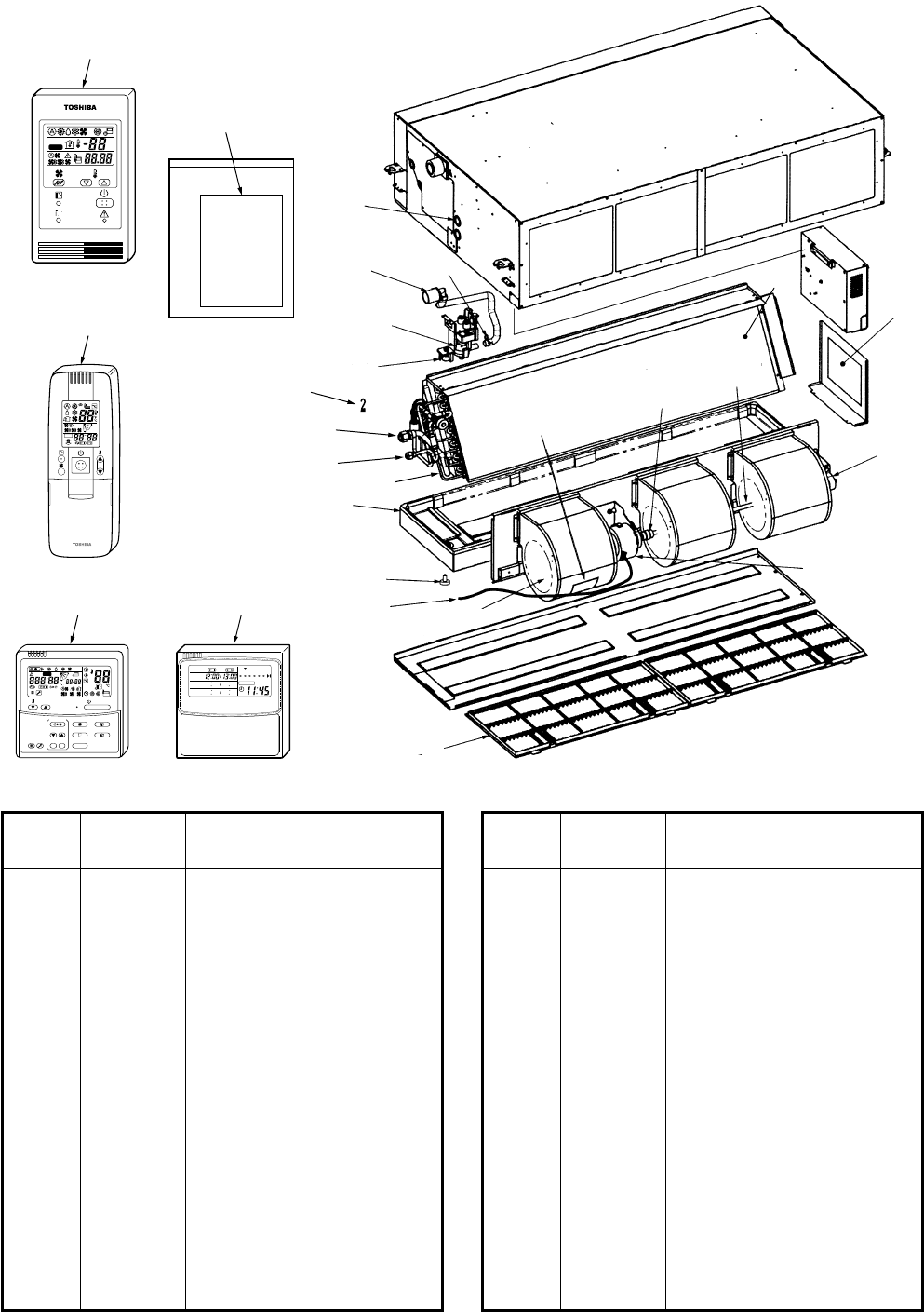
– 168 –
10
22
25
24
6, 7, 8
14 15
21
11
23
32
9
13
12
26
420
2
3, 904, 905
901, 902, 903 19
31
35
37
ADR
˚C
TEST
SETTING
ON / OFF
FAN
TEMP.
SWING/FIXTIME
MODE
VENT
UNITSET CL
FILTER
RESET
TEST
TIMER SET
CODE No.
UNIT No.
TEST
SETTING
DATA
SET
R.C. No.
H
34 36
WEEKLY TIMER
ERROR
SuMoTuWeTh Fr Sa
PROGRAM1
PROGRAM2
PROGRAM3
RAV-SM1102BT-E, RAV-SM1402BT-E
Location
Part Description
No. No.
2 43019904 Holder, Sensor
3 43047609 Bonnet
4 43079249 Band, Hose
10 43120226 Fan, Multi Blade
11 43121747 Pump Ass’y, Drain
12 43121740 Motor, Fan
13 43125131 Bearing, Shaft
14 43125162 Coupling
15 43125163 Shaft
19 4314Q017 Distributor Ass’y
20 4314J270 Refrigeration cycle Ass’y
22 43160553 Lead, Motor, Fan
23 43170233 Hose, Drain
24 43172166 Pan Ass’y, Drain
25 43179110 Plug
Location
Part Description
No. No.
26 43180311 Air Filter
31 4318T683 Owner’s Manual
32 43196012 Bushing
34 43166002 Remote Controller,
SX-A1EE (RBC-AMT31E)
35 43166004 Remote Controller,
SX-A11JE2 (RBC-AS21E2)
36 43166005 Remote Controller,
EX-W2JE2 (RBC-EXW21E2)
37 43166006 Remote Controller,
WH-H1JE2 (RBC-AX22CE2)
901 43049776 Soket
902 43194029 Bonnet
903 43149355 Nut, Flare, 3/8, IN
904 43149352 Nut, Flare, 5/8, IN
905 43149354 Soket
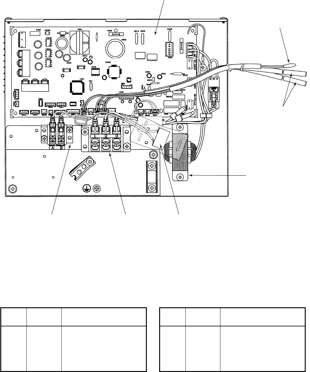
– 169 –
\
402
406
404
403
405 401 407
RAV-SM562BT-E, RAV-SM802BT-E, RAV-SM1102BT-E, RAV-SM1402BT-E
Location
Part Description
No. No.
401 43160565 Terminal Block, 3P, 20A
402 4316V281 P.C. Board Ass’y, MMC-1402
403 43050425 Sensor, TC (F6)
404 43050426 Sensor, TA
Location
Part Description
No. No.
405 43160568 Terminal Block, 2P
406 43158193 Reactor
407 43155203 Capacitor
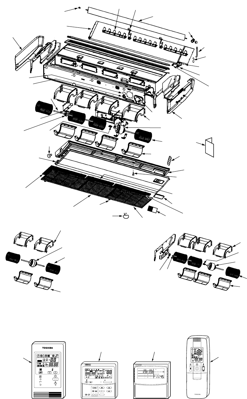
– 170 –
11
26
15
17
15
17
25
63
64
42
26
31
67
32
32
16
7, 8, 9
49
27, 28
RAV-SM562CT-E
(Fan assembly)
RAV-SM802CT-E
(Fan assembly)
17
25
43 41
60
61
10
40
26
58
36, 37, 38,39, 54, 55
22, 23, 24
33, 34, 35,53, 56, 57
47
48
66
1, 2, 3
44, 45, 46
14
17
25 52
27
(1101, 1401CT-E)
29
4, 5, 6
65
51
62
30 12, 13
50
12
(1101, 1401CT-E)
59
ON / OFF
FAN
TEMP.
SWING/FIXTIME
MODE
VENT
UNITSET CL
FILTER
RESET
TEST
TIMER SET
CODE No.
UNIT No.
TEST
SETTING
DATA
SET
R.C. No.
H
18 20
19 21
ADR
˚C
TEST
SETTING
WEEKLY TIMER
ERROR
SuMoTuWeTh Fr Sa
PROGRAM1
PROGRAM2
PROGRAM3
15-1-3. Under Ceiling Type
RAV-SM562CT-E, RAV-SM802CT-E, RAV-SM1102CT-E, RAV-SM1402CT-E
– 171 –
Location
Part Description
No. No.
1 4314J271 Refrigeration cycle Ass’y
(SM562CT)
2 4314J272 Refrigeration cycle Ass’y
(SM802CT)
3 4314J273 Refrigeration cycle Ass’y
(SM1102CT, SM1402CT)
4 43172188 Pan Drain Ass’y (SM562CT)
5 43172189 Pan Drain Ass’y (SM802CT)
6 43172190 Pan Drain Ass’y
(SM1102CT, SM1402CT)
7 43100356 Panel, Under (SM562CT)
8 43100357 Panel, Under (SM802CT)
9 43100358 Panel, Under
(SM1102CT, SM1402CT)
10 43102647 Cover Ass’y, Right Side
11 43102648 Cover Ass’y, Left Side
12 43109407 Grille, Inlet (SM562CT,
SM1102CT, SM1402CT)
13 43109408 Grille, Inlet (SM802CT,
SM1102CT, SM1402CT)
14 43121741 Motor, Fan,
SWF-280-120-2R, 120W
(SM1102CT, SM1402CT)
15 43121742 Motor, Fan,
SWF-280-60-1R, 60W
(SM562CT)
16 43121743 Motor, Fan,
SWF-280-60-2R, 60W
(SM802CT)
17 43120227 Fan, Multi Blade
18 43166002 Remote Controller,
SX-A1EE (RBC-AMT31E)
19 43166004 Remote Controller,
SX-A11JE2 (RBC-AS21E2)
20 43166005 Remote Controller,
EX-W2JE2 (RBC-EXW21E2)
21 43166006 Remote Controller,
WH-H1JE2 (RBC-AX22CE2)
22 4314Q012 Distributor Ass’y (SM562CT)
23 4314Q013 Distributor Ass’y (SM802CT)
24 4314Q014 Distributor Ass’y
(SM1102CT, SM1402CT)
25 43122084 Case, Fan, Lower
26 43122085 Case, Fan, Upper
27 43180314 Air Filter (SM562CT,
SM1102CT, SM1402CT)
28 43180315 Air Filter (SM802CT,
SM1102CT, SM1402CT)
29 43108014 Base, Receiver
30 43179136 Band, Hose
31 43125131 Bearing, Shaft
(SM1102CT, SM1402CT)
Location
Part Description
No. No.
32 43125162 Coupling (SM802CT,
SM1102CT, SM1402CT)
33 43047685 Nut, Flare, 1/4 IN (SM562CT)
34 43049776 Socket (SM802CT,
SM1102CT, SM1402CT)
35 43149351 Socket (SM562CT)
36 43047688 Nut, Flare, 1/2 IN (SM562CT)
37 43149352 Nut, Flare, 5/8 IN (SM802CT,
SM1102CT, SM1402CT)
38 43149353 Socket, 1/2 IN (SM562CT)
39 43149354 Socket, 5/8 IN (SM802CT,
SM1102CT, SM1402CT)
40 43149326 Cover, Back Base
41 43125164 Shaft, SS400B-D2 12
(SM802CT)
42 43125165 Shaft, SS400B-12 DIA
(SM1102CT, SM1402CT)
43 43125159 Bearing (SM802CT)
44 43109409 Grille Ass’y, Horizontal
(SM562CT)
45 43109410 Grille Ass’y, Horizontal
(SM802CT)
46 43109411 Grille Ass’y, Horizontal
(SM1102CT, SM1402CT)
47 43107260 Support, Grille Horizontal
48 43122086 Grille Ass’y, Vertical
49 43179129 Cap Drain
50 43107254 Hinge, Grille Inlet
51 43107255 Hook, Grille Inlet
52 43170234 Hose, Drain
53 43047609 Bonnet (SM802CT,
SM1102CT, SM1402CT)
54 43047303 Bonnet (SM562CT)
55 43194029 Bonnet (SM802CT,
SM1102CT, SM1402CT)
56 43149355 Nut, Flare, 3/8 IN (SM802CT,
SM1102CT, SM1402CT)
57 43049697 Bonnet (SM562CT)
58 43019904 Holder, Sensor
59 4318T682 Owner’s Manual
60 43121746 Driver Ass’y, Horizontal L
Louver
61 43160556 Lead, Louver Horizontal
62 43108016 Mark TOSHIBA
63 43162049 Bushing, 50DIA
64 43162050 Bushing, 56DIA
65 43197189 Screw, Fix Drain Pan
66 43107252 Shaft, Horizontal Louver
67 43139153 Spacer, Bearing
(SM1102CT, SM1402CT)
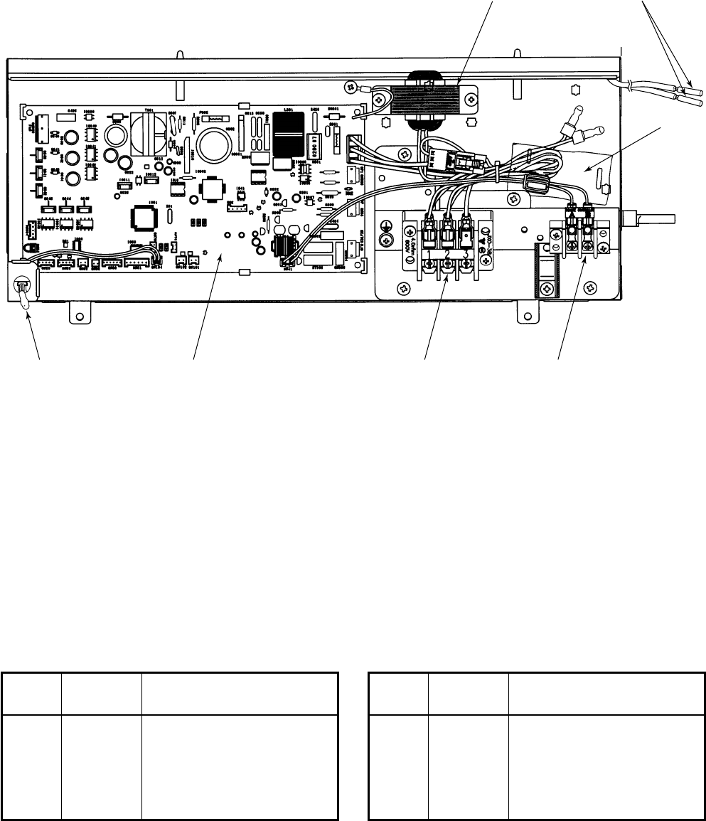
– 172 –
404 401
405
407
402406403
Location
Part Description
No. No.
401 43050425 Sensor, TC (F6)
402 43160565 Terminal Block, 3P, 20A
403 43050426 Sensor, TA
404 43158193 Reactor
Location
Part Description
No. No.
405 43160568 Terminal Block, 2P
406 4316V280 P.C. Board Ass’y, MMC-1402
407 43155203 Capacitor
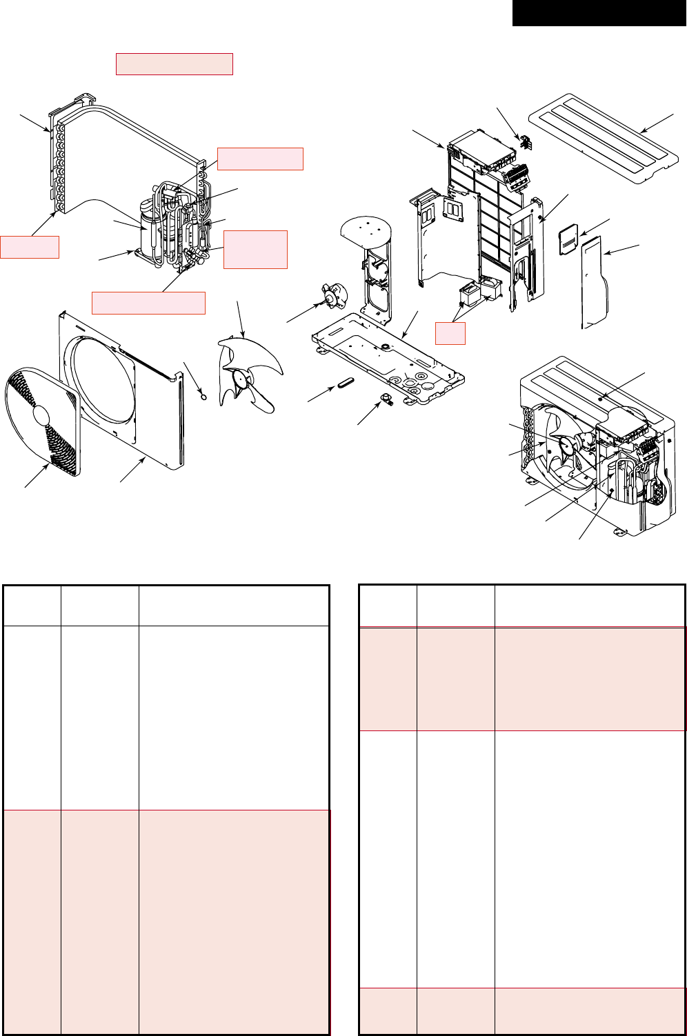
– 173 –
Location
Part Description
No. No.
1 43005657 Cabinet, Front
2 43005642 Cabinet, Upper
3 43005658 Cabinet, Side, Right
4 43005634 Cabinet, Side, Left
5 4301V035 Guard, Fan
6 4301V053 Guard, Fin
7 43100346 Base Ass’y
8 43119471 Cover, Valve, Packed
9 43162055 Cover, Wiring Ass’y
10 43041786 Compressor Ass’y,
DA150, A1F-20F
11 4314G204 Condenser Ass’y
(SM563AT-E)
12 4314G251 Condenser Ass’y
(SM803AT-E)
13 37546845 Valve, Packed, 6.35
(SM563AT-E)
14 43146680 Valve, Packed, 12.7
(SM563AT-E)
15 43146686 Valve, Packed, 9.52
(SM803AT-E)
16 43146681 Valve, Packed, 15.9
(SM803AT-E)
17 43147196 Bonnet, 1/4 IN (SM563AT-E)
18 43147195 Bonnet, 1/2 IN (SM563AT-E)
Location
Part Description
No. No.
19 43194029 Bonnet (SM803AT-E)
20 43047401 Bonnet, 3/8 IN (SM803AT-E)
21 43046444 Valve, 4-Way, STF-0108Z
(SM563AT-E)
22 43046445 Valve, 4-Way, STF-0213Z
(SM803AT-E)
23 43146722 Coil, Solenoid,
24 43146695 Valve, Pulse, Modulating
25 37546849 Coil, PMV, CAM-MD12TF-1
26 43055521 Reactor
27 4302C068 Motor, Fan, ICF-140-43-4
28 43020329 Fan, Propeller, PJ421
29 43047669 Nut, Flange
30 43032441 Nipple, Drain
31 43089160 Cap, Waterproof
32 43050407 Thermostat, Bimetal
33 43063339 Holder, Sensor (TO)
34 43049749 Rebber, Cushion
35 43063321 Holder, Sensor
36 43063322 Holder, Sensor
37 43063325 Holder, Sensor
38 43063317 Holder, Thermostat
39 4314Q064 Muffler (SM563AT-E)
39 4314Q063 Muffler (SM803AT-E)
15-2. Outdoor Unit
RAV-SM563AT-E, RAV-SM803AT-E
Revised : Mar. 2007
4
29
28
27
31
30
51
24, 25
37
10
34
35 : TD (Discharge Pipe Temp. Sensor) Holder
36 : TS (Suction Pipe Temp. Sensor) Holder
37 : TE (Condenser Pipe Temp. Sensor) Holder
38 : TO (Outdoor Temp. Sensor) Holder
39 : Muffler
2
2
6
33
3
9
8
29
28
35 36
10, 32, 38
7
21, 22, 23
14, 16, 17, 18
11, 12 13, 15,
19, 20
26
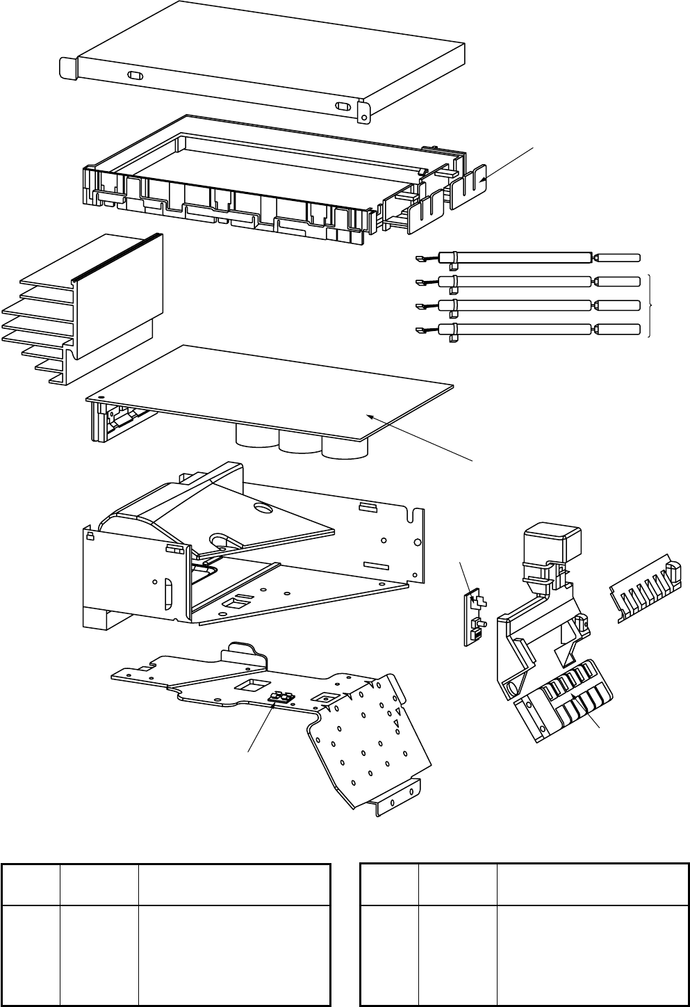
– 174 –
705
708
710
702
701
707
706
Location
Part Description
No. No.
701 43150319 Sensor Ass’y, Service
702 43050425 Sensor Ass’y, Service
705 43062228 Base, P.C. Board
706 43160566 Terminal Block, 6P, 20A
Location
Part Description
No. No.
707 4316V293 P.C. Board Ass’y, SW,
MCC-1530
708 4316V284 P.C. Board Ass’y, MCC-5009
710 43160571 Fuse Holder, 15A, 250V
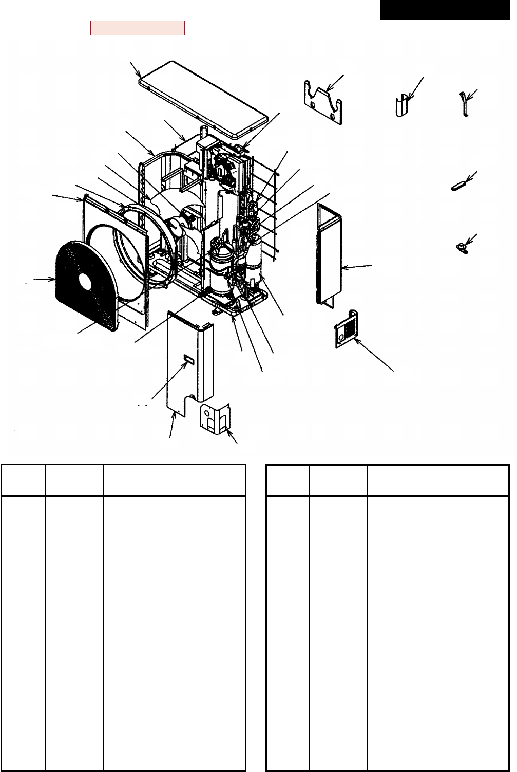
– 175 –
433
30
32
31
36
37
3
21, 22
23, 24
34 35
15, 16, 17 19, 20
14
212
25
27, 29
13
26, 28
18
6
11
10
9
8
7
1
5
RAV-SM1103AT-E, RAV-SM1403AT-E
Location
Part Description
No. No.
1 43005635 Cabinet, Air Outled
2 43100350 Cabinet, Front Ass’y
3 43100349 Cabinet, Side Ass’y
4 43100355 Panel, Upper
5 43191633 Guard, Fin
6 43191651 Guard, Fan
7 43122065 Bell Mouth
8 43047669 Nut, Flange
9 43120224 Fan, Propeller, PE492
10 43121744 Motor, Fan, ICF-280-100-1R
11 4314G209 Condenser Ass’y
12 43100347 Panel, Front, Piping
13 43100345 Panel, Back, Piping
14 43119390 Hanger
15 43041787 Compressor Ass’y,
DA420A3F-21M
16 43050407 Thermostat, Bimetal
17 43063317 Holder, Thermostat
18 43100343 Base Ass’y
19 43197183 Bolt, Compressor
Location
Part Description
No. No.
20 43149324 Rubber, Cushion, EPDM
21 43046445 Valve, 4-WAY, STF-0213Z
22 43146722 Coil, Solenoid,
STF-01AJ502E1
23 43146634 Valve, Pulse, Modulating
24 43146685 Coil, PMV, UKV-U048E
25 43148170 Accumulator Ass’y
26 43146686 Valve, Packed, 9.52 DIA
27 43146699 Valve, Ball
28 43047401 Bonnet, 3/8 IN
29 43194029 Bonnet
30 43158190 Reactor
31 43019904 Holder, Sensor
32 43063188 Holder, TC Sensor
33 43063332 Holder, Sensor
34 4314Q019 Strainer
35 4314Q033 Strainer
36 43089160 Cap, Waterproof
37 43032441 Nipple, Drain
Revised : Mar. 2007
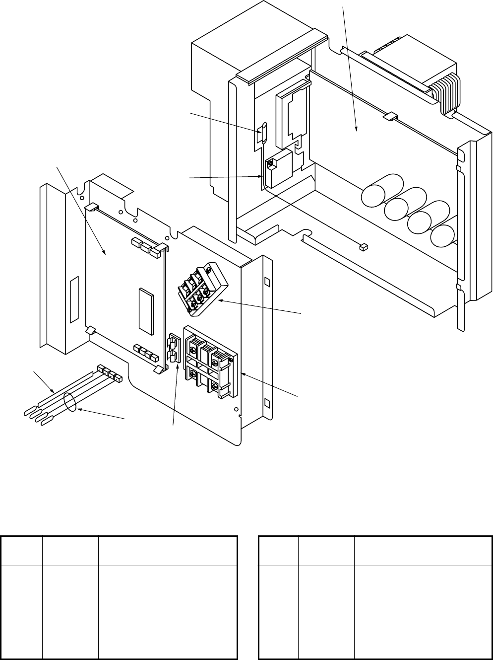
– 176 –
TO
TD
TSTE
702
704
708
703
705
710
707
701
706
Location
Part Description
No. No.
701 43150319 Sensor Ass’y, Service
702 43050425 Sensor Ass’y, Service
703 43160565 Terminal Block, 3P, 20A
704 43131052 Rectifier
705 43160567 Terminal Block, 3P, 30A
Location
Part Description
No. No.
706 4316V283 P.C. Board Ass’y, CDB,
MCC-1531
707 4316V291 P.C. Board Ass’y, IPDU,
MCC-1438
708 43150320 Sensor Ass’y, Service
710 43160571 Fuse Holder, 15A, 250V
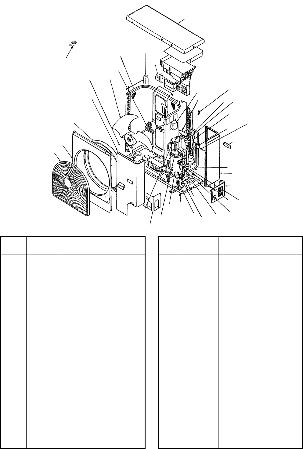
– 177 –
6
37
8910
11 5
38
32
21,22
4
36
34 24
23
30 35
14
31
3
13
25
28
29
26
27
20
19
18
12
15
16,17
33
1
7
2
RAV-SP562AT-E, RAV-SP802AT-E
Location
Part Description
No. No.
1 43100348 Cabinet, Air Outlet
2 43100350 Cabinet, Front Ass’y
3 43100349 Cabinet, Side Ass’y
4 43100351 Panel, Upper
5 43005489 Guard, Fin
6 43191651 Guard, Fan, PP-K
7 43122065 Bell, Mouth
8 43047669 Nut, Flange
9 43120213 Fan, Propeller, PJ491, AS-G
10 4302C069 Motor, Fan, ICF-140-63-2R
11 4314G205 Condenser Ass’y
(SP802AT-E)
11 4314G200 Condenser Ass’y
(SP562AT-E)
12 43100347 Panel, Front, Piping
13 43100345 Panel, Back, Piping
14 43119390 Hanger
15 43041785 Compressor Ass’y,
DA220A2F-20L
16 43050407 Thermostat, Bimetal
17 43063317 Holder, Thermostat
18 43100342 Base Ass’y
19 43049739 Cushion, Rubber
20 43097212 Nut
21 43046445 Valve, 4-Way, STF-0213Z
22 43046443 Coil, Solenoid,
VHV-01AJ503C1
Location
Part Description
No. No.
23 43146695 Valve, Pulse, Modulating,
CAMB30YGTF-2
24 43046450 Coil, PMV, CAM-MD12TF-8
25 43048066 Accumulator Ass’y
26 43046392 Valve, Packed, 6.35
(SP562AT-E)
26 37546845 Valve, Packed, 9.52DIA
(SP802AT-E)
27 43047686 Bonnet, 3/8 IN (SP802AT-E)
27 43147196 Bonnet, 1/4 IN (SP562AT-E)
28 43146680 Valve, Packed, 12.7,
HKU-R410A-H4 (SP562AT-E)
28 43146699 Valve, Ball (SP802AT-E)
29 43147194 Bonnet, 5/8 IN (SP802AT-E)
29 43047303 Bonnet, 1/2 IN (SP562AT-E)
30 4314Q018 Strainer
31 4314Q021 Strainer (SP562AT-E)
31 4314Q022 Strainer (SP802AT-E)
32 43058276 Reactor, CH47-Z-T
33 43063321 Holder, Sensor
34 43063322 Holder, Sensor
35 43063325 Holder, Sensor
36 43063332 Holder, Sensor
37 43032441 Nipple, Drain
38 43158192 Reactor, CH-43-Z-T
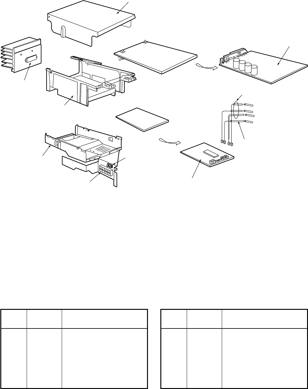
– 178 –
INVERTER BOX
INVERTER COVER
704
710
705
711
707
701
702
TE Sensor (Ø6)
TS Sensor (Ø6)
TO Sensor (Ø6)
TD Sensor (Ø4)
708
Location
Part Description
No. No.
701 43150319 Sensor, TD (F4)
702 43050425 Sensor, TC (F6)
704 43160566 Terminal Block, 6P, 20A
705 43162042 Base, P.C. Board
707 4316V282 P.C. Board Ass’y, CDB,
MCC-1531
Location
Part Description
No. No.
708 4316V278 P.C. Board Ass’y, IPDU,
MCC-1438
710 43160571 Fuse Holder, 15A, 250V
711 43131052 Rectifier
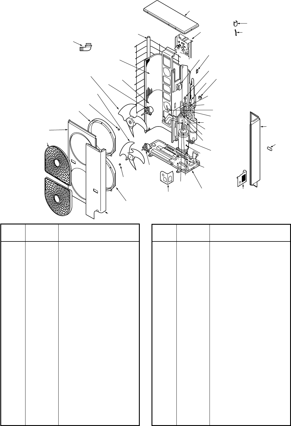
– 179 –
42
13 14
44
20
11 12
22
21
15
17
16 3,4
6
5
33
1,2 37
38
7,8
19
36
23,24
28,29
32
25
31
30
28 25
26,27
26 23 9
10
34
39
35
Inverter
41
40
43
RAV-SP1102AT-E, RAV-SP1402AT-E
Location
Part Description
No. No.
2 43100343 Base Ass’y
4 43041787 Compressor Ass’y,
DA420A3F-21M
5 43049739 Cushion, Rubber
6 43097212 Nut
7 43050407 Thermostat, Bimetal
8 43063317 Holder, Thermostat
9 4314G207 Condenser, Down
10 4314G208 Condenser, Up
11 43146687 Valve, 4-WAY, STF-0401G
12 43146683 Coil, Solenoid,
VHV-01AJ502E1,
13 43146634 Valve, Pulse, Modulating,
UKV-25D22
14 43146695 Coil, PMV
15 43146613 Valve, Ball, 5/8 IN
16 43147194 Bonnet, 5/8 IN
17 43146686 Valve, Packed, 3/8 IN
19 43047401 Bonnet, 3/8 IN
20 4314Q019 Strainer
21 43148170 Accumulator Ass’y, 2.5L
Location
Part Description
No. No.
21 43148170 Accumulator Ass’y, 2.5L
22 4314Q020 Strainer
23 4302C069 Motor, Fan, ICF-140-63-2R
25 43047669 Nut, Flange
26 43120213 Fan, Propeller, PJ491, AS-G
28 43122065 Bell Mouth, Plastic
30 43100352 Panel, Air Outlet
31 43191651 Guard, Fan, PP-K
32 43100353 Panel, Front
33 43100354 Panel, Side
34 43191602 Guard, Fin
35 43100355 Plate, Roof
36 43100347 Panel, Front, Piping
37 43100345 Panel, Back, Piping
38 43119390 Hanger
39 43158190 Peacter, CH-62-Z-T
40 43019904 Holder, Sensor, SUS
41 43063188 Holder, TC Sensor
42 43063332 Holder, Sensor
43 43032441 Nipple, Drain
44 43146676 Check, Joint
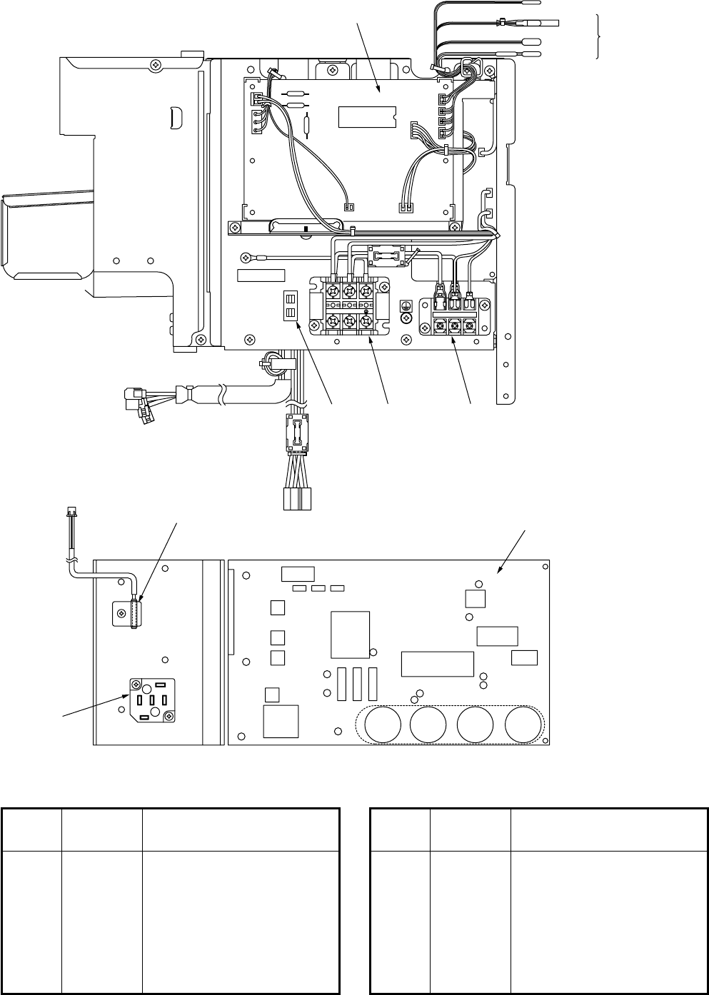
– 180 –
702 TD SENSOR
701 TC SENSOR
(F6)
703 SENSOR ASS’Y
NL
2 21
CN600
CN601
CN604
CN
605
CN800
CN12
CN03
CN04
IC800
CN02
CN01
R501
R502
R500
707
706
710 704
P18
BLU
P20
YEL
RED
P17
BLU
P28
BLK
RY01 P19
YEL
P21
ORG
P09
WHI
P12
GRY
P08
WHI
P13
GRY
P24
BRW
709
705
Location
Part Description
No. No.
701 43050425 Sensor Ass’y, Service
702 43150319 Sensor Ass’y, Service
703 43150320 Sensor Ass’y, Service
704 43160565 Terminal Block, 3P, 20A
705 43131052 Rectifier
706 43160567 Terminal Block, 3P, 30A
Location
Part Description
No. No.
707 4316V282 P.C. Board Ass’y, CDB,
MCC-1531
709 4316V291 P.C. Board Ass’y, IPDU,
MCC-1438
710 43160571 Fuse Holder, 15A, 250V
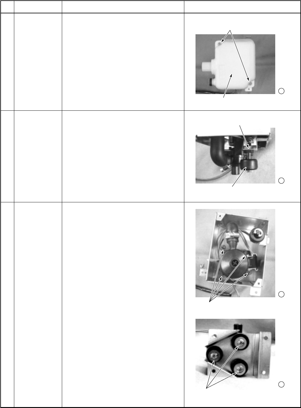
– 181 –
1 -2
2 -2
3 -2
3 -3
Drain pan
Plastics nut
Float switch
Screws
(Fixing drain pump and drain plate)
Screws
(Fixing drain pump and main unit)
Screws
(Fixing drain pan and main unit)
15-3. Replacement of Main Parts (Sold Separately)
15-3-1. Drain up Kit
TCB-DP22CE2
No.
Part name
Drain pan
Float switch
Drain pump
Procedure
1. Remove the Drain up kit from the main
unit.
2. Remove the set screws (2 positions)
and drain pan.
1. Remove the drain pan.
2. Remove the plastics nut of fixing float
switch.
3. Remove the float switch.
1. Remove the drain pan.
2. Remove the set screws (4 positions) of
fixing drain pump plate and main unit.
3. Remove the screws (3 positions) of
fixing drain pump plate and drain pump.
Remarks
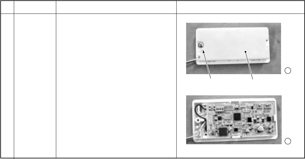
– 182 –
1 -2
1 -3
Screw P.C. board cover
15-3-2. Wireless Remote Control Kit
RBC-AX22CE2
No.
Part name
P.C. board
Procedure
1. Remove the signal receiving unit from
main unit.
2. Remove the set screw (1 position) and
P.C. board cover.
3. Remove the p.c. board.
Remarks

– 183 –
16. CORD HEATER INSTALLATION WORK
This is on installation for 2 HP and 3 HP Products
(RAV-SM563AT-E, RAV-SM803AT-E, RAV-SP562AT-E, RAV-SP802AT-E).
In case of 4 HP or 5 HP, refer to this installation as reference.
16-1. Required parts for installation work (Recommendation)
The above products conform to RoHS (2002/95/EC). Therefore when procuring and using the following recom-
mended parts at local site, it is recommended to confirm each part conforms to RoHS before use.
No.
1
2
3
4
5
6
7
8
9
10
11
12
Part name
Cord heater
Thermostat
Fuse
Fuse holder
P-shape
clamp
P-shape
clamp
Screw
Screw
Screw
Faston
Sleeve for
Faston
Close-end
connector
Q’ty
1
1
1
1
13
1
12
4
2
2
2
2
Specifications/Vendor
Drain line heaters CSC2 (3.0m, 40W/m) by Flexelec com.
(Please go to the following URL.)
http://www.flexelec.com
US-622AXRLQE by ASAHI KEIKI
Operating temperature: on 4 ± 4°C, off 15 ± 3°C
A thermostat holder is incorporated with a thermostat in the package.
(Please go to the following URL.)
http://www.asahikeiki.co.jp/product/product.html
On self-responsibility, you can use a product manufactured by other
company (For example, Texas Instruments) if its characteristics are
equivalent to those of ASAHI KEIKI. However, when the shape of the
thermostat holder is different from that of ASAHI KEIKI, apply some
treatment to No.14 thermostat fixing plate and then fix the holder.
ES3-5000, 250V / 5A by NAGASAWA Electric Co.
(Please go to the following URL.)
http://www.nagasawa-el.co.jp/
On self-responsibility, you can use a product manufactured by other
company if its characteristics are equivalent to those of NAGASAWA
Electric Co.
GM1H-02 by NAGASAWA Electric Co.
(Please go to the following URL.)
http://www.nagasawa-el.co.jp/
On self-responsibility, you can use a product manufactured by other
company if its characteristics are equivalent to those of NAGASAWA
Electric Co.
Use heat-resistance, weatherproof and non-hydrolytic type.
Material: 4-fluorinated ethylene copolymer
Harness diameter: Ø5.9
Use equivalence with the above specifications.
11 pieces are used to fix the cord heater to the outdoor unit base plate.
One piece is used to fix the power cord to the thermostat fixing plate.
One piece is used to fix the power cord to the terminal fixing plate.
Use heat-resistance, weatherproof and non-hydrolytic type.
Material: 4-fluorinated ethylene copolymer
Harness diameter: Ø9.1
Use equivalence with the above specifications.
One piece is used to fix the cord heater to the outdoor unit base plate.
Self-tapping screw type-B Ø4 × 6mm, truss head, stainless
These screws are used to fix the cord heater to the outdoor unit base
plate with P-shape clamp.
Self-tapping screw type-B Ø4 × 8mm, truss head, stainless
Two screws are used to fix the thermostat fixing plate to the side cabinet (R).
One screw is used to fix the power cord to the thermostat fixing plate.
One screw is used to fix the power cord to the terminal fixing plate.
Self-tapping screw type-B Ø3.5 × 6mm, pan head
These screws are used to fix the thermostat to the thermostat fixing
plate with the thermostat holder.
#250 They are used for the connecting part to the thermostat.
UL sleeve for #250
Use the most appropriate connector with the power cord diameter.
Remarks
Procured locally
Procured locally
Procured locally
Procured locally
Procured locally
Procured locally
Procured locally
Procured locally
Procured locally
Procured locally
Procured locally
Procured locally
Revised : Mar. 2007
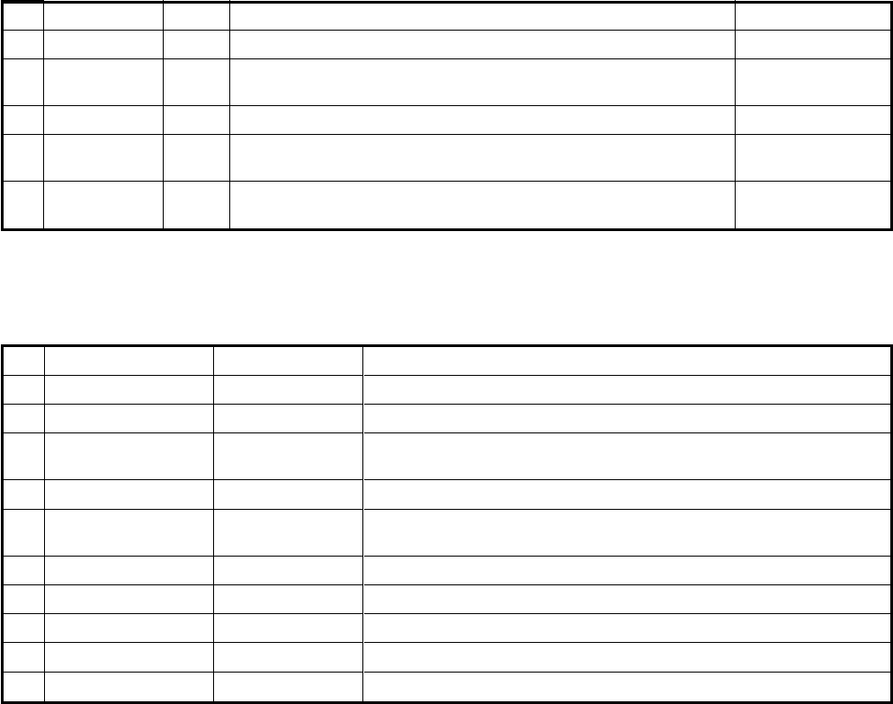
– 184 –
No.
13
14
15
16
17
Part name
Power cord
Thermostat
fixing plate
PVC tube
Shield tube
Bundling tie
Q’ty
1
1
1
1
1
Specifications/Vendor
2-cores x 0.75mm² or more, H05RN-F
Material: SGCC-Z08, Board thickness: 0.8t
Inside diameter Ø8 x outside diameter Ø11 x 70 mm
Inside diameter Ø18 x outside diameter Ø26 x 70 mm
Material: Polyethylene foam
Bundling tie for securing the wires
Material: 6/6 nylon
Remarks
Procured locally
Procured locally
(Drawing attached)
Procured locally
Procured locally
Procured locally
NOTE: The parts on the above table are recommended parts.
2. Required tools for installation work
No.
1
2
3
4
5
6
7
8
9
10
Part name
Plus screwdriver
Wrench
Motor drill
Faston crimping tool
Close-end connector
crimping tool
Cutting plier
Stripper
Cutter knife
Insulation tape
Metal-cutting shears
Specifications
Drill diameter:
Ø3.2 and Ø5.0
Fixing jig for #250
Usage
It is used for disassembling and assembling of each cabinet.
It is used for disassembling and assembling of compressor fixing nuts.
It is used to make the additional holes on the base or the side
cabinet (R).
It is used to process the side cabinet (L).
– 185 –
3. Cord heater installation wiring diagram
NOTE:
Separate the cord heater power from the air conditioner power, and connect it to its exclusive breaker.
By doing so, the power consumption can be decreased because the breaker can be turned off if there is no
possibility of freezing of the base plate in cooling operation, etc.
When the cord heater power is connected to the inverter P.C. board assembly or others without connected to the
exclusive breaker, the control P.C. board of the inverter assembly may cause a failure.
When the cord heater has been mounted on a base plate, do not mount the water-proof cap and drain nipple
which are provided with the outdoor unit on the base plate.
LN
Fuse Thermostat Cord heater
Outdoor unit
Earth leakage circuit breaker Power supply for air conditioner
Earth leakage circuit breaker Power supply for cord heater
* Be sure to connect the fuse and the thermostat to LIVE side of the cord heater.
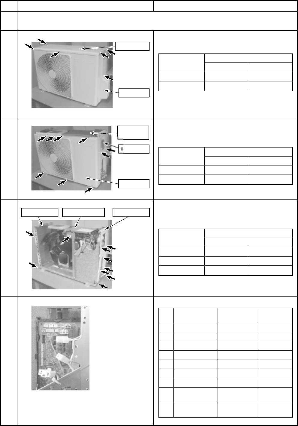
– 186 –
4. Cord heater installation work procedure
Upper cabine
t
Valv
e
c
ov
er
W
irin
g
cove
r
Water-proof
cover
Front
c
a
b
in
et
Side cabinet
(
L
)
Side cabinet
(
R
)
Inverter assembl
y
No.
1
Procedure
Remove each cabinet, inverter assembly, motor base assembly, and partition board assembly.
* Do not damage the electric parts such as cables, connectors, etc. while this work.
Remove the upper cabinet and the valve cover.
Related parts / Screws list
Photo / Explanatory diagram
Remove the front cabinet, the wiring cover and the
water-proof cover.
Related parts / Screws list
Remove the side cabinet (R/L) and the inverter
assembly.
Related parts / Screws list
Remove the inverter assembly.
1-1
1-2
1-3
1-4
No.
1
2
3
4
5
6
7
8
9
Part name
TE sensor
TD sensor
TO sensor
TS sensor
4-way valve coil
PMV coil
Fan motor
Compressor lead
Reactor
(2 pieces.)
Connector
No.
CN600
CN601
CN602
CN603
CN701
CN700
CN300
(Intermediate
connector)
(Intermediate
connector)
Connector
color
White
White
White
White
Yellow
White
White
White
White
Part name
Side cabinet (R)
Side cabinet (L)
Inverter assembly
Used screw
Screw type Quantity
Ø4 × 87
Ø4 × 83
Ø4 × 81
Part name
Front cabinet
Wiring cover
Used screw
Screw type Quantity
Ø4 × 87
Ø4 × 82
Part name
Upper cabinet
Valve cover
Used screw
Screw type Quantity
Ø4 × 85
Ø4 × 11
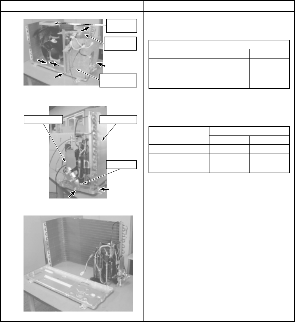
– 187 –
Sound
in
s
ulation
b
oar
d
Partition plate
assembl
y
M
o
t
o
r
b
a
se
assembl
y
Valve fixin
g
plat
e
Heat exchan
g
e
r
Compresso
r
No.
1-5
1-6
1-7
Photo / Explanatory diagram Procedure
Remove the motor base assembly, partition plate
assembly and the sound insulation board.
Related parts / Screws list
Part name
Motor base assembly
(Including motor and fan)
Partition plate assembly
(Including reactor)
Used screw
Screw type Quantity
Ø4 × 82
Ø4 × 83
Remove the fixing screws of the heat exchanger and the
valve fixing plate. Remove the compressor fixing bolt.
Related parts / Screws list
Part name
Heat exchanger
Valve fixing plate
Compressor
Used screw
Screw type Quantity
Ø4 × 81
Ø4 × 81
bolt 3
As shown in the left figure, remove the set of refrigera-
tion cycle assembly from the outdoor unit base plate.
* In this time, work attentively so that the cycle pipes are
not damaged by dent or deformation. Apply protective
measures to pipes if necessary.
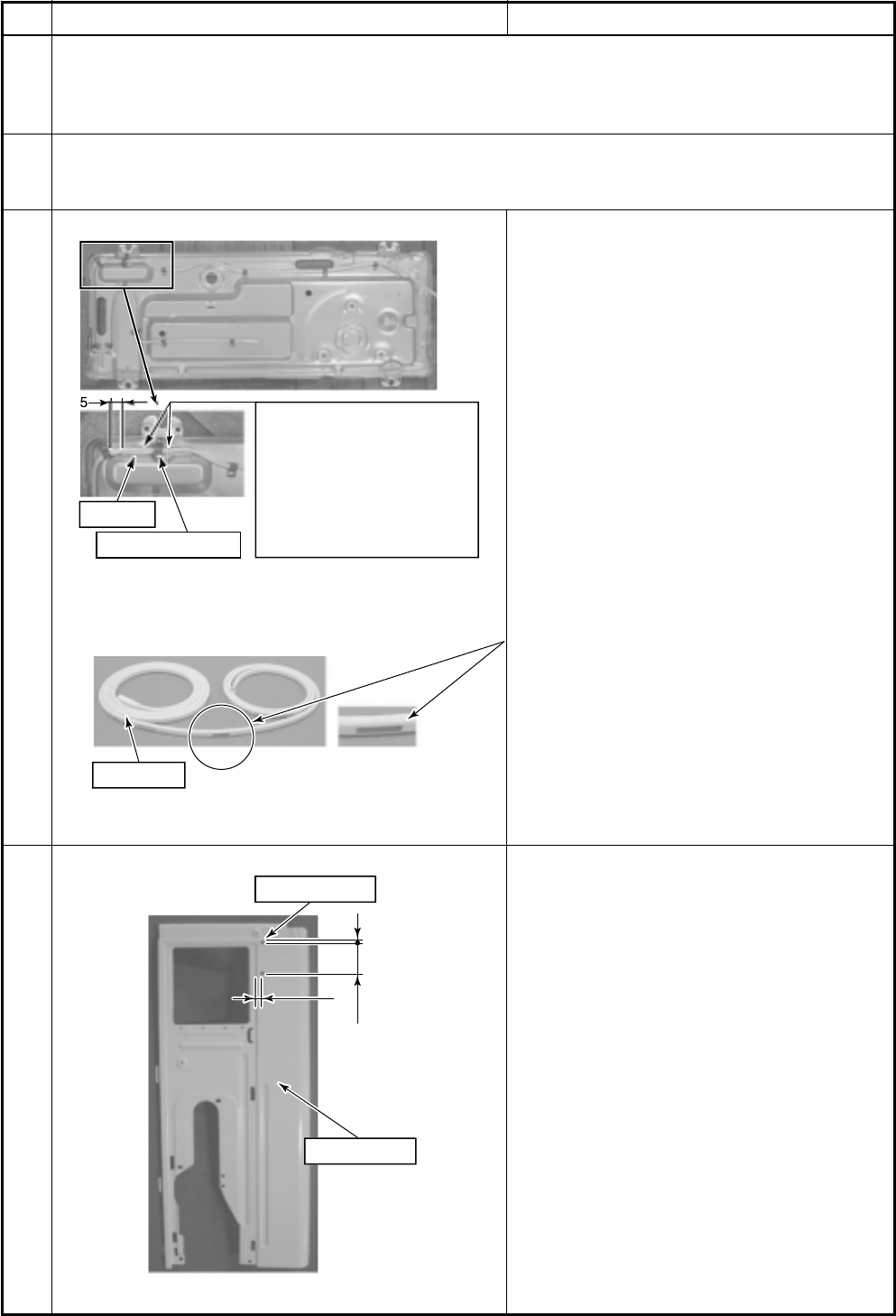
– 188 –
A
dded
h
o
l
e
2
-
φ
5
Side cabinet
(
R
)
7
5
46
Ø9.1 P-shape clamp
PV
C
tub
e
The PV
C
tube must be inserted
into th
e
c
or
d
h
e
at
e
r
be
tw
ee
n
the fixin
g
screws in order to
protect the cord heater from
th
ese
sc
r
e
w
s
.
U
n
de
r no
ci
r
c
um
s
tan
ces
mu
s
t
th
e
tu
be
be
allow
ed
to ri
de
ov
e
r
the tip of the fixing screws.
Enlar
g
e
d
marked par
t
Heatin
g
par
t
No.
2
2-1
2-2
2-3
Photo / Explanatory diagram Procedure
Cord heater installation work
Drill a hole on the outdoor unit base plate, and fix the cord heater to the outdoor unit base plate using
P-shape clamp.
Connect the cord heater cables.
Using a motor drill, etc., drill Ø3.2 holes on the outdoor unit base plate.
See APPENDIX-1 and 2 for the additional hole positions.
These holes are used to fix the cord heater to the outdoor unit base plate with P-shape clamp.
Insert the PVC tube into the cord heater.
This tube is designed to protect the cord heater
from the fixing screws used to secure the
anchoring feet.
As shown in the left figure, install the cord
heater (1.5m) to the outdoor unit base plate by
using P-shape clamp and screws (Self-tapping
screw type-B Ø4 × 6mm, stainless).
Pay attention to the direction of P-shape clamp
so that it is set to the same direction in the left
figure.
* If the drain port is frozen due to installation
status, etc., draw around the cord heater so
that the end part of the heater is inserted into
the drain port. In this case, add some fixing
positions to fix the cord heater surely.
* The end part from the marked part of the cord
heater heats up. When there is the heating
part near the electric parts box, a fire may
generate. Be sure to set the heating part on
the outdoor unit base plate at the fan room
side or near it. (within 20cm from the outdoor
unit base plate)
* Be careful that the cord heater does not hit
the fan.
Fix the cord heater without any loosening or
sag.
Drill a hole on the side cabinet (R) for fixing the
thermostat fixing plate.
Ø5 hole at two positions
When drilling a hole on the side cabinet (R), be
sure not to damage the cabinet.
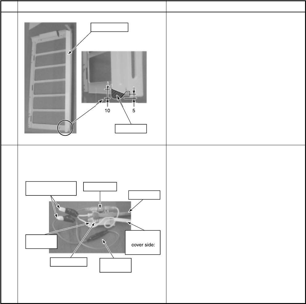
– 189 –
Fu
se
Fuse holde
r
Thermostat
Th
e
rmo
s
tat
fixin
g
plat
e
P-shape clamp
Pow
e
r
c
or
d
C
ord heate
r
* Transparent
L
s
i
de
Close-end connector
insulation tap
e
D
e
l
e
t
e
Side cabinet
(
L
)
No.
2-4
2-5
Photo / Explanatory diagram Procedure
Rework the side cabinet (L) to remove part of it.
The area to be removed is indicated by the
shaded lines in the left figure.
After removing part of the side cabinet (L), deburr
the edges of the side cabinet (L).
Perform end process and bundling of each cable.
Using fixing screws (Self-tapping screw type-B
Ø3.5 × 6mm), fix the thermostat to the thermostat
fixing plate.
Perform end process for various lead cables and
connect them according to the wiring diagram.
Attach #250 Faston and UL-approved sleeves
each to the end of lead cables which are con-
nected to the thermostat.
Using insulation tape, apply protective measures
to the connected parts by the close-end connec-
tors.
Using P-shape clamp and the screws (Self-
tapping screw type-B Ø4 × 8mm), fix the power
cord to the thermostat fixing plate.
When the power cord size does not match with P-
shape clamp, procure the most appropriate one at
the local site.
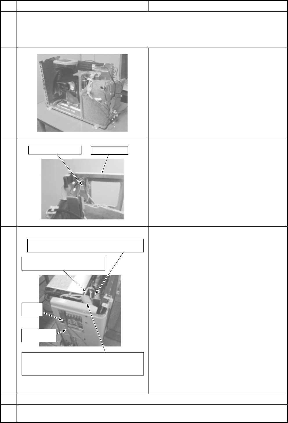
– 190 –
Side cabinet
(
R
)
Thermostat fixin
g
plat
e
Perform cable process for collected
c
or
d
h
e
at
e
r an
d
fan motor l
e
a
d
c
a
b
l
es.
Pow
e
r
c
or
d
for
c
or
d
h
e
at
er
P-shape
clamp
To keep the lead wires from comin
g
into contact with the
edges of the sheet metal or tips of the screws, wrap the
shield tubes around the leads to protect them and use
the bundling ties to secure them.
Do not make cord heater loose.
Do not put the heating part near the electric parts box.
No.
3
3-1
3-2
3-3
3-4
4
Photo / Explanatory diagram Procedure
Assembly
Return a set of the refrigeration cycle assembly into the outdoor unit base plate and reassemble sound
insulation board, partition plate assembly, fan motor assembly, and side cabinet (R/L) as original. Fix the
thermostat fixing plate to the side cabinet (R), built in the inverter assembly, and then connect various
cables. After then, incorporate front cabinet, upper cabinet, wiring cover, and valve cover as before.
Return a set of the refrigeration cycle assembly into
the outdoor unit base plate, and assemble sound
insulation board, partition plate assembly, fan motor
assembly, and side cabinet (R/L) as original.
Using screws (Self-tapping screw type-B Ø4 × 8mm,
stainless), fix the thermostat fixing plate to the side
cabinet (R).
After incorporating the inverter assembly as before,
furthermore perform cable process for cord heater
and power cord.
For the cord heater, perform cable process so that
there is no looseness or sag at the fan side.
Perform cable process for the cord heater together
with the fan motor lead cable, and collect the re-
mained part of cables at cable process part of the
inverter.
Secure the power cord for the cord heater to the
terminal block mounting plate using the P-shape
clamp, and pull it out from the wiring area of the side
cabinet (R).
* Check that there is the marked part of the cord
heater on the outdoor unit base plate or near it.
When there is the heating part near the electric
parts box, a fire may generate.
Since the lead wires connected to the cord heater
and thermostat may come into contact with the edges
of the sheet metal or tips of the screws, wrap the
shield tubes around the leads to protect them and
use the bundling ties to secure them.
Incorporate front cabinet, upper cabinet, wiring cover, water-proof cover and valve cover as before.
In installation work, connect power cord for the cord heater to another breaker separated from one for
power cord of the air conditioner.
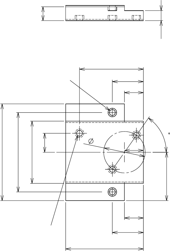
– 191 –
5. Drawing of thermostat fixing plate
Material: SGCC-Z08, Thickness: 0.8t
28
24
55
11
11
18
45
18
37
56
36
46
11
11
8
5.8
3-Ø3.4 burring hole
(Downward)
2-Ø3.4 burring hole
(Upward)
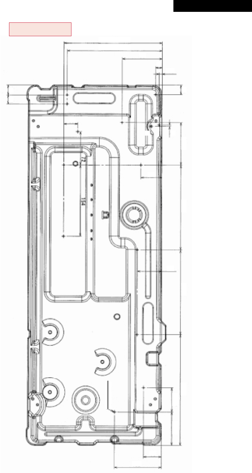
– 192 –
13-Ø3.2 hole
203
210
2119
3
91.5183183
51.773.3
20
240
85
14
6.5
30
45
52
38
100
16-2. Base Plate
1. RAV-SM563AT-E, RAV-SM803AT-E
Revised : Mar. 2007
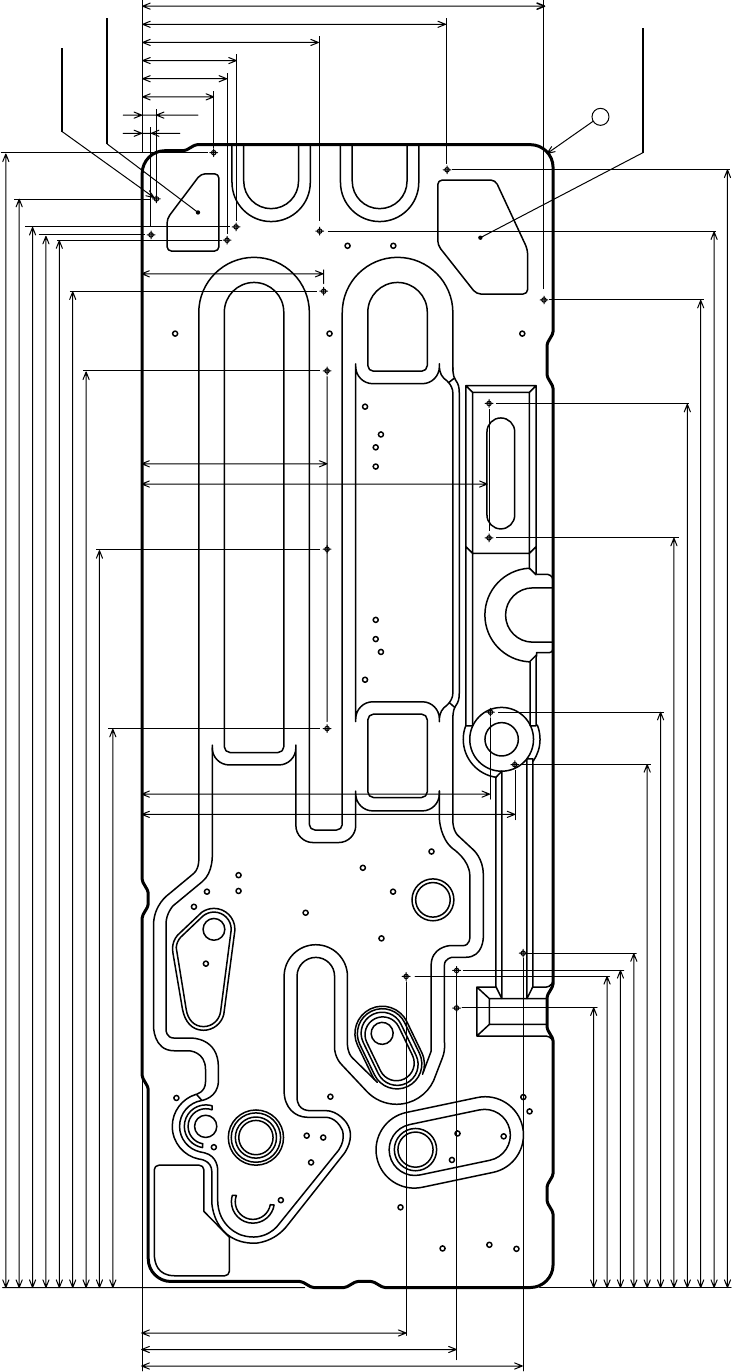
– 193 –
2. RAV-SM1103AT-E, RAV-SM1403AT-E,
RAV-SP562AT-E, RAV-SP802AT-E, RAV-SP1102AT-E, RAV-SP1402AT-E
Knockout punching
312
206 245 296
237
138
73
67
55
10.5
220
7
Knockout punching
20-Ø3.3 hole
1
245
249
263 408
453
590 695
778
832 879
892
855
834
827.5
823
783
720
580
440
271
290
145
141
271
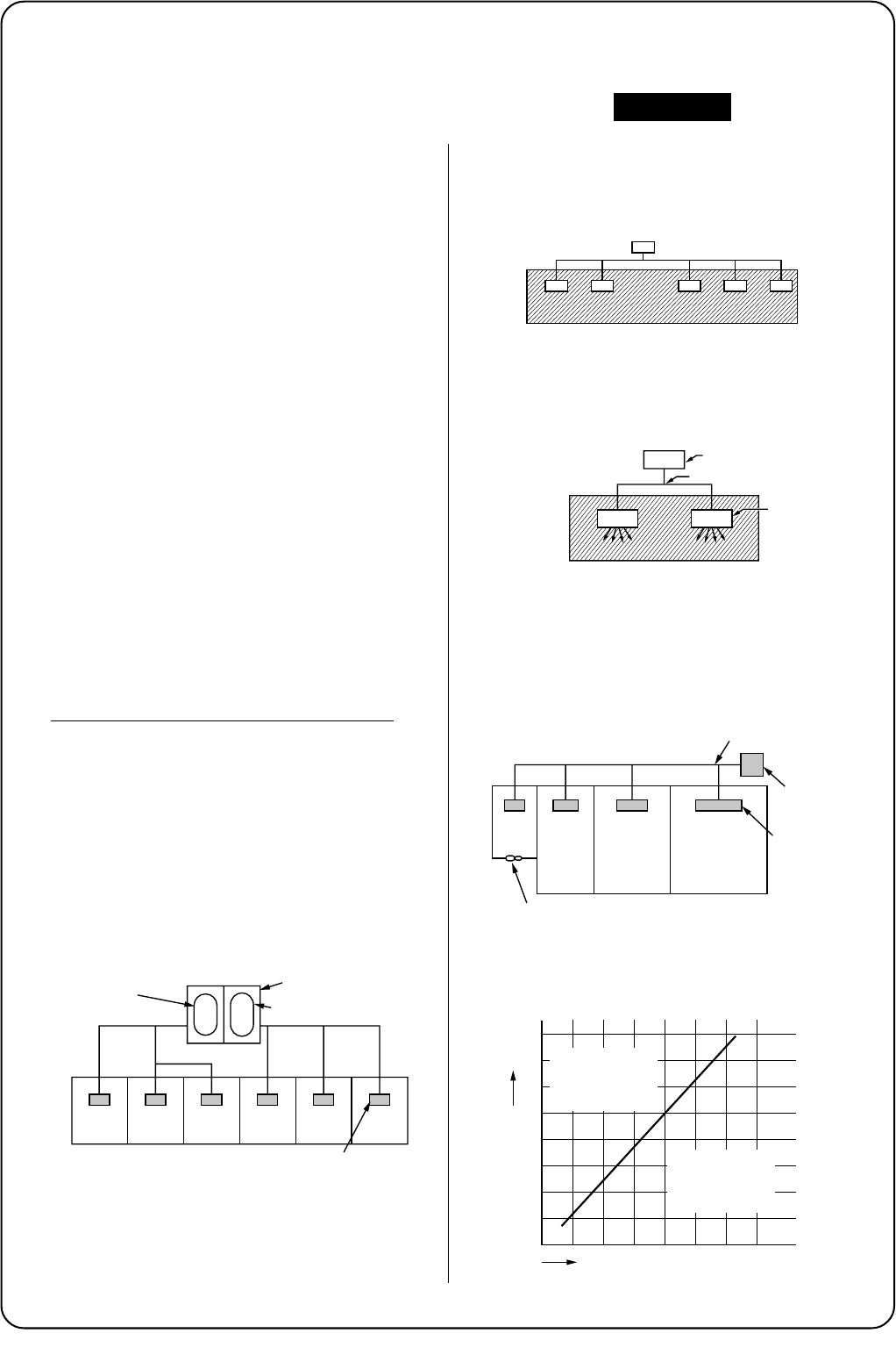
WARNINGS ON REFRIGERANT LEAKAGE
For the amount of charge in this example:
The possible amount of leaked refrigerant gas in
rooms A, B and C is 10kg.
The possible amount of leaked refrigerant gas in
rooms D, E and F is 15kg.
NOTE 2 :
The standards for minimum room volume are as follows.
(1) No partition (shaded portion)
(2) When there is an effective opening with the adjacent
room for ventilation of leaking refrigerant gas
(opening without a door, or an opening 0.15% or
larger than the respective floor spaces at the top or
bottom of the door).
(3) If an indoor unit is installed in each partitioned room
and the refrigerant piping is interconnected, the
smallest room of course becomes the object. But
when a mechanical ventilation is installed interlocked
with a gas leakage detector in the smallest room
where the density limit is exceeded, the volume of
the next smallest room becomes the object.
NOTE 3 :
The minimum indoor floor area compared with the
amount of refrigerant is roughly as follows:
(When the ceiling is 2.7m high)
Check of Concentration Limit
The room in which the air conditioner is to be
installed requires a design that in the event of
refrigerant gas leaking out, its concentration will not
exceed a set limit.
The refrigerant R410A which is used in the air
conditioner is safe, without the toxicity or combustibility of
ammonia, and is not restricted by laws to be imposed
which protect the ozone layer. However, since it contains
more than air, it poses the risk of suffocation if its
concentration should rise excessively. Suffocation from
leakage of R410A is almost non-existent. With the recent
increase in the number of high concentration buildings,
however, the installation of multi air conditioner systems
is on the increase because of the need for effective use
of floor space, individual control, energy conservation by
curtailing heat and carrying power etc.
Most importantly, the multi air conditioner system is able
to replenish a large amount of refrigerant compared with
conventional individual air conditioners. If a single unit of
the multi conditioner system is to be installed in a small
room, select a suitable model and installation procedure
so that if the refrigerant accidentally leaks out, its
concentration does not reach the limit (and in the event
of an emergency, measures can be made before injury
can occur).
In a room where the concentration may exceed the limit,
create an opening with adjacent rooms, or install
mechanical ventilation combined with a gas leak
detection device.
The concentration is as given below.
Total amount of refrigerant (kg)
Min. volume of the indoor unit installed room (m³)
≤ Concentration limit (kg/m³)
The concentration limit of R410A which is used in multi
air conditioners is 0.3kg/m³.
NOTE 1 :
If there are 2 or more refrigerating systems in a single
refrigerating device, the amounts of refrigerant should be
as charged in each independent device.
Important
Outdoor unit
e.g.,
charged amount (15kg)
e.g., charged
amount (10kg)
Indoor unit
Room A Room B Room C Room D Room E Room F
Outdoor unit
Refrigerant piping
Indoor unit
Outdoor unit
Refrigerant piping
Indoor unit
Very
small
room
Small
room Medium
room Large room
Mechanical ventilation device - Gas leak detector
0
5
10
10 20 30
15
20
25
30
35
40
Range below the
density limit
of 0.3 kg/m³
(countermeasures
not needed)
Range above
the density limit
of 0.3 kg/m³
(countermeasures
needed)
Total amount of refrigerant kg
Min. indoor floor area
m²

TOSHIBA CARRIER CORPORATION
2 CHOME 12-32, KONAN, MINATOKU, TOKYO, 108-0075, JAPAN
Copyright © 1999 to 2007 TOSHIBA CARRIER CORPORATION, ALL Rights Reserved.
