Toshiba Rav Sm560At E Service Manual
RAV-SM560AT-E to the manual 2392c3ba-7774-4621-8016-6d4da82c6644
2014-12-13
: Toshiba Toshiba-Rav-Sm560At-E-Service-Manual-127642 toshiba-rav-sm560at-e-service-manual-127642 toshiba pdf
Open the PDF directly: View PDF ![]() .
.
Page Count: 181 [warning: Documents this large are best viewed by clicking the View PDF Link!]
R410A
FILE NO. A02-014
SERVICE MANUAL
SPLIT TYPE
RAV-SM560AT-E/RAV-SM800AT-E
RAV-SM560UT-E/RAV-SM800UT-E
RAV-SM560BT-E/RAV-SM800BT-E
RAV-SM560KRT-E/RAV-SM800KRT-E
RAV-SM560XT-E/RAV-SM800XT-E
PRINTED IN JAPAN, June,2004 ToMo
Revised 3/June/2004
– 2 –
CONTENTS
1. SPECIFICATIONS ................................................................................................ 3
2. AIR DUCTING WORK ........................................................................................ 12
3. CONSTRUCTION VIEWS (EXTERNAL VIEWS) ............................................... 13
4. SYSTEMATIC REFRIGERATING CYCLE DIAGRAM ....................................... 20
5. WIRING DIAGRAM ............................................................................................ 22
6. SPECIFICATIONS OF ELECTRICAL PARTS ................................................... 28
7. REFRIGERANT R410A ..................................................................................... 30
8. CONTROL BLOCK DIAGRAM .......................................................................... 38
9. CIRCUIT CONFIGURATION AND CONTROL SPECIFICATIONS.................... 48
10. TROUBLESHOOTING ....................................................................................... 65
11. REPLACEMENT OF SERVICE INDOOR P.C. BOARD ..................................... 88
12. SETUP AT LOCAL SITE AND OTHERS ........................................................... 92
13. ADDRESS SETUP ........................................................................................... 103
14. TROUBLESHOOTING <WALL TYPE>............................................................ 108
15. DETACHMENTS............................................................................................... 135
16. EXPLODED VIEWS AND PARTS LIST ........................................................... 168

– 3 –
1. SPECIFICATIONS
1-1. Indoor Unit
1-1-1. 4-Way Air Discharge Cassette Type
Note 1 : The cooling capacities and electrical characteristics are measured under the conditions speciied by JIS B 8616 based
on the reference piping. The reference piping consists of 3 m of main piping and 2 m of branch piping connected with 0
meter height.
Note 2 : The sound level is measured in an anechoic chamber in accordance with JIS B8616. Normally, the values measured in
the actual operating environment become larger than the indicated values due to the effects of external sound.
Note : Rated conditions Cooling : Indoor air temperature 27°C DB/19°C WB, Outdoor air temperature 35°C DB
Heating : Indoor air temperature 20°C DB, Outdoor air temperature 7°C DB/6°C WB
Model name
Standard capacity (Note 1) (kW)
Heating low temp. capacity (Note 1) (kW)
Energy consumption effect ratio (Cooling)
Power supply
Electrical
Running current (A)
Power consumption (kW)
characteristics
(Low temp.) (kW)
Power factor (%)
Main unit
Appearance Ceiling Panel Model
(Sold separately) Panel color
Height (mm)
Main unit Width (mm)
Outer Depth (mm)
dimension
Ceiling panel
Height (mm)
Width (mm)
(Sold separately)
Depth (mm)
Total weight Main unit (kg)
Ceiling panel
Heat exchanger
Soundproof/Heat-insulating material
Fan
Fan unit Standard air flow High (Mid./Low) (m³/h)
Motor (W)
Air filter
Controller (Sold separately)
Connecting
Gas side (mm)
Liquid side (mm)
pipe
Drain port (Nominal dia.)
Sound level High (Mid./Low) (Note 2) (dB•A)
RAV-SM560UT-E RAV-SM800UT-E
Cooling Heating Average Cooling Heating Average
5.3 5.6 7.1 8.0
(1.5 – 5.6) (1.5 – 6.3) (2.2 – 8.0) (2.2–9.0)
4.9 7
3.01 [B] 3.90 [A] 3.46 3.03 [B] 3.45 [B] 3.24
1 phase 230V (220 – 240V) 50Hz
8.42–7.72 6.78–6.29 11.32–10.37 11.22–10.28
1.76 1.435 2.34 2.32
1.89 2.73
95 95 94 94
Zinc hot dipping steel plate
RBC-U21PG (W) E
Moon-white (Muncel 2.5GY 9.0/0.5)
256
840
840
53
950
950
21 22
4.5
Finned tubu
Inflammable polyethylene foam Foamed polyethylen
Turbo fan
1050 1200
60
Attached ceiling panel
RBC-AMT21E
Ø12.7 (1/2”) Ø15.9 (5/8”)
Ø6.4 (1/4”) Ø9.5 (3/8”)
25 (Polyvinyl chloride tube)
32 29 27 34 31 28
– 4 –
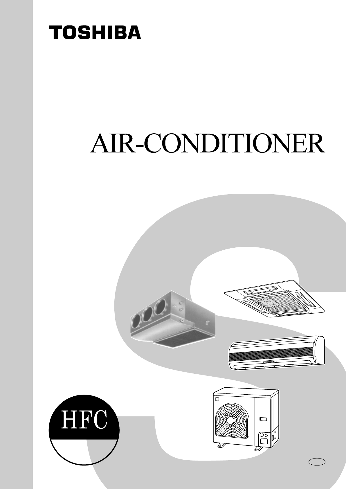
• Operation characteristic curve
<Cooling> <Heating>
• Capacity variation ratio according to temperature
<Cooling> <Heating>
0020
15 40 60 70 80 100
2
4
6
8
10
12
14
Compressor speed (rps)
Current (A)
• Conditions
Indoor : DB27 C/WB19 C
Outdoor : DB35 C
Air flow : High
Pipe length : 7.5m
230V
RAV-SM800UT-E
RAV-SM560UT-E
0020
15 40 60 80 90 100
2
4
6
8
10
12
16
14
Compressor speed (rps)
Current (A)
RAV-SM800UT-E
RAV-SM560UT-E
• Conditions
Indoor : DB20 C
Outdoor : DB7 C/WB6 C
Air flow : High
Pipe length : 7.5m
230V
50
55
60
65
70
75
80
85
90
95
100
105
32 33 34 35 36 37 38 39 40 41 42 43
Outsoor temp. ( C)
Capacity ratio (%)
• Conditions
Indoor : DB27 C/WB19 C
Indoor air flow : High
Pipe length : 7.5m
0
10
20
30
40
50
60
70
80
90
100
110
120
-14-12-10-8-6-4-20246810
Outsoor temp. ( C)
Capacity ratio (%)
• Conditions
Indoor : DB20 C
Indoor air flow : High
Pipe length : 7.5m

– 5 –
1-1-2. Concealed Duct Type
Note 1 : The cooling capacities and electrical characteristics are measured under the conditions speciied by JIS B 8616 based
on the reference piping. The reference piping consists of 3 m of main piping and 2 m of branch piping connected with 0
meter height.
Note 2 : The sound level is measured in an anechoic chamber in accordance with JIS B8616. Normally, the values measured in
the actual operating environment become larger than the indicated values due to the effects of external sound.
Note : Rated conditions Cooling : Indoor air temperature 27°C DB/19°C WB, Outdoor air temperature 35°C DB
Heating : Indoor air temperature 20°C DB, Outdoor air temperature 7°C DB/6°C WB
Model name
Standard capacity (Note 1) (kW)
Heating low temp. capacity (Note 1) (kW)
Energy consumption effect ratio (Cooling)
Power supply
Electrical
Running current (A)
Power consumption (kW)
characteristics
(Low temp.) (kW)
Power factor (%)
Main unit
Appearance Ceiling Panel Model
(Sold separately) Panel color
Height (mm)
Main unit Width (mm)
Outer Depth (mm)
dimension
Ceiling panel
Height (mm)
Width (mm)
(Sold separately)
Depth (mm)
Total weight Main unit (kg)
Ceiling panel
Heat exchanger
Soundproof/Heat-insulating material
Fan
Fan unit Standard air flow High (Mid./Low) (m³/h)
Motor (W)
Air filter
Controller (Sold separately)
Connecting
Gas side (mm)
Liquid side (mm)
pipe
Drain port (Nominal dia.)
Sound level High (Mid./Low) (Note 2) (dB•A)
RAV-SM560BT-E RAV-SM800BT-E
Cooling Heating Average Cooling Heating Average
5 5.6 7.1 8
(1.5 – 5.6) (1.5 – 6.3) (2.2 – 8.0) (2.2–9.0)
4.6 6.2
2.60 [D] 3.27 [C] 2.94 2.73 [D] 3.21 [C] 2.97
1 phase 230V (220 – 240V) 50Hz
9.19–8.42 8.18–7.50 12.57–11.52 12.04–11.04
1.92 1.71 2.6 2.49
1.78 2.62
95 95 94 94
Zinc hot dipping steel plate
——
——
320
700
800 (+7.5)
——
——
——
39 53
——
Finned tubu
Inflammable polyethylene foam Foamed polyethylen
Turbo fan
840 1140
60 100
Attached main unit
RBC-AMT21E
Ø12.7 (1/2”) Ø15.9 (5/8”)
Ø6.4 (1/4”) Ø9.5 (3/8”)
25 (Polyvinyl chloride tube)
42 39 36 43 40 37
– 6 –
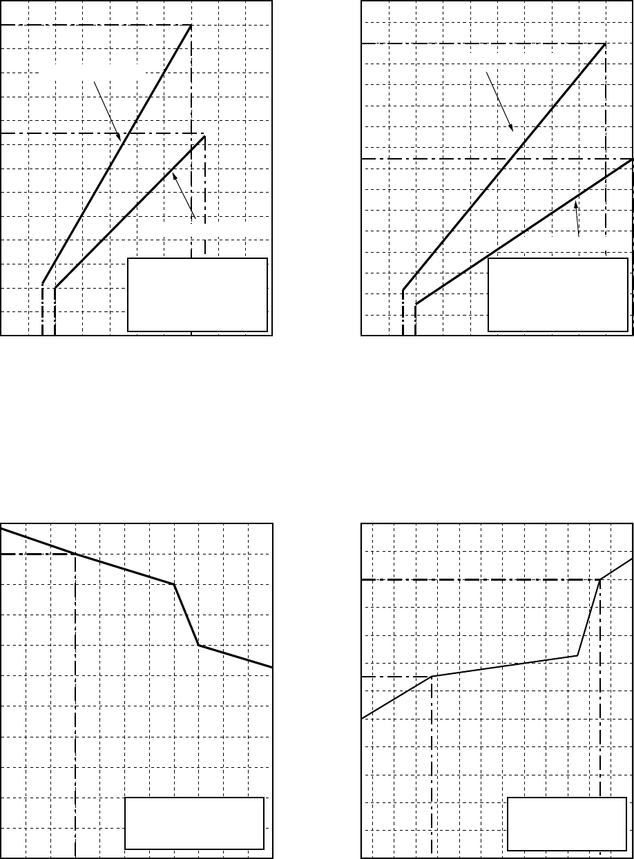
•Operation characteristic curve
<Cooling> <Heating>
•Capacity variation ratio according to temperature
<Cooling> <Heating>
0020
15 40 60 70 80 100
2
4
6
8
10
12
14
Compressor speed (rps)
Current (A)
• Conditions
Indoor : DB27 C/WB19 C
Outdoor : DB35 C
Air flow : High
Pipe length : 7.5m
230V
RAV-SM560BT-E
0020
15 40 60 80 90 100
2
4
6
8
10
12
16
14
Compressor speed (rps)
Current (A)
RAV-SM560BT-E
• Conditions
Indoor : DB20 C
Outdoor : DB7 C/WB6 C
Air flow : High
Pipe length : 7.5m
230V
50
55
60
65
70
75
80
85
90
95
100
105
32 33 34 35 36 37 38 39 40 41 42 43
Outsoor temp. ( C)
Capacity ratio (%)
• Conditions
Indoor : DB27 C/WB19 C
Indoor air flow : High
Pipe length : 7.5m
RAV-SM800BT-E RAV-SM800BT-E
0
10
20
30
40
50
60
70
80
90
100
110
120
-14-12-10-8-6-4-20246810
Outsoor temp. ( C)
Capacity ratio (%)
• Conditions
Indoor : DB20 C
Indoor air flow : High
Pipe length : 7.5m

– 7 –
1-1-3. High-Wall Type
Note 1 : The cooling capacities and electrical characteristics are measured under the conditions speciied by JIS B 8616 based
on the reference piping. The reference piping consists of 3 m of main piping and 2 m of branch piping connected with 0
meter height.
Note 2 : The sound level is measured in an anechoic chamber in accordance with JIS B8616. Normally, the values measured in
the actual operating environment become larger than the indicated values due to the effects of external sound.
Note : Rated conditions Cooling : Indoor air temperature 27°C DB/19°C WB, Outdoor air temperature 35°C DB
Heating : Indoor air temperature 20°C DB, Outdoor air temperature 7°C DB/6°C WB
Model name
Standard capacity (Note 1) (kW)
Heating low temp. capacity (Note 1) (kW)
Energy consumption effect ratio (Cooling)
Power supply
Electrical
Running current (A)
Power consumption (kW)
characteristics
(Low temp.) (kW)
Power factor (%)
Main unit
Appearance Ceiling Panel Model
(Sold separately) Panel color
Height (mm)
Main unit Width (mm)
Outer Depth (mm)
dimension
Ceiling panel
Height (mm)
Width (mm)
(Sold separately)
Depth (mm)
Total weight Main unit (kg)
Ceiling panel
Heat exchanger
Soundproof/Heat-insulating material
Fan
Fan unit Standard air flow High (Mid./Low) (m³/h)
Motor (W)
Air filter
Controller (Sold separately)
Connecting
Gas side (mm)
Liquid side (mm)
pipe
Drain port (Nominal dia.)
Sound level High (Mid./Low) (Note 2) (dB•A)
RAV-SM560KRT-E RAV-SM800KRT-E
Cooling Heating Average Cooling Heating Average
5.1 5.6 6.7 8
(1.5 – 5.6) (1.5 – 6.3) (2.2 – 8.0) (2.2–9.0)
4.9 5.8
2.93 [D] 3.29 [C] 3.11 2.46 [E] 3.00 [D] 3.24
1 phase 230V (220 – 240V) 50Hz
8.33–7.63 8.138–7.46 13.15–12.05 12.91–11.84
1.74 1.7 2.72 2.67
1.95 2.21
95 95 94 94
Pure white
——
——
298
998
208
——
——
——
12
——
Finned tubu
Inflammable polyethylene foam Foamed polyethylen
Turbo fan
840 1110
30
Attached main unit
Wired remote controller RBC-AMT21E
Ø12.7 (1/2”) Ø15.9 (5/8”)
Ø6.4 (1/4”) Ø9.5 (3/8”)
25 (Polyvinyl chloride tube)
45 41 36 45 41 36

– 8 –
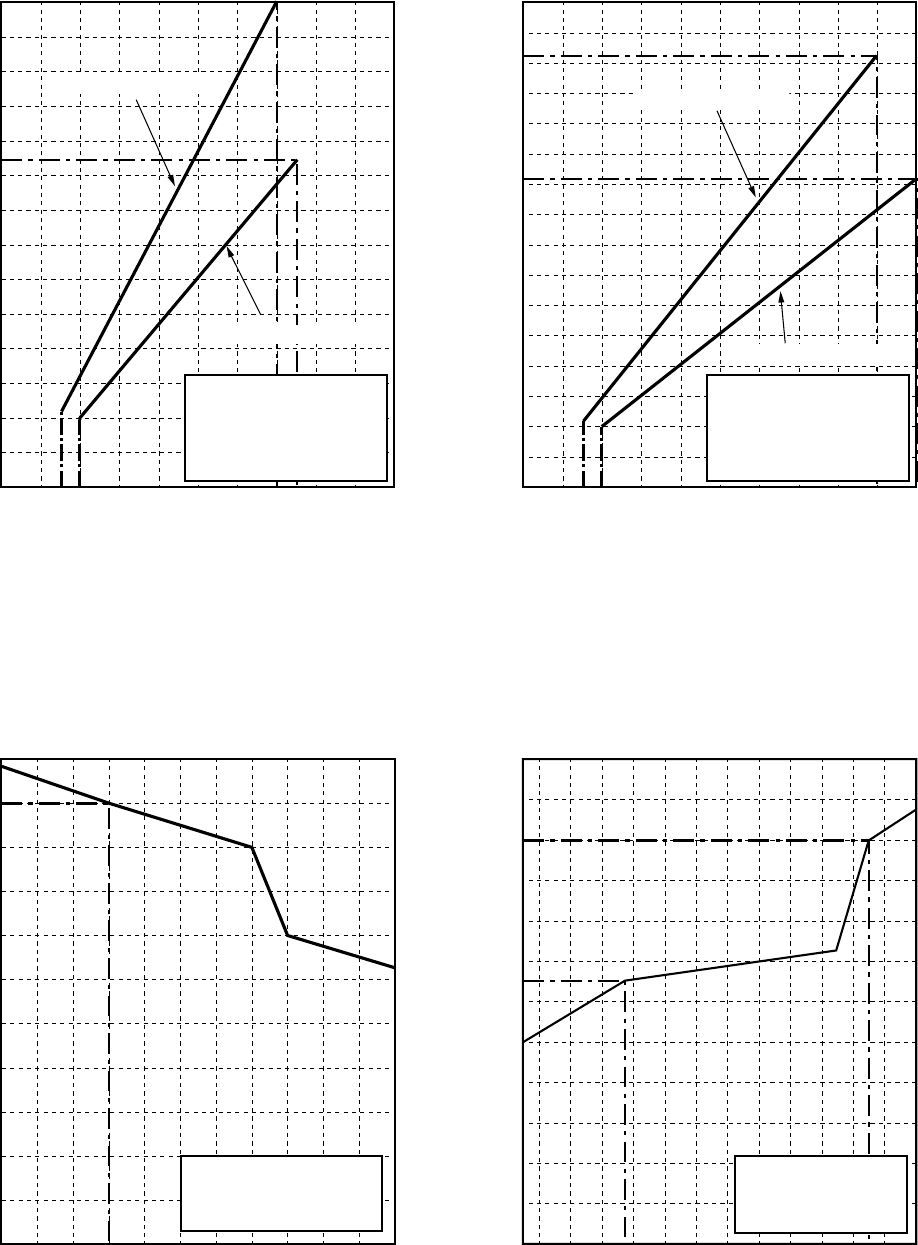
• Operation characteristic curve
<Cooling> <Heating>
• Capacity variation ratio according to temperature
<Cooling> <Heating>
0020
15 40 60 70 80 100
2
4
6
8
10
12
14
Compressor speed (rps)
Current (A)
• Conditions
Indoor : DB27 C/WB19 C
Outdoor : DB35 C
Air flow : High
Pipe length : 7.5m
230V
RAV-SM560KRT-E
0020
15 40 60 80 90 100
2
4
6
8
10
12
16
14
Compressor speed (rps)
Current (A)
RAV-SM800KRT-E
RAV-SM560KRT-E
• Conditions
Indoor : DB20 C
Outdoor : DB7 C/WB6 C
Air flow : High
Pipe length : 7.5m
230V
50
55
60
65
70
75
80
85
90
95
100
105
32 33 34 35 36 37 38 39 40 41 42 43
Outsoor temp. ( C)
Capacity ratio (%)
• Conditions
Indoor : DB27 C/WB19 C
Indoor air flow : High
Pipe length : 7.5m
RAV-SM800KRT-E
0
10
20
30
40
50
60
70
80
90
100
110
120
-14-12-10-8-6-4-20246810
Outsoor temp. ( C)
Capacity ratio (%)
• Conditions
Indoor : DB20 C
Indoor air flow : High
Pipe length : 7.5m

– 9 –
Note 1 : The cooling capacities and electrical characteristics are measured under the conditions speciied by JIS B 8616 based
on the reference piping. The reference piping consists of 3 m of main piping and 2 m of branch piping connected with 0
meter height.
Note 2 : The sound level is measured in an anechoic chamber in accordance with JIS B8616. Normally, the values measured in
the actual operating environment become larger than the indicated values due to the effects of external sound.
Note : Rated conditions Cooling : Indoor air temperature 27°C DB/19°C WB, Outdoor air temperature 35°C DB
Heating : Indoor air temperature 20°C DB, Outdoor air temperature 7°C DB/6°C WB
1-1-4. Flexible Type
Model name
Standard capacity (Note 1) (kW)
Heating low temp. capacity (Note 1) (kW)
Energy consumption effect ratio (Cooling)
Power supply
Electrical
Running current (A)
Power consumption (kW)
characteristics
(Low temp.) (kW)
Power factor (%)
Main unit
Appearance Ceiling Panel Model
(Sold separately) Panel color
Height (mm)
Main unit Width (mm)
Outer Depth (mm)
dimension
Ceiling panel
Height (mm)
Width (mm)
(Sold separately)
Depth (mm)
Total weight Main unit (kg)
Ceiling panel
Heat exchanger
Soundproof/Heat-insulating material
Fan
Fan unit Standard air flow High (Mid./Low) (m³/h)
Motor (W)
Air filter
Controller (Sold separately)
Connecting
Gas side (mm)
Liquid side (mm)
pipe
Drain port (Nominal dia.)
Sound level High (Mid./Low) (Note 2) (dB•A)
RAV-SM560XT-E RAV-SM800XT-E
Cooling Heating Average Cooling Heating Average
5.1 5.6 6.7 8
(1.5 – 5.6) (1.5 – 6.3) (2.2 – 8.0) (2.2–9.0)
4.9 5.8
2.93 [D] 3.29 [C] 3.11 2.46 [E] 3.00 [D] 3.24
1 phase 230V (220 – 240V) 50Hz
8.33–7.63 8.138–7.46 13.15–12.05 12.91–11.84
1.74 1.7 2.72 2.67
1.95 2.21
95 95 94 94
Pure white
——
——
298
998
208
——
——
——
12
——
Finned tubu
Inflammable polyethylene foam Foamed polyethylen
Cross flow fan
840 1110
30
Attached main unit
Wired remote controller RBC-AMT21E
Ø12.7 (1/2”) Ø15.9 (5/8”)
Ø6.4 (1/4”) Ø9.5 (3/8”)
25 (Polyvinyl chloride tube)
39 36 36 45 41 36
– 10 –
•Operation characteristic curve
<Cooling> <Heating>
•Capacity variation ratio according to temperature
<Cooling> <Heating>
0020
15 40 60 70 80 100
2
4
6
8
10
12
14
Compressor speed (rps)
Current (A)
• Conditions
Indoor : DB27 C/WB19 C
Outdoor : DB35 C
Air flow : High
Pipe length : 7.5m
230V
RAV-SM560XT-E
0020
15 40 60 80 90 100
2
4
6
8
10
12
14
Compressor speed (rps)
Current (A)
RAV-SM800XT-E
RAV-SM560XT-E
• Conditions
Indoor : DB20 C
Outdoor : DB7 C/WB6 C
Air flow : High
Pipe length : 7.5m
230V
50
55
60
65
70
75
80
85
90
95
100
105
32 33 34 35 36 37 38 39 40 41 42 43
Outsoor temp. ( C)
Capacity ratio (%)
• Conditions
Indoor : DB27 C/WB19 C
Indoor air flow : High
Pipe length : 7.5m
0
10
20
30
40
50
60
70
80
90
100
110
120
-14-12-10-8-6-4-20246810
Outsoor temp. ( C)
Capacity ratio (%)
• Conditions
Indoor : DB20 C
Indoor air flow : High
Pipe length : 7.5m
RAV-SM800XT-E

– 11 –
1-2. Outdoor Unit
Note 1 : The cooling capacities and electrical characteristics are measured under the conditions speciied by JIS B 8616 based
on the reference piping. The reference piping consists of 3 m piping connected with 0 meter height.
Note 2 : The sound level is measured in an anechoic chamber in accordance with JIS B8616. Normally, the values measured in
the actual operating environment become larger than the indicated values due to the effects of external sound.
Note : Rated conditions Cooling : Indoor air temperature 27°C DB/19°C WB, Outdoor air temperature 35°C DB
Heating : Indoor air temperature 20°C DB, Outdoor air temperature 7°C DB/6°C WB
Model name
Appearance
Power supply
Type
Compressor Motor (kW)
Pole
Refrigerant charged (kg)
Refrigerant control
Standard length
Max. total length (m)
Pipe Over 20m
Height difference Outdoor lower (m)
Outdoor higher (m)
Outer
Height (mm)
Width (mm)
dimension
Depth (mm)
Total weight (kg)
Heat exchanger
Fan
Fan unit Standard air flow High (m³/h)
Motor (W)
Connecting Gas side (mm)
pipe Liquid side (mm)
Protection device
Sound level High (Mid./Low) (dB•A)
(Note 2) (Cooling/Heating)
RAV-SM560AT-E RAV-SM800AT-E
Silky shade (Muncel 1Y8.5/0.5)
1 phase 230V (220 – 240V) 50Hz
(Power exclusive to outdoor is required.)
Hermetic compressor
1.1 1.6
4 poles
R410A 0.9 R410A 1.5
Pulse motor valve
20 (without additional charge)
30 50
Add 20g/m (Max. 200g) Add 40g/m (Max. 1200g)
30
50
595 795
780 780
270 270
35 55
Finned tube
Propeller fan
2400 3400
43 63
Ø12.7 (1/2”) Ø15.9 (5/8”)
Ø6.4 (1/4”) Ø9.5 (3/8”)
Discharge temp. sensor
Over-current sensor
Compressor thermo.
46/48 45/50
– 12 –
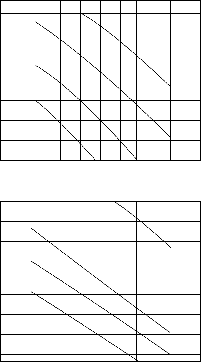
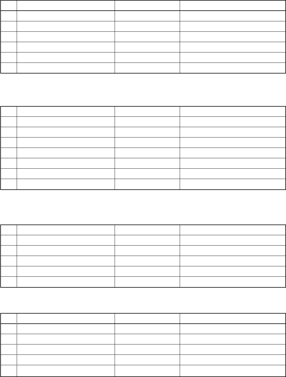
600570
70% (570m³/h) 110% (925m³/h)
70% (800m³/h) 110% (1255m³/h)
700 800 900 925
800 900 1000 1100 1200 1255
0
0
1
2
3
4
5
6
7
8
9
10
11
12
1
2
3
4
5
6
7
8
9
10
11
12
External static pressure (mmAq)
External static pressure (mmAq)
Standard air volume : 840m³/h
Standard air volume : 1140m³/h
Air volume (m³/hr.)
Air volume (m³/hr.)
500 1000
700 1300
High tap
Extra High tap
Low tap
Low tap
High tap
Extra High tap
Low tap
High tap
Extra High tap
Middole tap
Low tap
High tap
Extra High tap
Middole tap
Middle tap
Middle tap
2. AIR DUCTING WORK
2-1. Static Pressure Characteristics of Each Model
Fig. 1 RAV-SM560BT-E
Fig. 2 RAV-SM800BT-E
– 13 –
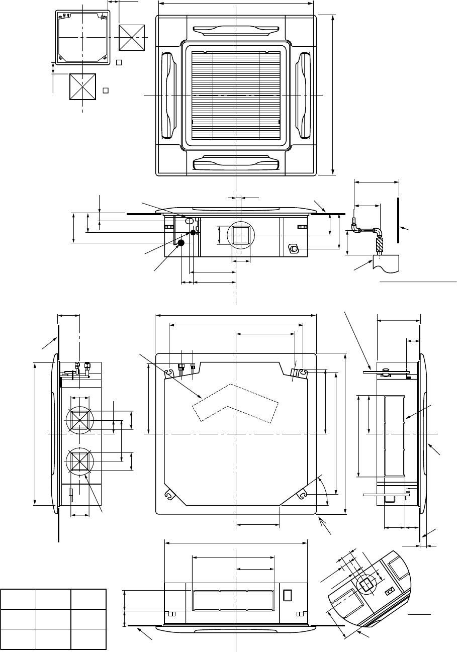
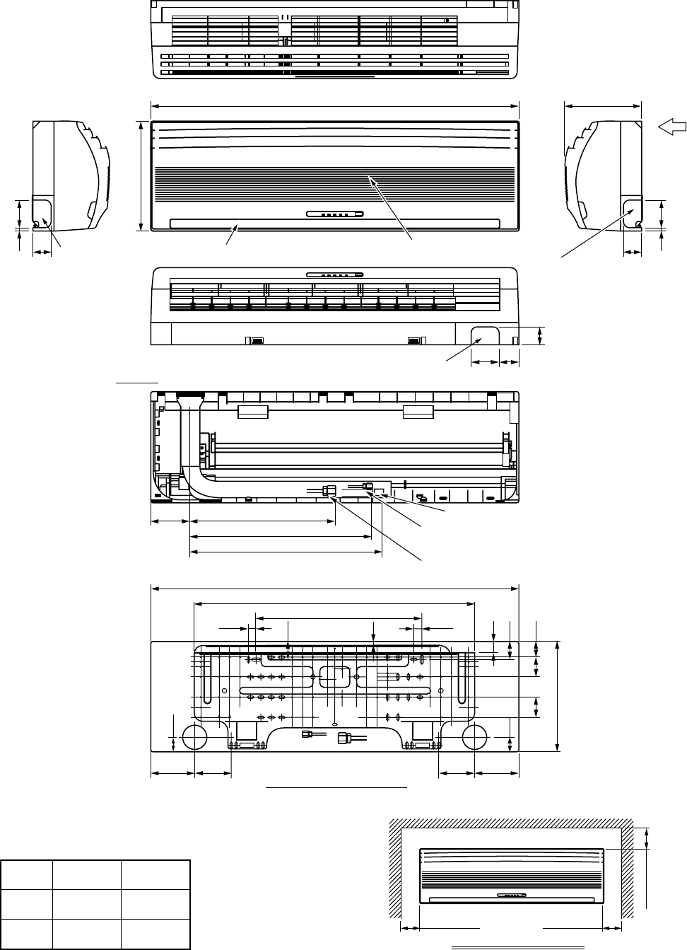
3. CONSTRUCTION VIEWS (EXTERNAL VIEWS)
3-1. Indoor Unit
4-Way Air Discharge Cassette Type
RAV-SM560UT-E/RAV-SM800UT-E
200 860 to 910 Recommended external size
200
860 to 910 Recommended external size
173
113
45
105
130
210
360
30
270
25070
130
105
254.5
480
227
120
57.5
25
64
188
57
35
256
346.5
97
35
88
415.0
381.6
227
480
240
Ø162 80
105105
12097
Surface under ceiling
Surface
under ceiling
Surface under ceiling
Surface
under ceiling
Surface
under ceiling
Standing
850 or less
Standing
640 or less
Surface
under ceiling
840 Hanging bolt
Z view
Drain up standing size
Ceiling
panel
(Sold
separately)
Knockout
for
humidifier
723 Hanging bolt pitch
950 Panel external dimension
840 Unit external dimension
790 Hanging bolt pitch
950 Panel external dimension
Electric
parts box
Refrigerant pipe
connecting port A
Cable draw-in port
Refrigerant pipe
connecting port B Indoor unit
Hanging bolt M10 or W3/8
Procured locally
Check port
(450)
Check port
(450)
SM560
SM800 Ø9.5
Ø6.4
A
Ø15.9
Ø12.7
B
150
– 14 –
Concealed Duct Type
RAV-SM560BT-E
170
12020
70252280
750 ± 7.5 Hanging bolt pitch
700 Dimension of main unit
150
160~6405
730
780 Ceiling opening size
80
60
457 to 637
75
720
210
509
630
300
130 80
30
35
90 120
305
314.5
240
211
45
Refrigerant pipe
connecting port
(Gas side Ø12.7)
80
170
155 to 335
30 320
210
170
100
70
450
150
450
2-Ø200
Discharge port flange
4-M10
Hanging bolt
(Procured locally)
For hanging bolt M10
(4-12 x 25 long hole)
25
25
800 Dimension of main unit
565 Hanging bolt pitch
Drain pipe connecting port
at drain up kit side
(For polyvinyl chloride pipe
(Inner dia. 32, Nominal dia. 25))
Refrigerant pipe
connecting port
(Liquid side Ø6.4)
Ø125 knockout hole (Only rear side)
(For air suction)
6-Ø4 tapping screw lower hole Ø160
Suction port canvas
Suction panel
470 Ceiling opening size
Panel
2-Ø26 power supply remote
controller cord draw-out port
Drain pipe connecting port
at main unit side
(For polyvinyl chloride pipe
(Inner dia. 32, Nominal dia. 25))
Plane view of main unit
Check port A
(Pipe side)
Discharge side
NOTE 1 :
For maintenance of the equipment, be sure to install
a check port A at the position as shown below.
NOTE 2 :
Using the drain up kit sold separately, drain-up by 300 (mm)
from drain pipe draw-out port of the main unit is necessary.
The drain-up over 300mm or more is impossible.
Drain up kit
(Sold separately)
– 15 –
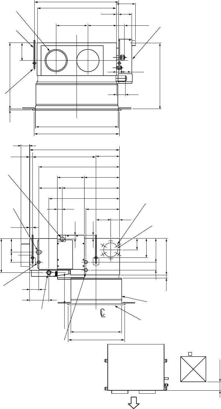
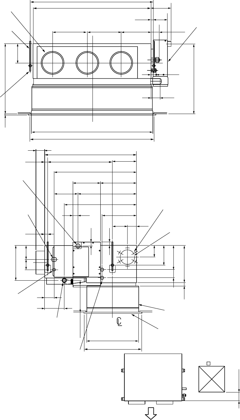
RAV-SM800BT-E
170
12020
70252290
290
1050 ± 7.5 Hanging bolt pitch
1000 Dimension of main unit
150
460~6405
1030
1050 Ceiling opening size
80
60
457 to 637
75
720
210
509
630
300
130 80
30
35
90 120
305
314.5
240
211
45
Refrigerant pipe
connecting port
(Gas side Ø12.7)
80
170
155 to 335
30 320
210
170
100
70
450
150
450
2-Ø200
Discharge port flange
4-M10
Hanging bolt
(Procured locally)
For hanging bolt M10
(4-12 x 25 long hole)
25
25
800 Dimension of main unit
565 Hanging bolt pitch
Drain pipe connecting port
at drain up kit side
(For polyvinyl chloride pipe
(Inner dia. 32, Nominal dia. 25))
Refrigerant pipe
connecting port
(Liquid side Ø6.4)
Ø125 knockout hole (Only rear side)
(For air suction)
6-Ø4 tapping screw lower hole Ø160
Suction port canvas
Suction panel
470 Ceiling opening size
Panel
2-Ø26 power supply remote
controller cord draw-out port
Drain pipe connecting port
at main unit side
(For polyvinyl chloride pipe
(Inner dia. 32, Nominal dia. 25))
Plane view of main unit
Check port A
(Pipe side)
Discharge side
NOTE 1 :
For maintenance of the equipment, be sure to install
a check port A at the position as shown below.
NOTE 2 :
Using the drain up kit sold separately, drain-up by 300 (mm)
from drain pipe draw-out port of the main unit is necessary.
The drain-up over 300mm or more is impossible.
Drain up kit
(Sold separately)
– 16 –
High-Wall Type
RAV-SM560KRT-E/RAV-SM800KRT-E
298
757
51
758
50
Pipe port from left
(Knockout hole)
Discharge port
998
Suction port
Pipe port from right
(Knockout hole)
Z
50
Pipe port from lower side
(Knockout hole)
75 56
Drain hose
Z views
Refrigerant pipe connecting port B
Refrigerant pipe connecting port A
110 390
490
540
998
763.5
450
20
10
29
48
48
40
40
41555555
298
20
100100 115115
Position of installation plate
53 or more 53 or more
55 or more
Space required for service
SM560
SM800 Ø9.5
Ø6.4
A
Liquid Side
Ø15.9
Ø12.7
B
Gas Side
– 17 –
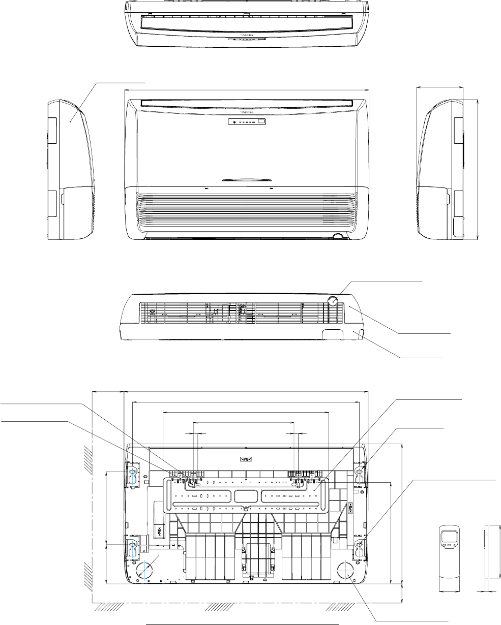
Under Ceiling/Console Type
RAV-SM560XT-E/RAV-SM800XT-E
Front panel
Knock out system
For stud bolt
(Ø8 – Ø10)
For stud bolt (Ø6)
Grille air inlet
Back body
Installation plate
Mount plate
M10 Suspention bolt
Wireless remote control
Knock out system
200 Min 1093
1015
742
450
20 20
330165
Ø74
70 Min
633
460
57 18
160
633
208
1093
UNDER CEILING & CONSOLE INSTALLATION
– 18 –
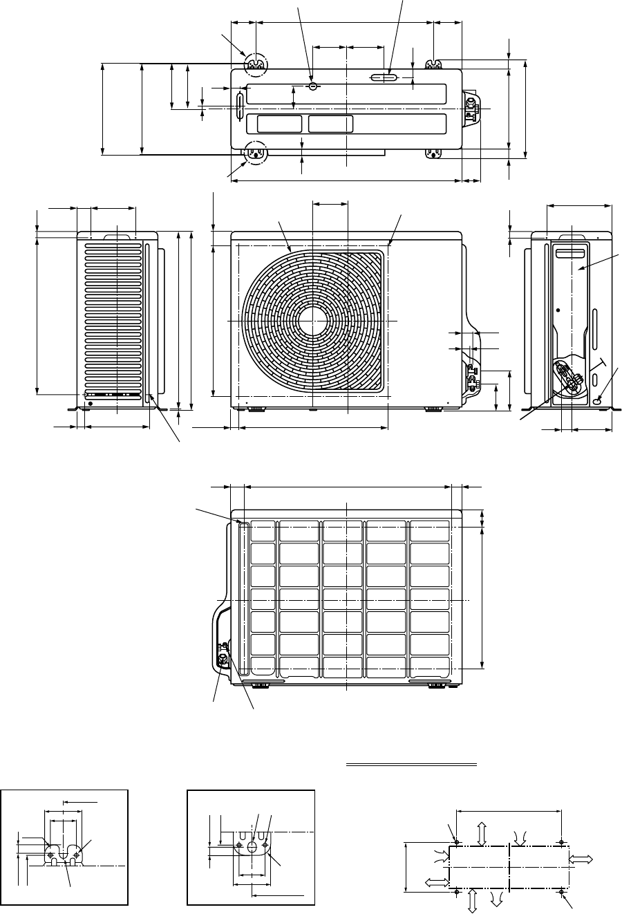
3-2. Outdoor Unit
RAV-SM560AT-E
Drain hole (Ø25) Drain hole (2-Ø20 x 88 long hole)
83
30
600
780
115.3 125
97
30
21 76
308
(Long hole pitch
For anchor bolt)
153
150
11
302
Ø6 hole pitch
2927031
330
A legs
B legs
Space required for service
Protective net mounting hole
(4-Ø4 embossing)
43 707 30
60
475
Refrigerant pipe connecting port
(Ø12.7 flare at gas side) Refrigerant pipe connecting port
(Ø6.4 flare at liquid side)
31
31 134
23
115.3
49.5
25 220
147
500 (Fan center dividing)
90.6
132
598
593
521 21
(49.3)
Discharge guard
Discharge guide mounting hole
(4-Ø4 embossing)
500 (Fan center dividing)
Protective net mounting hole
(2-Ø4 embossing)
21
216
Charge port
Earth
terminal
Valve cover
365
600
2-Ø11 x 14 U-shape holes
(For Ø8–Ø10 anchor bolt) Suction port
Discharge
port
Discharge
port
(Minimum
distance up to wall)
2-Ø11 x 14 long hole
(For Ø8–Ø10 anchor bolt)
500
or more
150
or more
300
or more
150
or more
600
308 11
308
302
11
302
52
36
52
36
R15 2-Ø6 hole
Product
external line
Product
external
line
Ø11 x 14 U-shape hole
Ø11 x 14 U-
shape holes 2-Ø6 hole
R15
600
Details of A legs Details of B legs
– 19 –
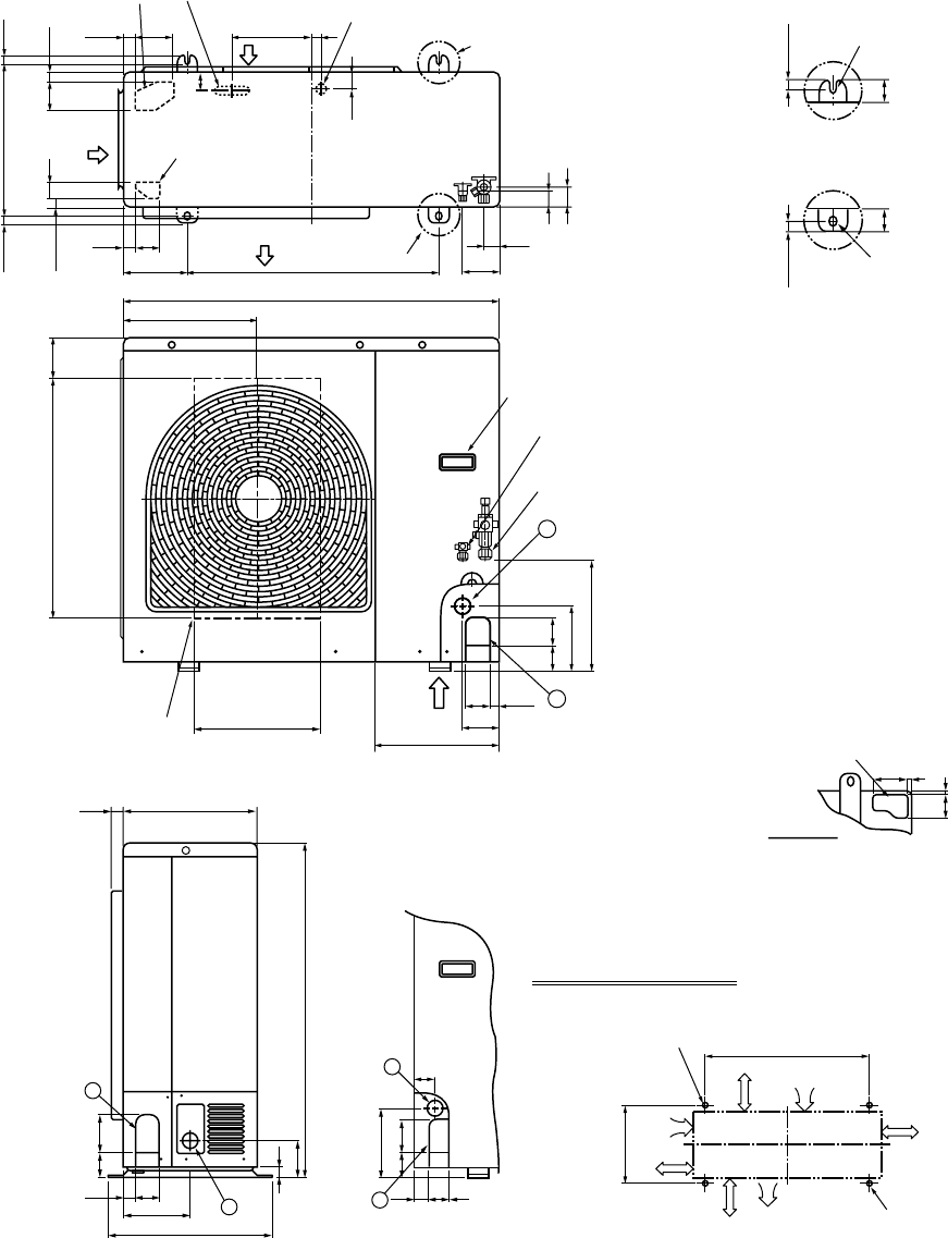
RAV-SM800AT-E
365 17.517.5
21
21
40 70
29 90 191 20
40
39
47
43
43
95
300150
6026
Knockout
(For draining)
Knockout
(For draining)
Drain hole (Ø20 x 88 burring hole)
Drain hole (Ø25 burring hole)
Part A
Part B
(Long hole pitch
for anchor bolt)
Suction
port
Suction
port
Discharge
port
Z
1
2
6760
264
565 101
154
900
2760
96
307
300
314
Handles
(Both sides)
Refrigerant pipe connecting port
(Ø9.5 flare at liquid side)
Refrigerant pipe connecting port
(Ø15.9 flare at gas side)
Discharge guide
mounting hole
(4-Ø4 embossing)
1
1
2
2
795
85
165
60 80
25
60 90
32028
400
161
58
46
30 45
27
Space required for service
365
600
2-Ø12 x 17 U-shape holes
(For Ø8–Ø10 anchor bolt)
Suction port
Discharge
port
Discharge
port
(Minimum
distance up to wall)
2-Ø12 x 17 long hole
(For Ø8–Ø10 anchor bolt)
500
or more
150
or more
150
or more
150
or more
58 7
86 7
Knockout for lower piping
Z views
17.5
4040
17.5
Installation bolt hole
(Ø12 x 17 U-shape holes)
Installation bolt hole
(Ø12 x 17 U-shape holes)
Details of B part
Details of A part
– 20 –
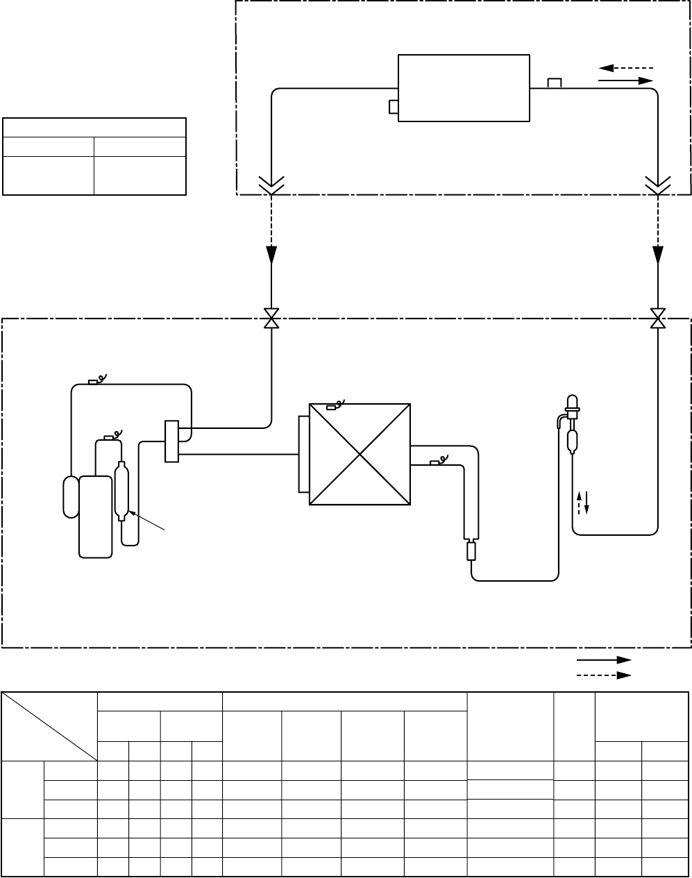
4. SYSTEMATIC REFRIGERATING CYCLE DIAGRAM
Indoor Unit/Outdoor Unit
RAV-SM560UT-E, RAV-SM560BT-E, RAV-SM560KRT-E/RAV-SM560AT-E
*4 poles are provided to this compressor.
The compressor frequency (Hz) measured with a clamp meter is 2 times of revolutions (rps) of the compressor.
Standard
Cooling Overload
Low load
Standard
Heating Overload
Low load
Pressure
(MPa) (kg/cm²G)
Pd Ps Pd Ps
3.1 0.9 31.9 8.9
3.6 1.0 37.1 10.4
0.9 0.7 9.1 7.1
2.3 0.6 23.6 6.2
3.3 1.2 33.2 11.8
1.7 0.2 16.4 1.8
Pipe surface temperature (°C)
Discharge Suction Indoor heat
Outdoor heat
exchanger exchanger
(TD) (TS) (TC) (TE)
85 15 10 50
93 20 15 57
20735
71 1 39 3
78 20 54 19
110 –20 26 –22
Compressor
revolutions per
second (rps)
*
74
72
28
84
47
110
Indoor
fan
HIGH
HIGH
LOW
HIGH
LOW
HIGH
Indoor/Outdoor
temp. conditions
(DB/WB) (°C)
Indoor Outdoor
27/19 35/–
32/24 43/–
18/15.5 –5/–
20/–7/6
30.–24/18
15/––20/
(70%)
Indoor unit
Outdoor unit
Outer diameter of refrigerant pipe
Gas side ØA Liquid side ØB
12.7mm 6.4mm
TCJ
sensor
Air heat exchanger
Strainer
TC sensor
Refrigerant pipe
at liquid side
Outer dia. ØB
Refrigerant pipe
at gas side
Outer dia. ØA
Packed valve
Outer dia. ØB
Packed valve
Outer dia. ØA
Max
30m
TS sensor
TD sensor
TO sensor
TE
sensor
Distributor
4-way valve
(VT7101D)
Muffler
Ø19 × L160
Rotary compressor
(DA130A1F-23F)
Heat exchanger
Ø8 multiple thread
ripple 1 row 22 stages
FP1.3 flat fin
PMV
(SKV-18D26)
R410A 0.9 kg
Cooling
Heating
– 21 –
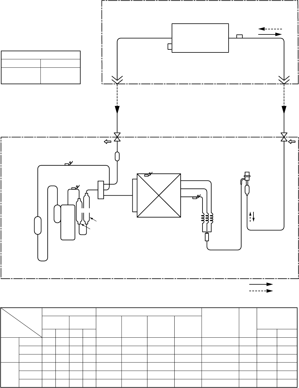
Indoor Unit/Outdoor Unit
RAV-SM800UT-E, RAV-SM800BT-E, RAV-SM800KRT-E/RAV-SM800AT-E
*4 poles are provided to this compressor.
The compressor frequency (Hz) measured with a clamp meter is 2 times of revolutions (rps) of the compressor.
Standard
Cooling Overload
Low load
Standard
Heating Overload
Low load
Pressure
(MPa) (kg/cm²G)
Pd Ps Pd Ps
3.3 0.9 33.4 8.8
3.7 1.1 37.8 11.4
1.0 0.8 10.0 7.9
2.5 0.6 25.8 6.3
3.4 1.1 34.7 11.5
2.0 0.2 20.3 2.3
Pipe surface temperature (°C)
Discharge Suction Indoor heat Outdoor heat
exchanger exchanger
(TD) (TS) (TC) (TE)
86 11 9 44
90 21 18 54
19448
67 6 42 2
85 23 55 16
89 –16 34 –18
Compressor
revolutions per
second (rps)
*
64
52
27
65
31
90
Indoor
fan
HIGH
HIGH
LOW
HIGH
LOW
HIGH
Indoor/Outdoor
temp. conditions
(DB/WB) (°C)
Indoor Outdoor
27/19 35/–
32/24 43/–
18/15.5 –5/–
20/–7/6
30.–24/18
15/––20/
(70%)
Indoor unit
Outdoor unit
Outer diameter of refrigerant pipe
Gas side ØA Liquid side ØB
15.9mm 9.5mm
TCJ
sensor
Air heat exchanger
Strainer
Strainer
TC sensor
Refrigerant pipe
at liquid side
Outer dia. ØB
Refrigerant pipe
at gas side
Outer dia. ØA
Packed valve
Outer dia. ØB
Packed valve
Outer dia. ØA
Max
50m
TS sensor
Accumulator
(1500cc)
TD sensor
TO sensor
TE
sensor
4-way valve
(STF-0213Z)
Ø25 × L160
Rotary compressor
(DA220A2F-20L)
Heat exchangerØ8
1 row 30 stages
FP1.3 flat fin
Modulating (PMV)
(SKV-18D26)
Capillary
Ø3×Ø2×
L530
Ø25 × L210
Muffler
R410A 1.5 kg
Cooling
Heating
Ps
Pd
– 22 –
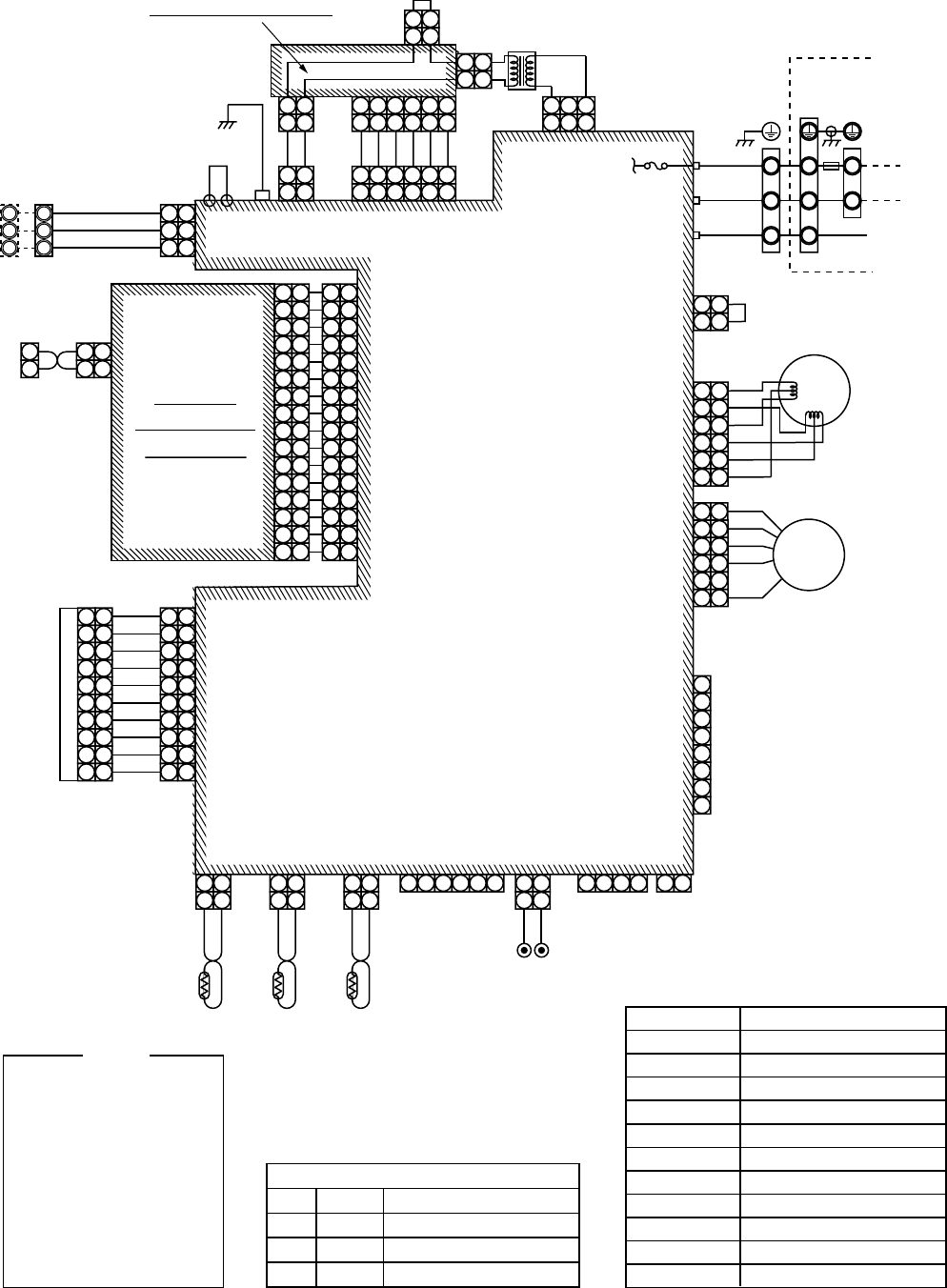
5. WIRING DIAGRAM
5-1. Indoor Unit
4-Way Air Discharge Cassette Type
RAV-SM560UT-E/RAV-SM800UT-E
FM
TA
TC
TCJ
LM1,LM2
DP
FS
RY302
: Fan motor
: Indoor temp. sensor
: Temp. sensor
: Temp. sensor
: Louver motor
: Drain pump motor
: Float switch
: Drain control relay
NOTE Color
Identification
BLK
BLU
RED
GRY
PNK
GRN
WHI
BRW
ORN
YEL
:
:
:
:
:
:
:
:
:
:
BLACK
BLUE
RED
GRAY
PINK
GREEN
WHITE
BROWN
ORANGE
YELLOW
1 2
1 2
1 1
2 2
3 3
TA
FS
CN104
(YEL)
CN34
(RED)
CN33
(WHI)
CN102
(RED) CN101
(BLK)
1 2
1 2
TCJ
1 2
CN73
(RED)
1 2
CN70
(WHI)
12
CN80
(GRN)
1 2 3
1 2
TC
(EXCT)
1 1
2 2
3 3
4 4
5 5
1
2
3
4
5
1 1
2 2
3 3
4 4
5 5
1 1
2 2
3 3
4 4
5 5
5 5
4 4
3 3
2 2
1 1
1 1
2 2
3 3
4 4
5 5
1 1
2 2
3 3
4 4
5 5
LM2
FM
LM1
Motor
drive
circuit Motor
drive
circuit
Power
supply
circuit
DC20V
DC15V
DC12V
DC7V
Fuse
F302
T3.15A
250V~
12
123
3
12
123
3 1 234
45
5
DP
CN333
(WHI)
CN334
(WHI)
CN68
(BLU) CN304
(GRY)
1 2
CN66
(WHI)
CN41
(BLU)
CN309
(YEL)
CN50
(WHI)
CN60
(WHI)
1
2
CN32
(WHI)
1
2
3
4
5
6
1
2
3
4
5
CN620
(BLU)
1
2
3
4
5
6
CN61
(YEL)
CN67
(BLK)
RED WHI BLK
BLK
BLK
BLK
P301
1 1
2 2 1 1
2 2
3
1
2
3
3B
A
(FAN DRIVE)
Wired Renote
Controller
CN1
(WHI)
WHI
BLK
1 1
2 2
Adapter for
Wireless Remote
Controller
WHI
BLK
MCC-1402
Control P.C. Board for
Indoor Unit
Indoor unit
earth screw
CN001
(WHI)
RY
302
Fuse
F301
250V~
T6.3A
RY
303
WHI
321
321
NL
Single phase
220 to 240V
50Hz
Serial
signal
Outdoor unit
earth screw
RED Closed-end
connector
– 23 –
Concealed Duct Type
RAV-SM560BT-E/RAV-SM800BT-E
1 2
1 2
1 1
2 2
3 3
TA
1 2
1 2
TCJ
1 2
1 2
TC
PNL EXCT
CN104
(YEL) CN102
(RED) CN101
(BLK)
1 2
1 2
CN070
(WHI)
CN060
(WHI)
CN032
(WHI)
OPTION
FAN
DRIVE
CN061
(YEL)
CN075
(WHI)
1 2 3
CN080
(GRN)
1 2
CN073
(RED)
FS
CN030
(RED)
1 1
2 2
3 3
1 1
2 2
3 3
1 1
2 2
3 3
1 1
2 2
3 3
4 4
5 5
6
1
2
1
2
3
4
5
6
CN050
(WHI)
CN041
(BLU)
CN067
(BLK)
CN074
(WHI)
1
2
3
4
5
6
1
2
3
4
5
6
6
CN068
(BLU)
CN083
(WHI)
1
2
3
LM
CN033
(GRN)
DP
FM
TR
Power
supply
circuit
1
1
2
A
B
2
Remote
Controller
CN1
123
CN309
(YEL)
1 2
CN066
(WHI)
12345
12345
1
1
2
3
4
5
6
7
8
9
1
2
3
4
5
6
7
8
9
1
2
3
4
5
6
7
1
2
3
4
5
6
7
1
2
3
4
5
6
78
9
1
2
3
4
5
6
7
8
9
1
2
3
4
5
6
7
8
9
1
2
3
4
5
6
7
1
2
3
4
5
6
7
1
2
3
4
5
6
7
8
9
1
2
3
4
5
6
7
8
9
23
CN304
(GRY)
RY
004
RED
YEL
BLU
ORN
BLK
UL
L
M
H
RED
WHI
WHI
BLK
321
321
NL
Indoor unit
earth screw
Outdoor unit
earth screw
RED Closed-end
connector
Fuse
F001
T5A
250V~
RY001
RY002
RY006
RY007
RY005
(When selecting
high-static pressure)
Color
Identification
BLK
BLU
RED
GRY
PNK
GRN
WHI
BRW
ORN
YEL
:
:
:
:
:
:
:
:
:
:
BLACK
BLUE
RED
GRAY
PINK
GREEN
WHITE
BROWN
ORANGE
YELLOW
FM
RC
TR
LM
TA
TC, TCJ
RY001
RY002
RY005~007
DP
: Fan motor
: Runing capacitor
: Transformer
: Louver motor
: Indoor temp. sensor
:
Indoor heat exchanger sensor
: Louver control relay
: Drain control relay
: Air volume control relay
: Drain pump motor
NOTE
RC
FM
RED
YEL
BLU
OPN
BLK
BRW
RED
YEL
BLU
OPN
BLK
BRW
– 24 –
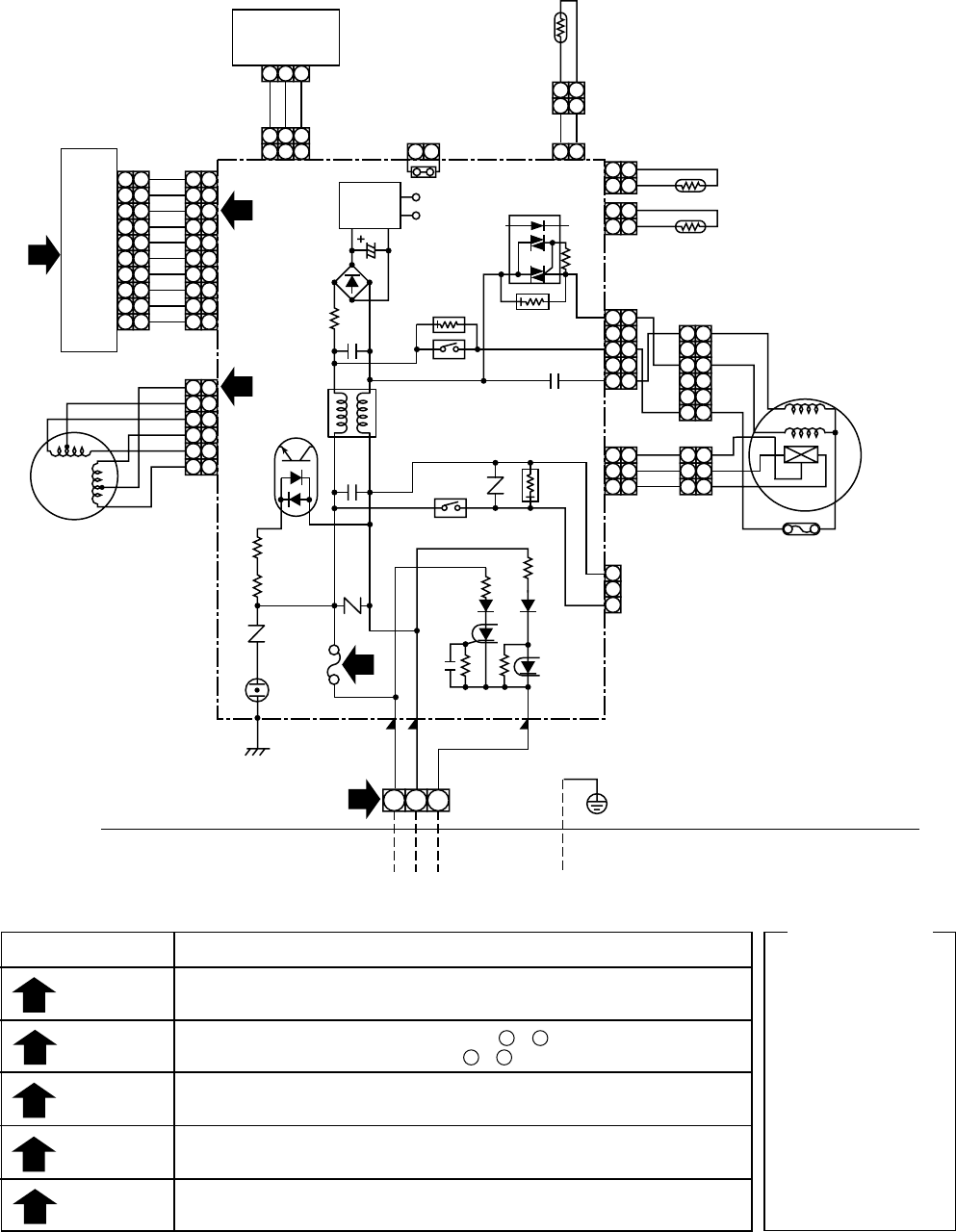
High-Wall Type
RAV-SM560KRT-E/RAV-SM800KRT-E
F
FM
LM
TA
TC
TCJ
TR
O/D
R/C
: Fuse (PCB)
: Fan motor
: Louver motor
: Temperature sensor
: Temperature sensor
: Temperature sensor
: Transformer
: Outdoor
: Remote Contoller
NOTE
1
2
3
4
5
6
1 1
2 2
3 3
4 4
5 5
6 6
7
8
1
2
3
4
5
6
7
8
9
10
11
12
13
14
15
16
1
2
3
4
5
6
7
8
9
10
11
12
13
14
15
16
1 1
2 2
1 1
2
X
Y 2
3 3
4 4
5 5
6 6
7 7
8 8
9 9
10
1
1
2
21
234 1
21
23456
10
11 11
12 12
13 13
14 14
15 15
16 16
1 1
2 2
1 1
2 2
3
A
B
C
A
B
C
3
CN01
RED
CN02
WHI
ORG
YEL
BLU
AI-NET
P.C. BOARD
MCC-1337
CN20
YEL CN13
WHI
CN31
WHI
CN02
WHI
1
2
3
4
5
6
7
8
9
10
1
2
3
4
5
6
7
8
9
10
1 1
2 2
3 3
4 4
5 5
6 6
7 7
8 8
9 9
10 10
CN213
WHI
CN25
CN50
WHI CN06
WHI CN21
WHI
CN14
WHI
CN210
WHI
CN207
WHI
CN11
WHI
TCJ
BLK
BLK
1
1
2
2
CN05
WHI
TC
BLK
BLK
1
1
2
2
CN04
WHI
TA
BLK
BLK
WHI
BLU
BLU
BLU
BLU
BLU
BLU
BLU
BLU
BLU
1
1
2
2
GRY
PNK
FM
LM
BLU
YEL
WHI
BLK
RED
1 1
2 2
3 3
4 4
5 5
6 6
BLU
PNK
YEL
OPG
RED
BRN
1 1
2 2
1
RED
GRN&YEL
CN230
Earth
Screw
Power Supply
220/240 50Hz
Serial Signal
2
WHI
CN231
3
BLK
CN223
1
2
3
L
N
F2
Outdoor unit
(1 Phase model)
Indoor unit
F201
T3,15A
250V~
Infra-Red Receiver
1
1
1
12
2
2
23
3
4
4
5
5
6
6
1
1
1
12
2
2
23
3
4
4
5
5
6
61
12
23
3
CN62
WHI
CN63
WHI
CN64
CN
240
CN61
WHI
1
1
2
2
CN12
WHI
CN16
BLU
BLK
P03 P02
TR
CN01
BLK
Remote Controller
(Option)
Central Centroller
Connection (Option)
SUB-CONTROL P.C. BOARD
Chack Code
04
08
09
0C
0d
0F
11
12
97
98
99
Diagnosis
Serial Signal Error
4-Way Valve Error
I/D Heart Exchange Error
TA Sensor Error
TC Sensor Error
TCJ Sensor Error
Indoor Fan Error
Indoor unit Error
LAN Comms Circuit Error
LAN Adress Setting
R/C Mis-Wiring
D05
D02
D13
D11
Orange
Green
Orange
Green
O/D Serial Signal Input
O/D Serial Signal Output
R/C Serial Signal Input
R/C Serial Signal Output
LED Detall
MCC-1370A
Control P.C. Board for
Indoor Unit
– 25 –
RAV-SM560XT-E/RAV-SM800XT-E
Color
Identification
BRW
RED
WHI
YEL
BLU
BLK
GRY
PNK
ORN
GRN&YEL
GRN
PUR
:
:
:
:
:
:
:
:
:
:
:
:
BROWN
RED
WHITE
YELLOW
BLUE
BLACK
GRAY
PINK
ORANGE
GREEN&
YELLOW
GREEN
PURPLE
SIMPLE CHECK POINTS FOR DIAGNOSING FAULTS
Diagnosis result
Check to see if OPERATION indicator goes on and off when the main switch
or breaker is turned on.
Check the power supply voltage between 1 - 2 (Refer to the name plate.)
Chack the fluctuate voltage between 2 - 3 (DC15 to 60V)
Check to see if the fuse blows out. (Check the varistor. : R22, R21)
Check the voltage at the No.8 pin on CN13 connector of the infrared receiver.
(Check the transformer and the power supply circuit of the rated voltage.)
Check the voltage at the brown lead of the louver motor.
(Check the transformer and the power supply circuit of the rated voltage.)
Check items
OPERATION
indicator
Terminal
block
Fuse
6.3A
DC 5V
DC 12V
1
2
3
4
5
1
2
21
3
4
5
6
7
8
9
10
1
2
3
4
5
6
7
8
9
10
1
2
3
4
5
6
7
8
9
10
1
2
3
4
5
6
7
8
9
10
INFRARED RAYS RECEIVE
AND INDICATION PARTS
SWITCH PCB
MCC-1428B
BRW
RED
ORN
YEL
PNK
BLU
BLU
WHI
BLU
BLU
BLU
BLU
BLU
BLU
BLU
BLU
CN13
CN07
CN100 CN402
J401
C01
R01
DB01
C02
DC12V IC03
C501
R405
R21
R22
SG01 F01
T6.3A
FUSE
250VAC
R09
R507
CR401
RY401
R506
CR502
RY501
CR501
CN05 CN03
CN01
CN10
CN11
CN401
CN23
FOR FLOAT SWITCH
(OPTION)
When you use float
switch you should cut J401
HEAT
EXCHANGER
SENSOR
(TCJ)
THERMO
SENSOR
(TA)
HEAT
EXCHANGER
SENSOR
(TC)
CN101
CN25
2
2
4
5
3
3
21 3
21 3
21 3
WHI
GRY
GRY
WHI
RED
WHI
RED
BLK
BLK
BLK
BLK
BLK
BLK
BLK
BLK CN30
P04 CN31
WHI
RED
BRW
POWER
SUPPLY
CIRCUIT
C15
IC04
DC5V
5
4
3
2
1
5
4
3
2
1
5
4
3
2
1
5
4
3
2
1
1
2
3
1
2
3
1
2
3
1
2
3
1
2
3
66
5
4
3
2
1
5
4
3
2
1
66
GRY
YEL
BLU
PUR
GRY
100”C
FAN-MOTOR
FOR DRAIN PUMP
(OPTION)
MCC-1428A
INDOOR
UNIT
LOUVER
MOTOR
OUTDOOR
UNIT
GRN&YEL
INDOOR
TERMINAL
BLOCK
1
21
2
1
21
2
21
21
21
21
– 26 –
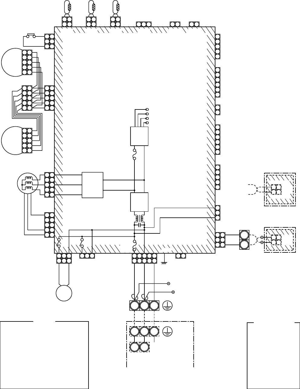
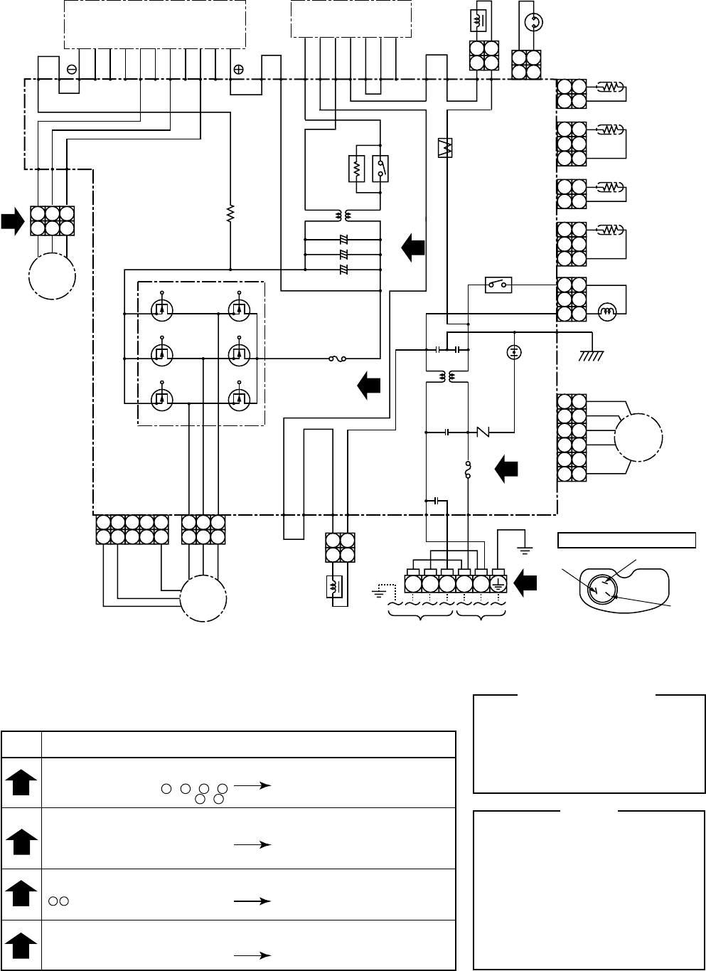
5-2. Outdoor Unit
RAV-SM560AT-E
SIMPLE CHECK POINTS FOR DIAGNOSING FAULTS
Diagnosis result
TERMINAL BLOCK
There is no supply voltage
(AC220 to 240V) between L - N , 1 - 2
There is no voltage (DC15 to 25V) 2 - 3
Power supply and connecting
cable check
Check
items
FUSE
T25A 250V to fuse (F01) blown
T3.15A 250V to fuse (F04) blown
Converter module (DB01) and
electrolytic capacitor (C12 to C14) check
IGBT module (Q200) check
Fan motor check
ELECTROLYTIC CAPACITOR VOLTAGE (C12, C13, C14)
DC320V not available between
+ – terminal of electrolytic capacitor T25A fuse (F01) check
P.C. board and converter
module (DB01) check
INVERTER OUTPUT (Inverter and compressor connector out of position)
(Please confirm within six minutes after instructing in the drive.)
Voltage between each line of inverter side
conector pins are not equal. IGBT module and
P.C. board check
CM
PMV
FM
TE
TD
TO
TS
IGBT
DB01
CT
Q300
: Compressor
: Pulse modulating valve
: Fan motor
: Heat exchanger Temp. Sensor
: Discharge Temp. Sensor
: Outdoor Temp. Sensor
: Suction Temp. Sensor
: Insulated Gate Bipolar Transistor
: Converter module
: Curreut Transformer
: Fan motor driver module
NOTE
Color Identification
BLK
BLU
RED
GRY
PNK
GRN
:
:
:
:
:
:
BLACK
BLUE
RED
GRAY
PINK
GREEN
WHI
BRW
ORN
YEL
PUR
:
:
:
:
:
WHITE
BROWN
ORANGE
YELLOW
PURPLE
P10
ORN
BRW
BZ
BY
BX
EW
BW
EV
BV
EU
BU
BLU
P09
P19P20
CT
C12
C13
C14
REACTOR
THERMOSTAT
FOR
COMPRESSOR
P08 P07
CN500
CN600
TE
TD
TO
TS
CN601
CN602
CN603
CN701
CN703
F01
P06 BLK
FUSE
T25A
250V~
P.C. BOARD
(MCC-813)
VARISTOR
SURGE
ABSORBER
RELAY
P02
P11
P12
P13
P14
CN300
Q300
CN301
P03
P01
ORN
WHI
PUR
BLK
FAN MOTOR
REACTOR
POWER
SUPPLY
220 to 240
50Hz
TO
INDOOR
UNIT
P17 P18
RED
WHI
BLK
YEL
PNK
GRY
FM
BLK
YEL
RED
ORN
RED
GRY
1
2
3
4
3
4
2
2
1
PULSE
MODULATING
VALVE
PMV
COIL FOR
4-WAY VALVE
N
L
3
2
1
+
–
+
–
+
–
POWER
RELAY
ELECTRONIC
STARTER
F04
FUSE
T3. 15A
250V~
DB01
Q200 CONVERTER
MODULE
IGBT MODULE
GEA
~
–
~
+
COMPRESSOR
RED
WHI
BLK
P21
P22
P23
CM
WHITE (S) BLACK (C)
RED (R)
TERMINAL OF COMPRESSOR
The sign in ( ) is displayed
in the terminalcover
11
22
11
22
11
33
22
11
33
22
11
33
22
44
66
55
11
33
22
2 1
2 1
2 1
2 1
2 1
2
3
3 1
2 1
2 1
2 1
2 1
3
3
2 1
21
4 3
43
5
5
– 27 –
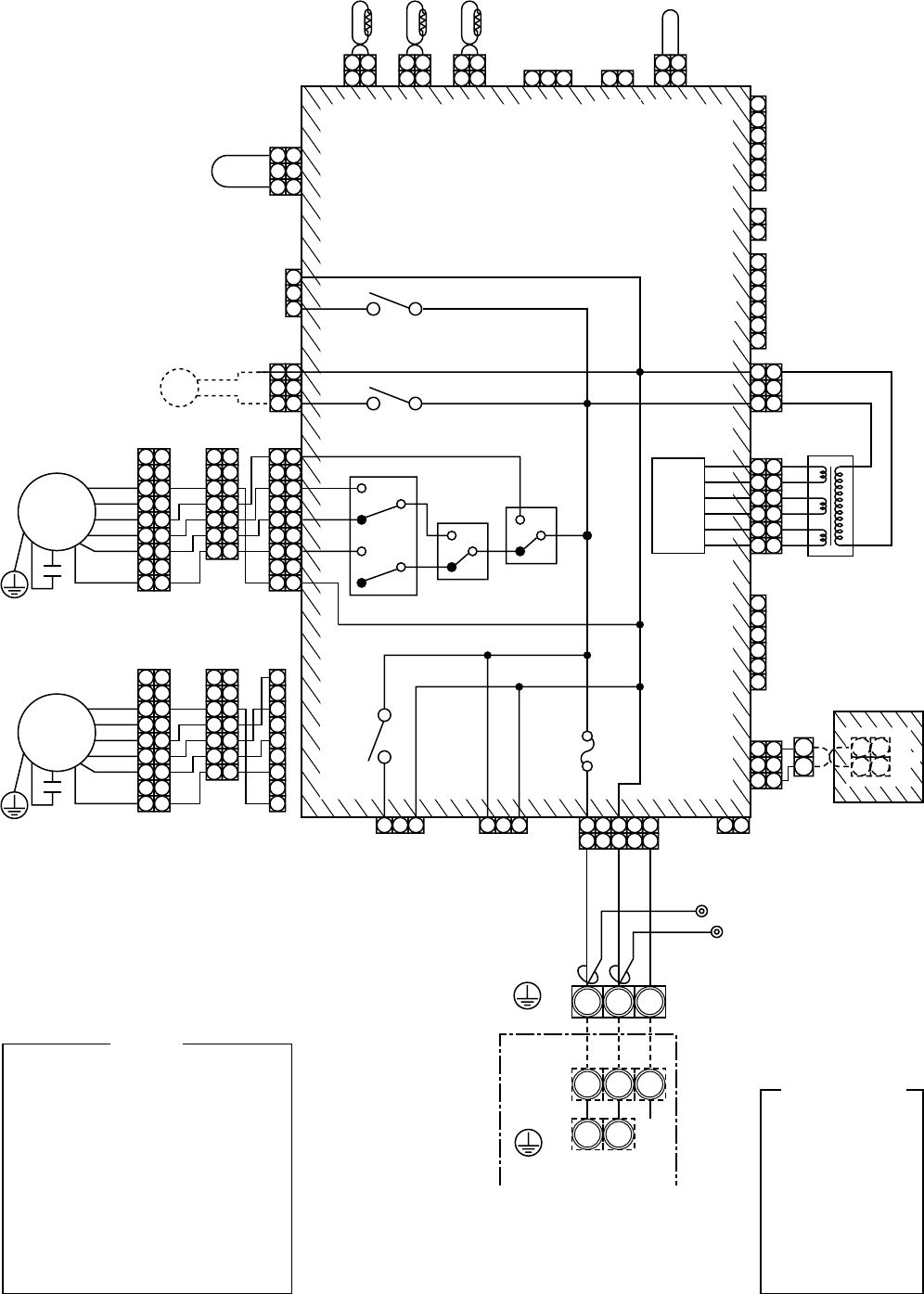
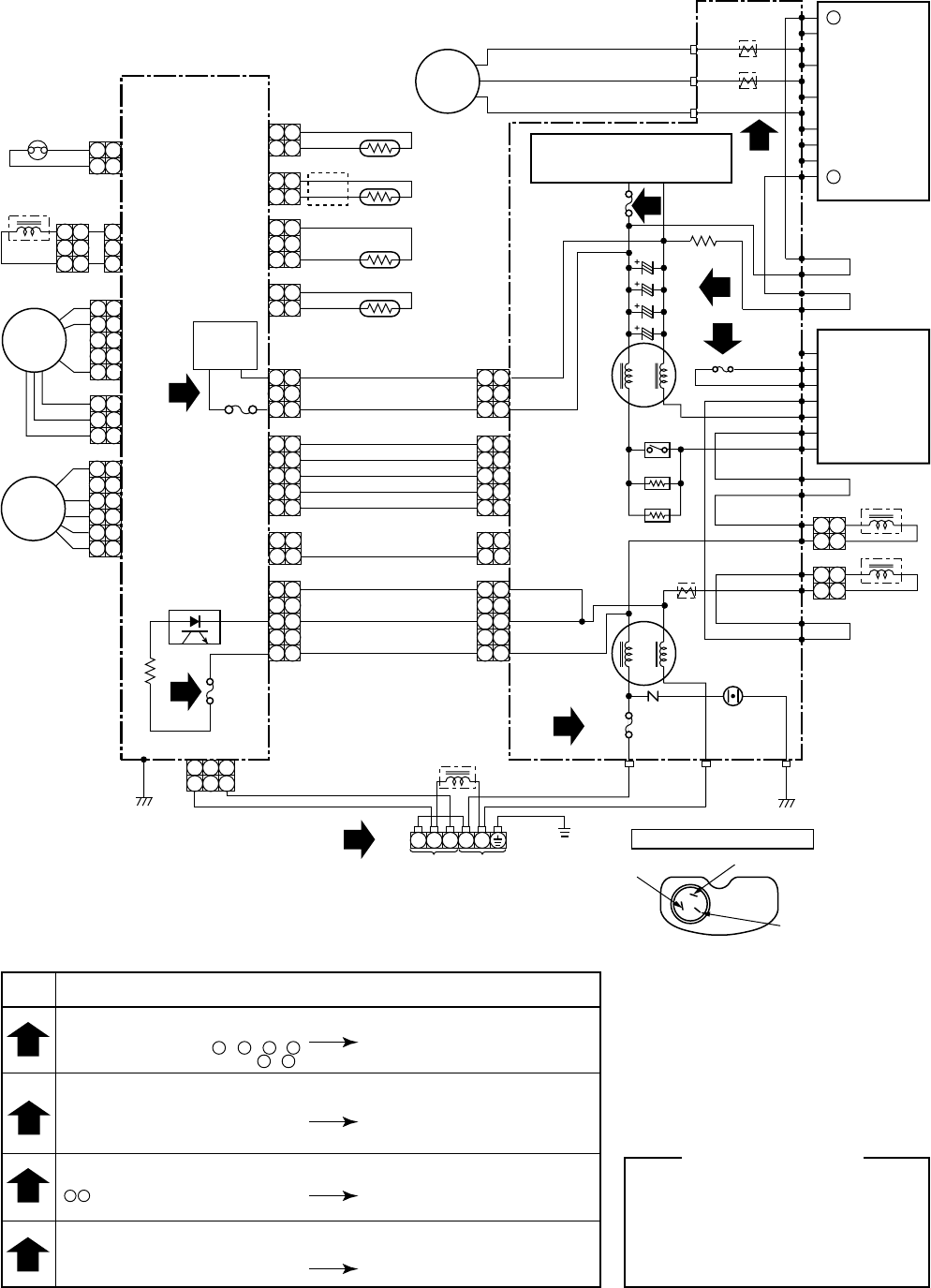
RAV-SM800AT-E
SIMPLE CHECK POINTS FOR DIAGNOSING FAULTS
Diagnosis result
TERMINAL BLOCK
There is no supply voltage
(AC220 to 240V) between L - N , 1 - 2
There is no voltage (DC15 to 25V) 2 - 3
Connecting cable check
1
2
3
4
FUSE
25A fuse (F01) blown, 15A fuse (F02) blown
3.15A fuse (F04) blown,
T5A fuse (F300) blown (SUB P.C. board)
T3.15A fuse (F01) blown (SUB P.C. board)
Converter module (DB01) and electrolytic
capacitor (C10 to C13) check IGBT
module (Q200) check, Fan motor check
SUB P.C. board check
ELECTROLYTIC CAPACITOR VOLTAGE (C10, C11, C12, C13)
DC320V not available between
+ terminal of electrolytic capacitor 25A fuse (F01) check
P.C. board and coverter
module (DB01) check
INVERTER OUTPUT (CN09, CN10, CN11)
(Please confirm within six minutes after instructing in the drive.)
Voltage between each line of inverterside
conector pins are not equal. IGBT module and
P.C. board check
Color Identification
BLK
BLU
RED
GRY
PNK
GRN
:
:
:
:
:
:
BLACK
BLUE
RED
GRAY
PINK
GREEN
WHI
BRN
ORN
YEL
PUR
:
:
:
:
:
WHITE
BROWN
ORANGE
YELLOW
PURPLE
3
2
1
3
2
1
2
12
1
5
4
1
5
4
3
2
3
21
3
1
3
1
6
5
4
3
2
1
6
5
4
3
2
1
ORN
ORN
VARISTOR
T02
CT
G
E
A
~
~
+
DB01
Converter
module
SURGE
ABSORBER
PHOTO COUPLER
P.C. BOARD
(MCC-1359)
SUB
P.C. BOARD
(MCC-1398)
F01
FUSE
T3.15A
F01
FUSE
25A
CN01
CN02
P12
P09
P11
P13
P19
P18
P17
P20
P10
RY01
R05
R06
CN04
CN800
CN302
CN06
CN05
CN04
C13
CN03
CN02CN01
CN702
THERMOSTAT
FOR
COMPRESSOR
CN500
CN700
CN300
CN301
BLKWHIRED
ORN
BRN
BZ
BY
BX
EW
BW
EV
BV
EU
BU
CN09
CN10
CN11
CN600 TD
3
2
1
3
1
GRN
CN604 TE
2
12
1
BLK
WHI
RED
Compressor
FAN MOTOR
4-WAY VALVE COIL
CN601 TO
2
12
1
CN605 TS
2
12
1
3
1
3
1
3
1
3
1
BLU
YEL
2
12
12
12
1
ORN
2
12
12
12
1
PNK
RED
3 3 3 3
BLU
4 4 4 4
WHI
5 5 5 5
BLK
CN13
2
12
12
12
1
RED
3 3 3 3
4 4 4 4
WHI
5 5 5 5
BLK
Fan
circuit
CM
FM
PMV
T03
CT
T04
CT
Q200
IGBT
POWER SUPPLY CIRCUIT
(FOR P.C. BOARD)
module
C12
C11
C10
+
3
1
F02
FUSE
15A
F04
FUSE
3.15A
F300
FUSE
T5A
2
12
1
REACTOR
POWER
RELAY
P08
P15
P14
2
12
1
REACTOR
REACTOR
RED
TO
INDOOR
UNIT
POWER
SUPPLY
220-240V
~50Hz
GRY
WHI
L N2 31
231 231
BLU
YEL
WHITE(S) BLACK(C)
RED(R)
TERMINAL OF COMPRESSOR
The sign in ( )
is displayed
in the terminal
cover
2
2
2
1
2
3
2
4
Check
items
– 28 –
6. SPECIFICATIONS OF ELECTRICAL PARTS
6-1. Indoor Unit
4-Way Air Discharge Cassette Type
RAV-SM560UT-E/RAV-SM800UT-E
Concealed Duct Type
RAV-SM560BT-E/RAV-SM800BT-E
High-Wall Type
RAV-SM560KRT-E/RAV-SM800KRT-E
RAV-SM560XT-E/RAV-SM800XT-E
No.
1
2
3
4
5
6
Specifications
Output (Rated) 60 W, 220–240 V
10 kΩ at 25°C
10 kΩ at 25°C
10 kΩ at 25°C
Parts name
Fan motor (for indoor)
Thermo. sensor (TA-sensor)
Heat exchanger sensor (TCJ-sensor)
Heat exchanger sensor (TC-sensor)
Float switch
Drain pump motor
Type
SWF-230-60-1
155 mm
Ø6 mm, 1200 mm
Ø6 mm, 1200 mm
FS-0218-106
ADP-1406
No.
1
2
3
4
5
6
7
Specifications
Output (Rated) 80 W, 220–240 V, 4P
Output (Rated) 80 W, 220–240 V, 4P
400WV, 5µF
400WV, 4.0µF
10 kΩ at 25°C
10 kΩ at 25°C
10 kΩ at 25°C
Parts name
Fan motor (RAV-SM800BT-E)
Fan motor (RAV-SM560BT-E)
Capacitor (RAV-SM800BT-E)
Capacitor (RAV-SM560BT-E)
Thermo. sensor (TA-sensor)
Heat exchanger sensor (TC-sensor)
Heat exchanger sensor (TCJ-sensor)
Type
STF-230-80-4C
STF-220-80-4C
EAG40M805UF1
CMPS400-4.0
818 mm
Ø6 mm, 1200 mm
Ø6 mm, 1200 mm
No.
1
2
3
4
5
Specifications
Output (Rated) 30 W, 220–240 V
10 kΩ at 25°C
10 kΩ at 25°C
Parts name
Fan motor (for indoor)
Grille motor
Thermo. sensor (TA-sensor)
Heat exchanger sensor (TC-sensor)
Heat exchanger sensor (TCJ-sensor)
Type
ICF340-30-1
MP35EA12
268 mm
Ø6 mm, 400 mm
Ø6 mm, 400 mm
No.
1
2
3
4
5
Specifications
Output (Rated) 50 W, 220–240 V
DC 12 V
10 kΩ at 25°C
10 kΩ at 25°C
Parts name
Fan motor (for indoor)
Grille motor
Thermo. sensor (TA-sensor)
Heat exchanger sensor (TC-sensor)
Heat exchanger sensor (TCJ-sensor)
Type
AFP-220-50-4A
MP35EA
mm
Ø6 mm, mm
Ø6 mm, mm
– 29 –
6-2. Outdoor Unit
RAV-SM560AT-E
RAV-SM800AT-E
6-3. Accessory Separate Sold Parts
RBC-U21PG (W) E (Ceiling panel)
TCB-DP11E (Drain up pump)
No.
1
2
3
4
5
6
7
8
9
10
11
Specifications
Output (Rated) 40 W
3 phase, 4P, 1100 W
1=10 mH, 16A
10 kΩ at 25°C
10 kΩ at 25°C
10 kΩ at 25°C
50 kΩ at 25°C
T3.15 A, AC 250 V
25 A, AC 250 V
ON : 90 ± 5°C, OFF : 125 ± 4°C
Parts name
Fan motor
Compressor
Reactor
Outdoor temp. sensor (To-sensor)
Heat exchanger sensor (Te-sensor)
Suction temp. sensor (Ts-sensor)
Discharge temp. sensor (Td-sensor)
Fuse (Switching power (Protect))
Fuse (Inverter, input (Current protect)
4-way valve solenoid coil
Compressor thermo. (Protection)
Type
ICF-140-43-1
DA130A1F-23F
CH-57
—
—
—
—
STF-0108G
US-622
No.
1
2
3
4
5
6
7
8
9
10
11
Specifications
Output (Rated) 63 W, 220–240 V
3 phase, 4P, 1600 W
mH, A
10 kΩ at 25°C
10 kΩ at 25°C
10 kΩ at 25°C
50 kΩ at 25°C
T3.15 A, AC 250 V
25 A, AC 250 V
ON : 90 ± 5°C, OFF : 125 ± 4°C
Parts name
Fan motor
Compressor
Reactor
Outdoor temp. sensor (To-sensor)
Heat exchanger sensor (Te-sensor)
Suction temp. sensor (Ts-sensor)
Discharge temp. sensor (Td-sensor)
Fuse (Switching power (Protect))
Fuse (Inverter, input (Current protect))
4-way valve solenoid coil
Compressor thermo. (Protection)
Type
ICF-140-63-1
DA220A2F-20L
CH-47
—
—
—
—
DKV-M0ZS743B0
No.
1
2
Specifications
DC 12 V
Parts name
Motor-louver
Type
MP24GA
No.
1
2
Specifications
AC 220–240 V
Parts name
Pump-drain
Type
PJD-05230TF-1
– 30 –
7. REFRIGERANT R410A
This air conditioner adopts the new refrigerant HFC
(R410A) which does not damage the ozone layer.
The working pressure of the new refrigerant R410A
is 1.6 times higher than conventional refrigerant
(R22). The refrigerating oil is also changed in
accordance with change of refrigerant, so be careful
that water, dust, and existing refrigerant or refrigerat-
ing oil are not entered in the refrigerant cycle of the
air conditioner using the new refrigerant during
installation work or servicing time.
The next section describes the precautions for air
conditioner using the new refrigerant. Conforming to
contents of the next section together with the
general cautions included in this manual, perform
the correct and safe work.
7-1. Safety During Installation/Servicing
As R410A’s pressure is about 1.6 times higher than
that of R22, improper installation/servicing may
cause a serious trouble. By using tools and materi-
als exclusive for R410A, it is necessary to carry out
installation/servicing safely while taking the following
precautions into consideration.
(1) Never use refrigerant other than R410A in an air
conditioner which is designed to operate with
R410A.
If other refrigerant than R410A is mixed, pres-
sure in the refrigeration cycle becomes abnor-
mally high, and it may cause personal injury, etc.
by a rupture.
(2) Confirm the used refrigerant name, and use
tools and materials exclusive for the refrigerant
R410A.
The refrigerant name R410A is indicated on the
visible place of the outdoor unit of the air condi-
tioner using R410A as refrigerant. To prevent
mischarging, the diameter of the service port
differs from that of R22.
(3) If a refrigeration gas leakage occurs during
installation/servicing, be sure to ventilate fully.
If the refrigerant gas comes into contact with fire,
a poisonous gas may occur.
(4) When installing or removing an air conditioner,
do not allow air or moisture to remain in the
refrigeration cycle. Otherwise, pressure in the
refrigeration cycle may become abnormally high
so that a rupture or personal injury may be
caused.
(5) After completion of installation work, check to
make sure that there is no refrigeration gas
leakage.
If the refrigerant gas leaks into the room, coming
into contact with fire in the fan-driven heater,
space heater, etc., a poisonous gas may occur.
(6) When an air conditioning system charged with a
large volume of refrigerant is installed in a small
room, it is necessary to exercise care so that,
even when refrigerant leaks, its concentration
does not exceed the marginal level.
If the refrigerant gas leakage occurs and its
concentration exceeds the marginal level, an
oxygen starvation accident may result.
(7) Be sure to carry out installation or removal
according to the installation manual.
Improper installation may cause refrigeration
trouble, water leakage, electric shock, fire, etc.
(8) Unauthorized modifications to the air conditioner
may be dangerous. If a breakdown occurs
please call a qualified air conditioner technician
or electrician.
Improper repair’s may result in water leakage,
electric shock and fire, etc.
7-2. Refrigerant Piping Installation
7-2-1. Piping Materials and Joints Used
For the refrigerant piping installation, copper pipes
and joints are mainly used. Copper pipes and joints
suitable for the refrigerant must be chosen and
installed. Furthermore, it is necessary to use clean
copper pipes and joints whose interior surfaces are
less affected by contaminants.
(1) Copper Pipes
It is necessary to use seamless copper pipes
which are made of either copper or copper alloy
and it is desirable that the amount of residual oil
is less than 40 mg/10 m. Do not use copper
pipes having a collapsed, deformed or discol-
ored portion (especially on the interior surface).
Otherwise, the expansion valve or capillary tube
may become blocked with contaminants.
As an air conditioner using R410A incurs
pressure higher than when using R22, it is
necessary to choose adequate materials.
Thicknesses of copper pipes used with R410A
are as shown in Table 7-2-1. Never use copper
pipes thinner than 0.8 mm even when it is
available on the market.
– 31 –
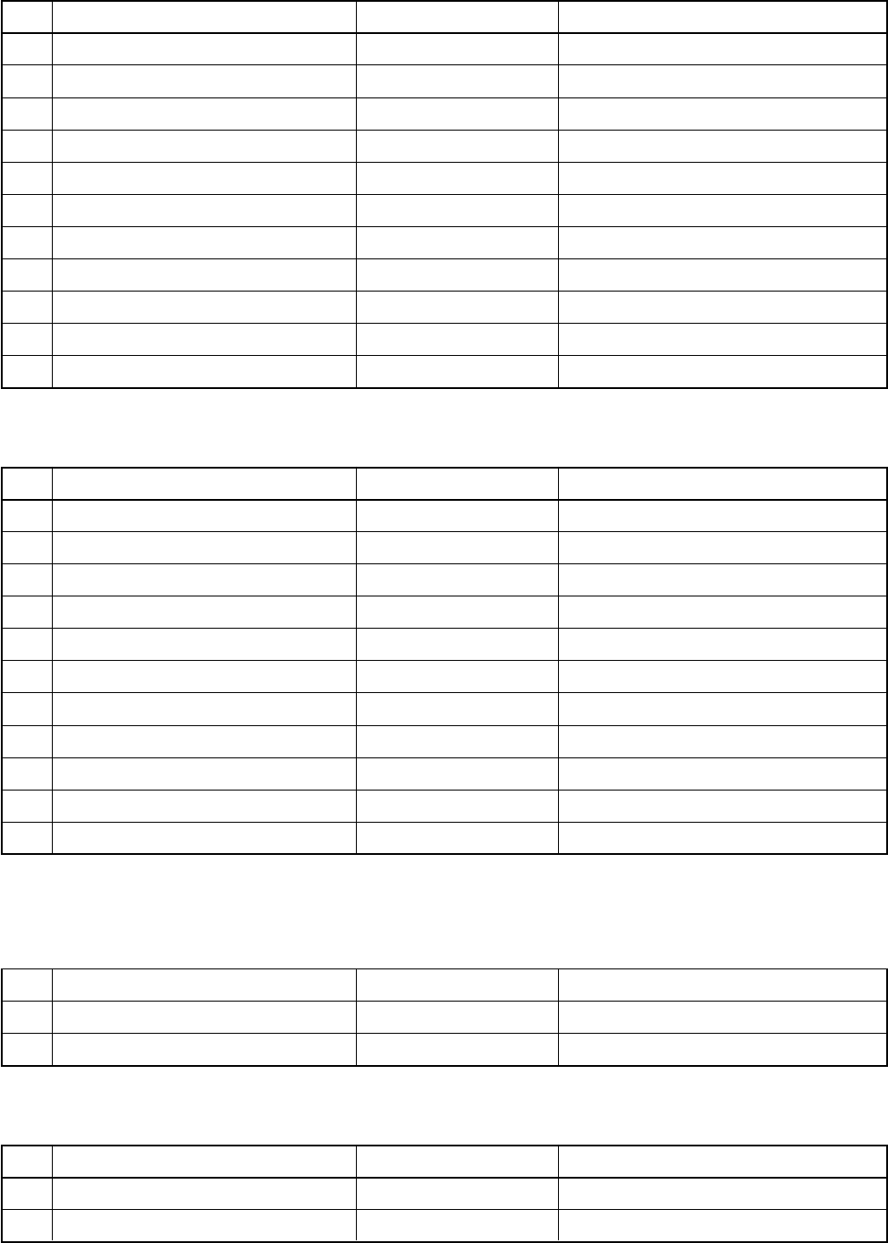
Nominal diameter
1/4
3/8
1/2
5/8
Thickness (mm)
R410A R22
0.80 0.80
0.80 0.80
0.80 0.80
1.00 1.00
Outer diameter (mm)
6.35
9.52
12.70
15.88
Nominal diameter
1/4
3/8
1/2
5/8
Reference outer diameter of
copper pipe jointed (mm)
6.35
9.52
12.70
15.88
Minimum joint thickness
(mm)
0.50
0.60
0.70
0.80
Table 7-2-1 Thicknesses of annealed copper pipes
(2) Joints
For copper pipes, flare joints or socket joints are
used. Prior to use, be sure to remove all con-
taminants.
a) Flare Joints
Flare joints used to connect the copper pipes
cannot be used for pipings whose outer
diameter exceeds 20 mm. In such a case,
socket joints can be used.
Sizes of flare pipe ends, flare joint ends and
flare nuts are as shown in Tables 7-2-3 to 7-
2-6 below.
b) Socket Joints
Socket joints are such that they are brazed
for connections, and used mainly for thick
pipings whose diameter is larger than 20 mm.
Thicknesses of socket joints are as shown in
Table 7-2-2.
Table 7-2-2 Minimum thicknesses of socket joints
7-2-2. Processing of Piping Materials
When performing the refrigerant piping installation,
care should be taken to ensure that water or dust
does not enter the pipe interior, that no other oil
other than lubricating oils used in the installed air
conditioner is used, and that refrigerant does not
leak. When using lubricating oils in the piping
processing, use such lubricating oils whose water
content has been removed. When stored, be sure to
seal the container with an airtight cap or any other
cover.
(1) Flare Processing Procedures and Precautions
a) Cutting the Pipe
By means of a pipe cutter, slowly cut the pipe
so that it is not deformed.
b) Removing Burrs and Chips
If the flared section has chips or burrs,
refrigerant leakage may occur. Carefully
remove all burrs and clean the cut surface
before installation.
– 32 –
A
ØD
A (mm)
Nominal
diameter
1/4
3/8
1/2
5/8
Outer
diameter
(mm)
6.35
9.52
12.70
15.88
Thickness
(mm)
0.8
0.8
0.8
1.0
Flare tool for
R410A clutch type
0 to 0.5
0 to 0.5
0 to 0.5
0 to 0.5
Conventional flare tool
Clutch type Wing nut type
1.0 to 1.5 1.5 to 2.0
1.0 to 1.5 1.5 to 2.0
1.0 to 1.5 2.0 to 2.5
1.0 to 1.5 2.0 to 2.5
A (mm)
Nominal
diameter
1/4
3/8
1/2
5/8
Outer
diameter
(mm)
6.35
9.52
12.70
15.88
Thickness
(mm)
0.8
0.8
0.8
1.0
Flare tool for
R22 clutch type
0 to 0.5
0 to 0.5
0 to 0.5
0 to 0.5
Conventional flare tool
Clutch type Wing nut type
0.5 to 1.0 1.0 to 1.5
0.5 to 1.0 1.0 to 1.5
0.5 to 1.0 1.5 to 2.0
0.5 to 1.0 1.5 to 2.0
Nominal
diameter
1/4
3/8
1/2
5/8
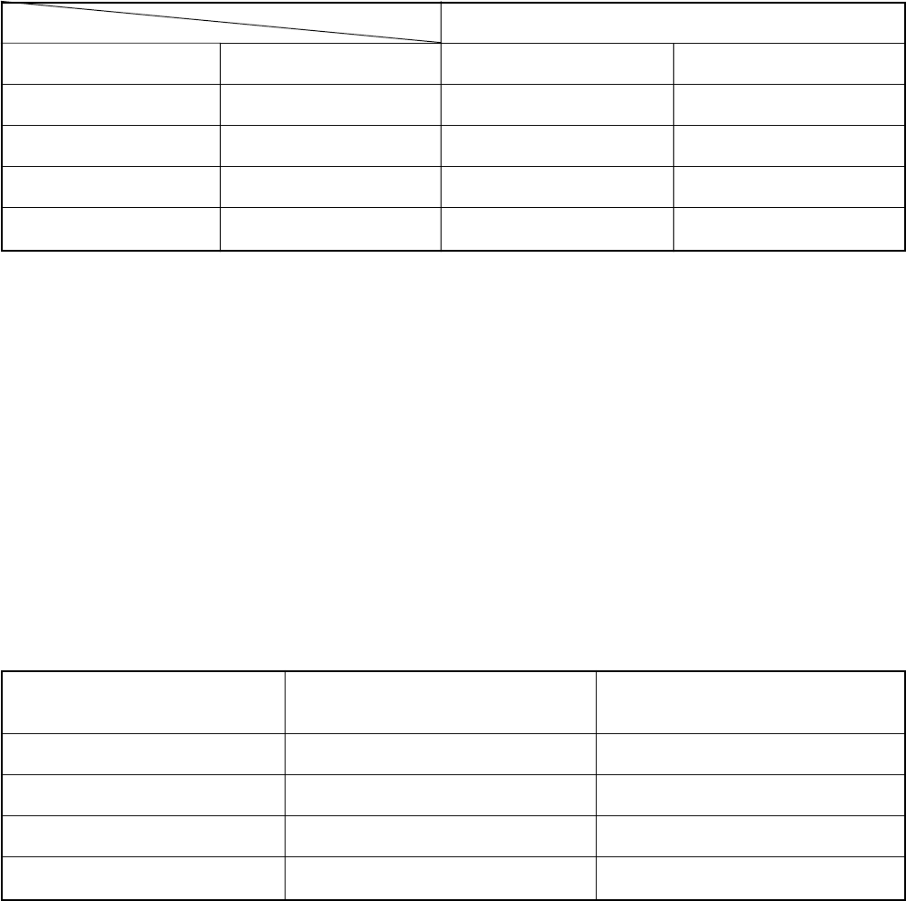
Dimension (mm)
ABCD
9.1 9.2 6.5 13
13.2 13.5 9.7 20
16.6 16.0 12.9 23
19.7 19.0 16.0 25
Outer diameter
(mm)
6.35
9.52
12.70
15,88
Thickness
(mm)
0.8
0.8
0.8
1.0
Flare nut
width (mm)
17
22
26
29
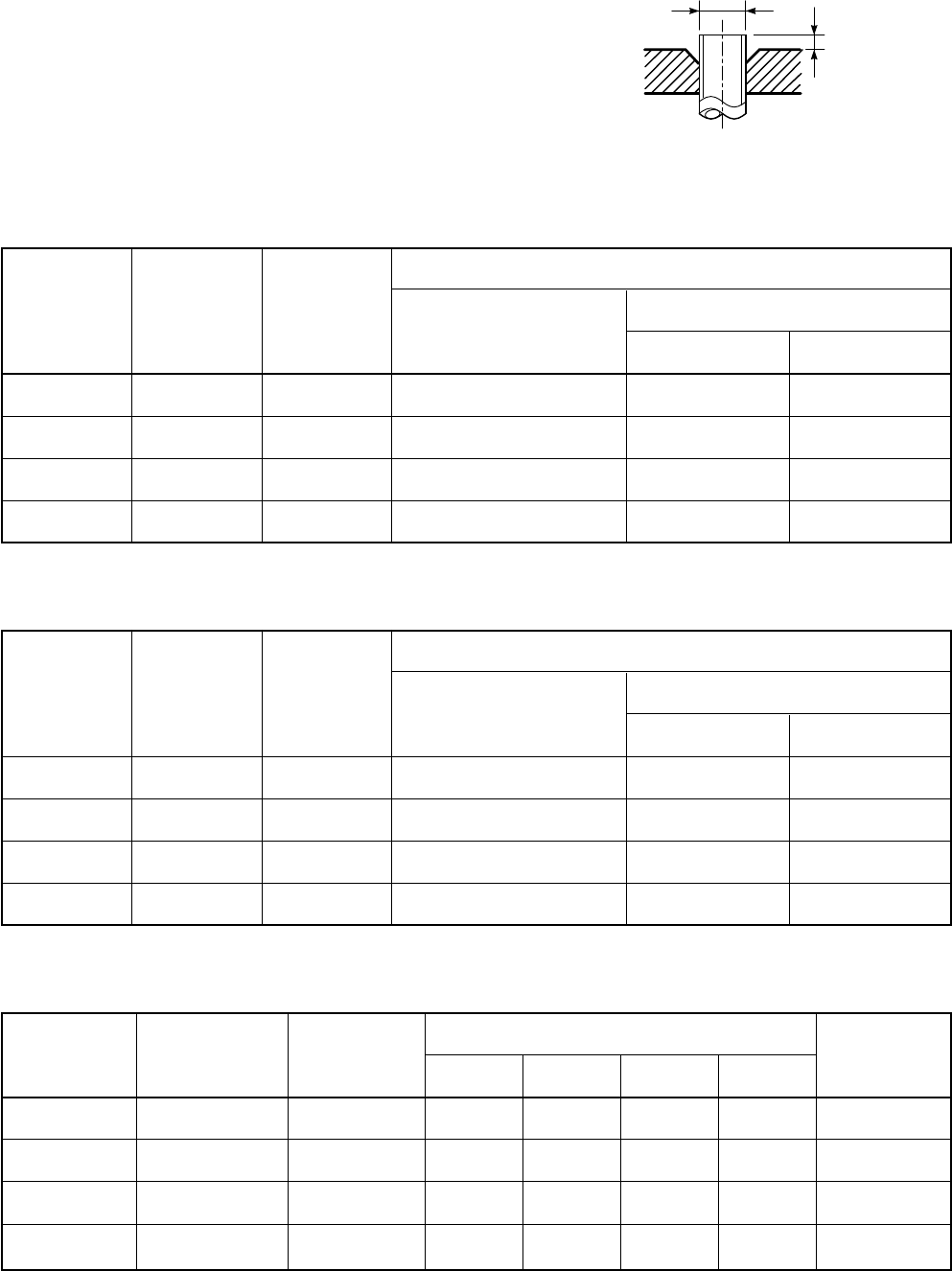
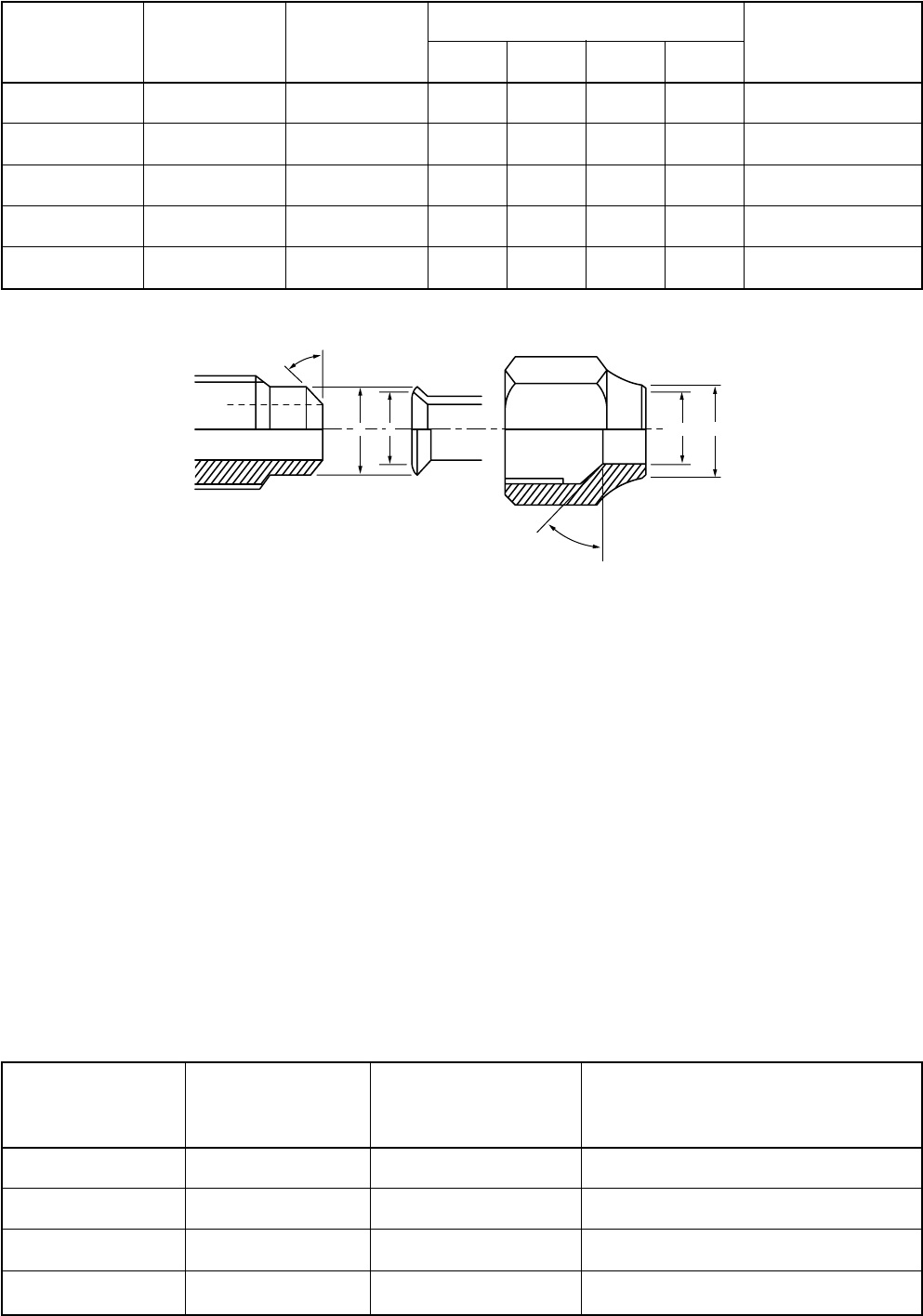
c) Insertion of Flare Nut
d) Flare Processing
Make certain that a clamp bar and copper
pipe have been cleaned.
By means of the clamp bar, perform the flare
processing correctly.
Use either a flare tool for R410A or conven-
tional flare tool.
Flare processing dimensions differ according
to the type of flare tool. When using a con-
ventional flare tool, be sure to secure “dimen-
sion A” by using a gauge for size adjustment.
Fig. 7-2-1 Flare processing dimensions
Table 7-2-3 Dimensions related to flare processing for R410A
Table 7-2-4 Dimensions related to flare processing for R22
Table 7-2-5 Flare and flare nut dimensions for R410A
– 33 –
43 to 45
45 to 46
B A CD
Nominal Outer diameter Thickness
diameter (mm) (mm)
1/4 6.35 0.8
3/8 9.52 0.8
1/2 12.70 0.8
5/8 15.88 1.0
3/4 19.05 1.0
Dimension (mm)
ABCD
9.0 9.2 6.5 13
13.0 13.5 9.7 20
16.2 16.0 12.9 20
19.4 19.0 16.0 23
23.3 24.0 19.2 34
Flare nut width
(mm)
17
22
24
27
36
Nominal Outer diameter Tightening torque
diameter (mm) N•m (kgf•cm)
1/4 6.35 14 to 18 (140 to 180)
3/8 9.52 33 to 42 (330 to 420)
1/2 12.70 50 to 62 (500 to 620)
5/8 15.88 63 to 77 (630 to 770)
Tightening torque of torque
wrenches available on the market
N•m (kgf•cm)
16 (160), 18 (180)
42 (420)
55 (550)
65 (650)
Table 7-2-6 Flare and flare nut dimensions for R22
Fig. 7-2-2 Relations between flare nut and flare seal surface
(2) Flare Connecting Procedures and Precautions
a) Make sure that the flare and union portions
do not have any scar or dust, etc.
b) Correctly align the processed flare surface
with the union axis.
c) Tighten the flare with designated torque by
means of a torque wrench. The tightening
torque for R410A is the same as that for
conventional R22. Incidentally, when the
torque is weak, the gas leakage may occur.
When it is strong, the flare nut may crack and
may be made non-removable. When choosing
the tightening torque, comply with values
designated by manufacturers. Table 7-2-7
shows reference values.
NOTE:
When applying oil to the flare surface, be sure to use
oil designated by the manufacturer. If any other oil is
used, the lubricating oils may deteriorate and cause
the compressor to burn out.
Table 7-2-7 Tightening torque of flare for R410A [Reference values]
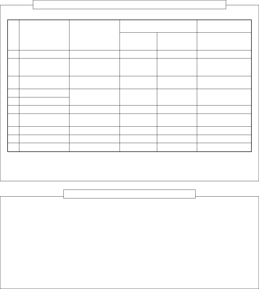
– 34 –
No. Used tool
Flare tool
Copper pipe gauge for
adjusting projection
margin
Torque wrench
Gauge manifold
Charge hose
Vacuum pump adapter
Electronic balance for
refrigerant charging
Refrigerant cylinder
Leakage detector
Charging cylinder
Usage
Pipe flaring
Flaring by conventional
flare tool
Connection of flare nut
Evacuating, refrigerant
charge, run check, etc.
Vacuum evacuating
Refrigerant charge
Refrigerant charge
Gas leakage check
Refrigerant charge
R410A
air conditioner installation
Existence of Whether conven-
new equipment tional equipment
for R410A can be used
Ye s *(Note 1)
Ye s *(Note 1)
Ye s
X
Ye s
X
Ye s
X
Ye s
X
Ye s
X
Ye s
X
(Note 2)
X
Conventional air
conditioner installation
Whether new equipment
can be used with
conventional refrigerant
¡
*(Note 1)
X
X
¡
¡
X
¡
X
7-3. Tools
7-3-1. Required Tools
The service port diameter of packed valve of the outdoor unit in the air conditioner using R410A is changed to
prevent mixing of other refrigerant. To reinforce the pressure-resisting strength, flare processing dimensions and
opposite side dimension of flare nut (For Ø12.7 copper pipe) of the refrigerant piping are lengthened.
The used refrigerating oil is changed, and mixing of oil may cause a trouble such as generation of sludge,
clogging of capillary, etc. Accordingly, the tools to be used are classified into the following three types.
(1) Tools exclusive for R410A (Those which cannot be used for conventional refrigerant (R22))
(2) Tools exclusive for R410A, but can be also used for conventional refrigerant (R22)
(3) Tools commonly used for R410A and for conventional refrigerant (R22)
The table below shows the tools exclusive for R410A and their interchangeability.
Tools exclusive for R410A (The following tools for R410A are required.)
Tools whose specifications are changed for R410A and their interchangeability
(Note 1) When flaring is carried out for R410A using the conventional flare tools, adjustment of projection
margin is necessary. For this adjustment, a copper pipe gauge, etc. are necessary.
(Note 2) Charging cylinder for R410A is being currently developed.
General tools (Conventional tools can be used.)
In addition to the above exclusive tools, the following equipments which serve also for R22 are necessary
as the general tools.
(1) Vacuum pump
Use vacuum pump by
attaching vacuum pump adapter.
(2) Torque wrench
(3) Pipe cutter
(4) Reamer
(5) Pipe bender
(6) Level vial
(7) Screwdriver (+, –)
(8) Spanner or Monkey wrench
(9) Hole core drill (Ø65)
(10) Hexagon wrench
(Opposite side 4mm)
(11) Tape measure
(12) Metal saw
Also prepare the following equipments for other installation method and run check.
(1) Clamp meter
(2) Thermometer
(3) Insulation resistance tester
(4) Electroscope
– 35 –
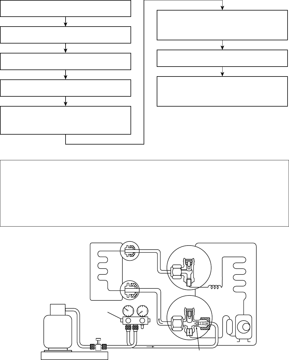
(INDOOR unit) (Liquid side)
Refrigerant cylinder
(With siphon pipe)
Check valve
(Gas side)
Open/Close valve
for charging
Electronic balance for refrigerant charging
Opened
(OUTDOOR unit)
Closed
Service port
Connect the charge hose to packed valve service
port at the outdoor unit’s gas side.
Recover the refrigerant, and check no refrigerant
remains in the equipment.
(For refrigerant charging, see the figure below.)
Connect the charge hose of the vacuum pump
adapter.
Open fully both packed valves at liquid and gas
sides.
Place the handle of the gauge manifold Low in the
fully opened position, and turn on the vacuum pump’s
power switch. Then, evacuating the refrigerant in the
cycle.
When the compound gauge’s pointer has indicated
–0.1 Mpa (–76 cmHg), place the handle Low in the
fully closed position, and turn off the vacuum pump’s
power switch.
Keep the status as it is for 1 to 2 minutes, and ensure
that the compound gauge’s pointer does not return.
Set the refrigerant cylinder to the electronic balance,
connect the connecting hose to the cylinder and the
connecting port of the electronic balance, and charge
liquid refrigerant.
7-4. Recharging of Refrigerant
When it is necessary to recharge refrigerant, charge the specified amount of new refrigerant according to the
following steps.
Never charge refrigerant exceeding the specified amount.
If the specified amount of refrigerant cannot be charged, charge refrigerant bit by bit in COOL mode.
Do not carry out additional charging.
When additional charging is carried out if refrigerant leaks, the refrigerant composition changes in the
refrigeration cycle, that is characteristics of the air conditioner changes, refrigerant exceeding the
specified amount is charged, and working pressure in the refrigeration cycle becomes abnormally high
pressure, and may cause a rupture or personal injury.
Fig. 7-4-1 Configuration of refrigerant charging

– 36 –
Gauge manifold
[ Cylinder with siphon ] [ Cylinder without siphon ]
OUTDOOR unit Gauge manifold
OUTDOOR unit
Refrigerant
cylinder
Electronic
balance
Refrigerant
cylinder
Electronic
balance
Siphon
Be sure to make setting so that liquid can be charged.
When using a cylinder equipped with a siphon, liquid can be charged without turning it upside down.
It is necessary for charging refrigerant under condition of liquid because R410A is mixed type of refrigerant.
Accordingly, when charging refrigerant from the refrigerant cylinder to the equipment, charge it turning the
cylinder upside down if cylinder is not equipped with siphon.
R410A refrigerant is HFC mixed refrigerant.
Therefore, if it is charged with gas, the composi-
tion of the charged refrigerant changes and the
characteristics of the equipment varies.
Fig. 7-4-2
7-5. Brazing of Pipes
7-5-1. Materials for Brazing
(1) Silver brazing filler
Silver brazing filler is an alloy mainly composed
of silver and copper. It is used to join iron,
copper or copper alloy, and is relatively expen-
sive though it excels in solderability.
(2) Phosphor bronze brazing filler
Phosphor bronze brazing filler is generally used
to join copper or copper alloy.
(3) Low temperature brazing filler
Low temperature brazing filler is generally called
solder, and is an alloy of tin and lead. Since it is
weak in adhesive strength, do not use it for
refrigerant pipes.
Phosphor bronze brazing filler tends to react
with sulfur and produce a fragile compound
water solution, which may cause a gas
leakage. Therefore, use any other type of
brazing filler at a hot spring resort, etc., and
coat the surface with a paint.
When performing brazing again at time of
servicing, use the same type of brazing filler.
7-5-2. Flux
(1) Reason why flux is necessary
•By removing the oxide film and any foreign
matter on the metal surface, it assists the flow
of brazing filler.
•In the brazing process, it prevents the metal
surface from being oxidized.
•By reducing the brazing filler's surface tension,
the brazing filler adheres better to the treated
metal.
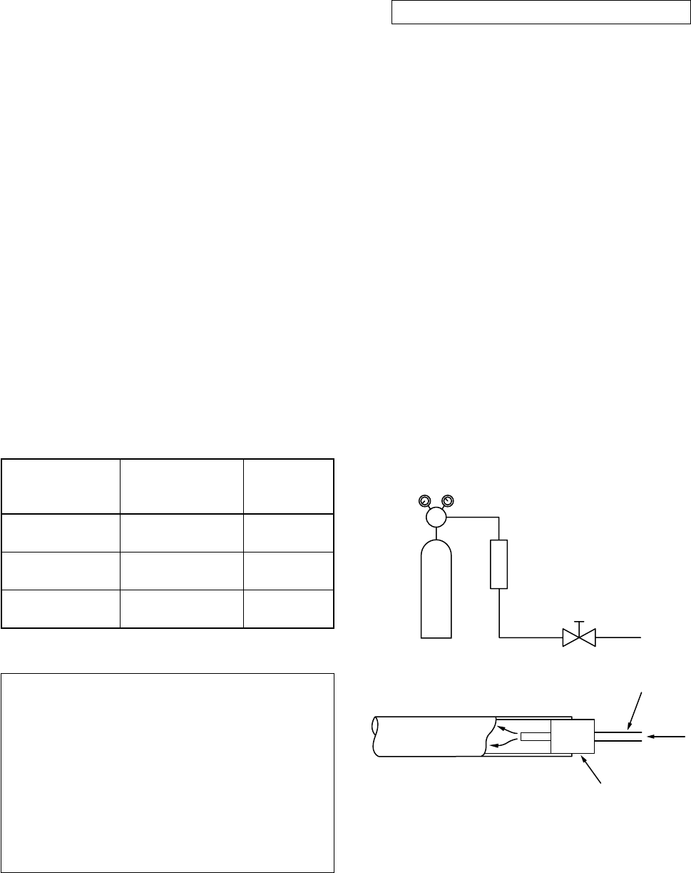
– 37 –
Nitrogen gas
cylinder
Pipe
Flow meter
M
Stop valve
From Nitrogen cylinder
Nitrogen
gas
Rubber plug
Piping
material
Copper - Copper
Copper - Iron
Iron - Iron
Used brazing
filler
Phosphor copper
Silver
Silver
Used
flux
Do not use
Paste flux
Vapor flux
(2) Characteristics required for flux
•Activated temperature of flux coincides with
the brazing temperature.
•Due to a wide effective temperature range, flux
is hard to carbonize.
•It is easy to remove slag after brazing.
•The corrosive action to the treated metal and
brazing filler is minimum.
•It excels in coating performance and is harm-
less to the human body.
As the flux works in a complicated manner as
described above, it is necessary to select an
adequate type of flux according to the type and
shape of treated metal, type of brazing filler and
brazing method, etc.
(3) Types of flux
•Noncorrosive flux
Generally, it is a compound of borax and boric
acid.
It is effective in case where the brazing tem-
perature is higher than 800°C.
•Activated flux
Most of fluxes generally used for silver brazing
are this type.
It features an increased oxide film removing
capability due to the addition of compounds
such as potassium fluoride, potassium chloride
and sodium fluoride to the borax-boric acid
compound.
(4) Piping materials for brazing and used braz-
ing filler/flux
Do not enter flux into the refrigeration cycle.
When chlorine contained in the flux remains
within the pipe, the lubricating oil deteriorates.
Therefore, use a flux which does not contain
chlorine.
When adding water to the flux, use water
which does not contain chlorine (e.g. distilled
water or ion-exchange water).
Remove the flux after brazing.
7-5-3. Brazing
As brazing work requires sophisticated techniques,
experiences based upon a theoretical knowledge, it
must be performed by a person qualified.
In order to prevent the oxide film from occurring in
the pipe interior during brazing, it is effective to
proceed with brazing while letting dry Nitrogen gas
(N2) flow.
Never use gas other than Nitrogen gas.
(1) Brazing method to prevent oxidation
Attach a reducing valve and a flow-meter to
the Nitrogen gas cylinder.
Use a copper pipe to direct the piping mate-
rial, and attach a flow-meter to the cylinder.
Apply a seal onto the clearance between the
piping material and inserted copper pipe for
Nitrogen in order to prevent backflow of the
Nitrogen gas.
When the Nitrogen gas is flowing, be sure to
keep the piping end open.
Adjust the flow rate of Nitrogen gas so that it
is lower than 0.05 m³/Hr or 0.02 MPa (0.2kgf/
cm²) by means of the reducing valve.
After performing the steps above, keep the
Nitrogen gas flowing until the pipe cools
down to a certain extent (temperature at
which pipes are touchable with hands).
Remove the flux completely after brazing.
Fig. 7-5-1 Prevention of oxidation during brazing
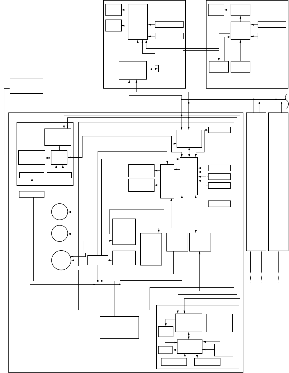
– 38 –
8. CONTROL BLOCK DIAGRAM
8-1. Indoor Control Circuit
Network adapter (Option)
Indoor control P.C. board (MCC-1402)
Display
LED
CPU
EEPROM
TA sensor
Display
LCD
Function setup
Key switch
#1 #3AB
Indoor unit
Main (Sub) master remote controller
Power
circuit
Fan motor
control
circuit
CPU
TMP88CH
47FG
(TMP88PH
47FG)
AC
synchronous
signal input
circuit
Serial
send/
receive
circuit
Run
Warning
Ready
Thermo. ON
Cool
Heat
Fan
Outside
output
Driver
Humidifier
relay output
Remote
controller
communication
circuit
CPU
H8/3039
Remote
controller
communication
circuit
Heater relay
output
TC sensor
TCJ sensor
Float input
Louver
motor
Drain
pump
Indoor
fan
motor
Transformer
Outdoor unit
123
123
Power circuit
DC5V
CPU
LCD
driver
Display
LCD
Function setup
Key switch
Weekly timer
Secondary
battery
DC5V
DC5V
*3
CN2 CN1
AB
123
Outdoor
unit
Same as
the left
*2
#2AB
123
Outdoor
unit
Same as
the left
*2
Max. 8 units are connectable.*1
*1 Max. 7 units when network adapters
are attached
*2 Network adapters are attached to only
one unit.
*3 Weekly timer is not connectable to the
sub remote controller.
Network adapter
P.C. board
(MCC-1401)
Remote
controller
communication
circuit
CPU
H8/3687
AI NET
communication
circuit
Central control
remote controller
(Option)
Power circuit
DC5V
Switch setup
Power
circuit
Power
circuit
Remote
controller
communication
circuit
Temporary
operation SW
Receive circuit
Display LED
Buzzer
Function
setup SW
CPU
Sensor P.C. board (MCC-1418)
Wireless remote controller kit
Option Option
Optional only for 4-way air
discharge cassette type models
DC280V
X
Y
DC20V
DC12V
DC5V
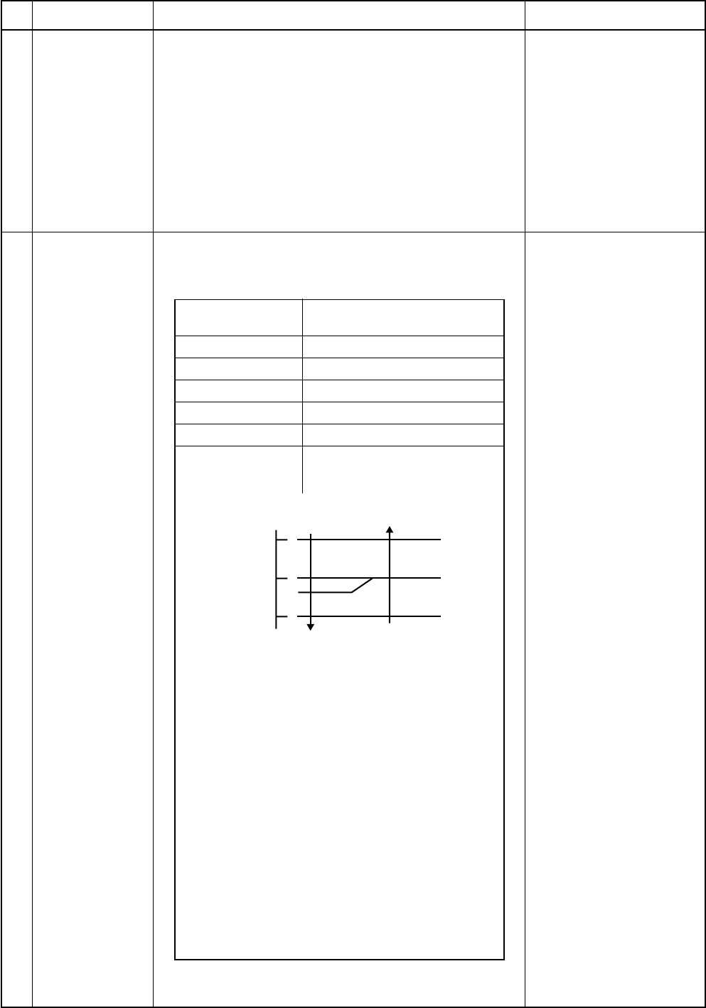
– 39 –
8-2. Control Specifications
No.
1
2
Item
When power
supply is reset
Operation mode
selection
Outline of specifications
1) Distinction of outdoor units
When the power supply is reset, the outdoors are
distinguished, and control is exchanged according to
the distinguished result.
2) Setting of speed of the indoor fan/setting whether to
adjust air direction or not.
(Only 4-way models)
Based on EEPROM data, speed of the indoor fan or
setting whether to adjust air direction or not is se-
lected.
1) Based on the operation mode selecting command
from the remote controller, the operation mode is
selected.
Remarks
Air speed/
Air direction adjustment
Remote controller
command
STOP
FAN
COOL
DRY
HEAT
AUTO
Outline of control
Air conditioner stops.
Fan operation
Cooling operation
Dry operation
Heating operation
• COOL/HEAT operation mode
is automatically selected by Ta
and Ts for operation.
1) Judge the selection of COOL/HEAT mode as shown
in the figure above.
When 10 minutes passed after thermostat had
been turned off, the heating operation (Thermo
OFF) is exchanged to cooling operation if Tsh
exceeds +1.5 or more.
(COOL OFF) and (COOL ON) in the figure indicate
an example.
When 10 minutes passed after thermostat had
been turned off, the cooling operation (Thermo
OFF) is exchanged to heating operation if Tsc
exceeds –1.5 or less.
2) For the automatic capacity control after judgment of
COOL/HEAT, refer to item 4.
3) For the temperature correction of room temperature
control in automatic heating operation, refer to item 3.
Ta : Room temperature
Ts : Setup temperature
Tsc : Setup temperature in
cooling operation
Tsh : Setup temperature
+ Room temperature
control temperature
compensation
+1.5
Tsc
or Tsh
-1.5
Ta
( C) COOL
(COOL ON)
(COOL OFF)
HEAT
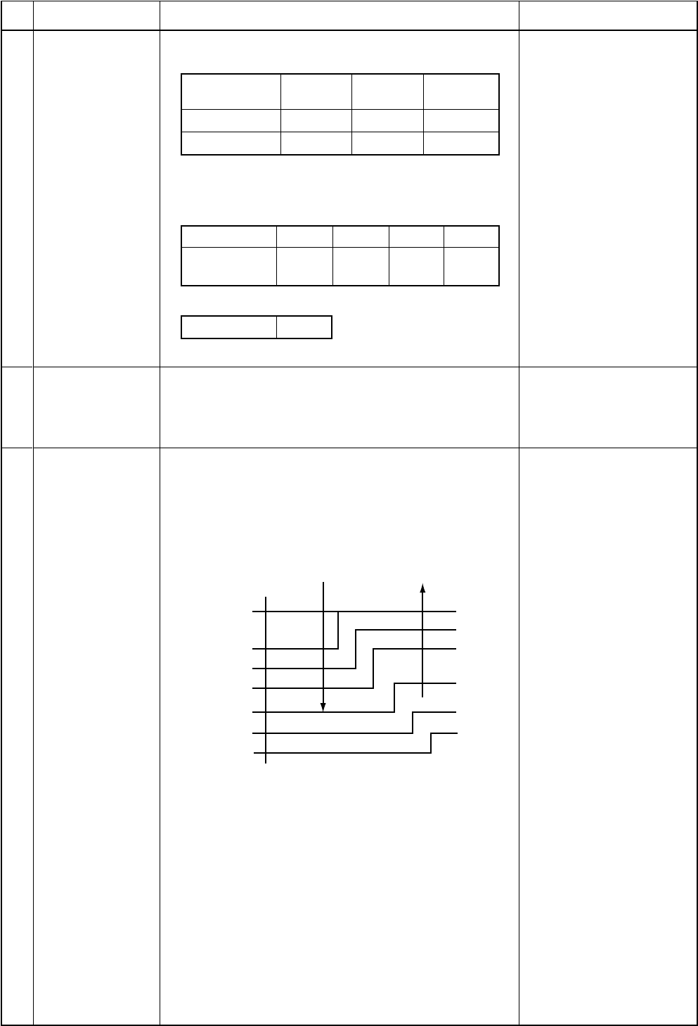
– 40 –
No.
3
Item
Room
temperature
control
Outline of specifications
1) Adjustment range Remote controller setup tem-
perature (°C)
Remarks
Wired type
Wireless type*
COOL/
DRY
18 to 29
18 to 30
Heating
operation
18 to 29
16 to 30
Auto
operation
18 to 29
17 to 27
* : Only for 4-way air discharge cassette type
2) Using the item code 06, the setup temperature in
heating operation can be compensated.
Setup data
Setup temp.
compensation
0246
+0°C +2°C +4°C +6°C
Automatic
capacity control
(GA control)
Setting at shipment
Setup data 2
1) Based on the difference between Ta and Ts, the
operation frequency is instructed to the outdoor unit.
1) Operation with (HH), (H), (L), or [AUTO] mode is
performed by the command from the remote controller.
2) When the air speed mode [AUTO] is selected, the air
speed varies by the difference between Ta and Ts.
<COOL>
HH > H > L > LLAir speed
selection
4
5
Shift of suction tempera-
ture in heating operation
• Controlling operation in case when thermo of remote
controller works is same as a case when thermo of
the body works.
• If the air speed has been changed once, it is not
changed for 3 minutes. However when the air volume
is exchanged, the air speed changes.
• When cooling operation has started, the air speed
selects a downward slope, that is, the high position.
• If the temperature is just on the difference boundary,
the air speed does not change.
• Mode in the parentheses indicates one in automatic
cooling operation.
+3.0
Ta ( C)
E
D
C
B
F
G
A
HH
(HH)
H (HH)
H (HH)
L(H)
L(H)
L(H)
L(L)
+2.0
+2.5
+1.5
+0.5
Tsc
-0.5
+1.0
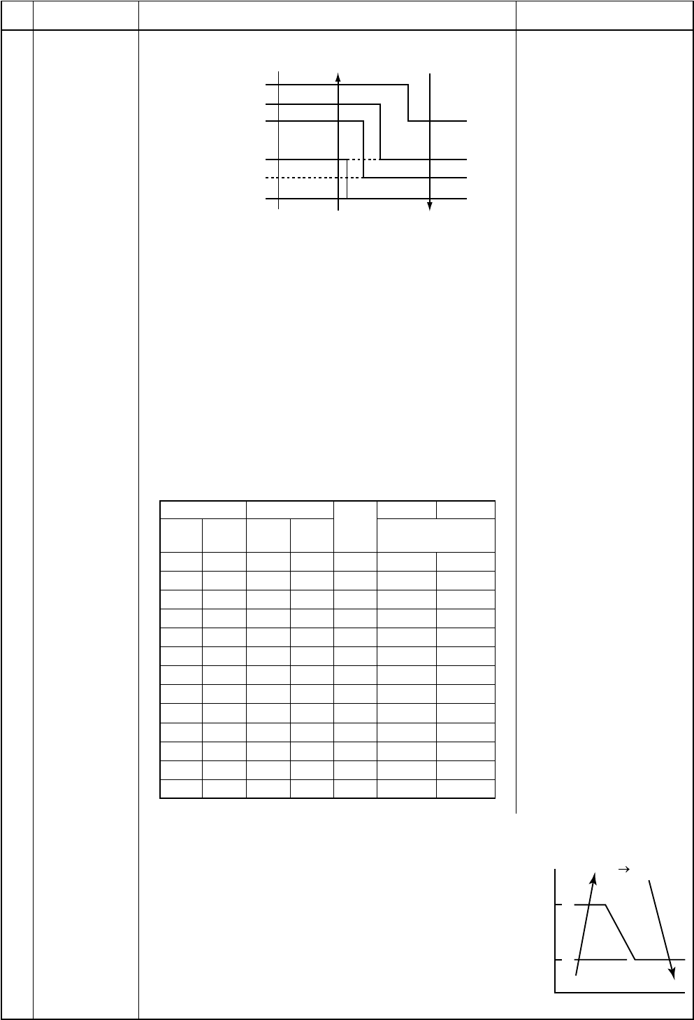
– 41 –
F5 F4
47
42
F5
Tc
( C)
No.
5
Item
Air speed
selection
(Continued)
Outline of specifications
<HEAT>
Remarks
Value in the parentheses indicates one when thermostat of
the remote controller works.
Value without parentheses indicates one when thermostat
of the body works.
•If the air speed has been changed once, it is not
changed for 1 minute. However when the air speed is
exchanged, the air speed changes.
•When heating operation has started, the air speed
selects a upward slope, that is, the high position.
•If the temperature is just on the difference boundary, the
air speed does not change.
•Mode in the parentheses indicates one in automatic
heating operation.
•In Tc ≥ 60°C, the air speed increases by 1 step.
<Operation of duct only>
Tc: Indoor heat exchanger
sensor temperature
Standard
COOL HEAT
UL UL
L
L+ L
L+
M
M
M+ M+
H
H
High ceiling
COOL HEAT
UL UL
LL
L+ L+
M+,M M+,M
HH
Tap
FD
FD
FB
FA
F9
F8
F7
F6
F5
F4
F3
F2
F1
SM560 SM800
Revolutions per
minute (rpm)
320 320
320 330
330 340
350 360
360 370
370 380
400 410
410 440
420 450
440 480
480 500
530 540
580 580
3) In heating operation, the mode changes to [UL] if
thermostat is turned off.
4) If Ta ≥ 25°C when heating operation has started and
when defrost operation has been cleared, it operates
with HIGH (H) mode or (HH) for 1 minute from when Tc
has entered in E zone of cool air discharge preventive
control (Item 6).
5) In automatic cooling/heating operation, the revolution
frequency of [HH] is set larger than that in the standard
cooling/heating operation. However the revolution
frequency is restricted in the automatic heating opera-
tion as shown in the following figure.
–1.0
Ta ( C)
E
D
C
B
A
(-0.5) L(L)
L(H)
H(H)
H
HH
(HH)
(HH)
+1.0
(+0.5)
+2.0
(+1.0)
+3.0
(+1.5)
+4.0
(+2.0)
Tsh
(0)
[PRE-HEAT] display
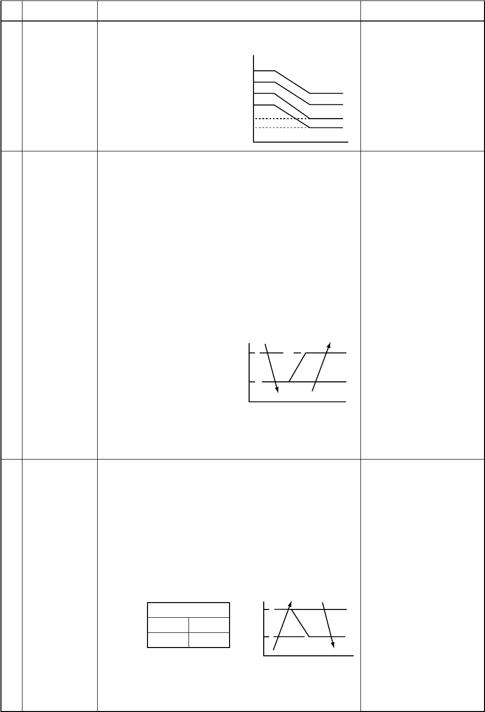
– 42 –
( C)
32
30
28
26
20
16
Tc
Tcj HH
H
L
UL
OFF
E zone
D zone
C zone
B zone
A zone
5
2
A
J
K
I
( C)
A
B
L
N
M
( C)Tc
Tcj
No.
6
Item
Cool air
discharge
preventive
control
Outline of specifications
1) In heating operation, the indoor fan is controlled based
on the detected temperature of Tc sensor or Tcj sensor.
As shown below, the
upper limit of the
revolution frequency
is determined.
Remarks
In D or E zone, the priority
is given to setup of air
volume exchange.
In A and B zones,
[PRE-HEAT] is displayed.
1) The cooling operation (including Dry operation) is
performed as follows based on the detected tempera-
ture of Tc sensor or Tcj sensor.
When [J] zone is detected for 6 minutes (Following
figure), the commanded frequency is decreased from
the real operation frequency. After then the commanded
frequency changes every 30 seconds while operation is
performed in [J] zone.
In [K] zone, time counting is interrupted and the opera-
tion is held.
When [I] zone is detected, the timer is cleared and the
operation returns to the normal operation.
If the commanded frequency becomes S0 because the
operation continues in [J] zone, the return temperature
A is raised from 5°C to 12°C until [I] zone is detected
and the indoor fan
operates with [M] mode.
In heating operation, the freeze-preventive control
works if 4-way valve is not exchanged and the condition
is satisfied. (However the temperature for J zone
dashing control is changed from 2°C to –5°C.)
7
8
Freeze preven-
tive control
(Low tempera-
ture release)
Tcj : Indoor heat ex-
changer sensor
temperature
High-temp
release control 1) The heating operation is performed as follows based on
the detected temperature of Tc sensor or Tcj sensor.
•When [M] zone is detected, the commanded fre-
quency is decreased from the real operation fre-
quency. After then the commanded frequency
changes every 30 seconds while operation is per-
formed in [M] zone.
•In [N] zone, the commanded frequency is held.
•When [L] zone is detected, the commanded fre-
quency is returned to the original value by approx.
6Hz every 60 seconds.
Setup at
shipment
Same when thermostat is
turned off.
Control temp (°C)
AB
56 (54) 52 (52)
NOTE :
When the operation has started or when Tc or Tcj became
lower than 30°C after start of the operation, temperature is
controlled between values in parentheses of A and B.
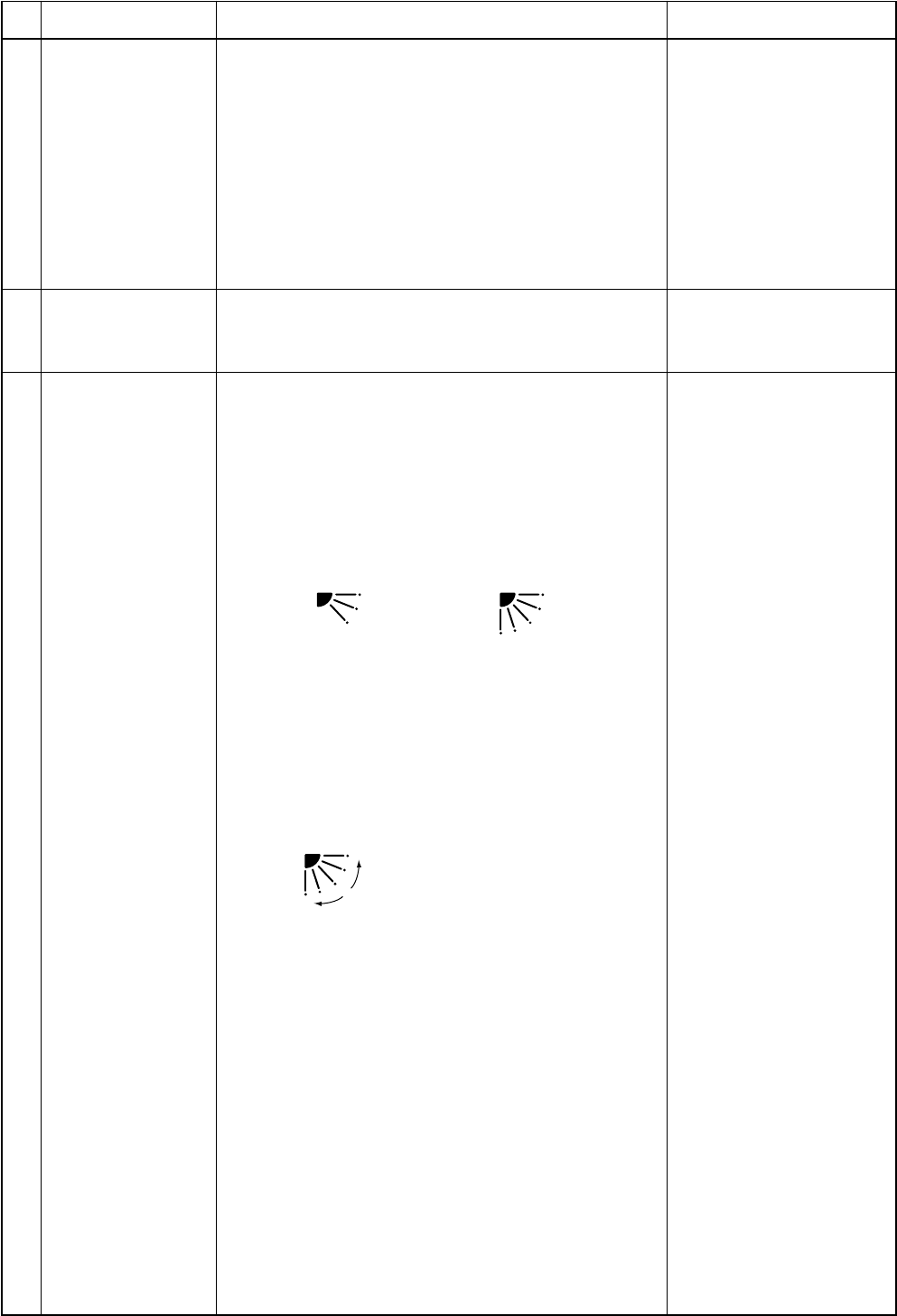
– 43 –
No.
9
Item
Drain pump control
(For the duct, when
the drain-up kit
(sold separately) is
mounted)
Outline of specifications
1) In cooling operation (including Dry operation), the
drain pump is usually operated.
2) If the float switch operates while drain pump
operates, the compressor stops, the drain pump
continues the operation, and a check code is
output.
3) If the float switch operates while drain pump stops,
the compressor stops and the drain pump oper-
ates. If the float switch keeps operating for approx.
4 minutes, a check code is output.
Remarks
Check code [P10]
When heating operation stops, the indoor fan operates
with LOW mode for approx. 30 seconds.
10
11
After-heat elimina-
tion
All modes
• In group twin/triple operation, the swinging
positions can be set up collectively or individu-
ally.
3) When the unit stops or when a warning is output,
the flap automatically moves downward.
4) While the heating operation is ready, the flap
automatically moves upward.
1) Flap position setup
• When the flap position is changed, the position
moves necessarily to downward discharge
position once to return to the set position.
• The flap position can be set up in the following
operation range.
Flap control
(For 4-way air
discharge cassette
type only)
Warning :
A check code is displayed
on the remote controller,
and the indoor unit stops.
(Excluding [F08] and
[L31])
In cooling/dry operation In heating/fan operation
• In group twin/triple operation, the flap positions
can be set up collectively or individually.
2) Swing setup
• The swinging position can be moved in the
following operation range.

– 44 –
No.
12
Item
Frequency fixed
operation
(Test run)
Outline of specifications
<In case of wired remote controller>
1. When pushing [CHECK] button for 4 seconds or more,
[TEST] is displayed on the display screen and the
mode enters in Test run mode.
2. Push [ON/OFF] button.
3. Using [MODE] button, change the mode from [COOL]
to [HEAT].
•Do not use other mode than [COOL]/[HEAT] mode.
•During test run operation, the temperature cannot be
adjusted.
•An error is detected as usual.
•A frequency fixed operation is performed.
4. After the test run, push [ON/OFF] button to stop the
operation. (Display in the display part is same as the
procedure in item 1).)
5. Push [CHECK] button to clear the test run mode.
([TEST] display in the display part disappears and the
status returns to the normal stop status.)
<In case of wireless remote controller>
(Option for 4-way air discharge cassette type only)
1. Turn off the power of the set.
Remove the adjuster with sensors from the ceiling
panel.
2. Turn Bit [1: TEST] of sensor P.C. board switch [S003]
from OFF to ON.
Attach the sensor P.C. board cover and mount the
adjuster with sensors to the ceiling panel.
Turn on the power of the set.
3. Push [ON/OFF] button of the wireless remote controller
and set the operation mode to [COOL] or [HEAT] using
[MODE] button.
(During test run operation, all the display lamps of
wireless remote controller sensors flash.)
•Do not use other mode than [COOL]/[HEAT] mode.
•An error is detected as usual.
•A frequency fixed operation is performed.
4. After the test run, push [ON/OFF] button to stop the
operation.
5. Turn off the power of the set.
Turn Bit [1: TEST] of sensor P.C. board switch [S003]
from ON to OFF.
Mount the adjuster with sensors to the ceiling panel.
Remarks
1) The operation time of the indoor fan is calculated, the
filter reset signal is sent to the remote controller when
the specified time (2500H) has passed, and it is
displayed on LCD.
2) When the filter reset signal has been received from the
remote controller, time of the calculation timer is
cleared. In this case, the measurement time is reset if
the specified time has passed, and display on LCD
disappears.
13 Filter sign display
(Except wireless
type)
[FILTER] goes on.
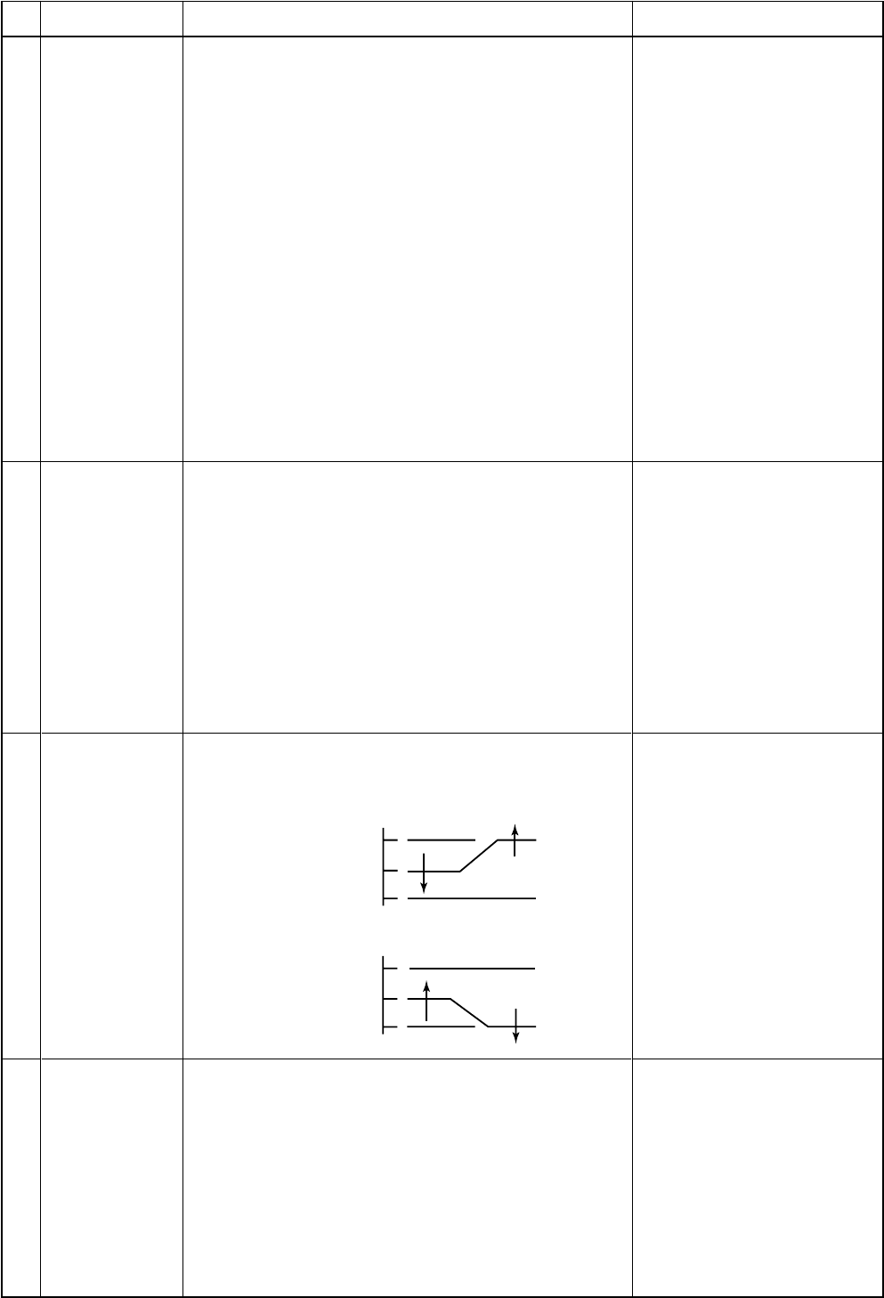
– 45 –
No.
14
Item
Central control
mode selection
Outline of specifications
1) Setting at the central controller side enables to select
the contents which can be operated on the remote
controller at indoor unit side.
2) RBC-AMT21
[Last push priority] :
The operation contents can be selected from both
remote controller and central controller of the indoor
unit side, and the operation is performed with the
contents selected at the last.
[Center] :
Start/Stop operation only can be handled on the
remote controller at indoor unit side.
[Operation Prohibited] :
It cannot be operated on the remote controller at
indoor unit side. (Stop status is held.)
Remarks
(No display)
[CENTER] goes on.
[CENTER] goes on.
In a case of wireless type, the
display lamp does not change.
However, contents which can be
operated are same.
The status set in [CENTER]/
[Operation Prohibited] mode is
notified with the receiving sound
“Pi, Pi, Pi, Pi, Pi” (5 times).
15
16
17
Energy-save
control
(By connected
outdoor unit)
Max. frequency
cut control
DC motor
(For 4-way air
discharge
cassette type
only)
1) Selecting [AUTO] mode enables an energy-saving to
be operated.
2) The setup temperature is shifted (corrected) in the
range not to lose the comfort ability according to input
values of various sensors.
3) Data (Input value room temp. Ta, Outside temp. To, Air
volume, Indoor heat exchanger sensor temp. Tc) for
20 minutes are taken the average to calculate
correction value of the setup temperature.
4) The setup temperature is shifted every 20 minutes,
and the shifted range is as follows.
In cooling time : +1.5 to –1.0K
In heating time : –1.5 to +1.0K
1) This control is operated by selecting [AUTO] opera-
tion mode.
2) COOL operation mode: the frequency is controlled
according to
the following
figure if
To < 28°C.
1) When the fan operation has started, positioning of the
stator and the rotor are performed.
(Moves slightly with tap sound)
2) The motor operates according to the command from
the indoor controller.
NOTES :
•When the fan rotates while the air conditioner stops
due to entering of outside air, etc, the air conditioner
may operated while the fan motor stops.
•When a fan locking is found, the air conditioner stops,
and an error is displayed.
3) HEAT operation mode: the frequency is controlled
according to
the right
figure if
To > 15°C.
Check code [P12]
+4
+3
Tsc
Ta( C) Normal control
Max. frequency is restricted
to approximately the rated
cooling frequency
Tsh
–3
–4
Ta( C)
Normal control
Max. frequency is restricted
to approximately the rated
heating frequency
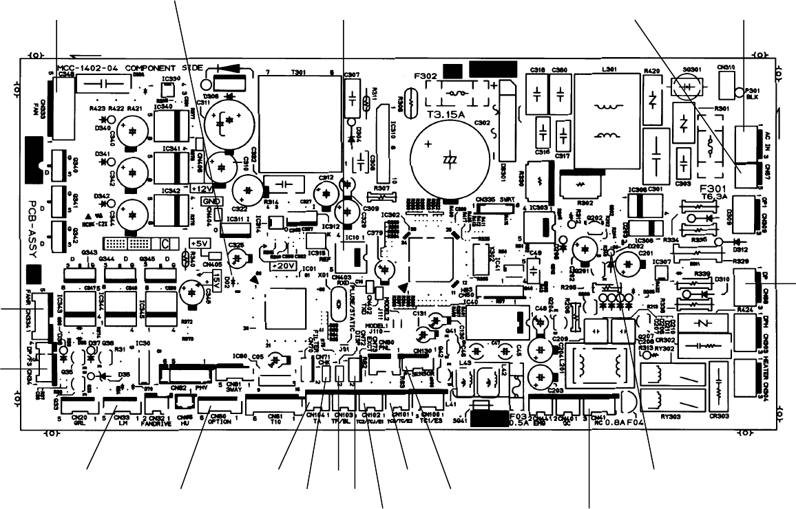
– 46 –
8-3. Indoor Print Circuit Board
4-Way Air Discharge Cassette Type
RAV-SM560UT-E/RAV-SM800UT-E
<MCC-1402>
Microcomputer operation LED
EEPROM Network adapter
power supply Indoor/Outdoor
inter-unit cable
Remote controller power LED
Drain pump output
Remote controller inter-unit cable
EXCT Outside error input
TC sensor
TCJ sensor
DISP
CHK
TA sensor
Optional output
Louver
Float SW
DC fan return
DC fan output
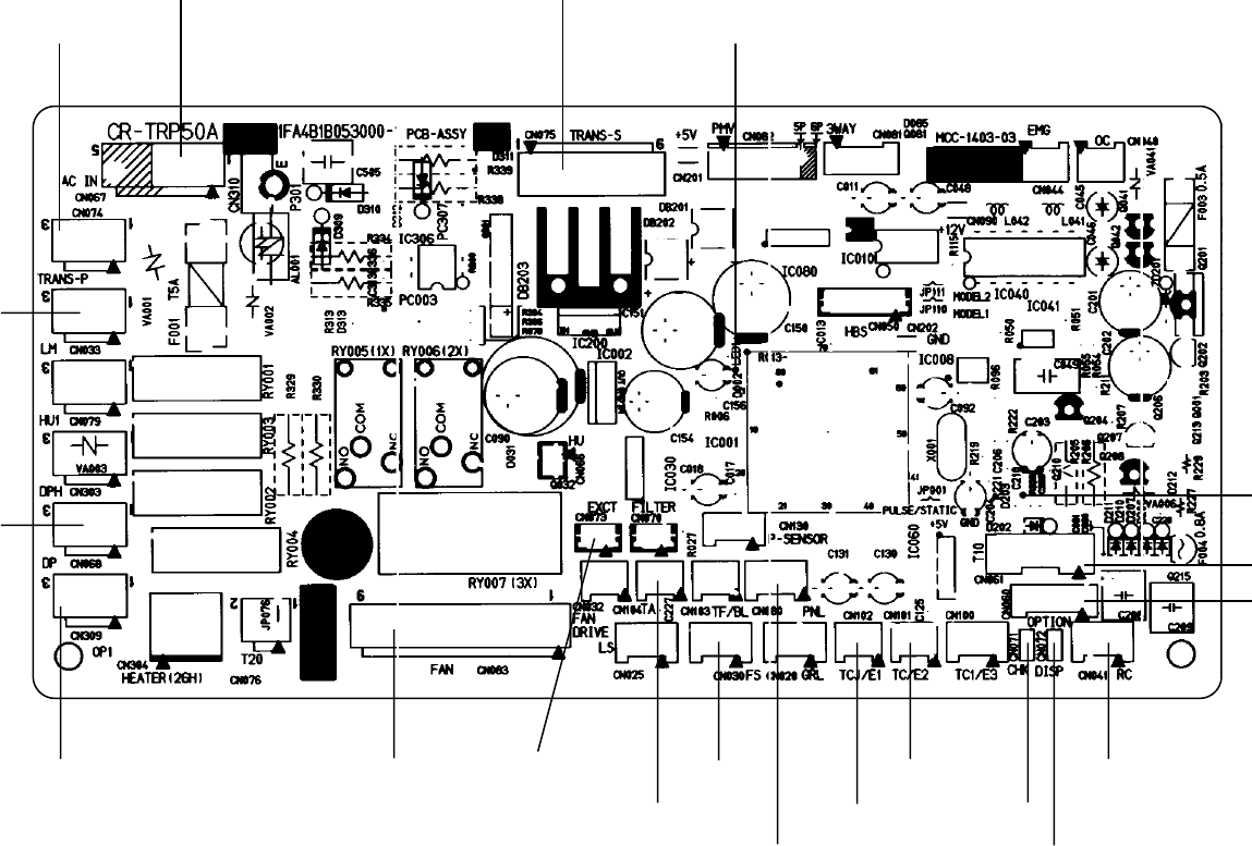
– 47 –
Concealed Duct Type
RAV-SM560BT-E/RAV-SM800BT-E
<MCC-1403>
Indoor/Outdoor inter-unit cable Power transformer input (AC11V,14V,20V)
Microcomputer operation LED
Power transformer output
Louver
Drain pump
output
Network adapter
power supply Fan output
TA sensor
EXCT Float SW
Outside error input
TCJ sensor
TCsensor
CHK
Remote controller
inter-unit cable
DISP
Optional output
HA
Remote controller
power LED
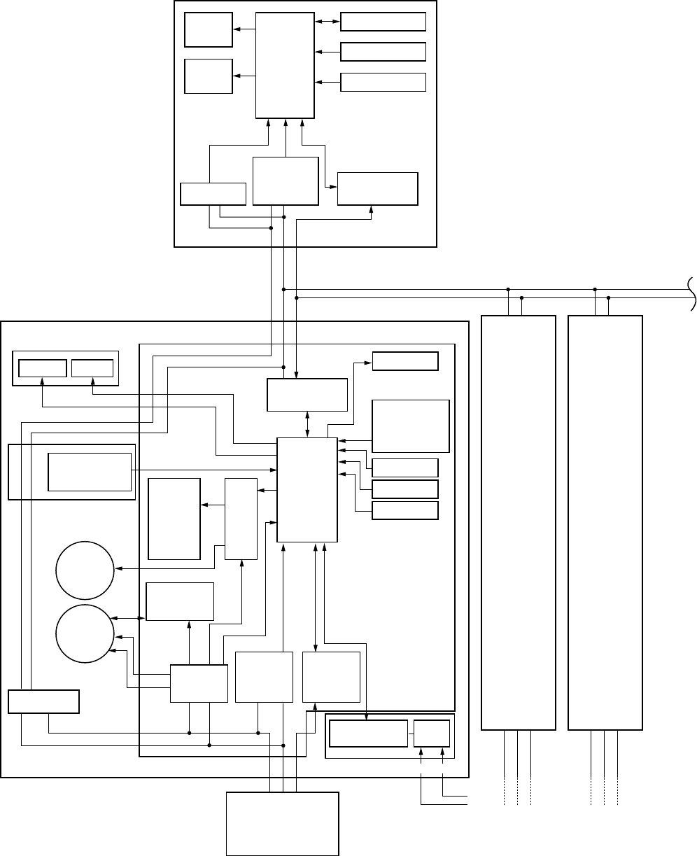
– 48 –
9. CIRCUIT CONFIGURATION AND CONTROL SPECIFICATIONS
9-1. Microcomputer System Block Diagram
9-1-1. Connection of Main Remote Controller
Main (Sub) master remote controller
Sensor display P.C. board
(MCC-819) Main P.C. board (MCC-1370A)
Display
LED
CPU EEPROM
EEPROM
TA sensor
TMP47C
820F
Display
LCD Function setup
Key switch
Sensors LED
TA shift setup
Model selection
Function setup
Remote controller
No. setupTwin/
Triple setup
Sub P.C. board
(MCC-1370B)
#1 #2
BC
Indoor unit
Optional
output
Comp.
Run
Error
Heat
Power
circuit
DC15V
DC
5V
DC
12V
AC
synchronous
signal input
circuit
Serial
send/
receive
circuit
Communication
LSI
Pulse
trans
Indoor fan
control circuit
Driver
CPU
Serial send/
receive circuit
Serial send/
receive circuit
AC
synchronous
signal input
circuit
TMP87CM
40AN
(TMP87PM
40AN)
TC sensor
TCJ sensor
Louver
motor
Indoor
fan
motor
Transformer
XY
Communication P.C. board (Option)
MCC-1337
Outdoor unit
123
123
DC310~340V
Power circuit
ABC
ABC
123
Outdoor
unit
Same as
the left
#3
BC
123
Outdoor
unit
Same as
the left
Max. 16 units are connectable.
The P.C. boards of the indoor unit are
classified into 4 boards according to the
function.
1. Main P.C. board (MCC-1370A)
Controller for power circuit, fan motor
driver, and whole unit
2. Sub P.C. board (MCC-1370B)
Setup of unit No. and concurrent twin
* The sub P.C. board is located near the
remote controller terminal block.
3. Sensor display P.C. board (MCC-819)
Wireless remote controller receive part,
LED display part
4. Communication P.C. board (MCC-1337)
Communication part with the central
control remote controller (Option)
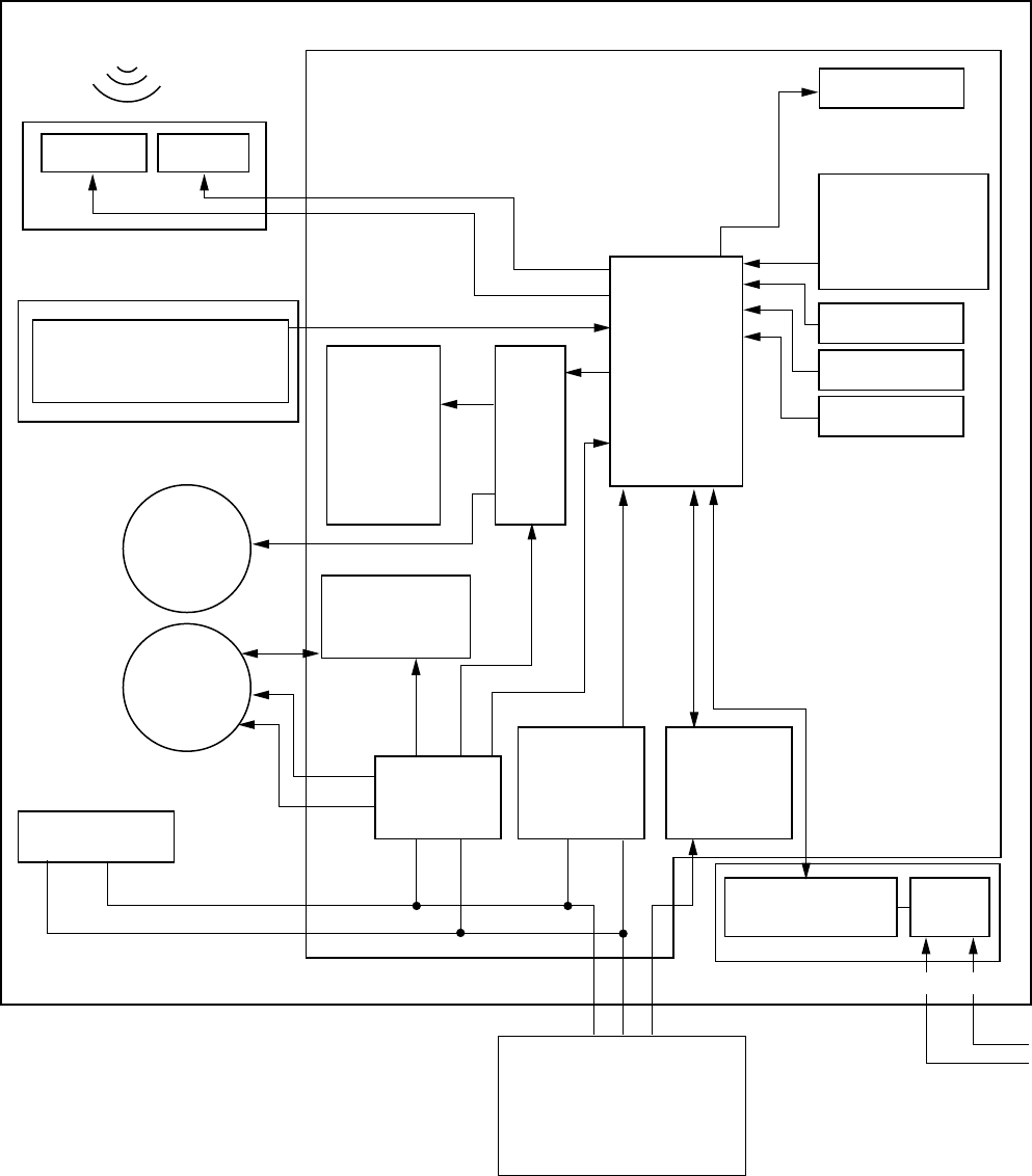
– 49 –
9-1-2. Connection of Wireless Remote Controller
Main P.C. board (MCC-1370A)
EEPROM
TA sensor
Sensors LED
TA shift setup
Model selection
Function setup
Remote controller
No. setupTwin/
Triple setup
Sub P.C. board(MCC-1370B)
#1
Indoor unit
Optional
output
Comp.
Run
Error
Heat
Power
circuit
DC15V
DC
5V
123
123
DC
12V
AC
synchronous
signal input
circuit
Serial
send/
receive
circuit
Communication
LSI
Pulse
trans
Indoor fan
control circuit
Driver
CPU
TMP87CM
40AN
(TMP87PM
40AN)
TC sensor
TCJ sensor
Louver
motor
Indoor
fan
motor
Transformer
XY
Communication P.C. board (Option)
MCC-1337
Outdoor unit
DC310~340V
Infrared radiation
Sensor display
P.C. board
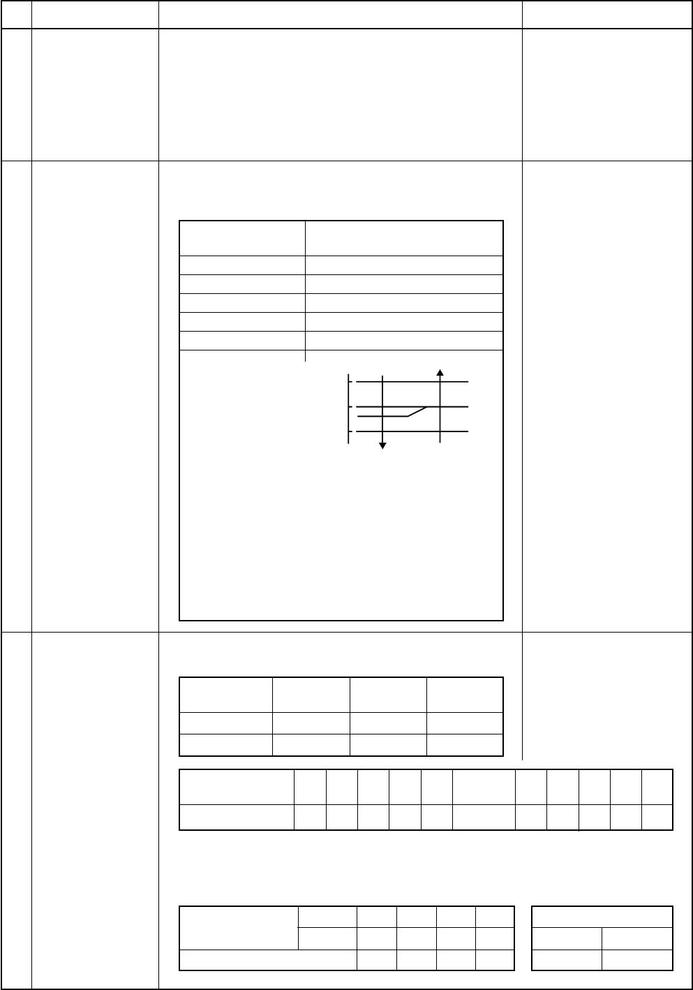
– 50 –
9-1-3. Control Specifications
No.
1
Item
When power
supply is reset
Outline of specifications
1) Distinction of outdoor units
When the power supply is reset, the outdoors are
distinguished, and control is exchanged according to
the distinguished result.
2) Setting of the indoor fan speed
Based on EEPROM data, rspeed of the indoor fan is
selected.
1) Based on the operation mode selecting command
from the remote controller, the operation mode is
selected.
Remarks
Air speed
Remote controller
command
STOP
FAN
COOL
DRY
HEAT
AUTO
Outline of control
Air conditioner stops.
Fan operation
Cooling operation
Dry operation
Heating operation
1) Judge the selection of COOL/HEAT mode as shown in the
figure below.
When the heating operation (Thermo OFF) is exchanged
to cooling operation if Tsh exceeds +3 or more.
(COOL OFF) and (COOL ON) in the figure indicate an
example.
When the cooling operation (Thermo OFF) is exchanged
to heating operation if Tsc exceeds -3 or less.
2) For the automatic capacity control after judgment of
COOL/HEAT, refer to item 4.
3) For the temperature correction of room temperature control
in automatic heating operation, refer to item 3.
Ta : Room temperature
Ts : Setup temperature
Tsc : Setup temperature
in cooling operation
Tsh : Setup temperature
in heating operation
1) Adjustment range Remote controller setup tempera-
ture (°C)
2
3
Operation mode
selection
Room tempera-
ture control
Standard type
Wireless type
COOL/
DRY
18 to 29
17 to 30
Heating
operation
18 to 29
17 to 30
Auto
operation
18 to 29
19 to 29
Remote controller
setup temp
Setup temp (°C)
▼5▼4▼3▼2▼1
19 20 21 22 23
Standard
24
▲1▲2▲3▲4▲5
25 26 27 28 29
2) Differential 1K (=deg)
3) In heating operation, the setup temperature can be
corrected by using Dip switch (SW03) on the indoor
P.C. board. Setup at shipment
Max. setup temperature
Ts (Max) = 35°C
SW03 1
2
Setup temp correction
ON ON OFF OFF
ON OFF ON OFF
+0°C+2°C+4°C+6°C
SW03
12
ON OFF
Ta
( C)
+3
Tsc
or Tsh
–3
Heating
COOL
(COOL ON)
(COOL OFF)
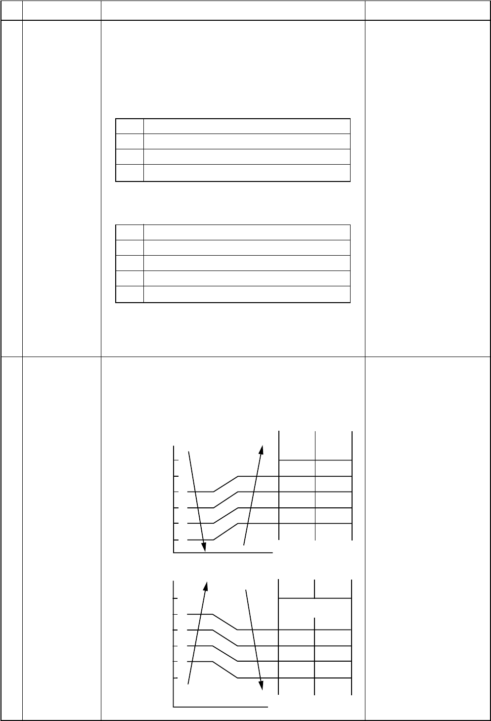
– 51 –
No.
4
Item
Automatic
capacity control
(GA control)
Outline of specifications
1) Based on the difference between Ta and Ts, the
operation frequency is instructed to the outdoor unit.
NOTE :
In cooling operation :
When calculating the following conditions for 29 minutes,
the commanded frequency is assumed as the rated
cooling frequency.
Remarks
5
1
2
3
4
Ta < 28°C
Indoor fan [High]
32°C < To ≤ 38°C or no To
Operation exceeding the rated cooling frequency
In heating operation: When calculating the following
conditions for 29 minutes, the commanded frequency is
assumed as the rated heating frequency.
1
2
3
4
5
Ta ≥ 19°C
Indoor fan [High]
5°C < To ≤ 10°C or no To
Operation exceeding the rated heating frequency
Tc ≥ 38°C
NOTE :
When air volume is set to [L], the maximum frequency is
restricted.
Tc : Temperature of indoor
heat exchanger
sensor
1) Operation with [HIGH (H)], [MED (M)], [LOW (L)], or
[AUTO] mode is performed by the command from the
remote controller.
2) When the air volume mode [AUTO] is selected, the air
volume varies by the difference between Ta and Ts.
<COOL>
Air volume
control
UH > H > M+ > M > L + >
L > UL
<HEAT>
+1.5
+1.0
+0.5
Tsc
–
0.5
Ta
H
M+
M
L+
L
H
M+
M+
M
L+
( C)
Normal
cooling
Cooling of
Auto
cooling/
heating
(HIGH)
(MED)
(HIGH)
(MED)
(LOW)
H
L+
L
M+
M
H
UH
M
L+
M+
M+
+0.5
Tsc
–
0.5
–
1.0
–
1.5
Ta
( C)
Normal
heating
Heatiing of
Auto
cooling/
heating
(HIGH)
(MED)
(MED)
UL (Ultra Low)
only in Comp OFF
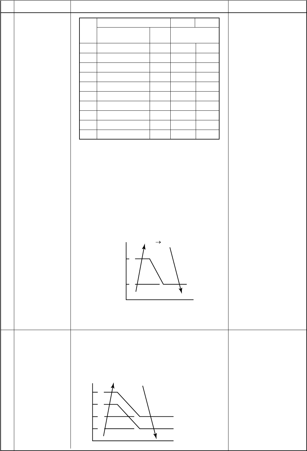
– 52 –
No.
5
Item
Air volume control
(Continued)
Outline of specifications Remarks
6
Tap
F4
F5
F6
F7
F8
F9
FA
FB
FC
FD
Air volume setup
COOL, DRY, FAN HEAT
UH
H
H
M+ M+
M
M
L+
L+ L
L
UL
SM560 SM800
Revolutions per
minute (rpm)
1290 1480
1230 1480
1180 1340
1150 1320
1120 1310
1060 1200
1060 1200
990 1100
940 1040
900 900
3) In heating operation, the mode changes to [Ultra
Low (UL)] or [STOP] if thermostat is turned off.
4) If Ta ≥ 25°C when heating operation has started and
when defrost operation has been cleared, it oper-
ates with MED mode or higher mode for 1 minute
from when Tc has entered in A zone of cool air
discharge preventive control (Item 6).
5) In automatic cooling/heating operation, the revolu-
tion frequency of [HIGH (H)] is set larger than that in
the standard cooling/heating operation. However the
revolution frequency is restricted in the automatic
heating operation as shown in the following figure.
“Stop” is a “cool air
discharge preventive
control” operation by Tc.
Tc: Indoor heat exchanger
sensor temp.
Display: [AUTO]
6) (For wireless type only) The mode enters [AUTO] in
automatic cooling/heating operation.
7) The mode enters [LOW (L)] during Dry operation
1) In heating operation, the indoor fan is controlled
based on the detected temperature of Tc sensor.
As shown below, the upper limit of the revolution
frequency is determined.
A zone : Setup air volume
from remote
controller
B zone : Low air
C zone : OFF
Cool air discharge
preventive control
Display in C zone
Display of main unit:
Defrost LED goes on.
When wired remote
controller is installed:
PRE-HEAT/DEFROST
goes on remote controller.
F5 F4
47
42
F4
Tc
( C)
30
26
20
16
Tc( C) A
BC
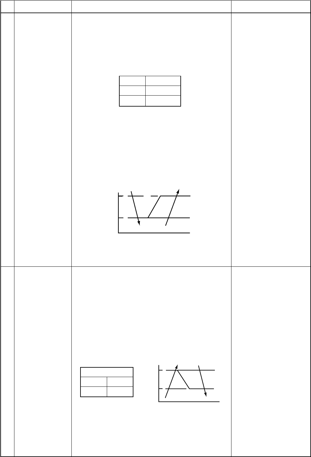
– 53 –
No.
7
Item
Freeze preventive
control
(Low temperature
release)
Outline of specifications
1) The cooling operation (including Dry operation) is
performed as follows based on the detected tem-
perature of Tc sensor or Tcj sensor.
When [J] zone is detected for T1 minutes (Following
figure), the commanded frequency is decreased
from the real operation frequency. After then the
commanded frequency changes every 30 seconds
while operation is performed in [J] zone.
Remarks
Tcj : Indoor heat
exchanger sensor
temperature
8
Normal
Twin
T1
6 minutes
6 minutes
In [K] zone, time counting is interrupted and the
operation is held.
When [I] zone is detected, the timer is cleared and
the operation returns to the normal operation.
If the commanded frequency becomes S0 because
the operation continues in [J] zone, the return
temperature A is raised from 5°C to 12°C until [I]
zone is detected and the indoor fan operates with [L]
mode.
In heating operation, the freeze-preventive control
works if 4-way valve is not exchanged and the
condition is satisfied.
High-temp release
control 1) The heating operation is performed as follows based
on the detected temperature of Tc sensor.
•When [M] zone is detected, the commanded
frequency is decreased from the real operation
frequency. After then the commanded frequency
changes every 30 seconds while operation is
performed in [M] zone.
•In [N] zone, the commanded frequency is held.
•When [L] zone is detected, the commanded
frequency is returned to the original value by
approx. 6Hz every 60 seconds.
Setup at shipment
Control temp (°C)
AB
56 (54) 52 (52)
NOTE :
When the operation has started or when Tc became
lower than 30°C after start of the operation, tempera-
ture is controlled between values in parentheses of A
and B.
Same when thermostat is
turned off.
5
2
K
I
J
A
( C)
A
B
L
N
M
Tc ( C)
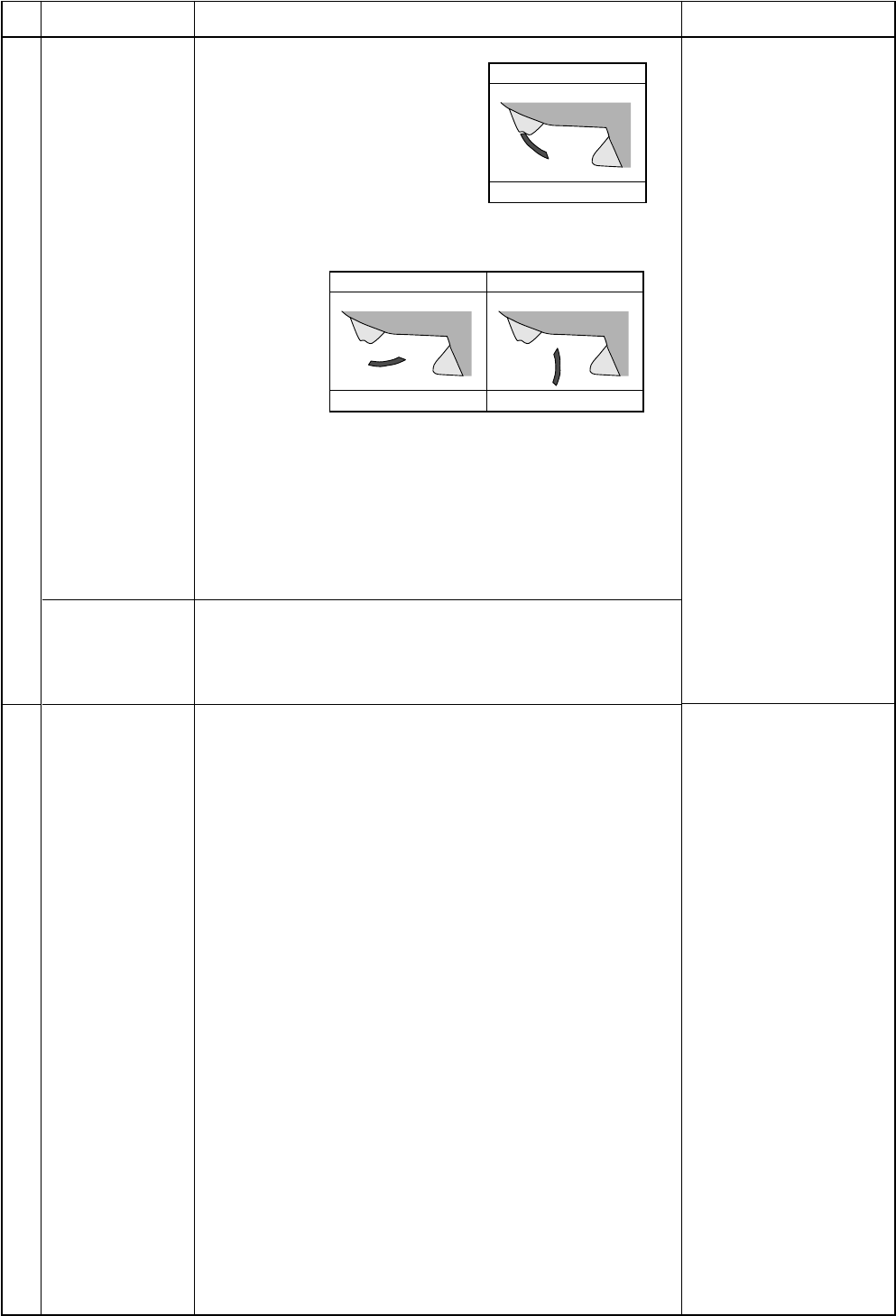
– 54 –
No.
9
Item
Louver control
1) Louver
position
Outline of specifications
The louver angle is displayed
setting 0° as “Full close”.
Remarks
10
1) In the initial operation after
power-ON, the position is
automatically controlled according to the operating
status (COOL/HEAT).
2) After then a louver position is stored in the microcom-
puter every time when position is operated on the
remote controller, and the louver operates at the position
stored in memory in the next operation and after.
* If the operation mode has been changed from COOL
to HEAT, from HEAT to COOL, or the power has
turned off, the stored louver position is cleared and
the status returns to one in item 1).
2) Air direction
adjustment
(Swing
operation)
Frequency fixed
operation
(Test run) [COOL]/[HEAT] flash.
Air volume: [AUTO]
Temperature
COOL: [L]
HEAT: [H]
Commanded frequency
Approximately [S7]
1) In case of wired remote controller
1. When pushing [ON/OFF] button on the remote
controller continuously for 5 seconds, the mode
enters [TEST]. The indoor fan rotates with [HIGH]
and a frequency fixed operation starts.
2. During this operation, the buttons other than [ON/
OFF], [UP △] and [DOWN ▽] cannot be accepted.
However, items 7 and 8 are effective.
3. To stop the frequency fixed operation, use [ON/OFF]
button only.
2) In case of wireless remote controller (Without wired
remote controller)
1. When pushing [Temporary] button continuously for
10 seconds or more, “Pi” sound is heard and the
mode enters [TEST]. The indoor fan rotates with
[HIGH] and a frequency fixed operation of [COOL]
starts.
NOTES :
•Temporary button is provided to near the display part of
the main unit when opening the front panel.
•If [Temporary] button is not continuously pushed for 10
seconds, “Automatic heating/cooling operation” is
performed.
2. To stop the operation, push [Temporary] button again.
NOTE :
Operation on the wireless remote controller is not ac-
cepted.
1) When pushing [LOUVER] button during operation, the
louver starts swinging.
2) When the louver has arrived at the desired position, push
[LOUVER] again. The louver stops at that position.
0
Full close
45 103
Cooling Heating
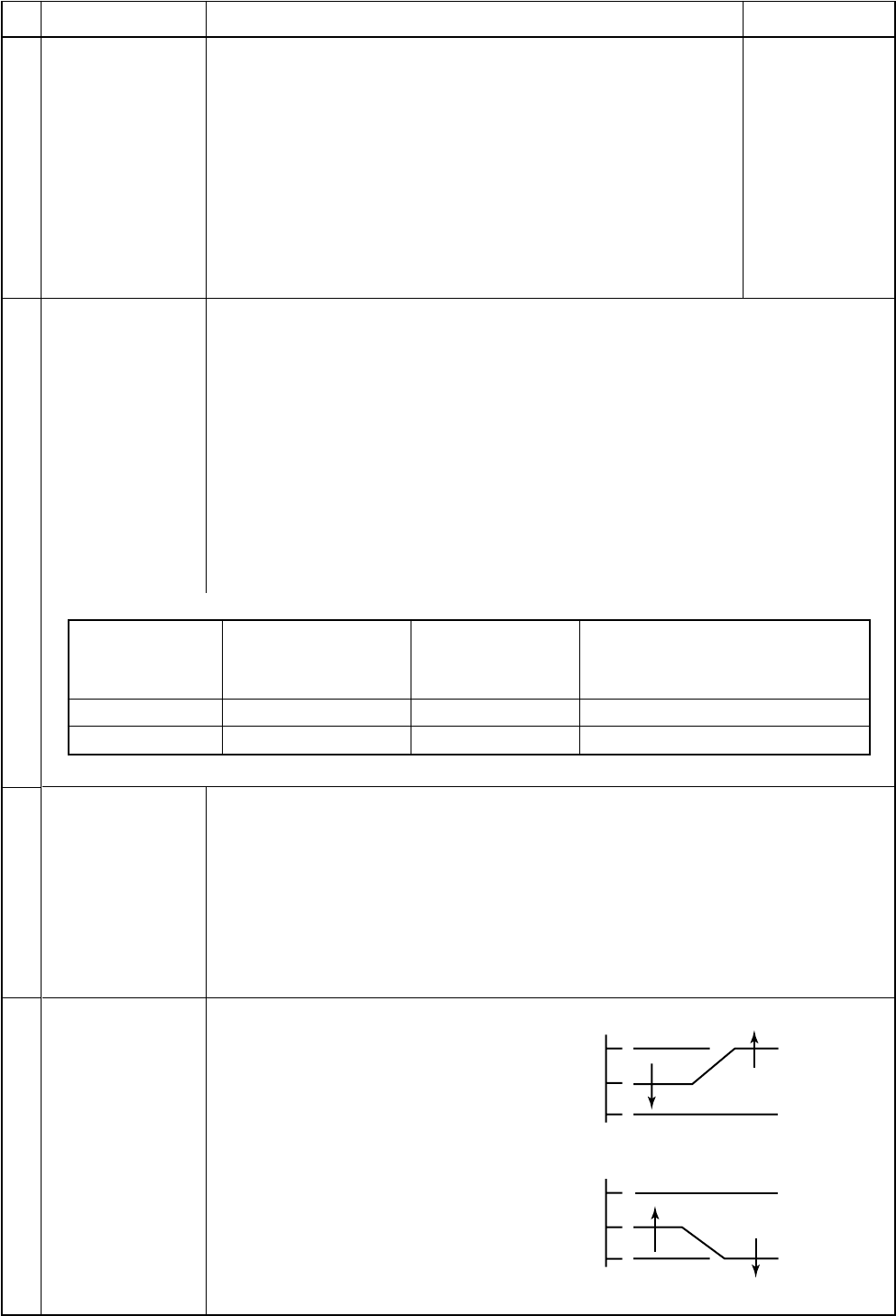
– 55 –
No.
11
Item
Filter sign display
Outline of specifications
1) The operation time of the indoor fan is calculated, the filter
lamp (Orange) on the display part of the main unit goes on
when the specified time (240H) has passed. When a wired
remote controller is connected, the filter reset signal is sent to
the remote controller, and also it is displayed on LCD of the
wired remote controller.
2) When the filter reset signal has been received from the wired
remote controller after [FILTER] lamp has gone on or when
the filter check button (Temporary button) is pushed, time of
the calculation timer is cleared. In this case, the measurement
time is reset if the specified time has passed, and display on
LCD and the display on the main unit disappear.
Remarks
[FILTER] goes
on.
12
13
14
Setup on central
control remote
controller
Last push priority
Center
Operation prohibited
Display on wired remote
controller
(In case of RBC-AM1)
[Central control] goes off.
[Central control] goes on.
[Central control] flashes.
Display on wired
remote controller
(In case of RBC-AM1)
[Center] goes off.
[Center] goes on.
[Center] flashes.
Display on main unit
(Only in case of no wired remote
controller)
No display
[DEFROST] lamp (Orange) 1Hz flashes.
[DEFROST] lamp (Orange) 5Hz flashes.
1) Setting at the central remote controller side enables to select the contents which
can be operated on the remote controller at indoor unit side.
2) Operation contents on the remote controller at indoor unit side
[Last push priority] :
The operation contents can be selected from both remote controller and the
central controller of the indoor unit side, and the operation is performed with the
contents selected at the last.
[Center] :
Start/Stop operation only can be handled on the remote controller at indoor unit
side.
[Operation Prohibited] :
It cannot be operated on the remote controller at indoor unit side.
(Stop status is held.)
3) Display on the display part of the main unit or wired remote controller
Energy-save
control
(By connected
outdoor unit)
NOTE : When a wired remote controller is connected, there is no display on the main unit.
1) Selecting [AUTO] mode enables an energy-saving to be operated.
2) The setup temperature is shifted (corrected) in the range not to lose the comfort
ability according to input values of various sensors.
3) Data (Input value room temp. Ta, Outside temp. To, Air volume, Indoor heat
exchanger sensor temp. Tc) for 20 minutes are taken the average to calculate
correction value of the setup temperature.
4) The setup temperature is shifted every 20 minutes, and the shifted range is as
follows. In cooling time : +1.5 to –1.0K
In heating time : –1.5 to +1.0K
1) This control is operated by selecting
[AUTO] operation mode.
2) COOL operation mode: the fre-
quency is controlled according to the
following figure if To < 28°C.
Max. frequency
cut control
3) HEAT operation mode: the frequency
is controlled according to the right
figure if To > 15°C.
Central control
mode selection
+4
+3
Tsc
Tsh
-3
-4
Ta( C)
Ta( C)
Normal control
Normal control
Max. frequency is restricted
to approximately the rated
cooling frequency
Max. frequency is restricted
to approximately the rated
heating frequency
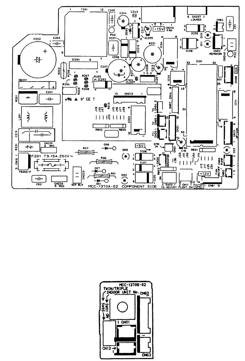
– 56 –
9-2. Indoor Control Circuit
9-2-1. Print Circuit Board
<Main P.C. board (MCC-1370A)>
<Sub P.C. board (MCC-1370B)>
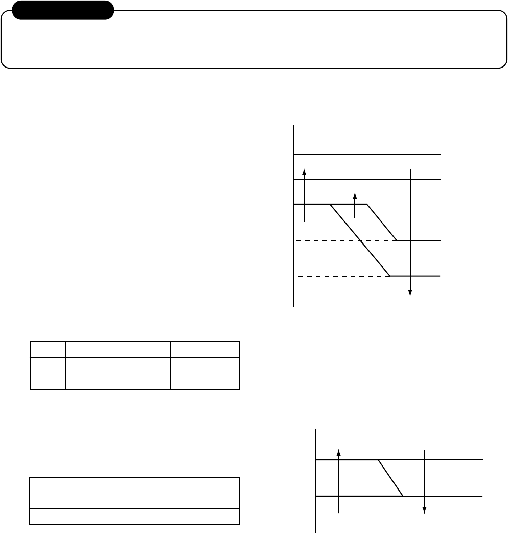
– 57 –
9-2-2. Outline of Main Controls
1. Pulse Modulating Valve (PMV) control
1) For PMV, SM560 is controlled with 45 to 500 pulses and SM800 with 50 to 500 pulses during operation,
respectively.
2) In cooling operation, PMV is controlled with the temperature difference between TS sensor and TC
sensor.
3) In heating operation, PMV is controlled with the temperature difference between TS sensor and TE
sensor.
4) For the temperature difference in items 2) and 3), 1 to 5K is aimed as the target in both cooling and
heating operations.
5) When the cycle excessively rose in both cooling and heating operations, PMV is controlled by TD sensor.
The aimed value is usually 105°C for SM560 and 100°C for SM800 in both cooling and heating opera-
tions.
REQUIREMENT
A sensor trouble may cause a liquid back-flow or abnormal overheat resulting in excessive shortening of the
compressor life. In a case of trouble on the compressor, be sure to check there is no error in the resistance
value an the refrigerating cycle of each sensor after repair and then start the operation.
2. Discharge temperature release control
1) This function controls the operation frequency,
that is, lowers the operation frequency when
the discharge temperature has not lower or
the discharge temperature has rapidly risen
during PMV control. It subdivides the fre-
quency control up to a unit of 0.6Hz to stabi-
lize the cycle.
2) When the discharge temperature is detected
in an abnormal stop zone, the unit stops the
compressor and restarts after 2 minutes 30
seconds. The error counter is cleared when it
has continued the operation for 10 minutes.
If the abnormal stop zone has been detected
by 4 times without clearing of counter, an
error ‘P03’ is displayed.
* The cause is considered as excessively little
amount of refrigerant, defective PMV, or
clogging of cycle.
3. Current release control
The output frequency and the output voltage are
controlled by AC current value detected by T02
on the outdoor P.C. board so that input current of
the inverter does not exceed the specified value.
SM560
SM800
abcde
117 112 108 105 98
111 106 100 95 90
[°C]
Objective
model
I1 value [A]
SM560
COOL HEAT
10.22 10.35
SM800
COOL HEAT
13.00 14.43
* For the cooling only models, only COOL is
objective.
a
b
c
d
e
TD [ C]
Error stop ("P03" display with 4 times of error counts)
As command is
Frequency down
Frequency holding
Frequency slow-up
(Up to command)
I1
1–0.5
[A]
Frequency down
Normal operation
Hold
Hold

– 58 –
9-2-3. Indoor P.C. Board Optional Connector Specifications
Function
Option output
Outside error
input
Filter option
error
CHK
Operation check
DISP display
mode
EXCT demand
Connector
No.
CN60
CN80
CN70
CN71
CN72
CN73
Pin
No.
1
2
3
4
5
6
1
2
3
1
2
1
2
1
2
1
2
Specifications
DC12V (COM)
Defrost output
Thermo. ON output
Cooling output
Heating output
Fan output
DC12V (COM)
DC12V (COM)
Outside error input
Filter/Option/Humidifier
setup input
0V
Check mode input
0V
Display mode input
0V
Demand input
0V
Remarks
ON during defrost operation of outdoor unit
ON during Real thermo-ON (Comp ON)
ON when operation mode is in cooling system
(COOL, DRY, COOL in AUTO cooling/heating)
ON when operation mode is in heating system
(HEAT, HEAT in AUTO cooling/heating)
ON during indoor fan ON
(Air purifier is used/Interlock cable)
(When continued for 1 minute)
Check code “L30” is output and forced operation stops.
Option error input is controlled. (Protective operation
for device attached to outside is displayed.)
* Setting of option error input is performed from
remote controller. (DN=2A)
Used for operation check of indoor unit. (Communica-
tion with outdoor unit or remote controller is not
performed, but the specified operation such as indoor
fan “H” or drain pump ON is output.)
Display mode enables indoor unit and remote control-
ler to communicate. (When power is turned on)
Forced thermo-OFF operation in indoor unit
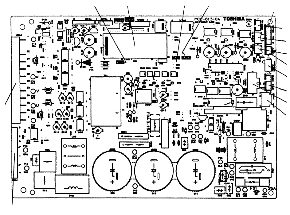
– 59 –
9-3. Outdoor Controls
9-3-1. Print Circuit Board
<Viewed from parts of P.C board>
MCC-1398 (RAV-SM560AT-E)
5V power supply MCU GND 12V power supply PMV output
TD sensor
TS sensor
TO sensor
TE sensor
Outdoor fan rpm input
Case thermo
Outdoor fan output
IGB module
Converter module
4-way valve output
(Except cooling only models)
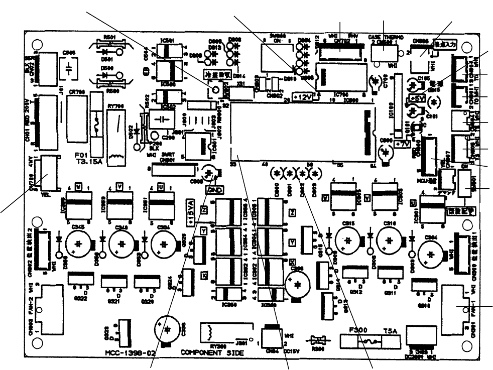
– 60 –
MCC-813 (RAV-SM800AT-E)
Pump down switch
4-way valve
output
12V power supply PMV output Case thermo Contactor against
night low-noise
5V power supply
TD sensor
TO sensor
TE sensor
Communication
between CDB and IPDU
TS sensor
Outdoor fan output
Status display LED
MCU
GND
Existing pipe
corresponding switch
(SW 801)
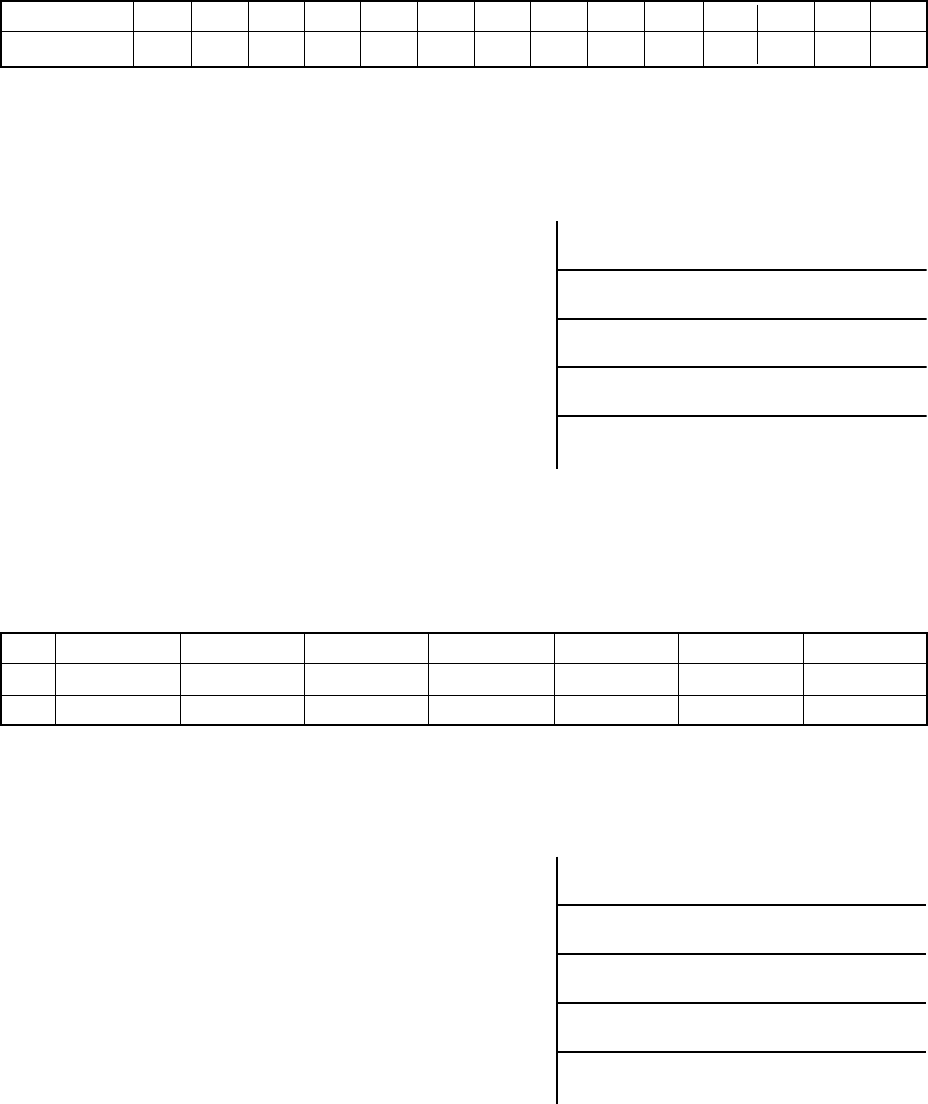
– 61 –
9-3-2. Outline of Main Controls
1. Outdoor fan control (Object: SM80)
Allocautions of fan tap revolutions [rpm]
TO
MIN
MAX
TO < 5°C5 ≤ TO <10°C 10 ≤ TO < 15°C 15 ≤ TO < 20°C 20 ≤ TO < 25°C25°C ≤ TO TO error
W1 W2 W3 W4 W5 WA W1
W6 W8 WA WC WE WE WE
2) Heating fan control
Q This control function lowers fan tap according to
TE sensor value when outdoor temperature is
high.
RWhen a status TE > 20°C is detected continu-
ously for 5 minutes, the operation may stop. This
status does not output an error code and is
assumed as usual status of thermo-OFF. The fan
restarts after approx. 2 minutes 30 seconds and
this intermittent operation is not a trouble.
SIf the status in item R is frequently found, it is
considered that the filter of suction part of the
indoor unit is dirty. Clean the filter and restart the
operation.
TThis control function does not work for 30 min-
utes after activation, 1 minute after defrosting,
and during defrost operation.
Control for fan tap by outdoor temperature in normal operation
1) Cooling fan control
QThe outdoor fan is controlled by TE sensor.
(Cooling: Temperature conditions after medium
term)
The cooling fan is controlled by every 1 tap of DC
fan control (14 taps).
RAt the activation time, although the maximum fan
tap in the following table are fixed for 60 seconds,
after then the fan may not rotate with high speed
for several minutes because the fan is controlled
by TE sensor value. It is not an abnormal status.
SWhen the discharge temperature sensor is
abnormal or the sensor comes off the holder, the
fan does not rotate with high speed, but a protec-
tive device works.
TWhen the outdoor fan does not rotate with high
speed, judge a fan error by comparing the control
data in the following table with TO and TE values.
SM800
W1 W2 W3 W4 W5 W6 W7 W8 W9 WA WB WC WD WE
250 270 290 310 340 370 400 440 480 520 560 610 700 780
MAX.
+30 rpm / 20 sec.
Hold zone
–30 rpm / 20 sec.
MIN.
46
37
34
20
TE [ C]
–60 rpm / 20 sec. STOP timer count
–60 rpm / 20 sec.
–30 rpm / 20 sec.
Hold zone
+30 rpm / 20 sec.
24
21
17
15
TE [ C]
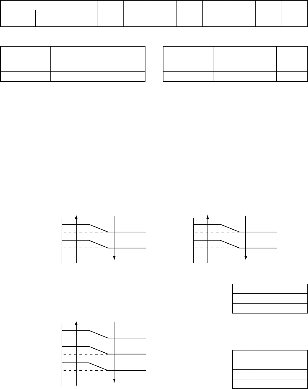
– 62 –
2. Outdoor fan control (Object: SM560)
The outdoor fan is controlled by TO sensor and the revolutions frequency of the compressor (rps).
The outdoor fan is controlled by every 1 tap of DC fan control (8 taps). According to each operation mode,
the fan is operated by selecting an outdoor fan operation tap in the following table based upon the conditions
of TO sensor and the compressor operation (rps).
Allocations of fan tap revolutions
Tap
SM560 Revolutions per
minute (rpm)
F1 F2 F3 F4 F5 F6 F7 F8
960 870 870 870 750 700 540 390
In cooling operation In heating operation
3. Coil heating control
1) This control function heats the compressor by turning on the stopped compressor instead of a case
heater. It purposes to prevent slackness of the refrigerant inside of the compressor.
2) As usual, turn on power of the compressor for the specified time before a test run after installation,
otherwise a trouble of the compressor may be caused. As same as a test run, it is recommended to turn
on power of the compressor beforehand when starting operation after power of the compressor has been
interrupted for a long time.
3) A judgment for electricity is performed by TD and TO sensors. If TO sensor is defective, a backup control
is automatically performed by TE sensor. For a case of defective TO sensor, judge it with the outdoor LED
display.
4) Coil heating is controlled by TD and TE sensor.
5) For every model, the power is turned off when TD is 30°C or more.
Frequency of the
compressor (rps)
TO ≥ 38°C
TO < 38°C
To 14 To 14 35 to MAX
F7 F4 F3
F7 F5 F4
Frequency of the
compressor (rps)
TO ≥ 5.5°C
TO < 5.5°C
To 14 To 14 35 to MAX
F7 F6 F4
F6 F6 F3
L
M
SM800
20W and equivalent
40W and equivalent
L
M
H
SM560
10W and equivalent
20W and equivalent
30W and equivalent
* TD sensor is read in once per 15 minutes.
No power-ON
Continuous ON (L)
Continuous ON (M)
No power-ON
Continuous ON (L)
Continuous ON (M)
Continuous ON (H)
No power-ON
Continuous ON (L)
Continuous ON (M)
Power-ON condition
TD < 30 C
(In trouble of sensor)
(Object: SM560)
TO [ C] TO [ C]
TO [ C]
20
18
12
10
18
15
10
8
10
9
4
3
2
1
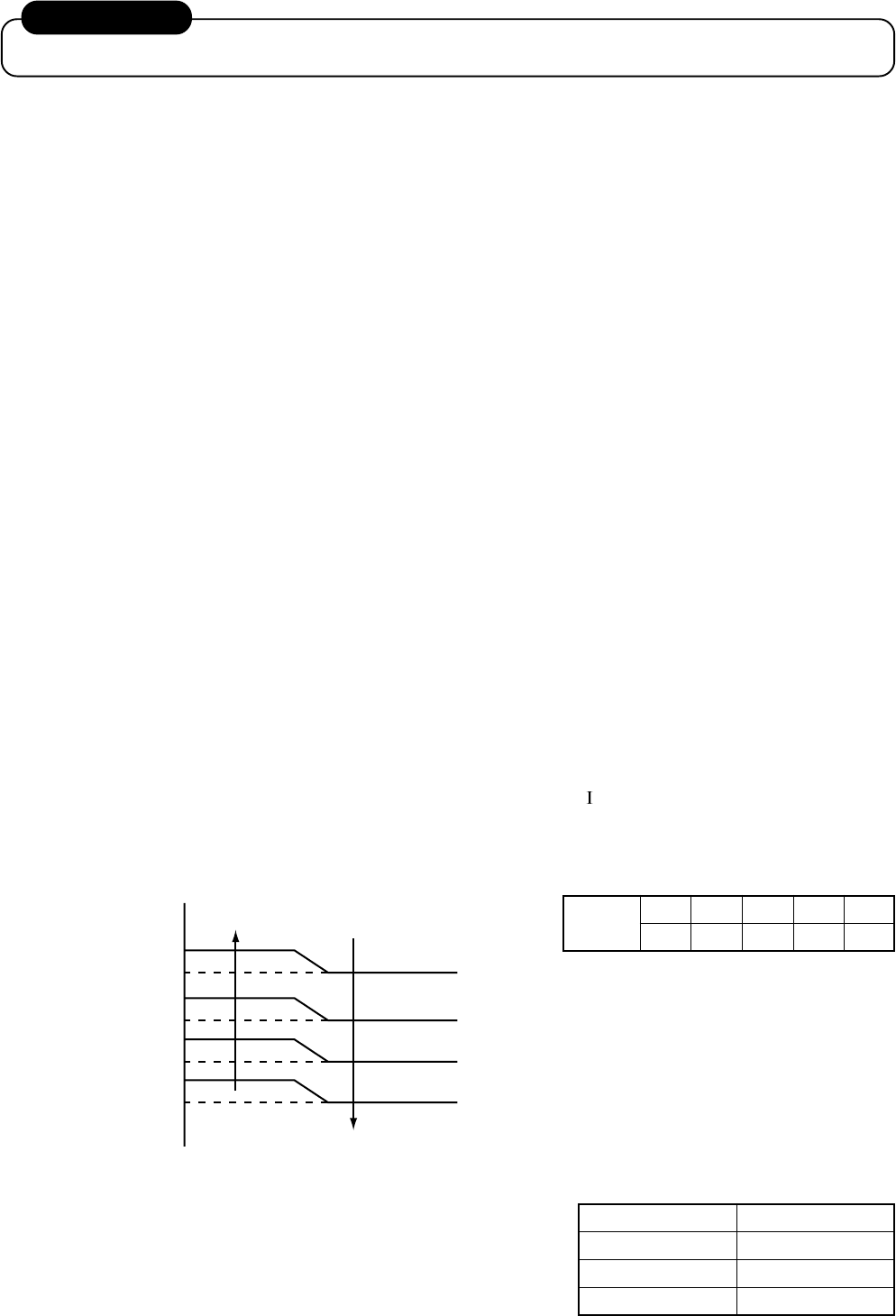
– 63 –
NOTIFICATION
It is not an abnormal phenomenon that electro-noise may be heard while heating the coil.
4. Short intermittent operation preventive control
QThe compressor may not stop for preventing the compressor for 3 to 10 minutes after start of the
operation even if Thermo-OFF signal has been received from the indoor. This phenomenon is not
abnormal. (Continuous operation time of the compressor differs according to the operating status.)
RIf the equipment is stopped from the remote controller, the operation does not continue.
5. High-voltage suppression TE control (Only for SM800)
QThis control suppresses that voltage becomes abnormally higher during cooling operation.
RStop the compressor under condition of TE ≥ 67°C, and count 1 on the error count.
SAfter 2 minutes 30 seconds passed, if TE < 67°C, the compressor restarts and the error count is
cleared when the operation continues for 10 minutes.
TWhen TE ≥ 67°C is detected again within 10 minutes, 1 is added to the error count and restart is
repeated.
UIf the error counts 10 are recognized, it is determined as an error and restart is not performed. Error
code ‘P04’ is displayed.
VAfter restarting the compressor, continue controlling by using 70% to 90% of the control value of the
current release control for minimum 30 minutes.
6. Over-current preventive control
QThis control function stops the compressor when over-current preventive circuit has detected an
abnormal current.
RThe compressor restarts with error count 1 after 2 minutes 30 seconds.
SIf the error counts 4 are recognized, it is determined as an error and restart is not performed. Error
code ‘H01’, ‘H02’ or ‘P26’ is displayed.
7. Current release value shift control
1) Object: SM800
Q This control function prevents troubles of the electron parts such as G-Tr of inverter of compressor
drive system and troubles of the compressor during cooling operation.
R This control function corrects the current release control value ( 1) in item 3 of 9-2-2 by TO sensor
value.
S The value to be corrected is based upon the following control diagram and correction value table.
SM800 Tabcd
39°C40°C60°C80°C85°C
Corrected value
2) Object: SM560
The current release value of a single-phase model is se-
lected from the right table according to TO sensor value.
Current release value shift control
TO
45 ≤ TO
40 ≤ TO < 45
TO < 45
SM560
7.07
7.90
10.22
T+8
T+7
T+5
T+4
T+2
T+1
T
T-1
TO [ C]
I1 x a%
I1 x b%
I1 x c%
I1 x d%
As I1
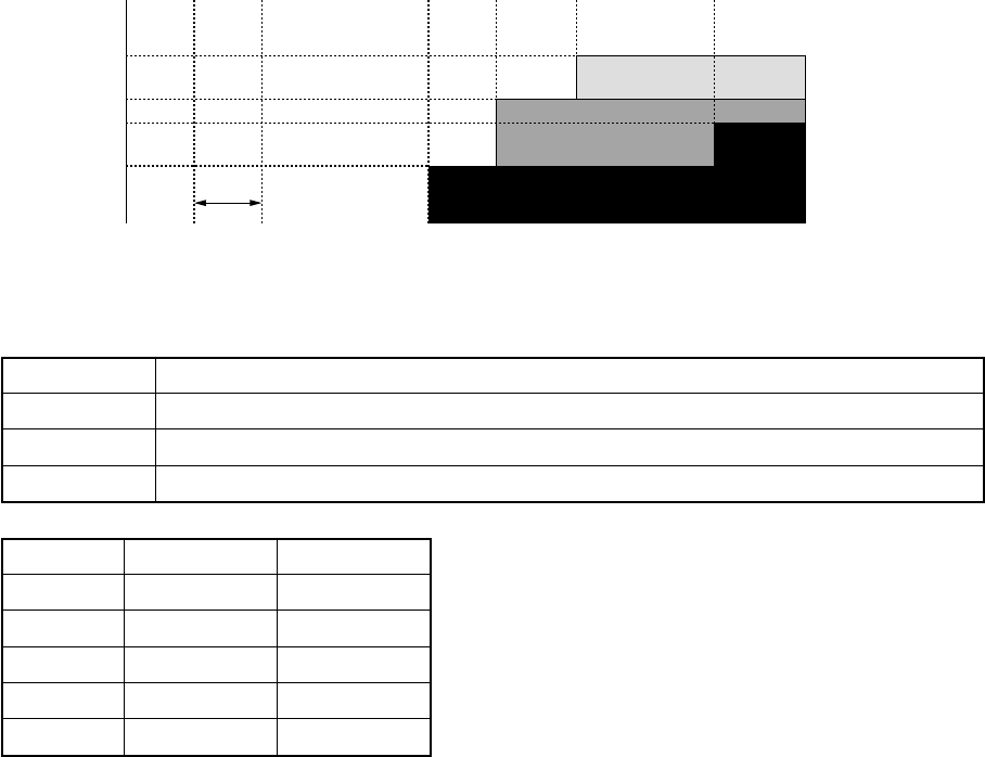
– 64 –
8. Defrost control
Q In heating operation, defrost operation is performed when TE sensor temperature satisfies any
condition in A zone to D zone.
R The defrost operation is immediately finished if TE sensor temperature has become 12°C or more, or
it also is finished when condition of 7°C ≤ TE < 12°C has continued for 1 minute. The defrost operation
is also finished when defrost operation has continued for 10 minutes even if TE sensor temperature
has become 7°C or lower.
S After defrost operation has finished, the compressor and the outdoor fan start heating operation after
stopped for approx. 50 seconds.
Start of heating operation
a
b
c
d
T
SM560
28
28
28
60
120
A zone
B zone
C zone
D zone
Defrost operation is performed in this zone when TE0-TE ≥ 3 continued for T seconds.
Defrost operation is performed in this zone when TE0-TE ≥ 3 continued for T seconds.
Defrost operation is performed when this zone continued for T seconds.
Defrost operation is performed when this zone continued for T seconds.
0 10 15 c b a d [min]
*
TE [ºC]
–5
–10
–13
–18
A zone
B zone
C zone
D zone
A zone
B zone
C zone
D zone
* The minimum TE value between 10 and 15 minutes after heating operation has started is stored in memory as TE0.
SM800
34
40
55
90
120

– 65 –
10. TROUBLESHOOTING
10-1. Summary of Troubleshooting
<Wired remote controller type>
1. Before troubleshooting
1) Required tools/instruments
• + and – screwdrivers, spanners, radio cutting pliers, nippers, push pins for reset switch
•Tester, thermometer, pressure gauge, etc.
2) Confirmation points before check
QThe following operations are normal.
a) Compressor does not operate.
•Is not 3-minutes delay (3 minutes after compressor OFF)?
•Does not thermostat turn off?
•Does not timer operate during fan operation?
•Is not outside high-temperature operation controlled in heating operation?
b) Indoor fan does not rotate.
•Does not cool air discharge preventive control work in heating operation?
c) Outdoor fan does not rotate or air volume changes.
•Does not high-temperature release operation control work in heating operation?
•Does not outside low-temperature operation control work in cooling operation?
•Is not defrost operation performed?
d) ON/OFF operation cannot be performed from remote controller.
•Is not the control operation performed from outside/remote side?
•Is not automatic address being set up?
(When the power is turned on at the first time or when indoor unit address setting is changed, the
operation cannot be performed for maximum approx. 5 minutes after power-ON.)
RDid you return the cabling to the initial positions?
SAre connecting cables of indoor unit and remote controller correct?
(2) Troubleshooting procedure
When a trouble occurred, check the parts along with the following procedure.
Trouble →→
→→
→ Confirmation of check code display →→
→→
→ Check defective position and parts.
NOTE :
For cause of a trouble, power conditions or malfunction/erroneous diagnosis of microcomputer due to
outer noise is considered except the items to be checked. If there is any noise source, change the cables
of the remote controller to shield cables.

– 66 –
<Wireless remote controller type> (Only for 4-way air discharge cassette type models)
1. Before troubleshooting
1) Required tools/instruments
• + and – screwdrivers, spanners, radio cutting pliers, nippers, etc.
•Tester, thermometer, pressure gauge, etc.
2) Confirmation points before check
QThe following operations are normal.
a) Compressor does not operate.
•Is not 3-minutes delay (3 minutes after compressor OFF)?
•Does not thermostat turn off?
•Does not timer operate during fan operation?
•Is not outside high-temperature operation controlled in heating operation?
b) Indoor fan does not rotate.
•Does not cool air discharge preventive control work in heating operation?
3) Outdoor fan does not rotate or air volume changes.
•Does not high-temperature release operation control work in heating operation?
•Does not outside low-temperature operation control work in cooling operation?
•Is not defrost operation performed?
4) ON/OFF operation cannot be performed from remote controller.
•Is not forced operation performed?
•Is not the control operation performed from outside/remote side?
•Is not automatic address being set up?
QDid you return the cabling to the initial positions?
RAre connecting cables between indoor unit and receiving unit correct?
2. Troubleshooting procedure
(When the power is turned on at the first time or when indoor unit address setting is changed, the operation
cannot be performed for maximum approx. 5 minutes after power-ON.)
When a trouble occurred, check the parts along with the following procedure.
Trouble →→
→→
→→→
→→
→
Confirmation of lamp display
(When 4-way air discharge cassette type wireless remote controller is connected)
Check defective
position and parts.
1) Outline of judgment
The primary judgment to check where a trouble occurred in indoor unit or outdoor unit is performed with
the following method.
Method to judge the erroneous position by flashing indication on the display part of indoor unit
(sensors of the receiving unit)
The indoor unit monitors operating status of the air conditioner, and the blocked contents of self-diagnosis
are displayed restricted to the following cases if a protective circuit works.

– 67 –
10-2. Check Code List
Error mode detected by indoor unit ◎ : Flash, 〇 : Go on, ● : Go off
Wireless sensor
lamp display
Operation
Timer Ready
◎●●
●●◎
◎●●
◎●◎
◎●◎
◎●◎
◎●◎
◎○◎
●◎◎
●◎◎
●◎◎
◎●◎
◎●◎
◎◎●
◎◎●
◎◎●
◎◎●
◎●●
◎●●
Wired remote
controller
Check code
E03
E04
E08
L03
L07
L08
L09
L30
P01
P10
P12
P19
P31
F01
F02
F10
F29
E10
E18
Diagnostic function
Cause of operation
No communication from remote controller (including wireless)
and communication adapters
The serial signal is not output from outdoor unit to indoor unit.
•Miscabling of inter-unit cables
•Defective serial sensing circuit on outdoor P.C. board
•Defective serial receiving circuit on indoor P.C. board
Duplicated indoor unit addresses
Duplicated indoor master units
There is group line in individual indoor units.
Unsetting of indoor group address
Unset indoor capacity
Abnormal outside interlock input
Fan motor thermal protection
Float switch operation
•Disconnection, coming-off, defective float switch contactor
of float circuit
Indoor DC fan error
Error in 4-way valve system
•Indoor heat exchanger temperature lowered after start of
heating operation.
Own unit stops while warning is output to other indoor units.
Coming-off, disconnection or short of indoor heat exchanger
sensor (TCJ)
Coming-off, disconnection or short of indoor heat exchanger
sensor (TC)
Coming-off, disconnection or short of indoor heat exchanger
sensor (TA)
Indoor EEPROM error
•EEPROM access error
Communication error between indoor MCU
•Communication error between fan driving MCU and main
MCU
Regular communication error between master and sub indoor
units or between main and sub indoor units
Status of air
conditioner
Stop
(Automatic reset)
S top
(Automatic reset)
Stop
Stop
Stop
Stop
Stop
Stop
Stop
(Automatic reset)
Stop (Sub unit)
(Automatic reset)
Stop
(Automatic reset)
Stop
(Automatic reset)
Stop
(Automatic reset)
Stop
(Automatic reset)
Stop
(Automatic reset)
Stop
(Automatic reset)
Condition
Displayed when
error is detected
Displayed when
error is detected
Displayed when
error is detected
Displayed when
error is detected
Displayed when
error is detected
Displayed when
error is detected
Displayed when
error is detected
Displayed when
error is detected
Displayed when
error is detected
Displayed when
error is detected
Displayed when
error is detected
Displayed when
error is detected
Displayed when
error is detected
Displayed when
error is detected
Displayed when
error is detected
Displayed when
error is detected
Judgment and measures
1. Check cables of remote controller and communication adapters.
•Handy remote controller LCD display OFF (Disconnection)
•Central remote controller [97] check code
1. Outdoor unit does not completely operate.
•Inter-unit cable check, correction of miscabling, case thermo operation
•Outdoor P.C. board check, P.C. board cables check
2. In normal operation
P.C. board (Indoor receiving/Outdoor sending) check
1. Check whether there is modification of remote controller connection (Group/
Individual) or not after power has been turned on (finish of group configuration/
address check).
* If group configuration and address are not normal when the power has been turned
on, the mode automatically shifts to address setup mode. (Resetting of address)
1. Set the indoor capacity. (DN=I1)
1. Check outside devices.
2. Check indoor P.C. board.
1. Check thermal relay of fan motor.
2. Check indoor P.C. board.
1. Defect of drain pump
2. Clogging of drain pump
3. Check float switch.
4. Check indoor P.C. board.
1. Defective detection of position
2. Over-current protective circuit of indoor fan driving unit operates.
3. Lock of indoor fan
4. Check indoor P.C. board.
1. Check 4-way valve.
2. Check indoor heat exchanger (TC/TCJ) sensor.
3. Check indoor P.C. board.
1. Judge sub unit while master unit is in [E03], [L03], [L07], [L08].
2. Check indoor P.C. board.
1. Check indoor heat exchanger temperature sensor (TCJ).
2. Check indoor P.C. board.
1. Check indoor heat exchanger temperature sensor (TC).
2. Check indoor P.C. board.
1. Check indoor heat exchanger temperature sensor (TA).
2. Check indoor P.C. board.
1. Check indoor EEPROM. (including socket insertion)
2. Check indoor P.C. board.
1. Check cables of remote controller.
2. Check power cables of indoor unit.
3. Check indoor P.C. board.
1. Check cables of remote controller.
2. Check indoor power cable.
3. Check indoor P.C. board.

– 68 –
Error mode detected by outdoor unit
◎ : Flash, 〇 : Go on, ● : Go off
Wireless sensor
lamp display
Operation
Timer Ready
●◎●
●◎●
●◎●
◎○◎
◎○◎
◎●◎
◎●◎
◎●◎
◎●◎
◎●◎
◎◎○
◎◎○
◎◎○
Wired remote
controller
Check code
H01
H02
H03
L29
L31
P03
P04
P22
P26
P29
F04
F06
F08
Diagnostic function
Cause of operation
Breakdown of compressor
•Displayed when error is detected
Compressor does not rotate.
•Over-current protective circuit operates after specified time
passed when compressor had been activated.
Current detection circuit error
•Current value at AC side is high even during compressor-OFF.
•Phase of power supply is missed.
Outdoor unit and other errors
•Communication error between CDB and IPDU
(Coming-off of connector)
•Heat sink temperature error
(Detection of temperature over specified value)
Phase detection protective circuit operates.
(Normal models)
Discharge temperature error
•Discharge temperature over specified value was detected.
High-pressure protection error by TE sensor
(Temperature over specified value was detected.)
Outdoor DC fan error
Inverter over-current protective circuit operates. (For a short time)
Short voltage of main circuit operates.
IPDU position detection circuit error
Coming-off, disconnection or short of outdoor temperature
sensor (TD)
Coming-off, disconnection or short of outdoor temperature
sensor (TE/TS)
Coming-off, disconnection or short of outdoor temperature
sensor (TO)
Status of air
conditioner
Stop
Stop
Stop
Stop
Operation continues.
(Compressor stops.)
Stop
Stop
Stop
Stop
Stop
Stop
Stop
Operation continues.
Condition
Displayed when
error is detected
Displayed when
error is detected
Displayed when
error is detected
Displayed when
error is detected
Displayed when
error is detected
Displayed when
error is detected
Displayed when
error is detected
Displayed when
error is detected
Displayed when
error is detected
Displayed when
error is detected
Displayed when
error is detected
Displayed when
error is detected
Displayed when
error is detected
Judgment and measures
1. Check power voltage. AC200V±20V
2. Overload operation of refrigerating cycle
3. Check current detection circuit at AC side.
1. Trouble of compressor (Compressor lock, etc.) : Replace compressor.
2. Defective cabling of compressor (Phase missing)
3. Phase-missing operation of power supply (3-phase model)
1. Compressor immediately stops even if restarted. : Check IPDU.
2. Phase-missing operation of power supply
Check 3-phase power voltage and cables.
1. Check cables of CDB and IPDU.
2. Abnormal overload operation of refrigerating cycle
1. Check power phase order (Reversed phase)/phase missing.
2. Check outdoor P.C. board.
1. Check refrigerating cycle. (Gas leak)
2. Trouble of PMV
3. Check Td sensor.
1. Overload operation of refrigerating cycle
2. Check outdoor temperature sensor (TE).
3. Check outdoor CDB P.C. board.
1. Defective detection of position
2. Over-current protective circuit of outdoor fan driving unit operates.
3. Lock of outdoor fan
4. Check outdoor CDB P.C. board.
1. Inverter immediately stops even if restarted. : Compressor motor rare short
2. Check IPDU. : Cabling error
1. Position detection circuit operates even if operating compressor by removing
3P connector. : Replace IPDU.
1. Check outdoor temperature sensor (TD).
2. Check outdoor CDB P.C. board.
1. Check outdoor temperature sensor (TE/TS).
2. Check outdoor CDB P.C. board.
1. Check outdoor temperature sensor (TO).
2. Check outdoor CDB P.C. board.
For an error mode detected in outdoor unit, the fan operates because sub unit of a group operation does not communicate with the outdoor unit.

– 69 –
Error mode detected by remote controller or network adapter
◎ : Flash, 〇 : Go on, ● : Go off
Wireless sensor
lamp display
Operation
Timer Ready
———
◎●●
◎●●
◎●●
◎○◎
———
———
———
Wired remote
controller
Check code
No check code
is displayed.
(Remote
controller does
not operate.)
E01*2
E02
E09
L20
Central remote
controller
98
—
*3
Central remote
controller
99
—
*3
Central remote
controller
97
—
Central remote
controller
b7
Diagnostic function
Cause of operation
No communication with master indoor unit
•Remote controller cable is not correctly
connected.
•Power of indoor unit is not turned on.
•Automatic address cannot be completed.
No communication with indoor master unit
•Disconnection of inter-unit cable between
remote controller and master indoor unit
(Detected at remote controller side)
Signal sending error to indoor unit
(Detected at remote controller side)
Multiple master remote controllers are recognized.
(Detected at remote controller side)
Duplicated indoor central addresses on
communication of central control system (AI-NET)
(Detected by central controller side)
Multiple network adapters on remote controller
communication line
(Detected by central controller side)
Interruption of central control system (AI-NET)
communication circuit
(Detected by central controller side)
Indoor Gr sub unit error
(Detected by central controller side)
Status of air conditioner
Stop
Stop
(Automatic restart)
* When there is center, operation
continues.
Stop
(Automatic restart)
* When there is center, operation
continues.
Stop
(Sub unit continues operation.)
Stop
(Automatic restart)
Operation continues.
Operation continues.
(According to handy remote controller)
Continuation/stop
(Based on a case)
Condition
—
Displayed when
error is detected
Displayed when
error is detected
Displayed when
error is detected
Displayed when
error is detected
Displayed when
error is detected
Displayed when
error is detected
Displayed when
error is detected
Judgment and measures
Remote controller power error, Defective indoor EEPROM
1. Check remote controller inter-unit cables.
2. Check remote controller.
3. Check indoor power cables.
4. Check indoor P.C. board.
5. Check indoor EEPROM. (including socket insertion)
: Phenomenon of automatic address repetition occurred.
Signal receiving of remote controller is defective.
1. Check remote controller inter-unit cables.
2. Check remote controller.
3. Check indoor power cables.
4. Check indoor P.C. board.
Signal sending of remote controller is defective.
1. Check sending circuit inside of remote controller.
: Replace remote controller.
1. Check there are multiple master units for 2 remote controllers
(including wireless).
: Master unit is one and others are sub units.
1. Check address setup of central control system network.
(Network adapter SW01)
2. Check network adapter P.C. board.
1. Check multiple network adapters.
2. Check inter-unit cable/miscabling of remote controller.
: Only one network adapter on remote controller communication line
1. Check communication line/miscabling. Check power of indoor unit.
2. Check communication. (XY terminals)
3. Check network adapter P.C. board.
4. Check central controller (such as central control remote controller, etc.).
Check the check code of corresponding unit by handy remote controller.
*2 Check code is not displayed by wired remote controller. (Usual operation of air conditioner is disabled.)
For wireless type models, E01 is notified by the display lamp.
*3 These errors are related to communication of remote controllers (A, B) and central system (AI-NET, X, Y), and [E01], [E02], [E03], [E09], or [E18] is displayed or no check code is displayed on the
remote controller according to the error contents.

– 70 –
10-3. Error Mode Detected by LED on Outdoor P.C. Board
<SW800: LED display in bit 1, bit 2, bit 3 OFF>
•When multiple errors are detected, the latest error is displayed.
•When LED display is ○ (Go on), there is the main cause of trouble on the objective part of control at CDB
side and the unit stops.
•When LED display is ◎ (Flash), there is the main cause of trouble on the objective part of control at IPDU
side and the unit stops.
•When case thermostat operates, the communication is interrupted on the serial circuit. If continuing the case
thermostat operation, a serial communication error occurs because serial sending to the indoor unit is inter-
rupted.
CDB side
IPDU side
No.
1
2
3
4
5
6
7
8
9
10
11
12
13
14
15
16
Item
TE sensor error
TD sensor error
TS sensor error
TO sensor error
Discharge temp. error
DC outdoor fan error
Communication error
between IPDU
(Abnormal stop)
High-pressure release
operation
EEPROM error
Communication error
between IPDU
(No abnormal stop)
G-Tr short-circuit
protection
Detection circuit error
Current sensor error
Phase missing detection
Comp. lock error
Comp. breakdown
Check code
Type A Type B
F06 18
F04 19
F06 18
F08 1B
P03 1E
P22 1A
L29 1C
P04 21
—
——
——
P26 14
P29 16
H03 17
H03 17
H02 1D
H01 1F
LED display
D800 D801 D802 D803
(Red) (Yellow) (Yellow) (Yellow)
○●●●
○○●●
●●○●
●○●●
●○○●
○○○●
○●●○
●○●○
○○●○
●●○○
◎●●●
●◎●●
◎◎●●
●●●◎
●●◎●
◎●◎●
○ : Go on ● : Go off ◎ : Flash (5Hz)
<<Check code>>
The check codes are classified into Type A and Type B according to the used remote controller. Be sure to
check the remote controller which you use.
Type A :
Neutral 2-cores type wired remote controller such as RBC-AMT21E, RBC-AS21E, and wireless remote control-
ler kit such as TCB-AX21U (W)-E
Type B :
Polarized 3-cores type wired remote controller such as RBC-SR1-PE, RBC-SR2-PE, and central control remote
controller such as RBC-CR64-PE
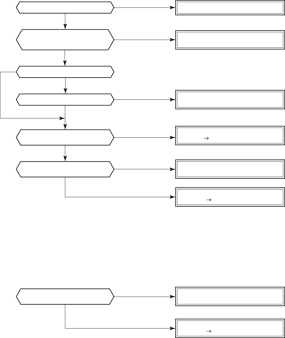
– 71 –
10-4. Troubleshooting Procedure for Each Check Code
10-4-1. New Check Code/Present Check Code (Central Control Side)
[E01 error]/*[99 error]
*: When central controller [99] is displayed, there are other causes of error.
[E09 error]/*[99 error]
*: When central controller [99] is displayed, there are other causes of error.
Is inter-unit cable of A and B normal?
Is there no disconnection
or contact error of connector on harness
from terminal block of indoor unit?
Is group control operation?
Is power of all indoor units turned on?
Is power supplied to remote controller?
AB terminal: Approx. DC18V
Are two remote controllers
set without master unit?
Are two remote controllers
set without master unit?
Correct inter-unit cable of remote controller.
Correct connection of connector.
Check circuit cables.
Check power connection of indoor unit.
(Turn on power again.)
Check indoor P.C. board (MCC-1402).
Defect Replace
Correct as a master unit/a sub unit
(Remote controller address connector)
Check remote controller P.C. board.
Defect Replace
Correct as a master unit/a sub unit
(Remote controller address connector)
Check remote controller P.C. board.
Defect Replace
NO
YES
NO
NO
NO
YES
YES
YES
NO
YES
YES
YES
NO
NO
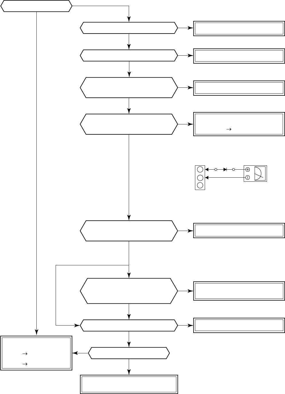
– 72 –
[E04 error]/[04 error]
Check item code [14].
Correct inter-unit cable.
Correct connection of connector.
Correct connection of connector.
Replace IPDU.
Replace IPDU.
Correct connection of connector.
Check/Correct charged
refrigerant amount.
For RAV-SM560AT-E,
main circuit on control
P.C. board
For RAV-SM560AT-E,
check case thermo.
Check indoor P.C. board
(MCC-1402 or MCC-1403).
Defect Replace
Check CDB.
Defect Replace
Does outdoor unit operate?
Is setup of group address correct?
Is case thermo (CN500) connected?
Does case thermo operate?
Are 1, 2, 3 inter-unit cables normal?
Are connections from connectors
of inter-terminal blocks (1, 2, 3)
of indoor/outdoor units normal?
Does voltage between
2 and 3 of inter-terminal blocks (1, 2, 3)
of indoor unit vary?*
Is DC280V applied between
terminals of electrolytic capacitor
of IPDU main circuit?
Check indoor P.C. board
(MCC-1402).
Defect Replace
*
As shown in the following figure,
perform measurement within
20 seconds after power ON.
Is DC7V power supplied to CDB?
Are cablings between Pin 2 and Pin 5
of CN800 and between IPDU
and CDB normal?
Black
White
3
2
1
Inter-terminal block
S5277G
NO
NO
NO
NO
NO
NO
NO
NO
NO
YES
YES
YES
YES
YES
YES
YES
YES
YES
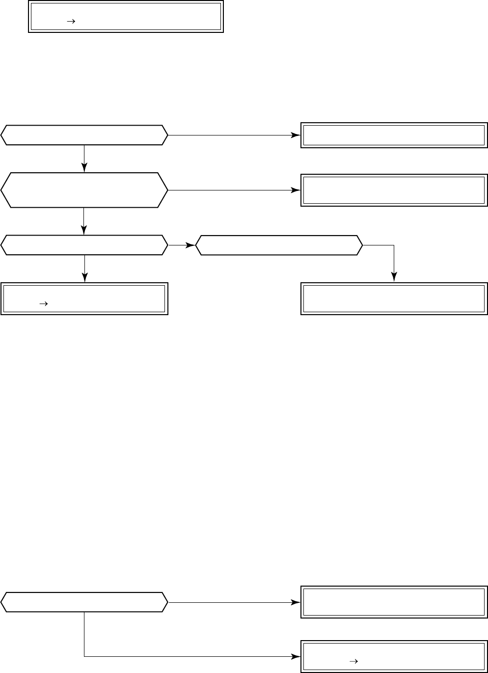
– 73 –
[E10 error]/[CF error]
<Only for 4-way air discharge cassette type (RAV-SM560UT-E/RAV-SM800UT-E)>
[E18 error]/[97 error] *[99 error]
*: When central controller [99] is displayed, there are other causes of trouble.
[E08, L03, L07, L08 error]/ *[96 error] [99 error]
*: When central controller [99] is displayed, there are other causes of trouble.
E08 : Duplicated indoor unit numbers
L03 : Two or more master units in a group control
L07 : One or more group addresses of [Individual] in a group control
L08 : Unset indoor group address (99)
If the above is detected when power has been turned on, the mode automatically enters in automatic ad-
dress setup mode. (Check code is not displayed.)
However, if the above is detected during automatic address setup mode, the check code may be displayed.
[L09 error]/[46 error]
Is inter-unit cable of A and B normal?
Is there no disconnection
or contact error of connector on harness
from terminal block of indoor unit?
Is group control operation? Is power of all indoor units turned on?
Correct inter-unit cable of remote controller.
Correct connection of connector.
Check circuit cables.
Check power connection of indoor unit.
(Turn on power again.)
Check indoor P.C. board (MCC-1402).
Defect Replace
Set capacity data of indoor unit.
(Setup item code (DN) = 11)
Check indoor P.C. board (MCC-1402).
Defect Replace
Check indoor control P.C. board (MCC-1402).
Defect Replace
NO
NO
YES
YES
YES
NO
NO
Is capacity of indoor unit unset? YES
NO
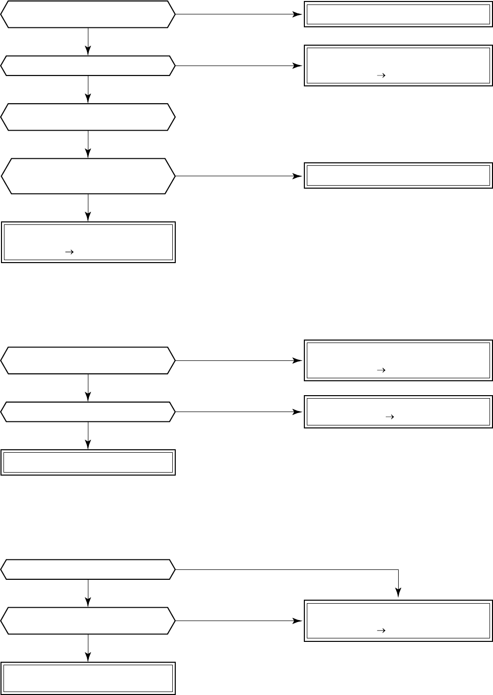
– 74 –
Correct cable connection
Correct central control network address.
Check operation cause.
Check indoor P.C. board
(MCC-1402 or MCC-1403).
Defect Replace
Check indoor P.C. board
(MCC-1402 or MCC-1403).
Defect Replace
Check indoor P.C. board
(MCC-1402 or MCC-1403).
Defect Replace
Check outside devices.
Defect Replace
Check corresponding
indoor/outdoor units.
Check central controller
(including network adapter).
Defect Replace.
NO
NO
YES
NO
NO
NO
NO
YES
YES
YES
NO
YES
YES
YES
YES
Are cable connections to
communication line X, Y normal?
Is indoor remote controller
[L20] displayed?
Is central controller [98] displayed?
Are outside devices of
connector CN80 connected?
Is check code displayed on sub unit
of main or sub remote controller?
Do outside devices normally operate?
Is group operation performed?
Are not multiple
same central control network
addresses connected?
[L20 error]/[98 error]
[L30 error]/[B6 error]
[b7 error] (Central controller)
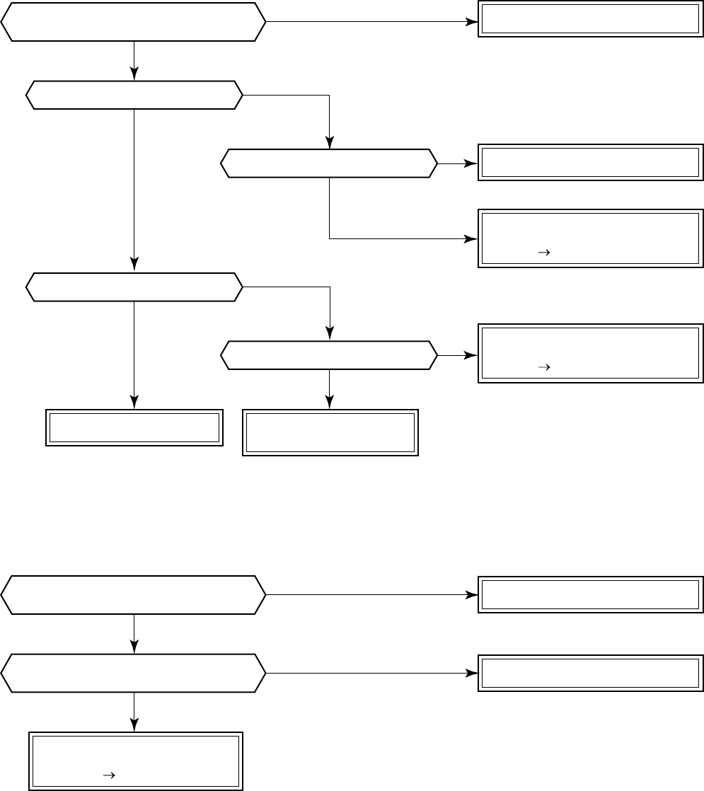
– 75 –
[P10 error]/[Ob error]
[F10 error] [0C error]
Correct connection of connector.
Check drain pipe, etc.
Check and correct cabling/wiring.
Correct connection of connector.
Replace TA sensor.
Check indoor P.C. board
(MCC-1402 or MCC-1403).
Defect Replace
Check indoor P.C. board
(MCC-1402 or MCC-1403).
Defect Replace
Check indoor P.C. board
(MCC-1402 or MCC-1403).
Defect Replace
Replace drain pump.
Check cabling.
* Refer to Characteristics-1.
NO
NO
NO
NO
NO
YES
YES
YES
YES
YES
Does float switch operate?
Does drain pump operate?
Is circuit cabling normal?
Is power of drain pump turned on?
Is connection of float switch connector
(Indoor control P.C. board CH34) normal?
NO
YES
Is connection of TA sensor connector
(indoor P.C. board CN104) normal?
NO
YES
Are characteristics of TA sensor
resistance value normal?
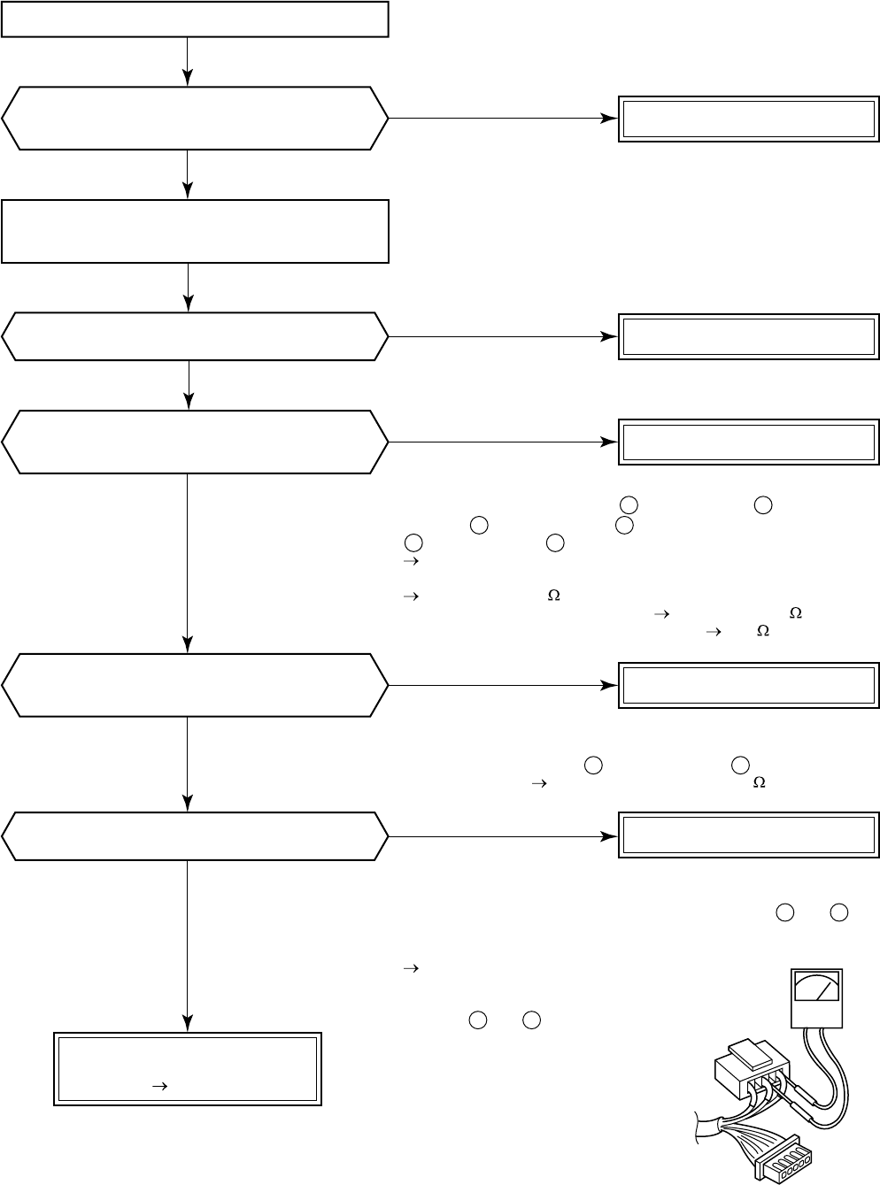
– 76 –
[P12 error]/[11 error]
<Only for 4-way air discharge cassette type models (RAV-SM560UT-E/RAV-SM800UT-E)>
Correct connection of connector.
Replace indoor fan motor.
*1
•Are not coil windings between (Red lead) and (White lead),
between (White lead) and (Black lead), between
(Black lead) and (Red lead) opened or shorted?
For resistance, see the following values.
AIU-P401H/HR, P451, P501, P561, P631, P711, P801
Approx. 70 to 100
AIU-P1121H/HR, P1401, P1601 Approx. 35 to 50
•Is not earthed between cabinet and 1, 3, 5 10M or more
*2
Check resistance of fan motor position detection circuit.
Is not coil winding between (Yellow lead) and (Pink lead)
opened or shorted? Resistance: Approx. 5 to 20k
*3
Check fan motor position detection signal.
•Using a tester, measure the voltage between CN334 and of
indoor P.C. board (MCC-1402) under condition that CN333 and
CN334 are mounted and the power is turned on.
Rotate the fan slowly with hands,
and check the pin voltage
swings between 0 to 5V voltage.
•Between and : 5V
Check indoor P.C. board
(MCC-1402).
Defect Replace
Remove connectors CN333 and
CN334 of indoor unit P.C. board
(MCC-1402).
Replace indoor fan motor.
Replace indoor fan motor.
Replace indoor fan motor.
YES
NO
NO
NO
NO
NO
YES
YES
YES
YES
Turn off the power.
Is resistance value of fan motor connector
CN333 at motor side of indoor P.C. board
(MCC-1402) correct? *2
Are not there connections errors or
disconnection on connectors CN333 and CN334
of indoor unit P.C. board (MCC-1402)?
Are resistance values between phases
at fan motor connector CN333 motor side of
indoor P.C. board (MCC-1402) correct? *1
Is signal output of indoor fan motor
position detection correct? *3
Does the fan rotate without trouble
when handling the fan with hands?
1 3
3 5
5
1
1 5
4 5
4
1
CN333
CN334
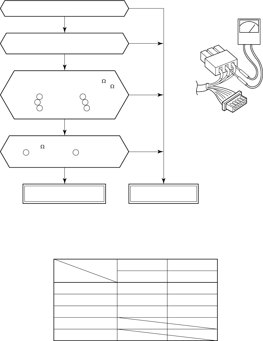
– 77 –
[P22 error]/[1A error]
(RAV-SM800AT-E)
* Connector of RAV-SM560AT-E differs from
that of RAV-SM800AT-E.
CN300: Motor coil winding
CN301: Motor position detection
Are connections of CN301 and
CN300 of P.C. board correct?
Does the fan rotate without trouble
when handling the fan with hands under condition
of removing CN301 and CN300 from P.C. board?
The status that the resistance values
between leads below are 50 to 80
for 40W motor (ICF-140-40) and 25 to 55
for 60W motor (ICF-140-60-1) is normal.
Between (Red lead) and (White lead)
Between (White lead) and (Black lead)
Between (Black lead) and (Red lead)
of motor winding of connector (CN301)
The status that there is
5k to 20k resistance values between
(Yellow lead) and (Pink lead)
of motor position detection of
connector (CN300) is normal.
Normal fan motor
(Control or CDB P.C. board) Defective fan motor
NOTE :
However, GND circuit error inside of the motor is rarely detected even if the above check is carried out.
When the circuit does not become normal even if P.C. board has been replaced, replace outdoor fan motor.
Objective P.C. board
Fan motor winding
Motor position detection
Fan motor winding
Motor position detection
Single phase
RAV-SM560AT-E
Single phase
RAV-SM800AT-E
Control P.C. board
CN300
CN301
CDB P.C. board
CN301
CN300
1 2
2 3
3 1
1 4
(Control P.C. board or CDB P.C. board)
NO
NO
NO
YES
YES
YES
YES
CN301
CN300
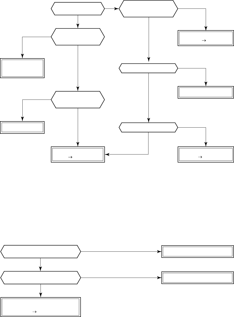
– 78 –
[P19 error]/[08 error]
• In cooling operation, if high pressure is abnormally raised, [P19 error]/[08 error] may be displayed. In this
case, remove cause of pressure up and then check again referring to the item [P04 error]/[21 error].
[F02 error]/[0d error]
NO
NO
YES
YES
* Refer to Characteristics-2.
* Refer to Characteristics-2.
Check 4-way valve
Defect Replace
Check CDB P.C. board.
Defect Replace
* For RAV-SM560AT-E, check control P.C. board.
Check and replace
electron expansion
valve.
Check indoor P.C. board.
Defect Replace
Replace TC sensor.
Is operation of
4-way valve normal?
Is voltage applied
to 4-way valve coil terminal
in heating operation?
Is circuit cable normal?
Check CDB P.C. board.
Is flow of refrigerant
by electron expansion
valve normal?
Are characteristics
of TC sensor resistance
value normal?
Check and correct circuit.
Correct connection of connector.
Replace TC sensor.
NO
NO
NO
YES
YES
YES
NO
NO
YES
NO
YES
YES
Check indoor P.C. board
(MCC-1402).
Defect Replace
Is connection of TC sensor connector
(Indoor P.C. board CN101) normal?
Are characteristics of
TC sensor resistance value normal?
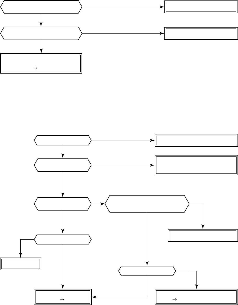
– 79 –
[F01 error]/[0F error]
[P26 error]/[14 error]
NO
NO
NO
NO
NO
YES
YES
NO
YES
YES
YES
NO
YES
YES
NO
YES
Correct connection of connector.
Replace TCJ sensor.
Improve the power supply line.
Replace IPDU.
Check indoor P.C. board
(MCC-1403).
Defect Replace
Is connection of TCJ sensor connector
(Indoor P.C. board CN102) normal?
Are characteristics of
TCJ sensor resistance value normal?
* Refer to Characteristics-2.
* For RAV-SM560AT-E,
check RY01 on the control P.C. board.
* Single-phase type is not
provided to RAV-SM560AT-E.
* Replace control P.C. board
of RAV-SM560AT-E.
Is power voltage normal?
Is not AC fuse fused?
Check and correct circuit cables.
Correct connection of connector.
Check and correct reactor connection.
Are connections of
cabling/connector normal?
Does RY01 relay of
IPDU operate?
Are not “P26” and “14” errors output
when an operation is performed by
removing 3P connector of compressor?
Replace IPDU.
* Replace control P.C. board
of RAV-SM560AT-E.
Is compressor normal?
Check rare short of compressor trouble.
Defect Replace
Check IPDU.
Defect Replace
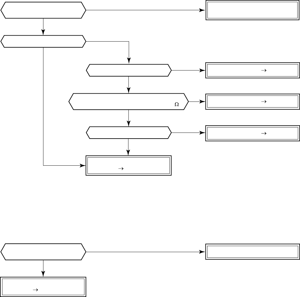
– 80 –
[P29 error]/[16 error]
[H03 error]/[17 error]
NO
NO
YES
NO
YES
YES
* For RAV-SM560AT-E, replace control P.C. board.
Are connections of
cable/connector normal?
Are cablings of power and
current sensor normal?
Is not winding shorted?
(Is resistance between windings 0.6 to 1.2 ?)
Is compressor normal?
Is not earthed?
Is not winding opened?
Compressor error Replace
Compressor error Replace
Compressor error Replace
Check and correct circuit cables.
Check and correct circuit cabling
such as cabling to compressor.
Check IPDU P.C. board.
Defect Replace
Check IPDU.
Defect Replace * For RAV-SM560AT-E, replace control P.C. board.
YES
YES
NO
NO
NO
YES
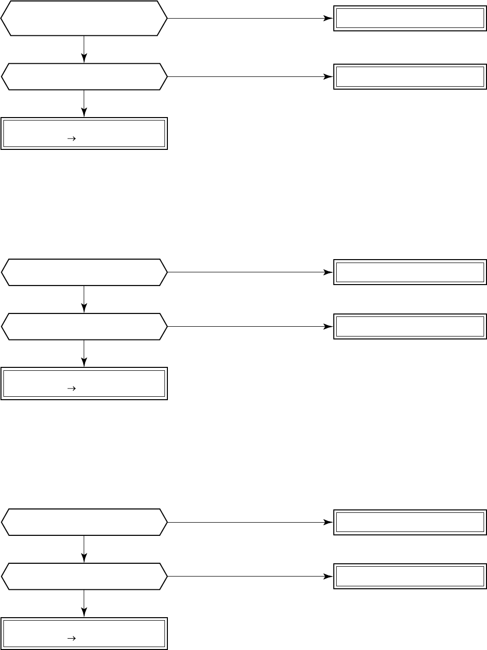
– 81 –
NO Correct connection of connector.
Check CDB.
Defect Replace * Refer to Characteristics-3.
YES
NO
Are characteristics of TE/TS sensor
resistance values normal? Replace TE and TS sensors.
YES
NO
Is connection of TD sensor connector
of CDB CN600 normal? Correct connection of connector.
Check control P.C. board.
Defect Replace * Refer to Characteristics-4.
YES
NO
Are characteristics of TD sensor
resistance value normal? Replace TD sensor.
YES
NO
Is connection of TO sensor connector
of CDB CN601 normal? Correct connection of connector.
Check CDB.
Defect Replace * Refer to Characteristics-5.
* (For RAV-SM560AT-E, CN602 TO sensor)
YES
NO
Are characteristics of TO sensor
resistance value normal? Replace TO sensor.
YES
* (For RAV-SM560AT-E, CN600 TE sensor and CN603 TS sensor)
* (For RAV-SM560AT-E, CN601 TD sensor)
Are connections of
TE/TS sensor connectors of
CDB CN604/CN605 normal?
[F06 error]/[18 error]
[F04 error]/[19 error]
[F08 error]/[1b error]
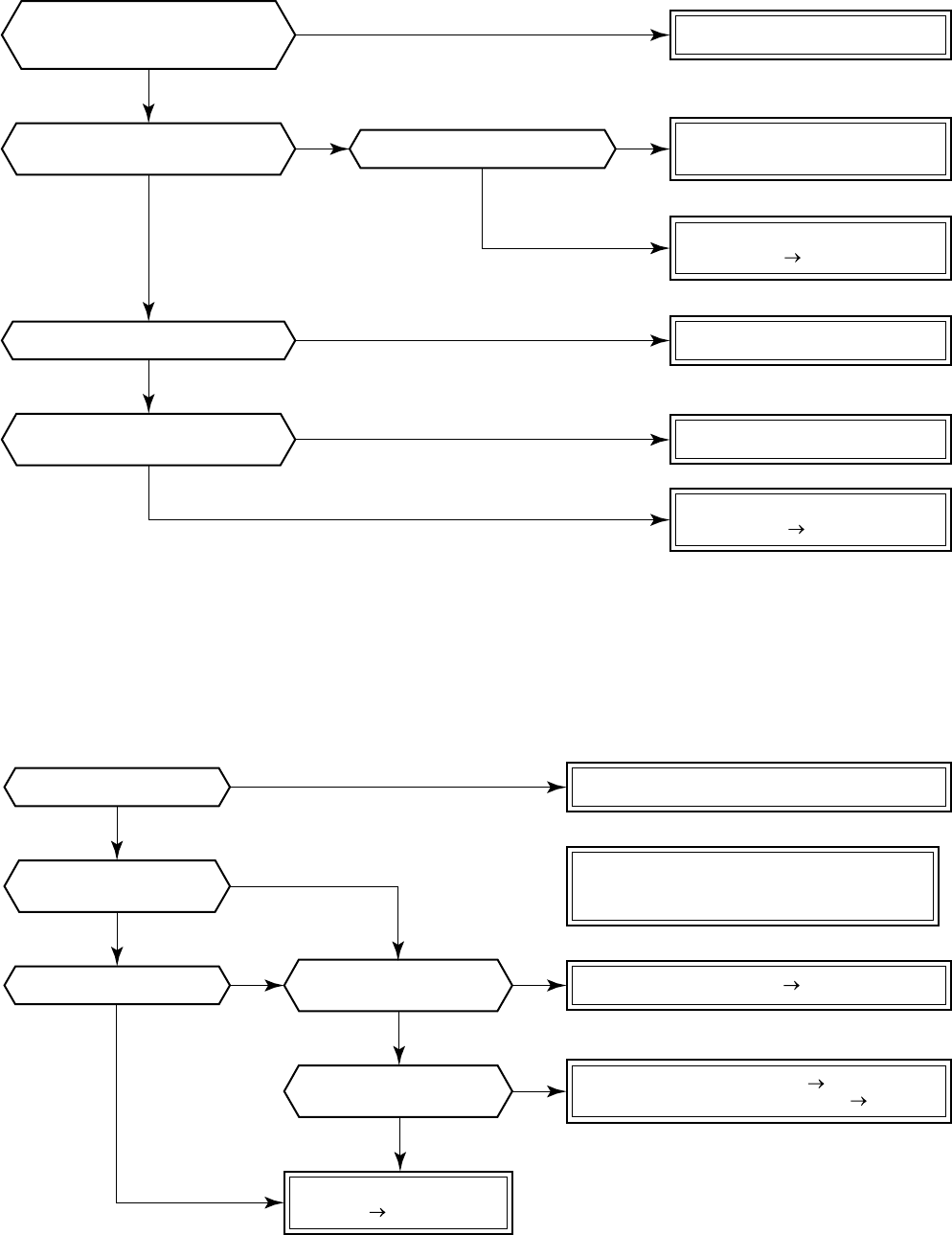
– 82 –
[L29 error]/[1C error]
[H02 error]/[1d error]
* For RAV-SM560AT-E, replace control P.C. board.
Is there no abnormal overload?
Are cabling/connector normal?
Was the error just after
power ON determined?
Is IPDU P.C. board come to
closely contact with heat sink?
Are connections of
CDB CN800 and CDB IPDU CN06
connectors normal?
Improve and eliminate the cause.
Correct connection of connector.
Correct mounting.
Improve power line.
Compressor lock Replace
Check cabling between IPDU
and CDB and connector.
IPDU P.C. board error
Defect Replace
IPDU P.C. board error
Defect Replace
Check TE and TS sensors. Replace
Check electron expansion valve. Replace
Is there no
slackened refrigerant?
Does electron expansion
valve normally operate?
Is power voltage normal?
Is compressor normal?
Are connections of
cable/connector normal?
Check and correct circuit cabling such
as cabling to compressor
(phase missing) and connector.
Check IPDU and CDB.
Defect Replace
NO
NO
NO
NO
NO NO
NO
NO
NO
YES
YES
YES YES
YES
YES
YES
YES
NO
YES
YES
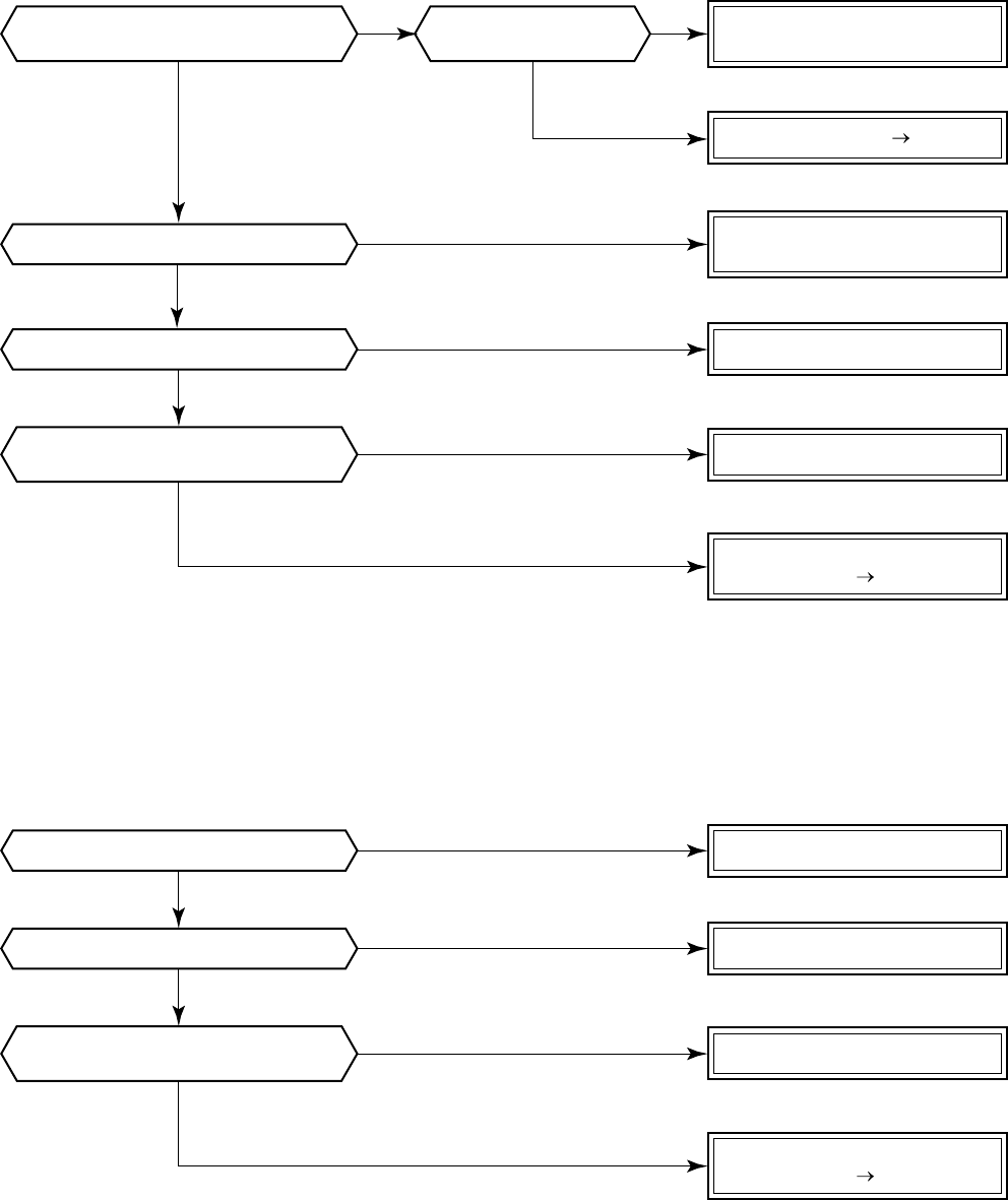
– 83 –
Check parts. Defect Replace
* Refer to Characteristics-4.
Is not abnormal overload?
Is power voltage normal?
Is not abnormal overload?
Is charged refrigerant amount normal?
Are characteristics of
TD sensor resistance value normal?
Is the circuit detected by
current sensor normal?
Is protective control such as
discharge temprelease control normal? Are connections of
cable/connector normal? Correct the cabling and
connection of connector.
Improve and delete the cause
Replace TD sensor.
Improve power line.
Improve and delete the cause.
Check and correct circuit cables.
Check CDB.
Defect Replace
Check and correct the charged
refrigerant amount.
* For RAV-SM560AT-E, replace control P.C. board.
Check IPDU.
Defect Replace
* For RAV-SM560AT-E, replace control P.C. board.
NO
NO
NO
NO
NO
NO
NO NO
YES
YES
YES
YES
YES
YES
YES YES
[P03 error]/[1E error]
[H01 error]/[1F error]
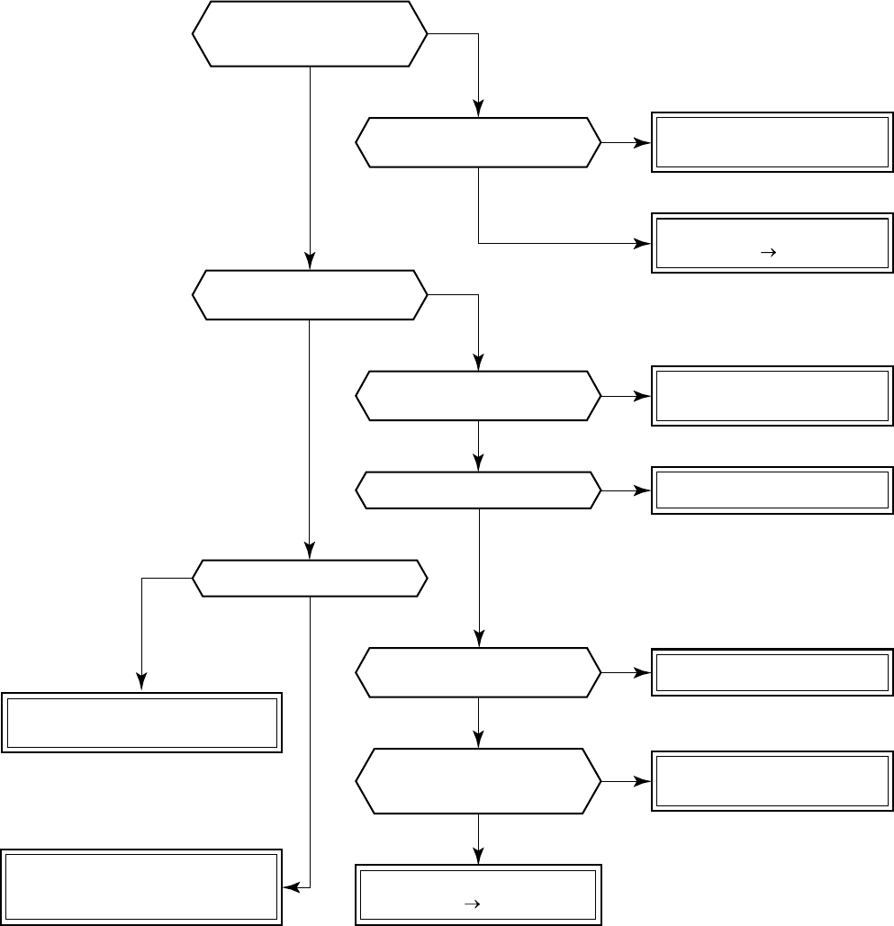
– 84 –
[P04 error]/[21 error]
* Refer to Characteristics-3 and 4.
* For RAV-SM560AT-E, replace control P.C. board.
Is high-voltage
protective operation by
TE sensor normal?
Is connection of cabling
connector normal?
Do not TD and TO sensors
come off the detection part?
Is connection of
connector normal?
Correct connection of
cabling connector.
Check TE sensor.
Defect Replace
Correct connection of
connector.
Check TE, TC, TS sensors.
Replace electron expansion valve.
Replace TD, TO,
and TC sensors.
Check CDB.
Defect Replace
Does cooling outdoor fan
normally operate?
Does PMV normally operate?
Is fan motor normal?
Replace fan motor.
Correct coming-off.
Are characteristics of
TD, TO, TC sensor resistance
values normal?
Check charged refrigerant amount.
Check liquid/gas valves.
Check abnormal overload.
NO
NO
NO
NO
NO
NO
NO
NO
YES
YES
YES
YES
YES
YES
YES
YES
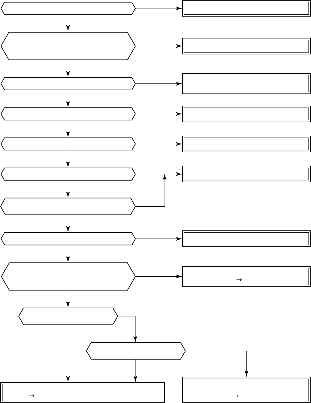
– 85 –
[97 error] (Central controller)
Correct communication line.
Correct connection of connector.
Correct power cable.
Turn on the source power supply.
Clear the check code.
Eliminate noise, etc.
NO
NO
NO
YES
YES
YES
YES
NO
NO
YES
Is X, Y communication line normal?
Is A, B communication line normal?
Is there no connection error of power line?
Is there no noise source, etc.?
Is not power of source power supply turned on?
Did a power failure occur?
NO
(Same as others)
Are connections between connectors
CN02, CN03 of network adapter P.C. board
and connectors CN309, CN41 of indoor P.C. board
(MCC-1402 or MCC-1403, normal?
Check connections of A, B terminal blocks.
Correct communication line of remote controller.
Check central controller.
Defect Replace
Check indoor P.C. board
(MCC-1402 or MCC-1403).
Defect Replace
Check network adapter P.C. board and power transformer.
Defect Replace
Is the network address changed
form remote controller?
Does network adapter P.C. board
LED (D01) go on?
Can handy remote controller control
normally other indoor units?
Can central remote controller
control normally other indoor units?
Is handling of central remote controller reflected
on the operation status of indoor unit?
YES
YES
YES
NO
NO
NO
NO
NO
YES
YES
YES
– 86 –
[E03 error] (Master indoor unit)
[E03 error] is detected when the indoor unit cannot receive a signal sent from the main remote controller (and
central controller).
In this case, check the communication cables of the remote controllers A and B, the central control system X
and Y. As communication is disabled, [E03] is not displayed on the main remote controller and the central
controller. [E01] is displayed on the main remote controller and [97 error] on the central controller, respectively.
If [E03] occurs during an operation, the air conditioner stops.
[F29 error] / [12 error]
[F29 error] or [12 error] indicates detection of trouble which occurred on IC10 non-volatile memory (EEPROM)
on the indoor unit P.C. board during operation of the air conditioner. Replace the service P.C. board.
* If EEPROM has not been inserted when the power was turned on or if EEPROM data never be read/written,
the automatic address mode is repeated. In this time, the central controller displays [97 error].
(Power ON)
[SET] is displayed on
main remote controller.
[SET] goes off.
LED (D02) on
indoor unit P.C. board flashes
with 1Hz for approx. 10 seconds.
Reboot
(Reset)
(Approx. 3 minutes)
(Approx. 1 minute)
(Repetition)
[P31 error] (Sub indoor unit)
When the master unit of a group operation has detected [E03], [L03], [L07], or [L08] error, the sub unit of the
group operation detects [P31 error] and then it stops. There is no display of the check code or alarm history of
the main remote controller.
(In this model, the mode enters in automatic address set mode when the master unit has detected [E03], [L03],
[L07], or [L08] error.)
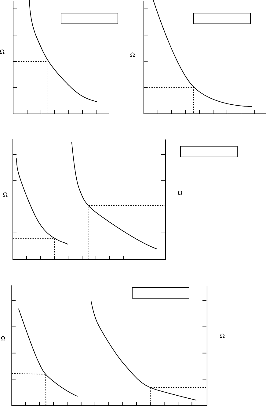
– 87 –
10-4-2. Relational Graph of Temperature Sensor Resistance Value and Temperature
Caracteristics-1
Resistance
(k )Resistance
(k )
Caracteristics-3
Caracteristics-2
Temperature [ C] Temperature [ C]
Resistance
(k )
(10 C or lower)
Resistance
(k )
(50 C or lower)
Temperature [ C]
Resistance
(k )
(50 C or higher)
Resistance
(k )
(10 C or higher)
Caracteristics-4
Temperature [ C]
TC, TCJ sensor
TE, TO, TS sensor
TD sensor
TA sensor
20
10
010 20 4030 50
200
100
20
10
0
0100-10 20 4030 50 60 70
40
30
20
10
00
–
10 10 3020 40 50 60 70
200
100
20
10
0
050 100
– 88 –
11. REPLACEMENT OF SERVICE INDOOR P.C. BOARD
[Requirement when replacing the service indoor P.C. board assembly]
In the non-volatile memory (Hereinafter said EEPROM, IC10) installed on the indoor P.C. board before replace-
ment, the type and capacity code exclusive to the corresponding model have been stored at shipment from the
factory and the important setup data such as system/indoor/group address set in (AUTO/MANUAL) mode or
setting of high ceiling selection have been stored at installation time. Replace the service indoor P.C. board
assembly according to the following procedure.
After replacement, check the indoor unit address and also the cycle by a test run.
<REPLACEMENT PROCEDURE>
CASE 1
Before replacement, power of the indoor unit can be turned on and the setup data can be readout from
the wired remote controller.
Read EEPROM data *1 (ref. P89)
ò
Replace service P.C. board & power ON *2 (ref. P89)
ò
Write the read data to EEPROM *3 (ref. P90)
ò
Power reset (All indoor units in the group when group operation)
CASE 2
Before replacement the setup data can not be readout from the wired remote controller.
Replace service P.C. board & power ON *2 (ref. P89)
ò
Write the data such as high ceiling setup to EEPROM (According to the customers’ information) *3
ò
Power reset (All indoor units in the group when group operation)
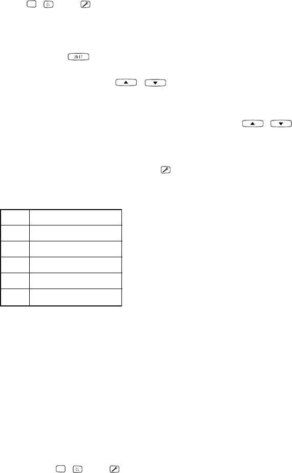
– 89 –
r1 Readout of the setup data from EEPROM
(Data in EEPROM contents, which have been changed at the local site, are read out together with data in
EEPROM set at shipment from the factory.)
1. Push
SET
, , and buttons of the remote controller at the same time for 4 seconds or more.
1
(Corresponded with No. in Remote controller)
When group operation, the master indoor unit address is displayed at the first time. In this time, the item
code (DN) 10
is displayed. The fan of the selected indoor unit operates and the flap starts swinging if any.
2. Every pushing button, the indoor unit address in the group are displayed successively.
2
Specify the
indoor unit No. to be replaced.
3. Using the set temperature
/
buttons, the item code (DN) can be moved up and down one by one.
3
4. First change the item code (DN) from
10
to
01
. (Setting of filter sign lighting time) Make a note of the set
data displayed in this time.
5. Next change the item code (DN) using the set temperature
/ buttons. Also make a note of the set data.
6. Repeat item 5. and make a note of the important set data as shown in the later table (Ex.).
•
01 to 9F are provided in the item code (DN). On the way of operation, DN No. may come out.
7. After finishing making a note, push button to return the status to usual stop status.
6
(Approx. 1 minute is required to start handling of the remote controller.)
DN
10
11
12
13
14
Contents
Type
Indoor unit capacity
Line address
Indoor address
Droup address
Minimum requirements for item code
(1) Type and capacity of the indoor unit is necessary to set the revolutions
frequency of the fan.
(2) If Line/Indoor/Group addresses differ from those before replacement,
the mode enters in automatic address setup mode and a manual
resetting may be required.
r2 Replacement of service P.C. board
1. Replace the P.C. board with a service P.C. board.
In this time, setting of jumper line (cut) or setting of (short-circuit) connecting connectors on the former P.C.
board should be reflected on the service P.C. board.
2. According to the system configuration, turn on power of the indoor unit with any method in the following items.
a) In case of single (individual) operation
Turn on the power supply.
1) Wait for completion of automatic address setup mode (Required time: Approx. 5 minutes) and then
proceed to r3.
(Line address = 1, Indoor address = 1, Group address = 0 (Individual) are automatically set.)
2) Push
SET
, , and buttons of the remote controller at the same time for 4 seconds or more
(
1
operation), interrupt the automatic address setup mode, and then proceed to r3.
(Unit No. ALL is displayed.)
b) In case of group operation
Turn on power of the indoor unit of which P.C. board has been replaced with the service P.C. board with
any method in the following items.
1) Turn on power of the replaced indoor unit only.
(However, the remote controller is also connected. Otherwise r3 operation cannot be performed.)
Same as 1) and 2) in item a).
2) Turn on power of the multiple indoor units including replaced indoor unit.
•Only 1 system for twin, triple, double twin
•For all units in the group
Wait for completion of automatic address setup mode (Required time: Approx. 5 minutes) and then
proceed to r3.
* The master unit of a group may change by setup of automatic address. The line address/indoor address of the
replaced indoor unit are automatically set to the vacant addresses except addresses belonging to other indoor
units which have not been replaced. It is recommended to make a note that the refrigerant line which includes
the corresponding indoor unit and that the corresponding indoor unit is master or sub in the group control.
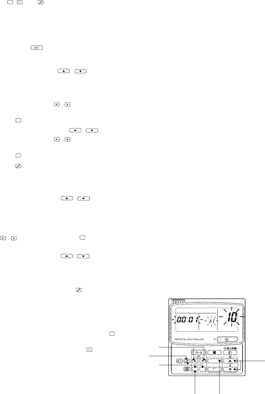
– 90 –
r3 Writing of the setup contents to EEPROM
(The contents of EEPROM installed on the service P.C. board have been set up at shipment from the factory.)
1. Push
SET
, , and buttons of the remote controller at the same time for 4 seconds or more.
1
(Corresponded with No. in Remote controller )
In group operation control, the master indoor unit No. is displayed at the first time. (If the automatic address
setup mode is interrupted in item 2. - a) - 2) in the previous page, the unit No. ALL is displayed.) In this time,
the item code (DN) 10 is displayed. The fan of the selected indoor unit operates and the flap starts swinging
if any.
2. Every pushing button, the indoor unit numbers in the group control are displayed successively.
2
Specify the indoor unit No. of which P.C. board has been replaced with a service P.C. board.
(When the unit No. ALL is displayed, this operation cannot be performed.)
3. Using the set temperature
/
buttons, the item code (DN) can be moved up and down one by one.
3
4. First set a type and capacity of the indoor unit.
(Setting the type and capacity writes the data at shipment from the factory in EEPROM.)
1) Set the item code (DN) to
10
. (As it is)
2) Using the timer time
/
buttons, set up a type.
4
(For example, 4-way air discharge cassette type is 0001) Refer to the attached table.
3) Push
SET
button. (OK when the display goes on.)
5
4) Using the set temperature /
buttons, set 11 to the item code (DN).
5) Using the timer time /
buttons, set the capacity.
(For example, 0012 for class 80) Refer to the attached table.
6) Push
SET
button. (OK when the display goes on.)
7) Push
button to return the status to usual stop status.
6
(Approx. 1 minute is required to start handling of the remote controller.)
5. Next write the contents which have been set up at the local site such as the address setup in EEPROM.
Repeat the above procedure 1. and 2.
6. Using the set temperature
/
buttons, set
01
to the item code (DN).
(Setup of lighting time of filter sign)
7. The contents of the displayed setup data in this time should be agreed with the contents in the previous
memorandum in r1.
1) If data disagree, change the displayed setup data to that in the previous memorandum by the timer time
/
buttons, and then push
SET
button. (OK when the display goes on.)
2) There is nothing to do when data agrees.
8. Using the set temperature
/
buttons, change the item code (DN).
As same as the above, check the contents of the setup data and then change them to data contents in the
previous memorandum.
9. Then repeat the procedure 7. and 8.
10. After completion of setup, push
button to return
the status to the usual stop status.
6
(Approx. 1 minute is required to start handling of
the remote controller.)
*01 to 9F are provided in the item code (DN).
On the way of operation, DN No. may come out.
When data has been changed by mistake and
SET
button has been pushed, the data can be returned
to the data before change by pushing button if
the item code (DN) was not yet changed.
<REMOTE CONTROLLER>
UNIT
SET
CL
UNIT No.
SET DATA
R.C. No.
4
613
52
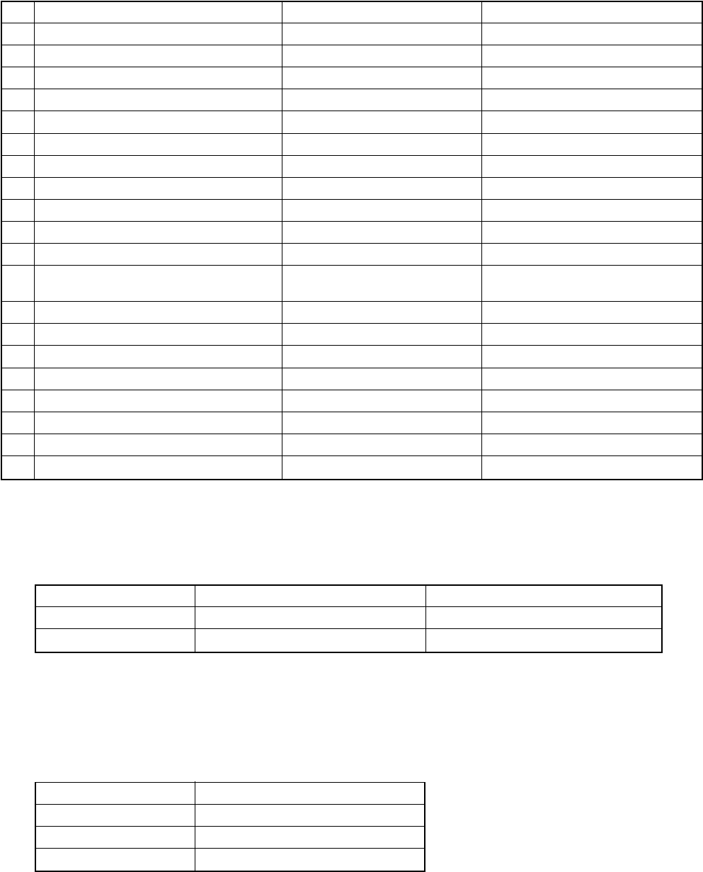
– 91 –
Memorandum for setup contents (Item code table (Example))
DN
01
02
03
06
0F
10
11
12
13
14
19
1E
28
2A
2b
2E
32
5d
60
8b
Item
Filter sign lighting time
Dirty state of filter
Central control address
Heating suction temp shift
Cooling only
Type
Indoor unit capacity
Line address
Indoor unit address
Group address
Flap type (Adjustment of air direction)
Temp difference of automatic cooling/
heating selecting control points
Automatic reset of power failure
Option
Thermo output selection (T10 ‡B)
Option
Sensor selection
High ceiling selection
Timer set (Wired remote controller)
Correction of high heat feeling
Memo At shipment
According to type
0000: Standard
0099: Unfixed
0002: +2°C (Floor type: 0)
0000: Shared for cooling/heating
According to model type
According to capacity type
0099: Unfixed
0099: Unfixed
0099: Unfixed
According to type
0003: 3 deg (Ts ± 1.5)
0000: None
0002:
0000: Thermo ON
0000:
0000: Body sensor
0000: Standard
0000: Available
0000: None
Type
Item code [10]
Setup data
0001*
0006
Type
4-way air discharge cassette
Concealed duct
Abbreviated name
RAV-SM560/800TU-E
RAV-SM560/800BT-E
* Initial setup value of EEPROM installed on the service P.C. board
Indoor unit capacity
Item code [11]
Setup data
0000*
0009
0012
Model
Invalid
56
80
* Initial setup value of EEPROM installed on the service P.C. board
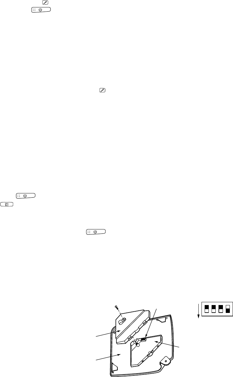
– 92 –
12. SETUP AT LOCAL SITE AND OTHERS
12-1. Indoor Unit
12-1-1. Test Run Setup on Remote Controller
<Wired remote controller>
1. When pushing
button on the remote controller for 4 seconds or more, “TEST” is displayed on LC display.
Then push button.
•“TEST” is displayed on LC display during operation of Test Run.
•During Test Run, temperature cannot be adjusted but air volume can be selected.
•In heating and cooling operation, a command to fix the Test Run frequency is output.
•Detection of error is performed as usual. However, do not use this function except case of Test Run be-
cause it applies load on the unit.
2. Use either heating or cooling operation mode for [TEST].
NOTE : The outdoor unit does not operate after power has been turned on or for approx. 3 minutes after
operation has stopped.
3. After a Test Run has finished, push
button again and check that [TEST] on LC display has gone off.
(To prevent a continuous test run operation, 60-minutes timer release function is provided to this remote
controller.)
<Wireless remote controller> (Option for 4-way air discharge cassette type)
1. Turn off power of the unit.
Remove the adjuster attached with sensors from the ceiling panel. For removing, refer to the Installation
manual attached to the ceiling panel. (Be careful to handle the adjuster because cables are connected to the
sensor.) Remove the sensor cover from the adjuster. (1 screw)
2. Change ON of Bit [1: TEST] of the sensor P.C. board switch [S003] to OFF.
Mount the sensor cover and mount the adjuster with sensor to the ceiling panel.
Turn on power of the unit.
3. Push
button on the wireless remote controller and select [COOL] or [HEAT] operation mode using
button. (All the display lamps of sensors on the wireless remote controller flash during Test Run.)
•Do not perform Test Run operation in other modes than [HEAT] / [COOL] mode.
•Detection of error is performed as usual.
4. After Test Run operation, push
button to stop the operation.
5. Turn off power of the unit.
Return Bit [1] of the sensor P.C. board switch [S003] to the original position. (ON → OFF)
Mount the adjuster with sensors to the ceiling panel.
Sensor cover
Adjust corner cap
1
2
3
4
ON
Sensor P.C. board
S003
Bit 1 : OFF to ON
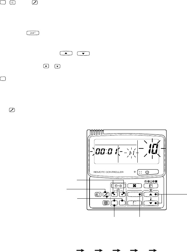
– 93 –
12-1-2. Setup to Select Function
<Procedure> Use this function while the indoor unit stops.
1
Push
SET
, , and buttons concurrently for 4 seconds or more.
The unit No. displayed at the first time indicates the indoor unit address of the master unit in the group control.
In this time, fan and flap of the selected indoor unit operate.
2
Every pushing button, the indoor unit numbers in the group control are displayed successively.
In this time, fan and flap of the selected indoor unit only operate.
3Using the set temperature /
buttons, set the item code (DN).
4
Using the timer time / buttons, select the setup data.
5
Push
SET
button. (OK if display goes on.)
•To change the selected indoor unit, proceed to
2
.
•To change the item to be set, proceed to
3
.
6
Pushing button returns the status to usual stop status.
UNIT
SET CL
UNIT No.
SET DATA
R.C. No.
4
613
5
1 2 3 4 5 6
2
END
<Operation procedure>

– 94 –
DN
01
02
03
06
0F
10
11
12
13
14
19
1E
28
2A
2b
2E
30
31
32
40
5d
60
8b
Item
Filter sign lighting
time
Dirty state of filter
Central control
address
Heating suction temp
shift
Cooling only
Type
Indoor unit capacity
Line address
Indoor unit address
Group address
Flap type
(Adjustment of air
direction)
Temp difference of
automatic cooling/
heating mode
selection COOL →
HEAT, HEAT →COOL
Automatic reset of
power failure
Option
Thermo output
selection (T10 )
Option
Option
Option
Sensor selection
Option
High ceiling selection
(Air volume selection)
Timer set
(Wired remote
controller)
Correction of high
heat feeling
Description
0000 : None 0001 : 150H
0002 : 2500H 0003 : 5000H
0004 : 10000H 0005 : Clogged sensor used
0000 : Standard 0001 : High degree of dirt
(Half of standard time)
0001 : No.1 unit to 0064 : No.64 unit
0099 : Unfixed
0000 : No shift 0001 : +1°C
0002 : +2°C to 0010 : -10°C
(Up to recommendation + 6)
0000 : Heat pump 0001 : Cooling only
(No display of [AUTO] [HEAT])
0000 : (Air discharge cassette 1) 0001 : (Air discharge cassette 4) to 0037
0000 : Unfixed 0001 to 0034
0001 : No.1 unit to 0030 : No.30 unit
0001 : No.1 unit to 0064 : No.64 unit
0000 : Individual 0001 : Master of group
0002 : Sub of group
0000 : No flap 0001 : Swing only
0004 : 4-way
0000 : 0 deg to 0010 : 10 deg
(For setup temperature, reversal of COOL/HEAT by ± (Data value)/2)
0000 : None 0001 : Reset
0000 : Indoor thermo ON 0001 : Output of outdoor comp-ON
receiving
0000 : Body TA sensor 0001 : Remote controller sensor
0000 : Standard filter
0001 : Oil guard, Super-long life, Optical regenerative deodorization
0003 : High performance (65%), High performance (90%),
High antibacterial performance (65%)
0000 : Available (Operable) 0001 : Unavailable (Operation prohibited)
0000 : None 0001 : Correction
At shipment
According to type
0000 : Standard
0099 : Unfixed
0002 : +2°C
(Floor type 0000: 0°C)
0000 : Shared for cooling/
heating
According to model type
According to capacity type
0099 : Unfixed
0099 : Unfixed
0099 : Unfixed
According to type
0003 : 3 deg
(Ts±1.5)
0000 : None
0002 : Default
0000: Thermo. ON
0000 : Default
0000 : Default
0000 : Default
0000 : Body sensor
0003 : Default
0000 : Standard
0000 : Available
0000 : None
Item No. (DN) table (Selection of function)
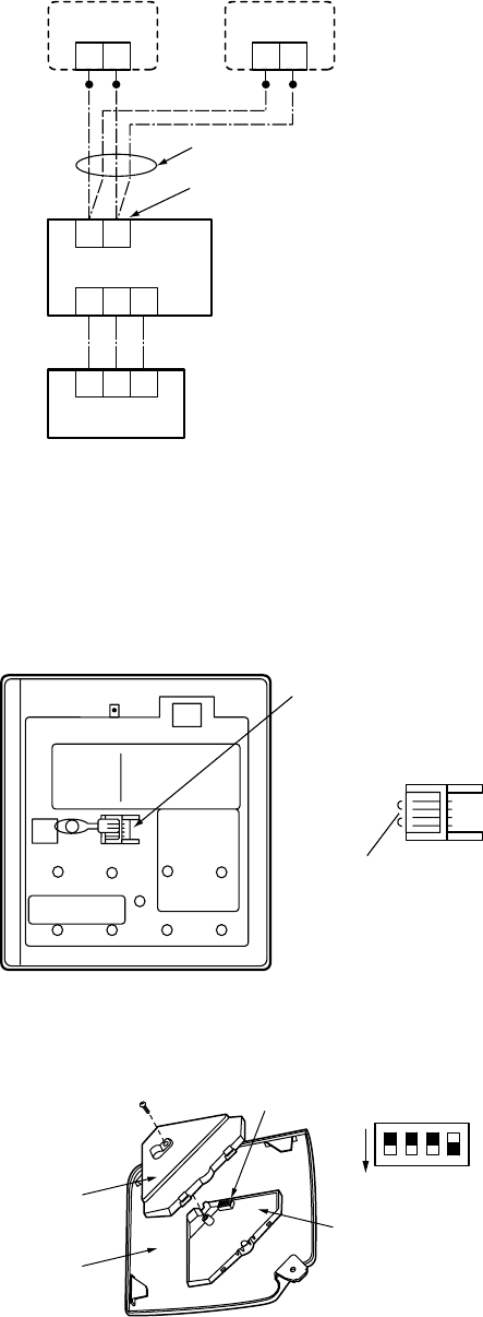
– 95 –
12-1-3. Cabling and Setting of Remote Controller Control
2-remote controller control (Controlled by two remote controllers)
One or multiple indoor units are controlled by two remote controllers.
(Max. 2 remote controllers are connectable.)
• 1 indoor unit is controlled by 2
remote controllers
(Setup method)
One or multiple indoor units are controlled by two remote controllers.
(Max. 2 remote controllers are connectable.)
<Wired remote controller>
How to set wired remote controller to sub remote
controller
Insert the remote controller address connector
provided on the rear side of the remote controller
switch P.C. board into Sub in exchange for Master.
<Wireless remote controller>
How to set wireless remote controller to sub
remote controller
Change OFF of Bit [3: Remote controller Sub/
Master] of switch S003 to ON.
[Operation]
1. The operation contents can be changed by Last-push-priority.
2. Use a timer on either Master remote controller or Sub remote controller.
Terminal block for
remote controller cables
Remote controller
cables (Procured locally)
Indoor unit
Outdoor unit
Remote controller
switch (Sub)
Remote controller
switch (Master)
Sold separately
213
213
BA
Sold separately
Master remote
controller
Remote controller
address connector
Rear side of remote
controller P.C. board
Sub
remote controller
Sensor
cover
Adjust
corner cap
1
2
3
4
ON
Sensor P.C. board
S003 Bit 1 : OFF to ON
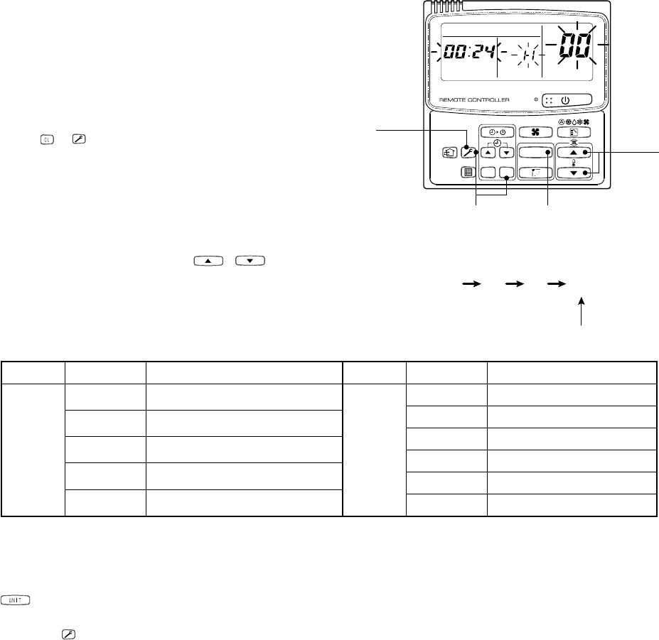
– 96 –
12-1-4. Monitor Function of Remote Controller Switch
nCall of sensor temperature display
<Contents>
Each sensor temperature of the remote controller, indoor
unit, and outdoor unit can become known by calling the
service monitor mode from the remote controller.
<Procedure>
1
Push +
buttons simultaneously for 4
seconds or more to call the service monitor
mode.
The service monitor goes on, the master indoor unit
No. is displayed, and then temperature of the item
code
00
is displayed.
2
Push the temperature setup
/
buttons
to select the sensor No. (Item code) of the sensor
to be monitored.
The sensor numbers are described below:
3
The temperature of indoor units and outdoor unit in a group control can be monitored by pushing
button to select the indoor unit to be monitored.
4
Pushing
button returns the display to usual display.
*1 Only master unit in group control
Indoor
unit data
Item code
00
01
02
03
04
Data name
Room temp (under control) *1
Room temp (remote controller)
Indoor suction temp
Indoor coil temp (TCJ)
Indoor coil temp (TC)
Outdoor
unit data
Item code
60
61
62
63
64
65
Data name
Heat exchanger temp TE
Outside temp TO
Discharge temp TD
Suction temp TS
—
Heat sink temp THS
UNIT
SET
CL
UNIT No.
SET DATA
R.C. No.
42
1 2 3 4
31
<Operation procedure>
Returned to usual display
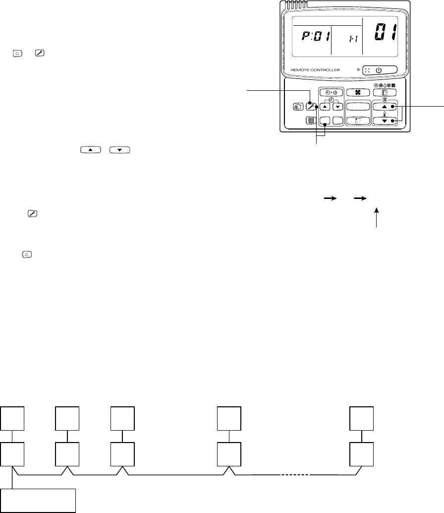
– 97 –
nCalling of error history
<Contents>
The error contents in the past can be called.
<Procedure>
1
Push +
buttons simultaneously for 4
seconds or more to call the service check mode.
Service Check goes on, the item code
01
is
displayed, and then the content of the latest alarm is
displayed. The number and error contents of the
indoor unit in which an error occurred are displayed.
2
In order to monitor another error history, push
the set temperature
/
buttons to
change the error history No. (Item code).
Item code
01
(Latest) → Item code
04
(Old)
NOTE : Four error histories are stored in memory.
3
Pushing
button returns the display to usual
display.
<Requirement>
Do not push
button, otherwise all the error histories of
the indoor unit are deleted.
UNIT
SET
CL
UNIT No.
SET DATA
R.C. No.
32
1
1 2 3
<Operation procedure>
Returned to usual display
(Group control operation)
In a group control, operation of maximum 8 indoor units can be controlled by a remote controller.
The indoor unit connected with outdoor unit (Individual/Master of twin) controls room temperature according to
setting on the remote controller.
<System example>
(1) Display range on remote controller
The setup range (Operation mode/Air volume select/Setup temp) of the indoor unit which was set to the
master unit is reflected on the remote controller.
(2) Address setup
Turn on power of the indoor unit to be controlled in a group within 3 minutes after setting of automatic
address.
If power of the indoor unit is not turned on within 3 minutes (completion of automatic address setting), the
system is rebooted and the automatic address setting will be judged again.
1) Connect 3 In/Out cables surely.
2) Check line address/indoor address/group address of the unit one by one.
3) The unit No. (line/indoor gout address) which have been set once keep the present status as a rule if the
unit No. is not duplicated with one of another unit.
OUT
IN
Remote controller
1-1
OUT
IN 2-1
Master
OUT
IN 3-1
OUT
IN 4-1
OUT
IN 7-1
Max. 8 units
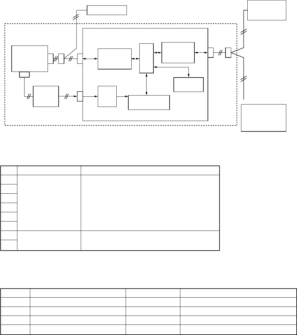
– 98 –
12-2. Network Adapter
Model name: TCB-PCNT20E
12-2-1. Function
A network adapter is an optional P.C. board to connect the indoor unit to AI net (Central control remote controller).
12-2-2. Microcomputer Block Diagram
12-2-3. Network Address Setup Switch (SW01)
No.
1
2
3
4
5
6
7
8
Item
LSB
Central control address
MSB
Setup availability from
remote controller
Setup contents
123456
×××× × × : No.1 unit × : Switch OFF
〇××× × × : No.2 unit 〇 : Switch OFF
:
〇〇〇〇 〇 × : No.63 unit
〇〇〇〇 〇 〇 : No.64 unit
Switch OFF : Setup available from remote controller
Switch ON : Setup unavailable from remote controller
12-2-4. LED Display Specification
LED No.
D01 (Red)
D02 (Red)
D03 (Red)
D04 (Red)
Function
Communication status: Remote controller
Communication status: Center
Operation status of air conditioner
Air conditioner error
Go on
During communication
During communication
Running
Error
Go off
No communication (including communication error)
No communication (including communication error)
Stop
Normal
* For positions of LED, refer to P.C. board external view.
CN03
CN02
CN01 5V
MCU
EEPROM
Remote controller
Indoor control
P.C. board
Power
transformer
Terminal
block
(A.B)
AC14V
AC220-
240V
Optional communication P.C. board
Remote
controller
communication
circuit
5V
power
supply Network address
setup switch
Indoor unit
AI-NET
communication
circuit
Central control
remote controller
Terminal
block
(X.Y)
Network
Communication
units: Total 64 units
Communication
distance: 1km
CN41
CN309
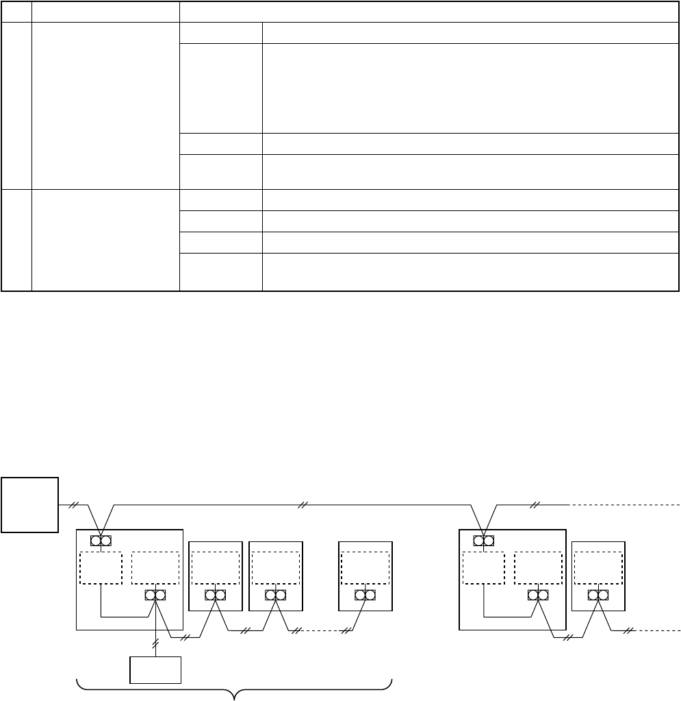
– 99 –
12-2-5. Communication Cable Specifications
No.
1
2
Communication circuit
Remote controller
communication side
AI NET side
Communication cable specifications
Cable
Cable type
Cable dia.
Cable length
Cable
Cable type
Cable dia.
Cable length
Neutral 2-cable type
CVV (JIS C3401) Controlling vinyl insulation vinyl seal cable
VCTF (JIS C3306) Vinyl cab tire round type cord
VCT (JIS C3401) 600V vinyl cab tire cable
VVR (JIS C3401) Vinyl insulation seal cable round type
MVVS Cable with net shielding for instrumentation
CPEVS Shielded polyethylene insulation vinyl seal cable
0.5 to 2.0 mm²
Total cable length Max. 500m
(Up to 400m when there is wireless remote controller in group)
Neutral 2-cable type
MVVS Cable with net shielding for instrumentation
1.25 mm² ≤ 500 m, 2.0 mm² ≤ 1 km
Total cable length : Up to 500m when using 1.25mm² cable,
Up to 1000m when using 2.0mm² cable
12-2-6. Cable Connection
<Network cable connection>
• Install a network adapter per 1 group of the group control (including single unit control). Also install a network
adapter to one of the indoor units in the group control.
Remote
controller
Central
control
remote
controller Indoor unit Indoor
unit
Network
adapter
Indoor
control
P.C. board
X Y
A B
Indoor
control
P.C. board
A B
Indoor
unit
Indoor
control
P.C. board
A B
Indoor
unit
Indoor
control
P.C. board
A B
Indoor unit Indoor
unit
Network
adapter
Indoor
control
P.C. board
X Y
A B
Indoor
control
P.C. board
A B
Connectable indoor units per group: Up to 8 units
(1-remote controller system*)
* In case of 2-remote controllers system,
the connectable indoor units are up to 7 units.
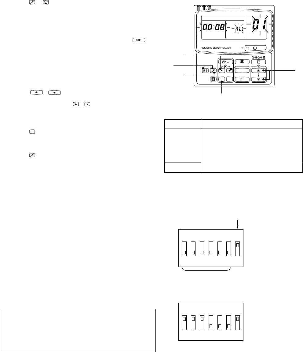
– 100 –
12-3. How to Set an Address Number
When connecting indoor units to the central control remote controller by using a network adapter, it is required
to set up a network address No.
•The network address No. should be agreed with the line No. of the central control remote controller.
•When the unit was shipped from the factory, the network address has been set to 1.
The following two methods to set the network address are provided.
1. How to set from the remote controller at indoor unit side
* This method is effective only when of set switch SW01 on the network adapter P.C. board is turned off.
<Procedure> Set the network address while the unit stops.
Fig. 1
Setup data
0001
0002
0003
:
0064
0099
UNIT
SET
CL
UNIT No.
SET DATA
R.C. No.
3
152
4
1
Push +
buttons for 4 seconds or more.
In the group control, the unit No RLL is displayed,
and then all the indoor units in the group control are
selected. In this time, fans of all the selected indoor
units are turned on. (Fig. 1)
(Keep status of RLL display without pushing
button.)
For the individual remote controller which is not
included in a group control, the line address and the
indoor unit address are displayed.
2
Specify the item code 03 using the temperature
setup /
buttons.
3
Using the timer time
/
buttons, select the
setup data.
The setup data are shown in the right table (Table 1).
4
Push
SET
button. (OK if display goes on)
•To change the item to be set, return to
2
.
5
Push
button.
The status returns to the usual stop status.
2. How to set by the switch on the network adapter P.C. board
When the remote controller cannot be found or when you don’t want to change setting of the network address
No. from the remote controller, use the setup switch SW01 on the network adapter P.C. board (Network address
No. setup switch) to set the address No.
<Procedure>
(1) Turn off the power.
(2) Turn of the address No. setup switch SW01 to ON
side. Accordingly the address No. set on the remote
controller is invalidated. (See Fig. 2.)
(3) Set the network address No. with combination of ON
and OFF of to of the address No. setup switch
SW01. The relation between combination of ON/OFF
and address No. is described in Table 2. The right
figure (Fig. 3) shows an example of case that the
address No. is set to 16.
When the network address No. has been changed,
be sure to turn of power of the central control remote
controller again or to reset the remote controller using
the reset hole on the operation panel of the central
control remote controller.
Table 1
Network address No.
1
2
3
:
64
Unset (Setup at shipment from factory)
Fig. 2
Fig. 3
Invalid address No. setup from
remote controller
No. setup switch
SW01
Address No. setup
ON side
OFF side
(Numeral side)
4567
32
1
ON
ON side
OFF side
(Numeral side)
Setup example of address No. 16
4567
321
ON

– 101 –
Table 2 Network address No. setup table (SW01)
〇 : ON side
× : OFF side
Address No.
01
02
03
04
05
06
07
08
09
10
11
12
13
14
15
16
17
18
19
20
21
22
23
24
25
26
27
28
29
30
31
32
Requirement in Service
When using this product as service part to replace the network adapter P.C. board, be sure to match the setup
of the setup switch SW01 (Network address No. setup switch) on the network adapter P.C. board with the P.C.
board setup before replacement.
Address No.
33
34
35
36
37
38
39
40
41
42
43
44
45
46
47
48
49
50
51
52
53
54
55
56
57
58
59
60
61
62
63
64
①②③④⑤⑥
××××××
〇×××××
×〇××××
〇〇××××
××〇×××
〇×〇×××
×〇〇×××
〇〇〇×××
×××〇××
〇××〇××
×〇×〇××
〇〇×〇××
××〇〇××
〇×〇〇××
×〇〇〇××
〇〇〇〇××
××××〇×
〇×××〇×
×〇××〇×
〇〇××〇×
××〇×〇×
〇×〇×〇×
×〇〇×〇×
〇〇〇×〇×
×××〇〇×
〇××〇〇×
×〇×〇〇×
〇〇×〇〇×
××〇〇〇×
〇×〇〇〇×
×〇〇〇〇×
〇〇〇〇〇×
①②③④⑤⑥
×××××〇
〇××××〇
×〇×××〇
〇〇×××〇
××〇××〇
〇×〇××〇
×〇〇××〇
〇〇〇××〇
×××〇×〇
〇××〇×〇
×〇×〇×〇
〇〇×〇×〇
××〇〇×〇
〇×〇〇×〇
×〇〇〇×〇
〇〇〇〇×〇
××××〇〇
〇×××〇〇
×〇××〇〇
〇〇××〇〇
××〇×〇〇
〇×〇×〇〇
×〇〇×〇〇
〇〇〇×〇〇
×××〇〇〇
〇××〇〇〇
×〇×〇〇〇
〇〇×〇〇〇
××〇〇〇〇
〇×〇〇〇〇
×〇〇〇〇〇
〇〇〇〇〇〇

– 102 –
12-4. Display and Operation of Main Remote Controller and Central Control Remote
Controller
1. Turn on all the power supplies of the air conditioner, and then turn on power of the central control remote
controller (Line 16 RBC-SXC1P, Line 64 TCB-SC641). If both power supplies are simultaneously turned on or
if they are turned on reversely, the check code [97] may be temporarily displayed on the central remote
controller. When settings of connecting cables and central control address are correct, the connected air
conditioner is displayed on the central control remote controller.
2. As shown in the following table, there is difference of LCD between main remote controller (RBC-AMT21)
and the central control remote controller and also there are restriction and others of operation.
3. When using the remote controller together with the former one (RBC-AM1, AT1), the display on the main
remote controller differs if [Last-push priority/Center/Operation Prohibited] is selected from the central control
remote controller.
1
2
3
4
5
6
Main remote controller
[SPEED] [AUTO]
[HH]
[H]
[L]
[SPEED] [HH]
[SPEED] [HH]
[H]
[L]
[SPEED] [AUTO]
[HH]
[H]
[L]
[SWING] and air
direction adjustment
(No display)
Test run (4 seconds)
3-digits display (alpha-
bet + 2-digits numeral)
Central control remote controller
[VOL] [AUTO]
[H]
[M]
[L]
[VOL] [FIX]
[VOL] [AUTO]
[H]
[M]
[L]
[VOL] [AUTO]
[LOUVER]
Manual operation for
[LOUVER]
Check code display and
check reset (3 seconds)
2-digits display (alpha-
bet or numeral)
Cautions
Display of air speed selection differs.
In duct type
Air speed becomes [H] and [FIX].
When handling main remote controller, [AUTO] is
not displayed. If [AUTO] is selected at center side,
[AUTO] is displayed on the main remote controller.
In this time, the air speed becomes [HH].
On the central remote controller, only [AUTO] is
displayed. The display on the main remote
controller changes to [AUTO] by changing the
setup temperature/louver, and the air speed is
automatically selected.
On the central remote controller, only [LOUVER] is
displayed. It is displayed while flap is swinging,
and the setup operation of [LOUVER] becomes
selection of swing ON/OFF.
To set up the air direction, use the main remote
controller.
In a model type without air direction adjustment
The function of long-pushing operation for the
check button differs. If the check reset operation
on the central remote controller is performed
during operation of air conditioner, the operation
stops once, and then the operation restarts. (Error
of air conditioner is cleared.)
Display of check code differs.
Ex. : Float switch operation
Main side: [P10]
Center side: [0b]
Item
Air volume selection
Air speed selection
in FAN mode
Air speed selection
in DRY mode
Air direction
adjustment
Check button
Check code
Contents
1
2
3
Contents
New remote controller
(RBC-AMT21)
(No display)
[CENTER] goes on
Former remote controller
(RBC-AM1, AT1)
(No display)
[CENTER] goes on
[CENTER] flashes
Remarks
All the settings and ON/OFF operations are
available.
The setup contents on the central control remote
controller are fixed, and only ON/OFF operation
and timer setup operation are available on the
main remote controller.
The setup contents on the central control remote
controller are fixed, and the air conditioner stops.
Operation from the main remote controller is
unavailable.
Item
Last-push priority
Center
Operation prohib-
ited
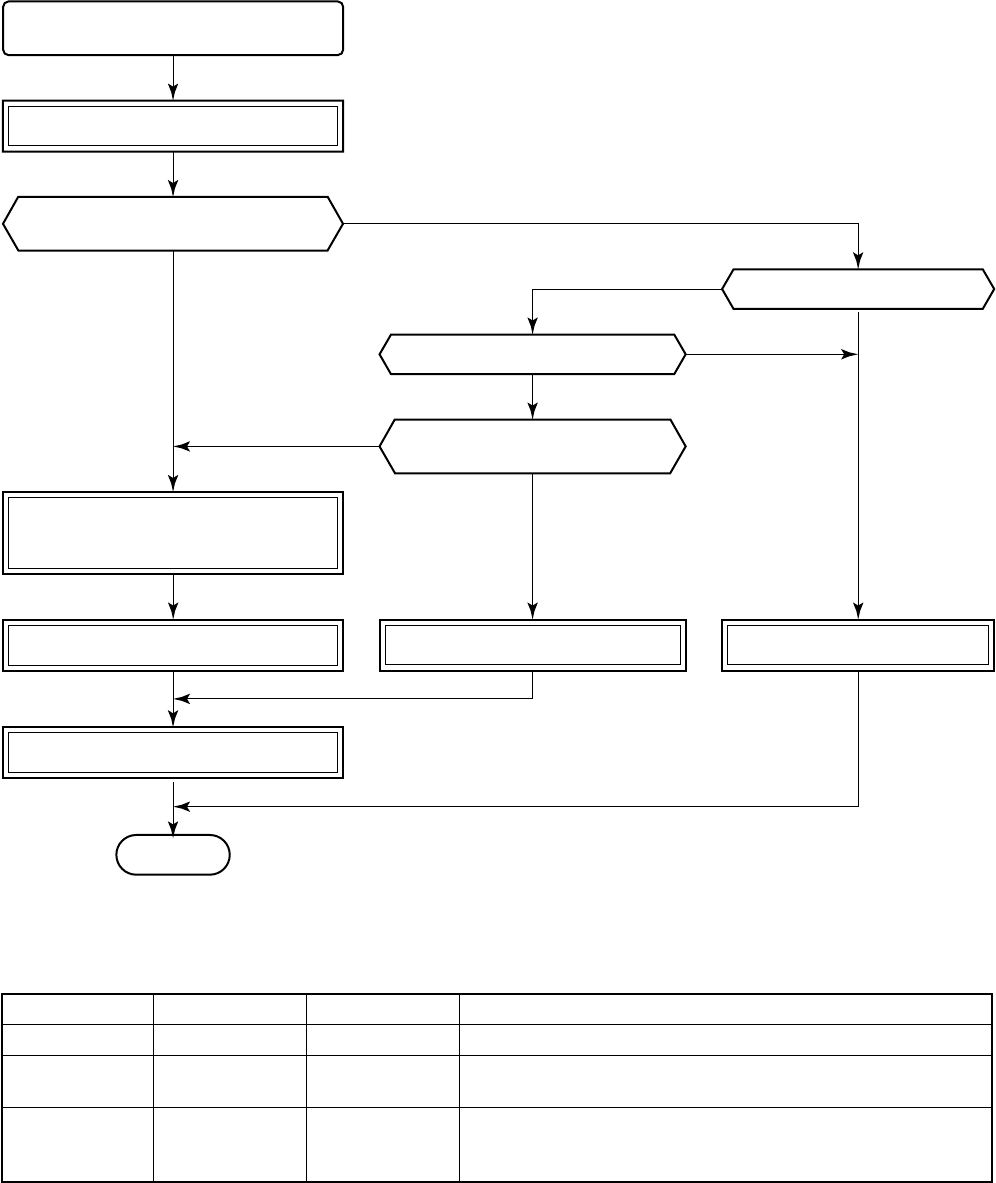
– 103 –
13. ADDRESS SETUP
13-1. Address Setup
<Address setup procedure>
When an outdoor unit and an indoor unit are connected, or when an outdoor unit is connected to each indoor
unit respectively in the group operation even if multiple refrigerant lines are provided, the automatic address
setup completes with power-ON of the outdoor unit. The operation of the remote controller is not accepted while
automatic address works. (Approx. 4 to 5 minutes)
•When the following addresses are not stored in the neutral memory (IC10) on the indoor P.C. board, a test run
operation cannot be performed. (Unfixed data at shipment from factory)
Line address
Indoor unit address
Group address
Item code
12
13
14
Data at shipment
0099
0099
0099
Setup data range
0001 (No. 1 unit) to 0030 (No. 30 unit)
0001 (No. 1 unit) to 0030 (No. 30 unit)
Max. value of indoor units in the identical refrigerant line (Double twin = 4)
0000 : Individual (Indoor units which are not controlled in a group)
0001 : Master unit (1 indoor unit in group control)
0002 : Sub unit (Indoor units other than master unit in group control)
Setup of line address of outdoor unit,
indoor unit address, and group address
Completion of cabling work
Turn on power of outdoor unit. Turn on power of outdoor unit.
Connect one remote controller with
one indoor unit (1 : 1) tentatively with
communication cable.
END
Turn on power of outdoor unit.
Set to all indoor units one by one.
Do you arbitrarily set the
indoor unit address?
Do you change setting after
automatic setting at the first time?
Is refrigerant line 1 line?
Is group control performed?
Setup of automatic
address finishes within
4 to 5 minutes.
After completion of address
setup, change is to arbitral
address/group manually.
(To AUTO address mode)
(MANUAL)
( ) ( )
YES
YES
YES
YES
NO
NO
NO
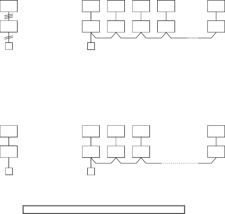
– 104 –
13-2. Address Setup & Group Control
<Terminology>
Indoor unit No. : N - n = Outdoor unit line address N (Max. 30) - Indoor unit address n (Max. 64)
Group address : 0 = Individual (Not group control)
1 = Master unit in group control
2 = Sub unit in group control
Master unit (= 1) : The representative of multiple indoor units in group operation sends/receives signals to/from
the remote controllers and sub indoor units. (* It has no relation with an indoor unit which
communicates serially with the outdoor units.)
The operation mode and setup temperature range are displayed on the remote controller
LCD. (Except sir direction adjustment of flap)
Sub unit (= 2) : Indoor units other than master unit in group operation
Basically, sub units do not send/receive signals to/from the remote controllers.
(Except errors and response to demand of service data)
13-2-1. System configuration
1. Single 2. Single group operation
13-2-2. Automatic address example from unset address (No miscabling)
1. Standard (One outdoor unit)
1) Single
Only turning on source power supply (Automatic completion)
2) Gr operation
(Multiple outdoor units = Miltiple indoor units only with serial
communication)
Outdoor
1-1
Individual
Indoor (Master/Sub)
Remote
controller
2-1
Sub 1-1
Sub 4-1
Master 3-1
Sub 8-1
Sub
1-1
Individual (Master/Sub)
Max. 8 units
2-1
Sub 1-1
Sub 4-1
Master 8-1
Sub
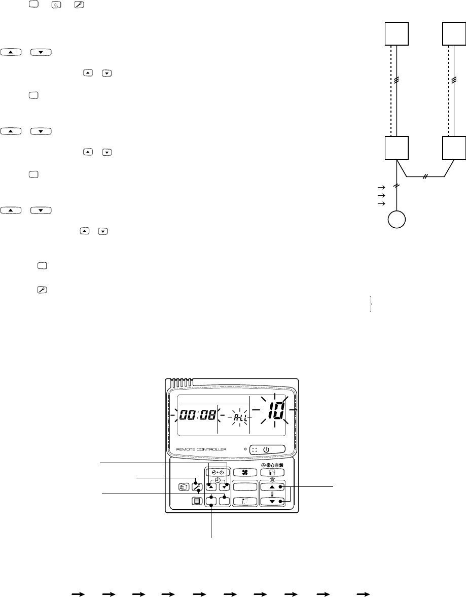
– 105 –
13-3. Address Setup
In case that addresses of the indoor units will be determined prior to piping work after cabling work
(Manual setting from remote controller)
<Address setup procedure>
•Set an indoor unit per a remote controller.
•Turn on power supply.
1
Push
SET
+ + buttons simultaneously
for 4 seconds or more.
2
(←←
←←
← Line address) Using the temperature setup
/
buttons, set 12 to the item code.
3
Using timer time / buttons, set the line address.
4
Push
SET
button. (OK when display goes on.)
5
(←←
←←
← Indoor unit address) Using the temperature setup
/ buttons, set 13 to the item code.
6
Using timer time / buttons, set 1 to the line address.
7
Push
SET
button. (OK when display goes on.)
8
(←←
←←
← Group address) Using the temperature setup
/
buttons, set 14 to the item code.
9
Using timer time /
buttons, set
0000
to Individual,
0001
to Master unit, and
0002
to sub unit.
10
Push
SET
button. (OK when display goes on.)
11
Push
button.
Setup completes.
(The status returns to the usual stop status.)
(Example of 2-lines cabling)
(Real line: Cabling, Broken line: Refrigerant pipe)
Line address 1
Indoor unit address 1
Group address 1
For the above example, perform setting by connecting
singly the wired remote controller without remote
controller inter-unit cable.
Group address
Individual : 0000
Master unit : 0001
Sub unit : 0002 In case of group control
OUT
IN
OUT
IN
2
1
2
UNIT
SET
CL
UNIT No.
SET DATA
R.C. No.
3, 6, 9 11
12, 5, 8
4, 7, 10
1 2 3 4 5 6 7 8 9 10 11
END
END
<Operation procedure>
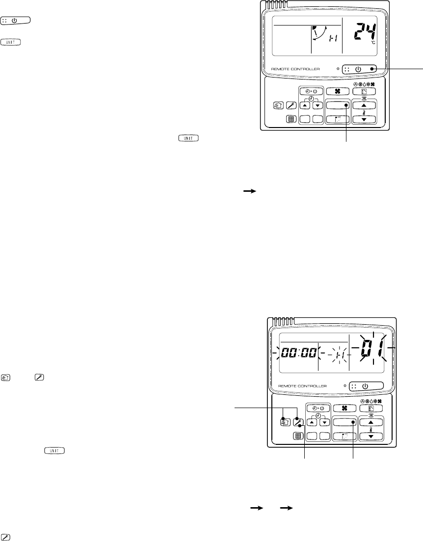
– 106 –
nConfirmation of indoor unit No. position
1. To know the indoor unit addresses though position of the indoor unit body is recognized
•In case of individual operation (Wired remote controller : indoor unit = 1 : 1)
(Follow to the procedure during operation)
<Procedure>
1
Push
button if the unit stops.
2
Push button.
Unit No. 1-1 is displayed on LCD.
(It disappears after several seconds.)
The displayed unit No. indicate line address and
indoor unit address.
(When other indoor units are connected to the
identical remote controller (Group control unit), other
unit numbers are also displayed every pushing
button.
UNIT
SET
CL
UNIT No.
CODE No.
1
1 2
2
END
Operation
<Operation procedure>
UNIT
SET CL
UNIT No.
SET DATA
R.C. No.
1
1 2 3
2
3
END
<Operation procedure>
2. To know the position of indoor unit body by address
•To confirm the unit No. in the group control
(Follow to the procedure during operation) (in this procedure, the indoor units in group control stop.)
<Procedure>
The indoor unit numbers in the group control are succes-
sively displayed, and fan, flap, and drain pump of the
corresponding indoor unit are turned on. (Follow to the
procedure during operation)
1
Push and buttons simultaneously for 4
seconds or more.
•Unit No. ALL is displayed.
•Fans and flaps of all the indoor units in the group
control operate.
2
Every pushing button, the unit numbers in
the group control are successively displayed.
•The unit No. displayed at the first time indicates the
master unit address.
•Fan and flap of the selected indoor unit only
operate.
3
Push button to finish the procedure. All the
indoor units in the group control stop.

– 107 –
RAV-SM800AT-E LED display when SW800 : Bit 1, 2, 3, 4 OFF
•When multiple errors are detected, the latest error is displayed.
•While LED displays 〇 (go on), there is the main cause of error in control at CDB side and it stops abnormally.
•While LED displays ◎ (flash), there is the main cause of error in control at IPDU side and it stops abnormally.
•For an error in case thermo operation, the communication is interrupted on the serial circuit. If continuing the
case thermo operation, serial sending to the indoor unit is interrupted and a serial communication error is
output.
Table A
CDB side
IPDU side
No.
1
2
3
4
5
6
7
8
9
10
11
12
13
14
15
16
Item
TE sensor error
TD sensor error
TS sensor error
TO sensor error
Discharge temp error
Out DC fan error
Communication error between IPDU
(Abnormal stop)
High-pressure release operation
EEPROM error
Communication error between IPDU
(No abnormal stop)
G-Tr short-circuit protection
Detection circuit error
Current sensor error
Phase missing detection
Comp lock error
Comp breakdown
Check code
B type
18
19
18
1B
1E
1A
1C
21
—
—
—
14
16
17
17
1D
1F
LED display
D800 D801 D802 D803
(Red) (Yellow) (Yellow) (Yellow)
〇●●●
〇〇●●
●●〇●
●〇●●
●〇〇●
〇〇〇●
〇●●〇
●〇●〇
〇〇●〇
●●〇〇
◎●●●
●◎●●
◎◎●●
●●●◎
●●◎●
◎●◎●
〇 : Go on, ● : Go off, ◎ : Flash (5 Hz)

– 108 –
14. TROUBLESHOOTING <WALL TYPE>
14-1. Summary of Troubleshooting
<Wired remote controller type>
1. Before troubleshooting
1) Required tools/instruments
• + and – screwdrivers, spanners, radio cutting pliers, nippers, push pins for reset switch
•Tester, thermometer, pressure gauge, etc.
2) Confirmation points before check
The following operations are normal.
a) Compressor does not operate.
•Is not 3-minutes delay (3 minutes after compressor OFF)?
•Does not thermostat turn off?
•Does not timer operate during fan operation?
•Is not detected an overflow error?
•Is not outside high-temperature operation controlled in heating operation?
b) Indoor fan does not rotate.
•Does not cool air discharge preventive control work in heating operation?
c) Outdoor fan does not rotate or air speed changes.
•Does not high-temperature release operation control work in heating operation?
•Does not outside low-temperature operation control work in cooling operation?
•Is not defrost operation performed?
d) ON/OFF operation cannot be performed from remote controller.
•Is not during emergency operation?
•Is not the control operation performed from outside/remote side?
Did you return the cabling to the initial positions?
Are connecting cables of indoor unit and remote controller correct?
2. Troubleshooting procedure
When a trouble occurred, check the parts along with the following procedure.
Trouble →→
→→
→ Confirmation of check code display →→
→→
→ Check defective position and parts.
NOTE :
For cause of a trouble, power conditions or malfunction/erroneous diagnosis of microcomputer due to outer
noise is considered except the items to be checked. If there is any noise source, change the cables of the
remote controller and the signal line to shield cables.
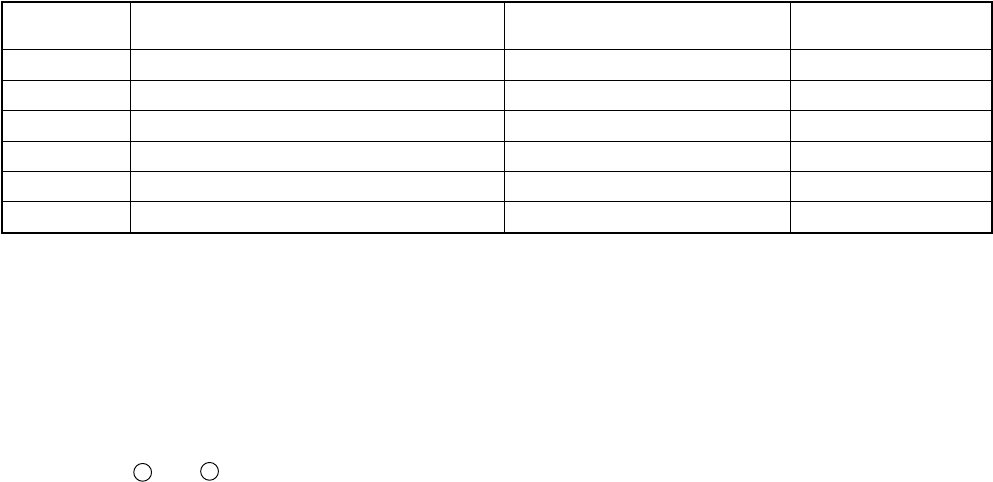
– 109 –
(a) Outline of Judgment
A primary judgment to detect cause of error exists on the indoor unit or outdoor unit is performed in the
following procedure.
<Judgment by flashing display on the indoor unit display part>
The indoor unit monitors operating status of the air conditioner, and if a protective circuit works, contents of
the self-diagnosis are displayed with a block restricted to the following cases on the indoor unit display part.
(b) Self-diagnosis by check code on the remote controller
Refer to “Judgment of error mode by check code on the remote controller”.
<Wireless remote controller type>
1. Before troubleshooting
1) Required tools/instruments
• + and – screwdrivers, spanners, radio cutting pliers, nippers, etc.
•Tester, thermometer, pressure gauge, etc.
2) Confirmation points before check
The following operations are normal.
a) Compressor does not operate.
•Is not 3-minutes delay (3 minutes after compressor OFF)?
•Does not thermostat turn off?
•Does not timer operate during fan operation?
•Is not outside high-temperature operation controlled in heating operation?
b) Indoor fan does not rotate.
•Does not cool air discharge preventive control work in heating operation?
c) Outdoor fan does not rotate or air volume changes.
•Does not high-temperature release operation control work in heating operation?
•Does not outside low-temperature operation control work in cooling operation?
•Is not defrost operation performed?
d) ON/OFF operation cannot be performed from remote controller.
•Is not forced operation performed?
•Is not the control operation performed from outside/remote side?
Did you return the cabling to the initial positions?
Are connecting cables between indoor unit and receiving unit correct?
Remote
controller code
—
00
01
02
03
—
Block display
Operation lamp display flashes. (1Hz)
Operation lamp display flashes. (5Hz)
Operation/timer lamp displays flash. (5Hz)
Operation/defrost lamp displays flash. (5Hz)
Operation/timer/defrost lamp displays flash. (5Hz)
——
Contents of self-diagnosis
Power failure (In power ON)
Indoor P.C. board
Inter-unit cables/transmission system
Outdoor P.C. board
Cycle system, etc.
——
Check code
——
0b to 0F, 11, 12, b5, b6
04
14 to 19, 1A, 1C
1d, 1E, 1F, 21
1b, 8b
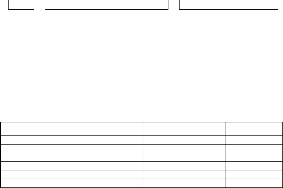
– 110 –
2. Troubleshooting procedure
When a trouble occurred, check the parts along with the following procedure.
Trouble →→
→→
→ Confirmation of check code by service mode →→
→→
→ Check defective position and parts.
NOTE :
For cause of a trouble, power conditions or malfunction/erroneous diagnosis of microcomputer due to outer
noise is considered except the items to be checked. If there is any noise source, change the cable of the signal
line to shield cable.
(a) Outline of Judgment
A primary judgment to detect cause of error exists on the indoor unit or outdoor unit is performed in the
following procedure.
<Judgment by flashing display on the indoor unit display part>
The indoor unit monitors operating status of the air conditioner, and if a protective circuit works, contents of
the self-diagnosis are displayed with a block restricted to the following cases on the indoor unit display part
(Sensors).
Remote
controller code
—
00
01
02
03
—
Block display
Operation lamp display flashes. (1Hz)
Operation lamp display flashes. (5Hz)
Operation/timer lamp displays flash. (5Hz)
Operation/defrost lamp displays flash. (5Hz)
Operation/timer/defrost lamp displays flash. (5Hz)
——
Contents of self-diagnosis
Power failure (In power ON)
Indoor P.C. board
Inter-unit cables/transmission system
Outdoor P.C. board
Cycle system, etc.
——
Check code
——
0b to 0F, 11, 12, b5, b6
04
14 to 19, 1A, 1C
1d, 1E, 1F, 21
1b, 8b
(b) Self-diagnosis by check code on the remote controller
In the wireless type models, the self-diagnosis for the protective circuit operation is performed by handling
the remote controller. First change the operation mode of the remote controller, and then perform the self-
diagnosis by the displayed contents of the remote controller and the existence of operation lamp flashing
(5Hz) and buzzer sound (Pi, Pi, Pi). During self-diagnosis operation, the timer lamp usually flashes (5Hz).
Selection of remote controller operation mode
1) Selection of service mode
Push the select button at lower side of the wireless remote controller with a tip of pencil, etc. for
approx. 3 seconds or more. In this time, check that [00] is displayed on the room temp. display part
and other displays go off.
2) Selection of normal mode
Push the reset button at lower side of the wireless remote controller with a tip of pencil, etc. In this
time, check that [“AM”] display on the time display part flashes.
Cautions in service
1) After service work, be sure to push the reset button to return the mode to normal mode.
2) After service by the check codes, turn off the power switch once and then turn on the switch to return
the stored memory in microcomputer to the initial status.
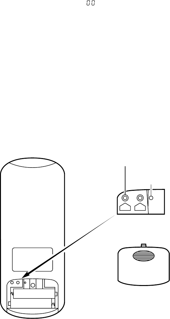
– 111 –
(c) Self-diagnosis with remote controller
With the indoor unit control, self-diagnosis of protective circuit action can be done by turning the remote
controller operation into service mode, operating the remote controller, observing the remote controller
indicators and checking whether TIMER lamp flashes (5 Hz).
NOTE :
•To perform this self-diagnosis, the remote controller with the service code of 43069666 is required.
<How to select remote control operation mode>
1. Selecting service mode
Push the switch button provided on rear bottom of the wireless remote control with a tip of pencil for more
than 3 seconds. Make sure the setting temperature
“ ”
is displayed on the display and other display is
turned off.
2. Selecting ordinary mode
Push the all clear button (ACL) on the rear bottom of the wireless remote controller with a tip of pencil for
more than 3 seconds. Make sure the operation mode display, wind volume display, clock display and setting
temperature display are turned on and “
:
” of the clock display is flashing.
<Cautions when doing service>
1. After completion of servicing, always push the all clear (ACL) button to return the operation mode to the
normal mode.
2. After completion of servicing by the check code, turn off the power once and then turn on the power to reset
memorized contents of the microcomputer to the initial status.
ACL CLOCK
(Rear bottom of remote control)
ACL
CLOCK
All clear button
Switch for selecting
service mode
Rear bottom cover
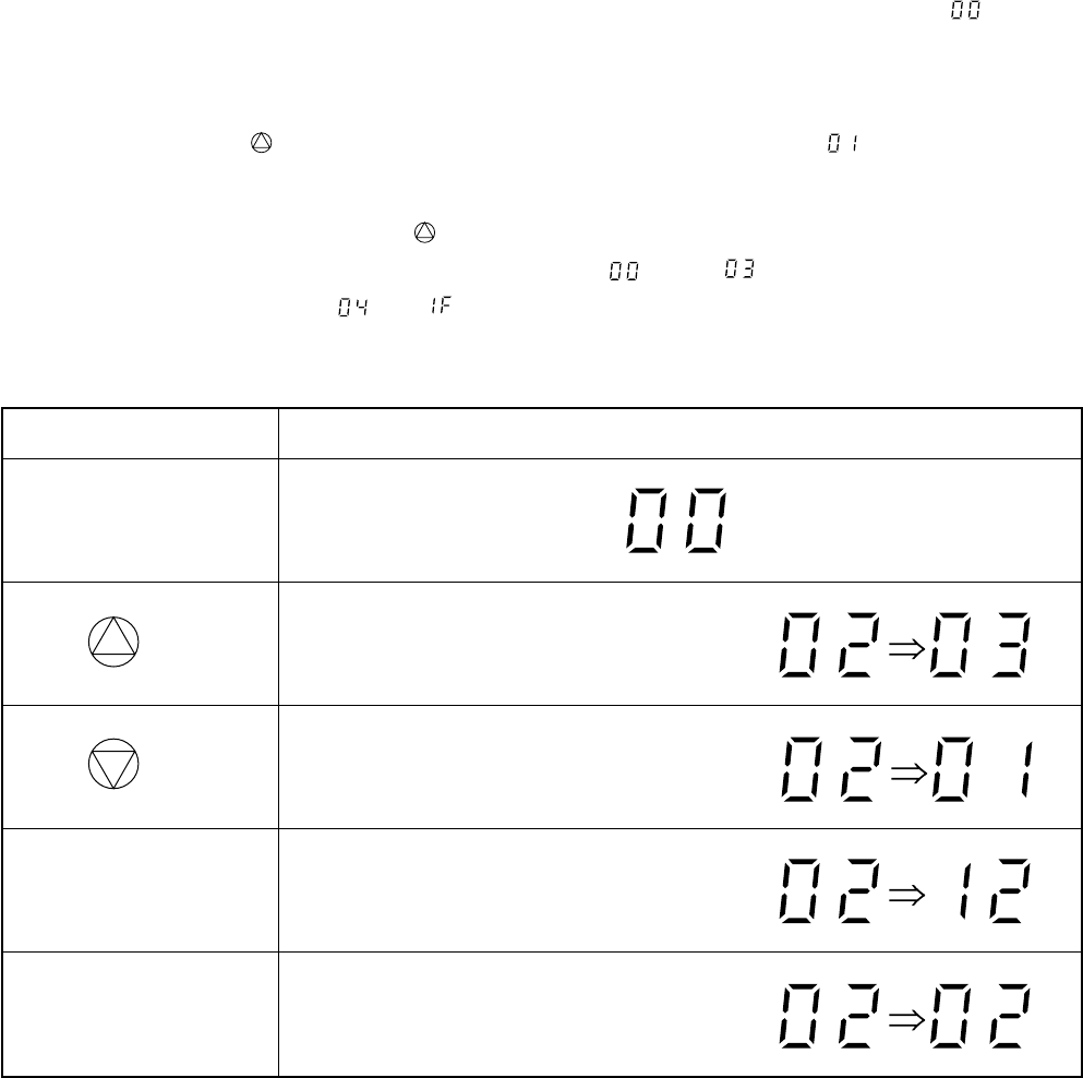
– 112 –
<Self-diagnosis by check codes>
1. The self-diagnosis by the check codes is conducted under the block displays.
2. Remote controller key operation under the service mode is conducted by ON/OFF or TEMP. The remote
controller display by each key operation is varied as shown below. Two digit number is displayed in a hexa-
decimal number.
3. The self-diagnosis by the check codes is conducted with procedures shown below.
1) Enter the service mode and make sure the off timer display of the remote controller shows
“ ”
.
2) Operate the “ON/OFF” key and make sure the timer lamp on the display section is flashing (5 Hz).
3) At the same time, also make sure the operation lamp is also flashing. This shows that the protection
circuit on the indoor P.C. board is working.
4) Operate the TEMP. key and make sure the remote controller display shows
“ ”
and flashing of the
operation lamp. If the operation lamp is flashing, it shows the protection circuits for connecting cable is
working or thermal fuse is blown.
5) In the same way, operate the TEMP. key so that the display is increased one by one to continue checks
by the self-diagnosis as shown in the next table. From
“ ”
up to
“ ”
check operations of protection
circuits for each block, and
“ ”
to
“ ”
check operations of the typical protection circuits.
”
“
”
“”
“
”
“”
“
”
“”
“
”
“”
“
Operating key
ON/OFF
TEMP. (Up)
TEMP. (Down)
“AUTO” LOUVER
“SET” LOUVER
Indication after operation
1 is added to data before operation.
(Example)
1 is subtracted from data before operation.
(Example)
10 is subtracted from data before operation.
(Example)
Data before operation is directly transferred.
(Example)
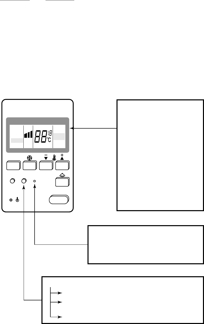
– 113 –
14-2. Troubleshooting with CHECK Display of Remote Controller
14-2-1. In case of main remote controller/sub-remote controller A
RBC-AM1E RBC-AS1E
1. Operation for CHECK display
When pushing the CHECK switch, the indoor unit No. (Group address No.) which sends the check code is
displayed at the right side of the set up TEMP. display section, and the check data of 2 errors/faults x 16 units
is displayed in the set up temp. display section.
If there is a filter display, the indoor unit No. which sends the filter signal is displayed at the right side of the
set up temp. display section, and then the check code is displayed as described above.
(1 display for 3 seconds)
LCD display “STANDBY”
is present.
• When phase-sequence of power
wiring is incorrect
• When combination of indoor units
is over capacity
• Indoor unit with command
excepted by operation mode
select switch
• When there is an indoor unit
which stopped with the indoor
overflow alarm “0b”.
• Indoor unit with cooling operation
command excepted by heating
priority control
RESET switch
Push the switch in the hole with pin.
The remote controller resets the power supply.
(All data is cleared.)
CHECK switch
Push for 0.5 seconds to display CHECK code.
Push for 3 seconds to reset indoor microprocessor.
(While indoor microprocessor is locked by ALL STOP alarm)
Push for 10 seconds to clear check data.
MODE
ON/OFF
FILTER
CHECK
MODE
MODE
FAN
AN
TEMP
TEMP
.
AUTO
FIX
FIX
CHECK
CHECK
ADDRESS
ADDRESS
UNIT
CENTRAL
12
FAN
COOL
COOL
HEAT
ST
ST
ANDBY
ANDBY
FILTER
PREHEA
PREHEA
T
DEFROST
LOUVER
MANUAL
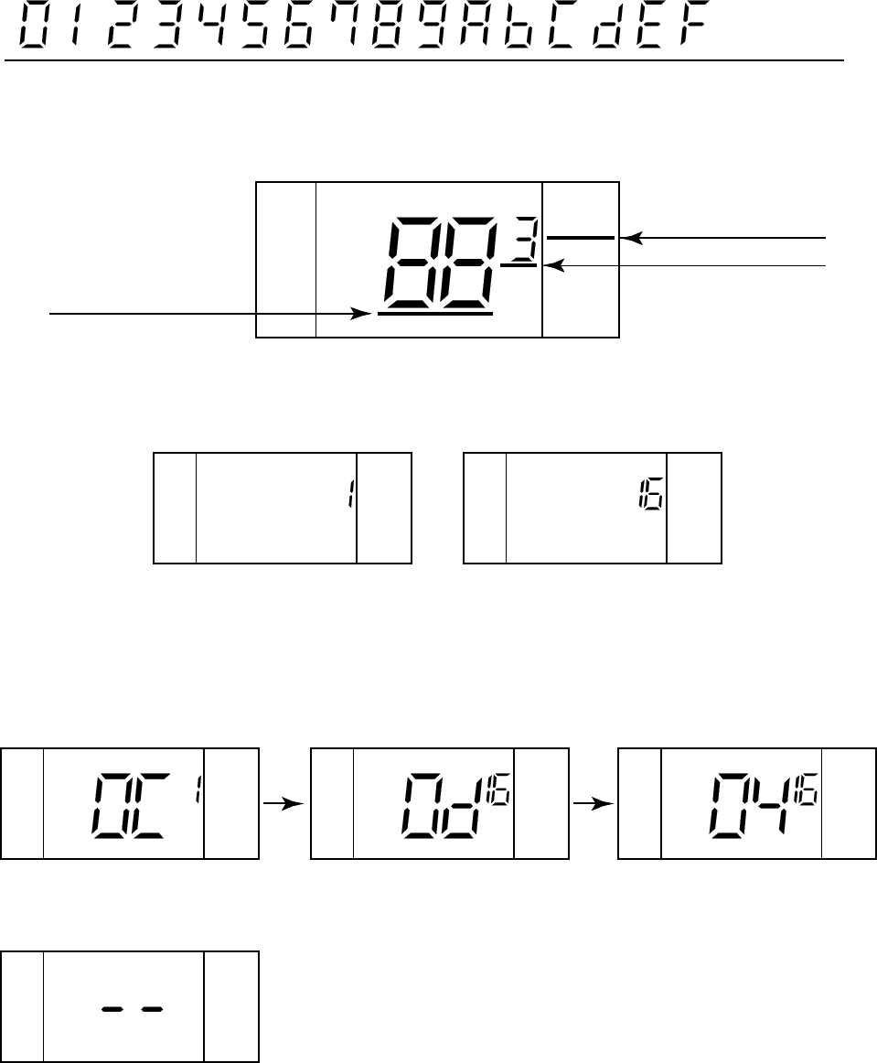
– 114 –
2. Reading of CHECK monitor display
FILTER
UNIT
CHECK
1 2
012345678910 11 12 13 14 15
FILTER
UNIT FILTER
UNIT
UNIT
CHECK
CHECK
1
UNIT
CHECK
1
UNIT
CHECK
2
<CHECK data>
(Example)
Hexadecimal
notation
Decimal notation
<7 segment display>
<Display on CHECK monitor>
<FILTER data>
(Example)
Room temp.sensor of No.1 is defective.
In No.16, first the heat exchanger sensor has failed.
Next, interconnection wire (serial signal line) of indoor/outdoor is defective.
Case that Filter signal is sent from No.1 and No.16 units under group operation
(Example) There is no check data.
CHECK code
FILTER sign
Indoor unit No.
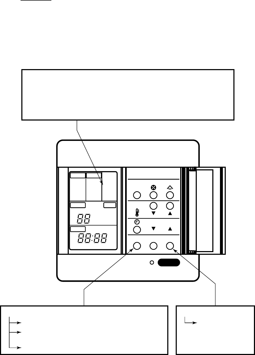
– 115 –
14-2-2. Remote controller with timer
RBC-AM1E
1. Operation for CHECK display
When pushing the CHECK switch, the indoor unit No. (Group address No.) which sends the check code is
displayed in the set up temp. display section, and check code is displayed in the TIME display section.
If FILTER display (air filter cleaning sign) is present, the indoor unit No. which sends the filter signal is dis-
played in the set up temp. display section, and then the check code is displayed. (1 display for 3 seconds)
ON/OFF
MODE
TIMER ADJUST
CHECK FILTER
REMOTE CONTROLLER
MODE
FAN ONLY
COOL
HEAT
TEMP
UNIT
CHECK
DEMAND
TIMER
LOUVER
MANUAL
FAN
AUTO
HIGH
MED
LOW
FIX
PREHEAT
DEFROST
OPERATION
STANDBY
FILTER
C
F
CONT.OFF ON ADDRESS
AFTER
H
M
(This display is for remote control with timer.)
LCD display STANDBY is present.
• When phase-sequence of power wiring is incorrect
• When combination of indoor units is over capacity.
• Indoor unit with command excepted by operation mode select switch
• When there is an indoor unit which stopped with the indoor overflow alarm “0b”.
• Indoor unit with cooling operation command excepted by heating priority control
CHECK switch
Push for 0.5 seconds to display CHECK code.
Push for 3 seconds to reset indoor microprocessor.
(While indoor microprocessor is locked by ALL STOP alarm)
Push for 10 seconds to clear check data.
RESET switch
Push the switch in
the hole with pin.
The remote controller
resets initialized.
(All data is cleared.)
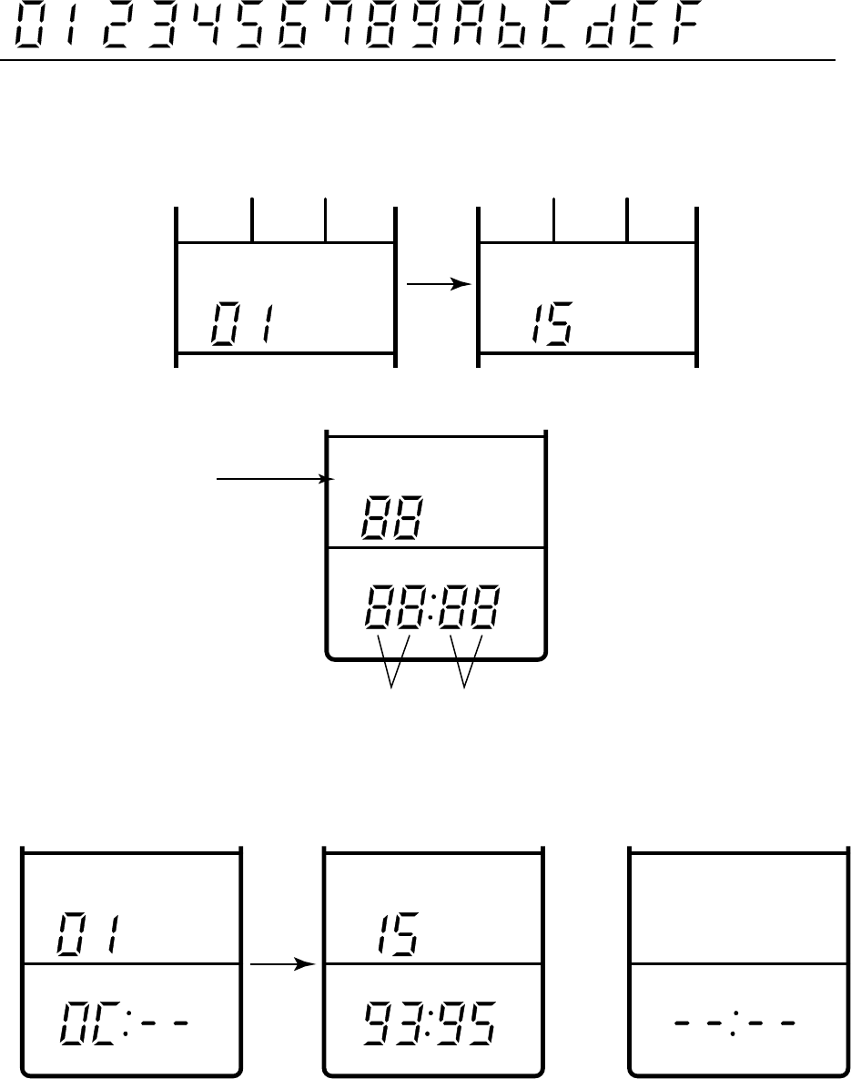
– 116 –
2. Reading of CHECK monitor display
<FILTER data>
(Example) Filter signal is sent from No.1 and No.15 units under grouping operation
(Example)
Room temp.sensor of No.1 is defective.
In No.15, first the indoor heat exchanger sensor has failed.
Next, interconnection wire (bus communication line) of
indoor/outdoor is defective.
(Example)
There is no check
data.
<CHECK data>
UNIT
CHECK
FILTER
UNIT
CHECK
FILTER
UNIT
CHECK
Unit No.
Check code detected at first Check code detected at last
UNIT
CHECK CHECK
UNIT
CHECK
After 3
seconds
0 1 2 3 4 5 6 7 8 9 10 11 12 13 14 15
Hexadecimal
notation
Decimal notation
<7 segment display>
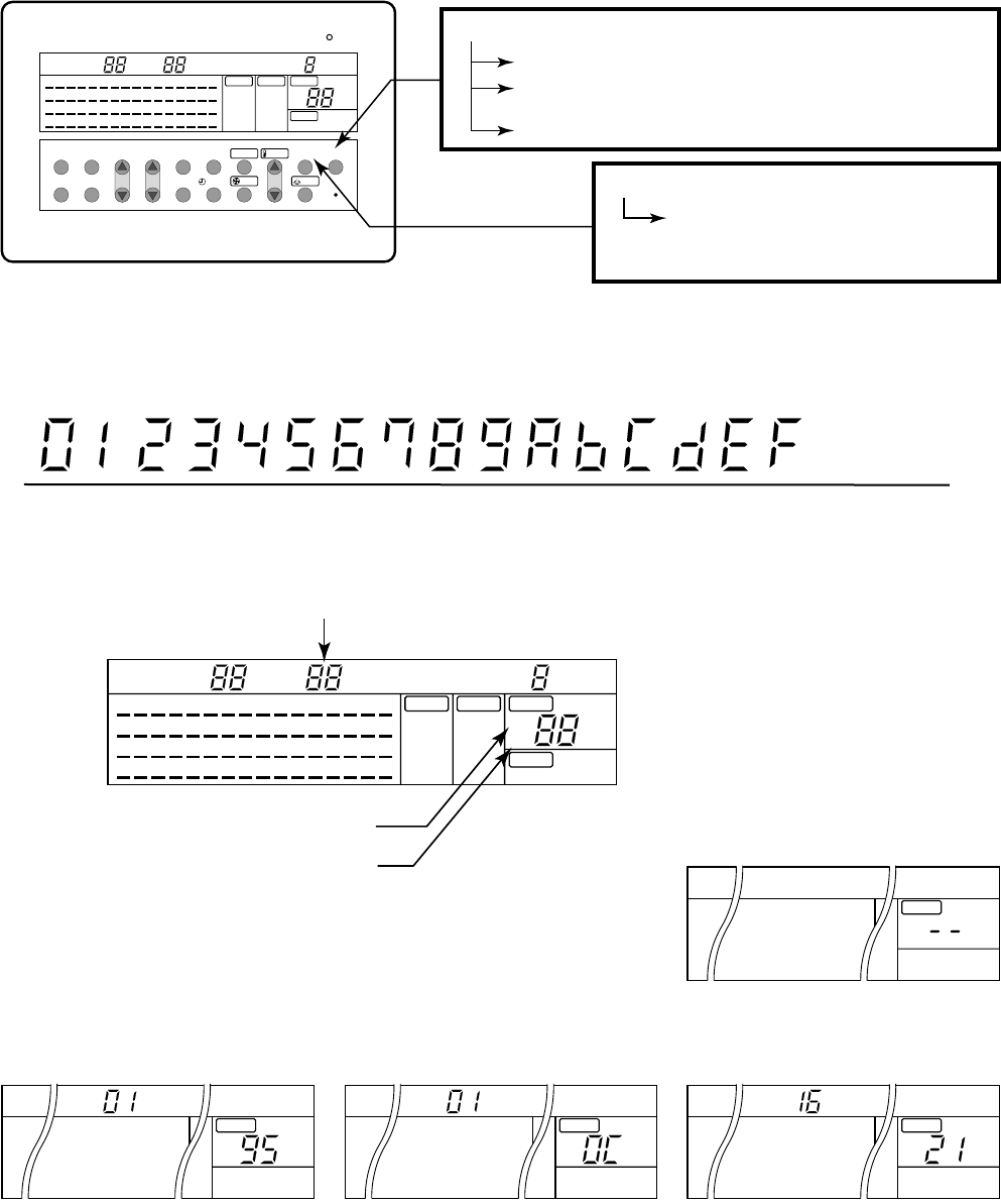
– 117 –
14-2-3. Central remote controller
1. Operation for CHECK display
When pushing the CHECK switch, the indoor unit No. (Network address No.) including the check data is
displayed in the UNIT No. display section, and the check code is displayed in the set up temp. display sec-
tion.
CHECK switch
Push for 0.5 seconds to display CHECK code.
Push for 3 seconds to reset indoor microprocessor.
(While indoor microprocessor is locked by ALL STOP alarm)
Push for 10 seconds to clear check data.
RESET switch
Push the switch in the hole with pin.
The remote controller resets initialized.
(All data is cleared.)
0 1 2 3 4 5 6 7 8 9 10 11 12 13 14 15
(Example)
Hexadecimal
notation
Decimal notation
<7 segment display>
<Display on CHECK monitor>
<CHECK data>
In No.1 unit, first the interconnection wire (bus communication line) of indoor/outdoor has failed.
Next, the room temp. sensor is defective.
For No.16 unit, the high pressure switch at the inverter unit side operates.
(Example)
There is no check data.
Unit line No. (Network address No.)
Check code detected at first
Check code detected at last
FILTER RESET
49 50 51 52 53 54 55 56 57 58 59 60 61 62 63 64
33 34 35 36 37 38 39 40 41 42 43 44 45 46 47 48
17 18 19 20 21 22 23 24 25 26 27 28 29 30 31 32
1
MONITOR
SET ZONE
ALL
CENTER
LOCKED
AUX. TYPE
TIMER No.
STANDBY
FILTER
ON
OFF
MODE
FAN ONLY
COOL
DRY
HEAT
AUTO
ON
UNIT
2 3 4 5 6 7 8 9
10 11 12 13 14 15 16
FAN
AUTO
HIGH
MED.
LOW
FIX
TEMP.
CHECK
1
2 C
LOUVER
MANUAL
LOUVER
FAN
TEMP.
MODE
MONITOR/SET ALL/ZONE
ZONE
UNIT ON
CENTER/LOCKED
CHECK
ZONE SET/ENTER
SELECT
OFF
TIMER ON
49 50 51 52 53 54 55 56 57 58 59 60 61 62 63 64
33 34 35 36 37 38 39 40 41 42 43 44 45 46 47 48
17 18 19 20 21 22 23 24 25 26 27 28 29 30 31 32
1
MONITOR
SET ZONE
ALL
CENTER
LOCKED
AUX. TYPE
TIMER No.
STANDBY
FILTER
ON
OFF
MODE
FAN ONLY
COOL
DRY
HEAT
AUTO
UNIT
2 3 4 5 6 7 8 9
10 11 12 13 14 15 16
FAN
AUTO
HIGH
MED.
LOW
FIX
TEMP.
CHECK
1
2 C
LOUVER
MANUAL
UNIT
TEMP.
CHECK
2
UNIT
TEMP.
CHECK
1
UNIT
TEMP.
CHECK
1
UNIT
TEMP.
CHECK
2. Reading of CHECK monitor display
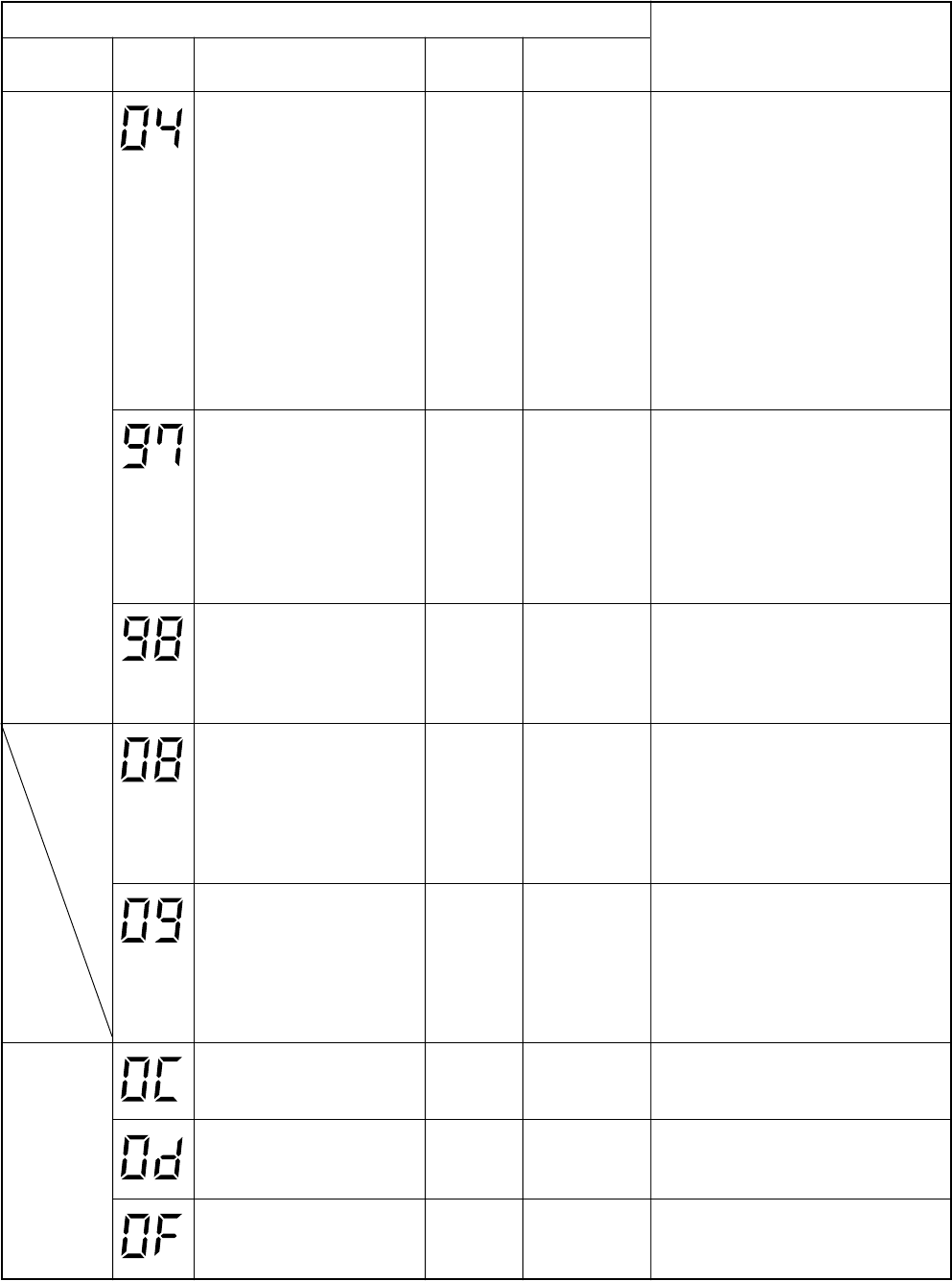
– 118 –
14-3. Check Code Table
Error mode detected by indoor unit (1)
Operation of diagnostic function
Block
display
[MODE]
[TIMER] lamp
5Hz flash
Check
code Cause of operation
The serial signal is not output
from outdoor unit to indoor unit.
•Miscabling of inter-unit cables
•Defective serial sending
circuit on outdoor P.C. board
•Defective serial receiving
circuit on outdoor P.C. board
•Compressor case thermo
operation
Status of air
conditioner
Operation
continues
Condition
Displayed when
error is detected
Judgment and measures
1. Outdoor unit does not completely
operate.
•Inter-unit cable check, correction of
miscabling
•Outdoor P.C. board check, P.C. board
cables check
•Compressor case thermo check
2. In normal operation
When outdoor sending serial LED
(Green) flashes, the receiving serial
LED (Orange) also flashes. : Indoor
P.C. board (Main P.C. board) check
When the receiving serial LED
(Orange) does not flash: Outdoor P.C.
board check
[MODE] lamp
5Hz flash
*
Operation
continues
(According
to remote
controller of
indoor unit)
Operation
continues
Operation
continues
Operation
continues
Operation
continues
Operation
continues
Operation
continues
Displayed when
error is detected
Displayed when
error is detected
Displayed when
error is detected
Displayed when
error is detected
Displayed when
error is detected
Displayed when
error is detected
Displayed when
error is detected
1. Communication line check, miscabling
check
Power supply check for central
controller (Central control remote
controller, etc.) and indoor unit
2. Communication check (XY terminal)
3. Indoor P.C. board check
4. Central controller check
(Communication P.C. board)
BUS communication circuit error
* BUS communication was
interrupted over the specified
time.
1. Check central control system network
address setting. (SW02)
2. Indoor P.C. board check
3. Central controller check
(Communication P.C. board)
Network address miss-setting
•Addresses of central
controllers (Central control
remote controller, etc.) are
duplicated.
Error in 4-way valve system
•Indoor heat exchanger
temperature rise after start of
cooling operation.
•Indoor heat exchanger
temperature fall after start of
heating operation.
1. Check 4-way valve.
2. Check 2-way valve and non-return
valve.
3. Check indoor heat exchanger sensor
(TC).
4. Check indoor P.C. board (Main P.C.
board).
Error in other cycles
•Indoor heat exchanger temp
(TC) does not vary after start
of cooling/heating operation.
1. Compressor case thermo operation
2. Coming-off of detection part of indoor
heat exchanger sensor
3. Check indoor heat exchanger sensor
(TC).
4. Check indoor P.C. board (Main P.C.
board).
1. Check indoor temp sensor (TA).
2. Check indoor P.C. board (Main P.C.
board).
Coming-off, disconnection or
short of indoor temp sensor
(TA)
1. Check indoor temp sensor (TC).
2. Check indoor P.C. board (Main P.C.
board).
Coming-off, disconnection or
short of indoor temp sensor
(TC)
1. Check indoor temp sensor (TCJ).
2. Check indoor P.C. board (Main P.C.
board).
Coming-off, disconnection or
short of indoor temp sensor
(TCJ)
* : No display in the setting at shipment
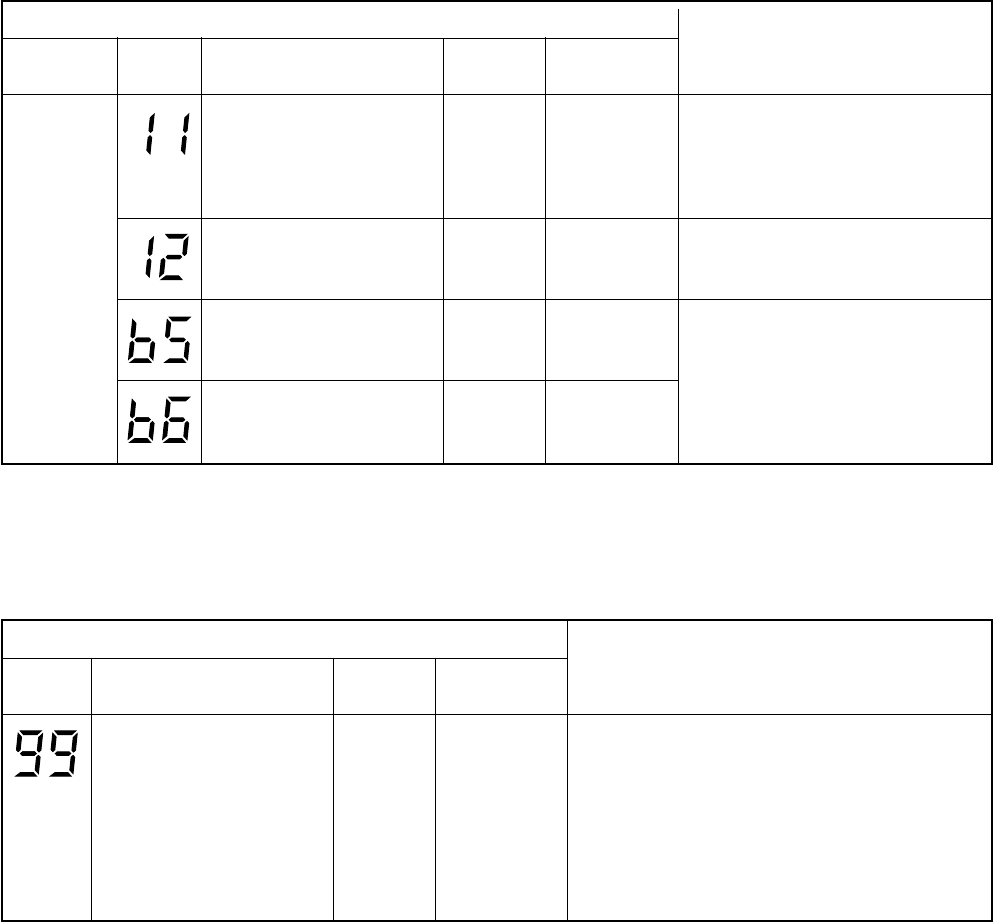
– 119 –
Error mode detected by indoor unit (1)
Operation of diagnostic function
Block
display
[MODE] lamp
5Hz flash
Check
code Cause of operation
Error in indoor fan system
Revolutions frequency error of
fan
Status of air
conditioner
All stop
Condition
Displayed when
error is detected
Judgment and measures
1. Check indoor fan motor connector
circuit (CN210).
2. Check indoor fan.
3. Check indoor P.C. board (Main P.C.
board).
Operation
continues
Operation
continues
All stop
Displayed when
error is detected
Displayed when
error is detected
Displayed when
error is detected
1. Check indoor P.C. board
(EEPROM and peripheral circuits)
(Main P.C. board).
Error in indoor unit or other
positions
1. EEPROM access error
Outside error input
Detected by input voltage level
from outside devices
1. Check outside devices.
2. Check indoor P.C. board (Main P.C.
board).
Outside interlock input
Detected by input voltage level
from outside devices
Error mode detected by indoor unit (2)
Operation of diagnostic function
Check
code Cause of operation
Serial return signal is not sent
from No. 1 indoor unit to
remote controller.
•Miscabling of inter-unit cable
between remote controller
and indoor unit
•Miss-setting of indoor unit No.
(Group address)
Status of air
conditioner
ON/OFF
Condition
Displayed when
error is detected
Judgment and measures
1. Indoor unit does not completely operate.
•Check inter-unit cable.
•Check indoor P.C. board. (Main/Sub P.C. boards)
•Check remote controller.
2. In normal operation
•Check setting of indoor unit No.
(SW01) (Sub P.C. board)
•Check remote controller.
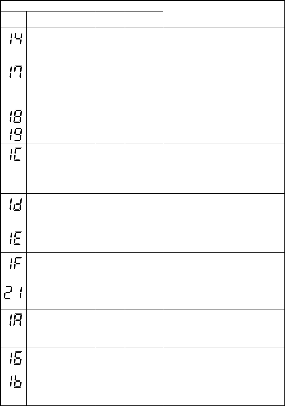
– 120 –
Operation of diagnostic function
Check
code Cause of operation
Inverter over-current protective
circuit operates.
(For a short time)
Status of air
conditioner
All stop
Condition
Displayed when
error is detected
Judgment and measures
1. Inverter immediately stops even if restarted.
•Compressor rare short
2. Check IPDU.
•Cabling error
Error mode detected by outdoor unit
All stop
All stop
All stop
All stop
All stop
All stop
All stop
All stop
All stop
All stop
Operation
continues
Displayed when
error is detected
Displayed when
error is detected
Displayed when
error is detected
Displayed when
error is detected
Displayed when
error is detected
Displayed when
error is detected
Displayed when
error is detected
Displayed when
error is detected
Displayed when
error is detected
Displayed when
error is detected
Displayed when
error is detected
Error on current detection
circuit
•Current value is high at AC
side even while compressor
stops.
•Phase of power supply is
missed.
1. Compressor immediately stops even if restarted.
: Check IPDU.
2. Phase-missing operation of power supply
•Check power voltage of R, S, T.
Coming-off, disconnection or
short of outdoor temp sensor 1. Check outdoor temp sensor (TE, TS).
2. Check CDB.
Coming-off, disconnection or
short of outdoor temp sensor 1. Check outdoor temp sensor (TD).
2. Check CDB.
Compressor drive output error
•Tin thermistor temp, Tin error
(IPDU heat sink temp. is high.)
Communication error between
IPDU
•Connector coming-off
between CDB and IPDU
1. Abnormal overload operation of refrigerating cycle
2. Loosening of screws and contact error of IPDU and
heat sink
3. Cooling error of heat sink
4. Check cabling of CDB and IPDU.
Compressor does not rotate.
(Over-current protective circuit
works when constant time
passed after activation of
compressor.)
1. Compressor error (Compressor lock, etc.)
: Replace compressor.
2. Cabling trouble of compressor (Phase missing)
Discharge temp error
•Discharge temp over
specified value was detected.
1. Check refrigerating cycle. (Gas leak)
2. Error of electron control valve
3. Check pipe sensor (TD).
1. Check power voltage. (AC200V±20V)
2. Overload operation of refrigerating cycle
3. Check current detection circuit at AC side.
Compressor breakdown
•Operation frequency lowered
and stops though operation
had started.
High-voltage protection error
by TE sensor
•TE temp over specified value
was detected.
1. Overload operation of refrigerating cycle
2. Check outdoor temp sensor (TE).
DC outdoor fan motor error
•IDC operation or lock was
detected by DC outdoor fan
driving.
1. Position detection error
2. Over-current protection circuit operation of outdoor fan
drive unit
•Check CDB.
•Refer to Judgment of outdoor fan.
1. Position detection circuit operates even if driving by
removing 3P connector of compressor.
•Replace IPDU.
Error on IPDU position
detection circuit
1. Check outdoor temp sensor (TO).
2. Check P.C. board.
Coming-off, disconnection or
short of outdoor temp sensor
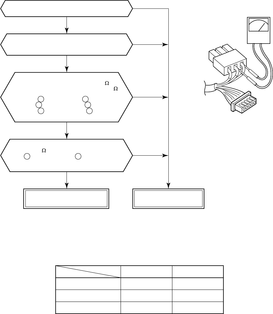
– 121 –
14-4. Troubleshooting for Each Check Code
[1A error]
•For RAV-SM560AT-E, CN300 changes to
CN301, and CN301 to CN300, respectively.
Are connections of CN301 and
CN300 of CDB correct?
Does the fan rotate without trouble
when handling the fan with hands under condition
of removing CN301 and CN300 from CDB?
The status that the resistance values
between leads below are 50 to 80
for 40W motor (ICF-140-43) and 25 to 55
for 60W motor (ICF-140-63-1) is normal.
Between (Red lead) and (White lead)
Between (White lead) and (Black lead)
Between (Black lead) and (Red lead)
of motor winding of connector (CN301)
The status that there is
5k to 20k resistance values between
(Yellow lead) and (Pink lead)
of motor position detection of connector
(CN300, CN302) is normal.
Normal fan motor Defective fan motor
NOTE :
However, GND circuit error inside of the motor is rarely detected even if the above check is carried out.
When the circuit does not become normal even if P.C. board has been replaced, replace outdoor fan motor.
Objective P.C. board
Fan motor winding
Motor position detection
RAV-SM560AT-E RAV-SM800AT-E
Control P.C. board
CN300
CN301
CDB P.C. board
CN301
CN300
1 2
2 3
3 1
1 4
(CDB error)
NO
NO
NO
YES
YES
YES
YES
CN301
CN300
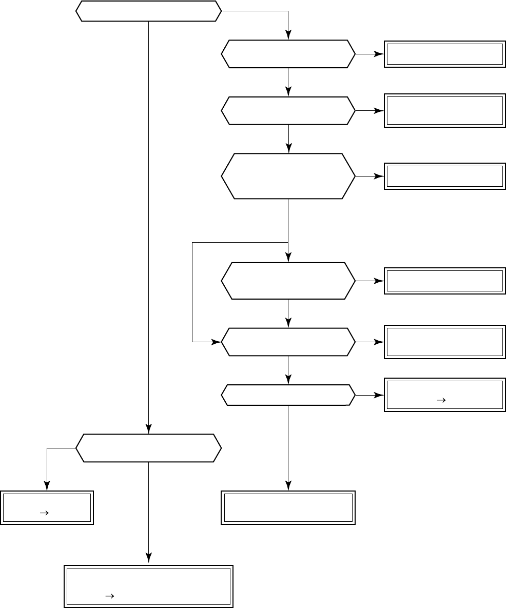
– 122 –
[04 error]
Correct inter-unit cable.
Replace IPDU.
Replace IPDU.
* For RAV-SM560AT-E,
replace control P.C. board.
Does outdoor unit operate?
NO
NO
NO
NO
NO
NO
NO
NO
YES
YES
YES
YES
YES
YES
YES
YES
Are 1, 2, 3 inter-unit
cables normal?
Are connections of
connectors normal? Correct connection
of connector.
Is case thermo
(CN500) connected?
Does LED (D05) (Orange)
on indoor main P.C. board flash?
Correct connection
of connector.
Check CDB.
Defect Replace
Is DC310 to 340V
applied between terminals
of electrolytic capacitor
of IPDU main circuit?
* For RAV-SM560AT-E,
replace control P.C. board.
* For RAV-SM560AT-E,
check case thermo.
Is DC310 to 340V
power supplied to CDB?
(CN03)
Does case thermo operate?
* For RAV-SM560AT-E,
replace control P.C. board.
Check/Correct charged
refrigerant amount.
* For RAV-SM560AT-E,
replace control P.C. board.
Check CDB.
Defect Replace
Check main indoor main P.C. board
(MCC-1370A).
Defect Replace
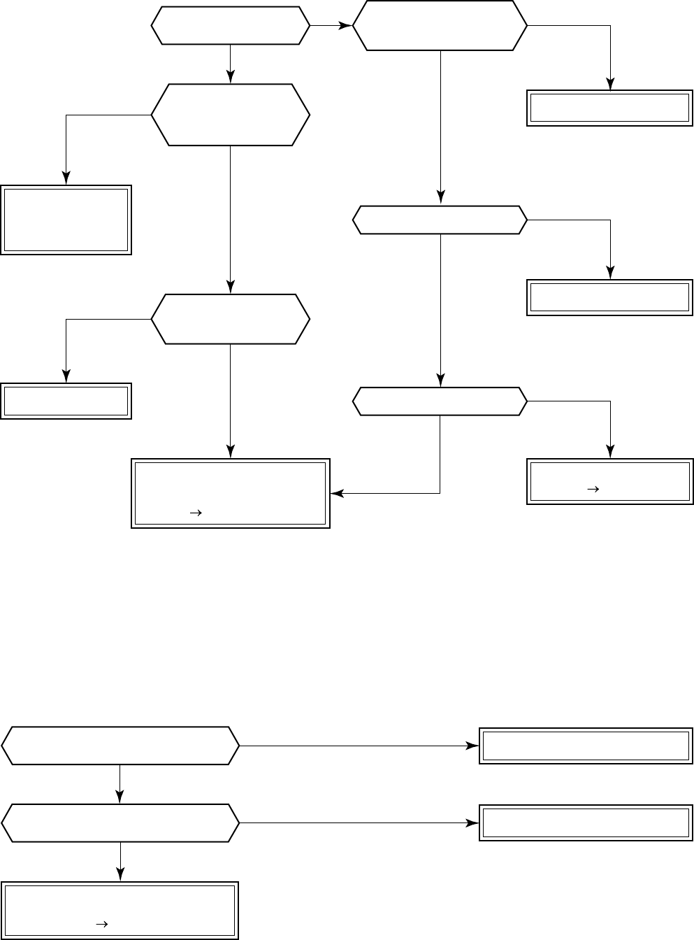
– 123 –
NO
NO
YES
YES
* Refer to Characteristics-2.
* Refer to Characteristics-1.
Check 4-way valve.
Check CDB P.C. board.
Defect Replace
* For RAV-SM560AT-E,
check control P.C. board.
Check and replace
2-way valve, check
valve, or electron
expansion valve.
Check indoor main P.C. board
(MCC-1370A) and
sub P.C. board (MCC-1370B).
Defect Replace
Replace TC sensor.
Is operation of
4-way valve normal?
Is 200V applied to
4-way valve coil terminal
in heating operation?
Is circuit cable normal?
Check CDB P.C. board.
Are characteristics
of TC sensor resistance
value normal?
Check and correct circuit.
Correct connection of connector.
Replace TA sensor.
NO
NO
NO
YES
YES
YES
YES
NO
YES
NO
YES
NO
Check indoor P.C. board
(MCC-1370A).
Defect Replace
Is connection of TA sensor connector
(Indoor main P.C. board CN04) normal?
Are characteristics of
TA sensor resistance value normal?
* For RAV-SM560AT-E,
replace control P.C. board.
Is flow of refrigerant by
2-way valve, check valve,
or electron expansion
valve normal?
[08 error]
•In cooling operation, if high pressure is abnormally raised, [08 error] may be displayed. In this case, remove
cause of pressure up and then check again referring to the item [21 error].
[0C error]
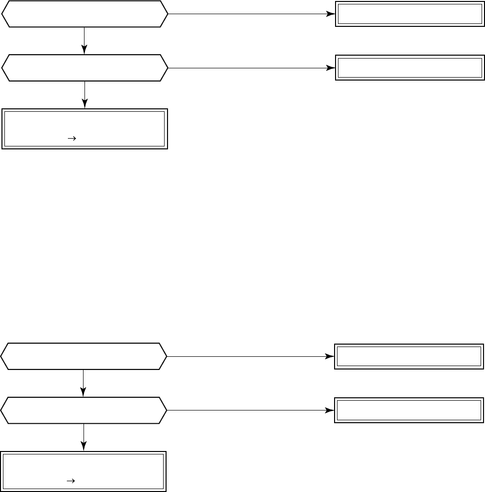
– 124 –
NO
NO
YES
YES * Refer to Characteristics-2.
Correct connection of connector.
Replace TC sensor.
Check indoor P.C. board
(MCC-1370A).
Defect Replace
Is connection of TC sensor connector
(Indoor P.C. board CN05) normal?
Are characteristics of
TC sensor resistance value normal?
NO
NO
YES
YES
Correct connection of connector.
Replace TCJ sensor.
Check indoor P.C. board
(MCC-1370A).
Defect Replace
Is connection of TCJ sensor connector
(Indoor P.C. board CN20) normal?
Are characteristics of
TCJ sensor resistance value normal?
* Refer to Characteristics-2.
[0d error]
[0F error]
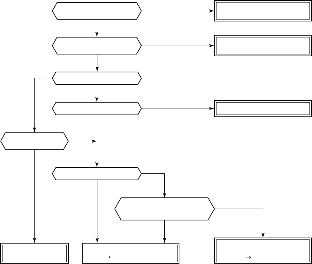
– 125 –
[99 error]
Correct inter-unit cable
of remote controller.
Is inter-unit cable of
A, B and C normal?
Correct connection of connector.
Check circuit cables.
Is there no disconnection or
contact error of connector?
Are not No.1 unit
duplicated?
Check indoor main P.C. board
(MCC-1370A).
Defect Replace
Set the unit to No.1.
Is individual (1 : 1) operation?
Is unit set to No.1?
Does indoor unit operate?
Does LED (Green)
on indoor main P.C. board flash?
(D13)
Check remote controller P.C. board.
Defect Replace
Avoid duplication of
unit No.1 setting.
YES
NO
NO
YES
YES
YES
NO
NO
YES
NO
NO
YES
NO
YES
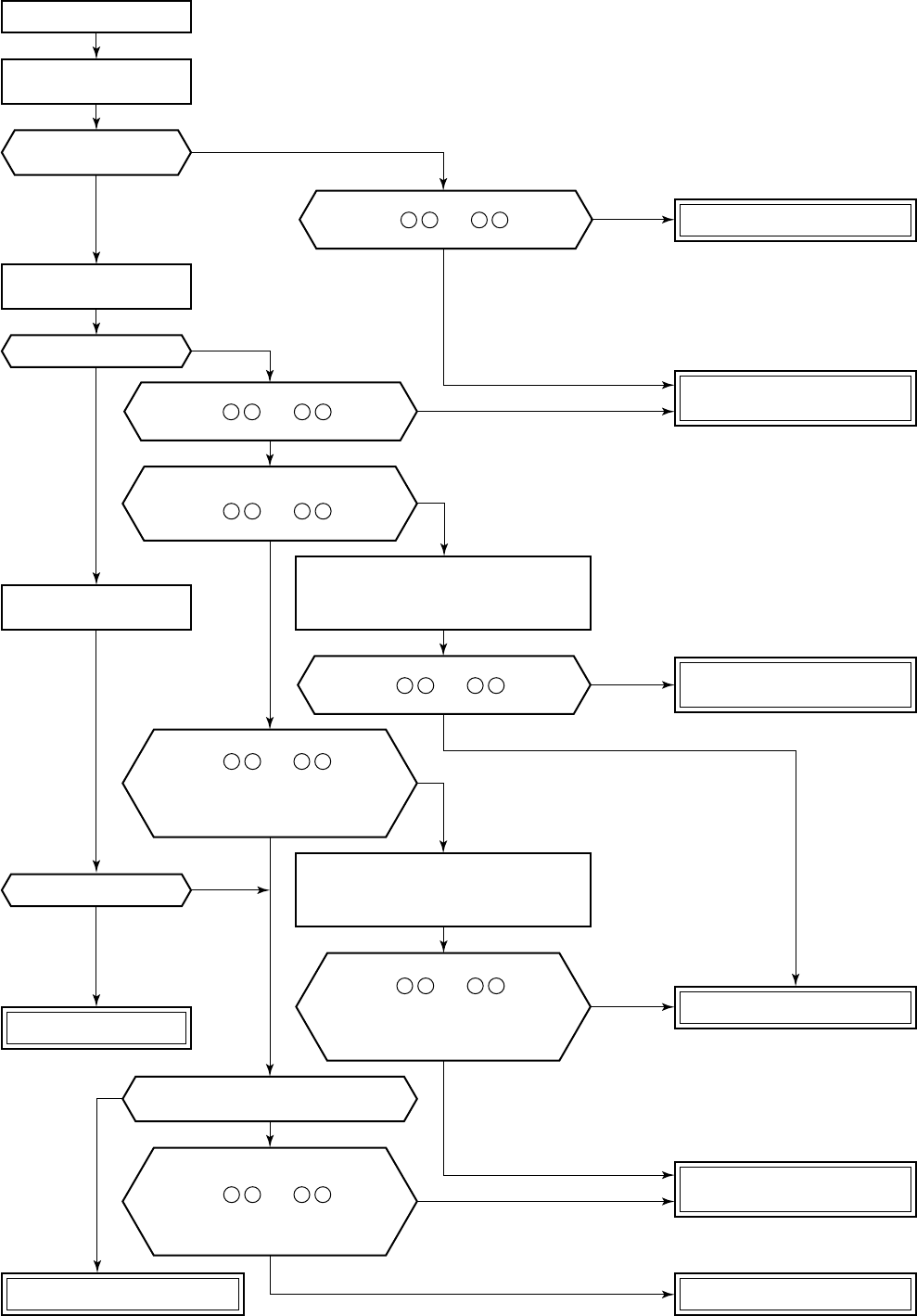
– 126 –
[11 error]
Turn off the breaker once.
Does the fan rotate?
Is fan speed raised?
Does fan stop when
operation stopped?
Is DC1V or more voltage applied
between 5 + and 3 – of the
motor connector (CN210)?
Is DC280V or more voltage applied
between 1 + and 3 – of the
motor connector (CN210)?
Is DC15V voltage applied
between 4 + and 3 – of the
motor connector (CN210)?
(Connection status of motor)
Is DC15V or more voltage applied
between 4 + and 3 – of the
motor connector (CN210)?
Is DC1V or more voltage applied
between 5 + and 3 – of the
motor connector (CN210) when changing
the operation mode (except HEAT)?
(Check within approx. 15 seconds
after operation has started.)
Stop the operation and disconnect the
receptacle. After removing motor connector,
connect receptacle again and then stop
the operation from remote controller.
Is DC1V or more voltage applied
between 5 + and 3 – of the
motor connector (CN210) when changing
the operation mode (except HEAT)?
(Check within approx. 15 seconds
after operation has started.)
Does 0 to 5V voltage
(revolutions return signal) generate
between 6 + and 3 – of the
motor connector (CN210) when rotating
the cross flow fan with hands under
condition of operation-stop?
Stop the operation and turn off the breaker.
After removing motor connector,
turn on the breaker again and then stop
the operation from remote controller.
Turn on the breaker
after approx. 10 seconds.
Start the operation with
cooling mode [L (Low)].
Change the cooling
mode to [H (High)].
Does the cross flow fan rotate normally
when handled with hands?
Replace indoor fan motor.
Replace indoor fan motor.
Replace indoor fan motor.
Repair bering of the
cross flow fan
.
Normal fan motor
Replace indoor main P.C. board
(MCC-1370A).
Replace indoor main P.C. board
(MCC-1370A).
Replace indoor main P.C. board
(MCC-1370A).
NO
YES
YES
YES
YES
YES
YES
YES
YES
YES
YES
NO
NO
NO
YES
NO
NO
NO
NO
NO
NO
NO
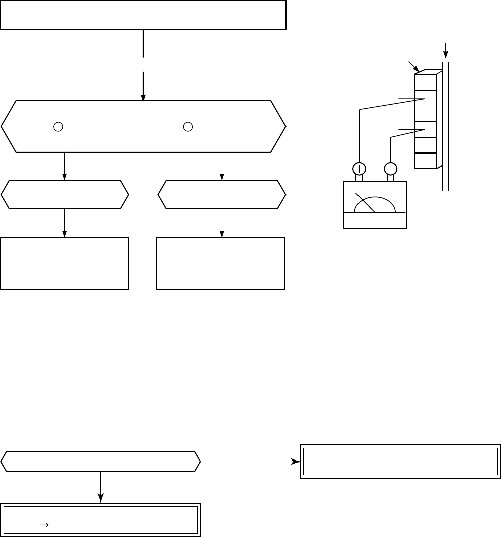
– 127 –
[11 error]
[12 error]
NO
Check indoor main P.C. board (MCC-1370A).
Defect Replace
Check power voltage. Improve line.
Check and eliminate noise, etc.
YES
Is there no turbulence of power supply?
Indoor fan starts rotating by inserting receptacle.
[Check output voltage (DC) of P.C. board fan motor.]
Measure the voltages of the motor connector
CN210 Pin 3 (GND (minus): Black) and Pin 5 (V line (plus): Yellow)
under condition that indoor fan rotates.
DC1.0V or more
6 (Blue)
5 (Yellow)
4 (White)
3 (Black)
2 –
1 (Red)
DC1.0V or less
CN210
Yellow
Black
P.C. board
DC
Defective
indoor main P.C. board
(MCC-1370A)
Defective indoor fan motor
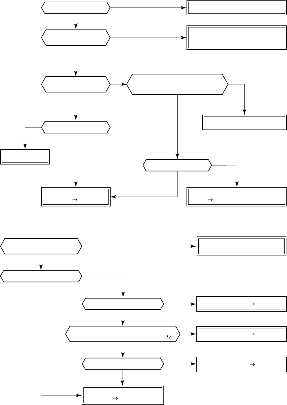
– 128 –
NO
NO
NO
YES
YES
NO
YES
NO
YES
YES
NO
YES
Improve the power supply line.
Replace IPDU.
* For RAV-SM560AT-E,
check RY01 on the control P.C. board.
* Single-phase type is not
provided to RAV-SM560AT-E.
* Replace control P.C. board
of RAV-SM560AT-E.
Is power voltage normal?
Is not AC fuse fused?
Check and correct circuit cables.
Correct connection of connector.
Check and correct reactor connection.
Are connections of
cabling/connector normal?
Does RY01 relay of
IPDU operate?
Is not “14” errors output
when an operation is performed by
removing 3P connector of compressor?
Replace IPDU.
* Replace control P.C. board
of RAV-SM560AT-E.
Is compressor normal?
Check rare short of compressor trouble.
Defect Replace
Check IPDU.
Defect Replace
NO
YES
NO
YES
YES
Are connections of
cable/connector normal?
Is not winding shorted?
(Is resistance between windings 0.6 to 1.2 ?)
Is compressor normal?
Is not earthed?
Is not winding opened?
Compressor error Replace
Compressor error Replace
Compressor error Replace
Check and correct circuit cabling
such as cabling to compressor.
Check IPDU P.C. board.
Defect Replace
YES
YES
NO
NO
NO
[14 error]
[16 error]
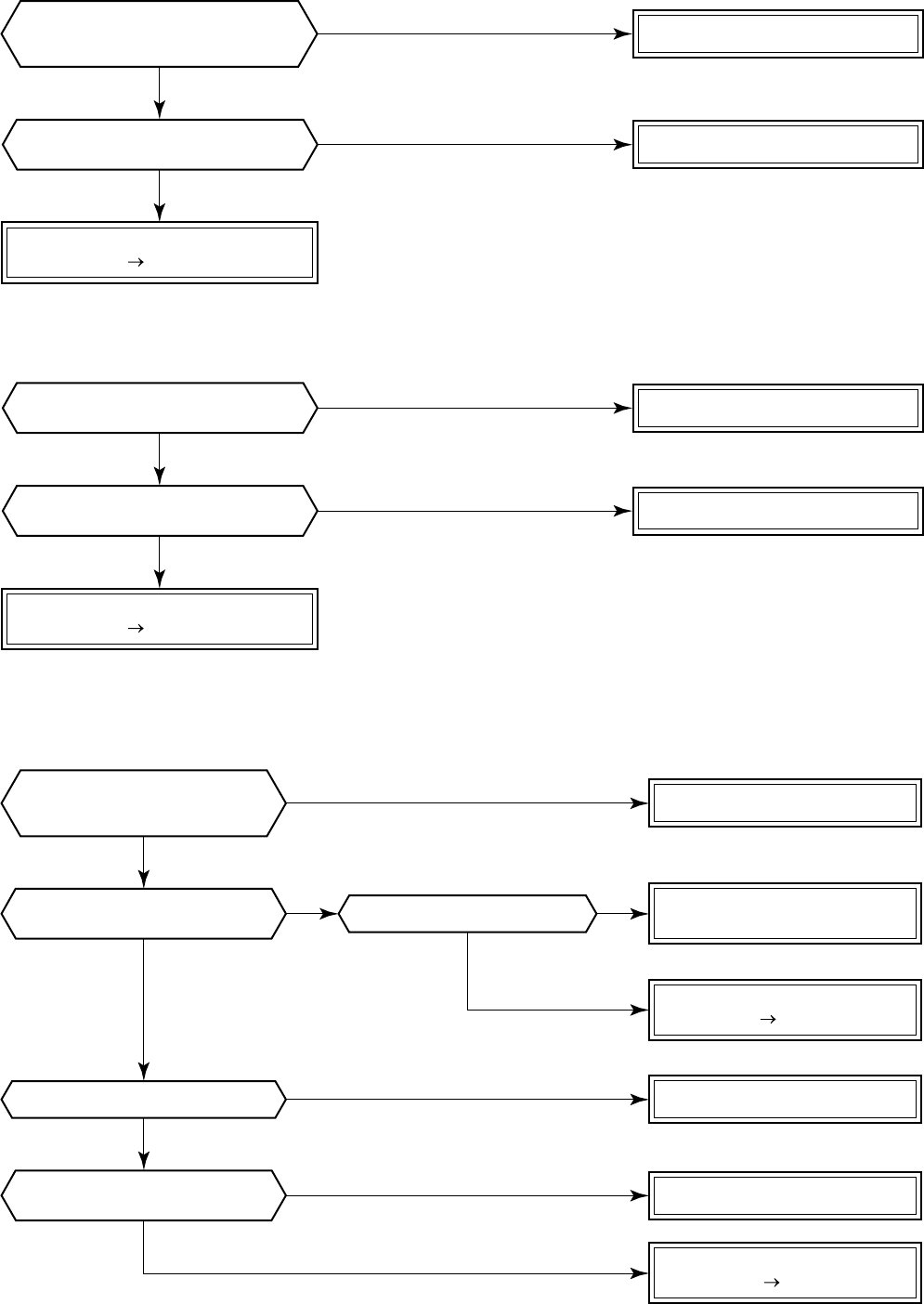
– 129 –
NO Correct connection of connector.
Check CDB.
Defect Replace * For RAV-SM560AT-E, replace the control P.C. board
* Refer to Characteristics-3.
YES
NO
Are characteristics of TE/TS sensor
resistance values normal? Replace TE and TS sensors.
YES
NO
Is connection of TD sensor connector
of CDB CN600 normal? Correct connection of connector.
Check control P.C. board.
Defect Replace * Refer to Characteristics-4.
YES
NO
Are characteristics of TD sensor
resistance value normal? Replace TD sensor.
YES
* (For RAV-SM560AT-E, CN600 TE sensor and CN603 TS sensor)
* For RAV-SM560AT-E, CN601 on control P.C. board
Are connections of
TE/TS sensor connectors of
CDB CN604/CN605 normal?
Is there no abnormal overload?
Are cabling/connector normal?
Was the error just after
power ON determined?
Is IPDU P.C. board come to
closely contact with heat sink?
Are connections of
CDB CN800 and CDB IPDU CN06
connectors normal?
Improve and eliminate the cause.
Correct connection of connector.
Correct mounting.
Check cabling between IPDU
and CDB and connector.
IPDU P.C. board error
Defect Replace
IPDU P.C. board error
Defect Replace
NO
NO
NO
NO
YES
YES
YES
NO
YES
YES
[18 error]
[19 error]
[1C error] * Except RAV-SM560AT-E
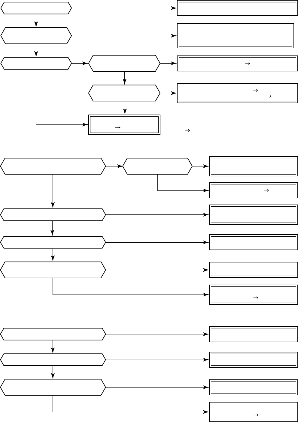
– 130 –
* For RAV-SM560AT-E, check control P.C. board.
Defect Replace
Improve power line.
Compressor lock Replace
Check TE and TS sensors. Replace
Check electron expansion valve. Replace
Is there no
slackened refrigerant?
Does electron expansion
valve normally operate?
Is power voltage normal?
Is compressor normal?
Are connections of
cable/connector normal?
Check and correct circuit cabling such
as cabling to compressor
(phase missing) and connector.
Check IPDU and CDB.
Defect Replace
NO
NO
NO NO
NO
YES
YES
YES YES
YES
Check parts. Defect Replace
* Refer to Characteristics-4.
Is not abnormal overload?
Is power voltage normal?
Is not abnormal overload?
Is charged refrigerant amount normal?
Are characteristics of
TD sensor resistance value normal?
Is the circuit detected by
current sensor normal?
Is protective control such as
discharge temprelease control normal? Are connections of
cable/connector normal? Correct the cabling and
connection of connector.
Improve and delete the cause
Replace TD sensor.
Improve power line.
Improve and delete the cause.
Check and correct circuit cables.
Check CDB.
Defect Replace
Check and correct the charged
refrigerant amount.
* For RAV-SM560AT-E, check control P.C. board.
Check IPDU.
Defect Replace
* For RAV-SM560AT-E, check control P.C. board.
NO
NO
NO
NO
NO
NO
NO NO
YES
YES
YES
YES
YES
YES
YES YES
[1d error]
[1E error]
[1F error]
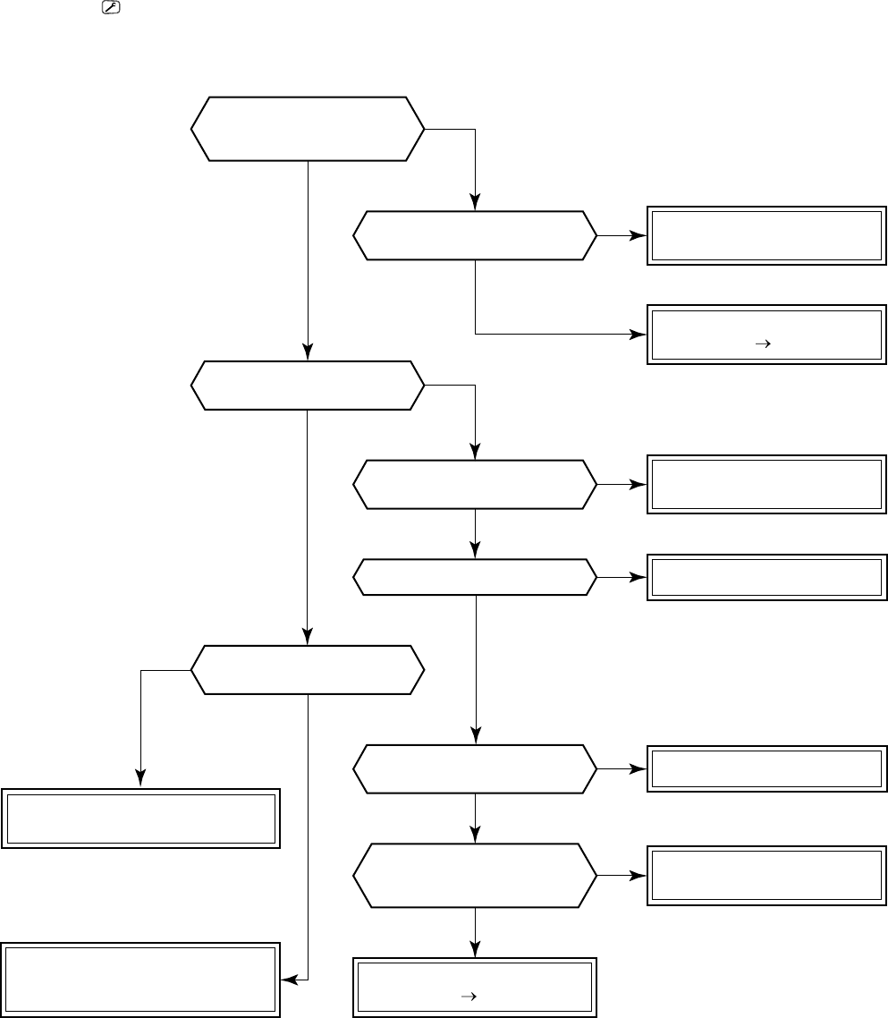
– 131 –
[21 error] [
] LCD flash
* Refer to Characteristics-3 and 4.
* For RAV-SM560AT-E, check control P.C. board.
Is high-voltage
protective operation by
TE sensor normal?
Is connection of cabling
connector normal?
Do not TD and TO sensors
come off the detection part?
Is connection of
connector normal?
Correct connection of
cabling connector.
Check TE sensor.
Defect Replace
Correct connection of
connector.
Check TE, TC, TS sensors.
Replace electron expansion valve.
Replace TD, TO,
and TC sensors.
Check CDB.
Defect Replace
Does cooling outdoor fan
normally operate?
Does electron control
valve normally operate?
Is fan motor normal?
Replace fan motor.
Correct coming-off.
Are characteristics of
TD, TO, TC sensor resistance
values normal?
Check charged refrigerant amount.
Check liquid/gas valves.
Check abnormal overload.
NO
NO
NO
NO
YES
NO
NO
NO
YES
YES
YES
YES
YES
YES
NO
YES

– 132 –
14-5. Simple Check Method for Main Parts
14-5-1. Indoor unit
No.
1
Part name
Temperature sensor (Ta)
Heat exchanger sensor (Tc)
Heat exchanger sensor (Tcj)
Check procedure
Measure the resistance value with tester by removing the connector.
(Normal temperature)
Normal value
lMeasure the resistance value of each winding coil with tester.
lFor P.C. board side, proceed to [11 error] of “Troubleshooting procedure for each
check code”.
10 kΩ to 20 kΩRefer to Characteristics table.
Measure the resistance value of each winding coil with tester.
(Under normal temperature 25°C)
Louver motor
MP35EA12
Position
Between 1 and 2
Between 1 and 3
Between 1 and 4
Between 1 and 5
Resistance value
130 ± 40Ω
Indoor fan motor
(ICF-340-30-1)
Position
Between (Black) and (Red)
Between (Black) and (White)
Between (Black) and (Yellow)
Between (Black) and (Blue)
Resistance value
∞ (MΩ)
27 to 47 kΩ
140 to 280 kΩ
∞ (MΩ)
2
3
Red
Black
White
Yellow
Blue 6
5
4
3
1
6
5
4
3
1
6
5
4
3
1
6
5
4
3
2
1
Brown
Red
Orange
Yellow
Pink
Blue 6
5
4
3
2
1
6
5
4
3
2
1
Circuit
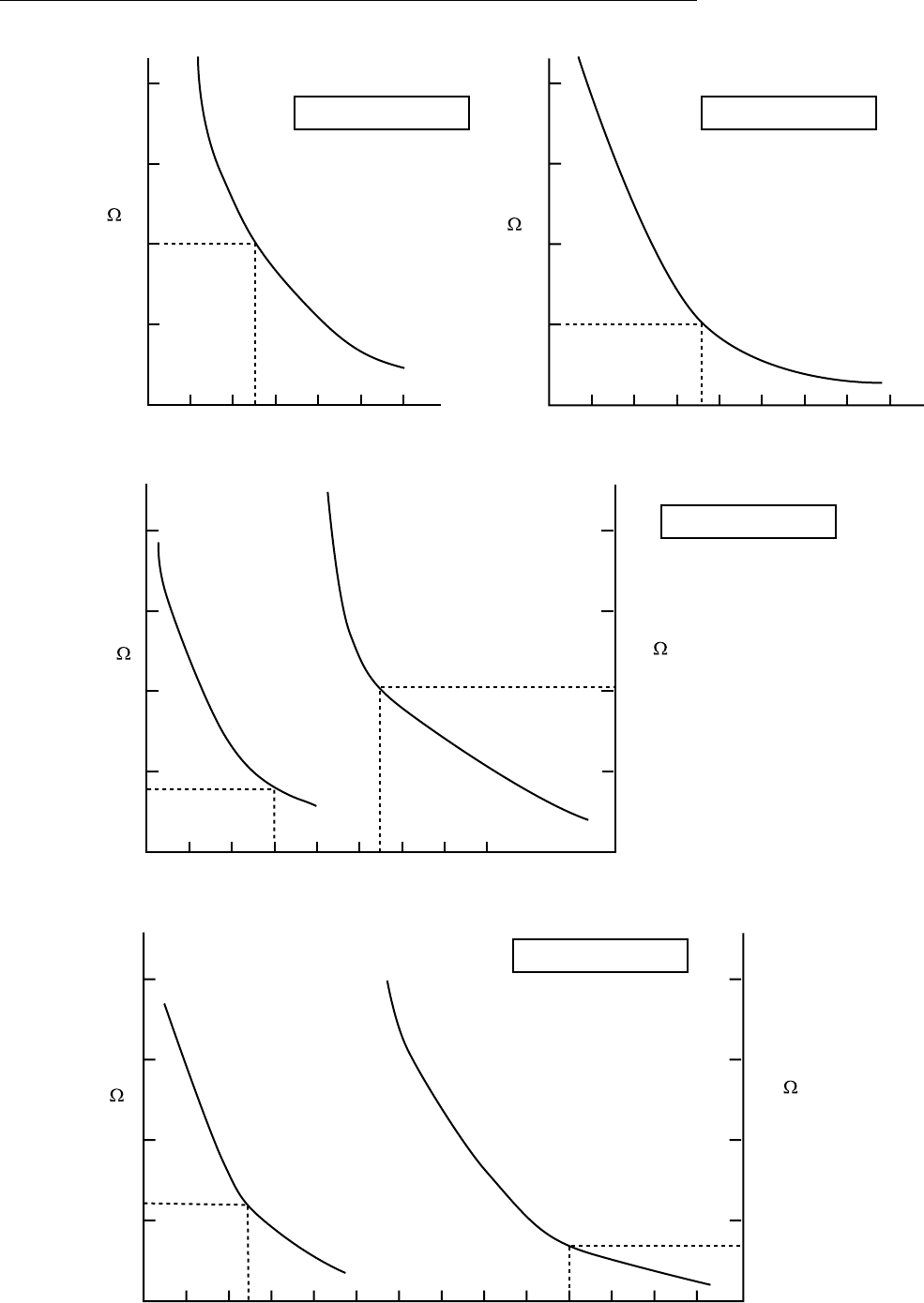
– 133 –
Relational graph of temperature sensor resistance value and temperature
Caracteristics-1
Resistance
(k )Resistance
(k )
Caracteristics-3
Caracteristics-2
Temperature [ C] Temperature [ C]
Resistance
(k )
(10 C or lower)
Resistance
(k )
(50 C or lower)
Temperature [ C]
Resistance
(k )
(50 C or higher)
Resistance
(k )
(10 C or higher)
Caracteristics-4
Temperature [ C]
TC, TCJ sensor
TE, TO, TS sensor
TD sensor
TA sensor
20
10
010 20 4030 50
200
100
20
10
0
0100-10 20 4030 50 60 70
40
30
20
10
00
–
10 10 3020 40 50 60 70
200
100
20
10
0
050 100
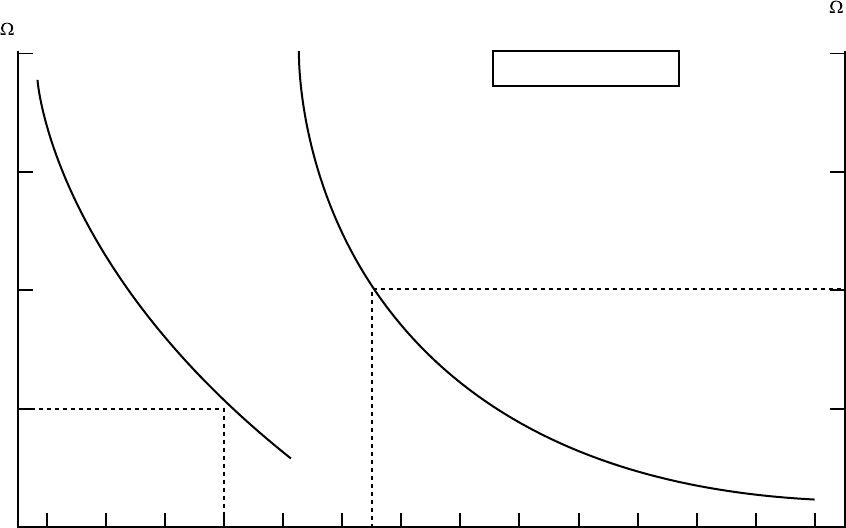
– 134 –
200
150
100
50
–30 –20 –100 102030405060708090100
Resistance
(K )
20
15
10
5
Resistance
(K )
(10 C or higher)
Caracteristics-5
Temperature [ºC]
TH sensor
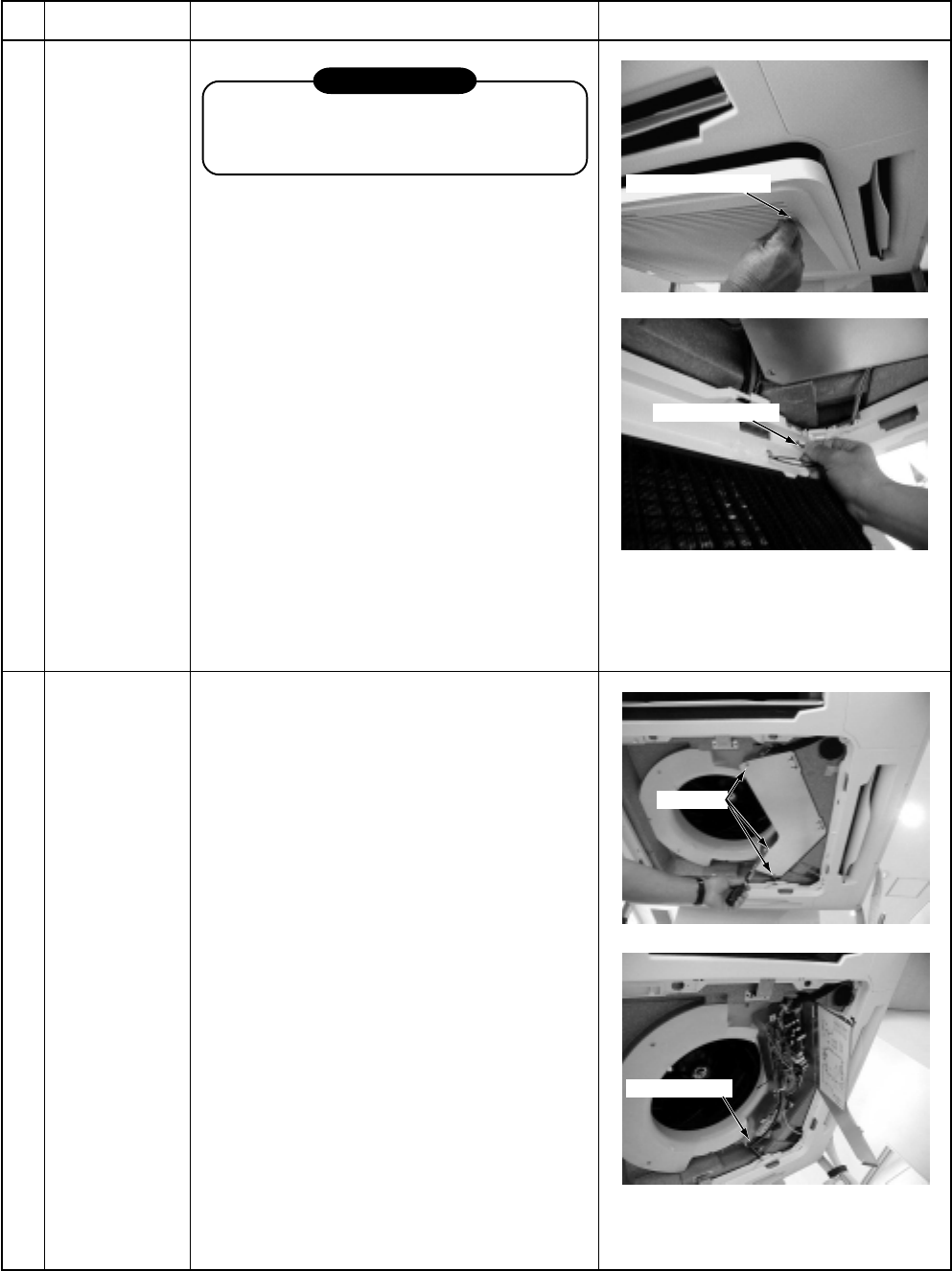
– 135 –
15. DETACHMENTS
15-1. Indoor Unit
RAV-SM560UT-E, SM800UT-E
No.
Q
Part name
Suction grille
Procedure
REQUIREMENT
Never forget to put on the gloves at
disassembling work, otherwise an injury
will be caused.
1. Detachment
1) Stop operation of the air conditioner,
and then turn off switch of the breaker.
2) Hang down the suction grille while
sliding two knobs of the suction grille
inward.
3) Remove a strap connecting the panel
and the suction grille to remove the
suction grille.
2. Attachment
1) Hang the suction grille to the panel.
2) Attach the strap of the suction grille to
the panel as before.
3) Close the suction grille, slide the knobs
outward, and then fix it.
Remarks
1. Detachment
1) Perform work of item 1. of Q.
2) Remove screws fixing the electric parts
cover. (Ø4 x 10, 3 pcs.)
3) Remove the electric parts cover from
the tentative hook, and then open the
cover.
2. Attachment
1) Close the electric parts cover and hang
the cover hole to the tentative hook.
2) Tighten the fixing screws.
(Ø4 x 10, 3 pcs.)
RElectric parts
cover
Knob of suction grille
Remove the strap.
3 screws
Tentative hook
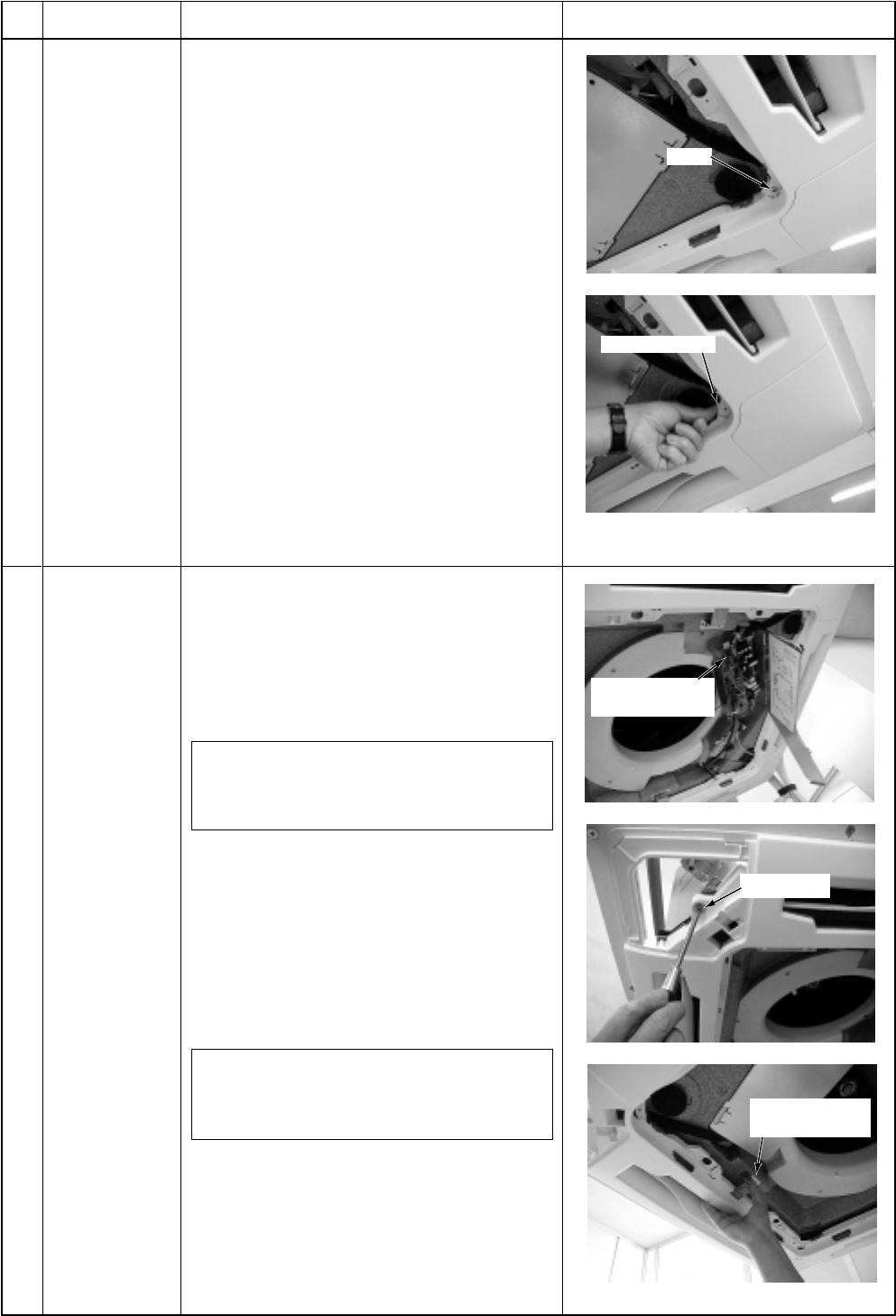
– 136 –
No.
S
Part name
Adjust corner
cap
Procedure
1. Detachment
1) Perform work of item 1. of Q.
2) Remove screws at 4 corners of the
suction port. (Ø4 x 10, 4 pcs.)
3) Push the knob outward and remove the
adjust corner cap by sliding it.
2. Attachment
1) Mount the adjust corner cap by sliding
it inward.
2) Tighten screws at 4 corners of the
suction port. (Ø4 x 10, 4 pcs.)
Remarks
Screw
Push outward
Remove the flap
connector
Fixing screw
Push the tentative
hook outward
1. Detachment
1) Perform works of items 1 of Q, 1 of R
and 1 of S.
2) Remove the flap connector (CN33,
White, 5P) connected to the control P.C.
board, and then remove the lead wire
from the clamp.
NOTE :
Remove the connector by releasing
locking of the housing.
3) Remove screws fixing the ceiling panel.
(M5, 4 pcs.)
4) Push the tentative hook outward to
remove the ceiling panel.
2. Attachment
1) Hang the tentative hook of the main
body drain pan to the tentative hook of
the ceiling panel.
NOTE :
A panel has directional property, so mount
a panel with attention to the marks.
2) Tighten fixing screws. (M5, 4 pcs.)
3) Connect flap connector of the ceiling
panel to connector (CN33, White, 5P)
on the control P.C. board.
TCeiling panel
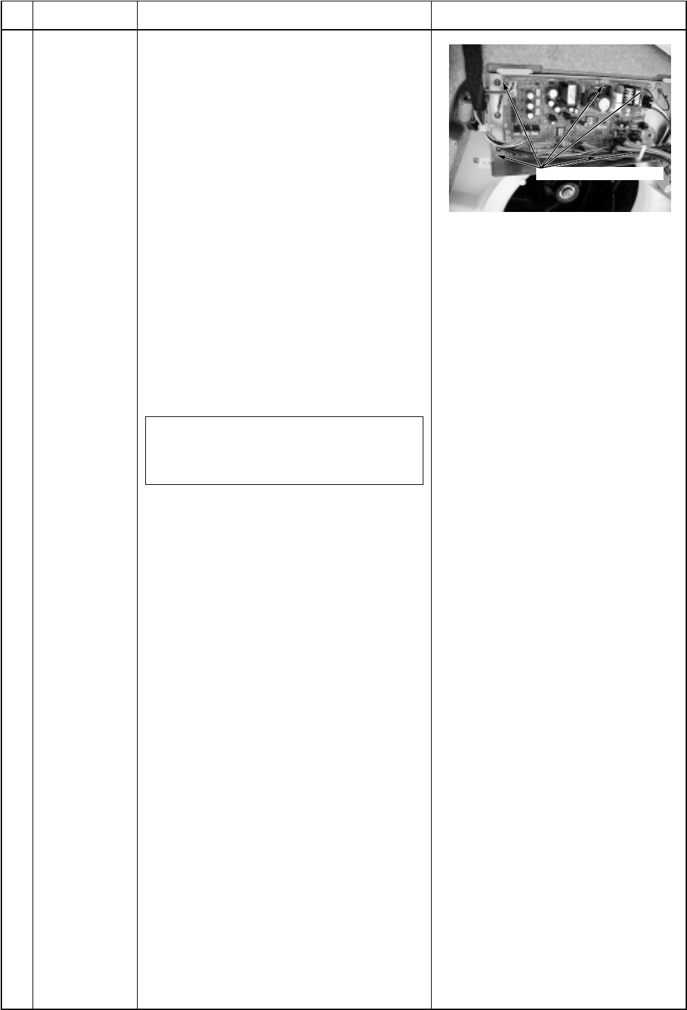
– 137 –
No.
U
Part name
Control P.C.
board
Procedure
1. Detachment
1) Perform works of items 1 of Q and 1 of
R.
2) Remove connectors which are con-
nected from the control P.C. board to
other parts.
CN33 : Flap motor (5P: White)
CN34 : Float switch (3P: Red)
CN41 : Terminal block of remote
controller (3P: Blue)
CN68 : Drain pump (3P: Blue)
CN67 : Terminal block of power supply
(5P: Black)
CN101 : TC sensor (2P: Black)
CN102 : TCJ sensor (2P: Red)
CN104 : Room temperature sensor
(2P: Yellow)
CN333 : Power supply of fan motor
(5P: White)
CN334 : Position detection of fan motor
(5P: White)
NOTE :
Remove the connector by releasing
locking of the housing.
3) Unlock locking of the card-edge spacer
at 6 positions to remove the control P.C.
board.
2. Attachment
1) Fix the control P.C. board to the card-
edge spacer at 6 positions.
2) Connect the connectors removed in
item 1 to the original positions.
Remarks
Card-edge spacer
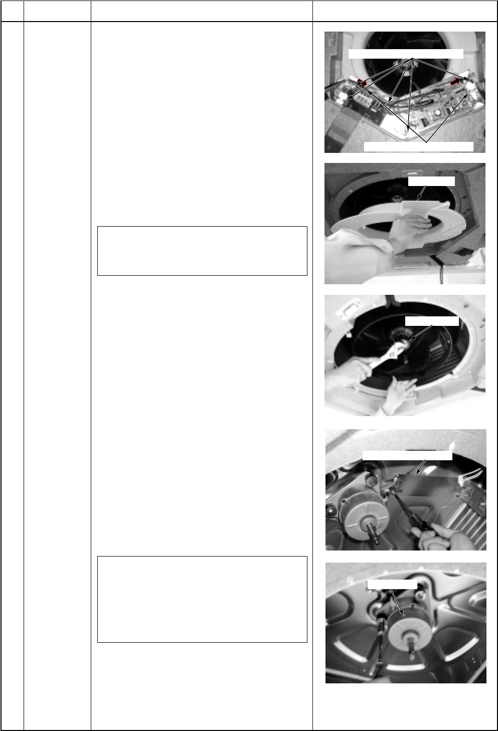
– 138 –
No.
V
Part name
Fan motor
Procedure
1. Detachment
1) Perform works of items 1 of Q and 1 of
R.
2) Remove clamps of the lead wires con-
nected to the following connectors of the
control P.C. board.
CN33 : Flap motor (5P: White)
CN34 : Float switch (3P: Red)
CN68 : Drain pump (3P: Blue)
CN101 : TC sensor (2P: Black)
CN102 : TCJ sensor (2P: Red)
CN333 : Power supply of fan motor
(5P: White)
CN334 : Position detection of fan motor
(5P: White)
NOTE :
Remove the connector by releasing locking
of the housing.
3) Remove screws fixing earth lead wire in
the electric parts box. (Ø4 x 6, 2 pcs.)
4) Remove indoor/outdoor inter-unit cable
and remote controller cable of the termi-
nal block.
5) Remove screws fixing the electric parts
box. (Ø4 x 10, 5 pcs.)
6) Remove screws fixing the bell mouth.
(Ø4 x 10, 6 pcs.)
7) Remove nuts fixing the turbo fan.
(M6, 1 pc.)
8) Remove screws fixing holder of the motor
lead wires to remove the motor lead wires
from the clamp. (Ø4 x 8, 3 pcs.)
9) Remove nuts fixing the fan motor to
remove it.
2. Attachment
1) Fix the parts, fan motor, holder of the
motor lead, turbo fan, bell mouth, and
electric parts box successively to their
original positions.
NOTE 1 :
When fixing the turbo fan, be sure to match
the fan boss with D-cut of the motor shaft.
NOTE 2 :
Fix the turbo fan with torque wrench
5.9 ± 0.6Nm.
2) Connect connectors, earth lead wire,
indoor/outdoor inter-unit cable, and
remote controller cable which have been
disconnected in the above item 1 as
before.
Remarks
Screws fixing earth lead wires
Screws fixing electric parts box
Bell mouth
Turbo fan
Motor lead holder
Fan motor
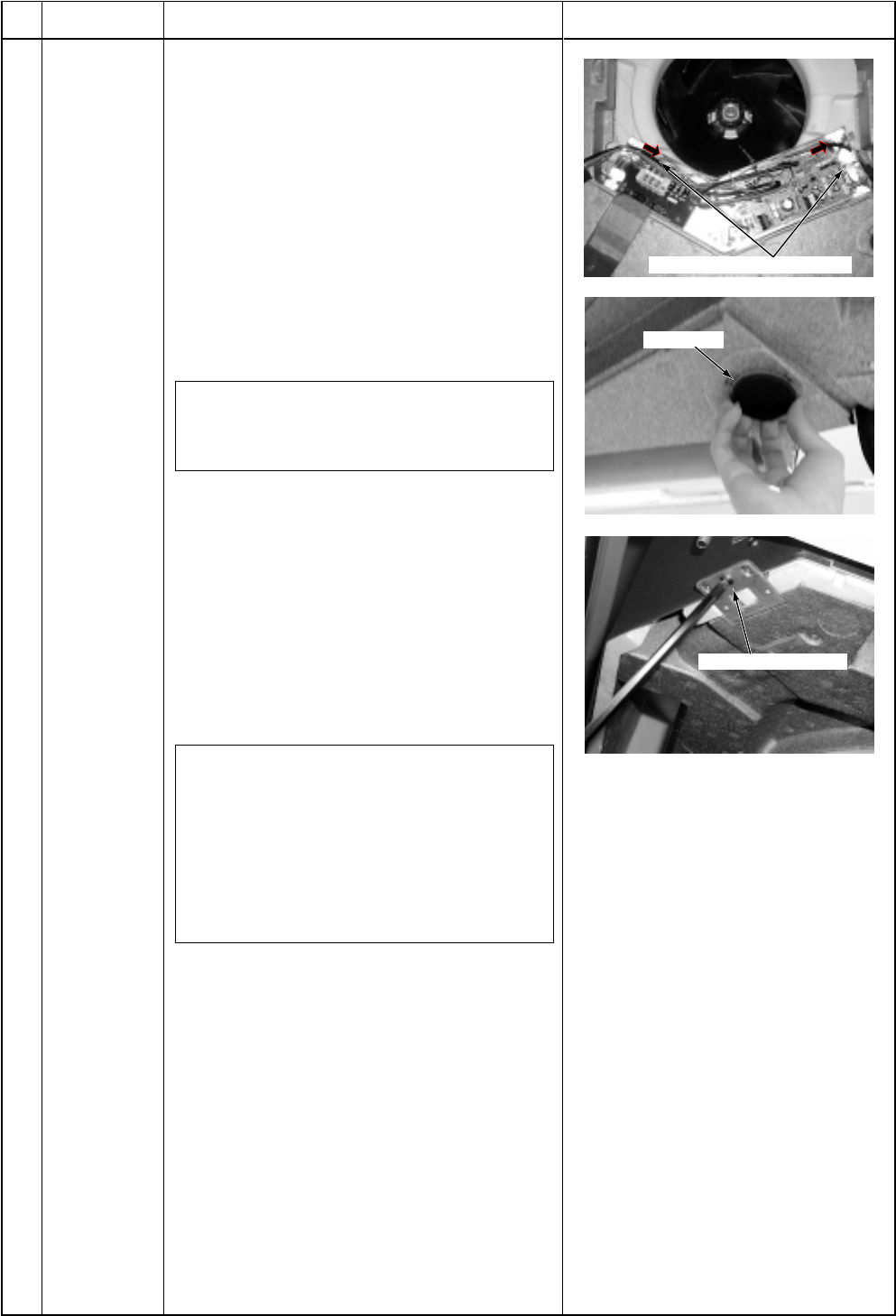
– 139 –
No.
W
Part name
Drain pan
Procedure
1. Detachment
1) Perform works of items 1 of Q, 1 of R, 1
of S and 1 of T.
2) Remove clamps of the lead wires con-
nected to the following connectors of the
control P.C. board.
CN34 : Float switch (3P: Red)
CN68 : Drain pump (3P: Blue)
CN101 : TC sensor (2P: Black)
CN102 : TCJ sensor (2P: Red)
CN333 : Power supply of fan motor
(5P: White)
CN334 : Position detection of fan motor
(5P: White)
NOTE :
Remove the connector by releasing locking
of the housing.
3) Remove screws fixing earth lead wire in
the electric parts box. (Ø4 x 6, 2 pcs.)
4) Remove indoor/outdoor inter-unit cable
and remote controller cable of the termi-
nal block.
5) Remove screws fixing the electric parts
box. (Ø4 x 10, 5 pcs.)
6) Remove screws fixing the bell mouth.
(Ø4 x 10, 6 pcs.)
7) Remove the drain cap, and drain water
accumulated in the drain pan.
NOTE 1 :
When removing the drain cap, be sure to
prepare a bucket to catch the drained water.
NOTE 2 :
Thermal insulator is adhered to the drain
cap. Be careful not to peel off the insulator.
If the insulator has been peeled, adhere it
with double-face tape, etc. as before.
8) Remove screws fixing the drain pan.
(Ø4 x 8, 4 pcs.)
2. Attachment
1) Fix the parts, drain cap, drain pan, bell
mouth, and electric parts box succes-
sively to their original positions.
2) Connect connectors, earth lead wire,
indoor/outdoor inter-unit cable, and
remote controller cable which have been
disconnected in the above item 1 as
before.
Remarks
Screws fixing earth lead wires
Drain cap
Screws fixing drain pan
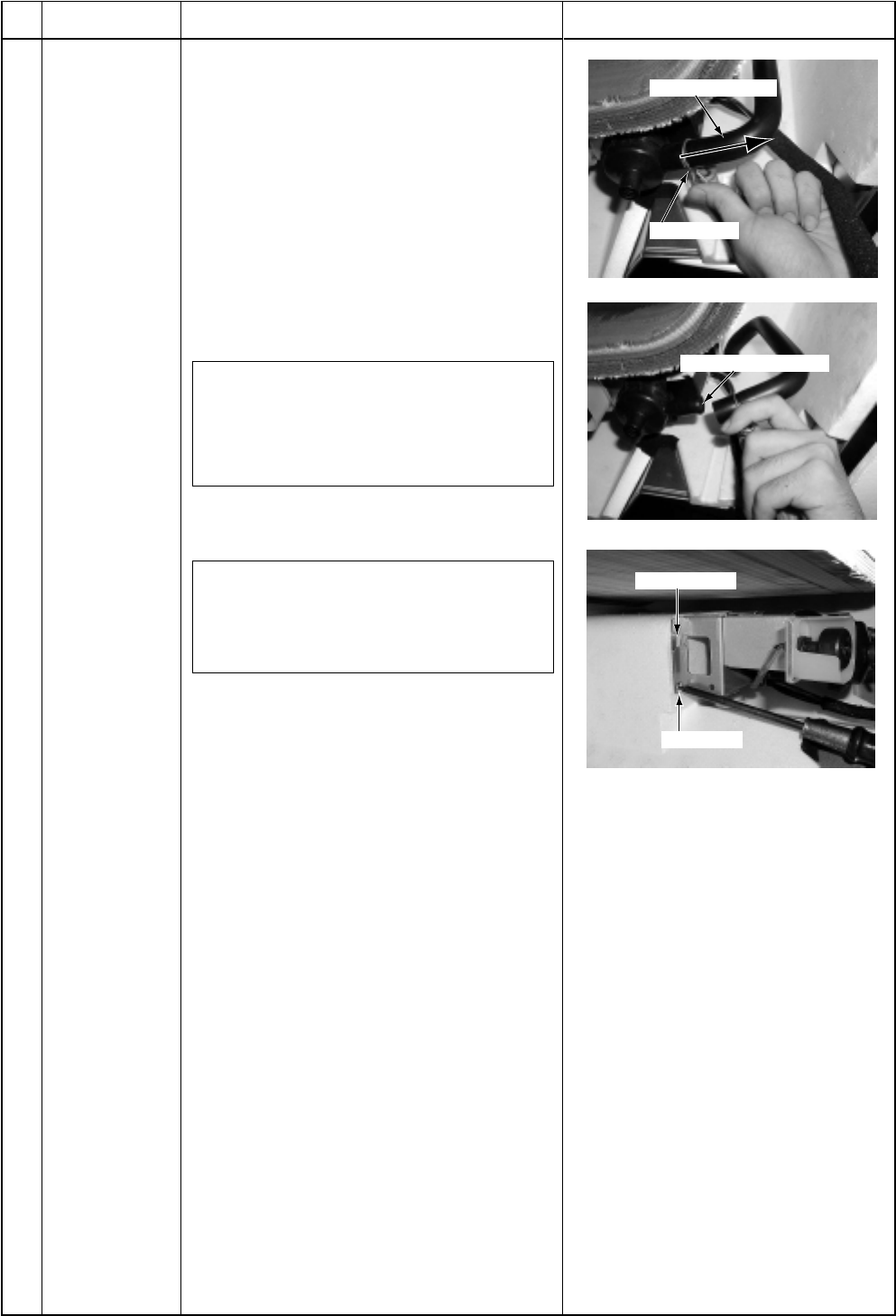
– 140 –
No.
X
Part name
Drain pump
assembly
Procedure
1. Detachment
1) Perform works of items 1 of Q, 1 of R,
1 of S, 1 of T and 1 of W.
2) Picking the hose band, slide it from
pump connecting part to remove the
drain hose.
3) Remove screw fixing the drain pump
assembly, slide hooking claws of the
drain pump assembly and the main
body (1 position), and then remove the
assembly. (Ø4 x 8, 3 pcs.)
3. Attachment
1) Fix the drain pump assembly as before.
NOTE :
The drain pump is fixed with a hook and 3
screws. In screwing, be sure that screws
do not to run on hooking claw at the main
body side.
2) Attach the drain hose and hose band
as before.
NOTE :
Insert the drain hose up to the end of
pump connecting part, and bind the white
mark position of the hose with band.
Remarks
Hose band
Slide to hose side.
Pump connecting part
Hooking claw
Fixing screw
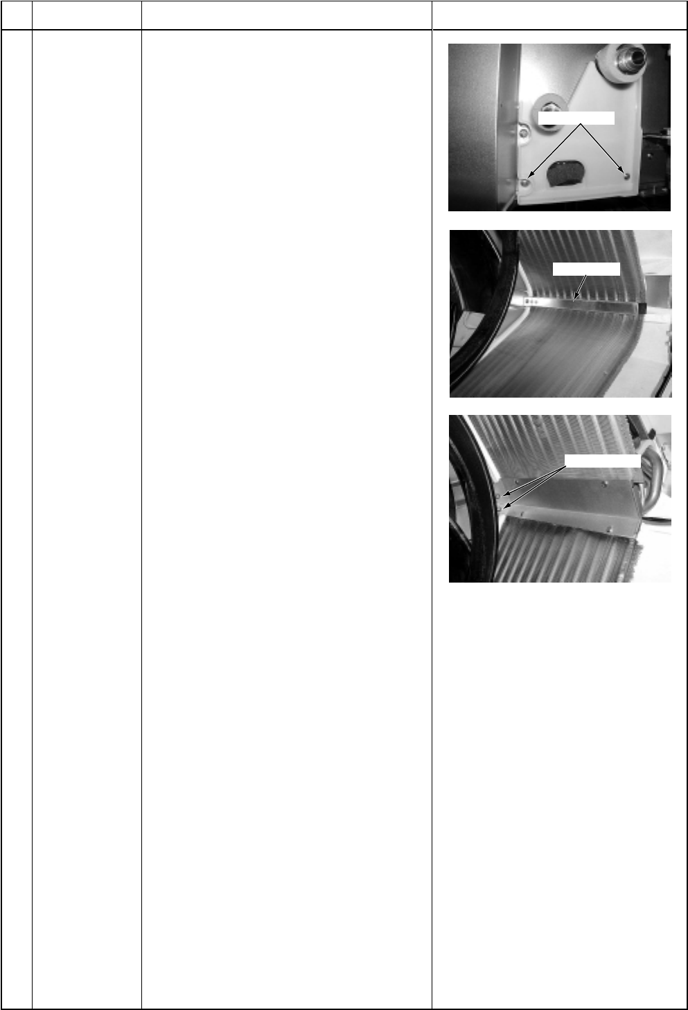
– 141 –
No.
Y
Part name
Heat exchanger
Procedure
1. Detachment
1) Recover refrigerant gas.
2) Remove refrigerant pipe at the indoor
unit side.
3) Perform works of items 1 of Q, 1 of R,
1 of S, 1 of T and 1 of W.
4) Remove screws fixing the pipe cover.
(Ø4 x 8, 2 pcs.)
5) Remove the heat exchanger by
removing fixing band and fixing screws
while holding the heat exchanger.
(Ø4 x 8, 3 pcs.)
2. Attachment
1) Fix the parts, heat exchanger, fixing
band, pipe cover, drain cap, drain pan,
bell mouth, and electric parts box
successively to their original positions.
2) Connect connectors, earth lead wire,
indoor/outdoor inter-unit cable, and
remote controller cable which have
been disconnected in the above item 1
as before.
3) Connect the refrigerant pipe as before,
and then perform vacuuming.
Remarks
Fixing screws
Fixing band
Fixing screws
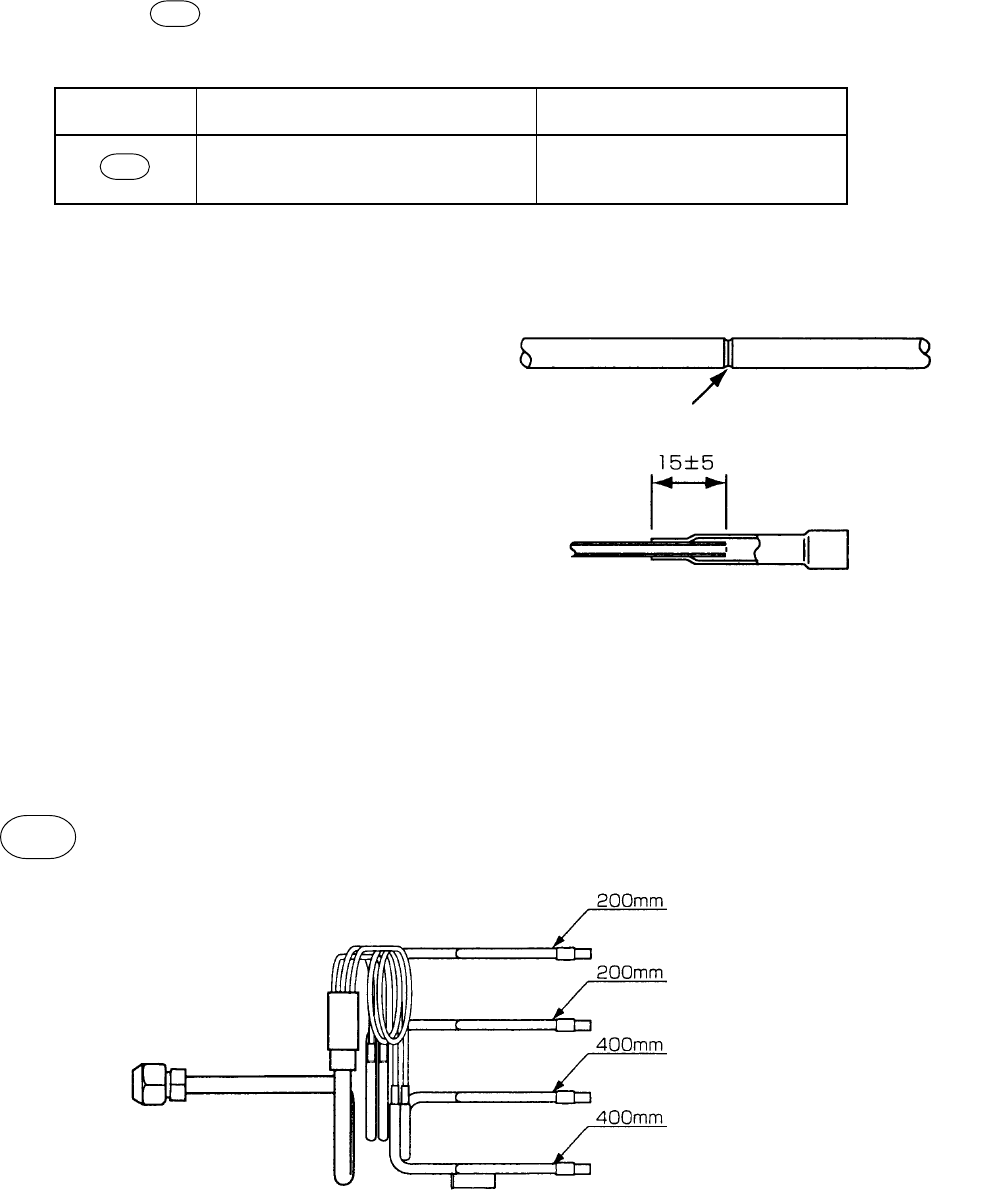
– 142 –
15-2. Replacement of Distributor Assembly
RAV-SM560UT-E
1. Cutting of Capillary Tube
A capillary tube ( 023 : Inner diameter 2mm, Length 1000mm) is brazed to a distributor assembly. Cut and
divide the tube to each length as shown below.
NOTE) Break off the capillary tube so
that inner diameter is not deformed
Ref No.
023
No. of capillary tubes
4
Cutting
200 mm : 2 pcs.
400 mm : 2 pcs.
[Cutting]
Plane circumference of the capillary tube with
triangle file, etc., and then break off it.
2. Attachment of joint pipe
Insert the attached joint pipe into the end of the
capillary tube up to 15mm, and braze it.
Form the capillary tube as same as that in the
distributor assembly before replacement.
3. Brazing to indoor heat exchanger
Attach the capillary tube processed in items 1 and 2 to the end of the pipe with brazing as shown below.
023
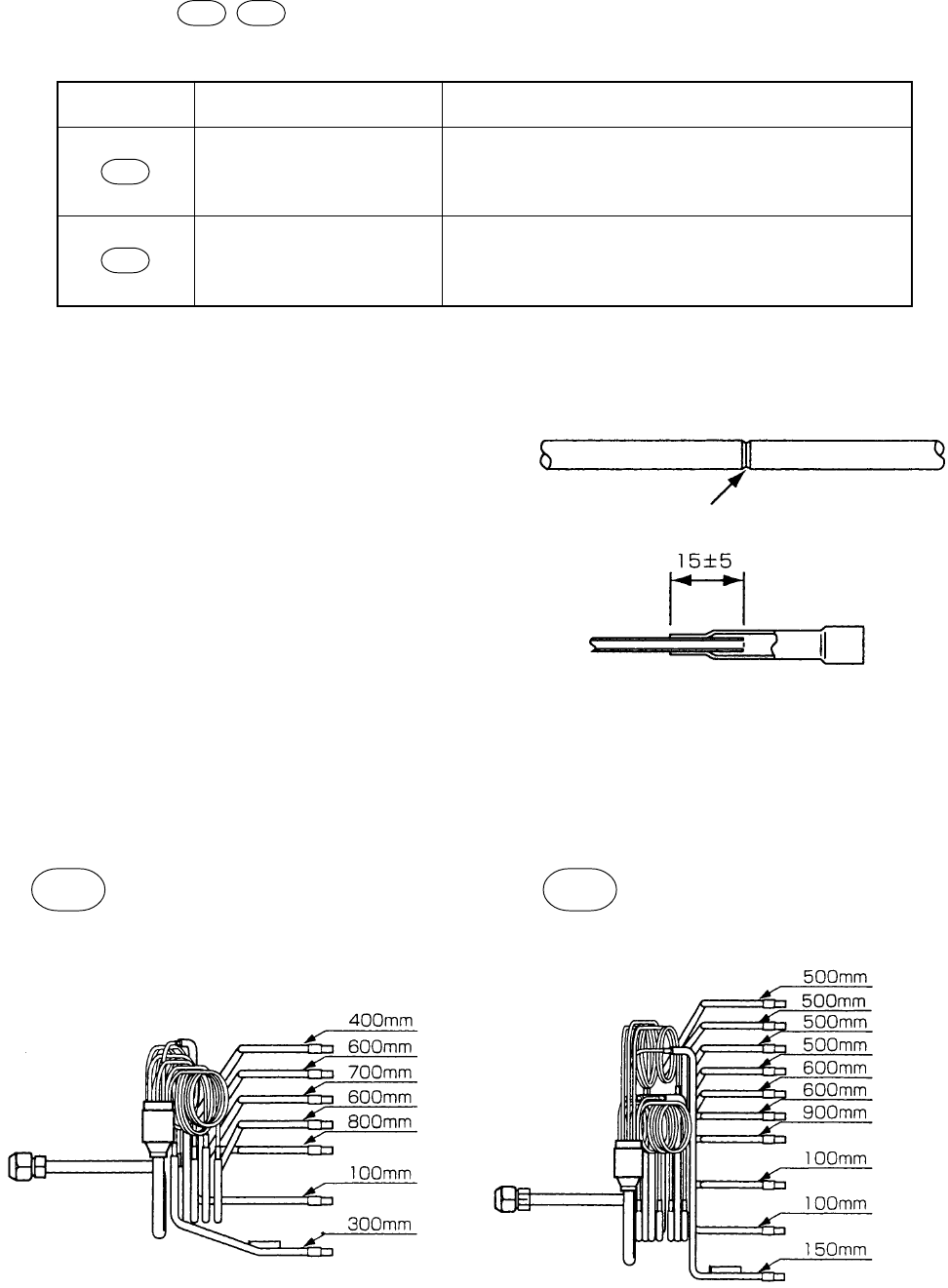
– 143 –
RAV-SM800UT-E
1. Cutting of Capillary Tube
A capillary tube ( 025 026 : Inner diameter 2mm, Length 1000mm) is brazed to a distributor assembly.
Cut and divide the tube to each length as shown below.
Ref No.
025
026
No. of capillary tubes
7
10
Cutting
100 mm : 1 pc. 600 mm : 2 pcs.
300 mm : 1 pc. 700 mm : 1 pc.
400 mm : 1 pc. 800 mm : 1 pc.
100 mm : 2 pcs. 600 mm : 2 pcs.
150 mm : 1 pc. 900 mm : 1 pc.
500 mm : 4 pcs.
[Cutting]
Plane circumference of the capillary tube with
triangle file, etc., and then break off it.
2. Attachment of joint pipe
Insert the attached joint pipe into the end of the
capillary tube up to 15mm, and braze it.
Form the capillary tube as same as that in the
distributor assembly before replacement.
3. Brazing to indoor heat exchanger
Attach the capillary tube processed in items 1 and 2 to the end of the pipe with brazing as shown below.
NOTE) Break off the capillary tube so
that inner diameter is not deformed
025 026
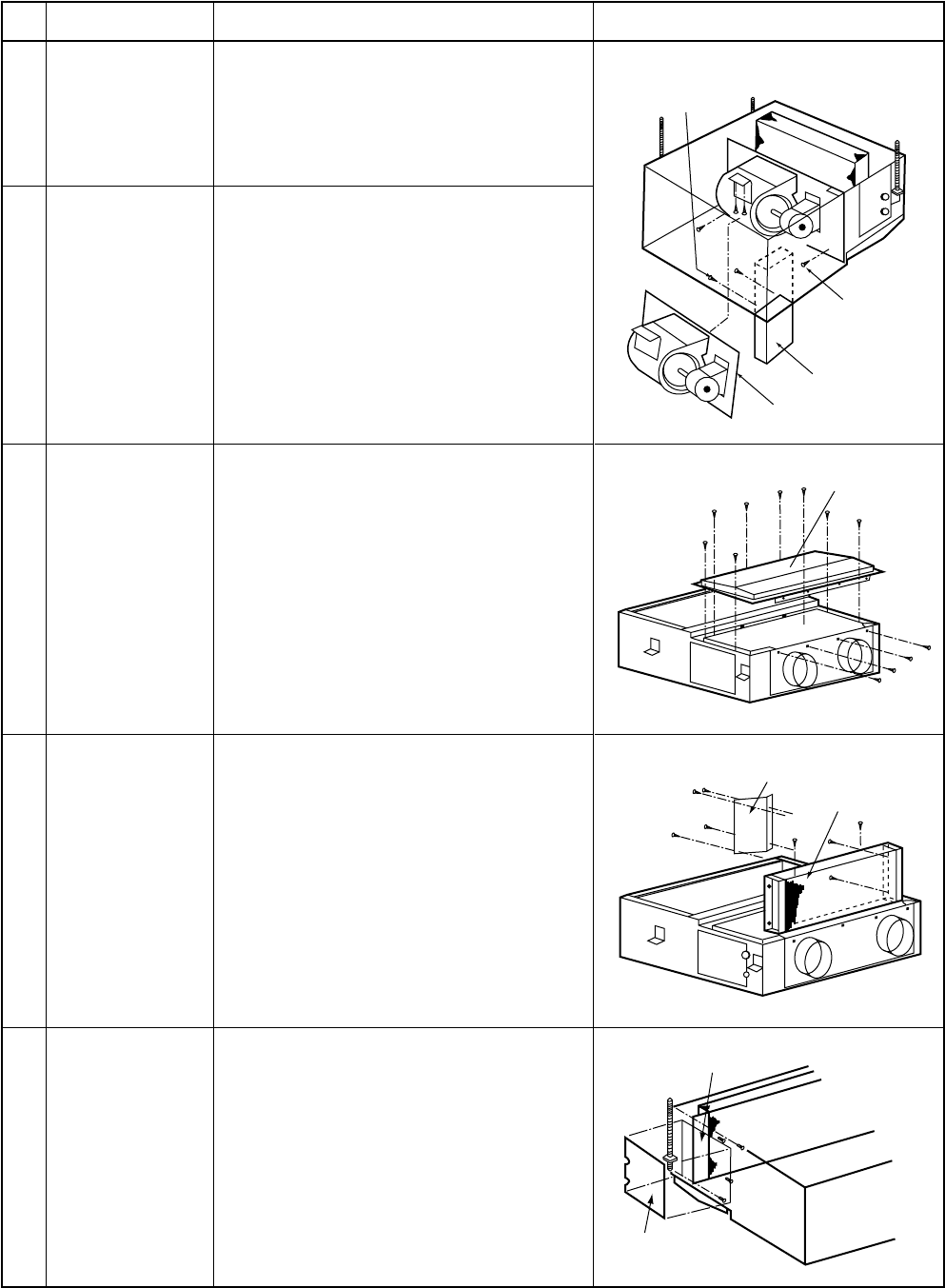
– 144 –
15-3. Replacement of Main Parts <Built-in type>
RAV-SM560BT-E, SM800BT-E
Be sure to turn off the power supply before disassembling work.
Electric parts
fixing screw
Fan fixing
screw
Electric parts
box
Fan
Drain pan
Shielding plate
Heat exchanger
Shielding plate
Check port cover
No.
1
Item
Electric parts box
Procedure
1) Remove the electric parts box.
(Supplement: Refer to How to remove
the electric parts box.)
In this time, remove connectors of TA
sensor, TC sensor, and TCJ sensor, if
necessary.)
1) Remove connector of the fan motor.
2) Remove screws fixing the fan. (Screws
at 4 positions)
3) Take off jointed portion of fan and
cabinet, and then put down the fan.
4) Loosen set screw of the Silocco fan.
5) Remove set screw of the fan case.
6) Remove the fan motor mounting metal,
and then replace the fan motor.
1) Take down the indoor unit and then
treat the drain pan on the floor.
2) Remove screws fixing the drain pan (12
positions) and then replace the drain
pan.
1) Take down the indoor unit and then
treat the heat exchanger on the floor.
2) Remove screws fixing the drain pan (12
positions) and then remove the drain
pan.
3) Remove the shielding plate. (Screws at
4 positions)
4) Remove screws (at 4 positions) fixing
the heat exchanger, and then replace
the heat exchanger.
1) Remove the check port cover.
2) Remove the shielding plate.
(At 4 positions)
3) Pull out the sensors inserted into pipe
of the heat exchanger.
2
3
4
5
Fan
Drain pan
Heat exchanger
TC sensor
(Sensor side)
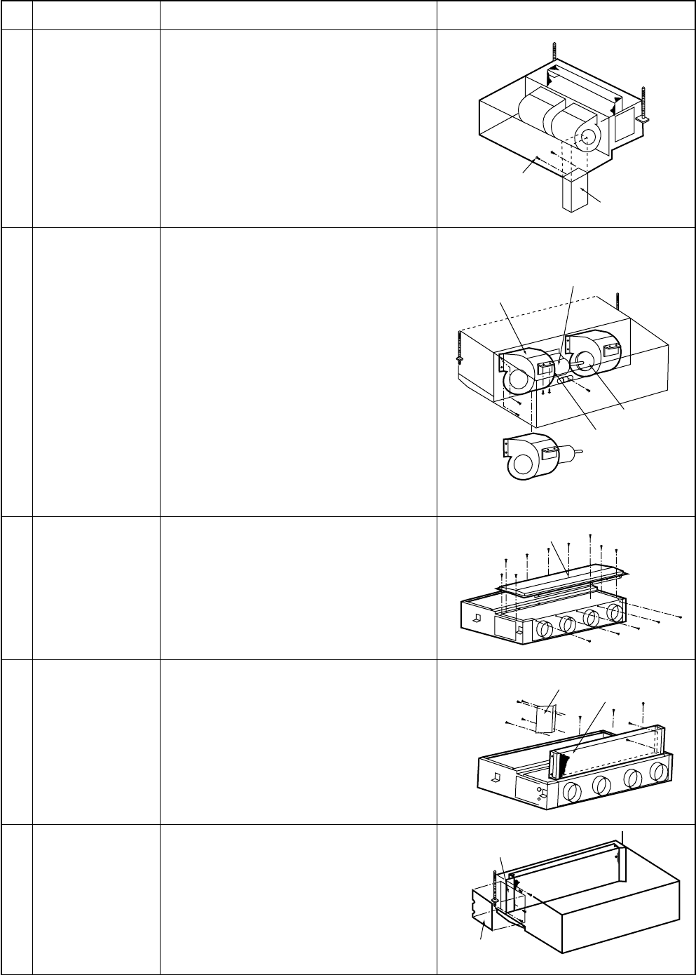
– 145 –
No.
1
Item
Electric parts box
Procedure
1) Remove the electric parts box.
(Supplement: Refer to How to remove
the electric parts box.)
In this time, remove connectors of TA
sensor, TC sensor, and TCJ sensor, if
necessary.)
AID-P710BH, P800BH, P1120BH
Be sure to turn off the power supply before disassembling work.
1) Remove connector of the fan motor.
2) Using a hexagonal wrench, loosen
coupling fixing screws at 2 positions,
and then slide the fan motor to reverse
side.
3) Remove set screws (6 positions) of the
fan case (left).
4) Remove fan motor mounting metal
(screws at 2 positions) while holding
the fan motor with hands.
5) Remove capacitor fixing screw
(1 position).
6) Take down the fan motor and the fan
case (left).
7) Loosen set screw of the Silocco fan.
8) Replace the fan motor.
1) Take down the indoor unit and then
treat the drain pan on the floor.
2) Remove screws fixing the drain pan
and then replace the drain pan.
1) Take down the indoor unit and then
treat the heat exchanger on the floor.
2) Remove screws fixing the drain pan
and then remove the drain pan.
3) Remove the shielding plate. (Screws at
4 positions)
4) Remove screws (at 5 positions) fixing
the heat exchanger, and then replace
the heat exchanger.
1) Remove the check port cover.
2) Remove the shielding plate.
(At 4 positions)
3) Pull out the sensors inserted into pipe
of the heat exchanger.
Electric
parts box
Electric parts
fixing screw
Silocco
fan (right)
Capacitor
Fan motor
Fan case (left)
Drain pan
Heat exchanger
Shielding plate
Shielding plate
Check port
cover
2
3
4
5
Fan
Drain pan
Heat exchanger
TC sensor
(Sensor side)
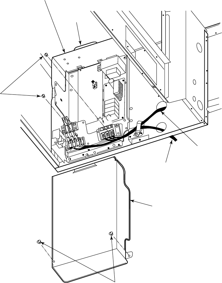
– 146 –
[SUPPLEMENT] How to remove the electric parts box
Electric parts box
The electric parts box is fixed to the indoor unit with claws at the rear side.
Lift up it once and pull toward you. Then claws come off.
Procedure 2
Remove these two screws to
remove the electric parts box.
Electric cable
Remote controller cable
Electric parts box cover
A hole at the ceiling surface side is fixed to
upper part of the electric parts box with claws.
Lift up it once and pull toward you.
Then claws come off.
Procedure 1
Remove these two screws to remove the electric parts box cover.
Hook
F7-43-4
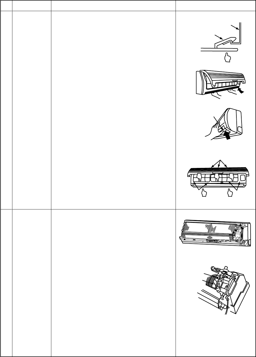
– 147 –
15-4. Replacements of Main Parts <Hi-Wall type>
15-4-1. Indoor Unit
No.
Part name
Front panel
Procedure
1) Stop operation of the air conditioner, and turn off
the power supply.
2) Push “PUSH” part at the lower side of the front
panel, and then take off claws of the front panel
from the installation board.
3) Open the suction grille and take off the front
panel fixing screws (4 pcs.).
4) After turning the side grille as shown in the right
figure, perform the following works.
5) Push the electric parts box with right thumb while
pulling both sides of the front panel toward you.
<Attachment of front panel>
1) Turn the side grille as shown in the right figure.
2) Push 3 positions at center of the discharge port
and 2 positions at lower center of the discharge
port, and then hook the hooking claws (3 posi-
tions) at upper surface of the front panel to the
rear board.
3) Tighten 4 screws.
•Insufficient hooking or pushing may cause
falling of dewdrop or discomforting noise.
When removing the front panel without turning
the side grille, the front panel may be broken.
Remarks
Screw
Drain guide
1) Perform work of item 1 of .
2) Remove the drain guide.
3) Take off screws for earth lead wire attached to
the end plate of the heat exchanger.
4) Disconnect connectors for fan motor and louver
motor from the microcomputer assembly.
5) Remove the display unit at the center of the set
from the main body.
Electric parts
box assembly
Installation board
Front panel
Upper hooking claws
(3 positions)
Fixing
screws Fixing
screws
Side grille
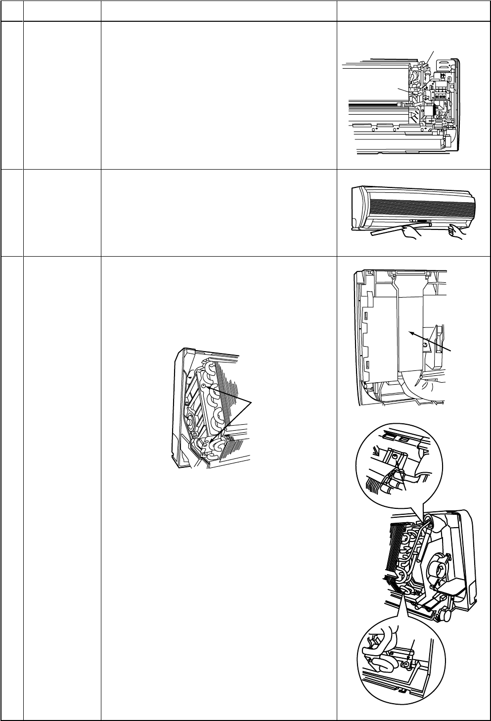
– 148 –
No.
Part name
Electric parts
box assembly
Procedure
6) Take off fixing screw (1 position) of the electric
parts base, and then pull out the electric parts
base toward you.
7) Pull out Tc sensor and Tcj sensor from sensor
holder of the heat exchanger. After replacement
of the parts, incorporate two sensors without
mistake as shown in the right figure.
(Tube is attached to Tcj sensor.)
8) After replacement of the parts, set a trap so that
water does not enter in the electric parts assem-
bly. (Incomplete process for lead wires may
cause water leak.)
Remarks
Tjc sensor position
(Tube is attached to Tcj sensor.)
TC sensor
position
Fixing screw
Pipe
holder
FFFixing
screw
Fixing
screw
Fixing
screw
1) Remove shaft of the side grille from the air
conditioner body. (First remove the left shaft and
then other shafts while sliding the side grille left
and right.)
1) Perform work of item .
2) Remove pipe holder at rear side of the main
body.
3) Take off fixing screws (2 pcs.) at the left side of
the end plate of the heat exchanger.
4) Take off two fixing screws of the heat exchanger
holder (right), and then remove the heat ex-
changer holder (right).
5) Take off fixing screw at lower right side of the
heat exchanger.
6) Remove the heat exchanger from the rear main
body by lifting it upward.
Side grille
Heat exchanger
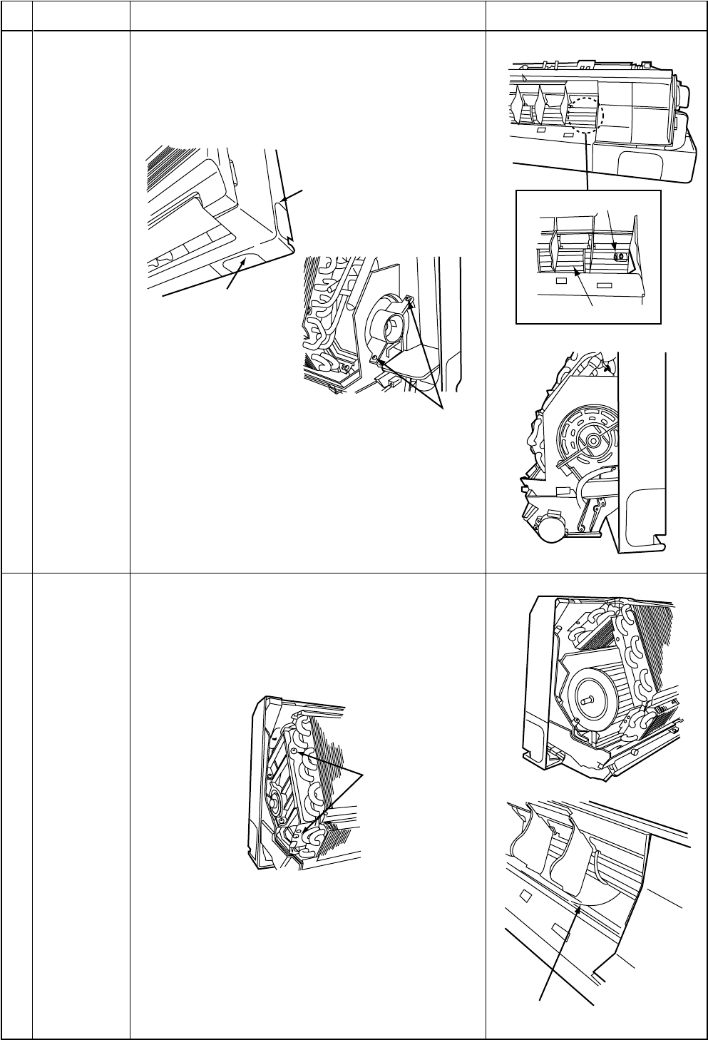
– 149 –
No.
Part name
Fan motor
Procedure
1) Perform work of item .
2) Perform work of item .
3) Loosen set screw of the cross flow fan from the
discharge port.
4) Remove the bushing (right).
Remarks
Bushing (right)
Push this
part upward
Fixing screws
Set screw
Cross fan
5) Take off two fixing screws of the motor band (right).
6) Pull out the motor band (right) and the fan motor
outward.
* Caution at reassembly
•Determine position of the fan motor so that connec-
tor of the fan motor enters in the positioning rib of
the motor band (right).
1) Perform works of items and .
2) Loosen set screw of the cross flow fan from the
discharge port.
3) Take off two fixing screws at the left side of the end
plate of the heat exchanger, and then take off two
fixing screws of the bearing base.
Fixing screw
Positioning rib
4) Lift up slightly the left side of the heat exchanger to
remove the bearing base.
5) Lift up the left side of the heat exchanger toward
you to remove the cross flow fan.
* Caution at reassembly
•Mount the cross flow fan so that the left end of the
first joint from right of the drift fan matches with the
left end of the positioning rib of the rear main body.
Cross flow
fan
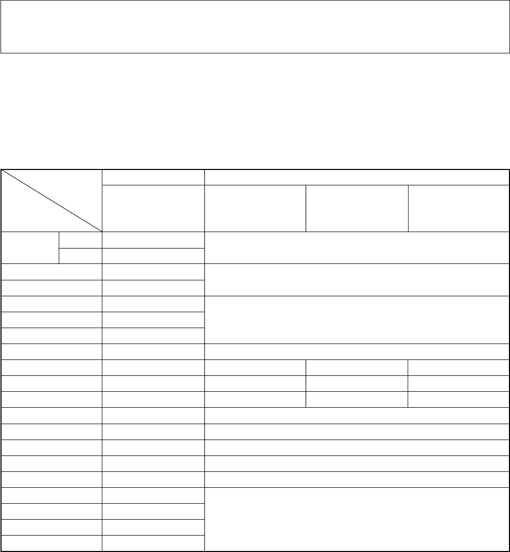
– 150 –
15-4.2. Replacement Procedure of Service Main P.C. Board
Replacement Procedure of Indoor Control P.C. Board
(AIK-PXXXH series, SIK-PXXXH series)
For this indoor control P.C. board [AIK/SIK-P SERVICE] corresponding to the common P.C. boards, follow to this
replacement procedure when replacing P.C. board.
(When using SIK-PXXXH series, P.C. board name, parts layout, etc. of the presently mounted P.C. board differ
from those of this service P.C. board. However there is no problem in the functions.)
Components
•Service P.C. board (MCC-1370A [AIK/SIK-P SERVICE] : 1 unit
•Replacement Procedure of Indoor Control P.C. Board : These sheets
•Replacement Record of remote controller/indoor control P.C. board/outdoor control P.C. board : 1 sheet
Replacement Procedure
1
Remove the presently mounted P.C. board from the electric parts box.
(Be sure to send back the replaced P.C. board with Replacement Record attached separately.)
2
Set Dip SW and jumpers of the service P.C. board according to the following exchange correspon-
dence table.
As it is : Setup of jumper of the service P.C. board is not changed.
3
Mount P.C. board according to [Mounting].
Model
Part
SW03 1
2
J01
J07
J09
J11
J12
J14
J15
J16
J17
J19
J22
J24
J25
J36
J50
J53
J54
J55
<Reference>
Service P.C. board
Initial setup
at shipment
ON
OFF
〇
〇
〇
〇
〇
〇
〇
〇
〇
×
〇
〇
〇
×
〇
〇
〇
〇
AIK-PXXXH series
AIK-P400H AIK-P630H AIK-P710H
AIK-P450H AIK-P800H
AIK-P500H
AIK-P560H
Match setup with one of former P.C. board.
As it is : 〇
Match setup with one of former P.C. board.
As it is : 〇
As it is : 〇As it is : 〇Cut : ×
As it is : 〇Cut : ×As it is : 〇
As it is : 〇As it is : 〇As it is : 〇
As it is : ×
As it is : 〇
Cut : ×
As it is : 〇
As it is : ×
As it is : 〇
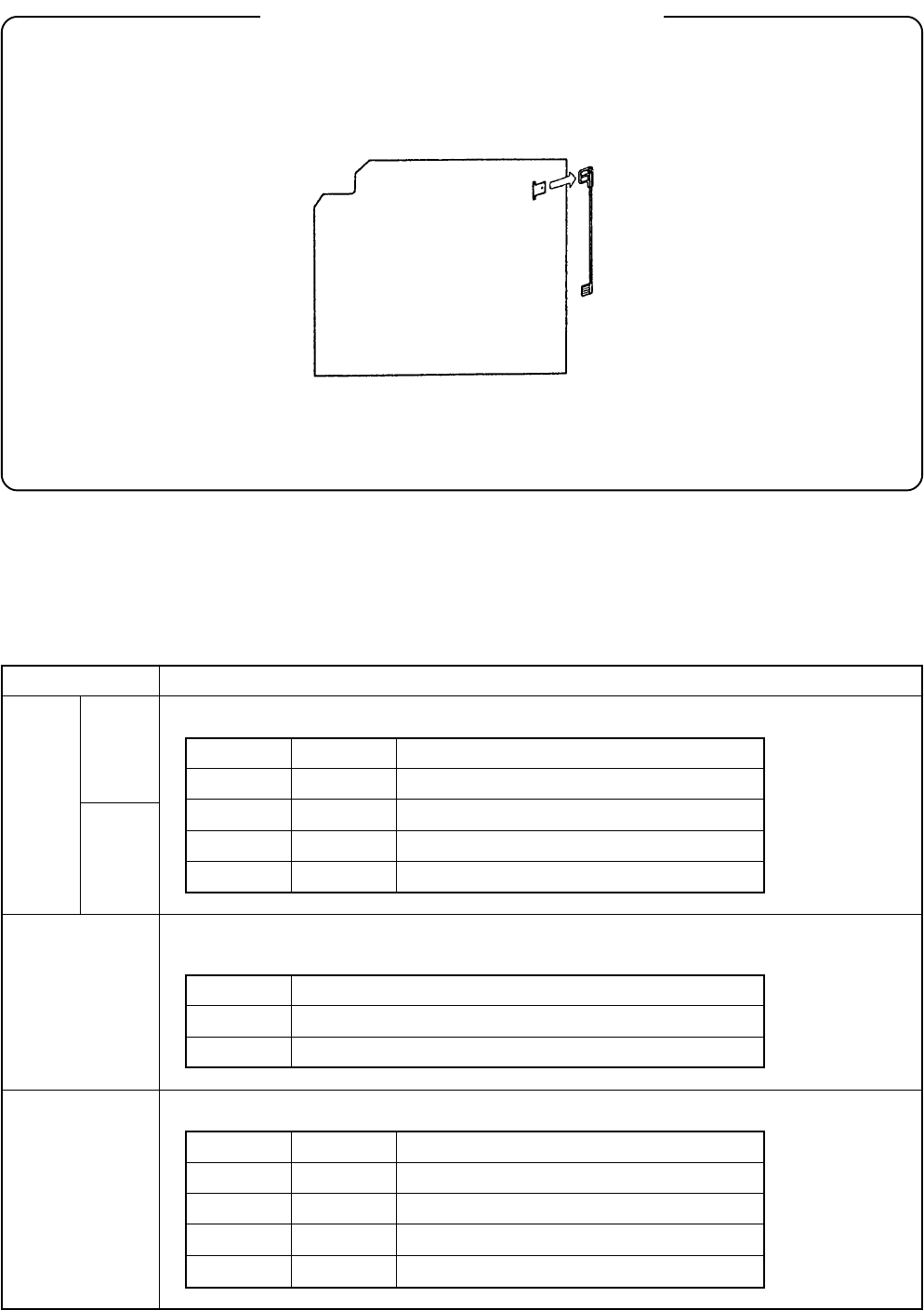
– 151 –
[Mounting]
In case of AIK-PXXXH series
1. As same as P.C. board before replacement, attach a cable (Black) which is screwed to the electric parts
box to CN240 without using a cable (Black) attached previously to CN240 of the service P.C. board.
Service P.C. board
Cable
(Remove a cable
attached previously
to CN240 of the
service P.C. board.)
CN204
2. Attach other cables as same as P.C. board before replacement.
Part name
SW03 1
2
Function
TA shift: Thermo-OFF point can be shifted in heating operation.
Bit 1 Bit 2
OFF OFF
OFF ON
ON OFF
ON ON
Shift Q’ty
+ 6K
+ 4K
+ 2K (Setup at shipment)
± 0K
Selection of hot start control temperature :
The starting temperature of the fan can be raised in heating operation.
J09
Provided
None
Setup
Normal (Setup at shipment)
Fan starting temp up (Approx. +4K)
Setup of filter timer
J11 J12
Provided Provided
None Provided
Provided None
None None
Setup
240 hours (Setup at shipment)
2500 hours
5000 hours
Without filter timer
J09
J11
J12
<(Reference) Explanation about functions of switches/jumpers>
•The following table shows the functions of the main switches and jumpers. Use as reference in miss-setup.
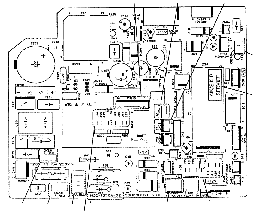
– 152 –
<Parts layout of service P.C. board>
CN213 display part CN04 temp. sensor CN05 heat exchanger
CN240
Label
Jumper
SW03: TA shift
P.C. board (MCC-1370A)
Jumper
CN223
CN230
CN231
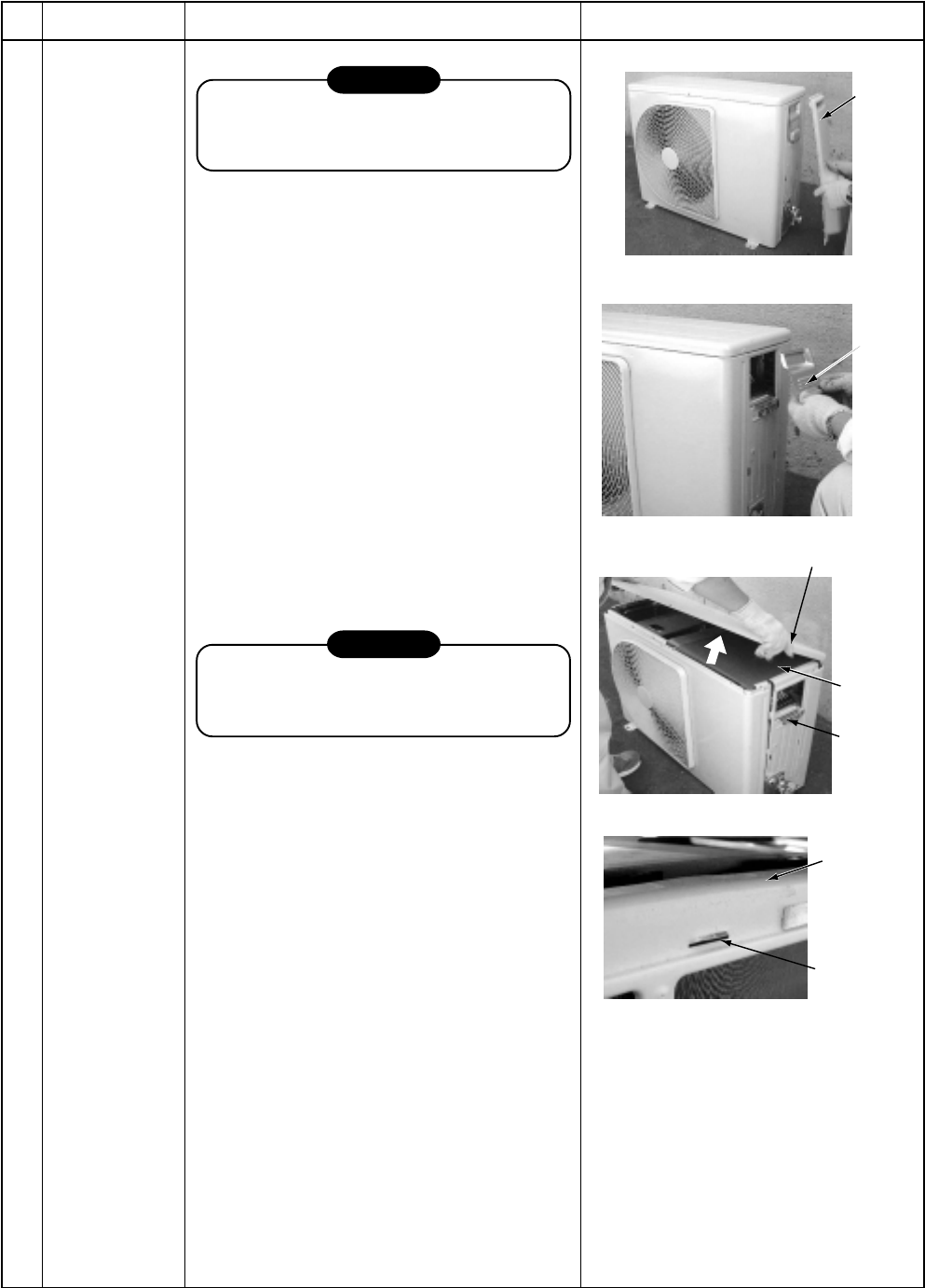
– 153 –
15-5. Outdoor Unit
RAV-SM560AT-E
No.
Part name
Common
procedure
Procedure
CAUTION
Never forget to put on the gloves at
working time, otherwise an injury will be
caused by the parts, etc.
1. Detachment
1) Stop operation of the air conditioner, and
turn off the main switch of the breaker for
air conditioner.
2) Remove the valve cover.
(ST1T Ø4 x 10L, 1 pc.)
•After removing screw, remove the valve
cover pulling it downward.
3) Remove wiring cover (ST1T Ø4 x 10L, 2
pcs.), and then remove connecting cable.
4) Remove the upper cabinet.
(ST1T Ø4 x 10L, 2 pcs.)
•After taking off screws, remove the
upper cabinet pulling it upward.
2. Attachment
1) Attach the waterproof cover.
CAUTION
Be sure to attach a waterproof cover.
If it is not attached, there is a possibility
that water enters inside of the outdoor unit.
2) Attach the upper cabinet.
(ST1T Ø4 x 10L, 2 pcs.)
•Hook the rear side of the upper cabinet
to claw of the rear cabinet, and then put
it on the front cabinet.
3) Perform cabling of connecting cables, and
fix with cord clamp.
(ST1T Ø4 x 10L 3 pcs.)
4) Attach the wiring cover.
(ST1T Ø4 x 10L, 2 pcs.)
5) Attach the valve cover.
(ST1T Ø4 x 10L, 1 pc.)
•Insert the upper part of the upper
cabinet, set hooking claw of the valve
cover to the slit (at three positions) of the
main body, and then attach it pushing
upward.
Remarks
Valve
cover
Wiring
cover
Upper cabinet
Water-proof
cover
Cord clamp
Rear cabinet
Claw
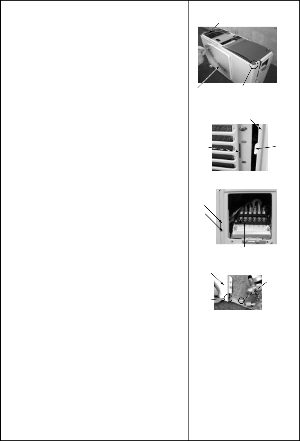
– 154 –
No.
Part name
Front cabinet
Procedure
1. Detachment
1) Perform work of item 1 of .
2) Remove screws (ST1T Ø4 x 10L, 2 pcs.)
of the front cabinet and the inverter cover.
3) Take off screws of the front cabinet and
the bottom plate. (ST1T Ø4 x 10L 3 pcs.)
4) Take off screws of the front cabinet and
the motor support.
(ST1T Ø4 x 10L, 2 pcs.)
•The left side of the front side if made to
insert to the rear cabinet, so remove it
pulling upward.
3. Attachment
1) Insert hook at the left side of the front side
into the rear cabinet.
2) Hook the lower part at the right side of the
front to concavity of the bottom plate.
Insert the hook of the rear cabinet into the
slit of the front cabinet.
3) Attach the removed screws to the original
positions.
Remarks
For single-phase type models,
also take off this screw
Motor support
Front cabinet
Front cabinet (Left side)
Slit Claw
Cord clamp
Slit
Hook
Front cabinet
Lower
slit
Concavity at
bottom plate
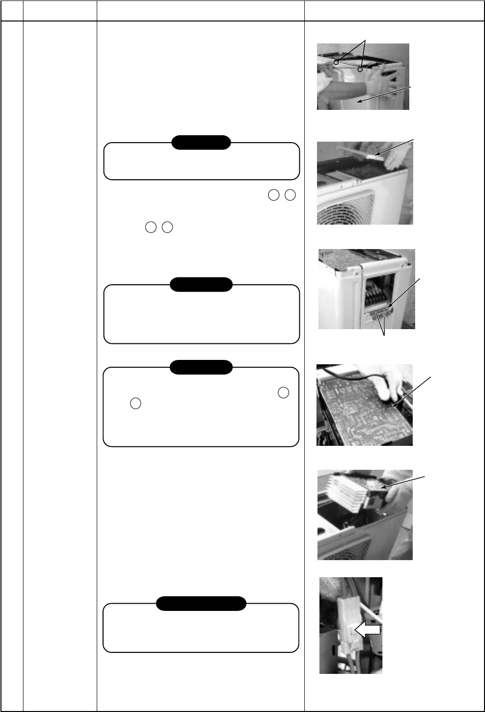
– 155 –
No.
Part name
Inverter
assembly
Procedure
1. Detachment
1) Perform work of item 1 of .
2) Take off screws of the upper part of the
front cabinet.
•If removing the inverter cover under this
condition, P.C. board can be checked.
•If there is no space in the upper part of
the upper cabinet, perform work of .
CAUTION
Be careful to check the inverter because
high-voltage circuit is incorporated in it.
3) Perform discharging by connecting + , –
polarities by discharging resistance
(approx. 100Ω, 40W) or plug of soldering
iron to + , – terminals of the C14
(printed as “CAUTION HIGH VOLTAGE”)
electrolytic capacitor (500µF) of P.C.
board.
WARNING
The electrolytic capacitor may not nor-
mally discharge according to error con-
tents and the voltage may remain. There-
fore, be sure to discharge the capacitor.
WARNING
For discharging, never use a screwdriver
and others for short-circuiting between +
and – electrodes. As the electrolytic
capacitor is one with a large capacity, it is
very dangerous because a large electric
spark will occur.
4) Take off screws (ST1T Ø4 x 10L, 2 pcs.)
fixing the main body and the inverter box.
5) Remove various lead wires from the
holder at upper part of the inverter box
and wiring holder at right side of the
terminal block.
6) Remove the lead wire from the bundled
part at left side of the terminal block.
7) Pull the inverter box upward.
8) Disconnect connectors of various lead
wires.
REQUIREMENT
As each connector has a lock mechanism,
avoid to remove the connector by holding
the lead wire, but by holding the connector.
Remarks
Screws
Front cabinet
Inverter cover
Cord clamp
Screws
(Discharging
period
10 seconds
or more)
Plug of
soldering iron
Discharging
position
Inverter
assembly
Remove the connectors
with locking function by
pushing the part indicated
by the arrow mark.
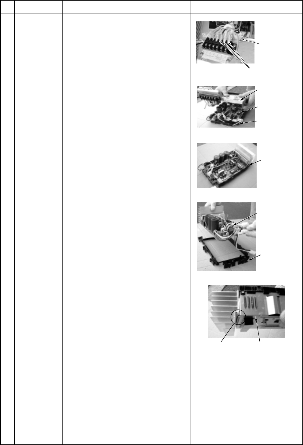
– 156 –
No.
Part name
Control P.C.
board assembly
Procedure
1) Disconnect lead wires and connectors
connected from the control P.C. board
assembly to other parts.
1. Lead wires
•Connection with the power terminal
block: 3 wires (Black, White, Orange)
•Earth wire: 1 wire (Black)
2. Connectors
•Connection with compressor:
Remove 3P connector.
•Connection with reactor:
Remove the relay connectors from
P07, 08 (2P, White) and P12, 13 (2P,
Yellow)
CN300 : Outdoor fan (3P, White)
CN301 : Position detection (5P, White)
CN701 : 4-way valve (3P, Yellow)
CN600 : TE sensor (2P, White)
CN601 : TD sensor (3P, White)
CN603 : TS sensor (3P, White)
CN602 : TO sensor (3P, White)
CN500 : Case thermo. (2P, White)
CN703 : PMV (6P, White)
2) Remove the inverter box (Metal plate).
3) Remove the control board assembly from
P.C. board base. (Remove the heat sink
and the control board assembly as they
are screwed.)
NOTES:
1. CN300, CN301 and CN701, etc. at the
control board assembly side are connec-
tors with locking function. Therefore,
remove the connector while pushing the
part indicated by an arrow mark.
2. Remove 4 hooking claws of P.C. board
base, and remove upward the heat sink
with hands.
4) Take off 3 screws fixing the heat sink and
main control board assembly side, and
replace the board with a new one.
NOTE:
When mounting a new board, check that the
board is correctly set in the groove of the
base holder of P.C. board base. Attach the
P.C. board so that the heat sink comes
securely contact with the metal sheet.
Remarks
Take off
earth screws.
Power line
Inverter box
(Metal sheet)
Control P.C.
board assembly
P.C. board base
Hooking claws
(4 positions)
Control P.C.
board assembly
P.C. board base
Inverter box
(Metal sheet)
Heat sink
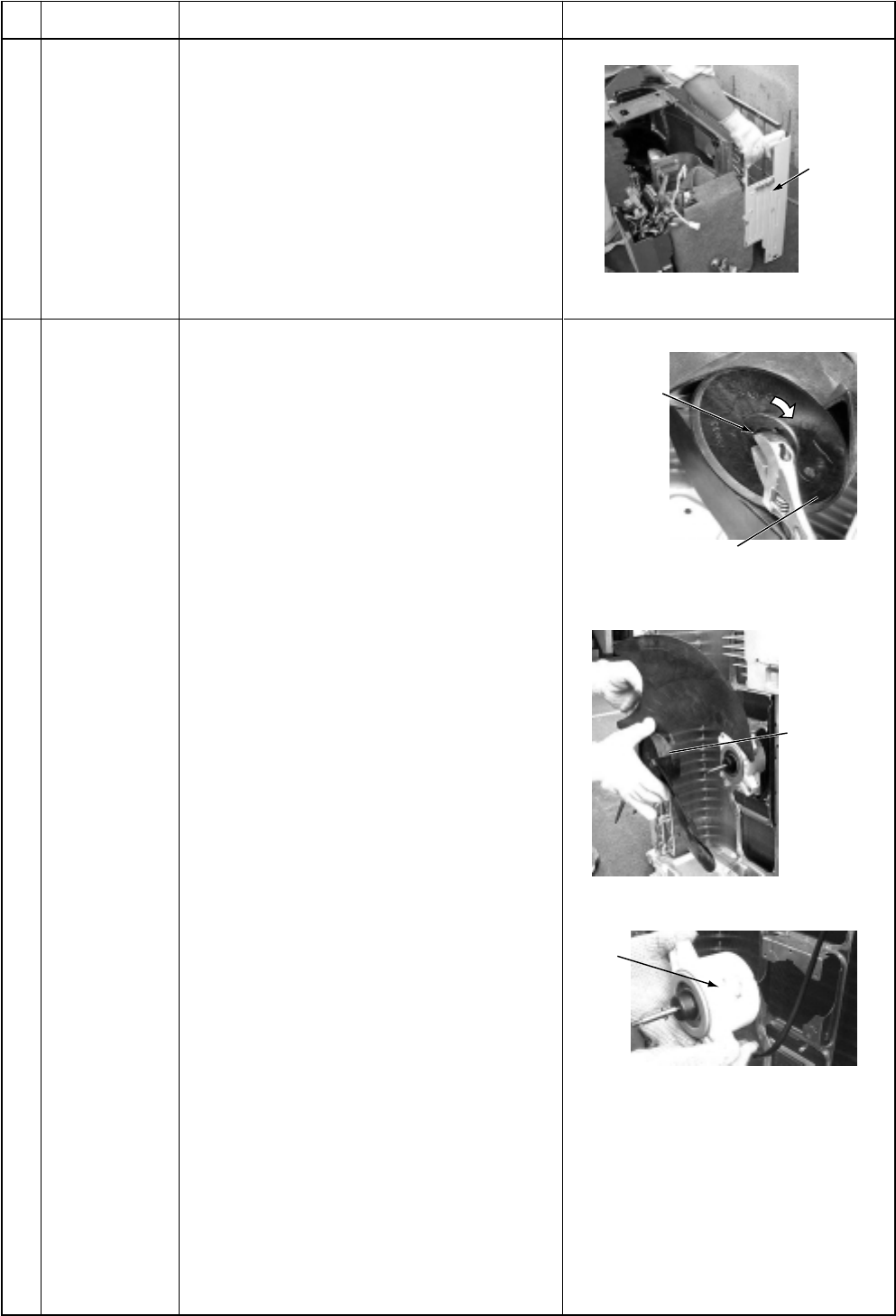
– 157 –
No.
Part name
Rear cabinet
Procedure
1) Perform works of items 1 of and , .
2) Take off fixed screws for the bottom plate.
(ST1T Ø4 x 10L, 3 pcs.)
3) Take off fixed screws for the heat ex-
changer. (ST1T Ø4 x 10L, 2 pcs.)
4) Take off fixed screw for the valve mounting
plate. (ST1T Ø4 x 10L, 1 pc.)
Remarks
1) Perform works of items 1 of and .
2) Take off the flange nut fixing the fan motor
and the propeller.
•Turning it clockwise, the flange nut can
be loosened. (To tighten the flange nut,
turn counterclockwise.)
3) Remove the propeller fan.
4) Disconnect the connector for fan motor
from the inverter.
5) Take off the fixing screws (3 pcs.) holding
by hands so that the fan motor does not
fall.
NOTE:
Tighten the flange nut with torque 4.9Nm
(50kgf/cm).
Fan motor
Rear cabinet
Flange nut
Loosen the nut by
turning clockwise
Propeller fan
Fan
motor
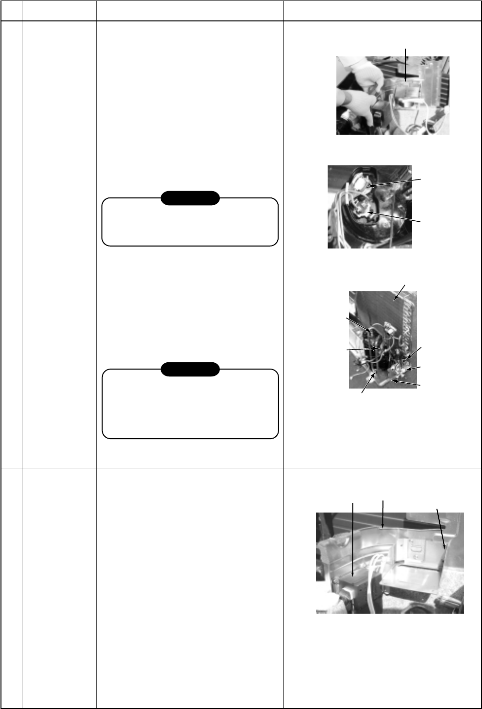
– 158 –
No.
Part name
Compressor
Procedure
1) Perform works of items 1 of and
, , , .
2) Discharge refrigerant gas.
3) Remove the partition plate.
(ST1T Ø4 x 10L, 2 pcs.)
4) Remove the noise-insulator.
5) Remove the terminal covers of the
compressor, and disconnect lead
wires of the compressor and the
compressor thermo assembly from
the terminal.
6) Remove pipes connected to the
compressor with a burner.
CAUTION
Pay attention to that flame does not
involve 4-way valve or PMV. (If doing
so, a malfunction may be caused.)
7) Take off the fixing screws of the
bottom plate and heat exchanger.
(ST1T Ø4 x 10L, 2 pcs.)
8) Take off the fixing screws of the valve
clamping plate to the bottom plate.
9) Pull upward he refrigerating cycle.
10) Take off nut fixing the compressor
to the bottom place.
CAUTION
When reconnecting the lead wires to
the compressor terminals after
replacement of the compressor, be
sure to caulk the Faston terminal
without loosening.
Remarks
Reactor 1) Perform works of item 1 of and .
2) First take off two screws (ST1T Ø4 x
10L) of the reactor fixed to the reactor
support.
3) Remove the reactor support from the
partition plate.
(ST1T Ø4 x 10L, 4 pcs.)
4) Take off two screws (ST1T Ø4 x 10L)
directly attached to the partition plate.
Partition plate
Compressor
Case thermo
lead
Heat exchanger
Screw
Valve
support board
Screws (2 pcs.)
Compressor bolt (3 pcs.)
Remove
(Suction pipe)
Remove
(Discharge pipe)
Reactor
Partition
plate Reactor
support board
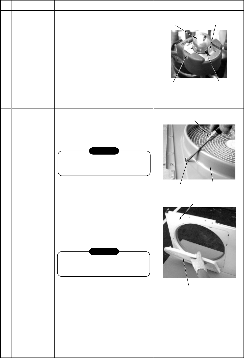
– 159 –
No.
Part name
Pulse Modulating
Valve (PMV) coil
Procedure
1. Detachment
1) Perform works of items and .
2) Release the coil from the concavity by
turning it, and remove coil from the
PMV.
2. Attachment
1) Put the coil deep into the bottom
position.
2) Fix the coil firmly by turning it to the
concavity.
Remarks
Fan guard 1. Detachment
1) Perform works of items 1 of , and .
2) Remove the front cabinet, and put it
down so that fan guard side directs
downward.
CAUTION
Perform works on a corrugated card-
board, cloth, etc. to prevent flaw on the
product.
3) Remove the hooking claws by pushing
with minus screwdriver along with the
arrow mark in the right figure, and
remove the fan guard.
2. Attachment
1) Insert claws of the fan guard in the hole
of the front cabinet. Push the hooking
claws (10 positions) with hands and
then fix the claws.
CAUTION
All the attaching works have completed.
Check that all the hooking claws are
fixed to the specified positions.
Positioning extrusion
PMV body
Concavity
PMV coil
Minus screwdriver
Front cabinet
Hooking claw
Front cabinet
Fan guard
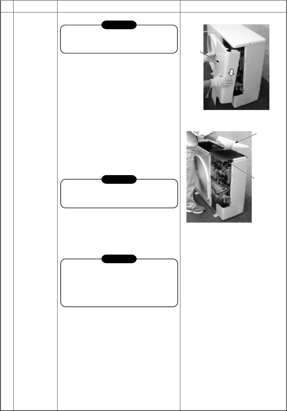
– 160 –
RAV-SM800AT-E
No.
Part name
Common
procedure
Procedure
CAUTION
Never forget to put on the gloves at
working time, otherwise an injury will be
caused by the parts, etc.
1. Detachment
1) Stop operation of the air conditioner, and
also turn off switch of the breaker.
2) Remove the front panel.
(ST1T Ø4 x 10L, 3 pcs.)
•After taking off screws, remove the front
panel by pulling it downward.
3) Disconnect the connecting cables and
power cord from the terminals and cord
clamp.
4) Remove the upper cabinet.
(ST1T Ø4 x 10L, 6 pcs.)
2. Attachment
1) Attach the waterproof cover.
CAUTION
Be sure to attach a waterproof cover.
If it is not attached, there is a possibility
that water enters inside of the outdoor unit.
2) Attach the upper cabinet.
(ST1T Ø4 x 10L, 6 pcs.)
3) Connect the connecting cable and power
cord at the terminal and fix them with cord
clamp.
CAUTION
Using bundling band sold at a market, be
sure to fix the power cables and indoor/
outdoor connecting cables along the inter-
unit cable so that they do not come to
contact with the compressor, valves and
cables at gas side, and the discharge pipe.
4) Attach the front cabinet.
(ST1T Ø4 x 10L, 3 pcs.)
Remarks
Front
cabinet
Upper plate
of cabinet
Water-proof
cove
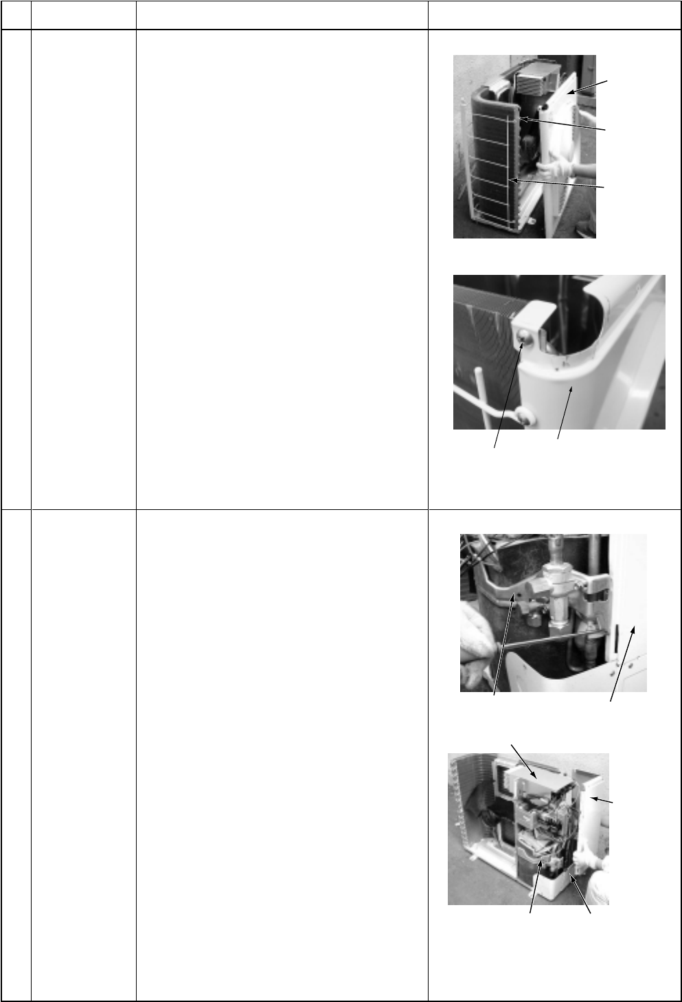
– 161 –
No.
Part name
Discharge port
cabinet
Procedure
1. Detachment
1) Perform work of item 1 of .
2) Take off screws (ST1T Ø4 x 10L, 3 pcs.) of
discharge port cabinet for the partition
plate.
3) Take off screws (ST1T Ø4 x 10L, 2 pcs.) of
discharge port cabinet for the bottom
plate.
4) Take off screw (ST1T Ø4 x 10L, 1 pc.) of
discharge port cabinet for the heat ex-
changer.
5) Take off screws (ST1T Ø4 x 10L, 2 pcs.) of
discharge port cabinet for the fin guard.
2. Attachment
1) Put the upper left side of the discharge
port cabinet on the end plate of the heat
exchanger, and then fix it with screw.
(ST1T Ø4 x 10L, 1 pc.)
2) Attach the removed screws to the original
positions.
Remarks
Side cabinet 1) Perform work of item 1 of .
2) Remove screw fixing the inverter and the
side cabinet. (ST1T Ø4 x 10, 1 pc.)
3) Remove screws of the side cabinet and
the valve support plate.
(ST1T Ø4 x 10, 2 pcs.)
4) Remove screw of the side cabinet and the
cabling panel (Rear).
(ST1T Ø4 x 10, 1 pc.)
5) Remove screw of the side cabinet and the
bottom plate. (ST1T Ø4 x 10, 1 pc.)
6) Remove screw of the side cabinet and the
fin guard (Heat exchanger).
(ST1T Ø4 x 10, 2 pcs.)
Side cabinet
Inverter
Fin guard
End plate of the
heat exchanger
Discharge port
Valve support plate Side cabinet
Inverter
Side cabinet
Cabling panel
(Rear)
Valve support
plate
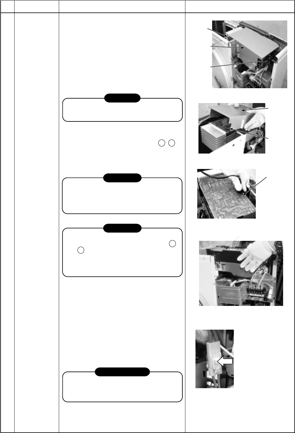
– 162 –
No.
Part name
Inverter
assembly
Procedure
1) Perform works of items of 1) to 5) of .
2) Take off screw (ST1T Ø4 x 10L, 1 pc.) of
the upper left part of the inverter cover.
•If removing the inverter cover under this
condition, P.C. board can be checked.
•If there is no space in the upper part of
the upper cabinet, perform works of
items 6) to 7) of (1) and remove the
partition fixing plate.
(ST1T Ø4 x 10L, 1 pc.)
CAUTION
Be careful to check the inverter because
high-voltage circuit is incorporated in it.
3) Perform discharging by connecting the
discharging resistance (approx. 100Ω,
40W) or plug of soldering iron to + , –
terminals of the C10 too 13 (printed as
“CAUTION HIGH VOLTAGE”) electrolytic
capacitor (760µF) of P.C. board.
WARNING
The electrolytic capacitor may not nor-
mally discharge according to error con-
tents and the voltage may remain. There-
fore, be sure to discharge the capacitor.
WARNING
For discharging, never use a screwdriver
and others for short-circuiting between +
and – electrodes. As the electrolytic
capacitor is one with a large capacity, it is
very dangerous because a large electric
spark will occur.
4) Remove various lead wires from the
holder at upper part of the inverter box.
5) Remove the hook for the partition plate
(lower left side).
6) Remove the hook for the side cabinet
(lower left side) and the screw, and lift up
the inverter assembly upward. (ST1T Ø4 x
10L, 1 pc.) In this time, cut off the band
bundling each lead wire.
7) Disconnect connectors of various lead
wires.
REQUIREMENT
As each connector has a lock mechanism,
avoid to remove the connector by holding
the lead wire, but by holding the connector.
Remarks
Screw
Inverter
assembly
Holder
Inverter
cover
Inverter
assembly
Plug of
soldering iron
Left time:
10 sec. or more
Screw
Hook for the side
cabinet (lower left side)
Inverter assembly
Remove the connectors
with locking function by
pushing the part indicated
by the arrow mark.
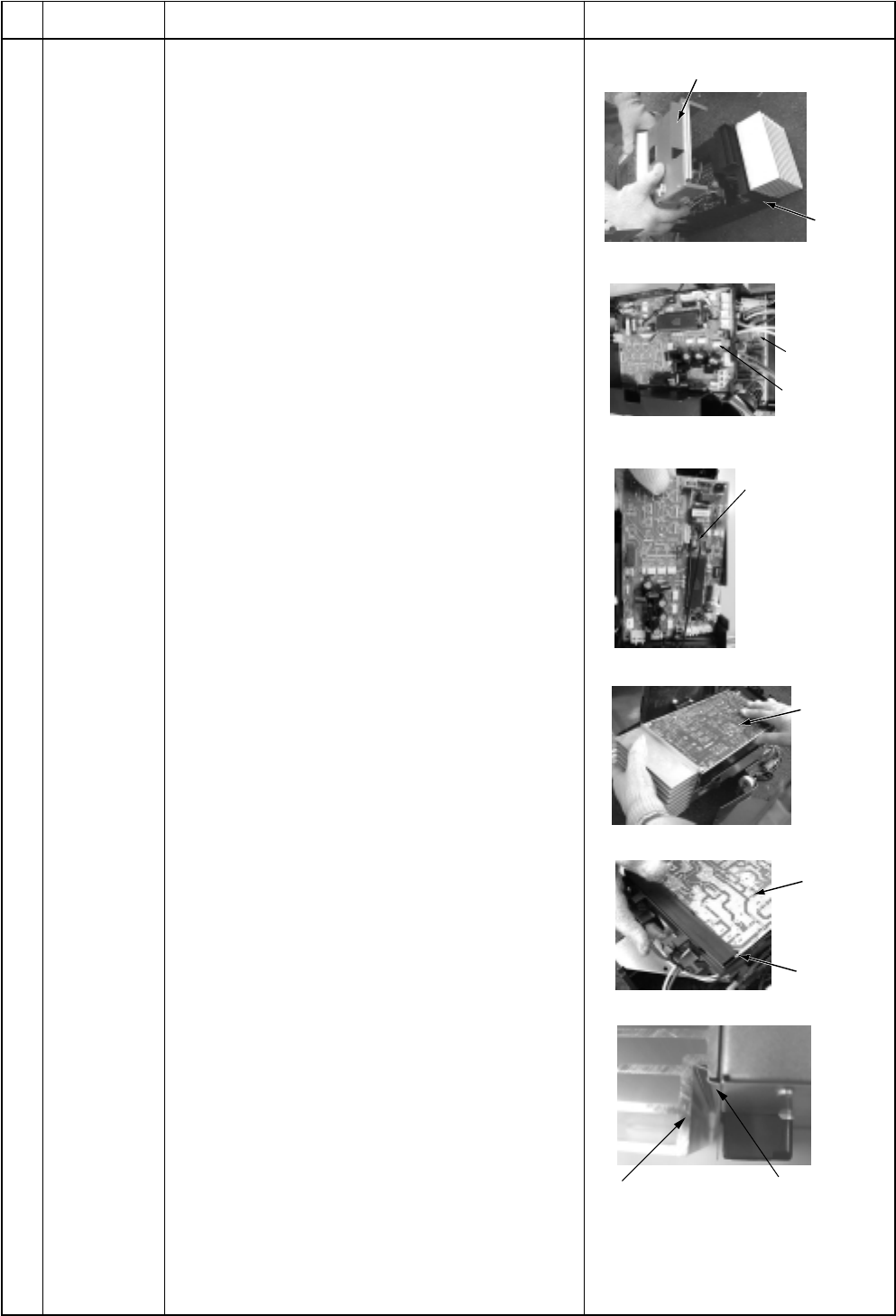
– 163 –
No.
Part name
Control P.C.
board
assembly
Procedure
1) Remove the inverter box from P.C. board base.
2) Disconnect lead wires and connectors con-
nected from the control P.C. board assembly to
other parts.
1. Lead wires:
With the power terminal block: 2 pcs.
(Single phase) (Red, White)
With the compressor: 3 pcs.
(Red, White, Black)
2. Connectors
CN301 : Outdoor fan (3P, White) *Note 1)
CN300 : Position detection (5P, White)
CN700 : 4-way valve (3P, Yellow) *Note 1)
CN702 : PMV coil (6P, White)
CN600 : TD sensor (3P, White)
CN605 : TS sensor (3P, White) *Note 1)
CN604 : TE sensor (2P, White) *Note 1)
CN601 : TO sensor (2P, White)
CN02 : Indoor/Outdoor connecting
terminal block (2P, Black)
CN500 : Case thermo (2P, White) *Note 1)
CN14, CN15 : Reactor (3P, Relay
connector, Blue) *Note 1)
*Note 1)
Remove the connector while releasing locking of
the housing.
3) Remove the control P.C. board assembly from
P.C. board base. (Remove the heat sink and
the inverter control P.C. board assembly as
they are screwed.)
Note 2)
Remove the heat sink upward by taking off two
claws of P.C. base and holding the heat sink.
4) Take off three screws fixing the heat sink to the
control P.C. board assembly.
5) Mount a new control P.C. board assembly.
Note 3)
When mounting a new board, check that it is
correctly set in the groove of the base holder of
P.C. board base.
Remarks
P.C. board
base
Inverter box (Metal sheet)
Inverter
control
P.C. board
assembly
Cycle control
P.C. board
assembly
Cycle control
P.C. board
assembly
Inverter
control
P.C. board
assembly
Inverter
control
P.C. board
assembly
Groove for
P.C. boaed
Heat sink Inverter box
(Metal sheet)
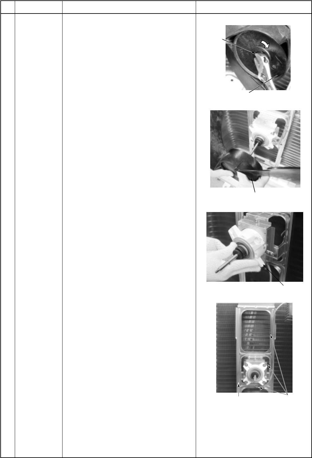
– 164 –
No.
Part name
Fan motor
Procedure
1) Perform works of items 1) to 5), 7) of
2) Remove the flange nut fixing the fan motor
and the propeller fan.
•Loosen the flange nut by turning clock-
wise. (To tighten the flange nut, turn it
counterclockwise.)
3) Remove the propeller fan.
4) Remove the lead wire from the hook fixing
the fan motor lead wires on the motor
base. (Three positions)
5) Disconnect the connector for fan motor
from the inverter.
6) Take off the fixing screws (4 pcs.) while
holding by hands so that the fan motor
does not fall.
NOTE :
Tighten the flange nut with torque 9.8Nm
(100kgf/cm).
Remarks
Flange
nut
Loosen by turning
clockwise
Fixing claws for
fan motor lead
wires (3 positions)
Motor base
Propeller fan
Fan motor
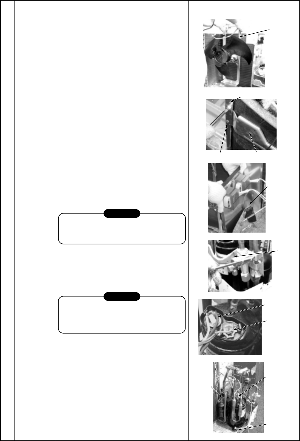
– 165 –
No.
Part name
Compressor
Procedure
1) Perform works of items , , , , and
.
2) Evacuate refrigerant gas.
3) Disconnect the connector for fan motor from
the inverter.
4) Take off screws fixing the motor base to the
bottom plate. (ST1T Ø4 x 10L, 2 pcs.)
5) Remove the motor base together with the
fan motor and the propeller fan.
6) Take off screws fixing the partition plate to
the valve support plate.
(ST1T Ø4 x 10L, 2 pcs.)
7) Remove the valve support plate.
(M6 x 4 pcs.)
8) Take off screws of the partition plate and the
bottom plate. (ST1T Ø4 x 10L, 2 pcs.)
9) Take off screws of the partition plate and the
heat exchanger. (ST1T Ø4 x 10L, 2 pcs.)
10) Remove the noise-insulator.
11) Remove the terminal covers of the com-
pressor, and disconnect lead wires of the
compressor and the compressor thermo
assembly from the terminal.
12) Remove pipes connected to the compres-
sor with a burner.
CAUTION
Pay attention to that flame does not involve
4-way valve or PMV. (If doing so, a malfunc-
tion may be caused.)
13) Pull the refrigerating cycle upward.
14) Take off nut fixing the compressor on the
bottom plate. (3 pcs.)
15) Pull the compressor toward you.
CAUTION
When reconnecting the lead wires to the
compressor terminals after replacement of
the compressor, be sure to caulk the Faston
terminal without loosening.
Remarks
Motor
base
Partition plate
Valve support
Screw
Partition
plate
Valve
support
Compressor
lead wire
Case thermo
Compressor
nut (3 pcs.)
Remove
(Suction
pipe)
Remove
(Discharge
pipe)
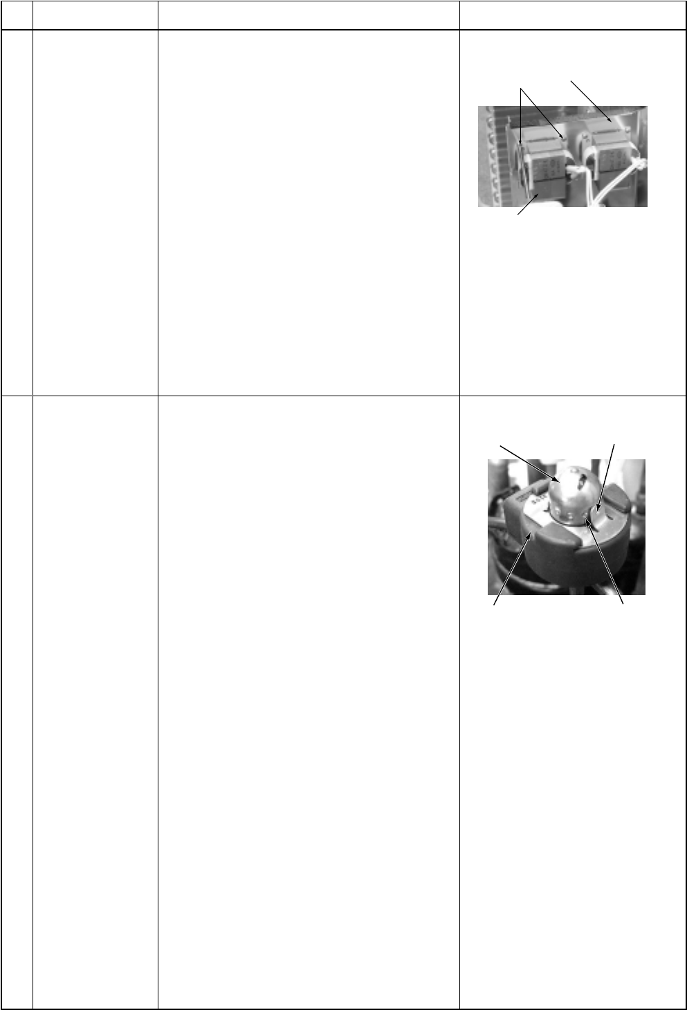
– 166 –
No.
Part name
Reactor
Procedure
1) Perform works of items 1 of and .
2) Take off screws fixing the reactor.
(Ø4 x 10L , 2 pcs. per one reactor.
An outdoor unit has two reactors on the
partition plate.)
Remarks
Reactor
Partition plate
Screws
Positioning extrusion
PMV body
PMV coil Concavity
1. Detachment
1) Perform works of items 1 of and .
2) Remove the coil from PMV body while
pulling it upward.
2. Attachment
1) Match the positioning extrusion of the coil
surely to the concavity of PMV body to fix it.
Pulse Modulating
Valve (PMV) coil
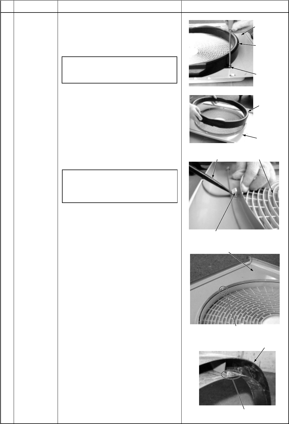
– 167 –
No.
Part name
Fan guard
Procedure
1. Detachment
1) Perform works of items 1 of and .
2) Remove the air flow cabinet, and put it
down so that the fan guard side directs
downward.
Perform work on a corrugated card-
board, cloth, etc. to prevent flaw to the
product.
3) Take off screws fixing the bell mouth.
(ST1Tf4 x 10L, 2 pcs.)
4) Remove the bell mouth.
5) Remove the hooking claws by pushing
with minus screwdriver along with the
arrow mark as shown in right figure.
2. Attachment
1) Insert claw of the fan guard in hole of the
discharge panel. Push the hooking claws
(5 positions) with hands and fix the claws.
After all the attachment works are
completed, check that all the hooking
claws are fixed to the specified posi-
tions.
2) Mount the bell mouth by hooking three
claws at upper side of the bell mouth in the
slits on the discharge cabinet.
3) After attachment, fix the bell mouth with
screws. (ST1Tf4 x 10L, 2 pcs.)
Remarks
Discharge
port cabinet
Bell mouth
Remove
two screws
Discharge
port cabinet
Bell mouth
Minus screwdriver Fan guard
Hooking claw
Discharge port cabinet
Slit (3 positions)
Claw (3 positions)
Bell mouth
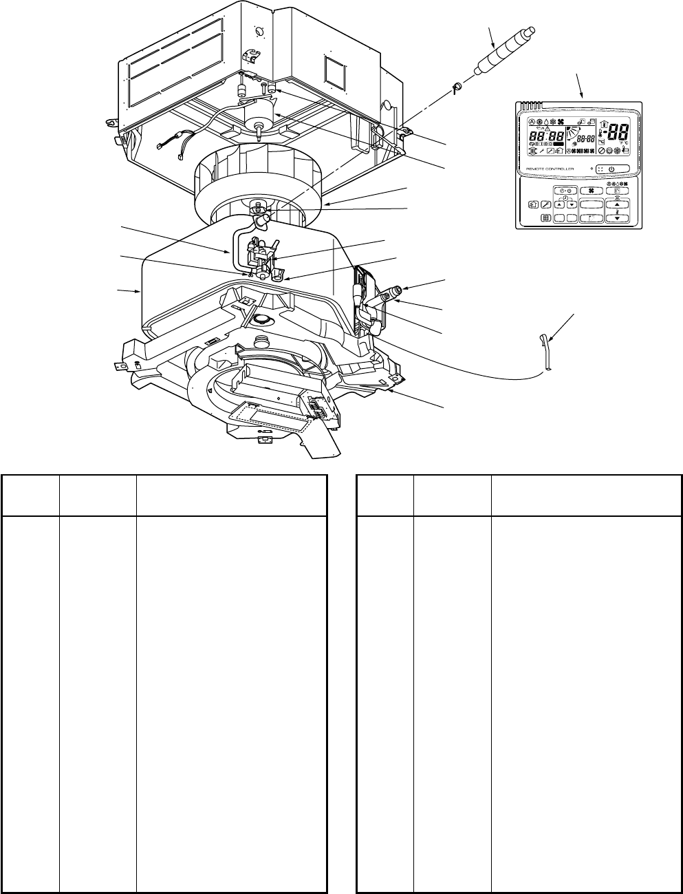
– 168 –
16. EXPLODED VIEWS AND PARTS LIST
16-1. Indoor Unit
4-Way Air Discharge Cassette Type
RAV-SM560UT-E/RAV-SM800UT-E
Location
Part Description
No.
216 43194078 Nut, Flare, 5/8 IN, Ø15.88
217 43194080 Socket, 1/2 IN, Ø12.7
218 43194079 Socket, 5/8 IN, Ø15.88
219 43049697 Bonnet, Ø6.35
220 43047609 Bonnet, Ø9.52
221 43147195 Bonnet, 1/2 IN, Ø12.7
222 43194029 Bonnet, Ø15.88
223 43019904 Holder, Sensor, SUS
224 43170231 Hose, Drain
225 43139137 Rubber, Cushion
226 43097204 Nut
227 43147656 Distributor Ass’y
228 43147657 Distributor Ass’y
229 4316V194 Remote Controller, SX-A3JE
230 4316V195 Remote Controller, SX-A11JE
231 4316V196 Remote Controller, WX-W2JE
232 4316V197 Remote Controller, WH-H1JE
Location
Part Description
No.
201 43121703 Pump, Drain, ADP-1409,
220-240V
202 43120215 Fan, Ass’y Turbo, TJ461
203 4314J122 Refrigeration Cycle Ass’y
204 4314J123 Refrigeration Cycle Ass’y
205 4318T313 Owner’s Manual
206 43172160 Pan Ass’y, Drain,
PS-F+ABS, Sheet
207 43151279 Switch, Float, FS-0218-106
208 43121692 Motor, Fan, SWF-230-60-1
209 43170232 Hose, Drain, 25A
210 43079249 Band, Hose
211 43047545 Nut, Flare, 1/4 IN, Ø6.35
212 43047546 Nut, Flare, 3/8 IN, Ø9.52
213 43194051 Socket, Ø6.35
214 43194026 Socket, Ø9.52
215 43194081 Nut, Flare, 1/2 IN, Ø12.7
215 43194081 Nut, Flare, 1/2 IN, Ø12.7
208
225
202
226
215,216,217,
218,221,222
211,212,213,
214,219,220
227,228
206
201
207
223
229
209
203,204
210
224
UNIT
SET
CL
SETTING
UNIT No.
CODE No.
TEST
SET DATA
R.C. No.
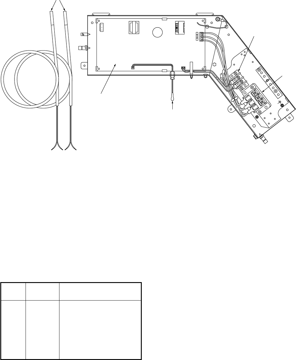
– 169 –
Location
Part Description
No.
401 43060750 Terminal Block, 3P
402 43050382 Sensor, TC (F6)
403 43150297 Sensor, TC
404 43160445 Terminal Block, 2P,
1A, AC30V
405 4316V188 P.C. Board Ass’y, MMC-1402
AB
405
403
404
402
401
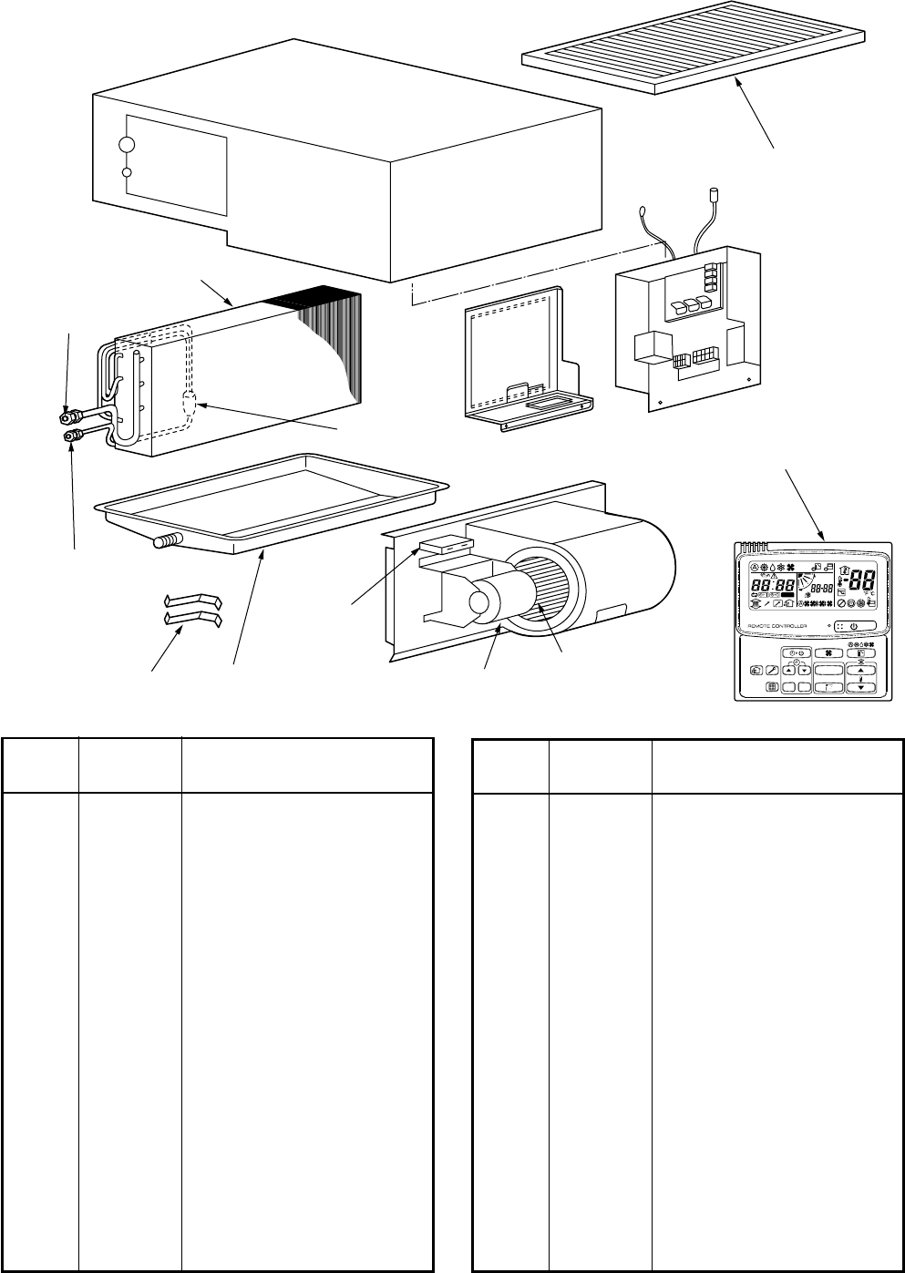
– 170 –
Location
Part Description
No.
201 43120149 Fan, Multi Blade
202 4314J100 Refrigeration Cycle Ass’y
203 4314J101 Refrigeration Cycle Ass’y
204 43147654 Distributor Ass’y
205 43147655 Distributor Ass’y
206 43121643 Motor, Fan
207 43121645 Motor, Fan
208 43191304 Drain Ass’y
209 43191305 Pan, Drain
210 43047545 Nut, Flare, 1/4 IN, Ø6.35
211 43047546 Nut, Flare, 3/8 IN, Ø9.52
212 43194081 Nut, Flare, 1/2 IN, Ø12.7
213 43194078 Nut, Flare, 5/8 IN, Ø15.88
214 43194051 Socket, Ø6.35
215 43194026 Socket, Ø9.52
216 43194080 Socket, 1/2 IN, Ø12.7
217 43194079 Socket, 5/8 IN, Ø15.88
Location
Part Description
No.
218 43049697 Bonnet, Ø6.35
219 43047609 Bonnet, Ø9.52
220 43147195 Bonnet, 1/2 IN, Ø12.7
221 43194029 Bonnet, Ø15.88
222 43019822 Holder, Sensor, SUS
223 43160394 Connector, 9P
224 43155088 Capacitor, Electrolytic,
2.5MFD, 500V
225 43155096 Capacitor, Electrolytic,
5MFD, 400V
226 43121688 Pump, Drain, PJD-05230TF,
220-240V 50/60Hz
227 4316V194 Remote Controller, SX-A3JE
228 4316V195 Remote Controller, SX-A11JE
229 4316V196 Remote Controller, WX-W2JE
230 43119462 Filter (SM560BT-E)
231 43119463 Filter (SM800BT-E)
Concealed Duct Type
RAV-SM560BT-E/RAV-SM800BT-E
204
206,207 201
224,225
202,203
222
210,211,214,
215,218,219
212,213,216,
217,220,221
208,209
227
230,231
UNIT
SET
CL
SETTING
UNIT No.
CODE No.
TEST
SET DATA
R.C. No.
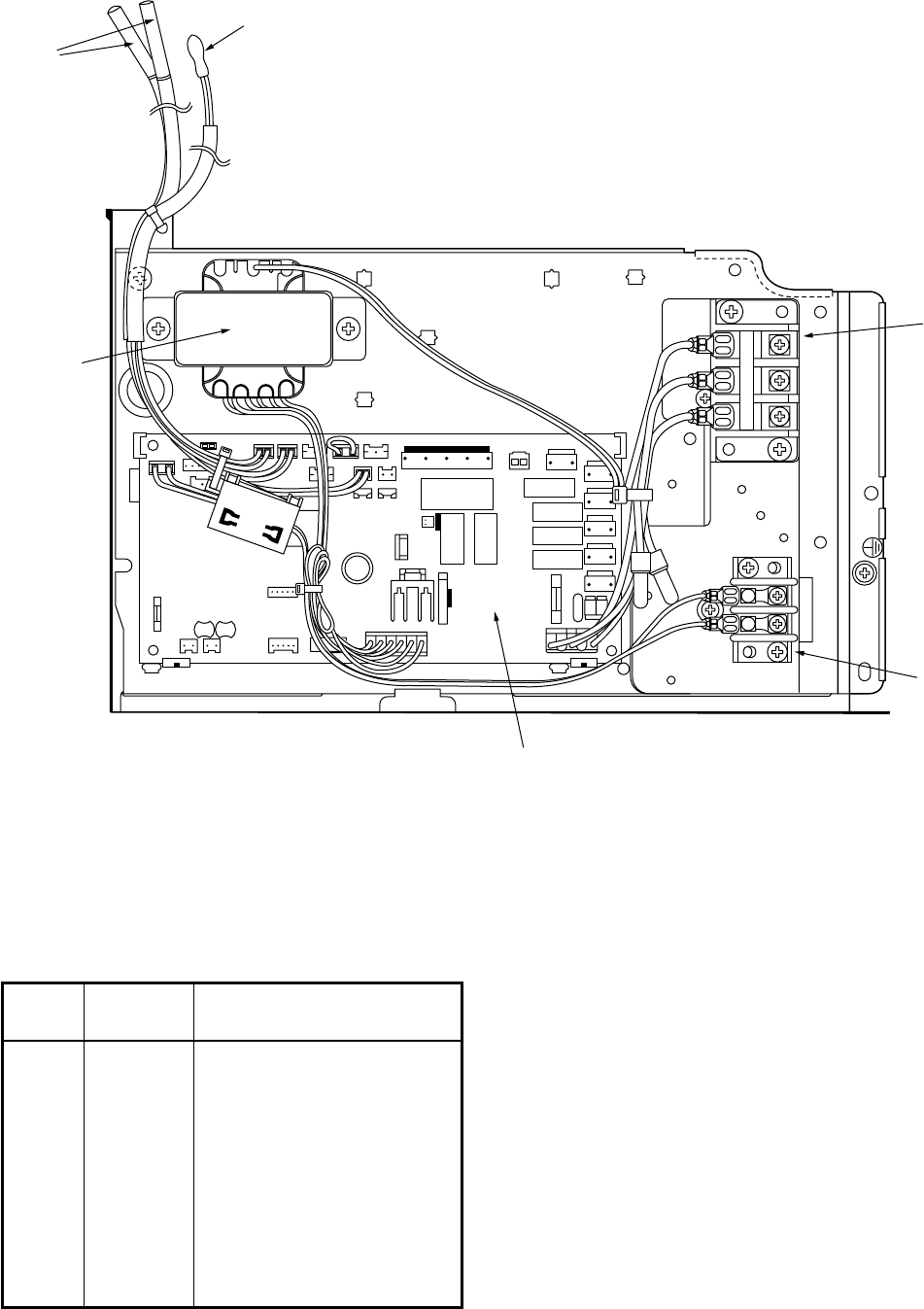
– 171 –
Location
Part Description
No.
401 43060750 Terminal Block, 3P
402 43050382 Sensor, TC (F6)
403 43150299 Sensor, TA
404 43160445 Terminal Block, 2P,
1A, AC30V
405 4316V189 P.C. Board Ass’y,
MCC-1403 (220-240V)
406 43158180 Transformer, TT-09
(AC220-240V)
403
401
404
405
402
406
3
2
1
AB
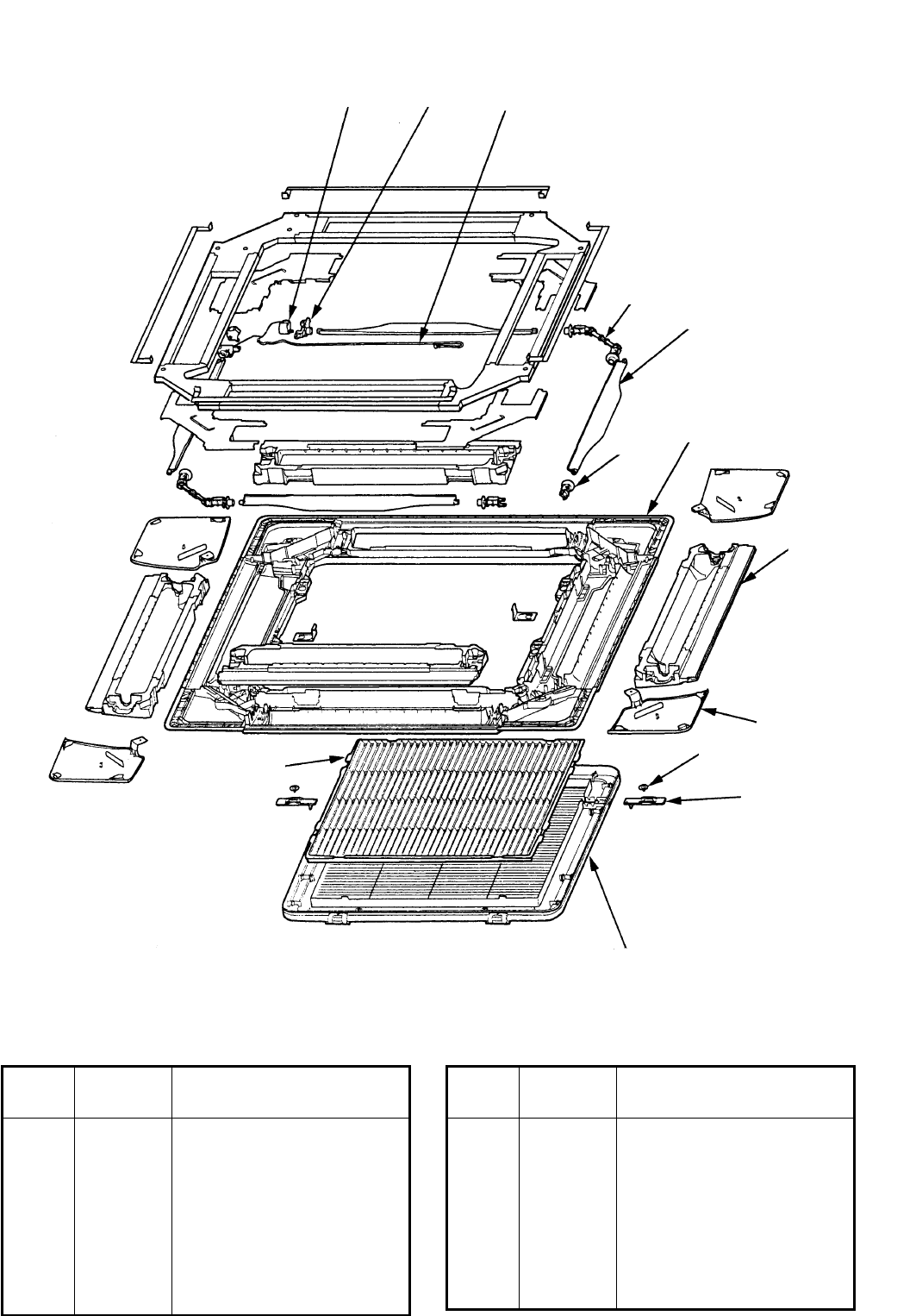
– 172 –
304 311
306
312
305
307
303
301
313
309
302
308
310
Location
Part Description
No.
301 43409164 Panel, PS-HI100
302 43480010 Air Filter, ABS
303 43407120 Outlet, Air Form, PS-F
304 4302C029 Motor, Louver, MP24GA
305 43409173 Louver, ABS
306 43422001 Joint, Kit
307 43422002 Joint, Kit
Location
Part Description
No.
308 43407116 Grille, Catch, ABS
309 43409168 Grille, Air, Inlet
310 43409182 Cover, Panel Ass’y,
PS-HI100
311 43407123 Fix, Motor, ABS
312 43460108 Lead, Motor
313 43482025 Washer, SPCC
RBC-U21PG(W) - E
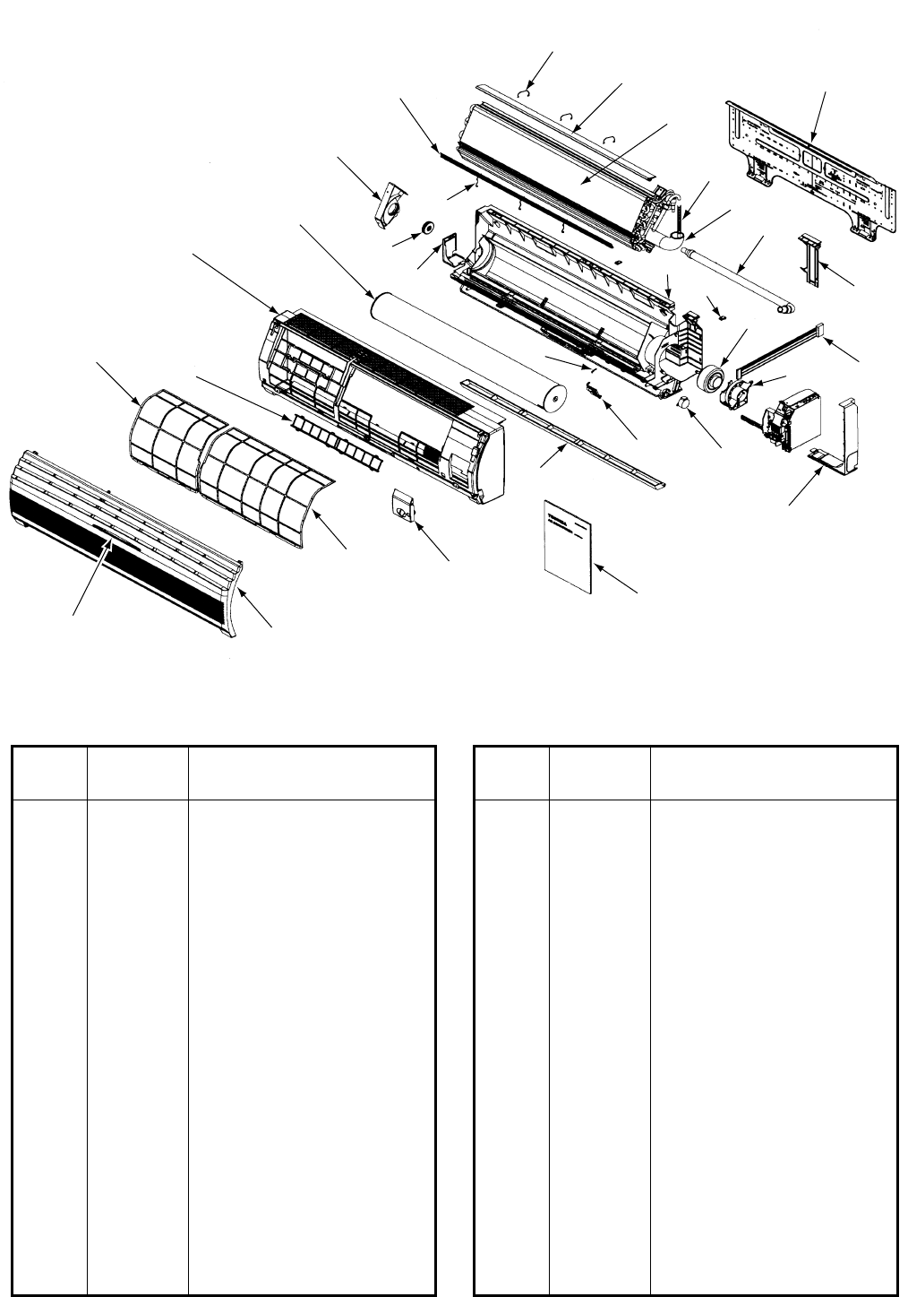
– 173 –
High-Wall Type
RAV-SM560KRT-E/RAV-SM800KRT-E
232
231
220
221
222
229
228
208
227
201
205 217
219
213
218
216
225224
233
236
204
202
211
230 209
226
212
207
223
210
203
206
Location
Part Description
No.
201 43T00355 Front Panel Ass’y
202 43T00356 Grille Ass’y
203 43T80014 Air Filter, (L)
204 43T80013 Air Filter, (R)
205 43T80003 Filter, Frame
206 43T01004 Mark
207 43T03010 Body, Right
208 43T03011 Body, Left
209 43T03012 Hide, Claw
210 43T09317 Grille, Horizontal
211 43T70301 Hose Ass’y, Drain
212 43T21302 Motor, Stepping, MP35EA12
213 43T44316 Refrigeration Cycle Ass’y
(SM560KRT-E)
213 42T44317 Refrigeration Cycle Ass’y
(SM800KRT-E)
216 43T11002 Pipe, Shield
216 43T11306 Pipe, Shield (SM800KRT-E)
Location
Part Description
No.
217 43T19003 Holder, Sensor
218 43T49009 Spring
219 43T49036 Plate, EVA, Seal
220 43T49039 Holder, Plate EVA, Seal (U)
221 43T49038 Plate EVA, Seal (D)
222 43T49037 Holder, Plate EVA, Seal (D)
223 43T79007 Guide, Drain
224 43T39016 Fix Motor
225 43T60075 Fan Motor Cord
226 43T21327 Motor, Fan, ICF-340-30-2
227 43T20014 Fan, Cross Flow
228 43T22008 Bearing
229 43T39015 Base, Bearing
230 43T03305 Back Body Ass’y
231 43T07022 Holder, Pipe
232 43T82007 Plate, Installation
233 43T85400 Owner’s Manual
236 43T62029 Cover, Terminal
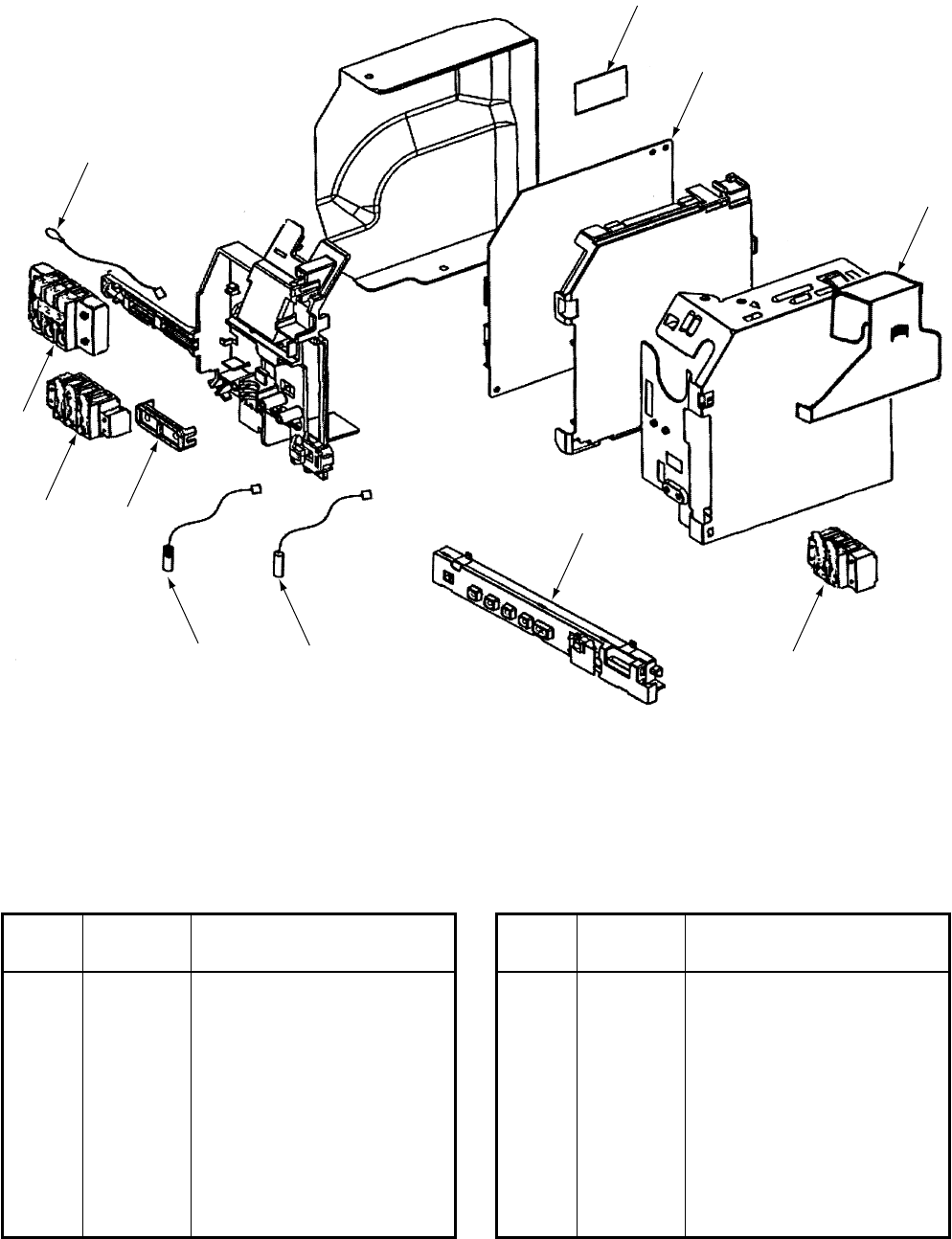
– 174 –
RAV-SM560KRT-E/RAV-SM800KRT-E
Location
Part Description
No.
401 43T60047 Terminal, 3P
402 43T60320 Terminal, 3P
403 43T60321 Terminal, 2P
404 43T50304 Temperature Sensor, TC, TCJ
406 43T69005 Sensor, Thermostat, TA
408 43T58302 Transformer, TT-02
410 43T69346 P.C. Board, Ass’y, MCC-
1370A, MCC-1370B
(SM560KRT-E)
Location
Part Description
No.
410 43T69347 P.C. Board, Ass’y, MCC-
1370A, MCC-1370B
(SM800KRT-E)
411 43T69325 P.C. Board, Ass’y, AI, MCC-
1337
412 43T69066 P.C. Board Ass’y, WRS-LED,
MCC-819-02
413 43162047 Cord clamp
408
403
404
410
412
413
401
402
404
411
406
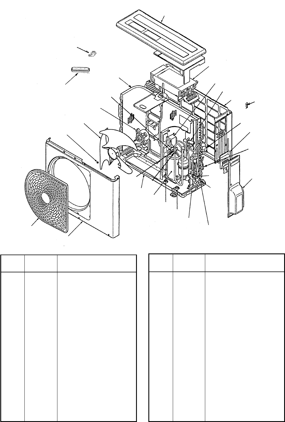
– 175 –
Location
Part Description
No.
18 43146617 Solenoid, Coil, LB64045
19 43046385 Valve, Pulse, Modulating,
SKV-18D26
20 43046394 Coil, PMV, DKV-
MOZS744BO
21 43046392 Valve, Packed, 6.35, AO
22 43147195 Bonnet, 1/2 IN
23 43046393 Valve, Packed, 12.7, HKU-
R410A-H4
24 43147196 Bonnet, 1/4 IN, 6.4 CU
25 43055521 Reactor, CH-57
26 43063321 Holder, Sensor, 4-8, 9.52
27 43063322 Holder, Sensor, 6-11.4, 12.7
28 43063325 Holder, Sensor, 6-6.35, 8
29 43063332 Holder, Sensor
30 43089160 Cap, Waterproof
31 43032441 Nipple, Drain
Location
Part Description
No.
1 43105037 Cabinet, Front, PCM
2 43100239 Cabinet, Back, PCM
3 43042468 Base, Ass’y
4 43005508 Cabinet, UP, PCM
5 43119460 Guard, Fan, PP
6 43119448 Cover, Packed, Valve
7 43062230 Cover, Wiring, Ass’y
8 43047667 Nut, Flange
9 43020329 Fan, Propeller, PJ421
10 4302C033 Motor, Fan, ICF-140-43-1
11 4314G128 Condenser, Ass’y
12 43041609 Compressor, DA130A1F-23F
13 43050407 Thermostat, Bimetal
14 43063317 Holder, Thermostat
15 43097206 Bolt, Compressor, M6
16 43049749 Rubber, Cushion
17 43046363 Valve, 4-WAY, VT7101D
16-2. Outdoor Unit
RAV-SM560AT-E
30
31
4
11
13,14
10
9
8
5
1
26
312 15 16
20
27
19
21,
22
23,
24
6
28
7
18
29
2
17
25
INVERTER
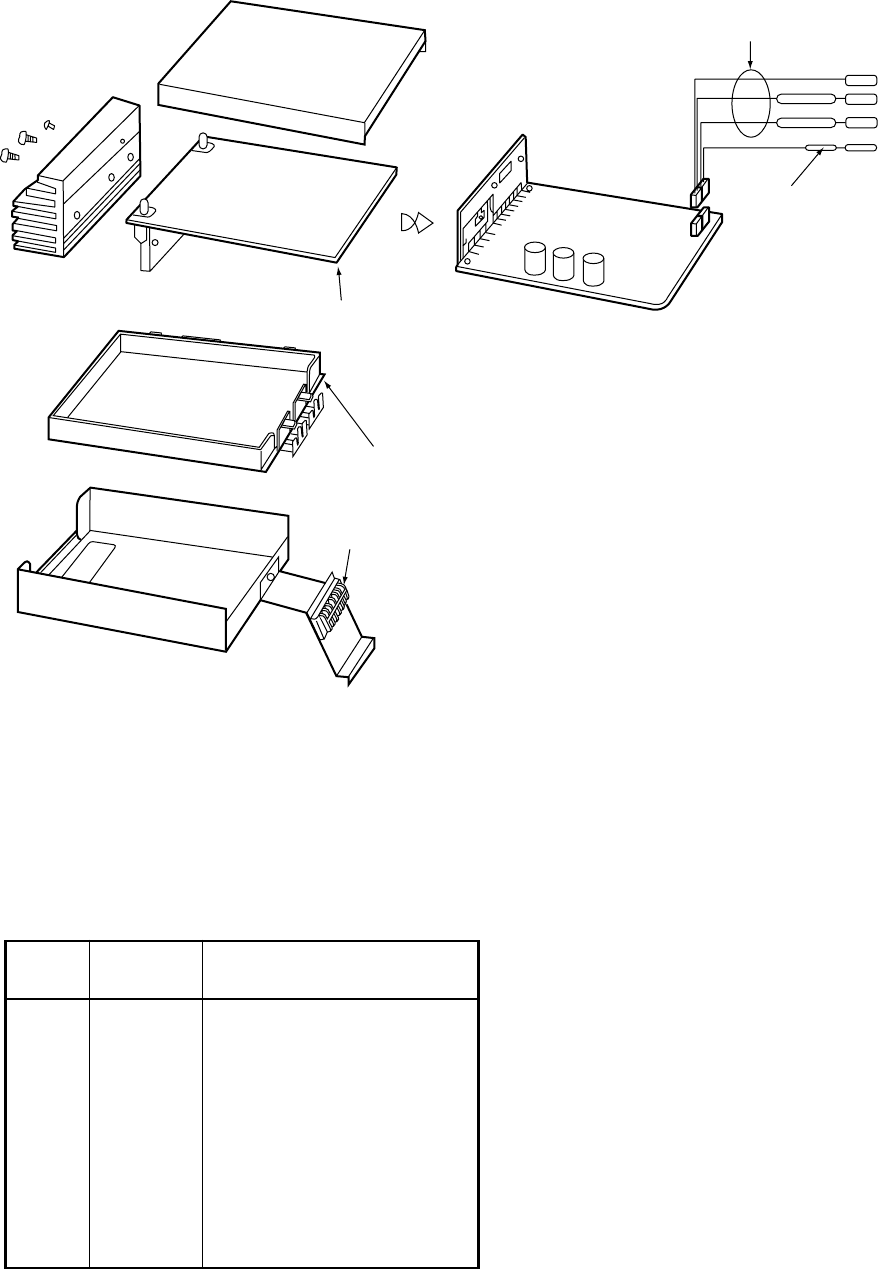
– 176 –
Location
Part Description
No.
701 43050334 Sensor, TD (F4),
TD Sensor
702 43050382 Sensor, TC (F6),
TC Sensor
703 43062228 Base, P.C. Board, ABS
704 43160469 Terminal Block, 6P,
AC250V, 20A
706 4316V182 P.C. Board Ass’y,
MCC-813
TE Sensor
TS Sensor
TO Sensor
TD Sensor
702
701
705
703
704
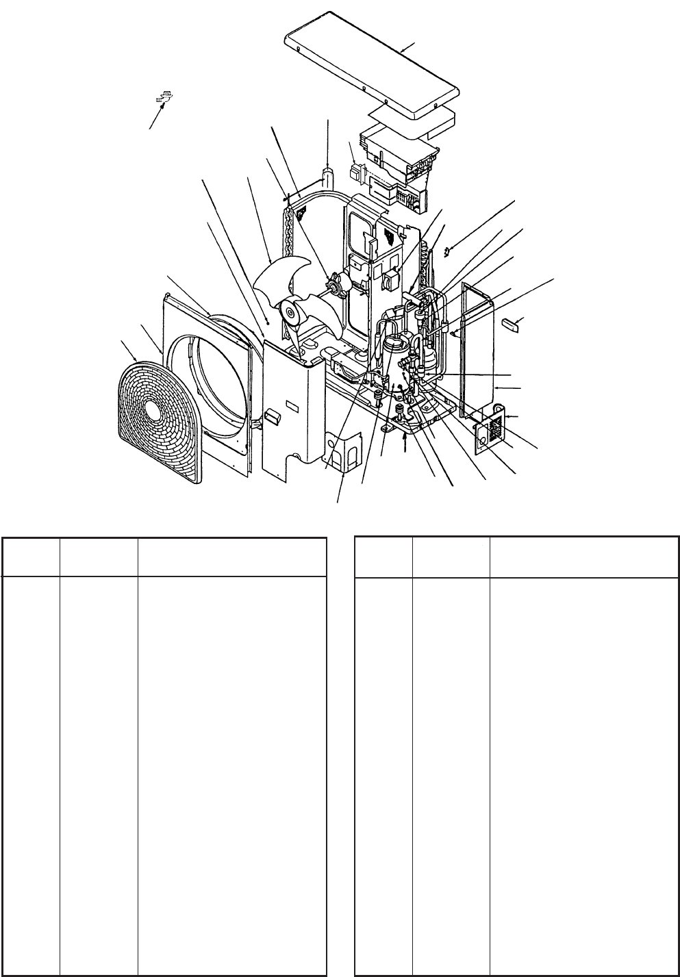
– 177 –
Location
Part Description
No.
22 43046348 Coil, Solenoid,
VHV-01A150A1
23 43046385 Valve, Pulse, Modulating,
SKV-18D26
24 43046386 Coil, PMV,
DKV-MO25743BO
25 43048066 Accumulator Ass’y
26 43146584 Valve, Packed, 9.52DIA,
HKT9.52
27 43047401 Bonnet, 3/8 IN, 9.52 CU
28 43146613 Valve, Ball, B5/8F
29 43194029 Bonnet
30 43148169 Strainer
31 43148176 Strainer
32 43058266 Reactor, CH-47-Z-K
33 43063321 Holder, Sensor,
4-8, 9.52
34 43063322 Holder, Sensor,
6-11.4, 12.7
35 43063325 Holder, Sensor,
6-6.35, 8
36 43063332 Holder, Sensor
37 43032441 Nipple, Drain
38 43058268 Reactor, CH-43-Z-K
Location
Part Description
No.
143191634 Cabinet, Air Outled
243191636 Cabinet, Front, Ass’y
343191635 Cabinet, Side, Ass’y
443191637 Panel, Upper
543005489 Guard, Fin
643191630 Guard, Fan, PP-K
743122065 Bell Mouth, Plastic
843047667 Nut, Flange
943120213 Fan, Propeller, PJ491, AS-G
10 43121693 Motor, Fan, ICF-140-63-1
11 4314G117 Condenser, Ass’y
12 43191515 Panel, Front, Piping
13 43191605 Panel, Back, Piping
14 43119390 Hanger
15 43041772 Compressor Ass’y
16 43050407 Thermostat, Bimetal
17 43063317 Holder, Thermostat
18 43005482 Base Ass’y
19 43049739 Cushion, Rubber
20 43097204 Nut
21 43046344 Valve, 4-WAY, CHV-0213
RAV-SM800AT-E
37
89
10
11 5
38
32
21,22
4
36
34 24
23
30 35
14
31
3
13
25
28
29
26
27
20
19
18
12
15
16,17
33
61
7
2
Revised 3/June/2004
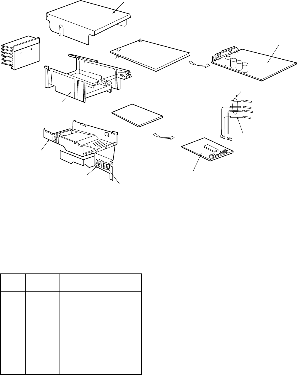
– 178 –
Location
Part Description
No.
701 43050334 Sensor, TD (F4), TD Sensor
702 43050382 Sensor, TC (F6), TC Sensor
704 43160469 Terminal Block, 6P,
AC250V, 20A
705 43162042 Base, P.C. Board, ABS
707 4316V183 P.C. Board Ass’y, CDB,
MCC-1398
708 4316V184 P.C. Board Ass’y, IPDU,
MCC-1359
INVERTER BOX
INVERTER COVER
704
703,705
706
707
701
702
TO Sensor
TE Sensor
TS Sensor
TD Sensor
708,709
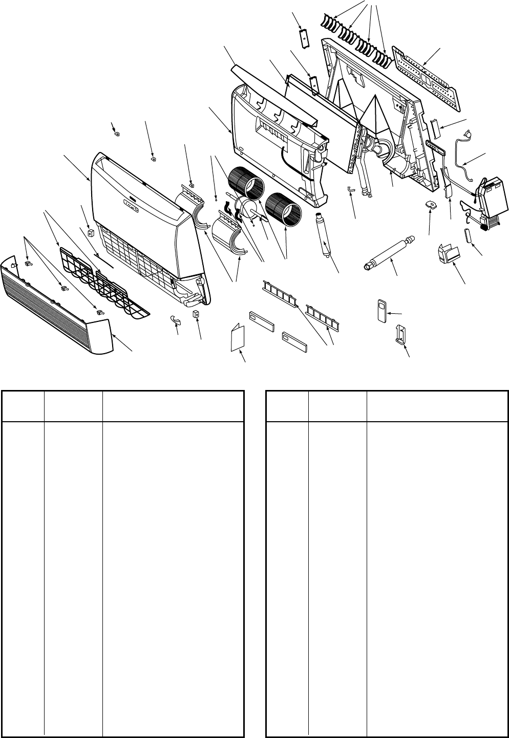
– 179 –
Location
Part Description
No.
201 43T09312 Air Inlet Grille
202 43T00357 Panel Arm Ass’y
203 43T00361 Front Panel Ass’y
203 43T00358 Front Panel Ass’y
204 43T01004 Mark
205 43T79303 Drain Band
206 43T80302 Air Filter
207 43T00359 Cap Screw C
208 43T00360 Cap Screw LR
209 43T20303 Fan Cover
210 43T20304 Motor Band Ass’y
211 43T20305 Multiblade Fan
212 43T19309 Screw Set (D-T)
213 43T21325 Fan Motor
214 43T72301 Drain Pan Ass’y
215 43T79304 Drain Hose Ass’y
216 43T19303 Lover Motor Ass’y
217 43T09313 Horizontal Louver
218 43T44319 Refrigeration Ass’y, Ø12.70
219 43T03303 Back Body Ass’y
Location
Part Description
No.
220 43T09314 Vertical Louver
221 43T49303 Pipe Holder
222 43T19304 Cover Body L
223 43T19305 Cover Body R
224 43T19306 Cover Body LD
225 43T19307 Bush Body R
226 43T19308 Bush Body D
227 43T82302 Installation Plate
228 43T60314 Terminal Cover
229 43T62303 Connector Cover
230 43T83003 Remote Controller Holder
231 43T69309 Wireless Remote Controller
231 43T69310 Wireless Remote Controller
232 43T85335 Owner’s Manual
232 43T85336 Owner’s Manual
232 43T85337 Owner’s Manual
232 43T85341 Owner’s Manual
233 43T49304 Flexible pipe, Ø12.70, Ass’y
234 43T80003 Filter Flame
235 43T00365 Grille Stopper Ass’y
RAV-SM560XT-E/RAV-SM800XT-E
220
222
224
218
217
214
212
208
207
208
203
235
204
206
202
201
205 235
232
234 230
231
209
210
213
211
221
219
233
226
228
215
229
227
223
216
225
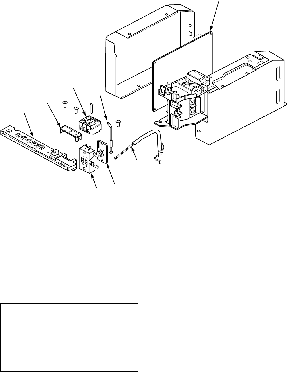
– 180 –
Location
Part Description
No.
401 43T69311 P.C. Board
401 43T69312 P.C. Board
401 43T69313 P.C. Board
401 43T69314 P.C. Board
402 43T50004 Temperature Sensor
401
402
403
404
405
408 407
406