Toshiba S2E21 Product Manual
2014-12-13
: Toshiba Toshiba-S2E21-Product-Manual-130719 toshiba-s2e21-product-manual-130719 toshiba pdf
Open the PDF directly: View PDF ![]() .
.
Page Count: 12

TOSHIBA
MOTOR
PROTECTION
RELAY
MODEL
S2E21

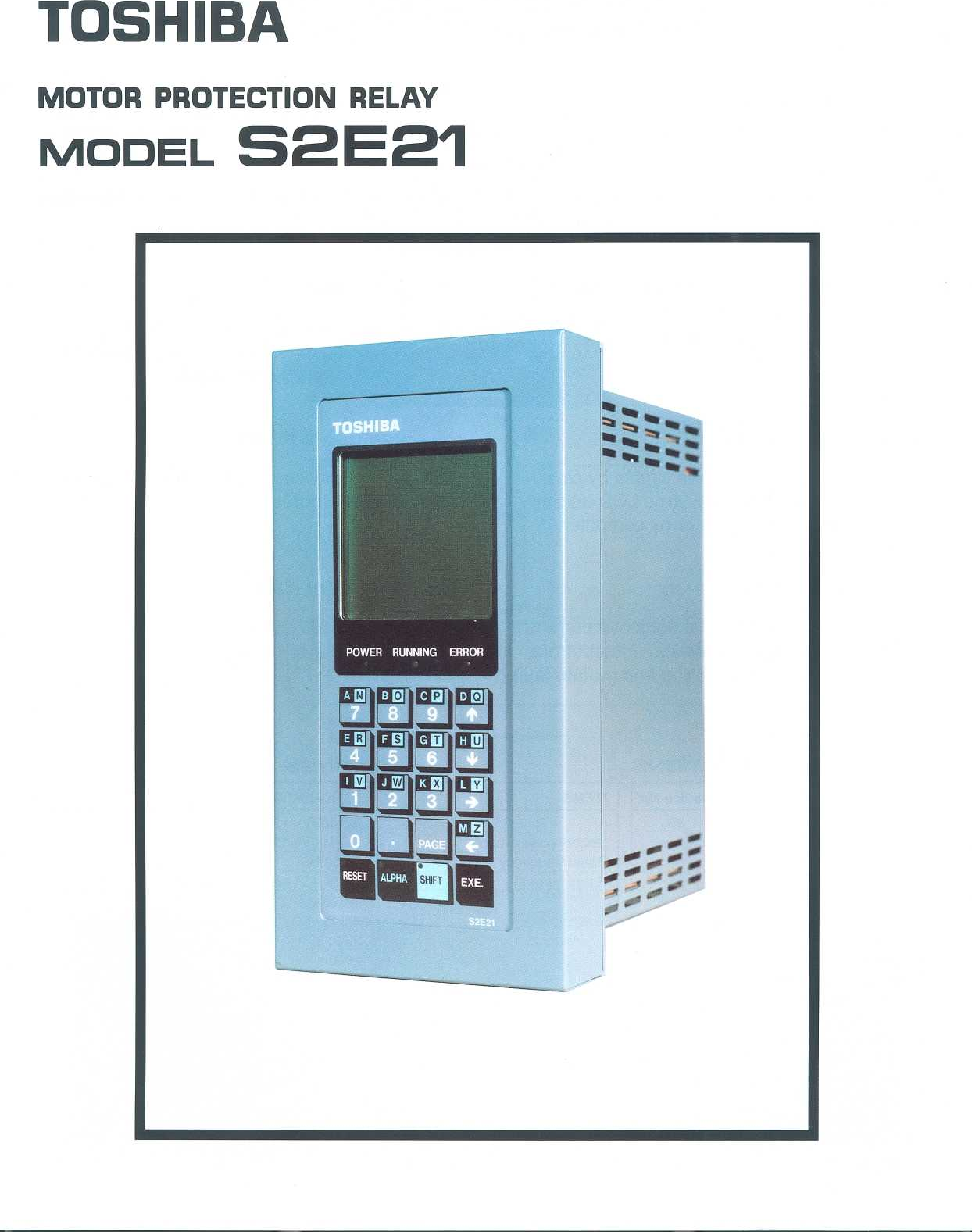
MOTOR
PROTECTION
RELAY
TOSHIBA
MODEL
S2E21
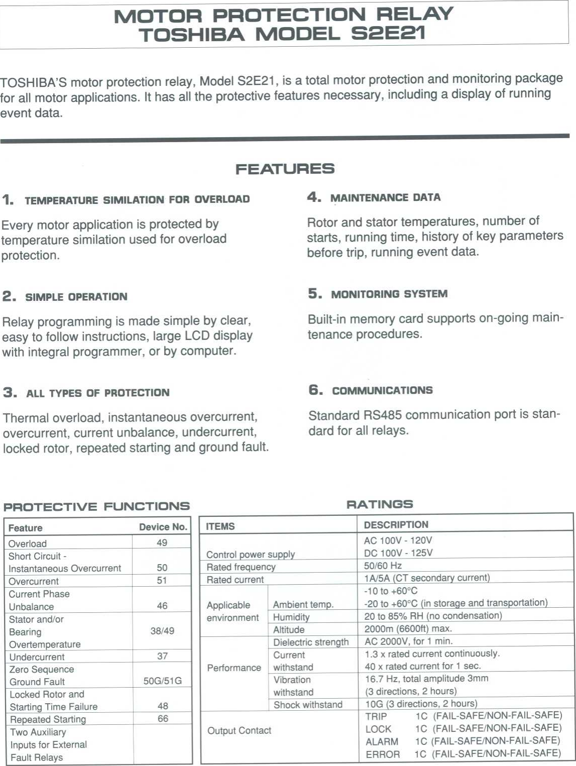
TOSHIBA'S
motor
protection
relay,
Model
S2E21,
is
a
total
motor
protection
and
monitoring
package
for
all
motor
applications
.
It
has
all
the
protective
features
necessary,
including
a
display
of
running
event
data
.
FEATURES
1
.
TEMPERATURE
SIMILATION
FOR
OVERLOAD
4
.
MAINTENANCE
DATA
Every motor
application
is
protected
by
Rotor
and
stator
temperatures,
number
of
temperature
similation
used
for
overload
starts,
running
time,
history
of
key
parameters
protection
.
before
trip,
running
event
data
.
2
.
SIMPLE
OPERATION
S
.
MONITORING
SYSTEM
Relay
programming
is
made
simple
by
clear,
Built-in
memory
card
supports on-going
main-
easy
to
follow
instructions,
large
LCD
display
tenance
procedures
.
with
integral
programmer,
or
by
computer
.
3
.
ALL
TYPES
OF
PROTECTION
G
.
COMMUNICATIONS
Thermal
overload,
instantaneous
overcurrent,
Standard
RS485
communication
port
is
stan
overcurrent,
current
unbalance,
undercurrent,
dard
for
all
relays
.
locked
rotor,
repeated
starting
and
ground
fault
.
PROTECTIVE
FUNCTIONS
RATINGS
Feature Device
No
.
ITEMS
DESCRIPTION
Overload
49
AC
100V
-
120V
Short
Circuit
-
Control
power
supply
DC
100V
-
125V
Instantaneous
Overcurrent
50
Rated
frequency
50/60
Hz
Overcurrent
51
Rated
current
1A/5A
CT
secondary
current
Current
Phase
Unbalance
46
Applicable
Ambient
temp
.
-10
to
+60°C
-20
to
+60°C
in
storage
and
transportation)
Stator
and/or
environment
Humidity
20
to
85%
RH
no
condensation)
Bearing
38/49
Altitude
2000m
(6600ft)
max
.
Overtemperature
Dielectric
strength
AC
2000V,
for
1
min
.
Undercurrent
37
Current
1
.3
x
rated
current
continuously
.
Zero
Sequence
Performance
withstand
40
x
rated current
for
1
sec
.
Ground
Fault
50G/51
G
Vibration
16
.7
Hz,
total
amplitude
3mm
Locked
Rotor
and
withstand
(3
directions,
2
hours)
Starting
Time
Failure
48
Shock
withstand
10G
3
directions,
2 hours
Repeated
Starting
66 TRIP
1C
(FAIL-SAFE/NON-FAIL-SAFE)
Two
Auxiliary
Inputs
for
External
Fault
Relays
Output
Contact
LOCK
1
C
(FAIL-SAFE/NON-FAIL-SAFE)
ALARM
1
C
(FAIL-SAFE/NON-FAIL-SAFE)
ERROR
1C
(FAIL-SAFE/NON-FAIL-SAFE)

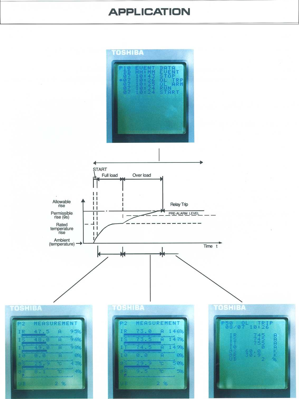
APPLICATION
START
Full
load
Over
load
Relay
Trip
I
--
--
-
PRE-ALARM
LEVEL
-
-
_________
Time
t
II
Allowable
II
rise
II
Permissible
I
I
rise (9s)
11
Rated
temperature
1
1
rise
I
Ambient
(temperature)

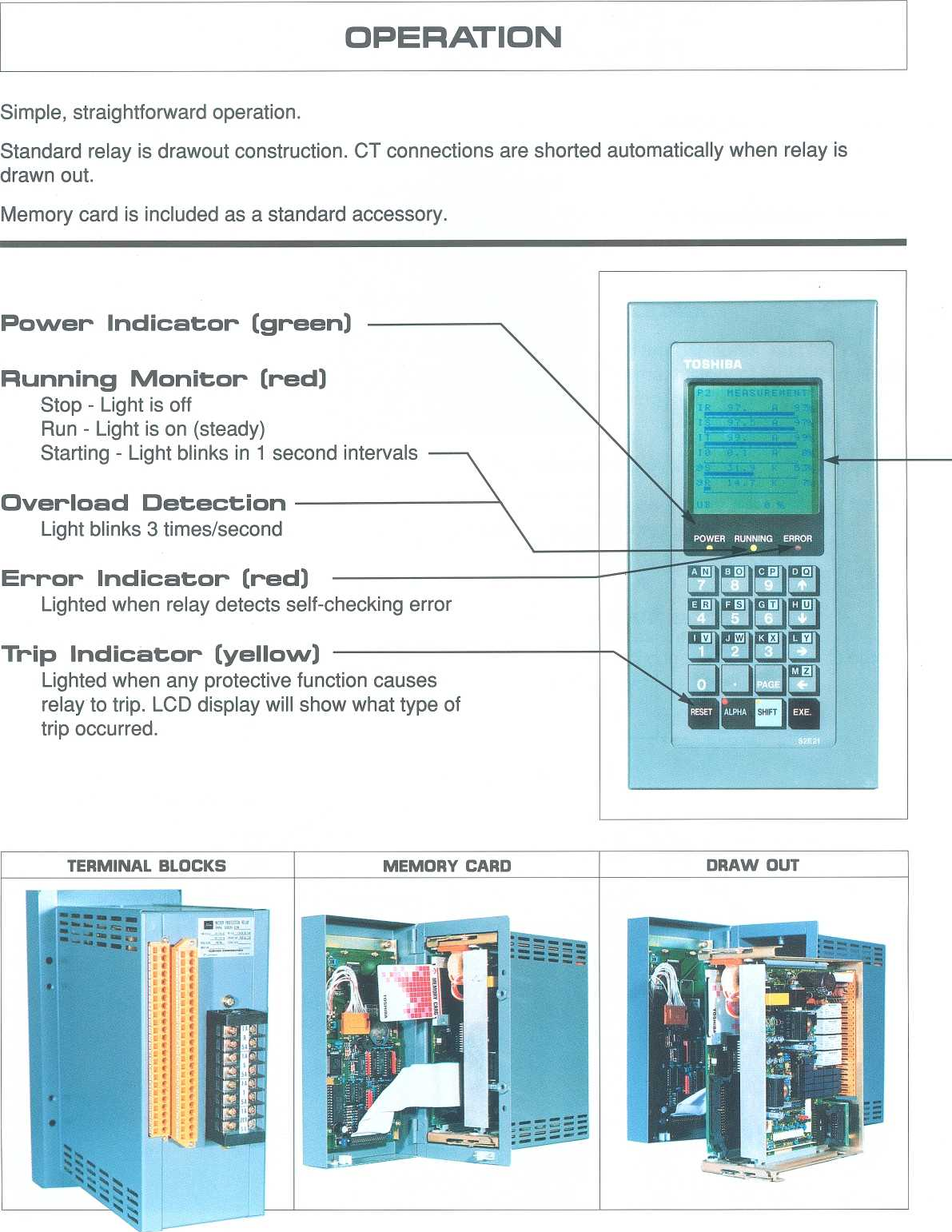
RunningMonitor
(red)
Stop
-
Light
is
off
Run
-
Light
is
on
(steady)
Starting
-
Light
blinks
in
1
second
intervals
OverloadDetection
Light
blinks
3
times/second
Error
Indicator
(red)
Lighted
when
relay
detects
self-checking
error
OPERATION
Simple,
straightforward
operation
.
Standard
relay
is
drawout
construction
.
CT
connections
are
shorted
automatically
when
relay
is
drawn
out
.
Memory
card
is
included
as
a
standard
accessory
.
Trip
Indicator
(yellow)
Lighted
when
any
protective
function
causes
relay
to
trip
.
LCD
display
will
show
what
type
of
trip
occurred
.

LCD
DISPLAY
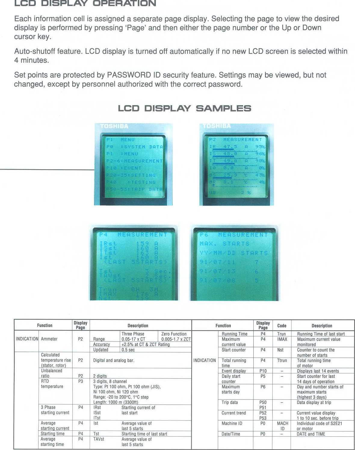
OPERATION
Each
information
cell
is
assigned
a
separate
page
display
.
Selecting
the
page
to
view
the
desired
display
is
performed
by pressing
`Page'
and
then
either
the
page
number
or
the
Up
or
Down
cursor
key
.
Auto-shutoff
feature
.
LCD
display
is
turned
off
automatically
if
no
new
LCD
screen
is
selected
within
4
minutes
.
Set
points
are
protected
by
PASSWORD
ID
security
feature
.
Settings
may
be
viewed,
but not
changed,
except
by
personnel
authorized
with
the
correct
password
.
LCD
DISPLAY
SAMPLES
Function Display
Page
Description
Function Display
Page
Code
Description
Three Phase
Zero
Function
Running
Time P4
Trun
Running
Time
of
last
start
INDICATION
Ammeter
P2
Range
0.05-17 x
CT
0
.005-1
.7 x
ZCT
Maximum
P4
I
MAX
Maximum
current
value
Accuracy
+2
.5%
at
CT
&
ZCT
Rating
current
value
monitored
Updated
0
.5
sec
Start
counter
P4
Nst
Counter
to
count
the
Calculated
number
of
starts
temperature
rise
stator,
rotor
P2
Digital
and
analog bar
.
INDICATION
Total
running
time
P4
Ttrun
Total
running
time
of
motor
Unbalanced
Event
display
P10
-Displays
last
14 events
ratio
P2
2
di
its
Daily
start
P5
-
Start
counter
for
last
RTD
P3
3
digits,
8 channel counter 14
days
of operation
temperature
Type
:
Pt
100
ohm,
Pt
100
ohm
(JIS),
Ni
100
ohm,
Ni
120
ohm
Range
:
-20
to
200°C,
1
°C
step
Maximum
starts
day
P6
-
Dayand
number
starts
of
maximum
starts
(highest
3 days)
Len
the
1000
m
3300ft
Trip
data
P50
-
Data
display
at trip
3
Phase
P4
IRst Starting
current
of
P51
starting
current
ISst
last
start
ITst
Current
trend
P52
P53
-
Current value
display
1
to
10 sec
.
before
trip
Average
starting
current
P4
Ist
Average
value
of
last
5
starts
Machine
ID PO
MACH
ID
Individual
code
of
S2E21
or
motor
Starting
time
P4
Tst
Starting
time
of last
start
Date/Time
PO
-
DATE
and
TIME
Average
starting
time
P4
TAVst
Average
value
of
last
5
starts

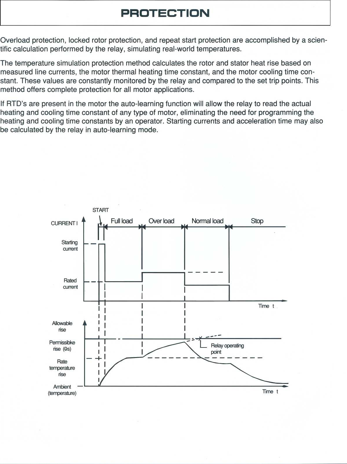
PROTECTION
Overload
protection,
locked
rotor
protection,
and
repeat
start
protection
are
accomplished
by
a
scien-
tific
calculation
performed
by the
relay,
simulating
real-world
temperatures
.
The
temperature
simulation
protection
method
calculates
the
rotor
and
stator
heat
rise
based
on
measured
line
currents,
the
motor
thermal
heating time
constant,
and
the
motor
cooling
time
con-
stant
.
These
values
are
constantly
monitored
by
the
relay
andcompared
to
the set
trip
points
.
This
method
offers
complete
protection
for
all
motor
applications
.
If
RTD's
are
present
in
the
motor
the
auto-learning
function
will
allow the
relay
to
read
the
actual
heating
and
cooling time
constant
of
any
type
of
motor,
eliminating
the
need
for
programming
the
heating
and
cooling time
constants
by
an
operator
.
Starting
currents
and
acceleration
time
may
also
be
calculated
by
the
relay
in
auto-learning
mode
.
Ambient
-
(temperature)
START
Time
t

10,000
0
.1
0
.1
Overload
Curve
Examples
43
1
2
1
10
100
1,000
Units
--~
Multiples
of
Current
(Times)
Overload
Curve
Examples
12
Time
(sec)
s
Short-circuit,
Overcurrent,
and
Undercurrent
1000
4
Overcurrent
-
m
Short-Circuit
1111
1
1
1111111
1
1111
HI
0
.01
0
.1
1
10
100
1,000
Units
Multiples
of
Current
(Times)
Unbalance
Curve
Ground
Fault
Curve
i
5 10 15 20 25
30 35
Time
(sec)
0
.5
5 10
15
20 25
30 35
40 45
Underbalance
(%)
Zero
square
current
(~
)
(Ratio
against
ZCT
primary
rating)
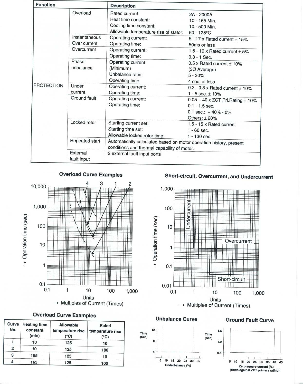
Function
Description
Overload Rated
curren
:
t
2A
-
2000A
Heat
time constant
:
10
-
165
Min
.
Cooling
time
constant
:
10
-
500
Min
.
Allowable
temperature
rise of
stator
:
60
-
125°C
Instantaneous
Operating
current
:
5
-
17 x
Rated
current
±
15%
Over
current
Operating
time
:
50ms
or less
Overcurrent
Operating
current
:
1
.5
-
10 x
Rated
current
±
5%-
Operating
time
:
0
.3
- 1
Sec
.
Phase
Operating
current
:
0
.5
x
Rated
current
±
10%
unbalance
(Minimum)
(3Q)
Average)
Unbalance
ratio
:
5-30%
Operating
time
:
4
sec
.
of
less
PROTECTION
Under
Operating
current
:
0
.3
-
0
.8
x
Rated
current
±
10%
current
Operating
time
:1 -
5
sec
.
±
10%
Ground
fault
Operating
current
:
0
.05
-
.40
x
ZCT
Pri
.Rating
±
10%
Operating
time
:
0
.1
- 1
.5
sec
.
0
.1
sec
. :
+
40%
-
0%
Others
:
±
20%
Locked
rotor
Starting
current
set
:
1
.5
-
15 x
Rated
current
Starting
time
set
:1 -
60
sec
.
Allowable
locked
rotor
time
:
1 -
130sec
.
Repeated
start
Automatically
calculated
based
on motor
operation
history,
present
conditions
and
thermal
capability
of
motor
.
External
2
external
fault
input ports
fault
input
Curve
No
.
Heating
time
constant
(min)
Allowable
temperature
rise
(IC)
Rated
temperature
rise
(IC)
1
10
125
10
2
10
125
100
3
165 125
10
4
165 125 100
C~i%
:
:al
1,000
c
100
U
NU
m
100
0)
I
10
~~
®
r
.
II
. .
._____1111
E
am
E
-_
~~
.
.
.
.r l
.
c
.rt
nOE
M
.II
I
0
10
c
0
1
am
a
O
MOM
~~/~IIIII~~~111111~~~~11111~~~111111
a)
Q
O
T
1
~1
N11
1I
111110111
a
WE!
ME_
j
0
.1
.
.lm
~~~IIIIII~~~IIIIII~~miIIIIMIIIII
Pl~~
.
.
.
.ll{

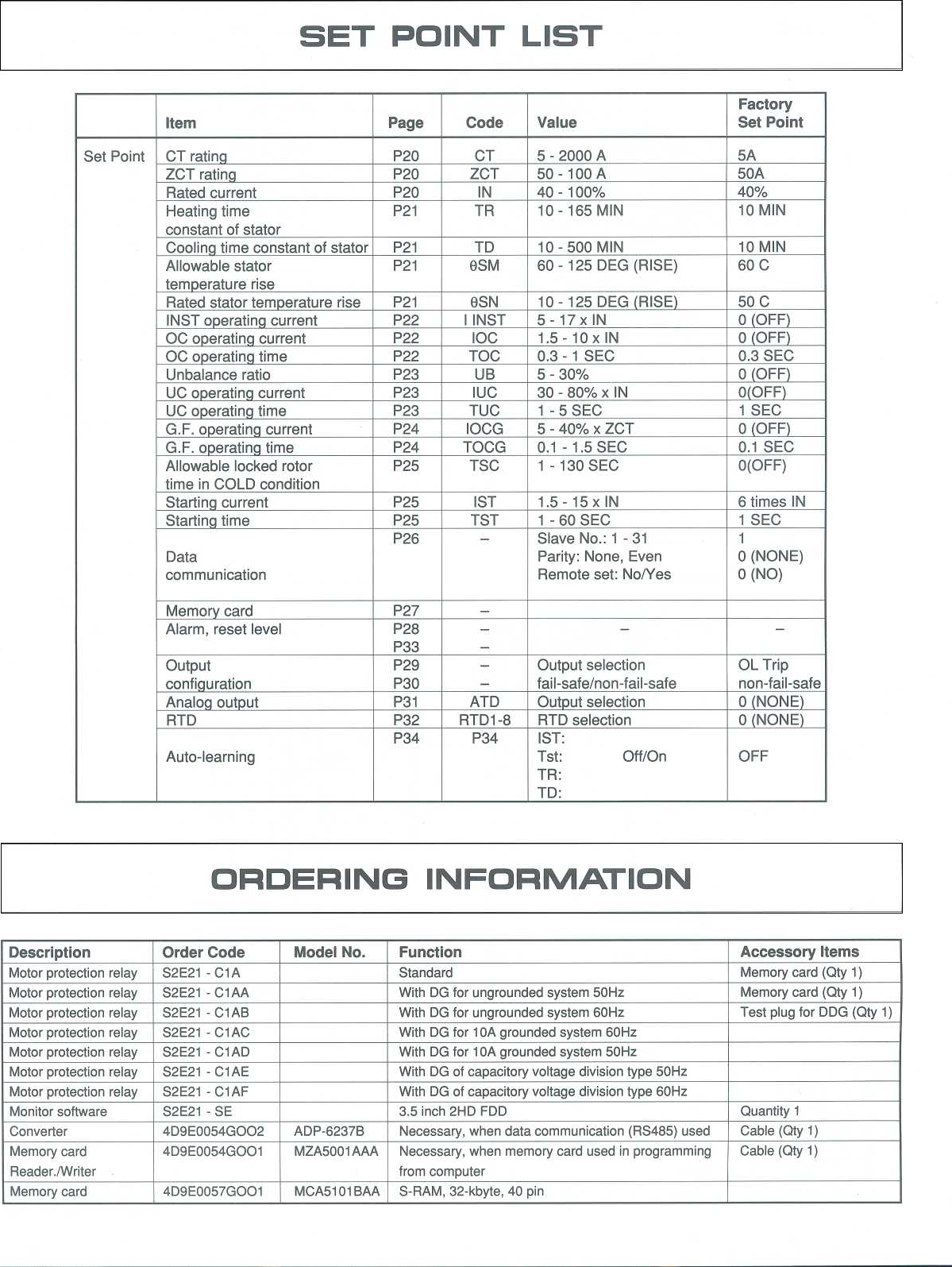
SET
POINT
LIST
ORDERING
INFORMATION
Item
Page
Code
Value
Factory
Set Point
Set
Point
CT
rating
P20
CT
5
-
2000
A
5A
ZCT
rating
P20
ZCT
50
-
100
A
50A
Rated
current
P20
IN
40-100%
40%
Heating
time
constant
of
stator
P21
TR
10
-
165
MIN
10
MIN
Cooling
time constant
of
stator
P21
TD
10
-
500
MIN
10
MIN
Allowable
stator
temperature
rise
P21
6SM
60
-
125
DEG
(RISE)
60
C
Rated
stator
temperature
rise
P21
9SN
10
-
125
DEG
RISE
50
C
INST
operating
current
P22
I
INST
5
-
17 x
IN
0
OFF
OC
operating
current
P22
IOC
1
.5
-
10 x
IN
0
OFF
OC
operating
time
P22
TOC
0
.3
- 1
SEC
0
.3
SEC
Unbalance
ratio
P23
UB
5-30%
0
OFF
UC
operating
current
P23 IUC
30
-
80%
x
IN
0(OFF)
UC
operating
time
P23
TUC
1 -
5
SEC
1
SEC
G
.F
.
operating
current
P24
IOCG
5
-
40%
x
ZCT
0
OFF
G
.F
.
operating
time
P24
TOCG
0
.1
- 1
.5
SEC
0
.1
SEC
Allowable
locked
rotor
time
in
COLD
condition
P25
TSC
1 -
130
SEC
0(OFF)
Starting
current
P25
IST
1
.5
-
15 x
IN
6 times
IN
Starting
time
P25
TST
1 -
60
SEC
1
SEC
Data
communication
P26
-
Slave
No
.
:
1
-31
Parity
:
None,
Even
Remote
set
:
No/Yes
1
0
(NONE)
0 (NO)
Memory
card
P27
-
Alarm,
reset
level
P28
P33
-
-- -
Output
configuration
P29
P30
-
-
Output
selection
fail-safe/non-fail-safe
OL
Trip
non-fail-safe
Analog
output
P31
ATD
Output
selection
0
NONE
RTD
P32
RTD1-8
RTD
selection
0
NONE
Auto-learning
P34 P34
IST
:
Tst
:
Off/On
TR
:
TD
:
OFF
Description
Order
Code
Model
No
.
Function
Accessory
Items
Motor
protection
relay
S2E21
-
C1
A
Standard
Memory
card
(Qty
1)
Motor
protection
relay
S2E21
-
ClAA
With
DG
for
ungrounded
system
50Hz
Memory
card
(Qty
1)
Motor
protection
relay
S2E21
-
C1
AB
With
DG
for
ungrounded
system
60Hz
Test
plug
for
DDG
(Qty
1)
Motor
protection
relay
S2E21
-
C1
AC
With
DG
for
10A
grounded
system
60Hz
Motor
protection
relay
S2E21
-
C1
AD
With
DG
for
10A
grounded
system
50Hz
Motor
protection
relay
S2E21
-
C1
AE
With
DG
of
capacitory
voltage
division
type
50Hz
Motor
protection
relay
S2E21
-
C1 AF
With
DG
of
capacitory
voltage
division
type
60Hz
Monitor software
S2E21
-SE
3
.5
inch
2HDFDD
Quantity
1
Converter
4D9E0054GOO2
ADP-6237B
Necessary,
when
data
communication
(RS485)
used
Cable
(Qty
1)
Memory
card
Reader
./Writer
4D9E0054GOO1
MZA5001
AAA
Necessary,
when
memory
card
used
in
programming
from
computer
Cable
(Qty
1)
M
e
m
o
ry
ca
r
d
4D
9
E
0057
GOO
1
MCA
5
101
BAA
S-RAM,
32-kbyte,
40
pin

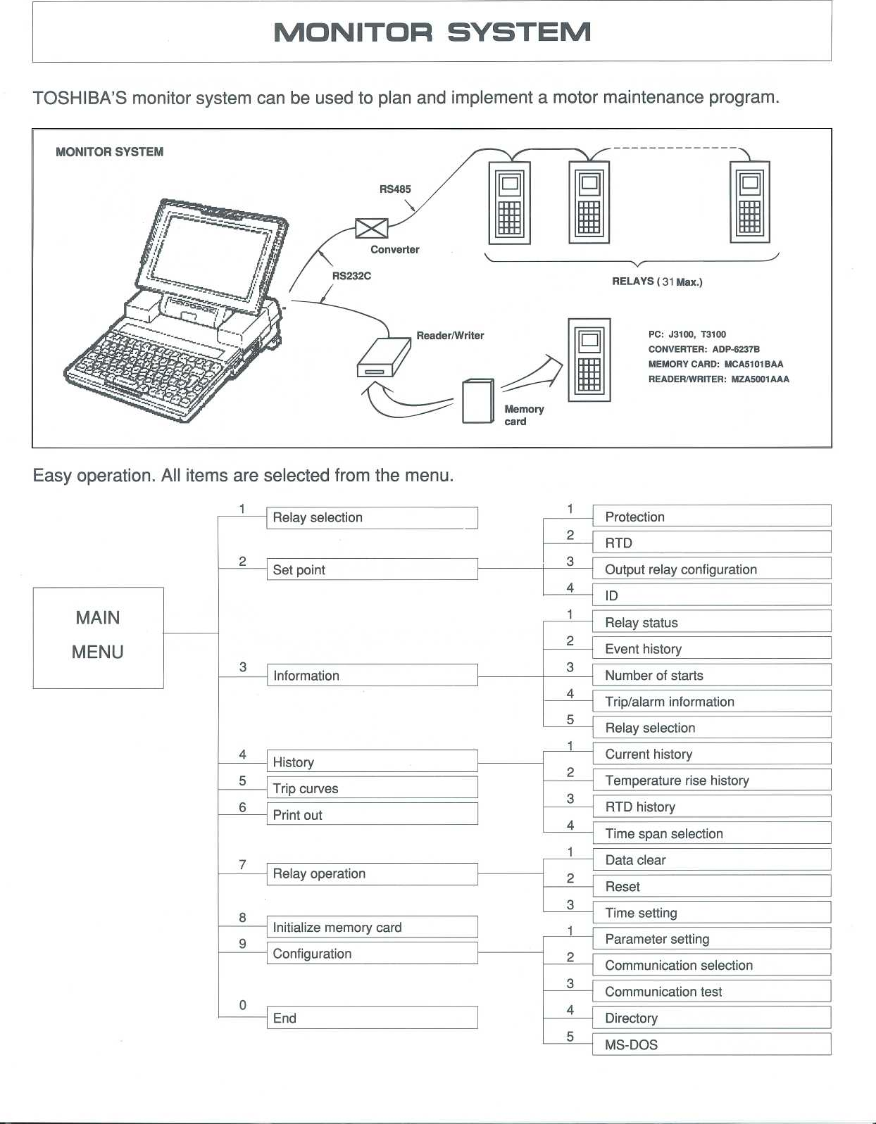
MONITOR
SYSTEM
TOSHIBA'S
monitor
system
can be
used
to
plan
and
implement
a motor
maintenance
program
.
MONITOR
SYSTEM
w
Bon
Bo~
Boom
Boom
Boom
R
PC
:
J3100,
T3100
CONVERTER
:
ADP-6237B
MEMORY
CARD
:
MCA5101BAA
READER/WRITER
:
MZA5001AAA
Easy
operation
.
All
items
are
selected
from
the
menu
.
MAIN
MENU
Relay
selection
Protection
2
RTD
2Set
point
3Output
relay
configuration
ID
Relay
status
2Event
history
3
Information
3
Number
of
starts
4
Trip/alarm
information
5Relay
selection
History
Current
history
5
Trip
curves
2
Temperature
rise
history
3
Print
out
RTD
history
4
Time
span
selection
Data
clear
Relay
operation
2
Reset
3
Time
setting
Initialize
memory
card
9
Parameter
setting
Configuration
2
Communication
selection
3
Communication
test
End
Directory
MS-DOS

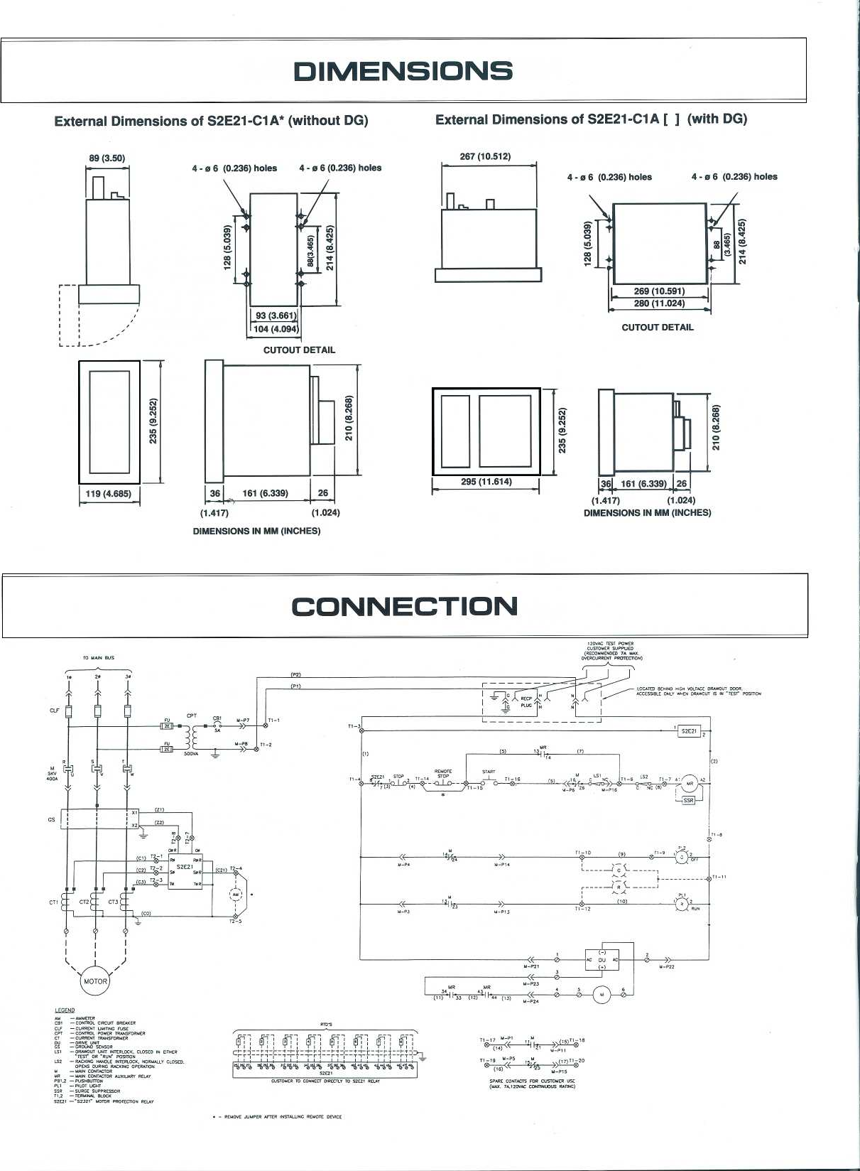
DIMENSIONS
External
Dimensions
of
S2E21-C1
A*
(without
DG)
External
Dimensions
of
S2E21-C1A
[
]
(with
DG)
89
(3 .50)
267
(10
.512)
4
-
o
6
(0
.236)
holes
4
-
o 6
(0
.236)
hales
IR
171-
N
N
N
07
N
CUTOUT
DETAIL
J
36
161
(6
.339)
26
DIMENSIONS
IN
MM
(INCHES)
ao
t0
N
O
N
U
D
295
(11
.614)
N
N
Of
N
4
-
o 6
(0
.236)
holes
4
-
e 6
(0
.236)
holes
(1
.417)
(1
.024)
(1
.417)
(1
.024)
DIMENSIONS
IN
MM
(INCHES)
CONNECTION
CUTOUT
DETAIL
L~Q
'~
<
t
~}L~
to
-
(u)
-
I
F7
21
'W's
4%
[tStDUEx
ro
mxxER
oixECrLr
m
sExtxEUr
(u1
.
~4t7wK
[ormx~
.o16
xatwG)
O
f0
N
O
N

NOTES

TOSHIBA
TOSHIBA
INTERNATIONAL
CORPORATION
INDUSTRIAL
DIVISION
13131
West
Little
York
Rd
.,
Houston,
Texas
77041
Tel
:
(713)
466-0277
Fax
:
(713)
466-8773
Telex
:
762078
U
.S
. :
800-231-1412
CANADA
:
800-872-2192
World
Wide
Web
Http
://www
.tic
.toshiba
.co
m
TOSHIBA
CORPORATION
1-1,
Shibaura
1-Chome,
Minato-Ku,
Tokyo,
105,
Japan
Telex
:
J22587
TOSHIBA
Cable
:
Toshiba Tokyo
Phone
:
457-4900
Fax
:
456-1631
OVERSEAS
OFFICES
:
Mexico
City,
Caracas,
Rio de
Janiero,
Buenos
Aires,
London,
Wien,
Berlin,
Hong
Kong,
Bangkok,
Manila,
Jakarta,
Sydney,
Wellington,
Johannesburg,
Beijing,
Tipei,
Guangzhou
TOSHIBA
INTERNATIONAL
CORPORATION
Pty
.
Ltd
.
:
Sydney,
Melbourne
Toshiba
International
Company
Limited
:
London
"
For
further
information,
please
contact
your
nearestToshiba
Representative
.
"
The
data
given
in
this
catalog
are
subject
to
change
without
notice
.
L-A-001-97
COPYRIGHT
©
1997
TOSHIBA
INTERNATIONAL
COPORATION
Printed
in
U
.S
.A
.