Toshiba Strata Dk8 Installation And Maintenance Manual & 16
Strata DK 8-16 Instalation Strata DK_8-16_Instalation www.TelecomUserGuides.com Access User Guides, Manuals and Brochures
2014-12-13
: Toshiba Toshiba-Strata-Dk8-Installation-And-Maintenance-Manual-127602 toshiba-strata-dk8-installation-and-maintenance-manual-127602 toshiba pdf
Open the PDF directly: View PDF ![]() .
.
Page Count: 321 [warning: Documents this large are best viewed by clicking the View PDF Link!]

Digital Key Telephone Systems
DK8 & DK16
INSTALLATION AND MAINTENANCE MANUAL
© COPYRIGHT 1993
TOSHIBA AMERICA INFORMATION SYSTEMS, INC.
Telecommunication Systems Division
All rights reserved. No part of this manual, covered by the copyrights hereon,
may be reproduced in any form or by any means—graphic, electronic, or
mechanical, including photocopying, recording, taping, or information retrieval
systems—with the exception of the System Record forms, without written
permission of the publisher of this material.
SERIAL NO. DK8 & DK16 DK8-MA-IN/MT-R1
4025021

INSTALLATION-INTRODUCTION
SECTION 100-816-201
MARCH 1993
INSTALLATION
TOSHIBA SYSTEM PRACTICES
DIGITAL KEY TELEPHONE SYSTEMS
Chapter One — Introduction Section 100-816-201
Chapter Two — Site Requirements Section 100-816-202
Chapter Three — System Configuration Section 100-816-203
Chapter Four — DK8 KSU and PCB Installation Section 100-816-204
Chapter Five — DK16 KSU and PCB Installation Section 100-816-205
Chapter Six — Station Apparatus Installation Section 100-816-206
Chapter Seven — Peripheral Installation Section 100-816-207
Chapter Eight — Wiring Diagrams Section 100-816-208

INSTALLATION-INTRODUCTION
SECTION 100-016-201
NOVEMBER 1992

INSTALLATION-INTRODUCTION
SECTION 100-816-201
MARCH 1993
INSTALLATION
CHAPTER ONE
INTRODUCTION
TOSHIBA SYSTEM PRACTICES
DIGITAL KEY TELEPHONE SYSTEMS
INSTALLATION-INTRODUCTION
SECTION 100-816-201
MARCH 1993
1-i
TABLE OF CONTENTS
PARAGRAPH SUBJECT PAGE
1PURPOSE .............................................................................................................. 1-1
2ORGANIZATION .................................................................................................... 1-1
3REFERENCE DOCUMENTATION ........................................................................ 1-1
3.10 General Description ............................................................................................ 1-1
3.20 Programming ...................................................................................................... 1-1
3.30 User Guides........................................................................................................ 1-1
3.40 Fault Finding Procedures ................................................................................... 1-1
3.50 Remote Maintenance and Administration........................................................... 1-1
4SYSTEM MNEMONICS/TERMS............................................................................ 1-1
4.10 Use of Notes, Important Notes, Cautions, and Warnings.................................... 1-5
INSTALLATION-INTRODUCTION
SECTION 100-816-201
MARCH 1993
1-1
1 PURPOSE
1.00 The purpose of this section is to provide
detailed step-by-step instructions for installing the
STRATA DK8 and STRATA DK16 systems.
1.01 This chapter provides an overview of the
entire installation section, and includes a list of
reference documentation that supports the in-
stalled system; a list of system mnemonics is also
provided.
2 ORGANIZATION
2.00 This manual is organized in modular chap-
ters for easy removal and replacement of updated
materials. The chapters are as follows:
Chapter One - Introduction
Chapter Two - Site Requirements
Chapter Three - System Configuration
Chapter Four - STRATA DK8 KSU and PCB
Installation
Chapter Five - STRATA DK16 KSU and PCB
Installation
Chapter Six - Station Apparatus Installation
Chapter Seven - Peripherals Installation
Chapter Eight - System Wiring and Main Dis-
tribution Frame Arrangements
3 REFERENCE DOCUMENTATION
3.00 The STRATA DK8 and DK16 digital key
systems are supported by the following comple-
ment of reference documentation:
3.10 General Description: An overview of the
STRATA DK8 and DK16 systems and their fea-
tures.
3.20 Programming: Detailed step-by-step in-
structions on how to enter data in the System
Record sheets, and how to program the system
from the completed System Record Sheets. LCD
responses are included to provide clear guidance
for the programmer.
3.30 User Guides: Detailed step-by-step guides
on how to operate digital telephones, electronic
telephones, standard telephones, direct station
selection consoles, add-on modules and data in-
terface units.
3.40 Fault Finding Procedures: Hardware trou-
bleshooting and diagnostic information presented
in flowchart form.
3.50 Remote Maintenance and Administration:
Programming and maintenance procedures spe-
cially adapted for remote maintenance and admin-
istration terminal use. Detailed, step-by-step in-
structions are provided, complete with the terminal
responses.
4 SYSTEM MNEMONICS/TERMS
4.00 Mnemonics are used to identify the system’s
hardware, operation, and features. The following
alphabetical listing describes the mnemonics used
in this manual.
ADM: Add-on Module—A telephone upgrade that
provides 20 Direct Station Selection (DSS) but-
tons with busy LED indication on STRATA DK16
and 10 DSS buttons plus 8 speed dial buttons
(one for every station), one night transfer and
one all call page button on STRATA DK8. Can
be installed on any or all 2000-series Digital
Telephones in the system. Attaches to the tele-
phone and uses the same port assigned to the
telephone. ADM buttons are fixed and cannot
be changed in system programming.
BPS: Bits Per Second—Unit of measure that re-
fers to the transmission speed (baud rate) of
electronic signals. It is used when describing
data interface unit and modem operation.
CO: Central Office—The facility which houses
switching equipment that provides telephone
service (CO lines, Centrex lines, etc.) for the
immediate geographical area.
CO Line: A term used to define the STRATA
hardware circuit that connects to the Central
Office network line pair. Each CO line is as-
signed a CO line number in system software.
INSTALLATION-INTRODUCTION
SECTION 100-816-201
MARCH 1993
1-2
CODECs: Coder/Decoders—Semiconductors that
allow the system to process analog-to-digital
and digital-to-analog conversions.
DDCB: Digital Door Phone/Lock Control Unit—A
peripheral hardware unit that can be connected
to designated digital telephone circuits/ports.
The DDCB has three interfaces, two of which
are dedicated to door phones (MDFB), and one
that can be connected to a MDFB or a door lock.
DISA: Direct Inward System Access—A feature
available for CO lines that allows an outside
party to access a STRATA system’s internal
stations or outgoing CO lines without going
through an operator or automated attendant. An
optional security code and/or account codes
may be set to prevent unauthorized access to
outgoing CO lines for through system calling.
DK: Digital Key.
DKSU8: Key Service Unit (STRATA DK8 only)—
The standard key service unit which includes
the system's motherboard, power supply, two
CO line circuits, four digital telephone circuits,
relay service, and interface for Music-on-hold
(MOH)/Background Music (BGM) and External
Page.
DKSUB16: Base Key Service Unit (STRATA DK16
only)—The standard key service unit which in-
cludes the system's motherboard, power sup-
ply, four CO line circuits, eight digital telephone
circuits, relay service, and interface for Music-
on-hold (MOH)/Background Music (BGM) and
External Page.
DKSUE16: Expansion Key Service Unit (STRATA
DK16 only)—The optional key service unit which
has four universal slots that can support CO line,
station, and external option printed circuit boards
that are compatible with the larger STRATA DK
systems (DK24/DK56/DK96).
DSS: Direct Station Selection Console (STRATA
DK16 only)—A console designed to facilitate
the processing of a heavy load of incoming calls.
There are two types of DSS consoles: the DDSS
console and the HDSS console. The chief differ-
ence between them is that the DDSS console
can be connected to designated digital tele-
phone circuits, while the HDSS console can
only be connected to designated electronic tele-
phone circuits.
DTMF: Dual-tone Multi-frequency—Push-button
dialing.
DVSU: Off-hook Call Announce Upgrade—A sub-
assembly that allows a digital telephone to re-
ceive Off-hook Call Announce.
EOCU: Off-hook Call Announce Upgrade (STRATA
DK16 only)—An optional subassembly to the
Electronic Telephone Interface Unit PCB (PEKU)
or Standard/Electronic Telephone Interface Unit
(PESU) that provides support for electronic tele-
phones that must receive Off-hook Call An-
nounce. Electronic telephones that must re-
ceive Off-hook Call Announce must also have
an HVSU2 subassembly or the combined HVSU/
HVSI subassemblies.
FCC: Federal Communication Commission—The
telecommunication industry’s federal regulatory
agency. All Toshiba hardware is FCC listed or
approved.
HESB: External Speaker Box—A speaker/ampli-
fier that can be configured with the system and
telephones to provide a variety of functions.
HESC-65A: A cable that connects an HHEU-
equipped digital telephone or electronic tele-
phone to an HESB for a Loud Ringing Bell .
HHEU: Loud Ringing Bell/Headset Jack Interface
Upgrade—A small subassembly for use inside a
digital telephone or a 6500-series electronic
telephone that allows a speaker (HESB) and/or
a headset to be installed with the station.
HVSU2: Off-hook Call Announce Upgrade—A
subassembly that enables an electronic tele-
phone to receive Off-hook Call Announce.
INSTALLATION-INTRODUCTION
SECTION 100-816-201
MARCH 1993
1-3
IMDU: Remote Maintenance Modem Interface
Unit (STRATA DK16 only)—A subassembly
installed on a PIOU or PIOUS PCB in the op-
tional DK16 Expansion Key Service Unit that
allows the system to be connected with a remote
maintenance/administration terminal.
KCDU: CO Line/Digital Telephone Interface Unit
(STRATA DK16 only)—Optional printed circuit
board providing two loop start CO line circuits
and four digital telephone circuits that can be
installed in the Expansion Unit. The digital tele-
phone circuits support the same devices as the
PDKU except for the DDSS console.
KCOU: CO Line Interface Unit (STRATA DK16
only)—Factory-installed printed circuit board that
comes standard with the Base Key Service Unit
to provide four loop start CO line circuits. Avail-
able as a spare unit for field replacements.
KFCU: (STRATA DK16 only) Option feature car-
tridge that plugs into the Base Unit to provide
feature upgrades to DK16.
KPSU16: (STRATA DK16 only) Power supply that
comes factory-installed in the Base Key Service
Unit. This power supply provides power to the
entire system, in its standard and expanded
configurations. Available as a spare unit for field
replacements.
K4RCU: (STRATA DK16 only) Optional unit that
can be installed in the Base Key Service Unit to
provide a 4-circuit Dual-tone Multi-frequency
receiver for CO lines and standard telephones.
It also provides busy tone detection for Auto
Busy Redial.
KSTU: Standard Telephone Interface Unit
(STRATA DK16 only)—Optional printed circuit
board that can be installed in the Base Key
Service Unit to provide four standard telephone
circuits.
LCD: Liquid Crystal Display—Display used for
messaging, identification, and status that ap-
pears on some digital and electronic telephones.
LED: Light Emitting Diode—Status indicators lo-
cated on printed circuit boards, digital telephones,
and electronic telephones.
LSI: Large Scale Integration—Related to circuit
design technology. STRATA DK8 and STRATA
DK16 printed circuit boards use LSI circuit de-
sign.
MDF: Main Distribution Frame—The wiring frame
usually located in a phone closet.
MDFB: Door Phone Box—A peripheral two-way
speaker box option. Each MDFB connects to a
DDCB. A DDCB can support as many as three
MDFBs.
OCA: Off-hook Call Announce.
PBX: Private Branch Exchange—Industry-stan-
dard term which refers to a telephone switch,
usually on-premises, which serves an individual
company, and is connected to a public tele-
phone exchange through the CO.
PCB: Printed Circuit Board.
PCM: Pulse Code Modulation—A widely used
form of digital telephone switching.
PCOU1: CO Line Interface Unit (STRATA DK16
only)—A printed circuit board that can be in-
stalled in the optional Expansion Key Service
Unit to provide the system with four loop start
CO lines circuits.
PCOU2: (STRATA DK16 only) The PCOU2 is a
direct replacement for the PCOU1. Their fit/
form/function is identical; however, for manu-
facturing reasons, the PCOU1 was phased out
in favor of the PCOU2.
PDIU-DI/PDIU-DI2: Integrated Data Interface
Unit—Replaces the normal digital telephone
base to enable the telephone to transmit and
receive data between a terminal/personal com-
puter connected to the telephone and data
devices connected to other PDIU-DIs, or to
modems, printers, and computers connected to
INSTALLATION-INTRODUCTION
SECTION 100-816-201
MARCH 1993
1-4
Stand-alone Data Interface Units (PDIU-DSs).
The PDIU-DI is also used to provide personal
computer access to outside dial-up data ser-
vices and/or bulletin boards.
NOTE:
The PDIU-DI and the PDIU-DI2 are identical,
except that the PDIU-DI attaches to 1000-
series Digital Telephones, while the PDIU-
DI2 attaches to 2000-series Digital Tele-
phones.
PDIU-DS : Stand-alone Data Interface Unit—Used
for modem pooling, printer sharing, and access
to a host/mainframe computer.
PDKU1: Digital Telephone Interface Unit (STRATA
DK16 only)—A printed board that can be in-
stalled in the optional Expansion Key Service
Unit to provide the system with eight digital
telephone circuits. In addition to digital tele-
phones, the PDKU can support data interface
units (Stand-alone and Integrated), a digital
DSS console (DDSS), and a digital door phone/
lock control unit (DDCB).
PDKU2: Digital Telephone Interface Unit (STRATA
DK16 only)—Provides same function as the
PDKU1, except that the PDKU1 can only sup-
port data interface units on Circuits 1 ~ 7, while
the PDKU2 can support data interface units on
Circuits 1 ~ 8.
PEKU: Electronic Telephone Interface Unit
(STRATA DK16 only)—An optional PCB that
provides the system with eight electronic tele-
phone circuits, which can support electronic
telephones, a Background Music source, an
electronic DSS console (HDSS), and an ampli-
fier for two CO line conference calls.
PESU:
Standard/Electronic Interface Unit
(STRATA
DK16 only)
—A printed circuit board with two
standard telephone circuits and four electronic
telephone circuits that can be installed in the
optional Expansion Key Service Unit. The elec-
tronic telephone circuits can support the same
devices as the PEKU, except for the HDSS
console. The standard telephone circuits can
support the same single-line devices as the KSTU
and the PSTU.
PFT: Power Failure Transfer Interface—Dedicated
standard telephone interface located on the
motherboard in the DKSUB16 (STRATA DK16)
or DKSU8 (STRATA DK8) to provide emergency
service during a system power failure.
PIOU: Option Interface Unit (STRATA DK16 only)—
A printed circuit board that can be installed in the
optional Expansion Key Service Unit to provide
support and/or circuit interface for optional hard-
ware peripherals and upgrades.
PIOUS: (STRATA DK16 only) The same as the
PIOU, except the PIOUS has one external pag-
ing interface zone, while the PIOU has four.
NOTE:
The system cannot support the PIOU and
PIOUS simultaneously. Only one or the other
can be installed.
PORT: There are two types of ports: physical and
logical. A physical port is an actual station circuit
location; a logical port is the set of characteris-
tics—features, station intercom number, etc.—
assigned to the physical port. Logical ports are
mobile. They can be moved from one physical
port to another.
PBTC: A Toshiba-supplied cable used to connect
customer-supplied batteries to the power sup-
ply in the DKSUB for emergency reserve power.
PPTC: (STRATA DK16 only) A Toshiba-supplied
adapter that is used to connect the modular
SMDR and/or maintenance ports to the DB-25
connector of a printer, terminal, modem or call
accounting machine. The SMDR/Maintenance
(TTY) port is located on the optional QSMU PCB
(STRATA DK8), or PIOU or PIOUS PCB
(STRATA DK16).
PSTU1: Standard Telephone Interface Unit
(STRATA DK16 only)—A printed circuit board
with a built-in ring generator that can be installed
in the optional Expansion Key Service Unit to
INSTALLATION-INTRODUCTION
SECTION 100-816-201
MARCH 1993
1-5
provide interface for eight standard telephones
or optional hardware peripherals (voice mail
devices, fax machine, Background Music source,
etc).
PSTU2: Standard Telephone Interface Unit
(STRATA DK16 only)—Provides the same func-
tion as the PSTU with the addition of a switch to
select high or low ringing generator voltage.
QCDU: CO Line/Digital Telephone Interface Unit
(STRATA DK8 only)—Optional printed circuit
board providing one loop start CO line circuit
and two digital telephone circuits that can be
installed in the KSU. A maximum of two QCDUs
may be installed in the DK8.
QCNU: Conference Unit (STRATA DK8 only)—
Standard factory-installed printed circuit board
provides two conference circuits that can be
installed in the KSU. The PCB allows two simul-
taneous conferences: four parties for the first,
and three parties for the second simultaneous
conference.
QPSU: (STRATA DK8 only)—Power supply that
comes factory-installed in the KSU. This power
supply provides power to the entire system.
Available as a spare unit for field replacements.
QRCU: Optional printed circuit board that can be
installed in the KSU to provide a 3-circuit Dual-
tone Multi-frequency receiver for DISA CO lines
and standard telephones. It also provides busy
tone detection for Auto Busy Redial.
QSMU: SMDR/TTY Interface Unit (STRATA DK8
only)—Optional printed circuit board which
provides either SMDR, or Remote Maintenance
Terminal (TTY) or external modem interface.
QSMU configuration is selectable in system
programming.
QSTU: Standard Telephone Interface Unit
(STRATA DK8 only)—Optional printed circuit
board that can be installed in the KSU to provide
two standard telephone circuits.
RAM: Random Access Memory—Refers to the
type of system memory that holds individual
system configuration and feature programming.
RAM is read/write memory, and can be easily
revised in programming.
ROM: Read Only Memory—Refers to the type of
system memory that holds static software that
comprises the mechanics of the features’ func-
tions. ROM is only revised by Toshiba software
engineers.
4.10 Use of Notes, Important Notes, Cautions,
and Warnings
4.11 Notes call attention to specific items to elabo-
rate, or to refer the reader to other information.
4.12 Important Notes are used when the informa-
tion is considered to be very important.
4.13 Cautions call attention to the possibility of
equipment being damaged if the instructions are
not followed closely.
4.14 Warnings are used when the given tasks
involved could cause the possibility of personal
injury or death to the technician.

INSTALLATION-SITE REQUIREMENTS
SECTION 100-816-202
MARCH 1993
TOSHIBA SYSTEM PRACTICES
DIGITAL KEY TELEPHONE SYSTEMS
INSTALLATION
CHAPTER TWO
SITE REQUIREMENTS
INSTALLATION-SITE REQUIREMENTS
SECTION 100-816-202
MARCH 1993
2-i
TABLE OF CONTENTS
PARAGRAPH SUBJECT PAGE
1GENERAL .............................................................................................................. 2-1
2INPUT POWER REQUIREMENTS ........................................................................ 2-1
3SITE CONSIDERATIONS ...................................................................................... 2-1
3.00 Clearance and Location Requirements .............................................................. 2-1
3.10 Electrical/Environmental Requirements and Characteristics............................... 2-2
4GROUNDING REQUIREMENTS ........................................................................... 2-2
4.10 Third Wire Ground Test ...................................................................................... 2-2
4.20 Alternate or Additional Ground ........................................................................... 2-4
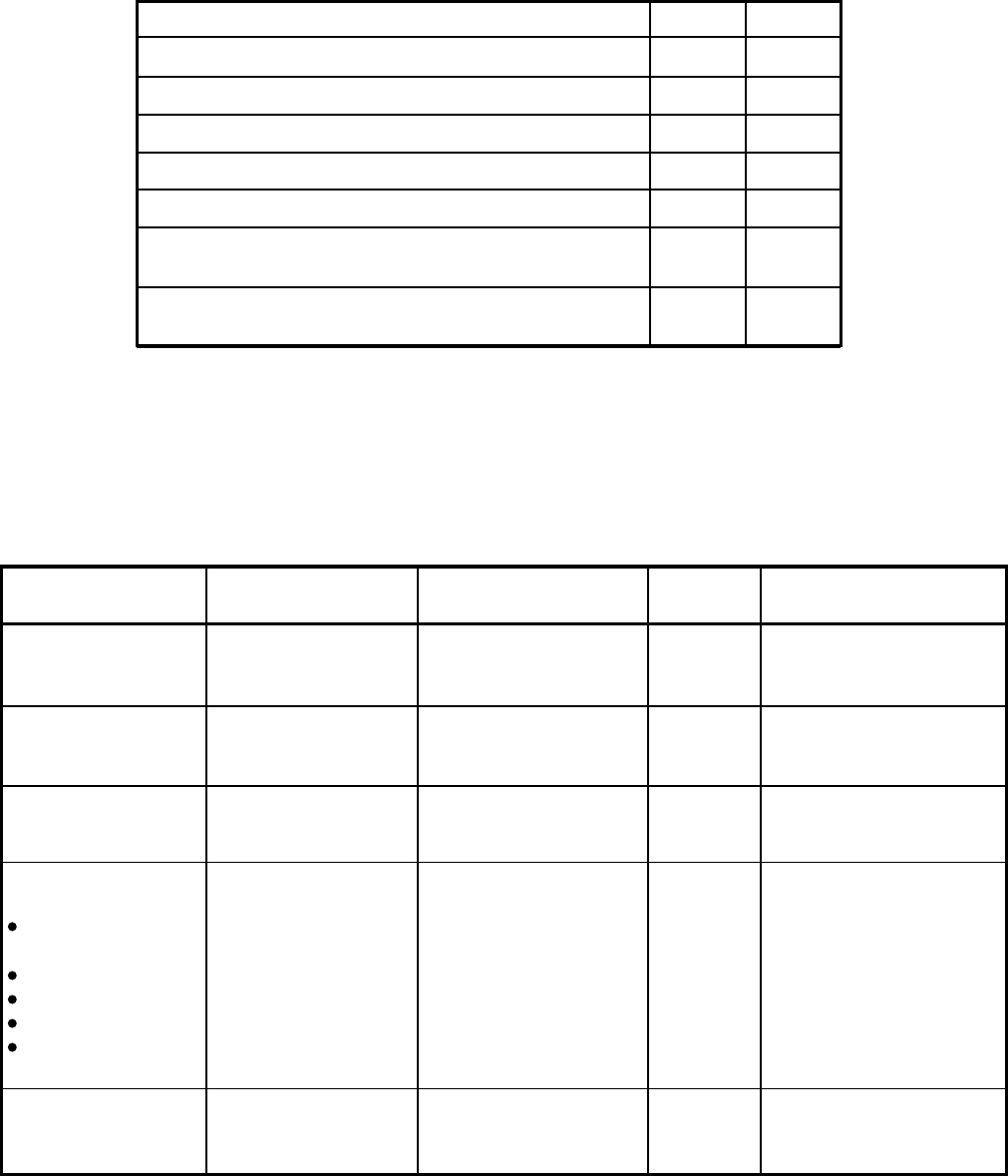
TABLE LIST
TABLE TITLE PAGE
2-A SUMMARY OF ELECTRICAL/ENVIRONMENTAL CHARACTERISTICS .............. 2-3
FIGURE LIST
FIGURE TITLE PAGE
2-1 DK8 BASE KEY SERVICE UNIT AND HPFB MINIMUM CLEARANCE
REQUIREMENTS................................................................................................... 2-1
2-2 BASE KEY SERVICE UNIT MINIMUM CLEARANCE REQUIREMENTS .............. 2-1
2-3 DK16 COMBINED BASE AND EXPANSION KEY SERVICE UNIT
MINIMUM CLEARANCE REQUIREMENTS .......................................................... 2-2
2-4 KSU GROUNDING DIAGRAM ............................................................................... 2-3
INSTALLATION-SITE REQUIREMENTS
SECTION 100-816-202
MARCH 1993
2-1
1 GENERAL
1.00 This chapter defines the installation site re-
quirements necessary to ensure a proper operat-
ing environment for the STRATA DK8 and DK16.
Also included are grounding requirements.
2 INPUT POWER REQUIREMENTS
2.00 The system requires an input power source
of 117VAC nominal (85VAC ~ 135VAC), 50/60 Hz,
15 amps. The AC outlet is recommended to be
dedicated
and unswitched, with a solid third wire
ground (refer to Paragraph 4). This is to eliminate
interference from branch circuit motor noise or the
like, and to prevent accidental power-off.
2.01 To avoid accidental power turn-off, it is rec-
ommended that an ON/OFF wall switch
not
be
used on this dedicated AC circuit.
2.02 An option Reserve Power Battery and
Charger (HPFB) is available for use with the
STRATA DK8 to serve as a power failure backup.
For the STRATA DK16, a reserve power source
(two customer-supplied 12-volt batteries) may be
connected to the system to serve as a power
failure backup.
3 SITE CONSIDERATIONS
3.00 Clearance and Location Requirements
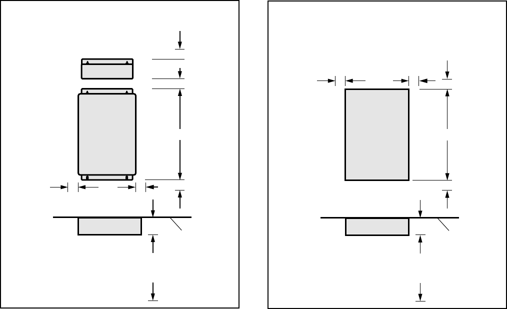
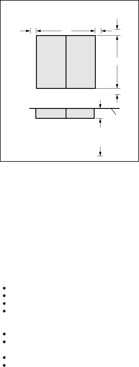
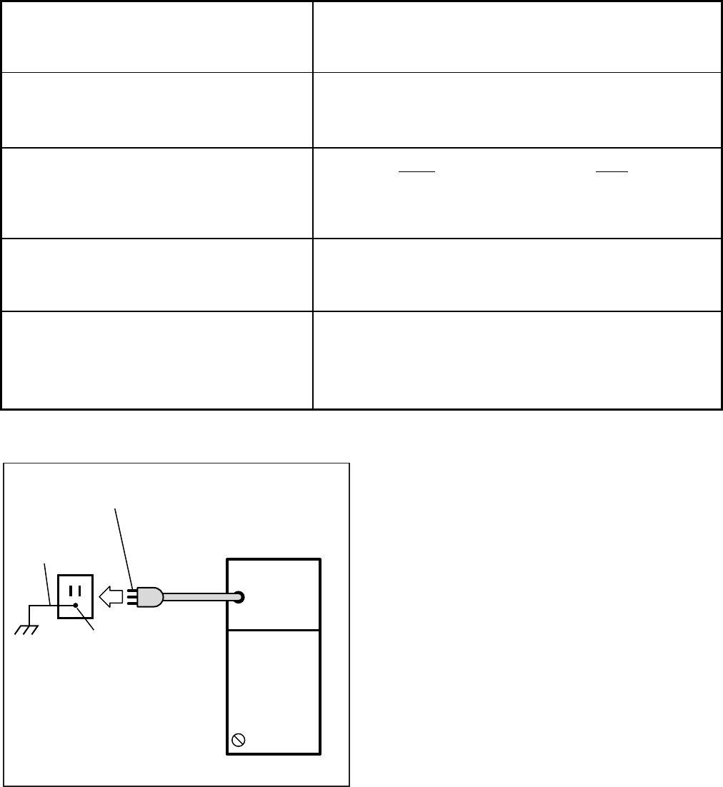
3.01 The key service units must be wall mounted.
Figure 2-1 shows the minimum clearance require-
ments for the STRATA DK8 system, and includes
the recommended mounting location and clear-
ance requirements for the optional HPFB. Figures
2-2 (Base Key Service Unit) and 2-3 (Base and
Expansion Key Service Unit together) show the
minimum clearance requirements for the standard
FIGURE 2-2
DK16 BASE KEY SERVICE UNIT
MINIMUM CLEARANCE REQUIREMENTS
2"
2"
16.4"
FRONT VIEW
DK8 KEY SERVICE UNIT
AND HPFB CLEARANCE
TOP VIEW
3"
3 FEET
WALL
2"
DK 8 KSU
HPFB
2" 2"10"
2" 2" 2"
2"
18"
FRONT VIEW
12.25"
DK16 BASE KEY SERVICE UNIT CLEARANCE
TOP VIEW
3.5"
3 FEET
WALL
DK 16
BASE KSU
FIGURE 2-1
DK8 KEY SERVICE UNIT AND HPFB
MINIMUM CLEARANCE REQUIREMENTS
INSTALLATION-SITE REQUIREMENTS
SECTION 100-816-202
MARCH 1993
2-2
3.03 If reserve power is to be installed for the
STRATA DK16, the batteries will require a well-
ventilated location close (within nine feet) to the
DKSUB16 (the optional Toshiba-supplied battery
cable is 9 feet in length). The STRATA DK8
reserve battery (HPFB) should be mounted di-
rectly above the DKSU8 as shown in Figure 2-1.
3.10 Electrical/Environmental Requirements
and Characteristics
3.11 The electrical/environmental requirements
and characteristics for each system are provided
in Table 2-A.
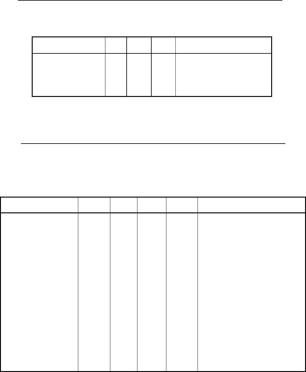
4 GROUNDING REQUIREMENTS
4.00 The systems require a solid earth ground for
proper operation. Failure to provide ground may
lead to confusing trouble symptoms and, in ex-
treme cases, system failure. The AC power cord
contains a conductor for the "third wire ground"
provided by the commercial power outlet. The
third-wire ground should be the only ground nec-
essary for the DK8/DK16; this ground must origi-
nate at the buildings main power distribution panel
and have a solid connection to earth ground.
(Figure 2-4)
4.10 Third Wire Ground Test
4.11 Test the "third wire ground" for continuity by
either measuring the resistance between the third
prong terminal (earth ground) and a metal cold
water pipe (maximum: 1 ohm), or by using a
commercially available earth ground indicator. If
neither procedure is possible, perform the follow-
ing earth ground test procedure:
WARNING!
Hazardous voltages that may cause death
or injury are exposed during the following
test. Use great care when working with AC
power line voltage.
1) Obtain a suitable voltmeter, and set it for a
possible reading of up to 250 VAC.
and optioned STRATA DK16 system. Refer to
Chapter 4 for DK16 key service unit wall mounting
instructions.
3.02 The following conditions must be considered
when selecting a location for the key service unit(s):
The location MUST BE:
Dry and clean
Well ventilated
Well illuminated
Easily accessible
The location MUST NOT BE:
Subject to extreme heat or cold
Subject to corrosive fumes, dust, or other air-
borne contaminants
Subject to excessive vibration
Next to television, radio, office automation, or
high frequency equipment
FIGURE 2-3
DK16 COMBINED BASE AND
EXPANSION KEY SERVICE UNIT
MINIMUM CLEARANCE REQUIREMENTS
2"
2"
18"
FRONT VIEW
20"
TOP VIEW
DK16 BASE AND EXPANSION
UNIT CLEARANCE
3.5"
3 FEET
WALL
2"
BASEEXP
BASEEXP
2"
INSTALLATION-SITE REQUIREMENTS
SECTION 100-816-202
MARCH 1993
2-3
TABLE 2-A
SUMMARY OF ELECTRICAL/ENVIRONMENTAL CHARACTERISTICS
Primary power
Input AC
AC frequency
Power
Environmental specifications
Operating temperature
Operating humidity
Storage temperature
Battery charger characteristics
(DK16 only)
Power supply
DC voltage output
specification
85 ~ 135VAC
50/60 Hz
DK8-46 watts maximum, DK16-75 watts maximum
32 ~ 104°F (0 ~ 40°C)
20 ~ 80% relative humidity without condensation
- 4 ~ 158°F (-20 ~ 70°C)
Charger: current limiting
Nominal float voltage: 2.275 volts/cell
Charge current: 0.7 amps maximum
Battery discharge cut-off voltage: 20.5 ± 0.5VDC
DK16
–24VDC: (–26.3 ~ –27.8VDC)
+5VDC: ( +4.5 ~ +5.5VDC)
–5VDC: ( –4.5 ~ –5.5VDC)
QSTU, KSTU, PSTU or PESU (circuits 1 & 2) Square wave output with high/low option jumper:
Low position, 130 ± 20VDC peak–to–peak (no-load)
High position, 190 ± 25VDC peak–to–peak (no-load)
Two ringers maximum per circuit, high or low position
GENERAL
Ring voltage
Ringing capability
DK8
+24VDC: (+26.3 ~ +27.8VDC)
+5VDC: ( +4.5 ~ +5.5VDC)
Note: +5V converter
on KSU PCB
POWER
SUPPLY
FG
THIRD WIRE
AC GROUND
GROUND 1 THIRD WIRE GROUND
TO AC POWER CORD
DK8 OR DK16 KSU
A
ELECTRICAL
SYSTEM GROUND
FIGURE 2-4
KSU GROUNDING DIAGRAM
2) Connect the meter probes between the two
main AC voltage terminals (white and black
wires) on the wall outlet. The reading obtained
should be between 100 ~ 120 VAC.
3) Move one of the meter probes to the third
terminal (green wire ground). Either the same
reading or a reading of zero volts should be
obtained.
4) If the reading is zero volts, leave one probe on
the ground terminal and move the other probe
to the second voltage terminal.
CAUTION!
If a reading of zero volts is obtained on
both voltage terminals (white wire to green
wire, black wire to green wire), the outlet is
not properly grounded. Omit steps 5 and
6, and proceed directly to step 7.
INSTALLATION-SITE REQUIREMENTS
SECTION 100-816-202
MARCH 1993
2-4
5) If a reading of zero volts on one terminal, and
a reading of 100 ~ 120 VAC on the other
terminal is obtained, remove both probes from
the outlet.
6) Set the meter to the “OHMS/Rx1” scale. Place
one probe on the ground terminal, and the
other probe on the terminal that produced a
reading of zero volts. The reading should be
less than 1 ohm.
CAUTION!
If the reading is more than one ohm, then
the outlet is not adequately grounded.
7) If the above tests show the outlet is not prop-
erly grounded, the condition should be cor-
rected (per Article 250 of the National Electri-
cal Code) by a qualified electrician before the
system is connected.
4.20 Alternate or Additional Ground
4.21 If the “third wire” AC ground can not practi-
cally be improved or if extreme motor noise or
other disturbance causes system malfunction, or if
local area lightning storms exist, a separate direct
ground may be warranted.
4.22 Connect a separate earth ground from a cold
water pipe or earth grounding rod directly to the FG
screw terminal on the DK8/DK16 power supply.
See Figure 4-5 of Section 100-816-204 (for
STRATA DK8) or Figure 5-8 of Section 100-816-
205 (for STRATA DK16).

INSTALLATION-CONFIGURATION
SECTION 100-816-203
MARCH 1993
TOSHIBA SYSTEM PRACTICES
DIGITAL KEY TELEPHONE SYSTEMS
INSTALLATION
CHAPTER THREE
SYSTEM CONFIGURATION
INSTALLATION-CONFIGURATION
SECTION 100-816-203
MARCH 1993
3-i
TABLE OF CONTENTS
PARAGRAPH SUBJECT PAGE
1INTRODUCTION ...................................................................................................... 3-1
2SYSTEM CAPACITY................................................................................................ 3-1
2.00 Total System Capacity.......................................................................................... 3-1
2.10 The DK8 Key Service Unit .................................................................................... 3-1
2.20 The DK16 Base Key Service Unit......................................................................... 3-1
2.30 The DK16 Expansion Key Service Unit ................................................................ 3-1
3STATION CONSIDERATIONS ................................................................................ 3-5
3.10 Telephone Circuit (Port) Types............................................................................. 3-5
3.20 Digital Telephone Circuit Connections ................................................................. 3-5
3.30 Electronic Telephone Circuit Connections (STRATA DK16 Only) ........................ 3-8
3.40 Standard Telephone Circuit Options .................................................................... 3-8
4TELEPHONE UPGRADES ...................................................................................... 3-9
4.10 Digital Telephone Upgrades ................................................................................. 3-9
4.20 Electronic Telephone Upgrades ........................................................................... 3-9
5CONFIGURATION EXAMPLES ............................................................................... 3-9
5.10 Strata DK8 - Example 1 (Small Retail Store)........................................................ 3-9
5.20 Strata DK8 - Example 2 (Home Office) ................................................................ 3-9
5.40 Strata DK16 - Example 1 (Bank) .......................................................................... 3-10
5.50 Strata DK16 - Example 2 (Office/Warehouse)...................................................... 3-10
6CONFIGURATION WORKSHEET ........................................................................... 3-10
TABLE LIST
TABLE TITLE PAGE
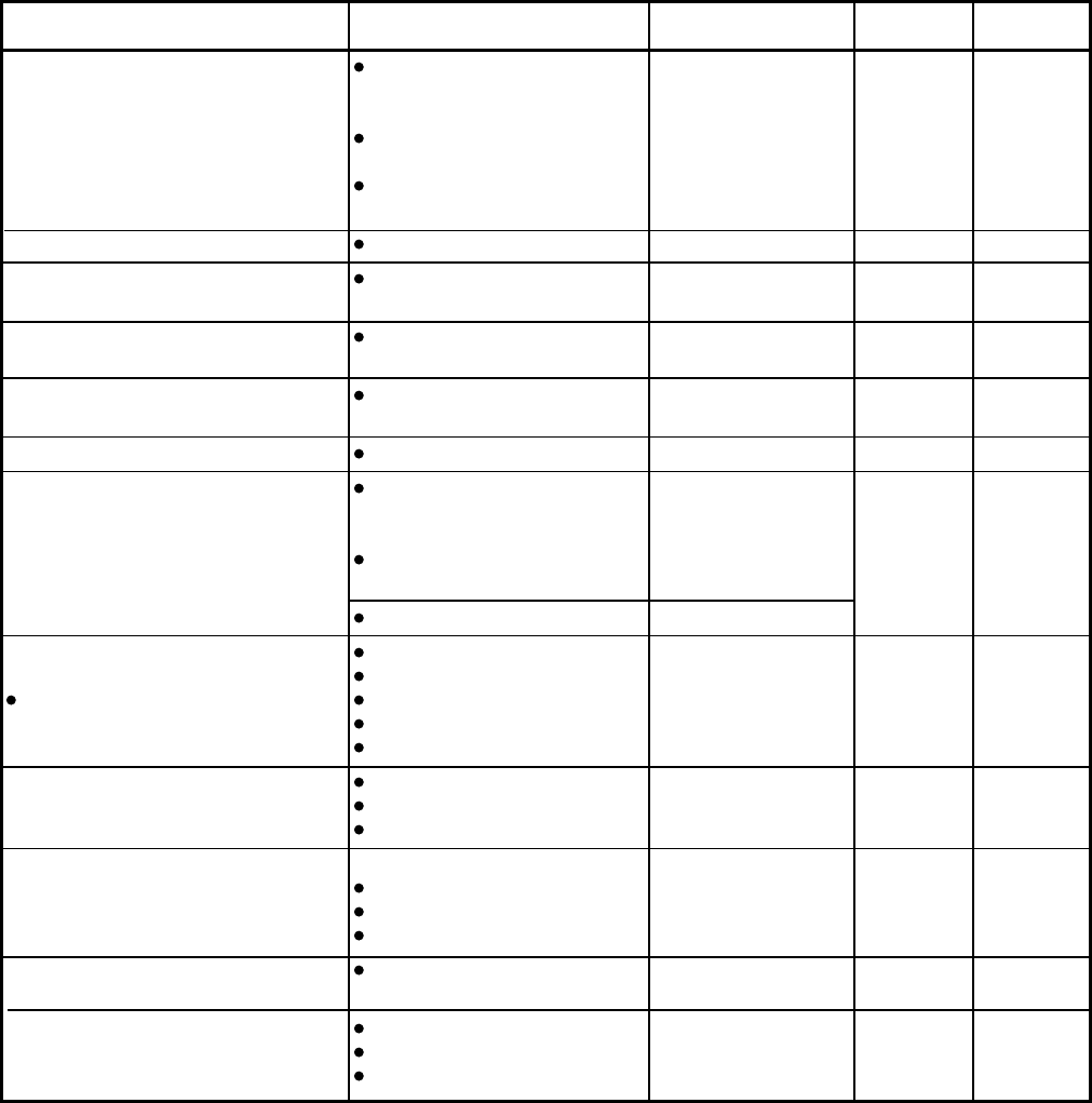
3-A DK8 CO LINE/STATION CONFIGURATION GUIDE ............................................... 3-2
3-B DK16 CO LINE/STATION CONFIGURATION GUIDE (BASE AND
EXPANSION UNIT) .................................................................................................. 3-2
3-C DK8 KEY SERVICE UNIT COMPONENTS ............................................................. 3-3
3-D DK16 BASE KEY SERVICE UNIT COMPONENTS................................................. 3-4
3-E DK16 EXPANSION KEY SERVICE UNIT PCBs ...................................................... 3-5
3-F INTERFACE OPTION .............................................................................................. 3-6
3-G STRATA DK8 STATION APPARATUS OVERVIEW ............................................... 3-6
3-H STRATA DK16 STATION APPARATUS OVERVIEW ............................................. 3-7
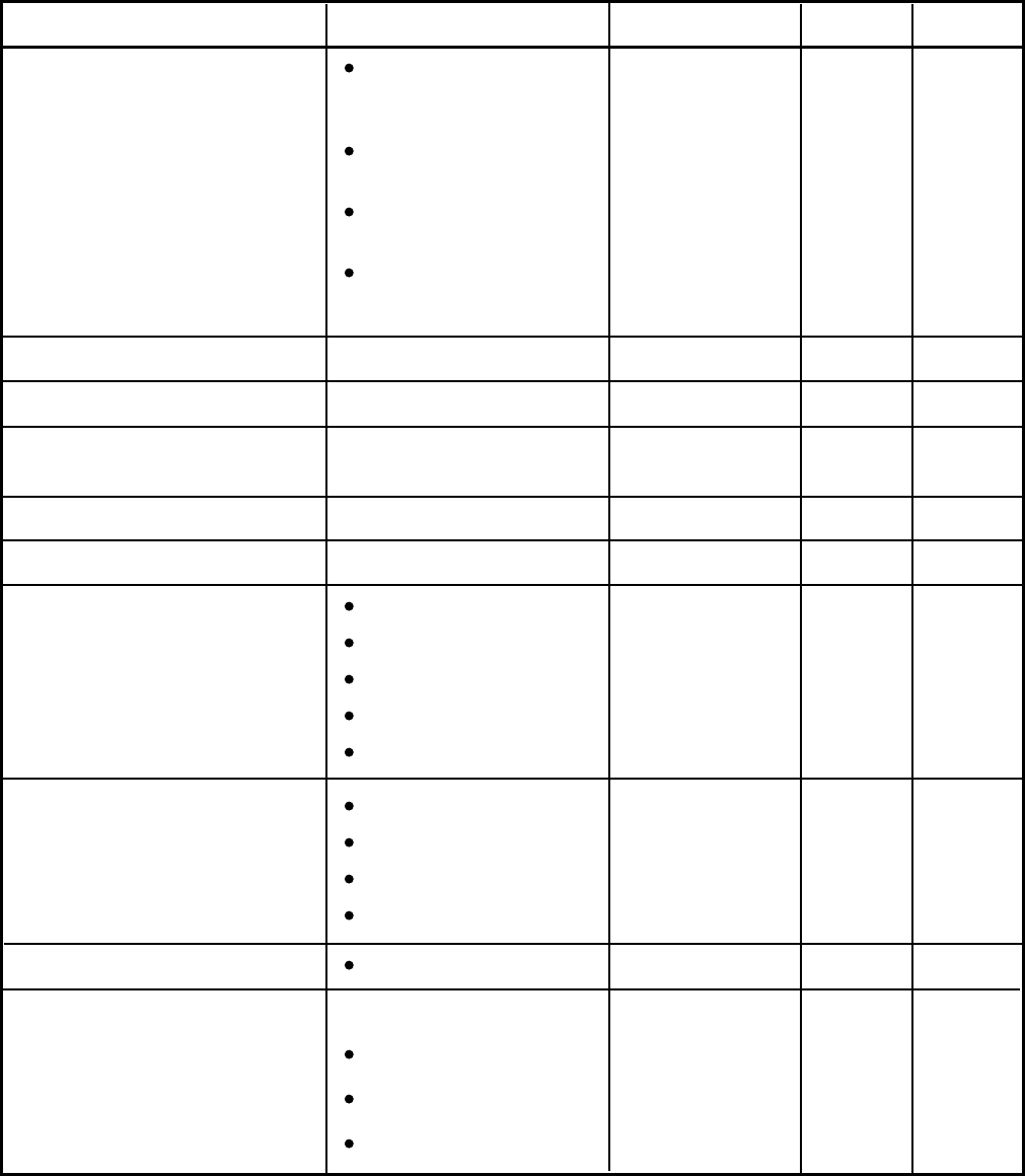
WORKSHEETS
NUMBER TITLE PAGE
1DK8 STATION AND CO LINE TOTALS ................................................................... 3-11
2DK8 KEY SERVICE UNIT AND PCBs ..................................................................... 3-12
3DK8 PERIPHERALS AND UPGRADES .................................................................. 3-13
1DK16 STATION AND CO LINE TOTALS ................................................................. 3-15
2DK16 KEY SERVICE UNIT AND PCBs ................................................................... 3-16
3DK16 PERIPHERALS AND UPGRADES ................................................................ 3-17
4DK16 SYSTEM POWER CHECK ............................................................................ 3-19

INSTALLATION-CONFIGURATION
SECTION 100-816-203
MARCH 1993
3-ii
INSTALLATION-CONFIGURATION
SECTION 100-816-203
MARCH 1993
3-1
1 INTRODUCTION
1.00 This chapter offers guidelines and consider-
ations on how to configure a STRATA DK8/DK16
system, which can support a wide variety of sta-
tions and peripherals.
2 SYSTEM CAPACITY
2.00 Total System Capacity
2.01 The STRATA DK8/DK16 systems have a
modular design which allows them to support a
number of station and CO line configurations. The
main component of each system is the Key Ser-
vice Unit. The DK8 KSU can have up to 10 stations
and four CO lines. The DK16 Base Key Service
Unit can have up to 12 stations and four CO lines.
An Expansion Key Service Unit can be added to
the DK16 to increase the station capacity to 20 and
the CO line capacity to eight. Station and CO line
configurations are shown in Table 3-A (for DK8)
and Table 3-B (for DK16).
2.10 The DK8 Key Service Unit
2.11 Station and CO Lines. The DK8 Key Service
Unit comes standard with four digital telephone
circuits (ports) and two CO line circuits (Table
3-C). An optional printed circuit board called the
QCDU can be added to the KSU to provide one CO
line circuit and two digital telephone circuits. A
maximum of two QCDUs may be added to provide
a total of four additional digital telephone circuits
and two additional CO line circuits. Another op-
tional printed circuit board called the QSTU can be
added to the DK8 KSU to provide two standard
telephone circuits.
2.12 Peripherals. The DK8 Key Service Unit can
support a number of peripherals, which are not
considered as stations and do not affect the maxi-
mum station and CO line capacities. A customer-
supplied Music-on-hold source, optional reserve
power battery and charger, a customer-supplied
emergency standard telephone for system power
failure occurrences and an amplifier with speaker
for paging and night ringing can all be connected
to the Key Service Unit (Table 3-C). A relay contact
is also provided to control one of the following
peripherals: Music-on-hold source, night bell, or
page amplifier mute control.
2.20 The DK16 Base Key Service Unit
2.21 Station and CO Lines. The DK16 Base Key
Service Unit comes standard with eight digital
telephone circuits (ports) and four CO line circuits
(Table 3-D). An optional printed circuit board called
the KSTU can be added to the unit to provide four
standard telephone circuits (ports).
2.22 Peripherals. The DK16 Base Key Service
Unit can support a number of peripherals, which
are not considered as stations and do not affect
the maximum station and CO line capacities. A
customer-supplied Music-on-hold source, cus-
tomer-supplied separate background music
source, customer-supplied reserve power bat-
teries, a customer-supplied emergency stan-
dard telephone for system power failure occur-
rences and an amplifier with speaker for paging
and night ringing can all be connected to the
Base Key Service Unit (Table 3-D). A relay
contact is also provided to control one of the
following peripherals: Music-on-hold source, night
bell, or Page Amplifier mute control.
2.30 The DK16 Expansion Key Service Unit
2.31 Station and CO Lines. The optional DK16
Expansion Key Service Unit has four universal
slots which can support a maximum of four CO
lines and eight stations. Printed circuit boards
(PCBs) that support CO lines and can be installed
in the Expansion Unit are the PCOU and KCDU
(Table 3-E). PCBs that can support stations and be
installed in the Expansion Unit are the PDKU,
PEKU, PSTU, PESU, and KCDU.
2.32 Peripherals. The Expansion Unit can sup-
port either a PIOU or PIOUS PCB, which both
provide, among other features, Station Message
Detail Recording (SMDR), an interface for a local
programming terminal, and connectors for an in-
ternal modem (IMDU) for remote maintenance
and administration (Table 3-F). Any device that
connects to the PIOU or PIOUS should not be
considered a station and does not affect the
system's station capacity.
INSTALLATION-CONFIGURATION
SECTION 100-816-203
MARCH 1993
3-2
TABLE 3-A
DK8 CO LINE/STATION CONFIGURATION GUIDE
CONFIGURATION CO
LINES BY STATION COs DKTs SLTs EQUIPMENT
2 by 4
2 by 6
3 by 6
3 by 8
4 by 8
4 by 10
2
2
3
3
4
4
4
4
6
6
8
8
2
2
2
KSU
KSU + QSTU
KSU + QCDU
KSU + QCDU + QSTU
KSU + QCDU + QCDU
KSU + QCDU + QCDU + QSTU
EQUIPMENT
KSU = Key Service Unit ·2 CO Lines/4 digital circuits)
QCDU = Optional PCB (1 CO line/2 digital circuits)
QSTU = Optional PCB (2 standard circuits)
CO = Central Office
DKT = Digital Telephone
SLT = Standard Telephone
CONFIGURATION CO
LINES BY STATION COs DKTs EKTs SLTs EQUIPMENT
4 by 8
4 by 12
4 by 14
4 by 16
4 by 16
4 by 16
4 by 18
4 by 20
4 by 20
4 by 20
6 by 12
6 by 16
8 by 8
8 by 12
8 by 14
8 by 16
8 by 16
8 by 16
8 by 18
8 by 20
8 by 20
8 by 20
8 by 20
4
4
4
4
4
4
4
4
4
4
6
6
8
8
8
8
8
8
8
8
8
8
8
8
8
8
8
8
16
8
8
16
8
12
12
8
8
8
8
16
16
8
16
8
16
8
4
8
4
8
4
8
4
8
4
2
8
6
4
4
12
4
4
2
6
4
4
4
12
BU
BU + KSTU
BU + EU + PESU
BU + EU + PSTU
BU + EU + PEKU
BU + EU + PDKU
BU + KSTU + PESU
BU + KSTU + EU + PEKU
BU + KSTU + EU + PDKU
BU + KSTU + EU + PSTU
BU + EU + KCDU
BU + KSTU + EU + KCDU
BU + EU + PCOU
BU + KSTU + EU + PCOU
BU + EU + PCOU + PESU
BU + EU + PCOU + PEKU
BU + EU + PDKU + PCOU
BU + EU + KCDU + KCDU
BU + KSTU + EU + PCOU + PESU
BU + KSTU + EU + KCDU + KCDU
BU + KSTU + EU + PCOU + PEKU
BU + KSTU + EU + PCOU + PDKU
BU + KSTU + EU + PCOU + PSTU
BU
KSTU
EU
PDKU
KCDU
PEKU
PESU
EQUIPMENT
Base Unit (4 CO lines/8 digital circuits)
Base Unit Option (4 standard circuits)
Expansion Unit
EU option (8 digital circuits)
EU option (2 CO lines/4 digital circuits)
EU option (8 electronic circuits)
EU option (2 standard/4 electronic circuits)
=
=
=
=
=
=
=
EU option (8 standard circuits)
EU option (4 CO lines)
Central Office line
Digital telephone
Electronic telephone
Standard telephone
=
=
=
=
=
=
PSTU
PCOU
CO
DKT
EKT
SLT
TABLE 3-B
DK16 CO LINE/STATION CONFIGURATION GUIDE (BASE AND EXPANSION UNIT)
INSTALLATION-CONFIGURATION
SECTION 100-816-203
MARCH 1993
3-3
TABLE 3-C
DK8 KEY SERVICE UNIT COMPONENTS
Item Connector TypeSupports Standard Optional
Digital Telephones (with
or without PDIU–DI2 or
ADM)
Stand-alone Data
Interface Units (PDIU-DS)
Door Phone Lock/Control
Unit (DDCB)
Loop Start CO Lines
Standard Telephone
(one)*
Optional HPFB Battery
(one or two per system)
Music-on-hold/BGM
Source*
Amplifier/Speaker
Digital Telephones (with
or without PDIU–DI2 or
ADM)
Stand-alone Data
Interface Units (PDIU-DS)
Loop Start CO Line
Standard Telephones*
Other Single-line Devices*
Fax Machine*
Voice Mail Devices
Alternate BGM source*
Automatic Busy Redial
Standard telephone ports
DISA
Night Relay
External Page Mute
MOH Control Relay
2 Simultaneous
Conferences
SMDR Printer*, or
Maintenance Terminal* or
Modem*
Digital Telephone Circuits (4)
CO Line Circuits (2)
Power Failure Transfer Interface
Battery Backup Interface
Music-On-Hold/BGM Interface
600 Ohm page Interface
CO line CKT (1)/
Digital Telephone CKT (2) (QCDU)
(max. 2 QCDU per system)
Standard Telephone
Interface Unit (QSTU)
2 standard telephone circuits
(1 max.) QSTU per system
DTMF/ABR Tone Receiver
(3-Receiver CKT per QRCU )
Control Relay
Conference Circuit Interface Unit
(QCNU)
SMDR/TTY Interface Unit (QSMU)
(Requires PPTC)
25-pair Amphenol
RJ11 Modular
RJ11 Modular
Proprietary
Cable/Connector
RCA Jack
RCA Jack
25-pair Amphenol
RJ11 Modular
25-pair Amphenol
Internal
25-pair Amphenol
Internal
6-pin Modular
(PPTC adaptor)
✓
✓
✓
Interface
✓
✓
✓
✓
HPFB
with cable
✓
✓
✓
✓
One of the following:
*
Customer supplied equipment not offered by Toshiba Telecommunication Systems Division.
INSTALLATION-CONFIGURATION
SECTION 100-816-203
MARCH 1993
3-4
TABLE 3-D
DK16 BASE KEY SERVICE UNIT COMPONENTS
Item
Digital Telephone Circuits (8)
CO Line Circuits (4)
Power Failure Transfer Interface
Battery Backup Interface with
built-in charger
Music-On-Hold/BGM Interface
600 Ohm page Interface
Standard Telephone*
Interface Unit (4-Circuit)
(KSTU)
Connector Type
25-pair Amphenol
RJ11 Modular
RJ11 Modular
RCA Jack
RCA Jack
25-pair Amphenol
Internal
✓
✓
✓
✓
✓
✓
✓
Internal
25-pair Amphenol
Proprietary
Connector/Cable
✓
✓
DTMF/ABR
Receiver (K4RCU)
Supports
Loop Start CO Lines
Standard Telephone (one)*
Two 12-volt Batteries*
Music-on-Hold/BGM source*
Amplifier/Speaker
Standard Telephones*
Other Single-line Devices*
Alternate BGM Source*
Fax machine*
Voice mail devices
Automatic Busy Redial
Standard Telephone Ports
Interprets DTMF Tones
DISA
Feature Cartridge
Control Relay
Future Feature Upgrades
MOH Source Control
Night Bell Control
BGM Mute Control
Choice of one: ✓
Standard Optional
Digital Telephones (with
or without PDIU–DI2 or
ADM)
Stand-alone Data
Interface Units (PDIU-DS)
Door Phone Lock/Control
Unit (DDCB)
Digital Direct Station
Selection Console (DDSS)
*
Customer supplied equipment not offered by Toshiba Telecommunication Systems Division.
Cable and
Batteries

INSTALLATION-CONFIGURATION
SECTION 100-816-203
MARCH 1993
3-5
TABLE 3-E
DK16 EXPANSION KEY SERVICE UNIT PCBs
• Electronic telephones
• HDSS console
• BGM source
• EOCU PCB for OCA
• Standard telephones
• Voice mail ports
• Background music source
• Off-premises stations
• Other similar devices
Standard: same as PSTU
Electronic: same as PEKU
except PESU does not
support HDSS console
• Central Office loop start
lines
• Central Office loop
start lines
• DKT circuits same as
PDKU, except no DDSS
See Table 3-D
8 electronic telephone
circuits
2 standard telephone/
4 electronic telephone circuits
(standard/electronic
telephone ports)
8 standard telephone
circuits
4 CO line circuits
(lines)
2 CO line circuits/
4 digital telephone circuits
See Table 3-D
PEKU
PSTU
PESU
PCOU
PIOU,
PIOUS
PCB Interfaces
Circuits per PCB
PDKU 8 digital telephone
circuits • Digital telephones with or
without PDIU-DI2 or ADM
• DDSS console
• PDIU-DSs
• DDCB
Connector
25-pair amphenol
25-pair amphenol
25-pair amphenol
25-pair amphenol
RJ14C modular
RJ14C Modular
(CO Line circuits)
25-pair amphenol (PIOU)
Spring clip terminal (PIOUS)
KCDU
25-pair amphenol
(digital telephone circuits)
3 STATION CONSIDERATIONS
3.00 For configuration purposes, a station can be
considered as any device which is connected to a
dedicated telephone circuit. Although the words
"telephone" and "station" are often used synony-
mously and interchangeably in STRATA DK8/
DK16 documentation, devices other than tele-
phones—such as Stand-alone Data Interface units
(PDIU-DSs)—should also be considered as sta-
tions when configuring a system, because they
require a dedicated telephone circuit. A station
apparatus overview is shown in Table 3-G (for
STRATA DK8) and Table 3-H (for STRATA DK16).
3.10 Telephone Circuit (Port) Types
3.11 There are three types of telephone circuits to
which stations can be connected: digital telephone
circuits, electronic telephone circuits, and stan-
dard telephone circuits. All three types of circuits
are available with the STRATA DK16. The STRATA
DK8 does not support electronic telephone cir-
cuits.
3.20 Digital Telephone Circuit Connections
3.21 The STRATA DK8 Key Service Unit provides
four digital telephone circuits. The QCDU PCB
provides two.
INSTALLATION-CONFIGURATION
SECTION 100-816-203
MARCH 1993
3-6
TABLE 3-F
PIOU/PIOUS INTERFACE OPTION (DK16 ONLY)
NOTE: X = the option is provided
Expansion Unit Interface Options PIOU PIOUS
Zone Page Interface (unamplified, 4 zones)
Night Transfer or Music-on-Hold Control Relay
Door Lock or External Amplifier Control Relay
Alarm Sensor
SMDR output (RS-232/6-wire modular connector)
Maintenance Port for a Local ASCII Terminal or
External Modem (RS-232/6-wire modular connector)
Remote Maintenance Modem (IMDU subassembly, no
external connector)
X
X
X
X
X
X
X
X
X
X
X
X
X
TABLE 3-G
STRATA DK8 STATION APPARATUS OVERVIEW
Type and Number of
Circuits Required
Digital, one for each
DKT
Digital, one for each
PDIU-DS
Digital, one for each
DDCB
Standard, one for
each device (voice
mail devices may
require more than one
circuit)
Standard port for the
source
KSU
Capacity
4
4
2
—
1
KSU and Optional PCB
Combined Capacity
8
8
2
2
1
Station
Digital Telephone
DKT with or without
ADM or PDIUDI
Stand-alone Data
Interface Unit (PDIU-
DS)
Digital Door
Phone/Lock Control
Unit (DDCB)
Single-wire pair
devices:
Standard
Telephone
Voice Mail Device
Facsimile Machine
Modem
Dictation
Equipment
Alternate
Background Music
Source
*
PCB or Interface
KSU (Circuits 1 ~ 4)
QCDU (Circuits 1 ~ 2)
KSU (Circiuts 1 ~ 4)
QCDU (Circuits 1 ~ 2)
KSU Port 02
Port 03
QSTU (Circuits 1 ~ 2)
QSTU (Circuit 2)
Port 19
*
May require interface transformer, see Section 100-816-207.

INSTALLATION-CONFIGURATION
SECTION 100-816-203
MARCH 1993
3-7
TABLE 3-H
STRATA DK16 STATION APPARATUS OVERVIEW
Station
Digital Telephone
(DKT with or without
ADM or PDIU-DI)
Stand-alone Data
Interface Unit
(PDIU-DS)
Digital Direct Station
Selection Console
(DDSS)
Digital Door
Phone/Lock Control
Unit (DDCB)
Electronic Telephone
(EKT)
Electronic Direct
Station Selection
Console (HDSS)
Conference Amplifier
Single-wire-pair
Devices:
• Standard Telephone
• Voice Mail Device
• Facsimile Machine
• Modem
• Dictation Equipment
Alternate
Background Music
Source
Type and Number of
Circuits Required
Digital, one for each
DKT
Digital, one for each
PDIU-DS
Digital, one for each
DDSS
Digital, one for each
DDCB
Electronic, one for
each EKT
Electronic, two for the
HDSS
Electronic, two for the
amplifier
Standard, one for
each device (voice
mail devices may
require more than one
circuit)
Standard or
Electronic, one for the
source
PCB or Interface
Base Unit (Circuits 1~8)
PDKU2 (Circuits 1~8)
KCDU (Circuits 1~4)
Base Unit (Circuits 1~8)
PDKU2 (Circuits 1~8)
KCDU (Circuits 1~4)
Base Unit (Circuit 8)
PDKU (Circuit 8)
Base Unit (Circuit 5)
PDKU (Circuit 1)
or first
KCDU (Circuit 1)
PEKU (Circuits 1~8)
PESU (Circuit 5~8)
PEKU (Circuits 7 and 8)
PEKU (Circuits 6 and 7)
PESU (Circuits 6 and 7)
KSTU (Circuits 1~4)
PSTU (Circuits 1~8)
PESU (Circuits 1~2)
KSTU (Circuit 4)
PEKU (Circuit 3)
PESU (Circuit 8)
PSTU (Circuit 4)
Base Unit
Capacity
8
8
1
1
0
0
0
4
1
Base and Expansion
Unit Combined Capacity
16
16
2
2
8
1
1
12
1
*
May require interface transformer, see Section 100-816-207.

INSTALLATION-CONFIGURATION
SECTION 100-816-203
MARCH 1993
3-8
NOTE:
A maximum of two QCDU PCBs may be
installed in the STRATA DK8.
3.22 The STRATA DK16 Base Key Service Unit
and the PDKU PCB each provide eight digital
telephone circuits. The KCDU PCB provides four.
NOTE:
A maximum of two KCDU PCBs may be
installed in the STRATA DK16. If a KCDU is
installed, no other type of station PCB can be
installed in the STRATA DK16.
3.23 The following devices can be connected to
digital telephone circuits:
Digital Telephones (2000- and 1000-series):
Each digital telephone requires one circuit, and
each digital telephone circuit can support a
digital telephone.
Stand-alone Data Interface Units (PDIU-DS):
Each PDIU-DS requires one circuit. Any digital
telephone circuit, except for Circuit 8 on a PDKU1
(STRATA DK16), can support a PDIU-DS (see
Note 1).
NOTES:
1. There are two versions of the PDKU:
PDKU1 and PDKU2. The versions are
identical, except that Circuits 1 ~ 8 on the
PDKU2 can each support PDIU-DSs/
PDIU-DI, while only Circuits 1 ~ 7 on a
PDKU1 can support PDIU-DSs or PDIU-
DIs. Also, PDIU1 does not support 2000-
series digital telephone continuous DTMF
tones.
2. The Integrated Data Interface Unit (PDIU-
DI/PDIU-DI2) and the Add-on Module
(ADM) do not require a dedicated circuit.
They share a circuit with the telephone.
3. Only one option (PDIU-DI2 or ADM) can
be installed on a 2000-series digital tele-
phone.
•Digital Direct Station Selection Console
(DDSS): (available with STRATA DK16 only)
Each DDSS Console requires one circuit. DDSS
Consoles can connect only to Circuit 8 in the
Base Key Service Unit and Circuit 8 on a PDKU.
The KCDU cannot support a DDSS console.
•Digital Door Phone/Lock Control Box
(DDCB): Each DDCB requires one circuit.
DDCBs can only connect to Circuits 3 and 4
(Ports 02 and 03) in the STRATA DK8 Key
Service Unit or Circuit 5 (Port 04) in the STRATA
DK16 Base Key Service Unit, and Circuit 1 (Port
12) on either the PDKU or KCDU (STRATA
DK16).
3.30 Electronic Telephone Circuit Connec-
tions (STRATA DK16 Only)
3.31 There are no electronic telephone circuits in
the Base Key Service Unit, and none can be
added to it. However, either the PEKU PCB, which
has eight electronic telephone circuits, or the
PESU, which has four electronic telephone cir-
cuits, can be installed in the Expansion Key Ser-
vice Unit. The following devices can be connected
to electronic telephone circuits.
Electronic Telephones (6500-, 6000-, 3000-,
2000-series): An electronic telephone can be
connected to any electronic telephone circuit.
One electronic telephone circuit is required per
electronic telephone.
•Electronic Direct Station Selection Console
(HDSS): The system will support only one HDSS
console. The console must be connected to
both Circuits 7 and 8 on the PEKU. The PESU
will not support an HDSS Console.
• Alternate Background Music Source: The
system will support an alternate Background
Music source which can be heard over digital
and electronic telephone speakers and external
page speakers. This source can be connected
to either Circuit 3 on a PEKU, Circuit 8 on a
PESU, or Circuit 4 on a KSTU or PSTU PCB.
• Conference Amplifier: An amplifier for two CO
line conferencing can be connected to Circuits
6 and 7 (Ports 17 and 18) on a PEKU or PESU.
3.40 Standard Telephone Circuit Options
3.41 In addition to supporting standard telephones,
each of the standard telephone circuits can sup-
port any one of a number of single-wire-pair de-
vices, including voice mail/Auto Attendant devices
and modems. The QSTU, which can be installed
in the STRATA DK8 Key Service Unit, has two
INSTALLATION-CONFIGURATION
SECTION 100-816-203
MARCH 1993
3-9
standard telephone circuits. The KSTU, which can
be installed in the STRATA DK16 Base Key Ser-
vice Unit, has four standard telephone circuits; the
PSTU, which can be installed in the DK16 Expan-
sion Key Service Unit, has eight; and the PESU,
which can also be installed in the DK16 Expansion
Unit, has two (Circuits 1 and 2).
4 TELEPHONE UPGRADES
4.00 Digital and Electronic telephones can be
upgraded for a number of features; there are no
upgrades for standard telephones. Each of these
upgrades shares a circuit with the telephone that it
is connected to and is not considered a station.
4.10 Digital Telephone Upgrades
4.11 Digital telephones can be upgraded with the
following subassemblies:
• Integrated Data Interface Unit (PDIU-DI/PDIU-
DI2): A Digital telephone can be upgraded with
a PDIU-DI/PDIU-DI2 to provide the telephone
with data switching capabilities. 2000-series
Digital Telephones use the PDIU-DI2, and 1000-
series Digital Telephones use the PDIU-DI.
PDIU-DI2 cannot be installed on a telephone if
ADM is installed.
• Add-on Module (ADM): A 2000-series Digital
Telephone can be upgraded with an ADM to
provide 20 Direct Station Selection buttons on
STRATA DK16, or 10 DSS buttons, 8 speed dial
buttons, one night transfer button and one all
call page button on STRATA DK8. The 1000-
series Digital Telephone models cannot support
ADMs. ADM cannot be installed on a telephone
if PDIU-DI2 is installed.
• Off-hook Call Announce Upgrade (DVSU): A
Digital telephone that must receive Off-hook
Call Announce must be upgraded with a DVSU.
•Loud Ringing Bell/Headset Upgrade (HHEU):
A digital telephone can be upgraded with an
HHEU to provide a dual interface for the Loud
Ringing Bell feature and/or a headset. (Simulta-
neously with PDIU-DI2 or ADM).
4.20 Electronic Telephone Upgrades
4.21 On STRATA DK16, electronic telephones
can be upgraded with the following subassem-
blies:
• Off-hook Call Announce Upgrade (HVSU2 or
HVSU/HVSI): An electronic telephone must be
upgraded with the HVSU2 subassembly or the
combined HVSU/HVSI subassemblies to re-
ceive Off-hook Call Announce.
NOTE:
A PEKU or PESU PCB that supports elec-
tronic telephones that must receive Off-hook
Call Announce must be equipped with an
EOCU.
•Loud Ringing Bell/Headset Upgrade (HHEU):
An electronic telephone can be upgraded with
an HHEU to provide a dual interface for the Loud
Ringing Bell feature and a headset simulta-
neously.
5 CONFIGURATION EXAMPLES
5.00 The following provides an examples of how to
configure a STRATA DK8.
5.10 Strata DK8 - Example 1 (Smalll Retail
Store)
5.11 Customer Requirements. A store needs
two CO lines and four digital telephones.
5.12 Analysis. The store's system hardware re-
quirements are as follows:
•Two CO line circuits for the CO lines.
• Four digital telephone circuits for the digital
telephones.
5.13 Conclusion. A standard Key Service Unit
would be adequate in this case. The unit's stan-
dard four digital telephone circuits and two CO line
circuits could easily accommodate the store's needs
and allow for future expansion.
5.20 Strata DK8 - Example 2 (Home/Office)
5.21 Customer Requirements. In addition to three
CO lines, a home/office needs five digital tele-
phones (three of which will have PDIU-DIs), a
modem, a door phone, one facsimilie machine,
Music-on-hold and Telephone Set Background
Music.
5.22 Analysis. The customer's requirements could
be broken down as follows:

INSTALLATION-CONFIGURATION
SECTION 100-816-203
MARCH 1993
3-10
3 CO line circuits for the three CO lines
7 digital telephone circuits
one for each of the five digital telephones;
the PDIU-DIs do not require dedicated cir-
cuits.
one for a digital door phone/lock control unit
to support a door phone
one for the PDIU-DS connected to the mo-
dem
2 standard telephone circuits
one for the modem
one for the facsimilie machine
A music source for Music-on-hold and Back-
ground music can be connected to the Key
Service Unit MOH RCA jacks.
5.23 Conclusion. Several optional PCBs in addi-
tion to the Key Service unit would be needed for the
application. Two CO line circuits and four digital
telephone circuits would be provided by the KSU.
The third CO line circuit, as well as two digital
telephone circuits would be provided by an op-
tional QCDU. A second QCDU would be neces-
sary to provide the seventh digital telephone cir-
cuit. An optional QSTU would provide the two
standard telephone circuits. An optional QRCU
would be needed for the Dual-tone Multi-frequency
(DTMF) tones generated by the devices (modem
and facsimilie machine) connected to the standard
telephone lines.
5.30 The following provides an examples of how to
configure a STRATA DK16.
5.40 Strata DK16 - Example 1 (Bank)
5.41 Customer Requirements. A bank needs two
CO lines and six digital telephones (three of which
must be equipped with a PDIU-DI). It also wants to
connect a printer to a PDIU-DS.
5.42 Analysis. The bank's system hardware re-
quirements are as follows:
•Two CO line circuits for the two CO lines.
• Seven digital telephone circuits. Six for tele-
phones and one for the PDIU-DS. (The
PDIU-DIs do not require a dedicated circuit.)
5.43 Conclusion. A standard Base Key Service
Unit would be adequate in this case. The unit's
standard eight digital telephone circuits and four
CO line circuits could easily accommodate the
bank's needs.
5.50 Strata DK16 - Example 2 (Office/Ware-
house)
5.51 Customer Requirements. In addition to five
CO lines, a small office-warehouse facility needs
11 digital telephones (three of which will have
PDIU-DIs), two PDIU-DSs, a modem, a facsimile
machine, conference capability, a door phone,
one standard telephone, Music-on-hold, and an
amplifier/speaker for paging.
5.52 Analysis. The customer's requirements could
be broken down as follows:
14 digital telephone circuits
one for each of the 11 digital telephones; the
PDIU-DIs do not require dedicated circuits.
one for each of the two PDIU-DSs
one for a digital door phone/lock control unit
to support a door phone
3 standard telephone circuits
one for the modem
one for the facsimile machine
one for the standard telephone
A music source for Music-on-hold and an ampli-
fier/speaker for paging could both be connected
to the Key Service Unit RCA jacks.
A K4RCU would be needed for the Dual-tone
Multi-frequency (DTMF) tones generated by the
devices connected to the standard telephone
circuits.
A PCOU would be needed for the fifth CO line.
5.53 Conclusion. An Expansion Key Service Unit
in addition to the Base Key Service Unit would be
needed for this application. The three standard
telephone circuits could be contained on the op-
tional KSTU PCB in the Base Unit. However, a
PDKU installed in the Expansion Unit would be
required for six of the 14 digital telephone circuits.
The Expansion Unit would also be needed for the
PCOU. The optional K4RCU, along with the music
source and the page/amplifier, as noted earlier,
could be connected to the Base Unit.
6 CONFIGURATION WORKSHEETS
6.00 Worksheets are provided in this chapter to
help configure the system.
INSTALLATION-CONFIGURATION
SECTION 100-816-203
MARCH 1993
3-11
DK8 WORKSHEET 1, STATION AND CO LINE TOTALS
1. DIGITAL PORTS (CIRCUITS)
Device Quantity x Ports/Per = Ports Used
DDCBs (2 max.) _____ X 1 = ___________
PDIU-DSs (8 max.) _____ X 1 = __________
Digital Telephones (with or _____ X 1 = __________
without PDIU-DIs or ADMs)
(8 max.) Total Digital Ports = __________
(8 max.)
2. STANDARD PORTS (CIRCUITS)
Device Quantity x Ports/Per = Ports Used
Maximum of 2 items
total, including Standard
Telephones:
Standard Telephones _____ X 1 = __________
or
Other Devices:
–Voice Mail
–Auto Attendant
–BGM Source
–Fax
–Modem _____ X 1 = __________
Total Standard Ports = __________
(2 maximum)
3. CO LINES
Number of CO lines required? _______
(Maximum of 4)
INSTALLATION-CONFIGURATION
SECTION 100-816-203
MARCH 1993
3-12
DK8 WORKSHEET 2, KEY SERVICE UNIT AND PCBs
1. From Worksheet 1 enter the number of required ports (circuits) and lines.
Digital Ports: _____ (8 max)
Standard Ports: _____ (2 max)
CO Lines: _____ (4 max)
NOTE: The maximum number of digital ports is 8, and standard ports is 2. The
maximum number of CO lines is four.
2. Cross off the printed circuit boards (PCBs)—in addition to the standard Base Key Service Unit lines and
ports— needed to support the ports and lines entered in Step 1 of this worksheet.
KSU Interfaces (built-in)
2 CO lines, 4 digital ports
KSU Optional Unit Station and Line PCBs
QCDU (1 CO line and
2 digital ports): _____ two max.
QSTU (2 standard ports): _____ one max.
3. Refer to Worksheet 3 to determine option and peripheral requirements.
INSTALLATION-CONFIGURATION
SECTION 100-816-203
MARCH 1993
3-13
DK8 WORKSHEET 3, PERIPHERALS AND UPGRADES
1. BASE UNIT PERIPHERALS
Battery Backup Interface: Yes or No _____
One or two HPFB batteries can be connected to a backup battery interface (Standard on DK8) to provide
backup battery backup if there is a power failure. (Connecting cable is included. 1-HPFB for .5 ~ 1 hour
backup; 2-HPFBs for 1.5 ~ 2 hours backup.)
QRCU: Yes or No _____
The QRCU is required to interpret Dual-tone Multi-frequency (DTMF) tones from standard telephones, Voice
Mail, Auto Attendant, and DISA CO circuits, or if the Auto Busy Redial (ABR) feature is required.
Music-on-hold/Background Music Source Interface: Yes or No _____
A music source can be connected to this interface (Standard on DK8) to provide Music-on-hold to CO lines
and stations on hold, and to provide Background Music to station speakers and external page speakers.
Power Failure Transfer Interface: Yes or No _____
A standard telephone can be connected to this interface to provide connection to a CO line if there is a power
failure. PFT interface is standard on DK8; one customer-supplied standard telephone is required.
600 ohm page Interface (Standard on DK8): Yes or No _____
This interface connects with customer-supplied speakers and amplifiers for paging (or Toshiba HESB) and
Background Music applications.
QSMU: Yes or No _____
A customer-supplied Station Message Detail Recording (SMDR) printer, or Remote Maintenance Terminal
(TTY) or modem.
PPTC: Yes or No _____
Modular adaptor required for interface to SMDR device or Maintenance Terminal or Modem.
2. TELEPHONE UPGRADES (All upgrades share the telephone port and do not require separate ports.)
Add-on Module (ADM): Total _____
2000-series digital telephones can be equipped with an Add-on Module to provide 10 Direct Station Selection
buttons, autodial buttons, all call page, and night transfer (if PDIU-DI2 is installed, ADM cannot be installed).
DVSU: Total _____
One DVSU is required for each digital telephone that must receive Off-hook Call Announce.
HESC-65A: Total _____
One HESC-65A modular connecting cable is required to connect the HESB to the HHEU in each telephone
requiring the Loud Ringing Bell feature. See HHEU and HESB.
HHEU: Total _____
One HHEU must be installed in each digital telephone that supports a headset or connects to an HESB for
the Loud Ringing Bell feature. See HESC-65A.
PDIU-DI2: Total_____ for 2000-series Digital Telephones;
(If ADM is installed, PDIU-DI2 cannot be installed).
PDIU-D1: Total_____ for 1000-series Digital Telephones
Digital telephones must be equipped with a PDIU-DI2 or a PDIU-DI to transmit and receive voice and data
calls.
INSTALLATION-CONFIGURATION
SECTION 100-816-203
MARCH 1993
3-14
DK8 WORKSHEET 3, PERIPHERALS AND UPGRADES (continued)
Miscellaneous Peripherals
HESB (Amplifier/Speaker): Total _____
1. One HESB and HHEU is required for each digital telephone with the Loud Ringing Bell feature.
2. One HESB is optional to provide single-zone external page connected to the KSU's 600 ohm external
page output. (Customer-supplied amplifiers/speakers may be used in place of the HESB.)
3. One HESB is optional to provide a talkback amplifier/page speaker connected to the KSU's 600 ohm
external page output. (Customer-supplied amplifiers/speakers may be used in place of the HESB.) Talkback
requires MDFB also.
DDCB/MDFB (Door Phone): Total DDCBs _____ Total MDFBs _____
The MDFB plugs into the DDCB to provide a door phone. Each DDCB can support up to three MDFBs; a
maximum of two DDCBs and 6 MDFBs can be connected to the system. Each DDCB requires a digital
telephone circuit. The MDFB may also be connected to the HESB amplifier/speaker to provide page
talkback.
NOTE:
Worksheet 4, System Power Check, is not required for DK8. The DK8 power supply will support any DK8
maximum configuration.
INSTALLATION-CONFIGURATION
SECTION 100-816-203
MARCH 1993
3-15
DK16 WORKSHEET 1, STATION AND CO LINE TOTALS
1. DIGITAL PORTS (CIRCUITS)
Device Quantity x Ports/Per = Ports Used
DDSS Consoles (2 max.) _____ X 1 = __________
DDCBs (2 max.) _____ X 1 = __________
PDIU-DSs (16 max.) _____ X 1 = __________
Digital Telephones (with or _____ X 1 = __________
without PDIU-DIs or ADMs)
(16 max. Total Digital Ports = __________
(16 max.)
2. ELECTRONIC PORTS (CIRCUITS)
Device Quantity x Ports/Per = Ports Used
HDSS Console (1 max.) _____ X 2 = __________
Alternate BGM Source (1 max.) _____ X 1 = __________
Conference Amplifier (1 max.) _____ X 2 = __________
Electronic Telephones _____ X 1 = __________
(8 max.)
Total Electronic Ports = __________
(8 max.)
3. STANDARD PORTS (CIRCUITS)
Device Quantity x Ports/Per = Ports Used
Maximum of 12 items
total, including Standard
Telephones:
Standard Telephones _____ X 1 = __________
or
Other Devices:
–Voice Mail _____ X 1 = __________
–Auto Attendant _____ X 1 = __________
–Fax _____ X 1 = __________
–Modem _____ X 1 = __________
–Alternate Background
Music (BGM) Source _____ X 1 = __________
Total Standard Ports = __________
(12 maximum)
4. CO LINES
Number of CO lines required? _______
(8 maximum)
INSTALLATION-CONFIGURATION
SECTION 100-816-203
MARCH 1993
3-16
DK16 WORKSHEET 2, KEY SERVICE UNIT AND PCBs
1. From Worksheet 1 enter the number of required ports (circuits) and lines.
Digital Ports: _____
Electronic Ports: _____
Standard Ports: _____
CO Lines: _____
NOTE: The maximum number of combined digital, electronic, and standard ports
is 20. The maximum number of CO lines is eight.
2. Cross off the printed circuit boards (PCBs)—in addition to the standard Base Key Service Unit lines and
ports— needed to support the ports and lines entered in Step 1 of this worksheet.
Base Unit Interfaces/PCBs
Base Unit (4 CO lines, 8 digital ports): X built-in
KSTU (4 standard ports): _____ one max.
Expansion Unit Station and line PCBs
KCDU (2 CO lines and
4 digital ports): _____ two max. (KCDU cannot be installed
with any other type of
- or - station PCB or PCOU PCB)
PDKU (8 digital ports): _____ one max.
- or -
PEKU (8 electronic ports): _____ one max.
- or -
PSTU (8 standard ports): _____ one max.
- or -
PESU (2 standard ports and
(4 electronic ports): _____ one max.
PCOU (4 CO lines): _____ one max. (PCOU can be installed with
PDKU, PEKU, PESU, or
PSTU, but not with KCDU)
NOTES:
1. The Base Unit by can only support up to 12 stations (8 digital and 4 standard)
and four CO lines.
2. The Expansion Unit can support up to eight stations and four CO lines.
3. If installing two DDCBs, a PDKU or a KCDU is required to support the second
DDCB—no matter what the total number of digital ports.
4. If installing two DDSS Consoles, a PDKU is required to support the second
DDSS Console—no matter the total number of digital ports. (KCDU does not
support DDSS.)
3. Refer to Worksheet 3 to determine option and peripheral requirements.
4. Refer to Worksheet 4 to determine the amount of power used by the system.
INSTALLATION-CONFIGURATION
SECTION 100-816-203
MARCH 1993
3-17
DK16 WORKSHEET 3, PERIPHERALS AND UPGRADES
1. BASE UNIT PERIPHERALS
Battery Backup Interface: Yes or No _____
Two 12-volt customer-supplied batteries can be connected to this interface to provide backup battery backup
if there is a power failure. See PBTC-3M.
K4RCU: Yes or No _____
The K4RCU is required to interpret Dual-tone Multi-frequency (DTMF) tones from standard telephones, Voice
Mail, Auto Attendant, and DISA CO circuits.
Music-on-hold/Background Music Source Interface: Yes or No _____
A music source can be connected to this interface (Standard on DK16) to provide Music-on-hold to CO lines
and stations on hold, and to provide Background Music to station speakers and external page speakers.
Alternate Background Music Source: Yes or No _____ (see Worksheet 1)
Power Failure Transfer Interface: Yes or No _____
A standard telephone can be connected to this interface to provide connection to a CO line if there is a power
failure. PFT interface is standard on DK16; one customer-supplied standard telephone is required.
PBTC-3M: Yes or No _____
One PBTC-3M cable is required for each system that requires battery backup. See Battery Backup Interface.
600 ohm page interface (Standard on DK16): Yes or No _____
This interface connects with customer-supplied speakers and amplifiers (or Toshiba HESB) for paging and
Background Music applications.
Night Bell: Yes or No _____
A customer supplied night ringing bell can be installed and controlled by the Base Unit relay control (Standard
on DK16).
2. EXPANSION UNIT PERIPHERAL PCB
PIOU or PIOUS: If yes, which one _____
See Table 3-D.
PPTC: One or Two _____
Modular adaptor, required for PIOU/PIOUS interface to SMDR device or local maintenance terminal.
3. TELEPHONE UPGRADES (All upgrades share the telephone port and do not require separate ports.)
Add-on Module: Total _____
2000-series digital telephones can be equipped with an Add-on Module to provide 20 Direct Station Selection
buttons. (If PDIU-DI2 is installed, Add-on Module cannot be installed.)
DVSU: Total _____
One DVSU is required for each digital telephone that must receive Off-hook Call Announce.
HESC-65A: Total _____
One HESC-65A modular connecting cable is required to connect the HESB to the HHEU in each telephone
requiring the Loud Ringing Bell feature. See HHEU and HESB.
INSTALLATION-CONFIGURATION
SECTION 100-816-203
MARCH 1993
3-18
DK16 WORKSHEET 3, PERIPHERALS AND UPGRADES (continued)
HHEU: Total _____
One HHEU must be installed in each digital and electronic telephone that supports a headset or connects to
an HESB for the Loud Ringing Bell feature. See HESC-65A.
HVSU2 or Combined HVSU/HVSI: Total _____
Electronic telephones must be equipped with either the HVSU2 assembly or the combined HVSU and HVSIs
assemblies to receive Off-hook Call Announce. See EOCU under Miscellaneous Peripherals.
PDIU-DI2: Total_____ for 2000-series Digital Telephones;
PDIU-D1: Total_____ for 1000-series Digital Telephones
Digital telephones must be equipped with a PDIU-DI2 or a PDIU-DI to transmit and receive voice and data
calls. (If Add-on module is installed, then PDIU-DI2 cannot be installed.)
Miscellaneous Peripherals
DPFT: Yes or No_____
The DPFT provides a means to connect eight selected CO lines to standard telephones if there is a power
failure. (PSTU must be installed in Expansion Unit)
EOCU: Yes or No _____
An EOCU must be installed on a PEKU or PESU that is connected to electronic telephones which are
equipped to receive Off-hook Call Announce. See HVSU2 and HVSU/HVSI in Telephone Upgrades.
HESB (Amplifier/Speaker): Total _____
1. One HESB and HHEU is required for each digital and electronic telephone with the Loud Ringing Bell
feature.
2. One HESB is optional to provide single-zone external page connected to the Base Unit's 600 ohm exter-
nal page output. (Customer-supplied amplifiers/speakers may be used in place of the HESB.)
3. One HESB is optional to provide a talkback amplifier/page speaker connected to the Base Unit's 600 ohm
external page output. (Customer-supplied amplifiers/speakers may be used in place of the HESB.) Talkback
for HESB requires an MDFB.
MDFB (Door Phone): Total _____
The MDFB plugs into the DDCB to provide a door phone. Each DDCB can support up to three MDFBs; a
maximum of two DDCBs can be connected to the system. Each DDCB requires a Digital Telephone circuit.
The MDFB may also be connected to the HESB amplifier/speaker to provide page talkback.
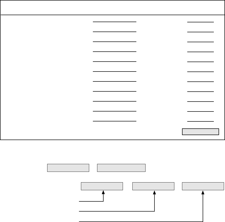
INSTALLATION-CONFIGURATION
SECTION 100-816-203
MARCH 1993
3-19
DK16 WORKSHEET 4, SYSTEM POWER CHECK
Equipment Type: Equipment
Quantity XPower Used
(Factor) = Ports Used
2000- and 1000-series digital telephone
2000-series electronic telephone
3000-series electronic telephone
6000-series electronic telephone
6005-series electronic telephone
6500-series electronic telephone
DDSS/HDSS console*
PDIU-DI2 and PDIU-DI
PDIU-DS
Standard telephone
Add-on Module
X
X
X
X
X
X
X
X
X
X
X
(1.0)
(2.0)
(2.5)
(2.0)
(2.0)
(1.0)
(0.8)
(0.5)
(0.8)
(1.0)
(0.4)
=
=
=
=
=
=
=
=
=
=
=
.
.
.
.
.
.
.
.
.
.
.
Total Power Used
Total Power Used:
* All series.
Power Criteria:
Power Supplied Must be greater than zero.
Configuration Power Check:
Power Supplied
Total Power Used
Must be Greater than Zero
—
—=
Total Power Used:
24.8


INSTALLATION-DK8 KSU & PCB
SECTION 100-816-204
MARCH 1993
INSTALLATION
CHAPTER FOUR
DK8 KSU AND PCB INSTALLATION
TOSHIBA SYSTEM PRACTICES
DIGITAL KEY TELEPHONE SYSTEMS

INSTALLATION-DK8 KSU & PCB
SECTION 100-816-204
MARCH 1993
4-i
TABLE OF CONTENTS
PARAGRAPH SUBJECT PAGE
PART I
DK8 KSU INSTALLATION ................................................................................... 4-1
1GENERAL .............................................................................................................. 4-1
2KEY SERVICE UNIT MOUNTING ......................................................................... 4-1
2.00 Mounting Surface Considerations ...................................................................... 4-1
2.10 Mounting Preparation ......................................................................................... 4-1
2.20 Mounting the Key Service Unit ........................................................................... 4-4
2.30 Installing the Reserve Power Battery and Charger (HPFB) ................................ 4-4
3POWER SUPPLY TEST REMOVAL AND REPLACEMENT .................................. 4-5
3.10 Power Supply Removal ...................................................................................... 4-5
3.20 Power Supply Replacement ............................................................................... 4-5
4DK8 POWER FAILURE EMERGENCY TRANSFER OPTION ............................... 4-5
4.10 DK8 Power Failure Emergency Transfer Installation .......................................... 4-5
4.20 DK8 Power Failure Emergency Transfer Test..................................................... 4-5
PART II
DK8 PRINTED CIRCUIT BOARD INSTALLATION ............................................... 4-9
5GENERAL .............................................................................................................. 4-9
6PCB INSTALLATION CONSIDERATIONS ............................................................ 4-9
6.10 KSU Option PCBs .............................................................................................. 4-9
6.20 PCB Option Considerations................................................................................ 4-9
6.30 PCB Installation/Power Supply Considerations................................................... 4-9
7CO LINE/DIGITAL TELEPHONE INTERFACE UNIT (QCDU) ............................... 4-9
7.00 General ............................................................................................................... 4-9
7.10 QCDU Configuration........................................................................................... 4-11
7.20 QCDU Installation Procedure ............................................................................. 4-11
7.30 QCDU Wiring ...................................................................................................... 4-12
7.40 QCDU Programming Overview .......................................................................... 4-13
8STANDARD TELEPHONE INTERFACE UNIT (QSTU).......................................... 4-13
8.00 General ............................................................................................................... 4-13
8.10 QSTU Configuration ........................................................................................... 4-13
8.20 QSTU Installation Procedure .............................................................................. 4-13
8.30 QSTU Wiring ...................................................................................................... 4-13
8.40 QSTU Programming Overview ........................................................................... 4-13
9DTMF RECEIVER/ABR TONE DETECTOR UNIT (QRCU) ................................... 4-13
9.00 General ............................................................................................................... 4-13
9.10 QRCU Configuration........................................................................................... 4-14
9.20 QRCU Installation Procedure ............................................................................. 4-14
9.30 QRCU Wiring ...................................................................................................... 4-15
9.40 QRCU Programming Overview .......................................................................... 4-15
10 CONFERENCE CIRCUITS (QCNU) ...................................................................... 4-15
10.00 General ............................................................................................................... 4-15
10.10 QCNU Configuration........................................................................................... 4-15
10.20 QCNU Installation Procedure ............................................................................. 4-15
10.30 QCNU Wiring ...................................................................................................... 4-15
INSTALLATION-DK8 KSU & PCB
SECTION 100-816-204
MARCH 1993
4-ii
TABLE OF CONTENTS (CONTINUED)
PARAGRAPH SUBJECT PAGE
10.40 QCNU Programming Overview .......................................................................... 4-15
11 OPTION INTERFACE UNIT (QSMU)..................................................................... 4-16
11.00 General ............................................................................................................... 4-16
11.10 QSMU Hardware Options ................................................................................... 4-16
11.20 QSMU Configuration .......................................................................................... 4-16
11.30 QSMU Installation Procedure ............................................................................. 4-16
11.40 QSMU Wiring...................................................................................................... 4-17
11.50 QSMU Programming Overview .......................................................................... 4-17
11.60 Device Communication Parameters ................................................................... 4-17
12 BUILT-IN CO LINE, DIGITAL TELEPHONE AND OTHER CIRCUITS ................... 4-17
12.00 General ............................................................................................................... 4-17
12.10 Built-in CO Line Circuits ..................................................................................... 4-17
12.20 Built-In Digital Telephone Circuits ...................................................................... 4-17
12.30 KSU Motherboard CO Line/Digital Station Circuit Wiring ................................... 4-17
12.40 Power Failure Telephone Installation ................................................................. 4-17
12.50 Music-On-Hold (MOH)/Background Music (BGM) Source Connection ............... 4-17
12.60 External Page Output Connection ...................................................................... 4-17
FIGURE LIST
FIGURE TITLE PAGE
4-1 DK8 KEY SERVICE UNIT WALL MOUNT METHOD ............................................. 4-1
4-2 DK8 DIMENSIONS AND SCREW LOCATIONS ..................................................... 4-2
4-3 DK8 SIDE VIEW DIMENSION AND PLUG/JACK LOCATIONS ............................. 4-3
4-4 DK8 CABLING DIAGRAM ...................................................................................... 4-6
4-5 DK8 BASE UNIT JACKS AND CONNECTORS...................................................... 4-7
4-6 DK8 KEY SERVICE UNIT POWER FAILURE TRANSFER (PFT)
CIRCUIT DIAGRAM ............................................................................................... 4-8
4-7 DK8 PRINTED CIRCUIT BOARD INSTALLATION................................................. 4-10
4-8 QCDU CONTROLS AND INTERFACE CONNECTORS ........................................ 4-11
4-9 MODULAR JACK COVER REMOVAL AND STORAGE......................................... 4-12
4-10 QSTU CONTROLS AND INTERFACE CONNECTORS ......................................... 4-14
4-11 QRCU INTERFACE CONNECTORS ..................................................................... 4-15
4-12 QCNU INTERFACE CONNECTORS ..................................................................... 4-16
4-13 QSMU CONTROLS AND INTERFACE CONNECTORS ........................................ 4-16
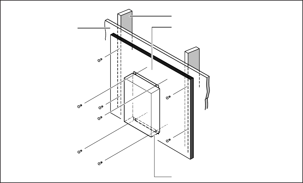
4-1
INSTALLATION-DK8 KSU & PCB
SECTION 100-816-204
MARCH 1993
secure the hard board to the wall, making
certain that screws are aligned with studs.
2.10 Mounting Preparation
1) Loosen the screws on the front cover of the
Key Service Unit, and remove the cover (Figure
4-2).
2) Move the SW1 RAM Storage Battery jumper
plug strap on the motherboard to the ON
position (Figure 4-5).
3) If the DK8 is less than one mile from the central
office (or PBX), set the CO line PAD switches,
SW101 and SW201, to the PAD position to
provide a 3db level loss to avoid excessive
loudness.
4) Install all optional PCBs per Paragraph 5.
FIGURE 4-1
DK8 KEY SERVICE UNIT WALL MOUNT METHOD
STUD
PLASTER
BOARD HARD BOARD
(1/4 INCH PLYWOOD)
DK8 KSU
PART I. KSU INSTALLATION
1 GENERAL
1.00 This chapter provides the instructions nec-
essary to mount the STRATA DK8 Key Service
Unit. Instructions are also provided on how to
remove and replace the power supply.
2 KEY SERVICE UNIT MOUNTING
2.00 Mounting Surface Considerations
2.01 The Key Service Unit (KSU) is designed to be
mounted on a wall or other vertical surface. It is
recommended to use the method shown in Figure
4-1 (see Note). See Figure 4-2 for DK8 KSU
physical dimensions.
NOTE:
Install screws first to the hard board, and then
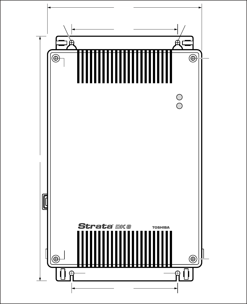
4-2
INSTALLATION-DK8 KSU & PCB
SECTION 100-816-204
MARCH 1993
16.375"
AC
DC
6.875"
10"
WALL
MOUNT
SCREW
WALL
MOUNT
SCREW
FRONT
COVER
SCREW
6.75"
FRONT
COVER
SCREW
FRONT
COVER
SCREW
FRONT
COVER
SCREW
WALL MOUNT
SCREW WALL MOUNT
SCREW
FIGURE 4-2
DK8 DIMENSIONS AND SCREW LOCATIONS
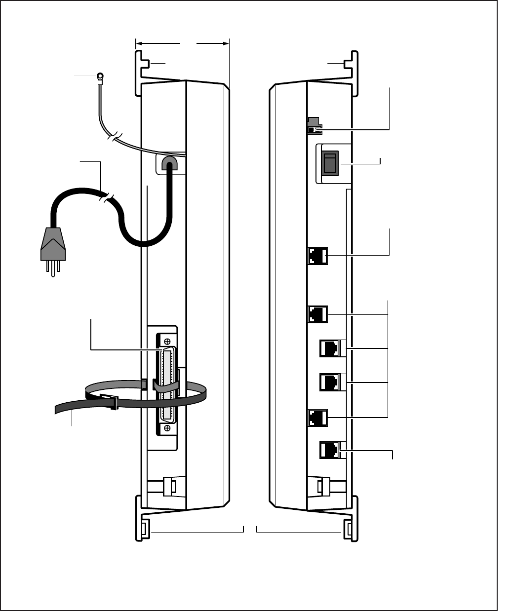
4-3
INSTALLATION-DK8 KSU & PCB
SECTION 100-816-204
MARCH 1993
FIGURE 4-3
DK8 SIDE VIEW DIMENSION AND PLUG/JACK LOCATIONS
TIE-WRAP
HOLDER
TIE-WRAP
HOLDER
TIE-WRAP HOLDER
AC POWER
CORD AND
PLUG 4' 7"
STATION TIP/RING
AMPHENOL 25-PAIR
JACK (FEMALE)
LEFT SIDE VIEW RIGHT SIDE VIEW
6-WIRE SMDR/TTY
MODULAR JACK
RJ11 CO LINE JACKS
DC ON/OFF
POWER SWITCH
RESERVE BATTERY
(HPFB) CONNECTOR
3"
RJ11 POWER FAILURE
TRANSFER JACK
BATT
SMDR/
TTY
TIE WRAP
SUPPLIED WITH
DK8 TO HOLD
AMPHENOL
CONNECTOR
O
—
CO4
CO2
CO1
CO3
PFT
TO HPFB
FG
SCREW
4-4
INSTALLATION-DK8 KSU & PCB
SECTION 100-816-204
MARCH 1993
2.20 Mounting the Key Service Unit
1) Make sure the power supply switch is turned
OFF.
2) Place the Key Service Unit on the desired
location on the mounting surface and mark the
location of the four screw holes (there is one
on each corner). See Figures 4-1 and 4-2.
NOTE:
Make sure the location of the Key Service
Unit meets the minimum clearance require-
ments specified in Figure 2-1 in Chapter 2.
3) Drill holes on these marks.
4) Secure screws approximately two thirds of the
way into the top two holes on the mounting
surface.
5) Hang the unit from the top two screws and
then secure the screws completely into the
mounting surface.
6) Finish securing the unit to the mounting sur-
face by completely screwing the bottom two
screws into the wall.
7) Ground system according to Chapter 2, Para-
graph 4.
8) Connect applicable wiring (modular CO line
cords, 25-pair amphenol connector cable, etc.)
to the Key Service Unit. Route the wiring as
shown in Figure 4-4, and then fasten wiring to
the unit with the tie wraps that come with the
Key Service Unit. (See Section 100-816-208,
for additional wiring information.)
NOTE:
Figure 4-4 shows cables routed to the right;
they may also be routed to the left, depending
on the location of the MDF.
9) If the Reserve Power Battery and Charger
(HPFB) is going to be installed, refer now to
Paragraph 2.30. If not, proceed to Step 10.
10) Plug the AC power cable into an outlet and
then turn ON the DC power supply switch.
11) Reinstall the front cover onto the Key Service
Unit.
2.30 Installing the Reserve Power Battery
and Charger (HPFB) (Figure 4-4)
1) Place the HPFU directly above the DK8 KSU.
2) Mark the location of the two screw holes, then
drill holes.
3) Screw the two screws two-thirds into the mount-
ing surface.
4) Hang the HFPU on the screws then tighten the
screws into the mounting surface.
5) Plug the first HPFU connector into BATT con-
nector on the right side of the KSU.
6) Connect a ground wire from the HPFB "FG"
screw to the DK8 QPSU8 screw labeled
"HPFB6." The ground wire can be fed through
the opening by the AC power cord (see Figure
4-3).
NOTE:
The DK8 should be plugged into AC power
and the DC power switch should be turned
on. The HFPU will not start to operate if AC
power is not available during the initial instal-
lation.
7) The 24V LED on the HPFU should light. If it
does not light, press the battery OFF switch
with a pencil point or other small-tipped object.
8) Dress and tie-wrap the HPFU cables per Fig-
ure 4-4.
9) To mount a second HPFU, repeat steps 1~4,
then plug the second HPFU connector in the
first HPFU and connect an FG wire between
each HPFB FG screw.
10) To test the HPFU, remove the DK8 AC plug
from the AC outlet. The DK8 AC LED will go
out but the DK8 DC LED remains on, also the
system remains in normal working order and
the HPFU 24V LED remains on.
11) If it is desired to turn off the HPFU (after loss
of AC power), use a pencil or other sharp
object to press the Battery Off switch.
CAUTION!
Once the HPFU is turned off or unplugged
(During AC power loss) it will not operate
again until AC power is restored to the
DK8 KSU.
4-5
INSTALLATION-DK8 KSU & PCB
SECTION 100-816-204
MARCH 1993
3 POWER SUPPLY REMOVAL AND
REPLACEMENT
3.00 The power supply comes factory-installed in
the Key Service Unit (Figure 4-5); if necessary, it
can be removed and replaced.
3.10 Power Supply Removal (Figure 4-5)
1) Make sure that the power supply switch is OFF
and that the AC power cable is not plugged
into an outlet. Confirm that green AC LED is
not lit.
2) Loosen the screws on the front cover of the
Key Service Unit, and remove the cover.
3) Unplug HPFB cable from BATT connector of
power supply and disconnect the HPFB ground
wire (Figure 4-5).
4) Unplug the AC cable from the CN1 connector
on the power supply (Figure 4-5).
5) Remove the FG screw, and disconnect the
green third wire ground ring terminal (Figure
4-5).
6) Unplug the DC cable from the CN3 connector
on the power supply (Figure 4-5).
7) Remove the top two, and bottom left corner
screws that attach the power supply to the Key
Service Unit. Remove power supply.
3.20 Power Supply Replacement (Figure 4-5)
1) Set the power supply in its proper place in the
Key Service Unit (Figure 4-5).
2) Secure the power supply to the Key Service
Unit with the top two, and bottom left corner
screws.
3) Install the green third wire ground ring terminal
with the FG screw.
4) Plug the AC cable into the CN1 connector on
the power supply (Figure 4-5).
5) Plug the DC cable into the CN3 connector on
the power supply (Figure 4-5).
6) Plug the AC power cable into an outlet and
turn ON the power supply switch.
7) Test QPSU8 power supply according to the
DK8 Hardware Fault Isolation procedure, Sec-
tion 100-816-500, Paragraph 6.
8) Plug HPFB cable into BATT connector of
power supply and reconnect the HPFB ground
wire (Figure 4-5).
9) Reinstall the cover on the key service unit.
4 DK8 POWER FAILURE EMERGENCY
TRANSFER OPTION
4.00 A dedicated standard telephone can be con-
nected to the Power Failure Transfer Interface
(PF1) on the Key Service Unit to provide power
failure backup. During normal operation, this tele-
phone cannot be used—it does not count as a
station; so it does not reduce the system's 10
maximum station capacity. But if there is a power
failure, the telephone will automatically be con-
nected to CO line 1. When power is restored, the
system will automatically resume with its normal
station and CO line assignments, and the dedi-
cated telephone will become inoperative again.
4.10 DK8 Power Failure Emergency Transfer
Installation. Install the dedicated emergency stan-
dard telephone as follows (see Figure 4-6):
1) Connect a standard telephone to the PF1
connector in the Base Unit.
4.20 DK8 Power Failure Emergency Transfer
Test.
1) Turn the system power switch off.
2) Lift the emergency standard telephone hand-
set, and verify that there is CO dial tone.
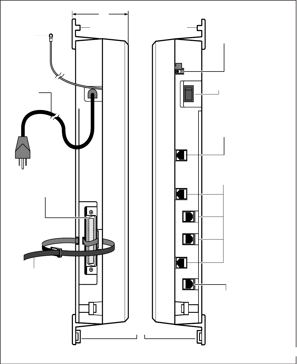
4-6
INSTALLATION-DK8 KSU & PCB
SECTION 100-816-204
MARCH 1993
FIGURE 4-4
DK8 CABLING DIAGRAM
TIE-WRAP
HOLDER
TIE-WRAP
HOLDER
TIE-WRAP HOLDER
AC POWER
CORD AND
PLUG 4' 7"
STATION TIP/RING
AMPHENOL 25-PAIR
JACK (FEMALE)
LEFT SIDE VIEW RIGHT SIDE VIEW
6-WIRE SMDR/TTY
MODULAR JACK
RJ11 CO LINE JACKS
DC ON/OFF
POWER SWITCH
RESERVE BATTERY
(HPFB) CONNECTOR
3"
RJ11 POWER FAILURE
TRANSFER JACK
BATT
SMDR/
TTY
TIE WRAP
SUPPLIED WITH
DK8 TO HOLD
AMPHENOL
CONNECTOR
O
—
CO4
CO2
CO1
CO3
PFT
TO HPFB
FG
SCREW
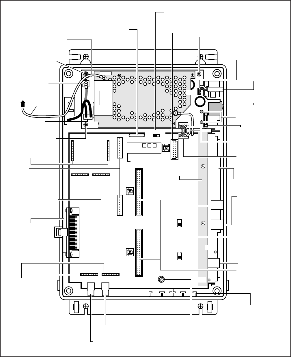
4-7
INSTALLATION-DK8 KSU & PCB
SECTION 100-816-204
MARCH 1993
FIGURE 4-5
DK8 BASE UNIT JACKS AND CONNECTORS
WARNING
Hazardous voltage inside !
If servicing required,
remove A.C. cord.
QMA
ROM
IC5
J16
RCU
J15
SW1
ON OFF
J17
CONF
J18
CONF
J11 J14
J10 CDU
PAD NOR
SW201
J9 CDU
PAD NOR
SW101
STU
J12
STU
J13
VR701
J20
AC
DC
CN3
J19
J2
J1
C01
QMAU1A
J7 J8
STU STU
J3
C02
PIN 1
42
CN3, J19
POWER SUPPLY
CONNECTORS
AND CABLE
J2, CO LINE 1
MODULAR JACK
(RJ11)
J1, POWER FAILURE
TELEPHONE
MODULAR JACK
(RJ11)
F.G. SCREW FOR
THIRD WIRE
GROUND
CONNECTION TO
POWER SUPPLY
QPSU8 POWER SUPPLY
POWER SUPPLY
MOUNTING SCREW
J15, J16
CONNECTOR FOR
QSTU INSTALLATION
ACN1
POWER CORD
CONNECTOR
25-PAIR FEMALE
AMPHENOL
CONNECTOR (TO
STATION TIP/RING
AND RELAY
CONTACT)
J12, J13
CONNECTORS
FOR QSTU
INSTALLATION
J7, MUSIC-ON-HOLD RCA JACK
J8, EXTERNAL
PAGE RCA JACK VR701 MOH VOLUME
CONTROL SCREW
ADJUSTER
DK8 MAIN PRINTED
CIRCUIT BOARD
J9, J10
CONNECTORS
FOR QCDU(S)
INSTALLATION
(1-PER QCDU)
MODULAR JACK
COVER HOLDERS
(FOR STORAGE OF
MODULAR JACK
COVERS)
J17, J18
CONNECTOR FOR
QCNU INSTALLATION
J11, J14
CONNECTOR FOR
QSTU INSTALLATION
SW101 (CO1)
SW201 (CO2):
3-db PAD
SWITCHES FOR
CO LINE 1 AND 2
POWER SUPPLY
MOUNTING SCREW
RAM STORAGE BATTERY JUMPER PLUG
RAM STORAGE
BATTERY J20-CONNECTOR FOR QSMU
PCB INSTALLATION
CN4, BATTERY
CONNECTOR PLUG
BATTERY
CONNECTOR
FOR HPFB
DC POWER
ON/OFF SWITCH
AC AND DC
POWER
INDICATOR LEDs
F201, 3 AMP FUSE
NON-REPLACABLE
YELLOW
WIRES (+24V)
POWER SUPPLY
MOUNTING SCREW
FG
CN4
PF1
HPFB6
HPFB
GROUND
WIRE
TO HPFB6
FG SCREW
CN1
J3, CO LINE 2
MODULAR JACK
(RJ11)
FG1A
FG1A
SYSTEM FRAME
GROUND BAR
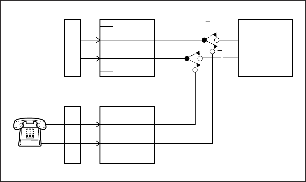
4-8
INSTALLATION-DK8 KSU & PCB
SECTION 100-816-204
MARCH 1993
FIGURE 4-6
DK8 KEY SERVICE UNIT POWER FAILURE TRANSFER (PFT) CIRCUIT DIAGRAM
4
3
MOD JACK CO1
(KSU)
MDF
CO
LINE
5
2
MOD JACK PF1
(BASE UNIT)
R
T
MDF
PFT
STANDARD
TELEPHONE
DK8 OR DK16
KSU MAIN PCB
T
R
POWER FAIL
CONNECTION
POWER AVAILABLE
CONNECTION
KCOU
CO LINE 1
INSTALLATION-DK8 KSU & PCB
SECTION 100-816-204
MARCH 1993
4-9
PART II. PRINTED CIRCUIT BOARD
INSTALLATION
5 GENERAL
5.01 This chapter provides procedures for installa-
tion of STRATA DK8 system optional printed circuit
boards (PCBs) into the Key Service Unit. This
includes installation instructions, optional configu-
ration information, and wiring and programming
considerations for each PCB.
5.02 Be sure the ground has been checked. (See
Chapter 2 for grounding.)
6 PCB INSTALLATION
CONSIDERATIONS
6.01 The STRATA DK8 KSU comes standard with
four digital telephone circuits (ports) and two CO
line circuits. These circuits, along with the common
control unit, are built into the motherboard.
6.10 KSU Option PCBs
6.11 The KSU can support up to five optional
printed circuit boards (PCBs) (Figure 4-7): it can
support a maximum of two QCDUs, each of which
provides one CO line circuit and two digital tele-
phone circuits; a QSTU which provides two stan-
dard telephone circuits (ports); a QRCU which
provides three circuits to receive DTMF tones
(required for DISA and devices connected to
QSTUs), and three circuits to detect busy tone
(required for the ABR feature); and a QSMU which
provides a port for either a Station Message Detail
Recording (SMDR) device or a maintenance termi-
nal or modem (System Program 10-3, LED 04)
selects the function of the port — SMDR or TTY).
6.12 The KSU does not come from the factory with
any option PCBs installed. Each of the option
PCBs listed above must be installed in specific
locations as described later in this chapter.
NOTE:
QCNU is a standard factory installed piggy-
back PCB which provides conference circuits
allowing two simultaneous conferences with
four of these parties on the first conference
call and three parties on the second simulta-
neous conference.
6.20 PCB Option Considerations
6.21 PCBs may be configured for a variety of
hardware and software options. Hardware options
are defined as either internal (generally related to
optional PCB subassemblies) or external (related
to connection of peripheral equipment such as
background music, voice mail, etc). Hardware and
software options for each PCB are identified in the
individual PCB installation procedures in this chap-
ter.
6.22 PCB Hardware Options. Each PCB must be
configured for the applicable hardware options
prior to installation of the PCB. Configuration in-
structions for internal hardware options are pro-
vided in the individual PCB installation procedures
in this chapter. Configuration instructions for exter-
nal hardware options are provided in Peripheral
Installation, Section 100-816-207.
6.23 PCB Software Options. PCBs are config-
ured for software options through programming,
after installation of the PCBs in the KSU. A pro-
gramming overview for each PCB is provided in the
individual PCB installation procedures in this chap-
ter. Refer to the Programming Procedures, Section
100-816-300, for detailed programming instruc-
tions.
6.30 PCB Installation/Power Supply Consid-
erations
6.31 Whenever removing or installing PCBs it is
recommended that the power supply be OFF.
7 CO LINE/DIGITAL TELEPHONE
INTERFACE UNIT (QCDU)
7.00 General
7.01 The QCDU provides one loop start CO line
circuit and two digital telephone circuits. The QCDU
digital telephone circuits can support digital tele-
phones, PDIU-DIs/PDIU-DI2s or ADMs connected
to the telephones and PDIU-DSs. The QCDU does
not support a DDSS console or DDCB. A maximum
of two QCDU PCBs may be installed in the KSU.
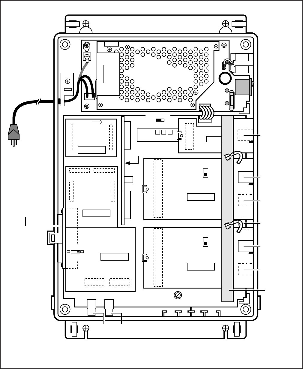
INSTALLATION-DK8 KSU & PCB
SECTION 100-816-204
MARCH 1993
4-10
FIGURE 4-7
DK8 PRINTED CIRCUIT BOARD INSTALLATION
QCDU1A
QCDU1A
QMA
ROM
IC5
J16
RCU
J15
QSTS1A
QCNU1A
MOH
JACK 600Ω
PAGE
SW1
ON OFF
CONF
J1
J17
CONF
J2
J18
J1
J11
J4
J14
J7
J5
J6
J8
J2J1
J10
J1
CDU
PAD NOR
SW101
F.G.
CO4
F.G.
J9
J1
CDU
PAD NOR
SW101
SW1
190 130
J2
STU
J12
J3
STU
J13
QSTU1A
VR701
STU STU
BATT
COMPONENT SIDE
PIN 1
RIGHT
QSMU1A
SMDR
J2
J20
WARNING
Hazardous voltage inside !
If servicing required,
remove A.C. cord.
(MOH VOLUME
CONTROL)
CO3
HPFB6
AC
DC
CO2
CO1
PFT, RJ11
MODLULAR
JACK
SMDR/TTY
3-PAIR
MODULAR
JACK
J6-25-PAIR
AMPHENOL
JACK FOR
TELEPHONE
TIP/RING AND
RELAY
CONTACT
(FEMALE)
SYSTEM
FRAME
GROUND
BAR
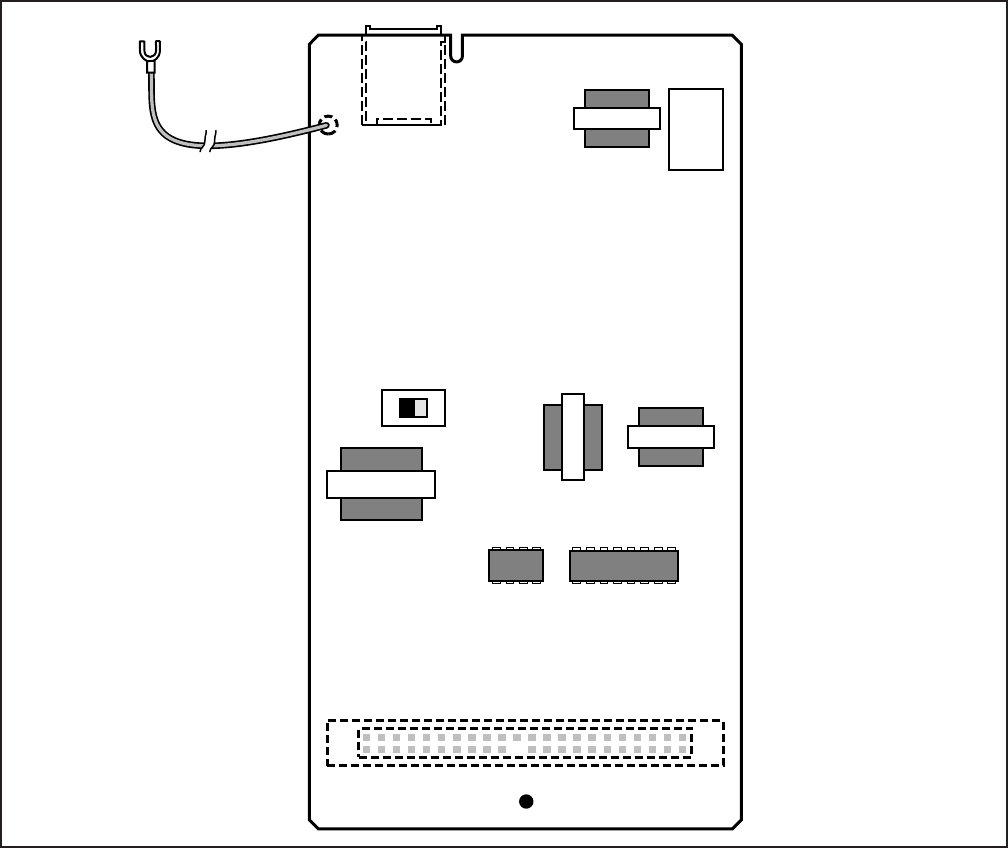
INSTALLATION-DK8 KSU & PCB
SECTION 100-816-204
MARCH 1993
4-11
FIGURE 4-8
QCDU CONTROLS AND INTERFACE CONNECTORS
7.02 The QCDU is shown in Figure 4-8.
7.10 QCDU Configuration
7.11 The QCDU may have to be configured to
control excessive loudness if the system is close to
a CO or installed behind a PBX telephone system.
It does not have to be configured for anything else.
The decibel (db) PAD switch, SW101 controls the
loudness by providing a 3 db signal level drop to, or
from, the PBX or CO when set to the PAD position.
The switch comes from the factory set at NOR (for
normal) meaning no PAD loss.
7.20 QCDU Installation Procedure
7.21 Install the QCDU in accordance with the
following steps (Figure 4-7):
1) Remove the PCB from its protective packag-
ing.
2) If the system is located within one mile of the
CO or PBX telephone system, set db PAD
switch SW101 to the PAD position.
3) Make sure that the power supply switch is
OFF.
FG
J2
CO 3/4
PAD NOR
J1
TO SYSTEM FRAME
GROUND BAR
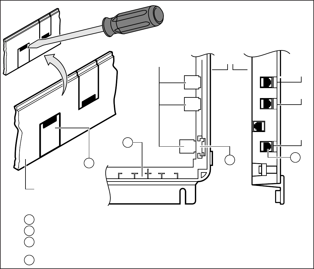
INSTALLATION-DK8 KSU & PCB
SECTION 100-816-204
MARCH 1993
4-12
FIGURE 4-9
MODULAR JACK COVER REMOVAL AND STORAGE
4) Slide front edge and FG wire of QCDU under
the "System Frame Ground Bar", align and
insert QCDU connector J1 into the motherboard
connector (J9 for CO3 first, J10 for CO4
second), and apply firm, even pressure to
ensure proper mating of the connectors. Make
sure the edge of the QCDU next to the connec-
tor J1 snaps firmly into the standoffs on the
KSU motherboard.
5) Connect the Frame Ground (FG) lead from the
QCDU to the screw nearest the QCDU located
on the system Frame Ground bar.
6) Remove the "knock-out" from the KSU cover
CO3 or CO4 access slot, and store the "knock-
out" in the slots provided in the KSU base
(Figure 4-9).
7.30 QCDU Wiring
7.31 Refer to the DK8 MDF to CO Line Wiring
Diagram in Section 100-816-208 for wiring/inter-
connecting details.
KNOCK OUT JACK COVER WHEN OCDU, SMDR/TTY IS INSTALLED
TAKE OUTJACK COVER WHEN PFT IS CONNECTED
STORE THE JACK COVER THAT HAS BEEN TAKEN OUT IN THE JACKCOVER
HOLDER
REINSTALL THE JACK COVER WHEN THE PFT TELEPHONE IS UNPLUGGED
MODULAR
JACK BASE
C02
COVER
C01
PFT
12
3
2
1
3
4
4

INSTALLATION-DK8 KSU & PCB
SECTION 100-816-204
MARCH 1993
4-13
7.40 QCDU Programming Overview
7.41 The following parameters may be specified,
through programming, for the QCDU.
Program 10-1
Allows/denies two-CO Line Conference and Di-
rect Inward System Access (DISA).
Program 15
Auto Release detection; DISA, and other at-
tributes to the CO line.
Program 16
Assigns CO line to groups 81 ~ 84, and dial 9
group.
Program 40
Assigns stations access to CO line (incoming
and outgoing access).
8 STANDARD TELEPHONE
INTERFACE UNIT (QSTU)
8.00 General
8.01 The QSTU provides two standard telephone
circuits. The QSTU supports two-wire devices such
as standard telephones, Auto Attendant devices,
separate BGM source connection, voice mail ma-
chines, and facsimile machines.
NOTE:
For the system to recognize the Dual-Tone
Multi-Frequency (DTMF) tones generated by
standard telephones (or any other device con-
nected to a QSTU port), a QRCU must be
installed.
8.02 The QSTU is shown in Figure 4-10. Note that
the QSTS PCB is factory installed on the QSTU.
8.10 QSTU Configuration
8.11 The QSTU only has to be configured for the
ring generator voltage level, nothing else. Before
installing the QSTU in the KSU, set the SW1 ring
generator to 130V P-P or 190V P-P (Figure 4-10).
Most standard telephones and two-wire devices
require 190; however, some devices may experi-
ence ring-trip at 190, and should be set at 130.
8.20 QSTU Installation Procedure
8.21 Install the QSTU in accordance with the fol-
lowing steps (Figure 4-7):
1) Remove the PCB from its protective packag-
ing.
2) Set the ring voltage jumper plug SW1 to select
the appropriate ring generator voltage level,
either 130V P-P or 190V P-P.
3) Make sure that the power supply switch is
OFF.
4) Align and insert QSTU connectors J1, J2, J3,
and J4 motherboard connectors J11, J12,
J13, and J14 respectively, and apply firm,
even pressure to ensure proper mating of the
connectors.
8.30 QSTU Wiring
8.31 Refer to DK8 MDF to KSU Amphenol Wiring in
Section 100-816-208 for QSTU wiring.
8.32 The QSTU must be connected to a OL13A (or
equivalent) type lines for off-premises stations.
(300 ohms loop resistance max., including the
telephone or other devices DC off hook resistance.)
8.40 QSTU Programming Overview
8.41 The following parameters may be specified for
the QSTU:
Program 31
Used to configure all QSTU ports connected to
voice mail (see Chapter 7 for voice mail installa-
tion).
Program 10-2
Used to set standard telephone ringing option
and separate BGM assignment.
NOTE:
QSTU Ports are fixed. They are assigned
even if a QSTU is not installed.
9 DTMF RECEIVER/ABR TONE
DETECTOR UNIT (QRCU)
9.00 General
9.01 The QRCU must be installed to recognize
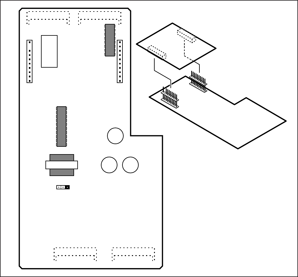
INSTALLATION-DK8 KSU & PCB
SECTION 100-816-204
MARCH 1993
4-14
FIGURE 4-10
QSTU CONTROLS AND INTERFACE CONNECTORS
J4J1
J3
J5 J6
SW1
190 130
QSTS
QSTU
QSTS
FACTORY
INSTALLED
J2
Dual-Tone Multi-Frequency (DTMF) tones gener-
ated by a standard telephone (or any other device
connected to a standard telephone circuit (QSTU)),
and it is required for Direct Inward System Access
(DISA) calls. The QRCU circuits are also used to
detect busy tone for the Automatic Busy Redial
(ABR) feature and must be installed to allow ABR
to operate.
9.02 The QRCU is shown in Figure 4-11.
9.10 QRCU Configuration
9.11 The QRCU does not have to be configured for
operation.
9.20 QRCU Installation Procedure
9.21 Install the QRCU in accordance with the
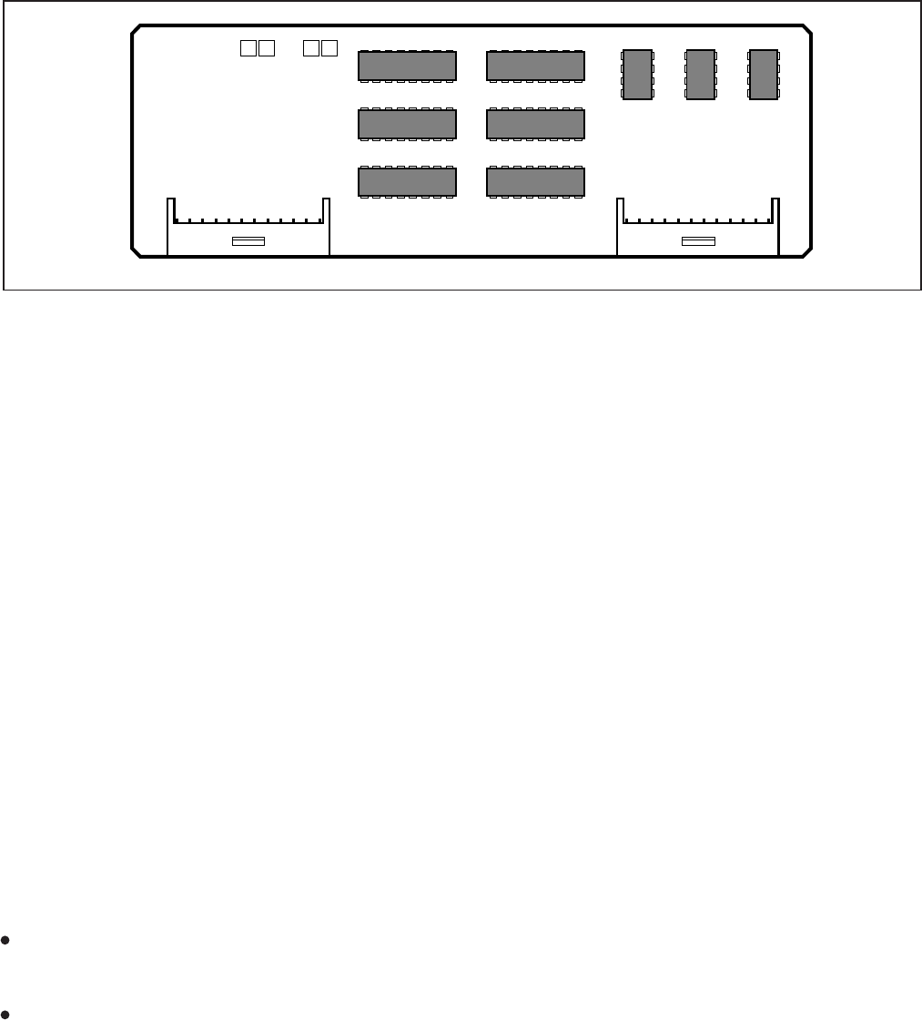
INSTALLATION-DK8 KSU & PCB
SECTION 100-816-204
MARCH 1993
4-15
J1 J2
DK8RCU1A V.1
FIGURE 4-11
QRCU INTERFACE CONNECTORS
following steps (Figure 4-7).
1) Remove the PCB from its protective packag-
ing.
2) Make sure that the power supply switch is
OFF.
3) Align and insert QRCU connectors J1 and J2
into motherboard connectors J15 and J16
respectively (note the component side place-
ment in Figure 4-7), and apply firm, even
pressure to ensure proper mating of connec-
tors. Push down until connectors lock together.
9.30 QRCU Wiring
9.31 The QRCU does not require any wiring.
9.40 QRCU Programming Overview
9.41 The following parameters may be specified:
Program 12
Set QRCU release time.
Program 15
Sets QRCU operation after CO line flash.
10 CONFERENCE CIRCUITS (QCNU)
10.00 General
10.01 The QCNU provides two conference circuits
which allow two simultaneous conferences (one
four-party and one three-party). The QCNU is stan-
dard and is installed at the factory. If it is necessary
to remove and replace the QCNU, turn the system
off, remove the QCNU, and install another QCNU
per paragraph 10.20.
10.02 The QCNU is shown in Figure 4-7.
10.10 QCNU Configuration
10.11 The QCNU does not have to be configured
for operation.
10.20 QCNU Installation Procedure
10.21 Install the QCNU in accordance with the
following steps (Figure 4-7):
1) Remove the PCB from its protective packag-
ing.
2) Make sure that the power supply switch is
OFF.
3) Align and insert QCNU connectors J1 and
J2 into motherboard connectors J17 and
J18 respectively, and apply firm, even pres-
sure to ensure proper mating of connectors.
(Note the side with “
➝
RIGHT” silkscreened
on it should be positioned as shown in Fig-
ure 4-7.)
10.30 QCNU Wiring
10.31 The QCNU does not require any wiring.
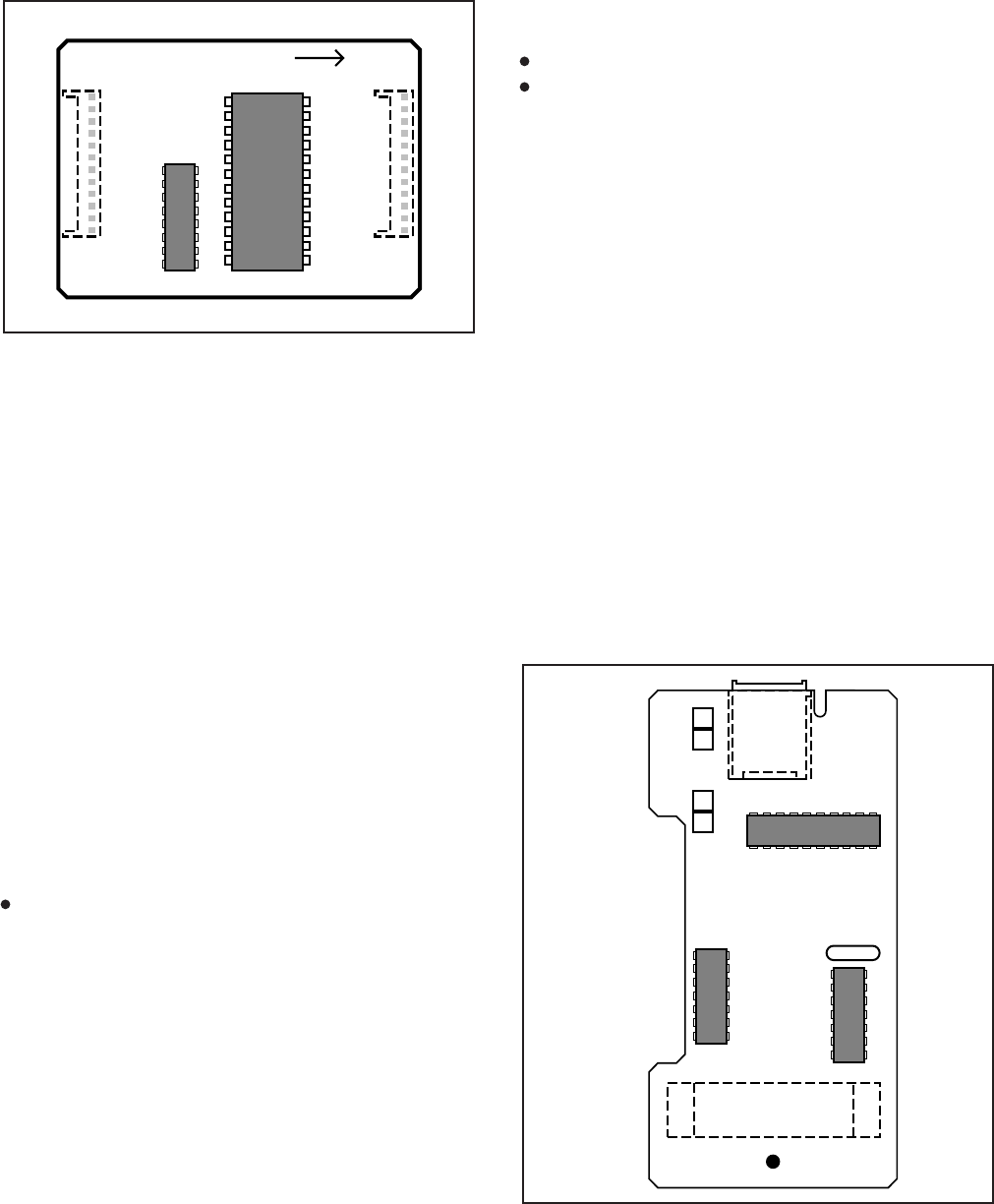
INSTALLATION-DK8 KSU & PCB
SECTION 100-816-204
MARCH 1993
4-16
J1J2
RIGHT
Maintenance Terminal (TTY) or modem; and in
System Prograrm 10-3:
LED 04 ON — TTY
LED 04 OFF — SMDR
11.30 QSMU Installation Procedure
11.31 Install the QSMU in accordance with the
following steps (See Figure 4-7):
1) Remove the PCB from its protective packag-
ing.
2) Ensure the QSMU has been configured for the
appropriate program options (refer to Para-
graphs 11.10 and 11.20).
3) Slide the QSMU under the "System Frame
Ground Bar", align and insert QSMU connec-
tor J2 into motherboard connector J20, ensur-
ing the side of the QSMU with the modular
connector goes on the right side. (The QSMU
is not silkscreened “
➝
RIGHT”.) Apply firm,
even pressure to ensure proper mating of
connectors. Make sure the edge of the QSMU
opposite connector J2 snaps firmly into the
standoffs on the KSU motherboard.
FIGURE 4-13
QSMU CONTROLS AND INTERFACE CONNECTORS
10.40 QCNU Programming Overview
10.41 The QCNU does not require any program-
ming.
11 OPTION INTERFACE UNIT (QSMU)
11.00 General
11.01 The QSMU provides a circuit interface with
peripheral options.
11.02 The QSMU is shown in Figure 4-13.
11.10 QSMU Hardware Options
11.11 The QSMU supports the following STRATA
DK8 external hardware options:
SMDR output or TTY (maintenance) port two-
way interface.
NOTE:
Refer to Peripheral Equipment Installation,
Section 100-816-207, for installation of SMDR
and the Remote Maintenance Section 100-
816-600 for TTY.
11.20 QSMU Configuration
11.21 The QSMU must be configured for operation
with the appropriate external hardware: either an
SMDR printer or call accounting device; Remote
8B
8A
1B
1A
QSMU1A V.1
J1
FIGURE 4-12
QCNU INTERFACE CONNECTORS

INSTALLATION-DK8 KSU & PCB
SECTION 100-816-204
MARCH 1993
4-17
are integrated into the KSU motherboard and are
identical to the QCDU CO line circuits. For wiring
and programming considerations, see the QCDU
instructions in Paragraph 7.
12.20 Built-in Digital Telephone Circuits
12.21 The four digital telephone circuits that come
standard with the system are integrated into the
motherboard in the KSU. These circuits are identi-
cal to the digital circuits found on the QCDU. The
motherboard does not have to be configured for the
digital circuits to operate. For wiring and program-
ming considerations, see the QCDU instructions in
Paragraph 7.
12.30 KSU Motherboard CO Line/Digital
Station Circuit Wiring
12.31 Refer to Section 100-816-208 for details.
Station circuits: DK8 MDF to KSU Amphenol
Wiring Diagram
CO lines: DK8 MDF TO CO Line (KSU and
QCDU) Wiring Diagram
12.40 Power Failure Telephone Installation
1) Remove the RJ11 cover (Figure 4-9) from the
PFT jack and store the jack cover.
2) Connect the power failure telephone (500/
2500-type standard telephone to the PFT jack.
(Refer to the DK8 MDF to CO Line Wiring
Diagram in Section 100-816-208.
12.50 Music-On-Hold (MOH)/Background
Music (BGM) Source Connection
12.51 Connect the MOH/BGM source to the MOH
RCA jack (Figure 4-7) in accordance with Music
Source Configuration A in Section 100-816-207.
12.60 External Page Output Connection
12.61 Connect the external page system to the
600Ω PAGE RCA output jack (Figure 4-7) to an
external amplifier in accordance with the External
Page Installation guidelines in Section 100-816-
207.
4) Remove the "knock-out" from the KSU cover
SMDR/TTY access slot, and store the "knock-
out" in the slots provided in the KSU base
(Figure 4-9).
11.40 QSMU Wiring
11.41 Refer to Peripheral Equipment Installation
(Section 100-816-207, SMDR) and Remote Main-
tenance (Section 100-816-600, TTY) for QSMU
wiring/interconnecting details.
11.50 QSMU Programming Overview
11.51 The following parameters may be specified,
through programming, for the QSMU:
Program 60
Assigns SMDR options.
Program 10-3
LED04-SMDR/TTY Select option.
11.60 Device Communication Parameters
11.61 Set the communication parameters for the
device connected tot he QSMU SMDR/TTY jack as
follows:
TTY: 7 Bits, 1-Stop Bit, Even Parity
SMDR: 8 Bits, 1-Stop Bit, Odd Parity
TTY/SMDR: 1200 bps
12 BUILT-IN CO LINE, DIGITAL TELE-
PHONE, AND OTHER CIRCUITS
12.00 General
12.01 As mentioned in Paragraph 6, the KSU
comes standard with two CO lines and four digital
telephone circuits already installed.
12.10 Built-in CO Line Circuits
12.11 The two standard loop start CO line circuits

INSTALLATION-INTRODUCTION
SECTION 100-816-205
MARCH 1993
INSTALLATION
CHAPTER FIVE
DK16 KSU AND PCB INSTALLATION
TOSHIBA SYSTEM PRACTICES
DIGITAL KEY TELEPHONE SYSTEMS

INSTALLATION-INTRODUCTION
SECTION 100-816-205
MARCH 1993
INSTALLATION-DK16 KSU & PCB
SECTION 100-816-205
MARCH 1993
5-i
TABLE OF CONTENTS
PARAGRAPH SUBJECT PAGE
PART I
DK16 KSU INSTALLATION .................................................................................... 5-1
1GENERAL ................................................................................................................ 5-1
2DK KEY SERVICE UNIT MOUNTING ..................................................................... 5-1
2.00 Mounting Surface Considerations ........................................................................ 5-1
2.10 Mounting Preparation ........................................................................................... 5-1
2.20 Mounting the Base Key Service Unit .................................................................... 5-1
2.30 Mounting the Expansion Key Service Unit ........................................................... 5-4
2.40 Reserve Power Failure Options............................................................................ 5-10
3POWER SUPPLY REMOVAL AND REPLACEMENT ............................................. 5-11
3.10 Power Supply Removal ........................................................................................ 5-11
3.20 Power Supply Replacement ................................................................................. 5-12
PART II
DK16 PRINTED CIRCUIT BOARD INSTALLATION .............................................. 5-13
4GENERAL ................................................................................................................ 5-13
5PCB INSTALLATION CONSIDERATIONS .............................................................. 5-13
5.10 Base Unit PCBs .................................................................................................... 5-13
5.20 Expansion Unit PCBs ........................................................................................... 5-13
5.30 PCB Option Considerations.................................................................................. 5-13
5.40 PCB Installation/Power Supply Considerations.................................................... 5-14
6BASE UNIT STANDARD TELEPHONE INTERFACE UNIT (KSTU) ........................ 5-14
6.00 General ................................................................................................................. 5-14
6.10 KSTU Configuration.............................................................................................. 5-14
6.20 KSTU Installation Procedure ................................................................................ 5-14
6.30 KSTU Wiring ......................................................................................................... 5-15
6.40 KSTU Programming Overview ............................................................................. 5-15
7DIGITAL TELEPHONE INTERFACE UNIT (PDKU) ................................................ 5-15
7.00 General ................................................................................................................. 5-15
7.10 PDKU Hardware Options...................................................................................... 5-16
7.20 PDKU Installation Procedure ................................................................................ 5-17
7.30 PDKU Wiring ........................................................................................................ 5-17
7.40 PDKU Programming Overview ............................................................................. 5-17
8ELECTRONIC TELEPHONE INTERFACE UNIT (PEKU) ........................................ 5-17
8.00 General ................................................................................................................. 5-17
8.10 PEKU Hardware Options...................................................................................... 5-17
8.20 PEKU Installation Procedure ................................................................................ 5-19
8.30 PEKU Wiring......................................................................................................... 5-20
8.40 PEKU Programming Overview ............................................................................. 5-20
9STANDARD TELEPHONE INTERFACE UNIT (PSTU) ........................................... 5-20
9.00 General ................................................................................................................. 5-20
9.10 PSTU (1 and 2) Hardware Options...................................................................... 5-20
9.20 PSTU Installation Procedure ................................................................................ 5-21
9.30 PSTU Wiring ......................................................................................................... 5-22
9.40 PSTU Programming Overview ............................................................................. 5-22
INSTALLATION-DK16 KSU & PCB
SECTION 100-816-205
MARCH 1993
TABLE OF CONTENTS (continued)
PARAGRAPH SUBJECT PAGE
10 STANDARD/ELECTRONIC TELEPHONE INTERFACE UNIT (PESU).................... 5-22
10.00 General ................................................................................................................. 5-22
10.10 PESU Hardware Options...................................................................................... 5-22
10.20 PESU Installation Procedure ................................................................................ 5-25
10.30 PESU Wiring......................................................................................................... 5-25
10.40 PESU Programming Overview ............................................................................. 5-25
11 CO LINE UNIT (PCOU) ............................................................................................ 5-25
11.00 General 5-25
11.10 PCOU Hardware Options 5-25
11.20 PCOU Installation Procedure ............................................................................... 5-25
11.30 PCOU Wiring ........................................................................................................ 5-26
11.40 PCOU Programming Overview............................................................................. 5-26
12 OPTION INTERFACE UNIT (PIOU AND PIOUS) .................................................... 5-28
12.00 General ................................................................................................................. 5-28
12.10 PIOU and PIOUS Hardware Options.................................................................... 5-28
12.20 PIOU and PIOUS Installation Procedure.............................................................. 5-30
12.30 PIOU and PIOUS Wiring ...................................................................................... 5-30
12.40 PIOU and PIOUS Programming Overview ........................................................... 5-30
13 CO LINE/DIGITAL TELEPHONE INTERFACE UNIT (KCDU) .................................. 5-31
13.00 General ................................................................................................................. 5-31
13.10 KCDU Configuration ............................................................................................. 5-31
13.20 KCDU Installation Procedure................................................................................ 5-32
13.30 KCDU Wiring ........................................................................................................ 5-33
13.40 KCDU Programming Overview ............................................................................. 5-33
14 DTMF RECEIVER/ABR TONE DETECTOR UNIT (K4RCU) .................................... 5-33
14.00 General ................................................................................................................. 5-33
14.10 K4RCU Configuration ........................................................................................... 5-33
14.20 K4RCU Installation Procedure.............................................................................. 5-33
14.30 K4RCU Wiring ...................................................................................................... 5-34
14.40 K4RCU Programming Overview ........................................................................... 5-34
15 BUILT-IN CO LINE AND DIGITAL TELEPHONE CIRCUITS.................................... 5-34
15.00 General ................................................................................................................. 5-34
15.10 Built-in CO Line Circuits ....................................................................................... 5-34
15.20 Digital Telephone Circuits..................................................................................... 5-34
15.30 Base Unit CO Line/Digital Station Circuit Wiring .................................................. 5-34
16 KCOU REMOVAL AND REPLACEMENT ................................................................ 5-35
16.00 General ................................................................................................................. 5-35
16.10 KCOU Removal .................................................................................................... 5-35
16.20 KCOU Replacement ............................................................................................. 5-35
17 DK16 POWER FAILURE EMERGENCY TRANSFER OPTION ............................... 5-36
17.10 DK16 Power Failure Emergency Transfer Installation ......................................... 5-36
5-ii
INSTALLATION-DK16 KSU & PCB
SECTION 100-816-205
MARCH 1993
FIGURE LIST
FIGURE TITLE PAGE
5-1 DK16 BASE KEY SERVICE UNIT EXTERIOR ........................................................ 5-2
5-2 DK16 BASE KEY SERVICE UNIT WALL MOUNTING METHODS .......................... 5-3
5-3 DK16 BASE KEY SERVICE UNIT INTERIOR ......................................................... 5-3
5-4 DK16 BASE KEY SERVICE UNIT WIRING CONNECTIONS .................................. 5-5
5-5 CONNECTING THE DK16 EXPANSION UNIT TO THE DK16 BASE UNIT ............ 5-6
5-6 MOUNTING THE DK16 EXPANSION UNIT ............................................................ 5-7
5-7 DK16 EXPANSION UNIT INTERIOR ....................................................................... 5-8
5-8 DK16 EXPANSION UNIT WIRING CONNECTIONS ............................................... 5-9
5-9 POWER SUPPLY (KPSU) ....................................................................................... 5-11
5-10 BASE UNIT POWER FAILURE TRANSFER (PFT) CIRCUIT DIAGRAM................. 5-12
5-11 KSTU OPTIONS AND CONNECTORS ................................................................... 5-14
5-12 PDKU INTERFACE CONNECTION ......................................................................... 5-16
5-13 PEKU CONTROLS AND INTERFACE CONNECTORS .......................................... 5-18
5-14 OFF-HOOK CALL ANNOUNCE UNIT (EOCU) INTERFACE CONNECTORS......... 5-20
5-15 PSTU AND SUBUNIT (SSTU) ................................................................................. 5-21
5-16 PESU PCB OPTION LOCATION AND IDENTIFICATION ........................................ 5-23
5-17 PCOU CONTROLS, INDICATORS, AND INTERFACE CONNECTORS ................. 5-26
5-18 PIOU CONTROLS, INDICATORS, AND INTERFACE CONNECTORS ................... 5-28
5-19 PIOUS PCB SWITCH/JUMPER, OPTION LOCATION............................................ 5-30
5-20 REMOTE MAINTENANCE MODEM UNIT (IMDU) INTERFACE CONNECTORS ... 5-32
5-21 KCDU INDICATORS, OPTIONS AND CONNECTORS........................................... 5-32
5-22 K4RCU PCB ............................................................................................................. 5-34
5-23 KCOU PCB ............................................................................................................... 5-35
5-24 EMERGENCY STANDARD TELEPHONE INSTALLATION ..................................... 5-36
TABLE LIST
TABLE SUBJECT PAGE
5-A KSTU CONTROLS AND INTERFACE CONNECTORS .......................................... 5-15
5-B PEKU CONTROLS AND INTERFACE CONNECTORS .......................................... 5-19
5-C PSTU CONTROLS AND INTERFACE CONNECTORS .......................................... 5-21
5-D PESU CONTROLS AND INTERFACE CONNECTORS .......................................... 5-24
5-E PCOU CONTROLS, INDICATORS, AND INTERFACE CONNECTORS ................. 5-27
5-F PIOU CONTROLS AND INTERFACE CONNECTORS ........................................... 5-29
5-G PIOUS CONTROLS AND INTERFACE CONNECTORS......................................... 5-31
5-H KCDU CONTROLS, INDICATORS, AND CONNECTORS ....................................... 5-33
5-iii
INSTALLATION-DK16 KSU & PCB
SECTION 100-816-205
MARCH 1993
IMPORTANT INITIAL INSTALLATION NOTES!
These minimum installation steps must be carried out for proper system operation.
1. Set the SW1 switch in the Base Unit ON for BATTERY OPERATION; otherwise, all programmed
customer data will be lost on power down.
2. If required, install KSTU and K4RCU in the Base Unit.
3. If the system is configured with an Expansion Unit, follow the order prescribed below:
a) Install PDKU, PEKU, PSTU, PESU, or KCDU in Slot 04.
b) If installing two KCDUs, install a KCDU in Slot 05. (The other KCDU should be installed in
Slot 04.)
c) If the system is configured with a PCOU, install it in Slot 05. (The system cannot be
configured with both a PCOU and KCDU in the Expansion Unit.)
d) If the system is configured with a PIOU or PIOUS, install it in Slot 06. (Slot 07 should be
reserved for future use.)
4. Initialize Programs 00 ~ 97 by running Program 90.
5. Run Program 92.
6. Enter the hardware configuration with Program 03, exit the programming mode, turn power
OFF for five seconds, then turn power back ON.
WHEN LATER ADDING KSU PCBs
1. Install new PCBs and set the new configuration with Program 03. (Turn power OFF for five
seconds after running Program 03.)
2. Program new features, options, etc. created by new additions.

5-1
INSTALLATION-DK16 KSU & PCB
SECTION 100-816-205
MARCH 1993
PART I. KSU INSTALLATION
1 GENERAL
1.00 This chapter provides the instructions nec-
essary to mount both the STRATA DK16 Base Key
Service Unit and the Expansion Key Service Unit.
Instructions are also provided on how to test,
remove, and replace the power supply and base
unit CO line interface subassembly.
2 KEY SERVICE UNIT MOUNTING
2.00 Mounting Surface Considerations
2.01 The Base Key Service Unit and the optional
Expansion Key Service Unit are both designed to
be mounted on a wall or other vertical surface. It is
recommended to use Method 1 or 2 in Figure 5-2
(see Note).
NOTE:
If mounting the KSU directly to a wall, be sure
to align screws with studs behind the wall; if
using a hard board between the KSU and the
wall, install screws first to the hard board, and
then secure the hard board to the wall, mak-
ing certain that screws are aligned with studs.
2.10 Mounting Preparation
1) Loosen the screws on the front cover and the
side cover of the Base Key Service Unit, and
remove the covers (Figure 5-1).
2) Move the SW1 Memory Battery Backup strap
on the motherboard to the ON position (Figure
5-3).
3) If applicable, install the K4RCU into the Base
Key Service Unit (see Paragraph 14).
4) If applicable, install the KSTU into the Base
Key Service Unit (see Paragraph 6).
5) Plug the AC power cable into an outlet (Figure
5-3).
The "AC" LED on the power supply will light
green (If not, refer to the Fault Finding sec-
tion later in this manual).
6) Turn the switch on the power supply to the ON
position (Figure 5-3).
The "DC" LED on the power supply will light
green. (If not, refer to the Fault Finding
section later in this manual).
7) Using a voltmeter or other device which checks
voltage, measure the voltages referenced to
frame ground (FG) at the DC OUT connector
pins (test points) located on the motherboard
(Figure 5-3). The voltages should fall within
the ranges below. If the voltages do not fall
within the ranges, unplug the DC power pins
from the DC OUT connector and measure
again at the same location; if the ranges
remain unacceptable, replace the power sup-
ply (see Paragraph 3).
Yellow-Green, Black, and Green Wires: 0V
Yellow Wire: -24V
Range: -26.3V ~ -27.8V
Red Wire: 5V
Range: 4.5V ~ 5.5V
Blue Wire: -5V
Range: -4.5V ~ -5.5V
2.20 Mounting the Base Key Service Unit
1) Make sure the power supply switch is turned
OFF.
2) Place the Base Key Service Unit on the de-
sired location on the mounting surface and
mark the location of the four screw holes
(there is one on each corner). See Figure 5-2.
NOTE:
Make sure the location of the Base Key
Service Unit meets the minimum clearance
requirements specified in Figure 2-2 in Chap-
ter 2.
3) Drill holes on these marks.
NOTE:
If mounting the KSU directly to a wall, be sure
to align screws with studs behind the wall; if
using a hard board between the KSU and the
wall, install screws first to the hard board, and
then secure the hard board to the wall, mak-
ing certain that screws are aligned with studs.
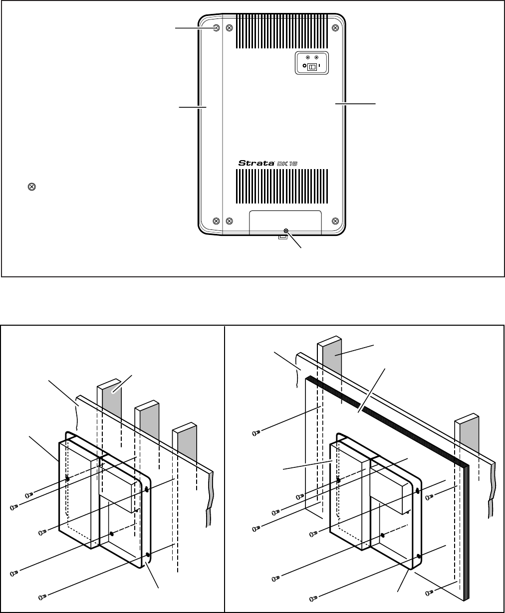
INSTALLATION-DK16 KSU & PCB
SECTION 100-816-205
MARCH 1993
5-2
FIGURE 5-1
DK16 BASE KEY SERVICE UNIT EXTERIOR
METHOD 1 METHOD 2
STUD
PLASTERBOARD
STUD
PLASTER
BOARD
HARD BOARD
(1/2 INCH PLYWOOD)
EXPANSION
UNIT
BASE UNIT BASE UNIT
EXPANSION
UNIT
FIGURE 5-2
DK16 BASE KEY SERVICE UNIT WALL MOUNTING METHODS
BASE COVER
SIDE COVER
AC DC
POWER
KFCU DOOR SCREW
(Do not remove to mount KSU)
COVER
SCREWS (6)
= Six cover screws to be removed
before mounting KSU
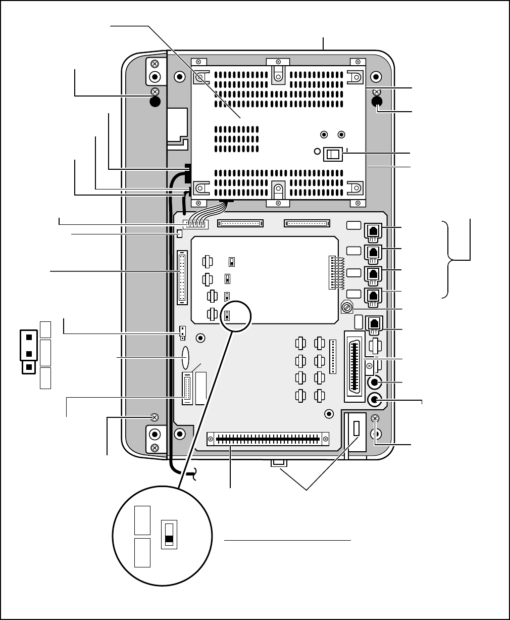
5-3
INSTALLATION-DK16 KSU & PCB
SECTION 100-816-205
MARCH 1993
FIGURE 5-3
DK16 BASE KEY SERVICE UNIT INTERIOR
AC DC
DC POWER
KPSU16
DC POWER SWITCH
TIE WRAP
HOLDER
AC POWER CABLE
MOUNTING HOLE
AND SCREW
MOUNTING HOLE
AND SCREW
MOUNTING HOLE
AND SCREW
MOUNTING HOLE
AND SCREW
DC OUT
CONNECTOR
P9 (KPSU16
VOLTAGE
TEST POINTS)
BATT
±
KRCU
PULL
LOCK
PUSH
UNLOCK
OFF BATT ON
SW1
MEMORY BATTERY
BACKUP STRAP
OFF BATT ON
–24V CIRCUIT
BREAKER
(RIGHT SIDE)
J4 (CO4)
J3 (CO3)
J2 (CO2)
J1 (CO1)
MODULAR
CONNECTORS
PFI
(STANDARD
TELEPHONE)
MOH VOLUME
CONTROL
P5 (AMPHENOL JACK)
J6, MOH
(TO MOH/BGM
SOURCE)
J7, 600Ω PAGE
(TO PAGE AMP)
KFCU
CONNECTOR
KSTU
OPTIONAL KSTU
SHOWN FOR
REFERENCE ONLY
BATTERY
RIBBON
CONNECTOR (P3)
TB1, FG2
CONNECTOR
FOR EXPANSION
GROUND WIRE
FG SCREW
(LEFT SIDE)
FG WIRE
(GREEN/YELLOW)
P1
P8
P2A P2B
KCOU
SW
400 SW
425 SW
450 SW
475
RESERVE POWER
BATTERY
CONNECTOR
SW
400
NOR PAD
PAD SWITCH ASSIGNMENTS:
SW400 – CO1
SW425 – CO2
SW450 – CO3
SW475 – CO4
POWER SUPPLY
INSTALLATION-DK16 KSU & PCB
SECTION 100-816-205
MARCH 1993
5-4
4) Secure screws approximately two thirds of the
way into the top two holes on the mounting
surface.
5) Hang the unit from the top two screws and
then secure the screws completely into the
mounting surface.
6) Finish securing the unit to the mounting sur-
face by completley screwing the bottom two
screws into the wall.
7) Ground system according to Chapter 2, para-
graph 4.
8) Connect applicable wiring (modular CO line
cords, 25-pair amphenol connector cable, etc.)
to the Base Key Service Unit and then fasten
wiring to the unit with the tie wrap that comes
with the base unit (Figure 5-4). Remove
amphenol connector clamp from plastic bag
that comes with the Base Unit. Fasten the
clamp to hold the amphenol connector.
9) Connect Reserve batteries (per Paragraph
2.40) and plug battery cable into BATT con-
nector of the KPSU16 power supply (Figure 5-
3 and 5-4).
10) Set the KCOU PAD switches (SW400-SW475)
to the appropriate position (Figure 5-3). The
factory setting is NORMAL. If CO lines are
connected to a PBX or are in close proximity
to the central office the PAD position may be
required.
11) If the Expansion Key Service Unit is going to
be installed, refer now to Paragraph 2.30. If
not, proceed to Step 12.
12) Plug the AC power cable into an outlet and
then turn ON the power supply switch.
13) Reinstall the front and side covers onto the
Base Key Service Unit.
2.30 Mounting the Expansion Key Service
Unit
1) Make sure the side cover is removed from the
Base Key Service Unit. Turn Base Key Ser-
vice Unit DC power switch off.
2) Set the Expansion Key Service Unit on the
Base Key Service Unit's hinge mounts, mak-
ing sure that the Expansion Unit sets properly
in place (Figure 5-5).
3) Remove safety lock from plastic bag which
comes with the Expansion Unit. Install safety
lock to the Base Unit as shown in Figure 5-5.
4) Pull out on the safety lock until it can no longer
be moved, securing the Expansion Key Ser-
vice Unit to the Base Key Service Unit (Figure
5-5). Do not detach the lock from the Base Key
Service Unit.
5) Connect the Expansion Key Service Unit Rib-
bon Cable to the connector on the Base Key
Service Unit (Figure 5-5). Close ribbon cable
connector lock on Base Unit.
6) Connect Expansion Unit green/yellow ground
wire plug (FG2) to TB1 of the Base Unit. (Make
sure the plug locks on TB1.) See Figure 5-3
and 5-4.
7) Making sure that the Expansion Key Service
Unit is flush against the mounting surface,
mark the location of the Expansion Unit mount-
ing screw hole (Figure 5-6).
8) Swing the Expansion Key Service Unit away
from the mounting surface, and drill a hole at
the mark made in Step 7.
9) Install applicable printed circuit boards (PCBs)
(see Chapter 5, Section II)—after PCBs are
installed, slide the slot lock to the lock position
(Figure 5-7).
10) Swing the Expansion Key Service Unit back to
the mounting surface and secure it to the
surface with a screw.
11) Connect applicable wiring (modular CO line
cords, 25-pair amphenol connector, etc.) to
the PCBs (Figure 5-8).
12) Fasten the wiring with tie wraps (supplied) to
the bottom of the Expansion and Base Key
Service Units (Figure 5-8).
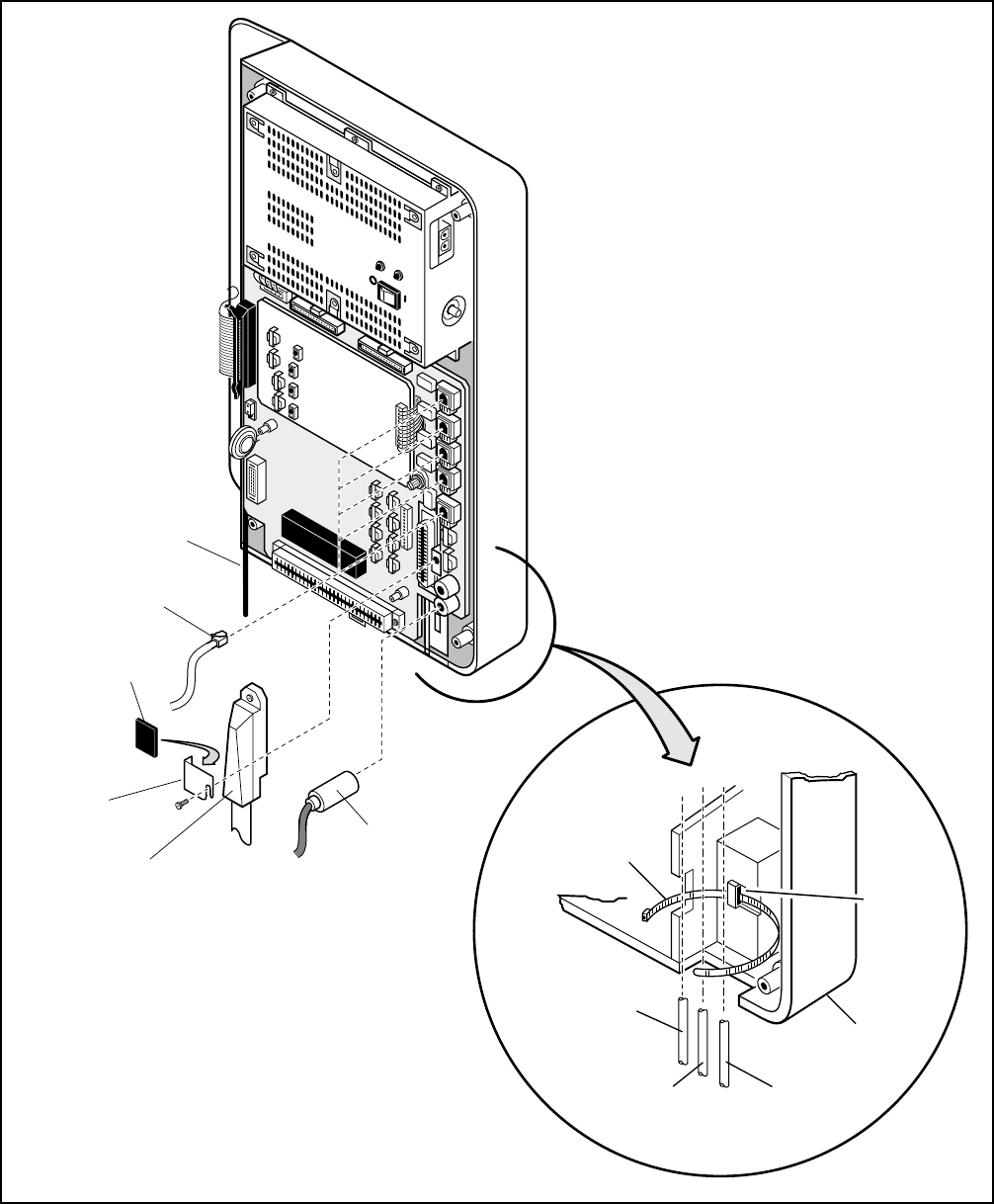
5-5
INSTALLATION-DK16 KSU & PCB
SECTION 100-816-205
MARCH 1993
FIGURE 5-4
DK16 BASE KEY SERVICE UNIT WIRING CONNECTIONS
KRCU
AC DC
POWER
–24V
SELF-ADHESIVE
RUBBER PAD
1
MODULAR
CONNECTOR
RCA JACK
AMPHENOL
CONNECTOR
TIE WRAP
HOLDER
DK 16
BASE UNIT
PIN JACK
CORD (X2)
AMPHENOL
CORD (X1)
MODULAR
CORD (X5)
TIE WRAP
1
AMPHENOL
CLAMP
1
AC POWER CORD
2
NOTES
1.
2.
SUPPLIED IN PLASTIC BAG WITH
BASE UNIT.
DO NOT ROUTE POWER CORD WITH
OTHER CORDS.
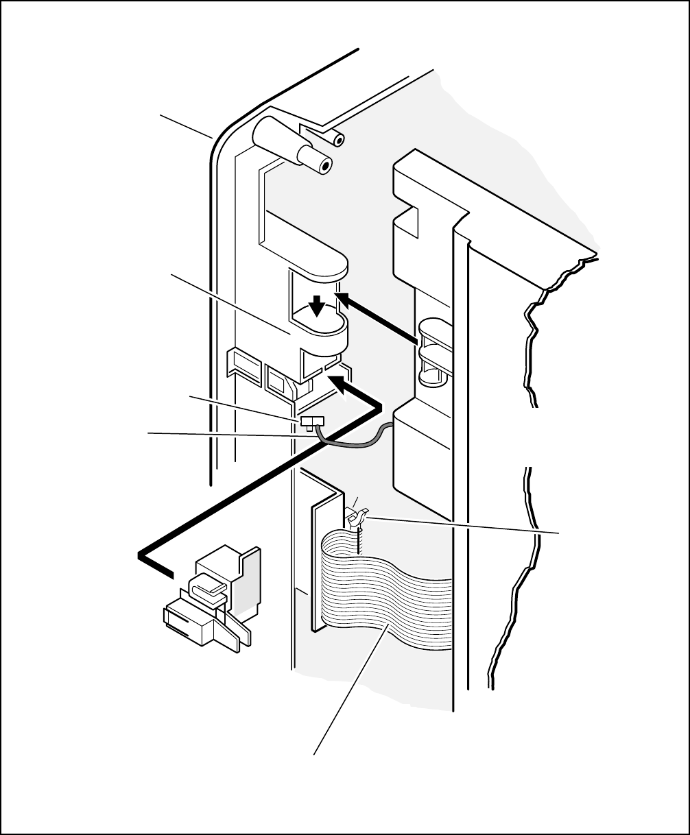
INSTALLATION-DK16 KSU & PCB
SECTION 100-816-205
MARCH 1993
5-6
HINGE
MOUNT
PULL
LOCK
PUSH
UNLOCK
SAFETY LOCK
(SUPPLIED WITH
EXPANSION UNIT)
RIBBON CABLE (FROM EXPANSION UNIT – PLUGS
INTO EXPANSION CONNECTOR (P3) OF BASE UNIT)
BACK OF DK16
EXPANSION UNIT
DK16 BASE
UNIT
GREEN/YELLOW
FG2 WIRE AND PLUG
(FROM EXPANSION
UNIT – PLUGS INTO
TB1 OF BASE UNIT)
TB1 (FG2)
P3
RIBBON
CONNECTOR
LOCK
FIGURE 5-5
CONNECTING THE DK16 EXPANSION UNIT TO THE DK16 BASE UNIT
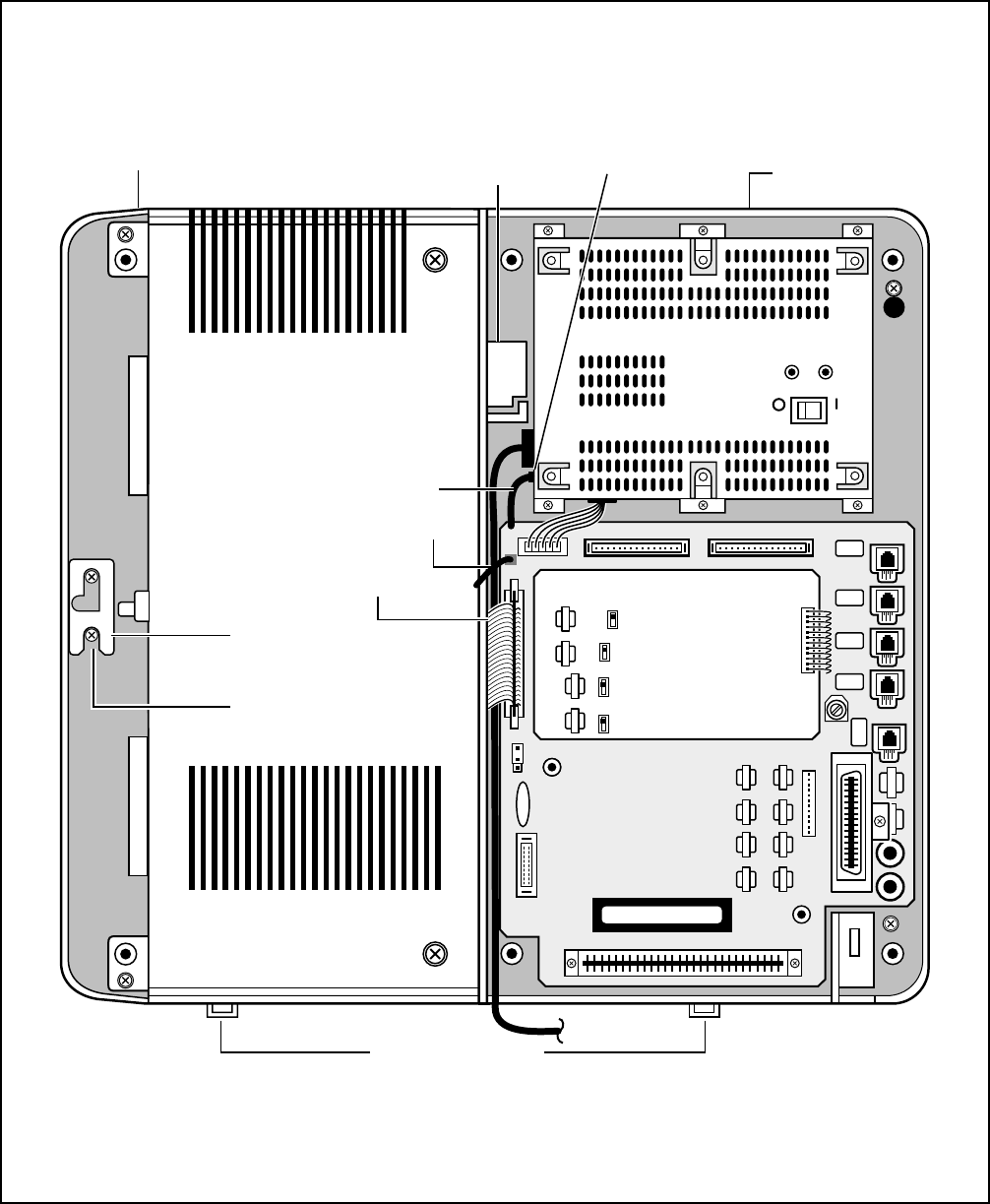
5-7
INSTALLATION-DK16 KSU & PCB
SECTION 100-816-205
MARCH 1993
FIGURE 5-6
MOUNTING THE DK16 EXPANSION UNIT
AC DC
DC POWER
EXPANSION
SAFETY LOCK
EXPANSION
UNIT LATCH
RIBBON CABLE
TO EXPANSION UNIT
MOUNTING
HOLE AND SCREW
BASE UNIT
EXPANSION
UNIT
PULL
LOCK
PUSH
UNLOCK
TIE WRAP HOLDER
FG WIRE
FG2 WIRE
FG SCREW
OFF BATT ON
AC CORD
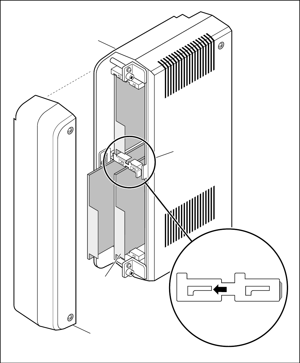
INSTALLATION-DK16 KSU & PCB
SECTION 100-816-205
MARCH 1993
5-8
FIGURE 5-7
DK16 EXPANSION UNIT INTERIOR
EXPANSION UNIT
SLOT LOCK
PCB
SO6
SO4
SO7
SO5
LOCK
SIDE COVER
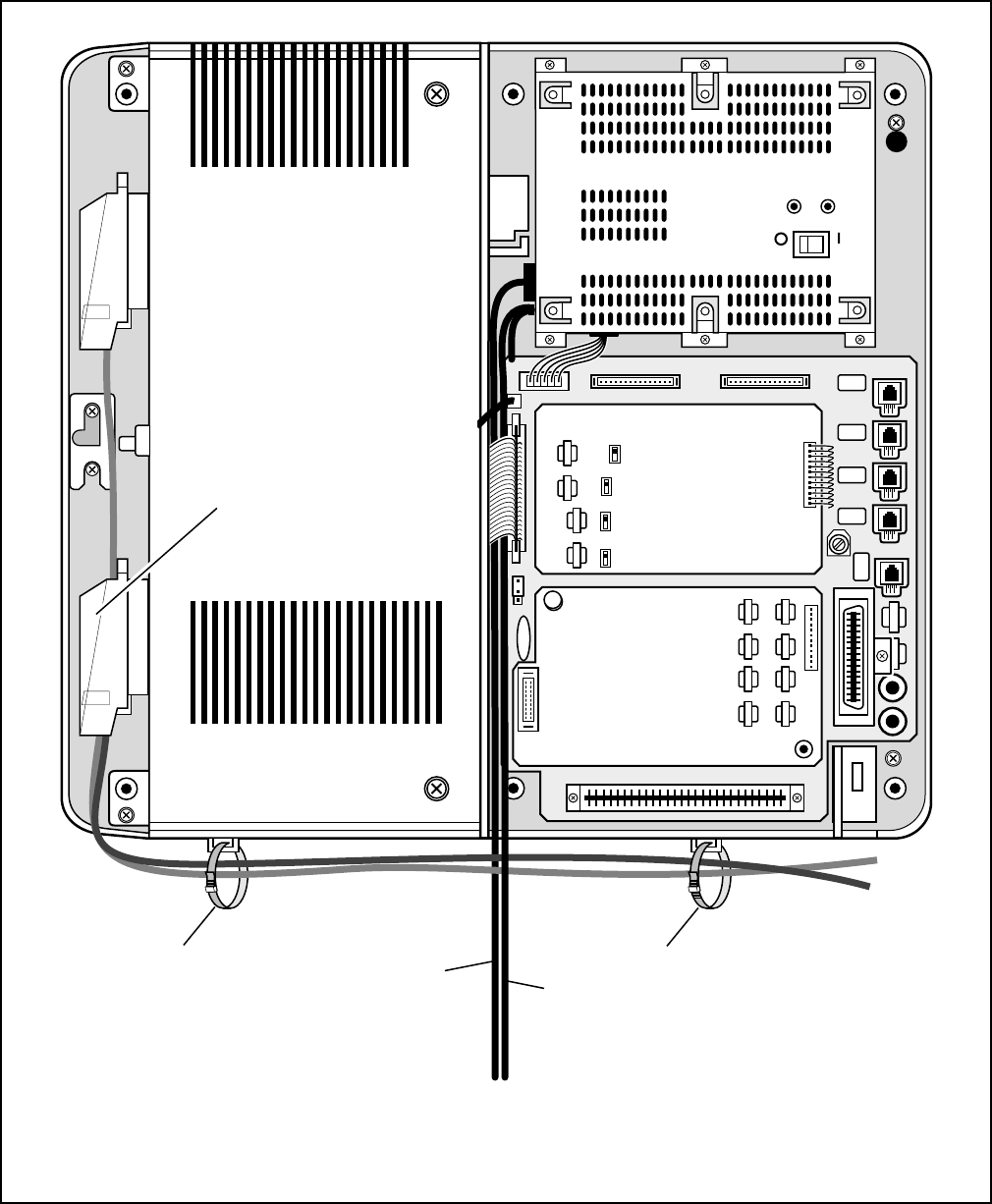
5-9
INSTALLATION-DK16 KSU & PCB
SECTION 100-816-205
MARCH 1993
FIGURE 5-8
DK16 EXPANSION UNIT WIRING CONNECTIONS
AC DC
DC POWER
BATT
±
PULL
LOCK
PUSH
UNLOCK
KRCU
TIE WRAP
AMPHENOL
CONNECTOR
TIE WRAP
TO MDF
9 FT
AC POWER CORD
TO AC OUTLET (DO NOT ROUTE
AC POWER CORD SIDE-BY-SIDE
WITH OTHER CABLES)
OPTIONAL AC GROUND WIRE
FROM FG TERMINAL TO EARTH
GROUND (COLD WATER PIPE)
OFF BATT ON
INSTALLATION-DK16 KSU & PCB
SECTION 100-816-205
MARCH 1993
5-10
13) Knock out the tab on the bottom of the side
cover.
14) Plug the AC power cable into an outlet and
then turn ON the power supply switch.
15) Install the side cover to the Expansion Key
Service Unit (Figure 5-7).
2.40 Reserve Power/Power Failure Options
2.41 The STRATA DK systems offer two options
to protect system operation in the event of a power
failure; the Reserve Power option (Paragraph 2.42-
2.44), and the Power Failure Emergency Transfer
option (Paragraph 17).
2.42 Reserve Power Option STRATA DK16 sys-
tem power supply provides the capability of con-
necting a reserve power source (two customer
supplied 12-volt batteries) to ensure uninterrupted
system operation in the event of a power failure. A
pre-assembled interface cable for installation of
the Reserve Power option is available from Toshiba
(PBTC-3M), refer to Figure 5-9.
IMPORTANT NOTE!
Local ordinances may dictate battery type
and installation details.
2.43 The batteries require a well-ventilated loca-
tion close (within 9 feet) to the system —the
interface cable is 9 feet long.
WARNING!
To reduce the risk of fire or injury to
persons, read and follow these instruc-
tions:
1. Use only the following type and size
batteries: 12-volt, gelcell.
2. Do not dispose of the batteries in a fire.
The cells may explode. Check with
local codes for possible special dis-
posal instructions.
3. Do not open or mutilate the batteries.
Released electrolyte is corrosive and
may cause damage to the eyes or skin.
It may be toxic if swallowed.
4. Exercise care in handling batteries in
order not to short the battery with con-
duction materials such as rings, brace-
lets, and keys. The battery or conduc-
tor may overheat and cause burns.
5. Charge the batteries provided with or
identified for use with this product
only in accordance with the instruc-
tions and limitations specified in this
manual.
6. Observe proper polarity orientation
between the batteries and battery
charger.
2.44 Reserve Power Installation. Install the Re-
serve Power option in accordance with the follow-
ing steps (refer to Figure 5-9):
1) Connect the PBTC-3M black jumper wire
from the positive terminal of one 12VDC
battery to the negative terminal of the second
12VDC battery.
2) Ensure that a serviceable 10-ampere fuse is
installed in the in-line fuse holder of the PBTC-
3M battery cable.
3) Connect the white lead of the PBTC-3M bat-
tery cable to the open positive terminal of the
12VDC battery. Connect the black lead to the
open negative terminal of the second 12VDC
battery.
IMPORTANT NOTE!
The KSU must be connected to the live
operating (HOT) AC power source, and
the power supply ON/OFF switch set to
ON prior to the final step of connecting the
reserve power batteries to the power sup-
ply via the BATT +/- receptacle. If the
batteries are connected after AC power is
lost, reserve power will not function.
4) Connect the PBTC-3M battery cable two-
prong male plug to the power supply BATT +/
- receptacle.
5) To test reserve power operation, disconnect
the system AC power plug with the power
supply power ON/OFF switch in the ON posi-
tion. The system should continue to operate
without any interruption.
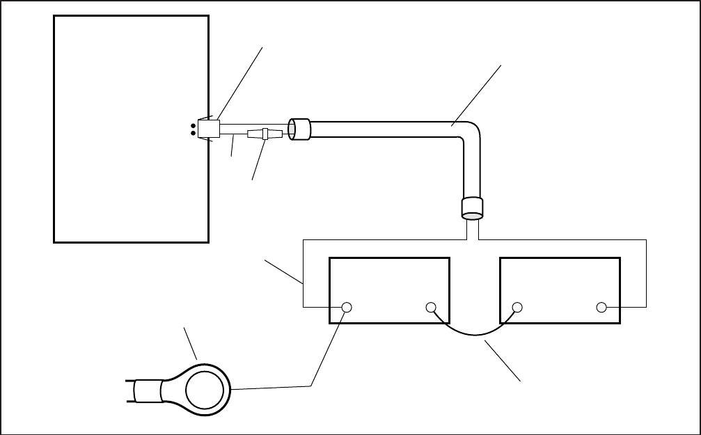
5-11
INSTALLATION-DK16 KSU & PCB
SECTION 100-816-205
MARCH 1993
FIGURE 5-9
RESERVE POWER/BATTERY WIRING
3 POWER SUPPLY REMOVAL AND
REPLACEMENT
3.00 The power supply (KSPU 16) comes factory-
installed in the Base Key Service Unit (Figure 5-
10); if necessary, it can be removed and replaced.
3.10 Power Supply Removal
1) Make sure that the power supply switch is
OFF and that the AC power cable is not
plugged into an outlet. Confirm that green AC
LED is not lit.
2) Unplug reserve battery cable from BATT con-
nector of power supply (Figure 5-10).
3) Remove K4RCU PCB and Expansion Unit
4) Unplug the DC cable from the DC OUT con-
nector (see Figure 5-10).
5) Remove FG screw from left side of power
ACTUAL
SIZE
PBTC-3M
BATTERY CABLE
WITH RING TERMINALS
AND PPSU CONNECTOR
(LENGTH 9 FEET)
POWER SUPPLY
BATT
TWO-PRONG
MALE CONNECTOR
(PRE-ASSEMBLED)
BLACK
WHITE
IN-LINE
FUSE HOLDER
10 A
(FUSE PROVIDED)
BLACK JUMPER
WITH RING TERMINALS
(PROVIDED)
WHITE
BLACK
12 VDC
BATTERY
+
–
12 VDC
BATTERY
+
KPSU16
+
–
RING TERMINALS 3/8 IN.
–
16AWG
supply to free FG wire/terminal and building
ground wire.
6) Remove the six screws that attach the power
supply to the Base Key Service Unit. Remove
power supply.
3.20 Power Supply Replacement
1) Route FG1 wire (soldered on both sides of
Base Unit motherboard) so it will be under the
power supply inside of standoffs (see Figure
5-10).
2) Set the power supply in its proper place in the
Base Key Service Unit (see Figure 5-9).
3) Secure the power supply to the Base Key
Service Unit with the six screws.
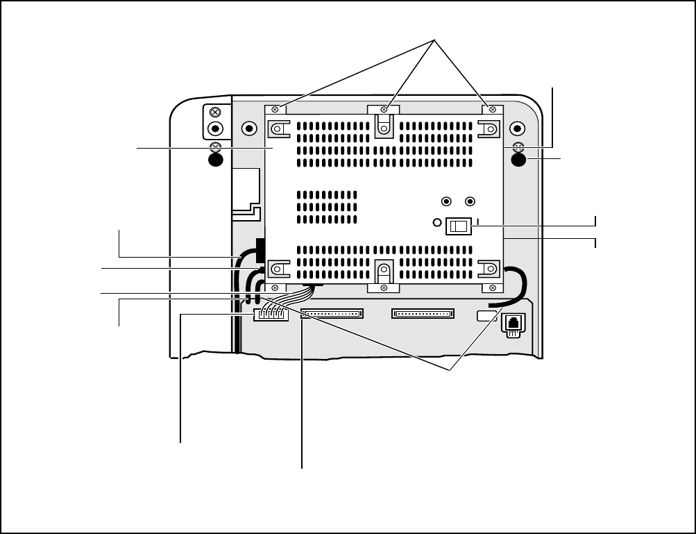
INSTALLATION-DK16 KSU & PCB
SECTION 100-816-205
MARCH 1993
5-12
AC DC
DC POWER
–24V CIRCUIT
BREAKER
(RIGHT SIDE)
AC POWER CABLE
MOUNTING HOLE
AND SCREW
MOUNTING
SCREWS (6)
DC OUT (P9) CONNECTOR
(KPSU16 VOLTAGE TEST POINTS)
BATT
±
KRCU
PULL
LOCK
PUSH
UNLOCK
DC CABLE
RESERVE BATTERY
CONNECTOR
DC POWER
SWITCH
FG1 GREEN/YELLOW WIRE RUN
UNDERNEATH POWER SUPPLY
BEHIND STAND-OFFS
(FG) GREEN/YELLOW
WIRE WITH RING
TERMINAL THAT IS
FASTENED TO
POWER SUPPLY
FG SCREW
FG SCREW
(LEFT SIDE)
KPSU16A
POWER SUPPLY
GREEN/YELLOW WIRE
(RIGHT-HAND SIDE)
FIGURE 5-10
POWER SUPPLY (KPSU16)
4) Plug the DC cable into the DC OUT connector.
Green/yellow wire is on right-hand side (Figure
5-10).
5) Fasten FG green/yellow wire ring terminal and
building ground wire to the left side of the
power supply with the FG screw.
6) Re-install K4RCU PCB (if required).
7) Plug the AC power cable into an outlet and
turn ON the power supply switch.
8) Refer to Paragraph 2.10 to confirm that the
power supply is working properly.
9) Plug reserve battery cable into BATT connec-
tor of power supply (Figure 5-10).

5-13
INSTALLATION-DK 16 KSU & PCB
SECTION 100-816-205
MARCH 1993
PART II. DK16 PRINTED CIRCUIT BOARD
INSTALLATION
4 GENERAL
4.01 This chapter provides procedures for installa-
tion of STRATA DK16 system printed circuit boards
(PCBs) into the Base and Expansion units. This
includes installation instructions, optional configu-
ration information, and wiring and programming
considerations for each PCB.
4.02 Be sure the power supply has been tested,
and the ground has been checked. (See Chapter 5,
Section I for the power supply and Chapter 3 for
grounding.)
4.03 It is recommended to install the Base Unit
option PCBs K4RCU and/or KSTU before mount-
ing the Base KSU on the wall.
4.04 Begin Expansion PCB installation only after
completion of Expansion Unit installation (see Chap-
ter 5, Section I).
5 DK16 PCB INSTALLATION
CONSIDERATIONS
5.01 The STRATA DK16 Base Unit comes stan-
dard with eight digital telephone circuits (ports) and
four CO line circuits. The digital circuits are inte-
grated into the motherboard, and the CO line cir-
cuits are on the KCOU which is attached to the P6
and P7 connectors on the motherboard. The com-
mon control unit, like the digital telephone circuits,
is built into the motherboard.
5.10 DK16 Base Unit PCBs
5.11 The Base Unit can support an optional KSTU
printed circuit board (PCB) which provides four
standard telephone circuits (ports). In addition, a
K4RCU PCB can be installed to receive DTMF
tones, and detect busy tone for Automatic Busy
Redial (ABR) operation.
5.20 DK16 Expansion Unit PCBs
5.21 The Expansion Unit can support a number of
PCBs: it can support a PCOU which provides four
CO line circuits; one or two KCDUs which provide
two CO line circuits and four digital telephone
circuits (ports); a PDKU which provides eight digital
telephone circuits (ports); a PEKU which provides
eight electronic telephone circuits (ports); a PESU
which provides two standard and four electronic
telephone circuits (ports); a PSTU which provides
eight standard telephone circuits (ports); and a
PIOU or PIOUS which both provide a port for a
Station Message Detail Recording (SMDR) device,
an interface for remote maintenance, and relay
control options.
5.22 The DK16 Expansion Unit does not come from
the factory with any PCBs installed. Any of the
PCBs listed above can fit into any of the unit's four
universal slots; however, it is recommended that
PCBs that support electronic or digital telephones
be installed into Slots 04 and 05, because Slots 06
and 07 cannot support Off-hook Call Announce or
Data Interface Units (DIUs).
Recommended PCB slot assignments:
KCDU — Slot 04 and 05 (2 maximum)
PDKU, PEKU, PESU, PSTU — Slot 04 (1 maxi-
mum, cannot be installed with KCDU.)
PCOU — Slot 05 (1 maximum, cannot be in-
stalled with KCDU.)
PIOU/PIOUS — Slot 06 (1 maximum)
5.30 PCB Option Considerations
5.31 PCBs may be configured for a variety of
hardware and software options. Hardware options
are defined as either internal (generally related to
optional PCB subassemblies) or external (related
to connection of peripheral equipment such as
background music, voice mail, etc). Hardware and
software options for each PCB are identified in the
individual PCB installation procedures in this chap-
ter.
5.32 PCB Hardware Options. Each PCB must be
configured for the applicable hardware options
prior to installation of the PCB. Configuration in-
structions for internal hardware options are pro-
vided in the individual PCB installation procedures
in this chapter. Configuration instructions for exter-
nal hardware options are provided in Peripheral
Installation, Section 100-816-207.
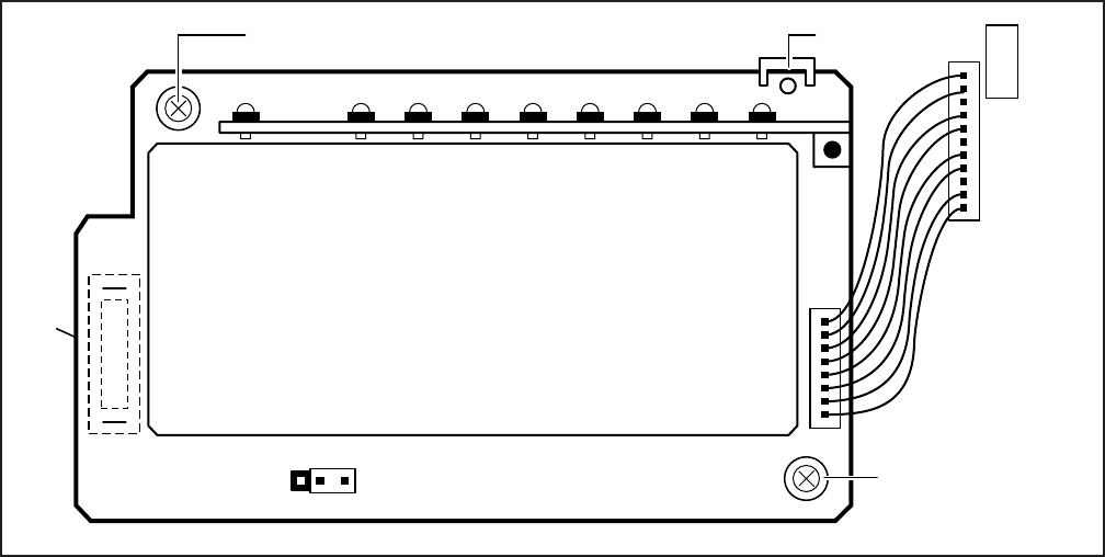
5-14
INSTALLATION-DK 16 KSU & PCB
SECTION 100-816-205
MARCH 1993
5.33 PCB Software Options. PCBs are config-
ured for software options through programming,
after installation of the PCBs in the KSU. A pro-
gramming overview for each PCB is provided in the
individual PCB installation procedures in this chap-
ter. Refer to the Programming Procedures, Section
100-816-300, for detailed programming instruc-
tions.
5.40 PCB Installation/Power Supply Consider-
ations
5.41 Whenever removing or installing PCBs it is
recommended that the power supply be OFF.
6 BASE UNIT STANDARD TELEPHONE
INTERFACE UNIT (KSTU)
6.00 General
6.01 The optional KSTU provides four standard
telephone circuits and it can only be installed in the
Base Unit. The KSTU supports the two-wire de-
vices such as standard telephones, Auto Attendant
devices, voice mail machines, and facsimile ma-
chines. The KSTU can also support an alternate
Background Music (BGM) source on circuit 4.
FIGURE 5-11
KSTU OPTIONS AND CONNECTORS
130
SW540
190
3 2 1
RED
P504
PLASTIC
STAND-OFF
MOUNTING
SCREW
MOUNTING
SCREW
RED
(WIRE)
P4 KSTU
P508
P8
NOTE:
For the system to recognize the Dual-Tone
Multi-Frequency (DTMF) tones generated by
standard telephones (or any other device con-
nected to a KSTU port), a K4RCU must be
installed in the Base Unit.
6.02 The KSTU is shown in Figure 5-11 and its
connectors and controls are described in Table 5-
A.
6.10 KSTU Configuration
6.11 The KSTU only has to be configured for the
ring generator voltage level, nothing else. Before
installing the KSTU in the Base Unit, set the SW540
ring generator to 130V P-P or 190V P-P. Most
standard telephones and two-wire devices require
190; however, some devices may experience ring-
trip at 190, and should be set at 130.
6.20 KSTU Installation Procedure
6.21 Install the KSTU in accordance with the follow-
ing steps:
1) Make sure that the power supply switch is
5-15
INSTALLATION-DK 16 KSU & PCB
SECTION 100-816-205
MARCH 1993
OFF.
2) Plug the KSTU cable into the P4 connector on
the motherboard in the Base Unit. The red
wire on the cable should match up with pin 1
on the lower side of the connector.
3) Plug the KSTU P508 female connector into
the P8 male connector on the motherboard.
4) Secure the KSTU to the standoffs with the two
provided screws.
6.30 KSTU Wiring
6.31 Refer to Base Unit Wiring in Section 100-816-
208 for KSTU wiring.
6.32 The KSTU must be connected to a OL13A (or
equivalent) type lines for off-premises stations.
(300 ohms loop resistance max., including the
telephone or other devices DC off hook resistance.
6.40 KSTU Programming Overview
6.41 The following parameters may be specified for
the KSTU:
Program 03
Specify code 31 for KSTU slot.
Program 31
Used to configure all KSTU ports connected to
voice mail (see Chapter 7 for voice mail installa-
tion).
Program 10-2
Used to set standard telephone ringing option.
Not required for Background Music (BGM) con-
nection.
Program 19
Used for BGM connection to KSTU Port 11.
NOTE:
KSTU Ports (08~11) are fixed. They are as-
signed even if a KSTU is not installed.
7 DIGITAL TELEPHONE INTERFACE
UNIT (PDKU)
7.00 General
7.01 The Digital Telephone Interface Unit (PDKU)
provides eight ports/circuits for digital telephones
and it can only be installed in the Expansion Unit.
The PDKU can also support Integrated Data Inter-
face Units (PDIU-DIs/PDIU-DI2s), Stand-alone Data
Interface Units (PDIU-DSs), a Digital Door Phone/
Lock Control Unit (DDCB), a Digital Direct Station
Selection Console (DDSS), and Add-on Modules
(ADMs). The DDSS console, DDCB, and PDIU-
DSs are wired directly to the PDKU and require no
additional hardware, but do require their own dedi-
cated ports/circuits. The PDIU-DI/PDIU-DI2 or the
ADM shares with its accompanying digital tele-
TABLE 5-A
KSTU CONTROLS AND INTERFACE CONNECTORS
CONTROL/INDICATOR/
CONNECTOR
(Figure 5-11)
TYPE OF COMPONENT DESCRIPTION
Ring Voltage Jumper
Plug SW540
Connector P508
Connector Cable P504
Three-terminal jumper
Female Connector
Cable
Sets ring generator voltage level for all
circuits:
H = 190V P-P
L = 130V P-P
Mates to male connector P8 on the
motherboard.
Connects to P4 connector on the
motherboard.
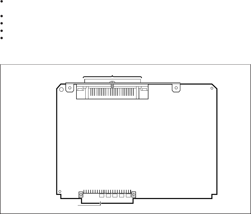
5-16
INSTALLATION-DK 16 KSU & PCB
SECTION 100-816-205
MARCH 1993
FIGURE 5-12
PDKU INTERFACE CONNECTION
BACKPLANE CONNECTOR
50-PIN AMPHENOL CONNECTOR (FEMALE)
NOTE:
There are two versions of the PDKU: PDKU1,
and PDKU2. These versions are identical
except for the number of Data Interface Units
(DIUs) they can support (see Paragraphs 7.14
and 7.15). Also, PDKU2 supports continuous
DTMF tones with 2000-series digital tele-
phones, but PDKU1 does not support continu-
ous DTMF tones.
7.12 Hardware Configuration
7.13 DDSS Console Configuration. Refer to Sta-
tion Apparatus Installation, Section 100-816-206,
for installation procedures for the DDSS console.
The DDSS console requires dedicated use of Cir-
cuit 8 of the PDKU.
7.14 PDIU-DS Configuration. Refer to Peripher-
als Installation, Section 100-816-207, for installa-
tion procedures for the PDIU-DS. A PDIU-DS can
be connected to Circuits 1 ~ 7 on a PDKU1 or
phone the same wire pair and circuit on the PDKU.
The PDKU (Figure 5-12) has no controls.
NOTE:
The PDIU-DI attaches to 1000-series Digital
Telephones, and the PDIU-DI2 attaches to
2000-series Digital Telephones.
7.10 PDKU Hardware Options
7.11 The PDKU supports the hardware options
noted below. Unlike the other PCBs, there are no
controls on the PDKU that need to be set for
options.
Internal option:
none
External option:
DDSS console
PDIU-DS
PDIU-DI/PDIU-DI2
DDCB

5-17
INSTALLATION-DK 16 KSU & PCB
SECTION 100-816-205
MARCH 1993
for a DDSS console and OCA.
Programs 20, 21, and 22
Use to configure PDIU-DIs/PDIU-DI2s and PDIU-
DSs.
Programs 28 and 29
Use for DDSS assignments.
Program 30
Adjusts initial off-hook volume level for digital
telephone handsets.
Program 92-5
Initializes initial ringing, speaker, and muted ring
volume levels of digital telephones.
Programs 77-1, 77-2, and 79
Used for DDCB and door phone assignments
8 ELECTRONIC TELEPHONE
INTERFACE UNIT (PEKU)
8.00 General
8.01 The Electronic Telephone Interface Unit
(PEKU) provides eight ports for electronic tele-
phones and it must be installed in the Expansion
Unit. It is recommended that the current 6500-
series be used, because this series consumes the
least amount of power.
8.02 The PEKU can be configured to receive Off-
hook Call Announce (OCA) by installing an Off-
hook Call Announce Unit (EOCU). It can also be
configured to support an HDSS console and an
external Background Music (BGM) source connec-
tor. An external amplifier for two-CO line confer-
ence calls can also be connected to Circuits 6 and
7 of the PEKU. The HDSS console, the external
amplifier, and the BGM source, are wired directly to
the PEKU and require no additional hardware, but
do require specific ports/circuits. Electronic tele-
phones also wire directly to the PEKU, and they can
be connected to any PEKU circuit.
8.03 PEKU controls and interface connectors are
shown in Figure 5-13 and described in Table 5-B.
8.10 PEKU Hardware Options
8.11 The PEKU supports the following hardware
options:
Internal Options
Off-hook Call Announce Unit (EOCU)
External Options
Circuits 1 ~ 8 on a PDKU2; the circuit must be
dedicated to the PDIU-DS.
7.15 PDIU-DI/PDIU-DI2 Configuration. Refer to
Station Apparatus Installation, Section 100-816-
206, and Peripherals Installation, Chapter 7, for
installation procedures for the PDIU-DI/PDIU-DI2.
PDIU-DIs/PDIU-DI2s can be equipped with any
digital telephone connected to PDKU Circuits 1 ~ 7
with PDKU1 or Circuits 1 ~ 8 with PDKU2.
7.16 DDCB Configuration. Refer to Peripherals
Installation, Section 100-816-207, for installation
procedures for the DDCB. The DDCB must be
connected to the Circuit 8 on the PDKU.
7.17 ADM Configuration. Refer to Section 100-
816-206, Paragraph 7.00.
7.20 PDKU Installation Procedure
7.21 Install the PDKU in accordance with the fol-
lowing steps:
1) Remove the PCB from its protective packag-
ing.
2) Insert the PDKU into the appropriate slot (see
Paragraph 5.22, and apply firm, even pres-
sure to ensure proper mating of connectors.
NOTE:
Ensure the PDKU's component side is facing
right when installing it in the KSU.
4) After installing the PDKU, gently pull the PCB
outward. If the connectors are properly mated,
a slight resistance will be felt.
7.30 PDKU Wiring
7.31 Refer to PDKU Wiring Diagrams, Chapter 8,
for wiring/interconnecting details.
7.40 PDKU Programming Overview
7.41 The following parameters may be specified,
through programming, for the PDKU:
Program 03
Specify code 61 if no options are installed on a
PDKU.
Specify code 62 to indicate a PDKU that will
support stations that must receive Off-hook Call
Announce (OCA).
• Specify code 64 to indicate a PDKU configured
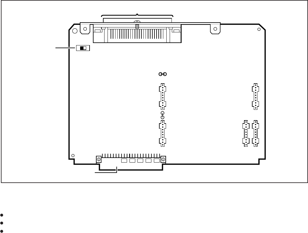
5-18
INSTALLATION-DK 16 KSU & PCB
SECTION 100-816-205
MARCH 1993
FIGURE 5-13
PEKU CONTROLS AND INTERFACE CONNECTORS
HDSS console
BGM source connection
External Amplifier
8.12 Off-hook Call Announce (EOCU) Instal-
lation. Install the Off-hook Call Announce Unit
(EOCU) in accordance with the following steps:
1) Remove the PCB from its protective packag-
ing.
NOTE:
PEKU connectors P10, P20, P40, P50, and
P60 are positioned to allow installation of the
EOCU only in the proper position (Figure 5-
13).
2) Mate EOCU connectors J10, J20, J40, J50,
and J60 with PEKU connectors P10, P20,
P40, P50, and P60 (Figure 5-14).
3) Apply firm, even pressure to EOCU to ensure
proper mating of connectors.
4) Use a 3-pair cable for making connections
between the PEKU and the Off-hook Call
Announce (OCA) electronic telephone. Refer
to Wiring Diagrams, Section 100-816-208, for
wiring/interconnecting details.
5) Refer to Station Apparatus Installation, Sec-
tion 100-816-206, for procedures to upgrade
electronic telephones for OCA.
8.13 HDSS Console Configuration. Configure
the PEKU to support an HDSS console in accor-
dance with the following steps:
1) Remove the PCB from its protective packag-
ing.
2) Set the SW1 DSS/EKT switch to DSS.
3) Refer to Station Apparatus Installation, Sec-
tion 100-816-206, for installation procedures
for the HDSS console. The HDSS console
requires dedicated use of Circuits 7 and 8 of
the PEKU PCB.
BACKPLANE CONNECTOR
SW1
50-PIN AMPHENOL CONNECTOR (FEMALE)
EKT
DSS
P20
P60P50
P40
P10
W5
W5, cut for
BGM option

5-19
INSTALLATION-DK 16 KSU & PCB
SECTION 100-816-205
MARCH 1993
8.14 Background Music (BGM) Configuration.
Configure the PEKU to support a BGM source in
accordance with the following steps:
1) Remove the PCB from its protective pack-
aging.
2) Cut the W5 (BGM) jumper wire on the PEKU
PCB.
3) Refer to Peripherals Installation, Section 100-
816-207, for installation procedures for BGM
connection.
8.15 External Amplifier Configuration. The
PEKU does not have to be configured to support an
external amplifier. However, the system must be
programmed for one; see Paragraph 8.40. See
Peripherals Installation, Section 100-816-207, for
external amplifier installation instructions.
8.20 PEKU Installation Procedure
8.21 Install the PEKU in accordance with the fol-
lowing steps:
1) Remove the PCB from its protective pack-
aging.
TABLE 5-B
PEKU CONTROLS AND INTERFACE CONNECTORS
CONTROL/INDICATOR/
CONNECTOR (Figure 5-13) TYPE OF COMPONENT DESCRIPTION
Off-hook Call
Announce P10
DSS/EKT DSS Console/
Electronic Telephone
SW1 Switch
Two-position slide switch Configures PEKU for operation with either
an HDSS console or electronic
telephones.
10-pin connector Interface connector for optional Off-hook
Call Announce subassembly
connector (used in conjunction with P20,
P40, P50, and P60).
Off-hook Call
Announce P20 10-pin connector Interface connector for optional Off-hook
Call Announce subassembly
connector (used in conjunction with P10,
P40, P50, and P60).
Off-hook Call
Announce P40 10-pin connector Interface connector for optional Off-hook
Call Announce subassembly
connector (used in conjunction with P10,
P20, P50, and P60).
Off-hook Call
Announce P50 10-pin connector Interface connector for optional Off-hook
Call Announce subassembly
connector (used in conjunction with P10,
P20, P40, and P60).
Off-hook Call
Announce P60 10-pin connector Interface connector for optional Off-hook
Call Announce subassembly
connector (used in conjunction with P10,
P20, P40, and P50).
BGM source connection
W5 Jumper Wire When cut, configures PEKU for BGM
source connection.
White jumper wire
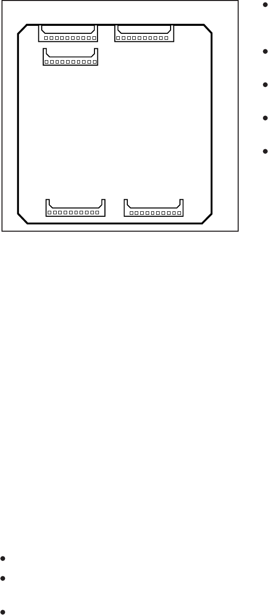
5-20
INSTALLATION-DK 16 KSU & PCB
SECTION 100-816-205
MARCH 1993
Specify code 24 to indicate a PEKU configured
for OCA and an HDSS console.
Program 10-2
Used for BGM connection.
Program 10-3
Used for external amplifier connection.
Program 19
Also used for BGM connection.
Programs 28 and 29
Used for HDSS assignments.
9 STANDARD TELEPHONE
INTERFACE UNIT (PSTU)
9.00 General
9.01 The Standard Telephone Interface Unit
(PSTU) provides an interface between standard
telephones or two-wire devices and the system,
and it must be installed in the Expansion Unit. The
PSTU PCB adds eight standard telephone lines to
the system. The PSTU can also support a Back-
ground Music (BGM) source.
NOTE:
For the system to recognize the Dual-Tone
Multi-Frequency (DTMF) tones generated by
a standard telephone (or any other device
connected to a PSTU port), a DTMF Receiver
Unit (K4RCU) must be installed in the Base
Unit.
9.02 PSTU controls are shown in Figure 5-15 and
described in Table 5-C.
9.10 PSTU (1 and 2) Hardware Options
9.11 There are two PSTU versions (1 and 2): They
are identical except for the ring generator. The ring
generator on the original version (V.3) of PSTU1 is
fixed at a 190V P-P level, while the ring generator
on PSTU1 (V.4) and PSTU2 can be set for 130V P-
P or 190V P-P. The W1 jumper plug is used to set
the voltage level. Most standard telephones and
two-wire devices require the 190V P-P level; how-
ever, some devices may experience ring-trip with
190V P-P and they require the 130V P-P level.
2) Ensure the PEKU has been configured for the
appropriate hardware options (refer to Para-
graph 8.10).
3) Insert the PEKU into the appropriate slot (refer
to Paragraph 5.22), and apply firm, even pres-
sure to ensure proper mating of connectors.
4) After installing the PEKU, gently pull the PCB
outward. If the connectors are properly mated,
a slight resistance will be felt.
8.30 PEKU Wiring
8.31 Refer to PEKU Wiring Diagrams, Section
100-816-208, for wiring/interconnecting details.
8.40 PEKU Programming Overview
8.41 The following parameters may be specified,
through programming, for the PEKU:
Program 03
Specify code 21 to indicate a station line PEKU.
Specify code 22 to indicate a PEKU configured
for OCA.
Specify code 23 to indicate a PEKU configured
for an HDSS console.
J60
J50
J40
J20 J10
FIGURE 5-14
OFF-HOOK CALL ANNOUNCE UNIT (EOCU)
INTERFACE CONNECTORS
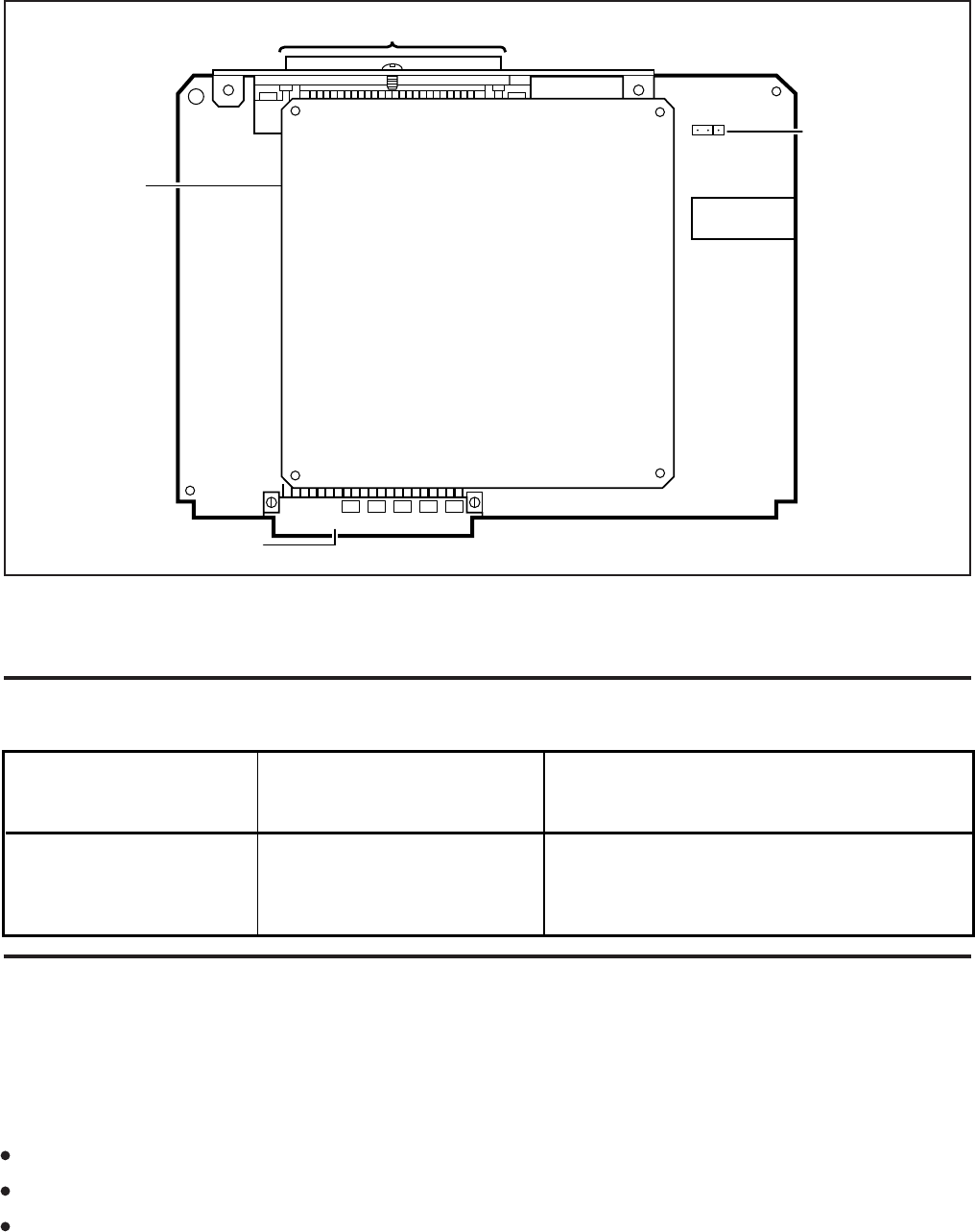
5-21
INSTALLATION-DK 16 KSU & PCB
SECTION 100-816-205
MARCH 1993
FIGURE 5-15
PSTU AND SUBUNIT (SSTU)
TABLE 5-C
PSTU CONTROLS AND INTERFACE CONNECTORS
CONTROL/INDICATOR/
CONNECTOR
(Figure 5-15)
TYPE OF COMPONENT DESCRIPTION
Ring Voltage W1 Jumper
Plug (PSTU1 ( ) and
PSTU2 only)
Three-terminal jumper Sets ring generator voltage level for all
circuits.
H = 190V P-P
L = 130V P-P
V.4
BACKPLANE CONNECTOR
50-PIN AMPHENOL CONNECTOR (FEMALE)
SSTU
SUBUNIT
W1
HL
W1 Ring Voltage
H = 190V P-P
L = 130V P-P
(For PSTU1 (V.4)
and PSTU2 only)
9.13 Unlike the PEKU or PESU, the PSTU does not
have to be configured for BGM: There is no jumper
wire to cut, etc.
9.20 PSTU Installation Procedure
9.21 Install the PSTU in accordance with the fol-
lowing steps:
1) Remove the PCB from its protective packag-
ing. The protective shield on the back of the
PSTU is designed to protect the installer from
NOTE:
PSTU1 (V.4) became available in November
1989. PSTU1(V.3) was discontinued.
9.12 Set the PSTU1 (V.4) or PSTU2 ring generator
level as required:
W1 set to H (190V P-P).
W1 set to L (130V P-P).
Two ringers maximum per port (H or L).

5-22
INSTALLATION-DK 16 KSU & PCB
SECTION 100-816-205
MARCH 1993
four electronic telephone interface circuits (5 ~ 8)
identical to PEKU circuits for connecting electronic
telephones, BGM or an external amplifier. The
PESU provides a ring generator for circuits 1 and 2
(with a ring voltage of either 190V P-P or 130V P-
P), and it must be installed in the Expansion Unit.
The PESU does not support an HDSS console
connection.
The PESU provides connectors to mount the
EOCU for OCA to electronic telephones.
NOTE:
A KSU must be installed in the Base Unit for
the system to recognize Dual-Tone Multi-
Frequency (DTMF) tones sent from standard
telephones or other two-wire devices that are
connected to the PESU.
10.02 The PESU controls and interface connec-
tors are shown in Figure 5-16 and described in
Table 5-D.
10.10 PESU Hardware Options
10.11 The PESU supports the following hardware
options:
Internal option: Off-hook Call Announce
(EOCU).
NOTE:
Refer to Section 100-816-206 and Section
100-816-207 for installation of external op-
tions.
10.12 Off-hook Call Announce (EOCU) Installa-
tion. Install the Off-hook Call Announce in accor-
dance with the following steps:
1) Remove the PCB from its protective packag-
ing.
NOTE:
PESU connectors P10, P20, P40, P50, and
P60 are positioned to allow installation of the
EOCU only in the proper position (refer to
Figure 5-16).
2) Mate the EOCU connectors J10, J20, J40,
J50, and J60 with the PESU connectors P10,
P20, P40, P50, and P60 (refer to Figure 5-16).
potentially hazardous ring voltage. Do not
remove this shield.
2) Ensure that the PSTU subunit (SSTU) is se-
curely attached to the PSTU (refer to Figure 5-
15).
NOTE:
W1, the ring generator level option, should be
set in the H position (factory) for initial instal-
lation.
3) Insert the PSTU into the appropriate slot (refer
to Paragraph 5.22), and apply firm, even pres-
sure to ensure proper mating of connectors.
9.30 PSTU Wiring
9.31 Refer to PSTU Wiring Diagram, Section 100-
816-208, for wiring/interconnecting details.
9.32 The PSTU is registered for use with OL13A
type lines for off-premises stations.
9.40 PSTU Programming Overview
9.41 The following parameters may be specified,
through programming, for the PSTU:
Program 03
Specify code 31 for all slots that have PSTUs
installed.
Program 31
Used to configure all PSTU ports connected to
voice mail (Section 100-816-207 for more de-
tails).
Program 10-2
Used to set standard telephone ringing option.
Also used for BGM connection.
Program 19
Used for BGM connection also.
10 STANDARD/ELECTRONIC TELE-
PHONE INTERFACE UNIT (PESU)
10.00 General
10.01 The Standard/Electronic Telephone Inter-
face Unit (PESU) provides two standard telephone
interface circuits (1 and 2) identical to PSTU circuits
for connection between standard telephones, or
two-wire devices, and the system. It also provides
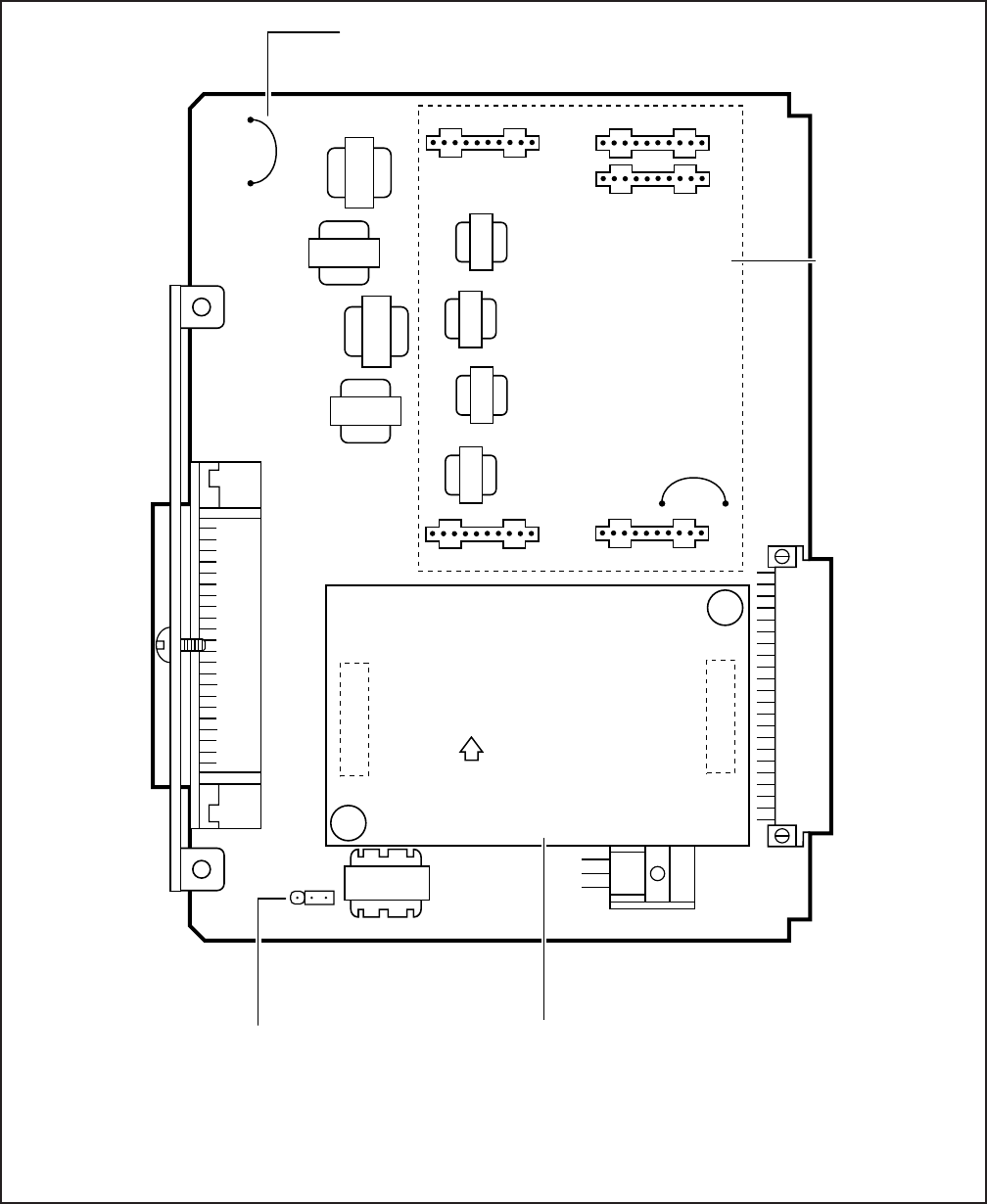
5-23
INSTALLATION-DK 16 KSU & PCB
SECTION 100-816-205
MARCH 1993
FIGURE 5-16
PESU PCB OPTION LOCATION AND IDENTIFICATION
UP
PESU
P60
P50
P40
P10 P20
ESTS
P70P80
OPTIONAL
EOCU, EQUIP
FOR OCA
FEATURE
BACKPLANE
CONNECTOR
ESTS: STANDARD TELEPHONE
INTERFACE, ALWAYS EQUIPPED
FROM FACTORY
RING VOLTAGE OPTION (CIRCUITS 1 & 2):
L = LOW LEVEL (130V P-P)
H = HIGH LEVEL (190V P-P)
50-PIN
AMPHENOL
CONNECTOR
(FEMALE)
P90
LH
NOTE: Connect two ringers maximum per port (H or L).
PESU
W7
CUT W7 ONLY IF BGM IS CONNECTED TO
CIRCUIT 8.

5-24
INSTALLATION-DK 16 KSU & PCB
SECTION 100-816-205
MARCH 1993
10.13 Background Music (BGM) Configura-
tion. Configure the PESU to support a BGM source
in accordance with the following steps:
1) Remove the PCB from its protective packag-
ing.
2) Cut the W7 (BGM) jumper wire on the PESU
PCB.
3) Refer to Peripherals Installation, Section 100-
816-207, for BGM installation procedures.
10.14 External Amplifier Configuration. The
PESU does not have to be configured to support an
3) Apply firm, even pressure to the EOCU to
ensure proper mating of connectors.
4) Use 3-pair cable for connecting the PESU and
the OCA electronic telephone (refer to Wiring
Diagrams, Section 100-816-208, for wiring/
interconnecting details).
5) Refer to Station Apparatus Installation, Sec-
tion 100-816-206, for procedures to add OCA
to electronic telephones.
TABLE 5-D
PESU CONTROLS AND INTERFACE CONNECTORS
CONTROL/INDICATOR/
CONNECTOR (Figure 5-16) TYPE OF COMPONENT DESCRIPTION
Off-hook Call
Announce P10
Ring Voltage Jumper
Plug P90
BGM W7 Jumper Pack When cut, configures PESU, circuit 8,
for BGM source connection.
White jumper wire
Sets ring generator voltage level for
circuits 1 and 2.
H = 190V P-P (factory setting)
L = 130V P-P
10-pin connector Interface connector for optional Off-hook
Call Announce subassembly
connector (used in conjunction with P20,
P40, P50, and P60).
Off-hook Call
Announce P20 10-pin connector Interface connector for optional Off-hook
Call Announce subassembly
connector (used in conjunction with P10,
P40, P50, and P60).
Off-hook Call
Announce P40 10-pin connector Interface connector for optional Off-hook
Call Announce subassembly
connector (used in conjunction with P10,
P20, P50, and P60).
Off-hook Call
Announce P50 10-pin connector Interface connector for optional Off-hook
Call Announce subassembly
connector (used in conjunction with P10,
P20, P40, and P60).
Off-hook Call
Announce P60 10-pin connector Interface connector for optional Off-hook
Call Announce subassembly
connector (used in conjunction with P10,
P20, P40, and P50).
Three-terminal jumper

5-25
INSTALLATION-DK 16 KSU & PCB
SECTION 100-816-205
MARCH 1993
external amplifier. However, the system must be
programmed for one; see Paragraph 10.40. The
external amplifier requires Circuits 6 and 7 on the
PESU. See Peripherals Installation, Section 100-
816-207, for external amplifier installation instruc-
tions.
10.20 PESU Installation Procedure
10.21 Install the PESU in accordance with the
following steps:
1) Remove the PCB from its protective packag-
ing. The protective shield on the back of the
PESU is designed to protect the installer from
potentially hazardous ring voltage. Do not
remove this shield.
2) Ensure that the PESU subunit (ESTS) is
securely attached to the PESU (refer to Figure
5-15).
3) If the electronic telephones connected to the
PESU must receive OCA calls, install the
EOCU subassembly PCB on the PESU per
Paragraph 10.12.
4) If a BGM source is connected to the PESU,
Circuit 8, cut W7.
5) Ensure that the ring voltage option, P90, is set
to the “H” position for initial installation. The “L”
position is used if devices connected to the
PESU trip ring voltage before answer.
6) Insert the PESU into the appropriate slot, and
apply firm, even pressure to ensure proper
mating of connectors.
7) After installing the PESU, gently pull the PCB
outward. If the connectors are properly mated,
a slight resistance will be felt.
10.30 PESU Wiring
10.31 Refer to PESU Wiring Diagram, Section
100-816-208, for wiring/interconnecting details.
10.40 PESU Programming Overview
10.41 The following parameters may be specified,
through programming, for the PESU:
Program 03
Specify code 25 for all slots that have PESUs
without EOCU.
Specify code 26 for all slots that have PESUs
equipped with EOCU.
NOTE:
A special code is not required to connect BGM
to a PESU.
Program 31
Configures the PESU Circuits 1 and 2 for con-
nection to voice mail devices.
Program 10-2
Sets the standard telephone ring cadence for
normal or distinctive ringing and BGM source
connection.
Program 10-3
Used for external amplifier connection.
Program 19
Also used for BGM connection.
11 CO LINE UNIT (PCOU)
11.00 General
11.01 The PCOU PCB adds four CO lines to the
system and it can only be installed in the Expansion
Unit. The PCOU provides Ring Detection, Dial
Outpulsing and Hold; as well as Automatic Busy
Redial (ABR) circuitry. Each CO line can be pro-
grammed for Dual-Tone Multi-Frequency (DTMF)
or dial pulse.
NOTE:
There are two PCOU versions (1 and 2). They
are identical in fit/form/function and are inter-
changeable in all DK system models.
11.02 PCOU controls, indicators, and interface
connectors are shown in Figure 5-17 and described
in Table 5-E.
11.10 PCOU Hardware Options
11.11 There are no hardware options supported
by the PCOU.
11.20 PCOU Installation Procedure
11.21 Install the PCOU in accordance with the
following steps:
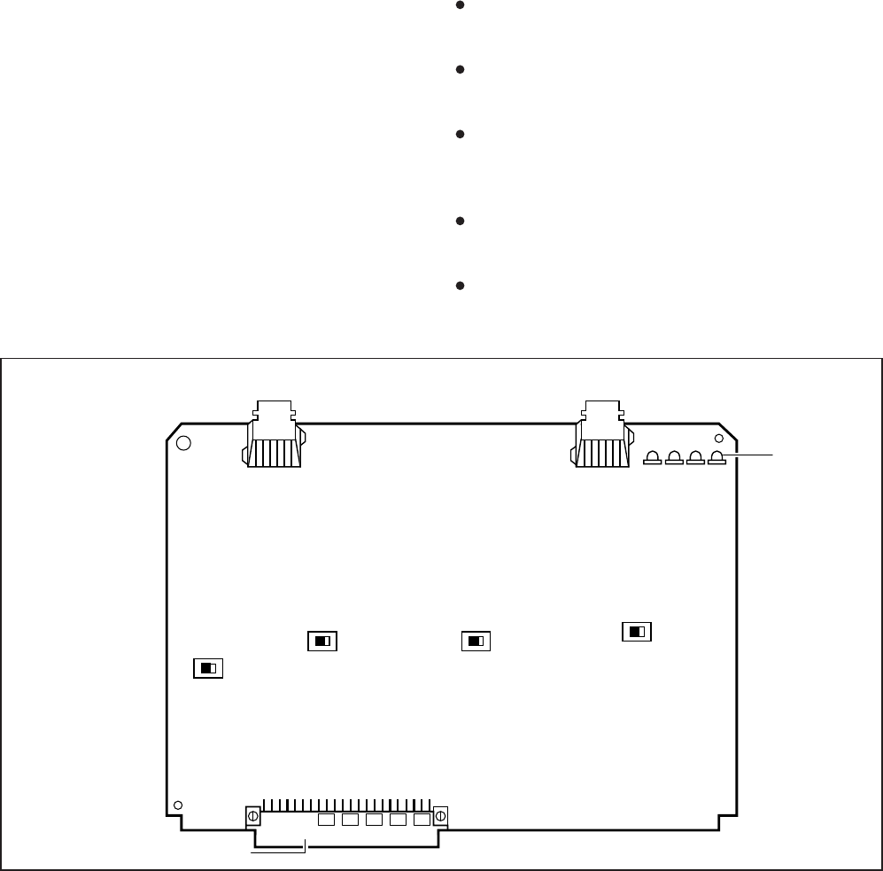
5-26
INSTALLATION-DK 16 KSU & PCB
SECTION 100-816-205
MARCH 1993
1) Remove the PCB from its protective packag-
ing.
NOTE:
The dB PAD switches SW101 through SW401
control excessive loudness resulting from close
proximity to the CO or PBX telephone office by
providing a 3 decibel (dB) signal level drop to, or
from, the PBX or CO when set to the 3 position.
Switches are factory-set to the 0 (0 dB signal
level drop) position.
2) If the Expansion Unit is located within one mile
of the PBX or CO telephone office, set dB PAD
switches SW101 through SW401 to the 3 (-3
dB signal level drop) position.
3) Insert the PCOU into the appropriate slot
(refer to Paragraph 2.22), and apply firm,
even pressure to ensure proper mating of
connectors.
4) After installing the PCOU, gently pull the PCB
outward. If the connectors are properly mated,
a slight resistance will be felt.
11.30 PCOU Wiring
11.31 Refer to PCOU Wiring Diagram, Section
100-816-208, for wiring/interconnecting details.
11.40 PCOU Programming Overview
11.41 The following parameters may be specified,
through programming, for the PCOU:
Program 03
Specify code 11 for the slot in which the PCOU
is installed.
Program 10-1
Allows/denies two-CO Line Conference and Di-
rect Inward System Access (DISA).
Program 15
Assigns DTMF/Dial Pulse (DP) Dialing, Tenant
Service, DISA, and other attributes to each CO
line.
Program 16
Assigns CO lines to groups 81 ~ 88, and dial 9
group.
Program 40
Assigns stations access to CO lines (incoming
and outgoing access).
FIGURE 5-17
PCOU CONTROLS, INDICATORS, AND INTERFACE CONNECTORS
SW301
SW201
BACKPLANE CONNECTOR
SW401
SW101
0 3
PAD
0 3
PAD 0 3
PAD
0 3
PAD
CO LINE MODULAR
JACK CIRCUITS 1 AND 2 CO LINE MODULAR
JACK CIRCUITS 3 AND 4
CO LINE
LED'S
1 2 3 4

5-27
INSTALLATION-DK 16 KSU & PCB
SECTION 100-816-205
MARCH 1993
Program 41
Assigns stations access to CO lines (outgoing
only).
Program 42-0, 1-8
Assigns behind PBX/CENTREX operation to
each CO line.
Programs 45 ~ 48
Defines Toll Restrictions for any CO line.
Programs 50 ~ 56
Defines Least Cost Routing using CO lines.
Program 78
Assigns special ringing of CO lines: Night Ring
Over Page, DISA, IMDU.
Programs 81 ~ 89
Assigns CO lines to ring selected stations.
Assigns Delayed Ringing to any CO line.
Program 93
Assigns names to CO lines.
TABLE 5-E
PCOU CONTROLS, INDICATORS, AND INTERFACE CONNECTORS
CONTROL/INDICATOR/
CONNECTOR
(Figure 5-17)
TYPE OF COMPONENT DESCRIPTION
CO Line Circuit 1
Indicator CD112 Red LED Lights to indicate CO line circuit 1 is in
operation (NOTE: CO line indicator will
not light unless PCOU is connected to
a CO).
J1 Connector Modular connector Interface connector for CO line circuits
1 and 2.
CO Line Circuit 2
Indicator CD212 Red LED Lights to indicate CO line circuit 2 is in
operation (NOTE: CO line indicator will
not light unless PCOU is connected to
a CO).
CO Line Circuit 3
Indicator CD312 Red LED Lights to indicate CO line circuit 3 is in
operation (NOTE: CO line indicator will
not light unless PCOU is connected to
a CO).
CO Line Circuit 4
Indicator CD412 Red LED Lights to indicate CO line circuit 4 is in
operation (NOTE: CO line indicator will
not light unless PCOU is connected to
a CO).
J2 Connector Modular connector Interface connector for CO line circuits
3 and 4.
PAD Switch SW101 Two-position slide Enables 3dB signal level drop for CO line
circuit 1.
PAD Switch SW201 Two-position slide Enables 3dB signal level drop for CO line
circuit 2.
PAD Switch SW301 Two-position slide Enables 3dB signal level drop for CO line
circuit 3.
PAD Switch SW401 Two-position slide Enables 3dB signal level drop for CO line
circuit 4.
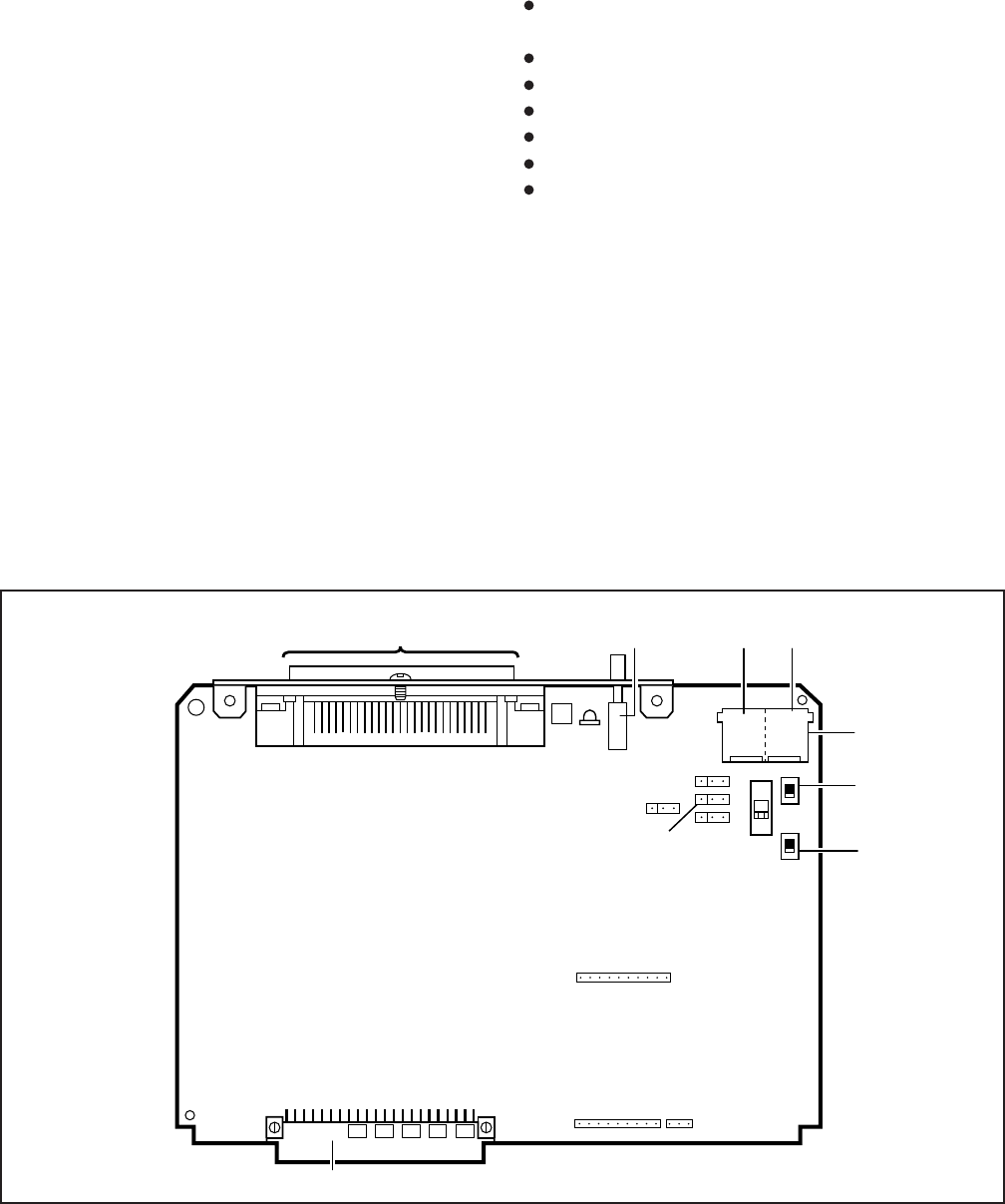
5-28
INSTALLATION-DK 16 KSU & PCB
SECTION 100-816-205
MARCH 1993
12 OPTION INTERFACE UNIT
(PIOU AND PIOUS)
12.00 General
12.01 The Option Interface Unit (PIOU or PIOUS)
provides a circuit interface with peripheral options.
A maximum of one PIOU or PIOUS PCB can be
installed in the system. The PIOU and PIOUS
support the same options, except the PIOUS
does not support Zone Paging (see Paragraph
12.11).
12.02 PIOU controls, indicators, and interface
connectors are shown in Figure 5-18 and de-
scribed in Table 5-F. PIOUS information is pro-
vided in Figure 5-19 and Table 5-G.
12.03 The internal 600 ohm or 3 watt page am-
plifier of the PIOU is not supported by Strata
DK16.
12.10 PIOU and PIOUS Hardware Options
12.11 The PIOU and PIOUS support the following
STRATA DK16 hardware options:
Internal Options
Remote Maintenance Modem Unit (IMDU)
External Options
Alarm Sensor
Local Maintenance Terminal or Modem
SMDR Printer or Call Accounting Port
Remote Maintenance Port
Relay control options
Zone Page via relays (PIOU only)
NOTE:
Refer to Peripheral Equipment Installation,
Section 100-816-207, for installation of exter-
nal options.
12.12 Remote Maintenance Modem Unit (IMDU)
Installation. Install the Remote Maintenance Mo-
dem Unit (IMDU) in accordance with the following
steps:
1) Remove the PCB from its protective packag-
ing.
FIGURE 5-18
PIOU CONTROLS, INDICATORS, AND INTERFACE CONNECTORS
P1
BACKPLANE CONNECTOR
P2
50-PIN AMPHENOL CONNECTOR (FEMALE) SW2
MC.C.I.T.T. N.O.
SPO
1200
300
TTY
MODEM
B
B
TTYSMDR
P13 P12 SPI
SW1
SW3
J3
P3
P11
P10

5-29
INSTALLATION-DK 16 KSU & PCB
SECTION 100-816-205
MARCH 1993
TABLE 5-F
PIOU CONTROLS AND INTERFACE CONNECTORS
CONTROL/INDICATOR/
CONNECTOR
(Figure 5-18)
TYPE OF COMPONENT DESCRIPTION
SMDR/TTY Interface
Connector J3 Dual modular connector Interface connector for SMDR printer/
call accounting device and
maintenance terminal/modem.
10-pin connector
Three-terminal jumper plug
Interface connector for Remote
Maintenance Modem piggy-back module.
External Page/Door Lock Control Relay
MAKE or BREAK jumper plug.
IMDU Connector P1
M/B Make/Break
Jumper Plug P10
TTY Baud Rate Switch
SW2
Two-position locking push-
button switch
Selects baud rate (300 or 1200 bps) for
Remote Maintenance Modem piggy-back
module (IMDU) or external TTY jack.
Modem/TTY Switch
SW3 Enables PIOU for operation with IMDU
modem or TTY jack.
9-pin connector Interface connector for Remote
Maintenance Modem piggy-back module.
IMDU Connector P2
3-pin connector Interface connector for Remote
Maintenance Modem piggy-back module.
IMDU Connector P3
Three-terminal jumper plug Night/Hold Relay MAKE or BREAK
jumper plug.
M/B Make/Break
Jumper Plug P11
Three-terminal jumper plug Alarm sensor normally open or normally
closed jumper plug.
Alarm Sensor N.O./N.C.
Jumper Plug P12
Three-terminal jumper plug IMDU or external modem operating
specification jumper plug.
CCITT/BELL Jumper
Plug P13
Two-position slide switch Selects baud rate (300 or 1200 bps) for
SMDR printer or call accounting device.
SMDR Baud Rate
Switch SW1
Two-position slide switch
2) Set the SW2 baud rate switch on the front
panel to 300 or 1200, as appropriate, after the
PIOU/PIOUS has been installed in the Expan-
sion Unit (in-300 bps—out-1200 bps).
3) Set SW3 to MODEM position for IMDU opera-
tion.
4) Set the P13 jumper plug on the PIOU to the
BELL position; or, cut the W4 jumper on the
PIOUS for BELL operation.
5) Mate IMDU connectors J1, J2, and J3 with
PIOU or PIOUS connectors P1, P2, and P3
(refer to Figure 5-20).
NOTE:
PIOU or PIOUS connectors P1, P2, and P3
are positioned to allow installation of the IMDU
only in the proper position.
6) Apply firm, even pressure to IMDU to ensure
proper mating of connectors.
NOTE:
The IMDU default station intercom number is
619; and IMDU communication parameters are
7-bits, even parity, 1-stop bit.
7) Refer to Programming Procedures, Section
100-816-300, Program 77-1, and set LED 14
to ON to enable IMDU operation.
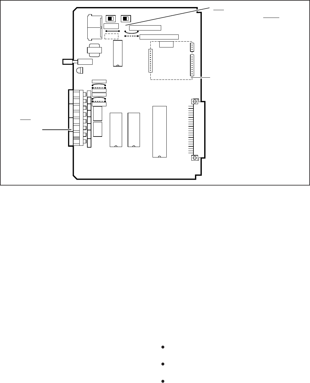
5-30
INSTALLATION-DK 16 KSU & PCB
SECTION 100-816-205
MARCH 1993
FIGURE 5-19
PIOUS PCB SWITCH/JUMPER, OPTION LOCATION
SPT SPR DET DER NHR ALMTNHT ALMR
SMDR
TTY
J3 SW1 SW3
CCITT
BELL
W4 NORMAL OPEN
NORMAL CLOSED
W3
IMDU
W1
W2
600 DE NH ALM
BREAK
MAKE
BREAK
MAKE
K2
K1
PIOUS
OPTIONAL IMDU PCB
REMOTE MAINTENANCE
MODEM
BACKPLANE
CONNECTOR
W4 NOT FACTORY
INSTALLED FOR BELL
MODEM SPECIFICATION
TBI
TERMINAL
STRIP
SW2
CD4
P1
P2
P3
NOTE:
Refer to Remote Maintenance Procedures,
Section 100-816-600, for information regard-
ing the IMDU.
12.20 PIOU and PIOUS Installation Procedure
12.21 Install the PIOU or PIOUS in accordance
with the following steps:
1) Remove the PCB from its protective packag-
ing.
2) Ensure the PIOU or PIOUS has been config-
ured for the appropriate hardware options
(refer to Paragraph 12.10 and Section 100-
816-207).
3) Insert the PIOU or PIOUS into slot 06 in the
Expansion Unit, and apply firm, even pressure
to ensure proper mating of connectors.
4) After installing the PIOU or PIOUS, gently pull
the PCB outward. If the connectors are prop-
erly mated, a slight resistance will be felt.
12.30 PIOU and PIOUS Wiring
12.31 Refer to Peripheral Equipment Installation
(Section 100-816-207) and Wiring Diagrams (Sec-
tion 100-816-208) for PIOU/PIOUS wiring/inter-
connecting details.
12.40 PIOU and PIOUS Programming Overview
12.41 The following parameters may be specified,
through programming, for the PIOU and PIOUS:
Program 77-1
Assigns relay control and IMDU options.
Program 60
Assigns SMDR options.
Program 78
Enables Night Ringing over External Page.

5-31
INSTALLATION-DK 16 KSU & PCB
SECTION 100-816-205
MARCH 1993
TABLE 5-G
PIOUS CONTROLS AND INTERFACE CONNECTORS
CONTROL/INDICATOR/
CONNECTOR
(Figure 5-19)
TYPE OF COMPONENT DESCRIPTION
SMDR/TTY Interface
Connector J3 Dual modular connector Interface connector for SMDR printer/
call accounting device and
maintenance terminal/modem.
10-pin connector
Wire jumper
Interface connector for Remote
Maintenance Modem piggy-back module.
External Page/Door Lock Control Relay
MAKE or BREAK jumper.
IMDU Connector P1
M/B Make/Break Jumper
W1
TTY Baud Rate Switch
SW2 Two-position locking push-
button switch
Selects baud rate (300 or 1200 bps) for
Remote Maintenance Modem piggy-back
module (IMDU) or external TTY jack.
Modem/TTY Switch
SW3 Enables PIOUS for operation with IMDU
modem or TTY jack.
9-pin connector Interface connector for Remote
Maintenance Modem piggy-back module.
IMDU Connector P2
3-pin connector Interface connector for Remote
Maintenance Modem piggy-back module.
IMDU Connector P3
Wire jumper Night/Hold Relay MAKE or BREAK
jumper.
M/B Make/Break Jumper
W2
Wire jumper Alarm sensor normally open or normally
closed jumper.
Alarm Sensor N.O./N.C.
W3
Wire jumper IMDU or external modem operating spec-
ification jumper plug. (BELL = NO W4)
CCITT/BELL Jumper
W4*
Two-position slide switch Selects baud rate (300 or 1200 bps) for
SMDR printer or call accounting device.
SMDR Baud Rate
Switch SW1
Two-position slide switch
*Most modems in USA re
q
uire BELL specification: W4 not factor
y
-installed.
13 CO LINE/DIGITAL TELEPHONE
INTERFACE UNIT (KCDU)
13.00 General
13.01 The KCDU, which can only be installed in the
Expansion Unit of DK16 (it will not function in DK24/
56/96), has two loop start CO line circuits and four
digital telephone circuits. The KCDU digital tele-
phone circuits can support all but one of the de-
vices supported by either the PDKU or Base Unit
integrated digital telephone circuits: digital tele-
phones, PDIU-DIs/PDIU-D12s, PDIU-DSs, ADMs,
and a DDCB. The KCDU does not support a DDSS
console. One or two KCDU PCBs may be installed
in the Expansion Unit. No other station or CO line
PCB can be installed if the KCDU is installed.
13.02 The KCDU is shown is Figure 5-21, and its
controls, connectors, and indicators are described
in Table 5-H.
13.10 KCDU Configuration
13.11 The KCDU may have to be configured to
control excessive loudness if the system is close to
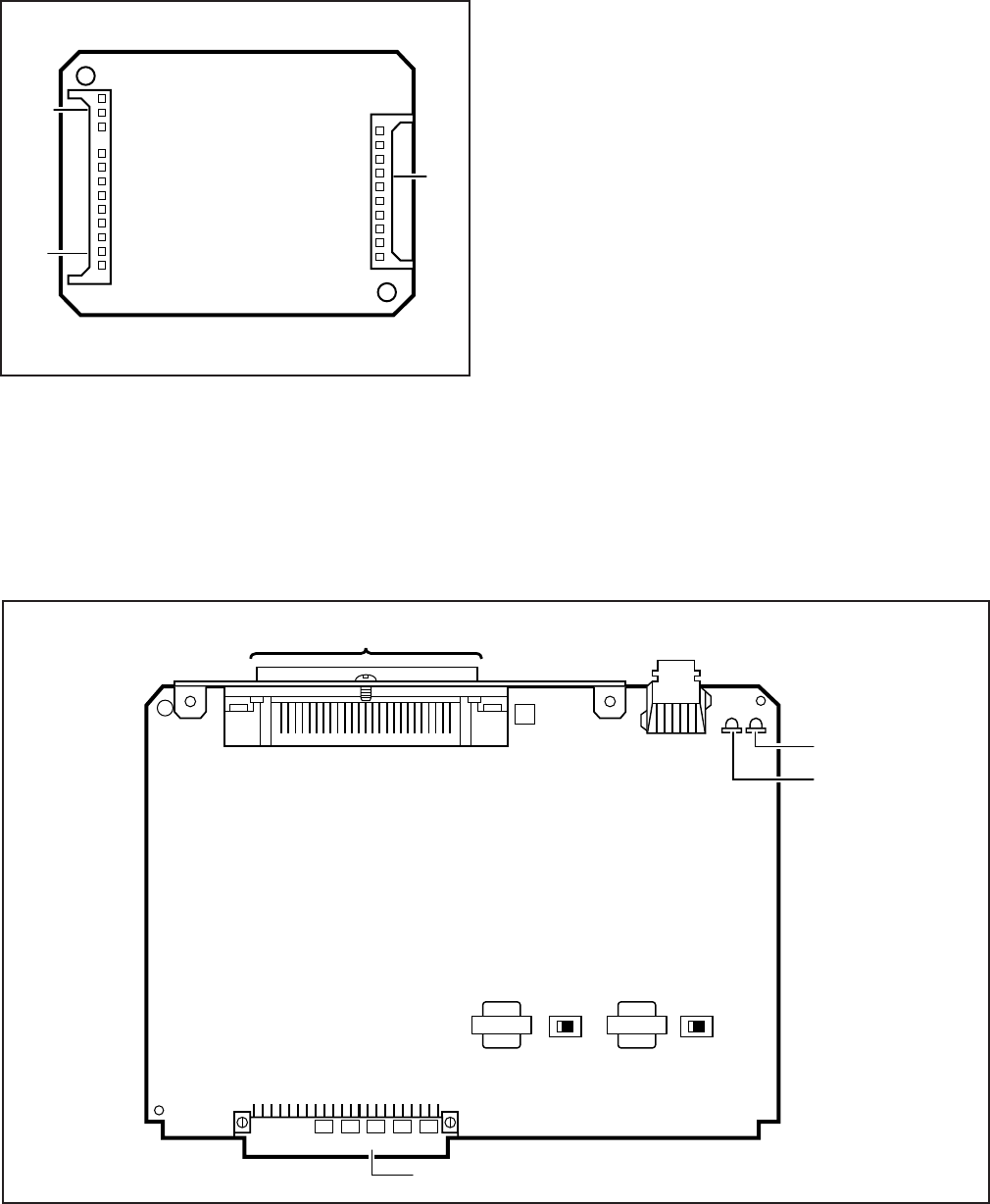
5-32
INSTALLATION-DK 16 KSU & PCB
SECTION 100-816-205
MARCH 1993
a CO or installed behind a PBX telephone system.
It does not have to be configured for anything else.
The decibel (db) PAD switches, SW501 (CO1) and
SW601 (CO2), control the loudness by providing a
3 db signal level drop to, or from, the PBX or CO
when set to the PAD position. The switch comes
from the factory set at NOR (for normal) meaning
no PAD loss.
13.20 KCDU Installation Procedure
13.21 Install the KCDU in accordance with the
following steps:
1) Remove the PCB from its protective packag-
ing.
2) If the system is located within one mile of the
CO or PBX telephone system, set db PAD
switches SW501 and SW601 to the PAD
position.
3) Insert the KCDU into the appropriate slot (04
first, 05 second) in the Expansion Unit, and
apply firm, even pressure to ensure proper
mating of the connectors.
FIGURE 5-20
REMOTE MAINTENANCE MODEM UNIT (IMDU)
IINTERFACE CONNECTORS
FIGURE 5-21
KCDU INDICATORS, OPTIONS, AND CONNECTORS
J3
J2
J1
BACKPLANE CONNECTOR
25-PAIR AMPHENOL CONNECTOR (FEMALE)
CO2
CO1
SW501
(CO1)
SW601
(CO2)
PAD NORPAD NOR
J7
5-33
INSTALLATION-DK 16 KSU & PCB
SECTION 100-816-205
MARCH 1993
TABLE 5-H
KCDU CONTROLS, INDICATORS, AND CONNECTORS
CONTROL/INDICATOR/
CONNECTOR
(Figure 5-21)
TYPE OF COMPONENT DESCRIPTION
CO line circuit 1
Indicator CD517
CO line circuit 2
Indicator CD617
J7 Connectors
PAD Switch SW501
PAD Switch SW601
Lights to indicate CO line circuit 1 is in
operation.
Lights to indicate CO line circuit 2 is in
operation.
Interface connector for CO line circuits,
1 and 2.
Enables 3dB signal level drop for CO line
circuit 1 (when set in PAD position).
Enables 3dB signal level drop for CO line
circuit 2 (when set in PAD position).
Red LED
Red LED
Modular connector
Two-position slide
Two-position slide
4) After installing the KCDU, gently pull the PCB
outward. If the connectors are properly mated,
a slight resistance will be felt.
13.30 KCDU Wiring
13.31 Refer to KCDU Wiring Diagram in Section
100-816-208 for wiring/interconnecting details.
13.40 KCDU Programming Overview
13.41 See the PCOU programming overview and
the PDKU overview in this chapter for KCDU pro-
gramming information. When running Program 03
for the KCDU slot(s), specify code 65 if the KCDU
does not support OCA or PDIU-DI telephones or
code 66 if the KCDU supports OCA or PDIU-DI
telephones. Do not specify code 11, 61, 62, or 64.
14 DTMF RECEIVER/ABR TONE
DETECTOR UNIT (K4RCU)
14.00 General
14.01 The K4RCU must be installed to recognize
Dual-Tone Multi-Frequency (DTMF) tones gener-
ated by a standard telephone (or any other device
connected to a standard telephone circuit) and it is
required for Direct Inward System Access (DISA)
calls. The K4RCU can only be installed in the Base
Unit. The K4RCU circuits are also used to detect
busy tone for the Automatic Busy Redial (ABR)
feature and must be installed to allow ABR to
operate.
14.10 K4RCU Configuration
14.11 The K4RCU does not have to be configured
for operation.
14.20 K4RCU Installation Procedure
14.21 Install the K4RCU in accordance with the
following steps (Figure 5-22).
1) Remove the PCB from its protective packag-
ing.
2) Make sure that the power supply switch is
OFF.
3) Making sure that the component side of the
K4RCU is facing up toward the power supply,
plug the K4RCU P602A and P602B female
connectors into the P2A and P2B (K4RCU)
connectors on the motherboard.
5-34
INSTALLATION-DK 16 KSU & PCB
SECTION 100-816-205
MARCH 1993
tical to the PCOU and KCDU CO line circuits. The
KCOU also has four PAD (3 dB) switches—SW400,
SW425, SW450, and SW475—to reduce exces-
sive loudness caused by a nearby CO or PBX
telephone system. For wiring and programming
considerations, see the PCOU instructions in Para-
graph 8. The Base Unit circuits are fixed and are
assigned to Base Unit virtual equipment slots as
follows: 8-digital station circuit to slot 01, 4-CO line
circuits (KCOU) to slot 02, and 4 standard tele-
phone circuits (KSTU) to slot 3.
15.20 Digital Telephone Circuits
15.21 The eight digital telephone circuits that come
standard with the system are integrated into the
motherboard in the Base Unit. These circuits are
indentical to the digital circuits found on the PDKU
and KCDU. The motherboard does not have to be
configured for the digital circuits to operate. For
wiring and programming considerations, see the
PDKU instructions in Paragraph 7.
15.30 Base Unit CO Line/Digital Station
Circuit Wiring
15.31 Refer to Section 100-816-208 for details.
14.30 K4RCU Wiring
14.31 The K4RCU does not require any wiring.
14.40 K4RCU Programming Overview
14.41 The following parameters may be specified:
Program 03
Enter code 92 for Slot 00 if K4RCU is installed.
Program 12
Set K4RCU release time.
Program 15
Sets K4RCU operation after CO line flash.
15 BUILT-IN CO LINE AND
DIGITAL TELEPHONE CIRCUITS
15.00 General
15.01 As mentioned in Paragraph 2, the Base Unit
comes standard with four CO lines and eight digital
telephone circuits already installed.
15.10 Built-in CO Line Circuits
15.11 The four standard loop start CO line circuits
are on a printed circuit board (PCB) called the
KCOU, which is installed on the motherboard at the
factory (Figure 5-23). The KCOU circuits are iden-
FIGURE 5-22
K4RCU PCB
VERSION
P602A P602B
P2A (BASE UNIT) P2B (BASE UNIT)
CONNECTORS
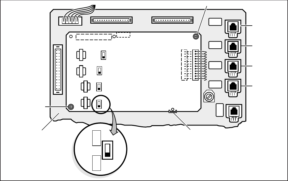
5-35
INSTALLATION-DK 16 KSU & PCB
SECTION 100-816-205
MARCH 1993
16 KCOU REMOVAL AND
REPLACEMENT
16.00 General
16.01 The KCOU comes factory-installed in the
Base Key Service Unit (Figure 5-3); if necessary,
it can be removed and replaced.
16.10 KCOU Removal
1) Make sure the Power Supply (KPSU16) DC
power switch is turned off.
2) Loosen and remove screws 1 and 2 (Figure
5-23).
3) Pull back plastic stand-off tab and pull up on
KCOU until P7 is unplugged.
4) Pull wires on P6 and remove P6 connector
from Base Unit.
16.20 KCOU Replacement
1) Make sure the Power Supply (KPSU16) DC
power switch is off.
2) Mate and connect KCOU P6 cable connector
to P6 on Base Unit motherboard so that the
red wire is aligned as shown in Figure 5-23.
3) Position KCOU as shown in Figure 5-23.
4) Mate and connect KCOU P7 to P7 on the Base
Unit motherboard.
5) Secure plastic stand-off tab and install screws
1 and 2.
6) Set SW400 ~ 475 to appropriate position. In
most cases set to the normal position (NOR);
if CO lines are connected to a PBX or are in
close proximity to the Central Office, set to the
PAD position to provide a 3 db loss in signal
level.
FIGURE 5-23
KCOU PCB
KRCU
BASE UNIT
MOTHERBOARD
SW400 SW425 SW450 SW475
J4 (CO4)
J3 (CO4)
J2 (CO4)
J1 (CO4)
PLASTIC STAND-OFF
(TAB)
SW400 FOR CO1
SW425 FOR CO2
SW450 FOR CO3
SW475 FOR CO4
SCREW (1)
SCREW (2)
P6
REDRED
P7
KCOU
P2BP2A
KCOU
SW400
PAD
NOR
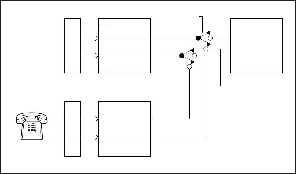
5-36
INSTALLATION-DK 16 KSU & PCB
SECTION 100-816-205
MARCH 1993
FIGURE 5-24
DK16 BASE UNIT POWER FAILURE TRANSFER (PFT) CIRCUIT DIAGRAM
4
3
MOD JACK CO1
(BASE UNIT)
MDF
CO
LINE
5
2
MOD JACK PF1
(BASE UNIT)
R
T
MDF
PFT
STANDARD
TELEPHONE
DK8 OR DK16
KSU MAIN PCB
T
R
POWER FAIL
CONNECTION
POWER AVAILABLE
CONNECTION
KCOU
CO LINE 1
17 DK16 POWER FAILURE EMERGENCY
TRANSFER OPTION
17.00 A dedicated standard telephone can be con-
nected to the Power Failure Transfer Interface
(PF1) on the DK16 Base Unit to provide power
failure backup. During normal operation, this tele-
phone cannot be used—it does not count as a
station; so it does not reduce the system's 20
maximum station capacity. But if there is a power
failure, the telephone will automatically be con-
nected to CO line 1. When power is restored, the
system will automatically resume with its normal
station and CO line assignments, and the dedi-
cated telephone will become inoperative again.
17.10 DK16 Power Failure Emergency Transfer
Installation. Install the dedicated emergency stan-
dard telephone as follows (see Figure 5-24):
1) Connect a standard telephone to the PF1
connector in the Base Unit.
17.11 DK16 Power Failure Emergency Trans-
fer Test.
1) Turn the system power switch off.
2) Lift the emergency standard telephone hand-
set, and verify that there is CO dial tone.

INSTALLATION-STATION APPARATUS
SECTION 100-816-206
MARCH 1993
INSTALLATION
CHAPTER SIX
STATION APPARATUS INSTALLATION
TOSHIBA SYSTEM PRACTICES
DIGITAL KEY TELEPHONE SYSTEMS

INSTALLATION-STATION APPARATUS
SECTION 100-816-206
MARCH 1993
INSTALLATION-STATION APPARATUS
SECTION 100-816-206
MARCH 1993
6-i
TABLE OF CONTENTS
PARAGRAPH SUBJECT PAGE
1OVERVIEW .............................................................................................................. 6-1
1.00 Purpose ................................................................................................................ 6-1
1.10 Types of Telephones ............................................................................................ 6-1
2TELEPHONE INSTALLATION ................................................................................. 6-1
2.00 General ................................................................................................................. 6-1
2.10 Connecting Digital Telephones to the System ..................................................... 6-1
2.20 Connecting Electronic Telephones to the System (DK16 only)............................. 6-2
2.30 Connecting Standard Telephones to the System ................................................. 6-2
2.40 Telephone Wall Mounting ..................................................................................... 6-2
3DIGITAL TELEPHONE UPGRADES ....................................................................... 6-4
3.10 Simultaneous Voice and Data Upgrade (PDIU-DI2 and PDIU-DI) ........................ 6-4
3.20 Off-hook Call Announce Upgrade (DVSU) ........................................................... 6-6
3.30 Loud Ringing Bell/Headset Upgrade (HHEU)....................................................... 6-6
3.40 Carbon Headset/Handset Straps.......................................................................... 6-9
3.50 Beep Strap............................................................................................................ 6-9
3.60 Microphone/Speaker Sensitivity Adjustment (Speakerphones Only) .................... 6-10
3.70 Busy Override and Camp-on Ring Tone Over Handset/Headset Option .............. 6-10
3.80 External Power Straps .......................................................................................... 6-10
3.90 DKT2000 Add-On-Module Installation.................................................................. 6-11
4ELECTRONIC TELEPHONE UPGRADE OPTIONS (DK16 Only)............................ 6-11
4.10 Off-hook Call Announce Upgrade (HVSU2 or HVSU/HVSI) ................................. 6-11
4.20 Loud Ringing Bell/Headset Upgrade (HHEU)....................................................... 6-12
4.30 Carbon Headset/Handset Straps.......................................................................... 6-13
4.40 Beep Strap............................................................................................................ 6-14
4.50 Microphone/Speaker Threshold (Speakerphones Only) ....................................... 6-14
4.60 Handset Receiver Volume-Up Strap (Version 2 6500-Series Telephones Only) .. 6-14
5DIRECT STATION SELECTION CONSOLE/SYSTEM CONNECTION
(DK16 Only).............................................................................................................. 6-14
5.10 DDSS Console Connections ................................................................................ 6-14
5.20 HDSS Console Connections ................................................................................ 6-15
6DOOR PHONE/LOCK CONTROL UNIT AND DOOR PHONE
INSTALLATION ........................................................................................................ 6-15
6.10 DDCB and MDFB Cabling .................................................................................... 6-16
6.20 DDCB Wall Mounting............................................................................................ 6-16
6.30 Door Phone (MDFB) Wall Mounting ..................................................................... 6-16
6.40 Door Phone/Lock Programming Considerations .................................................. 6-17
7ADD-ON MODULE INSTALLATION ........................................................................ 6-17
INSTALLATION-STATION APPARATUS
SECTION 100-816-206
MARCH 1993
FIGURE LIST
FIGURE TITLE PAGE
6-1 REMOVING THE TELEPHONE BASE .................................................................... 6-3
6-2 HANDSET HANGER ................................................................................................ 6-3
6-3 WALL MOUNTING BASE ROTATION ..................................................................... 6-3
6-4 PDIU-DI2 INSTALLATION INTO 2000-SERIES DIGITAL TELEPHONE.................. 6-5
6-5 PDIU-DI INSTALLATION INTO 1000-SERIES DIGITAL TELEPHONE.................... 6-5
6-6 DVSU INSTALLATION FOR DIGITAL TELEPHONES ............................................ 6-6
6-7 DKT2010-H STRAP AND CONNECTOR LOCATIONS ........................................... 6-7
6-8 DKT2010-SD, DKT2020-S, AND DKT2020-SD STRAP AND CONNECTOR
LOCATIONS ............................................................................................................. 6-7
6-9 1000-SERIES DIGITAL TELEPHONE STRAP AND CONNECTION
LOCATIONS ............................................................................................................. 6-7
6-10 HHEU INSTALLATION FOR DIGITAL TELEPHONE .............................................. 6-8
6-11 HESC-65A CABLING ............................................................................................... 6-8
6-12 HVSU2 INSTALLATION FOR ELECTRONIC TELEPHONES .................................. 6-11
6-13 ELECTRONIC TELEPHONE PCB CONNECTIONS ............................................... 6-12
6-14 HVSI/HVSU INSTALLATION FOR ELECTRONIC TELEPHONES .......................... 6-12
6-15 HHEU INSTALLATION FOR ELECTRONIC TELEPHONES.................................... 6-13
6-16 DOOR PHONE (DDCB) INSTALLATION................................................................. 6-16
6-17 DOOR PHONE (MDFB) INSTALLATION................................................................. 6-17
6-18 ADD-ON-MODULE INSTALLATION ........................................................................ 6-18
6-19 DK16 ADD-ON-MODULE DSS BUTTON ASSIGNMENTS ...................................... 6-18
6-20 DK8 ADD-ON-MODULE DSS BUTTON ASSIGNMENTS ........................................ 6-18
6-ii

6-1
INSTALLATION-STATION APPARATUS
SECTION 100-816-206
MARCH 1993
1 OVERVIEW
1.00 Purpose
1.01 This chapter provides instructions on how to
connect telephones to the STRATA DK8 and DK16
systems and how to configure and upgrade them
for optional features. Procedures for installing di-
rect station selection consoles and door phones
also appear in this chapter.
1.10 Types of Telephones
1.11 The STRATA DK8 and DK16 systems can
support the following telephones.
Digital Telephones: Installation instructions for
digital telephones in this chapter and elsewhere
in this manual apply only to the Toshiba 2000-
and 1000-series Digital Telephones. The 2000-
series Digital Telephones consist of four mod-
els: the DKT2010-H, the DKT2010-SD, the
DKT2020-S, and the DKT2020-SD. There are
two 1000-series Digital Telephone models, the
DKT1020-H and the DKT1020-SD.
Electronic Telephones: (DK16 only) The elec-
tronic telephone instructions here apply to the
Toshiba 6500-series Electronic Telephones,
although there are other electronic telephones
(the 2000-, 3000-, 6000-, and 6500-series) that
are compatible with the STRATA DK16. The
6500-series electronic telephones consist of
four models: the EKT6510-H, the EKT6510-S,
the EKT6520-H, and the EKT6520-SD.
Standard Telephones: 500- and 2500-type
standard telephones apply whenever standard
telephones are mentioned in this manual.
2 TELEPHONE INSTALLATION
2.00 General
2.01 This section describes the wiring required to
connect telephones to the system. Before install-
ing any telephone wiring, read the following warn-
ing and caution notes:
WARNING!
1. Never install the telephone wiring dur-
ing a lightning storm.
2. Never install the telephone jacks in
wet locations, unless the jack is spe-
cifically designed for wet locations.
3. Never touch uninsulated telephone
wires or terminals unless the telephone
line has been disconnected at the net-
work interface.
4. Use caution when installing or modify-
ing telephone lines.
5. If telephone, DSS console, Door phone
control box, or Door phone wiring ex-
its the building, external secondary
protection is required. See Section 100-
816-208.
CAUTION!
When installing the station cable, do not
run parallel to and within three feet of an
AC power line. AC power lines should be
crossed at right (90
°
) angles only. In par-
ticular, avoid running station wire pairs
near devices that generate electrical noise,
such as neon or fluorescent light fixtures.
2.10 Connecting Digital Telephones to the
System
2.11 The following provides information on how to
connect digital telephones to the DK8 or DK16
system.
NOTE:
Before proceeding, see warning and caution
notes in Paragraph 2.01.
2.12 Digital telephones connect to the digital tele-
phone ports via the main distribution frame (MDF)
with standard twisted-pair jacketed telephone cable.
Single-pair wiring is sufficient in most cases for
digital telephones to operate effectively at up to
1000 feet from the key service unit, if using 24
AWG cable. But digital telephones that are
equipped with Integrated Data Interface Units or
ADMs should have two-pair (or external power) to
function effectively at this distance. This also ap-
plies to digital telephones that are supported by
systems that must operate with battery reserve
power—see Wiring Diagrams, Section 100-816-
208, for loop limits (see Table 8-D).

INSTALLATION-STATION APPARATUS
SECTION 100-816-206
MARCH 1993
6-2
To accommodate the digital telephone line cord,
the cable should be terminated in a modular sta-
tion connector block (RJ-11) at the station location.
The standard single-pair, modular digital telephone
cord that is sent with the telephone is 7 feet (the
maximum allowed is 25 feet).
NOTES:
1. Digital telephone cable runs must not
have the following:
Cable splits (single or double)
Cable bridges (of any length)
High resistance or faulty cable splices
2. See Section 100-816-208 for secondary
protector information.
2.20 Connecting Electronic Telephones to
the System (DK16 only)
2.21 The following provides information on how to
connect electronic telephones to the DK16 sys-
tem.
NOTE:
Before proceeding, see warning and caution
notes in Paragraph 2.01.
2.22 Electronic telephones are connected to elec-
tronic telephone circuits in the DK16 Expansion
Unit on the Electronic Telephone Interface Unit
(PEKU) and the Standard/Electronic Telephone
Interface Unit (PESU) via the main distribution
frame (MDF) with standard twisted-pair jacketed
telephone cable. Two-pair wiring, as a minimum, is
required for telephone connection. However, three-
pair wiring is recommended to permit future up-
grades, such as Off-hook Call Announce.
To accommodate the electronic telephone line
cord, the cable should be terminated in a modular
station connector block (RJ-11) at the station loca-
tion. The standard two-pair modular electronic
telephone cord length is seven feet (the maximum
allowed length is 25 feet). See Wiring diagrams,
Section 100-816-208 for more details.
NOTE:
See Section 100-816-208 for secondary pro-
tector information.
The overall length of the station cable run from the
DK16 key service unit (KSU) to the telephone must
not exceed 1,000 feet (305 meters), if using 24
AWG cable.
2.30 Connecting Standard Telephones to the
System
2.31 The following provides information on how to
connect standard telephones to the DK8 or DK16
system.
NOTE:
Before proceeding, see warning and caution
notes in Paragraph 2.01.
2.32 Standard telephones connect to standard
telephone circuits in the DK8 Standard Telephone
Interface Unit (QSTU), telephone circuits on the
DK16 Base Unit Standard Telephone Interface
Unit (KSTU), the DK16 Standard Telephone Inter-
face Unit (PSTU), and the DK16 Standard/Elec-
tronic Telephone Interface Unit (PESU) via the
main distribution frame (MDF) with standard
twisted-pair jacketed telephone cable. Single-pair
wiring is required. (Refer to Wiring Diagrams,
Section 100-816-208, for more details.)
NOTE:
See Section 100-816-208 for secondary pro-
tector information.
The standard telephone cable's overall loop resis-
tance, connected on- or off-premises, is 300 ohms
maximum, including the telephone resistance. This
also applies to all devices connected to standard
telephone circuits. A standard telephone connected
off-premises via the telephone network should
interface with OL13A lines (or equivalent) and
connect to an RJ21X FIC jack (or equivalent).
2.40 Telephone Wall Mounting
2.41 This section provides instructions on how to
mount digital telephones and electronic telephones
(DK16 only) to a wall or other vertical surface.
Instructions on mounting standard telephones are
not provided here; refer to the manufacturer's
documentation for those instructions.
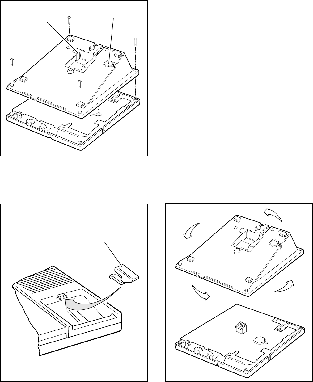
6-3
INSTALLATION-STATION APPARATUS
SECTION 100-816-206
MARCH 1993
FIGURE 6-1
REMOVING THE TELEPHONE BASE
FIGURE 6-2
HANDSET HANGER
FIGURE 6-3
WALL MOUNTING BASE ROTATION
HANDSET
HANGER
PLASTIC
TAB
HANDSET
HANGER
2.42 Mount digital and electronic telephones in
accordance with the following steps:
NOTES:
1. Digital telephones equipped with Inte-
grated Data Interface Units (PDIU-DIs or
PDIU-DI2s) cannot be wall mounted.
2. Electronic and older digital telephones
equipped with an HHEU1 can be wall
mounted. 2000-series Digital Telephones
with headsets can only be wall mounted
with an HHEU2.
1) Loosen the captive screws, and remove the
telephone base (Figure 6-1).
2) Using a suitable cutter, remove the handset
hanger from the base (Figure 6-1). Insert the
handset hanger in the slot provided on the
front of the telephone (Figure 6-2). The hanger
fits in the notch on the handset cradle.
3) Rotate the telephone base 180 degrees and
secure it to the telephone with its four captive
screws (Figure 6-3).

INSTALLATION-STATION APPARATUS
SECTION 100-816-206
MARCH 1993
6-4
with a PDIU-DI2 can support an HHEU at
the same time, but cannot support a
DVSU. A 1000-series Digital Telephone
equipped with a PDIU-DI cannot support
an HHEU, ADM, or a DVSU for OCA.
2. PDKU1 circuits 1 ~ 7 only can support
PDIU-DI(2)s, but all PDKU2 and base unit
digital circuits, can support PDIU-DI(2)s.
3.13 PDIU-DI(2) Installation. Install the integrated
data interface unit (PDIU-DI for 1000-series and
PDIU-DI2 for 2000-series) in accordance with the
following steps:
1) Loosen the four captive screws securing the
digital telephone base and remove it (Figure
6-1).
2) Refer to Figure 6-4 for 2000-series telephones
or Figure 6-5 for 1000-series telephones, and
insert the two integrated unit wire plugs into
the connectors on the printed circuit board
(PCB) in the telephone (observing the red
wire for correct positioning).
3) Attach the integrated unit to the bottom of the
telephone and secure with the four captive
screws.
4) Remove the telephone number directory tray
from the original telephone base and install it
on the integrated unit telephone base. Bend
the tray by squeezing its sides so it bows
slightly to remove and re-install (Figure 6-4 or
6-5).
5) Check Table 8-D in Section 100-816-208;
install 2-pair house cable (or external power)
and 2-pair modular cord (supplied with PDIU-
DI) if required to achieve maximum distance.
3.14 Integrated Data Interface Unit Program-
ming Overview
Program 39
Assigns the Data Call, Data Release, and
Modem buttons.
Programs 20 and 22
Used for data interface unit assignments.
4) Connect the telephone to the wall modular
connector with a cord approximately four
inches long (available at most telephone sup-
ply companies). Route the cord into the hol-
low portion of the base.
5) Mount the telephone on the wall mounting
modular connector plate.
3 DIGITAL TELEPHONE UPGRADES
3.00 This section describes how to upgrade and
configure 2000- and 1000-series Digital Tele-
phones for features and options.
3.10 Simultaneous Voice and Data Upgrade
(PDIU-DI2 and PDIU-DI)
3.11 Both the 2000- and 1000-series Digital Tele-
phones can be upgraded with an integrated data
interface unit to transmit and receive simultaneous
voice and data calls. There are two versions of the
integrated unit: the PDIU-DI and the PDIU-DI2.
The 2000-series telephones can only be equipped
with a PDIU-DI2, and the 1000-series telephones
can only be equipped with a PDIU-DI. Asynchro-
nous devices, such as personal computers (PC)
and terminals, can be connected to the standard
RS-232 connector of the PDIU-DI(2). Station us-
ers are able to transmit and receive RS-232 data
over the single wire pair of the PDIU-DI(2)-equipped
telephone.
3.12 Data calls can be manually dialed with a
Data Call button and disconnected with a Data
Release button on the telephone; or, data and
voice calls can be dialed from the keyboard of the
terminal or PC using standard "AT" commands.
Digital telephones may also be assigned a Mo-
dem button to reserve a modem or monitor mo-
dem availability and status. Assign feature buttons
to telephones with Program 39.
NOTES:
1. 1000- and 2000-series Digital Telephones
equipped with a PDIU-DI(2) cannot be
wall-mounted or equipped with an Add-
On-Module (ADM), or DVSU for OCA. A
2000-series digital telephone equipped
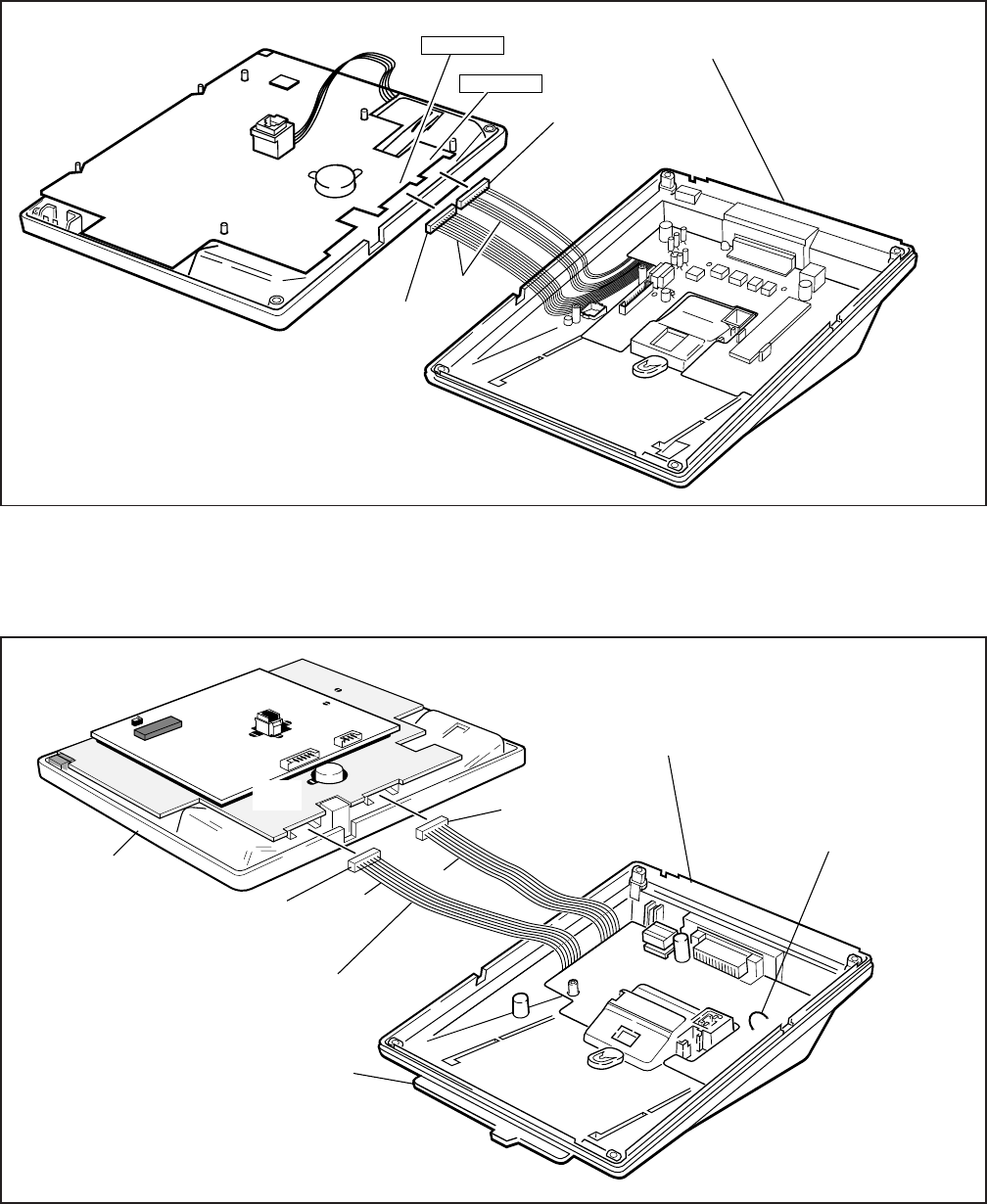
6-5
INSTALLATION-STATION APPARATUS
SECTION 100-816-206
MARCH 1993
TO P2 OF
BOTTOM PCB
DIGITAL
TELEPHONE
TOP ASSEMBLY
PDIU-DI2 2000
DIGITAL
TELEPHONE BASE
TO P1 OF
BOTTOM PCB
RS-232 (FEMALE)
DB-25 CONNECTOR
RED
WIRE
DIU & VSU
DIU & ADM
FIGURE 6-4
PDIU-DI2 INSTALLATION INTO 2000-SERIES DIGITAL TELEPHONE
TO P2 OF
BOTTOM PCB
RED
WIRE
DKTO-20KD
DKT10-SUB(SPF) TOSHIBA
DVSU
HHEU
DIGITAL
TELEPHONE
TOP ASSEMBLY
PDIU
TO P1 OF
BOTTOM PCB
RS-232 (FEMALE)
DB-25 CONNECTOR
RED
WIRE
PDIU-DI 1000 DIGITAL
TELEPHONE BASE
IMPORTANT: DO NOT CONNECT
DIU CABLES TO HHEU CONNECTOR
RED
RED
DIRECTORY TRAY
PERCEPTION
STRAP (ONLY CUT
IF INSTALLED ON
PERCEPTION)
NOTE:
A 1000-SERIES DIGITAL TELEPHONE
CANNOT SUPPORT AN HHEU AND A
PDIU-DI AT THE SAME TIME.
PDIU-DI PCB
PDIU/
DVSU
FIGURE 6-5
PDIU-DI INSTALLATION INTO 1000-SERIES DIGITAL TELEPHONE
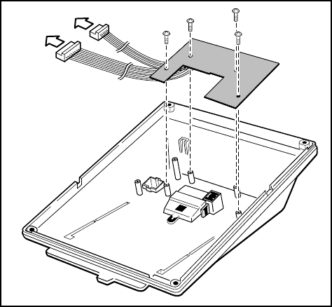
INSTALLATION-STATION APPARATUS
SECTION 100-816-206
MARCH 1993
6-6
3.20 Off-hook Call Announce Upgrade
(DVSU)
3.21 To receive Off-hook Call Announce (OCA)
calls, a digital telephone must be upgraded with a
DVSU; the telephone making the call does not
require a DVSU. An additional wire pair is not
required for digital telephones that receive OCA
calls. The DVSU is compatible with both 2000-
series and 1000-series Digital Telephones.
NOTE:
Digital telephones cannot be equipped with a
DVSU and integrated data interface unit
(PDIU-DI or PDIU-DI2) at the same time.
3.22 DVSU Upgrade Installation. Install the
DVSU upgrade in accordance with the following
steps.
1) Loosen the four captive screws securing the
telephone base (Figure 6-1) and remove the
base.
2) Loosen the four captive screws securing the
metal plate to the standoffs inside the base
where the DVSU will be installed (Figure 6-6).
Remove the plate, which can be discarded.
3) Position the DVSU PCB on the standoffs
(Figure 6-6), and secure with the four pro-
vided screws.
4A) If installing the DVSU into a 2000-series digital
telephone, refer to Figure 6-7 (DKT2010-H)
or Figure 6-8 (DKT2010-SD, DKT2020-S,
DKT2020-SD), and then connect the DVSU
wire plugs to the DVSU connectors on the
printed circuit board (PCB) inside the
telephone.
4B) If installing the DVSU into a 1000-series digi-
tal telephone, refer to Figure 6-9, and connect
the DVSU wire plugs to the DVSU connectors
on the PCBs inside the telephone.
5) Reinstall the telephone base and secure it
with its four captive screws.
3.30 Loud Ringing Bell/Headset Upgrade
(HHEU)
3.31 The loud ringing bell/headset upgrade (HHEU)
enables an external speaker (HESB) for the Loud
Ringing Bell feature and/or a headset to be con-
nected to both series of digital telephones.
NOTES:
1. There are two types of HHEU: the HHEU1
(which has four versions, V.1 ~ V.4) and
the HHEU2.
2. Both 2000- and 1000-series Digital Tele-
phones require either an HHEU2 or a V.3
or V.4 HHEU1 for HESB operation; ear-
lier HHEU1 versions are only sufficient
for headset operation only.
3. Only digital telephones equipped with an
HHEU2 can be wall mounted. The HHEU2
is identical to the V.4 HHEU1, except that
the HHEU2 has longer wires to accom-
modate wall mounting.
4. A Toshiba HESC-65A cable is required to
connect the HHEU in a digital telephone
to the HESB.
5. 1000-series digital telephones cannot be
equipped with the HHEU (any type or
RED
WIRE
RED WIRE
FIGURE 6-6
DVSU INSTALLATION FOR DIGITAL
TELEPHONES
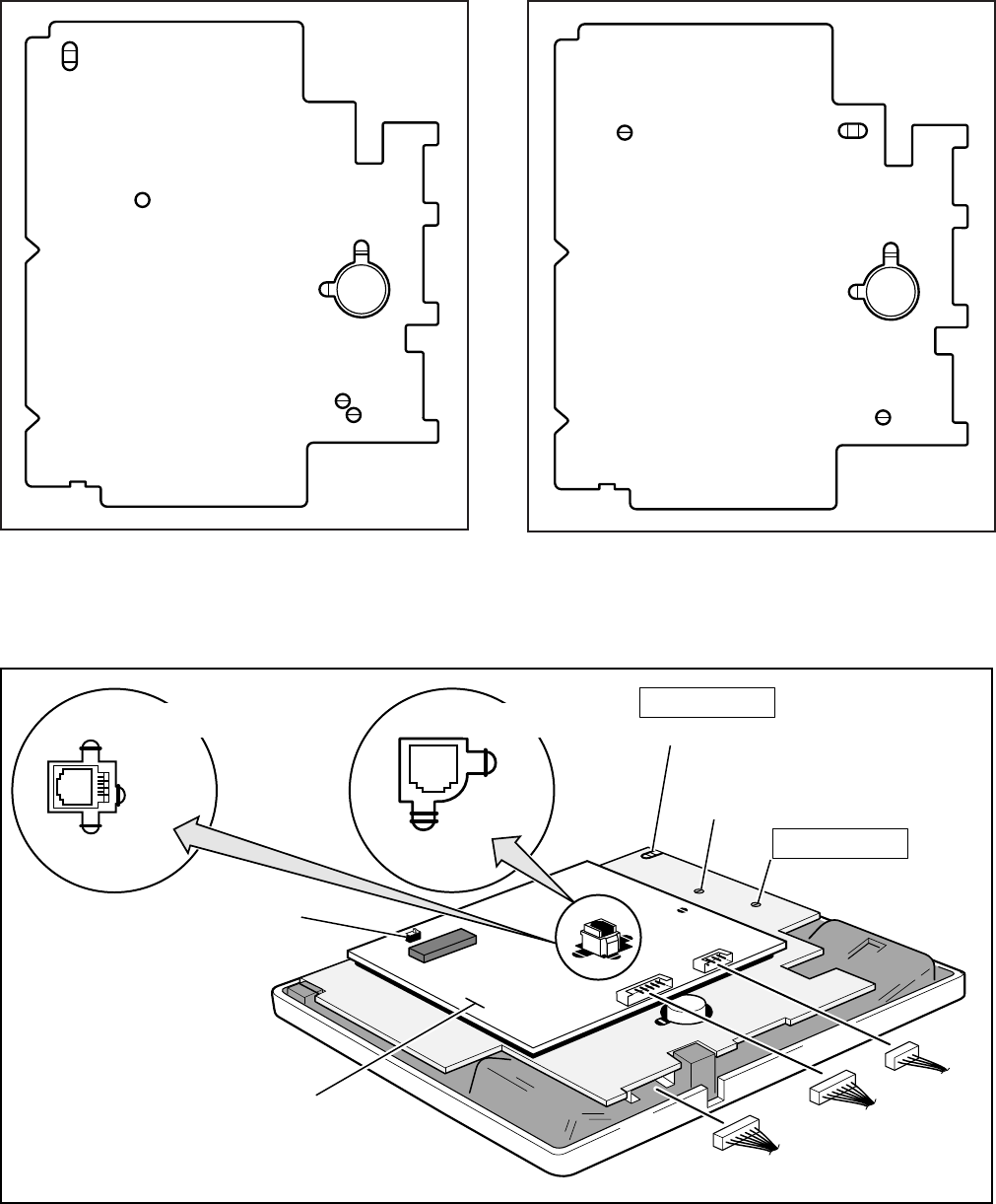
6-7
INSTALLATION-STATION APPARATUS
SECTION 100-816-206
MARCH 1993
DIU&ADMDIU&DVSUHHEU DVSU
P1P2P3 P6
CARBON
EX.SP
HHEU
W203
W201
W202
W204
W204
BEEP
HS-BOV
EX.POW
W101
W102
W409
RED
RED
RED
DIU&ADMDIU&DVSUHHEU DVSU
P1P2P3 P6
CARBON
EX.SP
HHEU
W203
W201
W202
W204
BEEP
EX.POW
W101
W102
REDREDREDRED
FIGURE 6-8
DKT2010-SD, DKT2020-S, AND DKT2020-SD
STRAP AND CONNECTOR LOCATIONS
FIGURE 6-7
DKT2010-H STRAP AND CONNECTOR
LOCATIONS
1020SD ROOM
NOISE SWITCH
DVSU
DVSU
HHEU
EX.SP STRAP
W204-1020H
W305-1020SD DVSU
HHEU
DVSU
RED
WIRE
RED
WIRE
W202
HHEU
CARBON
W201 W203
HHEU W303
CARBON
W301
CARBON
W302
DKT1O-20KD
DKT10-SUB(SPF) TOSHIBA
H
N
W101/W102-1020SD
EX: POWER
W101/W102-1020H
EX: POWER
DKT1020H
DKT1020SD
BEEP
W301-1020H
W304-1020SD
RED
WIRE
FIGURE 6-9
1000-SERIES DIGITAL TELEPHONE STRAP AND CONNECTION LOCATIONS
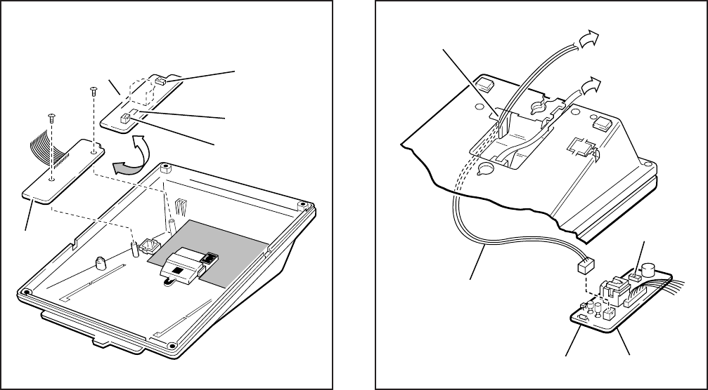
INSTALLATION-STATION APPARATUS
SECTION 100-816-206
MARCH 1993
6-8
version) and the integrated data interface
unit (PDIU-DI) at the same time, but 2000-
series digital telephones can support an
HHEU and a PDIU-DI2 at the same time.
3.32 HHEU Upgrade Installation (HHEU) Install
the Loud Ringing Bell/headset upgrade (HHEU) in
accordance with the following steps.
1) Loosen the four captive screws securing the
telephone base (Figure 6-1), and remove the
base.
2) Using a screwdriver or other suitable tool,
remove the plastic tab located on the back of
the base (Figure 6-1); the HHEU modular
connector for the headset will be accessed
through this opening.
3) If installing a V.3 HHEU1, set the SW601
switch on the HHEU to HEADSET for the
headset or loud bell application (Figure 6-10).
V.4 HHEU1 and HHEU2 do not have this
switch, because both of these upgrades are
automatically set for the headset/loud bell
application.
4) Connect the HESC-65A cable to P601 of the
HHEU (both HHEU1A versions and the
HHEU2 have P601) if the Loud Ringing Bell
option is required (Figure 6-11). Refer to
Section 100-816-207 for HESB installation
procedures.
5A) For the V.3 HHEU1: If only the headset is
connected to the HHEU, cut both sides of the
R607 resistor (Figure 6-10), then remove the
resistor to eliminate electrical contact.
NOTE:
Do not cut the R607 resistor if connecting an
HESB to the HHEU for the Loud Ringing
Bell—even if a headset is also installed on the
HHEU.
5B) For the V.4 HHEU1 and the HHEU2: If only
the headset is connected to the HHEU, cut
the OCA strap (Figure 6-10).
NOTE:
Do not cut the OCA strap if connecting an
HESB to the HHEU for the Loud Ringing
FIGURE 6-10
HHEU INSTALLATION FOR DIGITAL TELEPHONE
FEED THROUGH
FOR HESC-65(A) CABLE TO HESB
BLOCK
SW601
HHEU P601
HESC-65 CABLE
OR
HESC-65A CABLE
HHEU
COMPONENT SIDE OF HHEU
SW601
P601
R607 (HHEU1 V.1 ~ V.3)
OCA (HHEU1
(HHEU1 V.1 ~ V.3)
V.4 or HHEU2)
FIGURE 6-11
HESC-65A CABLING
6-9
INSTALLATION-STATION APPARATUS
SECTION 100-816-206
MARCH 1993
Bell—even if a headset is also installed on the
HHEU.
6) Position the HHEU PCB on the standoffs
inside the base (Figure 6-10), and secure with
the two provided screws.
7A) For 2000-series digital telephones, refer to
Figure 6-7 (DKT2010-H) or Figure 6-8
(DKT2010-SD, DKT2020-S, DKT2020-SD),
and connect the wire plug of the HHEU PCB
to the HHEU connector on the printed circuit
board (PCB) on the telephone.
7B) For 1000-series digital telephones, refer to
Figure 6-9, and connect the wire plug of the
HHEU to the HHEU connector on the PCB of
the telephone.
8A) For 2000-series digital telephones, refer to
Figure 6-7 (DKT2010-H) or Figure 6-8
(DKT2010-SD, DKT2020-S, DKT2020-SD),
and locate the EX.SP strap on the PCB in the
telephone. Cut the strap if an HESB will be
connected to the HHEU.
8B) For 1000-series digital telephones, refer to
Figure 6-9, and locate the EX.SP strap on the
upper PCB in the telephone, and cut it if an
HHEU will be connected to an HESB for the
Loud Ringing Bell option.
9A) For 2000-series digital telephones, refer to
Figure 6-7 (DKT2010-H) or Figure 6-8
(DKT2010-SD, DKT2020-S, DKT2020-SD),
and locate the HHEU strap on the PCB in the
telephone. Cut the strap if a headset will be
connected to the HHEU.
9B) For 1000-series digital telephones, refer to
Figure 6-9, and locate the HHEU strap on the
upper PCB in the telephone. Cut the strap if
an HHEU will be connected to a headset.
NOTE:
If the HHEU PCB is removed from the tele-
phone, the HHEU strap must be replaced for
proper telephone operation.
10) Reinstall the telephone base, and secure it
with its four captive screws.
11) To adjust the volume of the HESB Loud
Ringing Bell: Call the telephone connected to
the HESB, and adjust the volume control on
the back of the HESB and the ring volume
control on the telephone.
3.40 Carbon Headset/Handset Straps
3.41 If a carbon-type handset or headset is con-
nected to the handset jack on the side of the
telephone, two jumper straps inside the telephone
must be cut. Cut the straps in accordance with the
following steps:
NOTE:
It is not necessary to cut these straps if the
headset is connected to the HHEU.
1) Loosen the four captive screws securing the
telephone base (Figure 6-1), and remove the
base.
2A) For 2000-series digital telephones refer to
Figure 6-7 or 6-8, and cut the CARBON
straps, W201 and W202.
2B) For 1000-series digital telephones, refer to
Figure 6-9, and cut the CARBON straps,
(W301 and W302 on the DKT1020-SD; W201
and W203 on the DKT1020-H).
3) Reinstall the telephone base, and secure it
with its four captive screws.
3.50 Beep Strap
3.51 A "beep" sounds whenever a dialpad button
or feature button is pressed on a digital telephone.
To eliminate this beep follow the procedure below:
1) Loosen the four captive screws securing the
telephone base (Figure 6-1), and remove the
base.
2A) For 2000-series digital telephones, refer to
Figures 6-7 or 6-8, and cut the BEEP strap.
2B) For 1000-series digital telephones, refer to
Figure 6-9, and cut the BEEP strap.
3) Reinstall the telephone base, and secure it
with its four captive screws.

INSTALLATION-STATION APPARATUS
SECTION 100-816-206
MARCH 1993
6-10
3.60 Microphone/Speaker Sensitivity Adjust-
ment (Speakerphones Only)
3.61 High ambient noise levels may cause the
speaker on some digital telephone speakerphone
models to cut off frequently. To prevent this for the
1000-series digital telephone models, perform the
following procedure to make the telephones less
sensitive to the noise: (The 2000-series Tele-
phones are adjusted per the instructions in the
Note after the procedure.)
1) Loosen the four captive screws securing the
1000-series Digital Telephone speakerphone
base (Figure 6-1), and remove the base.
2) For the 1000-series speakerphone model
(DKT1020-SD), refer to Figure 6-9, and lo-
cate the ROOM NOISE switch. Push the
switch carefully to the H (high) position (for
low sensitivity) when there is high background
noise in the area surrounding the telephone.
3) Reinstall the telephone base, and secure it
with its four captive screws.
NOTES:
1. To make the 2000-series Digital Tele-
phone speakerphone models less sensi-
tive to loud surrounding noise, hold down
Mic
button, then press the up
Vol
but-
ton. The less-sensitive level will be set
after the third flash of the Mic LED. To
reset the sensitivity back to the normal
level, hold down the
Mic button
, then
press the down
Vol
button. The normal
level will be set after the third flash of the
Mic LED.
2. On 2000-series Digital Telephone speak-
erphone models that are set for low sen-
sitivity, the Mic LED will flash at the in-use
rate when using the speakerphone. When
set to normal sensitivity, the Mic LED will
be on steady when using the speaker-
phone.
3.70 Busy Override and Camp-on Ring Tone
Over Handset/Headset Option
3.71 The Busy Override and Camp-on Ring tones
can be sent over the telephone handset or head-
set, in addition to the speaker, with 2000-series
digital telephones. The tones only sound over the
speaker with 1000-series Digital Telephones. Per-
form the following procedure to have these tones
sent over the handset of the DKT2010-H model:
(For the DKT2010-SD, the DKT2020-S, and the
DKT2020-SD models, see the Note following the
procedure.)
1) Loosen the four captive screws securing the
telephone base (Figure 6-1), and remove the
base.
2) Refer to Figure 6-7, and install a strap in the
HS-BOV W409 location.
3) Reinstall the telephone base, and secure it
with its four captive screws.
NOTES:
1. To enable Busy Override tone and Camp-
on Ring tones over the handset or head-
set of a DKT2010-SD, DKT2020-SD,
DKT2020-S model, hold down the
Re-
dial
button and press the up
Vol
button.
To block the tone, hold down the
Redial
button and press the down
Vol
button.
2. For this to function properly with head-
sets, make sure the OCA strap or R607 is
cut on the HHEU PCB and the HHEU
strap is cut on the telephone (see Para-
graph 3.32).
3.80 External Power Straps
3.81 Digital telephones equipped with options
such as Integrated Data Interface Units and ADMs
require two-pair wiring or external power to oper-
ate efficiently at the maximum-allowed distance
from the key service unit (KSU). Two-pair wiring or
external power is also necessary for maximum
cable run lengths for digital telephones that are
connected to systems that must operate with re-
serve power. (See Table 8-D in Section 100-816-
208 for reference.)
Each Digital telephone has two external power
straps which must be cut for external power when
the cabling of the telephone is connected to an
external AC/DC power supply. Cut these straps in
accordance with the following procedure:
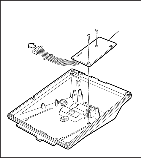
6-11
INSTALLATION-STATION APPARATUS
SECTION 100-816-206
MARCH 1993
1) Loosen the four captive screws securing the
telephone base (Figure 6-1), and remove the
base.
2) Depending on the telephone, refer to Figure
6-7, 6-8, or 6-9 and locate the EX.POW
straps, W101 and W102. Cut these straps.
3) Reinstall the telephone base, and secure it
with its four captive screws.
NOTE:
Refer to Section 100-816-208 for external
AC/DC power supply ordering information
and installation instructions.
3.90 DKT2000 Add-On-Module Installation
3.91 See Paragraph 7 in this chapter.
4 ELECTRONIC TELEPHONE
UPGRADE OPTIONS (DK16 Only)
4.00 This section describes how to upgrade and
configure electronic telephones for features and
options.
4.10 Off-hook Call Announce Upgrade
(HVSU2 or HVSU/HVSI)
4.11 Electronic telephones must be equipped with
either the HVSU2 subassembly or the combined
HVSU and HVSI subassemblies to receive Off-
hook Call Announce (OCA) calls. These tele-
phones also require three-pair wiring to receive
OCA, instead of the standard two-pair. Telephones
making OCA calls do not require an upgrade or
extra wire pair.
4.12 HVSU2 Upgrade Installation. Install the
HVSU2 in accordance with the following steps:
1) Loosen the four captive screws securing the
telephone base (Figure 6-1), and remove the
base.
2) Position the HVSU2 on the standoffs inside
the base, and secure with the two provided
screws (Figure 6-12).
3) Connect the HVSU2 wire plug to the P2
connector on the printed circuit board (PCB)
in the telephone (Figure 6-13).
4.13 HVSU/HVSI Upgrade Installation. In-
stall the HVSU/HVSI subassemblies in accor-
dance with the following steps:
1) Loosen the four captive screws securing the
telephone base (Figure 6-1), and remove the
base.
2) Align the P5 connector on the HVSI subas-
sembly with the receptacle on the HVSU
subassembly (Figure 6-14). Apply firm, even
pressure to the PCBs to ensure that the
connectors mate properly (they should click).
NOTE:
Exercise care when assembling the HVSU to
the HVSI to prevent damage to the connector
pins; also, verify that the HVSU is aligned with
the silk-screened image on the HVSI.
TO HVSU
CONNECTOR (P2)
ON MAIN PCB
INSIDE
TELEPHONE
HVSU2
FIGURE 6-12
HVSU2 INSTALLATION FOR ELECTRONIC
TELEPHONES
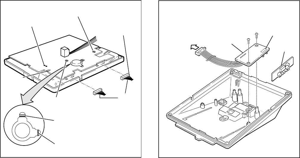
INSTALLATION-STATION APPARATUS
SECTION 100-816-206
MARCH 1993
6-12
3) Position the HVSU/HVSI subassembly on the
standoffs inside the base, and secure with the
two screws provided (Figure 6-14).
4) Connect the HVSU/HVSI subassembly wire
plug to the P2 connector on the electronic
telephone PCB (Figure 6-13).
5) Reinstall the electronic telephone base, and
secure it with its four captive screws.
4.20 Loud Ringing Bell/Headset Upgrade
(HHEU)
4.21 The Loud Ringing Bell/Headset upgrade
(HHEU) enables an external speaker (HESB) and/
or a headset to be connected to the electronic
telephone. The HESB serves as a Loud Ringing
Bell when connected to a telephone.
NOTES:
1. There are two types of HHEU: the HHEU1
(which has four versions, V.1 ~ V.4) and
the HHEU2.
2. Only electronic telephones equipped with
an HHEU2 can be wall mounted. The
HHEU2 is identical to the V.4 HHEU1,
except that the HHEU2 has longer wires
to accommodate wall mounting.
3. A Toshiba HESC-65 or HESC-65A cable
is required to connect the HHEU in an
electronic telephone to the HESB. Refer
to Section 100-816-207 for HESB instal-
lation procedures.
4. All HHEU versions and types, except for
V.1 HHEU1, are compatible with the Off-
hook Call Announce upgrades (HVSU2
and HVSU/HVSI).
4.22 HHEU Upgrade Installation. Install the HHEU
upgrade in accordance with the following steps:
1) Loosen the four captive screws securing the
telephone base (Figure 6-1), and remove the
base.
2) Using a screwdriver or other suitable tool,
remove the plastic tab located on the back of
R-UP (6510-H,
6510-S, 6520-S)
TO HHEU
CONNECTOR
P1
TO HVSU
CONNECTOR, P2
ROOM NOISE
BEEP
STRAP
HI
CARBON STRAPS
W201
W202
CARBON
HHEU STRAP
W203
RED
WIRE
RED
RED
R-UP
(6520-SD)
P2
P1
FIGURE 6-13
ELECTRONIC TELEPHONE PCB CONNECTIONS
FIGURE 6-14
HVSI/HVSU INSTALLATION FOR ELECTRONIC
TELEPHONES
TO P2 HVSU
CONNECTOR
ON MAIN PCB
INSIDE
TELEPHONE HSVI
P5
HVSU
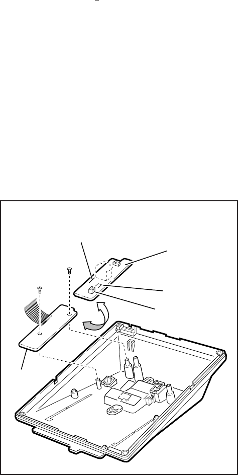
6-13
INSTALLATION-STATION APPARATUS
SECTION 100-816-206
MARCH 1993
the base (Figure 6-1). The HHEU modular
connector for the headset will be accessed
through this opening.
3) If using a V.3 or earlier HHEU1, set the
SW601 switch to the HEADSET position for
HESB and/or headset connection (Figure 6-
15). This switch is not on either the V.4
HHEU1 or the HHEU2, because the opera-
tion is automatic with these subassemblies.
4) Connect the HESC-65 or HESC-65A cable
(either one) to P601 of the HHEU if the Loud
Ringing Bell option is required (Figure 6-11).
Refer to Section 100-816-207 for HESB in-
stallation procedures.
5A) For the V.3 or earlier HHEU1: If only the
headset is connected to the HHEU, cut both
sides of the R607 resistor on the HHEU
(Figure 6-15) and then remove the resistor to
eliminate electrical contact.
NOTE:
Do not cut the R607 resistor if connecting an
HESB to the HHEU for the Loud Ringing
Bell—even if a headset is also installed on the
HHEU.
5B) For the V.4 HHEU1 or the HHEU2: If only the
headset is connected to the HHEU, cut the
OCA strap (Figure 6-15).
NOTE:
Do not cut the OCA strap if connecting an
HESB to the HHEU for the Loud Ringing
Bell—even if a headset is also installed on the
HHEU.
6) Position the HHEU subassembly on the stand-
offs inside the base (Figure 6-15), and secure
with the two provided screws.
7) Connect the HHEU subassembly wire plug to
the P1 connector on the electronic telephone
PCB (Figure 6-13).
8) Cut the HHEU strap on the telephone PCB
(Figure 6-13).
NOTE:
The HHEU strap must be replaced if the
HHEU PCB is removed from the telephone.
9) Reinstall the telephone base, and secure it
with its four captive screws.
10) To adjust the volume of the HESB Loud
Ringing Bell: Call the telephone connected to
the HESB, and adjust the volume control on
the back of the HESB and the ring volume
control on the telephone.
4.30 Carbon Headset/Handset Straps
4.31 If a carbon-type handset or headset is con-
nected to the handset jack on the side of the 6500-
series electronic telephone, two straps inside the
telephone must be cut. Cut the straps in accor-
dance with the following steps:
NOTE:
It is not necessary to cut these straps if the
headset is connected to the HHEU.
FIGURE 6-15
HHEU INSTALLATION FOR ELECTRONIC
TELEPHONES
HHEU
COMPONENT SIDE OF HHEU
SW601
P601
R607 (HHEU1 V.1 ~ V.3)
OCA (HHEU1
(HHEU1A V.1 ~V.3)
V.4 or HHEU2)
TO P1, HHEU
CONNECTOR
OF
TELEPHONE
PCB
INSTALLATION-STATION APPARATUS
SECTION 100-816-206
MARCH 1993
6-14
1) Loosen the four captive screws securing the
telephone base (Figure 6-1), and remove the
base.
2) Refer to Figure 6-13, and locate the CAR-
BON straps, W201 and W202. Cut both
straps.
3) Reinstall the telephone base, and secure it
with its four captive screws.
4.40 Beep Strap
4.41 A "beep" sounds whenever a dialpad button
or feature button is pressed on an electronic
telephone. This beep can be eliminated with the
following procedure:
1) Remove the four captive screws securing the
telephone base to the telephone (Figure 6-1),
and remove the base.
2) Locate and cut the BEEP strap on the tele-
phone printed circuit board (PCB) (Figure 6-
13).
3) Reinstall the electronic telephone base, and
secure in place using the four captive screws.
4.50 Microphone/Speaker Threshold (Speak-
erphones only)
4.51 High ambient noise levels may cause the
speaker on the electronic telephone speakerphone
models (the EKT6510-S, the EKT6520-S, and the
EKT6520-SD) to cut off frequently. To make these
telephones less sensitive to noise and to prevent
the cut-off, follow the steps below:
1) Remove the four captive screws securing the
base to the telephone, and remove the base
(Figure 6-1).
2) Locate the ROOM NOISE switch on the
printed circuit board (PCB) inside the tele-
phone, and push it carefully to the HI (high)
position (Figure 6-13).
3) Reinstall the telephone base and secure in
place using the four captive screws.
4.60 Handset Receiver Volume-up Strap
(Version 2 6500-series Telephones Only)
4.61 For Version 2 (V.2) 6500-series electronic
telephones only, the handset receiver volume can
be increased six decibels (db) by cutting a strap
inside of the telephone. Cut the strap in accor-
dance with the following steps:
1) Remove the four captive screws securing the
telephone base to the telephone, and remove
the base (Figure 6-1).
2) Locate the R-UP strap on the printed circuit
board (PCB) inside the telephone, and cut it
(Figure 6-13).
3) Reinstall the telephone base, and secure in
place using the four captive screws.
5 DIRECT STATION SELECTION
CONSOLE/SYSTEM CONNECTION
(DK16 Only)
5.01 STRATA DK16 systems configured with just
a Base Unit can support one Direct Station Selec-
tion Console, and systems with the optional Ex-
pansion Unit can support two consoles. There are
two types of consoles: the DDSS console and the
HDSS console. The DDSS console can be con-
nected to designated digital telephone circuits,
and the HDSS console can only be connected to
designated PEKU circuits. This section provides
instructions on how to install both types of con-
soles.
5.10 DDSS Console Connections
5.11 The DDSS console, which can operate with a
digital or electronic telephone (preferably an LCD
model), can connect only to Circuit 8 of the Base
Unit digital telephone circuit set or Circuit 8 of the
PDKU. Standard twisted single-pair or two-pair
jacketed telephone cable (maximum 1000 feet,
303 meters) is used for the connection. To accom-
modate the DDSS console connection, the instru-
ment end of the cable should be terminated in a
modular station connector block (RJ-11). Refer to
Wiring Diagrams, Section 100-816-208, for wiring/
interconnecting details, including cable length limi-
tations (see Table 8-D).

6-15
INSTALLATION-STATION APPARATUS
SECTION 100-816-206
MARCH 1993
NOTE:
1. DDSS console cable runs must not have
the following:
Cable splits (single or double)
Cable bridges (of any length)
High resistance or faulty cable splices
2. See Section 100-816-208 for secondary
protection information.
CAUTION!
When installing the DDSS cable, do not
run parallel to and within 3 feet of an AC
power line. AC power lines should be
crossed at right (90
°
) angles only. In par-
ticular, avoid running station wire pairs
near devices that generate electrical noise,
such as neon or fluorescent light fixtures.
5.12 DDSS Console Configuration. The follow-
ing considerations should be made when installing
DDSS consoles:
DDSS consoles can connect only to Circuit 8 of
the Base Unit digital telephone circuit set or
Circuit 8 of the PDKU.
A maximum of two DDSS consoles can be
installed per system equipped with an Expan-
sion Unit.
DDSS consoles can operate with an attendant
electronic telephone, as well as with a digital
one.
A KCDU will not support a DDSS.
5.13 DDSS Programming Overview
Program 03
Code 64 identifies the slots that support DDSS
consoles.
Program 28
Assigns DDSS console(s) to telephones.
Program 29
Assigns button functions for DDSS consoles.
5.20 HDSS Console Connections
5.21 The HDSS console must be connected to the
data pairs of circuits 7 and 8 on a PEKU in the
Expansion Unit (via the MDF) with standard two-
pair twisted, jacketed telephone cable. To accom-
modate the connection, the instrument end of the
HDSS console cable should be terminated in a
modular station connector block (RJ-11). Refer to
Wiring Diagrams, Section 100-816-208, for wiring/
interconnecting details. The overall length of the
cable run from the Expansion Unit (KSU) to the
HDSS console must not exceed 500 feet (152
meters), if using 24 AWG cable. The HDSS con-
sole can operate with either an electronic or digital
telephone (preferably an LCD model).
CAUTION!
When installing the HDSS console cable,
do not run parallel to and within 3 feet of an
AC power line. AC power lines should be
crossed at right (90
°
) angles only. Avoid
running HDSS console wire pairs near
devices that generate electrical noise, such
as neon or fluorescent light fixtures.
5.22 HDSS Console Configuration. The follow-
ing considerations should be made when installing
an HDSS console:
A PEKU PCB is required in the expansion unit
for an HDSS console. (The DSS switch on the
PEKU must be set to DSS.)
Two PEKU ports are required for the HDSS
console (always Circuits 7 and 8).
The PESU does not support the HDSS console.
A system must be configured with the Expan-
sion Unit to support an HDSS console. Only one
HDSS console can be installed in a system.
5.23 HDSS Programming Overview
Program 03
Codes 23 and 24 identify the slot that supports
a PEKU that interfaces with the HDSS console.
Program 28
Assigns HDSS console to a telephone.
Program 29
Assigns individual button functions for the
HDSS console.
6 DOOR PHONE/LOCK CONTROL UNIT
AND DOOR PHONE INSTALLATION
6.01 This section provides installation instructions
for the digital door phone/lock control units (DDCB).
It also includes installation instructions for the door
phone (MDFB). Each DDCB can support as many
as three door phones (MDFBs), or two MDFBs and
one door lock.
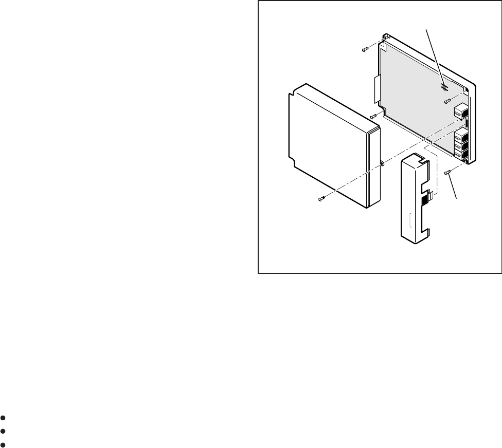
INSTALLATION-STATION APPARATUS
SECTION 100-816-206
MARCH 1993
6-16
NOTE:
DK8 and DK16 do not support the HDCB.
6.02 DK8 and DK16 systems can be equipped with
up to six MDFBs.
6.03 For DK8, DDCBs can only connect to Circuit
3 (Port 02) and Circuit 4 (Port 03).
6.04 For DK16, DDCBs can only connect to Ports
04 and 12. DDCBs can only connect to Circuit 5
(Port 04) of the Base Unit and/or Circuit 1 (Port 12)
of a PDKU or KCDU in the Expansion Unit.
NOTE:
DDCBs cannot connect to the QSTU, KSTU,
PSTU, PESU or PEKU.
6.10 DDCB and MDFB Cabling
6.11 Refer to Section 100-816-208 for DDCB and
MDFB wiring/interconnecting details. For door lock
control installation procedures, refer to Section
100-816-208. The length of the cable run from the
key service unit (KSU) to the MDFB (via the DDCB)
must not exceed 1,000 feet (305 meters), if using
24 AWG cable (see Table 8-D).
NOTES:
1. DDCB cable runs must not have the fol-
lowing:
Cable splits (single or double)
Cable bridges (of any length)
High resistance or faulty cable splices
2. See Section 100-816-208 for secondary
protector information.
6.20 DDCB Wall Mounting
6.21 The DDCB is designed to be mounted on a
wall or other vertical surface. Mount the units in
accordance with the following steps:
1) Locate the two mounting holes on the right-
hand side on the DDCB (Figure 6-16).
2) Remove the side cover from the DDCB to
expose the two left-hand mounting holes (Fig-
ure 6-16).
3) Position the DDCB adjacent to the key ser-
vice unit (KSU) with regard to wiring needs.
KSU
A
B
C
DOOR
PHONE
MOUNTING
SCREWS (4)
EXTERNAL POWER STRAPS
(DDCB ONLY)
NOTE
See Table 8-D regarding external power requirements.
FIGURE 6-16
DOOR PHONE (DDCB) INSTALLATION
4) Secure the DDCB to the mounting surface
with four one-inch panhead wood screws.
6.30 Door Phone (MDFB) Wall Mounting
6.31 Mount door phones (MDFBs) to a wall or
vertical surface in accordance with the following
steps:
1) Remove the screw from the bottom of the
cover. Detach the cover from the base and
metal frame (Figure 6-17).
2) Position the metal frame and base to the
mounting surface and secure with two one-
inch panhead wood screws (Figure 6-17).
3) Attach cover to the metal frame and base and
secure with the screw which was removed in
Step 1.
6.32 Door Phone Volume Control. Adjust the
ring and voice volume to the MDFB in accordance
with the following procedure:
1) Remove the screw from the bottom of the
MDFB cover. Detach the cover from the base
and metal frame (Figure 6-17).
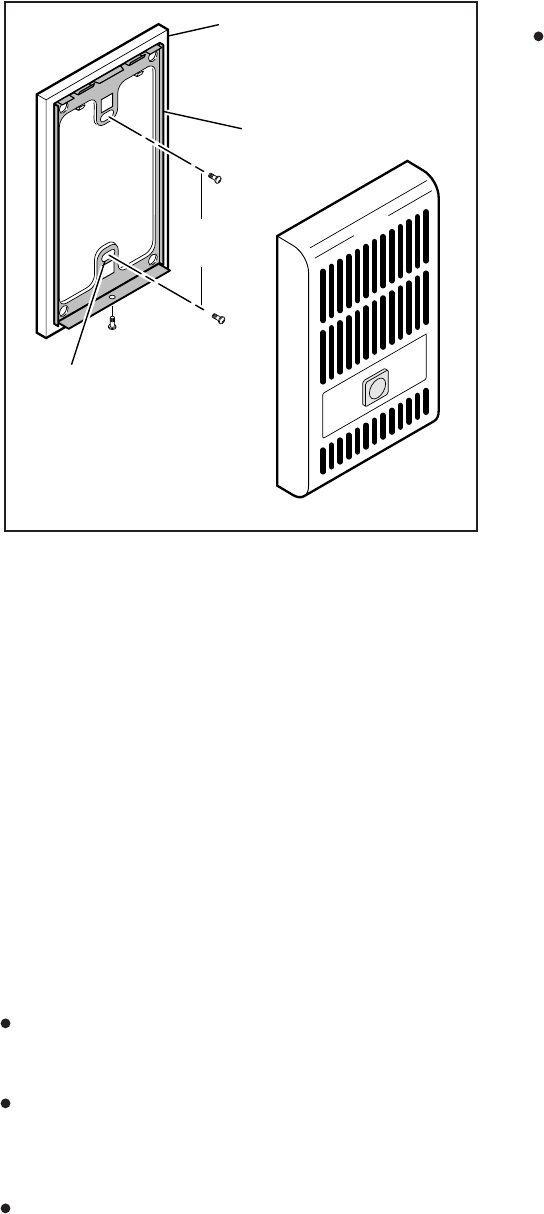
6-17
INSTALLATION-STATION APPARATUS
SECTION 100-816-206
MARCH 1993
FIGURE 6-17
DOOR PHONE (MDFB) INSTALLATION
TWO WALL
MOUNTING
HOLES
DOOR PHONE
BASE
METAL
FRAME
3.25
INCHES
2) The volume level is changed by a screw
adjustment on the back of the MDFB. Turn
the screw with a flat-tipped screwdriver while
ringing the MDFB or while on a call with it. The
volume level will change as the screw is
turned.
6.40 Door Phone/Lock Programming Consid-
erations
6.41 The following programs should be consid-
ered when programming the system for door
phones:
Program 39
Assigns door phone and door lock buttons to
digital telephones.
Program 77-1
Assigns DDCBs to ports, door phone ringing
over External Page during the NIGHT mode,
and door lock activation time.
Program 77-2
Used to busy out unused MDFB positions and to
identify which DDCBs support the door lock
option, and to set the door phone to ring one or
five times.
Program 79
Assigns door phone-to-station ringing assign-
ments.
7 ADD-ON MODULE INSTALLATION
7.01 Install the Add-on Module (DADM 2020) to a
2000-series Digital Telephone (only) according to
the steps that follow:
1) Loosen the four captive screws securing the
2000-series Digital Telephone base (Figure
6-1) and remove the base.
2) Remove the base handset hanger (Figure
6-1).
3) Loosen two captive screws securing ADM
base and remove base.
4) Put on ADM cable (supplied with ADM) through
telephone base and ADM base as shown in
Figure 6-18.
5) Connect ADM cable connectors to P1 of ADM
and P1 of DKT2000 telephone as shown in
Figure 6-18.
6) Install base of ADM and telephone – tuck
ADM cable into ADM and telephone base as
necessary for proper length.
7) Secure ADM to telephone base with ADM
connecting Plate (using four screws).
8) Check Table 8-D in Section 100-816-208;
install 2-pair house cable (or external power)
and 2-pair modular cord (supplied with ADM)
if required to achieve maximum distance.
7.11 ADM Programming. ADMs do not require
programming. The ADM provides 20 DSS buttons
only (Figure 6-19) for the STRATA DK16, and 10
DSS buttons, 8 speed dial buttons, one night
transfer button, and one all call page button (Fig-
ure 6-20) for the STRATA DK8. One ADM can be
installed on any (or all) 2000-series telephone (16
max on DK16 or 8 max on DK8).
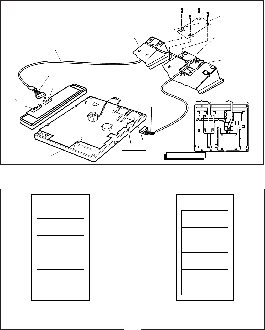
INSTALLATION-STATION APPARATUS
SECTION 100-816-206
MARCH 1993
6-18
19
18
17
16
15
14
13
12
11
10
SD 17
SD 16
SD 15
SD 14
SD 13
SD 12
SD 11
SD 10
Note: The button assignments for DSS (10-19),
Speed Dial (SD10 ~ 17), All Call Page, and
Night Transfer button assignments are fixed
and cannot be changed.
Night
Transfer
All Call
Page
FIGURE 6-20
DK8 ADD-ON MODULE DSS BUTTON
ASSIGNMENTS
FIGURE 6-18
ADD-ON MODULE INSTALLATION
1
BLACK WIRE TO PIN 1
BLACK WIRE TO PIN 1 (SMALLER CONNECTOR)
1
12
P 1
P 2
DIU & ADM
VIEW OF BOTTOM
ADM CABLE
(SUPPLIED WITH ADM)
NOT USED
ON DK16
P1 OF BOTTOM PCB
DADM2020 2000-SERIES DKT
TELEPHONE
BASE
REMOVE HANDSET
HANGER (SEE
PARAGRAPH 2.42,
STEP 2)
ADM CONNECTION
PLATE (PROVIDED
WITH ADM)
4-SCREWS
ADM BASE
2000-SERIES
DIGITAL TELEPHONE
(LARGER CONNECTOR)
19
18
17
16
15
14
13
12
11
10
29
28
27
26
25
24
23
22
21
20
Note: This DSS button
assignment is fixed and
cannot be chan
g
ed.
FIGURE 6-19
DK16 ADD-ON MODULE DSS BUTTON
ASSIGNMENTS

INSTALLATION-PERIPHERALS
SECTION 100-816-207
MARCH 1993
INSTALLATION
CHAPTER SEVEN
PERIPHERAL INSTALLATION
TOSHIBA SYSTEM PRACTICES
DIGITAL KEY TELEPHONE SYSTEMS
7-i
INSTALLATION-PERIPHERALS
SECTION 100-816-207
MARCH 1993
TABLE OF CONTENTS
PARAGRAPH SUBJECT PAGE
1GENERAL .............................................................................................................. 7-1
2MUSIC-ON-HOLD/BACKGROUND MUSIC OPTIONS .......................................... 7-1
2.10 DK8 and DK16 Music-on-Hold (MOH) Option ..................................................... 7-1
2.20 Background Music (BGM) Options ..................................................................... 7-3
3RELAY CONTROL OPTIONS ................................................................................ 7-4
3.00 General ............................................................................................................... 7-4
3.10 DK8 KSU and DK16 Base Unit Relay ................................................................ 7-7
3.20 DK16 Expansion Unit PIOU and PIOUS Relays ................................................. 7-7
3.30 DK16 Expansion Unit Night Transfer/Music-on-Hold Relay Options with
PIOU or PIOUS .................................................................................................. 7-9
4EXTERNAL SPEAKER UNIT (HESB) OPTIONS.................................................... 7-12
4.10 System Hardware Requirements........................................................................ 7-12
4.20 HESB Option Installation .................................................................................... 7-12
5EXTERNAL PAGE OPTIONS ................................................................................ 7-19
5.00 System Hardware Requirements........................................................................ 7-19
5.10 External Page Option Installation ....................................................................... 7-19
6DK8 AND DK16 STATION MESSAGE DETAIL RECORDING (SMDR)
PRINTER/CALL ACCOUNTING DEVICE OPTIONS .............................................. 7-23
6.10 SMDR Hardware Requirements ......................................................................... 7-27
6.20 SMDR Printer/Call Accounting Device Installation .............................................. 7-27
7VOICE MAIL OPTIONS.......................................................................................... 7-28
7.00 System Hardware Requirements........................................................................ 7-28
7.10 Toshiba VP Voice Messaging System................................................................ 7-28
7.20 Customer-supplied Voice Mail Messaging Systems ........................................... 7-30
8DK16 ALARM SENSOR INSTALLATION .............................................................. 7-32
9DK16 NIGHT RINGING OVER EXTERNAL ZONE PAGE...................................... 7-33
10 DATA INTERFACE UNIT INSTALLATION ............................................................ 7-34
10.00 General ............................................................................................................... 7-34
10.10 Common DIU Connections ................................................................................. 7-34
10.20 EIA Interface Leads (Signals)............................................................................. 7-35
10.30 DIP Switch Options............................................................................................. 7-36
10.40 PDIU-DI to Personal Computer (PC) Installation ................................................ 7-36
10.50 PDIU-DS to Printer Installation ........................................................................... 7-37
10.60 PDIU-DS to Modem Installation.......................................................................... 7-38
10.70 PDIU-DS Disassembly and Assembly................................................................ 7-40
10.80 PDIU-DI/PDIU-DS Installation Tests .................................................................. 7-51
11 DK16 TWO-CO LINE EXTERNAL AMPLIFIED CONFERENCE ............................ 7-56
11.00 General ............................................................................................................... 7-56
FIGURE LIST
FIGURE TITLE PAGE
7-1 DK8 AND DK16 MUSIC-ON-HOLD AND BACKGROUND MUSIC
FUNCTIONAL DIAGRAM..................................................................................... 7-2
7-2 DK16 BGM SOURCE/STANDARD TELEPHONE CIRCUIT PRECAUTION
DIAGRAM............................................................................................................. 7-4
7-3 DK8 AND DK16 MUSIC SOURCE CONFIGURATION A ..................................... 7-5
7-4 DK8 AND DK16 MUSIC SOURCE CONFIGURATION B ..................................... 7-5
7-5 DK16 MUSIC SOURCE CONFIGURATION C...................................................... 7-6
7-ii
INSTALLATION-PERIPHERALS
SECTION 100-816-207
MARCH 1993
FIGURE LIST
FIGURE TITLE PAGE
7-6 DK16 PIOU RELAY CONTROL FUNCTIONAL WIRING DIAGRAM .................... 7-8
7-7 DK16 PIOUS RELAY CONTROL FUNCTIONAL WIRING DIAGRAM.................. 7-9
7-8 DK16 DOOR LOCK CONTROL OPTION (PIOU/PIOUS) ..................................... 7-10
7-9 DK8 AND DK16 DOOR LOCK CONTROL OPTION (DDCB) ............................... 7-11
7-10 DK8 AND DK16 HESB/DIGITAL TELEPHONE WITH LOUD RINGING
BELL WIRING ...................................................................................................... 7-14
7-11 DK16 HESB/ELECTRONIC TELEPHONE WITH LOUD RINGING
BELL WIRING ...................................................................................................... 7-15
7-12 DK8 AND DK16 HESB/AMPLIFIED SPEAKER WIRING...................................... 7-17
7-13 DK8 AND DK16 HESB/TALKBACK AMPLIFIED SPEAKER WIRING.................. 7-18
7-14 HESB WALL MOUNTING .................................................................................... 7-19
7-15 DK8 AND DK16 PAGE AND SEPARATE BGM USING SAME AMPLIFIER ........ 7-20
7-16 DK16 PIOU ZONE, PAGE/BGM/NIGHT RING (SEPARATE AMPLIFIERS) ........ 7-21
7-17 DK16 PAGING WITH MULTIPLE AMPLIFIERS ................................................... 7-22
7-18 DK16 NIGHT RINGING OVER ALL EXTERNAL PAGE ZONES .......................... 7-24
7-19 DK8 AND DK16 SMDR PRINTOUT EXAMPLES ................................................ 7-26
7-20 DK8 AND DK16 PIOU/PIOUS SMDR CABLE CONNECTIONS ........................... 7-28
7-21 PIOU/PIOUS SMDR PORT (PROGRAM 97) DATA DUMP EXAMPLE................ 7-29
7-22 DK8 AND DK16 VOICE MAIL/AUTO ATTENDANT BLOCK DIAGRAM............... 7-30
7-23 DK16 ALARM SENSOR BLOCK DIAGRAM ......................................................... 7-33
7-24 DK8 OR DK16 DATA INSTALLATION EXAMPLE BLOCK DIAGRAM ................. 7-41
7-25 DK8 AND DK16 PDIU-DI TO IBM AT-TYPE COMPUTER
RS-232 CONNECTOR/CABLE CONNECTIONS.................................................. 7-42
7-26 DK8 AND DK16 PDIU-DI TO IBM XT-TYPE COMPUTER,
RS-232 CONNECTOR/CABLE CONNECTIONS.................................................. 7-43
7-27 DK8 AND DK16 PDIU-DS TO TOSHIBA PRINTER,
RS-232 CONNECTOR/CABLE CONNECTIONS.................................................. 7-44
7-28 DK8 AND DK16 PDIU-DS TO HAYES-TYPE SMART MODEM,
RS-232 CONNECTOR/CABLE CONNECTIONS.................................................. 7-45
7-29 DK8 AND DK16 PDIU-DI/PDIU-DS MODULAR CABLE/RJ-45 ADAPTER
CONNECTIONS ................................................................................................... 7-46
7-30 DK8 AND DK16 PDIU-DI/PDIU-DS MODULAR CORDS
AND RJ-45/RS-232 ADAPTER PIN CONNECTIONS .......................................... 7-47
7-31 DK8 AND DK16 PDIU-DS JUMPER PLUG OPTIONS/RS-232
CONNECTOR INFORMATION ............................................................................ 7-48
7-32 DK8 AND DK16 PDIU-DI/PDIU-DS SW1 DIP SWITCH INFORMATION ............. 7-49
7-33 DK8 AND DK16 PDIU-DS DISASSEMBLY/ASSEMBLY DIAGRAM .................... 7-50
7-34 DK8 AND DK16 PC TO PC TEST CALL USING AT COMMANDS ...................... 7-51
7-35 DK8 AND DK16 PC TO PRINTER TEST CALL USING MANUAL DIALING ........ 7-52
7-36 DK8 AND DK16 INTERNAL PC TO EXTERNAL PC TEST CALL
USING AT COMMANDS ...................................................................................... 7-53
7-37 DK8 AND DK16 EXTERNAL PC TO INTERNAL PC TEST CALL
USING AT COMMANDS ...................................................................................... 7-54
7-38 DK8 AND DK16 PC AUTO DIAL VOICE CALL TEST .......................................... 7-56
7-39 DK16 AMPLIFIED TWO-CO LINE CONFERENCE AND/OR AMPLIFIED DISA
FUNCTIONAL WIRING DIAGRAM ....................................................................... 7-57

INSTALLATION-PERIPHERALS
SECTION 100-816-207
MARCH 1993
7-1
1 GENERAL
1.00 This chapter provides procedures necessary
to connect optional peripheral equipment to the
STRATA DK8 or DK16. The installation instruc-
tions for each peripheral option include hardware
requirements, printed circuit board (PCB) configu-
ration, interconnection/wiring requirements, and
programming considerations, as applicable.
1.01 Peripheral equipment is connected to the
Base Unit itself and PCBs located in the Base Unit
and Expansion Unit on the DK16. On the DK8,
peripheral equipment connects to the KSU. Refer
to Section 100-816-204 for Key Service Unit instal-
lation instructions, PCB installation instructions,
and PCB configuration information for the DK8.
Refer to Section 100-816-205 for Base Unit and
Expansion Unit installation instructions, PCB in-
stallation instructions, and PCB configuration infor-
mation for the DK16.
1.02 Wiring diagrams for each peripheral are lo-
cated in this chapter.
2 MUSIC-ON-HOLD/BACKGROUND
MUSIC OPTIONS
2.00 STRATA DK8 and DK16 systems provides a
Music-on-Hold option for CO lines and digital, elec-
tronic (DK16 only) and standard telephones con-
nected to the system. A variety of Background
Music options are also provided (refer to Figure
7-1).
2.10 DK8 and DK16 Music-on-Hold (MOH)
Option
2.11 An external music source—such as a tape
player or tuner—can be connected to the RCA jack
(labeled MOH) on the STRATA DK8 or DK16. The
MOH source can be controlled (on/off) by a relay
option set in Program 77-1. The DK8 KSU and
DK16 Base Unit relay can control the MOH source,
or the DK16 night bell. The MOH source and MOH
relay contact specifications are:
MOH Source Specifications
Input Impedance: 600 ohms
Input Voltage (recommended levels)
Minimum: 0.14 VRMS (-15 dBm)
Maximum: 0.77 VRMS (0 dBm)
Relay Contact Specifications
Voltage: 24VDC maximum
Current: 1 ampere maximum
IMPORTANT NOTICE!
MUSIC-ON-HOLD
In accordance with U.S. Copyright Law, a
license may be required from the Ameri-
can Society of Composers, Authors, and
Publishers (ASCAP), or other similar or-
ganization, if copyrighted music is trans-
mitted through the Music-on-Hold feature
of this telecommunications system.
Toshiba America Information Systems,
Inc., hereby disclaims any liability arising
out of the failure to obtain such a license.
2.12 Music-on-Hold Installation. Install the Mu-
sic-on-Hold option in accordance with the following
steps (refer to Figure 7-1):
1) Connect the external music source to the
MOH RCA jack on the DK8 KSU or DK16
Base Unit.
2) Rotate the MOH volume control (VR1) on the
Base Unit to adjust Music-on-Hold volume:
clockwise increases volume; counterclock-
wise decreases volume. Listen to the CO line
on-hold when setting MOH to the proper vol-
ume.
3A) If MOH relay control is required in DK8, the
MOH relay is selected in Program 77-1. Fol-
low program instructions to make selection.
This will short pins 42 and 17 of the DK8 KSU
or DK16 Base Unit amphenol connector when
MOH is activated by a CO line on hold.
3B) If MOH relay control is required in DK16, the
Base Unit or the PIOU/PIOUS relay may be
selected in Program 77-1. Follow Program
instruction to make the selection.
4A) Set PIOU jumper plug P11 to MAKE or BREAK
position as required:
MAKE (M)—Shorts the normally open
contacts (pins 9 and 34) when MOH is
activated.
BREAK (B)—Opens the normally closed
contacts (pins 9 and 34) when MOH is
activated.
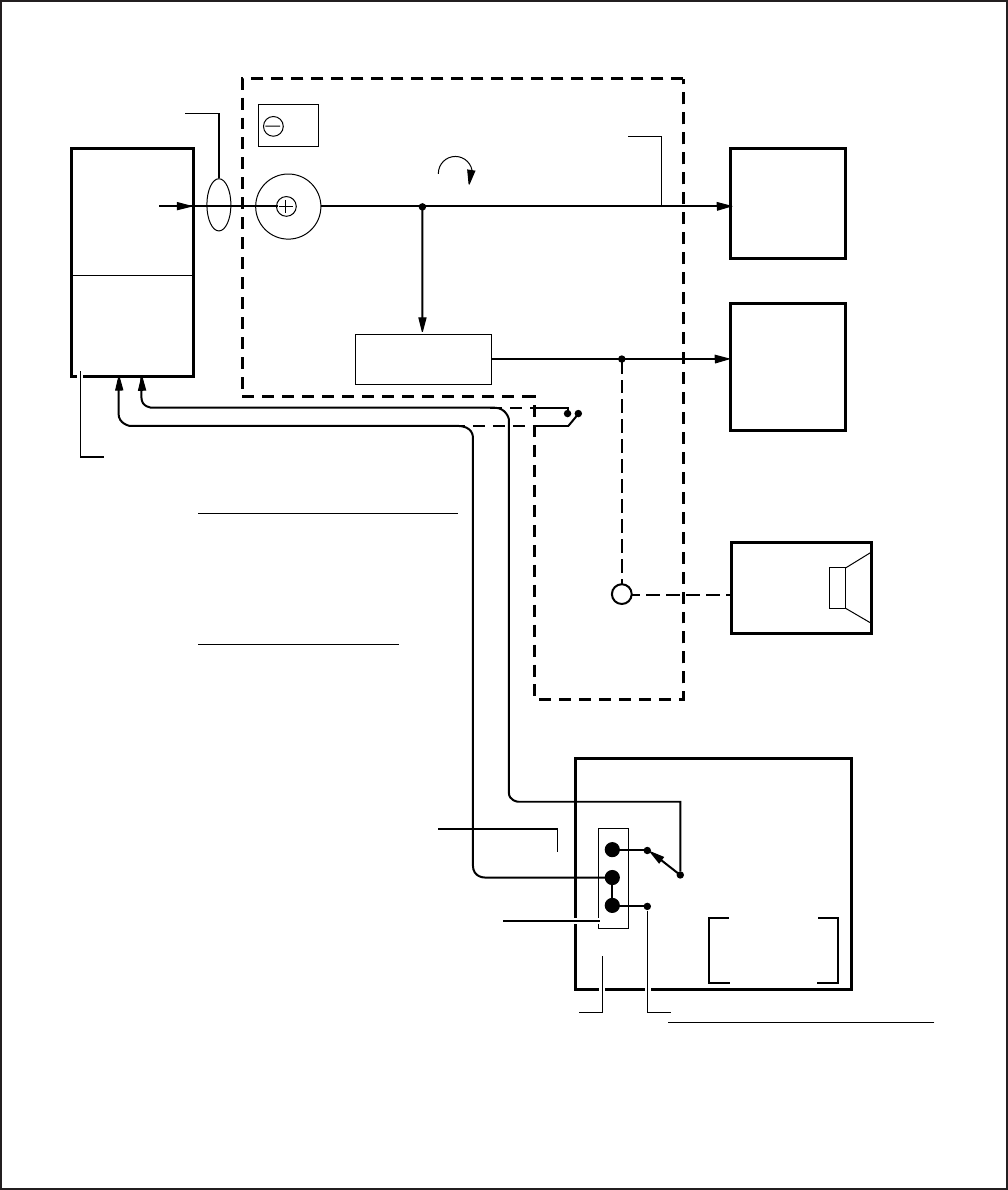
INSTALLATION-PERIPHERALS
SECTION 100-816-207
MARCH 1993
7-2
FIGURE 7-1
DK8 AND DK16 MUSIC-ON-HOLD AND BACKGROUND MUSIC FUNCTIONAL DIAGRAM
(SEE MDF WIRING DIAGRAM FOR DETAILS)
MUSIC-
ON-HOLD
SOURCE
ON/OFF
CONTROL
(24 VOLT
MAX)
TWISTED PAIR
24 AWG. VR1 MOH/BGM
VOLUME CONTROL
MAX.
MUSIC
MOH
RCA
JACK
PAGE/BGM
CONTROL
PAGE OR
BACKGROUND
MUSIC
MUSIC-
ON-HOLD
BACKPLANE
BGM TO:
DIGITAL
AND
ELECTRONIC
TELEPHONE
SPEAKERS
OPTIONAL
EXTERNAL PAGE/
BGM OUTPUTS
HESB OR
AMPLIFIER
AND
SPEAKER
(9)
(34)
B
M
P11 SELECT
MOH
PROG. 77-1
RELAY CONTACT SPECIFICATION:
24 VDC MAX.
1 AMPERE, MAX.
MOH/NT
RELAY CONTACT
JUMPER PLUG (MAKE OR BREAK)
( ) PIN NO.s OF PIOU
AMPHENOL CONNECTOR
MOH SOURCE SPECIFICATIONS:
INPUT IMPEDANCE: 600Ω
INPUT VOLTAGE:
RECOMMENDED LEVELS,
MIN. = 0.14 VRMS (-15 dBm)
MAX. = 0.77 VRMS (0 dBm)
•
•
DK8 KSU OR DK16 BASE KEY SERVICE UNIT
MOH TO:
CO LINES
AND
STATIONS
ON-HOLD
MOH OR
NIGHT TRANSFER
CONTROL
RELAY
*
*
W2, IF USING PIOUS
(SEE FIGURE 7-7)
TYPICAL MOH SOURCES:
• TAPE PLAYER
• TUNER
DK16 EXPANSION UNIT
PIOU/PIOUS (NOTE)
600 OHM
PAGE
RCA JACK
DK8 OR
DK16
RELAY
PROG:
77-1
(NOTE)
MOH CONTROL-CHOOSE BASE UNIT
OR PIOU/PIOUS RELAY:
NOTE:
DK8 KSU relay or DK16 Base Unit relay can be
programmed (77-1) as the MOH control relay: or in DK16
the PIOU MOH/NT relay can be used to control MOH.
AMPHENOL
PIN NO. (4)
(17)

INSTALLATION-PERIPHERALS
SECTION 100-816-207
MARCH 1993
7-3
4B) Solder PIOUS jumper W2 to MAKE or BREAK
position if required:
MAKE (M)—Shorts the normally open
contacts (NHT and NHR) when any CO
line is in the hold condition.
BREAK (B)—Opens the normally closed
contacts (NHT and NHR) when any CO
line is in the hold condition.
5) For DK8 and DK16, MOH is sent to any station
or CO line that is on hold.
6) MOH is also applied through the Page/Back-
ground Music (BGM) control to provide BGM
to electronic/digital telephone speakers and
external page (refer to Paragraph 2.20).
2.20 Background Music (BGM) Options
2.21 The Background Music options allow music
to play over optional external speakers (external
page system) and/or electronic and/or telephone
speakers. The system allows BGM to be config-
ured any of the three ways described below:
1) Configuration A (DK8 and DK16)—one music
source: This configuration allows BGM and
MOH to share the same music source (see
Figure 7-3). With this configuration, the MOH/
BGM music source is connected to the MOH
RCA jack on the DK8 KSU or DK16 Base Unit.
The music source is sent to CO lines/stations
on hold, to electronic/digital telephone speak-
ers with BGM turned on (via Intercom 481
or Tel Set Music button), and to the exter-
nal page system via the 600 ohm RCA jack on
the DK8 KSU or DK16 Base Unit.
2) Configuration B—two music sources: This
configuration allows the MOH source to be
connected to the MOH jack on the DK8 KSU
or DK16 Base Unit (as in Configuration A) and
a separate BGM source to be connected to a
designated circuit on either a QSTU (circuit 2,
Port 19), PEKU (circuit 3), PESU (circuit 8),
PSTU, or KSTU (circuit 4)—see Figure 7-4.
With this configuration, the MOH source is
sent only to CO lines/stations on hold, while
the BGM source is sent directly to electronic/
digital telephone speakers and to the external
page system via the 600 ohm RCA jack on the
DK8 KSU or DK16 Base Unit.
3) Configuration C (DK16 only)—three music
sources: This configuration allows the MOH
source to be connected to the MOH jack on
the Base Unit (as in Configuration A). The
digital or electronic telephone BGM source is
connected to a designated circuit on the PEKU,
PESU, PSTU, or KSTU (as in Configuration
B), and a separate BGM source is sent to the
external page speakers via the PIOU Zone
relay contacts (see Figure 7-5). When a sepa-
rate BGM source is connected to the PIOU,
two customer-supplied amplifiers are required
to drive the external speakers. One amplifier
(1) drives the speakers for BGM when page is
idle and the other amplifier (2) drives the
speakers during page.
2.22 MOH Source as Background Music Instal-
lation (DK8 and DK16). Install the MOH/Back-
ground Music option in accordance with the follow-
ing steps (refer to Figure 7-1):
1) Ensure that the Music-on-Hold option is in-
stalled in accordance with Paragraph 2.12.
2) The output of the MOH RCA jack is applied to
the 600 ohm PAGE RCA jack output.
3) When using an HESB or external amplifier
for paging/BGM, adjust volume using the
HESB or amplifier volume control.
2.23 Alternate BGM Source Installation A
BGM source can be connected to either a QSTU,
PSTU, KSTU, PEKU, or PESU. This music will be
sent to all electronic/digital telephone speakers
and to the external page system via the 600 ohm
PAGE RCA jack on the DK8 KSU or DK16 Base
Unit. This BGM source is separated from the
MOH source connected to the MOH RCA jack on
the DK8 KSU or DK16 Base Unit. Connect the
BGM source to the QSTU, PSTU, KSTU, PEKU
or PESU in accordance with the following steps
(Figure 7-4):
NOTE:
If connecting the BGM source to the KSTU,
PSTU, or QSTU PCB, a telephone adaptor
matching/isolation transformer should be in-
stalled between the source and the PCB to
protect the source from potentially ruinous
voltages generated by the PCB (see Figure
7-2).
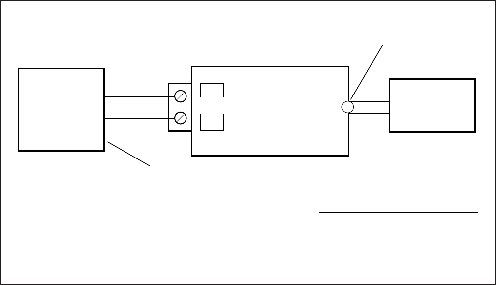
INSTALLATION-PERIPHERALS
SECTION 100-816-207
MARCH 1993
7-4
FIGURE 7-2
DK16 BGM SOURCE/STANDARD TELEPHONE CIRCUIT PRECAUTION DIAGRAM
1) For DK16, enter the programming mode and
identify the BGM slot number in Program 19 of
the printed circuit board (KSTU, PSTU, PEKU,
and PESU) which the BGM source will be
connected to.
2) Connect the BGM source to the tip and ring of
the appropriate circuit of the BGM PCB: KSTU
or PSTU (circuit 4), PEKU (circuit 3), and
PESU (circuit 8). In Program 10-2, use LED 09
or 10 to specify the circuit number PEKU or
PESU. KSTU or PSTU does not require Pro-
gram 10-2 assignment.
2A) For DK8, enter the programming mode and
set LED 10 to on in Program 10-2. This
assigns QSTU circuit 2, Port 19 as the BGM
source for the system. You must cycle system
power for Program 10-2 to take effect.
3) If BGM is connected to PEKU or PESU, cut
W5 on the PEKU or W7 on the PESU PCB
that BGM is connected to.
4) Using the BGM source’s volume control,
adjust the BGM volume to the desired level
while listening to BGM via an digital or
electronic telephone speaker and/or the ex-
ternal page speakers. When BGM is sent to
external speakers via the 600 ohm RCA jack
PCB, use the external amplifier volume con-
trol to balance the BGM and page volume
levels.
2.24 External Background Music Installation.
The external background music options are
closely associated with the external paging op-
tions. Refer to Paragraph 5 for external paging
amplifier installation.
3 RELAY CONTROL OPTIONS
3.00 General
3.01 The DK8 KSU and DK16 Base Unit provides
one relay, and the PIOU and PIOUS each provides
two relays that control peripheral options.
HIGH LEVEL
OUTPUT
KSTU OR PSTU
CIRCUIT 4
OR
QSTU,
CIRCUIT 2
(PORT 19) PHONE LINE
TIP
RING
UNIVERSITY SOUND
MODEL TM-2
TELEPHONE ADAPTOR
(OR EQUIVALENT)
INPUT
BGM MUSIC
SOURCE
600Ω OUTPUT
OR 8Ω OUTPUT
1
SEE PROGRAM 19 FOR SLOT KSTU OR PSTU ASSIGNMENT
SEE PROGRAM 10-2, LED 10 FOR QSTU, PORT 19 ASSIGNMENT
NOTE:
1. UNIVERSITY SOUND
1327 Ralston Avenue
Sylmar, Ca. 91342-7607
Phone: (818) 362-9516
RCA JACK
*
*
BGM SOURCE SPECIFICATIONS:
• INPUT IMPEDANCE: 600Ω
• INPUT VOLTAGE:
RECOMMENDED LEVELS,
MIN. = 0.14 VRMS (–15 dBm)
MAX. = 0.77 VRMS (0 dBm)
INSTALLATION-PERIPHERALS
SECTION 100-816-207
MARCH 1993
7-5
FIGURE 7-3
DK8 AND DK16 MUSIC SOURCE CONFIGURATION A
FIGURE 7-4
DK8 AND DK16 MUSIC SOURCE CONFIGURATION B
CO LINES AND
STATIONS ON-HOLD
ELECTRONIC/DIGITAL
TELEPHONE SPEAKER
(BGM: 481 ON/480 OFF)
(BGM WHEN PAGE IS IDLE)
MOH
BGM PAGE
MOH/BGM SOURCE
(SHARED)
TO EXTERNAL
PAGE SYSTEM
DK8/DK16
600 OHM
PAGE RCA
JACK
DK8/DK16
MOH
RCA
JACK
VR1
MOH VOLUME
CONTROL
MOH SOURCE SPECIFICATIONS:
• INPUT IMPEDANCE: 600Ω
• INPUT VOLTAGE:
RECOMMENDED LEVELS,
MIN. = 0.14 VRMS (–15 dBm)
MAX. = 0.77 VRMS (0 dBm)
*
DK8 KSU or DK16 BASE KEY SERVICE UNIT
CO LINES AND
STATIONS ON-HOLD
MOH
DK8 OR DK16
600 OHM
PAGE
JACK
VT
VR
(BGM WHEN
PAGE IS IDLE)
(600Ω OUTPUT)
(BGM: 491 ON/490 OFF)
BGM/PAGE
TO EXTERNAL
PAGE SYSTEM
(BGM: 481 ON/480 OFF)
MOH SOURCE
ELECTRONIC/DIGITAL
TELEPHONE SPEAKER
BGM SOURCE:
DIGITAL/ELECTRONIC
TELEPHONES AND
EXTERNAL SPEAKERS
BACKPLANE WIRING
INSTALLATION WIRING
QSTU
KSTU, PSTU
PESU
OR PEKU
DK8 OR DK16 MOH
RCA JACK
*
*
BGM
BGM/MOH SOURCE SPECIFICATIONS:
• INPUT IMPEDANCE: 600Ω
• INPUT VOLTAGE:
RECOMMENDED LEVELS,
MIN. = 0.14 VRMS (–15 dBm)
MAX. = 0.77 VRMS (0 dBm)
SEE: PROGRAM 19 (SLOT ASSIGNMENT)
SEE: PROGRAM 10-2 (CIRCUIT ASSIGNMENT)
*
DK8 OR DK16 VR1 MOH
VOLUME CONTROL
QSTU – CIRCUIT 2
KSTU/PSTU – CIRCUIT 4
PEKU – CIRCUIT 3
PESU – CIRCUIT 8
INSTALLATION-PERIPHERALS
SECTION 100-816-207
MARCH 1993
7-6
CO LINES AND
STATIONS ON-HOLD
MOH
VT
VR
MOH SOURCE
ELECTRONIC/
DIGITAL TELEPHONE
BGM SOURCE
BGM/PAGE
ELECTRONIC/DIGITAL
TELEPHONE SPEAKER
EXTERNAL SPEAKER
BGM SOURCE
AMPLIFIER (2)
AMPLIFIER (1)
PIOU ONLY
P23
(BGM WHEN PAGE IS IDLE)
ZONE RELAYS
ACTIVATE
WITH PAGE
TO EXTERNAL
PAGE SPEAKER
BACKPLANE WIRING
INSTALLATION WIRING
PAGE
(BGM: 481 ON/480 OFF)
PAGE
PAGE
OR BGM
BGM
BGM
KSTU,PSTU,
PESU
OR PEKU
IN SLOT
SEE: PROGRAM 10-2 (CIRCUIT ASSIGNMENT)
PROGRAM 19 (SLOT ASSIGNMENT)
J6 MOH
RCA JACK
(BASE UNIT)
J7, 600 OHM
PAGE OUTPUT
(BASE UNIT)
KSTU/PSTU – CIRCUIT 4
PEKU – CIRCUIT 3
PESU – CIRCUIT 8
DK16 EXPANSION
UNIT
FIGURE 7-5
DK16 MUSIC SOURCE CONFIGURATION C

INSTALLATION-PERIPHERALS
SECTION 100-816-207
MARCH 1993
7-7
3.10 DK8 KSU and DK16 Base Unit Relay
3.11 The DK8 KSU or DK16 Base Unit Relay can be
programmed for one of three options:
BGM mute
Night transfer
MOH source control
These options are set in Program 77-1 (LED 01
and 02). Only one option is allowed per installation.
However, in the DK16, these options can be supple-
mented with PIOU/PIOUS relay options. Refer to
Chapter 8 for wiring/interconnecting details. Elec-
trical specifications for the relay contacts are as
follows:
Voltage
24VDC maximum
Current
1 ampere maximum
Normally open—closed when activated
3.20 DK16 Expansion Unit PIOU and PIOUS
Relays
3.21 The Expansion Unit via the PIOU or PIOUS
provides two additional relays that control periph-
eral options (see Figures 7-6, 7-7, 8-23, and 8-25).
Door Lock Relay/BGM mute
Night Transfer/Music-on-Hold Relay
NOTE:
The above relay options are available in con-
junction with the Base Unit relay option.
3.22 Each relay may be configured as normally
open (make) or normally closed (BREAK). Electri-
cal specifications for the relay contacts are as
follows:
Voltage
24VDC maximum
Current
1 ampere maximum
CAUTION!
Do not connect relays directly to 120VAC
power source.
3.23 Door Lock Control (PIOU or PIOUS). Con-
figure the PIOU or PIOUS for the door lock control
function in accordance with the following steps
(refer to Figure 7-6 and 7-7):
NOTE:
Only one door lock control is available using an
optional interface PCB (PIOU or PIOUS), be-
cause only one interface PCB is allowed .
1) Access Program 77-1. Set LED 07 for the
door lock control function.
2) Access Program 77-1. Set LED 20 to OFF for
a 3-second door lock activation time, or set LED
20 to ON for a 6-second door lock activation
time.
3A) Set the P10 jumper plug on the PIOU to the
MAKE or BREAK position, as required:
MAKE—Shorts the normally open con-
tacts (pins 7 and 32) when a station’s
door lock button is pressed.
BREAK—Opens the normally closed
contacts (pins 7 and 32) when a station’s
door lock button is pressed.
3B) Solder the W1 jumper plug on the PIOUS to
the MAKE or BREAK position as required:
MAKE—Shorts the normally open con-
tacts (DET and DER) when a station’s
door lock button is pressed.
BREAK—Opens the normally closed
contacts (DET and DER) when a station’s
door lock button is pressed.
4) Refer to Figure 7-8 for wiring/interconnecting
details. Connect the PIOU or PIOUS to the
MDF as required for the door lock control
function.
3.24 DK8 and DK16 DDCB Door Lock Control.
In addition to the door lock control provided by the
PIOU or PIOUS (DK16 only), each door phone/lock
control box (DDCB) installed provides one door
lock control. Only two DDCBs can be installed in a
system: On DK8 a DDCB can be connected to
Circuit 3 (Port 02) and/or Circuit 4 (Port 03); on
DK16 a DDCB can be connected to the circuit 5
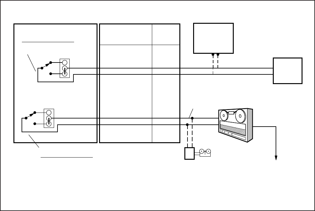
INSTALLATION-PERIPHERALS
SECTION 100-816-207
MARCH 1993
7-8
PIOU 25 PR.
CONNECTIONS
PIN NO. COLOR
MDF 66M
BLOCK
PIN NO.s
PIOU PCB
DOOR
LOCK
CONTROL
PAGE
AMPLIFIER
SELECT RELAY FUNCTION
WITH PROGRAM 77-1
DOOR LOCK OR EXTERNAL
PAGE CONTROL
BREAK
P10
MAKE
P11
BREAK
MAKE
NIGHT
BELL TO MUSIC-ON-
HOLD INPUT
MDF
CONNECTIONS
ALL WIRES SHOULD
BE JACKETED 24 AWG
TWISTED PAIRS
SELECT RELAY FUNCTION
WITH PROGRAM 77-1:
32
7
34
9
R-O
O-R
R-Br
Br-R
13
14
17
18
.
.
.
.
.
.
.
.
DE.T
DE. R
NH.T
NH.R
CONTROL
TAPE
PLAYER
NOTE:
Dotted lines and solid lines differentiate optional connections
where applicable; do not connect both options simultaneously.
BGM MUTE
NIGHT RELAY OR
MOH CONTROL
(Logical Port 04) of the Base Unit Digital telephone
circuit set and to circuit 1 of the KCDU or PDKU
(Logical Port 12) in the Expansion Unit. Each
DDCB door lock control installed reduces the sys-
tem door phone capacity of six by one. Any elec-
tronic or digital telephone can be equipped with a
button for each of the door locks. Install each DDCB
door lock control as follows:
DDCB Installation
1) On DK8, connect applicable digital telephone
circuit (Logical Port 02 or 03) to the DDCB
KSU modular jack (see Figure 7-9 and Figure
8-4).
2) On DK16, connect the applicable digital tele-
phone circuit (Logical Port 04 or 12) to the
DDCB HKSU modular jack (see Figure 7-9
and Figure 8-4).
3) On the DDCB, set SW1 to the DOOR position,
and SW2 to the LOCK position.
4) In Program 77-1, set the door unlock activa-
tion for three or six seconds, and enable the
applicable port for DDCB connection, and
specify if door phones should ring over exter-
nal page at night.
5) In Program 77-2, enable the DDCB B-jack for
door lock operation, and specify 1 or 5 rings
when door button is pressed.
6) In Program 79, specify door phone ringing
assignments.
7) In Program 39, assign Unlock Door buttons to
the desired stations.
8) Check each Unlock Door button from each
station: DDCB modular B-jack (pins 3 and 4)
will momentarily close (three or six seconds)
when the appropriate Unlock Door button is
pressed.
FIGURE 7-6
DK16 PIOU RELAY CONTROL FUNCTIONAL WIRING DIAGRAM
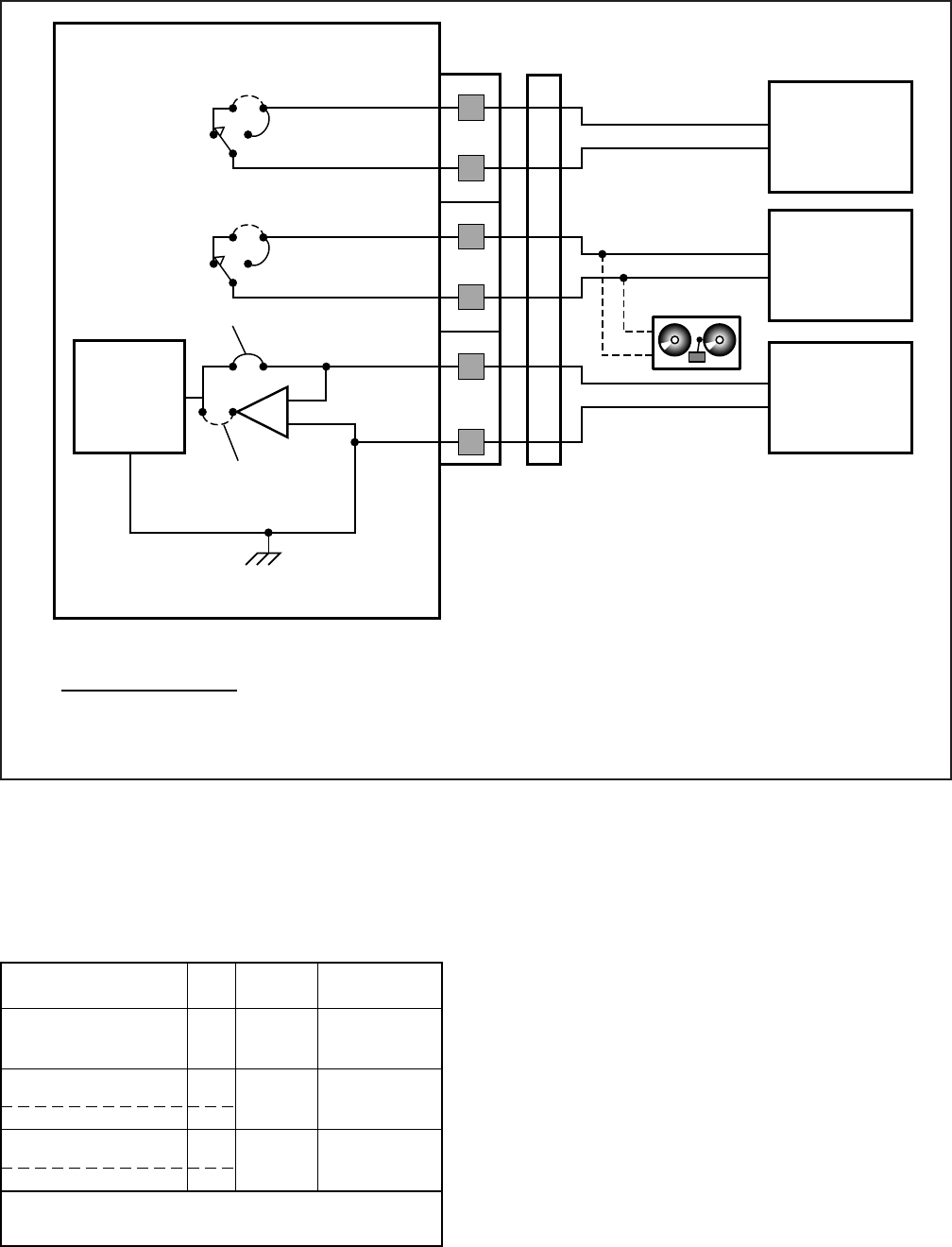
INSTALLATION-PERIPHERALS
SECTION 100-816-207
MARCH 1993
7-9
FIGURE 7-7
DK16 PIOUS RELAY CONTROL FUNCTIONAL WIRING DIAGRAM
ALARM
SENSOR
NORMAL
CLOSE
NORMAL OPEN
ALMT
ALMR
NHR
NHT
DER
DET
BREAK
W1
MAKE
K1
W2
K2
W3
PIOUS
ALM
NH
DE
DOOR
LOCK
CONTROL
MOH
SOURCE
UNIT
FACILITY
ALARM
UNIT
NIGHT BELL
RELAY OPTIONS:
• K1 (DE): DOOR LOCK OR AMP MUTE CONTROL; PROGRAM 77-1, LED 07
• K2 (NH): NIGHT RELAY OR MUSIC-ON-HOLD CONTROL; PROGRAM 77-1, LED 05
• K1 & K2: 24VDC, 1 AMP MAXIMUM
BREAK
MAKE
All wiring connections must be 24 AWG twisted pairs.
•
TBI MDF
3.25 Door Lock Assignments Guide
Host Port
No. Door
Lock No. Prog. 39
Assignments
Note: CKT1 must be used in installing DDCB on KCDU
or PDKU. (Must be in Port 12)
DK16 PIOU/PIOUS
Ckt 5 DK16
Base Unit DDCB
Ckt 3 DK8 KSU DDCB
Ckt 1 Expansion Unit
(PDKU or KCDU)
Ckt 4 DK8 KSU DDCB
N/A
04
02
12
03
0
Unlock
Door 0
1
Unlock
Door 1
2
Unlock
Door 2
Code 71
Code 72
Code 73
3.30 DK16 Expansion Unit Night Transfer/
Music-on-Hold Relay Options with PIOU or
PIOUS
3.31 The NHT/NHR relay may be programmed for
either the night relay or the MOH relay function
(refer to Figures 7-6 and 7-7). These functions can
be provided in addition to the relay service provided
by the Base Unit.
3.32 When configured for the night transfer func-
tion with Program 77-1, the relay activates if the
system is in the NIGHT mode. The relay may be
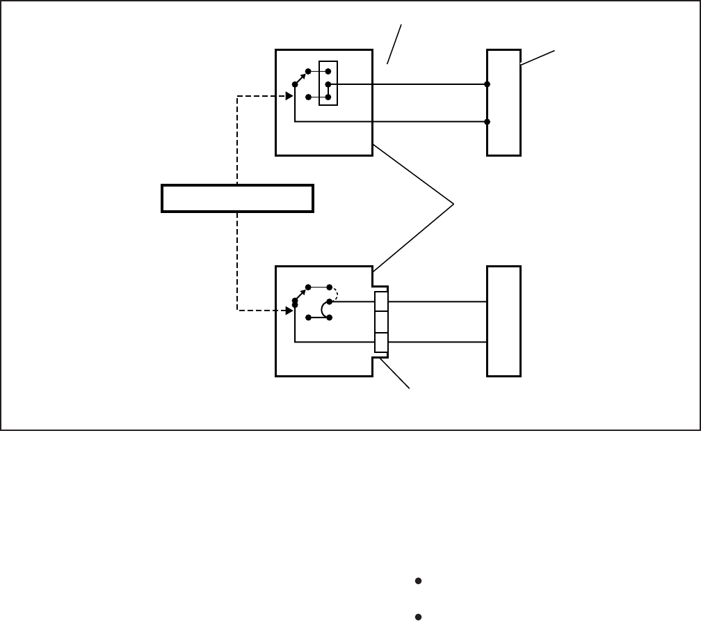
INSTALLATION-PERIPHERALS
SECTION 100-816-207
MARCH 1993
7-10
FIGURE 7-8
DK16 DOOR LOCK CONTROL OPTION (PIOU/PIOUS)
programmed to activate continuously when the
Night Transfer 1 button (only) is set to NIGHT
mode (for indirect answering machine control); or
to pulsate at 1-second ON/3-seconds OFF (for a
night bell) when incoming CO lines night ring over
external page (Program 78-13) (NT1 = tenant 1
CO lines; NT2 = tenant 2 CO lines) per Program
15.
3.33 When configured for the Music-on-Hold func-
tion with Program 77-1, the relay activates any
time a CO line is on hold. In this configuration, the
relay is normally used to control the Music-on-Hold
source.
3.34 DK16 Night Transfer Relay Control. Con-
figure the PIOU or PIOUS for the Night Transfer
Relay function in accordance with the following
steps (refer to Figures 7-6 and 7-7):
1) Access Program 77-1. Set LED 05 to OFF to
configure the Night/Hold Relay for the Night
Relay function.
2) Access Program 77-1. Set LED 06 to provide
continuous or pulsating relay activation as
follows:
OFF—Programs the relay for continuous
activation when NT1 button (only) is set.
ON—Programs the relay for pulsating
activation when the NT1 or NT2 button
is set to NIGHT mode and a tenant 1 or
tenant 2 CO line rings.
NOTE:
CO lines must be enabled in Program 78-13
for the NT pulsating relay function.
3) Access Programs 87, 88, and 89 to set the
CO lines that will activate the relay (when the
system is in the NIGHT mode).
4) Access Program 39 to program a Night
Transfer button (NT1 or NT2) on all tele-
phones that are to transfer the system into the
NIGHT mode.
P10
B
M
PIN 34, R-BR
PIN 9, BR-R
17
18
MDF
PIOU
W1
K1
MAKE
DET
DER
MDF
PIOUS
TO DOOR LOCK
SEE
FOR WIRING
TO DOOR LOCK
BREAK
DE
TERMINAL ON FRONT EDGE OF PCB
NOTE:
Unlock Door 0
assigned to digital and electronic
telephones in Program 39 with
Code 71.
K1/P10 (24VDC, 1.0 AMP MAX.)
25-PAIR
AMPHENOL
DET
DER
FIGURE 8-23
SEE ,
LED 07, 20
FOR RELAY OPTIONS
PROGRAM 77-1
DOOR LOCK 0 BUTTON
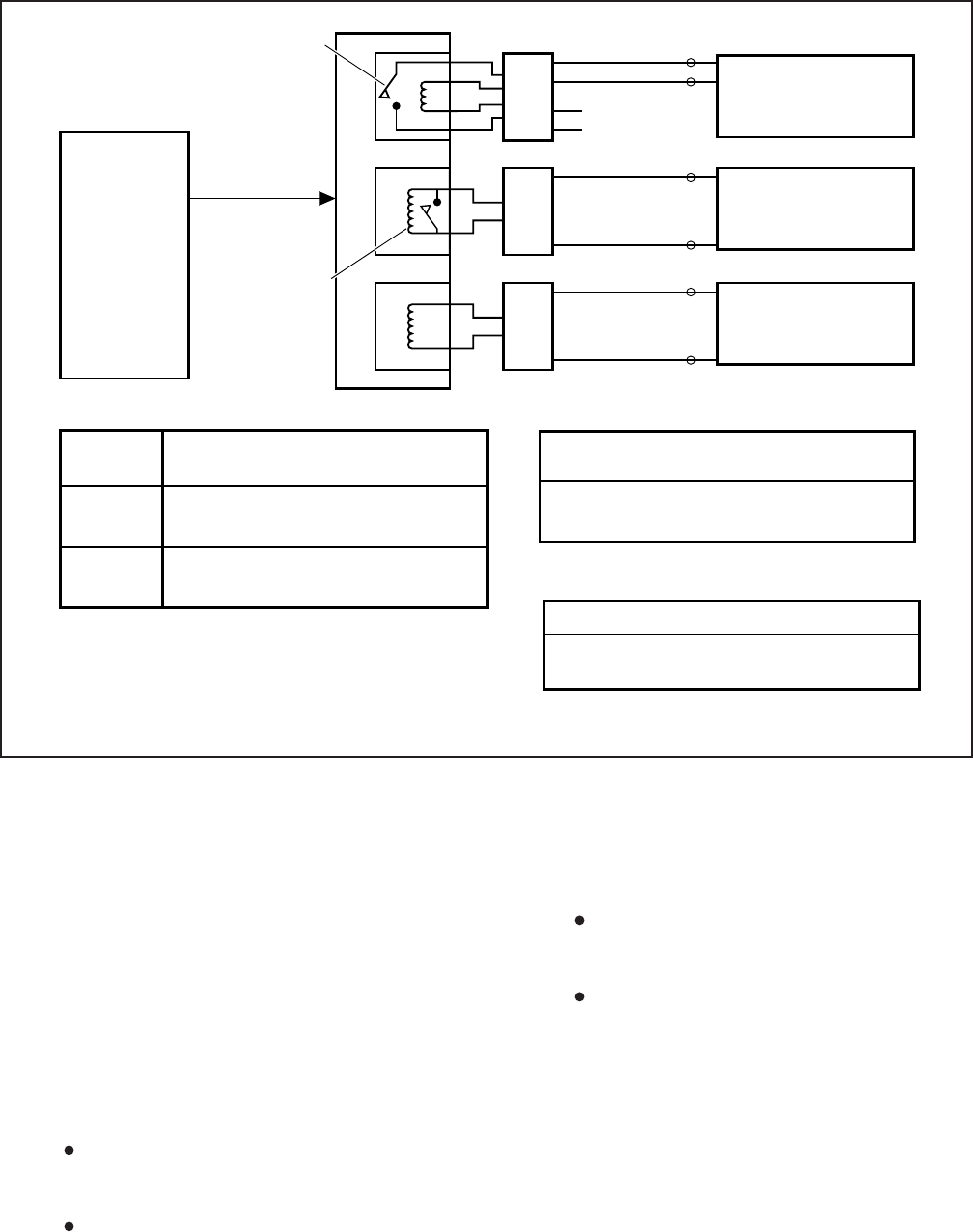
INSTALLATION-PERIPHERALS
SECTION 100-816-207
MARCH 1993
7-11
5) Access Programs 29-1 ~ 29-2 to program a
Night Transfer button (NT1 or NT2) on all
DSS consoles that are to transfer the system
into the NIGHT mode.
6) If tenant operation is required, access Pro-
gram 15 to set the CO lines for tenant 1 (NT1)
or tenant 2 (NT2) operation.
7A) Set the P11 jumper plug on the PIOU to the
MAKE or BREAK position, as required:
MAKE—Shorts the normally open con-
tacts (pins 9 and 34) when the night relay
is activated.
BREAK—Opens the normally closed
contacts (pins 9 and 34) when the night
relay is activated.
7B) Solder the jumper W2 on the PIOUS to the
MAKE or BREAK position, as required:
MAKE—Shorts the normally open con-
tacts (NHT and NHR) when the night
relay is activated.
BREAK—Opens the normally closed
contacts (NHT and NHR) when night
relay is activated.
8) Refer to Figures 7-6 and 7-7 for wiring/inter-
connecting details. Connect the PIOU or PI-
OUS to the MDF as required for the night relay
function.
NOTE:
Door phones programmed to ring over exter-
nal page in night mode (Program 77-1) do not
activate the NT relay.
FIGURE 7-9
DK8 AND DK16 DOOR LOCK CONTROL OPTION (DDCB)
DK16 KDCU,
CKT1
- OR-
DK16 PDKU,
CKT1
- OR -
DK16 DIGITAL
CKT5 OF
BASE UNIT
- OR -
DK8 KSU,
CKT 3 AND 4
(See Fig. 8-4
wiring diagrams)
(DK16 Port 04, 12)
(DK8 Port 02, 03)
DDCB
A
C
2
B
3
4
5
RJ11 3
4
2
5TO CUSTOMER
SUPPLIED
DEVICE
MDFB
1
2
RJ11 3
4
MDFB
1
RJ11 3
4
MDFB
1
3
4
DOOR PHONE
A
DOOR PHONE
B
- or -
DOOR LOCK CONTROL
2
2
DOOR PHONE
C
3
4
DDCB TO DK16 BASE UNIT WIRING CHART
BASE UNIT
AMPHENOL TO DDCB KSU JACK
DT (34) / DR (9)
PT (35) / PR (10)
TO
TO
PIN 3 / 4
PIN 5 / 6
DDCB TO DK16 EXPANSION UNIT
WIRING CHART
KCDU OR PDKU TO DDCB KSU JACK
DT (26) / DR (1) TO PIN 3 / 4
See Figure 8-4 for DK16 Base Unit, PDKU, and
KCDU pin-out information
NOTES
1.
2.
3.
Relay control contact will close when the door phone is in the
ringing, talk, or monitor state.
See Paragraph 4.25 for Door Lock assignments.
Relay contact specifications are -24VDC at 1.0 amp. max. Do
not connect relay contacts to 120 AC commercial power.
NOTE 1
RELAY
CONTROL
CONTACT
DOOR LOCK
CONTROL
CONTACT
NOTE 2
PT (27) / PR (2) TO PIN 5 / 6
DDCB TO DK8 KSU WIRING CHART
PORT NO. TO DDCB
KSU JACK
DT (30) / DR (5)
PT (31) / PR (6)
DT (32) / DR (7)
PT (33) / PR (8)
TO
TO
TO
TO
PIN 3 / 4
PIN 5 / 6
PIN 3 / 4
PIN 5 / 6
DK8 AMPHENOL
02
03

INSTALLATION-PERIPHERALS
SECTION 100-816-207
MARCH 1993
7-12
3.35 DK16 Expansion Unit MOH Relay Control.
Configure the PIOU or PIOUS for the MOH relay
function in accordance with the following steps
(refer to Figures 7-6 and 7-7):
1) Access Program 77-1. Set LED 05 to ON to
configure the Night/MOH relay for the MOH
relay function.
2A) Set the P11 jumper plug on the PIOU to the
MAKE or BREAK position, as required:
MAKE—Shorts the normally open con-
tacts (pins 9 and 34) when any CO line is
on hold.
BREAK—Opens the normally closed
contacts (pins 9 and 34) when any CO
line is on hold.
2B) Solder the W2 jumper on the PIOUS to the
MAKE or BREAK position, as required:
MAKE—Shorts the normally open con-
tacts (NHT and NHR) when any CO line
is on hold.
BREAK—Opens the normally closed
contacts (NHT and NHR) when any CO
line is in on hold.
3) Refer to Figures 7-6 and 7-7 for wiring/inter-
connecting details. Connect the PIOU or
PIOUS to the MDF as required for the MOH
relay function.
4 EXTERNAL SPEAKER UNIT (HESB)
OPTIONS
4.00 STRATA DK8 and DK16 systems provide
three options utilizing an HESB:
4.01 DK8 and DK16 Loud Ringing Bell Option.
The Loud Ringing Bell option allows the voice first
or ringing signal tone to be amplified without the use
of other manufacturers’ equipment. The voice first
and ringing signal tones can be amplified on all
6500-series electronic telephones and 2000- and
1000-series digital telephones equipped with HHEU
PCBs (refer to Section 100-816-206). The HESB
automatically turns off once the ringing call or voice
first has been manually answered from the elec-
tronic or digital telephone. This turn-off feature
prevents audio feedback problems.
4.02 Amplified Speaker Option. The Amplified
Speaker option allows the HESB to be configured
as a paging speaker. The HESB is connected to the
600 ohm Page RCA jack on the DK8 KSU or DK16
Base Unit to provide an amplified external speaker.
4.03 Talkback Amplified Speaker Option. The
Talkback Amplified Speaker option allows a
talkback speaker to be provided in areas where a
telephone is not needed. In this configuration, the
HESB is connected to the 600 ohm Page RCA jack
on the DK8 KSU or DK16 Base Unit and is used as
the amplifier and speaker. The door phone unit
(MDFB) is connected to the HESB, and serves as
a microphone to provide talkback operation. (The
MDFB microphone is always on in this application
so the pushbutton is inoperative, and the unit
serves only as a microphone for talkback.)
NOTE:
The 600 ohm Page RCA jack is two-way
(duplex) and is compatible with most commer-
cially available talkback amplifiers.
4.10 System Hardware Requirements
4.11 System hardware requirements vary depend-
ing on the HESB option selected. Refer to the
following installation procedures for the system
hardware requirements for each option.
4.20 HESB Option Installation
4.21 Loud Ringing Bell Installation. Install the
HESB Loud Ringing Bell option in accordance with
the following procedures:
DK8 and DK16 HESB Installation for Digital
Telephone Loud Ring Bell (Figure 7-10):
1) Connect a jumper between Terminals 2 and
10 on the HESB TB1 terminal block.
2) Connect a jumper between Terminals 4 and 5
on the HESB TB2 terminal block.
NOTES:
1. HESB connections made in steps 3~5
may be accomplished using the HESB
VOICE modular jack instead of the TB1
terminal block.

INSTALLATION-PERIPHERALS
SECTION 100-816-207
MARCH 1993
7-13
2. Install an HHEU PCB and HESC-65A cable
in the telephone per Section 100-816-206
before proceeding with Step 3.
3) Connect Terminal 1 of the HESB TB1 terminal
block to the red (+) wire of the HESC-65A
using a modular block.
4) Connect Terminal 2 of the HESB TB1 terminal
block to the green (–) wire of the HESC-65A
using a modular block.
5) Connect Terminal 8 of the HESB TB1 terminal
block to the yellow (L2) wire of the HESC-65A
cable using a modular block.
6) Connect the HACU-120 power supply’s +12V
lead to Terminal 1 of the HESB TB2 terminal
block, and connect the power supply’s 0V lead
to Terminal 2.
7) Plug the provided power cord into the power
supply and to a 117VAC, 60Hz power source.
DK16 HESB Installation for Electronic Tele-
phone Loud Ring Bell (Figure 7-11):
1) On the HESB TB1 terminal block: connect a
jumper between Terminals 6 and 7, and con-
nect another jumper between Terminals 5 and
8.
2) On the HESB TB2 terminal block, connect a
jumper between Terminals 4 and 5.
NOTES:
1. HESB connections made in steps 3~6
may be accomplished using the HESB
VOICE modular jack instead of the TB1
terminal block.
2. Install an HHEU PCB and HESC-65 (or
HESC-65A) cable in the telephone per
Section 100-816-206 before proceeding
with Step 3.
3) Connect Terminal 1 of the HESB TB1 terminal
block to the red (+) wire of the HESC-65 cable
using a modular block.
4) Connect Terminal 2 of the HESB TB1 terminal
block to the green (–) wire of the HESC-65
cable using a modular block.
5) Connect Terminal 3 of the HESB TB1 terminal
block to pin 3 of the electronic telephone’s
modular block (VOICE TIP).
6) Connect Terminal 4 of the HESB TB1 terminal
block to Pin 4 of the electronic telephone’s
modular block (VOICE RING).
7) Connect the HACU-120 power supply’s +12V
lead to Terminal 1 of the HESB TB2 terminal
block, and connect the power supply’s 0V lead
to Terminal 2.
8) Plug the provided power cord into the power
supply and to a 117VAC, 60Hz power source.
4.22 Loud Ringing Bell Test. Test the Loud Ring-
ing Bell installation in accordance with the follow-
ing steps:
1) Make a CO or station call to the station config-
ured for the loud ringing bell.
Ringing will be heard over the HESB.
2) Adjust the HESB volume control to the desired
level. (Screwdriver adjustment on back of
HESB and ring level control of associated
telephone.)
3) If ringing is heard at the station, but not over
the HESB, perform the following check while
the station is ringing:
a) Using a suitable voltmeter, measure volt-
age across terminals 1 (+) and 2 (-) of the
HESB TB1 terminal block.
Voltage indication should be 4.5 ~
5.0 VDC.
NOTE:
Ringing stops once the call is manually an-
swered. There should be NO voltage potential
across terminals 1 and 2.
b) If voltage is not as specified during ring-
ing, check that the telephone wiring con-
nections to the HESB have been made
properly (wires to terminals 1 and 2 of the
HESB TB1 terminal block may have been
reversed).
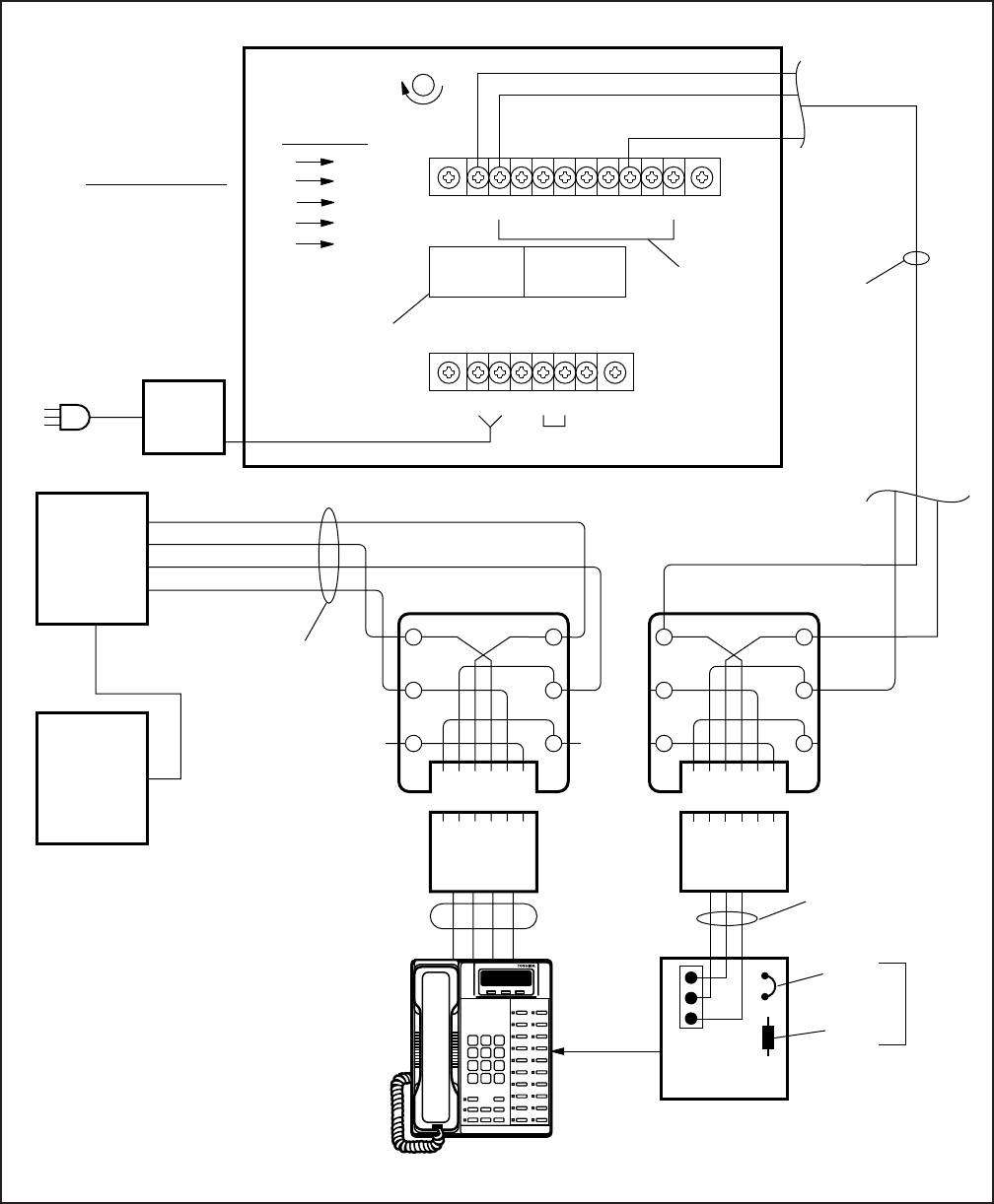
INSTALLATION-PERIPHERALS
SECTION 100-816-207
MARCH 1993
7-14
FIGURE 7-10
DK8 AND DK16 HESB/DIGITAL TELEPHONE WITH LOUD RINGING BELL WIRING
12345678910
TB1
(L2)
6 5 4 3 2 1
NOT USED 6 5 4 3 2 1
NOT USED
VOICE DOOR PHONE
MODULAR
CONNECTORS
MAY BE USED
JUMPER WIRES:
TB1
2-10 TB2
4-5
HACU-120
117/VAC TO
12 VDC
12345
TB2
12V 0V
12V 0V
117
VAC
24 AWG
JACKETED
TWISTED
PAIR
FROM
DIGITAL
TELEPHONE
TO HESB
HESB (REAR VIEW)
(-)
GN
654321
Y
BL
R
BK
W
GN
654321
Y
BL
R
BK
W
123456
+
P601
HHEU
(V.3 or .4)
TIP
RING
PT
PR
25-PAIR
CABLE
STATION CABLING
MDF
66 BLOCK
JACKETED
TWISTED PAIR
24 AWG
MODULAR
CORD STATION HESC-65A
CABLE
BASE UNIT,
PDKU, OR
KCDU
POWER
SUPPLY
JUMPERS
INTERNAL
WIRING:
TBI
1
2
3
4
VOICE
6
1
3
4
(+)
(-)
VOLUME CONTROL
(+)
(L2)
(-)
(L2)
(+)
GREEN
YELLOW
RED
NOTE:
See Section 100-816-206
for instructions to cut EXSP
and HHEU jumpers on the
digital telephone main PCB.
INSTALL HHEU CIRCUIT (V.3 or .4) or
HHEU2 CARD INTO BASE OF DKT PER
HHEU INSTALLATION INFORMATION
IN SECTION 100-816-206.
123456
OCA
STRAP
R607
DO NOT
CUT
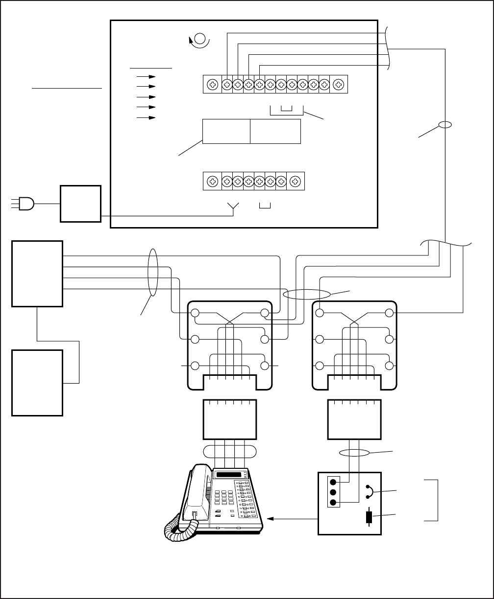
INSTALLATION-PERIPHERALS
SECTION 100-816-207
MARCH 1993
7-15
FIGURE 7-11
DK16 HESB/ELECTRONIC TELEPHONE WITH LOUD RINGING BELL WIRING
12345678910
TB1
VOICE TIP
VOICE RING
6 5 4 3 2 1 6 5 4 3 2 1
NOT USED
VOICE DOOR PHONE
MODULAR
CONNECTORS
MAY BE USED
JUMPER WIRES:
TB1
5-8
6-7
TB2
4-5
HACU-120
117/VAC TO
12 VDC
12345
TB2
12V 0V
12V 0V
117
VAC
24 AWG
JACKETED
TWISTED
PAIR
FROM
ELECTRONIC
TELEPHONE
TO HESB
HESB (REAR VIEW)
VOICE TIP
VOICE RING
(-)
GN
654321
Y
BL
R
BK
W
123456
GN
654321
Y
BL
R
BK
W
123456
OCA
RING
INSTALL HHEU CIRCUIT
CARD INTO BASE OF
ELECTRONIC TELEPHONE
PER INSTRUCTIONS IN
SECTION 100-816-206.
3
2
1
P601
HHEU
VOICE TIP
VOICE RING
DATA T1
DATA R1
OCA
TIP
25-PAIR
CABLE
STATION CABLING
MDF
66 BLOCK
JACKETED
TWISTED PAIR
24 AWG
MODULAR
CORD STATION HESC-65 or HESC-65A
CABLE
ELECTRONIC
TELEPHONE
6500-SERIES
PEKU
(CKT 1~8)
OR
PESU
(CKT 5~8)
POWER
SUPPLY
JUMPERS
JACKETED
INTERNAL
WIRING:
TBI
1
2
3
4
VOICE
6
1
3
4
(-)
(+)
(+) (RED)
(-) (GREEN)
VOLUME CONTROL
(+)
GREEN RED
OCA
STRAP
R607
DO NOT
CUT OCA
STRAP OR
R607
NOTE:
See Section 100-816-206
for instructions on how to
cut the HHEU strap inside
the telephone.

INSTALLATION-PERIPHERALS
SECTION 100-816-207
MARCH 1993
7-16
4.23 Amplified Speaker Installation. Install the
HESB Amplified Speaker option in accordance
with the following steps (refer to Figure 7-12):
1) Connect a jumper between terminals 1 and 2
of the HESB TB1 terminal block.
2) Connect a jumper between terminals 6 and 7
of the HESB TB1 terminal block.
3) Connect a jumper between terminals 5 and 8
of the HESB TB1 terminal block.
4) Connect a jumper between terminals 3 and 4
of the HESB TB2 terminal block.
5) Connect a jumper between terminals 5 and 6
of the HESB TB2 terminal block.
6) Connect the 600 ohm PAGE RCA jack output
on the DK8 KSU or DK16 Base Unit to termi-
nals 3 and 4 of the HESB TB1 terminal block.
7) Connect the power supply’s +12V lead to
terminal 1 of the HESB TB2 terminal block,
and connect the 0V lead to terminal 2.
8) Plug the provided power cord into the power
supply and to a 117VAC, 60Hz power source.
4.24 Amplified Speaker Test. Test the amplified
speaker installation in accordance with the follow-
ing steps:
1) Make an external page.
Page should be heard over the HESB.
2) Adjust the HESB volume control to the desired
level (screwdriver adjustment on back of
HESB).
4.25 HESB/MDFB Talkback Amplified Speaker
Installation. Install the HESB/MDFB Talkback Am-
plified Speaker option in accordance with the fol-
lowing steps (refer to Figure 7-13):
1) Connect a jumper between terminals 1 and 2
of the HESB TB1 terminal block.
2) Connect a jumper between terminals 3 and 4
of the HESB TB2 terminal block.
3) Connect a jumper between terminals 5 and 6
of the HESB TB2 terminal block.
NOTE:
HESB connections made in steps 4 ~ 7 may
be accomplished using the HESB VOICE and
DOOR PHONE modular jack instead of the
TB1 terminal block.
4) Connect terminal 7 of the HESB TB1 terminal
block to pin L1 of the MDFB.
5) Connect terminal 8 of the HESB TB1 terminal
block to pin L2 of the MDFB.
6) Connect terminal 9 of the HESB TB1 terminal
block to pin 1 of the MDFB.
7) Connect terminal 10 of the HESB TB1 termi-
nal block to pin 2 of the MDFB.
8) Connect the 600 ohm PAGE RCA jack output
from DK8 KSU or DK16 base unit to terminals
3 and 4 of the HESB TB1 terminal block.
9) Connect the HACU-120 Power Supply’s +12V
lead to terminal 1 of the HESB TB2 terminal
block, and connect the 0V lead to terminal 2.
10) Plug the provided power cord into the power
supply and to a 117 VAC, 60Hz power source.
4.26 Talkback Amplified Speaker Test. Test the
Talkback Amplified Speaker installation in accor-
dance with the following steps:
1) Make an external page.
Page will be heard over the HESB.
2) Verify that someone speaking into the door
phone can be heard at the paging station (with
this application, pressing the door phone but-
ton is not required to talkback through the door
phone).
4.27 HESB Wall Mounting Instructions. The
HESB can be mounted to a wall or other vertical
surface. Use the following instruction to mount the
HESB (see Figure 7-14).
1) Find a suitable location on the mounting sur-
face for the HESB.
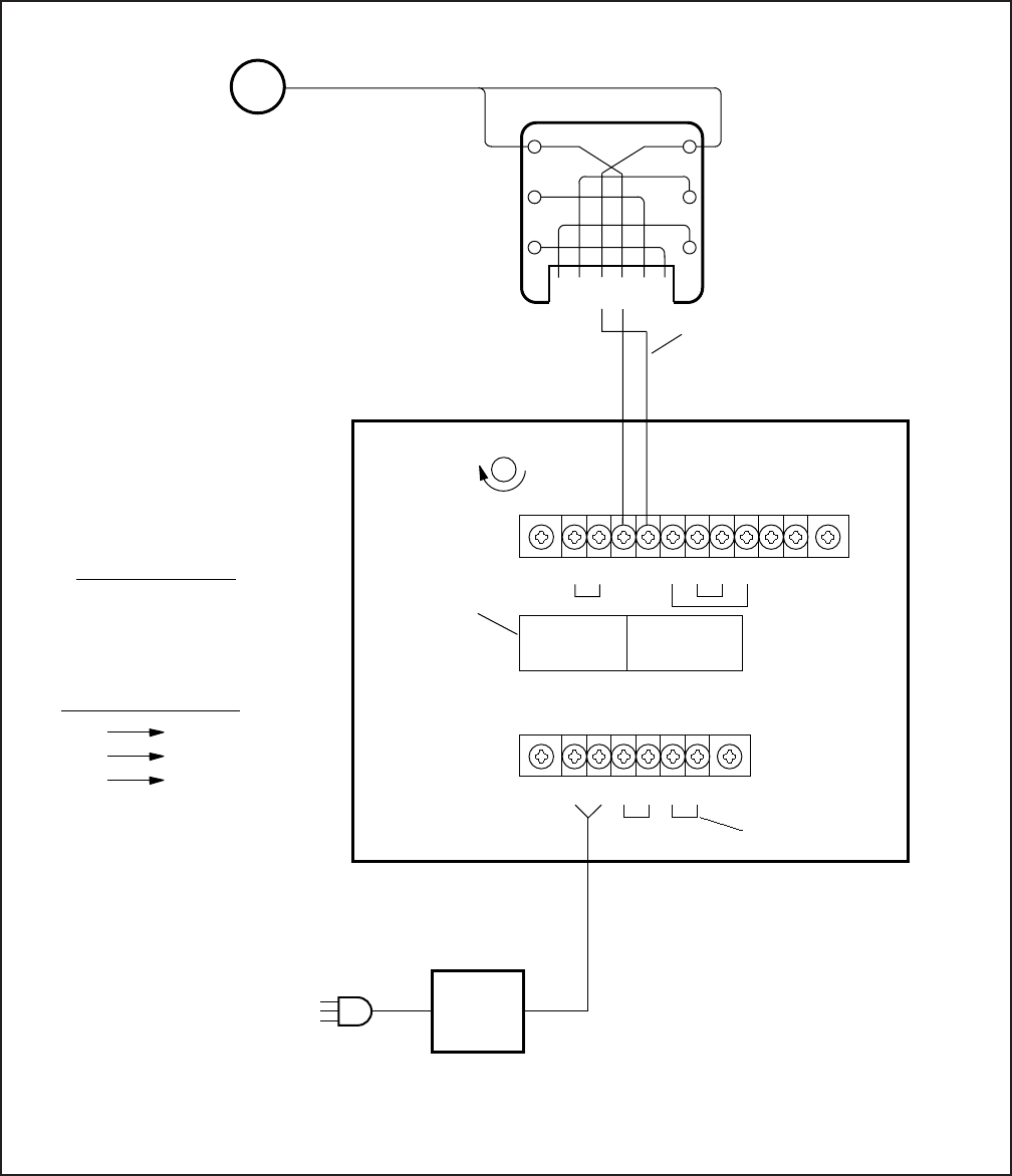
INSTALLATION-PERIPHERALS
SECTION 100-816-207
MARCH 1993
7-17
FIGURE 7-12
DK8 AND DK16 HESB/AMPLIFIED SPEAKER WIRING
12345678910
TB1
6 5 4 3 2 1 6 5 4 3 2 1
NOT USED
VOICE DOOR PHONE
JUMPER WIRES:
TB1
1-2
5-8
6-7
TB2
3-4
5-6
123456
TB2
12V 0V
12V
VDC
0V
POWER
SUPPLY
HESB (REAR VIEW)
117 VAC
TO
12 VDC
MODULAR
CONNECTOR
MAY BE USED
JUMPERS
VOLUME CONTROL
TBI
3
4
VOICE
3
4
INTERNAL WIRING:
615432
R GN
Y
BL
BK
W
DK8 OR DK16 KSU
600 OHM PAGE
RCA JACK
JACKETED TWISTED PAIR
24AWG
NOTE:
PIOU/PIOUS page outputs
do not operate.
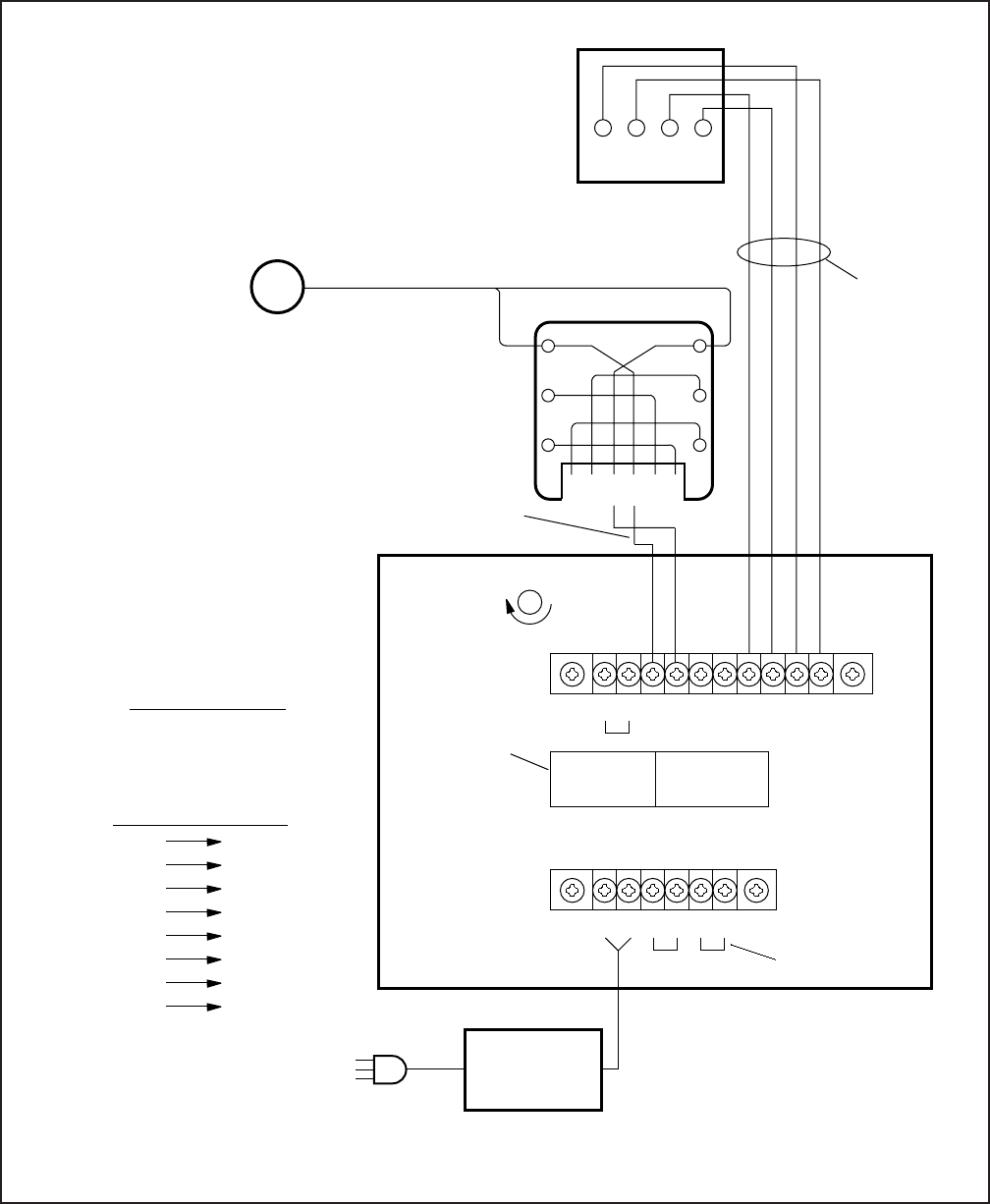
INSTALLATION-PERIPHERALS
SECTION 100-816-207
MARCH 1993
7-18
FIGURE 7-13
DK8 AND DK16 HESB/TALKBACK AMPLIFIED SPEAKER WIRING
12345678910
TB1
6 5 4 3 2 1 6 5 4 3 2 1
VOICE DOOR PHONE
123456
TB2
12V 0V
12V 0V
POWER
CONVERTER
HESB (REAR VIEW)
117 VAC TO 12 VDC
MODULAR
CONNECTOR
MAY BE USED
JACKETED
TWISTED
PAIR
24 AWG
MDFB (REAR VIEW)
1 2 L1 L2
12L1 L2
JUMPERS
DOOR PHONE
TALKBACK
MICROPHONE
VOLUME CONTROL
JUMPER WIRES:
TB1
1-2 TB2
3-4
5-6
DOOR PHONE
INTERNAL WIRING:
TBI
4
3
TBI
7
8
9
10
VOICE
4
3
4
3
2
5HACU-120
NOTE:
The 600 ohm duplex page output is
compatible with most commercially
available talkback amplifiers.
615432
R GN
Y
BL
BK
W
DK8 OR DK16 KSU
600 OHM PAGE
RCA JACK
JACKETED TWISTED PAIR
24AWG
NOTE:
PIOU/PIOUS page outputs
do not operate.
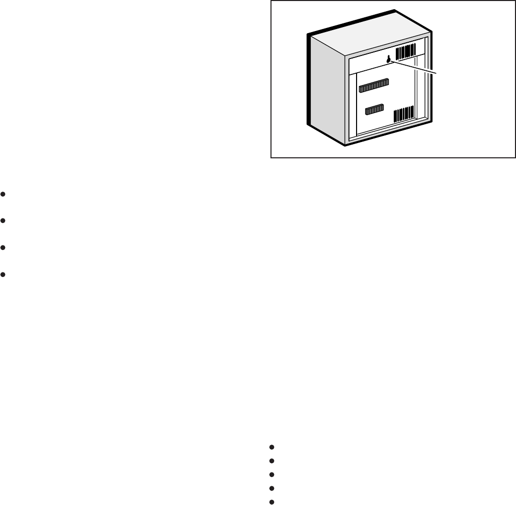
INSTALLATION-PERIPHERALS
SECTION 100-816-207
MARCH 1993
7-19
FIGURE 7-14
HESB WALL MOUNTING
2) Screw a 1.25-inch panhead wood screw into
the mounting surface, use wall anchors if
mounting to drywall surface.
3) Hang the HESB from the screw.
5 EXTERNAL PAGE OPTIONS
5.00 System Hardware Requirements
5.01 The STRATA DK systems offer a variety of
external page options. Additionally, a BGM option
is available with each external page option. DK
systems support:
DK8 and DK16 Paging with BGM (same ampli-
fier)
DK16 Zone paging with BGM (separate amplifi-
ers)
DK16 Zone paging with BGM (multiple amplifi-
ers)
See Paragraph 2 of this section for more Page/
BGM options
5.10 External Page Option Installation
5.11 All voice paging connections are made via the
600 ohm Page RCA jack on the DK8 KSU or DK16
Base Unit. The PIOU and PIOUS voice and BGM
(600 ohm and 3 watt) outputs are inoperable on the
DK16 Expansion Unit.
5.12 DK8 and DK16 Page with Separate Ex-
ternal BGM (same amplifier). In this configura-
tion the MOH source or alternate BGM source
provides BGM to digital/electronic telephones
and a separate BGM source provides music to
external speakers. Also, in this configuration Pag-
ing and external BGM are amplified by a common
customer-supplied paging amplifier. When the ex-
ternal page access code is dialed, the external
page control relay is activated, which applies a
short to the amplifier mute control to mute the
external BGM music. Install this option in accor-
dance with the following steps (refer to Figure
7-15):
1) Connect the input no. 1 from the paging ampli-
fier via an RJ11 jack to the 600 ohm RCA jack
on the DK8 KSU or DK16 Base Unit.
2) Connect the paging amplifier mute terminal
via a MDF to pins 42 and 17 of the 25-pair
amphenol connector from the DK8 KSU or
DK16 Base Unit.
3) Connect the music source to the input no. 2 of
the paging amplifier.
4) Connect the speaker to the paging amplifier
output.
5.13 DK16 Zone Page with BGM (separate am-
plifiers). This configuration provides multiple-zone
paging capability. The output of the paging ampli-
fier is routed back to the PIOU, where it is switched
to one of four sets of speakers by PIOU relays K1
through K4. The relay selected is determined by
the access code dialed by the station user. Default
access codes are:
K1/zone A = 35
K2/zone B = 36
K3/zone C = 37
K4/zone D = 38
All zones = 39
NOTE:
Multi-zone page output rating is 30W/maxi-
mum at 300 ohms.
5.14 An all zone page code (39) is also available as
an option (see Program 10-2). When the all page
code is dialed, all four relays are activated to permit
simultaneous paging to all speaker zones and all
digital and electronic telephone speakers. Install
this option in accordance with the following steps
(refer to Figure 7-16):
ONE WALL
MOUNTING
HOLE
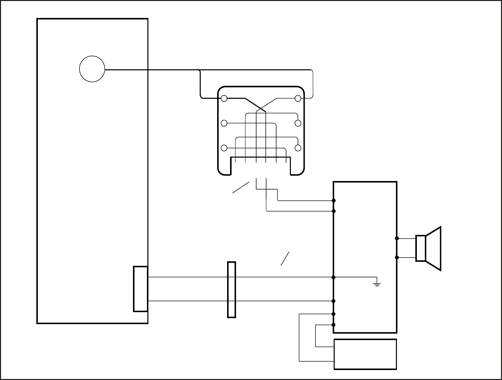
INSTALLATION-PERIPHERALS
SECTION 100-816-207
MARCH 1993
7-20
FIGURE 7-15
DK8 AND DK16 PAGE AND SEPARATE BGM USING SAME AMPLIFIER
5) Connect the PIOU PGOUT pins to the zone A
~ zone D speakers (A).
5.15 DK16 Zone Page with BGM (multiple am-
plifiers). This configuration also provides multiple-
zone paging capability, as in Paragraph 5.13. How-
ever, separate amplifiers are used for each zone.
Install this option in accordance with the following
steps (refer to Figure 7-17):
1) Connect the inputs from the paging amplifiers
via an RJ11 jack to the J7 600 ohm Page RCA
Jack on the Base unit. Or, direct connect J7 to
Amp using a standard audio cable with RCA
plugs.
1) Connect the input from the paging amplifier
via an RJ11 jack to the J7 600 ohm RCA Jack
on the Base Unit. Or, direct connect J7 to Amp
using a standard audio cable with RCA plugs.
2) Connect the BGM music source to the music
amplifier input.
3) Connect the paging amplifier's (+) output to
each PGIN of the PIOU K1 ~ K4 relays and
the amplifier's (-) output to each of the zone A
~ zone D speakers (C).
4) Connect the BGM music amplifier (+) output to
terminal 23 (PG COMMON) of the PIOU, and
the (–) to the (–) output of the page amplifier.
(42)
INPUT 1
OUTPUT
EXTERNAL
PAGING AMP
(17)
EXTERNAL
BGM MUSIC
SOURCE
MUTE 2
INPUT 2
615432
R GN
Y
BL
BK
W
PAGE
600 OHM
RCA JACK
JACKETED
TWISTED PAIR
24AWG
DK8 KSU OR DK16
BASE KEY
SERVICE UNIT
66 BLOCK
PIN NUMBERS
DK8 KSU OR DK16
BASE UNIT
25-PAIR
AMPHENOL
CONNECTOR
33
34
SPEAKER
NOTE:
BGM over external page option
must be turned off: Dial
Intercom + 490 from Station 10.
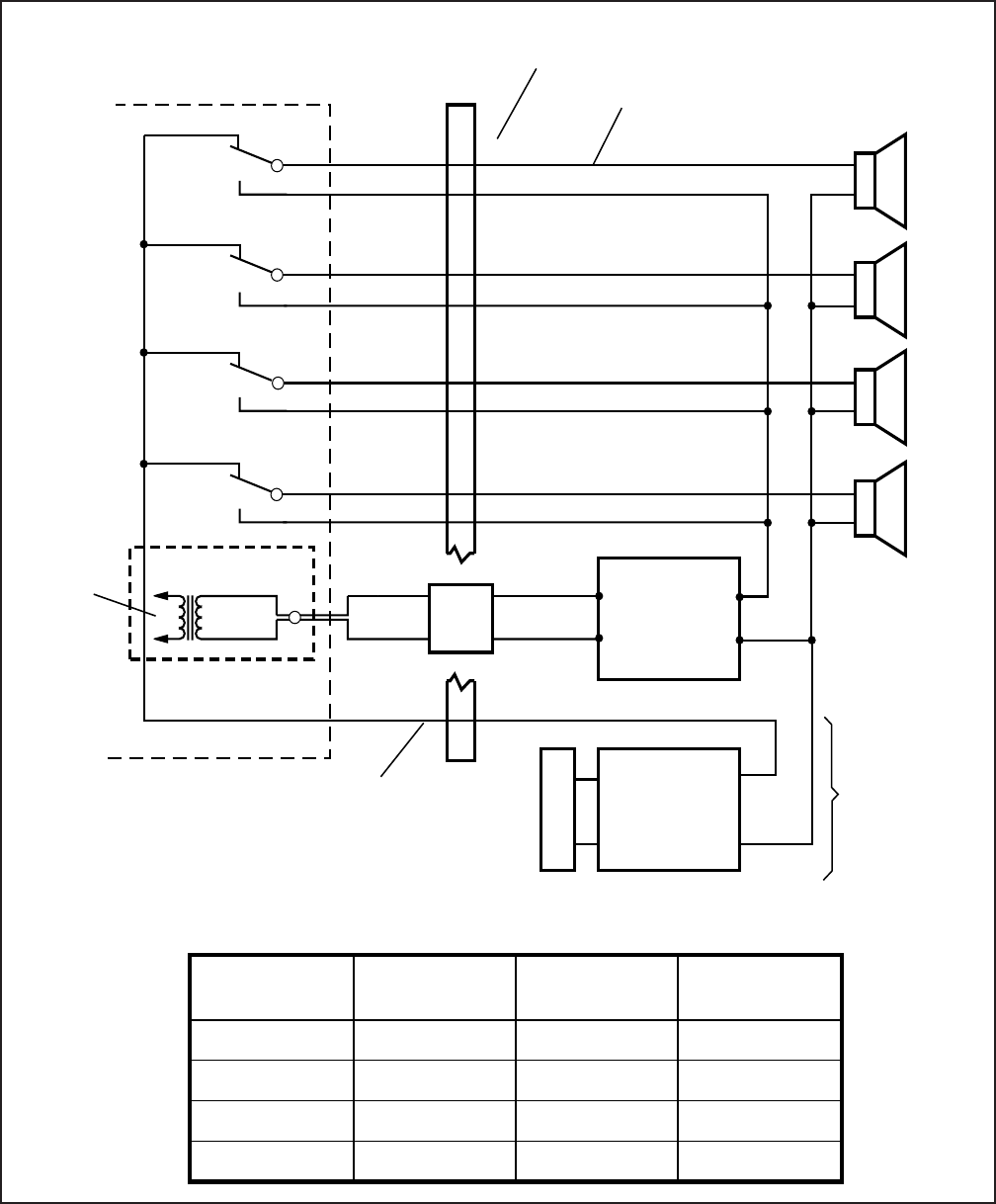
INSTALLATION-PERIPHERALS
SECTION 100-816-207
MARCH 1993
7-21
FIGURE 7-16
DK16 PIOU ZONE, PAGE/BGM/NIGHT RING (SEPARATE AMPLIFIERS)
K1
K2
K3
K4
600
PIOU
PGOUT 1 (15)
ZONE A
ZONE B
ZONE C
ZONE D
PGOUT 2 (17)
INPUT
OUTPUT
PIOU PIN NUMBERS ( )
25-PAIR CABLE
PAGING AMP
MUSIC AMP
BGM
MUSIC
SOURCE
(TO EXTERNAL
SPEAKER ONLY)
OPTIONAL
CONNECTION
SPEAKER
COMMON
LINE
B
M
B
M
B
M
B
M
Ω
INPUT
OUTPUT
JACKETED
TWISTED PAIR
24 AWG
PG
COMMON (23) 46
41
42
37
38
33
34
29
PGOUT 3 (19)
PGIN 2 (42)
PGIN 3 (44)
PGOUT 4 (21)
PGIN 4 (46)
PGIN 1 (40)
30
66 BLOCK
PIN NUMBERS
A
C
A
C
A
C
A
C
BGM OR
NIGHT
RINGING
AND/OR
PAGE
FROM
BASE
UNIT J7
600 OHM
RCA JACK
Program 77-1
Button/LED Zone/
Relay LED ON
Assignment LED OFF
Assignment
13
12
11
10
K4
K3
K2
K1
Tenant 2 COs
Tenant 2 COs
Tenant 2 COs
Tenant 2 COs
Tenant 1 COs
Tenant 1 COs
Tenant 1 COs
Tenant 1 COs
NIGHT RINGING PROGRAM ASSIGNMENTS
(SEE PARAGRAPH 9 OF SECTION 100-816-207)
RJ11
JACK
BASE KEY
SERVICE UNIT
J7
(+)
(–)
(+)
(–)
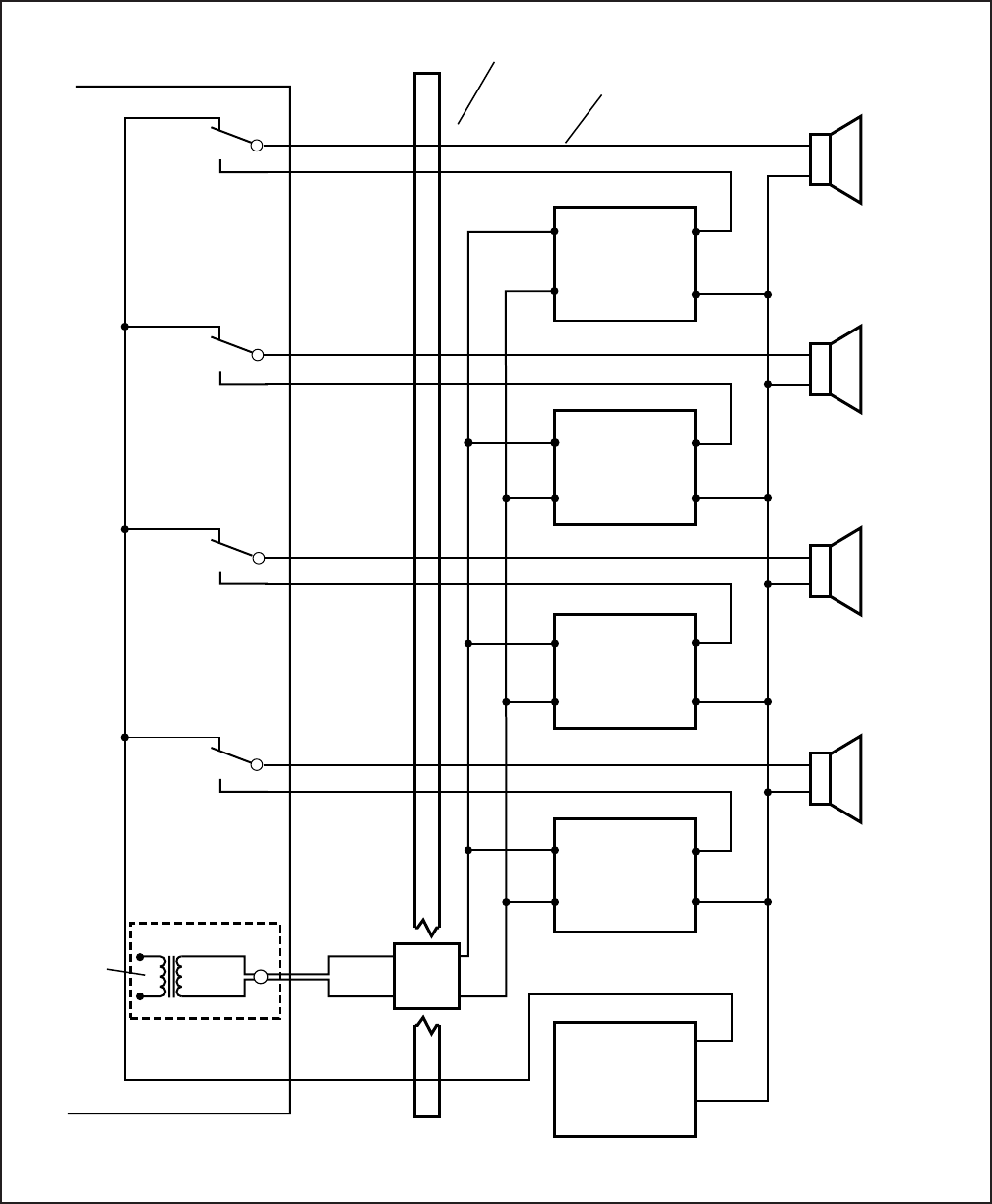
INSTALLATION-PERIPHERALS
SECTION 100-816-207
MARCH 1993
7-22
FIGURE 7-17
DK16 PAGING WITH MULTIPLE AMPLIFIERS
INPUT
AMP
1
OUTPUT
INPUT
AMP
2
OUTPUT
INPUT
AMP
3
OUTPUT
INPUT
AMP
4
OUTPUT
K1
K2
K3
K4
BGM OR
NIGHT
RING OR
PAGE
FROM
BASE
UNIT J7
600 OHM
RCA JACK
600
PG
COMMON (23) 46
41
42
37
38
33
34
29
MDF
PIOU
PGOUT 1 (15)
PGIN 1 (40) ZONE A
(35)
ZONE B
(36)
ZONE C
(37)
ZONE D
(38)
PGOUT 2 (17)
PGIN 2 (42)
PGOUT 3 (19)
PGIN 3 (44)
PGOUT 4 (21)
PGIN 4 (46)
Ω
JACKETED
TWISTED PAIR
24 AWG
BGM MUSIC
SOURCE &
AMPLIFIER OUTPUT
66 BLOCK
PIN NUMBERS
PIOU PIN NUMBERS ( )
25-PAIR CABLES
30
PAGE ACCESS
CODES ( ):
ALL ZONES
(39)
(+)
(–)
BASE UNIT
J7
RJ77
JACK
A
C
A
C
A
C
A
C
+
–
+
–
+
–
+
–

INSTALLATION-PERIPHERALS
SECTION 100-816-207
MARCH 1993
7-23
2) Connect the music source to the music ampli-
fier input.
3) Connect the paging amplifier outputs to PIOU
(PGIN) relays K1 ~ K4 and zone A ~ zone D
speakers (C).
4) Connect the music amplifier (+) output to
terminal 23 (PG COMMON) of the PIOU, and
the (–) output to the “C” terminal of zone A ~
zone D speakers.
5) Connect zone A ~ zone D speakers “A” termi-
nal to the “PGOUT” contact of the PIOU relays
K1~ K4 respectively.
5.16 DK16 Night Ringing over All External Page
Zones (PIOU only). To allow the night ringing
signal to be sent over zone paging, install the
paging amplifier in accordance with the following
steps (refer to Figure 7-18). (Steps 2 ~ 6 are
performed at the MDF.)
IMPORTANT NOTE: To night ring over
selected PAGE zone, see Paragraph 9 of this
section.
1) Connect the amplifier input via an RJ11 jack to
the J7 600 ohm Page RCA jack on the Base
unit. Or, direct connect J7 to Amp using a
standard audio cable with RCA plugs.
2) Cross-connect the amplifier output A to the
PGIN1 ~ PGIN4 connector from the PIOU.
3) Cross-connect the amplifier output B to the
zone A ~ zone D speaker common line.
4) Cross-connect the PIOU PGOUT1 ~ PGOUT4
to zone A ~ zone D speakers (A).
5) Cross-connect the amplifier output A to pin 9
(NHR) of the PIOU.
6) Cross-connect a jumper from pin 34 (NHT) to
pin 23 (PG COMMON) from the PIOU PCB.
7) In Program 77-1, set LED 05 to OFF and 06
to ON. Set LED 08 to ON if door phones are to
ring over external page when the system is in
NIGHT mode.
8) In Program 78, enable the CO lines that are to
ring via external page when the system is set
in the NIGHT mode.
9) In Program 39, assign the Night Transfer
1 or Night Transfer 2 buttons to digital or
electronic telephones per the System Record
Sheets (see Note 2).
10) Press the Night Transfer 1 or Night
Transfer 2 button on an electronic or digital
telephone to set the system into the NIGHT
mode. Test by calling into the system on a CO
line assigned (Program 78) to night ring over
external page.
When ringing sounds (see Note 2) over
the page, press Intercom 5 3 5 to
answer.
NOTES:
1. All zones will ring with this option; night
ringing to selected zones is not possible;
see paragraph 9 for night ring over se-
lected page zones.
2. The
Night Transfer 1
or
Night Trans-
fer 2
buttons put CO lines in NIGHT ring
mode per Program 15; NT1-TENANT 1/
NT2-TENANT 2 CO line assignment.
6 DK8 AND DK16 STATION MESSAGE
DETAIL RECORDING (SMDR) PRINTER/
CALL ACCOUNTING DEVICE OPTIONS
6.00 An SMDR printer or call accounting device
may be connected to the system to provide a hard-
copy record of station activity (incoming, outgoing,
and transferred calls account code entries) on CO
lines or a printout of the customer data base. Call
record data is printed out at the completion of each
call. Program SMDR with Program 60, and use
Program 97 to have the SMDR printer display the
customer data base.
6.01 SMDR will send out special names for the
following types of calls:
MSS: Prints on DISA calls to stations (see Note).
MODM: Prints on calls to the IMDU remote
maintenance modem (station 619).
DISA: Prints on DISA calls to CO lines when
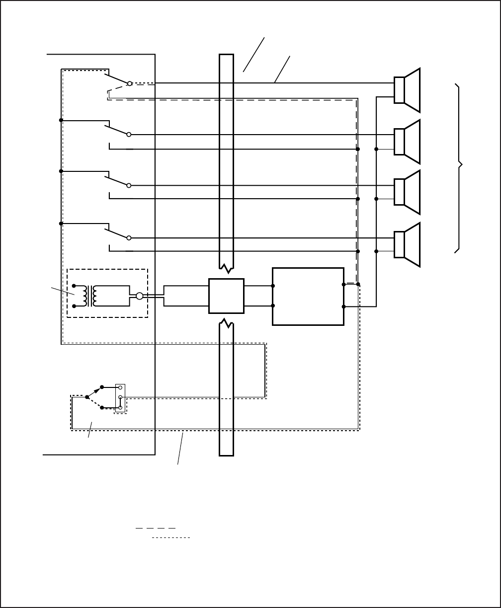
INSTALLATION-PERIPHERALS
SECTION 100-816-207
MARCH 1993
7-24
FIGURE 7-18
DK16 NIGHT RINGING OVER ALL EXTERNAL PAGE ZONES
(JUMPER WIRE)
18
17
P11
ALL
ZONES
(39)
MDF
NOTES:
1. Page signal path .
2. Night ring signal path .
K1
K2
K3
K4
600
PIOU
PGOUT 1 (15)
ZONE A
(35)
ZONE B
(36)
ZONE C
(37)
ZONE D
(38)
PGOUT 2 (17)
INPUT
OUTPUT
PIOU PIN NUMBERS ( )
25-PAIR CABLE
PAGING AMP
SPEAKER
COMMON
LINE
(B)
B
M
B
M
B
M
B
M
Ω
JACKETED
TWISTED PAIR
24 AWG
PG
COMMON (23) 46
41
42
37
38
33
34
29
PGOUT 3 (19)
PGIN 2 (42)
PGIN 3 (44)
PGOUT 4 (21)
PGIN 4 (46)
PGIN 1 (40)
30
66 BLOCK
PIN NUMBERS
A
C
A
C
A
C
A
C
PAGE AND
NIGHT RING
SIGNAL
FROM
BASE
UNIT J7
600 OHM
PAGE RCA
JACK
BREAK
MAKE
3. Background music over zone page is not possible with this configuration.
4. Available with PIOU only: not PIOUS.
5. Night ringing will be sent to all zones; selected zones are not possible.
(A)
NHT (34)
NHR (9)
PAGE ACCESS
CODES ( ):
NIGHT RELAY
77-1:
78:
77-1:
LED 05, OFF.
LED 06, ON.
ENABLE CO LINES TO NIGHT RING
OVER EXTERNAL PAGE.
LED 08, ON. FOR DOOR PHONE
NIGHT RING OVER PAGE.
PROGRAMMING:
BASE UNIT
J7
RJ11
JACK

INSTALLATION-PERIPHERALS
SECTION 100-816-207
MARCH 1993
7-25
Line 03 returns intercom dial tone to caller after
two ring cycles (5 ~ 6 seconds).
Caller dials 13.
After 48 seconds from start of call, station 13
answers.
Printout B prints after station 13 answers the call
at 4:32.
NOTE:
If Program 60-2 is set for 10 seconds, MSS
will not print if the call is answered within 10
seconds from when the caller receives dial
tone.
PRINTOUT B
03 MSS 04:32 00:00:48 00:05 13
EXAMPLE 3—DISA Outgoing CO Line Call
NOTE:
DISA CO line calls print out as DISA.
Call Sequence C
Outside caller rings CO line 01 (line 01 is pro-
grammed as DISA).
Line 01 returns intercom dial tone after two ring
cycles (5 ~ 6 seconds).
Caller dials 703 to access CO line 03 (outgoing).
Caller dials the DISA security code and receives
CO dial tone.
Caller dials the telephone number and con-
verses when the call is answered.
Caller hangs up.
The call releases, and Printout C prints after the
call disconnects at 12:22.
NOTES:
1. If the CO provides the auto release (AR)
signal (see Program 15), the call discon-
nects when either party hangs up. A “*” will
print out following the CO line number if
the call is disconnected by the AR signal.
2. If the auto release signal is not returned,
the CO lines will remain seized until the
DISA disconnect timer releases the call
(approximately five minutes).
PRINTOUT C
Auto Release Signal:
03*DISA 12:22 00:02;01 (outgoing)
01 DISA 12:22 00:02;01 (incoming)
calling through the system CO-to-CO.
NOTE:
MSS will print only on DISA calls that are
answered 10 seconds or 1 second (see Pro-
gram 60-2) after the DK dial tone is sent to the
calling party. If set for 10 seconds and the call
is answered before 10 seconds, the call will
register as a normal incoming call and the
MSS/transfer portion of the call will not print
out.
6.02 Figure 7-19 shows a sample SMDR printout
and describes the contents of each column of the
printout. The following examples show several call
record samples and describe the sequence of
events which occurred to generate the call records.
NOTE:
SMDR printout “time of day” and day/month/
year (DD/MM/YY) is the same as the system
clock time/date. SMDR DD/MM/YY will print
out each time 50 call records are generated.
SMDR PRINTOUT EXAMPLES
Direct Inward System Access (DISA) CO Lines
NOTE:
DISA station calls print out as MSS.
EXAMPLE 1—Ring, No Answer DISA Call
Call Sequence A
Outside caller rings CO line 03 (CO line 03 is
programmed as a DISA line).
Line 03 returns intercom dial tone to caller after
two ring cycles (5 ~ 6 seconds).
Caller does nothing.
After 32 seconds, call is disconnected.
Printout A prints after disconnect at 4:59.
PRINTOUT A
03 MSS 04:59 00:00:32 00:06
EXAMPLE 2—DISA Internal Station Call
Call Sequence B
Outside caller rings CO line 03 (CO line 03 is
programmed as a DISA line).
INSTALLATION-PERIPHERALS
SECTION 100-816-207
MARCH 1993
7-26
FIGURE 7-19
DK8 AND DK16 SMDR PRINTOUT EXAMPLES
01 15 08:14 00:00;22
01 MODM 08:15 00:00;18
03 10 08:16 00:00;28
03 DISA 08:16 00:00;15
01 DISA 08:17 00:00;25
03 MSS 08:18 00:00;12
03 15 08:19 00:00;22
03* 12 08:19 00:00;16
04 10 08:20 00:00;34
02 10 08:22 00:00;22
01 15 08:23 00:00;40
<DD/MM/YY, EVERY FIFTY CALL RECORDS AND AT MIDNIGHT>
00;00
00;08 12
00;06 15
123456987
12345678912345678965412365
7145833700
7145833700
456789
123456789456321
(FC: 35-60)
(FC: 62-76)
(FC: 30-33)
(FC: 24-28)
(FC: 15-22)
(FC: 9-13)
(FC: 4-7)
Field Column (FC: 1-2)
Account Code
(4~15 digits)
Outgoing Telephone Number (1~26 digits)
Station to which the CO Line was transferred (1~4 digits)
Time of Day (HH:MM; hour and minute the call was released)
Call Duration (HH:MM:SS, see Note 1)
Station Number (1~4 digits; see Note 2)
CO Line Incoming Ring Duration Before Answer (MM:SS)
CO Line Number (01~36)
NOTES:
1.
2.
3.
4.
5.
6.
*
3
<DISA CALL TO IMDU>
<OUTGOING DISA ACCESS BY INCOMING DISA 01>
<INCOMING DISA AND ACCESS CO 03 OUTGOING>
<05 ANSWERS DISA CALL 12 SECONDS AFTER DK DIAL TONE>
07/06/90
First Digit (varies) Last (always this column)
First Digit (varies) Last
6
3
3
3
3
3
3
3
Call Duration (incoming, outgoing, or transfer) can be 1.0 or 10 seconds (minimum) to generate a call record
printout (see Program 60-2).
“MSS”: designates a Direct Inward System Access (DISA) CO call to a station that is not answered; or, answered
after 1.0 or 10 seconds (depending on Program 60-2). DISA calls always register 05 ~ 06 seconds ring before
answer duration time.
“MODM”: designates a call to the IMDU, Remote Maintenance Modem.
“DISA”: designates a DISA call thru the system via CO to CO connection.
Field column information is provided for SMDR output formatting purposes.
The call record data is ASCII-formatted, 8 bits; no parity, 1-stop bit.
Special dial printout:
Tone = "T"
Long pause = "L"
Flash = "F"
Pause = "P"
The "
*
" indicates that the call was disconnected by the Central Office Calling Party Control (CPC) or Automatic
Release (AR) signal. CO lines must have Programs 15-0 and 15-3 enabled to be dropped by the CPC signal.
12

INSTALLATION-PERIPHERALS
SECTION 100-816-207
MARCH 1993
7-27
Disconnect Timer:
01 DISA 12:24 00:04;57 (incoming)
03 DISA 12:24 00:04;57 (outgoing)
6.03 System Program Data Printout. If a printer
is connected to the SMDR port on the QSMU,
PIOU, or PIOUS, customer program information
stored in the system RAM may be printed out for
reference by using Program 97 (see Paragraph
6.14).
6.10 SMDR Hardware Requirements
6.11 The DK8 system must be equipped with a
QSMU option PCB. QSMU Program 10-3, LED 04
must be OFF. Install the QSMU PCB in accordance
with Section 100-816-204 and wire the SMDR
device to the QSMU (PPTC/mocular cord) in accor-
dance with Section 100-816-208. The DK16 sys-
tem must be equipped with a PIOU or PIOUS PCB
in the Expansion Unit to support the SMDR printer/
call accounting device option. Connection of the
printer or call accounting device to the PIOU or
PIOUS PCB is accomplished with a 3-pair modular
cord (7 feet maximum) and a PPTC connector
adaptor (refer to Figure 7-20 for details). Call record
data is ASCII-formatted, 8 bits, no parity, 1-stop bit.
6.12 The DK8 KSU and DK16 PIOU or PIOUS
contains a call record buffer which stores call
record data (for 20 calls on DK8 or 50 calls on
DK16) when the printed or call accounting device is
turned off, or when no device is connected to the
SMDR port. No further call records are stored after
the buffer is filled. When the printer or call account-
ing device is made operational, an “ERROR
BUFFER OVERFLOW” message is printed to indi-
cate that the buffer was full, and that some call
information may have been lost.
6.13 SMDR Programming Considerations
6.14 Selectable programming options for the SMDR
printer or call accounting device are:
Program 60
Item 2—Determines the length of time a call
must be active before it will be registered by
SMDR.
Item 3—Selects the records of outgoing calls or
outgoing and incoming calls to be printed.
Item 4—Selects digit length of account code (4 to
15 digits).
Item 5—Allows only long distance call records to
be printed.
Program 97
Allows system program data to be printed via the
SMDR port (refer to Figure 7-21 for an example
printout).
NOTES:
1. An SMDR printer must be connected to
the SMDR port to use the printout option
selected by Program 97.
2. Call record data is lost when program data
is printed out using Program
97
.
6.20 SMDR Printer/Call Accounting Device In-
stallation
6.21 Install the SMDR printer/call accounting de-
vice option in accordance with the following steps
(refer to Figures 7-20, 8-26, and 8-24):
1) Connect the interface cable and the PPTC
adaptor from the DK8 QSMU or DK16 PIOU or
PIOUS SMDR port to the SMDR printer or call
accounting device DB25 connector.
2) Set the DK16 PIOU or PIOUS SW1 switch to
the appropriate baud rate (300 or 1200 bps),
as determined by the baud rate of the printer
or call accounting device. For DK8, QSMU is
always 1200 bps.
3) The DK8 QSMU Program 10-3, LED 04 must
be OFF for SMDR operation.
4) Set the printer or call accounting device to 8-
bits/no parity/one stop bit.
5) Program (Program 60) the system for the
required SMDR printer/call accounting device
options (refer to Paragraph 6.13 and the Pro-
gramming Procedures, Section 100-816-300).
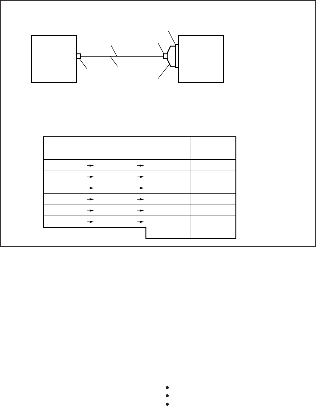
INSTALLATION-PERIPHERALS
SECTION 100-816-207
MARCH 1993
7-28
FIGURE 7-20
DK8 AND DK16 PIOU/PIOUS SMDR CABLE CONNECTIONS
BASIC CONNECTION
3-pair
Modular
Cord (7 ft. max)
SMDR
Modular
Jack
Modular
Jack
Toshiba
PPTC1A-5M,
RS232, Modular
to DB25 Adaptor
DB25
Plug
BASIC WIRING (see: QSMU PIOU or PIOUS TTY and SMDR Wiring in Chapter 8 for more detail)
PIOU, SMDR Jack
Modular Pin No.
1
2
3
4
5
6
Modular Pin No.
6
5
4
3
2
1
DB25 Pin No.
3
2
6
20
8
7
4 Jumper to 5
RS-232
Lead Name
RD
TD
DSR
DTR
CD
SG
RTS to CTS
50 ft. max
24 AWG Wire
Twisted Pair
Modularized
PPTC1A-5M Adaptor
To
To
To
To
To
To
To
To
To
To
To
To
DATA FORMAT:
• ASCII
• 8-bits
• No parity
• 1-stop bit
• QSMU: 1200 bps
• PIOU/PIOUS 300 or
• 1200 bps
DK8, QSMU*
DK16, PIOU
or
DK16, PIOUS
Printer
or Call
Accounting
Device
*QSMU,
PROGRAM 10-3
LED 04-OFF
7 VOICE MAIL OPTIONS
7.00 System Hardware Requirements
7.01 The STRATA DK8 and DK16 may be config-
ured to support Toshiba VP voice mail messaging
system or a customer-supplier voice mail system.
7.02 The DK8 must be equipped with a QSTU, and
the DK16 must be equipped with a KSTU, PSTU, or
PESU to support a voice mail system. The DK8
QSTU is equipped with two standard telephone
circuits; the DK16 KSTU is equipped with four
standard telephone circuits, the PSTU with eight,
and the PESU with two. A K4RCU subassembly
must be installed in the DK16 Base Unit, and a
QRCU must be installed in the DK8 KSU. The voice
mail system can be connected to any standard
telephone circuit at the MDF block.
7.10 Toshiba VP Voice Messaging System
7.11 The STRATA DK8 and DK16 is designed to
support the full range of features offered by the
Toshiba VP provides various call routing, message
handling, and information management features,
including:
Automated Attendant
Call Forward to Voice Mailbox
Message Waiting Indication
INSTALLATION-PERIPHERALS
SECTION 100-816-207
MARCH 1993
7-29
Voice Mail Control from digital and electronic
telephone
System Monitoring
Feature Integration
7.12 A block diagram of voice mail connections is
shown in Figure 7-22. See Section 100-816-204 for
QSTU and Section 100-816-205 for PSTU, KSTU,
and PESU installation instructions.
7.13 STRATA DK8 and DK16/VP Programming
Considerations. Some features of STRATA DK8
and DK16 system programming are intended for
Toshiba VP, and are not necessarily available for
customer-supplied voice mail messaging systems.
These programming features are:
Answer (A) Tone. The STRATA DK8 and DK16
stations will send an answer tone to Toshiba VP
when the station answers a Toshiba VP call.
Disconnect (D) Tone. The STRATA DK8 and
DK16 stations will send a disconnect tone to
Toshiba VP when the station hangs up while
connected to Toshiba VP. (D-Tone is also sent to
release the Toshiba VP auto attendant port
when an outside CO line caller hangs-up and the
Central Office provides a disconnect signal, per
Program 15-0 and 15-3.)
NOTE:
1. Not all Central Offices provide the discon-
nect signal (calling party control) so this
feature will not operate in all areas.
2. Both answer and disconnect tones pro-
vide more efficient Toshiba VP port use.
Always enable these options. Both op-
tions are enabled by accessing Program
31 and setting LED 15 to ON (LEDs 16 and
17 must also be ON to allow A and D
tones), and by accessing Program 15-0
and 15-3 and enabling CO lines with ARVM
and AROH calls.
3. The AR signal of some Central Offices is
not reliable and may occur at times during
a CO line voice connection causing the
call to disconnect during a conversation. If
this occurs, disable AROH and ARVM
calls on all CO lines (Program 15-0 and
15-3).
FIGURE 7-21
PIOU/PIOUS SMDR PORT (PROGRAM 97) DATA DUMP EXAMPLE
00
01
02
03
04
05
06
81
81
81
81
81
81
81
11111111
00000000
00000000
00000000
00000000
00000000
00000000
8 1
CO LINE
NUMBERS
NOTES:
1. In this example all lines are programmed to immediately ring the station at port 00 only.
2. 0 = LED off, 1 = LED on.
CO LINE 08
PROGRAM NUMBER
STATION PORT
NUMBERS
CO LINE 01
(CO LINE)
(LEDs ON)
(LEDs OFF)
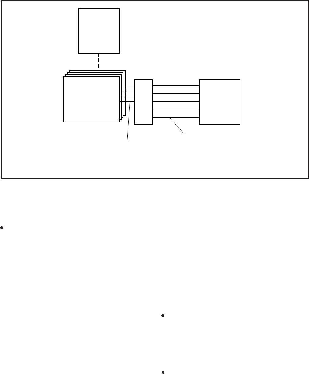
INSTALLATION-PERIPHERALS
SECTION 100-816-207
MARCH 1993
7-30
FIGURE 7-22
DK8 AND DK16 VOICE MAIL/AUTO ATTENDANT BLOCK DIAGRAM
MDF VOICE MAIL OR AUTO
ATTENDANT MACHINE
25-PIN CABLE
(8 CIRCUITS PER PSTU)
(2 CIRCUITS PER PESU)
(4 CIRCUITS PER KSTU)
(2 CIRCUITS PER QSTU)
QSTU, KSTU/PSTU/PESU CIRCUIT TIP & RING
(1 PAIR PER PORT)
NOTE:
The K4RCU or QRCU allows VM DTMF dialing.
DK8 QRCU
OR
DK16 K4RCU
DK8 QSTU (CKT 1 & 2)
or
PSTU (CKT 1~8)
or
DK16 PESU (CKT 1 & 2)
or
DK16 KSTU (CKT 1 ~ 4)
B Tone Signals. Stations send a recall (B) tone
to VP whenever Toshiba VP answers a transfer
(camp-on) recall from a station that did not an-
swer a Toshiba VP blind transfer. (The B tone
notifies Toshiba VP that the call is a recall and not
a new call, allowing Toshiba VP to respond with
the appropriate greeting.) For this feature to
operate, the QSTU, PSTU, KSTU, or PESU
voice mail ports must have LEDs 19 and 20
turned ON in Program 31.
7.14 Toshiba VP Installation. Use the preceding
information in concert with Paragraphs 7.23 and
7.24 to install Toshiba VP.
7.20 Customer-supplied Voice Mail Messaging
Systems
7.21 STRATA DK8 and DK16 systems are de-
signed to support a wide range of customer-sup-
plied voice mail messaging systems. Depending
on the voice mail system used, some of the features
available with Toshiba VP (refer to Paragraph 7.10)
may be available with the customer-supplied sys-
tem.
7.22 DK8 and DK16 Voice Mail (QSTU, PSTU,
KSTU, or PESU Port) Programming Consider-
ations
7.23 Voice mail (all types) QSTU, KSTU, PSTU, or
PESU port programming is accomplished using
Programs 31 and 10-2 (refer to Programming
Procedures, Section 100-816-300, for details). Voice
mail (VM) programming features are:
VM Groups—This feature groups VM QSTU,
KSTU, PSTU or PESU ports together so that
message waiting set/cancel signals appear to
originate from the lowest port in the VM group. All
VM ports connected to a particular VM machine
should be set in the
same
VM group (Program
31, LEDs 05 ~ 08).
Message Waiting Set/Cancel—If the VM ma-
chine has the ability to dial a code, plus the
appropriate station numbers to set or cancel the
message waiting LEDs on electronic telephones,

INSTALLATION-PERIPHERALS
SECTION 100-816-207
MARCH 1993
7-31
program the VM machine to dial the following
sequences (In Program 10-2, turn LED 04 ON):
1) To set a MW LED, the VM machine must
dial 6 3 + station number.
2) To cancel a MW LED, the VM machine
must dial 6 4 + station number.
NOTE:
Only dial codes 63 and 64 are set in the VM
device configuration; the VM device will dial
the station number automatically to set/cancel
the Message Waiting indication LED.
No Conference VM—Prevents undesired CO
line three-party connections during VM call trans-
fers. All VM ports should be set for no conference
(Program 31, LED 09).
Privacy Override Deny—Prevents stations from
overriding (breaking in) in-progress VM calls
(Program 31, LED 18).
End-to-End Signaling—Allows VM port
DTMF operation. All VM ports should be set for
end-to-end signaling (Program 31, LED 17).
NOTE:
The DK8 QRCU or DK16 K4RCU must be
installed to allow End-to-End Signaling.
VM to VM Call Blocking—Prevents VM auto
attendant calls from forwarding back to VM auto
attendant during supervised transfers (Program
31, LED 04 ON). This will prevent the problem of
auto attendant to auto attendant looping connec-
tions.
Receive Auto Call Forward ID Codes—Pro-
vides auto digits from call forwarded stations to
direct callers to stations’ mailboxes. All VM ports
should be set to receive auto ID code (Program
31, LED 16).
“A” and “D” tones; see Paragraph 7.13.
7.24 Voice Mail Program Checklist. The follow-
ing items should be verified before programming
voice mail:
1) Set Toshiba VP Maintenance Menu system
parameters to “D” = STRATA DK8 and DK16
(see Toshiba VP
Installation and Maintenance
Manual
for other parameter settings).
2) STRATA DK8 and DK16 programs:
Program 92: Initialization clears voice mail
auto dial codes.
Program 03: Verify that the KRCU is pro-
grammed in the Base Unit to allow the VM/
AA to send DTMF tones (does not apply to
DK8).
Program 04: Assigns station numbers to
VM/AA ports (initialized numbers recom-
mended).
Program 05: First digit of special codes 63
and 64 (initialized numbers recommended).
Program 10-1: Set the system for voice first,
and program the VM/AA device to dial the
suffix as “1” after station numbers.
Program 10-2: Set LED 04 ON for set/cancel
operation and 06 ON for the VM to detect 80
msec. tones.
Program 13: If the VM/AA device is the
message center, set the lowest VM port as
the message center.
Program 31: Turn LEDs 05, 09, and 15 ~ 20
ON for the QSTU, KSTU, PESU, or PSTU
ports that are connected to the Toshiba VP
VM/AA ports. Do not set these options for
standard telephone, digital telephone, or elec-
tronic telephone station ports. LED 04 should
be off if the auto attendant only “BLIND”
transfers; if the AA does “Supervise” or
“Screened” transfers, set LED 04 ON for auto
attendant ports.
NOTE:
A, D, and B tones should be enabled only for
VM/AA devices that respond to these tones.
Program 33: Set the QSTU, KSTU, PESU
and PSTU ports that are connected to the
VM/AA ports to a hunting sequence, starting
with the lowest port hunting to the next high-
est port, etc. The last hunt should be to an
attendant.
Program 35: LEDs 01 and 02 must be ON for
stations to receive the message indication
(Msg LED flashing) from a VM device.

INSTALLATION-PERIPHERALS
SECTION 100-816-207
MARCH 1993
7-32
Program 35: LED 20 should be ON to assign
auto attendant ports the “Busy Station Trans-
fer” option. with this option the auto attendant
will receive ring backtone when calling sta-
tions designated with “Busy Station Ringing”
(Program 35, LED 19 ON). This allows the
auto attendant to transfer calls to busy sta-
tions. Set LED 19 ON for answer position
stations.
Program 36: Set fixed call forward to VM/AA
port per customer requirements.
Program 37: Set the timer for the VM/AA
ports to 22 seconds minimum to allow call
forward no answer to work on VM transferred
calls.
Program 39: Set the Message Waiting Indi-
cation, Fixed Call Forward, Redial, and Speed
Dial Select buttons on the digital and elec-
tronic telephones that will be used to commu-
nicate with the VM/AA device.
NOTE:
Message Waiting (Msg) and Redial buttons
are fixed buttons on digital telephones and it is
not necessary to assign them in Program 39.
Speed Dial is initialized as Button 20 on
Digital telephones.
Programs 81 ~ 89: Verify that the ringing
assignments to the VM/AA devices are set
per customer requirements.
Programs 16, 40, 41, 45 ~ 48 and 50 ~ 56:
Verify that outgoing CO line access is al-
lowed on VM ports to allow the VM/AA beeper
notification feature to operate.
7.25 Voice Mail System Installation. Install the
voice mail messaging system in accordance with
the following steps (See Figure 7-22):
1) Ensure that the QSTU, KSTU, PSTU, or PESU
PCB is installed in the system per Section
100-816-204 (DK8) or Section 100-816-205
(DK16).
2) Connect the voice mail messaging system to
the selected QSTU, KSTU, PSTU, or PESU
standard telephone ports (refer to Wiring Dia-
grams, Section 100-816-208, for QSTU, PSTU,
KSTU, and PESU wiring/interconnecting de-
tails).
3) Program the system for the required voice
mail messaging features (refer to Paragraphs
7.13 and 7.22).
4) Ensure that the DK8 QRCU or DK16 K4RCU
is installed, and (for DK16) verify that the CTU
code in Program 03 is for KRCU-4 operation
as required (this is not required for DK8 QRCU).
5) Perform additional voice mail messaging sys-
tem programming as applicable (refer to cus-
tomer-supplied installation/programming
manuals).
NOTE:
Some voice mail devices may ring trip when
called; in this case, set the ring voltage jumper
to L (low position) on the QSTU, KSTU, PESU,
or PSTU2 PCB connected to the voice mail
device.
8 DK16 ALARM SENSOR INSTALLATION
8.00 The PIOU or PIOUS PCB provides a circuit
that can be set to detect a relay open or closed
condition from a facility alarm system. When the
sensor is activated, all electronic and digital tele-
phones will sound an alarm signal. The electronic/
digital telephone alarm signal can be reset by any
electronic or digital telephone with an alarm reset
button (see Program 39).
8.01 Alarm Sensor Options. Jumper plug P12 on
the PIOU is used to set the alarm sensor to detect
an open or closed condition from the facility alarm
system. Set P12 as follows (refer to Figure 7-23):
To detect a closed condition, set P12 to the N.O.
position.
To detect an open condition, set P12 to the N.C.
position.
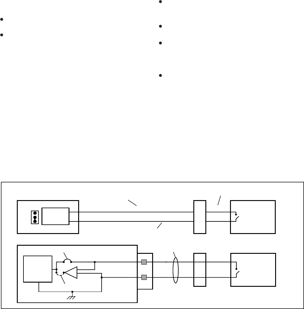
INSTALLATION-PERIPHERALS
SECTION 100-816-207
MARCH 1993
7-33
INSTALLATION-PERIPHERALS
SECTION 100-816-207
MARCH 1993
INSTALLATION-PERIPHERALS
SECTION 100-816-207
MARCH 1993
8.02 Jumper W3 on the PIOUS is used to set the
alarm sensor to detect an open or closed condition
from the facility alarm system. Solder the W3 jumper
wire as follows (refer to Figure 7-23):
To detect a closed condition, solder W3 to the
normal open position.
To detect an open condition, solder W3 to the
normal closed position.
8.03 Alarm Sensor Wiring. Refer to Figure 7-23,
and connect the facility alarm system relay con-
tacts to the PIOU/PIOUS PCB.
9 DK16 NIGHT RINGING
OVER EXTERNAL ZONE PAGE
9.00 In systems shared by two tenants, each tenant’s
CO lines can be assigned to night ring separate
PIOU external page zones (Figure 7-16). This
feature can also be used in one-tenant systems.
9.01 With shared systems, for example, tenant 1’s
night ringing CO lines could be programmed to ring
PIOU external page zones 1 and 2, while tenant 2’s
lines could be programmed to ring zones 3 and 4.
In non-shared systems, night ringing CO lines can
be assigned to ring all of the zones or just selected
zones.
9.02 The following programs must be used to
assign CO lines to ring selected PIOU page zones:
Program 78-1: Assigns CO lines, tenant 1 and
tenant 2, that will night ring over PIOU external
page zones.
Program 15-5: Assigns CO lines to tenant 1 or
tenant 2. Lines are initialized as tenant 1.
Program 77-1 (LEDs 10 ~ 13): Assigns tenant 1
and tenant 2 CO lines to night ring specific PIOU
external page zones. LED 06 must also be ON in
Program 77-1.
Program 39: Assigns appropriate Night
Transfer, or Night Transfer 1 (tenant 1),
and NT2 (tenant 2) buttons to electronic and
digital telephones.
NOTES:
1. See Paragraph 5 and Figure 7-16 and
7-17 for PIOU zone paging installation
instructions.
2. Any station can pick up CO lines that night
ring over external page zones by dialing
Intercom 5 9.
FIGURE 7-23
DK16 ALARM SENSOR BLOCK DIAGRAM (PIOU/PIOUS)
PIOU PCB
N.C.
N.O.
P12 ALARM
SENSOR
ALMT (36)
ALMR (11)
25-PAIR CABLE
66 BLOCK PIN NUMBERS
PIOU PIN NUMBERS ( )
25-PAIR CABLE
21
22
FACILITY
ALARM
SYSTEM
MDF
ALARM
SENSOR
NORMAL CLOSE
NORMAL OPEN
ALMT
ALMR
W3 ALM
TB1
TWISTED
PAIR
PIOUS PCB
MDF
FACILITY
ALARM
SYSTEM
INSTALLATION-PERIPHERALS
SECTION 100-816-207
MARCH 1993
7-34
10 DATA INTERFACE UNIT
INSTALLATION
10.00 General
10.01 STRATA DK8 and DK16 support two types of
Data Interface Units (DIUs) that enable digital tele-
phone users to simultaneously transmit and re-
ceive data on the same digital station port and wire
pair while communicating on a voice call. One unit,
called the integrated DIU (PDIU-DI/PDIU-DI2),
becomes part of the digital telephone, replacing the
telephone’s base; the other unit, is a small self-
contained unit called the stand-alone DIU (PDIU-
DS). Each DIU is powered by the digital port it is
connected (see Table 8-D for wiring requirements).
NOTES:
1. “Digital Ports” includes the DK8 KSU, DK16
Base Unit, PDKU and KCDU digital sta-
tion ports. This applies wherever the term
“Digital Ports” is used in the text and
figures in this chapter.
2. 2000-series digital telephones require
PDIU-DI2 and 1000-series telephones re-
quire PDIU-DI.
10.02 Both DIUs can be connected to standard
Electronic Industries Association (EIA) RS-232
asynchronous serial data devices. EIA devices are
divided into two categories: data communication
equipment (DCE) and data terminal equipment
(DTE). Common DCE devices are modems and
some printers; common DTE devices are personal
computers, ASCII terminals, and some printers.
The PDIU-DI operates like a DCE and connects
directly to DTE devices using standard RS-232
cables. Depending on how its internal jumper plugs
are configured, the PDIU-DS can either operate
like a DTE and connect to DCE devices; or operate
like a DCE device and connect to a DTE device. In
most applications, DTE and DCE devices exchange
data between each other via the standard RS-232
cable connection.
10.03 DIUs can function with DCE and DTE de-
vices at data speeds of up to 19.2 kbps. However,
keyboard dialing using AT commands (from a PC
or terminal connected to a DIU) is limited to 9600
bps. A speed of 19.2 kbps can be achieved when
dialing from a PDIU-DI-equipped digital telephone
dialpad, but many PC software programs do not yet
handle 19.2 kbps in an error-free manner. Also for
a 19.2 Kbps operation the computer or terminal’s
“COM” port must be specified to function at 19.2
Kbps. Some computer “COM” ports, like those
used in older IBM XT type computers, will not
operate at 19.2 without errors. DIU data transmis-
sion speed is set by the first AT command that the
DIU receives once it is in the command state; if
manual dialing or receiving calls in the auto answer
(default) mode, the transmission speed is transpar-
ent.
IMPORTANT NOTE!
To use the PDIU-DI or PDIU-DS with AT
commands, communications software or
a PC program that performs terminal emu-
lation must be used. AT commands cannot
be issued from the computer’s operating
system prompt.
10.10 Common DIU Connections
10.11 The block diagram in Figure 7-24 illustrates
common DIU connections. In this example, PDIU-
DIs are connected to personal computers (PC1 and
PC2), and PDIU-DSs are connected to a serial
printer and modems. The personal computer users
can transfer files internally, print files on the same
printer, and access the modem pool to send/re-
ceive data to/from an external personal computer
or dial up data service.
10.12 To access these devices, a data call connec-
tion must be established between the DIUs. This is
accomplished by dialing the destination DIU from a
digital telephone dialpad or from a PC keyboard
using standard AT dial commands. PDIU-DIs share
the same intercom numbers/ports with the digital
telephone to which they are connected, while PDIU-
DSs have their own. The Intercom and Data Call
LEDs on the digital telephone tell the system
whether a voice or data call is being made: the
Intercom LED, voice calls; and the Data Call LED
initiates data calls. When dialing from a keyboard
with AT commands, A␣ T D is typed for voice calls,
and A T D D for data calls.

INSTALLATION-PERIPHERALS
SECTION 100-816-207
MARCH 1993
7-35
10.13 Installation instructions for these devices are
provided in Paragraphs 10.40 thru 10.70. Call
paths and scenarios for five types of data test calls
are provided in Paragraphs 10.82 ~ 10.86. Step-
by-step data calling procedures are provided in the
Data Interface User Guide
in the
Installation &
Maintenance Manual
,
Operating Procedures.
10.20 EIA Interface Leads (Signals)
10.21 Both DIUs operate with nine standard EIA
RS-232 interface leads (signals) on which signal-
ing data is transmitted and received. DIUs connect
to serial data devices with standard RS-232 cables,
available from telephone supply stores (see Fig-
ures 7-25 ~ 7-30). The PDIU-DI/PDIU-DS requires
nine signals for some applications, but can function
with eight using modular cords and connectors with
RJ45/DB25 adapters for other applications. If un-
certain which signals are necessary for an applica-
tion, all nine should be connected.
IMPORTANT NOTES!
1. The PDIU-DI is always a DCE device;
the PDIU-DS may be a DTE or DCE,
depending on how its internal jumpers
(1 ~ 9) are configured.
2. In the descriptions below, when a sig-
nal is ON, its potential is about seven
volts positive relative to signal ground
(pin 7); when a signal is OFF, it is about
7 volts negative relative to the signal
ground (pin 7).
Frame Ground (FG, Pin 1): The FG signal (EIA
circuit AA) is a protective or safety ground which
is bonded to the PDIU-DI/PDIU-DS PCB. If
required by local codes, the FG should be con-
nected to external ground.
Signal Ground (SG, Pin 7): The SG signal (EIA
circuit AB) establishes the common ground ref-
erence for all other PDIU and data device sig-
nals and must be wired for all applications.
Transmit Data (TD, Pin 2): DTE devices trans-
mit and DCE devices receive data on the TD
lead (EIA circuit BA). Before the DTE device can
transmit the TD signal, the RTS, CTS, DSR, and
DTR signals (all discussed below) must be ON.
The TD signal is OFF in the idle state.
Receive Data (RD, Pin 3): The DCE device
transmits data to the DTE device on the RD lead
(EIA circuit BB); the DTE receives data on the
RD.
Request to Send (RTS, Pin 4): Some DTE
devices send an RTS signal (EIA circuit CA) to
the DCE device when they are ready to transmit
data on the TD lead. If the DTE device does not
generate the RTS signal, the DIU DIP switch
SW1-4 should be set ON to inform the DIU.
Sometimes, the DTE/DCE device may use RTS/
CTS for Ready/Busy type flow control, in these
cases DIP switch SW1-4 should be OFF (see
Figure 7-32 for DIP switch information).
Clear to Send (CTS, Pin 5): The DCE device
sends the CTS signal (EIA circuit CB) which
indicates that it is prepared to transmit data to
the line side. The DCE device sends this signal
only when it receives the RTS signal from the
DTE device. Sometimes, the DTE/DCE device
may use RTS/CTS for Ready/Busy type flow
control; in these cases, dip switch SW1-4 should
be OFF (see Figure 7-32 for DIP switch informa-
tion).
Data Set Ready (DSR, Pin 6): When connected
to the communication channel and prepared to
exchange control characters to initiate data trans-
mission, the DCE device sends the DSR signal
(EIA circuit CC) to the DTE device. If the PDIU
DIP switch SW1-2 is set ON, DSR will be ON
continuously; if the switch is set OFF, DSR
follows DTR (if DSR is ON, DTR is ON, etc.)
SW1-2 should be OFF in most cases (see Figure
7-32 for DIP switch information).
Data Carrier Detect (DCD, Pin 8): The DCE
device sends the DCD signal (DCD, Pin 8) when
receiving the carrier signal on the line side.
Before transmitting or receiving data, most DTE
devices require that the DCD be ON. If the
carrier signal is removed by the remote end or
lost due to a fault condition on the line, the DCE
notifies the DTE device by an OFF condition with
the DCD signal; PDIU DIP switch SW1-2 is set
ON to set the DCD ON continuously; if set OFF,
the DCD signal will only be ON when connection
between two DIUs is established and OFF when
a connection is not established. SW1-2 is set
OFF when the DTE/DCE uses the DTR/DSR
signals for Ready/Busy flow control (see Figure
7-32 for DIP switch information).

INSTALLATION-PERIPHERALS
SECTION 100-816-207
MARCH 1993
7-36
Data Terminal Ready (DTR, Pin 20): The DTE
device sends the DTR signal (EIA circuit CD) to
the DCE device, prompting the DCE device to
open the communication line. The line is closed
and the call disconnected when the DTE device
quits sending the DTR signal. DTR may be sent
any time to indicate that the DTE is ready to
transmit or receive data. DIP switch SW1-2
should be set OFF in most cases (see Figure 7-
32 for DIP switch information).
Ring Indicator (RI, Pin 22): The RI signal (EIA
circuit CE) is sent by the DCE device to the DTE
device. Whenever the DCE device receives a
ringing signal on the line side, it turns the RI
signal ON. If DIU DIP switch SW1-3 is set ON,
the RI signal will be on continuously if ringing; if
the switch is set OFF, the RI signal will be one
second ON/three seconds OFF when the DIU
detects ringing signal.
10.30 DIP Switch Options
10.31 The PDIU-DI and the PDIU-DS each have a
four-control DIP switch which can be configured for
signaling options. The switch is located on the
bottom of the PDIU-DI, and on the back panel of the
PDIU-DS (see Figure 7-32).
SW1-1: Normally this switch is set ON to discon-
nect devices from DIUs automatically. The con-
nection is maintained if data is exchanged be-
tween the device and the DIU within eight to nine
second intervals. If SW1-1 is OFF on the called
and calling DIU, data calls will remain connected
until released manually.
SW1-2: This switch is placed in the ON position
when the PDIU-DI (or PDIU-DS configured like
a DCE) must hold DCD and DSR ON continu-
ously. If SW1-2 is OFF, DSR follows DTR and
DCD will be ON only when the DIU is connected
on a data call to another DIU. SW1-2 should be
OFF on a DIU when it is connected to a personal
computer that uses a communications software
program to establish data calls with AT com-
mands; and whenever PDIU-DS is connected to
a modem.
SW1-3: The PDIU-DI (or PDIU-DS configured
as a DCE) sends the Ring Indicate (RI) signal to
the computer to tell the computer (DTE) that the
PDIU is receiving an incoming call. SW1-3 should
be ON for the DIU to send RI steady, and OFF to
send at one second ON/three seconds OFF
intervals.
SW1-4: This switch is placed in the ON position
if the computer does not output the RTS signal
or when connected to a modem that tracks the
DCD signal (modem set with AT&C1). Some-
times, the DTE device may use RTS/CTS for
Ready/Busy flow control, in these cases SW1-4
should be OFF. In this case the DCD signal of
the calling DTE is used as the RTS lead of the
called DTE and the DCD signal of the called DTE
is used as the RTS signal of the other DTE. In
this case a signal which stops the DTE from
transmitting data (usually the CTS lead) should
be cross-connected to the DIU’s DCD signal.
Consult the DTE device or application software
documentation to determine which type of flow
control is required. If the DIU-DS is connected to
a modem that tracks carrier detect (AT&C1)
SW1-4 should be ON.
10.40 PDIU-DI to Personal Computer (PC)
Installation
10.41 The PDIU-DI always functions as a DCE
device; it transmits data on the Receive Data lead
(RD) and receives data on the Transmit Data lead
(TD). Most personal computers function as a DTE
device; PCs transmit data on the TD lead and
receive data on the RD lead. Follow the steps below
to install the PDIU-DI to a DTE, PC:
NOTES:
1. Use the steps below when installing an
ASCII terminal, personal computer, or any
other DTE device to a PDIU-DI.
2. The PDIU-DI can connect to a DCE com-
puter or any other DCE-type device using
a specially configured RS-232 cable or
adapter; but this application is rarely re-
quired.
3. Change the PDIU-DI escape sequence
per the guidelines in paragraph 10.63.
1) Install the digital telephone that is to be
equipped with PDIU-DI per the instructions in
Section 100-816-206 and the drawing in Sec-
tion 100-816-208.
2) Install the PDIU-DI under the digital telephone
per the instructions in Section 100-816-206.

INSTALLATION-PERIPHERALS
SECTION 100-816-207
MARCH 1993
7-37
NOTE:
The PDIU-DI always operates as a DCE de-
vice; therefore, unlike the PDIU-DS, it has no
internal jumpers.
3) Connect the appropriate RS-232 cable be-
tween the PDIU-DI’s DB-25 female connector
and the PC’s appropriate asynchronous serial
communications port connector (COM port).
IMPORTANT NOTE!
Check the PC manufacturer’s serial com-
munication port interface documentation
for correct RS-232 pin requirements; re-
quirements vary with each manufacturer.
The number of EIA RS-232 signals required
(8, 9, or 10 wires) depends on the applica-
tion. When EIA signal requirements are not
known, connect the 10 EIA signals listed in
Paragraph 10.20. Figures 7-25 and 7-30
provide diagrams for connecting RS-232
cables between PDIU-DIs and Toshiba lap
top, and IBM, XT and AT PCs.
4) Set the PDIU-DI DIP switch (SW1-1 ~ 4) for
the desired application. Figure 7-32 shows the
DIP switch locations and Paragraph 10.30
describes switch functions.
5) Access Program 20 to configure the PDIU-DI
for DTE-type connection and Program 39 for
data button assignments of the digital tele-
phone connected to the PDIU-DI.
Program 20
The port number entered for the PDIU-DI
in Program 20 is the port number of the
digital telephone to which the PDIU-DI is
connected.
LED 01: Should always be ON for PDIU-
DI ports.
LED 02: Should be ON for PDIU-DI ports,
unless the PC user will never use DIU AT
commands (other than ATDD, ATDT,
and ATD) and never require the PDIU-DI
to send result codes to display on the PC
display screen. Frequently, it is difficult
to determine the full extent of these
requirements; so it is recommended to
turn LED 02 ON. See the
Data Interface
User Guide
for information regarding DIU
AT commands and result codes.
LEDs 03 and 04: Should be OFF for
PDIU-DI ports.
LED 05: Should be ON if the system is
installed behind a PBX or Centrex that
uses access codes to make external
calls or to insert a pause following DIU
access of an outside line.
LEDs 17 ~ 20: Used to establish data
security groups. PDIU stations are only
allowed to make calls to PDIUs in the
same data group to which they are as-
signed.
Program 39
The following data call buttons can be
assigned digital telephones equipped with
PDIU-DIs: Data Call, and Modem.
Assign SD buttons to data devices as
required. Do not assign DSS buttons to
data devices; DSS buttons are used for
voice calls only.
10.50 PDIU-DS to Printer Installation
10.51 STRATA DK8 and DK16 enables serial print-
ers (laser, dot matrix, or other types) to be con-
nected to stand-alone data interface units (PDIU-
DSs). Digital telephones equipped with PDIU-DIs
can share access to these printers. Serial printers
operate as DCE or DTE devices, depending on the
vendor; the PDIU-DS can be connected to either
type, since it can be configured as a DTE or DCE
device. (The PDIU-DS comes from the factory
configured as a DCE device.) Follow the steps
below to install the PDIU-DS to a serial printer.
NOTES:
1. Only serial printers (not parallel) that con-
form to EIA RS-232 signaling require-
ments can be connected to PDIU-DSs.
2. In rare applications, it may be desired to
connect printers to PDIU-DIs. Refer to the
printer’s installation instructions.

INSTALLATION-PERIPHERALS
SECTION 100-816-207
MARCH 1993
7-38
1) Consult the serial printer’s documentation and
determine if the printer operates as a DCE or
DTE device:
If the printer is a DCE device: Disas-
semble the PDIU-DS and configure it to
operate like a DTE device by placing the
jumper plugs (P1 ~ P9) in the “B-C”
(MODEM) position. Reassemble the
PDIU-DS, and mark “B-C” on the bottom
identification label for future reference.
(Paragraph 10.70 provides PDIU-DS dis-
assembly/assembly instructions, and Fig-
ure 7-31 provides jumper plug informa-
tion.)
If the printer is a DTE device: It may not
be necessary to disassemble the PDIU-
DS, since it comes direct from the factory
configured as a DCE device. However, if
uncertain, disassemble the PDIU-DS and
verify that jumper plugs (P1 ~ P9) are in
the “A-B” (DTE) position. Reassemble
the PDIU-DS and mark “A-B” on the
bottom identification label for future ref-
erence. (Paragraph 10.70 provides
PDIU-DS disassembly/assembly instruc-
tions, and Figure 7-31 provides jumper
plug information.)
2) Connect the PDIU-DS to the appropriate digi-
tal telephone circuit per wiring diagrams in
Section100-816-208 and information provided
in Section 100-816-206.
3) Connect the appropriate RS-232 cable be-
tween the printer and the PDIU-DS (see Fig-
ure 7-27 and 7-29 for an example printer
cable connection).
4) If steps 2 and 3 are done properly, the Power
and Ready LEDs on the PDIU-DS should light
when the printer is turned on and ready.
5) Set the PDIU-DS DIP switch (SW1-1 ~ 4) for
the desired application. Figure 7-32 shows the
DIP switch locations and Paragraph 10.30
describes switch functions.
NOTE:
If using Toshiba computers and printers with
X-On/X-OFF flow control, set SW1-(4) “ON”
on the DIU connected to the computer and
DIU connected to the printer.
IMPORTANT NOTE!
Check the printer’s serial documentation
for correct RS-232 pin requirements. The
requirements vary with each manufacturer.
6) Use Program 20 to configure the PDIU-DS to
connect to a serial printer (see Programming
Section 100-816-302 for instructions and
record sheets).
LED 01: Should always be ON for PDIU-
DS ports.
LED 02: Should be OFF for PDIU-DS
ports connected to printers.
LED 03: Should be OFF for PDIU-DS
ports that connect to DTE- or DCE-type
printers.
LED 04: Should always be ON for PDIU-
DS ports.
LED 05: Should be OFF for PDIU-DS
ports connected to printers.
LEDs 17 ~ 20: Data security groups can
be used to allow or deny digital tele-
phones equipped with PDIU-DIs access
to PDIU-DS ports connected to a printer.
DIU stations can only make data calls to
DIUs in the same data security group.
7) Program 22 should be used to configure
PDIU-DSs to hunt if more than one PDIU-DS
connected to the same printer/server.
10.60 PDIU-DS to Modem Installation
10.61 STRATA DK16 enables asynchronous-type
(not synchronous) modems to be connected to
PDIU-DSs. This allows PDIU-DI equipped digital
telephones that are connected to personal comput-
ers, terminals, and other devices to share access to
a modem or modem pool.

INSTALLATION-PERIPHERALS
SECTION 100-816-207
MARCH 1993
7-39
IMPORTANT NOTE!
Modems must be “smart modems” that
respond to AT commands and return re-
sult codes. Modems are customer-sup-
plied.
10.62 A modem(s) can be accessed internally for
outgoing data calls or externally for incoming data
calls. Modems operate as DCE devices; so PDIU-
DSs that are connected to them must be configured
to operate like a DTE device. In the example
installation in Figure 7-24, the line side of the two
modems are connected to KSTU/PSTU/PESU ports
to establish a modem pool; however, the line side
of modems could be connected directly to a dedi-
cated CO line. If modems are connected directly to
telephone network CO lines, automatic transfer of
CO line voice calls to system modems (data call)
will not function as described in the
Data Interface
User Guide
. For best operation and utilization of
CO lines and modems, it is recommended to con-
nect modems to QSTU, PSTU or KSTU standard
station ports in a modem pool configuration. The
RS-232 side of the modem connects to the PDIU-
DS with standard RS-232 cables; the PDIU-DS line
side (RJ-11 connector) always connects to its own
individual digital port. Use the following instructions
to install modems to PDIU-DSs.
1) Configure the PDIU-DS as a DTE device:
Disassemble the PDIU-DS and place jumper
plugs P1 ~ P9 in the “B-C” position (MODEM).
Reassemble the PDIU-DS and mark “B-C” on
the bottom identification label for future refer-
ence. (Paragraph 10.70 provides PDIU-DS
disassembly/assembly instructions and Fig-
ure 7-31 provides jumper plug information.)
2) Connect the PDIU-DS to the appropriate Digi-
tal port circuit per the wiring diagrams in Sec-
tion 100-816-208.
3) Connect the appropriate RS-232 cable be-
tween the modem and the PDIU-DS. Figure 7-
28 shows an example PDIU-DS to “smart
modem” RS-232 connection.
IMPORTANT NOTE!
All ten PDIU-DS EIA leads (signals) should
be connected to the modem. Consult the
modem’s documentation for correct RS-
232 pin requirements; the requirements
may vary with each manufacturer.
4) Connect the line side of the modem to a
QSTU, PSTU, KSTU or PESU standard tele-
phone circuit or a dedicated CO line (consult
the modem’s documentation to install the it to
a CO line). Section 100-816-208 provides
QSTU, KSTU/PESU/PSTU station port wiring
information.
5) Set the PDIU-DS DIP switch (SW1-1 ~ 4) for
the desired application. Figure 7-32 shows the
DIP switch location and Paragraph 10.30 de-
scribes switch functions.
NOTE:
If the modem tracks carrier detect (DCD,
AT&C1), SW1(4) should be “ON,” and SW1(2)
should be OFF when PDIU-DS is connected
to a modem.
6) Use the programs below to configure the
PDIU-DS to connect to an asynchronous
modem (see Programming Section 100-816-
302 for explanations and record sheets).
Program 20
LED 01: Should always be ON for PDIU-
DS ports
LED 02: Should be ON for PDIU-DS
ports connected to modems, enabling
the use of AT commands and result
codes when incoming calls are made
from outside the system to modems con-
nected to PDIU-DSs.
LED 03: Should be set ON for PDIU-DS
ports connected to modems.
LED 04: Should always be ON for PDIU-
DS ports.
LED 05: Should be ON if the system is
installed behind a PBX/Centrex that uses

INSTALLATION-PERIPHERALS
SECTION 100-816-207
MARCH 1993
7-40
access codes to place outgoing trunk
calls.
LED 06: Should be ON for DIUs con-
nected to modems. With this feature
turned on, the DIU will send a one-sec-
ond release signal on the DTR to drop the
modem when the data user presses the
Data Release button on the telephone.
LEDs 17 ~ 20: Data security groups can
be used to allow or deny digital tele-
phones equipped with PDIU-DIs access
to the PDIU-DS ports connected to a
modem. DIU stations can only make
data calls to DIUs in the same data
security group.
Program 21
For each PDIU-DS/modem pair, assign
the digital, QSTU, KSTU, and PSTU (or
PESU) ports that will be connected to the
PDIU-DS and modem, respectively.
Program 22/33
If more than one modem/PDIU-DS pair is
configured as a system modem pool, the
PDIU-DSs should be set to hunt each
other in Program 22. The modem QSTU,
PSTU, KSTU, or PESU ports should be
set to hunt each other in Program 33.
Program 31
LED 18 should be turned on for all QSTU,
KSTU, PESU or PSTU station ports that
are connected to modems. This provides
data security by preventing executive or
privacy override of modem calls.
10.63 Modem Setup Recommendations
1) Always change the escape sequence of the
telephone PDIU-DI from default (+++) to some
other ASCII character (ATS2=XX command
to PDIU-DI). This allows placing the PDIU-DI
or modem into the command mode selec-
tively. The ATS2=XX command should be in
the modem initialization command of the com-
munication software of the PC connected to
the PDIU-DI (XX = new ASCII Escape charac-
ter). This will ensure that the new Escape
sequence is restored if the telephone or
PDIU-DI is unplugged.
2) Set the modem to recognize the DTR signal to
disconnect (AT&D2 command to modem).
3) When the modem tracks the DCD signal,
issue AT&C1 command to modem.
10.70 PDIU-DS Disassembly and Assembly
10.71 To set the jumper plugs (P1 ~ P9) on the PCB
inside the PDIU-DS for DCE or DTE operation, the
PDIU-DS must be disassembled. Disassemble
the PDIU-DS in accordance with the following
steps:
10.72 Disassembling the PDIU-DS
1) Remove the four screws securing the bottom
panel to the rest of the unit (see Figure 7-33).
These screws are not captive; so place to-
gether where they can be easily accessed.
2) Remove the bottom panel.
3) Remove the PCB inside the PDIU-DS by
lifting the back panel from its side grooves.
4) Turn the PCB over and set the jumper plugs
(P1 ~ P9) as follows:
If the PDIU-DS is connected to a DTE,
set the plugs to the “A-B” position.
If the PDIU-DS is connected to a DCE de-
vice, set the plugs to the “B-C” position.
NOTE:
Do not cut PDIU-DS PERCEPTION jumper
wire for STRATA DK8 or DK16 installations.
10.73 Assembling the PDIU-DS
1) Position the back panel to the PCB (see Fig-
ure 7-33).
2) Slide the back panel down into its side grooves.
3) Attach the bottom panel, and secure with the
four non-captive screws.
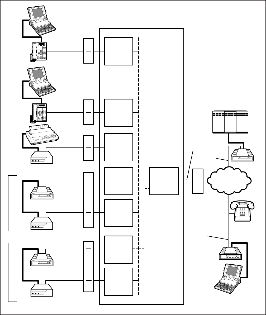
INSTALLATION-PERIPHERALS
SECTION 100-816-207
MARCH 1993
7-41
FIGURE 7-24
DK8 OR DK16 DATA INSTALLATION EXAMPLE BLOCK DIAGRAM
DIGITAL
(PORT 05)
QSTU
OR
KSTU
(PORT 08)
DIGITAL
(PORT 03)
DIGITAL
(PORT 00)
DIGITAL
(PORT 01)
TOSHIBA
DIU
POWER READY CONNECT
TOSHIBA
QSTU
OR
KSTU
(PORT 09)
DIGITAL
(PORT 04)
DIU
POWER READY CONNECT
TOSHIBA
DIU
POWER READY CONNECT
TOSHIBA
LAPTOP, PC 1
RS-232
1
DKT/PDIU-DI
(10)
MDF
2
MDF
2
MDF
2
MDF
3
MDF
3
RS-232
1
RS-232
1
RS-232
1
RS-232
1
LAPTOP, PC 2
DKT/PDIU-DI
(11 )
SERIAL
PRINTER
PDIU-DS
(13)
MODEM
(18)
PDIU-DS
(14)
MODEM 1
(19)
PDIU-DS
(15)
MODEM
POOL
MODEM
MDF
CO
LINE 1
PUBLIC
TELEPHONE
NETWORK
TELEPHONE
LINE X
TELEPHONE
LINE Y RS-232
1
LAPTOP,
PC 3
DIAL-UP
COMPUTER
SERVICE
NOTES:
1. RS-232 cable and connector
information is provided in
Figures 7-25 to 7-32.
2. PDIU-DI/PDIU-DS MDF
station wiring to Digital Ports,
is in Section 100-816-208.
3. Modem MDF station wiring to
QSTU, KSTU, PSTU or PESU
is in Section 100-816-205.
STRATA DK16 KSU
MODEM
RS-232
1
LINE Z
STANDARD
TELEPHONE
INSTALLATION-PERIPHERALS
SECTION 100-816-207
MARCH 1993
7-42
FIGURE 7-25
DK8 AND DK16 PDIU-DI TO IBM AT-TYPE COMPUTER, RS-232 CONNECTOR/CABLE CONNECTIONS
IBM PC AT modem style (serial)
DB25 to DB9, RS-232 cable.
Pin to pin connections are
confiqured as a straight cable,
not as a null modem cable
(50 ft max, 24AWG;
customer-supplied).
6789
23451
6789
23451
DB9
PIN #
1
2
3
4
5
6
7
8
9
NAME
DCD
RD
TD
DTR
SG
DSR
RTS
CTS
RI
DB25
PIN #
8
3
2
20
7
6
4
5
22
12345678
2022
12345678
2022
Rear view of asynchronous (serial)
communication interface connector (DB9) of
Toshiba laptop or IBM AT personal computer
Rear view of PDIU-DI DB25,
RS-232 female connector
TOSHIBA LAPTOP OR IBM AT-TYPE
PERSONAL COMPUTER (DTE)
PDIU-DI
(FUNCTIONS LIKE A DCE)
DB25
FEMALE
CONNECTOR
DB25
MALE
CONNECTOR
DB9
MALE
CONNECTOR DB9
FEMALE
CONNECTOR
NOTES:
1. Some RS-232 EIA leads may be called by other names by some manufacturers.
2. The computer receives data on Pin 2 (RD) and sends data on Pin 3 (TD).
PIN DESIGNATIONS
COM PORT
PIN #
NAME
1
DCD
2
RD
3
TD
4
DTR
5
SG
6
DSR
7
RTS
8
CTS
9
RI
PDIU-DI
PIN #
NAME
1
FG
3
RD
4
RTS
5
CTS
6
DSR
7
SG
8
DCD
20
DTR
22
RI
PIN DESIGNATIONS
2
TD
INSTALLATION-PERIPHERALS
SECTION 100-816-207
MARCH 1993
7-43
FIGURE 7-26
DK8 AND DK16 PDIU-DI TO IBM XT-TYPE COMPUTER, RS-232 CONNECTOR/CABLE CONNECTIONS
DB25
PIN #
8
3
2
20
7
6
4
5
22
1
NAME
DCD
RD
TD
DTR
SG
DSR
RTS
CTS
RI
FG
DB25
PIN #
8
3
2
20
7
6
4
5
22
1
12345678
2022
12345678
2022
Rear view of personal computer
or ASCII terminal DB25,
RS-232 connector
Rear view of PDIU-DI DB25,
RS-232 female connector
IBM XT PERSONAL COMPUTER
OR ASCII TERMINAL
(FUNCTIONS LIKE A DTE)
PDIU-DI
(FUNCTIONS LIKE A DCE)
NOTE:
The PC/ASCII terminal receives
data on Pin 3 (RD) and transmits
data on Pin 2 (TD).
DB25 PIN DESIGNATIONS
PDIU-DI
PIN #
NAME
1
FG
3
RD
4
RTS
5
CTS
6
DSR
7
SG
8
DCD
20
DTR
22
RI
DB25 PIN DESIGNATIONS
2
TD
PDIU-DI
PIN #
NAME
1
FG
3
RD
4
RTS
5
CTS
6
DSR
7
SG
8
DCD
20
DTR
22
RI
2
TD
12 345 6 78
20 22
DB25 FEMALE
CONNECTOR
DB25 MALE
CONNECTOR
20 22
12 345 6 78
RS-232 CABLE
DB25 FEMALE
CONNECTOR DB25 MALE
CONNECTOR
IBM PC XT modem style (serial)
DB25 to DB25 (M/F) RS-232
cable (50 ft max, 24 AWG,
customer-supplied).
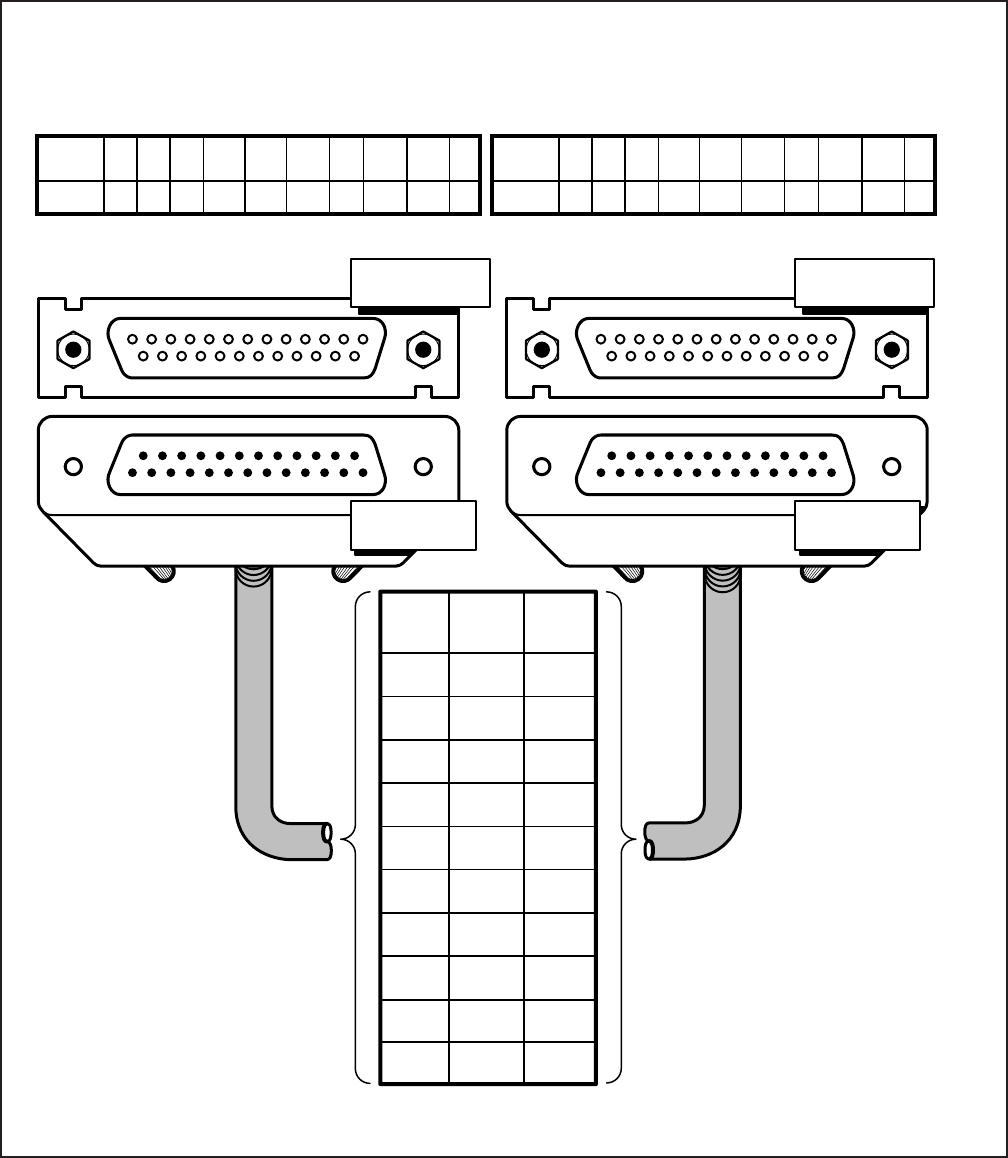
INSTALLATION-PERIPHERALS
SECTION 100-816-207
MARCH 1993
7-44
FIGURE 7-27
DK8 AND DK16 PDIU-DS TO TOSHIBA PRINTER, RS-232 CONNECTOR/CABLE CONNECTIONS
DB25
PIN #
8
3
2
20
7
6
4
N/C
N/C
1
NAME
DCD
RD
TD
DTR
SG
DSR
RTS
CTS
RI
FG
DB25
PIN #
8
3
2
20
7
6
4
5
22
1
12345678
2022
12345678
2022
Rear view of printer
or ASCII terminal DB25,
RS-232 connector.
Rear view of PDIU-DI DB25,
RS-232 female connector
TOSHIBA PS321SL PRINTER
(FUNCTIONS LIKE A DTE) PDIU-DS
(CONFIGURED IN THE "CONNECT TO DTE" MODE:
P1 ~ P9 = A-B SO PDIU FUNCTIONS LIKE A DCE)
NOTES:
1. The printer receives data on Pin 3
(RD) and transmits data on Pin 2
(TD).
2. The PDIU-DS should be in the
connect-to-DTE mode (P1 ~ P9 are
strapped A-B), so that it transmits
data on Pin 3 (RD) and receives
data on Pin 2 (TD).
DB25 PIN DESIGNATIONS
PDIU-DS
PIN #
NAME
1
FG
3
RD
4
RTS
5
CTS
6
DSR
7
SG
8
DCD
20
DTR
22
RI
DB25 PIN DESIGNATIONS
2
TD
PRINTER
PIN #
NAME
1
FG
3
RD
4
RTS
5
N/C
6
DSR
7
SG
8
DCD
20
DTR
22
RI
2
TD
20
DB25 FEMALE
CONNECTOR
DB25 FEMALE
CONNECTOR
2022
RS-232 CABLE
DB25 MALE
CONNECTOR
1234678
51234678
DB25 MALE
CONNECTOR
(50 ft max, 24 AWG;
customer supplied).
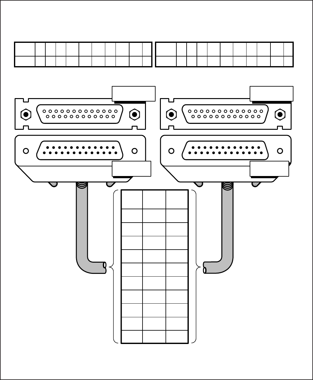
INSTALLATION-PERIPHERALS
SECTION 100-816-207
MARCH 1993
7-45
FIGURE 7-28
DK8 AND DK16 PDIU-DS TO HAYES-TYPE SMART MODEM, RS-232 CONNECTOR/CABLE CONNECTIONS
DB25
PIN #
8
3
2
20
7
6
4
5
22
1
NAME
DCD
RD
TD
DTR
SG
DSR
RTS
CTS
RI
FG
DB25
PIN #
8
3
2
20
7
6
4
5
22
1
123456785
2022
12345678
2022
Rear view of modem DB25 connector Rear view of PDIU-DS DB25, connector
HAYES-TYPE SMART MODEM
(FUNCTIONS LIKE A DCE) PDIU-DS
(CONFIGURED IN THE "CONNECT TO MODEM"
MODE, P1 ~ P9 = B-C, SO IT FUNCTIONS LIKE A DTE)
NOTES:
1. Modem receives data on pin 2 (TD) and transmits data on pin 3 (RD).
2. The PDIU-DS must be in the connect to modem mode (P1 ~ P9 strapped B-C) so that it transmits
data on pin 2 (TD) and receives data on pin 3 (RD).
20
DB25 FEMALE
CONNECTOR
DB25 FEMALE
CONNECTOR
2022
RS-232 CABLE
1234678
51234678
DB25 MALE
CONNECTOR
22
PDIU-DS
PIN #
NAME
1
FG
3
RD
4
RTS
5
CTS
6
DSR
7
SG
8
DCD
20
DTR
22
RI
2
TD
MODEM
PIN #
NAME
1
FG
3
RD
4
RTS
5
CTS
6
DSR
7
SG
8
DCD
20
DTR
22
RI
2
TD
(50 ft max, 24 AWG;
customer supplied)
DB25 MALE
CONNECTOR
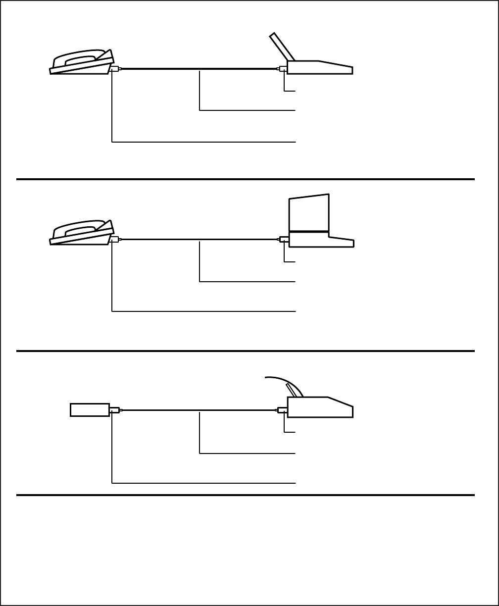
INSTALLATION-PERIPHERALS
SECTION 100-816-207
MARCH 1993
7-46
FIGURE 7-29
DK8 AND DK16 PDIU-DI/PDIU-DS MODULAR CABLE/RJ-45 ADAPTER CONNECTIONS
CONNECTION EXAMPLE 1
IMPORTANT!
Will not function with applications that require the RI signal to PC.
CONNECTION EXAMPLE 2
IMPORTANT!
Will not function with applications that require the RI signal to PC.
CONNECTION EXAMPLE 3
TOSHIBA P321SL OR SIMILAR
STANDARD TYPE SERIAL PRINTER
DIGITAL TELEPHONE TOSHIBA LAPTOP OR IBM AT TYPE
PERSONAL COMPUTER (PC)
PDIU-DI BASE TYPE 1 MODULAR ADAPTER
1
TYPE B MODULAR CORD (CROSSED)
1
(50 ft max, 24AWG)
TYPE 2 MODULAR ADAPTER
1
DIGITAL TELEPHONE IBM PC OR XT TYPE
PERSONAL COMPUTER (PC)
PDIU-DI BASE TYPE 3 MODULAR ADAPTER
1
TYPE A MODULAR CORD (STRAIGHT)
1
(50 ft max, 24AWG)
TYPE 2 MODULAR ADAPTER
1
STAND-ALONE DIU
PDIU-DS TYPE 2 MODULAR ADAPTER
1
TYPE A MODULAR CORD
1
(50 ft max, 24AWG)
TYPE 2 MODULAR ADAPTER
1
NOTES:
1. See Figure 7-30 for detailed pin out information of modular cords and adapters.
2. Never use modular cords and adapters when connecting a PDIU-DI/PDIU-DS to a modem.
3. Connection examples 1 and 2 work when using the PDIU-DI to make calls with personal computer applications (auto-
dialers, printer sharing, outgoing modem calls, etc). If the PC PDIU-DI must receive calls, the RI lead is normally
required; therefore, a standard RS-232 cable must be used (see Figures 7-25 and 7-28).
4. In Connection Example 3, PDIU-DS must be in the connect to DTE mode (P1 ~ P9, strapped A-B).
5. All modular cords and adapters are customer-supplied.
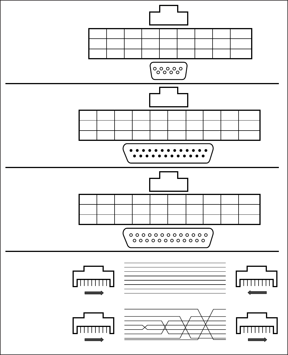
INSTALLATION-PERIPHERALS
SECTION 100-816-207
MARCH 1993
7-47
FIGURE 7-30
DK8 AND DK16 PDIU-DI/PDIU-DS MODULAR CORDS AND RJ-45/RS-232 ADAPTER PIN CONNECTIONS
6789
23451
8 7 6 5 4 3 2 1
8
DSR
6
7
RTS
7
6
RD
2
5
DCD
1
4
TD
3
2
GND
5
1
CTS
8
2345678
20
8 7 6 5 4 3 2 1
2345678
20
8 7 6 5 4 3 2 1
8
CTS
5
7
SG
7
6
DTR
20
5
TD
2
3
RD
3
2
RTS
4
1
DSR
6
4
DCD
8
8
CTS
5
7
SG
7
6
DTR
20
5
TD
2
3
RD
3
2
RTS
4
1
DSR
6
4
DCD
8
TYPE 1
RJ45 TO DB9 (FEMALE) ADAPTER
TYPE 2
RJ45 TO DB25 (MALE) ADAPTER
TYPE 3
RJ45 TO DB25 (FEMALE) ADAPTER
TYPE A
RJ45 FLAT MODULAR
CORD (STRAIGHT)
RJ45 STRAIGHT THROUGH
1
2
3
4
5
6
7
8
1
2
3
4
5
6
7
8
1
8
FRONT
1
2
3
4
5
6
7
8
8
7
6
5
4
3
2
1
1
8
FRONT
8
1
FRONT
1
8
FRONT
RJ45 CROSS PINNING
TYPE B
RJ45 FLAT MODULAR
CORD (CROSSED)
N/C
RI
9
RJ45
DB9
LEAD
NAME
N/C
RI
22
RJ45
DB25
LEAD
NAME
LEAD
NAME
N/C
RI
22
RJ45
DB25
Modular Cords (50 ft max, 24AWG; customer-supplied)
INSTALLATION-PERIPHERALS
SECTION 100-816-207
MARCH 1993
7-48
FIGURE 7-31
DK8 AND DK16 PDIU-DS JUMPER PLUG OPTIONS/RS-232 CONNECTOR INFORMATION
1234
DNTA
ON
MODULAR JACK
FOR CONNECTING
1- OR 2-PAIR
TO DIGITAL CIRCUIT
DIU
POWER READY CONNECT
PDIU-DS (REAR VIEW)
SW1: SEE FIGURE 8-36 FOR
SWITCH (1 ~ 4) OPTIONS
INFORMATION
12345678910111213
141516171819202122232425
CTS
DSR
SG
DCD
RTS
RD
TD
FG
RI
DTR RS-232, DB25
(FEMALE) CONNECTOR
P5
P1
P2
P7
P4
P3
P6
P8
P9
ABC
A-B DTE
B-C MODEM
SIGNAL
ABBREVIATON
SIGNAL DIRECTION AND FUNCTION OF P1 ~ P9
PDIU-DS CONNECTED TO DTE PDIU-DS CONNECTED TO DCE
FUNCTION:
A-B
(DTE MODE)
FG
SG
TD
RD
RTS
CTS
DSR
DTR
DCD
RI
P1
P2
P6
P7/P5
P4
P3
P8
P9
P1
P2
P6
P7/P5
P4
P3
P8
P9
SIGNAL NAME/
FUNCTION
FRAME GROUND
SIGNAL GROUND
TRANSMIT DATA
RECEIVE DATA
REQUEST TO SEND
CLEAR TO SEND
DATA SET READY
DATA TERMINAL READY
DATA CARRIER DETECT
RING INDICATOR
PDIU-DS
PIN NO.
1
7
2
3
4
5
6
20
8
22
SIGNAL
DIRECTION
DTE DIU
DTE DIU
DTE DIU
DTE DIU
DTE DIU
DTE DIU
DTE DIU
DTE DIU
FUNCTION:
B-C
(MODEM MODE)
SIGNAL
DIRECTION
MODEM DIU
MODEM DIU
MODEM DIU
MODEM DIU
MODEM DIU
MODEM DIU
MODEM DIU
MODEM DIU
NOTES:
1. Mode select (P1 ~ P9) “A-B” if PDIU-DS is connected to a terminal-type device (DTE).
2. Mode select (P1 ~ P9) “B-C” if PDIU-DS is connected to a modem-type device (DCE).
3. See Figure 7-33 to disassemble/assemble PDIU-DS.
4. Some RS-232 leads go by different names depending on the equipment manufacturer.
5. Do not cut the Perception strap when installing a PDIU-DS in Strata DK systems.
P1 ~ P9 LOCATED ON PCB INSIDE
OF PDIU-DS UNIT (SEE NOTES)
PDIU-DS (FRONT VIEW)
CONNECT LED
READY LED
POWER LED
(SEE PARAGRAPH 10.72)
PERCEPTION
5
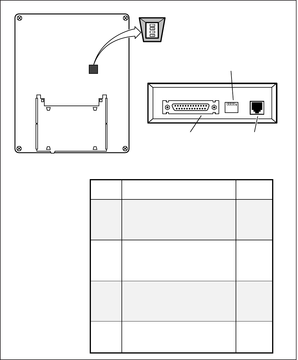
INSTALLATION-PERIPHERALS
SECTION 100-816-207
MARCH 1993
7-49
FIGURE 7-32
DK8 AND DK16 PDIU-DI/PDIU-DS SW1 DIP SWITCH INFORMATION
SWITCH
SW1
(1)
SW1
(2)
SW1
(3)
SW1
(4)
FUNCTION
Forced hang up when DIU does not
detect space signal on TD or RD for
about 9 minutes
ON: enable (auto-disconnect)1
OFF: disable
DCD, DSR control
ON: continuous on
OFF: DSR depends on DTR
(DCD is on during
communication state)
RI control
ON: RI is on continuously during
ringing state
OFF: RI is 1 sec ON/3 sec OFF
during ringing state
RTS control
ON: DTE doesn't have RTS signal
OFF: DTE has RTS signal (ready/busy
flow control: RTS/CTS:DCD)
INITIAL
POSITION
OFF
OFF
OFF
OFF
PDIU-DI AND -DS SW1 DIP SWITCH (1 ~ 4) FUNCTIONS
ACCESS FROM BOTTOM
— OUTSIDE OF PDIU-DI
DIP SWITCH
PDIU-DI DIGITAL TELEPHONE BASE
PDIU-DI (BOTTOM VIEW)
1 2 3 4
DIP SWITCH SW1 BACK VIEW
(ACCESS FROM BACK
— OUTSIDE OF PDIU-DS)
1234
DNTA
ON
PDIU-DS (REAR VIEW)
DB25 CONNECTOR (FEMALE)
FOR DTE OR DCE RS-232
CABLE CONNECTION
MODULAR
CONNECTOR FOR
DIGITAL PORT
CONNECTION
DIRECTORY TRAY:
REMOVE FROM ORIGINAL
TELEPHONE BASE AND
INSTALL ON PDIU-DI BASE
OFF
NOTES:
1. DIU port must have
LED 02 ON in Program 20
to enable auto disconnect.
2. See Paragraphs 10.20
and 10.30 for more details
regarding SW1 option
settings.
3. When a PDIU-DS is connec-
ted to a modem that tracks
the DCD signal (AT&C1)
SW1(4) must be ON.
4. If using Toshiba Personal
Computers and Toshiba
Printers using X-ON/X-OFF
flow control, set SW1(4) ON
on PDIU-DIs and -DSs.
5. SW1(2) should be off when
PDIU-DS is connected to a
modem.
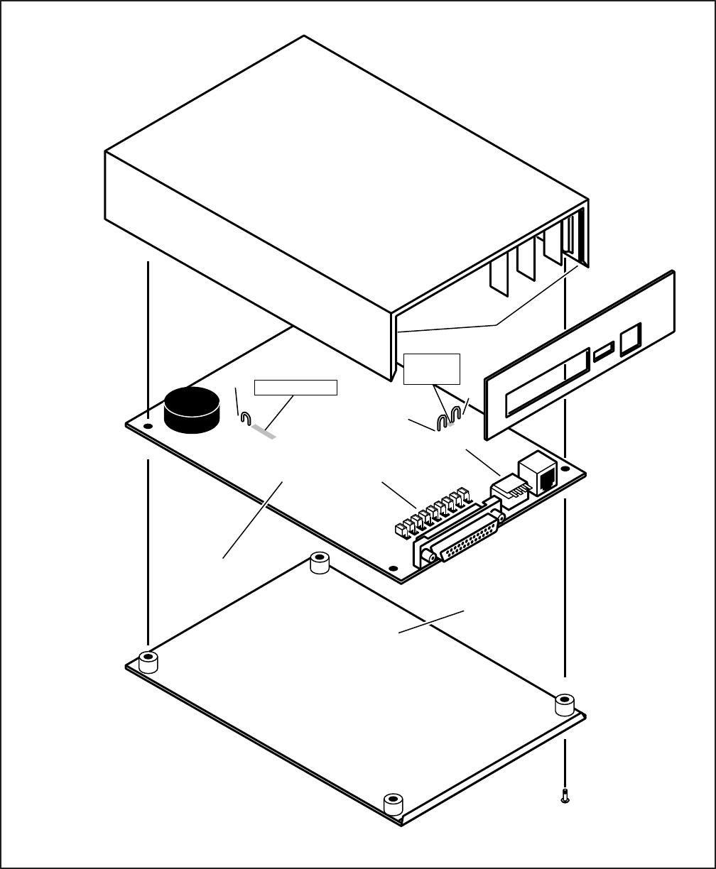
INSTALLATION-PERIPHERALS
SECTION 100-816-207
MARCH 1993
7-50
FIGURE 7-33
DK8 AND DK16 PDIU-DS DISASSEMBLY/ASSEMBLY DIAGRAM
PDIU-DS
PCB
DTE/MODEM
JUMPER PLUGS
P1~P9
SW1
SIDE GROOVES
BOTTOM
PANEL
Do not cut the PERCEPTION jumper wire for
STRATA DK8 or DK16 installations.
Jumper wire is for PERCEPTION applications only.
See Table 8-D regarding external power requirements.
EX.
POWER
W2
W1
PERCEPTION
W3
NOTES:
1.
2.
INSTALLATION-PERIPHERALS
SECTION 100-816-207
MARCH 1993
7-51
10.80 PDIU-DI/PDIU-DS Installation Tests
10.81 Paragraphs 10.82 ~ 10.86 provide tests for
five DIU call applications. The telephone and port
numbers used in these figures are provided for
explanation purposes only; when actually testing,
use port and telephone numbers appropriate for
the system. Each of these tests can be conducted
with manual dialing from a digital telephone’s dial-
pad or AT dialing from a personal computer’s
keyboard; however, only the preferred method of
dialing for application is presented.
10.82 PC-to-PC Test Call Using AT Commands
(see Figure 7-34)
1) DIU Programming:
Program 20: Ports 00 and 01. LEDs 01,
02, and 17 ON; all other LEDs OFF.
Program 39: Ports 00 and 01. Data
Call (56) and Data Release (54) but-
tons should be provided.
Default settings for PDIU-DI S-Regis-
ters.
2) Make sure PC 1 and PC 2 are on-line with a
communications software package and that
the communication parameters of each PC
and communication software package are set
to the same values (data transmission rate,
parity, data bits, stop bits, flow control, etc.).
3) From PC 1’s keyboard, type A T D D 1 1 and
press ENTER (AT commands must be capi-
tal letters).
The Data Call LEDs will be lit on DKT 10
and 11
PC 1 displays, CONNECT XXXX.
PC 2 displays, RING.
PC 1 and PC 2 are connected as shown
by the thick solid lines. PDIU-DIs are now
in the communication mode.
4) Typing from PC 1 keyboard will display on PC
2 display and vice versa.
5) To terminate the call: Press Data Release,
or;
a) Type XXX from either PC keyboard.
The PC screen displays, OK.
FIGURE 7-34
DK8 AND DK16 PC TO PC TEST CALL USING AT COMMANDS
DIGITAL
(PORT 00)
DIGITAL
(PORT 01)
LAPTOP PC 1
RS-232
DKT/PDIU-DI
(10)
MDF
MDF
RS-232
LAPTOP PC 2
DKT/PDIU-DI
(11 )
STRATA DK8 OR DK16
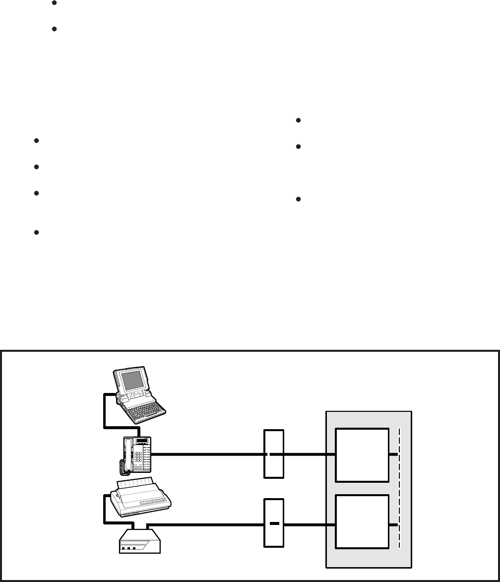
INSTALLATION-PERIPHERALS
SECTION 100-816-207
MARCH 1993
7-52
normally accomplished using the DOS and
MODE commands.
3) Using the manufacturer’s documentation,
make sure the communication parameters
(data speed, parity, data bits, stop bits, etc.) of
the PC COM port match the printer’s serial
interface parameters.
4) To connect the PC to the printer, press the
DKT’s Data Call button and dial 1 3.
The CONNECT on the PDIU-DS will be
lit.
The connection between the PC and the
printer is completed, as shown by the
thick lines above (PDIU-DS 13 is in the
communication mode).
If busy tone is sent to the DKT, the
connection is not complete; press Data
Release and try step 4 again.
5) Operate the PC to print data as required.
6) To terminate the call, press the DKT’s Data
Release button.
b) Type A T H from the PC keyboard used
in step 5a.
PC 1 and PC 2 screens both display,
NO CARRIER.
The Data Call LEDs on each DKT are
off.
XXX = PDIU-DI escape sequence (see
Para-
graph 10.63)
10.83 PC to Printer Test Call Using Manual
Dialing (see Figure 7-35)
1) DIU Programming:
Program 20: Port 01. LEDs 01, 02, and
17 ON; all other LEDs OFF.
Program 20: Port 03. LEDs 01, 04, and
17 ON; all other LEDs OFF.
Program 39: Port 01. Data Call (56)
and Data Release (54) buttons should
be provided.
Default settings for PDIU-DI, S-Regis-
ters.
2) Make sure the PC is configured to print data
from its serial COM port (the PC COM port
connected to DKT/PDIU-DI port 01). This is
DIGITAL
(PORT 01)
TOSHIBA
DIU
POWER READY CONNECT
TOSHIBA
MDF
MDF
RS-232
RS-232
LAPTOP PC
DKT/PDIU-DI
(11)
SERIAL
PRINTER
PDIU-DS
(13)
STRATA DK8 OR DK16
DIGITAL
(PORT 03)
FIGURE 7-35
DK8 AND DK16 PC TO PRINTER TEST CALL USING MANUAL DIALING
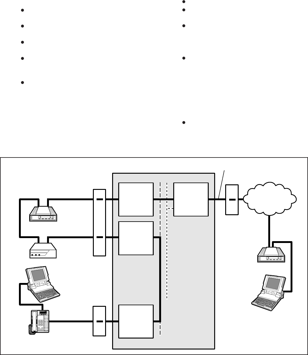
INSTALLATION-PERIPHERALS
SECTION 100-816-207
MARCH 1993
7-53
3) From PC 1’s keyboard, type A T D D 1 4 and
press ENTER (AT commands must be capi-
tal letters).
The Data Call LED on DKT 14 will be lit.
The CONNECT LED on PDIU-DS 14 will
be lit.
The screen on PC 1 displays, CON-
NECT XXXX, where XXXX is the data
transmission speed set by the communi-
cations software.
At this time, PC 1 and PDIU-DS 14 are
connected as shown by the thick lines
above (PDIU-DS 14 is in the communica-
tion mode); PC 1 is now linked directly to
the RS-232 side of the internal modem;
PC 1 can issue AT commands to the
internal modem, which is now in the
command mode.
If Digital/PDIU-DS port 04 is the only DIU
port connected to the modem (Program
20, LED 03 ON), the Modem LEDs on all
DKTs will be lit.
10.84 Internal PC to External PC Test Call Using
AT Commands (see Figure 7-36)
1) DIU Programming:
Program 20: Port 00. LEDs 01, 02, and
17 ON; all other LEDs OFF.
Program 20: Port 04. LEDs 01, 02, 03,
04, 06, and 17 ON; all other LEDs OFF.
Program 21: Digital port 04 assigned
with KSTU port 08.
Program 39: Port 00. Data Call (56),
Data Release (54), and Modem (55)
buttons should be provided.
Default settings for PDIU-DI and PDIU-
DS S-Registers.
2) Make sure PC 1 and PC 2 are on-line with a
communications software package and that
the communication parameters of each PC
and communication software package are set
to the same values (data transmission rate,
parity, data bits, stop bits, flow control, etc.).
FIGURE 7-36
DK8 AND DK16 INTERNAL PC TO EXTERNAL PC TEST CALL USING AT COMMANDS
QSTU OR
KSTU
(PORT 08)
DIGITAL
(PORT 04)
DIU
POWER READY CONNECT
TOSHIBA
MDF
RS-232
INTERNAL
MODEM
(18)
PDIU-DS
(14) EXTERNAL
MODEM
(AUTO
ANSWER)
MDF
CO
LINE 1
PUBLIC
TELEPHONE
NETWORK
583-3700
TELEPHONE
LINE
674-4700 RS-232
LAPTOP
PC 2
STRATA DK8 OR DK16
DIGITAL
(PORT 00)
LAPTOP PC 1
RS-232 DKT/PDIU-DI
(10)
MDF
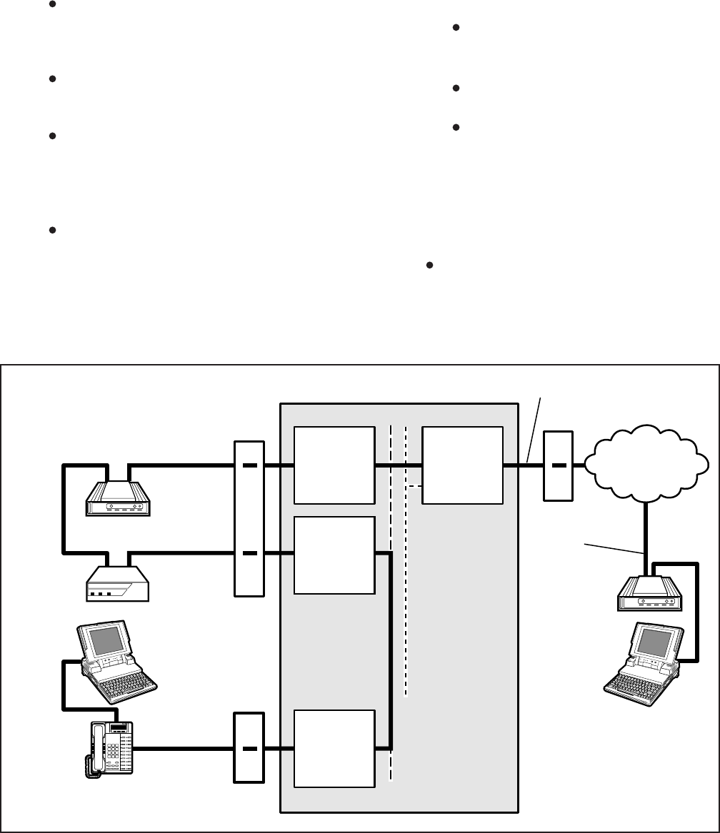
INSTALLATION-PERIPHERALS
SECTION 100-816-207
MARCH 1993
7-54
4) From PC 1’s keyboard, type A T D T 7 0 1
6 7 4 4 7 0 0 and press ENTER.
The internal modem (18) goes off-hook,
dials 701 to seize the CO line, and then
dials the external modem’s telephone
number (674-4700).
The external modem rings and auto an-
swers; the modems handshake and es-
tablish communications.
If the modems send result codes, the
screen on PC 1 displays, CONNECT
XXXX, where XXXX is the data transmis-
sion speed set by the communication
software.
At this time PC 1 and PC 2 are con-
nected, as shown by the thick lines above,
to exchange data (file transfers, type
messages, etc.).
5) To terminate the call: Press the telephone
Data Release button and;
a) Type + + + from PC2 keyboard.
The PC screen displays, OK.
b) Type A T H from the PC keyboard used
in step 5a.
PC 1 and PC 2 screens both display,
NO CARRIER.
The Data Call LED on DKT 10 will be
unlit.
10.85 External PC to Internal PC Test Call Using
AT Commands (see Figure 7-37)
1) DIU Programming:
Program 20: Port 00. LEDs 01, 02, and
17 ON; all other LEDs OFF.
FIGURE 7-37
DK8 AND DK16 EXTERNAL PC TO INTERNAL PC TEST CALL USING AT COMMANDS
QSTU OR
KSTU
(PORT 08)
DIGITAL
(PORT 04)
DIU
POWER READY CONNECT
TOSHIBA
MDF
RS-232
INTERNAL
MODEM
(18)
PDIU-DS
(14) EXTERNAL
MODEM
MDF
CO
LINE 1
PUBLIC
TELEPHONE
NETWORK
583-3700
TELEPHONE
LINE
674-4700 RS-232
LAPTOP
PC 2
STRATA DK8 OR DK16
DIGITAL
(PORT 00)
LAPTOP PC 1
RS-232 DKT/PDIU-DI
(10)
MDF

INSTALLATION-PERIPHERALS
SECTION 100-816-207
MARCH 1993
7-55
The CONNECT LED on the PDIU-DS
(14) will be lit; the Data Call and Modem
LEDs on DKT 10 will also be lit.
The screens on PC 1 and PC 2 display,
CONNECT XXXX, where XXXX is the
data transmission speed set by the com-
munication software.
At this time, PC 1 and PC 2 are con-
nected, as shown by the thick lines, to
exchange data (file transfers, typed mes-
sages, etc.).
5) To terminate the call: Press the telephone
Data Release button, and
a) Type + + + from PC2 keyboard.
The PC screen displays, OK.
b) Type A T H from the PC keyboard used
in step 5a.
PC 1’s and PC 2’s screens both dis-
play, NO CARRIER.
The DATA and MODEM LEDs on
DKT 10 will turn off.
10.86 PC Auto Dial Voice Call Test (see Figure
7-38)
There are many off-the-shelf, IBM/MS-DOS com-
patible, desktop organizer software packages that
provide an auto dialer function. One of these is the
terminal resident SideKick. It is used in this section
for test explanation purposes only. If you choose
another auto dialer software package, the detailed
response may be different than that shown here.
1) DIU Programming:
Program 20: Port 01. LEDs 01, 02, and 17
ON; all other LEDs OFF.
Program 39: Port 01. Data Call (56) and
Data Release (54) buttons are optional; if
the PDIU-DI is only used for the PC auto dial
application, the Data Call and Data
Release buttons are unnecessary.
2) Make sure that the auto dial application soft-
ware is installed on the PC root directory and
that the communication parameters of the PC
and application software are set to the same
values (in this test example, Sidekick
“SKINSTAL” program).
Program 20: Port 04. LEDs 01, 02, 03,
04, 06, and 17 ON; all other LEDs OFF.
Program 21: Digital port 04 assigned
with PSTU port 08.
Program 39: Port 00. Data Call (56),
Data Release (54), and Modem (55)
buttons should be provided.
Program 81: Port 08. LED 01 ON (CO
line 01 rings QSTU/KSTU port 08).
Internal modem: set to auto answer
(S0=1).
Default settings for PDIU-DI and PDIU-
DS, S-Registers.
2) Make sure PC 1 and PC 2 are on-line with a
communications software package and that
the communication parameters of each PC
and communication software package are set
to the same values (data transmission rate,
parity, data bits, stop bits, flow control, etc.).
3) From PC 2’s keyboard, type A T D T 5 8 3
3 7 0 0 and press ENTER.
The external modem originates the call
to STRATA DK16 CO line 01.
CO line 01 rings incoming to the internal
modem (QSTU or KSTU port 08).
The internal modem rings and auto an-
swers; the modems handshake and es-
tablish communications.
If the modems send result codes, the
PC’s screens display, CONNECT XXXX,
where XXXX is the data transmission
speed set by the communications soft-
ware.
At this time, PC 2 is connected to PDIU-
DS (14), as shown by the thick lines
above (PDIU-DS 14 is in the command
mode). PC 2 can now issue AT com-
mands to PDIU-DS 14.
If Digital/PDIU-DS port 04 is the only
PDIU port connected to a modem (Pro-
gram 20, LED 03 ON), then the Modem
LEDs on all DKTs will light.
4) From PC 2’s keyboard, type A T D D 1 0 and
press ENTER (AT commands must be capi-
tal letters); this prompts PDIU-DS (14) to dial
and connect to PDIU-DI (10).
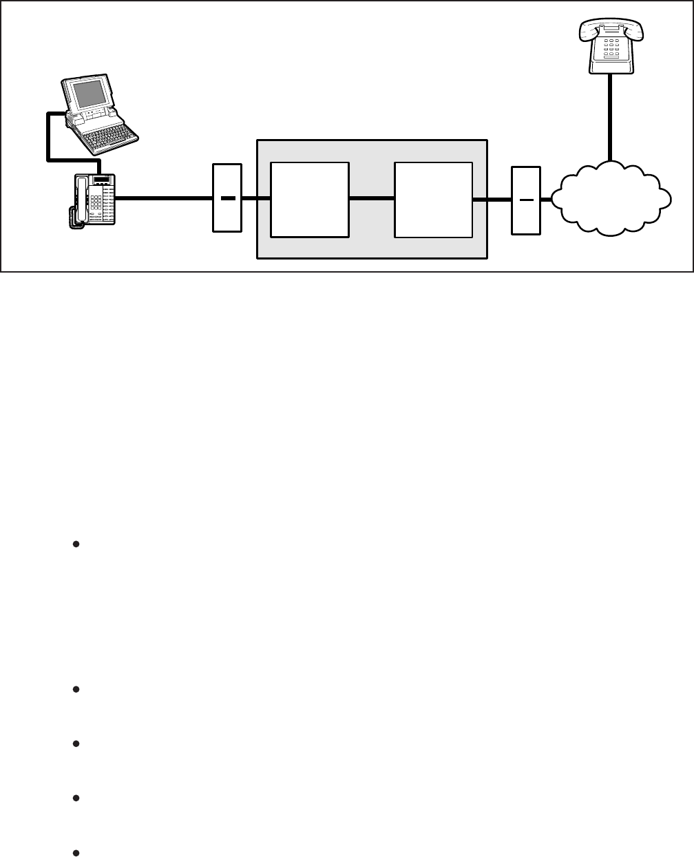
INSTALLATION-PERIPHERALS
SECTION 100-816-207
MARCH 1993
7-56
3) Make sure that a dialing directory consisting of
names and telephone numbers you wish to
auto dial is installed within the application
software (include the appropriate STRATA
CO line access code prefixing each telephone
number).
4) To auto dial using Sidekick from the PC key-
board:
a) Press the ALT and CTRL keys simulta-
neously.
The PC screen displays the Sidekick
menu window.
b) Press F5 twice (Sidekick prompts “search
for INITials:” to display on the PC’s
screen).
c) Type the initials or name of the person or
organization you wish to auto dial.
d) Press ENTER.
Sidekick finds and highlights the de-
sired name/number.
e) Press ENTER again.
DKT/PDIU-DI 11 seizes the appro-
priate CO line and auto dials the
selected telephone number.
The LEDs of the DKT’s Data Call
and CO line 01 buttons will be lit (if
assigned in Program 39).
Dial tone, DTMF tones, and ringback
or busy tones are audible from the
DKT’s speaker.
5) Take the DKT’s handset off-hook at any time
after the telephone number is dialed (press
the SPACE bar to release the Data Call
button only); or, remain on-hook and use the
DKT’s speakerphone to talk when the called
party answers (LCD model only, do not press
the SPACE bar when using the speaker-
phone).
6) To terminate the call anytime:
a) If off-hook, press the SPACE bar and
place the DKT handset on-hook.
b) If talking via the speakerphone, press the
SPACE bar.
11 DK16 TWO-CO LINE EXTERNAL
AMPLIFIED CONFERENCE
11.00 General
11.01 A customer-supplied two-way amplifier can
be installed to amplify two-CO line tandem, DISA,
and conference calls. The amplifier will only sup-
port one call at a time: Any conference, two CO-line
tandem, or DISA calls originated while the amplifier
is being used for another call will be unamplified.
The amplifier is connected to two designated PEKU
or PESU station ports and will automatically be
switched into a two-CO line connection established
between any CO lines in the system.
DIGITAL
(PORT 01)
MDF
RS-232
LAPTOP PC 2
DKT/PDIU-DI
(11)
MDF
CO
LINE 1
PUBLIC
TELEPHONE
NETWORK
STANDARD
TELEPHONE
STRATA DK8 OR DK16
DIALED LINE
FIGURE 7-38
DK8 AND DK16 PC AUTO DIAL VOICE CALL TEST
INSTALLATION-PERIPHERALS
SECTION 100-816-207
MARCH 1993
7-57
NOTES (Amplifier):
1.
2.
3.
4.
NOTES (PROGRAMMING):
• Program 10-3, circuit assignments
• Program 10-1, LED 19 and 20 ON.
• Program 15-5, enable appropriate CO lines for
tandem connection.
• Program 78-2, enable appropriate CO lines if
amplified DISA is required.
• Program 10-2, LED 18 and 19 ON.
PROGRAM 10-3
PESU/PEKU PORT
CONF. ENABLE
BUTTON/LED
LED 02, ON
PESU OR
PEKU SLOT
POSITION
04
PESU OR
PEKU PORT
NUMBER
PESU OR
PEKU
CIRCUIT
A = 17
B = 18 CKT6
CKT7
PUBLIC
TELEPHONE
NETWORK
CKT, X
PCM
CONFERENCE
SWITCH
T
R
CO
LINE
VT(6), P36/BK-BL T, P51
24AWG
TWISTED
PAIR
VR(6), P11/BL-BK
DT(6)
DR(6)
NOT USED
R, P33
PORT A
(CKT 6)
CKT, Y
T
R
VT(7), P38/BK-GN T, P41
VR(7), P13/GN-BK
DT(7)
DR(7)
NOT USED
R, P49
PORT B
(CKT 7)
OUTSIDE
PARTY 1
OUTSIDE
PARTY 2
ANY
STATION
CALL
AMP
POWER
SUPPLY
–24
GND
P35
P17
R-TEC, PS16
POWER ADAPTER
(NOTES)
+
24VDC
–
117VAC
60HZ
DUPLEX
AC-PLUG
SYSTEM
TELEPHONE
THAT SETS UP
2-CO LINE
CONFERENCE
CALL
CKTA
24AWG
25-PAIR
CABLE
R-TEC, VFR5050
AMPLIFIER
(see NOTES)
R-TEC EDGE
CONNECTOR
MDF
BASE UNIT
PESU or
PEKU
ANY CO LINE
MAY BE USED FOR
CONFERENCE; SEE
PROGRAMMING NOTES
FOR TANDEM AND/OR
DISA CO LINES
CKTB
All amplifier equipment is customer or dealer-
supplied.
Use a 2-way, telephone CO line amplifier that is
FCC Part 68 registered and provides automatic
gain control; the above example is with a Reliance
Electric Co., R-TEC VFR5050 (VVSG) Repeater,
with 500-X or 500-X-CT mounting assembly and a
PS16 power adapter.
Recommended switch settings for VFR5050 are:
• FLAT GAIN (1, 2, 4, 8): all ON
• Equalizer (1 ~ 5): all OFF
• Sensitivity: NORM
• S1 screw: down = Data DIS OFF
The above R-TEC options may be different for
some installations; see R-TEC VFR5050
installation Practice before installing VFR5050.
CO
LINE
SLOT 04
EXPANSION
UNIT
FIGURE 7-39
DK16 AMPLIFIED TWO-CO LINE CONFERENCE AND/OR AMPLIFIED DISA FUNCTIONAL WIRING
DIAGRAM

INSTALLATION-PERIPHERALS
SECTION 100-816-207
MARCH 1993
7-58
11.02 Amplified Talk Path. Figure 7-39 provides a
functional diagram of a two-CO line amplified con-
ference connection (an R-TEC VFR5050 amplifier
is used here). The talk path for the connection is as
follows: outside party 1—public telephone net-
work—CO, CKTX—STRATA DK16—PEKU, port
A—into AMP, CKTA—Out AMP, CKT B—PEKU,
port B—STRATA DK16—CO, CKTY—public tele-
phone network—outside party 2. This path is two-
way so when outside party 2 talks, the talk level is
amplified in the reverse direction.
NOTE:
Only the outside party 1 talk path is amplified
to/from a system telephone when it is con-
nected into a two-CO line conference.
11.03 Amplifier Requirements.
Customer-supplied.
Must be FCC-registered, Part 68, and
provide automatic gain control.
Requires two PEKU or PESU station
ports (17 and 18).
Refer to the amplifier manufacturer’s in-
stallation documentation for amplifier
grounding instructions.
11.04 Installation. Connect a two-way amplifier to
the STRATA DK16 system in accordance with the
following steps (see Figures 7-39 and 8-27).
1) At the main distribution frame (MDF), connect
the voice pair (VT, VR, port A) of circuit 6 on
the designated PEKU or PESU PCB to one
input of the customer-supplied two-way am-
plifier. In the example in Figure 7-39, this is
CKTA (Central Office Side A) of the VFR5050.
2) At the MDF, connect the voice pair (VT, VR,
port B) of circuit 7 on the designated PESU or
PEKU PCB to the other input of the amplifier.
In the Figure 7-39 example, this is CKTB
(subscriber side B) of VFR5050.
3) Plug the amplifier’s power cord into the 117
VAC (standard) wall outlet.
4) Set the gain and other amplifier parameters
options per the amplifier manufacturer’s in-
stallation documentation.
5) Program the STRATA DK16 system as
follows:
Program 10-3: Enables the appropriate
PEKU or PESU PCB ports for amplifier
connection. Only enable the ports that
will be connected with the amplifier(s).
Program 15-5: Enables appropriate CO
lines for tandem connection.
Program 10-1: LEDs 19 and 20 must be
ON.
Program 10-2: LED 18 and 19 must be
ON.

INSTALLATION-WIRING DIAGRAMS
SECTION 100-816-208
MARCH 1993
8-i
INSTALLATION
CHAPTER EIGHT
WIRING DIAGRAMS
TOSHIBA SYSTEM PRACTICES
DIGITAL KEY TELEPHONE SYSTEMS
8-i
INSTALLATION-WIRING DIAGRAMS
SECTION 100-816-208
MARCH 1993
TABLE OF CONTENTS
PARAGRAPH SUBJECT PAGE
1GENERAL .............................................................................................................. 8-1
2WIRING DIAGRAMS .............................................................................................. 8-1
2.10 Station Wiring Diagrams ..................................................................................... 8-1
2.20 CO Line Wiring Diagrams ................................................................................... 8-1
2.30 PIOU and PIOUS Wiring Diagrams .................................................................... 8-1
FIGURE LIST
FIGURE TITLE PAGE
8-1 SECONDARY PROTECTOR DIAGRAM ............................................................... 8-5
8-2 DK8 MDF WIRING TO KSU AMPHENOL STATION AND RELAY
CONNECTIONS ..................................................................................................... 8-7
8-3 DK8 MDF WIRING TO CO LINES (KSU AND QCDU) ........................................... 8-8
8-4 DK8/DK16 MDF WIRING DDCB AND DOOR LOCK CONTROL ........................... 8-9
8-5 DK8 QSTU/DK16 KSTU STATION/MDF CROSS CONNECT RECORD ............... 8-10
8-6 DK8 AND DK16 CO LINE RECORD ...................................................................... 8-10
8-7 DK8 QSMU TTY/SMDR WIRING ........................................................................... 8-11
8-8 DK16 MDF WIRING/BASE UNIT P5 AMPHENOL STATION AND RELAY
CONNECTIONS ..................................................................................................... 8-12
8-9 DK16 MDF WIRING/CO LINES TO BASE UNIT .................................................... 8-13
8-10 DK16 MDF WIRING FOR DIGITAL TELEPHONES (DKTS) AND DIGITAL
DSS CONSOLE (DDSS) TO PDKU ....................................................................... 8-14
8-11 DK16 MDF WIRING FOR DIGITAL TELEPHONES (DKTS) WITH
PDIU-DI/PDIU-DI2 AND PDIU-DS TO PDKU, KCDU, OR BASE UNIT.................. 8-15
8-12 DK8 OR DK16 PDKU, KCDU, DK8 KSU, OR DK16 BASE KSU DIGITAL
STATION/MDF CROSS CONNECT RECORD ....................................................... 8-16
8-13 DK16 MDF WIRING/ELECTRONIC TELEPHONE TO PEKU ................................ 8-17
8-14 DK16 MDF WIRING/HDSS CONSOLE AND ASSOCIATED ELECTRONIC
TELEPHONE WIRING TO PEKU .......................................................................... 8-18
8-15 DK16 PEKU BACKGROUND MUSIC CONNECTION ............................................ 8-19
8-16 DK16 PEKU STATION/MDF CROSS CONNECT RECORD .................................. 8-20
8-17 DK16 MDF WIRING/STANDARD TELEPHONE, VOICE MAIL TO PSTU ............. 8-21
8-18 DK16 PSTU STATION/MDF CROSS CONNECT RECORD .................................. 8-22
8-19 DK16 PESU CIRCUIT CARD WIRING DIAGRAM.................................................. 8-23
8-20 DK16 PESU STATION/MDF CROSS CONNECT RECORD .................................. 8-24
8-21 DK16 MDF WIRING/CO LINES TO PCOU ............................................................ 8-25
8-22 DK16 MDF WIRING/CO LINES AND DIGITAL TELEPHONES TO KCDU ............ 8-26
8-23 DK16 MDF WIRING/PIOU PERIPHERALS (25-PAIR) ........................................... 8-27
8-24 DK16 PIOUS/TTY AND SMDR WIRING ................................................................ 8-28
8-25 DK16 PIOUS PAGE/RELAY/ALARM CONNECTIONS .......................................... 8-29
8-26 DK16 PIOU SMDR/TTY OPTIONS AND WIRING .................................................. 8-30
8-27 DK16 MDF WIRING/AMPLIFIED TWO-CO LINE CONFERENCE ......................... 8-31
8-28 DK16 EXTERNAL POWER FOR DIGITAL TELEPHONE CONNECTION ............. 8-32
8-ii
INSTALLATION-WIRING DIAGRAMS
SECTION 100-816-208
MARCH 1993
TABLE LIST
TABLE TITLE PAGE
8-A FCC REGISTRATION NUMBERS STRATA DK8 AND DK16 ................................ 8-1
8-B STATION LOOP REQUIREMENTS ....................................................................... 8-2
8-C NETWORK REQUIREMENTS ............................................................................... 8-3
8-D DIGITAL TELEPHONE/DIU/DDSS CONSOLE/ADM/LOOP LIMITS ...................... 8-4
8-1
INSTALLATION-WIRING DIAGRAMS
SECTION 100-816-208
MARCH 1993
1 GENERAL
1.00 This chapter contains point-to-point wiring
diagrams for connection of telephones, lines, pe-
ripheral equipment, and power supply to the DK
systems. Wiring diagrams are divided into groups
according to the PCB or unit which provides the
interface for, or controls the operation of, the asso-
ciated equipment.
2 WIRING DIAGRAMS
2.01 The following paragraphs list and identify the
wiring diagrams provided in this chapter.
2.10 Station Wiring Diagrams
Figure 8-1 — Secondary Protector Diagram
Figure 8-2 — DK8 MDF Wiring to KSU
Amphenol Station and Relay Connections
Figure 8-3 — DK8 MDF Wiring to CO Lines
(KSU and QCDU)
Figure 8-4 — DK8/DK16 MDF Wiring DDCB
and Door Lock Control
Figure 8-6 — DK8 and DK16 CO Line Record
Figure 8-7 — DK8 QSMU TTY/SMDR Wiring
Figure 8-8 — DK16 MDF Wiring/Base Unit
P5 Amphenol Station and Relay Connections
Figure 8-9 — DK16 MDF Wiring/CO Lines to
Base Unit
Figure 8-10 — DK16 MDF Wiring for Digital
Telephones (DKTS) and Digital DSS Console
(DDSS) to PDKU
Figure 8-11 — DK16 MDF Wiring for Digital
Telephones (DKTS) with PDIU-DI/PDIU-DI2 and
PDIU-DS to PDKU, KCDU, or Base Unit
Figure 8-12 — DK8 or DK16 PDKU, KCDU,
DK8 KSU or DK16 Base KSU Digital Station/
MDF Cross Connect Record
Figure 8-13 — DK16 MDF Wiring/Electronic
Telephone to PEKU
Figure 8-14 — DK16 MDF Wiring/HDSS Con-
sole and Associated Electronic Telephone Wir-
ing to PEKU
Figure 8-15 — DK16 PEKU Background Mu-
sic Connection
Figure 8-16 — DK16 PEKU Station/MDF Cross
Connect Record
Figure 8-17 — DK16 MDF Wiring/Standard
Telephone, Voice Mail to PSTU
Figure 8-18 — DK16 PSTU Station/MDF Cross
Connect Record
Figure 8-21 — DK16 MDF Wiring/CO Lines to
PCOU
Figure 8-27 — DK16 MDF Wiring/Amplified
Two-CO Line Conference
Figure 8-28 — DK16 External Power for
Digital Telephone Connection
2.20 CO Line Wiring Diagrams
Figure 8-5 — DK8 QSTU/DK16 KSTU Sta-
tion/MDF Cross Connect Record
Figure 8-19 — DK16 PESU Circuit Card Wir-
ing Diagram
Figure 8-20 — DK16 PESU Station/MDF
Cross Connect Record
2.30 PIOU and PIOUS Wiring Diagrams
Figure 8-22 — DK16 MDF Wiring/CO Lines
and Digital Telephones to KCDU
Figure 8-23 — DK16 MDF Wiring/PIOU Pe-
ripherals (25-Pair)
Figure 8-24 — DK16 PIOUS/TTY and SMDR
Wiring
Figure 8-25 — DK16 PIOUS Page/Relay/
Alarm Connections
Figure 8-26 — DK16 PIOU SMDR/TTY
Options and Wiring
TABLE 8-A
FCC REGISTRATION NUMBERS STRATA DK8 AND DK16
Manufacture Country
Made in Singapore
Made in Malaysia
Key System
CJ6 SNG-73672-KF-E
CJ6 MLA-74479-KF-E
Hybrid System
CJ6 SNG-73673-MF-E
CJ6 MLA-74478-MF-E
System
DK16
DK8

8-2
INSTALLATION-WIRING DIAGRAMS
SECTION 100-816-208
MARCH 1993
TABLE 8-B
STATION LOOP REQUIREMENTS
NOTES:
1. Use 24 AWG twisted pairs.
2. PESU circuits 3 and 4 are not used.
3. DDCB can connect only to Circuit 5 of the DK16 Base Unit or Circuit 1 of the PDKU or KCDU.
4. Two-pair, larger wire, or local telephone power supply is required to achieve maximum range,
see Table 8-D.
Device Description Max Loop Resistance
(Including Device) Max Distance from
KSU to Device Number of
Wire Pairs
Standard telephones,
voice mail,
auto attendant, etc.
Electronic
4
telephone
HDSS console
Digital telephone
or
DDCB
3
DDSS console
PDIU-DI
PDIU-DI2
PDIU-DS
40 ohms
20 ohms
300 ohms
40 ohms
40 ohms
40 ohms
40 ohms
1000 ft. (303 m)
500 ft. (152 m)
1000 ft. (303 m)
1000 ft. (303 m)
1000 ft. (303 m)
1000 ft. (303 m)
2-pair. EKTs which
receive OCA calls
need 3-pair.
1-pair
1-pair
Shares digital
telephone wire-pair.
4
4
4
1-pair
4
1-pair
1
Approx. 3000 ft. (909 m)
with 150 ohm device. See
manufacturer's product
specifications for exact
resistance of device.
ADM 40 ohms 1000 ft. (303 m) Shares digital
telephone wire-pair.
4
8-3
INSTALLATION-WIRING DIAGRAMS
SECTION 100-816-208
MARCH 1993
TABLE 8-C
NETWORK REQUIREMENTS
*
Circuits 1 and 2
TOSHIBA
Printed Circuit Board or Interface
QCDU/KCDU/PCOU/PCOU2
(Loop Start Line)
DK8 KSU DK16 Base KSU
(Loop Slant Line)
QSTU/KSTU/PESU*/PSTU/
PSTU2 (Off-premises Station)
Facility
Interface Code
02LS2
02LS2
0L13A
Network
Jack
RJ14C
RJ11C
RJ21X
Ringer
Equivalence
0.2B
0.2B
N/A

8-4
INSTALLATION-WIRING DIAGRAMS
SECTION 100-816-208
MARCH 1993
TABLE 8-D
DIGITAL TELEPHONE/DIU/DDSS CONSOLE/ADM/LOOP LIMITS
MODE
QPSU/KPSU
or
Battery Backup
1
DKT Ringing
(Volume Max)
DKT with
DVSU (OCA)
DKT with HHEU
or
Carbon Handset
DKT with PDIU-DI/
PDIU-DI2
PDIU-DS
DKT with HHEU
and PDIU-DI/PDIU-DI2
Maximum line length (24 AWG)
1 Pair
NOTES:
1.
2.
3.
4.
2 Pair 1 Pair plus
external power
3
1000 ft (303 m)
675 ft (204 m)
1000 ft (303 m)
495 ft (150 m)
1000 ft (303 m)
330 ft (100 m)
495 ft (150 m)
165 ft (50 m)
1000 ft (303 m)
675 ft (204 m)
495 ft (150 m)
33 ft (10 m)
1000 ft (303 m)
500 ft (151 m)
1000 ft (303 m)
500 ft (151 m)
1000 ft (303 m)
165 ft (50 m)
675 ft (204 m)
165 ft (50 m)
QPSU/KPSU
Battery Backup
QPSU/KPSU
Battery Backup
QPSU/KPSU
Battery Backup
QPSU/KPSU
Battery Backup
QPSU/KPSU
Battery Backup
QPSU/KPSU
Battery Backup
QPSU/KPSU
Battery Backup
QPSU/KPSU
Battery Backup
QPSU/KPSU
Battery Backup
QPSU/KPSU
Battery Backup
1000 ft (303 m)
1000 ft (303 m)
1000 ft (303 m)
1000 ft (303 m)
1000 ft (303 m)
1000 ft (303 m)
1000 ft (303 m)
675 ft (200 m)
1000 ft (303 m)
1000 ft (303 m)
1000 ft (303 m)
330 ft (100 m)
1000 ft (303 m)
1000 ft (303 m)
1000 ft (303 m)
1000 ft (303 m)
1000 ft (303 m)
1000 ft (303 m)
1000 ft (303 m)
1000 ft (303 m)
1000 ft (303 m)
1000 ft (303 m)
1000 ft (303 m)
1000 ft (303 m)
1000 ft (303 m)
1000 ft (303 m)
1000 ft (303 m)
1000 ft (303 m)
1000 ft (303 m)
1000 ft (303 m)
1000 ft (303 m)
1000 ft (303 m)
1000 ft (303 m)
1000 ft (303 m)
1000 ft (303 m)
1000 ft (303 m)
1000 ft (303 m)
1000 ft (303 m)
1000 ft (303 m)
1000 ft (303 m)
DDSS2060A
DDCB
DKT with DVSU
and HHEU
Battery backup applies to instances when the system is being powered by batteries exclusively.
Digital telephones and other digital devices can operate at maximum lengths with two pair wiring or an external
power source.
See Figure 8-28 for external power wiring.
Digital cable runs must not have the following:
Cable splits (single or double)
Cable bridges (of any length)
High resistance or faulty cable splices
DKT with ADM
8-5
INSTALLATION-WIRING DIAGRAMS
SECTION 100-816-208
MARCH 1993
FIGURE 8-1
SECONDARY PROTECTOR DIAGRAM
IMPORTANT!
To protect against transient voltages and currents, secondary protectors must be installed if
there is outside wiring (Figure 8-1). These protectors, which contain fast semiconductors in
addition to fuses, shall comply with the requirements for secondary protectors for communication
circuits, UL 497A. As of October 1, 1990, the following manufacturers offer secondary
protectors that are UL listed.
QSTU
PESU
KSTU
PSTU
BUILDING #1 BUILDING #2
DK8 KSU
DK16 KSU
BASE UNIT
KCDU
PCOU
QCDU
HESB
DIGITAL OR
ELECTRONIC
TELEPHONE
DIGITAL OR
ELECTRONIC
TELEPHONE
STANDARD
TELEPHONE
OR OTHER
DEVICE
MDFB
CO LINE
Secondary protectors
DDCB
DK8 KSU
DK16 KSU
BASE UNIT
QCDU
PDKU
PEKU
PESU
KCDU
DSS
CONSOLE
(DK16 only)
219209
208 218
207 217
206 216
205 215
204 214
203 213
202 212
201 211
200 210 220 230
231221
222 232
223 233
224 234
225 235
226 236
237
227
228 238
229 239 249 NT1
AC
248
247 257
256
246
245 255
254
244
253
243
242 252
241 251
240 250

8-6
INSTALLATION-WIRING DIAGRAMS
SECTION 100-816-208
MARCH 1993
1. Certron Corp; Anaheim, California 92807
Secondary protector: Model 08450.
2. Curtis Mfg. Co. Inc; Jaffrey, New Hampshire 03452
Secondary protector: Model Diamond Chip. For indoor use on the protected side of the
telephone circuit only.
3. Oneac Corp; Libertyville, Illinois 60048
Secondary protector: Model OnLine 614+ and OnLine DG/S. For indoor use on the
protected side of primary telephone protector only.
4. Siemon Co.; Watertown, Connecticut 06795
Secondary protector for communication circuits: Model PM-2305. Intended for use with
Listed Siemon 66M1 Block: Models PG-04, -25, -50, or PK-04 ground kit and Listed Type
1 enclosure. For use on the protected side of a Listed Primary Telecommunications
Protector for indoor use only.
5. Simplex Time Recorder Co.; Gardner, Massachusetts 01440
Isolated loop circuit protectors: Models 2081-9027 and 2081-9028. Intended for use
between data communication equipment or signal lines of building system equipment.
Install and test the secondary protectors per the installation instructions of the applicable
manufacturer.
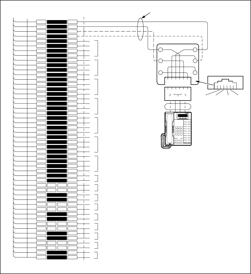
8-7
INSTALLATION-WIRING DIAGRAMS
SECTION 100-816-208
MARCH 1993
FIGURE 8-2
DK8 MDF WIRING TO KSU AMPHENOL STATION AND RELAY CONNECTIONS
1
2
3
4
5
6
7
8
9
10
11
12
13
14
15
16
17
18
19
20
21
22
23
24
25
26
27
28
29
30
31
32
33
34
35
36
37
38
39
40
41
42
43
44
45
46
47
48
49
50
1
2
3
4
5
6
7
8
9
10
11
12
13
14
15
16
17
18
19
20
21
22
23
24
25
26
27
28
29
30
31
32
33
34
35
36
37
38
39
40
41
42
43
44
45
46
47
48
49
50
W-BL
BL-W
W-O
O-W
W-GN
GN-W
W-BR
BR-W
W-S
S-W
R-BL
BL-R
R-O
O-R
R-GN
GN-R
R-BR
BR-R
R-S
S-R
BK-BL
BL-BK
BK-O
O-BK
BK-GN
GN-BK
BK-BR
BR-BK
BK-S
S-BK
Y-BL
BL-Y
Y-O
O-Y
Y-GN
GN-Y
Y-BR
BR-Y
Y-S
S-Y
V-BL
BL-V
V-O
O-V
V-GN
GN-V
V-BR
BR-V
V-S
S-V
26
1
27
2
28
3
29
4
30
5
31
6
32
7
33
8
34
9
35
10
36
11
37
12
38
13
39
14
40
15
41
16
42
17
43
18
44
19
45
20
46
21
47
22
48
23
49
24
50
25
BRIDGING
CLIPS
TO BASE UNIT (P5)
W/FEMALE CONNECTOR
25-PAIR CABLE W/MALE AMP CONNECTOR
66M150 SPLIT BLOCK
CIRCUIT 2 TO DKT2
4
OR PDIU-DS
CIRCUIT 3 TO DKT3
4
OR PDIU-DS OR
DDCB
CIRCUIT 4 TO DKT4
4
OR PDIU-DS OR
DDCB
CIRCUIT 6 TO DKT6
5
OR PDIU-DS
CIRCUIT 7 TO DKT7
5
OR PDIU-DS
CIRCUIT 5 TO DKT5
5
OR PDIU-DS
(-) T1 (VOICE/DATA)
4
(GND) R1 (VOICE/DATA)
(-) PT1 (ADD, POWER)
(GND) PR1 (ADD. POWER)
T2
R2
PT2
PR2
T3
R3
PT3
PR3
T4
R4
PT4
PR4
T5
R5
PT5
PR5
T6
R6
PT6
PR6
T7
R7
PT7
PR7
NOT USED
JACKETED TWISTED PAIRS
24AWG (1 OR 2 PAIR, SEE NOTE 2)
STATION CABLING
GN
654321
Y
BL
R
BK
W
34
R1
PT1
T1
PR1
25
PR TR PT
RJ11
DIGITAL
TELEPHONE (DKT 1)
(WITH OR WITHOUT ADM,
PDIU-DI/PDIU-DI2)
MODULAR
CORD
GND
PR
(-)
T
GND
R
(-)
PT
STD TEL
3
CIRCUIT 1
NOT USED
STD TEL
CIRCUIT 2
OR BGM
NOT USED
R1
T1
R1
T1
CIRCUIT 8 TO DKT8
5
OR PDIU-DS
T8
R8
PT8
PR8
NOTES:
1. Voltage levels:
T, PT = -26.3 ~ 27.8 VDC
R, PR = 0.0 VDC (GND)
(Reference to FG Ground
2. T/R wires are always required; PT/PR are additional power
wires required only for long station runs per Table 8-D.
PT/PR may be used with normal station runs also.
3. Standard Telephone circuits 1 ~ 2 require a QSTU to be
installed.
4. DKT circuits (1 ~ 4) are standard on the DK8 main PCB.
5. DKT circuits (5 ~ 6) require one optional QCDU circuit and
DKT circuit (7 ~ 8) require a second QCDU to be installed.
RELAY
CONTACTS
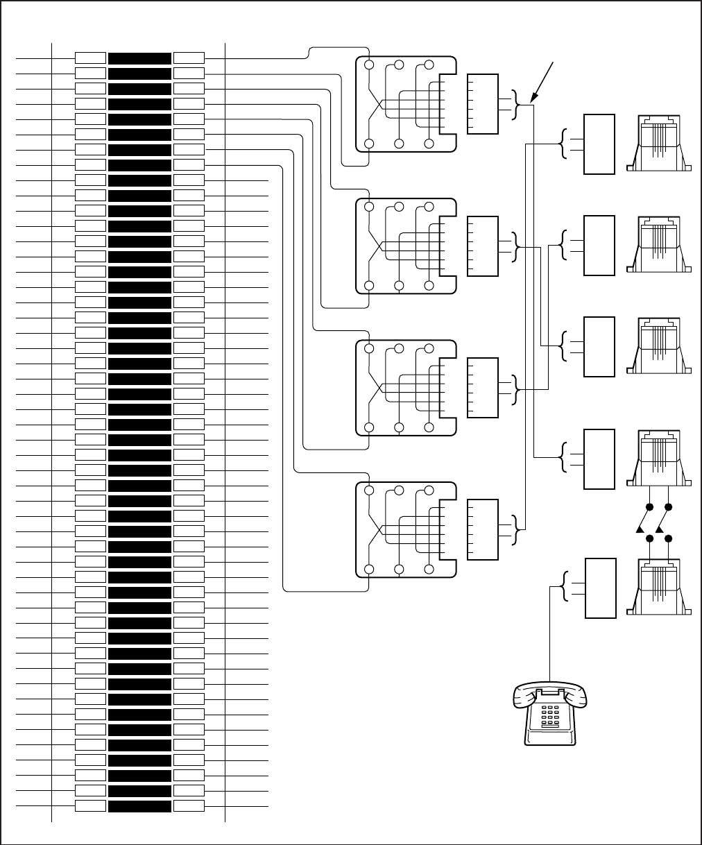
8-8
INSTALLATION-WIRING DIAGRAMS
SECTION 100-816-208
MARCH 1993
FIGURE 8-3
DK8 MDF WIRING TO CO LINES (KSU AND QCDU)
1
2
3
4
5
6
7
8
9
10
11
12
13
14
15
16
17
18
19
20
21
22
23
24
25
26
27
28
29
30
31
32
33
34
35
36
37
38
39
40
41
42
43
44
45
46
47
48
49
50
1
2
3
4
5
6
7
8
9
10
11
12
13
14
15
16
17
18
19
20
21
22
23
24
25
26
27
28
29
30
31
32
33
34
35
36
37
38
39
40
41
42
43
44
45
46
47
48
49
50
BRIDGING
CLIPS
66M150 SPLIT BLOCK
GN
654321
Y
BL
R
BK
W
2345
MODULAR
CORDS
1-6
T1
R1
T2
R2
T3
R3
T4
R4
T1
R1
T2
R2
T3
R3
T4
R4
TO
NETWORK
R1 T1
POWER FAILURE
STANDARD TELEPHONE
CO4
2
GN
654321
Y
BL
R
BK
W
2345
R2 T2
GN
654321
Y
BL
R
BK
W
2345
R3 T3
GN
654321
Y
BL
R
BK
W
2345
R4 T4
4
3
1-6
CO3
2
1-6
CO2
1
1-6
CO1
1
1-6
PFT
1
(BOTTOM)
NETWORK JACK: RJ11
FIC: 02LS2
CO3
CO4
CO2
CO1
RJ11 MODULAR JACKS
R
T
4
3
R
T
4
3
R
T
4
3
R
T
4
3
R
T
NOTES:
1. PFT, CO1, and CO2 modular
jacks are equipped on the main
circuit card of the DK8.
2. CO3 requires one optional
QCDU and CO4 requires a
second QCDU to be installed.
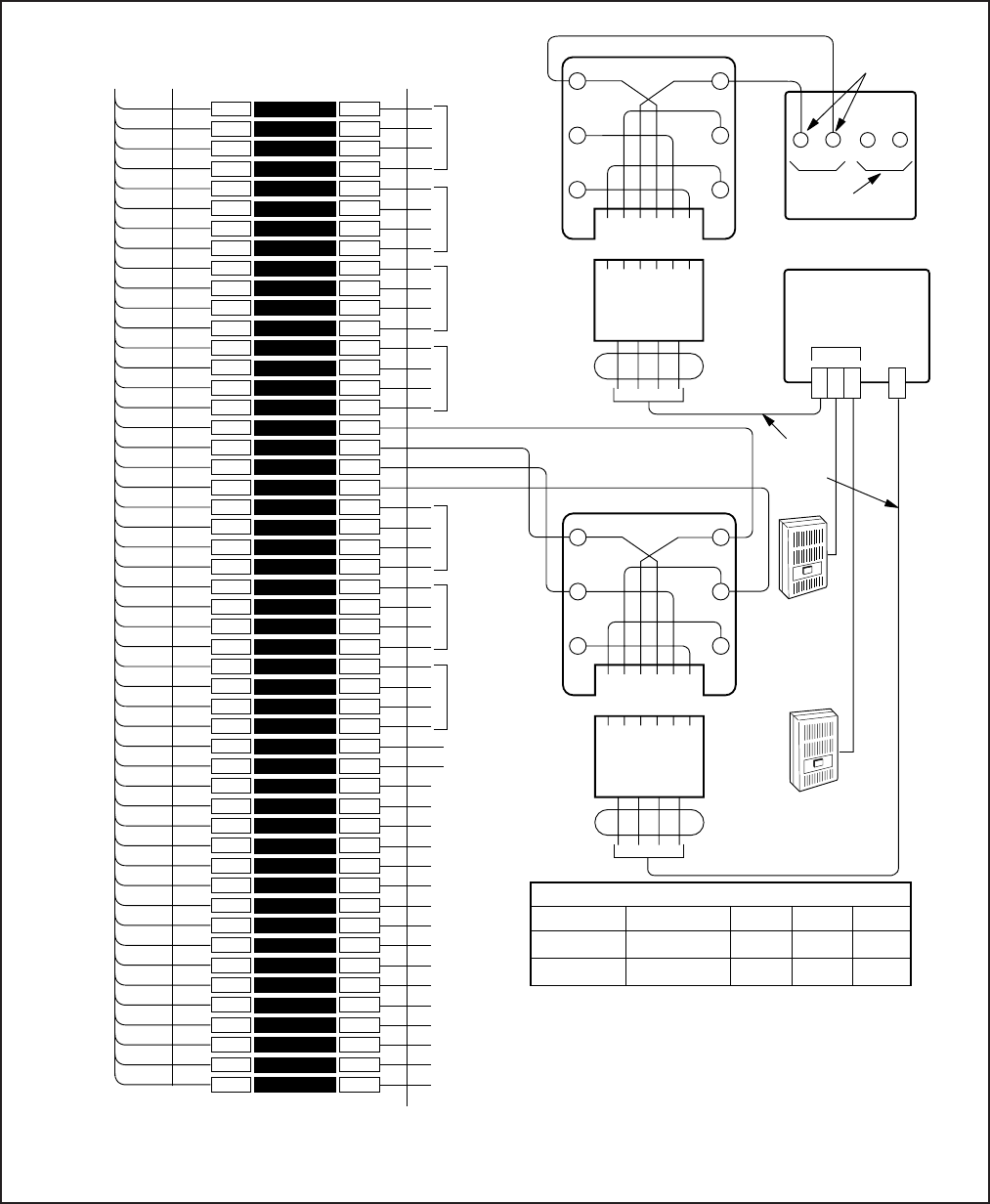
8-9
INSTALLATION-WIRING DIAGRAMS
SECTION 100-816-208
MARCH 1993
FIGURE 8-4
DK8/DK16 MDF WIRING DDCB AND DOOR LOCK CONTROL
1
2
3
4
5
6
7
8
9
10
11
12
13
14
15
16
17
18
19
20
21
22
23
24
25
26
27
28
29
30
31
32
33
34
35
36
37
38
39
40
41
42
43
44
45
46
47
48
49
50
1
2
3
4
5
6
7
8
9
10
11
12
13
14
15
16
17
18
19
20
21
22
23
24
25
26
27
28
29
30
31
32
33
34
35
36
37
38
39
40
41
42
43
44
45
46
47
48
49
50
W-BL
BL-W
W-O
O-W
W-GN
GN-W
W-BR
BR-W
W-S
S-W
R-BL
BL-R
R-O
O-R
R-GN
GN-R
R-BR
BR-R
R-S
S-R
BK-BL
BL-BK
BK-O
O-BK
BK-GN
GN-BK
BK-BR
BR-BK
BK-S
S-BK
Y-BL
BL-Y
Y-O
O-Y
Y-GN
GN-Y
Y-BR
BR-Y
Y-S
S-Y
V-BL
BL-V
V-O
O-V
V-GN
GN-V
V-BR
BR-V
V-S
S-V
26
1
27
2
28
3
29
4
30
5
31
6
32
7
33
8
34
9
35
10
36
11
37
12
38
13
39
14
40
15
41
16
42
17
43
18
44
19
45
20
46
21
47
22
48
23
49
24
50
25
BRIDGINGCLIPS T1
25 PAIR CABLE W/MAIL AMP CONNECTOR
66M150 SPLIT BLOCK
CIRCUIT 2
CIRCUIT 3
(DK8 DDCB)
CIRCUIT 4
(DK8 DDCB)
CIRCUIT 6
CIRCUIT 7
CIRCUIT 8
GN
654321
Y
BL
R
BK
W
2345
MODULAR
CORD
GN
654321
Y
BL
R
BK
W
34
MODULAR
CORD
12L1
L2
NOT
USED
ABC
DOOR PHONE
MDFB
DDCB
HKSU
MDFB
DOOR
PHONE B
OR DOOR
LOCK
CONTROL
MDFB
DOOR
PHONE C
See Note 3 & 4
MDFB (REAR VIEW)
2-PAIR
MODULAR
CORDS
- T5 (VOICE/DATA)
(GND) R5 (VOICE/DATA)
PT 5
PR 5
SCREW
TERMINALS
DOOR PHONE A
DK16 PORT #
4
12
A
551
554
B
552
555
C
553
556
MDFB (DOOR PHONE) STATION NUMBERS
CONNECT
DDCB TO
CIRCUIT 1
OF KCDU
OR PDKU
(SEE TABLE 8-D)
R1
PT1
PR1
TO KCDU OR PDKU IN DK16 EXPANSION
UNIT OR AMPHENOL CONNCECTOR OF
DK8 OR DK16 KSU. W/FEMALE
CONNECTOR
DK8 PORT #
02
03
NOTES:
1. This figure shows DDCB connected to CKT5 of Base Unit
2. DDCB "B" output options:
SW1: Always in DOOR position.
SW2: DOOR position; “B” connects to door phone.
LOCK position; “B” connects to door lock.
3. DDCB may be connected to DK8 circuit 3 (Port 02) and/or
circuit 4 (Port 03)
4. DDCB may be connected to circuit 5, Port 4, of DK16 Base Unit
or circuit 1 (Port 12) of KCDU or PDKU of DK16 Expansion
Unit.
5. See Table 8-D for cable lengths.
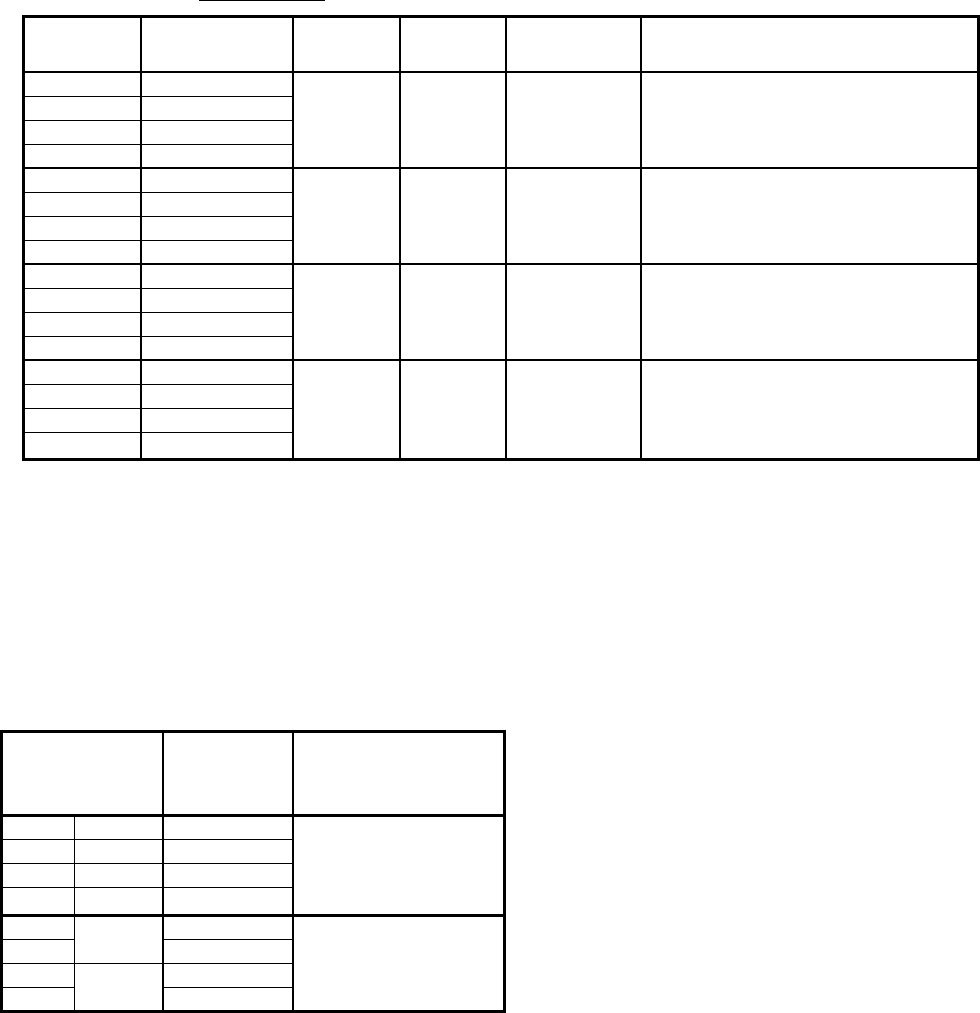
8-10
INSTALLATION-WIRING DIAGRAMS
SECTION 100-816-208
MARCH 1993
FIGURE 8-5
DK8 QSTU/DK16 KSTU STATION/MDF CROSS CONNECT RECORD
FIGURE 8-6
DK8 AND DK16 CO LINE RECORD
1
2
3
4
5
6
7
8
MDF PAIR
NUMBERS
RJ11C/RJ14C CO LINE
NUMBER
BASE UNIT
(KCDU/PCOU)
CO LINE CROSS-CONNECT RECORD
RJ11C
RJ11C
RJ11C
RJ11C
RJ14C
RJ14C
DK8 KSU
DK16 BASE UNIT,
FIXED SLOT 02
KCDU/PCOU
SLOT 04, 05
(DK16 ONLY)
Y-BR
BR-Y
Y-S
S-Y
V-BL
BL-V
V-O
O-V
V-GN
GN-V
V-BR
BR-V
V-S
S-V
COLOR
CODE STANDARD TELEPHONE/
DEVICE LOCATION
T
R
NOT USED
NOT USED
T
R
NOT USED
NOT USED
T
R
NOT USED
NOT USED
T
R
NOT USED
NOT USED
DESIGNATION CKT
NUMBER PORT
NUMBER INTERCOM
NUMBER
1
23
31
41,2
MDF BLOCK NO. KSTU/QSTU
NOTE:
1. Circuit 3 and 4 are available on DK16 KSTU only.
2. Circuit 4 can support a Background Music (BGM) source, KSTU or PSTU, DK16 only.
3. Circuit 2 can support a Background Music (BGM) source, QSTU Port 19, DK8 only.
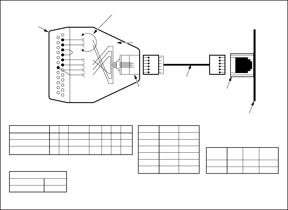
8-11
INSTALLATION-WIRING DIAGRAMS
SECTION 100-816-208
MARCH 1993
FIGURE 8-7
DK8 QSMU TTY/SMDR WIRING
NOTE 1:
TTY
(6-PIN
MODULAR
JACK)
PIN NO.
1
2
3
4
5
6
TTY
TYRD
TYTD
TYDSR
TYDTR
TYCD
TYSG
SMDR
SMRD
SMTD
SMDSR
SMDTR
SMCD
SMSG
NOTE 2: Wire colors may vary with other
types of modular adaptors.
6-1
1
Y
2
3
4
5
6
7
8
13
TD
RD
DSR
SG
CD
DTR
Y
W
G
BL
R
BK
14
20
25
1 (BL)
6 (W) 6-PIN MODULAR
JACK
DB-25 RS-232
(MALE)
PIOU MODULAR PIN-OUT
LEAD NAME
DB25 PINS
MODULAR PINS
WIRE COLOR
TD
2
5
Y
RD
3
6
W
JUMPER
4-5
N/A
BR
DSR
6
4
G
SG
7
1
BL
CD
8
2
BK
DTR
20
3
R
PPTC PIN-OUT
6
1
6
1
TO:
PDIU-DS,
ASCII
TERMINAL,
EXTERNAL
MODEM,
SMDR PRINTER,
OR ACCOUNTING
DEVICE
If connected to an external Hayes compatible
modem, interchange pin 2 and pin 3, and pin 20
and 8. Send AT&C1 ATSO = 1 <ENTER>
command to external modem to track status of
carrier detect signal.
6-WIRE
MODULAR CORD
QSMU TTY/SMDR
6-PIN MODULAR
JACK
QSMU PCB
OPTION
TTY
SMDR
DATA
BITS
7
8
STOP
BITS
1
1
COMMUNICATION PARAMETERS:
PARITY
EVEN
NONE
LED04 ON
LED04 OFF
TTY
SMDR
NOTE: QSMU TTY/SMDR
PROGRAM OPTION:
PROGRAM 10-3 TTY/SMDR SPEED: 1200 BPS
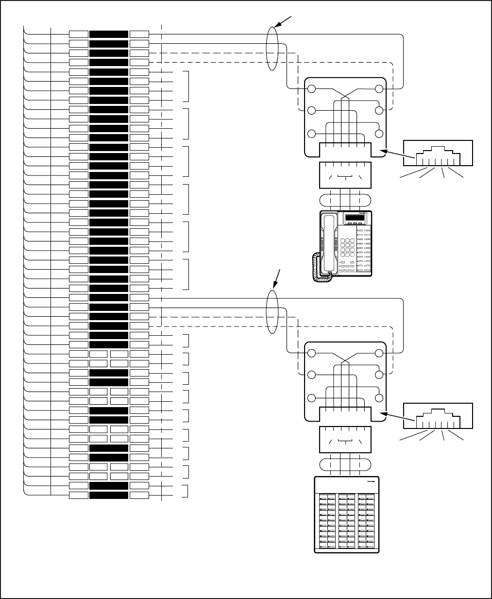
8-12
INSTALLATION-WIRING DIAGRAMS
SECTION 100-816-208
MARCH 1993
1
2
3
4
5
6
7
8
9
10
11
12
13
14
15
16
17
18
19
20
21
22
23
24
25
26
27
28
29
30
31
32
33
34
35
36
37
38
39
40
41
42
43
44
45
46
47
48
49
50
1
2
3
4
5
6
7
8
9
10
11
12
13
14
15
16
17
18
19
20
21
22
23
24
25
26
27
28
29
30
31
32
33
34
35
36
37
38
39
40
41
42
43
44
45
46
47
48
49
50
W-BL
BL-W
W-O
O-W
W-GN
GN-W
W-BR
BR-W
W-S
S-W
R-BL
BL-R
R-O
O-R
R-GN
GN-R
R-BR
BR-R
R-S
S-R
BK-BL
BL-BK
BK-O
O-BK
BK-GN
GN-BK
BK-BR
BR-BK
BK-S
S-BK
Y-BL
BL-Y
Y-O
O-Y
Y-GN
GN-Y
Y-BR
BR-Y
Y-S
S-Y
V-BL
BL-V
V-O
O-V
V-GN
GN-V
V-BR
BR-V
V-S
S-V
26
1
27
2
28
3
29
4
30
5
31
6
32
7
33
8
34
9
35
10
36
11
37
12
38
13
39
14
40
15
41
16
42
17
43
18
44
19
45
20
46
21
47
22
48
23
49
24
50
25
BRIDGING
CLIPS
TO BASE UNIT (P5)
W/FEMALE CONNECTOR
25-PAIR CABLE W/MALE AMP CONNECTOR
66M150 SPLIT BLOCK
CIRCUIT 2 TO DKT2
OR PDIU-DS
CIRCUIT 3 TO DKT3
OR PDIU-DS
CIRCUIT 4 TO DKT4
OR PDIU-DS
CIRCUIT 6 TO DKT6
OR PDIU-DS
CIRCUIT 7 TO DKT7
OR PDIU-DS
CIRCUIT 5 TO DKT5
OR PDIU-DS
OR DDCB
(-) T1 (VOICE/DATA)
(GND) R1 (VOICE/DATA)
(-) PT1 (ADD, POWER)
(GND) PR1 (ADD. POWER)
T2
R2
PT2
PR2
T3
R3
PT3
PR3
T4
R4
PT4
PR4
T5
R5
PT5
PR5
T6
R6
PT6
PR6
T7
R7
PT7
PR7
(-) T8 (VOICE/DATA)
(GND) R8 (VOICE/DATA)
(-) PT (ADD, POWER)
(GND) PR (ADD. POWER)
NOT USED
NOTES:
Voltage levels:
T, PT =
R, PR =
(Reference to FG ground)
-26.3 ~ 27.8 VDC
0.0 VDC (GND)
T/R wires are always required; PT/PR are additional power wires required only for
long station runs per Table 8-D. PT/PR may be used with normal station runs also.
Standard Telephone circuits 1 ~ 4 require a KSTU in the base unit.
1.
2.
3.
GN
654321
Y
BL
R
BK
W
34
R8
PT8
T8
PR8
25
PR TR PT
JACKETED TWISTED PAIRS
24AWG (1 OR 2 PAIR, SEE NOTE 2)
STATION CABLING
GN
654321
Y
BL
R
BK
W
34
R1
PT1
T1
PR1
25
PR TR PT
RJ11
RJ11
DIGITAL
TELEPHONE (DKT 1)
(WITH OR WITHOUT
PDIU-DI/PDIU-DI2)
DDSS/BLF CONSOLE
(CIRCUIT 8 0NLY)
— OR —
DIGITAL
TELEPHONE (DKT 8)
(SEE
NOTE 2)
MODULAR
CORD
MODULAR
CORD
GND
PR
(-)
T
GND
R
(-)
PT
GND
PR
(-)
T
GND
R
(-)
PT
RELAY CONTACT
STD TEL
CIRCUIT 1
NOT USED
STD TEL
CIRCUIT 2
NOT USED
STD TEL
CIRCUIT 3
NOT USED
STD TEL CIRCUIT 4
OR OPTIONAL BGM
SOURCE
R1
T1
R1
T1
R3
T3
R4
T4
209
208
207
206
205
204
203
202
201
200
219
218
217
216
215
214
213
212
211
210
229
228
227
226
225
224
223
222
221
220
239
238
237
236
235
234
233
232
231
230
249
248
247
246
245
244
243
242
241
240
Night 1
All Call
257
256
255
254
253
252
251
250
— OR —
PDIU-DS
FIGURE 8-8
DK16 MDF WIRING/BASE UNIT P5 AMPHENOL STATION AND RELAY CONNECTIONS
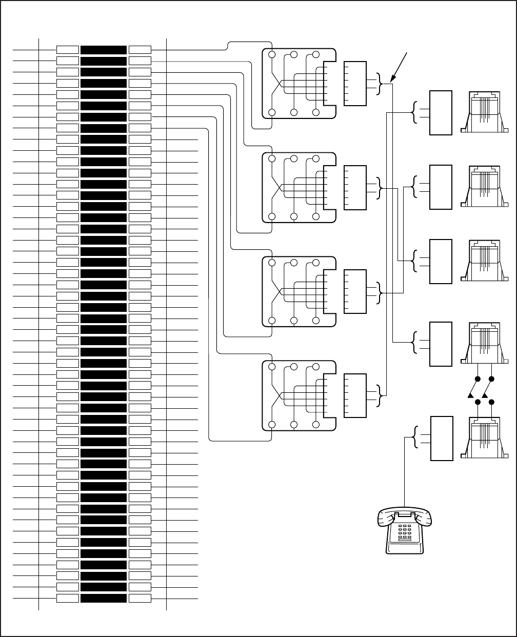
8-13
INSTALLATION-WIRING DIAGRAMS
SECTION 100-816-208
MARCH 1993
1
2
3
4
5
6
7
8
9
10
11
12
13
14
15
16
17
18
19
20
21
22
23
24
25
26
27
28
29
30
31
32
33
34
35
36
37
38
39
40
41
42
43
44
45
46
47
48
49
50
1
2
3
4
5
6
7
8
9
10
11
12
13
14
15
16
17
18
19
20
21
22
23
24
25
26
27
28
29
30
31
32
33
34
35
36
37
38
39
40
41
42
43
44
45
46
47
48
49
50
BRIDGING
CLIPS
66M150 SPLIT BLOCK
GN
654321
Y
BL
R
BK
W
2345
MODULAR
CORDS
1-6
T1
R1
T2
R2
T3
R3
T4
R4
T1
R1
T2
R2
T3
R3
T4
R4
TO
NETWORK
R1 T1
DK16 BASE UNIT
MAIN CIRCUIT
BOARD MODULAR
JACKS (TOP)
POWER FAILURE
STANDARD TELEPHONE
CO4
GN
654321
Y
BL
R
BK
W
2345
R2 T2
GN
654321
Y
BL
R
BK
W
2345
R3 T3
GN
654321
Y
BL
R
BK
W
2345
R4 T4
4
3
1-6
CO3
1-6
CO2
1-6
CO1
1-6
PFT
(BOTTOM)
NETWORK JACK: RJ11
FIC: 02LS2
CO3
CO4
CO2
CO1
RJ11 MODULAR JACKS
R
T
4
3
R
T
4
3
R
T
4
3
R
T
4
3
R
T
FIGURE 8-9
DK16 MDF WIRING/CO LINES TO BASE UNIT
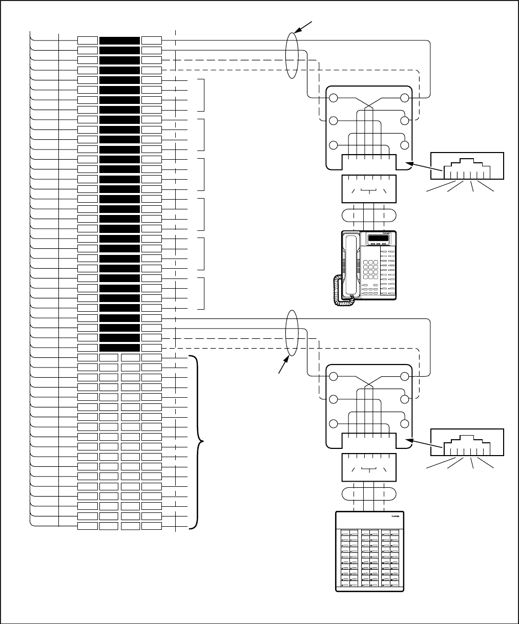
8-14
INSTALLATION-WIRING DIAGRAMS
SECTION 100-816-208
MARCH 1993
1
2
3
4
5
6
7
8
9
10
11
12
13
14
15
16
17
18
19
20
21
22
23
24
25
26
27
28
29
30
31
32
33
34
35
36
37
38
39
40
41
42
43
44
45
46
47
48
49
50
1
2
3
4
5
6
7
8
9
10
11
12
13
14
15
16
17
18
19
20
21
22
23
24
25
26
27
28
29
30
31
32
33
34
35
36
37
38
39
40
41
42
43
44
45
46
47
48
49
50
W-BL
BL-W
W-O
O-W
W-GN
GN-W
W-BR
BR-W
W-S
S-W
R-BL
BL-R
R-O
O-R
R-GN
GN-R
R-BR
BR-R
R-S
S-R
BK-BL
BL-BK
BK-O
O-BK
BK-GN
GN-BK
BK-BR
BR-BK
BK-S
S-BK
Y-BL
BL-Y
Y-O
O-Y
Y-GN
GN-Y
Y-BR
BR-Y
Y-S
S-Y
V-BL
BL-V
V-O
O-V
V-GN
GN-V
V-BR
BR-V
V-S
S-V
26
1
27
2
28
3
29
4
30
5
31
6
32
7
33
8
34
9
35
10
36
11
37
12
38
13
39
14
40
15
41
16
42
17
43
18
44
19
45
20
46
21
47
22
48
23
49
24
50
25
BRIDGING
CLIPS
TO PDKU
W/FEMALE CONNECTOR
25-PAIR CABLE W/MALE AMP CONNECTOR
66M150 SPLIT BLOCK
CIRCUIT 2 TO DKT2
OR PDIU-DS
CIRCUIT 3 TO DKT3
OR PDIU-DS
CIRCUIT 4 TO DKT4
OR PDIU-DS
CIRCUIT 6 TO DKT6
OR PDIU-DS
CIRCUIT 7 TO DKT7
OR PDIU-DS
CIRCUIT 5 TO DKT5
OR PDIU-DS
(-) T1 (VOICE/DATA)
(GND) R1 (VOICE/DATA)
(-) PT1 (ADD, POWER)
(GND) PR1 (ADD. POWER)
T2
R2
PT2
PR2
T3
R3
PT3
PR3
T4
R4
PT4
PR4
T5
R5
PT5
PR5
T6
R6
PT6
PR6
T7
R7
PT7
PR7
(-) T8 (VOICE/DATA)
(GND) R8 (VOICE/DATA)
(-) PT (ADD, POWER)
(GND) PR (ADD. POWER)
NOT USED
NOTES:
Voltage levels:
T, PT =
R, PR =
(Reference to FG ground)
-26.3 ~ 27.8 VDC
0.0 VDC (GND)
T/R wires are always required; PT/PR are additional power wires required only for
lon
g
station runs per Table 8-D. PT/PR ma
y
be used with normal station runs also.
1.
2.
GN
654321
Y
BL
R
BK
W
34
R8
PT8
T8
PR8
25
PR TR PT
JACKETED TWISTED PAIRS
24AWG (1 OR 2 PAIR, SEE NOTE 2)
STATION CABLING
GN
654321
Y
BL
R
BK
W
34
R1
PT1
T1
PR1
25
PR TR PT
RJ11
RJ11
DIGITAL
TELEPHONE (DKT 1)
DDSS/BLF CONSOLE
(CIRCUIT 8 0NLY)
— OR —
DIGITAL
TELEPHONE (DKT 8)
(SEE NOTE 2)
MODULAR
CORD
MODULAR
CORD
GND
PR
(-)
T
GND
R
(-)
PT
GND
PR
(-)
T
GND
R
(-)
PT
209
208
207
206
205
204
203
202
201
200
219
218
217
216
215
214
213
212
211
210
229
228
227
226
225
224
223
222
221
220
239
238
237
236
235
234
233
232
231
230
249
248
247
246
245
244
243
242
241
240
Night 1
All Call
257
256
255
254
253
252
251
250
— OR —
PDIU-DS (WITH PDKU2)
FIGURE 8-10
DK16 MDF WIRING FOR DIGITAL TELEPHONES (DKTS) AND DIGITAL DSS CONSOLE (DDSS) TO PDKU
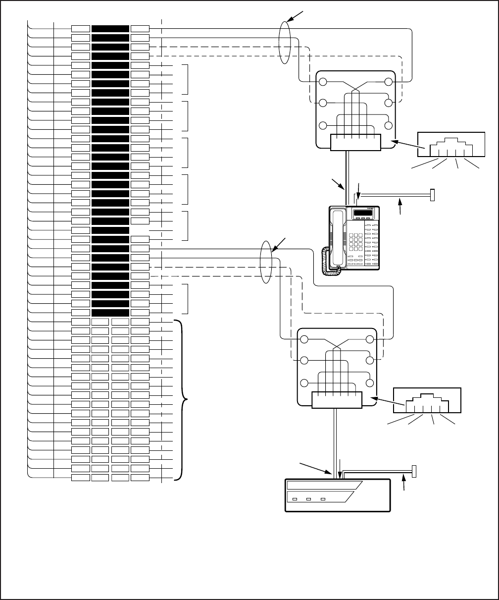
8-15
INSTALLATION-WIRING DIAGRAMS
SECTION 100-816-208
MARCH 1993
NOTES:
1.
2.
3
4.
5.
Voltage levels:
T, PT = -26.3 ~ 27.8 VDC
R, PR = 0.0 VDC (GND)
(Reference to SG ground)
T/R wires are always required; PT/PR are additional power wires required only for long station runs or when operating on
reserve power per Table 8-D. PT/PR may be used with normal station runs also.
RS-232 cable length is max 50 ft with 24 AWG wire.
DIUs can be connected to circuits 1 ~ 7 with PDKU1; all Base Unit, KCDU, and PDKU2 digital circuits support DIUs.
Expansion Unit slots 04 and 05 only can support DIU.
KCDU provides circuits 1 ~ 4 only.
1
2
3
4
5
6
7
8
9
10
11
12
13
14
15
16
17
18
19
20
21
22
23
24
25
26
27
28
29
30
31
32
33
34
35
36
37
38
39
40
41
42
43
44
45
46
47
48
49
50
1
2
3
4
5
6
7
8
9
10
11
12
13
14
15
16
17
18
19
20
21
22
23
24
25
26
27
28
29
30
31
32
33
34
35
36
37
38
39
40
41
42
43
44
45
46
47
48
49
50
W-BL
BL-W
W-O
O-W
W-GN
GN-W
W-BR
BR-W
W-S
S-W
R-BL
BL-R
R-O
O-R
R-GN
GN-R
R-BR
BR-R
R-S
S-R
BK-BL
BL-BK
BK-O
O-BK
BK-GN
GN-BK
BK-BR
BR-BK
BK-S
S-BK
Y-BL
BL-Y
Y-O
O-Y
Y-GN
GN-Y
Y-BR
BR-Y
Y-S
S-Y
V-BL
BL-V
V-O
O-V
V-GN
GN-V
V-BR
BR-V
V-S
S-V
26
1
27
2
28
3
29
4
30
5
31
6
32
7
33
8
34
9
35
10
36
11
37
12
38
13
39
14
40
15
41
16
42
17
43
18
44
19
45
20
46
21
47
22
48
23
49
24
50
25
BRIDGING
CLIPS
TO PDKU/KCDU/BASE UNIT
W/FEMALE CONNECTOR
25-PAIR CABLE W/MALE AMP CONNECTOR
66M150 SPLIT BLOCK
CIRCUIT 2 TO DKT2
OR PDIU-DS
CIRCUIT 3 TO DKT3
OR PDIU-DS
CIRCUIT 4 TO DKT4
OR PDIU-DS
CIRCUIT 6 TO DKT6
OR PDIU-DS
CIRCUIT 5 TO DKT5
OR PDIU-DS
(-) T1 (VOICE/DATA)
(GND) R1 (VOICE/DATA)
(-) PT1 (ADD, POWER)
(GND) PR1 (ADD. POWER)
T2
R2
PT2
PR2
T3
R3
PT3
PR3
T4
R4
PT4
PR4
T5
R5
PT5
PR5
T6
R6
PT6
PR6
CIRCUIT 8 TO DKT8
OR DDSS
T8
R8
PT8
PR8
NOT USED
GN
654321
Y
BL
R
BK
W
T8
PR8
JACKETED TWISTED PAIRS
24AWG (1 OR 2 PAIR, SEE NOTE 2)
STATION CABLING
GN
654321
Y
BL
R
BK
W
R1
PT1
T1
PR1
GND
PR
(-)
T
GND
R
(-)
PT
(-)
T
GND
R
(-)
PT
RJ11
RJ11
DIGITAL
TELEPHONE (DKT 1)
(WITH OR WITHOUT
PDIU-DI/PDIU-DI2)
2- OR 4-WIRE
MODULAR CORD
TO RJ11 JACK
ON BOTTOM
OF PDIU-DI/
PDIU-DI2
(-) T7 (VOICE/DATA)
(GND) R7 (VOICE/DATA)
(-) PT (ADD, POWER)
(GND) PR (ADD. POWER)
R8
PT8
(SEE NOTE 2)
DB-25
FEMALE
CONNECTOR
RS-232
CABLE
(SEE SECTION 100-016-207)
3
TO PERSONAL
COMPUTER
OR ASCII
TERMINAL, ETC.
2- OR 4-WIRE
MODULAR CORD
TO RJ11 JACK ON
THE BACK SIDE
OF PDIU-DS
DB-25
FEMALE CONNECTOR
RS-232
CABLE
(SEE SECTION 100-016-207)
3
TO MODEM, PRINTER,
OR HOST COMPUTER
ETC.
GND
PR
DIU
POWER READY CONNECT
TOSHIBA
PDIU-DS
FIGURE 8-11
DK16 MDF WIRING FOR DIGITAL TELEPHONES (DKTS) WITH PDIU-DI/PDIU-DI2 AND PDIU-DS TO
PDKU, KCDU, OR BASE UNIT

8-16
INSTALLATION-WIRING DIAGRAMS
SECTION 100-816-208
MARCH 1993
W-Bl
Bl-W
W-O
O-W
W-G
G-W
W-Br
Br-W
W-S
S-W
R- Bl
Bl-R
R-O
O-R
R-G
G-R
R-Br
Br-R
R-S
S-R
Bk-Bl
Bl-Bk
Bk-O
O-Bk
Bk-G
G-Bk
Bk-Br
Br-Bk
Bk-S
S-Bk
Y-Bl
Bl-Y
COLOR
CODE DIGITAL TELEPHONE/
DEVICE LOCATION
T
R
PWR T
PWR R
T
R
PWR T
PWR R
T
R
PWR T
PWR R
T
R
PWR T
PWR R
T
R
PWR T
PWR R
T
R
PWR T
PWR R
T
R
PWR T
PWR R
T
R
PWR T
PWR R
DESIGNATION CKT
NUMBER PORT
NUMBER INTERCOM
NUMBER
1
2
3
4
5
6
7
8
MDF BLOCK NO. SLOT NO.
NOTES:
1. Indicate if PDIU-DS, digital telephone (with or without PDIU-DI/PDIU-DI2 or ADM) or DDSS console
(number 1 or 2) is connected.
2. PDIU-DS and PDIU-DI/PDIU-DI2 can be connected to circuits 1 ~ 7 only on PDKU1; all Base Unit,
KCDU, and PDKU2 digital circuits support DIUs.
3. Expansion Unit slots 04 and 05 only can support DIUs.
4. For KCDU, only ckt number 1 thru 4 apply.
5. Make copies as necessary.
6. PDKU and KCDU Circuit 1 can support DDCB. Base Unit Circuit 5 can support DDCB.
7. DK8 circuit 3 and or circuit 4 can support DDCB.
6
6
7
7
FIGURE 8-12
DK8 OR DK16 PDKU, KCDU, DK8 KSU OR DK16 BASE KSU DIGITAL STATION/MDF
CROSS CONNECT RECORD
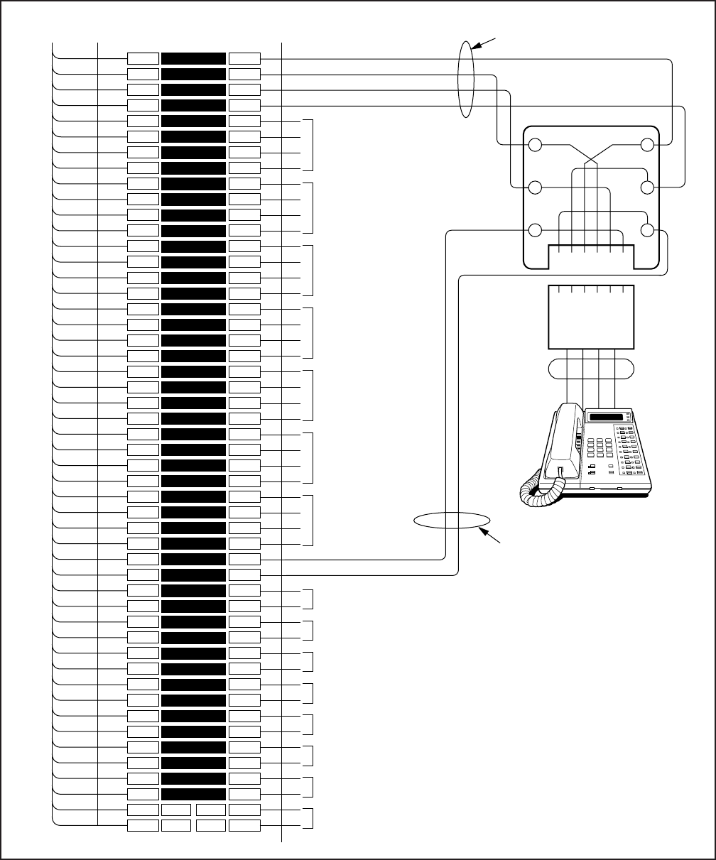
8-17
INSTALLATION-WIRING DIAGRAMS
SECTION 100-816-208
MARCH 1993
FIGURE 8-13
DK16 MDF WIRING/ELECTRONIC TELEPHONE TO PEKU
1
2
3
4
5
6
7
8
9
10
11
12
13
14
15
16
17
18
19
20
21
22
23
24
25
26
27
28
29
30
31
32
33
34
35
36
37
38
39
40
41
42
43
44
45
46
47
48
49
50
1
2
3
4
5
6
7
8
9
10
11
12
13
14
15
16
17
18
19
20
21
22
23
24
25
26
27
28
29
30
31
32
33
34
35
36
37
38
39
40
41
42
43
44
45
46
47
48
49
50
W-BL
BL-W
W-O
O-W
W-GN
GN-W
W-BR
BR-W
W-S
S-W
R-BL
BL-R
R-O
O-R
R-GN
GN-R
R-BR
BR-R
R-S
S-R
BK-BL
BL-BK
BK-O
O-BK
BK-GN
GN-BK
BK-BR
BR-BK
BK-S
S-BK
Y-BL
BL-Y
Y-O
O-Y
Y-GN
GN-Y
Y-BR
BR-Y
Y-S
S-Y
V-BL
BL-V
V-O
O-V
V-GN
GN-V
V-BR
BR-V
V-S
S-V
26
1
27
2
28
3
29
4
30
5
31
6
32
7
33
8
34
9
35
10
36
11
37
12
38
13
39
14
40
15
41
16
42
17
43
18
44
19
45
20
46
21
47
22
48
23
49
24
50
25
BRIDGING
CLIPS
TO PEKU W/FEMALE
CONNECTOR
25-PAIR CABLE W/MALE AMP CONNECTOR
66M150 SPLIT BLOCK
CIRCUIT 2
CIRCUIT 3
CIRCUIT 4
CIRCUIT 5
CIRCUIT 6
CIRCUIT 7
CIRCUIT 8
NOT USED
CIRCUIT 2
CIRCUIT 3
CIRCUIT 4
CIRCUIT 5
CIRCUIT 6
CIRCUIT 7
CIRCUIT 8
GN
654321
Y
BL
R
BK
W
123456
OCA T1 (OT)
OCA R1 (OR)
VOICE T1 (VT)
VOICE R1 (VR)
DATA T1 (DT)
DATA R1 (DR)
JACKETED TWISTED PAIRS
24 AWG
MODULAR
CORD STATION
ONLY IF ELECTRONIC TELEPHONE
RECEIVES "OFF-HOOK" CALLS
To receive OCA, the 6500-series electronic telephone
must have HVSU2 subassembly or combined
HVSU/HVSI subassemblies installed.
Program 31, button/LED 03 must be “on” for
electronic telephone to receive OCA.
1.
2.
3.
4.
NOTES:
ELECTRONIC
TELEPHONE
STATION CABLING
VT
VR
DT
DR
VT
VR
DT
DR
VT
VR
DT
DR
VT
VR
DT
DR
VT
VR
DT
DR
VT
VR
DT
DR
VT
VR
DT
DR
OT
OR
OT
OR
OT
OR
OT
OR
OT
OR
OT
OR
OT
OR
DT
OCAT OCAR
DR
VR VT
All cable 24 AWG, max 40 ohm loop resistance from
PEKU to electronic telephone (1000 ft).
An HHEU must be installed inside 6500-series
electronic telephones for headset or HESB,
loud bell option.
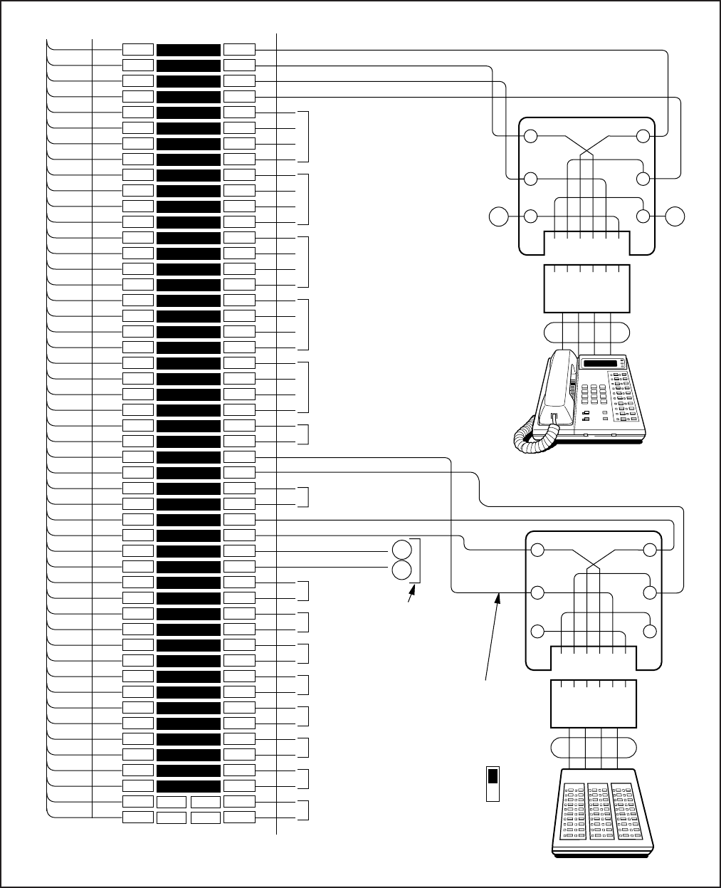
8-18
INSTALLATION-WIRING DIAGRAMS
SECTION 100-816-208
MARCH 1993
1
2
3
4
5
6
7
8
9
10
11
12
13
14
15
16
17
18
19
20
21
22
23
24
25
26
27
28
29
30
31
32
33
34
35
36
37
38
39
40
41
42
43
44
45
46
47
48
49
50
1
2
3
4
5
6
7
8
9
10
11
12
13
14
15
16
17
18
19
20
21
22
23
24
25
26
27
28
29
30
31
32
33
34
35
36
37
38
39
40
41
42
43
44
45
46
47
48
49
50
W-BL
BL-W
W-O
O-W
W-GN
GN-W
W-BR
BR-W
W-S
S-W
R-BL
BL-R
R-O
O-R
R-GN
GN-R
R-BR
BR-R
R-S
S-R
BK-BL
BL-BK
BK-O
O-BK
BK-GN
GN-BK
BK-BR
BR-BK
BK-S
S-BK
Y-BL
BL-Y
Y-O
O-Y
Y-GN
GN-Y
Y-BR
BR-Y
Y-S
S-Y
V-BL
BL-V
V-O
O-V
V-GN
GN-V
V-BR
BR-V
V-S
S-V
26
1
27
2
28
3
29
4
30
5
31
6
32
7
33
8
34
9
35
10
36
11
37
12
38
13
39
14
40
15
41
16
42
17
43
18
44
19
45
20
46
21
47
22
48
23
49
24
50
25
BRIDGING
CLIPS
TO PEKU W/FEMALE
CONNECTOR
25 PAIR CABLE W/MALE AMP CONNECTOR
66M150 SPLIT BLOCK
CIRCUIT 2
CIRCUIT 3
CIRCUIT 4
CIRCUIT 5
CIRCUIT 6
CIRCUIT 7
CIRCUIT 8
NOT USED
CIRCUIT 2
CIRCUIT 3
CIRCUIT 4
CIRCUIT 5
CIRCUIT 6
OCA T1
OCA R1
VOICE T1
VOICE R1
DATA T1
DATA R1
GN
654321
Y
BL
R
BK
W
123456
MODULAR
CORD STATION
GN
654321
Y
BL
R
BK
W
2345
MODULAR
CORD
ELECTRONIC
TELEPHONE
ASSOCIATED
WITH HDSS
HDSS/BLF CONSOLE
X
Y
XY
DSS
EKT
SW1
NOTE: Place
PEKU SW1 to DSS.
CIRCUITS 7&8 T/R
PAIR ORDER MUST BE
WIRED AS SHOWN
T7
R8 T8
R7
ONLY IF
ELECTRONIC
TELEPHONE
RECEIVES
OFF-HOOK CALLS
DATA TIP 8
DATA RING 8
VOICE PAIR-NOT USED
CIRCUIT 8
VOICE PAIR-NOT USED
CIRCUIT 7 DATA TIP 7
DATA RING 7
JACKETED
STATION CABLE
TWISTED PAIR
24 AWG
NOTE: See Program 28
for electronic telephone
to DSS assignments.
TO
OCA
T1
TO
OCA
R1
NOTE: All cable 24 AWG max
loop resistance: 20 ohms
from PEKU to DSS (500 ft).
NOTE: See Program 29 to assign DSS buttons.
FIGURE 8-14
DK16 MDF WIRING/HDSS CONSOLE AND ASSOCIATED ELECTRONIC TELEPHONE WIRING TO PEKU
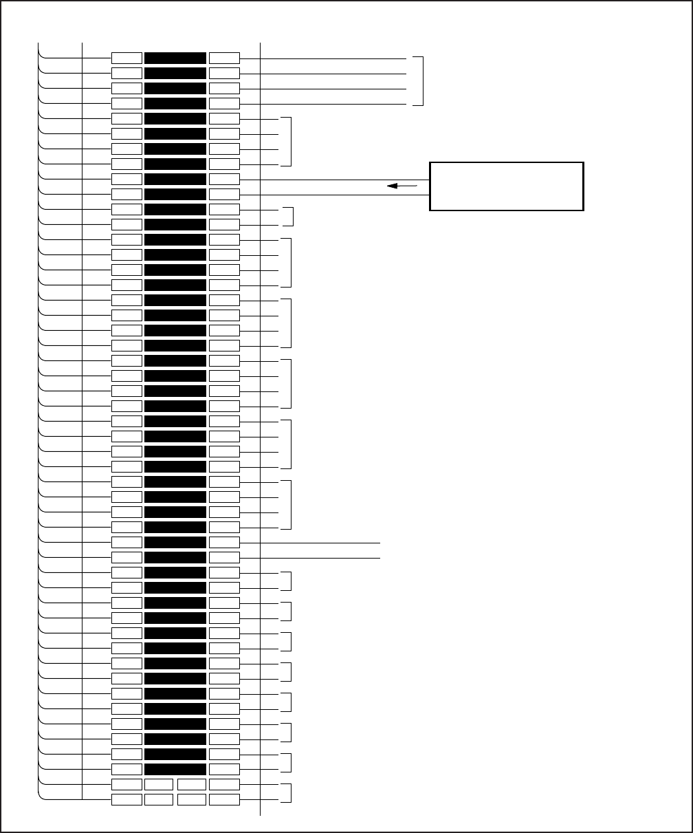
8-19
INSTALLATION-WIRING DIAGRAMS
SECTION 100-816-208
MARCH 1993
FIGURE 8-15
DK16 PEKU BACKGROUND MUSIC CONNECTION
1
2
3
4
5
6
7
8
9
10
11
12
13
14
15
16
17
18
19
20
21
22
23
24
25
26
27
28
29
30
31
32
33
34
35
36
37
38
39
40
41
42
43
44
45
46
47
48
49
50
1
2
3
4
5
6
7
8
9
10
11
12
13
14
15
16
17
18
19
20
21
22
23
24
25
26
27
28
29
30
31
32
33
34
35
36
37
38
39
40
41
42
43
44
45
46
47
48
49
50
W-BL
BL-W
W-O
O-W
W-GN
GN-W
W-BR
BR-W
W-S
S-W
R-BL
BL-R
R-O
O-R
R-GN
GN-R
R-BR
BR-R
R-S
S-R
BK-BL
BL-BK
BK-O
O-BK
BK-GN
GN-BK
BK-BR
BR-BK
BK-S
S-BK
Y-BL
BL-Y
Y-O
O-Y
Y-GN
GN-Y
Y-BR
BR-Y
Y-S
S-Y
V-BL
BL-V
V-O
O-V
V-GN
GN-V
V-BR
BR-V
V-S
S-V
26
1
27
2
28
3
29
4
30
5
31
6
32
7
33
8
34
9
35
10
36
11
37
12
38
13
39
14
40
15
41
16
42
17
43
18
44
19
45
20
46
21
47
22
48
23
49
24
50
25
BRIDGING
CLIPS
TO PEKU W/FEMALE
CONNECTOR
25-PAIR CABLE W/MALE AMP CONNECTOR
66M150 SPLIT BLOCK
CIRCUIT 2 TO ELECTRONIC TELEPHONES THAT RECEIVE OCA
CIRCUIT 3 TO ELECTRONIC TELEPHONES THAT RECEIVE OCA
CIRCUIT 4 TO ELECTRONIC TELEPHONES THAT RECEIVE OCA
CIRCUIT 2 TO ELECTRONIC
TELEPHONE
CIRCUIT 4 TO ELECTRONIC
TELEPHONE
CIRCUIT 5 TO ELECTRONIC
TELEPHONE
CIRCUIT 6 TO
ELECTRONIC
TELEPHONE
CIRCUIT 7 TO
ELECTRONIC
TELEPHONE
OR HDSS
CIRCUIT 8 TO
ELECTRONIC
TELEPHONE
OR HDSS
OCA T1 (OT)
OCA R1 (OR) TO ELECTRONIC TELEPHONES THAT RECEIVE OCA
VOICE T1 (VT)
VOICE R1 (VR)
DATA T1 (DT)
DATA R1 (DR)
Program 10-2, button/LED 09 "on", for
BGM connection to port 02. See Program 19 for
slot assignment.
Cut W5 jumper on PEKU.
Provide BGM to electronic telephone speakers
and external page.
1.
2.
3.
4.
NOTES:
STATION CABLING (24 AWG, TWISTED PAIRS)
VT2
VR2
DT2
DR2
VT3
VR3
DT3
DR3
VT
VR
DT
DR
VT
VR
DT
DR
VT
VR
DT
DR
VT
VR
DT
DR
VT
VR
DT
DR
OT
OR
OT
OR
OT
OR
OT
OR
OT
OR
OT
OR
OT
OR
NOT USED
TO ELECTRONIC TELEPHONE
CIRCUIT 5 TO ELECTRONIC TELEPHONES THAT RECEIVE OCA
CIRCUIT 6 TO ELECTRONIC TELEPHONES THAT RECEIVE OCA
CIRCUIT 7 TO ELECTRONIC TELEPHONES THAT RECEIVE OCA
CIRCUIT 8 TO ELECTRONIC TELEPHONES THAT RECEIVE OCA
NOT USED
BACKGROUND MUSIC
SOURCE OUTPUT
(600 OHMS; 1V RMS MAX)
Volume is adjusted at BGM source
only (not at PEKU).

8-20
INSTALLATION-WIRING DIAGRAMS
SECTION 100-816-208
MARCH 1993
W-Bl
Bl-W
W-O
O-W
W-G
G-W
W-Br
Br-W
W-S
S-W
R- Bl
Bl-R
R-O
O-R
R-G
G-R
R-Br
Br-R
R-S
S-R
Bk-Bl
Bl-Bk
Bk-O
O-Bk
Bk-G
G-Bk
Bk-Br
Br-Bk
Bk-S
S-Bk
Y-Bl
Bl-Y
COLOR
CODE
VT
VR
DT
DR
ELECTRONIC TELEPHONE/
DEVICE LOCATION
VT
VR
DT
DR
VT
VR
DT
DR
VT
VR
DT
DR
VT
VR
DT
DR
VT
VR
DT
DR
VT
VR
DT
DR
VT
VR
DT
DR
DESIGNATION CKT
NUMBER PORT
NUMBER INTERCOM
NUMBER
1
2
3
4
5
6
7
8
MDF BLOCK NO. SLOT NO.
1
2
2
NOTES:
1. Indicate if BGM or electronic telephone is connected (see Program 10-2 and 19); BGM connects to VT
and VR, circuit 3 only (DT and DR not used).
2. Indicate if electronic telephone or HDSS console.
3. OCA wirin
g
not shown, see MDF-to-electronic telephone wirin
g
.
FIGURE 8-16
DK16 PEKU STATION/MDF CROSS CONNECT RECORD
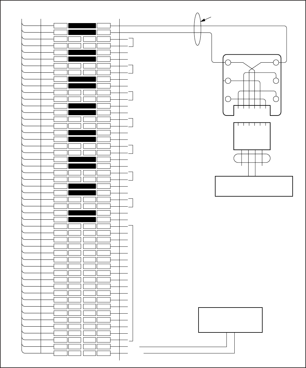
8-21
INSTALLATION-WIRING DIAGRAMS
SECTION 100-816-208
MARCH 1993
FIGURE 8-17
DK16 MDF WIRING/STANDARD TELEPHONE, VOICE MAIL TO PSTU
1
2
3
4
5
6
7
8
9
10
11
12
13
14
15
16
17
18
19
20
21
22
23
24
25
26
27
28
29
30
31
32
33
34
35
36
37
38
39
40
41
42
43
44
45
46
47
48
49
50
1
2
3
4
5
6
7
8
9
10
11
12
13
14
15
16
17
18
19
20
21
22
23
24
25
26
27
28
29
30
31
32
33
34
35
36
37
38
39
40
41
42
43
44
45
46
47
48
49
50
W-BL
BL-W
W-O
O-W
W-GN
GN-W
W-BR
BR-W
W-S
S-W
R-BL
BL-R
R-O
O-R
R-GN
GN-R
R-BR
BR-R
R-S
S-R
BK-BL
BL-BK
BK-O
O-BK
BK-GN
GN-BK
BK-BR
BR-BK
BK-S
S-BK
Y-BL
BL-Y
Y-O
O-Y
Y-GN
GN-Y
Y-BR
BR-Y
Y-S
S-Y
V-BL
BL-V
V-O
O-V
V-GN
GN-V
V-BR
BR-V
V-S
S-V
26
1
27
2
28
3
29
4
30
5
31
6
32
7
33
8
34
9
35
10
36
11
37
12
38
13
39
14
40
15
41
16
42
17
43
18
44
19
45
20
46
21
47
22
48
23
49
24
50
25
BRIDGING
CLIPS
TO PSTU
W/FEMALE CONNECTOR
25-PAIR CABLE W/MALE AMP CONNECTOR
66M150 SPLIT BLOCK
GN
654321
Y
BL
R
BK
W
123456
JACKETED TWISTED STATION CABLE
24 AWG
MODULAR
CORD
TIP 1
RING 1
STANDARD TELEPHONE,
VOICE MAIL PORT, OR
SIMILAR DEVICE
T2
R2
T3
R3
T4
R4
T5
R5
T6
R6
T7
R7
T8
R8
NOT USED
NOT USED
NOT USED
NOT USED
NOT USED
NOT USED
NOT USED
DG
-24 V
NOT USED
TIP RING
DPFT
POWER FAILURE
TRANSFER BOX
(J1)
DG
(J1, 50) -24 VOLTS
(J1, 25)
NOTES:
1. All cable 24 AWG; max loop resistance -
300 ohms from PSTU to standard
telephone/VM port.
2. Standard telephones may be on- or
off-premises. Off-premises connection
is made via OL13A FIC, and RJ21X jack.
3. Connect up to two telephone ringers
to each Tip and Ring pair.
4. W1, ring voltage option;
L = 130V P-P
H = 190V P-P
5. Two ringers maximum per port, "H" or "L"
position.
(ckt 3 CAN SUPPORT BGM)
(ckt 8 CAN
SUPPORT BGM)

8-22
INSTALLATION-WIRING DIAGRAMS
SECTION 100-816-208
MARCH 1993
W-Bl
Bl-W
W-O
O-W
W-G
G-W
W-Br
Br-W
W-S
S-W
R- Bl
Bl-R
R-O
O-R
R-G
G-R
R-Br
Br-R
R-S
S-R
Bk-Bl
Bl-Bk
Bk-O
O-Bk
Bk-G
G-Bk
Bk-Br
Br-Bk
Bk-S
S-Bk
Y-Bl
Bl-Y
COLOR
CODE STANDARD TELEPHONE/
DEVICE LOCATION
T
R
NOT USED
NOT USED
T
R
NOT USED
NOT USED
T
R
NOT USED
NOT USED
T
R
NOT USED
NOT USED
T
R
NOT USED
NOT USED
T
R
NOT USED
NOT USED
T
R
NOT USED
NOT USED
T
R
NOT USED
NOT USED
DESIGNATION CKT
NUMBER PORT
NUMBER INTERCOM
NUMBER
1
2
3
4
5
6
7
8
NOTES:
1. Indicate if standard telephone, voice mail port, etc.
2. Circuit 3 or 8 can support a Back
g
round Music
(
BGM
)
source.
2
2
MDF BLOCK NO. DKSU SLOT NO.
FIGURE 8-18
DK16 PSTU STATION/MDF CROSS CONNECT RECORD
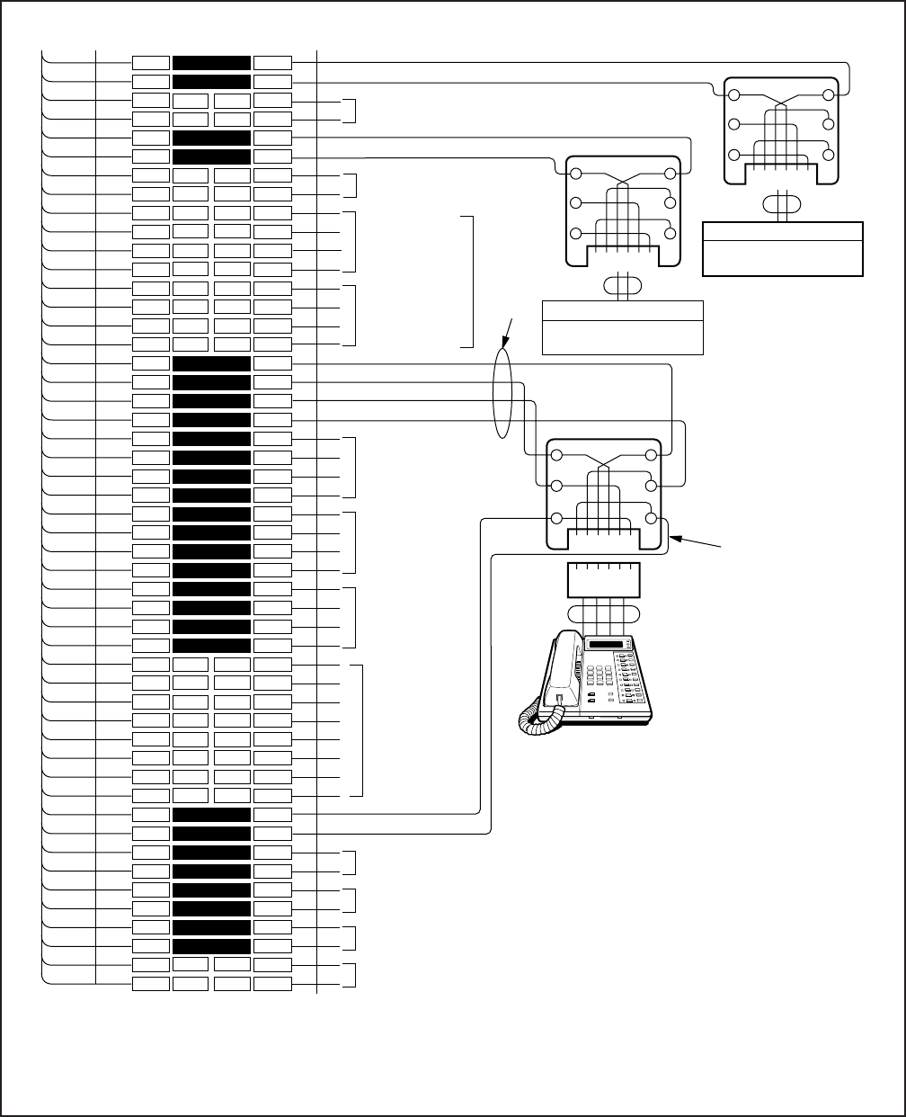
8-23
INSTALLATION-WIRING DIAGRAMS
SECTION 100-816-208
MARCH 1993
1
2
3
4
5
6
7
8
9
10
11
12
13
14
15
16
17
18
19
20
21
22
23
24
25
26
27
28
29
30
31
32
33
34
35
36
37
38
39
40
41
42
43
44
45
46
47
48
49
50
1
2
3
4
5
6
7
8
9
10
11
12
13
14
15
16
17
18
19
20
21
22
23
24
25
26
27
28
29
30
31
32
33
34
35
36
37
38
39
40
41
42
43
44
45
46
47
48
49
50
W-BL
BL-W
W-O
O-W
W-GN
GN-W
W-BR
BR-W
W-S
S-W
R-BL
BL-R
R-O
O-R
R-GN
GN-R
R-BR
BR-R
R-S
S-R
BK-BL
BL-BK
BK-O
O-BK
BK-GN
GN-BK
BK-BR
BR-BK
BK-S
S-BK
Y-BL
BL-Y
Y-O
O-Y
Y-GN
GN-Y
Y-BR
BR-Y
Y-S
S-Y
V-BL
BL-V
V-O
O-V
V-GN
GN-V
V-BR
BR-V
V-S
S-V
26
1
27
2
28
3
29
4
30
5
31
6
32
7
33
8
34
9
35
10
36
11
37
12
38
13
39
14
40
15
41
16
42
17
43
18
44
19
45
20
46
21
47
22
48
23
49
24
50
25
BRIDGING CLIPS
TO PESU W/FEMALE
CONNECTOR
25-PAIR CABLE W/MALE AMP CONNECTOR
66M150 SPLIT BLOCK
CIRCUIT 3
NOT USED
CIRCUIT 4
NOT USED
CIRCUIT 6
TO ELECTRONIC
TELEPHONE 2
CIRCUIT 8 TO
ELECTRONIC
TELEPHONE 4
OR BGM
(NOTE 5)
OCA T1 (OT) 5
OCA R1 (OR) 5
VT
VR
DT
DR
TIP 1
RING 1
GN
Y
BL
R
BK
W
NOT USED
NOT USED
(PORTS COUNT
IN SOFTWARE)
654321
654321
GN
654321
Y
BL
R
BK
W
123456
24
AWG
MODULAR
CORD STATION
DT
OCAT OCAR
DR
VR VT
RJ11
OT AND OR:
ONLY IF
ELECTRONIC
TELEPHONE
RECEIVES
OFF-HOOK CALL
ANNOUNCE CALLS
VOICE MAIL PORT OR
SIMILAR DEVICE
VOICE MAIL PORT OR
SIMILAR DEVICE
RJ11
RJ11
VT
VR
DT
DR
VT
VR
DT
DR
OT
OR
OT
OR
OT
OR
VOICE T1 (VT) 5
VOICE R1 (VR) 5
DATA T1 (DT) 5
DATA R1 (DR) 5
RING
TIP
TIP
RING
STANDARD TELEPHONE 2
STANDARD TELEPHONE 1
RING 2
TIP 2
CIRCUIT 7 TO
ELECTRONIC
TELEPHONE 3
GN
Y
BL
R
BK
W
STRAP OPTION:
P90 - RING VOLTAGE OPTION (CIRCUIT 1 & 2):
L = LOW LEVEL (130V P-P)
H = HIGH LEVEL (190V P-P)
NOTE:
Two-ringers max may be
connected (high or low)
to Tip/Ring.
NOT USED
NOT USED
CIRCUIT 6
CIRCUIT 7
CIRCUIT 8
ELECTRONIC TELEPHONE
(NOTE 5)
STATION CABLING JACKETED TWISTED PAIRS (24 AWG)
1.
2.
3.
4.
5.
NOTES: (Electronic telephone Circuits 5~8)
To receive OCA, the 6500-series electronic telephone must
have an HVSU2 or the combined HVSI and HVSU installed.
Program 31
, button/LED 03 must be “on” for electronic
telephone to receive OCA.
An HHEU must be installed inside 6500-series electronic
telephones for headset or HESB; Loud Ringing Bell option.
All cable 24 AWG, max 40 ohm loop resistance from PESU
to electronic telephone (1000 ft).
HDSS connection is not available with PESU.
1.
2.
3.
4.
NOTES: (Standard telephone circuits 1 & 2)
All cable 24 AWG; max loop resistance - 300 ohms from PESU to standard telephone/VM port.
Standard telephones may be on- or off-premises. Off-premises connection is made via OL13A FIC, and RJ21X jack.
Two ringers max per port.
Circuit 6 and 7 can provide interface for an external conference amplifier (Prog 10-3).
FIGURE 8-19
DK16 PESU CIRCUIT CARD WIRING DIAGRAM

8-24
INSTALLATION-WIRING DIAGRAMS
SECTION 100-816-208
MARCH 1993
W-Bl
Bl-W
W-O
O-W
W-G
G-W
W-Br
Br-W
W-S
S-W
R- Bl
Bl-R
R-O
O-R
R-G
G-R
R-Br
Br-R
R-S
S-R
Bk-Bl
Bl-Bk
Bk-O
O-Bk
Bk-G
G-Bk
Bk-Br
Br-Bk
Bk-S
S-Bk
Y-Bl
Bl-Y
COLOR
CODE
T
R
NOT USED
NOT USED
DEVICE/STANDARD TELEPHONE/
ELECTRONIC TELEPHONE LOCATION
T
R
NOT USED
NOT USED
NOT USED
NOT USED
NOT USED
NOT USED
NOT USED
NOT USED
NOT USED
NOT USED
VT
VR
DT
DR
VT
VR
DT
DR
VT
VR
DT
DR
VT
VR
DT
DR
DESIGNATION CKT
NUMBER PORT
NUMBER INTERCOM
NUMBER
1
2
3
4
5
6
7
8
MDF BLOCK NO.
NOTES:
1. HDSS is not allowed.
2. Indicate if external amplifier is connected.
3. Indicate if BGM or electronic telephone is connected; BGM connects to VT and VR,
circuit 8 only (DT and DR not used).
4. OCA wiring not shown, see MDF-to-electronic telephone wiring.
N/A
N/A
N/A
N/A
1, 3
1, 2
2
FIGURE 8-20
DK16 PESU STATION/MDF CROSS CONNECT RECORD
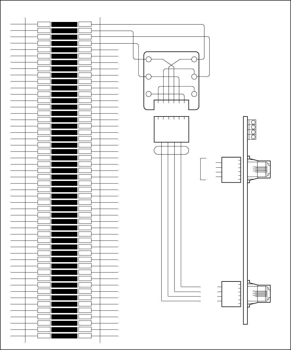
8-25
INSTALLATION-WIRING DIAGRAMS
SECTION 100-816-208
MARCH 1993
1
2
3
4
5
6
7
8
9
10
11
12
13
14
15
16
17
18
19
20
21
22
23
24
25
26
27
28
29
30
31
32
33
34
35
36
37
38
39
40
41
42
43
44
45
46
47
48
49
50
1
2
3
4
5
6
7
8
9
10
11
12
13
14
15
16
17
18
19
20
21
22
23
24
25
26
27
28
29
30
31
32
33
34
35
36
37
38
39
40
41
42
43
44
45
46
47
48
49
50
BRIDGING
CLIPS
66M150 SPLIT BLOCK
GN
654321
Y
BL
R
BK
W
2345
MODULAR
CORD
1-6
1
2
3456
1-6
T1
R1
T2
R2
T1
R1
T2
R2
TO
NETWORK
R1
R2
T1
T2
TELCO-PROVIDED
MODULAR BLOCK,
625-TYPE OR
EQUIVALENT
PCOU
#4
#3
#2
#1
CO3+4
SAME
R4
R3
T3
T4
5
4
3
2
R2
R1
T1
T2
5
4
3
2
CO1+2
PCOU
PIN-OUT
NETWORK JACK: RJ14C
FIC: 02LS2
1
2
3456
FIGURE 8-21
DK16 MDF WIRING/CO LINES TO PCOU
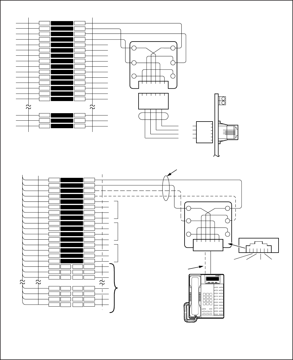
8-26
INSTALLATION-WIRING DIAGRAMS
SECTION 100-816-208
MARCH 1993
FIGURE 8-22
DK16 MDF WIRING/CO LINES AND DIGITAL TELEPHONES TO KCDU
1
2
3
4
5
6
7
8
9
10
11
12
13
14
15
16
17
18
19
47
48
49
50
1
2
3
4
5
6
7
8
9
10
11
12
13
14
15
16
17
18
19
47
48
49
50
W-BL
BL-W
W-O
O-W
W-GN
GN-W
W-BR
BR-W
W-S
S-W
R-BL
BL-R
R-O
O-R
R-GN
GN-R
R-BR
BR-R
R-S
V-BR
BR-V
V-S
S-V
26
1
27
2
28
3
29
4
30
5
31
6
32
7
33
8
34
9
35
49
24
50
25
BRIDGING
CLIPS
TO KCDU
W/FEMALE CONNECTOR
25-PAIR CABLE W/MALE AMP CONNECTOR
66M150 SPLIT BLOCK
CIRCUIT 2 TO DKT2
OR PDIU-DS
CIRCUIT 3 TO DKT3
OR PDIU-DS
CIRCUIT 4 TO DKT4
OR PDIU-DS
(-) T1 (VOICE/DATA)
(GND) R1 (VOICE/DATA)
(-) PT1 (ADD, POWER)
(GND) PR1 (ADD. POWER)
T2
R2
PT2
PR2
T3
R3
PT3
PR3
T4
R4
PT4
PR4
NOT USED
NOTES:
Voltage levels:
T, PT =
R, PR =
(Reference to SG ground)
-26.3 ~ 27.8 VDC
0.0 VDC (GND)
T/R wires are always required; PT/PR are additional power wires required only for long station runs or when operating
on reserve power per Table 8-D. PT/PR may be used with normal station runs also.
ADMs and/or DIUs can be connected to circuits 1 ~ 4, DDCB can be connected to Circuit 1.
1.
2.
3.
JACKETED TWISTED PAIRS
24AWG (1 OR 2 PAIR, SEE NOTE 2)
STATION CABLING
GN
654321
Y
BL
R
BK
W
R1
PT1
T1
PR1
RJ11
DIGITAL
TELEPHONE
(WITH OR WITHOUT
PDIU-DI/PDIU-DI2) OR
PDIU-DS
- or -
DDCB
2- OR 4-WIRE
MODULAR CORD
TO RJ11 JACK
ON BOTTOM
OF PDIU-DI
GND
PR (5)
(-)
T (4)
GND
R (3)
(-)
PT (2)
1
2
3
4
5
6
7
8
9
10
11
12
13
14
15
48
49
50
1
2
3
4
5
6
7
8
9
10
11
12
13
14
15
48
49
50
BRIDGING
CLIPS
66M150 SPLIT BLOCK
GN
654321
Y
BL
R
BK
W
2345
MODULAR
CORD
1-6
T1
R1
T2
R2
T1
R1
T2
R2
TO
NETWORK
R1
R2
T1
T2
KCDU
CO2 LED
CO1 LED
CO1+2
MODULAR
JACK
R2
R1
T1
T2
5
4
3
2
KCDU
PIN-OUT
1
2
3456
NETWORK JACK: RJ14C
FIC: 02LS2
CO LINE CABLING
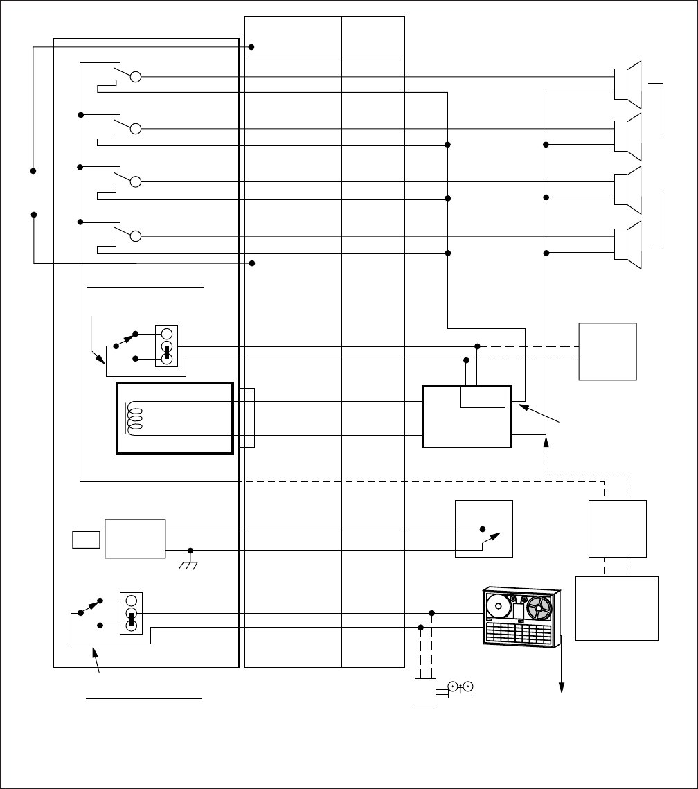
8-27
INSTALLATION-WIRING DIAGRAMS
SECTION 100-816-208
MARCH 1993
PIOU 25PR.
CONNECTIONS
PIN COLOR
MDF 66M
BLOCK
PIN
PG.OUT 1
PG.IN 1
PIOU PCB
15
40
17
42
19
44
21
46
S-Bk
Bk-S
O-Y
Y-O
Br-Y
Y-Br
Bl-V
V-Bl
30
29
34
33
38
37
42
41
.
.
.
.
.
.
.
.
ZONE (35)
ZONE (36)
ZONE (37)
ZONE (38)
ALL
ZONE
PAGE
(39)
MULTI-ZONE PAGE
30W MAX./COMPOSITE IMPEDANCE
300 OHMS
DOOR
LOCK
CONTROL
AMPLIFIER
MULTI-ZONE
SELECT RELAY FUNCTION
WITH PROGRAM 77-1
DOOR LOCK OR
AMP. CONTROL
BREAK
PI0
MAKE
BASE UNIT
600Ω (DUPLEX)
P12
N.C.
N.O.
ALARM
SENSOR
P11
BREAK
MAKE
ALARM
SYSTEM
NIGHT
BELL
TO MUSIC-ON-HOLD
INPUT ON P6 CONNECTOR
ON BASE UNIT.
MDF
CONNECTIONS
ALL WIRES SHOULD
BE JACKETED 24 AWG.
TWISTED PAIRS
SELECT RELAY FUNCTION
WITH PROGRAM 77-1:
NIGHT RELAY OR
MOH CONTROL
TAPE
PLAYER
32
7
23
36
11
34
9
R-O
O-R
Gn-V
Bk-Bl
Bl-Bk
R-Br
Br-R
13
14
46
21
22
17
18
.
.
.
.
.
.
.
COMMON
AMP.
EXTERNAL
BACKGROUND
MUSIC
SOURCE
CONTROL
RCA JACK
PIOU
ONLY
MUTE
PG.OUT 2
PG.IN 2
PG.OUT 3
PG.IN 3
PG.OUT 4
PG.IN 4
MUTE CONTROL ALSO
PROVIDED BY BASE
UNIT PAGE RELAY
(PIN 42 AND 17 OF
P5 AMPHENOL)
J 7
NOTE:
This figure shows PIOU relay callouts. See Chapter 5 for PIOUS relay callouts.
FIGURE 8-23
DK16 MDF WIRING/PIOU PERIPHERALS (25-PAIR)
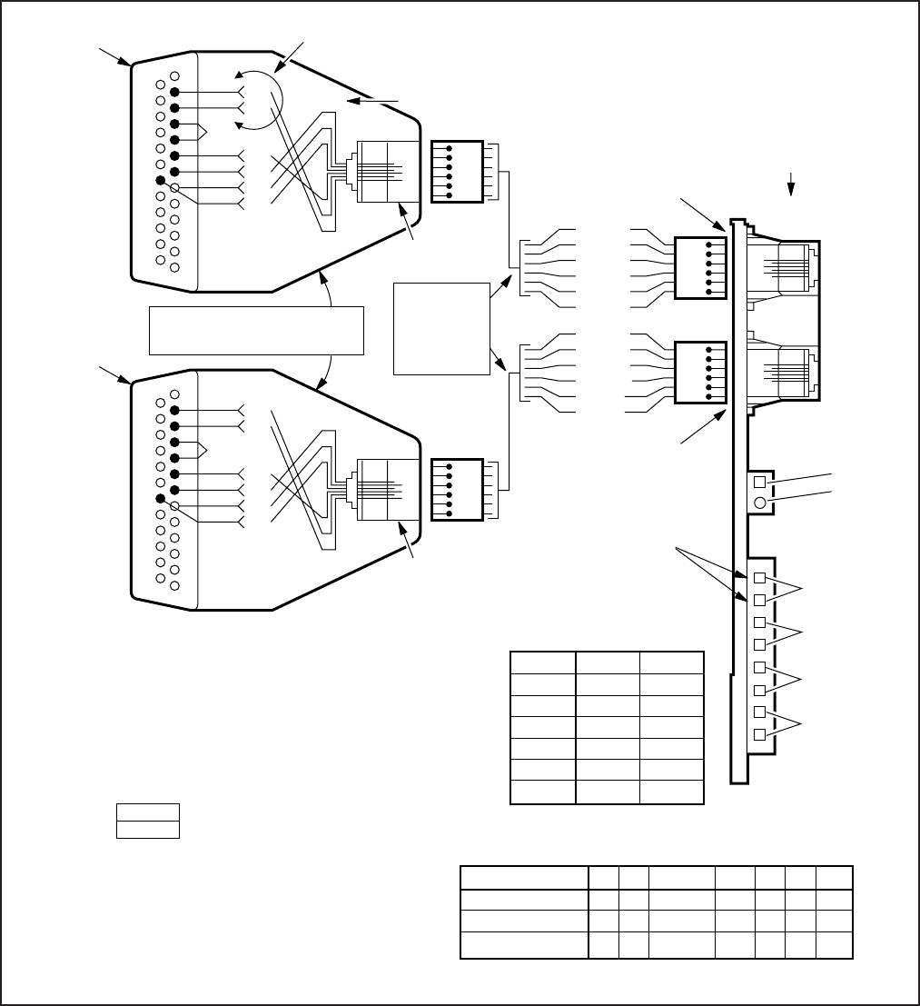
8-28
INSTALLATION-WIRING DIAGRAMS
SECTION 100-816-208
MARCH 1993
PDIU-DS,
TO ASCII
TERMINAL,
OR
EXTERNAL
MODEM
TTY
(IMDU)
(6-PIN
MODULAR
JACK)
SMDR
(6-PIN
MODULAR
JACK)
SW2
LED
CD4
600 OHM
PAGE
LEAD NAME
DB25 PINS
MODULAR PINS
WIRE COLOR
TD
2
5
Y
RD
3
6
W
JUMPER
4-5
N/A
BR
DSR
6
4
G
SG
7
1
BL
CD
8
2
BK
DTR
20
3
R
PIN NO.
1
2
3
4
5
6
TTY
TYRD
TYTD
TYDSR
TYDTR
TYCD
TYSG
SMDR
SMRD
SMTD
SMDSR
SMDTR
SMCD
SMSG
STATION MESSAGE
DETAIL RECORDING
PORT
TO PRINTER
PDIU-DS,
OR CALL
ACCOUNTING
DEVICE
TYSG
TYCD
TYDTR
TYDSR
TYTD
TYRD
1-6
6-1
1
Y
2
3
4
5
6
7
8
13
TD
RD
DSR
SG
CD
DTR
Y
W
G
BL
R
BK
14
20
25
1 (BL)
6 (W) 6-PIN MODULAR
JACK
SMSG
SMCD
SMDTR
SMDSR
SMTD
SMRD
1-6
1
Y
2
3
4
5
6
7
8
13
TD
RD
DSR
SG
CD
DTR
Y
W
G
BL
BK
R
14
20
25
1 (BL)
6 (W)
6-1
6-PIN MODULAR
JACK
MAINTENANCE
PORT
PIOUS
CARD
DB-25 RS-232
(MALE)
DB-25 RS-232
(MALE)
TOSHIBA RS-232/MODULAR
ADAPTOR PART NO. PPTC
PIOU MODULAR PIN-OUT
PPTC PIN-OUT
6
1
6
1
6
1
6
1
TB1 TO MDF:
DOOR LOCK/
AMP, MUTE
NIGHT
RELAY/ MOH
CONTROL
ALARM
3-PAIR
MODULAR
CORD MAX.
50 FT WITH
24 AWG
• 7–BIT
• EVEN PARITY
• 1–STOP
• 8–BIT
• NO–PARITY
• 1–STOP BIT
NOTE 1: If connected to external modem, interchange pin 2 and pin 3,
and pin 20 and 8. Send AT&C1 command to external modem
to track status of carrier detect signal.
NOTE 3: PIOUS option settings:
Sets the SMDR baud rate
to be 300 or 1200 BPS.
Sets the PIOU programming speed to be
300 or 1200 BPS (for IMDU or TTY jack).
LED CO4 “On” = 300 BPS/SW2 set “In”.
LED CO4 “Off” = 1200 BPS/SW2 set “Out”.
Sets the PIOUS to operate with the
IMDU or an external device
connected to the TTY modular jack.
SW1 –
SW2 –
SW3 –
For IMDU operation (7, even, 1)
For ASCII terminal (8, none, 1)
or external modem (8, none, 1).
MODEM
TTY
–
–
NOTE 2: Wire colors may vary with other
types of modular adaptors.
Sets the IMDU and TTY jack
for bell or CCITT specification.
"W4 not installed".
W4 –
BELL -
NOTE: 600 ohm Page
is not functional
on DK16
NOTE 4: PDIU-DS jumpers should be set to
the B-C position when connected
to the PIOUS TTY or SMDR port.
FIGURE 8-24
DK16 PIOUS/TTY AND SMDR WIRING
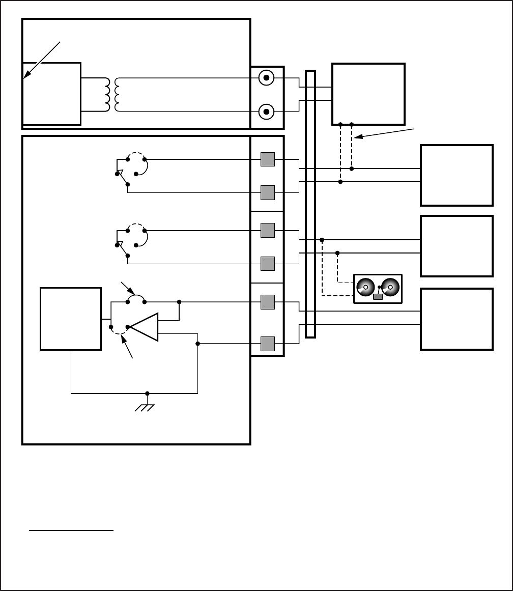
8-29
INSTALLATION-WIRING DIAGRAMS
SECTION 100-816-208
MARCH 1993
PAGE
AND
BGM
ALARM
SENSOR
NORMAL
CLOSE
NORMAL OPEN
ALMT
ALMR
NHR
NHT
DER
DET
RCA PAGE JACK J7
BASE UNIT
BREAK
W1
MAKE
K1
W2
K2
W3
PIOUS
ALM
NH
DE
600Ω
HESB
OR
PAGE
AMPLIFIER
DOOR
LOCK
CONTROL
MOH
SOURCE
UNIT
FACILITY
ALARM
UNIT
NIGHT BELL
RELAY OPTIONS:
• K1 (DE): DOOR LOCK OR AMP MUTE CONTROL; PROGRAM 77-1, LED 07
• K2 (NH): NIGHT RELAY OR MUSIC-ON-HOLD CONTROL; PROGRAM 77-1, LED 05
• K1 & K2: 24 VDC, 1 AMP MAXIMUM
BREAK
MAKE
MUTE
CONTROL
KSU BACKPLANE
All wiring connections must be 24 AWG twisted pairs.
Dotted lines show optional connections; only one optional connection is allowed.
•
•
MDF
Amplifier mute
control can also
be provided by
Page relay in
Base Units (Pin 42
and 17 of P5
amphenol
connector).
FIGURE 8-25
DK16 PIOUS PAGE/RELAY/ALARM CONNECTIONS
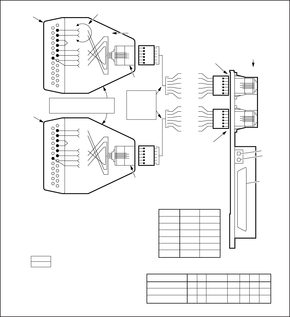
8-30
INSTALLATION-WIRING DIAGRAMS
SECTION 100-816-208
MARCH 1993
FIGURE 8-26
DK16 PIOU SMDR/TTY OPTIONS AND WIRING
NOTE 1:
TTY
(6-PIN
MODULAR
JACK)
SMDR
(6-PIN
MODULAR
JACK)
SW2
LED
CD4
(25-PAIR
FEMALE
AMP.
JACK)
SEE
PIOU/MDF
DRAWING
IN THIS
SECTION
LEAD NAME
DB25 PINS
MODULAR PINS
WIRE COLOR
TD
2
5
Y
RD
3
6
W
JUMPER
4-5
N/A
BR
DSR
6
4
G
SG
7
1
BL
CD
8
2
BK
DTR
20
3
R
PIN NO.
1
2
3
4
5
6
TTY
TYRD
TYTD
TYDSR
TYDTR
TYCD
TYSG
SMDR
SMRD
SMTD
SMDSR
SMDTR
SMCD
SMSG
NOTE 3: PIOU option settings:
Sets the SMDR baud rate
to be 300 or 1200 BPS.
Sets the PIOU programming speed to be
300 or 1200 BPS (for IMDU or TTY jack).
LED CO4 “On” = 300 BPS/SW2 set “In”.
LED CO4 “Off” = 1200 BPS/SW2 set “Out”.
Sets the PIOU to operate with the
IMDU or an external device
connected to the TTY modular jack.
SW1 –
SW2 –
SW3 –
For IMDU operation (7, even, 1)
For ASCII terminal (8, none, 1)
or external modem (8, none, 1).
MODEM
TTY
–
–
STATION MESSAGE
DETAIL RECORDING
PORT
NOTE 2: Wire colors may vary with other
types of modular adaptors.
TYSG
TYCD
TYDTR
TYDSR
TYTD
TYRD
1-6
6-1
1
Y
2
3
4
5
6
7
8
13
TD
RD
DSR
SG
CD
DTR
Y
W
G
BL
R
BK
14
20
25
1 (BL)
6 (W) 6-PIN MODULAR
JACK
SMSG
SMCD
SMDTR
SMDSR
SMTD
SMRD
1-6
1
Y
2
3
4
5
6
7
8
13
TD
RD
DSR
SG
CD
DTR
Y
W
G
BL
BK
R
14
20
25
1 (BL)
6 (W)
6-1
6-PIN MODULAR
JACK
MAINTENANCE
PORT PIOU
CARD
DB-25 RS-232
(MALE)
DB-25 RS-232
(MALE)
3-PAIR
MODULAR
CORD MAX.
50 FT WITH
24 AWG
TOSHIBA RS-232/MODULAR
ADAPTOR PART NO. PPTC
PIOU MODULAR PIN-OUT
PPTC PIN-OUT
Sets the IMDU and TTY jack
for bell or CCITT specification.
P13 –
6
1
6
1
6
1
6
1
• 7–BIT
• EVEN PARITY
• 1–STOP BIT
• 8–BIT
• NO PARITY
• 1–STOP BIT
PDIU-DS,
TO ASCII
TERMINAL,
OR
EXTERNAL
MODEM
TO PRINTER
PDIU-DS,
OR CALL
ACCOUNTING
DEVICE
NOTE 4: PDIU-DS jumpers should be set to
the B-C position when connected t
o the PIOU TTY or SMDR port.
If connected to an external Hayes compatible modem, interchange pin 2
and pin 3, and pin 20 and 8. Send AT&C1 8D2SO = 6AW <ENTER>
command to external modem
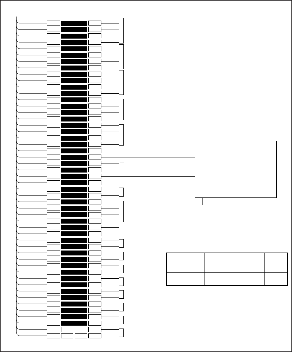
8-31
INSTALLATION-WIRING DIAGRAMS
SECTION 100-816-208
MARCH 1993
1
2
3
4
5
6
7
8
9
10
11
12
13
14
15
16
17
18
19
20
21
22
23
24
25
26
27
28
29
30
31
32
33
34
35
36
37
38
39
40
41
42
43
44
45
46
47
48
49
50
1
2
3
4
5
6
7
8
9
10
11
12
13
14
15
16
17
18
19
20
21
22
23
24
25
26
27
28
29
30
31
32
33
34
35
36
37
38
39
40
41
42
43
44
45
46
47
48
49
50
W-BL
BL-W
W-O
O-W
W-GN
GN-W
W-BR
BR-W
W-S
S-W
R-BL
BL-R
R-O
O-R
R-GN
GN-R
R-BR
BR-R
R-S
S-R
BK-BL
BL-BK
BK-O
O-BK
BK-GN
GN-BK
BK-BR
BR-BK
BK-S
S-BK
Y-BL
BL-Y
Y-O
O-Y
Y-GN
GN-Y
Y-BR
BR-Y
Y-S
S-Y
V-BL
BL-V
V-O
O-V
V-GN
GN-V
V-BR
BR-V
V-S
S-V
26
1
27
2
28
3
29
4
30
5
31
6
32
7
33
8
34
9
35
10
36
11
37
12
38
13
39
14
40
15
41
16
42
17
43
18
44
19
45
20
46
21
47
22
48
23
49
24
50
25
BRIDGING
CLIPS
TO PEKU W/FEMALE
CONNECTOR
25-PAIR CABLE W/MALE AMP CONNECTOR
66M150 SPLIT BLOCK
CIRCUIT 2 TO EKT
CIRCUIT 3 TO EKT
NOT USED
NOTES:
1. Amplifier or Repeater must have
Automatic Gain Control and be
FCC Registered from Part 68.
2. Refer to Manufacturer’s Installation
Documentation for Amplifier or
Line Repeater Pin numbering.
3. Connect to PEKU or PESU.
VT1
VR1
DT1
DR1
VT2
VR2
DT2
DR2
VT3
VR3
DT3
DR3
VT4
VR4
DT4
DR4
VT5
VR5
DT5
DR5
VT6
VR6
DT6
DR6
VT7
VR7
DT7
DR7
VT8
VR8
DT8
DR8
OT2
OR2
OT3
OR3
OT4
OR4
OT5
OR5
OT6
OR6
OT7
OR7
OT8
OR8
CIRCUIT 8
CIRCUIT 7
CIRCUIT 6
CIRCUIT 5
CIRCUIT 4
CIRCUIT 3
CIRCUIT 2
OCA T1 (OT)
OCA R1 (OR)
CIRCUIT 8 TO EKT
NOT USED
NOT USED
CIRCUIT 5 TO EKT
CIRCUIT 4 TO EKT
CIRCUIT 1 TO EKT
SYSTEM PROGRAMS
• Program 10-3, circuit assignments:
• Program 10-1, LED 19 and 20 ON.
• Program 15-5, enable appropriate CO
lines for tandem connection.
• Program 78-2, enable appropriate CO
lines if amplified DISA is required.
• Program 10-2, LED 18 and 19 ON.
PROGRAM 10-3
LED
LED 02, ON
SLOT
POSITION
04
PEKU OR
PESU PORT
NUMBER
A = 17
B = 18
PEKU
OR PESU
CIRCUIT
CKT6
CKT7
PEKU (OR PESU) CIRCUIT 6
VOICE PAIR
PEKU (OR PESU) CIRCUIT 7
VOICE PAIR
PORT A (CENTRAL OFFICE SIDE)
PORT B (SUBSCRIBER SIDE)
(SEE NOTE 2)
CUSTOMER SUPPLIED
TWO-WAY AMPLIFIER
OR
LINE REPEATERS (SEE NOTE 1)
TO 117VAC
FIGURE 8-27
DK16 MDF WIRING/AMPLIFIED TWO-CO LINE CONFERENCE
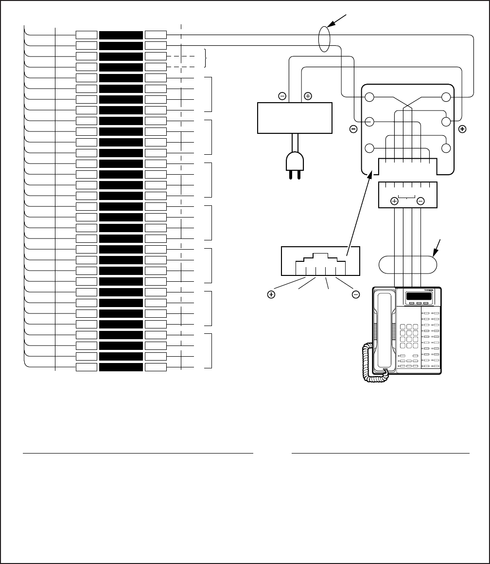
8-32
INSTALLATION-WIRING DIAGRAMS
SECTION 100-816-208
MARCH 1993
1
2
3
4
5
6
7
8
9
10
11
12
13
14
15
16
17
18
19
20
21
22
23
24
25
26
27
28
29
30
31
32
1
2
3
4
5
6
7
8
9
10
11
12
13
14
15
16
17
18
19
20
21
22
23
24
25
26
27
28
29
30
31
32
W-BL
BL-W
W-O
O-W
W-GN
GN-W
W-BR
BR-W
W-S
S-W
R-BL
BL-R
R-O
O-R
R-GN
GN-R
R-BR
BR-R
R-S
S-R
BK-BL
BL-BK
BK-O
O-BK
BK-GN
GN-BK
BK-BR
BR-BK
BK-S
S-BK
Y-BL
BL-Y
26
1
27
2
28
3
29
4
30
5
31
6
32
7
33
8
34
9
35
10
36
11
37
12
38
13
39
14
40
15
41
16
BRIDGING
CLIPS
PDKU CONNECTOR
25-PAIR CABLE W/MALE AMP CONNECTOR
CKT 2
(-) T1 (VOICE/DATA)
(GND) R1 (VOICE/DATA)
PT1
RT2
T2
R2
PT2
PR2
T3
R3
PT3
PR3
T4
R4
PT4
PR4
T5
R5
PT5
PR5
T6
R6
PT6
PR6
T8
R8
PT8
PR8
JACKETED TWISTED PAIRS
24AWG (1 PAIR)
STATION CABLING
GN
Y
BL
R
BK
W
R1 T1
(-)
T
GND
R
RJ11
DIGITAL (1000 OR 2000 SERIES)
TELEPHONE
(WITH OR WITHOUT PDIU-DI/
PDIU-DI2)
-OR-
DDSS, DDCB, PDIU-DS
(NOT USED)
CKT 3
CKT 4
CKT 5
CKT 6
T7
R7
PT7
PR7
CKT 7
CKT 8
AC/DC EXTERNAL
POWER SOURCE
3245
654321
TR
TO 120 VAC
COMMERCIAL POWER
OUTLET
AC/DC EXTERNAL POWER SOURCE SPECIFICATIONS:
AC IN:
DC OUT: 120 VDC ± 10%
24 VDC ± 10%
160 MA (MIN.) DC CURRENT
200 MV P-P (MAX) AC RIPPLE ON DC OUTPUT
EXTERNAL POWER STRAPS:
If the external power is installed, cut the
external power straps located inside the
digital telephone, DDSS, DDCB, or PDIU-
DS.
See Table 8-D at the front of this section for
external power requirements.
DC OUTPUT
AC INPUT
2-PAIR
MOD CORD
REQUIRED
AC/DC power supplies that meet the above
requirements are available from most telephone
equipment supply houses.
FIGURE 8-28
DK16 EXTERNAL POWER FOR DIGITAL TELEPHONE CONNECTION

FAULT FINDING
SECTION 100-816-500
MARCH 1993
TOSHIBA SYSTEM PRACTICES
DIGITAL KEY TELEPHONE SYSTEMS
FAULT FINDING PROCEDURES
STRATA DK FAULT FINDING
SECTION 100-816-500
MARCH 1993
TABLE OF CONTENTS
PARAGRAPH SUBJECT PAGE
1GENERAL .............................................................................................................. 1
2FAULT CLASSIFICATION...................................................................................... 1
3FAULT CLEARING PROCEDURES ...................................................................... 1
4DEFECTIVE APPARATUS RETURNS .................................................................. 2
5FAULT IDENTIFICATION AND ELIMINATION PROCEDURES ........................... 2
6DK8 HARDWARE FAULT ISOLATION .................................................................. 2
7DK16 HARDWARE FAULT ISOLATION ................................................................ 4
8STATION CABLE CONTINUITY CHECK............................................................... 4
8.01 Voltmeter Test .................................................................................................... 4
8.10 Ohmmeter Test................................................................................................... 5
8.20 Cable Installation ................................................................................................ 5
9FAULT ISOLATION FLOWCHARTS ...................................................................... 5
FLOWCHARTS ...................................................................................................... 7
CHART NO. 1 — FAULT CLASSIFICATION ................................................... 7
CHART NO. 2 — CATASTROPHIC FAULTS .................................................. 8
CHART NO. 3 — STATION DIAL TONE FAULTS........................................... 9
CHART NO. 4 — CO DIAL TONE FAULTS ..................................................... 10
CHART NO. 5 — DSS CONSOLE FAULTS .................................................... 11
CHART NO. 6 — VOICE MAIL/(EXTERNAL) AUTO ATTENDANT
FAULTS ............................................................................... 12
CHART NO. 7 — STATION MESSAGE DETAIL RECORDING
FAULTS ............................................................................... 13
CHART NO. 8 — REMOTE MAINTENANCE FAULTS.................................... 14
TABLE LIST
TABLE TITLE PAGE
AFLOWCHARTS ...................................................................................................... 1
BSTATION CABLE CONTINUITY CHECK USING VOLTMETER ........................... 6
CSTATION CABLE CONTINUITY CHECK USING OHMMETER ............................ 6
DSTATION CABLE CONTINUITY CHECK USING VOLTMETER ........................... 6
ESTATION CABLE CONTINUITY CHECK USING OHMMETER ............................ 6
FIGURE LIST
FIGURE TITLE PAGE
1FLOWCHART SYMBOLS ...................................................................................... 1
2QPSU8 DC VOLTAGE TEST ................................................................................. 3
3KPSU16 DC VOLTAGE TEST ............................................................................... 3
-i-
FAULT FINDING
SECTION 100-816-500
MARCH 1993
-1-
as described in
Programming Procedures.
It is very important to verify that the sys-
tem programming is correct and func-
tional before troubleshooting the hard-
ware.
3.02 Initialize the system (Program 90, 92, and
03) before testing new systems or when in DK16
cases,, changing the KFCU, Feature cartridge (if
instructions specify).
3.03 Faults in the DK8 and DK16 are cleared by
replacing PCBs, telephones (digital or electronic)
or the power supply, as instructed in the flow-
charts.
3.04 Five symbols are used in the flowcharts,
which are identified in Figure 1.
3.05 The flowcharts are sequentially arranged to
permit rapid fault localization within the system.
All
fault clearing must begin with the Fault Classifica-
tion Flowchart
, which is arranged in the correct
1 GENERAL
1.01 This section describes the maintenance pro-
cedures used to diagnose faults in the STRATA
DK8 and DK16 digital key telephone system. Faults
are classified and then cleared by replacing the
malfunctioning unit and performing operational
tests in the sequences prescribed by the fault
clearing flowcharts in Paragraph 9.
2 FAULT CLASSIFICATION
2.01 A Fault Classification Flowchart is provided to
ensure that fault clearing is pursued in a logical
sequence (Chart No. 1).
2.02 An assumption is made in the flowcharts that
the fault was discovered and reported by a digital
or electronic telephone user. All faults, therefore,
are classified according to the way they would
appear at the digital or electronic telephone.
2.03 Faults and associated flowcharts in Table A
are organized into the following categories:
Flowchart
TABLE A
FLOWCHARTS
Title
Fault Classification
Catastrophic Faults
Station Dial Tone Faults
CO Line Dial Tone Faults
DSS Console Faults
Voice Mail/(External) Auto Attendant
(VM/AA) Faults
Station Message Detail Recording
(SMDR) Faults
Remote Maintenance Faults
1
2
3
4
5
6
7
8
3 FAULT CLEARING PROCEDURES
3.01 Before attempting to clear any fault, ensure
that it is in the system and not caused by associ-
ated external equipment, such as wiring, MOH
source, etc.
IMPORTANT!
Many system features are assigned, en-
abled or disabled using software entries
Progression TO or FROM
another flowchart location.
Letters and numbers denote
the exact entrance or exit
points.
Important notes affecting the
fault clearing procedure.
Marking points of a
flowchart sequence.
Question to be answered
YES or NO.
Statement of a required
action.
FIGURE 1
FLOWCHART SYMBOLS
fault locating sequence.

FAULT FINDING
SECTION 100-816-500
MARCH 1993
-2-
3.06 The following precautions must be observed
when handling PCBs:
DO NOT:
Drop a PCB.
Stack one PCB on top of another.
Handle a PCB without discharging any
static electricity from your person by
touching the grounded cabinet.
Touch PCB contacts with your fingers.
Important!
If the fault is not cleared by substituting a
PCB, the original PCB must be reinstalled
in the KSU before trying another PCB.
4 DEFECTIVE APPARATUS RETURNS
4.01 When a defective system apparatus is
shipped for repair, the apparatus must be packed
in a suitable container (the original box is highly
recommended), as follows:
a) Anti-static containers for all other PCBs and
Feature cartridge.
b) Plastic bags for digital or electronic tele-
phones, KSU, etc.
4.02 NEVER WRITE ON THE APPARATUS
ITSELF! Describe the nature of the defect on an
information tag. Attach the tag to the front of the
unit with string (not wire) so the tag can remain
attached during the testing and repair process.
Return tags are available from Toshiba America
Information Systems, Inc., TSD Division.
5 FAULT IDENTIFICATION AND
ELIMINATION PROCEDURES
5.01 The DK8 or DK16, KSU common control
circuits or DK16 KFCU may contain a “soft” fault
due to an extremely high level of static electricity.
If it is found defective during the fault finding
procedures, attempt to clear a soft fault prior to
returning the KSU or KFCU for repair. The
correct procedure for this is to perform the
initialization procedure, and then re-program
the system as necessary to test for the fault. If
the fault returns after these procedures are
performed, tag the defective KSU or KFCU and
return it for repair.
6 DK8 HARDWARE FAULT ISOLATION
6.01 If a DK8 hardware fault is suspected, check
the hardware using the following procedure:
1) Make sure the BATT jumper plug (SW1 on the
KSU motherboard) is in the ON position to
save the system’s customer data base.
2) Unplug HPFB battery cable from BATT con-
nector on QPSU8 Power Supply (see Figure
2).
3) Remove all piggy-back PCBs from the DK8
motherboard one at a time. Retest to check if
the problem is cleared each time a PCB is
removed. If it is found that a particular PCB is
causing the problem, replace that PCB and
retest (piggy-back PCBs include QSTU,
QCDU, QRCU, QCNU, and QSMU).
4) Test power supply as follows (refer to Figure
2):
a) Plug the AC power cable into an outlet.
The “AC” LED on the power supply
should light green.
b) Turn the power supply switch to the ON
position.
The “DC” LED on the power supply
should light green.
c) Using the voltmeter, measure the volt-
ages referenced to frame ground (FG) at
the power supply connector CN3 pins
(test points) and pin 42 of IC5 located on
the motherboard (Figure 2). The volt-
ages should fall within the ranges below.
If the voltages do not fall within the
range, unplug the DC power pins from
power supply connector CN3 and mea-
sure +24V again at the same location; if
the voltages remain unacceptable, re-
place the power supply (see Section
100-816-204).
J19 Green Wires: 0V
J19 Yellow Wires: +24V
Range: +26.3V ~ +27.8V
IC5, Pin 42, +5V
Range: +4.5V ~ +5.5V
d) If the +24V tests within range but +5V is
not with-in specification, the KSU must
be replaced.
FAULT FINDING
SECTION 100-816-500
MARCH 1993
-3-
FIGURE 3
KPSU16 DC VOLTAGE TEST
FIGURE 2
QPSU8 DC VOLTAGE TEST
AC DC
DC POWER
–24 VOLT
CIRCUIT BREAKER
DC OUT (P9)
CONNECTOR
(VOLTAGE
TEST POINTS)
BATT
±
PULL
LOCK
PUSH
UNLOCK
RESERVE
BATTERY
CONNECTOR
FOR PBTC CABLE
DK16 BASE UNIT
MOTHERBOARD
(FG) SCREW
GREEN/YELLOW: 0V
BLACK: 0V
YELLOW: –26.3V ~ –27.8V
RED: +4.5 ~ +5.5
BLUE: –4.5 ~ –5.5
GREEN: 0V
DK16 KSU KPSU 16A POWER SUPPLY
WARNING
Hazardous voltage inside !
If servicing required,
remove A.C. cord.
QMA
ROM
IC5
J16
SW1
ON OFF
J17
CONF
J18
CONF
J20
AC
DC
CN3
J19
42
F.G. SCREW FOR
THIRD WIRE GROUND
CONNECTION
QPSU8 POWER SUPPLY
POWER SUPPLY
MOUNTING SCREW
CN1, AC
POWER CORD
CONNECTOR
POWER SUPPLY
MOUNTING SCREW
RAM STORAGE BATTERY JUMPER PLUGRAM STORAGE
BATTERY J20-CONNECTOR FOR QSMU
PCB INSTALLATION
CN4, BATTERY
CONNECTOR PLUG
BATTERY
CONNECTOR
FOR HPFB
DC POWER
ON/OFF SWITCH
AC AND DC
POWER
INDICATOR LEDs
F201, 3 AMP FUSE
POWER SUPPLY
MOUNTING SCREW
FG
CN4
IC5, PIN 42, +5V
TEST POINT (+4.5 ~ +5.5)
YELLOW WIRES:
+26.3V ~ +27,8V
GREEN WIRES:
(FG) OV
HPFB
GROUND WIRE

FAULT FINDING
SECTION 100-816-500
MARCH 1993
-4-
Important Note:
Do not attempt to replace Fuse F201
7 DK16 HARDWARE FAULT ISOLATION
7.01 If a DK16 hardware fault is suspected, check
the hardware using the following procedure:
1) Make sure the BATT jumper plug (SW1 on
the base unit motherboard) is in the ON
position to save the system’s customer data
base.
2) Unplug the PBTC battery cable from BATT
connector on KPSU16 Power Supply (see
Figure 2).
3) Lightly press the -24V circuit breaker to en-
sure it has not opened (Figure 3). If the circuit
breaker has opened and will not rest, remove
assemblies (KSTU, KCOU, Expansion Unit
PCBs, Expansion Unit) one at a time and try
to reset -24V circuit breaker. If it is found lthat
one of the removable assemblies causes the
circuit breaker to open, replace that assem-
bly. (See Section 100-816-205 for PCB re-
moval and Expansion Unit installation and
removal.)
a) If the -24V circuit breaker cannot be
reset with all removable assemblies dis-
connected, disconnect the DC OUT con-
nect (P9) from the Base unit motherboard
and try to reset the -24V breaker.
b) If the circuit breaker resets when the DC
OUT connector is removed, the Base
Unit or Power Supply may be defective.
Replace the Power Supply first (per Sec-
tion 100-816-205) to avoid reprogram-
ming the system.
c) If the -24V breaker continues to open
;after the power Supply is replaced, in-
stall the original Power supply onto the
DK16 Key Service Unit (KSU) and re-
place the KSU with another KSU.
4) If the –24V circuit breaker is not open (Step 3)
check the Power Supply DC voltages as
follows:
Using a voltmeter or other device which checks
voltage, measure the voltages referenced to
frame ground (FG) at the DC OUT connector
pins (test points) located on the motherboard
(Figure 2). The voltages should fall within the
ranges below. If the voltages do not fall within
the ranges, unplug the DC power pins from
the DC OUT connector and measure again at
the same location; if the ranges remain unac-
ceptable, replace the Power Supply.
(FG) Yellow-Green Wire: 0V
Yellow Wire: – 24V
• Range: –26.3V ~ –27.8V
Red Wire: 5V
• Range: 4.5V ~ 5.5V
Blue Wire: –5V
• Range: –4.5V ~ –5.5V
4) Check system third wire ground per Section
100-816-202.
5) If the –24V circuit breaker, DC power, and
third wire ground are within required limits,
remove all hardware assemblies, one at a
time, and test to see if the fault is cleared
(remove KSTU, KCOU, K4RCU and Expan-
sion Unit PCBs and remove Expansion Unit
per Section 100-816-205).
6) If the above hardware check did not clear the
fault, call your Technical Support Group.
8 STATION CABLE CONTINUITY CHECK
8.01 Voltmeter Test
8.02 The continuity of the cable run between the
DK16 KSU and the digital or electronic telephone
is checked with a voltmeter as follows:
NOTE:
Perform the following at the locations indi-
cated:
1. Modular block: Check all stations cables.
2. MDF: Check cable from KSU to MDF.
3. These tests also apply for troubleshooting
cable problems with DDCB and PDIU-DS
devices.
4. Refer to
Section 100-816-208
for appropriate
MDF wiring diagrams.
FAULT FINDING
SECTION 100-816-500
MARCH 1993
-5-
1) Disconnect the digital or electronic telephone.
2) Using a DC voltmeter, measure between the
wires of the two pairs to verify the readings
shown in Table B for electronic telephone
ports (PEKU or PESU). Refer to Table D for
digital telephone ports. The reading will be a
plus or minus depending on meter lead place-
ment.
3) An improper reading indicates an open,
crossed or shorted wire.
4) For the MDF-to-telephone (digital or elec-
tronic) cable, a more precise check is made
using an ohmmeter.
8.10 Ohmmeter Test
8.11 The continuity of the cable run between the
KSU and digital or electronic telephone is checked
with an ohmmeter as follows:
1) Disconnect the electronic or digital tele-
phone.
2) At the MDF, remove the bridging clips.
3) At the MDF, place shorting jumper wires
between the T and R of pair #1 (green-red),
the T and R of pair #2 (black-yellow) and the
T and R of OCA pair #3 (blue-white), for
PEKU/PESU only. (For MDF pin numbers,
see Section 100-816-208.)
4) At the modular block, measure the resis-
tance between all wire combinations. The
proper readings are shown in Table C for
electronic telephones and HDSSs, and Table
E for digital telephones, DDSSs and DDCBs.
8.20 Cable Installation
8.21 If cable voltmeter and ohmmeter tests are
within limits, digital telephones may not operate
because of the following:
1) Digital telephone cable runs must be free of
cable splits (single or double). Test for and
eliminate all cable splits.
2) Cable bridge taps – Digital telephones will
not operate if cable runs contain any type
(short or long) of cable bridge. Test for and
eliminate all cable bridges.
3) When installing the station cable, do not run
parallel to and within 3 feet of an AC power
line. AC power lines should be crossed at
right (90°) angles only. In particular, avoid
running station wire pairs near devices that
generate electrical noise, such as neon or
fluorescent light fixtures.
4) Check Table 8-D, in Section 100-816-208.
Verify that your telephone is wired correctly
(2-pair or External power) for the options it
supports (ADM, PDIU-DI, HHEU, DVSU,
etc.).
9 FAULT ISOLATION FLOW CHARTS
9.01 The following troubleshooting flow charts are
available to aid in fault isolation. It is recommended
to read paragraph 1~5 of this section and then
proceed to CHART 1, page 7, to begin fault isola-
tion.
FAULT FINDING
SECTION 100-816-500
MARCH 1993
-6-
NOTES:
1. This is the maximum allowable reading for all Digital and Electronic telephone cable runs except if connecting an HDSS
console to Circuits 7 and 8 of a PEKU—then the maximum cable restriction is 20 ohms, not 40 ohms.
2. The green-red, black-yellow and white-blue measurements should be within 10% of each other.
3. Nominal voltage—within the limits of
±
26.3 ~
±
27.8 VDC while under AC power, polarity depending on voltmeter lead
placements.
Pair
TABLE C
(ELECTRONIC TELEPHONE CABLES)
STATION CABLE CONTINUITY
CHECK USING OHMMETER
1
1
1
1
1
2
3
3
3
3
3
3
3
3
Wire
T
R
T
R
T
T
T
T
R
T
R
T
R
T
Color
Green
Red
Green
Red
Green
Black
White
White
Blue
White
Blue
White
Blue
White
FROM
Pair
2
2
2
2
1
2
3
1
1
1
1
2
2
2
Wire
T
T
R
R
R
R
R
R
R
T
T
T
T
R
Color
Black
Black
Yellow
Yellow
Red
Yellow
Blue
Red
Red
Green
Green
Black
Black
Yellow
TO Resistance
open
open
open
open
40 ohms
40 ohms
40 ohms
open
open
open
open
open
open
open
1
1
1
Pair
TABLE E
(DIGITAL TELEPHONE CABLES)
STATION CABLE CONTINUITY
CHECK USING OHMMETER
1
1
1
1
1
2
Wire
T
R
T
R
T
T
Color
Green
Red
Green
Red
Green
Black
FROM
Pair
2
2
2
2
1
2
Wire
T
T
R
R
R
R
Color
Black
Black
Yellow
Yellow
Red
Yellow
TO Resistance
open
open
open
open
40 ohms
40 ohms
1
1
Pair
TABLE D
(DIGITAL TELEPHONE CABLES)
STATION CABLE CONTINUITY
CHECK USING VOLTMETER
1
1
1
1
1
2
Wire
T
R
T
R
T
T
Color
Green
Red
Green
Red
Green
Black
FROM
Pair
2
2
2
2
1
2
Wire
T
T
R
R
R
R
Color
Black
Black
Yellow
Yellow
Red
Yellow
TO VOLTAGE
0
24
24
0
24
24
3
3
3
3
Pair
TABLE B
(ELECTRONIC TELEPHONE CABLES)
STATION CABLE CONTINUITY
CHECK USING VOLTMETER
1
1
1
1
1
2
3
3
3
3
3
3
3
3
3
Wire
T
R
T
R
T
T
T
T
R
T
R
T
R
T
R
Color
Green
Red
Green
Red
Green
Black
White
White
Blue
White
Blue
White
Blue
White
Blue
FROM
Pair
2
2
2
2
1
2
3
1
1
1
1
2
2
2
2
Wire
T
T
R
R
R
R
R
R
R
T
T
T
T
R
R
Color
Black
Black
Yellow
Yellow
Red
Yellow
Blue
Red
Red
Green
Green
Black
Black
Yellow
Yellow
TO VOLTAGE
3
24
24
24
24
0
0
0
0
0
0
0
0
0
0
0
3
3
3
3
FAULT FINDING
SECTION 100-816-500
MARCH 1993
-7-
CHART NO. 1
FAULT CLASSIFICATION
START
Please read
Chapters 1~5 of
this section
before
proceeding.
Is the
system completely
non-operational?
Is it a station
no dial tone
fault?
Is it a CO
line no dial
tone fault?
Is a DSS
console non-
operational?
Is it a
voice mail/auto
attd fault?
Is it
an SMDR
fault?
1-1
Go to
Chart 2
Go to
Chart 3
Go to
Chart 4
Go to
Chart 5
Go to
Chart 6
Go to
Chart 7
Call your
technical support
group.
NO
NO
NO
NO
NO
Is it a
remote
maintenance
fault?
Is the fault
classified on
this page?
Go to
Chart 8
Go to
appropriate
Chart 1~12
NO
NO
1-1
NO
YES
YES
YES
YES
YES
YES
YES
YES
FAULT FINDING
SECTION 100-816-500
MARCH 1993
-8-
CHART NO. 2
CATASTROPHIC FAULTS
START
Is the system
completely
non-operational?
Check system
hardware per
paragraph 6.01 for DK8
or 7.01 for DK16
of this section.
Was the fault
isolated by completing
the system hardware
check?
Re-initialize the system
(Programs 90, 92, and
03) and re-check fault
using default program
data (do not enter
customer data base).
Was the
fault cleared
after re-initializing
the system?
Call your
technical support
group.
Does the fault
re-occur after
entering customer
data base?
Reprogram customer
data base, one program
at a time, and check
to see if fault re-occurs.
Tag the defective
unit(s) and return
for repair.
2-1
2-2
2-5
2-6
2-8
2-3
Go to
Chart 1
2-4
2-7
END
END
NO
YES
YES
NO
NO
YES
YES
NO
NOTE:
Program 03 is not used for DK8.
FAULT FINDING
SECTION 100-816-500
MARCH 1993
-9-
CHART NO. 3
STATION DIAL TONE FAULTS
START
Check station wiring
per paragraph 8
of this section.
Repair if necessary.
Is the fault
cleared?
3-1
END
YES
Is
the
faulty station on a
replaceable station
PCB?
3-2
Replace the PCB
and retest
3-3
Replace the DK8 or
DK16 Base KSU and
initialize the system
(Prog: 90, 92, 03).
Is the
fault
cleared?
3-7
NO
Are the
faulty station(s) only
in the DK16 expansion
unit?
Retest.
Change the expansion
unit and retest.
3-5
YES
Is the
fault
cleared?
YES
3-6 END
Go to
3-4
Call your technical
support group.
NO
YES
NO
NO
NO
3-8
YES
Is the fault
cleared?
NO YES 3-4
Replace the defective
unit and return it to the
repair center
Go to
3-4
Replaceable Station
PCBs
DK8: QCDU and
QSTU
DK16 Base: KSTU
DK16 Expansion:
KCDU, PDKU,
PEKU, PESU
FAULT FINDING
SECTION 100-816-500
MARCH 1993
-10-
CHART NO. 4
CO LINE DIAL TONE FAULTS
Replaceable CO Line
PCBs
DK8: QCDU
DK16 Base: KCOU
DK16 Expansion:
KCDU, PCOU
Is the
fault
cleared?
Go to
4-5
Call your technical
support group.
NO
YES
YES
Retest.
Change the DK8 or
DK16 Base KSU and
initialize the system
(Prog: 90, 92, 03).
Is the
fault
cleared?
Go to
4-5
4-7
NO
NO
Are the
faulty CO lines
only in the DK16
expansion
unit?
4-10
NOTE:
Program 03 is not used on DK8.
4-5
Is the
fault
cleared?
4-4
YES
START
Check CO line wiring
per section 100-816-008.
Test central office line
using a standard telephone
or butt set at the
TELCO block.
Is the fault
cleared?
4-1
4-2
END
NO
Repair as necessary.
Are all
faulty CO lines
on a replaceable PCB
(not including KSU
Main PCB )?
YES
Change the PCB
and retest.
4-3
YES
1.
2.
NO
Replace the defective
unit and return it to the
repair center.
END
4-9
YES Change the expansion
unit and retest.
4-6
FAULT FINDING
SECTION 100-816-500
MARCH 1993
-11-
CHART NO.5
DSS CONSOLE FAULTS (DK16 ONLY)
START
DSS
console
type? 5-0
END
DDSS
Go to
5-0
Is the correct
PCB slot code entered
in Program 03?
Enter correct PCB slot
code using Program 03;
then turn power OFF
(for 5 seconds) and
then ON.
5-3
Refer to section 100-816-008 and
verify wiring:
Is the
fault
cleared?
YES
5-4
Go to
5-3
Test DSS cable with
cable continuity. Check
in paragraph 8 of
this section.
HDSS
NO
On PEKU connected
to HDSS, set SW1
to the DSS position.
5-1
NO
5-2
Is the
fault
cleared?
•
•
For DDSS, circuit 8 of the base
unit or PDKU (KCDU does not
support DDSS).
For HDSS, circuit 7 and 8 of
PEKU (PESU does not support
HDSS).
Correct as necessary.
Correct as necessary.
Is the
fault
cleared?
YES
5-5
Call your technical
support group.
NO
END
END
NO
YES
YES
FAULT FINDING
SECTION 100-816-500
MARCH 1993
-12-
CHART NO.6
VOICE MAIL/(EXTERNAL) AUTO ATTENDANT (VM/AA) FAULTS
Is the
fault
cleared?
YES END
START
This chart assumes
the VM/AA device
has no faults.
Is the
fault
cleared?
YES
6-3
NO
6-2
Is VM/AA
integration completely
non-operational?
END
YES
Read “Voice Mail Options” in paragraph 9 of
Section 100-816-207. Also read programming
instructs (in Chapter 2 of Section 100-816-
302) for the following programs: 03 (Code 92,
slot 00 for K4RCU DK16 only), 15-0 and 15-3
(Auto release), and 31 (LEDs: 04, 05, 09, 15 ~
20). This information explains System
Hardware and Programming options related to
Voice Mail and external auto attendant.
Correct Hardware and/or System
Programming as necessary.
Check that the VM I.D. codes (656 and
657) are stored correctly in users’ Digital
or Electronic telephones. Use operating
procedures in the manual for instructions.
6-1
Check that QRCU (DK8) or
K4RCU (DK16) is installed
correctly and programmed with
Code 92 in Prog. 03.
(Prog. 03 is not required for DK8,
QRCU).
NO
Check that the VM/AA ports are
connected to the standard
telephone station ports correctly.
(Refer to QSTU, KSTU, PSTU, or
PESU wiring diagrams in Section
100-816-208.)
Correct if necessary.
Is the
fault
cleared?
YES
6-4
NO
END
Is the
fault
cleared?
YES
6-5
NO
END
Call your technical
support group.
Using a standard DTMF
telephone, check all standard
telephone circuits (QSTU, KSTU,
PSTU, or PESU).
Replace defective PCB if
necessary.
Other VM/AA related programs:
• 10-2, LED 11 – No DTMF tones
• 13 – Message center
• 33 – Station hunting
• 35 – Busy station transfer/ringing
• 36 – Fixed call forward
• 37 – Ring transfer recall time
6-6
NO
FAULT FINDING
SECTION 100-816-500
MARCH 1993
-13-
CHART NO.7
STATION MESSAGE DETAIL RECORDING (SMDR) FAULTS
START
No
SMDR data or
garbled data is
detected at the QSMU,
PIOU/PIOUS SMDR
port.
7-1
Is the
fault
cleared?
YES
7-5
NO
This chart assumes
the SMDR device
has no faults.
NO
END
YES
Read the SMDR
installation
instructions in
paragraph 7 of
Section 100-816-207
before proceeding
with this chart.
SMDR
data records are
sent correctly but not
when the customer
requires.
7-2
YES
Set SMDR options in
Program 60: Threshold
time, long distance
calls only, etc.
Is the
fault
cleared?
YES
7-3
END
7-4
Is the
fault
cleared?
YES
7-6
NO
END
7-7
Check that the SMDR device
is wired correctly to the QSMU,
PIOU/PIOUS SMDR port.
(Refer to PIOU or PIOUS wiring
in Section 100-816-208.)
Fix as required.
Is the
fault
cleared?
YES
7-8
NO
END
Is the
fault
cleared?
YES
7-9
NO
END
Call your technical
support group.
NO
No other faults are
classified. Call your
technical support
group for assistance.
NO
On DK16, the SMDR
port is the bottom
modular jack (TTY is on
top) of PIOU/PIOUS.
On DK8 & DK16, the
modular cord connecting
to the SMDR port must
be 6-wires.
Verify that the SMDR device
communication parameters are
set for: 8-data bits, no-parity,
1-stop bit.
1200 bps on KD8,
300 or 1200 bps on DK16
Change as required.
Change the QSMU,
PIOU or PIOUS PCB.
•
•
Call your technical
support group.
On DK8 only, verify that the
QSMU is installed and
programmed for SMDR: Prog.
10-3, LED 04 is off for SMDR.
(QSMU is 1200 bps only)
On DK16 only, Verify that the
PIOU/PIOUS baud rate switch
(SW1) is in the correct position
(300 bps or 1200 bps) to match
the SMDR device baud rate.
(Refer to PIOU/PIOUS
installation instructions in
Section 100-816-205.)
Change as required.
FAULT FINDING
SECTION 100-816-500
MARCH 1993
-14-
CHART NO.8
REMOTE MAINTENANCE FAULTS
START
Is Remote
Maintenance connection
via external modem on TTY
port or IMDU
modem?
IMDU modem installed on
PIOU or PIOUS (DK16 only)
8-1
END
Read the Remote Maintenance Section
100-816-600, Paragraphs 1 to 7. This chart
assumes that the remote terminal and
modem have no fault and that Remote
Maintenance does not operate.
Is the
fault
cleared?
Call your technical
support group.
If a Digital or Electronic telephone
is in the programming mode, it is
not possible to enter the Remote
Maintenance mode.
8-5
8-4
Is the
fault
cleared?
8-3
On DK8, check that Prog. 10-3, LED 04 is on
for QSMU TTY operation. Check that the
communication parameters of the remote
terminal are set to match the TTY port (7-data
bits, even-parity, 1-stop bit).
On DK16, check that PIOU/PIOUS SW3
switch
is in the TTY position.
Correct as necessary.
8-2
YES
NO
Check that the modem or terminal connected
to the TTY port is wired correctly per the
Remote Maintenance Section 200-816-600
and QSMU, PIOU/PIOUS MDF wiring in
Section 100-816-208.
Correct above if necessary or
replace QSMU, PIOU or PIOUS.
On DK16, the TTY port is the top
modular jack (SMDR is bottom) of
the PIOU/PIOUS.
On DK8 & DK16 the modular cord
connecting the TTY port to the
terminal or external modem must be
6-wires.
•
•
On DK16, check that the IMDU, PIOU, or
PIOUS is installed correctly per Section 100-
816-205.
On DK16, check that the baud rate switch
(SW2, push-button switch on PIOU/PIOUS)
is set to the correct position (300 bps LED
ON, 1200 bps LED OFF) to match the
remote terminal baud rate.
QSMU, TTY Port is 1200 bps only.
Correct as necessary.
External modem
connected to QSMU,
PIOU, PIOUS TTY port
Check that the communication parameters of
the remote terminal are set to match the
IMDU (7-data bits, even parity, 1-stop bit).
Check that the PIOU/PIOUS SW3
switch is in the MODEM position.
Enable the IMDU by turning LED 14 ON in
Program 77-1.
If required, assign CO lines for DISA or to
ring IMDU in system Program 78, Code
51~53.
When calling IMDU via DISA or ring
transfer, dial 619.
Correct above if necessary or
replace IMDU or PIOU(S).
•
•
•

REMOTE ADMINISTRATION AND MAINTENANCE PROCEDURES
SECTION 100-816-600
MARCH 1993
TOSHIBA SYSTEM PRACTICES
DIGITAL KEY TELEPHONE SYSTEMS
REMOTE ADMINISTRATION
AND
MAINTENANCE PROCEDURES

REMOTE ADMINISTRATION AND MAINTENANCE PROCEDURES
SECTION 100-816-600
MARCH 1993
REMOTE ADMINISTRATION & MAINTENANCE PROCEDURES
SECTION 100-816-600
MARCH 1993
TABLE LIST
PARAGRAPH SUBJECT PAGE
1USING REMOTE ADMINISTRATION AND MAINTENANCE............................................ 1
2GENERAL DESCRIPTION................................................................................................ 2
3HARDWARE REQUIREMENTS........................................................................................ 2
4TERMINAL/MODEM INSTALLATION ............................................................................... 5
4.10 Maintenance Terminal/External Modem Option System Hardware Requirements ...... 6
4.20 DK8 and DK16 Local Maintenance Terminal Installation .............................................. 6
4.30 Remote Maintenance Option Installation ...................................................................... 6
4.40 Programming ................................................................................................................ 7
4.50 DK16 IMDU On-site Testing.......................................................................................... 7
5LOCAL TERMINAL OPERATION ..................................................................................... 8
5.00 Requirements................................................................................................................ 8
5.10 Set-up ........................................................................................................................... 8
5.20 Local Operation............................................................................................................. 8
6REMOTE TERMINAL OPERATION .................................................................................. 8
6.00 Requirements................................................................................................................ 9
6.10 Set-up ........................................................................................................................... 9
6.20 Remote Operation......................................................................................................... 9
6.30 Operation ...................................................................................................................... 10
7MODE SELECTION .......................................................................................................... 10
7.00 Selecting a Mode .......................................................................................................... 10
8PROGRAM MODE ............................................................................................................ 10
8.00 General .........................................................................................................................10
8.10 System Record Sheets ................................................................................................. 10
8.20 Program Types ............................................................................................................. 11
8.30 Multiple Station (Range) Programming ......................................................................... 11
8.40 Programming Procedures ............................................................................................. 11
9DATA DUMP MODE ......................................................................................................... 11
9.00 General ......................................................................................................................... 11
10 TEST MODE ..................................................................................................................... 12
10.00 General .........................................................................................................................12
10.10 CO Line Testing ............................................................................................................ 13
11 LCD MESSAGE MODE..................................................................................................... 13
11.00 General ......................................................................................................................... 13
11.10 Remote Called Station Message Mode ......................................................................... 13
11.20 Remote Calling Station Message Mode ........................................................................ 13
12 SPEED DIAL MODE ......................................................................................................... 14
12.00 General .........................................................................................................................14
13 MODE EXIT....................................................................................................................... 14
14 DISCONTINUE OPERATION............................................................................................ 14
14.00 Local Terminal .............................................................................................................. 14
14.10 Remote Terminal .......................................................................................................... 14
15 EQUIPMENT COMPATIBILITY ......................................................................................... 14
-i-
REMOTE ADMINISTRATION & MAINTENANCE PROCEDURES
SECTION 100-816-600
MARCH 1993
TABLE LIST
TABLE SUBJECT PAGE
RM-A PPTC MODIFIED WIRING FOR EXTERNAL MODEM TO TTY CONNECTION ............... 4
RM-B PPTC WIRING FOR LOCAL TERMINAL OR PERSONAL COMPUTER TO
TTY CONNECTION ........................................................................................................... 5
RM-C PROGRAMMING PROMPTS ............................................................................................. 10
RM-D PROGRAM 90: INITIALIZING PROGRAMS 00 ~ 97 ......................................................... 15
RM-E PROGRAM 92: STATION SPEED DIAL, SPEED DIAL MEMO, VM ID CODES
INITIALIZATION ................................................................................................................. 16
RM-F PROGRAM 92 (CONTINUED): SYSTEM SPEED DIAL, SPEED DIAL MEMO
INITIALIZATION ................................................................................................................. 17
RM-G PROGRAM 92 (CONTINUED): LCD CHARACTER MESSAGE MEMORY
INITIALIZATION ................................................................................................................. 18
RM-H PROGRAM 92 (CONTINUED): TIMED REMINDERS INITIALIZATION ............................ 19
RM-I PROGRAM 92 (CONTINUED): DIGITAL TELEPHONE VOLUME LEVEL
INITIALIZATION ................................................................................................................. 20
RM-J PROGRAM 92 (CONTINUED): CALL FORWARD BACKUP RAM INITIALIZATION ......... 21
RM-K PROGRAM 03: SLOT ASSIGNMENTS ............................................................................. 22
RM-L PROGRAM 00: SOFTWARE CHECK/REMOTE
MAINTENANCE—SECURITY CODE ................................................................................ 23
RM-M PROGRAM 01: LOGICAL PORT DISPLAY ....................................................................... 24
RM-N PROGRAM 02: PHYSICAL PORT DISPLAY ..................................................................... 24
RM-O PROGRAM 04: PORT/STATION NUMBER ASSIGNMENT .............................................. 25
RM-P PROGRAM 05: FLEXIBLE ACCESS CODE NUMBERING ............................................... 25
RM-Q TYPE 1 PROGRAM PROCEDURE EXAMPLE (PROGRAMS: 10-1, 10-2, 10-3,
15, 16, 42-0, 77-1, 77-2)..................................................................................................... 26
RM-R TYPE 2 PROGRAM PROCEDURE EXAMPLE (PROGRAMS: 20, 30, 31, 35, 40,
41, 43, 79, 81 ~ 89) ............................................................................................................ 27
RM-S PROGRAM 12: SYSTEM ASSIGNMENTS—BASIC TIMING ............................................ 28
RM-T PROGRAM 13: DEFINING THE MESSAGE CENTER ...................................................... 28
RM-U PROGRAM 19: BACKGROUND MUSIC SLOT IDENTIFICATION .................................... 29
RM-V PROGRAM 21: MODEM POOLING ................................................................................... 29
RM-W PROGRAM 22: DATA STATION HUNTING (DATA CALL ONLY) ..................................... 30
RM-X PROGRAM 28: DSS CONSOLE/ATTENDANT TELEPHONE ASSIGNMENTS ................ 30
RM-Y PROGRAM 29: DSS CONSOLE BUTTON ASSIGNMENTS ............................................. 31
RM-Z PROGRAM 32: AUTOMATIC PREFERENCE ................................................................... 32
RM-AA PROGRAM 33: STATION HUNTING ................................................................................. 32
RM-AB PROGRAM 34: HOLD RECALL TIMING ........................................................................... 33
RM-AC PROGRAM 36: FIXED CALL FORWARD .......................................................................... 33
RM-AD PROGRAM 37: RING TRANSFER (CAMP-ON) RECALL TIME ........................................ 34
RM-AE PROGRAM 38: DIGITAL AND ELECTRONIC TELEPHONE BUTTONSTRIP TYPE ........ 35
RM-AF PROGRAM 39: FLEXIBLE BUTTON ASSIGNMENT ......................................................... 36
RM-AG PROGRAM 42-1~8: PBX ACCESS CODE ........................................................................ 37
RM-AH PROGRAM 60: SMDR OUTPUT/ACCOUNT CODE DIGIT LENGTH................................ 38
RM-AI PROGRAM 69: VERIFIABLE ACCOUNT CODE ENTRY .................................................. 39
RM-AJ PROGRAM 70: VERIFY ACCOUNT CODE/TOLL RESTRICTION ASSIGNMENT ........... 40
-ii-
REMOTE ADMINISTRATION & MAINTENANCE PROCEDURES
SECTION 100-816-600
MARCH 1993
TABLE LIST (Continued)
TABLE SUBJECT PAGE
RM-AK PROGRAM 78: CO LINE SPECIAL RINGING ASSIGNMENTS
DISA/IMDU/NIGHT RINGING OVER EXTERNAL PAGE .................................................. 41
RM-AL PROGRAM 80: DIGITAL AND ELECTRONIC TELEPHONE RINGING TONES ............... 42
RM-AM PROGRAM 93: CO LINE IDENTIFICATION ...................................................................... 43
RM-AN PROGRAM 44 (A OR B): TOLL RESTRICTION TRAVELING CLASS
OVERRIDE CODE ENTRY ................................................................................................ 44
RM-AO PROGRAM 45-1: TOLL RESTRICTION DIAL PLAN ......................................................... 44
RM-AP PROGRAM 45-2: TOLL RESTRICTION DISABLE ............................................................ 45
RM-AQ PROGRAM 45-3 ~ 6: EQUAL ACCESS, SPECIAL COMMON CARRIER NUMBERS,
AND AUTHORIZATION CODE DIGIT LENGTH ................................................................ 45
RM-AR PROGRAM 45-8 ~ 9: TOLL RESTRICTION OVERRIDE CODE ....................................... 46
RM-AS PROGRAM 46-2 ~ 4: TOLL RESTRICTION ALLOWED/DENIED
AREA CODES ASSIGNED BY CLASS .............................................................................. 46
RM-AT PROGRAM 46-6 ~ 8: TOLL RESTRICTION ALLOWED/DENIED
OFFICE CODES ASSIGNED BY CLASS .......................................................................... 47
RM-AU PROGRAM 46-10 ~ 40: TOLL RESTRICTION CLASS PARAMETERS ............................ 48
RM-AV PROGRAM 47: TOLL RESTRICTION EXCEPTION OFFICE CODES
ASSIGNED BY AREA CODE ............................................................................................. 49
RM-AW PROGRAM 48: STATION TOLL RESTRICTION CLASSIFICATION ................................. 50
RM-AX PROGRAM 50-1: LCR PARAMETERS .............................................................................. 50
RM-AY PROGRAM 50-2: LCR HOME AREA CODE...................................................................... 51
RM-AZ PROGRAM 50-31 ~ 35: LCR SPECIAL CODES................................................................ 51
RM-BA PROGRAM 50-4: LCR LDI PLAN NUMBER ...................................................................... 52
RM-BB PROGRAM 50-5: LCR LOCAL CALL PLAN NUMBER ...................................................... 52
RM-BC PROGRAM 50-6: LCR DIAL ZERO TIMEOUT................................................................... 53
RM-BD PROGRAM 51: LCR AREA CODES .................................................................................. 53
RM-BE PROGRAM 52: LCR OFFICE CODE EXCEPTIONS FOR SPECIFIED AREA CODE ....... 54
RM-BF PROGRAM 53: LCR SCHEDULE ASSIGNMENT.............................................................. 55
RM-BG PROGRAM 54: LCR ROUTE DEFINITION ........................................................................ 56
RM-BH PROGRAM 55-0: LCR MODIFIED DIGITS-DELETE ......................................................... 57
RM-BI PROGRAM 55-1: LCR MODIFIED DIGITS-ADD ............................................................... 58
RM-BJ PROGRAM 55-2: LCR MODIFIED DIGITS-END ............................................................... 59
RM-BK PROGRAM 56: LCR STATION GROUP ASSIGNMENT ................................................... 60
RM-BL PROGRAM DATA DUMP................................................................................................... 60
RM-BM SPEED DIALING DATA DUMP .......................................................................................... 61
RM-BN LCD MESSAGING DATA DUMP ....................................................................................... 61
RM-BO MODE 95: REMOTE CALLING STATION MESSAGING (ADD/REVIEW/CHANGE)......... 62
RM-BP MODE 97: REMOTE CALLING STATION MESSAGING (ADD/CHANGE)........................ 63
RM-BQ MODE 94: REMOTE CALLED STATION MESSAGING (ADD/REVIEW/CHANGE) .......... 64
RM-BR MODE 96: REMOTE CALLED STATION MESSAGING (ADD/CHANGE) ......................... 65
RM-BS STATION/CO LINE STATUS CHECK ................................................................................ 66
RM-BT GENERAL STATION ACCESS AND BUTTON ACTIVATION ........................................... 66
RM-BU CO LINE TEST ................................................................................................................... 67
RM-BV SYSTEM DATE/DAY/TIME SETTING PROCEDURE ........................................................ 68
RM-BW SPEED DIAL MODE (CHANGE/REVIEW)......................................................................... 69
-iii-
REMOTE ADMINISTRATION & MAINTENANCE PROCEDURES
SECTION 100-816-600
MARCH 1993
FIGURE LIST
FIGURE SUBJECT PAGE
1SECTION FLOWCHART.................................................................................................... 1
2REMOTE MAINTENANCE EXTERNAL MODEM CONNECTION FOR DK8/16
(METHOD ONE OF ONE) .................................................................................................. 3
3REMOTE MAINTENANCE EXTERNAL MODEM CONNECTION FOR DK8/16
(METHOD TWO OF TWO)................................................................................................. 3
4REMOTE MAINTENANCE USING IMDU MODEM (DK16 ONLY) ..................................... 4
5LOCAL MAINTENANCE USING ASCII TERMINAL OR PERSONAL COMPUTER........... 5
6DATA DUMP PRINTOUT EXAMPLE ................................................................................. 12
7SAMPLE PRINTOUT OF SYSTEM MESSAGES ............................................................... 12
8TEST MODE FUNCTION DIAGRAM ................................................................................. 13
INDEX
PAGE
INDEX ........................................................................................................................................................ 70
MESSAGE RECORD SHEET
PAGE
MESSAGE RECORD SHEET ................................................................................................................... 71
-iv-
REMOTE ADMINISTRATION AND MAINTENANCE PROCEDURES
SECTION 100-816-600
MARCH 1993
-1-
1 USING REMOTE ADMINISTRATION AND MAINTENANCE
1.01 Figure 1 is provided as a quick reference aid in using this section.
FIGURE 1
SECTION FLOWCHART
General Description: The functions available on
STRATA DK systems via a Local or Remote Terminal
are explained in Paragraph 2.
The hardware and installation requirements are
explained in Paragraphs 3 and 4.
Paragraph 14 provides an equipment compatibility list.
To terminate Local and Remote Terminal operation;
Paragraph 13.
To exit and/or change modes; Paragraph 12.
To set-up and operate a Local
Terminal, see Paragraph 5. To set-up and operate a Remote
Terminal, see Paragraph 6.
To enter Operation Modes from a Local or Remote
Terminal:
• Program
• Data Printout
• Test
• LCD Message Entry
• Speed Dial Entry
See Paragraph 7.
To output data
to a printer via
a terminal;
Paragraph 9.
To test via a
terminal;
Paragraph 10.
To set messages
via a terminal;
Paragraph 11.
Programming via
a terminal;
Paragraph 8.
2
3 4
5 6
7
8910 11
13
14
15
To change or
review speed dial
via a terminal;
Paragraph 12.12
REMOTE ADMINISTRATION AND MAINTENANCE PROCEDURES
SECTION 100-816-600
MARCH 1993
-2-
data base programs, including Speed Dial num-
bers and LCD messages.
Message Mode: Provides for sending, adding, or
changing digital and electronic telephone LCD
messages.
Speed Dial Mode: Allows Station and System
Speed Dial numbers to be programmed remotely.
NOTE:
All the functions in the preceding paragraphs
are also available via an on-site terminal con-
nected directly to an optional PIOU(S) PCB
with DK16, or the optional QSMU PCB with
DK8. These functions are also available to a
terminal with a modem connected to a stan-
dard telephone port (Paragraph 5 and Figure
5).
2.04 There are two levels of Remote Administra-
tion and Maintenance.
Level 1: Allows access to all programs.
Level 2: Allows access to Programs 30 ~ 39 and
77 ~ 89, which pertain only to individual station
options such as button assignments, class of
service, etc.
2.05 Each Remote Administration and Mainte-
nance level has a different programmable pass-
word for customer data base protection. This al-
lows a customer to make certain station moves,
adds, and changes in Level 2; while protecting the
critical system assignments in Level 1 (refer to
Program 00).
3 HARDWARE REQUIREMENTS
3.01 For Remote Administration and Maintenance
operation, the STRATA DK16 system must be
configured with either an IMDU-equipped PIOU(S)
PCB in the optional Expansion Unit or an external
modem connected to a PIOUS(S) and a dedicated
CO line or standard telephone circuit. (See Figures
2, 3, and 4.) The STRATA DK8 must be configured
with a QSMU PCB and an external modem con-
nected to a dedicated CO line or standard tele-
phone circuit. (See Figures 2 and 3.)
2 GENERAL DESCRIPTION
2.01 With the STRATA DK8, Remote Adminis-
tration and Maintenance is accomplished with a
remote terminal/modem communicating over the
public telephone network, but only via an exter-
nal modem connected to a dedicated CO line or
standard telephone port. See Figures 2 and 3.
With STRATA DK16 Remote Administration and
Maintenance is accomplished with a remote ter-
minal/modem communicating over the public
telephone network via either an external modem
(connected to a dedicated CO line or a standard
telephone port); or, a modem unit (IMDU) in-
stalled on a PIOU or PIOUS PCB in the Expan-
sion Unit. See Figures 2, 3 and 4.
2.02 Remote Administration and Maintenance calls
with the STRATA DK16 may connect to the IMDU
automatically via programmable CO line ringing
assignments (Program 81 ~ 89) or Direct Inward
System Access (DISA) CO lines (Program 78), or
manually via the standard call transfer feature to
intercom number 619. Automatic connection and
DISA allow remote programming to be accom-
plished after business hours without on-site assis-
tance. Remote Administration calls with the DK8 or
the DK16 via an external modem connected di-
rectly to a CO line (instead of an IMDU) connect to
the external modem automatically without any spe-
cial station or CO line ringing assignments. When
the external modem is connected to a standard
telephone port, the call transfer feature, DISA, and
ringing assignments can be utilized to access the
Remote Administration.
2.03 Remote Administration and Maintenance al-
lows the following functions to be accomplished
remotely:
Program Mode: Provides for complete program-
ming of all STRATA DK8 or DK16 programs.
Test Mode: Provides for testing of STRATA DK8 or
DK16 CO lines and stations.
Data Dump Mode: Provides a complete printout of
all or individual STRATA DK8 or DK16 customer
REMOTE ADMINISTRATION AND MAINTENANCE PROCEDURES
SECTION 100-816-600
MARCH 1993
-3-
REMOTE PERSONAL
COMPUTER
OR
ASCII TERMINAL
REMOTE
MODEM
RS-232
CABLE
CO LINE DEDICATED
CO LINE
TELEPHONE
NETWORK
QSMU (DK8)
— OR —
PIOU
OR
PIOUS DK16
ROM
AND
RAM
EXTERNAL
MODEM
MODEM LINE JACK
3-PAIR MODULAR CORD
TTY MODULAR JACK
(7-BITS, EVEN PARITY, 1-STOP BIT)
PPTC: ADAPTOR, MODIFIED FOR
EXTERNAL MODEM CONNECTION
AS SHOWN IN TABLE RM-A OF
THIS SECTION
RS232
DK8 OR DK16
REMOTE PERSONAL
COMPUTER
OR
ASCII TERMINAL
REMOTE
MODEM
RS-232
CABLE
CO LINE
TELEPHONE
NETWORK
QSMU (DK8)
— OR —
PIOU
OR
PIOUS DK16
ROM
AND
RAM
EXTERNAL
MODEM
TTY MODULAR JACK
(7-BITS, EVEN PARITY, 1-STOP BIT)
RS232
QSTU
— OR —
PSTU
— OR —
PESU
DK8 OR DK16
CO LINE
CIRCUIT
TIME
SWITCH
DK8 OR DK16
CO line connects to modem station port
via: DISA, Ring Transfer, or ringing
assignments (Programs 81 ~ 89)
MODEM LINE JACK
STANDARD TELEPHONE CIRCUIT
3-PAIR MODULAR CORD
PPTC: ADAPTOR, MODIFIED FOR EXTERNAL
MODEM CONNECTION AS SHOWN IN
TABLE RM-A OF THIS SECTION
FIGURE 2
REMOTE MAINTENANCE EXTERNAL MODEM CONNECTION FOR DK8 & DK16 METHOD ONE
FIGURE 3
REMOTE MAINTENANCE EXTERNAL MODEM CONNECTION FOR DK8 & DK16 METHOD TWO
REMOTE ADMINISTRATION AND MAINTENANCE PROCEDURES
SECTION 100-816-600
MARCH 1993
-4-
TABLE RM-A
PPTC MODIFIED WIRING FOR EXTERNAL MODEM TO TTY CONNECTION
FIGURE 4
REMOTE MAINTENANCE USING IMDU MODEM (DK16 ONLY)
REMOTE
MODEM
RS-232
CABLE
CO LINE TELEPHONE
NETWORK
ROM
AND
RAM
DK16
CO LINE
CIRCUIT
DK16
CO line connects to IMDU port (619)
via: DISA, Ring transfer, or ringing
assignments in Program 78
PIOU OR PIOUS
CO LINE
IMDU
TIME
SWITCH
PPTC1A-5M ADAPTORQSMU OR PIOU/PIOUS,
TTY JACK
MODULAR PIN NO. MODULAR PIN NO.
1
2
3
4
5
6
RD
TD
DSR
DTR
DCD
SG
RD,
TD,
DSR,
DTR,
DCD,
SG,
6
5
4
3
2
1
to
to
to
to
to
to
3*
2*
6
20*
8*
7
4 Jumper to 5
RD
TD
DSR
DTR
DCD
SG
RTS to CTS
to
to
to
to
to
to
DB25 PIN NO.
MODEM
RS-232
LEAD NAME
PPCT (Modular to DB25) ADAPTOR, MODIFIED WIRING FOR
CONNECTING TTY JACK TO AN EXTERNAL MODEM:
IMPORTANT:
*
PPTC1A-5M, pins 2 & 3 and pins 8 & 20 must
be reversed in the field, as shown, for modem
connection. Set Hayes modem to track status of
carrier detect signal (AT & C1) and to answer
(ATS0 = 1).
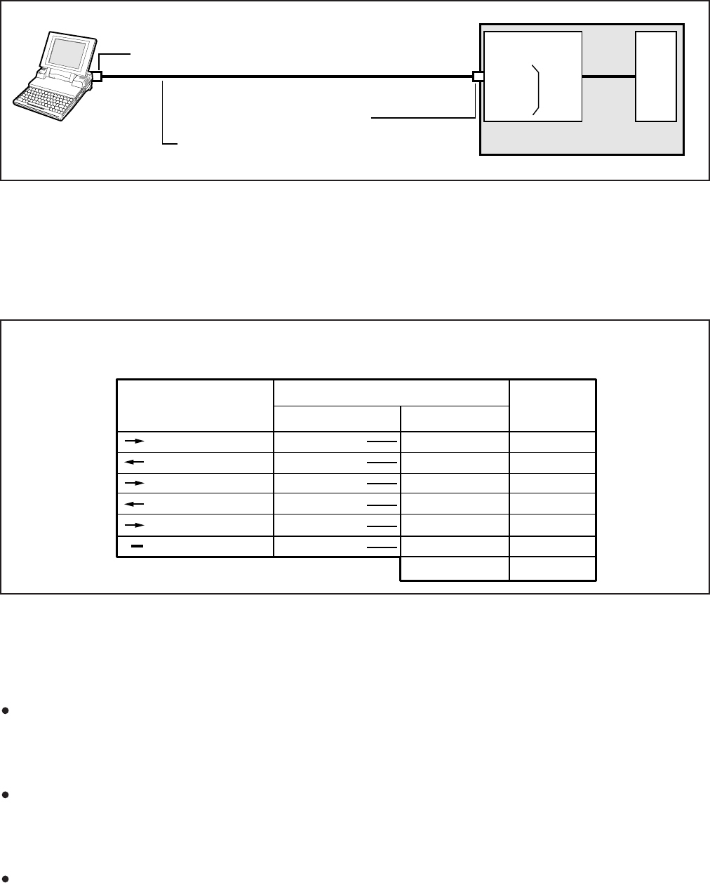
REMOTE ADMINISTRATION AND MAINTENANCE PROCEDURES
SECTION 100-816-600
MARCH 1993
-5-
FIGURE 5
LOCAL MAINTENANCE USING ASCII TERMINAL OR PERSONAL COMPUTER
ROM
AND
RAM
DK8 OR DK16
QSMU (DK8)
— OR —
PIOU
OR
PIOUS DK16
PPTC ADAPTER
SEE WIRING GUIDE BELOW (TABLE B)
TTY MODULAR JACK
(7-BITS, EVEN PARITY, 1-STOP)
3-PAIR MODULAR CORD
TABLE RM-B
PPTC WIRING FOR LOCAL TERMINAL OR PERSONAL COMPUTER TO TTY CONNECTION
QSMU OR PIOU/PIOUS,
TTY JACK
MODULAR PIN NO. MODULAR PIN NO.
1
2
3
4
5
6
RD
TD
DSR
DTR
DCD
SG
6
5
4
3
2
1
to
to
to
to
to
to
3
2
6
20
8
7
4 Jumper to 5
RD
TD
DSR
DTR
DCD
SG
RTS to CTS
to
to
to
to
to
to
DB25 PIN NO.
DTE
RS-232
LEAD NAME
PPTC1A-5M ADAPTOR
PPTC (MODULAR TO DB25) ADAPTOR WIRING FOR CONNECTING TTY JACK TO A
LOCAL TERMINAL OR PERSONAL COMPUTER SERIAL COMMUNICATIONS PORT.
RD
TD
DSR
DTR
DCD
SG
PIOU/PIOUS (DK16) so that maintenance and
programming can be administered internally or
externally from desktop personal computers or
terminals connected to Integrated Data Inter-
face Units (PDIU-DIs).
NOTES:
1. An external modem is required for Remote
Maintenance if a QSMU is installed on
DK8, or if an IMDU is not installed on DK16
PIOU or PIOUS. The IMDU has a built-in
maintenance channel for remote
connection; however, an external modem
requires a CO line or standard telephone
port (Figures 2 and 3).
2. The DK16 PIOU or PIOUS can only be
installed in the Expansion Unit.
4 TERMINAL/MODEM INSTALLATION
4.01 DK8 and DK16 provide customers with a
number of Remote Administration and Mainte-
nance configuration options:
A customer-supplied maintenance terminal can
be connected to the system TTY port (DK8
QSMU, or DK16 PIOU or PIOUS) via an exter-
nal modem either locally (Figure 5) or remotely
(Figures 2 and 3).
With the DK16, the IMDU modem (300 or 1200
baud full-duplex) can be connected to the DK16
PIOU or PIOUS to allow system programming
and testing to be accomplished from a remote
location (Figure 4).
Instead of a modem or terminal, a Stand-alone
Data Interface Unit (PDIU-DS) can be con-
nected to the TTY port on the QSMU (DK8) or

REMOTE ADMINISTRATION AND MAINTENANCE PROCEDURES
SECTION 100-816-600
MARCH 1993
-6-
6) For DK8 and DK16, set terminal communica-
tion parameters to seven bits, even parity,
one-stop bit (300, or 1200 bps. See step 3
above).
NOTE:
If a digital or electronic telephone is in the
program mode, programming from the main-
tenance terminal is not allowed.
4.30 Remote Maintenance Option Installation
4.31 DK16 IMDU Maintenance Modem (Figure
4). The IMDU mounts on the PIOU or PIOUS PCB
and provides 300 or 1200 bps, full-duplex commu-
nication for remote maintenance (seven bits, even
parity, one-stop bit). If the IMDU is employed, a
dedicated CO line or standard telephone port is not
required. Connection of the remote maintenance
terminal is through existing system CO lines via
intercom number 619. Refer to the PIOU or PIOUS
portion of Section 200-816-205 for hardware instal-
lation and programming requirements.
4.32 DK8 and DK16 External Maintenance Mo-
dem Installation. Refer to Figure 2 or 3, as appli-
cable, and install the external modem in accor-
dance with the following steps:
NOTE:
The Toshiba PPTC RS-232 modular-to-DB25
adaptor is factory configured for ASCII termi-
nal connection. Pins 2 and 3 and Pins 8 and 20
of the adaptor must be reversed for external
modem connection (see Table RM-A).
1) Connect the modular cord from the DK8 QSMU
or DK16 PIOU or PIOUS TTY port to the PPTC
adaptor and then to the external maintenance
modem RS-232 25-pin connector.
2) Connect the external maintenance modem
line-side to a dedicated CO line (tip and ring)
or to a dedicated standard telephone port, tip
and ring (QSTU with DK8; KSTU, PSTU, or
PESU with DK16). Refer to Wiring Diagrams,
Section 200-816-208, for wiring/interconnect-
ing details.
3) For DK16, set the PIOU or PIOUS SW2 switch
to match the modem or terminal baud rate:
Push in for 300 bps (baud rate indicator
4.10 Maintenance Terminal/External Modem
Option System Hardware Requirements
4.11 The STRATA DK8 must be equipped with a
QSMU PCB and the DK16 with a PIOU or PIOUS
PCB to support the maintenance terminal/external
modem options. Connecting the maintenance ter-
minal or external maintenance modem to the QSMU,
PIOU, or PIOUS PCB is accomplished with a
standard three-pair modular cord and a PPTC
adaptor connected to the PCB TTY jack.
4.20 DK8 and DK16 Local Maintenance
Terminal Installation
4.21 Install the ASCII terminal in accordance with
the following steps (Figure 5):
1) Connect the three-pair modular cable (24 AWG
twisted pairs) and the PPTC adaptor from the
DK8 QSMU or DK16 PIOU or PIOUS TTY port
to the remote maintenance terminal DB25
connector.
2) For the DK8 QSMU, set Program 10-3, LED
04 ON for TTY operation.
3) For the DK16, set the PIOU or PIOUS SW2
switch to match the modem or terminal baud
rate as follows:
Push in for 300 bps (baud rate indicator
CD4 is lit); let out (by pushing again) for
1200 bps (CD4 is not lit).
NOTE:
The DK8 QSMU baud rate is always 1200 bps.
4) For DK16, set the PIOU or PIOUS SW3 switch
to the TTY position.
NOTE:
The PIOU or PIOUS SW3 switch is set to
MODEM position for IMDU operation only.
5) For DK16, set the P13 jumper plug on the
PIOU to the BELL configuration, or cut the W4
jumper on the PIOUS (also for BELL configu-
ration).
NOTE:
The P13 (PIOU) and W4 (PIOUS) CCITT
configurations are not normally used in the
USA.

REMOTE ADMINISTRATION AND MAINTENANCE PROCEDURES
SECTION 100-816-600
MARCH 1993
-7-
CD4 is lit); let out (by pushing again) for
1200 bps (CD4 is not lit).
NOTE:
The DK8 QSMU baud rate is always 1200 bps.
4) For DK16, set the PIOU or PIOUS SW3 switch
to the TTY position.
NOTE:
The PIOU or PIOUS SW3 switch is set to the
MODEM position for IMDU operation only.
5) For DK16, set the P13 jumper plug on the
PIOU to the BELL configuration, or cut the W4
jumper on the PIOUS (also for BELL configu-
ration).
NOTE:
The P13 (PIOU) and W4 (PIOUS) CCITT
configurations are not normally used in the
USA.
6) The communication parameters for the termi-
nal that will be used to communicate through
the external modem connected to the TTY
port should be set to seven-bits, even parity,
one-stop bit. (300 or 1200 bps, see step 3
above).
7) Programming and system testing, via the ex-
ternal maintenance modem, is described later
in this section. Access to the external mainte-
nance modem is accomplished as follows:
If the modem is connected to a dedicated
CO line, call the CO line number to estab-
lish modem communication.
If the modem is connected to a standard
telephone port, call a STRATA DK CO
line that can be transferred to (or pro-
grammed to ring) the standard telephone
modem port to establish modem commu-
nication. It is also possible to establish
communications by calling in on a
STRATA DK DISA CO line and dialing the
intercom number of the modem connected
to the standard telephone port.
4.40 Programming
4.41 If an IMDU is used on DK16, enable the IMDU
in Program 77-1 (LED 14). If using an external
modem with STRATA DK16 or DK8, skip LED 14 in
Program 77-1.
4.42 For DK8 only, turn LED 04 “ON” in Program
10-3 to activate the QSMU for external modem
operation.
4.43 For DK16 only, if Remote Administration and
Maintenance calls are to connect to the IMDU
automatically, assign the designated CO lines to
ring the IMDU intercom number (619) in Program
78 as required (use standard STRATA DK16 pro-
gramming procedures).
4.44 For all cases of Remote/Local Maintenance
with a PC or ASCII terminal for either STRATA DK8
or STRATA DK16 program the security codes for
Levels 1 and 2 as in the Programming Procedures,
Section 200-816-300. Reference Program 00.
NOTE:
The security codes are initialized as “0000”.
These codes may also be changed via a local
or remote terminal.
4.50 DK16 IMDU On-site Testing
4.51 From any working station, test the functioning
of the IMDU for DK16.
1) Press the Intercom button.
Receive intercom dial tone.
2) Dial 6 1 9.
Receive modem tone from the IMDU after
a two-second delay.
3) Press the Speaker button to release.
4) Make an incoming call over each CO line that
is programmed to ring the IMDU (station 619).
Receive modem tone from the IMDU after
a two-second delay with each call.
NOTE:
This test checks basic programming and IMDU
operation, and should be completed before

REMOTE ADMINISTRATION AND MAINTENANCE PROCEDURES
SECTION 100-816-600
MARCH 1993
-8-
continuing with Remote Administration and
Maintenance installation.
5) If a terminal is to be utilized on-site, refer to
Paragraph 5. For off-site programming refer to
Paragraph 6.
5 LOCAL TERMINAL OPERATION
5.00 Requirements
5.01 For DK16, the optional Expansion Unit must
have a PIOU or PIOUS PCB installed to perform
on-site Remote Administration from a local termi-
nal. For DK8, a QSMU PCB is required. Paragraph
4 and Figure 5 provide installation details on local
terminal installation.
5.02 The local terminal for either the STRATA
DK16 or the DK8 must have an EIA RS-232 inter-
face, communicate in ASCII code at 300 or 1200
bps (1200 bps only for DK8), have a standard
typewriter-type keyboard, and display data via a
CRT display or printer. A personal computer (PC)
capable of emulating the described terminal with a
communications software package (such as
PROCOMM) may also be used (Figure 5).
5.03 Operating the PC or terminals, local or re-
mote, is identical. The only difference is the physi-
cal connection and the method used to establish
initial communications.
5.10 Set-up
5.11 Refer to Figure 2 and verify that the local
terminal is connected and set-up as follows:
1) Connect the RS-232 cable to the terminal
connector and the PIOU(S) or QSMU TTY
connector.
NOTE:
If a personal computer is being used, connect
the cable to the serial “COM” port.
2) Set the PC or terminal baud rate to match the
DK16 SW2 PIOU(S) setting (300 or 1200 bps)
or the DK8 QSMU setting (1200 bps).
3) Set the terminal for “Full Duplex” operation.
4) Set the keyboard for “Caps Lock” on.
5) Set the parameters of the terminal (or modem)
connected to the TTY to:
Word length: Seven bits
Stop bits: One
Parity: Even
5.20 Local Operation
5.21 Use the procedure below to establish com-
munications between the local terminal and the
PIOU(S) or the QSMU so that programming may be
accomplished via the terminal.
NOTE:
Hereafter, whenever the term
CR
is used, it
means the return or enter key, depending on
the keyboard being used.
SPACE
means the
space bar. An empty square indicates one of
several characters will appear in that location
(either on the terminal screen or in a printout).
1) Set-up the terminal as described in Paragraph
5.10.
2) Set the terminal to on-line.
3) Set “Caps Lock” on (upper case).
4) Press CR key.
The system responds, and the terminal
displays:
DK CONNECT
> CODE
5) Type the four-digit security code, and press
CR. (Default code = 0000.)
The system responds, and the terminal
displays:
OK
MODE
NOTE:
The security code can be entered any time the
CODE prompt appears.
6) To continue, go to Paragraph 7.
6 REMOTE TERMINAL OPERATION
6.00 Requirements
6.01 Terminal: For the STRATA DK8 or the
STRATA DK16, the terminal must interface with an

REMOTE ADMINISTRATION AND MAINTENANCE PROCEDURES
SECTION 100-816-600
MARCH 1993
-9-
remote terminal and the IMDU or an external
modem connected to a dedicated CO line, call the
number of the system CO line assigned to ring the
IMDU or the external modem via the remote termi-
nal/modem set-up:
1) Observe the following:
When the CO line rings-in, it will connect
to the IMDU or the external modem and
the IMDU or external modem will respond
by returning modem answer tone to the
remote modem.
The remote modem will return modem
tone to the IMDU or external modem and
communication will be established.
When communication is established, the
terminal will display: CONNECTED or
COMMUNICATIONS (see Note in Para-
graph 6.22).
2) To continue, Press CR and enter the security
code per Paragraph 6.30.
6.22 Manual connection via call transfer:
1) Using a telephone (at the remote location) that
can switch to the terminal/modem, dial the
number of a system CO line.
2) When the call is answered, request that it be
transferred to station 619 if an IMDU is being
used. For applications where an external mo-
dem is connected to a dedicated standard
telephone port, ask to be transferred to the
intercom number assigned to the modem.
3) After the call is transferred and you hear
modem tone from the IMDU or external mo-
dem, switch the call from the telephone to the
terminal/modem.
4) Observe the following:
When the CO line is transferred, it will
connect to the IMDU or external modem.
The IMDU or the external modem and the
remote modem will respond to each other
with modem tone and communication is
established.
asynchronous modem, communicate in ASCII code
at 300 or 1200 bps (1200 only for DK8), have a
standard typewriter-type keyboard, and display
data via a CRT display or printer. A personal
computer capable of emulating the described ter-
minal with a communications software package
(such as PROCOMM) may also be used. (See
Paragraph 15 for compatible personal computers).
6.02 Modem: For either system, the modem must
be full-duplex asynchronous, operate at 300 or
1200 bps (1200 only for DK8) and have an RS-232
interface to connect with a terminal or PC (as
described in Paragraph 6.01). It must interface with
the public telephone network and be compatible
with Bell 103 or 212 modem specifications.
6.10 Set-up
6.11 Refer to Figures 2, 3, and 4, and verify that the
remote terminal is connected and set-up as follows:
1) Connect the terminal and modem together
with the RS-232 cable.
NOTE:
If a personal computer is being used, connect
the cable to the serial “COM” port.
2) Connect the modem line input to a CO/PBX
line for access to the public telephone net-
work.
3) Set the terminal and modem baud rate to
match the DK16 PIOU(S) setting (300 or 1200
bps) or DK8 QSMU setting (1200 bps).
4) Set the terminal and modem for “Full Duplex”
operation.
5) Set the terminal parameters to:
Word length: Seven bits
Stop bits: One
Parity: Even
6.20 Remote Operation
6.21 Automatic connection via ringing assign-
ments: To establish communication between the
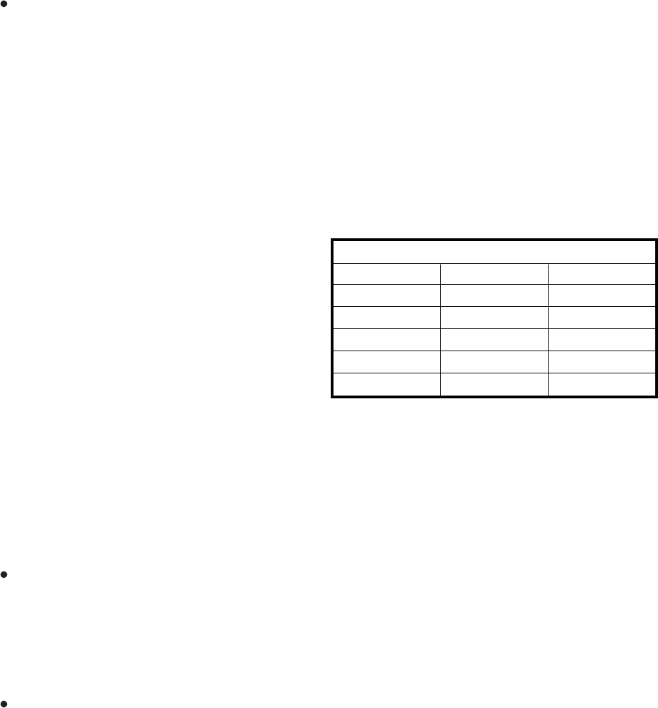
REMOTE ADMINISTRATION AND MAINTENANCE PROCEDURES
SECTION 100-816-600
MARCH 1993
-10-
When communication is established, the
terminal will display: CONNECTED or
COMMUNICATIONS (see Note).
NOTE:
If the connection is not completed or commu-
nication is unsuccessful, the remote terminal
will display:
NO CARRIER.
If this is the case,
check that the equipment is installed per Para-
graph 5.10 or 6.10 of this section and try
again.
6.30 Operation
6.31 Once communication is established between
the remote terminal and the IMDU or external
modem, follow the steps below to enter the security
code and receive the MODE prompt.
NOTE:
Hereafter, whenever the term
CR
is used, it
means the return or enter key, depending on
the keyboard being used.
SPACE
means the
space bar. An empty square indicates one of
several characters will appear in that location
(either on the terminal’s screen or in a print-
out).
1) Set the keyboard for “Caps Lock” on.
2) Press the CR key.
The system responds, and the terminal
displays:
DK CONNECT
>CODE
3) Enter the four-digit security code and press
the CR key. (Default code is “0000”.)
The system responds, and the terminal
displays:
OK
MODE
7 MODE SELECTION
7.00 Selecting a Mode
7.01 To enter an operating mode for either the
DK8 or the DK16, establish communication with
the terminal, enter the security code, and press the
CR key to receive the MODE prompt.
NOTE:
Refer to Paragraphs 5.20 or 6.20 to accom-
plish the above.
1) Set the keyboard for “Caps Lock” on (the
mode name must be entered in capital let-
ters).
2) At the MODE prompt, enter the desired mode
name (Table RM-C).
3) Press the CR key.
4) Verify the correct prompt return (Table RM-C).
8 PROGRAM MODE
8.00 General
8.01 Data governing overall system operation and
feature execution for the systems are stored in
read-only memory (ROM) and cannot be altered in
the field. However, the data controlling operation of
the various options, both system and station, are
stored in random-access memory (RAM) and can
easily be changed according to individual installa-
tion requirements.
8.02 All options are controlled by selections made
in the System Record Sheet. An initialization proc-
ess is provided for verifying predetermined system
assignments. The installer can then proceed with
any necessary changes.
8.03 Internal battery power is provided to prevent
loss of system data memory in the event of a power
failure.
TABLE RM-C—PROGRAMMING PROMPTS
Mode Function Mode Name Prompt Return
Program
Data Dump
Test
LCD Messages
Speed Dial No.
PROG
DUMP
TEST
MESG
REPT
P
D
T
(NONE)
R

REMOTE ADMINISTRATION AND MAINTENANCE PROCEDURES
SECTION 100-816-600
MARCH 1993
-11-
8.10 System Record Sheets
8.11 Before system data can be programmed, the
System Record Sheets which contain the customer
data base must be available (see Programming,
Section 200-816-302).
8.20 Program Types
8.21 There are three types of programs:
Type 1: All Type 1 programs use the same proce-
dure; however, each button/LED has a different
meaning, depending on the program number.
The status of this data is reviewed, changed,
and stored in system memory using Type 1
program procedures.
Type 2: All Type 2 programs follow the same entry
procedure; however, they require port number
and button/LED entries. Each button/LED has a
different meaning, depending on the program
number.
Type 3: In this type program, the information shown
in the System Record Sheet indicates the data to
be stored in system memory. Each program has
a different meaning, and the data is reviewed,
changed or stored in memory using an individual
procedure for each program.
8.30 Multiple Station (Range) Programming
8.31 Some programs select options for individual
stations (where ■ ■■ ■ represents the port number
being programmed). To save time, it is possible to
program all ports or a range of ports simultane-
ously.
8.32 Multiple station programming is accomplished
by substituting a range of ports (■ ■■ ■ *■ ■■ ■) for the
port number part (■ ■■ ■) of the program.
Example, all ports: 0 0 * 0 9 (DK8) or 0 0 * 1
9
(DK16)
8.33 When the multiple station range is entered,
the terminal displays existing data as follows:
Y or N: Y or N indicates if a button LED is ON or
OFF; if DATA is the same for all ports in the
dialed group: Y = button/LED "ON"; N = button/
LED "OFF."
U: If DATA is not the same for all ports, U indicates
that the button/LED is "ON" for at least one, but
not all ports, in that group.
8.40 Programming Procedures
1) Refer to a completed System Record Sheet.
2) Place the terminal into the program mode per
Paragraph 7.
3) Program procedures are categorized and pre-
sented in the following order. Use these pro-
cedures to store System Record Sheet data in
working memory.
a) Initialization procedures:
These procedures must be completed
whenever a system is first installed (see
Type 3 programs).
b) Type 1 programs:
10-1, 10-2, 10-3, 15, 16, 42-0, 77-1, 77-
2.
c) Type 2 programs:
Station Class of Service;
20, 30, 31, 35, 40, 41, 43, 79, 81 ~ 89.
d) Type 3 programs:
Initialization; 90, 92
General; 00, 01, 02 03, 04, 05, 12, 13,
21, 22, 19, 28, 29, 32, 33, 34, 36, 37,
38, 39, 42-1 ~ 8, 44, 60, 69, 70, 78,
80, 93.
Toll Restriction; 45 ~ 48.
Least Cost Routing; 50 ~ 56.
9 DATA DUMP MODE
9.00 General
9.01 This mode allows three types of data to be
displayed or output to a printer: Programs (Cus-
tomer Data Base), Speed Dialing Numbers (Sta-
tion/System), and LCD Messages (Station/Sys-
tem).
9.02 The three procedures for the Data Dump
mode are called: Program Dump, Speed Dialing
Dump, and LCD Messages Dump.
9.03 Program Dump: While in the dump mode
(see Paragraph 7), enter "PRG" and up to three
characters and press CR. The alphanumeric char-
REMOTE ADMINISTRATION AND MAINTENANCE PROCEDURES
SECTION 100-816-600
MARCH 1993
-12-
acters represent a program group or a particular
program, i.e., ALL, 03, 04, 10, 39, etc. For a printout
example, see Figure 6.
NOTE:
Programs are output only in the groups indi-
cated. To print out or review a program not
included above, use Program Mode proce-
dures.
9.04 Speed Dialing Dump: While in the dump
mode (see Paragraph 7), enter “REP” and two or
three characters and press CR. The characters
represent the speed dialing codes for either an
individual station, A L L (all stations and system
data) S Y S (system data only).
9.05 LCD Messages Dump: While in the dump
mode (see Paragraph 7), enter “MSG” and two or
three characters and press CR. The characters
represent stored messages for either an individual
station, A L L (all stations and system data) or
S Y S (system data only). For a printout example,
see Figure 7.
9.06 Tables provide a quick reference to the step-
by-step procedures to output the appropriate data.
10 TEST MODE
10.00 General
10.01 The remote test mode (see paragraph 7)
can be used to test STRATA DK8 or DK16 stations
and CO line circuits from an off-site location.
10.02 This testing function is accomplished by
accessing stations from the remote terminal, and
activating various buttons on digital and elec-
tronic telephones to make telephone calls, set
function buttons, change the system time and
date, etc. (see Figure 8 and Tables RM-BS ~ BV).
IMPORTANT!
Any digital or electronic telephone button
can be activated from the remote terminal
at any time while in the Test Mode (even
while the end user is using the telephone).
Therefore, caution must be used to prevent
service interruption or interference. The
Test Mode provides status tests to check
whether or not a station or CO line is in use.
The status checks should always be made
before performing other tests (see Table
RM-BS).
10.10 CO Line Testing
10.11 To test CO line transmission, two or three
CO lines must be available at the remote site (see
Figure 8 and Table RM-BU).
10.12 CO line testing is accomplished by using all
of the following two methods:
1) Establish a talk path between the two remote
stations (B & C) via a CO-to-CO connection
through STRATA DK8 or DK16.
81
81
81
81
81
81
81
00
01
02
03
04
05
06
8 1
11111111
00000000
00000000
00000000
00000000
00000000
00000000
1:SELECT(LED ON)
CO LINE
NUMBERS
STATION PORT NUMBER
PROGRAM NUMBER
CO LINE 01CO LINE 08
FIGURE 7
SAMPLE PRINTOUT OF SYSTEM MESSAGES
FIGURE 6
DATA DUMP PRINTOUT EXAMPLE
>MODE DUMP
D MSG SYS
SYS M60 OUT TO LUNCH
SYS M61 IN A MEETING
SYS M62 CALL
SYS M63 BACK AT
SYS M64 RETURN ON
SYS M65
SYS M66
SYS M67
SYS M68
SYS M69
D
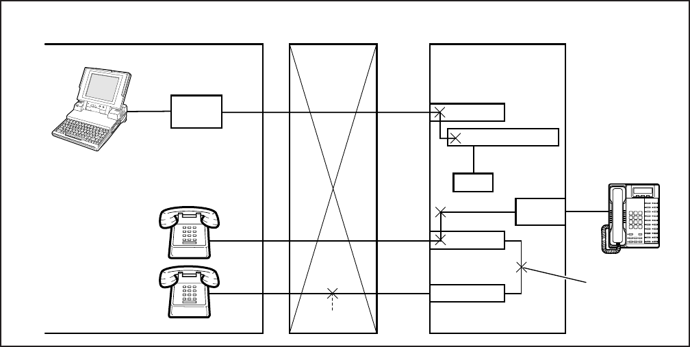
REMOTE ADMINISTRATION AND MAINTENANCE PROCEDURES
SECTION 100-816-600
MARCH 1993
-13-
FIGURE 8
TEST MODE FUNCTION DIAGRAM
PUBLIC TELEPHONE
NETWORKREMOTE SITE STRATA DK16/DK8
PC OR
TERMINAL
REMOTE
STATION B
REMOTE
STATION C
CO LINE
CO LINE
TIME OR
WEATHER
Digital Telephone XX
CO-to-CO
CONNECTION
MODEM
(DK16: 300 or 1200 BPS)
RS-232 CO LINE CO LINE A
CO LINE B
CO LINE C CO LINE C
CO LINE B
CO LINE A
IMDU OR EXT. MODEM
CPU
DATA
BUS
STATION
CKT
TS100
TOSHIBA
(DK8: 1200 BPS)
2) Establish a talk path between a remote station
and the time or weather service via a CO-to-
CO connection through STRATA DK8 or DK16.
10.13 The procedures in the tables provide ex-
amples of the types of tests and functions that can
be accomplished with the Test Mode. These proce-
dures do not cover all the possible tests that can be
performed remotely; however, by using the prin-
ciples given, other tests are possible.
11 LCD MESSAGE MODE
11.00 General
11.01 This mode allows a local or remote terminal
to set Called and Calling Station LCD messages for
station users (see Table RM-BO ~ BR). The mes-
sages may be system or station type and are stored
in their respective memory locations when set.
11.10 Remote Called Station Message Mode
11.11 Allows the terminal to set a Called Station
Message for an originating station with the destina-
tion of the message being a station or group of
stations.
11.12 When the message is set, the Msg LED(s)
on the destination station(s) flash.
11.13 When a destination station calls the originat-
ing station, the message is displayed on the desti-
nation station’s LCD.
Mode 94: To edit and/or review a Called Station
Message before setting it, use this mode. It will
print out the existing message and allow addi-
tions to it (such as a time or a date) before it is set.
(The message cannot be changed with this
mode—just added to.)
Mode 96: To add or change a Called Station
Message before setting it, use this mode. It does
not display the existing message, but allows a
completely new message to be entered before it
is set.
11.20 Remote Calling Station Message Mode
11.21 Allows the terminal to set a Calling Station
Message for a station. The message will be set on

REMOTE ADMINISTRATION AND MAINTENANCE PROCEDURES
SECTION 100-816-600
MARCH 1993
-14-
the station’s LCD and is automatically displayed on
other stations’ LCDs whenever they call that sta-
tion.
Mode 95: To edit and/or review a Calling Station
Message before setting it, use this mode. It will
display the existing message and allow additions
to it (such as a time or a date) before it is set. (The
message cannot be changed with this mode—
just added to.)
Mode 97: To add or change a Calling Station
Message before setting it, use this mode. It does
not display the existing message, but allows a
completely new message to be entered before it
is set.
11.22 Use the procedures in the tables to set
messages via Modes 94/96 and 95/97.
12 SPEED DIAL MODE
12.00 General
12.01 The Speed Dial Mode (see Table RM-BW)
can be used to add or change speed dial numbers
to any of the System Speed Dial memory locations
(60 ~ 99) and Station Speed Dial memory locations
(10 ~ 49).
12.02 Chain Speed Dial numbers can also be
programmed using the Speed Dial Mode. See the
Digital or Electronic Telephone User Guide for
more information regarding chain Speed Dialing.
12.03 To program Speed Dial numbers, enter the
REPT mode per Paragraph 7 of this section. Then
use the Speed Dial Mode Procedure at the end of
this section.
13 MODE EXIT
13.01 Exit the current mode per Paragraph 13.02
and select the desired mode via Paragraph 7.
13.02 To exit the Program (PROG), Data Dump
(DUMP), Test (TEST) or Speed Dial (REPT) mode:
At the P, D, T or R prompt, enter Q U I T CR and
observe:
>MODE
13.03 To exit the LCD Message (MESG) mode:
At anytime while in the message mode, enter: m
0 q and observe:
>MODE
NOTE:
To exit the Message Mode, the terminal key-
board must be in lower case.
14 DISCONTINUE OPERATION
14.00 Local Terminal
14.01 Exit current operating mode via Paragraph
13 and observe that the MODE prompt is displayed
on the terminal.
14.10 Remote Terminal
14.11 Exit current operating mode via Paragraph
13 and observe that the MODE prompt is displayed
on the terminal.
14.12 To discontinue remote operation:
1) Take the terminal off-line.
2) Verify that the modem drops the line.
15 EQUIPMENT COMPATIBILITY
15.01 Equipment that is known to be compatible
with STRATA DK8 and DK16 Remote Administra-
tion and Maintenance is listed as follows. This list
does not show all of the equipment that will work,
only the equipment that has been proven compat-
ible in the field or lab.
Terminals
Texas Instruments: Silent 700
Panasonic: KXD-4920
Personal Computers with the PROCOMM com-
munications software package.
Modems
Hayes compatible

REMOTE ADMINISTRATION AND MAINTENANCE PROCEDURES
SECTION 100-816-600
MARCH 1993
-15-
IMPORTANT NOTE:
For DK16 only: If all programs are initialized, the "IMDU enabled" has also been turned off in
Program 77-1
, LED 14. If using the IMDU for remote programming, go into
Program 77-1
and turn
button/LED 14 on as shown in steps 9, 10, and 11. If this is not completed, remote programming
must be reactivated locally from the programming digital or electronic telephone.
TABLE RM-D
PROGRAM 90
INITIALIZING PROGRAMS 00 ~ 97
ACTIONSTEP DISPLAY/PRINTOUT
1>MODE PROGEnter the Program Mode
At the >MODE prompt enter P R O G CR.
2P 90
P90
Enter Program Number 90
Press CR.
3P90 00
*
97To Initialize All Programs Enter 0 0
*
9 7
NOTE: Single programs can be initialized by entering a single
program number plus
#.
Group numbers are separated by an
*
.
4P90 00
*
97 01 NEnter button/LED number 0 1.
5P90 00
*
97 01 N YChange 01 button/LED to “ON” by entering Y.
7
8 Press CR.
Press SPACE.6
P90 00
*
97 01 N Y
02 N Y
Initialization complete. P90 00
*
97 01 N
P90
02 N Y
P90 00
*
97 01 N Y
02 N
9
10
11
12
Exit Program 90
Press # # CR.P90 #
P
For DK16, Enter Program 77
Press 7 7 CR.P77
then: Y CR.
Press 1 1 4.P77 1 14 N
P77 1 14 N Y
P77
To Exit this Program:
Press # # CR.
NOTE: If program data is not entered correctly, then
CR
will
not respond. To retry, press
DELETE CR.
Change LED 02 to “ON” by entering Y.

REMOTE ADMINISTRATION AND MAINTENANCE PROCEDURES
SECTION 100-816-600
MARCH 1993
-16-
TABLE RM-E
PROGRAM 92
STATION SPEED DIAL, SPEED DIAL MEMO, VM ID CODES INITIALIZATION
ACTIONSTEP DISPLAY/PRINTOUT
1>MODE PROGEnter Program Mode
At the >MODE prompt, enter P R O G CR.
2P 92
P92
Enter Program Number 92
Press CR.
3P92
P92 1
Enter 1.
4P92
P92 1 01 N
Enter button/LED number: 0 1.
5P92
P92 1 01 N Y
Change LED 01 to “ON” by entering Y.
7
8 Press CR.
Press SPACE two times.6
P92
P92 1 01 N Y
Change LED 03 to “ON” by entering Y.
Initialization complete. P92
P92 1 01 N Y
P92
P92
P92 1 01 N Y
02 N
03 N Y
02 N
03 N
02 N
03 N Y
NOTE: If program data is not entered correctly,
CR
will
not respond. To retry, press
DELETE CR
at the same time
.
9 Clear system speed dial using the procedure on the next page.

REMOTE ADMINISTRATION AND MAINTENANCE PROCEDURES
SECTION 100-816-600
MARCH 1993
-17-
TABLE RM-F
PROGRAM 92 (continued)
SYSTEM SPEED DIAL, SPEED DIAL MEMO INITIALIZATION
ACTIONSTEP DISPLAY/PRINTOUT
1>MODE PROGEnter Program Mode
At the >MODE prompt, enter P R O G CR.
2P 92
P92
Enter Program Number 92
Press CR.
3P92
P92 2
Enter 2.
4P92
P92 2 01 N
Enter button/LED number 0 1.
5P92
P92 2 01 N Y
Change LED 01 to “ON” by entering Y.
7
8 Press CR.
Press SPACE three times.6
P92
P92 2 01 N Y
Change LED 04 to “ON” by entering Y.
Initialization complete. P92
P92 2 01 N Y
P92
P92
P92 2 01 N Y
02 N
03 N
04 N Y
02 N
03 N
04 N
02 N
03 N
04 N Y
NOTE: If program data is not entered correctly,
CR
will
not respond. To retry, press
DELETE CR
at the same time
.
Clear LCD message memory, using the procedure on the
next page.
9

REMOTE ADMINISTRATION AND MAINTENANCE PROCEDURES
SECTION 100-816-600
MARCH 1993
-18-
TABLE RM-G
PROGRAM 92 (continued)
LCD CHARACTER MESSAGE MEMORY INITIALIZATION
ACTIONSTEP DISPLAY/PRINTOUT
1>MODE PROGEnter Program Mode
At the >MODE prompt, enter P R O G CR.
2P 92
P92
Enter Program Number 92
Press CR.
3P92
P92 3
Enter 3.
4P92
P92 3 02 N
Enter button/LED number 0 2.
5P92
P92 3 02 N Y
Change LED 02 to “ON” by entering Y.
7
8 Press CR.
Press SPACE.6
P92
P92 3 02 N Y
Change LED 03 to “ON” by entering Y.
Initialization complete. P92
P92 3 02 N Y
P92
P92
P92 3 02 N Y
03 N Y
03 N
03 N Y
NOTE: If program data is not entered correctly,
CR
will
not respond. To retry, press
DELETE CR
at the same time
.
9 Clear the timed reminders using the procedure on the next page.

REMOTE ADMINISTRATION AND MAINTENANCE PROCEDURES
SECTION 100-816-600
MARCH 1993
-19-
TABLE RM-H
PROGRAM 92 (continued)
TIMED REMINDERS INITIALIZATION
ACTIONSTEP DISPLAY/PRINTOUT
1>MODE PROGEnter Program Mode
At the >MODE prompt, enter P R O G CR.
2P 92
P92
Enter Program Number 92
Press CR.
3P92
P92 4
Enter 4.
4P92
P92 4 02 N
Enter button/LED number 0 2.
5P92
P92 4 02 N Y
Change LED 02 to "ON" by
entering Y.
7 Change key 04 to "ON" by
entering Y.
8 Press CR.
Initialization complete.
6P92
P92 4 02 N Y
Press SPACE two times.
03 N
04 N
P92
P92 4 02 N Y
03 N
04 N Y
P92
P92 4 02 N Y
P92
03 N
04 N Y
NOTE: If program data is not entered correctly,
CR
will
not respond. To retry, press
DELETE CR
at the same time
.
9 To exit this program, press # # CR.

REMOTE ADMINISTRATION AND MAINTENANCE PROCEDURES
SECTION 100-816-600
MARCH 1993
-20-
TABLE RM-I
PROGRAM 92 (continued)
DIGITAL TELEPHONE VOLUME LEVEL INITIALIZATION
ACTIONSTEP DISPLAY/PRINTOUT
1>MODE PROG
P
Enter Program Mode
At the >MODE prompt, enter P R O G CR.
2P 92
P92
Enter Program Number 92
Press CR.
3P92 5Enter 5.
4P92 5 01 N YEnter 0 1; change button/LED 01 to "ON" by entering Y.
5P92 5 01 N YPress SPACE four times.
6
7 Press CR.
Change LED 05 to “ON” by entering Y.
Initialization complete.
02 N
03 N
04 N
05 N
8 To exit this program, press # # CR.
P92 5 01 N Y
02 N
03 N
04 N
05 N Y
P92 5 01 N Y
P92
02 N
03 N
04 N
05 N
NOTE: If program data is not entered correctly,
CR
will not
respond. To retry, press
DELETE CR
at the same time
.

REMOTE ADMINISTRATION AND MAINTENANCE PROCEDURES
SECTION 100-816-600
MARCH 1993
-21-
IMPORTANT NOTE:
This program clears Call Forward memory for all stations, but does not reset the Call Forward
indication on the station (Call Forward LCD information and/or Call Forward button/LED). To
clear station Call Forward indications, system power must be turned OFF for five seconds, then
ON. Fixed Call Forward is not cleared by this program.
TABLE RM-J
PROGRAM 92 (continued)
CALL FORWARD BACKUP RAM INITIALIZATION
ACTIONSTEP DISPLAY/PRINTOUT
1>MODE PROGEnter Program Mode
At the >MODE prompt, enter P R O G CR.
2P 92
P92
Enter Program Number 92
Press CR.
3P92
P92 9
Enter 9.
4P92
P92 9 03 N
Enter button/LED number 0 3.
5P92
P92 9 03 N Y
Change LED 03 to "ON" by
entering Y.
7 Change LED 04 to "ON" by
entering Y.
8 Press CR.
Initialization complete.
6P92
P92 9 03 N Y
Press SPACE.
04 N
P92
P92 9 03 N Y
04 N Y
P92
P92 9 03 N Y
P92 04 N Y
NOTE: If program data is not entered correctly,
CR
will
not respond. To retry, press
DELETE CR
at the same time
.
9 To exit this program, press # # CR.

REMOTE ADMINISTRATION AND MAINTENANCE PROCEDURES
SECTION 100-816-600
MARCH 1993
-22-
IMPORTANT NOTES:
1. This program only applies to DK16 and must be completed with on-site assistance (after
installing PCBs, if any) because the system must be powered down momentarily after PCB
code entry.
2. Even though PCB codes display as being changed, they are not entered into working
memory until the system DC power is cycled OFF and ON.
3. If PCB codes are not entered into working memory by cycling DC power, PCB options will
not function.
4. Only
Program 03
requires the system power to be turned OFF and ON to store data into
working memory.
To store data, press CR.
Continue returning to Step 3 until all
data is entered.
To exit this program, press # #, press CR.
TABLE RM-K
PROGRAM 03
SLOT ASSIGNMENTS
ACTIONSTEP DISPLAY/PRINTOUT
1>MODE PROG
P
Enter the Program Mode
At the >MODE prompt, enter P R O G CR.
2P 03
P03
Enter Program Number 03
Press CR.
3P03
P03 00 91
Enter the Slot Number
Refer to the System Record Sheet and enter the desired
slot number.
Example: Slot number 00, enter 0 0.
4P03
P03 00 91 92
Enter the PCB Code Number
5P03
P03 00 91 92
P03 ##
P
To Exit Program/Store Data
Refer to the System Record Sheet and enter the desired
PCB code number.
Example: PCB code 92, enter 9 2.
A)
B)
C)
6 Turn system power "OFF" for 5 seconds and then turn
power "ON" to store data in working memory (see Notes).
Remote maintenance is disconnected.
Program 03
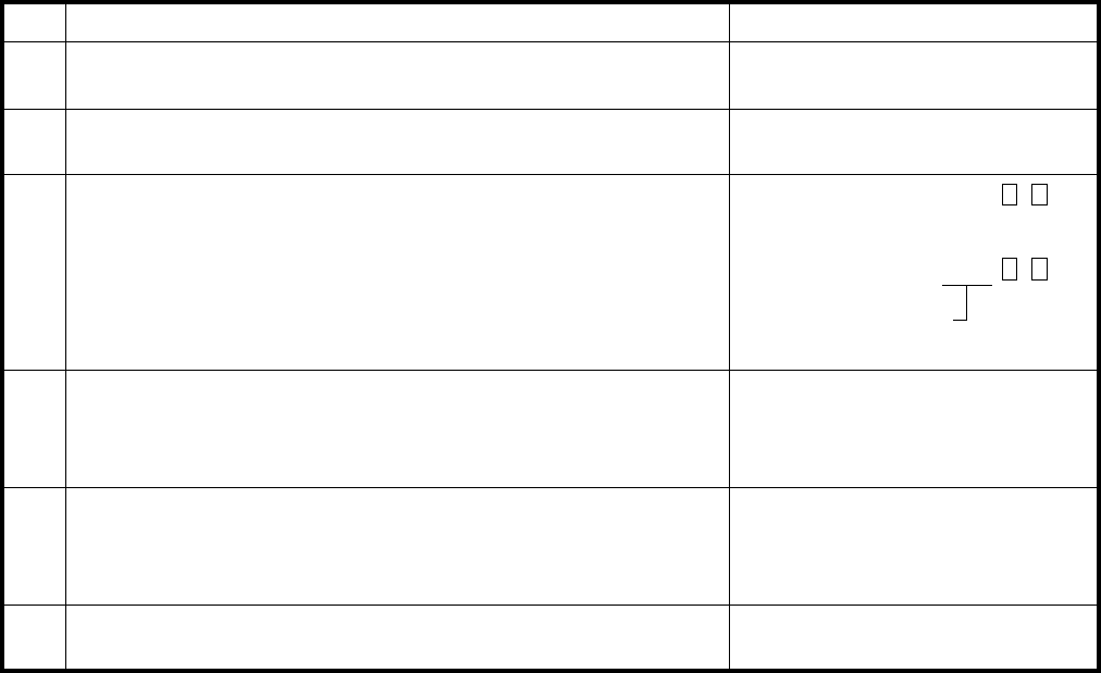
REMOTE ADMINISTRATION AND MAINTENANCE PROCEDURES
SECTION 100-816-600
MARCH 1993
-23-
TABLE RM-L
PROGRAM 00
SOFTWARE CHECK/REMOTE MAINTENANCE—SECURITY CODE
ACTIONSTEP DISPLAY/PRINTOUT
1>MODE PROG
P
Enter Program Mode
At the >MODE prompt, enter P R O G CR.
2P 00
P00
Enter Program Number 00
Press CR.
3P00 0 Version = PSSA
P00
To Check Software Version
. System will display the system's software
version.
Press CR.
4P00 1 0000
P00
To Change Level 1 Security Code
5P00 2 0000
P00
To Change Level 2 Security Code
. The system will display the present
level 1, four-digit code. Refer to the System Record Sheet
and change if required. Press CR.
6To Exit This Program P00 ##
P
. The system will display the present
level 2, four-digit code. Refer to the System Record Sheet
and change if required. Press CR.
Press # # CR.
Enter Action Code 0
Enter Action Code 1
Enter Action Code 2
•
Software version
Version = QMA
or
For DK16, PSSA. For DK8, QMA
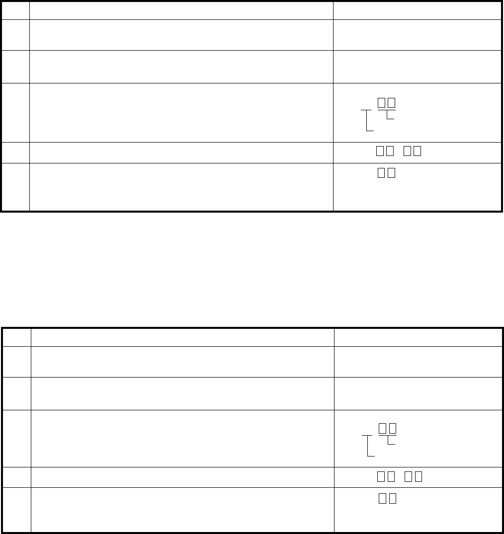
REMOTE ADMINISTRATION AND MAINTENANCE PROCEDURES
SECTION 100-816-600
MARCH 1993
-24-
TABLE RM-M
PROGRAM 01
LOGICAL PORT DISPLAY
ACTIONSTEP DISPLAY/PRINTOUT
1>MODE PROG
P
Enter the Program Mode
At the >MODE prompt, enter P R O G CR.
2P 01
P01
Enter Program Number 01
Press CR.
3P01
P01 01
Enter the Physical Port Number
4
5
Enter the desired physical port number.
Example: Port number 01, enter 0 1.
Verify Physical Port's Associated Logical Port
To Display More Ports/Exit Program
A) To display more logical ports, press CR and go to Step 3.
B) To exit this program, enter # # CR (twice).
P01 01 ##
P01 ##
P
(after exit)
Logical Port Displays
Physical Port
P01 01
( = Logical Port)
TABLE RM-N
PROGRAM 02
PHYSICAL PORT DISPLAY
ACTIONSTEP DISPLAY/PRINTOUT
1>MODE PROG
P
Enter the Program Mode
At the >MODE prompt, enter P R O G CR.
2P 02
P02
Enter Program Number 02
Press CR.
3Enter the Logical Port Number
4
5
Enter the desired logical port number.
Example: Port number 02, enter 0 2.
Verify Logical Ports Associated Physical Port
To Display More Ports/Exit Program
A) To display more physical ports, press CR and go to Step 3.
B) To exit this program, enter # # CR (twice).
P02
P02 02
P02 02 ##
P02 ##
P
(after exit)
Physical Port Displays
Logical Port
P02 02
( = Physical Port)

REMOTE ADMINISTRATION AND MAINTENANCE PROCEDURES
SECTION 100-816-600
MARCH 1993
-25-
NOTE:
A blank is displayed by "N".
NOTE:
Programs 10-1, 10-2, and 10-3 use Type 1 procedure.
To store data; press CR.
Continue returning to Step 3 until all Program 04
data is entered.
To exit this program, press # # CR.
TABLE RM-O
PROGRAM 04
PORT/STATION NUMBER ASSIGNMENT
ACTIONSTEP DISPLAY/PRINTOUT
1>MODE PROG
P
Enter the Program Mode
At the >MODE prompt enter P R O G CR.
2P 04
P04
Enter Program Number 04
Press CR.
3P04
P04 01
Enter the Logical Port Number
Refer to the System Record Sheet and enter the desired
logical port number.
Example: Port number 01, enter 0 1.
4P04
P04 01# 11 06
Press # button.
5P04
P04 01# 11 06
P04 ##
P
To Exit Program/Store Data
System displays present station number. Refer to the
System Record Sheet and enter the desired station number.
Example: Station number 16, enter 1 6.
A)
B)
C)
TABLE RM-P
PROGRAM 05
FLEXIBLE ACCESS CODE NUMBERING
ACTIONSTEP DISPLAY/PRINTOUT
1>MODE PROGEnter the Program Mode
At the >MODE prompt, enter P R O G CR.
2P 05
P05
Enter Program Number 05
Press CR.
3P05 4 4Enter Access Code number that you wish to change (0 ~ 9)
4
5
P05 4 4 6
6P
To Exit this Program
Example: 4 (if it was not previously changed, the system
will print another 4. If it has been previously changed,
the system will print the number to which it was changed).
Press # # CR.
Change the number if required (one or two digits)
Example: Change to 6, press CR.
Continue returning to Step 3 until all required access
codes have been changed.
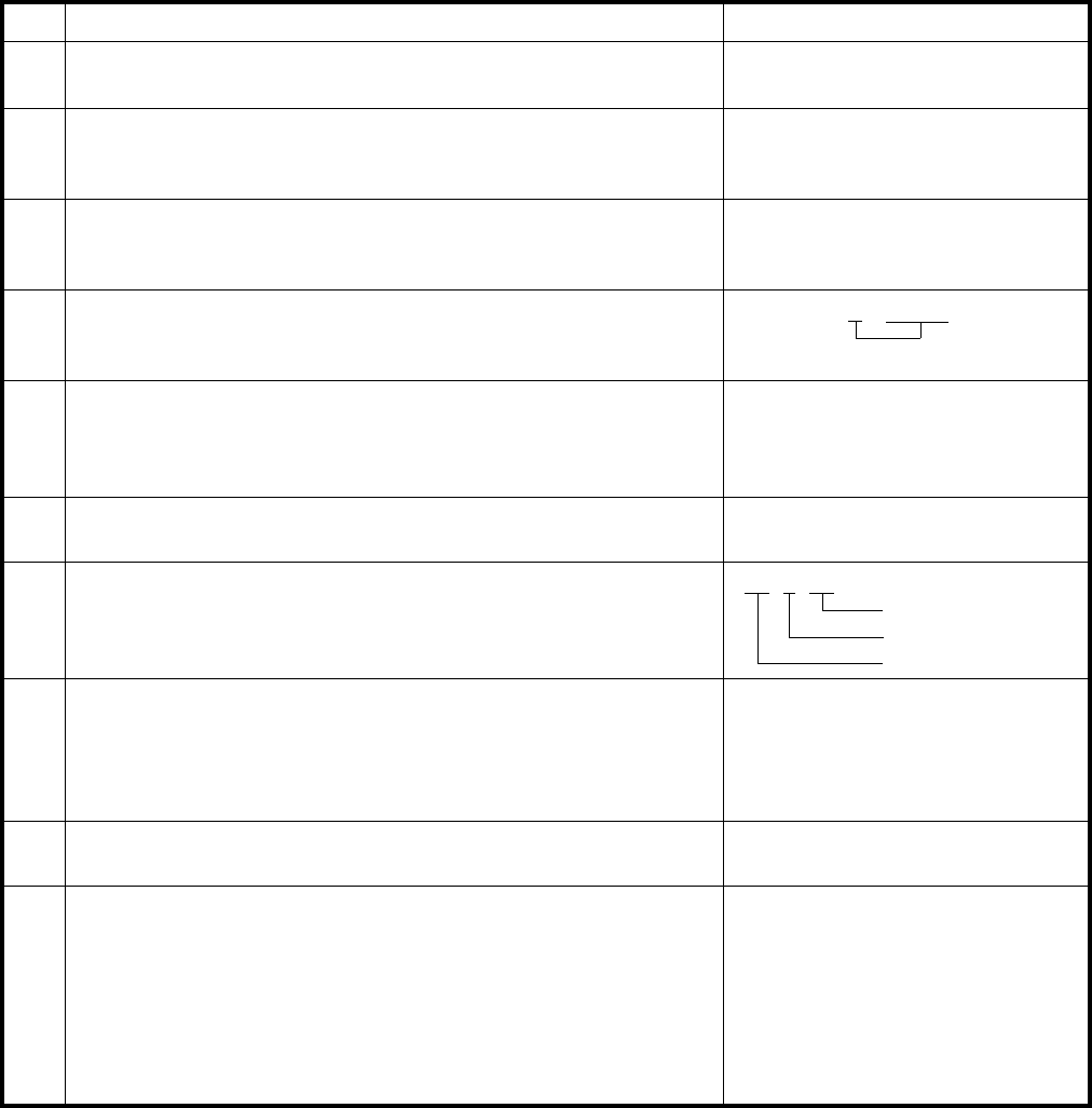
REMOTE ADMINISTRATION AND MAINTENANCE PROCEDURES
SECTION 100-816-600
MARCH 1993
-26-
TABLE RM-Q
TYPE 1 PROGRAM PROCEDURE EXAMPLE
ACTIONSTEP DISPLAY/PRINTOUT
1>MODE PROG
P
Enter Program Mode
At the >MODE prompt, enter P R O G CR.
2P 10
P10
Enter Program Number
Refer to the record sheet and enter the desired program number.
Example: Program 10-1, enter 1 0, press CR.
3P10 1Enter Program Code or Digit(s) Per Record Sheet
1 or other digit required.
4P10 1 01 NEnter Button/LED Number
Enter the desired button/LED number.
Example: Button/LED 01, enter 0 1.
5P10 1 01 N YTo Change Button/LED Status
Refer to the System Record Sheet and change the button/LED
status, if required (Y or N).
Example: Enter Y.
6
(PROGRAMS: 10-1, 10-2, 10-3, 15, 16, 42-0, 77-1, 77-2)
NOTE: Most programs do not require a second digit.
P10 1 01 Y-7
To Advance to Next Button/LED
Press SPACE. Repeat step 5 if necessary. P10 1 01 Y
02 N
8To Exit Program/Store Data
A)
B)
C)
P10
P10 ##
P
To store data, press CR.
To exit this program, press # #, then press CR.
Continue returning to step 2 until all Type 1 programs
are completed.
To Review Button/LED Status Change
Enter CR.
Re-enter Steps 3 and 4.
NOTE: This step is optional and not required to save data.
(see note)
9
10
To Exit the Program Mode
Press # # CR.> MODE
To Enter Another Mode
Press
D U M P CR (data dump)
T E S T CR (test)
M E S G CR (LCD messages)
R E P T CR (speed dial)
D
T
R
(no prompt)
Button LED Number
Program Code
Program Number
NOTE:
Y = button/LED "ON", N = button/LED "OFF"
Button LED "ON"
REMOTE ADMINISTRATION AND MAINTENANCE PROCEDURES
SECTION 100-816-600
MARCH 1993
-27-
TABLE RM-R
TYPE 2 PROGRAM PROCEDURE EXAMPLE
ACTIONSTEP DISPLAY/PRINTOUT
1>MODE PROG
P
Enter Program Mode
At the >MODE prompt, enter P R O G CR.
2P 30Enter Program Number
Refer to the record sheet and enter the desired program number.
Example: Program 30, enter 3 0, press CR.
3P30
P30 04
Enter Port Number
Refer to the System Record Sheet and enter the desired
port number(s). Example: 0 4.
4P30 04#Press # button.
5P30 04# 01 NEnter the Desired Button/LED Number
Example: Button/LED 01, enter: 0 1.
7
(PROGRAMS: 20, 30, 31, 35, 40, 41, 43, 79, 81 ~ 89)
8
To Advance to Next Button/LED
Press SPACE (repeat Step 6 if necessary).
9To Exit Program/Store Data
A)
B)
C)
P10
P10 ##
P
To store data, press CR.
To exit this program, press # #, then press CR.
Continue returning to Step 2 until all Type 2 programs
are completed.
6P30 04# 01 N YTo Change Button/LED Status
Refer to the System Record Sheet and change the button/LED
status, if required (Y or N).
Example: Enter Y.
10
11
(Note)
P30 04# 01 Y-
Button LED Number
Port Number
Program Number
To Review Button/LED Status Change
Press CR.
Re-enter Steps 3, 4, and 5.
>MODETo Exit the Program Mode
Press # # CR.
To Enter Another Mode,
D U M P CR (data dump)
T E S T CR (test)
M E S G CR (LCD messages)
R E P T CR (speed dial)
D
T
R
(no prompt)
NOTE:
Y = button/LED
(
s
)
"ON", N = button/LED
(
s
)
"OFF"; U = button/LED
(
s
)
"ON" some ports and "OFF" other ports.
or Port Range
*
Press
LED "ON"

REMOTE ADMINISTRATION AND MAINTENANCE PROCEDURES
SECTION 100-816-600
MARCH 1993
-28-
TABLE RM-S
PROGRAM 12
SYSTEM ASSIGNMENTS – BASIC TIMING
ACTIONSTEP DISPLAY/PRINTOUT
1>MODE PROG
P
Enter the Program Mode
At the >MODE prompt, enter P R O G CR.
2P 12
P12
Enter Program Number 12
3P12 3 1Check the record sheet and enter the program code that is
required.
As an example, feature 3, enter 3.
The present selection will be displayed.
Press CR.
4P12 3 1 2Refer to the record sheet and change if required.
As an example, change it to 2.
Enter 2.
5P12 3 1 2
P12 ##
P
To Exit Program/Store Data
A)
B)
C)
To store data, press CR.
Continue returning to Step 3 until all Program 12 data is
entered.
To exit this program, press # # CR.
NOTES:
1. A blank is displayed by "N".
2. Programs 15 and 16 use Type 1 procedure.
TABLE RM-T
PROGRAM 13
DEFINING THE MESSAGE CENTER
ACTIONSTEP DISPLAY/PRINTOUT
1>MODE PROG
P
Enter the Program Mode
At the >MODE prompt, enter P R O G CR.
2P 13
P13
Enter Program Number 13
3P13
P13 1 NN
Enter the number 1. The present port number will be displayed.
Refer to the record sheet and enter the required port number.
Example: Port 00, enter 0 0 CR.
4P13 1 NN 00
P13
P13 1 NN 00
P13 ##
P
Press # # CR.
5To Exit this Program
Press CR.

REMOTE ADMINISTRATION AND MAINTENANCE PROCEDURES
SECTION 100-816-600
MARCH 1993
-29-
TABLE RM-U
PROGRAM 19
BACKGROUND MUSIC SLOT IDENTIFICATION
ACTIONSTEP DISPLAY/PRINTOUT
1>MODE PROG
P
Enter the Program Mode
At the >MODE prompt, enter P R O G CR.
2P 19
P19
Enter Program Number 19
3P19
P19 1 NN
Enter the number 1.
The present slot number will be displayed.
Press CR.
4P19 1 NN 04
P19
Refer to the record sheet and enter the required slot number.
Example: Slot 04, enter 0 4 CR.
5P1 19 ##
P
To Exit this Program
Press # # CR.
NOTE:
Pro
g
ram 20
uses T
y
pe 2 procedure.
TABLE RM-V
PROGRAM 21
MODEM POOLING
ACTIONSTEP DISPLAY/PRINTOUT
1>MODE PROG
P
Enter Program Mode
At the >MODE prompt, enter P R O G CR.
2P 21
P21
Enter Program Number 21
3P21 04
Refer to the System Record Sheet, and enter the required port
number for the PDIU-DS.
Example: port 04; Enter: 0 4.
Press CR.
6P21 04 # NN 08
P21 ##
P
To Exit Program/Store Data
A)
B)
C)
To store data, press CR.
Continue returning to Step 3 until all Program 21 data
is entered.
To exit this program, press # # CR.
4P21 04 # NNPress #.
The system will display the presently selected standard telephone
port number.
5P21 04 # NN 08Refer to the System Record Sheet, and enter the required
standard telephone port number.
Example: Port 08; Enter: 0 8.

REMOTE ADMINISTRATION AND MAINTENANCE PROCEDURES
SECTION 100-816-600
MARCH 1993
-30-
TABLE RM-W
PROGRAM 22
DATA STATION HUNTING (DATA CALL ONLY)
ACTIONSTEP DISPLAY/PRINTOUT
1>MODE PROGEnter the Program Mode
At the >MODE prompt, enter P R O G CR.
2P 22
P22
Enter Program Number 22
Press CR.
3P22 03Refer to the record sheet and enter the required
port number.
Example: Port 03, enter 0 3.
4 Enter #. The present data will be displayed. P22 03# NN
5 Refer to the record sheet and enter the port number
that will be the hunt point.
Example: Port 00, enter 0 0.
6P22 03# NN 00
P22 ##
P
To Exit Program/Store Data
A)
B)
C)
P
P22 03# NN 00
To store data, press CR.
Continue returning to step 3 until all
data is entered.
To exit this program, press # # CR.
Program 22
TABLE RM-X
PROGRAM 28
DSS CONSOLE/ATTENDANT TELEPHONE ASSIGNMENTS
ACTIONSTEP DISPLAY/PRINTOUT
1>MODE PROG
P
Enter Program Mode
At the >MODE prompt, enter P R O G CR.
2P 28
P28
Enter Program Number 28
3P28 1 1 2Refer to the System Record Sheet and enter the required DSS
console number (1 ~ 2).
The system will display the telephone to which the
DSS console is assigned.
Example: DSS console number 1 is assigned to telephone
number 1.
Press CR.
4P28 1 1 2
P28 ##
P
To Exit Program/Store Data
Refer to the System Record Sheet and change if required.
Example: Assign DSS console 1 to electronic telephone 2.
Enter: 2.
A)
B)
C)
To store data, press CR.
Continue returning to Step 3 until all data has
been entered for this program.
To exit this program, press # # CR.
NOTE:
This pro
g
ram applies to di
g
ital and electronic DSS consoles and di
g
ital and electronic telephones.
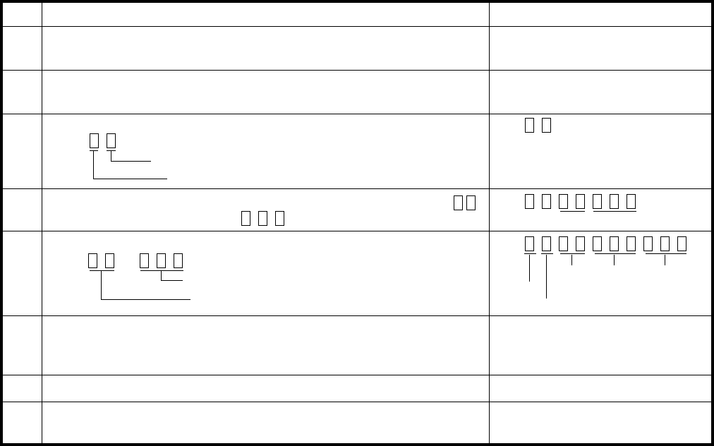
REMOTE ADMINISTRATION AND MAINTENANCE PROCEDURES
SECTION 100-816-600
MARCH 1993
-31-
TABLE RM-Y
PROGRAM 29
DSS CONSOLE BUTTON ASSIGNMENTS
ACTIONSTEP DISPLAY/PRINTOUT
1>MODE PROG
P
Enter Program Mode
At the >MODE prompt, enter P R O G CR.
2P 29
P29
Enter Program Number
3P29Enter Console Number and Buttonstrip Group Number
5
P29 Enter the 2-digit Button Number to be Programmed (01 ~ 20):
(current feature code displays after button entry).
7
8
Press SPACE to go to next button.6
Enter New (2- or 3-digit) Feature Code
Press or
Press 2 9 CR.
Press
Button Group Number (1 ~ 3)
Console Number (1 ~ 2)
4Key code
3-digit code
2-digit code Console
Button group
Button
No.
New
code
Old
code
P29
P29
Press CR to store data.
or
Continue with Step 3 until all data is entered.
To Exit this Program
Press # # CR.
Program 29
NOTE:
Pro
g
rams 30 and 31
,
use T
y
pe 1 procedure.

REMOTE ADMINISTRATION AND MAINTENANCE PROCEDURES
SECTION 100-816-600
MARCH 1993
-32-
TABLE RM-Z
PROGRAM 32
AUTOMATIC PREFERENCE
1>MODE PROG
Enter the Program Mode
At the >MODE prompt, enter P R O G CR.
ACTION
STEP DISPLAY/PRINTOUT
2P 32
P32
Enter the Program Number 32
3P32 01Refer to the record sheet and enter the required port number.
4P32 01# 100
Press CR.
5P32 01 # 100 0
Refer to the record sheet and enter the required
ringing code. Example: Code 0, enter 0.
7To Exit Program/Store Data
A) To store data, press CR.
B) Continue returning to step 3 until all Program 32 data
is entered.
C) To exit this program, press # # CR.
6P32 01# 100 011Refer to the record sheet and enter the required
automatic off-hook code. Example: Code 11, enter 1 1.
P32 01# 100 011
P32 ##
P
P
Example: Port 01, enter 0 1.
Enter #. The present status for this port will be displayed.
TABLE RM-AA
PROGRAM 33
STATION HUNTING
ACTIONSTEP DISPLAY/PRINTOUT
1>MODE PROGEnter the Program Mode
At the >MODE prompt, enter P R O G CR.
2P 33
P33
Enter Program Number 33
Press CR.
3P33 03Refer to the record sheet and enter the required
port number.
Example: Port 03, enter 0 3.
4 Enter #. The present data will be displayed. P33 03# NN
5 Refer to the record sheet and enter the port number
that will be the hunt point.
Example: Port 00, enter 0 0.
6P33 03# NN 00
P33 ##
P
To Exit Program/Store Data
A)
B)
C)
P
P33 03# NN 00
To store data, press CR.
Continue returning to step 3 until all Program 33
data is entered.
To exit this program, press # # CR.

REMOTE ADMINISTRATION AND MAINTENANCE PROCEDURES
SECTION 100-816-600
MARCH 1993
-33-
TABLE RM-AB
PROGRAM 34
HOLD RECALL TIMING
ACTIONSTEP DISPLAY/PRINTOUT
1>MODE PROGEnter the Program Mode
At the >MODE prompt, enter P R O G CR.
2P 34
P34
Enter Program Number 34
Press CR.
3P34 05Refer to the record sheet and enter the required
port number.
Example: Port 05, enter 0 5.
4 Press #. The present data will be displayed. P34 05# 032
5 Refer to the record sheet and enter the required timing.
Example: 160 seconds, enter 1 6 0.
6P34 05# 032 160
P34 ##
P
To Exit Program/Store Data
A)
B)
C)
P
P34 05# 032 160
To store data, press CR.
Continue returning to step 3 until all Program 34
data has been entered.
To exit this program, press # # CR.
NOTE:
, use T
y
pe 2 procedure.Pro
g
ram 35
TABLE RM-AC
PROGRAM 36
FIXED CALL FORWARD
ACTIONSTEP DISPLAY/PRINTOUT
1>MODE PROGEnter the Program Mode
At the >MODE prompt, enter P R O G CR.
2P 36
P36
Enter Program Number 36
Press CR.
3P36 00
Refer to the System Record Sheet and enter the
port number for the station that will have a Fixed
Call Forward button. Example: Port 00, enter 0 0.
4 Press #. The present data will be displayed. P36 00# NN
5 Refer to the System Record Sheet and enter
the port to be forwarded to when the Fixed
Call Forward button is pressed. Example: Port 04, enter 0 4.
P
P36 00# NN 04
6P36 00# NN 04
P36 ##
P
To Exit Program/Store Data
A)
B)
C)
To store data, press CR.
Continue returning to step 3 until all Program 36
data is entered.
To exit this program, press # # CR.

REMOTE ADMINISTRATION AND MAINTENANCE PROCEDURES
SECTION 100-816-600
MARCH 1993
-34-
TABLE RM-AD
PROGRAM 37
RING TRANSFER (CAMP-ON) RECALL TIME
ACTIONSTEP DISPLAY/PRINTOUT
1>MODE PROGEnter the Program Mode
At the >MODE prompt, enter P R O G CR.
2P 37
P37
Enter the Program Number 37
Press CR.
3P37 01
Refer to the System Record Sheet and enter the
required port number. Example: Port 01, enter 0 1.
4 Press #. System will display the present ring transfer
recall time.
P37 01# 064
P
5 Refer to the System Record Sheet and enter
the required ring transfer timeout.
Example: 70 seconds. Enter 0 7 0.
P37 01# 064 070
6P37 01# 064 070
P37 ##
P
To Exit Program/Store Data
A)
B)
C)
To store data, press CR.
Continue returning to step 3 until all Program 37
data is entered.
To exit this program, press # # CR.

REMOTE ADMINISTRATION AND MAINTENANCE PROCEDURES
SECTION 100-816-600
MARCH 1993
-35-
TABLE RM-AE
PROGRAM 38
DIGITAL AND ELECTRONIC TELEPHONE BUTTONSTRIP TYPE
ACTIONSTEP DISPLAY/PRINTOUT
1>MODE PROGEnter the Program Mode
At the >MODE prompt, enter P R O G CR.
2P 38
P38
Enter the Program Number 38
Press CR.
3P38 00
Refer to the System Record Sheet and enter the
required port number. Example: Port 00, enter 0 0.
4 Press #. The system will display the present
telephone code.
P38 00# 31
P
5 Refer to the System Record Sheet and enter
the required telephone code number.
Example: Code 21, enter 2 1.
P38 00# 31 21
6P38 00# 31 21
P38 ##
P
To Exit Program/Store Data
A)
B)
C)
To store data, press CR.
Continue returning to step 3 until all Program 38
data is entered.
To exit this program, press # # CR.

REMOTE ADMINISTRATION AND MAINTENANCE PROCEDURES
SECTION 100-816-600
MARCH 1993
-36-
TABLE RM-AF
PROGRAM 39
FLEXIBLE BUTTON ASSIGNMENT
ACTIONSTEP DISPLAY/PRINTOUT
1>MODE PROGEnter the Program Mode
At the >MODE prompt, enter P R O G CR.
2P 39
P39
Enter the Program Number 39
Press CR.
3P39 00
4P39 00#
Press #.
5P39 00# 01 00
7To select the next button number, press SPACE.P39 00# 01 00 01
9P39 00# 01 00 01
6P39 00# 01 00 01
Refer to the System Record Sheet and enter the required
feature code (2 or 3 digits).
Example: Code 01, enter 0 1.
P
Refer to the System Record Sheet and enter
the required port number.
Example: Port 00, enter 0 0.
Refer to the System Record Sheet and enter
the button number.
Example: Button 01, enter 0 1.
The system will display the feature code presently
assigned to this button.
02 02
Continue returning to step 6 until all port
00 features are programmed.
A)
B) 02 02
P39 ##
P
Continue returning to step 3 until all Program 39
data has been entered.
To exit this program and store data, press # # CR.
8Press CR to store data. P39
NOTES:
1. Program 40, 41: use Type 2 procedure.
Pro
g
ram 42-0: use T
y
pe 1 procedure.2.

REMOTE ADMINISTRATION AND MAINTENANCE PROCEDURES
SECTION 100-816-600
MARCH 1993
-37-
TABLE RM-AG
PROGRAM 42-1 ~ 8
PBX ACCESS CODE
ACTIONSTEP DISPLAY/PRINTOUT
1>MODE PROG
P
Enter Program Mode
At the >MODE prompt, enter P R O G CR.
2Enter Program Number 42
Press CR.
3P42 1 NN
Refer to the System Record Sheet and enter the required
PBX group number (1 ~ 8).
System will display present PBX access code.
4P42 1 NN 9N
5P42 1 NN 9N
P42 ##
P
To Exit Program/Store Data
A)
B)
C)
P 42
P42
Refer to the System Record Sheet and enter the required
access code.
N = Space
# = Don't care
Example: 9, enter 9 N.
To store data press CR.
Return to step 3 to continue in this program.
To exit this program, press # # CR.

REMOTE ADMINISTRATION AND MAINTENANCE PROCEDURES
SECTION 100-816-600
MARCH 1993
-38-
TABLE RM-AH
PROGRAM 60
SMDR OUTPUT/ACCOUNT CODE DIGIT LENGTH
ACTIONSTEP DISPLAY/PRINTOUT
1>MODE PROG
P
Enter Program Mode
At the >MODE prompt, enter PROGCR
2P 60
P60
Enter Program Number 60
CR
3B P60 3 1
P60
Press
Allow SMDR printout.
System will print out "1" if incoming and outgoing calls will be
printed on SMDR. A "0" will be printed out if only outgoing calls
will be printed.
3C P60 4 06Set Account Code Digit Length
Enter: Item code 4.
The system will display the number of digits allowed in the
account code. The default is 06.
Refer to the System Record Sheet and enter the required number
of digits (04 ~ 15) and press CR.
If you wish to change another parameter within this program,
enter its associated item code. To exit this program, go to step 4.
Refer to the System Record Sheet and change (to 1 or 0), if
required, and press CR.
If you wish to change another parameter within this program,
enter its associated item code. To exit this program, go to step 4.
3D P60 5 0
4To Exit Program/Store Data
Press # # CR.
3E P60 6 NNNN
P60 6 NNNN
P60 ##
P
SMDR Toll Calls Only
The system will display the presently selected feature (0 ~ 5).
The default is 0. Refer to the System Record Sheet and enter the
required feature code and press CR.
If you wish to change another parameter within this program,
enter its associated item code. To exit this program, go to step 4.
Enter DISA ID Code
System will display last entered ID code number. Default = Blank.
Refer to the System Record Sheets, and enter a new code if
desired, and then press CR.
If you wish to change another parameter within this program,
enter its associated item code. To exit this program, go to step 4.
.
.
Enter: Action code 3.
Enter: Action code 5.
Enter: Item code 6.
3A P60 21SMDR Threshold Time
Enter: Item code 2.
The system will display either "0" or "1". "0" indicates that the
threshold time is set at 0.1 seconds. "1" indicates 10 seconds.
The default is "1".
Refer to the System Record Sheet, and enter the correct digit—
if it is not already being displayed—and then CR.
If you wish to change another parameter within this program,
enter its associated item code. To exit this program, go to step 4.
3F P60 7 13Credit Card Call Digit Length
Enter: Item code 7.
The system will display the current digit length.
Refer to the System Record Sheet, and enter the desired length,
01 ~ 30 digits, and then CR. Example: 13 digits; enter 1 3 CR.
If you wish to change another parameter within this program,
enter its associated item code. To exit this program, go to step 4.

REMOTE ADMINISTRATION AND MAINTENANCE PROCEDURES
SECTION 100-816-600
MARCH 1993
-39-
TABLE RM-AI
PROGRAM 69
VERIFIABLE ACCOUNT CODE ENTRY
ACTIONSTEP DISPLAY/PRINTOUT
1>MODE PROG
P
Enter Program Mode
At the >MODE prompt, enter P R O G CR.
2P 69
P69
Enter Program Number 69
3P69 001 NNNNNNNNNNNNNNN
Press CR.
Refer to the System Record Sheet, and enter the required code
number (000 ~ 299).
Example: code number 001; Enter: 0 0 1.
The system will display the present account code number
assigned to 001.
Note:
The number of digits will be as defined in
Program 60-4
.
4P69 001 NNNNNN 987654A)
B)
5To Exit Program/Store Data
A)
B)
C)
P69 001 NNNNNN 987654
P69 ##
P
Refer to the System Record Sheets, and enter the required
account code number.
Example: number 987654; Enter: 9 8 7 6 5 4.
To clear and erase all data enter (all caps)
N N N N N N N N N N N N N N N .
To store data, press CR.
Continue returning to step 3 until all Program 69 data
is entered.
To exit this program, press # # CR.

REMOTE ADMINISTRATION AND MAINTENANCE PROCEDURES
SECTION 100-816-600
MARCH 1993
-40-
TABLE RM-AJ
PROGRAM 70
VERIFY ACCOUNT CODE/TOLL RESTRICTION ASSIGNMENT
ACTIONSTEP DISPLAY/PRINTOUT
1>MODE PROG
P
Enter Program Mode
At the >MODE prompt, enter P R O G CR.
2P 70
P70
Enter Program Number 70
3P70 002 YZ
Press CR.
Refer to the System Record Sheet, and enter the required code
number (000 ~ 299).
Example: code number 002; Enter: 0 0 2.
The system will display the present digit Restrict (Y) and Toll
Restriction Status (Z) for entered code number.
4 Refer to the System Record Sheet, and enter the required
digit Restrict and Toll Restriction data.
Example: digit Restrict (1) and Toll Restriction (3);
Enter: 1 3.
5To Exit Program/Store Data
A) To store data, press CR.
B) Continue returning to step 3 until all Program 70 data
is entered.
C) To exit this program, press # # CR.
P70 002 YZ 13
P70 002 YZ 13
P70 ##
P
NOTE:
Pro
g
rams 77-1 and 77-2, use T
y
pe 1 procedure.

REMOTE ADMINISTRATION AND MAINTENANCE PROCEDURES
SECTION 100-816-600
MARCH 1993
-41-
TABLE RM-AK
PROGRAM 78
CO LINE SPECIAL RINGING ASSIGNMENTS-DISA/IMDU/
NIGHT RINGING OVER EXTERNAL PAGE
ACTIONSTEP DISPLAY/PRINTOUT
1>MODE PROG
P
Enter Program Mode
At the >MODE prompt, enter P R O G CR.
2P 78
P78
Enter Program Number 78
3P78 1
Press CR.
6To Exit Program/Store Data
A)
B)
C)
To store data, press CR.
Continue returning to step 3 until all data has been entered
for this program.
To exit this program, press # # CR.
Refer to the System Record Sheet and enter the feature number
for the feature to be programmed.
Example: Feature code 1, enter 1.
4P78 13Refer to the System Record Sheet and enter the code number
for the area of the feature being programmed.
Example: Code 3, enter 3.
P78 13 01 N
02 N Y
P78 ##
P
P78 13 01 N
02 N Y
Refer to the System Record Sheet and enter the CO line buttons
that will be associated with this feature.
Example: CO button 01, enter 0 1.
The system will designate whether the CO button/LED is on/off.
Refer to the System Record Sheet and change if required.
Press SPACE to display next CO button/LED.
5
NOTE:
Pro
g
ram 79 uses T
y
pe 2 procedure.

REMOTE ADMINISTRATION AND MAINTENANCE PROCEDURES
SECTION 100-816-600
MARCH 1993
-42-
TABLE RM-AL
PROGRAM 80
DIGITAL AND ELECTRONIC TELEPHONE RINGING TONES
ACTIONSTEP DISPLAY/PRINTOUT
1>MODE PROG
P
Enter Program Mode.
At the >MODE prompt, enter P R O G CR.
2P 80
P80
Enter Program Number 80
3P80 01
Press CR.
6To Exit Program/Store Data
A)
B)
C)
To store data, press CR.
Continue returning to step 3 until all data has been entered
for this program.
To exit this program, press # # CR.
Refer to the System Record Sheet and enter the required
port number.
Example: Port 01, enter 0 1.
4P80 01# 1Press # key.
The system will display 1 or 2 corresponding to tone 1 or tone 2.
P80 01# 1 2
P80 ##
P
P80 01# 1 2Refer to the System Record Sheet and change if required.
Example: Tone 2, enter 2.
5
NOTE:
Pro
g
rams 81 ~ 89 use T
y
pe 2 procedure.
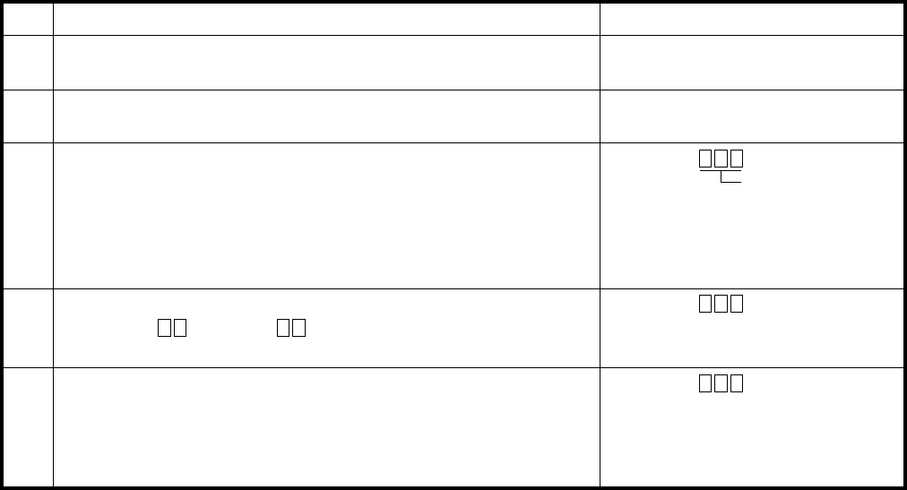
REMOTE ADMINISTRATION AND MAINTENANCE PROCEDURES
SECTION 100-816-600
MARCH 1993
-43-
TABLE RM-AM
PROGRAM 93
CO LINE IDENTIFICATION
ACTIONSTEP DISPLAY/PRINTOUT
1>MODE PROG
P
Enter Program Mode
At the >MODE prompt, enter P R O G CR.
2P 93
P93
Enter Action Code 13P93 1 02
Refer to the System Record Sheet and enter the appropriate
CO line number.
Example: CO line 2, enter 0 2.
The system will display previously entered identification
characters (up to 16 characters).
5To Exit Program/Store Data
A)
B)
C)
To store data, press CR.
Continue returning to step 3 until all data has been entered
for this program.
To exit this program, press # # CR.
4 Refer to the System Record Sheet and change identification
if required:
Example: OVERSEAS.
Enter Program Number 93
Press CR.
(up to 16)
P93 1 02
OVERSEAS
(up to 16)
P93 1 02
OVERSEAS
P93 ##
P
(up to 16)
NOTE:
Use
SPACE
to clear characters.
Current I.D.
.......... (16 characters maximum).

REMOTE ADMINISTRATION AND MAINTENANCE PROCEDURES
SECTION 100-816-600
MARCH 1993
-44-
TABLE RM-AN
PROGRAM 44 (A OR B)
TOLL RESTRICTION TRAVELING CLASS OVERRIDE CODE ENTRY
ACTIONSTEP DISPLAY/PRINTOUT
1>MODE PROG
P
Enter Program Mode
At the >MODE prompt, enter P R O G CR.
2P 44
P44
Enter Program Number 44 (Do not enter A or B)
3P44 1 NNNN
P44 1 NNNN 3456
P44 ##
P
Refer to the System Record Sheet and enter the required Toll
Restriction Class number (1 ~ 4).
Example: Class 1; Enter: 1.
The system will display the present override code assigned to
that class number.
5To Exit Program/Store Data
A) To store data, press CR.
B) Continue returning to step 3 until all Program 44 data
is entered.
C) To exit this program, press # # CR.
Press CR.
4 Refer to the System Record Sheet and enter the required override
code number.
Example: 3456; Enter 3 4 5 6.
P44 1 NNNN 3456
TABLE RM-AO
PROGRAM 45-1
TOLL RESTRICTION DIAL PLAN
ACTIONSTEP DISPLAY/PRINTOUT
1>MODE PROG
P
Enter the Program Mode
At the >MODE prompt, enter P R O G CR.
2Enter Program Number 45
Press CR.
3P45 1 1
The system will display the present dial plan code number (1 ~ 5).
4P45 1 1 2
5P45 1 1 2
P45 ##
P
To Exit Program/Store Data
A) To store data, press CR.
B) To exit this program, press # # CR.
P 45
P45
Refer to the record sheet and enter the required code number.
Example: Code 2, enter 2.
Enter the number 1.

REMOTE ADMINISTRATION AND MAINTENANCE PROCEDURES
SECTION 100-816-600
MARCH 1993
-45-
TABLE RM-AP
PROGRAM 45-2
TOLL RESTRICTION DISABLE
ACTIONSTEP DISPLAY/PRINTOUT
1>MODE PROG
P
Enter the Program Mode
At the >MODE prompt, enter P R O G CR.
2P 45
P45
Enter Program Number 45
3P45 2Enter the number 2.
4P45 2 01 NRefer to the record sheet and enter the required CO line number.
Example: CO line 01, enter 0 1. The system will display
N or Y to define if the LED is on or off.
5
P45 2 01 N Y
P45 ##
P
Refer to the System Record Sheet and change the CO line
status as required (Y or N).
Press SPACE to step to next CO line number.
6To Exit Program/Store Data
A)
B) To store data, press CR.
To exit this program, press # # CR.
Press CR.
02 N
P45 2 01 N Y
02 N
TABLE RM-AQ
PROGRAM 45-3 ~ 6
EQUAL ACCESS, SPECIAL COMMON CARRIER NUMBERS, and AUTHORIZATION CODE DIGIT LENGTH
ACTIONSTEP DISPLAY/PRINTOUT
1>MODE PROG
P
Enter Program Mode
At the >MODE prompt, enter P R O G CR.
2P 45
P45
Enter Program Number 45
3P45 3 NNNNN
P45 4 00 12
P45
Refer to the record sheet and enter the item number (3 ~ 6).
Example: Item 3, enter 3. The system will display
the present equal access number or EA1 Code.
5
P45 ##
P
Enter code number 4. The system will display present authorization
code digit length. Refer to the System Record Sheet and enter
the required authorization code number digit length.
Example: 12, enter: 1 2 CR.
6 To exit this program, press # # CR.
Press CR.
4 Refer to the System Record Sheet and enter the required number.
Example: 12345, enter 1 2 3 4 5 CR.P45 3 NNNNN 12345
P45
NOTE:
Items 5 and 6 are entered the same wa
y
as 3 and 4, respectivel
y
.
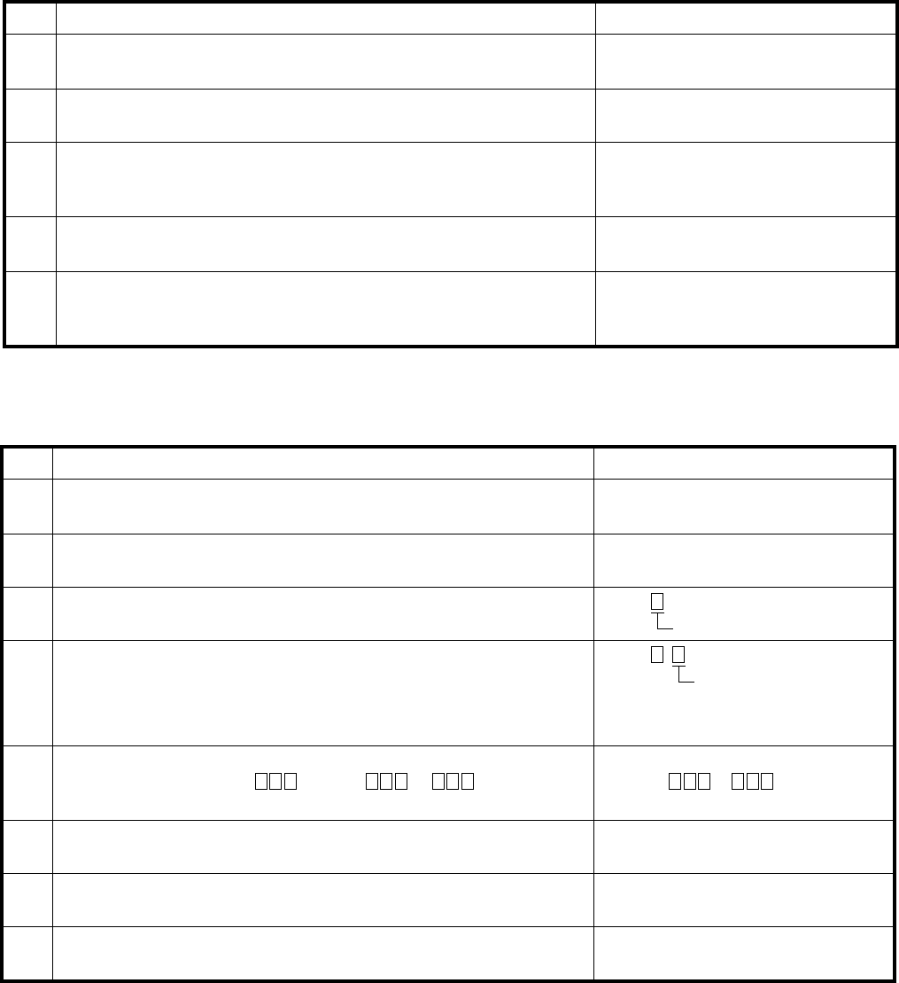
REMOTE ADMINISTRATION AND MAINTENANCE PROCEDURES
SECTION 100-816-600
MARCH 1993
-46-
TABLE RM-AR
PROGRAM 45-8 ~ 9
TOLL RESTRICTION OVERRIDE CODE
ACTIONSTEP DISPLAY/PRINTOUT
1>MODE PROG
P
Enter the Program Mode
At the >MODE prompt, enter P R O G CR.
2P 45
P45
Enter the Program Number 45
3P45 8 NNNN
P45 8 NNNN 1234
P45 ##
P
Refer to the System Record Sheet and enter 8 or 9 for the
desired code number. The system will display the present
override code number.
5To Exit Program/Store Data
Press CR.
4 Refer to the record sheet and enter a new number if required.
Example: 1234. Enter: 1 2 3 4.P45 8 NNNN 1234
A)
B) To store data, press CR.
To exit this program, press # # CR.
TABLE RM-AS
PROGRAM 46–2 ~ 4
TOLL RESTRICTION ALLOWED/DENIED AREA CODES ASSIGNED BY CLASS
ACTIONSTEP DISPLAY/PRINTOUT
1>MODE PROG
P
Enter Program Mode
At the >MODE prompt, enter P R O G CR.
2P 46
P46
Enter Program Number 46
5
Press CR.
Refer to the System Record Sheet and enter the area code or
area code group. Single . Group
*
.
Press SPACE to enter more codes.
P46 X Y
ALLOW –
or DENY
6 Press SPACE to temporarily store data. Press CR when
completed. P46
7Continue returning to step 3 until all data input is completed for
this program.
8To Exit this Program
Press # # CR.P46 ##
P
3 Enter class number (1 ~ 4). P46
Class Number
4 Enter 2, 3, or 4 SPACE P46
ALLOW? or DENY?
• 2
• 3
• 4 SPACE
— to add codes to memory (allow).
— to delete codes from memory (deny).
— to display codes in memory (allowed codes).
2, 3 or 4
REMOTE ADMINISTRATION AND MAINTENANCE PROCEDURES
SECTION 100-816-600
MARCH 1993
-47-
TABLE RM-AT
PROGRAM 46-6 ~ 8
TOLL RESTRICTION ALLOWED/DENIED OFFICE CODES ASSIGNED BY CLASS
ACTIONSTEP DISPLAY/PRINTOUT
1>MODE PROG
P
Enter Program Mode
At the >MODE prompt, enter P R O G CR.
2P 46
P46
Enter Program Number 46
6
Press CR.
Refer to the System Record Sheet and enter the office code or
office code group. Single . Group
*
.
Press SPACE to enter more codes.
P46 X Y
ALLOW –
or DENY
7
Press SPACE to temporarily store data. Press SPACE when
completed. P46
8
Continue returning to step 3 until all data input is completed for
this program.
To Exit this Program
Press # # CR.P46 ##
P
3 Enter class number (1 ~ 4). P46
Class Number (X)
4 Enter 6, 7, or 8 SPACE.P46
• 6
• 7
• 8 SPACE
— to add codes to memory (allowed).
— to delete codes from memory (deny).
— to display codes in memory (allowed codes).
6, 7, or 8 (Y)
5

REMOTE ADMINISTRATION AND MAINTENANCE PROCEDURES
SECTION 100-816-600
MARCH 1993
-48-
TABLE RM-AU
PROGRAM 46-10 ~ 40
TOLL RESTRICTION CLASS PARAMETERS
ACTIONSTEP DISPLAY/PRINTOUT
1>MODE PROG
P
Enter Program Mode
At the >MODE prompt, enter P R O G CR.
2P 46
P46
Enter Program Number 46
3P46 10Refer to the System Record Sheet and enter the Toll Restriction
class number (1 ~ 4). Then enter the number 0.
Example: Class 1, enter 1 0.
6To Exit Program/Store Data
Press CR.
4 Refer to the System Record Sheet and enter the required
button/LED number.
Example: Button number 11, enter 1 1. The system will display
the status of the button/LED.
P46 10 11 TABLE 1N
A)
B) To store data, press CR.
To exit this program, press # # CR.
5 Refer to the System Record Sheet and change if required (Y or N).
To access next button number, press SPACE.P46 10 11 TABLE1 N Y
12 TABLE2 N
P46 10 11 TABLE1 N Y
P46 ##
P
12 TABLE2 N
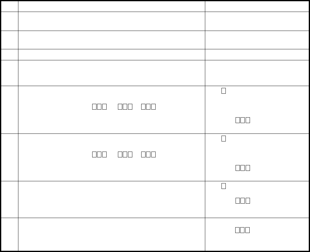
REMOTE ADMINISTRATION AND MAINTENANCE PROCEDURES
SECTION 100-816-600
MARCH 1993
-49-
TABLE RM-AV
PROGRAM 47
TOLL RESTRICTION EXCEPTION OFFICE CODES ASSIGNED BY AREA CODE
ACTIONSTEP DISPLAY/PRINTOUT
1>MODE PROG
P
Enter Program Mode
At the >MODE prompt, enter P R O G CR.
2P 47
P47
Enter Program Number 47
3P47 Y 1 AREA CODE NNNEnter exception table (1 ~ 8) and press 1.
Press CR.
4 Refer to the System Record Sheet and enter the required area
code and press CR.
Example: AC 714, enter 7 1 4 CR.
P47 Y 1 AREA CODE NNN 714
P47
5a
6P47 Y 2
Except
P47 ##
P
To Exit Program/Store Data: # # CR.
To Add Exception Office Codes to Table
• Enter exception table (1 ~ 8) and press 2.
• Enter exception codes or * .
• Press SPACE to add more codes.
• Press SPACE CR to store codes.
P47
Except
Except
2
5b To Delete Exception Office Codes from Table
• Enter exception table (1 ~ 8) and press 3.
• Enter exception codes or * .
• Press SPACE to delete more codes.
• Press SPACE CR to store codes.
P47
Delete
Delete
3
5c To Display Exception Office Codes in Table
• Enter exception table (1 ~ 8) and press 4 SPACE.
• Press SPACE to display more codes.
• Press CR to exit display.
P47
Except
4

REMOTE ADMINISTRATION AND MAINTENANCE PROCEDURES
SECTION 100-816-600
MARCH 1993
-50-
To store data, press CR.
Continue returning to step 3 until all data is recorded for this
program.
To exit this program, press # # CR.
TABLE RM-AW
PROGRAM 48
STATION TOLL RESTRICTION CLASSIFICATION
ACTIONSTEP DISPLAY/PRINTOUT
1>MODE PROG
P
Enter the Program Mode
At the >MODE prompt, enter P R O G CR.
2P 48
P48
Enter Program Number 48
3P48 00Refer to the System Record Sheet and enter the required port
number.
Example: Port 00, enter 0 0.
Press CR.
4 Press # key. The system will display the present data as a
two-digit code: The first digit designates digit free or digit restrict.
The second digit is the station restriction code. Refer to the
System Record Sheet and change if required.
P48 00# 13
5To Exit Program/Store Data P48 00# 13
P48 ##
P
A)
B)
C)
To store data, press CR.
To exit this program, press # # CR.
TABLE RM-AX
PROGRAM 50-1
LCR PARAMETERS
ACTIONSTEP DISPLAY/PRINTOUT
1>MODE PROG
P
Enter Program Mode
At the >MODE prompt, enter P R O G CR.
2P 50
P50
Enter Program Number 50.
3P50 1 01 NEnter 1. Refer to the System Record Sheet and enter the required
button/LED number.
Example: Button 01, enter 0 1.
Press CR.
4 Refer to the System Record Sheet and change button/LED status,
if required.
Press SPACE to move to next button/LED.
P50 1 01 N
02 N
5To Exit Program/Store Data P50 1 01 N
02 N
P50 ##
P
A)
B)

REMOTE ADMINISTRATION AND MAINTENANCE PROCEDURES
SECTION 100-816-600
MARCH 1993
-51-
To store data, press CR.
To exit this program, press # # CR.
TABLE RM-AY
PROGRAM 50-2
LCR HOME AREA CODE
ACTIONSTEP DISPLAY/PRINTOUT
1>MODE PROG
P
Enter Program Mode
At the >MODE prompt, enter P R O G CR.
2P 50
P50
Enter Program Number 50
3P50 2 NNNEnter the number 2. The system will display the last area code
programmed. Refer to the System Record Sheet and change
if required.
Press CR.
4To Exit Program/Store Data P50 2 NNN
P50 ##
P
A)
B)
To store data, press CR.
Continue returning to step 3 until all data for this program has
been entered.
To exit this program, press # # CR.
TABLE RM-AZ
PROGRAM 50-31 ~ 35
LCR SPECIAL CODES
ACTIONSTEP DISPLAY/PRINTOUT
1>MODE PROG
P
Enter Program Mode
At the >MODE prompt, enter P R O G CR.
2P 50
P50
Enter Program Number 50
3P50 31 NNNNRefer to the System Record Sheet and enter 31 ~ 35 as required.
Example: 31, enter 3 1.
System will display previously programmed number. Refer to the
System Record Sheet and change if required.
Press CR.
4To Exit Program/Store Data P50 31 NNNN
P50 ##
P
A)
B)
C)

REMOTE ADMINISTRATION AND MAINTENANCE PROCEDURES
SECTION 100-816-600
MARCH 1993
-52-
TABLE RM-BA
PROGRAM 50-4
LCR LDI PLAN NUMBER
ACTIONSTEP DISPLAY/PRINTOUT
1>MODE PROG
P
Enter Program Mode
At the >MODE prompt, enter P R O G CR.
2P 50
P50
Enter Program Number 50
3P50 4 1
Press CR.
4P50 4 1
P50 ##
P
Exit Program/Store Data
A)
B) To store data, press CR.
To exit this program, press # # CR.
Enter the number 4
The system will display the present LDI route number.
Refer to the System Record Sheet and change if required.
TABLE RM-BB
PROGRAM 50-5
LCR LOCAL CALL PLAN NUMBER
ACTIONSTEP DISPLAY/PRINTOUT
1>MODE PROG
P
Enter Program Mode
At the >MODE prompt, enter P R O G CR.
2P 50
P50
Enter Program Number 50
3P50 5 1 2
Press CR.
4P50 5 1 2
P50 ##
P
Exit Program/Store Data
A)
B) To store data, press CR.
To exit this program, press # # CR.
Enter the number 5
The system will display the present local route plan number.
Refer to the System Record Sheet and change if required.
Example: 2, enter 2.
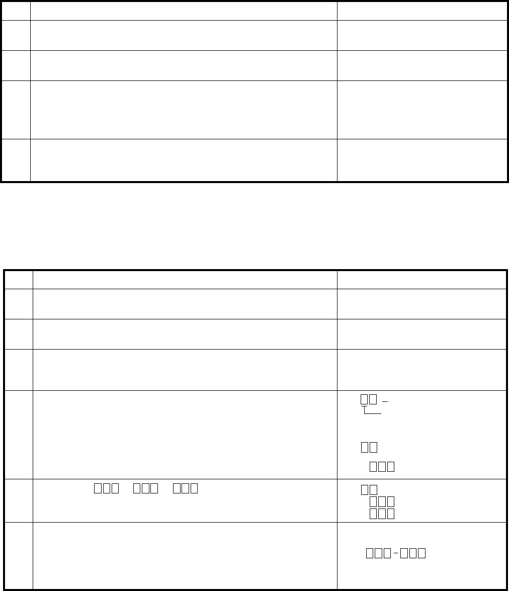
REMOTE ADMINISTRATION AND MAINTENANCE PROCEDURES
SECTION 100-816-600
MARCH 1993
-53-
TABLE RM-BC
PROGRAM 50-6
LCR DIAL ZERO TIMEOUT
ACTIONSTEP DISPLAY/PRINTOUT
1>MODE PROG
P
Enter Program Mode
At the >MODE prompt, enter P R O G CR.
2P 50
P50
Enter Program Number 50
3P50 6 06 10
Press CR.
4P50 6 06 10
P50 ##
P
Exit Program/Store Data
A)
B) To store data, press CR.
To exit this program, press # # CR.
Enter the number 6
The system will display the present dial zero timeout.
Refer to the System Record Sheet and change if required.
Example: 10, enter 1 0.
TABLE RM-BD
PROGRAM 51
LCR AREA CODES
ACTIONSTEP DISPLAY/PRINTOUT
1>MODE PROG
P
Enter Program Mode
At the >MODE prompt, enter P R O G CR.
2P 51
P51
Enter Program Number 51
3P51 1
Press CR.
6Exit Program/Store Data
A)
B)
C)
To store data, press CR.
Continue returning to step 3 until all data has been
entered for this program.
To exit this program, press # # CR.
P51 12
212
or
P51 ##
P
4Enter 2, 3, or 4 SPACE
Refer to the System Record Sheet and enter the required
route plan number (1 ~ 8).
Example: Route plan 1, enter 1.
P51
P51
• 2
• 3
• 4 SPACE
— To add area codes to table.
— To delete area codes from table.
— to display area codes in table,
continue to press SPACE to display more codes.
Press CR to exit display.
2, 3 or 4
<— CODES
5Enter codes or
*
and
press SPACE after each code entry.
P51
Plan No.
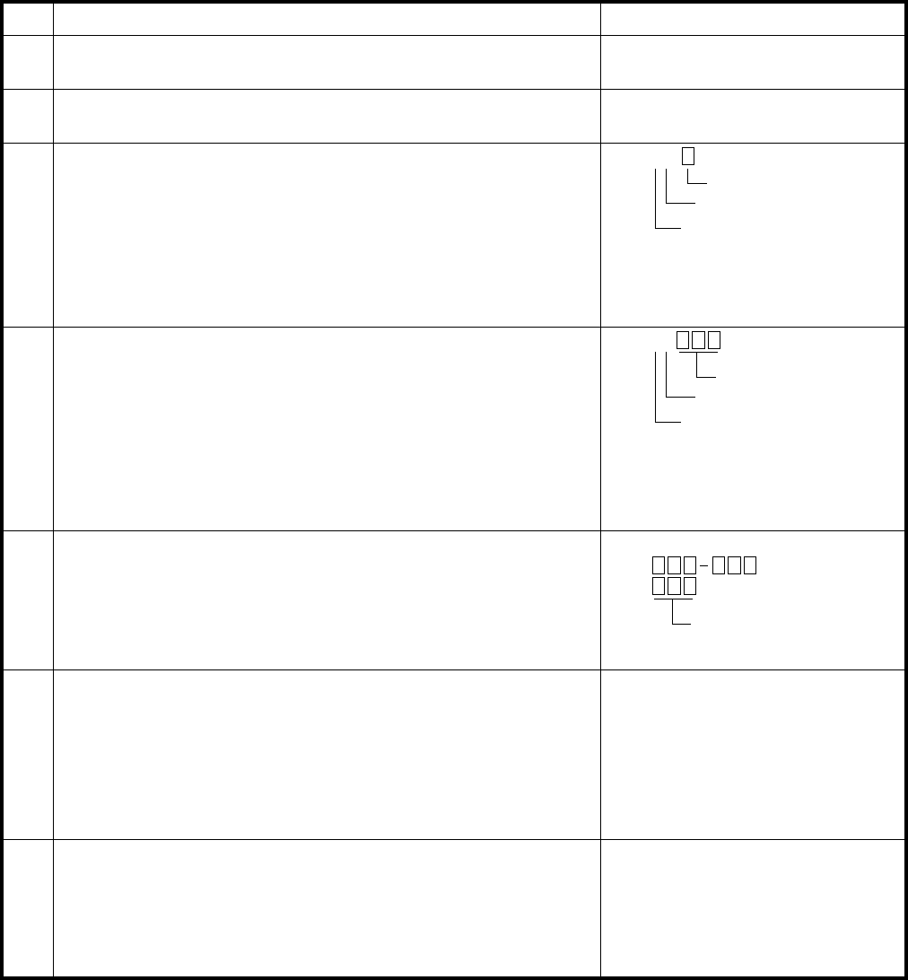
REMOTE ADMINISTRATION AND MAINTENANCE PROCEDURES
SECTION 100-816-600
MARCH 1993
-54-
TABLE RM-BE
PROGRAM 52
LCR OFFICE CODE EXCEPTIONS FOR SPECIFIED AREA CODE
ACTIONSTEP DISPLAY/PRINTOUT
1>MODE PROG
P
Enter Program Mode
At the >MODE prompt, enter P R O G CR.
2P 52
P52
Enter Program Number 52
3P52 10 3
Press CR.
Define Route Plan Number
Refer to the System Record Sheet and enter the
exception table number (1 ~ 8).
Example: Table 1, enter 1.
The system will print out the currently defined route
plan number. Refer to the System Record Sheet and enter
new plan number if required. Example: Change to 3.
4P52 11 212
P52
Define Area Code Number
Enter exception table number (1 ~ 8) defined in step 3.
The system will print out the currently defined area
code number. Refer to the System Record Sheet and enter the
new area code number if required.
Press CR.
Press CR.
5P52 14Display Office Codes
Enter exception table number defined in step 3.
Press SPACE to display previously selected office codes.
Continually press SPACE until all previously selected
codes have been displayed, then press CR.
6P52 12
300-325
P52
To Add (2) or Delete (3) Office Codes
Press CR.
Enter exception table number defined in step 3.
Refer to the System Record Sheets and enter 2
to add office codes or 3 to delete office codes.
Example: Add office codes 300-325
Enter 2 (or 3) 3 0 0
*
3 2 5 CR.
7P52 ##
P
To Exit Program/Store Data
A)
B)
C)
Data was stored when CR was pressed in step 6.
Continue returning to step 3 until all data is entered
for this program.
To exit this program.
Press # # CR.
LCR Plan No.
Action Code
Exception Table No.
Example: Change to 212, enter 2 1 2.
Area Code
Action Code
Exception Table No.
Office Codes
Enter Action code 0.
Enter Action code 1.
Enter Action code 4.

REMOTE ADMINISTRATION AND MAINTENANCE PROCEDURES
SECTION 100-816-600
MARCH 1993
-55-
TABLE RM-BF
PROGRAM 53
LCR SCHEDULE ASSIGNMENT
ACTIONSTEP DISPLAY/PRINTOUT
1>MODE PROG
P
Enter Program Mode
At the >MODE prompt, enter P R O G CR.
2P 53
P53
Enter Program Number 53
3P53 1
Press CR.
7P53 ##
P
To Exit Program/Store Data
A)
B)
C)
Data was stored when pressing CR in step 6.
Continue returning to step 3 until all data is entered
for this program.
To exit this program.
Press # # CR.
Define Route Plan Number
Refer to the System Record Sheet and enter the route
plan number (1 ~ 8).
Example: Route Plan 1, enter 1.
4P53 11Define Schedule Number
Refer to the System Record Sheet and enter the required
schedule number (1 ~ 3).
Example: Schedule 1, enter 1.
5P53 110 0000 0800
P53
The system will display the previously selected time for
the route plan number (step 3) and the schedule number (step 4).
Refer to the System Record Sheet and change the time if required.
Example: Change to 0800. Enter 0 8 0 0.
Press CR and repeat steps 3, 4, and 5 for all plans/schedules.
NOTE: Enter time using 24-hour format:
H H M M.
6P53 111 NNNN 12
P53
Enter the route plan number as defined in step 3.
Enter the schedule number as defined in step 4.
Refer to the System Record Sheet and enter the required
station group number (1 ~ 4).
Example: Group 1, enter 1.
Priority Class Assignment
The system will display the previously entered route definition
numbers (reference
Refer to the System Record Sheet and enter required
route definition numbers (1 ~ 4) and press CR.
Example: Enter 1 and 2 CR.
Enter Code Number 0
Program 54 ).
Continue to repeat steps 3, 4, and 6 until all plans/schedules
are entered.

REMOTE ADMINISTRATION AND MAINTENANCE PROCEDURES
SECTION 100-816-600
MARCH 1993
-56-
TABLE RM-BG
PROGRAM 54
LCR ROUTE DEFINITION
ACTIONSTEP DISPLAY/PRINTOUT
1>MODE PROG
P
Enter Program Mode
At the >MODE prompt, enter P R O G CR.
2P 54
P54
Enter Program Number 54
3P54 1
Press CR.
5P54 12 11 32
P54 ##
P
To Exit Program/Store Data
A)
B)
C)
To store data, press CR.
Continue returning to step 3 until all data has been entered
for this program.
To exit this program, press # # CR.
Refer to the System Record Sheet and enter the required
route plan number (1 ~ 8).
Example: Route plan 1, enter 1.
4P54 12 11 32Enter Route Definition Number
Refer to the System Record Sheet and enter the required
route definition number (1 ~ 4).
Example: Enter route definition number 2, enter 2.
The system will display the previously entered CO line
group number (1 ~ 8) and the modified digits table number (1 ~ 6).
Refer to the System Record Sheet and enter the CO line
group and modified digit numbers as required, then press CR.
Example: Change the CO line group number to 3 and the
modified digits table to 2. Enter: 3 2 CR.
Enter Route Plan Number
Modified Digit Table No.
CO Line Group No.
Route Definition No.
Plan No.

REMOTE ADMINISTRATION AND MAINTENANCE PROCEDURES
SECTION 100-816-600
MARCH 1993
-57-
Press CR.
TABLE RM-BH
PROGRAM 55-0
LCR MODIFIED DIGITS-DELETE
ACTIONSTEP DISPLAY/PRINTOUT
1>MODE PROG
P
Enter Program Mode
At the >MODE prompt, enter P R O G CR.
2P 55
P55
Enter Program Number 55
3P55 1
5To Exit Program/Store Data
A)
B)
C)
To store data, press CR.
Continue returning to step 3 until all data has been entered
for this program.
To exit this program, press # # CR.
Refer to the System Record Sheet and enter the modified
digits table number (1 ~ 6).
Example: Enter modified digits table number 1, enter 1.
4P55 10 05 10Enter Code 0
The system will display any previously entered number of
digits to be deleted (01 ~ 10).
Refer to the System Record Sheet and change number if required.
Example: Change to 10, enter: 1 0.
Enter Modified Digits Table Number
P55 10 05 10
P55 ##
P
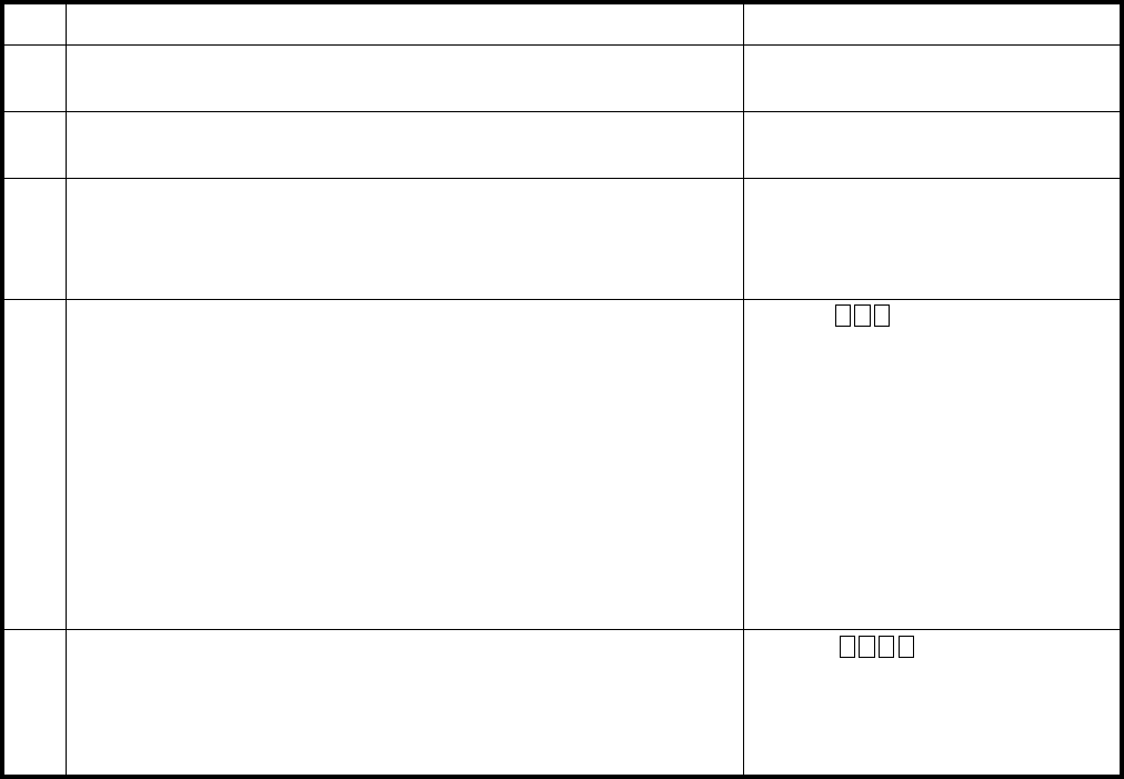
REMOTE ADMINISTRATION AND MAINTENANCE PROCEDURES
SECTION 100-816-600
MARCH 1993
-58-
Press CR.
TABLE RM-BI
PROGRAM 55-1
LCR MODIFIED DIGITS-ADD
ACTIONSTEP DISPLAY/PRINTOUT
1>MODE PROG
P
Enter Program Mode
At the >MODE prompt, enter P R O G CR.
2P 55
P55
Enter Program Number 55
3P55 1
5To Exit Program/Store Data
A)
B)
C)
To store data, press CR.
Continue returning to step 3 until all data has been entered
for this program.
To exit this program, press # # CR.
Refer to the System Record Sheet and enter the required
modified digits table number (1 ~ 6).
Example: Enter table number 1, enter 1.
4P55 11
1 2 3 4 P3
Enter Code 1
The system will display any previously entered digits (up to 22).
Refer to the System Record Sheet and enter new numbers,
if required.
Example: Enter 1 2 3 4 P 3.
Enter Modified Digits Table Number
(up to 22 digits)
NOTE: Pause codes may also be entered. To enter pauses,
press "P" plus the pause number (1 ~ 8).
P55 11
1 2 3 4 P3
P55 ##
P
Special Code Input
Pause
Tone
Clear
=
=
=
P 1 ~ P 8.
T at beginning of digits to convert.
C as first digit, then CR.
REMOTE ADMINISTRATION AND MAINTENANCE PROCEDURES
SECTION 100-816-600
MARCH 1993
-59-
TABLE RM-BJ
PROGRAM 55-2
LCR MODIFIED DIGITS-END
ACTIONSTEP DISPLAY/PRINTOUT
1>MODE PROG
P
Enter Program Mode
At the >MODE prompt, enter P R O G CR.
2P 55
P55
Enter Program Number 55
3P55 1
Press CR.
5To Exit Program/Store Data
A)
B)
C)
To store data, press CR.
Continue returning to step 3 until all data has been entered
for this program.
To exit this program, press # # CR.
Refer to the System Record Sheet and enter the required
modified digits table number (1 ~ 6).
Example: Enter table number 1, enter 1.
4P55 12
1 2 3 4 P3
Enter Code 2
The system will display any previously entered digits (up to 22).
Refer to the System Record Sheet and enter new numbers,
if required.
Example: Enter 1 2 3 4 P 3.
Enter Modified Digits Table Number
(up to 22 digits)
NOTE: Pause codes may also be entered. To enter pauses,
press "P" plus the pause number (1 ~ 8).
P55 12
1 2 3 4 P3
P55 ##
P
(up to 22 digits)
Special Code Input
Pause
Tone
Clear
=
=
=
P 1 ~ P 8.
T at beginning of digits to convert.
C as first digit, then CR.
REMOTE ADMINISTRATION AND MAINTENANCE PROCEDURES
SECTION 100-816-600
MARCH 1993
-60-
TABLE RM-BK
PROGRAM 56
LCR STATION GROUP ASSIGNMENT
ACTIONSTEP DISPLAY/PRINTOUT
1>MODE PROG
P
Enter Program Mode
At the >MODE prompt, enter P R O G CR.
2P 56
P56
Enter Program Number 56
3P56 01
Press CR.
5To Exit Program/Store Data
A)
B)
C)
To store data, press CR.
Continue returning to step 3 until all data has been entered
for this program.
To exit this program, press # # CR.
Refer to the System Record Sheet and enter the
required port number, or
*
.
Example: Port 01, enter 0 1.
4P56 01# 1 4
Press # Key
The system will display any previously entered group number (1 ~ 4).
Refer to the System Record Sheet and change as required.
Example: Change to 4, enter 4.
Enter Port Number
P56 01# 1 4
P56 ##
P
(if single port entry in step 3).
TABLE RM-BL
PROGRAM DATA DUMP
ACTIONSTEP DISPLAY/PRINTOUT
1>MODE DUMP
D
Enter the Data Dump Mode
At the >MODE prompt, enter D U M P CR.
2D PROGTo Output Program Data
3To Stop Printout at Any Time D
Enter P R G CR
= Program number or A L L for all programs.
Enter DELETE CR at the same time.
4To Exit the Dump Mode >MODE
Enter Q U I T CR.
REMOTE ADMINISTRATION AND MAINTENANCE PROCEDURES
SECTION 100-816-600
MARCH 1993
-61-
TABLE RM-BM
SPEED DIALING DATA DUMP
ACTIONSTEP DISPLAY/PRINTOUT
1>MODE DUMP
D
Enter the Data Dump Mode
At the >MODE prompt, enter D U M P CR.
2To Output Speed Dialing Data
3To Stop Printout at Any Time D
Enter R E P CR
= A L L or S Y S
= Port number for individual station speed dial.
---or--- R E P CR
Enter DELETE CR at the same time.
4To Exit the Dump Mode
Enter Q U I T CR.
TABLE RM-BN
LCD MESSAGING DATA DUMP
ACTIONSTEP DISPLAY/PRINTOUT
1>MODE DUMPEnter the Data Dump Mode
At the >MODE prompt, enter D U M P CR.
2To Output Message Data
3To Stop Printout at Any Time D
Enter M S G CR
= A L L or S Y S
= Port number of individual station.
---or--- M S G CR
Enter DELETE CR at the same time.
D MSG
4To Exit the Dump Mode >MODE
Enter Q U I T CR.
REMOTE ADMINISTRATION AND MAINTENANCE PROCEDURES
SECTION 100-816-600
MARCH 1993
-62-
NOTES:
1. To cancel a message set via Mode 95, use Mode 97 procedure.
2. [M] represents the message entered.
3. DKT = digital telephone; EKT = electronic telephone.
TABLE RM-BO
MODE 95
REMOTE CALLING STATION MESSAGING (ADD/REVIEW/CHANGE)
ACTIONSTEP DISPLAY/PRINTOUT
1>MODE MESGEnter the Message Mode
At the >MODE prompt, enter M E S G CR.
2m 95To Add Or Review a Calling Station Message
3
Set the terminal keyboard to the lower case (cap lock off) and
enter m 9 5.
4
m95 XXX
5
Enter p (p = page command and
= 2-digit message memory location: 10 ~ 19 personal
messages and 60 ~ 99 = system message).
6
To Change Previous Message
7
To Set the Message on DKT or EKT XXX’s LCD
To Exit the Message Mode m 0
q
> MODE
Enter X X X (XXX = station number where the message will be
set and stored).
m95 XXX p [M]
Set the terminal keyboard to upper case and change message
(alphanumeric, 32 characters max.).
Set the terminal keyboard to lower case and enter p m 0.
At any time, enter m 0 q (lower case).
NOTE:
Enter “m” anytime it is desired to start over in this procedure.
NOTES:
1.
2.
To store system messages permanently, DKT or EKT XXX
must be the station at port 00.
After
p
is entered, the previously stored message is
displayed. If there is no stored message, nothing is displayed.
m95 XXX p [M+]
m95 XXX p [M+] p
m 0
Zero
REMOTE ADMINISTRATION AND MAINTENANCE PROCEDURES
SECTION 100-816-600
MARCH 1993
-63-
NOTES:
1. To cancel a message set via Mode 95, use Mode 97 with any message number in step 4 and skip
step 5.
2. [M] represents the message entered.
3. DKT = digital telephone; EKT = electronic telephone.
TABLE RM-BP
MODE 97
REMOTE CALLING STATION MESSAGING (ADD/CHANGE)
ACTIONSTEP DISPLAY/PRINTOUT
1>MODE MESGEnter the Message Mode
At the >MODE prompt, enter M E S G CR.
2m 97To Add a Message
3
Set the terminal keyboard to lower case (caps lock off) and
enter m 9 7.
4
m97 XXX
5
Enter: p (p = page command and
= 2-digit message memory location: 10 ~ 19 personal
messages and 60 ~ 99 = system messages).
6
To Add a Message
To Exit the Message Mode m 0
q
>MODE
Enter X X X (XXX = station number for which the message will
be set and stored).
m97 XXX p
NOTE:
To store system message change permanently, DKT or EKT XXX
must be station assigned to port 00.
Set the terminal keyboard to upper case and enter message
(alphanumeric, 32 characters max.). New message displays as
it is entered.
At any time, enter m 0 q (lower case).
NOTE:
Enter “m” at anytime it is desired to start over in this procedure.
7
m97 XXX p [M]
To Set the Message on the DKT/EKT LCD
Set the terminal keyboard to lower case and enter p m 0.m97 XXX p [M] p
m 0
(or change a previously stored message)
Zero
REMOTE ADMINISTRATION AND MAINTENANCE PROCEDURES
SECTION 100-816-600
MARCH 1993
-64-
NOTES:
1. Press
m
at any time to start over.
2. [M] represents the message entered.
TABLE RM-BQ
MODE 94
REMOTE CALLED STATION MESSAGING (ADD/REVIEW/CHANGE)
ACTIONSTEP DISPLAY/PRINTOUT
1>MODE MESGEnter the Message Mode
At the >MODE prompt, enter M E S G CR.
2m 94To Add Or Review a Called Station Message
3
Set the terminal keyboard to the lower case (cap lock off) and
enter m 9 4.
4 Enter p Y Y Y (p = page command [lower case] and
Y Y Y = originating station number).
m94 XXX
m94 XXX p YYY
5 Enter p (p = page command [lower case] and
= 2-digit message memory location: 10 ~ 19 personal
messages and 60 ~ 99 = system messages).
After p is entered, the previously stored message (M) is
6To Change the Message (M+)
7To Set Message
8To Exit the Message Mode m 0
q
>MODE
Enter X X X (XXX = Destination station number or destination
group number [30 = all stations, 31-34 per system,
displayed. (If there is no stored message, nothing is displayed.)
m94 XXX p YYY p [M]
Set the terminal keyboard to upper case and change message
as required (alphanumeric, 32 characters max. for total message).
m94 XXX p YYY p [M+]
m94 XXX p YYY p [M+] p
m 0Set the terminal keyboard to lower case and enter p m 0.
Destination station: Msg LED flashes, “CALL YYYM” is
displayed.
Origination station: “SENT XXXM” is displayed.
At any time, enter m 0 q (lower case).
Program 31]).
Zero
REMOTE ADMINISTRATION AND MAINTENANCE PROCEDURES
SECTION 100-816-600
MARCH 1993
-65-
NOTES:
1. [M] represents the message entered.
2. DKT = digital telephone; EKT = electronic telephone.
TABLE RM-BR
MODE 96
REMOTE CALLED STATION MESSAGING (ADD/CHANGE)
ACTIONSTEP DISPLAY/PRINTOUT
1>MODE MESGEnter the Message Mode
At the >MODE prompt, enter M E S G CR.
2m 96To Change or Add a New Called Station Message
3
Set the terminal keyboard to the lower case (cap lock off) and
enter m 9 6.
4
m96 XXX
5 Enter p (p = page command and
= 2-digit message memory location: 10 ~ 19 personal
messages and 60 ~ 99 = system messages).
6
8
To Set the Message
To Exit the Message Mode m 0
q
>MODE
Enter X X X (XXX = destination station number or destination
station group number – 30 = all DKTs/EKTs, 31 ~ 34 per system,
m96 XXX p YYY p
Set the terminal keyboard to upper case and enter message
as required (alphanumeric, 32 characters max.). New message
displays as it is entered.
Set the terminal keyboard to lower case and enter p m 0.
Destination station: Msg LED flashes, “CALL YYYM” is
displayed on LCD.
Origination station: “SENT XXXM” is displayed on LCD.
At any time, enter m 0 p (lower case).
NOTE:
Enter “m” (lower case) anytime it is desired to start over
in this procedure.
Enter p Y Y Y (p = page command and YYY = originating
station number). m96 XXX p YYY
m96 XXX p YYY p [M]
7m96 XXX p YYY p [M] p
m 0
To Add the New Message [M]
Program 31).
Zero
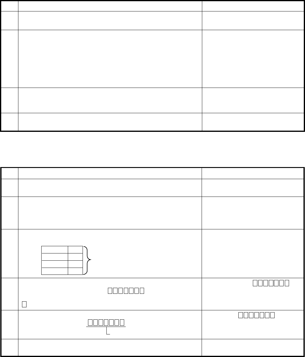
REMOTE ADMINISTRATION AND MAINTENANCE PROCEDURES
SECTION 100-816-600
MARCH 1993
-66-
TABLE RM-BS
STATION/CO LINE STATUS CHECK
ACTIONSTEP DISPLAY/PRINTOUT
1>MODE TESTEnter the Test Mode
At the >MODE prompt, enter T E S T CR.
2T SEKT XX IDLE ON-HOOK
T
To Check Station Line Status
3To Check CO Line Status
Enter S E K T X X (X X = port number).
Possible status: Idle on-hook, idle off-hook, busy on-hook,
busy off-hook.
4To Exit the Test Mode
At the T prompt, enter Q U I T CR.
T SCOYY – BUSY
TEnter S C O Y Y (Y Y = CO line number).
Possible status: Idle, busy.
T QUIT
> MODE
IMPORTANT!
To prevent service interference, station line status must be
idle on-hook before initiating a test from that station.
TABLE RM-BT
GENERAL STATION ACCESS AND BUTTON ACTIVATION
ACTIONSTEP DISPLAY/PRINTOUT
1>MODE TEST
T
Enter the Test Mode
At the >MODE prompt, enter T E S T CR.
2T TKXX KYY
T
To Activate A Button
Enter T K X X K Y Y CR.
XX = Port number and YY = button number.
NOTE: Button numbers begin at 01.
3TTKXX F
T
To Activate A Function Button
Enter T K X X F CR F = function button designator
SPKR
HOLD
CONF
MIC
S
H
C
M
4TTKXX K01 AAA
T
To Access A CO Line (via CO Access Code) and Dial Out
Enter T K X X K 0 1 A A A CR.
AAA = 1, 2, or 3-digit CO line access code and
= telephone number.
5TTKXX KYY
T
To Access A CO Line (via CO Line Button) and Dial Out
Enter T K X X K Y Y CR.
YY = CO line number.
6To Exit the Test Mode
At T prompt, enter Q U I T CR.
F = S, H, C, M
Telephone Number
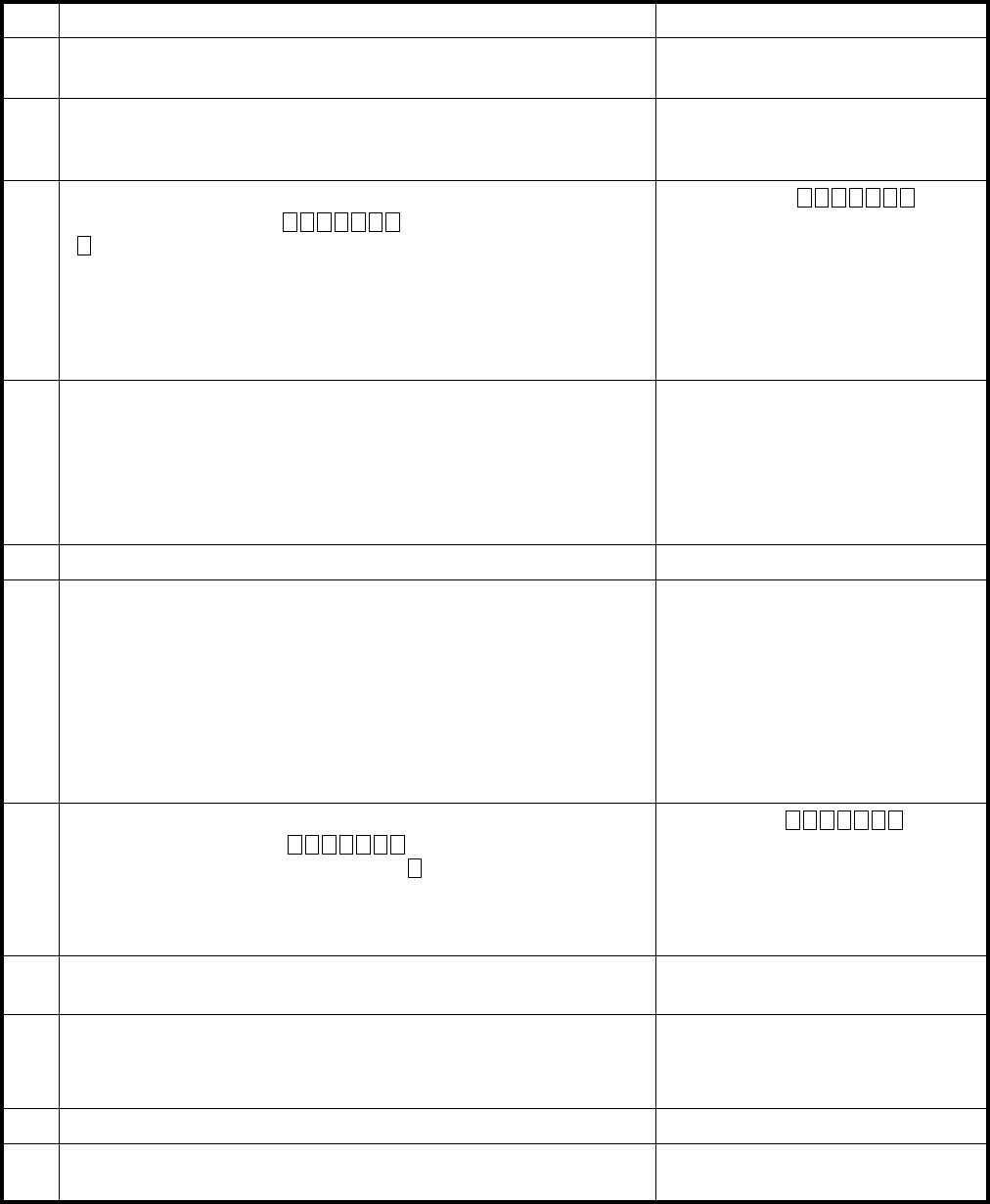
REMOTE ADMINISTRATION AND MAINTENANCE PROCEDURES
SECTION 100-816-600
MARCH 1993
-67-
TABLE RM-BU
CO LINE TEST
ACTIONSTEP DISPLAY/PRINTOUT
1>MODE TESTEnter the Test Mode
At the >MODE prompt, enter T E S T CR.
2T SEKT XX IDLE ON-HOOK
T
T SCO YY IDLE
To Verify Station/CO Line Status
3Call Remote Station B
Enter T K X X K Y Y CR.
( = station B’s telephone number)
Answer station B.
4A)
B)
C)
T TK XX KYY
T
T TKXX H
T
NOTE:
If the system is equipped with Music-on-hold, go to step 4. If the
line must be tested via a CO-to-CO connection, go to step 6.
Station line status, enter S E K T X X X X
CO line status, enter S C O Y Y Y Y = station port).
= CO line number).
(from SEKT XX and CO line YY)
Press the Hold button on TK XX (station B on hold).
Enter T K X X H CR.
Listen at station B and check that the transmission from the
music source is acceptable.
Press the Spkr button on TKXX (to release the call).
Enter T K X X S CR.
5 Continue returning to step 2 until all CO lines are tested.
6To Set Up A CO-to-CO Connection
Press the Cnf/Trn button on T K X X.
NOTES:
1.
2.
3.
Station B is connected via step 3.
Verify that
The next step must be completed immediately to avoid
dial tone timeout.
T TKXX S
T
T TKXX C
T
7 Call station C (or local time/weather) via CO line C.
Enter: T K X X K Y Y CR.
X X = CO line C’s button number and = telephone number of
station C.
Answer station C (or verify time/weather connection) and go to
next step.
T TKXX KYY
T
8 Press the Cnf/Trn button on STXX to establish a conference
between all parties.
9 If you wish to tie the two CO lines together and hang up:
Enter T K X X C CR.
T TKXX C
T
T TKXX C
TTKXX S
T
10 Continue returning to step 2 until all CO lines are tested.
11 To Exit the Test Mode,
At the T prompt, enter Q U I T CR.
(
(
Enter T K X X C CR.
Program 15-5 allows CO-to-CO connections.
Enter T K X X S CR.

REMOTE ADMINISTRATION AND MAINTENANCE PROCEDURES
SECTION 100-816-600
MARCH 1993
-68-
TABLE RM-BV
SYSTEM DATE/DAY/TIME SETTING PROCEDURE
ACTIONSTEP DISPLAY/PRINTOUT
1>MODE TEST
T
Enter the Test Mode
At the >MODE prompt, enter T E S T CR.
2T TK00 K01 651YYMMDD#
T
To Set Date
3To Set Time Of Day
Enter T K 0 0 K 0 1 6 5 1 Y Y M M D D # CR.
4
5To Exit the Test Mode
At T prompt, enter Q U I T CR.
TTK00 K01 652HHMMSS#
Enter T K 0 0 K 0 1 6 5 2 H H M M S S # CR.
To Set Day Of The Week
Enter T K 0 0 K 0 1 6 5 3 D # CR.
(D = day of week with Sunday = 1 ~ Saturday = 7)
TTK00 K01 653D#
T
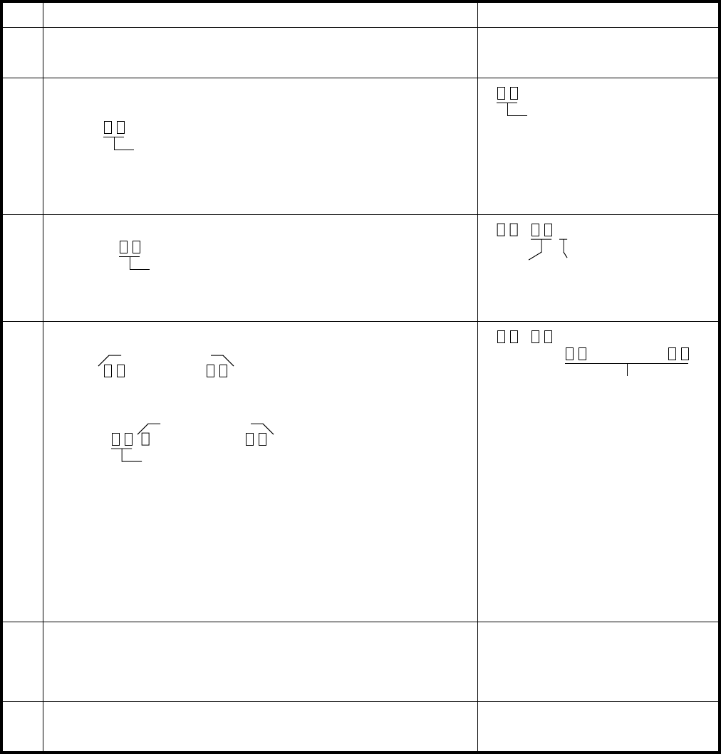
REMOTE ADMINISTRATION AND MAINTENANCE PROCEDURES
SECTION 100-816-600
MARCH 1993
-69-
TABLE RM-BW
SPEED DIAL MODE (CHANGE/REVIEW)
ACTIONSTEP DISPLAY/PRINTOUT
1>MODE REPTEnter the Speed Dial Mode
At the >MODE prompt, enter R E P T CR.
2REnter the station port number for which the speed
dial number will be programmed
Press
(00 ~ 19)
Station Port Number
NOTE: If programming system speed dial, enter
port number
0 0.
3REnter Speed Dial Memory Location to be Programmed
A) Press
10 ~ 49 Station
60 ~ 99 System Memory
location
(current memory will display) N
Nothing in
memory
4R1) To enter speed dial number (20 digits max)
Press
N
. . . . . . . . . .
20-digit number
2) To enter chain dial number
Press A. . . . . . . . . . . .
17-digit number
System speed dial location (90 ~ 99)
. . . . . . . . . .
New speed dial number
(Refer to Digital or Electronic Telephone User Guide for
information regarding chain dialing.)
Special Entries: F=Flash; P=1.5 or 3-sec Pause (Prog. 12);
L=10-sec Pause; N=Clear Memory.
5RTo store data, press CR
NOTE: If program entry is not correct,
CR
will not
respond. To try again, press
DELETE CR
at the same time.
6>MODETo Exit the Speed Dial Mode
Press Q U I T CR.
B) Press SPACE to review each memory location or go to Step 4.
Special code entry: I = Intercom
H = Hold
C = Conference
REMOTE ADMINISTRATION AND MAINTENANCE PROCEDURES
SECTION 100-816-600
MARCH 1993
-70-
REMOTE MAINTENANCE PROCEDURES INDEX
INITITAILIZATION PROGRAMS PAGE NUMBER
System Programs (90) 15
Station Speed Dial, VM I.D. Codes (92) 16
System Speed Dial (92) 17
LCD Messages (92) 18
Timed Reminders (92) 19
Digital Telephone Volume Level (92) 20
Call Forward Backup (92) 21
PCB Slot Assignments (03) 22
PROGRAM PROGRAM TYPE PAGE NUMBER
TYPE 1 1 26
TYPE 2 2 27
00 3 23
01 3 24
02 3 24
03 3 22
04 3 25
05 3 25
10 (-1, -2, -3) 1 26
12 3 28
13 3 28
15 1 26
16 1 26
19 3 29
20 2 27
21 3 29
22 3 30
28 3 30
29 3 31
30 2 27
31 2 27
32 3 32
33 3 32
34 3 33
35 2 27
36 3 33
37 3 34
38 3 35
39 3 36
40 2 27
41 2 27
42-0 1 26
42-1 ~ 8 3 37
44 (A, B) 3 44
45-1 3 44
45-2 3 45
45-3 ~ 6 3 45
45-8 ~ 9 3 46
46-2 ~ 4 3 46
46-6 ~ 8 3 47
PROGRAM PROGRAM TYPE PAGE NUMBER
46-10 ~ 40 3 48
47 3 49
48 3 50
50-1 3 50
50-2 3 51
50-31 ~ 35 3 51
50-4 3 52
50-5 3 52
50-6 3 53
51 3 43
52 3 54
53 3 55
54 3 56
55-0 3 57
55-1 3 58
55-2 3 59
56 3 60
60 3 38
69 3 39
70 3 40
77 (-1, -2) 1 26
78 3 41
79 2 27
80 3 42
81 ~ 89 2 27
93 3 43
DATA DUMP PROCEDURES
System Programs 60
Speed Dial Numbers 61
LCD Messages 61
REMOTE LCD
MESSAGING PROCEDURES
Remote Calling Station (Edit) (Mode 95) 62
Remote Calling Station (New) (Mode 97) 63
Remote Called Station (Edit) (Mode 94) 64
Remote Called Station (New) (Mode 96) 65
REMOTE TEST PROCEDURES
Station/Line Status Check 66
Station Button Activation 66
CO Line Test 67
Set: Date/Day/Time 68
REMOTE
Speed Dial (Change/Review) 69

REMOTE ADMINISTRATION AND MAINTENANCE PROCEDURES
SECTION 100-816-600
MARCH 1993
-71-
MESSAGE RECORD SHEET—Use several sheets if necessary
MESG.#______
MESG.#______
MESG.#______
MESG.#______
MESG.#______
MESG.#______
MESG.#______
MESG.#______
MESG.#______
MESG.#______
MESG.#______
