Toshiba Telephone Ctx28 Users Manual Strata CTX Installation & Maintenance
DP5900 Toshiba CTX I&M Manual CTX 28 CTX 100 & CTX 670
2014-12-13
: Toshiba Toshiba-Telephone-Ctx28-Users-Manual-131832 toshiba-telephone-ctx28-users-manual-131832 toshiba pdf
Open the PDF directly: View PDF ![]() .
.
Page Count: 495 [warning: Documents this large are best viewed by clicking the View PDF Link!]
- Title Page
- Publication Information
- TAIS DSD License Agreement
- TAIS DSD Limited Warranty
- Contents
- Introduction
- Chapter 1 -CTX28 Installation
- Inspection
- Packaging and Storage
- CTX28 FCC/ACTA Registration Numbers
- Site Requirements
- AC Power and Grounding Requirements
- Installing the CTX28 Cabinet
- Step 1: Mount the Cabinet on the Wall
- PCB Installation
- Step 1: Set Jumpers on the GMAU1A (Motherboard)
- Step 2: Install the GVMU1A Voice Mail PCB (optional)
- Step 3: Install the GCTU1A (Processor)
- Step 4: Install the GCDU1A (DKT and Loop Start Interface)
- Step 5: Install the GSTU1A
- Step 6: Install the GETS1A
- Step 7: Install the BSIS1A (optional)
- Step 8: Install the HPFB-6 (Reserve Power Battery/Charger)
- Step 9: Install Wiring
- Digital Telephone Connection
- Loop Limits
- CTX28 Secondary Protection
- MDF Wiring
- GVMU Administration PC Connections
- Chapter 2 - Strata CTX Configuration
- Strata CTX100-S/CTX100 Overview
- CTX100-S and CTX100 Processors
- CTX100 Cabinet Slots
- CTX100-S/CTX100 License Control
- Strata CTX670 Overview
- CTX670 Processor PCBs
- CTX670 License Control
- CTX670 Cabinet Slots
- CTX670 Remote Expansion Cabinet
- System Capacities
- Universal Slot PCBs
- Functional Block Diagrams
- Worksheet Description
- CTX670 Remote Cabinet Configuration Considerations
- Worksheet 1: Toshiba DKT and IP Telephones
- Worksheet 2: Standard Telephone, Stratagy DK, IVP8
- Worksheet 3: CO Line
- Worksheet 4: Page/MOH/Control Relay
- Worksheet 5: Strata CTX100 Cabinet Slots
- CTX100 Max. Capacity Configuration Examples
- Digital Telephones and Loop Start Lines With or Without Caller ID
- Analog Loop Start Lines with or without Caller ID
- CTX100 Base Only: Digital Telephones and T1 and/or PRI lines
- CTX100 Base & Expansion: Digital Telephones and T1 and/or PRI lines
- CTX100 Base Only: Digital Telephones and Analog Tie, DID, and/or Ground Start Lines
- CTX100: Analog Tie, DID and/or Ground Start Lines
- Worksheet 6: Strata CTX670 Cabinet Slots
- Worksheet 7 - System Power Factor Check
- Cabinet Power Factor Check
- Worksheet 8 - CTX Primary AC and Reserve Power
- Reserve Power (CTX100 and CTX670)
- Primary/Reserve Power Cabinet Hardware
- Worksheet 9 - Software Licenses
- Hardware Compatibility
- Chapter 3 - Strata CTX100-S/CTX100 Installation
- Inspection
- Packaging and Storage
- Site Requirements
- AC Power and Grounding Requirements
- Installing the CTX100 Cabinet
- Step 1: Remove Cabinet Covers
- Step 10: Remove the Back Cover from the Cabinet(s)
- Step 11: Check the Base/Expansion Power Supply Jumper Plug
- Step 12: Mount the Base Cabinet
- Step 13: Mount the Expansion Cabinet (if required)
- Step 14: Install Reserve Power
- Step 15: Check Power Supply Circuit Breakers and Fuses
- Step 16: Set Jumpers and Install Option PCBs onto the ACTU
- Step 17: Install the Main Processor (ACTU) PCB
- Step 18: Install Other PCBs into the Cabinet(s)
- Step 19: Attach and Route PCB Cables
- Chapter 4 - Strata CTX670 Installation
- Inspection
- Packaging and Storage
- Site Requirements
- Power Considerations
- FCC Registration Information
- Cabinet Installation Considerations
- Recommended Installation Sequence
- Check the -24 Volt Circuit Breakers
- Check the Power Factor Indicator and Reset Button
- Power Supply (BPSU672) Removal
- Power Supply Replacement
- Wall Mounting the Base (Top) Cabinet
- Wall Mounting Expansion Cabinets
- AC Power Requirements
- Cabinet AC Power Component Description
- AC/Reserve Power and Data Cabling Overview
- Cabinet AC Power Considerations
- Cabinet AC Power Component Requirements for Wall Mounted Systems
- Reserve Battery Cabinet Components/Cables
- Reserve Power for One or Two Cabinets (Wall Mount)
- Reserve Power for Three or More Cabinets (Wall Mount)
- Cabinet Floor Mounting
- Reserve Power/AC Wiring for Three or More Cabinets (Floor Mount)
- PCB Installation Considerations
- PCB Option Considerations
- BCTU1A/BEXU1A Installation
- BECU/BBCU Installation
- Remote Expansion Cabinet Unit
- Chapter 5 - Rack Mount Cabinets
- Basic Specifications
- Inspection
- Site Requirements
- Power Considerations
- FCC Registration Information
- Wiring for 7 Cabinet Configuration
- Primary Power Cabinet Hardware
- AC/Reserve Power and Data Cabling Overview
- Cabinet AC Power Considerations
- AC Power Component Requirements
- Power Supply Unit (BRPSU672A)
- Changing Plug for Power Strip BRPSB240A
- AC Cabling
- Remote Expansion Cabinet Unit
- Chapter 6 - PCB Installation
- PCB Chapter Layout
- PCB Hardware/Software Options
- CTX100 ACTU Processor PCBs
- CTX670 BCTU/BEXU Processor PCBs
- CTX670 BECU/BBCU Processor PCBs
- PCB Installation Power Supply Considerations
- ADKU - Digital Telephone Interface Unit
- ASTU - Standard Telephone Interface Unit (CTX100 only)
- BDKU/BDKS - Digital Telephone Interface Unit
- BIOU - Option Interface Units
- BSTU/RSTU - Standard Telephone Interface Unit
- BVPU - Internet Protocol (IP) Interface Unit
- BWDKU1A - Digital Telephone Interface Unit
- Programming
- PDKU2 - Digital Telephone Interface Unit
- RCIU1, RCIU2, RCIS - Caller ID Interface
- RCOU3A, RCOS3A - Four-Circuit Loop Start CO Line Interface Unit
- RDDU - Direct Inward Dialing Line Interface Unit
- RDSU - Digital/Standard Telephone Interface Unit
- RDTU2 - T1 Interface Unit
- REMU2A - Tie Line Unit
- RGLU2 - Loop/Ground Start CO Line Interface Unit
- RMCU/RCMS - E911 CAMA Trunk Direct Interface
- Network Requirements
- Chapter 7 - ISDN Interfaces
- PRI Overview
- BRI S/T Overview
- BRI U Overview
- BPTU/RPTU Overview
- BPTU Interface Unit
- BPTU Installation
- RPTU Interface Unit
- RPTU Installation
- BPTU and RPTU Cabling
- RBSU/RBSS Interface Units
- Overview
- RBSU Connection Options
- Capacity and Cabinet Slot Information
- PS-1 Backup Power Option
- RBSU/RBSS Installation
- Modular Jack Pin Configurations
- RBSU/RBSS Premise Wiring Guidelines
- Connecting RBSU to Network Side (TE-Mode)
- Connecting RBSU/RBSS Station Devices (NT-Mode)
- RBSU/RBSS Passive Bus Configurations
- RBUU/RBUS Interface Unit
- ISDN Testing and Troubleshooting
- Timing and Synchronization
- PRI/BRI Call Monitoring
- Call Monitor Output for ISDN
- Chapter 8 - T1
- Chapter 9 - IP Telephony and QSIG Over IP
- Pre-installation Guidelines
- Step 1: Perform a LAN Voice Readiness Assessment
- Step 2: Install BIPU-M2A
- Step 3: Install IP Telephones
- Step 4: Connect IPTs to Network
- Power over LAN
- Installing and Operating the SoftIPT
- Hardware/Software Required
- Before You Begin
- Step 1: Install SoftIPT
- Upgrading the SoftIPT
- Step 2: Start the SoftIPT
- Making a Call
- Switching a Call to Your Headset
- Creating a Directory
- Using the Directory to Call
- Labeling Feature Buttons
- Using the Call Log
- Uninstalling the SoftIPT
- Application Notes for Wireless 802.11 Networks
- Tested Platforms
- CTX IP Troubleshooting
- IP Telephone Ping Test
- LCD Network Failure Displays
- Collect CTX Trace Data on CTX SmartMedia Card
- Collect BIPU Logs
- Check Log0.log/Log0.err for Error Message Output
- Check Whether Message Associated Warnings/Errors Were Printed
- Verify CTX/BIPU/IPT Hardware, Software and Firmware Version
- CTX System Configuration
- Network Information
- Capture Points
- How To Capture Packets
- Requirement for Capture Tool
- IP Troubleshooting Resolutions
- Private Networking Over Internet Protocol
- Chapter 10 -MDF PCB Wiring
- Station Loop Lengths
- Station Wiring Diagrams
- ADKU and BDKU/BDKS Digital Station Wiring
- PDKU Digital Station Wiring
- Digital Telephone DSS and DDCB External Power Connection
- RDSU Wiring
- RSTU or PSTU Analog Devices Wiring
- Power Failure Cut Through (DPFT) Wiring Pin-outs
- CO Line Wiring Diagrams
- RGLU2, RCOU or PCOU Wiring
- RCOU/RCOS Wiring
- RMCU/RMCS Wiring Diagram
- RCIU1/RCIS or RCIU2/RCIS Wiring
- DID and Tie Line Wiring
- PEMU Wiring
- Option Interface PCB Wiring Diagram
- Chapter 11 -Station Apparatus
- 3000-series Digital Telephones Telephone
- 3000-series Telephone Installation
- 3000-series Telephone Option PCBs
- Install TAPI Service Provider
- Add/Edit TSP Configuration Information
- Test/Use TAPI Service Provider
- IPT Telephone
- 3000-series, IPT1020-SD Button Layouts
- Telephone Settings
- Digital Add-on Module Installation
- Tilt Stands
- Telephone Wall Mounting
- Direct Station Selection (DSS) Console/System Connection
- Standard Telephones
- Cordless Digital Telephones
- Cordless Telephone Installation
- Step 1: Review Safety Instructions
- Step 2: Select Location
- Step 3: Place DKT3000-series Telephones into 2000-Mode
- Step 4: Connect Telephone Cables
- Step 5: Connect and Apply Power
- Step 6: Wall Installation (Optional)
- Step 7: Raise the Base Unit Antenna
- Step 8: Install Handset Battery Pack
- Step 9: Charge Batteries for First Time
- Step 10: Install Headset (Optional)
- Step 11: Attach Belt Clip (Optional)
- Cordless Telephone Troubleshooting and Specifications
- Troubleshooting
- Simultaneous Conversation Channels
- Range and Performance
- Radio Interference
- Telephone Line Problems
- Privacy
- Specifications
- 2000-series Telephones
- 2000-series Telephone Option PCBs
- Telephone Speaker Off-hook Call Announce Upgrade (DVSU/ BVSU)
- HHEU Installation
- Carbon Headset/Handset Straps
- Beep Strap
- Microphone/Speaker Sensitivity Adjustment (Speakerphones Only)
- Busy Override and Camp-on Ring Tone Over Handset/Headset Option
- External Power Straps
- DIP Switches
- DKT2020-FDSP Full-Duplex Speakerphone with External Microphone
- Digital Single Line Telephone (DKT2001 only)
- Chapter 12 -Peripheral Installation
- Index

TOSHIBA Digital Solutions Division
June 2004
CTX28, CTX100-S, CTX100 and CTX670
Installation and Maintenance
Manual
Digital Business Telephone Systems

Publication Information
Toshiba America Information Systems, Inc., Digital Solutions Division, reserves the
right, without prior notice, to revise this information publication for any reason,
including, but not limited to, utilization of new advances in the state of technical arts or
to simply change the design of this document.
Further, Toshiba America Information Systems, Inc., Digital Solutions Division, also
reserves the right, without prior notice, to make such changes in equipment design or
components as engineering or manufacturing methods may warrant.
© Copyright 2004
Toshiba America Information Systems, Inc.
Digital Solutions Division
All rights reserved. No part of this manual, covered by the copyrights hereon, may be
reproduced in any form or by any means—graphic, electronic, or mechanical,
including recording, taping, photocopying, or information retrieval systems—without
express written permission of the publisher of this material.
Strata and SmartMedia are registered trademarks of Toshiba Corporation.
Stratagy is a registered trademark of Toshiba America Information Systems, Inc.
Trademarks, registered trademarks, and service marks are the property of their
respective owners.
CTX-MA-IM/MT-VE
Version E, June 2004
Strata CTX28, CTX100 and CTX670
General End User Information
The Strata CTX28, CTX100 or CTX670 Digital Business Telephone System is
registered in accordance with the provisions of Part 68 of the Federal Communications
Commission’s Rules and Regulations.
FCC Requirements
Means of Connection: The Federal Communications Commission (FCC) has
established rules which permit the Strata CTX28, CTX100 or CTX670 system to be
connected directly to the telephone network. Connection points are provided by the
telephone company—connections for this type of customer-provided equipment will
not be provided on coin lines. Connections to party lines are subject to state tariffs.
Incidence of Harm: If the system is malfunctioning, it may also be disrupting the
telephone network. The system should be disconnected until the problem can be
determined and repaired. If this is not done, the telephone company may temporarily
disconnect service. If possible, they will notify you in advance, but, if advance notice is
not practical, you will be notified as soon as possible. You will be informed of your
right to file a complaint with the FCC.
Service or Repair: For service or repair, contact your local Toshiba telecommunications
distributor. To obtain the nearest Toshiba telecommunications distributor in your area,
log onto www.toshiba.com/taistsd/locator.htm or call (800) 222-5805 and ask for a
Toshiba Telecom Dealer.
Telephone Network Compatibility: The telephone company may make changes in its
facilities, equipment, operations, and procedures. If such changes affect the
compatibility or use of the Strata CTX28, CTX100 or CTX670 system, the telephone
company will notify you in advance to give you an opportunity to maintain
uninterrupted service.
Notification of Telephone Company: Before connecting a Strata CTX28, CTX100 or
CTX670 system to the telephone network, the telephone company may request the
following:
1. Your telephone number.
2. FCC registration number:
• Strata CTX28, CTX100 or CTX670 may be configured as a Key, Hybrid or PBX
telephone system. The appropriate configuration for your system is dependent
upon your operation of the system.
• If the operation of your system is only manual selection of outgoing lines, it may
be registered as a Key telephone system.
• If your operation requires automatic selection of outgoing lines, such as dial
access, Least Cost Routing, Pooled Line Buttons, etc., the system must be
registered as a Hybrid telephone system. In addition to the above, certain
features (tie Lines, Off-premises Stations, etc.) may also require Hybrid
telephone system registration in some areas.
• If you are unsure of your type of operation and/or the appropriate FCC
registration number, contact your local Toshiba telecommunications distributor
for assistance.
•CTX28 FCC/ACTA Registration Numbers
Hybrid: CJ6MF03BDTCHS28, fully-protected multifunction systems
Key: CJ6KD03BDTCHS28, key systems for analog applications
•CTX100 Registration Numbers
PBX: CJ6MUL-35931-PF-E, fully-protected PBXs
Hybrid: CJ6MUL-35930-MF-E, fully-protected multifunction systems
Key: CJ6MUL-35929-KF-E, fully-protected telephone key systems
•CTX670 Registration Numbers
PBX: CJ6MUL-35934-PF-E, fully-protected PBXs
Hybrid: CJ6MUL-35933-MF-E, fully-protected multifunction systems
Key: CJ6MUL-35932-KF-E, fully-protected telephone key systems
• Ringer equivalence number: 0.3B. The ringer equivalence number (REN) is
useful to determine the quantity of devices which you may connect to your
telephone line and still have all of those devices ring when your number is
called. In most areas, but not all, the sum of the RENs of all devices connected to
one line should not exceed five (5.0B). To be certain of the number of devices
you may connect to your line, as determined by the REN, you should contact
your local telephone company to ascertain the maximum REN for your calling
area.
3. Network connection information USOC jack required: RJ11/14C,
RJ21/2E/2F/2G/2HX/RJ49C (see Network Requirements in this document). Items
2, 3 and 4 are also indicated on the equipment label.
4. Authorized Network Parts: 02LS2/GS2, 02RV2-T/O, OL13C/B, T11/12/31/32M,
04DU9-BN/DN/1SN, 02IS5, 04DU9-BN/DN/1SN1ZN
Radio Frequency Interference
Warning: This equipment generates, uses, and can radiate radio frequency energy and if
not installed and used in accordance with the manufacturer’s instruction manual, may
cause interference to radio communications. It has been tested and found to comply
with the limits for a Class A computing device pursuant to Subpart J of Part 15 of FCC
Rules, which are designed to provide reasonable protection against such interference
when operated in a commercial environment. Operation of this equipment in a
residential area is likely to cause interference, in which case, the user, at his/her own
expense, will be required to take whatever measures may be required to correct the
interference.
This system is listed with Underwriters Laboratory.
UL Requirement: If wiring from any telephone exits the building or is
subject to lightning or other electrical surges, then secondary protection
is required. Secondary protection is also required on DID, OPS, and Tie
lines. (Additional information is provided in this manual.)
Important Notice — Music-On-Hold
In accordance with U.S. Copyright Law, a license may be required from
the American Society of Composers, Authors and Publishers, or other similar
organization, if radio or TV broadcasts are transmitted through the music-on-hold
feature of this telecommunication system. Toshiba America Information Systems, Inc.,
hereby disclaims any liability arising out of the failure to obtain such a license.
CP01, Issue 8, Part I Section 14.1
Notice: The Industry Canada label identifies certified equipment. This certification
means that the equipment meets certain telecommunications network protective,
operational and safety requirements as prescribed in the appropriate Terminal
Equipment Technical Requirements document(s). The Department does not guarantee
the Equipment will operate to the user’s satisfaction.
Before installing this equipment, users should ensure that it is permissible to be
connected to the facilities of the local telecommunications company. The equipment
must also be installed using an acceptable method of connection. The customer should
be aware that compliance with the above conditions may not prevent degradation of
service in some situations.
Repairs to certified equipment should be coordinated by a representative designated by
the supplier. Any repairs or alterations made by the user to this equipment, or
equipment malfunctions, may give the telecommunications company cause to request
the user to disconnect the equipment.
Users should ensure for their own protection that the electrical ground connections of
the power utility, telephone lines and internal metallic water pipe system, if present, are
connected together. This precaution may be particularly important in rural areas.
CAUTION! Users should not attempt to make such connections themselves, but
should contact the appropriate electric inspection authority, or
electrician, as appropriate.
CP01, Issue 8, Part I Section 14.2
Notice: The Ringer Equivalence Number (REN) assigned to each terminal device
provides an indication of the maximum number of terminals allowed to be connected to
a telephone interface. The terminal on an interface may consist of any combination of
devices subject only to the requirement that the sum of the Ringer Equivalence
Numbers of all the Devices does not exceed 5.
UL
®

TOSHIBA AMERICA INFORMATION SYSTEMS, INC. (“TAIS”)
Digital Solutions Division License Agreement
IMPORTANT: THIS LICENSE AGREEMENT (“AGREEMENT”) IS A LEGAL AGREEMENT BETWEEN YOU (“YOU”) AND TAIS. CAREFULLY READ THIS LICENSE AGREEMENT. USE OF ANY
SOFTWARE OR ANY RELATED INFORMATION (COLLECTIVELY, “SOFTWARE”) INSTALLED ON OR SHIPPED WITH A TAIS DIGITAL SOLUTIONS PRODUCT OR OTHERWISE MADE AVAILABLE TO
YOU BY TAIS IN WHATEVER FORM OR MEDIA, WILL CONSTITUTE YOUR ACCEPTANCE OF THESE TERMS, UNLESS SEPARATE TERMS ARE PROVIDED BY THE SOFTWARE SUPPLIER. IF
YOU DO NOT AGREE WITH THE TERMS OF THIS LICENSE AGREEMENT, DO NOT INSTALL, COPY OR USE THE SOFTWARE AND PROMPTLY RETURN IT TO THE LOCATION FROM WHICH YOU
OBTAINED IT IN ACCORDANCE WITH APPLICABLE RETURN POLICIES. EXCEPT AS OTHERWISE AUTHORIZED IN WRITING BY TAIS, THIS SOFTWARE IS LICENSED FOR DISTRIBUTION ONLY
TO END-USERS PURSUANT TO THIS LICENSE AGREEMENT.
1. License Grant. The Software is not sold; it is licensed upon payment of applicable charges. TAIS grants to you a personal, non-transferable and non-exclusive right to use the copy of the Software
provided under this License Agreement. You agree you will not copy the Software except as necessary to use it on one TAIS system at a time at one location. Modifying, translating, renting, copying,
distributing, transferring or assigning all or part of the Software, or any rights granted hereunder, to any other persons and removing any proprietary notices, labels or marks from the Software is strictly
prohibited; You agree violation of such restrictions will cause irreparable harm to TAIS and provide grounds for injunctive relief, without notice, against You or any other person in possession of the Software.
You and any other person whose possession of the software violates this License Agreement shall promptly surrender possession of the Software to TAIS, upon demand. Furthermore, you hereby agree not
to create derivative works based on the Software. TAIS reserves the right to terminate this license and to immediately repossess the software in the event that You or any other person violates this License
Agreement.
2. Intellectual Property. You acknowledge that no title to the intellectual property in the Software is transferred to you. You further acknowledge that title and full ownership rights to the Software will remain
the exclusive property of TAIS and/or its suppliers, and you will not acquire any rights to the Software, except the license expressly set forth above. You will not remove or change any proprietary notices
contained in or on the Software. The Software is protected under US patent, copyright, trade secret, and/or other proprietary laws, as well as international treaties. Any transfer, use, or copying of the
software in violation of the License Agreement constitutes copyright infringement. You are hereby on notice that any transfer, use, or copying of the Software in violation of this License Agreement constitutes
a willful infringement of copyright.
3. No Reverse Engineering. You agree that you will not attempt, and if you employ employees or engage contractors, you will use your best efforts to prevent your employees and contractors from
attempting to reverse compile, reverse engineer, modify, translate or disassemble the Software in whole or in part. Any failure to comply with the above or any other terms and conditions contained herein
will result in the automatic termination of this license and the reversion of the rights granted hereunder back to TAIS.
4. Limited Warranty. THE SOFTWARE IS PROVIDED “AS IS” WITHOUT WARRANTY OF ANY KIND. TO THE MAXIMUM EXTENT PERMITTED BY APPLICABLE LAW, TAIS AND ITS SUPPLIERS
DISCLAIM ALL WARRANTIES WITH REGARD TO THE SOFTWARE, EITHER EXPRESS OR IMPLIED, INCLUDING, BUT NOT LIMITED TO, THE WARRANTY OF NON-INFRINGEMENT OF THIRD
PARTY RIGHTS, THE WARRANTY OF YEAR 2000 COMPLIANCE, AND THE IMPLIED WARRANTIES OF MERCHANTABILITY AND FITNESS FOR A PARTICULAR PURPOSE. THE ENTIRE RISK AS
TO THE QUALITY AND PERFORMANCE OF THE SOFTWARE IS WITH YOU. NEITHER TAIS NOR ITS SUPPLIERS WARRANT THAT THE FUNCTIONS CONTAINED IN THE SOFTWARE WILL MEET
YOUR REQUIREMENTS OR THAT THE OPERATION OF THE SOFTWARE WILL BE UNINTERRUPTED OR ERROR-FREE. HOWEVER, TAIS WARRANTS THAT ANY MEDIA ON WHICH THE
SOFTWARE IS FURNISHED IS FREE FROM DEFECTS IN MATERIAL AND WORKMANSHIP UNDER NORMAL USE FOR A PERIOD OF NINETY (90) DAYS FROM THE DATE OF DELIVERY TO
YOU.
5. Limitation Of Liability. TAIS’ ENTIRE LIABILITY AND YOUR SOLE AND EXCLUSIVE REMEDY UNDER THIS LICENSE AGREEMENT SHALL BE AT TAIS’ OPTION REPLACEMENT OF THE MEDIA OR
REFUND OF THE PRICE PAID. TO THE MAXIMUM EXTENT PERMITTED BY APPLICABLE LAW, IN NO EVENT SHALL TAIS OR ITS SUPPLIERS BE LIABLE TO YOU FOR ANY CONSEQUENTIAL,
SPECIAL, INCIDENTAL OR INDIRECT DAMAGES FOR PERSONAL INJURY, LOSS OF BUSINESS PROFITS, BUSINESS INTERRUPTION, LOSS OF BUSINESS INFORMATION/DATA, OR ANY
OTHER PECUNIARY LOSS OF ANY KIND ARISING OUT OF THE USE OR INABILITY TO USE THE SOFTWARE, EVEN IF TAIS OR ITS SUPPLIER HAS BEEN ADVISED OF THE POSSIBILITY OF
SUCH DAMAGES. IN NO EVENT SHALL TAIS OR ITS SUPPLIERS BE LIABLE FOR ANY CLAIM BY A THIRD PARTY.
6. State/Jurisdiction Laws. SOME STATES/JURISDICTIONS DO NOT ALLOW THE EXCLUSION OF IMPLIED WARRANTIES OR LIMITATIONS ON HOW LONG AN IMPLIED WARRANTY MAY LAST, OR
THE EXCLUSION OR LIMITATION OF INCIDENTAL OR CONSEQUENTIAL DAMAGES, SO SUCH LIMITATIONS OR EXCLUSIONS MAY NOT APPLY TO YOU. THIS LIMITED WARRANTY GIVES YOU
SPECIFIC RIGHTS AND YOU MAY ALSO HAVE OTHER RIGHTS WHICH VARY FROM STATE/JURISDICTION TO STATE/JURISDICTION.
7. Export Laws. This License Agreement involves products and/or technical data that may be controlled under the United States Export Administration Regulations and may be subject to the approval of the
United States Department of Commerce prior to export. Any export, directly or indirectly, in contravention of the United States Export Administration Regulations, or any other applicable law, regulation or
order, is prohibited.
8. Governing Law. This License Agreement will be governed by the laws of the State of California, United States of America, excluding its conflict of law provisions.
9. United States Government Restricted Rights. The Software is provided with Restricted Rights. Use, duplication, or disclosure by the United States Government, its agencies and/or instrumentalities is
subject to restrictions as set forth in subparagraph (c)(1)(ii) of The Rights in Technical Data and Computer Software Clause at DFARS 252.227-7013 (October 1988) or subparagraphs (c)(1) and (2) of the
Commercial Computer Software - Restricted Rights at 48 CFR 52.227-19, as applicable.
10. Severability. If any provision of this License Agreement shall be held to be invalid, illegal or unenforceable, the validity, legality and enforceability of the remaining provisions hereof shall not in any way
be affected or impaired.
11. No Waiver. No waiver of any breach of any provision of this License Agreement shall constitute a waiver of any prior, concurrent or subsequent breach of the same or any other provisions hereof, and no
waiver shall be effective unless made in writing and signed by an authorized representative of the waiving party.
YOU ACKNOWLEDGE THAT YOU HAVE READ THIS LICENSE AGREEMENT AND THAT YOU UNDERSTAND ITS PROVISIONS. YOU AGREE TO BE BOUND BY ITS TERMS AND CONDITIONS. YOU
FURTHER AGREE THAT THIS LICENSE AGREEMENT CONTAINS THE COMPLETE AND EXCLUSIVE AGREEMENT BETWEEN YOU AND TAIS AND SUPERSEDES ANY PROPOSAL OR PRIOR
AGREEMENT, ORAL OR WRITTEN, OR ANY OTHER COMMUNICATION RELATING TO THE SUBJECT MATTER OF THIS LICENSE AGREEMENT.
Toshiba America Information Systems, Inc.
Digital Solutions Division
9740 Irvine Boulevard
Irvine, California 92618-1697
United States of America
DSD 060204
5932
Toshiba America Information Systems, Inc.
Digital Solutions Division
Limited Warranty
Toshiba America Information Systems, Inc., (“TAIS”) warrants that this telephone equipment (except for fuses,
lamps, and other consumables) will, upon delivery by TAIS or an authorized TAIS dealer to a retail customer in new
condition, be free from defects in material and workmanship for twenty-four (24) months after delivery. This
warranty is void (a) if the equipment is used under other than normal use and maintenance conditions, (b) if the
equipment is modified or altered, unless the modification or alteration is expressly authorized by TAIS, (c) if the
equipment is subject to abuse, neglect, lightning, electrical fault, or accident, (d) if the equipment is repaired by
someone other than TAIS or an authorized TAIS dealer, (e) if the equipment’s serial number is defaced or missing, or
(f) if the equipment is installed or used in combination or in assembly with products not supplied by TAIS and which
are not compatible or are of inferior quality, design, or performance.
The sole obligation of TAIS or Toshiba Corporation under this warranty, or under any other legal obligation with
respect to the equipment, is the repair or replacement by TAIS or its authorized dealer of such defective or missing
parts as are causing the malfunction with new or refurbished parts (at their option). If TAIS or one of its authorized
dealers does not replace or repair such parts, the retail customer’s sole remedy will be a refund of the price charged by
TAIS to its dealers for such parts as are proven to be defective, and which are returned to TAIS through one of its
authorized dealers within the warranty period and no later than thirty (30) days after such malfunction, whichever
first occurs.
Under no circumstances will the retail customer or any user or dealer or other person be entitled to any direct, special,
indirect, consequential, or exemplary damages, for breach of contract, tort, or otherwise. Under no circumstances will
any such person be entitled to any sum greater than the purchase price paid for the item of equipment that is
malfunctioning.
To obtain service under this warranty, the retail customer must bring the malfunction of the machine to the attention
of one of TAIS’ authorized dealers within the twenty-four (24) month period and no later than thirty (30) days after
such malfunction, whichever first occurs. Failure to bring the malfunction to the attention of an authorized TAIS
dealer within the prescribed time results in the customer being not entitled to warranty service.
THERE ARE NO OTHER WARRANTIES FROM EITHER TOSHIBA AMERICA INFORMATION SYSTEMS,
INC., OR TOSHIBA CORPORATION WHICH EXTEND BEYOND THE FACE OF THIS WARRANTY. ALL
OTHER WARRANTIES, EXPRESS OR IMPLIED, INCLUDING THE WARRANTIES OF
MERCHANTABILITY, FITNESS FOR A PARTICULAR PURPOSE, AND FITNESS FOR USE, ARE
EXCLUDED.
No TAIS dealer and no person other than an officer of TAIS may extend or modify this warranty. No such
modification or extension is effective unless it is in writing and signed by the vice president and general manager,
Digital Solutions Division.

Strata CTX I&M 06/04 i
Contents
Introduction
Organization ........................................................................................................................................xiii
Conventions ......................................................................................................................................... xiv
Related Documents/Media ................................................................................................................... xv
General Description ....................................................................................................................... xv
Programming Manual .................................................................................................................... xv
User Guides ................................................................................................................................... xv
Quick Reference Guides ................................................................................................................ xv
CD-ROMs ...................................................................................................................................... xv
Chapter 1 – CTX28 Installation
Inspection ............................................................................................................................................1-1
Packaging and Storage ........................................................................................................................1-1
CTX28 FCC/ACTA Registration Numbers ........................................................................................1-1
Site Requirements ...............................................................................................................................1-2
Input Power ...................................................................................................................................1-2
Clearance and Location ................................................................................................................1-2
AC Power and Grounding Requirements ............................................................................................1-4
AC Power Ground Test ................................................................................................................1-5
Installing the CTX28 Cabinet .............................................................................................................1-6
Step 1: Mount the Cabinet on the Wall .........................................................................................1-6
PCB Installation ............................................................................................................................1-8
Step 2: Set Jumpers on the GMAU1A (Motherboard) ...............................................................1-10
Step 3: Install the GVMU1A Voice Mail PCB (optional) ..........................................................1-12
Step 4: Install the GCTU1A (Processor) ....................................................................................1-14
Step 5: Install the GCDU1A (DKT and Loop Start Interface) ...................................................1-16
Step 6: Install the GSTU1A ........................................................................................................1-17
Step 7: Install the GETS1A ........................................................................................................1-17
Step 8: Install the BSIS1A (optional) .........................................................................................1-18
Step 9: Install the HPFB-6 (Reserve Power Battery/Charger) ...................................................1-18
Step 10: Install Wiring ................................................................................................................1-19
Digital Telephone Connection ..........................................................................................................1-21
Loop Limits ......................................................................................................................................1-22
CTX28 Secondary Protection ...........................................................................................................1-23
MDF Wiring ......................................................................................................................................1-24
GVMU Administration PC Connections ..........................................................................................1-25

Contents
Chapter 2 – Strata CTX Configuration
ii Strata CTX I&M 06/04
Chapter 2 – Strata CTX Configuration
Strata CTX100-S/CTX100 Overview .................................................................................................2-1
CTX100-S and CTX100 Processors ...................................................................................................2-2
CPU/Memory ................................................................................................................................2-2
Large Scale Integrated (LSI) Circuits ...........................................................................................2-2
Memory Protection Battery ..........................................................................................................2-2
Relay Control Interface ................................................................................................................2-2
External Page Interface .................................................................................................................2-2
Music-on-hold/Background Music Interface ................................................................................2-3
SmartMedia Memory ...................................................................................................................2-3
CTX100 Processor Optional Subassemblies ................................................................................2-3
CTX100 Cabinet Slots ........................................................................................................................2-3
Base Cabinet .................................................................................................................................2-3
Expansion Cabinets ......................................................................................................................2-3
CTX100-S/CTX100 License Control .................................................................................................2-4
Licensed Software Options ...........................................................................................................2-4
Strata CTX670 Overview ....................................................................................................................2-5
CTX670 Processor PCBs ....................................................................................................................2-5
CPU/Memory ................................................................................................................................2-5
Large-scale Integrated (LSI) circuits ............................................................................................2-6
Memory Protection Battery ..........................................................................................................2-6
Music-on-hold/Background Music Interface ................................................................................2-6
SmartMedia Memory ....................................................................................................................2-6
Network Interface .........................................................................................................................2-6
CTX670 Processor PCB Subassemblies .......................................................................................2-7
CTX670 License Control ....................................................................................................................2-7
Licensed Software Options ...........................................................................................................2-7
CTX670 Cabinet Slots ........................................................................................................................2-8
Base Cabinet .................................................................................................................................2-8
Expansion Cabinets ......................................................................................................................2-8
CTX670 Remote Expansion Cabinet ..................................................................................................2-9
System Capacities ...............................................................................................................................2-9
Universal Slot PCBs ..........................................................................................................................2-14
Station, Line and Option PCBs ...................................................................................................2-14
Functional Block Diagrams ...............................................................................................................2-18
Worksheet Description ......................................................................................................................2-22
CTX670 Remote Cabinet Configuration Considerations .................................................................2-22
Component Worksheets ..............................................................................................................2-22
Worksheet 1: Toshiba DKT and IP Telephones ..............................................................................2-23
Worksheet 2: Standard Telephone, Stratagy DK, IVP8 ...................................................................2-24
Worksheet 3: CO Line ....................................................................................................................2-25
Worksheet 4: Page/MOH/Control Relay ..........................................................................................2-26
Worksheet 5: Strata CTX100 Cabinet Slots ......................................................................................2-26
CTX100 Max. Capacity Configuration Examples ............................................................................2-28
Digital Telephones and Loop Start Lines With or Without Caller ID ........................................2-28
Analog Loop Start Lines with or without Caller ID ...................................................................2-29
CTX100 Base Only: Digital Telephones and T1 and/or PRI lines .............................................2-32
CTX100 Base & Expansion: Digital Telephones and T1 and/or PRI lines ................................2-33
CTX100 Base Only: Digital Telephones and Analog Tie, DID, and/or Ground Start Lines .....2-34

Contents
Chapter 3 – Strata CTX100-S/CTX100 Installation
Strata CTX I&M 06/04 iii
CTX100: Analog Tie, DID and/or Ground Start Lines ..............................................................2-35
Worksheet 6: Strata CTX670 Cabinet Slots ......................................................................................2-37
PCB Placement Guidelines .........................................................................................................2-38
Worksheet 7 – System Power Factor Check .....................................................................................2-42
Telephone/Device Power Factors ...............................................................................................2-44
Cabinet Power Factor Check .............................................................................................................2-45
CTX100 ...................................................................................................................................... 2-45
CTX670 ......................................................................................................................................2-46
Worksheet 8 – CTX Primary AC and Reserve Power ......................................................................2-47
CTX100 AC Power Considerations ...........................................................................................2-47
CTX670 AC Power Considerations ...........................................................................................2-47
Reserve Power (CTX100 and CTX670) ...........................................................................................2-48
Primary/Reserve Power Cabinet Hardware ......................................................................................2-49
CTX670 Cabinet AC Power Component Requirements for Wall Mounted Systems ................2-52
Worksheet 9 – Software Licenses .....................................................................................................2-54
Hardware Compatibility ....................................................................................................................2-55
Chapter 3 – Strata CTX100-S/CTX100 Installation
Inspection ............................................................................................................................................3-1
Packaging and Storage ........................................................................................................................3-1
Site Requirements ...............................................................................................................................3-1
Input Power ...................................................................................................................................3-1
Cabinet Size and Weight ..............................................................................................................3-2
Clearance and Location ................................................................................................................3-2
Environmental Considerations .....................................................................................................3-4
AC Power and Grounding Requirements ............................................................................................3-4
Power Considerations ...................................................................................................................3-4
AC Power and Third-wire Ground Test .......................................................................................3-5
Alternate or Additional Ground ....................................................................................................3-5
Installing the CTX100 Cabinet ...........................................................................................................3-6
Step 1: Remove Cabinet Covers ...................................................................................................3-6
Step 2: Remove the Back Cover from the Cabinet(s) ..................................................................3-6
Step 3: Check the Base/Expansion Power Supply Jumper Plug ..................................................3-7
Step 4: Mount the Base Cabinet ...................................................................................................3-7
Step 5: Mount the Expansion Cabinet (if required) ......................................................................3-9
Step 6: Install Reserve Power .....................................................................................................3-10
Step 7: Check Power Supply Circuit Breakers and Fuses ..........................................................3-15
Step 8: Set Jumpers and Install Option PCBs onto the ACTU ...................................................3-19
Step 9: Install the Main Processor (ACTU) PCB .......................................................................3-21
Step 10: Install Other PCBs into the Cabinet(s) .........................................................................3-22
Step 11: Attach and Route PCB Cables ......................................................................................3-23
Chapter 4 – Strata CTX670 Installation
Inspection ............................................................................................................................................4-1
Packaging and Storage ........................................................................................................................4-1
Site Requirements ...............................................................................................................................4-2
Input Power ...................................................................................................................................4-2
Clearance and Location ................................................................................................................4-2
Power Considerations ..........................................................................................................................4-4
Reserve Power ..............................................................................................................................4-4

Contents
Chapter 5 – Rack Mount Cabinets
iv Strata CTX I&M 06/04
FCC Registration Information .............................................................................................................4-5
Cabinet Installation Considerations ....................................................................................................4-6
Recommended Installation Sequence ...........................................................................................4-6
Step 1: Install Power Supply ...............................................................................................................4-6
Check the -24 Volt Circuit Breakers ............................................................................................4-7
Check the Power Factor Indicator and Reset Button ....................................................................4-8
Power Supply (BPSU672) Removal .............................................................................................4-8
Power Supply Replacement ..........................................................................................................4-8
Step 2: Mount Cabinets......................................................................................................................4-10
Wall Mounting the Base (Top) Cabinet .....................................................................................4-10
Wall Mounting Expansion Cabinets ...........................................................................................4-11
Step 3: Install Data Cables .................................................................................................................4-16
Step 4: Ground the System.................................................................................................................4-18
Step 5: Install AC Power Components...............................................................................................4-20
AC Power Requirements ............................................................................................................4-20
Cabinet AC Power Component Description ...............................................................................4-21
AC/Reserve Power and Data Cabling Overview ........................................................................4-22
Cabinet AC Power Considerations .............................................................................................4-24
Cabinet AC Power Component Requirements for Wall Mounted Systems ...............................4-24
Step 6: Install Reserve Power ............................................................................................................4-29
Reserve Battery Cabinet Components/Cables ............................................................................4-30
Reserve Power for One or Two Cabinets (Wall Mount) ............................................................4-30
Reserve Power for Three or More Cabinets (Wall Mount) ........................................................4-31
Cabinet Floor Mounting .............................................................................................................4-33
Reserve Power/AC Wiring for Three or More Cabinets (Floor Mount) ....................................4-42
Step 7: Install Processor and Universal PCBs....................................................................................4-43
PCB Installation Considerations .................................................................................................4-43
PCB Option Considerations ........................................................................................................4-43
BCTU1A/BEXU1A Installation .................................................................................................4-44
BECU/BBCU Installation ...........................................................................................................4-50
Remote Expansion Cabinet Unit .......................................................................................................4-55
Remote Cabinet Installation Instructions ...................................................................................4-56
Status Indicators .........................................................................................................................4-60
Monitor Port Communication Parameters ..................................................................................4-61
Monitor Port Pin Assignments ...................................................................................................4-61
Chapter 5 – Rack Mount Cabinets
Basic Specifications ............................................................................................................................5-1
Inspection ............................................................................................................................................5-2
Site Requirements ...............................................................................................................................5-2
Space .............................................................................................................................................5-2
Ventilation ....................................................................................................................................5-2
Input Power ...................................................................................................................................5-3
Environmental Conditions ............................................................................................................5-3
Location ........................................................................................................................................5-3
Power Considerations ..........................................................................................................................5-3
Reserve Power ..............................................................................................................................5-3
FCC Registration Information .............................................................................................................5-4
Step 1: Prior to Cabinet Installation ....................................................................................................5-5
Step 1A:Assemble Rack ............................................................................................................... 5-5

Contents
Chapter 6 – PCB Installation
Strata CTX I&M 06/04 v
Step 1B:Move Flange Position (Optional) ................................................................................... 5-5
Step 2: Install First Cabinet..................................................................................................................5-5
Step 2A:Take Off Front and Back Covers.................................................................................... 5-6
Step 2B:Take Off Base of Cabinet ............................................................................................... 5-6
Step 2C:Attach Cabinet to Rack................................................................................................... 5-6
Step 2D:Reattach Cabinet to Base................................................................................................ 5-8
Step 3: Install Remaining Cabinet(s) ...................................................................................................5-8
Step 3A:Take Off Front and Back Covers.................................................................................... 5-8
Step 3B:Install and Attach Cabinet(s) to Rack............................................................................. 5-8
Step 4: Attach Amphenol Cable...........................................................................................................5-9
Step 5: Attach the AC Cable ..............................................................................................................5-10
Step 6: Connect Data and Ground Cables..........................................................................................5-11
Step 7: Verify Power Supply Settings................................................................................................5-12
Step 8: Fill Out Slot Assignments......................................................................................................5-12
Step 9: Attach Mesh Tie (B50MT) ....................................................................................................5-12
Step 10: Install Power Strip (BRPSB120A).......................................................................................5-13
Step 11: (Optional) Install Power Strip (BRPSB240A).....................................................................5-13
Step 12: (Optional) Install Reserve Power.........................................................................................5-14
Reserve Battery Cabinet Components/Cables ............................................................................5-15
Install Reserve Power for One or Two Cabinets ........................................................................5-16
Install Reserve Power for Three or More Cabinets ....................................................................5-16
Install Reserve Power Battery Distribution Box (if required) ....................................................5-17
Step 13: Ground the System...............................................................................................................5-18
Step 14: Install Processor and Universal PCBs..................................................................................5-18
Step 15: Attach Front and Back Covers.............................................................................................5-18
Wiring for 7 Cabinet Configuration ..................................................................................................5-20
Primary Power Cabinet Hardware ....................................................................................................5-24
AC/Reserve Power and Data Cabling Overview ..............................................................................5-25
Cabinet AC Power Considerations ....................................................................................................5-27
AC Power Component Requirements ...............................................................................................5-27
Power Supply Unit (BRPSU672A) ...................................................................................................5-28
Check the Power Factor Indicator and Reset Button ..................................................................5-28
Check the -24 Volt Circuit Breakers ..........................................................................................5-29
Changing Plug for Power Strip BRPSB240A ...................................................................................5-30
Step 1: Remove NEMA 6-20P from Power Strip........................................................................5-30
Step 2: Attach NEMA L6-20P Plug to Power Strip ...................................................................5-31
AC Cabling ........................................................................................................................................5-33
Remote Expansion Cabinet Unit .......................................................................................................5-35
Remote Cabinet Installation Instructions ...................................................................................5-35
Chapter 6 – PCB Installation
PCB Chapter Layout ...........................................................................................................................6-1
PCB Hardware/Software Options .......................................................................................................6-2
CTX100 ACTU Processor PCBs ........................................................................................................6-2
CTX670 BCTU/BEXU Processor PCBs ............................................................................................6-2
CTX670 BECU/BBCU Processor PCBs ............................................................................................6-2
PCB Installation Power Supply Considerations ..................................................................................6-2
ADKU – Digital Telephone Interface Unit .........................................................................................6-3
ADKU Hardware Options ............................................................................................................6-3
ADKU Installation ........................................................................................................................6-3

Contents
Chapter 7 – ISDN Interfaces
vi Strata CTX I&M 06/04
ASTU – Standard Telephone Interface Unit (CTX100 only) .............................................................6-4
ASTU Installation .........................................................................................................................6-4
ASTU1 Wiring .............................................................................................................................6-4
BDKU/BDKS – Digital Telephone Interface Unit .............................................................................6-7
BDKU Hardware Options ............................................................................................................6-7
BDKS ............................................................................................................................................6-7
BDKU Installation ........................................................................................................................6-7
BIOU – Option Interface Units ...........................................................................................................6-9
BIOU Installation .........................................................................................................................6-9
BSTU/RSTU – Standard Telephone Interface Unit ..........................................................................6-11
R48S -48 Volt Supply Subassembly Installation .......................................................................6-11
BSTU/RSTU Installation ............................................................................................................6-11
BVPU – Internet Protocol (IP) Interface Unit ...................................................................................6-15
BVPU Configuration ..................................................................................................................6-15
BVPU Installation .......................................................................................................................6-15
BWDKU1A – Digital Telephone Interface Unit ..............................................................................6-17
BWDKU1A Installation .............................................................................................................6-17
Programming .....................................................................................................................................6-18
PDKU2 – Digital Telephone Interface Unit ......................................................................................6-19
PDKU2 Hardware Options .........................................................................................................6-19
PDKU2 Installation ....................................................................................................................6-19
RCIU1, RCIU2, RCIS – Caller ID Interface .....................................................................................6-20
RCIS PCB ...................................................................................................................................6-20
RCIU1/RCIS or RCIU2/RCIS Installation .................................................................................6-20
RCOU3A, RCOS3A – Four-Circuit Loop Start CO Line Interface Unit .........................................6-22
RCOS Installation (Internal Option) ...........................................................................................6-22
RCOU Installation ......................................................................................................................6-25
RDDU – Direct Inward Dialing Line Interface Unit ........................................................................6-28
RDDU Installation ......................................................................................................................6-28
RDSU – Digital/Standard Telephone Interface Unit ........................................................................6-30
Installing R48S Ring Generator (Internal Option) .....................................................................6-30
Installing RSTS (Internal Option) ..............................................................................................6-30
RDSU Installation .......................................................................................................................6-30
RDTU2 – T1 Interface Unit ..............................................................................................................6-32
REMU2A – Tie Line Unit .................................................................................................................6-32
REMU2A and REMU Installation .............................................................................................6-32
PEMU Installation ......................................................................................................................6-32
RGLU2 – Loop/Ground Start CO Line Interface Unit .....................................................................6-36
RGLU2 Installation ....................................................................................................................6-36
RMCU/RCMS – E911 CAMA Trunk Direct Interface ....................................................................6-38
RCMS Subassemblies Installation ..............................................................................................6-38
RMCU Installation .....................................................................................................................6-39
Network Requirements ......................................................................................................................6-42
Chapter 7 – ISDN Interfaces
PRI Overview ......................................................................................................................................7-1
BRI S/T Overview ...............................................................................................................................7-1
BRI U Overview .................................................................................................................................7-1
Strata CTX ISDN Reference Model .............................................................................................7-2

Contents
Chapter 8 – T1
Strata CTX I&M 06/04 vii
BPTU/RPTU Overview ......................................................................................................................7-3
CSU Requirements .......................................................................................................................7-3
Slot Assignments ..........................................................................................................................7-3
BPTU Interface Unit ...........................................................................................................................7-4
BPTU Installation ................................................................................................................................7-4
Power Factor .................................................................................................................................7-4
BPTU Self Test .............................................................................................................................7-6
BPTU Cable Length Equalizer Switches .....................................................................................7-6
BPTU Loop Back Jumper Plugs ...................................................................................................7-7
BPTU Front Panel Indicators .......................................................................................................7-7
Ferrite Core ...................................................................................................................................7-7
BPTU Cabling ..............................................................................................................................7-7
RPTU Interface Unit ...........................................................................................................................7-8
RPTU Installation ................................................................................................................................7-8
BPTU and RPTU Cabling .................................................................................................................7-11
RBSU/RBSS Interface Units .............................................................................................................7-14
Overview ....................................................................................................................................7-14
RBSU Connection Options .........................................................................................................7-14
Capacity and Cabinet Slot Information ......................................................................................7-15
PS-1 Backup Power Option ........................................................................................................7-16
RBSU/RBSS Installation ............................................................................................................7-16
Modular Jack Pin Configurations ...............................................................................................7-19
RBSU/RBSS Premise Wiring Guidelines ..................................................................................7-21
Connecting RBSU to Network Side (TE-Mode) ........................................................................7-23
Connecting RBSU/RBSS Station Devices (NT-Mode) ..............................................................7-24
RBSU/RBSS Passive Bus Configurations ..................................................................................7-26
RBUU/RBUS Interface Unit .............................................................................................................7-27
RBUU Installation ......................................................................................................................7-27
RBUU/RBUS Wiring Guidelines ...............................................................................................7-30
ISDN Testing and Troubleshooting ..................................................................................................7-33
BRI-U, LT Interface Terminal Loop Back Test .........................................................................7-33
Loop-back Test ...........................................................................................................................7-34
Timing and Synchronization .............................................................................................................7-35
PRI/BRI Call Monitoring ..................................................................................................................7-37
Call Monitor Output for ISDN ..........................................................................................................7-37
BRI Call Monitor ........................................................................................................................7-40
Chapter 8 – T1
Program Channels ...............................................................................................................................8-1
Select Slot Assignments ......................................................................................................................8-1
RDTU3 - T1 Interface Unit .................................................................................................................8-2
RDTU Installation ...............................................................................................................................8-4
Power Factor .................................................................................................................................8-4
RDTU3 Cabling ............................................................................................................................8-5
RDTU3 Self Test and CSU Test Switch ......................................................................................8-8
RDTU3 Equalizer Switches ..........................................................................................................8-8
RDTU3 Loop Back Jumper Plugs ................................................................................................8-8
RDTU3 Front Panel Indicators .....................................................................................................8-8
Call Data Monitor Jack .................................................................................................................8-9
Loop Back ....................................................................................................................................8-9

Contents
Chapter 9 – IP Telephony and QSIG Over IP
viii Strata CTX I&M 06/04
RDTU3A Call Data Information .......................................................................................................8-10
Commands ..................................................................................................................................8-10
Indicators ....................................................................................................................................8-11
RDTU1 & 2 - T1 Interface Unit ........................................................................................................8-15
RDTU1 and 2 Cable Installation ................................................................................................8-18
CSU Installation ................................................................................................................................8-19
Loop Back Testing ............................................................................................................................8-19
RDTU Self Test ..........................................................................................................................8-19
Network/CSU T1 Span Test .......................................................................................................8-20
Network/CSU/RDTU Span Test ................................................................................................8-20
Test RDTU Lines ........................................................................................................................8-21
Chapter 9 – IP Telephony and QSIG Over IP
Pre-installation Guidelines ..................................................................................................................9-1
Client Firewall Considerations .....................................................................................................9-2
Dos and Don’ts for Setting Up the System ...................................................................................9-2
Step 1: Perform a LAN Voice Readiness Assessment ........................................................................9-3
Methods of Estimating Bandwidth Requirements ........................................................................9-3
Step 2: Install BIPU-M2A ...................................................................................................................9-6
Connect BIPU-M2A to LAN or VPN Server ...............................................................................9-6
BIPU-M2A Interface Unit ............................................................................................................9-7
Step 3: Install IP Telephones ...............................................................................................................9-8
IPT Operation Notes .....................................................................................................................9-9
IPT Telephone Options ...............................................................................................................9-10
IP Telephone Add-on Modules ...................................................................................................9-10
Tilt Stand Installation .................................................................................................................9-10
External Speaker Unit (HESB) Option .......................................................................................9-10
Handset/Headset Option Straps ..................................................................................................9-11
Step 4: Connect IPTs to Network ......................................................................................................9-13
IPT Connections .........................................................................................................................9-13
IPT Anywhere .............................................................................................................................9-13
Security Requirements ................................................................................................................9-15
Addressing ..................................................................................................................................9-16
Power over LAN ...............................................................................................................................9-16
Installing and Operating the SoftIPT ................................................................................................9-18
Hardware/Software Required .....................................................................................................9-19
Before You Begin .......................................................................................................................9-19
Step 1: Install SoftIPT ................................................................................................................9-20
Upgrading the SoftIPT ................................................................................................................9-21
Step 2: Start the SoftIPT .............................................................................................................9-21
Making a Call .............................................................................................................................9-22
Switching a Call to Your Headset ..............................................................................................9-22
Creating a Directory ...................................................................................................................9-23
Using the Directory to Call .........................................................................................................9-23
Labeling Feature Buttons ............................................................................................................9-24
Using the Call Log ......................................................................................................................9-25
Uninstalling the SoftIPT .............................................................................................................9-25
Application Notes for Wireless 802.11 Networks ......................................................................9-26
Tested Platforms .........................................................................................................................9-28
CTX IP Troubleshooting ...................................................................................................................9-29

Contents
Chapter 10 – MDF PCB Wiring
Strata CTX I&M 06/04 ix
IP Telephone Ping Test ...............................................................................................................9-29
LCD Network Failure Displays ..................................................................................................9-30
Collect CTX Trace Data on CTX SmartMedia Card .................................................................9-30
Collect BIPU Logs ......................................................................................................................9-30
Check Log0.log/Log0.err for Error Message Output .................................................................9-31
Check Whether Message Associated Warnings/Errors Were Printed ........................................9-31
Verify CTX/BIPU/IPT Hardware, Software and Firmware Version .........................................9-32
CTX System Configuration ........................................................................................................9-32
Network Information ..................................................................................................................9-33
Capture Points .............................................................................................................................9-35
How To Capture Packets ............................................................................................................9-35
Requirement for Capture Tool ....................................................................................................9-36
IP Troubleshooting Resolutions .................................................................................................9-36
Private Networking Over Internet Protocol ......................................................................................9-40
BIPU-Q1A - Strata Net QSIG over IP Interface Unit ................................................................9-40
Strata Net QSIG Over IP and IPT Bandwidth Requirements .....................................................9-41
BIPU-Q1A Installation ...............................................................................................................9-42
Connect BIPU-Q1A to LAN, Server or Router ..........................................................................9-42
Chapter 10 – MDF PCB Wiring
Station Loop Lengths ........................................................................................................................10-2
Station Wiring Diagrams ...................................................................................................................10-4
ADKU and BDKU/BDKS Digital Station Wiring .....................................................................10-5
PDKU Digital Station Wiring .....................................................................................................10-8
Digital Telephone DSS and DDCB External Power Connection ...............................................10-9
RDSU Wiring ...........................................................................................................................10-11
RSTU or PSTU Analog Devices Wiring ..................................................................................10-13
Power Failure Cut Through (DPFT) Wiring Pin-outs ..............................................................10-15
CO Line Wiring Diagrams .......................................................................................................10-17
RGLU2, RCOU or PCOU Wiring ............................................................................................10-17
RCOU/RCOS Wiring ...............................................................................................................10-19
RMCU/RMCS Wiring Diagram ...............................................................................................10-20
RCIU1/RCIS or RCIU2/RCIS Wiring .....................................................................................10-21
DID and Tie Line Wiring .........................................................................................................10-22
PEMU Wiring ...........................................................................................................................10-24
Option Interface PCB Wiring Diagram ...........................................................................................10-26
Chapter 11 – Station Apparatus
3000-series Digital Telephones Telephone .......................................................................................11-1
3000-series Telephone Installation ...................................................................................................11-2
Digital Telephone System Connection .......................................................................................11-2
3000-series Telephone Option PCBs ................................................................................................11-3
Telephone Speaker Off-hook Call Announce Upgrade (BVSU) ...............................................11-5
Telephone Headset (BHEU) Upgrade ........................................................................................11-7
Telephone Option Straps ............................................................................................................11-9
TAPI and Simultaneous Voice and Data Upgrades for 3000-series Telephones (BPCI) ........11-11
Install TAPI Service Provider .........................................................................................................11-12
Add/Edit TSP Configuration Information .......................................................................................11-13
Test/Use TAPI Service Provider .....................................................................................................11-13
IPT Telephone .................................................................................................................................11-13

Contents
Chapter 11 – Station Apparatus
xStrata CTX I&M 06/04
3000-series, IPT1020-SD Button Layouts ......................................................................................11-14
Telephone Settings ..........................................................................................................................11-17
3000-Series/IPT Telephones .....................................................................................................11-17
3000-Series Telephones ............................................................................................................11-19
Digital Add-on Module Installation ................................................................................................11-21
Tilt Stands .......................................................................................................................................11-23
Tilt Stand Installation with Add-on Modules ...........................................................................11-24
Tilt Stand for DKT/IPT + Two ADMs .....................................................................................11-26
Telephone Wall Mounting ..............................................................................................................11-27
Direct Station Selection (DSS) Console/System Connection .........................................................11-29
DSS Console Connections ........................................................................................................11-29
Standard Telephones .......................................................................................................................11-29
Cordless Digital Telephones ...........................................................................................................11-30
Cordless Telephone Installation ......................................................................................................11-31
Step 1: Review Safety Instructions............................................................................................11-31
Step 2: Select Location .............................................................................................................11-33
Step 3: Place DKT3000-series Telephones into 2000-Mode ...................................................11-33
Step 4: Connect Telephone Cables ...........................................................................................11-34
Step 5: Connect and Apply Power ............................................................................................11-35
Step 6: Wall Installation (Optional) ..........................................................................................11-36
Step 7: Raise the Base Unit Antenna ........................................................................................11-39
Step 8: Install Handset Battery Pack ........................................................................................11-39
Step 9: Charge Batteries for First Time ....................................................................................11-39
Step 10: Install Headset (Optional) ..........................................................................................11-40
Step 11: Attach Belt Clip (Optional) ........................................................................................11-40
Cordless Telephone Troubleshooting and Specifications ...............................................................11-41
Troubleshooting ..............................................................................................................................11-41
Low Battery ..............................................................................................................................11-42
Cleaning Charging Unit Contacts .............................................................................................11-42
Charging Spare Battery Packs (DKT2204-CT only) ................................................................11-43
Simultaneous Conversation Channels .............................................................................................11-43
DKT2204-CT ............................................................................................................................11-43
DKT2304-CT ............................................................................................................................11-43
Range and Performance ..................................................................................................................11-44
Radio Interference ...........................................................................................................................11-44
Telephone Line Problems ...............................................................................................................11-44
Privacy .............................................................................................................................................11-44
Specifications ..................................................................................................................................11-45
2000-series Telephones ...................................................................................................................11-46
2000-series Telephone Option PCBs ........................................................................................11-46
Telephone Speaker Off-hook Call Announce Upgrade (DVSU/BVSU) .................................11-46
HHEU Installation ....................................................................................................................11-48
Carbon Headset/Handset Straps ...............................................................................................11-50
Beep Strap .................................................................................................................................11-50
Microphone/Speaker Sensitivity Adjustment (Speakerphones Only) ......................................11-50
Busy Override and Camp-on Ring Tone Over Handset/Headset Option .................................11-51
External Power Straps ..............................................................................................................11-51
DIP Switches ............................................................................................................................11-52
DKT2020-FDSP Full-Duplex Speakerphone with External Microphone ................................11-53
Digital Single Line Telephone (DKT2001 only) ......................................................................11-57

Contents
Chapter 12 – Peripheral Installation
Strata CTX I&M 06/04 xi
Chapter 12 – Peripheral Installation
Application PC and Server Interfaces ...............................................................................................12-1
Network Interface Connections ..................................................................................................12-2
Music-On-Hold/Background Music Interfaces .................................................................................12-8
External Page with BIOU Interface ................................................................................................12-10
Control Relays with BIOU Interface ........................................................................................12-13
Door Phone/Door Lock with DDCB Interface ................................................................................12-14
DDCB and MDFB Cabling ......................................................................................................12-14
DDCB Wall Mounting ..............................................................................................................12-14
Door Phone Wire Connections .................................................................................................12-14
Calling from a Door Phone .......................................................................................................12-15
Calling a Door Phone ...............................................................................................................12-15
Door Lock Control ....................................................................................................................12-15
Door Phone/Lock Programming ...............................................................................................12-15
MDFB Wall Mounting .............................................................................................................12-15
External Speaker Unit (HESB) Options ..........................................................................................12-17
Telephone External Ringer .......................................................................................................12-17
Telephone (BHEU) to External Speaker (HESB) Cable Connection .......................................12-18
Amplified Page Speaker Option ...............................................................................................12-21
Talkback Amplified Page Speaker with Talkback Option .......................................................12-23
HESB Wall Mounting ..............................................................................................................12-24
Power Failure Options .....................................................................................................................12-25
Reserve Power ..........................................................................................................................12-25
Power Failure Transfer Unit .....................................................................................................12-25
Power Failure Emergency Transfer (DPFT) Installation .........................................................12-26
Station Message Detail Recording (SMDR) ...................................................................................12-27
SMDR Record Types ................................................................................................................12-27
Index.......................................................................................................................................................IN-1

Contents
Chapter 12 – Peripheral Installation
xii Strata CTX I&M 06/04

Strata CTX I&M 06/04 xiii
Introduction
This manual provides detailed step-by-step instructions for installing and maintaining the Strata
CTX100-S, CTX100 and CTX670 digital business telephone systems. It is intended for qualified
service technicians and system programmers.
Use this manual in conjunction with the Strata CTX Programming Manual which covers the
programs related to the Strata CTX28, CTX100-S, CTX100 and CTX670 systems discussed in this
book.
Organization
This manual is organized into these sections/chapters for your convenience:
•Chapter 1 – Strata CTX Configuration explains how to configure a Strata CTX28, CTX100-
S, CTX100 or CTX670 system. It also provides worksheets for determining hardware and
station equipment placement and requirements.
•Chapter 2 – CTX28 Installation covers site requirements, input power requirements, cable
lengths/network requirements, and grounding requirements for the CTX28.
•Chapter 3 – CTX100-S/CTX100 Installation covers site requirements and Base and
Expansion cabinet installation for the CTX100-S and CTX100. Also includes input power
requirements, cable lengths/network requirements, and grounding requirements.
•Chapter 4 – Strata CTX670 Installation covers site requirements and Base and Expansion
cabinet installation for the Strata CTX670. Explains how to remove and replace cabinets on
installed systems. Also includes input power requirements, cable lengths/network
requirements, and grounding requirements.
•Chapter 5 – Rack Mount Installation provides installation instructions for the rack-
mountable Strata CTX670 Base and Expansion cabinets.
•Chapter 6 – PCB Installation provides procedures for Strata CTX system Printed Circuit
Boards (PCBs) for installation into universal slots. Includes installation instructions, optional
configuration information, and wiring and programming considerations for each PCB.
•Chapter 7 – ISDN Interfaces contains an overview of the ISDN hardware with specific
information on the ISDN Primary Rate Interface (PRI) and Basic Rate Interfaces (BRI). It
includes instructions for installation, hardware requirements, wiring requirements, and some
programming considerations.
•Chapter 8 – T1 provides information on T1/DS-1 interfacing for the Strata CTX.
•Chapter 9 – IPT provides installation and hardware information for the IP telephone interface
PCB (BIPU-Mxx), the IP telephone (IPT1020-SD) and the add-on module (DADM3120).

Introduction
Conventions
xiv Strata CTX I&M 06/04
•Chapter 10 – MDF PCB Wiring contains point-to-point wiring diagrams for connection of
telephones, lines, peripheral equipment, and power supplies to the Strata CTX systems.
•Chapter 11 – Station Apparatus provides instructions on how to connect telephones to the
Strata CTX systems and how to configure and upgrade them for optional features. Procedures
for installing direct station selection consoles, PC and conventional attendant consoles, and
door phones also appear.
•Chapter 12 – Peripheral Installation provides connection procedures for optional peripheral
equipment to Strata CTX systems. The instructions include hardware requirements, PCB
configuration, interconnection/wiring requirements, and programming considerations.
•Index
Conventions
Conventions Description
Note
Elaborates specific items or references other information. Within
some tables, general notes apply to the entire table and numbered
notes apply to specific items.
Important! Calls attention to important instructions or information.
CAUTION! Advises you that hardware, software applications, or data
could be damaged if the instructions are not followed closely.
WARNING! Alerts you when the given task could cause personal injury or
death.
[DN] Represents any Directory Number button, also known as an
extension or intercom number.
[PDN] Represents any Primary Directory Number button (the extension
number for the telephone).
[SDN] Represents any Secondary appearance of a PDN. A PDN which
appears on another telephone is considered an SDN.
[PhDN] Represents any Phantom Directory Number button (an additional
DN).
Arial Bold Represents telephone buttons.
Courier Shows a computer keyboard entry or screen display.
“Type” Indicates entry of a string of text.
“Press” Indicates entry of a single key. For example: Type prog then
press Enter.
Plus (+)
Shows a multiple PC keyboard or phone button entry. Entries
without spaces between them show a simultaneous entry.
Example: Esc+Enter. Entries with spaces between them show a
sequential entry. Example: # + 5.

Introduction
Related Documents/Media
Strata CTX I&M 06/04 xv
Related Documents/Media
Note Some documents listed here may appear in different versions on the CD-ROM or in print.
To find the most current version, check the version/date in the Publication Information on
the back of the document’s title page.
General Description
• Strata CTX General Description
Programming Manual
• Strata CTX Programming Manual
User Guides
• Strata CTX DKT/IPT Telephone
• Strata CTX DKT3001/2001 Digital Single Line Telephone
• Strata CTX Standard Telephone
• Strata CTX DKT2204-CT/DKT2304-CT Cordless Telephone
Quick Reference Guides
• Strata CTX DKT/IPT Telephone
CD-ROMs
• Strata CTX WinAdmin Application Software and CTX/DK/Partner Products Documentation
Library
• Strata CTX Call Center Solutions Application Software and Documentation Library (includes
Strata CTX ACD software and documentation, Net Server software and documentation, and
Voice Assistant software and documentation)
• OAISYS (includes software and documentation for OAISYS Chat, Call Router, and
Net Phone)
For authorized users, Internet site FYI (http://fyi.tsd.toshiba.com) contains all current Strata CTX
documentation and enables you to view, print and download current publications.
Tilde (~) Means “through.” Example: 350 ~ 640 Hz frequency range.
³Denotes the step in a one-step procedure.
³Denotes a procedure.
Start > Settings > Printers Denotes a progression of buttons and/or menu options on the
screen you should select.
See Figure 10
Grey words within the printed text denote cross-references. In the
electronic version of this document (Library CD-ROM or FYI
Internet download), cross-references appear in blue hypertext.
Conventions Description

Introduction
Related Documents/Media
xvi Strata CTX I&M 06/04

Strata CTX I&M 06/04 1-1
CTX28 Installation
CTX28 Installation 1
This chapter explains how to install the Strata CTX28 system. It includes information on site
requirements, wiring diagrams, and step-by-step instructions on how to install the unit(s), the
ground wiring, AC power cabling, reserve power (battery backup) cabling, and Printed Circuit
Board (PCB) cabling.
Inspection
1. When the system is received, examine all packages carefully and note any visible damage. If
any damage is found, do not open the packages. Contact the delivery carrier immediately and
make the proper claims.
2. After unpacking (and before installing), check the system against the packing list and inspect
all equipment for damage. If equipment is missing or damaged, contact your supplier
immediately.
3. Be sure to retain original packaging materials for re-use when storing or transporting system
hardware.
Packaging and Storage
CAUTION! When handling (installing, removing, examining) PCBs, do not touch the
back (soldered) side or edge connector. Always hold the PCB by its edges.
³When packaging and storing the system, remove PCBs from the system cabinet. PCBs should
be packaged in their original antistatic bags for protection against electrostatic discharge. Be
sure to package equipment in its original shipping containers.
CTX28 FCC/ACTA Registration Numbers
• ACTA/FCC Part 68 Registration for Key System Code (KD): CJ6KD03BDTCHS28
• ACTA/FCC Part 68 Registration for Multifunction Code (MF): CJ6MF03BDTCHS28
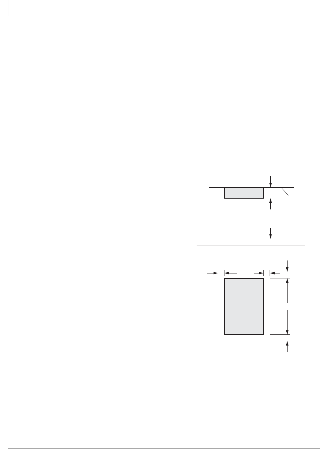
CTX28 Installation
Site Requirements
1-2 Strata CTX I&M 06/04
Site Requirements
This section defines the installation site requirements necessary to ensure a proper operating
environment for the CTX28. Also included are grounding requirements.
Input Power
The system requires an input power source of 115VAC ± 10VAC, 50/60 Hz, 1.5 amps. The AC
outlet is recommended to be dedicated and unswitched. (See “AC Power and Grounding
Requirements” on page 1-4.)
This eliminates interference from branch circuit motor noise or the like, and to prevent accidental
power-off. To avoid accidental power turn-off, Toshiba recommends that you do not use an On/Off
wall switch on this dedicated AC circuit.
For the Strata CTX28, a reserve power source (HPFB-6) may be connected to the system to serve
as a power failure backup (See Step 8 on page 1-18).
Clearance and Location
The minimum clearance requirements for the
Strata CTX28 Base cabinet is shown in
Figure 1-1. Refer to Figure 1-5 on page 1-7 for
CTX28 KSU mounting instructions.
Consider the following conditions when selecting
a location for the KSU(s):
The location must be:
• Dry and clean
• Well ventilated
• Well illuminated
• Easily accessible
The location must not be:
• Subject to extreme heat or cold
• Subject to corrosive fumes, dust, or other
airborne contaminants
• Subject to excessive vibration
• Next to television, radio, office automation, or
high frequency equipment
If reserve power (HPFB-6) is to be installed for
the Strata CTX28, the batteries will require a
well-ventilated location close to the CHSU28A.
2" 2" 2"
2"
18"
Front View
12.25"
Top View
3.5"
3 Feet
Wall
CTX28
Base KSU
7062
Figure 1-1 CTX28 Base KSU Clearance
Requirements
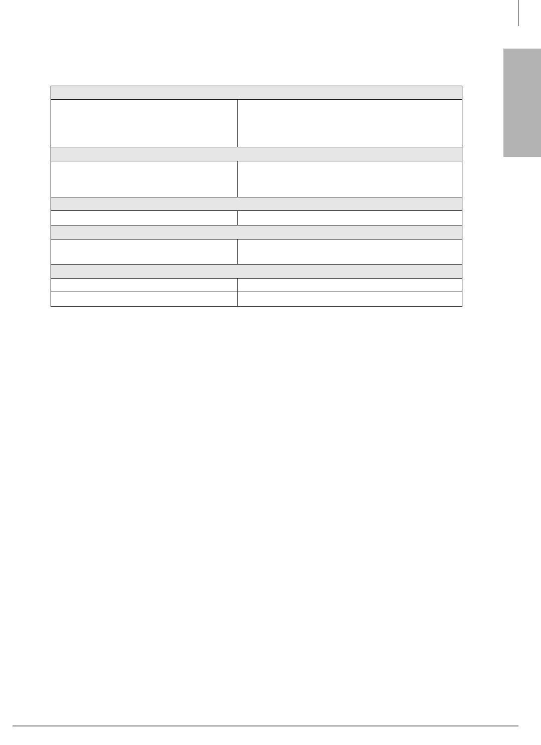
CTX28 Installation
Site Requirements
Strata CTX I&M 06/04 1-3
CTX28 Installation
Table 1-1 provides a summary of the electrical and environmental characteristics.
Table 1-1 Summary of Electrical/Environmental Characteristics
CTX28 Primary Power
Input AC (Power Supply Specification)
AC frequency
Power
AC input current
100~240VAC
50/60 Hz
CTX28 - 100 watts maximum
1.5A maximum
Environmental Specifications
Operating temperature
Operating humidity
Storage temperature
32~104° F (0 ~40° C)
20~80% relative humidity without condensation
-4~140° F (-20~60° C)
Power
Input DC 15V to use the factory-shipped AC adapter
Power Converter
DC voltage output specification -24VDC (-26.3~-28.3VDC)
+5VDC (+4.5~+5.5VDC)
Standard Telephone Ring Circuit (GMAU and GSTU)
Ring Voltage 180V p-p square wave
Ringing capability 1 REN, 1 circuit - one telephone per circuit
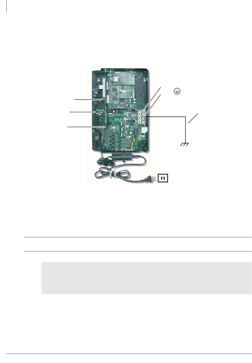
CTX28 Installation
AC Power and Grounding Requirements
1-4 Strata CTX I&M 06/04
AC Power and Grounding Requirements
The CTX28 requires a solid earth ground for proper operation. The AC power cord connects to a
standard AC power outlet. The ground for the CTX28 must originate at the building’s main power
distribution panel and have a solid connection to earth ground. (See Figure 1-2.)
Figure 1-2 Ground to AC Power Cord
CAUTION! Lack of proper ground may cause improper operation and, in extreme cases,
system failure.
WARNING! Failure to provide a proper ground may be a safety hazard to service
personnel or lead to confusing trouble symptoms, such as noise on the talk
path including GVMU greetings and messages. In extreme cases, system
failure may result because the system is not properly protected from
lightning or power transients.
AC Adapter Cord
plugs into GMAS
TB3 on GMAU
Dealer-supplied wire
(#10 AWG gauge or
larger to pass ground
specification test)
CTX28 Cabinet
Grounding Rod
or
Electrical Building
Ground (Main Power
Distribution Box)
AC Voltage
90VAC ± 264VAC
7126
AC Current
1.5 amps max.
TB2
TB1 to HPFB6 FG
(#10 AWG Wire)
P10 Wire Connector
to HPFBG Battery Connector
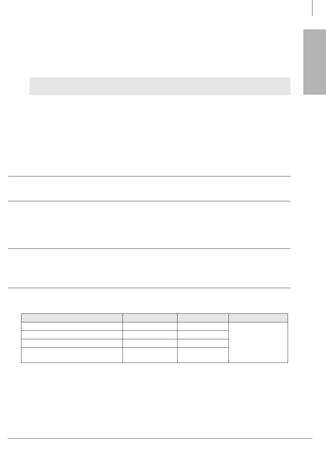
CTX28 Installation
AC Power and Grounding Requirements
Strata CTX I&M 06/04 1-5
CTX28 Installation
AC Power Ground Test
Test the “wire ground” for continuity by either measuring the resistance between the TB3 terminal
(earth ground) on the GMAU and a metal cold water pipe (maximum: 1 ohm), or by using a
commercially available earth ground indicator. If neither procedure is possible, perform the
following earth ground test procedure.
³To perform the earth ground test procedure
1. Obtain a suitable voltmeter, and set it for a possible reading of up to 250VAC.
2. Connect the meter probes between the two main AC voltage terminals (white and black wires)
on the wall outlet. The reading obtained should be between 100~125VAC.
3. Move one of the meter probes to TB3 terminal (green wire ground). Either the same reading or
a reading of zero volts should be obtained.
4. If the reading is zero volts, leave one probe on the ground terminal and move the other probe to
the second voltage terminal.
CAUTION! If a reading of zero volts is obtained on both voltage terminals (white wire to
TB3 wire, black wire to TB3 wire), the outlet is not properly grounded. Omit
Steps 5 and 6, and see following CAUTION!
5. If a reading of zero volts on one terminal, and a reading of 100~125VAC on the other terminal
is obtained, remove both probes from the outlet.
6. Set the meter to the “OHMS/Rx1” scale. Place one probe on the TB3 ground terminal, and the
other probe on the terminal that produced a reading of zero volts. The reading should be less
than one ohm.
CAUTION! If the reading is more than one ohm, then the outlet is not adequately
grounded. If the above tests show the outlet AC voltage is not in range or is
not properly grounded, the condition should be corrected (per Article 250 of
the National Electrical Code) by a qualified electrician before the system is
connected.
WARNING! Hazardous voltages that may cause death or injury are exposed during the
following test. Use great care when working with AC power line voltage.
Table 1-2 Grounding Wiring Summary
Grounding Requirement From To Description
System connects to earth ground Earth ground TB3 on GMAU
Less than 1 ohm
FG of HPFB-6 connect to GMAU HPFB-6 FG Screw TB1 on GMAU
HPFB-6 Ground Feed TB1 on GMAU TB3 on GMAU
GETS connects green ground wire to
GMAU GETS ground wire TB2 on GMAU
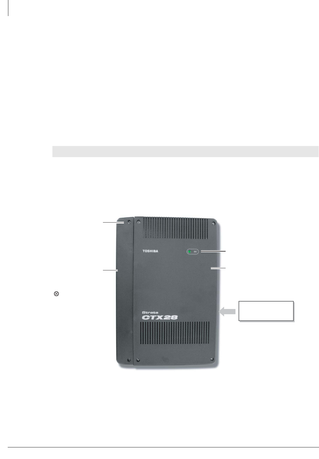
CTX28 Installation
Installing the CTX28 Cabinet
1-6 Strata CTX I&M 06/04
Installing the CTX28 Cabinet
Check the items shipped.
• CHSU28A cabinet
• GCTU1A processor PCB
• AC adapter
• Tie wrap for cable clamp
• Tie wrap for AC adapter
• Velcro strap for AC adapter cord
Step 1: Mount the Cabinet on the Wall
The Base cabinet is designed to be mounted on a wall or other vertical surface.
³ To mount the Base KSU
1. Make sure the location for the CTX28 meets the minimum clearance requirements specified in
Figure 1-1 on page 1-2.
2. Loosen the screws on the front cover and the side cover of the Base KSU, remove the covers
(see Figure 1-3).
Figure 1-3 CTX28 Cabinet Exterior
WARNING! To prevent electrical shock, make sure the power supply switch is turned Off.
Base Cover
Side Cover
Cover
Screws (6)
DC Power LED
=
7125a
Six cover screws
to be removed
before mounting
KSU
Model: CHSU28A
Strata CTX28
Label on edge of
Base KSU
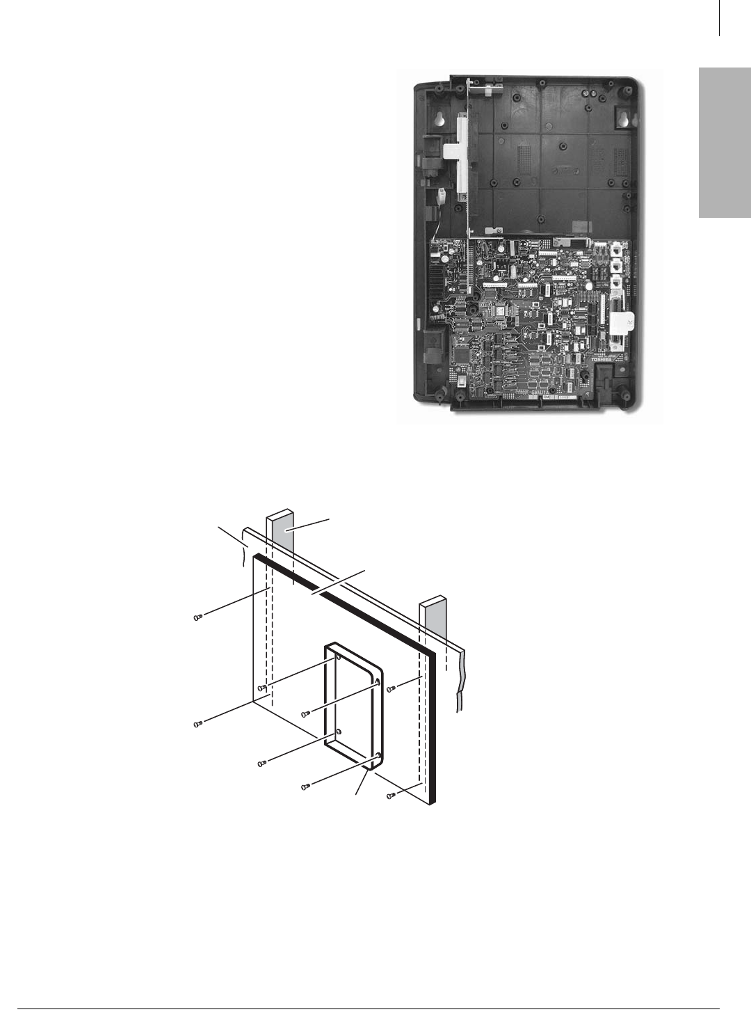
CTX28 Installation
Installing the CTX28 Cabinet
Strata CTX I&M 06/04 1-7
CTX28 Installation
3. Place the Base KSU on the desired
location on the mounting surface and
mark the location of the four screw
holes. See Figures 1-4 and 1-5.
4. Using a hard board between the KSU
and the wall, secure the hard board to
the wall first, making certain that screws
are aligned with studs. See Figure 1-5.
5. Drill holes on these marks and secure
screws approximately two thirds of the
way into the top two holes on the
mounting surface.
6. Hang the unit from the top two screws
and then secure the top screws
completely into the mounting surface.
7. Finish securing the unit to the mounting
surface by completely screwing the
bottom two screws into the wall.
Figure 1-5 KSU Wall Mounting
8. Ground system according to “AC Power and Grounding Requirements” on page 1-4.
7104
Figure 1-4 CTX28 Base KSU Interior
Method 2
Stud
Plaster
Board
Hard Board
(1/2 Inch Plywood)
Base KSU
7114
CTX28 Installation
Installing the CTX28 Cabinet
1-8 Strata CTX I&M 06/04
PCB Installation
Overview Instructions
The following is an overview for installing the Printed Circuit Boards (PCBs) into the Strata
CTX28. After reading this section, proceed to the step-by-step instructions for each PCB.
1. Apply proper settings on the GMAU1A (motherboard Figure 1-7).
2. If applicable, set SW6 battery jumper to ON and install the GVMU1A Voice Mail card
(Figures 1-8 and 1-9).
3. Set P601 battery jumper to ON and install the GCTU1A (processor Figures 1-6 and 1-10).
4. If applicable, install the GCDU1A (3 CO, 3 CLID and 8 DKT circuits Figure 1-11).
5. If applicable, install GSTU1A (standard telephone interface Figure 1-12).
6. If applicable, install the GETS1A 100Base-TX I/F PCB (Figure 1-13).
7. If applicable, install the BSIS1A for SMDR (Figure 1-6).
8. If applicable, install HPFB-6 battery/charger (Figure 1-14).
9. Connect wiring (Table 1-14).
10.Connect AC Adaptor to P2 of the CTX28 sub-motherboard (GMAS, Figures 1-15 and 1-16)
and plug the AC Adaptor into AC power.
11.Turn the System ON by sliding the SW1 ON/OFF switch down. The ON/OFF LED located by
STANDBY will turn on (Figure 1-15).
PCB Descriptions
This describes the CTX28 cabinet PCBs (see Table 1-3 and Figure 1-6.)
Table 1-3 CTX28 (CHSU28) Cabinet circuit cards
Part Title Description
GMAU1A Main Motherboard The GMAU motherboard supports 3 CO lines, 3 CLIDs,
8 Digital Telephones, 1 Standard Telephone. The
GCTU, GVMU, and AC power adaptor plugs into the
GMAS sub-motherboard dedicated slots.
GMAS1A Sub-motherboard
GCTU1A Processor Shipped with cabinet.
GVMU1A Voice Mail Circuit Card (Optional) Voice Mail.
GCDU1A CO, CLID, DKT circuit
card
(Optional) Supports 3 CO lines, 3 CLIDs, 8 Digital
Telephones. The GCDU1A plugs onto the motherboard.
GSTU1A Standard Telephone
Circuit Card (Optional) Provides 1 Standard Telephone port.
GETS1A 100BaseT I/F (Optional) Ethernet 100Base T cable.(optional)
BSIS1A RS232C (Optional) RS232-C. Provides 4 serial I/O ports.
HPFB6 External Battery (Optional) Provides backup Reserve power.
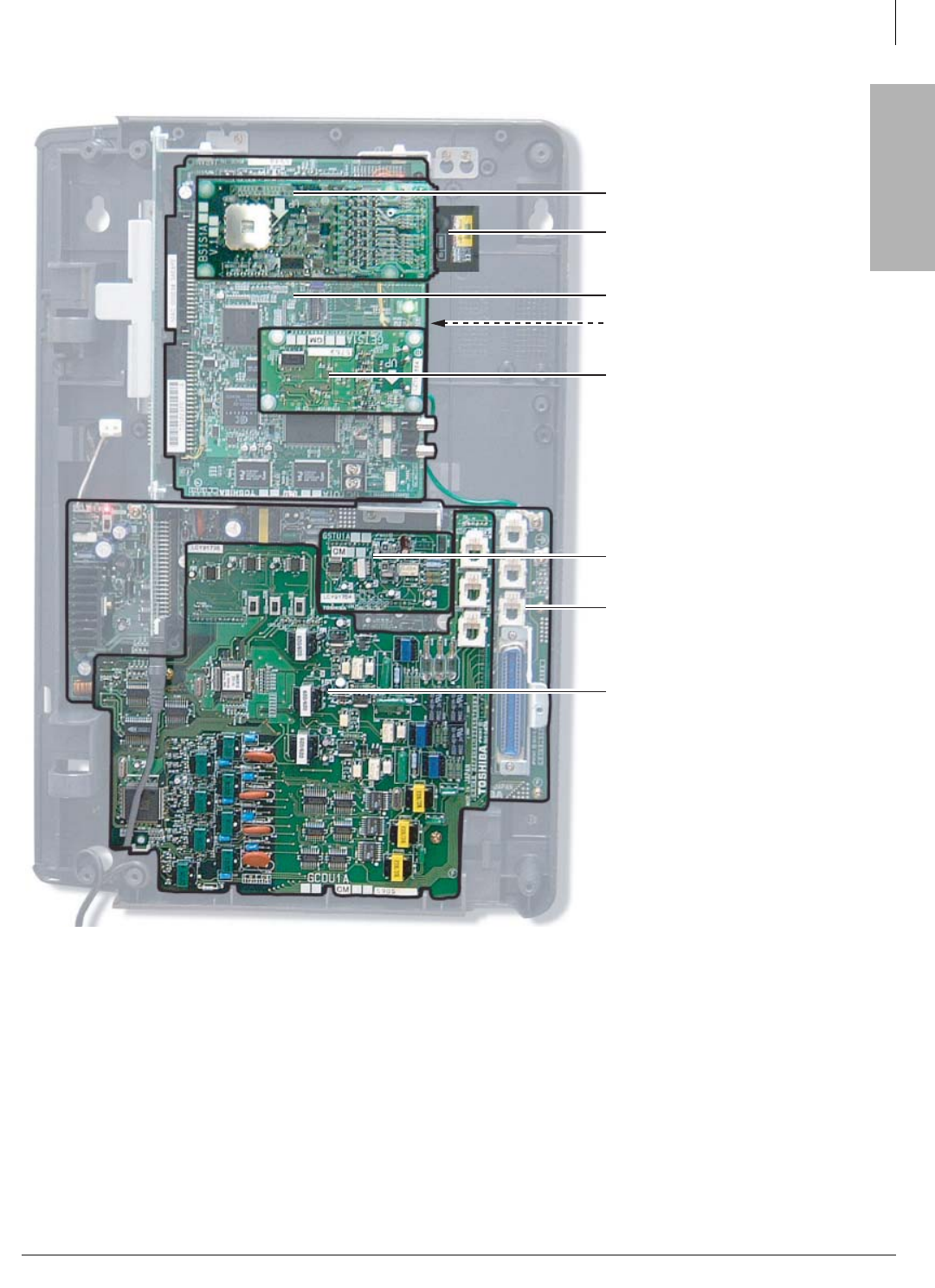
CTX28 Installation
Installing the CTX28 Cabinet
Strata CTX I&M 06/04 1-9
CTX28 Installation
Figure 1-6 CTX28 Interior with PCBs
7108
SmartMedia Card
GCTU (Processor)
GVMU (Voice Mail)
installs beneath the GCTU
BSIS (RS232-C)
GETS (100Base TX)
GSTU (Standard Telephone)
GMAU (Main Motherboard)
GCDU
(CO, CLID, DKT)
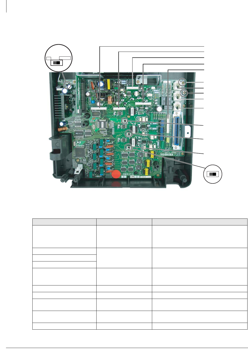
CTX28 Installation
Installing the CTX28 Cabinet
1-10 Strata CTX I&M 06/04
Step 1: Set Jumpers on the GMAU1A (Motherboard)
The GMAU1A (shown in Figure 1-7) supports up to 6 CO lines with Caller ID (CLID).
Figure 1-7 GMAU PCB
Table 1-4 GMAU Controls, Switches and Indicators
Control/Indicator/Connector Type of Component Description
SW1 2-position slide switch
Power Switch:
[STANDBY] = no DC power supply.
[ON] = DC voltage supplied. [ON] activates the
reserve power from HPFB-6 battery pack.
SW400
2-position slide switch 3dB Pad switchSW500
SW600
CD6 LED
Power indicator; when SW1 is [ON], turned on.
Red both AC power and 3Reserve power. SW1
is [STANDBY], turned off.
TB1 Plate with screw Grounding for HPFB-6 external battery
TB2 Plate with screw Grounding for GETS Ethernet card
TB3 Plate with screw Grounding for CTX28 system, connect to earth
ground
P1 50-pin Amphenol
connector DKT, SLT and Power Failure Transfer interface
P3 44-pin DIN connector GMAS interface
7113
SW1
ON/OFF
(Standby)
SW400
(3db/0DB)
SW500
(3db/0DB)
SW600
(3db/0DB)
CO1
TB2
P8
TB3
CO2
CO3
P6
P5
P7
P4
ONSTANDBY
SW1

CTX28 Installation
Installing the CTX28 Cabinet
Strata CTX I&M 06/04 1-11
CTX28 Installation
P4 16-pin female connector
GCDU DKT and loop start interfaceP5 13-pin female connector
P6 10-pin female connector
P7 13-pin female connector GSTU standard telephone interface
P8 10-pin female connector
P9 6-pin female connector GCDU interface
P10 3-pin connector HPFB-6 external battery interface
P11 3-pin female connector GSTU standard telephone interface
P400
Modular connector
Interface for CO Line circuit (CO1)
P500 Interface for CO Line circuit (CO2)
P600 Interface for CO Line circuit (CO3)
F1 2.0A Fuse -24VDC Over current protection
Table 1-5 GMAS (Sub-motherboard)
Control/Indicator/Connector Type of Component Description
P1 44-pin DIN male connector GMAU interface
P2 Pin Jack DC-IN (DC15V) jack
J1 44-pin DIN female connector GVMU interface
J2 44-pin DIN female connector GCTU interface
J3
Table 1-4 GMAU Controls, Switches and Indicators
(continued)
Control/Indicator/Connector Type of Component Description
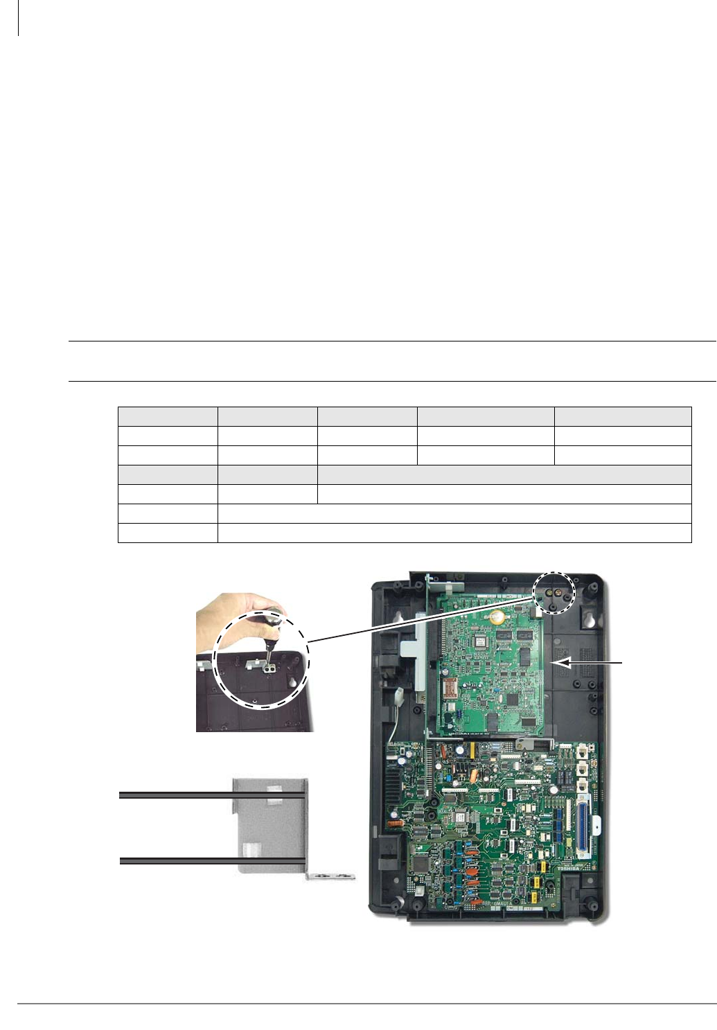
CTX28 Installation
Installing the CTX28 Cabinet
1-12 Strata CTX I&M 06/04
Step 2: Install the GVMU1A Voice Mail PCB (optional)
1. In the CTX28 cabinet, remove the two screws and the PCB stopper (Figure 1-8).
2. On the GVMU, set the SW6 battery jumper to ON and set the Greeting language switch
(Figure 1-9). Default language is “English.” See Table 1-6 for other language settings.
3. Turn off system power and if GCTU is installed remove GCTU before installing the GVMU.
4. Install the GVMU into the lower slot of the GMAS (sub-motherboard) (see Figure 1-8).
5. Install the GCTU per Step 3 and turn system power ON.
Note To program GVMU, refer to Strata CTX28 Voice Processing Programming Manual and use
XADM4 Admin software.
³To re-initialize GVMU to default data after it has been in use (see CAUTION! below)
1. Turn off CTX28 system power and uninstall GCTU and GVMU.
2. Remove the GVMU battery jumper for two minutes.
3. Place the GVMU battery jumper back to the ON position, then install the GVMU and GCTU.
4. Turn system power back on.
CAUTION! Initializing GVMU to default data will erase all Names, Security codes and
saved Messages.
Figure 1-8 GVMU/GCTU PCB Stopper
Table 1-6 English/French Greetings Settings on the GVMU1A
Jumper English French English to French French to English
SW2 OFF ON OFF ON
SW3 OFF OFF ON ON
Jumper Admin PC Real Time Debug Monitor
SW4 OFF (default) ON (used for debug information, i.e., log and trace data by TTY.
SW5 Not used.
SW6 Battery Jumper – must be in ON position
7162
GVMU
GCTU
GVMU
PCB Stopper
7252
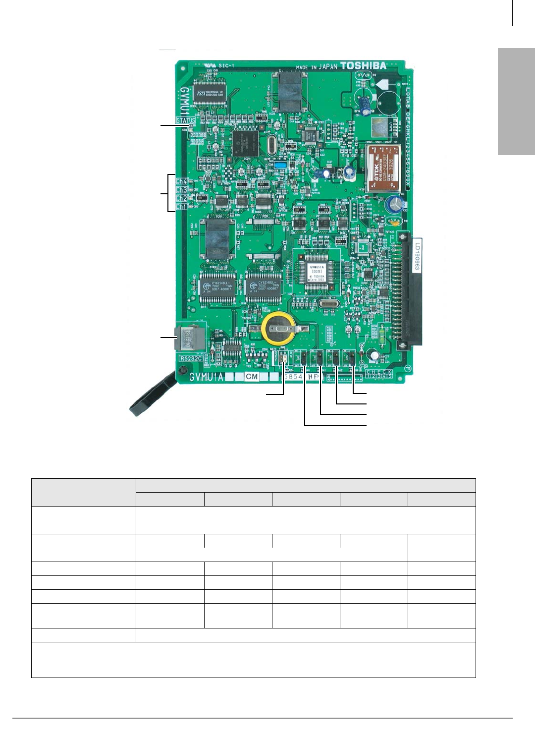
CTX28 Installation
Installing the CTX28 Cabinet
Strata CTX I&M 06/04 1-13
CTX28 Installation
Figure 1-9 Close Up of PCB Stopper for GCTU and GVMU
Table 1-7 LED Indicators on the GVMU1A
Indication/ State GVMU1A LEDs
Ch1 Ch2 Ch3 Ch4 Status
Power On
(Initialize Sequence*)
All LEDs turn ON (Red), then all LEDs turn OFF and cycle ON/OFF through all ports
for one to two minutes while initializing and then all LEDs turn off.
Normal
(Busy/Idle)
OFF OFF OFF OFF Blinking
ON = Busy; OFF = Idle
Failure Blinking Blinking Blinking Blinking OFF
Shut Down ON ON ON ON OFF
Back Up/Restore ON ON ON ON ON
No 1.8V input Voltage
in GVMU ON OFF OFF ON ON
Not mounted/defective Light flickers and switches from the LED to LED (from Ch1~Ch4) + Status LED
* The initialize sequence operates each time the CTX28 power is cycled off/on or the CTX28 processor is reset
or initialized – GVMU program data remains saved. However, if the GVMU battery jumper is removed, GVMU
program data and saved messages will be erased.
7395
SW2 - Language Jumper
SW6 - Battery Jumper
RS232C
Maintenance
Jack
Status LED
VM Port LEDS
(Ch1 ~ Ch4)
Busy/Idle
SW3 - Language Jumper
SW4 - Admin PC/Debug Monit
SW5 - Not Used
Note: For details, see
GVMU Admin PC
Connections later in
this chapter.
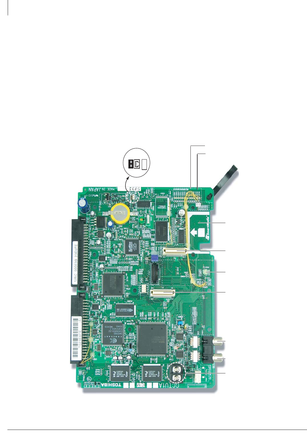
CTX28 Installation
Installing the CTX28 Cabinet
1-14 Strata CTX I&M 06/04
Step 3: Install the GCTU1A (Processor)
The GCTU1A is the main processor for the CTX28. It is shipped with the CTX28 Base cabinet.
³To install the GCTU1A into the CTX28
1. Skip this step if you have installed a Voice Mail PCB and already removed the PCB stopper. If
you have not done this, then in the CTX28 cabinet, remove the two screws and the PCB stopper
(see Figure 1-8).
2. Set the P601 battery jumper to ON (see Figure 1-10) and insert the GCTU1A (shipped with the
cabinet) in the upper slot of the GMAS sub-motherboard (see Figure 1-6). Place it next to the
guide rail of the PCB stopper (see Figure 1-8).
3. Secure the PCB stopper with the original two screws.
4. Insert the SmartMedia card (gold contacts face left, notched corner faces forward and up) into
the SmartMedia slot on the GCTU1A (see Figure 1-6).
Figure 1-10 GCTU PCB
7264
OFF ON
BATT
P601 Battery
P903P902
SmartMedia Slot
DC Power On/Off LED
MOH
External Speaker
P2 (for BSIS)
P1 (for GETS)
P901 Control Relay Contact
SmartMedia LED
Heart Beat LED
CTX28 Installation
Installing the CTX28 Cabinet
Strata CTX I&M 06/04 1-15
CTX28 Installation
Table 1-8 GCTU
Control/Indicator/
Connector Type of Component Description
P1 60 pin connector GETS Interface
P2 60 pin connector BSIS Interface
P501 SmartMedia house SmartMedia interface
P601 Jumper plug Must always be in the “ON” position to maintain
customer data
P801 RCA Jack Paging interface and BGM/MOH interface
P901 2 pin screw terminal Relay contact
P902 44-pin male DIN
connector CTX28 Back plane connector
P903 44-pin male DIN
connector CTX28 Back plane connector
CD101 LED Processor operation indication
CD501 LED SmartMedia access indicator
CD908 LED Green DC power indicator for CTX28 system. Shown
on front cover (see Figure 1-3).
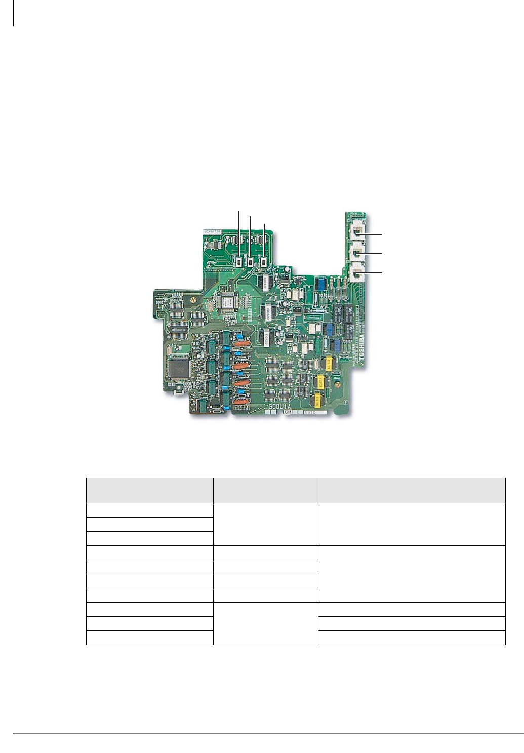
CTX28 Installation
Installing the CTX28 Cabinet
1-16 Strata CTX I&M 06/04
Step 4: Install the GCDU1A (DKT and Loop Start Interface)
The GCDU1A PCB adds an additional 3 CO lines, 3 Caller ID units, and 8 digital telephone
circuits with a single PCB. It attaches to the GMAU1A motherboard. With the GCDU1A installed,
the CTX28 supports up to 16 digital telephones (DKTs), 6 CO lines and 6 Caller ID circuits.
³To install the GCDU1A
³Carefully place the GCDU1A pins over the GMAU connectors (see Figure 1-6 and Figure
1-11). Press down on the PCB to secure the pins to the connectors (see Table 1-9).
Figure 1-11 GCDU1A PCB
Table 1-9 GCDU1A Controls, Indicators and Connectors
Control/Indicator/
Connector Type of Component Description
SW400
2-position slide switch 3dB Pad switchSW500
SW600
P4 16-pin male connector
GMAU interface
P5 12-pin male connector
P6 9-pin male connector
P9 6-pin male connector
P400
Modular connector
Interface for CO Line circuit (CO4)
P500 Interface for CO Line circuit (CO5)
P600 Interface for CO Line circuit (CO6)
7260
CO4
CO5
CO6
SW600
SW500
SW400
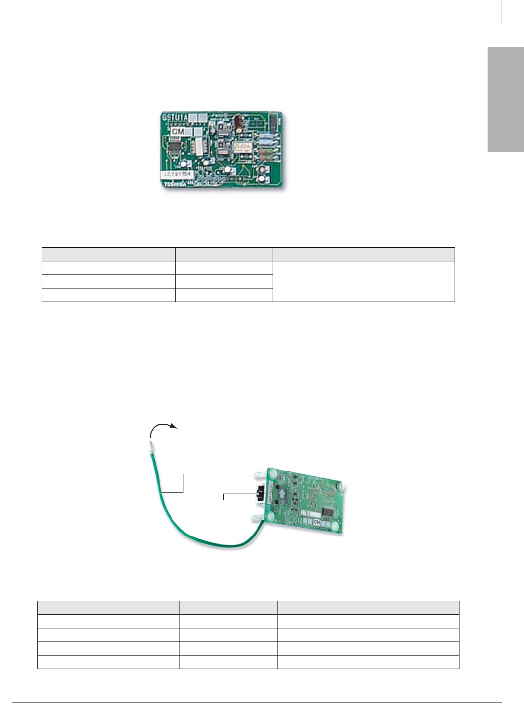
CTX28 Installation
Installing the CTX28 Cabinet
Strata CTX I&M 06/04 1-17
CTX28 Installation
Step 5: Install the GSTU1A
The GSTU1A provides one additional standard telephone interface.
³To install the GSTU1A, align the GSTU1A pins over the GMAU1A motherboard and press
down firmly (see Figure 1-6).
Figure 1-12 GSTU1A PCB
Step 6: Install the GETS1A
The GETS1A supports 100Base TX Ethernet.
³To install the GETS1A
1. Place option PCB arrow side up over the plastic stand-off with the connectors and stand-off
holes on the GCTU1A. The “UP” arrow should point down. Snap GETS1A securely into place.
2. Attach the FG ring to TB2 on the GMAU1A motherboard with the screw shown in Figures 1-2
and 1-13.
Figure 1-13 GETS (100Base TX)
Table 1-10 GSTU1A Controls, Indicators, and Connectors
Control/Indicator/Connector Type of Component Description
P7 12-pin male connector
GMAU interfaceP8 9-pin male connector
P11 3-pin male connector
Table 1-11 GETS (100Base TX)
Control/Indicator/Connector Type of Component Description
CD1 LED LAN link indicator
CD2 LED Transmission and receive indicator
P1 60 pin connector GCTU interface
P2 RJ45 Network interface port
7259
7261a
Ethernet Plug
FG Green Wire
To TB2 On GMAU
CTX28 Installation
Installing the CTX28 Cabinet
1-18 Strata CTX I&M 06/04
Step 7: Install the BSIS1A (optional)
The BSIS provides RS-232 serial ports.
³To install the BSIS1A, align the BSIS1A pins over the GCTU1A and press down firmly (see
Figure 1-6).
Step 8: Install the HPFB-6 (Reserve Power Battery/Charger)
One or two HPFB-6 optional units can be added to the CTX28 to provide reserve power. The
amount of reserve power time depends on the hardware (see Table 1-12). The table below is an
estimate of battery backup time based on the premise that the HPFB-6 unit(s) are fully charged at
the time of AC power failure. This estimated backup time is based on low call traffic, the time
estimates will be reduced by as much as half with extreme heavy traffic volumes.
1. Place the HPFB-6 directly below the Strata CTX28 KSU. See Figure 1-14 for minimum
clearance requirements. A second HPFB-6 can be installed directly below the unit to supply
backup reserve power.
2. Mark the location of the two screw holes, then drill holes.
3. Screw the two screws two-thirds into the mounting surface.
4. Hang the HPFB-6 on the screws then tighten the screws into the mounting surface.
5. Plug the first HPFB-6 connector into BATT connector P10 on GMAU.
6. Connect a #10 ground AWG wire from the HPFB-6 “FG” screw to the CTX28 screw labeled
“TB1” (Figure 1-2).
Note The CTX28 should be plugged into AC power and the DC power switch should be turned
On when installing the HPFU-6. The HPFU-6 will not start to operate if AC power is not
available during the initial installation.
7. The 24VDC LED on the HPFB-6 should light. If it does not light, press the battery Off switch
with a pencil point or other small-tipped object.
8. Dress and tie-wrap the HPFB-6 cables.
9. To mount a second HPFB-6, repeat Steps 1~4, then plug the second HPFB-6 connector in the
first HPFB-6 and connect an FG wire between each HPFB-6 FG screw.
10. To test the HPFB-6, remove the CTX28 AC plug from the AC outlet. The CTX28 AC LED will
go out, but the CTX28 DC LED remains on. Also the system remains in normal working order
and the HPFB-6 24V LED remains on.
11. If it is desired to turn off the HPFB-6 (after loss of AC power), use a pencil or other sharp
object to press the Battery Off switch.
CAUTION! Once the HPFB-6 is turned Off or unplugged (during AC power loss) it will not
operate again until AC power is restored to the CTX28 KSU.
Table 1-12 CTX28 Reserve Power Duration Estimates
Hardware 1 HPFB-6 2 HPFB-6
3CO/8DKT - No GVMU 1 hr. 40 min. 3 hr. 20 min.
3CO/8DKT - with GVMU 1 hr. 30 min 3 hr.
6CO/16DKT - No GVMU 1 hr. 5 min. 2 hr. 10 min.
6CO/16DKT - with GVMU 1 hr. 2 hr.
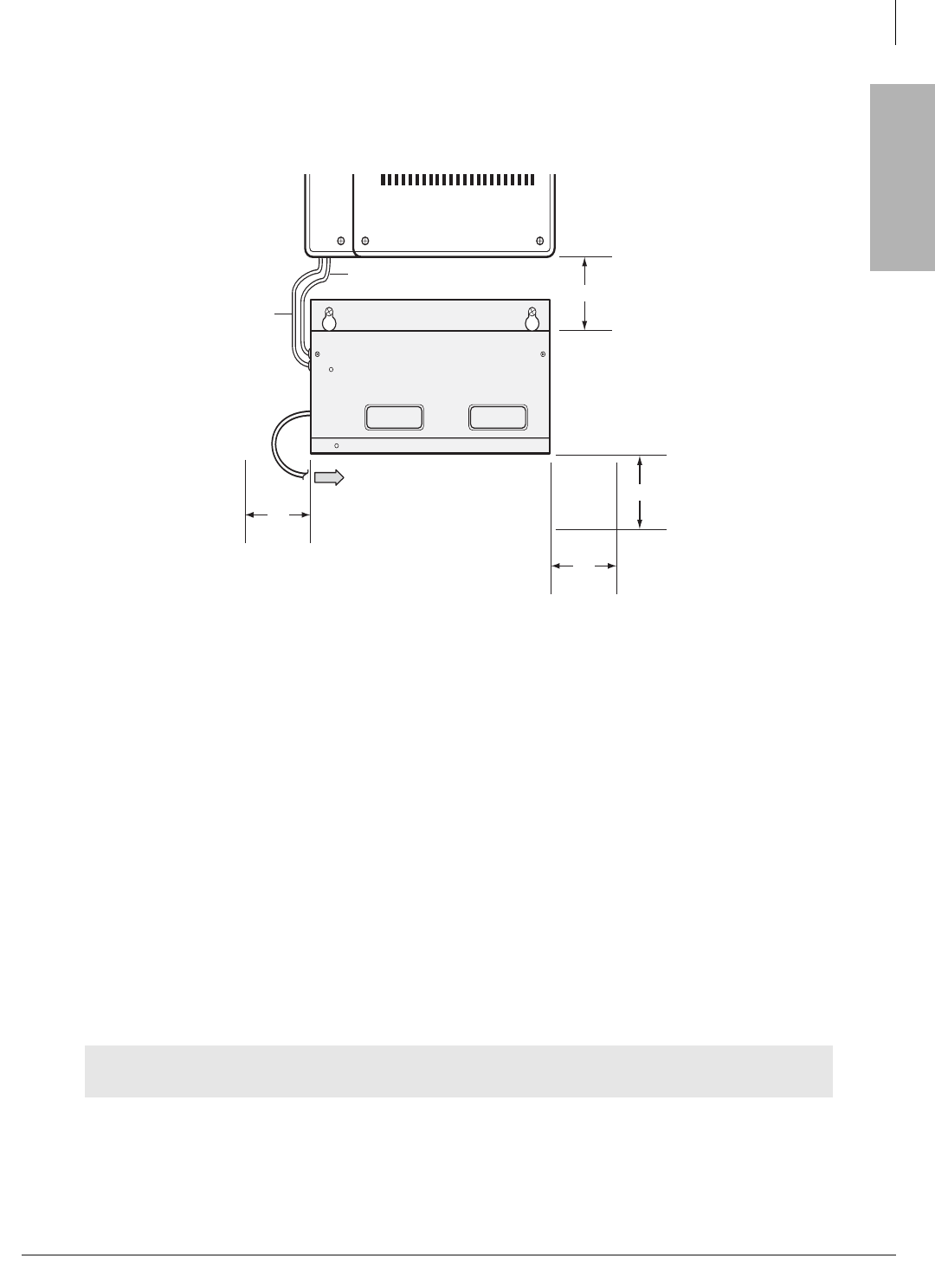
CTX28 Installation
Installing the CTX28 Cabinet
Strata CTX I&M 06/04 1-19
CTX28 Installation
Note The CTX28 KSU does not provide a battery charger, the HPFB-6 contains built-in
batteries and a battery charger; therefore, do not connect any other type of batteries to
the CTX28.
Figure 1-14 HPFB-6 Reserve Power Installation
Step 9: Install Wiring
1. Refer to Figure 1-15 for the following steps. Loosen the screw on the Amphenol clamp and
remove the clamp. Plug in the 25-pair Amphenol connector and replace the clamp to hold the
Amphenol connector in place.
2. Connect all other PCB wiring (e.g., modular CO line cords, LAN cable, etc.). Slide the shorter
tie-wrap through the holder. Then fasten wiring to the unit with the tie wrap that comes with the
Base KSU.
3. Connect the end of the AC adapter cable to the GMAS PCB as shown in Figures 1-15 and 1-16.
4. Connect the other end of the GETS (100Base TX) LAN cable to the LAN connected to the
CTX WinAdmin PC.
5. Plug the AC adapter into a power strip connected to an power outlet.
6. Put the On/Standby switch into “On” position. The DC LED should light green. The CTX28 is
now ready to program.
WARNING! Do not smoke near batteries. Avoid creating any electrical sparks near
batteries.
2“
From Second HPFB (optional)
To P10 Connector (see Fig. 1-2)
HPFB Unit:
Reserve Power Battery
and Charger (optional)
#10 AWG HPFB
FG Wire to TB1
(see Fig. 1-2)
7253
2“
2“
2“
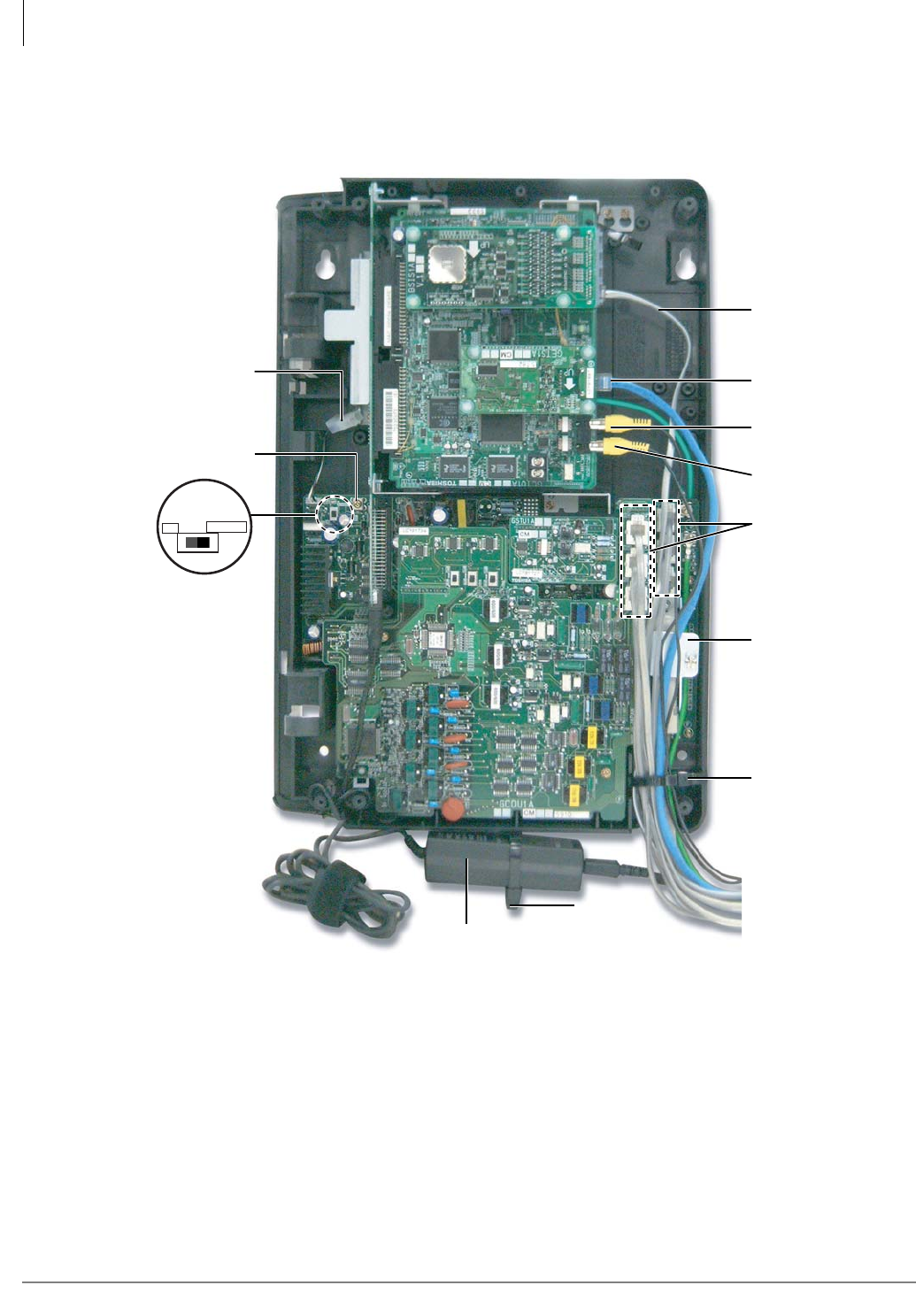
CTX28 Installation
Installing the CTX28 Cabinet
1-20 Strata CTX I&M 06/04
Figure 1-15 Standard Unit Wiring (without option units) and AC Adapter
7158
Amphenol
Connector
secured
under clamp
CO, CLID,
DKT
BSIS
(4 RS-232C)
Tie Wrap
(supplied)
Tie Wrap
(supplied)
100 Base TX
Music On Hold
(MOH)
External Speaker
(Paging)
TB1 (to HPFB FG)
P10 (to HPFB
Battery Cord)
AC Adapter
SW1
ON/OFF
(Standby)
ONSTANDBY
SW1
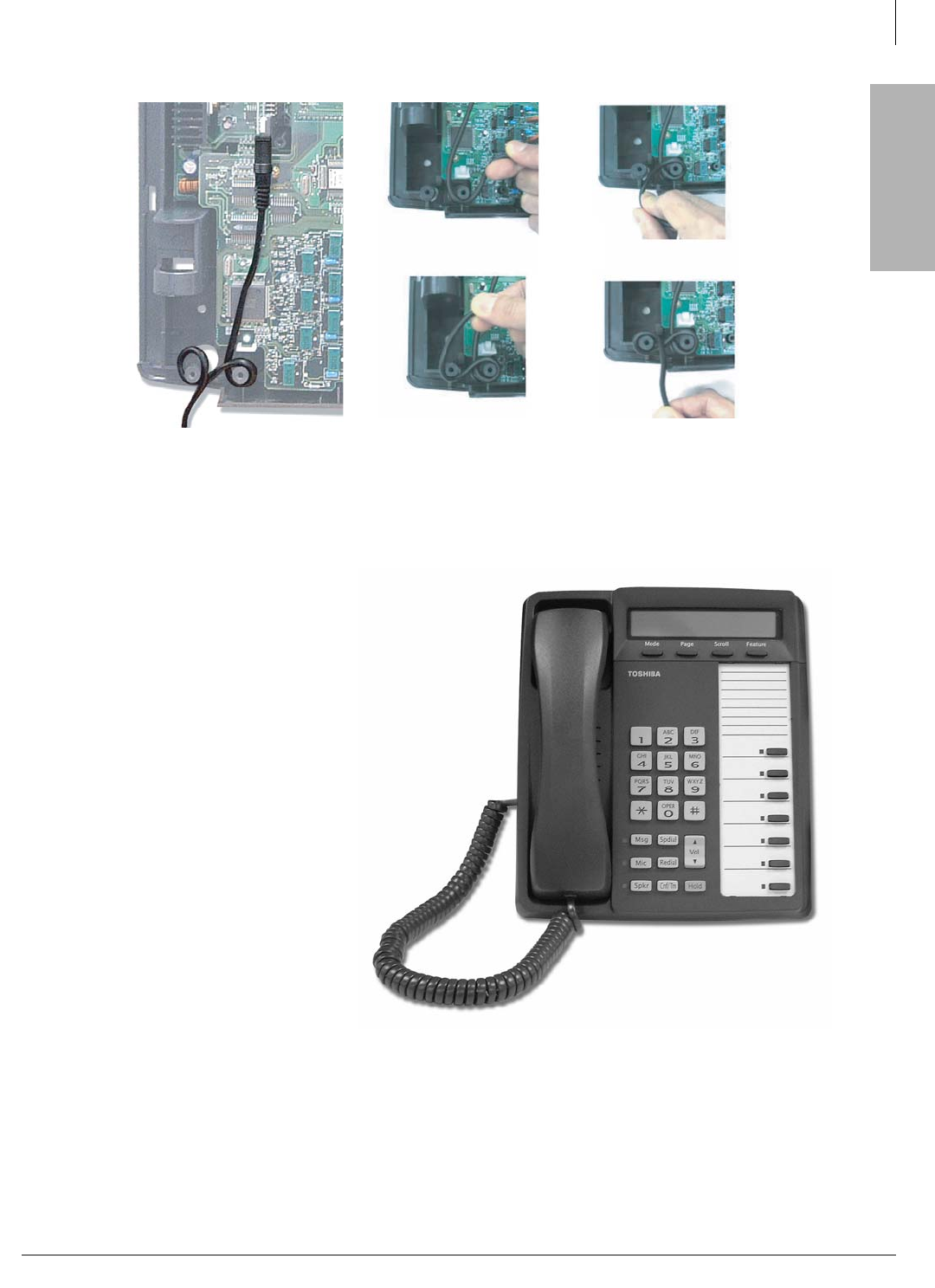
CTX28 Installation
Digital Telephone Connection
Strata CTX I&M 06/04 1-21
CTX28 Installation
Figure 1-16 AC Adapter Wiring Procedure
Digital Telephone Connection
The Strata CTX28 supports any
Toshiba 2000 and 3000-series
digital telephones, including the
new DKT3007-SD telephone
(shown right).
The DKT3007-SD only works on
the CTX28.
The DKT3007-SD works just like
the DKT3020-SD and DKT3010-
SD, except that it has seven
flexible buttons.
The CTX28 supports all
DKT2000 and DKT3000-series
Add-on Modules and DSS
Consoles.
CTX28 supports Handset Off-
hook Call Announce (OCA), but
not Speaker OCA.
1
34
2
7257
Figure 1-17 DKT3007-SD Telephone
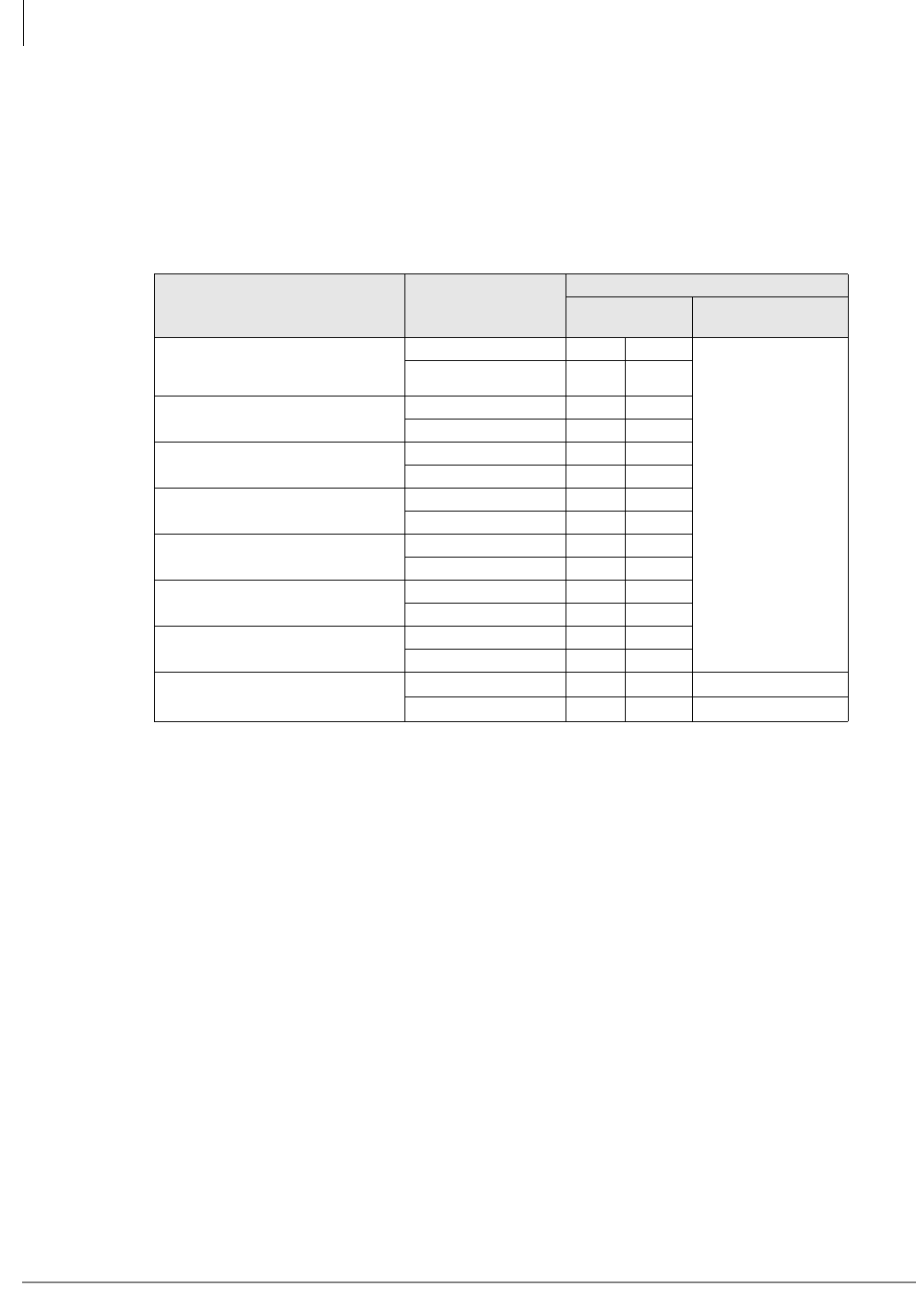
CTX28 Installation
Loop Limits
1-22 Strata CTX I&M 06/04
Loop Limits
This section provides the maximum loop lengths for connection of telephones, lines, peripheral
equipment, and power supplies. The following information applies to only the Strata CTX28
system (see Table 1-13). Diagrams that are applicable to all systems, including the CTX28, can be
found in Chapter 10 – MDF PCB Wiring.
Table 1-13 Digital Telephone/DIU/DDSS Console/ADM/Loop Limits
Mode CTX28 KSU or
Battery Backup1
1. Battery backup applies to instances when the system is being powered by batteries exclusively.
Maximum line length (24 AWG)
1 Pair
feet meters
1 Pair plus
external power2
2. Digital cable runs must not have the following:
Cable splits (single or double)
Cable bridges (of any length)
High resistance or faulty cable splices
DKT3000-series or DKT2000-series
models, DKT with BVSU or DVSU or
BHEU or HHEU.
CTX28 KSU 1000 303
1000 feet
303 meters
Battery Backup 695 204
DKT with BPCI CTX28 KSU 1000 303
Battery Backup 500 151
DKT with BPCI and BHEU CTX28 KSU 1000 303
Battery Backup 500 151
DDSS3060 or 2060 CTX28 KSU 1000 303
Battery Backup 675 204
DDCB3A CTX28 KSU 165 50
Battery Backup 500 151
BATI, RATI CTX28 KSU 1000 303
Battery Backup 1000 303
DKT with 1 ADM CTX28 KSU 675 204
Battery Backup 165 50
DKT with 2 ADMs CTX28 KSU 500 151
Battery Backup 33 10
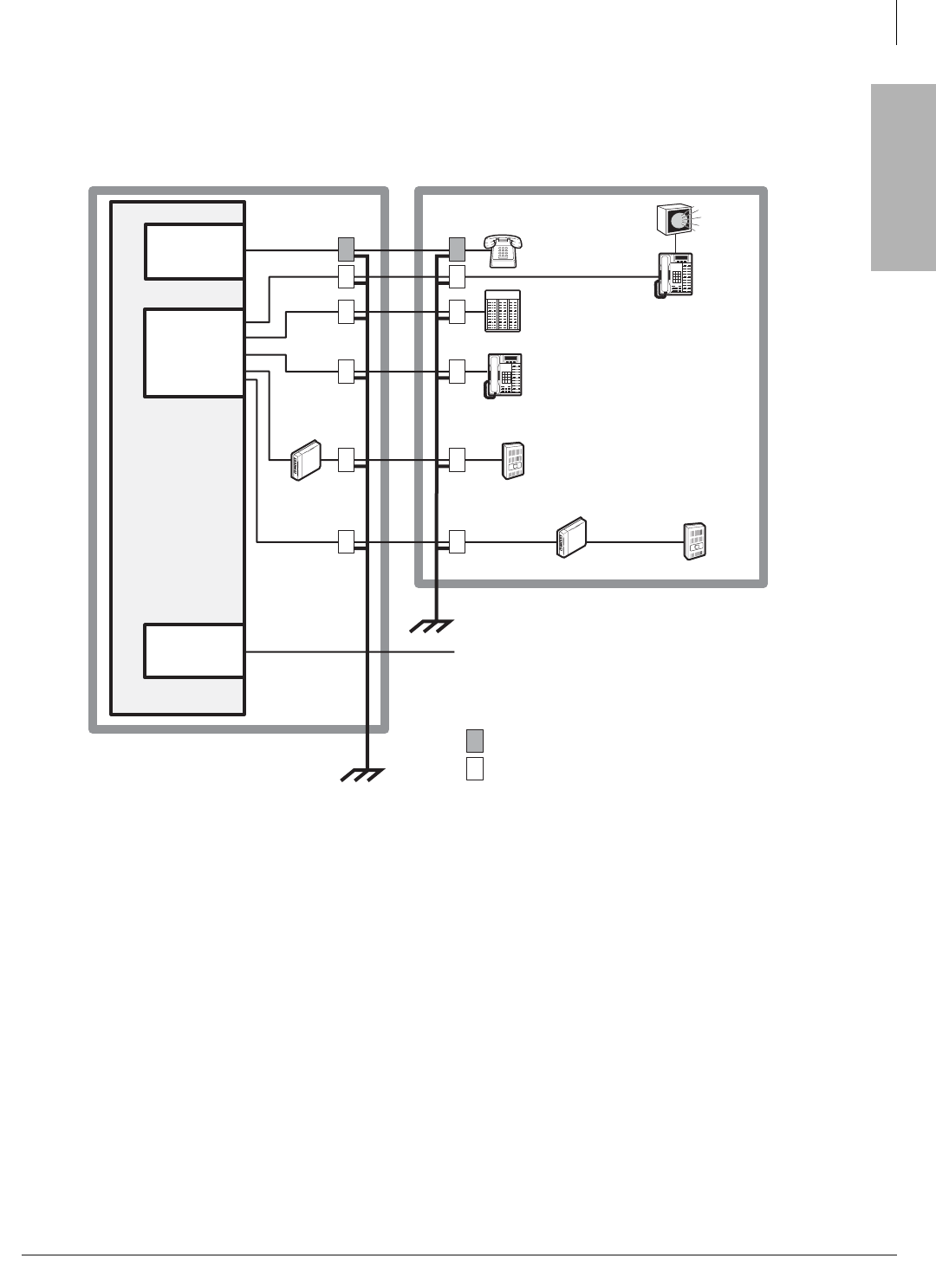
CTX28 Installation
CTX28 Secondary Protection
Strata CTX I&M 06/04 1-23
CTX28 Installation
CTX28 Secondary Protection
The following diagram (see Figure 1-18) shows where secondary protectors must be installed for
outside wiring.
Figure 1-18 CTX28 Secondary Protector Diagram
Important! To protect against transient voltages and currents, solid state secondary protectors
must be installed if there is outside wiring. These protectors, which contain fast
semiconductors in addition to fuses, shall comply with the requirements for
secondary protectors for communication circuits, UL 497A. Care must be taken to
ensure that they are very well grounded to a reliable earth ground. Recommended
protectors are available in the fast Series 6 line from ONEAC Corp., Libertyville,
Illinois 60048, (800) 327-8801. Install and test the secondary protectors precisely to
the installation instructions of these manufacturer.
Standard
Telephone
Building #1 Building #2
Digital Telephone
Digital Telephone
or Cordless Base
MDFB
Loop CO Line
Secondary protectors – standard voltage
Secondary protectors – low voltage
GMAU
GCDU
GMAU
GDCU
DDSS
Console
HESB
DDCB
MDFB
GMAU
GSTU
7255
(Earth Ground)
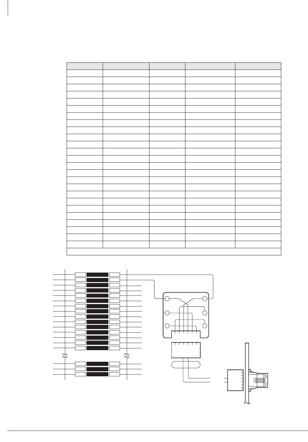
CTX28 Installation
MDF Wiring
1-24 Strata CTX I&M 06/04
MDF Wiring
For Registration information refer to “CTX28 FCC/ACTA Registration Numbers” on page 1-1.
Figure 1-19 MDF Wiring to CO Lines (GMAU and GCDU)
Table 1-14 Station Wiring for Amphenol Connector (P1) on GMAU1
Pin No. Signal Pin No. Signal Station
1 VR1 26 VT1 DKT #1
2 VR2 27 VT2 DKT #2
3 VR3 28 VT3 DKT #3
4 VR4 29 VT4 DKT #4
5 VR5 30 VT5 DKT #5
6 VR6 31 VT6 DKT #6
7 VR7 32 VT7 DKT #7
8 VR8 33 VT8 DKT #8
9 VR9 34 VT9 DKT #9
10 VR10 35 VT10 DKT #10
11 VR11 36 VT11 DKT #11
12 VR12 37 VT12 DKT #12
13 VR13 38 VT13 DKT #13
14 VR14 39 VT14 DKT #14
15 VR15 40 VT15 DKT #15
16 VR16 41 VT16 DKT #16
17 (NC) 42 (NC)
18 PF1R 43 PF1T PFT circuit*
19 (NC) 44 (NC)
20 (NC) 45 (NC)
21 (NC) 46 (NC)
22 (NC) 47 (NC)
23 CR1 48 CT1 STU #1
24 (NC) 49 (NC)
25 CR2 50 CT2 STU #2
* Connect a Standard Telephone to PFT pair to provide access to CO Line1 during a power failure.
1
2
3
4
5
6
7
8
9
10
11
12
13
14
15
48
49
50
1
2
3
4
5
6
7
8
9
10
11
12
13
14
15
48
49
50
BRIDGING
CLIPS
66M150 SPLIT BLOCK
GN
654321
Y
BL
R
BK
W
2345
MODULAR
CORD
1-6
T1
R1
T1
R1
TO
NETWORK
R1 T1
GMAU
GCDU
CO1~6
MODULAR
JACKS
R2
R1
T1
T2
5
4
3
2
GMAU
GCDU
PIN-OUT
1
2
3456
NETWORK JACK: RJ14C
FIC: 02LS2
CO LINE CABLING
7262
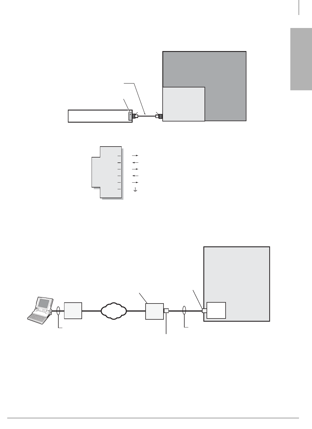
CTX28 Installation
GVMU Administration PC Connections
Strata CTX I&M 06/04 1-25
CTX28 Installation
GVMU Administration PC Connections
Figure 1-20 GVMU Serial Port Interface Connection
Figure 1-21 GVMU PC Modem Interface Connection
GVMU
Strata CTX28
RS232C Jack
6-wire Modular Cord - telephone
cross-pinned type (modular jack locking
tabs on the same side of the cord).
Toshiba PPTC or PPTC9
connectors to PC COM port
7407
Strata CTX28 Serial Port Modular Pins
GVMU RJ11
(Six-pin jack)
TD
RD
DTR
DSR
SG
CD
(Data to GVMU)
(Data from GVMU)
(Data Terminal Ready to GVMU)
(Data Set Ready from GVMU)
(CTX/Terminal Signal Ground)
(Carrier Detect from GVMU)
2
1
4
3
6
5
PC with GVMU XADM Software
GVMU
Strata CTX28
Modem
RS-232 Cable
Remote GVMU
PC using
XADM software
CO LineCO Line
Telephone
Network
7406
Ext.
Modem
3-Pair Modular Cord - telephone
cross-pinned type (modular jack
locking tabs on the same side of
the cord).
Toshiba PPTC25-MDM
connector to Modem
RS232C Maintenance
Jack
Dealer Supplied
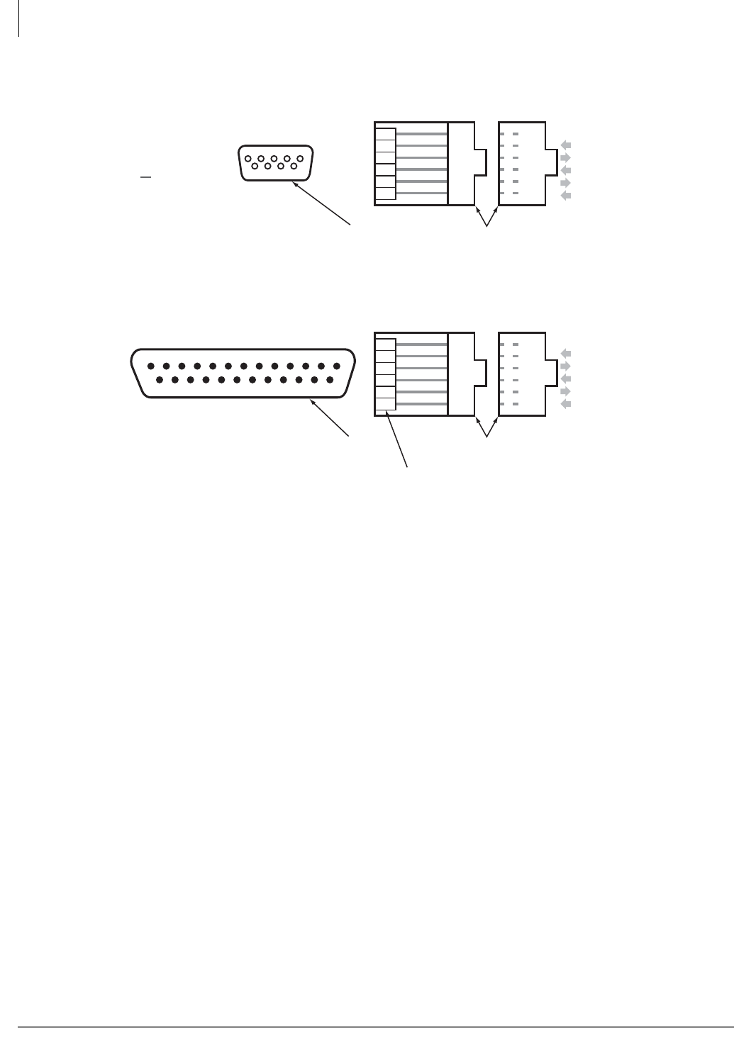
CTX28 Installation
GVMU Administration PC Connections
1-26 Strata CTX I&M 06/04
Figure 1-22 Serial Port Adaptors Pin Numbers
2
3
6
4
1
5
6
5
4
3
2
1
RD
TD
DSR
DTR
DCD
SG
PPTC-9
6789
23451
Connect to PC 9-pin
COMX Port (DTE)
(female) 6
5
4
3
2
1
SG
DCD
DTR
DSR
TD
RD
Modular Jack Pinout
(front view)
DB9 Pinout
(front view)
7405
GVMU
RS232C
Maintenance Jack
234567
20
8
PPTC25-MDM
Connect to External
Modem (DTE)
(male) 2
3
20
6
8
7
6
5
4
3
2
1
RD
TD
DSR
DTR
DCD
SG
6
5
4
3
2
1
SG
DCD
DTR
DSR
TD
RD
Modular Jack Pinout
(front view)
DB25
Pinout
(front view) Jumper
Pin 4-5
GVMU
RS232C
Maintenance Jack
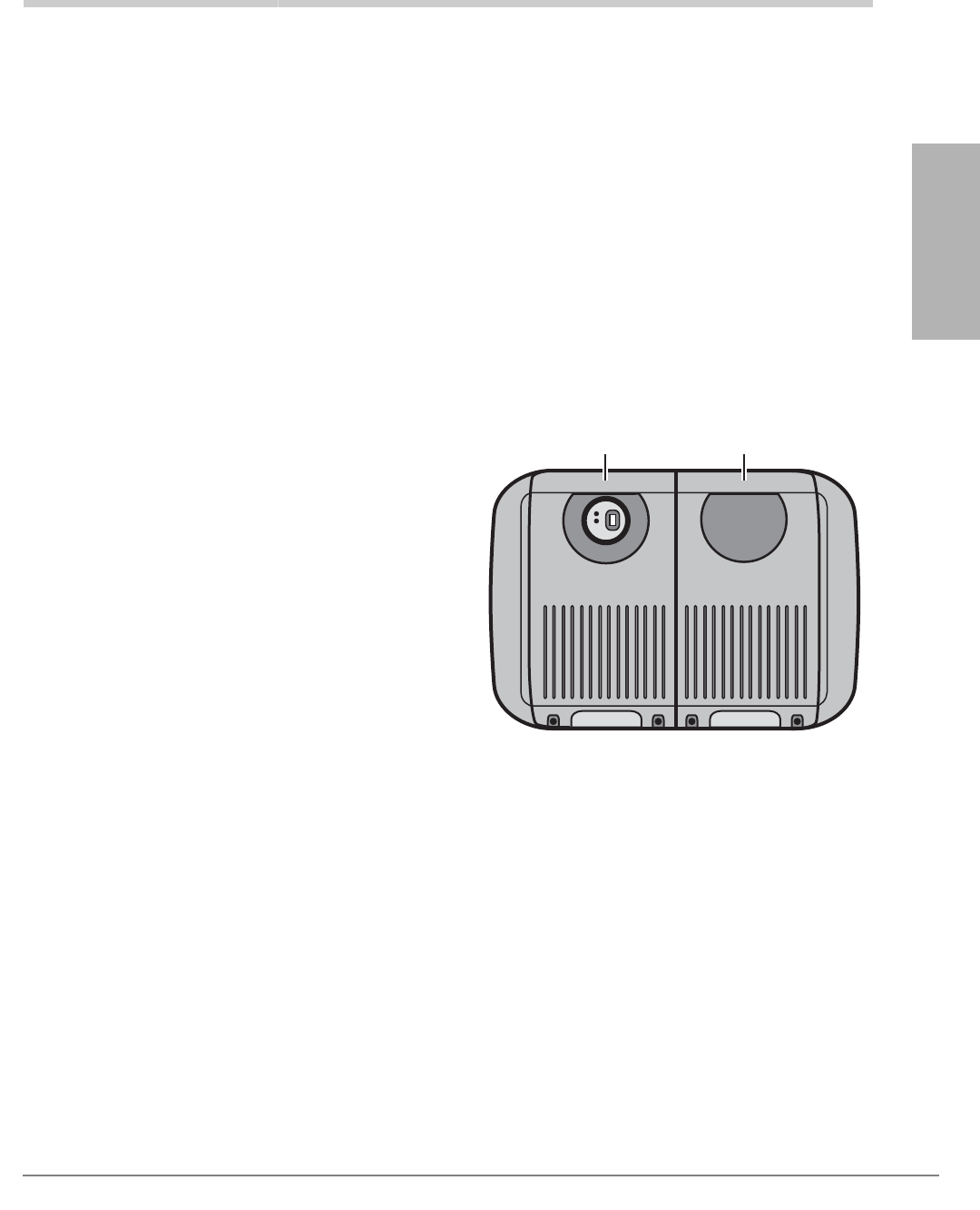
Strata CTX I&M 06/04 2-1
Strata CTX
Configuration
Strata CTX Configuration 2
This chapter contains information and worksheets to help configure the Strata CTX100-S,
CTX100 and CTX670 hardware components. A system overview of the Strata CTX100-S,
CTX100 and Strata CTX670 hardware components and the maximum station and line capacities
available with the system processor is provided.
Worksheets follow this information to aid in determining the actual cabinets and interface PCBs
needed for particular proposals and how these PCBs should be placed in Strata CTX cabinet slots.
(Worksheets begin on page 2-22.)
Strata CTX100-S/CTX100 Overview
The Strata CTX100-S/CTX100 systems are
compact systems, yet they provide large system
features (see Figure 2-1 and Table 2-1). It is
designed for wall mounting and occupies very
little space.
They are designed for wall mounting and
occupy very little space.
The CTX100 processor (ACTU2A) comes with
32 ports (licensed) and can grow to 112 ports
by adding 4-port licenses.
The CTX100-S processor (ACTU2A-S) comes
with 16 ports (licensed) and can grow to 32
ports by adding two eight-port licenses. Then, it
can grow to 112 ports with four-port licenses.
Note The Strata CTX100-S and CTX100
system capacities depend on the licenses
stored on the system processor and the hardware described in this chapter. See “CTX100-S/
CTX100 License Control” on page 2-4.
Important! The Strata CTX100-S uses the same hardware and configuration as the Strata
CTX100, with a few exceptions. Whenever the CTX100 is mentioned in this book, it
applies to both the CTX100-S and CTX100, unless specified otherwise.
Each ACTU2 basic processor can be configured with a one or two cabinet system. A single (Base)
cabinet system supports a combination of up to 64 Central Office (CO) lines and stations, while a
two cabinet system (Base and Expansion) can support up to 112 CO lines and stations.
System line and station capacity is expanded by adding CO line and station Printed Circuit Boards
(PCBs) and port licenses into its universal slot architecture.
5976
Base Expansion
Figure 2-1 CTX100-S /CTX100
Base/Expansion Cabinets

Strata CTX Configuration
CTX100-S and CTX100 Processors
2-2 Strata CTX I&M 06/04
The CTX100 easily connects to outside public and private telephone lines. All of the telephones
(stations) tied to the system can have direct access to each other, as well as to the public and
private network. All lines, stations, and options are tied together through the cabinets.
CTX100-S and CTX100 Processors
Each system operates with one processor PCB (ACTU2A-S for CTX100-S, ACTU2A for
CTX100) that installs in a dedicated slot of the Base Cabinet. The processors incorporate the
following hardware features
CPU/Memory
Either processor PCB uses a high-speed, 32-bit, RISC processor, Dynamic Random Access
Memory (DRAM) working memory, Static Random Access Memory (SRAM) with lithium battery
for memory back-up, and flash program memory.
Large Scale Integrated (LSI) Circuits
The processors each have LSI circuits that support the following:
• 16 DTMF receiver hardware processor are built into the ACTU2. Five or more DTMF receivers
requires appropriate licenses. See “CTX100-S/CTX100 License Control” on page 2-4.
• 16 Busy Tone (BT) detector circuits for Auto Busy Redial (ABR) are built into the ACTU2.
• 64 built-in conference circuits (see Table 2-7 on page 2-12 for more information).
• Built-in, adjustable, digital volume PAD technology enables audio volume to be adjusted in
eight steps to compensate for conference and/or CO line network losses.
Memory Protection Battery
If commercial AC power is lost or if a system is moved or stored without power, either processor
has an on-board battery that protects data and the customer’s programmed configuration from
memory loss. This information will be maintained in a powerless system for at least six years.
Relay Control Interface
An on-board terminal strip provides an interface to a normally open relay contact which can be
programmed to control a Night Bell, door lock or to mute BGM during an external page.
External Page Interface
A 600 ohm RCA jack is built into the processor to interface with a Toshiba External Amplified
Speaker (HESB) or a customer-supplied page amplifier and speaker(s) for external paging, night
ring over external page, and external BGM applications.
Table 2-1 CTX100-S / CTX100 Cabinet Specifications
Cabinet Weight1
1. Weight includes the processor PCB in the Base Cabinet and four universal PCBs in each cabinet.
Height Width Depth
Base Cabinet (CHSUB112A) 19.4 lbs. 14.6 in. 11.9 in. 10.2 in.
Base + Expansion Cabinet (CHSUE112A) 34.6 lbs. 14.6 in. 19.9 in. 10.2 in.

Strata CTX
Configuration
Strata CTX Configuration
CTX100 Cabinet Slots
Strata CTX I&M 06/04 2-3
Music-on-hold/Background Music Interface
A 600-ohm RCA jack and volume controls are built into the processor to interface with Music-on-
hold and/or Background Music (BGM) sources (one of the jacks is for future use). With the
CTX100, you can have up to 15 MOH/BGM source interfaces by adding:
• Up to two BIOU PCBs, each provides three MOH/BGM input sources
• An RSTU PCB that provides up to eight MOH/BGM input sources
• An ASTU PCB provides one alternate BGM source
SmartMedia Memory
Each processor has an on-board SmartMediaTM memory card slot. A SmartMedia flash memory
card can be inserted into the slot to backup and restore customer program data. It also makes it
easy to upload operating system data for software upgrades and is used for maintenance functions.
CTX100 Processor Optional Subassemblies
Optional subassemblies can be attached to the ACTU2A-S or ACTU2A processors to provide
additional features. The subassemblies are:
•AMDS (Modem) – Provides a 33.6Kbps/V.34 modem for point-to-point local or remote
connection to the CTX WinAdminTM administration PC.
•BSIS (Serial Port Interface) – Provides up to two RS-232 interface ports for SMDR interface
to Call Accounting devices, SMDI or Toshiba Proprietary interface to Voice Mail devices, and
two future applications.
CTX100 Cabinet Slots
Base Cabinet
The Base Cabinet has one dedicated slot used for the system processor PCB and four universal
slots (S101~S104), that can accommodate station, line or option PCBs. It also houses a power
supply that is packaged with the cabinet.
Expansion Cabinets
One expansion cabinet provides four universal PCB slots (S105~S108) that can accommodate
station, line or option PCBs. It also houses a power supply that is packaged with the cabinet.

Strata CTX Configuration
CTX100-S/CTX100 License Control
2-4 Strata CTX I&M 06/04
CTX100-S/CTX100 License Control
The system size and feature capability is controlled using a software License Key Code. This key
code is obtained from Toshiba Internet FYI during the ordering process and is installed onto the
system processor via Strata CTX WinAdmin. Processor license codes activate system hardware
capacities in the following increments.
• The first 16 line/station ports on the CTX100-S do not require a license. The upgrade from 16
to 24 ports and from 24 to 32 ports requires the eight port upgrade LIC100S-8 PORTS license.
Each additional set of 4 line/station ports requires the four port upgrade LIC100-4 PORTS
license.
• The first 32 line/station ports on the CTX100 do not require a license. Each additional set of
four line/station ports requires one LIC100-4 PORTS license (maximum of 112 ports).
• The ACTU2A-S and ACTU2 processors each provide 16 DTMF built-in receiver hardware
circuits and 16 ABR circuits. The first four DTMF circuits and all ABR circuits do not require
a license. Each additional set of four DTMF receiver circuits requires one LIC100-4DTMF
license (maximum of 16 DTMF circuits).
Note DTMF tone receiver circuits are required for standard telephones, Voice Mail DTMF
integration, Tie, DID and DNIS line service.
• The optional RS-232 serial port interface (BSIS) provides two circuits to interface with SMDI
or Toshiba Proprietary Voice Mail integration, Call Accounting SMDR, and two for future
applications. The first circuit does not require a license, but circuits two through four each
require one LIC100-SER PORT license.
Licensed Software Options
Some software options are activated with license codes. The following software options require a
license:
• Each CTX system (node) in a Strata Net QSIG Network (ISDN or IP) requires one LIC100-
QSIG NET license. A maximum of four serial network nodes are allowed in any one serial
chain in the network topology.
• The built-in LAN interface for all CTI Open Architecture applications. Each individual CTI
Open Architecture application requires one LIC100-CSTA AP license (maximum nine).
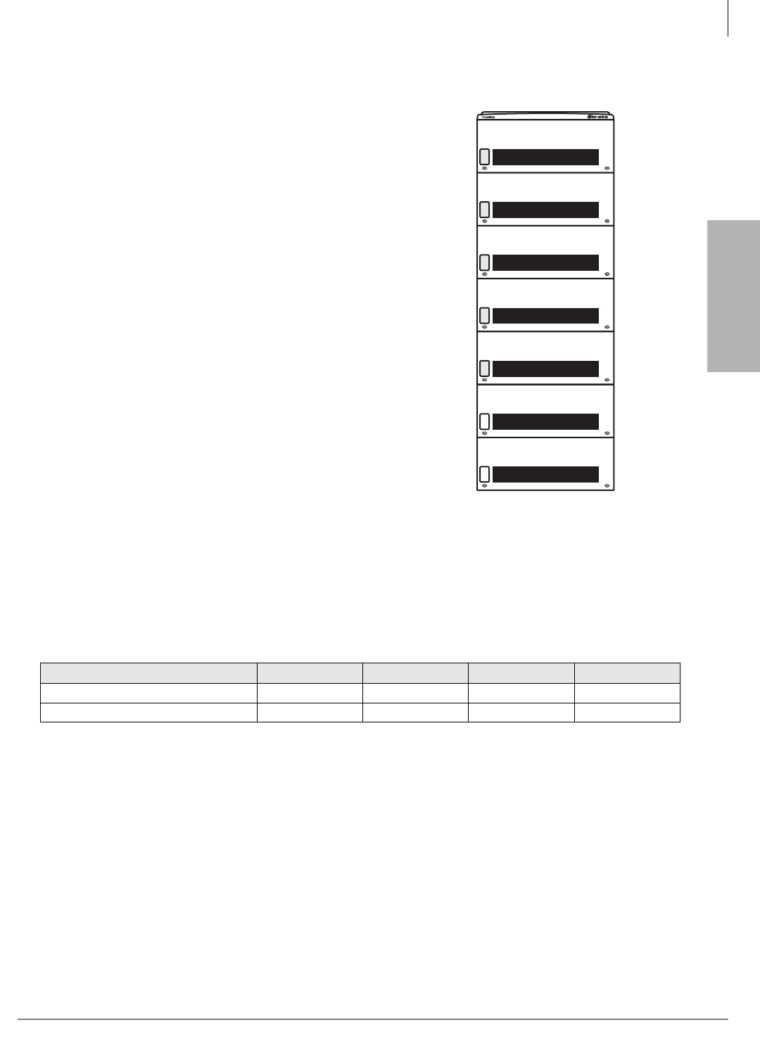
Strata CTX
Configuration
Strata CTX Configuration
Strata CTX670 Overview
Strata CTX I&M 06/04 2-5
Strata CTX670 Overview
The Strata CTX670 system provides sophisticated
telecommunication features in a modular system
designed for growth. Its universal slot architecture
enables you to select the combination of Central Office
(CO) lines, stations, and peripheral options that best suit
your needs.
The CTX670 basic BCTU processor can be configured
for smaller systems as a one or two cabinet system with a
capacity of up to 192 CO lines and stations combined. It
can expand to support up to seven cabinets with a
capacity of up to 672 CO lines and stations combined
with the BCTU/BEXU processors (see Figure 2-2).
System line and station capacity is expanded by adding
processor expansion Printed Circuit Boards (PCBs),
cabinets and line/station PCBs.
The CTX670 easily connects to outside public and
private telephone lines. All of the telephones (stations)
tied to the system can have direct access to each other as
well as to the public and private network.
Note The Strata CTX670 system capacities depend on
the licenses stored on the system processor and
the hardware described in this chapter. See
“CTX670 License Control” on page 2-7.
The Base Cabinet and optional Expansion Cabinets are
the building blocks of the system. Each system has a Base Cabinet, and can have from one to six
Expansion Cabinets. All lines, stations, and options are tied together through the cabinets.
The overall weight and dimensions of the CTX670 cabinets are shown in Table 2-2.
CTX670 Processor PCBs
The system operates with the BCTU only or the BCTU and BEXU processor PCBs install in
dedicated slots of the Base Cabinet. The BCTU and BEXU processor incorporates the following
on-board hardware features:
CPU/Memory
The CTX670 uses a high-speed, 32-bit, Reduced Instruction Set Computing (RISC) processor,
Dynamic Random Access Memory (DRAM) working memory, Static Random Access Memory
(SRAM) with lithium battery for back-up memory, and flash program memory.
Table 2-2 CTX670 Cabinet Specifications
Cabinet Weight Height Width Depth
Base Cabinet (CHSUB672A) 31 lbs. 11.625 in. 26.5 in. 10.3 in.
Expansion Cabinet (CHSUE672A) 29 lbs. 9.75 in. 26.5 in. 10.3 in.
5398
Figure 2-2 CTX 670 Base/
Expansion Cabinets

Strata CTX Configuration
CTX670 Processor PCBs
2-6 Strata CTX I&M 06/04
Large-scale Integrated (LSI) circuits
The processor has LSI circuits that support the following:
• BCTU provides 16 built-in DTMF receivers; 32 available using the BCTU and BEXU. For five
or more DTMF receivers, appropriate licenses are required. See “CTX670 License Control” on
page 2-7.
• BCTU provides 16 built-in Busy Tone (BT) detectors for Auto Busy Redial (ABR); 32
available using the BCTU and BEXU.
• BCTU provides 64 built-in conference circuits; up to 96 conference circuits are available using
the BCTU and BEXU. (See Table 2-7 on page 2-12 for more information).
• Built-in, adjustable, digital volume PAD technology enables audio volume to be adjusted in
eight steps to compensate for conference and/or CO line network losses.
Memory Protection Battery
If commercial AC power is lost or if a system is moved or stored without power, the processor has
an internal battery that protects data and the customer’s programmed configuration from memory
loss. This information will be maintained in a powerless system for at least six years.
Music-on-hold/Background Music Interface
An RCA jack and volume control are built into the processor to interface with a Music-on-hold
and/ or Background Music source. With the CTX670, you can have up to 15 MOH/BGM sources
by adding:
• Up to two BIOU PCBs, each provides three MOH/BGM input sources.
• An RSTU PCB that provides up to eight MOH/BGM input sources.
• MOH/BGM source volume adjustment is controlled by software programming.
SmartMedia Memory
The processor has an on-board SmartMedia card slot. A SmartMedia flash memory card can be
inserted to backup and restore customer program data. It also makes it easy to upload operating
system data for software upgrades and is used for maintenance functions.
Network Interface
The processor has an on-board Ethernet 10base-T Ethernet circuit for connection to Open
Architecture Computer Telephony Interface (CTI) applications. This provides extensive call
control and telephone support for CTI applications. The Ethernet Network Interface Card (NIC)
port also enables connection to the following:
• CTX Attendant Console
• ACD server
• Local and Remote CTX WinAdmin PC
• Soft Key Control of Voice Mail features

Strata CTX
Configuration
Strata CTX Configuration
CTX670 License Control
Strata CTX I&M 06/04 2-7
CTX670 Processor PCB Subassemblies
Subassemblies can be added to the BCTU processor PCB to provide additional features. The
subassemblies are:
• AMDS (Modem) – Provides a 33.6Kbps/V.34 modem for point-to-point local or remote
connection to the CTX WinAdminTM administration PC.
• BSIS interface PCB which attaches to the BCTU to provide up to four RS-232 interface ports
for SMDR Call Accounting and SMDI or Toshiba Proprietary Voice Mail interface.
See Table 2-3 on page 2-9 for the number of cabinets and universal PCB slots for the Basic and
Expanded systems.
CTX670 License Control
The system size and feature capability is controlled using a software License Key Code. This key
code is obtained from the Toshiba Internet FYI site during the ordering process and is installed
onto the system processor via Strata CTX WinAdmin. Processor license codes activate system
hardware capacities in the following increments.
• The first 64 line/station ports do not require a license. Each additional set of four line/station
ports requires one LIC670-4PORTS license (maximum of 672 ports).
• The on-board DTMF receiver circuit provides up to 32 DTMF receiver hardware circuits. The
first four DTMF circuits do not require a license. Each additional set of four DTMF receiver
circuits requires one LIC670-4DTMF license (max. total of 32 DTMF circuits).
Note DTMF tone receiver circuits are required for standard telephones, Voice Mail DTMF
integration, Tie, DID and DNIS line service.
• The optional RS-232 serial port interface (BSIS) provides two circuits to interface with Voice
Mail SMDI or Toshiba Proprietary Voice Mail integration, Call Accounting SMDR, and two
for future applications. The first circuit does not require a license, but circuits two through four
each require one LIC670-SER PORT license.
Licensed Software Options
Some software options are activated with license codes. The following software options require a
license:
• Each CTX system (node) in a Strata Net QSIG Network requires one LIC670-QSIG NET
license. A maximum of four serial network nodes are allowed in any one serial chain in the
network topology.
• Each individual CTI Open Architecture application requires one LIC670-CSTA AP license
(maximum nine).
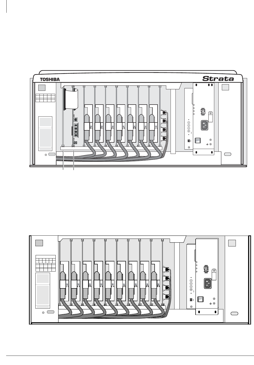
Strata CTX Configuration
CTX670 Cabinet Slots
2-8 Strata CTX I&M 06/04
CTX670 Cabinet Slots
Base Cabinet
The Base Cabinet has two dedicated slots used for the system processor PCBs and eight universal
slots, labeled “S101~S108,” that can accommodate station, CO line or option PCBs (see Figure
2-3). It also houses a power supply.
Figure 2-3 Strata CTX670 Base Cabinet Interior
Expansion Cabinets
One to six Expansion Cabinets can be added to increase the system station and CO line capacity.
Each expansion cabinet provides 10 slots (S_01~S_10). Figure 2-4 shows an Expansion Cabinet.
Refer to the following section for cabinet slot and station/line capacities. Tables 2-4 and 2-5 show
the number of stations and CO lines allowed when additional cabinets and PCBs are used.
POW
+5V
-5V
P.F .
RESET
EXP
BASE
AC IN
BATT
DC OUT
-24V1
-24V2
-24V3
-24V4
+
-
POWER
ON
OFF
FG
5002
B101 B102 S101 S102 S103 S104 S105 S106 S107 S108
6965
B101 B102 S101 S102 S103
S104 S105 S106 S107 S108
BEXU BCTU
S_01 S_02 S_03 S_04 S_05 S_06 S_07 S_08 S_09 S_10
5003
CABINET NO.
2
S_01 S_02 S_03 S_04 S_05
S_06 S_07 S_08 S_09 S_10
34567
POW
+5V
-5V
P. F.
RESET
EXP
BASE
AC IN
AC IN
DC OUT
-27V1
-27V2
-27V3
-27V4
+
-
POWER
ON
OFF
FG
5002
POW
+5V
-5V
P. F.
RESET
EXP
BASE
AC IN
BATT
DC OUT
-27V1
-27V2
-27V3
-27V4
+
-
POWER
ON
OFF
FG
5002
Figure 2-4 Strata CTX670 Expansion Cabinet Interior
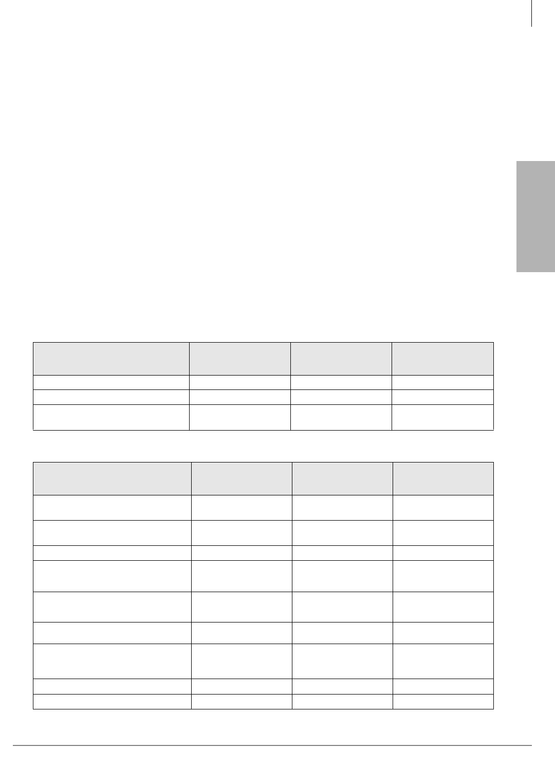
Strata CTX
Configuration
Strata CTX Configuration
CTX670 Remote Expansion Cabinet
Strata CTX I&M 06/04 2-9
CTX670 Remote Expansion Cabinet
A CTX670 Expansion Cabinet can be located up to three kilometers from its Base Cabinet.
Remote Expansion Cabinets are enabled by the RRCU PCB. One RRCU connects to up to two
ribbon-type Data Cables and applies the inter-cabinet signal to a multi-mode fiber-optic pair. One
fiber pair can support one or two expansion cabinets in one remote location using one RRCU in the
Base Cabinet and another in the Remote Expansion Cabinet.
The CTX670 Base Cabinet supports up to six Remote Expansion Cabinets (at least one RRCU
PCB is required for each remote location).
Remote cabinets support the BIOU for external Page Zones, Night Bell, etc., and all CO line and
trunk interface PCBs. Network clock synchronization can only be derived from digital trunks
installed in the Base Cabinet (Master) location.
System Capacities
This section contains Strata CTX100 and CTX670 capacities for stations and peripherals, CO
lines, station buttons and system features. All tables apply to both systems unless otherwise noted.
Important! The maximum capacities listed for the CTX100 in Tables 2-3~2-7 are based on an
expanded CTX100 (Base + Expansion cabinet).
Table 2-3 Cabinet and Slot Capacities
Cabinets/Slots/Ports CTX100
CTX670
Basic Processor
BCTU
CTX670
Expanded Processor
BCTU + BEXU
Cabinets 1 or 2 1 to 2 1 to 7
Universal slots 4 or 8 8 or 18 8 to 68
Maximum capacity of ports
(lines + stations) 112 192 672
Table 2-4 Station/Peripherals System Capacities
Stations CTX100
Base & Expansion
CTX670
Basic Processor
BCTU
CTX670
Expanded Processor
BCTU + BEXU
Add-on modules (DADM3120,
DADM3020) per Base Cabinet130 DKTs with 1 ADM
23 DKTs with 2 ADMs
55 DKTs with 1 ADM
43 DKTs with 2 ADMs
55 DKTs with 1 ADM
43 DKTs with 2 ADMs
Add-on modules (DADM3020) per
Expansion Cabinet1
31 DKTs with 1 ADM
24 DKTs with 2 ADMs
57 DKTs with 1 ADM
45 DKTs with 2 ADMs
57 DKTs with 1 ADM
45 DKTs with 2 ADMs
CTX Attendant consoles 224
DKT3000- and 2000-series DKTs1
72/system
(40 Base Cabinet)
(40/Expan. Cab.)
152/system
(72 Base Cabinet)
(80/Expan. Cab.)
552/system
(72 Base Cabinet)
(80/Expan. Cab.)
IPT telephones 64 per cabinet
72 per system
128 Base
160 Expansion
160 System
128 Base
160 Expansion
560 System
IPT telephones with DADM3120226 per cabinet
26 per system
58 per cabinet
58 per system
200 per cabinet
200 per system
Cordless Telephones
(DKT2004-CT, DKT2104-CT,
DKT2204-CT, DKT2304-CT)1
72 152 552
Door locks 4510
Door phone control boxes (DDCB) 238
Strata CTX Configuration
System Capacities
2-10 Strata CTX I&M 06/04
Door phones 6924
DSS consoles (DDSS) 3516
ISDN BRI station circuits TE-1 and TA
(2B+D per circuit) 12 28 96
Off-premise stations 64 144 544
BPCI used for TAPI only: per cabinet135 66 66
Total Stations (Digital/Analog/ISDN
BRI B channel combined) 72 160 560
Standard stations 64 144 544
Calls existing at the same time 56 96 366
1. Limit is based on cabinet Power Factor (PF).
2. Based on the maximum allowed flexible buttons.
Table 2-5 Line Capacities and Universal PCB Slots
Lines CTX100
Base & Expansion
CTX670
Basic
Processor
BCTU
CTX670
Expanded
Processor
BCTU + BEXU
CO lines – loop start
(analog - 8 lines/slot) 64 96 264
CO lines – ground start
(analog - 4 lines/slot) 32 72 264
DID lines (analog - 4 lines/slot) 32 72 264
Tie lines (analog - 4 lines/slot) 32 72 264
VoIP lines (4 lines/slot)1
1. Capacity is limited by FCC, Part 15, ElectroMagnetic Compatibility (EMC) restrictions.
82020
T1 lines (DS-1)2
2. T1 lines can be loop start, ground start, Tie or DID (maximum 24 lines per unit, any type or combination).
64 96 264
ISDN BRI B channel lines3
3. BRI lines provide CO line services, including Caller ID, DID and Direct Inward Lines (DIL).
64 96 256
ISDN PRI B channel lines4
4. PRI lines provide CO line services, including QSIG Networking, Calling Party Number/Name, DID, Tie, POTS, FX and DIT.
48 96 264
Strata Net over IP Channels5
5. Strata Net over IP channels provides Strata Net functionality.
48 96 264
Total lines (Analog, T1, ISDN BRI and
PRI B channels combined) 64 96 264
Channel Groups 32 48 128
Number of groups w/ GCO Line
buttons 32 50 128
Table 2-4 Station/Peripherals System Capacities
(continued)
Stations CTX100
Base & Expansion
CTX670
Basic Processor
BCTU
CTX670
Expanded Processor
BCTU + BEXU
Strata CTX
Configuration
Strata CTX Configuration
System Capacities
Strata CTX I&M 06/04 2-11
Table 2-6 Station Buttons
Station Buttons per System CTX100 Base &
Expansion
CTX670
Basic Processor
BCTU
CTX670 Expanded
Processor
BCTU + BEXU
Call Forward, Personal CF Buttons 72 160 560
CO Line Buttons 64 96 264
Group CO Line Buttons 64 96 264
Pooled CO Line Buttons 32 50 128
CO Group and Pooled Line Buttons 64 96 264
Station Loop Buttons 81550
Door Unlock Buttons 4816
Flexible Telephone Buttons 1600 3500 12000
Line Buttons in use at the same time 1440 3200 3200
Message Waiting Registration (DNs with MW) 130 230 800
Multiple Appearances of DNs on Telephones 2000 4000 12000
Night Transfer Buttons 32 64 128
One Touch Buttons 800 1750 6000
Primary Directory Numbers [PDNs] per system 72 160 560
Phantom Directory Numbers [PhDNs] per system 288 640 2240
[PhDNs] with Message Waiting Indication LED 18 38 128
ISDN DNs 96
(8 DNs/station)
224
(8 DNs/station)
768
(8 DNs/station)

Strata CTX Configuration
System Capacities
2-12 Strata CTX I&M 06/04
Table 2-7 System Feature Capacities
Features CTX100 Base &
Expansion
CTX670
Basic Processor
BCTU
CTX670 Expanded
Processor
BCTU + BEXU
Pilot DNs 100 200 256
Advisory LCD Messages (Set on a Telephone) 111
Advisory LCD Messages Lists (per System) 10 10 10
Attendant Groups 111
Call Accounting SMDR Interface1111
Call Forward, System CF Patterns 410 32
Call Park Orbits (General) 14 32 64
Call Park Orbits (Individual) 56 96 336
Caller ID/ANI/CNIS Numbers stored (Call History
records)
Up to 100/station Up to 100/station Up to 100/station
Up to 660/system Up to 1000/system Up to 2000/system
CO Line Groups - Incoming Line Groups (ILG) 32 50 128
CO Line Groups - Outgoing Line Groups (OLG) 32 50 128
Outgoing Line Groups (OLG) Members per
system
(Trunks + ISDN Line Service Index)
96 144 392
Conference Circuits 64 64 96
Conferencing (three-parties simultaneously)220 21 21
Conferencing (eight-parties simultaneously)28812
Conference Party types (up to 8 total lines +
stations)
6 lines max.
8 stations max.
6 lines max.
8 stations max.
6 lines max.
8 stations max.
Two-CO Line Conferencing – simultaneously2
(Two party only, no telephone or VM port) 32 48 132
Conference/Line Volume Adjustment (PAD)
Groups 610 32
DID Numbers for Calling Number ID/system 225 500 1000
DNIS/DID Network Routing Numbers 200 400 1000
DNIS/DID Numbers 450 1000 2000
DTMF Receivers316 16 32
E911 Groups 888
Emergency Call Groups 888
Hunt Groups (Serial/Circular/Distributed
combined) 90 200 640
Hunt Group Size (DNs per group) 72 160 560
Hunt Group Stations (per system) 360 800 2800
ISDN DNs 96 224 768
ISDN Line Service Indexes 32 48 128
Multiple Call Ring Group 16 32 64
Night Bell Control Relay4111
Night Transfer Control Relay411 1
Off-hook Call Announce Handsets (simultaneous) 20 21 31
Strata CTX
Configuration
Strata CTX Configuration
System Capacities
Strata CTX I&M 06/04 2-13
Off-hook Call Announce to Telephone Speakers 572 112 352
Page Mute External BGM Control Relay411 1
Page Zone Relays4888
Page Groups (Phones with or without External Zones) 4816
Paging – (Group Page – simultaneous stations paged) 72 120 120
Pickup Groups 510 32
Ring Tones (External Call Ring Tones for DKTs) 444
Ring Tones (Internal Call Ring Tones for DKTs) 111
Speed Dial - Station SD numbers per system61080 2400 5600
Speed Dial - System SD numbers per system 800 800 800
Stratagy DK Voice Mail Systems per system 111
Tenants 111
Destination Restriction Level (DRL) Classes 16 16 16
Verified Account Codes 135 300 1000
Voice Mail SMDI Interface1111
1. SMDI and SMDR require BSIS serial port interface.
2. Conference circuits are used dynamically, so the maximum number of simultaneous conferences is affected by the number of
conference members in each conference. The total number of members in simultaneous conferences cannot exceed the total
number of conference circuits. Each conference can have up to eight members.
3. DTMF receivers are required for standard touch tone telephones, voice mail integration, Tie, DID and DISA lines.
4. An option BIOU is required for up to four zone page relays and four control relays on the CTX100 and CTX670. One control
relay is provided on board the CTX100 processor.
5. Speaker OCA capacity is determined by 2B channel slot availability and power supply. Requires BVSU option in telephone.
Speaker OCA is not available on IPT1020-SD telephones.
6. Up to 100 Station SD numbers, allocated in increments of 10, can be programmed per station.
Table 2-7 System Feature Capacities
(continued)
Features CTX100 Base &
Expansion
CTX670
Basic Processor
BCTU
CTX670 Expanded
Processor
BCTU + BEXU
Strata CTX Configuration
Universal Slot PCBs
2-14 Strata CTX I&M 06/04
Universal Slot PCBs
Universal Printed Circuit Boards (PCBs) installed in the Strata CTX100 or CTX670 cabinets
provide interfaces for stations, lines, and peripherals. Each PCB measures 7.5 x 5.5 inches (190 x
140 mm) and mounts in the slot with a 44-pin backplane connector. PCB external connections to
station equipment are made to the Main Distribution Frame (MDF) using industry-standard
connectors.
Station, Line and Option PCBs
The PCBs are categorized as station, CO line or option PCBs (see Tables 2-8~2-10). Feature
subassemblies that plug onto a universal slot PCB, such as the Standard Telephone Interface
Subassembly (RSTS), are listed below the associated PCB.
Table 2-8 Station PCBs
Digital Telephone Interface Unit (ADKU) (CTX100 only)
Provides eight circuits for 3000 and/or 2000-series
digital telephones.
Interface Options: Provides the same interface options as
the BDKU (see below), but does not support BDKS.
Compatible only with CTX100.
Standard Telephone Interface Unit (ASTU) (CTX100 only)
Provides two standard telephone circuits. Maximum
number of ringers per circuit is three
Interface Options:
Standard telephones (no message waiting)
Other single-line devices
Alternate BGM source
Fax machines
Voice mail devices
Digital Telephone Interface Unit (BDKU)
Provides eight circuits for 3000 and/or 2000-series
digital telephones (BDKU) + eight more with BDKS
(optional).
Interface Options: Digital telephones (with or without
BHEU, BPCI, BVSU, DADMs, or digital cordless
telephone). Supports BDKS.
Stand-alone digital cordless telephone
DDSS console
BATI
DDCB
Supports large LCD (DKT3014) features.
Digital Telephone Interface Subassembly (BDKS)
Provides eight additional circuits for 3000 and/or 2000-
series digital telephones. Attaches to BDKU. One per
BDKU. Do not use BDKS for Speaker OCA telephones,
except in slot 103 of the CTX100.
Interface Options: Same as BDKU. Not compatible with
ADKU or PDKU.
Digital Telephone Interface Unit (PDKU2)
Provides 8 digital telephone circuits. (2000-series
phones only. Do not use the PDKU for 3000-series
digital telephones. With 3000-series DKTs, the LCD
display is only 16 characters wide and the Spdial button
will not work.
Interface Options: Digital telephones (with or without
BHEU or HHEU, DVSU, DADMs, or digital cordless
telephone)
Stand-alone digital cordless telephone
DDSS console
DDCB
Does not support DKT3014-SDL features.
Strata CTX
Configuration
Strata CTX Configuration
Universal Slot PCBs
Strata CTX I&M 06/04 2-15
Digital Telephone Interface Unit (BWDKU1A)
Provides 8 or 16 digital telephone circuits. Compatible
with Strata CTX and Strata DK. Jumper plugs on the
PCB determine the number of DKT circuits and CTX or
DK compatibility. It does not need a Ferrite Core. It has
one protector for every two circuits. The BWDKU1A is
similar to BDKU/BDKS, except DKT wiring is all 1 pair.
Interface Options: Digital telephones (with or without
BHEU or HHEU, DVSU, DADMs, or digital cordless
telephone)
Stand-alone digital cordless telephone
DDSS console
DDCB
Internet Protocol Telephone (IPT) Interface Unit (BIPU-M1A, BIPU-M2A)
Provides 16 IPT telephone circuits
One 100Base-TX RJ45 port
Built-in Digital Signal Processor (DSP) (BIPS1A-16)
One RS-232 maintenance port
Network Address Translation (NAT) compatible for
remote IP telephones (BIPU-M2A)
Enhanced version of MEGACO+ for Voice over IP
MEGACO+ mobility for Mobility Communications
System (MCS) Roaming (BIPU-M2A)
Interface Options: LAN, Virtual Private Network (VPN)
Internet, VPN WAN, Intranet.
Digital/Standard Telephone Interface Unit (RDSU)
Without RSTS, provides:
Two standard telephone/
Four digital telephone circuits (2000-series phones
only).
With RSTS, provides:
Four standard telephone/
Four digital telephone circuits (2000-series phones
only).
Interface Options:
Digital – same as PDKU.
Standard – same as RSTU (standard Message Waiting
not available)
Standard Telephone Interface Unit (BSTU, RSTU3)
Provides eight standard telephone circuits. Stutter dial
tone is provided for Message Waiting audible indication.
Interface Options:
Standard telephones
Voice mail ports
Off-premises stations
Other similar devices
Alternate BGM source
Auto Attendant digital announcer
Message Waiting lamp
Fax machines
ACD announcer
Standard Telephone Subassembly (RSTS)
Attaches to RDSU. Provides two additional standard
telephone circuits. One maximum per RDSU.
Interface Options: Same as RSTU, except no Message
Waiting lamp.
-48 Volt Supply Internal Option (R48S)
Attaches to BSTU, RSTU and RDSU
48VDC circuit for up to eight standard telephone circuits.
Interface Options: Optionally interfaces to the RSTU and
RDSU to extend loop length of standard telephones from
600 ohms to 1200 ohms. Required for OPS operation.
Stratagy DK
Provides two, four, six, or eight VM ports.
All of the above Stratagy DK systems use eight station
ports of Strata CTX capacity.
Table 2-8 Station PCBs
(continued)
Strata CTX Configuration
Universal Slot PCBs
2-16 Strata CTX I&M 06/04
Table 2-9 CO Line PCBs
Strata Net Over VoIP Interface Unit (BIPU-Q1A)
Provides 16 IP QSIG channels
One 100Base-TX RJ45 port
One RS-232 maintenance port
QSIG over IP standard protocol (ECMA-336)
Voice coding G.711/G.729A
Built-in Digital Signal Processor (DSP) (BIPS1A-16)
NAT compatible
Interface Options: LAN, Virtual Private Network (VPN)
Internet, VPN WAN, Intranet.
Internet Protocol (IP) Interface Unit (BVPU)
Provides four VoIP Circuits as E&M Tie lines
One 10Base-T port
One RS-232 maintenance port
H.323 standard for Voice over Internet Protocol
(VoIP)
Interface Options: LAN, Internet, WAN.
Caller ID Interface Unit (RCIU2)
Provides four Caller ID circuits.
With RCIS: eight circuits.
Interface Options:
Provides Caller ID LCD display for analog loop or
ground start lines with Caller ID. Requires: RCOU,
RCOS, RGLU2, RGLU3 or PCOU. Not compatible with
T1.
Caller ID Interface Subassembly (RCIS)
Attaches to the RCIU2.
Same as RCIU2.
Direct Inward Dialing Interface Unit (RDDU)
Provides four DID circuits. Interface Options:
DID analog lines.
Enhanced 911 CAMA Trunk Interface Unit (RMCU/RCMS)
E911 CAMA circuits. Provides up to four CAMA trunk
circuits. The RMCU/RCMS eliminates the need for
connection of adjunct terminal adapter equipment to
E911 CAMA trunks.
Requires one or two RCMS PCBs for two or four
CAMA lines respectively.
E911 analog CAMA trunks.
CAMA Trunk Subassembly (RCMS)
RCMS attaches to RMCU. Provides two E911 CAMA
circuits.
Up to two RCMSs per RMCU for four CAMA lines
max. (One RCMS comes packaged with the RMCU.)
Same as RMCU.
Ground/Loop Start Interface CO Line Interface Unit (RGLU2, RGLU3)
Provides four ground or loop start line circuits. Each
can be individually set for ground or loop start
operation.
Interface Options:
Analog loop or ground start analog lines.
ISDN S/T-type Basic Rate Interface Unit (RBSU)
Two ISDN BRI S/T point circuits (NT or TE). Each
circuit is 2B+1D. (Host for the RBSS.)
Interface Options: Network and/or station side.
Basic Rate Interface Subassembly (RBSS)
Attaches to RBSU. One RBSS subassembly per
RBSU.
Two ISDN BRI, S point circuits (2B+D each).
Interface Options: Station side only.
Strata CTX
Configuration
Strata CTX Configuration
Universal Slot PCBs
Strata CTX I&M 06/04 2-17
ISDN U-type Basic Rate Interface Unit (RBUU)
Provides two ISDN BRI, U point circuits (2B+D each).
Host for the RBUS.
Interface Options: Network and/or station side.
Network side requires a dealer-supplied NT1 interface.
Basic Rate Interface Subassembly (RBUS)
Attaches to RBUU. One RBUS subassembly per
RBUU.
Two ISDN BRI, U point circuits (2B+D each)
subassembly for the RBUU.
Interface Options: Network and/or station side.
ISDN Primary Rate Interface Unit (BPTU1 or RPTU2)
Provides (1~8B + D), (1~16B + D), or (1~23B + D)
channels (lines), depends on system programming.
BPTU or RPTU2 is required for QSIG Networking.
Interface Options:
ISDN PRI
POTS
FX
Tie (senderized)
Tie (cut through)
OUTWATS (intra-LATA)
OUTWATS (inter-LATA)
InWATS
QSIG
Loop Start CO Line Interface Unit (RCOU)
Provides four CO analog loop start line circuits.
With RCOS, provides eight CO analog loop start line
circuits.
Interface Options:
CO analog loop start lines
Loop Start CO Line Interface Subassembly (RCOS)
Provides four additional Loop Start CO lines. One
RCOS subassembly per RCOU.
Same as RCOU.
T1/DS-1 Interface Unit (RDTU2)
Provides T1 (DS1) Interface: 1~8, 1~16, or 1~24
channels (lines), depends on system programming.
Interface Options:
T1
Loop start lines
Ground start lines
Tie lines (wink or immediate)
DID/DOD lines (wink or immediate)
Remote Expansion Cabinet Unit (RRCU)
Supports two CTX670 remote cabinets. 62.5 mµ,
multi-mode fiber.
Remote cabinet not supported by main system reserve
power.
Tie Line Unit (REMU2)
Provides four analog Tie line circuits. Interface Options:
E&M Tie lines
Two- or four-wire transmission
Type I signaling
Type II signaling
Immediate start
Wink start
Table 2-10 Option PCBs
Option Interface Unit (BIOU) Interface Options:
Provides Paging output (600 ohm and three-watt amp),
four zone paging relays, three MOH interfaces and four
control relays (Night Transfer and BGM mute).
Table 2-9 CO Line PCBs
(continued)
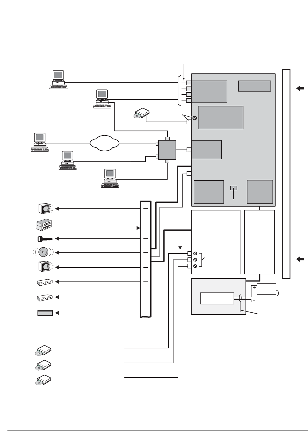
Strata CTX Configuration
Functional Block Diagrams
2-18 Strata CTX I&M 06/04
Functional Block Diagrams
The Functional Block Diagrams show the PCBs and interface connectors used for connecting the
station.
Figure 2-5 CTX100 System Processor and Option Interface PCBs
Data and Speech Highway
6752
ACTU Processor PCB
(one or two per system)
Relay Contacts
Virtual slot 09
ASTU
Relay Contact (Programmable)
RCA Jack (600 ohm Page Output)
MOH/BGM
RCA Jacks
Battery Charger
ABCS
12V
Battery
12V
Battery
(2 or 4 Batteries)
ABTC - 3m Cable
MOH/BGM Jack
+Volume Control
APSU112 Cabinet
Power Supply
MOH/BGM
Volume Controls
Up to Four Programmable Serial (RS-232)
Port Modular Jacks Available
ACD
(CSTA)
SMDR
Call Accounting
Remote CTX
WinAdmin PC
Local CTX
WinAdmin
Notes
1. Optional.
2. License Control.
Music Source 1: Background Music
and/or Music-on-hold
Music Source 2: Background Music
and/or Music-on-hold
Music Source 3: Background Music
and/or Music-on-hold
BSIS
2
(Optional)
Conference
SW with PAD
Interface PCB
BIOU 1
1
1
AMDS
Remote Maintenance
Modem
1
1
Ethernet
Interface
DTMF/ABR
Receivers
RJ45
Smart Media
Maintenance
and
Customer
Database
License
Internet
Music Source: External Zone Page
Background Music
Door Lock Control Relay
External Zone Page Relays (4 Zones)
External Page Amplifier (600 ohm Output)
Main Distribution
Frame (MDF)
Night Bell Control Relay
Amplified Page Output (3 Watts)
BGM Mute Control Relay
Night Control Relay
25 Pair
Hub
or
LAN
SMDI or Toshiba Proprietary
Integration
Toshiba Proprietary Soft Key LCD Link
Stratagy ES
Voice Mail
On this page, all equipment, except Stratagy ES,
connected to the system processor PCBs and
BIOU PCB is customer-supplied.
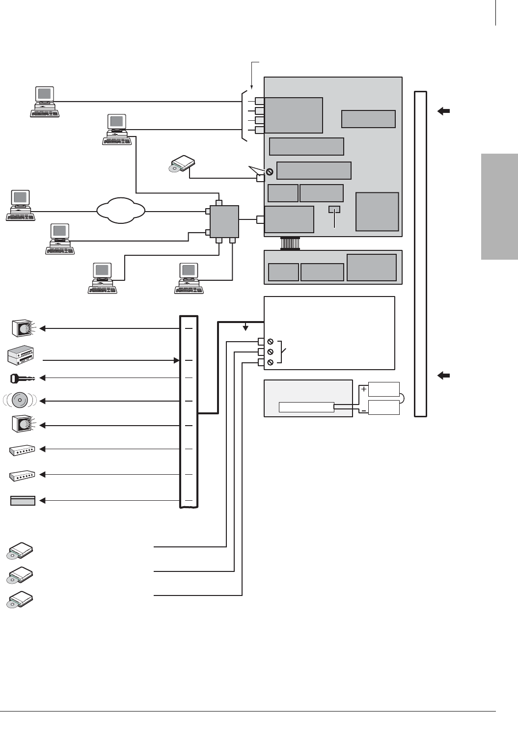
Strata CTX
Configuration
Strata CTX Configuration
Functional Block Diagrams
Strata CTX I&M 06/04 2-19
Figure 2-6 CTX670 System Processor and Optional Interface PCBs
Data and Speech Highway
6942
BCTU Processor PCB
Interface PCB
Relay Contacts, Page Output
Music Source: External Zone Page
Background Music
Door Lock Control Relay
External Zone Page Relays (4 Zones)
External Page Amplifier (600 ohm Output)
Main Distribution
Frame (MDF)
Night Bell Control Relay
Battery Charger
12V
Battery
12V
Battery
(2 or 4 Batteries)
MOH/BGM Jack
+Volume Control
BPSU672 Cabinet
Power Supply
MOH/BGM
Volume Controls
Up to Four Programmable Serial (RS-232)
Port Modular Jacks Available
ACD
(CSTA)
SMDR
Call Accounting
Amplified Page Output (3 Watts)
Remote CTX
WinAdmin PC
Local CTX
WinAdmin
BGM Mute Control Relay
Night Control Relay
Notes
1. Optional.
2. Optional. See description of License Control
earlier in this chapter.
3. Optional one or two per system.
25 Pair
Music Source 1: Background Music
and/or Music-on-hold
Music Source 2: Background Music
and/or Music-on-hold
Music Source 3: Background Music
and/or Music-on-hold
2
AMDS1 Remote
Maintenance Modem
BSIS
(Optional)
Conference
SW with PAD
Ethernet
Interface
DTMF/ABR
Receivers( Built-In )
BIOU 3
RJ45
Smart Media
Maintenance
and
Customer
Database
License
Internet
MOH/BGM
RCA Jacks
BEXU Processor PCB
Memory Time Switch
DTMF/ABR
Receivers
( Built-In )
Hub
or
LAN
SMDI and Stratagy ES Integration
Toshiba Proprietary Soft Key LCD Link
Stratagy ES
Voice Mail
On this page, all equipment, except Stratagy ES,
connected to the system processor PCBs and
BIOU PCB is customer-supplied.
Memory Time Switch
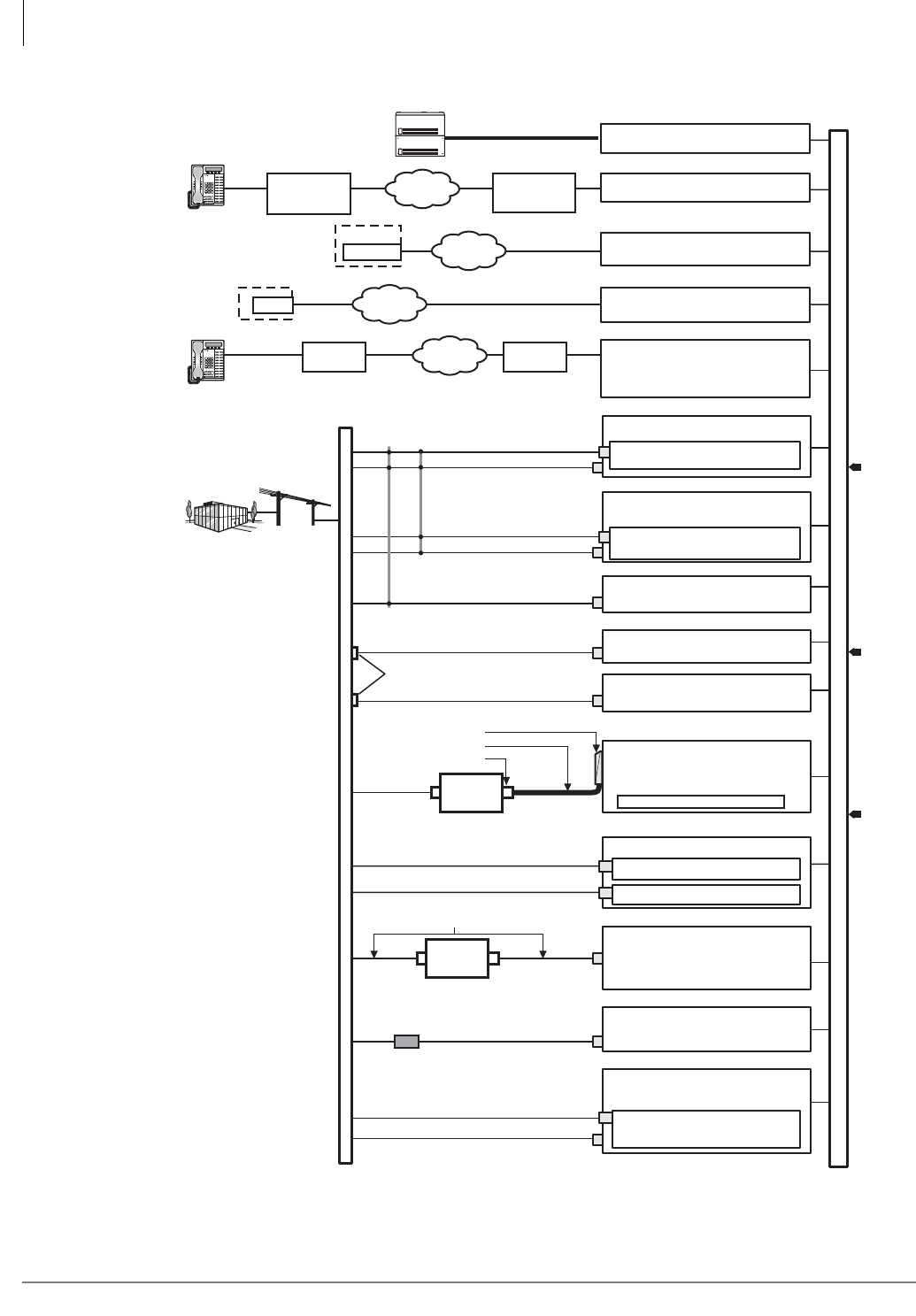
Strata CTX Configuration
Functional Block Diagrams
2-20 Strata CTX I&M 06/04
Figure 2-7 CTX100 and CTX670 CO Line Side Functional Block Diagram
RDTU2 or RDTU3?
• 2T1 / DS1(24 Channels / Lines)
• Loop Start, Ground Start, Tie, DID
Channel
Service
Unit (CSU)
25-pair Amphenol
TOSHIBA NDTU Cable
DB15
PLL Synchronization Circuits
2
RCOU3
4 Loop Start Co Lines (Analog)
RGLU2, RGLU3
4 Loop or Ground Start CO Lines (Analog)
RCOS
(Optional PCB on RCOU Only):
4 Loop Start CO Lines (Analog)
RCIU2
RCIS
4 Caller ID Circuits
4 Caller ID Circuits
(Two 4-Wire Modular Jacks)
MDF
(Two 4-Wire Modular Jacks)
(Two 4-Wire Modular Jacks)
(Two 4-Wire Modular Jacks)
(Two 4-Wire Modular Jacks)
1
RDDU 4 DID CO Lines (Analog)
REMU
4 E&M Tie Lines (Analog)
(REMU, Four 8-Wire Modular Jacks)
(Two 4-Wire Modular Jacks)
Secondary Protectors 2
BPTU1 or RPTU1 or 2
ISDN PRI (23B+1D channels)
Digital Voice/Data
Toshiba RPRI-CBL-KIT
Channel
Service
Unit (CSU) 8-wire Modular Jacks
2
ISDN BRI (U)
2 Circuits (NT-1?)
Voice/Data (2B+D)
RBUU
RBUS
ISDN BRI (U)
2 Circuits (NT-1)
Voice/Data (2B+D)
U
3
U
3
8-wire Modular Jacks
8-wire Modular Jacks
ISDN BRI (S/T)
2 Circuits (TE)
Voice/Data (2B+D)
RBSU
NT1 per circuit
2
U
3
T
3
8-wire Modular Jacks
RMCU Trunk Circuits for E911
RCMS 2 Trunk Circuits
RCMS 2 Trunk Circuits
CAMA Line (2-wire Modular Jacks)
CAMA Line (2-wire Modular Jacks)
Network
Demarcation
Point
Remote Location(s)
Remote
Location(s) BVPU
Voice Over IP Unit (4 Circuits)
BDKU/BDKS or PDKU
(CTX100 & CTX670) or
RRCU
Remote Cabinet Interface Card
Optical Fiber Cable
3 km/(1.86 mi.)
10Base-T
CTX Expansion
Cabinets
Digital
Telephone
MCK
EXTender
MCK
Gateway
IP Network
IP Network
6739
4
Central Office
Centrex
PBX
Common Carrier
Other Telephone System
E911 Public Safety Answer
Point (PSAP)
Priviate Networking Lines
•
•
•
•
•
•
•
•
•
•
•
•
Data and Speech Highway
QSIG networks (RPTU2)4
Page ScrollMode Feature
Msg
Mic Redial
Spdial
Spkr Cnf/Trn Hold
Vol
Page ScrollMode Feature
Msg
Mic Redial
Spdial
Spkr Cnf/Trn Hold
Vol
1. RCIU2/RCIS tip/ring cross
connected to RCOU, RCOS, or
RGLU tip/ring at MDF.
2. Customer-supplied equipment.
3. U, S, T, R, are ISDN reference
model termination points.
4. RPTU2 is required for QSIG
Networking.
CTX / DK
BVPU
Remote
Node(s) BIPU-Q2A
Strata Net QSIG Over IP Unit
100Base-TX
CTX
BIPU-Q1A
(CTX100 only)
ADKU
Remote Location(s)
BIPU-M2A
IP Telephone
With or without
VPN Router
or Server
With or without
VPN Router
or Server
IP Network
IP Network
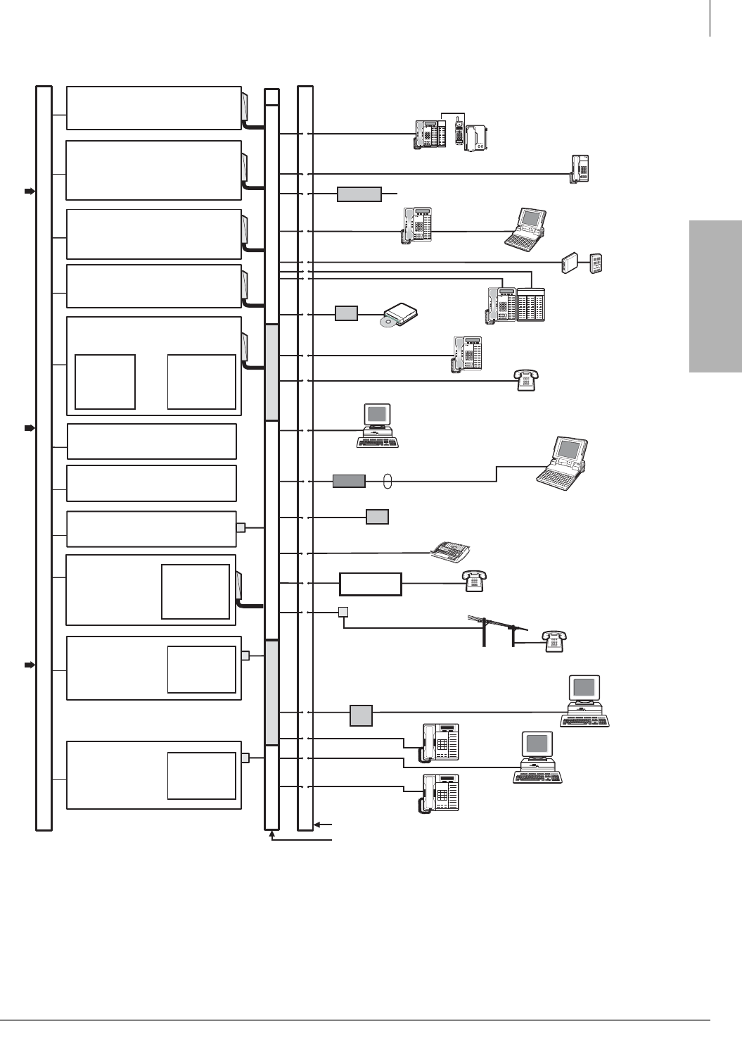
Strata CTX
Configuration
Strata CTX Configuration
Functional Block Diagrams
Strata CTX I&M 06/04 2-21
Figure 2-8 CTX100 and CTX670 Station Side Functional Block Diagram
S3R3
S3
U3
U3
RBSU
2B+1D/Circuit
(2-NT Circuits)
RBUU
2B+1D/Circuit
(2-LT Circuits)
1
1
1
1
1
2
1
1
RDSU4
4 Digital Telephone Circuits
2 Standard Telephone Circuits
ADKU
8 Digital Telephone Circuits (max).
(CTX100 only)
BDKU
8 Digital Telephone Circuits and
BDKU/BDKS
16 Digital Telephone Circuits
RSTS
(Option PCB)
2 Standard
Telephone
Circuits
R48S
(Option PCB,
RDSU/RSTU3
Only) -48 Volt
Loop Supply
R48S
(Option PCB,
RDSU/RSTU3
Only) -48 Volt
Loop Supply
RBSS
2B+1D/Circuit
(2-NT Circuits)
RBUS
2B+1D/Circuit
(2-LT Circuits)
Digital Telephone (DKT)
and Add-on Module
Digital Telephone
with BPCI-DI 4
DDCB
Cordless DKT
MDFB
Door Phones and
Lock Controls
TAPI PC
Music
on-hold
source
(up to 8)
1 Pair Modular Cord RS-232 Cable
PC
1-pair Modular Cords
DPFT
Modem
RS-232 Cables
Connects audio path to Attd Console
Handset 4
Modular Jacks
Main Distribution Frame (MDF)
Power Failure
Transfer Unit
Power Failure
Standard Telephone (8 max.)
Off-premises Station
Secondary
Protector
1. Customer-supplied equipment.
2. RSTU2 or above is required for standard telephone message
waiting lamp.
3. U, S, T, R are ISDN reference model termination points.
4. PDKU and RDSU should only be used for 2000-series digital
telephones. They do not support all of the 3000-series digital telephone
features, including LCD. The PDKU also does not support BPCI, BATI
and the CTX Attendant Console.
Fax
6966
RSTU3/BSTU
8 Standard
Telephone Circuits
PC
ISDN
Telephone
(TE-1, S-Type)
COM Port
ISDN
Telephone
(TE-1, U-Type)
PC with
Video Card
(TE-1, U-Type)
Digital Single Line
Telephone (DKT)
Standard
Telephone
Digital
Telephone
PDKU24
8 Digital Telephone Circuits
BWDKU
8 or 16 Digital Telephone Circuits
iES32
4~32 Voice Mail Circuits (Programmable)
IVP8
2~8 Voice Mail Circuits (Programmable)
Data and Speech Highway
ASTU (CTX100 only)
2 Standard Telephone Circuits
TA
BATI
Transformer
Auto Attendant
(Dealer supplied)
Stratagy ES
Voice Mail
VM Ports
Digital Telephone
with DSS Console
Page ScrollMode Feature
Msg
Mic Redial
Spdial
Spkr Cnf/Trn Hold
Vol
Page ScrollMode Feature
Msg
Mic Redial
Spdial
Spkr Cnf/Trn Hold
Vol
Page ScrollMode Feature
Msg
Mic Redial
Spdial
Spkr Cnf/Trn Hold
Vol
Page ScrollMode Feature
Msg
Mic Redial
Spdial
Spkr Cnf/Trn Hold
Vol

Strata CTX Configuration
Worksheet Description
2-22 Strata CTX I&M 06/04
Worksheet Description
These configuration worksheets cover Strata CTX telephones, PCBs and cabinets; they do not
cover other peripheral equipment requirements.
Knowledge of all customer telephone requirements is needed to complete the worksheets. These
include all telephone sets, CO line types and Strata CTX system feature options for the main
location (with the Strata CTX Base Cabinet) and each remote location. A set of worksheets for the
main system location and a separate set of worksheets for each remote location must be completed.
CTX670 Remote Cabinet Configuration
Considerations
Several items must be considered when configuring a CTX670 system with Remote Cabinets.
(CTX100 systems do not support remote cabinet configurations).
1. Each location must be configured independently. Separate worksheets are needed for each
location to break down the line, trunk and service circuits by locations. Use the rules provided
in this chapter to determine the required quantities of PCBs.
2. Estimate the number of cabinets according to normal configuration worksheets.
3. Account for RRCU PCBs at each remote location (see Table 2-52 on page 2-38 in Worksheet
6). An RRCU PCB can support up to two Expansion Cabinets at one remote location. For
example, 18 PCBs at one remote location would require two Expansion Cabinets and one
RRCU card for the remote location.
4. If necessary, adjust the number of cabinets required. The maximum number of Expansion
Cabinets per system is six. The maximum number of remote locations is also six. The
maximum number of cabinets supported by one fiber connection is two.
5. Determine the total number of RRCU PCBs required at all remote locations (see Table 2-52 on
page 2-38 in Worksheet 6). Add the same number of RRCU cards to the configuration of the
Base Cabinet.
6. Validate the configuration. A valid configuration answers “yes” to the following questions.
• Do all cabinets (local and remote) comply with power limitations? The RRCU has a power
factor of 4.0. See Table 2-58 on page 2-43 in Worksheet 7.
• Are there six or fewer remote locations?
• Are there six or fewer RRCU cards in the Base Cabinet?
7. Order one cabinet cover (BCTC) and cable mesh shield (B50MT) for each remote location.
8. Digital Trunks – A Remote Cabinet can support all PCBs that can be installed in a local
Expansion Cabinet, including digital trunk cards. However, the system cannot derive network
clock synchronization from a digital trunk installed in a remote cabinet. This requires a digital
trunk installed in the Base Cabinet or in a local Expansion Cabinet connected to the Base by a
standard ribbon cable. For each Remote Cabinet location, local trunks may be required for
correct 911 service.
Component Worksheets
Fill in Worksheets 1~8 for each location to determine system cabinet and PCB requirements for:
Customer Name _____________________ Location Description_____________________
Main Location _______________ Remote Location 1___ 2___ 3___ 4___ 5___ 6___

Strata CTX
Configuration
Strata CTX Configuration
Worksheet 1: Toshiba DKT and IP Telephones
Strata CTX I&M 06/04 2-23
Worksheet 1: Toshiba DKT and IP Telephones
Important! The maximum number of DKTs per cabinet is 80. This is a power factor limitation
(see Worksheet 7)
Main Location _______________ Remote Location 1___ 2____ 3____ 4____ 5____ 6____
Item# Digital Telephone Equipment Required for Cabinet Number __________ Qty
DT01 DKT3010-S - 10 button Digital Speakerphone (gray)
DT02 DKT3010-S (W) - 10 button Digital Speakerphone (white)
DT03 DKT3010-SD - 10 button Digital Speakerphone with LCD (gray)
DT04 DKT3010-SD (W) - 10 button Digital Speakerphone with LCD (white)
DT05 DKT3020-S - 20 button Digital Speakerphone (gray)
DT06 DKT3020-S (W) - 20 button Digital Speakerphone (white)
DT07 DKT3020-SD - 20 button Digital Speakerphone with LCD (gray)
DT08 DKT3020-SD (W) - 20 button Digital Speakerphone with LCD (white)
DT09 DKT3014-SDL - 14 button Digital with large LCD (gray)
DT10 DKT3014-SDL - 14 button Digital with large LCD (white)
DT11 DDSS3060 - 60 button Digital Direct station Select Console (gray)
DT12 DDSS3060 - 60 (W) button Digital Direct station Select Console (white)
DT13 IPT1020-SD - 20 button IP Telephone (gray)
DT14 DKT2010-S -10 button Digital Speakerphone (gray)
DT15 DKT2010-S (W) -10 button Digital Speakerphone (white)
DT16 DKT2010-SD -10 button Digital Speakerphone with LCD (gray)
DT17 DKT2010-SD (W) -10 button Digital Speakerphone with LCD (white)
DT18 DKT2020-S -20 button Digital Speakerphone (gray)
DT19 DKT2020-S (W) -20 button Digital Speakerphone (white)
DT20 DKT2020-SD -20 button Digital Speakerphone with LCD (gray)
DT21 DKT2020-SD (W) -20 button Digital Speakerphone with LCD (white)
DT22 DKT2020-FDSP -20 button Digital Full-Duplex Speakerphone with LCD (gray)
DT23 DDSS2060- 60 button Digital Direct Station Select Console (gray)
DT24 DDSS2060 (W) -60 button Digital Direct Station Select Console (white)
DT25 DDCB - Digital Door Phone Control Box (supports 3 MDFB Door phones)
DT26 Pre-wired Digital Telephone Ports (allocates spare, hot wired digital ports)
DT27 DKT2204-CT - Digital Cordless Phone (digital spread spectrum - sharing port with DKT)1
1. Do not count shared ports into the Total (DT20) BWDKU or BDKU/BDKS ports required.
DT28 DKT2204-CT - Digital Cordless Phone (digital spread spectrum - stand alone)
DT29 DKT2304-CT - Digital Cordless Phone (digital narrow band sharing port with DKT)1
DT30 DKT2304-CT - Digital Cordless Phone (digital narrow band - stand alone)
DT31 Total Digital ports required (Add DT01 Qty. ~ DT29 Qty.)
DT32 Total BDKU, BWDKU or BDKU/BDKS or ADKU PCBs/Slots required (DT30, Qty./8 or DT30 Qty./16)2
2. Round up these totals to the nearest whole number.
DT33 Total RDSU PCBs/Slots required to add 4 DKT/2 SLT Devices
DT34 Total RDSU/RSTS PCBs/Slots required to add 4 DKT/4 SLT Equipment
Item IP Telephone Qty
IPT01 IPT1020-SD
IPT02 Total BIPU-M2A PCBs/slots required (IPT01 quantity/16)
Strata CTX Configuration
Worksheet 2: Standard Telephone, Stratagy DK, IVP8
2-24 Strata CTX I&M 06/04
Worksheet 2: Standard Telephone, Stratagy DK,
IVP8
Miscellaneous Digital Telephone Equipment (See Table 2-52)
DT34 RFDM - External Microphone for DKT2020-FDSP Full Duplex Digital Speakerphone
DT35 MDFB - Door Phone connected to Digital Door Phone Control Box (requires 1DDCB output)
DT36 Door Lock connected to Digital Door Phone Control Box (requires 1DDCB output)
DT37 BVSU - Interface for Digital Telephones that require Speaker OCA (DKT3000 and DKT2000)
DT38 BPCI - PC/TAPI Interface for digital telephone (gray) (DKT3000)
DT39 Secondary Protectors for any Digital station devices located off-premise.
DT40 BHEU - Telephone Headset Interface (DKT2000 and DKT3000)
DT41 DADM3020 - 20-button Add-on module (gray)
DT42 DADM3020(w) - 20-button Add-on module (white)
DT43 DADM2020 -20 button Digital Add-on Module (gray)
DT44 DADM2020 (W) -20 button Digital Add-on Module (white)
DT45 DADM3120 - 20 button IP or DKT Add-on module (gray)
Main Location _______________ Remote Location 1___ 2___ 3___ 4____5___ 6____
Item# Dealer Supplied Standard Telephone (SLT) Equipment Required Qty
ST1 Standard Tone-Dial Telephone
ST3 External Modem and/or Fax Devices
ST4 External Voice Mail Ports to support Stratagy or other VM (not for Stratagy DK)
ST5 Other Devices, not listed, requiring standard telephone circuit interface
ST6 Alternate BGM Source connected to Std.Tel. port (allocates ASTU, BSTU, RSTU ports)
ST7 Pre-wired Standard Telephone ports (to allocate spare, hot wired, standard tel. ports)
ST8 Total ASTU, BSTU, RSTU PCBs/Slots required (ST1~ST9, QTY/8)*
ST9 Total RDSU PCBs/Slots required to add 4 DKT/2 SLT Devices
ST10 Total RDSU/RSTS PCBs/Slots required to add 4 DKT/4 SLT Equipment
Miscellaneous Standard Telephone (SLT) Equipment Required
ST11 R48S PCB for up to 8 Standard Telephone Off Premise Station (OPS) circuits
ST12 Secondary Protector for Standard telephone equipment located off premise
ST13 DPFT, Power Failure Transfer Unit for up to 8 standard telephone/loop start lines
Stratagy DK or IVP8 Equipment Required
ST14 Each Stratagy Voice Mail PCB provides up to 8 Voice Mail ports and uses 8 ports of system capacity. No
other PCBs are required to interface with Stratagy DK or IVP8. (One allowed per CTX system.)
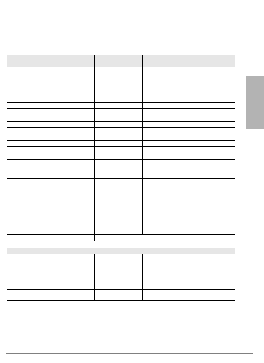
Strata CTX
Configuration
Strata CTX Configuration
Worksheet 3: CO Line
Strata CTX I&M 06/04 2-25
Worksheet 3: CO Line
Main Location _______________ Remote Location 1___ 2___ 3___ 4____5___ 6____
Item # CO Line Type Required Line
Qty /X= PCB
Qty PCB Name Slots Required1
1. Round up fractions to the nearest whole number.
CO1 Analog Loop Start CO Lines with RCOU /4= RCOU 1 Slot/RCOU =
CO2 Analog Loop Start CO Lines with
RCOU/RCOS /8= RCOU/RCOS 1 Slot/RCOU/RCOS =
CO3 Analog Ground Start CO Lines with
RGLU /4= RGLU 1 Slot/RGLU =
CO4 Caller ID Line interface with RCIU /4= RCIU 1 Slot/RCIU =
CO5 Caller ID Line interface with RCIU/RCIS /8= RCIU/RCIS 1 Slot/RCIU/IS =
CO6 BVPU VoIP Circuits2
2. Maximum of five PCBs with CTX670 and two BVPU PCBs with CTX100 because of FCC Part 15 emissions requirement.
/4= BVPU 1 Slot/BVPU =
CO7 Analog Tie Lines with REMU /4= REMU 1 Slot/REMU =
CO8 Analog DID Lines with RDDU /4= RDDU 1 Slot/RDDU =
CO9 T1 Digital Lines with RDTU2 /24= RDTU2 2 Slots/RDTU2 =
CO10 T1 Digital Lines with RDTU2 /16= RDTU2 1 Slot/RDTU2 =
CO11 T1 Digital Lines with RDTU2 /8= RDTU2 1 Slots/RDTU2 =
CO12 IP with BIPU-Q1A /8= BIPU-Q1A 1 Slot/BIPU-Q1A =
CO13 IP with BIPU-Q1A /16= BIPU-Q1A 1 Slot/BIPU-Q1A =
CO14 ISDN and/or QSIG with RPTU or BPTU /23 RPTU2 1 Slot/RPTU2 =
CO15 ISDN and/or QSIG with RPTU or BPTU /16 RPTU2 1 Slot/RPTU2 =
CO16 ISDN and/or QSIG with RPTU or BPTU /8 RPTU2 1 Slot/RPTU2 =
CO17 ISDN BRI Circuit3, U-type with RBUU
3. Each ISDN BRI circuit can be configured to provide two CO lines or interface to one BRI station. Each circuit uses 2 CO lines and
2 station ports of system capacity regardless of how it is configured (line or station).
/2= RBUU 1 Slot/RBUU =
CO18 ISDN BRI Circuits1, U-type with RBUU/
RBUS /4= RBUU/RBUS 1 Slot/RBUU/US =
CO19 ISDN BRI Circuits1, S/T-type with
RBSU /2= RBSU 1 Slot/RBSU =
CO20 ISDN BRI Circuits1, S/T-type with
RBSU/RBSS /4= RBSU/RBSS 1 Slot/RBSU/RBSS =
CO21
E911 CAMA Circuits (RMCS/RCMS=2
circuits, add another RCMS for 4
circuits
/4= RMCU/RCMS 1 Slot/RMCU/RMMS=
CO22 Total Slots required for line PCBs
Miscellaneous CO Line Equipment
CO23 Dealer-supplied NT-1 S/T BRI Line
Circuits Number of NT-1s No slots required.
CO24 Dealer-supplied CSU for BPTU or
RPTU and/or RDTU2 Number of CSUs No slots required.
CO25 Cable kits for BPTU or RPTU2 Number of RPRI-CBL-KIT No slots required.
CO26 Cable Kits for BPTU or RPTU2 Number of RPRI-CBL-KIT No slots required.
CO27 Secondary Protectors For RDDU and
REMU Number of Protectors. No slots required.
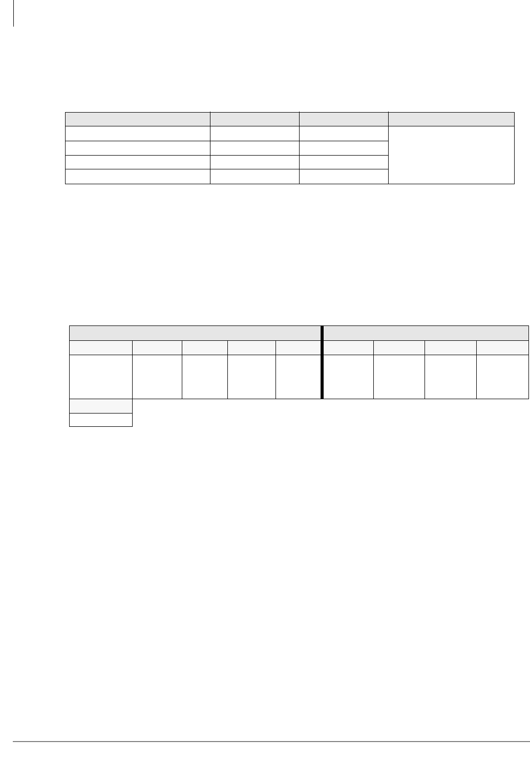
Strata CTX Configuration
Worksheet 4: Page/MOH/Control Relay
2-26 Strata CTX I&M 06/04
Worksheet 4: Page/MOH/Control Relay
Up to two BIOU interfaces can be installed to provide the following interfaces:
Worksheet 5: Strata CTX100 Cabinet Slots
Write in the PCBs installed in each cabinet slot in the Cabinet Diagram below. Use the PCB
placement guideline below to place PCBs in the correct slots. A number of tables provide CTX100
capacities and configuration examples in this section.
For cost-effective configurations, try to fit all PCBs into the CTX100 Base Cabinet. This allows up
to 16 loop start COs by 32 DKTs, and up to 24 T1 or PRI COs by 40 DKTs.
• If loop start CO and DKT combinations are required, use CTX100-ECONOPKG (RCOU,
ADKU with common equipment) for up to four CO by eight DKTs or CTX100-ECONOTWO
(two RCOU, two ADKU with common equipment) for eight CO lines by 16 DKTs or greater.
Otherwise, use CTX100-0X8PKG.
• If more than 16 channels are required on an RDTU, BPTU, RPTU, place PCB in S103. Slot 104
is available for another PCB.
• BIPU-M2A, BIPU-M1A or BIPU-Q1A can be installed in any slot to provide 16 channels.
• If 9~16 DKTs require Speaker OCA, place BDKU/BDKS PCBs in S103 if it is available.
• Place other required PCBs according to the guidelines herein.
• Consult the following tables of maximum system capacity slot configurations as guidelines for
PCB slot placement.
• Check system capacities in Tables 2-3~2-7 to confirm that the features to be used are within
limitations.
Main Location _______________ Remote Location 1___ 2___ 3___ 4___ 5___ 6___
Feature 1 BIOU 2 BIOUs Enter No. of Required BIOUs
Page Zone Relays 4 8
Control Relays1
1. The CTX100 processor provides one built-in control relay.
48
MOH/BGM Device Interface2
2. CTX100 and CTX670 processors each provide one built-in MOH/BGM interface (RCA jack).
36
Page Outputs3
3. CTX100 processor provides one built-in 600 ohm page output. Each BIOU provides a 600 ohm and 3-watt page output on
the CTX670 only.
4. Control relays provide closures for a door lock, page mute, night service and night bell contact.
12
CTX Base Cabinet Slots CTX Expansion Cabinet Slots
ACTU S101 S102 S103 S104 S105 S106 S107 S108
(AETS___)
(AMDS__)
(ARCS__)
(BSIS__)
S109
(ASTU__)

Strata CTX
Configuration
Strata CTX Configuration
Worksheet 5: Strata CTX100 Cabinet Slots
Strata CTX I&M 06/04 2-27
Notes
1. Always check the cabinet power factors using Worksheet 7 to make sure the installed PCBs and
telephones do not exceed the power factor limitations.
2. ACTU processor optional subassembly functions (see “CTX100 Processor Optional
Subassemblies” on page 2-3). Any PCB plus its PCB subassembly can be installed in any slot
with the exception of RDTU, BPTU, RPTU PCBs that support more than 16 channels, and
BDKU/BDKS PCBs that support Speaker OCA.
3. RDTU, BPTU, RPTU PCBs can be placed in any odd numbered slot using the following rules:
• If RDTU, BPTU or RPTU is placed in Slot 103 (preferred) with 8, 16 or 24 channels,
another PCB can still be installed in S104.
• If RDTU, BPTU or RPTU is placed in Slots 101, 105, or 107 with 8 or 16 channels, another
PCB can still be installed in the next slot; however, if 17~24 channels are required the next
even slot must be vacant.
• RDTU and/or BPTU or RPTU can be placed in any odd slot. If more than 16 channels are
required, the next slot must be vacant, except if the PCB is placed in slot 103, which
provides up to 32 time slots for RDTU, BPTU, or RPTU. Max. BPTU or RDTU channels =
64; max. RPTU channels = 48.
• If only 16 B channels of PRI are needed, another card can be installed in the next slot. The
position of D-channels can still be set to the 24th channel because the data of the D-channel
is passed through the data highway, not the PCM highway. The position of the D-channel
doesn’t affect the installation of cards in the CTX.
4. Digital telephone PCBs that support Speaker OCA can be placed in slots using the following
rules:
• If ADKU, BDKU (without BDKS) or PDKU must support Speaker OCA, it can be installed
in any slot; another PCB can be installed in the next even slot.
• If a BWDKU or BDKU/BDKS PCB must support Speaker OCA it can only be installed in
Slot 103; another PCB can be installed in S104.
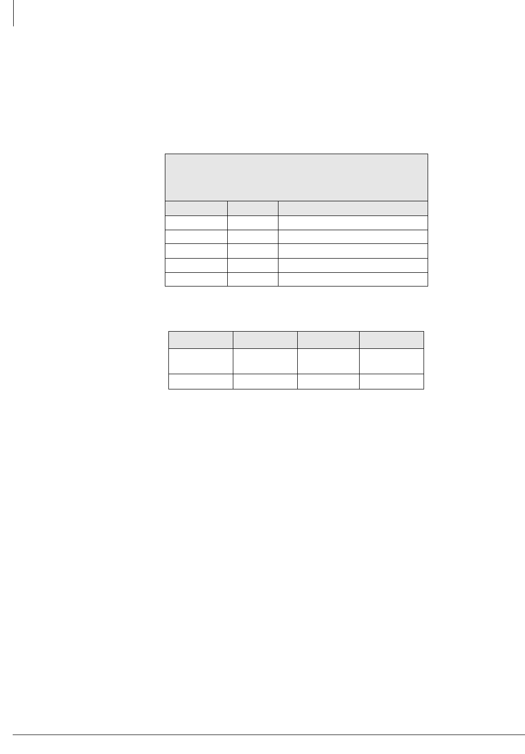
Strata CTX Configuration
CTX100 Max. Capacity Configuration Examples
2-28 Strata CTX I&M 06/04
CTX100 Max. Capacity Configuration Examples
The tables in this section summarize the maximum capacities of digital telephones with various
types of line circuits. A PCB placement diagram for each numbered configuration follows tables.
Digital Telephones and Loop Start Lines With or Without Caller ID
Table 2-11 CTX100 Base Cabinet with Analog, Loop Start Lines
4 Universal Slots
40 Stations (Max.)
24 CO lines (Max.)
44 Stations + Analog loop start lines combined (Max.)
Table No. Stations Analog loop start lines
2-12 40 4 (none can have Caller ID)
2-13 32 8 (all can have Caller ID)
2-14 32 16 (none can have Caller ID)
2-15 16 16 (8 can have Caller ID)
2-16 241
1. Using ADKU.
8 (none can have Caller ID)
Table 2-12 CTX100 Base: 40 stations, 4 loop start lines, 0 CLID
S101 S102 S1031
1. S103 is only 8 DKTs and S104 is only 4 lines because of cabinet
power factor
S104
BDKU/
BDKS
BDKU/
BDKS ADKU RCOU
16 DKTs 16 DKTs 8 DKTs 4 lines
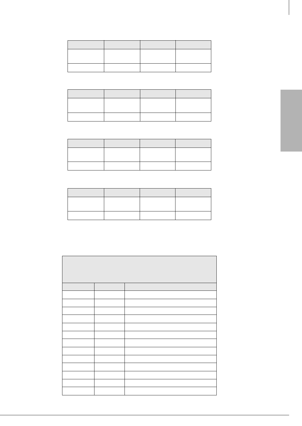
Strata CTX
Configuration
Strata CTX Configuration
CTX100 Max. Capacity Configuration Examples
Strata CTX I&M 06/04 2-29
Analog Loop Start Lines with or without Caller ID
Table 2-13 CTX100 Base: 32 stations, 8 loop start lines, 8 CLID
S101 S102 S103 S104
BDKU/
BDKS
BDKU/
BDKS
RCOU/
RCOS RCIU/RCIS
16 DKTs 16 DKTs 8 lines 8 CLID
Table 2-14 CTX100 Base: 32 stations, 16 loop start lines, 0 CLID
S101 S102 S103 S104
BDKU/
BDKS
BDKU/
BDKS
RCOU/
RCOS
RCOU/
RCOS
16 DKTs 16 DKTs 8 lines 8 lines
Table 2-15 CTX100 Base: 16 stations, 16 loop start lines, 8 CLID
S101 S102 S103 S104
BDKU/
BDKS
RCOU/
RCOS
RCOU/
RCOS RCIU/RCIS
16 DKTs 8 lines 8 lines 8 CLID
Table 2-16 CTX100 Base: 24 stations with ADKU, 8 loop start lines, 0 CLID
S101 S102 S103 S104
ADKU ADKU ADKU RCOU/
RCOS
8 DKTs 8 DKTs 8 DKTs 8 lines
Table 2-17 CTX100 Base and Expansion Cabinet with Analog Loop Start Lines
8 Universal Slots
72 Stations (Max.)
56 CO lines (Max.)
92 Stations + Analog Loop Start Lines combined (Max.)
Table No. Stations Analog loop start lines
2-18 72 20 (none can have Caller ID)
2-19 72 16 (8 can have Caller ID)
2-20 64 32 (none can have Caller ID)
2-21 64 24 (8 can have Caller ID)
2-22 64 16 (all can have Caller ID)
2-23 48 40 (none can have Caller ID)
2-24 48 32 (8 can have Caller ID)
2-25 48 24 (16 can have Caller ID)
2-26 32 48 (none can have Caller ID)
2-27 32 40 (8 can have Caller ID)
2-28 32 32(16 can have Caller ID)
2-29 32 24 (24 can have Caller ID)
2-30 16 32 (24 can have Caller ID)
Strata CTX Configuration
CTX100 Max. Capacity Configuration Examples
2-30 Strata CTX I&M 06/04
Table 2-18 CTX100 Base & Expansion: 72 stations, 20 loop start lines, 0 CLID
S101 S102 S1031
1. S103 is only 4 lines and S104 is only 8 DKTs because of cabinet power factor.
S104 S105 S106 S107 S108
BDKU/
BDKS
BDKU/
BDKS RCOU ADKU BDKU/
BDKS
BDKU/
BDKS
RCOU/
RCOS
RCOU/
RCOS
16 DKTs 16 DKTs 4 lines 8 DKTs 16 DKTs 16 DKTs 8 lines 8 lines
Table 2-19 CTX100 Base & Expansion: 72 stations, 16 loop start lines, 8 CLID
S101 S102 S103 S1041
1. S104, only 8 DKTs because of cabinet power factor.
S105 S106 S107 S108
BDKU/
BDKS
BDKU/
BDKS RCIU/RCIS ADKU BDKU/
BDKS
BDKU/
BDKS
RCOU/
RCOS
RCOU/
RCOS
16 DKTs 16 DKTs 8 CLID 8 DKTs 16 DKTs 16 DKTs 8 lines 8 lines
Table 2-20 CTX100 Base & Expansion: 64 stations, 32 loop start lines, 0 CLID
S101 S102 S103 S104 S105 S106 S107 S108
BDKU/
BDKS
BDKU/
BDKS
RCOU/
RCOS
RCOU/
RCOS
BDKU/
BDKS
BDKU/
BDKS
RCOU/
RCOS
RCOU/
RCOS
16 DKTs 16 DKTs 8 lines 8 lines 16 DKTs 16 DKTs 8 lines 8 lines
Table 2-21 CTX100 Base & Expansion: 64 stations, 24 loop start lines, 8 CLID
S101 S102 S103 S104 S105 S106 S107 S108
BDKU/
BDKS
BDKU/
BDKS RCIU/RCIS RCOU/
RCOS
BDKU/
BDKS
BDKU/
BDKS
RCOU/
RCOS
RCOU/
RCOS
16 DKTs 16 DKTs 8 CLID 8 lines 16 DKTs 16 DKTs 8 lines 8 lines
Table 2-22 CTX100 Base & Expansion: 64 stations, 16 loop start lines, 16 CLID
S101 S102 S103 S104 S105 S106 S107 S108
BDKU/
BDKS
BDKU/
BDKS RCIU/RCIS RCOU/
RCOS
BDKU/
BDKS
BDKU/
BDKS RCIU/RCIS RCOU/
RCOS
16 DKTs 16 DKTs 8 CLID 8 lines 16 DKTs 16 DKTs 8 CLID 8 lines
Table 2-23 CTX100 Base & Expansion: 48 stations, 40 loop start lines, 0 CLID
S101 S102 S103 S104 S105 S106 S107 S108
BDKU/
BDKS
BDKU/
BDKS
RCOU/
RCOS
RCOU/
RCOS
BDKU/
BDKS
RCOU/
RCOS
RCOU/
RCOS
RCOU/
RCOS
16 DKTs 16 DKTs 8 lines 8 lines 16 DKTs 8 lines 8 lines 8 lines
Table 2-24 CTX100 Base & Expansion: 48 stations, 32 loop start lines, 8 CLID
S101 S102 S103 S104 S105 S106 S107 S108
BDKU/
BDKS
BDKU/
BDKS
RCOU/
RCOS
RCOU/
RCOS
BDKU/
BDKS
RCOU/
RCOS RCIU/RCIS RCOU/
RCOS
16 DKTs 16 DKTs 8 lines 8 lines 16 DKTs 8 lines 8 CLID 8 lines
Strata CTX
Configuration
Strata CTX Configuration
CTX100 Max. Capacity Configuration Examples
Strata CTX I&M 06/04 2-31
Table 2-25 CTX100 Base & Expansion: 48 stations, 24 loop start lines, 16 CLID
S101 S102 S103 S104 S105 S106 S107 S108
BDKU/
BDKS
BDKU/
BDKS RCIU/RCIS RCOU/
RCOS
BDKU/
BDKS
RCOU/
RCOS RCIU/RCIS RCOU/
RCOS
16 DKTs 16 DKTs 8 CLID 8 lines 16 DKTs 8 lines 8 CLID 8 lines
Table 2-26 CTX100 Base & Expansion: 32 stations, 48 loop start lines, 0 CLID
S101 S102 S103 S104 S105 S106 S107 S108
BDKU/
BDKS
BDKU/
BDKS
RCOU/
RCOS
RCOU/
RCOS
RCOU/
RCOS
RCOU/
RCOS
RCOU/
RCOS
RCOU/
RCOS
16 DKTs 16 DKTs 8 lines 8 lines 8 lines 8 lines 8 lines 8 lines
Table 2-27 CTX100 Base & Expansion: 32 stations, 40 loop start lines, 8 CLID
S101 S102 S103 S104 S105 S106 S107 S108
BDKU/
BDKS
BDKU/
BDKS
RCOU/
RCOS
RCOU/
RCOS
RCOU/
RCOS
RCOU/
RCOS RCIU/RCIS RCOU/
RCOS
16 DKTs 16 DKTs 8 lines 8 lines 8 lines 8 lines 8 CLID 8 lines
Table 2-28 CTX100 Base & Expansion: 32 stations, 32 loop start lines, 16 CLID
S101 S102 S103 S104 S105 S106 S107 S108
BDKU/
BDKS
BDKU/
BDKS
RCOU/
RCOS
RCOU/
RCOS RCIU/RCIS RCOU/
RCOS RCIU/RCIS RCOU/
RCOS
16 DKTs 16 DKTs 8 lines 8 lines 8 CLID 8 lines 8 CLID 8 lines
Table 2-29 CTX100 Base & Expansion: 32 stations, 24 loop start lines, 24 CLID
S101 S102 S103 S104 S105 S106 S107 S108
BDKU/
BDKS
BDKU/
BDKS RCIU/RCIS RCOU/
RCOS RCIU/RCIS RCOU/
RCOS RCIU/RCIS RCOU/
RCOS
16 DKTs 16 DKTs 8 CLID 8 lines 8 CLID 8 lines 8 CLID 8 lines
Table 2-30 CTX100 Base & Expansion: 16 stations, 32 loop start lines, 24 CLID
S101 S102 S103 S104 S105 S106 S107 S108
BDKU/
BDKS
RCOU/
RCOS RCIU/RCIS RCOU/
RCOS RCIU/RCIS RCOU/
RCOS RCIU/RCIS RCOU/
RCOS
16 DKTs 8 lines 8 CLID 8 lines 8 CLID 8 lines 8 CLID 8 lines
Strata CTX Configuration
CTX100 Max. Capacity Configuration Examples
2-32 Strata CTX I&M 06/04
CTX100 Base Only: Digital Telephones and T1 and/or PRI lines
RPTU2 (PRI) is limited to 48 channels; RDTU2 and BPTU (T1) are limited to 64 channels.
Table 2-31 CTX100 CTX Base Cabinet with T1 and/or PRI lines
4 Universal Slots
40 Stations (Max.)
48 lines (Max.)
64 Stations + T1 and/or PRI or IP-QSIG lines combined (Max.)
Table No. Stations T1 and/or PRI lines
2-32 40 24/23
2-33 32 40/40
2-34 16 48/46
Table 2-32 CTX100 Base: 40 stations and 24 T1 and/or PRI lines
S101 S102 S103 S1041
1. S104, only 8 DKTs because of cabinet power factor.
BDKU/
BDKS
BDKU/
BDKS RxTU22
2. RxTU2 could be RDTU2 (T1), RPTU2 or BPTU (PRI).
ADKU
16 DKTs 16 DKTs 24 lines 8 DKTs
Table 2-33 CTX100 Base: 32 stations and 40 T1 and/or PRI lines
S101 S102 S103 S104
RxTU2 BDKU/
BDKS RxTU21
1. RxTU2 could be RDTU2 (T1), RPTU2 or BPTU (PRI).
BDKU/
BDKS
16/15 lines 16 DKTS 24/23 lines 16 DKTS
Table 2-34 CTX100 Base: 16 stations and 48 T1 and/or PRI lines
S101 S102 S103 S104
RxTU2 Vacant
(Shared) RxTU21
1. RxTU2 could be RDTU2 (T1), RPTU2 or BPTU (PRI).
BDKU/
BDKS
24/23lines 24/23 lines 16 DKTS
Strata CTX
Configuration
Strata CTX Configuration
CTX100 Max. Capacity Configuration Examples
Strata CTX I&M 06/04 2-33
CTX100 Base & Expansion: Digital Telephones and T1 and/or PRI lines
8 Universal Slots
72 Stations (Max.)
64 lines (Max.)
112 Stations + T1 and/or PRI or IP-QSIG lines
combined (Max.)
Stations T1 and/or PRI lines1
1. PRI lines are limited to 48B channels.
72 40/40
64 48/48
56 56/48
48 64/48
Table 2-35 CTX100 Base and Expansion: 72 stations and 40 T1 and/or PRI lines
S101 S102 S103 S1041
1. S104, only 8 DKTs because of cabinet power factor.
S105 S106 S107 S108
BDKU/
BDKS
BDKU/
BDKS RxTU2 ADKU RxTU22
2. RxTU2 could be RDTU2 (T1), RPTU2 or BPTU (PRI).
BDKU/
BDKS
BDKU/
BDKS
16 DKTs 16 DKTs 24 lines 8 DKTs 16 lines 16 DKTs 16 DKTs
Table 2-36 CTX100 Base and Expansion: 56 stations and 56 T1 and/or PRI lines
S101 S102 S103 S1041
1. S104, only 8 DKTs because of cabinet power factor.
S105 S106 S107 S108
BDKU/
BDKS
BDKU/
BDKS RxTU2 ADKU RxTU22
2. RxTU2 could be RDTU2 (T1), RPTU2 or BPTU (PRI).
Vacant
(Shared) RDTU2 BDKU/
BDKS
16 DKTs 16 DKTs 24 lines 8 DKTs 24 lines 8 lines 16 DKTs
Table 2-37 CTX100 Base and Expansion: 48 stations and 64 T1 and/or PRI lines
S101 S102 S103 S1041
1. S104, only 8 DKTs because of cabinet power factor.
S105 S106 S107 S108
BDKU/
BDKS
BDKU/
BDKS RxTU2 ADKU RxTU22
2. RxTU2 could be RDTU2 (T1), RPTU2 or BPTU (PRI).
Vacant
(Shared) RDTU2 ADKU
16 DKTS 16 DKTS 24 lines 8 DKTS 24 lines 16 lines 8 DKTs
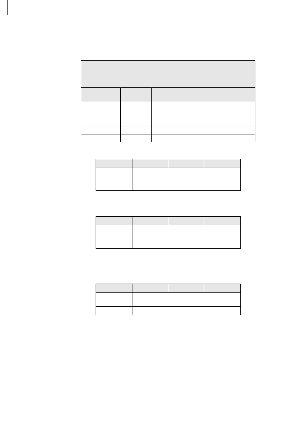
Strata CTX Configuration
CTX100 Max. Capacity Configuration Examples
2-34 Strata CTX I&M 06/04
CTX100 Base Only: Digital Telephones and Analog Tie, DID, and/or
Ground Start Lines
Table 2-38 CTX100 Base Cabinet with Analog Tie, DID and /or Ground Start Lines
4 Universal Slots
40 Stations (Max.)
16 CO lines (Max.)
40 Stations + Analog Tie, DID, Ground Start Lines combined (Max.)
Table No. Stations Analog Tie, DID, and/or Ground Start
Lines
2-39 40 4 line (Ground Start only)
2-40 32 8 lines (4 Tie/DID max.).
2-41 24 8 line any type
2-42 16 12 line any type
2-43 0 16 line any type
Table 2-39 CTX100 Base: 40 stations, 4 Ground Start Lines
S101 S102 S103 S104
BDKU/
BDKS
BDKU/
BDKS ADKU RGLU1
1. RGLU ground start lines only because of cabinet power factor.
16 DKTs 16 DKTs 8 DKTs 4 lines
Table 2-40 CTX100 Base: 32 stations, 4 Tie or DID and 4 Ground Start Lines
S101 S102 S103 S104
BDKU/
BDKS
BDKU/
BDKS RxxU1
1. RxxU can be REMU (Tie) or RDDU (DID).
RGLU2
2. RGLU ground start lines only because of cabinet power factor.
16 DKTs 16 DKTs 4 lines 4 lines
Table 2-41 CTX100 Base: 24 stations, 8 Tie, DID and/or Ground Start Lines
S101 S102 S103 S104
BDKU/
BDKS ADKU RxxU1
1. RxxU can be REMU (Tie), RDDU (DID), or RGLU ground start
lines.
RxxU
16 DKTs 8 DKTs 4 lines 4 lines
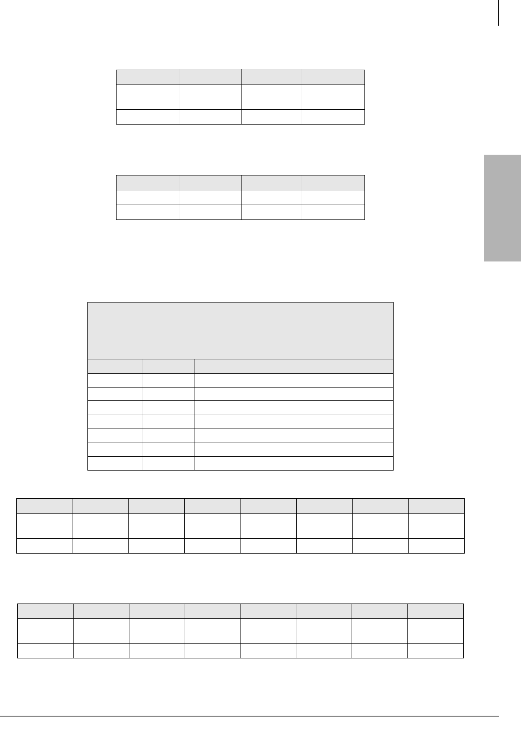
Strata CTX
Configuration
Strata CTX Configuration
CTX100 Max. Capacity Configuration Examples
Strata CTX I&M 06/04 2-35
CTX100: Analog Tie, DID and/or Ground Start Lines
Table 2-42 CTX100 Base: 16 stations, 12 Tie, DID and/or Ground Start Lines
S101 S102 S103 S104
BDKU/
BDKS RxxU RxxU1
1. RxxU can be REMU (Tie), RDDU (DID), or RGLU ground start
lines.
RxxU
16 DKTs 4 lines 4 lines 4 lines
Table 2-43 CTX100 Base: 0 stations, 16 Tie, DID and/or Ground Start Lines
S101 S102 S103 S104
RxxU1
1. RxxU can be REMU (Tie), RDDU (DID), or RGLU ground start
lines.
RxxU RxxU RxxU
4 lines 4 lines 4 lines 4 lines
Table 2-44 CTX100 Base and Expansion Cabinet with Analog Tie, DID and/or Ground
Start Lines
8 Universal Slots
72 Stations (Max.)
32 CO lines (Max.)
80 Stations + Analog Tie, DID and/or Ground Start Lines combined
(Max.)
Table No. Stations Analog Tie, DID, and/or Ground Start Lines
2-45 72 12 lines (4 Tie/DID max.)
2-46 64 16 lines (8 Tie/DID max.)
2-47 56 16 lines (12 Tie/DID max.)
2-48 48 16 lines any type
2-49 48 20 lines (16 Tie/DID max.)
2-50 32 24 lines any type
2-51 16 28 lines any type
Table 2-45 CTX100 Base & Expansion: 72 stations, 4 Tie or DID and 8 Ground Start Lines
S101 S102 S103 S104 S105 S106 S107 S108
BDKU/
BDKS
BDKU/
BDKS ADKU RGLU2BDKU/
BDKS
BDKU/
BDKS RxxU1
1. RxxU can be REMU (Tie), RDDU (DID), or RGLU ground start lines.
RGLU2
2. RGLU can not be substituted with REMU or RDDU because of cabinet power factor.
16 DKTs 16 DKTs 8 DKTs 4 lines 16 DKTs 16 DKTs 4 lines 4 lines
Table 2-46 CTX100 Base & Expansion: 64 stations, 8 tie or DID and 8 Ground Start Lines
S101 S102 S103 S104 S105 S106 S107 S108
BDKU/
BDKS
BDKU/
BDKS RxxU RGLU2BDKU/
BDKS
BDKU/
BDKS RxxU1
1. RxxU can be REMU (Tie), RDDU (DID), or RGLU ground start lines.
RGLU2
2. RGLU can not be substituted with REMU or RDDU because of cabinet power factor.
16 DKTs 16 DKTs 4 lines 4 lines 16 DKTs 16 DKTs 4 lines 4 lines

Strata CTX Configuration
CTX100 Max. Capacity Configuration Examples
2-36 Strata CTX I&M 06/04
Table 2-47 CTX100 Base & Expansion: 56 stations, 12 Tie or DID and 4 Ground Start Lines
S101 S102 S103 S104 S105 S106 S107 S108
BDKU/
BDKS ADKU RxxU RxxU BDKU/
BDKS
BDKU/
BDKS RxxU1
1. RxxU can be REMU (Tie), RDDU (DID), or RGLU ground start lines.
RGLU2
2. RGLU can not be substituted with REMU or RDDU because of cabinet power factor.
16 DKTs 8 DKTs 4 lines 4 lines 16 DKTs 16 DKTs 4 lines 4 lines
Table 2-48 CTX100 Base & Expansion: 48 stations, 16 Tie, DID and/or Ground Start Lines
S101 S102 S103 S104 S105 S106 S107 S108
BDKU/
BDKS ADKU RxxU1
1. RxxU can be REMU (Tie), RDDU (DID), or RGLU ground start lines.
RxxU BDKU/
BDKS ADKU RxxU RxxU
16 DKTs 8 DKTs 4 lines 4 lines 16 DKTs 8 DKTs 4 lines 4 lines
Table 2-49 CTX100 Base & Expansion: 48 stations, 16 Tie or DID and 4 Ground Start Lines
S101 S102 S103 S104 S105 S106 S107 S108
BDKU/
BDKS
BDKU/
BDKS RxxU1
1. RxxU can be REMU (Tie), RDDU (DID), or RGLU ground start lines.
RGLU2
2. RGLU can not be substituted with REMU or RDDU because of cabinet power factor.
BDKU/
BDKS RxxU RxxU RxxU
16 DKTs 16 DKTs 4 lines 4 lines 16 DKTs 4 lines 4 lines 4 lines
Table 2-50 CTX100 Base & Expansion: 32 stations, 24 Tie, DID and/or Ground Start Lines
S101 S102 S103 S104 S105 S106 S107 S108
BDKU/
BDKS RxxU1
1. RxxU can be REMU (Tie), RDDU (DID), or RGLU ground start lines.
RxxU RxxU BDKU/
BDKS RxxU RxxU RxxU
16 DKTs 4 lines 4 lines 4 lines 16 DKTs 4 lines 4 lines 4 lines
Table 2-51 CTX100 Base & Expansion: 16 stations, 28 lines
S101 S102 S103 S104 S105 S106 S107 S108
BDKU/
BDKS RxxU1
1. RxxU can be REMU (Tie), RDDU (DID), or RGLU ground start lines.
RxxU RxxU RxxU RxxU RxxU RxxU
16 DKTs 4 lines 4 lines 4 lines 4 lines 4 lines 4 lines 4 lines
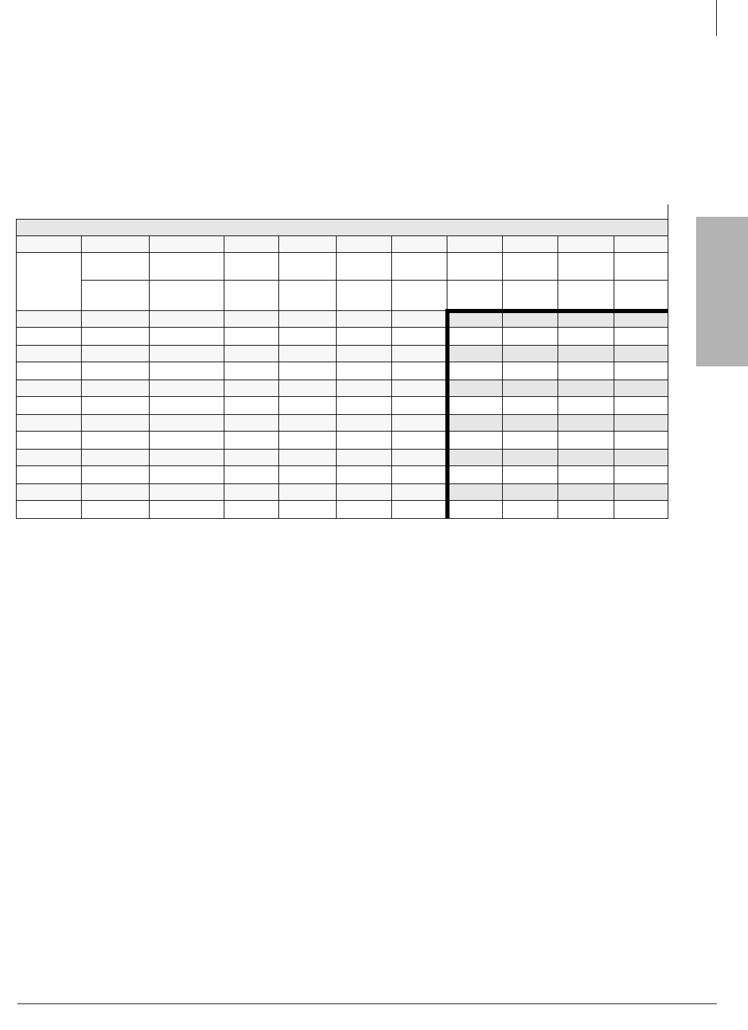
Strata CTX
Configuration
Strata CTX Configuration
Worksheet 6: Strata CTX670 Cabinet Slots
Strata CTX I&M 06/04 2-37
Worksheet 6: Strata CTX670 Cabinet Slots
The cabinet diagram below enables you to write in the PCBs installed in each cabinet slot. Use the
PCB placement guideline below to place PCBs in the correct slots. Fill in the PCBs that go into
each slot from the PCB quantities determined in the worksheets on the previous pages and the
information provided in this worksheet. After completing Worksheet 6, Worksheet 7 must be
completed to verify that the cabinet power factors do not exceed 85.
Notes
●B101/B102 – Main processor slots. AMDS, BEXS, BBMS, BSIS are optional subassembly PCBs (see “CTX100
Processor Optional Subassemblies” on page 2-3).
●Cabinet slots marked with * provide 8 time slots; all other slots provide 16 time slots.
●BIPU-M and BIPU-Q can be installed in slots with 16 time slots only. Slots that provide 8 time slots (marked with *) do
not support BIPU cards. BIPU PCBs can only be placed in 16 channel slots.
Important!
If a BIPU-M or BIPU-Q is installed RCOU1A, RCOS1A RDDU1A, RGLU1A, RGLU2A, and two-wire
REMU cards should not be installed to avoid excessive Echo Return Loss (ERL).
●Any combination of up to 96 (basic processor) or 264 (expanded processor) RPTU, BPTU and RDTU channels can be
installed in the CTX670.
●RDTU, BPTU and RPTU PCBs can only be placed in odd slots of the Base Cabinet and slots S_01, S_03, and S_05 in
any Expansion Cabinet. If 17 or more channels are used, the next highest slot adjacent to the RDTU, BPTU, or RPTU
slot
cannot
be used. Slots adjacent to 8 or 16 channel RDTU, BPTU or RPTU PCBs can be used.
●The maximum number of RDTU and/or RPTU cards is determined by the CTX system line capacity. Any number of line
interface cards (RDTU, RPTU, BPTU, RCOU/RCOS, REMU, RDDU, RGLU, BIPU-Q1A) can be installed, providing that
the quantity of lines and channels do not exceed the CTX system’s line capacity.
●If only 16 B channels of PRI are needed, another card can be installed in the next slot. The position of D-channels can
still be set to the 24th channel because the data of the D-channel is passed through the data highway, not the PCM
highway. The position of the D-channel doesn’t affect the installation of cards in the CTX.
●Network clock signals can only be derived from digital trunk PCBs, such as the RDTU and RPTU, that are installed in the Base
Cabinet (Master) location. Do not install these digital trunk cards into the Remote Cabinets.
●BDKU, PDKU, RDSU without Speaker OCA can be in any available slot in any cabinet. BDKU, PDKU, RDSU with
Speaker OCA can be in any available slots in the Base and S_01~S_06 in all Exp. Cabs.
●BDKU/BDKS or BWDKU without Speaker OCA can be in any available slots in the Base and S_01~S_06 in the
Expansion Cabs. It is recommended you not install Speaker OCA telephones on the BWDKU or BDKU/BDKS. If
you do, it must be in an odd slot and the next slot must be vacant.
●If the BWDKU is placed in slots 7~10, it must be set for 8 circuits with PCB jumper and in Program 100.
●Maximum 80 digital telephones per shelf due to the Power Factor restriction.
●For more details, see the following Placement Guidelines section.
Main Location _______________ Remote Location 1___ 2___ 3___ 4___ 5___ 6___
CTX Cabinet Slots
Base B101 B102 S101 S102 S103 S104 S105 S106 S107 S108
PCB Type
BEXU BCTU
(AMDS, BSIS)
BECU
(BEXS, BSIS)
BBCU
(BBMS)
Cab 2 S201 S202 S203 S204 S205 S206 S207*S208*S209*S210*
PCB Type
Cab 3 S301 S302 S303 S304 S305 S306 S307*S308*S309*S310*
PCB Type
Cab 4 S401 S402 S403 S404 S405 S406 S407*S408*S409*S410*
PCB Type
Cab 5 S501 S502 S503 S504 S505 S506 S507*S508*S509*S510*
PCB Type
Cab 6 S601 S602 S603 S604 S605 S606 S607*S608*S609*S610*
PCB Type
Cab 7 S701 S702 S703 S704 S705 S706 S707*S708*S709*S710*
PCB Type

Strata CTX Configuration
Worksheet 6: Strata CTX670 Cabinet Slots
2-38 Strata CTX I&M 06/04
PCB Placement Guidelines
Install the RRCU PCBs in the Base Cabinet first. Station, line and option PCBs can be mixed in
cabinets in any pattern. Do not skip slots except for vacant slots that provide RDTU, BPTU or
RPTU capacity. Also, do not skip slots except for vacant slots that provide for BBKU/BDKS with
Speaker OCA. Refer to Tables 2-54 and 2-55. Toshiba recommends placing the RDTU, BPTU or
RPTU, BWDKU and BDKU/BDKS PCBs first because they have special placement rules. Use the
following numbered sequence as a guide to installing the PCBs.
Important! When placing PCBs, do not install more than five BWDKU or BDKU/BDKS PCBs
in the same cabinet. Five BWDKU or BDKU/BDKS PCBs support 80 digital
telephones, which brings the cabinet power factor to 82.25. Adding more PCBs of
any type to a cabinet that has five BWDKU or BDKU/BDKS PCBs may cause the
cabinet to exceed its power factor (85 max.). See Worksheet 7.
Step 1: Processor PCBs
• BCTU (slot B102) or the older BECU (Slot B101)/ BBCU (slot B102), are required for system
operation.
• The BCTU will support up to two cabinets without the BEXU. With the BEXU, up to 7
cabinets are supported.
• The BECU/BBCU supports up to two cabinets without the BEXS/BBMS expansion
subassemblies. BEXS and BBMS subassembly PCBs are required for 3 to 7 cabinet systems.
• BSIS subassembly PCB is required for SMDR and/or SMDI or Toshiba Proprietary Voice Mail
RS-232 interface.
Note The BECU/BBCU and BCTU is licensed for 64 ports and four DTMF receivers from the
factory. If more capacity is required additional licenses must be uploaded to the processor.
See “Worksheet 9 – Software Licenses” on page 2-54.
Step 2: Remote Cabinet PCBs
• RRCU PCBs installed in the main location must be placed in Base Cabinet slots S102~S108 in
any order. Before installing other PCBs make sure there is a Base Cabinet slot available for
each RRCU PCB needed. An RRCU may occupy a vacant slot adjacent to RDTU, BPTU or
RPTU. An RRCU PCB in a remote location can support one or two remote cabinets and can be
installed in any slot of either cabinet.
The number of RRCU PCBs required in the Base and Remote Cabinet locations is shown in
Table 2-52:
Table 2-52 Main Processor PCB/ Remote Cabinet Configuration
RRCU PCBs
Needed in
Base Cabinet
Remote Cabinet Configuration RRCU PCBs Needed at
Remote Location (s)
1 1 or 2 Remote Cabinets in one location 1
22 to 4 Remote Cabinets in two locations or 3 to 4 Remote
cabinets in one location. 2
3 3 cabinets if cabinets are in separate remote locations. 3
4 4 cabinets if cabinets are in separate remote locations. 4
5 5 cabinets if cabinets are in separate remote locations. 5
6 6 cabinets if cabinets are in separate remote locations. 6
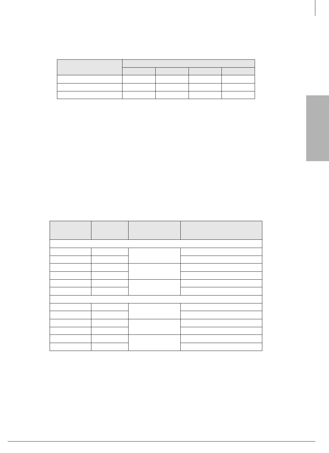
Strata CTX
Configuration
Strata CTX Configuration
Worksheet 6: Strata CTX670 Cabinet Slots
Strata CTX I&M 06/04 2-39
• Cables are provided according to the connectors on the RRCU card to which they are attached.
See Table 2-53 for connector information.
Step 3: BIOU Interface PCB
• Up to two BIOU PCBs can be installed in any local/remote cabinet slot, except the BIOU may
not occupy a vacant slot adjacent to RDTU, BPTU or RPTU. See “Worksheet 4: Page/MOH/
Control Relay” on page 2-26 for BIOU functions.
Step 4: T1 Digital Line PCBs
•See Worksheet 3: CO Line to determine RDTU PCB requirements.
• RDTU must be placed in designated slots as shown in Table 2-54. The RDTU PCB can provide
up to 16 or 24 T1 lines. The RDTU slot provides 16 T1 lines, an additional eight lines requires
that the cabinet slot adjacent to RDTU be vacant. Up to 11 RDTU PCBs can be installed in a
fully expanded system
Table 2-53 Remote Cabinet Data Cables and Connectors
Data Cables RRCU Connectors
M1 S1 M2 S2
BDCL1A-MS1 X X
BDCL1A-M2 X
BDCL1A-S2 X
X = Applies to connector.
Table 2-54 RDTU PCB Cabinet Slot Configuration
T1 Channels
Needed per
Cabinet
Slots
Needed
RDTU PCBs
Needed1
1. RDTU PCBs do not have to be installed in the order shown in this table. Example: If only one
RDTU is needed, it can be installed in any RDTU slot shown in the table so long as the slot is
supported by the installed processor.
RDTU cabinet slot placement1
Base Cabinet
1~16 1 1S103-RDTU
17~24 2 S104-vacant2
2. The slot occupied by RDTU supports 1-16 channels; the slot adjacent to RDTU must be vacant
if channels 17 through 24 are needed.
24~40 3 2S105-RDTU
41~48 4 S106-vacant2
49~64 5 3S107-RDTU
65~72 6 S108-vacant2
Second through seventh cabinets
1~16 1 1S_01- RDTU
17~24 2 S_02-vacant2
25~40 3 2S_03- RDTU
41~48 4 S_04-vacant2
49~64 5 3S_05-RDTU
65~72 6 S_06-vacant2
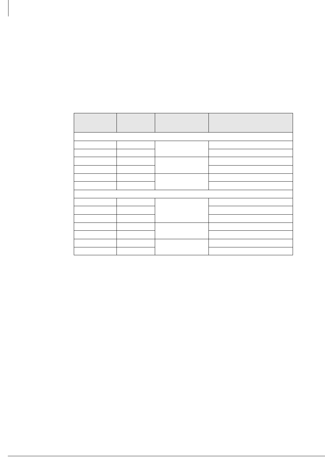
Strata CTX Configuration
Worksheet 6: Strata CTX670 Cabinet Slots
2-40 Strata CTX I&M 06/04
Step 5: ISDN PRI Digital Line PCBs
See Worksheet 3: CO Line to determine RDTU PCB requirements.
The BPTU or RPTU must be placed in designated slots as shown in Table 2-55. The BPTU or
RPTU PCB can provide up to 16 or 23 ISDN PRI lines. The BPTU or RPTU slot provides 16 PRI
lines, an additional seven lines requires that the cabinet slot adjacent to BPTU or RPTU be vacant.
Up to 11 RDTU PCBs can be installed in a fully expanded system.
Important! BPTU1 or RPTU2 is required for QSIG Networking.
Step 6: Digital and Standard Telephone Station PCBs and the Stratagy DK Voice Mail
PCB
•See Worksheet 2: Standard Telephone, Stratagy DK, IVP8 to determine station PCB
requirements.
• BDKU (+ optional BDKS), PDKU, ASTU, BSTU, RSTU, RDSU/RSTS and the Stratagy DK:
Each PCB or PCB combination requires one slot. Refer to the Notes under the cabinet diagram
in Worksheet 6: Strata CTX670 Cabinet Slots to determine into which slots these PCBs can be
installed. BDKU/BDKS, PDKU, ASTU, BSTU, RSTU and RDSU/RSTS PCBs cannot be
installed in slots left vacant for RDTU or BPTU or RPTU. Each PCB provides up to eight
circuits for the type of stations or Voice Mail ports it supports, except BDKU with BDKS
which provides 16 circuits for digital telephones.
Table 2-55 BPTU or RPTU PCB Cabinet Slot Configuration
PRI Lines
Needed per
Cabinet
Slots
Needed
BPTU or RPTU
PCBs Needed1
1. BPTU or RPTU PCBs do not have to be installed in the order shown in this table. Example: If
only one BPTU or RPTU is needed, it can be installed in any BPTU or RPTU slot shown in the
table so long as the slot is supported by the installed processor.
BPTU or RPTU cabinet slot
placement1
Base Cabinet
1~16 1 1S103 – BPTU or RPTU
17~23 2 S104-vacant2
2. The slot occupied by RPTU supports 1-16 channels; the slot adjacent to RPTU must be vacant
if channels 17 through 23 are needed.
24~39 3 2S105 – BPTU or RPTU
40~46 4 S106-vacant2
47~62 5 3S107 – BPTU or RPTU
63~69 6 S108-vacant2
Second through seventh cabinets
11~16 1 S_01 – BPTU or RPTU
17~23 2 S_02-vacant2
24~39 3 2S_03 – BPTU or RPTU
40~46 4 S_04-vacant2
47~62 5 3S_05 – BPTU or RPTU
63~69 6 S_06-vacant2

Strata CTX
Configuration
Strata CTX Configuration
Worksheet 6: Strata CTX670 Cabinet Slots
Strata CTX I&M 06/04 2-41
Step 7: ISDN BRI Digital Station PCBs
•See Worksheet 3: CO Line to determine BRI station PCB requirements.
• RBUU, RBUU with RBUS, RBSU, RBSU with RBSS: Each PCB or PCB combination
requires one slot. These PCBs can be installed in any slot, except a slot is left vacant to provide
capacity for RDTU, BPTU or RPTU as shown in Tables 2-54 and 2-55. Each single PCB
provides two BRI circuits and combination PCBs provide four BRI circuits, for the type of BRI
stations it supports. Each ISDN BRI station requires one BRI circuit.
Step 8: Analog and VoIP Tie Line PCBs
•See Worksheet 3: CO Line to determine Analog and BVPU line PCB requirements.
• RDDU, RCOU, RCOU with RCOS, RGLU, REMU, and BVPU: Each PCB or PCB
combination requires one slot. These PCBs can be installed in any slot, except a slot that is left
vacant to provide capacity for RDTU, BPTU or RPTU as shown in Tables 2-54 and 2-55. Each
PCB provides up to four circuits for the type of lines it supports, except RCOU with RCOS
which provides eight circuits.
Step 9: ISDN BRI Digital Line PCBs
•See Worksheet 3: CO Line to determine ISDN BRI line PCB requirements.
• RBUU, RBUU with RBUS, RBSU, RBSU with RBSS: Each PCB or PCB combination
requires one slot. These PCBs can be installed in any slot, except a slot that is left vacant to
provide capacity for RDTU, BPTU or RPTU as shown in Tables 2-54 and 2-55. Each single
PCB provides 2 BRI circuits (four lines) and combination PCBs provide four BRI circuits (8
lines), for the type of BRI Line it supports. Each ISDN BRI circuit provides two lines for the
Strata CTX system.
Step 10: Power Factor
• After the Cabinets are configured calculate the power factor of each cabinet using Worksheet 7
– System Power Factor Check.
Step 11: Check Systems Capacities
• Check systems capacities in Tables 2-3~2-7 to confirm the features to be used are within
limitations.
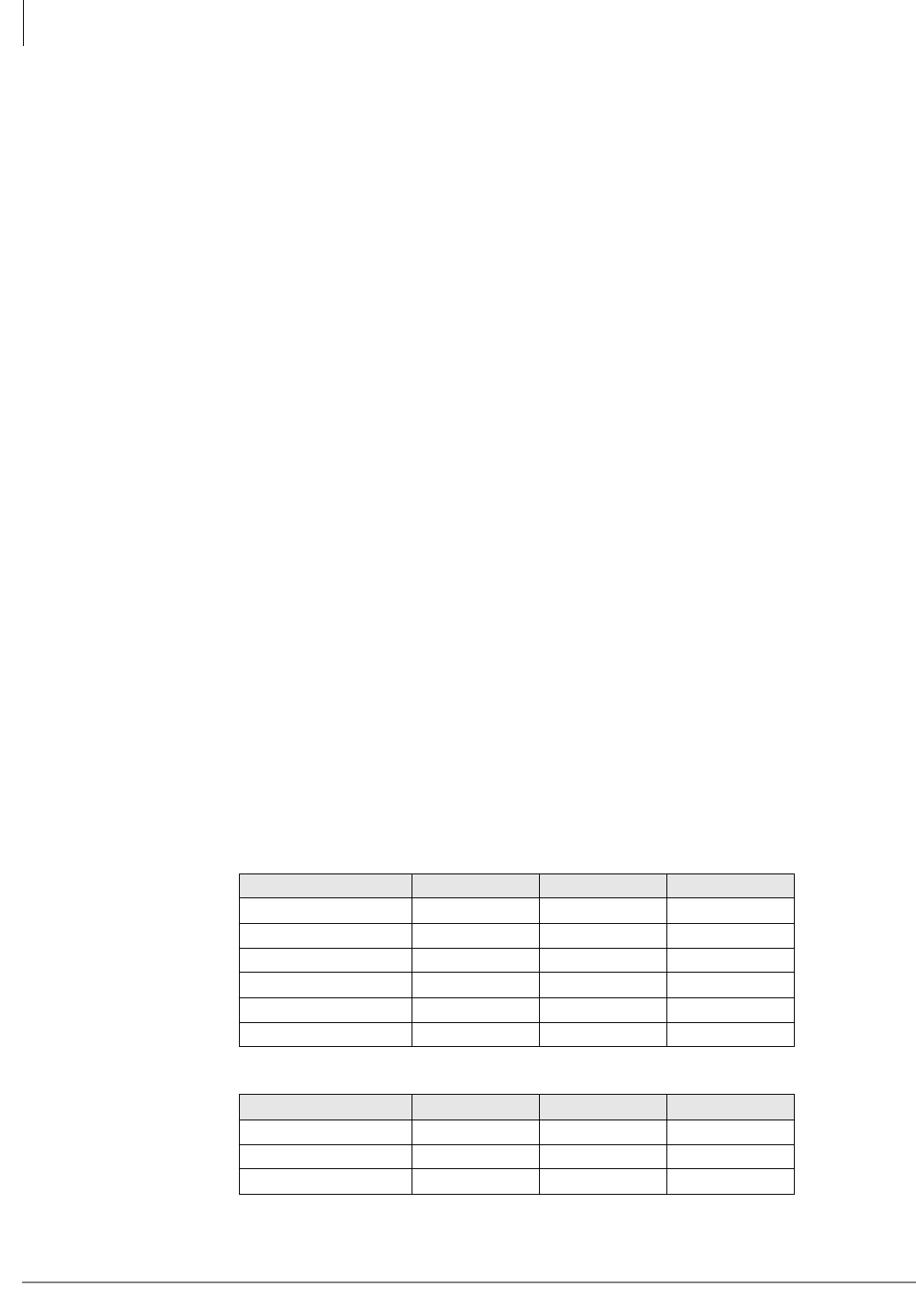
Strata CTX Configuration
Worksheet 7 – System Power Factor Check
2-42 Strata CTX I&M 06/04
Worksheet 7 – System Power Factor Check
The Strata CTX power supply was engineered for maximum cost efficiency to provide power for
the most configurations. Because of this design, there are some -24VDC power limitations for
telephone option hardware.
Each telephone/device and PCB has been assigned Power Factors (PFs) that reflect the amount of
power supply resources they consume. The Power Supply Unit has also been assigned Power
Factors that reflect how much power it can supply. To make sure the cabinet power supply is
operating within its limit, it is necessary to add up the PFs of each telephone/device and PCB
installed in each cabinet to verify that their total PFs do not exceed the Power Supply PF.
Use the worksheets on pages 2-44~2-45 to calculate that each cabinet’s PF is within limits.
Important!
Power Factor Considerations:
•The individual PCB and telephone power factors can be found on pages 2-43 and 2-44.
•The sum of all PCB and telephones –24VDC PFs in a given cabinet cannot exceed:
85 for CTX670
45 for CTX100
•The sum of all PCB +5VDC PFs in a given cabinet cannot exceed:
40 for CTX670
20 for CTX100
Telephones do not have +5VDC PFs.
•If a cabinet PF is exceeded it is necessary to reconfigure the cabinet to meet PF limits.
•If a cabinet’s Power Factor is exceeded, cabinet or connected peripherals may malfunction
during ringing or voice paging, whereas normal operation will occur for idle telephones.
•The Strata CTX100 and CTX670 power supplies provide a PF alarm LED and reset button. If
this LED is on, reset it with the reset button. Then recheck the cabinet PFs to make sure they
are within limits.
PCB Power Factor calculation examples are shown in Tables 2-56 and 2-57.
Table 2-56 Strata CTX Base Cabinet Example
PCB Quantity +5VDC PF -24VDC PF
PDKU 2 1.6 0.6
RBSU + RBSS 1 3.1 0.3
RCOU + RCOS 1 3.6 4.0
BBCU 1 4.5 2.0
BECU 1 4.5 2.0
Total 6 17.3 8.9
Table 2-57 Strata CTX Expansion Cabinet Example
PCB Quantity +5VDC PF -24VDC PF
RBSU + RBSS 1 3.1 0.3
RCOU + RCOS 1 3.6 4.0
Total 2 6.7 4.3
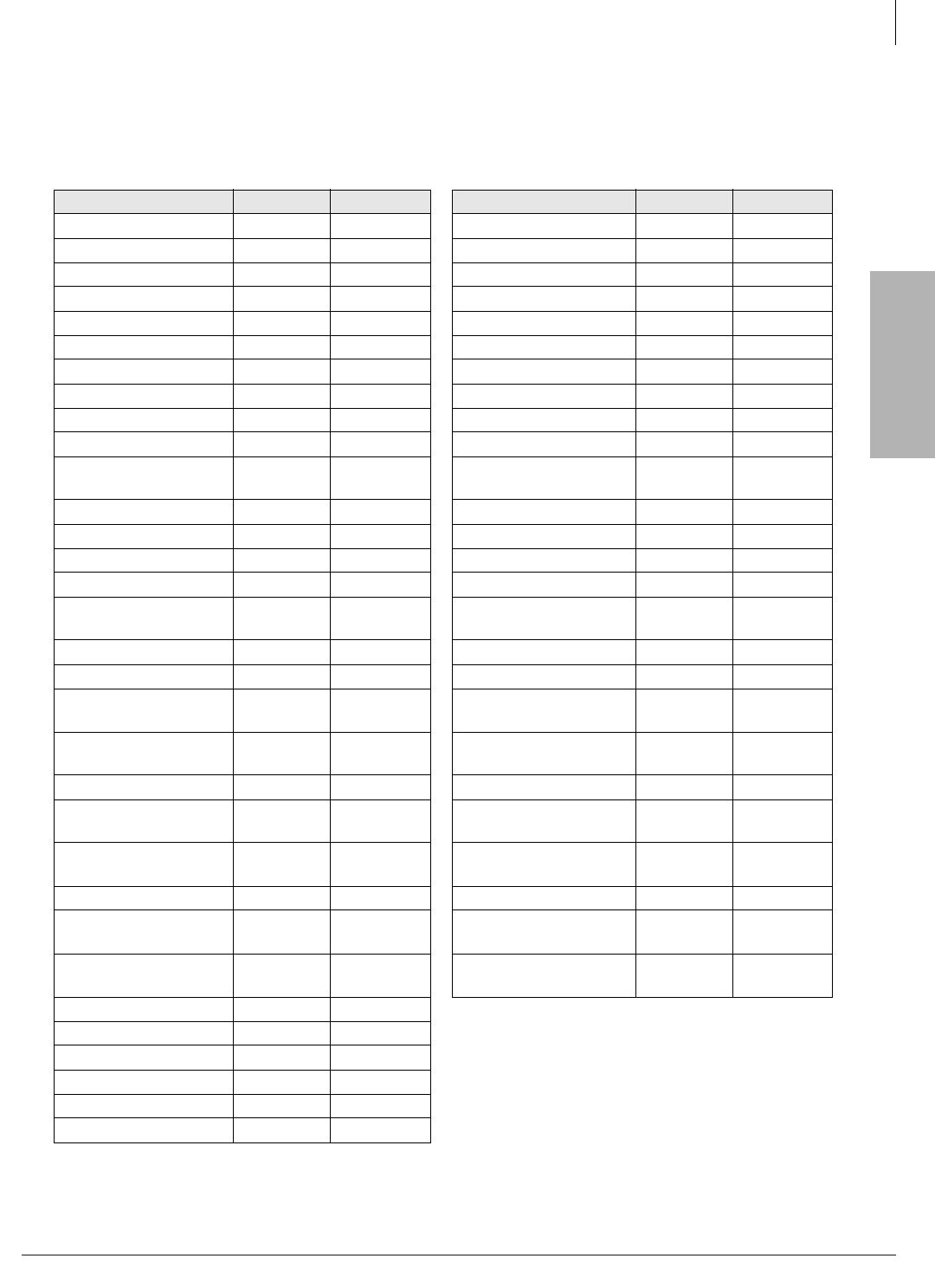
Strata CTX
Configuration
Strata CTX Configuration
Worksheet 7 – System Power Factor Check
Strata CTX I&M 06/04 2-43
Table 2-58 shows the individual PCB +5VDC and -24VDC power factors. -24VDC PF numbers
for telephones and devices are shown on page 2-44; telephones do not require +5VDC PF
considerations.
Table 2-58 PCB and Power Supply Power Factors
PCB Type +5VDC PF -24VDC PF PCB Type +5VDC PF -24VDC PF
ACTU1, 2 1.1 0.5 RCIS1 0.3 0.1
ADKU 0.8 0.3 RCIU1, 2 0.7 0.2
AETS 0.2 0.1 RCIU2 0.7 0.2
ARCS 0.0 0.0 RCMS1 0.6 0.3
AMDS 1.3 0.5 RCOS1, 2 1.7 2.0
ASTU 0.3 0.5 RCOU (4 CO) 2.5 2.0
BCTU 8.5 3.4 RCOU + RCOS (8 CO) 3.6 4.0
BEXU 4.0 1.6 RCOU1, 2 1.9 2.0
BBCU1 4.5 2.0 RDDU1 2.6 7.0
BECU1 4.5 2.0 RDSU1 (-24VDC) 1.1 0.3
BEXS1 2.0 1.0 RDSU1 + R48S1
(-48VDC) 1.1 0.5
BBMS1 0 0 RDTU1, 2 1.8 1.0
BDKU1 0.8 0.3 RDTU3 0.2 0.6
BDKS1 0.4 0.15 REMU2/PEMU1 1.0 7.5
BIOU1 1.5 6.6 RGLU1, 2 2.1 2.5
BIPU-M2A, BIPU-M1A/
BIPU-Q1A 0.1 3.0 RMCU1 0.7 0.3
BPTU1 2.3 0.7 RPTU1, 2 2.6 1.0
BSIS1 1.0 0.5 RSTU1, 2, 3 (-24VDC) 1.4 0.5
BSTU1 (-24VDC) 1.4 1.0 RSTU1+ R48S
(-48VDC) 1.4 1.0
BSTU1 + R48S (-
48VDC) 1.4 2.3 RSTU2, 3 + R48S
(-48VDC) 4.0 2.3
BVPU1‘ 0.0 3.5 RRCU1 0.0 4.0
BWDKU 0.8 0.3 Stratagy iES32,
32 circuits 014
PCOU1, 2 1.9 2.0 Stratagy iES32,
16-circuits 014
PDKU1, 2 0.8 0.3 Stratagy IVP8 4.0 2.3
R40S1 0.0 2.8 Power Supply
APSU112 (CTX100) (20.0) (45.0)
RBSS1 0.6 0.3 Power Supply
BPSU672 (CTX670) (40.0) (85.0)
RBSS2 0.0 0.3
RBSU + RBSS 3.1 0.3
RBSU1 2.5 1.0
RBSU2 0.0 1.0
RBUS1 0.0 0.3
RBUU1 0.0 1.0
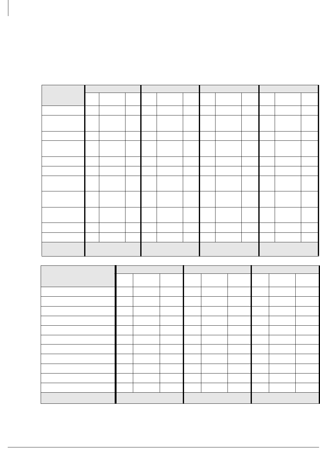
Strata CTX Configuration
Worksheet 7 – System Power Factor Check
2-44 Strata CTX I&M 06/04
Telephone/Device Power Factors
The power supply of each cabinet supplies a limited amount of power. Use the Worksheet below to
calculate the total Telephone/Device -24 VDC PF for each cabinet. Add it to the appropriate
cabinet in “Cabinet Power Factor Check” on page 2-45. Telephones do not have +5VDC PFs.
Note PF varies by number of telephones because of station paging limit of 32 telephones. Always
use “1.0” for DKT telephones when calculating PFs for individual cabinets.
Main Location _______________ Remote Location 1___ 2___ 3___ 4____ 5___ 6____
Telephone/
Device
Cabinet 1 (Base) Cabinet 2 (Exp.) Cabinet 3 (Exp.) Cabinet 4 (Exp.)
Qty. -24 VDC
PF Total Qty. -24 VDC
PF Total Qty. -24 VDC
PF Total Qty. -24 VDC
PF Total
DKT (any series) x 1.0 = x 1.0 = x 1.0 = x 1.0 =
DDCB (with
MDFB) x 1.2 = x 1.2 = x 1.2 = x 1.2 =
DDSS Console x 0.8 = x 0.8 = x 0.8 = x 0.8 =
Add-on Module
(DADM) x 0.4 = x 0.4 = x 0.4 = x 0.4 =
BATI x 0.7 = x 0.7 = x 0.7 = x 0.7 =
Integrated BPCI x 0.2 = x 0.2 = x 0.2 = x 0.2 =
Standard Phone
(-48VDC) x 1.0 = x 1.0 = x 1.0 = x 1.0 =
Standard Phone
(-24VDC) x 0.5 = x 0.5 = x 0.5 = x 0.5 =
Power Failure
Unit (DPFT) x 3.0 = x 3.0 = x 3.0 = x 3.0 =
HHEU or BHEU x 0.1 = x 0.1 = x 0.1 = x 0.1 =
BVSU or DVSU x 0.2 = x 0.2 = x 0.2 = x 0.2 =
Total Power
Factor (PF) Telephone PF ____ Telephone PF ____ Telephone PF ____ Telephone PF ____
Telephone/Device
Cabinet 5 (Exp.) Cabinet 6 (Exp.) Cabinet 7 (Exp.)
Qty. -24 VDC
PF Total Qty. -24 VDC
PF Total Qty. -24 VDC
PF Total
DKT (any series) x 1.0 = x 1.0 = x 1.0 =
DDCB (w.MDFB) x 1.2 = x 1.2 = x 1.2 =
DDSS Console x 0.8 = x 0.8 = x 0.8 =
Add-on Module x 0.4 = x 0.4 = x 0.4 =
BATI x 0.7 = x 0.7 = x 0.7 =
Integrated BPCI x 0.2 = x 0.2 = x 0.2 =
Standard Telephone (-48VDC) x 1.0 = x 1.0 = x 1.0 =
Standard Telephone (-24VDC) x 0.5 = x 0.5 = x 0.5 =
Power Failure Unit (DPFT) x 3.0 = x 3.0 = x 3.0 =
HHEU or BHEU x 0.1 = x 0.1 = x 0.1 =
BVSU or DVSU x 0.2 = x 0.2 = x 0.2 =
Total Power Factor (PF) Telephone PF ____ Telephone PF ____ Telephone PF ____
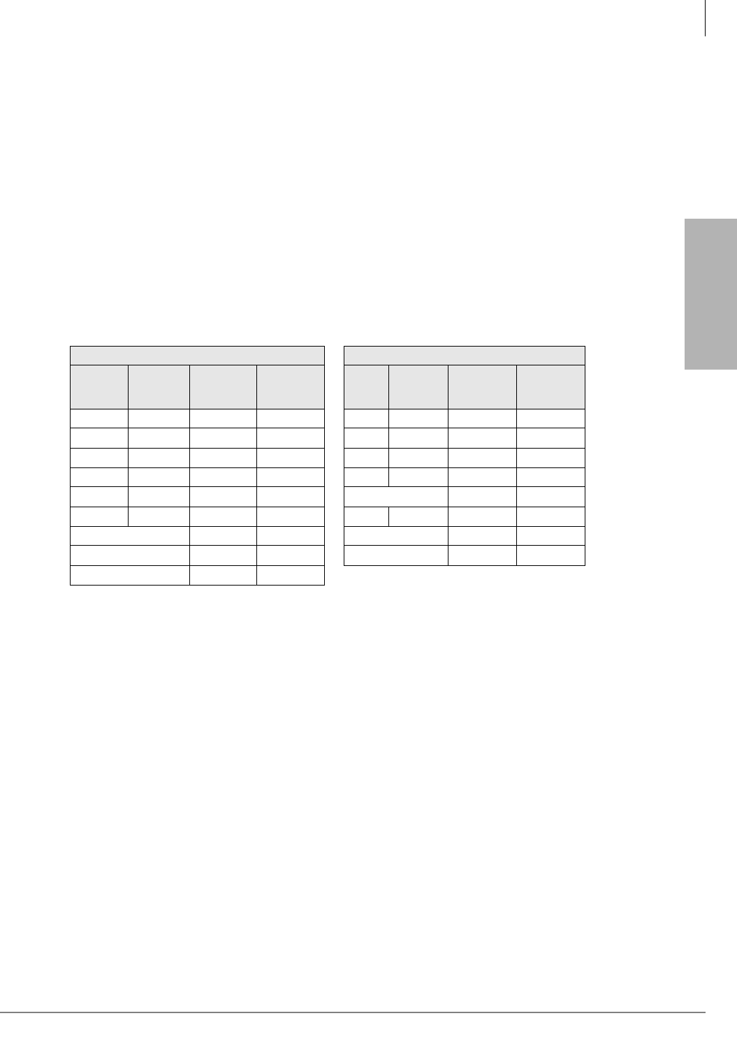
Strata CTX
Configuration
Strata CTX Configuration
Cabinet Power Factor Check
Strata CTX I&M 06/04 2-45
Cabinet Power Factor Check
1. Enter the PCB Type and PCB Power Factor for each cabinet slot (see Worksheets 5 and 7 for
PCB slot configuration).
2. Total the PCB PF for each cabinet.
3. Enter the Total Telephone PF for each cabinet (from the Telephone/Device Worksheet on the
previous page).
4. Make sure the Total Cabinet PFs do not exceed the limits noted below. If either PF exceeds its
limit, adjust the PCB/telephone placement to meet the PF requirement.
Note Total +5VDC PF of PCBs must be less than 20 for each CTX100 cabinet and 40 for each
CTX670 cabinet. Total -24VDC PF of PCBs and telephones must be less than 45 for each
CTX100 cabinet and 85 for each CTX670 cabinet.
CTX100
CTX100 Base Cabinet CTX100 Expansion Cabinet
Slot PCB
Type
PCB
+5VDC
PF
PCB
-24VDC
PF
Slot PCB
Type
PCB
+5VDC
PF
PCB
-24VDC
PF
ACTU ACTU 2.6 1.11
1. Power factor includes ACTU and all ACTU option PCBs.
S105
S101 S106
S102 S107
S103 S108
S104 Total PCB PF
S109 ASTU
Total PCB PF Total Phone PF
Total Phone PF Total Cabinet PF
Total Cabinet PF
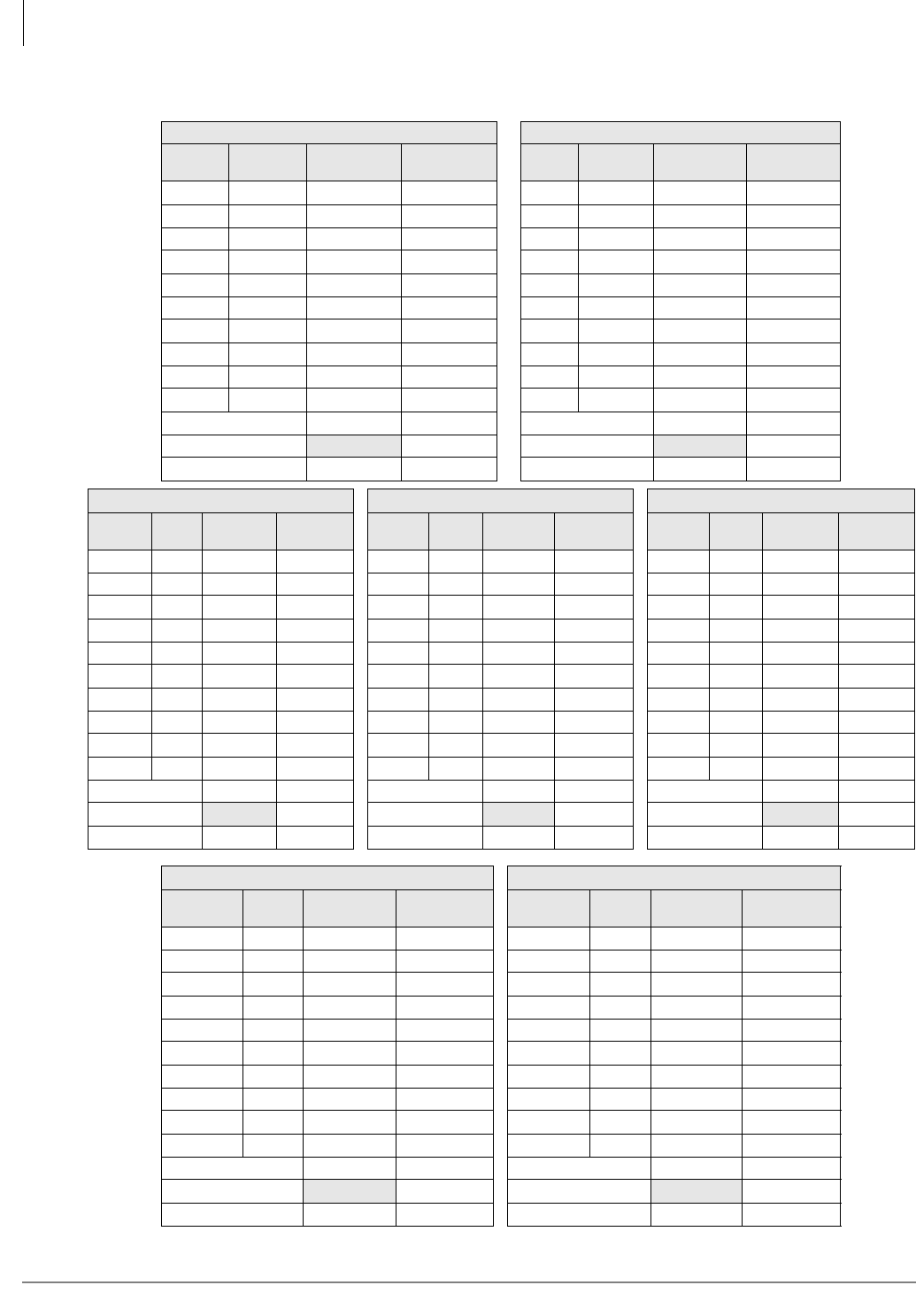
Strata CTX Configuration
Cabinet Power Factor Check
2-46 Strata CTX I&M 06/04
CTX670
CTX670 Cabinet 1 (base) CTX670 Cabinet 2
Slot PCB
Type
PCB
+5VDC PF
PCB
-24VDC PF Slot PCB
Type
PCB
+5VDC PF
PCB
-24VDC PF
B101 S201
B102 S202
S101 S203
S102 S204
S103 S205
S104 S206
S105 S207
S106 S208
S107 S209
S108 S210
Total PCB PF Total PCB PF
Total Phone PF Total Phone PF
Total Cabinet PF Total Cabinet PF
CTX670 Cabinet 3 CTX670 Cabinet 4 CTX670 Cabinet 5
Slot PCB
Type
PCB
+5VDC PF
PCB
-24VDC PF Slot PCB
Type
PCB
+5VDC PF
PCB
-24VDC PF Slot PCB
Type
PCB
+5VDC PF
PCB
-24VDC PF
S301 S401 S501
S302 S402 S502
S303 S403 S503
S304 S404 S504
S305 S405 S505
S306 S406 S506
S307 S407 S507
S308 S408 S508
S309 S409 S509
S310 S410 S510
Total PCB PF Total PCB PF Total PCB PF
Total Phone PF Total Phone PF Total Phone PF
Total Cabinet PF Total Cabinet PF Total Cabinet PF
CTX670 Cabinet 6 CTX670 Cabinet 7
Slot PCB
Type
PCB
+5VDC PF
PCB
-24VDC PF Slot PCB
Type
PCB
+5VDC PF
PCB
-24VDC PF
S601 S701
S602 S702
S603 S703
S604 S704
S605 S705
S606 S706
S607 S707
S608 S708
S609 S709
S610 S710
Total PCB PF Total PCB PF
Total Phone PF Total Phone PF
Total Cabinet PF Total Cabinet PF
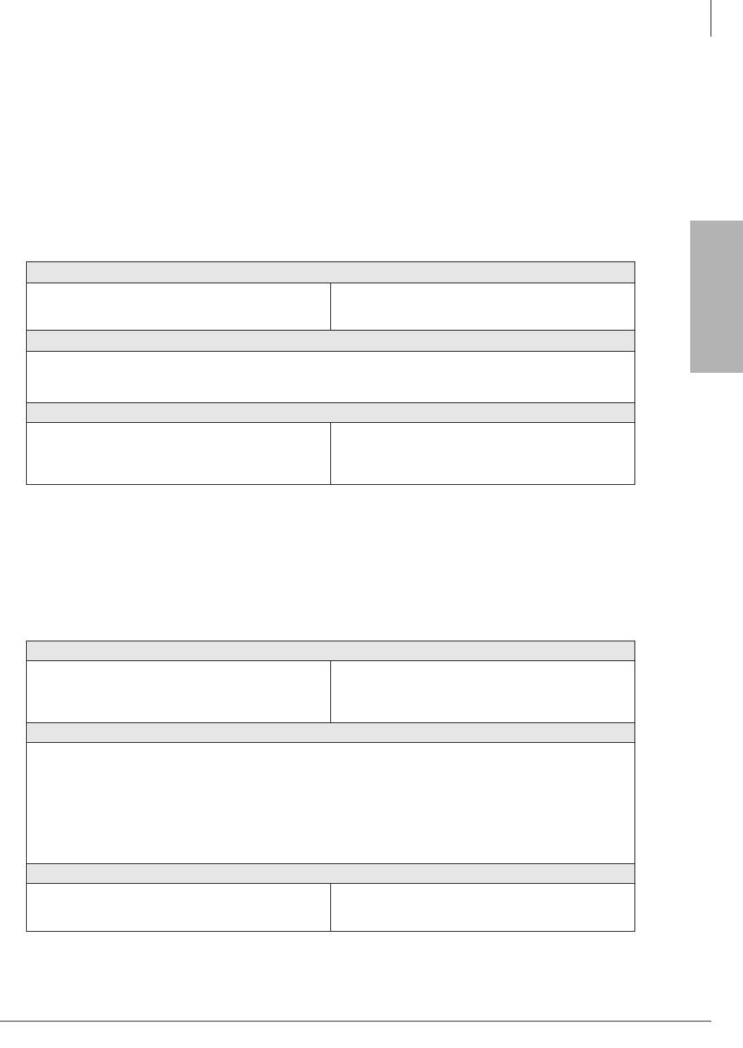
Strata CTX
Configuration
Strata CTX Configuration
Worksheet 8 – CTX Primary AC and Reserve Power
Strata CTX I&M 06/04 2-47
Worksheet 8 – CTX Primary AC and Reserve
Power
CTX100 AC Power Considerations
The power supply in each Strata CTX100 Base and Expansion Cabinet furnishes power to all of
the stations and some of the interface peripherals (see Table 2-59). The primary AC power for each
cabinet is 120VAC.
CTX670 AC Power Considerations
The power supply in each Strata CTX670 Base and Expansion Cabinet furnishes power to all of
the stations and some of the interface peripherals (see Table 2-60). The primary AC power can be
120VAC, 208VAC or 240VAC. Systems containing six or seven cabinets require 208VAC or
240VAC.
Table 2-59 Strata CTX100 Electrical Characteristics
Strata CTX100 Primary AC Power Voltage
Input AC
AC Frequency
Watts per cabinet (maximum)
120VAC
60 Hz, Single-phase (48Hz~62Hz)
100 watts (maximum)
Strata CTX100 Primary Power Current Consumption (Rating in Amperes)
120VAC
1 cabinet
2 cabinets
1.8 amps
3.6 amps
Power Supply Unit (APSU112A)
DC voltage output specification
-24VDC (-26.3~-27.8VDC, 3.2 DC amps)
+5VDC (+4.5~5.5VDC, 2.0 DC amps)
-5VDC (-4.5~-5.5VDC, 0.2 DC amps)
+3.3VDC (+3.0~3.6VDC, 0.5 DC amps
Table 2-60 Strata CTX670 Electrical Characteristics
Strata CTX670 Primary AC Power Voltage
Input AC
AC Frequency
Watts per cabinet (continuous)
Watts for five cabinet system
115±10VAC or 208±20VAC or 240±20VAC
50/60 Hz, Single-phase (48~62Hz)
180
900
Strata CTX670 Primary Power Current Consumption (Rating in Amperes)
120VAC 208VAC 240VAC
1 cabinet
2 cabinets
3 cabinets
4 cabinets
5 cabinets
6 cabinets
7 cabinets
3.2 amps
6.4 amps
9.6 amps
12.8 amps
16.0 amps
N/A
N/A
2.2 amps
4.4 amps
6.6 amps
8.8 amps
11.0 amps
13.2 amps
15.4 amps
2.0 amps
4.0 amps
6.0 amps
8.0 amps
10.0 amps
12.0 amps
14.0 amps
Power Supply Unit (BPSU672)
DC voltage output specification
-24VDC (-26.3~-27.8VDC, 6.0 DC amps)
+5VDC (+4.5~5.5VDC, 4.0 DC amps)
-5VDC (-4.5~-5.5VDC, 0.8 DC amps)
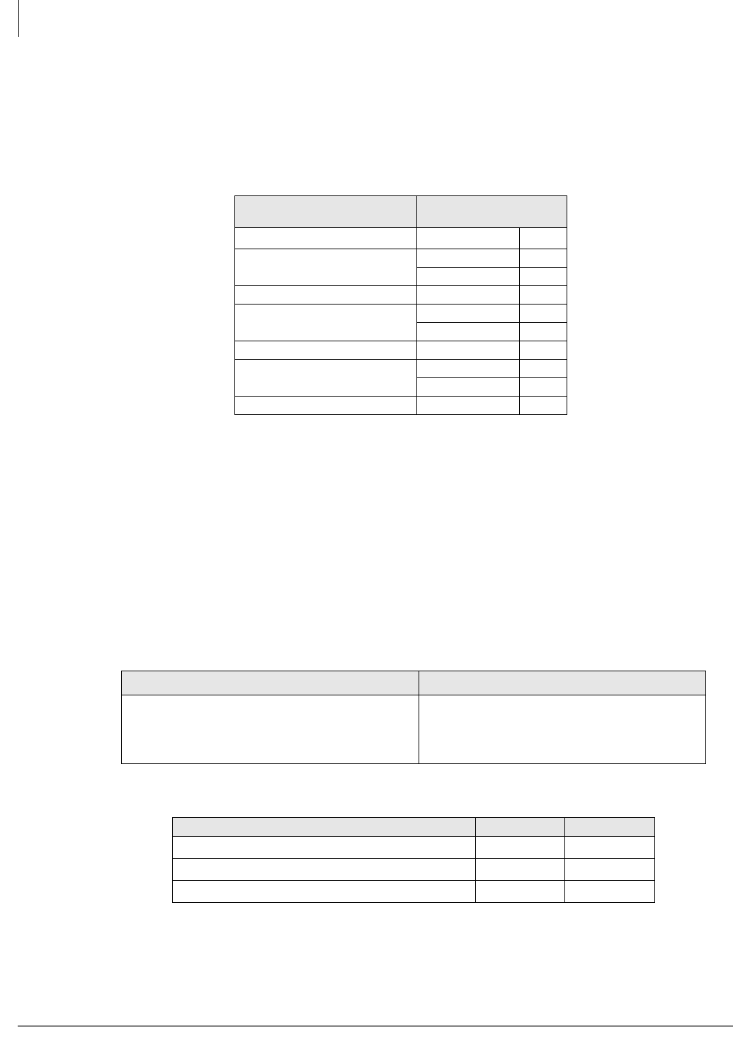
Strata CTX Configuration
Reserve Power (CTX100 and CTX670)
2-48 Strata CTX I&M 06/04
Determine CTX670 system miscellaneous power components in the following worksheet. (See
Tables 2-63 and 2-66 for component descriptions.) These components are not used on CTX100
systems.
Enter the number of cabinet power components needed:
Reserve Power (CTX100 and CTX670)
Two or four customer-supplied 12VDC reserve batteries (80 ampere-hours max.) can be connected
to either system to maintain normal operation during a power failure (see Tables 2-61~2-64). The
batteries are kept in a highly-charged state by the power supply’s battery charger and must be
connected when the system is operating normally. Fully charged batteries must be connected when
normal AC power is available, batteries cannot be connected after/during an actual power failure.
The battery changer is standard on the CTX670 power supply. An optional ABCS battery changer
must be used in the CTX100 power supply.
Main Location ____________ Remote Location 1___ 2___ 3___ 4____5___ 6____
CTX670 Cabinet Power
Components
Enter the Number
Required
Spare Power Supply BPSU672
AC Power Strips RPSB2
BPSB240
208/240VAC Power Supply Cord BACL240
Battery Cables PBTC-3M
BBTC1A-2.0M
Battery DIstribution Box BBDB
Conduit Box BCCB120
BCCB240
Floor Mount Stand BFIF
Table 2-61 CTX100 Reserve Power Characteristics
Battery Charger Characteristics Maximum Battery Charger Drain (-24VDC)
Charger: current limiting
Nominal float voltage: 2.275 volts/cell
Charge current: 280mA amps maximum
Battery discharge cut-off voltage: 20.5 ±0.5VDC
Base Cabinet
Base + Expansion Cabinets
3.15 amps
6.30 amps
Table 2-62 CTX100 Typical Reserve Power Duration Estimates1
1. Assumes 80 ampere-hours with 12VDC batteries.
Number of Cabinets 1 2
Estimated operation time Two-battery configuration 25 hr. 12.5 hr.
Estimated operation time Four-battery configuration 50 hr. 25 hr.
DC Current Drain (-24VDC) 3.15 amps. 6.30 amps.
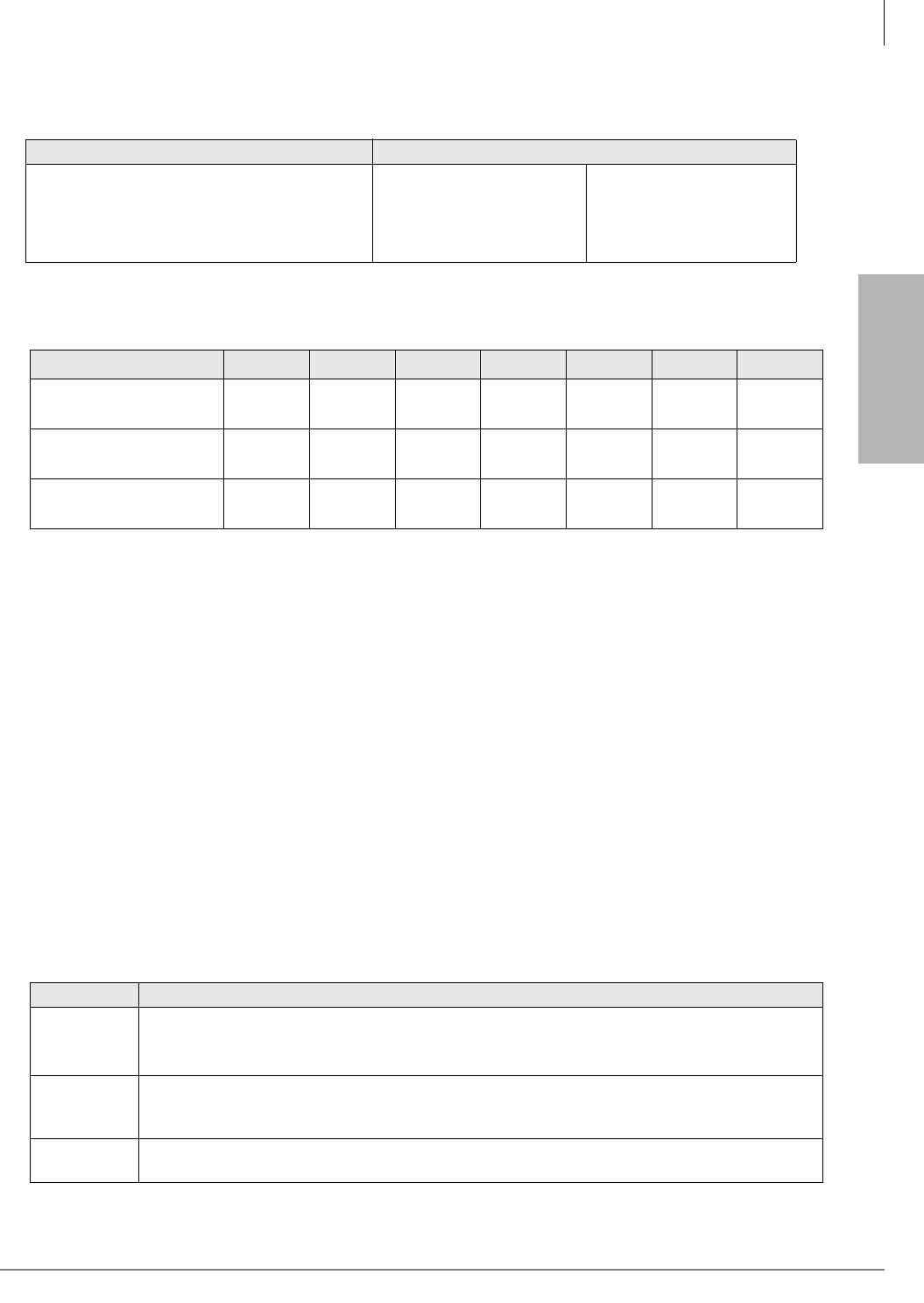
Strata CTX
Configuration
Strata CTX Configuration
Primary/Reserve Power Cabinet Hardware
Strata CTX I&M 06/04 2-49
Primary/Reserve Power Cabinet Hardware
The type of cabinet mounting can have an effect the power requirements. There are two types of
mounting for the CTX100 and CTX670 (listed below).
•Cabinet Wall Mounting – The lightweight and compact design of CTX100 and CTX670
enables easy wall mounting. Wall Mounting requires no special hardware.
•Cabinet Floor Mounting – Only the CTX670 can be floor mounted (requires the BFIF
hardware kit). If floor mounting three or more cabinets, AC and reserve power must be
connected to the BCCB conduit connection box option by a licensed electrician. If more than
two cabinets require reserve power batteries, the BBDB must be installed.
Underwriters’ Laboratory (UL) and local electrical codes require certain standards for connecting
commercial AC and reserve power to the Strata CTX system. Tables 2-63 and 2-66 describe which
assemblies may be required to meet UL and local electrical code standards.
The power distribution hardware for the CTX100 is shown in Table 2-65.
Table 2-63 CTX670 Reserve Power Characteristics
Battery Charger Characteristics Maximum Battery Charger Drain (-24VDC)
Charger: current limiting
Nominal float voltage: 2.275 volts/cell
Charge current: 0.7 amps maximum
Battery discharge cut-off voltage: 20.5 ±0.5VDC
1 cabinet
2 cabinets
3 cabinets
4 cabinets
6.0 amps
12.0 amps
18.0 amps
24.0 amps
5 cabinets
6 cabinets
7 cabinets
30.0 amps
36.0 amps
42.0 amps
Table 2-64 CTX670 Typical Reserve Power Duration Estimates1
1. Assumes 80 ampere-hours with 12VDC batteries.
Number of Cabinets 1234567
Estimated operation time
Two-battery configuration 12.0 hr. 6.0 hr. 4.0 hr. 3.0 hr. 2.5 hr. 2.0 hr. 1.8 hr.
Estimated operation time
Four-battery configuration 24.0 hr. 12.0 hr. 8.0 hr. 6.0 hr. 5.0 hr. 4.0 hr. 3.5 hr.
DC Current Drain
(-24VDC)
4.6
amps.
8.7
amps.
12.8
amps.
16.9
amps.
21.0
amps.
25.1
amps.
29.2
amps.
Table 2-65 CTX100 Cabinet Power Distribution Hardware
Option Description
APSU112
Strata CTX100 cabinet power supply is supplied with each cabinet. Operates with 120VAC as
the system’s primary power source and requires 1.8 amps AC per cabinet.
The power supply AC cord is 5 ft. long with a standard three prong plug.
ABTC-3M
A three-meter long battery cable is used to connect reserve power batteries to the ABCS battery
charger when the system has less than three cabinets. One reserve power cable is required for
each cabinet.
ABCS Option battery charger that is installed on the APSU112 power supply. One per cabinet is
required with the ABTC-3M if connecting reserve power batteries to the CTX100.

Strata CTX Configuration
Primary/Reserve Power Cabinet Hardware
2-50 Strata CTX I&M 06/04
Table 2-66 CTX670 Power Cabinet Hardware
Option Description
BPSU672
Strata CTX670 cabinet power supply must be ordered for each cabinet. Operates with 120VAC,
208VAC, or 240VAC connected as the system’s primary AC power source. It automatically
detects and adjusts to the type of primary AC power that is connected. The power supply is
included with each cabinet ordered but must be installed in the field.
Standard 9 ft. AC power cords with AC120VAC/15A plugs are provided with Strata CTX Base or
Expansion cabinets. When AC208V or AC240V power is used, a special AC cord, BACL240, is
required for each cabinet power supply and must be ordered separately.
RPSB2
Cabinet power strip for 120VAC primary power – provides three standard 120VAC/15A outlets
(NEMA5-15R) and nine ft. AC power cord with standard 120VAC/15A plug (NEMA5-15P). This
unit is field installed inside system cabinet side panels. The system can use 12 amps. (max.).
One RPSB2 is required for two cabinet systems if the local electric code allows only one AC
power cord to be connected to the system.
If the local electric code allows only one AC power cord to be connected to the system, 208VAC
or 240VAC must be used as primary AC power for systems with four or more cabinets.
One RPSB2 is required for a three or four cabinet system if the local electric code allows two AC
power cords connected to the system.
Two RPSB2s are required for a five cabinet system if the local electric code allows two AC
power cords connected to the system.
BPSB240
Cabinet power strip for 208VAC or 240VAC primary power - provides three 240VAC/20A outlets
(NEMA 6-20R) and 9ft. AC power cord with a standard 240VAC/20A plug (NEMA 6-20P). This
unit is field installed inside system cabinet side panels. The system can use 16 amps. (max.).
One BPSB240 is required for two or three cabinet systems.
Two BPSB240s are required for four or five cabinet systems.
Local electric codes allow only one AC power cord to be connected to the system when using
208VAC or 240VAC as the primary AC power.
BPSB240 conforms to the National Electric Code standards. If using 208VAC as primary power,
the plug on the BPSB240 AC power cord that exits the cabinet (NEMA 6-20P) may have to be
changed to a twist-lock type by a certified electrician to conform with local electric codes.
BACL240
AC208V or AC240VAC nine ft. power supply cord. The cord is rated at 10 amps. (max.) and
must be used when the system is powered by 208VAC or 240VAC. One cord is required for
each cabinet power supply and must be ordered separately only if using 208VAC or 240VAC as
the system primary AC power.
The cord is equipped with a 250VAC/20A plug (NEMA 6-20P) which is standard for 240VAC. If
using 208VAC as the system primary power this cord may have to be changed by a certified
electrician for one or two cabinet installations. If using three or more cabinets, a BPSB240
power strip is required and the power strip plug may have to be changed by a certified
electrician depending on local electric codes.
PBTC-3M
A three-meter long battery cable is used to connect reserve power batteries to the system
power supply when the system has less than three cabinets. One reserve power cable is
required for each cabinet in a one or two cabinet system (wall or floor mount). The cable
connects the Strata CTX670 cabinet power supply directly to the battery terminals (a BBDB is
not required).

Strata CTX
Configuration
Strata CTX Configuration
Primary/Reserve Power Cabinet Hardware
Strata CTX I&M 06/04 2-51
BBDB
Strata CTX reserve power battery distribution box is required when connecting reserve power
batteries to three or more cabinets (wall or floor mount). The box is field installed into one of the
Strata CTX cabinet side panels.
The BBDB provides seven BBTC2A-2.0M, battery distribution cables to connect reserve power
from the BDDB box to each individual cabinet power supply.
One or two BBTC1A-2.0M must be ordered separately when using the BBDB battery
distribution box.
BBTC1A-
2.0M
A two-meter battery cable used to connect reserve power batteries to the BBDB battery
distribution box. One reserve power cable is required in a three or four cabinet system and two
cables are required for five, six or seven cabinet systems (wall or floor mount). The cable
connects Strata CTX BBDB box directly to the battery terminals.
BCCB120
or
BCCB240
Strata CTX conduit connection box is installed in the bottom cabinet, side panel. It is used to
hardwire Primary AC power and reserve battery power connections through conduit. These
boxes are required by UL for three or more floor mounted cabinets. Conduit boxes are not
required for wall mounted systems with any number of cabinets or floor mounted system with
one or two cabinets. They can be used as an option on any system.
The BCCB120 is required when connecting AC120VAC as the primary power source and the
BCCB240 is required when connecting AC208VAC or AC240VAC as the primary power source.
BCCB conduit boxes must be field installed by a certified electrician.
BFIF
Floor mount fixture kit is required when floor mounting Strata CTX cabinets.
Provides two metal stands for mounting any number of Strata CTX cabinets on the floor. Three
pairs or wall brackets (RWBF) are supplied with BFIF to use when mounting three or more
Strata CTX cabinets on floor. The wall brackets are needed to secure floor-mounted systems to
the wall for safety purposes.
Table 2-66 CTX670 Power Cabinet Hardware
(continued)
Option Description
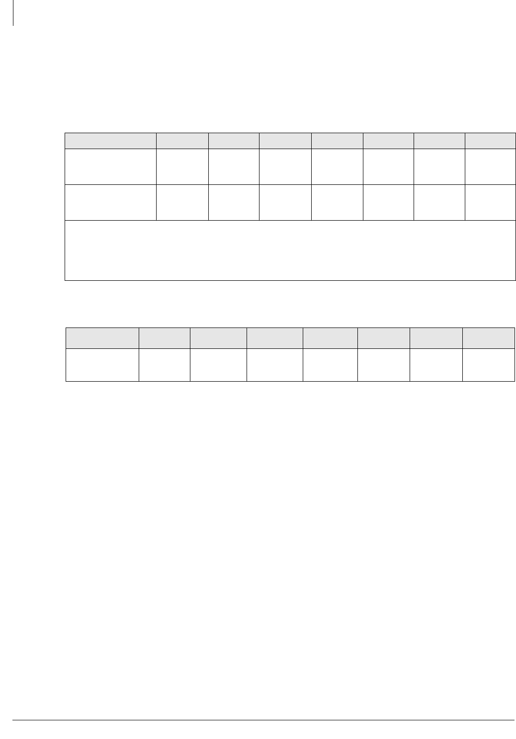
Strata CTX Configuration
Primary/Reserve Power Cabinet Hardware
2-52 Strata CTX I&M 06/04
CTX670 Cabinet AC Power Component Requirements for Wall
Mounted Systems
Tables 2-67 and 2-68 show the cabinet parts required to distribute AC power for various
configurations of the Strata CTX cabinets.
Important! The plugs and wall receptacles required by the local electrical code might differ for
208VAC and 240VAC. Thus in some areas of the U.S., the plug used on the Toshiba
240VAC power strip and 240VAC power supply cord (NEMA code 6-20P) can not
be used for 208VAC installations. In this case, when using 208VAC, the AC plugs on
the BPSB240 power strip cord that connects directly to the 208VAC wall outlet must
be changed by a certified electrician per the local electrical code.
Table 2-67 Wall Mount Cabinet Power Component Requirements for 120VAC Primary Power
Local Electrical Code 1 Cabinet 2 Cabinets 3 Cabinets 4 Cabinets 5 Cabinets 6 Cabinets 7 Cabinets
Allows only one
120VAC power cord
from system
0 RPSB2 1 RPSB2 1 RPSB2 N/A N/A N/A N/A
Allows two 120VAC
power cords from
system
0 RPSB2 0 RPSB2 1 RPSB2 1 RPSB2 2 RPSB2 N/A N/A
●One dedicated, isolated, 20 amp. AC circuit breaker with dual outlets is required.
●N/A= If the system contains more than three cabinets and if the local code allows only one AC cord, the
system requires a BCCB120 conduit box wired by a certified electrician when using 120VAC as primary
power. Otherwise, 208VAC or 240VAC should be used as the primary power source (see cabinet power
options listed below). If more than five cabinets are installed, 208VAC or 240VAC is required.
Table 2-68 Wall Mount Cabinet Power Component Requirements for 208VAC or
240VAC Primary Power
Local Electrical
Code 1 Cabinet 2 Cabinets 3 Cabinets 4 Cabinets 5 Cabinets 6 Cabinets 7 Cabinets
Allows One AC
power cord from
system
1 BACL240 1 BPSB240
2 BACL240
1 BPSB240
3 BACL240
2 BPSB240
4 BACL240
2 BPSB240
5 BACL240
3 BPSB240
6 BACL240
3 BPSB240
7 BACL240
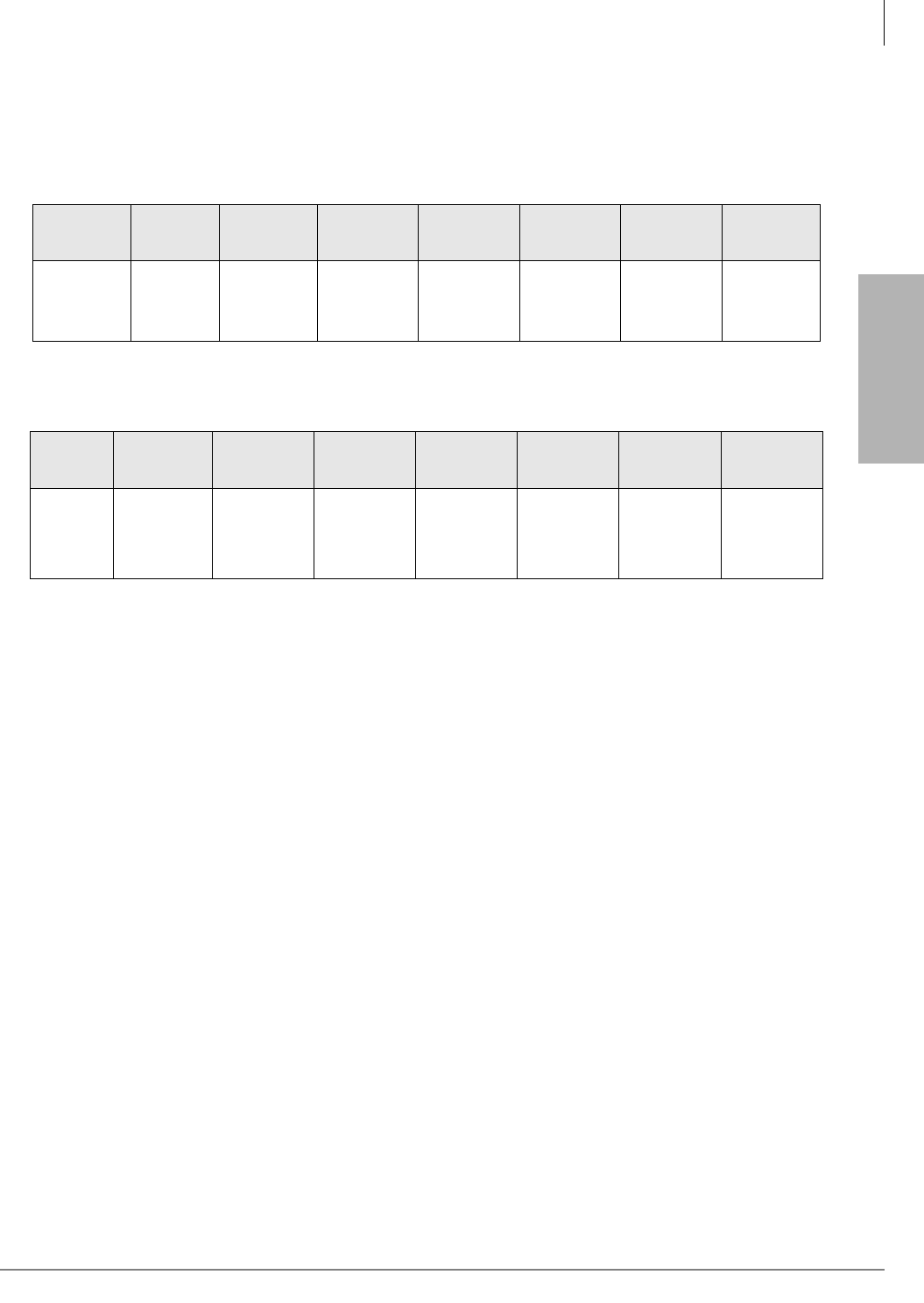
Strata CTX
Configuration
Strata CTX Configuration
Primary/Reserve Power Cabinet Hardware
Strata CTX I&M 06/04 2-53
Cabinet AC Power Component Installation
After the cabinets have been floor mounted, the AC power components should be installed Tables
2-69 and 2-70 show the primary AC power components required for floor mounted systems.
Table 2-69 Floor Mount Cabinet Component Requirements for 120VAC Primary Power
Local
Electrical
Code
1 Cabinet 2 Cabinets 3 Cabinets 4 Cabinets 5 Cabinets 6 Cabinets 7 Cabinets
3 or more
cabinets
require a
conduit box
1 – BFIF 1 – BFIF 1 -BCCB1201
1 – BFIF
1 – BCCB1201
1 – RPSB2
1 – BFIF
1. A BCCB120 conduit connection box must be installed and wired by a certified electrician per the local electrical code.
1 – BCCB1201
2 – RPSB2
1 – BFIF
1 – BCCB1201
2 – RPSB2
1 – BFIF
N/A
Table 2-70 Floor Mount Cabinet Component Requirements for 208VAC or 240VAC Primary Power
Local
Electrical
Code
1 Cabinet 2 Cabinets 3 Cabinets 4 Cabinets 5 Cabinets 6 Cabinets 7 Cabinets
3 or more
cabinets
require a
conduit box
1 – BACL240
1 – BFIF
1 – BCCB2401
2 – BACL240
1 – BFIF
1. A BCCB240 conduit connection box must be installed and wired by a certified electrician per the local electrical code.
1 – BCCB2401
1 – BPSB240
3 – BACL240
1 – BFIF
1 – BCCB2401
1 – BPSB240
4 – BACL240
1 – BFIF
1 – BCCB2401
2 – BPSB240
5 – BACL240
1 – BFIF
1 – BCCB2401
2 – BPSB240
6 – BACL240
1 – BFIF
1 – BCCB2401
3 – BPSB240
7 – BACL240
1 – BFIF

Strata CTX Configuration
Worksheet 9 – Software Licenses
2-54 Strata CTX I&M 06/04
Worksheet 9 – Software Licenses
Enter the quantity of software license(s) required for your hardware configuration using the
following worksheet.
Part Number Strata CTX
Software Licenses Comments Qty
LIC100-4 PORTS 4-port Line/Station License
for CTX100.
Required for every 4 ports used for trunks or
stations beyond the 32 ports bundled with the
CTX100 processor (maximum total of 112 ports).
LIC670-4 PORTS 4-port Line/Station License
for CTX670.
Required for every 4 ports used for trunks or
stations beyond the 64 ports bundled with the
CTX670 processor (maximum total of 672 ports).
LIC100-4 DTMF
4-port DTMF Receiver
License for CTX100 Ports
5~16 and above.
Required for activation of 4 DTMF receiver ports
number 5 and above on CTX100 system.
Maximum 16 DTMF receiver ports per system.
ARCS required.
LIC670-4 DTMF
4-port DTMF Receiver
License for CTX670 Ports
9~32 and above.
Required for activation of 4 DTMF receiver ports
– number 5 and above on CTX670 system.
Maximum 32 DTMF receiver ports per system.
LIC100-SER PORT
BSIS RS-232 serial port
interface for SMDI or
Toshiba Proprietary Voice
Mail (VM) interface, Call
Accounting SMDR and
future applications.
One circuit does not require a license, but circuits
2~4 each require one LIC100-SER PORT
license.
LIC670-SER PORT
BSIS RS-232 serial port
interface for SMDI or
Toshiba Proprietary VM
interface, Call Accounting
SMDR and future
applications.
One circuit does not require a license, but circuits
2~4 each require one LIC670-SER PORT
license.
LIC100-QSIG NET
Strata Net QSIG
Networking Application
License.
One required per system to network multiple
CTX100 systems using Strata Net QSIG
networking features.
LIC670-QSIG NET
Strata Net QSIG
Networking Application
License.
One required per system to network multiple
CTX670 systems using Strata Net QSIG
networking features.
LIC SOFTDKT-1 Toshiba SoftDKTTM
Licensing on the CTX will allow the concurrent
connection of as many clients as you want,
provided that each client has a license).
SOFTDKT-LIC-PKG SoftDKT license and
CD-ROM
The license and CD-ROM can be purchased as a
bundle.
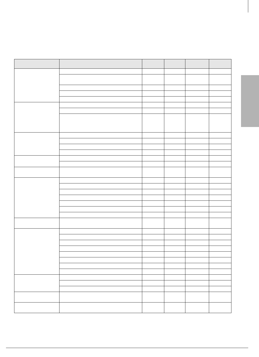
Strata CTX
Configuration
Strata CTX Configuration
Hardware Compatibility
Strata CTX I&M 06/04 2-55
Hardware Compatibility
PCB compatibility for the Strata DK424, DK424i, CTX100 and CTX670 systems is shown in
Table 2-71.4.
Table 2-71 Hardware Compatibility
Category Unit Name DK280 &
DK424 DK424i CTX100 CTX670
Processor Card
BCTU/BEXU NC NC NC X
BECU/BBCU with optional BBMS, BEXS,
BSIS NC NC1NC X
B_CAU/B_CBU cards for DK424i NC X NC NC
RCTU cards for DK424 X NC NC NC
ACTU1, 2A-S and subassemblies NC NC X NC
DTMF Receiver Unit
BRCS-4/8/12 X X NC NC
RRCS-4/8/12 X NC NC NC
ARCS (16) NC NC
Used for
ACTU1.
Built-in
ACTU2.
16/32
Built-in
Optional Interface
Unit
BIOU NC NC X X
BSIS NC NC X X
PIOU, PIOUS, RSIU, RSIS X X NC NC
RSSU X X NC NC
Standard
Telephone Interface
BSTU, RSTU3, RDSU/RSTS X X X X
ASTU (R1.3 and higher) NC NC X NC
Electronic
Telephone Interface PEKU, PESU X X NC NC
Digital Telephone
Interface
ADKU NC NC X NC
BDKU X X X X
BWDKU1A X2XX X
BDKS NC NC X X
BPCI NC NC X X
PDKU2 (DKT2000-series phones only) X X X X
RDSU, RSTS (DKT2000-series only) X X X X
IP Telephone
Interface BIPU-M2A, BIPU-M1A3NC NC X X
CO Line Interface
BVPU X X X X
RCIU/RCIS X X X X
RCMU/RCMS X X X X
RCOU/RCOS4XX X X
RDDU X X X X
RDTU2, 3 X X X X
REMU X X X X
RGLU2, RGLU3 X X X X
ISDN Interface
RBSU/RBSS X2XX X
RBUU/RBUS X2XX X
BPTU1, RPTU2, RPTU X5XXX
6
Remote Expansion
Cabinet Interface RRCU X X NC X
Strata Net over IP-
QSIG Interface BIPU-Q1A3NC NC X X4

Strata CTX Configuration
Hardware Compatibility
2-56 Strata CTX I&M 06/04
Stations and
Terminal
Equipment
EKT2000, EKT6000, EKT6500, HDSS,
HDCB X X NC NC
Existing Proprietary Attendant Console X X NC NC
DK424 PC Attendant X X NC NC
Strata CTX PC Attendant Console, BATI NC NC X X
RPCI (RS-232C) - Data or TAPI X X NC NC
Stations and
Terminal
Equipment
BPCI (RS-232C) - Data or Voice Record TAPI NC NC X X
DKT10007XX X X
DKT2000 X X X X
DKT3000 X8X8XX
IPT1020-SD NC NC X X
Ethernet LAN AETS NC NC
Used for
ACTU1.
Built-in
ACTU2.
Built-in
V.34 Admin Modem AMDS NC NC X Built-in
Base Cabinet
DKSUB424 or DKSUB280 X NC NC NC
CHSUB672 NC X NC X
CHSUB112 NC NC X NC
Expansion Cabinet
DKSUE424 X NC NC NC
CHSUE672 NC X NC X
CHSUE112 NC NC X NC
Data Cable for Strata DK424 Expansion
Cabinet XNCNCNC
Data Cable for CTX670 Expansion Cabinet NC X NC X
Data Cable for CTX100 Expansion Cabinet NC NC X NC
Power Supply Unit
RPSU424 (120VAC) X NC NC NC
BPSU672 (120VAC/208VAC/240VAC power
supply) NC X NC X
APSU112 (120VAC) NC NC X NC
Conduit
Connection Box
RCCB2 X NC NC NC
BCCB120 (120V box) NC X NC X
BCCB240 (240V box) NC X NC X
Battery Distribution
Box
RBDB2 X NC NC NC
BBDB1 (new Battery Dist. Box, 7 BBTC2A-
2.0M) XXNCX
Power Strip
RPSB1 (120VAC power strip) X NC NC NC
RPSB2 (120VAC power strip) X X NC X
BPSB240 (240VAC power strip) NC NC NC X
Battery Cable
PBTC-3M X X NC X
BBTC1A-2.0M NC X NC X
ABTC-3M NC NC X NC
Battery Charger ABCS1 Built-in Built-in X Built-in
X = Compatible NC = Not Compatible
1. If the BCTU, BEXU or BECU/BBCU replaces the DK424i processors, then the system is upgraded to a CTX670.
2. Jumper plugs on the BWDKU1A determine 8 or 16 DKT circuits and CTX or DK compatibility.
3. If a BIPU-M or BIPU-Q is installed RCOU1A, RCOS1A RDDU1A, RGLU1A, RGLU2A, and two-wire REMU cards should not
be installed to avoid excessive Echo Return Loss (ERL).
4. The RCOS1A cannot be installed on the RCOU3A. The RCOS3 can be installed on the RCOU1A.
5. Requires Release 4.x software.
6. BPTU1, RPTU2, or BIPU-Q1A is required for QSIG Networking.
7. DKT1000-series telephones do not support continuous DTMF tones.
8. Functions as a DKT2000.
Table 2-71 Hardware Compatibility
(continued)
Category Unit Name DK280 &
DK424 DK424i CTX100 CTX670

Strata CTX I&M 06/04 3-1
Strata CTX100-S/
CTX100 Installation
Strata CTX100-S/CTX100 Installation 3
This chapter explains how to install the Strata CTX100-S/CTX100 systems. It includes
information on site requirements, wiring diagrams, and step-by-step instructions on how to install
the unit(s), the ground wiring, AC power cabling, reserve power (battery backup) cabling, and
PCB cabling.
Inspection
1. When the system is received, examine all packages carefully and note any visible damage. If
any damage is found, do not open the packages. Contact the delivery carrier immediately and
make the proper claims.
2. After unpacking (and before installing), check the system against the packing list and inspect
all equipment for damage. If equipment is missing or damaged, contact your supplier
immediately.
3. Be sure to retain original packaging materials for re-use when storing or transporting system
hardware.
Packaging and Storage
CAUTION! When handling (installing, removing, examining) PCBs, do not touch the
back (soldered) side or edge connector. Always hold the PCB by its edges.
³When packaging and storing the system, remove PCBs from the system cabinet (the power
supply may remain installed in the cabinet for storage and shipment). PCBs should be
packaged in their original antistatic bags for protection against electrostatic discharge. Be sure
to package equipment in its original shipping containers.
Site Requirements
This section defines the installation site requirements necessary to ensure a proper operating
environment for the CTX100. Also included are grounding requirements.
Input Power
The Base Cabinet or the Base and Expansion Cabinet together require an input power source of
120VAC, 60 Hz, 15 amps. Each cabinet plugs into an AC power outlet. Each cabinet requires 1.8
amps AC from the power source or 3.6 amps AC combined. The power supply cord for each
cabinet is 4.5 ft. long with a standard three-prong 120VAC plug.

Strata CTX100-S/CTX100 Installation
Site Requirements
3-2 Strata CTX I&M 06/04
The AC outlet is recommended to be dedicated and unswitched, with a solid third-wire ground.
(See “AC Power and Grounding Requirements” on page 3-4.) This eliminates interference from
branch circuit motor noise or the like, and to prevent accidental power-off. To avoid accidental
power turn-off, Toshiba recommends that you do not use an On/Off wall switch on this dedicated
AC circuit.
For the Strata CTX100, a reserve power source (two or four customer-supplied 12VDC batteries)
may be connected to the system to serve as a power failure backup.
Cabinet Size and Weight
The wall that will support the CTX100 should be able to support 35 lbs. The weight of each
cabinet is shown in Table 2-1 on page 2-2.
Clearance and Location
The minimum clearance requirements for the Strata CTX100 Base and Expansion cabinets are
shown in Figure 3-1.
Consider the following conditions when selecting a location for the Cabinet(s):
The location must be:
• Dry and clean
• Well ventilated
• Well illuminated
• Easily accessible
The location must not be:
• Subject to extreme heat or cold
• Subject to corrosive fumes, dust, or other airborne contaminants
• Subject to excessive vibration
• Next to television, radio, office automation, or high frequency equipment
If reserve power is to be installed for the Strata CTX100, the batteries will require a well-
ventilated location close (within nine feet) to the CTX100 (the optional Toshiba-supplied battery
cable is nine feet in length).
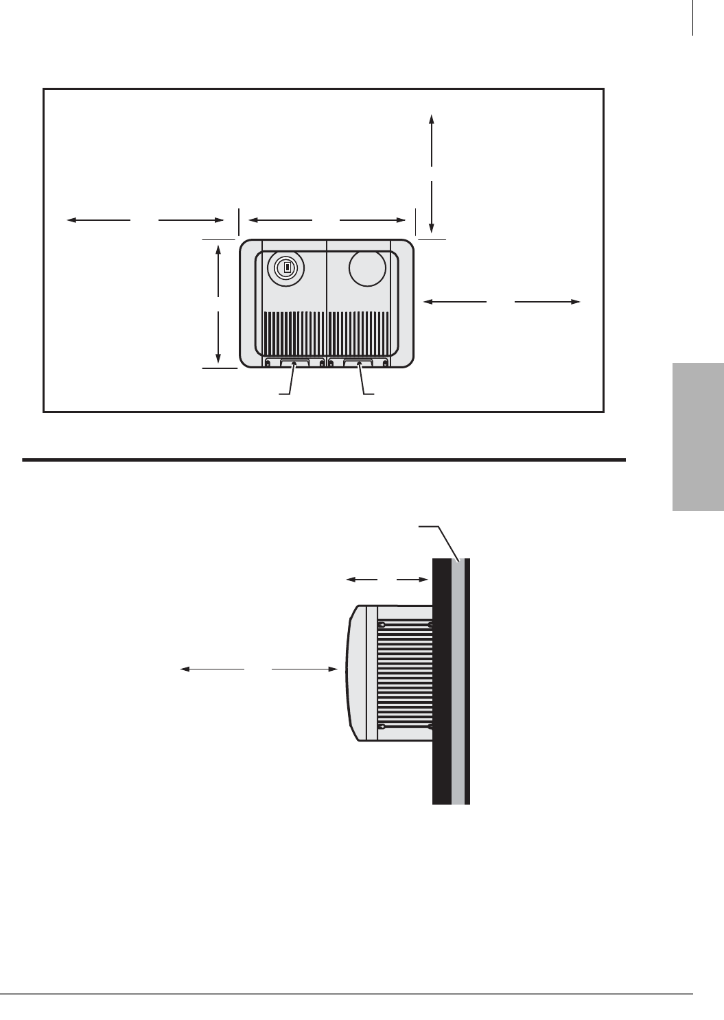
Strata CTX100-S/CTX100 Installation
Site Requirements
Strata CTX I&M 06/04 3-3
Strata CTX100-S/
CTX100 Installation
Front View
Base Cabinet Exp Cabinet
Side View
36''
Wall
5910
10"
19.9"
24"
36"
24"
14.5"
15.1"
Figure 3-1 CTX100 Base Cabinets and Expansion Clearance Requirements
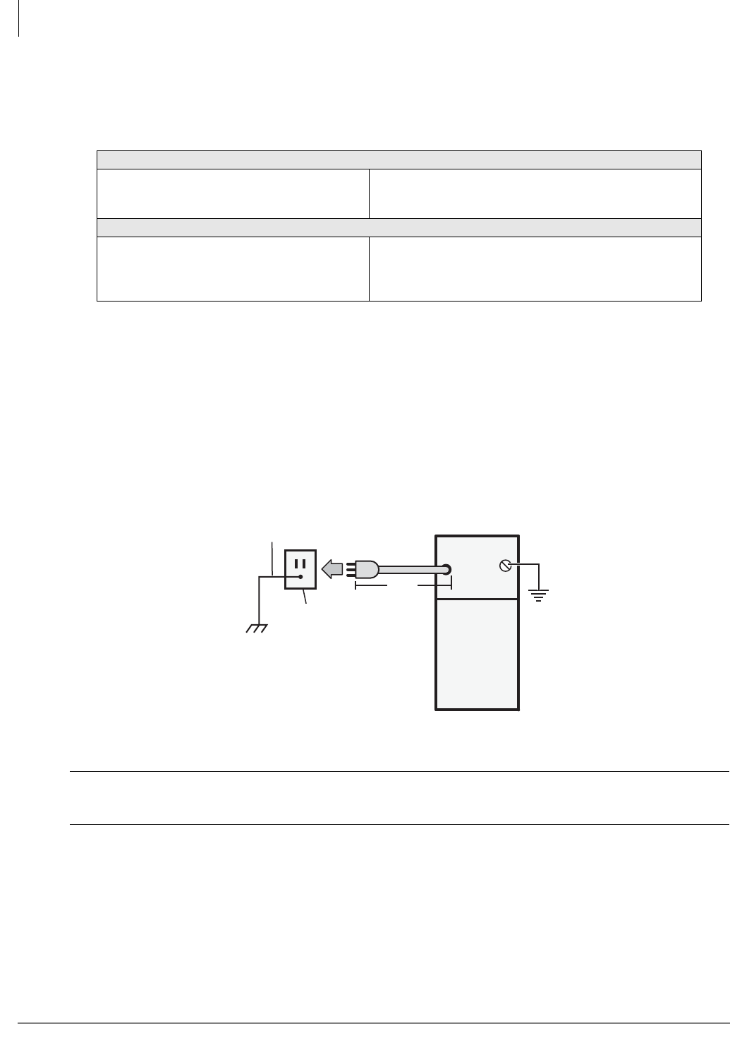
Strata CTX100-S/CTX100 Installation
AC Power and Grounding Requirements
3-4 Strata CTX I&M 06/04
Environmental Considerations
Table 3-1 provides a summary of the environmental characteristics.
AC Power and Grounding Requirements
The CTX100 requires a solid earth ground for proper operation. The five ft. AC power cord
contains a conductor for the “third-wire ground” provided by the commercial power outlet. The
third-wire ground should be the only ground necessary for each CTX100 cabinet; this ground must
originate at the building’s main power distribution panel and have a solid connection to earth
ground. (See Figure 3-2.)
CAUTION! Lack of proper ground may cause improper operation and, in extreme cases,
system failure.
An inter-cabinet ground wire connecting the Base and Expansion cabinets is not necessary.
Power Considerations
The power supply in each Strata CTX100 Base and Expansion Cabinet furnishes power to all of
the PCBs and stations and some of the interface peripherals. The primary AC power for each
cabinet is 120VAC (see Table 2-59 on page 2-47).
Table 3-1 CTX100 Environmental Characteristics
Environmental Specifications
Operating temperature
Operating humidity
Storage temperature
32~104° F (0~40° C)
20~80% relative humidity without condensation
-4~140° F (-20~60° C)
BTU Rating (Base plus Expansion Cabinet)
ACTU (installed)
BDKU (5 installed)
RCOU/RCOS (1 installed)
Digital Telephones (40 installed)
190 Watts (56 watt hours for both cabinets)
Power
Supply
Third Wire
AC Ground
Third Wire Ground
from AC Power Cord
CTX 100 Base Cabinet
A
Electrical Building
Ground (Main Power
Distribution Box)
Alternate Ground
AC Voltage
120VAC
AC Current
1.8 amps max.
5911
4' 5"
Figure 3-2 CTX100 Grounding Diagram

Strata CTX100-S/CTX100 Installation
AC Power and Grounding Requirements
Strata CTX I&M 06/04 3-5
Strata CTX100-S/
CTX100 Installation
AC Power and Third-wire Ground Test
Test the “third-wire ground” for continuity by either measuring the resistance between the third
prong terminal (earth ground) and a metal cold water pipe (maximum: 1 ohm), or by using a
commercially available earth ground indicator. If neither procedure is possible, perform the
following earth ground test procedure.
³To perform the earth ground test procedure
1. Obtain a suitable voltmeter, and set it for a possible reading of up to 250VAC.
2. Connect the meter probes between the two main AC voltage terminals (white and black wires)
on the wall outlet. The reading obtained should be between 100~125VAC.
3. Move one of the meter probes to the third terminal (green wire ground). Either the same
reading or a reading of zero volts should be obtained.
4. If the reading is zero volts, leave one probe on the ground terminal and move the other probe to
the second voltage terminal.
CAUTION! If a reading of zero volts is obtained on both voltage terminals (white wire to
green wire, black wire to green wire), the outlet is not properly grounded.
Omit Steps 5 and 6, and see following CAUTION!
5. If a reading of zero volts on one terminal, and a reading of 100~125VAC on the other terminal
is obtained, remove both probes from the outlet.
6. Set the meter to the “OHMS/Rx1” scale. Place one probe on the ground terminal, and the other
probe on the terminal that produced a reading of zero volts. The reading should be less than 1
ohm.
CAUTION! If the reading is more than one ohm, then the outlet is not adequately
grounded. If the above tests show the outlet AC voltage is not in range or is
not properly grounded, the condition should be corrected (per Article 250 of
the National Electrical Code) by a qualified electrician before the system is
connected.
Alternate or Additional Ground
If the “third-wire” AC ground can not practically be improved or if extreme motor noise or other
disturbance causes system malfunction, or if local area lightning storms exist, a separate direct
ground may be warranted.
Connect an alternate earth ground from a cold water pipe or earth grounding rod directly to the
screw terminal on the CTX100 power supply (see Figure 3-2).
WARNING! Hazardous voltages that may cause death or injury are exposed during the
following test. Use great care when working with AC power line voltage.
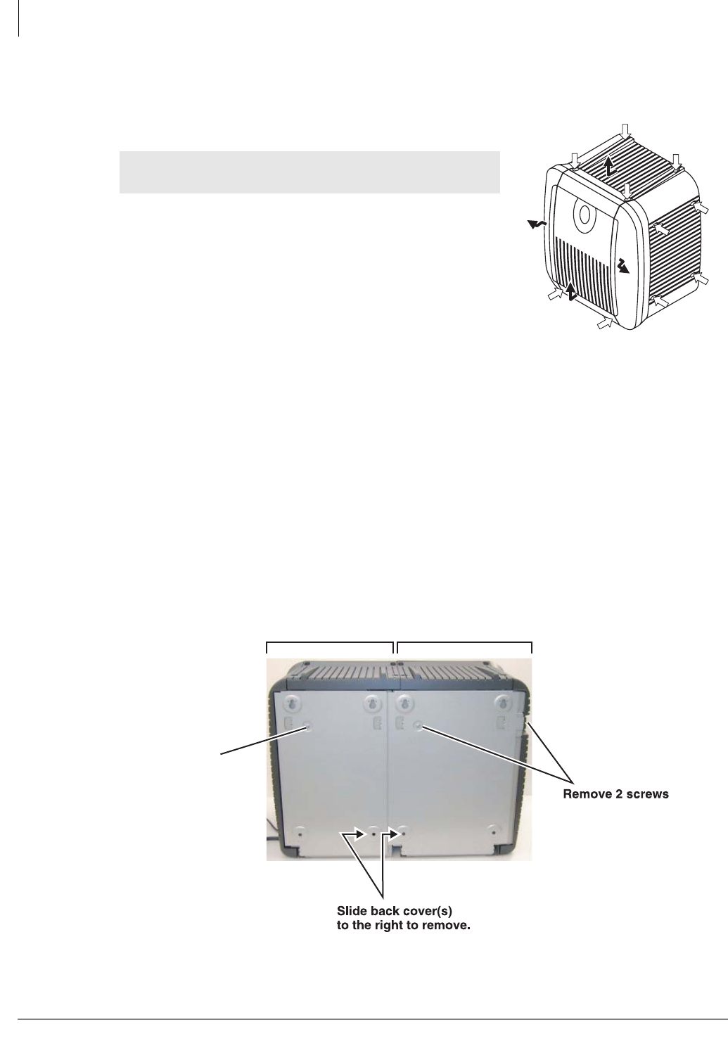
Strata CTX100-S/CTX100 Installation
Installing the CTX100 Cabinet
3-6 Strata CTX I&M 06/04
Installing the CTX100 Cabinet
Step 1: Remove Cabinet Covers
1. Loosen the screws from the front cover to remove it.
2. Loosen the four screws from the top cover and slide it off.
3. Loosen the four screws from each side cover and pull the
covers forward to remove them.
Step 10: Remove the Back Cover from the Cabinet(s)
1. Remove and save the two screws from the back of the Base Unit.
2. Slide the metal cover about a half inch to the right (it will drop down and forward) to remove it.
3. If you are installing an Expansion Cabinet, remove one screw from the back of the Expansion
Cabinet. Slide the metal cover to the right to remove it.
Note The figure below show the position of the screws. Back covers should be removed before
the Base and Expansion cabinets are attached to each other.
Figure 3-4 Base and Expansion Cabinet Back Covers
WARNING! Ensure the power supply AC plug is not
plugged into the AC outlet.
6074
Figure 3-3 Cabinet Cover
Removal
Remove 1 screw
EXPANSION BASE
5933

Strata CTX100-S/CTX100 Installation
Installing the CTX100 Cabinet
Strata CTX I&M 06/04 3-7
Strata CTX100-S/
CTX100 Installation
Step 11: Check the Base/Expansion Power Supply Jumper
Plug
The APSU112A power supply is used in both CTX100 cabinets.
³Check that the “BASE/EXP.” jumper plug is connected to the proper power supply connector
as shown in Figure 3-14. The power supply has two connectors: one is labeled “BASE” and
the other “EXP.”
• If the power supply is mounted in the CTX100 Base Cabinet, the “BASE/EXP.” jumper
plug must be plugged into the “BASE” connector.
• If the power supply is mounted in the CTX100 Expansion cabinet, the jumper plug must be
plugged into the “EXP.” connector.
Step 12: Mount the Base Cabinet
1. Make sure the location of the Base Cabinet meets the minimum clearance requirements
specified in Figure 3-1 on page 3-3.
Note The Base Cabinet AC power cord is four feet, five inches long.
2. Attach a 1/2” thick plywood back board to the wall where the CTX100 will be installed. Secure
the back board to the wall with screws attached to the wall studs, shown in Figure 3-5.
3. Place the Base Cabinet back cover at the desired location on the back board using a level and
mark the location of the four screw holes (there is one on each corner).
4. Drill holes on these marks.
5. Secure the top two screws approximately two thirds of the way into the top two holes on the
back board.
6. Hang the Base Cabinet back cover from the top two screws and then secure the top and bottom
screws completely into the back board. The base back cover should now be tightly secured to
the back board. See Figure 3-5.
7. To mount the Base Cabinet, position the cabinet hanger holes onto back cover hangers (two on
top and two on the bottom as shown in Figure 3-6). Slide the cabinet to the left.
8. Secure the Base Cabinet to the back cover with a screw through the left side bracket of the back
cover to the Base Cabinet. (See Screw “A” in Figure 3-5.)
9. If you are installing an Expansion Cabinet, go to “Step 13: Mount the Expansion Cabinet (if
required)” on page 3-9. Follow the steps, then return to these steps.
10. Ground the system according to “AC Power and Grounding Requirements” on page 3-4.
11. Go to “Step 16: Set Jumpers and Install Option PCBs onto the ACTU” on page 3-20.
WARNING! To prevent electrical shock, make sure the power supply is not plugged into
the AC outlet.
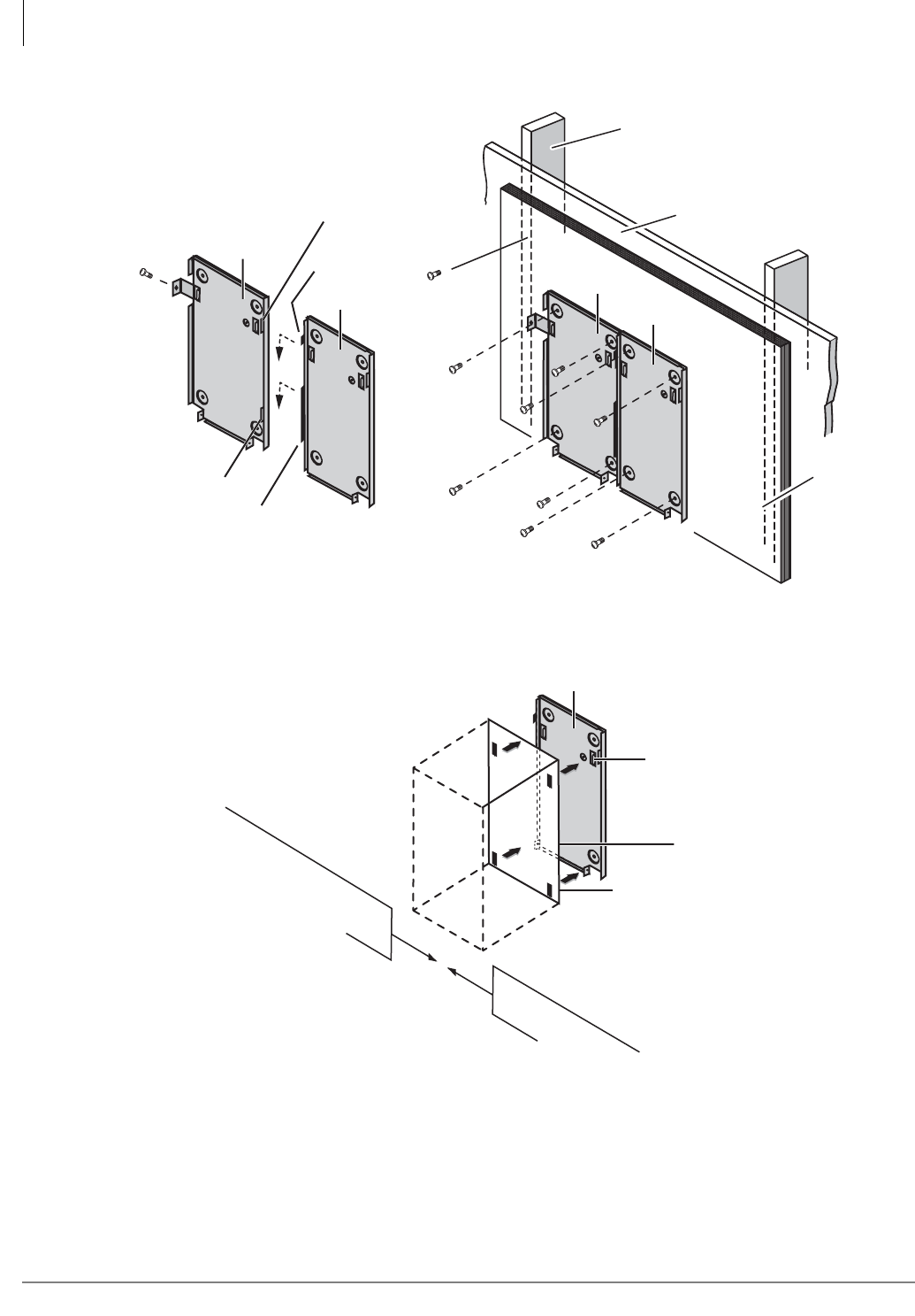
Strata CTX100-S/CTX100 Installation
Installing the CTX100 Cabinet
3-8 Strata CTX I&M 06/04
Figure 3-5 Cabinet Wall Mounting
Figure 3-6 Mounting CTX100 Cabinet on Back Cover
Screw A
Flange
Hook
Hook
Flange
Base
Expansion
Stud
Plaster
Board
Back Board
(1/2 Inch
Plywood)
5912
Base
Expansion
Hanger
Back Cover
Bottom left
hanger is only
used on the
Base Cabinet
Hanger Hole
Mount Cabinet - Slide
left
Unmount Cabinet - Slide
right and up
5937

Strata CTX100-S/CTX100 Installation
Installing the CTX100 Cabinet
Strata CTX I&M 06/04 3-9
Strata CTX100-S/
CTX100 Installation
Step 13: Mount the Expansion Cabinet (if required)
1. Turn Base Cabinet DC power switch Off. Remove the four screws on the right side cover of the
Base Cabinet.
2. Remove four screws from the right side of the Base Cabinet (since they will interfere with
attaching the Expansion Cabinet to the Base Cabinet later).
3. Remove the Expansion Cabinet back cover from the Expansion Cabinet (see Figure 3-4).
4. Place the Expansion Cabinet back cover next to the Base Cabinet back cover, making sure
expansion back cover hooks fit into the base back cover flanges (see Figure 3-5).
5. Mark the location of the four screw holes – there is one on each corner.
Make sure the location of the Expansion Cabinet meets the minimum clearance requirements
specified in Figure 3-1 on page 3-3.
6. Drill holes on these marks.
7. Place the Expansion Cabinet back cover on the wall back board and secure the back cover to
the back board with four screws.
8. On the right side of the AMAU motherboard inside the Base Cabinet, flip open the top and
bottom locks for data ribbon cable plug. Plug in the data ribbon and close the locks. Feed the
ribbon through the side hole of the Base Cabinet.
9. To mount the Expansion Cabinet, position it onto the back cover hangers.
Note Position the cabinet over the bottom right hanger first, and then carefully tilt the cover over
the top two hangers.
10.Slide the Expansion Cabinet to the left, feeding the data ribbon cable through the side hole of
the Expansion Cabinet.
11. Finish by securing the Expansion Cabinet to the Base cabinet with the two screws in front of
the cabinets where they join together. The expansion cabinet left-side flange fits over the Base
cabinet right side flange (see Figure 3-7).
12. On the AMAU motherboard of the Expansion Cabinet, flip open the two data ribbon locks,
plug in the data ribbon and close the locks. The data ribbon cable should now be connected to
the Base and Expansion cabinets.
13. Install PCBs into the Expansion Cabinet; follow the instructions in “Step 18: Install Other
PCBs into the Cabinet(s)”.
Note The Base Cabinet DC power switch will be the master control for turning the DC power of
both cabinets On/Off.
14. Attach the outside covers on the Expansion Cabinet.
WARNING! To prevent electrical shock, make sure the power supply is not plugged into
the AC outlet.
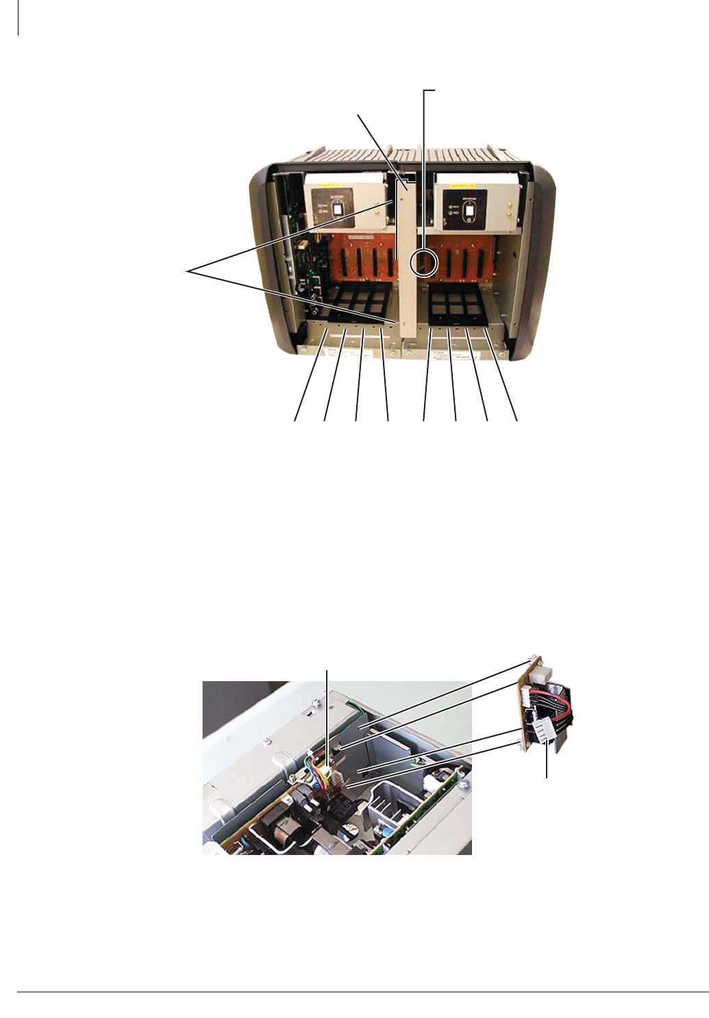
Strata CTX100-S/CTX100 Installation
Installing the CTX100 Cabinet
3-10 Strata CTX I&M 06/04
Figure 3-7 Base and Expansion Cabinet Interior
Step 14: Install Reserve Power
Skip this step if you are not going to install reserve power batteries.
A reserve power source (two or four customer supplied 12VDC batteries) can be connected to the
CTX100 power supply equipped with an ABCS battery charger to ensure uninterrupted system
operation in the event of a power failure. The ABCS battery charger and a pre-assembled battery
cable (ABTC-3M) for connecting the batteries is available from Toshiba (see Figure 3-8).
Figure 3-8 CTX100 Power Supply (Top view)
Flip open locks to plug in data cable.
Push locks closed once cable is
plugged in. Make sure locks are
closed.
Left side of Expansion Cabinet fits
over the right side of the Base
Cabinet.
S101 S102 S103 S104 S105 S106 S107 S108
5969
2 - Screws
Four-Wire Plug
Power Supply Four-Prong
Connector (CN-501)
ABCS1A
5970

Strata CTX100-S/CTX100 Installation
Installing the CTX100 Cabinet
Strata CTX I&M 06/04 3-11
Strata CTX100-S/
CTX100 Installation
Reserve Battery Considerations
Important! Local ordinances may dictate battery type and installation details.
The batteries require a well-ventilated location within nine feet of the system (the interface cable is
nine feet long).
Step 6A: Install the Optional ABCS1A Battery Charger
1. Attach the ABCS1A to the inside wall of the Power Supply (see photos below). Fit the two
holes on the ABCS1A over the metal prongs of the power supply and align the two plastic tips
of the ABCS1A over the holes on the inside wall of the power supply. Snap the ABCS1A into
place. Pull on the ABCS1A to make sure that it’s securely installed.
2. Attach the ABCS1A four-wire plug onto the power supply four-prong connector (CN-501).
Step 6B: Install the Battery Cable
1. A black jumper wire is supplied with the ABTC-3M cable. Connect the black jumper wire from
the positive terminal of one 12VDC battery to the negative terminal of the second 12VDC
battery (see Figure 3-9).
2. Ensure that a serviceable 10-amp fuse is installed in the in-line fuse holder of the ABTC-3M
battery cable.
3. Connect the white lead of the ABTC-3M battery cable to the open positive terminal of the
12VDC battery. Connect the black lead to the open negative terminal of the second 12VDC
battery.
WARNING! To reduce the risk of fire or injury to persons, read and follow these
instructions:
³Use only 12VDC gelcell batteries.
³Do not dispose of the batteries in a fire. The cells may explode. Check
with local codes for possible special disposal instructions.
³Do not open or mutilate the batteries. Released electrolyte is corrosive
and may cause damage to the eyes or skin. It may be toxic if swallowed.
³Exercise care in handling batteries in order not to short the battery with
conduction materials such as rings, bracelets, and keys. The battery or
conductor may overheat and cause burns.
³Charge the batteries provided with or identified for use with this product
only in accordance with the instructions and limitations specified in this
manual.
³Observe proper polarity orientation between the batteries and battery
charger.
WARNING! Whenever the cabinet top cover is removed, use extreme caution. Do not
touch any internal power supply components because hazardous voltages
may be exposed. Whenever adding/removing power supply components or
checking circuit breakers and fuses, unplug the power supply AC plug from
the AC source outlet.
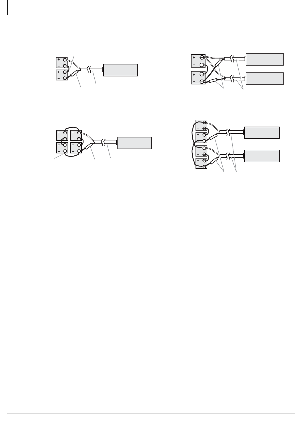
Strata CTX100-S/CTX100 Installation
Installing the CTX100 Cabinet
3-12 Strata CTX I&M 06/04
Figure 3-9 Battery Wiring Diagram
4. Run the ABTC-3M battery cable from the batteries to the ABCS battery charger located in the
CTX100 power supply. Dress the battery cable within the CTX100 cabinet(s) carefully (see
Figures 3-10~3-13).
Important! The CTX100 must be connected to the live operating (hot) AC power source, and the
power supply On/Off switch set to On prior to the final step of connecting the
reserve power battery cable to the ABCS battery charger. If the batteries are
connected after AC power is lost, reserve power will not function.
5. Connect the ABTC-3M battery cable two-prong female plug to the power supply
“CN-BAT” receptacle on the ABCS charger.
6. To test reserve power operation, disconnect the system AC power plug from the source outlet
while the power supply power On/Off switch in the On position. The AC and DC power lights
should be Off. The system should continue to operate without interruption or dropped calls.
7. Plug the AC power cable back into the outlet; make sure the power supply switch is On.
2-Batteries/1-Cabinet
12 Volt
Batteries
80 AMP/
HR Each
ABTC-3M Cables (9 ft.)
–
+ABCS CN-BAT
Connnector
10A Fuse
Black jumper wire
All Jumper Wires
must be 16 AWG Wire
ABCS CN-BAT
Connnector
ABCS CN-BAT
Connnector
4-Batteries/2-Cabinets
ABTC-3M Cables (9 ft.)
10A Fuse
Expansion Cabinet
Base Cabinet
12 Volt
Batteries
80 AMP/
HR Each
–
+
–
+
ABCS CN-BAT
Connnector
ABCS CN-BAT
Connnector
2-Batteries/2-Cabinets
10A Fuse
Exp. Cabinet Power Supply
Base Cabinet Power Supply
ABTC-3M Cables (9 ft.)
12 Volt
Batteries
80 AMP/
HR each
–
+
–
+
5934
4-Batteries/1-Cabinet
12 Volt
Batteries
80 AMP/
HR Each
ABTC-3M Cables (9 ft.)
–
+ABCS CN-BAT
Connnector
10A Fuse
Base Cabinet Power Supply
Base Cabinet Power Supply
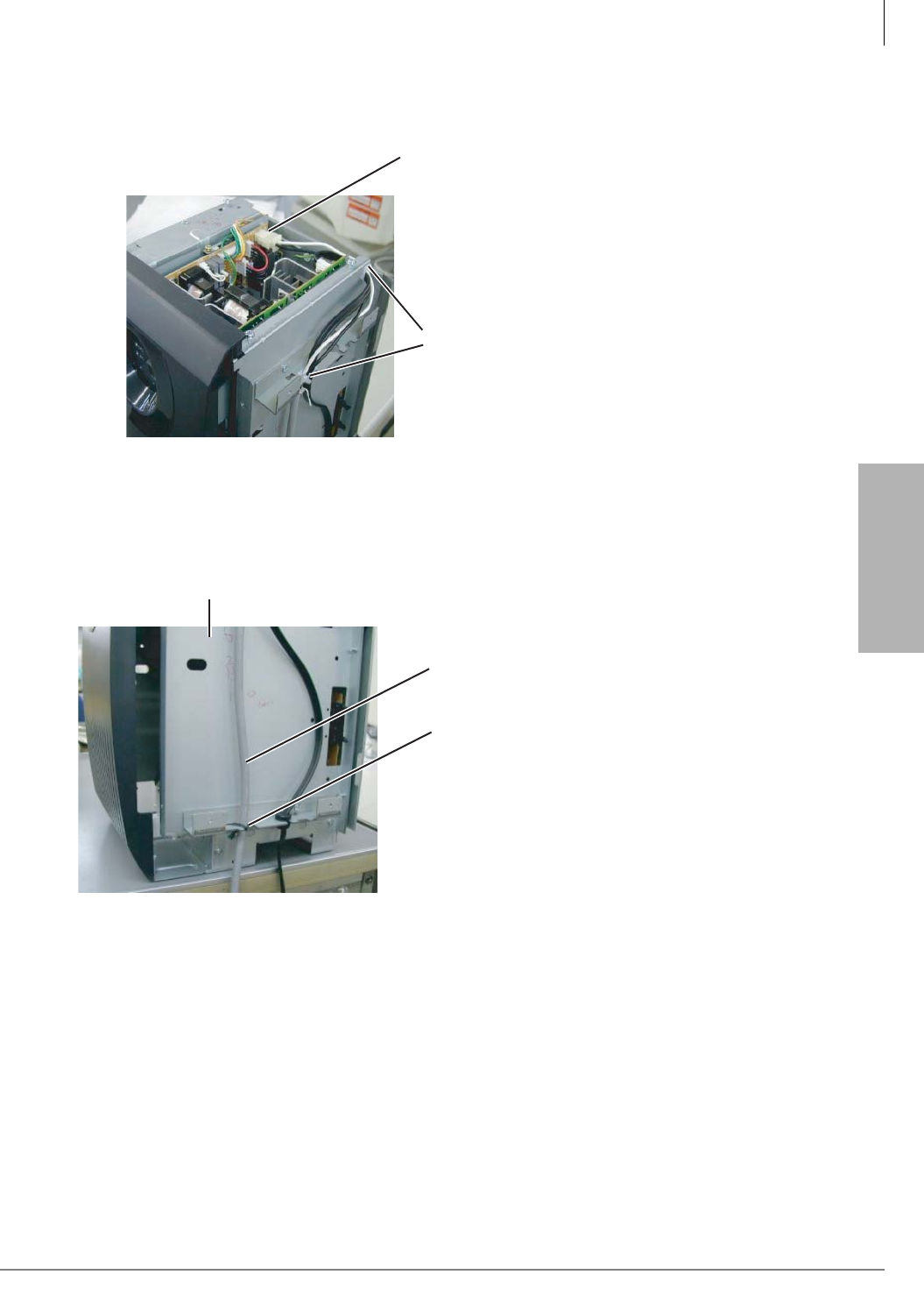
Strata CTX100-S/CTX100 Installation
Installing the CTX100 Cabinet
Strata CTX I&M 06/04 3-13
Strata CTX100-S/
CTX100 Installation
8. Confirm that the power supply is working properly. (AC Power lights should be On.)
Figure 3-10 Cable Wiring for the Base and Expansion Cabinets (Top view)
Figure 3-11 Cable Wiring for a Base Cabinet Only (Side view)
Connector of Battery Cable to
Battery Charger CN-BAT Connector
ABTC-3M Battery Cable to Battery Charger
(Tuck into plastic retainer with
AC power cord.)
5992
ABTC-3M Battery Cable to the Battery Charger
ABTC-3M Battery Cable is
secured with a tie wrap.
5993
Base Cabinet
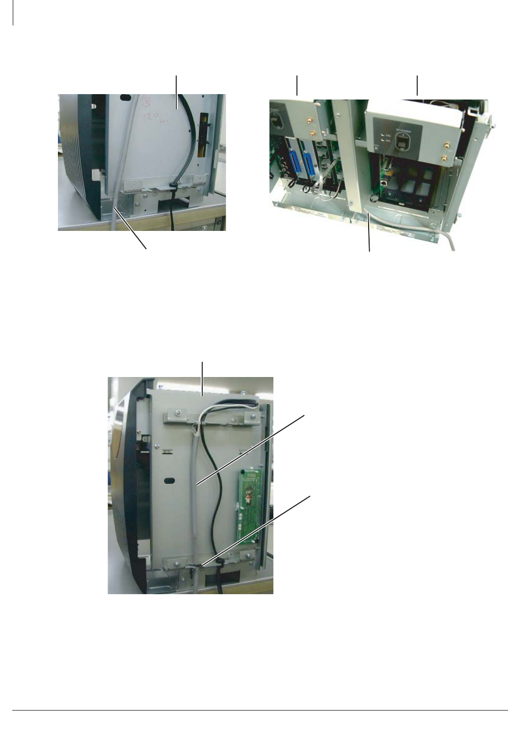
Strata CTX100-S/CTX100 Installation
Installing the CTX100 Cabinet
3-14 Strata CTX I&M 06/04
Figure 3-12 Cable Wiring for the Base with an Expansion Cabinet
Figure 3-13 Cable Wiring for the Expansion Cabinet (Side view)
ABTC-3M Cable
Base Cabinet (side view)
6078
Run ABTC-3M Cable
from Base Cabinet along
shelf of Exp. Cabinet to
Battery Charger
Base Cabinet Expansion Cabinet
ABTC-3M Battery Cable
to Battery Charger
ABTC-3M Battery Cable
is secured with a tie wrap.
Expansion Cabinet
5996

Strata CTX100-S/CTX100 Installation
Installing the CTX100 Cabinet
Strata CTX I&M 06/04 3-15
Strata CTX100-S/
CTX100 Installation
Step 15: Check Power Supply Circuit Breakers and Fuses
This step is only needed if you experience problems with the system.
Step 7A: Check the -24 Volt Circuit Breakers
The APSU112 provides two -24v circuit breakers as shown in Figure 3-14. If a low resistance
between –24 volts and ground exists the circuit breaker will trip. Usually the front panel DC green
LED indicator will turn off but not always. Also if AC power is recycled the DC LED indicator
may turn back on – even if the –24 volt circuit breaker is tripped.
Circuit Breaker Location and Slot Assignments (see Figure 3-14)
• The circuit breaker V1, located directly below the FG screw, protects the first and second
cabinet slots.
• The circuit breaker V2, located next to the BASE jumper connector, protects the third and
fourth cabinet slots.
Reset Circuit Breaker
1. A defective PCB or an external short on the MDF may cause the circuit breaker to trip.
2. If you suspect that a –24 volt circuit breaker has tripped, try to reset it by:
• Turn the power supply DC power switch off and unplug the power supply AC power cord
from the AC outlet – the inside of the power supply has exposed voltages.
• Gently press in each circuit breaker and listen for or try to feel it click. If the breaker was
tripped, you will hear or feel it click back to the set position.
• If the circuit breaker resets, pull the PCBs and check for MDF shorts associated with the
slots assigned to the tripped circuit breaker. Remove any defective PCBs and MDF shorts.
• Restore power and verify the system is working normally.
3. Replace the power supply if the circuit breaker continues to trip and a defective PCB or short
cannot be found. See “Step 7D: Remove and Replace the Power Supply (if required)” on page
3-17.
Step 7B: Check the AC Power Fuses
The APSU112 provides two AC power fuse as shown in Figure 3-14. If low resistance to ground
exists the fuse may blow. The front panel AC green LED indicator will turn off.
If you suspect that a AC fuse has blown you may check it by:
1. Turn the power supply DC power switch off and unplug the power supply AC power cord from
the AC outlet – the inside of the power supply has exposed voltages.
2. Remove each fuse and check that it is less than 0.3 ohms. Replace the fuse if it is defective. The
fuse size is T6.3AH 250V.
3. If you replace the fuse and it continues to blow, pull the PCBs and check for cabinet shorts.
Remove any defective PCBs and cabinet shorts.
WARNING! Whenever the cabinet top cover is removed, use extreme caution. Do not
touch any internal power supply components because hazardous voltages
may be exposed. Whenever adding/removing power supply components or
checking circuit breakers and fuses, unplug the power supply AC plug from
the AC source outlet.
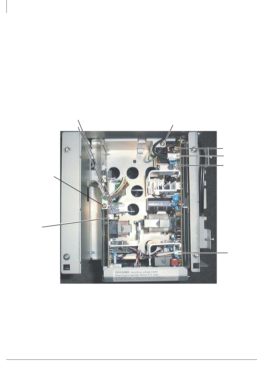
Strata CTX100-S/CTX100 Installation
Installing the CTX100 Cabinet
3-16 Strata CTX I&M 06/04
4. Replace the power supply if the fuse continues to blow and a defective PCB or short cannot be
found. See “Step 7D: Remove and Replace the Power Supply (if required)” on page 3-17.
Step 7C: Check the Power Factor Indicator and Reset Button
The front panel of APSU112 provides a Power Factor LED and Reset button. If the cabinet power
factor is exceeded by overload of PCBs, the PF LED will turn on.
³If the PF LED indicator turns on, press the PF reset button with a pointed tool or pencil. If the
PF LED turns off and does not turn on again it may have been turned on by a current surge
while installing a PCB while the power supply was turned-on.
³When a PF alarm is indicated, check that the cabinet power factor is not exceeded using
“Worksheet 7 – System Power Factor Check” on page 2-42. If the Power factor has been
exceeded relocate any PCBs that are causing the PF to be exceeded.
Figure 3-14 Power Supply Connectors Top View
AC Fuse
AC Fuse
AC Cord Third Wire Ground Screw
AC-IN Connector
EXP
Expansion
Cabinet
Power Supply
Jumper
Connector
V1-24 Volt Circuit
Breakers:
Motherboard
FG Wire Screw
V2
BASE
Base Cabinet
Power Supply
Jumper
Connector
5997
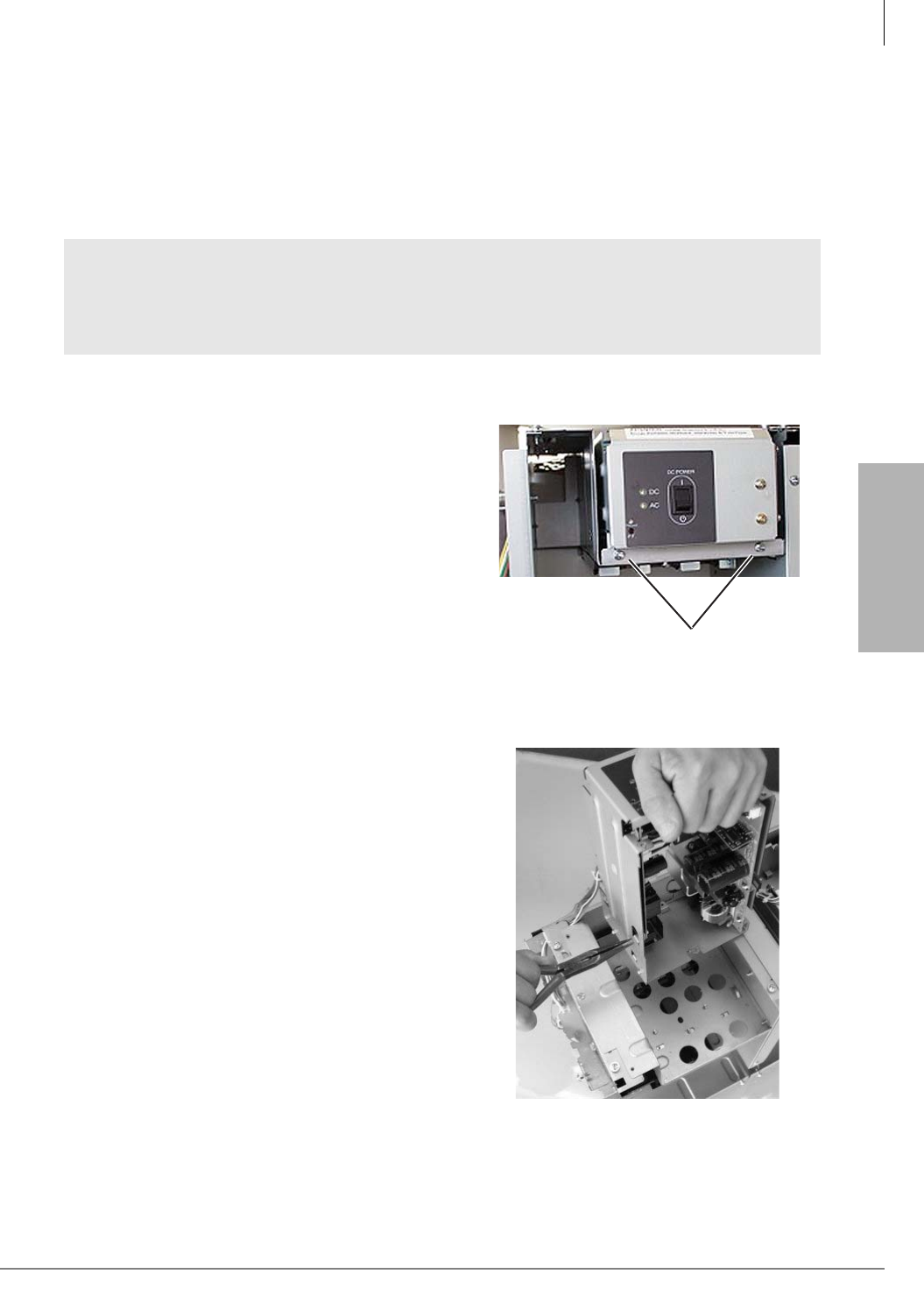
Strata CTX100-S/CTX100 Installation
Installing the CTX100 Cabinet
Strata CTX I&M 06/04 3-17
Strata CTX100-S/
CTX100 Installation
Step 7D: Remove and Replace the Power Supply (if required)
The power supply (APSU112) comes factory-installed in the Base and Expansion Cabinets; if
necessary, it can be removed and replaced. If you do not need to replace the power supply, skip this
step.
Removing the Power Supply
1. Make sure that the power supply switch is Off and that the AC power cable is not plugged into
an outlet. Confirm that the green AC LED is not lit (see Figure 3-15).
2. Remove the two screws in front of the Power
Supply (see Figure 3-15).
3. Unplug reserve battery cable from CN-BAT
connector of power supply.
4. Unplug the DC cable from the “CN OUT”
connector (P16) and cut the tie-wrap. Be careful
not to cut any wires.
5. Remove the FG screw from left side of power
supply to free FG wire/terminal and ground
wire.
6. Remove the Power Supply from the Cabinet (see
Figure 3-16).
7. If you are going to remove the ABCS battery
charger, use pliers to unlock the plastic holders
of the ABCS1A.
8. Unplug the AC power cord from the AC-IN
connector.
WARNING! Whenever the cabinet top cover is removed, use extreme caution. Do not
touch any internal power supply components because hazardous voltages
may be exposed. Whenever adding/removing power supply components or
checking circuit breakers and fuses, unplug the power supply AC plug from
the AC source outlet.
Two screws
5998
Figure 3-15 Power Supply (APSU112)
Figure 3-16 ABCS Power Supply Removal

Strata CTX100-S/CTX100 Installation
Installing the CTX100 Cabinet
3-18 Strata CTX I&M 06/04
Replacing the Power Supply
1. Make sure that the power supply switch is Off and that the AC power cable is not plugged into
an outlet.
2. Set the power supply in its proper place in the cabinet (see Figure 3-16).
3. Secure the power supply to the cabinet with the screws.
4. Connect the green/green-yellow wire from the AMAU motherboard to the FG screw on the
power supply.
5. Plug the DC cable into the CN OUT connector.
6. Install the ABCS battery charger.
7. Plug in the reserve battery cable to the CN-BAT connector of the ABCS battery charger.
8. Plug in the AC power cord connector into the AC-IN plug.
9. Insert and tight the two screws in front of the power supply (see Figure 3-15).
10.Plug the BASE/EXP jumper plug into the appropriate BASE or EXP connector on the power
supply (see Figure 3-14).
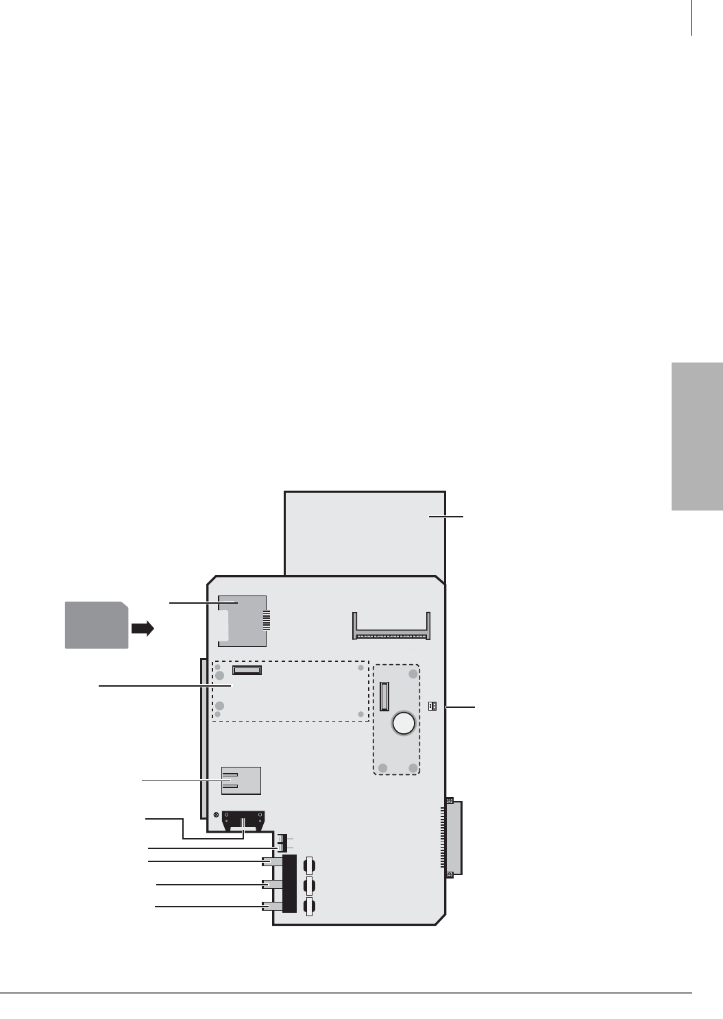
Strata CTX100-S/CTX100 Installation
Installing the CTX100 Cabinet
Strata CTX I&M 06/04 3-19
Strata CTX100-S/
CTX100 Installation
Step 16: Set Jumpers and Install Option PCBs onto the ACTU
³To install the ACTU2A
Refer to Figure 3-18 and perform the following steps on the ACTU2A.
1. Set the battery jumper, “BATT,” to the “On” position.
2. Make sure the WDT jumper plug is set to the ON position.
Note Unlike the ACTU1A, the ACTU2A does not use the AETS or the ARCS option PCBs. NIC
and DTMF circuits are built into the ACTU2.
3. Install needed option PCBs onto the ACTU (AMDS, BSIS).
4. Place option PCB arrow side up over the plastic stand-offs with the connectors and stand-off
holes on the ACTU. Snap option PCB securely into place.
5. Insert the SmartMedia card (gold contacts face left, notched corner faces forward and up) into
the SmartMedia slot on the ACTU.
6. Make sure the power supply switch is Off.
7. Install the ACTU into the Base Cabinet (see following photos).
Notes
• ACTU2A requires R1.3 software or later.
• MOH/BGM source volume is controlled by software PAD in Program 107-01, 02 and 03. Mu/
A law must be set to Mu law in software Program 105-35 for North America.
• For details on jumpers and add-ons (subassemblies) for the ACTU, see Table 3-2 on page 3-22.
Figure 3-17 ACTU2A PCB (CTX100 Processor)
600/600600/600 600/600
ON
P601
OFF
BATT
MOH1 EX SPMOH2
P2
P4
ACTU2
P3
R806
P6 P5
Place
BSIS
here
Place
AMDS
here
6636
BSIS1A
(RS232-C, SMDR and SMDI)
Control Relay Terminal
(Night Transfer, etc.)
ASTU plugs into P3
MOH/BGM1 RCA Jack
600 ohm page output
Metal Spacer
Future MOH2 Jack
10 Base-T Ethernet
Battery
Backup
Jumper
SmartMedia
Slot
SmartMedia Card
Note: The ACTU1A is a
larger board and does not
have the metal spacer.
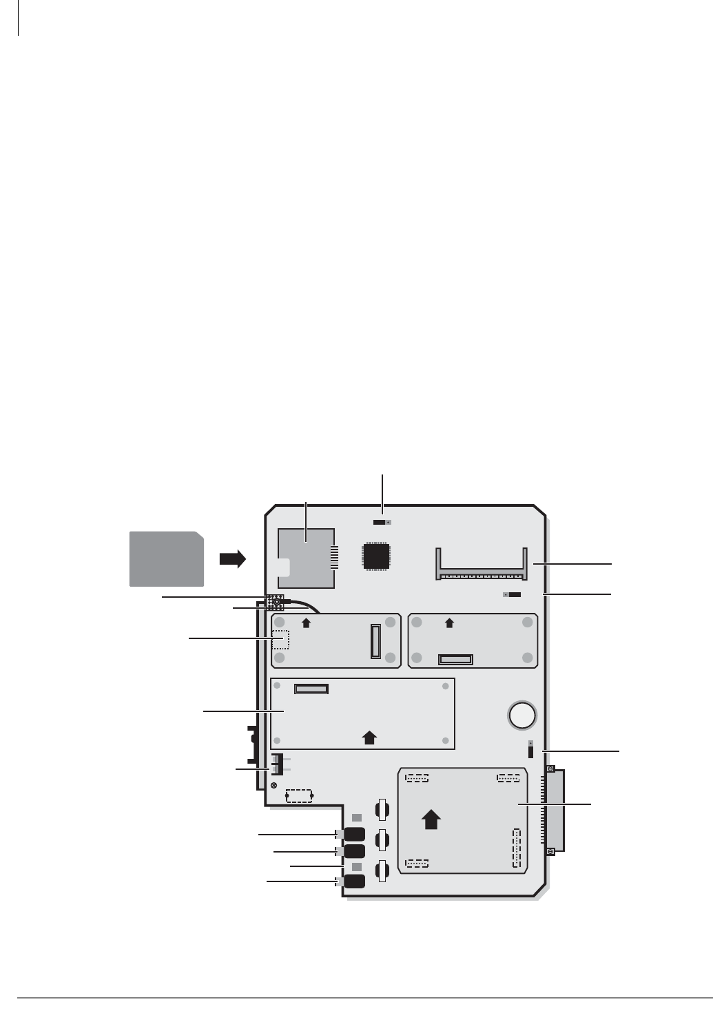
Strata CTX100-S/CTX100 Installation
Installing the CTX100 Cabinet
3-20 Strata CTX I&M 06/04
³To Install ACTU1A
Refer to Figure 3-18 with the following steps.
1. On the ACTU PCB, set the battery jumper, “BATT,” to the “On” position.
2. On the ACTU, make sure the Mu/A jumper plug is set to the Mu position (U.S. and Canada).
3. On the ACTU PCB, set the BBMS jumper “ATTACHED BBMS,” to the “NO” position.
Note If you are installing the AETS option PCB, before mounting the AETS, dress its green
jumper wire under and behind the Ethernet port and out the top as shown in Figure 3-18.
Remove the screw just above the AETS, place the jumper wire ring over the hole and
replace the screw to hold the jumper wire ring in place.
4. Install needed option PCBs onto the ACTU (AETS, AMDS, BSIS, ARCS).
5. Place option PCB arrow side up over the plastic stand-offs with the connectors and stand-off
holes on the ACTU. Snap option PCB securely into place.
6. Insert the SmartMedia card (gold contacts face left, notched corner faces forward and up) into
the SmartMedia slot on the ACTU.
7. Make sure the power supply switch is Off.
8. Install the ACTU into the Base Cabinet (see following photos).
Note For more details about the jumpers and add-ons (subassemblies) for the ACTU, see Table
3-2 on page 3-22.
Figure 3-18 ACTU PCB (CTX100 Processor)
5897
600/600600/600 600/600
ON BACK UP
P101
Mu A
OFF
MOH1MOH2
UP
YES
P301
P302
ATTACHED
BBMS
P601
P801
NO
ACTU1A
AMDS1A
BSIS
ARCS1A
BSIS1A
(RS232-C, SMDR and SMDI)
Control Relay Terminal
(Night Transfer, etc.)
MOH/BGM1 RCA Jack
600 ohm page output
Not Used
Not Used
UP UP
UP
AETS1A
Future MOH2 Jack
AETS1A
(10 Base-T Ethernet)
Ground
AETS Green Jumper Wire
Battery
Backup
Jumper
ARCS1A
(DTMF/ABR Circuits)
MOH/BGM Volume Control
SmartMedia Slot
SmartMedia Card
MU/A Law Jumper
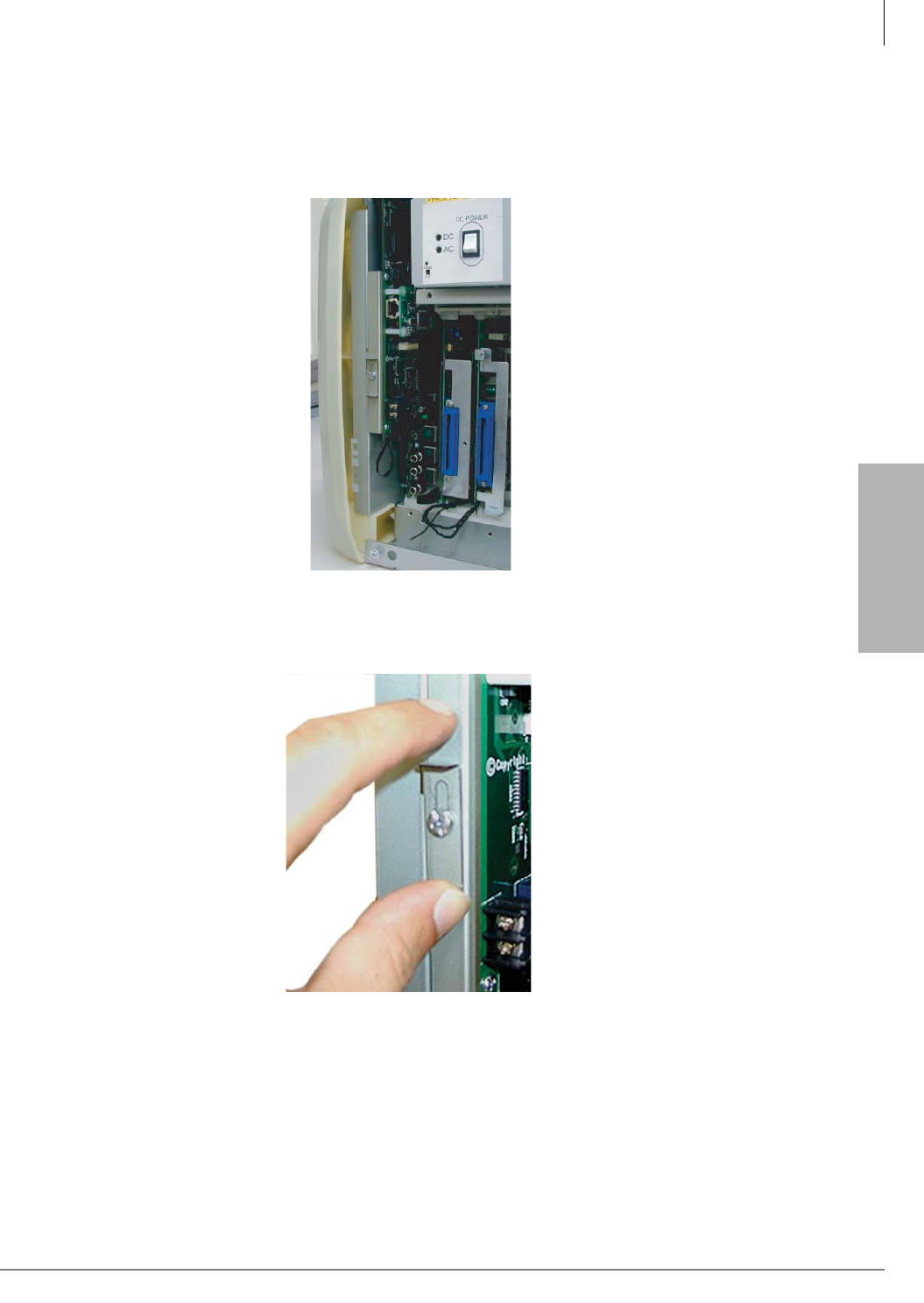
Strata CTX100-S/CTX100 Installation
Installing the CTX100 Cabinet
Strata CTX I&M 06/04 3-21
Strata CTX100-S/
CTX100 Installation
Step 17: Install the Main Processor (ACTU) PCB
The Strata CTX100 Base cabinet has one slot dedicated to the processor PCB.
1. Slide the ACTU processor PCB into the first slot on the left side of the cabinet (as shown).
2. Loosen the screw slightly, then slide the processor lock upwards. Tighten the screw so that the
PCB is locked into place.
6003
6004
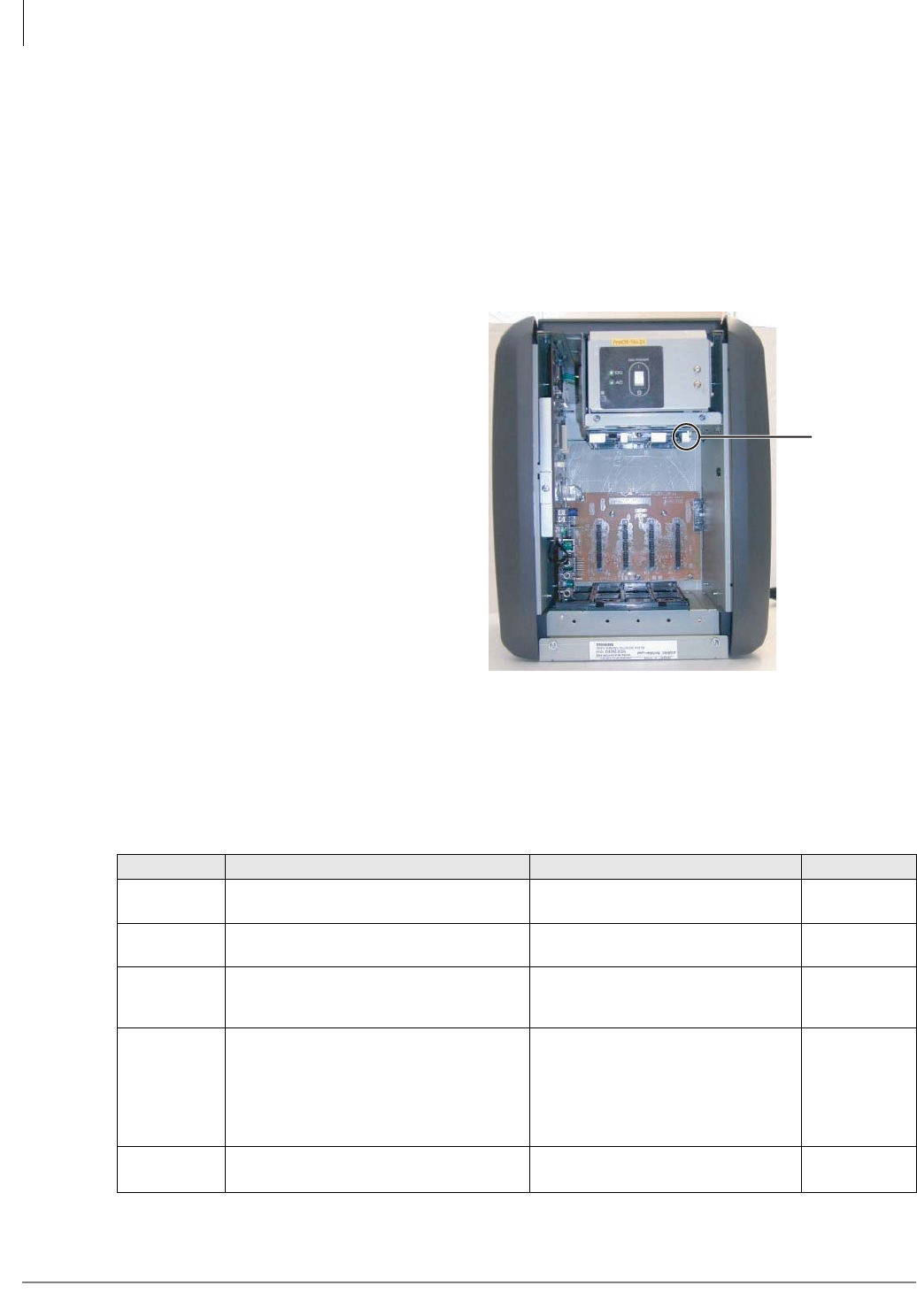
Strata CTX100-S/CTX100 Installation
Installing the CTX100 Cabinet
3-22 Strata CTX I&M 06/04
Step 18: Install Other PCBs into the Cabinet(s)
1. Each PCB must be configured for the applicable hardware options prior to installation of the
PCB to the CTX100 cabinets.
Configuration instructions for individual PCBs are in Chapter 6 – PCB Installation and Chapter
10 – MDF PCB Wiring. Configuration instructions for external hardware options are provided
in Chapter 12 – Peripheral Installation.
2. Use the PCB placement guide in “Worksheet 5: Strata CTX100 Cabinet Slots” on page 2-26 to
determine which PCB slot can be used for each PCB type.
3. Slide the PCB Slot Locking Bar to
the right, then insert each of the
PCBs; push the PCBs firmly toward
the motherboard, making sure that
the connectors are secured (see
Figure 3-19). Lightly tug on each
PCB to make sure that it’s installed
securely.
4. After all the PCBs are installed, slide
the PCB Slot Locking Bar to the left
to lock the PCBs into place.
5. Configure the PCBs for software
options through programming. Refer
to the Strata CTX Programming
Manual for more detailed
programming instructions.
Note The Base and Expansion cabinets
have four universal PCB slots
each which can accept the same
universal PCBs as the CTX670.
CTX100-only components are
shown in Table 3-2.
Table 3-2 CTX100 Cabinet and Processor Components
PCB Provides Comments Installs On
CHSUB112 Base Cabinet with power supply without
battery charger. Provides 4 universal slots.
CHSUE112 Expansion Cabinet with power supply
without battery charger. Provides 4 universal slots.
APSU112 Power Supply for CTX100. Spare power supply.
Base or
Expansion
Cabinet
ACTU
System Processor PCB. (Optional PCB
attachments include: modem. Ethernet
10BaseT, DTMF Receiver/Busy Tone
Detector and Serial Interface Unit.
One per system. Supports 8 PCB
slots (4 slots in the Base Cabinet +
4 more in the Expansion Cabinet).
Note The ACTU2A works with
software R1.3 and higher.
ARCS
(Optional) DTMF Receiver and ABR Circuits. One per system. Provides 16
DTMF and 16 ABR circuits. ACTU1 only
PCB Slot
Locking Bar
6005
Figure 3-19 PCB Slot Locking Bar
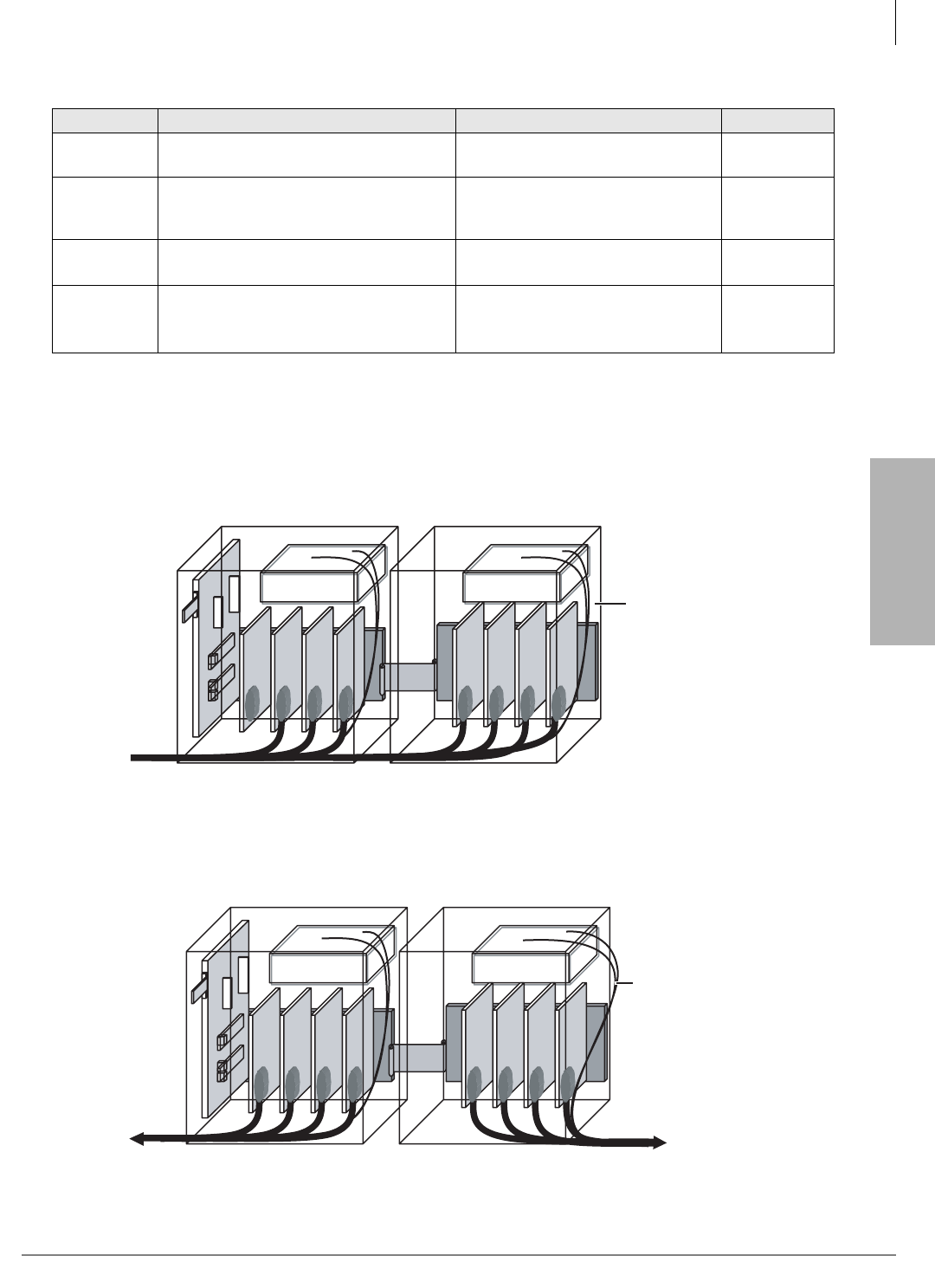
Strata CTX100-S/CTX100 Installation
Installing the CTX100 Cabinet
Strata CTX I&M 06/04 3-23
Strata CTX100-S/
CTX100 Installation
Step 19: Attach and Route PCB Cables
1. Determine the direction that you want the cables to exit the cabinet(s) from the following:
•Single Direction Cable Routing – Cabling from the Expansion Cabinet can run through the
Base Cabinet and exit from the Base Cabinet (see Figure 3-20).
Figure 3-20 Single Direction Cable Routing
•Opposite Direction Cable Routing – Cabling from the Expansion Cabinet can run through
the right and left sides (see Figure 3-21).
Figure 3-21 Opposite Direction Cable Routing
AETS
(Optional) Ethernet LAN (10 BaseT) One per system. Provides 10Mbps
LAN by one RJ45 for WinAdmin. ACTU1 only
AMDS
(Optional) V.34 Modem
One per system to provide
33.6kbps maximum modem for
WinAdmin.
ACTU
BSIS
(Optional)
Serial interface unit (same unit used for
CTX670).
Provides four RS-232 serial ports
(SMDR, SMDI) ACTU
ABCS
(Optional) Battery Charger Circuit.
One per Power Supply for
connection of Reserve Power
(requires ABTC-3M Battery Cable).
APSU112A
Table 3-2 CTX100 Cabinet and Processor Components
(continued)
PCB Provides Comments Installs On
6006
Power SupplyPower Supply
AC Cord and
Battery Cables
6007
Power SupplyPower Supply
AC Cord and
Battery Cables
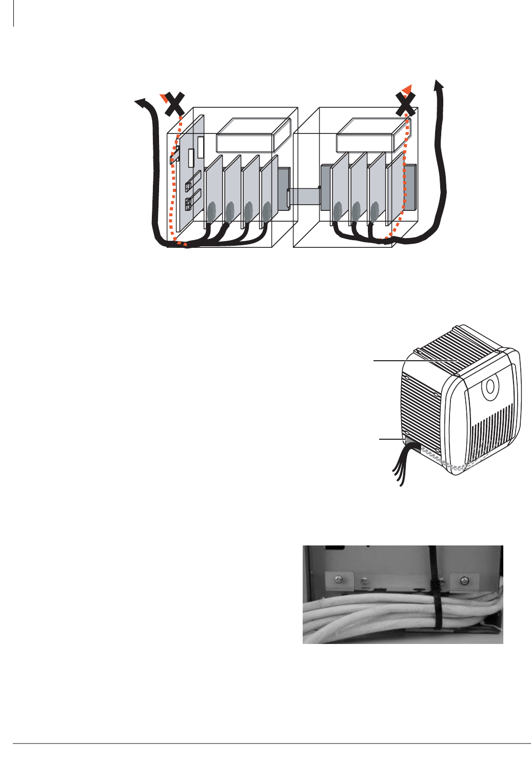
Strata CTX100-S/CTX100 Installation
Installing the CTX100 Cabinet
3-24 Strata CTX I&M 06/04
•Do Not Run Cables Out the Top – Cabling from either cabinet should be routed out the
lower sides, not from the top of the cabinet(s) (see Figure 3-22).
Figure 3-22 Avoid Improper Cable Routing
2. Remove the left or right
cover(s) of the cabinet and
knock out the rectangle(s) to
create a hole for the cables, as
needed (see Figure 3-23).
Note Cables can be run out of
either side of Base or
Expansion cabinets.
3. Connect applicable wiring (e.g.,
modular CO line cords, 25-pair
amphenol connector cables) to
the front of the PCBs as
described earlier.
4. Secure all Amphenol cables to
the cabinets with tie wraps (see
Figure 3-24).
6008
Power SupplyPower Supply
5968
Run cables through cover
knock-outs holes
(on all side covers)
To avoid heat problems,
do not store items on
top of the cabinets.
Figure 3-23 Base and Expansion Cabinet Cables and
Connectors
Figure 3-24 Tie-wrap Cables

Strata CTX I&M 06/04 4-1
Strata CTX670
Installation
Strata CTX670 Installation 4
This chapter explains how to install the Strata CTX670 system. It includes information on site
requirements and provides installation instructions for various cabinet configurations. It also
explains how to install ground wiring, AC power cabling, reserve power (Battery Backup) cabling,
and Printed Circuit Board (PCB) cabling.
Inspection
When the system is received, examine all packages carefully and note any visible damage. If any
damage is found, do not open the packages. Contact the delivery carrier immediately and make the
proper claims.
After unpacking (and before installing), check the system against the packing list and inspect all
equipment for damage. If equipment is missing or damaged, contact your supplier immediately.
Be sure to retain original packaging materials for re-use when storing or transporting system
hardware.
Packaging and Storage
CAUTION! When handling (installing, removing, examining) PCBs, do not touch the
back (soldered) side or edge connector. Always hold the PCB by its edges.
When packaging and storing the system, remove PCBs from the system cabinet (the power supply
may remain installed in the cabinet for storage and shipment). PCBs should be packaged in their
original antistatic bags for protection against electrostatic discharge. Be sure to package equipment
in its original shipping containers.

Strata CTX670 Installation
Site Requirements
4-2 Strata CTX I&M 06/04
Site Requirements
Input Power
The CTX670 requires an input power source of 115±10VAC or 208±20VAC or 240±20VAC, 50/
60 Hz, single phase. For up to five cabinets; 208VAC or 240VAC is required for six or seven
cabinets. The system requires one or two AC outlets that must be dedicated to system use, fused,
and grounded.
Each Remote Expansion Cabinet requires 3.2 amps. maximum. The remote cabinet installation
requires one or two AC outlets that must be dedicated to system use, fused, and grounded.
See Cabinet Installation Considerations for complete AC power cabling, ground wiring and
battery installation instructions for local and remote cabinets.
CAUTION! To avoid accidental power turn-off, do not use an On/Off wall switch for AC
circuits dedicated for the use of CTX670.
A reserve power source (two or four customer-supplied 12VDC batteries) can be connected to the
CTX670 to serve as a backup in case of power failure.
Separate reserve power may be required for remote expansion cabinets.
Clearance and Location
The Base and optional Expansion Cabinets can be either floor or wall mounted. Figure 4-1 shows
the minimum clearance requirements for up to seven cabinets.
Notes
• Floor mounting requires the following additional hardware:
• BFIF – floor mounting stands and brackets.
• BCCB – electrical conduit box, if three or more cabinets are installed.
• Wall mounting requires a plywood (3/4 inch thick) backboard.
When selecting a location for the cabinets, the location must be:
• Dry and clean
• Well-ventilated
• Well-illuminated
• Easily accessible
The location must not be:
• Subject to extreme heat or cold
• Subject to corrosive fumes, dust, or other airborne contaminants
• Subject to excessive vibration
• Next to television, radio, office automation, or high frequency equipment
Optional customer-supplied reserve batteries require a well-ventilated location close (within nine
feet) to the CTX670 cabinets.
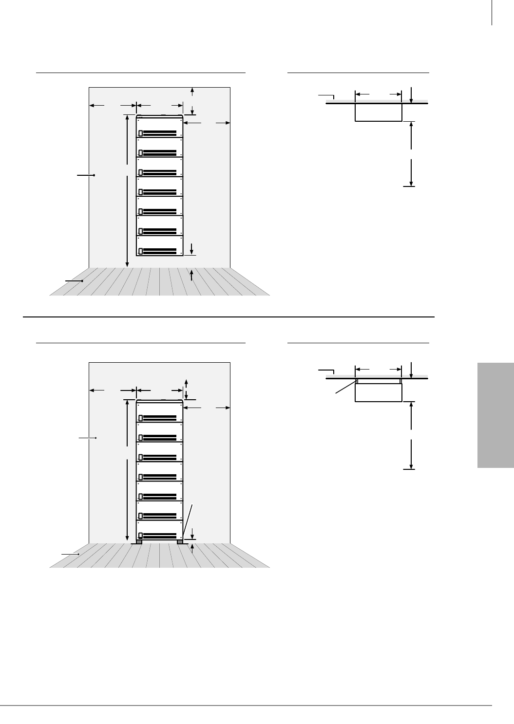
Strata CTX670 Installation
Site Requirements
Strata CTX I&M 06/04 4-3
Strata CTX670
Installation
Note The Base Cabinet may be mounted at the bottom of the stack.
Figure 4-1 CTX670 Minimum Clearance Requirements
24"
24"
78"
6"
14.5"
26.5"
Wall
Floor
Front View Top View
78" is minimum height requirements
for Wall Mounting up to 7 cabinets.
Wall
26.5"
Cabinets 10.65 "
36"
Wall
Front View Top View
75" is minimum height requirements
for Floor Mounting up to 7 cabinets.
12.65 "
Wall
26.5"
Cabinets
36"
2" Brackets
(RWBF)
5459
Floor
Expansion
Cabinet
Expansion
Cabinet
Expansion
Cabinet
Expansion
Cabinet
Expansion
Cabinet
Expansion
Cabinet
Base
Cabinet
13.5"
24"
24"
75"
26.5"
3"
3" Floor
Mount
Stands
(BFIF)
Expansion
Cabinet
Expansion
Cabinet
Expansion
Cabinet
Expansion
Cabinet
Expansion
Cabinet
Expansion
Cabinet
Base
Cabinet

Strata CTX670 Installation
Power Considerations
4-4 Strata CTX I&M 06/04
Power Considerations
Each CTX670 Base and Expansion Cabinet houses a power supply that furnishes power to all of
the stations and some of the peripherals that interface with the cabinet (see Table 2-60, “Strata
CTX670 Electrical Characteristics” on page 2-47).
Reserve Power
Two or four customer-supplied 12VDC reserve batteries can be connected to the system to
maintain normal operation during a power failure (see Table 2-63 on page 2-49 and Table 2-60 on
page 2-47). The batteries are kept in a highly-charged state by the standard power supply and must
be connected when the system is operating normally. Fully charged batteries must be connected
when normal AC power is available, batteries cannot be connected after/during an actual power
failure.
Underwriters’ Laboratory (UL) and local electrical codes require certain standards for connecting
commercial AC and reserve power to the CTX670 system. Table 4-1 describes which assemblies
may be required to meet UL and local electrical code standards.
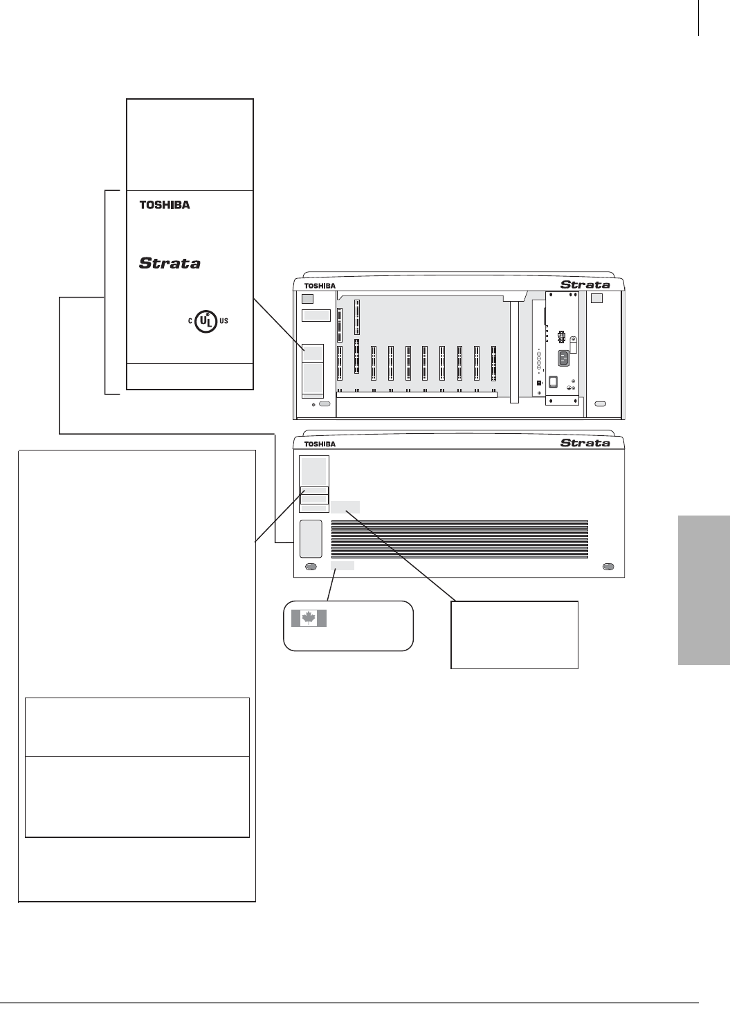
Strata CTX670 Installation
FCC Registration Information
Strata CTX I&M 06/04 4-5
Strata CTX670
Installation
FCC Registration Information
Figure 4-2 Location of Approval Labels
5035
POW
+5V
-5V
P.F.
RESET
EXP
BASE
AC IN
AC IN
DC OUT
-27V1
-27V2
-27V3
-27V4
+
-
POWER
ON
OFF
FG
5002
CAUTION: This unit may have more than one
power cord, up to seven power cords may be
provided.
To reduce the risk of electrical shock, disconnect all
power cords before servicing.
Fore use only on telephone wiring containing
secondary protection. See instruction manual.
For use only on telephone protected by Oneac
Corp., type 6-AP protector. see instruction manual.
ATTENTION: Cet appareil peut être muni de
plusieurs cordins d'alimentation électique: jusqu'a
sept dans ceertains cas.
Afin de réduire le risque de chocs éectriques,
débranchez tous les cordons d'alimentatin,
électrique avant l'entretien de l'appareil.
Utiliser seulement avec un reseau téléphonique
compreneant un dispositif de protection secondaire.
Voir le manuel d' instructions.
Utiliser seulement avec un reseau téléphonique
comprenant un dispositif de protection Oneac
Corp., type 6-AP. Voir le manuel d'instructions.
Complies with part 68, FCC rules
FCC Registration number CJ69XA-10242-KF-E
CJ69XA-10243-MF-E
CJ6JPN-22758-PF-E
Ringer equivalence0.2B(ac)0.0(dc),0.3B(ac)0.0(dc)
This device complies with Part 15 of the FCC rules.
Operation is subject ot the following two conditions:
(1) This device may not cause harmful interference,
and (2) this device must accept any interference
received, including interference that may cause
undesired operation.
TOSHIBA CORPORATION
This Class - A digital apparatus complies with
Canadian ICES-003.
Cet apparel numbérique de la class A est conforme
á la norme NMB-003 du Canada.
Manufactured under one
or more of the following
U.S. patents: 4,491,693
4,511,764 4,532,378
4,605,825 5,535,262
Industry Canada
Industrie Canada
248 3032 A
The unit shall be configured
only with those component
assemblies specified in the
installation instructions and
mounted only in the locations
specified.
See installation manual for
grounding requirement.
DIGITAL BUSINESS
TELEPHONE SYSTEM
MODEL CHSUB672A
INPUT:
100-120/208-240VAC
50/60Hz
3.2/2.2A
V. 1 A No XXXXXX
TOSHIBA CORPORATION
LISTED
49L7
E88891
AOI JS
This area shows through
opening in cover.
Strata CTX670 Installation
Cabinet Installation Considerations
4-6 Strata CTX I&M 06/04
Cabinet Installation Considerations
The Base (CHSUB672) and Expansion (CHSUE672) Cabinets can be wall or floor mounted. To
make it easier to add cabinets (after the initial installation) when a customer needs to expand,
install the Base Cabinet on top for wall-mount installations and on the bottom for floor-mount
installations.
The dimensions of the Base and Expansion Cabinets are:
Height: Base Cabinet: 11 3/4 inches
Height: Expansion Cabinet/Remote Expansion Cabinet: 10 inches
Width: 26 1/2 inches
Depth: 10 5/8 inches
Weight: approx. 30.5 lbs. (14 kg.)
Note The weight approximates a cabinet completely filled with PCBs. Weight may vary slightly,
depending on PCBs.
Recommended Installation Sequence
Note Each cabinet requires four wood screws (#12 X 2 inch size) for wall mount installation.
Wood screws are not provided with the system.
Step 1: Install Power Supply
The Base and Expansion Cabinets are factory-shipped without the power supply installed. The
CTX670 cabinets use the BPSU672 power supply, which is different from the DK280 or DK424.
³To install power supplies in cabinets of new or installed systems
1. Remove the power supply from its box. The power supply AC power cord for 120VAC and the
power supply mounting screws are provided with the KSU cabinet. If the system is to be
powered by 208VAC or 240VAC, another powered cord, BACL240 must be ordered separately
for each power supply.
2. Make sure that the front and right side covers are removed from the cabinet (see Figure 4-5).
3. Slide the power supply into the right side of the cabinet so that its four mounting holes align
with the four cabinet mounting holes. (Make sure that the two backplane FG wires are
positioned between the FG wire holder and the power supply.)
Step Reference Information
1. Install power supplies in cabinets. “Install Power Supply” on page 4-6.
2. Mount cabinets on wall or floor.
“Wall Mounting the Base (Top) Cabinet” on page 4-10.
“Cabinet Floor Mounting” on page 4-33.
3. Install ground wiring. “Ground the System” on page 4-18.
4. Install AC power cabling to cabinets. “Install AC Power Components” on page 4-20.
5. Install reserve power cabling. “Install Reserve Power” on page 4-29.
6. Install PCBs and PCB cabling. Figures 4-38~4-23, 4-42 and the section titled “Install
Processor and Universal PCBs” on page 4-43.

Strata CTX670 Installation
Install Power Supply
Strata CTX I&M 06/04 4-7
Strata CTX670
Installation
Note The backplane FG wires are not safety grounds: they are required for proper system CO line
operation.
4. Plug the Back Plane DC OUT cable plug into the DC OUT connector on the power supply.
(The plug has a guide key on it to ensure that it is plugged in correctly.)
5. Secure the FG wire spade lug to the power supply with the FG screw.
6. Secure the power supply to the cabinet with the four provided screws.
7. If the cabinet is the Base Unit, a standalone Remote Expansion Cabinet, or the first in a stack of
Remote Expansion Cabinets. Set the Exp/Base switch to the “Base” position (see Figure 4-3).
8. If the cabinet is an Expansion Unit, set the Exp/Base switch to the “Exp” position.
Important! The power supply set as “Base” is the master and has On/Off control over all other
power supplies, which are designated as slaves. If the master power supply is turned
Off or On, all other power supplies will automatically turn Off or On. (Individual
slave power supplies must be turned On.)
9. See Figure 4-3 to ensure that the power supply is properly installed.
10. Install power supplies in all cabinets, using Steps 1~9 of this procedure.
11. Install the Base and optional Expansion Cabinets, ground wiring, and cabinet bonding plates,
AC and reserve power cabling, and PCB cabling per the “Recommended Installation
Sequence” on page 4-6.
Check the -24 Volt Circuit Breakers
The BPSU672A provides four -24v circuit breakers as shown in Figure 4-3. If a low resistance
between –24 volts and ground exists the circuit breaker will trip. Usually the front panel DC green
LED indicator will turn off but not always. Also if AC power is recycled the DC LED indicator
may turn back on – even if the –24 volt circuit breaker is tripped.
Circuit Breaker Location and Slot Assignments (see Figure 4-3)
• The circuit breaker 24V1~24V4, located directly below DC-out cable, protects the cabinet slots
as shown in the Circuit Breaker assignment table.
Reset Circuit Breaker
1. A defective PCB or an external short on the MDF may cause the circuit breaker to trip.
2. If you suspect that a –24 volt circuit breaker has tripped, try to reset it by:
• Turn the power supply DC power switch off and unplug the power supply AC power cord
from the AC outlet – the inside of the power supply has exposed voltages.
• Gently press in each circuit breaker and listen for or try to feel it click. If the breaker was
tripped, you will hear or feel it click back to the set position.
• If the circuit breaker resets, pull the PCBs and check for MDF shorts associated with the
slots assigned to the tripped circuit breaker. Remove any defective PCBs and MDF shorts.
• Restore power and verify the system is working normally.
3. Replace the power supply if the circuit breaker continues to trip and a defective PCB or short
cannot be found.

Strata CTX670 Installation
Install Power Supply
4-8 Strata CTX I&M 06/04
Check the Power Factor Indicator and Reset Button
The front panel of BPSU672A provides a Power Factor LED and Reset button. If the cabinet
power factor is exceeded by overload of PCBs, the PF LED will turn on.
³If the PF LED indicator turns on, press the PF reset button with a pointed tool or pencil. If the
PF LED turns off and does not turn on again it may have been turned on by a current surge
while installing a PCB while the power supply was turned-on.
³When a PF alarm is indicated, check that the cabinet power factor is not exceeded using the
“Worksheet 7 – System Power Factor Check” on page 2-42. If the Power factor has been
exceeded relocate any PCBs that are causing the PF to be exceeded.
Power Supply (BPSU672) Removal
1. Remove the front and right side covers (Figure 4-5) from the cabinet. Remove the right side
covers of other cabinets as needed to disconnect wiring.
2. Turn the power supply Off, and disconnect the AC power cord, all ground wiring and reserve
power cabling that is connected to the power supply.
3. Disconnect the back plane DC OUT cable plug from the DC OUT connector.
4. Loosen the four mounting screws securing the power supply to the cabinet and remove the
power supply.
Power Supply Replacement
³Install the replacement power supply per “Install Power Supply” on page 4-6.
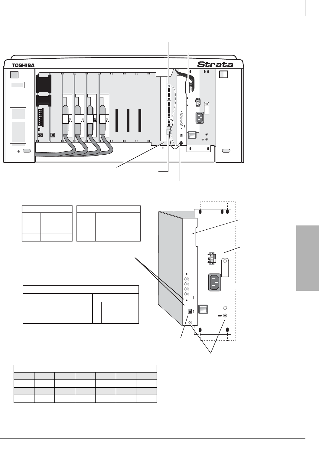
Strata CTX670 Installation
Install Power Supply
Strata CTX I&M 06/04 4-9
Strata CTX670
Installation
Figure 4-3 Power Supply Installation
POW
+5V
-5V
P.F .
RESET
EXP
BASE
AC IN
BATT
DC OUT
-27V1
-27V2
-27V3
-27V4
+
-
POWER
ON
OFF
FG
B101 B102 S101 S102 S103 S104 S105 S106 S107 S108
5039
AC IN
BATT
-24V1
-24V2
-24V3
-24V4
+
-
POWER
ON
OFF
POW
+5V
-5V
P. F.
RESET
EXP
BASE
DC OUT
FG
DC Voltage
Connector Jack
DC Voltage Specification
+5V (+4.5 ~ +5.5), 4.0 amps
-5V (–4.5 ~ –5.5), 0.8 amps
Expansion Cabinet only
-24V (–26.3 ~ –27.8), 6.0 amps
BATT (Volts)
+
–
0
–26.3 ~ –27.8
1. Back Plane DC Voltage Plug must be plugged
into Power Supply when checking voltages.
2. On BPSU672, the BATT output is 0 volts
unless connected to good batteries.
Power Factor (PF) alarm LED indicates
the cabinet PF was exceeded. Correct
the problem and press the RESET
button to clear the alarm.
24V Circuit Breaker Assignments:
24V-1
24V-2
24V-3
24V-4
EXP. Cabinet
24V-1
24V-2
24V-3
24V-4
S101, S102
S103, S104
S105, S106
S107, S108
S_01, S_02
S_03, S_04
S_05, S_06, S_07
S_08, S_09, S_10
Base Cabinet
Mounting Holes
Expansion/
Base Switch
FG Frame
Ground Screws
Battery Cable
Connector
AC Power
Cord Jack
Back Plane DC Voltage Connector
Back Plane DC Voltage Cable/Plug
Green/Green yellow wire is fastened with FG Screw
Cabinet Support Post Wire Clamp
2
DC Voltage Connector Plug Pin Wires
Yellow Blue White Green Green Green Red
-24 -5 +5 0 0 0 +5
Yellow Yellow Yellow Green Green Green Red
-24 -24 -24 0 0 0 +5

Strata CTX670 Installation
Mount Cabinets
4-10 Strata CTX I&M 06/04
Step 2: Mount Cabinets
There are two methods of mounting cabinets: wall or floor mounting. Wall mounting the most
common and economical method is described below. The floor mounting description begins on
page 4-33.
Note Toshiba recommends installing cabinets (see Figures 4-4~4-10) from the top down, Base
Cabinet on top, first Expansion Cabinet below it, second cabinet below that, etc.
Wall Mounting the Base (Top) Cabinet
Follow these instructions to wall mount the Base Cabinet or the first Remote Expansion Cabinet.
A wooden backboard between the cabinet and the wall is necessary (see Figure 4-4).
1. Obtain a board, such as plywood, that is at least 3/4 of an inch thick. The board should be at
least 6-1/2 feet high (completely expanded systems with seven cabinets require this much
height) and 26 inches wide (minimum).
Secure the board to the wall with wood screws with the bottom edge of the board is six inches
above the floor. (If there are wall studs, make sure the screws align with the studs.)
2. Remove the front, back, and side covers from the Base Cabinet or first Remote Expansion
Cabinet (see Figure 4-5).
Note The two screws on the front cover and the two screws on each side cover should be
loosened just enough to slide the covers off. The front cover slides left and the side covers
swing out and down for removal.
3. Hold the Base Cabinet back cover against the wall or backboard so that its two top mounting
holes are approximately 6-1/2 feet (78 inches) above the floor. This allows up to seven cabinets
to be installed (top-down) with a six-inch clearance between the floor and bottom cabinet (see
Figures 4-6 and 4-7).
4. Use a level to make sure that the back cover is held level.
5. Trace the upper arch of the top mounting holes with a pencil.
6. Remove the back cover from the wall. Draw a line between the top two marking hole marks.
7. Drill holes on the line in the middle of the arch tracing.
8. Screw #12 X 2 inch size wood screws into the two drilled holes, leaving about 1/8 of an inch
clearance between the screw heads and the wall.
9. Hang the Base Cabinet or first Remote Expansion Cabinet back cover from the top two screws
and secure the screws into the wall.
10. Drill holes at the bottom two mounting holes of the back cover, and secure #12 X 2 inch wood
screws into the two holes.
11. If installing a Base Cabinet or first Remote Expansion Cabinet back cover to the wall: Position
the cabinet on the back cover cabinet hangers, slide the cabinet right to the proper mounting
position, and secure the cabinet to the back cover with two screws on the right side of the
cabinet. If installing Expansion Cabinets, skip to “Wall Mounting Expansion Cabinets” on page
4-11.
12. Install ground wiring, AC and reserve power cabling, and PCB cabling per the “Recommended
Installation Sequence” on page 4-6.
13. Fill out the slot identification label on the cabinet (see Figure 4-8).
14. Reinstall the front cover, top cover, and side covers onto the cabinet.

Strata CTX670 Installation
Mount Cabinets
Strata CTX I&M 06/04 4-11
Strata CTX670
Installation
Wall Mounting Expansion Cabinets
1. Remove the front, back, and side covers from the Expansion Cabinets.
Note The two screws on the front cover and the two screws on each side cover should be
loosened just enough to slide the covers off. The front cover slides left and the side covers
swing out and down for removal.
2. Hold an Expansion Cabinet back cover against the wall so that its top locating parts align with
the bottom locating parts of the Base Cabinet back cover (see Figure 4-4 on page 4-12). To
secure the Expansion Cabinet back cover to the back board, repeat Steps 5~11 from “Wall
Mounting the Base (Top) Cabinet” on page 4-10.
3. To install additional Expansion Cabinet back covers, repeat Step 2 above.
4. Starting with the top Expansion Cabinet back cover (which is fastened to the wall), position an
Expansion Cabinet on the back cover cabinet hangers. Slide the cabinet to the right to the
proper mounting position, and secure the cabinet to the back cover with two screws to the right
side of the back cover. Repeat for all other Expansion Cabinets.
5. Loosen the bonding connection plates fastened on both sides of the first Expansion Cabinet
(see Figure 4-9) then fasten the plates between the Base Cabinet and the first Expansion
Cabinet. Repeat to connect the first Expansion Cabinet to the second Expansion Cabinet, etc.
6. Base Cabinet: Loosen data cable door locking screws and open data cable doors; then connect
the first Expansion Cabinet data cable to the “CAB 2” (top) data cable connector on the Base
Cabinet. Install data cables in appropriate connectors for all other Expansion Cabinets. (See
Figure 4-12.
7. After all data cables are installed, close data cable doors and secure with the locking screw.
Important! Data cable door screws must be firmly tightened for proper system operation. Data
cables for DK280 and DK424 cabinets are not compatible with CTX670 cabinets.
8. Install ground wiring, AC and reserve power cabling, and PCB cabling per the “Recommended
Installation Sequence” on page 4-6.
9. Fill out cabinet/slot identification labels on each cabinet.
10. Reinstall covers onto cabinets.
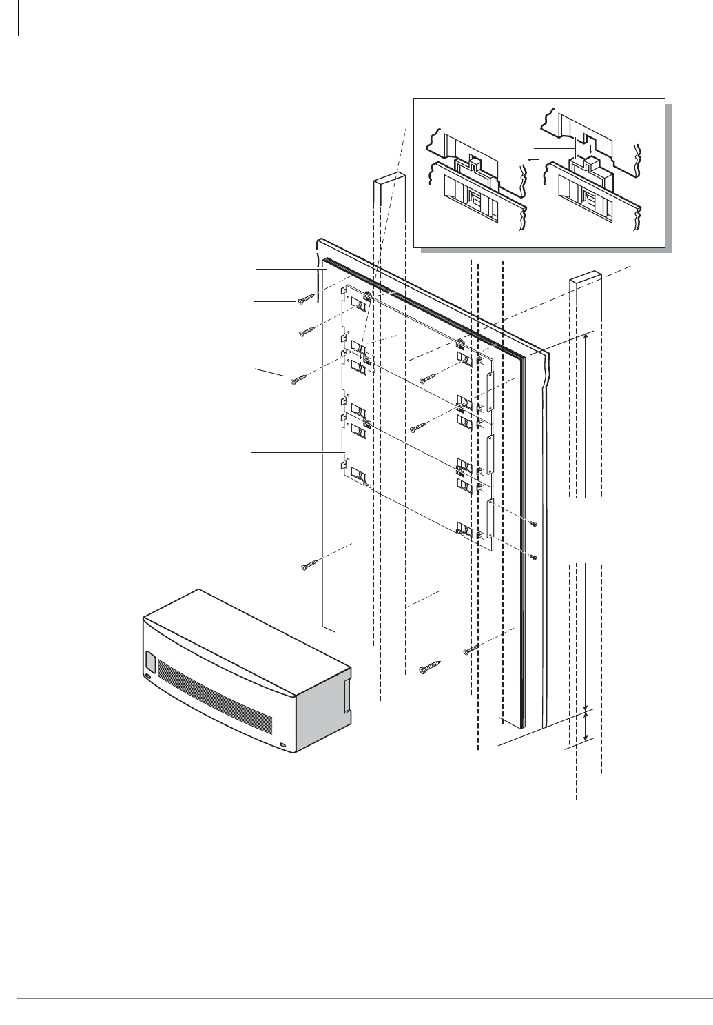
Strata CTX670 Installation
Mount Cabinets
4-12 Strata CTX I&M 06/04
Back Cover
6 inches between
bottom cabinet
and floor
Plaster Board Wall
Dealer Supplied
#12 X 1.25"
Wood Screws
(4 Screws Per
Cabinet)
#12 X 2" (or long enough to
secure to the wall stud)
Wood Screws
Use as many as necessary to
secure plywood backboard.
3/4" Plywood Backboard
Floor
5040
5.0 ft. minimum
for 5 cabinets
or
6.5 ft.
for 7 cabinets
Locating
Parts
Figure 4-4 Cabinet Mounting Surface Diagram
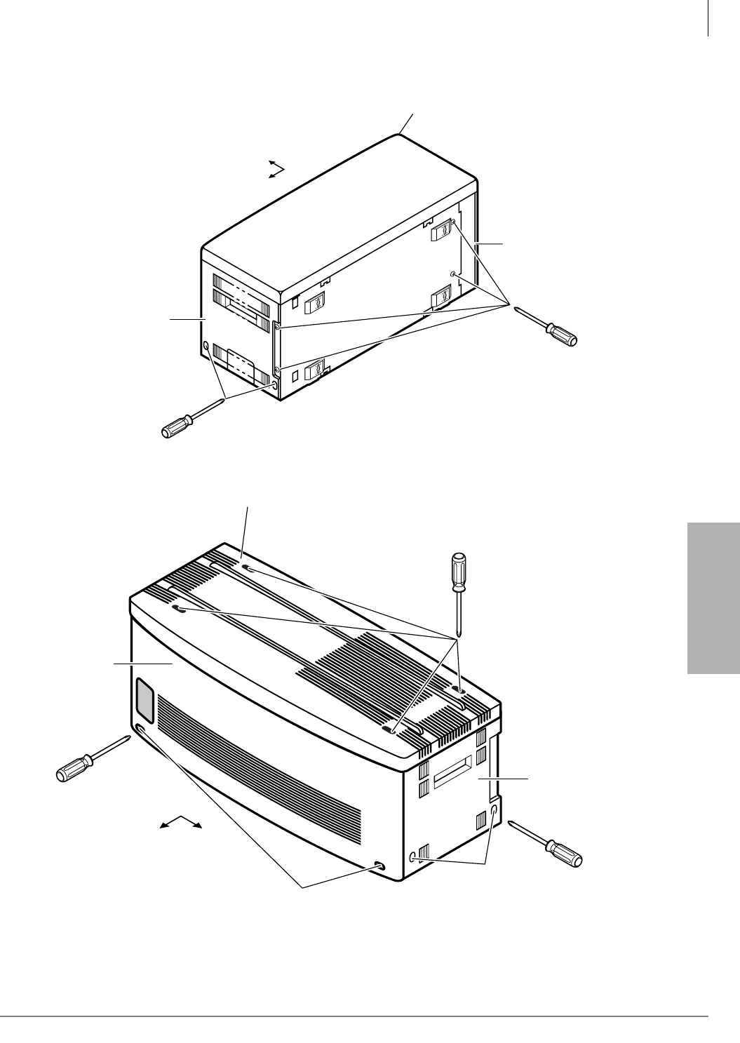
Strata CTX670 Installation
Mount Cabinets
Strata CTX I&M 06/04 4-13
Strata CTX670
Installation
Figure 4-5 Cabinet Cover Removal and Installation
Right
Front
Back Cover
Top Cover
(Base Cabinet Only)
Right
Side
Cover Remove four
screws to
remove back cover
Loosen two screws
to remove the side cover
(right and left covers)
5041
5038
Right
Front
Right Side
Cover
Top Cover
(Base Cabinet Only)
Front
Cover
Loosen two screws
to remove front cover
Loosen two screws
to remove the side covers
(right and left side covers)
Loosen four screws to
remove the top cover.
Note:
Do not remove the top
cover if the Base Cabinet
is the top cabinet.
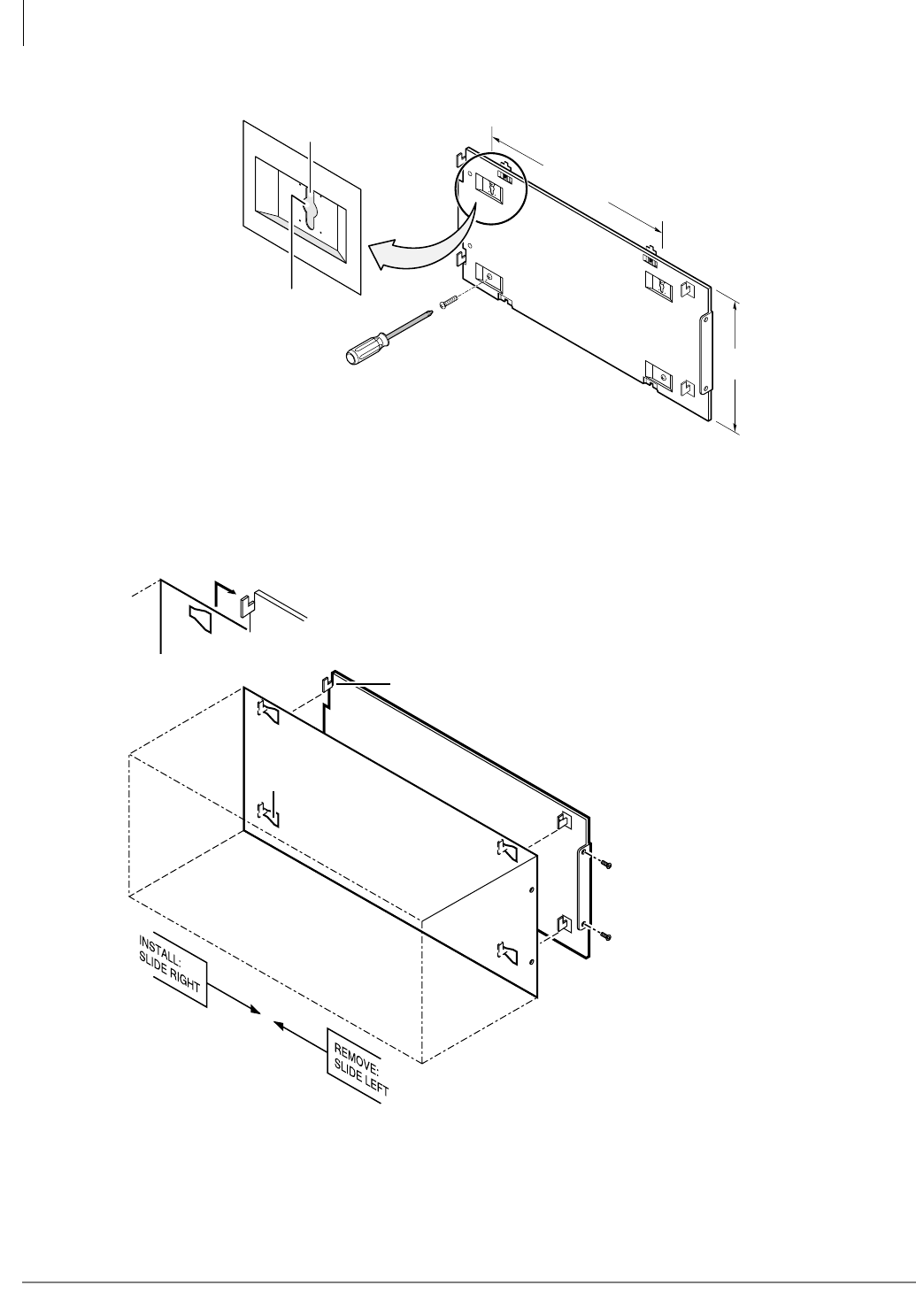
Strata CTX670 Installation
Mount Cabinets
4-14 Strata CTX I&M 06/04
18.8 IN.
9.9 IN.
Back Cover
Trace Upper
Arch
Marking Hole
1459
Figure 4-6 CTX670 Back Cover Mounting Holes
1460
Important!
After mounting
cabinet to back cover
use two screws to
fasten cabinet to back
cover.
Hanger
Back Cover
Mounting Strip
Hanger Hole
Back Cover
Hang cabinet on back cover
then slide to right.
Figure 4-7 CTX670 Mounting Cabinet on Back Cover
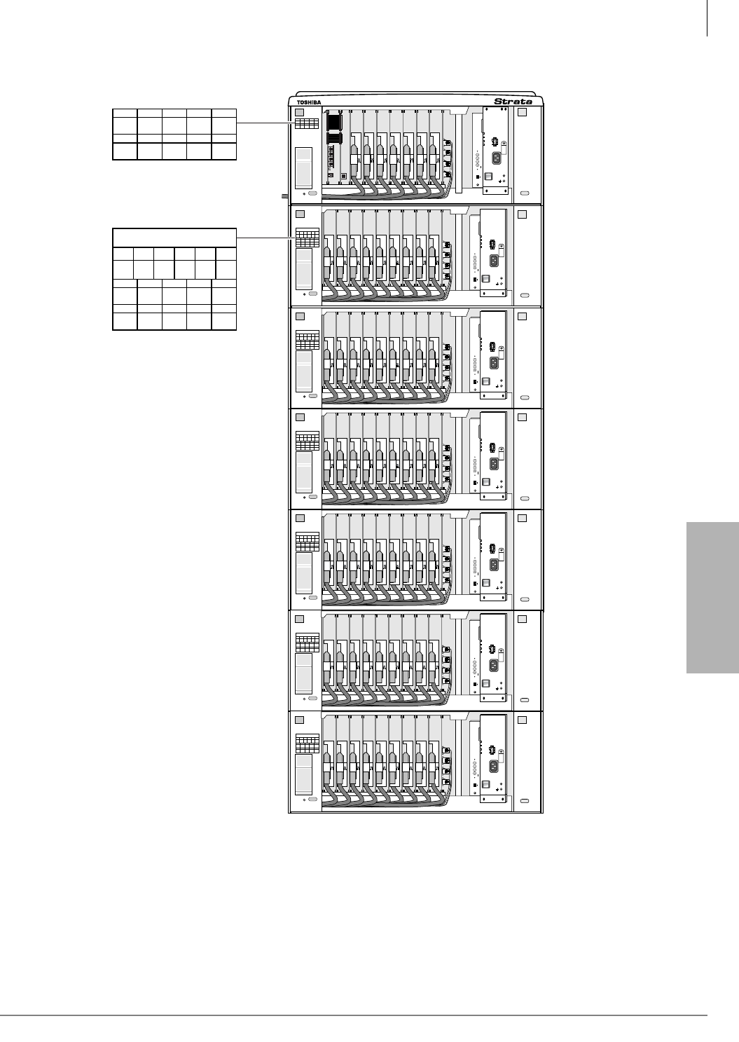
Strata CTX670 Installation
Mount Cabinets
Strata CTX I&M 06/04 4-15
Strata CTX670
Installation
Figure 4-8 CTX670 Cabinet Interior
POW
+5V
-5V
P.F.
RESET
EXP
BASE
AC IN
BATT
DC OUT
-24V1
-24V2
-24V3
-24V4
+
-
POWER
ON
OFF
FG
5002
B101 B102 S101 S102 S103 S104 S105 S106 S107 S108
S201 S 02 S203 S204 S205 S206 S207 S208 S209 S210
CABINET NO.
2
S201 S202 S203 S204 S205
S206 S207 S208 S209 S210
34567
POW
+5V
-5V
P.F.
RESET
EXP
BASE
AC IN
AC IN
DC OUT
-27V1
-27V2
-27V3
-27V4
+
-
POWER
ON
OFF
FG
5002
POW
+5V
-5V
P.F.
RESET
EXP
BASE
AC IN
BATT
DC OUT
-27V1
-27V2
-27V3
-27V4
+
-
POWER
ON
OFF
FG
5002
S201 S202 S203 S204 S205 S206 S207 S208 S209 S210
CABINET NO.
2
S201 S202 S203 S204 S205
S206 S207 S208 S209 S210
34567
POW
+5V
-5V
P.F.
RESET
EXP
BASE
AC IN
AC IN
DC OUT
-27V1
-27V2
-27V3
-27V4
+
-
POWER
ON
OFF
FG
5002
POW
+5V
-5V
P.F.
RESET
EXP
BASE
AC IN
BATT
DC OUT
-27V1
-27V2
-27V3
-27V4
+
-
POWER
ON
OFF
FG
5002
CABINET NO.
2
S_01 S_02 S_03 S_04 S_05
S_06 S_07 S_08 S_09 S_10
34567
B101 B102 B101 S102 S103
S104 S105 S106 S107 S108
B101 B102 S101 S102 S103
S104 S105 S106 S107 S108
5460
S201 S202 S203 S204 S205 S206 S207 S208 S209 S210
CABINET NO.
2
S201 S202 S203 S204 S205
S206 S207 S208 S209 S210
34567
POW
+5V
-5V
P.F.
RESET
EXP
BASE
AC IN
AC IN
DC OUT
-27V1
-27V2
-27V3
-27V4
+
-
POWER
ON
OFF
FG
5002
POW
+5V
-5V
P.F.
RESET
EXP
BASE
AC IN
BATT
DC OUT
-27V1
-27V2
-27V3
-27V4
+
-
POWER
ON
OFF
FG
5002
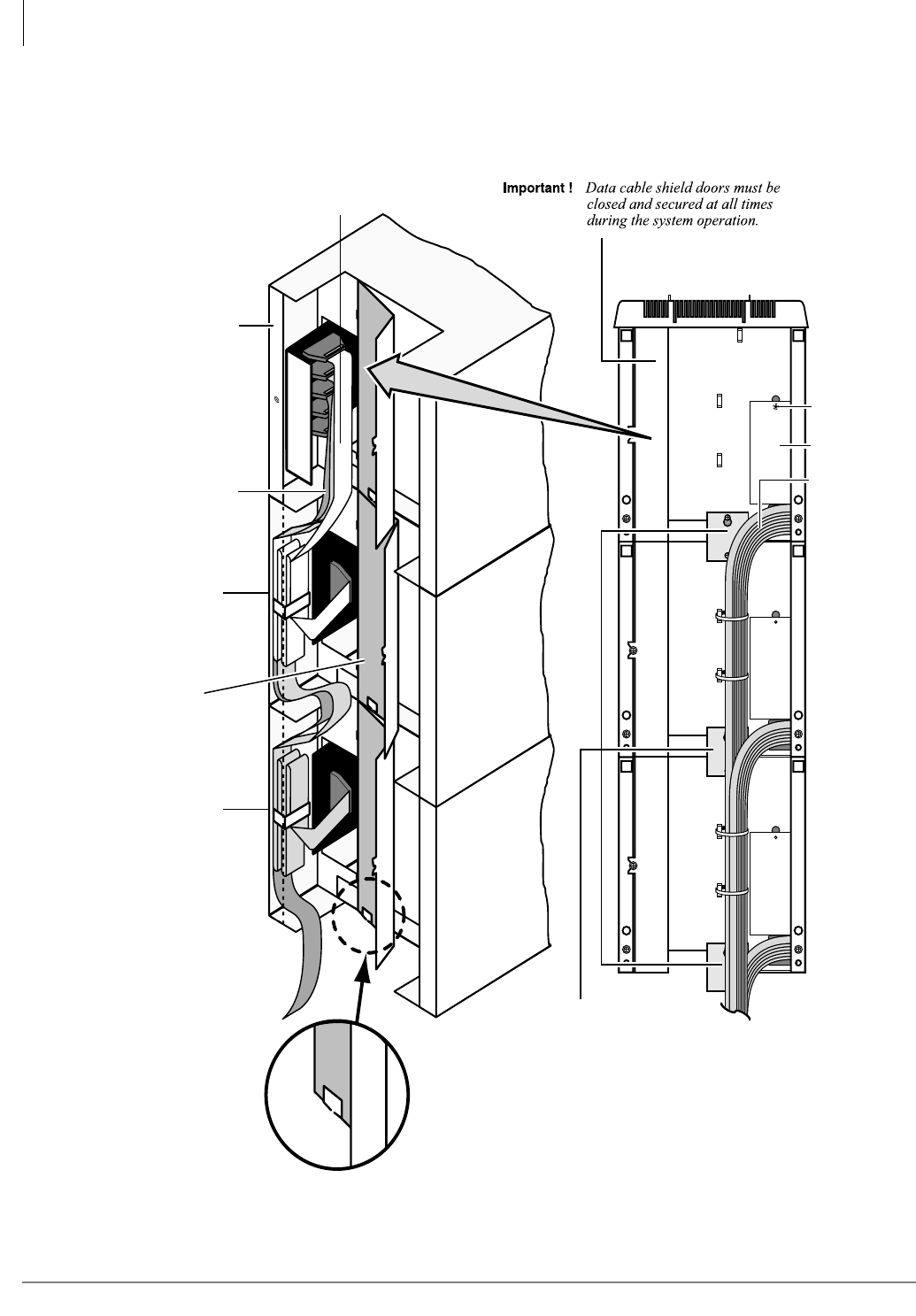
Strata CTX670 Installation
Install Data Cables
4-16 Strata CTX I&M 06/04
Step 3: Install Data Cables
1. After mounting the CTX670 cabinets, install the data cables. Then, install the bonding plate per
Figure 4-9.
Figure 4-9 Data Cables Shown in Cabinet Interior—Side View
To MDF
Left Side
Bonding Connection Plate
(required for all wall mount
expansion cabinets)
Remote Cabinet Cable
feed through hole
PCB Cable
Front
Data Cables
CAB
2
CAB
3
CAB
4
CAB
5
CAB
6
CAB
7
Cable Guard
Screw
Cable Guard
Data
Cable
Door
(shown open)
Base Cabinet
Expansion
Cabinet
Expansion
Cabinet
Cab 2 Cable
5342
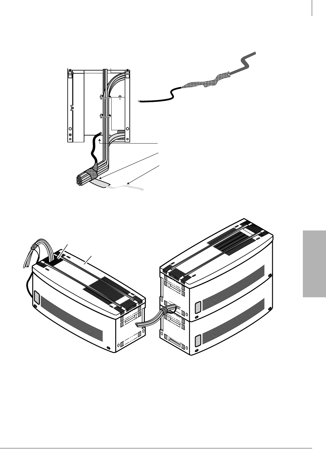
Strata CTX670 Installation
Install Data Cables
Strata CTX I&M 06/04 4-17
Strata CTX670
Installation
2. Wrap the cables in with the mesh tie. The purpose of the wrap is to shield the cables from EMI/
RFI effects. See Figure 4-10.
Front Cable Shield
(B50MT)
1. Attach lead to grounding screw.
2. Wrap mesh around
communication cables.
3. Secure with velcro strap.
CAUTION!
Mesh strap should not touch
cabinet metal surfaces.
Part No. B50MT comes with the Base
Cabinet. It must be ordered separately
for each Remote Cabinet pair.
25-Pair
Amphenol
Cables
5045
To MDF
Knock Out Plastic
To
MDF
Top
25-Pair
Amphenol
Cables
Figure 4-10 Cabinet Amphenol Cables

Strata CTX670 Installation
Ground the System
4-18 Strata CTX I&M 06/04
Step 4: Ground the System
The system requires a solid earth ground for proper operation and safety. The AC power cord(s)
already contains a conductor for the “third wire ground” provided by the commercial power outlet
(see Figure 4-11, for grounding points “A” and “B”). An insulated conductor must connect the
frame ground terminal on the Base Cabinet to a cold water pipe or the building ground (point “B”).
Before connecting the system to the AC power source, measure the impedance of the building
ground reference. If the ground path connected to the system has an impedance of 1 ohm or more,
a better ground must be installed. In Figure 4-11, the grounding path between point “A” and the
single point ground “B” must be less than 0.25 ohms.
The “third wire ground” coming from the primary AC power outlet must be dedicated and must be
routed through the same conduit as the phase conductors serving the system. The conductor
connected to the frame ground (FG screw) on the system power supply must be insulated and
comply with the general rules for grounding contained in Article 250 of the National Electrical
Code, NFPA 70, but must not depend on the cord and plug of the system.
If the CTX670 system consists of more than one cabinet, you must install the bonding connection
plates that come attached to each expansion cabinet. Refer to Figure 4-9. Connect the mother
board ground wires and the intercabinet ground wires per Figure 4-11.
Wrap the cable mesh shield (part No. B50MT) around the 25-pair communication cables that carry
stations over tip and ring, per Figure 4-10.
WARNING! Failure to provide a proper ground may be a safety hazard to service
personnel or lead to confusing trouble symptoms. In extreme cases, system
failure may result because the system is not properly protected from lighting
or power transients.
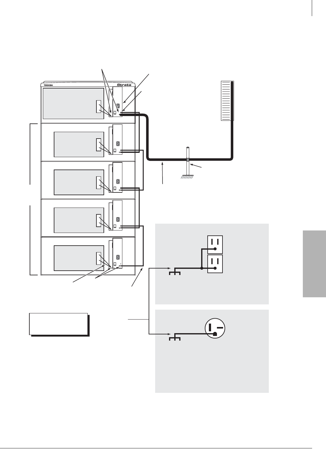
Strata CTX670 Installation
Ground the System
Strata CTX I&M 06/04 4-19
Strata CTX670
Installation
Figure 4-11 Cabinet Grounding
Cabinet Motherboard
Cabinet
Motherboard
Cabinet
Motherboard
Cabinet
Motherboard
Cabinet
Motherboard
FG Screws
Base
Cabinet
Power
Supply
FG (Frame Ground) Screws
The Single Point Ground must always be connected to
the Base Cabinet Power Supply FG Screw
(Top cabinet - Wall Mount or Bottom cabinet - Floor Mount.)
Expansion
Cabinets
Up to six
Inter-cabinet green wires
supplied with each cabinet
Green/Green Yellow
ground wires from
Motherboard
Earth Ground:
AWG #6 Wire
(minimum)
Length: 60 Feet
(maximum)
Per General Rules of Article
250 of the National Electric
Code, NFPA70
ONEAC 6-AP
or 6-DP
Solid State
Secondary
Protectors
Third Wire
AC Ground
Insulated Ground Wire “B”
Note:
The impedance of the link
between point “A” and “B” must
be less than 0.25 ohms.
Note:
The ground must be
routed through the
same conduit as the
phase conductors
serving the system.
Single Point Ground (SPG)
Cold Water Pipe or Ground Rod
Note:
The SPG cannot be structural
steel members or conduit.
“A”
“A”
Note:
The impedance of
the link between
point “A” and “B”
must be less than
0.25 ohms.
Note:
The impedance of
the link between
point “A” and “B”
must be less than
0.25 ohms.
120VAC System Primary Power ( 1-5 cabinets only )
Building Main Power
Panel Electrical Ground
208VAC ± 20VAC (50/60 Hz)
or 240VAC ± 20VAC (50/60 Hz)
Dedicated 20 Amp
Branch Circuit.
If 208VAC is used, the plug may have to be
changed by a licensed electrician.
Note:
The system may be
powered by 120, 208,
or 240VAC.
NEMA 6-20R,
240VAC
208 or 240VAC System Primary Power ( 1-7 cabinets )
115VAC ± 10VAC (50/60 Hz)
Dedicated 20 Amp
Branch Circuit
Building Main Power
Panel Electrical Ground
“B”
AWG #6 Wire
(minimum)
Length: 60 Feet
(maximum)
Point “B” is always on the
Base Cabinet, whether it's
on the top or bottom.
NEMA 5-15R,
120VAC
5044
The cabinets must be
located no more than 9
feet from the AC outlet.

Strata CTX670 Installation
Install AC Power Components
4-20 Strata CTX I&M 06/04
Step 5: Install AC Power Components
AC Power Requirements
The Strata CTX670 requires a single-phase, 50/60 cycles power source of 120, 208, or 240VAC,
on a dedicated 20 ampere circuit breaker. 208VAC or 240VAC is required for six or seven cabinet
systems.
The CTX670 power supply, BPSU672, automatically detects and adjusts for the type of AC
voltage (120/208/240) to which it is connected.
Toshiba recommends that a dedicated AC service panel be used for the CTX670. AC outlets must
be dedicated to CTX670 use, fused, and grounded. Equipment unrelated to the CTX670 must not
be connected to the circuit or service panel dedicated to the CTX670.
Note It may not always be possible to power a complete CTX670 from a single circuit breaker
panel. For example, in the case where a cabinet is remotely located.
To avoid accidental turn-off, do not configure the outlet serving the CTX670 with an On/Off
switch. AC outlets serving the cabinets must be close enough so that the power cord from the
cabinet power supply or power strip can reach the outlet (these power cords are nine ft.).
AC wall outlets for the CTX670 must be on dedicated 20amp breakers. AC outlets must meet
National Electrical codes specifications: NEMA 5-20R for 120VAC or NEMA 6-20R for
208VAC/240VAC.
AC power cabling requirements vary, depending on: The method of cabinet installation (floor or
wall mount), AC power source voltage (120VAC, 208VAC or 240VAC) and the number of
cabinets. Requirements for distribution of AC power within the cabinets of the CTX670 are as
described in Cabinet AC Power Distribution section.

Strata CTX670 Installation
Install AC Power Components
Strata CTX I&M 06/04 4-21
Strata CTX670
Installation
Cabinet AC Power Component Description
The table shown below identifies the cabinet parts required to distribute AC power within the
Strata CTX670 cabinets.
Table 4-1 Power Cabinet Hardware
Option Description
RPSB2
Cabinet power strip for 120VAC primary power – provides three standard 120VAC/15A outlets
(NEMA 5-15R) and nine ft. AC power cord with standard 120VAC/15A plug (NEMA 5-15P). This
unit is field installed inside system cabinet side panels. The system can use 12 amps. (max.).
See Figures 4-12~4-17.
One RPSB2 is required for two or three cabinet systems if the local electric code allows only one
AC power cord to be connected to the system.
Note If the local electric code allows only one AC power cord to be connected to the system,
208VAC or 240VAC must be used as primary AC power for systems with four or more
cabinets.
One RPSB2 is required for a three or four cabinet system if the local electric code allows two AC
power cords connected to the system.
Two RPSB2s are required for a five cabinet system if the local electric code allows two AC
power cords connected to the system.
BPSB240
Cabinet power strip for 208VAC or 240VAC primary power. Provides three 240VAC/20A outlets
(NEMA 6-20R) and nine ft. AC power cord with a standard 240VAC/20A plug (NEMA 6-20P).
This unit is field installed inside system cabinet side panels. The cord is rated at 16 amps.
(max.). See Figures 4-14~4-17.
One BPSB240 is required for two or three cabinet systems.
Two BPSB240s are required for four or five cabinet systems.
Three BPSB240s are required for six or seven cabinet systems.
Note
●Local electric codes allow only one AC power cord to be connected to the system when using
208VAC or 240VAC as the primary AC power.
●If using 208VAC as primary power, the plug on the BPSB240 AC power cord
(NEMA 6-20P) may have to be changed by a certified electrician depending on local electric
codes.
BACL240
AC208V or AC240VAC nine ft., 10 amps. (max.), power supply cord. This cord must be used
when the system is powered by 208VAC or 240VAC. One cord is required for each cabinet
power supply and must be ordered separately only if using 208VAC or 240VAC as the system
primary AC power.
Note The cord conforms with a National Electric Code standard plug (NEMA 6-20P) 208VAC/
240VAC. The power strip plug that exits the system may have to be changed to a twist-
lock type by a certified electrician to conform with local electric codes.
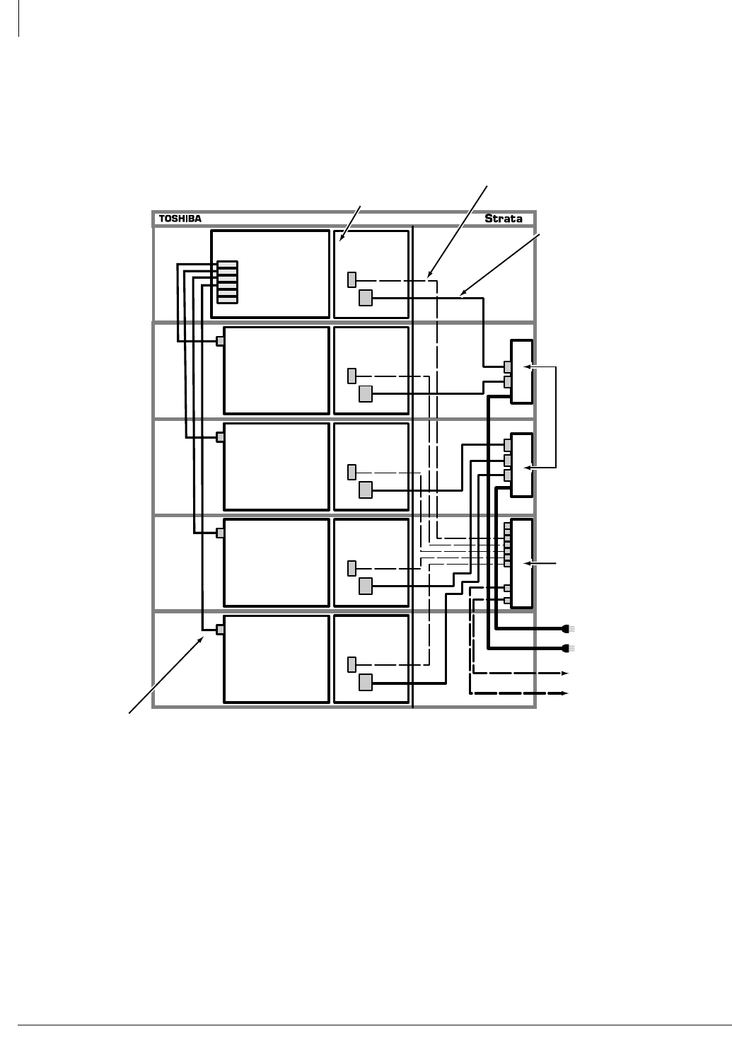
Strata CTX670 Installation
Install AC Power Components
4-22 Strata CTX I&M 06/04
AC/Reserve Power and Data Cabling Overview
Figures 4-12 and 4-13 show an overview of the AC power and data cabling for the CTX670.
Detailed illustrations of AC power strips and cords are on the following pages.
Motherboard BPSU672A
BATT
AC IN
BPSU672A
BATT
AC IN
BPSU672A
BATT
AC IN
BPSU672A
BATT
AC IN
BPSU672A
BATT
AC IN
CHSUB672A
Cabinet 1
(base)
CHSUE672A
Cabinet 2
(expansion)
CHSUE672A
Cabinet 3
(expansion)
CHSUE672A
Cabinet 4
(expansion)
CHSUE672A
Cabinet 5
(expansion)
Data Cable
(supplied with expansion cabinet)
7 BBTC2A-2M battery cables
supplied with BBDB
5046
Power Strip
• RPSB2 for
120VAC only
Battery Distribution Box
• BBDB
Power Strip Cables
to Primary AC Power outlet
s
(9 ft.) with NEMA 5-15P plug
BBTC1A-2M Cables
to Reserve Power Batteries
(2 m.)
Power Supply
Power supply cord for:
• 120VAC - supplied
2
3
4
5
6
7
Figure 4-12 120VAC Power/Data Cabling for up to Five Cabinets
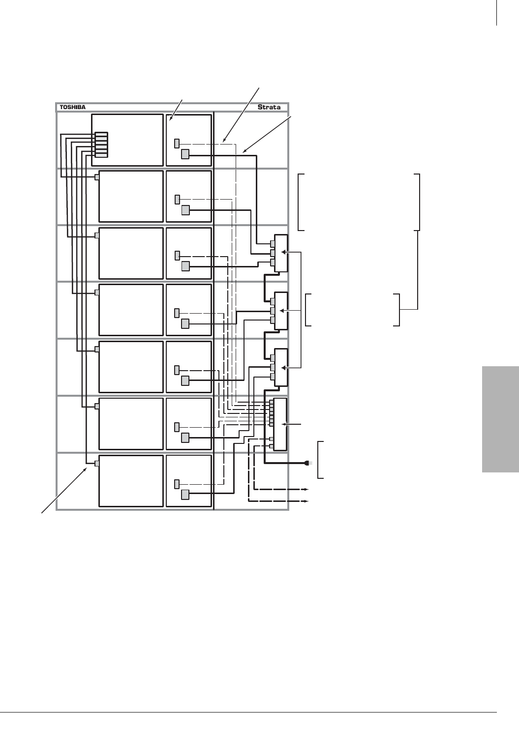
Strata CTX670 Installation
Install AC Power Components
Strata CTX I&M 06/04 4-23
Strata CTX670
Installation
Figure 4-13 208VAC/240VAC Power/Data Cabling for up to Seven Cabinets
BPSU672A
BATT
AC IN
BPSU672A
BATT
AC IN
5626
Motherboard BPSU672A
BATT
AC IN
BPSU672A
BATT
AC IN
BPSU672A
BATT
AC IN
BPSU672A
BATT
AC IN
BPSU672A
BATT
AC IN
CHSUB672A
Cabinet 1
(base)
CHSUE672A
Cabinet 4
(expansion)
CHSUE672A
Cabinet 5
(expansion)
CHSUE672A
Cabinet 2
(expansion)
CHSUE672A
Cabinet 3
(expansion)
CHSUE672A
Cabinet 6
(expansion)
CHSUE672A
Cabinet 7
(expansion)
Data Cable
(supplied with expansion cabinet)
7 BBTC2A-2M battery cables
supplied with BBDB
Battery Distribution Box
• BBDB
BBTC1A-2M Cables
to Reserve Power Batteries
(2 m.)
Power Supply
Power supply cord for
240VAC/ 10 amps,
ordered separately.
2
3
4
5
6
7
Power Strip
• BPSB240A for
208VAC/240VAC only
• Power Strip Cord is (9ft.)
• Power Strip Plug (NEMA 6-20-P)
• To 208VAC or 240VAC Primary
Power Outlet (NEMA-6-20-R)
Caution: Three 240VAC power
strips are required for all
systems with 6 or 7 cabinets.
Only one power cord is allowed
to be connected to the
208VAC/240VAC power outlet.
Strata CTX670 Installation
Install AC Power Components
4-24 Strata CTX I&M 06/04
Cabinet AC Power Considerations
The CTX670 power supply works with either 120VAC, 208VAC or 240VAC. CTX670 only
requires 120VAC (up to three cabinets if one AC cord is allowed or five cabinets if two AC cords
are allowed – see below).
If the system has more then five cabinets, 208VAC or 240AVC is required for the primary AC
power source. 208VAC or 240VAC can always be optionally used for systems with five or less
cabinets for future growth or, if the electrical code requires.
To determine AC power requirements, you need to check local electrical code requirements for
120VAC, 208VAC or 240VAC primary power. Some electrical codes stipulate that:
• 208VAC or 240VAC is required for telephones systems
• Only one electrical cord can connect to the telephone system.
• Only two electrical cords can connect to the telephone system.
• No electrical cord can connect to the telephone system – must use conduit wiring installed by a
certified electrician (example: when system is floor mounted).
Cabinet AC Power Component Requirements for Wall Mounted
Systems
Tables 4-2 and 4-3 show the cabinet parts required to distribute AC power for various
configurations of the CTX670 cabinets. Figures 4-14~4-17 show how to install these parts.
Important! The plugs and wall receptacles required by the local electrical code might differ for
208VAC and 240VAC. Thus in some areas of the U.S., the plug used on the Toshiba
240VAC power strip and 240VAC power supply cord (NEMA code 6-20P) can not
be used for 208VAC installations. In this case, when using 208VAC, the AC plugs on
the BPSB240 power strip cord that connects directly to the 208VAC wall outlet must
be changed by a certified electrician per the local electrical code.
Table 4-2 Wall Mount Cabinet Power Component Requirements for 120VAC Primary Power
Local Electrical Code Cabinets
1 2 3 4 5 6 7
Allows only one 120VAC
power cord from system 0 RPSB2 1 RPSB2 1 RPSB2 N/A N/A N/A N/A
Allows two 120VAC power
cords from system 0 RPSB2 0 RPSB2 1 RPSB2 1 RPSB2 2 RPSB2 N/A N/A
●One dedicated, isolated, 20 amp. AC circuit breaker with dual outlets is required.
●N/A= If the system contains more than three cabinets and if the local code allows only one AC cord, the system requires a
BCCB120 conduit box wired by a certified electrician when using 120VAC as primary power. Otherwise, 208VAC or
240VAC should be used as the primary power source (see cabinet power options listed below).
Table 4-3 Wall Mount Cabinet Power Component Requirements for 208VAC or
240VAC Primary Power
Local
Electrical
Code
Cabinets
1 2 3 4 5 6 7
Allows One
AC power
cord from
system
1 BACL240 1 BPSB240
2 BACL240
1 BPSB240
3 BACL240
2 BPSB240
4 BACL240
2 BPSB240
5 BACL240
3 BPSB240
6 BACL240
3 BPSB240
7 BACL240
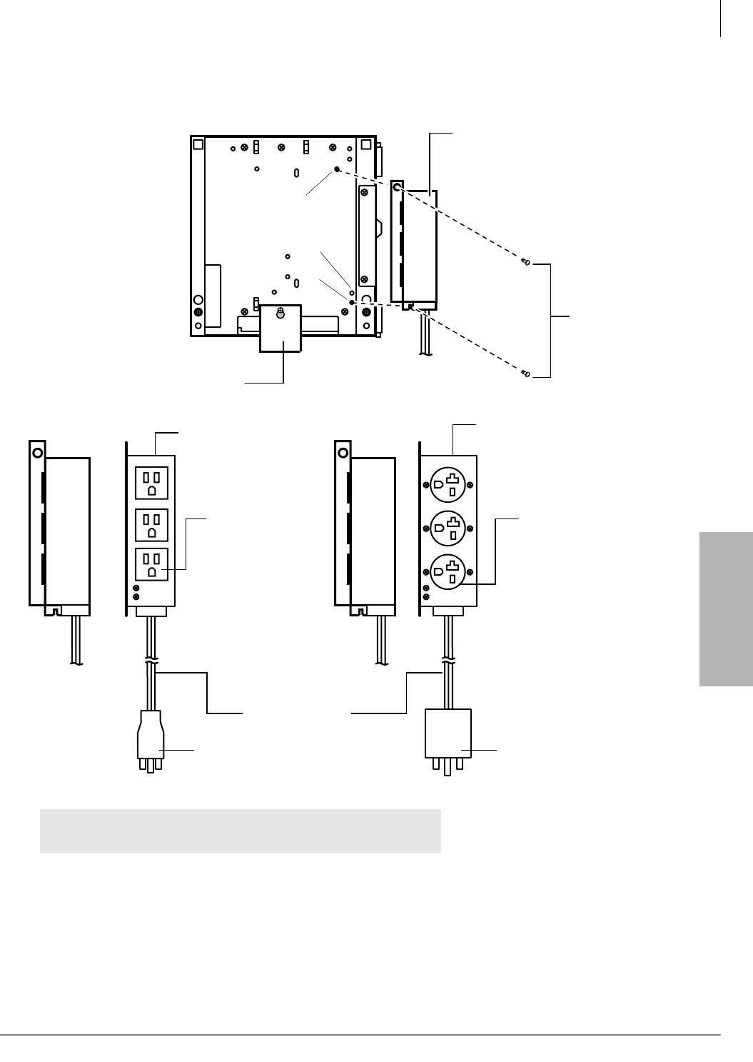
Strata CTX670 Installation
Install AC Power Components
Strata CTX I&M 06/04 4-25
Strata CTX670
Installation
Figure 4-14 AC Power Strip Installation
To AC Outlet
Power Strip
(RPSB2
or BPSB240)
Screws
provided
with
Power Strip
Power Strip for
208VAC or 240VAC (only)
BPSB240
Receptacle
Pass & Seymour 5858
NEMA No. 6-20R
16A max.
Cable Length 3 m.
(Approx. 9 ft.)
Cabinet Right-Side-Panel
Cabinet
Bonding Plate
5219
Power Strip for 120VAC (only)
RPSB2
Receptacle
NEMA No. 5-15R
Plug
NEMA No. 5-15P
12A max.
Plug
Pass & Seymour 5466-X
NEMA No. 6-20P
16A max.
WARNING! To prevent serious injury, always mount power strips with
provided screws before inserting plug into AC power.
RPSB2/BPSB240
RPSB2
BPSB240
5219
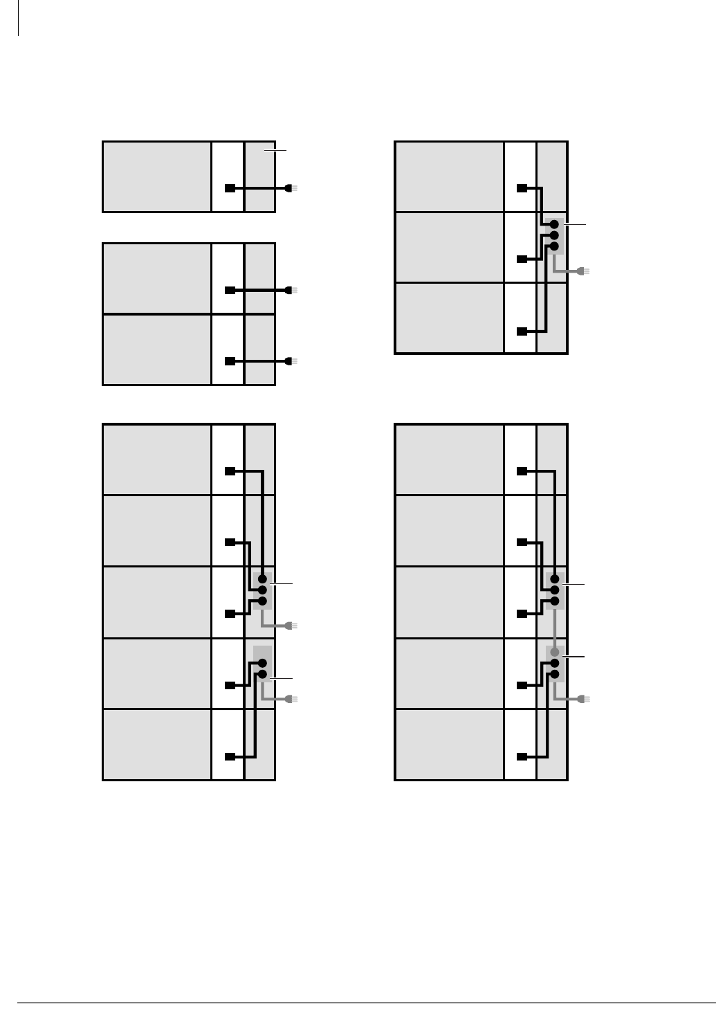
Strata CTX670 Installation
Install AC Power Components
4-26 Strata CTX I&M 06/04
Figure 4-15 AC Power Cords for One to Five Cabinets
Cabinet 1 Power
Supply
Cabinet 2 Power
Supply
Cabinet 3 Power
Supply
Cabinet 4 Power
Supply
Cabinet 5 Power
Supply
One cabinet - one AC cord exits system
Cabinet 1 Power
Supply
Cabinet 2 Power
Supply
Two cabinets - two AC cord exit system
Two or three cabinets - one AC cord exits system
5033
Four or five cabinets - two AC cords exit system Four or five cabinets - one AC cord exits system
Cabinet 1 Power
Supply
Cabinet 2 Power
Supply
Cabinet 3 Power
Supply
Cabinet 4 Power
Supply
Cabinet 5 Power
Supply
Notes 1, 2
(208VAC
or 240VAC only)
Notes 1, 2
(120VAC only)
Note 2
(120VAC only)
Note 2
(120VAC only)
Note 2
(120VAC only)
Notes 1, 2
(120/208/240VAC)
Notes 1, 2
(120/208/240VAC)
Cabinet 1 Power
Supply
Cabinet 2 Power
Supply
Cabinet 3 Power
Supply
BPSB240
(208/240VAC)
or
RPSB2
(120VAC)
Right-side
panel
Cabinet 1 Power
Supply
Front
BPSB240
BPSB240
RPSB2
RPSB2
Notes
1. 120VAC cord is supplied with cabinet. A special cord, BACL240, must be ordered for
each cabinet if 208VAC or 240VAC is used.
2. Power Strips must plug into the following AC outlets: 120VAC to NEMA 5-15R, and
208/240VAC to NEMA 6-20R.
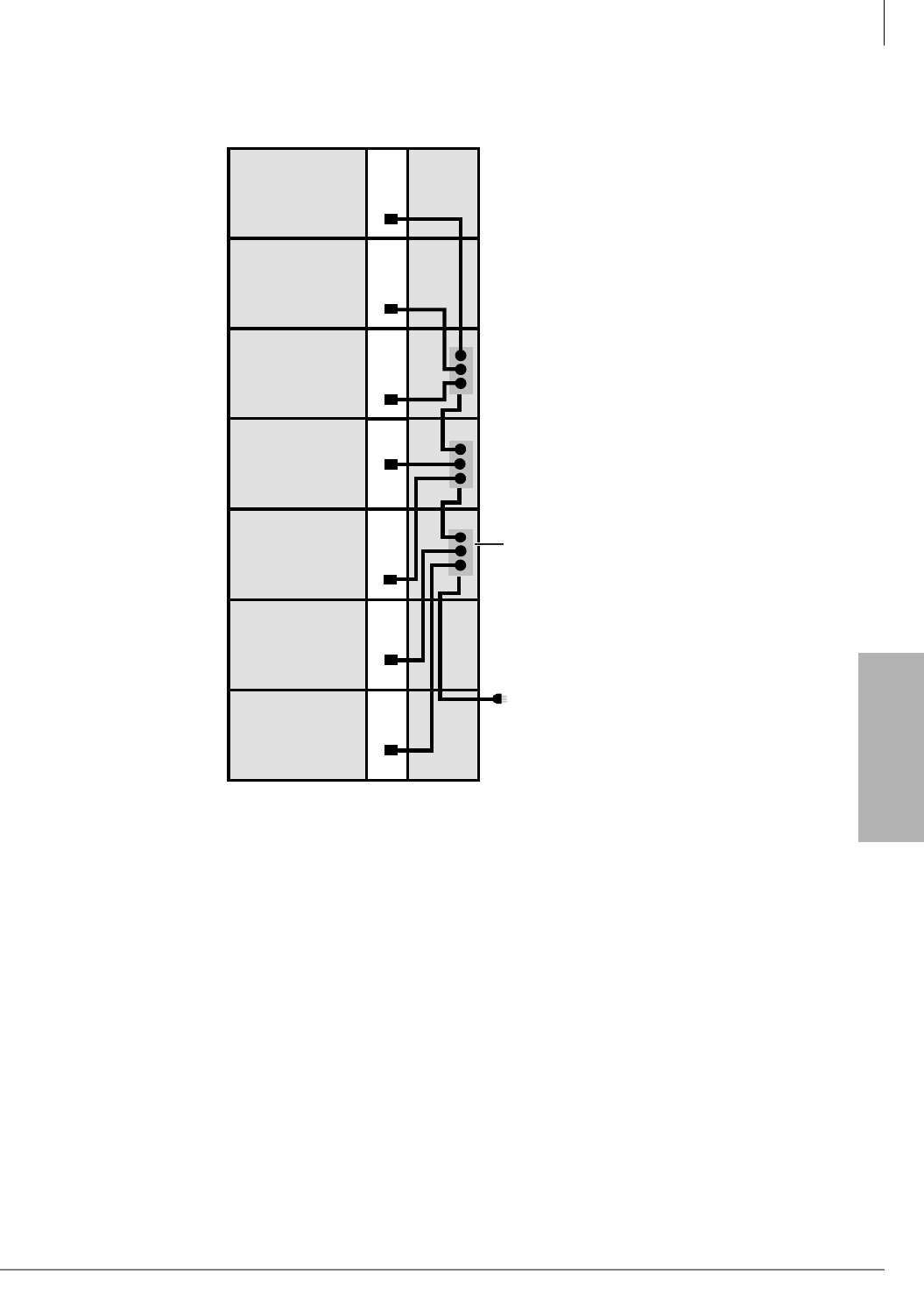
Strata CTX670 Installation
Install AC Power Components
Strata CTX I&M 06/04 4-27
Strata CTX670
Installation
Figure 4-16 AC Power Cords in Six or Seven Cabinets
5462
Six or Seven cabinets - one AC cord exits system
Cabinet 3 Power
Supply
Cabinet 1 Power
Supply
Cabinet 2 Power
Supply
Cabinet 4 Power
Supply
Cabinet 5 Power
Supply
Cabinet 6 Power
Supply
Cabinet 7 Power
Supply
Notes 1, 2
(208VAC
or 240VAC only)
BPSB240
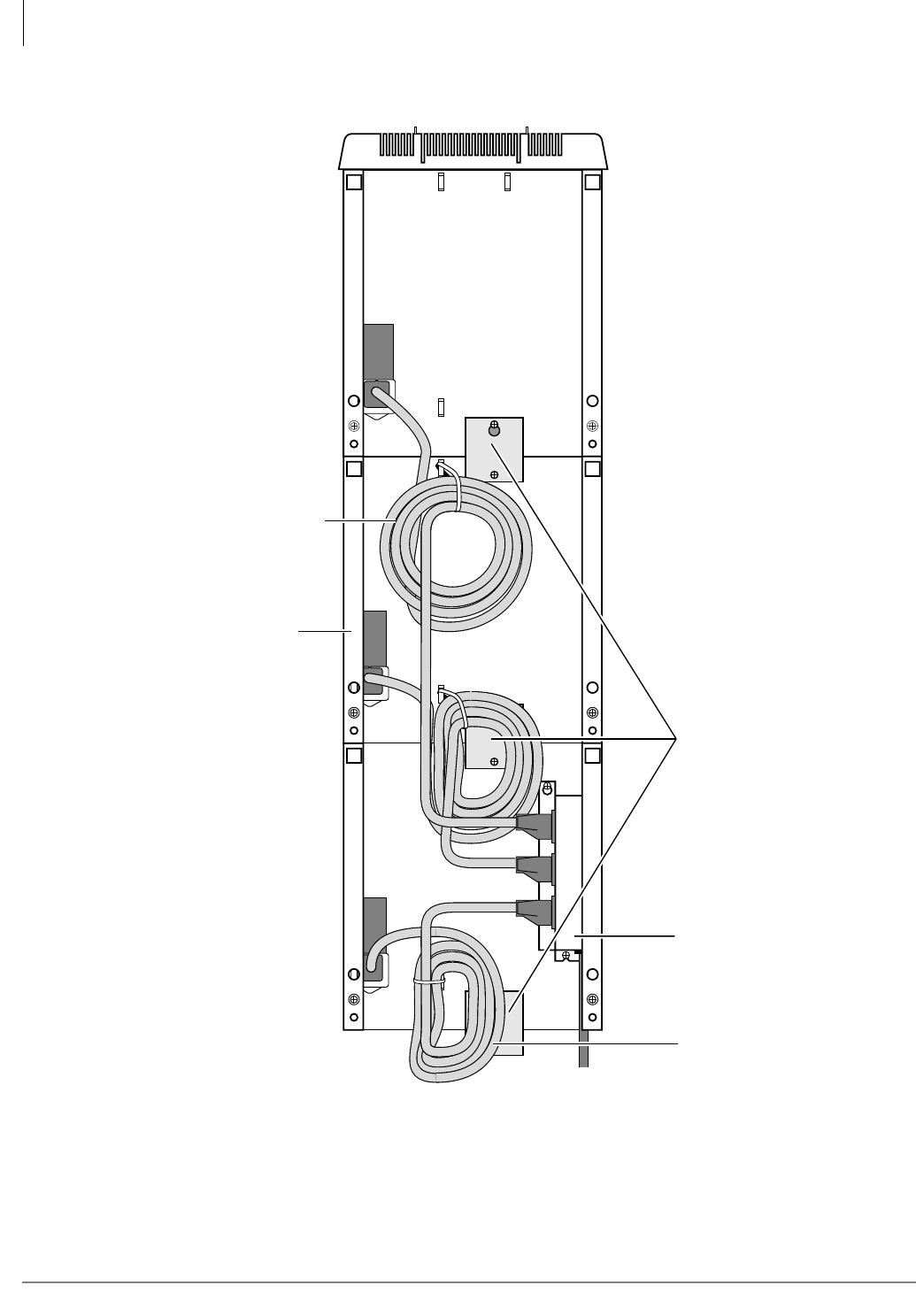
Strata CTX670 Installation
Install AC Power Components
4-28 Strata CTX I&M 06/04
To AC Outlet
Right Side
Bonding Connection
Plates
(Required for all wall
mounted expansion
cabinets on both
right and left sides)
AC Power
Cables
Front
RPSB2 or BPSB240
Power Strip
All Power Strip cords
are 9 feet long.
5233
120VAC power supply cord is
shipped with each cabinet.
A special AC power supply cord
(BACL240) must be ordered
separately for each power
supply if using 208VAC or
240VAC power.
Figure 4-17 AC Power Strips in Cabinet Interior

Strata CTX670 Installation
Install Reserve Power
Strata CTX I&M 06/04 4-29
Strata CTX670
Installation
Step 6: Install Reserve Power
Two or four customer-supplied, 12VDC batteries (80 amp hours maximum) can be connected to
the system as a power failure backup. In the event of a power failure, the system automatically
switches over to battery power without any interruption to existing calls or other normal system
functions.
Important! Batteries must be connected when normal AC power is available; they cannot be
connected during an AC power failure situation.
The length of time reserve power operates depends on the system, size and number of batteries
provided, and the system load. Typical reserve power duration estimates and battery specifications
are estimated with the following considerations (see Table 4-4):
• Batteries have full charge at start of operation.
• Two or four batteries connected per Figure 4-18.
• Batteries are 12VDC, rated at 80 amp/hours each.
• System is operating at full load traffic with LCD phones.
• Batteries used for this test are gel-cell and maintenance-free. Reserve duration will vary
depending upon battery type, age, and manufacturer. These figures should only be used as an
estimate.
The procedure for installing reserve power varies, depending on the number of cabinets in the
system and the mounting method employed in installing the cabinets. The following text details
reserve power battery installation requirements.
Table 4-4 Typical Reserve Power Duration Estimate
Number of Cabinets 1234567
Estimated operation time
Two-battery configuration
12.0
hrs. 6.0 hrs. 4.0 hrs. 3.0 hrs. 2.5 hrs. 2.0 hrs 1.8 hrs
Estimated operation time
Four-battery configuration
24.0
hrs. 12.0 hrs 8.0 hrs 6.0 hrs. 5.0 hrs. 4.0 hrs 3.5 hrs
WARNING! Some batteries can generate explosive gases. Therefore,
ensure that batteries are located in a well-ventilated area.
Do not smoke near batteries.
Avoid creating any electrical sparks near batteries.
Use commercially available battery enclosures to reduce risk to nearby
people and equipment.
WARNING! Battery cables that exit the cabinet(s) are not UL listed because of
possible incorrect installations. Have a licensed electrician install these
cables.

Strata CTX670 Installation
Install Reserve Power
4-30 Strata CTX I&M 06/04
Reserve Battery Cabinet Components/Cables
The part names and descriptions of the reserve battery cabinet components and cables are shown in
Table 4-5.
Reserve Power for One or Two Cabinets (Wall Mount)
1. Connect the black jumper wire (supplied with the PBTC-3M cable) from the positive terminal
of one 12VDC battery to the negative terminal of the second 12VDC battery (Figure 4-18).
2. Ensure that a serviceable 10-amp fuse is installed in the in-line fuse holder of the PBTC-3M
cable.
3. Connect the PBTC-3M battery cable white lead to the open positive terminal of the 12VDC
battery. Connect the black lead to the open negative terminal of the second 12VDC battery.
Important! The cabinet(s) must be connected to the (live) AC power source, and the power
supply On/Off switch set to On prior to the final step of connecting the reserve
power batteries to the power supply via the BATT+/- receptacle. If the batteries are
connected after AC power is lost, reserve power will not function.
4. Connect the PBTC-3M battery cable two-prong male plug to the Base Cabinet power supply
BATT +/- receptacle.
5. Repeat Steps 3 and 4 to connect a PBTC-3M to the Expansion Cabinet.
6. To test reserve power operation, disconnect system AC power plugs with power supply On/Off
switches in the On position. The system should continue to operate without interruption.
Note If connecting four batteries, follow the wiring diagram in Figure 4-18.
Table 4-5 Reserve Battery Cabinet Components/Cables
Option Description
PBTC-3M
A three-meter battery cable used to connect reserve power batteries to the system power
supply when the system has less than three cabinets. One reserve power cable is required
for each cabinet in a one or two cabinet system (wall or floor mount). The cable connects the
CTX670 cabinet power supply directly to the battery terminals (a BBDB is not required).
BBDB
CTX670 reserve power battery distribution box is required when connecting reserve power
batteries to three or more cabinets (wall or floor mount). The box is field installed into one of
the CTX670 cabinet side panels.
The BBDB provides seven BBTC2A-2.0M, battery distribution cables to connect reserve
power from the BDDB box to each individual cabinet power supply.
One or two BBTC1A-2.0M must be ordered separately when using the BBDB battery
distribution box.
BBTC1A-2.0M
A two-meter battery cable used to connect reserve power batteries to the BBDB battery
distribution box. One reserve power cable is required in a three or four cabinet system and
two cables are required for five or more cabinet systems (wall or floor mount). The cable
connects CTX670 BBDB box directly to the battery terminals.

Strata CTX670 Installation
Install Reserve Power
Strata CTX I&M 06/04 4-31
Strata CTX670
Installation
Reserve Power for Three or More Cabinets (Wall Mount)
1. Install the Battery Distribution Box (BBDB) to the bottom cabinet (see Figures 4-12 and 4-24).
The BCCB is not required for wall mount systems.
2. Connect two Cable “C” jumper wires from the positive terminal of one 12VDC battery to the
negative terminal of the second 12VDC batter, per Figure 4-18 (Cable “C” is supplied with the
BBTC1A-2.0M cable).
3. Ensure that a serviceable 15-amp fuse is installed in the in-line fuse holder of the BBTC1A-
2.0M battery cable.
4. Connect the white lead of the BBTC1A-2.0M battery cable to the open positive terminal of the
12VDC battery. Connect the black lead to the open negative terminal of the second 12VDC
battery.
5. Connect a second BBTC1A-2.0M in parallel to the first BBTC1A-2.0M cable per Steps 2, 3
and 4 instructions.
6. Plug the two BBTC1A-2.0M battery cables into the Battery Distribution Box.
Important! The cabinets must be connected to the (live) AC power source, and the power supply
On/Off switches set to On prior to the final step of connecting the reserve power
batteries to the power supplies via the BATT +/- receptacle. If the batteries are
connected after AC power is lost, reserve power will not function.
7. Connect the BBTC2A-2.0M cables from the Battery Distribution Box to the BATT +/-
receptacle of individual power supplies per Figure 4-12 (BBTC2A-2.0M cables are supplied
with an BBDB distribution box).
8. To test reserve power operation, disconnect the system AC power plugs with the power supply
On/Off switches in the On position. The system should continue to operate without
interruption.
Note If connecting four batteries, follow the wiring diagrams in Figure 4-18.
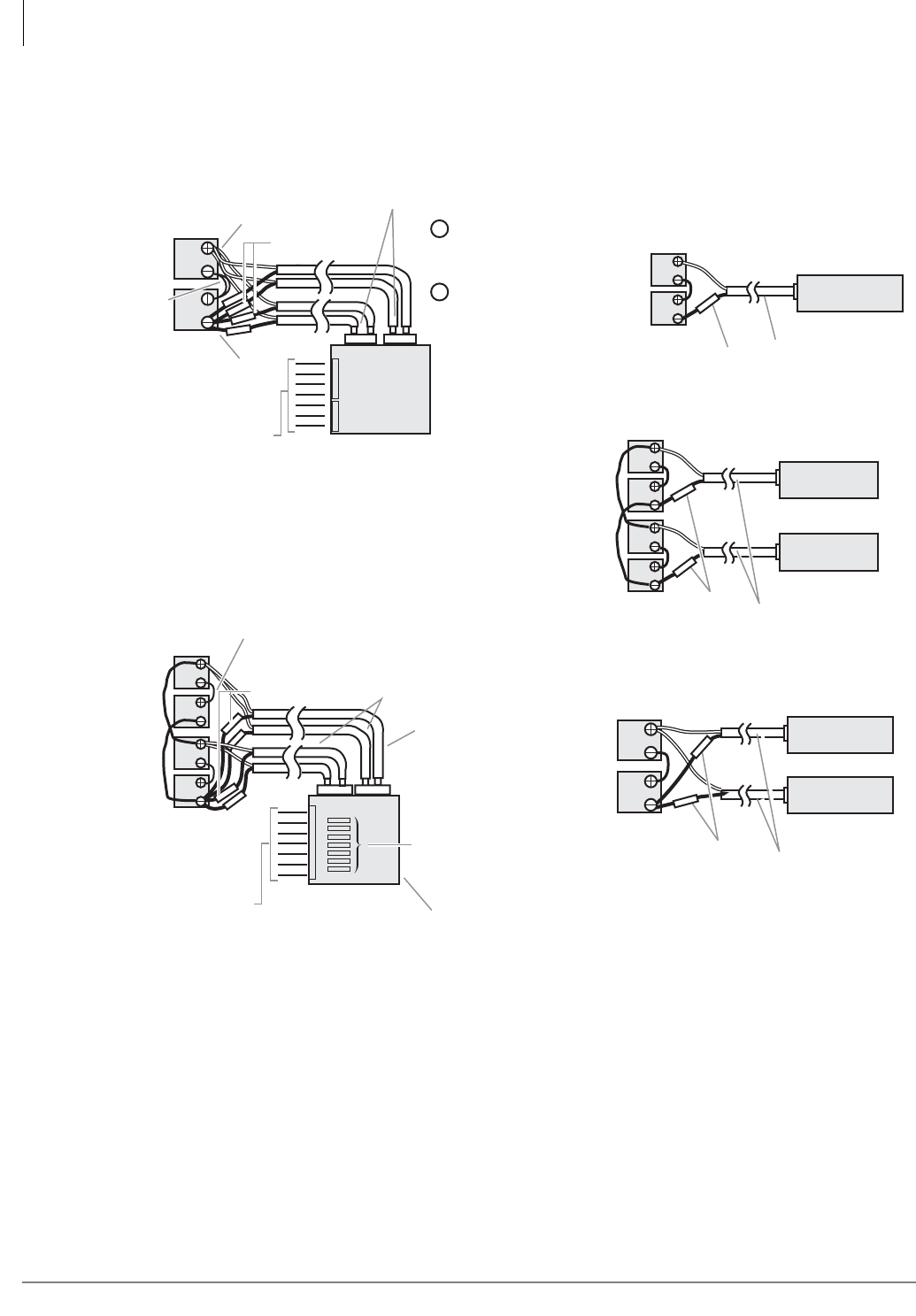
Strata CTX670 Installation
Install Reserve Power
4-32 Strata CTX I&M 06/04
To BPSU672 “BATT”
Connectors (7 max.)
White Wire
Black Wire
15A Fuse (2 each)
2-Batteries/1~7 Cabinets (with BBDB)
12 Volt
Batteries
80 AMP/
HR Each
BBTC2A-2M Cables (7 max.)
supplied with BBDB
4-Batteries/1~7 Cabinets (with BBDB)
To BPSU672 “BATT”
Connectors (7 max.)
2-Batteries/1-Cabinet (without BBDB)
12 Volt
Batteries
80 AMP/
HR each
12 Volt
Batteries
80 AMP/
HR Each
PBTC-3M Cables (9 ft.)
–
+BPSU672 BATT
Connector
BPSU672 BATT
Connector
BPSU672 BATT
Connnector
BPSU672 BATT
Connector
BPSU672 BATT
Connnector
4-Batteries/2-Cabinets (without BBDB)
2-Batteries/2-Cabinets (without BBDB)
10A Fuse
PBTC-3M Cables (9 ft.)
10A Fuse
Exp. Cabinet
Base Cabinet
Base Cabinet
Exp. Cabinet
Base Cabinet
PBTC-3M
Cables (9 ft.)
12 Volt
Batteries
80 AMP/
HR Each
12 Volt
Batteries
80 AMP/
HR each
BATT
BBDB
–
+
–
+
–
+
–
+
“C” Cable,
supplied
with
BBTC1A-2M
Cable
“C” Cables, supplied with
BBTC1A-2M Cable
Fuses
(12 AMP)
BBDB
(cover
removed)
10A Fuse
5221
BBTC2A-2M Cables
(7 max.) supplied
with BBDB
A
+–
A
A
B
+–
B
AB
B
15A Fuse (2 each)
BBTC1A-2M
Cable consists
of two (6.5 ft.) wires.
BBTC1A-2M
Cables (6.5 ft.)
Cabinet
1~4
(only)
Cabinet
5~7
(only)
A
B
2nd cable
required
for 5 or
more
cabinets
only
BBDB
Rating:
27.3VDC,
42A max.
Figure 4-18 Battery Wiring Diagram (Two or Four Batteries) Wall Mount Only

Strata CTX670 Installation
Install Reserve Power
Strata CTX I&M 06/04 4-33
Strata CTX670
Installation
Cabinet Floor Mounting
The part numbers and descriptions of the floor mounting hardware are shown in Table 4-6.
Floor Mounting One or Two Cabinets
1. Remove front, side, and top covers from cabinet(s) (Figure 4-5). Remove plastic locating parts
from all cabinet back covers using a Phillips screwdriver.
2. Make sure that cabinet power supplies (BPSU672A) are installed per “Install Power Supply”
on page 4-6.
3. If installing just one or two cabinets, install the BFIF fixtures on each side of the bottom of the
cabinet (Figure 4-19) and place the cabinet where it should be installed.
4. Set the bottom cabinet on the floor or mount surface, then set the top cabinet on the bottom
cabinet.
5. Fasten the two cabinets together with the four screws provided: (two screws at front “A” and
two at back “B” of cabinet. Place cabinet where it should be installed.
6. Connect the Expansion Cabinet data cable to the “CAB. 2” data cable connector on the Base
Cabinet (Figures 4-9 and 4-12).
...or if installing a Remote Expansion Cabinet: see details in “Remote Cabinet Installation
Instructions” on page 4-56.
7. Install ground wiring, AC and reserve power cabling, and PCB cabling per the “Recommended
Installation Sequence” on page 4-6.
8. Fill out cabinet/slot identification labels on cabinet(s) (Figure 4-8).
9. Reinstall covers on to cabinets (Figure 4-5).
Table 4-6 Floor Mount Hardware
Option Description
BCCB120 or
BCCB240
CTX670 conduit connection box that is installed in the base cabinet, side panel. It is used to
hardwire Primary AC power and reserve battery power connections through conduit. These
boxes are required by UL for three or more floor mounted cabinets. Conduit boxes are not
required for wall mounted systems with any number of cabinets or floor mounted system with
one or two cabinets. They can be used as an option on any system.
The BCCB120 is required when connecting AC120VAC as the primary power source and the
BCCB240 is required when connecting AC208VAC or AC240VAC as the primary power
source.
BCCB conduit boxes must be field installed by a certified electrician.
BFIF
Floor mount fixture kit is required when floor mounting two or more CTX670 cabinets.
Provides two metal stands for mounting any number of CTX670 cabinets on floor. Three
pairs or wall brackets (RWBF) are supplied with BFIF to use when mounting three or more
CTX670 cabinets on floor. The wall brackets are needed to secure floor-mounted systems to
the wall for safety purposes.

Strata CTX670 Installation
Install Reserve Power
4-34 Strata CTX I&M 06/04
Floor Mounting Three or More Cabinets
This section shows you how to mount three or more cabinets to a concrete, wood or computer
room floor. Use the General Steps for all of these methods first, then the specific steps that follow
for each method.
1. Make sure that cabinet power supplies (BPSU672A) are installed per “Install Power Supply”
on page 4-6.
2. Remove front, side, and top covers from all cabinets. Remove plastic locating parts from all
cabinet back covers using Phillips screwdriver (Figures 4-4 and 4-5).
3. Install a floor fixture (BFIF) on each side of the bottom cabinet. (Make sure that the fixture is
inside of the cabinet edge. For Steps 3~10, see Figures 4-19~4-23.
4. Place cabinet two on top of the bottom cabinet and connect them together at points “A” and
“B” with the screws provided.
5. Place cabinet three on top of cabinet two and connect them together at points “A” and “B” with
the screws provided.
6. If installing more than three cabinets, install wall brackets (RWBF) on the top of cabinet three.
Position the three cabinets parallel to the wall (two inches from the wall) and secure the wall
brackets to the wall with customer-provided wood screws and wall anchors as required.
7. For systems with just three cabinets, secure the floor fixtures (already attached to the bottom
cabinet) to the floor with the customer-provided floor bolts.
8. Refer to the sub-sections that follow the appropriate procedure to anchor the system to
concrete, wood, or computer room floor.
9. Add remaining cabinets, making sure that the cabinets are connected together at points A and B
with the screws provided.
10. For systems with four or more cabinets, make sure that wall brackets (RWBF) are installed on
both sides of the top cabinet, in addition to cabinet three.
11. Check to make sure the cabinets are parallel to the wall. Secure the floor fixtures attached to the
bottom cabinet to the floor with the customer-provided floor anchors.
12. Connect the data cable of each Expansion Cabinet to the applicable data cable connector on the
Base Cabinet (Figure 4-9). (The data cable from the first Expansion Cabinet should be
connected to the connector labeled “CAB. 2”, the cable from the second Expansion Cabinet to
the “CAB. 3” connector, etc.)
13. Install ground wiring, AC and reserve power cabling, and PCB cabling per the “Recommended
Installation Sequence” on page 4-6.
14. Fill out cabinet/slot identification labels on each cabinet and reinstall covers on the cabinets.
(The top cover should be installed on the top cabinet.)
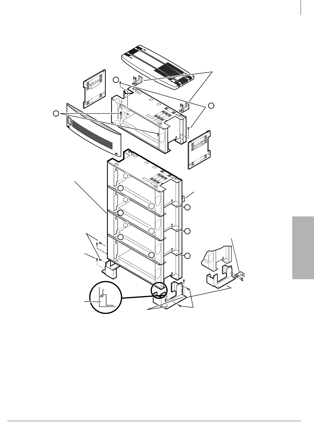
Strata CTX670 Installation
Install Reserve Power
Strata CTX I&M 06/04 4-35
Strata CTX670
Installation
Figure 4-19 CTX670 Cabinet Floor Installation
Important!
•BFIF (two-each) and RWBFA (six-each) are supplied with the floor installation kit BFIF.
•Upper and third cabinets must be fixed to the wall with RWBFS on each side (use #12 x 2 inch
wood screws and wall anchors, as required).
•Floor fixture (BFIF) must be fixed to floor by either anchor bolts, or wall by RWBF wall
brackets (see Figures 4-19 and 4-20).
•Screw size for BFIF and A and B cabinet screws are metric M5 x 10, .80 pitch.
A
B
Front (2)
Mouting
Screws
Provided
with BFIF Kit
Top Cabinet Wall
Securing Brackets
(RWBF)
(Left and
Right Side)
Back (2) Mounting
Screws Provided
with BFIF Kit
B
B
B
B
Bottom Wall
Securing Bracket
(RWBF)
Third Cabinet Wall
Securing Bracket
(RWBF)
(Left and right side)
B
B
A
A
A
B
BFIF
Mounting
Screws
Base Cabinet
(bottom)
BFIF is
inside of
cabinet edge BFIF
Mounting Screws
Floor
Fixture
(BFIF)
Anchor
Bolts (2)
Anchor
Bolts (2)
5042
B
A
A
AB
B
1
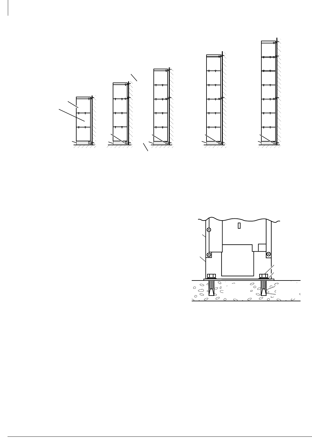
Strata CTX670 Installation
Install Reserve Power
4-36 Strata CTX I&M 06/04
Figure 4-20 Floor Mounting Cabinet Installation
Bolt Cabinets to Concrete Floor
1. Mount the CTX670 Base Cabinet on Floor
Mount Fixtures (see Figures 4-19 and
4-21). Position the Base Cabinet at the
selected installation location.
2. Mark the floor where holes will be drilled.
Move the Base Cabinet prior to drilling.
Note Cover the Base Cabinet with a drop
cloth to protect the power equipment
from dust created during drilling.
3. Use a hammer drill to make holes for 3/8-
inch bolt anchors.
4. Install the bolt anchors, with plugs, in the
drilled holes.
5. Using the driving tool and a hammer,
drive each bolt anchor into the floor.
6. Move the Base Cabinet into position on
the equipment room floor.
7. Secure the Base Cabinet to the floor using bolts, lock washers, and flat washers.
Note RWBF (3-pairs) and BFIF Stands (1-pair) are supplied with floor installation kit BFIF.
BFIF BFIF BFIF
RWBFs are used on left and
right sides, wherever indicated
BFIFs are used on left and
right sides, wherever indicated
“A”
Front two
screws, left
and right sides
“B”
Back two
screws, left
and right sides
AB
AB
AB
A
A
AB
AB
AB
AB
RWBF
RWBF
RWBF
RWBF
B
B
RWBF
RWBF
RWBF
BFIF BFIF
AB
AB
AB
AB
AB
RWBF
RWBF
RWBF
AB
AB
AB
AB
AB
AB
RWBF
RWBF
RWBF
RWBF
5007
Concrete
Floor
BFIF
(Floor
mount
fixture)
Bottom
Cabinet
Bolt
Lockwasher
Bolt Anchor
Plug
5242
Figure 4-21 Installation on Concrete Floor
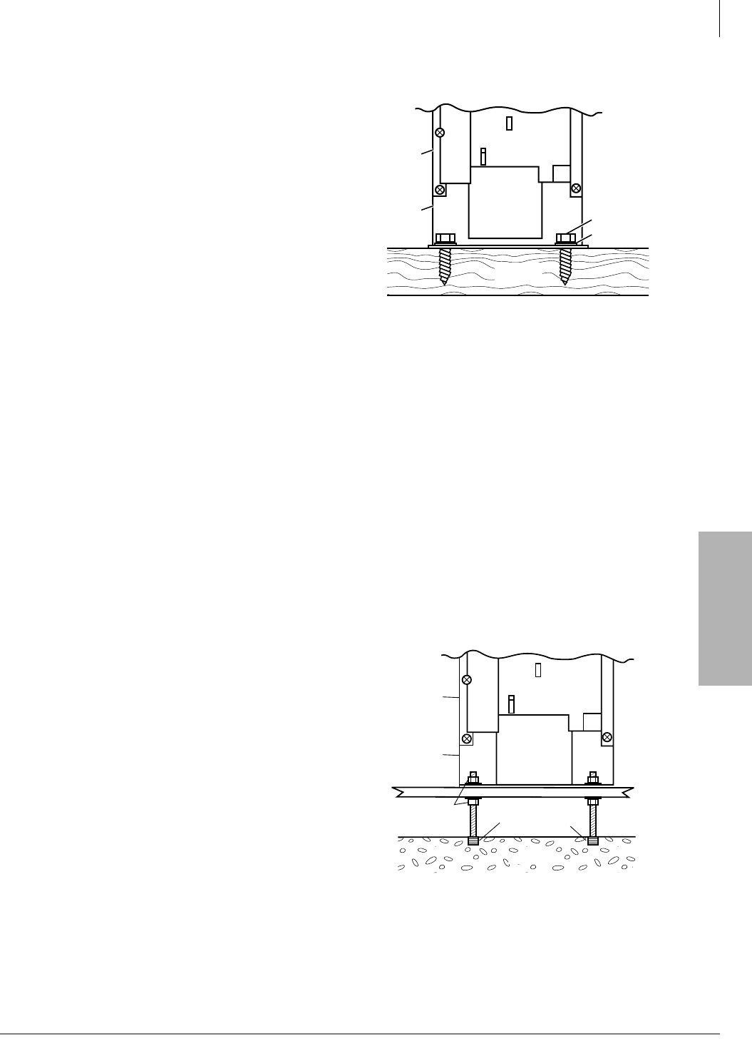
Strata CTX670 Installation
Install Reserve Power
Strata CTX I&M 06/04 4-37
Strata CTX670
Installation
Bolt Cabinets to Wooden Floor
1. Mount the CTX670 Base Cabinet on Floor
Mount Fixtures (BFIF). See Figures 4-19
and 4-20.
2. Position the Base Cabinet at the selected
installation location.
3. Mark the floor where holes will be drilled.
Move the Base Cabinet prior to drilling.
Note Cover the Base Cabinet with a drop cloth
to protect the power equipment from
dust created during drilling.
4. Drill pilot holes to make insertion of 3/8
inch lag bolts easier, and to prevent splitting
of wood flooring.
5. Move the Base Cabinet into position on the
equipment room floor.
6. Secure the Base Cabinet to the floor using lag bolts, lock washers, and flat washers.
Bolt Cabinets to Computer Room Floor
1. Mount the CTX670 Base Cabinet on Floor Mount Fixtures (BIMF). See Figures 4-19 and 4-20.
2. Position the Base Cabinet at the selected installation location.
3. Mark the floor where holes will be drilled. Move the Base Cabinet prior to drilling.
Note Cover the Base Cabinet with a drop cloth to protect the power equipment from dust created
during drilling.
4. Drill holes through tile for 3/8-inch threaded rods.
5. After the tiles have been drilled, insert threaded rods through the holes in the tile and mark the
concrete floor directly beneath the holes in the tiles.
6. Remove the tiles. Use a hammer drill to make holes for 3/8-inch bolt anchors.
7. Install the bolt anchors with plugs in the
drilled holes.
8. Using the driving tool and a hammer, drive
each bolt anchor into the floor.
9. Screw threaded rods into each bolt anchor.
10. Install a hex nut, lock washer, and flat
washer on each threaded rod. Screw the
nuts down far enough to allow floor tiles to
be replaced over the threaded rods.
11. Replace tiles over threaded rods in their
original positions on the floor.
12. Reach under the tiles, and screw the hex
nuts upward until the flat washers are
touching the bottom of the tile.
13. Use a hack saw to cut the threaded rods at a
height of approximately 1.5 inches above the floor tile.
14. Move the Base Cabinet into position over the threaded rods.
Wooden
Floor
BFIF
(Floor
mount
fixture)
Base
Cabinet
Bolt
Lockwasher
1468
Figure 4-22 Installation on Wooden Floor
Floor Tiles
Lead Anchors
Concrete
Flat Washer
Lock Washer
Hex Nut
BFIF
(Floor
mount
fixture)
Bottom
Cabinet
1469
Figure 4-23 Installation on Computer Room

Strata CTX670 Installation
Install Reserve Power
4-38 Strata CTX I&M 06/04
15. Secure the Base Cabinet to the floor using flat washers, lock washer, and hex nuts on each
threaded rod.Mount Cabinets to Computer Room Floor (Unbolted).
16. Make sure that cabinet power supplies (BPSU672A) are installed per “Install Power Supply”
on page 4-6.
17. Remove front, side, and top covers from all cabinets (Figure 4-5).
Note As shown in Figure 4-5, the two screws on each side cover and the three screws on the front
cover (the bottom left screw must be completely removed) should only be loosened and the
covers slid to the right for removal.
18. Remove plastic locating parts from all cabinet back covers using a Phillips screwdriver (Figure
4-4).
19. Install a floor fixture (BFIF) on each side of the bottom cabinet (Figures 4-19 and 4-23),
making sure that the fixture is inside of the cabinet edge.
20. Secure a wall bracket (RWBF) to both floor fixtures with the screws provided. Secure the wall
brackets to the wall with customer-provided wood screws and wall anchors.
21. Place a cabinet on top of the bottom cabinet and connect the cabinets together at points “A” and
“B”17 with the screws provided.
22. Install wall brackets (RWBF) on the top of cabinet three and secure them to the wall with
customer-provided wood screws and wall anchors.
23. Add remaining cabinets, making sure that the cabinets are connected together at points A and B
with screws provided.
24. For systems with four or more cabinets, make sure that wall brackets (RWBF) are installed on
both sides of the top cabinet, in addition to cabinet three.
25. Connect the data cable of each Expansion Cabinet to the applicable data cable connector on the
Base Cabinet (Figures 4-9 and 4-12). The data cable from the first Expansion Cabinet should be
connected to the connector labeled “CAB. 2”, the cable from the second Expansion Cabinet to
the “CAB. 3” connector, etc.).
26. Install ground wiring, AC and reserve power cabling, and PCB cabling per the “Recommended
Installation Sequence” on page 4-6.
27. Fill out cabinet/slot identification labels on each cabinet (see Figure 4-8), then reinstall covers
on the cabinets. (The top cover should be installed on the top cabinet.)
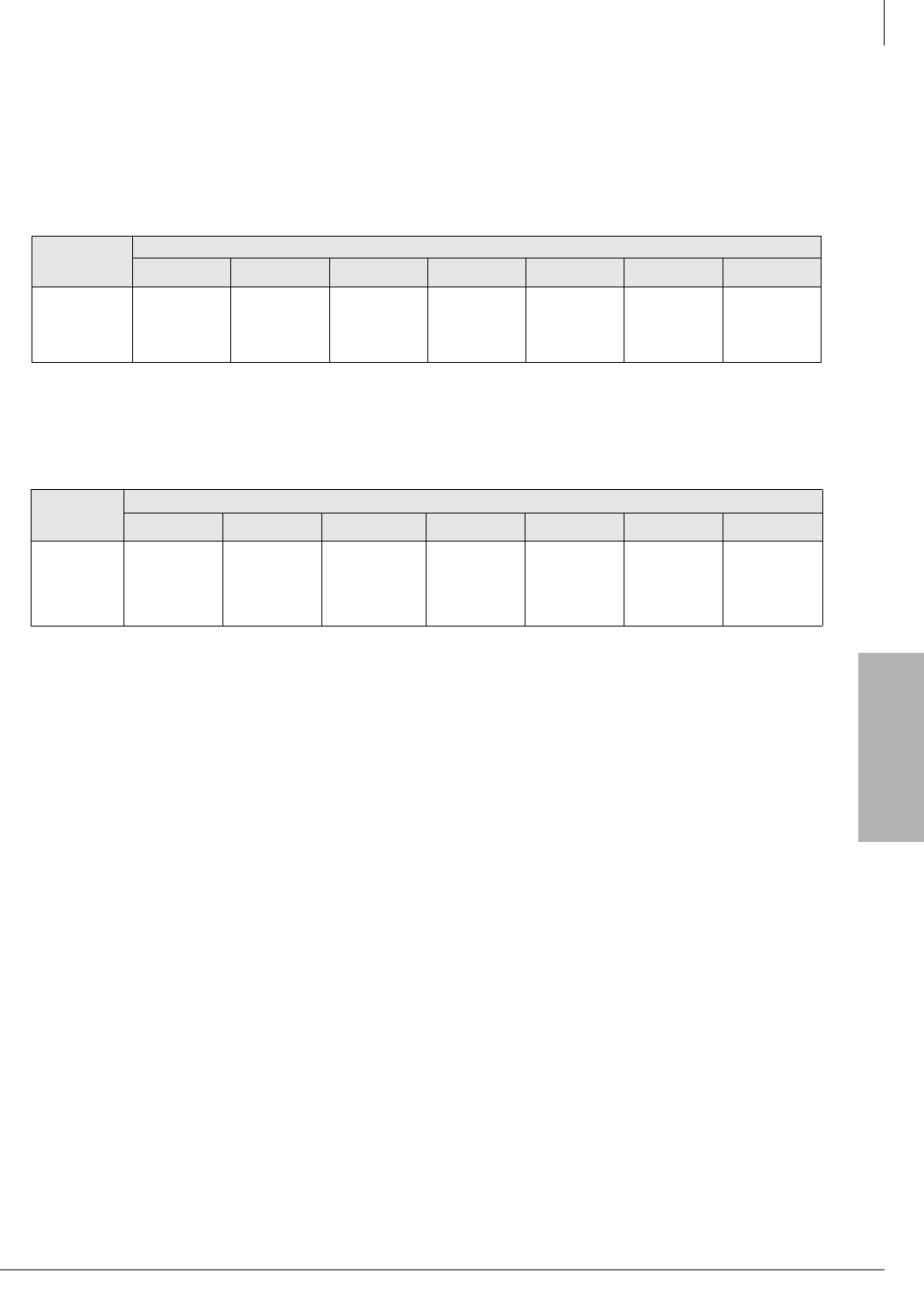
Strata CTX670 Installation
Install Reserve Power
Strata CTX I&M 06/04 4-39
Strata CTX670
Installation
Cabinet AC Power Component Installation
After the cabinets have been floor mounted, the AC power components should be installed. Tables
4-7 and 4-8 show the primary AC power components required for floor mounted systems.
Table 4-7 Floor Mount Cabinet Component Requirements for 120VAC Primary Power
Local
Electrical
Code
Cabinets
1 2 3 4 5 6 7
Three or more
cabinets
require a
conduit box
1 – BFIF 1 – BFIF 1 -BCCB1201
1 – BFIF
1 – BCCB1201
1 – RPSB2
1 – BFIF
1. A BCCB120 conduit connection box must be installed and wired by a certified electrician per the local
electrical code (see Figure 4-24).
1 – BCCB1201
2 – RPSB2
1 – BFIF
N/A N/A
Table 4-8 Floor Mount Cabinet Component Requirements for 208VAC or 240VAC Primary Power
Local
Electrical
Code
Cabinets
1 2 3 4 5 6 7
Two or more
cabinets
require a
conduit box
1 – BACL240
1 – BFIF
1 – BCCB2401
2 – BACL240
1 – BFIF
1. A BCCB240 conduit connection box must be installed and wired by a certified electrician per the local electrical code (see
Figure 4-25).
1 – BCCB2401
1 – BPSB240
3 – BACL240
1 – BFIF
1 – BCCB2401
1 – BPSB240
4 – BACL240
1 – BFIF
1 – BCCB2401
2 – BPSB240
5 – BACL240
1 – BFIF
1 – BCCB2401
2 – BPSB240
6 – BACL240
1 – BFIF
1 – BCCB2401
3 – BPSB240
7 – BACL240
1 – BFIF
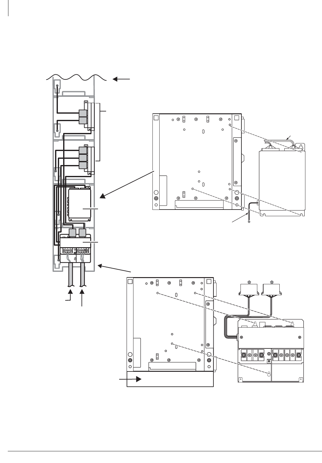
Strata CTX670 Installation
Install Reserve Power
4-40 Strata CTX I&M 06/04
Figure 4-24 Battery Distribution and Conduit Connection Box Installation
BBTCIA-2M
Cable from BCCB
BBDB1A
Battery
Distribution
Box
To BPSU672A Power
Supply "BATT" Jack
BBTC2A-2M
Seven Cables
Supplied with
BBDB
BCCB120A or BCCB240
Conduit Connection Box
AC Power
Battery
Cables to BBDB1A
Floor Mounted Bottom Cabinet
Bottom Cabinet (Wall Mount)
Second from Bottom Cabinet (Floor Mount)
RPSB2 or
BPSB240A
Power Strips
BBDB1A
Battery
Distribution Box
BCCB120 or 240
Conduit Connection Box
Conduit
Primary AC
Power Pannel
Reserve
Batteries
BFIF Floor
Mount Stand
Strata
4784
Up to 7 Cabinets
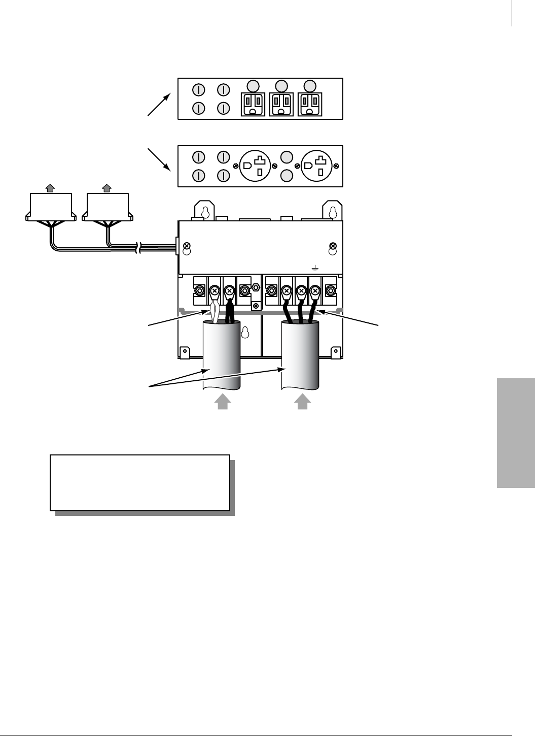
Strata CTX670 Installation
Install Reserve Power
Strata CTX I&M 06/04 4-41
Strata CTX670
Installation
Notes
• When floor mounting the CTX670, the batteries must be installed by a licensed electrician per
local electric code using conduit. (See Figure 4-25.)
• Batteries should be installed in a customer-supplied commercial battery box or enclosed rack.
To BBDB
Battery Distribution Box
F1~F4 Battery
Fuses 250VAC/15A
BCCB
BATT
-+
AC
NL
Battery Wire Specifications
#10 AWG minimum (2 pairs)
42A max.
AC Wire
Specifications:
BCCB120
#10 AWG
29A max.
BBCB240
#12 AWG
18A max.
BCCB120 (top view)
3 outlets
NEMA:5-15R
Fused: 250VAC/15A
Rated: 125VAC/15A
BCCB240 (top view)
2 outlets
NEMA:6-20R
Not Fused
Rated: 250VAC/20A
5047
F3 F1
F4 F2
F3 F1
F4 F2
Conduit
Holes to 1/2 inch trade size
WARNING!
BCCB conduit boxes must be
installed by a certified electrician.
From
reserve
battery
From
20A dedicated
circuit
Figure 4-25 BCCB AC Power and Battery Connections

Strata CTX670 Installation
Install Reserve Power
4-42 Strata CTX I&M 06/04
Reserve Power/AC Wiring for Three or More Cabinets (Floor
Mount)
Floor-mounted systems with three or more cabinets require a Conduit Connection Box (BCCB) to
connect reserve power cabling and AC power cabling to the system. Only a qualified electrician
can install cabling between the reserve power batteries and AC power cabling to the conduit
connection box. All other steps required to install reserve power, including installation of the
Battery Distribution Box (BBDB), can be accomplished by the normal system installer.
³To connect reserve power to floor-mounted systems with three or more cabinets
See Figures 4-12~4-17 and follow these steps:
1. Make sure that the Conduit Connection Box is installed on the bottom base cabinet (see Figure
4-24). The box can be installed by the regular system installer.
2. Have a licensed electrician install conduit and battery cabling to the Conduit Connection Box
per local electrical codes. The remaining steps in this procedure can be performed by the
regular system installer (see Figure 4-25).
3. Install the Battery Distribution Box on the second cabinet (the cabinet directly above the
bottom cabinet), see Figure 4-24.
4. Plug the two Conduit Connection Box cables (coming from the left side of the BCCB box) into
the Battery Distribution Box (BBDB).
Important! The cabinets must be connected to the (live) AC power source, and the power supply
On/Off switches set to On prior to the final step of connecting the reserve power
batteries to the power supplies via the BATT +/- receptacle. If the batteries are
connected after AC power is lost, reserve power will not function.
5. Connect cables from the (BBDB) Battery Distribution Box to the BATT +/- receptacle of
individual power supplies. BBTC2A-2M cables come with each BBDB distribution box (see
Figure 4-12).
6. To test reserve power operation, turn off the system AC power circuit breaker with power
supply On/Off switches in the On position. The system should continue to operate without
interruption.
Note AC/DC wiring and conduit must be installed by a licensed electrician per local electrical
code (conduit trade size is 1/2 inch).
See “Install Reserve Power” on page 4-29 for battery specifications and wiring guidelines.

Strata CTX670 Installation
Install Processor and Universal PCBs
Strata CTX I&M 06/04 4-43
Strata CTX670
Installation
Step 7: Install Processor and Universal PCBs
This section provides procedures for the installation of CTX670 processor (or common control)
PCBs.
The CTX670 system Base and Expansion Cabinets are shipped empty. PCBs are not installed at
the factory. Universal PCBs must be placed according to the configuration information obtained
and developed in Chapter 1 – Configuration. PCB installation is in Chapter 6 – PCB Installation.
• Install PCBs only after installing the Base Cabinet and, if applicable, Expansion Cabinets per
the Cabinet Installation section in this chapter.
• Be sure the power supply has been tested and the ground has been checked (see “Install Power
Supply” on page 4-6.
• Install universal slot PCBs per the CTX670 configuration guidelines (see “Worksheet 6: Strata
CTX670 Cabinet Slots” on page 2-37.
• Install the metal mesh shield, B50MT around the 25-pair cables connected to PCBs per Figure
4-10.
Important! After all PCBs are installed, be sure to slide the locking bar into the lock position to
ensure that the PCBs remain in place (see Figure 4-3 on page 4-9).
PCB Installation Considerations
The Base Cabinet has ten slots. The first two slots, labeled “B101” and “B102” are reserved for the
common control unit and future feature upgrades. The next eight slots (labeled “S101” ~“S108”)
are universal and capable of hosting any of the station, line, and option interface PCBs compatible
with the CTX670 systems.
The Expansion Cabinets have ten universal slots, labeled “S_01,” “S_02,” etc., where the blank
space of the label represents the number of the Expansion Cabinet. Like the universal slots in the
Base Cabinet, these universal slots are capable of hosting any of the station, line, and option
interface PCBs.
Cabinets are numbered from 1 to 7. The Base Cabinet is numbered 1; the first Expansion Cabinet,
number 2; the second Expansion Cabinet, number 3, etc. See the CTX670 Configuration and PCB
Installation section for details.
PCB Option Considerations
CTX670 PCBs can be configured for a variety of hardware and software options. Hardware
options are defined as either internal (generally related to optional PCB subassemblies) or external
(related to connection of peripheral equipment such as background music, voice mail, etc.).
Hardware Options
Some PCBs must be configured for hardware options prior to installation of the PCB in the
cabinet. Configuration instructions for internal hardware options are provided in the individual
PCB installation procedures in this chapter and in Chapter 6 – PCB Installation. Configuration
instructions for external hardware options are provided in Chapter 12 – Peripheral Installation.
Software Options
PCBs are configured for software options through programming, following the installation
instructions of the PCBs. A programming overview for each PCB is provided in the individual

Strata CTX670 Installation
Install Processor and Universal PCBs
4-44 Strata CTX I&M 06/04
PCB installation procedures in this chapter. Refer to the Strata CTX Programming Manual for
detailed programming instructions.
BCTU1A/BEXU1A Installation
This section explains how to install the new BCTU/BEXU processor PCBs into Strata CTX670
telephone systems. The BCTU/BEXU processor PCBs require Strata CTX Release 2.1, or higher,
software and CTX WinAdmin Release 2.1, or higher, software.
The BCTU can be installed without the BEXU for a maximum capacity of 192 ports. It supports
the Base and one Expansion cabinet. The BCTU by itself supports all the features and capacities
equal to the BECU/BBCU without the BEXS and BBMS expansion PCBs.
If the BEXU is installed with the BCTU, 672 ports are available, along with all the features and
capacities equal to the BECU/BBCU with BEXS and BBMS expansion PCBs.
The BCTU or BEXU do not have a built-in modem. The AMDS must be installed on the BCTU if
remote administration is required over telephone lines.
CAUTION!
•Do not remove the plastic insulation shield from the back of the BEXU PCB. If the
shield comes off, do not allow the back of the PCB to contact metal.
•The BCTU and BEXU PCBs are shipped from the factory with the battery jumper in
the “Off” position. Ensure it is moved to the “On” position before installing the
processor to protect customer configuration information stored in the processor RAM.
The battery will protect RAM for approximately six years. Otherwise, to conserve the
lithium battery, move the jumper to the “Off” position.
•When packaging the BCTU and BEXU PCBs, use only a nonconducting material
enclosure, such as plain cardboard. Conductive material can cause the internal battery
to discharge and erase memory in the BCTU and BEXU PCBs.
•Make sure that the power supply is Off when installing the BCTU and BECU PCB or
damage to the board could result.
•When removing the BCTU1A and BEXU1A, first detach the cable connecting the
BCTU and BEXU1A.
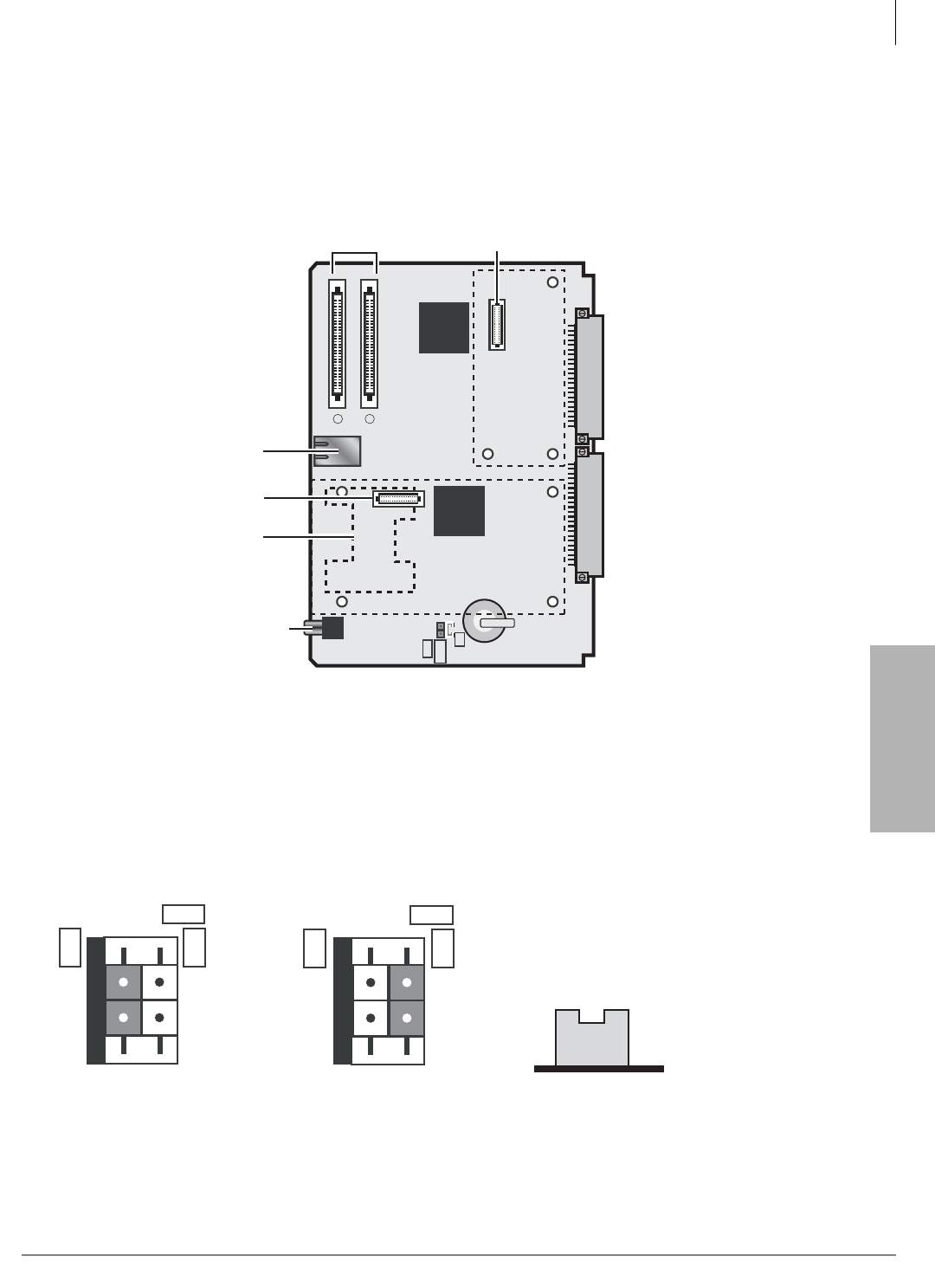
Strata CTX670 Installation
Install Processor and Universal PCBs
Strata CTX I&M 06/04 4-45
Strata CTX670
Installation
1. On the BCTU PCB (see Figure 4-26), set the battery jumper, “BATT” to the “On” position.
Although you can fit the jumper plug in a horizontal position, this would be incorrect. Be sure
to place the “BATT” jumper in the correct vertical and upright position (see Figure 4-27.)
Figure 4-26 BCTU1A Base Processor
Figure 4-27 Correct Battery Jumper Position
RCA Jack
BGM/MOH
RJ45
LAN
Connect
ribbon cable
to BEXU1A
AMDS
Interface
BCTU1A
6838
P801
P802
IC101
P601
P7
P2 P3
IC501
P4
P5
BATT
ON
OFF
Backplane Connectors
12
Smart
Media
Card
Slot
Place AMDS
here
Place BSIS
here
BSIS
Interface P8
P601
BATT
ON
OFF
P601
BATT
ON
OFF
Factory-shipped
Position
Memory Backup
Position
Proper Jumper Position
Side View
6963
PCB Front Side

Strata CTX670 Installation
Install Processor and Universal PCBs
4-46 Strata CTX I&M 06/04
2. Install the AMDS on the BCTU if remote maintenance is required.
3. Install the BSIS on the BCTU if SMDR or SMDI is required.
4. Install the BCTU Base Unit processor in slot B102 (see Figure 4-28). Ensure the component
side of the BCTU PCB is facing right when installing it in the Base Cabinet.
5. If you are installing more than one Expansion Unit, install the BEXU processor in slot B101
(see Figure 4-29).
6. Connect the two supplied ribbon cables from the BCTU to the BEXU by placing the ribbon
connectors over the appropriate connector on the PCB (see Figure 4-30). Each ribbon
connector has two locking tabs (top and bottom) that must be pressed down to lock the
connector to the PCB.
7. Insert the SmartMedia card (gold contacts face right, notched corner faces forward and down)
into the slot on the BCTU.
CAUTION!
•Heed any handling instructions in the SmartMedia Card User’s Manual.
•Avoid bending or subjecting the card to impact.
•When the card is not in used, store it in its sleeve.
•Avoid touching the connectors and protect the card from dirt, dust and liquids.
•Toshiba recommends backing up important data stored on the card.
8. Proceed with the system startup procedure in the Strata CTX Programming Manual.
Notes
Unlike the BBCU/BECU, the following are controlled by software programming for the BCTU/
BEXU:
• MOH/BGM source volume adjustments
• Mu/A Law selection
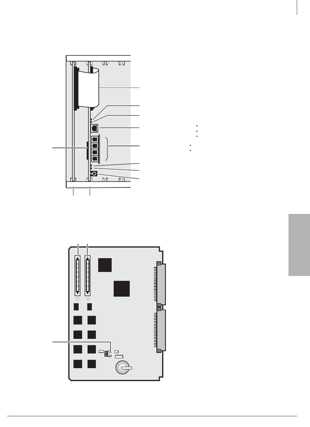
Strata CTX670 Installation
Install Processor and Universal PCBs
Strata CTX I&M 06/04 4-47
Strata CTX670
Installation
Unlike the BBCU/BECU, the internal modem is optional with the BCTU/BEXU processor.
AMDS interface (optional) plugs onto the BCTU card. See Table 4-9.
Figure 4-28 BCTU/BEXU Processor PCB Connectors
Figure 4-29 BEXU1A Expansion Unit Processor
B101 S_01B102 S_02
BEXU
BSIS Serial Ports
(RJ11, 6-pin modular)
Network Interface Jack
(RJ45, 8-pin modular)
LINK (LAN link)
TX/RX (LAN link transmitting/receiving)
SM (Smart Media Access Status LED)
HB (Processor Heart Beat LED)
MOH/BGM Input (RCA Jack)
BCTU
6920
1
2
3
4
Smart Media
Card Socket
(Slide card in,
gold contacts face
right, notched
corner down)
WinAdmin PC/Server
ACD PC/Server
Attendant Console PC / Server
Ribbon Cables
SMDR
SMDI
BEXU1A
6839
IC201
P5 P4
P5 P4
IC404
IC402
IC403
IC807
IC808
IC803
IC804
IC805
IC806
IC801
IC802
P2P1
P901
BATT
ON
OFF
Backplane Connectors
Important!
White battery
j
umper must be
moved to the
ON position.
1
2
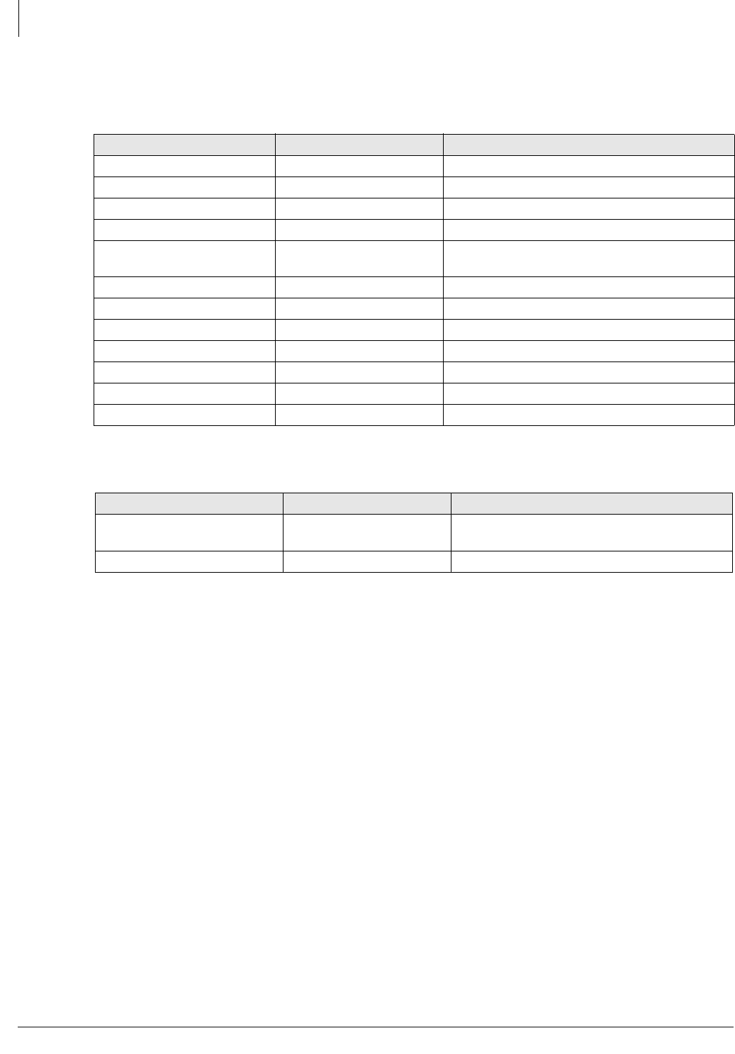
Strata CTX670 Installation
Install Processor and Universal PCBs
4-48 Strata CTX I&M 06/04
The following tables provide details about the connectors and indicators on the BCTU1A and
BEXU1A PCBs.
Table 4-9 BCTU Controls, Indicators, and Interface Connectors
Control/Indicator/Connector Type of Component Description
P801 RJ45 LAN Network interface port
P501 SmartMedia house SmartMedia Interface
P802 RCA Jack BGM/MOH interface
P2, P3 44-pin connectors Processor backplane
P601 BATT Jumper Plug Must always be in the ON position to maintain
customer data.
LINK, TX, RX LED LAN link transmission and receive indicator
SM LED SmartMedia access indicator
HB LED Processor operation indication
P7 60-pin connector AMDS interface (optional)
P8 60-pin connector BSIS interface (optional)
Connector P5 Connector and ribbon cable Ribbon cable connector to P4 (1) on the BEXU.
Connector P4 Connector and ribbon cable Ribbon cable connector to P5 (2) on the BEXU.
Table 4-10 BEXU Controls, Indicators, and Interface Connectors
Control/Indicator/Connector Type of Component Description
P901 BATT Jumper plug Must
always
be in the ON position to maintain
customer data.
P4, P5 Connector and ribbon cable Ribbon cable connector to BCTU1A.
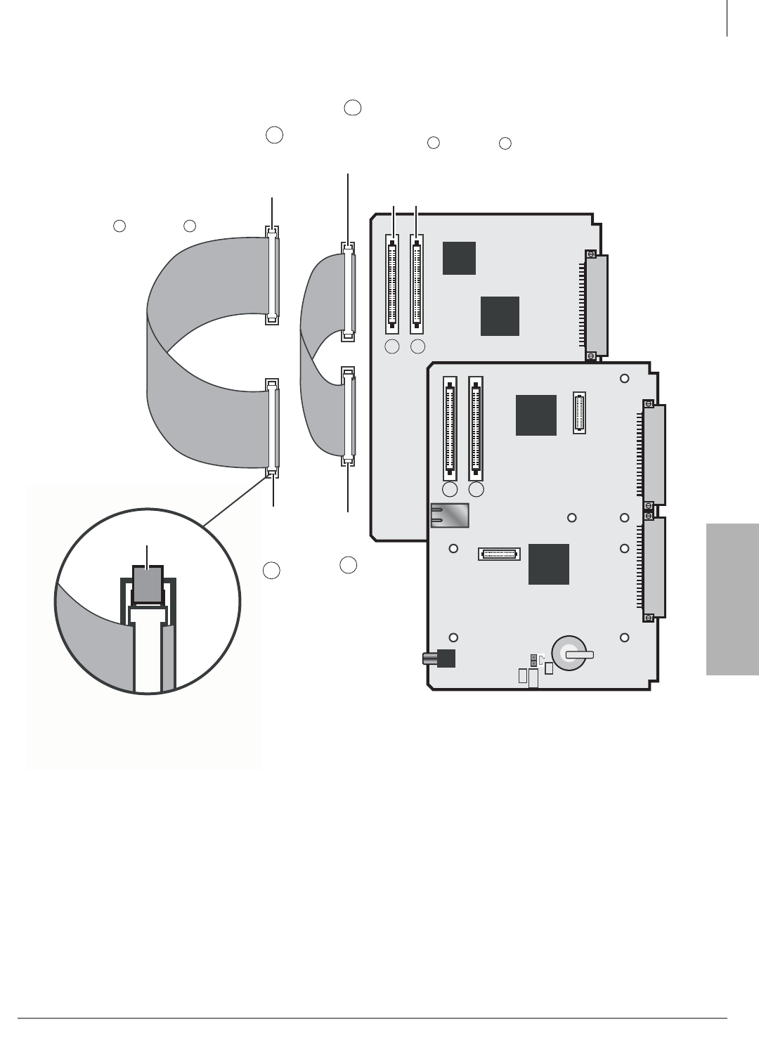
Strata CTX670 Installation
Install Processor and Universal PCBs
Strata CTX I&M 06/04 4-49
Strata CTX670
Installation
Figure 4-30 Detailed Ribbon Cable Connection for BEXU1A and BCTU1A
BEXU1A
BEXU1A
IC201
P5 P4
P5 P4
IC404
P2P1
1
2
2
22
1
11
Plug
to
P5
(BEXU)
Plug
to
P4
(BEXU)
BCTU1A
P801
P802
IC101
P601
P7
P2 P3
IC501
P4
P5
BATT
ON
OFF
12
P8
BCTU1A
Plug
to
(BCTU)
2
6962
Plug
to
P4
(BCTU)
Locking Tab
1
The short 60mm ribbon
cable connects from
BEXU1A to BCTU1A
The longer 120mm ribbon
cable connects from
BEXU1A to BCTU1A

Strata CTX670 Installation
Install Processor and Universal PCBs
4-50 Strata CTX I&M 06/04
BECU/BBCU Installation
CAUTION!
•Do not remove the plastic insulation shield from the back of the BBCU PCB. If the
shield comes off, do not allow the back of the PCB to contact metal.
•The BBCU PCBs are shipped from the factory with the battery jumper in the “Off”
position. Ensure it is moved to the “On” position before installing the BBCU to protect
customer configuration information stored in the BBCU RAM.
•When transporting the BBCU PCB, keep the battery jumper in the “On” position in
order to save the configuration data stored in BBCU RAM. (The battery will protect
RAM for approximately six years.) Otherwise, to conserve the lithium battery, move
the jumper to the “Off” position.
•When packaging the BECU and BBCU PCBs, use only a nonconducting material
enclosure, such as plain cardboard. Conductive material can cause the internal battery
to discharge and erase memory in the BECU and BBCU PCBs.
1. Set the battery jumper, “BATT,” on the BBCU PCB to the “On” position.
2. On the BBCU, make sure the Mu/A jumper plug is set to the Mu position (U.S. and Canada).
3. Before you install the BBMS, make sure the “ATTACHED BBMS” jumper is set to “NO.”
4. After installing the BBMS, change the “ATTACHED BBMS” jumper to “YES.”
5. If you are installing the Basic system, skip to Step 6. If you are installing the Expanded system,
install the BBMS and BEXS onto the BBCU and BECU respectively.
6. Install the BBMS onto the BBCU (see Figures 4-31 and 4-32). Install the BEXS onto the
BECU (see Figures 4-33 and 4-35).
7. If serial ports are required, install the BSIS onto the BECU (see Figures 4-34 and 4-35).
8. Make sure that the power supply is Off when installing the BBCU and BECU PCB or damage
to the board could result.
9. Install the BECU in slot B101 and the BBCU in slot B102, then connect the two BECU ribbon
cables to the BBCU, as shown in Figure 4-36.
10.Proceed with system startup procedure in the Strata CTX Programming Manual.
³To adjust the CTX670 MOH/BGM source
³Adjust the VR1 potentiometer to the desired volume level while listening to MOH or BGM
(see Chapter 12 – Peripheral Installation).
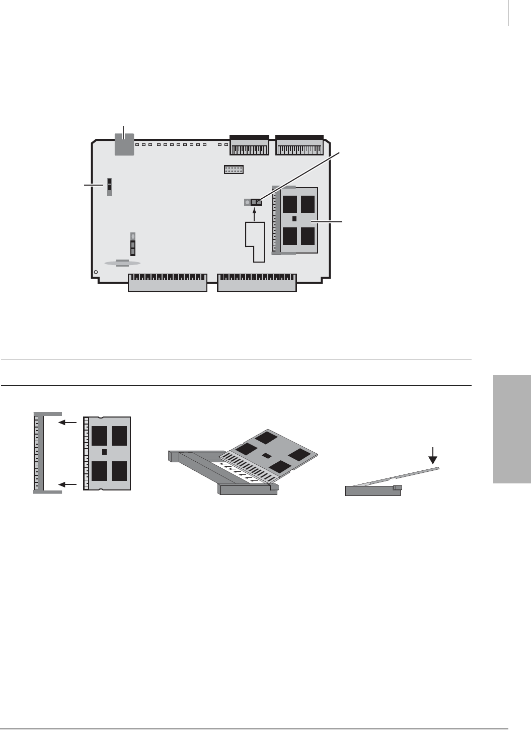
Strata CTX670 Installation
Install Processor and Universal PCBs
Strata CTX I&M 06/04 4-51
Strata CTX670
Installation
Figure 4-31 BBCU Processor PCB
CAUTION! Be careful installing the BBMS (Figure 4-32). It is fragile.
Figure 4-32 Installing the BBMS Backup Memory Module on the BBCU
BBCU1A
ON OFF
BATT
P7
P101
P701
1
3
P1
P5 P4
P2P3
MU A
BBMS1A
5254
Network
Interface
RJ45
MU Law
for U.S.
& Canada
BBMS
Memory
Module
Set the jumper
to "YES" only
after installing
the BBMS.
YES ATTACHED
BBMS
NO
1. Hold the BBMS top-side
up. The top side has five
chips and “BBMS1A.”
5526
BBMS1A
BBMS1A
2. Slide the BBMS
into the socket.
3. Push down on the outer
edge of the BBMS. It
should “snap” down.
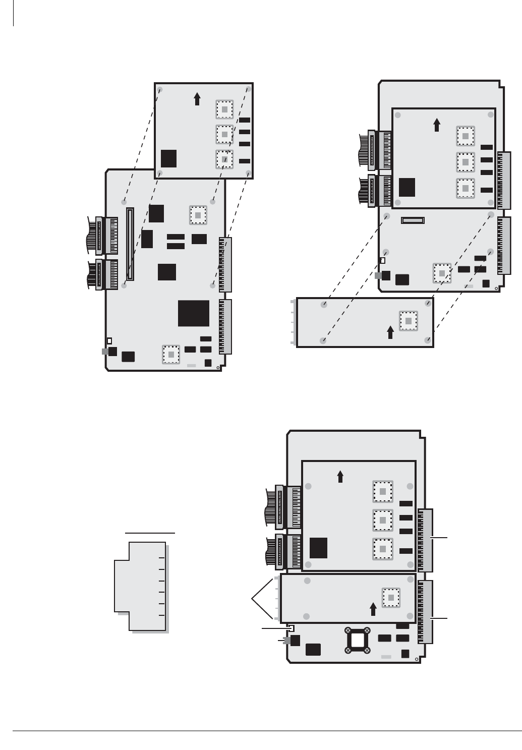
Strata CTX670 Installation
Install Processor and Universal PCBs
4-52 Strata CTX I&M 06/04
Figure 4-35 BECU with BEXS and BSIS
Figure 4-33 Installing BEXS onto BECU Figure 4-34 Installing BSIS onto BECU
5656
5529
P5
P1
P4
P6
BECU1A
IC401IC402IC403
BEXS1A
UP
IC404
5667
1
2
3
4
IC401IC402IC403
BECU1A
BEXS1A
BSIS1A
UP
IC404
UP
P8
RJ11
( 6-pin jack )
TD
RD
DTR
DSR
SG
CD
2
1
4
3
6
5
Serial Port Pins:
IC401IC402
P5
P3
1
2
3
4
P2 P1
P4
IC403
VR901
BECU1A
IC404
Four Programmable
Serial Ports
BSIS1A
UP
BEXS1A
UP
5416
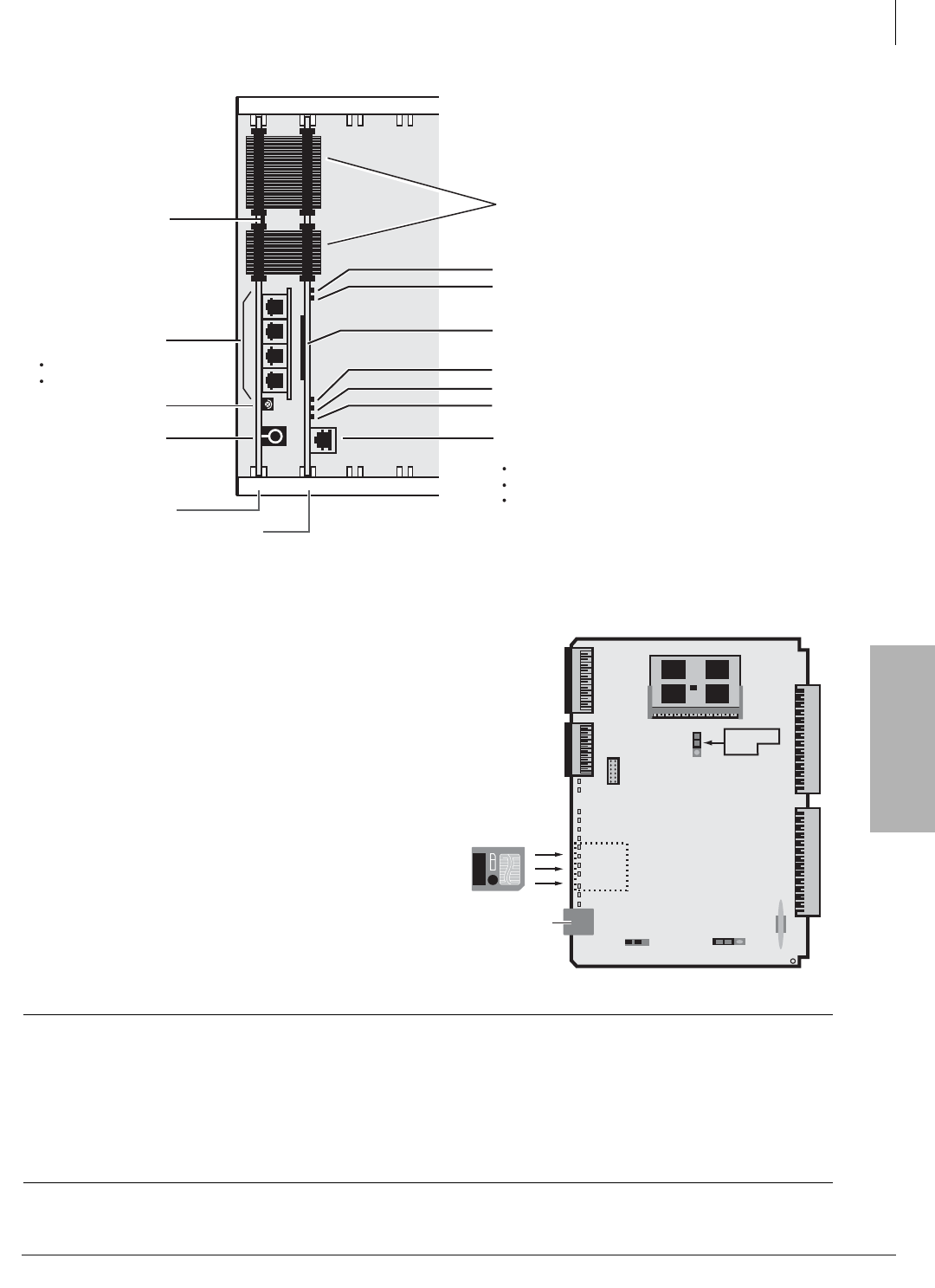
Strata CTX670 Installation
Install Processor and Universal PCBs
Strata CTX I&M 06/04 4-53
Strata CTX670
Installation
11. Insert the BECU into the “B101” slot
in the Base Cabinet (see Figure
4-36). Ensure the component side of
the BBCU PCB is facing right when
installing it in the Base Cabinet.
12. Insert the BBCU into slot B102.
13. Connect the supplied ribbon cables
between BECU and BBCU.
14. Insert the SmartMedia card (gold
contacts face right, notched corner
faces forward and down) into the slot
on the BBCU Figure 4-36 and 4-37.
CAUTION! Heed any warnings or handling instructions in the SmartMedia Card User’s
Manual.
Avoid bending or subjecting the card to impact.
When the card is not in used, store it in its sleeve.
Avoid touching the connectors and protect the card from dirt, dust and
liquids.
Toshiba recommends backing up important data stored on the card.
B101 S_01B102 S_02
BECU
BSIS Serial Ports
(RJ11, 6-pin modular)
Built-in Modem
(33.6 kbps, v.34
WinAdmin PC / Server)
Network Interface Jack
(RJ45, 8-pin modular)
Processor Heart Beat LED (0.4 seconds on/0.4 seconds off.)
Smart Media Access Status LED
Network Interface Link Connection LED.
Strata CTX Receive Network Data LED.
Strata CTX Send Network Data LED.
MOH Volume Control
(screw driver adjust)
MOH/BGM Input
(RCA Jack)
BBCU
5447
1
2
3
4
Smart Media Card Socket (Smart Media card slides in, gold
contacts face right, notched corner down)
WinAdmin PC/Server
ACD PC/Server
Attendant Console PC / Server
Ribbon Cables
SMDR
SMDI
Figure 4-36 BBCU/BECU Processor PCB Connectors
BBCU1A
P7
P101
ON OFF
BATT
P701
1
3
P1
P5 P4
P2P3
MU A
BBMS1A
5670
Network
Interface
RJ45
YES AT TA C H E D
BBMS
NO
Insert
Smart
Media
Card
Figure 4-37 SmartMedia Card Installation
Strata CTX670 Installation
Install Processor and Universal PCBs
4-54 Strata CTX I&M 06/04
Table 4-11 BECU Controls, Indicators, and Interface Connectors
Control/Indicator/
Connector Type of Component Description
VR901 Trim potentiometer Adjusts volume for MOH/BGM sources.
P3 RCA jack BGM/MOH interface
Connector P5 Connector and ribbon cable Ribbon cable connector to BBCU.
Connector P4 Connector and ribbon cable Ribbon cable connector to BBCU.
BSIS Four ports of I/O RS-232 (Optional unit) Adds up to four serial ports.
BEXS Time switch (Optional unit) Required for Expanded system,
along with the BMMS.
Table 4-12 BBCU Controls, Indicators, and Interface Connectors
Control/Indicator/Connector Type of Component Description
BATT Jumper plug
Must
always
be in the On position to retain
processor RAM data. The Strata CTX will not
operate properly if the jumper is in the Off
position or if it is not installed.
P7 RJ45 Network interface port.
BBMS Module Subassembly module Memory module. (Optional unit) Required for
Expanded system, along with the BEXS.
ATTACHED BBMS (Yes/No) Jumper
Jumper setting must always be set to “Yes,”
regardless of whether the BBMS is installed or
not.
P4 Connector and ribbon
cable Ribbon cable connector to BECU.
P5 Connector and ribbon
cable Ribbon cable connector to BECU.
P10 Mu /A Law Jumper plug
Jumper setting must be set to “Mu” law for
Canada and the U.S. For more information on
Mu law/A law settings, see “Country Settings
On/Off” on page 11-20.
SmartMedia Card socket
Holds SmartMedia Card which is used to
Backup/Restore Customer Data, Upgrade
Operating System, Log and Trace
Maintenance information.
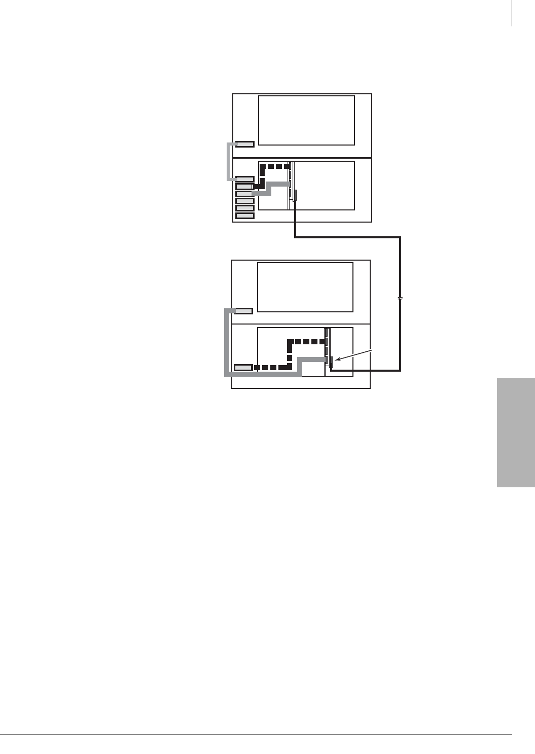
Strata CTX670 Installation
Remote Expansion Cabinet Unit
Strata CTX I&M 06/04 4-55
Strata CTX670
Installation
Remote Expansion Cabinet Unit
The RRCU1A PCB enables a
CTX670 Expansion Cabinet to
be located up to three kilometers
from its Base Cabinet. One
RRCU1A connects to up to two
ribbon-type Data Cables and
applies the inter-cabinet signal to
a fiber-optic pair. One fiber pair
can support one or two
expansion cabinets in one remote
location using one RRCU1A in
the Base Cabinet and another in
the Remote Expansion Cabinet.
A CTX670 Base Cabinet will
support up to six RRCU1A
PCBs. A CTX670 will support
up to six Remote Expansion
Cabinets.
An inter-cabinet Data Cable in
the Base Cabinet is attached to
an RRCU1A which converts the
signal and uses an LED source to
apply the signal to 500 MHz/km
multi-mode fiber. Another
RRCU1A in the Remote
Expansion Cabinet receives the
LED signal, converts it back to
its original form and applies it to
a ribbon Data Cable connected to
the Remote Expansion Cabinet.
See Figure 4-38.
This is a hardware solution and has no effect on software or administration. Remote cabinets
support all line and trunk interfaces.
Important! Network clock signals can only be derived from digital trunk PCBs, such as the
RDTU and RPTU, that are installed in the Base Cabinet (Master) location. Do not
install these digital trunk cards into the Remote Cabinets.
RRCU1A cards are used at both the Base (Master) and Remote (Slave) Cabinet locations. The card
set consists of an RRCU1A PCB and its ROMS1A daughter board. The RRCU1A connects to the
inter-cabinet Data Cables, holds the Remote/Slave option jumpers, and has an RS-232C port for
monitoring the fiber connection. (See Figure 4-41.)
The ROMS1A daughter board holds an SC-type fiber connector, a connector for control of two
8-circuit DPFT units, and status LEDs.
Fiber Optic
Connection
Up to
3 Kilometers
(Dealer Supplied)
Expansion Cabinet (2)
Base Cabinet
Remote Expansion Cabinet (4)
MSBU
Remote Expansion Cabinet (3)
5820
1 (M1)
2 (S1)
3 (M2)
2
3
4
5
6
7
Optical Module
4 (S2)
1 (M1)
2 (S1)
3 (M2) Optical
Module
4 (S2)
Local CTX Cabinets
Remote CTX Cabinets
Figure 4-38 Remote Expansion Cabinet Connection
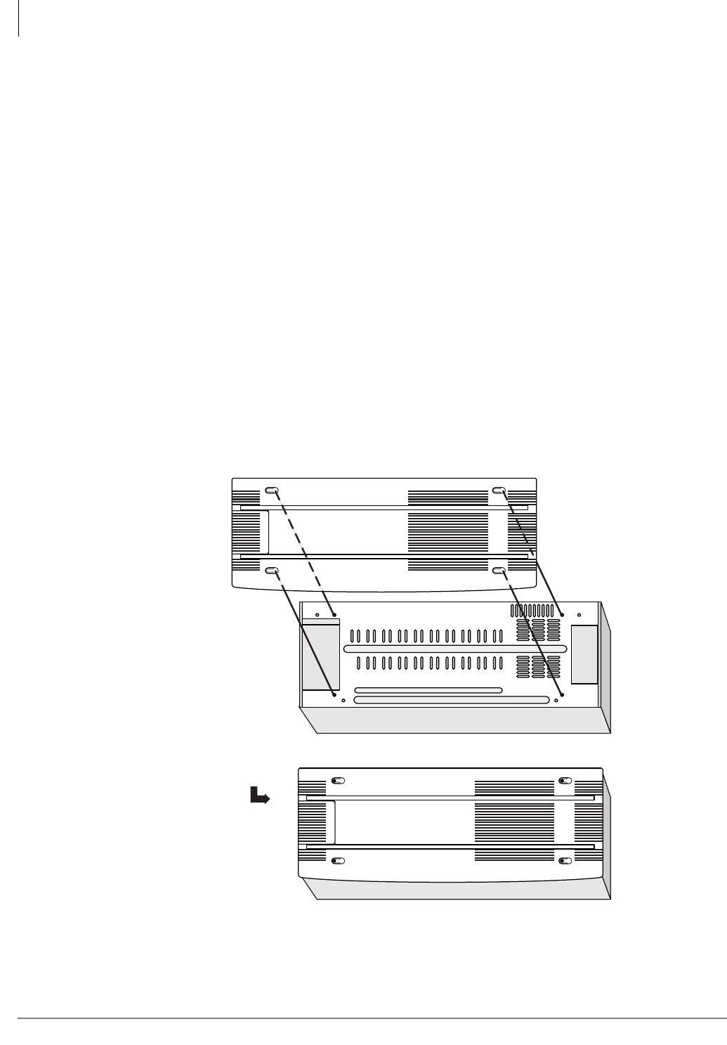
Strata CTX670 Installation
Remote Expansion Cabinet Unit
4-56 Strata CTX I&M 06/04
Remote Cabinet Installation Instructions
All instructions apply to both the Base Cabinet and the Remote Expansion Cabinet except where
specifically noted.
1. Install cabinets according to the instructions given at the beginning of this chapter. Pay
particular attention to wiring and grounding instructions given for Remote Expansion Cabinets.
2. If installing a standalone Remote Expansion Cabinet, or the first in a stack, set the “BASE/
EXP” switch to “BASE” in accordance with Figure 4-3.
3. Cabinets in which RRCU cards are installed must be modified to protect the routing of the
cables through the cabinet.
• Attach the plastic guide to the bracket provided with the RRCU1A card. See Figure 4-40.
• Attach the bracket to the inner wall of the cabinet.
4. Install the RRCU Card
• Select correct jumper options (see Figure 4-41). On the Master side, both option plugs
connect the center pin to the upper pin (M1, M2). On the Slave side, both option plugs
connect the center pin to the lower pin (S1, S2).
• Remove the protective rubber cap from the fiber connector on the ROMS1A daughter
board. See Figure 4-42.
5. Install a BCTC1A top cover on the topmost cabinet (see Figure 4-39).
Figure 4-39 Remove/Replace Remote Cabinet Cover
Place lid over screws
and slide it to the right.
Top View
5030
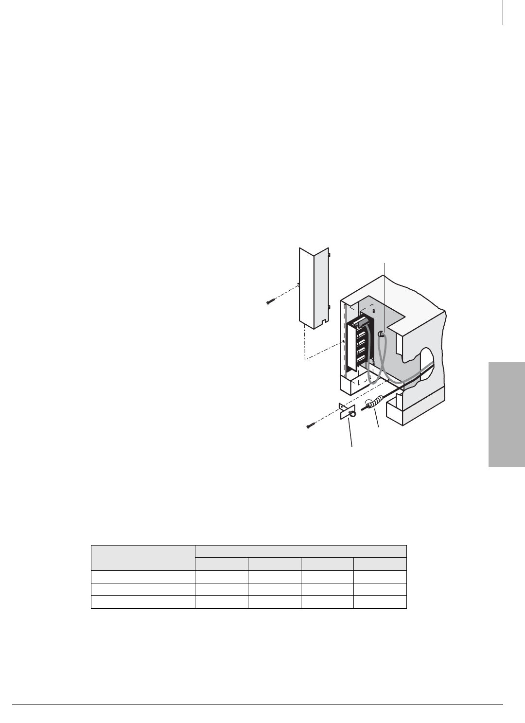
Strata CTX670 Installation
Remote Expansion Cabinet Unit
Strata CTX I&M 06/04 4-57
Strata CTX670
Installation
Important! When installing the RRCU, be sure to put the card in the slot before attaching the
data cables. Detach the data cable before removing an RRCU1A. Failure to do so
may cause interference with other data highways.
6. Insert the cards
• On the Master side, the RRCU card may be installed in Slots 1~8.
• On the Slave side, the RRCU card may be installed in Slots 1~10.
• The RRCU1A is a non-timeslot card and can be installed in slots normally left vacant
adjacent to digital trunk cards.
7. Connect the data cables
• At the Base Cabinet, attach an BDCL1A data cable from the data cable connector at the left
of the cabinet to Connector M1 or M2 on the RRCU card. (Cables are provided according to
the connectors on the RRCU card to which they are attached, see Table 4-13.)
• The cabinet connected to M1 in the
base emerges on connector S1 of the
RRCU1A at the Remote Expansion
Cabinet.
• The cabinet connected to connector
M2 of the RRCU in the base emerges
on connector S2 of the RRCU1A at
the Remote Expansion Cabinet. See
Figure 4-41.
• Route the cable through the
cabinet according to Figure
4-40.
• Coil the excess and attach it to
the grommet on the cabinet
wall with a tie wrap. Be careful
not to bind the cable tightly.
• Close the data cable doors.
Table 4-13 Remote Cabinet Data Cables and Connectors
Data Cables RRCU Connectors
M1 S1 M2 S2
BDCL1A-MS1 X X
BDCL1A-M2 X
BDCL1A-S2 X
X = applies to connector
CAB
2
CAB
3
CAB
4
CAB
5
CAB
6
CAB
7
4512
Data Cable Door
BDCL1A Data Cable
Spiral Tube
Clamp Bracket
for Spiral Tube
Figure 4-40 Insert Optical Fiber Through
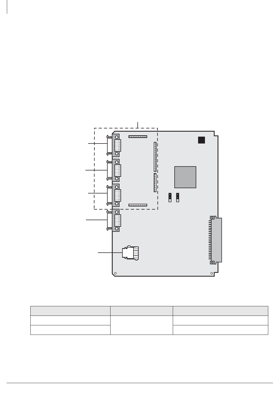
Strata CTX670 Installation
Remote Expansion Cabinet Unit
4-58 Strata CTX I&M 06/04
8. Connect the fiber optic cables
• Pass the fiber optic cable through the protective tube.
• Route the tube through the clamp attached to the inner cabinet wall and secure the clamp
• Attach fiber to the SC connectors on the ROMS1A daughterboard.
• The TX side of the Master connects to the RX side of the slave.
• The RX side of the Master connects to the TX side of the slave.
• TAIS recommends that the cables be marked within the cabinet for ease of maintenance.
• Observe the minimum bend radius of 30mm.
9. Restore power.
The RRCU PCB and its controls and connectors are shown in Figure 4-41 and Table 4-14.
Figure 4-41 Remote Expansion Cabinet Printed Circuit Board (RRCU1A)
The ROMS subassembly and fiber optic cable connectors is shown in Figure 4-42. Table 4-15 lists
the fiber optic cable specifications.
Table 4-14 RRCU Controls
Control/Indicator/Connector Type of Component Description
Jumper Plug P10
3-terminal Jumper Plug
Master Mode (M connections)
Jumper Plug P10 Slave Mode (S connections)
4356
RRCU1A
Backplane Connector
P8P9P7P6
M2 S2S1M1
Master 1
Connect to
Base Cabinet
Master 2
Connect to
Base Cabinet
Slave 1
Connect
to MSBU
Slave 2
Connect
to MSBU
RS-232
Port
ROMS1A
MS
MS
P11
P10
P4
P3
P2P1
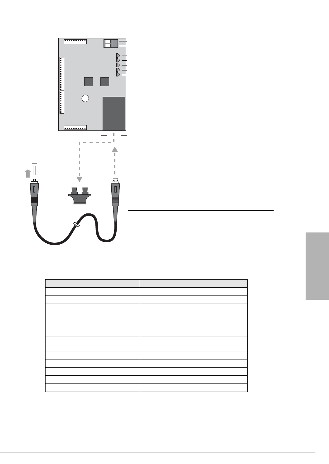
Strata CTX670 Installation
Remote Expansion Cabinet Unit
Strata CTX I&M 06/04 4-59
Strata CTX670
Installation
Figure 4-42 ROMS1A Subassembly
The fiber connection must conform to both the Optical Budget and Fiber Length specifications. It
is possible to have a fiber connection longer than 3 km with less than 9 dB of loss; however, the
CTX670 Remote Expansion Cabinet is sensitive to signal delay and cannot be guaranteed to
operate at distances greater than 3 km.
Table 4-15 Fiber Optic Specification
Item Specification
Transmission Speed 155.52 Mbps
Optical Source LED, 1300 nm
Fiber Type Multi-mode, Graded Index Fiber (GIF)
Core Diameter 62.5 micrometers
Cladding Diameter 125 micrometers
Connector Type SC (2-pin transmit and receive)
Maximum Fiber Length 3 km (500~1000 MHz/km fiber)
2 km (200~400 MHz/km fiber)
Optical Budget (Loss) 9 dB (one way)
Minimum Bend Radius 30 mm
Round Trip Delay Time 30 micro seconds.
Transmit Power >= -23.5 dBm
Receiver Sensitivity <= -30 dBm
TX Side RX Side
4379
ROMS1A
SD
RDER
SYCF
SYCS
RST
CD1
CD2
CD3
CD4
CD5
J3
J1
1
15
1
10
J2
J4
111
11 1
-24v
DG
PFT-CONTROL
Optical
Module
Plastic
Cap
Remove
Rubber Cap
to plug in
Fiber Optic
Cable
Fiber Optic
Cable
CAUTION! Inserting the fiber
connector at an angle or
too forcefully can cause
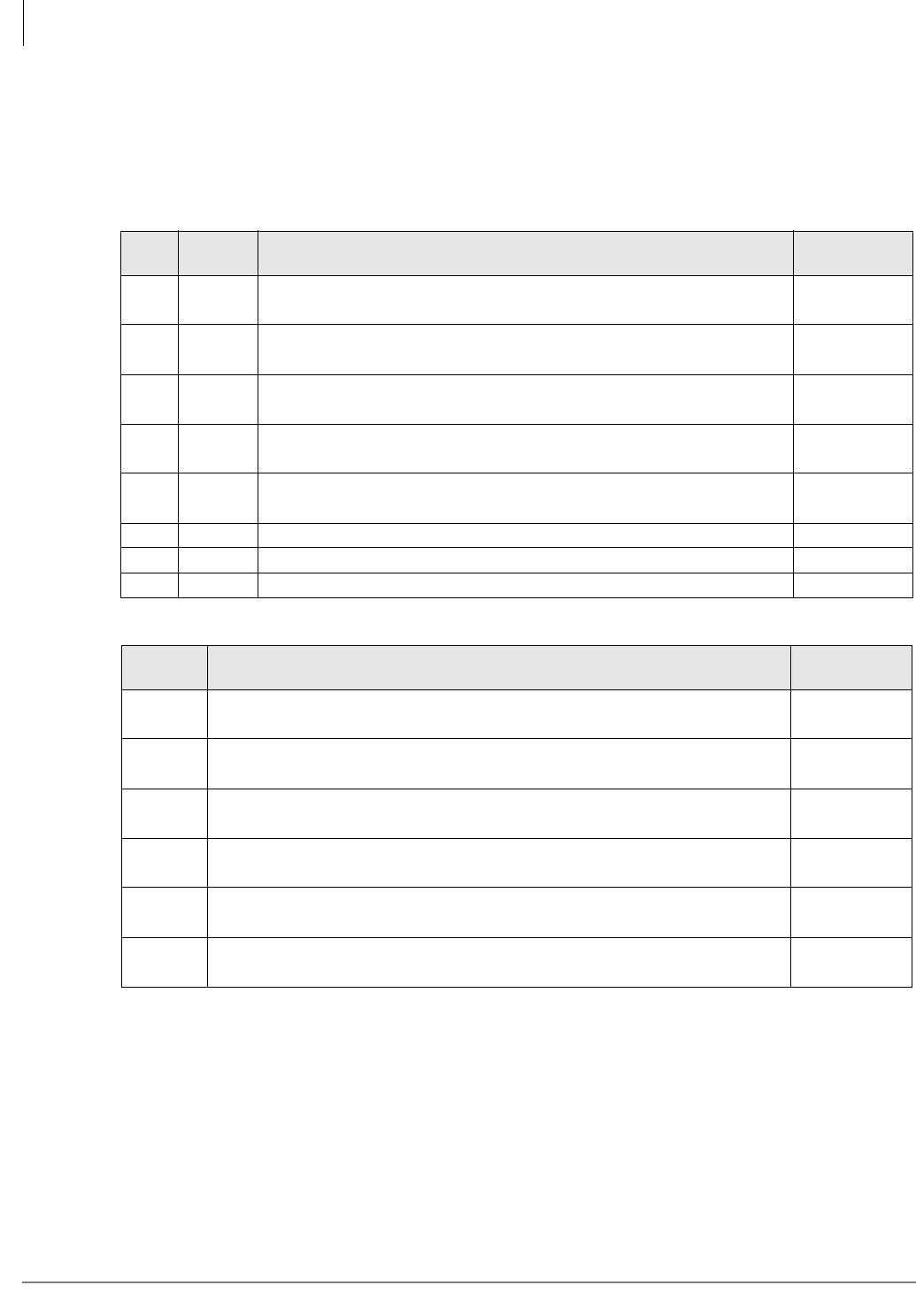
Strata CTX670 Installation
Remote Expansion Cabinet Unit
4-60 Strata CTX I&M 06/04
Status Indicators
The RRCU1A card set provides two status indicators: a set of LEDs on the ROMS1A card and an
RS232C Monitor Port on the RRCU1A. Status indications are provided according to Tables 4-16
and 4-17. Binary Code Output is generated upon change of a reported condition.
Table 4-16 RS-232C Binary Code Output
BIT Label Function Normal
Condition
D0 SD 1: Optical signal not detected
0: Optical signal detected 0
D1 RDER 1: Code rule violation detected in received data
0: Code rule violation not detected in received data 0
D2 SYCF 1: Frame synchronization of received data not established
0: Frame synchronization of received data established 0
D3 SYCS 1: System synchronization between cabinets not established
0: System synchronization between cabinets established 0
D4 RST 1: Reset signal from CTU detected
0: Reset signal from CTU not detected 0
D5 Not Used 0
D6 Not Used 1
D7 Not Used 0
Table 4-17 LED Status Indications
LED Function Normal
Condition
PWR Blinking: Power is supplied
Off: Power is not supplied Blinking
SD On: Optical signal not detected
Off: Optical signal detected Off
RDER On: Code rule violation detected in received data
Off: Code rule violation not detected in received data Off
SYCF On: Frame synchronization of received data not established
Off: Frame synchronization of received data established Off
SYCS On: System synchronization between cabinets not established
Off: System synchronization between cabinets established Off
RST On: Reset signal from CTU detected
Off: Reset signal from CTU not detected Off
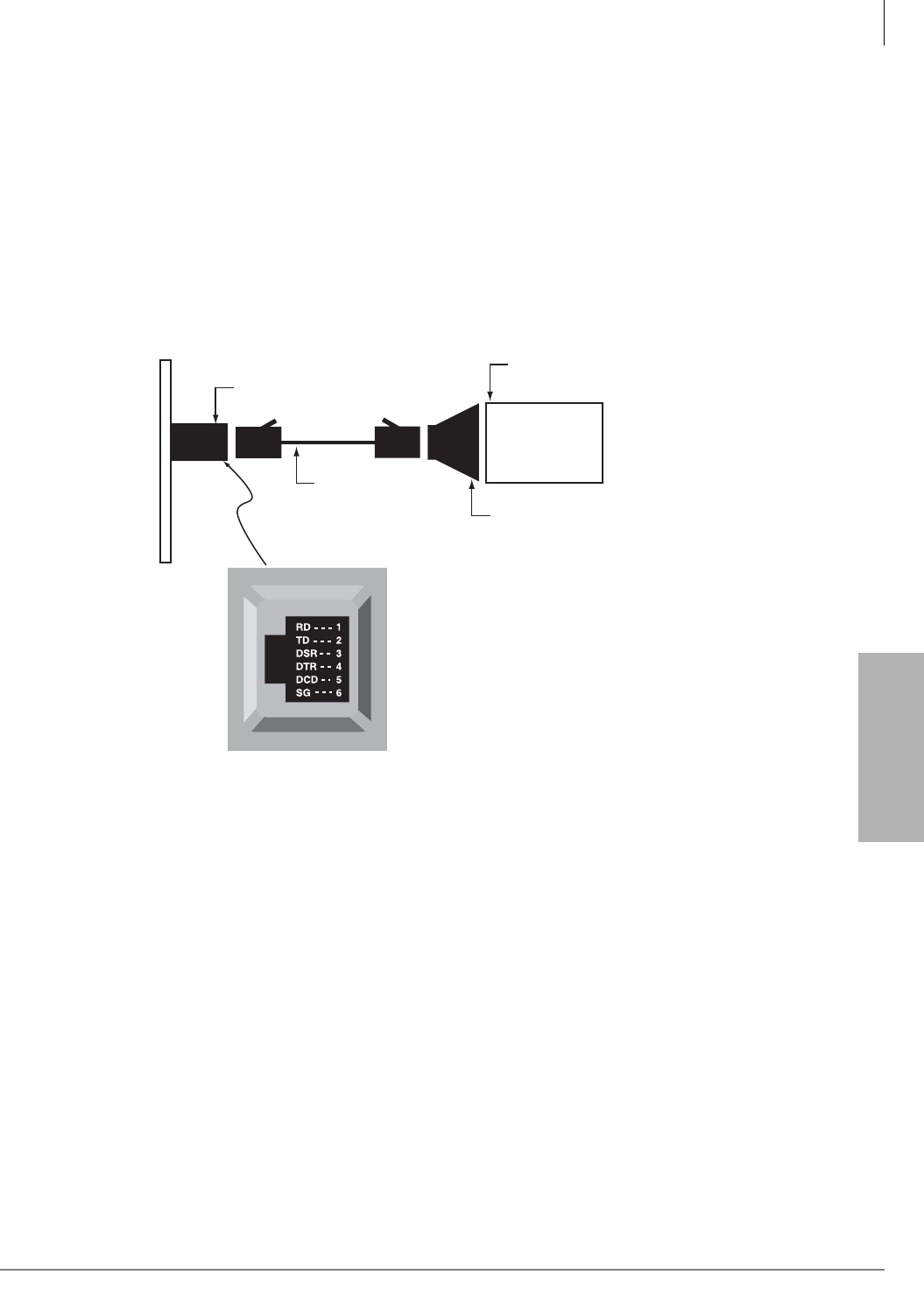
Strata CTX670 Installation
Remote Expansion Cabinet Unit
Strata CTX I&M 06/04 4-61
Strata CTX670
Installation
Monitor Port Communication Parameters
Data rate: 9600 bps
Data word bits: 8
Parity: None
Stop bits: 1
Monitor Port Pin Assignments
The monitor port pin connection and pin assignments are shown in Figure 4-43.
Figure 4-43 RRCU1A Monitor Jack
Monitor jack (RJ12)
pin numbering
Dealer-supplied 6-wire
telephone modular cord
(cross-pinned)
Monitor jack
PC with communication
software - such as ProComm™
PC DB9 or
DB25 Com port
Toshiba PPTC9 or
PPTC25F
RRCU1A
4439

Strata CTX670 Installation
Remote Expansion Cabinet Unit
4-62 Strata CTX I&M 06/04
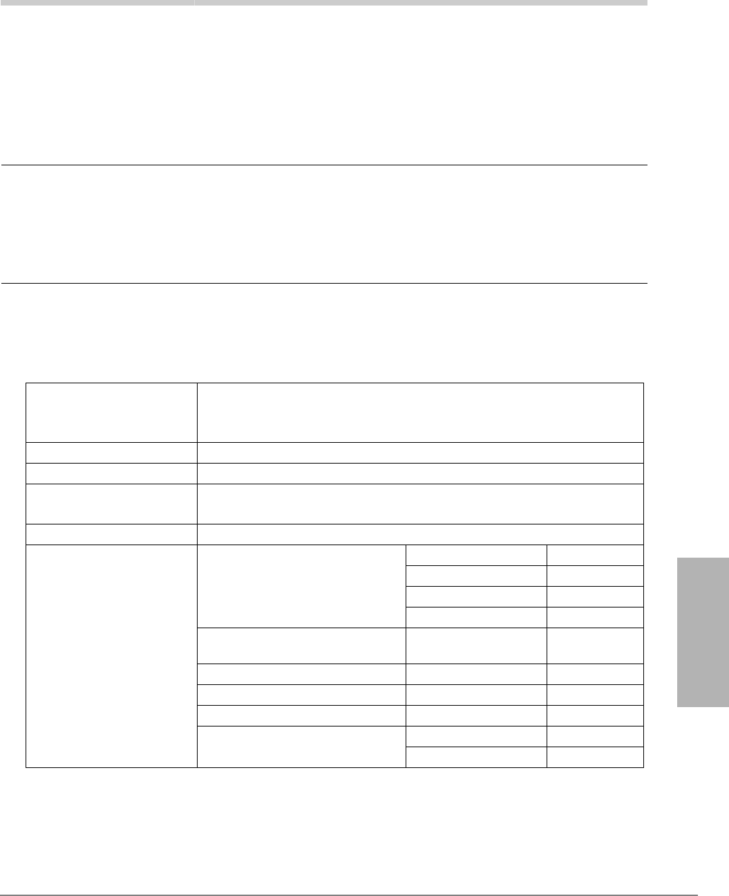
Strata CTX I&M 06/04 5-1
Rack Mount Cabinets
Rack Mount Cabinets 5
The Strata CTX Rack Mount Cabinets consist of a base cabinet (CRSUB672A) and expansion
cabinets (CRSUE672A). The cabinets are made of plated sheet metal, dark gray in color.
CAUTION! Toshiba does not support mixing floor/wall-mountable cabinets with Rack
Mount cabinets in a system installation (local or remote). Mixing cabinets in
an installation causes EMC, EMI, RFI and improper grounding problems.
However, you do not have to match the remote cabinets to the local cabinets.
For example, the local cabinets can be floor/wall-mountable while the
remote ones are rack mount or vice versa.
The 19 inch-wide rack must be supplied by the dealer.
Basic Specifications
Dimensions of Base Cabinet
Height: 10.5 inches (267mm)
Width: 1.58 feet (483mm—with bracket)
Depth: 1.17 feet (358mm)
Weight of Base Cabinet 22.04 lbs. (10 kg)
Power Supply Unit (PSU) BRPSU672A (initially built in)
19" Rack Installation
Dimension
IEC297-1 (EIA RS 310-D)
465.1mm (front face screw pitch – width)
Installation Cannot be floor or wall mounted.
Optional Equipment
Power Strip Box1
1. Power Strip Boxes for traditional cabinets cannot be used for rack mount cabinets.
BRPSB120A Option
BRPSB240A Option
RPSB2A Not applicable
BPSB240A Not applicable
Reserve Power Battery Distribution
Box2
2. Reserve batteries are connected using the same battery distribution box and battery cables as the CTX670
floor/wall-mountable cabinets.
BBDB1A Option
From PSU to Battery Cable PBTC1A-3M Option
From BBDB to Battery Cable BBTC1A-2.0M Option
AC240V Power Supply Cord BACL240A Option
Conduit Connection Box3
(No UL requirement.)
3. Traditional cabinet floor mount conduit connection boxes cannot be used for rack mount cabinets.
BCCB120A Not applicable
BCCB240A Not applicable
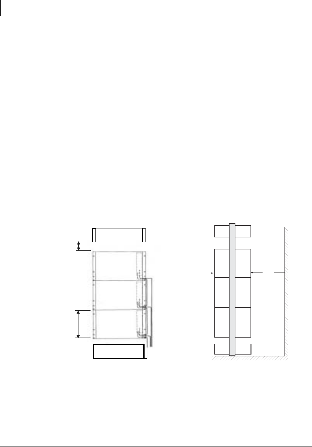
Rack Mount Cabinets
Inspection
5-2 Strata CTX I&M 06/04
Inspection
When the system is received, examine all packages carefully and note any visible damage. If any
damage is found, do not open the packages. Contact the delivery carrier immediately and make the
proper claims.
After unpacking (and before installing), check the system against the packing list and inspect all
equipment for damage. If equipment is missing or damaged, contact your supplier immediately.
Be sure to retain original packaging materials for re-use when storing or transporting system
hardware.
Site Requirements
Space
• Do not install other devices between cabinets.
• No gap should exist between the cabinets. This provides EMC by connecting 2 screws between
cabinets.
• The 3.28 ft. (1m) of space is necessary for the front and back of the rack to make installation
and repair easy. Installation and wiring are done from the front and rear of the cabinets.
• A space measuring 1.75 inches (44.5mm) must always be left above the top of the rack
mounted cabinet for the purpose of ventilation. It is also necessary to have a space between the
top/bottom cabinet and any other device (shown below).
Figure 5-1 Required Space
Ventilation
• 50% or more of the front and back of the cabinet must be left open for ventilation.
• Cabinet rack must always be left open for ventilation.
CRSUE672A
CRSUB672
A
10.5 inches
(267 mm)
1.75 inches
(
44.5mm
)
Other Device
Front View
CRSUE672A
Other Device
3.28'
3.28'
Side View
Wall

Rack Mount Cabinets
Power Considerations
Strata CTX I&M 06/04 5-3
Rack Mount Cabinets
Input Power
The Rack Mount Cabinets require an input power source of 115±10VAC or 208±20VAC or
240±20VAC, 50/60 Hz, single phase, for up to five cabinets; 208VAC or 240VAC is required for
six or seven cabinets. The system requires one or two AC outlets that must be dedicated to system
use, fused, and grounded.
CAUTION! To avoid accidental power turn-off, do not use an On/Off wall switch for AC
circuits dedicated for the use of the Rack Mount Cabinets.
A reserve power source (two or four customer-supplied 12VDC batteries) can be connected to
serve as a backup in case of power failure.
Environmental Conditions
CAUTION! Equipment is for use in a Restricted Access Location.
• Operating Temperature: 0~104 degree Fahrenheit (0~40 degree Centigrade)
• Operating Humidity: 20~80% relative humidity without condensation
Location
When selecting a location for the cabinets, the location must be:
• Dry and clean
• Well-ventilated
• Well-illuminated
• Easily accessible
The location must not be:
• Subject to extreme heat or cold
• Subject to corrosive fumes, dust, or other airborne contaminants
• Subject to excessive vibration
• Next to television, radio, office automation, or high frequency equipment
Power Considerations
Each Rack Mount Base and Expansion Cabinet houses a power supply that furnishes power to all
of the stations and some of the peripherals that interface with the cabinet (see Table 2-60, “Strata
CTX670 Electrical Characteristics” on page 2-47).
Reserve Power
Two or four customer-supplied 12VDC reserve batteries can be connected to the system to
maintain normal operation during a power failure (see Table 2-63 on page 2-49 and Table 2-60 on
page 2-47). The batteries are kept in a highly-charged state by the standard power supply and must
be connected when the system is operating normally. Fully charged batteries must be connected
when normal AC power is available, batteries cannot be connected after/during an actual power
failure.
Underwriters’ Laboratory (UL) and local electrical codes require certain standards for connecting
commercial AC and reserve power to the rack mount system. Table 5-3 describes which
assemblies may be required to meet UL and local electrical code standards. See “(Optional) Install
Reserve Power” on page 5-14 for instructions on installing reserve power.
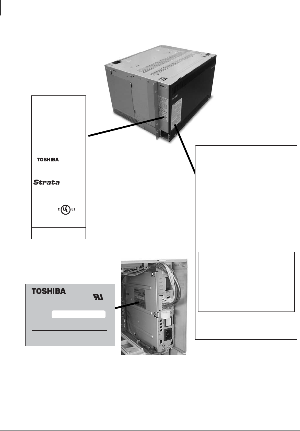
Rack Mount Cabinets
FCC Registration Information
5-4 Strata CTX I&M 06/04
FCC Registration Information
Figure 5-2 Location of Approval Labels
The unit shall be configured
only with those component
assemblies specified in the
installation instructions and
mounted only in the locations
specified.
See installation manual for
grounding requirement.
DIGITAL BUSINESS
TELEPHONE SYSTEM
MODEL CRSUB672A
INPUT:
100-120/208-240VAC
50/60Hz
3.2/2.2A
V. 1 A No. XXXXXX
TOSHIBA CORPORATION
LISTED
49L7
E88891
DCL
Manufactured under one
or more of the following
U.S. patents: 4,491,693
4,511,764 4,532,378
4,605,825 5,535,282
IC:248B-3032A
CAUTION:
This unit may have more than one
power cord, up to seven power cords may be
provided.
To reduce the risk of electrical shock, disconnect all
power cords before servicing.
Fore use only on telephone wiring containing
secondary protection. See instruction manual.
For use only on telephone protected by Oneac
Corp., type 6-AP protector. see instruction manual.
ATTENTION:
Cet appareil peut être muni de
plusieurs cordins d'alimentation électique: jusqu'a
sept dans ceertains cas.
Afin de réduire le risque de chocs éectriques,
débranchez tous les cordons d'alimentatin,
électrique avant l'entretien de l'appareil.
Utiliser seulement avec un reseau téléphonique
compreneant un dispositif de protection secondaire.
Voir le manuel d' instructions.
Utiliser seulement avec un reseau téléphonique
comprenant un dispositif de protection Oneac
Corp., type 6-AP. Voir le manuel d'instructions.
Complies with part 68, FCC rules
FCC Registration number CJ69XA-10242-KF-E
CJ69XA-10243-MF-E
CJ6JPN-22758-PF-E
Ringer equivalence0.2B(ac)0.0(dc),0.3B(ac)0.0(dc)
This device complies with Part 15 of the FCC rules.
Operation is subject ot the following two conditions:
(1) This device may not cause harmful interference,
and (2) this device must accept any interference
received, including interference that may cause
undesired operation.
TOSHIBA CORPORATION
This Class - A digital apparatus complies with
Canadian ICES-003.
Cet apparel numbérique de la class A est conforme
á la norme NMB-003 du Canada.
POWER SUPPLY ASSEMBLY
MODEL
BRPSU672A
E135386
IN : 100-120V/208 240V~50/60HZ 5A/3A
MADE IN
DCL
INDONESIA
OUT : -27V6A, +5V4A, -5V0.8A, BAT -27V0.6A
TOSHIBA CORPORATION
03Y0012
V.1A
C US
N
O.
7093
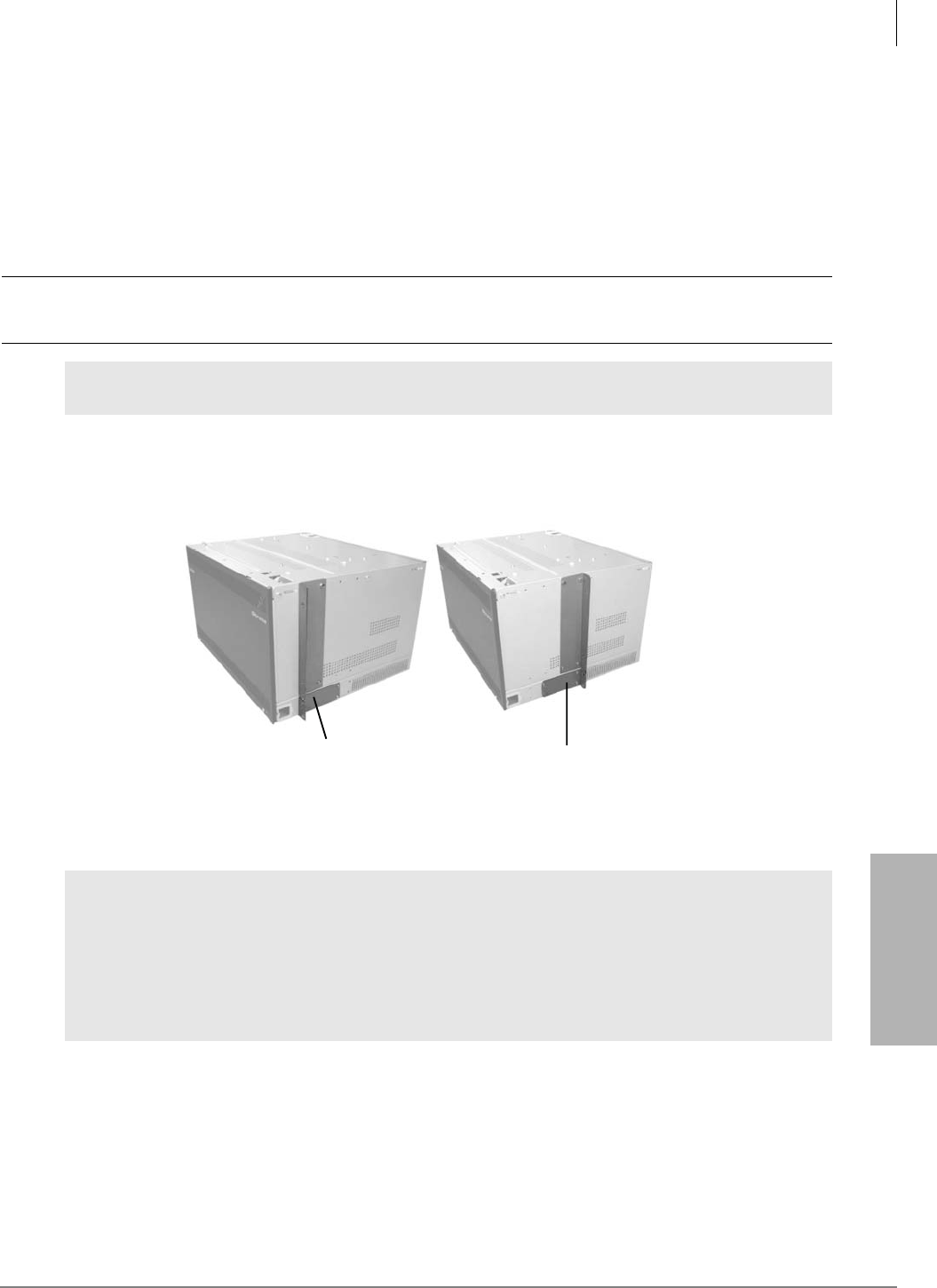
Rack Mount Cabinets
Step 1: Prior to Cabinet Installation
Strata CTX I&M 06/04 5-5
Rack Mount Cabinets
Step 1: Prior to Cabinet Installation
Important! When wiring optical fiber cable for the RRCU (remote cabinet), make sure the cable
bends at >1.18 inches (30mm) radius.
Step 1A: Assemble Rack
³Follow the rack manufacturer’s safety instructions when assembling the rack. The rack must
be secured to the floor.
CAUTION! Never move a rack by yourself. Due to the weight and height of the rack, at
least two people should perform the task.
Step 1B: Move Flange Position (Optional)
The unit ships with the flange in the front position but it can be moved to a center position (shown
below).
Step 2: Install First Cabinet
It is recommended you start mounting the bottom cabinet first and then mount the remaining
cabinets above the bottom cabinet. The base cabinet can be either the top or bottom cabinet.
You need to plan for any future cabinet additions when you mount the initial configuration. If
cabinets will be added in the future they can be added above or below the mounted cabinets.
The following procedures cover both top-down and bottom-up installation.
WARNING! Before installation of the cabinets, make sure that the rack is both level and
stable.
WARNING! To prevent bodily injury when installing or maintaining these cabinet(s):
•Because of the weight of the cabinet(s), it is recommended that two people
load the rack from the bottom up.
•If the rack has stabilizing devices, make sure to install them before installing
or servicing the rack mount cabinets.
•Do not step or stand on any cabinet when servicing other cabinets in the
rack.
Front Position Flange
(suitable for cabinet rack)
Center Position Flange
(suitable for open rack)
6968
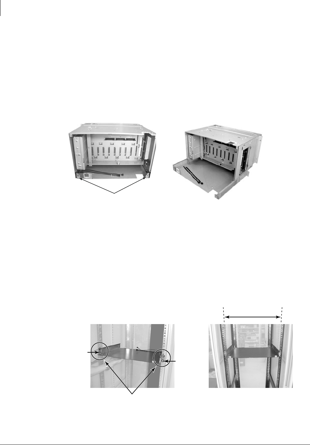
Rack Mount Cabinets
Step 2: Install First Cabinet
5-6 Strata CTX I&M 06/04
Step 2A: Take Off Front and Back Covers
1. Unscrew the two screws holding the front cover to the unit and slide the cover off.
2. Unscrew the four screws holding the back cover to the unit and take the cover off.
Step 2B: Take Off Base of Cabinet
Important! If two people are installing these cabinets, you can skip this step and proceed to item
3 under Step 2C.
³Unscrew the two screws holding the base of the cabinet secure and slide the cabinet back off
the base (shown below).
Step 2C: Attach Cabinet to Rack
In order to line up the first cabinet installed in the rack, you must position the bottom-most hole on
the flange with the top of two holes on the rack (marked Start on Figure 5-3).
The holes on the rack form a pattern of three-holes. A single hole 5/8” above the previous hole,
followed by two holes (1/2” apart) for a total space of 1-1/8”.
Important! If you do not start the cabinet installation in one of the holes marked Start in Figure
5-3 on page 5-7, the next cabinet will not match with the holes on the rack.
1. Attach the base of the cabinet to the rack with two screws on each flange (shown below). Refer
to the rack manufacturer’s documentation for screw size. Toshiba does not provide rack screws.
2. Put the cabinet on the base and slide the cabinet back so that it completely covers the base.
Screws
6971
19"
2 Screws per Flange
6973
Mounting Pillar of 19" Rack
Start
(see Fig. 4-3)
Start
(see Fig. 4-3)
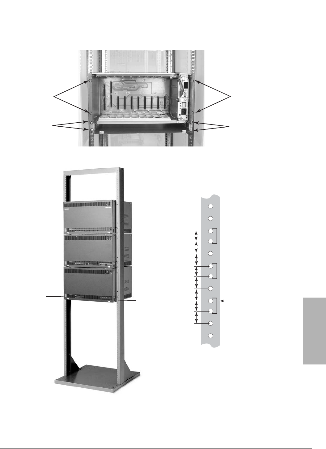
Rack Mount Cabinets
Step 2: Install First Cabinet
Strata CTX I&M 06/04 5-7
Rack Mount Cabinets
3. Screw the cabinet and flange to the rack using four screws on each side (shown below). Refer
to the rack manufacturer’s documentation for screw size. Toshiba does not provide rack screws.
Cabinet
(2 screws)
7087
Flange
(2 screws)
Cabinet
(2 screws)
Flange
(2 screws)
7080
5/8"
5/8"
1/2"
Star
t
5/8"
5/8"
1/2"
5/8"
1/2"
Note: Always install the
bottom cabinet first. The
bottom cabinet screw should
be lined up with the Start screw
hole of the rack as shown above.
Start
Flange
Figure 5-3 Rack Hole Positions
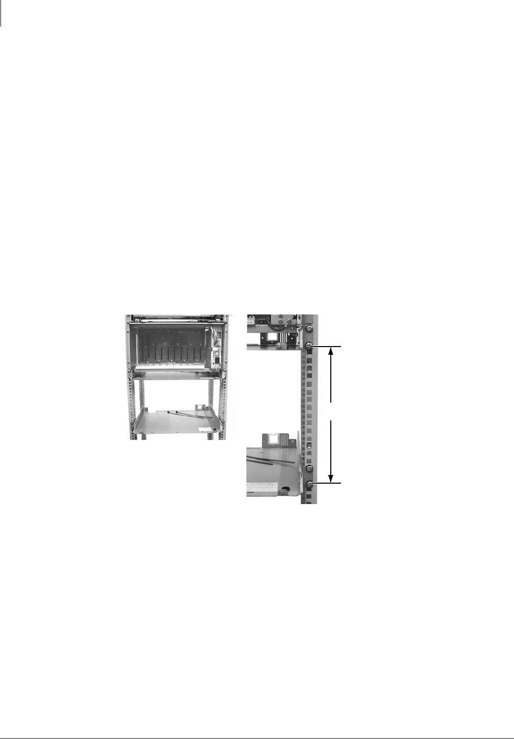
Rack Mount Cabinets
Step 3: Install Remaining Cabinet(s)
5-8 Strata CTX I&M 06/04
Step 2D: Reattach Cabinet to Base
Note Skip this step if you did not perform Step 2B.
³Using the two screws removed in “Step 2B: Take Off Base of Cabinet” on page 6, reattach the
cabinet to the base.
Step 3: Install Remaining Cabinet(s)
Step 3A: Take Off Front and Back Covers
1. Unscrew the two screws holding the front cover to the unit and slide the cover off.
2. Unscrew the four screws holding the back cover to the unit and take the cover off.
Step 3B: Install and Attach Cabinet(s) to Rack
Note See “Step 2C: Attach Cabinet to Rack” on page 5-6 for special instructions on positioning
the cabinets before attaching.
1. Place the base of the next cabinet 10.5 inches from the base of the upper base/expansion cabinet
(as shown below).
2. Screw the cabinet flange to the rack using two screws on each flange (four total).
6U = 10.5 inch or 267 mm
Start (see Fig. 4-3)
Start (see Fig. 4-3)
7101
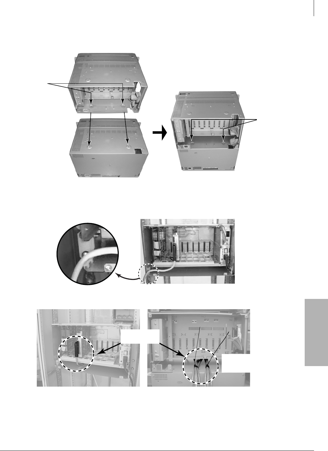
Rack Mount Cabinets
Step 4: Attach Amphenol Cable
Strata CTX I&M 06/04 5-9
Rack Mount Cabinets
3. Attach the upper and lower cabinets with 2 screws (shown below).
Step 4: Attach Amphenol Cable
³The cable can be wired either from the left front (shown below)
...or the center back (shown below).
2 screws
7144
2 screws
Front View 7082
Front View Back View
6977
Fix cable by
plastic clamp
Amphenol Cable
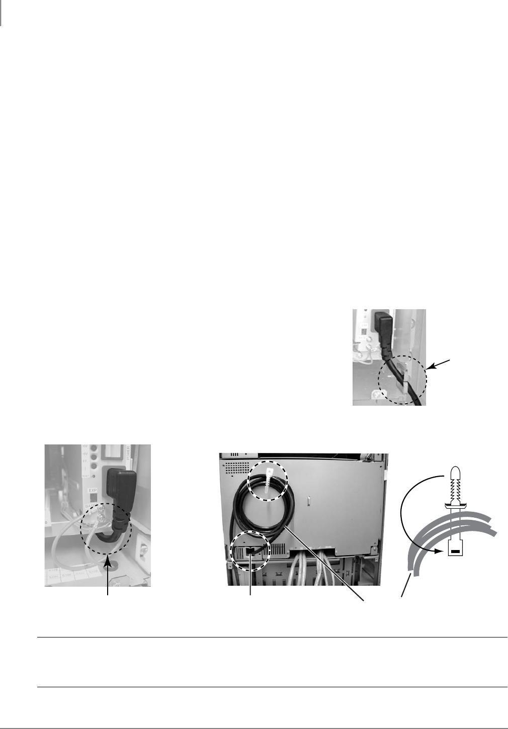
Rack Mount Cabinets
Step 5: Attach the AC Cable
5-10 Strata CTX I&M 06/04
Step 5: Attach the AC Cable
The Rack Mount Cabinet(s) require a single-phase, 50/60 cycles power source of 120, 208, or
240VAC, on a dedicated 20 ampere circuit breaker. 208VAC or 240VAC is required for six or
seven cabinet systems.
Toshiba recommends that a dedicated AC service panel be used. AC outlets must be dedicated to
rack mount cabinet use, fused, and grounded. Equipment unrelated to the rack mount cabinet(s)
must not be connected to the circuit or service panel dedicated to the rack mount cabinet(s).
Note It may not always be possible to power a complete rack mount cabinet system from a single
circuit breaker panel. For example, in the case where a cabinet is remotely located.
To avoid accidental turn-off, do not configure the outlet serving the rack mount cabinets with an
On/Off switch. AC outlets serving the cabinets must be close enough so that the power cord from
the cabinet power supply or power strip can reach the outlet (these power cords are nine ft.).
AC wall outlets for the rack mount cabinets must be on dedicated 20amp breakers. AC outlets
must meet National Electrical codes specifications: NEMA 5-20R for 120VAC or NEMA 6-20R
for 208VAC/240VAC.
AC power cabling requirements vary, depending on: The method of cabinet installation (i.e., rack,
floor or wall mount), AC power source voltage (120VAC, 208VAC or 240VAC) and the number of
cabinets.
³ The cable can be wired from the right front of the
cabinet (shown right).
...or
the cable can be wired from the back (as shown
below).
CAUTION! Arrange the rest of the AC cables outside the cabinet. Noise from the cables
influence electrical components (e.g., motherboard) when the cables are
located inside the cabinet.
AC Cable
goes through
plastic clamp
6987
AC Cable is wired
to the back
Front View Back View (with back cover)
6981
AC cable clamp
in back cover
AC cable
AC Cable Hole
in Back Face
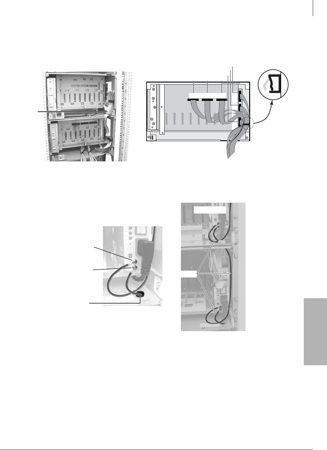
Rack Mount Cabinets
Step 6: Connect Data and Ground Cables
Strata CTX I&M 06/04 5-11
Rack Mount Cabinets
Step 6: Connect Data and Ground Cables
1. Wire the data cable between the base and expansion cabinet (shown below).
2. Wire the FG cable between the base and expansion cabinet by passing it through the hole in the
base of the expansion cabinet. Secure the FG wire spade lug to the power supply with the FG
screws (as shown below).
Note The backplane FG wires are not safety grounds: they are required for proper system CO line
operation.
7007
CAB
2CAB
5
CAB
6
CAB
7
CAB
3
CAB
4
CAB 2 CAB 3 CAB 4
View from Top
To MS B U
of respective
Exp. Cabinet
CAB 7
CAB 6
CAB 5
Back View
Base Cabinet
Data Cable
6985
Back View Base Cabinet
Screw FG Cable
from upper cabinet
Screw FG Cable
from lower cabinet
Pass FG Cable
through this Hole
6987a
FG Cable
6986a
Front View
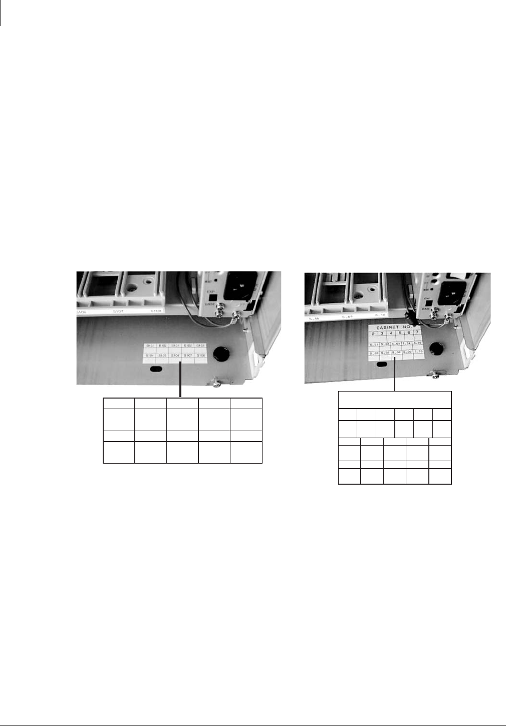
Rack Mount Cabinets
Step 7: Verify Power Supply Settings
5-12 Strata CTX I&M 06/04
Step 7: Verify Power Supply Settings
³If the cabinet is the Base Unit set the Exp/Base switch to the “Base” position (see “Power
Supply Unit (BRPSU672A)” on page 5-28).
...or if the cabinet is an Expansion Unit, set the Exp/Base switch to the “Exp” position.
Important! The power supply set as “Base” is the master and has On/Off control over all other
power supplies, which are designated as slaves. If the master power supply is turned
Off or On, all other power supplies will automatically turn Off or On. (Individual
slave power supplies must be turned On.)
Step 8: Fill Out Slot Assignments
The slot identification label appears on the lower right side of the cabinet interior (shown below).
Step 9: Attach Mesh Tie (B50MT)
³Wrap the cables in with the mesh tie. The purpose of the wrap is to shield the cables from
EMI/RFI effects. See Figures 5-6, 5-7 and 3-10 for additional information.
Note One mesh tie is required to wrap cables individually in each cabinet. One mesh tie is
required to wrap all cables where they exit the system. A B50MT Mesh Tie is included with
each base and expansion cabinet.
6999
B101 B102 S101 S102 S103
S104 S105 S106 S107 S108
Base Cabinet
6998
CABINET NO.
2
S_01 S_02 S_03 S_04 S_05
S_06 S_07 S_08 S_09 S_10
34567
Expansion Cabinet
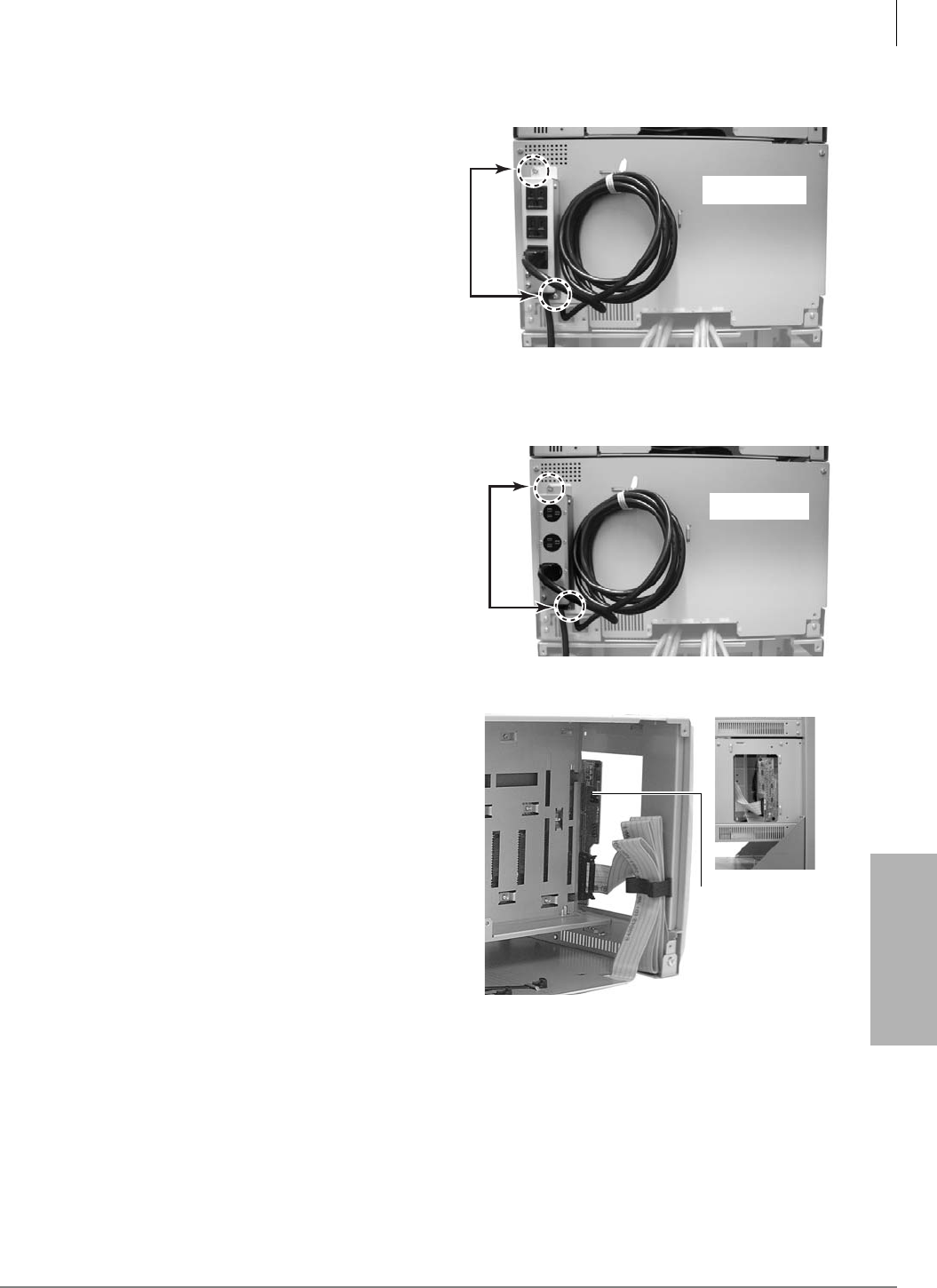
Rack Mount Cabinets
Step 10: Install Power Strip (BRPSB120A)
Strata CTX I&M 06/04 5-13
Rack Mount Cabinets
Step 10: Install Power Strip (BRPSB120A)
³Using 2 screws attach the BRPSB120A to
the back cover of the expansion cabinet (as
shown at right).
See also Table 5-3, “Power Cabinet
Hardware for Rack Mount Cabinets” on page
5-24 for additional information.
Step 11: (Optional) Install Power Strip (BRPSB240A)
Note If you are installing 4 or more cabinets, you
must use the BRPSB240A power strip. See
page 5-30 for additional requirements.
³Using 2 screws attach the BRPSB240A to the
back cover of the expansion cabinet (as shown
at right).
See also Table 5-3, “Power Cabinet Hardware
for Rack Mount Cabinets” on page 5-24 for
additional information.
Important! You can disconnect the MSBU and
reconnect it to the back side of the
expansion cabinet to make it easier
to perform maintenance (shown
right).
Back view
6989
Back view
6990
6994
Side viewBack view
MSBU
common to
that of
CHSUE672A

Rack Mount Cabinets
Step 12: (Optional) Install Reserve Power
5-14 Strata CTX I&M 06/04
Step 12: (Optional) Install Reserve Power
Two or four customer-supplied, 12VDC batteries (80 amp hours maximum) can be connected to
the system as a power failure backup. In the event of a power failure, the system automatically
switches over to battery power without any interruption to existing calls or other normal system
functions.
The procedure for installing reserve power varies, depending on the number of cabinets in the
system. The following text details reserve power battery installation requirements.
Important! Batteries must be connected when normal AC power is available; they cannot be
connected during an AC power failure situation.
The length of time reserve power operates depends on the system, size and number of batteries
provided, and the system load. Typical reserve power duration estimates and battery specifications
are estimated with the following considerations (see Table 5-1):
• Batteries have full charge at start of operation.
• Two or four batteries connected per Figure 5-4.
• Batteries are 12VDC, rated at 80 amp/hours each.
• System is operating at full load traffic with LCD phones.
• Batteries used for this test are gel-cell and maintenance-free. Reserve duration will vary
depending upon battery type, age, and manufacturer. These figures should only be used as an
estimate.
Table 5-1 Typical Reserve Power Duration Estimate
Number of Cabinets 1234567
Estimated operation time
Two-battery configuration
12.0
hrs. 6.0 hrs. 4.0 hrs. 3.0 hrs. 2.5 hrs. 2.0 hrs 1.8 hrs
Estimated operation time
Four-battery configuration
24.0
hrs. 12.0 hrs 8.0 hrs 6.0 hrs. 5.0 hrs. 4.0 hrs 3.5 hrs
WARNING! Some batteries can generate explosive gases. Therefore,
ensure that batteries are located in a well-ventilated area.
Do not smoke near batteries.
Avoid creating any electrical sparks near batteries.
Use commercially available battery enclosures to reduce risk to nearby
people and equipment.
Rack Mount Cabinets
Step 12: (Optional) Install Reserve Power
Strata CTX I&M 06/04 5-15
Rack Mount Cabinets
Reserve Battery Cabinet Components/Cables
The part names and descriptions of the reserve battery cabinet components and cables are shown in
Table 5-2.
Important! Reserve batteries can be installed in various configurations depending on backup
time (Table 5-1) and the number of cabinets (Figure 5-4). Use the guide in Figure
5-4 for installing batteries, as required.
WARNING! Battery cables that exit the cabinet(s) are not UL listed because of
possible incorrect installations. Have a licensed electrician install these
cables.
Table 5-2 Reserve Battery Cabinet Components/Cables for Rack Mount Cabinets
Option Description
PBTC1A-3M
A three-meter long battery cable is used to connect reserve power batteries to the system
power supply when the system has less than three cabinets. One reserve power cable is
required for each cabinet in a one or two cabinet system. The cable connects the Strata rack
cabinet power supply directly to the battery terminals (a BBDB1A is not required).
BBDB1A
Strata CTX reserve power battery distribution box is required when connecting reserve
power batteries to three or more cabinets. The box is field installed into one of the Strata CTX
cabinet side panels.
The BBDB1A provides seven BBTC2A-2.0M, battery distribution cables to connect reserve
power from the BDDB1A box to each individual cabinet power supply.
One or two BBTC1A-2.0M must be ordered separately when using the BBDB1A battery
distribution box.
BBTC1A-2.0M
A two-meter battery cable used to connect reserve power batteries to the BBDB1A battery
distribution box. One reserve power cable is required in a three or four cabinet system and
two cables are required for five, six or seven cabinet systems. The cable connects Strata
CTX BBDB1A box directly to the battery terminals.

Rack Mount Cabinets
Step 12: (Optional) Install Reserve Power
5-16 Strata CTX I&M 06/04
Install Reserve Power for One or Two Cabinets
1. Connect the black jumper wire (supplied with the PBTC1A-3M cable) from the positive
terminal of one 12VDC battery to the negative terminal of the second 12VDC battery (Figure
5-4).
2. Ensure that a serviceable 10-amp fuse is installed in the in-line fuse holder of the PBTC1A-3M
cable.
3. Connect the PBTC1A-3M battery cable white lead to the open positive terminal of the 12VDC
battery. Connect the black lead to the open negative terminal of the second 12VDC battery.
Important! The cabinet(s) must be connected to the (live) AC power source, and the power
supply On/Off switch set to On prior to the final step of connecting the reserve
power batteries to the power supply via the BATT+/- receptacle. If the batteries are
connected after AC power is lost, reserve power will not function.
4. Connect the PBTC1A-3M battery cable two-prong male plug to the Base Cabinet power supply
BATT +/- receptacle.
5. Repeat Steps 3 and 4 to connect a PBTC1A-3M to the Expansion Cabinet.
6. To test reserve power operation, disconnect system AC power plugs with power supply On/Off
switches in the On position. The system should continue to operate without interruption.
Note If connecting four batteries, follow the wiring diagram in Figure 5-4.
Install Reserve Power for Three or More Cabinets
1. Install the Battery Distribution Box (BBDB1A). See “Install Reserve Power Battery
Distribution Box (if required)” on page 5-17 and Figure 5-4. The BCCB is not required.
2. Connect two Cable “C” jumper wires from the positive terminal of one 12VDC battery to the
negative terminal of the second 12VDC battery, per Figure 5-4 (Cable “C” is supplied with the
BBTC1A-2.0M cable).
3. Ensure that a serviceable 15-amp fuse is installed in the in-line fuse holder of the
BBTC1A-2.0M battery cable.
4. Connect the white lead of the BBTC1A-2.0M battery cable to the open positive terminal of the
12VDC battery. Connect the black lead to the open negative terminal of the second 12VDC
battery.
5. Connect a second BBTC1A-2.0M in parallel to the first BBTC1A-2.0M cable per Steps 2, 3
and 4.
6. Plug the two BBTC1A-2.0M battery cables into the Battery Distribution Box.
Important! The cabinets must be connected to the (live) AC power source, and the power supply
On/Off switches set to On prior to the final step of connecting the reserve power
batteries to the power supplies via the BATT +/- receptacle. If the batteries are
connected after AC power is lost, reserve power will not function.
7. Connect the BBTC2A-2.0M cables from the Battery Distribution Box to the BATT +/-
receptacle of individual power supplies per Figure 5-4 (BBTC2A-2.0M cables are supplied
with a BBDB1A distribution box).
8. To test reserve power operation, disconnect the system AC power plugs with the power supply
On/Off switches in the On position. The system should continue to operate without
interruption.
Note If connecting four batteries, follow the wiring diagrams in Figure 5-4.
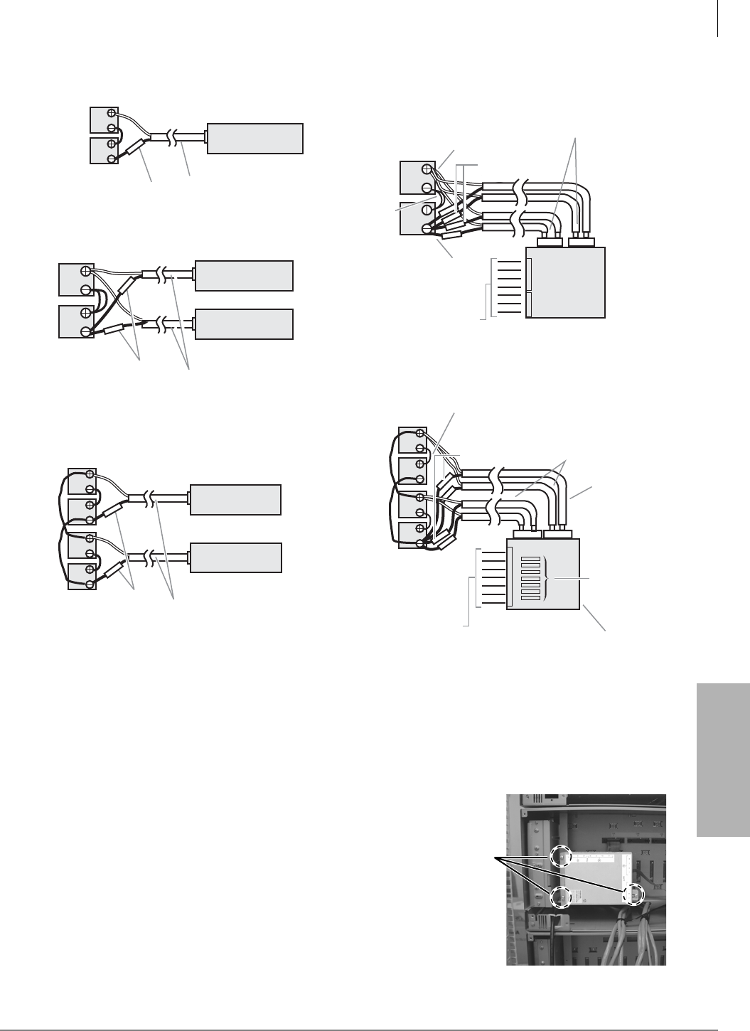
Rack Mount Cabinets
Step 12: (Optional) Install Reserve Power
Strata CTX I&M 06/04 5-17
Rack Mount Cabinets
Figure 5-4 Battery Wiring Diagram (Two or Four Batteries)
Install Reserve Power Battery Distribution Box (if required)
If a BBDB1A is required (see Figure 5-4), follow this procedure:
³Using 3 screws attach the BBDB1A (as shown
at right) to an expansion cabinet somewhere in
the middle of the system.
Notes
• The BBDB1A can also be installed in the base
cabinet.
• With a 7 cabinet installation, do not install the
BBDB1A in the top or bottom cabinet.
The 6.56 ft. (2m) BBTC2A-2.0M cables are
not long enough to reach from the bottom
cabinet to the top cabinet
To BRPSU672 “BATT”
Connectors (7 max.)
White Wire
Black Wire
15A Fuse (2 each)
2-Batteries/1~7 Cabinets (with BBDB1A)
12 Volt
Batteries
80 AMP/
HR Each
BBTC2A-2.0M Cables (7 max.)
supplied with BBDB1A
4-Batteries/1~7 Cabinets (with BBDB1A)
To BRPSU672 “BATT”
Connectors (7 max.)
2-Batteries/1-Cabinet (without BBDB1A)
12 Volt
Batteries
80 AMP/
HR each
12 Volt
Batteries
80 AMP/
HR Each
PBTC1A-3M Cables (9 ft.)
–
+BRPSU672 BATT
Connector
BRPSU672 BATT
Connector
BRPSU672 BATT
Connnector
BRPSU672 BATT
Connector
BRPSU672 BATT
Connnector
4-Batteries/2-Cabinets (without BBDB1A)
2-Batteries/2-Cabinets (without BBDB1A)
10A Fuse
PBTC1A-3M Cables (9 ft.)
10A Fuse
Exp. Cabinet
Base Cabinet
Base Cabinet
Exp. Cabinet
Base Cabinet
PBTC1A-3M
Cables (9 ft.)
12 Volt
Batteries
80 AMP/
HR Each
12 Volt
Batteries
80 AMP/
HR each
BATT
BBDB1A
–
+
–
+
–
+
–
+
“C” Cable,
supplied
with
BBTC1A-2.0M
Cable
“C” Cables, supplied with
BBTC1A-2.0M Cable
Fuses
(12 AMP)
BBDB1A
(cover
removed)
10A Fuse
5221
BBTC2A-2.0M Cables
(7 max.) supplied
with BBDB1A
A
+–
A
A
B
+–
B
AB
B
15A Fuse (2 each)
BBTC1A-2.0M
Cable consists
of two (6.5 ft.) wires.
BBTC1A-2.0M
Cables (6.5 ft.)
2nd cable
required
for 5 or
more
cabinets
only
BBDB1A
Rating:
27.3VDC,
42A max.
2nd cable (
B
required
for 5 or
more
cabinets
only
Back View
Using 3 screws
attach the BBDB1A
6988

Rack Mount Cabinets
Step 13: Ground the System
5-18 Strata CTX I&M 06/04
Step 13: Ground the System
The system requires a solid earth ground for proper operation and safety. The AC power cord(s)
already contains a conductor for the “third wire ground” provided by the commercial power outlet
(see Figure 5-5, for grounding points “A” and “B”). An insulated conductor must connect the
frame ground terminal on the Base Cabinet to a cold water pipe or the building ground (point “B”).
Before connecting the system to the AC power source, measure the impedance of the building
ground reference. If the ground path connected to the system has an impedance of 1 ohm or more,
a better ground must be installed. In Figure 5-5, the grounding path between point “A” and the
single point ground “B” must be less than 0.25 ohms.
The “third wire ground” coming from the primary AC power outlet must be dedicated and must be
routed through the same conduit as the phase conductors serving the system. The conductor
connected to the frame ground (FG screw) on the system power supply must be insulated and
comply with the general rules for grounding contained in Article 250 of the National Electrical
Code, NFPA 70, but must not depend on the cord and plug of the system.
If the CTX670 system consists of more than one cabinet, you must install the bonding connection
plates that come attached to each expansion cabinet. Refer to Figure 5-5. Connect the mother
board ground wires and the intercabinet ground wires per Figure 5-5.
On each cabinet, wrap the cable mesh shield (part No. B50MT) around the 25-pair communication
cables that carry stations over tip and ring, per Figures 5-6 and 5-7.
Step 14: Install Processor and Universal PCBs
See section entitled “Install Processor and Universal PCBs” on page 4-43.
Step 15: Attach Front and Back Covers
WARNING! Failure to provide a proper ground may be a safety hazard to service
personnel or lead to confusing trouble symptoms. In extreme cases, system
failure may result because the system is not properly protected from lighting
or power transients.
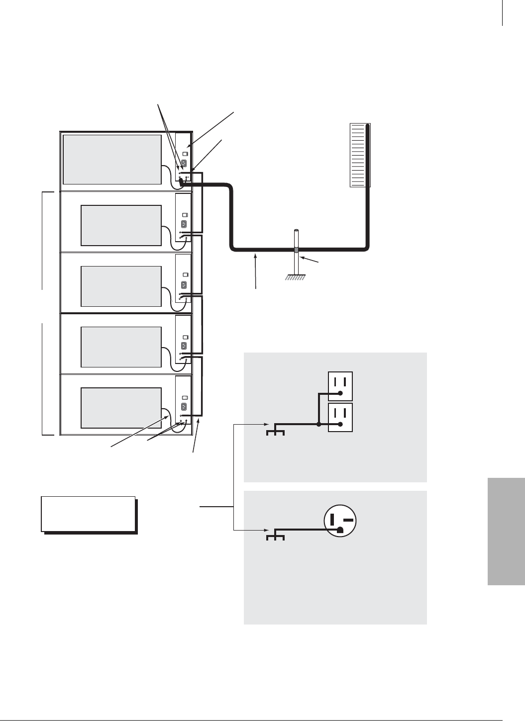
Rack Mount Cabinets
Step 15: Attach Front and Back Covers
Strata CTX I&M 06/04 5-19
Rack Mount Cabinets
Figure 5-5 Rack Mount Cabinet Grounding
Cabinet Motherboard
Cabinet
Motherboard
Cabinet
Motherboard
Cabinet
Motherboard
Cabinet
Motherboard
FG Screws
Base
Cabinet
Power
Supply
FG (Frame Ground) Screws
The Single Point Ground must always be connected to
the Base Cabinet Power Supply FG Screw
(Top cabinet - Wall Mount or Bottom cabinet - Floor Mount.)
Expansion
Cabinets
Up to six
Inter-cabinet green wires
supplied with each cabinet
Green ground
wires from
Motherboard
Earth Ground:
AWG #6 Wire
(minimum)
Length: 60 Feet
(maximum)
Per General Rules of Article
250 of the National Electric
Code, NFPA70
ONEAC 6-AP
or 6-DP
Solid State
Secondary
Protectors
Third Wire
AC Ground
Insulated Ground Wire “B”
Note:
The impedance of the link
between point “A” and “B” must
be less than 0.25 ohms.
Note:
The ground must be
routed through the
same conduit as the
phase conductors
serving the system.
Single Point Ground (SPG)
Cold Water Pipe or Ground Rod
Note:
The SPG cannot be structural
steel members or conduit.
“A”
“A”
Note:
The impedance of
the link between
point “A” and “B”
must be less than
0.25 ohms.
Note:
The impedance of
the link between
point “A” and “B”
must be less than
0.25 ohms.
120VAC System Primary Power ( 1-5 cabinets only )
Building Main Power
Panel Electrical Ground
208VAC ± 20VAC (50/60 Hz)
or 240VAC ± 20VAC (50/60 Hz)
Dedicated 20 Amp
Branch Circuit.
If 208VAC is used, the plug may have to be
changed by a licensed electrician.
Note:
The system may be
powered by 120, 208,
or 240VAC.
NEMA 6-20R,
240VAC
208 or 240VAC System Primary Power ( 1-7 cabinets )
115VAC ± 10VAC (50/60 Hz)
Dedicated 20 Amp
Branch Circuit
Building Main Power
Panel Electrical Ground
“B”
AWG #6 Wire
(minimum)
Length: 60 Feet
(maximum)
Point “B” is always on the
Base Cabinet, whether it's
on the top or bottom.
NEMA 5-15R,
120VAC
7076
The cabinets must be
located no more than 9
feet from the AC outlet.
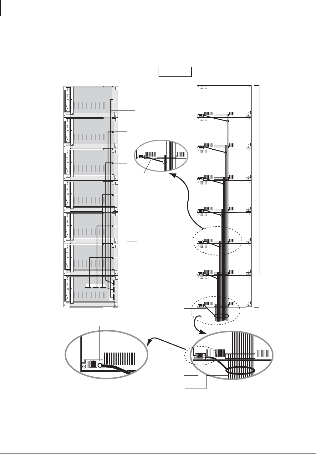
Rack Mount Cabinets
Wiring for 7 Cabinet Configuration
5-20 Strata CTX I&M 06/04
Wiring for 7 Cabinet Configuration
The following illustrations show an overview of the cabling for a 7 cabinet configuration.
Figure 5-6 Bottom Up Configuration (Center back wiring)
Mesh Tie
(B50MT)
CAB
2
CAB
5
CAB
6
CAB
3
CAB
4
CAB
2
CAB
5
CAB
6
CAB
3
CAB
4
CAB
2
CAB
5
CAB
6
CAB
3
CAB
4
CAB
2
CAB
5
CAB
6
CAB
3
CAB
4
CAB
2
CAB
5
CAB
6
CAB
3
CAB
4
CAB
2
CAB
5
CAB
6
CAB
3
CAB
4
CAB
2
CAB
5
CAB
6
CAB
3
CAB
4
CAB
2
CAB
5
CAB
6
CAB
3
CAB
4
CAB
2
CAB
5
CAB
6
CAB
3
CAB
4
CAB
2
CAB
5
CAB
6
CAB
3
CAB
4
CAB
2
CAB
5
CAB
6
CAB
3
CAB
4
CAB
2
CAB
5
CAB
6
CAB
3
CAB
4
CAB
2
CAB
5
CAB
6
CAB
3
CAB
4
CAB
2
CAB
5
CAB
6
CAB
3
CAB
4
7005
CAB
2
CAB
5
CAB
6
CAB
3
CAB
4
CAB
2
CAB
5
CAB
6
CAB
3
CAB
4
CAB
2
CAB
5
CAB
6
CAB
3
CAB
4
CAB
2
CAB
5
CAB
6
CAB
3
CAB
4
CAB
2
CAB
5
CAB
6
CAB
3
CAB
4
CAB
2
CAB
5
CAB
6
CAB
3
CAB
4
CAB
2
CAB
5
CAB
6
CAB
3
CAB
4
Screw Position of Mesh Tie (B50MT)
Mesh Tie
(B50MT)
Base
Cabinet
Expansion
Cabinet
Amphenol
Cable
Data Cable
to MSBU PCB.
MSBU
Bottom Down Configuration
Back View
CAB
2
CAB
3
CAB
4
234
CAB
5
CAB
6
CAB
7
5
6
7
Amphenol
Cable
Mesh Tie
(B50MT)
Note: Wrap all cabinet cables.
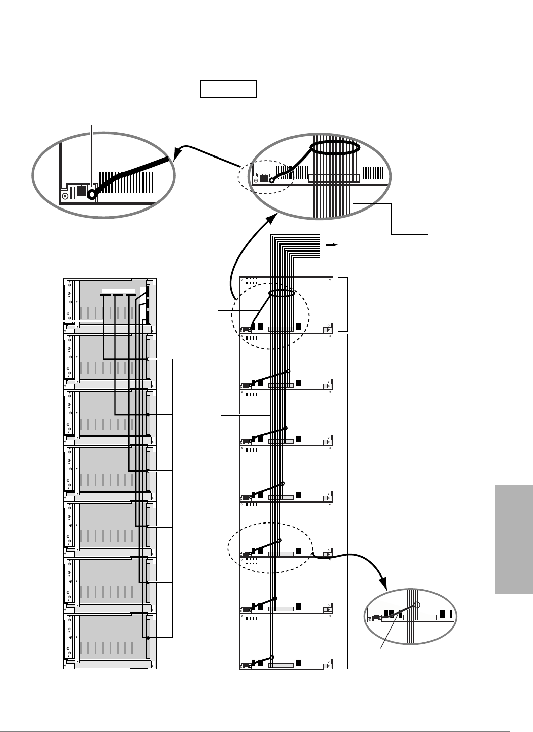
Rack Mount Cabinets
Wiring for 7 Cabinet Configuration
Strata CTX I&M 06/04 5-21
Rack Mount Cabinets
Figure 5-7 Top Down Configuration (Center back wiring)
Mesh Tie
(B50MT)
CAB
2
CAB
5
CAB
6
CAB
3
CAB
4
CAB
2
CAB
5
CAB
6
CAB
3
CAB
4
CAB
2
CAB
5
CAB
6
CAB
3
CAB
4
CAB
2
CAB
5
CAB
6
CAB
3
CAB
4
CAB
2
CAB
5
CAB
6
CAB
3
CAB
4
CAB
2
CAB
5
CAB
6
CAB
3
CAB
4
CAB
2
CAB
5
CAB
6
CAB
3
CAB
4
CAB
2
CAB
5
CAB
6
CAB
3
CAB
4
CAB
2
CAB
5
CAB
6
CAB
3
CAB
4
CAB
2
CAB
5
CAB
6
CAB
3
CAB
4
CAB
2
CAB
5
CAB
6
CAB
3
CAB
4
CAB
2
CAB
5
CAB
6
CAB
3
CAB
4
CAB
2
CAB
5
CAB
6
CAB
3
CAB
4
CAB
2
CAB
5
CAB
6
CAB
3
CAB
4
7008
CAB
2
CAB
5
CAB
6
CAB
3
CAB
4
CAB
2
CAB
5
CAB
6
CAB
7
CAB
3
CAB
4
CAB
2
CAB
5
CAB
6
CAB
3
CAB
4
CAB
2
CAB
5
CAB
6
CAB
3
CAB
4
CAB
2
CAB
5
CAB
6
CAB
3
CAB
4
CAB
2
CAB
5
CAB
6
CAB
3
CAB
4
CAB
2
CAB
5
CAB
6
CAB
3
CAB
4
CAB
2
CAB
5
CAB
6
CAB
3
CAB
4
234 5
6
7Mesh Tie
(B50MT)
Base
Cabinet
To MD F
Expansion
Cabinet
Amphenol
Cable
Data Cable
to MSBU PCB
MSBU
Top Down Configuration
Back View
Amphenol
Cable
Mesh Tie
(B50MT)
Note: Wrap all cabinet cables.
Screw Position of Mesh Tie (B50MT)
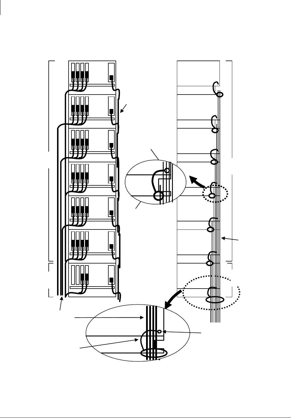
Rack Mount Cabinets
Wiring for 7 Cabinet Configuration
5-22 Strata CTX I&M 06/04
Figure 5-8 Bottom Up Configuration (Left Front wiring)
Base
Cabinet
Expansion
Cabinet
Note: Wrap all cabinet cables.
Amphenol
Cables
Screw position of Mesh Tie (B50MT).
Please move the screw from screw
position of Mesh Tie on the back.
Amphenol
Cables
Mesh Tie
(B50MT)
Amphenol
Cables
Mesh Tie
(B50MT)
Expansion
Cabinet
Base
Cabinet
Power
Supply
Cords
Front View Side View
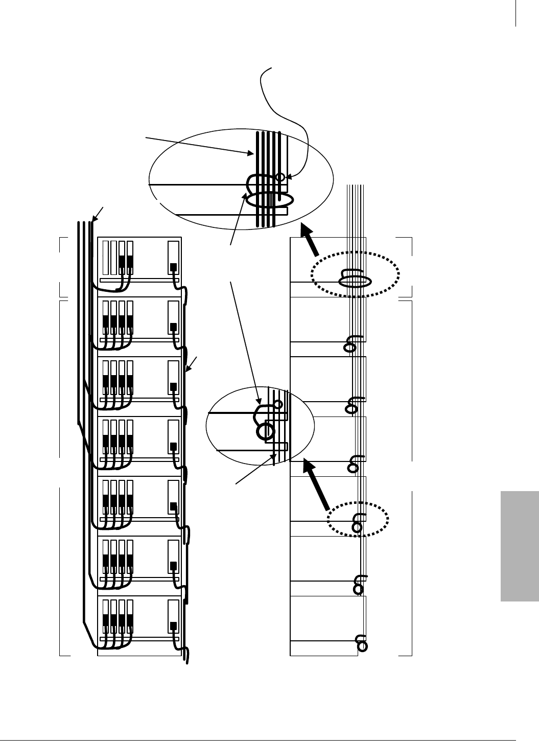
Rack Mount Cabinets
Wiring for 7 Cabinet Configuration
Strata CTX I&M 06/04 5-23
Rack Mount Cabinets
Figure 5-9 Top Down Configuration (Left Front wiring)
Base
Cabinet
Amphenol
Cables Note: Wrap all cabinet cables.
Mesh Tie
(B50MT)
Amphenol
Cables
Amphenol
Cables
Expansion
Cabinet
Base
Cabinet
Expansion
Cabinet
-Front View- -Side View-
S
crew position of Mesh Tie
(
B50MT
)
.
Please move the screw from screw
position of Mesh Tie on the back.
Power
Supply
Cords

Rack Mount Cabinets
Primary Power Cabinet Hardware
5-24 Strata CTX I&M 06/04
Primary Power Cabinet Hardware
The type of cabinet mounting can have an effect on the power requirements. Underwriters’
Laboratory (UL) and local electrical codes require certain standards for connecting commercial
AC and reserve power to the Strata CTX system. Table 5-3 describes which assemblies may be
required to meet UL and local electrical code standards.
Table 5-3 Power Cabinet Hardware for Rack Mount Cabinets
Option Description
BRPSB120A
Cabinet power strip for 120VAC primary power – provides three standard 120VAC/15A
outlets (NEMA5-15R) and nine ft. AC power cord with standard 120VAC/15A plug (NEMA5-
15P). This unit is field installed outside the system cabinet on the back cover. The system
can use 12 amps. (max.).
One BRPSB120A is required for two cabinet systems if the local electric code allows only
one AC power cord to be connected to the system.
Note If the local electric code allows only one AC power cord to be connected to the
system, 208VAC or 240VAC must be used as primary AC power for systems with four
or more cabinets.
One BRPSB120A is required for a three or four cabinet system if the local electric code
allows two AC power cords connected to the system.
Two BRPSB120As are required for a five cabinet system if the local electric code allows two
AC power cords connected to the system.
BRPSB240A
Cabinet power strip for 208VAC or 240VAC primary power - provides three 240VAC/20A
outlets (NEMA 6-20R) and 9ft. AC power cord with a standard 240VAC/20A plug (NEMA 6-
20P). This unit is field installed outside the system cabinet on the back cover. The system
can use 16 amps. (max.).
One BRPSB240A is required for two or three cabinet systems.
Two BRPSB240As are required for four or five cabinet systems.
Three BRPSB240As are required for six or seven cabinet systems.
Note
●Local electric codes allow only one AC power cord to be connected to the system when
using 208VAC or 240VAC as the primary AC power.
●BRPSB240A conforms to the National Electric Code standards. If using 208VAC as
primary power, the plug on the BRPSB240A AC power cord that exits the cabinet (NEMA
6-20P) may have to be changed to a twist-lock type by a certified electrician to conform
with local electric codes.
BACL240A
AC208V or AC240VAC nine ft. power supply cord. The cord is rated at 10 amps. (max.) and
must be used when the system is powered by 208VAC or 240VAC. One cord is required for
each cabinet power supply and must be ordered separately only if using 208VAC or 240VAC
as the system primary AC power.
Note The cord is equipped with a 250VAC/20A plug (NEMA 6-20P) which is standard for
240VAC. If using 208VAC as the system primary power this cord may have to be
changed by a certified electrician for one or two cabinet installations. If using three or
more cabinets, a BRPSB240A power strip is required and the power strip plug may
have to be changed by a certified electrician depending on local electric codes.
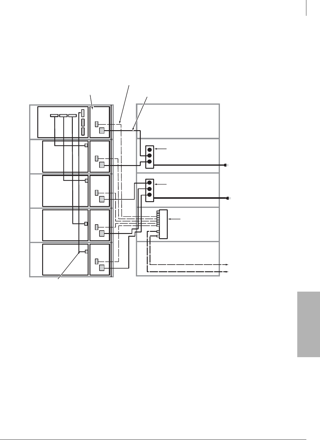
Rack Mount Cabinets
AC/Reserve Power and Data Cabling Overview
Strata CTX I&M 06/04 5-25
Rack Mount Cabinets
AC/Reserve Power and Data Cabling Overview
Figures 5-10 and 5-11 show an overview of the AC power and data cabling for the Rack Mount
Cabinets. Detailed illustrations of AC power strips and cords are on the following pages.
Figure 5-10 120VAC Power/Data Cabling for up to Five Cabinets
Motherboard
BRPSU672A
BATT
AC IN
BATT
AC IN
BATT
AC IN
BATT
AC IN
BATT
AC IN
CRSUB672A
Cabinet 1
(Base)
CRSUE672A
Cabinet 2
(Expansion)
CRSUE672A
Cabinet 3
(Expansion)
CRSUE672A
Cabinet 4
(Expansion)
CRSUE672A
Cabinet 5
(Expansion)
Data Cable
(supplied with expansion cabinet)
7 BBTC2A-2.0M Battery Cables
supplied with BBDB1A
7095
Power Strip
BRPSB120A for
120VAC only
Battery
Distribution
Box (BBDB1A)
Power Strip Cables
to Primary AC Power outlets
(9 ft.) with NEMA 5-15P plug
BBTC1A-2.0M Cables
to Reserve Power Batteries
(2 m.)
Power Supply 120 VAC Power Supply
Cord (supplied)
Power Strip
BRPSB120A for
120VAC only
Front View Back View
234 5
6
7
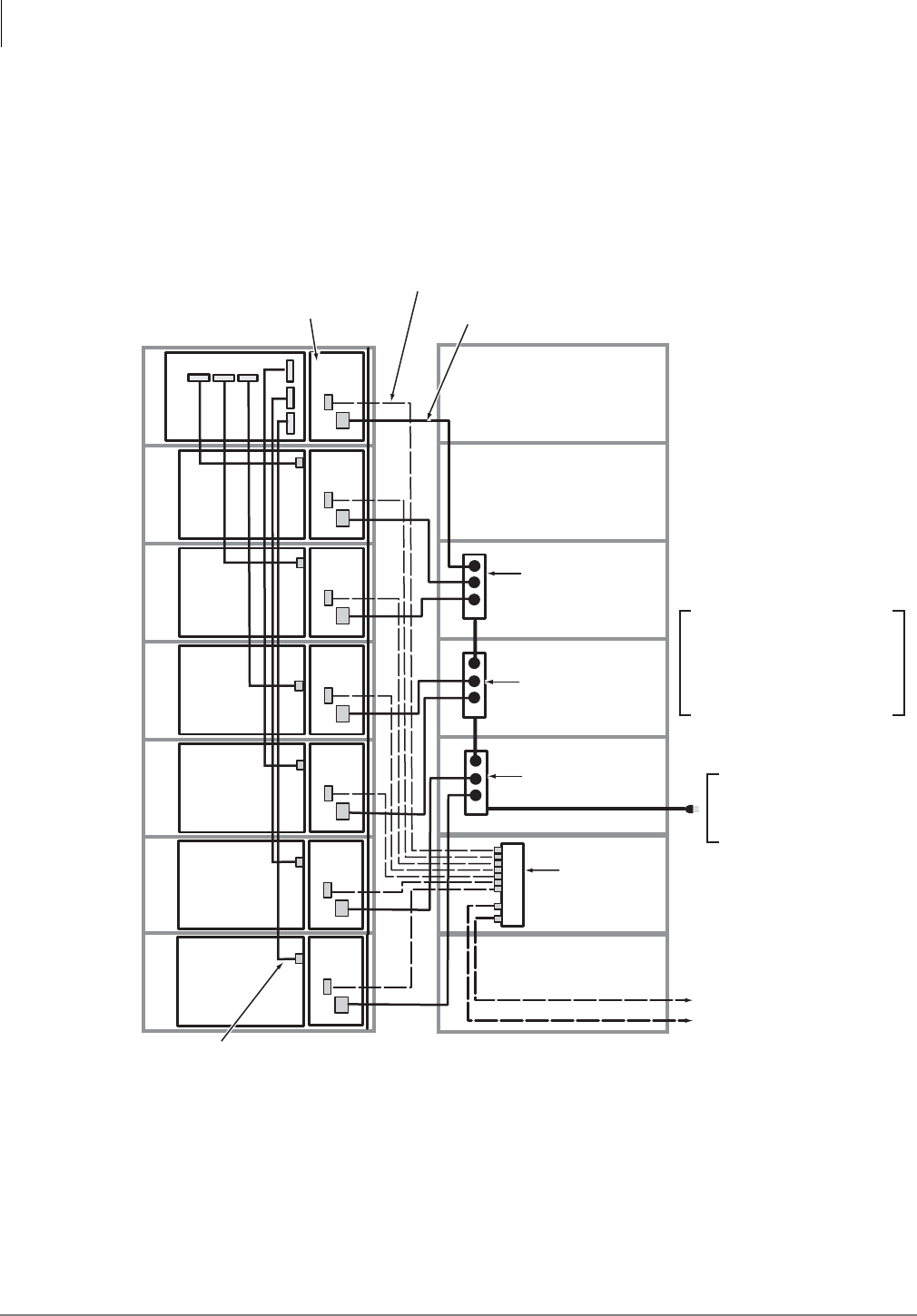
Rack Mount Cabinets
AC/Reserve Power and Data Cabling Overview
5-26 Strata CTX I&M 06/04
Figure 5-11 208VAC/240VAC Power/Data Cabling for up to Seven Cabinets
• Power Strip Cord is (9ft.)
• Power Strip Plug (NEMA 6-20P)
• To 208VAC or 240VAC Primary
Power Outlet (NEMA-6-20-R)
Caution: Three 240VAC power
strips are required for all
systems with 6 or 7 cabinets.
Only one power cord is allowed
to be connected to the
208VAC/240VAC power outlet.
Motherboard
BRPSU672A
BATT
AC IN
BATT
AC IN
BATT
AC IN
BATT
AC IN
BATT
AC IN
CRSUB672A
Cabinet 1
(Base)
CRSUE672A
Cabinet 2
(Expansion)
CRSUE672A
Cabinet 3
(Expansion)
CRSUE672A
Cabinet 4
(Expansion)
CRSUE672A
Cabinet 5
(Expansion)
Data Cable
(supplied with expansion cabinet)
7 BBTC2A-2.0M Battery Cables
supplied with BBDB1A
7096
Battery
Distribution
Box (BBDB1A)
BBTC1A-2.0M Cables
to Reserve Power Batteries
(2 m.)
Power Supply 240 VAC/10 amps. Power Supply
Cord (ordered separately) BACL240
Power Strip
BRPSB240A for
280VAC/240VAC only
Front View Back View
234 5
6
7
BATT
AC IN
BATT
AC IN
CRSUE672A
Cabinet 6
(Expansion)
CRSUE672A
Cabinet 7
(Expansion)
Power Strip
BRPSB240A for
280VAC/240VAC only
Power Strip
BRPSB240A for
280VAC/240VAC only

Rack Mount Cabinets
Cabinet AC Power Considerations
Strata CTX I&M 06/04 5-27
Rack Mount Cabinets
Cabinet AC Power Considerations
The rack mount cabinet power supply works with either 120VAC, 208VAC or 240VAC. The rack
mount only requires 120VAC (up to three cabinets if one AC cord is allowed or five cabinets if two
AC cords are allowed – see below).
If the system has more then five cabinets, 208VAC or 240AVC is required for the primary AC
power source. 208VAC or 240VAC can always be optionally used for systems with five or less
cabinets for future growth or, if the electrical code requires.
To determine AC power requirements, you need to check local electrical code requirements for
120VAC, 208VAC or 240VAC primary power. Some electrical codes stipulate that:
• 208VAC or 240VAC is required for telephones systems
• Only one electrical cord can connect to the telephone system.
• Only two electrical cords can connect to the telephone system.
• No electrical cord can connect to the telephone system – must use conduit wiring installed by a
certified electrician (example: when system is floor mounted).
AC Power Component Requirements
Table 5-4 show the cabinet parts required to distribute AC power for various configurations of the
Strata CTX cabinets.
Important! The plugs and wall receptacles required by the local electrical code might differ for
208VAC and 240VAC. Thus in some areas of the U.S., the plug used on the Toshiba
240VAC power strip and 240VAC power supply cord (NEMA code 6-20P) can not
be used for 208VAC installations. In this case, when using 208VAC, the AC plugs on
the BPSB240 power strip cord that connects directly to the 208VAC wall outlet must
be changed by a certified electrician per the local electrical code.
Table 5-4 Rack Mount Cabinet Power Component Requirements for 120VAC Primary Power
Local
Electrical
Code
Cabinets
1 2 3 4 5 6 7
Allows only
one 120VAC
power cord
from system
0 BRPSB120A 1 BRPSB120A 1 BRPSB120A N/A N/A N/A N/A
Allows two
120VAC
power cords
from system
0 BRPSB120A 0 BRPSB120A 1 BRPSB120A 1 BRPSB120A 2 BRPSB120A N/A N/A
●One dedicated, isolated, 20 amp. AC circuit breaker with dual outlets is required.
●N/A= If the system contains more than three cabinets and if the local code allows only one AC cord, the system requires a
BCCB120 conduit box wired by a certified electrician when using 120VAC as primary power. Otherwise, 208VAC or 240VAC
should be used as the primary power source (see cabinet power options listed below). If more than five cabinets are installed,
208VAC or 240VAC is required.
Table 5-5 Rack Mount Cabinet Power Component Requirements for 208VAC or 240VAC Primary Power
Local
Electrical
Code
Cabinets
1 2 3 4 5 6 7
Allows One
AC power
cord from
system
1 BACL240A 1 BRPSB240A
2 BACL240A
1 BRPSB240A
3 BACL240A
2 BRPSB240A
4 BACL240A
2 BRPSB240A
5 BACL240A
3 BRPSB240A
6 BACL240A
3 BRPSB240A
7 BACL240A
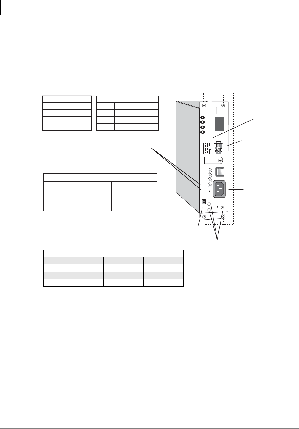
Rack Mount Cabinets
Power Supply Unit (BRPSU672A)
5-28 Strata CTX I&M 06/04
Power Supply Unit (BRPSU672A)
The BRPSU672A Power Supply Unit (shown below) comes factory installed in each Rack Mount
Base and Expansion Cabinet. It furnishes power to all of the stations and some of the peripherals
that interface with the cabinet.
The BRPSU672A automatically detects and adjusts for the type of AC voltage (120/208/240) to
which it is connected.
Figure 5-12 Power Supply Unit (BRPSU672A)
Check the Power Factor Indicator and Reset Button
The front panel of BRPSU672A provides a Power Factor LED and Reset button. If the cabinet
power factor is exceeded by overload of PCBs, the PF LED will turn on.
³If the PF LED indicator turns on, press the PF reset button with a pointed tool or pencil. If the
PF LED turns off and does not turn on again it may have been turned on by a current surge
while installing a PCB while the power supply was turned-on.
³When a PF alarm is indicated, check that the cabinet power factor is not exceeded using the
“Worksheet 7 – System Power Factor Check” on page 2-42. If the Power factor has been
exceeded relocate any PCBs that are causing the PF to be exceeded.
7000
BATT
EXP
BASE
FG
POW
+5V
-5V
P. F.
RESET
POWER ON
OFF
-24V1
-24V2
-24V3
-24V4
AC IN
DC OUT
FG
+
-
DC Voltage
Connector Jack
DC Voltage Specification
+5V (+4.5 ~ +5.5), 4.0 amps
-5V (–4.5 ~ –5.5), 0.8 amps
Expansion Cabinet only
-24V (–26.3 ~ –27.8), 6.0 amps
BATT (Volts)
+
–
0
–26.3 ~ –27.8
1. Back Plane DC Voltage Plug must be plugged
into Power Supply when checking voltages.
2. On BRPSU672, the BATT output is 0 volts
unless connected to good batteries.
Power Factor (PF) alarm LED indicates
the cabinet PF was exceeded. Correct
the problem and press the RESET
button to clear the alarm.
24V Circuit Breaker Assignments:
24V-1
24V-2
24V-3
24V-4
EXP. Cabinet
24V-1
24V-2
24V-3
24V-4
S101, S102
S103, S104
S105, S106
S107, S108
S_01, S_02
S_03, S_04
S_05, S_06, S_07
S_08, S_09, S_10
Base Cabinet
Expansion/
Base Switch
FG Frame
Ground Screws
Battery Cable
Connector
AC Power
Cord Jack
2
Mounting Holes
DC Voltage Connector Plug Pin Wires
Yellow Blue White Green Green Green Red
-24 -5 +5 0 0 0 +5
Yellow Yellow Yellow Green Green Green Red
-24 -24 -24 0 0 0 +5

Rack Mount Cabinets
Power Supply Unit (BRPSU672A)
Strata CTX I&M 06/04 5-29
Rack Mount Cabinets
Check the -24 Volt Circuit Breakers
The BRPSU672A provides four -24v circuit breakers as shown in figure above. If a low resistance
between –24 volts and ground exists the circuit breaker will trip. Usually the front panel DC green
LED indicator will turn off but not always. Also if AC power is recycled the DC LED indicator
may turn back on – even if the –24 volt circuit breaker is tripped.
Circuit Breaker Location and Slot Assignments
• The circuit breaker 24V1~24V4, located directly below DC-out cable, protects the cabinet slots
as shown in the Circuit Breaker assignment table.
Reset Circuit Breaker
1. A defective PCB or an external short on the MDF may cause the circuit breaker to trip.
2. If you suspect that a –24 volt circuit breaker has tripped, try to reset it by:
• Turn the power supply DC power switch off and unplug the power supply AC power cord
from the AC outlet – the inside of the power supply has exposed voltages.
• Gently press in each circuit breaker and listen for or try to feel it click. If the breaker was
tripped, you will hear or feel it click back to the set position.
• If the circuit breaker resets, pull the PCBs and check for MDF shorts associated with the
slots assigned to the tripped circuit breaker. Remove any defective PCBs and MDF shorts.
• Restore power and verify the system is working normally.
3. Replace the power supply if the circuit breaker continues to trip and a defective PCB or short
cannot be found.
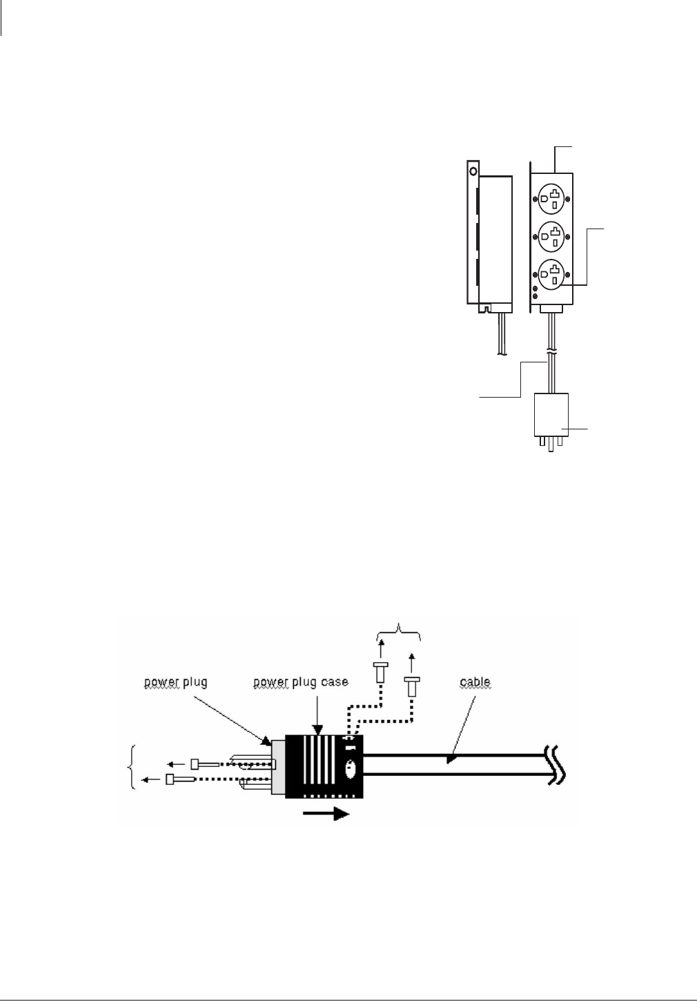
Rack Mount Cabinets
Changing Plug for Power Strip BRPSB240A
5-30 Strata CTX I&M 06/04
Changing Plug for Power Strip BRPSB240A
You must use a 240VAC power strip (BRPSB240A) if only one AC power cord is connected to a
system with four or more cabinets.
Most 240VAC wall outlets and UPS systems
(ONEAC or other) have twist locks. Twist
locks are mostly used at the wall outlet or UPS
to prevent accidental unplugging.
If you are plugging the Strata rack mount
power strip (BRPSB240A) into a twist lock
outlet/UPS, you will need to change the power
strip plug that exits the cabinets to a twist lock
plug.
Important! Only the 240VAC power strip
that exits the cabinets (see page
5-33) should be changed.
This procedure shows how to change the one
plug on the power strip (shown right).
Recommended parts: Pass & Seymour, L620-P
(NEMA Config. No. L6-20P).
Step 1: Remove NEMA 6-20P from Power Strip
1. Unplug the power strip from the AC.
2. Loosen a screw on both the power plug case and power plug.
3. Slide out the power plug case (shown below).
4. Loosen a screw on the power plug for cable.
Power Strip for
208VAC or 240VAC (only)
BRPSB240A
Receptacle
Pass & Seymour 5858
NEMA No. 6-20P
16A max.
Cable Length 3 m.
(Approx. 9 ft.)
Plug
Pass & Seymour 5466-X
NEMA No. 6-20P
16A max.
6944
Figure 5-13 Power Strip (BRPSB240A)
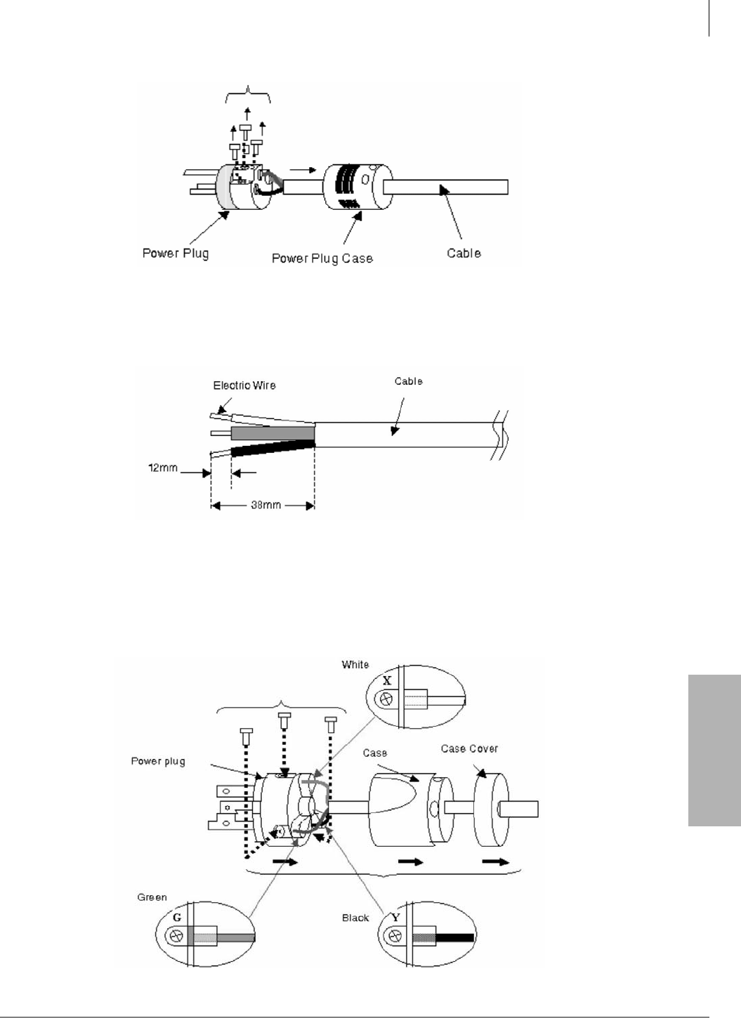
Rack Mount Cabinets
Changing Plug for Power Strip BRPSB240A
Strata CTX I&M 06/04 5-31
Rack Mount Cabinets
5. Pull out cable from the power plug (shown below).
Step 2: Attach NEMA L6-20P Plug to Power Strip
1. Strip 1.49 inches (38mm) of cover off the electrical wire.
2. At the wire tip, strip approx. .47 inches (12mm) from the outer cover of the wire (shown
below).
3. Each of the three electrical wires are inserted in a power plug and a screw tightened. The torque
of a screw is 0.8[Nm]. The wires and power plug matches in the following manner (shown
below):
• G (FG) matches the green wire.
• Y matches the black wire.
• X matches the white wire.
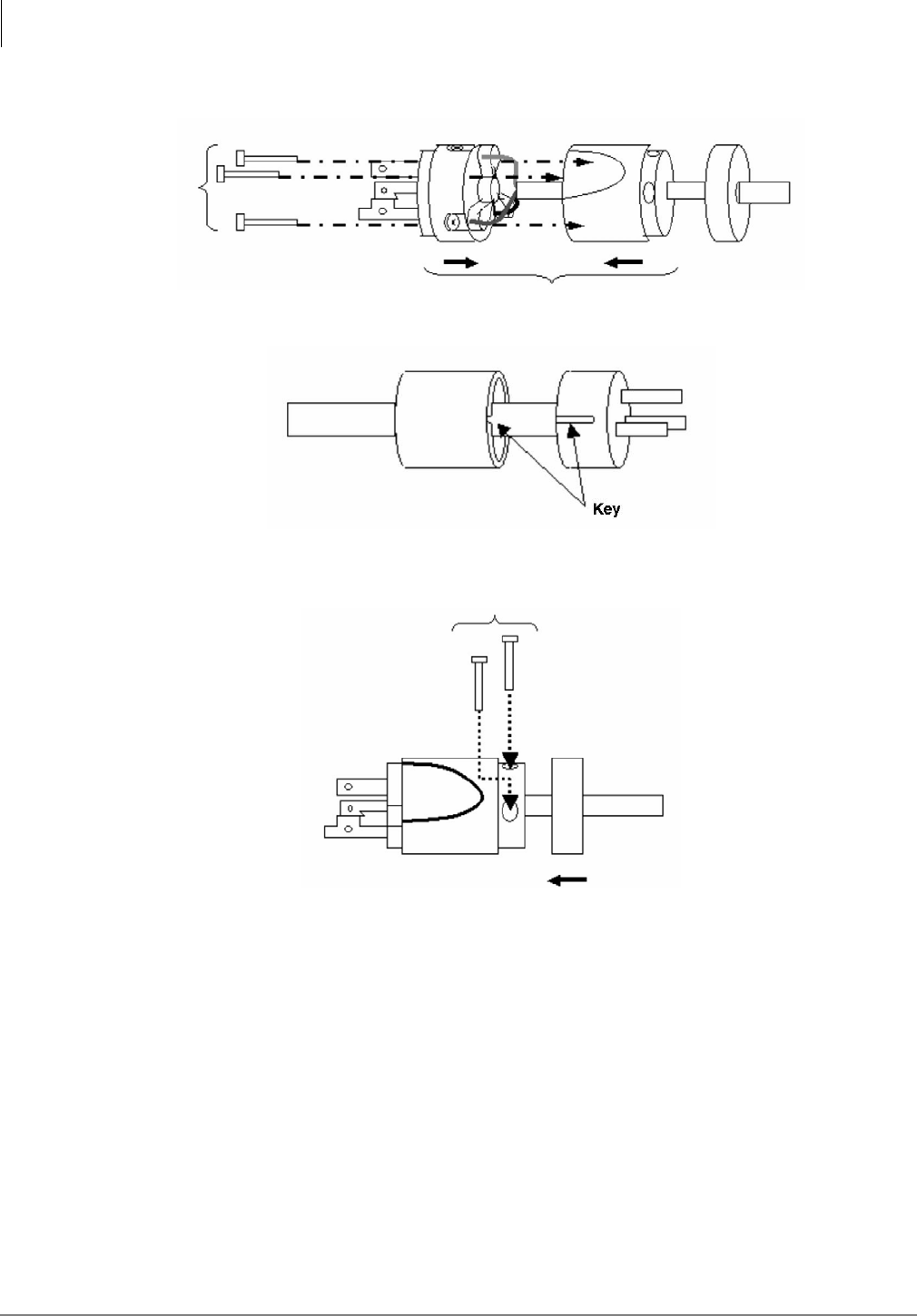
Rack Mount Cabinets
Changing Plug for Power Strip BRPSB240A
5-32 Strata CTX I&M 06/04
4. Put the power plug in a case and secure with a screw (shown below).
Note A key is arranged when a power plug and a case are fixed.
5. Tighten the screws (torque is 0.8[Nm]) and push cover and plug together (as shown below).
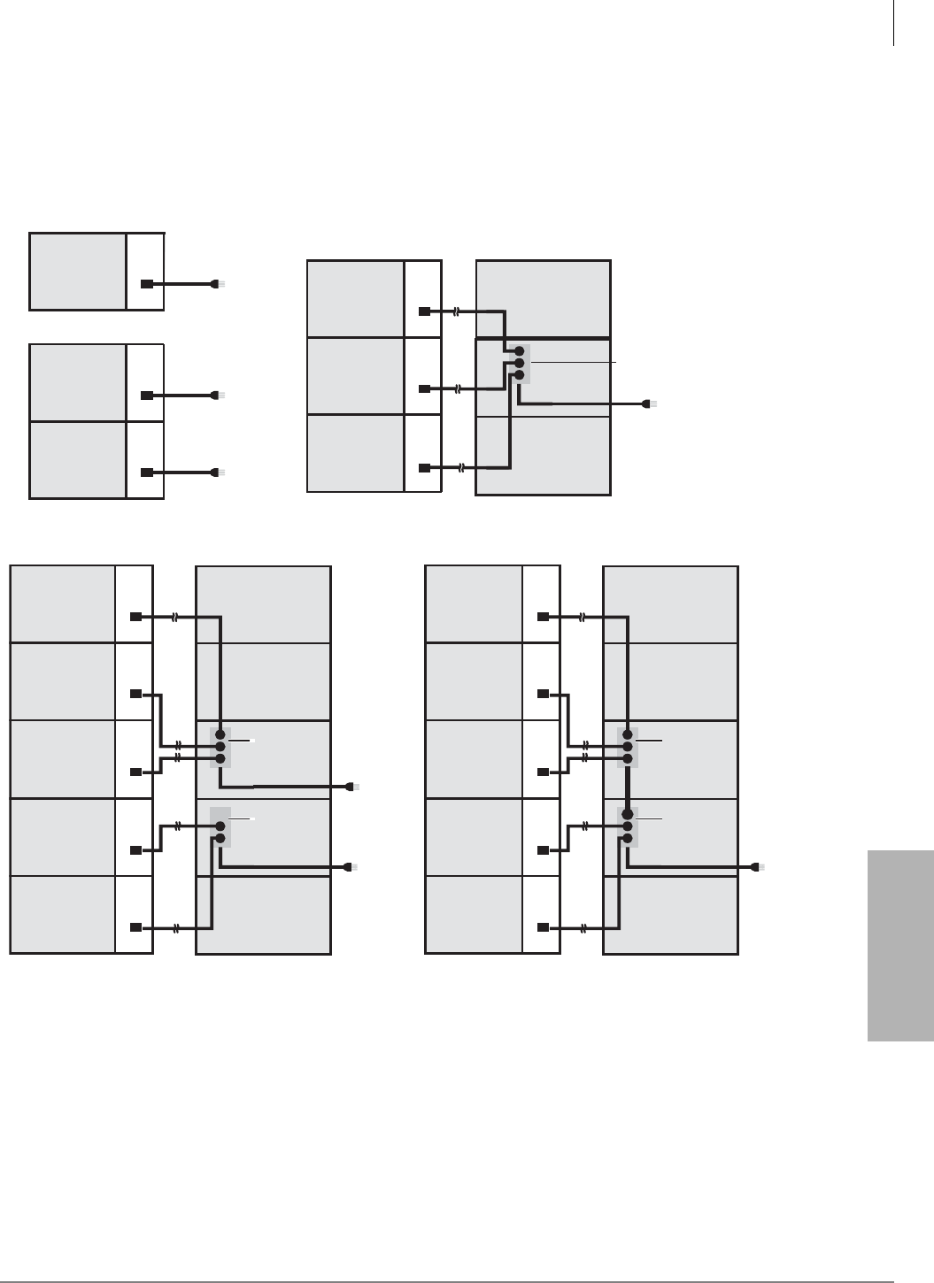
Rack Mount Cabinets
AC Cabling
Strata CTX I&M 06/04 5-33
Rack Mount Cabinets
AC Cabling
Note 1, 2 or 3 power strips are used depending on how many cabinets are installed (see diagrams
shown below.
Figure 5-14 AC Cabling (One to Five Cabinets)
Back View
Four or five cabinets - one AC cord exits system
Cabinet 1 Power
Supply
Cabinet 2 Power
Supply
Cabinet 3 Power
Supply
Cabinet 4 Power
Supply
Cabinet 5 Power
Supply
Front View Back View
One cabinet - one AC cord exits system
Cabinet 1 Power
Supply
Cabinet 2 Power
Supply
Two cabinets - two AC cord exit system
Note 2
(120VAC only)
Note 2
(120VAC only)
Notes 1, 2
(120/208/240VAC)
Cabinet 1 Power
Supply
Front
Four or five cabinets - two AC cord exits system
Cabinet 1 Power
Supply
Cabinet 2 Power
Supply
Cabinet 3 Power
Supply
Cabinet 4 Power
Supply
Cabinet 5 Power
Supply
Front View Back View
Two or three cabinets - one AC cord exits system
Notes 1, 2
(120/208/240VAC)
Cabinet 1 Power
Supply
Cabinet 2 Power
Supply
Cabinet 3 Power
Supply
BRPSB240A
(208/240VAC)
or
BRPSB120A
(120VAC)
Front View
Notes
1. 120VAC cord is supplied with cabinet. A special cord, BACL240A, must be ordered for each cabinet if 208VAC
or 240VAC is used.
2. Power Strips must plug into the following AC outlets: 120VAC to NEMA 5-15R, and 208/240VAC to NEMA 6-20R.
3. If four cabinets are installed only one BRPSB120A is required. You can plug the fourth cabinet
power supply directly into the 120VAC outlet.
Front
7002
BRPSB240A
BRPSB240A
(208VAC
or 240VAC only)
Notes 1, 2
BRPSB120A
BRPSB120A
(120VAC only)
Notes 3
Note 2
(120VAC only)
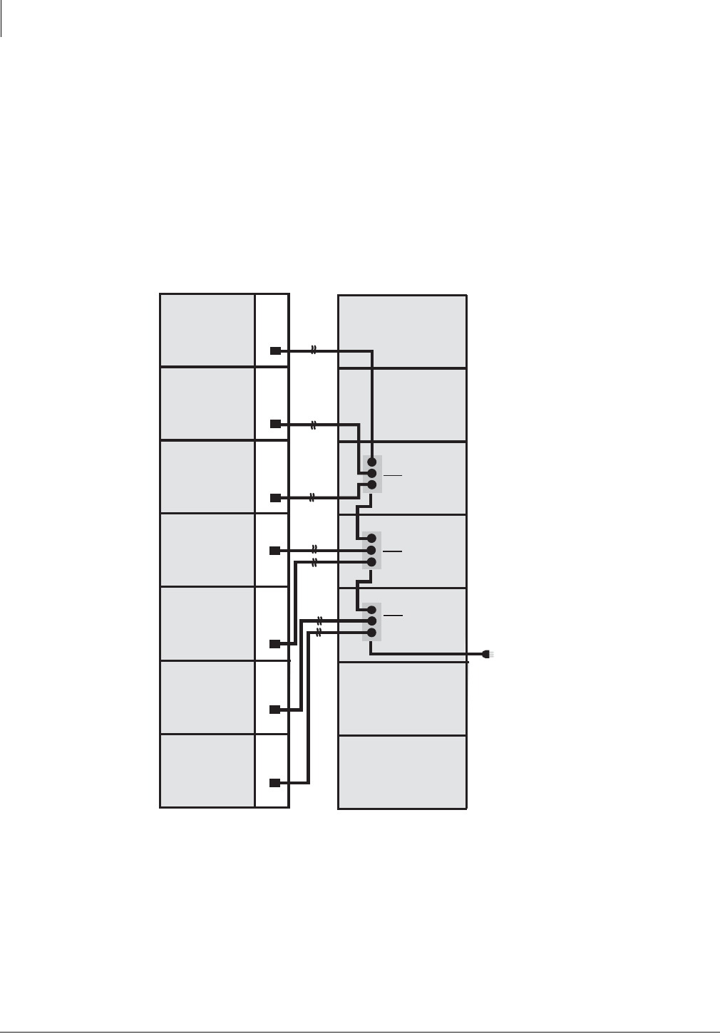
Rack Mount Cabinets
AC Cabling
5-34 Strata CTX I&M 06/04
Figure 5-15 AC Cabling (Six to Seven Cabinets)
Front View Back View
Front View Back View
Front View Back View
7003
Six or Seven cabinets - one AC cord exits system
Cabinet 3 Power
Supply
Cabinet 1 Power
Supply
Cabinet 2 Power
Supply
Cabinet 4 Power
Supply
Cabinet 5 Power
Supply
Cabinet 6 Power
Supply
Cabinet 7 Power
Supply
(208VAC
or 240VAC only)
BRPSB240A
Plug
Pass & Seymour 5466-X
NEMA No. 6-20P
BRPSB240A
BRPSB240A
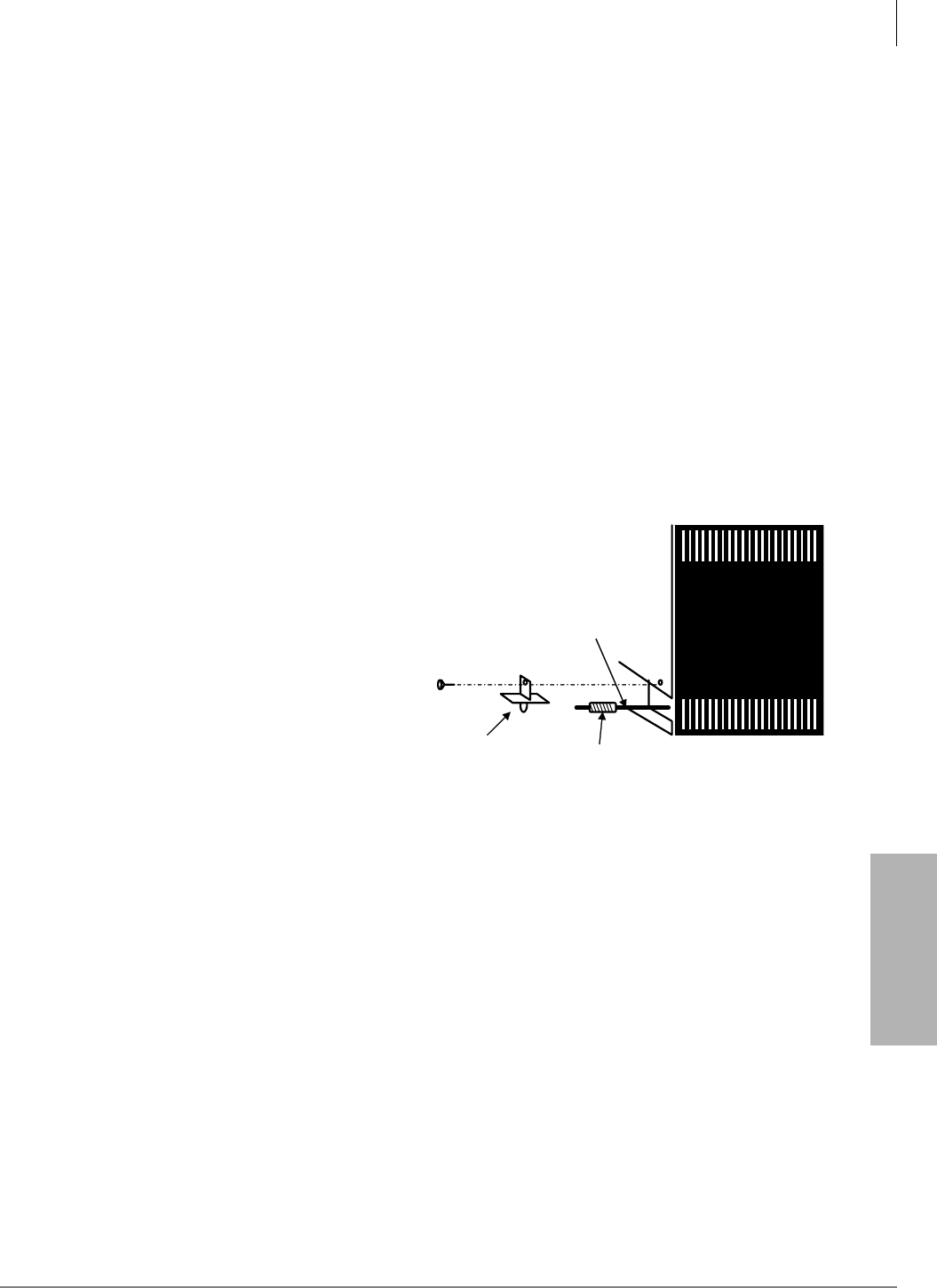
Rack Mount Cabinets
Remote Expansion Cabinet Unit
Strata CTX I&M 06/04 5-35
Rack Mount Cabinets
Remote Expansion Cabinet Unit
The RRCU1A PCB enables a Rack Mount Expansion Cabinet to be located up to three kilometers
from its Base Cabinet. One RRCU1A connects to up to two ribbon-type Data Cables and applies
the inter-cabinet signal to a fiber-optic pair. One fiber pair can support one or two expansion
cabinets in one remote location using one RRCU1A in the Base Cabinet and another in the Remote
Expansion Cabinet.
All instructions apply to both the Base Cabinet and the Remote Expansion Cabinet except where
specifically noted.
Note See “Remote Expansion Cabinet Unit” on page 4-55 for additional information.
Remote Cabinet Installation Instructions
1. Install cabinets according to the instructions given at the beginning of this chapter. Pay
particular attention to wiring and grounding instructions given for Remote Expansion Cabinets.
2. If installing a standalone Remote Expansion Cabinet, or the first in a stack, set the “BASE/
EXP” switch to “BASE” in accordance with Figure 5-12.
3. Cabinets in which RRCU cards are installed must be modified to protect the routing of the
cables through the cabinet.
• Attach the plastic guide to the bracket
provided with the RRCU1A card
(shown right).
• Attach the bracket to the wall of the
cabinet.
4. Install the RRCU Card (see Figure 4-36
on page 4-53 for a detailed description of
RRCU)
• Select correct jumper options. On the
Master side, both option plugs connect
the center pin to the upper pin (M1,
M2). On the Slave side, both option
plugs connect the center pin to the lower pin (S1, S2).
• Remove the protective rubber cap from the fiber connector on the ROMS1A daughter
board.
Important! When installing the RRCU, be sure to put the card in the slot before attaching the
data cables. Detach the data cable before removing an RRCU1A. Failure to do so
may cause interference with other data highways.
5. Insert the cards
• On the Master side, the RRCU card may be installed in Slots 1~8.
• On the Slave side, the RRCU card may be installed in Slots 1~10.
• The RRCU1A is a non-timeslot card and can be installed in slots normally left vacant
adjacent to digital trunk cards.
Spiral Tube
Optical Fiber
Clamp Bracket
For Spiral Tube
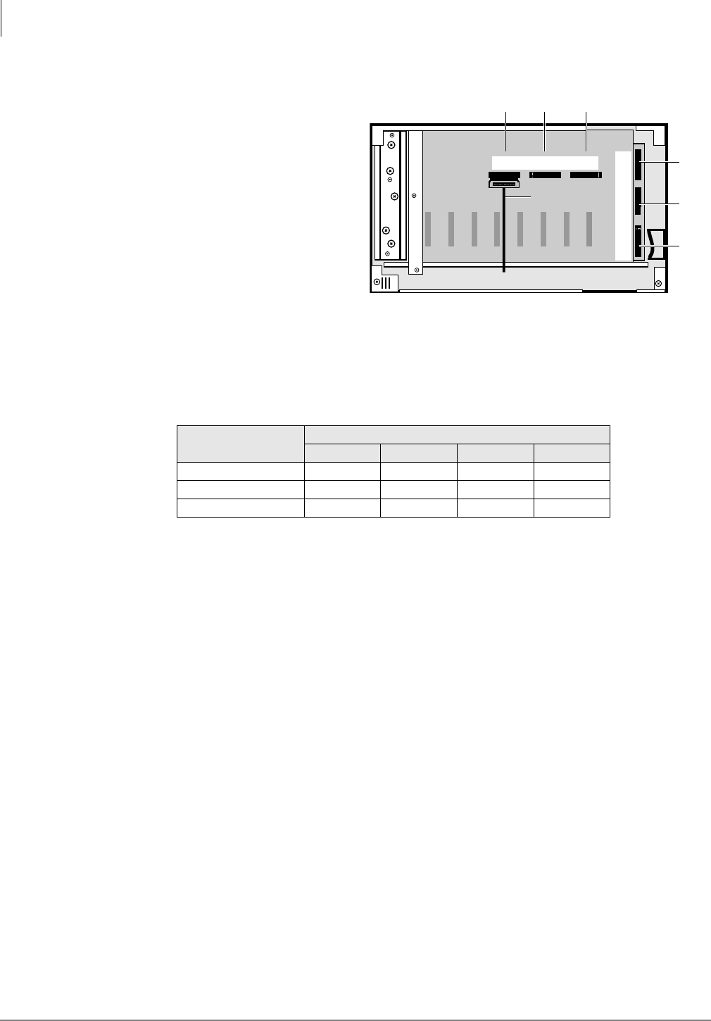
Rack Mount Cabinets
Remote Expansion Cabinet Unit
5-36 Strata CTX I&M 06/04
6. Connect the data cables
• At the Base Cabinet, attach an
BDCL1A data cable from the data
cable connector on the back of the
cabinet (shown right) to
Connector M1 or M2 on the
RRCU card. (Cables are provided
according to the connectors on the
RRCU card to which they are
attached, see Table 5-6.)
• The cabinet connected to M1 in
the base emerges on connector S1
of the RRCU1A at the Remote
Expansion Cabinet.
• The cabinet connected to connector M2 of the RRCU in the base emerges on connector S2
of the RRCU1A at the Remote Expansion Cabinet.
Note Coil the excess tie it with a tie wrap. Be careful not to bind the cable tightly.
7. Connect the fiber optic cables
• Attach fiber to the SC connectors on the ROMS1A daughterboard.
• The TX side of the Master connects to the RX side of the slave.
• The RX side of the Master connects to the TX side of the slave.
• TAIS recommends that the cables be marked within the cabinet for ease of maintenance.
• Observe the minimum bend radius of 30mm.
8. Restore power.
Table 5-6 Remote Cabinet Data Cables and Connectors
Data Cables RRCU Connectors
M1 S1 M2 S2
BDCL1A-MS1 X X
BDCL1A-M2 X
BDCL1A-S2 X
X=applies to connector
7077
CAB
2
CAB
5
CAB
6
CAB
3
CAB
4CAB 5
CAB 2 CAB 3 CAB 4
CAB 6
CAB 7
To RRCU1A card
on front of cabinet
CAB
7
BDCL1A cable
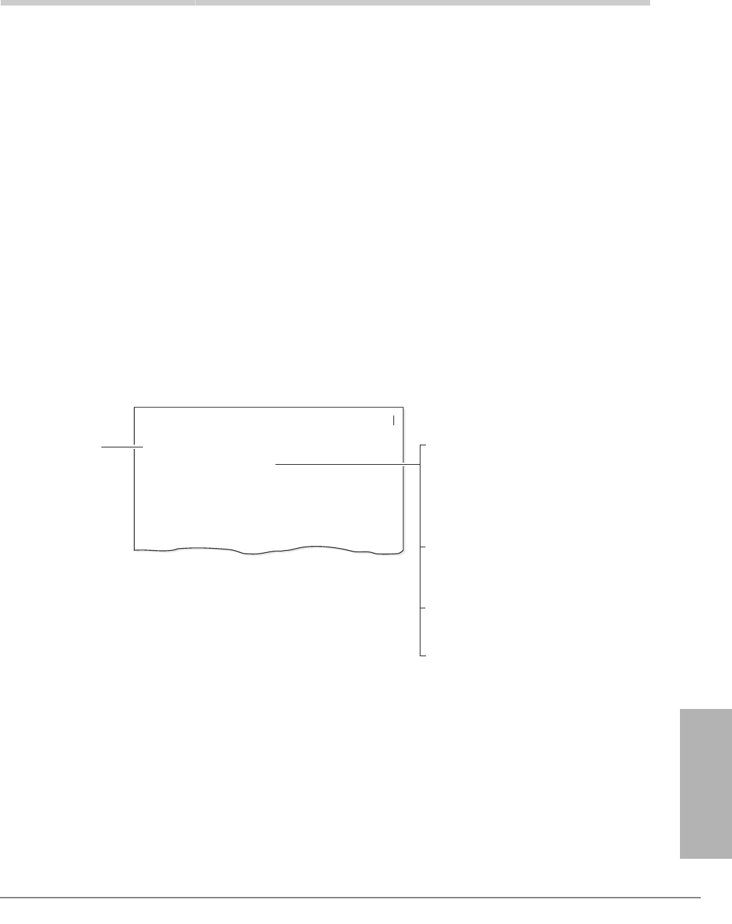
Strata CTX I&M 06/04 6-1
PCB Installation
PCB Installation 6
This chapter contains information on Printed Circuit Boards (PCBs) which can be used in the
cabinet slots of the Strata CTX systems.
Note Prior to PCB installation, the power supply must be tested and the ground checked.
PCB Chapter Layout
Each PCB outline begins with the PCB’s designation and title (the outline appears in the chapter in
alphabetical order by designation). A brief synopsis of the PCB appears next and includes a
notation of the system(s) that the PCB can be used in, the circuits supplied by the PCB, what
equipment the PCB interfaces with, and a list of the PCB’s older version(s) with a brief description
of their differences.
Installation instructions follow the synopsis with a table showing the PCB’s controls, indicators
and connectors and an illustration of the board.
Systems: Strata CTX100
Circuits per PCB: four DID lines
Interfaces with: DID (one or two-way) lines
Older Versions: none
RDDU - Direct Inward Dialing Line Interface Unit
PCB Title System:
Circuits per PCB:
Gives the type of system that is
compatible with the given PCB. Be
sure to read this information before
attempting to use a PCB with your
system application.
Type and number of circuits
available on the PCB.
Type of line/hardware the PCB can
accept.
Interfaces with:
Describes older version or versions
of the PCB.
Older Version(s):
The RDDU provides four Direct Inward Dialing (DID) lines, each of which can have a single
office code along with a block of extensions.
Each extension can be assigned to ring a station [DN] that appears on one or multiple stations,
Distributed Hunt or ACD Group, or an external telephone number selected in system
programming. This enables calls over the same line to be routed to different stations or groups
of stations. An extension can also be assigned to ring the maintenance modem. Each RDDU
can be set for either wink start or immediate. All RDDU lines support DNIS and ANI features.
RDDU controls, indicators, and interface connectors are shown in Figure 4-17 and described
in Table 4-9.
PCB Installation
RDDU - Direct Inward Dialing Line Interface Unit
6040

PCB Installation
PCB Hardware/Software Options
6-2 Strata CTX I&M 06/04
PCB Hardware/Software Options
PCBs can be configured for a variety of hardware and software options.
•Hardware Options – Hardware options are defined as either internal (generally related to
optional PCB subassemblies) or external (related to connection of peripheral equipment, such
as background music, voice mail, etc.). Each PCB must be configured for the applicable
hardware options prior to installation of the PCB.
Configurations for internal hardware options are in this chapter and Chapter 10 – MDF PCB
Wiring. Configurations for external hardware options appear in Chapter 12 – Peripheral
Installation.
•Software Options – After installation of the PCBs in the KSU, configure the PCBs for
software options through programming (see the Strata CTX Programming Manual).
CTX100 ACTU Processor PCBs
System:
Strata CTX100 Base Cabinet
Current Version:
ACTU1A
Older Version(s):
None
For information about the CTX100 ACTU processor, see “CTX100-S and CTX100 Processors” on
page 2-2 and “Set Jumpers and Install Option PCBs onto the ACTU” on page 3-19.
CTX670 BCTU/BEXU Processor PCBs
System:
Strata CTX670 Base Cabinet
Current Version:
BECU1A/BBCU1A
Older Version(s):
None
For information about the BECU/BBCU CTX670 processor PCBs, see “CTX670 Processor
PCBs” on page 2-5 and “BCTU1A/BEXU1A Installation” on page 4-44.
CTX670 BECU/BBCU Processor PCBs
System:
Strata CTX670 Base Cabinet
Current Version:
BECU1A/BBCU1A
Older Version(s):
None
For information about the BECU/BBCU CTX670 processor PCBs, see “CTX670 Processor
PCBs” on page 2-5 and “BECU/BBCU Installation” on page 4-50.
PCB Installation Power Supply Considerations
Toshiba recommends turning the power supply be Off whenever possible when removing or
installing the other PCBs.
WARNING! The power supply must be Off whenever removing or installing the
processor PCBs (see Figure 3-17 on page 3-19 and
Figure 4-3 on page 4-9).

PCB Installation
ADKU – Digital Telephone Interface Unit
Strata CTX I&M 06/04 6-3
PCB Installation
ADKU – Digital Telephone Interface Unit
Circuits per PCB:
eight digital telephone circuits
Interfaces with:
all Toshiba digital telephones (corded and cordless, DDCB, DSS, ADM, BPCI)
Older Version(s):
none
ADKU Hardware Options
The ADKU digital telephone interface unit only works with the CTX100. Refer to Chapter 11 –
Station Apparatus for instructions on how to connect digital telephones, DDCBs, and DDSS
consoles to the ADKU, as well as how to upgrade digital telephones with these options: a PC
Interface Unit (BPCI), a Speaker Off-hook Call Announce upgrade (BVSU), and a Headset/
External Speaker (BHEU).
ADKU Installation
³Insert the ADKU (component side facing right) into the appropriate slot, and apply firm, even
pressure to ensure proper mating of connectors.

PCB Installation
ASTU – Standard Telephone Interface Unit (CTX100 only)
6-4 Strata CTX I&M 06/04
ASTU – Standard Telephone Interface Unit
(CTX100 only)
Circuits per PCB:
two standard telephone circuits
maximum number of ringers per circuit is three
Interfaces with:
standard telephones (no message waiting)
other single-line devices
alternate BGM source
FAX machine
voice mail devices
Older Version(s):
none
The ASTU works with the CTX100 Base system with R1.3 and higher software. It provides two
standard telephone ports and connects to a unique slot on the side of the CTX100. It does not
occupy one of the universal slots.
ASTU Installation
1. Turn the power to the CTX100 off (press the DC power switch) and unplug the system.
2. Remove the front and left-side covers from the CTX100.
3. Refer to Figure 6-1 and Table 6-2. Make sure the SW2 switch is in the “Mu law” position for
the U.S. and Canada.
4. Align the holes on the ASTU with the white plastic posts on the left side of the CTX100 Base
Cabinet. Firmly press the ASTU onto the posts to attach it to the CTX100. Make sure that you
can still reach all attached cables and wires.
5. Slip the spade of the FG1 (green wire) under the grounding screw on the CTX100 and tighten
the screw.
6. From the CTX100, locate the multi-colored five wire cable (white connector) and plug it into
the P1 connector on the ASTU.
7. On the ASTU, locate the 10-wire P2 connector cable and plug it into the front of the ACTU
processor PCB on the CTX100 (see Figure 6-2). Press firmly so that both black flip-locks snap
shut. (To remove, flip up the front and back locks.)
8. Connect the standard telephone(s) or devices to J1 and J2 on the ASTU.
9. Plug in the CTX100 power and turn on the DC power switch in the front of the CTX100. If
everything seems to be working, re-attach the outside covers.
10. Power down and power up the CTX100 and the system will automatically recognize the ASTU
in virtual slot 09. Otherwise, you can use CTX WinAdmin R1.3 or later to assign the ASTU in
the 0109 position.
ASTU1 Wiring
1. 300 ohms loop resistance max., including the telephone or other devices DC off-hook
resistance.
2. ASTU requires secondary protectors with standard voltage for outside wiring. See Table 6-1 for
electrical characteristics.
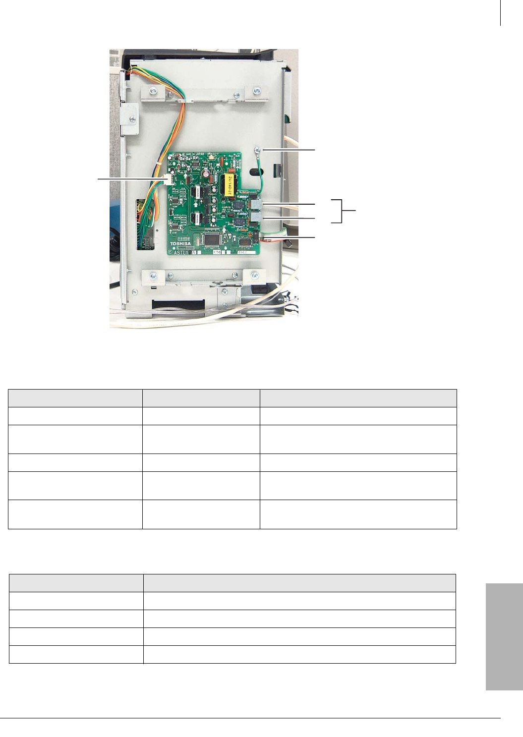
PCB Installation
ASTU – Standard Telephone Interface Unit (CTX100 only)
Strata CTX I&M 06/04 6-5
PCB Installation
Figure 6-1 ASTU Controls and Interface Connectors
Table 6-1 ASTU Controls, Indicators, and Interface Connectors
Control/Indicator/Connector Type of Component Description
P1 5-wire connector cable Connects to the motherboard for supply power.
P2 10-wire connector cable Connects to the processor PCB for data and
signal highway.
J1, J2 RJ11 - 6-pin modular Interfaces with single-line devices.
SW2 Jumper plug Factory shipped in “Mu law” position. For
countries requiring “A Law,” switch to “A.”
FG1 Green Wire Connects to the chassis with a screw (frame
ground).
Table 6-2 ASTU Electrical Characteristics
Item Description
Single line device interface RJ11 Connector
Ringer Type Square Wave
Ringer Voltage 190Vp-p Open Voltage (Square Wave)
Line Voltage -24V
FG1
Frame Ground
P1
Power Connector
P2
Connects to ACTU P8
J2
J1
RJ11 Connections
for single-line devices
6634
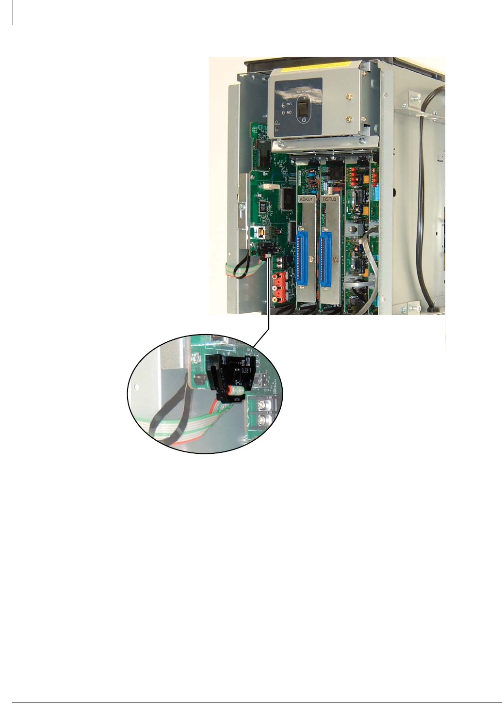
PCB Installation
ASTU – Standard Telephone Interface Unit (CTX100 only)
6-6 Strata CTX I&M 06/04
Figure 6-2 ASTU/ACTU Wire Connection
66
3
Wire from ASTU (P2)
plugs into ACTU (P8)
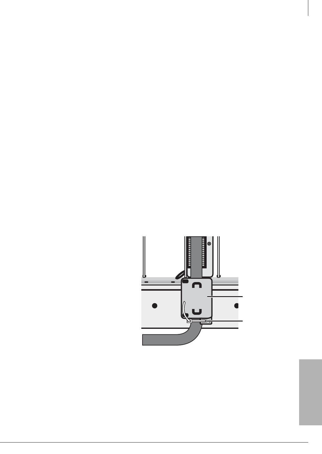
PCB Installation
BDKU/BDKS – Digital Telephone Interface Unit
Strata CTX I&M 06/04 6-7
PCB Installation
BDKU/BDKS – Digital Telephone Interface Unit
Circuits per PCB:
eight digital telephone circuits (plus eight more with the BDKS PCB)
Interfaces with:
all Toshiba digital telephones (corded and cordless, DDCB, DSS, ADM, BPCI)
Older Version(s):
none
BDKU Hardware Options
BDKU can be equipped with a BDKS piggyback PCB to provide a total of 16 circuits. Refer to
Chapter 11 – Station Apparatus for instructions on how to connect digital telephones, DDCBs, and
DDSS consoles to the BDKU/BDKS, as well as how to upgrade digital telephones with these
options: a PC Interface Unit (BPCI), a Speaker Off-hook Call Announce upgrade (BVSU), and a
Headset/External Speaker (BHEU). The BDKU can be installed alone, or with the BDKS
subassembly.
BDKS
The BDKS can be installed onto the BDKU to add eight more digital telephone circuits.
³To install the BDKS
³Match the BDKS connectors to the BDKU, as shown in Figure 6-4. Press firmly to ensure that
the connectors are snug.
BDKU Installation
1. Set the BDKU/PDKU switch for the appropriate system (refer to Figure 6-4 and Table 6-3).
2. Insert the BDKU2 (component side
facing right) into the appropriate slot,
and apply firm, even pressure to
ensure proper mating of connectors.
Refer to “Worksheet 6: Strata
CTX670 Cabinet Slots” on page 2-37
to ensure the BDKU is in a suitable
slot.
3. Install the Ferrite Core (comes with
the BDKU) onto the 25-pair cable
that connects the BDKU to the MDF:
Flip open the two snaps on the Ferrite
Core, then snap it shut around the
BDKU cord as shown in Figure 6-3.
The core must be as close as possible
to the BDKU.
The core is needed to comply with
FCC requirements.
4. Some Ferrite Cores require a tie-wrap
at the bottom to keep it from sliding.
For those, feed the tie-wrap through
the slots in the Ferrite Core, then cinch it.
S
104
5845
F
e
rr
i
t
e
C
o
r
e
T
i
e
W
r
a
p
Figure 6-3 BDKU Ferrite Core
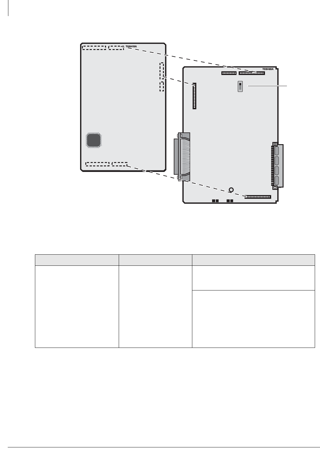
PCB Installation
BDKU/BDKS – Digital Telephone Interface Unit
6-8 Strata CTX I&M 06/04
Figure 6-4 BDKU/BDKS PCB
Table 6-3 BDKU Controls, Indicators, and Interface Connectors
Control/Indicator/Connector Type of Component Description
P2 BDKU/PDKU Jumper Plug
Strata CTX: set P2 to BDKU for all slots to
enable: 3000-series telephone features and
buttons and the BDKS to be operational.
Strata DK: set P2 to PDKU for all slots:
All DK Cabinet slots
(BDKS does not function on the Strata DK)
If the switch is set to the PDKU mode, the
DKT3000-series telephone LCD will be 16
characters, and the Spdial and LCD Feature
buttons will not work.
J40J41
J30
J10 J11
J20
BDKU1A V.1
BDKU1
P20
P10
P30
J1
P1
P40
5498
PDKU
P2
BDKU
Optional BDKS, adds eight
more DKT ports.
See P2
"Setting"
below.
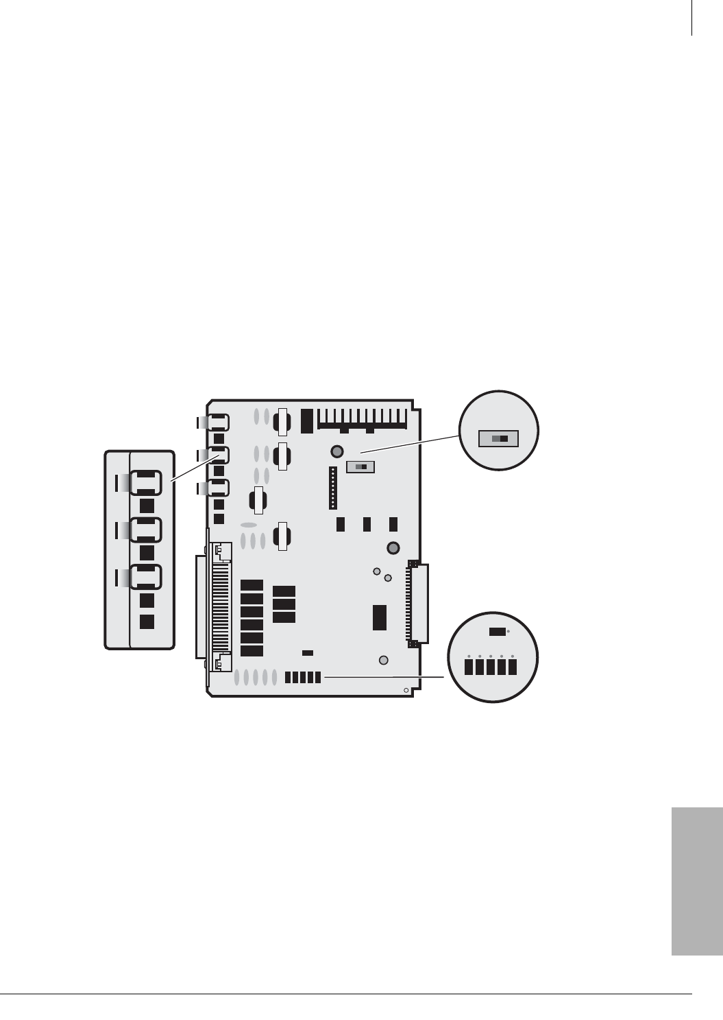
PCB Installation
BIOU – Option Interface Units
Strata CTX I&M 06/04 6-9
PCB Installation
BIOU – Option Interface Units
Circuits per PCB:
(see interfaces)
Interfaces with:
three music-on-hold sources, system page and control relays
Older Version(s):
none
The BIOU provides a Paging Output (amplified and non-amplified), four zone paging relays, three
Music-on-hold (MOH) interfaces and four control relays (Night Transfer, Night Bell and
Background Music (BGM) mute). One or two BIOUS can be installed in a Strata CTX.
BIOU controls, indicators, and interface connectors are shown in Figure 6-5 and described in
Table 6-4.
BIOU Installation
³Insert the BIOU (component side facing right) into any available PCB slot in the cabinet. See
“Worksheet 6: Strata CTX670 Cabinet Slots” on page 2-37. Apply firm, even pressure to
ensure proper mating of connectors.
Figure 6-5 BIOU PCB
5805
BIOU1A
600/600
600/600600/600
600/600
B B B B N.C
MMMM
N.O
Mu A
SW1
SW600
MOH3 MOH2 MOH1 SP
SP0 SP1
MOH3 MOH2 MOH1 SP
SW600
SP0 SP1
BBBBN.C
MMMM
N.O
Mu A
SW1
J3 J2 J1
SW100
Control Relay
Jumpers
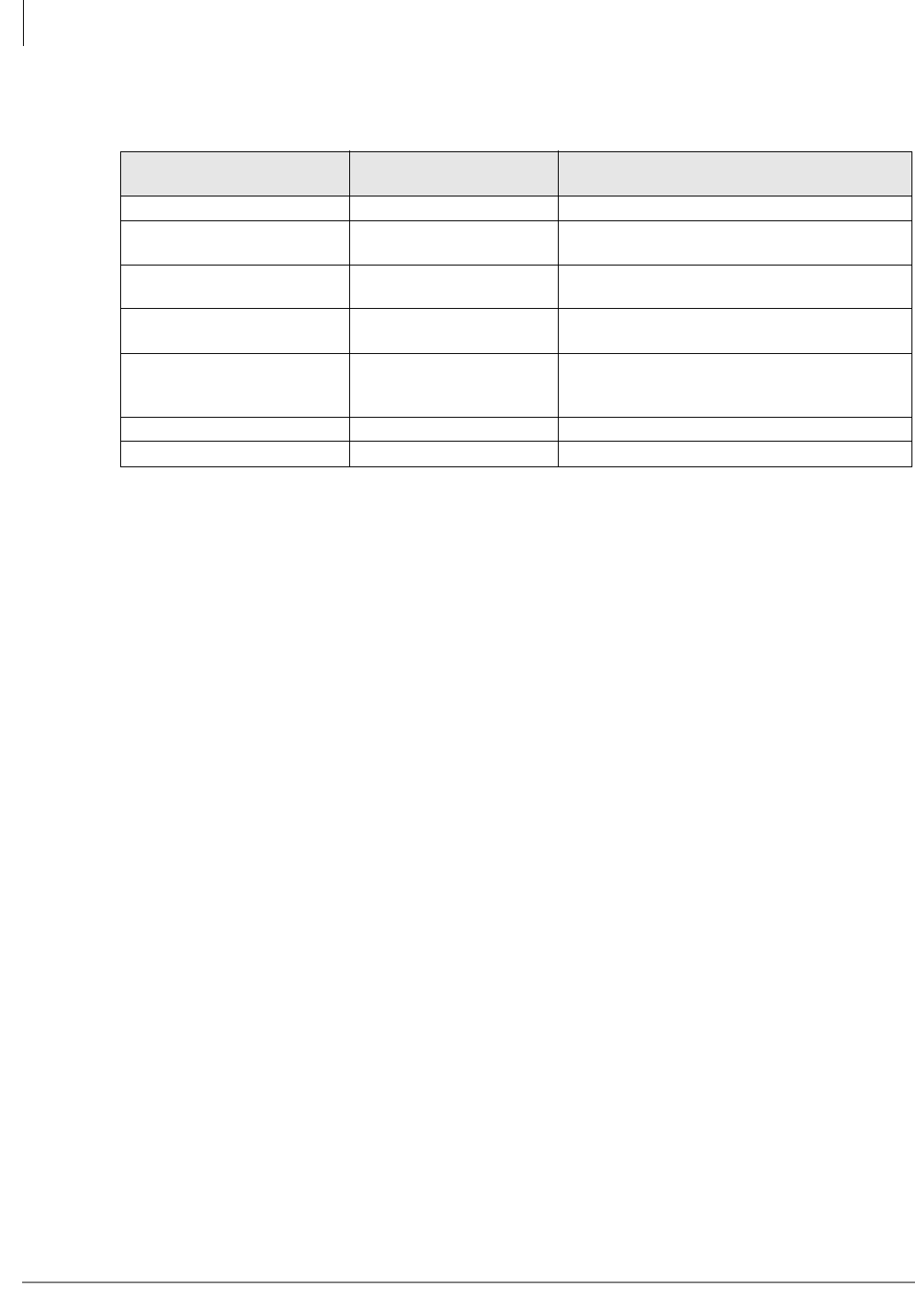
PCB Installation
BIOU – Option Interface Units
6-10 Strata CTX I&M 06/04
Table 6-4 BIOU Controls, Indicators, and Connectors
Control/Indicator/
Connector Type of Component Description
SW600 Page Output Switch SP0=600 ohms. SP1 = 3-watt amp.
J1, J2, J3 RCA jack for connecting
MOH/BGM source
Interface connector for MOH/BGM source 1, 2,
or 3.
MOH1, MOH2, MOH3 Screwdriver volume
control
Adjusts volume of respective MOH jacks 1, 2,
and 3.
SP Screwdriver volume
control Adjusts volume of SP1; 3-watt page amplifier.
B/M Break/Make control relay
jumpers
Set in the Make (close) or Break (open)
position, depending upon which one should
occur when the application relay activates.
N.C/N.O Jumper plug Not used.
SW1 Mu/A Jumper plug Select Mu law for U.S. and Canada.
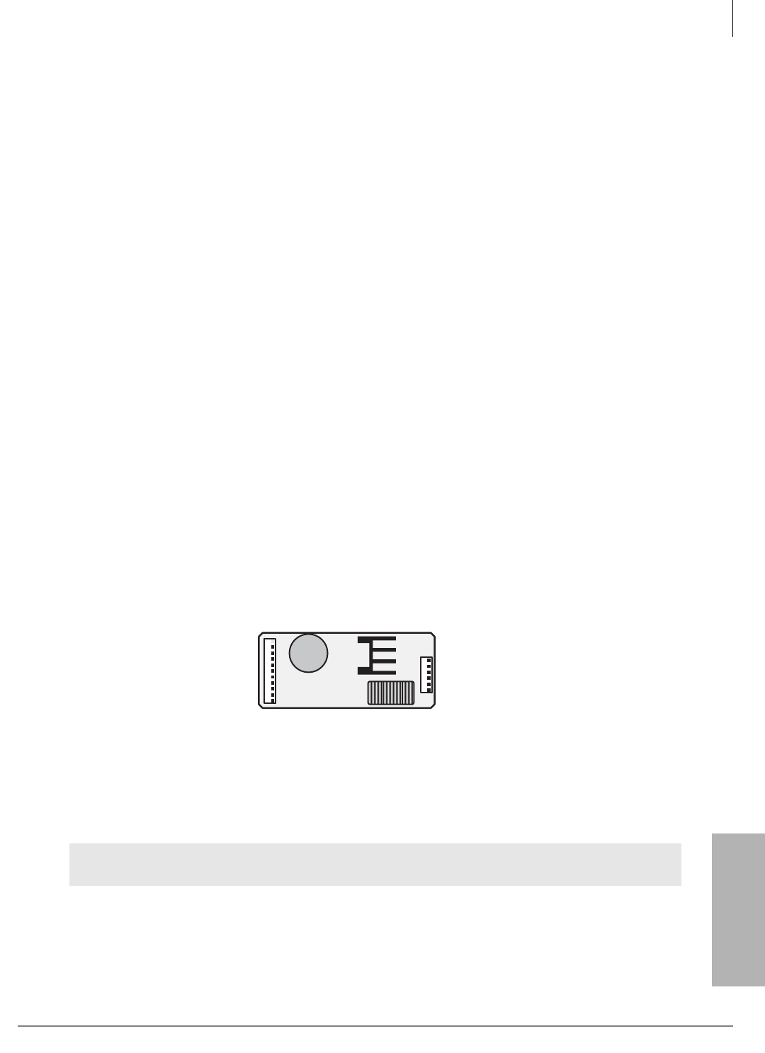
PCB Installation
BSTU/RSTU – Standard Telephone Interface Unit
Strata CTX I&M 06/04 6-11
PCB Installation
BSTU/RSTU – Standard Telephone Interface Unit
Circuits per PCB:
eight standard telephone circuits
Interfaces with:
standard telephones
voice mail ports
off-premises stations
other similar devices
alternate BGM sources
auto attendant digital announcer
message waiting lamp
Older Version(s):
RSTU3, RSTU2, RSTU1
The BSTU and RSTU are basically the same and are interchangeable. Ringer Capacity for the
BSTU is three telephones or devices per circuit. RSTU1, 2 and 3 allow one telephone or device per
circuit.
Notes
• For the system to recognize the DTMF tones generated by a standard telephone (or any other
device connected to a standard telephone port), a DTMF receiver unit must be equipped on the
processor PCB (ARCS subassembly must be installed on ACTU processor of the CTX100.
DTMF receivers are standard on CTX670 processors).
• BSTU and RSTU3 provides Message Waiting (MW). RSTU1 and RSTU2 do not provide MW.
R48S -48 Volt Supply Subassembly Installation
R48S is required for line loop resistance greater than 600 ohms. The maximum loop resistance
allowed with 48S = 1200 ohms; without 48S = 600 ohms.
³Mate the R48S connectors P6 and P7 (Figures 6-6~6-9) with the R48S connectors P6 and P7
on the BSTU or RSTU.
Note BSTU and RSTU connectors P6 and P7 are positioned so that the R48S only fits in the
proper position.
Figure 6-6 R48S Interface Connectors
BSTU/RSTU Installation
1. Make sure the factory-installed SBSS (BSTU subunit) or SRSS (RSTU subunit) is securely
attached to the BSTU or RSTU (Figures 6-8 and 6-9).
Note “RSTU” can be substituted for “BSTU” in these instructions.
2. Insert the BSTU (component side facing right) into the appropriate slot, and apply firm, even
pressure to ensure proper mating of connectors.
WARNING! The shield on the back of the BSTU and RSTU is designed to protect you from
potentially hazardous ring voltage. Do NOT remove this shield.
P6
P7
1374
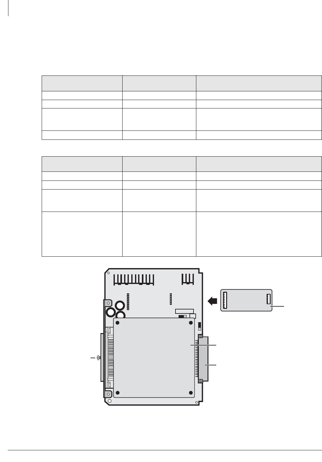
PCB Installation
BSTU/RSTU – Standard Telephone Interface Unit
6-12 Strata CTX I&M 06/04
3. After installing the BSTU, gently pull the BSTU outward. If the connectors are properly mated,
a light resistance is felt.
Note When installing the RSTU3 into an existing system, system power must be cycled only if
the MW mode (P11) is changed.
Figure 6-7 BSTU Controls and Interface Connectors
Table 6-5 BSTU Controls, Indicators, and Connectors
Control/Indicator/
Connector Type of Component Description
R48S connector P6 9-pin connector Interface connector to P6 of R48S.
R48S connector P7 6-pin connector Interface connector to P7 of R48S.
Mu/A P10 3-terminal jumper
Mu Law or A Law PCM companding. (Must be
set to Mu Law in the U.S. and Canada). No
strap = Mu Law.
Ring-time P12 3-terminal jumper Always set jumper to “REN3.”
Table 6-6 RSTU1, 2 and 3 Controls, Indicators, and Connectors
Control/Indicator/
Connector Type of Component Description
R48S connector P6 (RSTU) 9-pin connector Interface connector to P6 of R48S.
R48S connector P7 (RSTU) 6-pin connector Interface connector to P7 of R48S.
Mu/A P10 (RSTU3 only) 3-terminal jumper
Mu Law or A Law PCM companding. (Must be
set to Mu Law in the U.S. and Canada). No
strap = Mu Law.
MW (Message Waiting) Mode
P11 (RSTU3 only) 3-terminal jumper
CON = Electronically controlled message
waiting light (U.S. and Canada).
NOR = Relay controlled message waiting light.
Do not use this in the U.S. and Canada since
this option may cause message waiting cross-
talk noise in some installations.
BSTU1A
RING-TIME
P12
P7
P6
50-Pin Amphenol
Connector (Female)
6592
Backplane Connector
Mu A
P10
P6
P7
R48S
Optional
SBSS Subunit
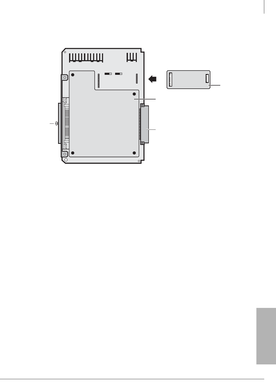
PCB Installation
BSTU/RSTU – Standard Telephone Interface Unit
Strata CTX I&M 06/04 6-13
PCB Installation
Figure 6-8 RSTU3 Controls and Interface Connectors
RSTU3A
MW-Mode Mu A
CON NOR P10
P7
P6
P11
50-Pin Amphenol
Connector (Female)
SRSS Subunit
5896
Backplane Connector
P6
P7
R48S
Optional
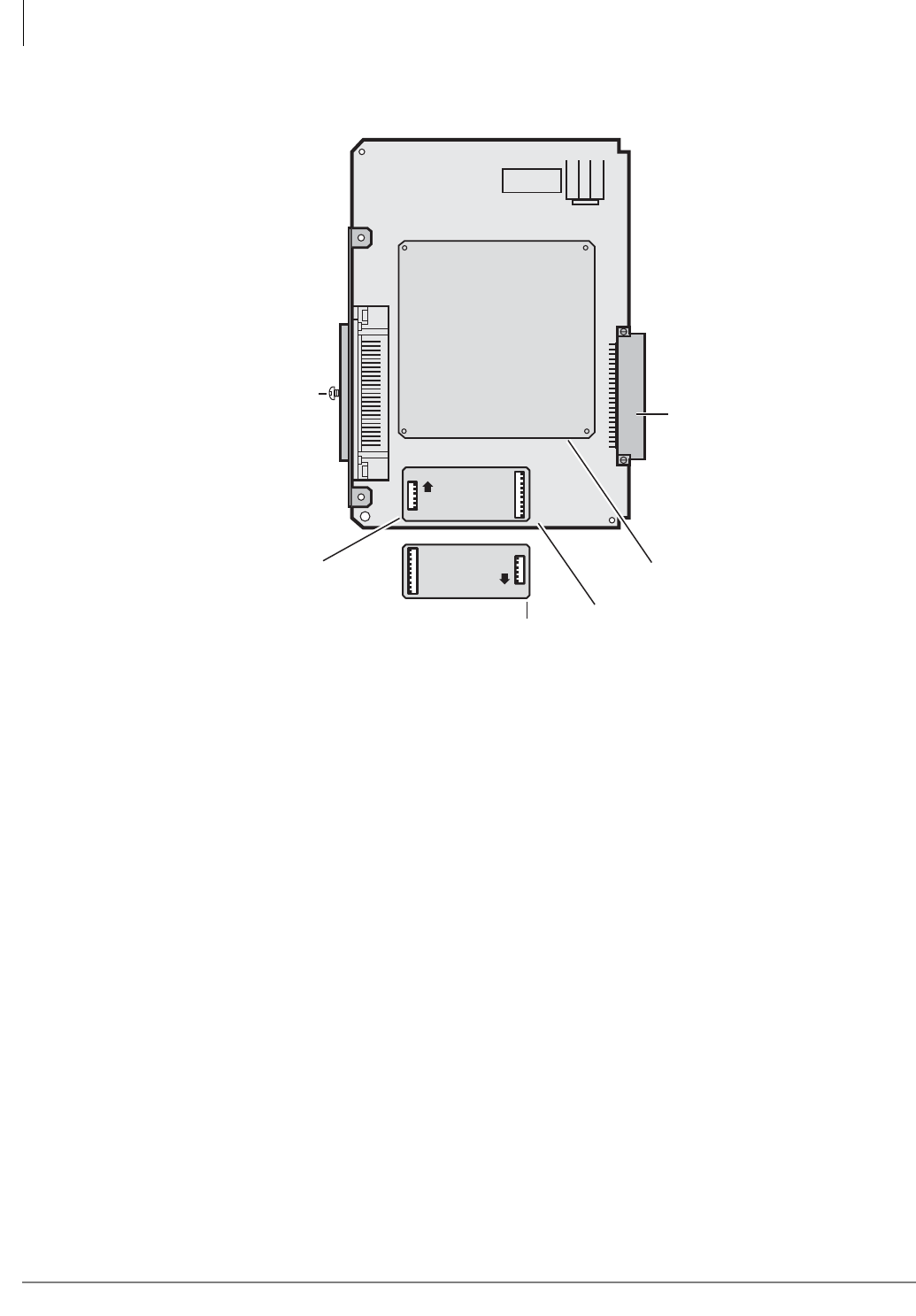
PCB Installation
BSTU/RSTU – Standard Telephone Interface Unit
6-14 Strata CTX I&M 06/04
Figure 6-9 RSTU or RSTU2 Controls and Interface Connectors
SSTU
Subunit
RSTU
OR
RSTU2
50-Pin Amphenol
Connector (Female)
Optional
R48S
Installed
on RSTU1
R48S
Installed
on RSTU2
P6
P7 UP
R48S
P6
P7 UP
R48S
5809
Backplane Connector
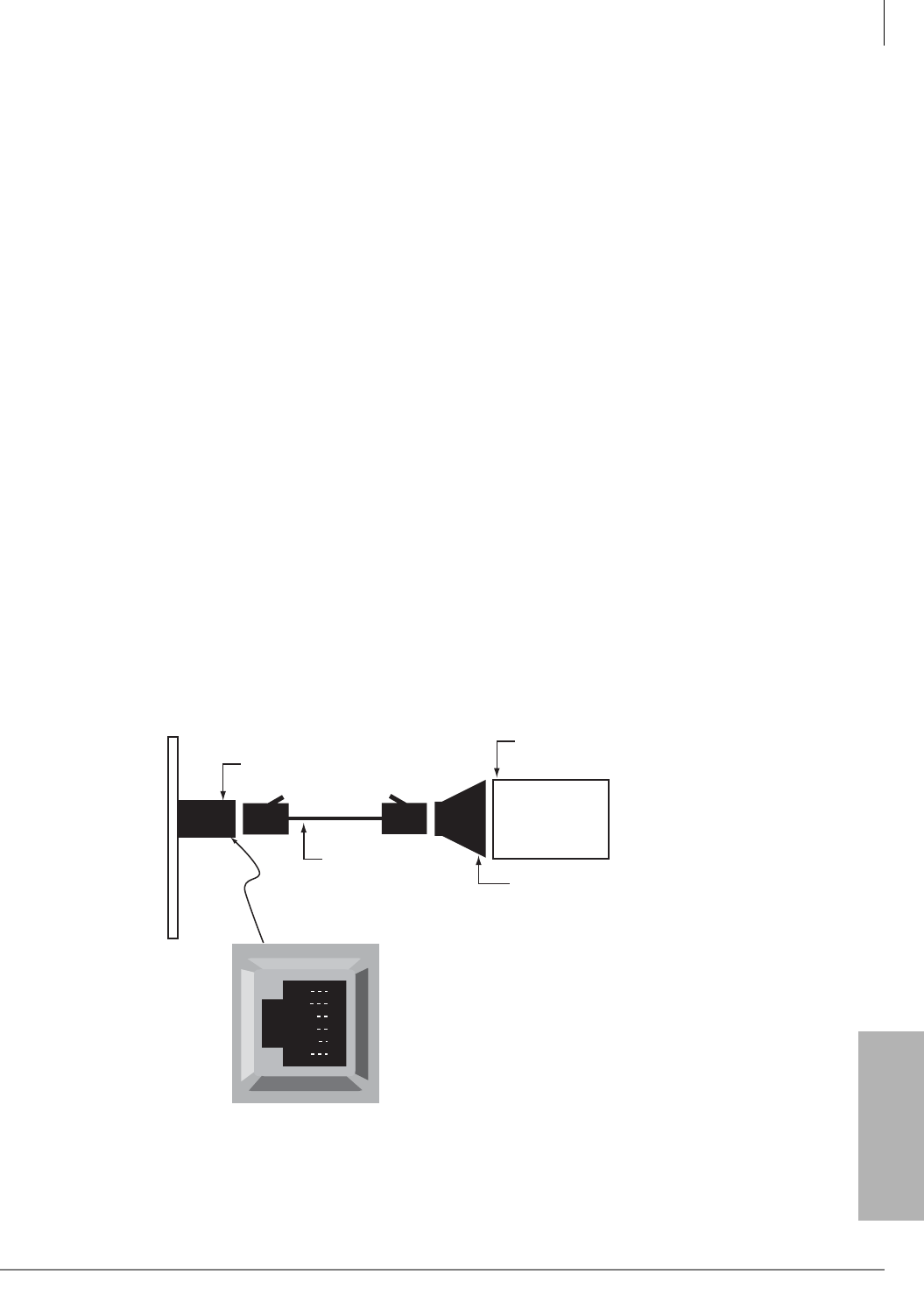
PCB Installation
BVPU – Internet Protocol (IP) Interface Unit
Strata CTX I&M 06/04 6-15
PCB Installation
BVPU – Internet Protocol (IP) Interface Unit
Circuits per PCB:
four Tie line circuits; one 10BaseT Ethernet connection
Interfaces with:
H.323 version 2 terminals over an IP network
Appears as:
4 E&M Tie lines
2- or 4-wire transmission
Type I and II Signaling
Immediate and Wink Start
Older Version(s):
none
BVPU Configuration
Note Maximum of five BVPUs for CTX670 and a maximum of two BVPUs for CTX100 because
of FCC Part 15 Electromagnetic Capability (EMC) emissions restrictions.
BVPU controls, indicators, and interface connectors are shown in Figure 6-10 and described in
Table 6-7.
BVPU Installation
1. Insert the BVPU (component side facing right) into the appropriate slot and apply firm, even
pressure to ensure proper mating of connectors.
2. Attach the 10BaseT Ethernet connection to the LAN connector.
3. Connect a PC equipped with Maintenance Console Software (MCS) to the serial port according
to the drawing below. A serial connection is necessary to establish the IP address of the BVPU.
Once the IP address is established, maintenance may be conducted over the Ethernet port.
4. After installing the BVPU, gently pull it outward. If the connectors are properly mated, a slight
resistance is felt.
Figure 6-10 BVPU Monitor Jack
RD
TD
DSR
DTR
DCD
SG
1
2
3
4
5
6
Call-monitor jack (RJ12)
pin numbering
Dealer-supplied
6-wire telephone
modular cord
(cross-pinned)
Monitor jack
PC with maintenance
console software
PC DB9 or
DB25 Com port
Toshiba PPTC9 or
PPTC25F
BVPU
5243
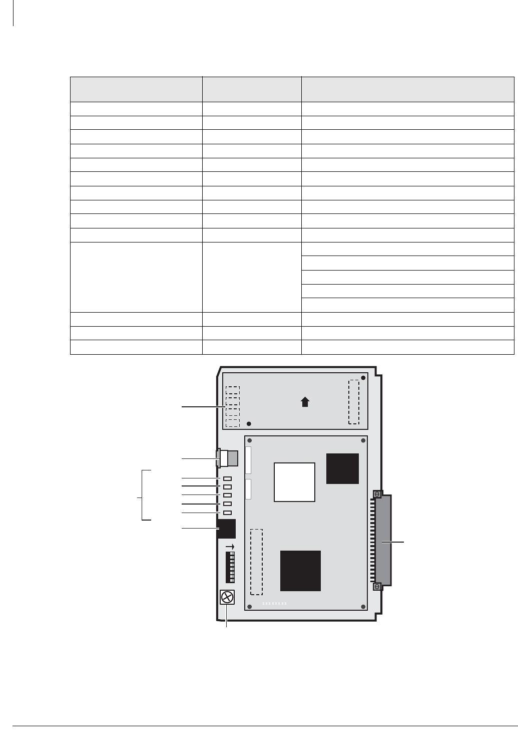
PCB Installation
BVPU – Internet Protocol (IP) Interface Unit
6-16 Strata CTX I&M 06/04
Figure 6-11 BVPU PCB
Table 6-7 BVPU Controls, Indicators, and Connectors
Control/Indicator/
Connector Type of Component Description
Serial Port RS-232C maintenance connection
LAN Connector RJ45 10BaseT ethernet connection
SW0 DIP Switch Unused. All switches = Off
LED 1 Green LED On = Tie trunk 4 active
LED 2 Green LED On = Tie trunk 3 active
LED 3 Green LED On = Tie trunk 2 active
LED 4 Green LED On = Tie trunk 1 active
LED 5 Green LED Power On/Off
LED 6 Yellow LED Line Status (On=Busy / Off = Idle)
LED 7 Red LED Alarm (On = Abnormal)
LED 8 Green LED
On-Line
On = Operating
Off = Starting up or Off
Slow Flash = Detected error in BVPU
Fast Flash = Shut down mode
LED 9 Yellow LED Link Indication (On = Normal)
LED 10 Green LED Data (On = Data communication in progress)
LED 11 Yellow LED Collision (On = collisions occurring)
5806
SPORT
Line in Use
LEDs
LAN
LINK
ONLINE
ALARM
BUSY
POWER
Serial Port
12345678
ON
MSB LSB
TBO Ground Terminal
Backplane
Connector
LEDs
BVPU1A
BDM
0123456LED7
CN1
JTAG
CN2
VPIS1A
UP
1
2
3
4
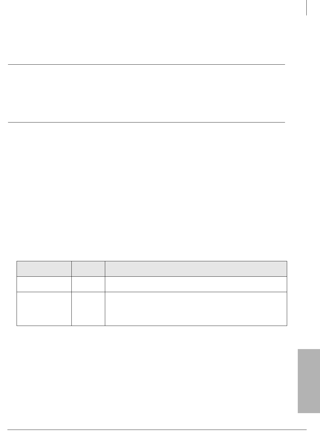
PCB Installation
BWDKU1A – Digital Telephone Interface Unit
Strata CTX I&M 06/04 6-17
PCB Installation
BWDKU1A – Digital Telephone Interface Unit
Circuits per PCB:
16 digital telephone circuits
Interfaces with:
all Toshiba digital telephones (corded and cordless, DDCB, DSS, ADM, BPCI)
CAUTION! Existing SpectraLink interface units are not compatible with the
BWDKU1A. A firmware update will be available from Spectralink in the
near future.
When installing Add-on modules, be sure to check Table 10-1 on page 10-2
to verify maximum line lengths. BWDKU supports 1 pair wiring per Table
10-2 on page 10-6.
Older Version(s):
none
The BWDKU1A is very similar to the BDKU + BDKS, but it supports 16 DKT circuits with a
single PCB. It is also compatible with Strata DK but only supports eight circuits.
BWDKU1A Installation
1. See Table 6-8 and Figure 6-12, then make any jumper adjustments needed for DKT or slot
requirements. The BWDKU1A can be installed in any slot; however, if it is installed in
expansion slots S_07~S_10, you must move the jumper plug to the “8 CCT” position.
Important! Do not detach the SWDR1A subassembly. The BWDKU1A will not work properly
without it.
2. Insert the BWDKU1A (component side facing right) into the appropriate slot, and apply firm,
even pressure to ensure proper mating of connectors.
Table 6-8 BWDKU1A Slot Placement
Slot Numbers Available
Circuits BWDKU1A Jumper Settings
Base & Expansion
S_0 ~S_06 16 The CTX identifies the BWDKU1A as a BDKU + BDKS. Leave jumper plug
503 in the “BDKU” position and leave P504 in the “16 CCT” position.
Expansion
S_07~S_10 8
Move jumper 504 to the “8 CCT” position when the BWDKU1A is placed in
slots S_07~S_10. The BWDKU1A will work like a BDKU on a CTX system.
Note If the BWDKU1A is installed on DK system, move jumper P503 to
the “PDKU” position.
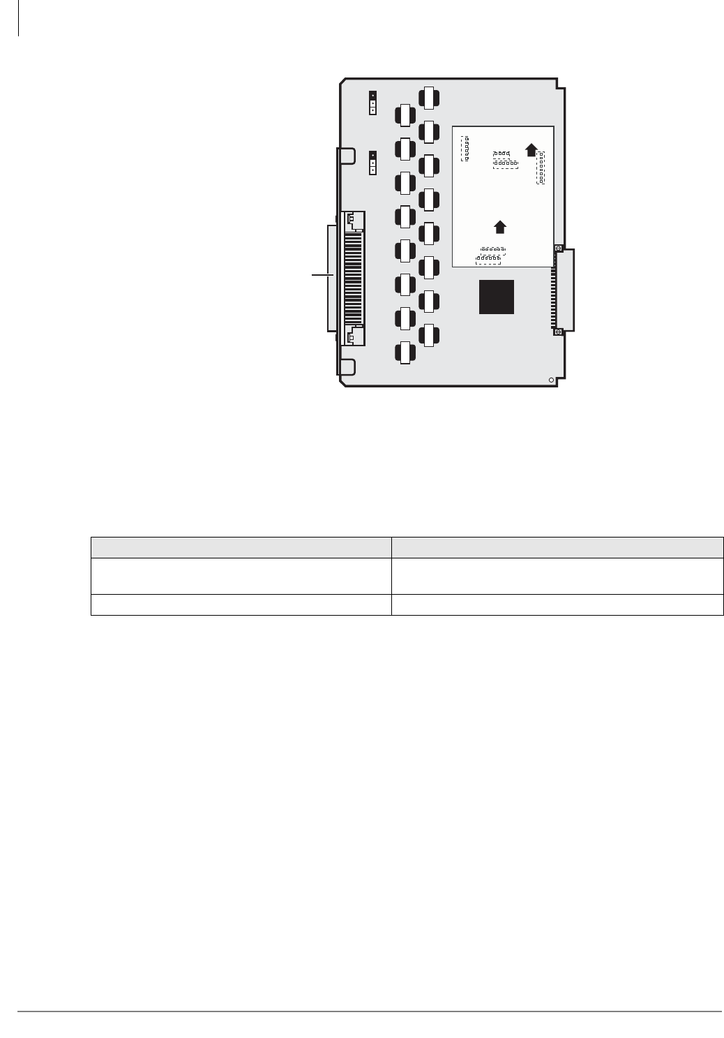
PCB Installation
Programming
6-18 Strata CTX I&M 06/04
Figure 6-12 BWDKU1A PCB
Note The BWDKU1A does not need a Ferrite Core.
A comparison of the BWDKU1A and the BDKU/BDKS is shown in Table 6-9.
The power factor for the BWDKU1A is +5VDC = 0.8, -24VDC = 0.3.
Refer to Chapter 11 – Station Apparatus for instructions on how to connect digital telephones,
DADMs and DDSS consoles to the BWDKU1A. Refer to Chapter 12 – Peripheral Installation for
instructions on connecting Door Phones (DDCBs).
Programming
In Strata CTX Program 100, use the same CTX WinAdmin selections as the BDKU or BDKU/
BDKS. A “BWDKU” selection will be added to Program 100 in a future version of CTX
WinAdmin.
In Strata DK, Program 03, code selection 61, 62, or 64 for the “BWDKU.”
Table 6-9 BWDKU1A and BDKU/BDKS Comparison
BWDKU1A BDKU/BDKS
DKT wiring is all 1 pair. Line length is shorter than
the BDKU. DKT wiring is 2 pairs (BDKU) and 1 pair (BDKS) mixed.
One protector circuit for every two circuits. One protector circuit for every one circuit.
IC502
6837
BWDKU1A
BWDKU1
0210602106021060210602106021060210602106
0210602106021060210602106021060210602106
SWDR1A
UP
UP
J1
J4
P503 P504
J6
J3
J2
J5
Backplane Connector
50-Pin Amphenol
Connector (Female)
BDKU PDKU 16 CCT 8 CCT
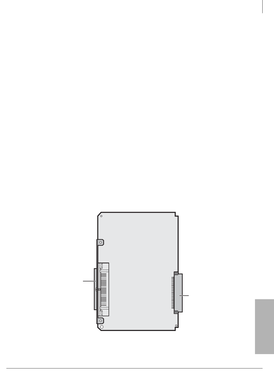
PCB Installation
PDKU2 – Digital Telephone Interface Unit
Strata CTX I&M 06/04 6-19
PCB Installation
PDKU2 – Digital Telephone Interface Unit
Circuits per PCB:
eight digital telephone circuits
Interfaces with:
digital telephones (with or w/o ADM) (See Notes under Hardware Options)DDSS
console (circuit 8 only)
cordless digital telephones (DKT2004-CT, DKT2104-CT)
DKT2001 single line digital telephones
Older Version(s):
PDKU1 (identical to PDKU2 except it does not support continuous DTMF tones
w/DKT2000-series telephones, DIUs can only be connected to circuits 1~7)
PDKU2 Hardware Options
PDKU2 does not have to be configured for any option. Refer to Chapter 11 – Station Apparatus for
instructions on how to connect digital telephones, DADMs, and DDSS consoles to the PDKU2.
Refer to Chapter 12 – Peripheral Installation for instructions on connecting Door Phones
(DDCBs).
Notes
• BPCI, RPCI-DI and PDIU-DI are not supported on Strata CTX.
• With the DKT3000-series telephones, limitations are 16 (not 24) character LCD display,
Spdial and LCD Feature buttons don’t work and the BPCI cannot be used
There are no controls or indicators on the PDKU (Figure 6-13).
PDKU2 Installation
1. Insert the PDKU2 (component side facing right) into the appropriate slot, and apply firm, even
pressure to ensure proper mating of connectors.
2. After installing the PDKU, gently pull the PCB outward. If the connectors are properly mated,
a slight resistance is felt.
Figure 6-13 PDKU2 PCB
Backplane Connector
50-Pin Female Amphenol Connector
5807

PCB Installation
RCIU1, RCIU2, RCIS – Caller ID Interface
6-20 Strata CTX I&M 06/04
RCIU1, RCIU2, RCIS – Caller ID Interface
Circuits per PCB:
four Caller ID circuits
Interfaces with:
loop or ground start lines w/Caller ID (requires RCOU or RGLU2)
Older Version(s):
none
The RCIU1, RCIU2 PCB provides the Caller ID feature, also known as Calling Number Delivery
(CND).
Caller ID can be provided on analog loop start lines (PCOU or RCOU PCBs) and analog ground
start lines (RGLU2 PCB) only. It is not available on any other type of analog lines (RDDU/DID
and/or REMU, PEMU Tie) or any type of digital lines (RDTU- T1, including ground start, loop
start, DID and Tie lines).
³An RCIU1/RCIS or RCIU2/RCIS circuit must be available in addition to each RCOU, RGLU,
etc., line that is to receive Caller ID. When ordered from the factory, the RCIU1, RCIU2 PCB
comes equipped with four Caller ID circuits.
RCIS PCB
An RCIS piggy-back PCB can be installed onto the RCIU to provide an additional four Caller ID
circuits. Hence, an installed RCIU/RCIS can provide a maximum of eight Caller ID circuits per
cabinet slot.
To provide up to eight circuits, always install RCIS onto RCIU1 or RCIU2 instead of installing
two RCIU PCBs (Program 100 code 009 always assigns each RCIU slot with eight software
Caller ID circuits).
Each RCIU/RCIS Caller ID circuit has a two-wire tip/ring interface which must be bridge-wired
across its corresponding ground or loop start CO line tip/ring on the MDF (see Figure 10-11 on
page 10-20). Each RCIU/RCIS modular jack provides interface for two Caller ID circuits.
RCIU1 or RCIU2 Installation
³Install the RCIU1/RCIU2 PCBs in any universal cabinet slot of the Strata CTX670 (except
slot 11 or slot 12 if the RSIU is installed in slot 11).
Note It is not necessary to install the RCIU1, RCIU2, RCIU1/RCIS, or RCIU2/RCIS PCBs in the
same cabinet as their associated CO lines or in slots adjacent to the lines.
RCIU1/RCIS or RCIU2/RCIS Installation
1. Install the RCIS onto the RCIU1 or RCIU2 as required (see Figures 6-14 and 6-15).
2. Install the RCIU1/RCIS or RCIU2/RCIS into the appropriate cabinet slot. The circuit modular
jack numbering and the tip/ring cross connect wiring of BECU to RCOU, PCOU, or RGLU is
shown in Figure 10-8 on page 10-13.
Note It is not necessary to install the RCIU1, RCIU2, RCIU1/RCIS, or RCIU2/RCIS PCBs in the
same cabinet as their associated CO lines or in slots adjacent to the lines.
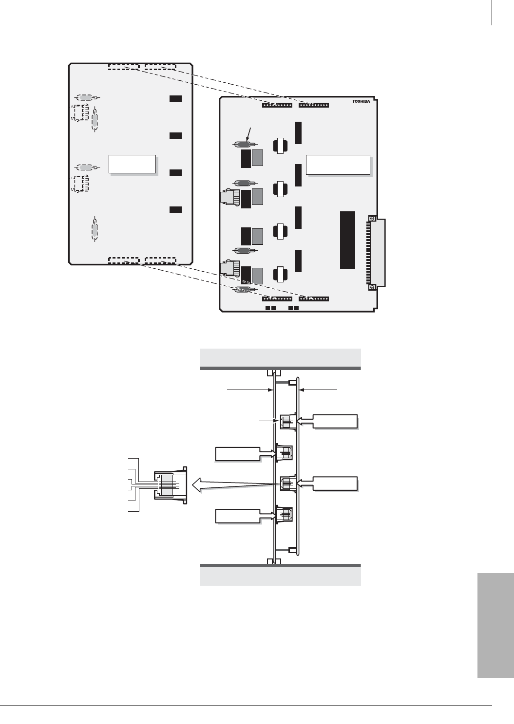
PCB Installation
RCIU1, RCIU2, RCIS – Caller ID Interface
Strata CTX I&M 06/04 6-21
PCB Installation
Figure 6-14 RCIU1/RCIS PCB
Figure 6-15 RCIU1/RCIS or RCIU2/RCIS PCB Modular Jack Positions
RCIU1A V.1
RCIU1
J2
J1
P11
P12 P13
20K/20K 20K/20K 20K/20K 20K/20K
RCIS1A
(reverse)
RCIU1A or RCIU2A
(front)
Secondary
Protectors
J10 J11
J12
J4
J3
J13
P10
1392
SXX
CKT 5 & 6
CKT 7 & 8
CKT 1 & 2
CKT 3 & 4
RCIU1 or RCIU2 RCIS
4-wire
Modular Jack (4)
Not Used
T2
T1
R1
R2
Not Used
1393

PCB Installation
RCOU3A, RCOS3A – Four-Circuit Loop Start CO Line Interface Unit
6-22 Strata CTX I&M 06/04
RCOU3A, RCOS3A – Four-Circuit Loop Start CO
Line Interface Unit
Circuits per PCB:
four loop start CO line circuits
Interfaces with:
loop start lines
Older Version(s):
RCOU1 (does not have Mu Law/A Law jumper plug)
PCOU2 (does not have ABR circuitry, uses RCTU, K4RCU ABR circuits)
PCOU1 (has ABR circuitry, identical and interchangeable w/PCOU2)
The RCOU3A and RCOU provide ring detection, dial outpulsing, and hold circuitry. Each RCOU
line can be programmed for DTMF or dial pulse signaling and has surge absorbers for secondary
protection.
The RCOU3A and RCOU PCBs are shown in Figures 6-18 and 6-19 and described in Table 6-12.
RCOS Installation (Internal Option)
An RCOS3A PCB can be installed on the RCOU3A or RCOU1A for four more loop start lines
(for a total of eight lines–the RCOS circuits provide the same options as the RCOU). Each RCOS
circuit has surge absorbers for secondary protection.
Excessive loudness which is caused by close proximity to a CO or PBX telephone can be fixed
through the RCOS and RCOU decibel (dB) Pad switches. RCOS dB switches SW501, SW601,
SW701, and SW801 and RCOU dB switches SW101, SW201, SW301, and SW401 provide a -3
dB signal level drop between the PBX and CO when set to position 3. Switches are factory-set at
the 0 (0 dB signal level drop) position.
The RCOS3A and RCOS1A PCBs are shown in Figures 6-16 and 6-17 and described in Tables
6-10 and 6-11.
³To install an RCOS3A PCB
1. If the Strata CTX system is within one mile of the PBX or CO, set the RCOS dB Pad switches
SW501, SW601, SW701, and SW801 to the 3 (-3 dB signal level drop) position. Set the RCOU
dB Pad switches to position 3 also.
Note RCOU male connectors P11, P12, P13, and P14 are positioned to allow installation of the
RCOS only in the proper position.
2. Mate the RCOS3A female connectors J11, J12, J13, and J14 (Figure 6-16) to the RCOU3A or
RCOU1A male connectors P11, P12, P13, and P14 (Figures 6-18 or 6-19).
3. (RCOS3A only) For Mexico, the U.K, or Asia, insert the short jumper plug on the A Law side.
For the U.S. and Canada, no plug is required. (No plug is the Mu Law assignment).
4. Apply firm, even pressure to the RCOS to ensure proper mating of connectors.
Note The RCOS1A cannot be installed on the RCOU3A.
PCB Installation
RCOU3A, RCOS3A – Four-Circuit Loop Start CO Line Interface Unit
Strata CTX I&M 06/04 6-23
PCB Installation
Table 6-10 RCOS3A Controls, Indicators, and Connectors
Control/Indicator/
Connector Type of Component Description
CO line circuit 5~8 indicators Red LED
Lights to indicate that line circuit is in operation.
(CO line indicator will not light unless RCOU is
connected to a CO line).
J3 connector Modular connector Interface connector for CO line circuits 5 and 6.
J4 connector Modular connector Interface connector for CO line circuits 7 and 8.
Pad switch SW501 (circuit 5)
2-position slide switch Enables -3dB signal level drop for CO line
circuit.
Pad switch SW601 (circuit 6)
Pad switch SW701 (circuit 7)
Pad switch SW801 (circuit8)
RCOU3A connector J11, J12,
J13, J14 11-pin female connector Interface connector for RCOU3A. RCOS3A can
be connected with RCOU3A and RCOU1A.
Mu Law/A Law jumper plug
P2
(RCOS3A only)
3-terminal jumper
No jumper plug is the default for the U.S. and
Canada. For countries requiring A Law, insert
the jumper plug (provided in the PCB box) on
the A Law side.
Table 6-11 RCOS1A Controls, Indicators, and Connectors
Control/Indicator/
Connector Type of Component Description
CO line circuit 5~8 indicators Red LED
Lights to indicate that line circuit is in operation.
(CO line indicator will not light unless RCOU is
connected to a CO line).
J3 connector Modular connector Interface connector for CO line circuits 5 and 6.
J4 connector Modular connector Interface connector for CO line circuits 7 and 8.
Pad switch SW501 (circuit 1)
2-position slide switch Enables -3dB signal level drop for CO line
circuit.
Pad switch SW601 (circuit 2)
Pad switch SW701 (circuit 3)
Pad switch SW801 (circuit 4)
RCOU connector J11, J12,
J13, J14 Female connector Interface connector for RCOU 4-circuit loop
start CO line unit.
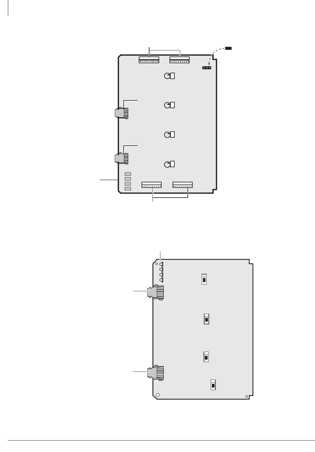
PCB Installation
RCOU3A, RCOS3A – Four-Circuit Loop Start CO Line Interface Unit
6-24 Strata CTX I&M 06/04
Figure 6-16 RCOS3A PCB
Figure 6-17 RCOS PCB
J13
J14
J12
J11
MuP1
A
03 03 0 3 0 3
SW501 SW601 SW701 SW801
CO Line Modular
Jack Circuits
5 and 6
CO Line Modular
Jack Circuits
7 and 8
J4J3
RCOU Connectors
RCOU Connectors
Plug is not
used in the U.S.
and Canada
CO Line
LEDs
5907
432 1
Chip LEDs
CO Line Modular
Jack Circuits 1 and 2
CO Line Modular
Jack Circuits 3 and 4
CO Line LEDs
4321
SW101
0 3
PAD
0 3
PAD
0 3
PAD
0 3
PAD
SW301 SW201
SW401
5811
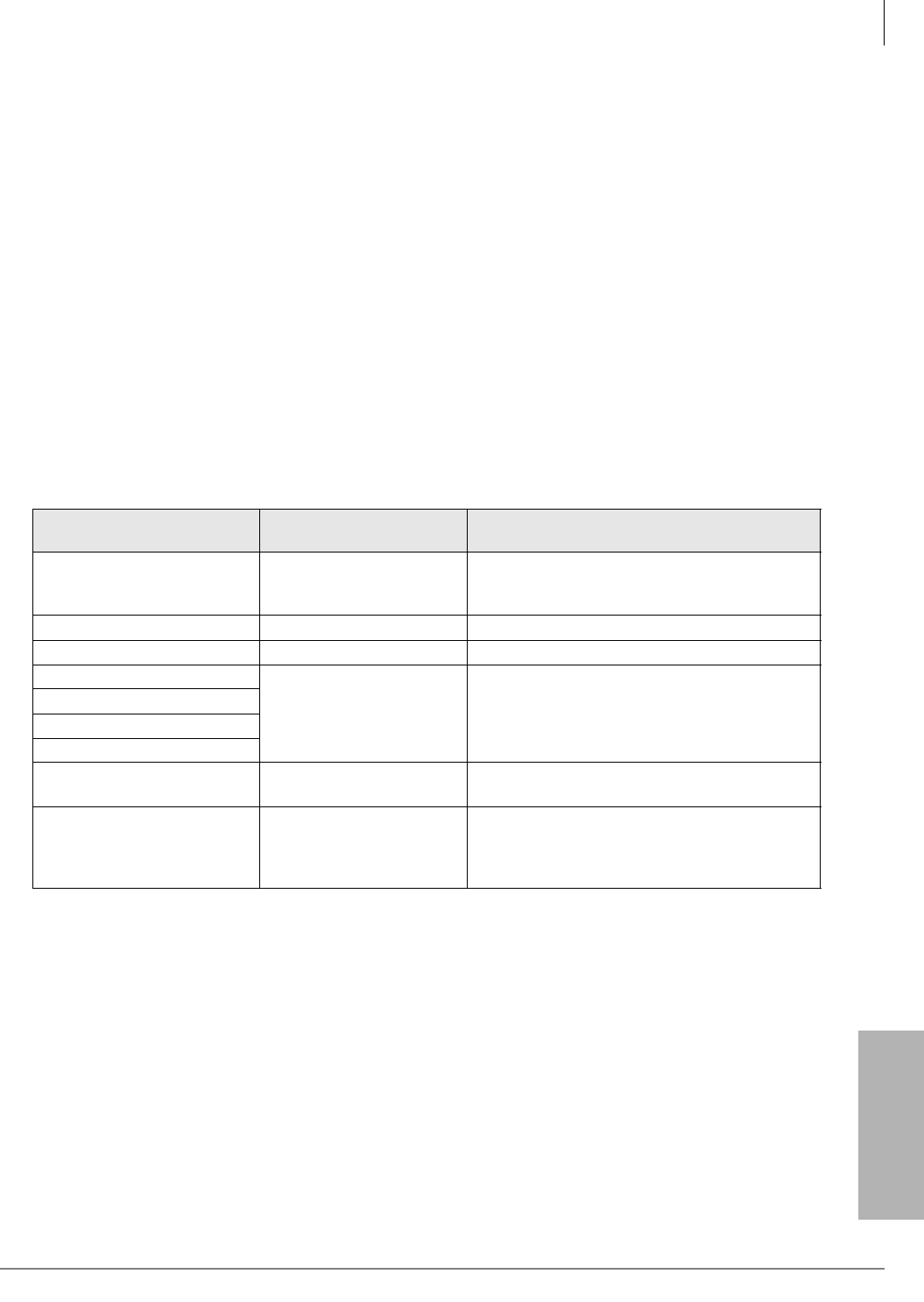
PCB Installation
RCOU3A, RCOS3A – Four-Circuit Loop Start CO Line Interface Unit
Strata CTX I&M 06/04 6-25
PCB Installation
RCOU Installation
Note The decibel (dB) Pad switches SW101, SW201, SW301, and SW401 control excessive
loudness resulting from close proximity to a Central Office or PBX telephone office by
providing a -3 dB signal level drop to, or from, the PBX or CO when set to the 3 position.
Switches are factory-set to the 0 (0 dB signal level drop) position.
³To install an RCOU3A or RCOU1A PCB
1. If the Strata CTX system is within one mile of the PBX or Central Office, set the RCOU dB
Pad switches SW101, SW201, SW301, and SW401 to the 3 (-3 dB signal level drop) position.
2. (RCOU3A only) For Mexico, the U.K, or Asia, insert the short jumper plug on the A Law side.
For the U.S. and Canada, no plug is required. (No plug is the Mu Law assignment).
3. Insert the RCOU (component side facing right) into the appropriate slot and apply firm, even
pressure to ensure proper mating of connectors. PCOU2 can be installed in place of RCOU, see
the appropriate Configuration chapter.
4. After installing the RCOU, gently pull the PCB outward. If the connectors are properly mated,
a slight resistance is felt.
Table 6-12 RCOU3A and RCOU1A Controls, Indicators, and Connectors
Control/Indicator/
Connector Type of Component Description
CO line circuit 1~4 indicators Red LED
Lights to indicate that line circuit is in operation.
(CO line indicator will not light unless RCOU is
connected to a CO line).
J1 connector Modular connector Interface connector for CO line circuits 1 and 2.
J2 connector Modular connector Interface connector for CO line circuits 3 and 4.
Pad switch SW101 (circuit 1)
2-position slide switch Enables -3dB signal level drop for CO line
circuit.
Pad switch SW201 (circuit 2)
Pad switch SW301 (circuit 3)
Pad switch SW401 (circuit 4)
RCOS connector P11, P12,
P13, P14 10-pin male connector Interface connector for RCOS 4-circuit loop
start CO line unit.
Mu Law/A Law jumper plug
P2
(RCOU3A only)
3-terminal jumper
No jumper plug is the default for the U.S. and
Canada. For countries requiring A Law, insert
the jumper plug (provided in the PCB box) on
the A Law side.
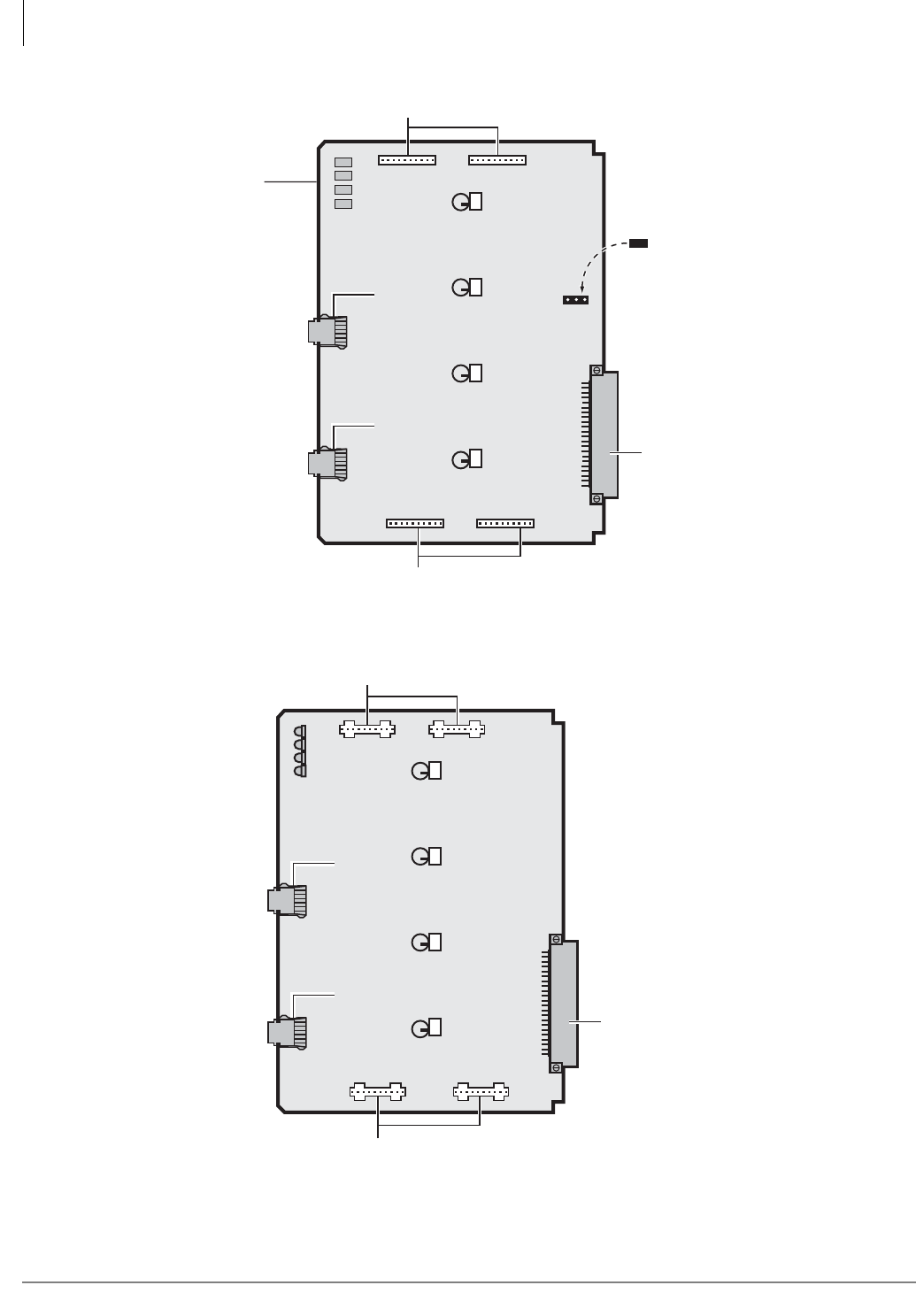
PCB Installation
RCOU3A, RCOS3A – Four-Circuit Loop Start CO Line Interface Unit
6-26 Strata CTX I&M 06/04
Figure 6-18 RCOU3A PCB
Figure 6-19 RCOU PCB
P11
P12
P14
P13
30
SW401
30
SW301
30
SW201
MuP2
A
30
SW101
CO Line Modular
Jack Circuits
3 and 4
CO Line Modular
Jack Circuits
1 and 2
J1J2
RCOS Connectors
RCOS Connectors
Plug is not
used in the U.S.
and Canada
CO Line
LEDs
5904
Backplane Connector
432 1
Chip LEDs
P11
P12
P14
P13
30
SW401
30
SW301
30
SW201
30
SW101
Red LEDs
CO Line Modular
Jack Circuits
3 and 4
CO Line Modular
Jack Circuits
1 and 2
J1J2
RCOS Connectors
RCOS Connectors
4 3 2 1
5810
Backplane Connector
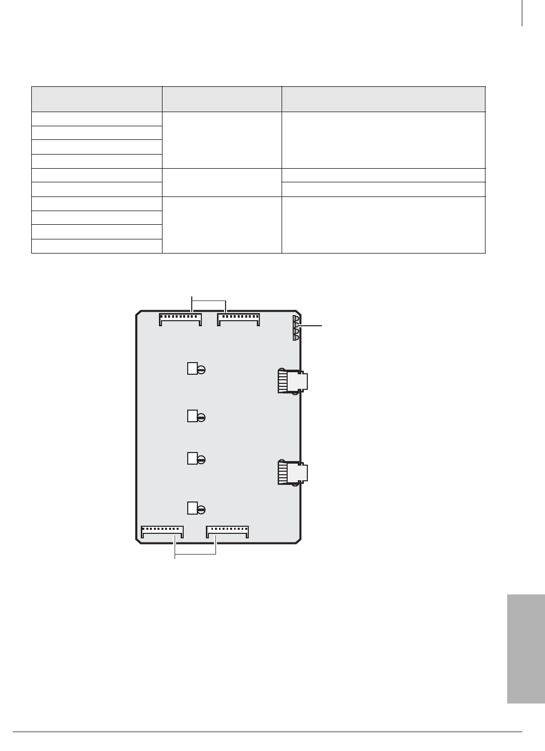
PCB Installation
RCOU3A, RCOS3A – Four-Circuit Loop Start CO Line Interface Unit
Strata CTX I&M 06/04 6-27
PCB Installation
Figure 6-20 PCOU2 PCB
Table 6-13 PCOU2 Controls, Indicators, and Connectors
Control/Indicator/
Connector Type of Component Description
CO line circuit 1 CD112
Red LED
Lights to indicate that line circuit is in operation.
CO line indicator will not light unless PCOU is
connected to a CO.
CO line circuit 2 CD212
CO line circuit 3 CD312
CO line circuit 4 CD412
J1 connector Modular connector Interface connector for CO line circuits 1 and 2.
J2 connector Interface connector for CO line circuits 3 and 4.
Pad switch SW101 (circuit 1)
2-position slide switch Enables -3dB signal level drop for CO line
circuit.
Pad switch SW201 (circuit 2)
Pad switch SW301 (circuit 3)
Pad switch SW401 (circuit 4)
J14
J13
J12
J11
J4 J3
30 30 30 30
SW801 SW701 SW601 SW501
RCOU
Connectors
RCOU
Connectors
Trunk Modular
Jack Circuits
7 and 8
Trunk Modular
Jack Circuits
5 and 6
Red LEDs
8 7 6 5
5812
PCB Installation
RDDU – Direct Inward Dialing Line Interface Unit
6-28 Strata CTX I&M 06/04
RDDU – Direct Inward Dialing Line Interface Unit
Circuits per PCB:
four DID lines
Interfaces with:
DID (one or two-way) lines
Older Version(s):
none
The RDDU provides four Direct Inward Dialing (DID) lines, each of which can have a single
office code along with a block of extensions.
Each extension can be assigned to ring a station [DN] that appears on one or multiple stations,
Distributed Hunt or ACD Group, or an external telephone number selected in system
programming. This enables calls over the same line to be routed to different stations or groups of
stations. An extension can also be assigned to ring the maintenance modem. Each RDDU can be
set for either wink start or immediate. All RDDU lines support DNIS and ANI features.
RDDU controls, indicators, and interface connectors are shown in Figure 6-21 and described in
Table 6-14.
RDDU Installation
Note Switches are factory-set to the 0 (0 dB signal level drop) position.
1. If the KSU is located within one mile of the PBX or CO, set dB Pad switches SW101 through
SW401 to the 3 (-3 dB signal level drop) position to control excessive loudness resulting from
close proximity to the PBX or CO.
2. Sensitivity jumpers P101~P401 are used mostly for dial pulse operation, to adjust for dial
pulsing at different loop lengths. If close to the central office, the sensitivity should be set for
low (L); as the loop length increases, it should be set to medium (M), then high (H).
3. Insert the RDDU (component side facing right) into the appropriate slot and apply firm, even
pressure to ensure proper mating of connectors.
4. After installing the RDDU, gently pull the PCB outward. If the connectors are properly mated,
a slight resistance is felt.
Table 6-14 RDDU Controls, Indicators, and Connectors
Control/Indicator/
Connector Type of Component Description
Pad switch SW101 (circuit 1)
3-position slide switch Enables -3 dB signal level drop for line circuit.
Pad switch SW201 (circuit 2)
Pad switch SW301 (circuit 3)
Pad switch SW401 (circuit 4)
J1 connector Modular connection Interface connector for DID line circuits 1 & 2
J2 connector Modular connection Interface connector for DID line circuits 3 & 4
DID line circuit 1 CD122 Red LED (top)
Lights to indicate line circuit is in operation.
(Trunk indicator will not light unless RDDU is
connected to a DID line.)
DID line circuit 2 CD222 Red LED
DID line circuit 3 CD322 Red LED
DID line circuit 4 CD422 Red LED (bottom)
Jumper plug P101
3-terminal jumper plug Adjusts for dial pulsing at different loop lengths.
Jumper plug P201
Jumper plug P301
Jumper plug P401
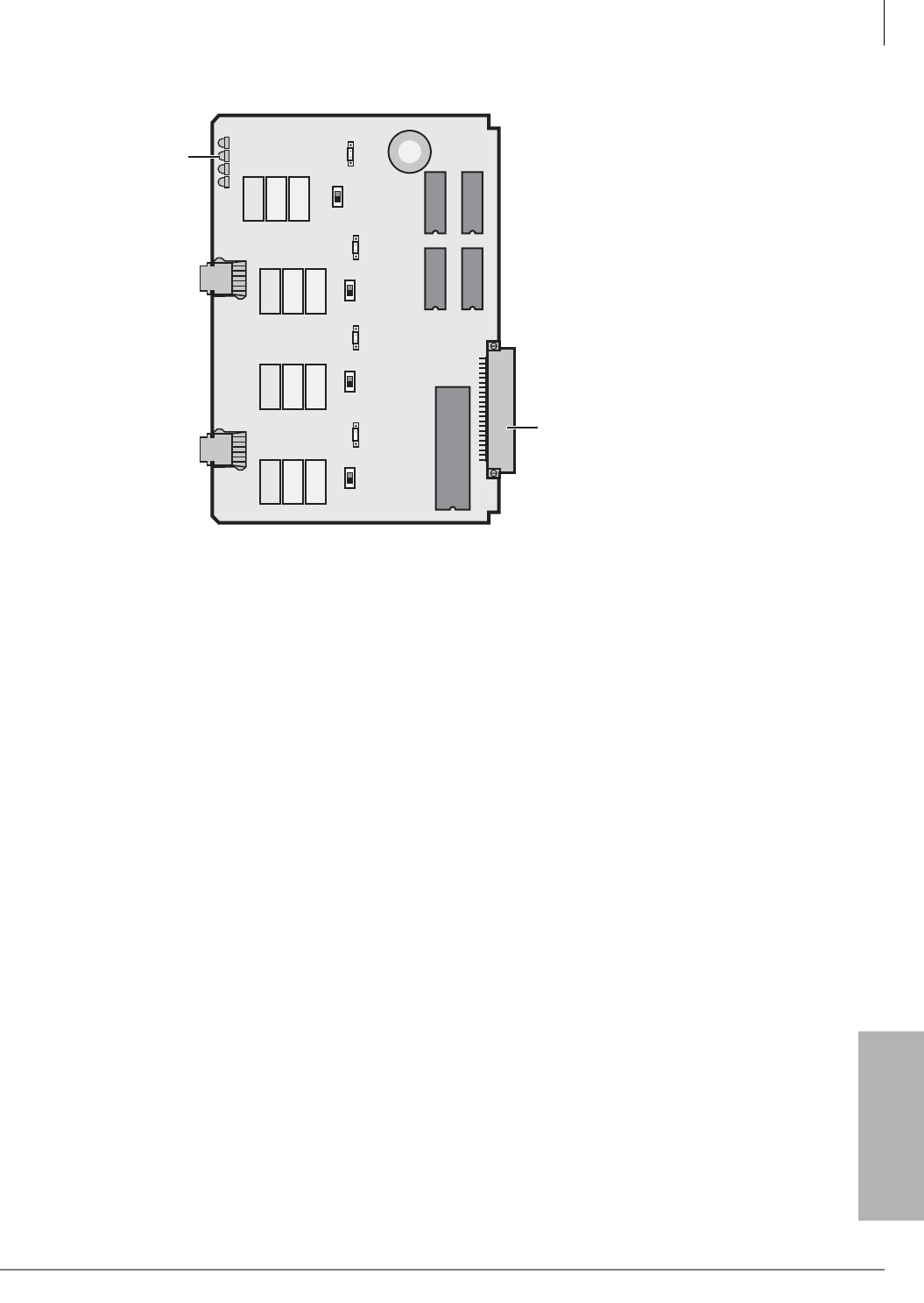
PCB Installation
RDDU – Direct Inward Dialing Line Interface Unit
Strata CTX I&M 06/04 6-29
PCB Installation
Figure 6-21 RDDU Controls, Indicators, and Interface Connectors
4
J1J2
SW401
SW301 SW201 SW101
LEDs
321
RDDU
RDDU
P401
H M L
P301
H M L
P201
H M L
3 0 3 03 0
3 0
5813
P101
H M L
Backplane Connector

PCB Installation
RDSU – Digital/Standard Telephone Interface Unit
6-30 Strata CTX I&M 06/04
RDSU – Digital/Standard Telephone Interface Unit
Circuits per PCB:
(with RSTS) four standard telephone (circuits 1~4)/four digital telephone (circuits 5~8)
(without RSTS) two standard telephone circuits (1 and 2)/four digital telephone
circuits
Interfaces with:
digital circuits (see PDKU)
digital telephones
standard circuits
standard telephones
voice mail ports
off-premises stations
other similar devices
alternate BGM source
auto attendant digital announcer
message waiting lamp
Older Version(s):
none
An optional Standard Telephone Interface Subunit (RSTS) can be attached to the RDSU to provide
two more standard telephone ports (circuits 3 and 4).
RDSU and RSTS controls and interface connectors are shown in Figure 6-22. RDSU interface
connectors are described in Table 6-15.
Note For the system to recognize the DTMF tones generated by incoming DID lines a DTMF
Receiver Unit (RRCS -4, -8, or -12) must be installed on the processor PCB.
Installing R48S Ring Generator (Internal Option)
An optional R48S unit can be connected to the RDSU or RSTU to change the standard telephone
loop voltage from -24VDC to -48VDC, extending the standard telephone circuit loop length
(including the resistance of the phone) from 600 ohms to 1200 ohms. The features provided by the
R48S apply to the RSTS circuits as well as the basic RDSU standard telephone circuits.
³To install the R48S on the RDSU
³Mate the R48S connectors R6 and R7 with the RDSU connectors R6 and R7. RDSU
connectors P6 and P7 are positioned to allow installation of the R48S only in the proper
position (Figure 6-5).
Installing RSTS (Internal Option)
³Mate the RSTS connectors P2~P5 with the RDSU connectors P2~P5. RDSU connectors
P2~P5 are positioned to allow installation of the RSTS only in the proper position (Figure
6-22).
RDSU Installation
1. Ensure the SSTU subunit and optional subassemblies are securely attached to the RDSU
(Figure 6-22).
2. Insert the RDSU into the appropriate slot, and apply firm, even pressure to ensure proper
mating of connectors.
WARNING! The protective shield on the back of the RDSU is designed to protect the
installer from potentially hazardous ring voltage. Do not remove this shield.
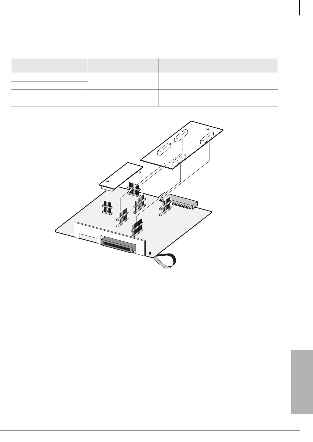
PCB Installation
RDSU – Digital/Standard Telephone Interface Unit
Strata CTX I&M 06/04 6-31
PCB Installation
3. After installing the RDSU gently pull the RDSU outward. If the connectors are properly mated,
a light resistance is felt.
Figure 6-22 RDSU, RSTS PCBs
Table 6-15 RDSU, RSTS Controls, Indicators, and Connectors
Control/Indicator/
Connector Type of Component Description
RSTS connector P2/P3 10-pin connector Connector for RSTS subassembly that provides
two standard telephone circuits.
RSTS connector P4/P5
R48S connector to P6 8-pin connector Interface connector for R48S.
R48S connector to P7 6-pin connector
RSTS
R48S
RDSU1
P3
P4
P2
P5
P6
P7
P6
P3
P4
P2
P5
P7
1377

PCB Installation
RDTU2 – T1 Interface Unit
6-32 Strata CTX I&M 06/04
RDTU2 – T1 Interface Unit
See Chapter 8 – T1 for RDTU PCB installation information.
REMU2A – Tie Line Unit
Circuits per PCB:
four Tie line circuits
Interfaces with:
E&M Tie lines
2- or 4-wire transmission
Type I and II Signaling
Immediate and Wink Start
Older Version(s):
REMU1 (Does not have Mu Law/A Law jumper plug)
PEMU (Type I signaling & immediate start only,
does not provide Pad switches)
The REMU2A has four decibel (dB) Pad switches which can be set to reduce excessive loudness
resulting from close proximity to a central office or PBX by providing a -3 dB signal level drop to
the PBX or central office. (Pad is for Transmit and Receive for 2W operation, and Transmit only is
for 4W operation.)
REMU2A and REMU controls, indicators, and interface connectors are shown in Figures 6-23,
6-24 and described in Table 6-16.
PEMU controls, indicators, and interface connectors are shown in Figure 6-25 and described in
Table 6-17.
REMU2A and REMU Installation
1. Set the 2W/4W jumper plugs SW103~SW403 to the appropriate positions.
2. Set the P102/104, P202/204, P302/304, and P402/404 jumper plugs for Type 1 or Type 2
signaling.
3. If the system is located within one mile of the PBX or central office, set the REMU dB Pad
switches SW101, SW201, SW301, and SW401 to the 3 (-3 dB signal level drop) position.
4. (REMU2A only) Make sure the jumper plugs for P105, P205, P305 and P405 are set to the
TYP1,2 (default), unless the unit is used in the U.K. or Japan, in which case the plug should be
moved to DC5.
5. (REMU2A only) Do not change the position of the jumper plug on P2 selects Mu Law
(default). However, if the unit is used in Mexico, the U.K, or Asia, move the jumper plug to A
Law.
6. Insert the REMU (component side facing right) into the appropriate slot and apply firm, even
pressure to ensure proper mating of connectors.
7. After installing the REMU, gently pull it outward. If the connectors are properly mated, a slight
resistance is felt.
PEMU Installation
1. Determine if the E&M Tie lines will be configured for 2- or 4-wire transmission.
2. Set the 2W/4W jumper plugs P103, P203, P303, and P403 to the appropriate positions.
3. Set the FG jumper plug P3 to the “2-3” position.
4. Set all GND/BAT jumper plugs to the “BAT” position for connection to the telephone network.
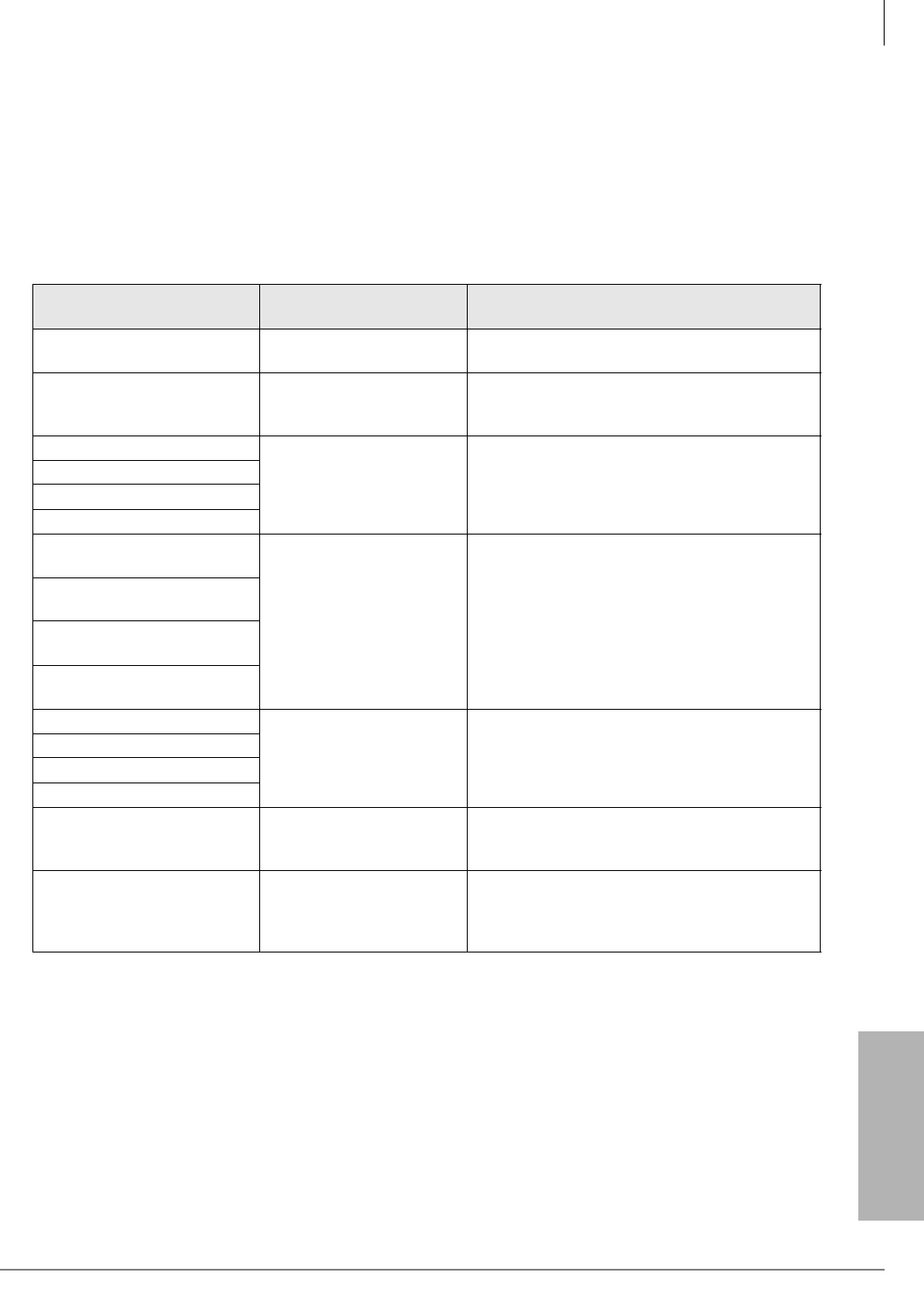
PCB Installation
REMU2A – Tie Line Unit
Strata CTX I&M 06/04 6-33
PCB Installation
Note The “GND” position is used to connect PEMU circuits back-to-back on premises only, 1000
feet maximum (E&M lead wires must be crossed).
5. Insert the PEMU (component side facing right) into the appropriate slot and apply firm, even
pressure to ensure proper mating of connectors.)
6. After installing, gently pull the PEMU outward. If the connectors are properly mated, a slight
resistance is felt.
Table 6-16 REMU2A and REMU1A Controls, Indicators, and Connectors
Control/Indicator/
Connector Type of Component Description
Tie trunk circuits 1~4
(CD102, 202, 302, and 402) Red LED Lights to indicate that Tie line is in operation.
E&M Tie trunk connector
circuits 1~4 (J101, 201, 301,
and 401)
Modular connector Interface connector for E&M Tie line circuit.
Pad switch SW101 (circuit 1)
2-position slide switch Enables -3 dB signal level drop for line circuit.
Pad switch SW201 (circuit 2)
Pad switch SW301 (circuit 3)
Pad switch SW401 (circuit 4)
TYP1/TYP2 jumper plugs
P102/104
3-terminal jumper Enables line circuit to be set for Type 1 or Type
2 signaling.
TYP1/TYP2 jumper plugs
P202/204
TYP1/TYP2 jumper plugs
P302/304
TYP1/TYP2 jumper plugs
P402/404
2W/4W switch 102 (circuit 1)
2-position slide switch Selects 2- or 4-wire configuration for E&M Tie
line circuit.
2W/4W switch 202 (circuit 2)
2W/4W switch 302 (circuit 3)
2W/4W switch 402 (circuit 4)
TYP1,2/DC5 jumper plugs
P105, P205, P305, P405
(REMU2A only)
3-terminal jumper
For most countries, use the default position
(TYP1,2). In the U.K. and Japan, place the
jumper plug on DC5.
Mu Law/A Law jumper plug
P2
(REMU2A only)
3-terminal jumper
Do not move the jumper plug which is in the
default for the U.S. and Canada. For countries
requiring A Law, place the jumper plug
(provided in the PCB box) on the A Law side.
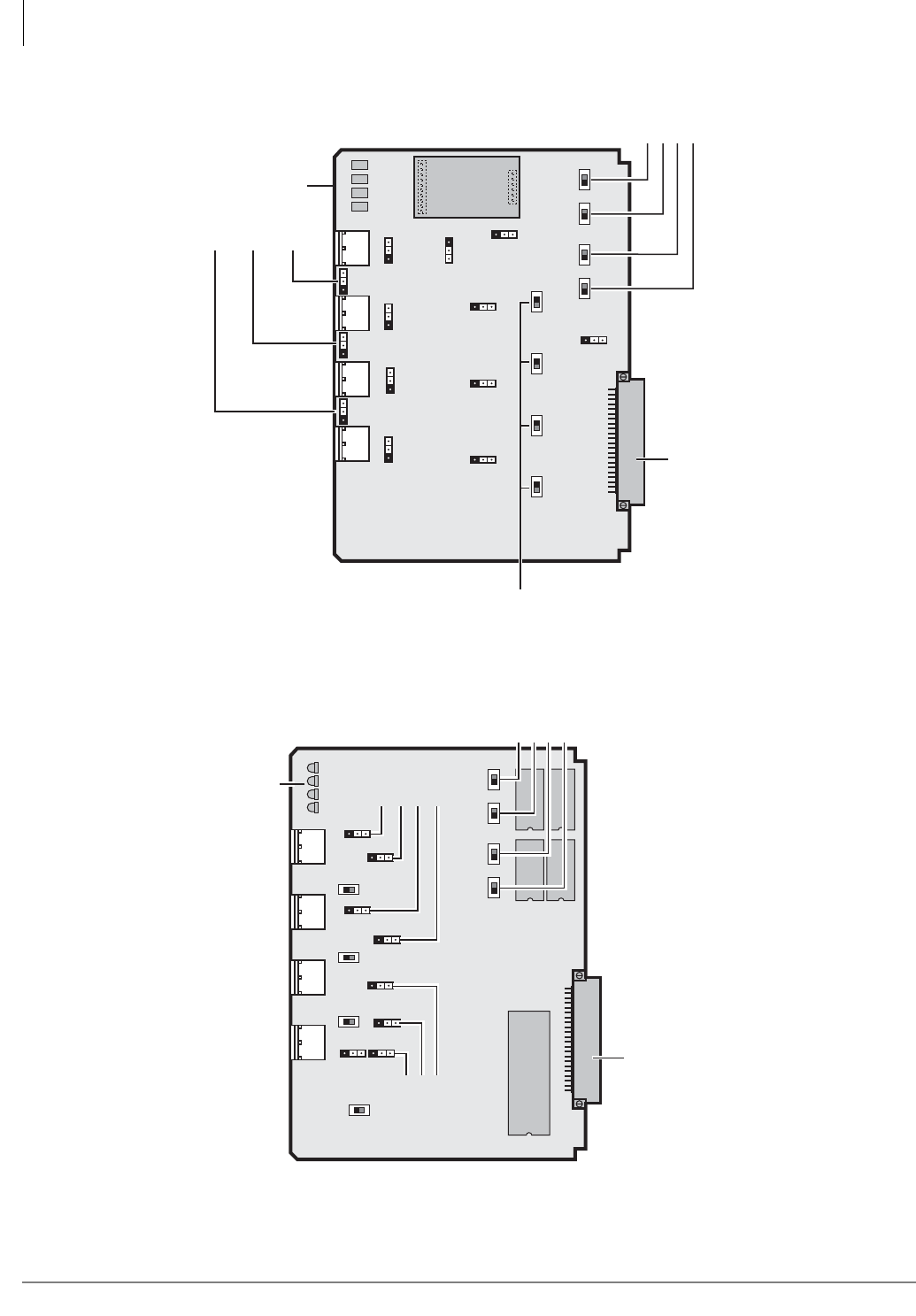
PCB Installation
REMU2A – Tie Line Unit
6-34 Strata CTX I&M 06/04
Figure 6-23 REMU2A PCB
Figure 6-24 REMU PCB
J201 J101J401
P
404
P
402
P
302
P
202
P
102
P
304
P
305
P
205
P
105
P
204
P
104
03030303
P
2
M
u
(
D
e
f
a
ul
t
)
A
R
E
M
U
2
A
SW
102
SW
202
SW
302
SW
402
2
W
4
W
2
W
4
W
2
W
4
W
2
W
4
W
J301
5905
B
ack
pl
a
n
e
C
onn
ec
t
o
r
P
AD
s
wi
t
c
h
C
O L
in
e
LE
D
s
E
48
S
1
A
TYP
1
/
BA
TT
TYP
2
/G
ND
TYP
1
/
BA
TT
TYP
2
/G
ND
P
405
DC5
TYP
1
/
2
TYP
1
/
BA
TT
TYP
2
/G
ND
TYP
1
/
BA
TT
TYP
2
/G
ND
TYP
1
/
BA
TT
TYP
2
/G
ND
TYP
1
/
BA
TT
TYP
2
/G
ND
TYP
1
/
2
DC5
TYP
1
/
2
DC5
TYP
1
/
2
DC5
TYP
1
/
BA
TT
TYP
2
/G
ND
TYP
1
/
BA
TT
TYP
2
/G
ND
SW
401
SW
301
SW
201
SW
101
4321
C
hip
LE
D
s
J201 J101
TYP1
TYP2
TYP1
TYP2
SW401
0
3
4321
J401
SW301
0
3
P102
0
3
SW101
0
3
TYP1
TYP2
TYP1
TYP2
P304
P302
P404
P402 TYP1
TYP2
P202
P204
P104
TYP1
TYP2
TYP1
TYP2
TYP1
TYP2
REMU
SW201
SW102
SW202
SW302
SW402
2W 4W
2W 4W
2W 4W
2W 4W
J301
5814
Backplane Connector
LEDs
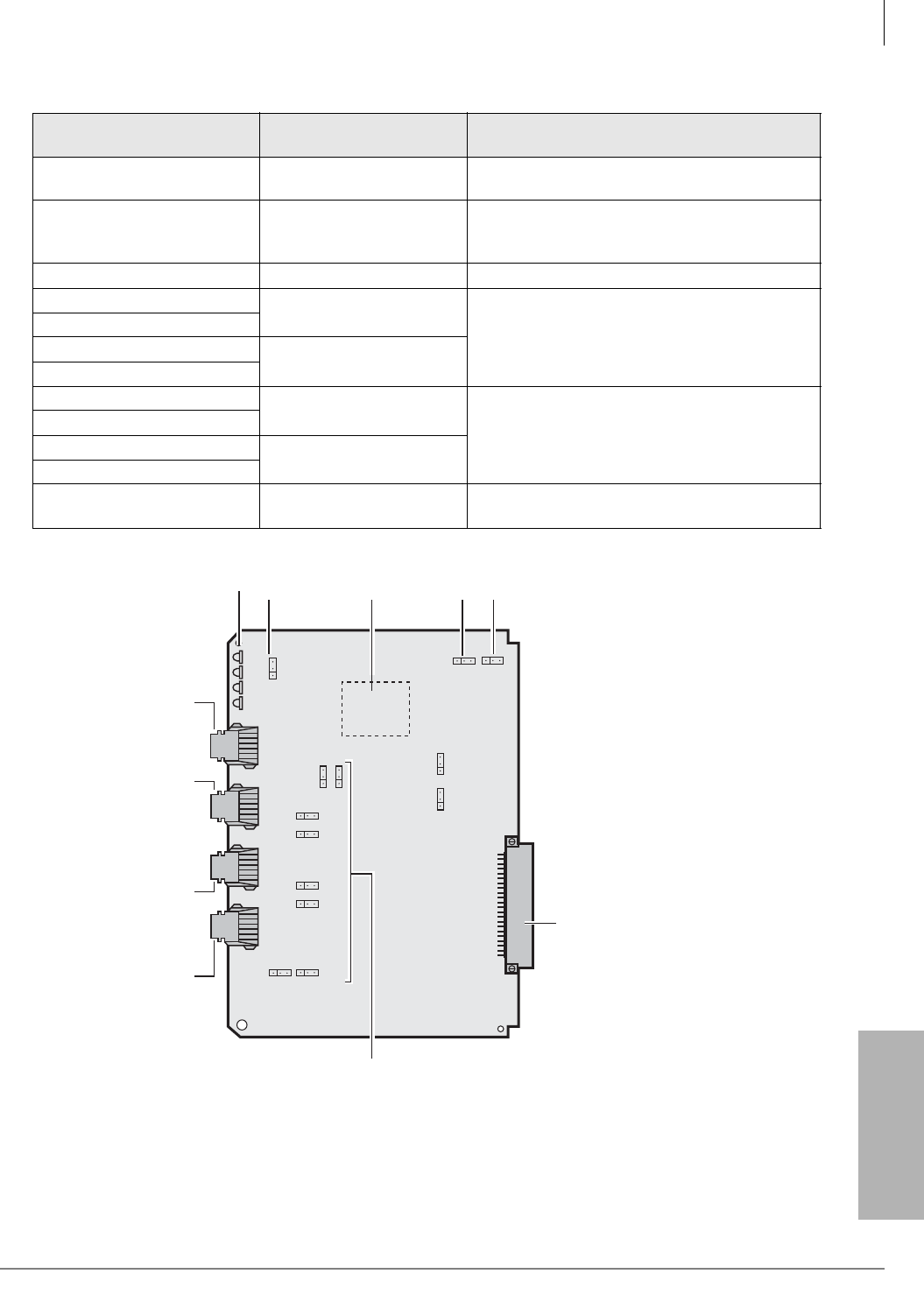
PCB Installation
REMU2A – Tie Line Unit
Strata CTX I&M 06/04 6-35
PCB Installation
Figure 6-25 PEMU PCB
Table 6-17 PEMU Controls, Indicators, and Connectors
Control/Indicator/
Connector Type of Component Description
Tie trunk circuit 1~4 (CD102,
202, 302, and 402) Red LED Lights to indicate that Tie line is in operation.
E&M Tie line connector J101,
201, 301,and 401 (circuit
1~4)
Modular connector Interface connector for E&M Tie line circuit.
FG jumper P3 3-terminal jumper Enables or disables -48VDC ground to FG.
GND/BAT jumper P101 3-terminal jumper
(Tie line 1) Enables -3 dB signal level drop for line circuit.
GND/BAT jumper P102
GND/BAT jumper P201 3-terminal jumper
(Tie line 2)
GND/BAT jumper P202
GND/BAT jumper P301 3-terminal jumper
(Tie line 3) M-lead origination for Tie line (must be in BAT
position per FCC requirements.
GND/BAT jumper P302
GND/BAT jumper P401 3-terminal jumper
(Tie line 4)
GND/BAT jumper P402
2W/4W switch P103, 203,
303, and 402 (circuit 1~4) 3-terminal jumper Selects 2- or 4-wire configuration for E&M Tie
line circuit.
Ground/Battery
Jumpers
(Leave In
Factory Positions)
Tie Line 1
Tie Line 4
2W
4W
2W
4W
2W
4W
4 3 2 1
1 2 3
2W
4W
J101J201J301J401
FG
P103P203
P303 P403
Tie Line 3
Tie Line 2
P3
P401
P402
P301P302
P201P202
P102
P101
SP1020
-48 Volt
Supply
LEDs
5815
Backplane Connector
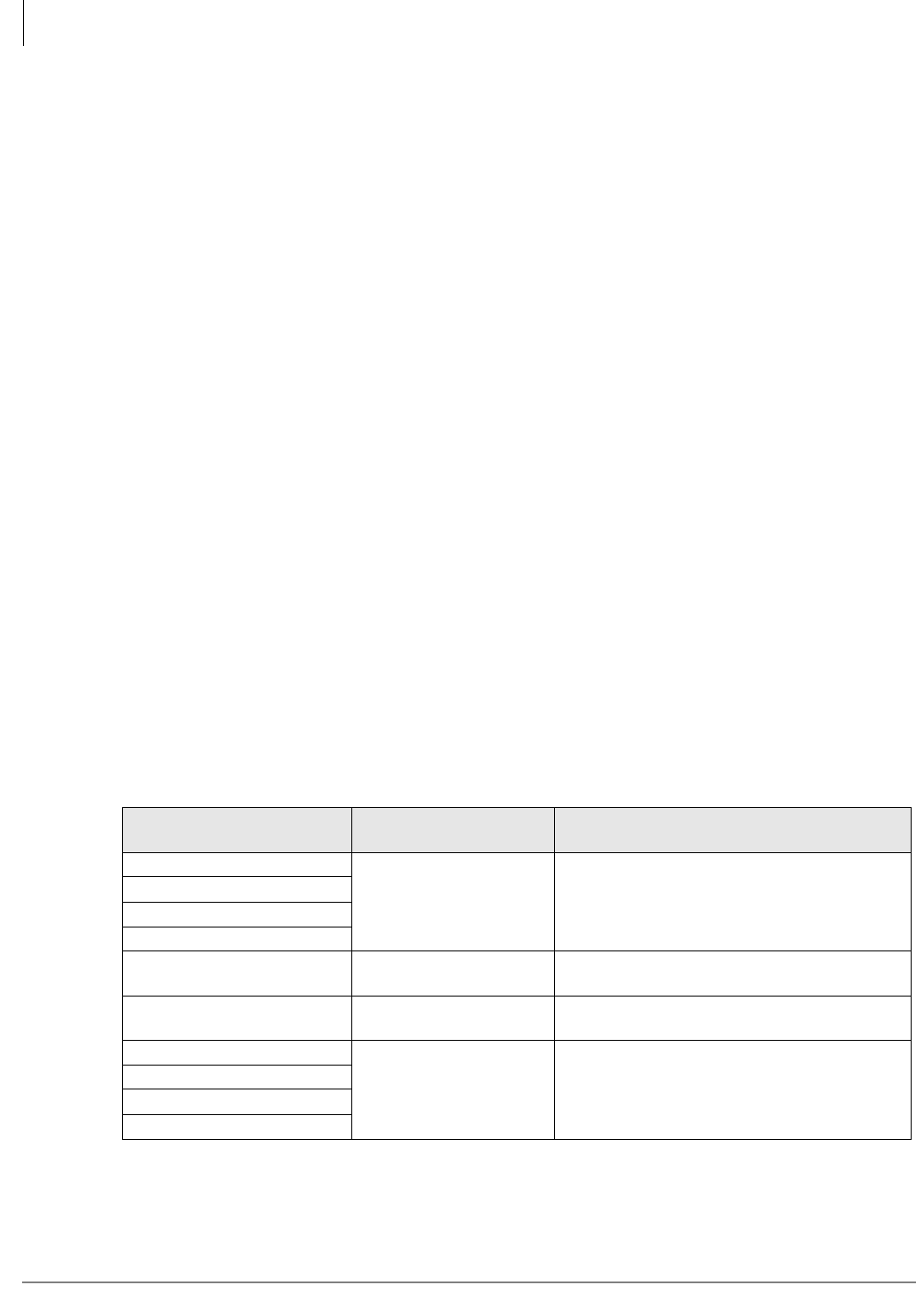
PCB Installation
RGLU2 – Loop/Ground Start CO Line Interface Unit
6-36 Strata CTX I&M 06/04
RGLU2 – Loop/Ground Start CO Line Interface
Unit
Circuits per PCB:
four line circuits
Interfaces with:
loop or ground start lines
Older Version(s):
RGLU1 (does not have hookflash to CO)
The RGLU2 also provides ring detection, dial outpulsing, and hold. Each RGLU2 line can be
programmed for DTMF or dial pulse signaling and gas tube secondary protection.
RGLU2 controls, indicators, and interface connectors are shown in Figure 6-26 and described in
Table 6-18.
RGLU2 Installation
Note The decibel (dB) Pad switches SW101, SW201, SW301, and SW401 control excessive
loudness resulting from close proximity to a central office or PBX telephone office by
providing a -3 dB signal level drop to, or from, the PBX or central office when set to the 3
position. Switches are factory set to the 0 (0 dB signal level drop) position.
³To install an RGLU2 PCB
1. If the Strata CTX670 is within one mile of the PBX or central office, set the dB Pad switches
SW101, SW201, SW301, and SW401 to the 3 (-3 dB signal level drop) position.
2. Set each line for ground start (GND) or loop start (LOOP) by setting the following jumper
plugs: SW103 for line 1, SW203 for line 2, SW303 for line 3, and SW403 for line 4.
3. Insert the RGLU2 (component side facing right) into the appropriate slot and apply firm, even
pressure to ensure proper mating of connectors.
4. After installing the RGLU2, gently pull the PCB outward. If the connectors are properly mated,
a slight resistance is felt.
Table 6-18 RGLU2 Controls, Indicators, and Connectors
Control/Indicator/
Connector Type of Component Description
Line circuit 1
Red LED
Lights to indicate that line circuit is in operation.
CO line indicator will not light unless RGLU2 is
connected to a line.
Line circuit 2
Line circuit 3
Line circuit 4
J1 connector Modular connector RJ14 modular Interface connector for trunk
circuits 1 and 2.
J2 connector Modular connector RJ14 modular Interface connector for trunk
circuits 3 and 4.
Pad switch SW101 (circuit 1)
2-position slice switch Enables -3dB signal level drop for trunk circuits.
Pad switch SW201 (circuit 2)
Pad switch SW301 (circuit 3)
Pad switch SW401 (circuit 4)
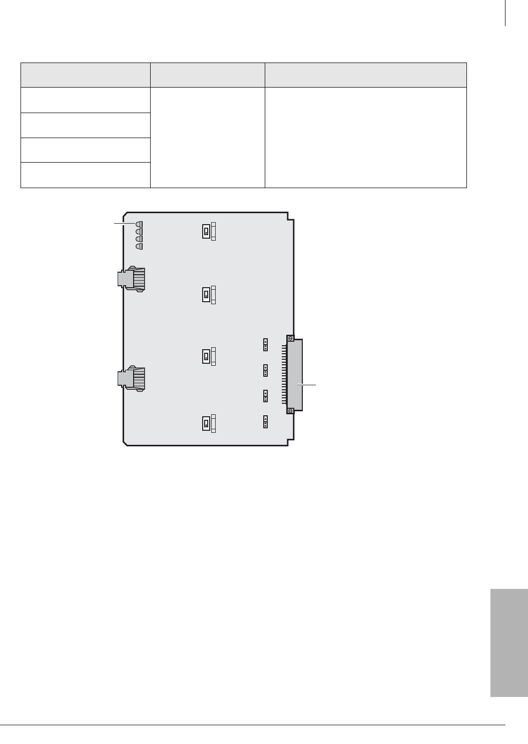
PCB Installation
RGLU2 – Loop/Ground Start CO Line Interface Unit
Strata CTX I&M 06/04 6-37
PCB Installation
Figure 6-26 RGLU2 PCB
LOOP/GND jumper SW103
(configures line 1)
3-terminal jumper Used to configure line for loop or ground start.
LOOP/GND jumper SW203
(configures line 2)
LOOP/GND jumper SW303
(configures line 3)
LOOP/GND jumper SW403
(configures line 4)
Table 6-18 RGLU2 Controls, Indicators, and Connectors
(continued)
Control/Indicator/
Connector Type of Component Description
4 3 2 1
J1J2
SW401
3 0PAD
SW301 SW201 SW101
RGLU
3 0PAD 3 0PAD 3 0PAD
SW403
LOOP GND
SW303
LOOP GND
SW203
LOOP GND
SW103
LOOP GND
5816
Backplane Connector
Red LEDs
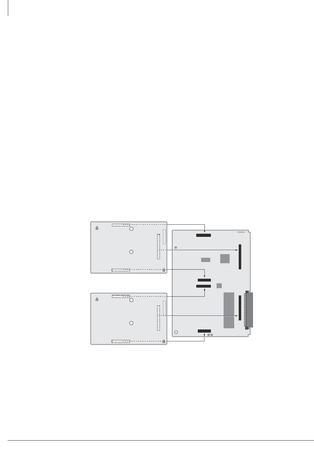
PCB Installation
RMCU/RCMS – E911 CAMA Trunk Direct Interface
6-38 Strata CTX I&M 06/04
RMCU/RCMS – E911 CAMA Trunk Direct Interface
Circuits per PCB:
four circuits
Interfaces with:
enhanced 911 locator services
Older Version(s):
none
The E911 CAMA Trunk Direct Interface card (RMCU) enables cost-effective connection to the
Enhanced 911 locator services without third-party equipment. Figure 6-29 shows the RMCU. The
RMCU supports two subassemblies (RCMS) that provide a total of up to four ports as shown in
Figure 6-27. Only one RMCU PCB can be installed in a Strata CTX670 system.
The RMCU has no CAMA circuits. It requires one RCMS subassembly to provide one or two
CAMA trunks and two RCMS PCBs to provide up to four CAMA trunks.
Location of the RCMS LEDs are shown in Figure 6-30 and the functions of the RCMS LEDs are
given in Table 6-19.
RCMS Subassemblies Installation
1. Attach one or two subassemblies (RCMS) to the connectors on the RMCU as shown in Figure
6-27. If only one RCMS is to be installed, install it in the bottom position.
2. Apply firm even pressure to ensure that the connectors are properly seated in the RMCU
connector blocks. If they are seated properly, a light resistance is felt when you pull the units
away from the RMCU.
Figure 6-27 Placement of RCMS Subassemblies on the RMCU Interface Card
RMCU1A -CM V.1
RMCU1A
2758
UP
®UP
ABCDEFGHK
RCMS1A
RMCU1A
UP
®UP
ABCDEFGHK
RCMS1A
P6
P5
P7
P3
P2
P4
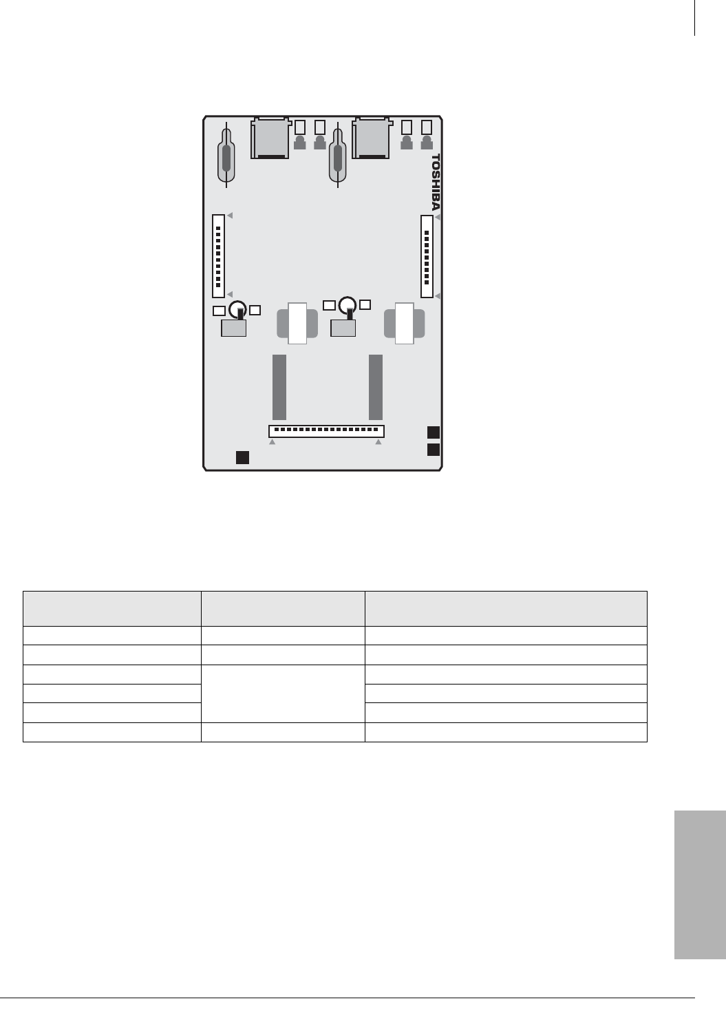
PCB Installation
RMCU/RCMS – E911 CAMA Trunk Direct Interface
Strata CTX I&M 06/04 6-39
PCB Installation
Figure 6-28 RCMS Subassembly (stand-alone)
RMCU Installation
1. Insert the RMCU (component side facing right) into the appropriate slot, and apply firm, even
pressure to ensure proper seating of the connectors.
2. Gently pull the unit outward. If the connectors are properly seated, a light resistance is felt.
3. Wire the RCMS jacks, J4 and J5, to the network CAMA trunks per Figure 10-9 on page 10-17.
4. Test the CAMA trunk and set the 3-dB Pad switches, SW101 and SW 201, for the appropriate
volume level.
Table 6-19 RCMS Subassembly Controls, Indicators, and Connectors
Controls, Indicators, &
Connectors
Type of
Component Description
SW101 Switch 3-dB Pad switch for circuit 1 or 3.
SW201 Switch 3-dB Pad switch for circuit 2 or 4.
J1
Connector Blocks
Jacks to connect to RMCU.
J2 Jacks to connect to RMCU.
J3 Jacks to connect to RMCU.
RJ11 6-pin modular connector Network interface jack to CAMA trunk.
RCMS1A
600 / 600
600 / 600
RCMS1A -CM V.1
RCMS1
CB
NB
CB
NB
5817
J2
J3
SW101 SW201
J1
J4
J5 PAD
3
0
PAD
3
0
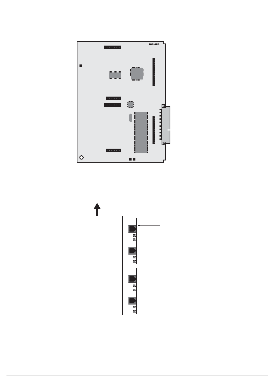
PCB Installation
RMCU/RCMS – E911 CAMA Trunk Direct Interface
6-40 Strata CTX I&M 06/04
Figure 6-29 RMCU Interface Card
Figure 6-30 Location of the RCMS LEDs
RMCU1A -CM V.1
RMCU1A
5818
RMCU1A
P6
P5
P7
P3
P2
P4
RMCUV.1
RMC21B
TC35354F
Backplane Connector
RMCU1A
2796
RCMS1A (2/2)
LEDs (indicate Trunk Condition)
Network Busy (NB) LED
Customer Busy (CB) LED
RCMS1A (1/2)
RJ11 2-Pin Modular Connector
CAMA #4
CAMA #3
CAMA #2
CAMA #1
TOP
NB LED
CB LED
NB LED
CB LED
NB LED
CB LED
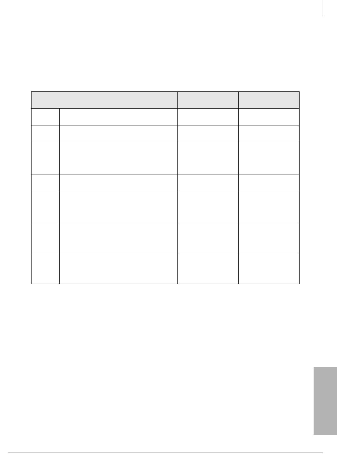
PCB Installation
RMCU/RCMS – E911 CAMA Trunk Direct Interface
Strata CTX I&M 06/04 6-41
PCB Installation
RCMS LEDs
Customer Busy (CB) LEDs – The RMCU firmware controls this LED synchronizing with
off-hook status inside switch.
Network Busy (NB) LEDs – RMCU hardware controls this LED synchronizing with the supply
of voltage from the carrier.
Table 6-20 LED Indications (Normal Operation)
Status NB LED
(Network Busy)
CB LED
(Customer Busy)
1No network connection.
RMCU is in stand-by mode. On Off
2Network connected.
RMCU is in stand-by mode. Off1
1. If the NB LED stays On, even if the modular connector of the network is connected, check the following:
●Tip and Ring could be reversed.
●Network could be busy.
Off
3
Network is in stand-by mode and the RMCU
is off hook.
Network is connected and the RMCU MF
sending dial tone.
Off On
4Network is seizing and the RMCU is off-
hook. Flashing On
5
Network is connecting, before ANI is sent,
and the RMCU is sending.
Network is connecting and the RMCU is
communicating.
On On
6Network is disconnecting first and then the
RMCU disconnects.
On then Off
NB is turned off, then
approx. 400 msec
after CB is turned off.
On then Off
7RMCU is disconnecting first and then the
network disconnects.
On then Off
NB is turned off
within 700 msec after
CB is turned off.
On then Off
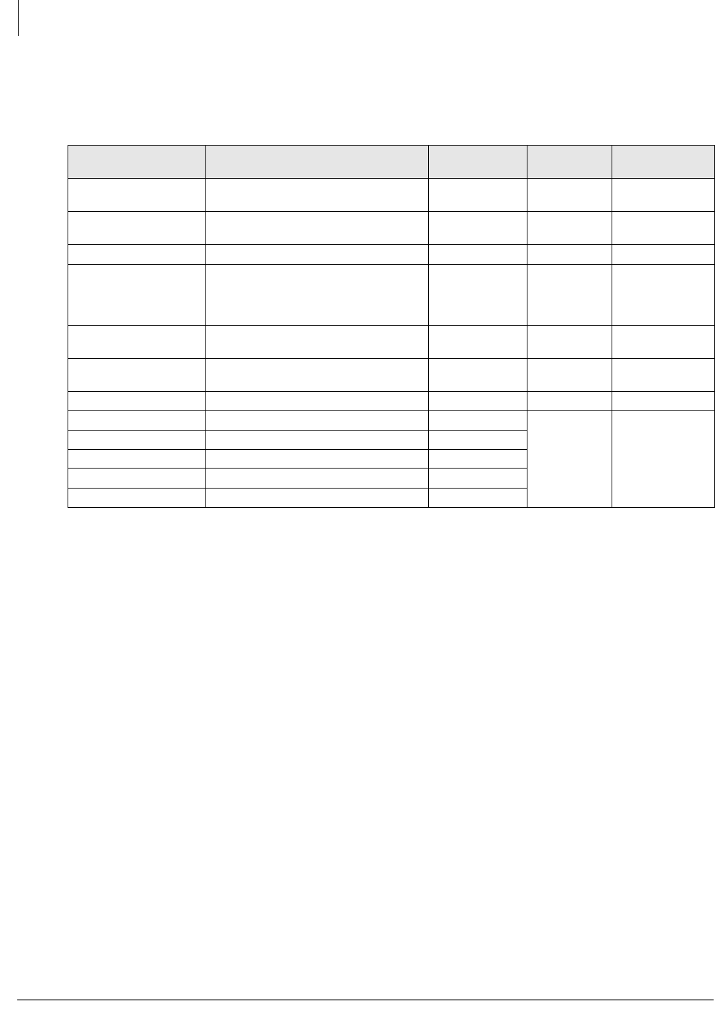
PCB Installation
Network Requirements
6-42 Strata CTX I&M 06/04
Network Requirements
The system network requirements are provided in Table 6-21.
Table 6-21 PCB Network Requirements
PCB/Interface Facility Interface Code Network Jack Ringer
Equivalence
Universal Service
Order Code
RSTU2/RDSU1
(Off-premises Station)
1. Only RDSU ckts. 1~4 provide Off-premises Station (OPS) ability. RDSU must use OL13A or OL13B if providing –24 volt loop
voltage. If equipped with the –48 volt loop option PCB (R48S), OL13A, OL13B, or OL13C may be used for OPS connection.
OL13B (RSTU2, –24V)
OL13C (RSTU2, RDSU with R48S-48V) RJ21X N/A 9.0F
RCOU/RCOS2
(loop start line)
2. Loop current requirements for Strata loop and ground start lines: 20 milliamperes (mA) min./120 mA max.
02LS2 RJ14C/RJ21X
(all others) 0.3B N/A
RDDU 02RV2-T (Dealer-supplied CSU) RJ14C/RJ21X 0.0B AS.2
REMU type 1 or type 2
TL11M, 2-wire
TL31M, 4-wire
TL12M, type 2, 2-wire
TL32M, type 2, 4-wire
RJ2EX
RJ2GX
RJ2FX
RJ2HX
Not Available
(N/A) 9.0F
RGLU22 (ground or loop
start line)
02GS2 (ground)
02LS2 (loop) RJ14C/RJ11CX 0.3B N/A
RDTU (DS-1/T1)3
3. When ordering DS-1/T1 circuits, six items must be specified:
• The number of channels per T1 circuit, fractional increments are normally 8, 12, or 16 channels, full service is 24 channels.
Unused channels must be bit-stuffed.
• CO line types assigned to each channel: Loop Start, Ground Start, Tie (Wink or Immediate Start), DID (Wink or Immediate).
• Frame Format Type: Super Frame (SF) or Extended Super Frame (ESF). The T1 provider normally specifies the Frame Format
to be used, either is adequate for CO digital voice lines. ESF provides a higher level of performance monitoring, but requires
trained personnel and the ESF CSU normally costs more than an SF only CSU.
• Line Code Type: Alternate Mark Inversion (AMI) or Bipolar 8 Zero Substitution (B8ZS). The T1 provider normally specified the
Line Code to be used, either is adequate for T1 CO digital voice lines.
• The customer may have to provide the Channel Service Unit (CSU) to interface the CTX T1 circuit to the Telco T1 circuit. (CSUs
are a Telco requirement.)
• RDTU Network Channel Interface Codes: 04DU9-BN, 04DU9-DNZZ, 04DU9-1SN, 04DU9-1KN, 04DU9-1ZN.
(See last bullet note on Note 2 below.) RJ48C/RJ48X/
RJ48M N/A 6.0P
RCIU2/RCIS (Caller ID) N/A RJ21X/RJ14C 0.3B N/A
RPTU (PRI)4, 5
4. For information on how to order ISDN PRI/BRI circuits, you should refer to the Toshiba ISDN Training CBT. ISDN circuits may
require a customer-provided CSU for PRI and/or Terminal Adapter or Network Terminal units for BRI. In U.S. CSU/TAs must be
UL-listed in the U.S. In Canada, they must be CSA certified.
5. RPTU2 is required for QSIG private networking.
04DU9-1SN (Dealer-supplied CSU) RJ48C/RJ48M
N/A 6.0P
RPTU (QSIGI) 04DU9-1SN (Dealer-supplied CSU) RJ48C/RJ48M
RBSU/RBSS (S/T, BRI)302IS5 (Dealer-supplied NT-1) RJ48C/RJ48X
RBUU/RBUS (U, BRI)302IS5 RJ48C/RJ48X
RMCU/RCMS (CAMA) 02RV2-O RJ11C/RJ21-X

Strata CTX I&M 06/04 7-1
ISDN Interfaces
ISDN Interfaces 7
This chapter covers information on the ISDN Primary Rate Interface (PRI) and Basic Rate
Interfaces (BRI).
PRI Overview
For PRI services, the Strata CTX uses a BPTU or RPTU PCB to connect to a Public Switched
Telephone Network (PSTN) PRI line using a UL listed (or CSA certified in Canada) Channel
Service Unit (CSU) in most locations in the U.S. Each BPTU or RPTU provides 23B + D channels.
The B-channels support CO speech and data connections on the PSTN side only.
The Strata CTX also uses a BPTU or RPTU2 PCB to connect Strata Net QSIG network nodes
using DS-1. A DS-1 may be obtained in several ways, most commonly, leasing it from a carrier.
BRI S/T Overview
BRI S/T is available with the RBSU PCB. The RBSU provides two BRI S/T circuits to connect to
the PSTN BRI line using an external UL listed NT1; or, on the station-side, connect to:
• S-type ISDN telephones and Terminal Equipment (TE-1-S)
• S-type Terminal Adapters (TA-S) with non-ISDN devices
Each TE-1-S and TA1-S device can support voice and/or RS-232 switched-circuit data as shown in
Figure 7-1. The station-side BRI S/T circuits are point-to-multipoint.
A subassembly (RBSS) can be attached to the RBSU for two additional BRIs for S-type station-
side connections only. The RBSU PCB and the RBSS subassembly are shown in Figures 7-11 and
Figure 7-12 on page 7-17. The combination of RBSU and RBSS uses only one slot to provide up
to four BRI S/T circuits.
Note Each installed RBSU or RBSS circuit provides a 2B + D connection and uses a system
capacity of two station ports and two CO lines regardless of the circuit application, even if
the circuit is not actually connected.
BRI U Overview
For BRI U services, the RBUU provides two BRI U circuits that connect directly to PSTN BRI
lines; or, on the station side, connect to:
• U-type ISDN telephones and Terminal Equipment (TE-1-U)
• U-type Terminal Adapters (TA-U) with non-ISDN devices
Each TE-1-U and TA-U device can support voice and/or RS-232 switched-circuit data
depending on the device (see Figure 7-1). The station-side BRI U circuits are point-to-point.
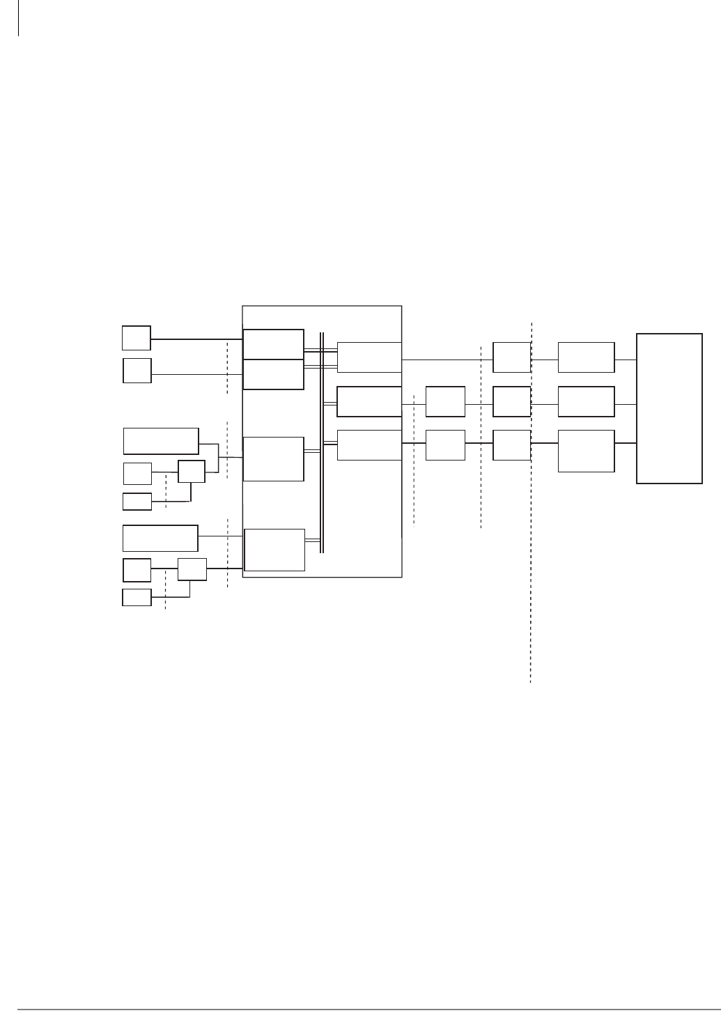
ISDN Interfaces
BRI U Overview
7-2 Strata CTX I&M 06/04
A subassembly (RBUS) can be attached to the RBUU for two additional BRIs for PSTN and/or
U-type station connections. The RBUU PCB and the RBUS subassemblies are shown in
Figures 7-23 and Figure 7-24 on page 7-28. The combination of RBUU and RBUS uses only
one slot to provide up to four U-type BRI circuits.
Notes
●Each installed RBUU or RBUS circuit provides a 2B + D connection and uses a system
capacity of two station ports and two CO lines regardless of the circuit application, even if the
circuit is not actually connected.
Strata CTX ISDN Reference Model
A block diagram of the Strata CTX ISDN PCBs and reference points is provided in Figure 7-1.
Figure 7-1 ISDN Reference Model
CTX (NT2)
R
S
U
T
U
ISDN
SWITCH
Demarcation Point
R
SLT
DKT
TE-1-S
(Voice or Data)
SLT TA-S
TE-1-U
(Voice or Data)
RSTU
PDKU
RBSU/RBSS
(NTs
(P-MP)
RBUU/RBUS
RBSU
BPTU or
RPTU (TE)
RBUU/RBUS
(LT)
(P-P)
NT1
CSU
(NT1)
RJ48C
8-wire
RJ48C
8-wire
RJ48C
8-wire
Loop
Termination
Loop
Termination
Office
Channel
Unit
BRI
BRI
PRI
Office Channel Unit, or OCR, is
the CO Channel Service Unit
Dealer-
supplied
CSU and NT1
Telco-
supplied
Jacks
R, T, S, and U are ISDN standard reference points
Customer Premises Equipment
Public Switched
Telephone Network
(PSTN)
6643
PC
R
SLT TA-U
PC
P-P = Point-to-Point
P-MP = Point-to Multipoint
(passive bus)
TE-1 = Terminal Equipment, Type 1
TA = Terminal Adapter

ISDN Interfaces
BPTU/RPTU Overview
Strata CTX I&M 06/04 7-3
ISDN Interfaces
BPTU/RPTU Overview
Both the BPTU and RPTU provides 24 channels for ISDN PRI service. The BPTU is fully
compatible with RDTU2 and will replace the RPTU. Network connection using BPTU or RPTU
PRI interface requires installation of a customer-provided CSU in most locations of the U.S. Refer
to “CSU Requirements” on page 7-3 for CSU installation.
The BPTU or RPTU is a DS-1 divided into 24 TDM channels using standard T1 electrical signal
format. The BPTU or RPTU’s D-channel is typically the 24th channel and can control the
signaling of 23 of its own B-channels and 24 B-channels of another designated BPTU or RPTU.
Each BPTU or RPTU can also use its own D-channel for control.
The BPTU or RPTU’s in-service bit rate is 1.544 mbps (± 4.6 ppm), but during a maintenance
session, the rate may vary ± 32 ppm. The BPTU or RPTU provides Binary 8-Zero Substitution
(B8ZS) and ESF with Framing Pattern Sequence (FPS) and Cyclical Redundancy Check (CRC)
error checking in the framing bits.
Extracting the Stratum-1 clock from the ISDN PRI, BRI, or T1 provider is the most common
method used to synchronize the BPTU or RPTU PCB and the Strata CTX time switch to the public
telephone network. One BPTU, RPTU, RBSU, RBUU, or RDTU T1 must extract the clock from
the ISDN or T1 provider. The selected unit is designated as the “Primary” timing source in
Program 105. In remote cabinet applications, the Primary clock source PCB must be installed in
the Base Cabinet (main location). For more information, refer to “Timing and Synchronization” on
page 7-35.
A dealer-supplied CSU must be installed between the ISDN PRI network line and the BPTU or
RPTU PCB as shown in Figure 7-1. Some telephone companies supply the CSU and call it the
Network Interface Unit (NIU).
CSU Requirements
In the U.S., the CSU must be UL listed and comply with Part 68 of the FCC rules. It must also
comply with the limits for a Class A digital device, pursuant to Part 15 of FCC Rules. In Canada,
the CSU must be CSA certified.
The CSU is transparent to data, clock, and framing. It acts as a repeater, not a controller, for
timing. The CSU also acts as a signal regenerator and must be able to perform loop-back tests and
maintenance to both the network and Strata CTX BPTU or RPTU. The CSU is the same type as
used for T1 circuits although it performs the function as NT1 for PRI ISDN in the ISDN reference
model as shown in Figure 7-1.
Slot Assignments
Up to eleven BPTU or RPTU PCBs can be installed in a Strata CTX system providing up to 264
PRI lines (B-channels). If BPTU or RPTU (PRI) and RDTU (T1) PCBs are installed, the maximum
combined PCBs cannot exceed eleven. The PCBs must be placed in designated slots in each of the
cabinets. Refer to Chapter 2 – Strata CTX Configuration, “ISDN PRI Digital Line PCBs” on page
2-40, for the guidelines regarding BPTU or RPTU PCB slot assignments.

ISDN Interfaces
BPTU Interface Unit
7-4 Strata CTX I&M 06/04
BPTU Interface Unit
System:
DK424, DK40i, CTX100 & 670
Circuits per PCB:
24 channels per PCB
Interfaces with:
ISDN PRI
Older Version(s):
none
The BPTU has an RS-232C port to trace data that is transmitted between the CTX system CPU and
the BPTU.
T1 Framing: ESF
Line cording: B8ZS
Digital PAD: Transmit side +6dB to -15dB. Receive side +6dB to -15dB (software controlled)
BPTU Installation
Power Factor
BPTUA uses 5V only. 5V power factor = 2.30
³To install an BPTU PCB
1. Look for IC19 on the BPTU PCB. If it is on the PCB, move the SW10 jumper to “ROM.” If
IC19 is not on this PCB, leave the jumper on the “CPU” setting (see Table 7-1).
2. If you want to run the PCB Self Test, refer to BPTU Self Test.
3. Turn the Strata CTX system power Off.
4. Insert the BPTU (component side facing right) into the appropriate slot and apply firm, even
pressure to ensure proper seating of connectors.
Refer to Chapter 2 – Strata CTX Configuration:
•“Worksheet 5: Strata CTX100 Cabinet Slots” on page 2-26
...or “Worksheet 6: Strata CTX670 Cabinet Slots” on page 2-37
•“ISDN PRI Digital Line PCBs” on page 2-40 (mentioned above in slot assignments)
5. After installing the BPTU, gently pull the PCB outward. If the connectors are properly seated, a
slight resistance is felt.
6. For cabling information and requirements, refer to “BPTU and RPTU Cabling” on page 7-11.
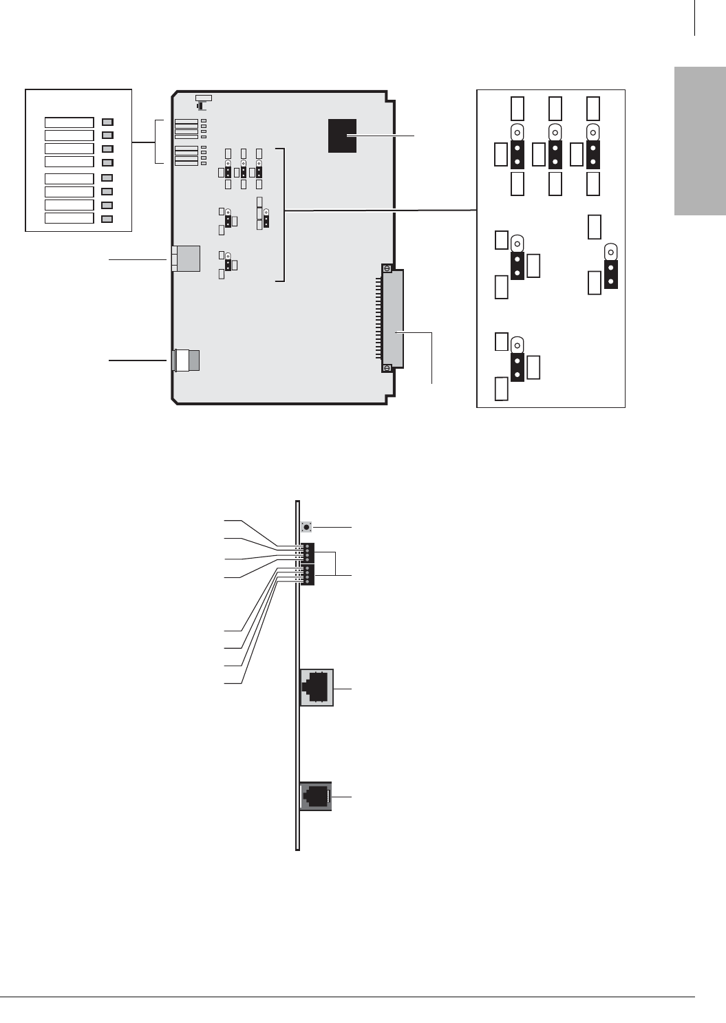
ISDN Interfaces
BPTU Installation
Strata CTX I&M 06/04 7-5
ISDN Interfaces
Figure 7-2 BPTU PCB
Figure 7-3 BPTU LEDs and Connectors
RS-232C
Connector for
Call Data
Monitor (RJ-12)
J1
J2
SW1
6640
Backplane
Connector
OFF
EQ
ON
SW4
R28
OFF
EQ
ON
SW5
R28
OFF
EQ
ON
SW6
R28
OFF
LB
ON SW8
CPU
ROM SW10
OFF
LB
ON SW9
BPTU1A
FSYNC
MFSYNC
BALM/AIS
YALM/RAI
LOS
BSY
PSYNC
SSYNC
MONITOR
Status/Alarm LEDs
FSYNC
MFSYNC
BALM/AIS
YALM/RAI
LOS
BSY
PSYNC
SSYNC
OFF
EQ
ON
SW4
OFF
EQ
ON
SW5
OFF
EQ
ON
SW6
OFF
LB
ON SW8
CPU
ROM SW10
OFF
LB
ON SW9
RJ-45
8-pin Modular
Network/CSU
Interface Jack
RESET
IC19
Reset Switch
(resets the software)
RS-232C Connector
for Call-Data Monitor (RJ-12)
RJ-45 8-pin
(shielded)
Modular Connector (to CSU)
6642
LEDs
FSYNC - Not Used
MFSYNC
BALM/AIS
YALM/RAI
LOS
BSY
PSYNC
SSYNC - Not Used
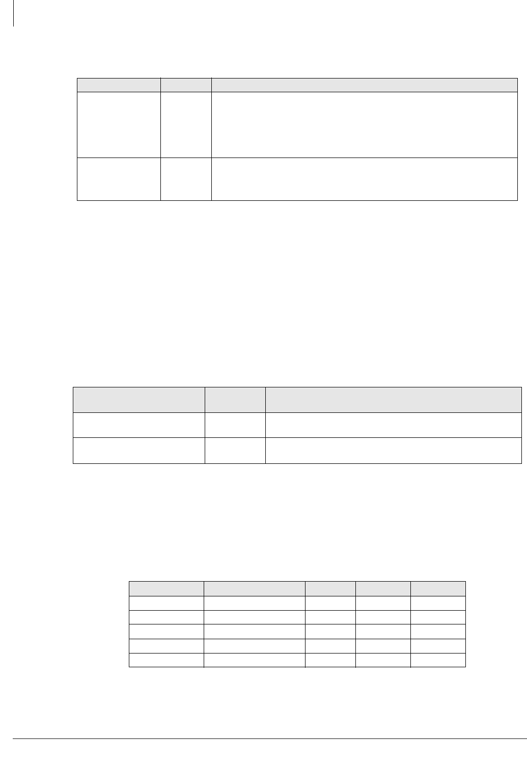
ISDN Interfaces
BPTU Installation
7-6 Strata CTX I&M 06/04
BPTU Self Test
1. Remove the RJ45 network cable to perform the Self Test.
2. Remove the BPTU and set the SW8 and SW9 switches to On (see Table 7-2).
3. Insert BPTU back into the same slot that it was in. If all LEDS turn Off except PSYNCH or
SSYNCH, the PCB has passed the self test.
4. After self check passes, put the switches back into position for normal operation (both Off) and
insert the BPTU PCB back into the appropriate slot.
5. Plug the RJ45 network cable back in.
Note Do not use the BPTU as a clock extraction unit while in Self Test mode.
BPTU Cable Length Equalizer Switches
The distance between the Strata CTX, BPTU and CSU or BPTU to other Customer Premise
Equipment (CPE) T1 may vary (0~655 ft.) as shown. (See “BPTU Cabling” on page 7-7.) The
BPTU interface transmitter must be equalized and its impedance must be matched to the cable
length connecting the BPTU to the CSU or other CPE, T1 (see Table 7-3).
Table 7-1 SW10 Internal or External ROM Setting
Mode SW10 Note
Internal ROM
(Default mode) CPU
When there is an internal ROM on the CPU (TMP93PW46), BPTUA
operates with the SW10.
Use this mode when IC19 is not on PCB.
If the SW10 is in CPU position, BPTUA is operating with the internal
ROM regardless of IC19 existence.
External ROM
(Upgrade) ROM
BPTUA is operating with the external ROM (IC19).
Use this mode only when IC19 is on PCB.
If the SW10 is in ROM position without IC19, the BPTUA will not work.
Table 7-2 SW8, SW9 BPTUA Self and CSU Test
Mode SW8 and
SW9 Notes
BPTUA self test Both On With both SW8 and SW9 On, all LEDS turn Off. If there is
more than one BPTU, these LEDs will not flash.
Normal operation (non-loop
back) Both Off
Table 7-3 BPTU Equalizer Setting Switch
Mode Feet from CTX SW4 SW5 SW6
Short 0 to 133 feet Off Off Off
Semi-short 133 to 266 feet On Off Off
Medium 266 to 399 feet Off On Off
Semi-long 399 to 533 feet On On Off
Long 533 to 655 feet X X On
X = Doesn’t matter.
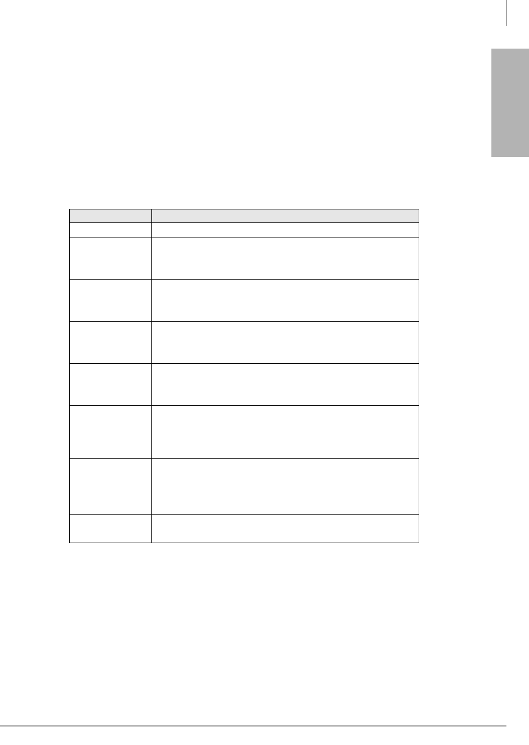
ISDN Interfaces
BPTU Installation
Strata CTX I&M 06/04 7-7
ISDN Interfaces
BPTU Loop Back Jumper Plugs
The BPTU PCB provides jumper plugs for loop back testing. Loop back tests are described in
“Loop-back Test” on page 7-34. See Table 7-2 for switch settings for Loop Back tests.
BPTU Front Panel Indicators
The BPTU PCB provides seven LED indicators to show the status of BPTU: Busy or Idle
condition, Alarm status, and Synchronization status.
See Table 7-4 for the function of each status LED. Figure 7-3 on page 7-5 shows the LED
locations.
Ferrite Core
Install the Ferrite core provided with the BPTU PCB, as shown in Figure 7-7 on page 7-13. This
core is needed to comply with FCC requirements.
BPTU Cabling
The BPTU and RPTU PCBs use the same cabling methods. Refer to “BPTU and RPTU Cabling”
on page 7-11.
Table 7-4 BPTU LED Functions
BPTU LEDs Indication
FSYNC Frame Sync error indication. This LED is not mounted.
MFSYNC
Multi-frame Sync error indication (same with FSYNC)
On = No frame synchronization status
Off = Frame synchronization status
BALM/AIS
AIS indication
On = BPTU is receiving AIS
Off = BPTU is not receiving AIS
YAL M/ RAI
RAI indication
On = BPTU is receiving RAI
Off = BPTU is not receiving RAI
LOS
Signaling Loss indication
On = BPTU is not receiving T1 signals
Off = BPTU is receiving T1 signals
BSY
Busy state indication
On = One or more B-channels are in use. Also when BPTU does
not receive far end 1.544 mbs carrier signal, BSY is on steady.
Off = All B-channels are idle
PSYNC
Primary synchronization indication
On = BPTU is assigned as the secondary timing PCB.
Off = BPTU is not assigned as the CLK timing PCB
Flashing = BPTU is extracting T1 CLK
SSYNC Secondary synchronization indication
Not mounted

ISDN Interfaces
RPTU Interface Unit
7-8 Strata CTX I&M 06/04
RPTU Interface Unit
Circuits per PCB:
24 channels
Interfaces with:
ISDN PRI
Older Version(s):
none
The RPTU provides 24 channels for ISDN PRI service. Network connection using RPTU PRI
interface requires installation of a customer-provided CSU in most locations of the U.S. Refer to
“CSU Requirements” on page 7-3 for CSU installation.
Switches, jumpers, and interface connectors are described in Table 7-5. The RPTU’s LEDs show
operation status (see Figures 7-4 and 7-5 on page 7-9 and Table 7-6).
Testing procedures (local and remote loop back) are in “Loop-back Test” on page 7-34.
RPTU Installation
Before installing a RPTU PCB into a Strata CTX system, refer to Chapter 2 – Strata CTX
Configuration:
•“Worksheet 6: Strata CTX670 Cabinet Slots” on page 2-37
•“ISDN PRI Digital Line PCBs” on page 2-40 (mentioned above in slot assignments)
³To install an RPTU PCB
1. Set the jumper wire plugs JP1 and JP2 (LB) to the Off position.
2. Turn the Strata CTX system power Off.
3. Insert the RPTU (component side facing right) into the appropriate slot and apply firm, even
pressure to ensure proper seating of connectors.
4. After installing the RPTU, gently pull the PCB outward. If the connectors are properly seated, a
slight resistance is felt.
Note For cabling information and requirements, refer to “BPTU and RPTU Cabling” on page
7-11.
Table 7-5 RPTU Switches, Jumpers, and Connectors
Switches/Jumpers/Connector Description
SW1 (Line length adjustment switch)
Matches the RPTU impedance to the impedance of the
line (length between the CSU and the RPTU). Refer to
Table 7-7 on page 7-10.
SW2 (Reset switch)1
1. If this switch on the Primary Clock source RPTU is pressed, the clock source will automatically revert to the
Secondary Clock source.
Resets or initializes the RPTU firmware. Press this switch
to correct an out-of-service condition, or just prior to
connecting to the Network PRI.
JP1 & JP2 (Loop-back jumpers) Makes loop-back tests of the cabling between the ISDN
Network switch, CSU, and RPTU.
J1 8-pin Modular Connector (RJ45) Connects the RPTU to the CSU/network PRI ISDN line.
J2 6-pin Modular Connector (RJ11) Connects the RPTU to a terminal or PC to monitor
D-channel data.
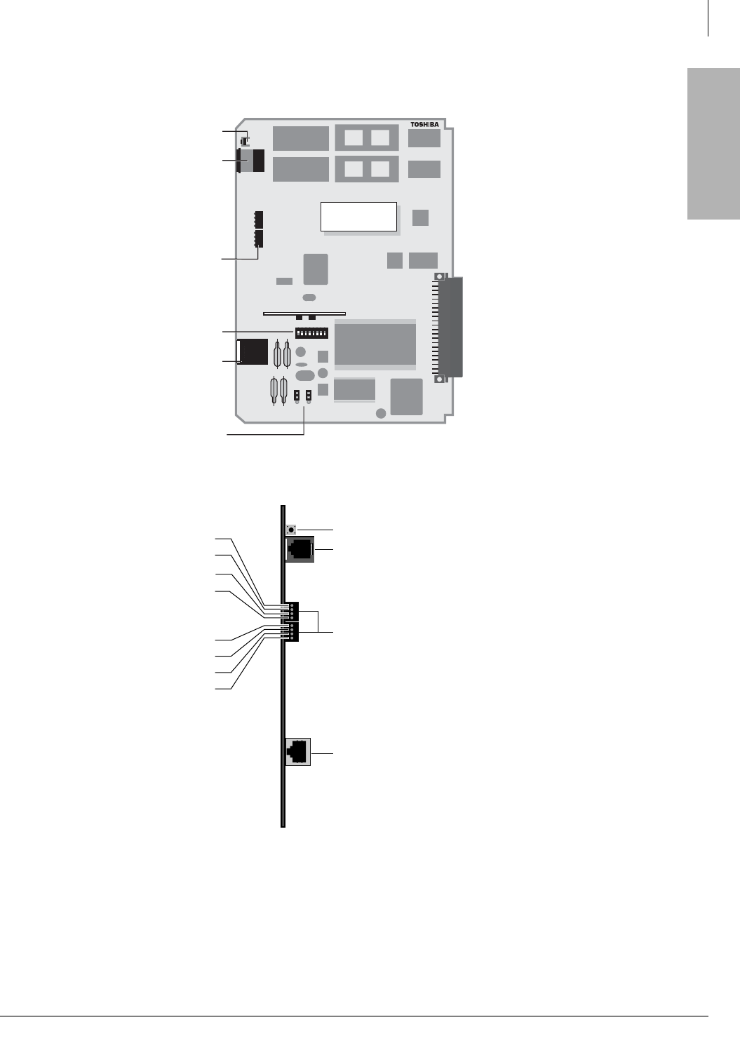
ISDN Interfaces
RPTU Installation
Strata CTX I&M 06/04 7-9
ISDN Interfaces
Note The RPTU2 is required for QSIG networking.
Figure 7-4 RPTU2 PCB
Figure 7-5 RPTU LEDs and Connectors
Backplane Connector
5819
RS-232C
RESET
CD2 CD1
FSYC
AIS
RAB
LOS
RST
BSU
TS
RPTU2
RPTU2 V .1
ISDN (PRI)
JP1
JP2
12345678
OFF MCC
RPTU
(front)
SW2
J2
LEDs
SW1
J1
JP1 & JP2
Reset Switch
(resets the software)
RS-232C Connector
for Call-Data Monitor (RJ-12)
LEDs
RJ-45 8-pin
(shielded)
Modular Connector (to CSU)
Not Used
FSYC
AIS
RAB
LOS
RST
BSY
TS
2747
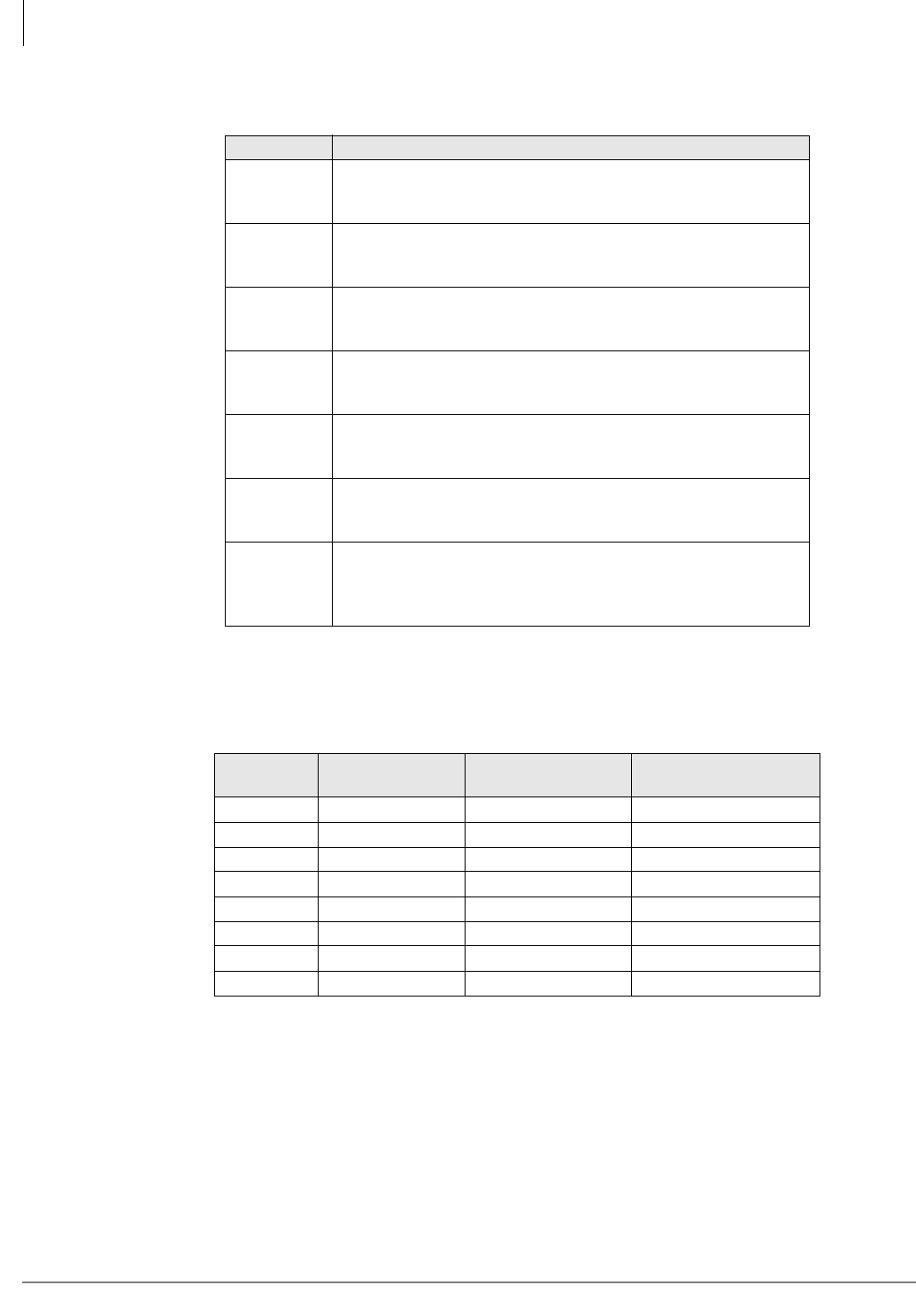
ISDN Interfaces
RPTU Installation
7-10 Strata CTX I&M 06/04
The RPTU SW1 settings for the proper cable length are shown in Table 7-7. For cabling
instructions, see BPTU and RPTU Cabling.
Table 7-6 RPTU LED Functions
LED Functions
FSYC
Frame Synchronization
On: Frame alignment is lost.
Off: Frame alignment is working properly.
AIS
Alarm Indication Signal
On: Receiving an alarm from the CO.
Off: Circuit is working properly.
RAB
Remote Alarm
On: Receiving a remote alarm from the CO.
Off: Circuit is working properly.
LOS
Loss of Signal
On: IC signal cannot be detected.
Off: Circuit is working properly.
RST
Reset
On: CPU is resetting the software.
Off: Circuit is working properly.
BSY
Busy
On: One or more B-channels are busy.
Off: All B-channels are idle.
TS
Timing Signal
On: Circuit is secondary timing source.
Off: Circuit is not used for system timing.
Flashing:Circuit is primary timing source.
Table 7-7 RPTU SW1 Cable Length Settings
SW1 Short
(0 - 150 ft.)
Medium
(150 - 450 ft.)
Long
(450 - 655 ft.)
1On Off Off
2Off On Off
3Off Off On
4Off On Off
5Off Off On
6Off On Off
7Off Off On
8 Not Used Not Used Not Used

ISDN Interfaces
BPTU and RPTU Cabling
Strata CTX I&M 06/04 7-11
ISDN Interfaces
BPTU and RPTU Cabling
To meet Part 15 of FCC Rules, ISDN PRI equipment must be connected using CAT5, Shielded
Twisted-Pair (STP) cabling between the CSU and the BPTU or RPTU. CAT5 STP protects against
cross talk, Radio Frequency Interference (RFI), and/or Electro Magnetic Interference (EMI). STP
protects ISDN signal data while being transmitted through the cable and keeps the cable itself from
emitting EMI and RFI.
Important! To avoid ground loops, connect only the BPTU or RPTU end of the shielded cable to
ground. The Strata CTX grounds the CAT5 cable shield between the Strata CTX and
CSU at the BPTU or RPTU RJ45 jack. You do not have to connect the CSU ground
drain. The CSU ground should not be connected to the cable shield.
Shield continuity must be maintained from the BPTU or RPTU to the CSU, particularly if using
extension connecting cables. Keep the cable as short as possible between the CSU and the PRI
Demarcation jack, because there is no shield between the CSU and the Demarcation jack.
Toshiba provides a cable kit (Part No. RPRI-CBL-KIT), that contains all that you need to connect
the network ISDN jack to the network side of most CSUs and the equipment side of the CSU to the
BPTU or RPTU PCB. Depending on the manufacturer, the CSU may use DB15 or modular jacks.
If the CSU is equipped with the modular jacks, the DB15/modular adapters are not used. If this is
the case, make sure the CSU modular jacks are not shielded jacks.
A detailed pinout diagram for the RJ45 network jack (USOC RJ48C or RJ48X) and the modular
cords/adaptors are shown in Figure 7-6 on page 7-12 and Figure 7-8 on page 7-13.
Cable Length
The distance between the BPTU/RPTU and CSU or the BPTU/RPTU and other Customer Premise
Equipment (CPE) may vary (0~655 ft.). The BPTU or RPTU must be equalized and its impedance
must match the impedance of the connecting cable.
³BPTU: Set the SW settings for the proper cable length (see Table 7-3 on page 7-6 and Figure
7-3 on page 7-5).
³RPTU: Set the SW settings for the proper cable length (see Table 7-7 on page 7-10 and Figure
7-5 on page 7-9).
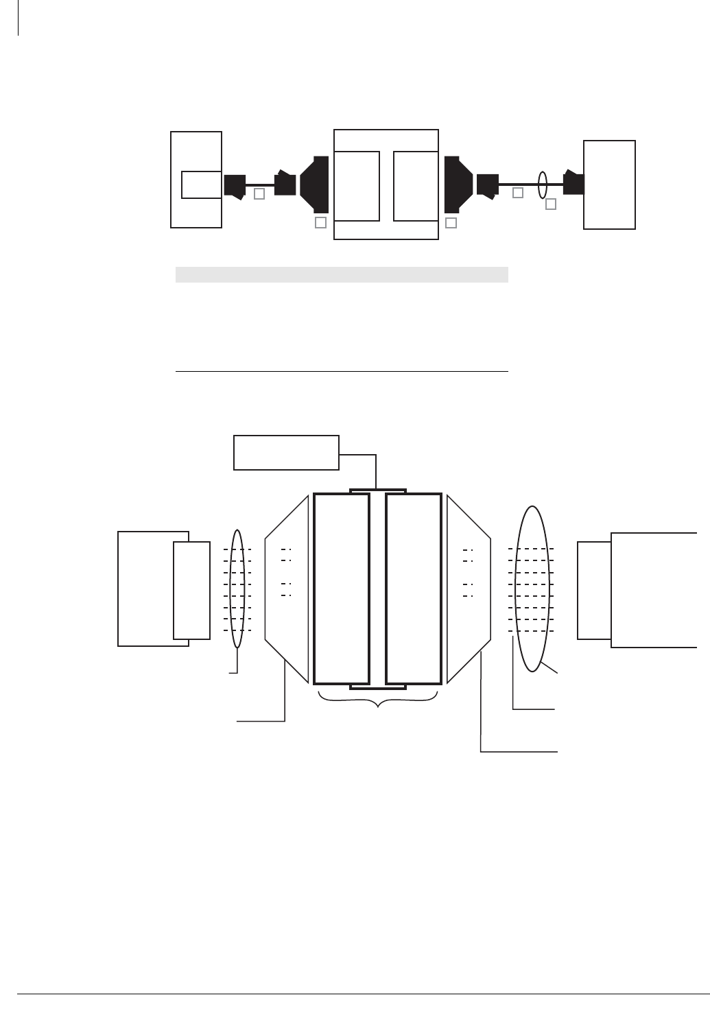
ISDN Interfaces
BPTU and RPTU Cabling
7-12 Strata CTX I&M 06/04
Cable Installation
Use the Toshiba RPRI cable kit to connect the BPTU or RPTU PCB to a CSU. Install the kit as
shown in Figure 7-6.
.
Figure 7-6 Detailed Pinouts for ISDN PRI Cabling
Network Jack/BPTU or RPTU Modular Jack
Pin Function
1 Tip – Receives from the network (NT – TE)
2 Ring – Receives from the network (NT – TE)
3 Not Used
4 Tip – Transmits to the network (TE – NT)
5 Ring – Transmits to the network (TE – NT)
6 Not Used
7 Not Used
8 Not Used
ISDN PRI
Network
Jack
CSU
DB15
(female)
DB15
(male)
BPTU
or
RPTU
6645
A
BC
D
E
RJ45
Item Description
A1
1. Cable A and D are straight-pinned data cables, not cross-
pinned telephony cables.
Fifteen feet of CAT5 unshielded cable
BOne DB15 modular adapter (CSU to network jack)
COne DB15 modular adapter (CSU to RPTU)
D1Thirty feet of CAT5 shielded cable
EOne Ferrite core
C
S
U
1
2
3
4
5
6
7
8
1
2
3
4
5
6
7
8
1
2
3
4
5
6
7
8
1
2
3
4
5
6
7
8
CSU Local Power
Adapter
Network
Interface
Jack
RJ48-C
or
RJ48-X
(8-pin
Modular)
1-T1
2-R1
3-
4-R
5-T
6-
7-Nu
8-Nu
1-T1
2-R1
3-
4-R
5-T
6-
7-Nu
8-Nu
BPTU or
RPTU
8-pin
Modular
Jack
1
2
3
4
5
6
7
8
3
11
9
1
1
2
3
4
5
6
7
8
3
11
9
1
3-T1
11-R1
3-
9-R
1-T
3-T1
11-R1
3-
9-R
1-T
CSU
DB15
Male
CSU
DB15
Female
Toshiba-supplied 8-wire modular
cord, straight-through pinning
(15 ft. CAT5, unshielded)
Toshiba-supplied 8-pin modular
cord to DB15 female adapter
Dealer-supplied CSU
Toshiba-supplied 8-pin modular
to DB15 male adapter
Toshiba-supplied 8-wire
modular cord, straight-through
pinning (30 ft. CAT5, shielded)
Toshiba-supplied Ferrite core
6646
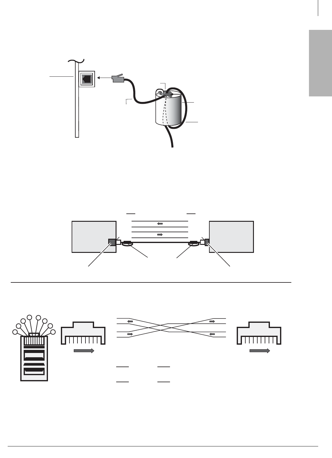
ISDN Interfaces
BPTU and RPTU Cabling
Strata CTX I&M 06/04 7-13
ISDN Interfaces
Ferrite Core
Install the Ferrite core provided with the RPRI cable kit as shown in Figure 7-7. This core is
needed to comply with FCC requirements.
Figure 7-7 Ferrite Core Installation
Figure 7-8 Direct Connect Two BPTU or RPTU2 PCBs for QSIG Networking
Ferrite Core
FER-CORE-ISDN
One Turn
CAT5 Shielded Cable
R
PT
U
S
id
e
V
i
e
w
5963
Tie Wrap
N
o
t
e
:
The Ferrite core must be
as close as possible to the RPTU.
ISDN PRI Jack
6644
Pin of one end to
of one end to of other end - each direction
To make a cross-pinned modular cord on a existing straight through cord:
On one end only, swap Pin 1 with Pin 5 and then Pin 2 with Pin 4.
of other end - each direction
Pin15
2
Pin 4
Pin
RJ45 Cable Cross Pinning
T
R
T
R
T
R
T
R
1
2
3
4
5
6
7
8
1
2
3
4
5
6
7
8
18
Front Front
18
Bottom Side Up
Connector Head
1
2
3456
7
8
Connecting two BPTUs or two RDTU3s
BPTU or RDTU3 BPTU or RDTU3
Strata CTX PBX or Cable
Cross-Pinned, RJ45 Modular Cord
Ferrite Core
(655 ft. max. CAT5 wire) RJ45 Network Jack
RJ45 Network Jack
1
2
5
4
5
4
2
1
Pin Pin
T
R
RR
R
TT
T
Important
Note:
Set SWs on
each BPTU
per Table 7-3

ISDN Interfaces
RBSU/RBSS Interface Units
7-14 Strata CTX I&M 06/04
RBSU/RBSS Interface Units
Circuits per PCB:
2 circuits (2B + D each circuit)
Interfaces with:
ISDN BRI S/T when connected to the Public Network or a BRI S-type, TE-1, or TA devices
when connecting to ISDN station equipment
Older Version(s):
none
RBSU/RBSS switches, jumpers, and connectors are shown in Figures 7-11 and 7-12 on page 7-17
and described in Table 7-8.
LEDs on the RBSU/RBSS show a continuous status of BRI operation. Refer to Table 7-8 on page
7-17 for a list of each LED’s status.
Overview
The RBSU and RBSS PCBs provide the Basic Rate Interface (BRI) circuits. The RBSU is the
main plug-in PCB that plugs into the Strata CTX cabinet slots.
The RBSS is an optional PCB that plugs onto the RBSU. Each PCB provides two ISDN BRI
circuits. Each BRI circuit provides 2 B-channels + 1D channel for voice/data/video applications.
An REBU PCB is a piggy-back PCB that plugs onto the RBSU and provides basic functions for
RBSU/RBSS circuits so it must always be installed on the RBSU.
The RBSU circuits are four-wire S/T type circuits and connect to the Public Switched Telephone
Network (PSTN) BRI lines using an Network Terminator unit (NT1); or, on the station side, they
can connect to ISDN Terminal Equipment (TE) or Terminal Adapters (TA) as shown in Figure 7-9.
TE devices include any ISDN device (telephone, fax, computer) that connects directly to S/T
ISDN BRI circuits. TA devices match the protocol of non-ISDN devices (telephone, fax,
computer) to the protocol of S/T ISDN BRI circuits.
The TBSU and RBSU circuits can be configured as:
• BRI – TE circuits which connect to Telephone Network BRI lines using a NT1.
• BRI – NT circuits which connect to ISDN TEs or TAs. These devices must be S-type station
devices.
Important! The Strata CTX BRI circuits allocate line numbers and station ports differently.
Each BRI circuit consumes two line numbers and two station port when configured
as line-side or station side.
RBSU Connection Options
The RBSU connection options (BRI line or ISDN TE-1/TA devices) are selected in customer
database programming and option switches located on the RBSU.
The RBSU circuits that connect to the ISDN network side requires a dealer-supplied NTI interface
box to convert the two-wire, U-interface BRI line from the telephone network to the four-wire,
T-interface of the RBSU circuit. The NT1 must be UL listed (U.S.) or CSA certified (Canada). The
network BRI line connection is a point-to-point connection, which means that the network BRI
line can only be connected to one RBSU or TBSU circuit via the NT1 (T-reference point).
RBSS circuits connect directly to S-type TE-1 or TA ISDN devices only. They do not support BRI-
TE telephone network BRI line connections.
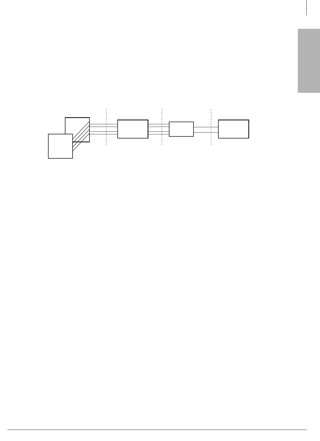
ISDN Interfaces
RBSU/RBSS Interface Units
Strata CTX I&M 06/04 7-15
ISDN Interfaces
The RBSU, and/or RBSS circuits that connect to the Strata CTX station side, (BRI-NT, S-
reference point) allows direct connection of multiple ISDN (TE-1 or TA) devices. The S point of
the RBSU/RBSS supports the Toshiba Strata CTX passive bus, also known as point-to-multipoint
connection. The terminal-side (S-point) of the RBSU/RBSS BRI circuit can have parallel
connections of up to two TE-1s or TAs maximum.
When multiple TE-1 and TA devices are installed on a single RBSU/RBSS BRI circuit, the devices
must share, or contend for, that circuit’s two B-channels. That is to say, a maximum of two
simultaneous voice and/or data calls are allowed between both devices connected to the same BRI
circuit. The contention rule for the two BRI B-channels is first come, first serve.
Figure 7-9 RBSU/RBSS Interfaces between the S/T Reference Points
Capacity and Cabinet Slot Information
The RBSU/RBSS can be installed in any slot except in a slot that has been left vacant to provide
capacity for RDTU, BPTU or RPTU2 or RPTU as shown in Table 2-54 on page 2-39 and Table
2-55 on page 2-40. Each RBSU and/or RBSS contains two circuits and each circuit reduces the
system capacity by two station ports and two CO lines (one port/line per B-channel). Therefore, if
the RBSU PCB is installed, the station port and CO line count will increment by four ports and
four lines at the RBSU cabinet slot.
If the RBSU/RBSS is installed, the station port and CO line count will increment by eight station
ports and eight lines at the RBSU/RBSS cabinet slot. RBSU and RBSS PCBs can be installed in
any combination so long as the number of RBSU PCBs is the same or greater than the number of
RBSS PCBs. See “ISDN BRI Digital Station PCBs” on page 2-41 and “Worksheet 3: CO Line” on
page 2-25 for the maximum BRI circuits allowed.
RX
TX
DK TBSU or
RBSU/RBSS NT1
RX
TX
PSTN
RX/TX
UTS
BRI
(2-wire)
BRI-TE
(4-wire)
BRI-NT
(4-wire)
3336
S, T, and U are ISDN reference points.
TE = S-type Terminal Equipment
TA = S-type Terminal Adaptor
TE-1
or
TA
1
2
...
TE-1
or
TA
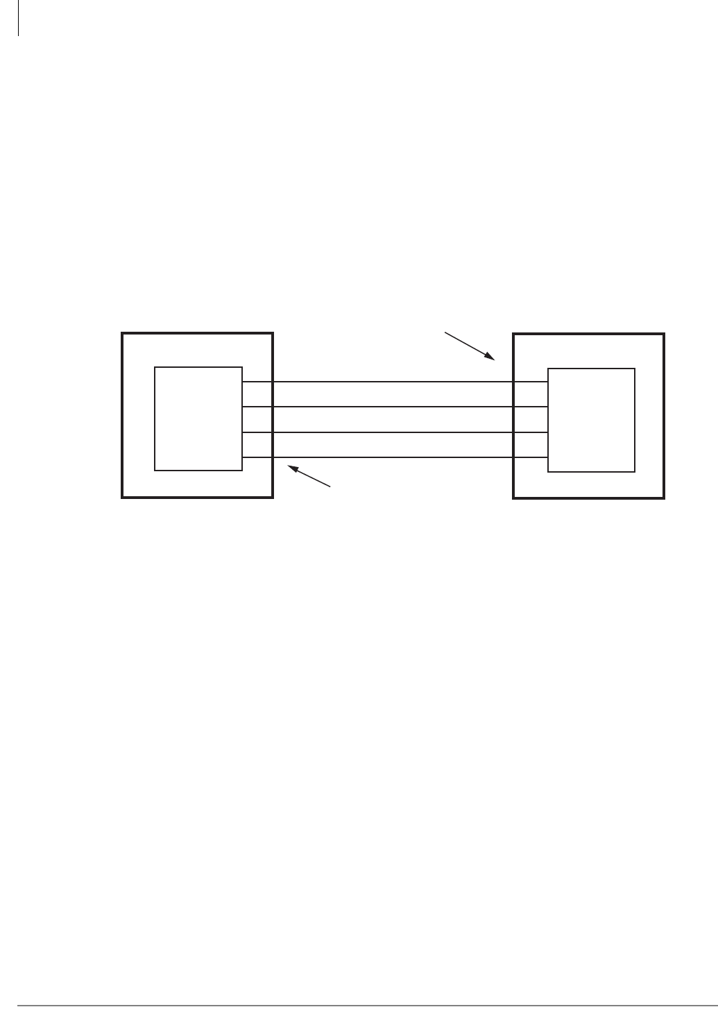
ISDN Interfaces
RBSU/RBSS Interface Units
7-16 Strata CTX I&M 06/04
PS-1 Backup Power Option
The RBSU provides an optional backup power supply, R40S, that will supply backup power to TE
devices in the event of an AC power loss. This power backup option only applies to RBSU or
RBSS circuits that are configured in the NT mode. See Figure 7-13 to install the R40S.
Also the Strata CTX system must have battery backup to allow the R40S power backup function to
operate. The R40S power supply is an ISDN, PS-1 type power unit which means it supplies power
to TE devices on the RBSU/RBSS transmit and receive wire pairs as shown in Figure 7-10. This
power arrangement is also known as phantom power.
Each of the four circuits on RBSU/RBSS can be connected to share the R40S using option
switches on the PCBs (see Table 7-8). Before using the R40S as a backup power source, make sure
the TE devices do not require more power than the R40S can supply and the TE is compatible with
the ISDN PS-1 power arrangement.
Figure 7-10 Power Limits of the Backup Power Supply
RBSU/RBSS Installation
Step 1: Run Related Programs
³Run all ISDN programs related to RBSU/RBSS BRI circuits prior to installation of the PCBs.
This enables the circuits to operate immediately upon insertion. ISDN BRI programs are
explained in the Strata CTX Programming Manual under the ISDN tab.
Step 2: Set Option Switches/Jumpers
³Set all option switches and jumpers on the RBSU and RBSS PCBs before plugging the RBSS
onto the RBSU or inserting the RBSU into the system. RBSU/RBSS switch/jumper
information and locations are shown in Figures 7-11, 7-12 and Table 7-8.
4774
RX +
TX +
Pin 3
Pin 6
Pin 4
Pin 5
Pin 3
Pin 6
Pin 4
Pin 5
RX -
TX -
TE Device
Power sink
R40S PS-1
Power
Source
RJ45 Pin Nos. on
RBSU or RBSS
NT circuit
RJ45 Pin Nos.
on TE device
R40S Power Limits:
Voltage: 33.3VDC to 38.85VDC maximum
Current: 100mA maximum (25mA maximum per each RBSU/RBSS circuit)
TE RBSU
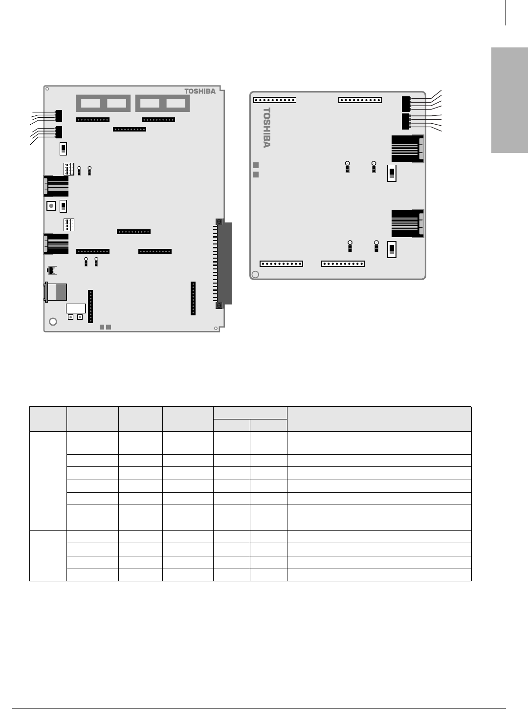
ISDN Interfaces
RBSU/RBSS Interface Units
Strata CTX I&M 06/04 7-17
ISDN Interfaces
Table 7-8 RBSU/RBSS Option Switches, Jumpers, and Connectors
PCB Circuit Option
Switch Type Circuit Type Description
TE NT
RBSU
All SW 1 Push-
button N/A N/A Resets firmware on all circuits of RBSU/RBSS.
Drops calls off the RBSU/RBSS.
1 SW 2 Jumper X X Causes the circuit to operate as TE or NT1.
1. Requires programming to set as TE or NT.
1 SW 3 Slide On Off Switches a 100-ohm resistor in/out of the circuit.
1 SW 4, 5 Jumper N/A On Switches PS-1 in/out of the circuit.
2 SW 6 Jumper X X Causes the circuit to operate as TE or NT1.
2 SW 7 Slide On Off Switches a 100-ohm resistor in/out of the circuit.
2 SW 8, 9 Jumper N/A On Switches PS-1 in/out of the circuit.
RBSS
3 (NT only) SW 1 Slide On Off Switches a 100-ohm resistor in/out of the circuit.
3 (NT only) SW 3, 4 Jumper N/A On Switches PS-1 in/out of the circuit.
4 (NT only) SW 2 Slide On Off Switches a 100-ohm resistor in/out of the circuit.
4 (NT only) SW 5, 6 Jumper N/A On Switches PS-1 in/out of the circuit.
RBSU1A-CM V.1
RBSU1
2789
RBSU1A
BSY
TS
LOS
FS
BSY
TS
LOS
FS
P2 P4
P7
SW7
SW6
SW9
SW8
J2 SW3
SW2
J1
P5
P6
P3
SW5
SW4
SW1
J3
P8
P9
TB3
PFT
contacts
TB1 TB2
Figure 7-11 RBSU PCB
SW2
SW3
SW4
SW5
SW6
RBSS1A-CM V.1
SW1
F
J4 J2
J3 J5
2788
RBSS BSY
TS
LOS
FS
BSY
TS
LOS
FS
J7J6
Figure 7-12 RBSS PCB
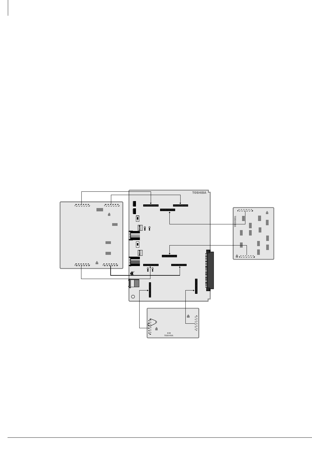
ISDN Interfaces
RBSU/RBSS Interface Units
7-18 Strata CTX I&M 06/04
Step 3: Install the REBS
Note The REBS provides a basic part of the RBSU/RBSS circuit functionality; therefore, it must
always be installed on the RBSU (see Figure 7-13).
1. Align the two connectors carefully while observing the “UP” arrows on the REBS.
2. Plug the REBS onto the RBSU.
Step 4: Install the RBSS
Note If one or two additional BRI-NT circuits are required, install the RBSS (see Figure 7-13).
1. Align the four connectors carefully while observing the “UP” arrows on the REBS.
2. Plug the RBSS onto the RBSU.
Step 5: Install the R40S
Note If ISDN PS-1 backup power for TE devices is required, install the R40S (optional PCB) (see
Figure 7-13).
1. Align the two connectors carefully while observing the “UP” arrows on the R40S.
2. Plug the R40S onto the RBSU.
Figure 7-13 Location of RBSU Plug-on PCBs
UP
UP
UP
UP
UP
UP
R40S1A-CM V.1
RBSU
Optional RBSS1A REBS
R40S
2761
(always install)
Optional PS-1 Power Supply
Two-circuit Subassembly

ISDN Interfaces
RBSU/RBSS Interface Units
Strata CTX I&M 06/04 7-19
ISDN Interfaces
Step 6: Install RBSU/RBSS PCBs into Cabinet
After setting the switches and jumpers and installing the plug-on PCBs as described in the
preceding paragraphs, the RBSU/RBSS PCBs can be installed in the appropriate cabinet slots.
Refer to RBSU/RBSS Capacity and Cabinet Slot Information on Figure 7-14. After the RBSU/
RBSS is installed in the Strata CTX cabinet, the status LEDs and connecting jacks are positioned
as shown in Figure 7-14.
Modular Jack Pin Configurations
BRI (S/T) Circuit Jack (TE or NT Mode)
The RBSU and RBSU/RBSS BRI circuit jack is a shielded RJ45 (8-pin modular) with Transmit
(Tx) and Receive (Rx) pin numbers as shown in Figure 7-14. The Tx and Rx pin numbers change
when the BRI circuit is configured with RBSU and RBSU/RBSS option switches for TE or NT
(Tables 7-8 and 7-14). If the R40S is installed on the RBSU, the PS-1 voltage is carried on the Tx/
Rx wires with polarity. (See Table 7-10).
The position of the RBSU BRI and RBSU/RBSS circuit jacks are shown in Figures 7-14 and 7-15
respectively.
Table 7-9 RBSU/RBSS LED Indications
LED Indication
BSY
Circuit Busy
On – Any B-channel is in use.
Off – B-channels are idle.
TS
Timing Source
Blinking On/Off – The RBSU is extracting the clock from the BRI line and is the
Primary synchronization circuit for ISDN and T1.
On – The RBSU is the secondary (backup) synchronization circuit for the ISDN
and T1.
Off – The RBSU is not used for ISDN or T1 synchronization.
LOS
Loss of Signal
On – Clock timing cannot be detected from the line.
Off – Normal condition.
FS
Frame Alignment Alarm
On – Frame alignment cannot be established.
Off – Frame alignment is established.
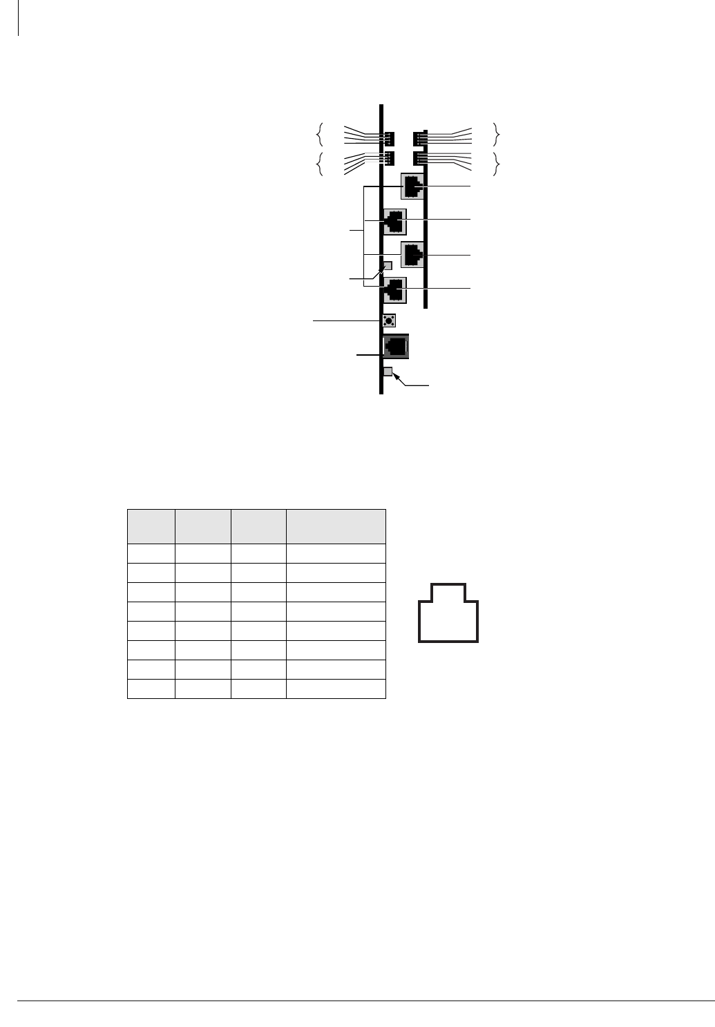
ISDN Interfaces
RBSU/RBSS Interface Units
7-20 Strata CTX I&M 06/04
Figure 7-14 RBSU/RBSS Location of LEDs and Connector Locations
Monitor Jack
The RBSU/RBSS monitor jack is an RJ12 (6-pin modular). This jack provides an RS-232 output
that enables you to monitor the RBSU/RBSS BRI circuit D-channel, layer-2 and layer-3 data. The
monitor jack pin configuration and communication parameters are the same as BPTU or RPTU and
RBUU (see Figures 7-32, 7-35 and 7-36). For RBSU monitor jacks, see Figure 7-34 and Figure
7-14 on page 7-20.)
Table 7-10 RJ45 Pins in the 8-pin Modular Jack
Pin
No.
TE
Side
NT
Side
PS1/R40S
Polarity
1 N/C N/C N/C
2 N/C N/C N/C
3TxRx +
4RxTx +
5RxTx -
6TxRx -
7 N/C N/C N/C
8 N/C N/C N/C
RBSU
Reset Switch
(resets RBSU Firmware)
RS-232C Connector
for Call-Data Monitor
RJ-45 8-pin (shielded)
Modular Connector
BSY
TS
LOS
FS
BSY
TS
LOS
FS
2795
RBSS
3rd Circuit
2nd Circuit
1st Circuit
4th Circuit
BSY
TS
LOS
FS
BSY
TS
LOS
FS
CKT2
CKT1
CKT4
CKT3
TB3 (FG)
TB1 and TB2 (PFT)
87654321
3048
Front View of RJ-45 Jack Cavity
Note: The RJ-45 pins are numbered as shown above.

ISDN Interfaces
RBSU/RBSS Interface Units
Strata CTX I&M 06/04 7-21
ISDN Interfaces
RBSU/RBSS Premise Wiring Guidelines
Power Failure Terminal Screws
TB1 and TB2 are the connecting points that interface a pair of dry contacts that can be used for
power failure switching purposes (see Figure 7-14 for the locations). When the Strata CTX system
has power (from AC source or batteries) there is a short circuit across TB1 and TB2. In the event
of no power to the Strata CTX, there is an open circuit across TB1 and TB2. The specifications for
TB1 and TB2 contacts are:
• Maximum switchable voltage: 30VDC
• Maximum switchable current: 80mA
• Short circuit resistance: Approximately 15 ohms
Grounding Terminal Screws
TB3 is a screw terminal that can be used to connect a ground wire to the RBSU PCB (see Figure
7-14 for the location). This ground enables the RBSU/RBSS to meet Electro Magnetic
Compatibility (EMC) requirements. The RBSU complies with EMC requirements without
grounding TB3 on the RBSU, so it is not necessary to connect a ground wire to TB3.
BRI Wire Type Recommendations
CAT3 or CAT5 wire is recommended for ISDN BRI customer-premises wiring. While the ISDN
BRI signal works for some distance over almost any wire that is suitable for analog voice service,
better wire enables longer runs. CAT5 provides better 100-ohm impedance matching (at little extra
cost) between the RBSU/RBSS circuit and the station Terminal Equipment (TE-1).
Normally the CAT3 or CAT5 wiring does not have to be shielded when used for ISDN BRI
premises wiring. However, the RJ45 jacks on the RBSU/RBSS BRI circuits are shielded and
provide a ground shield in the event that shielded modular plugs and cable are used.
Note If using shielded cable and plugs, cable runs should only be grounded at the Strata CTX
RBSU/RBSS, RJ45 jacks. To prevent ground loops, do not ground both ends of shielded
cable runs.
RBSU/RBSS BRI Cable Jacks and Connectors
In the U.S., the standard connector for ISDN equipment is the eight-pin RJ jack. Patch cables have
eight-pole plugs at both ends. The same pinout applies to both ends of an ISDN cable, which is the
practice of the data world. This means that a flat untwisted cable with an RJ modular plug at both
ends will have the locking tab of the plug on one end, “up;” and on the other end, “down,” as
shown in Figure 7-15.
Note This is the opposite of telephony “silver satin” cables which have locking tabs on both ends
facing the same direction. Telephony cables cause the pins at either end to crossover while
data cables provide a straight through pin-to-pin connection between modular jacks.
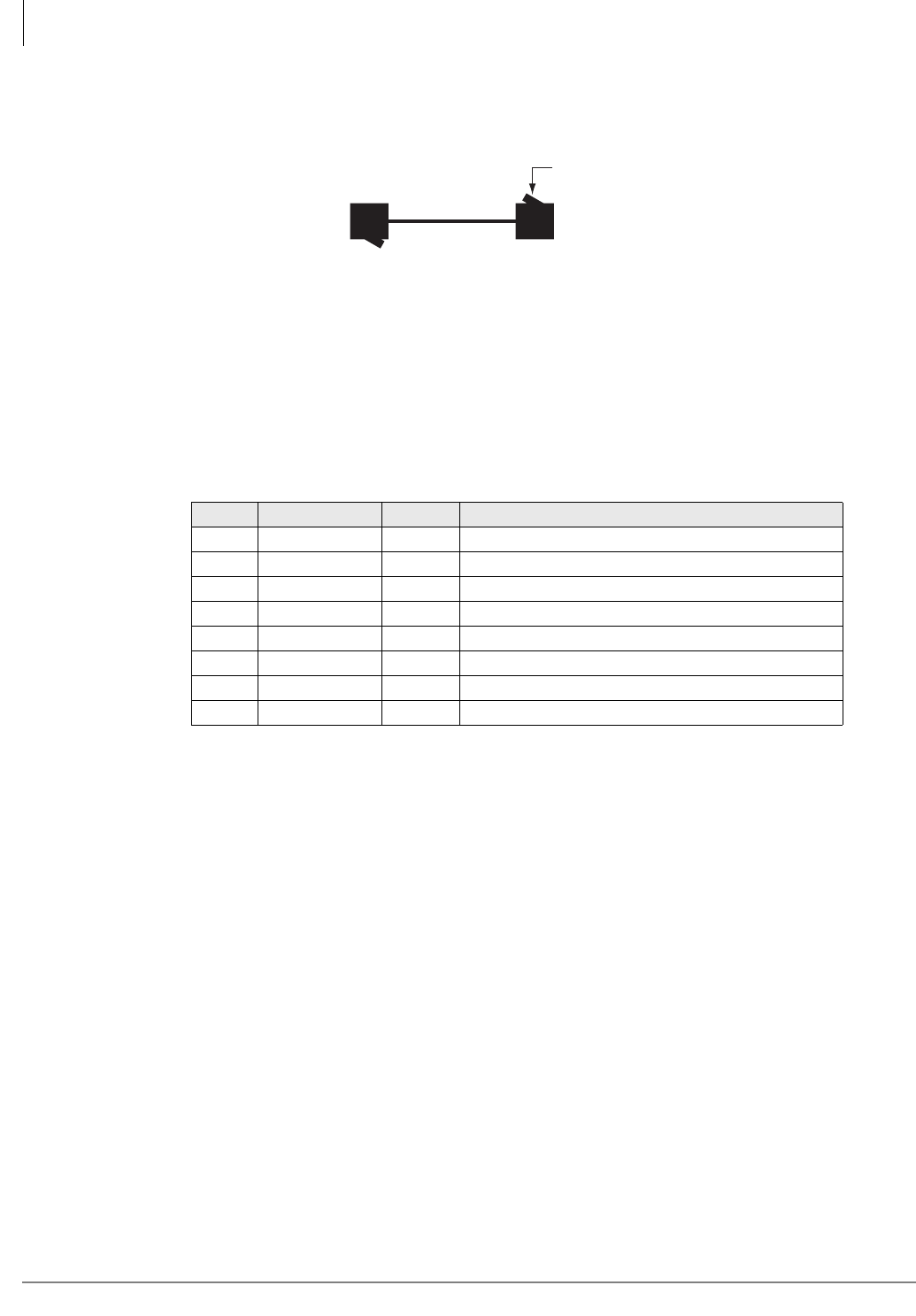
ISDN Interfaces
RBSU/RBSS Interface Units
7-22 Strata CTX I&M 06/04
A cord of up to 10 meters connects the ISDN BRI RJ45 wall jack to the desktop TE-1 or TA RJ45
jack. Bellcore recommends that all TE-1 and TA devices be attached with the same standard cord
to ensure compatibility.
Figure 7-15 Modular ISDN Data Cable
The standard pinouts for ISDN jacks is the TIA-568A or TIA-568B jack as listed in Table 7-11.
The variants A and B to the TIA specification are electrically the same, only the wire colors are
different. However, you should only use one type TIA jack in a customer installation because
mixing the two may cause certain wire pairs to be swapped which would result in line faults.
Notes
• Pins are numbered left to right when looking into the jack cavity with the locking tab down.
• TIA-568A swaps pair two with pair three, changing only the color of the wires on the pins.
Electrical performance is the same.
Table 7-11 TIA-568B (RJ45) Jack – ISDN Standard Interface Modular Connector Pinout (RBSU-
NT mode
Pin Color Name Function
1 Green T2 Power 3 (not used on RBSU/RBSS)
2 Green/White R2 Power 3 (not used on RBSU/RBSS)
3 Orange/White R3 RX+
4 Blue/White R1 TX+
5Blue T1TX-
6 Orange T3 RX-
7 Brown T4 - Power 2 (not used on RBSU/RBSS)
8 Brown/White R4 + Power 2 (not used on RBSU/RBSS)
3039
Four-pair Wire
RJ-45
Eight-pole Plug
Locking Tab
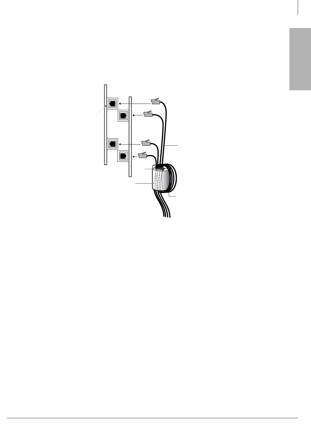
ISDN Interfaces
RBSU/RBSS Interface Units
Strata CTX I&M 06/04 7-23
ISDN Interfaces
Strata CTX BRI Circuit EMC Ferrite Core Requirement
To ensure that the Strata CTX BRI circuit meets the EMC requirements, it is necessary to run all
wire connecting ISDN BRI circuits (TE, LT mode and NT mode) through a Ferrite core. Use
Toshiba part number, FER-CORE-ISDN, to order the ferrite core. It is not shipped automatically
with the BRI circuit cards, it must be grounded separately. Figure 7-16 shows how to dress the
wiring through the Ferrite core.
Figure 7-16 BRI Circuit Ferrite Core Installation
Connecting RBSU to Network Side (TE-Mode)
The RBSU only, not the RBSS, circuits can be connected to the network side of a BRI line. The
RBSU circuits must be configured in the TE-mode (refer to option switches in Table 7-8 on page
7-17).
In the U.S., the BRI line from the ISDN service provider is a two-wire U-type BRI line. This line
connects to the RBSU TE circuit via a customer-provided NT1 as shown in Figure 7-17. The NT1
is necessary to convert the network BRI, two-wire, U interface to the RBSU BRI, four-wire, T
interface. The NT1 must be UL listed (U.S.) or CSA certified (Canada).
The NT1 is powered by local AC power via an AC adapter supplied with the NT1. The connection
between the NT1 and the RBSU TE circuit is a point-to-point connection, so the NT1 can connect
to only one RBSU BRI TE circuit.
A 100-ohm Terminating Resistor (TR) is required on each end of the point-to-point connection.
The TR must be switched into the RBSU TE circuit (refer to option switches in Table 7-11 on page
7-22 and Table 7-8 on page 7-17) and into the NT1 device.
RBSU or RBUU
4697
Ferrite Core
FER-CORE-ISDN
One Turn
CAT 3, 4,
or 5 Cable
Tie
Wrap
Note:
RBSS or RBUS
Locate the Ferrite core
as close as possible to
the BRI modular jack.
ISDN
PRI Jack
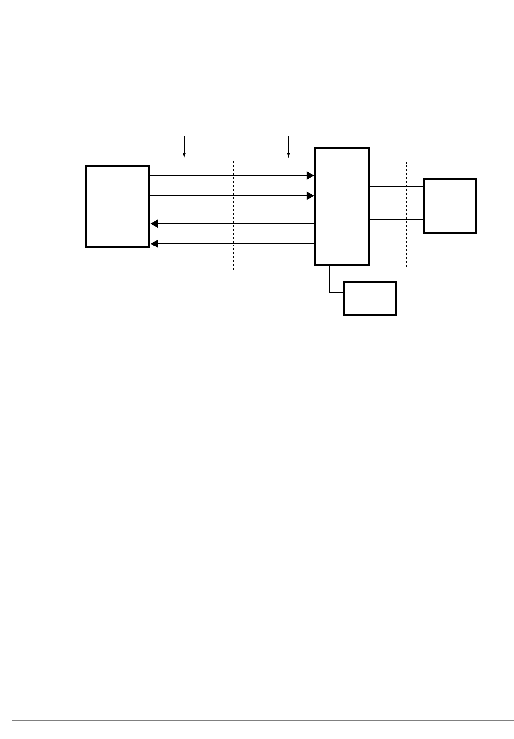
ISDN Interfaces
RBSU/RBSS Interface Units
7-24 Strata CTX I&M 06/04
Most NT1 devices have TR option switches; if the NT1 does not have TRs, two 100-ohm TRs
must be wired into the NT1 modular jack - one 100-ohm resistor across each pair (Tx and Rx).
Refer to the NT1 manufacturers documentation for the maximum loop length between the NT1
and the network jack. The maximum loop length between the NT1 and the RBSU circuit is 1650
feet.
Figure 7-17 RBSU to NT1 Point-to-point Connection
Connecting RBSU/RBSS Station Devices (NT-Mode)
S-type TAs and TE-1s can be connected to the station side of TBSU, RBSU, and RBSS circuits.
TA and TE devices must be powered by local AC power using AC adapter supplied with the TA or
TE device. The RBSU/RBSS circuits must be configured in the NT mode when connected to TA
and TE devices (refer to option switches in Table 7-8 on page 7-17 and Table 7-11 on page 7-22).
The TA enables you to connect non-ISDN voice and data devices to ISDN BRI circuits. The TA
matches the protocol of existing interfaces (R-reference point) to the ISDN S/T protocol (see
Figure 7-1 on page 7-2). TA devices include asynchronous circuit-switched adapters that convert
RS-232 sync data (like data from a PC COM port) to B-channel 64 kbps sync.
TAs also enable you to connect standard telephones and non-ISDN fax machines to receive and
make calls over ISDN circuits. TEs include any user device (telephone, fax, PC video conference
board) that is designed to plug directly into the ISDN (S/T) interface without the use of a TA.
There are two types of ISDN TA and TE-1 devices: the U-type and the S/T type. Most
manufacturers of ISDN station devices make both types. On the RBSU/RBSS station side,
BRI-NT circuits only function with S/T type TA and TE-1 devices. You cannot connect U-type
TE-1 or TA devices to the RBSU/RBSS BRI-NT circuits.
Also, connecting an NT1 to the RBSU/RBSS BRI-NT circuit to convert from S/T to U interface is
not supported to enable the use of U-type TE-1 or TA device on the station side of the RBSU/
RBSS. U-type TE-1 and TA device interface is provided in the Strata CTX by the RBUU/RBUS
BRI circuit only.
The RBSU/RBSS BRI-NT circuit supports the National ISDN 2 (NI2) S-Interface “passive bus.”
It is called a passive bus, because it contains no logical functions. The RBSU/RBSS BRI-NT
interface supports a point-to-multipoint connection on two twisted pairs. Up to two TE-1 and/or
TA devices can be connected to one RBSU/RBSS, BRI-NT circuit. Using standardized wiring and
RBSU
TE-Circuit
Switch in
100-ohm TR
using RBSU
option switch.
RJ45 Pinout
(RBSU - BRI jack)
5433
Network
BRI-line
RJ11 Jack
NT-1
Switch
in 100-ohm
TR.
T and U are ISDN standard
reference points.
Note:
BRI
(four-wire)
T
BRI
(two-wire)
U
Demarcation Point
3
6
4
5
3
6
4
5
RX
RX
TX
RXTX
TX
RX TX RX/TX
RX/TX4
5
RJ45 Pinout
(NT1 - S/T jack)
Local AC
Power
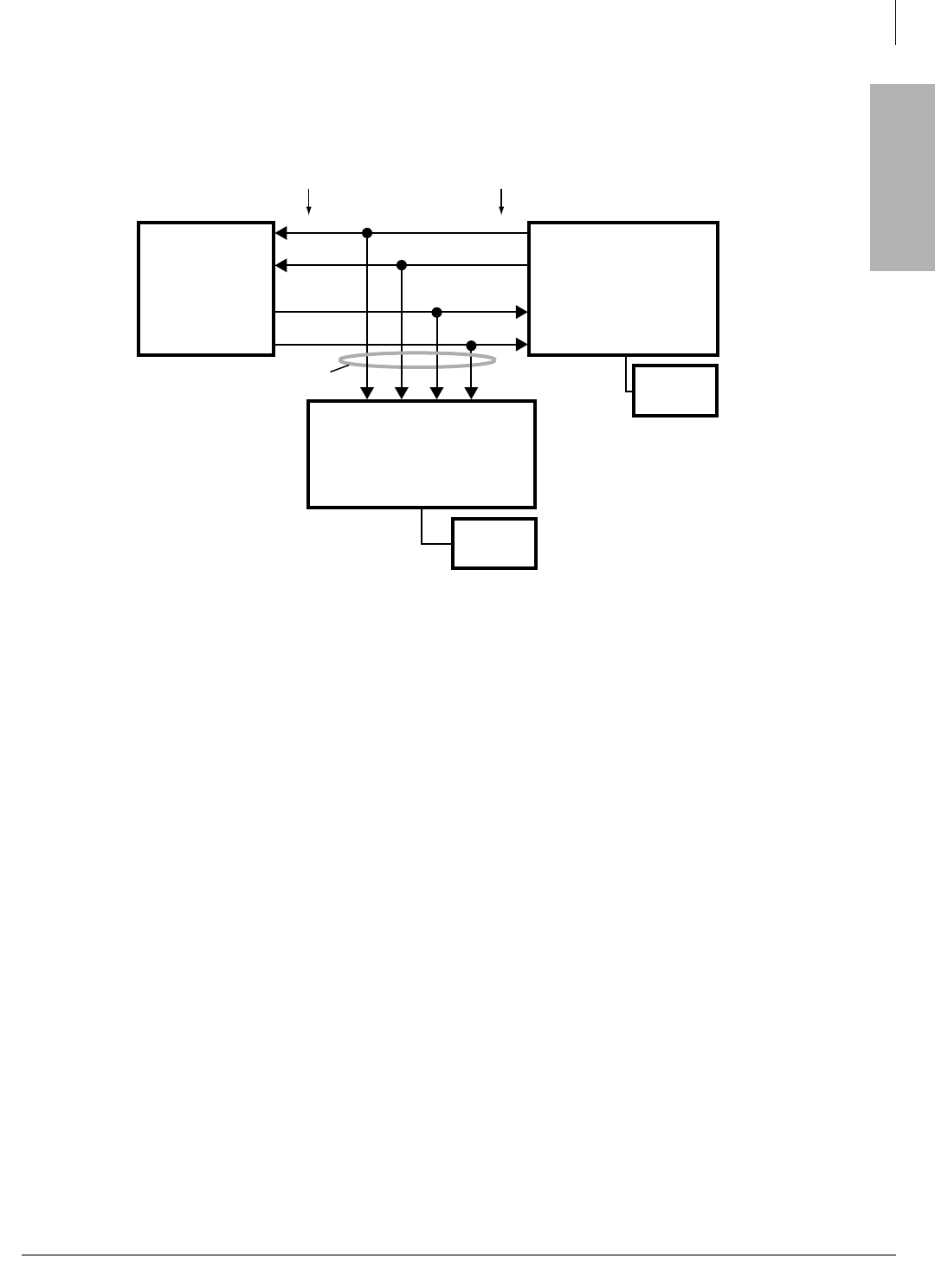
ISDN Interfaces
RBSU/RBSS Interface Units
Strata CTX I&M 06/04 7-25
ISDN Interfaces
modular connectors, as explained in previous paragraphs, maintains control of polarity. The pinout
from the RBSU/RBSS circuit to a S-type TE-1 or TA device is shown in Figure 7-18 and Table
7-10.
Figure 7-18 RBSU/RBSS NT Circuit Pinout on Passive Bus
As a parallel bus, the RBSU/RBSS BRI-NT passive bus will accept TE-1 and TA devices scattered
on the bus; however, the locations of the TE and TA devices on the S bus is limited by timing
considerations. Specifically, the round trip propagation delay of a signal from the RBSU/RBSS
circuit to one device must be within four microseconds of the delay from the other device on the
bus. That is to say, layer-1 frames from the RBSU/RBSS must be received within a two
microsecond window. This says nothing about how large the delay can be. In fact, it can be much
larger, as long as the differences remain small.
To control electrical characteristics, a 100-ohm terminating resistor (TR) is required at both ends
of the passive bus. One resistor should be across the Tx pair and one across the Rx pair at either
end of the passive bus. Branch-type passive bus configurations, shown in Figures 7-19~7-22, may
only require a TR on the RBSU/RBSS NT circuit side and not on the TE or TA device side of the
bus.
The RBSU and RBSS circuits provide an option switch that allows the 100-ohm TR to be switched
into the circuit on the Strata CTX side of the bus (see Table 7-8 on page 7-17 and Table 7-11 on
page 7-22). Most TE-1 and TA devices also provide option switches to connect 100-ohm
terminating resistors as shown in Figure 7-17.
If the TE or TA devices do not provide TRs, they may be permanently wired in place on a RJ45
jack at the far end of the bus. Only one terminating resistor on each pair should be on the far (TE)
end of the passive bus - do not switch in TRs on more than one TE-1 or TA device on the passive
bus.
Important! The correct placement of TRs on the Passive Bus is critical to ISDN BRI circuit
operation (see the following RBSU/RBSS Passive Bus configurations section).
RBSU
NT Circuit
Insert 100-ohm
TR using RBSU
and RBSS
option switches.
RJ45
Pinout
5434
S-type, TE-1s or TAs without
100-ohm terminating resistors
(maximum eight TE-1s or TAs per
RBSU/RBSS circuit).
BRI (four-wire)
3
6
4
5
3
6
4
5
RJ45
Pinout
S-type, TE-1 or TA with
100-ohm TR or just a
100-ohm terminating
resistor across each pair
on a RJ45 jack.
To local
AC Power
To local
AC Power
3 6 4 5
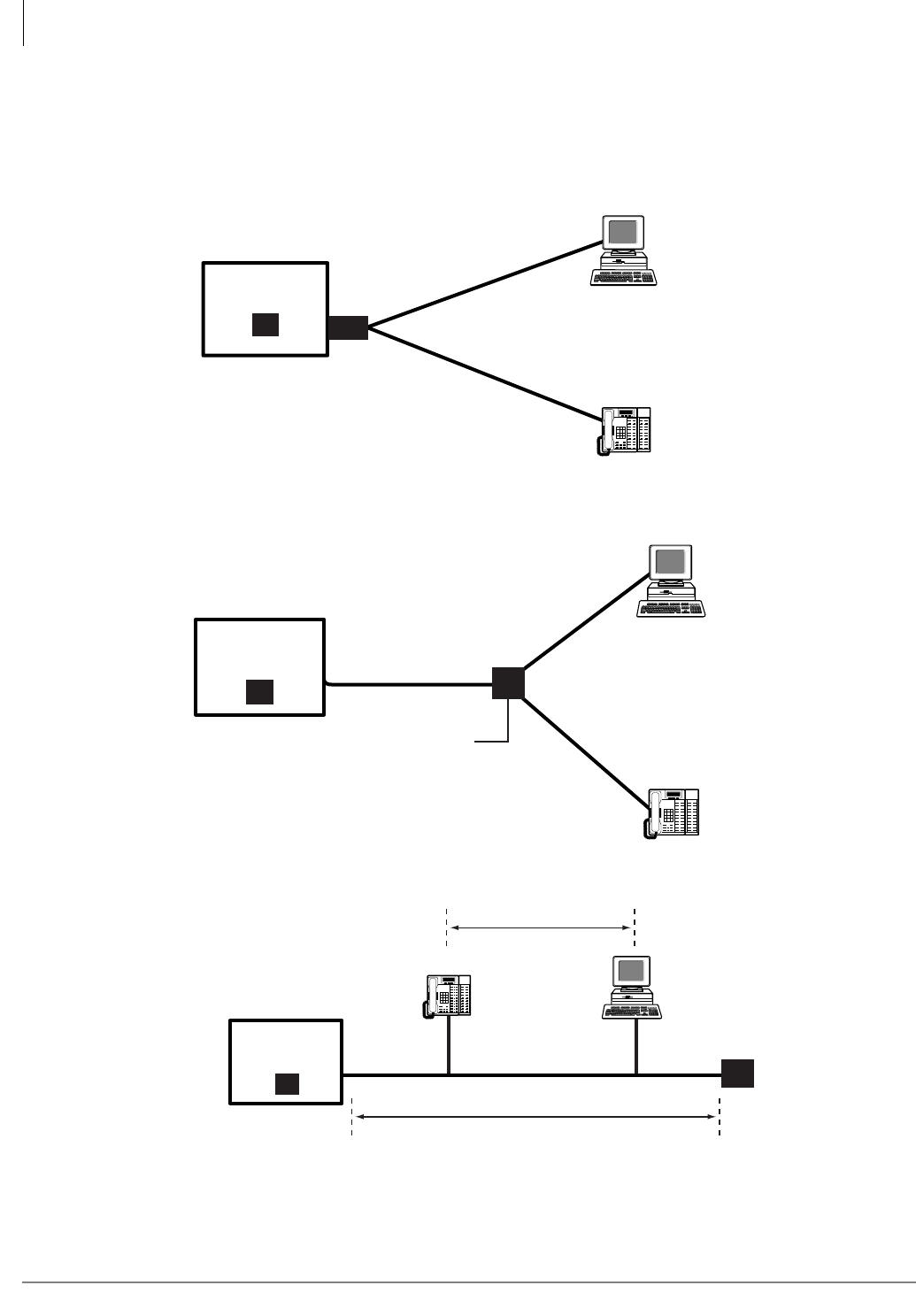
ISDN Interfaces
RBSU/RBSS Interface Units
7-26 Strata CTX I&M 06/04
RBSU/RBSS Passive Bus Configurations
The placement of S-type TE and TA devices on the BRI S-passive bus is critical for good RBSU/
RBSS BRI circuit performance. Figures 7-19~7-22 show four passive bus architectures that are
known to work. In all installations, follow the guidelines of any of these passive-bus models using
the wire, cables, and jacks described in the previous paragraphs.
Figure 7-19 Simplified Short-branched Passive Bus
Figure 7-20 Branched Passive Bus
Figure 7-21 Extended Passive Bus
RJ45
360' max
5435
360' max
TA and PC Com Port
ISDN Telephone
RBSU/RBSS
NT-Mode
TR
RJ45
5436
*
*
850' No more than 130' difference
between any 2 branches.
*
RBSU/RBSS
NT-Mode
TR
RJ45 with
TRs
TE-1 PC Card
ISDN Telephone
5437
TR
1650'
82'
RJ45
RBSU/RBSS
NT-Mode
TR
ISDN Telephone TE-1 PC Card
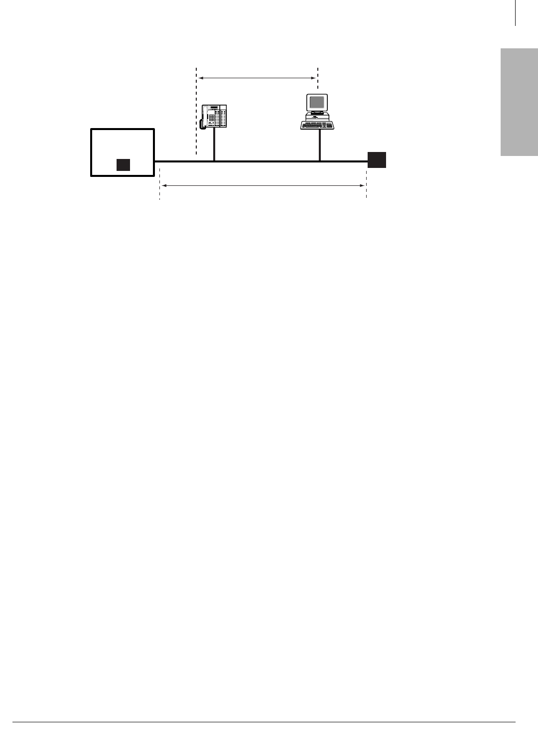
ISDN Interfaces
RBUU/RBUS Interface Unit
Strata CTX I&M 06/04 7-27
ISDN Interfaces
Figure 7-22 Short Passive Bus
RBUU/RBUS Interface Unit
Circuits per PCB:
2 circuits (2B + D each circuit)
Interfaces with:
ISDN BRI U when connected to the Public Network or a BRI U-type TE-1 or TA devices
when connecting to ISDN station equipment
Older Version(s):
none
The Strata CTX RBUU/RBUS interface unit (Figures 7-23 and 7-24) supports ISDN BRI U-type
TE1 or TA devices.
LEDs on the RBUU/RBUS show a continuous status of operation. Refer to Table 7-12 for a list of
each LED’s status.
Figure 7-25 shows the location of the LEDs and connectors.
RBUU Installation
Before you can begin installation of the RBUU, you may have to install the subassemblies.
³To install the subassemblies (RBUS)
³Place the RBUS card (component side facing down) onto the RBUU connectors. Apply firm,
even pressure to ensure proper seating of the connectors. The RBUS card should have been
installed at the factory.
³To install an RBUU PCB
1. Insert the RBUU (component side facing right) into the appropriate expansion unit slot and
apply firm, even pressure to ensure proper seating of connectors.
2. After installing the RBUU, gently pull the PCB outward. If the connectors are properly seated,
a slight resistance is felt.
5438
TR
640'
490'
RJ45
RBSU/RBSS
NT-Mode
TR
ISDN Telephone TE-1 PC Card
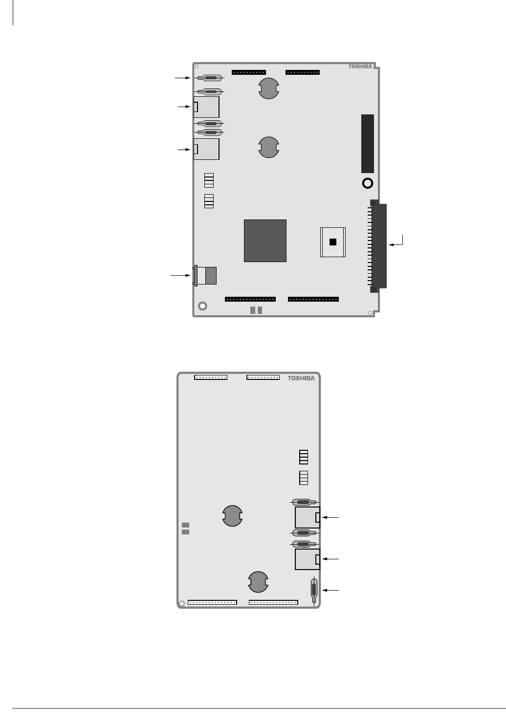
ISDN Interfaces
RBUU/RBUS Interface Unit
7-28 Strata CTX I&M 06/04
Figure 7-23 RBUU PCB
Figure 7-24 RBUS Subassembly
Circuit 2
Circuit 1
Circuit 1
P10 P10
BSY
T S
LOS
F S
BSY
T S
LOS
F S
2799
RBUU1A
RJ45 Modular
for Circuit 1
Secondary
Protectors
RJ45 Modular
for Circuit 2
LED Indicators
RS-232C
Monitor Output
DIN
Connector
Circuit 2
J101 J201
P12 P13
RBUU1A
J3
Circuit 3
Circuit 3
Circuit 4
P13 P12
P11 P10
Circuit 4
BSY
T S
LOS
F S
BSY
T S
LOS
F S
F
2800
RBUS1A
LED Indicators
RJ45 Modular
for Circuit 3
RJ45 Modular
for Circuit 4
Secondary
Protectors
J401 J301
RBSU1A
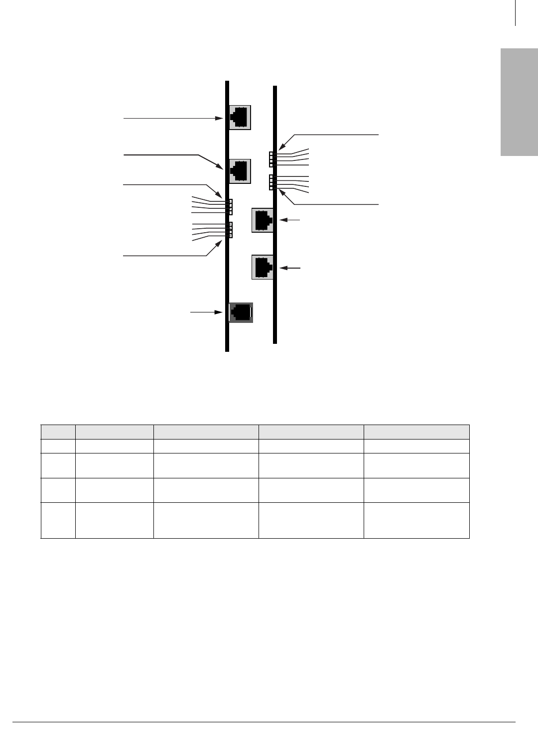
ISDN Interfaces
RBUU/RBUS Interface Unit
Strata CTX I&M 06/04 7-29
ISDN Interfaces
Figure 7-25 Location of LEDs and Connectors (RBUU/RBUS)
Table 7-12 RBUU/RBUS LED Indications
LED Definition LED Off LED On LED Blinking
BSY Busy Port is in idle. Port is busy. Port is in test mode.
TS Time
Synchronization
Not CLK extraction
port.
Secondary CLK
extraction port. Extracting CLK port.
PSI1
1. PSI is labeled LOS on Beta PCBs
Port Status
Indicator Port is in LT mode. Port is in NT mode. AIB is received by this
port.
FS Frame
Synchronization
Frame alignment is
established. Frame Alignment error.
Port is trying to
establish frame
alignment.
RBUU1A
RS-232C
Monitor Output
4776
RBUS1A
RJ45 Modular
for Circuit 3
RJ45 Modular
for Circuit 4
RJ45 Modular
for Circuit 1
RJ45 Modular
for Circuit 2
LED Indicators
for Circuit 1
LED Indicators
for Circuit 2
LED Indicators
for Circuit 3
LED Indicators
for Circuit 4
BSY
T S
PSI
F S
BSY
T S
PSI
F S
BSY
T S
PSI
F S
BSY
T S
PSI
F S
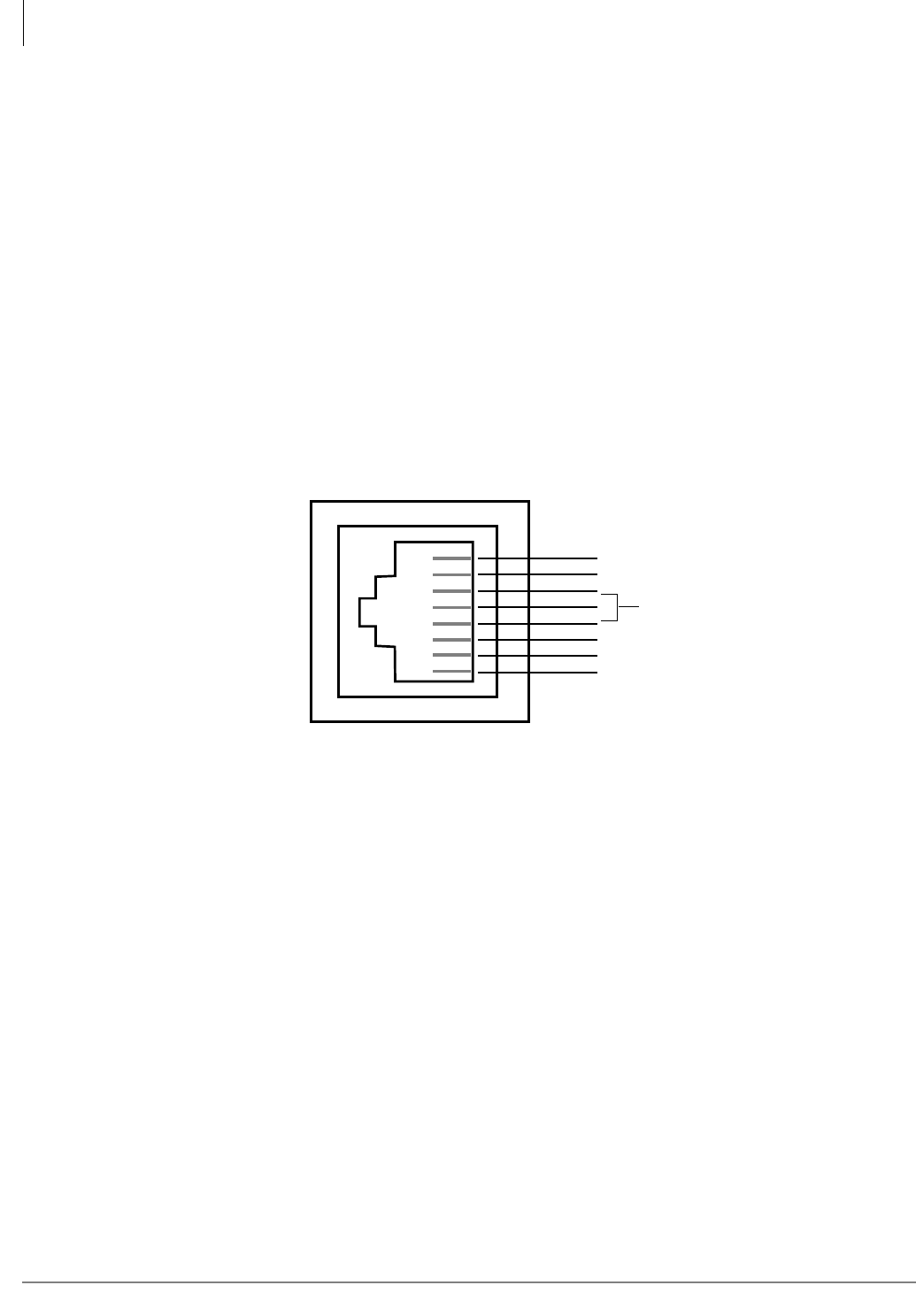
ISDN Interfaces
RBUU/RBUS Interface Unit
7-30 Strata CTX I&M 06/04
RBUU/RBUS Wiring Guidelines
• Strata CTX BRI-U interface circuits can be configured to connect to an ISDN line circuit (NT
mode, line-side) or to ISDN U-type terminal equipment TE1 or terminal adapters TA (LT
mode, station side).
• Install the Toshiba-supplied Ferrite core on each ISDN circuit card per Figure 7-16 on
page 7-23. The Ferrite core is not supplied with the ISDN circuit cards must be ordered
separately.
• For more information regarding the Strata CTX BRI-U interface, see “PRI and BRI Overview”
at the beginning of this chapter.
Line-side cabling
• The ISDN BRI U-interface circuits are two-wire on the PSTN line-side.
• The wiring from the demarc to the Strata CTX BRI circuit should be made with CAT3~CAT5
twisted pair wire.
• The pinout of the Strata CTX BRI-U circuit jack is shown below.
Figure 7-26 Strata CTX BRI-U RJ45 Circuit Jack Printout
• The maximum distance between the PSTN BRI interface circuit and the Strata CTX ISDN BRI
U line-side circuit (NT) is 18 kft. The Telco with the use of a repeater or fiber optic cable may
extend this distance.
• The U interface pair should go directly from the demarc jack to the Strata CTX interface PCB
with no bridge taps to different locations or should not have loading coils installed.
• BRI line-side cables should not be shielded.
• Each line-side BRI circuit requires a ferrite core as shown in Figure 7-16 on page 7-23.
• In the USA, most BRI-U Demarc jacks are RJ11, but they may be RJ45 eight-wire jacks. In
Canada the BRI-U Demarc jack is usually RJ45.
• Polarity of the U interface pair is not critical.
RJ45 Jack
NT and LT Mode
4732
8
7
6
5
4
3
2
1
NC
NC
NC
Tip
Ring
NC
NC
NC
NC = No Connection
BRI Pair
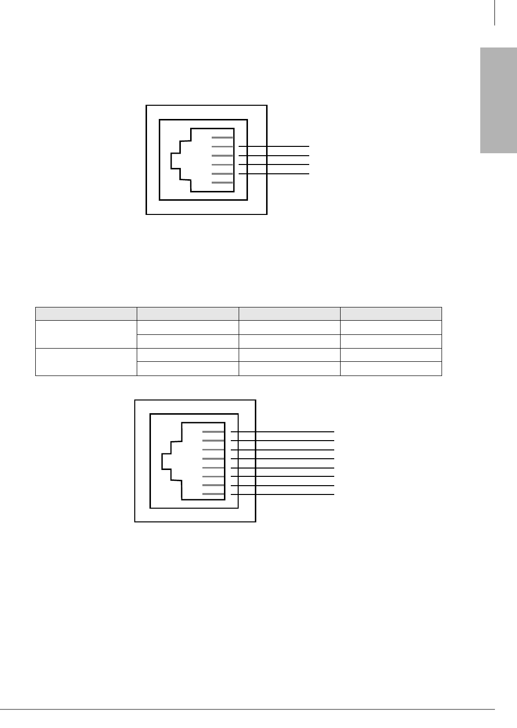
ISDN Interfaces
RBUU/RBUS Interface Unit
Strata CTX I&M 06/04 7-31
ISDN Interfaces
• The ISDN BRI-U wire pair is usually on the center pair of the Demarc jack, pins 3 and 4 on
RJ11 and pins 4 and 5 on RJ45. Demarc coding is shown in Tables 7-13, 7-14 and 7-15. Typical
demarc jack wiring is shown in Figures 7-27 and 7-28:
Figure 7-27 Six-pin Modular Plug (RJ11)
Figure 7-28 Eight-pin Modular Plug (RJ45)
Table 7-13 Quad Cable with RJ11 Demarc Coding
Conductor Color Pin Use
Pair 1 Red 3 Line 1
Green 4 Line 1
Pair 2 Yellow 5 Line 2/Power
Black 2 Line 2/Power
RJ11 Demarc Jack
4726
6
5
4
3
2
1
BLACK
RED
GREEN
YELLOW
RJ45 Demarc Jack
4727
1
2
3
4
5
6
7
8
WHITE-GREEN
GREEN
WHITE-ORANGE
BLUE
WHITE-BLUE
ORANGE
WHITE-BROWN
BROWN
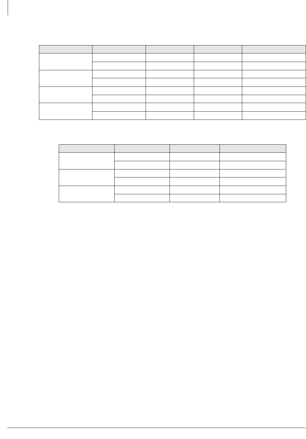
ISDN Interfaces
RBUU/RBUS Interface Unit
7-32 Strata CTX I&M 06/04
Notes
●PS2 and PS3 are not used with the Strata CTX BRI-U interface PCBs.
●Check with the BRI circuit supplier to determine the pin out of the demarc jacks because some
jacks may be wired with two or three BRI-U line circuits each jack.
Station-Side Cabling
• The ISDN BRI U-interface circuits are two-wire on the Strata CTX station-side.
• The maximum distance between the Strata CTX ISDN BRI-U, station-side circuit (LT) and the
U-type Terminal Equipment or Terminal Adapter is 18kft.
• The house wiring from the Strata CTX BRI circuit to the wall jack should be made with CAT3~
CAT5 twisted pair wire.
• Each station-side BRI circuit requires a ferrite core as shown in Figure 7-16 on page 7-23.
• The flat satin telephone cord that connects from the wall jacks to ISDN terminal equipment
should be no longer than 33 feet.
• BRI station-side cables should not be shielded.
• Polarity of the U interface pair is not critical.
• The U interface pair should go directly from the Strata CTX interface PCB to the U-type TE1
or TA with no bridge taps or loading coils to different locations.
• The pin-out of the RBUU/RBUS BRI jack is shown in Figure 7-25:
Call Monitor Jack Cabling
The pin-out for the BRI-U interface call monitor jack is provided in Figure 7-32 of this chapter.
Table 7-14 Four-Pair with RJ45 Demarc Jack Coding
Conductor Color T56A Pin T56B Pin Use
Pair 1 White-Blue 5 5 Line 1
Blue 4 4 Line 1
Pair 2 White-Orange 3 1 Line 2
Orange 6 2 Line 2
Pair3 White-Green 1 3 PS3 plus power
Green 2 6 PS3 minus power
Pair 4 White-Brown 7 7 PS2 plus power
Brown 8 8 PS2 minus power
Table 7-15 Three-Pair with RJ11 Demarc Coding
Conductor Color Pin Use
Pair 1 White-Blue 4 Line 1
Blue 3 Line 1
Pair 2 White-Orange 2 Line 2
Orange 5 Line 2
Pair3 White-Green 1 Line 3
Green 6 Line 3
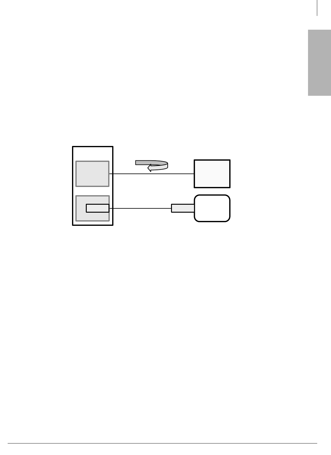
ISDN Interfaces
ISDN Testing and Troubleshooting
Strata CTX I&M 06/04 7-33
ISDN Interfaces
ISDN Testing and Troubleshooting
BRI-U, LT Interface Terminal Loop Back Test
The Strata CTX provides a built-in loop back test to check the U-type, lSDN terminal connected to
the RBUU or RBUS circuit. The Strata CTX performs the 2B+D loop test using the eoc ISDN,
layer 1 function. This tests the U-terminal and the wire connection from the Strata CTX to the BRI
device; it does not check the Strata CTX PCM highway or RBUU/RBUS functionality.
1. Connect the U-terminal device to the Strata CTX BRI, RJ45 circuit jack (see Figure 7-29).
2. Connect the Strata CTX TTY port (PIOU, RSIU, TSIU, etc.) to the COM port of a PC running
a communications application such as ProComm or Hyper Terminal, etc.
3. Setup the com-port parameters for 7-bits, even parity, 1-stop bit and the appropriate speed.
Figure 7-29 Strata CTX TTY Port BRI Connection to PC
4. Press the Enter key on the PC keyboard. The Strata CTX responds with CODE.
Note Make all entries from the PC keyboard in Capital letters.
5. At the CODE prompt, type the Strata CTX, four-digit code from the PC keyboard. The Strata
CTX responds with MODE
6. At the MODE prompt, type TEST and press Enter from the PC keyboard. The Strata CTX
responds with T.
7. At the T prompt, type LBUU ss m and press Enter from the PC keyboard. Where ss = BRI
PCB slot number and m=BRI circuit number (1-4).
Notes
●The U-terminal must be idle, and remain idle, during the loop back test.
●The Strata CTX sends 4 octets of data to the U-terminal during the loop back test: 0X00,
0XFF, 0XB2, and 0X4D. These octets are sent to the B1, B2, and D channels 50 times. If the
Strata CTX receives 80% of the sent data back, it assumes the test to pass. (i.e., the U-terminal
and wiring is good.)
If the Strata CTX responds with:
## BUU LOOP BACK TEST ##
SLOT=ss CIRCUIT=m B1:OK B2:OK D:OK
5866
Strata System
RBUU
(LT Mode)
PC with Hyper
Terminal
Software
U-Terminal
device
(loop back)
1-pair BRI Circuit Line Cord
3-pair Telephone Cord
RSIU or PIOU
TTY Port TTY Port
Test data from Strata sent to
Terminal. If 80% of sent data is
returned test passes.
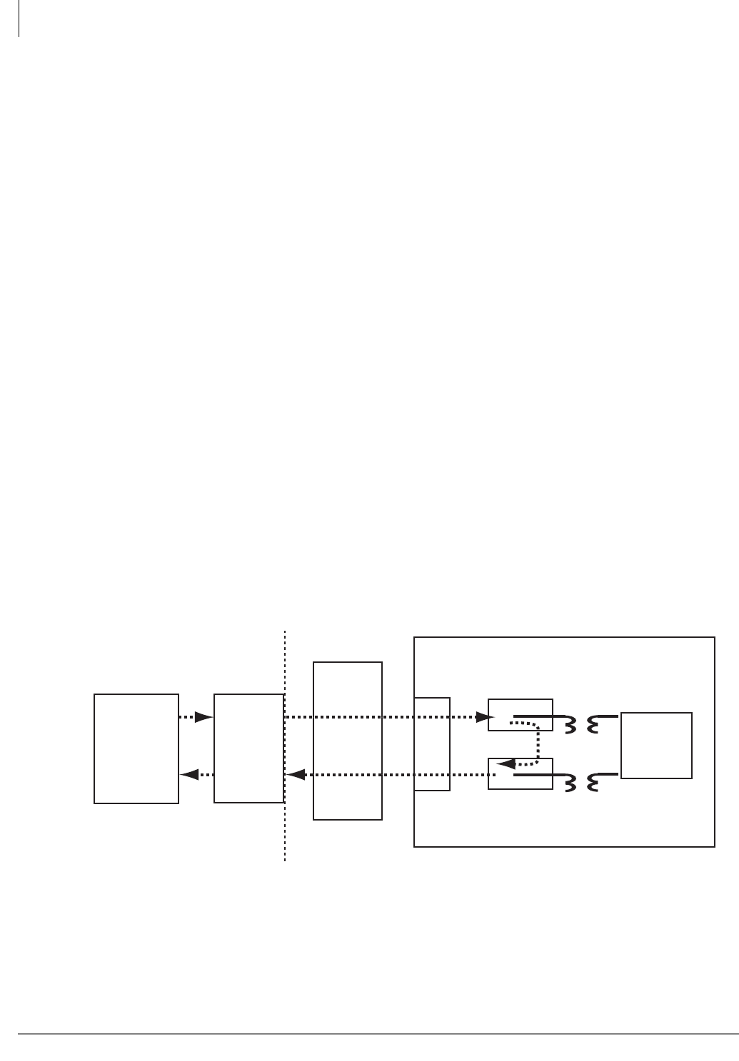
ISDN Interfaces
ISDN Testing and Troubleshooting
7-34 Strata CTX I&M 06/04
The above response indicates the test was passed and that the B1, B2 and D channels and the
wire connections for the tested device are operating properly.
If the Strata CTX responds with:
TEST FAIL
The test failure could be caused by:
• U-terminal is in busy state when the test was started.
• U-terminal is in TQ/ACB/ACD mode when the test was started
• The Strata CTX BRI PCB slot or circuit number was not entered correctly.
• U-terminal can not support loop back testing U-terminal, BRI PCB, or wiring is defective.
If the Strata CTX responds with:
TEST EXIT
Test exit could be caused by:
• The Strata CTX processor did not get test results from the BRI circuit within five seconds
from start of the test.
• U-terminal or BRI circuit was unplugged during the test.
• User made the exit request during testing
Loop-back Test
The BPTU and RPTU have loop-back test jumpers that enable physical connections (cables/jacks/
plugs) between the PCB, CSU, and the network PRI line to be tested (see Figure 7-30). The tests
check that the CSU receives and transmits the PRI signal properly in both directions. The test
signals, generated by the Network PRI provider, pass through the CSU and loop around the BPTU
or RPTU. The BPTU or RPTU sends the received test signal back through the CSU to the Network
and the Network detector checks for a valid signal.
Figure 7-30 Loop-back Test
CO ISDN
PRI Test
Signal
ISDN PRI
CSU ISDN PRI
(RJ45)
JP1
(LB-ON)
JP2
(LB-ON)
1.5MHz
line
Interface
LSI
Demarcation Point
6689
BPTU or RPTU
Network
Jack
RJ48C
or RJ48X

ISDN Interfaces
Timing and Synchronization
Strata CTX I&M 06/04 7-35
ISDN Interfaces
Loop-back Test
1. Remove the PRI modular cord from the RPTU RJ45 jack and remove the RPTU from its card
slot.
2. Place the JP1 and JP2 jumpers to the LB-On position. Install the RPTU with the Strata CTX
power Off and the PRI modular disconnected from the RPTU RJ45 jack.
3. Turn the Strata CTX power On and connect the PRI modular cord to RPTU RJ45.
4. After the PRI line and RPTU are synchronized, have the CO generate the loop-back test sign
(all “1s” or “0s”).
CAUTION! Do not have the CO do a QRS loop-back test, because the test signal may
cause the Strata CTX to drop all calls and/or stop operating.
5. If the loop-back test fails, perform tests to isolate the problem with an ISDN test set, such as the
Sunbird, ISDN, or Trend DUET. In this case, the network PRI line is disconnected and the test
set is connected to the CSU network input jack. For testing details, refer to the ISDN test set
operating procedures.
Timing and Synchronization
The Digital Network is connected by timing clocks that synchronize the network and have various
degrees of precision (stratum levels). There are four stratum levels – 1 is the highest and 4 is the
lowest. They are associated with the following sources:
•Stratum – 1: Public Telephone Network clock
•Stratum – 2: #4 ESS Toll Switches
•Stratum – 3: #5 ESS Central Offices
•Stratum – 4: Digital PBXs
In the Strata CTX, one PRI, BRI, or T1 PCB can be programmed to extract the Stratum clock
signal. It uses the signal as the Strata CTX system Primary clock reference. The clock provider
should be a reliable source, such as a Telco or common carrier (AT&T). All other PRI, BRI, or T1
lines connected to the Strata CTX will be synchronized to the same clock provider. If the PRI,
BRI, or T1 are not synchronized to the same clock provider, the Strata CTX could experience
“slip” problems.
The timing or synchronization program determines how the Strata CTX digital voice or data
transmission path is synchronized with the far-end digital path. For proper PRI, BRI, and T1
operation, the equipment at each end of the line must be synchronized.
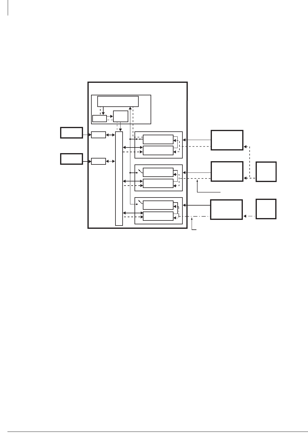
ISDN Interfaces
Timing and Synchronization
7-36 Strata CTX I&M 06/04
The Strata CTX processor time switch is synchronized as the slave to the PRI, BRI, or T1 line
(Line 1 in Figure 7-31).
If a malfunction occurs and Primary reference synchronization is lost, the Strata CTX
automatically switches modes and synchronizes to the Secondary reference, provided that there is
another PRI, BRI, or T1 installed in the Strata CTX system.
Figure 7-31 Primary and Secondary References
Figure 7-31 shows the Primary reference PCB. The clock signal from Line 1 passes through the
PCB Software Switch (SS1) and the synchronization circuit of the RCTU PCB. The RCTU clock
passes the clock source through the time switch and synchronizes the Strata CTX digital
transmission voice or data path.
The Secondary reference is activated if the Primary reference fails. The Strata CTX automatically
switches over to the Secondary reference PCB by opening its synchronization circuit (SS1) and
closing the synchronization circuit (SS2). When this occurs, the digital voice or data path of the
Strata CTX is synchronized to the Line 2 clock source.
If the path is not synchronized to the Stratum – 1 clock source, calls connected through that path
experience “slipping” or “jitter” in the digital voice or data path (channels). Figure 14-7 shows an
unsynchronized signal from Line 3. The unsynchronized signal produces a clicking or popping
sound that is heard by the people connected through this path or causes data errors on data
transmissions.
5439
PDKU
Primary Reference PCB*
Secondary Reference PCB*
Other RDTU, RPTU, or RBSU
CTX Digital Transmission Voice Path
Synchronization
Circuit
Synchronization
Circuit
Synchronization
Circuit
Digital Voice
Path
Digital Voice
Path
Digital Voice
Path
Strata CTX
Digital
Telephone
Standard
Telephone
SS1
SS2
SS3
Line 1
Line 2
Line 3
Public Switched
Telephone
Network (PSTN)
PRI, BRI, or T1
AT&T or
other provider
PRI, BRI, or T1
Other
PRI, BRI, or T1
provider
Stratum-1
Clock
Source
Processor PCB
Clock not synchronized properly
with Stratum-1 Clock Source
Time
Switch
Clock
Synchronization
Circuit
Clock synchronized properly
with Stratum-1 Clock Source
Other
Clock
Source
RSTU
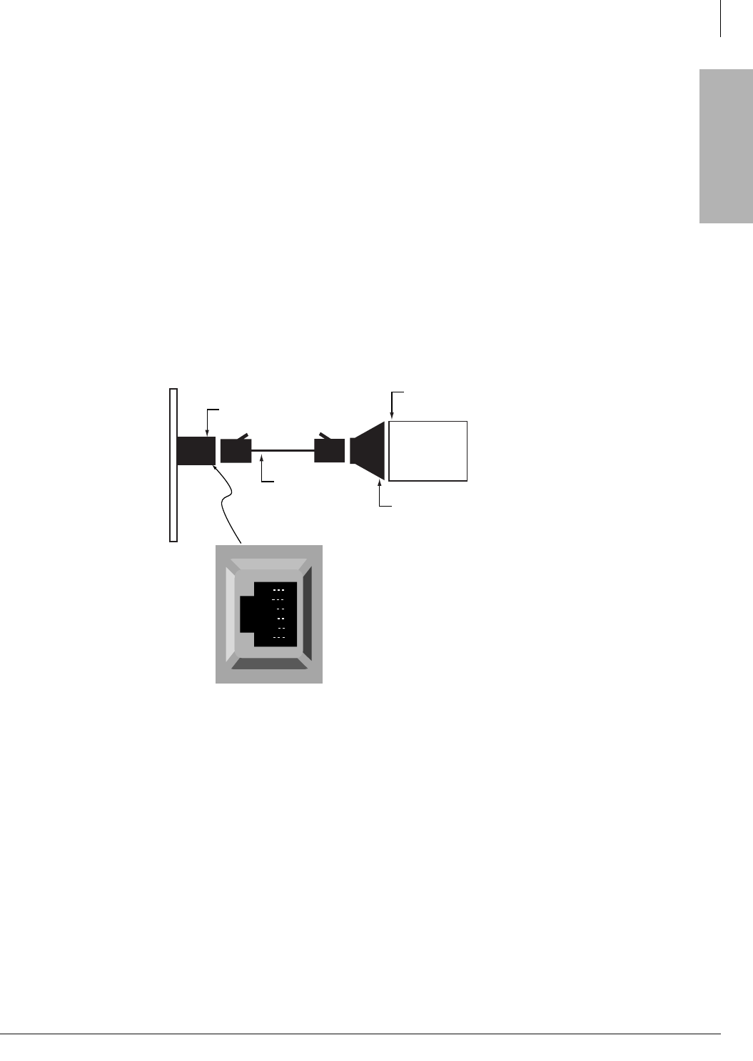
ISDN Interfaces
PRI/BRI Call Monitoring
Strata CTX I&M 06/04 7-37
ISDN Interfaces
PRI/BRI Call Monitoring
The Strata CTX ISDN circuit cards provide an RS-232 monitor function that enables you to
monitor the ISDN D-channel call progress layer two and three messages (setup, connect, and
release). This data can be monitored live, saved to a file, and/or printed using a PC with
communication software.
The hardware connections and communication parameters for the ISDN monitor port are shown in
Figure 7-32. Once this connection is setup and established, call monitoring data continues to be
sent (on the fly) as PRI and BRI calls are originated or received.
Two sample printouts from the RPTU monitor are provided. Figure 7-32 shows typical ISDN PRI
start-up and synchronization sequences that occur at connection and power on. Figure 7-33 shows
typical ISDN PRI outgoing call setup and release sequences. BRI monitor data is similar to PRI
monitor data.
The communication parameters for all call-monitor jacks are 9600 bps, 7, 1, even.
Note The RPTU, RBSU and RBUU ISDN interface PCBs each have a call-monitor jack. The pin
numbering and communication parameters are the same for each call-monitor jack. The
call-monitor jack on each PCB provides data only for the circuits of the PCB on which it
appears.
Figure 7-32 Call-monitor Jack for the RPTU, RBSU, and RBUU
Call Monitor Output for ISDN
See the following figures for examples of Call Monitor Output printouts.
RD
TD
DSR
DTR
DCD
SG
1
2
3
4
5
6
Call-monitor jack (RJ12)
pin numbering
Dealer-supplied 6-wire
telephone modular cord
(cross-pinned)
Call-monitor jack
PC with communication
software - such as ProComm™
PC DB9 or
DB25 Com port
Toshiba PPTC9 or
PPTC25F
Strata PRI or BRI PCB Monitor Jack
4696

ISDN Interfaces
Call Monitor Output for ISDN
7-38 Strata CTX I&M 06/04
Figure 7-33 PRI Start-up and Synchronization Sequences
/*-------------------------*/
Copyright(C) 1997
TOSHIBA Corporation
All rights reserved
RPTU Ver.1G
[Reset]
/*-------------------------*/
<U1>00;00016 Act. (F1)
/*-------------------------*/
Copyright(C) 1997
TOSHIBA Corporation
All rights reserved
RPTU Ver.1G
[Reset]
/*-------------------------*/
<U1>00;00016 Act. (F1)
<U1>00;09634 LOS (F3)
<U1>00;12109 Act. (F1)
/*-------------------------*/
Copyright(C) 1997
TOSHIBA Corporation
All rights reserved
RPTU Ver.1G
[Reset]
/*-------------------------*/
<U1>00;00017 Act. (F1)
<U1>00;06619 Tx :[SAPI]00 C [TEI]000 [FRAME]SABME P
<U1>00;06630 Rx:[SAPI]00 R [TEI]000 [FRAME]UA F
<U1>00;07236 Rx:[SAPI]00 C [TEI]000 [FRAME]SABME P
<U1>00;07245 Tx :[SAPI]00 R [TEI]000 [FRAME]UA F
<U1>00;11754 LOS (F3)
<U1>00;14228 Act. (F1)
<U1>00;14415 Tx :[SAPI]00 C [TEI]000 [FRAME]SABME P
<U1>00;14427 Rx:[SAPI]00 R [TEI]000 [FRAME]UA F
<U1>00;14753 Tx :[SAPI]00 C [TEI]000 [FRAME]SABME P
<U1>00;14765 Rx:[SAPI]00 R [TEI]000 [FRAME]UA F
<U1>00;24275 Tx :[SAPI]00 C [TEI]000 [FRAME]INFO [N(S)]000 [N(R)]000
PD = Q.931(08)
CR = 02 0002
MT = SETUP(05)
04 03 80 90 A2 18 03 A9 83 97 70 08 C1 35 38 33 ..........p..583
33 30 30 31 3001
<U1>00;24292 Rx:[SAPI]00 R [TEI]000 [FRAME]RR [N(R)]001
<U1>00;28315 Tx :[SAPI]00 C [TEI]000 [FRAME]INFO [N(S)]001 [N(R)]000
PD = Q.931(08)
CR = 02 0002
MT = SETUP(05)
04 03 80 90 A2 18 03 A9 83 97 70 08 C1 35 38 33 ..........p..583
33 30 30 31 3001
<U1>00;28333 Rx:[SAPI]00 R [TEI]000 [FRAME]RR [N(R)]002
<U1>00;43812 Rx:[SAPI]00 C [TEI]000 [FRAME]INFO [N(S)]000 [N(R)]002
PD = Q.931(08)
CR = 02 8002
MT = CONN(07)
2759

ISDN Interfaces
Call Monitor Output for ISDN
Strata CTX I&M 06/04 7-39
ISDN Interfaces
Figure 7-34 PRI Outgoing Call Connect and Release
<U1>01;14446 Rx:[SAPI]00 C [TEI]000 [FRAME]RR P [N(R)]004
<U1>01;14449 Tx :[SAPI]00 C [TEI]000 [FRAME]RR P [N(R)]002
<U1>01;14456 Tx :[SAPI]00 R [TEI]000 [FRAME]RR F [N(R)]002
<U1>01;14460 Rx:[SAPI]00 R [TEI]000 [FRAME]RR F [N(R)]004
<U1>01;19450 Tx :[SAPI]00 C [TEI]000 [FRAME]INFO [N(S)]004 [N(R)]002
PD = Q.931(08)
CR = 02 0003
MT = SETUP(05)
04 03 80 90 A2 18 03 A9 83 97 70 08 C1 35 38 33 ..........p..583
33 30 30 31 3001
<U1>01;19466 Rx:[SAPI]00 R [TEI]000 [FRAME]RR [N(R)]005
<U1>01;19878 Rx:[SAPI]00 C [TEI]000 [FRAME]INFO [N(S)]002 [N(R)]005
PD = Q.931(08)
CR = 02 8003
MT = CALL PROC(02)
18 03 A9 83 97 .....
<U1>01;19888 Tx :[SAPI]00 R [TEI]000 [FRAME]RR [N(R)]003
<U1>01;19924 Rx:[SAPI]00 C [TEI]000 [FRAME]INFO [N(S)]003 [N(R)]005
PD = Q.931(08)
CR = 02 8003
MT = ALERT(01)
18 03 A9 83 97 .....
<U1>01;19932 Tx :[SAPI]00 R [TEI]000 [FRAME]RR [N(R)]004
<U1>01;25464 Rx:[SAPI]00 C [TEI]000 [FRAME]INFO [N(S)]004 [N(R)]005
PD = Q.931(08)
CR = 02 8003
MT = CONN(07)
18 03 A9 83 97 .....
<U1>01;25476 Tx :[SAPI]00 R [TEI]000 [FRAME]RR [N(R)]005
<U1>01;25785 Tx :[SAPI]00 C [TEI]000 [FRAME]INFO [N(S)]005 [N(R)]005
PD = Q.931(08)
CR = 02 0003
MT = CONN ACK(0F)
<U1>01;25799 Rx:[SAPI]00 R [TEI]000 [FRAME]RR [N(R)]006
<U1>01;46127 Rx:[SAPI]00 C [TEI]000 [FRAME]INFO [N(S)]005 [N(R)]006
PD = Q.931(08)
CR = 02 8003
MT = DISC(45)
08 02 80 90 ....
<U1>01;46138 Tx :[SAPI]00 R [TEI]000 [FRAME]RR [N(R)]006
<U1>01;46449 Tx :[SAPI]00 C [TEI]000 [FRAME]INFO [N(S)]006 [N(R)]006
PD = Q.931(08)
CR = 02 0003
MT = REL(4D)
08 02 80 90 ....
<U1>01;46464 Rx:[SAPI]00 R [TEI]000 [FRAME]RR [N(R)]007
<U1>01;46784 Rx:[SAPI]00 C [TEI]000 [FRAME]INFO [N(S)]006 [N(R)]007
PD = Q.931(08)
CR = 02 8003
MT = REL COMP(5A)
08 02 80 90 ....
<U1>01;46795 Tx :[SAPI]00 R [TEI]000 [FRAME]RR [N(R)]007
<U1>02;16659 Tx :[SAPI]00 C [TEI]000 [FRAME]RR P [N(R)]007
<U1>02;16670 Rx:[SAPI]00 R [TEI]000 [FRAME]RR F [N(R)]007
<U1>02;22661 Rx:[SAPI]00 C [TEI]000 [FRAME]INFO [N(S)]007 [N(R)]007
PD = Q.931(08)
CR = 02 0004
2760

ISDN Interfaces
Call Monitor Output for ISDN
7-40 Strata CTX I&M 06/04
BRI Call Monitor
The call-monitor jack located on the RBSU enables you to use a PC or ASCII terminal to monitor
the BRI, D-channel call setup, layer-2 and layer-3 data (refer to Figure 7-32 on page 7-37 for
information about connecting the monitor jack). Figures 7-35 and 7-36 provide examples of BRI
call setup message information that is available from the RBSU call-monitor jack.
Figure 7-35 Outgoing Call Setup Output of BRI Call Monitor
<U3>06;57’958 Tx :[SAPI]00 C [TEI]102 [FRAME]RR P [N(R)]021
<U3>06;57’970 Rx:[SAPI]00 R [TEI]102 [FRAME]RR F [N(R)]019
<U3>07;07’166 Rx:[SAPI]00 C [TEI]102 [FRAME]INFO [N(S)]021 [N(R)]019
PD = Q.931(08)
CR = 01 0F
MT = SETUP(05)
04 03 80 90 A2 6C 05 C1 33 30 37 32 96 7B 01 81 .....l..3072.{..
<U3>07;07’217 Tx :[SAPI]00 R [TEI]102 [FRAME]RR [N(R)]022
<U3>07;07’735 Tx :[SAPI]00 C [TEI]102 [FRAME]INFO [N(S)]019 [N(R)]022
PD = Q.931(08)
CR = 01 8F
MT = SETUP ACK(0D)
18 01 89 1E 02 80 88 34 01 00 32 01 C2 95 2A 24 .......4..2...*$
80 9E 14 44 49 41 4C 20 53 54 41 54 49 4F 4E 20 ...DIAL STATION
4E 4F 2E 20 4F 52 20 9E 0B 41 43 43 45 53 53 20 NO. OR ..ACCESS
43 4F 44 45 CODE
<U3>07;07’750 Rx:[SAPI]00 R [TEI]102 [FRAME]RR [N(R)]020
<U3>07;07’866 Rx:[SAPI]00 C [TEI]102 [FRAME]INFO [N(S)]022 [N(R)]020
PD = Q.931(08)
CR = 01 0F
MT = INFO(7B)
2C 01 31 ,.1
<U3>07;07’909 Tx :[SAPI]00 R [TEI]102 [FRAME]RR [N(R)]023
<U3>07;08’171 Rx:[SAPI]00 C [TEI]102 [FRAME]INFO [N(S)]023 [N(R)]020
PD = Q.931(08)
CR = 01 0F
MT = INFO(7B)
2C 01 30 ,.0
<U3>07;08’192 Tx :[SAPI]00 R [TEI]102 [FRAME]RR [N(R)]024
<U3>07;08’415 Rx:[SAPI]00 C [TEI]102 [FRAME]INFO [N(S)]024 [N(R)]020
PD = Q.931(08)
CR = 01 0F
MT = INFO(7B)
2C 01 30 ,.0
<U3>07;08’450 Tx :[SAPI]00 R [TEI]102 [FRAME]RR [N(R)]025
<U3>07;08’658 Rx:[SAPI]00 C [TEI]102 [FRAME]INFO [N(S)]025 [N(R)]020
PD = Q.931(08)
CR = 01 0F
MT = INFO(7B)
2C 01 35 ,.5
<U3>07;08’682 Tx :[SAPI]00 R [TEI]102 [FRAME]RR [N(R)]026
<U3>07;08’941 Tx :[SAPI]00 C [TEI]102 [FRAME]INFO [N(S)]020 [N(R)]026
PD = Q.931(08)
CR = 01 8F
MT = CALL PROC(02)
18 01 89 32 01 82 ...2..
<U3>07;08’958 Rx:[SAPI]00 R [TEI]102 [FRAME]RR [N(R)]021
<U3>07;09’086 Tx :[SAPI]00 C [TEI]102 [FRAME]INFO [N(S)]021 [N(R)]026
PD = Q.931(08)
CR = 01 8F
MT = ALERT(01)
18 01 89 1E 02 80 88 34 01 40 95 2A 0B 80 9E 08 .......4.@.*....
43 41 4C 4C 49 4E 47 20 CALLING
<U3>07;09’106 Rx:[SAPI]00 R [TEI]102 [FRAME]RR [N(R)]022
<U2>07;09’314 Tx :[SAPI]00 C [TEI]112 [FRAME]RR P [N(R)]000
<U4>07;09’318 Rx:[SAPI]00 C [TEI]112 [FRAME]RR P [N(R)]000
<U4>07;09’344 Tx :[SAPI]00 R [TEI]112 [FRAME]RR F [N(R)]000

ISDN Interfaces
Call Monitor Output for ISDN
Strata CTX I&M 06/04 7-41
ISDN Interfaces
Figure 7-36 Incoming Call Setup Output of BRI Call Monitor
<U2>07;40’993 Tx :[SAPI]00 R [TEI]113 [FRAME]RR F [N(R)]000
<U4>07;40’997 Rx:[SAPI]00 R [TEI]113 [FRAME]RR F [N(R)]000
<U4>07;41’000 Tx :[SAPI]00 R [TEI]113 [FRAME]RR F [N(R)]000
<U2>07;41’005 Rx:[SAPI]00 R [TEI]113 [FRAME]RR F [N(R)]000
<U3>07;41’168 Tx :[SAPI]00 C [TEI]102 [FRAME]RR P [N(R)]027
<U3>07;41’180 Rx:[SAPI]00 R [TEI]102 [FRAME]RR F [N(R)]025
<U3>07;53’481 Tx :[SAPI]00 C [TEI]127 [FRAME]U-INFO
PD = Q.931(08)
CR = 01 04
MT = SETUP(05)
04 03 80 90 A2 18 01 89 1E 02 80 83 6C 06 00 83 ............l...
31 30 30 35 70 05 80 33 30 37 32 34 01 40 1005p..30724.@
<U3>07;53’514 Rx:[SAPI]00 C [TEI]102 [FRAME]INFO [N(S)]027 [N(R)]025
PD = Q.931(08)
CR = 01 84
MT = ALERT(01)
18 01 89 ...
<U3>07;53’548 Tx :[SAPI]00 R [TEI]102 [FRAME]RR [N(R)]028
<U3>07;55’488 Rx:[SAPI]00 C [TEI]102 [FRAME]INFO [N(S)]028 [N(R)]025
PD = Q.931(08)
CR = 01 84
MT = CONN(07)
<U3>07;55’518 Tx :[SAPI]00 R [TEI]102 [FRAME]RR [N(R)]029
<U3>07;55’781 Tx :[SAPI]00 C [TEI]102 [FRAME]INFO [N(S)]025 [N(R)]029
PD = Q.931(08)
CR = 01 04
MT = CONN ACK(0F)
18 01 89 34 01 4F 95 2A 03 80 9E 00 ...4.O.*....
<U3>07;55’792 Rx:[SAPI]00 R [TEI]102 [FRAME]RR [N(R)]026
<U3>07;57’585 Rx:[SAPI]00 C [TEI]102 [FRAME]INFO [N(S)]029 [N(R)]026
PD = Q.931(08)
CR = 01 84
MT = DISC(45)
08 02 80 90 ....
<U3>07;57’619 Tx :[SAPI]00 R [TEI]102 [FRAME]RR [N(R)]030
<U3>07;57’942 Tx :[SAPI]00 C [TEI]102 [FRAME]INFO [N(S)]026 [N(R)]030
PD = Q.931(08)
CR = 01 04
MT = REL(4D)
08 02 80 90 ....
<U3>07;57’959 Rx:[SAPI]00 R [TEI]102 [FRAME]RR [N(R)]027
<U3>07;57’979 Rx:[SAPI]00 C [TEI]102 [FRAME]INFO [N(S)]030 [N(R)]027
PD = Q.931(08)
CR = 01 84
MT = REL COMP(5A)
<U3>07;58’029 Tx :[SAPI]00 R [TEI]102 [FRAME]RR [N(R)]031
<U1>07;59’447 Await. Sig.(F4)
<U4>08;05’903 Tx :[SAPI]00 C [TEI]112 [FRAME]RR P [N(R)]000
<U2>08;05’907 Rx:[SAPI]00 C [TEI]112 [FRAME]RR P [N(R)]000
<U2>08;05’928 Tx :[SAPI]00 R [TEI]112 [FRAME]RR F [N(R)]000
<U4>08;05’932 Rx:[SAPI]00 R [TEI]112 [FRAME]RR F [N(R)]000
<U2>08;05’969 Tx :[SAPI]00 C [TEI]112 [FRAME]RR P [N(R)]000
<U4>08;05’973 Rx:[SAPI]00 C [TEI]112 [FRAME]RR P [N(R)]000
<U4>08;05’989 Tx :[SAPI]00 R [TEI]112 [FRAME]RR F [N(R)]000

ISDN Interfaces
Call Monitor Output for ISDN
7-42 Strata CTX I&M 06/04

Strata CTX I&M 06/04 8-1
T1
T1 8
This chapter covers the RDTU T1/DS-1 interface for the Strata CTX systems. It contains
information about the RDTU3 and RDTU1/2. The RDTU3 is a replacement for the RDTU1 and 2.
Note “RDTU” refers to all RDTU (1, 2 or 3) PCBs. When a distinction is required, the exact
numbered term, such as “RDTU3” is used.
Program Channels
The RDTU PCB provides T1/DS-1 interface for up to 24 channels on the Strata CTX. Each
channel can be individually set for loop start, ground start, Tie, or DID line operation (voice only,
not data lines). Each RDTU can be set in system programming to activate (1~8), (1~16), or (1~24)
channels (lines). Fractional increments of 4, 12, and 20 are also possible but the RDTU still
assigns 8, 16, or 24 channels respectively in system software.
Example: If only 12 channels of fractional T1 are used, assign RDTU as a 16 channel RDTU. The
system assigns 16 CO lines to the RDTU even though only 12 CO lines are used.
Select Slot Assignments
RDTU PCBs can be installed in a Strata CTX to provide up to 264 lines (max). RDTU PCBs can
be installed in any CTX cabinet, except remote CTX cabinets driven with RRCU cards. RDTU
PCBs must be placed in designated slots in each of the Strata CTX cabinets. (See “Worksheet 5:
Strata CTX100 Cabinet Slots” on page 2-26 and “Worksheet 6: Strata CTX670 Cabinet Slots” on
page 2-37.)
If an RDTU is installed in a cabinet (in some cases one slot to the right of the RDTU may not be
used in that cabinet) the number of unusable slots in a cabinet depends on which slot the RDTU
occupies and how many lines (16 or 24) the RDTU is programmed to provide.
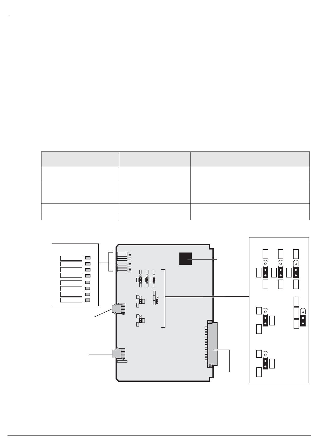
T1
RDTU3 - T1 Interface Unit
8-2 Strata CTX I&M 06/04
RDTU3 - T1 Interface Unit
System:
CTX100 & 670
Circuits per PCB:
8, 16, 24 channels per PCB
Interfaces with:
Ground / Loop start CO lines DID or TIE lines (Wink or Immediate)
Older Version(s):
RDTU1, RDTU2
The RDTU3A has an RS-232C port to trace data that is transmitted between the CTX system CPU
and the RDTU3A. This PCB also enables T1 line alarm data to be monitored.
T1 Framing: D4 (SF) or ESF
Line cording: AMI with ZCS or B8ZS
Digital PAD: Transmit side +3dB to -15dB. Receive side +3dB to -15dB (software controlled)
Figure 8-1 RDTU3 PCB
Table 8-1 RDTU3 Controls, Indicators, and Connectors
Control/Indicator/
Connector Type of Component Description
SW4~SW6 Equalizer Setting
Switch Jumper switches Sets the line length between RDTU and CSUs
or other T1 (see also Table 8-6).
SW8, SW9 Jumper switches
Used for Self Test and CSU Test or for non-
loop back normal operation (see also Ta bl e
8-5).
SW10 3-terminal jumper plug See Table 8-3.
IC19 External ROM upgrade Provides external ROM option (see Tabl e 8 -3 ).
RS-232C
Connector for
Call Data
Monitor (RJ-12)
J1J2
6351
Backplane
Connector
OFF
EQ
ON
SW4
R28
OFF
EQ
ON
SW5
R28
OFF
EQ
ON
SW6
R28
OFF
LB
ON SW8
CPU
ROM SW10
OFF
LB
ON SW9
RDTU3A
FSYNC
MFSYNC
BALM/AIS
YALM/RAI
LOS
BSY
PSYNC
SSYNC
MONITOR
Status/Alarm LEDs
FSYNC
MFSYNC
BALM/AIS
YALM/RAI
LOS
BSY
PSYNC
SSYNC
OFF
EQ
ON
SW4
R28
OFF
EQ
ON
SW5
R28
OFF
EQ
ON
SW6
R28
OFF
LB
ON SW8
CPU
ROM SW10
OFF
LB
ON SW9
IC19
RJ-45
8-pin Modular
Network/CSU
Interface Jack
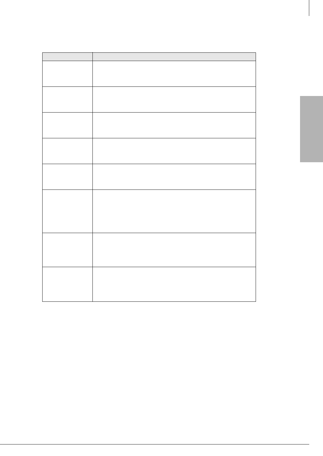
T1
T1
RDTU3 - T1 Interface Unit
Strata CTX I&M 06/04 8-3
For more detailed information on these alarms, refer to Table 8-6 on page 8-8.
Table 8-2 RDTU3 LED Functions
RDTU3 LEDs Indication
FSYNC
Frame Sync error indication
On = No frame synchronization status
Off = Frame synchronization status
MFSYNC
Multi-frame Sync error indication (same with FSYNC)
On = No frame synchronization status
Off = Frame synchronization status
BALM/AIS
Blue Alarm indication
On = RDTU3A is receiving Blue Alarm
Off = RDTU3A is not receiving Blue Alarm
YAL M/ RAI
Yellow Alarm indication
On = RDTU3A is receiving Yellow Alarm
Off = RDTU3A is not receiving Yellow Alarm
LOS
Signaling Loss indication
On = RDTU3A is not receiving T1 signals
Off = RDTU3A is receiving T1 signals
BSY
Busy state indication
On = One or more RDTU channels are in use
Or RDTU is not receiving T1 signals
Off = No RDTU channel is in use
Flashing = RDTU is in Remote Loop Back mode
PSYNC
Primary synchronization indication
On = RDTU is assigned as the primary timing PCB
Off = RDTU is not assigned as the primary timing PCB
Flashing = RDTU is extracting T1 CLK
SSYNC
Secondary synchronization indication
On = RDTU is assigned as the secondary timing PCB
Off = RDTU is not assigned as the secondary timing PCB
Flashing = RDTU is extracting T1 CLK
T1
RDTU Installation
8-4 Strata CTX I&M 06/04
RDTU Installation
³To install an RDTU PCB
1. Set the jumper wire plugs to the correct position for the cable length.
• RDTU3 – see “RDTU3 - T1 Interface Unit” on page 8-2
• RDTU1 and 2– see “RDTU3 Cabling” on page 8-5.
2. Turn the Strata CTX system power Off.
3. Refer to Chapter 2 – Strata CTX Configuration to determine the appropriate slot for the RDTU:
•“Worksheet 5: Strata CTX100 Cabinet Slots” on page 2-26
•“Worksheet 6: Strata CTX670 Cabinet Slots” on page 2-37
•“RDTU3 - T1 Interface Unit” on page 8-2 or “RDTU3 Cabling” on page 8-5
4. Insert the RDTU (component side facing right) into the appropriate slot and apply firm, even
pressure to ensure proper seating of connectors.
5. For the RDTU3 only, set the SW10 jumper plug for internal or external ROM operation, per
Table 8-3.
Note For cabling information and requirements, refer to the specific instructions for the type of
card.
Power Factor
RDTU3A uses 5V only. 5V power factor = 2.0, -24PF = 0.0
Table 8-3 SW10 Internal or External ROM Setting
Mode SW10 Note
Internal ROM
(Default mode) CPU
When there is an internal ROM on the CPU (TMP93PW46), RDTU3A
operates with the SW10.
Use this mode when IC19 is not on PCB (see Figure 8-1).
If the SW10 is in CPU position, RDTU3A is operating with the internal
ROM regardless of IC19 existence.
External ROM
(Upgrade) ROM
RDTU3A is operating with the external ROM (IC19).
Use this mode only when IC19 is on PCB (see Figure 8-1).
If the SW10 is in ROM position without IC19, the RDTU3A will not work.
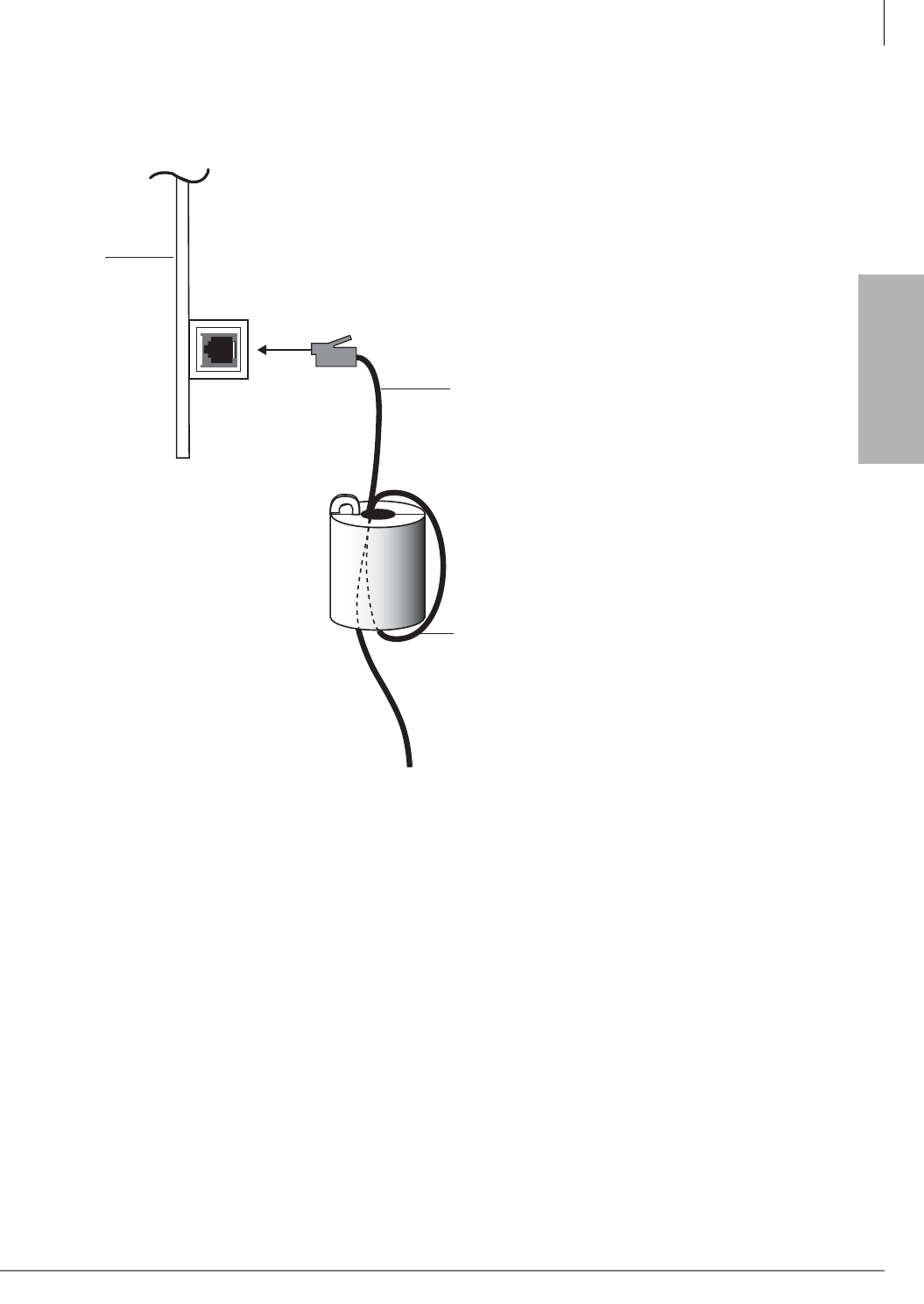
T1
T1
RDTU Installation
Strata CTX I&M 06/04 8-5
Ferrite Core
Install the Ferrite core provided with the RDTU3 PCB, as shown in Figure 8-2. This core is needed
to comply with FCC requirements.
Figure 8-2 RDTU3 Ferrite Core Installation
RDTU3 Cabling
Each RDTU3 T1 PCB requires the following connecting equipment and cables to provide service
(see the following sections and Figure 8-3).
RDTU3 to Network
If the RDTU3 must interface to a public telephone network or common carrier T1 circuit, the
RDTU3 must be connected to a CSU. Use the RDTU3-CBL-KIT to connect the RDTU to the
CSU. The function of the CSU is to provide the required interface between the RDTU PCB and the
Public Telephone or Carrier Network. The interface created by the CSU normally provides
protection and capabilities for loop back testing both the Network equipment and the RDTU PCB.
Connecting the CSU to the Network Interface Unit (NIU) is specified by the CSU manufacturer—
see CSU installation documentation. The RDTU3-CBL-KIT supplies the cables and connectors
required to connect the CSU to the NIU.
One Turn
CAT5 Shielded Cable
RDTU3
Side View
6306
Note: The Ferrite core must be
as close as possible to the PCB.
RJ-45 Network/
CSU Interface Jack
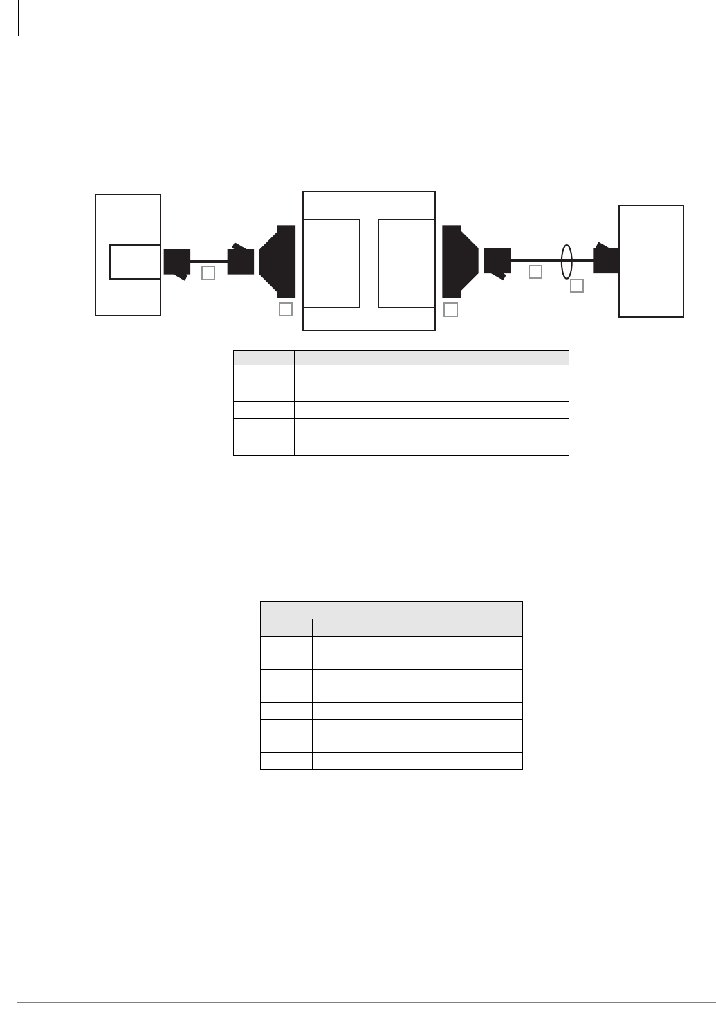
T1
RDTU Installation
8-6 Strata CTX I&M 06/04
RDTU3 to PBX T1 (Separated More Than 655 ft.)
If the RDTU3 must interface to a customer’s premises T1 circuit (PBX, key/hybrid, or another
Strata CTX) to provide Tie line service, the RDTU3 must be connected to a CSU (with Toshiba
cable kit RDTU3-CBL-KIT) if the other customer premise T1 equipment is more than 655 ft. from
the RDTU. The T1 span on the other end must also connect to a CSU.
Figure 8-3 RDTU3 Connection to Digital Network or OCC
RDTU to PBX T1 - Direct Back-to-back Connection (up to 655 ft.)
If the RDTU is within 655 ft. of the far-end PBX T1 circuit, a CSU is not required. However,
connecting a RDTU T1 span to another PBX or Key/Hybrid T1, in a Tie line configuration at a
distance less than 655 ft. (without a CSU) will require a customer provided special cable. The
transmit and receive pair of this span cable must be crossed pairs and the wires must be 24 AWG,
twisted pair, otherwise 22 AWG, ABAM type cable must be used. (See Figure 8-4.)
Table 8-4 Detailed Pinouts for RDTU3 Network Jack
Network Jack/RDTU3 Modular Jack
Pin Function
1 Tip – Receives from the network
2 Ring – Receives from the network
3 Not Used
4 Ring – Transmits to the network
5 Tip – Transmits to the network
6 Not Used
7 Not Used
8 Not Used
Network
Jack
or RDTU3
RDTU3
CSU (NIU)
DB15
(female)
DB15
(male)
6618
A
BC
D
E
RJ45
Item Description
A1
1. Items A and D come with the RDTU3-CBL-KIT.
Items A and D are straight-pinned data cables, not cross-
pinned telephony cables.
15 feet of CAT5 unshielded cable
B1 DB15 modular adapter (CSU to network jack)
C1 DB15 modular adapter (CSU to RPTU)
D130 feet of CAT5 shielded cable
E1 Ferrite core (supplied with RDTU3 PCB)
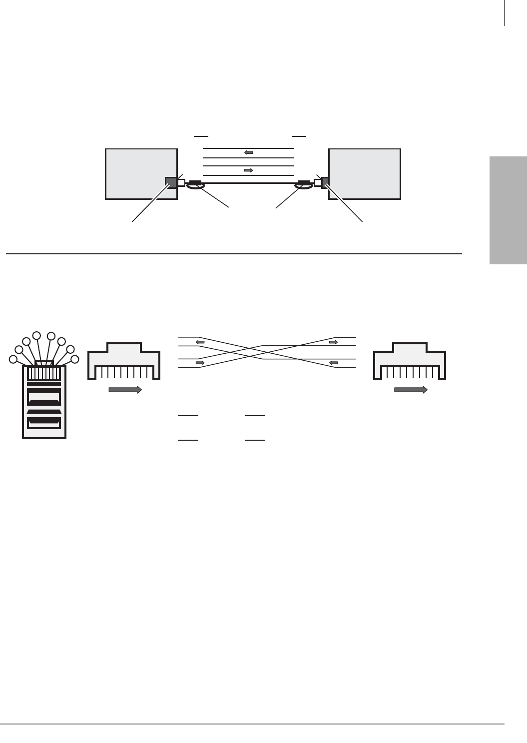
T1
T1
RDTU Installation
Strata CTX I&M 06/04 8-7
Figure 8-4 Required Cables/Connectors for RDTU Connection at Distances of Less than 655 (200 Meters)
6565
Pin of one end to
of one end to of other end - each direction
To make a Cross-Pinned Modular Cord on a existing straight through cord:
On one end only, swap Pin 1 with Pin 5 and then Pin 2 with Pin 4.
of other end - each direction
Pin15
2
Pin 4
Pin
RJ45 Cross Pinning
T
R
T
R
T
R
T
R
1
2
3
4
5
6
7
8
1
2
3
4
5
6
7
8
18
Front Front
18
Bottom Side Up
Connector Head
1
2
3456
7
8
Connecting two RDTU3 PCBs
RDTU3 RDTU3 or other
T1 interface
Strata CTX PBX or CTX
Cross-Pinned, RJ45 Modular Cord
Ferrite Core
(655 ft. max. CAT5 wire) RJ45 JackRJ45 Jack
1
2
5
4
5
4
2
1
Pin Pin
T
R
RR
R
TT
T
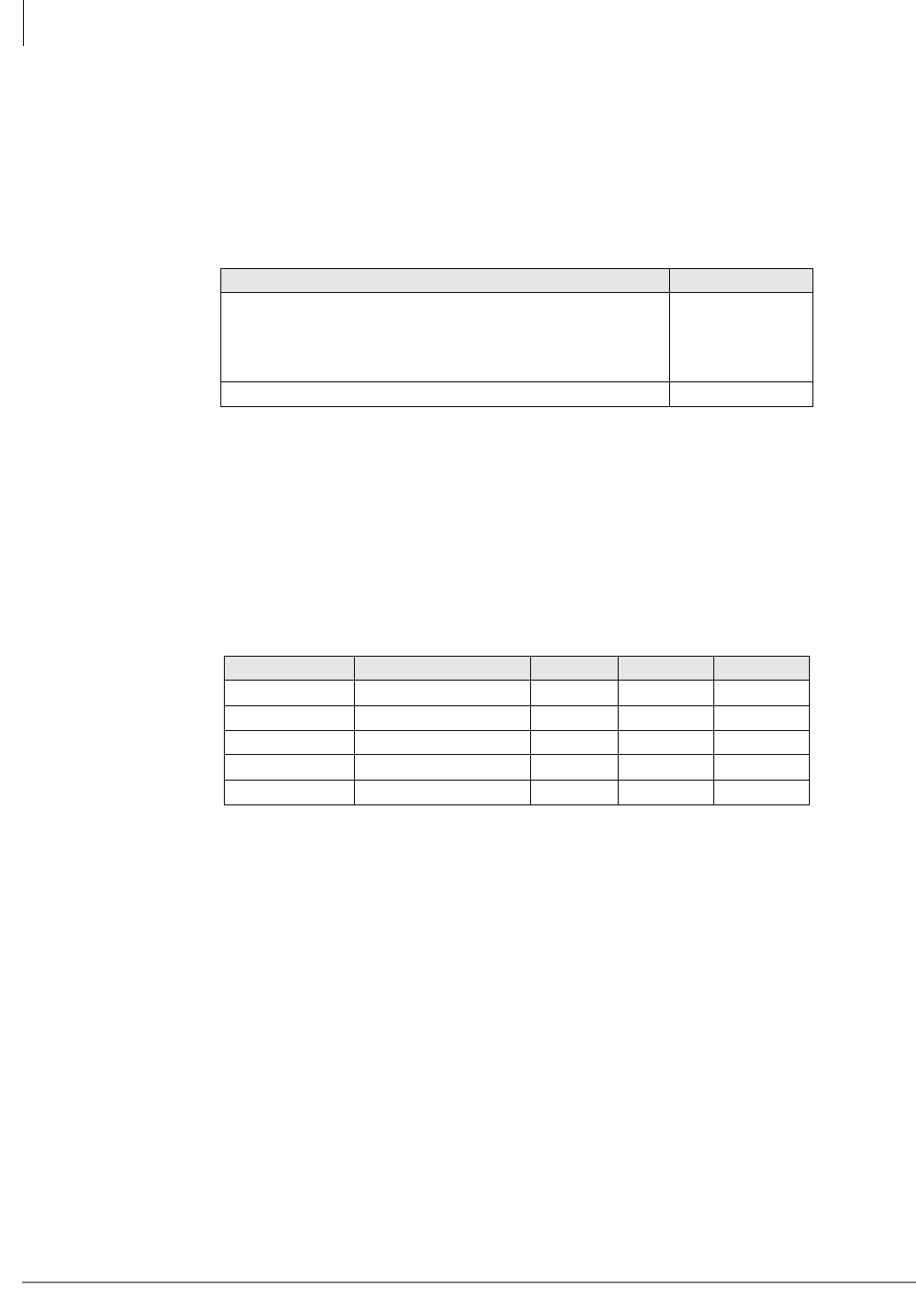
T1
RDTU Installation
8-8 Strata CTX I&M 06/04
RDTU3 Self Test and CSU Test Switch
1. Remove the RJ45 cable to perform the Self Test.
2. Set the SW8 and SW9 switches to On (see Table 8-5).
3. After self check passes, put the switches back into position for normal operation and insert the
RDTU PCB back into the appropriate slot.
RDTU3 Equalizer Switches
The distance between the Strata CTX, RDTU and CSU or RDTU to other Customer Premise
Equipment (CPE) T1 may vary (0~655 ft.) as shown. (See “RDTU3 Cabling” on page 8-5.) The
RDTU interface transmitter must be equalized and its impedance must be matched to the cable
length connecting the RDTU to the CSU or other CPE, T1.
³Set the appropriate SW1 Equalizer Switch setting and set SW1 to the setting that matches the
RDTU cable length (see Table 8-6).
RDTU3 Loop Back Jumper Plugs
The RDTU PCB provides jumper plugs for loop back testing. Loop back tests are described in
“Loop Back Testing” on page 8-19. See Table 8-5 for switch settings for Loop Back tests.
RDTU3 Front Panel Indicators
The RDTU3 PCB provides seven LED indicators to show the status of RDTU: Busy or Idle
condition, Alarm status, and Synchronization status. See Table 8-2 for the function of each status
LED. Figure 8-1 shows the LED locations. Busy LED (BSY)—Turns on when one or more RDTU
channels (lines) are in use. Also, when the RDTU does not receive the far end 1.544 mbs carrier
signal, the RDTU will cause the BSY to be on steady.
Table 8-5 SW8, SW9 RDTU3A Self and CSU Test
Mode SW8 and SW9
RDTU3A self test and CSU test mode
Both On
All LEDS turn Off
except PSYNCH
or SYNCH
Normal operation (non-loop back) Both Off
Table 8-6 Equalizer Setting Switch
Mode Feet from CTX SW4 SW5 SW6
Short 0 to 133 feet Off Off Off
Semi-short 133 to 266 feet On Off Off
Medium 266 to 399 feet Off On Off
Semi-long 399 to 533 feet On On Off
Long 533 to 655 feet X X On
X = Doesn’t matter.
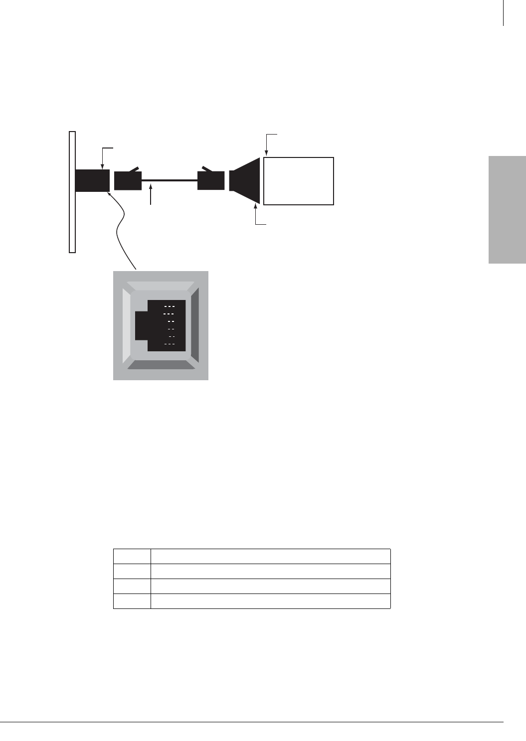
T1
T1
RDTU Installation
Strata CTX I&M 06/04 8-9
Call Data Monitor Jack
RDTU3A has an RS-232C port for maintenance monitoring and troubleshooting purposes. This
should be used when requested by Toshiba Technical Support Engineers.
Communication parameters are 9600bps, 8, and 1.
Figure 8-5 Call Monitor Jack for the RDTU3
Loop Back
You can put the RDTU3A in remote loop back mode with this port.
The command “L” and “Q” are used for remote loop back command.
L = Start remote loop back mode
Q = Quit remote loop back mode
Remote loop back commands are shown below.
The RDTU3A loop back test can made with the same process described in “Network/CSU/RDTU
Span Test” on page 8-20. Refer to Figure 8-12 on page 8-21.
l Echo back
L RDTU outputs L and BSY LED flashes
q Echo back
Q RDTU outputs Q and BSY LED is operating normal
RD
TD
DSR
DTR
DCD
SG
1
2
3
4
5
6
1 Output
2 Input
3 Output
4 NC
5 Output
6 Signal Ground
Call-monitor jack (RJ11)
pin numbering
Dealer-supplied 6-wire
telephone modular cord
(cross-pinned)
RDTU3 Call-monitor jack
PC with communication
software - such as ProComm™
PC DB9 or
DB25 Com port
Toshiba PPTC9 or
PPTC25F
6444

T1
RDTU3A Call Data Information
8-10 Strata CTX I&M 06/04
RDTU3A Call Data Information
RDTU3A has an RS-232C port to trace data that the RDTU3A sends and receives from the CTX
system processor. The T1 line alarm data can also be monitored with the RDTU3.
Commands
You can type the commands in the following table to check the status indicators also described in
the table below.
Table 8-7 RDTU3 Status Commands
Command Function Format Indication
U
When you power
On or when you
enter “U,” the unit
name and software
version appears.
u [RTN]
RDTU3A © TOSHIBA 2002 VER.1A
UNIT MODE:FFMxx SCHxx TSxx RPDxxxx TPDxxxx
ZCSxx
ERR:CRCyyy SLPyyy FSYyyyy BPVyyyyy
ALARM:YA on/off BA on/off FSL on/off
CRC = CRC Error in ESF mode
SLP = Slip error
FSY = Frame Sync error
BPV = Bipolar violation error
CH Channel mode
check command
C v [RTN]
v = 0 to 23
Note: H = 1
or 0
CH.vv : DTxx DRyy DDTon/off
CH MODE: Ax
Explanation:
CH.vv:vv = channel numbers 0~23
DTxx:xx = DHin data code for RDTU3A to RCTU (see Tabl e
8-9)
DTyy:yy = DHout datacode RCTU to RDTU3A (see Tabl e
8-10)
DDTon/off:
DDT1 = RDTU cannot receive requests from the central
processor at this time (see following Notes).
DDT0 = RDTU is available to receive requests from the
central processor
CH MODE:
A8 = CO loop, A0 = CP grpimd. AA = Tie immediate, AB =
Tie Wink, AC = DID Immediate, AD = DID WInk
This information is the same as “2-2 Data-HWY code” and
“2-5 Channel Trunk Type information.”
Loop back
Set RDTU3A into
the Remote Loop
Back mode
Useful for checking
remote equipment.
When RDTU3A is in
this mode, BSY
LED will flush.
L [RTN] L
Quit Loop
back
Quit Loop back
mode Q [RTN] Q

T1
T1
RDTU3A Call Data Information
Strata CTX I&M 06/04 8-11
Notes
• There are some cases when the RDTU will not receive requests from the central processor unit
(CPU), such as the time waiting for wink signal. When the RDTU attempts to move to a non-
receiving state, the RDTU sends commands to the CPU to stop sending requests. The CPU
stops sending requests until the RDTU cancels the stop. “DDT1” indicates that the RDTU is in
a non-receiving state.
• Dial pulse digits are communicated using A/B bits, so the RDTU can detect and send out from
the monitor port. DTMF digits cannot monitored because they pass through the speech path.
Indicators
When the conditions described in the “Timing” column of the table below occur, the information
in the “Indication” column appears on-screen.
Table 8-8 RDTU3 Indications
Indication
Type Indication Timing
Alarm
information
ALARM:YAON/OFF BAON/OFF FSLON/OFF
YA = Yellow Alarm
BA = Blue Alarm
FSL = Frame Sync Loss
Occurs when the T1
line alarm state
changes.
When all Alarms are
OFF state, RDTU3A
gets frame sync.
UNIT MODE: FFMxx SCHxx TSxx RPDxxxx TPDxxxx ZCSxx
FFM = Frame format mode
01 = D4 mode 10 = ESF mode
SCH = Sync operation CHannel
01 = Primary CLK extraction channel
10 = Secondary CLK extraction channel
TS = Voice channel number
01 = 8 PCM ch 10 = 16 PCM ch 11 = 24 PCM ch
RPD = Receive digital PAD setting
0001/0010 = +3dB 0011 = 0dB 0100 = -3dB
0101 = -6dB 0110 = -9dB 0111 = -12dB
_______1000 = -15dB
TPD = Transmit digital PAD
0001/0010 = +3dB 0011 = 0dB 0100 = -3dB
0101 = -6dB 0110 = -9dB 0111 = -12dB
1000 = -15dB
ZCS = Zero Code Suppression mode
01 = PZC (Not used) 10 = B8ZS
11 = AMI with ZCS
If you change the card
in programming, the
above indication
information displays.
Channel Trunk
Typ e
Information
CH MODEx-y:Az Az Az Az Az Az
x-y = channel number 0-5/6-11/12-17/18-23
Az = Channel mode
A8 = CO Loop A9 = CO Ground
AA = TIE Immediate AB = TIE Wink
AC = DID Immediate AD = DID Wink
If you change the
trunk type in
programming, the
above data displays.
T1
RDTU3A Call Data Information
8-12 Strata CTX I&M 06/04
TLCS-900
stack pointer
and program
counter
information
SP = xxxxxxh PC = yyyyyyh Watch Dog Timer
reset will occur.
Data-HWY
code
CH.xx DTyy DRzz DDT1/0
xx = channel number, from 0 to 23
yy = DHin data code (RDTU3A to RCTU) See Table 8-9.
zz = DHout data code (RCTU to RDTU3A) See Table
8-10.
DDT1 means Don’t Disturb Time. DDT0 is normal time.
Changing of yy or zz
or DDT will occur.
Each voice channel’s
DHin and DHout data
will be indicated.
Table 8-9 DT (DHin) Data Code
Data (Hex) Meaning
00 No error T1 unit operation is good.
01 Receive B-bit fall down (Ringing signal for CO Loop/Ground)
02 Receive B-bit rise up (Ringing signals for CO Loop/Ground)
09 Receive Off-Hook from line
0A Receive On-Hook from line
11 Receive DP Dial 1
12 Receive DP Dial 2
13 Receive DP Dial 3
14 Receive DP Dial 4
15 Receive DP Dial 5
16 Receive DP Dial 6
17 Receive DP Dial 7
18 Receive DP Dial 8
19 Receive DP Dial 9
1A Receive DP Dial 0
21 Receive A-bit rise up (Idle signal for CO Ground)
22 Receive A-bit fall down (Seizer signal for CO Ground)
23 Receive answer from line
40 No error
41 Frame-bit error
42 CRC error
43 Frame-bit error and CRC error
44 Slip error
45 Frame-bit error and Slip error
46 CRC error and Slip error
47 Frame-bit error and CRC error and Slip error
Table 8-8 RDTU3 Indications
(continued)
Indication
Type Indication Timing

T1
T1
RDTU3A Call Data Information
Strata CTX I&M 06/04 8-13
48 Bipolar violation
49 Frame-bit error and Bipolar violation
4A CRC error and Bipolar violation
4B Frame-bit error and CRC error and Bipolar violation
4C Slip error and Bipolar violation
4D Frame error and Slip error and Bipolar violation
4E CRC error and Slip error and Bipolar violation
4F Frame error and Slip error and CRC error and Bipolar violation
7B Receive Dial error
7C Receive Wink error
80 Idle code
Table 8-9 DT (DHin) Data Code
(continued)
Data (Hex) Meaning

T1
RDTU3A Call Data Information
8-14 Strata CTX I&M 06/04
Table 8-10 DR (DHout) Data Code
Data (Hex) Meaning
01 Request out going call
02 Off-Hook
03 Ready to receive dial
04 On-Hook
08 Send Off-Hook
11 Send Dial Digit 1
12 Send Dial Digit 2
13 Send Dial Digit 3
14 Send Dial Digit 4
15 Send Dial Digit 5
16 Send Dial Digit 6
17 Send Dial Digit 7
18 Send Dial Digit 8
19 Send Dial Digit 9
1A Send Dial Digit 0
41 to 5F Flash time setting From 0.1S to 3.1S
61 to 7F Pause time setting From 0.1S to 3.1S
A1 Status confirmation
A8 Set this channel as CO Loop
A9 Set this channel as CO Ground
AA Set this channel as TIE Immediate
AB Set this channel as TIE Wink
AC Set this channel as DID Immediate
AD Set this channel as DID Wink
B0 Dial speed 650mS 10pps 40%
B1 Dial speed 650mS 10pps 33%
B2 Dial speed 500mS 20pps 40%
B3 Dial speed 500mS 20pps 33%
B4 Dial speed 850mS 10pps 40%
B5 Dial speed 850mS 10pps 33%
B6 Dial speed 850mS 20pps 40%
B7 Dial speed 850mS 20pps 33%
B8 Dial speed 850mS 10pps 40%
B9 Dial speed 850mS 10pps 33%
BA Dial speed 850mS 20pps 40%
BB Dial speed 850mS 20pps 33%
BC Dial speed 850mS 10pps 40%
BD Dial speed 850mS 10pps 33%
BE Dial speed 850mS 20pps 40%
BF Dial speed 850mS 20pps 33%
80 Idle code
T1
T1
RDTU1 & 2 - T1 Interface Unit
Strata CTX I&M 06/04 8-15
RDTU1 & 2 - T1 Interface Unit
Circuits per PCB:
8, 16, or 24 channels
Interfaces with:
ground start CO lines
loop start CO lines
DID or Tie lines
Older Version(s):
none
RDTU is configured for Tie or DID lines and an RRCS must be installed for DTMF operation.
LEDs on the RDTU show a continuous status of RDTU operation. The Strata CTX can support up
to eight RDTU2 or RPTU2 PCBs total.
RDTU controls and interface connectors are shown in Figure 8-7 and described in Table 8-12.
The RDTU requires installation of a customer-provided Channel Service Unit (CSU). Refer to
“CSU Installation” on page 8-19 for CSU installation.
Testing procedures (local loop back and remote loop back) are in “Loop Back Testing” on page
8-19.
SW1 Equalizer Switch and Loop Back Jumpers (Internal Option)
The distance between the Strata CTX cabinets and the CSU (or other customer premise T1 circuit)
determines the setting of the SW1 Equalizer Switch. The SW1 switch consists of a bank of smaller
switches, S1~S7.
³Set the SW1 switch per Table 8-11.
Note The maximum distance between the RDTU and the CSU or other T1 circuits can not be
more than 655 feet (see “RDTU to PBX T1 (Separated More Than 655 ft.)” on page 8-6).
RDTU1 & 2 Installation
1. Set jumper wire plugs P1 (LB), P2, P3, and P4 to the Off position. See “Loop Back Testing” on
page 8-19 for loop back testing procedures.
See “SW1 Equalizer Switch and Loop Back Jumpers (Internal Option)” on page 8-15 for the
appropriate SW1 equalizer switch setting.
2. Insert the RDTU (component side facing right) into the appropriate slot and apply firm, even
pressure to ensure proper mating of connectors. (See “Worksheet 6: Strata CTX670 Cabinet
Slots” on page 2-37 for RDTU slot assignment recommendations.) (See Figure 8-6.)
Table 8-11 RDTU1 & 2 Equalizer Switch and Loop Back Jumpers
Mode Feet from Strata
CTX S1 S2 S3 S4 S5 S6 S7 S8
Short 0~150 On Off Off Off Off Off Off N/A
Medium 151~450 Off On Off On Off On Off N/A
Long 450~655 Off Off On Off On Off On N/A
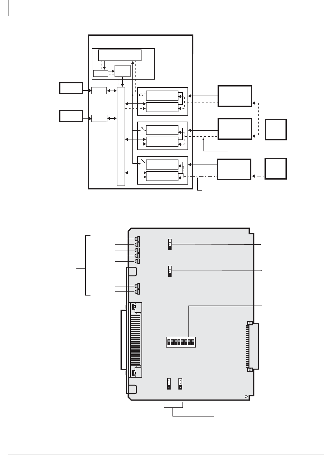
T1
RDTU1 & 2 - T1 Interface Unit
8-16 Strata CTX I&M 06/04
Figure 8-7 RDTU1A PCB (RDTU2 is similar)
5439
PDKU
Primary Reference PCB*
Secondary Reference PCB*
Other RDTU, RPTU, or RBSU
CTX Digital Transmission Voice Path
Synchronization
Circuit
Synchronization
Circuit
Synchronization
Circuit
Digital Voice
Path
Digital Voice
Path
Digital Voice
Path
Strata CTX
Digital
Telephone
Standard
Telephone
SS1
SS2
SS3
Line 1
Line 2
Line 3
Public Switched
Telephone
Network (PSTN)
PRI, BRI, or T1
AT&T or
other provider
PRI, BRI, or T1
Other
PRI, BRI, or T1
provider
Stratum-1
Clock
Source
Processor PCB
Clock not synchronized properly
with Stratum-1 Clock Source
Time
Switch
Clock
Synchronization
Circuit
Clock synchronized properly
with Stratum-1 Clock Source
Other
Clock
Source
RSTU
Figure 8-6 RDTU Primary/Secondary Reference Block Diagram
P3: Future Use
P4: Remote Loop
Back Test
Equalizer
Setting Switch
P1, P2: Self Test Network
CD3
CD7
CD6
CD5
CD4
BSY
FLAM
MFALM
YALM
BALM
CD2
CD1
PSYNC
SSYNC
6396
P1
P6
OFF ON
P2
LB
OFF
S1 OFF S8
ON
P3LLB
OFF ON
P4RLB
OFF ON
LED Status
Indicators
SW1
RDTU1A
T1
T1
RDTU1 & 2 - T1 Interface Unit
Strata CTX I&M 06/04 8-17
Alarms are used to indicate potentially serious telephone network problems. Example: when
monitoring a T1 network, if a Blue or Yellow alarm is indicated, it can be concluded that there is a
cable fault or some other serious transmission impairment.
Table 8-12 RDTU1 and 2 LED Functions
Alarm LED Function
Frame Alarm
(FALM)
Turns On steady if the RDTU has not achieved synchronization or when the span
cable is not connected.
Multi-Frame Alarm
(MFALM)
LEDs turn On steady if the RDTU receives the 1.554 mbs T1 carrier from the far
end, but has not achieved Frame synchronization or when the span cable is not
connected. Also, if the RDTU is set for SF and the far end is sending ESF (or vice
versa), the MFALM LED will be On steady.
Red Alarm (FALM
and MFALM)
When FALM and MFALM are both On steady, it’s a Red alarm condition. This
means the RDTU does not detect a proper carrier signal (1.544 mbs T1) on its
receive pair and the RDTU is not synchronized. During a Red alarm condition, the
RDTU turns the BSY LED On steady and attempts to send a Yellow alarm signal
(RDTU YALM LED flashes) to the far end T1 circuit.
Ye l l o w A l a r m
(YALM)
When the far end network or CPE T1 does not detect the RDTU transmitted 1.544
mbs T1 carrier signal on its receive pair the far end, T1 sends a Yellow alarm signal
pattern to the RDTU. The RDTU should turn on the YALM LED (the YALM repeats
the signal it receives from the far end—flashing or steady). If the RDTU does not
receive the far end carrier signal, the RDTU sends the Yellow alarm signal to the far
end and causes the BSY and YALM LEDs to flash.
Blue Alarm (BALM)
The Blue alarm, also known as the Alarm Indication Signal (AIS), is detected by the
RDTU. This signal is sent by the Far End Network equipment to RDTU when it
loses the carrier from a Network T1 circuit (other than RDTU). This signal assures
that the RDTU maintains synchronization when there is a problem between two
Network Nodes. The RDTU BALM also lights if the far end sends a Blue alarm
signal during loop back. The RDTU sends a Blue alarm signal when loop-back test
is being performed.
Primary
Synchronization
(PSYNC)
See Figure 8-6 on page 8-16 – If one RDTU PCB is assigned as the Primary Timing
T1 PCB in Program 105, the PSYNC LED of this RDTU PCB flashes when it is
synchronized with the far end T1 span line clock provider.
If the Primary RDTU is not synchronized with the clock provider, the PSYNC LED
will be On steady. The SSYNC LED of the Primary sync RDTU PCB should always
be Off. The Primary sync RDTU PCB synchronizes the RTCU (time-switch) to the
clock signal it receives from the T1 span circuit to which it is connected. The RTCU
then synchronizes the Strata CTX PCM talk path (time-switch) to the far end PCM
talk path.
Secondary
Synchronization
(SSYNC)
If an RDTU PCB is assigned as the Secondary time T1 PCB in Program 105, its
SSYNC LED will be On steady (standby mode) when the Strata CTX is
synchronized to the Primary T1 clock provider.
In the event Primary synchronization is lost (4 out of 12 consecutive frame timing
bits are in error), the Strata CTX switches from synchronizing to the Primary RDTU
span line clock to the span line clock connected RDTU designated as the
Secondary Timing Reference. When the Strata CTX is synchronized to the
Secondary Reference RDTU, the PSYNC LED on the Primary Reference RDTU
turns on steady and the SSYNC LED on the Secondary Reference RDTU will flash.
Run Free
(PSYNC/SSYNC)
If the RDTU PCB is the clock provider to the Far-end T1 span circuit, both the
PSYNC and SSYNC LEDs are always Off.
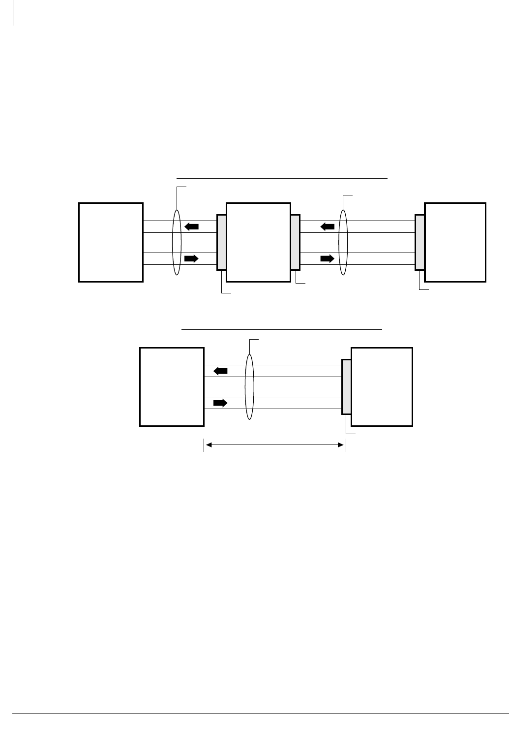
T1
RDTU1 & 2 - T1 Interface Unit
8-18 Strata CTX I&M 06/04
RDTU1 and 2 Cable Installation
The RDTU PCB is shipped with a Toshiba cable for connecting the RDTU PCB to a CSU. The
30 ft. cable is specially made to conform with EIA specifications (see Figure 8-8).
All other cables required to connect the T1 span line to the RDTU PCB are customer-supplied and
must conform with EIA specification, see the Notes of Figure 8-8. Almost all CSU manufacturers
supply cables that comply with T1 span specifications for connecting the CSU to customer
premise equipment (like Strata CTX, RDTU) to the Network Interface equipment.
Figure 8-8 RDTU Cable Connections
Notes
• Pins 2 and 4 of the DB-15 connector in most CSUs are frame ground. No connection is
required.
• NDTU cable is supplied with RDTU PCB (30 ft. maximum).
• Customer-supplied span cables must be 22 AWG, ABAM cable or, if using standard 24 AWG
twisted pair, the transmit pair must be separated from the receive pair by at least 5-cable pairs.
Most CSU manufacturers supply cables to connect the CSU to the Network Interface Unit or
other CPE equipment.
1670
RDTU PCB
(26)
(1)
(27)
(2)
T
R
T1
R1
Black
Red
White
Green
Customer-supplied Cable (See Notes)
RDTU To Customer Premise Equipment (CPE) T1
RDTU Amphenol
CPE T1 (PBX
or Key
System) or
Channel Bank
655 Feet Maximum
Transmit
Receive
(4) T
(5) R
(1) T1
(2) R1
Network
Interface Unit
USOC-RJ48C
or RJ48X
8-Pin Modular
(RJ45 Type Jack)
NDTU DB-15
Connector (Male)
DB-15
Connector (Female)
Customer Supplied
Cable (See Notes)
RDTU To Network or Long Distance T1 Provider
NDTU
Amphenol
Connector (Male)
(1)
(9)
(3)
(11)
Customer-
supplied
CSU
RDTU PCB
(26)
(1)
(27)
(2)
T
R
T1
R1
Black
Red
White
Green
(1)
(9)
(3)
(11)
NDTU Cable (30 ft. Maximum)
Transmit
Receive
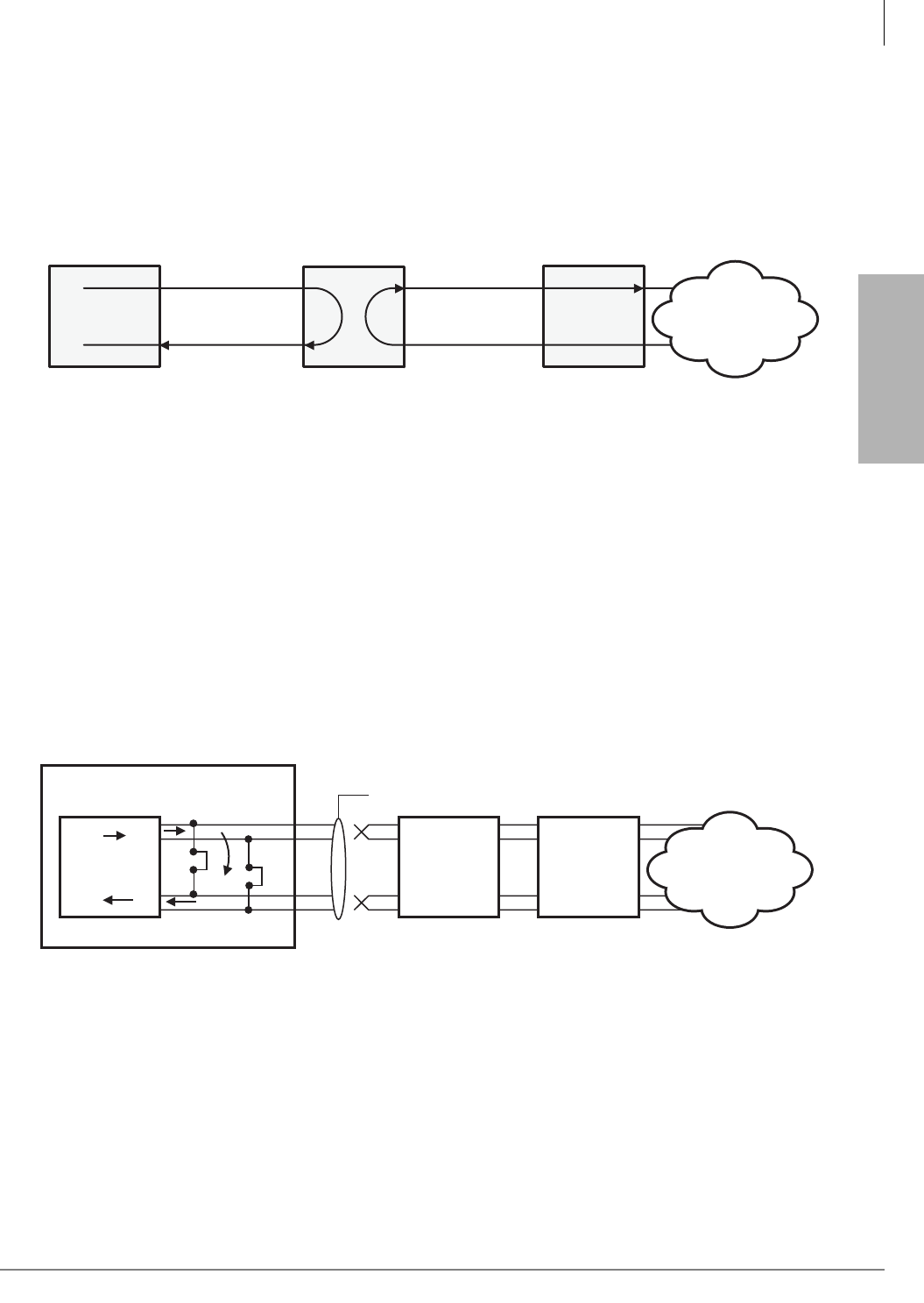
T1
T1
CSU Installation
Strata CTX I&M 06/04 8-19
CSU Installation
³Install the CSUs and wire them to the RDTU and NIU or customer premises T1 circuit, as
required (see Figure 8-9).
Note Before connecting the CSU to the Telco line, notify the T1 provider. You should also notify
the T1 provider before disconnecting the CSU.
Figure 8-9 CSU Local and Network Loop Back Tests
Loop Back Testing
The RDTU provides three loop back test configurations. These loop back tests should be
performed as required in conjunction with CSU loop back tests (see CSU loop back test
documentation).
RDTU Self Test
This test should be performed upon initial installation of a RDTU PCB. Program the RDTU per
the Strata CTX Programming Manual; then perform the RDTU loop back test, per the instructions
in Figure 8-10, before connecting the far end (CSU, Network, or CPE) T1 span line.
Figure 8-10 RDTU Self Test
Transmit
Receive
CSU NIU
Receive
Transmit
Local Loop Back Network Loop Back
CTX RDTU
Network
5801
RDTU Self Check
T1 Framer IC Chip
P1 Network
Interface
Unit
CSU
Remove NDTU Cable
P2
RDTU3 (DS2155)
RDTU1/2 (MM8976B)
Network
6688
Notes
●RDTU1 & 2, move P1 and P2 to On (see Figure 8-7); RDTU3 move SW8 & SW9 to On.
●Remove NDTU cable from RDTU amphenol connector.
●After about 12 seconds, all RDTU LEDs (except PRI/SEC SYNC) turn Off.
●Appropriate Primary or Secondary sync. LED flashes if RDTU is Primary or Secondary reference.
●If RDTU is not a Primary or Secondary reference, then the Primary and Secondary sync LEDs should
turn Off.
●Do not use the RDTU3A as a clock extraction unit.
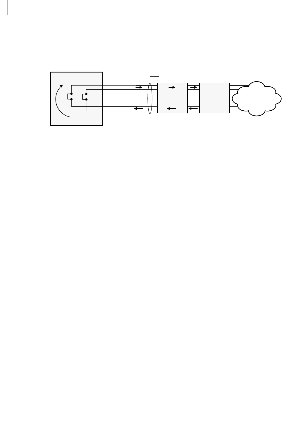
T1
Loop Back Testing
8-20 Strata CTX I&M 06/04
Network/CSU T1 Span Test
This test verifies that the far end (CSU, Network, or CPE) T1 equipment and span cabling is
functioning properly. This test checks all T1 span cabling including the RDTU Amphenol cable
and connector. Guidelines for this test are provided in Figure 8-11.
Figure 8-11 Network/CSU T1 Span Test
Network/CSU/RDTU Span Test
This test checks all equipment that is checked with the test in the above paragraph, but this test
also checks that the RDTU Mitel LSI chip is functioning. Examples for this test are shown in
Figures 8-10~8-12.
Note Loop back tests with CSU and Network equipment can also be performed when connecting
the RDTU PCB directly to a customer premise (PBX, Key Hybrid, Channel bank) T1
circuit.
The RDTU Self Test is an active test of the RDTU circuit.
The Network/CSU Test checks all cables, the Network and CSU equipment (RDTU is not active).
The Remote Loop Back (RLB) Test is an Active test of RDTU (LSI MM8976B or DS2155), CSU,
Network equipment and all cables.
Network/CSU Check
Loop
Back
P1 Network
Interface
Unit
CSU
NDTU Cable
P2
On On
P26, TT
P1, TR
P27, RT
P2, RR
Network
1672
Notes
●P1 and P2 to On position (see Figure 8-7).
●Unplug RDTU from Strata CTX back plane.
●CSU or Network T1 equipment should receive its own transmitted signal.
●Indications and results depend on CSU and/or Network equipment.
●Do not use the RDTU3A as a clock extraction unit.
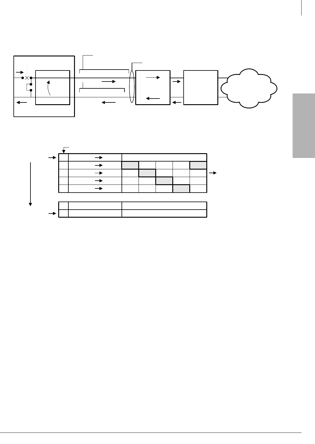
T1
T1
Loop Back Testing
Strata CTX I&M 06/04 8-21
Refer to Figure 8-3 and the CSU manufacturer’s Installation and Maintenance manual for
information on CSU Local/Network Loopback Tests.
Figure 8-12 Network/CSU/RDTU Span Test
Notes
●Local loop back and network loop back test cannot be performed simultaneously.
●CSU local/network loop back is a function of the CSU, not all CSUs provide this function –
see CSU I&M documentation for CSU loop back test procedures.
Test RDTU Lines
³After loop back testing is complete and synchronized with the far end T1 circuit, perform test
calls on all RDTU lines.
RDTU
RDTU TX Open
MITEL Chip
P4
MM8976B
P1/P26 Transmit
P2/P27 Receive
NDTU Cable
RDTU Amphenol Pin Nos.
Network
CSU
Network
Interface
Unit (NIU)
2581
Top LED
Bottom LED
T = About 1/2 Second
Continue to Cycle when
P4 is in ON Position
0
0
0
0
0
ON Steady
ON
OFF
OFF
OFF
OFF
ON
OFF
OFF
OFF
OFF
ON
OFF
OFF
OFF
OFF
ON
ON
OFF
OFF
OFF
Busy
FALM
FMALM
YALM
BALM
T1 T2 T3 T4 T5
0
0
ON or OFF, Steady
ON or OFF, Steady
Primary SYNC
Secondary SYNC
LEDS ON RDTU PCB
T6
1673

T1
Loop Back Testing
8-22 Strata CTX I&M 06/04

Strata CTX I&M 06/04 9-1
IP Telephony and QSIG
Over IP
IP Telephony and QSIG Over IP 9
This chapter explains how to install the Strata CTX Internet Protocol (IP) telephones
(IPT1020-SD). It also covers installing the Internet Protocol Telephone (IPT) interface
(BIPU-M2A or BIPU-M1A) units into Strata CTX systems with Release 2.0 or higher software, as
well as the Strata Net QSIG over IP Interface Unit (BIPU-Q1A) that requires CTX Release 2.1
software.
The BIPU-M2A provides Network Address Translation (NAT) compatibility; whereas,
BIPU-M1A requires a Virtual Private Network (VPN) connection for remote IP telephone
connections.
IPTs support most CTX telephone features. As of this release, Speaker OCA is the only CTX
telephone feature not supported by IPT1020-SD telephones. Handset OCA is supported.
CTX WinAdmin 2.1 or higher is required to program CTX Release 2.0 software. This is available
on FYI and on the Strata CTX WinAdmin Application Software and CTX/DK/Partner Products
Documentation Library CD-ROM.
Pre-installation Guidelines
In general, it’s important to obtain as much information as possible about the client’s telephone
network topology. Below are examples of the kind of information that you need to know up front.
❐Determine what type of IPT to network connections would be best for the client: switch,
LAN, or VPN. Refer to “Step 4: Connect IPTs to Network” on page 9-13 for more
information.
❐Find out who is the client’s IP carrier or provider.
❐Find out if that IP carrier or provider allows more than one IP address per off-site system.
Some providers offer multiple IP addresses, others may offer only one. This limitation
should be discussed with the client.
❐Are there other limitations for the IP carrier/provider regarding internet access. For
example, some services require a user authorization number to access the internet. You
will need this information. Inquire about Point-to-point Over Ethernet (PPOE) restrictions.
❐How much bandwidth is available for IP connections?
❐The client’s IR department needs to extend their LAN to the networked location.
❐Toshiba recommends that you perform a LAN Voice Readiness Assessment if installing
IPTs on your LAN. Quality of Service (QoS) and calls are highly dependent on setting up
correct quality parameters. Refer to “Step 1: Perform a LAN Voice Readiness
Assessment” on page 9-3.

IP Telephony and QSIG Over IP
Pre-installation Guidelines
9-2 Strata CTX I&M 06/04
Client Firewall Considerations
When installing a CTX with IP, you need to obtain information about your client’s firewall.
❐Will the client allow you access through their firewall? If not, you will have to configure
around their firewall.
In case of providing services like packet filtering by setting a firewall between the
terminal used for the “IPT Anywhere” environment and the BIPU-MIA interface, you
need to prepare an appropriate setting that allows IPT control signals and voice signals to
penetrate the packet filter and other features of the firewall.
❐If your clients are using Zonealarm® and Microsoft Windows XP®, you have to enable
the following:
•COM surrogate: access to trusted & Internet
•Generic Host Process: access to trusted & Internet
•Microsoft Distributed Transaction Coordinator (MS DTC) console program: access to
trusted & Internet AND access as a server to trusted & Internet
•Internet Information Services (IIS): access to trusted & Internet
•Windows Management Instrumentation (WMI): access to trusted & Internet
Dos and Don’ts for Setting Up the System
CTX IP Telephones and Strata Net are not compatible with older CTX line cards. If IP Telephones
access any of the line cards listed below, the user will experience unacceptable echo return loss
and voice quality. For best speech quality we recommend using the appropriate CTX cards for
CTX IP telephone connections.
Make sure that you have Printed Circuit Boards (PCBs) that are compatible with CTX R2.0 and
higher software and the IP telephones.
•Do not use – RCOU1A, RCOS1A, REMU1A (two-wire), RDDU1A, RGLU1A, RGLU2A
•OK to use – RCOU3A, RCOS3A, REMU1A (four-wire), REMU2A (two-wire/four-wire),
RGLU3A. and RDDU2A.
•Must use VPN for remote IP telephones that connect over the Internet with BIPU-M1A.
• With the BIPU-M2A, the IP telephone will now work with DSL and cable routers.
When connecting remote IP telephones to the BIPU-M2A over the Internet, a VPN router is
needed to circumvent Network Address Translation (NAT) and firewall issues by tunneling.
Otherwise, the BIPU-2MA must be configured with a public IP address outside the network
firewall. See “IPT Anywhere” on page 9-13.

IP Telephony and QSIG Over IP
Pre-installation Guidelines
Strata CTX I&M 06/04 9-3
IP Telephony and QSIG
Over IP
Step 1: Perform a LAN Voice Readiness
Assessment
Deploying many IP telephones on a data LAN can have some unexpected pitfalls if the network
does not have the bandwidth and speed required to handle VoIP traffic. To prevent delay, jitter, and
data loss for VoIP traffic and retain the performance of your other business-critical network
applications a network Voice Readiness Assessment should be completed before installing VoIP.
Important! Voice Readiness Assessments are the responsibility of the installing TSD dealer.
Toshiba is not responsible for supporting problems which occur because the
network on which the IP telephones are installed does not meet VoIP packet
requirements.
Methods of Estimating Bandwidth Requirements
A “rule of thumb” way to translate voice packet use into worst-case LAN bandwidth requirements
is shown below. (This is no substitute for a professional Voice Readiness Assessment).
• When IP telephones use the G.711 CODEC with a packetization rate of 20 millisec. (best voice
quality), the bandwidth utilization rounds up to 115K bit/sec. per conversation.
• If the system has 100 IP telephones, multiple 25 simultaneous conversations by 115K bit/sec.
for an additional bandwidth requirement of 2.9M bit/sec. on the LAN.
Note The “25 simultaneous conversations” assume ¼ of the IP telephone users are talking at the
same time. This scenario is considered worst-case because the best quality CODEC (G.711)
is used as apposed to the G.729a which 29Kbps less bandwidth per conversation.
If installing IPTs on your LAN, Toshiba highly recommends downloading “A Handbook for
Successful VoIP Deployment: Network Testing, QoS, and More,” located at the time of this
printing at.http://www.netiq.com/products/vm/whitepapers.asp. Toshiba recommends reading this
document and making sure that you have:
• Tested Voice Over IP (VoIP) Call Quality
• Prepared your Data Network for VoIP, considering your needs for bandwidth, equipment
upgrades, network architecture, Quality of Service (QoS) and tuning, and classification of
traffic considerations.
CAUTION! If installing IP telephones remotely using cable or Digital Subscriber Lines
(DSL) Internet Service Providers (ISP) providers, Toshiba recommends
setting the telephone to use the G729a CODEC because upstream
bandwidth restrictions are usually imposed by the provider. Even if the
provider advertises an upstream rate is 128kbs, this bandwidth can still be
less depending on traffic conditions.

IP Telephony and QSIG Over IP
Pre-installation Guidelines
9-4 Strata CTX I&M 06/04
To assist you in estimating your particular needs, refer to the following diagram that shows typical
CTX IP telephone applications.
Figure 9-1 IP CTX Functional Diagram
LAN (10/100Base-T)
LAN (10/100Base-T)
6706
PSTN
CTX
BIPU-MIA
FAX
PC Attendant
Console
Single Line
Telephone
Digital
Telephone
IP Digital
Telephone
IP Digital
Telephone
IP Digital
Telephone
IP Digital
Telephone
IP Digital
Telephone
IP Digital
Telephone
IP Digital
Telephone
Remote
Call Center
SOHO/IPT Anywhere
IP Digital
Telephone
IP Digital
Telephone
Application
Server
(ACD/IVR/VM/
UM/FAX/Mail)
Back/Front Office
Application Server
(ERP/SCM/CRM/SFA)
Application Server
(ACD/IVR/VM/
UM/FAX/Mail)
Database Server
Router
PC
Cable Modem
Router
VPN Router
Internet
or
WAN
IP CTX Functional Diagram
*** (VPN)
. Cable Modem
. FWA
. xDSL
. Fiber Optics
***
***
Web (VPN) Server
VPN Server
***
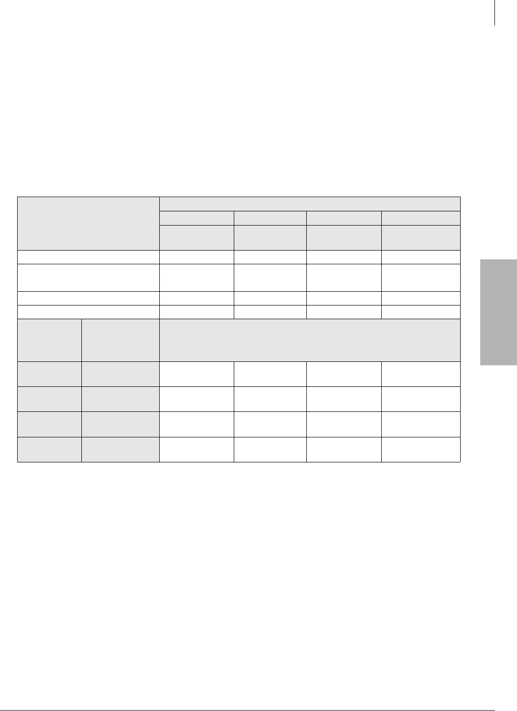
IP Telephony and QSIG Over IP
Pre-installation Guidelines
Strata CTX I&M 06/04 9-5
IP Telephony and QSIG
Over IP
Review Voice Quality Considerations
For best speech quality we recommend not using the older CTX analog line cards for CTX IP
telephone connections. If these cards are used, IP telephones will experience fair or bad voice
quality. (See “Dos and Don’ts for Setting Up the System” on page 9-2.)
The amount of bandwidth required for communications over a particular IP network segment
depends on the number of voice channels supported, the anticipated call setup traffic, and how
much other data network traffic is present.
The quality of service (Excellent, Good, Fair, and Bad) provided by CTX IP Telephones and CTX
IP QSIG channels depends heavily on the LAN parameters as shown in Table 9-1.
Table 9-1 Quality of Service
IP Network Quality Parameters
Speech
Excellent Good Fair Poor
No one perceives
delay.1
1. Ratings of Excellent, Good, Fair, Poor were based on the tester in a quiet room and the tester could not see the other call
party. IPT is usable even with a "Poor" rating if delay is acceptable.
Very few people
perceive delay.1
Some people may
perceive delay.1
Many people may
perceive delay.1
Latency (Round trip delay)2
2. When selecting router equipment, the Latency, Jitter, Packet loss and Packet error conditions above should be considered as
well as the bandwidth. Bandwidth can be calculated with the CODEC and packet size. For better results, more bandwidth may
be required, depending on the amount of overall data traffic. For more details on QoS refer to “A Handbook for Successful
VoIP Deployment: Network Testing, QoS, and More” by John Q. Walker, NetIQ Corporation on www.netiq.com.
20ms or less 50ms or less 100ms or less 200ms or less
Jitter220ms or less 50ms or less 50ms or less 50ms or less
(-10 ms ~ +10ms) (-25ms ~ +25ms) (-25ms ~ +25ms) (-25ms ~ +25ms)
Packet loss21×10-3 or less 1×10⁻³ or less 1×10⁻³ or less 1×10⁻³ or less
Packet error21×10-4 or less 1×10⁻⁴ or less 1×10⁻⁴ or less 1×10⁻⁴ or less
CODEC &
Packet Interval
(Prgs. 250-07,
152-01)
Bandwidth per
channel (Single
direction, control
channel included)
Speech quality per the combination of the network environment described
above and the CODEC parameters.
G.711 at 20ms 115kbps3
(Speech 88kbps)
3. Use this number to estimate the bandwidth needed for the CODEC and interval timing required to achieve an expected
Quality of Service (Excellent, Good, etc). This bandwidth includes header and control information and a 25% margin for
network traffic variances.
Excellent Good Fair Poor
G.711 at 40ms 99kbps3
(Speech 76kbps) Excellent Good Fair Poor
G.729A at 40ms 29kbps3
(Speech 20kbps) Good Good Fair Poor
G.729A at 80ms 22kbps3
(Speech 14kbps) Good Fair Poor Poor
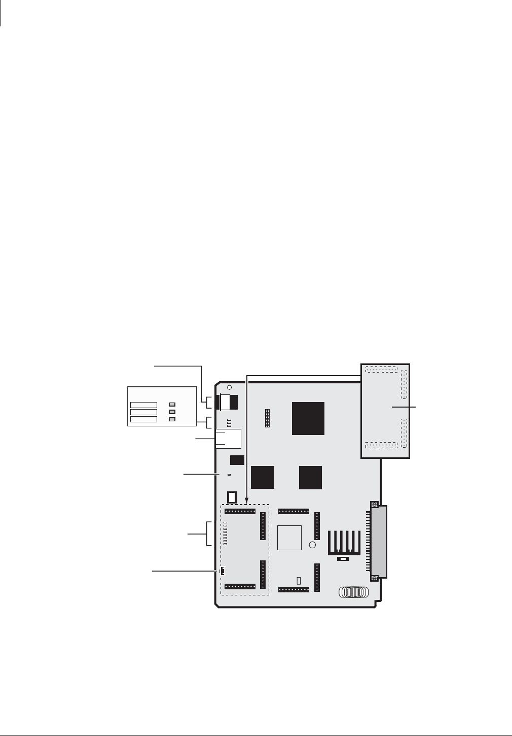
IP Telephony and QSIG Over IP
Pre-installation Guidelines
9-6 Strata CTX I&M 06/04
Step 2: Install BIPU-M2A
1. Make sure the BIPS1A is installed onto the BIPU-M2A PCB (see Figure 9-2).
2. Install the BIPU-M2A into one of the following slots:
• CTX100 Base and Expansion Cabinet slots (1~8, 8 or 16 IPTs per slot per Program 100)
• CTX670 Base Cabinet slots (1~8, 8 or 16 IPTs per slot per Program 100)
• CTX670 Expansion Cabinet slots (1~6, 8 or 16 IPTs per slot per Program 100)
3. Follow the procedure in “Worksheet 7 – System Power Factor Check” on page 2-42 to check
the cabinet power factor.
4. Power up the system.
5. Program the CTX per the instructions in the Strata CTX Programming Manual, refer to the
chapter titled “IP Telephone Programming” and “Appendix A – “Applications, Tips, and
Tricks.”
Connect BIPU-M2A to LAN or VPN Server
1. Plug one end of a straight-through CAT5/5E/6 LAN cable into the RJ45 Ethernet port on the
BIPU-M2A PCB in the CTX. (See Figure 9-2.)
2. Plug the other end of the BIPU-M2A CAT5/5E/6 LAN cable into a LAN or server jack (see
Figures 9-8 and 9-9.)
Note The BIPU-M2A or Q1A-switch cables are straight-through cables.
Figure 9-2 BIPU-M2A or BIPU-Q1A PCB ZZ
PTC1111-01
0211
YCL
V.01
BIPU-M2A
or
BIPU-Q1A
6632
12345678
HB
RD LINK SD
Reset
RJ45 Ethernet Port
RS232
Maintenance Jack
Factory
Installed
Heart Beat LED
P601
P2
P702 P704
P701
P703
Status/Alarm LEDs
For engineering
purposes only
Ethernet Port LEDs
RD
LINK
SD
P705
P706 P708
P707
BIPS1A - /16
Backplane Connector

IP Telephony and QSIG Over IP
Pre-installation Guidelines
Strata CTX I&M 06/04 9-7
IP Telephony and QSIG
Over IP
BIPU-M2A Interface Unit
System:
CTX100 & 670
Circuits per PCB:
8 to 16 IPT telephone circuits (programmable)
Interfaces with:
IP telephones
Older Version(s):
BIPU-M1A
The BIPU-M2A PCB interfaces with Toshiba IPT1020-SD telephones only. These telephones
operate the same as the DKT3000-series telephones, but do not support Speaker OCA (refer to the
DKT/IPT Telephone User Guide for operating procedures). The BIPU-M2A has 16 IP telephone
circuits (eight or 16 circuits are enabled in Program 100).
The BIPU-M2A supports both G.711 and G.729A standard codec compressions simultaneously.
The type of compression used is set independently for each telephone in system programming (see
the “IP Telephone” section).
The BIPU-M2A operates on the network at 10/100 Mbps and can be connected to a fast switch
router, LAN, WAN, etc. When connecting remote IP telephones to the BIPU-M2A over the
Internet, a VPN router is needed to circumvent Network Address Translation (NAT) and firewall
issues by tunneling. Otherwise, the BIPU-2MA must be configured with a public IP address
outside the network firewall.
BIPU-M2A provides MEGACO+ mobility to enable roaming with Toshiba Mobility
Communications System (MCS) applications (available with Toshiba MCS R1.0). The BIPU-M2
enables remote IP telephones to be connected over VPN and non-VPN IP networks.
BIPU-M2A firmware can be updated locally or remotely using CTX WinAdmin. This enables
service personnel to update IP equipment with new features and enhancements as they become
available. Updates require a brief interruption (a few minutes) of IP telephone operation.
Table 9-2 BIPU-M2A or BIPU-Q1A Buttons, LEDs and Jumpers
Indicator Definition
Ethernet Port LEDs
RD - Indicates BIPU-M2A or BIPUQ1A receives data from switch.
LINK - Indicates data activity between BIPU-M2A and switch
SD - Indicates BIPU-M2A or BIPUQ1A sends data to switch.
Heartbeat LEDs Flashes at a steady rate to indicate BIPU-M1A or BIPU-M2A or BIPUQ1A
is operating normally.
Status/Alarm LEDs For Toshiba Field Support Engineering use only.
Reset button Use when requested by Toshiba Field Support Engineer.
RS232 Maintenance Jack For Toshiba Field Support Engineers only.

IP Telephony and QSIG Over IP
Pre-installation Guidelines
9-8 Strata CTX I&M 06/04
Step 3: Install IP Telephones
Before installing any telephone wiring, read the following warning and caution notes:
CAUTION! When installing the station cable, do not run the cables parallel if they are
within three feet of an AC power line. AC power lines should be crossed at
right (90°) angles only. In particular, avoid running station wire pairs near
devices that generate electrical noise, such as neon or fluorescent light
fixtures.
CAUTION! Do not use cleansers that contain benzene, paint thinner, alcohol or other
solvents on the telephone's rubber feet. The color of the rubber may transfer
to the desk or mounting surface.
1. Install the AC power adapter
onto the IP telephone (IPT).
If using Power over LAN, install
PowerDsine unit per the
installation manual supplied with
that unit.
The IPT1020-SD must use the
AC adapter that is provided with
the telephone.
Important! To power your
Toshiba IPT1020-SD
base unit, use only UL
Listed AC Adapter
Model BADP120-1A
(supplied with IPT)
Ratings are:
Input: 120VAC 60Hz, 250mA
Output: 12VDC 1A
WARNING!
³Never install the telephone wiring during a lightning storm.
³Never install the telephone jacks in wet locations, unless the jack is specifically designed for wet
locations.
³Never touch uninsulated telephone wires or terminals unless the telephone line has been
disconnected at the network interface.
³Use caution when installing or modifying telephone lines.
³If telephone wiring exits the building, external secondary protection is required. See Chapter 10
– MDF PCB Wiring.
6742
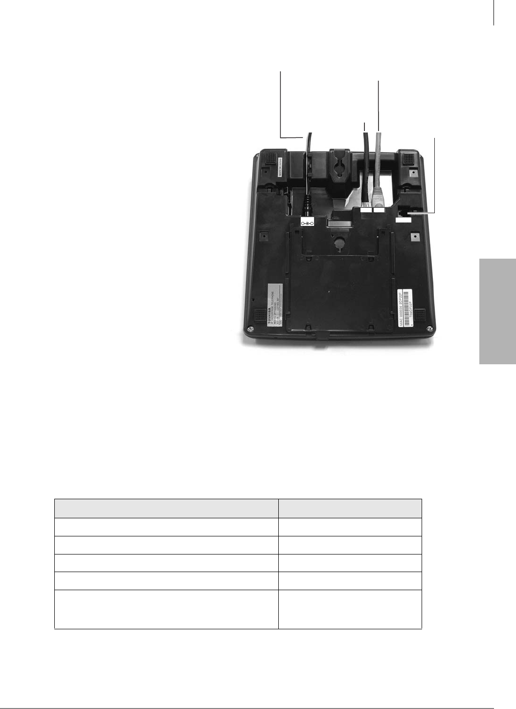
IP Telephony and QSIG Over IP
Pre-installation Guidelines
Strata CTX I&M 06/04 9-9
IP Telephony and QSIG
Over IP
2. Use the supplied Ethernet
10/100Base-T (straight-through cable)
with an RJ45 connector (eight pin
jack) to connect to the telephone LAN
jack (see Figure on right).
3. Connect the other end of the telephone
LAN cord to the LAN or server (see
Figures 9-3 and 9-8.)
4. The IPT operates like a switch, as
opposed to a hub, so the IPT can be
connected directly to the LAN and
then a PC can be connected to the IPT
PC jack to make a connection to the
LAN.
5. Use the same type of RJ45 cable
connector used in the previous step to
connect the IPT to the PC.
Notes
• A new Add-on Module (ADM) (part
number DADM3120) can be
connected to the IP telephone. The
DKT3000 ADM is not compatible
with the IPT. The installation is the
same as for the older model DADMs.
See “Digital Add-on Module
Installation” on page 11-21 for
installation instructions.
• For details on other IPT options, see “Power over LAN” on page 9-16. If Power over LAN is
used, the AC adapter should not be installed and vice versa.
IPT Operation Notes
The following provides information IPT operation with Strata CTX systems (see Table 9-3).
Table 9-3 IPT1020-SD Operation with Strata CTX
IPT1020-SD Buttons and Features Strata CTX System with BIPU
Basic LCD 2 x 24 characters
LCD Feature button Operational
Fixed Spdial button Operational
IPT1020-SD telephones per cabinet slot 16 telephones max.
Programming Mode “A” (Beep Tone On/Off, etc.)
Program Mode “A” is for telephone options that are
controlled by the ROM inside the telephone.
Not Operational
DC12V
_+
LAN PC
HEADSET
AC Adapter Connects
to LAN Switch,
Router
Power
Over LAN
Connects
to PC
Built in
Headset
or HESB
Interface
6682
Figure 9-3 IPT Connections
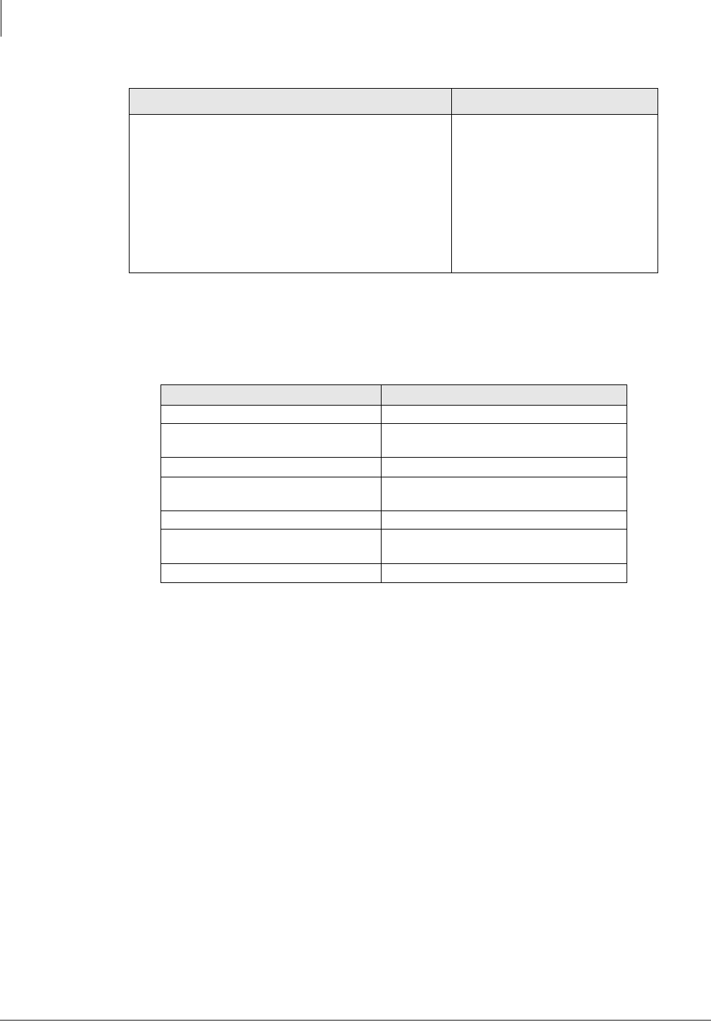
IP Telephony and QSIG Over IP
Pre-installation Guidelines
9-10 Strata CTX I&M 06/04
IPT Telephone Options
A number of telephone option plugs and connectors are built-in to the IPT1020-SD (see Table 9-4
for compatibility).
IP Telephone Add-on Modules
One or two DADM3120 add-on modules can be connected directly to the IPT1020-SD. Each
DADM3120 provides 20 additional feature buttons. The installation is the same as the
DADM3020. For instructions, refer to “Digital Add-on Module Installation” on page 11-21.
Tilt Stand Installation
See “Tilt Stands” on page 11-23 for instructions.
External Speaker Unit (HESB) Option
See Chapter 10 – Peripheral Installation for installation instructions.
Programming Mode “B” (Flexible Buttons, One Touch,
etc.) Program Mode “B” is for telephone options
controlled by the Strata CTX670 processor and database
memory. (See the
Strata CTX DKT/IPT User Guide.
)
Same as DKT3000 telephones
except:
●Indication code from center is
abandoned.
●Keep alive control does not
work in terminal setting mode.
●IPT does not notify the state of
terminal setting mode to
Strata CTX.
Table 9-4 IPT Component Compatibility
Item IPT1020-SD
Add-on Modules DADM3120 only
Desktop Computer Telephony Interface
(CTI) Future
Speaker OCA Future
Tilt Stands BTSD for telephone only and BTSA for
telephone with ADM(s)
Headset Interface Mounted inside.
External Ringer HESB interface connector is mounted
inside.
Cordless Telephones N/A
Table 9-3 IPT1020-SD Operation with Strata CTX
(continued)
IPT1020-SD Buttons and Features Strata CTX System with BIPU
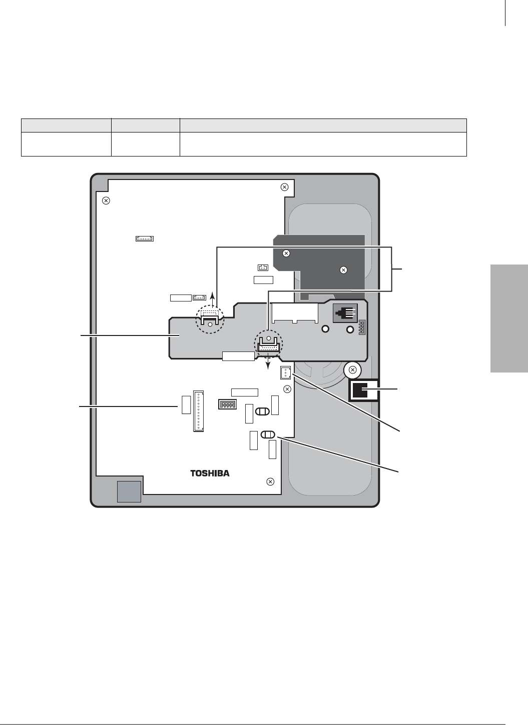
IP Telephony and QSIG Over IP
Pre-installation Guidelines
Strata CTX I&M 06/04 9-11
IP Telephony and QSIG
Over IP
Handset/Headset Option Straps
The option straps on the IPT telephones must be cut when installing carbon handsets, external
power or headsets. Refer to Table 9-5 and Figure 9-4 for further instruction.
Figure 9-4 IPT1020-SD Strap Connection Location
Table 9-5 Station Option Interface PCB Compatibility
Strap on IPT PCB Part No. Explanation
Carbon W401, W402,
W403, W404
If a carbon-type handset or carbon-type headset is connected to the
handset
jack, four jumper wire straps inside the telephone must be cut.
6525
IPT10-20KSD
ADM
HEADSET
J502
J402
UARTO
P101
LED Port
J201
J200
W402
W403
W401
W400
CARBON
CARBON
CARBON
CARBON
IPT10-SUB
Handset jack
to HESB
Add-on Module
plug
For wall
mounting, you
need to rotate
the IPT10-SUB.
Gently pull back
the two white
plastic tabs from
the IPT10-SUB to
release it.
Carbon handse
t
headset wires
Pull back clips
to release
IPT10-SUB.
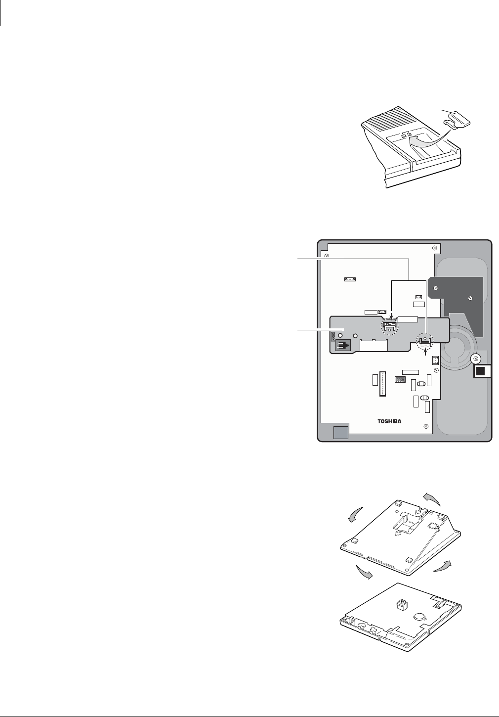
IP Telephony and QSIG Over IP
Pre-installation Guidelines
9-12 Strata CTX I&M 06/04
³To wall mount IP telephones
Refer to Figures 9-5~9-7 and the following steps.
1. Loosen the captive screws, and remove the telephone base.
2. Using a suitable cutter, remove the handset hanger from
the base.
3. Insert the handset hanger in the slot on the front of the
phone. It fits in the notch on the cradle.
4. Carefully remove the IPT10-SUB from the base unit by
pulling back the plastic clips that hold it in place (see
Figure 9-4).
5. Rotate the IPT10-SUB
180 degrees. Secure it
back onto the
telephone PCB with
the white plastic clips
(see Figure 9-6)
6. Rotate the telephone base 180 degrees and secure
it to the telephone with its four captive screws
(see Figure 9-7)
7. Connect the phone to the wall modular connector
with a cord approximately four inches long
(available at most telephone supply companies).
8. Route the cord into the hollow portion of the base.
9. Mount the phone on the wall mounting modular
connector plate.
Handset
Hanger
1479
Figure 9-5 Handset Hanger
6751
IPT10-20KSD
ADM
HEADSET
J502
J402
UARTO
P101
LED Port
J201
J200
W402
W403
W401
W400
CARBON
CARBON
CARBON
CARBON
IPT10-SUB
IPT10-SUB should be
turned this way (180
degrees from original
placement) for wall
mounting the telephone.
Push in clips to secure
IPT10-SUB.
Figure 9-6 Rotate IPT10-SUB for Wall Mounting
Figure 9-7 Wall Mounting Base Rotation
1480
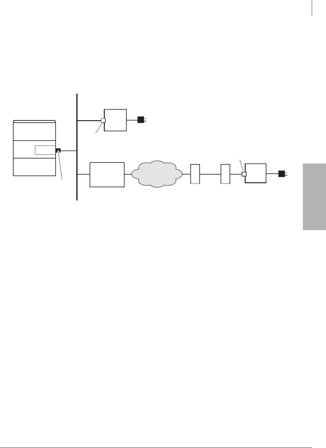
IP Telephony and QSIG Over IP
Pre-installation Guidelines
Strata CTX I&M 06/04 9-13
IP Telephony and QSIG
Over IP
Step 4: Connect IPTs to Network
The following diagrams are examples of IP connections to either a hub, LAN or VPN network.
IPT Connections
Figure 9-8 shows how the IP components should be connected. Refer to the Strata CTX
Programming manual for IPT programming procedures.
Figure 9-8 IP-CTX Connections Example
IPT Anywhere
IPT Anywhere enables you to connect IP telephones remotely throughout the Internet and use all
Strata CTX telephone features (except Speaker OCA). IPT remote connections can be set with or
without the use of Virtual Private Network (VPN). VPN connections provide increased security
and is recommended for permanent type IPT remote connections. When moving IPT telephones
frequently to different locations (hotels, conferences, etc.) non-VPN connections are more
practical.
When using home type xDSL or cable connections, only one or two IPTs may be connected
because of xDSL and cable bandwidth limitations. High speed T1, fiber, or ATM-type connections
are required when installing more than two IPTs at a remote site.
An Internet configuration could use the following connections:
• No VPN, and thus, no security (BIPU-M2A)
• Third party Virtual Private Network (VPN) software residing on DHCP gateway server. To
connect IPTs over the Internet, using third party or Microsoft VPN software residing on a
DHCP gateway server (see Figure 9-9.)
• ATM (IP over ATM virtualization by VC/VP)
• Broadband Ethernet virtualization by Virtual LAN (VLAN)
• IP-VPN (IP-VPN based on Multi-protocol Label Switching (MPLS)
• Private line connection
6788
IPT1
DN3001
IP address of IPT1
192.168.1.241
IP address of IPT2
192.168.1.242
to 120VAC
to
120VAC
IPT2
DN3002
RJ45
Ethernet
Port
LAN RJ45
Jack
LAN RJ45
Jack
Strata CTX
Example IP address
of BIPU
192.168.1.230
BIPU
Switch or LAN
(DHCP server)
with or
without VPN
Cable/
DSL Modem VPN
Router
(VPN is optional
with BIPU-M2A)
LAN
Virtual Private
Network (VPN)

IP Telephony and QSIG Over IP
Pre-installation Guidelines
9-14 Strata CTX I&M 06/04
• For an access line to link the user’s location with the access point of the carrier or provider,
using a private line, broadband line (xDSL, CATV), or fiber optics is recommended.
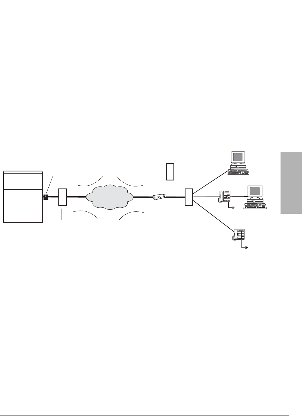
IP Telephony and QSIG Over IP
Pre-installation Guidelines
Strata CTX I&M 06/04 9-15
IP Telephony and QSIG
Over IP
IPT Anywhere enables IPT users working in satellite offices or off-site at home to make full use of
the extension features of the CTX IP telephones.
With IPT Anywhere, you should apply the following to prevent deterioration of voice quality:
•Voice compression by G.729A is available in Program 250-08 if using more than one IPT or a
cable or xDSL connection.
•Voice attributes table should be prepared according to the user’s “IPT Anywhere”
environment and provided to each terminal used for implementing this “IPT Anywhere”
environment (Program 152).
•Priority control functions supported by BIPU-M2A, IEEE802.1p and Diffserv (Program 150-
03) can be applied to the station used for implementing the “IPT Anywhere” environment.
The following picture shows how the VPN components should be connected (see the Strata CTX
Programming manual for IPT programming procedures).
Figure 9-9 IP-CTX Virtual Private Network Connections (Example)
Security Requirements
The terminal authentication using MAC addresses, provides an effective means of restricting the
connection of unauthorized terminals in normal LAN environment, is also applicable to “IPT
Anywhere” environment. A networked security system is required in a “IPT Anywhere”
environment. But by limiting the implementation of “IPT Anywhere” environment to only within
an intranet environment, the required level of security can be provided.
The required level of security network can be physically provided with an intranet or by a VPN
service provided by the carrier or the provider, since the network will be virtually separated
between each contract user of the carrier’s or provider’s VPN service.
In case of providing services like packet filtering by setting a firewall between the terminal used
for the “IPT Anywhere” environment and IP-CTX, you need to prepare an appropriate setting that
allows IPT control signals and voice signals to penetrate the packet filter and other features of the
firewall.
6716
RJ45
Ethernet
Port
Internet
VPN*VPN*
Cable/DSL
Modem
DHCP Gateway
Server with
VPN software*
VPN is optional with BIPU-M2A.
With BIPU-M1A, VPN is necessary
to circumvent NAT issues.
Remote Network
PC
AC Power
AC Power
IPT
IPT
Router
(VPN
Compatible)
DHCP Gateway
Server with
VPN software*
or PC
Strata CTX
Example IP address
of BIPU
192.168.1.230
BIPU-M2A
*
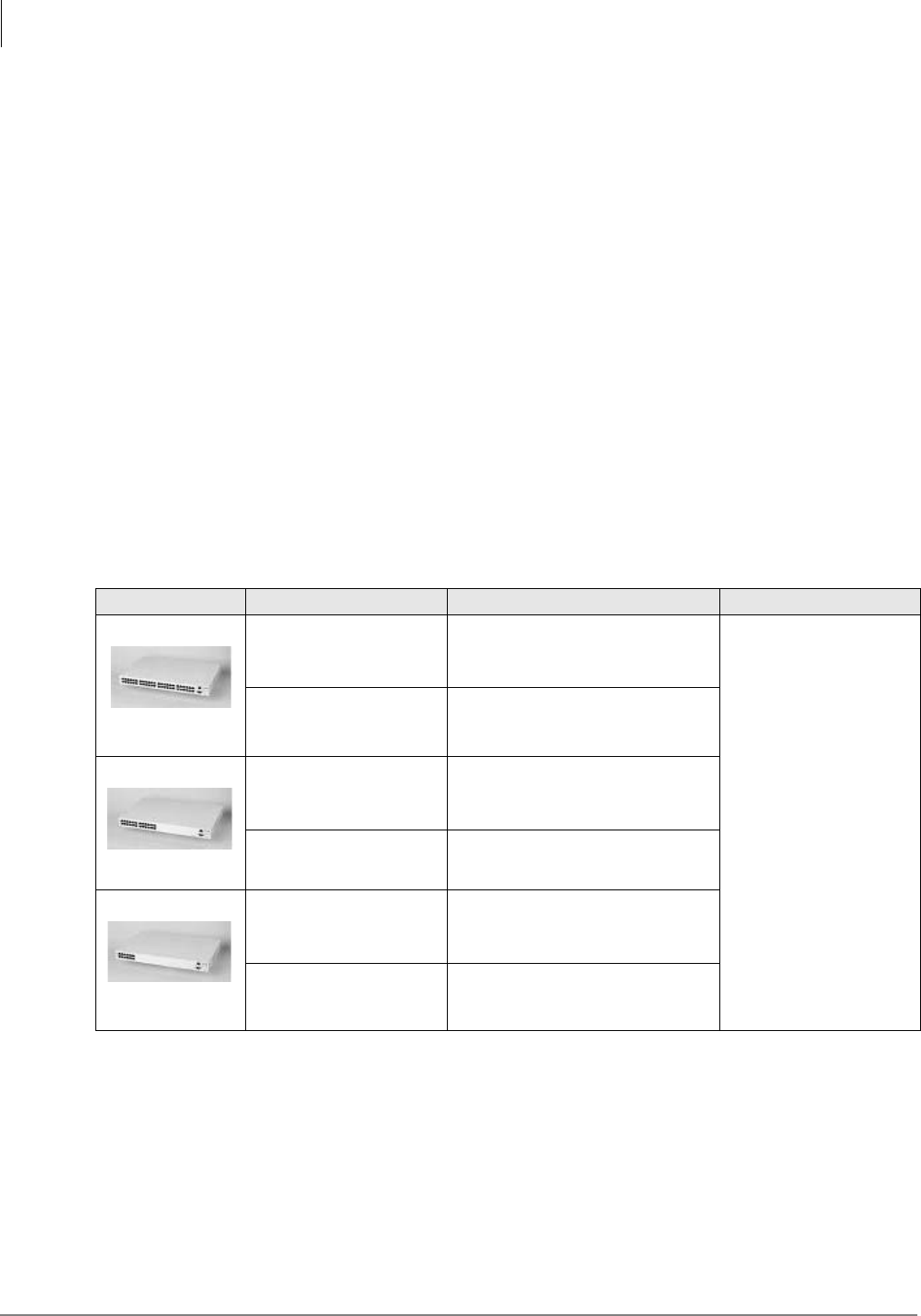
IP Telephony and QSIG Over IP
Power over LAN
9-16 Strata CTX I&M 06/04
Addressing
Regarding addressing of IP packets exchanged between IPT and the main system unit, the
following restrictions are normally applied.
• NAT (Network Address Translation)/NAPT (Network Address and Port Translation) devices
NAT/NAPT devices must not be used for communication between the “IPT Anywhere”
terminal and the interface card. The original IP header and UDP header must not be revised.
• VPN Tunneling – By making the private IP address a capsule of the global IP address, the
private IP address can be used to tunnel through the global IP network. Using tunneling makes
communication between the “IPT Anywhere” telephone and the interface card transparent.
Tunneling use requires that the carrier or the provider that the user is in contract with provides
a tunneling device or that the user installs his/her own tunneling device separately.
• Address system – It’s important to devise a control system to prevent the private IP addresses
of the network for the “IPT Anywhere” telephone and the network to which the interface card
installed in this terminal belongs from overlapping.
Power over LAN
The recommended electric power device by LAN is called Power over LANTM from PowerDsine,
Ltd. http://www.powerdsine.com. Compatible models are shown in Table 9-6
Table 9-6 Power over LAN Models
Port Models Model Name Input Output
24 port type
PD-PH-6024/ACDC/48
AC input Voltage: 88 – 264 VAC
AC Frequency: 47 – 63 Hz
DC input Current: 10A at 48 VDC
Output Voltage: -48VDC
User Port Power:
16.8W (Maximum)
Data Rates: 10/100
Mbps
PD-PH-6024/AC/48 AC input Voltage: 88 – 264 VAC
AC Frequency: 47 – 63 Hz
12 port type
PD-PH-6012/ACDC/48
AC input Voltage: 88 – 264 VAC
AC Frequency: 47 – 63 Hz
DC input Current: 10A at 48 VDC
PD-PH-6012/AC/48 AC input Voltage: 88 – 264 VAC
AC Frequency: 47 – 63 Hz
6 port type
PD-PH-6006/ACDC/48
AC input Voltage: 88 – 264 VAC
AC Frequency: 47 – 63 Hz
DC input Current: 10A at 48 VDC
PD-PH-6006/AC/48 AC input Voltage: 88 – 264 VAC
AC Frequency: 47 – 63 Hz
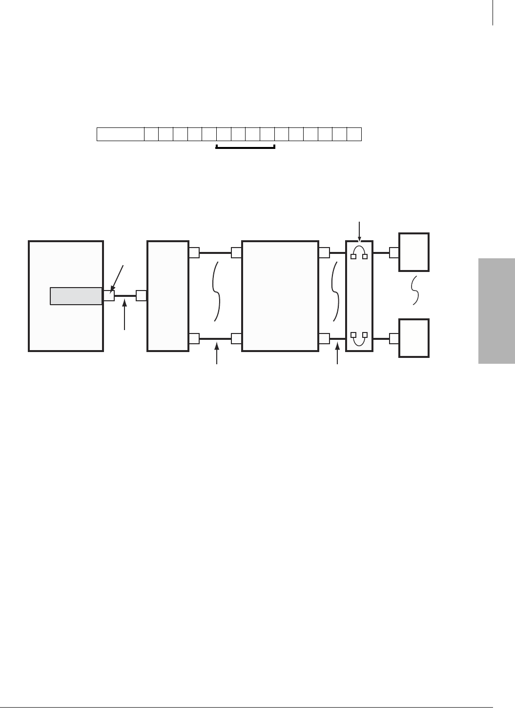
IP Telephony and QSIG Over IP
Power over LAN
Strata CTX I&M 06/04 9-17
IP Telephony and QSIG
Over IP
Note Toshiba does not supply the Power over LAN units. When you order the Power over LAN
model from PowerDsine, please indicate that you need the Power over LAN that can
support the Toshiba IPT1020-SD Some models don’t support the IPT1020-SD.
Be sure to order the PowerDsine products (PD-6000 product family) from a software revision that
is equal to 6805 or higher (produced from March 15, 2003). The software revision numbers appear
in the position shown below on the serial number label.
An example of a typical IPT-CTX connection using a PowerDsine Power over LAN unit is shown
in Figure 9-10.
Figure 9-10 Typical IPT-CTX Connection Using PowerDsine Power over LAN Unit
S/N: 6805
Software Revision
6803
CTX
CAT5
Modular
Cord
RJ45
CAT5e Patch Panel
or Termination Block
IN
IN
OUT
OUT
IPT
IPT
1
16
1
16
1
16
CAT5
Modular
Cord
RJ45
Network
Jack
CAT5
Modular
Cord
RJ45
PowerDsineFast
Switch
BIPU-M1A
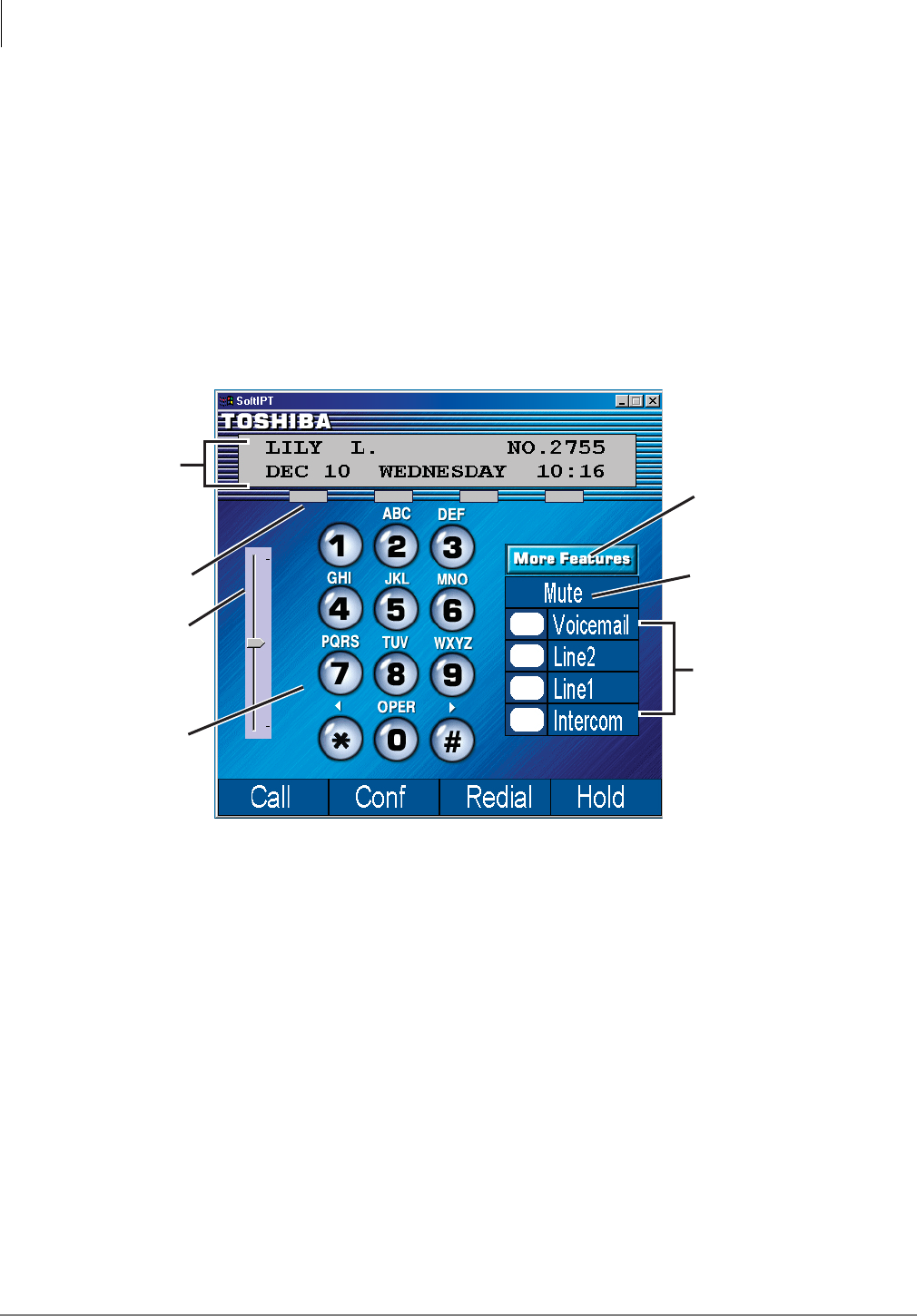
IP Telephony and QSIG Over IP
Installing and Operating the SoftIPT
9-18 Strata CTX I&M 06/04
Installing and Operating the SoftIPT
This section explains how to install and operate the Toshiba SoftIPTTM. It also discusses how the
SoftIPT will work on wireless 802.11 networks.
The SoftIPT is a software phone client that runs on wired or wireless laptops, tablets and desktop
PCs with the Microsoft® Windows XP® operating software.
The SoftIPT enables true mobility with access to voice mail, programmable feature buttons, and a
directory that works with Microsoft Outlook® 2002. And because it’s wireless, you can access
Internet services on the same PC.
The main SoftIPT GUI is shown below.
Click
More Features
to see more buttons
or the directory.
Mute turns
microphone
speaker On/Off.
Up to six flexible
buttons are
programmed from
the Strata CTX.
Volume
Control
Live call
progress
display
Soft Keys
Select or
click on
dial pad
buttons
6821
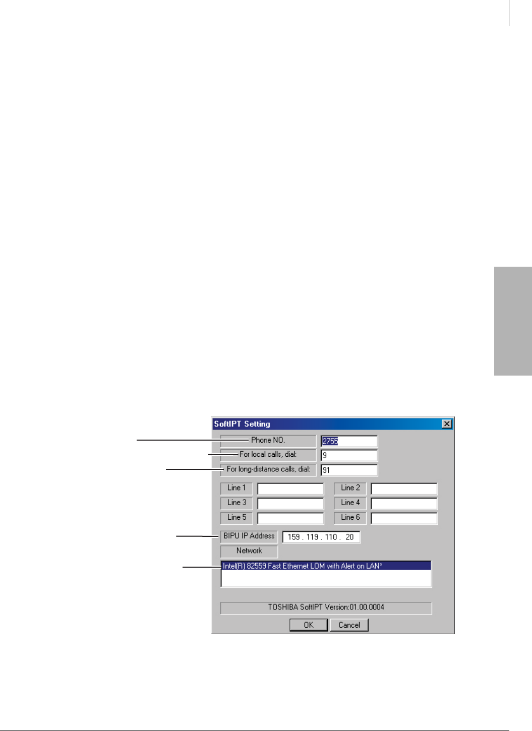
IP Telephony and QSIG Over IP
Installing and Operating the SoftIPT
Strata CTX I&M 06/04 9-19
IP Telephony and QSIG
Over IP
Hardware/Software Required
The SoftIPT works with the Strata CTX100-S, CTX100 and CTX670 telephone systems with CTX
R2.1 MG020 or higher.
SoftIPT operation requires a wired or wireless 802.11 connection over the IP network (Internet,
WAN, LAN, etc.) to the CTX BIPU-M2A or BIPU-M1A PCB with firmware version 07e or
higher IP interface. The voice communications uses the MEGACO+ protocol for call control
signaling and RTP for voice transmission.
Note The SoftIPT can work on wireless 802.11 networks (see “Application Notes for Wireless
802.11 Networks” on page 9-26 for more information).
A user can install the SoftIPT on a laptop, tablet or desktop PC at the same time, but each should
have a unique station ID and license. The SoftIPT works with desktop or laptop PCs with
Windows XP, or higher, operating system (OS).
Access points are required for wireless systems. Customers must supply their own access points
and headphone/microphones. The SoftIPT requires the use of a headset. Without the headset, the
far end of the conversation will hear the echo caused by the laptop's built-in microphone picking
up the output of the speaker.
The SoftIPT Graphical User Interface (GUI) has fixed and flexible buttons. Fixed buttons cannot
be changed (Intercom, Mute, Voicemail, Directory, Settings, Call Log and Help). Flexible buttons
can be assigned different features and labels.
Before You Begin
Important! See the illustration below. You will need to enter items A~E during the installation
process. Check with your Telephone System Administrator to make sure that you
have this information. After entering this information, we suggest that you print this
screen for future reference.
Note Changing button labels “Line 1” ~ “Line 6” is optional. You can change these labels, but it
does not change the button function. See “Labeling Feature Buttons” for details.
6949
Enter IP Address
of BIPU-MXX PCB
Select the network
adapter used by
the SoftIPT
Outside line access code
Long distance
dialing prefix
SoftDKT extension
number
D.
C.
B.
E.
A.
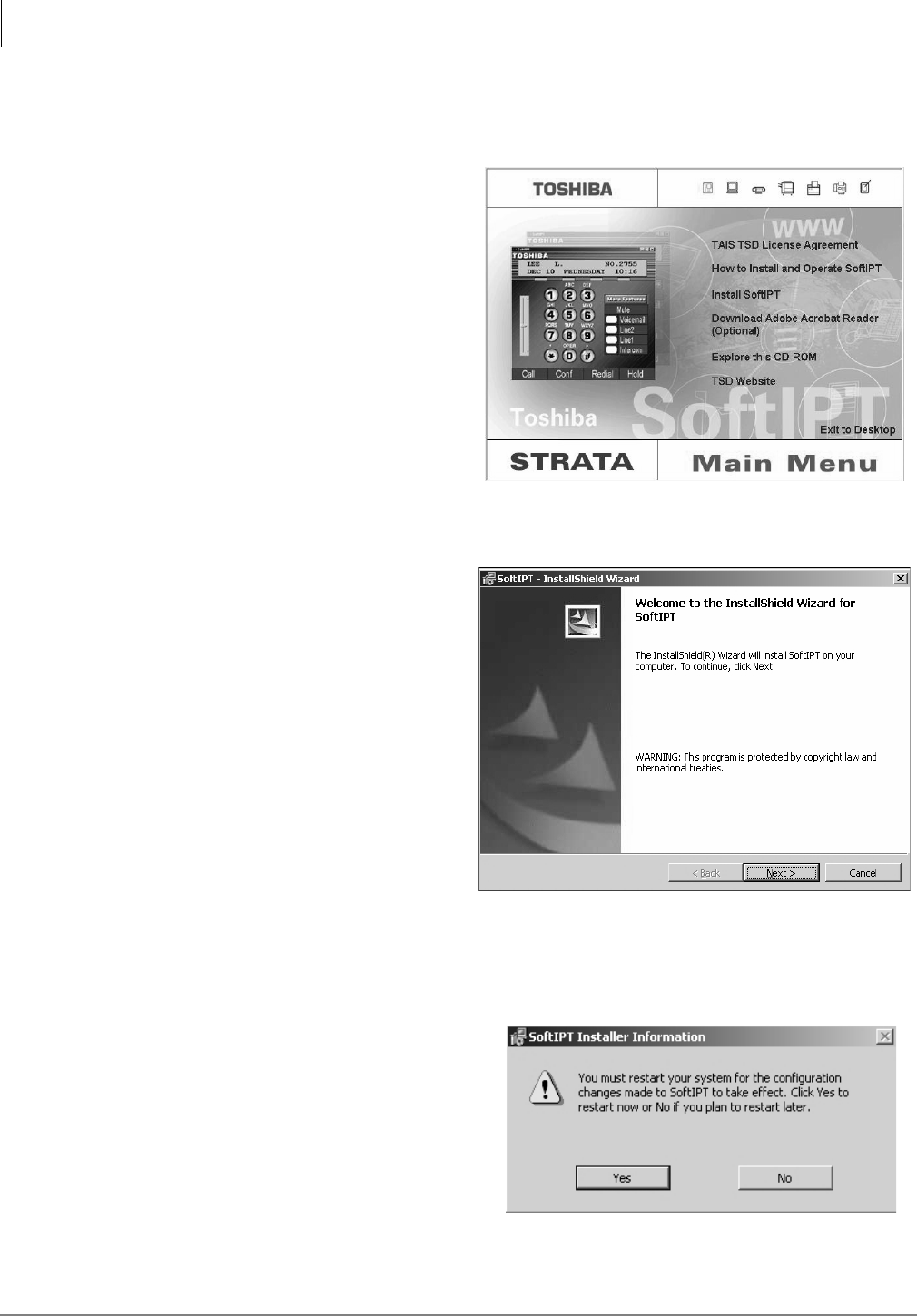
IP Telephony and QSIG Over IP
Installing and Operating the SoftIPT
9-20 Strata CTX I&M 06/04
Step 1: Install SoftIPT
Follow these instructions to install the SoftIPT on a tablet, laptop or desktop PC.
1. Insert the SoftIPT CD-ROM into
your CD-ROM drive.
2. From the Main Menu, select “Install
SoftIPT.” The InstallShield Wizard
performs “Preparing to Install.”
3. In the Welcome window (shown
right), click Next.
4. Read the TAIS TSD License
Agreement, select “I accept the terms
in the license agreement,” then
5. click Next to continue.
6. In the Customer Information screen,
click Next.
7. In the Destination Folder window,
click Next.
8. In the Ready to Install the Program
window, click Install.
9. Click Finish to exit the Wizard.
10. At the Restart window (shown right),
click Yes, unless you want to restart
at another time.
7050
7049
7051

IP Telephony and QSIG Over IP
Installing and Operating the SoftIPT
Strata CTX I&M 06/04 9-21
IP Telephony and QSIG
Over IP
11. In the Softphone Setting window (shown under “Before You Begin” on page 9-19), enter the
following:
• SoftIPT extension
• Outgoing Prefix (outside line access code, if required)
• Long Distance prefix
• IP address of BIPU-MXX (xx = version number). See your System Administrator for this
address
• If there are multiple network adapters, select the one for SoftIPT.
Note Changing button labels “Line 1” ~ “Line 6” is optional See “Labeling Feature Buttons” on
page 9-24 for details.
12. Click OK. If requested to enter an integer, make sure you have entered a phone extension or
area code. From the SoftIPT main screen, click the “X” in the upper right corner (exits the
SoftIPT application).
13. Double click on the SoftIPT icon to restart the SoftIPT.
14. Plug in your headset. The next two steps are guides to adjusting the microphone/headset
volume.
15. Select Start > Control Panel > Sounds and Audio Devices.
16. On the Voice tab, click Volume. Adjust the Microphone volume. Click Advanced. Make sure
all check boxes are off and set MIC volume to 90% high. Select OK. The SoftIPT is ready to
use.
Upgrading the SoftIPT
1. Close the SoftIPT application if you are using it.
2. Insert Strata CTX CD-ROM into your CD-ROM drive.
3. Double click on SoftIPT-PCInstaller.exe. The SoftIPT - InstallShield Wizard runs. You will be
prompted to select upgrade, repair or remove the program.
4. Click Upgrade or Repair.
5. Click Finish to exit the Wizard. Your SoftIPT is upgraded.
Step 2: Start the SoftIPT
³On a PC, double click on the SoftIPT icon on your PC desktop.
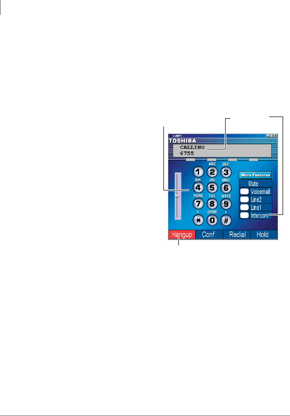
IP Telephony and QSIG Over IP
Installing and Operating the SoftIPT
9-22 Strata CTX I&M 06/04
Making a Call
The Toshiba SoftIPT integrates the power of a PC with all of the features available on a DKT3000-
series telephone, except background music. The main difference is that you use a mouse or stylus
to select buttons.
Other than these few differences, you can use most of the features described in the Strata CTX
DKT/IPT User Guide, available on the Internet FYI site, Documentation > User Guides. Refer to
this guide for instructions on using the other features.
³To ma k e a c a ll
1. Click Call. Hear dial tone.
(If you have “hot dialing,” skip this
step. Click on a button on the dial
pad and if you hear dial tone, you
have “hot dialing.”)
2. Click or select the on-screen dial
pad buttons to dial a call.
...or if the dialed numbers don’t
appear on-screen, click Intercom,
then dial by clicking on the dial pad
buttons on-screen.
3. When connected to a call, you can
select any of the call buttons, such
as Hangup, Redial, Hold or
Conf.
4. Click Hangup to end the call.
Note Do not use BGM (#490) on the
SoftIPT. It conflicts with
incoming calls.
Switching a Call to Your Headset
You can switch a call from your DKT3000- or 2000-series digital telephone to the SoftIPT by
placing the call on Hold and using the Call Pickup feature.
1. Press Hold on your digital telephone.
2. On the SoftIPT, dial #5#72 + the extension number of your digital telephone.
When you are on a call, the Call button changes
to Hangup. Click Hangup to end the call.
6825
If dialed numbers
don't appear,
click Intercom,
then dial.
Select or click on
dial pad buttons
to call.
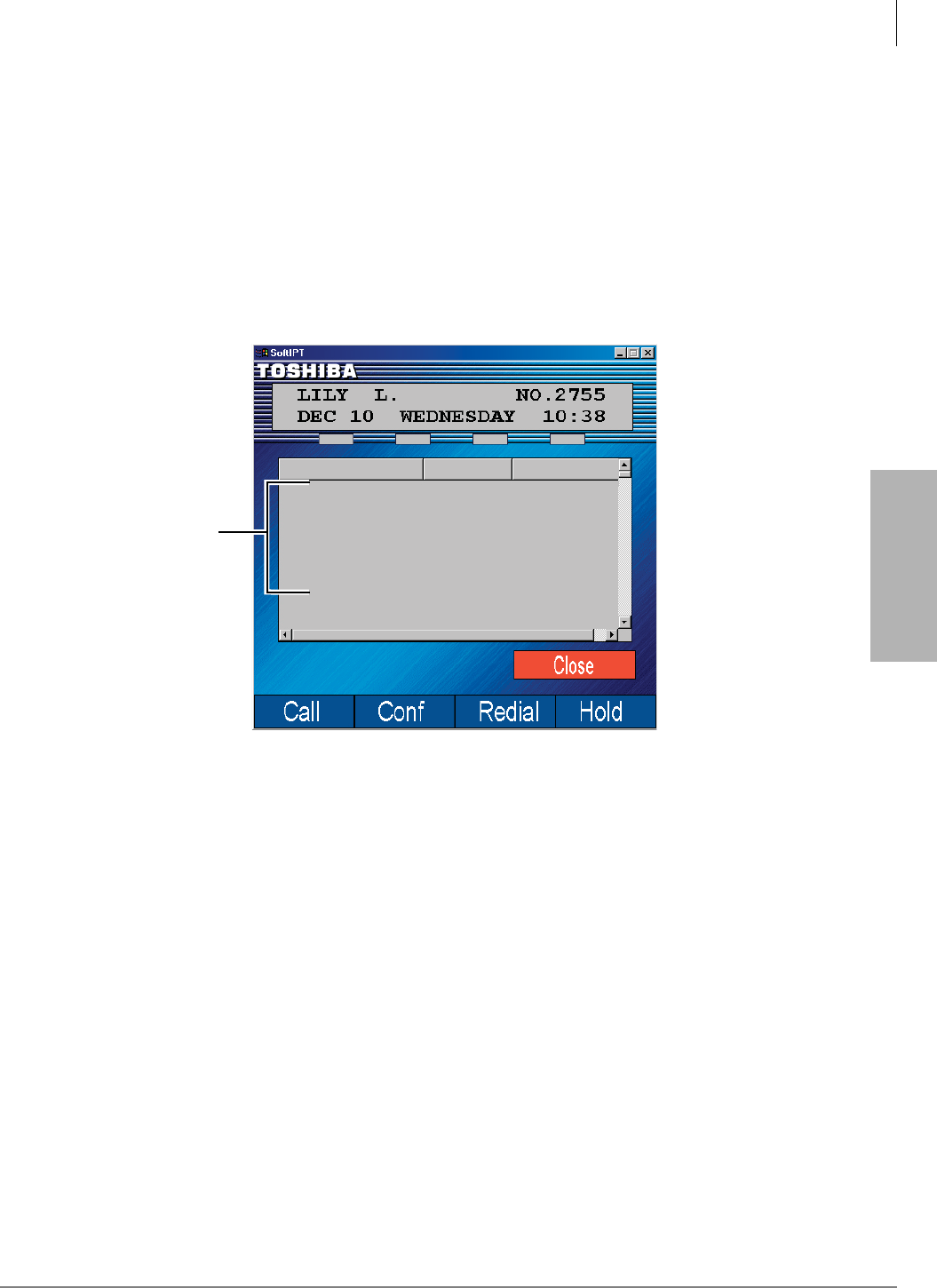
IP Telephony and QSIG Over IP
Installing and Operating the SoftIPT
Strata CTX I&M 06/04 9-23
IP Telephony and QSIG
Over IP
Creating a Directory
You can create a directory with Microsoft Outlook 2002 (not Outlook Express).
1. Open Microsoft Outlook 2002.
2. Double click on the Contacts icon, click on the New contact icon.
3. Type in the contact information, click Save and Close. Add as many entries as desired. To edit
an entry, double click on the name to open.
4. Open the Soft Phone.
5. Click More Features twice, click Directory. The directory displays (see below).
Using the Directory to Call
³Click on the name. The SoftIPT calls the contact.
7052
Hugh Leon
Jessica Kai
Kenny Voldrich
Tony Garaldi
Tony Bell
Bob Rogers
Shayla Morgan
3202
4011
3249
4201
4100
3237
3200
Work
Work
Work
Work
Work
Work
Work
Name Type Number
Click on a name,
Strata CTX dials
the number.
7052
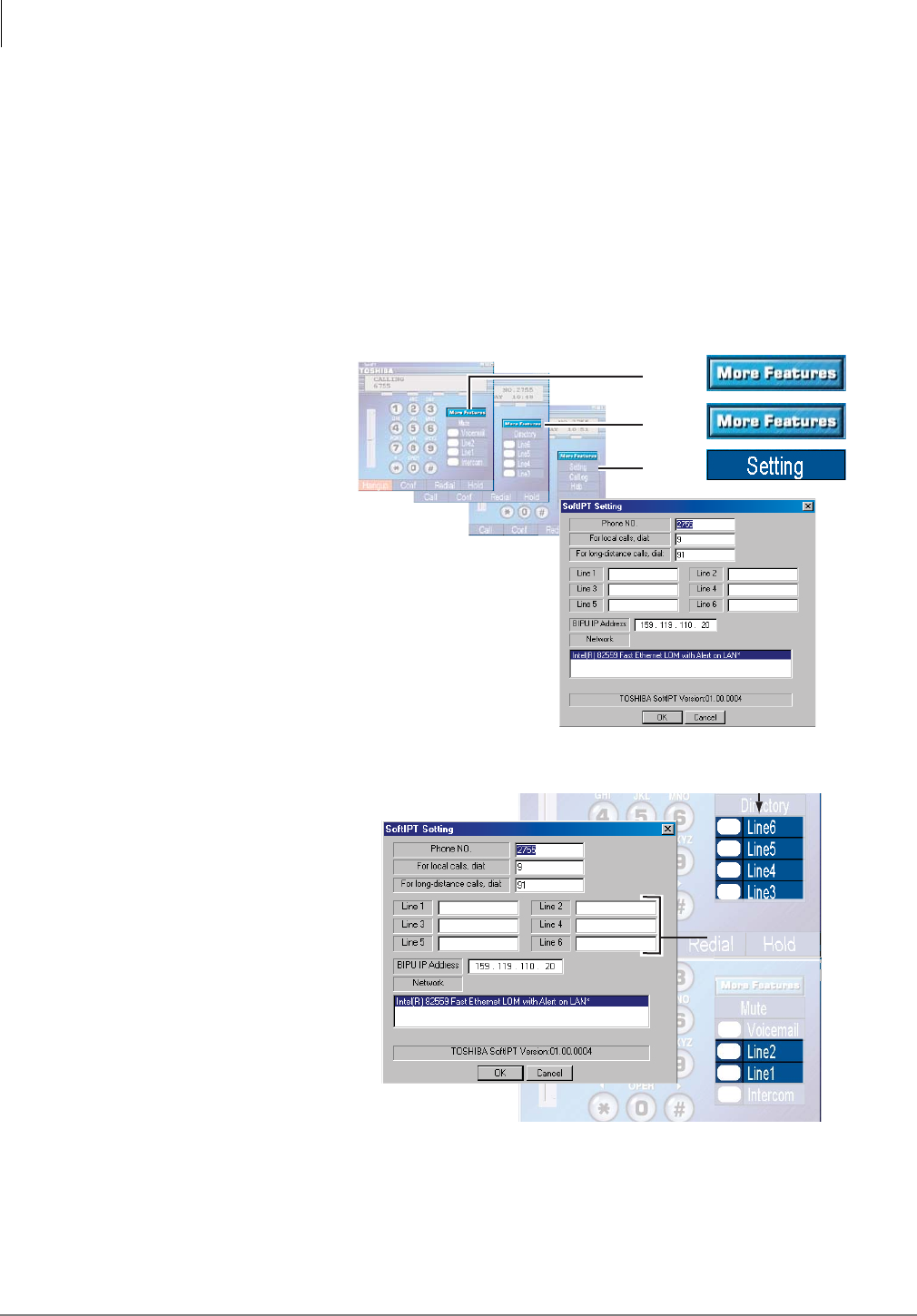
IP Telephony and QSIG Over IP
Installing and Operating the SoftIPT
9-24 Strata CTX I&M 06/04
Labeling Feature Buttons
From the Softphone Setting window, you can change six of the telephone button labels. Changing
the label does not change the function. To change the function, see “Programming Feature
Buttons” in the Strata CTX DKT/IPT User Guide.
³To find out what features are assigned to the feature buttons
1. Dial #9876 to enter user programming mode.
2. Click on HOLD, then click on the feature button.
³To change Feature Button Labels
1. Click More
Features twice.
Click Setting.
2. From the Softphone
Setting window
(shown right), type
in button labels
(eight characters
max.), click OK.
3. Click the “X” in the
upper right corner to
shut down the
SoftIPT. Your
changes won’t
appear until you shut
down and restart the
SoftIPT.
4. Click on the SoftIPT
icon to restart. The new button labels will display.
Note If you reprogrammed the button functions per the instructions in the user guide, you cannot
manually exit from “programming mode.” Just wait a few seconds for the system to time
out and the SoftIPT will return to idle.
6936
Click
Softphone Setting window opens.
Click
Click
again
6827
ls
l
C
a
n
e
n
te
r l
abe
e1~6
e
to
rename
Line
e
to rename Line
to rename Line
ns.
n
F
eatu
r
e
B
utton
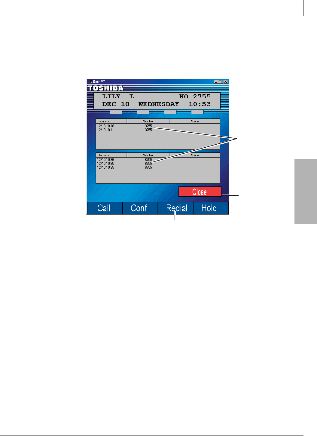
IP Telephony and QSIG Over IP
Installing and Operating the SoftIPT
Strata CTX I&M 06/04 9-25
IP Telephony and QSIG
Over IP
Using the Call Log
The SoftIPT keeps a log of incoming and outgoing calls.
³To access the Call Log
1. Click More Features until you see the Call Log button.
2. Click Call Log.
The log displays
(shown right).
From this screen,
you can:
3. Click Redial to
dial the last
outgoing number
...or click on an
incoming or
outgoing number
to dial it.
You can click
Close to close
this screen and
return to the dial
pad to enter an
access code or to
access the Mute,
Voicemail,
Directory or
other buttons.
Uninstalling the SoftIPT
³To remove SoftIPT from your PC
1. Click on Start > Control Panel > Add or Remove Programs.
2. Select SoftIPT, click Remove.
³To remove the SoftIPT folder, select Start > Programs > File Explorer.
³Select My Documents > My Device > Program File > Toshiba > SoftIPT, then select Delete.
Click on an
incoming
or outgoing
number to
dial it.
Click Redial to dial the
last outgoing number.
Click Close
to return to
the dial pad.
6922

IP Telephony and QSIG Over IP
Installing and Operating the SoftIPT
9-26 Strata CTX I&M 06/04
Application Notes for Wireless 802.11 Networks
The Toshiba SoftIPT™ works on wireless 802.11 networks. However, current access point
technology does not provide for the management of quality of service over the wireless network,
which can result in a few observable degradations in voice quality.
Our objective here is to describe these issues for the network engineer, and offer some
recommendations. As the technology evolves, and the knowledge base grows, other problems and
solutions will emerge, hence the network engineer is encouraged to search out other sources of
information, from the specific access point manufacturers or from experts in the 802.11 wireless
industry.
Possible problems and their implications are:
1. Dropped packets may occur due to RF signal strength, especially as you get further away from
the access point. When small amounts of packet loss occur, you will notice a popping or
clipping sound. With larger amounts of packet loss, gaps in the conversation will occur. This
is very similar to the behavior of digital cell phones in the same situations. The best way to deal
with this is to design the wireless network for good coverage where it is needed.
2. Dropped packets may also occur due to excessive traffic on the wireless network. With multiple
devices accessing data through the same wireless network, current access points do not have a
method for prioritizing voice packets over data packets so when data applications create more
traffic than the wireless bandwidth can sustain, voice packets may get dropped. In addition,
access points do not have a mechanism for limiting the number of simultaneous sessions. In our
lab we find that up to seven calls can take place simultaneously on a single access point. This
number will vary depending on the access point, the RF environment, and any other activity in
the wireless environment.
3. When one terminal is in a poor signal area for the access point that it is associated with, the
access point may automatically reduce its data rate in order to achieve better communications
with that terminal. This new data rate affects communications with all terminals, which will
reduce the number of simultaneous calls the access point can support. Network engineers
should consider whether they want to disable the Auto TX Data Rate Feature.
4. Disconnected calls will result if you move too far away from the access point, or generally are
in a poor signal strength area. With current 802.11 wireless technology, when a terminal can’t
communicate with an access point, it will disassociate with it. This appears to the phone
application as a loss of the network, and the phone application disconnects. Even if you quickly
move back into range of an access point, it will take several seconds for the 802.11 terminal to
detect and re-associate with the access point.
5. Wireless networks can only get so large, before you have to break them up into multiple
subnets. Somewhere between 256 and 1000 nodes is where networks begin to need to be
broken up into multiple subnets. When multiple subnets are employed, the call will get dropped
as the terminal gets out of range of its subnet. But the terminal can reestablish its call after
associating with the new subnet.
FYI: At Toshiba we are working on technology to address problems 2~4 for the SoftIPT. Check
back with us.

IP Telephony and QSIG Over IP
Installing and Operating the SoftIPT
Strata CTX I&M 06/04 9-27
IP Telephony and QSIG
Over IP
Wireless Recommendations
Follow these recommendations when using the SoftIPT on a wireless network.
• Ensure that no more than seven SoftIPT clients are working through a single access point at one
time.
• Engineer your wireless network so that there is good signal strength everywhere wireless
terminals will be used.
• Use the ping program to test your wireless network. In Microsoft® Windows® perform the
following:
1. Select Start > Run.
2. Type command, click OK.
3. At the prompt, type ping ñt ñl160 ñw250 (BIPU IP address, such as
159.119.112.32) and press Enter.
This starts the ping program and sends packets to the BIPU. ñl160 makes the packets the
same size as a 20msec. voice packet, and the ñw250 says if there is no response in 250
msec., then the packet dropped. Periodically you can press <Ctrl><Break> keys and see
the packet loss statistics. Packet loss ratios of 1% or less can be considered acceptable This
tool provides quantitative results that can be used when trying to engineer the wireless
network.
• Employ a channel allocation strategy. 802.11b supports multiple data rates, from 1Mbps up to
11Mbps. At 11Mbps – the objective of most networks these days, access points that are less
than five channels away will interfere with each other. This would mean that access points must
be on channels 1, 6, or 11. Some wireless network engineers have suggested that using
channels 1, 4, 7 and 10 would provide a very important fourth channel, and have minimal
interference.
• Check your environment for other access points and other equipment operating in the 802.11
band. There are many programs available that will allow you to identify access points within
reach of the terminal running the program. One example is Network Stumbler (this is not an
endorsement or recommendation of a particular product). Also consider that some cordless
phones operate in the same 2.4GHz band as 802.11b.
Considerations
To get the best use from your SoftIPT, consider the following tips.
• Use a headset with an attached microphone to provide good call quality and privacy. If you
don’t use a microphone/headset, the called party will hear an echo.
• When you are not wearing the headset, unplug it so that you can hear the phone ring. When the
headset is plugged in, you can only hear ringing through the headset.
• Use Microsoft Outlook 2002 to create contacts. The SoftIPT does not work with Outlook
Express.
• Dialing tips: When you click or select buttons on the SoftIPT, you will not hear button tones.
Also, you must use the SoftIPT directory, keyboard or dial pad buttons to call another number.
The SoftIPT does not recognize numbers that you “copy” and “paste” onto the screen.
• If you minimize the SoftIPT, incoming calls “pop up” the SoftIPT to the foreground. If you
want the SoftIPT to “pop up” for incoming calls, always minimize it after each call.
• The SoftIPT disconnects immediately after the called party hangs up. If you select the
Hangup button and it turns back to the Call button, it means that the other party disconnected
first.

IP Telephony and QSIG Over IP
Installing and Operating the SoftIPT
9-28 Strata CTX I&M 06/04
•The Conf button works the same as the Cnf/Trn (Conference/Transfer) button on the DKT/
IPT telephones.
• You can make a Windows “shortcut” and add it to your program menu or add it as a Quick
Launch item using the standard Windows method. The SoftIPT application does not
automatically do this.
• When you exit the SoftIPT, any Call Forwarding that you set also turns off.
• Make sure that you are running only one version of the SoftIPT. If you click on the shortcut
icon or start the program while you are already running it, another SoftIPT application will
open. If you see “Searching BIPU...” or “Can’t Register SoftIPT” click the close button to
make sure that there isn’t another SoftIPT running.
• If you are on a SoftIPT call and you are viewing the Setting window, select Cancel to exit the
Setting window. Avoid selecting OK during a call, since it will reset the SoftIPT and the call.
The application will operate with the new Setting information after you start the SoftIPT again.
• The Call Log does not record calls that have a name associated with it. It logs calls that are
stored on the Strata CTX as a number.
• For the SoftIPT, configure the Strata CTX BIPU PCB for G.711 CODEC at 20msec. (40msec.
voice packet transmission interval is not supported and G.729 is not supported.)
Note Quality of Service statistics are not available on Strata CTX for the SoftIPT.
Tested Platforms
The following devices and PC platforms have been tested with the SoftIPT.
Audio Devices
• YAMAHA AC-XG, ALi Audio Wave, or Analog Devices (ADI)
PC Platforms
• Portege 3500, 1.3GHz, 256MB, “ALi Audio Wave,” Windows XP pro
• Satellite 5200, 2GHz, 512MB, “YAMAHA AC-XG WDM Audio,” Windows XP pro
• Satellite Pro M10, 1.6GHz, 512MB, “SoundMAX Digital Audio,” Windows XP pro
• Tecra S1, 1.5GHz, 512MB, “SoundMAX Digital Audio,” Windows XP pro
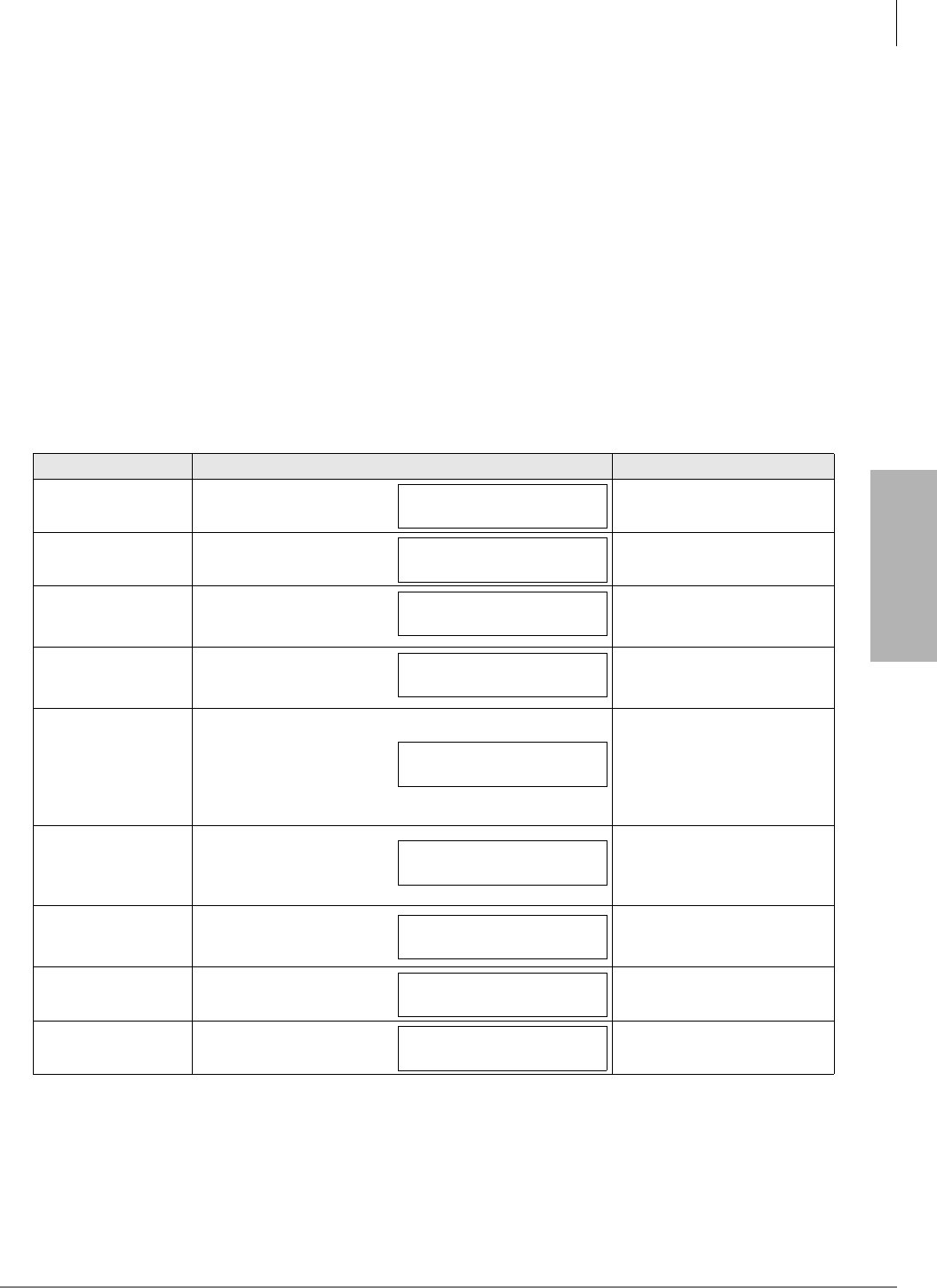
IP Telephony and QSIG Over IP
CTX IP Troubleshooting
Strata CTX I&M 06/04 9-29
IP Telephony and QSIG
Over IP
CTX IP Troubleshooting
This section provides guidelines for troubleshooting the CTX with IP. It covers the kind of data to
collect for troubleshooting and how to collect it. Toshiba TSD Technical Support will require
collecting data for diagnosing problems.
IP Telephone Ping Test
The IPT sends 10 ping packets of 64 bytes. The time lapse between ping packets is one second.
The time that the IPT waits for a reply is five seconds. When the IPT receives the reply packet
within five seconds, the counter which shows received packets increases in number.
1. Press 3, 6, 9 and Hold simultaneously.
2. Press 2 Hold to select the Network Setting Mode. Refer to the following table to continue with
the test.
Table 9-7Ping Test
Action LCD Indication Remarks
1. Press FB15.IPT changes into a network
diagnosis mode.
2. Press 1.IPT is ready to send ping
packets.
In case the IP address of
the IPT is not set
(processing DHCP).
It is impossible to execute ping
when IP addresses of IPT and
BIPU are not set.
In case the IP address of
BIPU is not set (executing
RAS).
3. Press Hold.
Ping packets are sent and
IPT displays the number of
received and sent packets.
When the IPT sends ping
packets, it displays the IP
address of BIPU on its LCD.
The display format is “Number
of received packets/number of
sent packets.”
After sending 10 ping
packets, IPT displays new
result.
If you operate off-hook and on-
hook while ping is executing,
the ping is stopped and
changes to normal mode.
4. (Optional)
Press 2.
The sending of ping
packets is stopped.
The counter is continuously
increased during the sending
of the packets.
5. (Optional)
Press 3.
Previous result is
displayed.
If ping is not executed, the
LCD displays the following:
LOOP BACK MODE
PING TO BIPU
PING TO BIPU
CAN’T GET IPT ADDRESS
PING TO BIPU
CAN’T GET BIPU ADDRESS
PING TO 172.16.36.100
PING RESULT 5/5
PING TO 172.16.36.100
PING RESULT 10/10
STOP PING
EXECUTING 5/5
PING TO 172.16.36.100
PING RESULT 10/10
PING TO BIPU
PING RESULT 0/0
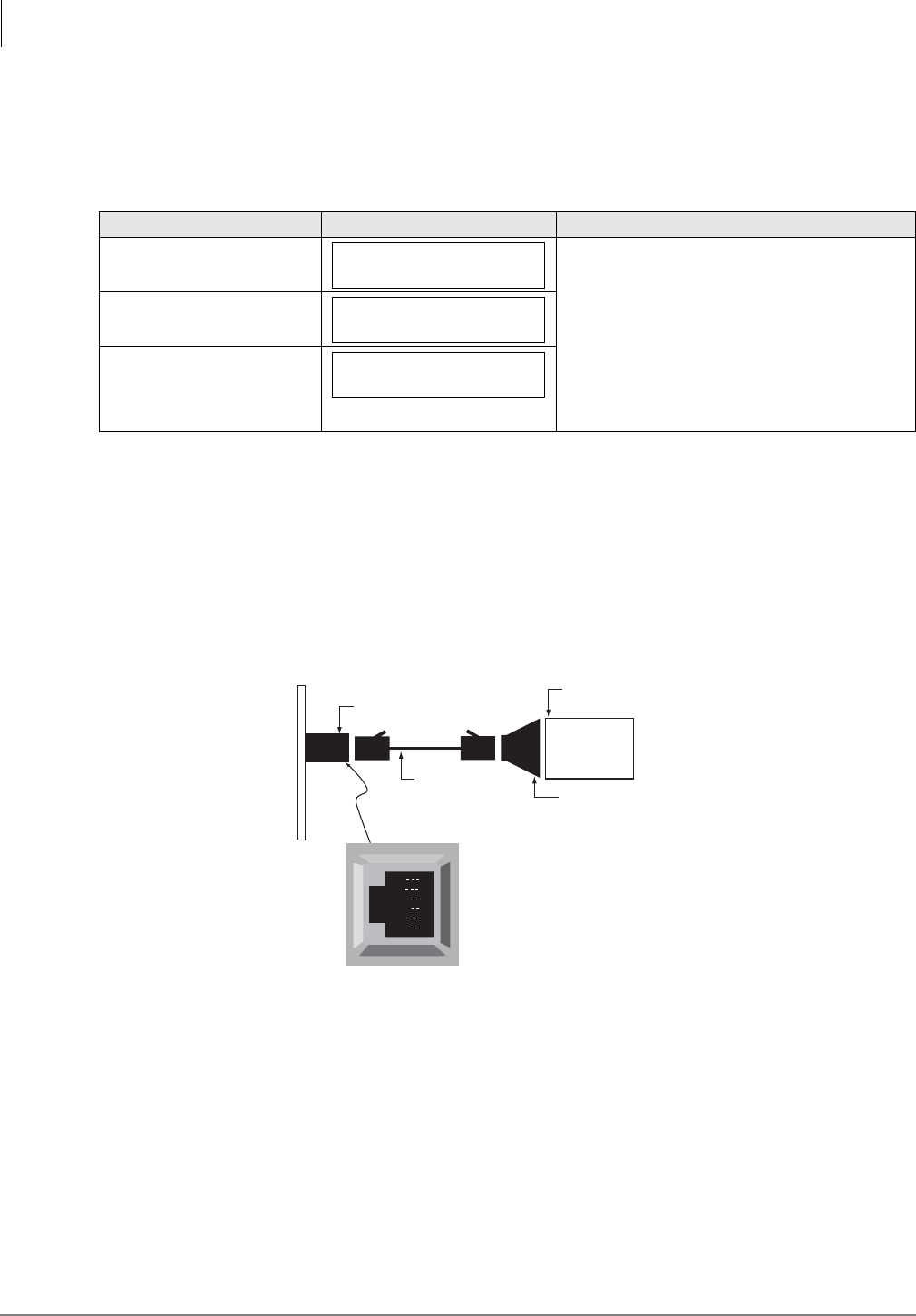
IP Telephony and QSIG Over IP
CTX IP Troubleshooting
9-30 Strata CTX I&M 06/04
LCD Network Failure Displays
When LCD Network failure occurs between BIPU and IPT, IPT displays one of the following LCD
messages.
Collect CTX Trace Data on CTX SmartMedia Card
The Trace Data consists of an EventTrace, Error Log, Admin Log, and ProgData.The procedure is
provided in the Strata CTX Programming Manual.
Collect BIPU Logs
1. Connect to PC by RS-232C cable and launch a terminal emulator software (Hyper Terminal,
ProCom, etc.). See Figure 9-11.
Figure 9-11 BIPU Monitor Jack
Serial port setings:
• Baud rate: 9600
• Data: 8 bit
• Parity: none
• Stop: 1 bit
• Flow control: none
Table 9-8LCD Network Failure
Conditions LCD Indication Remarks
1. Failed in TCP
connection with BIPU.
When this LCD message appears, IPT resets
after 10 seconds.
2. Cut off TCP connection
with BIPU.
3. Keep alive error
(DCH data from BIPU
was stopped 20
seconds or more.)
BIPU TCP CONNECT
ERROR
BIPU TCP PORT IS
CLOSED
BIPU ALIVE PACKET STOP
RD
TD
DSR
DTR
DCD
SG
1
2
3
4
5
6
Call-monitor jack (RJ-12)
pin numbering
Dealer-supplied
6-wire telephone
modular cord
(cross-pinned)
Call-monitor jack
PC with communication
software, such as ProComm™
PC DB9 or
DB25 Com port
Toshiba PPTC9 or
PPTC25F
CTX BIPU PCB Monitor Jack
6711
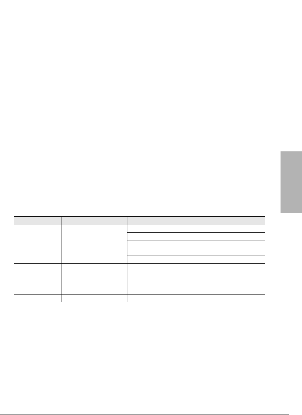
IP Telephony and QSIG Over IP
CTX IP Troubleshooting
Strata CTX I&M 06/04 9-31
IP Telephony and QSIG
Over IP
2. Log onto the BIPU. At “A.B.C.D login:” prompt, type root
A.B.C.D login: root
(*) A.B.C.D: BIPU IP address programmed in Program 151-FB01.
3. Display the log files and put them into the text file.
# cat Log0.log
# cat Log0.err
(*) Log0.log contains the all contents of Log0.err.
Check Log0.log/Log0.err for Error Message Output
The format of error message is:
Date Time E module-name:error message ex
2003/02/13 17:39:49:340 E CBipulo:Reboot:vp init
³Display the kernel boot message and put it into the text file # dmesg.
Check Whether Message Associated Warnings/Errors Were
Printed
BIPU Reset
³If the BIPU resets, find the text string with the implied reset cause.
Table 9-9 BIPU Reset Causes
Reset cause String in the Log file Known conditions
Software Reset Called CPU reset
DSP hardware initialization was failed or timed out.
DSP command execution was failed or timed out.
Any internal process was dead.
Modify the network configuration (IP address, etc.)
BIPU program update
WDT Overflow WDT Timer Overflow DSP lock
BIPU is overloaded with network traffic.
Hardware WDT
(PM only) -- CPU lock
Others -- --
IP Telephony and QSIG Over IP
CTX IP Troubleshooting
9-32 Strata CTX I&M 06/04
Verify CTX/BIPU/IPT Hardware, Software and Firmware Version
Mandatory Data
Optional Data for Program Update
CTX System Configuration
In the following record sheets, record the card configuration for the cabinet where the BIPU is
installed. Include the following information:
• Mark the BIPU slot.
• Input card type based on Prog100 --> upper space
• Input installed card information when the problem was occurred. --> lower space
• Card information:
•card type
• hardware version (CMx, PM)
• firmware version
• In addition, the version of processor board, cabinet and power unit.
Which What How Example
CTX Software Program 901 FB1 NA200MF010, SA200MF009
BIPU
Hardware Labeled on card CM4, CM5, PM
FPGA Labeled on chip V. 0 3 , V. 0 4
Firmware
(BootRom version included) Program 151 FB4 BIPU10A, BIPQ02B
BIPS Hardware Labeled on card CM3, CM5
IPT
Hardware Labeled on base CM9
Firmware
(BootRom version included)
Program 250 FB9 or
Terminal Setting Mode DIP11PA, DIP11QB
Which What Example
FTP
Operating system Windows XP server, RedHat Linux
Server program name IIS, wu-ftpd, CTX internal
TCP/IP properties IP address, netmask, gateway address
WinAdmin WinAdmin version V1.30, V2.00
BIPU Target BIPU firmware version BIPU11B
IPT Target BIPU firmware version DIP11QB
CTX670
Slot 12345678910
Base
Exp.
IP Telephony and QSIG Over IP
CTX IP Troubleshooting
Strata CTX I&M 06/04 9-33
IP Telephony and QSIG
Over IP
Network Information
Network Equipment that BIPU/IPT Directly Connects To
• Switching Hub (Layer2 Switch) Port
• Repeater Hub Port
• Router Port
• Layer3 Switch Port
Acceptable settings are shown in the table below.
Network Diagram
Sketch the simple network diagram.
CTX100
Slot 12345678
Base/
Exp.
Equipment
type
Link speed Mode Vlan, Priority Routing protocol
10Mbps
10/100Mbps
1Gbps
half duplex
full duplex
auto
IEEE802.1p
tag vlan
port vlan
static
rip
igrp/eigrp
others
Repeater Hub N/
A
N/
A
N/
A
N/
A
N/
A
N/
A
N/
A
N/
A
N/
A
Switching Hub N/
A
N/
A
N/
A
N/
A
Router
Layer3 Switch
IP Telephony and QSIG Over IP
CTX IP Troubleshooting
9-34 Strata CTX I&M 06/04
Capture Packets
Packet types to be captured are:
The following is the port number used by each protocol. This is useful for filtering captured data.
RAS (Registration, Admission and Status)
MEGACO+
RTP/RTCP
FTP/FTP-data
DHCP
Protocol Name Type Use, Purpose
RAS (H.225) udp for searching BIPU and registering IPT with the system
MEGACO+ tcp call control protocol
RTP udp carry the voice data
RTCP udp
control RTP
System uses this protocol to measure the round-trip delay of rtp packets
between BIPU and IPT (currently unavailable).
SNMP udp get/set CTX data from CTX WinAdmin
FTP tcp to download updating file when updating the BIPU/IPT program.
FTP-data tcp to download updating file when updating the BIPU/IPT program.
DHCP udp request to lease an IP address (IPT only)
IP-QSIG tcp encapsulate QSIG message over IP network
IPT BIPU
Discovery (GRQ, GCF, GRJ) 1718 1718
Registration (RRQ, RCF, RRJ) 1719 1719
IPT BIPU
random 2944
IPT BIPU
RTP 1500 X (11000 – 13000). Always an even number.
RTCP 1501 X+1. Always an odd number.
BIPU (FTP client) FTP server
FTP 1024 (initial)
1026 (retry) 21 (well-known)
FTP-data 1025 (initial)
1027 (retry)
20 or any port (Depends
on server implementation)
DHCP server DHCP client (IPT)
67 68
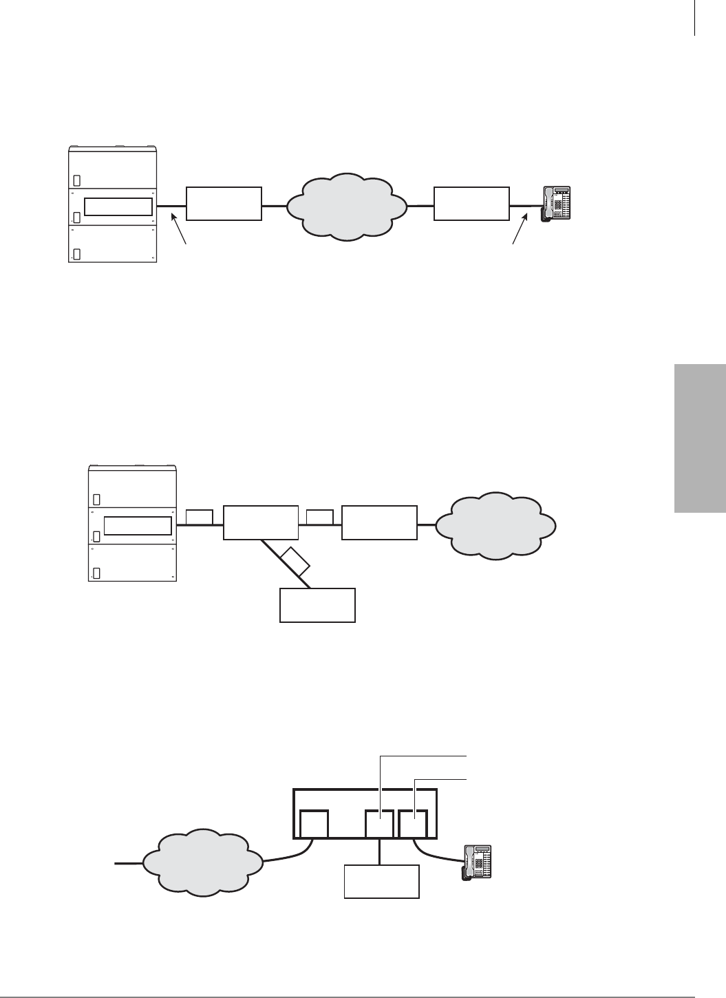
IP Telephony and QSIG Over IP
CTX IP Troubleshooting
Strata CTX I&M 06/04 9-35
IP Telephony and QSIG
Over IP
Capture Points
The capture point for the BIPU and the IPT are shown in Figure 9-12.
Figure 9-12 Capture Point Locations
How To Capture Packets
Using Repeater Hub (Dumb Hub)
If you want to use a repeater hub (dumb hub) for troubleshooting, it should be connected as shown
in Figure 9-13.Toshiba does not recommend the use of the repeater Hub to be unable to ensure the
voice quality. A repeater hub should only be used for resolving the problems.
Figure 9-13 Repeater Hub Location
Using Switching Hub with Mirroring Function
By using mirroring function, it is possible to capture all send/receive data to one specific port (it’s
called source port). See Figure 9-14.
Figure 9-14 Switching Hub with Mirroring Function
Switch Switch
Strata CTX
BIPU
6707
IPT
Page ScrollMode Feature
Msg
Mic Redial
Spdial
Spkr Cnf/Trn Hold
Vol
IP Network
Capture point for BIPU Capture point for IPT
Repeater
Monitor
device
Switch
Strata CTX
BIPU
6709
IP Network
Switch
Monitor
device
Mirror port
Source port
6708
IP Network
IPT
Page ScrollMode Feature
Msg
Mic Redial
Spdial
Spkr Cnf/Trn Hold
Vol
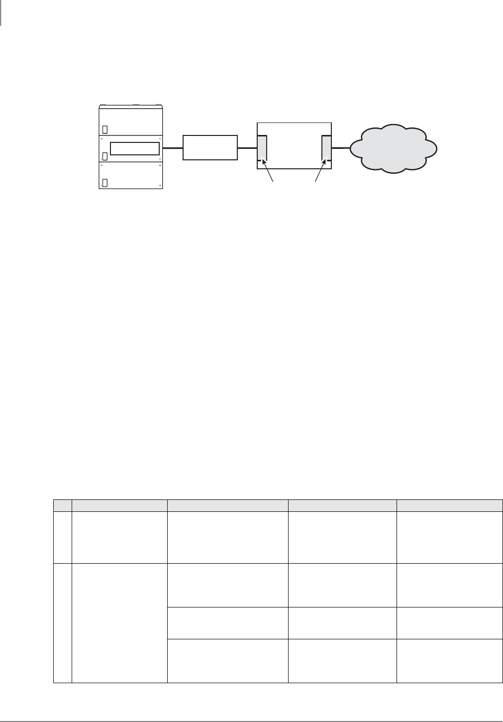
IP Telephony and QSIG Over IP
CTX IP Troubleshooting
9-36 Strata CTX I&M 06/04
Using PC or Workstation With Multiple Network Interfaces
Start capture tool and specify the network interface face on BIPU/IPT. See Figure 9-15.
Figure 9-15 PC or Workstation With Multiple Network Interfaces
Requirement for Capture Tool
The following is the better, but not mandatory.
• Support GUI format (summary, details and dump).
• Enable to decode VoIP protocols.
Examples:
•Sniffer
• Ethereal
• Network Monitor for MS-Windows
• tcpdump (Linux, BSD)
• snoop (Solaris)
To analyze the captured data more efficiently, save the captured data in binary format (not text
format). The libcap format is better (suffix is .cap).
IP Troubleshooting Resolutions
Table 9-10 IP Troubleshooting Problems and Resolutions
No. Problem Action Cause How to Resolve
1IPT repeats reset and
reboot.
“Remove that IPT from network.
Execute ping command to an IP
address assigned to that IPT
from PC. Do you receive the
reply packets?”
IP address was duplicated
with other IPTs or network
equipment.
Don’t duplicate IP address.
Connectivity Problems:
2IPT is unable to connect
to BIPU.
Verify the IPT configuration
(enter terminal setting mode by
pressing 3+6+9+Hold).
In FK11, Check the BIPU IP
address is same as that of
Prog151-FK1
Incorrect programming of
BIPU IP address.
Re-configure the BIPU IP
address correctly.
Ping to BIPU but no replies are
received.
1. LAN cable has come
loose.
2. Gateway setting of IPT
was mistaken.”
1. Check LAN cable on a
route.
2. Re-configure the Default
Gateway address correctly.
Switch
Strata CTX
BIPU
6710
IP Network
Monitor device
Network Interface card

IP Telephony and QSIG Over IP
CTX IP Troubleshooting
Strata CTX I&M 06/04 9-37
IP Telephony and QSIG
Over IP
3
IPT has harsh noise
during talking or hearing
any tone.
Check the network equipment
located on the routing path
between BIPU and IPT.
Repeater HUB was used.
Replace to Switching HUB.
Toshiba recommends the
use of SW-HUB.”
“Capture the network traffic
between BIPU and IPT, and
analyze the captured data.
Verify the following.
(1)The interval of RTP packets is
almost same as the value
configured by Prog 152-FK1.
(2)This interval is constant.
Path band-width of the
network between BIPU and
IPT was too narrow.
Reduce the number of
connected IPTs.
Apply the priority control.
Change voice CODEC to
G.729A”
Routing delay or packet loss
due to low performance of
routing devices (router or L3
switch).
Same as above.
“Illegal packets were sent to
BIPU/IPTs. Flow a lot of
broadcast packets.”
Remove the originator.
LAN Problems:
4
“IPT is unable to connect
to BIPU.
Condition:
Two repeater HUBs were
cascaded.”
Verify the specification of each
repeater HUB.
10M-repeater HUB and 10/
100M-repeater HUB were
cascaded.
In case that some repeater
HUB connects to the other
one having different link
speed each other, one of
those needs to have internal
bridge circuit.
5 No voice path
“If priority control function
(IEEE802.1p) was set to
““enable””, return to ““disable””
and try again. If voice path was
restored, verify the specification
of routers/switches between
BIPU and IPT.”
“Routers or LAN switches
were unable to interpret
Ethernet frame with VLAN
tag correctly (IEEE802.1p
uses a part of VLAN tag
field). So, these frames were
discarded by the router/
switch.”
Disable IEEE802.1p
function. *note) Equipment
not to be complied with
IEEE802.1Q/1p seem to
regard ethernet frames with
VLAN tag field as illegal
frames and to discard these
frames.
6
“IPT is unable to connect
to BIPU.
Condition:
IPT connects to LAN
switch complied with
IEEE802.1Q (tag-based
VLAN).”
Check the port configuration of
LAN switch.
The IPT connection port was
configured as tag-based
VLAN port. Therefore, this
port passed only ethernet
frames with VLAN-ID same
as port configuration, and
discarded other frames.
Disable VLAN setting. IP-
CTX does not support tag-
based VLAN. So, BIPU and
IPT cannot belong any
VLAN.
7
There are two gateways
in the network segment
which BIPU belongs, and
one of them is configured
as default gateway of
BIPU.
- restriction
If default gateway is down
for a while, BIPU cannot re-
route another gateway
automatically.
8
IPT Problems:
“IPT shows ““Can’t set
IPaddress””.”
Check the DHCP server exists
on the same network as that IPT.
DHCP server does not exists
on the network.
Setting up and starting
DHCP service, or configure
IPT’s IP address and Subnet
mask manually.
DHCP server is located
beyond the router.
Setting up and starting
DHCP service on the same
network as that IPT.
Table 9-10 IP Troubleshooting Problems and Resolutions
(continued)
No. Problem Action Cause How to Resolve

IP Telephony and QSIG Over IP
CTX IP Troubleshooting
9-38 Strata CTX I&M 06/04
IPT Problems:
9“IPT shows ““BIPU not
found””.”
Verify the following:
1. BIPU is running (heart-beat
LED is blinking).
2. Ping to BIPU is successful.
3. BIPU discovery mode in
terminal setting mode. If
““2:Broadcast”” is selected,
BIPUs have to locate same
network segment as IPT.”
1. BIPU was down.
2. BIPU was network
unreachable.
3. BIPU was located beyond
the router but IPT tried to
discover BIPU by
broadcasting.”
3. Change BIPU discovery
mode to ““1:Manual”” and
configure BIPU IP address
in IPT terminal setting
mode.”
10 “IPT shows ““Can’t get
StationID””.”
Check there are available
Station IDs.
All Station IDs are already
used by other IPTs.
New IPT assigns by Prog
200 and permits Automatic
Station ID Assignment by
Prog 150 or Prog 250.
Check CTX permits the
Automatic Station ID
Assignment.
“Programming as Automatic
Station ID Assignment is set
to ““disable””.”
Permits Automatic Station ID
Assignment by Prog 150 or
Prog 250.
11 “IPT shows ““StationID
unmatch””.”
Step 1: Enter terminal setting
mode, and then press dial ““2””
to enter network configurations,
and then press FK5 to display
the StationID.
Step 2: Enter CTX programming
mode, and then enter prime DN
same as Station ID in Prog 250.
Command error or not?”
Station ID is out of prime DN
list which are assigned to
IPT.
Set Station ID from within
prime DN list which are
assigned to IPT.
12 “IPT shows ““Not exist
Multicast addr””.”
Enter the terminal configuration
mode, and then press ““2”” to
enter the network configuration.
Verify the following:
(1) FK11
(2) FK13”
“In FK11, ““3:Multicast”” was
selected, but no multicast
address was assigned in
FK13.”
Change BIPU discovery
mode (FK11), or enter the
multicast address for
discovery.
Note CTX does not
support the
procedure of
discovery using
multicast. This is
future support.”
13 “IPT shows ““Not exist
BIPU addr””.”
“Enter the terminal configuration
mode, and then press ““2”” to
enter the network configuration.
Verify the following:
(1) FK11
(2) FK12”
“In FK11, ““1:Manual”” was
selected, but no BIPU
address was assigned in
FK12.”
Change BIPU discovery
mode, or enter the BIPU
address for discovery.
14 “IPT shows ““Can’t
register IPT:E0””.”
1. Enter terminal configuration
mode, then press ““2”” to enter
the network configuration. Verify
StationID in FK5.
2. In Prog 250, enter prime DN
same as the StationID verified
step1.
3. If no error, move step4.”
“Station ID assigned in
terminal configuration mode
was out of IPT’s prime DN
list. Maybe this station was
deleted or prime DN was
changed.”
Change Station ID.
4. Try the following: Enter Prog
250 with Prime DN same as the
Station ID verified Step 1. Select
FK8 and change voice CODEC.
Terminal data regarding that
StationID was not
synchronized between CTX
and BIPU. Maybe BIPU failed
to receive the data.
This is a known problem.
Table 9-10 IP Troubleshooting Problems and Resolutions
(continued)
No. Problem Action Cause How to Resolve
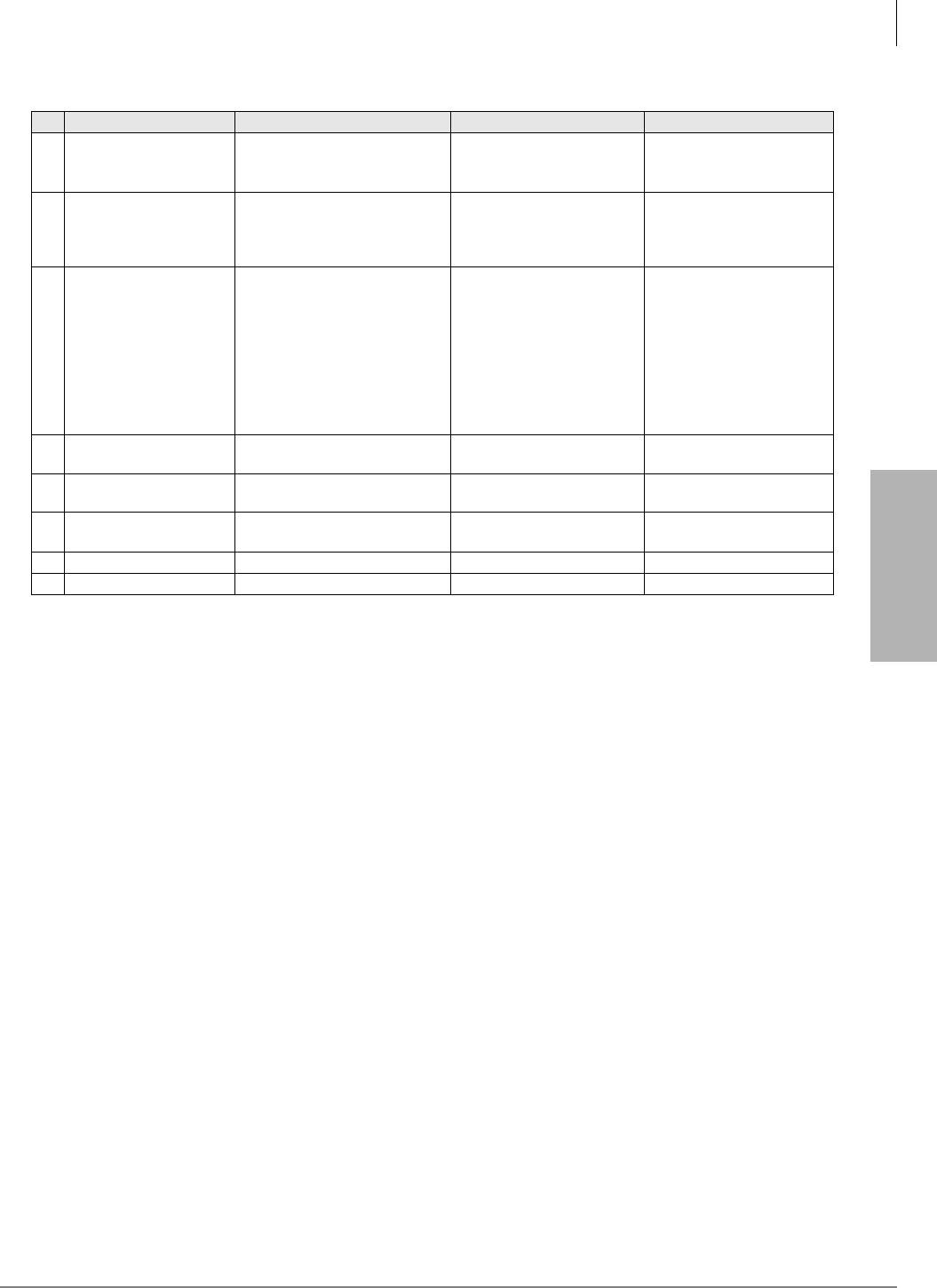
IP Telephony and QSIG Over IP
CTX IP Troubleshooting
Strata CTX I&M 06/04 9-39
IP Telephony and QSIG
Over IP
IPT Problems:
15 “IPT shows ““Can’t
register IPT:E4””.”
Find the IPT which has same
Station ID. Station ID duplicated. Set unique Station ID.
16 “IPT shows ““Can’t
register IPT:E11””.” No resources are available.
Create a new IPT terminal in
Prog 200. Or, Change
destination BIPU having
some idle resources.”
17 “IPT shows ““Can’t
register IPT:E13””.”
“Check CTX applies Terminal
Authentication feature, or, IP
address filtering. Verify Prog 150
FK2 and Prog 250 FK5, FK6 for
Terminal Authentication. Verify
Prog 250 FK2, FK3 for IP
address filtering.”
1. Terminal Authentication
feature was applied but
Station MAC address was
different from that
programmed in CTX.
2. IP address filtering was
applied but Station IP
address was different from
that programmed in CTX.”
See Spec.1203 for Terminal
Authentication. See
Spec.1200 for IP address
filtering.”
18 “IPT shows ““BIPU TCP
CONNECT ERROR””.”
Fail to establish TCP
connection to BIPU.
19 “IPT shows ““BIPU TCP
PORT IS CLOSED””.”
TCP connection was
disconnected by BIPU.
20 “IPT shows ““BIPU ALIVE
PAC K ET S TO P ”” .” Keep-Alive was failing.
21
22
Table 9-10 IP Troubleshooting Problems and Resolutions
(continued)
No. Problem Action Cause How to Resolve
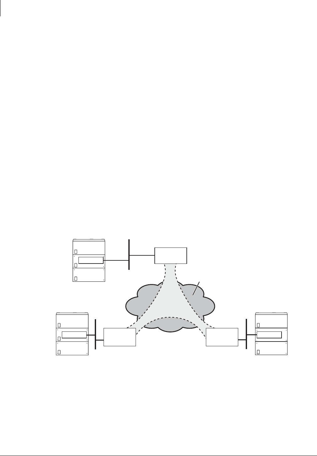
IP Telephony and QSIG Over IP
Private Networking Over Internet Protocol
9-40 Strata CTX I&M 06/04
Private Networking Over Internet Protocol
Strata Net CTX multi-system networking can be implemented over an IP network using Strata
CTX systems with BIPU-Q1A IP interface PCBs. The BIPU-Q1A requires CTX Release 2.1
software. This feature offers the same connection service as ISDN dedicated lines with QSIG
protocol on the public network. QSIG over IP, like any other IP device (i.e., Cisco routers, etc.)
does support reliable passage of modemized data signals, such as modem signal and G3 fax.
BIPU-Q1A - Strata Net QSIG over IP Interface Unit
Circuits per PCB:
eight or 16 circuits
Interfaces with:
Strata Net over IP Networking
Older Version(s):
None
The BIPU-Q1A can be configured for up to 16 channels in system programming. The BIPU-Q1A
supports the same functions of call control as the dedicated ISDN QSIG interface and the two
interface types can be mixed in on a Strata Net network. However, the BIPU-Q1A only interfaces
with the BIPU-Q1A, not with the BPTU or RPTU interfaces and vice versa.
For bandwidth requirements, refer to the section “Strata Net QSIG Over IP and IPT Bandwidth
Requirements” on page 9-41.
Refer to “Dos and Don’ts for Setting Up the System” on page 9-2 if you are planning to mix
analog and IP QSIG circuit cards in the same Strata CTX system.
An example of Strata Net QSIG over IP networking is shown below.
Figure 9-16 QSIG Over IP Example
QSIG
over
IP
QSIG
over
IP
QSIG over IP
IP Network
(Internet, Intranet, WAN)
T1, Fiber, etc.
*
*
Strata CTX
6755
BIPU-Q1A
Router
or Server with
or without VPN
LAN
Strata CTX
Router
or Server with
or without VPN
LAN
*
BIPU-Q1A
Strata CTX
Router
or Server with
or without VPN
LAN
*
BIPU-Q1A
VPN
Tunnelling
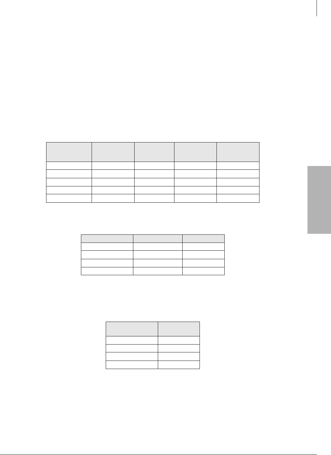
IP Telephony and QSIG Over IP
Private Networking Over Internet Protocol
Strata CTX I&M 06/04 9-41
IP Telephony and QSIG
Over IP
Strata Net QSIG Over IP and IPT Bandwidth Requirements
The bandwidth requirements for Strata Net QSIG over IP is the same as those for IP telephones.
Refer to Table 9-1 on page 9-5 to estimate the quality of service (Excellent, Good, Fair, and Poor)
provided by CTX IP QSIG channels depending heavily on the LAN parameters.
When sharing voice and data on the same network segment, the data will cause some jitter in voice
communications, especially on slower segments. Table 9-11 shows calculations of the amount of
jitter assuming a worst case data packet size of 1500 bytes (Maximum Transmission Unit (MTU) =
1500) based on a segment’s bandwidth. This also requires that the routers connecting the segment
through the WAN support Diffserv.
Note A router that doesn’t support Diffserv may stack multiple data packets together increasing
the jitter perhaps indefinately. And the voice quality will be indeterminate.
Class definition categories are shown in Table 9-12.
Table 9-13 shows the amount of bandwidth required for setting up and tearing down calls
independent of the amount of voice traffic.
Table 9-11 QSIG over IP Jitter on Mixed Voice and Data WAN
No. of
B-Channels
of WAN
Bandwidth
(kbps)
Time to
transmit max.
MTU (ms)
Expected
Jitter (ms) Class
2 128 93.75 100 Poor
4 256 46.88 50 Fair
6 384 23.44 30 Fair
8 512 15.63 20 Good
24 1536 1.00 1 Excellent
Table 9-12 QSIG over IPClass Definitions
Class Delay (ms) Jitter (ms)
Excellent < 20 < 10
Good < 50 < 20
Fair < 100 < 50
Poor < 200 < 100
Table 9-13 QSIG over IP Bandwidth
Required for Call Setup
Traffic Rate
(BHCA1)
1. BHC = Busy Hour Call Attempts
Required
Bandwidth
1000 6
2000 12
4000 23
6000 36

IP Telephony and QSIG Over IP
Private Networking Over Internet Protocol
9-42 Strata CTX I&M 06/04
So the amount of bandwidth that is required on a segment to support a specific number of calls
is the sum of the number of channels multiplied by the bandwidth for the selected CODEC and
interval, plus the bandwidth required for the selected number of busy hour call attempts. And
the jitter is determined by the bandwidth of the WAN segment.
Example: If you want to support 4 calls using the G..711 CODEC with a 20 msec. interval, this
requires 4 x 88 kbps = 352 kbps of bandwidth. In addition, to support 1000 busy hour call
attempts, 6 kbps must be added for a total of 358 kbps. If only voice is going to be carried on
the segment, then a 384 kbps segment (6 B-channels) is sufficient. If voice and data are going
to be mixed on the segment, then at least 25% (89.5 kbps) should be added, or more, based on
the amount of data traffic desired. In this case, a total of 447 kbps will be required which
would best be supported by a 512 kbps segment (8 B-channels). This would result in an
expected jitter of 20 ms in the voice traffic.
BIPU-Q1A Installation
1. Make sure the BIPS1A daughter card is securely installed onto the BIPU-Q1A PCB (the
BIPS1A is installed on the BIPU-Q1A at the factory). See Figure 9-2 on page 9-6.
2. Install the BIPU-Q1A into one of the following slots:
• CTX100 Base and Expansion Cabinet slots (1~8, 16 channels per slot per Program 100)
• CTX670 Base Cabinet slots (1~8, 16 channels per slot per Program 100)
• CTX670 Expansion Cabinet slots (1~6, 16 channels per slot per Program 100)
3. Follow the procedure in Chapter 2 – Strata CTX Configuration to check the cabinet power
factor.
4. Power up the system. Refer to Table 9-2 for status indicators.
5. Program the CTX per the instructions in the Strata CTX Programming Manual.
Connect BIPU-Q1A to LAN, Server or Router
1. Plug one end of a straight-through CAT5/5e/6 LAN cable into the RJ45 Ethernet port on the
BIPU-Q1A PCB in the CTX. (See Figure 9-2 on page 9-6.)
2. Plug the other end of the BIPU-Q1A CAT5/5e/6 LAN cord into a LAN, server or router jack.
Note The BIPU-M2A or Q1A-switch cables are straight-through cables.
Figure 9-17 BIPU-Q1A or BIPU-M2A PCB
Table 9-14 BIPU-Q1A or BIPU-M2A Buttons, LEDs and Jumpers
Indicator Definition
Ethernet Port LEDs
RD - Indicates BIPU-M2A or BIPUQ1A receives data from switch.
LINK - Indicates data activity between BIPU-M2A and switch
SD - Indicates BIPU-M2A or BIPUQ1A sends data to switch.
Heartbeat LEDs Flashes at a steady rate to indicate BIPU-M1A or BIPU-M2A or BIPUQ1A
is operating normally.
Status/Alarm LEDs For Toshiba Field Support Engineering use only.
Reset button Use when requested by Toshiba Field Support Engineer.
RS232 Maintenance Jack For Toshiba Field Support Engineers only.
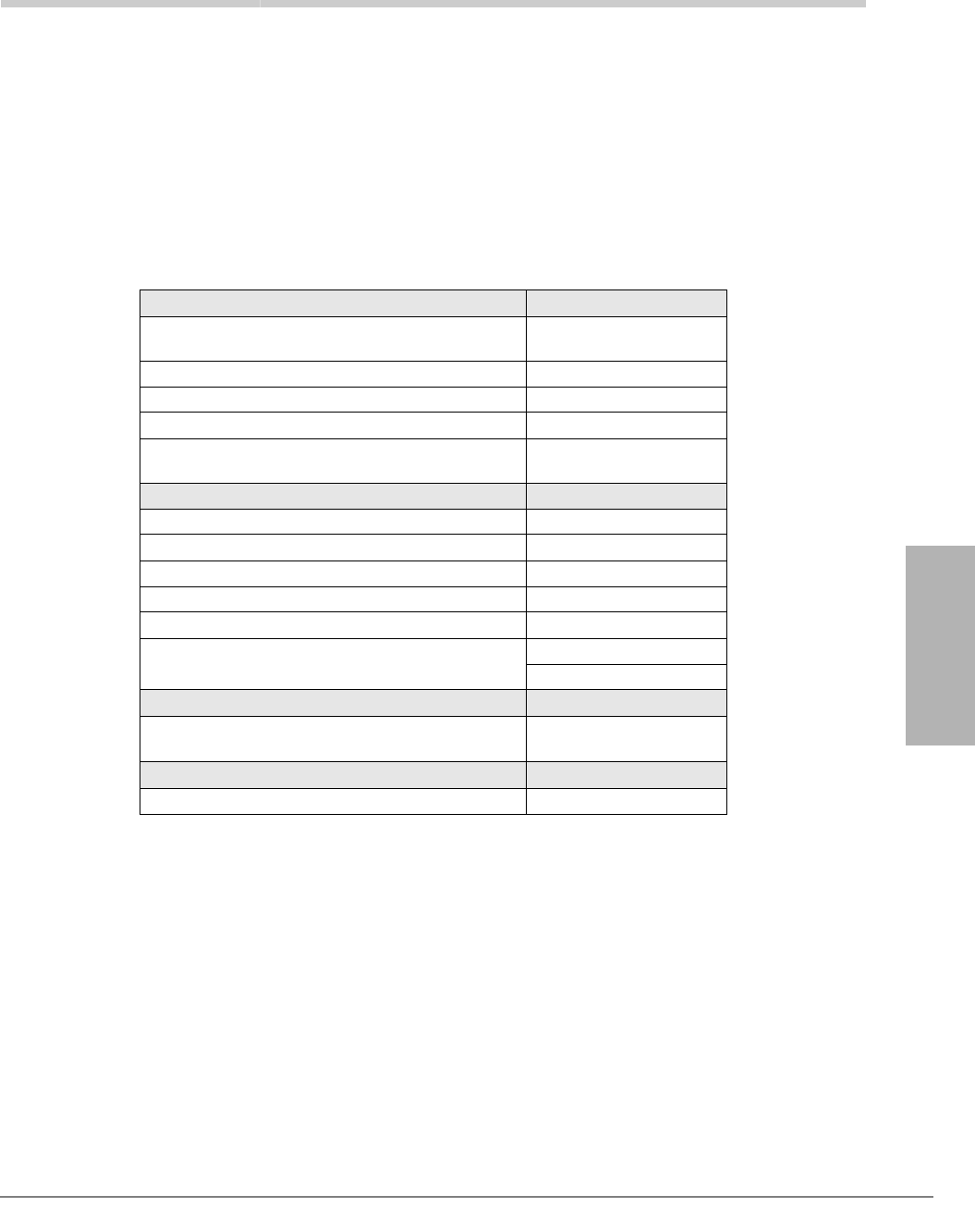
Strata CTX I&M 06/04 10-1
MDF PCB Wiring
MDF PCB Wiring 10
This chapter contains point-to-point wiring diagrams for connection of telephones, lines,
peripheral equipment, and power supplies for the universal slot PCBs of the Strata CTX system.
Wiring diagrams are divided into groups according to the PCB which provides the interface for, or
controls the operation of, the associated equipment as listed below:
Notes
• Before using the Connect Record Sheets (following each Wiring Diagram), make copies for
future use.
• The RDTU2 cable connection information is in Chapter 8 – T1.
• The RDTU, RBUU, RBUS cable connection is in Chapter 10 – MDF PCB Wiring.
Stations PCB
DKTs (BPCI, DDSS, DDCB, ADM and BATU) ADKU, BDKU/BDKS,
BWDKU
DKTs and DDSS PDKU
External Power for DKTs and DDCB BDKU, PDKU
DKTs or Standard Phones RDSU
Standard Telephone ASTU, RSTU, RDSU,
RSTS, PSTU
CO Lines PCB
Analog Ground Start RGLU
Analog Loop Start RCOU/RCOS
Analog E911 RMCU/RMCS
Caller ID with RGLU or RCOU/RCOS RCIU/RCIS
Analog DID/CO Lines RDDU
Analog E&M Tie Lines REMU
PEMU
Option Interface PCB
External Paging, Night Bell, Night Transfer Door
Lock and BGM mute control BIOU
Power Failure PCB
DPFT Power Failure Transfer box DPFT
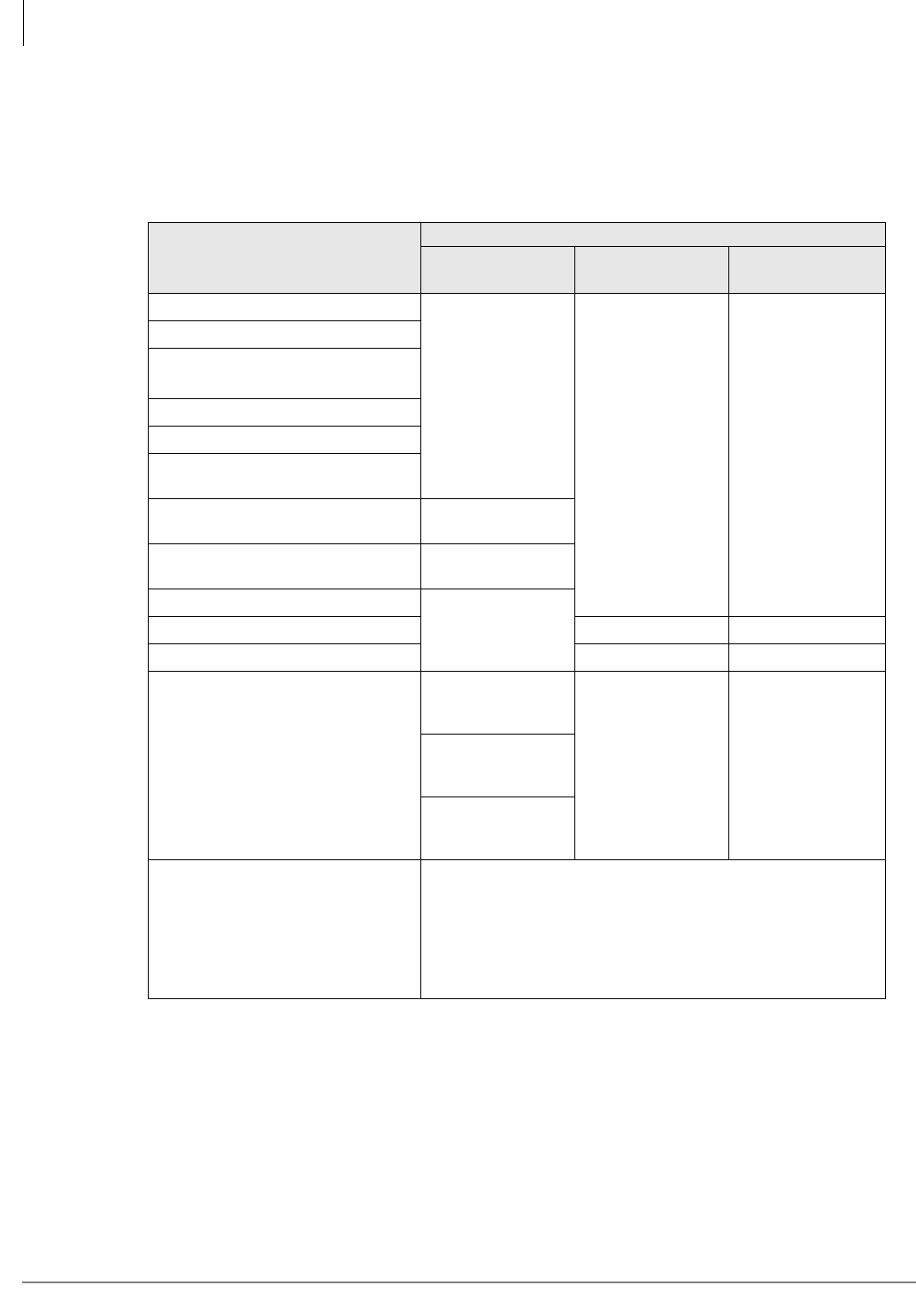
MDF PCB Wiring
Station Loop Lengths
10-2 Strata CTX I&M 06/04
Station Loop Lengths
In a single site installation, the Base and optional Expansion Cabinets must be placed within the
allowed maximum distance of each other as designated by Table 10-1
Table 10-1 Station Loop Lengths1
1. When the system is powered by backup battery, range may be less as the backup battery is discharged.
Mode
Maximum line length (24 AWG)
1 Pair2
2. One-pair wiring must be used with BWDKU and BDKS (see Figure 10-3 on page 10-6). The BWDKU and BDKS do
not support two pair wiring.
2 Pair 1 Pair plus
external power 3
3. Two-pair wiring or optional telephone power supply is required to achieve maximum range in all cases.
DKT3000 or DKT2000-series 4
4. BDKS and BWDKU do not provide the power wire pair; an external power supply is required to achieve maximum
range (see Figure 10-6 on page 10-9).
1000 ft. (303m)
1000 ft. (303m) 1000 ft. (303m)
DKT with BVSU or DVSU
DKT with
BHEU or HHEU
DKT with BPCI
DKT with BPCI + BHEU
DKT with BVSU + BHEU
or DVSU + HHEU
DKT with DADM3020 or DADM2020
(1 ADM)2675 ft. (204m)
DKT with DADM3020 or DADM2020
(2 ADMs)2500 ft. (151m)
DDSS3060 or DDSS2060
1000 ft. (303m)BATI, RATI n/a n/a
DDCB3 1000 ft. (303m) 1000 ft. (303m)
Standard telephones, voice mail, AA,
etc.
Approx. 3000 ft.
(909 m) with 150
ohm device. 5
5. See manufacturer’s product specifications for exact resistance of device.
n/a n/a
Approx. 9000 ft.
(2727 m) with 150
ohm device.5
Approx. 21000 ft.
(6363 m) with 150
ohm device.5
IPT1020-SD
The IP telephone interface is 10Base-T/100Base-TX and requires
CAT5/5e/6 twisted pair cabling.
The maximum distance between the IP telephone jack and the
ethernet device it connects to is 100 meters (328 ft.). This includes
the 3 meter (9.84 ft.) straight-through CAT5 cable (black) supplied
with the IP telephone. Ethernet devices include
BIPU-M2A, BIPU-M1A servers, routers, etc.
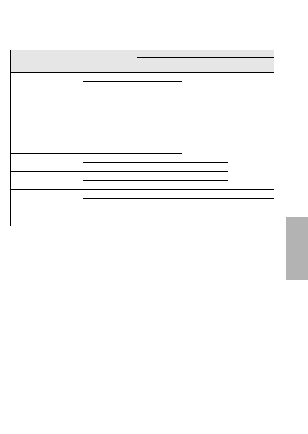
MDF PCB Wiring
Station Loop Lengths
Strata CTX I&M 06/04 10-3
MDF PCB Wiring
DKT3000-series telephone loop limits are in Table 10-2.
Table 10-2 Loop Limits for DKT3000-series Telephones
Telephone/Device
Power Supply Unit
(PSU) or Battery
Backup
Maximum line length (24 AWG)
1 Pair1
1. One pair wiring must be used with BWDKU. The BWDKU does not support two pair wiring.
2 Pair 1 Pair plus
external power2
2. Two pair wiring or optional telephone power supply is required to achieve maximum range in all cases.
DKT3000-series or DKT2000-
series models3,
DKT with BVSU or DVSU or
DKT with BHEU or HHEU
3. BDKS does not provide the power wire pair, an external power supply is required to achieve maximum range (see Figure
10-2).
PSU 1000 ft. (303m)
1000 ft. (303m)
1000 ft. (303m)
Battery Backup 675 ft. (204m)
DKT with BPCI PSU 1000 ft. (303m)
Battery Backup 500 ft. (151m)
DKT with BPCI + BHEU PSU 1000 ft. (303m)
Battery Backup 500 ft. (151m)
DKT with DADM3020 or
DADM2020 (1 ADM)
PSU 675 ft. (204m)
Battery Backup 165 ft. (50m)
DKT with DADM3020 or
DADM2020 (2 ADMs)
PSU 500 ft. (151m)
Battery Backup 33 ft. (10m) 330 ft. (100m)
DDSS3060 or DDSS2060 PSU 1000 ft. (303m) 1000 ft. (303m)
Battery Backup 675 ft. (204m) 1000 ft. (303m)
BATI, RATI PSU 1000 ft. (303m) n/a n/a
Battery Backup 1000 ft. (303m) n/a n/a
DDCB3A PSU 1000 ft. (303m) 1000 ft. (303m) 1000 ft. (303m)
Battery Backup 165 ft. (50m) 675 ft. (204m) 1000 ft. (303m)
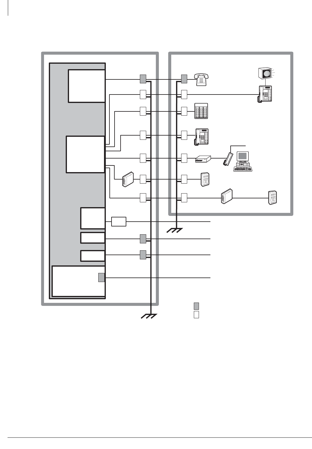
MDF PCB Wiring
Station Wiring Diagrams
10-4 Strata CTX I&M 06/04
Station Wiring Diagrams
Important! To protect against transient voltages and currents, solid state secondary protectors
must be installed if there is outside wiring, and on all DID and E&M Tie lines.
These protectors, which contain fast semiconductors in addition to fuses, shall
comply with the requirements for secondary protectors for communication circuits,
UL 497A. Care must be taken to ensure that they are very well grounded to a
reliable earth ground. Recommended protectors are available in the fast Series 6
line from ONEAC Corp., Libertyville, Illinois 60048, (800) 327-8801. Install and
test the secondary protectors precisely to the installation instructions of the
manufacturer.
Figure 10-1 Strata CTX Secondary Protector Diagram
Standard
Telephone
Building #1 Building #2
PCOU, RCOU/RCOS
RGLU, RCIU/RCIS,
RBUU/RBUS,
RBSU/RBSS,
RMCU/RCMS
RDDU
Digital
Telephone
Digital Telephone
or Cordless Base
E&M Tie Line (to PSTA)
Ground/Loop/ISDN BRI/ (to PSTA)
E911 CAMA Lines (Gas tube secondary
protectors provided on the interface cards
per UL requirements.
Secondary protectors – standard voltage
Secondary protectors – low voltage
MDFB
DDCB
DDSS
Console
HESB
RDTU,
BPTU
or RPTU
REMU
DID Line
POW DTR DSR
BATI
Console Handset
PC
Attendant
Console
DDCB
MDFB
T1 Span Line or ISDN PRI Line
Earth Ground
Earth Ground
CSU
PSTU
RSTU/RSTU2/
RSTU3/
RDSU/RSTS/
ASTU/BSTU
6687
ADKU,
BDKU/BDKS,
BWDKU
or PDKU
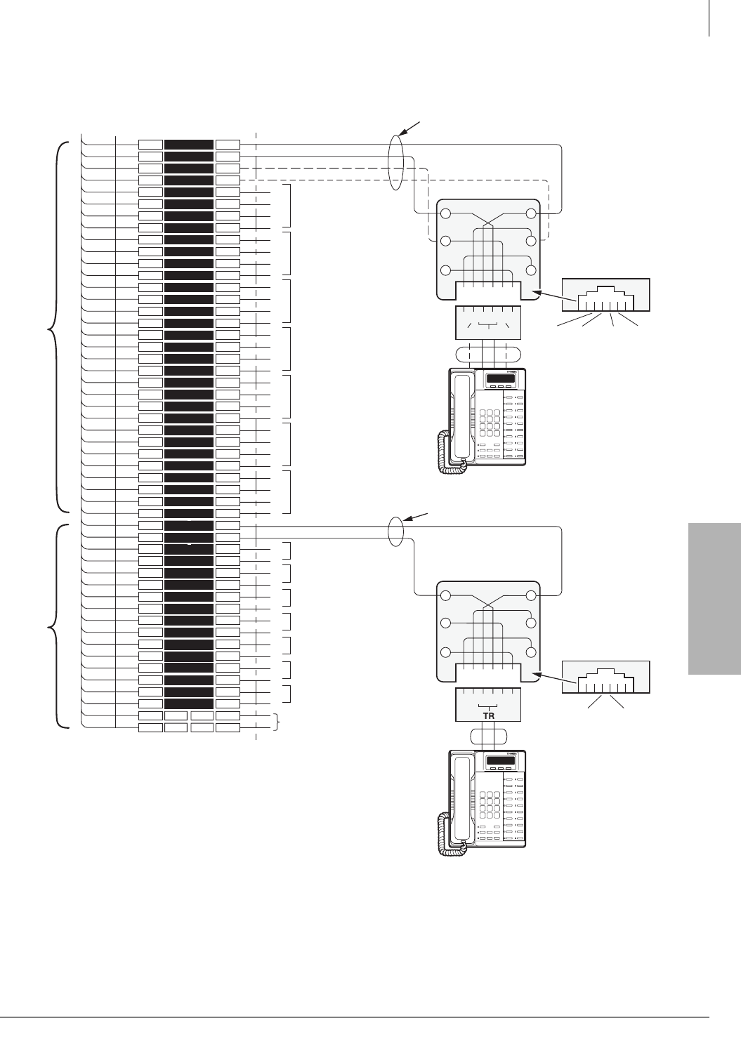
MDF PCB Wiring
Station Wiring Diagrams
Strata CTX I&M 06/04 10-5
MDF PCB Wiring
ADKU and BDKU/BDKS Digital Station Wiring
Figure 10-2 ADKU and BDKU/BDKS (DKT, DDCB, ADM, DDS, BATI, BDIU-DI) Wiring
1
2
3
4
5
6
7
8
9
10
11
12
13
14
15
16
17
18
19
20
21
22
23
24
25
26
27
28
29
30
31
32
33
34
35
36
37
38
39
40
41
42
43
44
45
46
47
48
49
50
1
2
3
4
5
6
7
8
9
10
11
12
13
14
15
16
17
18
19
20
21
22
23
24
25
26
27
28
29
30
31
32
33
34
35
36
37
38
39
40
41
42
43
44
45
46
47
48
49
50
W-BL
BL-W
W-O
O-W
W-GN
GN-W
W-BR
BR-W
W-S
S-W
R-BL
BL-R
R-O
O-R
R-GN
GN-R
R-BR
BR-R
R-S
S-R
BK-BL
BL-BK
BK-O
O-BK
BK-GN
GN-BK
BK-BR
BR-BK
BK-S
S-BK
Y-BL
BL-Y
Y-O
O-Y
Y-GN
GN-Y
Y-BR
BR-Y
Y-S
S-Y
V-BL
BL-V
V-O
O-V
V-GN
GN-V
V-BR
BR-V
V-S
S-V
26
1
27
2
28
3
29
4
30
5
31
6
32
7
33
8
34
9
35
10
36
11
37
12
38
13
39
14
40
15
41
16
42
17
43
18
44
19
45
20
46
21
47
22
48
23
49
24
50
25
Bridging
Clips
To ADKU or BDKU/BDKS
W/Female Connector
66M150 Split Block
Circuit 2
Circuit 3
ADKU
or
BDKU
BDKS
Circuit 4
Circuit 6
Circuit 7
Circuit 8
Circuit 10
Circuit 11
Circuit 12
Circuit 13
Circuit 14
Circuit 15
Circuit 16
Circuit 5
(-) T1 (Voice/Data)
(GND) R1 (Voice/Data)
(-) PT1 (Add. Power)
(GND) PR1 (Add. Power)
T2
R2
PT2
PR2
T3
R3
PT3
PR3
T4
R4
PT4
PR4
T5
R5
PT5
PR5
T6
R6
PT6
PR6
T7
R7
PT7
PR7
T8
R8
PT8
PR8
T10
R10
T11
R11
T12
R12
T13
R13
T14
R14
T15
R15
T16
R16
Not Used
Jacketed Twisted Pairs
24 AWG (1 or 2 pair. See Note 1.)
Station Cabling
GN
654321
Y
BL
R
BK
W
34
R1
PT1
T1
PR1
25
PR TR PT
RJ11
Digital Telephone (with or
w/o ADM, BDIU-DI), DSS,
BATI or DDCB.
RPCI and PDIU-DI are not
supported.
Digital Telephone (with or
w/o ADM, BDIU-DI), DSS,
BATI or DDCB.
RPCI and PDIU-DI are not
supported.
Modular
Cord
GND
PR
(-)
T
GND
R
(-)
PT
(-) T9 (Voice/Data
(GND) R9 (Voice/Data)
Jacketed Twisted Pairs 24 AWG
GN
654321
Y
BL
R
BK
W
34
R1 T1
RJ11
Modular
Cord
5501
(-)
T
GND
R
Notes
1. T/R wires are always required; PT/PR are additional power wires
required only for long station runs per Table 10-1. PT/PR may be
used with normal station runs also.
2. Voltage levels:
T, PT = -26.3~27.8 VDC
R, PR = 0.0 VDC (GND). Reference to SG ground.
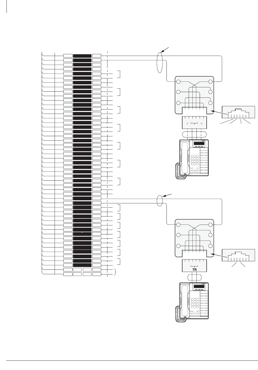
MDF PCB Wiring
Station Wiring Diagrams
10-6 Strata CTX I&M 06/04
BWDKU Digital Station Wiring
Figure 10-3 BWDKU Digital Station Wiring
1
2
3
4
5
6
7
8
9
10
11
12
13
14
15
16
17
18
19
20
21
22
23
24
25
26
27
28
29
30
31
32
33
34
35
36
37
38
39
40
41
42
43
44
45
46
47
48
49
50
1
2
3
4
5
6
7
8
9
10
11
12
13
14
15
16
17
18
19
20
21
22
23
24
25
26
27
28
29
30
31
32
33
34
35
36
37
38
39
40
41
42
43
44
45
46
47
48
49
50
W-BL
BL-W
W-O
O-W
W-GN
GN-W
W-BR
BR-W
W-S
S-W
R-BL
BL-R
R-O
O-R
R-GN
GN-R
R-BR
BR-R
R-S
S-R
BK-BL
BL-BK
BK-O
O-BK
BK-GN
GN-BK
BK-BR
BR-BK
BK-S
S-BK
Y-BL
BL-Y
Y-O
O-Y
Y-GN
GN-Y
Y-BR
BR-Y
Y-S
S-Y
V-BL
BL-V
V-O
O-V
V-GN
GN-V
V-BR
BR-V
V-S
S-V
26
1
27
2
28
3
29
4
30
5
31
6
32
7
33
8
34
9
35
10
36
11
37
12
38
13
39
14
40
15
41
16
42
17
43
18
44
19
45
20
46
21
47
22
48
23
49
24
50
25
Bridging
Clips
To BWDKU
W/Female Connector
66M150 Split Block
Circuit 2
Circuit 3
Circuit 4
Circuit 6
Circuit 7
Circuit 8
Circuit 10
Circuit 11
Circuit 12
Circuit 13
Circuit 14
Circuit 15
Circuit 16
Circuit 5
(-) T1 (Voice/Data)
(GND) R1 (Voice/Data)
T2
R2
T3
R3
T4
R4
T5
R5
T6
R6
T7
R7
T8
R8
T10
R10
T11
R11
T12
R12
T13
R13
T14
R14
T15
R15
T16
R16
Not Used
Jacketed Twisted Pairs
24 AWG (1 or 2 pair. See Note 1.)
Station Cabling
GN
654321
Y
BL
R
BK
W
34
R1 T1
25
PR TR PT
RJ11
Digital Telephone (with or
w/o ADM, BDIU-DI), DSS,
BATI or DDCB.
RPCI and PDIU-DI are not
supported.
Digital Telephone (with or
w/o ADM, BDIU-DI), DSS,
BATI or DDCB.
RPCI and PDIU-DI are not
supported.
Modular
Cord
GND
PR
(-)
T
GND
R
(-)
PT
(-) T9 (Voice/Data
(GND) R9 (Voice/Data)
Jacketed Twisted Pairs 24 AWG
GN
654321
Y
BL
R
BK
W
34
R1 T1
RJ11
Modular
Cord
6931
(-)
T
GND
R
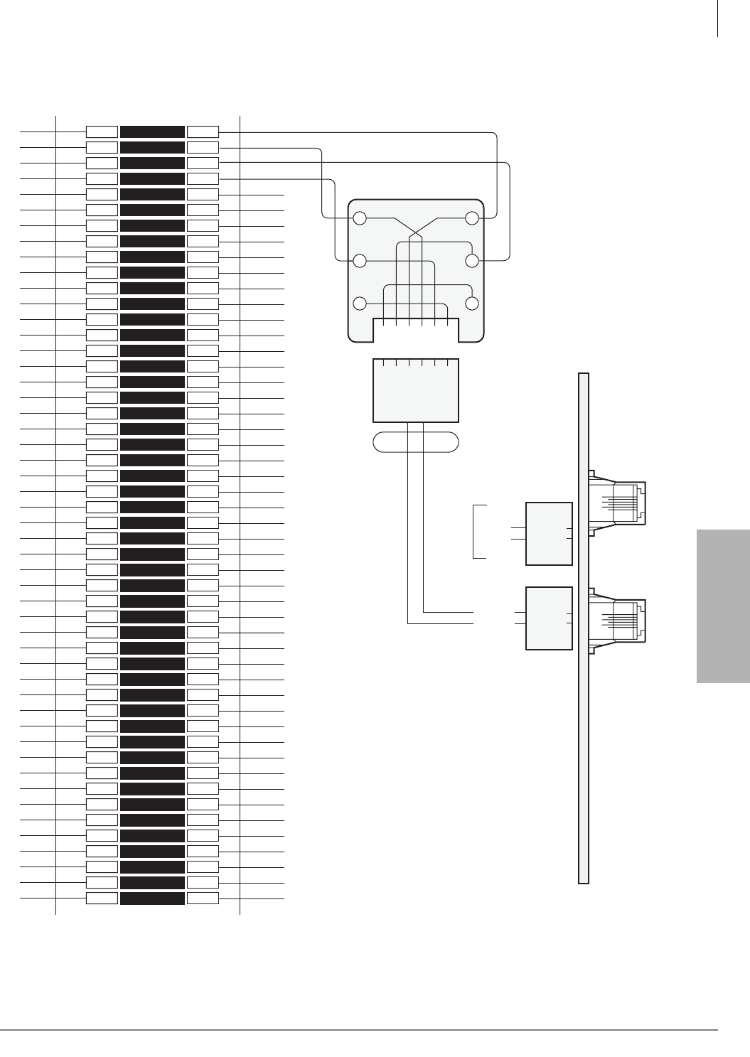
MDF PCB Wiring
Station Wiring Diagrams
Strata CTX I&M 06/04 10-7
MDF PCB Wiring
Figure 10-4 ASTU Wiring
1
2
3
4
5
6
7
8
9
10
11
12
13
14
15
16
17
18
19
20
21
22
23
24
25
26
27
28
29
30
31
32
33
34
35
36
37
38
39
40
41
42
43
44
45
46
47
48
49
50
1
2
3
4
5
6
7
8
9
10
11
12
13
14
15
16
17
18
19
20
21
22
23
24
25
26
27
28
29
30
31
32
33
34
35
36
37
38
39
40
41
42
43
44
45
46
47
48
49
50
Bridging
Clips
66M150 Split Block
GN
654321
Y
BL
R
BK
W
34
Modular
Cord
6-1
T1
R1
T2
R2
T1
R1
T2
R2
To
Telephone
R1
R2
T1
T2
Telco-provided
Modular Block,
625-Type Or
Equivalent
ASTU
6-1
J2
34
Same R3
T3
4
3
R1
T1
4
3J1
ASTU
Pin-out
Network Jack: RJ11
34
6639
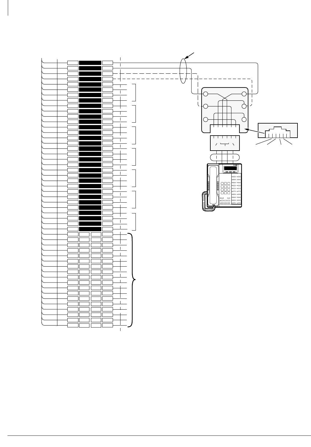
MDF PCB Wiring
Station Wiring Diagrams
10-8 Strata CTX I&M 06/04
PDKU Digital Station Wiring
Figure 10-5 PDKU Wiring
1
2
3
4
5
6
7
8
9
10
11
12
13
14
15
16
17
18
19
20
21
22
23
24
25
26
27
28
29
30
31
32
33
34
35
36
37
38
39
40
41
42
43
44
45
46
47
48
49
50
1
2
3
4
5
6
7
8
9
10
11
12
13
14
15
16
17
18
19
20
21
22
23
24
25
26
27
28
29
30
31
32
33
34
35
36
37
38
39
40
41
42
43
44
45
46
47
48
49
50
W-BL
BL-W
W-O
O-W
W-GN
GN-W
W-BR
BR-W
W-S
S-W
R-BL
BL-R
R-O
O-R
R-GN
GN-R
R-BR
BR-R
R-S
S-R
BK-BL
BL-BK
BK-O
O-BK
BK-GN
GN-BK
BK-BR
BR-BK
BK-S
S-BK
Y-BL
BL-Y
Y-O
O-Y
Y-GN
GN-Y
Y-BR
BR-Y
Y-S
S-Y
V-BL
BL-V
V-O
O-V
V-GN
GN-V
V-BR
BR-V
V-S
S-V
26
1
27
2
28
3
29
4
30
5
31
6
32
7
33
8
34
9
35
10
36
11
37
12
38
13
39
14
40
15
41
16
42
17
43
18
44
19
45
20
46
21
47
22
48
23
49
24
50
25
Bridging
Clips
To PDKU
W/Female Connector
25-Pair Cable W/Male Amp Connector
66M150 Split Block
Circuit 2
Circuit 3
Circuit 4
Circuit 6
Circuit 7
Circuit 8
Circuit 5
(-) T1 (Voice/Data)
(GND) R1 (Voice/Data)
(-) PT1 (Add. Power)
(GND) PR1 (Add. Power)
T2
R2
PT2
PR2
T3
R3
PT3
PR3
T4
R4
PT4
PR4
T5
R5
PT5
PR5
T6
R6
PT6
PR6
T7
R7
PT7
PR7
T8
R8
PT8
PR8
Not Used
Jacketed Twisted Pairs
24 AWG (1 or 2 pair. See Note 1.)
Station Cabling
GN
654321
Y
BL
R
BK
W
34
R1
PT1
T1
PR1
25
PR TR PT
RJ11
Modular
Cord
GND
PR
(-)
T
GND
R
(-)
PT
5663
Digital Telephone (with or
w/o ADM, DSS, or DDCB.
BATI, BPCI, RPCI,
and PDIU-DI are not
supported with PDKU.
With the PDKU, 3000-series
DKTs function as 2000-series DKTS
16 character LCD, no Spdial or LCD
Feature buttons.
Notes
1. T/R wires are always required; PT/PR are additional power wires required
only for long station runs per Table 10-1. PT/PR may be used with normal
station runs also.
Voltage levels:
T, PT = -26.3~27.8 VDC
R, PR = 0.0 VDC (GND). Reference to SG ground.
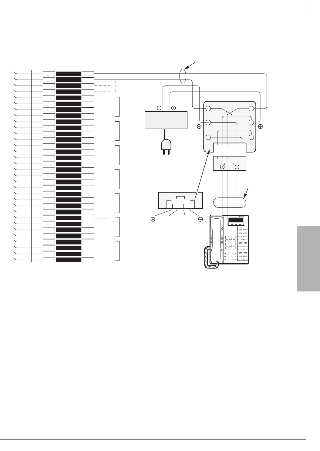
MDF PCB Wiring
Station Wiring Diagrams
Strata CTX I&M 06/04 10-9
MDF PCB Wiring
Digital Telephone DSS and DDCB External Power Connection
Figure 10-6 Digital Telephone DSS and DDCB External Power Connection
1
2
3
4
5
6
7
8
9
10
11
12
13
14
15
16
17
18
19
20
21
22
23
24
25
26
27
28
29
30
31
32
1
2
3
4
5
6
7
8
9
10
11
12
13
14
15
16
17
18
19
20
21
22
23
24
25
26
27
28
29
30
31
32
W-BL
BL-W
W-O
O-W
W-GN
GN-W
W-BR
BR-W
W-S
S-W
R-BL
BL-R
R-O
O-R
R-GN
GN-R
R-BR
BR-R
R-S
S-R
BK-BL
BL-BK
BK-O
O-BK
BK-GN
GN-BK
BK-BR
BR-BK
BK-S
S-BK
Y-BL
BL-Y
26
1
27
2
28
3
29
4
30
5
31
6
32
7
33
8
34
9
35
10
36
11
37
12
38
13
39
14
40
15
41
16
Bridging
Clips
BDKU or PDKU
Connector
25-PAIR CABLE W/MALE AMP CONNECTOR
CKT 2
(-) T1 (Voice/Data)
(GND) R1 (Voice/Data)
PT1
RT2
T2
R2
PT2
PR2
T3
R3
PT3
PR3
T4
R4
PT4
PR4
T5
R5
PT5
PR5
T6
R6
PT6
PR6
T8
R8
PT8
PR8
Jacketed Twisted Pairs
24AWG (1 Pair)
Station Cabling
GN
Y
BL
R
BK
W
R1 T1
(-)
T
GND
R
RJ11
Digital Telephone
(with or w/out BPCI-DI, ADM)
or...
DDSS, DDCB, BATI
(Not Used)
CKT 3
CKT 4
CKT 5
CKT 6
T7
R7
PT7
PR7
CKT 7
CKT 8
AC/DC External
Power Source
3245
654321
TR
To 120VAC Commercial
Power Outlet
AC/DC External Power Source Specifications:
PT/PR power wires are not available on the BDKS or BWDKU.
AC IN:
DC OUT:
120VAC ± 10%
24VDC ± 10%
160 MA (Min.) DC Current
200 MV P-P (Max) AC Ripple On DC Output
External Power Straps:
If the external power is installed, cut the
external power straps located inside the
digital telephone DDSS, DDCB.
DC Output
AC Input
2-Pair
Modular Cord
Required
5665
AC/DC power supplies that meet the above requirements are
available from most telephone equipment supply houses.
See Table 10-1 on page 10-2
for external power
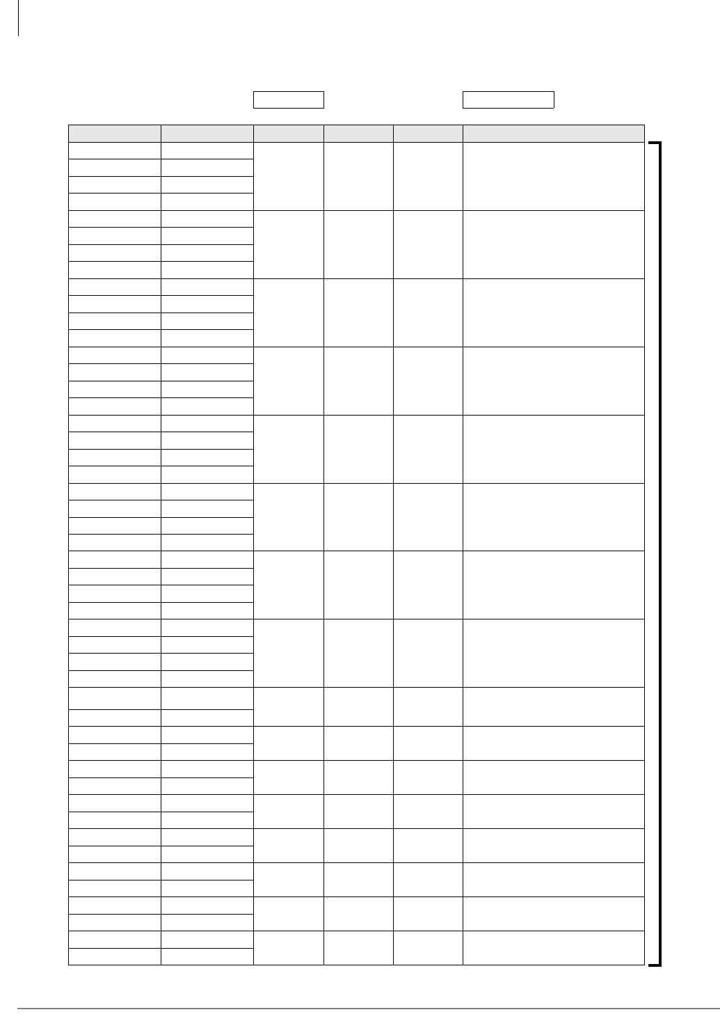
MDF PCB Wiring
Station Wiring Diagrams
10-10 Strata CTX I&M 06/04
Table 10-3 BDKU Station MDF Cross Connect Record
MDF Block Number KSU Slot Number
Color Code Designation CKT PDN Intercom Device/Standard Telephone
W-Bl T
1
ADKU,
BDKU
or
PDKU
Bl-W R
W-O PRW-T
O-W PRW-R
W-G T
2
G-W R
W-Br PRW-T
Br-W PRW-R
W-S T
3
S-W R
R-Bl PRW-T
Bl-R PRW-R
R-O T
4
O-R R
R-G PRW-T
G-R PRW-R
R-Br T
5
Br-R R
R-S PRW-T
S-R PRW-R
Bk-Bl T
6
Bl-Bk R
Bk-O PRW-T
O-Bk PRW-R
Bk-G T
7
G-Bk R
Bk-Br PRW-T
Br-Bk PRW-R
Bk-S T
8
S-Bk R
Y- B l P R W- T
Bl-Y PRW-R
Y- O T 9
O-Y R
Y- G N T 10
GN-Y R
Y- B R T 11
BR-Y R
Y- S T 12 BDKS
S-Y R
V-BL T 13
BL-V R
V-O T 14
O-V R
V-GN T 15
GN-V R
V-BR T 16
BR-V R
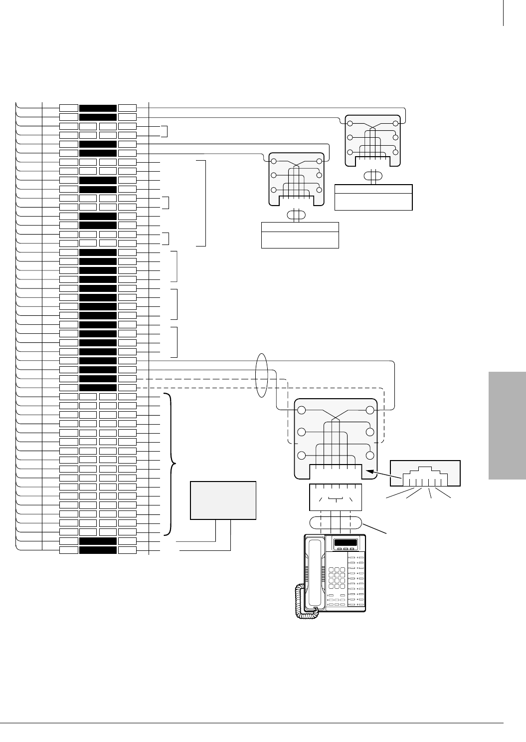
MDF PCB Wiring
Station Wiring Diagrams
Strata CTX I&M 06/04 10-11
MDF PCB Wiring
RDSU Wiring
Figure 10-7 RDSU Wiring
1
2
3
4
5
6
7
8
9
10
11
12
13
14
15
16
17
18
19
20
21
22
23
24
25
26
27
28
29
30
31
32
33
34
35
36
37
38
39
40
41
42
43
44
45
46
47
48
49
50
1
2
3
4
5
6
7
8
9
10
11
12
13
14
15
16
17
18
19
20
21
22
23
24
25
26
27
28
29
30
31
32
33
34
35
36
37
38
39
40
41
42
43
44
45
46
47
48
49
50
W-BL
BL-W
W-O
O-W
W-GN
GN-W
W-BR
BR-W
W-S
S-W
R-BL
BL-R
R-O
O-R
R-GN
GN-R
R-BR
BR-R
R-S
S-R
BK-BL
BL-BK
BK-O
O-BK
BK-GN
GN-BK
BK-BR
BR-BK
BK-S
S-BK
Y-BL
BL-Y
Y-O
O-Y
Y-GN
GN-Y
Y-BR
BR-Y
Y-S
S-Y
V-BL
BL-V
V-O
O-V
V-GN
GN-V
V-BR
BR-V
V-S
S-V
26
1
27
2
28
3
29
4
30
5
31
6
32
7
33
8
34
9
35
10
36
11
37
12
38
13
39
14
40
15
41
16
42
17
43
18
44
19
45
20
46
21
47
22
48
23
49
24
50
25
Bridging Clips
To RDSU W/Female
Connector
25-Pair Cable With Male Amp Connector
66M150 SPLIT BLOCK
Tip 1
Ring 1
GN
Y
BL
R
BK
W
654321
654321
Voice Mail Port Or
Similar Device
Voice Mail Port Or
Similar Device
RJ11
RJ11
RING
Tip
TIP
Ring
Standard Telephone 2
Standard Telephone 1
Ring 2
Tip 2
GN
Y
BL
R
BK
W
Not Used
Station Cabling Jacketed Twisted Pairs (24 AWG)
T3
R3
T4
R4
Not Used
Not Used
Standard
Telephone
Circuits 3 and 4
available with
optional RSTS
PCB.
Wire the same
as Circuits 1
and 2.
Circuit 6 to DKT 6
or PDIU-DS
Circuit 7 to DKT 7
or PDIU-DS
Circuit 5 to DKT 5
or PDIU-DS
or DDCB
T5
R5
PT5
PR5
T6
R6
PT6
PR6
T7
R7
PT7
PR7
(-) T8 (Voice/Data)
(GND) R8 (Voice/Data)
(-) PT (Add Power)
(GND) PR (Add Power)
Not Used
GN
654321
Y
BL
R
BK
W
34
R8
PT8
T8
PR8
25
PR TR PT
RJ11
Digital
Telephone
Modular
Cord
GND
PR
(-)
T
GND
R
(-)
PT
(See Note)
DPFT
Power Failure
Transfer Box
(J1)
-24VDC
(J1, 25)
DG
(J1, 50)
DG
-24V
1603
Digital Telephone (with or w/o ADM, DSS,
or DDCB. BATI, BPCI, RPCI, and PDIU-DI
are not supported with PDKU.
With the PDKU, 3000-series DKTs function
as 2000-series DKTS: 16 character LCD, no
Spdial or LCD Feature buttons.
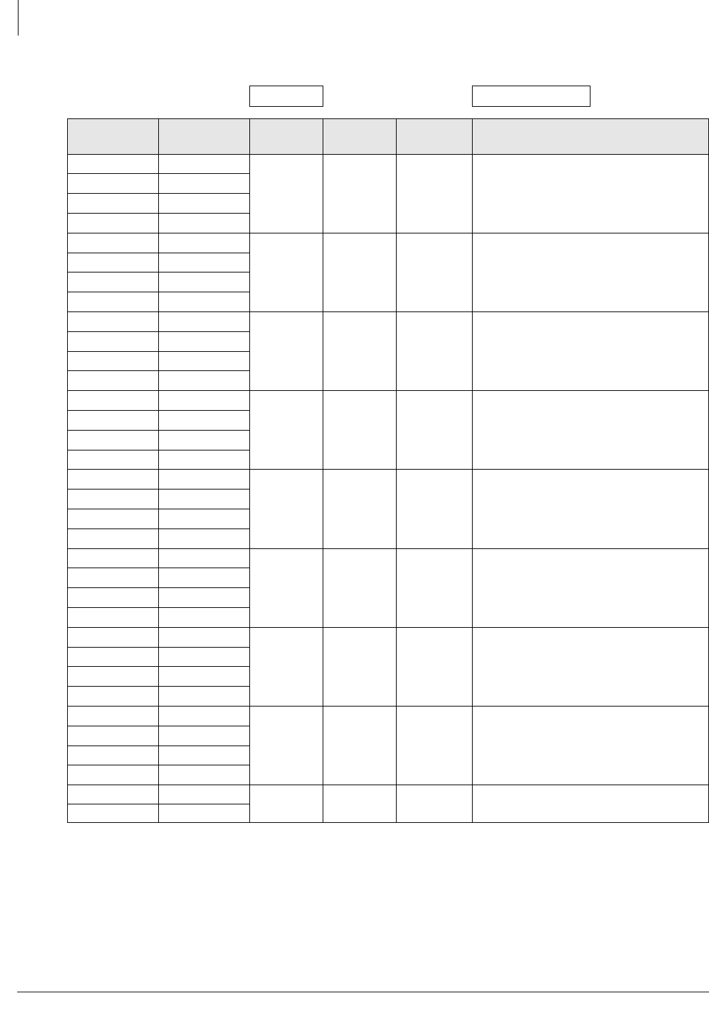
MDF PCB Wiring
Station Wiring Diagrams
10-12 Strata CTX I&M 06/04
Table 10-4 RDSU Station MDF Cross Connect Record
Note Indicate if standard telephone, voice mail port, etc.
MDF Block Number KSU Slot Number
Color Code Designation CKT
Number
Port
Number
Directory
Number Device/Standard Telephone Location
W-Bl T
1 (Standard)
Bl-W R
W-O Not Used
O-W Not Used
W-G T
2 (Standard) Indicate if separate BGM source
connected to Circuit 2.
G-W R
W-Br Not Used
Br-W Not Used
W-S T
3(Standard)
(RSTS)
S-W R
R-Bl Not Used
Bl-R Not Used
R-O T
4(Standard)
(RSTS)
O-R R
R-G Not Used
G-R Not Used
R-Br T
5(Digital)
DDCBs connect only to Circuit 5, Ports
004, 012, 020, and 028
Br-R R
R-S PWRT
S-R PWRR
Bk-Bl T
6(Digital)
Bl-Bk R
Bk-O PWRT
O-Bk PWRR
Bk-G T
7(Digital)
G-Bk R
Bk-Br PWRT
Br-Bk PWRR
Bk-S T
8(Digital)
S-Bk R
Y-Bl PWRT
Bl-Y PWRR
V-S Data Ground N/A N/A N/A DPFT – Power Failure Transfer Box
S-V -24VDC
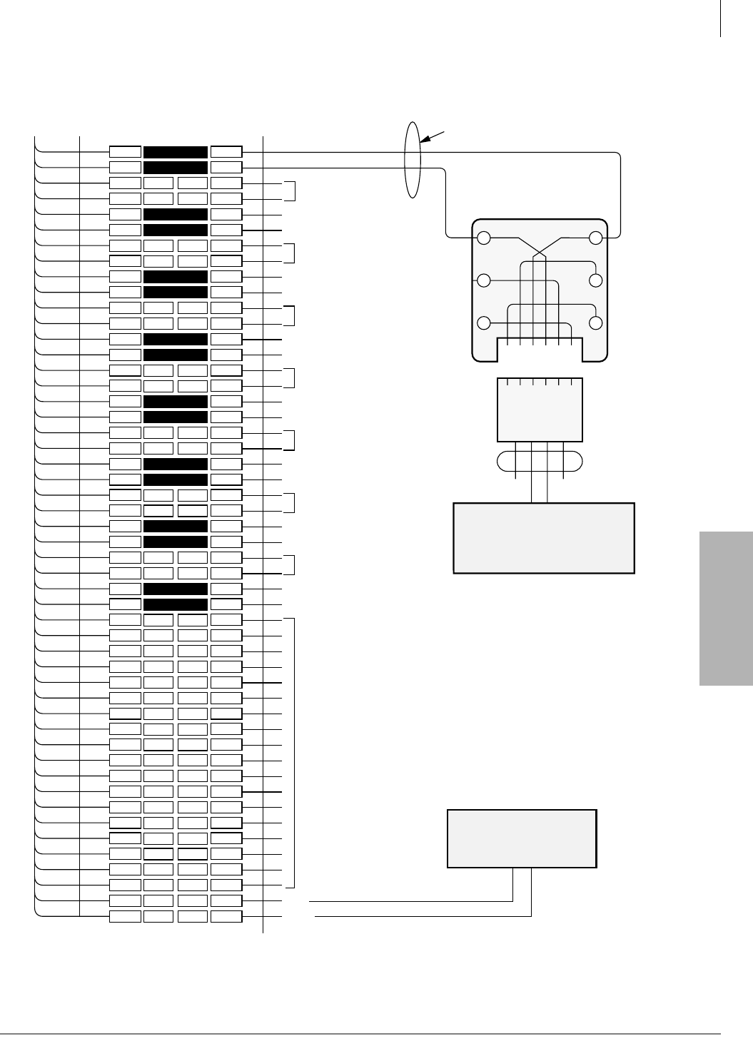
MDF PCB Wiring
Station Wiring Diagrams
Strata CTX I&M 06/04 10-13
MDF PCB Wiring
RSTU or PSTU Analog Devices Wiring
Figure 10-8 RSTU or PSTU Wiring
1
2
3
4
5
6
7
8
9
10
11
12
13
14
15
16
17
18
19
20
21
22
23
24
25
26
27
28
29
30
31
32
33
34
35
36
37
38
39
40
41
42
43
44
45
46
47
48
49
50
1
2
3
4
5
6
7
8
9
10
11
12
13
14
15
16
17
18
19
20
21
22
23
24
25
26
27
28
29
30
31
32
33
34
35
36
37
38
39
40
41
42
43
44
45
46
47
48
49
50
W-BL
BL-W
W-O
O-W
W-GN
GN-W
W-BR
BR-W
W-S
S-W
R-BL
BL-R
R-O
O-R
R-GN
GN-R
R-BR
BR-R
R-S
S-R
BK-BL
BL-BK
BK-O
O-BK
BK-GN
GN-BK
BK-BR
BR-BK
BK-S
S-BK
Y-BL
BL-Y
Y-O
O-Y
Y-GN
GN-Y
Y-BR
BR-Y
Y-S
S-Y
V-BL
BL-V
V-O
O-V
V-GN
GN-V
V-BR
BR-V
V-S
S-V
26
1
27
2
28
3
29
4
30
5
31
6
32
7
33
8
34
9
35
10
36
11
37
12
38
13
39
14
40
15
41
16
42
17
43
18
44
19
45
20
46
21
47
22
48
23
49
24
50
25
Bridging
Clips
To RSTU or PSTU
w/Female Connector
25-Pair Cable w/Male amp Connector
66M150 Split Block
GN
654321
Y
BL
R
BK
W
123456
Jacketed Twisted Station Cable
24 AWG
Modular
Cord
Tip 1
Ring 1
T2
R2
T3
R3
T4
R4
T5
R5
T6
R6
T7
R7
T8
R8
Not Used
Not Used
Not Used
Not Used
Not Used
Not Used
Not Used
DG
-24V
Not Used
Tip Ring
DPFT
Power Failure
Transfer Box
(J1)
DG
(J1, 50)
-24 Volts
(J1, 25)
Notes
• An alternate BGM source can be connected to
Circuit 2 of RSTU or PSTU. An isolation
transformer may be required when connecting
BGM to RSTU or PSTU.
• Two ringers maximum.
(See Notes)
5664
Standard Telephone,
Voice Mail Port, ACD/Auto
Attendant Digital Announcer,
or Similar Device
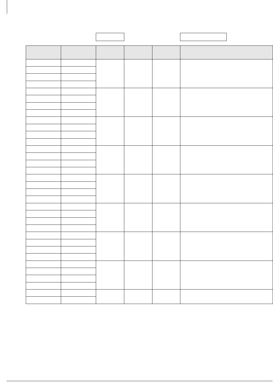
MDF PCB Wiring
Station Wiring Diagrams
10-14 Strata CTX I&M 06/04
Table 10-5 RSTU/RSTU2/RDSU/RSTS/PSTU/PSTU2 Station MDF Cross Connect Record
Note Indicate if standard telephone, voice mail port, etc.
MDF Block Number KSU Slot Number
Color Code Designation CKT
Number
Port
Number
Intercom
Number Device/Standard Telephone Location
W-Bl T
1
Bl-W R
W-O Not Used
O-W Not Used
W-G T
2 Indicate if separate BGM source.
G-W R
W-Br Not Used
Br-W Not Used
W-S T
3
S-W R
R-Bl Not Used
Bl-R Not Used
R-O T
4
O-R R
R-G Not Used
G-R Not Used
R-Br T
5
Br-R R
R-S Not Used
S-R Not Used
Bk-Bl T
6
Bl-Bk R
Bk-O Not Used
O-Bk Not Used
Bk-G T
7
G-Bk R
Bk-Br Not Used
Br-Bk Not Used
Bk-S T
8
S-Bk R
Y-Bl Not Used
Bl-Y Not Used
V-S Data Ground N/A N/A N/A DPFT – Power Failure Transfer Box
S-V -24VDC

MDF PCB Wiring
Station Wiring Diagrams
Strata CTX I&M 06/04 10-15
MDF PCB Wiring
Power Failure Cut Through (DPFT) Wiring Pin-outs
Table 10-6 DPFT Connector J2/Terminal Sequence & Designations/Station Line Connection
Pair Pin Color Code Lead Designation Function PSTU/RSTU PCB Position
1t 26 W-BI T TIP-TEL #1
R 1 BI-W RRING-TEL #1
2T 27 W-O T TIP-RSTU/RSTU/RDSU #1
R 2 O-W RRING-PSTU/RSTU/RDSU #1
3T 28 W-G T TIP-TEL #2
R 3 G-W RRING-TEL #2
4T 29 W-Br T TIP-RSTU/RSTU/RDSU #2
R 4 Br-W RRING-PSTU/RSTU/RDSU #2
5T 30 W-S T TIP-TEL #3
R 5 S-W RRING-TEL #3
6T 31 R-BI T TIP-RSTU/RSTU/RDSU #3
R 6 BI-R RRING-PSTU/RSTU/RDSU #3
7T 32 R-O T TIP-TEL #4
R 7 O-R RRING-TEL #4
8T 33 R-G T TIP-RSTU/RSTU/RDSU #4
R 8 G-R RRING-PSTU/RSTU/RDSU #4
9T 34 R-Br T TIP-TEL #5
R 9 Br-R RRING-TEL #5
10T 35 R-S T TIP-RSTU/RSTU/RDSU #5
R10 S-R RRING-PSTU/RSTU/RDSU #5
11T 36 Bk-BI T TIP-TEL #6
R11 BI-Bk RRING-TEL #6
12T 37 Bk-O T TIP-RSTU/RSTU/RDSU #6
R12 O-Bk RRING-PSTU/RSTU/RDSU #6
13T 38 Bk-G T TIP-TEL #7
R13 G-Bk RRING-TEL #7
14T 39 Bk-Br T TIP-RSTU/RSTU/RDSU #7
R14 Br-Bk RRING-PSTU/RSTU/RDSU #7
15T 40 Bk-S T TIP-TEL #8
R15 S-Bk RRING-TEL #8
16T 41 Y-Bl T TIP-RSTU/RSTU/RDSU #8
R16 Bl-Y RRING-PSTU/RSTU/RDSU #8
17T 42 Y-O Spare
R17 O-Y Spare
18T 43 Y-G Spare
R18 G-Y Spare
19T 44 Y-Br Spare
R19 Br-Y Spare
20T 45 Y-S Spare
R20 S-Y Spare
21T 46 V-Bl Spare
R21 Bl-V Spare
22T 47 V-O Spare
R22 O-V Spare
23T 48 V-G Spare
R23 G-V Spare
24T 49 V-Br Spare
R24 Br-V Spare
25T 50 V-S Spare
R25 S-V Spare

MDF PCB Wiring
Station Wiring Diagrams
10-16 Strata CTX I&M 06/04
Table 10-7 DPFT Connector J1/Terminal Sequence & Designations/CO Line Connection & DPFT Control
Pair Pin Color Code Lead Designation Function PSTU/RSTU PCB Position
1t 26 W-BI T TIP-CO #1
R 1 BI-W RRING-CO #1
2T 27 W-O T TIP-PCOU/RCOU #1
R 2 O-W RRING-PCOU/RCOU #1
3T 28 W-G T TIP-CO #2
R 3 G-W RRING-CO #2
4T 29 W-Br T TIP-PCOU/RCOU #2
R 4 Br-W RRING-PCOU/RCOU #2
5T 30 W-S T TIP-CO #3
R 5 S-W RRING-CO #3
6T 31 R-BI T TIP-PCOU/RCOU #3
R 6 BI-R RRING-PCOU/RCOU #3
7T 32 R-O T TIP-CO #4
R 7 O-R RRING-CO #4
8T 33 R-G T TIP-PCOU/RCOU #4
R 8 G-R RRING-PCOU/RCOU #4
9T 34 R-Br T TIP-CO #5
R 9 Br-R RRING-CO #5
10T 35 R-S T TIP-PCOU/RCOU #5
R10 S-R RRING-PCOU/RCOU #5
11T 36 Bk-BI T TIP-CO #6
R11 BI-Bk RRING-CO #6
12T 37 Bk-O T TIP-PCOU/RCOU #6
R12 O-Bk RRING-PCOU/RCOU #6
13T 38 Bk-G T TIP-CO #7
R13 G-Bk RRING-CO #7
14T 39 Bk-Br T TIP-PCOU/RCOU #7
R14 Br-Bk RRING-PCOU/RCOU #7
15T 40 Bk-S T TIP-CO #8
R15 S-Bk RRING-CO #8
16T 41 Y-Bl T TIP-PCOU/RCOU #8
R16 Bl-Y RRING-PCOU/RCOU #8
17T 42 Y-O Spare
R17 O-Y Spare
18T 43 Y-G Spare
R18 G-Y Spare
19T 44 Y-Br Spare
R19 Br-Y Spare
20T 45 Y-S Spare
R20 S-Y Spare
21T 46 V-Bl Spare
R21 Bl-V Spare
22T 47 V-O Spare
R22 O-V Spare
23T 48 V-G Spare
R23 G-V Spare
24T 49 V-Br Spare
R24 Br-V Spare
25T 50 V-S PFT DG PFT GROUND (INPUT) RDSU/RSTU/PSTU/PIN50
R25 S-V PFT -24V PFT -24V (INPUT) RDSU/RSTU/PSTU/PIN25
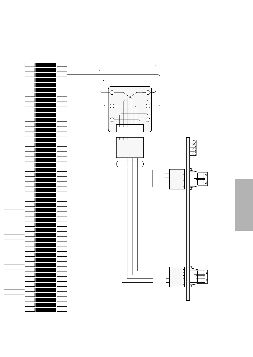
MDF PCB Wiring
Station Wiring Diagrams
Strata CTX I&M 06/04 10-17
MDF PCB Wiring
CO Line Wiring Diagrams
RGLU2, RCOU or PCOU Wiring
Figure 10-9 RGLU2, RCOU or PCOU Wiring
1
2
3
4
5
6
7
8
9
10
11
12
13
14
15
16
17
18
19
20
21
22
23
24
25
26
27
28
29
30
31
32
33
34
35
36
37
38
39
40
41
42
43
44
45
46
47
48
49
50
1
2
3
4
5
6
7
8
9
10
11
12
13
14
15
16
17
18
19
20
21
22
23
24
25
26
27
28
29
30
31
32
33
34
35
36
37
38
39
40
41
42
43
44
45
46
47
48
49
50
Bridging
Clips
66M150 Split Block
GN
654321
Y
BL
R
BK
W
2345
Modular
Cord
6-1
1
2
3456
6-1
T1
R1
T2
R2
T1
R1
T2
R2
To
Network
R1
R2
T1
T2
Telco-provided
Modular Block,
625-Type Or
Equivalent
RGLU or PCOU
#4
#3
#2
#1
CO3+4
Same
R4
R3
T3
T4
5
4
3
2
R2
R1
T1
T2
5
4
3
2
CO1+2
PCOU
Pin-out
Network Jack: RJ14C
FIC: 02LS2 (PCOU), 02GS2 (RGLU2)
1
2
3456
1598

MDF PCB Wiring
Station Wiring Diagrams
10-18 Strata CTX I&M 06/04
Table 10-8 CO Line (RCOU/RCOS, RGLU2, RDDU, PEMU, REMU, RDDU, RDTU) MDF Cross Connect Record
MDF Block
Number
CO Line
Number
PCB Type and
Cabinet Slot
Number
MDF Block
Number
CO Line
Number
PCB Type and
Cabinet Slot
Number
MDF Block
Number
CO Line
Number
PCB Type and
Cabinet Slot
Number
MDF PCB Wiring
Station Wiring Diagrams
Strata CTX I&M 06/04 10-19
MDF PCB Wiring
RCOU/RCOS Wiring
Figure 10-10 CO to RCOU Wiring
1
2
3
4
5
6
7
8
9
10
11
12
13
14
15
16
17
18
19
20
21
22
23
24
25
26
27
28
29
30
31
32
33
34
35
36
37
38
39
40
41
42
43
44
45
46
47
48
49
50
1
2
3
4
5
6
7
8
9
10
11
12
13
14
15
16
17
18
19
20
21
22
23
24
25
26
27
28
29
30
31
32
33
34
35
36
37
38
39
40
41
42
43
44
45
46
47
48
49
50
Bridging
Clips
66M150 Split Block
GN
654321
Y
BL
R
BK
W
2345
Modular
Cord
1
2
3456
T1
R1
T2
R2
T1
R1
T2
R2
To
Network
R1
R2
T1
T2
Telco-provided
Modular Block,
625-type or
Equivalent
Same
R8
R7
T7
T8
5
4
3
2
R2
R1
T1
T2
5
4
3
2
Network Jack: RJ14C
FIC: 02LS2
6-16-1
4
3
2
1
7 + 8
1-61-6
8
7
6
5
3 + 4
5 + 6
RCOU RCOS
1 + 2
1
2
3456
Same
R4
R3
T3
T4
5
4
3
2
1
2
3456
Same
R6
R5
T5
T6
5
4
3
2
1
2
3456
1602
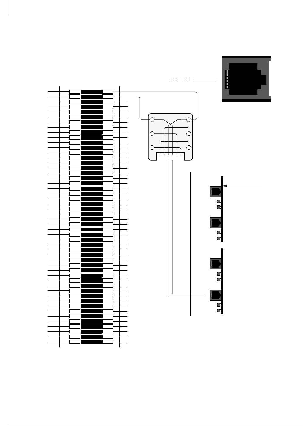
MDF PCB Wiring
Station Wiring Diagrams
10-20 Strata CTX I&M 06/04
RMCU/RMCS Wiring Diagram
Figure 10-11 RMCU/RMCS Wiring Diagram
1
2
3
4
5
6
7
8
9
10
11
12
13
14
15
16
17
18
19
20
21
22
23
24
25
26
27
28
29
30
31
32
33
34
35
36
37
38
39
40
41
42
43
44
45
46
47
48
49
50
1
2
3
4
5
6
7
8
9
10
11
12
13
14
15
16
17
18
19
20
21
22
23
24
25
26
27
28
29
30
31
32
33
34
35
36
37
38
39
40
41
42
43
44
45
46
47
48
49
50
Bridging
Clips
66M150 Split Block
GN
654321
Y
BL
R
BK
W
T1
R1
T1
R1
To
Network
or
PSAP
R1
R2
T1
T2
RMCU1A
RCMS1A (2/2)
LEDs (indicates
trunk condition)
Network Busy (NB) LED
Customer Busy (CB) LED
RCMS1A (1/2)
RJ11 2-Pin
Modular
Connector
CAMA #4
CAMA #3
CAMA #2
CAMA #1
NB LED
CB LED
NB LED
CB LED
NB LED
CB LED
Ring
Tip
4
3
Ring
Tip
4
3
Ring
Tip
4
3
Ring
Tip
4
3
2798
Only one circuit is shown connected.
NOTE: Make sure Tip and Ring are connected
properly, CAMA lines are polarity sensitive.
RJ-11 2-pin
6
5
4
3
2
1
Ring
Tip
6
5
4
3
2
1
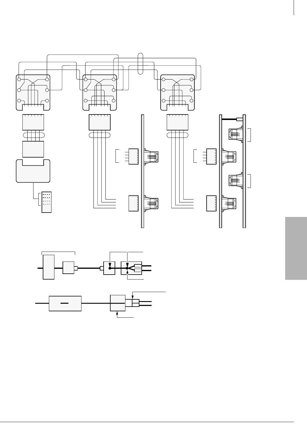
MDF PCB Wiring
Station Wiring Diagrams
Strata CTX I&M 06/04 10-21
MDF PCB Wiring
RCIU1/RCIS or RCIU2/RCIS Wiring
GN
654321
Y
BL
R
BK
W
2345
Modular
Cords
R1
R2
T1
T2
Dealer Supplied
Modular Block,
625-Type or
Equivalent
(See Notes)
R2
R1
T1
T2
5
4
3
2
CKT 7&8
1-61-6
CKT 3&4
CKT 5&6
RCIU RCIS
CKT 1&2
1
2
3456
Same
Same
Same
R4
R3
T3
T4
5
4
3
2
1
2
3456
GN
654321
Y
BL
R
BK
W
23452345
4-Wire
Modular
Cord
4-Wire
Modular
Cord
Telco
RJ14C
Modular Jack
T1
T2
Dealer Supplied
Modular Block,
625-Type or
Equivalent
(See Notes)
Bridging Jumper Wires
R1
R1
R2
R2
GN
654321
Y
BL
R
BK
W
T1
T2
Dealer Supplied
Modular Block,
625-Type or
Equivalent
(See Notes)
R2
R1
T1
T2
T1
R1
T2
R2
LINE X
LINE Y
Telco
RJ21X
5
4
3
2
Network Jack: RJ14C/RJ21X
FIC: 02LS2 (Loop Start) OR 02GS2 (Ground Start)
6-16-1
6-16-1
CKT 3&4
RGLU/RCOU/RCOS/PCOU/TCOU
Pin-outPin-out
CKT 1&2
1
2
3456
Same
R4
R3
T3
T4
5
4
3
2
1
2
3456
Network
RJ21X
Network
RJ14C RJ14C
Telco Jacks
Telco RJ21X
4-Wire
Modular
Cord
Installer Cross Connect Customer
Supplied Modular Jacks
Duplex Modular Jack (AA-104A-4 or Equivalent)
RCOU 4-Wire Modular Cord1
4-Wire Single Modular Jack (RJ14C) from Telco
RCIU/RCIS 4-Wire Modular Cord2
RCOU 4-Wire Modular Cord1
4-Wire Connector (267A2 Or Equivalent)
RCIU/RCIS 4-Wire Modular Cord2
1608
Note 4-wire modular jacks such as graybar part number AA-104A-4 could be used in place of the two modular
jacks; or, a T-connector such as graybar part number 267A2 Adaptor could be used.
Figure 10-12 RCIU1/RCIS or RCIU2/RCIS MDF Wiring Diagram
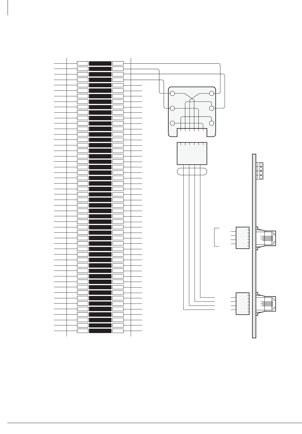
MDF PCB Wiring
Station Wiring Diagrams
10-22 Strata CTX I&M 06/04
DID and Tie Line Wiring
Figure 10-13 MDF Wiring/DID CO Lines to RDDU
1
2
3
4
5
6
7
8
9
10
11
12
13
14
15
16
17
18
19
20
21
22
23
24
25
26
27
28
29
30
31
32
33
34
35
36
37
38
39
40
41
42
43
44
45
46
47
48
49
50
1
2
3
4
5
6
7
8
9
10
11
12
13
14
15
16
17
18
19
20
21
22
23
24
25
26
27
28
29
30
31
32
33
34
35
36
37
38
39
40
41
42
43
44
45
46
47
48
49
50
Bridging
Clips
66M150 Split Block
GN
654321
Y
BL
R
BK
W
2345
Modular
Cord
T1
R1
T2
R2
T1
R1
T2
R2
To
Network
R1
R2
T1
T2
Telco-provided
Modular Block,
625-Type or Equivalent
R2
R1
T1
T2
5
4
3
2
RDDU
Pin-out
Network Jack: RJ14C
FIC:
6-16-1
4
3
2
1
J2
RDDU
J1
Same
R4
R3
T3
T4
5
4
3
2
1
2
34561
2
3456
1605
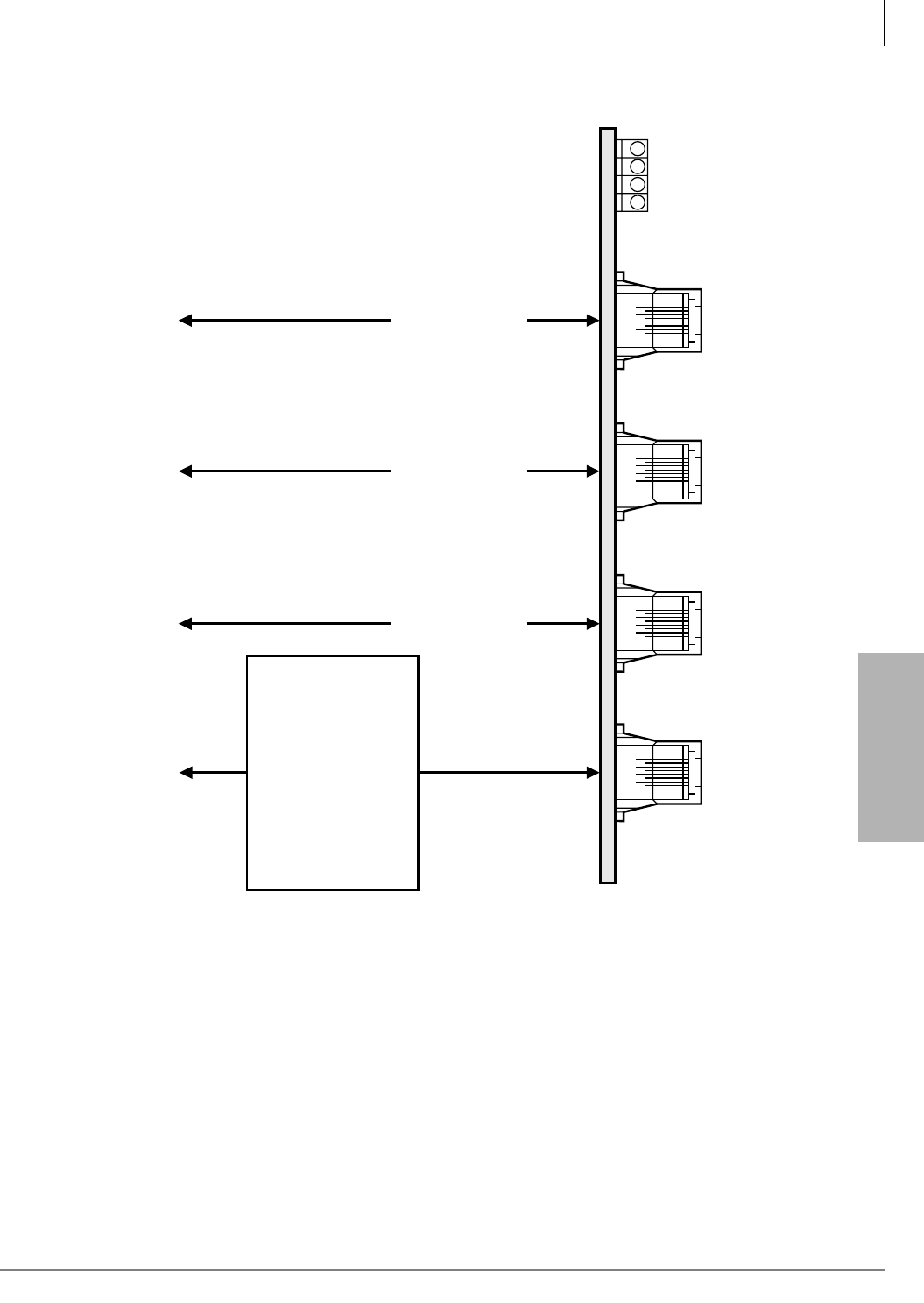
MDF PCB Wiring
Station Wiring Diagrams
Strata CTX I&M 06/04 10-23
MDF PCB Wiring
REMU
#4
#3
#2
#1
8-1
Line #4
8-1
Line #1
8-1
Line #3
8-1
Line #2
Same Pinout
as Line #1
Same Pinout
as Line #1
Same Pinout
as Line #1
To Network Jack
LEAD — PIN #
SB — 8
M—7
SG — 6
T—5
R—4
E—3
4WR1 — 2
4WT1 — 1
To Network Jack
To Network Jack
To Network Jack
(USOC: RJ1CX)
1600
Figure 10-14 MDF Wiring REMU 2/4 Wire Type I/II
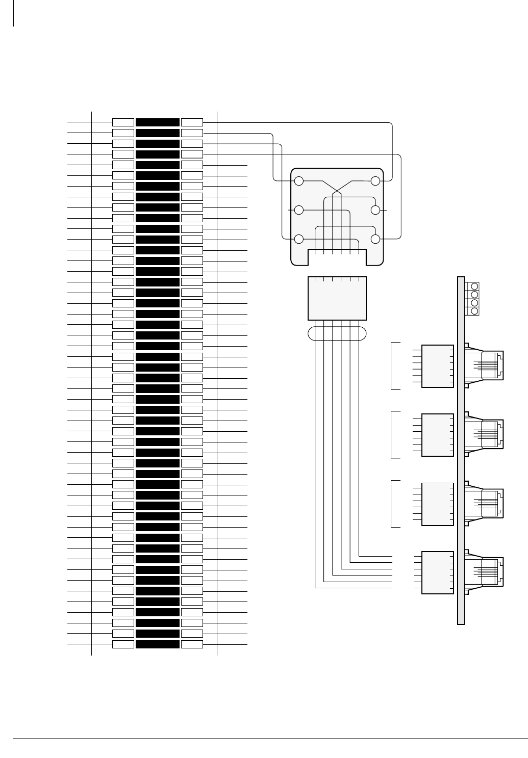
MDF PCB Wiring
Station Wiring Diagrams
10-24 Strata CTX I&M 06/04
PEMU Wiring
1
2
3
4
5
6
7
8
9
10
11
12
13
14
15
16
17
18
19
20
21
22
23
24
25
26
27
28
29
30
31
32
33
34
35
36
37
38
39
40
41
42
43
44
45
46
47
48
49
50
1
2
3
4
5
6
7
8
9
10
11
12
13
14
15
16
17
18
19
20
21
22
23
24
25
26
27
28
29
30
31
32
33
34
35
36
37
38
39
40
41
42
43
44
45
46
47
48
49
50
Bridging
Clips
66M150 Split Block
GN
654321
Y
BL
R
BK
W
5
*
342
*
Modular
Cord
123456
T
R
E
M
T
R
E
M
To
Network
R
E
T
M
Telco-provided
Modular Block,
625-Type or Equivalent
PEMU
2-Wire
#4
#3
#2
#1
Same
PEMU
Pin-out
Network Jack: RJ2EX
FIC: TL11M
6-16-1 6-16-1
6
5
4
3
2
1
E
*
R
T
*
M
Same
6
5
4
3
2
1
E
*
R
T
*
M
Same
6
5
4
3
2
1
E
*
R
T
*
M
6
5
4
3
2
1
E
*
R
T
*
M
61
#4
#3
#2
#1
*Not Used
**
123456123456123456
1587
Figure 10-15 MDF Wiring/2-Wire Tie Line to PEMU
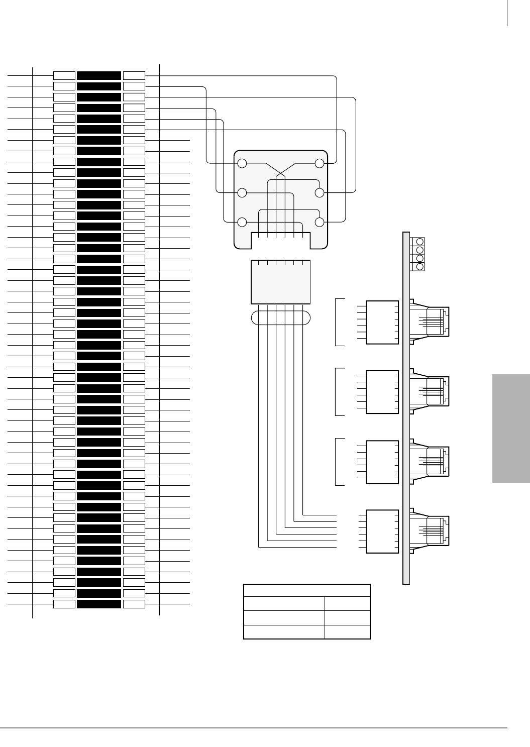
MDF PCB Wiring
Station Wiring Diagrams
Strata CTX I&M 06/04 10-25
MDF PCB Wiring
Figure 10-17 MDF Wiring/4-Wire Tie Line to PEMU
1
2
3
4
5
6
7
8
9
10
11
12
13
14
15
16
17
18
19
20
21
22
23
24
25
26
27
28
29
30
31
32
33
34
35
36
37
38
39
40
41
42
43
44
45
46
47
48
49
50
1
2
3
4
5
6
7
8
9
10
11
12
13
14
15
16
17
18
19
20
21
22
23
24
25
26
27
28
29
30
31
32
33
34
35
36
37
38
39
40
41
42
43
44
45
46
47
48
49
50
Bridging
Clips
66M150 Split Block
GN
654321
Y
BL
R
BK
W
2345
Modular
Cord
6-1
123456
6-1
T
R
T1
R1
E
M
To
Network
R
E
T
M
Telco-provided
Modular Block,
625-Type Or
Equivalent
PEMU
4-Wire
#4
#3
#2
#1
Same
PEMU
Pin-out
Network Jack: RJ2GX
FIC: TL31M
6-16-1
6
5
4
3
2
1
E
R1
R
T
T1
M
Same
6
5
4
3
2
1
E
R1
R
T
T1
M
Same
6
5
4
3
2
1
E
R1
R
T
T1
M
6
5
4
3
2
1
E
R1
R
T
T1
M
61
#4
#3
#2
#1
R1 T1
T
R
T1
R1
E
M
DK, Transmit
DK, Receive
Signaling
T, R
T1, R1
E, M
DK Wire Pair Functions
123456123456123456
1588
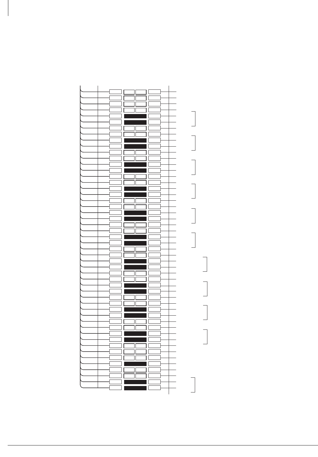
MDF PCB Wiring
Option Interface PCB Wiring Diagram
10-26 Strata CTX I&M 06/04
Option Interface PCB Wiring Diagram
This section covers wiring for the option interface PCB, the BIOU, which enables external paging,
Night Bell, Night Transfer, Door Lock and BGM mute control. For more information and
connection diagrams, see “External Page with BIOU Interface” on page 12-10.
Figure 10-18 MDF Wiring to BIOU
1
2
3
4
5
6
7
8
9
10
11
12
13
14
15
16
17
18
19
20
21
22
23
24
25
26
27
28
29
30
31
32
33
34
35
36
37
38
39
40
41
42
43
44
45
46
47
48
49
50
1
2
3
4
5
6
7
8
9
10
11
12
13
14
15
16
17
18
19
20
21
22
23
24
25
26
27
28
29
30
31
32
33
34
35
36
37
38
39
40
41
42
43
44
45
46
47
48
49
50
W-BL
BL-W
W-O
O-W
W-GN
GN-W
W-BR
BR-W
W-S
S-W
R-BL
BL-R
R-O
O-R
R-GN
GN-R
R-BR
BR-R
R-S
S-R
BK-BL
BL-BK
BK-O
O-BK
BK-GN
GN-BK
BK-BR
BR-BK
BK-S
S-BK
Y-BL
BL-Y
Y-O
O-Y
Y-GN
GN-Y
Y-BR
BR-Y
Y-S
S-Y
V-BL
BL-V
V-O
O-V
V-GN
GN-V
V-BR
BR-V
V-S
S-V
26
1
27
2
28
3
29
4
30
5
31
6
32
7
33
8
34
9
35
10
36
11
37
12
38
13
39
14
40
15
41
16
42
17
43
18
44
19
45
20
46
21
47
22
48
23
49
24
50
25
To BIOU With
Female Connector
25 Pair Cable W/Male Amp Connector
66M150 Split Block
5493
1
2
3
4
5
6
7
8
9
10
11
12
13
14
15
16
17
18
19
20
21
22
23
24
25
26
27
28
29
30
31
32
33
34
35
36
37
38
39
40
41
42
43
44
45
46
47
48
49
50
1
2
3
4
5
6
7
8
9
10
11
12
13
14
15
16
17
18
19
20
21
22
23
24
25
26
27
28
29
30
31
32
33
34
35
36
37
38
39
40
41
42
43
44
45
46
47
48
49
50
W-BL
BL-W
W-O
O-W
W-GN
GN-W
W-BR
BR-W
W-S
S-W
R-BL
BL-R
R-O
O-R
R-GN
GN-R
R-BR
BR-R
R-S
S-R
BK-BL
BL-BK
BK-O
O-BK
BK-GN
GN-BK
BK-BR
BR-BK
BK-S
S-BK
Y-BL
BL-Y
Y-O
O-Y
Y-GN
GN-Y
Y-BR
BR-Y
Y-S
S-Y
V-BL
BL-V
V-O
O-V
V-GN
GN-V
V-BR
BR-V
V-S
S-V
26
1
27
2
28
3
29
4
30
5
31
6
32
7
33
8
34
9
35
10
36
11
37
12
38
13
39
14
40
15
41
16
42
17
43
18
44
19
45
20
46
21
47
22
48
23
49
24
50
25
25 Pair Cable W/Male Amp Connector
66M150 Split Block
1
2
3
4
5
6
7
8
9
10
11
12
13
14
15
16
17
18
19
20
21
22
23
24
25
26
27
28
29
30
31
32
33
34
35
36
37
38
39
40
41
42
43
44
45
46
47
48
49
50
1
2
3
4
5
6
7
8
9
10
11
12
13
14
15
16
17
18
19
20
21
22
23
24
25
26
27
28
29
30
31
32
33
34
35
36
37
38
39
40
41
42
43
44
45
46
47
48
49
50
W-BL
BL-W
W-O
O-W
W-GN
GN-W
W-BR
BR-W
W-S
S-W
R-BL
BL-R
R-O
O-R
R-GN
GN-R
R-BR
BR-R
R-S
S-R
BK-BL
BL-BK
BK-O
O-BK
BK-GN
GN-BK
BK-BR
BR-BK
BK-S
S-BK
Y-BL
BL-Y
Y-O
O-Y
Y-GN
GN-Y
Y-BR
BR-Y
Y-S
S-Y
V-BL
BL-V
V-O
O-V
V-GN
GN-V
V-BR
BR-V
V-S
S-V
26
1
27
2
28
3
29
4
30
5
31
6
32
7
33
8
34
9
35
10
36
11
37
12
38
13
39
14
40
15
41
16
42
17
43
18
44
19
45
20
46
21
47
22
48
23
49
24
50
25
Bridging
Clips
25 Pair Cable W/Male Amp Connector
66M150 Split Block
Zone Page Common
CRT1
CRR1 Control Relay 1 Contacts
CRT2
CRR2 Control Relay 2 Contacts
CRT3
CRR3 Control Relay 3 Contacts
CRT4
CRR4 Control Relay 4 Contacts
Page In 1
Page Out 1 Zone 1
Page In 2
Page Out 2 Zone 2
Page In 3
Page Out 3 Zone 3
Page In 4
Page Out 4 Zone 4
SPT1
SPR1
3 Watt Page Output (BIOU, SW600
must be set to SP1)
(SPR1 is BIOU Analog Circuit Ground)
SPTO
SPRO
600 ohm Page Output (BIOU, SW600
must be set to SPO)
ALMT
ALMR
ALMT Sensor (not used in CTX)
(ALMR is BIOU Digital Circuit Ground)

Strata CTX I&M 06/04 11-1
Station Apparatus
Station Apparatus 11
This chapter provides instructions on how to connect telephones to the Strata CTX systems and
how to configure and upgrade them for optional features.
The Strata CTX systems can support Toshiba corded and cordless digital telephones, as well as
most standard telephones provided by other suppliers. The digital telephone information in this
chapter applies to the 3000-series and 2000-series telephones that connect to the PDKU, ADKU or
BDKU/BDKS interface.
Strata CTX does not support Toshiba electronic telephones (EKT) or other devices supported by
the PEKU and PESU interface PCBs. For information on earlier models, refer to the appropriate
Strata DK manual. Procedures for installing direct station selection consoles and add-on modules
also appear in this chapter.
Note Strata IP telephones are discussed in the IPT chapter of this document.
3000-series Digital Telephones Telephone
The 3000-series digital telephone (DKT) models consist of:
• DKT3010-S (10-button speakerphone model which enables users to make and receive outside
and internal calls without lifting the handset)
• DKT3020-S (20-button speakerphone model which enables users to make and receive outside
and internal calls without lifting the handset)
• DKT3010-SD (10-button speakerphone model equipped with an LCD that displays two rows
of 24-characters. The speakerphone enables users to make and receive outside and internal calls
without lifting the handset.)
• DKT3020-SD (20-button speakerphone model equipped with an LCD that displays two rows
of 24-characters. The speakerphone enables users to make and receive outside and internal calls
without lifting the handset.)
• DKT3014-SDL (14-button speakerphone model equipped with 16 buttons for LCD soft keys
and a large LCD. The large LCD accommodates up to eight rows of 24 characters on a screen
which tilts for easy viewing.)
• DKT3001 (single line, digital telephone that enables users to make and receive outside and
internal calls using the handset.)
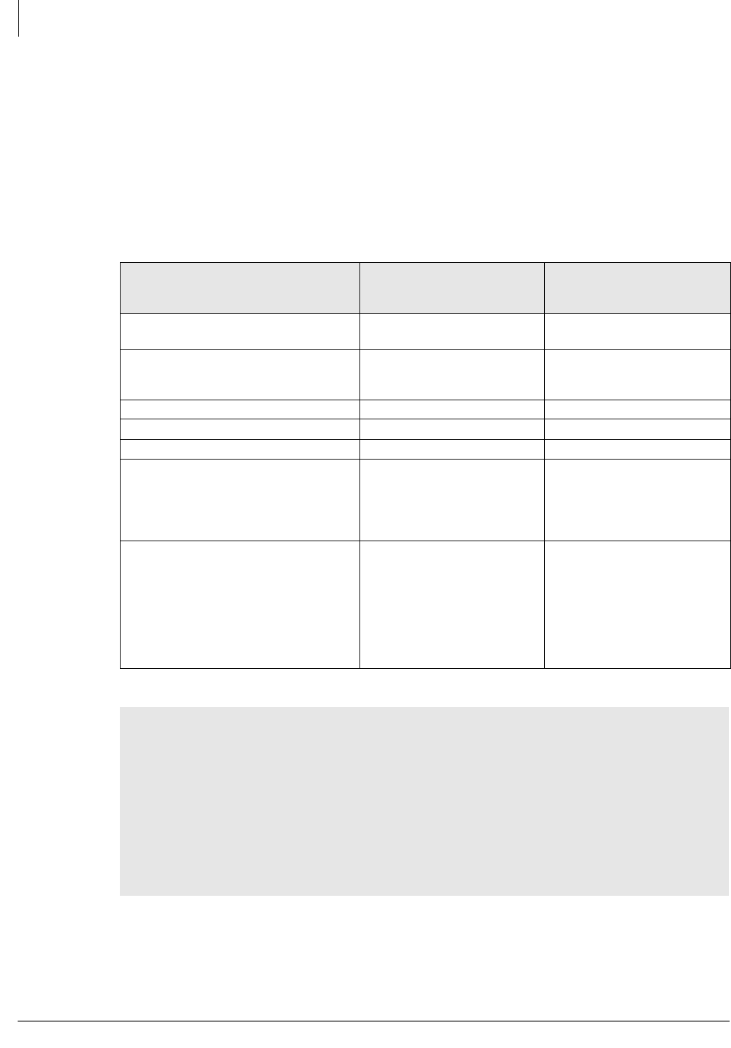
Station Apparatus
3000-series Telephone Installation
11-2 Strata CTX I&M 06/04
3000-series Telephone Installation
Digital Telephone System Connection
The following provides information on how to connect all 3000-series DKTs to the Strata CTX
systems. 3000-series DKTs can be connected to the BDKU/BDKS and/or the PDKU interface
PCB. To obtain all capabilities, the DKT3000-series telephone must be connected to the BDKU/
BDKS. For details on feature availability per station PCB, see Table 11-1.
Before installing any telephone wiring, read the following warning and caution notes:
Table 11-1 DKT3000 Operation with Strata CTX and DK Systems
DKT3000 Telephone
and Feature
Strata CTX System
with BDKU/BDKS
Strata CTX system w/ PDKU
and DK System w/ PDKU or
BDKU
DKT3020/3010 Basic LCD 2 x 24 characters 2 x 16 characters, left-
justified
DKT3014 Large LCD 8 x 24 characters with VM
and Directory Dial softkeys
2 x 16 characters, left-
justified, no VM and
Directory Dial softkeys
LCD Feature button Operational Not operational
Fixed Spdial button Operational Not operational
DKT3000 telephones per cabinet slot 16 telephones max. 8 telephones max.
DKT3000 Programming Mode “A”
(Beep Tone On/Off, etc.) Program
Mode “A” is for telephone options that
are controlled by the ROM inside the
telephone.
Operational Operational
DKT3000 Programming Mode “B”
(Flexible Buttons, One Touch, etc.)
Program Mode “B” is for telephone
options controlled by the Strata
CTX670 processor and database
memory. (See the
Strata CTX
DKT3000/2000-series Digital
Telephone User Guide.
)
Operational
Strata CTX with PDKU is
operational. DK system with
PDKU or BDKU is not
operational.
WARNING!
³Never install the telephone wiring during a lightning storm.
³Never install the telephone jacks in wet locations, unless the jack is specifically
designed for wet locations.
³Never touch uninsulated telephone wires or terminals unless the telephone line has
been disconnected at the network interface.
³Use caution when installing or modifying telephone lines.
³If telephone, DSS console, door phone control box, or door phone wiring exits the
building, external secondary protection is required. See Chapter 10 – MDF PCB Wiring.

Station Apparatus
3000-series Telephone Option PCBs
Strata CTX I&M 06/04 11-3
Station Apparatus
CAUTION! When installing the station cable, do not run the cables parallel if they are
within three feet of an AC power line. AC power lines should be crossed at
right (90°) angles only. In particular, avoid running station wire pairs near
devices that generate electrical noise, such as neon or fluorescent light
fixtures.
CAUTION! Do not use cleansers that contain benzene, paint thinner, alcohol or other
solvents on the telephone's rubber feet. The color of the rubber may transfer
to the desk or mounting surface.
Digital telephones connect to the digital telephone ports via the MDF with standard twisted-pair
jacketed telephone cable. If using 24 AWG cable, single-pair wiring is sufficient in most cases for
digital telephones to operate effectively at up to 1000 feet from the system.
Digital telephones that are equipped with ADMs should have two-pair (or external power) to
function effectively at this distance. This also applies to digital telephones supported by systems
that must operate with battery reserve power (see Chapter 4 – Strata CTX670 Installation for more
information).
To accommodate the digital telephone line cord, the cable should be terminated in a modular
station connector block (RJ11) at the station location. The standard single-pair, modular digital
telephone cord that is sent with the telephone is 7 ft. (the maximum allowed is 25 ft.).
Notes
●Digital telephone cable runs must not have cable splits (single or double), cable bridges (of
any length), or high resistance or faulty cable splices.
3000-series Telephone Option PCBs
Digital telephones can be upgraded with option PCBs to add a number of features. Each of these
upgrades shares a circuit with the telephone that it is connected to and is not considered a station.
See Table 11-2 for more information.
Table 11-2 3000 Telephone Subassembly Upgrades
Subassembly No. per
Phone Function
BVSU1
1. Only one of these options is allowed per telephone: BVSU, BPCI or DADM.
1
Speaker Off-hook Call Announce (OCA): Provides interface for digital
telephone to receive Speaker OCA. Not required for Handset/Headset
OCA.
BHEU or
HHEU 1
Headset and external ringer telephone interface: Can be installed with
BVSU, BPCI or DADM. (See “Telephone Headset (BHEU) Upgrade” on
page 11-7 for installation instructions.)
BPCI 1 TAPI PC application and data calling interfaces.
DADM302011 or 2 Add-on Module (ADM): Provides telephone with 20 (or 40 with two ADMs)
additional feature buttons.
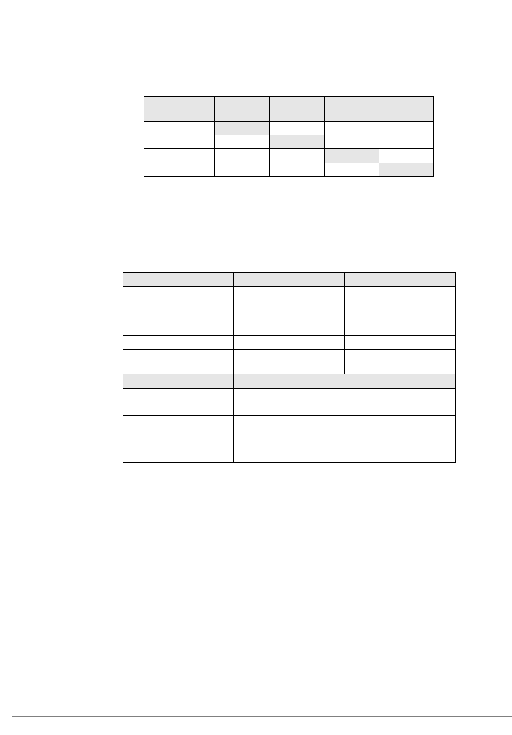
Station Apparatus
3000-series Telephone Option PCBs
11-4 Strata CTX I&M 06/04
Some of the option PCBs are compatible, meaning that more than one option can be added to a
telephone. The following table shows which options are compatible.
Option PCBs must be compatible with type of telephone (i.e., 3000- or 2000-series) they are
installed in (see Table 11-4 for compatibility).
Table 11-3 Station Option Interface PCB Compatibility
Item BPCI BHEU/
HHEU BVSU ADM
BPCI XNCNC
BHEU/HHEU XXX
BVSU NC X NC
ADM NC X NC
X = Compatible, can be used together in the same telephone.
NC = Not compatible, cannot be used together in the same telephone.
Table 11-4 DKT3000 and DKT2000 Component Compatibility
Item 2000-series DKT 3000-series DKT
Add-on Modules DADM2020 only DADM3020, DADM3120
Desktop Computer
Telephony Interface
(CTI)
n/a BPCI only
Speaker OCA BVSU or DVSU BVSU only
Tilt Stands BTSD for DKT BTSD for DKT and BTSA
for DKT with ADM(s)
Item 2000- and 3000-series DKTs
Headset Interface HHEU2 and BHEU
External Ringer HHEU2/HESB and BHEU/HESB
Cordless Telephones
DKT2104 and DKT2004. When these cordless
telephones are connected to a DKT3000, the
DKT3000 must be placed in DKT2000 mode (see
“DKT2000 Mode On/Off” on page 11-19).
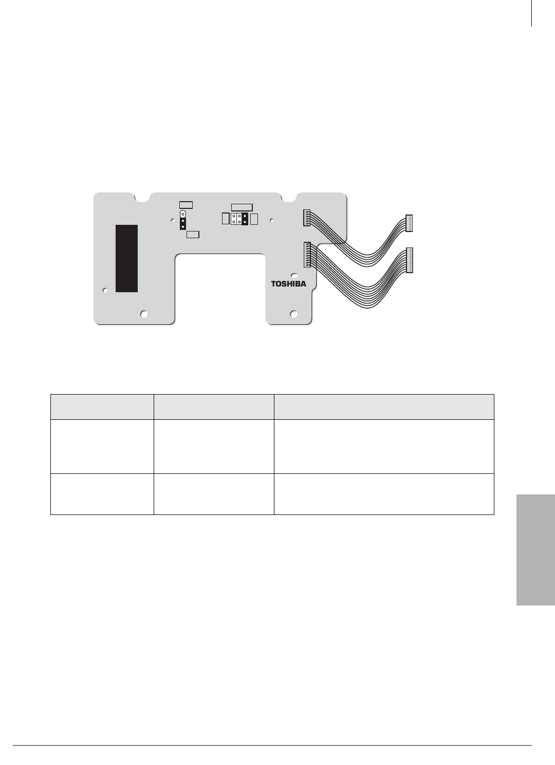
Station Apparatus
3000-series Telephone Option PCBs
Strata CTX I&M 06/04 11-5
Station Apparatus
Telephone Speaker Off-hook Call Announce Upgrade (BVSU)
To receive Speaker Off-hook Call Announce (OCA) calls over the digital telephone speaker, a
digital telephone must be upgraded with a BVSU; the telephone making the call does not require a
BVSU. Digital telephones do not require an additional wire pair to receive Speaker OCA call. The
BVSU is not necessary to receive handset OCA.
BVSU Upgrade Installation for DKT3000-series Telephones
1. Loosen the four captive screws on the telephone base and remove the base (see Figure 11-2).
2. On the BVSU (see Figure 11-1, set strip pins SW1 and SW2 per Table 11-5.
Figure 11-1 Speaker Off-hook Call Announce Upgrade (BVSU1A)
3. Slide the BVSU under the tabs.
4. Position the BVSU holes over the standoffs and secure with the two provided screws. (Two
large head screws for DKT3000s, four smaller head crews for the DKT2000.)
5. Connect the BVSU wire plugs to the two “PCI/VSU” connectors on the PCB inside the phone,
with the red wire on the side where “RED” is silk-screened on the DKT PCB (see Figures 11-7
and 11-8).
6. Reinstall the telephone base and secure it with its four captive screws
Table 11-5 BVSU Jumper Settings
Control/Indicator/
Connector Type of Component Description
SW1 6-terminal jumper plug
30 (default) - use for DKT3000 telephones.
20 Mu - use for DKT2000 telephones in Mu Law
countries, including U.S. and Canada.
20A - use for DKT2000 in A Law countries.
SW2 3-terminal jumper plug
SPF (default setting). Use for all DKT3000
DKT2000 telephones, except the DKT2010-H.
HFU - use for DKT2010-H telephones.
6068
BVSU1A
HFU
SPF
SW2
SW1
20 Mu
20 A
30
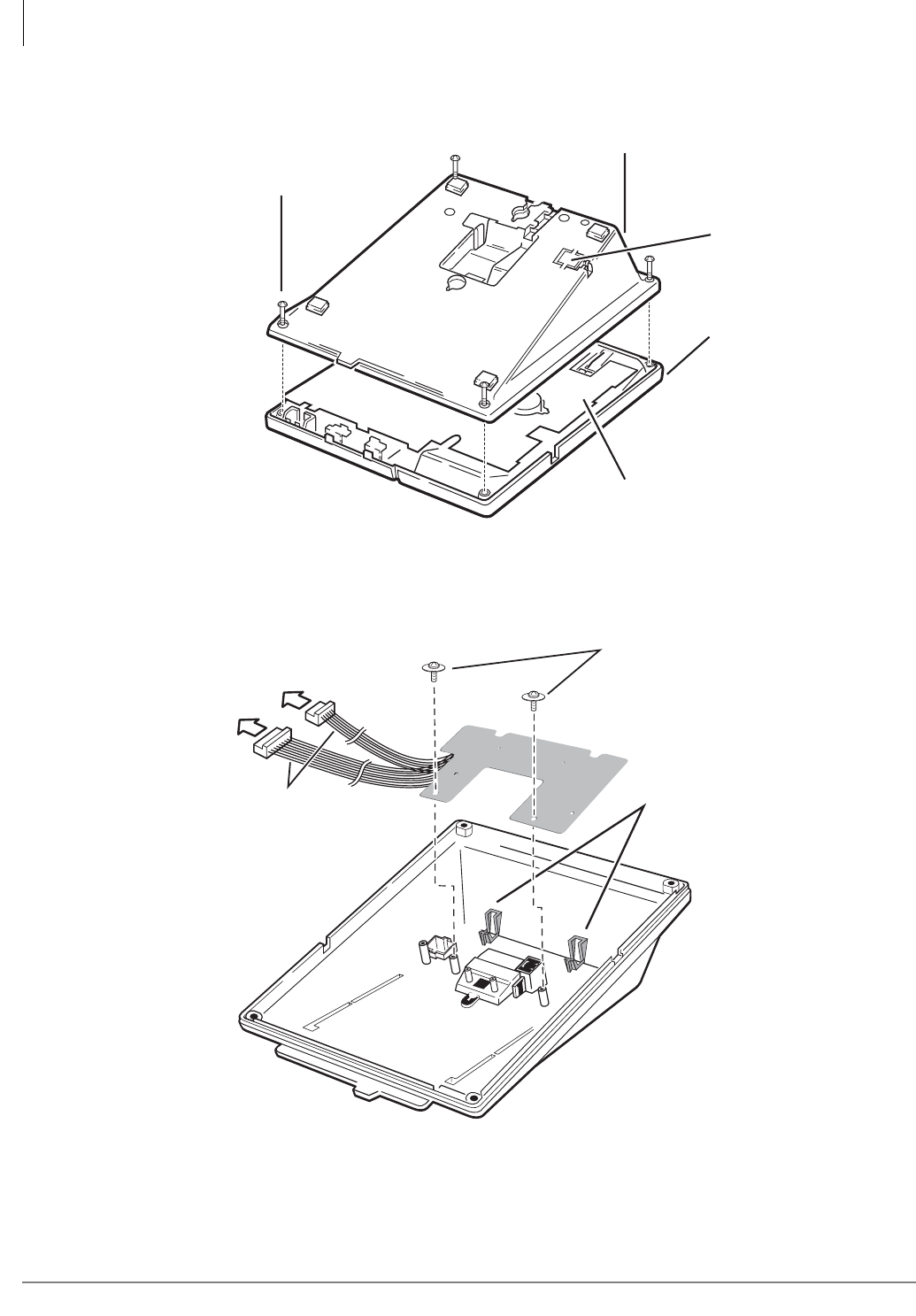
Station Apparatus
3000-series Telephone Option PCBs
11-6 Strata CTX I&M 06/04
Figure 11-2 Removing Telephone Base
Figure 11-3 BVSU Installation
6122
Telephone Base
Knock out for
HHEU or BHEU
Telephone
Housing
Telephone PCB
Captive Screws
(One in Each Corner)
DKT3000-series,
slide the BVSU
under base tabs
Red Wire
6066
To PCI/VSU
Connectors
on Telephone
Fasten
Two
Screws
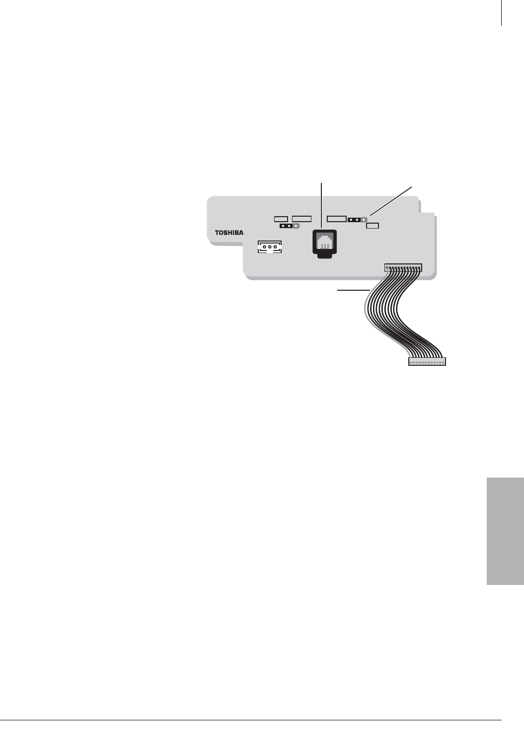
Station Apparatus
3000-series Telephone Option PCBs
Strata CTX I&M 06/04 11-7
Station Apparatus
Telephone Headset (BHEU) Upgrade
The BHEU can be installed into the DKT3000-series telephones to enable headset or external
ringer use. For information on connecting the external ringer, refer to “Telephone (BHEU) to
External Speaker (HESB) Cable Connection” on page 12-18. The BHEU can also be installed into
DKT3010 and DKT3020 telephones that have either a BVSU or BPCI installed. For DKT3001
and DKT3014 telephones, the installation is same as below, only the connector location is
different.
BHEU Installation
1. Loosen the four captive screws
on the telephone base, and
remove the base. Knock out hole
for the BHEU cord (see Figure
11-2).
2. If you are connecting an ECM or
Carbon-type headset to the
BHEU, leave the BHEU jumper
in the “AUTO” position (see
Figure 11-4).
“AUTO” enables the BHEU
current detector to determine
which headset type is connected
(less than 2mA detects EMC and
more than 2mA detects Carbon).
If, in a rare case the current is
marginal using a carbon headset
(only) and performance is not
adequate, set the jumper to
“CARBON.”
BHEU1A
P1
SW1
SW2
AUTO CARBON NORMAL
LOW
RED
Transmission Level
Headset Modular
Connector
5502
Figure 11-4 BHEU PCB
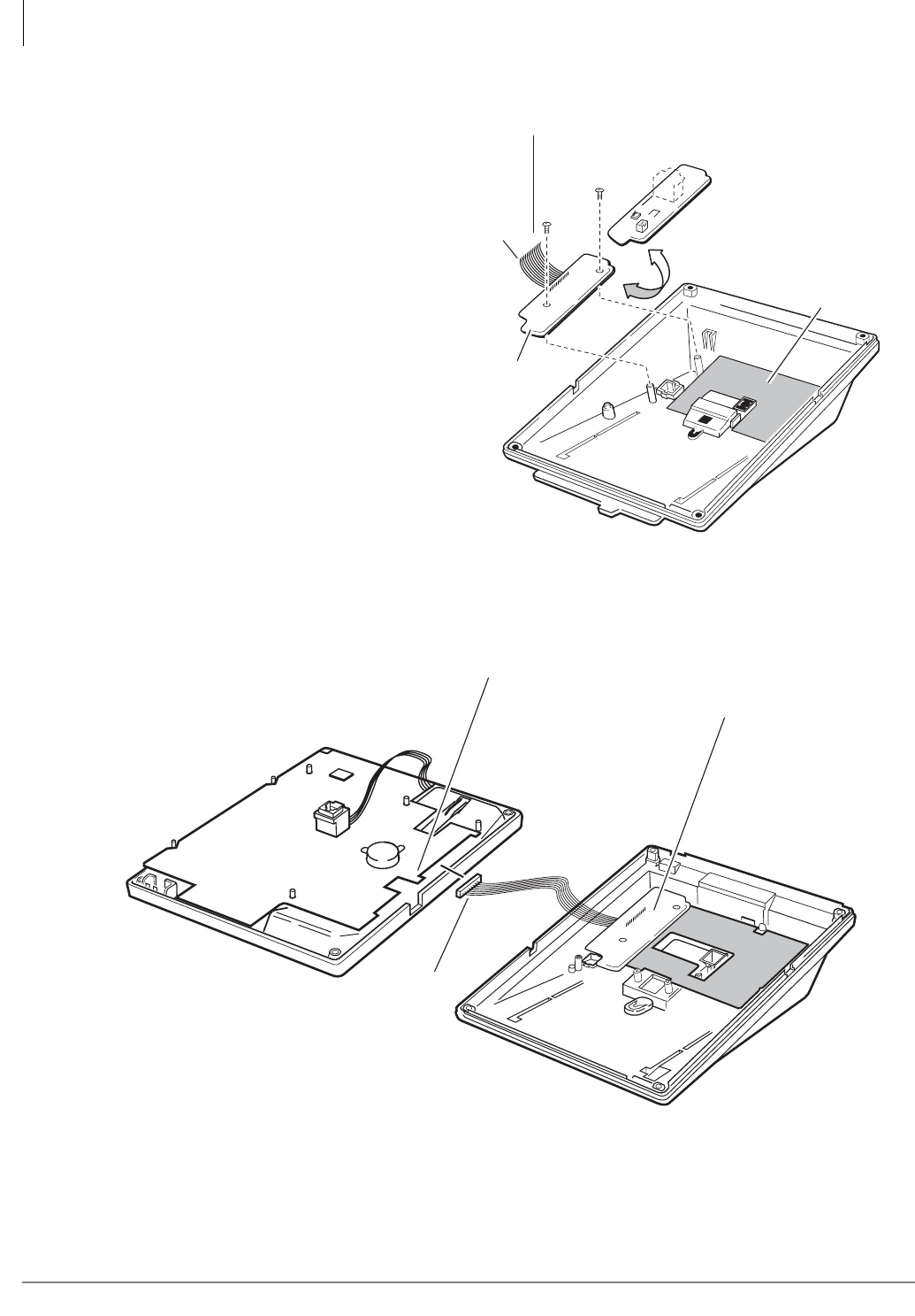
Station Apparatus
3000-series Telephone Option PCBs
11-8 Strata CTX I&M 06/04
3. Make sure that the SW2 jumper plug
is set to “NORMAL.”
4. If you do not want the handset
receiver to work when the handset is
on-hook and a headset (connected to
BHEU) is being used, cut the HEU
strap on the DKT PCB (see Figures
11-7 and 11-8).
5. Position the BHEU PCB (component
side down) on the standoffs inside the
base, and secure with the two
provided screws (see Figure 11-5).
6. Connect the BHEU integrated wire
plug to P3 (HEU) on the telephone
base PCB (see Figures 11-6 and
11-9). Note the location of the red
wire.
...or for DKT3001 telephones only,
connect the BHEU wire plug to P1
(HEU) on the telephone base PCB
(see Figure 11-9). Note the location of
the red wire.
7. Reinstall the base on the telephone.
Figure 11-6 BHEU Installation
BHEU
To HEU connector
on telephone
Turn BHEU component
side down.
BVSU or BPCI
(optional)
5651
Red
Wire
Figure 11-5 BHEU Installation
Digital
Telephone
Top Assembly
Digital
Telephone Base
Red
Wire
5657
(P3) HEU
BHEU
BVSU or BPCI
(optional)
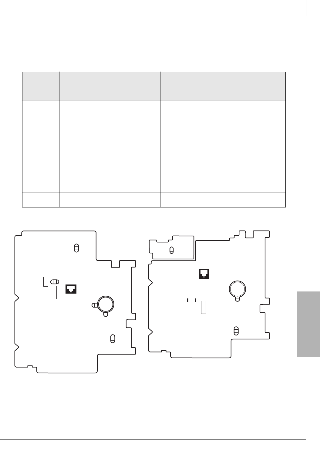
Station Apparatus
3000-series Telephone Option PCBs
Strata CTX I&M 06/04 11-9
Station Apparatus
Telephone Option Straps
Certain option straps on the DKT3000-series phones must be cut when installing carbon handsets,
external power or headsets. Refer to Table 11-6 and Figures 11-7~11-9 for further instruction.
Table 11-6 Station Option Interface PCB Compatibility
Name of
the Strap
on the DKT
PCB
DKT3010-S,
DKT3020-S,
DKT3010-SD,
DKT3020-SD
DKT301
4-SDL
DKT300
1Explanation
Carbon W301, W302 W301,
W302
If a carbon-type handset or carbon-type headset
is connected to the
handset
jack, the carbon wire
jumper straps, listed on the left, must be cut
inside the telephone. When a carbon headset is
connected to the BHEU, you do
not
need to cut
the straps. See Figures 11-7~11-9.
HEU W303 W303 W103
To turn off the handset receiver when the
handset is on-hook and a headset is used with
the BHEU, cut the “HEU” strap shown on the left.
EX.POWER W101, W102 W101,
W102
W101,
W102
Cut the “EX.POWER” straps only when external
power is connected to the second pair (pins 2
and 5) of the telephone modular jack. See
Figures 11-7~11-9.
SET UP W401, W402 W401,
W402 Do not cut – for factory use only.
Figure 11-7 DKT3010, DKT3020 Strap and
Connector Locations
Figure 11-8 DKT3014 Strap and Connector
Locations
PCI/ VSU
PCI /ADMPCI /VSUHEU
P1
P2
P3
P6
Carbon
W302
HEU
W303
W301
CARBON
EX.POWER
W101
EX.POWER
W102
RED
RED
RED
RED
5603
W401
W402
SET UP
GND
PCI/ VSU
EX.POWER
W102
W101
PCI /ADMPCI /VSUHEU
P1P2P3
P6
HEU
W303
W301
CARBON
W302
CARBON
REDREDRED
RED
5668
W402
W401
GND
SET UP
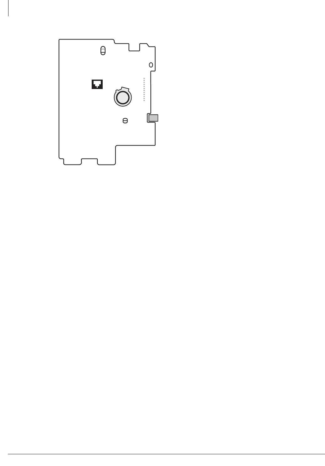
Station Apparatus
3000-series Telephone Option PCBs
11-10 Strata CTX I&M 06/04
Figure 11-9 DKT3001 BHEU Connector Location
DKT3001 12
HEU
P1
5653
EX.
POWER
RED
HEU 103
W101
W102
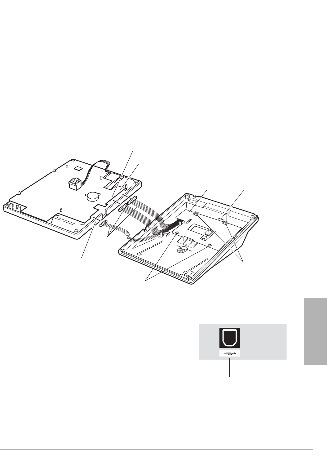
Station Apparatus
3000-series Telephone Option PCBs
Strata CTX I&M 06/04 11-11
Station Apparatus
TAPI and Simultaneous Voice and Data Upgrades for 3000-
series Telephones (BPCI)
Digital telephones can be upgraded with a Personal Computer Interface (PCI) to provide desktop
interface with the telephone and PC USB port. The PC connected to the BPCI can place telephone
calls, receive Caller ID, ANI, and DNIS information. The BPCI is compatible with Microsoft
TAPI application programs.
BPCI Installation
1. Loosen the four captive screws on the digital telephone base to remove it. Knock out the plastic
cover on the telephone base to provide access to the BPCI USB port. See Figure 11-10.
2. Refer to Figure 11-10 and install the BPCI inside the phone base. Secure with screws.
3. Insert the three integrated unit wire plugs into connectors P1, P2 and P6 on the PCB in the
telephone. Make sure that the red wire is positioned as shown. (P1-P1, P2-P2, P6-P4.)
Figure 11-10 BPCI Installation
4. Stick the USB label onto the base, just below the modular
cord port (see Figure 11-11).
Important!
•BPCI requires a DKT3000-series telephone set in the
DKT3000 mode (see “DKT2000 Mode On/Off” on page
11-19).
•The BPCI also requires that the DKT3000-series
telephone be connected to a BDKU or BDKS PCB set to
the “BDKU” mode (not the “PDKU” mode). BPCI will
not function on a telephone connected to a PDKU or
RDSU PCB.
Digital
Telephone
Top Assembly
Digital
Telephone Base
PC USB
Connection
Port (knock out
plastic cover
on telephone
base)
(P1)
Install
Two Screws
Slide BPCI
under tabs on
the telephone base
(P2)
(P4)
Red
Wire
5608
(P6) PCI/VSU
(P1) PCI/ADM
(P2) PCI/VSU
BPCI
6035
USB Label
Figure 11-11 USB Label
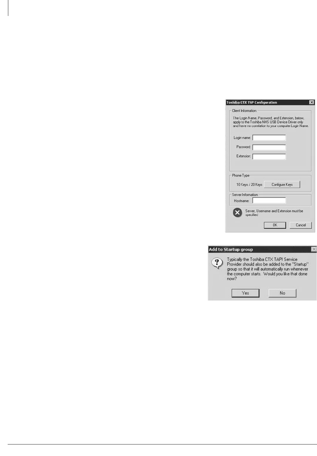
Station Apparatus
Install TAPI Service Provider
11-12 Strata CTX I&M 06/04
Install TAPI Service Provider
This Desktop Open Application Interface (OAI) Manual provides step-by-step instructions for
installing the software application.
1. Insert the Strata CTX CD-ROM into your CD-ROM drive. From the Main Menu, click Install
TSP.
2. Follow the on-screen instructions. Toshiba recommends that default settings be used, but
alternate paths, program groups, etc., are offered to meet your specific needs.
3. When the Toshiba CTX TSP Configuration screen displays
(shown right), type in the following information:
•Login Name: Use any name you desire.
•Password: Optional, leave blank if not needed.
•Extension: Primary DN of connected DKT3000 phone.
•Hostname: Typically this is “localhost.”
4. (Optional) Click on Configure Keys. This section enables
you to use more useful names for the line appearances on
your phone. If you do not change their name, an
application will show the line appearances as FB1 through
FB20. Only the 20 feature keys of the main phone can be
selected for TAPI dialing, using a specific appearance.
5. Click OK to save your entries. An error box displays and
you need to click OK again.
6. Click Cancel on the Toshiba CTX TSP
Configuration screen to continue. The Add to
Startup group screen displays (shown right).
7. If you want the Toshiba CTX TAPI Service Provider
program added to the Startup group, click Yes.
8. The installation continues. On the last screen, click
Finish.
9. Restart PC to complete the installation.

Station Apparatus
Add/Edit TSP Configuration Information
Strata CTX I&M 06/04 11-13
Station Apparatus
Add/Edit TSP Configuration Information
1. Select Start > Setting > Control Panel. Select either the Telephony or Phones and Modems
(name is dependant upon the operating system used).
2. Select Advanced Tab to see a current list of providers. If “Toshiba CTX TAPI Service
Provider” is not found, click ADD, select it and click OK.
3. Highlight “Toshiba CTX TAPI Service Provider” and click Configure. Enter/Edit the
information on the screen (see Steps 3 and 4 above for additional information).
4. When finished, click OK > Close.
Test/Use TAPI Service Provider
An easy way to test or use your TAPI Service Provider is to use “Phone Dialer” supplied in most
Windows® operating systems. This program is typically found in “Accessories/Communications/
Phone Dialer.”
1. From the Main Menu, select Edit/Options.
2. In the Line Tab choose the Phone option for Preferred Line for Calling.
3. In Line used for Phone Calls, pull-down the list and select the appropriate line to use when
making a call. For example:
Toshiba CTX TSP Ext. 3351, Address 0 is typically the primary DN for extension 3351
IPT Telephone
Toshiba offers an Internet Protocol (IP) Telephone
model, the IPT1020-SD. The BIPU-M2A PCB IP
telephone interface must be installed in the Strata
CTX100 or CTX670.
The IPT1020-SD is a 20-button speakerphone model
equipped with an LCD that displays two rows of 24-
characters. The speakerphone enables users to make and
receive outside and internal calls without lifting the
handset. A full-duplex speakerphone is not supported.
The IPT has the following features:
• Full DKT feature set (except Speaker OCA)
• DKT Anywhere
• Automatic Configuration
• Terminal Authentication (security)
• Digital Add-on Modules (DADM3120)
• Built-in headset interface for headsets and external speaker connection (HESB)
•See Chapter 9 – IP Telephony and QSIG Over IP for more information on IPTs, the
DADM31020 and the BIPU-M2A PCB.
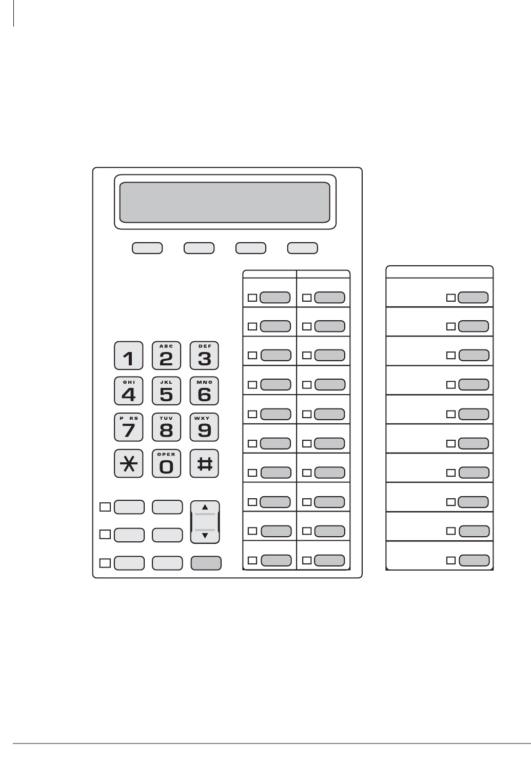
Station Apparatus
3000-series, IPT1020-SD Button Layouts
11-14 Strata CTX I&M 06/04
3000-series, IPT1020-SD Button Layouts
The button layout for the 3010- and 3020-series telephones and IPT1020-SD telephone are shown
in Figure 11-12. The DKT3014, large LCD telephone has additional buttons for features and
programming (see Figure 11-13).On the DKT3001, the Msg and Flex buttons are programmable
(see Figure 11-14).
Figure 11-12 DKT3010/3020 and IPT1020-SD Button Telephones
DKT3010-S and
DKT3010-SD only
6717
Msg Spdial
RedialMic
Spkr Cnf/Trn Hold
(FB10)
(FB08)
(FB09)
(FB07)
(FB06)
(FB05)
(FB04)
(FB03)
(FB02)
(FB01)
(FB10)
(FB08)
(FB09)
(FB07)
(FB06)
(FB05)
(FB04)
(FB03)
(FB02)
(FB01)
(FB20)
(FB19)
(FB18)
(FB17)
(FB16)
(FB15)
(FB14)
(FB13)
(FB12)
(FB11)
PageMode Scroll Feature
IPT1020-SD, DKT3020-S, DKT3020-SD
LCD
(24 Characters by 2 lines)
Vol
ZQ
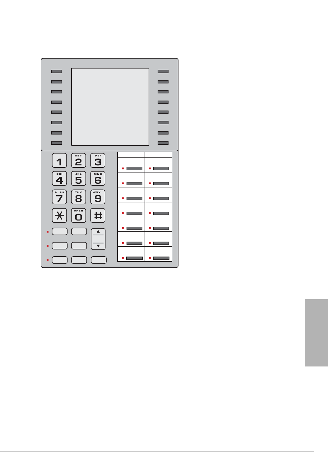
Station Apparatus
3000-series, IPT1020-SD Button Layouts
Strata CTX I&M 06/04 11-15
Station Apparatus
Figure 11-13 DKT3014-SDL Buttons
5442
FB01
FB02
FB03
FB04
FB05
FB06
FB07
FB08
FB09
FB10
FB11
FB12
FB13
FB14
FB buttons for 14-button phones
DKT3014-SDL
Msg Spdial
RedialMic
Spkr Cnf/Trn Hold
Vol
ZQ
Feature
Scroll
Mode
Page
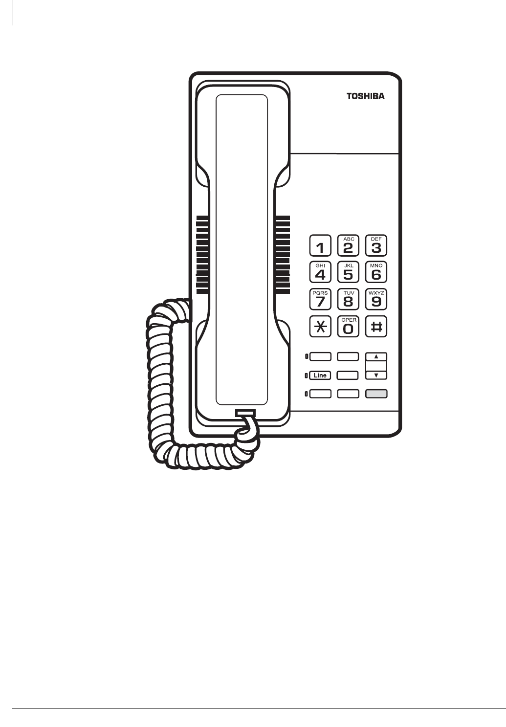
Station Apparatus
3000-series, IPT1020-SD Button Layouts
11-16 Strata CTX I&M 06/04
Figure 11-14 DKT3001 Buttons
5654
Line
Msg
Spkr Hold
VOL
Spdial
Cnf/Trn
Flex

Station Apparatus
Telephone Settings
Strata CTX I&M 06/04 11-17
Station Apparatus
Telephone Settings
3000-Series/IPT Telephones
Telephone Programming Mode A
The 3000-series telephones enable you to set a number of features directly from the phone,
including: Call Waiting Tone (On/Off), Flex Key, Msg Key, LCD contrast, Speakerphone/
Microphone Room Noise Sensitivity (On/Off), and Country settings. “Telephone Programming
Mode A” programs settings on a ROM chip inside the telephone.
Note Some of the procedures use Feature Buttons (FB1, FB2, etc.). When your telephone is in
Programming Mode, the flexible buttons are numbered as Feature Buttons, as shown in
Figures 11-12 and 11-13.
³To place your telephone in Programming Mode A
³Press 3+6+9+Hold simultaneously. The LCD displays “DKT PROGRAM MODE” and
“SELECT=”. Your phone will not ring if it receives a call while in Programming Mode.
³To exit from Programming Mode A
³Go Off- and On-hook or wait for 30 seconds for Programming Mode to automatically time out.
Telephone Program Option Reset
This function resets all Programming Mode A option settings to their default setting.
1. Press 3+6+9+Hold (simultaneously).
2. Press Vol ▲ + Msg (Msg LED On means reset is set to activate)
3. Press Hold to activate reset.
4. Go off-hook, then on-hook to exit the program mode.
Dial Pad and Button Beeps
Digital telephones can emit a “beep” sound whenever a dial pad or feature button is pressed. The
“beeps” are On by default. Follow these steps to turn the “beeps” On or Off on 3000-series DKTs.
1. Press 3+6+9+Hold (simultaneously).
2. Press 0.
3. Press Feature Button 1 (FB1) to toggle On/Off.
FB1, LED On: buttons beep.
FB1, LED Off: buttons do not beep.
4. Press Hold to set the option.
5. You must also go off-hook, then on-hook to exit the program mode.

Station Apparatus
Telephone Settings
11-18 Strata CTX I&M 06/04
Speakerphone/Microphone Sensitivity Adjustment
When you are using the speakerphone, high ambient noise levels may cause the party you are
talking with to be to cut off frequently. If this happens, follow these steps to lower the sensitivity of
the microphone on a 3000-series telephone. The default is normal sensitivity.
1. Press 3+6+9+Hold (simultaneously).
2. Press 0.
3. Press Feature Button 3 (FB3) to toggle On/Off.
FB3, LED On: Lower sensitivity
FB3, LED Off: Normal sensitivity
4. Press Hold to set the option.
5. Go off-hook, then on-hook to exit the program mode.
Call Waiting and Camp-on Ring Tone Over Handset/Headset Option
Call Waiting and Camp-on tones are sent to a busy telephone’s speaker to indicate that a call is
waiting. Call Waiting and Camp-on Tones can be sent, as an option, to the telephone handset or
headset, in addition to the speaker. Follow these steps to turn handset/headset Call Waiting and
Camp-on tone On/Off for a 3000-series telephone. The default is Off.
1. Press 3+6+9+Hold (simultaneously).
2. Press 0.
3. Press Feature Button 4 (FB4) to toggle On/Off.
FB4, LED On: Call Waiting tone
FB4, LED On: No Call Waiting tone
4. Press Hold to set the option.
5. Go off-hook, then on-hook to exit the program mode.
Reset and Adjust the LCD Contrast
Step 1: Adjust LCD Contrast for the LCD Telephones
1. Press and hold down the Mic button, and press and release Vol ▲ or Vol ▼ repeatedly.
Each time you press Vol ▲ or Vol ▼, the contrast increases or decreases. There are eight steps
in either direction. To return to the middle setting, repeat “Step 1” above.
2. Press Hold to reset the LCD contrast.
3. Go off-hook, then on-hook to exit the program mode.
Step 2: Reset LCD Contrast for the DKT3014-SDL
1. Press 3+6+9+Hold (simultaneously).
2. Press Mode.
3. Press Msg so that the Msg LED is On.
4. Press Hold. This sets the LCD lightness/darkness contrast on the middle setting.
5. Go off-hook, then on-hook to exit the program mode.

Station Apparatus
Telephone Settings
Strata CTX I&M 06/04 11-19
Station Apparatus
3000-Series Telephones
DKT2000 Mode On/Off
If you have a cordless telephone (DKT2204-CT or DKT2304-CT) that is connected to a 3000-
series telephone, you must place your DKT into 2000-mode before connecting the cordless
telephone; otherwise, the 3000-series telephone will not work.
In 2000-mode:
• Only 16 characters by two lines display on the LCD.
• LCD Feature button does not work
• Spdial button does not work
Step 1: Turn DKT2000 Mode On/Off
Important! You must change the mode on DKT3000 telephone before connecting a
DKT2204-CT or DKT2304-CT to the DKT3000.
1. On the DKT3000 telephone, press 3+6+9+Hold (simultaneously).
2. Press #.
3. Press FB7 (or FB13 on the DKT3014). LED On = 2000 telephone. LED Off = 3000
telephone.
4. Press Hold.
5. Lift the handset to exit programming mode. Wait a few seconds for the telephone to reset itself.
Step 2: Connect Cordless Telephone to DKT3000 Telephone
Redial/Feature Button Activation/Deactivation (DKT3001 only)
Your Flex button has been set to act as a Redial button by default. However, you can reprogram
the Flex button to work as Flexible Button, as it set in system programming. These steps enable
you to change how the button functions.
1. Press 3+6+9+Hold (simultaneously).
2. Press 0 7.
3. Press Msg to toggle On/Off
Msg LED On: Flex button works as Feature Button
Msg LED Off: Flex button works as a Redial button.
4. Press Hold to set the option.
5. Go off-hook, then on-hook to exit the program mode.
Note If you program the Flex button to work as Flexible Button 3, you can press * to redial.
Msg/Feature Button Activation/Deactivation (DKT3001 only)
Your Msg button has been set by default to work as a Msg button; however, you can reprogram it
to work as Feature Button.
1. Press 3+6+9+Hold (simultaneously).
2. Press 0 8.
3. Press Msg to toggle On/Off.

Station Apparatus
Telephone Settings
11-20 Strata CTX I&M 06/04
Msg LED On: Msg operates as Feature Button
Msg LED Off: Works as a Msg button.
4. Press Hold to set the option.
5. Go off-hook, then on-hook to exit the program mode.
Test the Display on Large LCD Telephones (DKT3014-SDL only)
1. Press 3+6+9+Hold (simultaneously).
2. Press Page.
3. Press 1. LCD screen is blank.
4. Press 2. Each segment shows three vertical lines, in all eight rows.
5. Press 3. Each segment contains five short horizontal lines, in all eight rows.
6. Press 4. Each segment contains a pattern of small dots, in all eight rows.
7. Press 5. All of the available characters, including numbers, display.
8. Go off-hook, then on-hook to exit the program mode.
Country Settings On/Off
This procedure enables you to change the country settings for telephone CODEC operation in
various countries, see Table 11-7.
1. Press 3+6+9+Hold (simultaneously).
2. Press *.
3. Press Feature Buttons 1~4 (FB1~FB4) On/Off according to the Table below
...or, for the DKT3001, pressing 1~4 and toggle the Msg LED On/Off (see following)
press 1 (Msg LED Off means that FB1 is Off)
press 2 (Msg LED Off means that FB2 is Off)
press 3 (Msg LED Off means that FB3 is Off)
press 4 (Msg LED Off means that FB4 is Off)
4. Press Hold to set the option.
5. Go off-hook, then on-hook to exit the program mode.
Note On the DKT3001, the Msg LED shows if the feature has been turned On/Off. There is no
visible indication on the other telephones. If the telephone ringer and busy tone buzzes or
doesn’t sound clear, check the country settings.
Table 11-7 Country Code Settings for Mu Law/A Law
Country FB1 FB2 FB3 FB4
USA, Canada (default is Mu Law) Off Off Off Off
Mexico Off Off Off On
Taiwan On Off Off Off
Hong Kong, Thailand Off On Off Off
Singapore, Malaysia, Indonesia, Sri Lanka, India,
China On On Off On
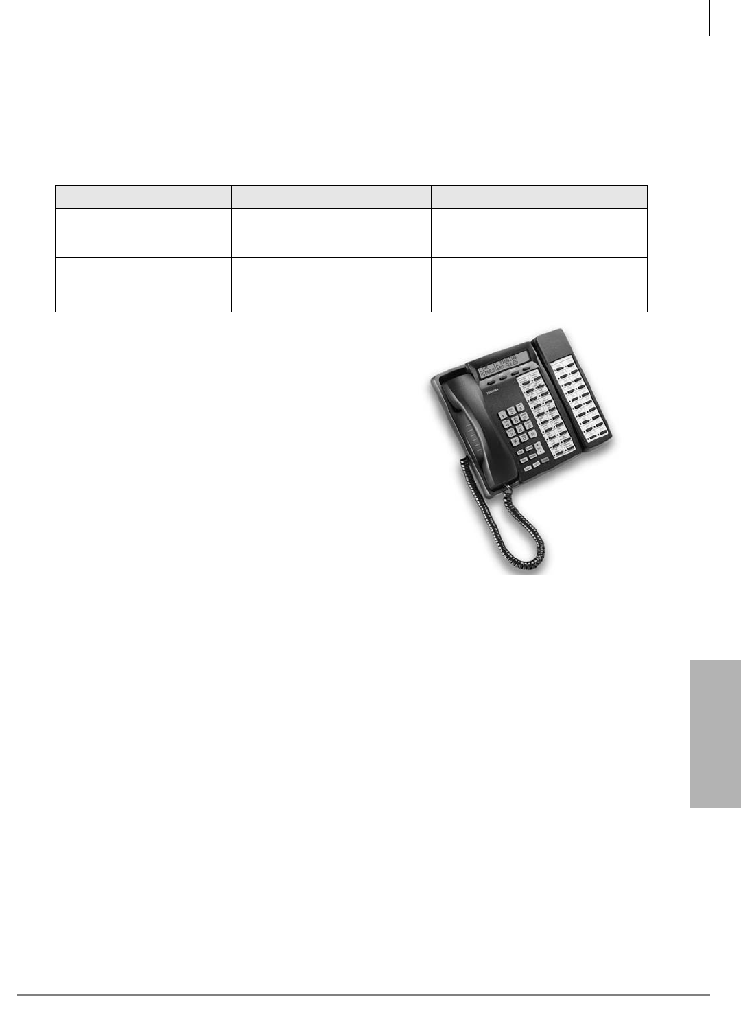
Station Apparatus
Digital Add-on Module Installation
Strata CTX I&M 06/04 11-21
Station Apparatus
Digital Add-on Module Installation
The DADM provides 20 buttons that can be flexibly programmed for any telephone feature that is
provided by the Strata CTX system. There are two DADM models available—DADM3020 and
DADM3120. The differences are shown in Table 11-8.
Install one or two DADM to a Toshiba digital
telephone (only) (shown at right) or an IP telephone.
The digital telephone and the DADM must belong to
the same series, i.e., 3000- or 2000-series.
IPT1020-SD telephones can only be connected to a
DADM3120.
• See the appropriate system Installation Chapter for
loop length and secondary protection
requirements.
• DADMs cannot be installed on telephones that
have BPCI, BVSU or DVSU installed.
³To install DADMs
See Figure 11-15 and follow these steps:
1. Loosen the four captive screws on the digital
telephone base and remove it.
2. Remove the base handset hanger.
3. Loosen two captive screws on DADM and remove bases.
4. Put the DADM supplied cable through the telephone and DADM bases.
5. Connect DADM cable connectors to P1 of DADM and P1 of DKT telephone.
6. Install base of DADM and telephone – tuck DADM cable into DADM and telephone base, as
necessary, for proper length.
7. Secure DADM to telephone base with DADM connecting plate (using four screws).
8. If required to achieve maximum distance, install two-pair house cable (or external power) and
two-pair modular cord, supplied with DADM. (See Chapter 10 – MDF PCB Wiring.)
9. If a second DADM should be installed, connect P1 of the second DADM to P2 of the first
DADM with the DADM connecting cable.
Table 11-8 DADM Comparison
Add-on Module DADM3020 DADM3120
Telephone to be connected DKT3010-S/20-S/10-SD/20-SD,
DKT3014-SDL
IPT1020-SD,
DKT3010-S/20-S/10-SD/20-SD,
DKT3014-SDL
Color of DADM Black, white Black
Power Source of ADM
Circuit 24 VDC 5 VDC
5843
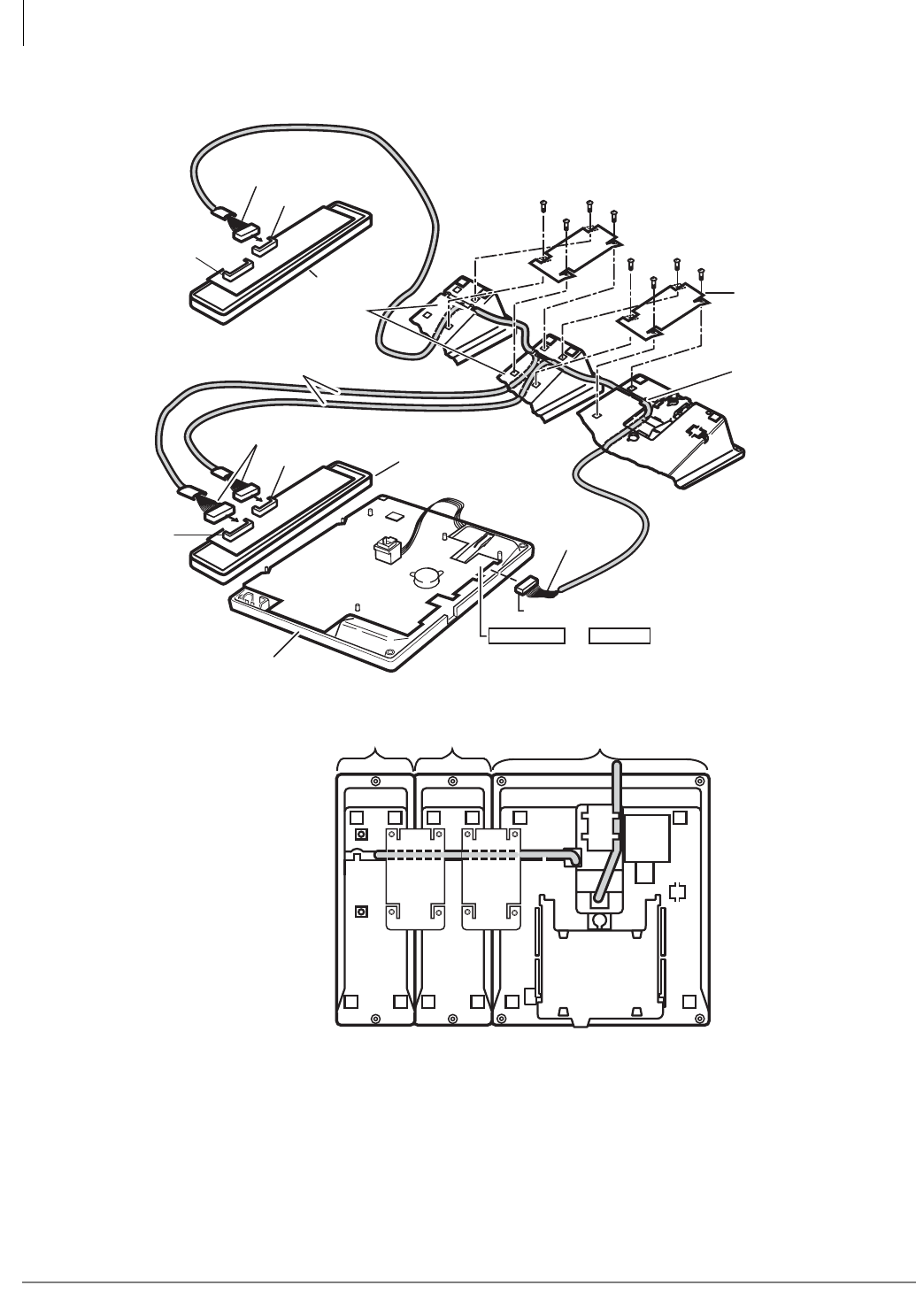
Station Apparatus
Digital Add-on Module Installation
11-22 Strata CTX I&M 06/04
Figure 11-15 Digital Add-On-Module
6507
DIU & ADM PCI/ADM
1
Black Wire
to Pin 1
Black Wire to Pin 1
1
110
12
P 1
P 2
DADM Cable
(Supplied with DADM)
P1 of Bottom PCB
Telephone
Base
Remove Handset
Hanger
DADM Connection
Plate (provided
with DADM)
4-Screws
Telephone
or
View of Bottom
DADMX020 DKT/IPTDADMX020
4-Screws
DADM Base
(Smaller Connector)
P 1
P 2 (No
Connection)
First DADM
Second DADM
1
110
12
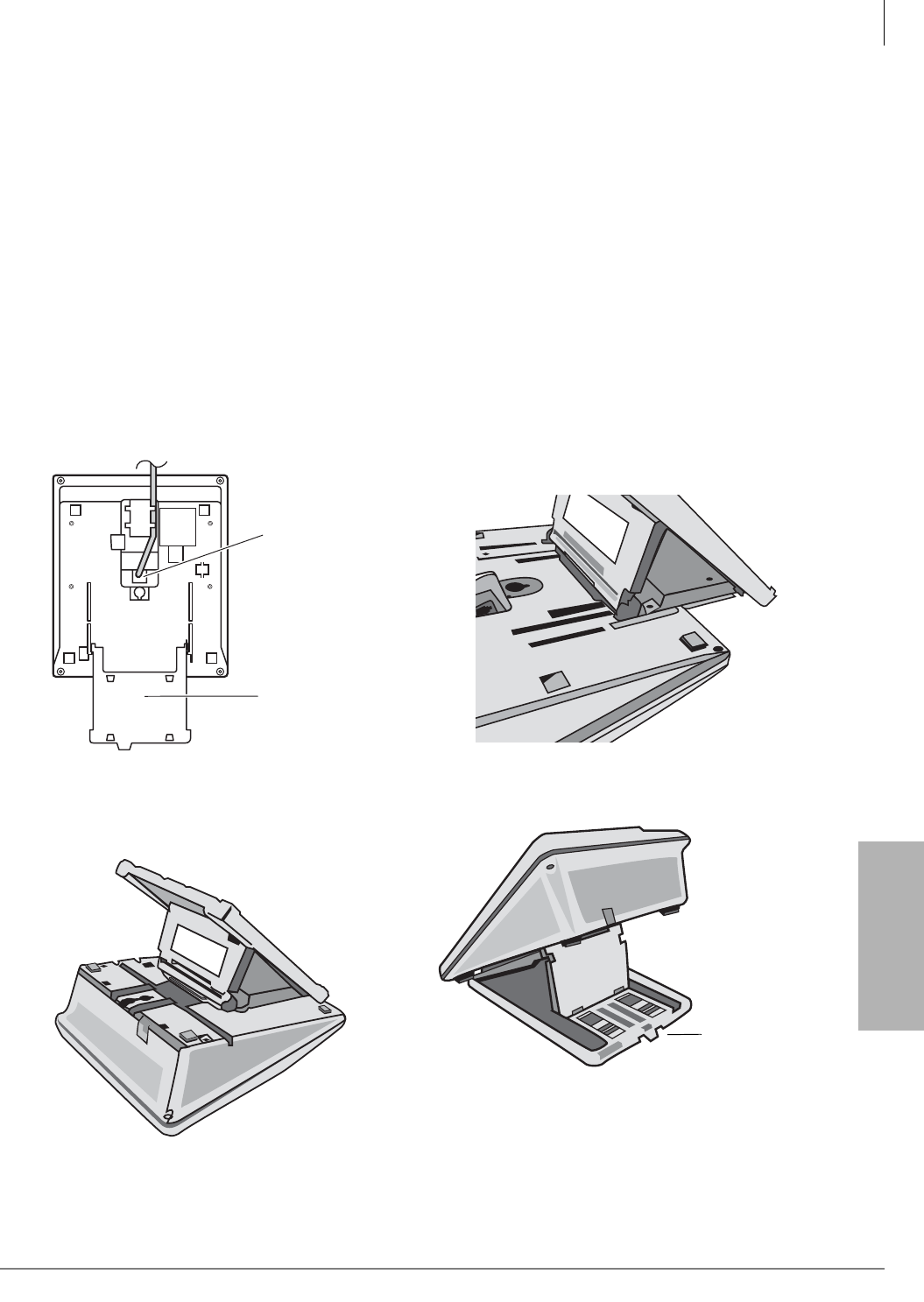
Station Apparatus
Tilt Stands
Strata CTX I&M 06/04 11-23
Station Apparatus
Tilt Stands
This section explains how to attach desktop tilt stands to 3000-series or 2000-series digital DKTs,
the IPT1020-SD or to a DSS console. Use Tilt Stand model “BTSD” (not BTSA) with a standalone
DKT, IPT or DSS.
³To attach a Tilt Stand to a 3000-series DKT, IPT1020-SD or DSS
1. Plug the phone jack into the bottom of the phone or DSS console.
2. Slide the Address Tray out, then gently squeeze the tray and remove it (see Figure 11-16).
3. Pull the top of the Tilt Stand so that it’s open at an angle.
4. Slide the Tilt Stand into the former Address Tray holder. (The Stand should catch under the
front tray holder notches.) Push Stand in until it snaps into place (see Figures 11-17 and 11-18).
5. Push in the Lock Release to adjust the tilt angle (0, 10, 20 or 30 degrees, see Figure 11-19).
6. Insert the Address Tray back into its holder.
Figure 11-16 Bottom View of Telephone Figure 11-17 Slide Tilt Stand into Address Tray Slot
Notice:
If you change the tilt stand angle, hold the telephone
in your hand when you push the release button so the
unit does not fall onto the stand.
Figure 11-18 Tilt Stand “Snaps” In Figure 11-19 Telephone on a Tilt Stand
5448
Plug in
phone jack
Squeeze and
slide out the
address tray
5846
5847
5848
Lock Button
Release
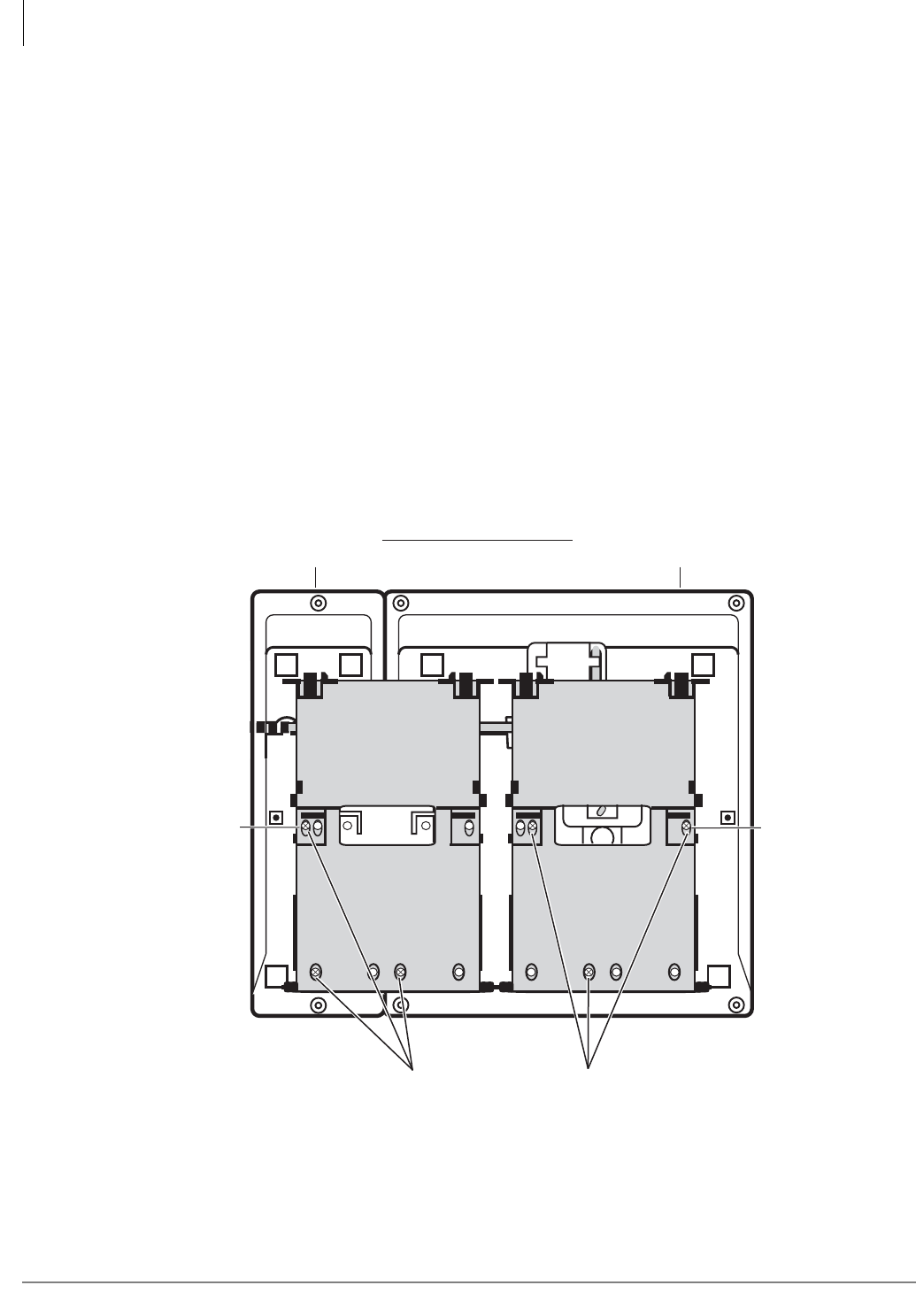
Station Apparatus
Tilt Stands
11-24 Strata CTX I&M 06/04
Tilt Stand Installation with Add-on Modules
This section explains how to attach a tilt stand to a digital or IP telephone with one or two ADMs.
Follow the instructions for the appropriate number of ADMs. Use Tilt Stand model “BTSA” (not
“BTSD”) for telephones with one or two ADMs.
³To attach a digital or IP telephone with one ADM to a Tilt Stand
1. Complete the steps under “To install DADMs” on page 11-21.
2. Make sure bottom phone jack is plugged in.
3. Remove Tilt Stand from Tilt Stand Base (see Figure 11-21).
4. Place the spacers on the outer holes, as shown (see Figure 11-22).
5. Attach Tilt Stand to bottom of telephone with screws (see Figure 11-20).
6. Reinstall the Tilt Stand Base: Fit the Tilt Stand Base over the Tilt Stand so that the “bottom
pegs” fit into the holder. Adjust Tilt Stand so that the “top pegs” fit into the top Tilt Stand Base
holes (see Figure 11-21). Do this to both stands.
7. Pull up on the Tilt Stand Bases so that they open to the maximum angle (30 degrees).
8. Push in the Release button to adjust the tilt angle (0, 10, 20 or 30 degrees) of each Tilt Stand.
Figure 11-20 Attach Tilt Stands to DKT/IPT and One ADM
6506
1 PHONE
1 ADM
PHONE PHONE
PHONE
Spacer
Spacer
2 ADM 2 ADM
1 ADM
1 ADM
2 ADM
1 ADM
2 ADM
1 ADM
2 ADM
1 ADM
2 ADM
PHONE
PHONE
1 ADM + 1 DKT (or 1 IPT)
Put in three screws in the
positions marked “PHONE.”
Insert a spacer beneath each stand as shown. Put in the
screw with the spacer first. Then insert the other two screws.
Put in three screws in the
positions marked “1ADM.”
ADM DKT/IPT
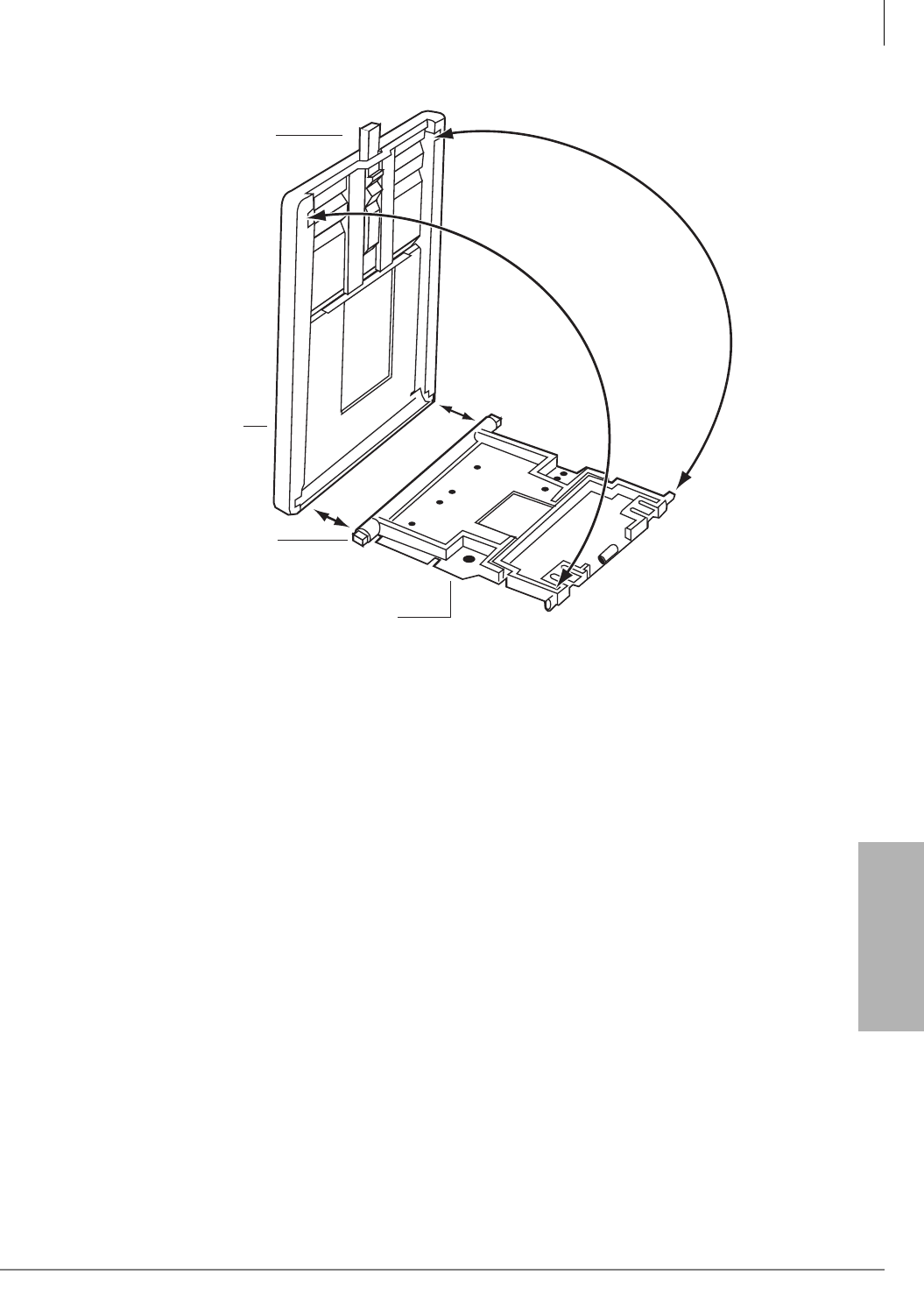
Station Apparatus
Tilt Stands
Strata CTX I&M 06/04 11-25
Station Apparatus
Figure 11-21 Release Adjustment Button
5475
Tilt Stand Base
Release
Button
Tilt Stand
Fit Tilt Base onto
Tilt Stand Bottom Pegs
To remove the base
from the tilt stand:
1. Push in lock release.
2. Open the tilt stand 90
degrees.
3. Pull the Base away
from the stand to
remove it.
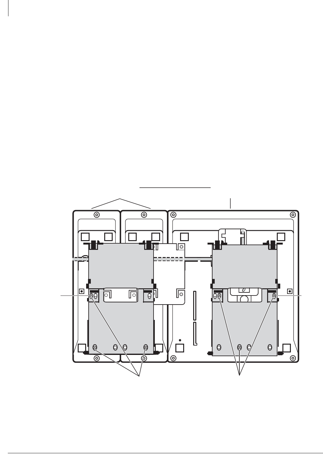
Station Apparatus
Tilt Stands
11-26 Strata CTX I&M 06/04
Tilt Stand for DKT/IPT + Two ADMs
Use Tilt Stand models “BTSA” for DKTs or IPTs with one or two ADMs.
³To attach a Tilt Stand to a 3000-series DKT, IPT1020-SD with two ADMs
1. Complete the steps under “To install DADMs” on page 11-21.
2. Make sure bottom phone jack is plugged in.
3. Remove Tilt Stand from Tilt Stand Base (see Figure 11-21).
4. Place the spacers on the outer holes, as shown (see Figure 11-22).
5. Attach Tilt Stand to bottom of DKT with screws.
6. Reinstall the Tilt Stand Base: Fit the Tilt Stand Base over the Tilt Stand so that the “bottom
pegs” fit into the holder. Adjust Tilt Stand so that the “top pegs” fit into the top Tilt Stand Base
holes. Do this to both stands.
7. Pull up on the Tilt Stand Bases so that they open to the maximum angle (30 degrees). See
Figure 11-23.
8. Push in the Lock Release button to adjust the tilt angle (0, 10, 20 or 30 degrees) of each Tilt
Stand.
Figure 11-22 Attach Tilt Stands to DKT/IPT with Two ADMs
6527
PHONE
1 ADM
(A)
Spacer
2 ADM
1 ADM
2 ADM PHONE
PHONE
DKT
DKT
1 ADM
2 ADM
1 ADM
2 ADM PHONE PHONE
PHONE
(A)
Spacer
2 ADM
1 ADM
1 ADM
2 ADM
1 ADM
2 ADM
2 ADMs + 1 DKT (or 1 IPT)
Put in three screws in the
positions marked “PHONE.”
Insert a spacer beneath each stand as shown. Put in the
screw with the spacer first. Then insert the other two screws.
Put in three screws in the
positions marked “2ADM.”
ADMs DKT/IPT
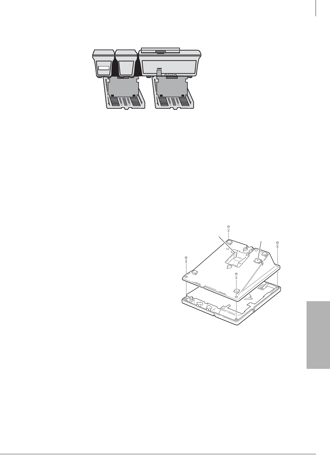
Station Apparatus
Telephone Wall Mounting
Strata CTX I&M 06/04 11-27
Station Apparatus
Figure 11-23Tilt Stands in Raised Position for DKT and Two ADMs
Telephone Wall Mounting
This section explains how to mount digital telephones to a wall. See the manufacturer’s
documentation for instructions on mounting standard phones.
Notes
●Digital telephones equipped with BPCIs or PDIU-DI2s cannot be wall mounted.
●DKT3014-SDL equipped with a BHEU cannot be wall-mounted.
●2000-series digital telephones with headsets can only be wall mounted with an HHEU2.
³To mount digital telephones
Refer to Figures 11-24~11-26 and the following
steps.
1. Loosen the captive screws, and remove the
telephone base.
2. Using a suitable cutter, remove the handset
hanger from the base.
3. Insert the handset hanger in the slot on the front
of the phone. The hanger fits in the notch on the
handset cradle.
4. Rotate the telephone base 180 degrees and
secure it to the telephone with its four captive
screws.
Note Tilt up the LCD of the DKT3014-SDL before
fixing the base.
5849
Handset Hanger
Plastic Tab
1478
Figure 11-24 Removing the Telephone Base
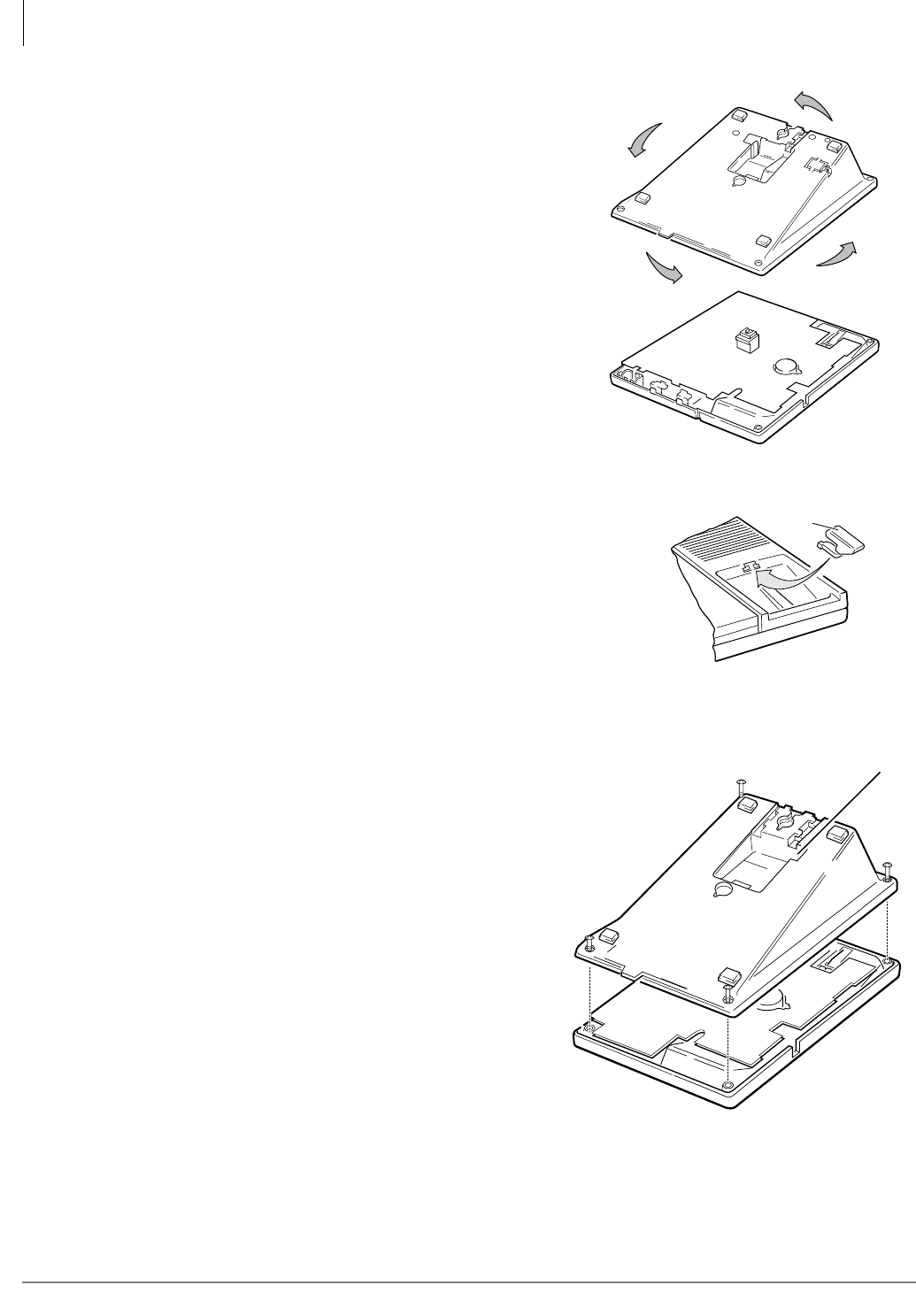
Station Apparatus
Telephone Wall Mounting
11-28 Strata CTX I&M 06/04
5. Connect the phone to the wall modular connector
with a cord approximately four inches long
(available at most telephone supply companies).
6. Route the cord into the hollow portion of the base.
7. Mount the phone on the wall mounting modular
connector plate.
³To wall mount DKT3001 or DKT2001 digital
SLTs
1. Loosen the screws, and remove the telephone
base.
2. Using a suitable cutter, remove the handset
hanger from the base.
3. Insert the handset hanger in the slot on the
front of the phone. The hanger fits in the
notch on the handset cradle.
4. Rotate the telephone base 180 degrees and
secure it to the telephone with its four
screws.
5. Connect the phone to the wall modular
connector with a cord approximately four
inches long (available at most telephone
supply companies).
6. Route the cord into the hollow portion of the
base.
7. Mount the phone on the wall mounting
modular connector plate. For instructions for installing and programming the DKT2001, see
“Digital Single Line Telephone (DKT2001 only)” on page 11-57.
Figure 11-25 Wall Mounting Base Rotation
1480
Handset
Hanger
1479
Figure 11-26 Handset Hanger
Handset Hanger
3633
Figure 11-27 Removing the Telephone Base

Station Apparatus
Direct Station Selection (DSS) Console/System Connection
Strata CTX I&M 06/04 11-29
Station Apparatus
Direct Station Selection (DSS) Console/System
Connection
The DSS console can be connected to a BDKU/BKDS or
PDKU on any circuit. DSS consoles are associated with
digital telephones via system programming. This section
provides instructions on how to install the consoles.
DSS Console Connections
DSS consoles are connected to BDKU/BDKS or PDKU
PCBs using standard twisted single-pair or two-pair jacketed
telephone cable (maximum 1000 feet, 303 meters) is used for
the connection.
To accommodate the DSS console connection, the
instrument end of the cable should be terminated in a
modular station connector block (RJ11). Refer to Chapter 10
– MDF PCB Wiring for wiring/interconnecting details.
Notes
●DSS console cable runs must not have cable splits (single or double), cable bridges (of any
length) or high resistance or faulty cable splices.
●See the appropriate Installation chapter for secondary protection information and loop limits.
CAUTION! When installing the DDSS cable, do not run the cables parallel if they are
within three feet of an AC power line. AC power lines should be crossed at
right (90°) angles only. In particular, avoid running station wire pairs near
devices that generate electrical noise, such as neon or fluorescent light
fixtures.
Standard Telephones
This section explains how to connect standard telephones to the Strata CTX670 system. Toshiba
does not provide standard telephones. Whenever standard telephones are mentioned in this
manual, it refers to 500- and 2500-type standard telephones.
Note Before proceeding, see warning and caution notes in “3000-series Telephone Installation”
on page 11-2.
Standard telephones connect to circuits on the Standard Telephone Interface PCBs: RSTU,
RSTU2, RDSU/RSTS and PSTU via the MDF with standard twisted-pair jacketed telephone
cable. (See single-pair wiring in Chapter 10 – MDF PCB Wiring for more details.)
The standard telephone cable’s overall loop resistance, connected on- or off-premises, is 300 ohms
max. for PSTU; 600 ohms for RSTU and RDSU/RSTS with -24VDC (no R48S), and 1200 ohms
for RSTU and RDSU/RSTS with -48VDC (R48S installed on RSTU, RSTU2, or RDSU PCB),
including telephone resistance. This applies to all devices connected to standard telephone circuits.
A standard telephone connected off-premises via the telephone network should interface with
OL13A, OL13B, or OL13C lines (or equivalent) and connect to an RJ21X, FIC jack or equivalent.
5842
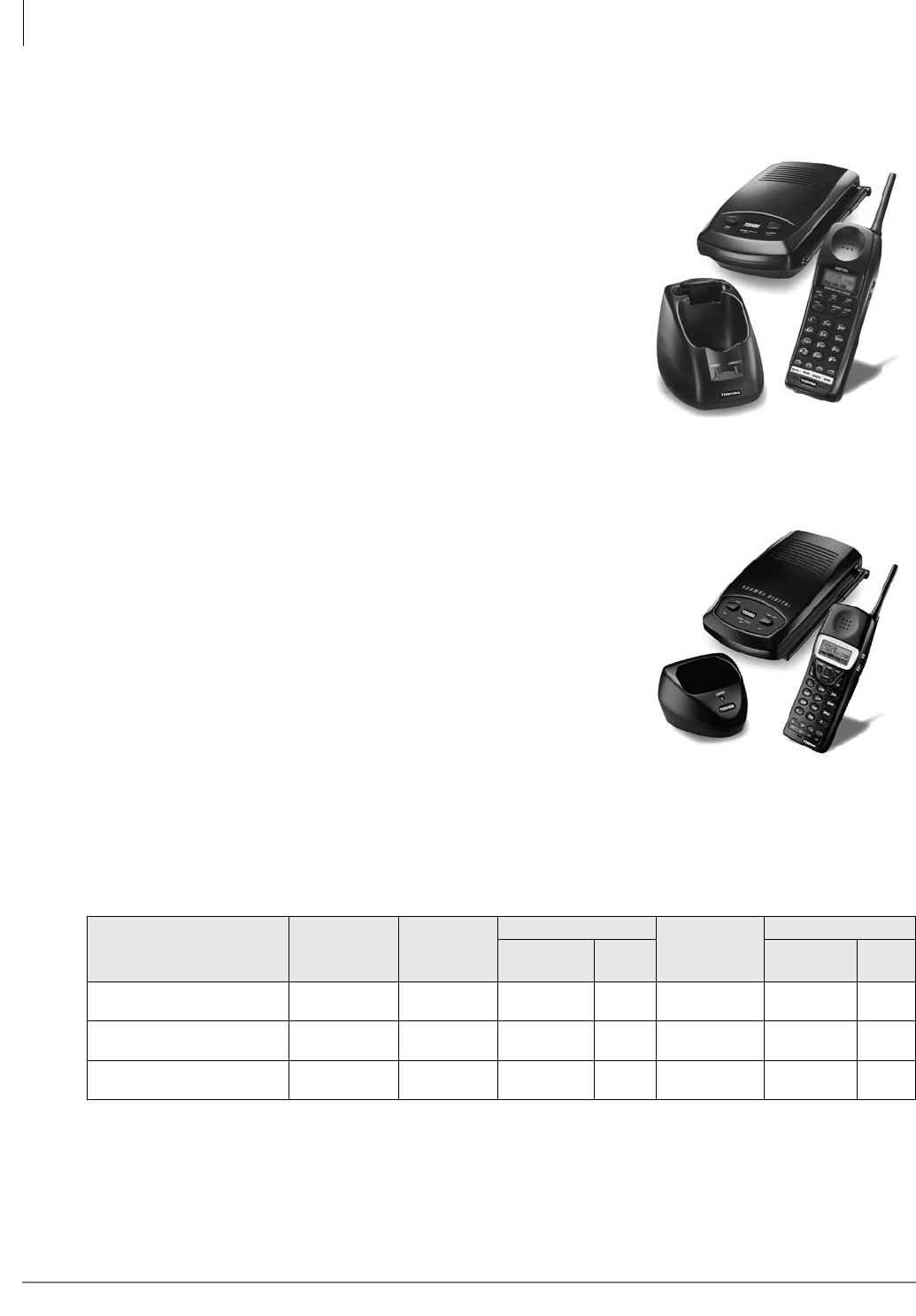
Station Apparatus
Cordless Digital Telephones
11-30 Strata CTX I&M 06/04
Cordless Digital Telephones
Toshiba offers two cordless digital telephone models, the
DKT2204-CT and the DKT2304-CT (shown right). The
DKT2204-CT uses digital spread spectrum and the
DKT2304-CT uses digital narrow band technology.
Some of the features for both cordless models include:
• Liquid Crystal Display (LCD) that wraps using two lines,
total of 32 characters
• Ringer and handset volume control
• Single button access to: Conference, Hold, Redial,
Message and Transfer features
• Four programmable function buttons
• Charging stand
• AutoStandby
• AutoTalk
• Vibrate ringer alert
• Out-of-range protection
• Low-battery protection system
• Headset jack (2.5mm)
• Stand-alone or DKT operation
• High quality ultra-secure conversation with 32Kbps
Adaptive Differential Pulse Code Modulation (ADPCM)
voice code combination.
• Three ring tones
Cordless Telephone Compatibility
The chart below shows the compatibility of Strata DKT2204-CT and the DKT2304-CT with Strata
CTX digital line cards. The BDKU PCB has a switch for BDKU or PDKU mode. A “standalone”
cordless phone connects directly to a digital line circuit without an associated DKT.
Notes
●The handset and base unit of each cordless telephone is equipped with the same security code.
In order for the handset to operate, it must be installed with the matching base unit.
●DKT3000 telephones must be set to operate in the DKT2000 mode when used with the
DKT2204-CT and the DKT2304-CT (see “DKT2000 Mode On/Off” on page 11-19).
PCB System Type
BDKS D2 DKT-2204/ DKT-2204 w/ DKT DKT-2304 DKT-2304 w/ DKT
Jumper Plug (Stand
alone) Cordless DKT (Stand
alone) Cordless DKT
PDKU in Strata CTX or
DK
Not
Applicable OK OK OK OK OK OK
BDKU in Strata DK PDKU
position OK OK OK OK OK OK
BDKU/BDKS in Strata
CTX
BDKU
position OK OK See
Notes OK OK See
Notes
6828
Figure 11-28 DKT2204-CT
6829
Figure 11-29 DKT2304-CT

Station Apparatus
Cordless Telephone Installation
Strata CTX I&M 06/04 11-31
Station Apparatus
Cordless Telephone Installation
Step 1: Review Safety Instructions
³Read and understand all product instructions.
³Follow all warnings and instructions marked on the product.
³Cleaning precautions:
• Unplug this product from the wall outlet before cleaning.
• Do not use liquid cleaners or aerosol cleaners.
• Use a dry cloth for cleaning.
³Do not use this product near water; for example, near a sink, or in any wet area.
³Never spill liquid of any kind on the product.
³Do not place this product on an unstable cart, stand, or table. The telephone could fall, causing
serious damage to the unit.
³To protect the product from overheating, do not:
• Block or cover any slots or openings in the base unit.
• Place near or over a radiator or heat register.
• Place in an enclosed cabinet unless proper ventilation is provided.
³Operate this product only from the type of power source indicated on the marking label.
³Do not allow anything to rest on the power cord. Do not locate this product where the cord
could be damaged by persons walking on it.
³Do not overload wall outlets and extension cords because it could result in fire or electrical
shock.
³Never push objects of any kind into the base unit slots, as the objects could touch dangerous
voltage points or short out parts that could cause fire or electric shock.
³To reduce the risk of electric shock, do not disassemble this product. Opening or removing
covers could expose you to dangerous voltages or other risks. Incorrect re-assembly can cause
electric shock when the appliance is subsequently used. Contact qualified service personnel
when service or repair work is required.
³Unplug this product from the wall outlet and refer servicing to qualified service personnel
under the following conditions:
• When the power supply cord is damaged or frayed.
• If liquid has been spilled into the product.
• If the product has been exposed to rain or water.
• If the product does not operate normally when following the operating instructions. Adjust
only those controls that are covered by the operating instructions. Improper adjustment of
other controls may result in damage, and will often require extensive work by a qualified
technician to restore the product to normal operation.
WARNING! Toshiba DOES NOT represent this unit to be waterproof. To
reduce the risk of fire, electrical shock, or damage to the unit, DO
NOT expose this unit to rain or moisture.

Station Apparatus
Cordless Telephone Installation
11-32 Strata CTX I&M 06/04
• If the product has been dropped, or the cabinet has been damaged.
• If the product exhibits a distinct change in performance.
³Do not use the telephone to report a gas leak in the vicinity of the leak.
³Unplug all electrical appliances when you know an electrical storm is approaching. Lightning
can pass through the wiring and damage any device connected to it. This telephone is no
exception.
CAUTION! Changes or modifications to this product not expressly approved by Toshiba, or
operation of this product in any way other than as detailed by this User Guide,
could void your authority to operate this product.
WARNING! Do not attempt to unplug any appliance during an electrical storm.
WARNING! To reduce the risk of fire and/or personal injury from the Nickel-
Cadmium battery, follow these instructions:
³Use only battery model BT-2499 (DKT2204-CT) or BT930
(DKT2304-CT). Use of any other battery could cause a safety
hazard.
³Do not dispose of the battery in a fire. The cell will explode.
Under federal, state and local laws, it could be illegal to
dispose of old batteries by placing them in the trash. Check
with your local government for information on where to recycle
or dispose of old batteries. If you cannot find the information
you need, contact Toshiba for assistance.
³Do not remove or damage the battery casing.
³Do not short circuit the battery. Exercise care in handling the
battery in order not to short the battery with rings, bracelets,
and keys or other conductive materials. The battery or
conductor could overheat and cause burns.
³Charge the battery only in accordance with the instructions
and limitations specified in the instruction manual provided for
this product.
³Do not charge the Rechargeable battery in any charger other
than the one designed to charge it as specified in this user
guide. Using another charger may damage the battery, or
cause the battery to explode.
³Observe proper polarity orientation between the battery and
charging unit.

Station Apparatus
Cordless Telephone Installation
Strata CTX I&M 06/04 11-33
Station Apparatus
Step 2: Select Location
1. Select a location that is not subject to excessive heat or humidity. Keep the base unit and
handset away from sources of electrical noise, such as motors and fluorescent lighting.
2. Determine if the base unit will sit on your desk or be wall mounted. If wall mounted, go to Step
6: “Wall Installation (Optional)” on page 36.
3. Place the base unit on a desk or tabletop near a standard 120VAC outlet and within reach of the
Strata CTX digital line connection.
Important! Place the base unit to the right of the DKT. If placed on the left, the cordless antenna
picks up a tone due to its close proximity to the DKT speaker and electronic parts.
Step 3: Place DKT3000-series Telephones into 2000-Mode
You must place your DKT3000-series telephone into 2000-mode before connecting the cordless
telephone; otherwise, the 3000-series telephone will not work.
In 2000-mode, the DKT3000 telephone operation changes are:
•Only 16 characters by two lines display on the LCD.
•LCD Feature button does not work
•Spdial button does not work
³To change DKT3000-series telephones into 2000-mode
1. On the DKT3000 telephone, press 3+6+9+Hold (simultaneously).
2. Press #.
3. Press FB7 (or FB10 on the DKT3014). LED On = 2000 mode. LED Off = 3000 mode.
Note Flexible Buttons (FB) are numbered from the bottom up and left to right.
FB7 for example would be the seventh button up on the left.
4. Press Hold.
5. Lift the handset to exit programming mode. Wait a few seconds for the telephone to reset itself.
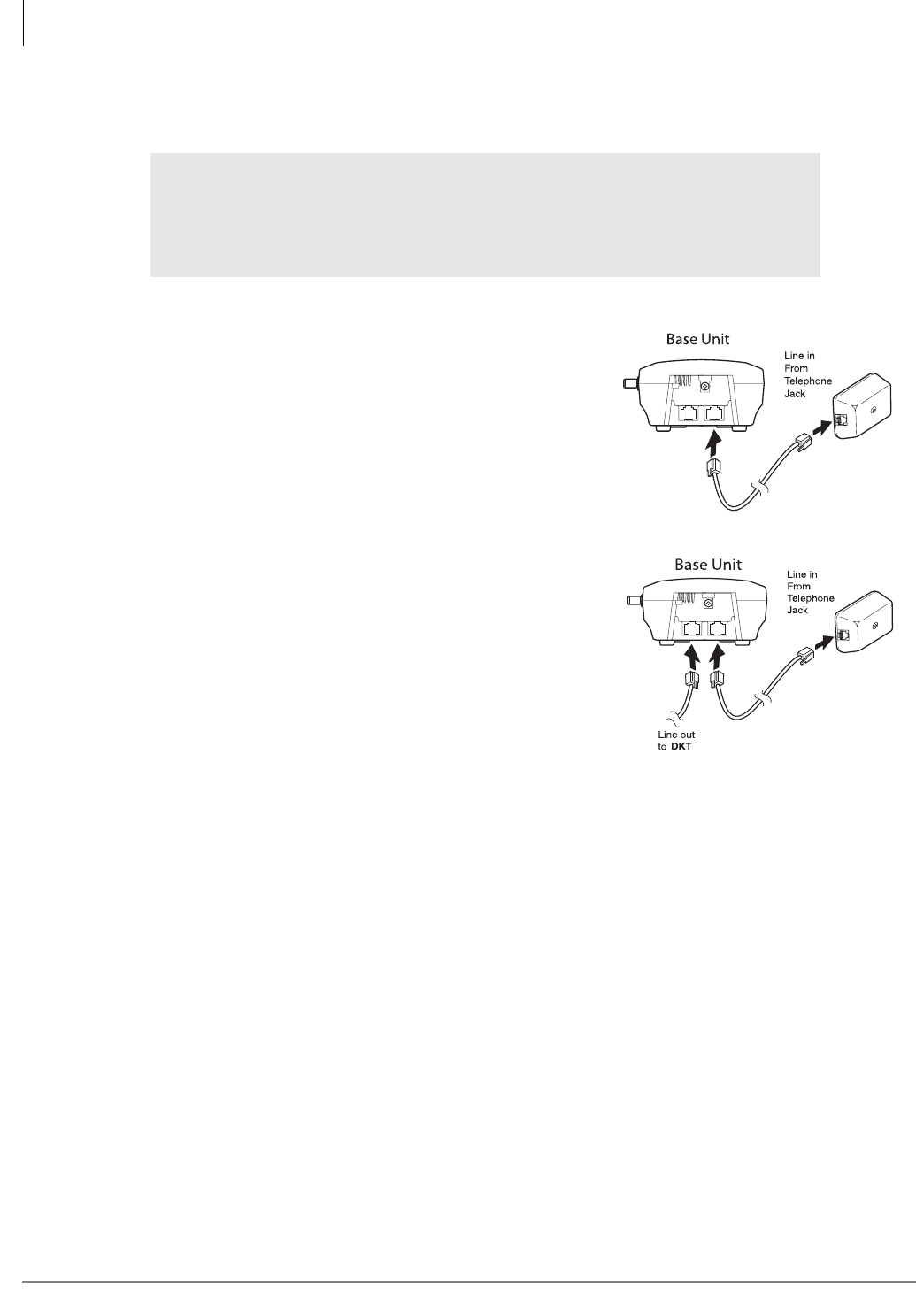
Station Apparatus
Cordless Telephone Installation
11-34 Strata CTX I&M 06/04
Step 4: Connect Telephone Cables
Your cordless telephone must be connected to a digital telephone PBX port.
³To connect as a stand-alone telephone
³Connect the modular jack labeled “Line In” directly
to the telephone wall jack using one of the supplied
cables (shown at right).
³To connect to a Strata DKT
1. Unplug the cable from the DKT and plug into the
“Line In” jack of cordless telephone base unit
(shown at right).
2. Plug the additional two-foot cable into the “Line
Out” jack of the base unit and into the DKT jack
located on the bottom of the telephone.
WARNING! ³Never install telephone wiring during a lightning storm.
³Never touch uninsulated telephone wires or terminals unless
the telephone line has been disconnected at the network
interface.
³Use caution when installing or modifying telephone lines.
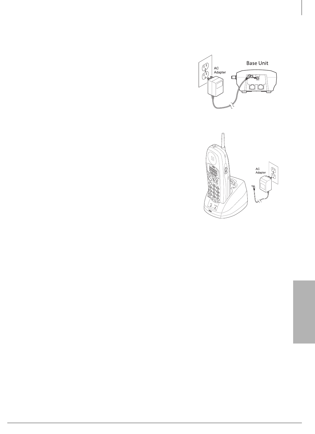
Station Apparatus
Cordless Telephone Installation
Strata CTX I&M 06/04 11-35
Station Apparatus
Step 5: Connect and Apply Power
Base Unit
1. Plug the AC adapter cord into the AC adapter input jack on
the base unit (shown at right).
2. Plug the AC adapter into a standard 120VAC wall outlet.
3. Check to see that the power LED is on.
Charging Unit
1. Plug the AC adapter cord into the input jack on the charging
unit (shown at right).
2. Plug the AC adapter into a standard 120VAC wall outlet.
3. Check to see that the CHARGE LED is on.
Note You can place the handset in the charging unit with or
without the belt clip attached.
Important!
•Use only the supplied AC adapter.
•If the CHARGE LED on the charging unit and/or the
POWER LED on the base unit do not light, return everything
to your Authorized Dealer.
•Always route the power cord where it is not a trip hazard, and
where it cannot become chafed and create a fire or electrical
hazard.
DKT2204-CT (pictured)
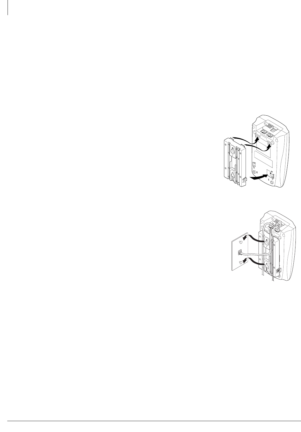
Station Apparatus
Cordless Telephone Installation
11-36 Strata CTX I&M 06/04
Step 6: Wall Installation (Optional)
Important! You must place your DKT3000-series telephone into 2000-mode before connecting
the cordless telephone; otherwise, the 3000-series telephone will not work. See
“Place DKT3000-series Telephones into 2000-Mode” on page 33 for instructions.
Standard Wall Plate Mounting
These telephones are designed to be mounted on a standard wall plate. To attach the wall mount
stand to the base unit:
1. Select a wall location near a 120VAC outlet and within reach of the Strata CTX digital line
connection.
2. Slide the wall mount stand into the notches at the top of the
base unit, push the wall mount stand down and snap it into
place (shown right).
3. Plug the AC adapter into the base unit.
4. Place the AC adapter cord inside the molded channel of the
wall mount stand.
5. Plug one end of the telephone cord into the LINE jack on
the base unit. Optionally, plug one end of a Strata DKT
telephone into the PHONE jack. Then place the telephone
cord(s) inside the molded channel(s) on the bottom of the
wall mount stand.
6. Plug the other end of the telephone cord into the modular wall jack.
7. Place the base unit on the posts of the wall plate and push down
until it’s firmly seated (shown right).
8. Plug the AC adapter into a standard 120VAC wall outlet.
Note Do not use an outlet controlled by a wall switch.
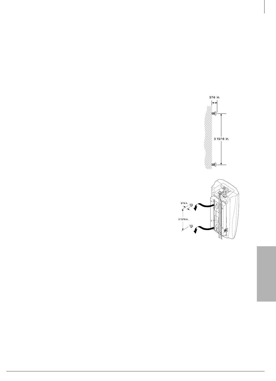
Station Apparatus
Cordless Telephone Installation
Strata CTX I&M 06/04 11-37
Station Apparatus
Direct Wall Mounting
If you do not have a standard wall plate, you can mount your telephone directly on a wall. Before
mounting your telephone, consider the following:
•Select a location away from electrical cables, pipes, or other items behind the mounting
location that could cause a hazard when inserting screws into the wall.
•Make sure the wall material is capable of supporting the weight of the base unit.
•Use #10 screws with anchoring devices suitable for the wall.
³To wall mount the base unit
1. Insert two mounting screws 3-15/16 inches apart. Allow about 3/16 of
an inch between the wall and screw heads for mounting the telephone
(shown right).
2. Plug and secure the AC adapter cord by following Steps 2 and 3 of
the “Standard Wall Plate Mounting” on page 36.
3. Plug one end of the telephone line cord into the LINE jack on the base
unit. Optionally, plug one end of a Strata DKT telephone into the
PHONE jack. Then place the telephone cord(s) inside the molded
channel(s) on the bottom of the wall mount stand.
4. Place the base unit on the posts of the wall screws and push
down until it’s firmly seated.
5. Plug the other end of the telephone cord into a telephone wall
jack.
6. Plug the AC adapter into a standard 120VAC wall outlet by
following Step 7 of the Standard Wall Plate Mounting.
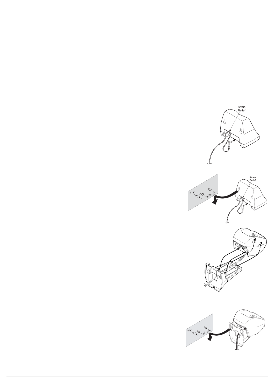
Station Apparatus
Cordless Telephone Installation
11-38 Strata CTX I&M 06/04
Charging Unit Wall Mounting
The charging unit is also designed to be wall mounted. Before mounting your charging unit,
consider the following:
•Select a location away from electrical cables, pipes, or other items behind the mounting
location that could cause a hazard when inserting screws into the wall.
•Make sure the wall material is capable of supporting the weight of the charging unit.
•Use #10 screws with anchoring devices suitable for the wall material where the charging unit
will be placed.
DKT2204-CT
1. Insert two mounting screws 1-9/10 inches apart. Allow about 3/
16 of an inch between the wall and screw heads for mounting the
telephone.
2. Plug the AC adapter into the charging unit as previously
described. Wrap the AC adapter cord around the strain relief
(shown right).
3. Place the charging unit on the posts of the wall screws and
push down until it’s firmly seated (shown right).
4. Plug the AC adapter into a standard 120VAC wall outlet.
DKT2304-CT
1. Insert two mounting screws 1-1/5 inches apart. Allow
about 3/16 of an inch between the wall and screw heads for
mounting the telephone (shown right).
2. Pass the one end through the hole of the wall mount stand and
plug it into the charging unit. Wrap the AC adapter cord around
the strain relief.
3. Slide the wall mount stand into the notches on the bottom of the
charging unit.
4. Place the charging unit on the posts of the wall screws and
push down until it’s firmly seated (shown right).
5. Plug the AC adapter into a standard 120VAC wall outlet.
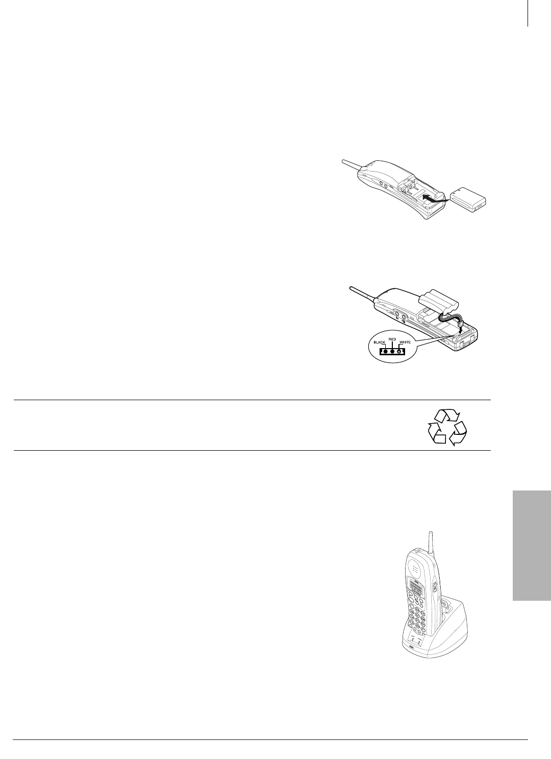
Station Apparatus
Cordless Telephone Installation
Strata CTX I&M 06/04 11-39
Station Apparatus
Step 7: Raise the Base Unit Antenna
³Before using your handset, raise the base unit antenna to the vertical position.
Step 8: Install Handset Battery Pack
DKT2204-CT
1. Remove the battery cover by pressing the latch and sliding the cover down and off the handset.
2. Slide the battery pack down into the handset (shown right).
3. Securely close the battery compartment cover by sliding it
up until it snaps into place.
DKT2304-CT
1. Remove the battery cover by pressing the latch and sliding
the cover down and off the handset.
2. Connect the battery pack connector observing correct
polarity to the jack inside the battery compartment. Do not
exert any force on this connection. It could cause damage
to the battery or handset. Once you are certain that you
have made a good connection, then insert the battery pack
into the battery compartment. Do not pinch the wires
(shown right).
3. Securely close the battery compartment cover by sliding it
up until it snaps into place.
CAUTION! Rechargeable Nickel-Metal-Hydride batteries must be disposed
of properly.
4.
Step 9: Charge Batteries for First Time
Important! Before using your handset, the battery must be continuously charged for five hours.
1. Place the handset in the charging unit (shown at right).
2. Ensure that the CHARGE LED lights. If it does not, make sure that
the AC adapter is plugged in and that the handset is making good
contact with the charging unit contacts.
DKT2204-CT Charging
Unit (pictured)
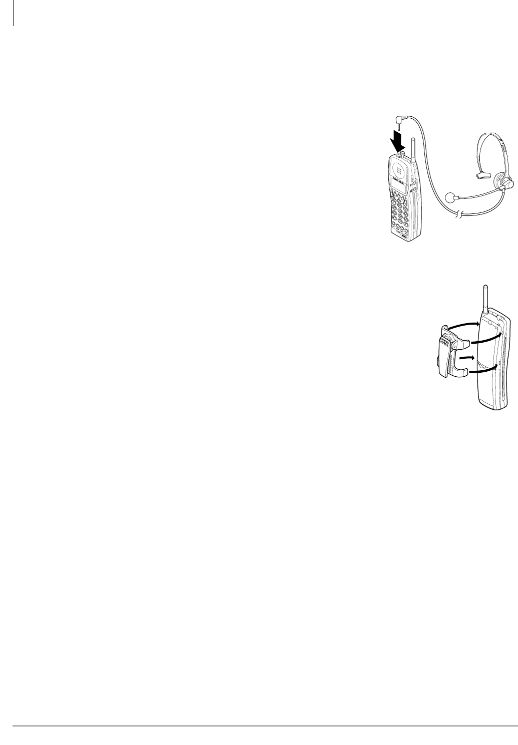
Station Apparatus
Cordless Telephone Installation
11-40 Strata CTX I&M 06/04
Step 10: Install Headset (Optional)
The optional headset provides a hands-free option. With the headset installed, you can use the belt
clip to carry the handset and conduct a conversation. All feature operations remain the same except
the handset earphone and microphone are disconnected.
³Open the cover over the headset jack that is located on the top
of the handset and plug in the headset as shown at right.
Important! Only use headsets especially designed or modified
for use with radio frequency equipment.
Step 11: Attach Belt Clip (Optional)
Note The belt clip is designed to fit snugly onto the handset.
1. Snap the tab out of the belt clip notch on the top of the handset.
2. Slide the belt clip into the space where the belt clip tab was, carefully
aligning the belt clip sides to the notches.
3. Press firmly until it snaps into place.
4. Use the belt clip to attach the handset to your belt or pocket.
³To remove the belt clip
1. Press the retaining clip in toward the belt clip blade and slide the clip up at
the same time.
Reinstall the cover tab.

Station Apparatus
Cordless Telephone Troubleshooting and Specifications
Strata CTX I&M 06/04 11-41
Station Apparatus
Cordless Telephone Troubleshooting and
Specifications
This section covers these topics:
•Troubleshooting
•Simultaneous conversation channels
•Range and performance
•Radio interference
•Telephone line problems
•More than one cordless telephone
•Privacy
•Specifications
Troubleshooting
If your cordless telephone is not performing to your expectations, try the suggestions in Table 1. If
you are still unable to resolve the problem, contact your telephone System Administrator.
Important! Do not attempt to service this unit yourself. All service must be done by qualified
service personnel.
Table 1 Troubleshooting Suggestions
Condition Suggestion
CHARGE LED does not light when
handset is placed on charging unit.
• Make sure the AC adapter is plugged into the charging
unit and wall outlet.
• Make sure handset is properly seated in charging unit.
• Make sure the battery pack is properly placed in the
handset.
• Make sure that the charging contacts on the handset
and charging unit are clean.
Conversation is interrupted frequently.
• Make sure that the base unit antenna is fully vertical.
• Move closer to the base unit.
• Check for low battery warning.
Warning tone and NO SERVICE
message.
• Move closer to the base unit.
• Make sure the AC adapter is plugged into the base unit
and wall outlet.
Handset doesn’t ring.
• The battery pack may be weak. Charge the battery pack
for five~six hours.
• Make sure the base unit antenna is fully vertical.
• The handset may be too far away from the base unit.
• The ringer may be set to Off.
• Make sure the AC adapter is plugged into the base unit
and wall outlet.
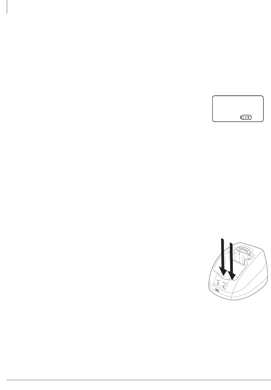
Station Apparatus
Troubleshooting
11-42 Strata CTX I&M 06/04
Low Battery
Your cordless telephone comes equipped with one rechargeable battery:
•DKT2204-CT: BT2499 battery that provides six hours of talk and four days of standby time
(fully charged).
•DKT2304-CT: BT930 battery that provides seven hours of talk and five days of standby time
(fully charged).
A “fast charge” in the handset and a “trickle charge” in the charging unit enables the extended talk
and standby times.
When the battery is low, the Battery icon displays on the LCD
(shown right) and the handset beeps. Low battery symptoms are:
•On a call
• All buttons and functions operate
• Handset beeps once every three seconds
Note To continue your call, you must replace the battery pack within 20 seconds.
•In standby mode
• None of the buttons operate
• LCD messages are cleared
• Handset beeps every 15 seconds for three minutes
• Cannot make or receive call
To restore your battery capacity, return the handset to the charging unit for charging or replace the
handset battery with a charged one. If the handset is on the charging unit for one minute, battery
low condition is cancelled. The Battery icon is turned Off and battery low tone stops.
For more information on installing and charging the battery, see Step 8: “Install Handset Battery
Pack” on page 39.
Cleaning Charging Unit Contacts
To maintain a good charge, it is important to clean all charging
contacts on the handset, spare battery pack (DKT2204-CT only) and
charging unit about once a month (shown right). Use a pencil eraser
or a soft dry cloth. Do not use any liquids or solvents.
DKT2204-CT Charging
Unit (pictured)

Station Apparatus
Simultaneous Conversation Channels
Strata CTX I&M 06/04 11-43
Station Apparatus
Charging Spare Battery Packs (DKT2204-CT only)
The charging unit of your cordless telephone is equipped to charge the spare battery pack with or
without the handset in the front slot.
1. Slide the spare battery pack into the second slot in the charging unit
until the retaining clip snaps over the top of the pack.
2. Make sure the BATT CHARGE indicator lights. If the BATT
CHARGE indicator doesn’t light, check to see that the AC adapter is
plugged in, and that the battery pack is making good contact with the
unit’s charging contacts.
Note Charge the battery pack without interruption for 12~15 hours.
3. When charging is complete, press out on the latch and remove the
battery pack for use. Or, if you don’t need the battery pack immediately,
leave it in the charging compartment. It will not overcharge.
Simultaneous Conversation Channels
DKT2204-CT
The DKT2204-CT cordless digital telephone has 10 operating channels available.
A common misconception is that this limits a customer to 10 cordless telephones. This is not the
case. Each cordless digital telephone can operate on any of the 10 channels. When you turn on a
cordless digital telephone, the telephone selects an available channel within its’ range. In a given
cordless range, 10 simultaneous calls can be made. In most businesses, it is unlikely that all 10
channels will be in use at the same time. Typically 20 to 30 telephones can share the 10 channels.
Another factor is the distribution of the telephones in a facility. If your cordless digital telephones
are disbursed throughout a facility, there should not be contention for channels. If there are more
than 10 cordless digital telephones in one area and 10 users are using their cordless telephones, an
11th user would not be able to connect at that time.
DKT2304-CT
The DKT2304-CT cordless handset has 30 operating channels available. A common
misconception is that this limits a customer to 30 handsets. This is not the case. Each handset can
operate on any of the 30 channels because each one selects an available channel within its range.
In a given range, 30 simultaneous calls can be made.
Another factor is the distribution of the telephones in a facility. If your handsets are disbursed
throughout a facility, there should not be contention for all channels. If there are more than 30 in
one area and 30 users are using their handsets, the 31st user would not be able to get dial tone.

Station Apparatus
Range and Performance
11-44 Strata CTX I&M 06/04
Range and Performance
The DKT2204-CT operates up to 1.1 miles and the DKT2304-CT .7 miles from its base in a
completely unrestricted test environment. Typically, ranges of 300 to 400 feet are possible,
depending on the building structure in which it is used. For optimum range and performance from
your handset, try the following:
•Place the base units at least three to six feet away from the DKT; three feet from metal
structures; and six feet from computers, fax machines or other electronic equipment.
•Use an AC outlet not associated with computer or electromagnetic equipment.
•Wherever possible, put the base unit in the middle of the coverage area.
•Mount the base unit high in the room for maximum range.
•If you have two to three cordless telephones, put them 12 feet apart.
•If you have four to 10 cordless telephones, put them 20 feet apart.
•If you want to use more than one cordless telephone in your office, they must operate on
different channels. Press the Channel (DKT2204-CT)/CH (DKT2304-CT) button on the
handset to select a channel that provides the clearest communication.
Radio Interference
Radio interference occasionally interrupts conversations, which does not mean that your unit is
defective. Move to a different location while you are talking. If the interference continues, move
the base unit. If there is still interference, contact your System Administrator.
Telephone Line Problems
The FCC and IC have granted the telephone company the right to disconnect service in the event
that your telephone causes problems on the telephone line. Also, the telephone company may
make changes in facilities and services which may affect the operation of your unit. However, your
telephone company must give adequate notice in writing prior to such actions to allow you time for
making necessary arrangements to continue uninterrupted service.
If you are having trouble with your telephone service, you must first disconnect your telephone to
determine if it is the cause of your problem. If you determine that it is the cause, you must leave it
disconnected until the trouble has been corrected.
Privacy
Cordless telephones are radio devices. Communications between the handset and base unit of your
cordless telephone are accomplished by means of radio waves which are broadcast over the open
airways. Because of the inherent physical properties of radio waves, your communications can be
received by radio receiving devices other than your own cordless telephone unit. Consequently,
any communications using your cordless telephone may not be private.
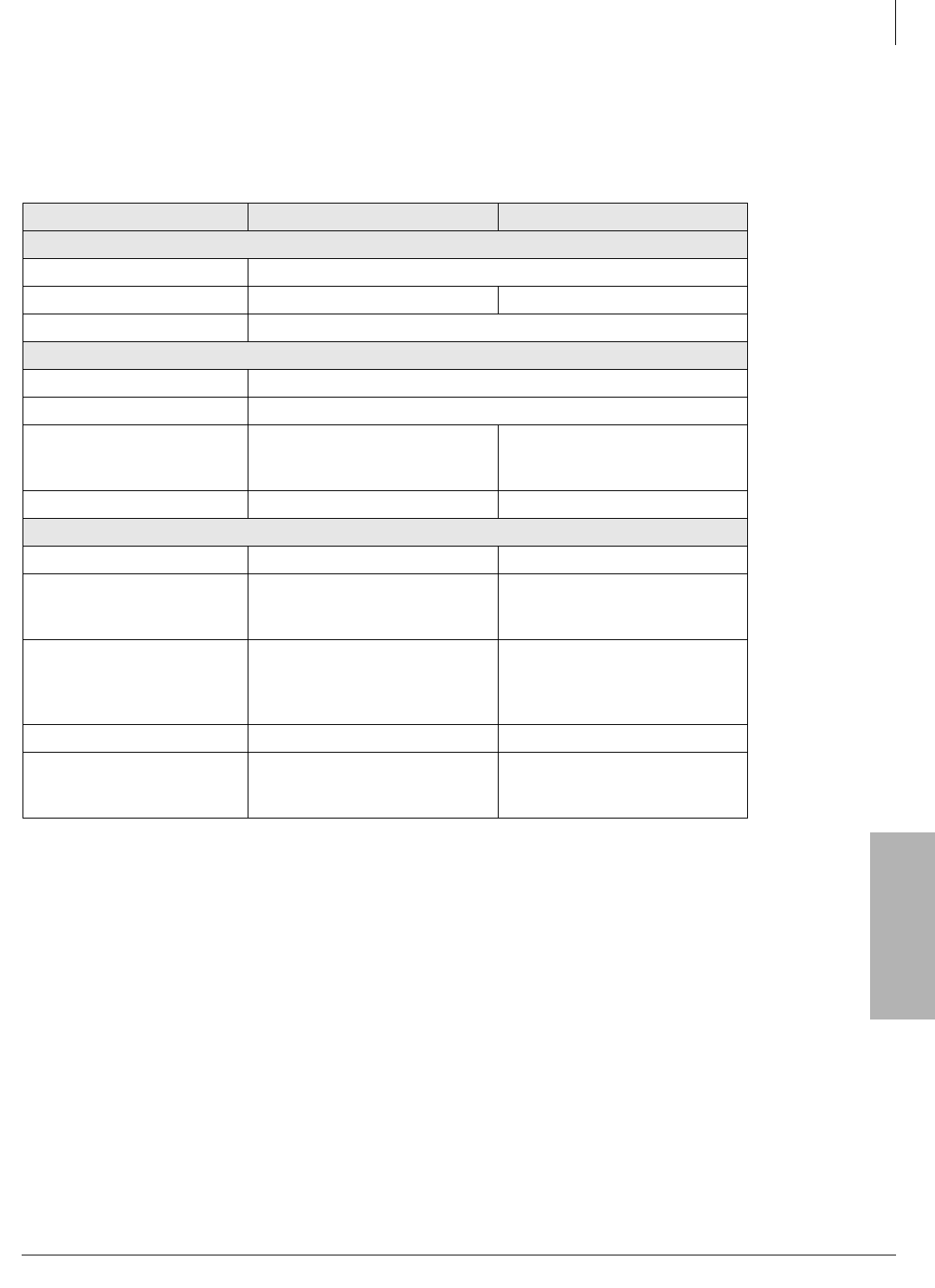
Station Apparatus
Specifications
Strata CTX I&M 06/04 11-45
Station Apparatus
Specifications
For frequencies, power requirements, weight and size specifications, see Table 2.
Table 2 Specifications
Feature DKT2204-CT DKT2304-CT
General
Frequency Control Phase Lock Loop
Modulation Spread Spectrum Digital
Operating Temperature 0° to 50° C (+32° F to + 122°F)
Base Unit
Receive/Transmit Frequency 902~928 MHz
Power Requirements 10VDC from supplied AC adapter
Size
Width – 4.25 inches
Depth – 7.5 inches
Height – 2.25 inches
Width – 4.25 inches
Depth – 7 5/8 inches
Height – 2.25 inches
Weight Approximately 15.4 oz. Approximately 13.7 oz.
Handset
Receive/Transmit Frequency 902~928 MHz 905~925 MHz (30 channels)
Power Requirements
Nickel-cadmium battery pack
(BT2499)
NI-MH Battery Pack (BT2499A)
Ni-MH Battery Pack
Size
Width – 2 1/5. inches
Depth – 1 2/3 inches
Height – 8 2/3 inches with
antenna
Width – 2. inches
Depth – 1.25 inches
Height – 5.5 inches without
antenna
Weight Approximately 8.8 oz. with battery Approximately 5.2 oz. with battery
Battery
Capacity – 800 mAh, 3.6V
Talk Mode – 6 hours (typical)
Standby Mode – 4 days (typical)
Capacity – 800 mAh, 3.6V
Talk Mode – 7 hours (typical)
Standby Mode – 5 days (typical)
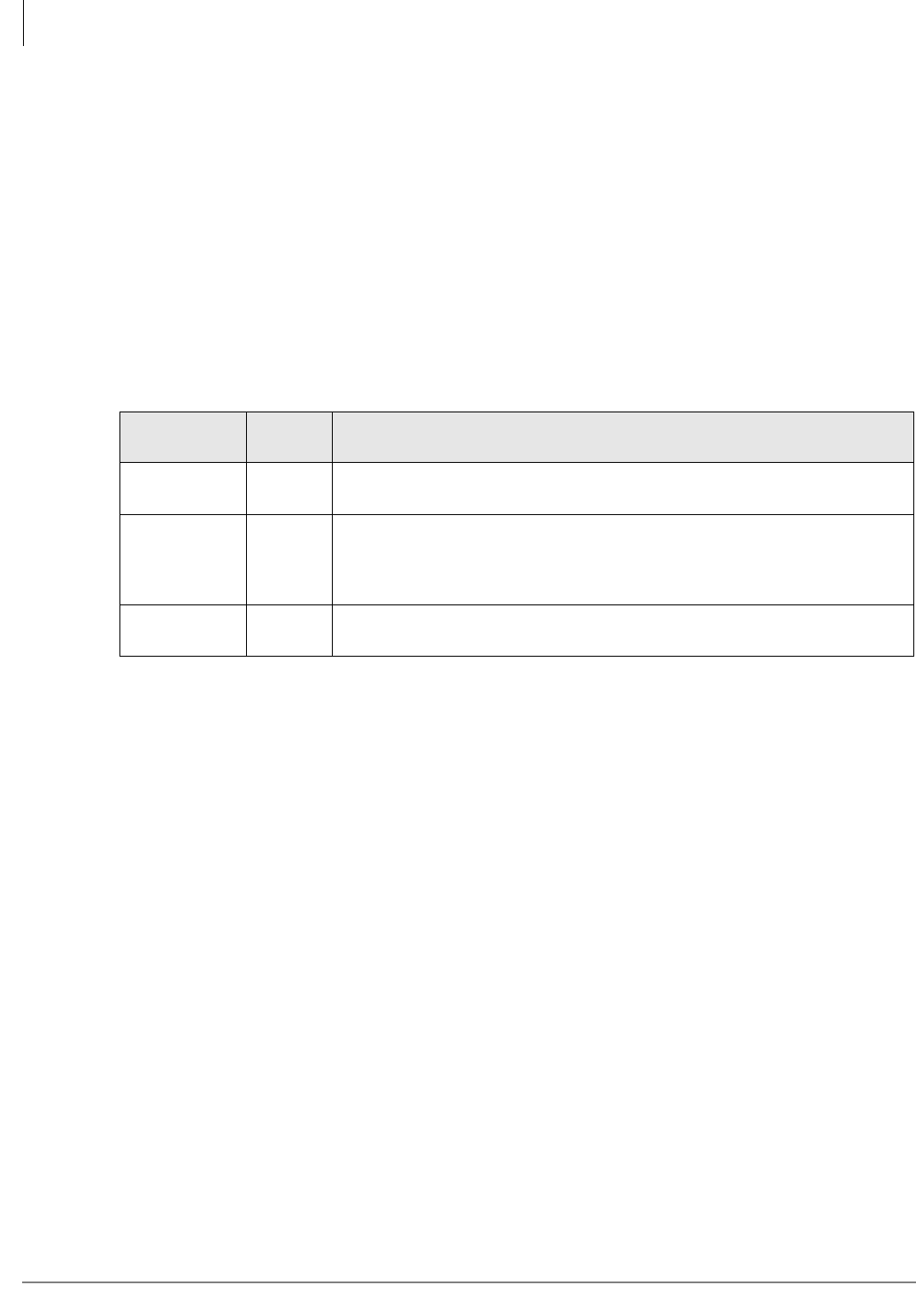
Station Apparatus
2000-series Telephones
11-46 Strata CTX I&M 06/04
2000-series Telephones
The 2000-series digital telephones consist of four models:
• DKT2010-S – 10-Button Digital Speakerphone
• DKT2020-S – 20-button Digital Speakerphone
• DKT2010-SD – 10-Button Digital Speakerphone with Liquid Crystal Display
• DKT2020-SD – 20-Button Digital Speakerphone with LCD
• DKT2020-FDSP – Same as DKT2020-SD with Full-duplex Speakerphone
2000-series Telephone Option PCBs
Telephone Speaker Off-hook Call Announce Upgrade (DVSU/
BVSU)
To receive Speaker Off-hook Call Announce (OCA) calls over the digital telephone speaker, a
2000-series digital telephone must be upgraded with a DVSU or BVSU; the telephone making the
call does not require a DVSU or BVSU. Digital telephones do not require an additional wire pair
to receive Speaker OCA call.
BVSU/DVSU Upgrade Installation for DKT2000-series Telephones
1. Loosen the four captive screws on the telephone base and remove it (see Figure 11-24 on page
11-27).
2. Loosen the four captive screws on the metal plate to the standoffs inside the base. Remove and
discard the plate.
Table 11-9 2000 Telephone Subassembly Upgrades
Subassembly No. per
Phone Function
BVSU or
DVSU1
1. Only one of these subassemblies is allowed per telephone: DVSU, BPCI, PDIU-DI or DADM.
1Off-hook Call Announce (OCA): Provides interface for digital telephone to
receive Speaker OCA. Not required for Handset/Headset OCA.
BHEU or
HHEU 1
Headset and loud ringing bell telephone interface: Can be installed with
DVSU or DADM, but not with the Full-duplex Speakerphone External
Microphone (RFDM). (See “Telephone Headset (BHEU) Upgrade” on page 11-7
for installation instructions.)
DADM202011 or 2 ADM, DSS: Provides telephone with 20 (or 40 with two DADMs) additional
feature buttons for DSS, System or Station speed dial, or CO line appearances.
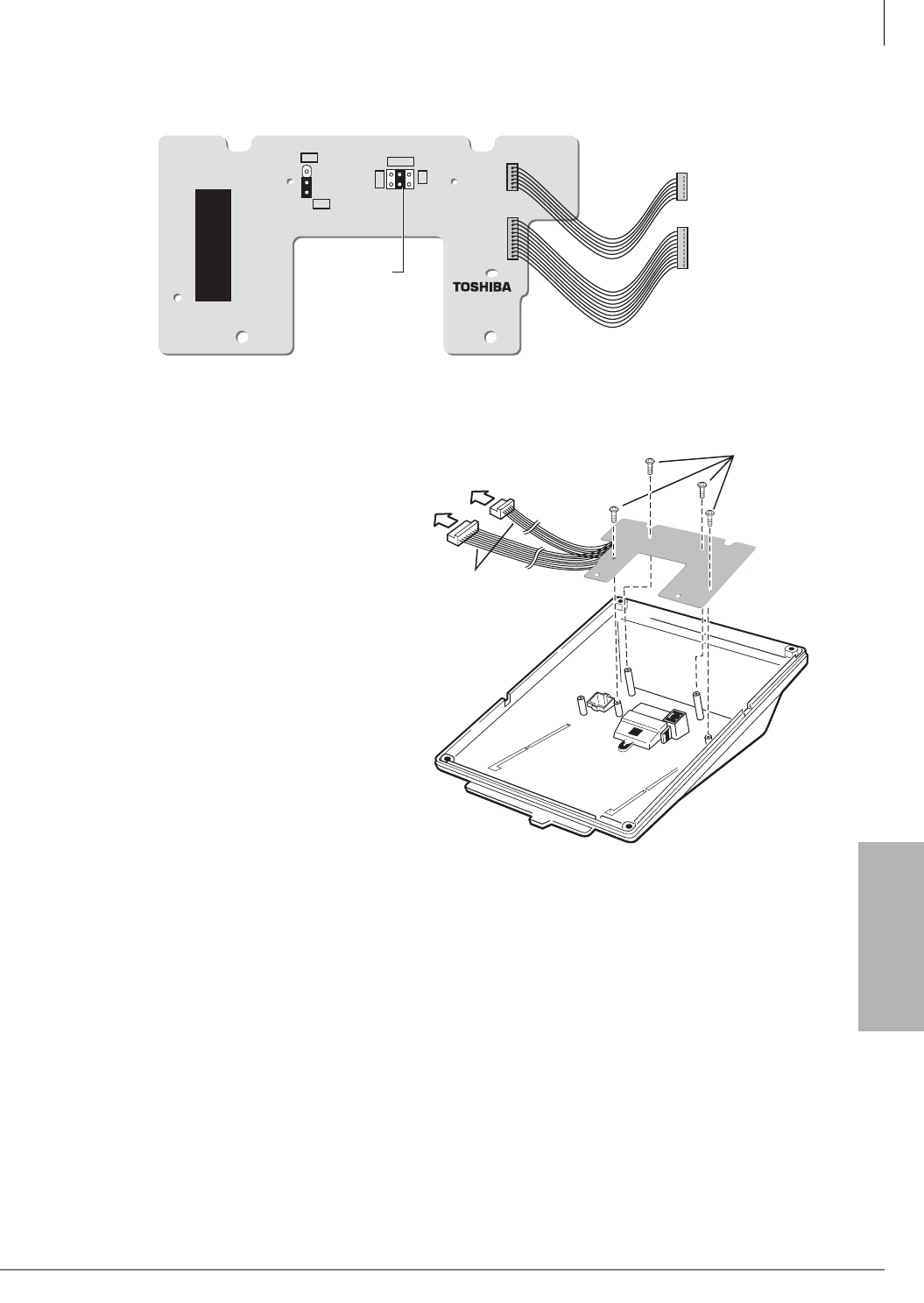
Station Apparatus
2000-series Telephones
Strata CTX I&M 06/04 11-47
Station Apparatus
3. For the BVSU only, make sure that the SW1 and SW2 pins are set per Figure 11-30 and Table
11-5 on page 11-5.
Figure 11-30 Speaker Off-hook Call Announce Upgrade (BVSU1A)
4. Position the BVSU/DVSU PCB on the
standoffs), and secure with the four
provided screws (see Figure 11-31).
5. Connect the BVSU/DVSU wire plugs to
the VSU connectors on the PCB inside
the phone.
6. Reinstall the telephone base. Secure it
with its four captive screws.
6073
BVSU1A
HFU
SPF
SW2
SW1
20 Mu
20 A
30
Move jumper to
the middle position
(20 Mu) for
DKT2000 phones
To PCI/VSU
Connectors
on Telephone
Red Wire
Fasten
Four
Screws
6072
Figure 11-31 BVSU/DVSU Installation
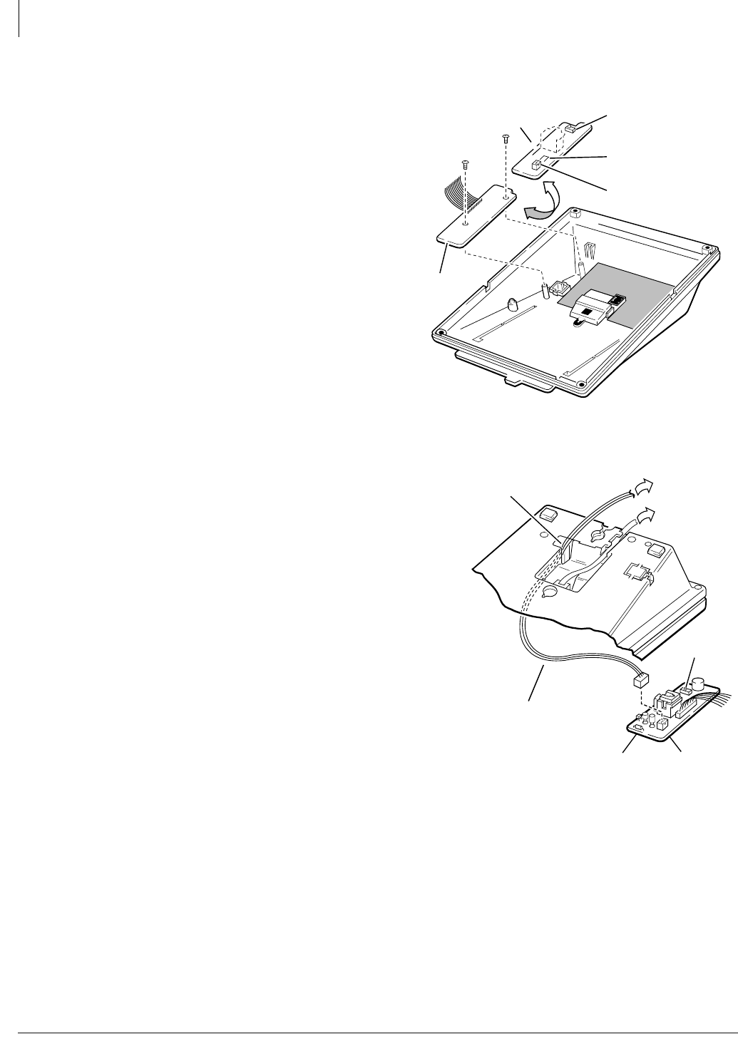
Station Apparatus
2000-series Telephones
11-48 Strata CTX I&M 06/04
HHEU Installation
See Figures 11-24 and 11-32~11-35 and
follow these steps:
1. Loosen the four captive screws on the
telephone base, and remove the base.
2. Use a screwdriver or other suitable
tool to remove the plastic tab on the
back of the base. (The HHEU modular
connector for the headset is accessed
through this opening.)
3. If installing a V.3 HHEU1, set the
SW601 switch on the HHEU to
headset for the headset or loud bell
application.
V.4 HHEU1 and HHEU2 do not have
this switch, because they are
automatically set for the headset/loud
bell application.
4. Connect the HESC-65A cable to P601 of the
HHEU (both HHEU1A versions and the
HHEU2 have P601) if the Loud Ringing Bell
option is required.
Refer to Chapter 12 – Peripheral Installation
for HESB installation procedures.
5. For the V.3 HHEU1: If only the headset is
connected to the HHEU, cut both sides of the
R607 resistor, then remove the resistor to
eliminate electrical contact.
Note Do not cut the R607 resistor if
connecting an HESB to the HHEU
for the Loud Ringing Bell–even if a
headset is also installed on the
HHEU.
...or
For the V.4 HHEU1 and the HHEU2: if only
the headset is connected to the HHEU, cut the
speaker OCA strap.
Note Do not cut the speaker OCA strap if connecting an HESB to the HHEU for the Loud
Ringing Bell–even if a headset is also installed on the HHEU.
6. Position the HHEU PCB on the standoffs inside the base, and secure with the two provided
screws.
Note See Figures 11-34~11-35 for Steps 7~8.
HHEU
Component Side of HHEU
SW601
(HHEU1 V.1 ~ V.3)
P601
R607 (HHEU1 V.1 ~ V.3)
OCA
(HHEU1 V.4
or HHEU2)
1487
Figure 11-32 HHEU Installation
Feed Through
for HESC-65(A) Cable
To HESB
Block
SW601
HHEU P601
HESC-65 Cable
or
HESC-65A Cable
1488
Figure 11-33 HESC-65A Cabling
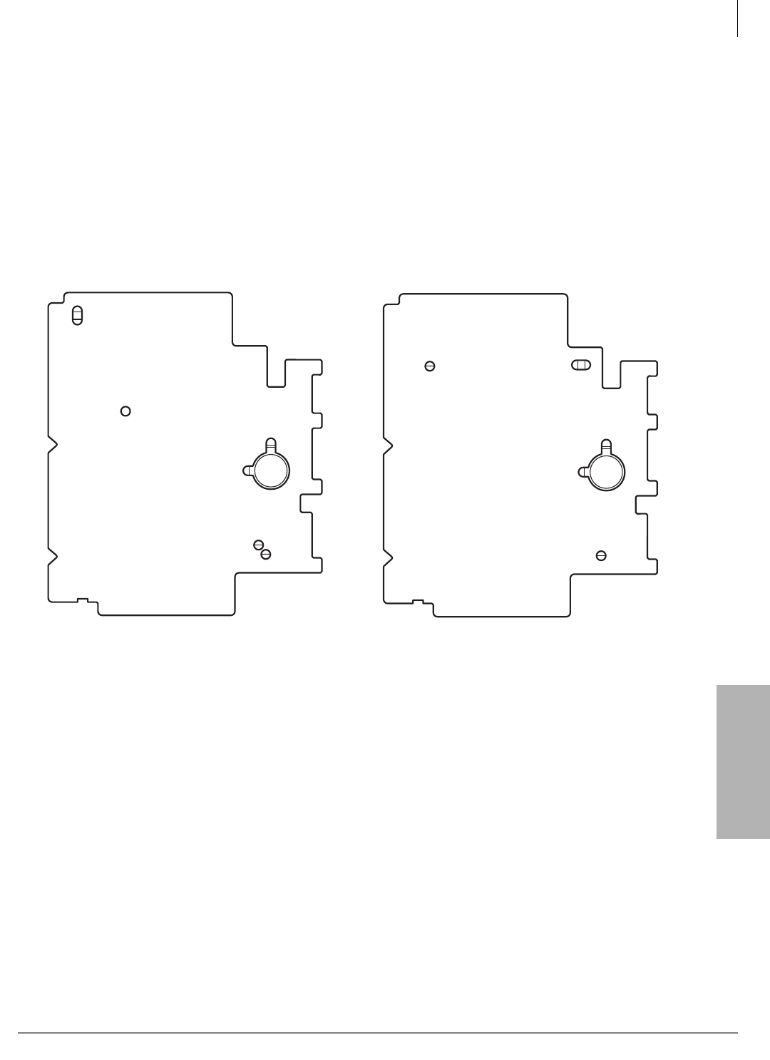
Station Apparatus
2000-series Telephones
Strata CTX I&M 06/04 11-49
Station Apparatus
7. Connect the wire plug of the HHEU PCB to the HHEU connector on the PCB in the phone.
8. If an HESB will be connected to the HHEU (for Loud Ringing Bell), locate the EX.SP strap on
the PCB in the telephone and cut the strap.
9. If a headset will be connected to the HHEU, locate and cut the HHEU strap on the PCB in the
phone.
Note If the HHEU PCB is removed from the phone, the HHEU strap must be replaced for
proper telephone operation.
10. Reinstall the telephone base; secure with the four captive screws.
Notes
●There are two types of HHEUs: the HHEU1 (which has four versions, V.1~V.4) and the
HHEU2.
●2000-series digital telephones require either an HHEU2 or a V.3 or V.4 HHEU1 for HESB
operation; earlier HHEU1 versions are only sufficient for headset operation only.
●Only digital telephones equipped with an HHEU2 can be wall mounted. The HHEU2 is
identical to the V.4 HHEU1, except that the HHEU2 has longer wires to accommodate wall
mounting.
●A Toshiba HESC-65A cable is required to connect the HHEU in a digital telephone to the
HESB.
Figure 11-34 DKT2010-S Strap and Connector
Locations
Figure 11-35 DKT2010-SD, DKT2020-S, and
DKT2020-SD Strap and Connector
Locations
DIU&ADMDIU&DVSUDVSU
P1P2P6
Carbon
EX.SP
HHEU
W203
W201
W202
W204
W204
BEEP
HS-BOV
EX.POW
W101
W102
W409
REDRED
RED
1484
HHEU
P3
DIU&ADM
DIU&DVSU
HHEU DVSU
P1P2P3 P6
Carbon
EX.SP
HHEU
W203
W201
W202
W204
BEEP
EX.POW
EX.POW
W101
W102
REDREDREDRED
1485

Station Apparatus
2000-series Telephones
11-50 Strata CTX I&M 06/04
³To adjust the volume of the HESB Loud Ringing Bell
1. Call the telephone connected to the HESB.
2. Adjust the volume control on the back of the HESB and the ring volume control on the
telephone.
Note TAPI and Simultaneous Voice and Data Upgrades (RPCI-DI or
PDIU-DI2) for 2000-series Telephones is not available on the Strata CTX.
Carbon Headset/Handset Straps
If a carbon-type handset or headset is connected to the handset jack on the side of the telephone,
two jumper straps inside the telephone must be cut.
³To cut the straps
Note You do not need to cut these straps if the headset is connected to the HHEU.
See Figures 11-24 and 11-34~11-35 and follow these steps:
1. Loosen the four captive screws on the telephone base, and remove the base.
2. For 2000-series digital telephones, and cut the W201 and W202 carbon straps.
3. Reinstall the telephone base, and secure it with its four captive screws.
Beep Strap
A “beep” sounds whenever a dial pad or feature button is pressed on a digital telephone.
³To eliminate the beep sound
See Figures 11-24 and 11-34~11-35 and follow these steps:
1. Loosen the four captive screws from the telephone base and remove the base.
2. Cut the beep strap.
3. Reinstall the telephone base, and secure it with its four captive screws.
Microphone/Speaker Sensitivity Adjustment (Speakerphones
Only)
High ambient noise levels may cause the speaker on some digital telephone speakerphone models
to cut off frequently.
³To reduce sensitivity to loud surrounding noise
³Hold down Mic button, then press the Vol ▲ button. The less-sensitive level will be set after
the third flash of the Mic LED.
³To reset the sensitivity back to the normal level
³Hold down the Mic button, then press the Vol ▼ button. The normal level will be set after the
third flash of the Mic LED.
Note On speakerphone models that are set for low sensitivity, the Mic LED flashes at the in-
use rate when the speakerphone is used. When set to normal sensitivity, the Mic LED
is on steady when using the speakerphone.

Station Apparatus
2000-series Telephones
Strata CTX I&M 06/04 11-51
Station Apparatus
Busy Override and Camp-on Ring Tone Over Handset/Headset
Option
Busy override and camp-on ring tones can be sent over the DKT handset or headset, in addition to
the speaker.
³To send busy override/camp-on ring tones over the handset of the DKT2010-H model
1. Loosen the four captive screws on the telephone base (Figure 11-24), and remove the base.
2. Install a strap in the HS-BOV W409 location (see Figure 11-34).
3. Reinstall the telephone base.
³To send busy override/camp-on ring tones over the handset/headset of the DKT2010-SD/
2020-S/2020-SD
³Hold down the Redial button and press the Vol ▲ button.
³To block the tone over the handset/headset of the DKT2010-SD/2020-S/2020-SD
³Hold down the Redial button and press the Vol ▼ button.
Note For this to function properly with headsets, make sure the speaker OCA strap or R607
is cut on the HHEU PCB and the HHEU strap is cut on the telephone. (See Figures
11-32, 11-34 and 11-35).
External Power Straps
Digital telephones equipped with options such as integrated data interface units and ADMs require
two-pair wiring or external power to operate efficiently at the maximum-allowed distance from the
KSU. Two-pair wiring or external power is also necessary for maximum cable run lengths for
digital telephones that are connected to systems that must operate with reserve power (see Chapter
4 – Strata CTX670 Installation for more information).
Each digital telephone has two external power straps which must be cut for external power when
the cabling of the telephone is connected to an external AC/DC power supply.
³To cut the straps
See Figures 11-24 and 11-34~11-35 and follow these steps:
1. Loosen the four captive screws on the telephone base and remove the base.
2. Depending on the telephone, locate the W101 and W102 external power straps and cut them.
3. Reinstall the telephone base, and secure it with its four captive screws.
Note Refer to Chapter 10 – MDF PCB Wiring for external AC/DC power supply ordering
information and installation instructions.
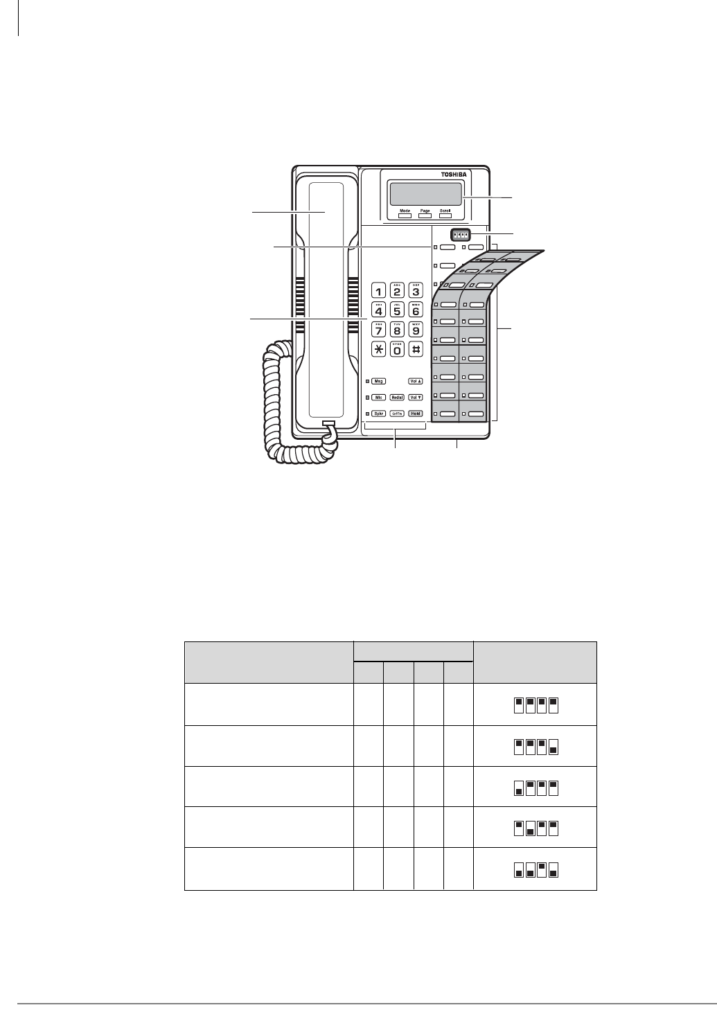
Station Apparatus
2000-series Telephones
11-52 Strata CTX I&M 06/04
DIP Switches
The DKT2000 V.4 series telephones have DIP switches that enable use for the international
market. The DIP switches are located underneath the flexible button key strip on the DKT2000 V.4
series telephones (see Figure 11-36). On the DKT2001, the DIP switch is located on the base.
S
Figure 11-36 DKT 2000-series V.4 DIP Switches
Table 11-10 shows the correct country settings for the DKT2010-S, DKT2020-S, DKT2010-SD,
DKT2020-SD, DKT2001 V.4 telephones.
Note The default DIP switch settings are preset for the USA and Canada. Therefore, you do not
need to adjust any of these from the default factory settings for North America.
Table 11-10 DKT International DIP Switch Settings
Line 9
Line 8
Line 7
Line 6
Line 5
Line 4
Line 3
Line 2
Line 1
Intercom
Speed
Dial
Do Not
Disturb
Line 17
Line 16
Line 15
Line 14
Line 13
Line 12
Line 11
Line 10
ON
1234
Fixed Buttons Microphone Location
Dial Pad
Handset
Red/Green
LED Indicators
DIP Switches
(some models)
3926
LCD Display
Flexible Buttons
USA and Canada
(Default Setting) ON ON ON ON
Mexico ON ON ON OFF
Taiwan OFF ON ON ON
Hong Kong
Thailand1ON OFF ON ON
Singapore, Malaysia, Indonesia,
Sri Lanka, India and China OFF OFF ON OFF
ON
1234
ON
1234
ON
1234
ON
1234
5669
ON
1234
DIP Switch PositionCountry
DIP Switch
1234
1. The DKT2000 V.4 is not compatible for Hong Kong and Thailand. Use the
V.4A or later versions in these two countries.

Station Apparatus
2000-series Telephones
Strata CTX I&M 06/04 11-53
Station Apparatus
DKT2020-FDSP Full-Duplex Speakerphone with External
Microphone
The DKT2020-FDSP is designed to allow both parties of a speakerphone call to speak
simultaneously. This eliminates “clipping” and enables true two-way conversation. However,
when two parties are talking simultaneously, the performance is not as good as on a handset. The
technology necessitates some volume loss in this situation.
An optional External Microphone can be connected for improved performance. However, the
External Microphone is extremely directional and should only be used in certain applications. The
telephone also provides half-duplex/full-duplex manual selection.
The DKT2020-FDSP has three operational modes for enhanced microphone use (Best, Good and
Normal). These modes allow adjustments for different room acoustical characteristics. Choosing
either the Internal or External Microphone (RFDM) and proper operational mode should be pre-
selected by the system installer.
When the External Microphone option is installed, the telephone’s Internal Microphone is disabled
on all but Voice First Handsfree Answerback calls and OCA calls. The External Microphone is
powered by the phone (no batteries are required) and does not need to be turned off when not in
use.
Choosing either the Internal or External Microphone is performed on the DIP switch 5, located
under the keystrip (see Figure 11-35).
Important!
The DKT2020-FDSP’s full-duplex operation depends on the speaker volume setting. Raising or
lowering speaker volume directly affects the performance of the full-duplex operation.
•Depending on the room’s echo characteristics, raising the volume of the speakerphone can
cause the full-duplex operation to deteriorate. When set to maximum volume, it may be
necessary to switch to half-duplex operation.
• The speakerphone will automatically reduce volume in each direction when both the FDSP
user and the distant party are talking at the same time. The volume reduction is required to
control the echoes at high volume levels. It is possible for surrounding conversations and other
sounds to trigger this effect even when you are not speaking.
• The performance of the DKT2020-FDSP can vary on calls that involve a delay, such as
wireless calls, Voice Over Internet Protocol calls, etc. With these types of calls, the quality can
diminish.
• When using the [PDN] or Intercom button, the performance for internal calls is not as good as
for external calls.
DIP Switches
The DKT2020-FDSP has DIP switches that enable the External Microphone and use telephone use
in other countries. The DIP switches are under the flexible button key strip (see Figure 11-35).
There are three different DIP switch settings for optimum operation in various types of
environments:
•Best – provides full-duplex operation with the Internal or External Microphone. This is ideal
for a large enclosed area, such as an office with little echo. Echo varies according to the
environment. For instance, a room that is relatively empty has more echo than a room with
furniture or items that can absorb sound waves.
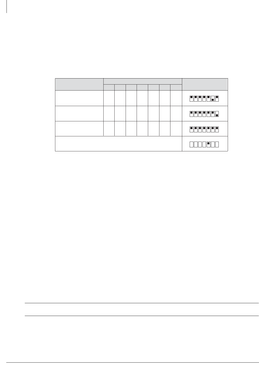
Station Apparatus
2000-series Telephones
11-54 Strata CTX I&M 06/04
•Good – provides full-duplex operation with the Internal or External Microphone. This is ideal
for a small office with high echo.
•Normal – provides full-duplex operation with the Internal or External Microphone. This works
well with an open office area, such as an office cubicle.
Table 11-11 shows the switch positions for the three different settings.
Table 11-11 DKT2020-FDSP DIP Switch Settings
Note The first four DIP switches are used to select the country, same as all other DK2000-series
telephones. The default DIP switch settings (1~4) are preset to On for the USA and Canada.
If you need to make adjustments for other countries, see Table 11-10 on page 11-52.
³To use the External Microphone
1. Plug in the RFDM External Microphone to the bottom of the phone (see Figures 11-37 and
11-38).
2. Turn the microphone On by opening it (see Figure 11-39).
Note The High/Low switch works independently from the telephone’s speakerphone. This setting
must be on High for proper operation.
Important!
●The microphone has a narrow voice pick-up range so the front of the microphone should
always point toward the person speaking (see Figure 11-40).
●Be sure to place the microphone at least one foot from the telephone speaker and do not point
the microphone toward the telephone speaker grille.
●To use the external microphone in a conference room setting, place the microphone away from
all parties to eliminate some of the directional effect. Parties may have to speak up to be
heard.
●The RFDM External Microphone is not compatible with the HHEU or BHEU.
CAUTION! Avoid pulling the microphone cord excessively.
Best ON ON ON ON
Good ON ON ON ON
Normal
(Default) ON ON ON ON
ON OFF ON
ON ON OFF
ON ON ON
ON
1 2 3 4
ON
1 2 3 4
5206
ON
1 2 3 4
5 6 7
5 6 7
5 6 7
ON
1 2 3 4 5 6 7
DIP Switch 5 ON for Internal Microphone; OFF for External.
DIP Switch Position
Full Duplex Setting 1 234
DIP Switch
567
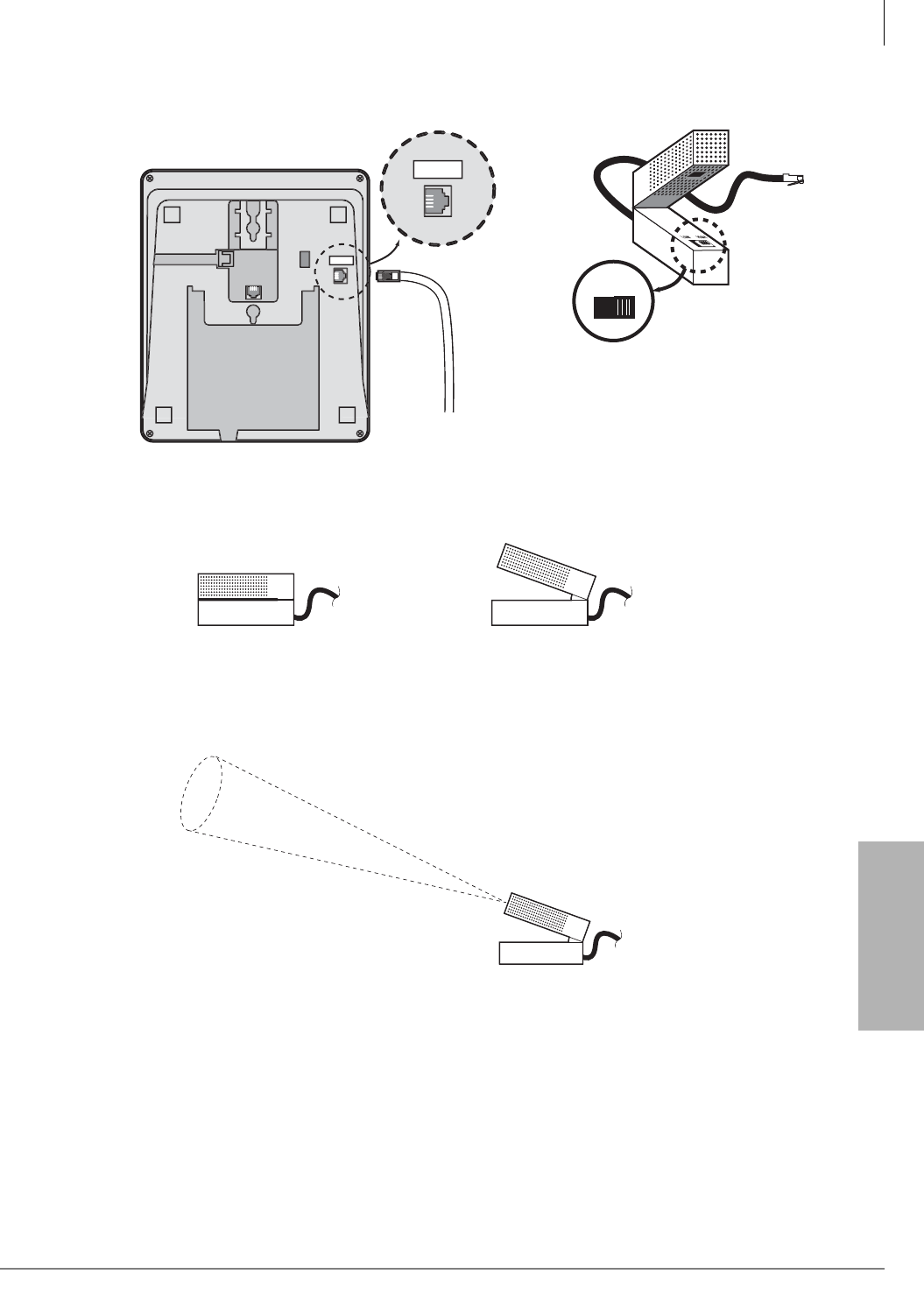
Station Apparatus
2000-series Telephones
Strata CTX I&M 06/04 11-55
Station Apparatus
Figure 11-39External Microphone On/Off
Figure 11-40External Microphone Voice Pick-up Path
s
Figure 11-37 RFDM Plug on DKT2020-FDSP Figure 11-38 RFDM Unit
5
21
8
EXT MI
C
EXT MI
C
LOW HIGH
5217
5352
RFDM Unit (OFF Position) RFDM Unit (ON Position)
5353
RFDM Super Directional Microphone
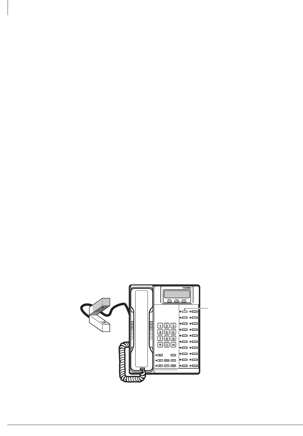
Station Apparatus
2000-series Telephones
11-56 Strata CTX I&M 06/04
Speech Training Mode
When the DKT2020-FDSP is used in speakerphone mode, it adjusts to both the telephone line’s
and room’s acoustic properties. At the beginning of each speakerphone call, the echo canceller
must perform Speech Training by evaluating both the FDSP user and the far-end user’s voice,
background noise and line quality.
³To train the speakerphone
³The parties at both the local telephone and on the far end should take turns speaking for
approximately 10 seconds.
³To improve speaker quality
³If the conversation becomes unstable during the call, or there is clipped speech, feedback or
short silences, first try adjusting the volume. This forces the FDSP phone into speech training
mode. The LED will go on.
³If conversation is still unstable, press button 10 to activate half-duplex mode. You can turn off
button 10 at any time to reactivate full-duplex mode.
³To force the telephone into Speech Training mode
³During a call, momentarily press Vol▲, Vol▼, Hold or MIC.
During Speech Training mode, the speakerphone operates in half-duplex mode.
Tips for best results
• Avoid blocking the microphone or shuffling paper near the microphone.
• Avoid placing the speakerphone where it can detect excessive background noise, especially
during Speech Training mode.
• Avoid moving the telephone during a call—this changes the room’s acoustic properties. If the
telephone or microphone is moved, you may have to force the Speech Training mode.
Special Button Operation (Button 10)
When using the external or Internal Microphone, button 10 works as a toggle from full- to half-
duplex on the DKT2020-FDSP.
5241
Button 10
toggles
between full-
and half-duplex.
Figure 11-41 Button 10 on the Full-duplex Speakerphone
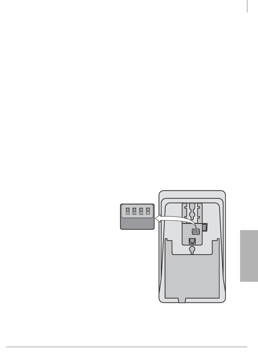
Station Apparatus
2000-series Telephones
Strata CTX I&M 06/04 11-57
Station Apparatus
³To toggle full/half-duplex mode
³Press button 10 (see Figure 11-41) to turn full-duplex mode On or Off.
Full-duplex mode: Button 10 LED Off.
Half-duplex mode: Button 10 LED On.
Notes
●Button 10 functions the same for Internal and/or External Microphone.
●If DIP switch 6 and 7, in Figure 12, are turned Off, the Full/half-duplex function of Button 10
is disabled.
●The DKT2020-FDSP’s full-duplex operation depends on the speaker volume setting. Raising
or lowering the speaker volume directly affects the performance of the full-duplex operation.
Important!
•If raising or lowering the volume does not improve performance, switch to half-duplex mode by
pressing Key 10.
•If both you and the distant party are using full-duplex speakerphones, the sensitivity to both
echo paths may cause a reduction or instability of volume. If this happens, it may be necessary
to switch to half-duplex mode by pressing key 10.
Digital Single Line Telephone (DKT2001 only)
For instructions on installing the DKT3001 SLT, see “Digital Telephone System Connection” on
page 11-2.
DKT 2001 Installation
1. Set the DIP switches to match Figure
11-42. The DIP switches are preset from
the factory for the USA and Canada.
Refer to Table 11-10 on page 11-52 for
other country settings.
2. If required to achieve maximum
distance (greater than 1000 ft.), install a
two-pair house cable (or external
power).
3
4
82
4
1
ON
2
3
4
Figure 11-42 DKT2001 DIP Switch Settings

Station Apparatus
2000-series Telephones
11-58 Strata CTX I&M 06/04

Strata CTX I&M 06/04 12-1
Peripheral Installation
Peripheral Installation 12
This chapter provides information and diagrams for connecting peripheral equipment to the Strata
CTX interface circuits. These interfaces include those listed below:
• Application PC and Server Interfaces
• Strata CTX WinAdmin, ACD, Attendant Console, SMDI and SMDR
• Music-On-Hold/Background Music Interfaces
• External Page with BIOU Interface
• Control Relays with BIOU Interface
• Door Phone/Door Lock with DDCB Interface
• Telephone External Ringer with HESB Interface
• Amplified Page with HESB Interface
• Amplified Page/Talk-Back with HESB Interface
• Power Failure Cut-through with DPFT Interface
• Station Message Detailed Recording
Application PC and Server Interfaces
Application PCs and/or servers are connected to the Strata CTX system via a Network Interface
jack, RS-232 serial ports and/or a Strata CTX modem depending on the application. These
interfaces are provided by the CTX system processor. The network jack and built-in modem are
standard equipment on the CTX670 processor and option PCBs on the CTX100 processor. The
BSIS four-port serial interface is an optional PCB that mounts on the CTX100 or CTX670
processor (see Figure 12-1).
•CTX WinAdmin, Stratagy VM Proprietary Integration, Attendant Console and ACD
Network Interface – These application PC/servers equipped with a standard Network
Interface Card (NIC) connect to the Strata CTX network jack. One network interface jack is
standard on the Strata CTX670, BBCB processor PCB. The AETS option is required on the
CTX100 ACTU processor. This is the only network jack interface on the Strata CTX (see
Figures 12-1~12-4).
•CTX WinAdmin Modem Interface – CTX WinAdmin PC servers equipped with a modem
can connect the Strata CTX maintenance modem. One built-in maintenance Modem is standard
on the Strata CTX670, BECU processor PCB. An AMDS option PCB is required for CTX100
ACTU processor PCB.The Strata CTX modem supports point-to-point TCP/IP connection to a
CTX WinAdmin PC modem over PSTN telephone lines (see Figure 12-5 for a connection
diagrams).
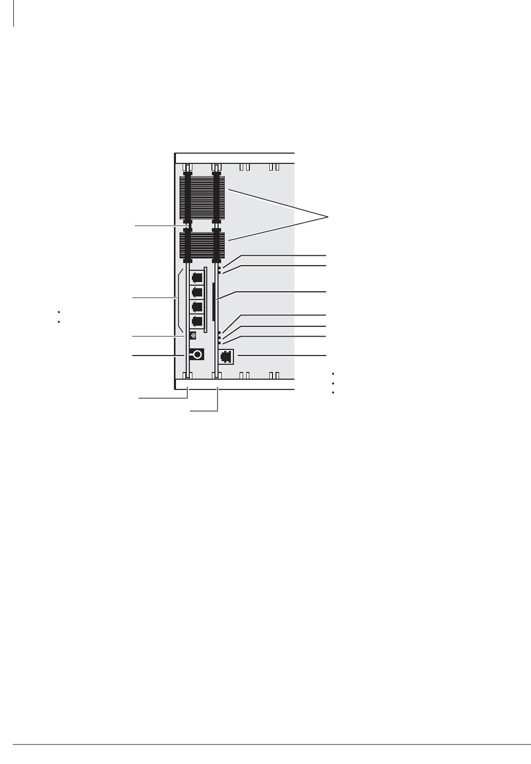
Peripheral Installation
Application PC and Server Interfaces
12-2 Strata CTX I&M 06/04
•SMDR and SMDI or Stratagy VM Serial/RS-232 Interface – Application PC/servers
equipped with standard RS-232 COM ports connect to the Strata CTX serial interface ports.
The Strata CTX provides four RS-232 interface jacks on the BSIS PCB. The BSIS is an
optional PCB that piggy backs on the system processor PCB (see Figures 12-6 and 12-7 for a
connection diagrams). Refer to the Strata CTX Programming Manual, Programs 803 and 804
to set up these interfaces.
Figure 12-1 Application PC/Server Interfaces
Network Interface Connections
Figure 12-2 shows basic network interface connections. Figure 12-3 shows application PC or
server direct connections. Refer to Program 801 to set up the LAN interface. Network jack wiring
guidelines are listed below:
• The CTX100 and CTX670 network interface is 10BaseT and requires CAT5 twisted pair
cabling.
• The maximum distance between the BBCU network jack and the application PC or server is
100 meters (328 ft.) when using CAT5 cabling without repeaters.
• Unshielded CAT5 cabling is adequate for most installations.
• Shielded CAT5 cabling is needed to protect the cable in environments that have excessive
electromagnetic interference (EMI).
Network Jack LED Indications
The three LEDs located on the BBCU and AETS network jack indicate activity when sending
or receiving data on the network (see Figure 12-4).
B101 S_01B102 S_02
BECU
BSIS Serial Ports
(RJ11, 6-pin modular)
Built-in Modem
(33.6 kbps, v.34
WinAdmin PC / Server)
Network Interface Jack
(RJ45, 8-pin modular)
Processor Heart Beat LED (0.4 seconds on/0.4 seconds off.)
Smart Media Access Status LED
Network Interface Link Connection LED.
Strata CTX Receive Network Data LED.
Strata CTX Send Network Data LED.
MOH Volume Control
(screw driver adjust)
MOH/BGM Input
(RCA Jack)
BBCU
5447
1
2
3
4
Smart Media Card Socket (Smart Media card slides in, gold
contacts face right, notched corner down)
WinAdmin PC/Server
ACD PC/Server
Attendant Console PC / Server
Ribbon Cables
SMDR
SMDI
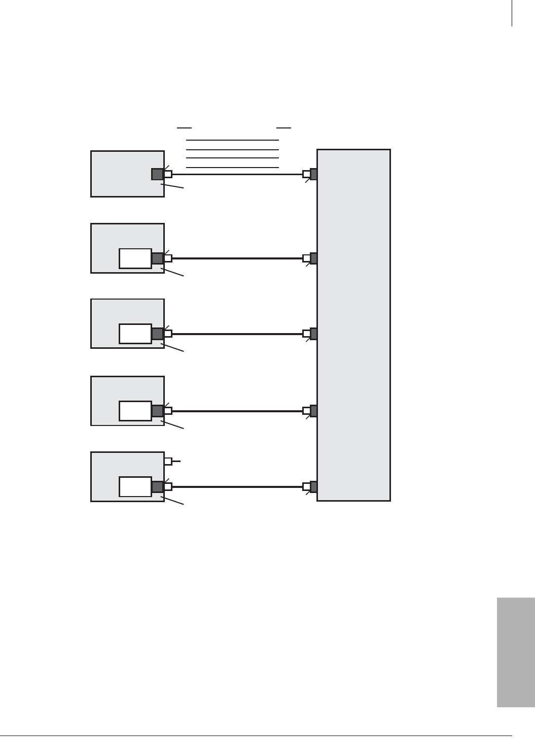
Peripheral Installation
Application PC and Server Interfaces
Strata CTX I&M 06/04 12-3
Peripheral Installation
Figure 12-2 Network Interface Connections
1
2
3
6
1
2
3
6
Pin Pin
TD+
TD-
RD- TD-
RD-
RD+ TD+
RD+
Application PC or Server, Network or HUB Connection to Strata CTX
5595
CTX WinAdmin
Application
ACTU or BBCU
Processor
Strata CTX
Straight-pinned, 8-wire Modular Cord
Network Interface RJ45 Jack
PC or Server
LAN
or
HUB
NIC Straight-pinned, 8-wire Modular Cord
Network Interface RJ45 Jack
ACD
Application
PC or Server
NIC Straight-pinned, 8-wire Modular Cord
Network Interface RJ45 Jack
Attendant Console
Application
PC or Server
NIC Straight-pinned, 8-wire Modular Cord
Network Interface RJ45 Jack
Stratagy ES
Voice Mail System
PC or Server
NIC Straight-pinned, 8-wire Modular Cord
LCD Soft Key Link
SMDI Link to BSIS
See Figure 12-6.
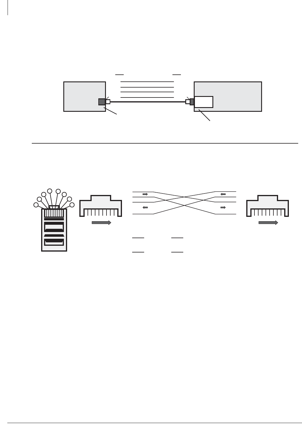
Peripheral Installation
Application PC and Server Interfaces
12-4 Strata CTX I&M 06/04
Figure 12-3 Application PC or Server Direct Connection
5962
Pin of one end to
of one end to of other end - each direction
To make a Network Interface cross-pinned modular cord on an existing straight through cord:
On one end only, swap Pin 1 with Pin 3 and then Pin 2 with Pin 6.
of other end - each directionPin1 3
2
Pin 6
Pin
TD +
Network Interface Cable Cross Pinning
RD +
RD -
TD +
TD - TD -
RD -
RD +
1
2
3
4
5
6
7
8
1
2
3
4
5
6
7
8
18
Front Front
18
Bottom Side Up
Connector Head
1
2
3456
7
8
Application PC or Server, Direct Connection to Strata CTX
ACTU or BBCU
Processor
Strata CTX
CTX WinAdmin,
Stratagy ES,
Attd. Console, or
ACD Application
Application PC or Server
Cross-pinned, 8-wire Modular Cord
Network Interface RJ45 Jack
Network Interface Card with RJ45 Jack
NIC
1
2
3
6
3
6
1
2
Pin Pin
TD+
TD-
RD- TD-
RD-
RD+ TD+
RD+
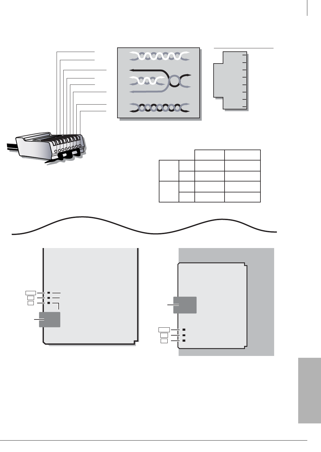
Peripheral Installation
Application PC and Server Interfaces
Strata CTX I&M 06/04 12-5
Peripheral Installation
Figure 12-4 Network Interface Jack Pin Numbers and LEDs
5594
CD801
CD101
Network
Interface
RJ45
P7
TX
RX
LINK LAN Link Indication, LED On when Link is Connected
LAN Data Receive Indication, LED On when CTX is
Receiving Data Packets
LAN Data Send Indication, LED On when CTX is
Sending Data Packets
P5
5499
Strata CTX uses Pairs 2 and 3.
RJ45 Modular
Male Plug
1
2
3
4
5
6
7
8
1
2
3
4
5
6
7
8
P4
Pair 1
Pair 2
Pair 3
Pair 4
(8)
(7)
RD-
(5)
(4)
(6)
(3)
(2)
(1)
RD+
TD-
TD+
(not used)
(not used)
(not used)
(not used)
RJ45
( 8-pin jack )
TD-
TD+
Not Used
RD+
RD-
Not Used
Not Used
Not Used
2
1
4
3
6
5
8
7
CTX Network Interface Jack (P7)
TIA Network Wall Jack Wire Color Codes
CAUTION: Do not mix different TIA Wall Jack Types in an Installation.
Pair 2
Pair 3
Pin 1
Pin 2
Pin 3
Pin 6
Green
Green/White
Orange/White
Orange
TIA-568A
White/Green
Green/White
Orange/White
White/Orange
TIA-568B
Network
Interface
RJ45
P1
TX
RX
LINK
CTX100 ACTU1A
AETS
CTX 670 BBCU1A
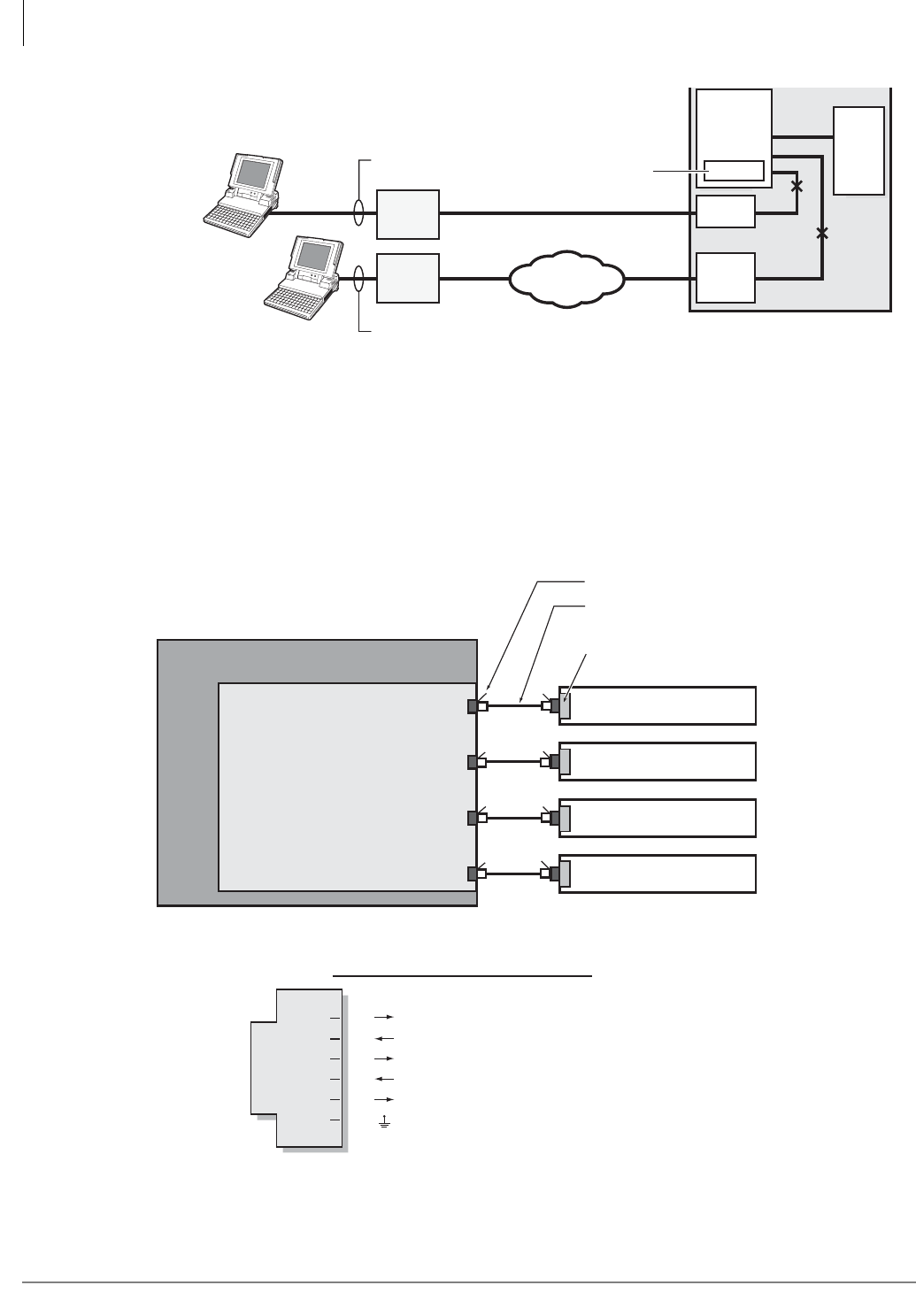
Peripheral Installation
Application PC and Server Interfaces
12-6 Strata CTX I&M 06/04
Figure 12-5 CTX WinAdmin Modem Interface Connection
Figure 12-6 Serial Port Interface Connections
Flash
or ROM
and
RAM
CO Line
Circuit Strata CTX
33.6 kbps v.34
Point-to-point TCP/IP
Dial #19
Time
Switch
Modem
RS-232 Cable
RS-232 Cable
Remote CTX
WinAdmin PC
CO LineCO Line Telephone
Network
5592
Local CTX
WinAdmin PC
Modem
BCTU,
BECU or
ACTU/
AMDS
Modem
RSTU
CTX Modem Programs and Dialing Numbers
DID – Program 309: Ring direct to built-in modem.
Ground/Loop – Program 310: Ring direct to built-in modem
Transfer, Tie, or DISA – Program 102: Dial #19 to transfer to or dial the modem directly.
Note: The PC modem can be external or internal.
SMDI
SMDR
BSIS (piggy-back) PCB
ACTU or BECU Processor PCB
Note: Total data rate four ports combined is 57.6kbps. maximum.
Port 1
Port 2
Port 3
Port 4
BSIS (Port 1-4)
6-wire Modular Cord - telephone
cross-pinned type (modular jack locking
tabs on the same side of the cord).
Toshiba PPTC or PPTC9
connectors to PC COM port
Stratagy Voice Mail System
Call Accounting System
5604
Strata CTX Serial Port Modular Pins:
BSIS RJ11
(Six-pin jack)
TD
RD
DTR
DSR
SG
CD
(Data to CTX)
(Data from CTX)
(Data Terminal Ready to CTX)
(Data Set Ready from CTX)
(CTX/Terminal Signal Ground)
(Carrier Detect from CTX)
2
1
4
3
6
5
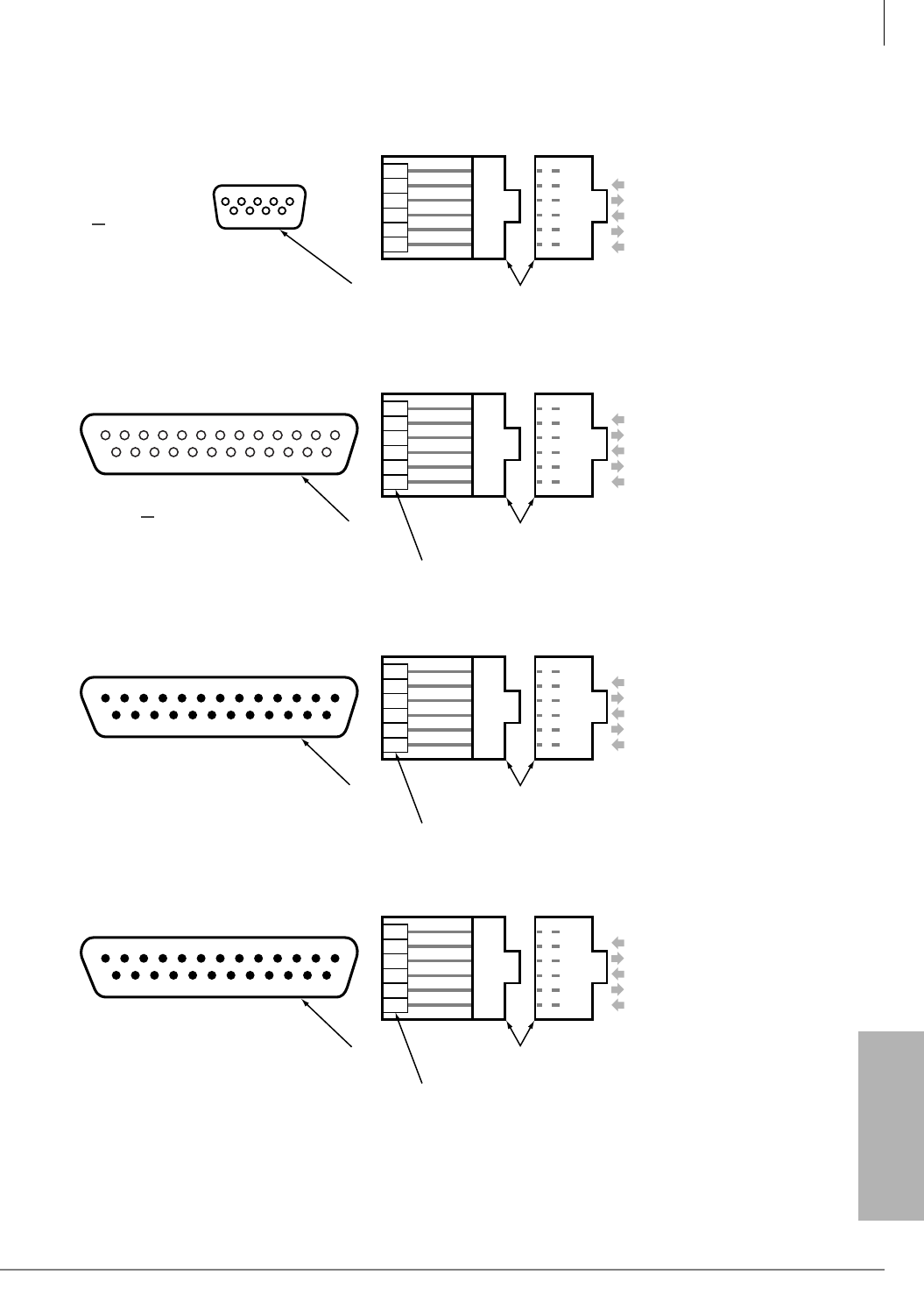
Peripheral Installation
Application PC and Server Interfaces
Strata CTX I&M 06/04 12-7
Peripheral Installation
Figure 12-7 Serial Port Adaptors Pin Numbers
8
20
76 5432
2
3
6
4
1
5
6
5
4
3
2
1
RD
TD
DSR
DTR
DCD
SG
PPTC-9
BSIS Connector
PPTC-25F
BSIS Connector
6789
23451
Connect to PC 9-pin
COMX Port (DTE)
Connect to PC 25-pin
COMX Port (DTE)
(female)
(female)
6
5
4
3
2
1
SG
DCD
DTR
DSR
TD
RD
Modular Jack Pinout
(front view)
DB9 Pinout
(front view)
3
2
6
20
8
7
6
5
4
3
2
1
RD
TD
DSR
DTR
DCD
SG
6
5
4
3
2
1
SG
DCD
DTR
DSR
TD
RD
Modular Jack Pinout
(front view)
DB25
Pinout
(front view) Jumper
Pin 4-5
5593
Strata CTX
Strata CTX
234567
20
8
BSIS Connector
PPTC25-MDM
Connect to External
Modem (DTE)
(male)
2
3
20
6
8
7
6
5
4
3
2
1
RD
TD
DSR
DTR
DCD
SG
6
5
4
3
2
1
SG
DCD
DTR
DSR
TD
RD
Modular Jack Pinout
(front view)
DB25
Pinout
(front view) Jumper
Pin 4-5
Strata CTX
234567
20
8
BSIS Connector
PPTC
Connect to:
• ASCII Terminal
• Printer
• Call Accounting Device
•DTE
(male)
3
2
6
20
8
7
6
5
4
3
2
1
RD
TD
DSR
DTR
DCD
SG
6
5
4
3
2
1
SG
DCD
DTR
DSR
TD
RD
Modular Jack Pinout
(side view)
DB25
Pinout
(front and
side view)
Jumper
Pin 4-5
Strata CTX

Peripheral Installation
Music-On-Hold/Background Music Interfaces
12-8 Strata CTX I&M 06/04
Music-On-Hold/Background Music Interfaces
Strata CTX provides up to 15 MOH/BGM music source interfaces via the ACTU or BECU system
processor PCB, one or two BIOU optional interface PCBs, and RSTU standard telephone interface
PCBs. The destination of each music source is determined by system programming. The music
sources can be standard CD music players, telephony MOH machines and/or tape players, etc. The
music sources are connected to standard RCA type jacks on ACTU or BECU and BIOU and via a
dealer-supplied isolation transformer to RSTU (see Figure 12-8 for a connection diagram).
MOH is sent to callers placed on hold and BGM is sent to DKT telephone speakers and/or external
page speakers.
The ACTU, BECU and BIOU interfaces provide an input volume level control for each music
source. The volume levels of music sources connected to RSTU circuits rely strictly on the music
source volume controls.
MOH/BGM source output requirements:
• Output Impedance: 600 or 8 ohms
• Output voltage level: 0.14VRMS (-15dbm) ~ 0.77VRMS (0dbm).
An additional separate BGM source can be connected to the building’s external page amplifier to
play music over the paging speakers when the Strata CTX Page is not in use. This interface option
requires the BIOU zone relays or mute control (see External Page with BIOU Interface).
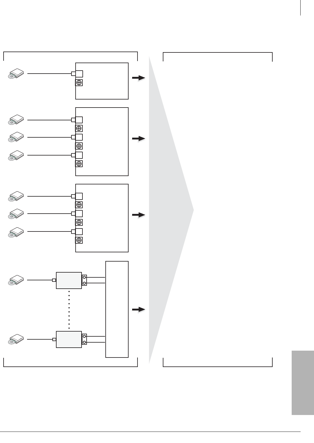
Peripheral Installation
Music-On-Hold/Background Music Interfaces
Strata CTX I&M 06/04 12-9
Peripheral Installation
Figure 12-8 MOH/BGM Interface Connection
RSTU PCB (S)
BECU PCB
VR 901 Volume Control
P3 RCA Jack
BIOU 1 PCB
J2 MOH2 RCA Jack
MOH2 Volume Control
J1 MOH1 RCA Jack
MOH1 Volume Control
J3 MOH3 RCA Jack
MOH3 Volume Control
BIOU 2 PCB
J2 MOH2 RCA Jack
MOH2 Volume Control
J1 MOH1 RCA Jack
MOH1 Volume Control
J3 MOH3 RCA Jack
MOH3 Volume Control
MOH/BGM Source 1
MOH/BGM Source 4
MOH/BGM Source 3
MOH/BGM Source 2
MOH/BGM Source 7
MOH/BGM Source 6
MOH/BGM Source 5
Up to 8
MOH/BGM
devices can
be connected to
RSTU ports.
MOH/BGM Source Connections MOH/BGM Destination
T
R
Time Switch
System Processor
5500
Insolation
Transformer 3
MOH/BGM
Source 8
T
R
Insolation
Transformer
MOH/BGM
Source 15
MOH - Ground/Loop Start DIT and DISA
CO lines are each assigned
individually in Program 310, PK04.
MOH - Analog DID and ISDN DID lines /
individually for each DID number in
Program 309, PK02.
BGM - External Page zones in
Program 105, PK13.
MOH - All outgoing lines are
assigned in outgoing line groups
in Program 306, PK12.
BGM - All digital telephone
speaker users select their source
from the telephone when they
turn on BGM
MOH - Outgoing Line Group in
in Program 304, PK12.
MOH - Stations and Tie lines are all
assigned to the same MOH source
in Program 105, PK02.
MOH - Called Party or DID numbers not
found are assigned in Program
318, PK02.
ACD music source is on a per-call basis
controlled by the ACD Application via the
CSTA Link.
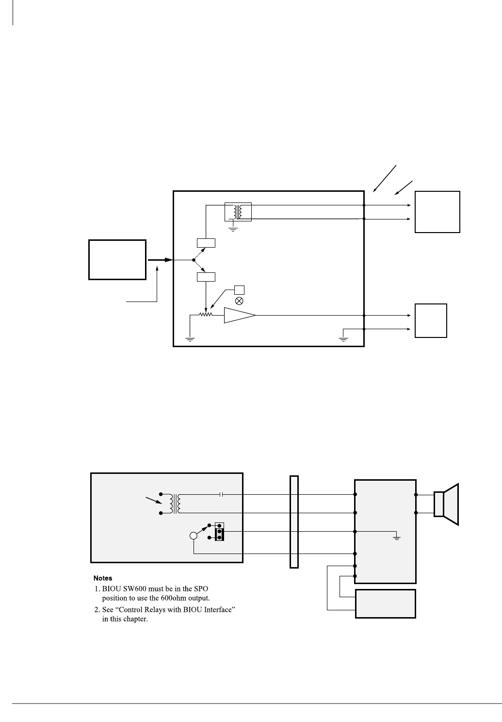
Peripheral Installation
External Page with BIOU Interface
12-10 Strata CTX I&M 06/04
External Page with BIOU Interface
Up to two BIOU interfaces can be installed for connecting external page equipment. Each BIOU
can provide up to four unique page zones for a total of eight page zones maximum per system. The
BIOU interfaces can be installed in the main cabinets and/or any remote cabinet. Each BIOU
provides a 600ohm, non-amplified page output and an 8 ohm, 3-watt amplified page output. Only
one type of page output, amplified or non-amplified, can selected per BIOU in a given installation.
The BIOU also provides a control relay which can be used to mute external BGM when the
external page circuit is active (see Figures 12-8~12-12 for connection diagrams).
Figure 12-9 Single Zone Page Options
A separate external BGM source can be connected to a building’s external Page speakers using the
BIOU interface. This enables the BGM sent over the external page speakers to be different from
the BGM sent to telephone speakers (see Figures 12-10) for separate BGM over external Page
connections).
Figure 12-10 Separate BGM Over External Page
SW600 (Select SPO or SP1)
System
Back Plane
5605
BIOU (1 or 2)
SPTO 38, BK-GN
SPRO 13, GN-BK
Jacketed
Twisted Pair
24 AWG
66 Block Wiring
Page, BGM
or Night Ringing
switched in by
System Processor
HESB
or
External
Amplifier
and Speaker
(8ohm minimum)
HESB
or
External
Speaker
600ΩTransformer
SPT1 50, V-S
SPR1 25, S-V
SPO
SP1
Level Control
3 Watt Amplifier
SP
BGM Mute Relay 2
1
Night Ring
and Page
from KSU
Backplane 600Ω
SPT (38) BK-GN
GN-BK
Input 1
Output
External
Paging Amp
M
BGM
Music
Source
Mute 2
Input 2
B
BIOU (1 on 2)
SPR (13)
MDF
5601
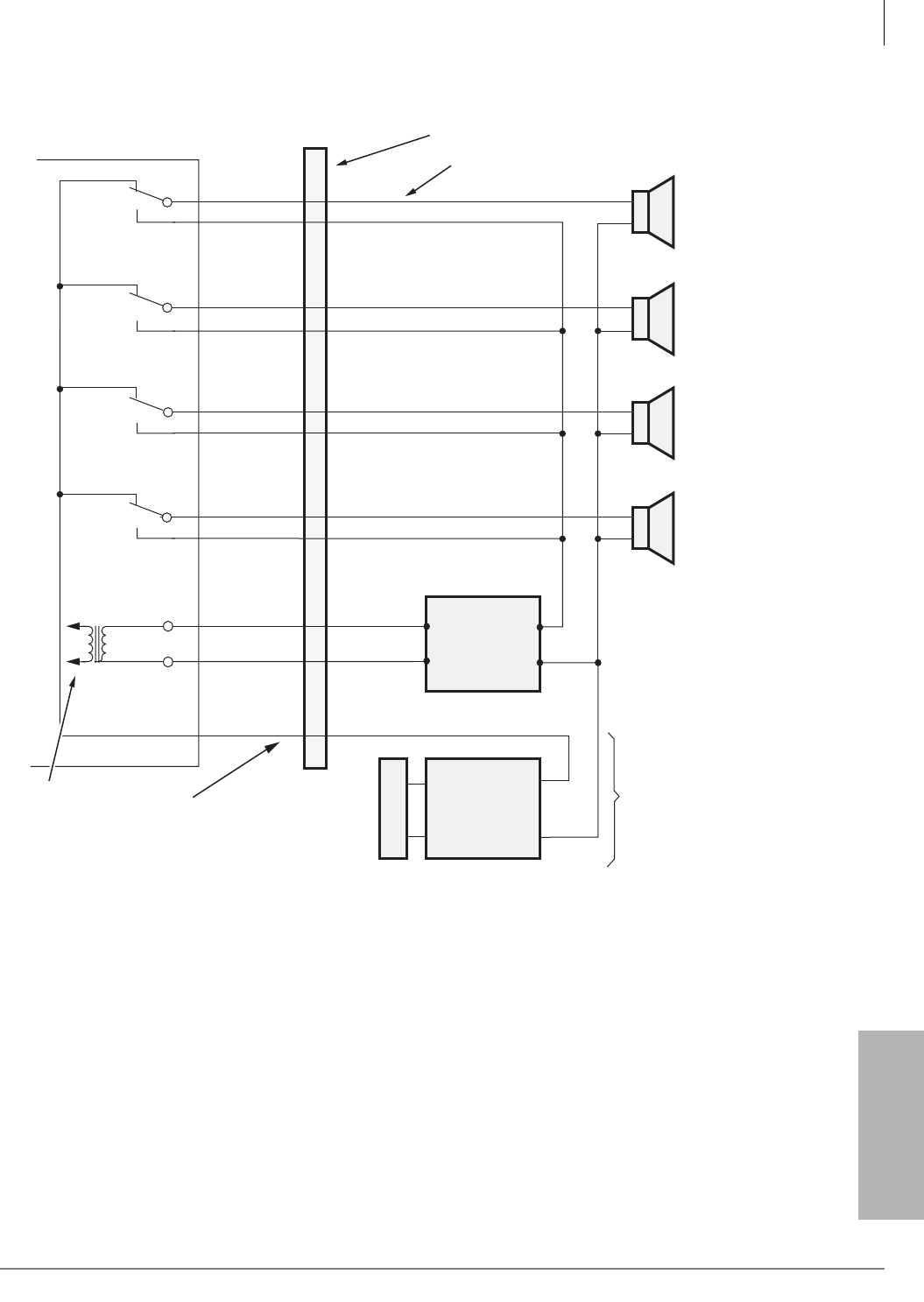
Peripheral Installation
External Page with BIOU Interface
Strata CTX I&M 06/04 12-11
Peripheral Installation
Figure 12-11 Zone Page with One External Amplifier
MDF
BIOU Pin
Numbers ( )
25-Pair Cable
Music Amp
Optional
Connection
Input
Output
Input
Output
PG
Common (23)
5610
Paging Amp
Speaker
Common
Line
A
C
A
C
C
C
Zone 2
Relay
Zone 3
Relay
Zone 4
Relay
600 ohm
M
B
M
B
M
GN-V
BK-GN
V-BL
BL-V
Y-BR
BR-Y
Y-O
GN-BK
PGOUT 3 (19)
PGIN 2 (42)
PGIN 3 (44)
PGOUT 4 (21)
PGIN 4 (46)
SPRO (13)
SPTO (38)
BGM Night
Ringing
and/or Page
from KSU
Backplane
Zone 1
Relay
BIOU (1 or 2)
PGOUT 1 (15)
PGOUT 2 (17)
B
M
B
Jacketed Twisted Pair
24 AWG
66 Block Wiring
O-Y
BK-S
PGIN 1 (40)
S-BK
A
A
CZone 1 / Zone 5
Zone 2 / Zone 6
Zone 3 / Zone 7
Zone 4 / Zone 8
12
BGM Music Source
(To External
Speaker Only)
6
3
Notes
1. Zones 1~ 4 are provided by the BIOU designated BIOU #1.
2. Zones 5 ~ 8 are provided by the BIOU designated BIOU # 2.
3. BIOU SW600 must be set to SPO for 600 ohm page output.
4. Page Zones are added to Page Groups in Program 503.
5. External BGM mute relay control can be provided using BIOU
control relay (see Figure 8-12).
6. BGM over External Page with an external Music Amp is optional.
7. BGM via 600 ohm output (SPRO/SPTO) is sent to selected Page Zones per
Program 105, FB13 and Program 503.
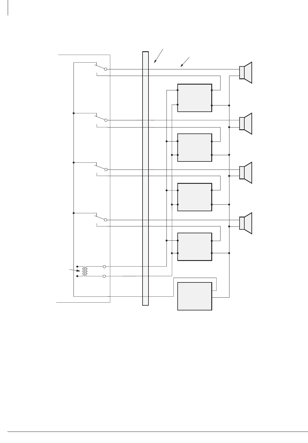
Peripheral Installation
External Page with BIOU Interface
12-12 Strata CTX I&M 06/04
The Notes in Figure 12-11 also apply to this figure.
Figure 12-12 Zone Page with Multiple Amplifiers
Night
Ringing
or Page
from KSU
Backplane
600
ohm
PG
Common (23)
SPTO (38)
SPRO (13)
GN-V
BK-GN
GN-BK
BGM Music
Source &
Amplifier
Output C
5496
BIOU Pin Numbers ( )
25-Pair Cables
Input
Amp
4
Output
Input
Amp
3
Output
Input
Amp
2
Output
Input
Amp
1
Output
A
C
C
Zone 3
Relay
Zone 4
Relay V-BL
BL-V
Y-BR
BR-Y
PGOUT 3 (19)
PGIN 3 (44)
PGOUT 4 (21)
PGIN 4 (46)
B
M
B
M
A
C
A
C
Zone 1
Relay
Zone 2
Relay Y-O
O-Y
BK-S
MDF
BIOU
PGOUT 1 (15)
PGIN 1 (40) Zone 1 / Zone 5
Zone 2 / Zone 6
Zone 3 / Zone 7
Zone 4 / Zone 8
PGOUT 2 (17)
PGIN 2 (42)
Jacketed
Twisted Pair
24 AWG
66 Block Wiring
B
M
B
M
A
C
S-BK
3
1
4
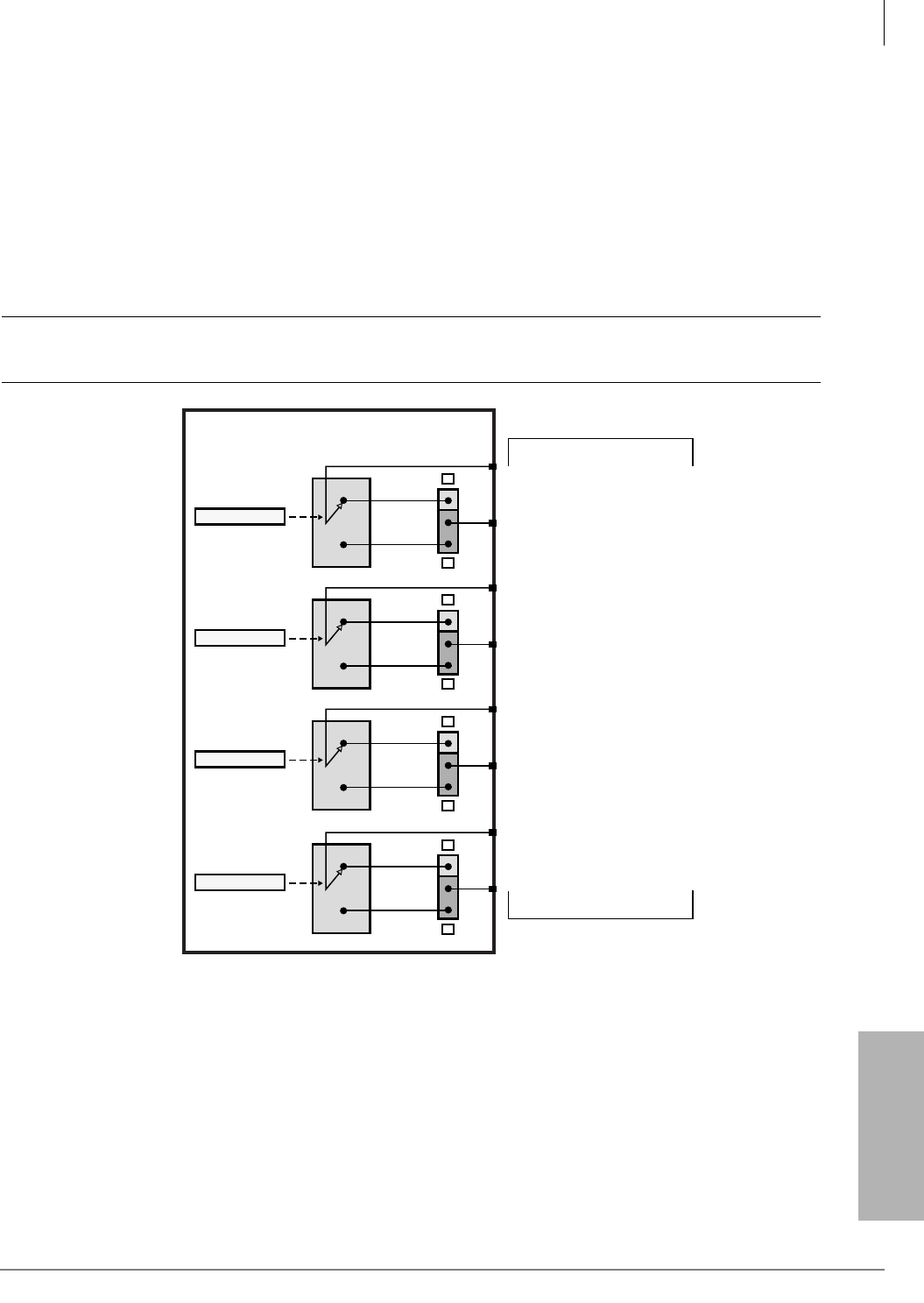
Peripheral Installation
External Page with BIOU Interface
Strata CTX I&M 06/04 12-13
Peripheral Installation
Control Relays with BIOU Interface
Up to two BIOU interfaces can be installed to provide control relays for Night Bell, Night
Transfer, Door Lock and BGM mute control. Each BIOU provides four control relays for a total of
eight relays (max.) per system. Each relay’s function is selected in system programming. BIOU
interfaces can be installed in the main cabinets and/or any remote cabinet (see Figure 12-8).
BIOU control relay contact power ratings are shown below:
• 24 VDC maximum
• 1.0 amperes maximum
CAUTION! BIOU relay contacts are not rated to switch 120/240VAC, connecting these
voltages may result in equipment damage, fire and/or personal injury.
Figure 12-13 BIOU Control Relays
5492
BIOU (1 or 2)
CRR2, Pin 5 (S-W)
CRT2, Pin 30 (W-S)
SW200
Relay 2
B
M
CRT3, Pin 32 (R-O)
CRR3, Pin 7 (O-R)
SW250
Relay 3
B
M
25- Pain Amphenol
Connector Pin Number
M
CRT1, Pin 28 (W-GN)
CRR1, Pin 3 (GN-W)
SW150
Relay 1
B
CRT4, Pin 34 (R-BR)
CRR4, Pin 9 (BR-R)
SW300
Relay 4
B
M
Notes
1. User Relay Service Program 515 to set control relay for Night Bell, Night, Door
Lock, External BGM mute functions as required.
2. Relay functions can open or close contacts by setting Make/Break switches
SW150~SW300.
3. Relay functions are set in Programs 503, 508 and 515.
4. Relay contacts are rated at 24 VDC, 1.0A maximum. Do not connect to 120VAC.
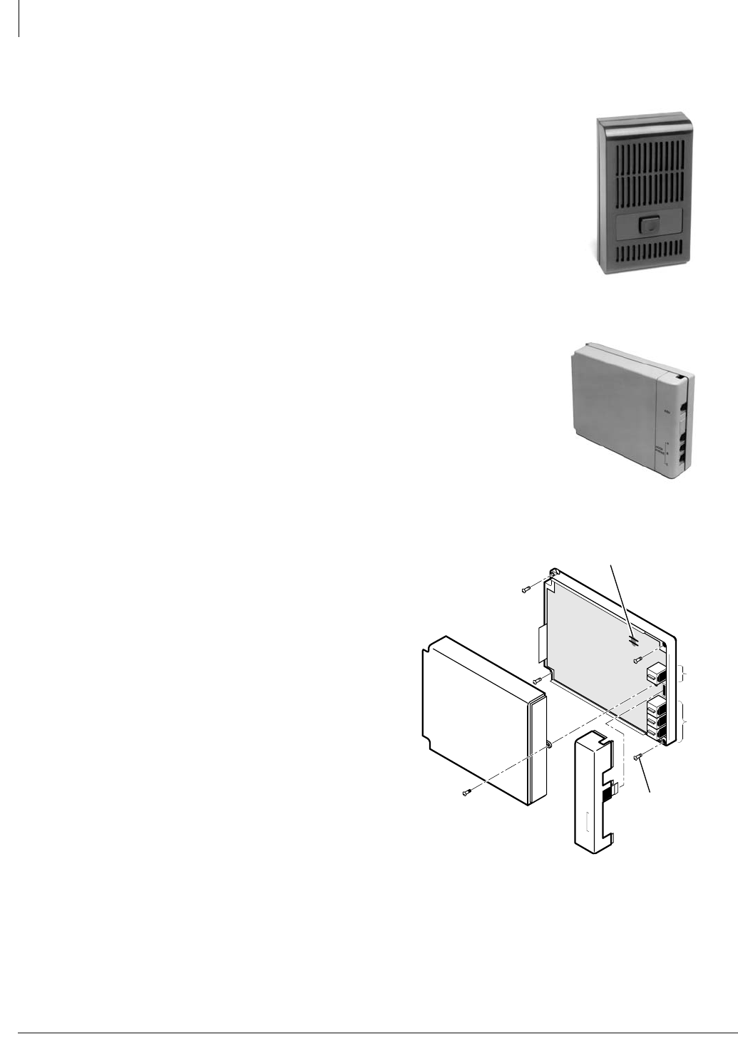
Peripheral Installation
Door Phone/Door Lock with DDCB Interface
12-14 Strata CTX I&M 06/04
Door Phone/Door Lock with DDCB Interface
The Strata CTX supports up to eight DDCB door phone control
boxes. Each DDCB supports up to three MDFB door phones
which provides a total of up to 24 door phones (see Figure
12-15). Each DDCB can provide a door unlock control relay in
place of one of the door phones.
DDCB and MDFB Cabling
For DDCB and MDFB wiring/interconnecting details and door
lock control installation procedures and secondary protection
information, refer to Chapter 10 – MDF PCB Wiring. If using
24 AWG cable, the length of the cable run from the Strata CTX
to the MDFB (via the DDCB) must not exceed 1,000 feet (305
meters).
• DDCB cable runs must not have cable splits (single or
double), cable bridges (of any length) or high resistance or
faulty cable splices.
DDCB Wall Mounting
The DDCB is designed to be mounted on a
wall or other vertical surface.
³To mount the units
1. Locate the two mounting holes on the
right-hand side on the DDCB (see Figure
12-14).
2. Remove the side cover from the DDCB to
expose the two left-hand mounting holes.
3. Position the DDCB adjacent to the Base
KSU with regard to wiring needs.
4. Secure the DDCB to the mounting surface
with four one-inch panhead wood screws.
Door Phone Wire Connections
Up to 24 door phones can be connected to the Strata CTX system. Door phones are connected as
follows: Up to three MDFB, door phones can connect to a single DDCB door phone control box,
which in turn connects to a single DKT interface port (See Figure 12-16 for door phone wiring
diagram). Only one of the three connected door phones can be active at a given point in time.
1873
1874
KSU
A
B
C
DOOR
PHONE
Mounting
Screws (4)
External Power Straps
(DDCB Only)
KSU
Jack
MDFB
Jack
A~C
1493
Figure 12-14 Door Phone (DDCB) Installation
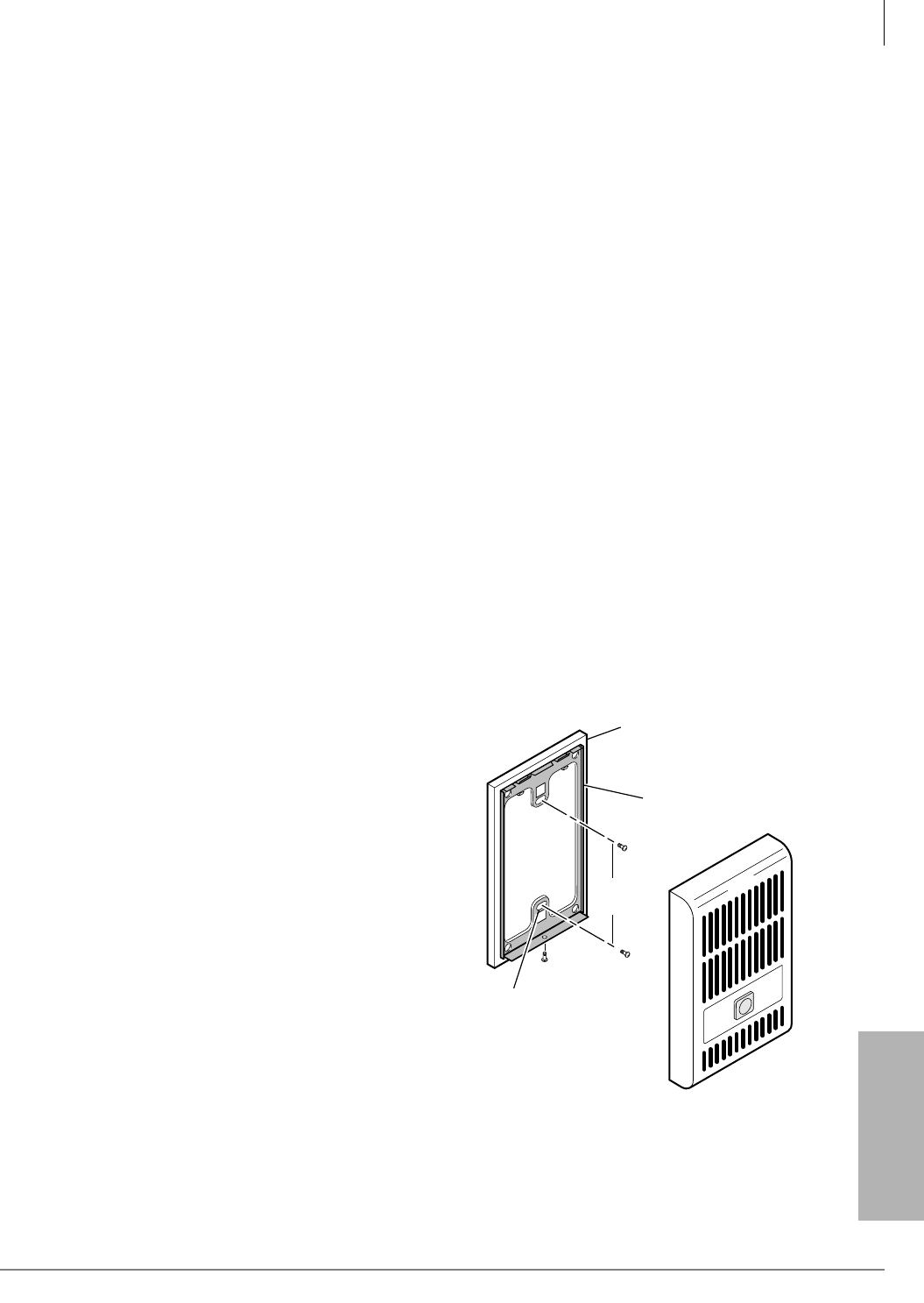
Peripheral Installation
Door Phone/Door Lock with DDCB Interface
Strata CTX I&M 06/04 12-15
Peripheral Installation
Calling from a Door Phone
Each door phone has a push button that rings selected telephones with one of three unique bing-
bong sounds. The door phone’s location displays on ringing telephone LCDs. The three bing-bong
ring types are permanently assigned to each of the DDCB ports (A, B and C) as shown in Figure
12-16. Door phones can also be programmed to ring over the system’s external paging equipment.
When a telephone answers a door phone call, a two-way talk-path is established between the
calling door phone and the called telephone.
Calling a Door Phone
Each door phone has a unique number (#15XX, where “XX” = 01~24 max., depending on system
size) that can be dialed from system telephones. When a system telephone calls a door phone, the
door phone does not ring but provides a two-way talk-path between the calling telephone and the
called door phone. This enables telephone users to monitor sounds in the general area where the
door phone is installed.
Door Lock Control
As an option, Port B of the DDCB can be connected to a door lock control device, instead of a
door phone, to unlock a door. The door lock control device is not supplied by Toshiba and must be
ordered separately. The door lock option is a hardware jumper located on the DDCB. This option
provides relay contacts that will open, or close the Port B wire pair when a telephone’s door lock
button is pressed or when a door lock feature code is dialed from a telephone (see Figure 12-16 for
option settings).
Door Phone/Lock Programming
Door phone assignments are in Program 507 and door lock assignments are in Program 508.
MDFB Wall Mounting
1. Remove the screw from the bottom of the
cover. Detach the cover from the base and
metal frame (see Figure 12-15).
2. Position the metal frame and base to the
mounting surface and secure with two one-
inch panhead wood screws.
3. Attach cover to the metal frame and base and
secure with the screw which was removed in
Step 1.
MDFB Volume Control Adjustments
1. Remove the screw from the bottom of the
MDFB cover.
2. Detach the cover from the base and metal
frame.
3. The volume level is changed by a screw
adjustment on the back of the MDFB. Turn
the screw with a flat-headed screwdriver
while ringing the MDFB or while on a call
with it. The volume level will change as the
screw is turned.
Two Wall
Mounting Holes
Door Phone
Base
Metal Frame
3.25
inches
1494
Figure 12-15 Door Phone (MDFB) Installation
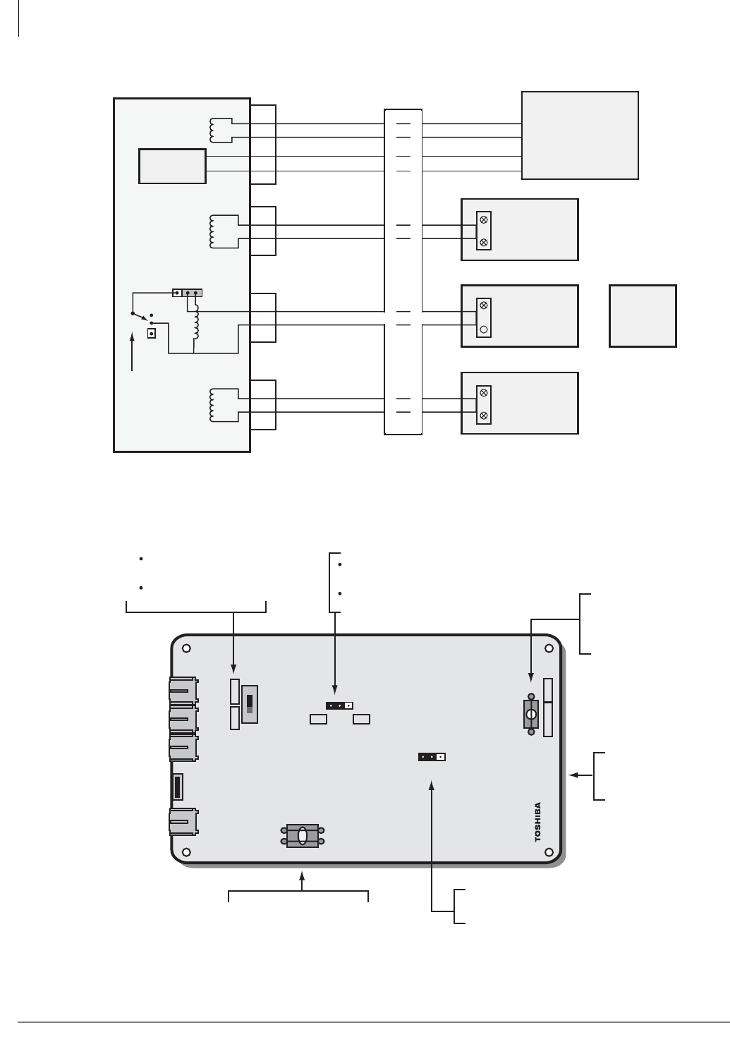
Peripheral Installation
Door Phone/Door Lock with DDCB Interface
12-16 Strata CTX I&M 06/04
Figure 12-16 DDCB3 Wiring and DDCU Door Lock PCB
DDCU3A V.1
5607
EX.POWER
EX.POWER
W2
W1
SW5
Mu A
SW3 N/CN/O
SW2
DOORLOCK
J1 J2 J3 J4
W3
DOOR C TONE
KSU
Door Phone C
Door Phone B
Door Phone A
Set Lock if J3 should be
door lock contacts
Set Door if J3 should be
door phone B interface
Cut W1 and W2 if External
Power is wired to J1 pin 2+5
(see Figure 6-4)
Set to N/C If Door Lock Relay contact should
open when Door Unlock button is pressed
Set to N/O if Door Lock contact should close
when Door Unlock Button is pressed
Must be set for MU Law
in USA and Canada
Cut W3 only if Door
Phone C ring should
sound like Door
Phone A
Notes
1. MDFB Terminal Pins L1 and L2 are used with HESB Talk Back
Amplifies Application only- See Figure 8-22.
2. Not available with BDKS.
3. Refer to Programs 123, 456, and 789.
Remove DDCB3
Cover for access to
hardware options
DDCB3
A
C
B
N/C
N/O
SW3
SW2
Lock Door
Door Lock
Relay Contact
(24VDC, 1.OA max)
(one bing-bong ring per ring cycle)
(two bing-bong rings per ring cycle)
(one bing-bong ring per ring cycle-low pitch)
MDF
KSU
- T (voice data)
R (voice data)
PR 2
PT
J1
J2
J3
J4
or
MDFB
3
4
Door
Lock
Control
Power
Circuit
MDFB
Door Phone
A
MDFB
Door Phone
B
3
4
MDFB
3
4
4
2
5
3
MDFB
Door Phone
C
1
1
2
2
1
2
PDKU, BDKU
or
BDKS
(any circuit)

Peripheral Installation
External Speaker Unit (HESB) Options
Strata CTX I&M 06/04 12-17
Peripheral Installation
External Speaker Unit (HESB) Options
Strata CTX systems provide three options utilizing an HESB:
• Telephone External Ringer
• Amplified Page Speaker
• Talkback Amplified Page Speaker with talkback
System hardware requirements vary depending on the HESB option selected. See the following
installation procedures for the hardware requirements for each option.
Telephone External Ringer
The loud ringing bell option enables the voice first or ringing signal tone to be amplified without
the use of other manufacturers’ equipment. The voice first and signal tone can be amplified on all
electronic and digital telephones equipped with HHEU PCBs and HESB. (See Chapter 7 – Station
Apparatus.)
The HESB automatically turns Off once the ringing call or voice first has been manually answered
from the electronic or digital telephone. This turn-off feature prevents audio feedback problems.
Step 1: Set Up the Telephone for the External Ringer Option
3000 Telephone Instructions
³To Turn the Loud Ringing Bell Feature On/Off (Default is Off)
1. Press 369+Hold (simultaneously).
2. Press # FB08 (FB08 = Feature Button 08, not dial pad 8).
3. Press Msg (Msg LED turns On) to turn On the External Speaker (HESB) connection
...or press Msg again (Msg LED turns Off) to turn Off the External Speaker (HESB)
connection.
4. Press Hold.
2000 Telephone Instructions
Important! See Chapter 11 – Station Apparatus for instructions on the HHEU jumpers and
cutting the EXSP on 2000-series digital telephones. See below for 3000 telephones.
Step 2: Connect the HESB External Ringer to the 3000-series Telephone
1. Connect a jumper between terminals 2 and 10 on the HESB TB1 terminal block (Figure 12-21).
2. Connect a jumper between terminals 4 and 5 on the HESB TB2 terminal block.
3. Install a BHEU PCB and HESC-65A cable per Figures 12-17 and 12-18.
Note HESB connections made in Steps 4~6 can be accomplished using the HESB VOICE
modular jack instead of the TB1 terminal block.
4. Connect terminal 1 of the HESB TB1 terminal block to the red (+) wire of the HESC-65A
using a modular block.
5. Connect terminal 2 of the HESB TB1 terminal block to the green (-) wire of the HESC-65A
using a modular block.
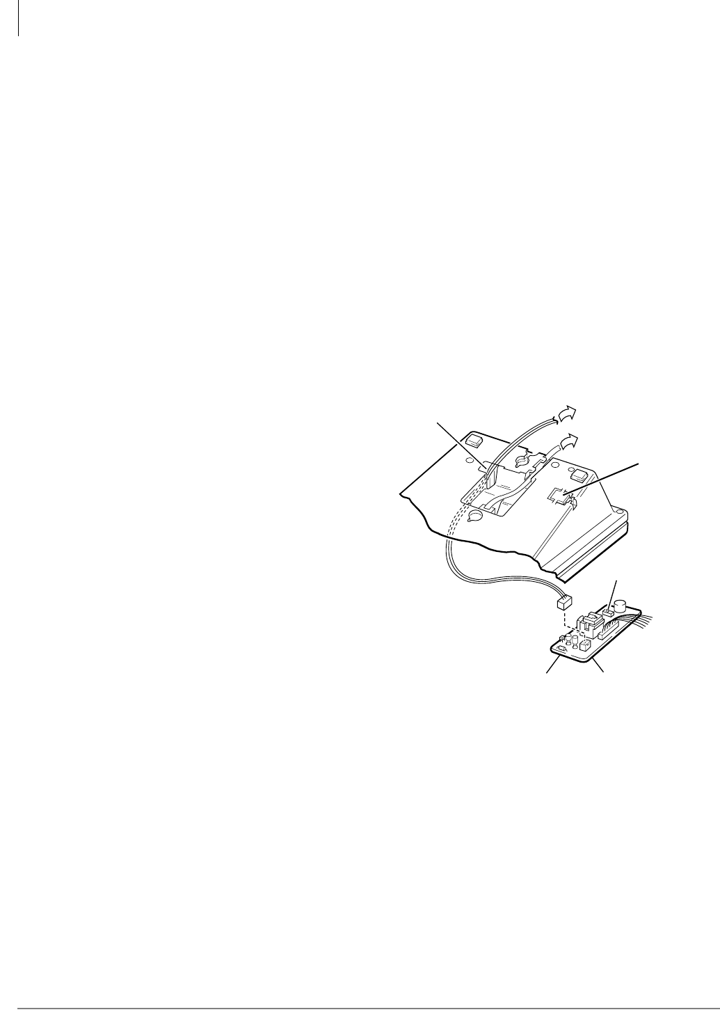
Peripheral Installation
External Speaker Unit (HESB) Options
12-18 Strata CTX I&M 06/04
6. Connect terminal 8 of the HESB TB1 terminal block to the yellow (L2) wire of the HESC-65A
cable using a modular block.
7. Connect the HACU-120 power supply’s +12V lead to terminal 1 of the HESB TB2 terminal
block, and connect the power supply’s 0V lead to terminal 2.
8. Plug the provided power cord into the power supply and to a 115VAC ± 10VAC, 60Hz power
source.
Important! If AC voltage is not within range, have a qualified electrician correct the problem.
Telephone (BHEU) to External Speaker (HESB) Cable
Connection
The HESC-65A cable is required to connect the telephone BHEU to the HESB external speaker.
The BHEU can be installed into the DKT3000-series telephones. It can also be installed into
DKT3010 and DKT3020 telephones that have either a BVSU or BPCI installed. For DKT3001
telephones, the installation is same as below, only the connector location is different.
HESC-65A and BHEU Installation
1. Loosen the four captive screws on
the telephone base, and remove
the base. Use a screwdriver or
other suitable tool to remove the
plastic tab on the back of the base.
(The HESC-65 cable connector is
accessed through this opening. See
Figure 12-17.)
2. Connect the HESC cable to P1 of
the BHEU and feed it through the
telephone base.
3. Position the BHEU PCB
(component side down) on the
standoffs inside the base, and
secure with the two provided
screws (see Figure 12-18).
4. Connect the BHEU integrated
wire plug to P3 (HEU) on the
telephone base PCB (see Figure
12-19). Note the location of the
red wire
...or for DKT3001 telephones only, connect the BHEU wire plug to P1 (HEU) on the telephone
base PCB (see Figure 12-20). Note the location of the red wire.
5. Reinstall the base on the telephone.
6. Connect the HESC-65A cable to the HESB (see Figure 12-17).
7. Connect station wiring (see Figure 12-21).
Feed through
HESC-65A Cable
To HESB
Block
SW601
BHEU P1
HESC-65 Cable
or
HESC-65A Cable
5650
Knock out
with
screwdriver
for BHEU
modular
connector
Figure 12-17 HESC-65A Cabling
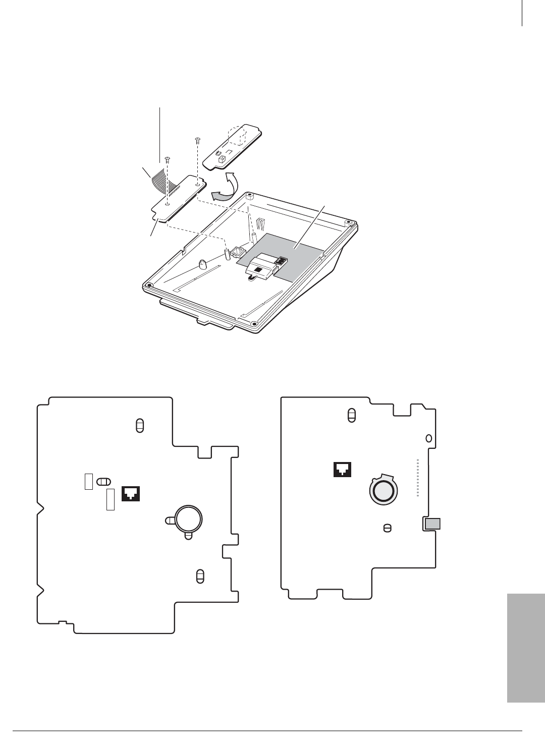
Peripheral Installation
External Speaker Unit (HESB) Options
Strata CTX I&M 06/04 12-19
Peripheral Installation
Figure 12-18 BHEU Installation
Figure 12-19 DKT3010, DKT3020, DKT3014
Strap and Connector Locations
Figure 12-20 DKT3001 BHEU Connector Location
BHEU
To HEU connector
on telephone
Turn BHEU component
side down.
BVSU or BPCI
(optional)
5651
Red
Wire
PCI/ VSU
PCI /ADMPCI /VSUHEU
P1
P2
P3
P6
Carbon
W302
HEU
W303
W301
CARBON
EX.POWER
W101
EX.POWER
W102
RED
RED
RED
RED
5603
W401
W402
SET UP
GND
DKT3001 12
HEU
P1
5653
EX.
POWER
RED
HEU 103
W101
W102
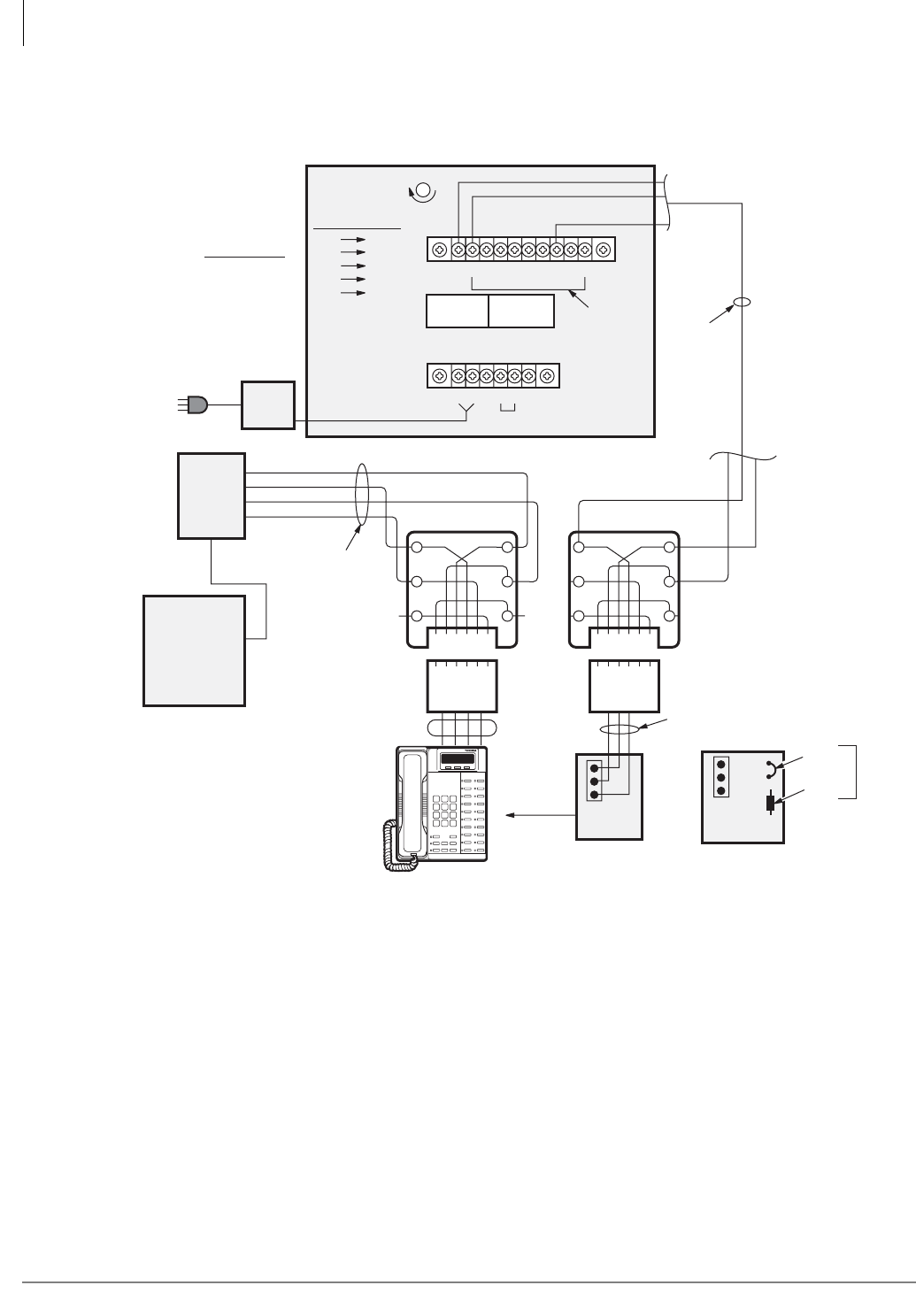
Peripheral Installation
External Speaker Unit (HESB) Options
12-20 Strata CTX I&M 06/04
Figure 12-21 Wiring the Telephone External Ringer with HESB Interface
P1
BHEU
(-)
(+)
(-)
(L2)
(+)
5606
25-Pair
Cable
Jacketed
Twisted Pair
24 AWG
HACU-120
115VAC to
12 VDC
115 VAC
Tip
Ring
PT
PR
Station Cabling
MDF
66 Block
Power
Supply
Modular
DKT2000 or 3000-series
Station HESC-65A Cable to P601
of HHEU or to P1 of BHEU
Green
Yellow
Red +
P601
HHEU
(V.3 or .4)
OCA
Strap
R607
Do Not
Cut
6 5 4 3 2 1
Not Used
6 5 4 3 2 1
Not Used
Voice Door Phone
12345
TB2
12V 0V
12V 0V
24 AWG
Jacketed
Twisted Pair
from
Digital
Telephone
to HESB
Jumpers
GN
Y
BL
R
BK
W
GN
Y
BL
R
BK
W
(L2)
654321
123456
654321
123456
TB1
(L2)
Jumper Wires:
TB1
2-10
TB2
4-5
HESB (Rear View)
Internal Wiring:
Volume Control
TBI
1
2
3
4
Voice
6
1
3
4
(+)
(-)
12345678910
BDKU,BDKS,
PDKU or
RDSU
± 10 VAC
maximum
Install BHEU, HHEU Circuit (V.3 or .4) or HHEU2 card
into base of DKT per BHEU or HHEU installation
instructions in this chapter.

Peripheral Installation
External Speaker Unit (HESB) Options
Strata CTX I&M 06/04 12-21
Peripheral Installation
Step 3: Test the Telephone External Ringer Option
1. Test the AC input voltage by plugging power cord into the power supply and to a
115VAC±10VAC to 12VDC power source.
2. Make a CO or station call to the station configured for the loud ringing bell. Ringing will be
heard over the HESB.
3. Use a small, slotted screwdriver to turn the volume control on the back of the HESB to the
desired level and adjust the ring volume control on the telephone.
4. If ringing is heard at the station, but not over the HESB, check the following while the station is
ringing:
• Using a suitable voltmeter, measure voltage across terminals 1 (+) and 2 (-) of the HESB
TB1 terminal block. Voltage indication should be 4.5~5VDC.
Note Ringing stops once the call is manually answered. There should be NO voltage potential
across terminals 1 and 2.
• If voltage is not as specified during ringing, check that the telephone wiring connections to
the HESB have been made properly (wires to terminals 1 and 2 of the HESB TB1 terminal
block may have been reversed).
Amplified Page Speaker Option
The amplified speaker option enables the HESB to be configured as a paging speaker. The HESB
is connected to the BIOU 600-ohm page output to provide an amplified external speaker.
³To install the HESB amplified speaker option
1. Connect a jumper between terminals 1 and 2 of the HESB TB1 terminal block (see Figure
12-22).
2. Connect a jumper between terminals 6 and 7 of the HESB TB1 terminal block.
3. Connect a jumper between terminals 5 and 8 of the HESB TB1 terminal block.
4. Connect a jumper between terminals 3 and 4 of the HESB TB2 terminal block.
5. Connect a jumper between terminals 5 and 6 of the HESB TB2 terminal block.
6. Connect the BIOU or ACTU 600-ohm page output (pins 13 and 38) to terminals 3 and 4 of the
HESB TB1 terminal block.
7. Connect the power supply’s +12V lead to terminal 1 of the HESB TB2 terminal block, and
connect the 0V lead to terminal 2.
8. Plug the provided power cord into the power supply and to a 115VAC±10VAC to 12VDC
power source.
9. Set the BIOU SW600 switch to the SPO position.
Important! If AC voltage is not within range, have a qualified electrician correct the problem.
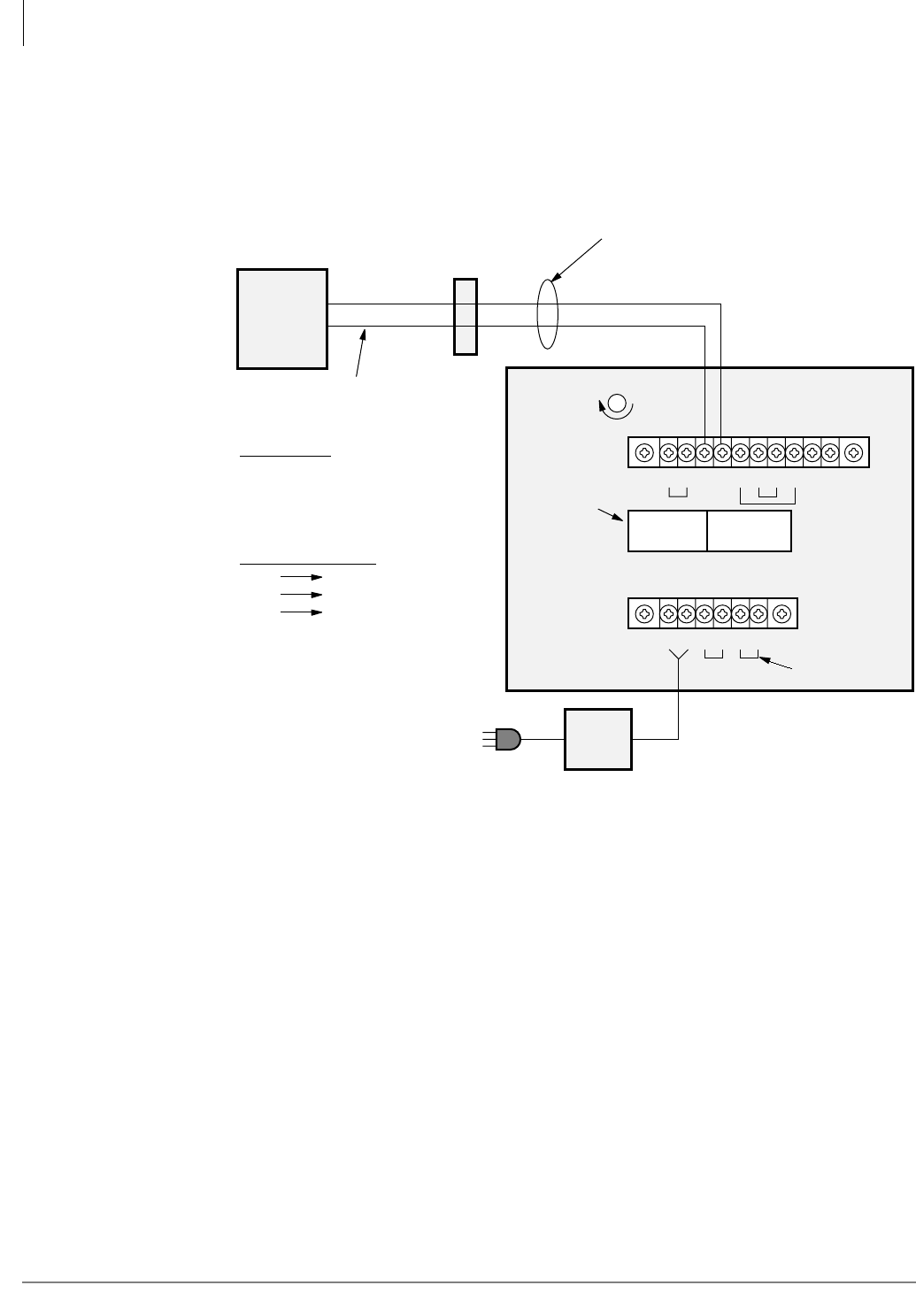
Peripheral Installation
External Speaker Unit (HESB) Options
12-22 Strata CTX I&M 06/04
³To test the amplified speaker option
1. Make an external page. The page should be heard over the HESB.
2. Verify that someone speaking into the door phone can be heard at the paging station. (With this
application, pressing the door phone button is not required to talk back through the door
phone.)
Figure 12-22 Amplified Page Speaker with HESB Interface
Jumper Wires:
BIOU
600Ω
Page
Output
BIOU switch SW600
must be in the
SPO position
MDF
66 Block
SPT (38, BK-GN)
SPR (13, GN-BK)
25-Pair Cable
Jacketed
Twisted
Pair
24 AWG
TB1
1-2
5-8
6-7
TB2
3-4
5-6
Modular
Connector
May Be Used
Volume Control
TBI
3
4
Voice
3
4
Internal Wiring:
6 5 4 3 2 1 6 5 4 3 2 1
Not Used
Voice
12V 0V
Note
• The 600 ohm page output sends
three types of signals during
system operation:
• Voice page
• Background music
• Night ringing
12345678910
TB1
Door Phone
123456
TB2
HESB (Rear View)
12V
VDC
0V Jumpers
5470
115 VAC (± 10 VAC) to 12 VDC
Power
Supply

Peripheral Installation
External Speaker Unit (HESB) Options
Strata CTX I&M 06/04 12-23
Peripheral Installation
Talkback Amplified Page Speaker with Talkback Option
The talkback amplified speaker option enables a talkback speaker to be provided in areas where a
telephone is not needed. In this configuration, the HESB is connected to the BIOU 600 ohm
(duplex) output and is used as the amplifier and speaker.
A door phone unit (MDFB) is connected to the HESB, and serves as a microphone to provide
talkback operation. (The MDFB push-button is inoperative, and the unit serves only as a
microphone for talkback and not as the normal door phone.)
Note The BIOU 600 ohm is a two-way (duplex) page output compatible with most commercially
available talkback amplifiers – door phone not required for talkback.
³To install the HESB amplified page speaker with talkback
1. Connect a jumper between terminals 1 and 2 of the HESB TB1 terminal block (see Figure
12-23).
2. Connect a jumper between terminals 3 and 4 of the HESB TB2 terminal block.
3. Connect a jumper between terminals 5 and 6 of the HESB TB2 terminal block.
Note HESB connections made in Steps 4~7 may be accomplished using the HESB VOICE and
door phone modular jack instead of the TB1 terminal block.
4. Connect terminal 7 of the HESB TB1 terminal block to Pin L1 of the MDFB.
5. Connect terminal 8 of the HESB TB1 terminal block to Pin L2 of the MDFB
6. Connect terminal 9 of the HESB TB1 terminal block to Pin 1 of the MDFB.
7. Connect terminal 10 of the HESB TB1 terminal block to Pin 2 of the MDFB.
8. Connect the BIOU 600-ohm page output (pins 13 and 38) to terminals 3 and 4 of the HESB
TB1 terminal block.
9. Set the BIOU SW600 switch to the SPO position.
10.Connect the HACU-120’s +12V lead to terminal 1 of the HESB TB2 terminal block, and
connect the 0V lead to terminal 2.
11. Plug the provided power cord into the power supply and to a 115VAC±10VAC to 12VDC.
Important! If AC voltage is not within range, have a qualified electrician correct the problem.
³To test the talkback amplified speaker
1. Make an external page. Page will be heard over the HESB.
2. Verify that someone speaking into the door phone can be heard at the paging station. (With this
application, pressing the door phone button is not required to talk back through the door
phone.)
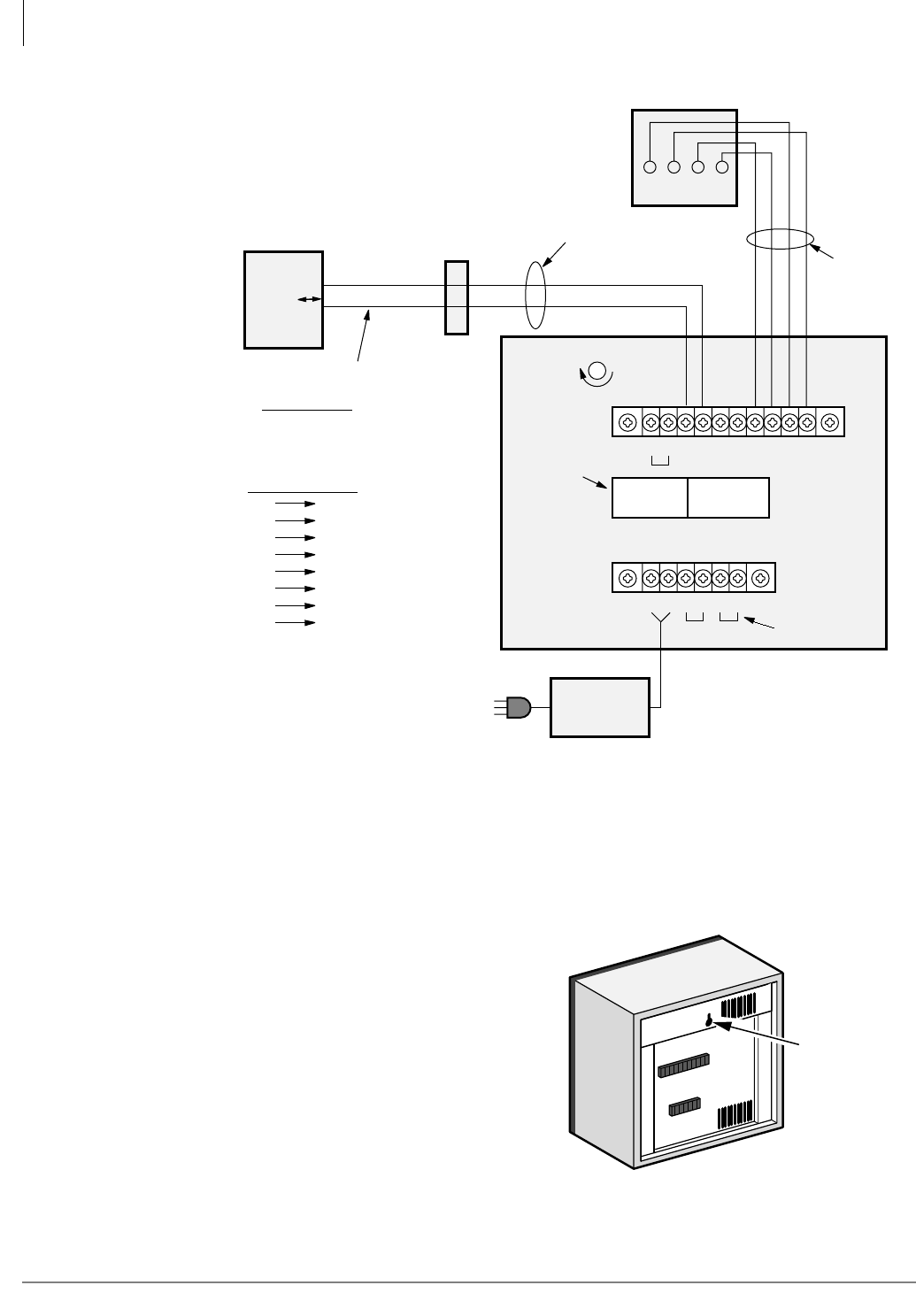
Peripheral Installation
External Speaker Unit (HESB) Options
12-24 Strata CTX I&M 06/04
Figure 12-23 Amplified Page/Talk-Back with HESB Interface
HESB Wall Mounting
Some applications may require that the HESB is mounted on a wall or other vertical surface.
³To wall mount the HESB
1. Find a suitable location on the mounting
surface for the HESB (see Figure 12-24).
2. Screw a 1.25-inch panhead wood screw into
the mounting surface.
3. Hang the HESB from the screw.
123456
12V 0V
HESB (Rear View)
115VAC ± 10VAC to 12VDC
Door Phone
Internal Wiring:
TBI
4
3
TBI
7
8
9
10
Voice
4
3
4
3
2
5
HACU-120
Notes
The 600 ohm duplex page output is
compatible with most
commercially available talkback
amplifiers. – MDFB not required.
Jumpers
Voice Door Phone
12V 0V
TB2
12345678910
TB1
6 5 4 3 2 1 6 5 4 3 2 1
Modular
Connector
May Be Used
BIOU
600Ω
Page
Output
BIOU switch,
SW600must be in
the SPO position
MDF
66 Block
SPT (38, BK-GN)
SPR (13, GN-BK)
25 Pair Cable
<Duplex>
12L1 L2
Volume Control
Jumper Wires:
TB1
1-2
TB2
3-4
5-6
Jacketed Twisted
Pair 24 AWG
Jacketed
Twisted
Pair
24 AWG
MDFB (Rear View)
1 2 L1 L2
Door Phone
Talkback
Microphone
5469
Power
Converter
One Wall
Mounting
Hole
1516
Figure 12-24 HESB Wall Mounting
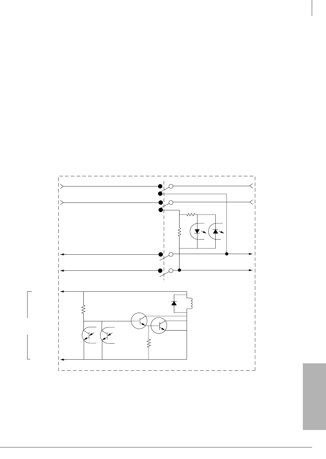
Peripheral Installation
Power Failure Options
Strata CTX I&M 06/04 12-25
Peripheral Installation
Power Failure Options
In the event of a power failure, Strata CTX uses these options:
Reserve Power
For information on the Reserve Power Option, see Chapter 1 – Installation.
Power Failure Transfer Unit
An optional Power Failure Transfer Unit (DPFT) can be installed that automatically connects up to
eight selected CO lines directly to designated standard telephones in the event of a power failure.
The DPFT enables normal operation of the selected CO lines and standard telephones when the
system is in service. When power is restored, each telephone is independently reconnected to
system standard telephone circuit ports after it is finished with its direct CO line call. The DPFT is
normally installed on the MDF.
Figure 12-25 provides a circuit diagram of the DPFT.
Figure 12-25 DPFT Circuit Diagram
J2-26
J2-1
J1-26
J1-1
Relay
J1-25
J1-50
J1-2
J1-27
J2-2
J2-27
Telephone Current
Detector
To TEL-T1
To TEL-R1
To CO-T1
To CO-R1
To RSTU/PSTU-T1
RDSU/RSTS
To RSTU/PSTU-R1
RDSU/RSTS
To RCOU/PCOU-T1
To RCOU/PCOU-R1
DG (Input)
-24V (Input)
RSTU or PSTU
Control
1498
Notes
• Representation of first of eight circuits.
• Conditions shown with AC power (-24VDC) off.

Peripheral Installation
Power Failure Options
12-26 Strata CTX I&M 06/04
Power Failure Emergency Transfer (DPFT) Installation
1. Mount the DPFT on or near the MDF.
Note See Chapter 10 – MDF PCB Wiring, DPFT/MDF interconnecting tables.
2. Using 25-pair cables with amphenol-type connectors (female for DPFT connector J1, male for
DPFT connector J2), connect the DPFT to two 66-type quick-connect blocks.
3. Connect the CO lines selected for emergency use to the DPFT J1-block “CO-TIP” and “CO-
RING” terminals.
4. Connect the RCOU, RCOS (or PCOU) circuits related to the emergency CO lines to the DPFT
J1-block “RCOU-TIP” and “RCOU-RING” terminals.
5. Connect the standard telephone stations selected for emergency use to the DPFT J2-block
“TEL-TIP” and “TEL-RING” terminals.
6. Connect the RSTU, RDSU/RSTS or PSTU standard telephone circuits related to the emergency
standard telephones to DPFT J2-block “PSTU/ RSTU-TIP” and “PSTU/RSTU-RING”
terminals.
7. Connect the DPFT to the RDSU/RSTU/PSTU DG and -24V terminals (See Chapter 10 – MDF
PCB Wiring for RSTU/PSTU and RCOU/PCOU wiring/interconnecting details). The -24V
(Pin 25) and DG (Pin 50) ground terminals are available on the RSTU2, RDSU, or PSTU only.
³To test the operation of the DPFT
1. Turn the system power switch Off.
2. Verify that CO dial tone is available at each standard telephone connected to the DPFT.
3. Call back to each telephone using an outside line.

Peripheral Installation
Station Message Detail Recording (SMDR)
Strata CTX I&M 06/04 12-27
Peripheral Installation
Station Message Detail Recording (SMDR)
For each incoming, outgoing, tandem or conference call, the Strata CTX can generate a record that
includes details of the call, including the originating station or trunk, the start time of the call, its
duration, authorization codes, etc. If a station user dials “911,” the Strata CTX also generates a
record at the beginning of the call as part of its internal notification that an emergency call is in
progress.
The BSIS optional PCB attaches to the ACTU of the CTX100 or the BECU of the CTX670 to
provide four RS-232 interface jacks (one for SMDR and one for SMDI). See Figures 12-6 and
12-7, starting on page 12-6 for connection information.
SMDR Record Types
Distinct records are generated for different types of calls. The table below lists the record types.
The type of each record is identified by a letter entry in the column of the record.
The use of multiple records allows the CTX to account for multi-stage calls such as transfers and
conferences. A simple outgoing or incoming call would generate a Normal record. A transferred
call would generate a Start record for the first segment of the call and an End record for the second
segment of the call. The appropriate times would be stored in each. A detailed description of
SMDR is provided in a separate manual.
Several fields in the record may displayed or masked based on system programming. They include
DISA security codes, authorization codes, ANI, DNIS and Caller ID.
The Strata CTX can buffer up to 1000 SMDR records in response to a loss of DTR signal from an
attached call accounting device or external buffer. When the buffer overflows, subsequent call
records will be lost until the buffer is cleared. The CTX buffer will be cleared by a system restart
or loss of system power.
Table 12-1 Call Record Types
Record Type Notes
B (aBandoned) When a call is abandoned
N (Normal) Simple outgoing or incoming call
S (Start) Start of complex outgoing or incoming call or 911 call
X (transfer) When a call is transferred
E (End) This record is associated with a specific S or X records, and indicates
termination of a call
I (Initial) When system is initialized
T (Time) When the system time or date is changed
A (Authorization) When the input Account Code is verified and the result is successful, the
Account Code is defined as the Authorization Code.
C (Charge Account) When an Account Code is entered
M (Charge Conference) When an Account Code is entered during a conference call

Peripheral Installation
Station Message Detail Recording (SMDR)
12-28 Strata CTX I&M 06/04
Table 12-2 SMDR Record Format
Line Column Name Format Notes
1
1(1) Record Type “N”/”S”/”X”/”E”/”B”/
”I”/”T”/”A”/”C”/”M”
See “SMDR Record Types” on page
12-27.
2(1) Space
3-5(3) Record Number XXX Record Number (000 -- 127)
6(1) Space
7-12(6) Node number XX 00 - 99
13(1) Space
14-20(7) Orig Information “DN”+XXXXX
“CF”+ XXXXX
“T”+OLG+MMM
“T”+ILG+MMM
“A”+OLG+MMM
“A”+ILG+MMM
Prime DN
X=ID of conference
“T”/”A”:Answersupervised/Unsupervised
ILG: Incoming Line Group
OLG: Outgoing Line Group
MMM: CO number/Channel Group
Number
(Left positioned and padded space)
21(1) Space
22-28(7) Term Information
29(1) Space
30-43(14) Time stamp MO/DD HH:MM:SS N/E Record: End of Call
S Record:Start of Call
If 911, time trunk is seized.
X Record: Completion of transfer
B Record: The call is abandoned
I Record: System initialized
T Record: Original/New system time
A/C/M Record: Input account code
MO = Month(01 -- 12)
DD = Day (00 -- 31)
HH = Hour (00 -- 23)
MM = Minutes 00 -- 59)
SS = Seconds (00 -- 59)
44(1) Space
45-54(10) Call duration HH:MM:SS.S HH = Hour (00 -- 23)
MM = Minutes (00 -- 59)
SS = Seconds (00 -- 59)
S = always 0
55(1) Space
56-87(32) Dial information XX….X Dials/Account Codes
(Left positioned and padded space)
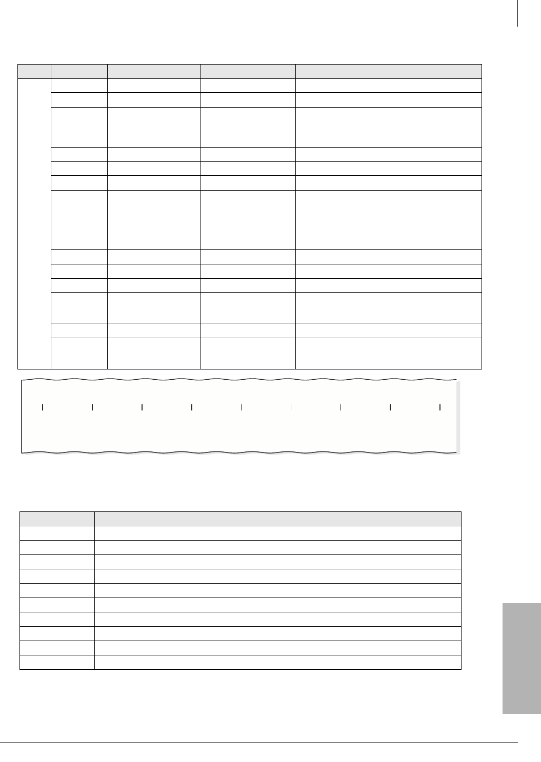
Peripheral Installation
Station Message Detail Recording (SMDR)
Strata CTX I&M 06/04 12-29
Peripheral Installation
Figure 12-26 Sample Call Record – Simple Outing Call, Outside Party Answers (Rel. 1.02 or lower)
Table 12-3 Sample Call Record Explanation (Rel. 1.02 or lower)
2
1(1) Spaces
2(1) New line “&”
3-19(17) Caller ID
CESID
XXX…XXX
“C”+ XXX…X
Caller ID
CESID
(Left positioned and padded spaces)
20(1) Spaces
21-24(4) DISA “DISA”
25(1) Spaces
26-38(13) ANI
XXXXX...XXXX (00 -- 99)
Area Code (000 -- 999)
Exchange Code (000 -- 999)
Extended Exchange code (0000 -- 9999)
39(1) Spaces
40-46(7) DNIS XXXXXXX (0000000 -- 9999999)
47(1) Spaces
48-54(7) AUXID 1 “DN”+XXXXX XXXXX = Prime DN
(Responsibility for outgoing)
55(1) Spaces
56-62(7) AUXID 2 NN+XXXXX NN = Node number (00 – 99)
XXXXX = Prime DN
Field Notes
N Normal incoming or outgoing call record.
001 Record number 1.
00 Used to identify the Node ID in a Strata Net network. Not used in a standalone system.
DN1234 Directory Number (DN) 1234 originated the call.
T000001 The call went out on Trunk Number 1.
06/28 Date
12:10:50 Time at which call was answered.
00:10:30:0 Duration of the call to the tenth of a second.
12134567890 The destination number dialed.
& Start of a new line. More complex call records may use two lines.
Table 12-2 SMDR Record Format
(continued)
Line Column Name Format Notes
6038
11020304050607080
N 001 00 DN1234 T000001 06/28 12:10:50 00:10:30.0 12134567890
GGGGGGGG

Peripheral Installation
Station Message Detail Recording (SMDR)
12-30 Strata CTX I&M 06/04
Record Formats (Release 1.03)
Table 12-4 SMDR Record Format (Software Release 1.03)
Line Column Name Format Notes
1
1(1) Record Type “N”/”S”/”X”/”E”/”B”/
”I”/”T”/”A”/”C”/”M”
See “SMDR Record Types” on page
12-27.
2(1) Space
3-5(3) Record Number XXX Record Number (000 -- 127)
6(1) Space
7-12(6) Node number XX 00 - 99
13(1) Space
14-22(9) Orig Information “DN”+XXXXX
“CF”+ XXXXX
“T”+OLG+MMM+N
N
“T”+ILG+MMM+N
N
“A”+OLG+MMM+N
N
“A”+ILG+MMM+N
N
Prime DN
X=ID of conference
“T”/”A”:Answersupervised/Unsupervised
ILG: Incoming Line Group
OLG: Outgoing Line Group
MMM: CO number/Channel Group No.
NN: ISDN-Bch if caller seizes non-ISDN
trunk, then “00” is shown as NN value.
(Left positioned and padded space)
23(1) Space
24-32(9) Term Information
33(1) Space
34-47(14) Time stamp MO/DD
HH:MM:SS
N/E Record: End of Call
S Record:Start of Call
If 911, time trunk is seized.
X Record: Completion of transfer
B Record: The call is abandoned
I Record: System initialized
T Record: Original/New system time
A/C/M Record: Input account code
MO = Month(01 -- 12)
DD = Day (00 -- 31)
HH = Hour (00 -- 23)
MM = Minutes 00 -- 59)
SS = Seconds (00 -- 59)
48(1) Space
49-58(10) Call duration HH:MM:SS.S HH = Hour (00 -- 23)
MM = Minutes (00 -- 59)
SS = Seconds (00 -- 59)
S = always 0
59(1) Space
60-91(32) Dial information XX….X Dials/Account Codes
(Left positioned and padded space)
Peripheral Installation
Station Message Detail Recording (SMDR)
Strata CTX I&M 06/04 12-31
Peripheral Installation
Figure 12-27 Sample Call Record – Simple Outing Call, Outside Party Answers (Software Release R1.03)
Table 12-5 Sample Call Record Explanation (Software Release R1.03)
2
1(1) Spaces
2(1) New line “&”
3-19(17) Caller ID
CESID
XXX…XXX
“C”+ XXX…X
Caller ID
CESID
(Left positioned and padded spaces)
20(1) Spaces
21-24(4) DISA “DISA”
25(1) Spaces
26-38(13) ANI XXXXX...XXXX (00 -- 99)
Area Code (000 -- 999)
Exchange Code (000 -- 999)
Extended Exchange code (0000 -- 9999)
39(1) Spaces
40-46(7) DNIS XXXXXXX (0000000 -- 9999999)
47(1) Spaces
48-54(7) AUXID 1 “DN”+XXXXX XXXXX = Prime DN
(Responsibility for outgoing)
55(1) Spaces
56-62(7) AUXID 2 NN+XXXXX NN = Node number (00 – 99)
XXXXX = Prime DN
Field Notes
N Normal incoming or outgoing call record.
001 Record number 1.
00 Used to identify the Node ID in a Strata Net network. Not used in a standalone system.
DN1234 Directory Number (DN) 1234 originated the call.
T00100100 The call went out on Trunk Number 1, OLG 1.
06/28 Date
12:10:50 Time at which call was answered.
00:10:30:0 Duration of the call to the tenth of a second.
12134567890 The destination number dialed.
& Start of a new line. More complex call records may use two lines.
Table 12-4 SMDR Record Format (Software Release 1.03)
(continued)
Line Column Name Format Notes
6516
11020304050607080
N 001 00 DN1234 T00100100 06/28 12:10:50 00:10:30.0 12134567890
N 024 110 DN2021 A02002023 06/28 13:45:05 00:00:26.0 9495833705
GGGGGGGG
Example of B-channel Call Record (B-channel is last two digits in term field)

Peripheral Installation
Station Message Detail Recording (SMDR)
12-32 Strata CTX I&M 06/04

Strata CTX I&M 06/04 IN-1
Index
Index
A
a law, 11-20
ABCS, 2-18, 3-10, 3-11, 3-12, 3-18, 3-23
ABR
circuits, 3-22
license control, 2-4, 2-7
ABTC-3M, 3-10, 3-11, 3-12, 3-14
AC adapter, 11-35
access point, 9-26
ACD, 2-18
license control, 2-4, 2-7
ACTU, 2-18, 3-20, 3-21, 3-22, 3-23
ACTU2A, 2-2, 3-19
ACTU2A-S, 2-2
add-on modules
capacities, 2-9
IPT, 9-10
addressing, 9-16
ADKU, 2-14, 6-3
ADM
limits, 1-22
AETS, 2-18, 3-23
AMDS, 2-3, 2-7, 2-18, 3-23
amplified page speaker, 12-17
ANI, 2-12
APSU112, 2-18, 3-15, 3-16, 3-17, 3-22
APSU112A, 3-23
ARCS, 3-22
ASTU, 2-14, 6-4
attach belt clip, 11-40
B
background music (see BGM)
backup memory module (BBMS), 4-51
BACL, 4-39
bandwidth requirements, 9-41
base cabinet
CTX100, 2-3
CTX670, 2-8
base unit, 11-35
antenna, 11-39
battery, 11-32
charging, 11-39
charging spare packs, 11-43
CTX28 reserve power battery/charger
(HPFB), 1-18
install in handset, 11-39
low, 11-42
removing and charging, 11-39
warnings, 11-32
battery cable, 3-11, 3-12
battery charger, 3-10, 3-11, 3-12, 3-18
battery jumper, 3-19, 3-20
BBMS, 2-3, 2-7, 3-20, 4-51
BCCB, 4-39
BCTU, 2-5, 2-55
BCTU/BEXU, 4-44
BDKU, 2-14
BDKU/BDKS, 6-7, 6-8
BECU, 4-52
BECU/BBCU, 4-50, 4-52
beep strap, 11-50
belt clip, 11-40
BEXS, 2-3, 2-7, 4-52
BEXU, 2-5, 2-55
BFIF, 4-35, 4-39
BGM, 2-3, 2-6, 6-9
interfaces, 12-8
over external page, 12-10
BHEU, 11-7, 12-18
BIOU, 2-18, 6-9, 12-8, 12-10
BIOU/BIOUS, 6-9
BIPS1A, 9-42

Index
C~D
IN-2 Strata CTX I&M 06/04
BIPU-M1A, 9-2
BIPU-M2A, 2-15, 9-6, 9-42
BIPU-Q1A, 9-40, 9-42
BPCI, 11-11
BPSB, 4-39
BPTU, 2-17, 7-3, 7-4
BSIS, 2-3, 2-7, 2-18, 3-23
interface ports, 12-6
BSTU, 2-15, 6-11
busy override, 11-18, 11-51
buttons, 2-11
BVPU, 6-15
BVSU, 11-5
BWDKU, 2-15, 2-55, 6-17, 10-6
C
cabinets (CTX670), 2-5
cabling
DDCB/HDCB/MDFB, 12-14
call monitoring, 7-37
call park orbits, 2-12
caller ID, 2-12
interface, 2-16, 6-20
lines (see also BRI, PRI lines)
CAMA trunk, 2-16
direct interface (RMCU/RCMS), 6-38
camp-on ring tone, 11-18, 11-51
capacities, 2-4, 2-5, 2-7, 2-9
buttons, 2-11
carbon headset/handset strap, 11-50
charging unit, 11-35
cleaning contacts, 11-42
CHSUB112, 3-22
CHSUE112, 3-22
CNIS abandoned call numbers, 2-12
CO line interface unit, 6-22
CO lines
capacities, 2-10
groups, 2-12
common control units, 4-44, 4-50
compatibility
IP, 9-2
PCBs and IPT, 9-2
conference
capacities, 2-12
ports, 2-12
connect and apply power, 11-35
connect telephone cables, 11-34
connecting to station devices (NT-mode), 7-24
control relays, 6-9
cordless digital telephones, 2-9
cross connect record
RCOU/RCOS, RGLU, RDDU, REMU,
RDDU, RDTU, 10-18
station
PDKU, 10-10
RDSU, 10-12
RSTU2/PSTU, 10-14
CTX attendant console, 2-9
CTX WinAdmin, 2-3, 2-6, 12-6
CTX100, 3-1
PCBs, 3-22
processor, 3-19, 3-20, 3-21
CTX100-S, 3-1
CTX28
cabinet installation, 1-6
CO, DKT, CLID PCB,CTX28
100Base-TX PCB, 1-9
GCDU, 1-9
GCTU, 1-9
GETS, 1-9
GMAU1A, 1-10
PCB installation, 1-8
processor, 1-9, 1-14, 1-16
secondary protector diagram, 1-23
voice mail PCBs, 1-12
D
DADM, 11-21
DADM3120, 2-9, 9-10
DDCB/HDCB, 12-14
cabling, 12-14
wall mounting, 12-14
DDSS
limits, 1-22
destination restriction level (DRL)
capacities, 2-13
DID, 2-10
CTX100 configurations, 2-34
RDDU, 2-16, 6-28
RDTU, 2-17, 8-2
digital add-on module (see DADM)
digital telephone
capacities, 2-9
limits, 1-22

Index
E~I
Strata CTX I&M 06/04 IN-3
Index
PCBs, 6-8
system connection, 9-9, 11-2
upgrade, 11-5, 11-46
beep strap, 11-50
busy override/camp-on ring tone over
handset/headset, 11-18, 11-51
carbon headset/handset strap, 11-50
external power strap, 11-51
loud ringing bell/headset, 11-7, 12-18
2000-series, 11-48
microphone/speaker
sensitivity adjustment, 11-18, 11-50
simultaneous voice/data, 11-11
TAPI, 11-11
telephone speaker off-hook call
announce, 11-5, 11-46
digital telephone interface unit, 6-3, 6-7, 6-19
digital/standard telephone interface unit, 6-30
direct inward dialing (see DID)
direct station selection (see DSS)
distributed hunt, 6-28
DIU
limits, 1-22
DKT capacities, 2-9
DKT2000 mode, 11-19
DKT2010 strap/connector locations, 11-49
DKT2104-CT, 2-9
DNIS, 2-12
door locks, 2-9, 12-14
door phones, 2-9, 12-14
capacities, 2-10
DPFT installation, 12-26
DSL, 9-3
DSS consoles, 2-10, 11-29
DTMF
license control, 2-4, 2-7
DTMF receiver (CTX100), 3-22
DVSU, 11-46
E
E&M tie line unit, 2-17
E911 CAMA trunk, 2-16
direct interface (RMCU/RCMS), 6-38
subassembly (RCMS), 2-16
EMC ferrite core requirement, 7-23
ethernet LAN, 3-23
expansion cabinets, 2-3, 2-8, 4-33
installation, 4-6
external page, 12-10
BGM, 12-10
zones, 2-13
external ringer, 12-17
external speaker unit (HESB), 9-10, 12-17
F
flash memory, 2-3, 2-6
functional block diagram, 2-18
G
G3 fax, 9-40
GCDU, 1-9
GCDU1A, 1-16
GCTU, 1-9
GCTU1A, 1-14
GETS, 1-9
GMAU1A, 1-10
ground/loop start interface CO line interface
unit, 2-16
grounding terminal screws, 7-21
GSTU1A, 1-8
GVMU1A, 1-12
H
handset OCA stations, 2-12
headset upgrade, 11-7, 11-48, 12-18
HESB, 9-10, 12-17
amplified speaker
installation, 12-21
installation test, 12-22
loud ringing bell, 12-17
installation for DKT, 12-17
test, 12-21
talkback amplified speaker
installation, 12-23
HHEU, 11-48
hunt groups, 2-12
I
installation
base cabinet, 4-6
BPCI, 11-11
DADM, 11-21
DPFT, 12-26
installation instructions, 11-31

Index
L~O
IN-4 Strata CTX I&M 06/04
installing optional headset, 11-40
Internet Protocol (IP), 9-1
IP
interface unit (BIPU-M2A), 9-6
telephone, 9-1, 11-13
add-on modules, 9-10
capacities, 2-9
ping test, 9-29
telephone installation, 9-8
telephony, 9-1
troubleshooting, 9-29
IPT, 9-1
anywhere, 9-13
bandwidth requirements, 9-41
interface PCB, 9-6
network connection, 9-13
PCB compatibility, 9-2
phone installation, 9-8
pre-installation guidelines, 9-1
security, 9-15
ISDN
BRI, 2-10
R40S PCB, 7-18
RBSS PCB, 7-18
RBSU/RBSS, 7-14, 7-23, 7-24
call monitor, 7-27
capacities and slots, 7-15
installation, 7-16, 7-19
LED indications, 7-19
LEDs, 7-19, 7-20
monitor jack, 7-20
passive bus configurations, 7-26
premise wiring guidelines, 7-21
PS-1 backup power option, 7-16
RBUU, 7-27
RBUU/RBUS, 7-29, 7-30
REBS PCB installation, 7-18
performance monitoring, 7-40
PRI, 2-10, 2-17
BPTU/RPTU overview, 7-3
testing and troubleshooting, 7-34
timing and synchronization, 7-35, 7-37
IVP8, 1-12
L
LAN
QSIG over IP, 9-42
large-scale integrated circuit, 2-2, 2-6
license control, 2-4, 2-7
line buttons, 2-11
line capacities, 2-10
lock control unit, 12-14
loop limits, 1-22
loop start CO line interface, 2-17
loop start line limits, 1-22
loop-back testing, 7-34
loud ringing bell upgrade, 11-7, 11-48, 12-18
LSI, 2-2, 2-6
M
main processor
CTX100, 3-21
CTX670 PCBs, 4-44, 4-50
maintenance modem, 2-3, 2-6, 12-6
MDFB, 12-14
cabling, 12-14
volume control, 12-15
wall mounting, 12-15
memory
SmartMedia, 2-3, 2-6
microphone/speaker
sensitivity adjustment, 11-18, 11-50
modem, 3-23
AMDS, 2-3, 2-7
MOH, 2-3, 2-6, 6-9
interfaces, 12-8
MOH/BGM
adjust volume, 4-50
mu law, 11-20
multiple call ring group, 2-12
music-on-hold (see MOH)
N
networking, 2-4, 2-7
IPTs, 9-13
Strata Net QSIG over IP, 9-40
night bell, 6-9
night ring, 12-10
night transfer, 6-9
O
off-hook call announce (OCA), 2-12, 2-13
off-premises stations, 2-10
one touch buttons per system, 2-11

Index
P~R
Strata CTX I&M 06/04 IN-5
Index
P
paging, 12-17
external zones, 2-13
max. simultaneous stations, 2-13
paging output, 6-9
PCBs, 1-16, 3-19, 3-20, 3-21
compatibility, 9-2
CTX100, 3-22
station, 2-14, 2-16, 2-17
universal slot, 2-14
PCOU, 6-27
PCOU2, 6-27
PDIU-DI, 11-11
PDKU2, 2-14, 6-19
performance, 11-44
phantom directory numbers per system, 2-11
pickup groups
capacities, 2-13
power
TE devices backup, 7-18
power failure
options, 3-17, 12-1, 12-25
power over LAN, 9-17
power requirements, 2-47, 3-4, 4-4
power supply, 3-15, 3-16, 3-17, 3-22
connectors, 3-16
CTX100
removal, 3-17
replacement, 3-18
wiring, 3-11
PRI
BPTU/RPTU, 7-3
primary directory numbers, 2-11
privacy, 11-44
processor
CTX100, 2-2, 3-19, 3-20, 3-21
CTX100/CTX100-S, 2-2
CTX100-S, 2-2
CTX28, 1-16
CTX670, 2-5
PCB subassemblies, 2-3, 2-7
PSTU2
installation, 6-11, 6-38
Q
QSIG, 2-10, 2-17, 2-56, 7-9
BPTU or RPTU, 7-13
networking
RPTU2, 2-17, 7-3
QSIG over IP, 2-10, 9-1, 9-41
bandwidth requirements, 9-41
BIPU-Q1A, 9-42
R
R40S, 7-18
R48S, 6-11
rack mount cabinets
ac cable, 5-10, 5-33
ac power component requirements, 5-27
amphenol cable, 5-9
assemble rack, 5-5
basic specifications, 5-1
changing power strip plug, 5-30
ground system, 5-18
inspection, 5-2
install
expansion cabinets, 5-8
first cabinet, 5-5
power strip, 5-13
processor/universal PCBs, 5-18
reserve power, 5-14
mesh tie (B50MT), 5-12
move flange, 5-5
power requirements, 5-3
power supply unit, 5-28
primary power cabinet hardware, 5-24
remote expansion cabinet unit, 5-35
site requirements, 5-2
wiring, 5-11, 5-20
radio interference, 11-44
range, 11-44
RBSS, 7-18
RBSU, 2-16, 7-14
RBSU/RBSS, 7-14, 7-19, 7-20
RBUU, 2-17, 7-27
RBUU/RBUS, 2-17
RCIS, 2-16, 6-20
RCIU1/RCIU2, 6-20
RCIU2, 2-16, 6-20
RCMS, 2-16, 6-38
RCOS, 2-17
RCOU, 2-17
RCOU/RCOS, 6-22
RDDU, 2-16, 6-28

Index
S~U
IN-6 Strata CTX I&M 06/04
RDSU, 2-15, 6-30, 6-31
R48S ring generator, 6-30
RDTU, 2-17, 6-31, 6-32, 8-1, 8-2
RDTU1/2, 8-15
REBS, 7-18
remote CTX WinAdmin PC, 2-18
remote expansion cabinets, 2-9, 2-18, 4-55
REMU, 2-17
reserve power
CTX100, 3-17
CTX670, 4-4
RGLU2, 2-16, 6-36
ring generator, 6-30
ring tones, 2-13
RMCU, 2-16, 6-39
RMCU/RCMS, 6-38, 10-20
RPTU, 7-3
RPTU2, 2-17
RRCU, 2-9, 4-55, 4-58
RSTS, 6-30, 6-31
RSTU, 6-11
RSTU2
illustration, 6-14
installation, 6-11, 6-38
RSTU3, 6-11
RWBFS, 4-35
S
safety instructions, 11-31
security for IPTs, 9-15
select location, 11-33
serial interface ports, 12-6
simultaneous conversation channels, 11-43
simultaneous voice/data upgrade, 11-11
SmartMedia, 1-14, 2-3, 2-6, 3-19, 3-20
SMDI, 2-3, 2-4, 2-7, 2-18, 12-6
SMDR, 2-3, 2-7, 2-18, 12-6, 12-27
SoftIPT, 9-18
buttons, 9-24
call log, 9-25
calling, 9-22
directory, 9-23
label feature buttons (Line1~Line6), 9-24
speaker OCA stations, 2-13
speakerphone, 11-18, 11-50
specifications, 11-45
speed dial, 2-13
standard telephone, 2-10, 11-29
interface unit, 6-4, 6-11
station
buttons, 2-11
station apparatus, 11-1
station hunt groups, 2-12
strap
beep, 11-50
carbon headset/handset, 11-50
external power, 11-51
Strata Net, 9-41
Stratagy, 2-18
interface, 12-6
subassemblies, 2-14
processor, 2-3, 2-7
system capacities, 2-5, 2-9
T
T1 interface unit, 6-32
RDTU1/2, 8-15
T1/DS-1
interface unit, 2-17
interfacing, 8-1
lines, 2-10
TAPI upgrade, 11-11
TCP/IP, 2-3, 2-6
telephone
battery backup, 1-22
telephone line problems, 11-44
telephones, 11-1
3000-series, 11-1
capacities, 2-9
cordless, 11-30
installation, 11-2
IP, 11-13
SoftIPT, 9-18
standard, 11-29
wall mounting, 11-27
tenants, 2-13
tie lines, 2-10
troubleshooting, 9-29, 11-41
U
universal slot PCB, 2-9, 2-14
ADKU, 6-3
BDKU/BDKS, 6-7
BIOU, 6-9
BVPU, 6-15

Index
V~W
Strata CTX I&M 06/04 IN-7
Index
BWDKU, 6-17
PCOU2, 6-27
PDKU2, 6-19
RCIU1/RCIU2/RCIS, 6-20
RCOS, 6-22
RCOU/RCOS, 6-22
RCOU2, 6-27
RDDU, 6-28
RDSU, 6-30
REMU, 6-32
RGLU, 6-36
V
verified account codes, 2-13
Virtual Private Network, 9-13
voice mail
interface (Stratagy), 12-6
SMDI, 2-13
VoIP, 9-3
lines, 2-10
VPN, 9-2, 9-13
W
wall installation
charging unit wall mounting, 11-38
direct wall mounting, 11-37
standard wall plate mounting, 11-36
WinAdmin
modem, 3-23
PC, 2-18
wireless 802.11 networks, 9-26
wireless access point, 9-26
wiring
RMCU/RCMS, 10-20
wiring diagram
2-wire tie line PEMU, 10-24
4-wire tie line PEMU, 10-25
ADKU and BDKU/BDKS, 10-5
CO line to MDF
RCIU1/RCIU2/RCIS, 10-21
RCOU/RCOS, 10-19
RDDU, 10-22
REMU 2/4 Wire Type I/II, 10-23
RGLU2 or PCOU, 10-17
CO/tie line, 10-17
CTX28
secondary protector, 1-23
station to MDF
RDSU, 10-11
RSTU/PSTU/RSTU2
standard telephone/voice mail/
DPFT, 10-13
