Toshiba Tohsiba Electromagnetic Flowmeter Converter L5232 Users Manual
2014-12-13
: Toshiba Toshiba-Tohsiba-Electromagnetic-Flowmeter-Converter-L5232-Users-Manual-131895 toshiba-tohsiba-electromagnetic-flowmeter-converter-l5232-users-manual-131895 toshiba pdf
Open the PDF directly: View PDF ![]() .
.
Page Count: 174 [warning: Documents this large are best viewed by clicking the View PDF Link!]

6F8A0917
NOTES
Before using the equipment, please read this manual carefully and understand the
contents, and then use the equipment correctly.
• NEVER attempt to operate the equipment in any ways that are not described in this
instruction manual.
• After reading this manual, store it with care in a place where it can be referred to
whenever needed.
• Please be sure that this manual is delivered to the personnel who will use this
product.
Electromagnetic Flowmeter Converter
LF232 Type
INSTRUCTION MANUAL

6F8A0917
-
1
-
NOTICE
Thank you very much for your purchase of our LF232 Type Electromagnetic Flowmeter
Converter.
This instruction manual describes about the precautions required when using the LF232
converter, installation, configuration and maintenance. It is intended for the personnel in
charge of the installation, operation and maintenance.
To use this product properly and safely, read this manual carefully before using this product.
After reading this manual, store it in a place where it can be referred to
whenever needed.
Toshiba LF232 electromagnetic flowmeter converters can be used in combination with
various types of electromagnetic flowmeter detectors.
For the notes on usage, piping, installation, configuration and maintenance of the combined
detector, check the model number of the combined detector and read the instruction manual of
the relevant detector.
About Safety Precautions
Read the Safety Precautions described at the front carefully and understand the contents
before using this product.
The “Safely symbols” used in the “Safety Precautions” are shown in a location such as in the
margin to the left of the corresponding commentary in the main text.
This product does not conform to standards for overseas specific areas such as CE mark used
in the EU market. Be careful that this product cannot be shipped to such areas where those
standards are required.
NOTES
1. The reproduction of the contents of this Manual in any form, whether wholly or in part,
is not permitted without explicit prior consent and approval.
2. The information contained in this Manual is subject to change or review without prior
notice.
3. Be sure to follow all safety, operating and handling precautions described in this
Manual and the regulations in force in the country in which this product is to be used.
2
nd Edition August, 2008
First Edition June, 2008
6F8A0917
-
2
-
SAFETY PRECAUTIONS
Safety signs and labels affixed to the product and/or described in this manual give important
information for using the product safely. They help prevent damage to property and obviate hazards
for persons using the product.
Make yourself familiar with signal words and symbols used for safety signs and labels. Then read the
safety precautions that follow to prevent an accident involving personal injury, death or damage to
property.
Explanation of signal words
The signal word or words are used to designate a degree or level of hazard seriousness.
The signal words used for the product described in this manual are WARNING and CAUTION.
Indicates a potentially hazardous situation which, if not avoided, could
result in death or serious injury.
Indicates a potentially hazardous situation which, if not avoided, may
result in minor to moderate injuries or in property damage.
Notes:
1 “Serious injury” refers to an injury such as loss of sight, physical damage, burns (high
temperature or low temperature) electric shock, bone fracture and poisoning and the after
effect of the injury remains or the injury requires hospitalization or long periods of outpatient
treatment.
2 “Minor to moderate injuries” refers to burns, electric shocks, and so on, that do not require
the injured person to be hospitalized or go to a hospital for a long period of time for medical
treatment. “Property damage” includes all kinds of damage to property, equipment or
materials.
Safety symbols
The following symbols are used in safety signs and labels affixed to a product and/or in the manual for
giving safety instructions.
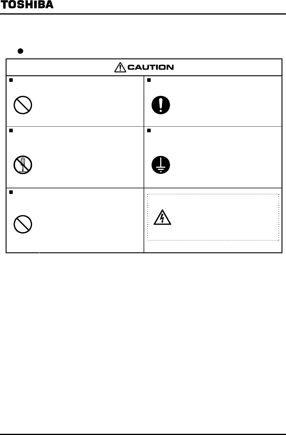
Indicates an action that is prohibited. Simply DON’T do this action.
The prohibited action is indicated by a picture or text inside or next to the circle
Indicates an action that is mandatory. DO this action.
The mandatory action is indicated by a picture or text inside or next to the circle.
Indicates a potential hazard. The potentially hazardous situation is indicated by a
picture or text inside or next to the triangle.
Color explanation
Background color: Yellow and Red, Border: Black, Picture display: Black
Background color: Yellow, Border: Black, Picture display: Black
6F8A0917
-
3
-
SAFETY PRECAUTIONS (continued)
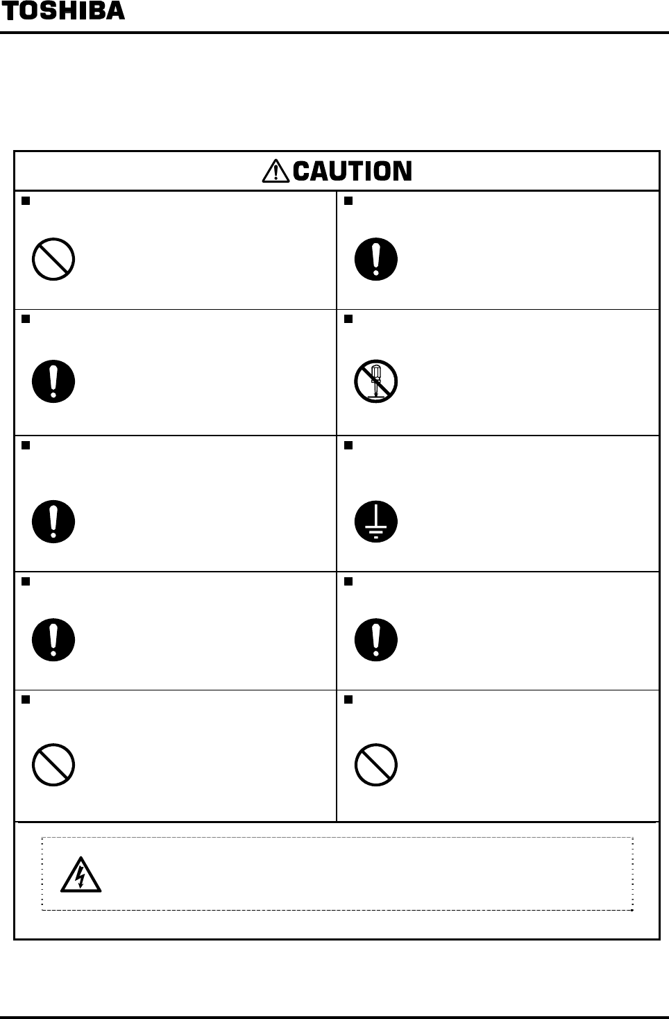
Safety Precautions for Installation and Wiring
Do not use the LF232 in an explosive
atmosphere.
Use an appropriate device to carry and install
the LF232.
DON’T
Using this product in an explosive
atmosphere can cause explosion.
DO
If this product falls to the ground,
injury, or malfunction of or damage
to the product, can be caused.
Install a switch and fuse to isolate the LF232
from mains power.
Do not modify or disassemble the LF232
unnecessarily.
DO
Power supply from mains power can
cause electric shock or circuit
break-down.
DON’T
Modifying or disassembling this
product can cause electric shock,
malfunction of or damage to this
product.
Turn off mains power before conducting wiring
work.
Ground the LF232 independently from power
equipment. Type D (100 ohm or less ground
resistance)
DO
Wiring while power is applied can
cause electric shock.
DO
Operating this product without
grounding can cause electric shock or
malfunction.
Turn off mains power before working on pipes. Use crimped terminal lugs for the terminal board
and GND terminal.
DO
Working on pipes while power is
applied can cause electric shock.
DO
Loose connections can cause electric
shock, fire from excessive current or
system malfunction.
Do not conduct wiring work with bare hands. Do not work on piping and wiring with wet
hands.
DON’T
Remaining electric charge even if
power is turned off can still cause
electric shock.
DON’T
Wet hands may result in electric
shock.
The label shown left is placed near the terminal board for power supply on the
converter.
Be alert to electric shock.
6F8A0917
-
4
-
SAFETY PRECAUTIONS (continued)
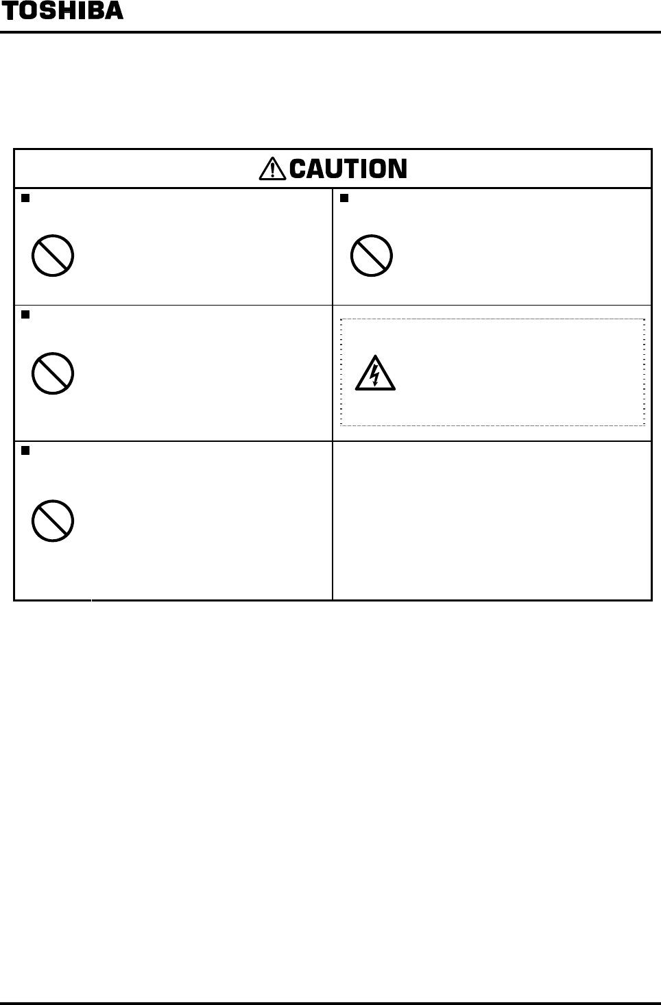
Safety Precautions for Maintenance and Inspection
Do not touch the LF232 main body when high
temperature fluid is being measured.
Do not conduct wiring work when power is
applied.
DON’T
The fluid raises the main body
temperature and can cause burns
when touched.
DON’T
Wiring while power is applied can
cause electric shock.
Do not conduct wiring work with wet hands.
DON’T
Wet hands may result in electric
shock.
The label shown left is placed near
the terminal board for power input.
(A black border and symbol on
yellow triangle)
Be alert to electric shock.
Do not use a fuse other than the one specified.
DON’T
Using a fuse other than the one
specified can cause system failure,
damage or malfunction.
Use a rated fuse as follows:
Fuse rating:
• 1A/250V for 100 to 240Vac or 110Vdc
• 2A/250V for 24 Vdc or large meter size spec.
100Vac or partially filled pipes spec. 100Vac
Dimensions: Diameter 5.2 mm × 20 mm
Melting time characteristic: Normal blow
Usage limitation
(1) This product is not manufactured for applying to a system requiring safety directly involved human
life as follows. Please contact your nearest Toshiba reprehensive if there is a possibility of using
this product for such use.
− Main control systems of nuclear power plants, safety protection systems in nuclear facilities or
other important systems requiring safety
− Medical control systems relating to life support
(2) This product is not approved for explosion-proof applications. Please do not use this product in an
explosive atmosphere (explosion protection area).
Warranty and Limitation of Liability
Toshiba does not accept liability for any damage or loss, material or personal, caused as a direct or
indirect result of the operation of this product in connection with, or due to, the occurrence of any
event of force majeure (including fire or earthquake) or the misuse of this product, whether intentional
or accidental.

6F8A0917
-
5
-
Handling Precautions
To obtain the optimum performance from the LF232 converter for years of continuous operation,
observe the following precautions.
(1) Do not store or install the flowmeter in:
• Places where there is direct sunlight. If this is unavoidable, use an appropriate sunshade. If
the control keys (infrared switches) are exposed to direct sunlight, they may not function
correctly.
• Places where there is snow and ice
Infrared switches may not function correctly.
• Places where excessive vibration or mechanical shock occurs.
• Places where high temperature or high humidity conditions obtain.
• Places where corrosive atmospheres exit.
• Places that can be submerged under water.
• Place where there is slop floor. To put the flowmeter temporarily on the floor, place it carefully
with something, such as stopper, to support it so that the flowmeter will not topple over.
• Places where there is following factors.
◆Factors to impede infrared switch to operate properly
・Intense light such as direct sunlight and reflected sunlight by window glass or metal plate
・Place where brightness changes suddenly such as ON/OFF of lighting
・Dense smoke or steam near the control panel
・Those attached on the control panel such as rain (dew drop), snow, ice, mud and oil, and haze
due to their attachment
・Light reflecting object near the control panel, or reflecting object such as metal plate placed
opposing to the control panel
When any of above factors is considered, take a measure for the proper operation of infrared
switch such as to place a cover or to secure a space for at least a person to stand in front of the
control panel.
When unable to avoid above factors, operate the EMF converter removing the factor by
covering the control panel by hand so that light does not shine on it, by cleaning those attached
on the control panel, or by standing in-between the reflecting object and the control panel to
block the light.
(2) Wire cables correctly and securely.
Be sure to ground at the combined converter side (class D grounding (grounding resistance
100Ω or less)). Avoid a common ground used with other equipment where earth current may
flow. An independent ground is preferable.
(3) The cable lead-in section must be tightened securely to keep air tightness.
(4) Keep the fluid to be measured from freezing.(This may damage the detector tube.)
(5) To prevent liquid leaks caused by corrosion, select materials appropriate for applicable fluids.

6F8A0917
-
6
-
Handling Precautions (continued)
(6) The converter housing covers and the cable connections are tightened securely at the time of
shipment. Do not remove these covers or connections unless it is necessary to wire new cables
or replace old ones. Otherwise, gradual deterioration of circuit isolation or damage to this
product can be caused.
(7) Observe the following precautions when you open the converter housing cover:
• Do not open the cover in the open air unprotected against rain or wind. This can cause electric
shock or cause damage to the flowmeter electronics.
• Do not open the cover under high ambient temperature or high humidity conditions or in
corrosive atmospheres. This can cause deterioration of system accuracy or cause damage to
the flowmeter electronics.
(8) This product may cause interference to radio and television sets if they are used near the
installation site. Use metal conduits etc. for cables to prevent this interference.
(9) Radio transmitters such as transceivers or cellular phones may cause interference to the
flowmeter if they are used near the installation site. Observe the following precautions when
using them:
• Close a transmitter cover before using a transceiver.
• Do not use a transceiver whose output power is more than 5 W.
• Move the antenna of a transceiver or a cellular phone at least 50 cm away from the flowmeter
and signal cables when using it.
• Do not use a radio transmitter or a cellular phone near the flowmeter while it is operating
online. The transmitter or cellular phone’s output impulse noise may interfere with the
flowmeter.
• Do not install a radio transmitter antenna near the flowmeter and signal cables.
(10) For reasons of flowmeter failure, inappropriate parameters, unsuitable cable connections or
poor installation conditions, the flowmeter may not operate properly. To prevent any of these
problems causing a system failure, it is recommended that you have preventive measures
designed and installed on the flowmeter signal receiving side.
(11) For piping and installation of the combined detector, check the model number of detector and
read the instruction manual of the relevant detector.
* We assume no responsibility for nonconformity caused by violation of precautions described
in this manual or used in violation of the installation method and the operation method
stipulated in a relevant ordinance or other regulations.

6F8A0917
-
7
-
Table of Contents
1. Product Inspection and Storage···················································································10
1.1 Product Inspection······································································································10
1.2 Storage ·······················································································································10
2. Overview ····························································································································11
3. Names of Parts ·················································································································12
4. Installation ·························································································································15
4.1 Cautionary Notes on Selecting the Installation Location ············································16
4.2 How to Install the Converter ·······················································································17
5. Wiring··································································································································19
5.1 Installation Cables ······································································································20
5.2 External Connections ·································································································21
5.3 Cautionary Notes on Wiring························································································22
5.3.1 Cautionary Notes on Wiring between Detector and Converter······················22
5.3.2 Cautionary Notes on Wiring between Instruments and Converter·················22
5.4 Wiring Method ············································································································23
5.4.1 Terminal Treatment of Cable ·········································································23
5.4.2 Cable Connection··························································································25
5.4.3 Grounding······································································································27
5.5 Digital I/O Connections·······························································································29
5.6 Cautionary Notes on Replacing Converter·································································30
5.6.1 Replacing the LF230 Converter·····································································30
5.6.2 Combination with an Existing Detector (for Large Meter Size)······················31
5.6.3 Replacement of partially filled pipes type ····················································32
6. Operation ···························································································································34
7. Display and Controls ······································································································36
7.1 Names and Functions of Display and Controls ··························································37
7.2 Display Format ···········································································································40
7.3 Basic Operations
(Mode Switching, Setting Mode Operation, Total Counter Operation)························43
7.3.1 Mode Switching ·····························································································43
7.3.2 Setting Mode Operation·················································································46
7.3.3 Password Input······························································································49
7.3.4 Totalizer Operation ························································································51
7.3.5 Maintenance Menu························································································53
7.4 Setting Menu List········································································································54

6F8A0917
-
8
-
8. Parameter Settings / Adjustment ·················································································55
8.1 Parameter Setting Items·····························································································55
8.2 Parameters Check / Change ······················································································56
8.2.1 Exciting Current Value···················································································56
8.2.2 Meter Size ·····································································································58
8.2.3 Exciting Frequency························································································60
8.2.4 Flow Direction································································································62
8.2.5 Password Setting···························································································64
8.2.6 Normal Indicating Unit ···················································································66
8.2.7 Custom Unit···································································································69
8.2.8 Span Value (Range) ·····················································································72
8.2.9 Damping Constant·························································································79
8.2.10 Low Cutoff value····························································································81
8.2.11 Current Output Setting Used When an Alarm Occurs ···································83
8.2.12 Display low cut On/Off···················································································85
8.2.13 Output Low Limit Setting ···············································································87
8.2.14 Digital I/O Function························································································89
8.2.15 Count Rate (Pulse Rate) and Pulse Width ····················································93
8.2.16 Preset Counter ······························································································98
8.2.17 Flow Rate High/Low limit Alarm···································································101
8.2.18 Fluid Empty Alarm ·······················································································105
8.2.19 Self-Diagnosis Function···············································································107
8.2.20 Rate-of-Change Limit Value and Control Time ············································110
8.3 Initial Settings When Shipped from the Factory ·······················································112
8.4 Fixed Value Output (Loop Check) ············································································114
8.5 Zero Adjustment ·······································································································118
8.5.1 Still Water Zero Adjustment ·········································································118
8.5.2 Zero Offset Adjustment················································································120
9. Mag-Prover Calibration·································································································122
9.1 Calibration Items·······································································································122
9.2 Converter Check / Calibration ··················································································123
9.2.1 0% Flow Rate Calibration (Zero Calibration)···············································123
9.2.2 50% Flow Rate Calibration··········································································124
9.2.3 100% Flow Rate Calibration (Span Calibration) ··········································125
9.2.4 Checking the Exciting Current Value···························································126
10. Function Description ····································································································127
10.1 Digital I/O Specifications···························································································128
10.2 Totalizer and Pulse Output ·······················································································129
10.3 Multi-Range Functions······························································································132

6F8A0917
-
9
-
10.4 Flow Rate High/Low Limit Alarm Output···································································138
10.5 Fluid Empty Alarm Output·························································································141
10.6 Preset Counter Output Function···············································································142
10.7 Remote Still Water Zero Adjustment·········································································146
10.8 Remote Selection of Fixed Value Output··································································147
10.9 Converter Error Alarm Output···················································································148
11. Communications Function ··························································································149
11.1 Connection with the HHT terminal············································································149
11.2 Procedure for Communication with HHT··································································151
11.3 Cautionary Notes on Communications·····································································152
12. Diagnosis and Alarms···································································································153
12.1 Diagnostic messages ·······························································································153
12.2 Output When an Error or Alarm Occurs····································································156
13. Maintenance and Inspection ·······················································································157
13.1 Maintenance·············································································································157
13.2 Troubleshooting········································································································159
13.2.1 Flow rate is not indicated·············································································159
13.2.2 Flow rate indication is not correct································································160
13.2.3 Flow rate indication is not stable ·································································161
14. Principle of Operation···································································································163
15. Specifications·················································································································164
15.1 Specifications ···········································································································164
15.2 Model Number Table ································································································169
16. Outline Drawing··············································································································171
6F8A0917
-
10
-
1. Product Inspection and Storage
1.1 Product Inspection
The LF232 electromagnetic flowmeter is shipped in a cardboard box filled with cushioning materials.
Open the package and check the following items:
Are the following items included?
Electromagnetic flowmeter main unit·························································1 unit
Instruction manual···············································································1 copy
Adjusting capacitor·························1 piece (only for large meter size specification)
Isn’t there any damage to the main unit?
Is the specification the same as when you placed an order?
If you find anything defective and unclear, contact the sales office from which you purchased the
product or your nearest Toshiba representative.
The capacitor attached for large meter size specification can be used to improve the performance when
combining the converter with an old type detector. This capacitor is usually not used. For details, see
5.3.1 “Cautionary Notes on Wiring between Detector and Converter”
1.2 Storage
Regarding the storage after the flowmeter is delivered and before starting installation work, be careful
about the following items:
Do not leave the flowmeter in a place such as outdoors where direct sunlight hits or a place exposed
to rain and wind.
Avoid places where humidity is extremely high or the temperature is extremely high or low and
store the flowmeter in a well ventilated place.
• Humidity range: 10 to 90% RH (no condensation)
• Storage temperature range: -13 to 149 °F (-25 to 65 °C)
Store the flowmeter in a place where vibration and shock does not occur.
If the cover of the converter is left open while being stored, insulation may be deteriorated. Do no
open the cover until the time of wiring for the converter.
To place the flowmeter temporarily on the floor, use a stopper, etc. when needed to prevent it from
rolling over.

6F8A0917
-
11
-
2. Overview
The electromagnetic flowmeter is an instrument to measure the volumetric flow rate of conductive
fluids using Faraday's law of electromagnetic induction.
The flowmeter consists of a detector which generates a signal of electromotive force proportional to
the flow rate of the fluid and detects this signal, and a converter which converts the signal detected by
the detector to a unified signal output.
Features
The electromagnetic flowmeter has features such as:
• No pressure loss by piping
• Flow measurement can be made not affected by conditions such as fluid temperature, pressure,
density and flow condition.
• It is easy to read the flow indication because a liner relation exists between the flow rate and
output signal.
The LF232 converter has additional features described below:
(1) High accuracy measurement of ±0.5% of rate can be obtained in the velocity range of 1.0ft/s to
32.8ft/s (0.3m/s to 10m/s). (Measurement range and accuracy are different by detector.)
(2) Stable measurement can be made even with fluids containing solids (sludge and slurry).
•The unique Noise-Sentry filter circuit and arithmetic logic unit (ALU) enables you to obtain a
stable output.
(3) The converter is equipped with various display and output functions.
• Various display and output functions can be easily set by switch operation.
• The converter is equipped with worldwide standard HART* protocol communication.
(4) Use of infrared switches
• Use of infrared switches allows you to perform various operations without opening the converter
housing cover.
(5) Easy-to-read liquid crystal display (16 characters × 2 lines)
• It is easy to read the indication even in a dark place by means of backlight.
* HART protocol··········“HART” stands for Highway Addressable Remote Transducer and is a
communication protocol recommended by HCF (HART communication
Foundation) for industrial sensors.
6F8A0917
-
12
-
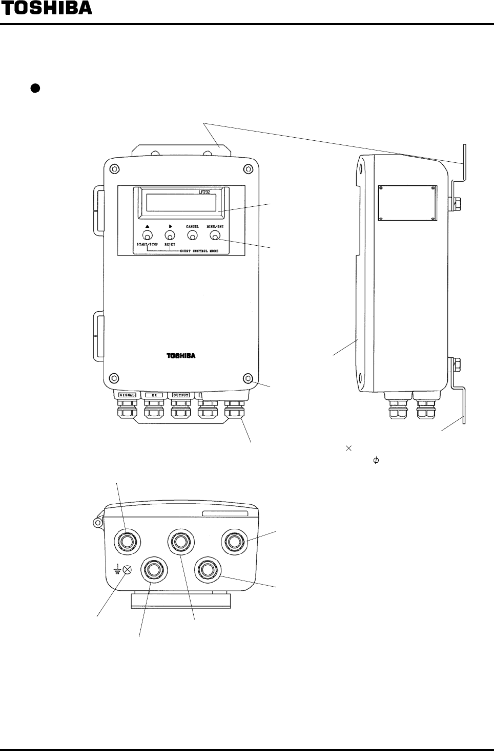
3. Names of Parts
Appearance
Mounting plate
Display section
Operation switch
(Infrared switch)
Converter cover
Converter cover
mounting screw
Mounting plate
Cable connection for signal cable
Cable connection for power cable
Ground terminal
Cable connection for excitation cable
Cable connection for output cable
Cable connection for digital I/O cable
Appropriate cable outer diameter: 11 to 13mm
Material: Nylon resin
Housing side connection: G(PF) 1/2 thread
Cable connection (Cap nuts) 5 pieces
Material: Nylon resin
Cable connection
for out
p
ut cable
Converter cover
mounting screw
6F8A0917
-
13
-
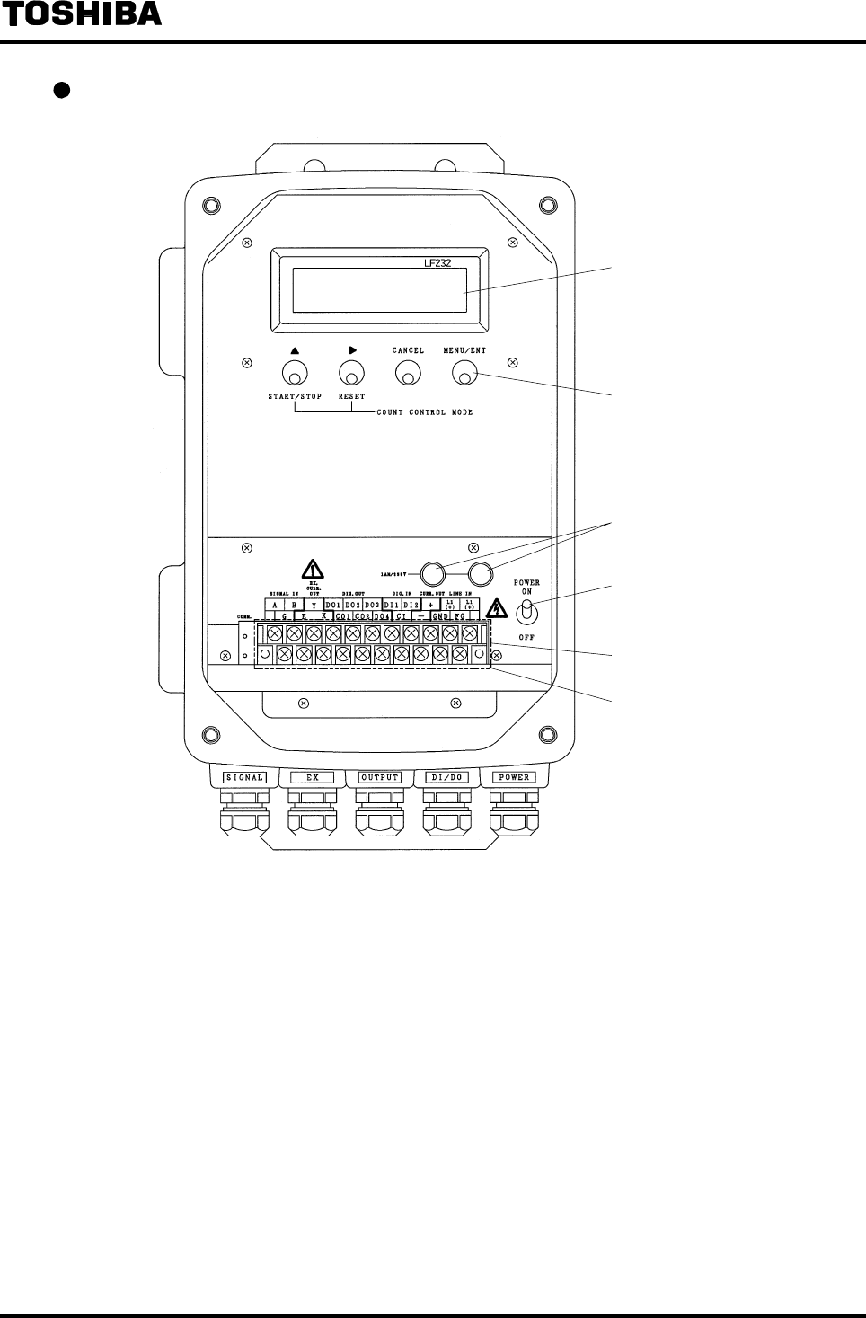
Internal structure (with converter cover opened)
Display section (LCD)
Operation switch
(Infrared switch)
Fuse holder
Power switch
Terminal block
Protection cover
6F8A0917
-
14
-
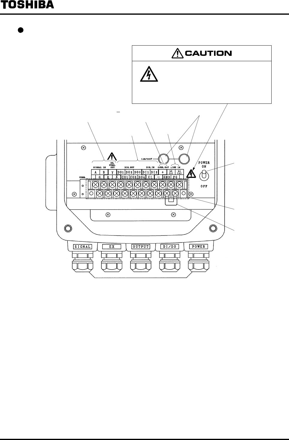
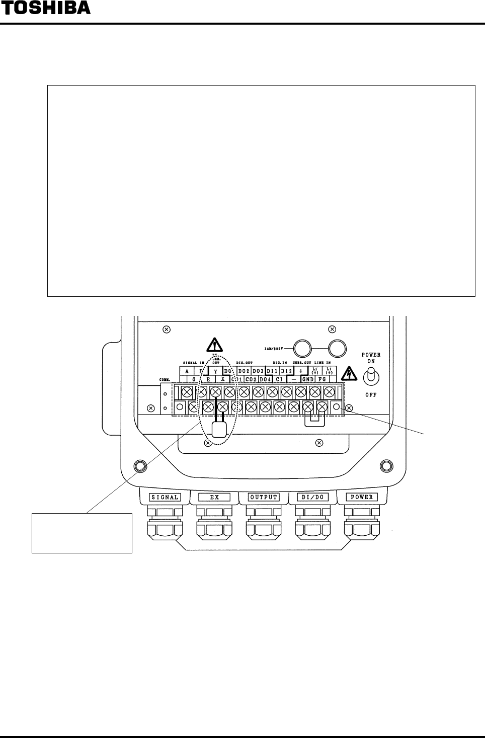
Terminal block construction
Detector connection terminals
Digital I/O terminals
Power supply
terminals
Power switch
Protection cover
Internal ground
terminal
Fuse holders
The label shown left is placed near the
terminal board for power supply on the
converter.
Be alert to electric shock.
4 20mADC current
output terminals
6F8A0917
-
15
-
4. Installation
Cautionary notes on installation
Do not use the LF232 in an explosive
atmosphere.
Use an appropriate device to carry and install
the LF232.
DON’T
Using this product in an explosive
atmosphere can cause explosion.
DO
If this product falls to the ground,
injury, or malfunction of or damage
to the product, can be caused.
Do not modify or disassemble the LF232
unnecessarily.
Ground the LF232 independently from power
equipment. Type D (100 ohm or less ground
resistance)
DON’T
Modifying or disassembling this
product can cause electric shock,
malfunction of or damage to this
product.
DO
Operating this product without
grounding can cause electric shock or
malfunction.
Do not work on piping and wiring with wet
hands.
DON’T
Wet hands may result in electric
shock.
The label shown left is placed near
the terminal board for power input.
(A black border and symbol on
yellow triangle)
Be alert to electric shock.

6F8A0917
-
16
-
4.1 Cautionary Notes on Selecting the Installation
Location
(1) Avoid places within the immediate proximity of the equipment producing interference to
measurement (such as motors, transformers, radio transmitters, electrolytic cells, or other
equipment causing electromagnetic or electrostatic interference).
(2) Avoid places where excessive vibration occurs.
(3) Avoid places where there is direct sunlight as mush as possible. If this is unavoidable, provide a
sunshade, etc.
(4) Avoid places where high corrosive atmosphere or high humidity condition exists.
(5) Avoid places of too great an elevation or constricted areas and install the flowmeter in a place
easy for necessary work.
(6) The standard length of the cable that connects the detector and the converter is 30m. Select a
converter installation location so that the distance of the detector and the converter will not exceed
30m.
(7) If direct sunlight hits the display and the operation section or if there is something nearby that
easily reflects light, this kind of light becomes disturbance light and the switch operation may not
work correctly. Be careful about the installation location and angle, or take measures such as
providing a sunshade or shield plate so that disturbance light does not hit the operation section
directly.
(8) Places where there is following factors.
◆Factors to impede infrared switch to operate properly
・Intense light such as direct sunlight and reflected sunlight by window glass or metal plate
・Place where brightness changes always such as ON/OFF of lighting
・Dense smoke or steam near the control panel
・Those attached on the control panel such as rain (dew drop), snow, ice, mud and oil, and haze due
to their attachment
・Light reflecting object near the control panel, or reflecting object such as metal plate placed
opposing to the control panel
When any of above factors is considered, take a measure for the proper operation of infrared switch
such as to place a cover or to secure a space for at least a person to stand in front of the control panel.
When unable to avoid above factors, operate the EMF converter removing the factor by covering the
control panel by hand so that light does not shine on it, by cleaning those attached on the control panel,
or by standing in-between the reflecting object and the control panel to block the light.
6F8A0917
-
17
-
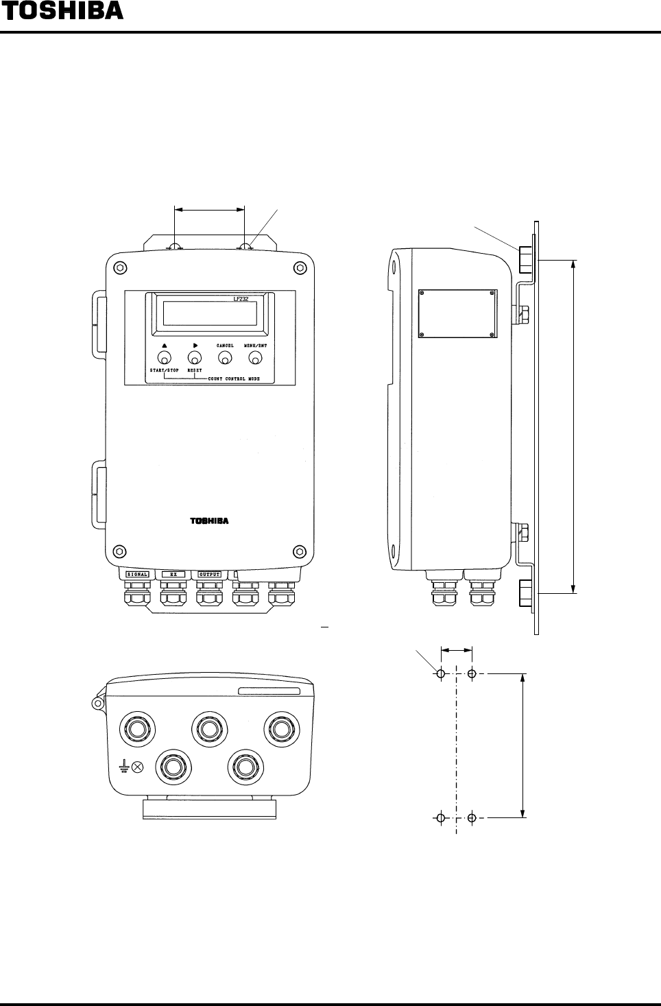
4.2 How to Install the Converter
The converter can be mounted on a panel, wall or on a pipe stand. Install the converter so that the front
of the converter cover stays vertically straight and the cable ports of the converter stay at the bottom.
Figure 4.1 shows an example of panel and wall mounting installation and Figure 4.2 shows an
example of pipe stand installation.
Figure 4.1 Example of Panel and Wall Mounting
2.91(74)
14.57 (370)
14.57(370)
2.91(74)
M10 bolt, etc.
Wall surface, etc.
Mounting Hole Dimensions
φ0.43 (φ12) hole
φ0.43 (φ12)
(M10 mounting holes)
Unit: inch (mm)
6F8A0917
-
18
-
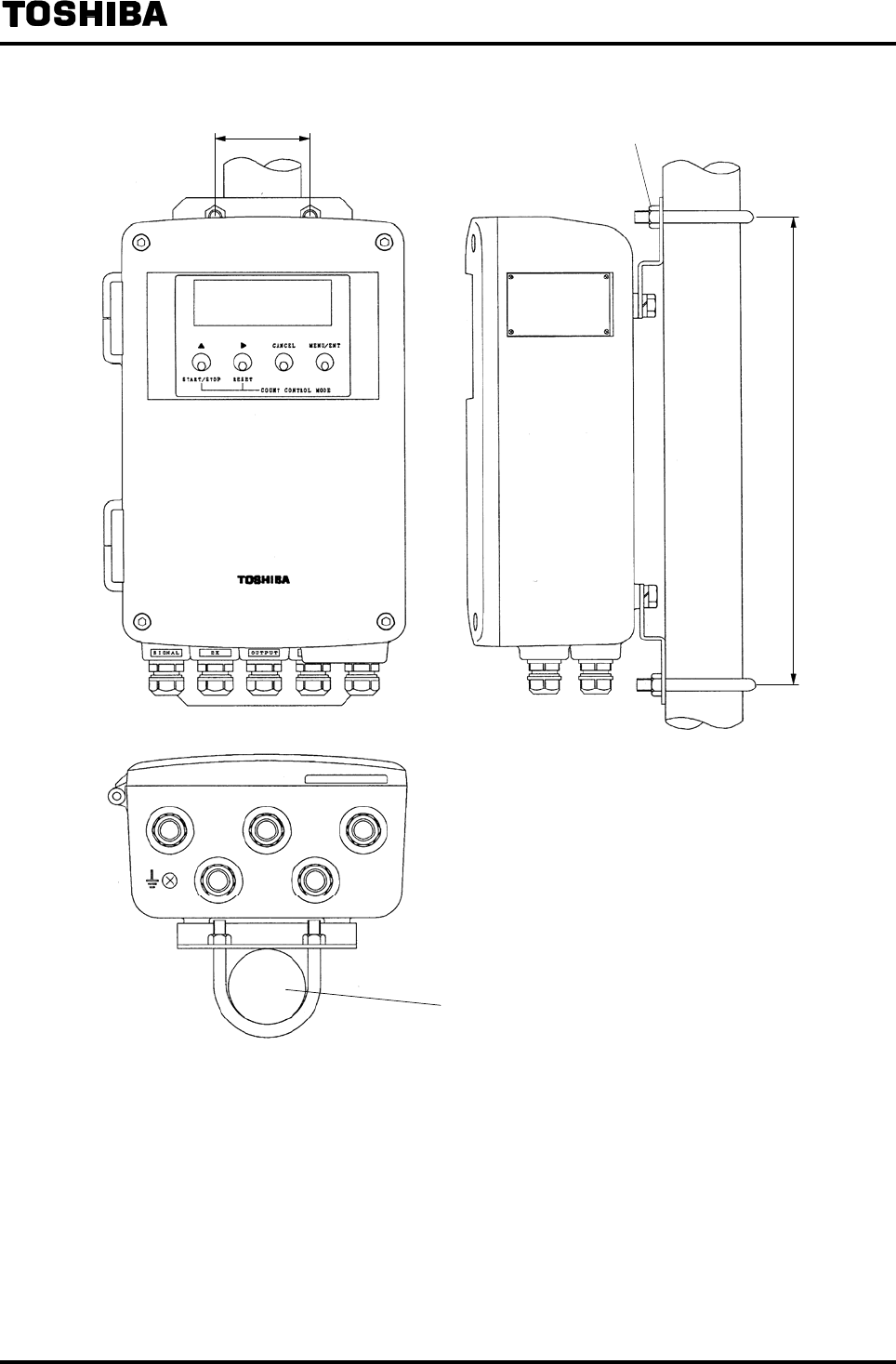
Figure 4.2 Example of Pipe Mounting
14.57 (370)
M10 U bolt, etc
2” (50A) PIPE
Unit: inch (mm)
2.91 (74)
6F8A0917
-
19
-
5. Wiring
Cautionary notes on wiring
urn off mains power before working on pipes. Install a switch and fuse to isolate the LF232
from mains power.
DO
Working on pipes while power is
applied can cause electric shock.
DO
Power supply from mains power can
cause electric shock or circuit
break-down.
Do not work on piping and wiring with wet
hands.
Ground the LF232 independently from power
equipment. Type D (100 ohm or less ground
resistance)
DON’T
Wet hands may result in electric
shock.
DO
Operating this product without
grounding can cause electric shock or
malfunction.
Do not conduct wiring work with bare hands. Use crimped terminal lugs for the terminal board
and GND terminal.
DON’T
Remaining electric charge even if
power is turned off can still cause
electric shock.
DO
Loose connections can cause electric
shock, fire from excessive current or
system malfunction.
Do not modify or disassemble the LF232
unnecessarily.
DON’T
Modifying or disassembling this
product can cause electric shock,
malfunction of or damage to this
product.
The label shown left is placed near
the terminal board for power input.
(A black border and symbol on
yellow triangle)
Be alert to electric shock.
Flowmeter performance may be affected by the way wiring is carried out. Proceed with correct wiring
by observing the following items.
(1) For cable route, avoid places near electrical equipment (such as motors, transformers or radio
transmitters) which cause electromagnetic or electrostatic interference.
(2) If the converter interior or cable ends get wet or humidified, deterioration of insulation occurs and
this may cause malfunction or noise problems. Avoid a rainy day if wiring is carried out outdoors.
Even indoors, make arrangements to prevent water from splashing over the converter and try to
finish the wiring as quickly as possible
(3) Since the excitation cable and the flow rate signal cable carry very small signals, pass each of the
cables separately through a thick steel conduit and keep them away from large current wiring as
much as possible, and do not install them in parallel.

6F8A0917
-
20
-
(4) If the converter needs to be installed in a location where watertight installation is required, make
unused cable ports watertight. (Be careful that the attached blind plate is used for dustproof
purpose and it is not effective for watertight installation.)
(5) The converter has a surge arrestor/protector installed inside. Therefore, do not conduct a withstand
voltage test for the converter. In addition, to check the insulation of the converter, use a voltage of
250VDC or less.
(6) When wiring is completed, be sure to install the protection cover of the terminal block.
5.1 Installation Cables
Use the kind of cables shown in Table 5.1 to connect to the converter.
Table 5.1 Installation Cables
Name Cable name
Nominal
cross-sectional area Overall diameter Description
Flow rate signal
cable
2-core shielded
chloroprene cabtyre
cable
( Rubber covered cable )
0.75mm2 0.433−0.512 inch
(11−13mm)
JIS C 3327 or
equivalent
Excitation cable 3-core chloroprene
cabtyre cable
( Rubber covered cable )
2mm2
1.25mm2
0.433−0.512 inch
(11−13mm)
JIS C 3327 or
equivalent
Power cable 3-core vinyl sheathed
cable or 2-core vinyl
sheathed cable
2mm2 0.433−0.512 inch
(11−13mm)
CVV JIS C 3401 or
equivalent
Output signal
cable
The number of insulated conductors the cable contains differs
depending on the specification of the output signal cable.
Use a shielded cable of overall diameter 0.433 to 0.512 inch
(11 to 13mm) with nominal cross-sectional area of 1.25mm2.
CVV-S
JCS-258-C or
equivalent
6F8A0917
-
21
-
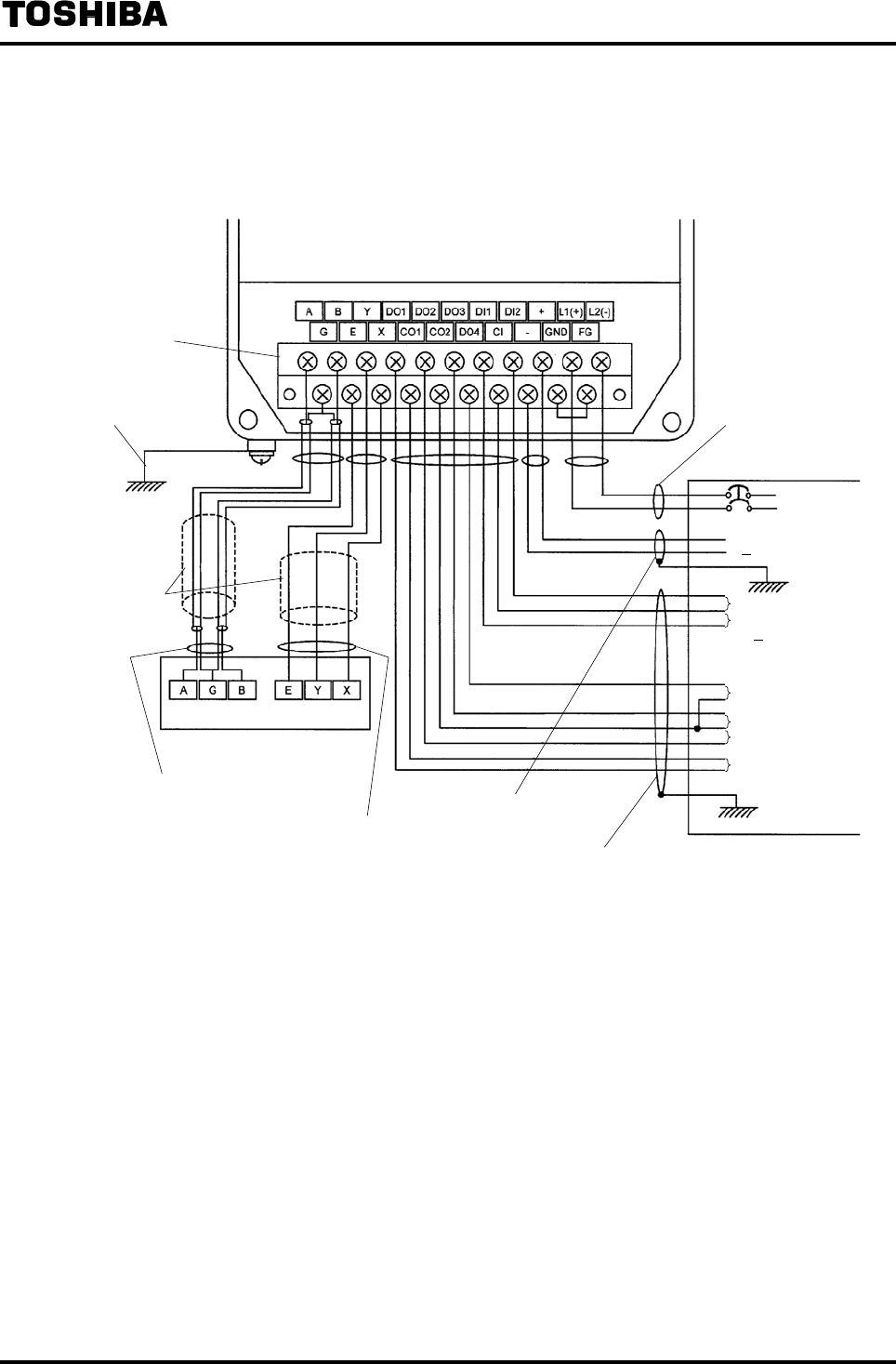
5.2 External Connections
The external connections of the converter are shown in Figure 5.1. See 5.4 “Wiring Method” to
connect the cables correctly
Terminal block
IV wire 5.5mm2or more
Class D grounding
(Ground resistance
100 or less)
Thick steel conduit
Flow rate signal cable
(2-core shielded cabtyre cable)
Connected detector
Excitation cable
(3-core cabtyre cable)
Output cable (CVV-S)
Power cable (CVV)
Power supply
Current output
(4 20mADC)
Digital input 2 (option)
Digital input 1 (option)
(20 30VDC)
Digital output 4 (option)
Digital output 3 (option)
Digital output 2 (option)
Digital output 1
Input/Output cable (CVV-S)
5.1 External Wiring Connection Diagram

6F8A0917
-
22
-
5.3 Cautionary Notes on Wiring
5.3.1 Cautionary Notes on Wiring between Detector and Converter
• Flow rate signal cable and excitation cable are attached to the detector.
Be sure to use the attached cables.
Note: If the length of the cables exceeds 30m, the cables may not be attached. Check whether
the cables are attached or not referring to the specification.
• The allowable cable length between the detector and the converter differs depending on the
conductivity of the fluid to be measured. Refer to the Instruction Manual of the detector combined.
• The end of the attached cable to connect to the converter is covered with cap to prevent entry of
humidity. Do not remove this cap from the cable until the cable is ready to be connected to the
converter.
• When you connect cables between the detector and the converter, connect the excitation cable first
and then the flow rate signal cable.
• Since the input signal cable carries very small signals, be sure to install the excitation cable and the
input signal cable in separate thick steel conduit (0.87 inch (22mm)) and separate them from other
large current wiring as much as possible and do not install them in parallel. The cable connection
port is G (PF) 1/2 female thread.
• The detector side of the attached cable is already connected when shipped from the factory. In
addition, since the terminal box of the detector has airtight structure, avoid removing the wired cable
from the detector.
• To replace the flow rate signal cable and excitation cable, refer also to the Instruction Manual of the
detector. Before you replace these cables, place an order for packing of the detector terminal box
cover as well as packing for the cable connection to Toshiba or Toshiba representative and make sure
to replace these packings when you replace the cables.
5.3.2 Cautionary Notes on Wiring between Instruments and Converter
• To avoid 2-point grounding, ground the shield of the output cable at the receiving instrument side as
a rule.
• Use a grounding wire of IV wire 5.5mm2 or more. The size of the screw for external grounding
terminal is M4. In addition, do not share the grounding wire with other equipment where grounding
current may flow. (An independent grounding is preferable.)
• Power cable
When a 3-core cable is used, ground the shield of the cable using the FG terminal.
When a 2-core cable is used, ground the shield of the cable using the external ground terminal and
make it as short as possible.
• When you replace the Toshiba LF230 flowmeter converter with this converter, be careful that the
cable connection is changed.
6F8A0917
-
23
-
5.4 Wiring Method
Do not conduct wiring work when power is
applied.
Do not work on piping and wiring with wet
hands.
DON’T
Wiring while power is applied can
cause electric shock.
DON’T
Wet hands may result in electric
shock.
5.4.1 Terminal Treatment of Cables
Proceed as follows to treat the terminals at the converter side of the flow rate signal and excitation
cable and to connect these cables to the terminal block. Use appropriate cables referring to 5.1
"Installation Cables." Attach and crimp a round type M4 insulated crimping terminal to the end of each
cable.
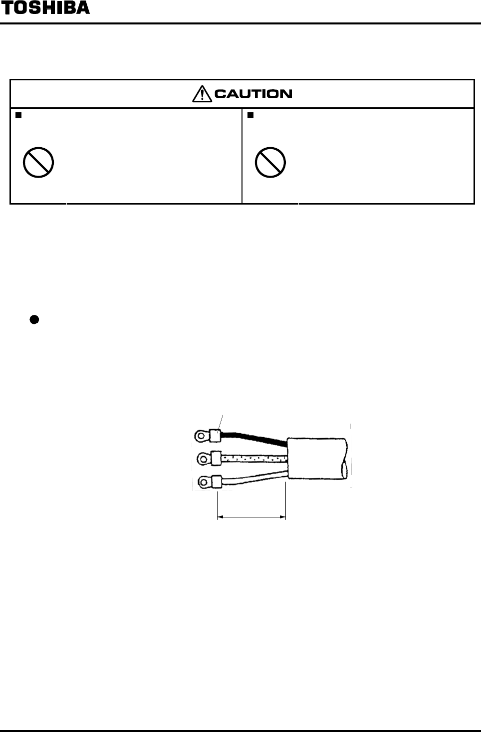
Excitation cable
Strip the sheath from the end of each wire as shown in Figure 5.2 and attach and crimp an M4
crimping terminal with insulated sleeve to the end of each wire and then connect the crimped
terminals to X and Y of the terminal block. Connect the terminal of red wire to E of the terminal
block.
X Black
E Red
Y White
M4 crimped terminal
25 to 45mm
Figure 5.2 Terminal Treatment of Excitation Cable
6F8A0917
-
24
-
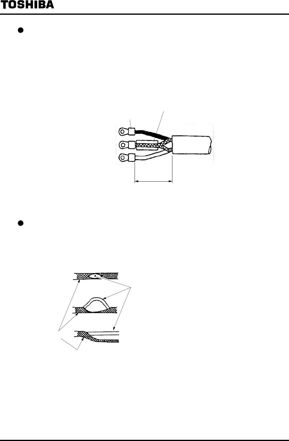
Connecting the input signal cable
Strip the sheath from the end of each wire of a 2-core individually shielded cable as shown in
Figure 5.3 and attach and crimp an M4 crimping terminal with insulating sleeve to the end of each
wire. Connect the crimped terminals to the A and B terminals of the terminal block. Twist the
shields of the two wires and cover them with a thermal contraction tube or vinyl tube so that the
shields do not make contact with the case or the core wires. Then attach and crimp an M4 crimping
terminal with insulated sleeve to the end of the twisted shields. Connect the crimped terminal to the
G terminal of the detector and the converter.
A Black
G Sealed
B White
Thermal contraction tube or vinyl tube
25 to 45mm
M4 crimped terminal
Figure 5.3 Terminal Treatment of Flow Rate Signal Cable
Cautionary notes on terminal treatment for shields of the signal cable
• When stripping external sheath, intermediate and insulation sheath, be careful not to scratch or cut
the internal conductors and the shield mesh.
• Do not unravel the shield mesh and treat it as shown in Figure 5.4.
Figure 5.4 How to Treat the Shield Mesh of Signal Cable
6F8A0917
-
25
-
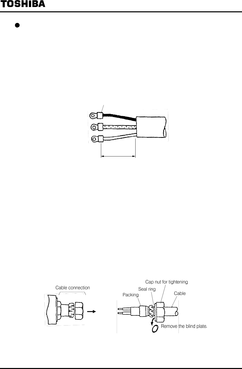
Power cable, current output cable and digital I/O cables
Necessary cables should be purchased and prepared by the agent in charge of installation.
Strip the sheath from the end of each wire and attach and crimp an M4 crimping terminal with
insulated sleeve to the end of each wire.
• Connect the power cable terminals to L1 and L2 of the terminal block.
• Connect the current output cable terminals to (+) and (−) of the terminal block.
• Connect the digital I/O cable terminals to the required terminals among the terminals of DI, DO1
− CO1, (CO2 to DO4) − CO2, (DI1, DI2) − CI.
M4 crimped terminal
25 to 45mm
Figure 5.5
Terminal Treatment of Power Cable, Current Output Cable and Digital I/O Cables
5.4.2 Cable Connection
Connect and install the terminal-treated cables to the terminal block in the procedure below.
* Connect the cables to the terminal block securely. A loose connection may cause incorrect
measurement. After connecting each cable, try to pull it to check whether it has been connected
securely.
Remove the cap nut for tightening the cable connection and attach the removed cap nut, seal ring and
packing onto the terminal-treated cable in this order and then lead the cable into the converter.
(The blind plate is used for dustproof protection during storage. Remove it when connecting a cable
because it is not needed.)
Figure 5.6 Cable Connection
6F8A0917
-
26
-
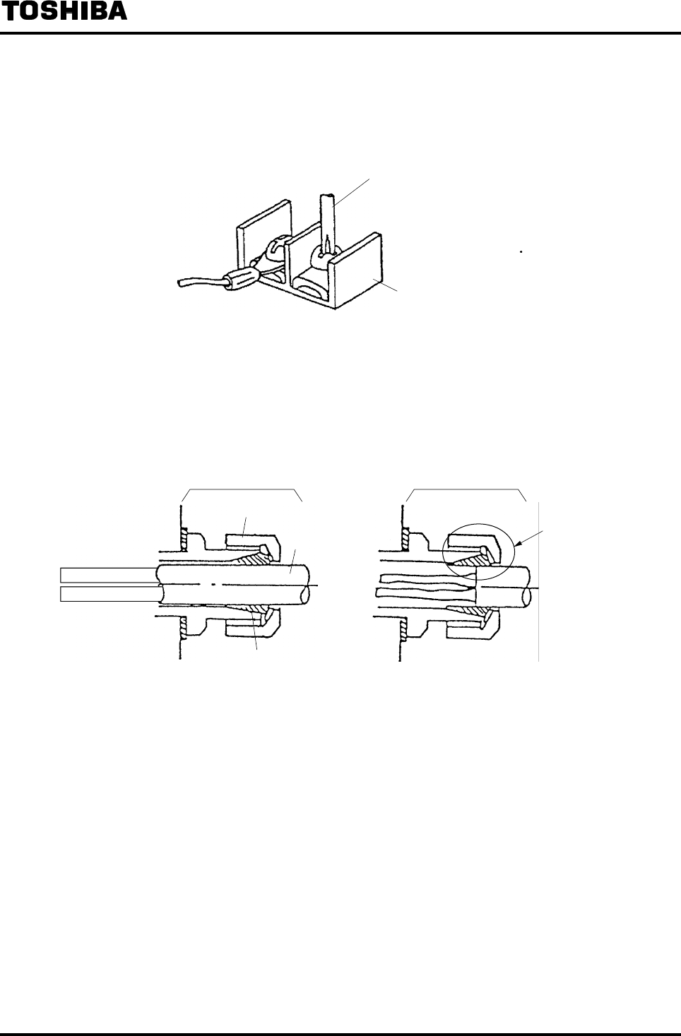
Referring to 5.2 "External Connections," connect each cable to the terminal block. Tighten the screws
of the terminal block tightly to make them securely connected. A loose connection may cause incorrect
measurement. After connecting each cable, try to pull it to check whether it has been connected
securely.
Phillips screwdriver
Terminal block
* The appropriate torque
for tightening the terminal
block screw is 1.2 N m
Figure 5.7 Connection to Terminal Block
After connecting the cables to the terminal block, take up the slack of the cables and tighten the cap
nut.
At this time, be careful that if the sheath-removed portion of the cable comes to the packing area, air
tightness may not be kept.
Cable connection
Cap nut for tightening
Cable
Packing
Correct
Because the contact
surface of the cable
and the packing is
small, air tightness
may not be kept.
Incorrect
Cable connection
Figure 5.8 Cable Tightening
6F8A0917
-
27
-
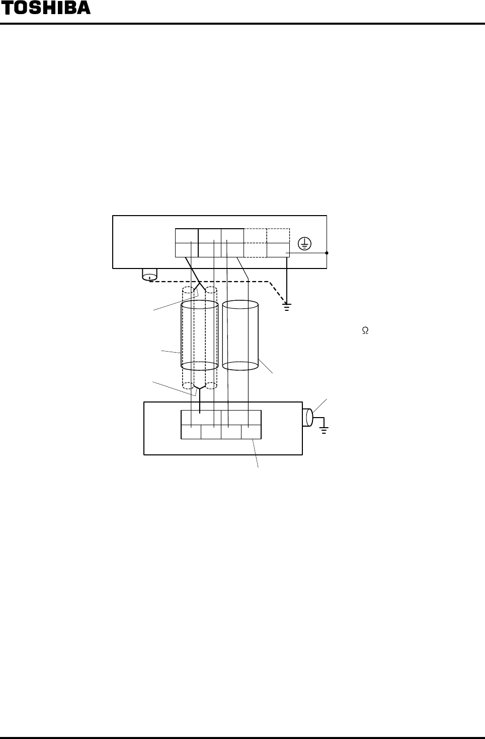
5.4.3 Grounding
The external ground terminal of the detector and the FG terminal of the converter (or external ground
terminal of the converter) must be grounded securely with Class D grounding (grounding resistance
100Ω or less). Use an IV wire 5.5mm2 or more for grounding wire.
In addition, do not share the grounding wire with other equipment where grounding current may flow.
(An independent grounding is preferable.)
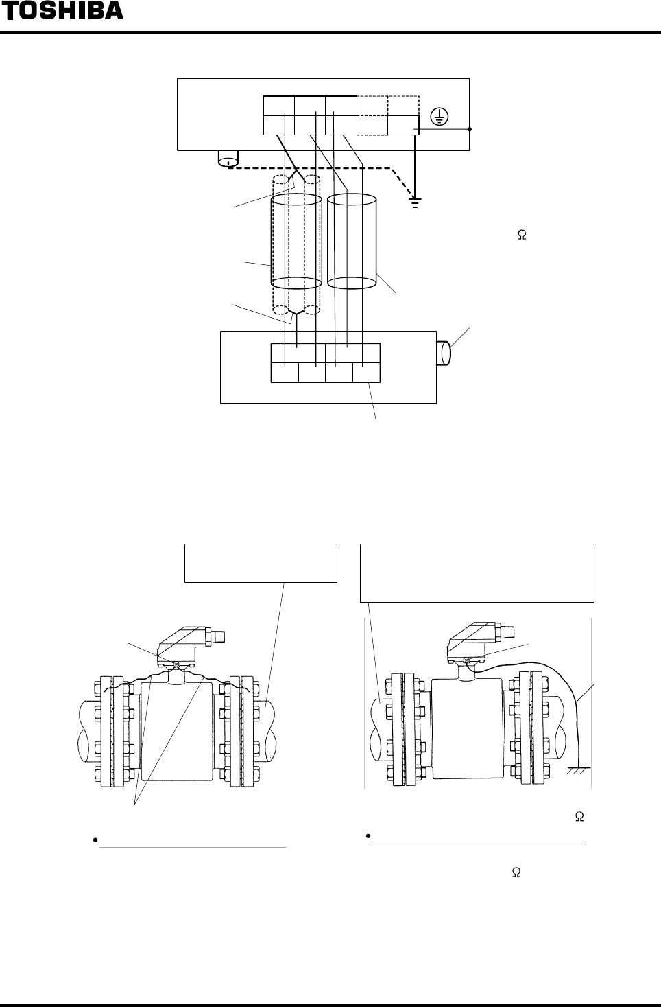
If it is difficult to carry out grounding work at the detector side due to a pit installation or other reasons,
use a 3-core cable for the excitation cable and connect the E terminal of the detector to the E terminal
or other reasons as shown in Figure 5.9(b), of the converter. (The E terminal of the converter is
internally connected to the FG terminal and the converter housing.)
ABX
G
Y
E
Converter
terminal block
External ground
terminal
Twisting shields
Input signal cable
Twisting shields Excitation cable
Detector terminal block
ABX
GEY FG
Ground terminal
Class D ground
(Ground resistance 100 or less)
Class D grounding
(Ground resistance 100 or less)
Figure 5.9(a) Wiring between Detector and Converter
6F8A0917
-
28
-
ABX
G
Y
E
Converter
terminal block
External ground
terminal
Twisting shields
Input signal cable
Twisting shields Excitation cable
Detector terminal block
ABX
GEY FG
Ground terminal
Class D grounding
(Ground resistance 100 or less)
Figure 5.9 (b) Wiring between Detector and Converter (when grounding for detector is
difficult)
Ground terminal
Conductive material pipe
Example: Metal, etc.
Non-conductive material pipe
Example: Resin pipe or metal pipe which
is internally coated with resin
Grounding wire
Ground terminal
Grounding wire
When piping material is non-conductive
Carry out class D grounding work
(grounding resistance 100 or less).
Class D ground
(Ground resistance
100 or less)
When piping material is conductive
Connect the grounding wires to both
ends of the piping flange.
Figure 5.10 Detector Grounding Method
6F8A0917
-
29
-
5.5 Digital I/O Connections
Digital I/O terminals consist of four contact output terminals (DO1 to DO4) and two voltage signal
input terminals (DI1 and DI2), and each terminal is isolated from internal circuits.
The terminal CO2 is the signal common for DO2 to DO4 and the terminal CI is the signal common for
DI1 and DI2. For details, see 10. “Function Description.”
The function of each terminal can be selected by settings.
For details, see 10. “Function Description.”
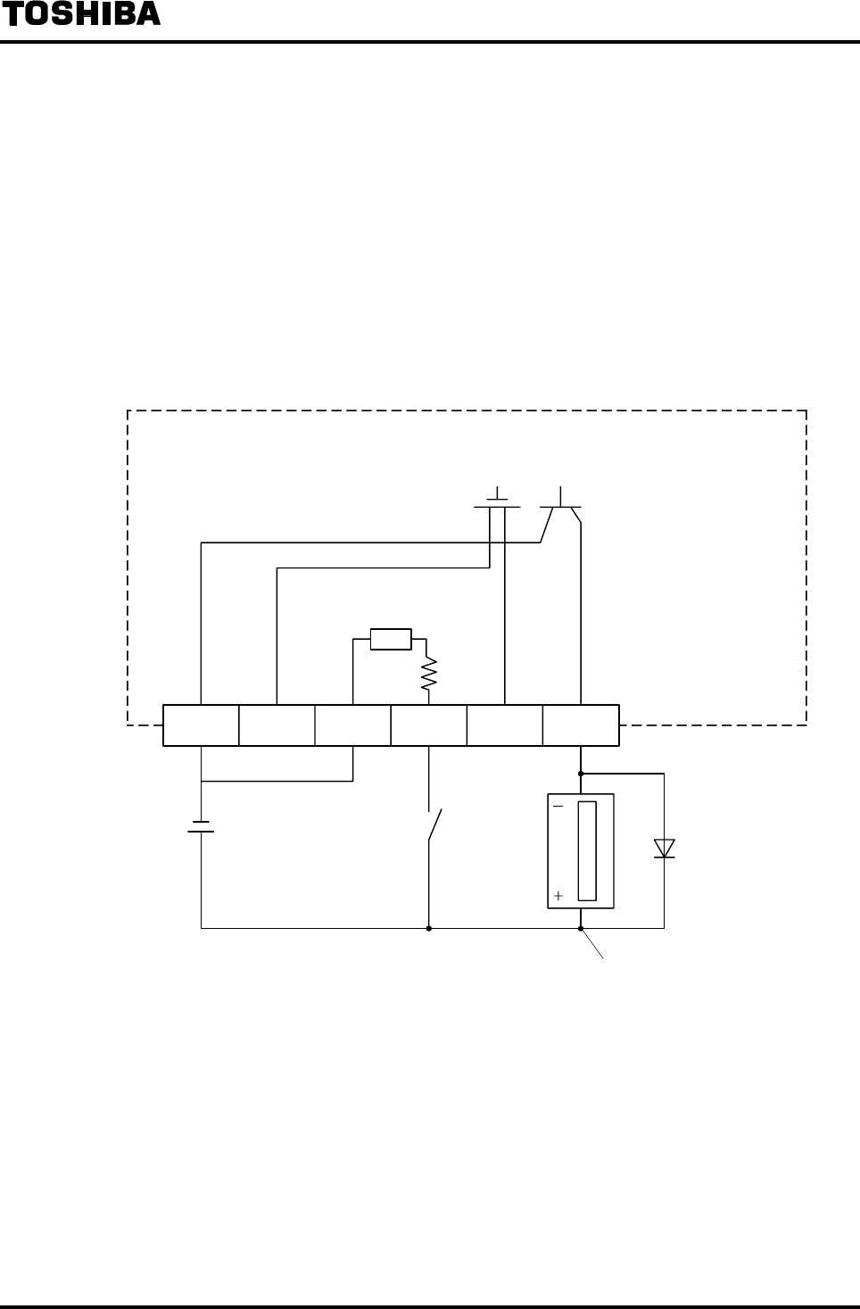
To drive an electromagnetic relay or electromagnetic counter using a digital output, connect a
surge-absorbing diode into the input circuit of the relay or the counter. Figure 5.11 shows a connection
example.
CI DI DO2 to
DO4 DO1CO2CO1
Photo-coupler
(Option)
Solid-state contact
(Option)
Transistor open collector
(Standard)
Resistor
(Option)
Converter inside
DC power supply
24VDC * Note 1
Surge absorbing diode
Electromagnetic counter
* Note 1 Use a surge-absorbing diode of rated current 1A and rated withstand voltage 200 V minimum.
* Note 2 In the case of standard specification (without Digital I/O), the solid-state contact, photo-coupler and
resistor are not built in. Leave DO2 to DO4, CO2, DI, DI2 and CI unconnected.
Figure 5.11 Connection Example of Electromagnetic Counter
6F8A0917
-
30
-
5.6 Cautionary Notes on Replacing Converter
5.6.1 Replacing the LF230 Converter
The following precautions must be taken to replace the conventional type LF230 with LF232.
Installation
• Since the hole diameter and pitch for mounting fitting, and the dimensions of the LF232 converter
main unit are the same as those of the LF230 converter, it is possible to replace the converter without
changing the mounting panel, installation space, etc.
• The operation switches of the LF232 are infrared switches. If direct sunlight hits the display and the
operation section or if there is something nearby that easily reflects light, this kind of light becomes
disturbance light and the switch operation may not work correctly. Be careful about the installation
location and angle, or take measures such as providing a sunshade or shield plate so that disturbance
light does not hit the operation section directly.
Wiring
• The positions of the LF232 cable ports are the same as those of the LF230.
• The specifications of the cable ports differ as shown in the table below.
Table 5.2 Comparison of Cable Port Specifications
LF230 LF232
Ports on the housing M27 fine pitch thread
Depth 0.433 inch (11mm)
G1/2
Depth 0.433 inch (11mm)
Material Stainless steel Nylon resin
Attached cable
connection
specifications Waterproof grade IP67 IP67
Appropriate cable
diameter
Excitation and DI/DO cables
φ0.433−0.512 inch
(φ11−13mm)
Other cables
φ0.394−0.472 inch
(φ10−12mm)
φ0.433−0.512 inch
(φ11−13mm)
Conduit connection port R (PT) 1/2 male thread Not provided
Blind plate (seal plate) Waterproof blind plate
attached
Dustproof blind plate attached
* (Note)
Note: The blind plate is not a waterproof type. If it is necessary to install the converter where waterproof
structure is needed, take waterproof measures for unused cable ports such as using sealing plugs sold on
the market.
• Since the terminal block specification of the LF232 is M4 screws, the same as that of the LF230, it is
possible to connect the cables without changing the cable terminals.
6F8A0917
-
31
-
5.6.2 Combination with an Existing Detector (for Large Meter Size)
When the LF232 flowmeter converter (LF232*B for large meter size) is combined with an existing detector of
commercial power excitation method, the excitation current may not become stable because of the difference of the
excitation method.
(Example of symptoms)
• When the excitation current is checked in the CAL mode, the excitation current is not displayed exactly as set
for the converter.
• The indicated value of the excitation current does not stabilize in the CAL mode and the minimum digit cannot
be read.
• The zero point of flow rate at the time of still water measurement is not stable.
If this happens, connect an adjusting capacitor provided for the detector (only for large meter size) between the
terminals X and Y of the terminal block for converter cable as shown below.
This capacitor is not needed if you combine with a detector of square-wave excitation method (guideline date:
manufacture date is 1981 or later).
In addition, if the symptom does not improve when the capacitor is connected, stop using the capacitor.
Terminal block
Connect an attached
capacitor between the
terminals X and Y.
Note: If any symptom described above does not occur when connected
with an existing detector, do not connect this capacitor.
Figure 5.12 How to Connect an Adjusting Capacitor

6F8A0917
-
32
-
5.6.3 Replacement of partially filled pipes type
When detector of partially filled pipes type is replaced from LF502 or LF502(FS2 type) to
LF232*F, please be careful to the following points.
• Installing
In the case of replacement from LF502(FS2 type):
The diameter of hole, width of installation metal fittings of LF232, an external size of the
body of converter are the same. In the installation panel processing, the built-in space, a
change is unnecessary.
Because switch of LF232 is the infrared switch, please avoid a place with the following
factor.
◆Factors to impede infrared switch to operate properly
・Intense light such as direct sunlight and reflected sunlight by window glass or metal plate
・Place where brightness changes always such as ON/OFF of lighting
・Dense smoke or steam near the control panel
・ Those attached on the control panel such as rain (dew drop), snow, ice, mud and oil, and
haze due to their attachment
・ Light reflecting object near the control panel, or reflecting object such as metal plate
placed opposing to the control panel
When any of above factors is considered, take a measure for the proper operation of infrared
switch such as to place a cover or to secure a space for at least a person to stand in front of the
control panel.
When unable to avoid above factors, operate the EMF converter removing the factor by
covering the control panel by hand so that light does not shine on it, by cleaning those attached
on the control panel, or by standing in-between the reflecting object and the control panel to
block the light.
Table 5.3 Case specifications comparison list (Partially filled pipes type)
Model LF502 LF502 (FS2 type) LF232*F
Width of installation (W×H) 220×200 74×370
Size of body(W×H×L)(Note) 325×426×264 234.5×370×150
Note: Cable ground, installation metal fittings are removed from height.

6F8A0917
-
33
-
• Wirering
・ Hole position of cable connection mouth of LF232* F is the same as LF502 (type FS2).
・ Because specifications of cable connection mouth are different in the following points,
Please be careful.
Table 5.4 Cable connection mouth specification comparison list
(Partially filled pipes type)
Model LF502 LF502 (type FS2) LF232*F
Joint of case side (Please use only an
attached cable ground)
M27 slim screw
Depth 0.433 inch (11mm)
G1/2
Depth 0.433 inch (11mm)
Materials Stainless steel Stainless steel Nylon resin
Grade of waterproofing IP67 IP67 IP67
Diameter of conformity
cable
Excitation, optional
cable
φ0.433~0.512 inch
(φ11~13mm)
Others
φ0.394~0.472 inch
(φ10~12mm)
Excitation, DI/DO
cable
φ0.433~0.512 inch
(φ11~13mm)
Others
φ0.394~0.472 inch
(φ10~12mm)
φ0.433~0.512 inch
(φ11~13mm)
Joint of conduit Rc(PT)3/4 male screw R(PT)1/2 male screw None
specifications of
attached cable
ground
Blind Attached waterproofing
blind
Attached waterproofing
blind
Attached protection
against dust blind
(Note)
(Note) There is not waterproofing of a blind. When converter needs waterproofing, please set
waterproof the cable connection mouth.
Terminal block specifications of LF232 are M4 screw terminals same as LF502.
Change of terminal processing of cable is unnecessary.
6F8A0917
-
34
-
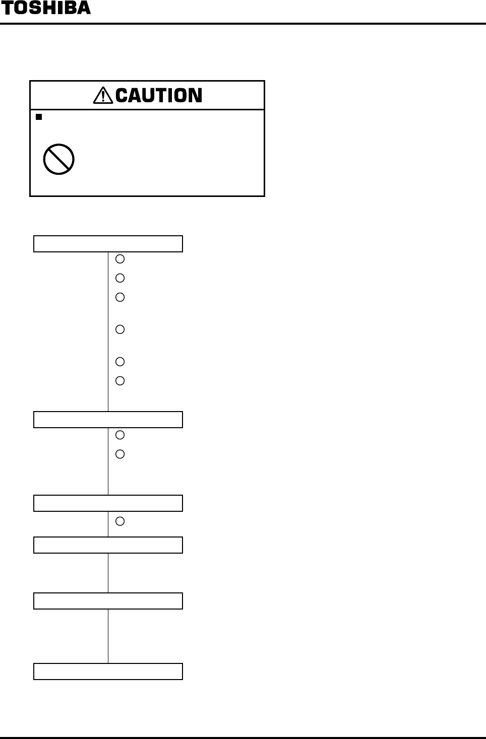
6. Operation
Do not touch the LF232 main body when high
temperature fluid is being measured.
DON’T
The fluid raises the main body
temperature and can cause burns
when touched.
For operation, follow the procedure described below.
Inspection for each part
Is the wiring and connection between the detector and converter correct?
Is the wiring between the converter and related instruments correct?
Isn’t tightening of connection between the detector and the mating pipe
forgotten?
Is the direction of arrow of the detector in accordance with the direction of
actual fluid?
Are the detector and the converter grounded securely?
Is the converter cover securely tightened?
Check the items above.
Introducing water
Let the fluid go through and fill the detector pipe. (Note)
When the detector pipe is filled with fluid, stop the fluid and keep it still.
In the case of the flowmeter which is partially filled pipes type, please let a fluid
stand still at water level high as possible more than water level 30%.
Applying power supply
Is the power supply as specified?
Checking the converter settings
* See 7. “Display and Controls,” 8. “Parameter Settings/Adjustment,” and 11.
“Communications Function.”
Zero adjustment
Wait for 30 minutes to warm up the flowmeter. Then perform zero adjustment.
(Check that the fluid remains still)
* See 8.5.1 “Still Water Zero Adjustment.”
Operation
After checking the items and performing adjustment listed above, let the fluid go through the detector
pipe. Then the outputs such as current output (4 to 20mADC) directly proportional to the flow rate can
be obtained.

6F8A0917
-
35
-
Note: If the fluid to be measured is not filled in the detector pipe (When detector is partially
filled pipes type, water level is not enough), flow rate becomes inconsistent and
measurement cannot be performed correctly.
Be sure to use the flowmeter while the fluid to be measured is filled in the detector pipe.
6F8A0917
-
36
-
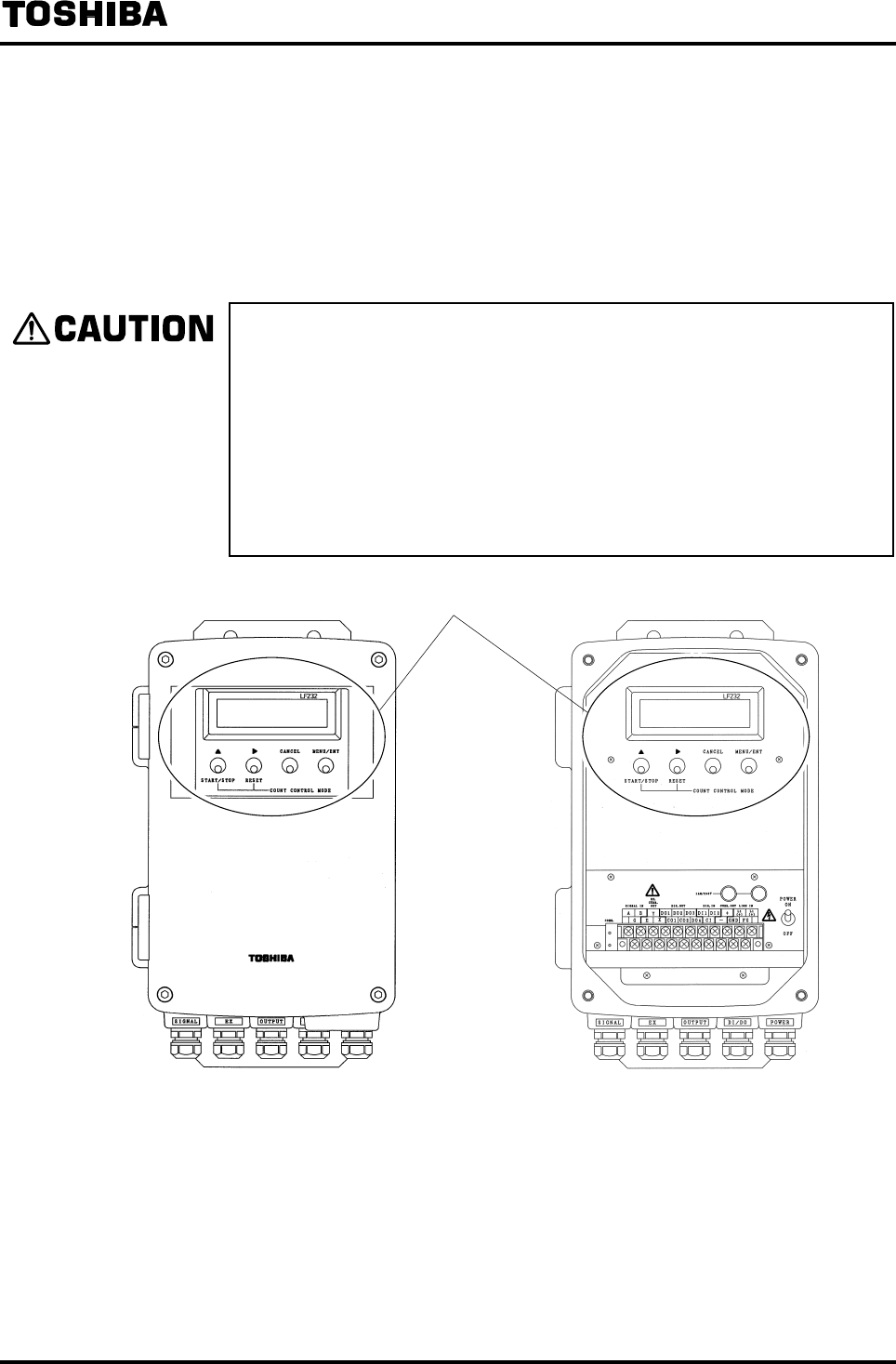
7. Display and Controls
For the LF232 converter, the measured value can be displayed and the parameters can be checked or
set using the LCD display and operation switches.
The operation switches are non-contact type (infrared method) and can be operated without opening
the converter cover (operable also while the cover is opened).
Observe the following precautions when you open the converter cover:
• Do not allow the converter exposed to rain and wind.
Adjustment in the rain may cause damage to the parts and may cause electric
shock and it is very dangerous.
In addition, if wind-blown dust enters the electronic circuits in the converter,
this may cause malfunction of the converter.
• Do not open the converter cover under high humidity condition
Opening the converter cover under high humidity condition can cause
deterioration of system accuracy or cause damage to the flowmeter parts.
Display and controls
(Cover Closed Condition) (Cover Opened Condition)
Figure 7.1 Display and Controls
6F8A0917
-
37
-
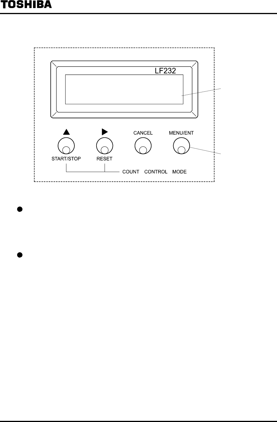
7.1 Names and Functions of Display and Controls
Display
Operation switch
(Infrared switch)
Figure 7.2 Display and Controls
LCD display
A 16-character × 2-line liquid crystal display with backlight is used.
Instantaneous flow rate and total flow, and various constants such as parameters can be displayed.
In addition, the backlight is always lit and data can be read clearly even in a dark place.
Operation switch (infrared switch)
Operation switches are infrared switches and the operation can be carried out without opening the
housing cover and operable also with the cover opened.

6F8A0917
-
38
-
Instructions
The operation principle of infrared switch is to irradiate infrared to the
front of control panel and detect the reflection from finger when operating.
Normal operation is impeded depending on the conditions such as
disturbing light from surroundings or stain attached to the control panel.
When unable to avoid such condition, operate the EMF converter in the
following manner.
Remove the factor to impede proper operation of infrared switch as below:
・ Cover the control panel by hand so that light does not shine on it
・ Clean the stain attached on the control panel
・ Clean the stain on the finger or the gloves to operate the EMF
converter, or wear gloves in light color
・ When there is a reflecting object placed opposing to the control panel,
stand in-between the reflecting object and the control panel to block
the light
Following are considered as the factors to impede infrared switch to
operate properly.
・ Intense light such as direct sunlight and reflected sunlight by window
glass or metal plate
・ Place where brightness changes always such as ON/OFF of lighting
・ Dense smoke or steam near the control panel
・ Those attached on the control panel such as rain (dew drop), snow,
ice, mud and oil, and haze due to their attachment
・ Operation of the control panel by hands wearing gloves in dark color
or stained fingers and gloves
・ Light reflecting object near the control panel, or reflecting object such
as metal plate placed opposing to the control panel
6F8A0917
-
39
-
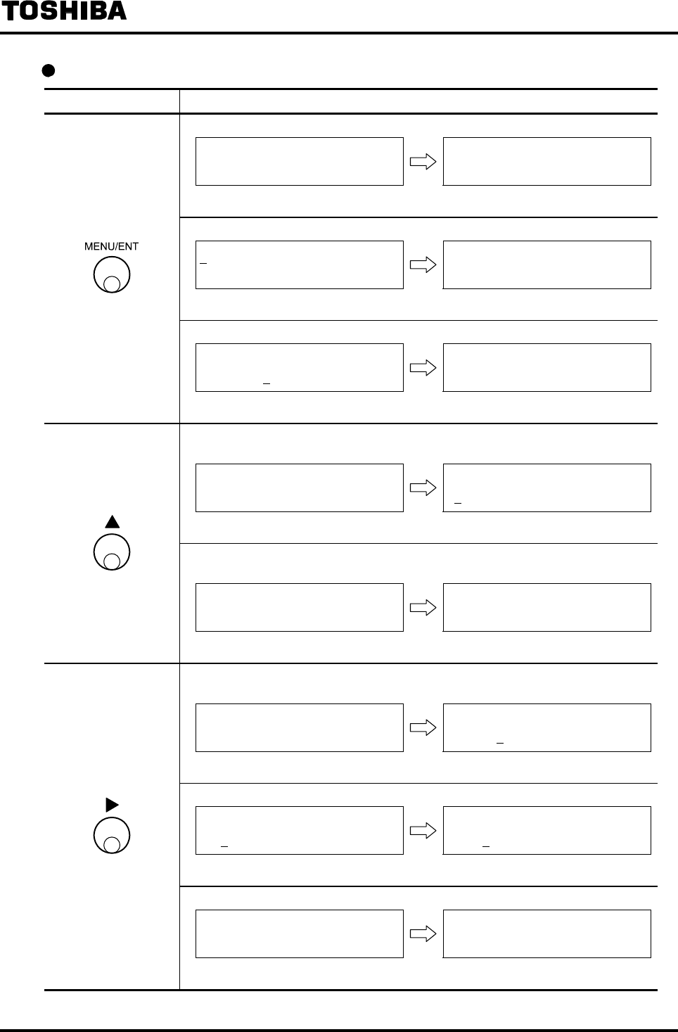
Functions of each switch
Switch Basic function
• Moves the mode from the measurement mode to menu display
10.00 m/s
100.0 %
ENTER 111
000
(Measurement mode) (Menu lock cancellation screen)
• Moves the mode to the setting, calibration or measurement mode
A1:EX CURR
A1:EX CURR
0.2100A
(Menu display) (Setting mode)
• Writes data in the setting mode.
B1:UNIT 1
%
B1:UNIT 1
%
(Data being changed) (Data has been changed)
• Changes the numeric value or items in menu display and in the setting,
calibration or measurement mode.
C2:RANGE 1
02.000 m/s
C2:RANGE 1
03.000 m/s
(Data 0.2000m/s) (Data 0.3000m/s)
• Starts or stops the totalizer (total value and pulse output) in the totalizer control
mode.
COUNT CTRL
F 1000 m3
COUNT CTRL
F 1000 m3 C
(Count stops) (Count starts)
• Enables the converter to change the setting value in the setting or calibration
mode and the cursor appears.
D1: DAMPING
00.5 S
D1: DAMPING
00.5 S
(Setting mode) (
Enabled to change the setting value
)
• Moves the cursor (digit) in menu display and in the setting mode
G1: COUNT RATE
1.23E-4 m3
G1: COUNT RATE
1.23E-4 m3
(Cursor at the position of “1”) (Cursor at the position of “2”)
• Resets the totalizer (total value) in the totalizer control mode
COUNT CTRL
F 1000 m3 C
COUNT CTRL
F 0 m3 C
(Counter in operaiton) (Resets the counter)
(*note)
6F8A0917
-
40
-
Note : There is not this screen to the converter before serial No.072320999.
( Menu screen is displayed. Menu lock cancellation screen is not displayed. )
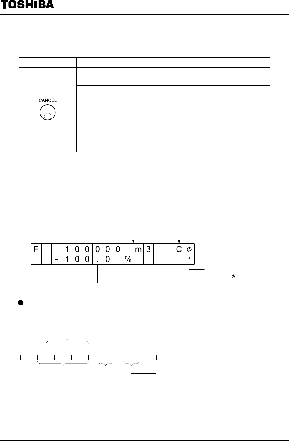
Switch Basic function
• Returns the screen from the parameter display screen to the menu display
screen.
• Returns the screen from the parameter input screen (Cursor ON) or
adjustment wait screen to the parameter display screen.
• Cancels the parameter input check screen (screen blinks) and returns to the
parameter input screen.
• If pressed while menu display screen is displayed, Function [MEAS MODE]
to return to the measurement mode appears.
(If MENU/ENT is pressed under that condition, the mode returns to the
measurement mode.)
7.2 Display Format
In the measurement mode, the measured data is displayed in the unit set by UNIT 1 and UNIT 2 in the
setting mode. (To set the unit, see 8.2.6 " Normal Indicating Unit ")
Displayed in the unit set by UNIT 1
In the case of total count display,
“C” appears while counting is in
progress.
Displayed in the unit set by UNIT 2
While communication is in
progress, “ ” appears.
Measured value display format
(1) Flow velocity value and instantaneous flow rate display
4 significant digits (for the span flow rate)
- 1 0 . 0 0 m l / s
Time unit
Flow unit
Numeric value is indicated in 7 digits including a
decimal point. (Up to 9999999)
Flow direction: Forward direction “ ” (blank)
Reverse direction “ − ”
6F8A0917
-
41
-
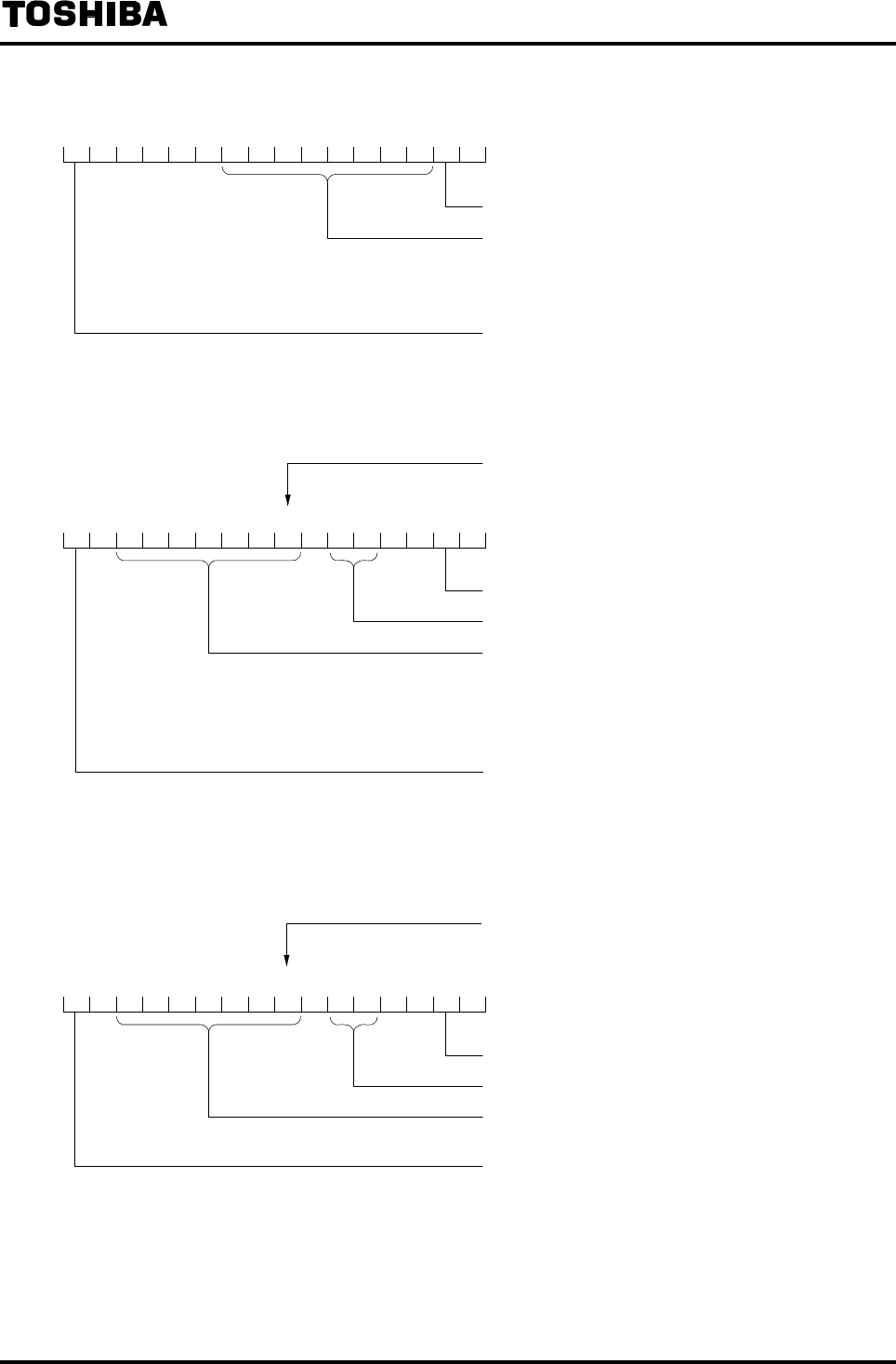
(2) Total count display
F 9 9 9 9 9 9 9 9 C
“C” is displayed when counting is in progress.
Total value is displayed in the unit of count
When the count exceeds the maximum value of
99999999, the count will be reset to 0 and will be
counted again.
In the case of forward flow count, “F” is displayed.
In the case of reverse flow count, “R” is displayed.
(3) Total flow value display
Displayed to the least significant digit of the set pulse
rate.
F 9 9 9 . 9 9 m l C
“C” is displayed when counting is in progress.
Flow unit
Numeric value is indicated in 8 digits including a
decimal point.
(Total valve is displayed up to 99999999, and when
the total count exceeds the maximum value of
99999999, the total valve will be reset to 0 and will be
counted again.)
In the case of forward flow count, “F” is displayed.
In the case of reverse flow count, “R” is displayed.
(4) Total difference flow value display
Displayed to the least significant digit of the set pulse
rate.
+ 9 9 9 . 9 9 m l C
“C” is displayed when counting is in progress.
Flow unit
Numeric value is indicated up to 8 digits including a
decimal point.
If forward flow count ≧ reverse flow count, “+” is
displayed.
If reverse flow count › forward flow count, “−” is
displayed.
For total difference flow value, the difference between the forward direction value and the reverse
direction value is displayed.
6F8A0917
-
42
-
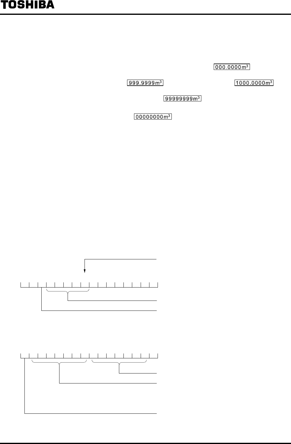
Notes on total flow value display
Note 1: The total flow value and the total difference flow value are displayed to the least
significant digit of the set count rate.
Example: When the set count rate is 0.0001 m3
Total flow / total difference flow display becomes and the value
increases in increments of 0.0001 m3.
If the value reaches , the display changes to at the
next count.
In the end, the display becomes .
When the set count rate is 10 m3
The display becomes and the value increases in increments
of
10 m3.
Note 2: In the case of total difference flow display, if the forward direction total flow value or
reverse direction total flow value exceeds 9,999,999, only the total value that exceeded
9,999,999 will be reset to 0 and the count continues.
Example: When the forward direction value returns to zero after it reaches the
maximum value
Forward direction:1000
Reverse direction:− 100
Flow difference: 900
→
Forward direction:
99999999
Reverse direction: − 100
Flow difference: 99999999
→
Forward direction: 0
Reverse direction:− 100
Flow difference: − 100
* In an example shown above, if the forward direction flow value is reset to zero
after reaching 99999999, flow difference indication changes from 99999899 to
−100 and the count continues.
(5) Percent display
Displayed to one decimal place (0.1%).
- 1 0 0 . 0 %
Up to 125.0% is displayed.
Flow direction: Forward direction “ ” (blank)
Reverse direction “ − ”
(6) Custom unit display
- 1 0 . 0 T E S T 1 2 3
Unit can be displayed up to 7 digits.
Value is indicated in 8 digits including a decimal point.
(Up to 9999999)
4 significant digits: m3/min value multiplied by the set
coefficient
Flow direction: Forward direction “ ” (blank)
Reverse direction ” − ”

6F8A0917
-
43
-
(7) Error message / other message display
E X C U R R E N T O P E N
If an error or alarm condition occurs, a message is displayed in the 2nd line.
(8) Fixed output display
* F I X O U T 2 0 . 0 m A
In the fixed output mode, a message is displayed in the 2nd line.
7.3 Basic Operations (
Mode Switching, Setting Mode Operation, Total Counter Operation
)
7.3.1 Mode Switching
(1) Types of mode
The following operation modes are provided in the LF232 converter and they can be changed by
operation switches.
• Measurement mode: This is the mode used at the time of flow measurement
The process value is displayed and output.
The flowmeter first goes to this mode when power is turned on.
• Totalizer operation mode: Totalizer can be started, stopped and reset.
For output, the process value is output in the same way as in the
measurement mode.
For details, see 7.3.4 “Totalizer Operation.”
• Setting mode: This is the mode to check or set various parameters.
Parameters can be selected from function menu.
Though various parameters are shown on the display, the process value is output
in the same way as in the measurement mode.
For details, see 8.2 “Parameter Check/Change.”
The following mode can also be selected using menu in the setting mode.
• Fixed value output mode (loop check): This is the mode in which 4 to 20mA output and the
totalizer pulse output frequency can be fixed to a preset
value.
For details, see 8.4 “Fixed Value Output (Loop Check).”
• Zero adjustment mode: This is the mode in which zero adjustment can be performed.
The process value is output in the same way as in the measurement
mode.
For details, see 8.5 “Zero Adjustment.”
• Calibration mode: This is the mode to check the circuits of the converter unit.
Zero point and span can be checked using the internal generator circuit that
generates simulation signals. Excitation current can also be checked.
The current output becomes the value corresponding to the simulation signal.
For digital output, the last value before entering the calibration mode will be
held.
For details, see 9. “Mag-Prover Calibration.”
6F8A0917
-
44
-
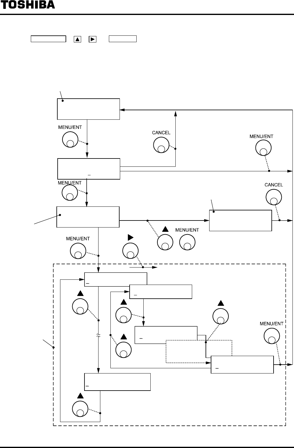
(2) Mode switching operation flow
MENU/ENT , , and CANCEL shown in the flow diagram below indicate the switch
operations and when the indicated switch is pressed, the process moves to the item indicated by
the corresponding arrow Æ.
>1:SET
2:CNT CTRL
10.00 m/s
100.0 %
COUNT CTRL
F 1000 m 3
M
1:MANUAL ZERO
A1:EX CURRENT
A0:MEAS MODE
A 1:EX CURRENT
A2:METER SIZE
Measurement mode
Press longer
for 3 seconds.
*(Note 2)
Mode Selection
Screen
*(Note 1)
(Set “0” to the 1st
digit of the function
code and press
MENU/ENT)
*(Note 2)
Setting mode
(Menu display)
Totalizer operation mode
(Point the cursor (>)
to SET.)
(Point the cursor (>) to
CNT CNTRL.)
ENTER111
000 V****
*(Note 3)
Input [111]
Not [111]

6F8A0917
-
45
-
Note 1: If password is set, the password selection screen appears.
For details, see 7.3.3, “Password Input.”
Note 2: If no operation is performed
for one minute while the mode selection screen or the
setting mode menu screen is displayed, the screen returns to the measurement
screen
Note 3: There is not this screen to the converter before serial No.072320999.
There is not software version (V****) to the converter before version V0109.
6F8A0917
-
46
-
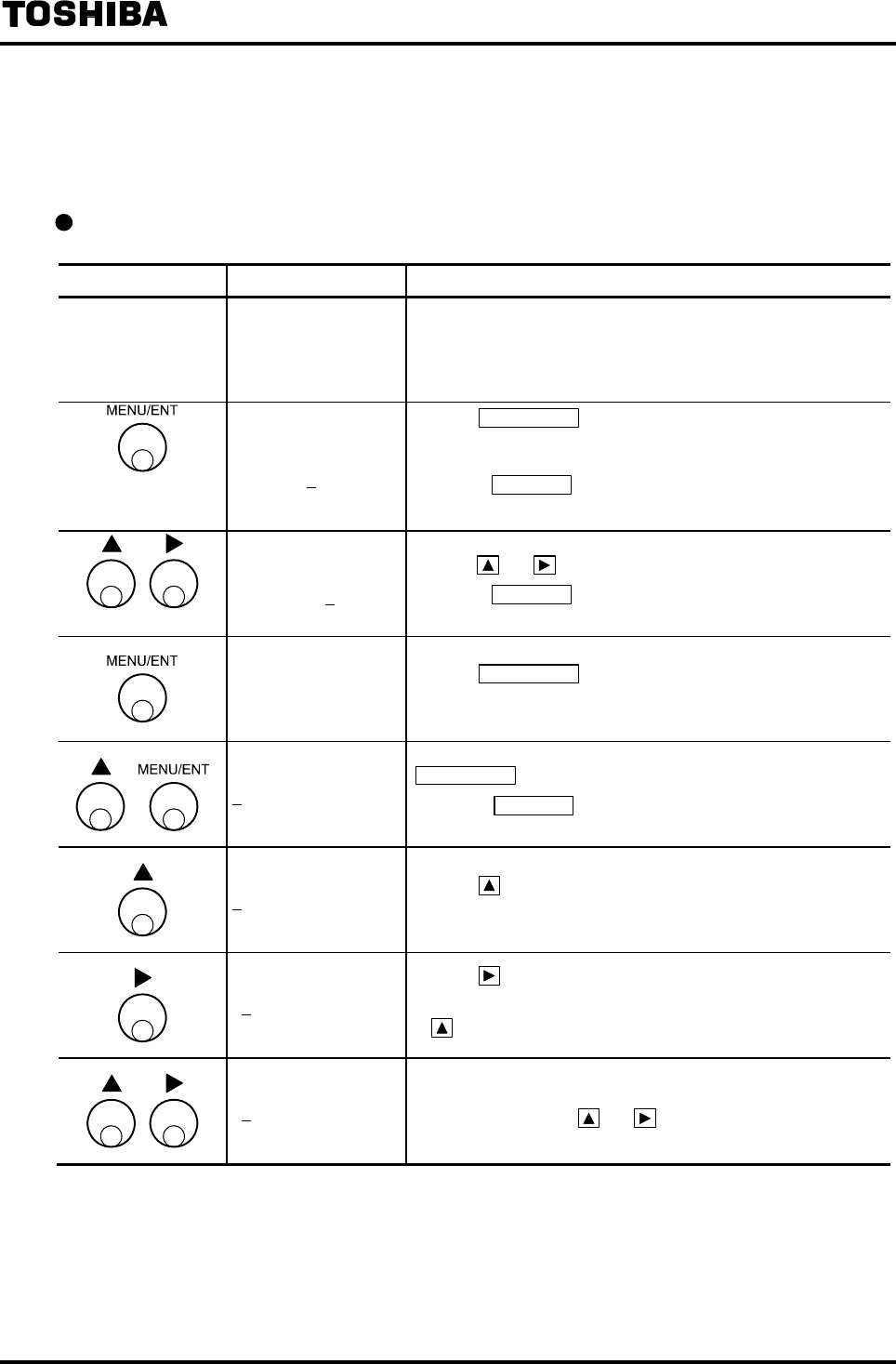
7.3.2 Setting Mode Operation
Proceed as follows to select the desired item and check or change the setting values.
* Switch operation indicates the switches to press.
Moving to the menu display
Switch operation Display example Description
−
10.00 m/s
100.0 % Measured value being displayed (measurement mode)
ENTER111
000 V****
Pressing MENU/ENT in the measurement mode for 3 seconds
or more, the screen moves to the menu lock cancellation
screen.
* Pressing CANCEL in the mode selection screen, the mode
returns to the measurement mode.
ENTER111
111 V****
Set the menu lock cancellation cord [111] by
pressing and .
* Pressing CANCEL in the mode selection screen, the mode
returns to the measurement mode.
>1:SET
2:CNT CTRL
Pressing MENU/ENT in the measurement mode for 3 seconds
or more, the screen moves to the mode selection screen.
A1:EX CURRENT
Select 1:SET in the mode selection screen and press
MENU/ENT . Then the menu screen appears.
* Pressing CANCEL in the mode selection screen, the mode
returns to the measurement mode.
B1:UNIT 1 Pressing , the function number (a combination of a letter
and a number) changes.
B1:UNIT 1
Pressing , the cursor moves.
* If the cursor is positioned at the digit of number, pressing
moves the cursor to the digit of letter.
C2:RANGE 1 Likewise, set the function number to the one you want to check
or change by pressing and .
Note1
Note1
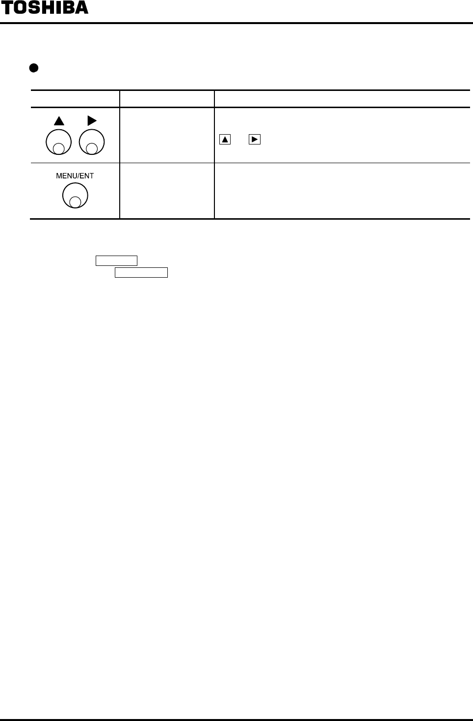
6F8A0917
-
47
-
To return from the menu display to the measurement mode
Switch operation Display example Description
C0: MEAS MODE Set the digit of number for function number to “0” by pressing
and (Note2). The digit of letter can be set to any letter.
10.00 m/s
100.0 %
The mode returns to the measurement mode (measured value
display screen).
Note1: There is not this screen to the converter before serial No.072320999.
There is not software version (V****) to the converter before version V0109.
Note2:Pressing CANCEL changes the digit of number to “0” (*0:MEAS MODE).
Then pressing MENU/ENT under that condition brings you back to the measurement mode with
minimum operations.
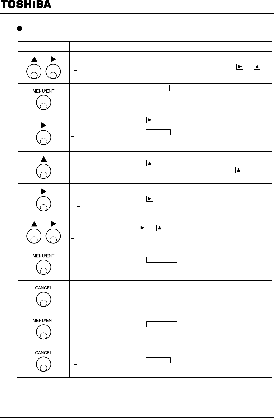
6F8A0917
-
48
-
Checking or changing the setting values
Switch operation Display example Description
C2: RANGE 1
Menu display
Select the desired item to check or change using and .
C2 (RANGE 1) in this example.
C2: RANGE 1
2.00000 m/s
Press MENU/ENT to decide the item to check or change.
The cursor disappears and the currently set value appears for
you to check. Pressing CANCEL under this condition brings
you back to the previous screen.
C2: RANGE 1
2.00000 m/s
Pressing , the cursor appears at the position of the set value
and enables the set value to be changed.
Pressing CANCEL under this condition, the cursor disappears
and the screen returns to the setting value check screen
(previous screen).
C2: RANGE 1
3.00000 m/s
Setting value changeable condition
Pressing , the setting value increases.
* If the cursor is positioned at the unit, pressing moves the
unit to the next unit.
C2: RANGE 1
3.0000 m/s Pressing , the cursor moves to the next digit.
C2: RANGE 1
5.00000 m/s
Press and to change the setting value.
In this example, set the value to 5.000m/s.
C2: RANGE 1
5.00000 m/s
Pressing MENU/ENT changes to the condition that data is
temporarily set and the entire data blinks.
( )
C2: RANGE 1
2.00000 m/s
If you want to cancel the data change such as when the
temporarily set data has an error, press CANCEL and then the
temporarily set data returns to the previously set value and the
screen returns to the setting value changeable condition.
C2: RANGE 1
5.00000 m/s
Pressing MENU/ENT confirms the data and the changed data
appears.
C2: RANGE 1 Pressing CANCEL returns you to the menu screen.
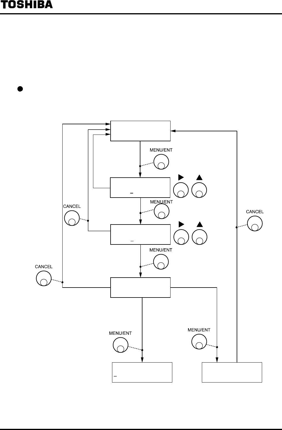
6F8A0917
-
49
-
7.3.3 Password Input
The password function is provided in the LF232 converter to prevent some functions that affect the
flow measurement from being used or adjusted. If password is set, totalizer cannot be reset.
For the setting menu limited by the password, see 7.4 “Setting Menu List.”
In addition, for how to set password, see 8.2.5 “Password Setting.”
Mode switching flow when password is set
If password is set, when the mode moves from the measurement mode to the menu screen, the
password input screen appears.
Note1: There is not this screen to the converter before serial No.072320999.
There is not software version (V****) to the converter before version V0109.
>1:SET
2:CNT CTRL
10.00 m/s
100.0 %
INPUT PASSWORD
000
Input [111]
Password
input
A1:EX CURRENT COUNT CTRL
F 1000 m 3
(Setting the cursor (>) to SET
and press MENU/SET)
(Setting the cursor (>)
to CNT CNTRL and
press MENU/ENT)
ENTER111
000
Press longer for
3 seconds.
Cancellation
cord input
[CANCEL] or
Code is not [111]
*Note1
V****
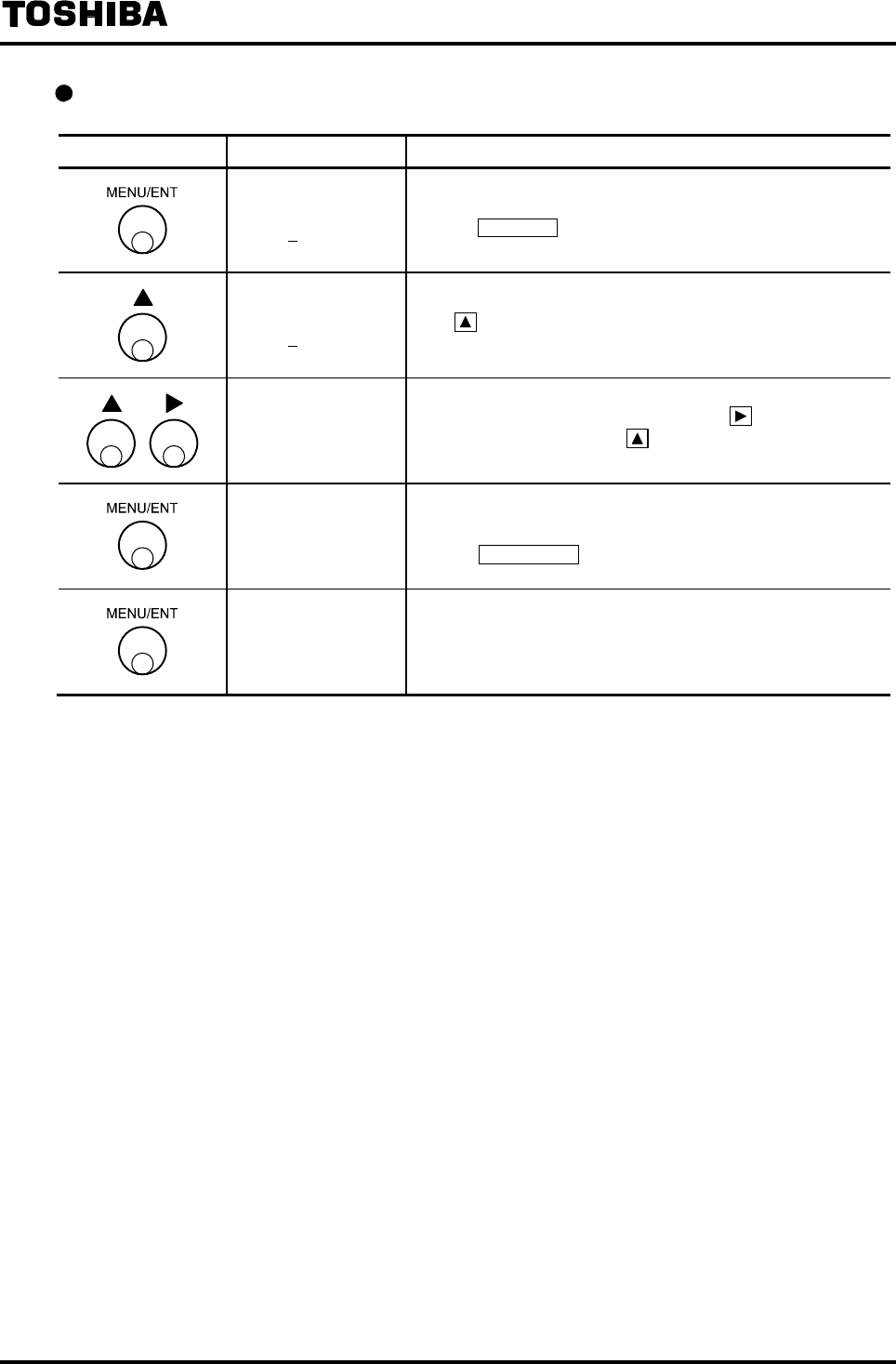
6F8A0917
-
50
-
Example of password input (mode selection: SET and password: 123)
Switch operation Display example Description
INPUT PASSWORD
000
The password input screen appears from the measurement
mode. The cursor appears.
Pressing CANCEL , the screen returns to the mode selection
screen.
INPUT PASSWORD
100 Press to change the value to 1.
INPUT PASSWORD
100
120
123
Change the number.
To change the number of other digit, press to move the
cursor to that digit and press to change the number there.
Repeat this operation until 123 appears on the screen.
INPUT PASSWORD
123
The display blinks and the set value is displayed for
conformation.
Pressing MENU/ENT again, the password will be written.
>1:SET
2:CNT CTRL
Regardless of whether the password input is correct or not, the
screen changes to the mode selection screen.
However, if the password input is erroneous, the setting value
cannot be changed and calibration cannot be performed.

6F8A0917
-
51
-
7.3.4 Totalizer Operation
In the totalizer operation mode, the totalizer can be started, stopped and reset.
If password is set (if password input does not match), the totalizer can be started or stopped but it
cannot be reset.
Note: To operate the totalizer, it is necessary to set necessary settings for the totalizer.
For details of how to set necessary settings for the totalizer, see 10. “Function
Description.”
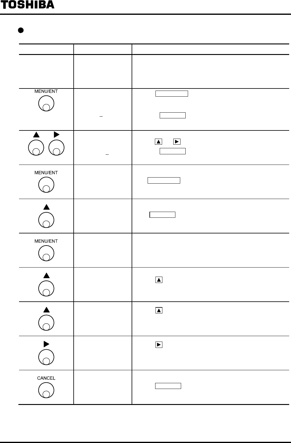
6F8A0917
-
52
-
Example of totalizer operation
Switch operation Display example Description
−
10.00 m/s
100.0% (Measurement mode)
ENTER111
000 V****
Pressing MENU/ENT in the measurement mode for 3 seconds
or more, the screen moves to the menu lock cancellation
screen.
* Pressing CANCEL in the mode selection screen, the mode
returns to the measurement mode.
ENTER111
111 V****
Set the menu lock cancellation cord [111] by
pressing and .
* Pressing CANCEL in the mode selection screen, the mode
returns to the measurement mode.
>1:SET
2:CNT CTRL Press MENU/ENT longer for 3 seconds.
1:SET
>2:CNT CTRL Select CANCEL in the mode selection screen.
COUNT CTRL
F 1000 m3 The totalizer operation screen appears.
COUNT CTRL
F 1000 m3 C
Pressing when the totalizer is stopped, the totalizer starts.
* “C” mark appears indicating that the totalizer has started.
COUNT CTRL
F 1000 m3
Pressing while the totalizer is in operation, the totalizer
stops.
* “C” mark disappears.
COUNT CTRL
F 0 m3
Pressing , the totalizer will be reset to zero.
* If the totalizer is reset, the count value cannot be returned to
the previous value.
10.00 m/s
100.0 % Pressing CANCEL returns you to the measurement mode.
Note1: There is not this screen to the converter before serial No.072320999.
There is not software version (V****) to the converter before version V0109.
Note1
Note1
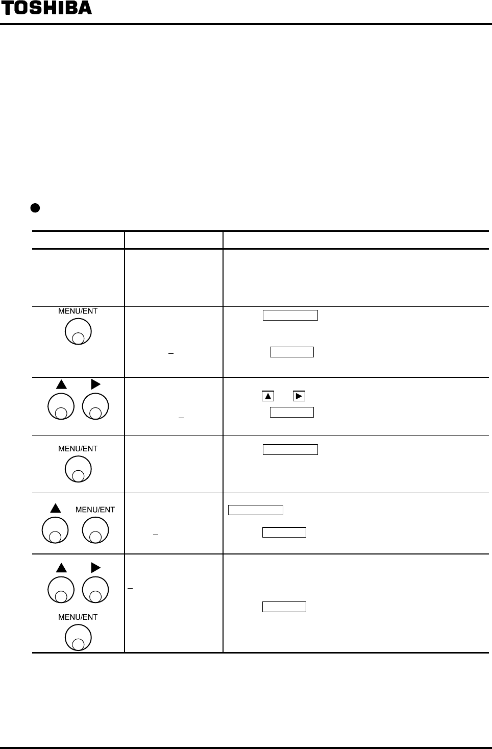
6F8A0917
-
53
-
7.3.5 Maintenance Menu
If you enter the service code to release the protection, the maintenance specific items in the setting
mode that are not displayed normally can be accessed and the parameters that are normally prohibited
to be rewritten can be changed.
This function is mainly used by service personnel, it is not necessary for general customers to enter
this function.
If erroneously operated and the service code input screen appears, either press [CANCEL] to return to
the measurement mode or press [MENU/ENT] to go on to the setting menu. (In this case, protection
will not be released.)
Example to move to the maintenance menu
Switch operation Display example Description
−
10.00 m/s
100.0 % Measured value being displayed (measurement mode)
ENTER111
000 V****
Pressing MENU/ENT in the measurement mode for 3 seconds
or more, the screen moves to the menu lock cancellation
screen.
* Pressing CANCEL in the mode selection screen, the mode
returns to the measurement mode.
ENTER111
111 V****
Set the menu lock cancellation cord [111] by
pressing and .
* Pressing CANCEL in the mode selection screen, the mode
returns to the measurement mode.
>1:SET
2:CNT CTRL
Pressing MENU/ENT for 3 seconds or more in the
measurement mode, the screen moves to the mode selection
screen.
INPUT SRV_CODE
000
Select 1:SET in the mode selection screen and press
MENU/ENT for 5 seconds or more, then the screen appears
that is used to enter the service code to release the protection.
Pressing CANCEL in the mode selection screen brings you
back to the measurement mode.
A1:EX CURR
Enter the service code and if it is correct, the maintenance
specific items in the setting menu can be accessed.
Pressing CANCEL in the service code input screen brings you
back to the mode selection screen.
Note1: There is not this screen to the converter before serial No.072320999.
There is not software version (V****) to the converter before version V0109.
Note1
Note1

6F8A0917
-
54
-
7.4 Setting Menu List
The constants set in the LF232 converter can be checked or changed in the order shown in the table
below.
The details of each item are described in the following sections:
• Setting items (A to M): Chapter 8. “Parameter Settings / Adjustment”
• Calibration item (N): Chapter 9. “Mag-Prover Calibration”
0 1 2 3 4 5 6 7 8
A Exciting
current setting
*1
Meter size *1 Exciting
frequency *1
Flow direction
setting *1
Password *1
B Main display
unit
Sub display
unit
Custom
coefficient *1
Custom unit
*1
C Range type *1 Range 1 *1 Range 2 *1 Range 3 *1 Range 4 *1 Hysteresis *1
D Damping
constant
Low cutoff
value
Current output
setting for
alarm *1
Display low
cut
On/Off
Output low
limit setting
*1
E Still water
zero
adjustment
F Digital output
1 *1
Digital output
2 *1
Digital output
3 *1
Digital output
4 *1
DO1 alarm
output state *1
DO2 alarm
output state *1
DO3 alarm
output state *1
DO4 alarm
output state *1
G Digital input 1
*1
Digital input 2
*1
DI1 control
signal level
setting *1
DI2 control
signal level
setting *1
H Count rate *1 Pulse width
setting mode
*1
Pulse width *1
I Preset count
value *1
Preset output
setting *1
J High limit
alarm On/Off
*1
High limit
value setting
*1
Low limit
alarm On/Off
*1
Low limit
value setting
*1
K High high
limit alarm
On/Off *1
High high
limit value
setting *1
Low low limit
value On/Off
*1
Low low limit
value setting
*1
L Fluid empty
alarm *1
Self-diagnosis
On/Off *1
Alarm output
preset *1
M Rate-of-chang
e limit
Control time
N Fixed value
output *1
Fixed current
*1
Fixed pulse *1
O Zero offset
P
Return to measurement mode
0%
Flow value
calibration *1
50%
Flow value
calibration
100%
Flow value
calibration *1
Exciting
current
monitor
Note 1: For items marked by *1 in the table above, if you enter a wrong password, you can check the setting value but
you cannot change or adjust the setting value.
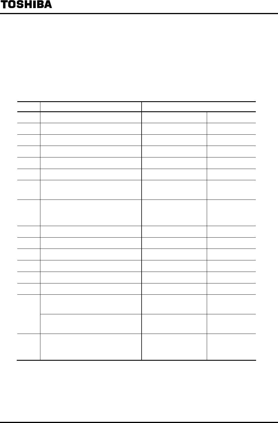
6F8A0917
-
55
-
8. Parameter Settings / Adjustment
8.1 Parameter Setting Items
To check or change each constant set in the LF232 converter, first select the desired setting item
described in 7.3.2, “Setting Mode Operation.”
For setting mode items, follow the explanation below to perform the settings.
No. Setting item Display example
8.2.1 Exciting current value A1: EX CURR 0.2100 A
8.2.2 Meter size A2: METER SIZE 50 mm
8.2.3 Exciting frequency A3: EX FREQ 24 Hz
8.2.4 Flow direction A4: FLOW DIRCTN 1:NORMAL
8.2.5 Password setting A5: PASSWORD 123
8.2.6 Normal display unit B1: UNIT 1 m3/h
8.2.7 Custom unit setting B3: CUSTOM DATA
B4: CUSTOM UNIT
12340.00
TEST123
8.2.8
Range type
Span value
Hysteresis
C1: RANGE TYPE
C2: RANGE 1
C6: RANGE HYST
1:SINGLE
01.000 m3/h
05.0 %
8.2.9 Damping constant D1: DAMPING 05.0 s
8.2.10 Low cutoff value D2: LOW CUT 05.0 %
8.2.11 Current output setting for alarm D3: ALM mA SET 2: 4.0mA
8.2.12 Display low cut On/Off D4: DSP LOW CUT 1: ON
8.2.13 Output low limit setting D5: LOW LIMIT 1: 4.0mA
8.5.1 Still water zero adjustment E1: ZERO ADJUST 0.1 %
Digital output function
Alarm output state
F1: DO1 FUNCT
F5: DO1 ALM STS
1:HIGH ALM
1:NORMAL CLOSE
8.2.14
Digital input function
Control signal level setting
G1: DI1 FUNCTN
G3: DI1 DET LV
2:CNT STA/STP
2:H LEVEL
8.2.15
Count rate
Pulse width mode
Pulse width
H1: COUNT RATE
H2: PLS MODE
H3: PLS WIDTH
1.00000 m3
1:AUTO
020 ms
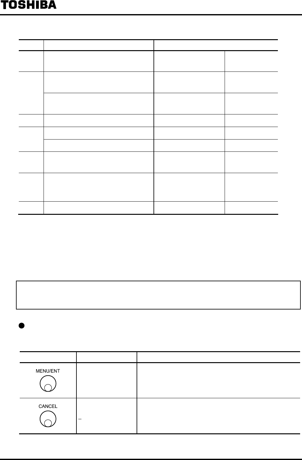
6F8A0917
-
56
-
No. Setting item Display example
8.2.16 Preset count value
Output function setting
I1: PRESET CNT
I2: PRESET FNC
00009000
1:HOLD
High/Low limit alarm On/Off
High/Low limit alarm value
J1: H ALM SET
J2: H ALM VAL
1:ON
+100.0 %
8.2.17
High high/Low low limit alarm On/Off
High high/Low low limit alarm value
K1: HH ALM SET
K2: HH ALM VAL
1:ON
+110.0 %
8.2.18 Fluid empty alarm L1: EMPTY ALM 1:NORMAL
Self-diagnosis On/Off L2: SELF CHECK 1:ON
8.2.19
Alarm output factor setting L3: ALM PRESET 1:WITHOUT EMP
8.2.20 Rate-of-change limit value
Control time
M1: LIMIT RATE
M2: LIMIT TIME
05.5 %
01 s
8.4 Fixed value output (Loop check)
N1: FIXED OUT
N2: FIXED CURR
N3: FIXED PULSE
OFF
20.0 mA
1000 pps
8.5.2 Zero offset adjustment O1: MANUAL ZERO -000.1 %
8.2 Parameters Check / Change
8.2.1 Exciting Current Value
The exciting current value is already adjusted when the product is shipped from the factory. Normally the
exciting current value is set to the same value as described on the detector nameplate.
Checking the exciting current value
Proceed as follows to check or change the exciting current value.
Switch operation Display example Description
A1: EX. CURR.
0.2100A
Select A1: EX. CURR. from the setting item selection menu.
The currently set exciting current value appears.
A1: EX. CURR. Returns to the menu of setting item selection.
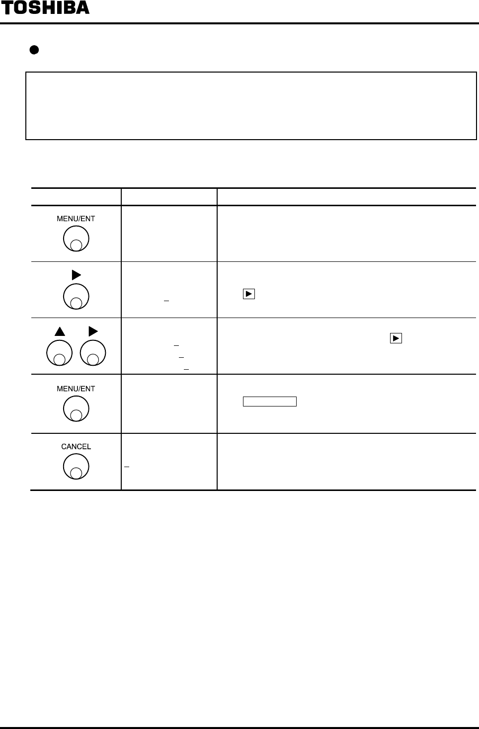
6F8A0917
-
57
-
Changing the exciting current value
To change the exciting current value, proceed as follows. However, the exciting current value is already
adjusted when the product is shipped from the factory. Do not change the exciting current value unless the
value is different from the one described on the detector nameplate. If you change this value to other value,
this may cause an error.
The following is an example to change the exciting current value from 0.1900A to 0.2150A.
Switch operation Display example Description
A1: EX. CURR.
0.1900A
Select A1:EX. CURR. from the setting item selection menu.
The currently set exciting current value (0.1900A in this
example) appears.
A1: EX. CURR.
0.1900A
The cursor appears.
Press further to move the cursor to the desired digit.
A1: EX. CURR.
0.2900A
0.2100A
0.2150A
Change the number of the digit.
To change the number of other digit, press to move the
cursor to that digit and change the number there. Repeat this
operation until 0.2150A appears on the display.
A1: EX. CURR.
0.2150A
The display blinks and the set value is displayed for
confirmation.
Press MENU/ENT again to write the data. Then the cursor
disappears and the display returns to the condition that the
setting value is displayed.
A1: EX. CURR. Returns to the menu of setting item selection.
Note: Set the exciting current value within the range shown below:
• For small and medium meter size detectors (LF232*A) 0.0500A to 0.2300A
• For large meter size detectors (LF232*B) 0.0500A to 3.000A
• For partially filled pipes detectors (LF232*F) 0.0500A to 1.500A
If you set an exciting current value outside of the settable range, a message such as *H. OVER
SPEC. appears and the value returns to the previous value. Try to set a new value again.
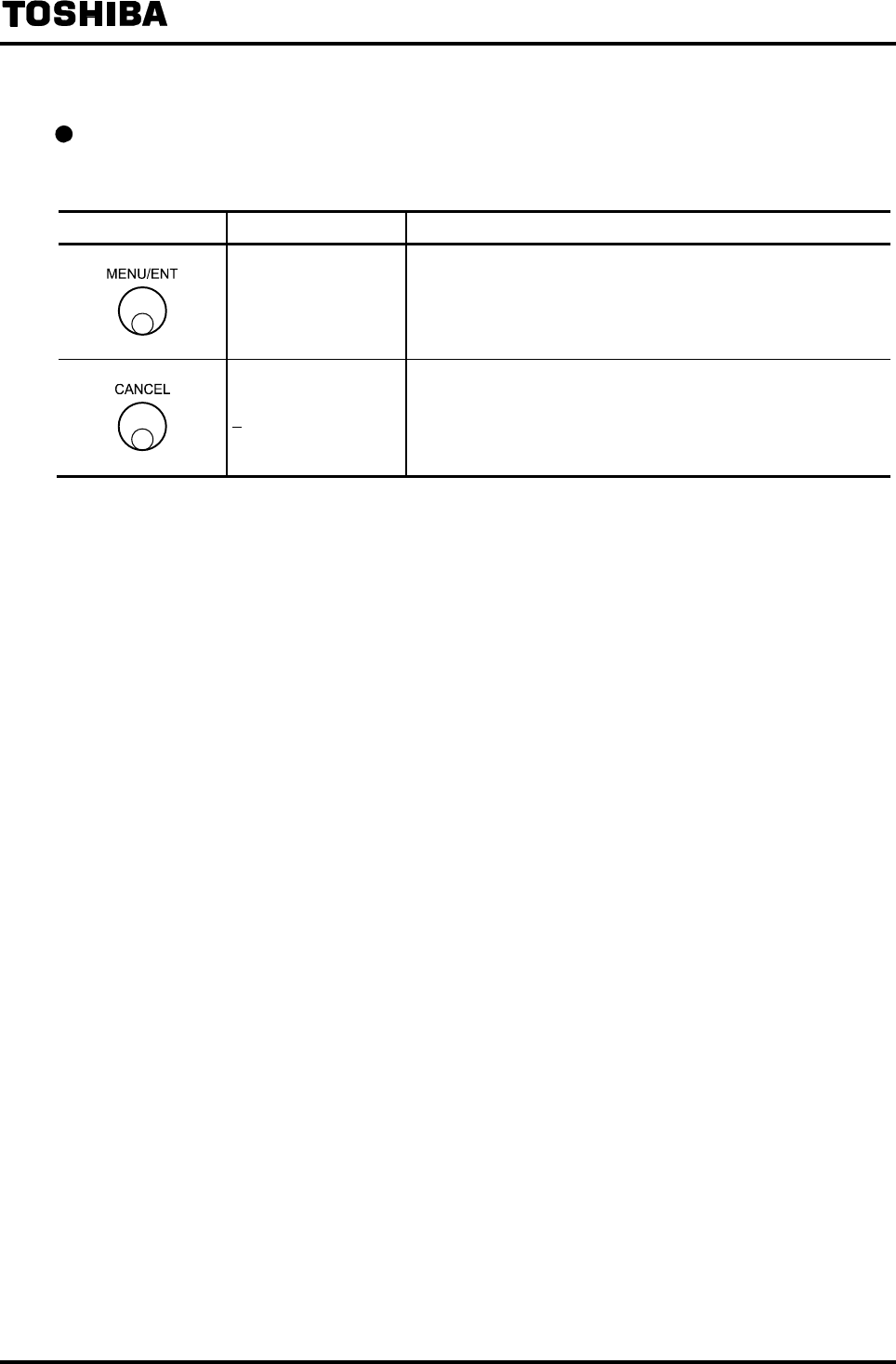
6F8A0917
-
58
-
8.2.2 Meter Size
Checking the meter size of the detector
Proceed as follows to check or change the meter size of the detector.
Switch operation Display example Description
A2: METER SIZE
50 mm
Select A2: METER SIZE from the setting item selection menu.
The currently set meter size of the detector appears.
A2: METER SIZE Returns to the menu of setting item selection.
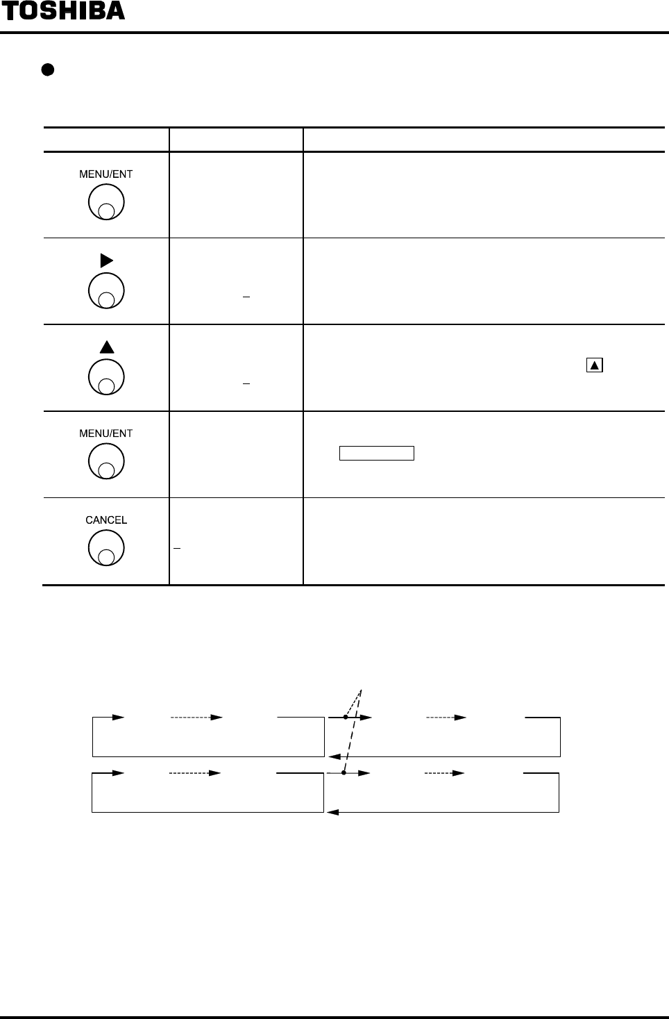
6F8A0917
-
59
-
Changing the meter size of the detector
The following is an example to change the meter size from 50mm to 10mm.
Switch operation Display example Description
A2: METER SIZE
50 mm
Select A2: METER SIZE from the setting item selection.
The currently set meter size (50mm in this example) appears.
A2: METER SIZE
50 mm The cursor appears.
A2: METER SIZE
100 mm
Change the set value for meter size to 100mm.
The set value for meter size can be changed using switch.
(Note 1)
A2: METER SIZE
100 mm
The display blinks and the set value is displayed for
confirmation.
Press MENU/ENT again to write the data. Then the cursor
disappears and the display returns to the condition that the
setting value is displayed.
A2: METER SIZE Returns to the menu of setting item selection.
Note 1: The meter size is displayed cyclically as shown below:
* For partially filled pipes detectors (LF232*F) : 6~24inch (150~600mm )
Note 2: If the setting value for meter value is changed, the setting value by flow unit and the setting
value for exciting frequency of no concern may be rewritten.
After the meter size is set, be sure to check the setting values of Range, Count (Pulse) Rate
and Exciting Frequency.
In the case of the converter for large meter
size detector (LF232*B)
600mm2.5mm 700mm 3000mm
0.1inch 24inch 28inch 120inch
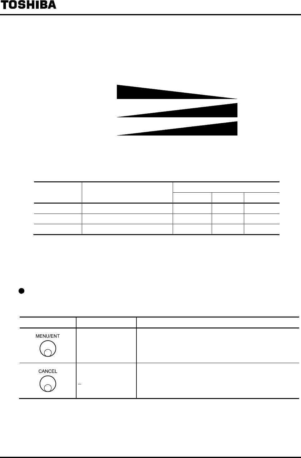
6F8A0917
-
60
-
8.2.3 Exciting Frequency
The exciting frequency can be selected from 6Hz, 12Hz and 24Hz. Since the features shown below are
apparent depending on the exciting frequency, select an appropriate exciting frequency.
Exciting frequency 6Hz 12Hz 24Hz
Zero-point stability Good
Response
Good
Fluid noise immunity
Good
However, the range of usable exciting frequency depending on the detector to be combined is shown
below.
Corresponding exciting frequency
Detector
combined Meter size 6Hz 12Hz 24Hz
LF470 1/10",1/6”,1/4" (2.5 to 6 mm) ○ ○ ◎
LF150 26” to 120” (500 to 3000 mm) ◎
−
−
335 All sizes ◎
−
−
* Partially filled pipes type LF232*F : Useable only 6Hz
◎ Factory setting
○ Combination allowed
− Combination not allowed
Checking the exciting frequency
Proceed as follows to check or change the setting value for exciting frequency.
Switch operation Display example Description
A3: EX. FREQ.
24 Hz
Select A3: EX. FREQ. from the setting item selection menu.
The currently set exciting frequency appears.
A3: EX. FREQ. Returns to the menu of setting item selection.
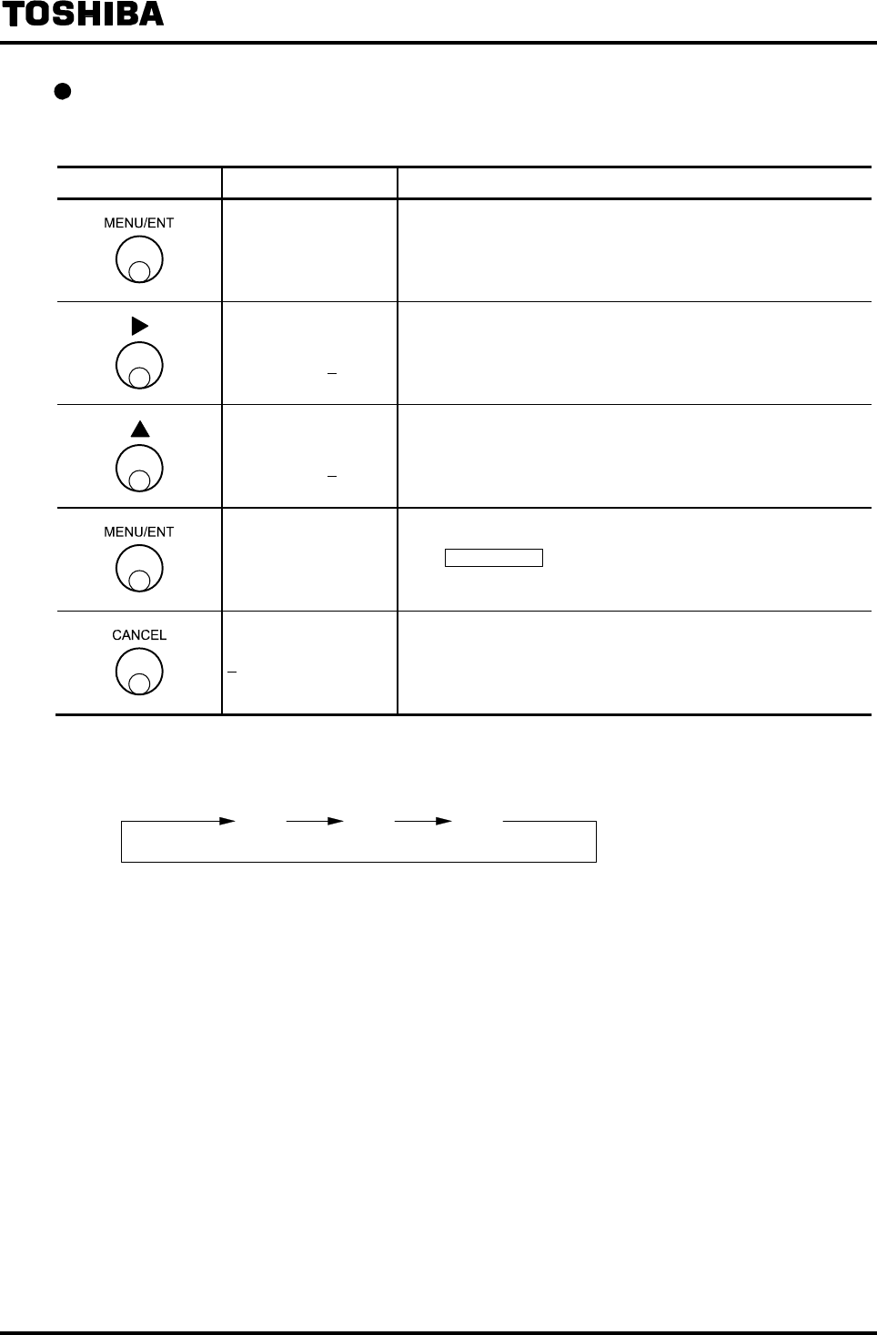
6F8A0917
-
61
-
Changing the setting value for exciting frequency.
The following is an example to change the exciting frequency from 24Hz to 12Hz.
Switch operation Display example Description
A3: EX. FREQ.
24 Hz
Select A3: EX FREQ. from the setting item selection menu.
The currently set exciting frequency (24Hz in this example)
appears.
A3: EX. FREQ.
24 Hz The cursor appears.
A3: EX. FREQ.
12 Hz
Change the exciting frequency to 12Hz.
The exciting frequency appears cyclically between 6Hz, 12Hz
and 24Hz. (Note 1)
A3: EX. FREQ.
12 Hz
The display blinks and the set value is displayed for
confirmation.
Press MENU/ENT again to write the data. Then the cursor
disappears and the display returns to the condition that the
setting value is displayed.
A3: EX. FREQ. Returns to the menu of setting item selection.
Note 1: The exciting frequency is displayed cyclically as shown below.
6Hz 12Hz 24Hz
* Partially filled pipes type LF232*F : Useable only 6Hz
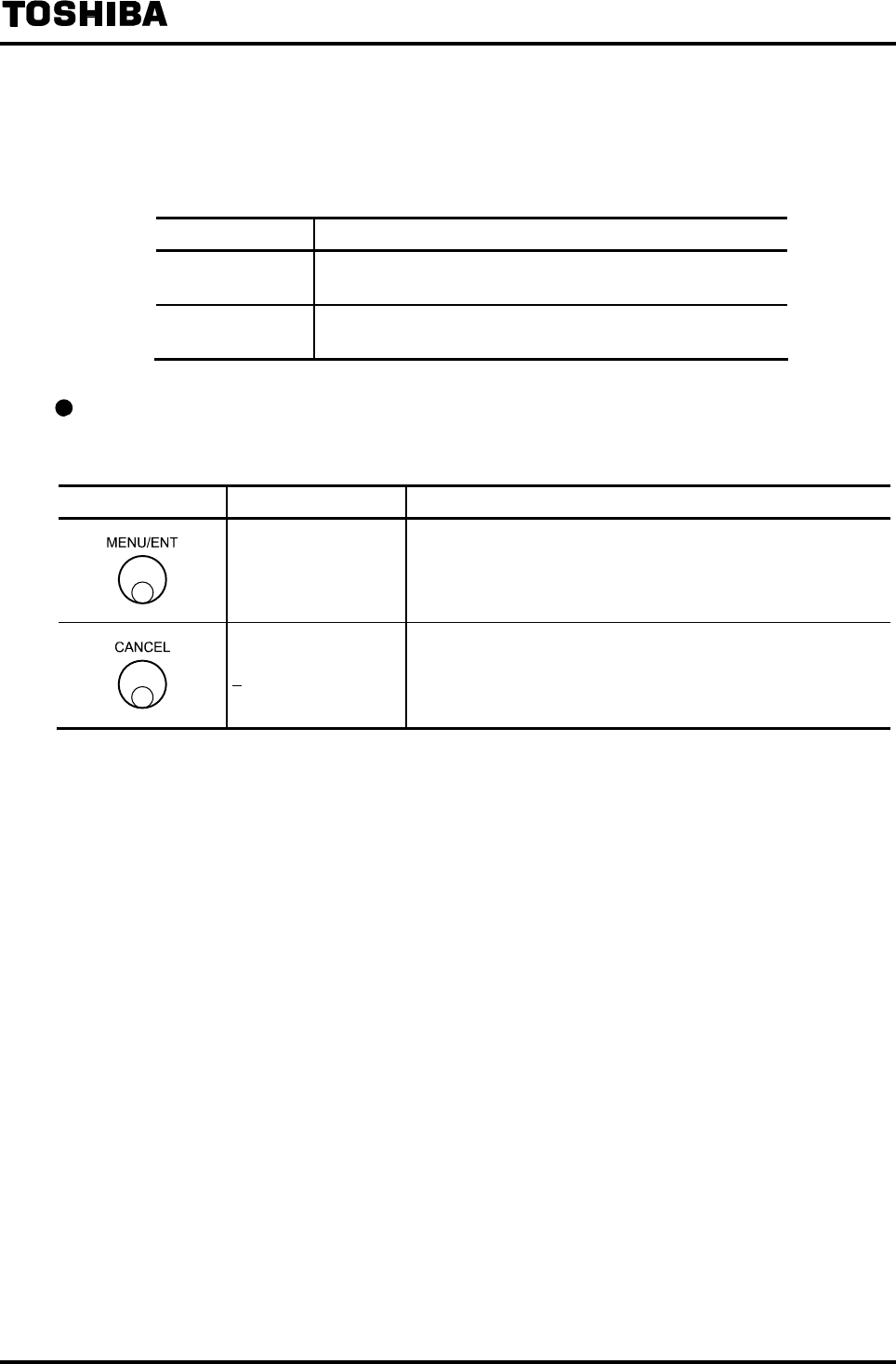
6F8A0917
-
62
-
8.2.4 Flow Direction
The flow direction of fluid can be set.
Normally use the flowmeter under the condition of NORMAL.
Selection item Description
1: NORMAL The flow is a direct flow when the fluid flows in the direction
indicated by the arrow on the detector.
2: SWITCH The flow is a direct flow when the fluid flows in the reverse
direction of the arrow on the detector.
Checking the flow direction.
Proceed as follows to check or change the setting value for direction flow.
Switch operation Display example Description
A4: FLOW DIRCTN
1:NORMAL
Select A4: FLOW DIRCTN from the setting item selection
menu.
The currently set flow direction appears.
A4: FLOW DIRCTN Returns to the menu of setting item selection.

6F8A0917
-
63
-
Changing the flow direction.
The following is an example to show how to change the flow direction from NORMAL to
SWITCH.
Switch operation Display example Description
A4: FLOW DIRCTN
1:NORMAL
Select A4: FLOW DIRCTN from the setting item selection
menu.
The currently set flow direction (NORMAL in this example)
appears.
A4: FLOW DIRCTN
1:NORMAL The cursor appears.
A4: FLOW DIRCTN
2:SWITCH Change the flow direction to SWITCH.
A4: FLOW DIRCTN
2:SWITCH
The display blinks and the set value is displayed for
confirmation.
Press MENU/ENT again to write the data. Then the cursor
disappears and the display returns to the condition that the
setting value is displayed.
A4: FLOW DIRCTN Returns to the menu of setting item selection.
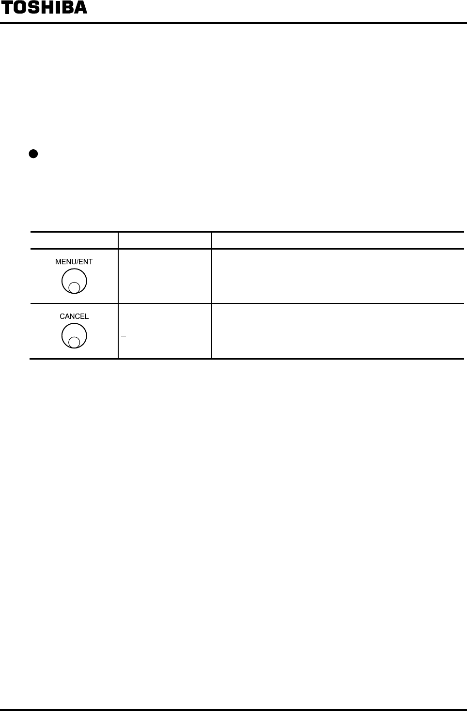
6F8A0917
-
64
-
8.2.5 Password Setting
The password function is provided to prohibit the settings and adjustment for the functions that affect
the flow measurement. See 7.4 “Setting Menu List” for the functions limited by the password function.
If other than “000” is set for password and the mode is retuned to the measurement mode, the
password function becomes valid. If “000” is set, there is no limitation such as setting is prohibition by
password.
Checking the password
Proceed as follows to check the password.
However, if other than “000” is set for password, you cannot check the password when you move to
the setting mode unless you enter the correct password.
(If you enter a wrong password, *** appears for password.)
Switch operation Display example Description
A5: PASSWORD
123
Select A5: PASSWORD from the setting item selection menu.
The currently set password appears.
A5: PASSWORD Returns to the menu of setting item selection item.
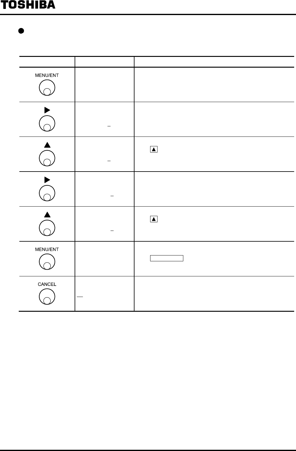
6F8A0917
-
65
-
Changing the password
The following is an example to show how to change the password from 123 to 453.
Switch operation Display example Description
A5: PASSWORD
123
Select A5: PASSWORD from the setting item selection menu.
The currently set password data (123 in this example) appears.
However, if a wrong password is entered when you move from
the measurement mode to the setting mode, *** appears.
A5: PASSWORD
123 The cursor appears.
A5: PASSWORD
423
Press to change the number of the 3rd digit of the password
from the right to 4.
A5: PASSWORD
423 Move the cursor to the 2nd digit.
A5: PASSWORD
453
Press switch to change the number of the 2nd digit of the
password to 5.
A5: PASSWORD
453
The display blinks and the set value is displayed for
conformation.
Press MENU/ENT again to writer the data. Then the cursor
disappears and the display returns to the condition that the
setting value is displayed.
A5: PASSWORD Returns to the menu of setting item selection.
Note: If password is set, be sure so manage the system so that the password is protected and not
forgotten.
If you forgot your password, you can check the password using the maintenance menu. For the
procedure to move to the maintenance menu, see 7.3.5 “Maintenance Menu.” The service code
to check the password is “800”.
For the management method including the method to read the password, use the management
method conforming to the management standard of the system used.
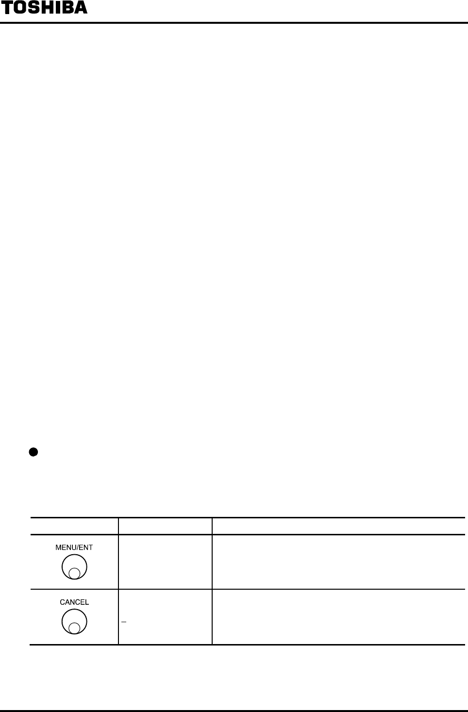
6F8A0917
-
66
-
8.2.6 Normal Indicating Unit
You can select one of the units listed below as normal indicating unit for 2 types of units, main unit
(UNIT 1) and sub unit (UNIT 2) to be displayed in the measurement mode.
• Flow velocity unit: m/s, ft/s
• Flow rate unit: m3/s, m3/min, m3/h, m3/d
l/s, l/min, l/h, l/d
ml/s, ml/min, ml/h, ml/d
gal/s, gal/min, gal/h, gal/d
bbl/s, bbl/min, bbl/h, bbl/d
pt/s, pt/min, pt/h, pt/d
qt/s, qt/min, qt/h, qt/d
• Volumetric flow: m3, l, ml, gal, bbl, pt, qt
• Other units: %, COUNT, RANGE, CUSTOM
%: Indicates the value in percent of the setting range
When multi-range is selected, the value is in percent of the range in operation.
COUNT: Indicates the count of the totalizer.
RANGE: Indicates the range number of the range in operation when multi-range is selected.
CUSTOM: Indicates the flow rate value in the unit defined in 8.2.7 “Custom Unit.”
If the unit is set to volumetric flow or COUNT, the flow direction for total flow can be
set.
If the indicting unit is set to volumetric flow or COUNT, the flow direction for total flow can also
be set.
• Volumetric flow direction: F: Forward direction, R: Reverse direction
B: Forward/Reverse automatic switching, D: Total difference flow
indication
Checking the normal indicating unit
Proceed as follows to check the normal indicating unit.
Here, only about the main unit (UNIT1) is explained. For sub unit (UNIT2), select the function
number “B2”.
Switch operation Display example Description
B1: UNIT 1
%
Select B1: UNIT 1 from the setting item selection menu.
The currently set main indicating unit appears.
B1: UNIT 1 Returns to the menu of setting item selection.
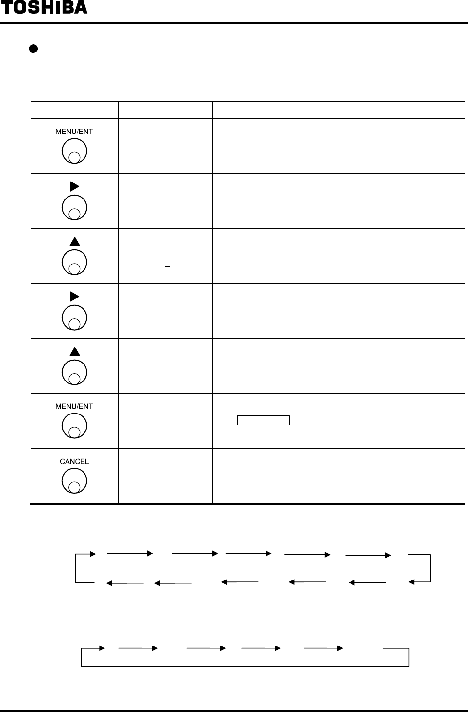
6F8A0917
-
67
-
Checking the normal indicating unit
The following is an example to change the main indicating unit (UNIT1) from % to ml/s.
In the case of sub unit (UNIT2), select the function “B2: UNIT 2.”
Switch operation Display example Description
B1: UNIT 1
%
Select B1: UNIT 1 from the setting item selection menu.
The currently set main indicating unit (% in this example)
appears.
B1: UNIT 1
% The cursor appears.
B1: UNIT 1
ml B Change the volumetric unit to ml. (Note 1)
B1: UNIT 1
ml B Move the cursor to the position of time unit.
B1: UNIT 1
ml/s Change the time unit to s. (Note 2)
B1: UNIT 1
ml/s
The display blinks and the set value is displayed for
confirmation.
Press MENU/ENT again to write the data. Then the cursor
disappears and the display returns to the condition that the
setting value is displayed.
B1: UNIT 1 Returns to the menu of setting item selection.
Note 1: Volumetric unit is displayed cyclically as follows:
Note 2: Time unit is displayed cyclically loops as follows:
%m
3ml
RANGE COUNT ft/s
lgal bbl
m/s
pt
qt
/
s
/
min
/
h
/
d(Space)
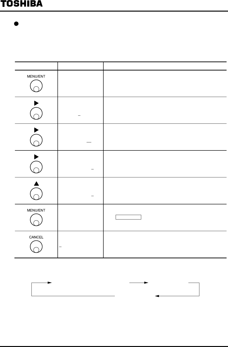
6F8A0917
-
68
-
Changing the flow direction for total flow
Proceed as follows to change the flow direction for total flow.
The following is an example to show how to change the main indicating unit from Forward flow
(F) to Forward/Rverse automatic switching (B).
In the case of sub unit (UNIT2), select the function “B2: UNIT 2.”
Switch operation Display example Description
B1: UNIT 1
m3 F
Select B1: UNIT 1 from the setting item selection menu.
The currently set main indicating unit (m3 F in this example)
appears.
B1: UNIT 1
m3 F The cursor appears.
B1: UNIT 1
m3 F Move the cursor to the position of time unit.
B1: UNIT 1
m3 F Move the cursor to the position of flow direction for total flow.
B1: UNIT 1
m3 B
Change the flow direction for total flow to B (forward/reverse
automatic switching). (Note 1)
B1: UNIT 1
m3 B
The display blinks and the set value is displayed for
conformation.
Press MENU/ENT again to write the data. Then the cursor
disappears and the display returns to the condition that the
setting value is displayed.
B1: UNIT 1 Returns to the menu of setting item selection.
Note 1: The flow direction for total flow is displayed cyclically as follows:
B (Forward/Reverse automatic switching) F (Forward direction)
R (Reverse direction)

6F8A0917
-
69
-
8.2.7 Custom Unit
The custom unit, which indicates the flow rate multiplied by an arbitrary coefficient, can be defined.
The flow rate indication using the custom unit defined here can be used by selecting CUSTOM in the
indicting unit setting.
The custom unit consists of an coefficient and a unit string
Coefficient of custom unit
A coefficient to determine the numeric value for indication by custom unit
The indicated value is calculated in the following equation:
Custom unit indication (numeric value) = Measured value in m3/min × Custom coefficient
The custom coefficient can be set in a numeric value of 6 digits including a decimal point.
Unit string of custom unit
The unit to be used for indication by custom unit
A string of up to 7 characters using the following codes can be set.
Alphabetic letters (lower case letters) : a − z
Alphabetic letters (upper case letters) : A − Z
Number: 0
− 9
Symbol: ( ) ····· Parentheses
% ········· Percent
. ··········· Period (dot)
⋅ ··········· Point
: ··········· Colon
= ·········· Equal sign
− ·········· Minus (hyphen)
* ·········· Asterisk
/ ··········· Slash
········· Space (blank)
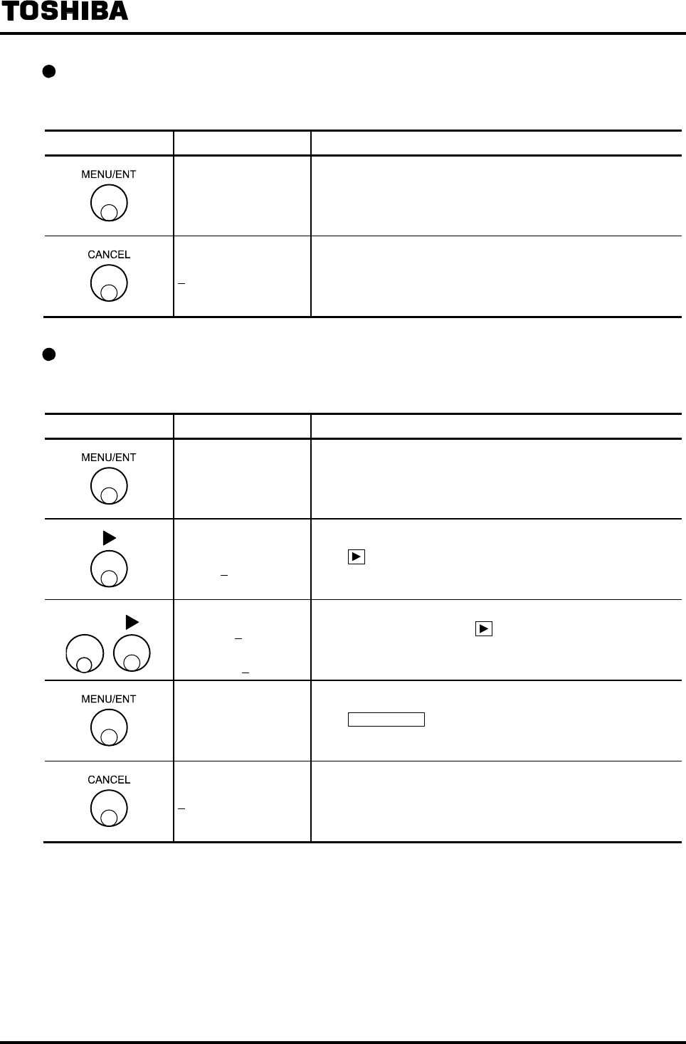
6F8A0917
-
70
-
Checking the coefficient of custom unit
Proceed as follows to check the coefficient of custom unit.
Switch operation Display example Description
B3: CUSTOM DATA
12340.00
Select B3: CUSTOM DATA from the setting item selection
menu.
The currently selected coefficient appears.
B3: CUSTOM DATA Returns to the menu of setting item selection.
Changing the coefficient of custom unit
The following is an example to show how to change the coefficient from 1.00 to 1.25.
Switch operation Display example Description
B3: CUSTOM DATA
1.000000
Select B3: CUSTOM DATA from the setting item selection
menu.
The currently set coefficient appears.
B3: CUSTOM DATA
1.000000
The cursor appears.
Press further to move the cursor to the desired digit to
change.
▲
B3: CUSTOM DATA
1.200000
↓
1.250000
Change the number of the digit.
To change other digit, press to move the cursor to that digit
and change the number there. Repeat this operation until
1.250000 appears on the display.
B3: CUSTOM DATA
1.250000
The display blinks and the set value is displayed for
confirmation.
Press MENU/ENT again to write the data. Then the cursor
disappears and the display returns to the condition that the
setting value is displayed.
B3: CUSTOM DATA Returns to the menu of setting item selection.
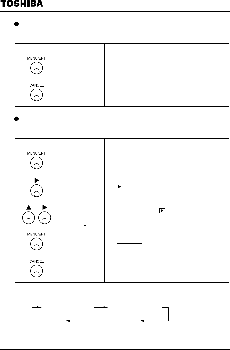
6F8A0917
-
71
-
Checking the unit string of custom unit
Proceed as follows to check the unit string of custom unit.
Switch operation Display example Description
B4: CUSTOM UNIT
AAA/BBB
Select B4: CUSTOM DATA from the setting item selection
menu.
The currently set unit appears.
B4: CUSTOM UNIT Returns to the menu of setting item selection.
Changing the unit string of custom unit
The following is an example to show how to change the unit string from AAA/BBB to XXX/ZZZ.
Switch operation Display example Description
B4: CUSTOM UNIT
AAA/BBB
Select B4: CUSTOM UNIT from the setting item selection
menu.
The currently set unit appears.
B4: CUSTOM UNIT
AAA/BBB
The cursor appears.
Press further to move the cursor to the desired digit to
change.
B4: CUSTOM UNIT
XAA/BBB
↓
XXX/ZZZ
Change the character of the digit. (Note 1)
To change other digit, press to move the cursor to that digit
and change the character there. Repeat this operation until
XXX/ZZZ appears on the display.
B4: CUSTOM UNIT
XXX/ZZZ
The display blinks and the set value is displayed for
confirmation.
Press MENU/ENT again to write the data. Then the cursor
disappears and the display returns to the condition that the set
value is displayed.
B4: CUSTOM UNIT Returns to the menu of setting item selection.
Note 1: The selectable characters are displayed cyclically as shown below:
Alphabet letter (lowercase) Alphabet letter (uppercase)
Symbol Number
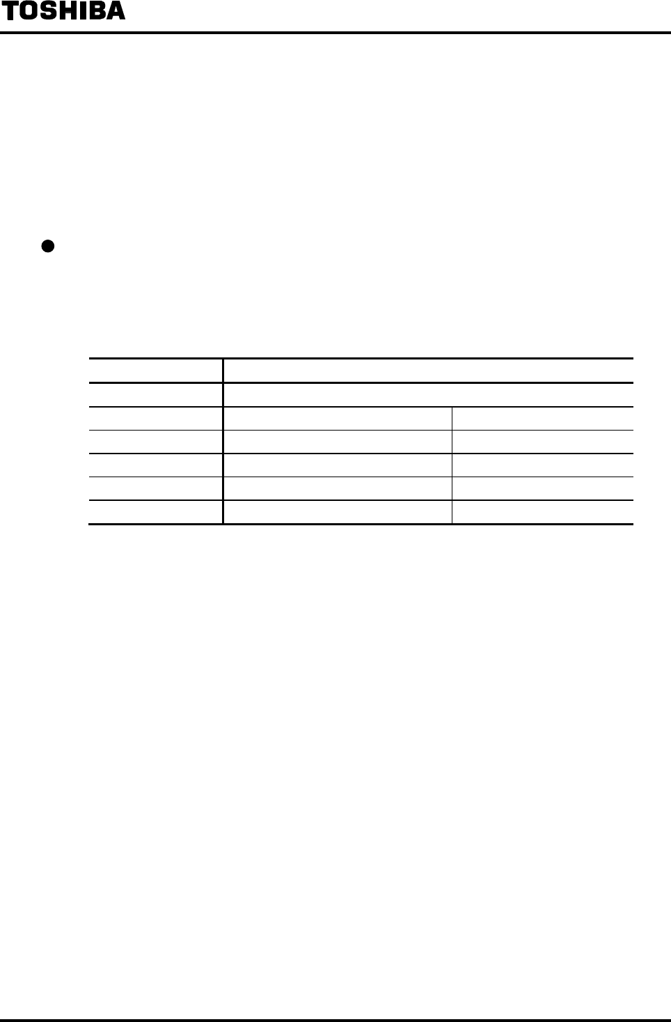
6F8A0917
-
72
-
8.2.8 Span Value (Range)
The following constants are set here.
(1) Range type
(2) Span unit (changeable only for Range 1)
(3) Span value
(4) Hysteresis
Range type
By selecting the range type, the multi-range function can be used in which the range in operation is
switched between the multiple ranges depending on whether the flow rate is value large or small, or
the flow direction is forward or reverse.
If it is not necessary to use the multi-range function, set the Range type to Single range.
RANGE TYPE RANGE TYPE
1:SINGLE Single range
2:4F-0R Single direction, 4 ranges Internal automatic switching
3:2F-2R Forward/reverse direction, 2 ranges Internal automatic switching
4:EXT.2F-0R Single direction, 2 ranges External signal switching
5:EXT.2F-2R Forward/reverse direction, 2 ranges External signal switching
6:EXT.4F-0R Single direction, 4 ranges External signal switching
Note: To use the multi-range function, the following DO and DI are required:
In the case of internal automatic switching ranges
2 ranges, forward/reverse range·························1 Digital Output
3 ranges or more, forward/reverse 2 ranges·······2 Digital Outputs
In the case of external signal switching ranges
2 ranges, forward/reverse range·························1 Digital Inputs
3 ranges or more, forward/reverse 2 ranges·······2 Digital Inputs

6F8A0917
-
73
-
Span value
The span value can be set using the actual flow rate unit (m3/h, etc.) and flow velocity unit (m/s).
(1) Setting range
The span value can be set within the range of 0 –1.0 ft/s to 0 – 32.8 ft/s (0.1m/s to 10m/s) in terms
of flow velocity
(The range that detector can measure changes with detector type. The details please refer to
Chapter 15 "specifications")
If you try to set a span value outside of this range, either of the following messages appears
depending on whether it is a high limit or low limit error:
* H. OVER SPEC. (if a value exceeding 32.8 ft/s (10 m/s) is set)
* L. OVER SPEC. (if a value of less than 1.0 ft/s (0.1 m/s) is set)
Try to set a new value again.
In the case of Single range setting, select Range 1 only.
(2) Multi-range setting
To use the multi-range function, select Ranges 1 to 4.
When you set these ranges, the following condition must be observed:
Range 1 > Range 2 > Range 3 > Range 4 (in the case of single direction, multiple ranges)
Range 1 > Range 2, Range 3 > Range 4 (in the case of forward/reverse direction, multiple
ranges)
If you try to set the ranges not conforming to the above condition, the following message appears:
* MULTI RNG ERR
Try to set the ranges again.
In addition, set “0” for the ranges not used.
(3) Influence on count rate (pulse rate)
If the range is changed when the count rate (pulse rate) is already set, pulse output at the time of
100% output may exceed the allowable output range.
If this happens, either of the following messages appears after the ranges are set and the system
goes to the count rate setting.
* H. OVER C RATE or * L. OVER C RATE
Try to set the count rate (pulse rate) again referring to 8.2.15 “Count Rate (pulse rate) and Pulse
Width.”
Unit of span
Range 1 is used to set the unit of span. The unit applies automatically to other ranges of Range 2 to
Range 4 and it is not necessary to set the unit for these ranges separately.
The setting units can be selected from the following units:
• Flow velocity unit: m/s
• Flow rate unit: m3/s, m3/min, m3/h, m3/d, l/s, l/min, l/h, l/d, ml/s, ml/min, ml/h, ml/d
If you change the unit, the new span value based on the newly set unit will be automatically
displayed.
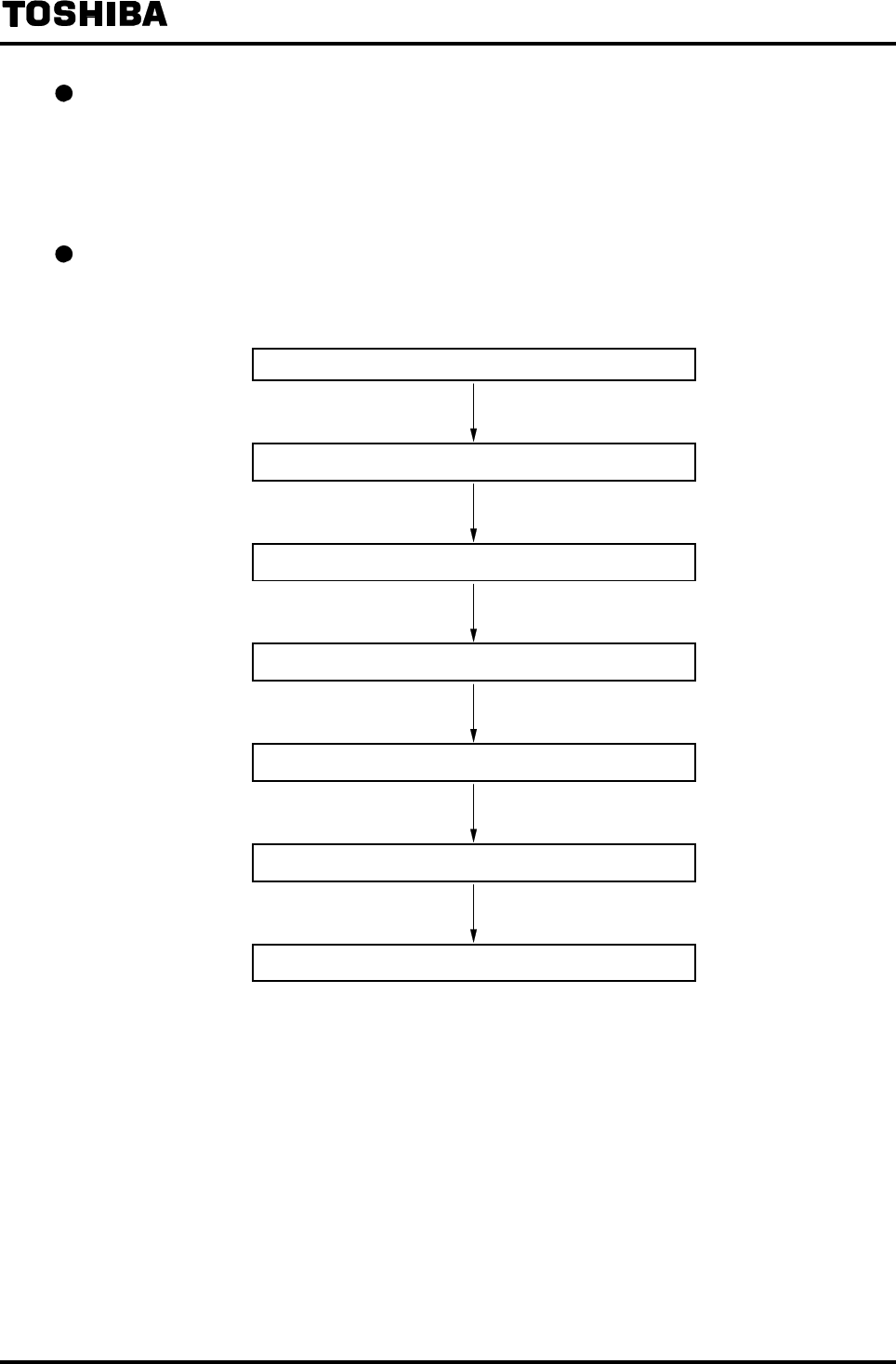
6F8A0917
-
74
-
Hysteresis
The dead band, which is used to switch the ranges in the case of internal automatic switching
multi-range, is set here.
It is not necessary to set hysteresis in other range types. (The set value will be ignored.)
The hysteresis can be set within the range of 0 to 25% in increments of 0.1%.
Span value (range) setting flow
The setting sequence of span value (range) is shown below.
Item selection of span value (range) setting
C1: RANGE TYPE : Range type setting
C2: RANGE 1 : Range 1 span value and unit setting
C3: RANGE 2 : Range 2 span value
C4: RANGE 3 : Range 3 span value
C5: RANGE 4 : Range 4 span value
C6: RANGE HYST : Hysteresis setting
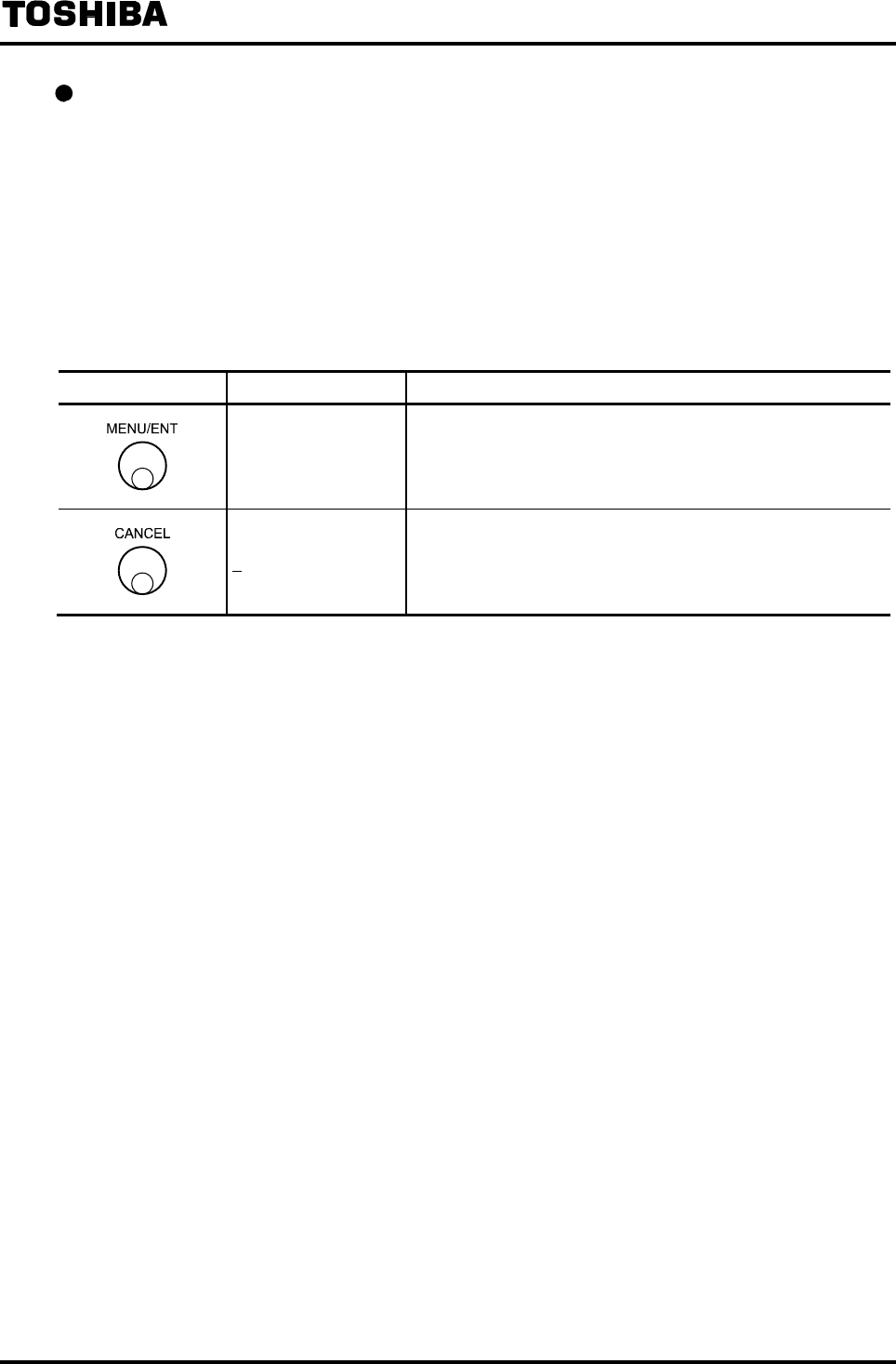
6F8A0917
-
75
-
Checking each constant
How to check the Range 1 is shown here.
To check other setting values, select the following function numbers:
Range type C1: RANGE TYPE
Range 2 span value C3: RANGE 2
Range 3 span value C4: RANGE 3
Range 4 span value C5: RANGE 4
Hysteresis C6: RANGE HYST
Switch operation Display example Description
C2: RANGE 1
02.000 m/s
Select C2:RANGE 1 from the setting item selection menu.
The currently set Range 1 span value appears.
C2: RANGE 1 Returns to the menu of setting item selection.
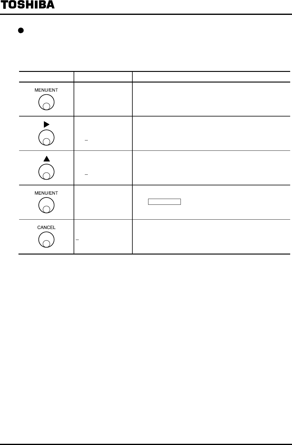
6F8A0917
-
76
-
Changing the range type
Before changing the span value, Rang type must be set.
The following is an example to show how to change the range type from Single range (1:SINGLE)
to the bidirectional internal signal switching multi-range (3:2F-2R).
Switch operation Display example Description
C1: RANGE TYPE
1:SINGLE
Select C1: RANGE TYPE from the setting item selection
menu.
The currently set range type (1:SINGLE) appears.
C1: RANGE TYPE
1:SINGLE The cursor appears.
C1: RANGE TYPE
3:2F-2R Select the range type 3:2F-2R.
C1: RANGE TYPE
3:2F-2R
The display blinks and the set value is displayed for
confirmation.
Press MENU/ENT again to write the data. Then the cursor
disappears and the display returns to the condition that the set
value is displayed.
C1: RANGE TYPE Returns to the menu of setting item selection.
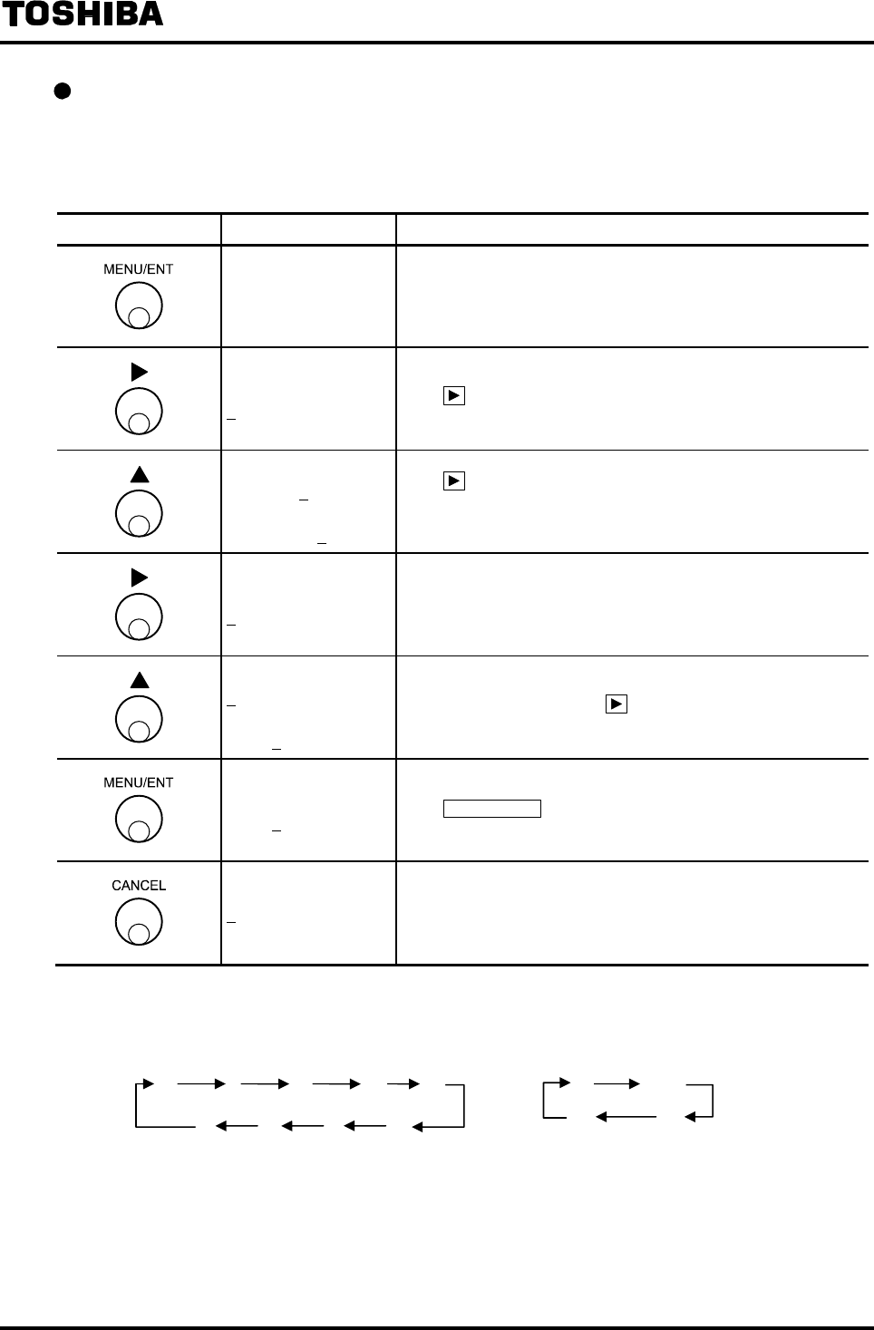
6F8A0917
-
77
-
Changing the span value
The span value for each range is set.
The following is an example to show how to change the span value of Range 1 from 2.0m3/h to 100
l/min.
Switch operation Display example Description
C2: RANGE 1
2.0000 m3/h
Select C2: RANGE 1 from the setting item selection menu.
The currently set span value for Range 1 (2.0 m3/h in this
example) appears.
C2: RANGE 1
2.0000 m3/h
The cursor appears.
Press further to move the cursor to the digit of volumetric
unit.
C2: RANGE 1
2000.0 l/h
↓
33.333 l/min
Change the volumetric unit to l.
Press to move the cursor to the digit of time unit and
likewise change the unit to min. (Note)
(The span value will be automatically changed as this unit is
changed.)
C2: RANGE 1
33.333 l/min Move the cursor to the desired digit to change.
C2: RANGE 1
13.333 l/min
↓
100.00 l/min
Change the number of the digit.
To change other digit, press under this condition to move
the cursor to that digit and change the number there.
C2: RANGE 1
100.00 l/min
The display blinks and the set value is displayed for
confirmation.
Press MENU/ENT again to write the data. The cursor
disappears and returns to the condition that the set value is
displayed.
C2: RANGE 1 Returns to the menu of setting item selection.
Note: The items of unit are displayed cyclically as shown below:
• A combination of m/min, m/h , m/d, ft/min, ft/h and ft/d cannot be selected.
m
3l gal
ml
/
s
/
min
/
h
/
d
Volumetric unit Time unit
bbl
m
ft
ptqt
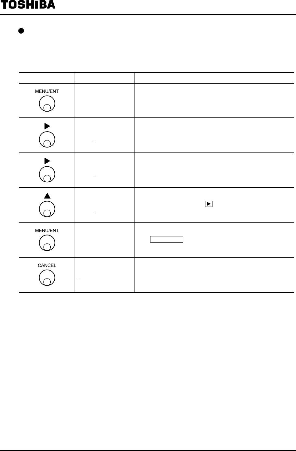
6F8A0917
-
78
-
Changing the hysteresis
The hysteresis value is set to 3% unless otherwise specified when the converter is shipped from the
factory.
The following is an example to show how to change the hysteresis value from 3% to 5%.
Switch operation Display example Description
C6: RANGE HYST
03.0 %
Select C6: RANGE HYST from the setting item selection
menu.
The currently set hysteresis value appears. (Note)
C6: RANGE HYST
03.0 % The cursor appears.
C6: RANGE HYST
03.0 % Move the cursor to the desired digit to change.
C6: RANGE HYST
05.0 %
Change the number of the digit.
To change other digit, press under this condition to move
the cursor to that digit and change the number there.
C6: RANGE HYST
05.0 %
The display blinks and the set value is displayed for
confirmation.
Press MENU/ENT again to write the data. Then the cursor
disappears and the display returns to the condition that the
setting value is displayed.
C6: RANGE HYST Returns to the menu of setting item selection.
Note: If you try to set a value exceeding 25.0%, *H. OVER SPEC.* appears and the value returns to
the previously set value. Try to set a new value again.
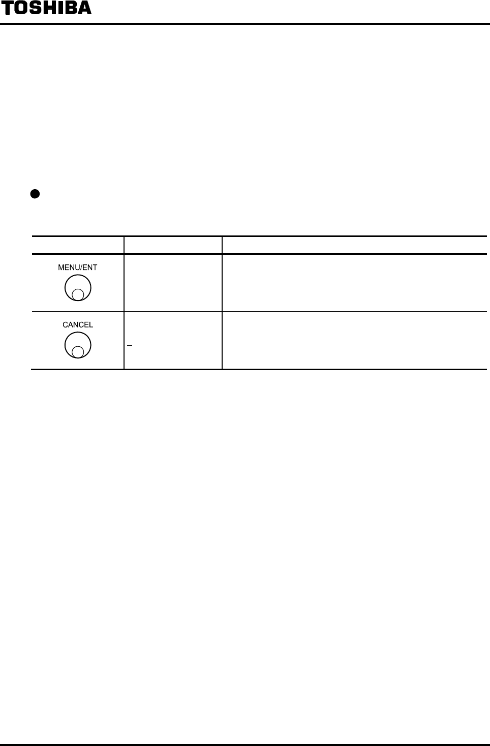
6F8A0917
-
79
-
8.2.9 Damping Constant
The damping constant is set to average out the output fluctuations. (The larger the damping constant,
the more the output is averaged and the fluctuations can be reduced but the response becomes slower.)
The damping constant can be set from 0.0sec, 0.5sec, and 1 to 60sec (1sec each).
(If detector is partially filled pipes type, the damping constant can be set from 0.0sec, 5sec, and 10 to
600sec (1sec each).)
Note: If 0.0 sec is set, the damping constant becomes a value equivalent to 0.1 sec.
If you set a value exceeding 60s, it is forcibly changed to 60s before data is written.
Checking the damping constant
Proceed as follows to check the damping constant.
Switch operation Display example Description
D1: DAMPING
02.0 s
Select D1: DAMPING from the setting item selection menu.
The currently set damping constant appears.
D1: DAMPING Returns to the menu of setting item selection.

6F8A0917
-
80
-
Changing the damping constant
The following is an example to show how to change the damping constant from 0.5 sec to 10 sec.
Switch operation Display example Description
D1: DAMPING
00.5 s
Select D1: DAMPING from the setting item selection menu.
The currently set damping constant (0.5 s in this example)
appears.
D1: DAMPING
00.5 s
The cursor appears.
Press further to move the cursor to the desired digit to
change.
D1: DAMPING
10.5 s
10.0 s
Change the number of the digit.
To change other digit, press under this condition to move
the cursor to that digit and change the number these.
D1: DAMPING
10.0 s
The display
b
links and the se
t
value is displayed for
confirmation.
Press MENU/ENT again to write the data. Then the cursor
disappears and the display returns to the condition that the
setting value is displayed.
D1: DAMPING Returns to the menu of setting item selection.
Note: If you set a value exceeding max value, it is forcibly changed to max value before data is
written.
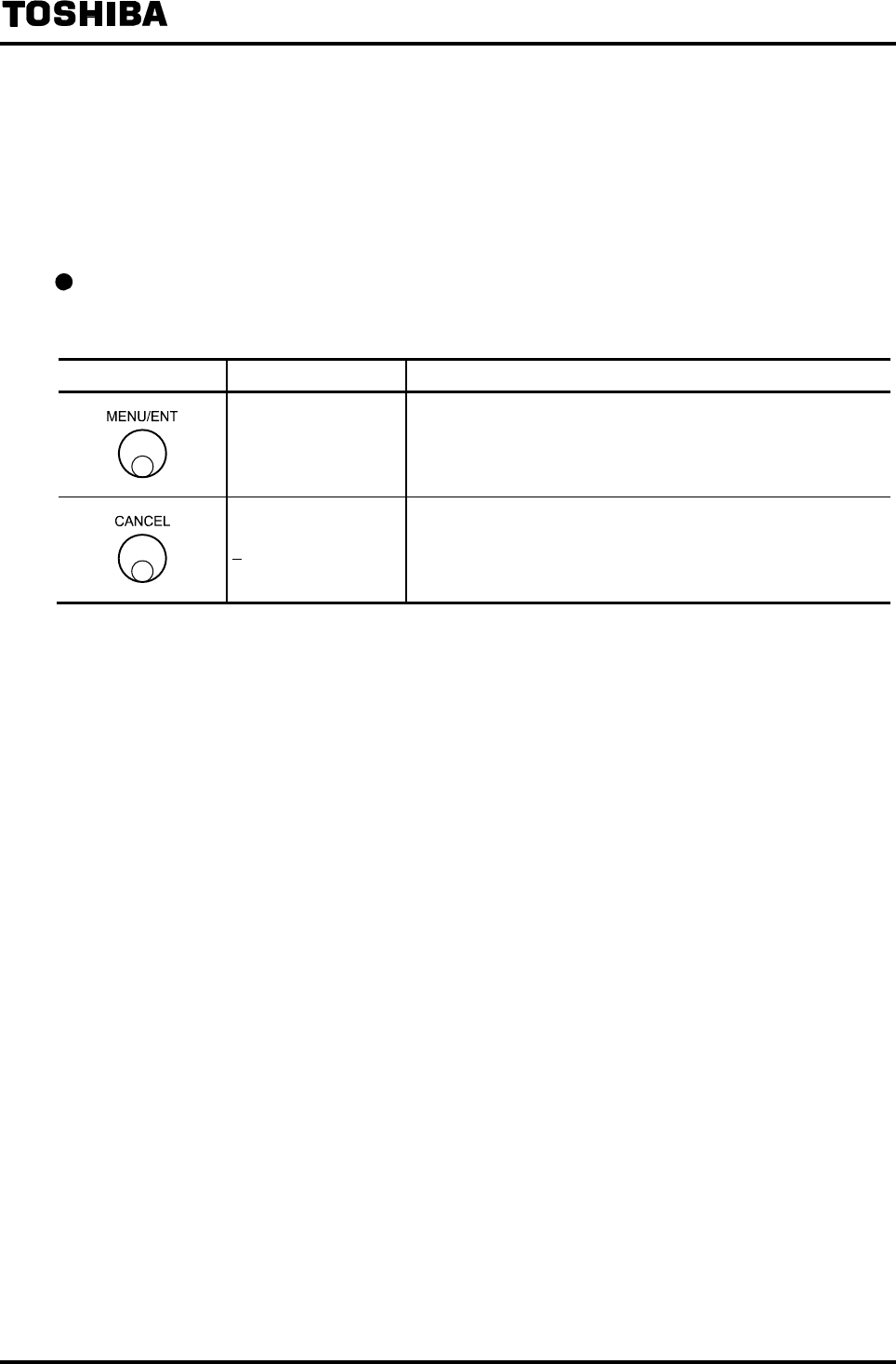
6F8A0917
-
81
-
8.2.10 Low Cutoff value
The low cutoff is the fuction to forcefully fix the current output to 0% when the flow rate becomes
equal or below the low cutoff value set near 0%.
The low cutoff value can be set from 0 to 10% and in increments of 0.1%.
If 0% is set, the low cutoff function does not work.
Checking the low cutoff value
Proceed as follows to check the low cutoff value.
Switch operation Display example Description
D2: LOW CUT
01.0 %
Select D2: LOW CUT from the setting item selection menu.
The currently set low cutoff value appears.
D2: LOW CUT Returns to the menu of setting item selection.

6F8A0917
-
82
-
Changing the low cutoff value
The following is an example to show how to change the low cutoff value from 1.0% to 3.0%.
Switch operation Display example Description
D2: LOW CUT
01.0 %
Select D2: LOW CUT from the setting item selection menu.
The currently set low cutoff value (1.0 % in this example)
appears.
D2: LOW CUT
01.0 %
The cursor appears.
Press further to move the cursor to the desired digit to
change.
D2: LOW CUT
03.0%
Change the number of the digit.
To change another digit, press under this condition to move
the cursor to that digit and change the number there.
D2: LOW CUT
03.0 %
The display brinks and the set value is displayed for
confirmation.
Press MENU/ENT again to write the data. Then the cursor
disappears and the display returns to the condition that the
setting value is displayed.
D2: LOW CUT Returns to the menu of setting item selection.
Note: If you try to set a value exceeding 10.0%, *H. OVER SPEC.* appears and the value returns to
the previously set value. In that case, try to set a new value again.
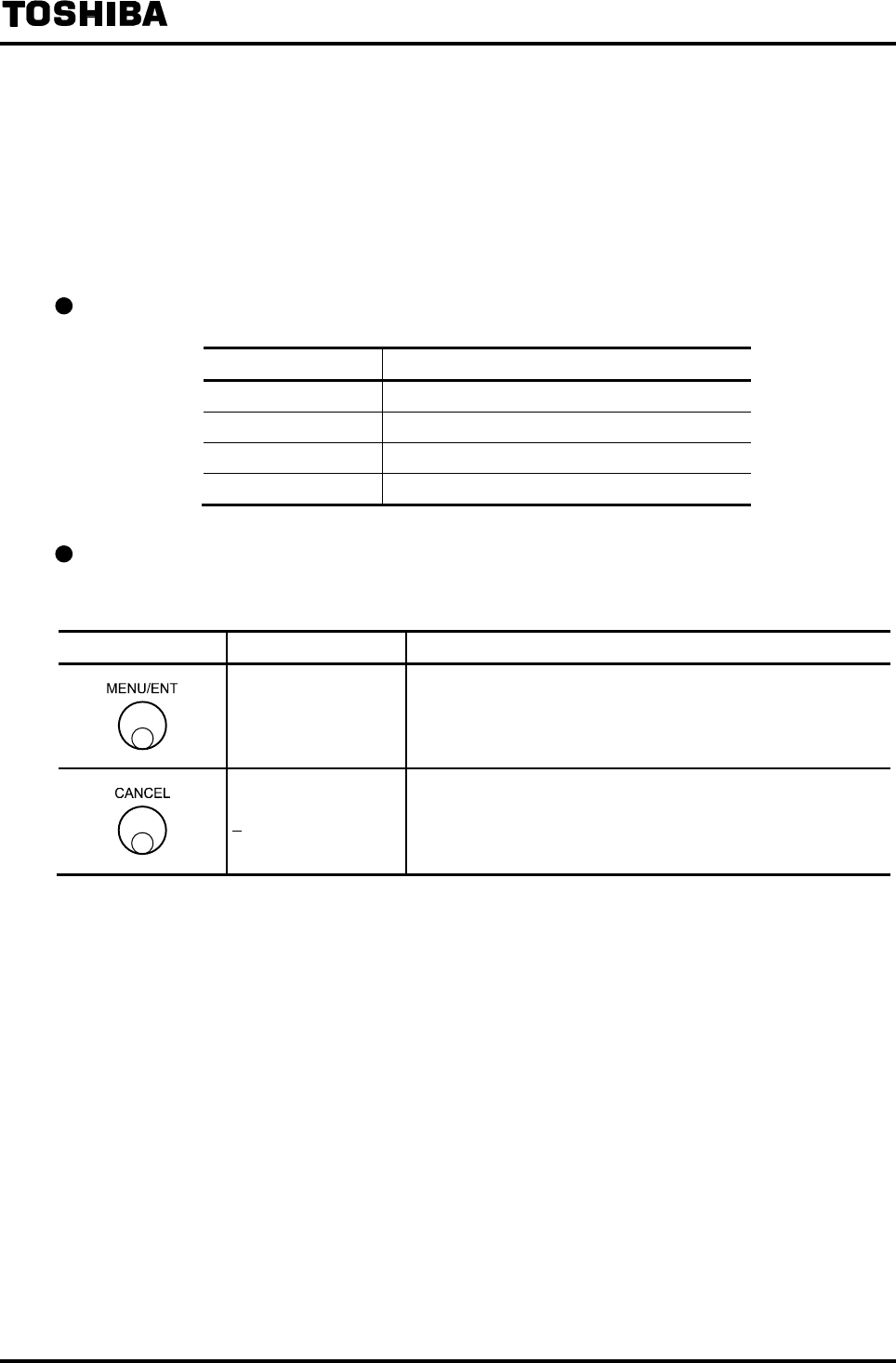
6F8A0917
-
83
-
8.2.11 Current Output Setting Used When an Alarm Occurs
The current output value setting used when an alarm occurs is the function to fix the current output to
a pre-selected value if a fluid empty alarm or a self-diagnosis alarm occurs.
For the type of alarms to fix the current output, see the alarm output factor setting in 8.2.19
“Self-Diagnosis Function.”
Select the current output value used when an alarm occurs from the table shown below.
Current output setting function used when an alarm occurs
Selection Current output value when an alarm occurs
1:UNDER 3.0mA 3.0mA or less
2:4.0mA 4.0mA
3:HOLD Fixed to the current output
4:OVER 24.0mA 24.0mA or more
Checking the current output value used when an alarm occurs
Proceed as follows to check the current output value used when an alarm occurs.
Switch operation Display example Description
D3: 4-20 ALM.OUT
2:4.0mA
Select D3: 4−20 ALM. OUT from the setting item selection
menu.
The currently set current output value used when an alarm
occurs appears.
D3: 4-20 ALM.OUT Returns to the menu of setting item selection.

6F8A0917
-
84
-
Changing the current output value used when an alarm occurs
The following is an example to show how to change the current output value, which is used when
an alarm occurs, from 4.0mA (2: 4.0mA) to 24.0mA or more (4: OVER 24.0mA).
Switch operation Display example Description
D3: 4-20 ALM.OUT
2:4.0mA
Select D3: 4−20 ALM. OUT from the setting item selection
menu.
The currently set alarm output value used when an alarm
occurs appears.
D3: 4-20 ALM.OUT
2:4.0mA The cursor appears.
D3: 4-20 ALM.OUT
4:OVER 24.0mA Press to select 4: OVER 24.0mA.
D3: 4-20 ALM.OUT
4:OVER 24.0mA
The display blinks and the set value is displayed for
confirmation.
Press MENU/ENT again to write the data. Then the cursor
disappears and the display returns to the condition that the
setting value is displayed.
D3: 4-20 ALM.OUT Returns to the menu of setting item selection.
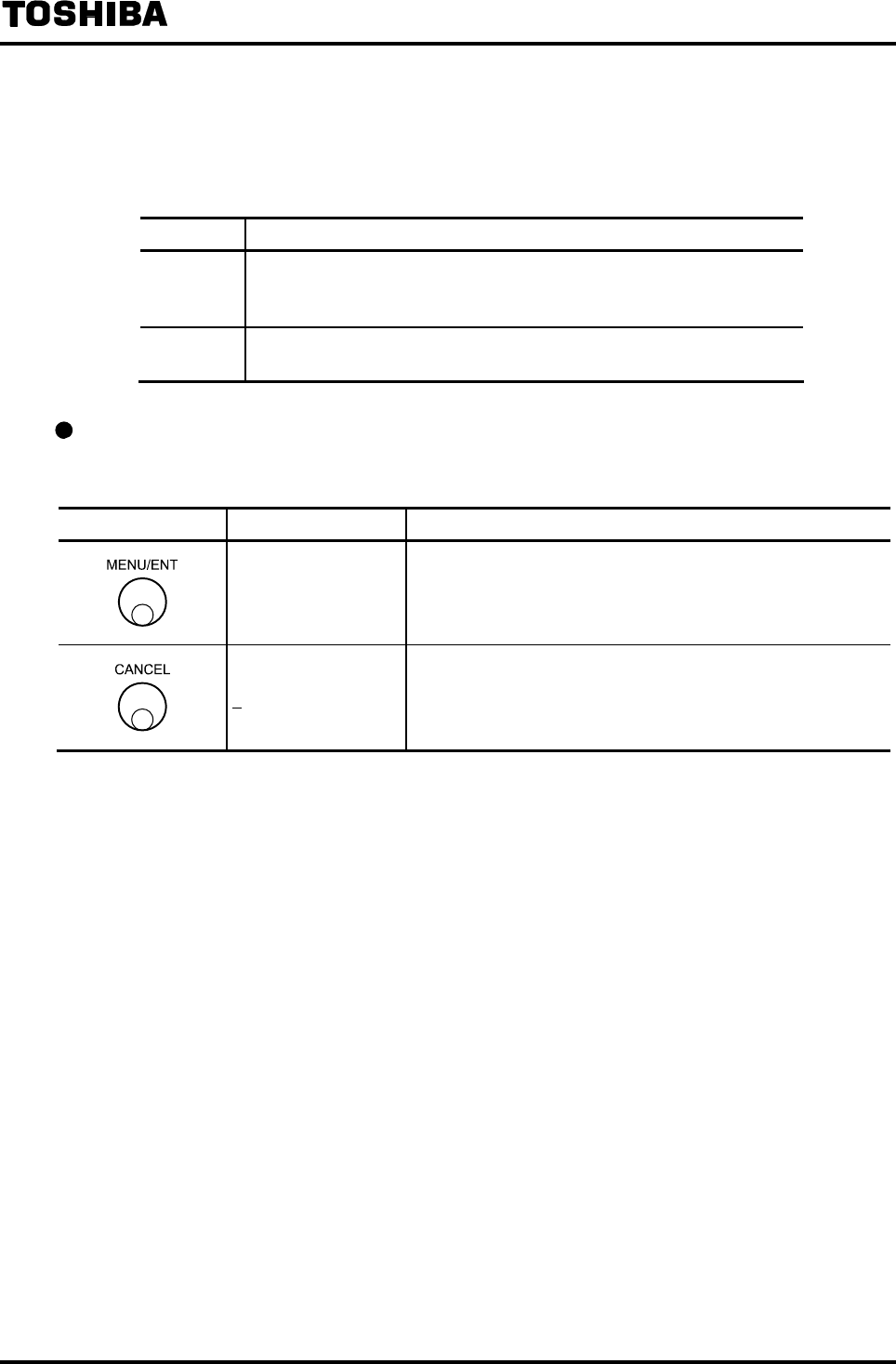
6F8A0917
-
85
-
8.2.12 Display low cut On/Off
When the low output is cutoff by the setting in 8.2.10 “Low cutoff value,” whether the instantaneous
flow rate, flow velocity and % value should be set to zero or not can be selected.
Selection Display low cutoff
1: ON Display low cut is effective (On)
Display (instantaneous flow rate, flow velocity and %) will be set to
zero when the low output is cutoff.
2: OFF Display low cut is not effective (Off)
Measured value will be output even if the low output is cutoff.
Checking whether the display low cut is On or Off
Proceed as follows to check whether the display low cut is On or Off.
Switch operation Display example Description
D4: DSP LOW CUT
2:OFF
Select D4: DSP LOW CUT from the setting item selection
menu.
The currently set display low cut On/Off status appears.
D4: DSP LOW CUT Returns to the menu of setting item selection.

6F8A0917
-
86
-
Changing the display low cut On/Off setting.
The following is an example to show how to change the display low cut setting from 2.OFF to
1:ON.
Switch operation Display example Description
D4: DSP LOW CUT
2:OFF
Select D3: 4−20 ALM. OUT from the setting item selection
menu.
The currently set alarm output value used when an alarm
occurs appears.
D4: DSP LOW CUT
2:OFF The cursor appears.
D4: DSP LOW CUT
1:ON Press to select 1:ON.
D4: DSP LOW CUT
1:ON
The display blinks and the set value is displayed for
confirmation.
Press MENU/ENT again to write the data. Then the cursor
disappears and the display returns to the condition that the set
value is displayed.
D4: DSP LOW CUT Returns to the menu of setting item selection.
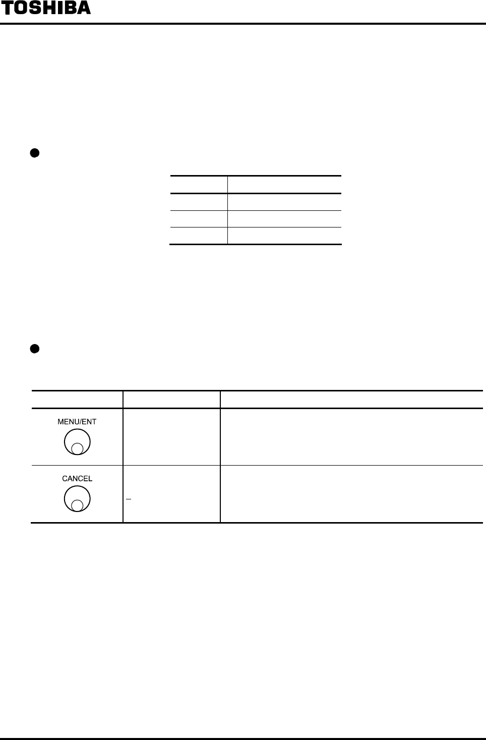
6F8A0917
-
87
-
8.2.13 Output Low Limit Setting
The low limit for 4 to 20mA output can be selected.
If 3.2mA or 2.4mA is selected, the output value of less than 4mA (0%) can be output when the flow is
in reverse direction.
The output low limit setting can be selected from the items shown in the table below.
Output low limit value
Selection Output low limit value
1:4.0mA 4.0mA(0%)
2:3.2mA 3.2mA (-5%)
3:2.4mA 2.4mA (-10%)
* To set the output low limit to other than 4.0mA, set the low cutoff value to 0% in 8.2.10 “Low
Cutoff Value.”
If the low cutoff value is set to other than 0%, the output low limit value becomes 4.0mA fixed
regardless of the value of the output low limit setting.
Checking the output low limit value setting.
Proceed as follows to check the output low limit value.
Switch operation Display example Description
D5: LOW LIMIT
1:4.0mA
Select D5: LOW LIMIT from the setting item selection menu.
The currently set output low limit value appears.
D5: LOW LIMIT Returns to the menu of setting item selection.

6F8A0917
-
88
-
Changing the output low limit value setting.
The following is an example to change the output low limit setting from 4.0mA (1: 4.0mA) to
3.2mA (2: 3.2mA).
Switch operation Display example Description
D5: LOW LIMIT
1:4.0mA
Select D5: LOW LIMIT from the setting item selection menu.
The currently set output low limit value appears.
D5: LOW LIMIT
1:4.0mA The cursor appears.
D5: LOW LIMIT
2:3.2mA Press to select 2:3.2mA.
D5: LOW LIMIT
2:3.2mA
The display blinks and the set value is displayed for
confirmation.
Press MENU/ENT again to write the data. Then the cursor
disappears and the display returns to the condition that the
setting value is displayed.
D5: LOW LIMIT Returns to the menu of setting item selection.
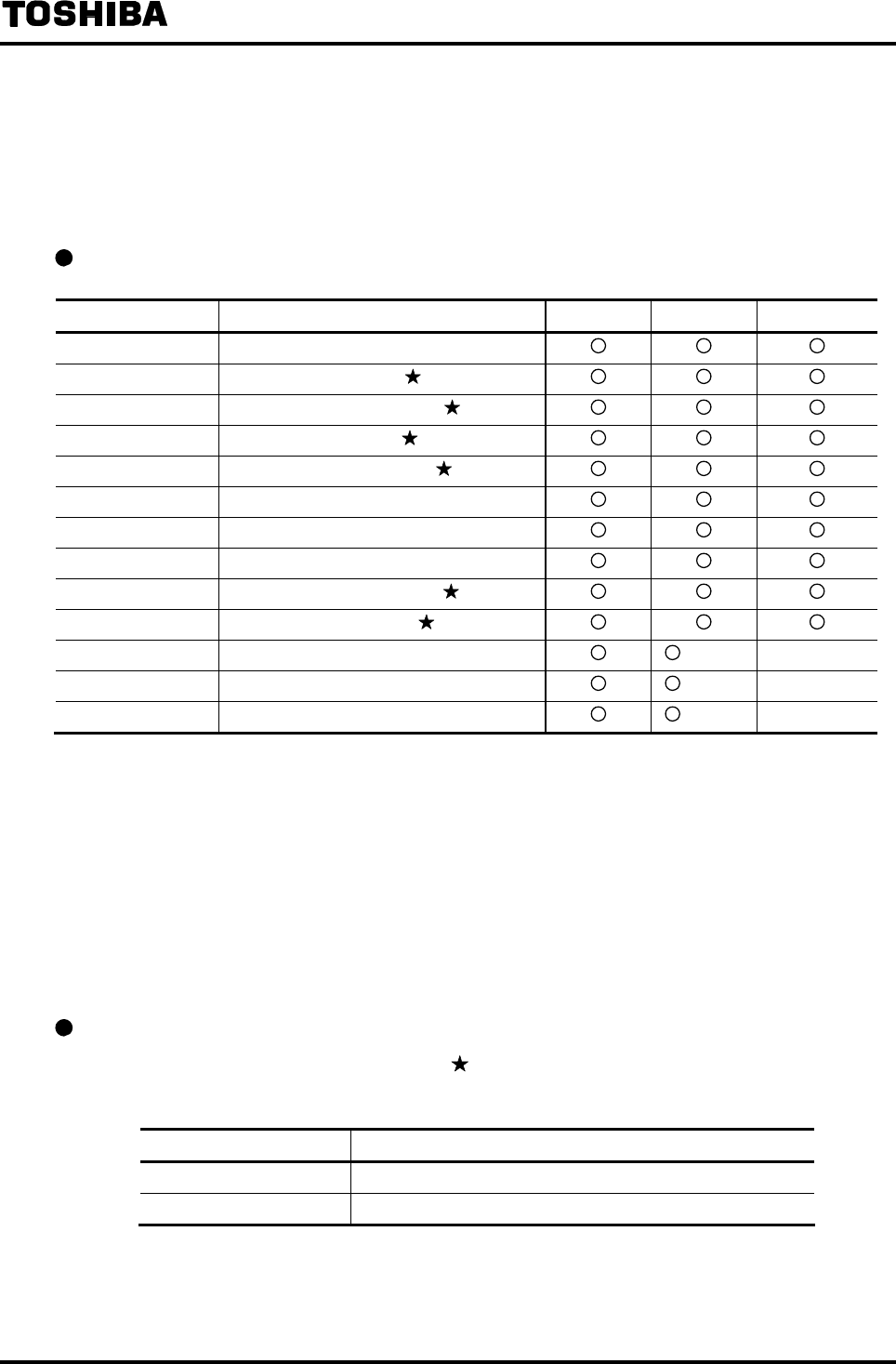
6F8A0917
-
89
-
8.2.14 Digital I/O Function
Digital I/O functions can be selected.
Select the digital I/O functions from the items shown below.
For details of digital I/O functions, see 10. “Function Description.”
Digital output functions (corresponding to each terminal)
DO FUNCT. Digital output functions DO1 DO2 DO3 to DO4
1: NO USE Not used
2: HIGH ALM High limit alarm output
3: HH ALM High-high limit alarm output
4: LOW ALM Low limit alarm output
5: LL ALM Low-low limit alarm output
6: RNG SIG 1 Range output No.1
7: RNG SIG 2 Range output No.2
8: PRESET Preset counter output
9: CONV. ALM Converter error alarm output (Note 3)
A: EMPTY ALM Fluid empty alarm output
B: PULSE OUT Pulse output (Note 1) (Note 2)
−
C: PULSE FRD Forward flow pulse output (Note 2)
−
D: PULSE REV Reverse flow pulse output (Note 2)
−
○: Enabled − : Disabled
Note 1: When the range type is set to the forward/reverse multi-range, and the pulse output (8: PULSE OUT) is
selected, pulse output can be sent out in either forward current or reverse current flow.
Note 2: Pulse output using the DO2 can be sent out up to 100pps.
When the pulse output is sent out using the DO2, set the count rate so that the pulse output for full scale
value does not exceed 100pps.
For count rate setting, see 8.2.15 “Count Rate (Pulse Rate) and Pulse Width.”
Note 3: For the types of alarms to output, see the alarm output factor setting in 8.2.19 “Self-Diagnosis
Function.”
Digital output state (only when alarm output is set)
For alarm output function (items indicated by above), alarm output operation can be selected
independently for each DO terminal.
DO ALM ACT Alarm output operation
1: NORMAL CLOSE Normal: Contact closed, When alarm occurs: Contact open
2: NORMAL OPEN Normal: Contact open, When alarm occur: Contact closed
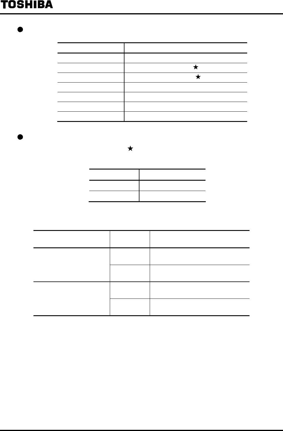
6F8A0917
-
90
-
Digital Input Function
DI FUNCT. Digital input function
1: NO USE Not used
2: C STA/STP Totalizer Start/Stop control
3: C RES/STA Totalizer Reset/Start control
4: RANGE SW1 Multi-range external switching signal 1
5: ZERO ADJ Still water zero adjustment start
6: FIXED OUT Fixed-value output mode control
7: RANGE SW2 Multi-range external switching signal 2
Level setting for digital input control signal (for totalizer control only)
For totalizer control (items indicated by above), the operating level (active level) for input control
signal can be selected for each DI terminal.
DI DET LEVEL Control signal level
1: L LEVEL Low level active
2: H LEVEL High level active
The operation for control signal input is shown below depending on the active level setting.
Digital input function setting Control signal
level setting Operation when control signal is input
L LEVEL High signal: Totalization Stop
Low signal: Totalization Start
CNT STA/STP
(Totalizer Start/Stop) H LEVEL High signal: Totalization Start
Low signal: Totalization Stop
L LEVEL High signal: Totalization Start
Low signal: Totalization Reset
CNT RES/STA
(Totalizer Reset/Start) H LEVEL High signal: Totalization Reset
Low signal: Totalization Start
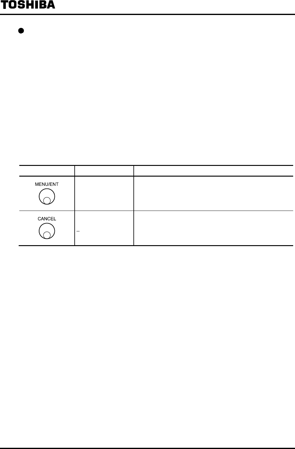
6F8A0917
-
91
-
Checking each setting for digital I/O
The following is an example to show how to check the function setting of Digital Output 1.
To check other setting values, select the following function numbers.
Digital Output 1 F1: DO1 FNCTN
Digital Output 2 F2: DO2 FNCTN
Digital Output 3 F3: DO3 FNCTN
Digital Output 4 F4: DO4 FNCTN
Digital Output alarm state 1 F5: DO1 ALM STS
Digital Output alarm state 2 F6: DO2 ALM STS
Digital Output alarm state 3 F7: DO3 ALM STS
Digital Output alarm state 4 F8: DO4 ALM STS
Digital Input 1 G1: DI1 FNCTN
Digital Input 2 G2: DI2 FNCTN
Digital Input control signal level 1 G3: DI1 DET LEV
Digital Input control signal level 2 G4: DI2 DET LEV
Switch operation Display example Description
F1: DO1 FNCTN
1:HIGH ALM
Select F1: DO1 FNCTN from the setting item selection menu.
The currently set function of Digital Output 1 appears.
F1: DO1 FNCTN Returns to the menu of setting item selection.
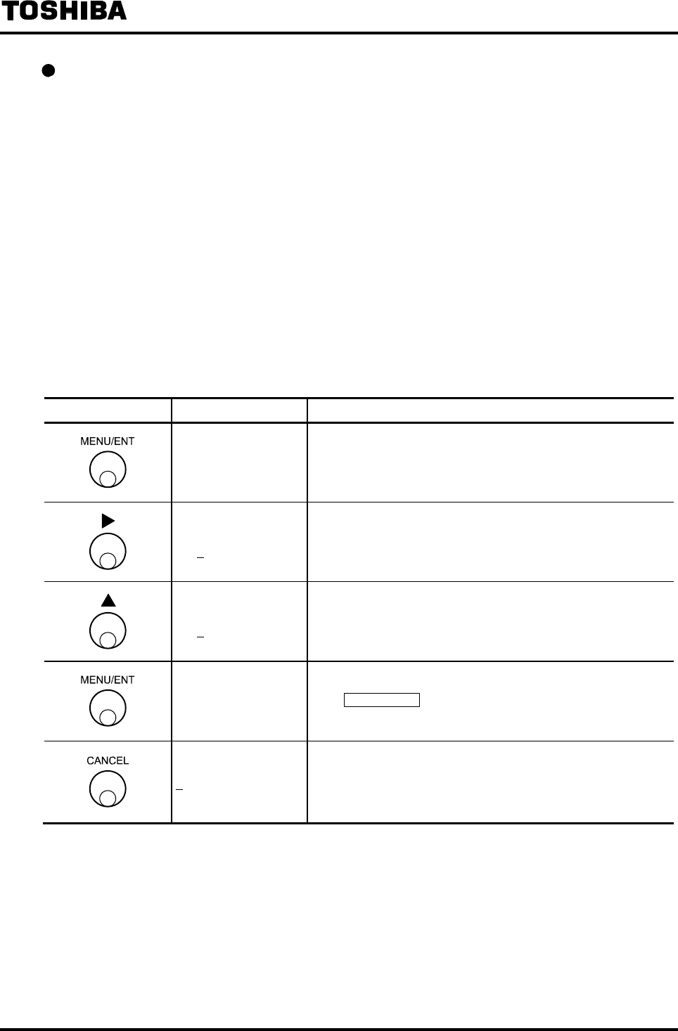
6F8A0917
-
92
-
Changing each setting for digital I/O
The following is an example to show how to change the function of Digital Output 1 from High
limit alarm output (2:HIGH ALM) to Fluid empty alarm (A:EMPTY ALM).
To change other setting values, select the following function numbers.
Digital Output 1 F1: DO1 FNCTN
Digital Output 2 F2: DO2 FNCTN
Digital Output 3 F3: DO3 FNCTN
Digital Output 4 F4: DO4 FNCTN
Digital Output alarm status 1 F5: DO1 ALM STS
Digital Output alarm status 2 F6: DO2 ALM STS
Digital Output alarm status 3 F7: DO3 ALM STS
Digital Output alarm status 4 F8: DO4 ALM STS
Digital Input 1 G1: DI1 FNCTN
Digital Input 2 G2: DI2 FNCTN
Digital Input control signal level 1 G3: DI1 DET LEV
Digital Input control signal level 2 G4: DI2 DET LEV
Switch operation Display example Description
F1: DO1 FNCTN
1:HIGH ALM
Select F1: DO1 FNCTN from the setting item selection menu.
The currently set function of Digital Output 1 appears.
F1: DO1 FNCTN
1:HIGH ALM The cursor appears.
F1: DO1 FNCTN
A:EMPTY ALM Select the output function A:EMPTY ALM.
F1: DO1 FNCTN
A:EMPTY ALM
The display blinks and the set value is displayed for
confirmation.
Press MENU/ENT again to write the data. Then the cursor
disappears and the display returns to the condition that the
setting value is displayed.
F1: DO1 FNCTN Returns to the menu of setting item selection.

6F8A0917
-
93
-
8.2.15 Count Rate (Pulse Rate) and Pulse Width
Totalizer is incremented each time a volumetric flow set for predetermined count rate enters and one
pulse is sent out through DO output.
It is necessary to set the count rate and pulse width when the total volumetric flow or count value
indication is selected or when pulse output is used.
The following parameters can be set here:
(1) Count rate (Pulse rate)
(2) Pulse width mode
(3) Pulse width
Notes
• To use the pulse output, it is necessary to set the DO function for output.
For how to set the DO function, see 8.2.14 “Digital I/O Function.”
If the pulse output is not used and only the total volumetric flow or count value indication is used,
it is not necessary to set the DO function.
• To use the total volumetric flow indication or count value indication, it is necessary to set the
indicating unit.
For how to set the indicating unit, see 8.2.6 “Normal Indicating Unit.”
Even if the pulse output only is used, it is recommended that you set a total volumetric flow unit
or a count value unit as indicating unit to check the operation.
Count rate
A volumetric value per 1 count (1 pulse) for the totalizer is set.
The total volumetric flow is the totalizer count multiplied by the count rate.
• The count rate must be set so that the pulse output at 100% output stays within a range of 3.6 to
3,600,000 pulses/h. If you try to set a value outside of this range, an error message
*H. OVER SPEC* or *L. OVER SPEC*
appears and the value returns to the previously set value. Try to set a new value again.
Example: When the range is 3,600m3/h (1m3/s), the settable count rate is as follows:
Minimum value: 3,600m3/h ÷ 3,600,000 pulses/h = 0.001m3 = 1 l (liter)
Maximum value: 3,600m3/h ÷ 3.6 pulses/h = 1,000m3
Pulse width mode
Whether the pulse width of the totalizer pulse output should be set automatically or a specified
pulse width is set can be selected.
Selection Pulse width setting
1:AUTO Pulse width automatic setting
Automatically set to the settable maximum pulse width according to the set count rate.
2:MANUAL Pulse width manual setting
Pulse width set by pulse width setting
Note: If the total volumetric flow indication or count value indication is used, and the pulse output is not
used, it is recommended that you select the pulse width automatic setting.

6F8A0917
-
94
-
Pulse width
The pulse width for totalizer pulse output is set.
If Automatic setting (1:AUTO) is selected for pulse width mode, it is not necessary to set the pulse
width.
• The pulse width must be set to a value within the range of 0.3ms to 500ms. If you try to set a
value exceeding 500 ms, the value will be forcibly changed to 500ms.
• The pulse width must be set to 40% or less of the pulse period at 100% output. If a value
exceeding this limit is tried to set, regardless of the range described above, an error message
* H. OVER SPEC
appears and the value returns to the previously set value. Try to set a new value again.
If the pulse width is set to 0, it will be automatically set to 40% of the pulse period at 100% output.
However, if the calculation result exceeds 100ms, it will be forcibly set to 100ms.
Example 1 In the case of the following:
Range: 3,600m3/h (1m3/s)
Count rate: 0.001m3
Since the count rate is 3,600 m3/h ÷ 0.001(m3) = 3,600,000 pulses/h (1000 pulses/s),
the full-scale period is 1s ÷ 1000 = 1ms.
Therefore, the pulse width can only be set to 1ms x 0.4 = 0.4ms.
Example 2 In the case of the following:
Rage: 3,600m3/h (1m3/s)
Count rate: 1000m3
Since the pulse count is 3,600m3/h ÷ 1000m3 = 3.6 pulses/h (0.001 pulse/s), the
full-scale period is 1s ÷ 0.001 = 1000s.
Therefore, the pulse width becomes 1000s × 0.4 = 400s. However, since the maximum
value is 500ms, the pulse width becomes 500ms.
Example 3 In the case of the following:
Rage: 3,600m3/h (1m3/s)
Count rate: 1m3
Pulse width is set to 0ms
Since the pulse count is 3,600m3/h ÷ 1m3 = 3600 pulses/h (1 pulse/s), the full-scale
period is 1s ÷ 1 = 1s.
Therefore, the pulse width becomes 1s × 0.4 = 400ms. However, in the case of
automatic setting, since the maximum value is 100ms, the pulse width becomes
100ms.
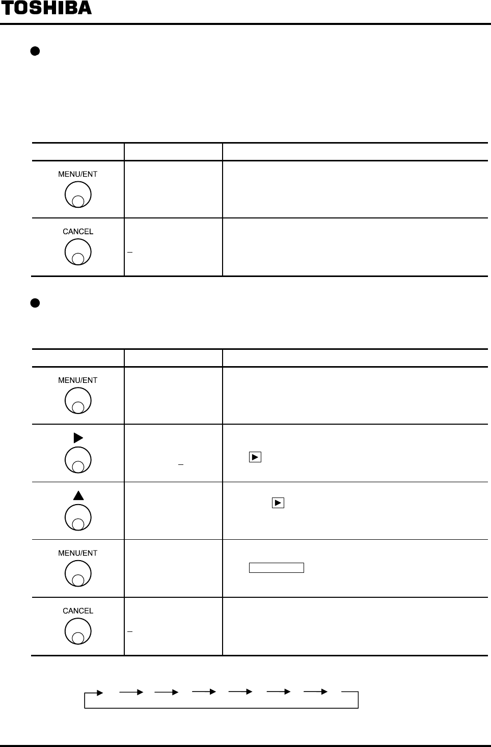
6F8A0917
-
95
-
Checking the count rate and pulse width
How to check the count rate setting is shown below.
To check other setting values, select the following function numbers:
Pulse width mode H2: PLS MODE
Pulse width H3: PLS WIDTH
Switch operation Display example Description
H1: COUNT RATE
1.00000 m3
Select H1: COUNT RATE from the setting item selection
menu.
The currently set count rate appears.
H1: COUNT RATE Returns to the menu of setting item selection.
Changing the count rate
The following is an example to change the count rate from 0.01m3 to 200 l (liter).
Switch operation Display example Description
H1: COUNT RATE
1.00000 m3
Select H1: COUNT RATE from the setting item selection
menu.
The currently set count rate appears.
H1: COUNT RATE
1.00000 m3
The cursor appears.
Press further to move the cursor to the digit of unit.
H1: COUNT RATE
1000.00 l
↓
200.000 l
Change the unit to l.
Then press to move the cursor to the desired digit to change
and change the number there. Repeat this operation until 200 l
appears on the display.
H1: COUNT RATE
200.000 l
The display blinks and the set value is displayed for
confirmation.
Press MENU/ENT again to write the data. Then the cursor
disappears and the display returns to the condition that the set
value is displayed.
H1: COUNT RATE Returns to the menu of setting item selection.
Note: The indicting units for count rate are displayed cyclically as shown below.
m
3 ml
l gal bbl pt qt
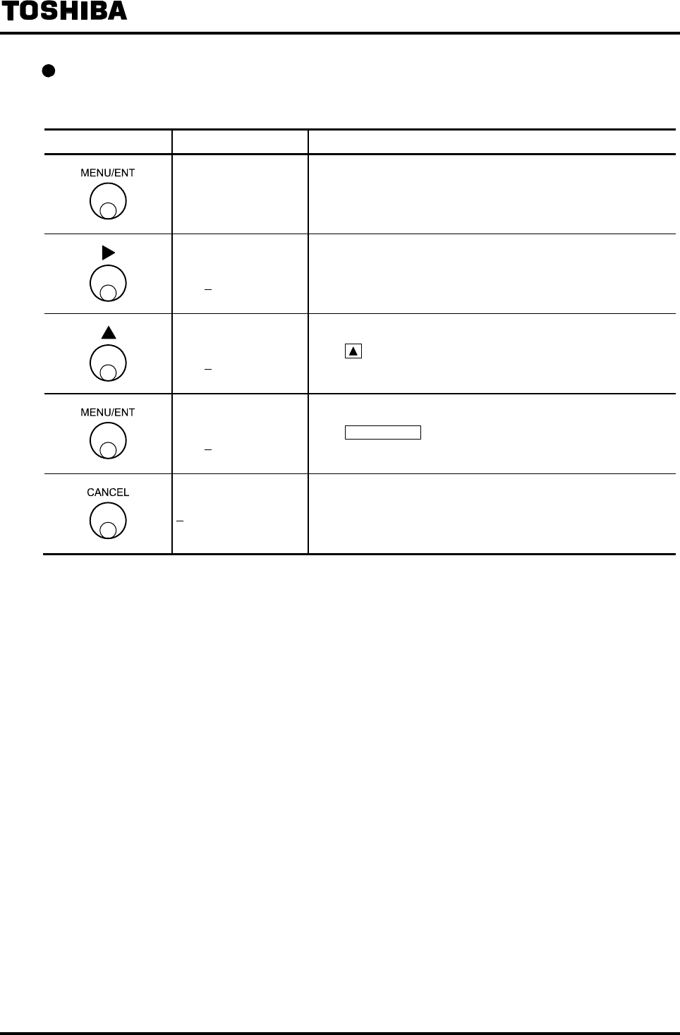
6F8A0917
-
96
-
Changing the pulse width mode setting
The following is an example to change the pulse width mode setting from 2:MANUAL to 1:AUTO.
Switch operation Display example Description
H2: PLS MODE
2:MANUAL
Select H2: PLS MODE from the setting item selection menu.
The currently set pulse width mode setting appears.
H2: PLS MODE
2:MANUAL The cursor appears.
H2: PLS MODE
1:AUTO Press to select 1:AUTO.
H2: PLS MODE
1:AUTO
The display blinks and the set value is displayed for
confirmation.
Press MENU/ENT again to write the data. Then the cursor
disappears and the display returns to the condition that the set
value is displayed.
H2: PLS MODE Returns to the menu of setting item selection.

6F8A0917
-
97
-
Changing the pulse width
The following is an example to change the pulse width from 100ms to 250ms.
Switch operation Display example Description
H3: PLS WIDTH
100.0 ms
Select H3: PLS WIDTH from the setting item selection menu.
The currently set pulse width appears.
H3: PLS WIDTH
100.0 ms
The cursor appears.
Press further to move the cursor to the desired digit to
change.
H3: PLS WIDTH
200.0 ms
↓
250.0 ms
Change the number of the digit.
To change other digit, press under this condition to move
the cursor to that digit and change the number there.
H3: PLS WIDTH
250.0 ms
The display blinks and the set value is displayed for
confirmation.
Press MENU/ENT again to write the data. Then the cursor
disappears and the display returns to the condition that the set
value is displayed.
H3: PLS WIDTH Returns to the menu of setting item selection.
Note: If you try to set a value exceeding the settable range, *H. OVER SPEC. appears and the value returns to
the previously set value. Try to set a new value again.
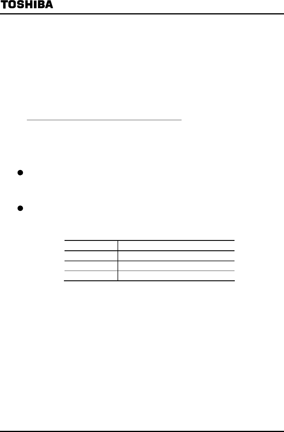
6F8A0917
-
98
-
8.2.16 Preset Counter
Preset counter is the function to output a signal through DO when the totalized count reaches a preset
value.
For details of preset counter function, also see 10. “Function Description.”
The following parameters can be set here:
(1) Preset count value
(2) Preset output function
Notes
• Preset counter works only for forward direction flow count.
• To use the preset counter, it is necessary to set the DO function for output.
For how to set the DO function, see 8.2.14 “Digital I/O Function.”
• To use the preset counter, it is recommended that you set a total volumetric flow unit or a count
value unit as indicating unit to check the operating condition.
For how to set the indicating unit, see 8.2.6 “Normal Indicating Unit.”
Preset count value
Preset value for preset counter is set.
Preset count value can be set within the range of 0 to 99999999.
Preset output function
The operation of DO output when the preset counter reaches the preset value can be selected. You
can select the operation of DO output from the items shown in the table below:
PRESET FUNCT. Preset output function
1: HOLD Output level is held
2: 50ms PULSE One-shot pulse output of 50ms pulse width
3: 500ms PULSE One-shot pulse output of 500ms pulse width
Note: If the preset output function is set to “50ms PULSE” or “500ms PULSE,”
select the preset count value to become 1, 2, 5, 25 or 125 × 10n. (If a value
not satisfying this condition is set, the preset output timing may be shifted
when the totalizer overflows.)
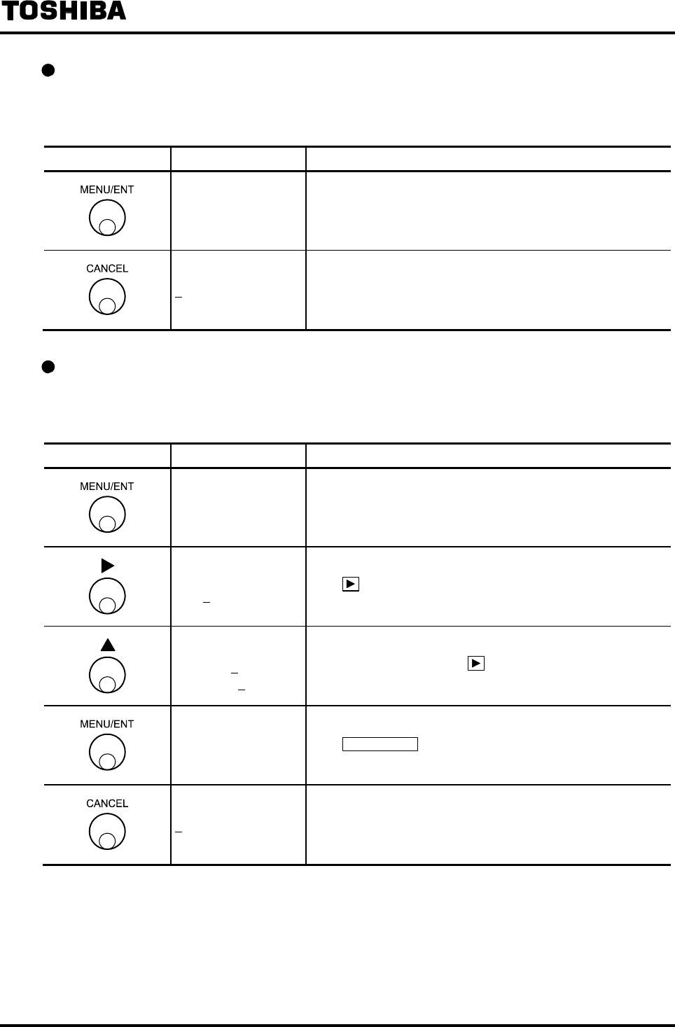
6F8A0917
-
99
-
Checking the preset counter setting
How to check the preset count value is shown below.
To check the preset output function, select the function “I2: PRESET FNC.”
Switch operation Display example Description
I1: PRESET CNT
00000300
Select H1:PRESET from the setting item select menu.
The currently set preset count value appears.
I1: PRESET CNT Returns to the menu of preset item selection.
Changing the preset count value
The following is an example to show how to change the preset value from 500 (count) to 1000
(count)
Switch operation Display example Description
I1: PRESET
00000500
Select I1:PRESET from the setting item selection menu.
The currently set preset count value (500 counts in this
example) appears.
I1: PRESET
00000500
The cursor appears.
Press further to move the cursor to the desire digit to
change.
I1: PRESET
00001500
00001000
Change the number of the digit.
To change other digit, press under this condition to move
the cursor to that digit and change the number there
I1: PRESET
00001000
The display blinks and the set value is displayed for
confirmation
Press MENU/ENT again to write the data. Then the cursor
disappears and the display returns to the condition the setting
value is displayed.
I1: PRESET Returns to the menu of setting item selection.

6F8A0917
-
100
-
Changing the preset output function
The following is an example to show how to change the preset output function from Output state
hold (1/HOLD) to One-shot pulse output (2:50ms PULSE).
Switch operation Display example Description
I2: PRESET FNC
1:HOLD
Select I2:PRESET FNC from the setting item selection menu.
The currently set preset count output function (HOLD in this
example) appears.
I2: PRESET FNC
1:HOLD The cursor appears.
I2: PRESET FNC
2:50ms PULSE Press to select the setting code 1:50ms PULSE.
I2: PRESET FNC
2:50ms PULSE
The display blinks and the set value is displayed for
confirmation
Press MENU/ENT again to write the data. Then the cursor
disappears and the display returns to the condition that the
setting value is displayed.
I2: PRESET FNC Returns to the menu of setting item selection.

6F8A0917
-
101
-
8.2.17 Flow Rate High/Low limit Alarm
The flow rate high/low limit alarm is the function to generate an alarm when the instantaneous flow
rate exceeds a preset high limit value (or low limit value).
When an alarm is generated, an alarm message is displayed and a signal can be output through DO.
Two outputs are provided each for high limit value and low limit value (4 outputs in total of high limit,
high-high limit, low limit and low-low limit) and an alarm output can be sent out separately.
The following parameters can be set here:
(1) High limit alarm On/Off
(2) High limit value
(3) Low limit alarm On/Off
(4) Low limit value
(5) High-high limit alarm On/Off
(6) High-high limit value
(7) Low-low limit alarm value On/Off
(8) Low-low limit value
Note
• To output a high/low limit alarm through DO, it is necessary to set the DO function for output.
For how to set the DO function, see 8.2.14 “Digital I/O Function.”
High/low limit alarm On/Off
Whether the high/low limit alarm is used or not can be selected
Selection Alarm operation
1: ON Alarm function provided
If the flow rate exceeds a selected high limit value (or low limit value),
an alarm is generated.
2: OFF Alarm function not provided
The selected alarm will not be generated.
High/low limit value
A flow rate value (high/low limit value) to generate an alarm is set in percent of the maximum
range (Range 1) flow rate value.
The high/low limit alarm value can be set within the range of −10% to 110% in increments of 0.5%.

6F8A0917
-
102
-
Checking the high/low limit alarm setting
Proceed as follows to check the high/low limit alarm setting.
The following is how to check whether the high limit alarm is provided (On) or not (Off).
To check other setting values, select the following function numbers:
High limit value J2: H ALM VAL
Low limit alarm On/Off J3: L ALM SET
Low limit value J4: L ALM VAL
High-high limit alarm On/Off K1: HH ALM SET
High-high limit alarm K2: HH ALM VAL
Low-low limit alarm On/Off K3: LL ALM SET
Low-low limit value K4: LL ALM VAL
Switch operation Display example Description
J1: H ALM SET
1:ON
Select J1: H ALM SET from the setting item selection menu.
The currently set high limit alarm On/Off setting appears.
J1: H ALM SET Returns to the menu of setting item selection.
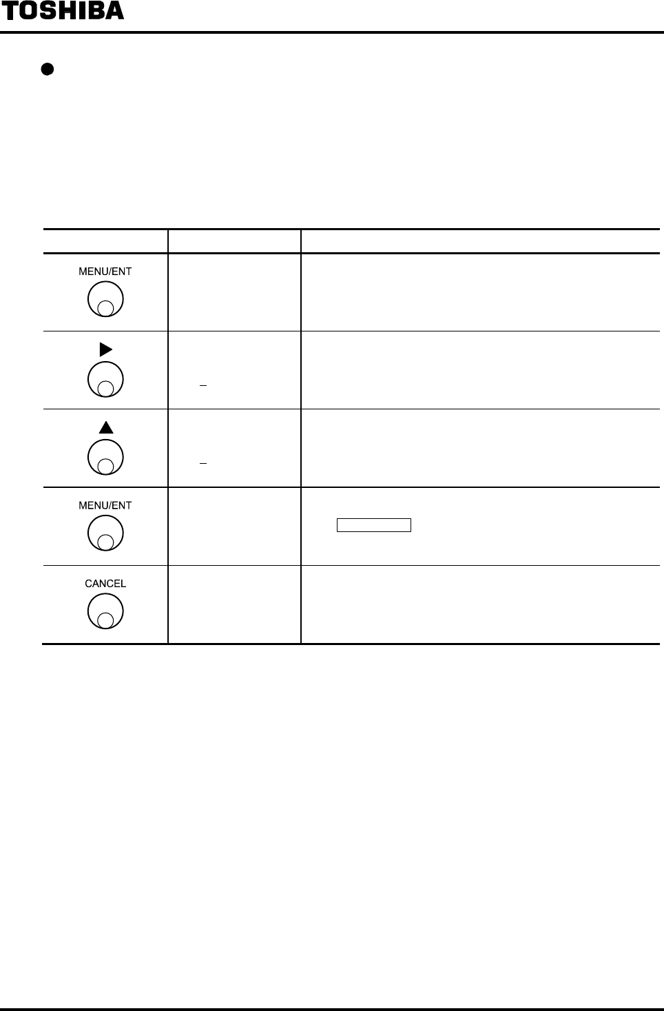
6F8A0917
-
103
-
Changing the high/low limit alarm On/Off
The following is an example to change the high limit alarm setting from OFF to ON.
To change other high/low limit alarm On/Off setting, select the following functions.
High limit alarm On/Off J1: H ALM SET
Low limit alarm On/Off J3: L ALM SET
High-high limit alarm On/Off K1: HH ALM SET
Low-low limit alarm On/Off K3: LL ALM SET
Switch operation Display example Description
J1: H ALM SET
2:OFF
Select J1: H ALM SET from the setting item selection menu.
The currently set On/Off setting for high limit alarm appears.
J1: H ALM SET
2:OFF The cursor appears.
J1: H ALM SET
1:ON Change the setting.
J1: H ALM SET
1:ON
The display blinks and the set value is displayed for
confirmation.
Press MENU/ENT again to write the data. Then the cursor
disappears and the display returns to the condition that the
setting value is displayed.
J1: H ALM SET Returns to the menu of setting item selection
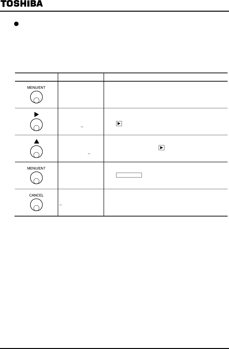
6F8A0917
-
104
-
Changing the high/low limit value
The following is an example to change the high limit value from +105% to +103%.
To change other high/low limit value setting, select the following functions.
Low limit value J4: L ALM SET
High-high limit value K2: HH ALM SET
Low-low limit value K4: LL ALM SET
Switch operation Display example Description
J2: H ALM VAL
+105.0%
Select J2: H ALM VAL from the setting item selection menu.
The currently set high limit alarm value appears.
J2: H ALM VAL
+105.0%
The cursor appears.
Press further to move the cursor to the digit to change.
J2: H ALM VAL
+103.0%
Change the number of the digit.
To change other digit, press under this condition to move
the cursor to that digit and change the number there.
J2: H ALM VAL
+103.0%
The display blinks and the set value is displayed for
conformation
Press MENU/ENT again to write the data. Then the cursor
disappears and the display returns to the condition that the
setting value is displayed.
J2: H ALM VAL Returns to the menu of setting item selection.
Note: If a value of 10% or less, or a value of 110% or more is tried to set, *L. Over SPEC. or *H. OVER SPEC.
appears and the value returns to the previously set value.
Try to set a new value again.
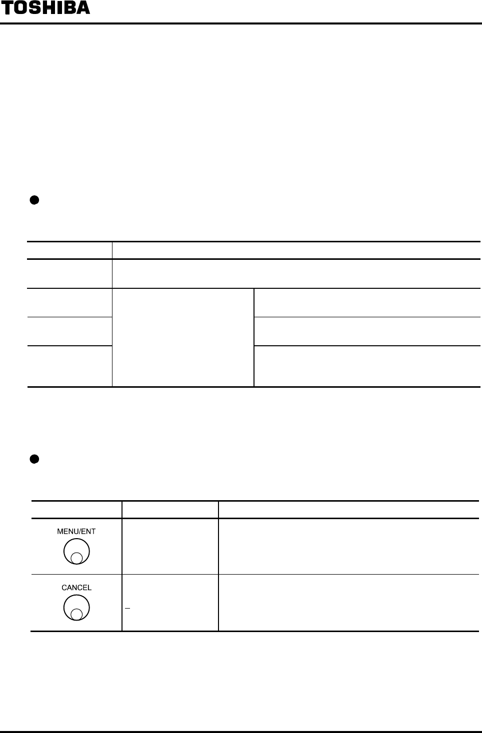
6F8A0917
-
105
-
8.2.18 Fluid Empty Alarm
Fluid empty alarm is the function to generate an alarm when a condition is detected in which fluid is
not filled or water level is not enough in the measuring pipe of the flowmeter.
If an alarm is generated, an alarm message is displayed and a signal can be output through DO.
Note
• To output a fluid empty alarm through DO, it is necessary to set the DO function for output.
For how to set the DO function, see 8.2.14 “Digital I/O Function.”
•In the case of LF232*F; Fluid empty alarm function is not usable. Set this function 'OFF'.
Setting the fluid empty alarm
Whether the fluid empty alarm should be used or not, and its detection sensitivity can be selected.
EMPTY Fluid empty alarm setting
1: OFF Fluid empty alarm not used
Fluid empty condition is not detected.
2: NORMAL Sensitivity: Standard
Detection sensitivity is set to the standard level.
3: SENSITIVE Sensitivity: High
Detection sensitivity is set to high sensitivity level.
4: SENSITIVE-H
Fluid empty alarm used
If a fluid empty condition is
detected, an alarm will be
output.
Sensitivity: Higher
Detection sensitivity is set to higher sensitivity
level.
* To use the fluid empty alarm, normally select 2:NORMAL (standard detection sensitivity). Select
3:SENSITVE or 4:SENSITIVE-H only when the fluid empty alarm is difficult to detect due to the condition
of the fluid to be measured or its piping condition.
Checking the fluid empty alarm On/Off setting
Proceed as follows to check whether the fluid empty alarm is used (On) or not (Off).
Switch operation Display example Description
L1: EMPTY ALM
1:NORMAL
Select L1:EMPTY ALM from the setting item selection menu.
The currently set fluid empty alarm On/Off setting appears.
L1: EMPTY ALM Returns to the menu of setting item selection.
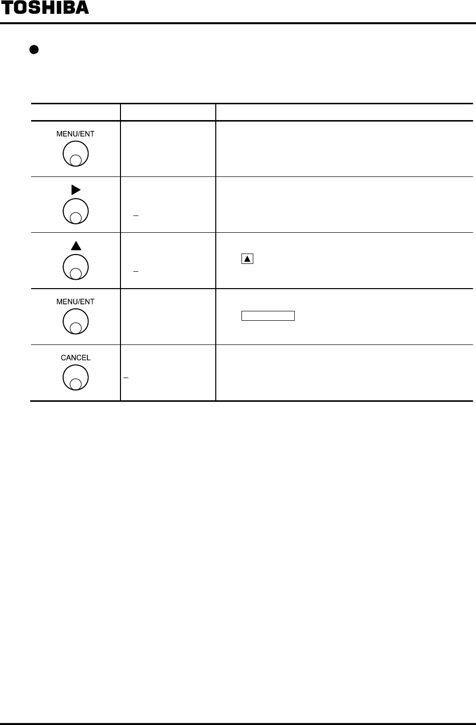
6F8A0917
-
106
-
Changing the fluid empty alarm On/Off setting.
The following is an example to change the fluid empty alarm setting from Alarm On (1:NORMAL)
to Alarm Off (0:OFF).
Switch operation Display example Description
L1: EMPTY ALM
1:NORMAL
Select L1:EMPTY ALM from the setting item selection menu.
Then the fluid empty alarm On/Off setting appears.
L1: EMPTY ALM
1:NORMAL The cursor appears.
L1: EMPTY ALM
2:OFF Press to select the fluid empty alarm Off
L1: EMPTY ALM
2:OFF
The display blinks and the set value is displayed for
confirmation.
Press MENU/ENT again to write the data. Then the cursor
disappears and the display returns to the condition that the
setting value is displayed.
L1: EMPTY ALM Returns to the menu of setting item selection.

6F8A0917
-
107
-
8.2.19 Self-Diagnosis Function
Self-diagnosis function is the function to generate an alarm if an error is found from the result of
diagnosis of internal circuits, memory, etc.
If an alarm is generated, an alarm message is displayed and a signal can be output through DO.
The following parameters can be set here:
(1) Self-diagnosis alarm On/Off
(2) DO alarm output factor setting
NOTE
• To output a self-diagnosis alarm through DO, it is necessary to set the DO function for output.
For how to set the DO function, see 8.2.14 “Digital I/O Function.”
Self-diagnosis function On/Off setting
Whether or not to use the self-diagnosis function can be selected.
Selection Self-diagnosis alarm is used or not
1: ON Self-diagnosis function is used
An alarm is generated if an error is detected.
2: OFF Self-diagnosis function is not used
Self-diagnosis will not be carried out.
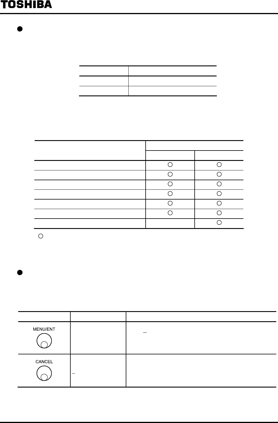
6F8A0917
-
108
-
Alarm output factor setting
When the diagnosis alarm is output through DO, whether a fluid empty alarm should be added to
the condition for alarm output can be selected.
Selection Diagnosis error alarm factor
1: WITHOUT EMP Fluid empty alarm is not included
2: WITH EMP Fluid empty alarm is included
List of alarm output factors
Diagnosis error items to output as a diagnosis alarm through DO are shown below.
Diagnosis alarm output (DO)
Diagnosis error item
WITHOUT EMP WITH EMP
RAM error
ROM error
Exciting current value error
Exciting circuit wire broken
ADC error (flow measurement circuit error)
Parameter error
Fluid empty alarm
−
: Diagnosis alarm is output through DO when an error is detected.
− : Diagnosis alarm is not output through DO even if an error is detected.
(However, an error message is displayed)
Checking the self-diagnosis alarm setting
Proceed as follows to check the self-diagnosis function setting.
The following is how to check whether the self-diagnosis alarm is used (On) or not (Off).
To check the alarm output factors, select the function “L3: ALM PRESET.”
Switch operation Display example Description
L2: SELF CHECK
1:ON
Select L2: SELF CHECK from the setting item selection menu.
Whether the self-diagnosis alarm is used (On) or not (Off)
appears.
L2: SELF CHECK Returns to the menu of setting item selection.

6F8A0917
-
109
-
Changing the self-diagnosis function setting
The following is an example to change the self-diagnosis function from Self-diagnosis function On
(1:ON) to Self-diagnosis function Off (2:OFF).
To change the setting for alarm output factors, select the function “L3: ALM PRESET.”
Switch operation Display example Description
L2: SELF CHECK
1:ON
Select L2: SELF CHEK from the setting item selection menu.
Whether the self-diagnosis function is used (On) or not (Off)
appears.
L2: SELF CHECK
1:ON The cursor appears.
L2: SELF CHECK
2:OFF Press to set the self-diagnosis function to OFF.
L2: SELF CHECK
2:OFF
The display blinks and the set value is displayed for
confirmation.
Press MENU/ENT again to write the data. Then the cursor
disappears and the display returns to the condition that the
setting value is displayed.
L2: SELF CHECK Returns to the menu of setting item selection.
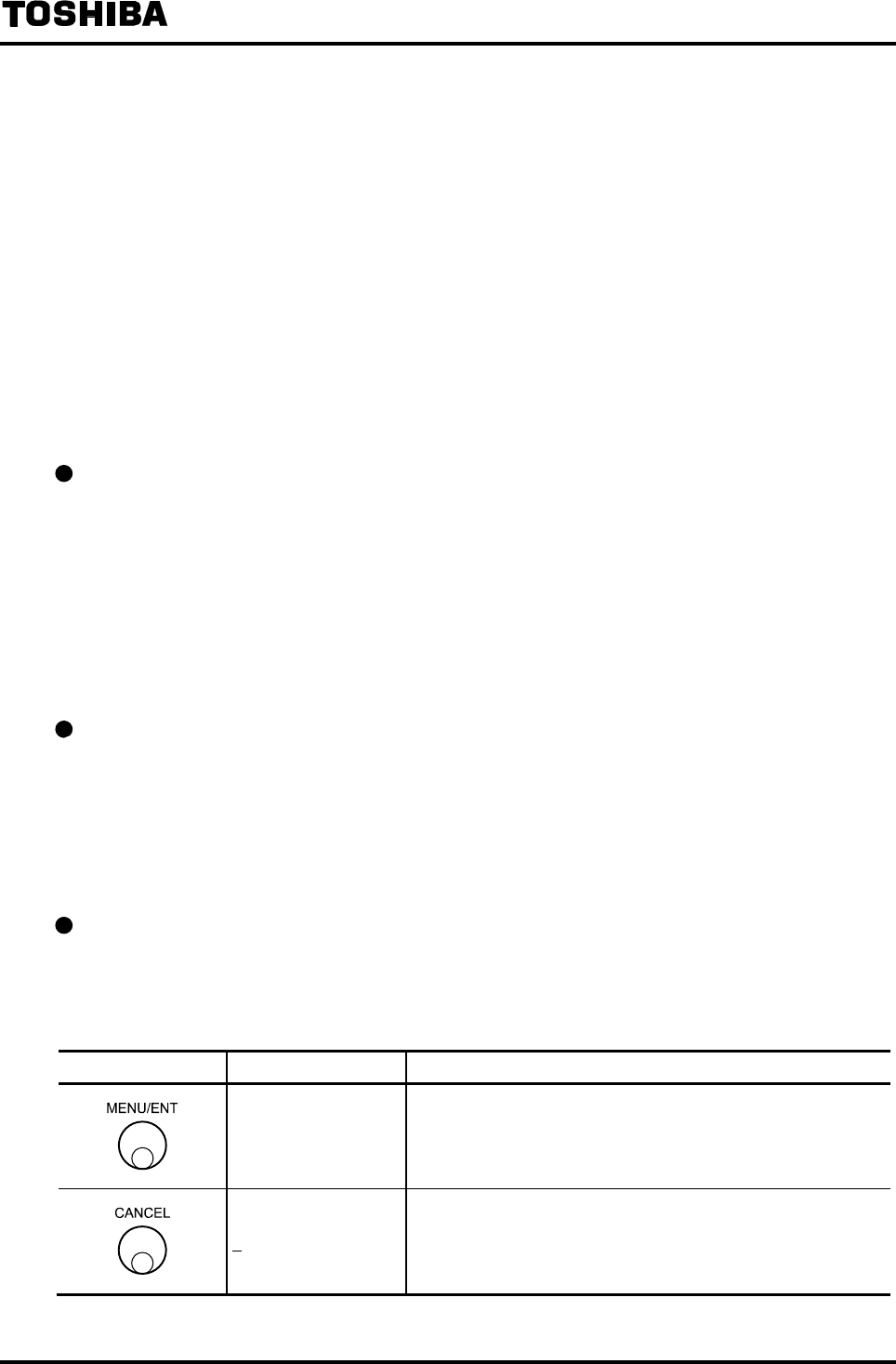
6F8A0917
-
110
-
8.2.20 Rate-of-Change Limit Value and Control Time
The rate-of-change limit is the function to prevent a sudden change in flow indication of the converter
when the measurement flow signal contains excessive noise.
Damping constant is also effective to prevent indication variations by increasing its value but the rate
of change limit control is effective against a sudden change in flow indication that the damping
constant cannot eliminate.
The following parameters can be set here:
(1) Rate-of-change limit value
(2) Rate-of-change control time
Note: To use the rate-of-change limit function, it is necessary to set both (1) and (2).
If either one is set to zero (factory setting value), this function does not work
When not using the rate-of-change limit function, set zero to either one of these items.
Rate-of-change limit value
Indication change is controlled within the limit value* against variations of measurement flow
signals.
* Indication variation per approx. 40ms will be controlled to within the limit value (in percent of
span).
The rate-of-change limit value can be set within the range of 0 to 30% in increments of 0.1%.
In the case of multi-range setting, the value is indicated in percent of the range in operation.
If 0 is set, the rate-of-change limit function does not work.
Rate-of-change control time
If the time used to control the indication against variations of measurement flow signal exceeds the
control time, the rate-of-change control will be turned off. (Flow indication will be output directly
without the rate-of-change limit function.)
Control time can be set within the range of 0 to 20s in increments of 1s.
If 0 is set, the rate-of-change limit function does not work.
Checking the rate-of-change limit setting
Proceed as follows to check the rate-of-change limit setting.
How to check the limit value is shown below.
To check the control time, select the function “M2: LIMIT TIME.”
Switch operation Display example Description
M1: LIMIT RATE
05.0 %
Select M1: LIMIT RATE from the setting item selection menu.
The currently set rate-of-change limit value appears.
M1: LIMIT RATE Returns to the menu of setting item selection.

6F8A0917
-
111
-
Changing the rate-of-change limit setting
The following is an example to change the limit value from 1.0% to 1.5%.
To change the control time, select the function “M2: LIMIT TIME.”
Switch operation Display example Description
M1: LIMIT RATE
1.0 %
Select M1: LIMIT RATE from the setting item selection menu.
The currently set rate-of change limit value appears.
M1: LIMIT RATE
1.0%
The cursor appears.
Press further to move the cursor to the desired digit to
change.
M1: LIMIT RATE
1.5 %
Change the number of the digit.
To change other digit, press under this condition to move
the cursor to that digit and change the number there.
M1: LIMIT RATE
1.5 %
The display blinks and the set value is displayed for
confirmation.
Press MENU/ENT again to write the data. Then the cursor
disappears and the display returns to the condition that the
setting value is displayed.
M1: LIMIT RATE Returns to the menu of setting item selection.
Note: If a value outside of the settable range is tried to set, *H. OVER SPEC. appears and the value returns to
the previously set value. Try to set a new value again.
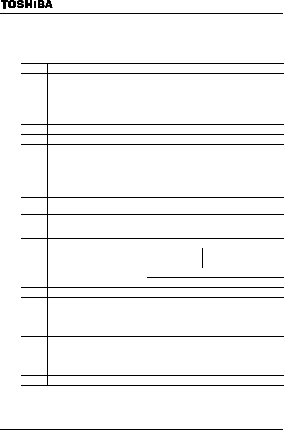
6F8A0917
-
112
-
8.3 Initial Settings When Shipped from the Factory
Initial settings used when shipped from the factory unless otherwise specified are shown below.
No. Parameter name Initial setting values
A1 Exciting current Adjusted value when shipped from the factory
(described on the detector nameplate)
A2 Meter size Specified meter size when ordered
(described in the Test Record)
A3 Exciting frequency Recommended value for the detector combined
(See 8.2.3 “Exciting Frequency.”)
A4 Flow direction NORMAL
A5 Password 000
B1 Indicating unit setting (main unit) m3/h (If any range is specified, the same unit as that of
the range)
B2 Indicating unit setting (sub display) % (If count rate is specified, the same unit as that of the
count rate)
B3 Custom coefficient 0
B4 Custom unit “ ” (7 blank spaces)
C1 Range type Range type specified when ordered
(If multi-range is not specified, Single range is set)
C2 to 4 Ranges 1 to 4 Values specified when ordered (described in the Test
Record. If not specified, Range 1 is the Toshiba
standard range and Ranges 2 to 4 are zeros)
C5 Hysteresis 3.0 %
Range of 1m/s or more 1.0s
Meter size
16”(400mm) or less Range of less than 1m/s
Meter size 20” (500mm) or more 3.0s
D1 Damping factor
For partially filled pipes detectors 10s
D2 Low cutoff value 1.0 %
D3 Output when an alarm occurs 4mA output
OFF D4 Display low cut
For partially filled pipes detectors: ON
D5 Output low limit setting 4mA
F1 Digital Output 1 PULSE OUT (Pulse Output)
F2 to 4 Digital Outputs 2 to 4 NO USE (Not used)
F5 to 8 Digital Output 1 to 4 states NORMAL OPEN
G1 to 2 Digital Inputs 1 to 2 NO USE (Not used)
G3 to 4 Digital inputs 1 to 2 detection levels H LEVEL
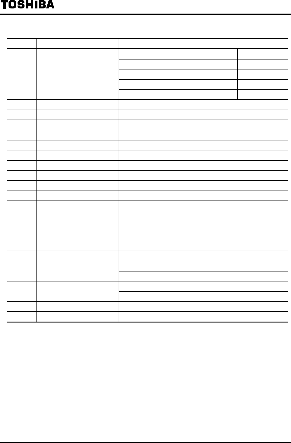
6F8A0917
-
113
-
No. Parameter name Initial setting values
H1 Count rate Meter size 1/10" to 1/4" (2.5 to 6 mm) 1L
Meter size 1/2" to 1 1/2” (15 to 40 mm) 0.01m3
Meter size 2" to 4” (50 to 100mm) 0.1m3
Meter size 6” to 24” (150 to 600mm) 1m3
Meter size 28” to 120” (700 to 3000mm) 10m3
H2 Pulse width setting mode AUTO
H3 Pulse width 100 ms
I1 Preset count value 00000000
I2 Preset output function HOLD
J1 High limit alarm setting OFF
J2 High limit alarm value 0.0 %
J3 Low limit alarm setting OFF
J4 Low limit alarm value 0.0 %
K1 High-high limit alarm setting OFF
K2 High-high limit alarm value 0.0 %
K3 Low-low limit alarm setting OFF
K4 Low-low limit alarm value 0.0 %
L1 Fluid empty alarm ON Detection level: NORMAL
(In the case of LF232*F; OFF)
L2 Self-diagnosis function ON
L3 Alarm output factor setting WITHOUT EMP (fluid empty alarm not included)
0.0 % M1 Rate-of-change limit
For partially filled pipes detectors: 10 %
0 s M2 Control time
For partially filled pipes detectors: 10 s
N1 Fixed value output function OFF
O1 Zero offset 0.0 %
6F8A0917
-
114
-
8.4 Fixed Value Output (Loop Check)
The fixed value output is the function to output a fixed current and/or a fixed pulse output
independently of the flow rate signal.
The following parameters can be set here:
(1) Fixed value output On/Off setting
(2) Fixed current output value
(3) Fixed pulse output value
Notes
• Fixed pulse output can be sent out only when DO1 or DO2 is set for pulse output.
• When the mode is switched to the fixed output mode by DI function, the preset values of items (2)
and (3) above will be output.
• In the fixed output mode, the condition of DO output (other than pulse output) will be
maintained.
Fixed value output On/Off setting
Fixed output mode can be selected by the setting as follows.
Selection Mode
1: ON Fixed value output mode On
Current output and pulse output become fixed output values.
2: OFF Fixed value output mode Off
Fixed output mode will be turned off and the mode goes to the
normal measurement mode.
When the fixed value output is set to ON, the main indicating unit only is displayed and the current
output set value is displayed in the lower line in the measurement mode.
Display example:
1.000 m/s
* FIX.OUT 20.0 mA
Flow velocity is displayed in main
indicating unit
Fixed current value is displayed
Note: When power is turned off and on again, the fixed output On/Off setting will be turned off.
Fixed current output value
The current value used in the fixed output mode is set.
Fixed current output value can be set in the range of 3 to 24mA in increments of 0.1mA.
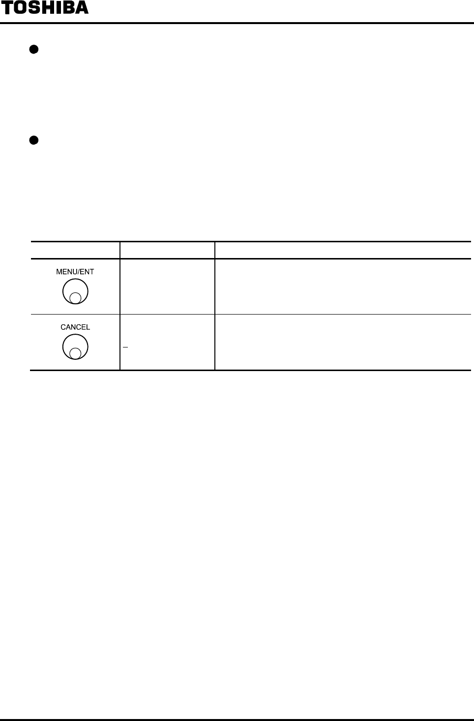
6F8A0917
-
115
-
Fixed pulse output value
The pulse frequency is set, which is used to output in the fixed output mode through the DO
terminal where the pulse output function is set.
The fixed pulse output value can be set within the range of 0 to 1000pps in increments of 1pps.
Note: When the pulse output is sent out from DO2 terminal, up to 100pps can be output.
Checking the fixed output function setting
Proceed as follows to check the fixed output function.
How to check the fixed value out On/Off setting is shown here.
To check other settings, select the following functions:
Fixed current output value N2: FIX CURR
Fixed pulse output value N3: FIX PULSE
Switch operation Display example Description
N1: FIXED OUT
1:ON
Select N1: FIXED OUT from the setting item selection menu.
The currently set fixed value output On/Off setting appears.
N1: FIXED OUT Returns to the menu of setting item selection.
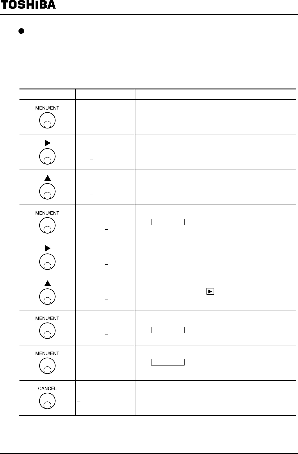
6F8A0917
-
116
-
Changing the fixed output function
The following is an example to change the fixed output function from Fixed value output OFF to
ON and then go on to set the current output value and the pulse output value. To change the current
output value or pulse output value independently, select the following function:
Fixed current output value N2: FIX CURR
Fixed pulse output value N3: FIX PULSE
Switch operation Display example Description
N1: FIXED OUT
2:OFF
Select N1: FIXED OUT from the setting item selection menu.
The currently set fixed value output On/Off setting appears.
N1: FIXED OUT
2:OFF The cursor appears.
N1: FIXED OUT
1:ON Select the fixed value output: ON.
N2: FIX. CURR.
10.0 mA
The display blinks and the set value is displayed for
conformation.
Press MENU/ENT again to write the data. The cursor
disappears and then the current output set value can be
changed.
N2: FIX. CURR.
10.0 mA Move the cursor to the desired digit to change.
N2: FIX. CURR.
20.0 mA
Change the number of the digit.
To change other digit, press under this condition to move
the cursor to the desired digit and change the number there.
N3: FIX. PULSE
100 PPS
The display blinks and the set value is displayed for
conformation.
Press MENU/ENT again to write the data. The cursor
disappears and then the pulse output set value can be changed.
N3: FIX. PULSE
100 PPS
The display blinks and the set value is displayed for
conformation.
Press MENU/ENT again to write the data. Then the cursor
disappears and the display returns to the condition that the
setting value is displayed.
N3: FIX. PULSE Returns to the menu of setting item selection.
Note. If a value outside of the settable range is tried to set, the upper limit or lower limit value of the settable
range will be forcibly set.
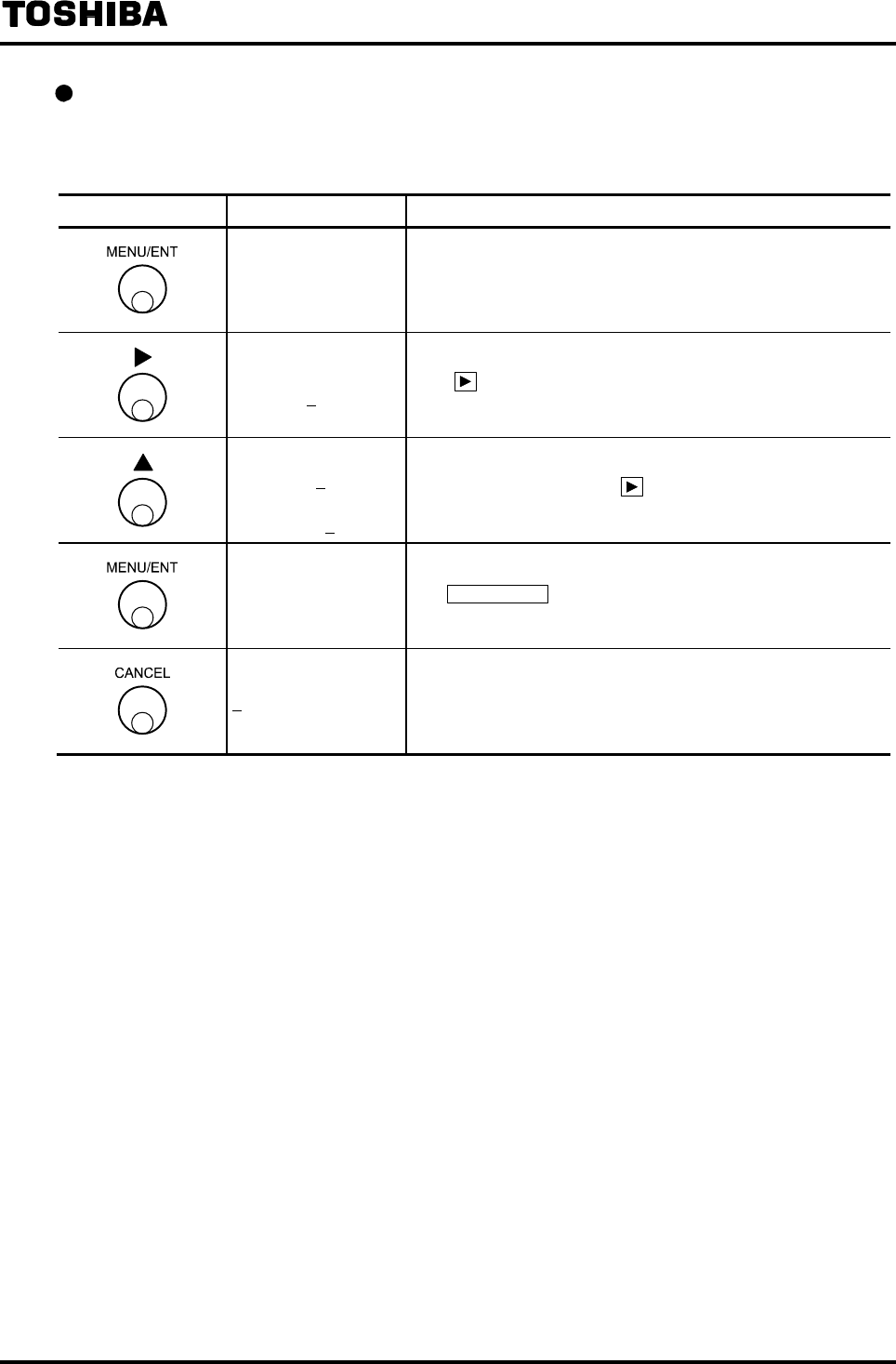
6F8A0917
-
117
-
Changing the fixed output constant
The following is an example to change the fixed pulse output value from 50pps to 100pps. To
change the fixed current output value, select the function “L2: FIX. CURR.”
Switch operation Display example Description
L3: FIX. PULSE
0050 pps
Select L3: FIX. PULSE from the setting item selection menu.
The currently set fixed pulse output value appears.
L3: FIX. PULSE
0050 pps
The cursor appears.
Press further to move the cursor to the desired digit to
change.
L3: FIX. PULSE
0150 pps
↓
0100 pps
Change the number of the digit.
To change other digit, press under this condition to move
the cursor to that digit and change the number there.
L3: FIX. PULSE
0100 pps
The display blinks and the set value is displayed for
confirmation.
Pres MENU/ENT again to write the data. Then the cursor
disappears and the display returns to the condition that the
setting value is displayed.
L3: FIX. PULSE Returns to the menu of setting item selection.
Note: If you try to set a value outside of the settable range, the value will be forcibly set to the upper limit or the
lower limit of the settable range.
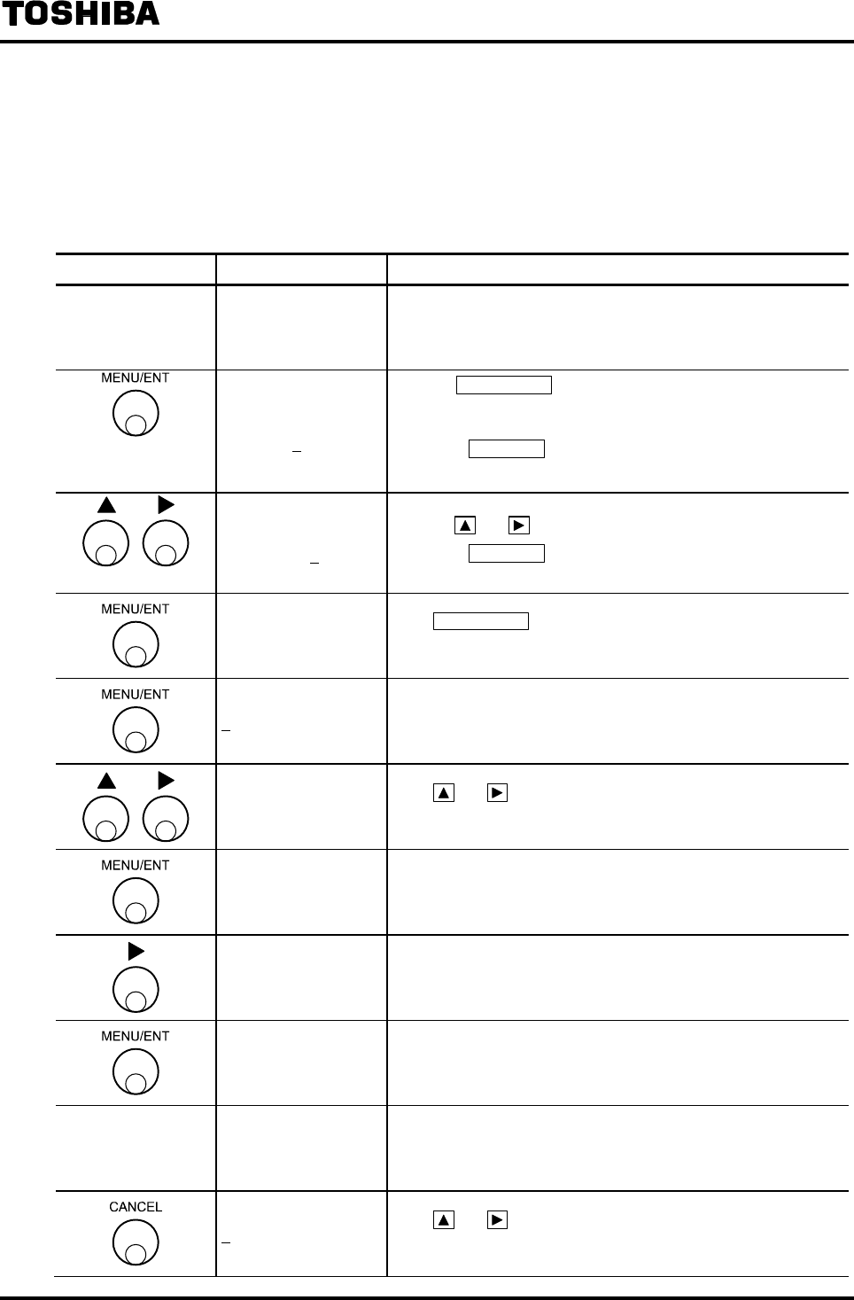
6F8A0917
-
118
-
8.5 Zero Adjustment
8.5.1 Still Water Zero Adjustment
Still water zero adjustment must be performed when the fluid in the measuring pipe of the detector
stays still.
Switch operation Display example Description
−
10.00 m/s
100.0 % Measured value being displayed (measurement mode)
ENTER111
000
Pressing MENU/ENT in the measurement mode for 3 seconds
or more, the screen moves to the menu lock cancellation
screen.
* Pressing CANCEL in the mode selection screen, the mode
returns to the measurement mode.
ENTER111
111
Set the menu lock cancellation cord [111] by
pressing and .
* Pressing CANCEL in the mode selection screen, the mode
returns to the measurement mode.
>1:SET
2:CNT CTRL
Press MENU/ENT for 3 seconds or more in the measurement
mode and then the mode changes to the mode selection screen.
A1:EX CURRENT Select 1:SET in the mode selection screen and then the menu
screen appears.
E1: ZERO ADJUST Press and so that the function number becomes E1:
ZERO ADJUST.
E1: ZERO ADJUST
01.0%
The current flow rate measured value in % unit appears.
(Check that the fluid to be measured stays still.)
ADJUST READY
01.0%
ADJUST READY appears and the system is ready for
adjustment. (If “CANCEL” is pressed, Adjustment ready
condition will be cancelled.)
E1: ZERO ADJUST
* ZERO ADJUST
About 3 to 6 seconds later, the still water zero adjustment ends
and the measured flow value after adjustment appears.
−
E1: ZERO ADJUST
00.0% Returns to the menu of setting item selection.
E1: ZERO ADJUST Press and so that the number digit of the function
number becomes 0.
Note2
Note2

6F8A0917
-
119
-
E0: MEAS MODE Returns to the measurement mode (measured value display
screen).
10.00 m/s
100.0 %
Note1: If the flow rate value is outside of the range of ±1.25
m/s, the adjustment result will not be reflected on the flow rate
measured value.
Note1:If the flow rate value is outside of the range of ±1.25 m/s, the adjustment result will not be reflected on
the flow rate measured value.
Note2: There is not this screen to the converter before serial No.072320999.
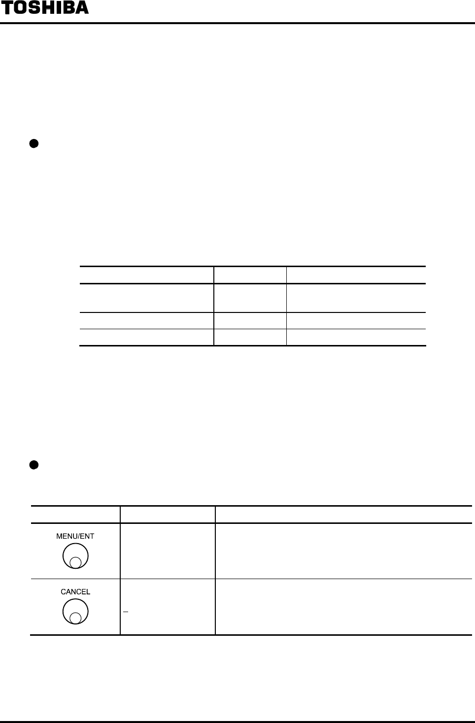
6F8A0917
-
120
-
8.5.2 Zero Offset Adjustment
This function is used to perform zero adjustment simply by comparing the output of the flowmeter
with other process value without stopping the process flow.
If zero adjustment can be performed with still water condition, it is not necessary to set this adjustment
value.
How to calculate the zero offset value
Zero offset is performed by setting the adjustment value.
The adjustment value can be obtained by the following equation:
Adjustment value (%) = {(Actual flow rate) − (LF232 measured value)}
* Calculate the value in percent of the setting range of Range 1.
(See the example below.)
(Example)
Flow rate Value in percent of the set span
Actual flow rate obtained from
other process value 10.0 m3/min 50.0 %
LF232 measured value 10.5 m3/min 52.5 %
Zero offset adjustment value −2.5 %
(If zero offset adjustment value is set to −2.5 %, the output of LF232 is shifted by
−2.5% and 50.0 % output can be obtained.)
The zero offset adjustment value can be set within the range of ±0.410ft/s (0.125 m/s) (±1.25% of
the maximum range 32.8ft/s (10 m/s))
Note: If you perform still water zero adjustment, zero offset adjustment value becomes zero.
Checking the zero offset adjustment value
Proceed as follows to check the zero offset adjustment value.
Switch operation Display example Description
O1: MANUAL ZERO
+002.5 %
Select O1: MANUAL ZERO from the setting item selection
menu.
The currently set zero offset adjustment value appears.
O1: MANUAL ZERO Returns to the menu of setting item selection.

6F8A0917
-
121
-
Changing the zero offset adjustment value
Changing the zero offset adjustment value from +1.0% to −2.5%.
Switch operation Display example Description
O1: MANUAL ZERO
+001.0%
Select O1: MANUAL ZERO from the setting item selection menu.
The currently set zero offset adjustment value appears.
O1: MANUAL ZERO
+001.0%
The cursor appears.
Press further to change the cursor to the desired digit to
change.
O1: MANUAL ZERO
-001.0%
↓
-002.5%
Change the number of the digit.
To change other digit, press under this condition to move
the cursor to that digit and change the number there.
O1: MANUAL ZERO
-002.5%
The display blinks and the set value is displayed for
confirmation.
Press MENU/ENT again to write the data. Then the cursor
disappears and the display returns to the condition that the
setting value is displayed.
O1: MANUAL ZERO Returns to the menu of setting item selection.
Note: If you try to set a value outside of the settable range, an error message of *H. OVER SPEC or *L. OVER
SPEC appears. Try to set a new value again.
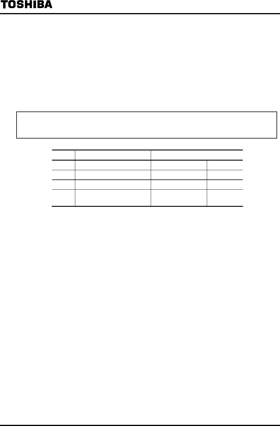
6F8A0917
-
122
-
9. Mag-Prover Calibration
9.1 Calibration Items
The calibration mode of the LF232 flowmeter converter is used to check or perform zero and span
calibration of the converter and check the exciting current. To change the mode to the calibration mode,
select the setting item in accordance with the procedure in 7.3.2 “Setting Mode Operation.”
The procedure on the following pages is used to check or perform zero and span calibration of the
converter and check the exciting current.
However, these values are already checked and calibrated when shipped from the factory. Do not
change these settings unless it is necessary to calibrate in the field, etc.
No. Setting item Display example
9.2.1 0 % flow rate calibration P1:FLOW CAL 0 0.0 %
9.2.2 50 % flow rate calibration P2:FLOW CAL 50 50.0 %
9.2.3 100 % flow rate calibration P3:FLOW CAL100 100.0 %
9.2.4 Checking the exciting current
output value P4:EX CURR DSP 0.2100 A
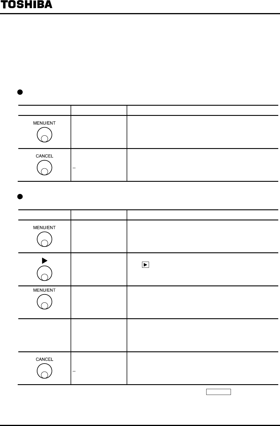
6F8A0917
-
123
-
9.2 Converter Check / Calibration
9.2.1 0% Flow Rate Calibration (Zero Calibration)
Using Mag-Prover internal calibration circuit, 0% flow rate (hereafter called zero point) calibration
can be performed.
Checking the zero point
Switch operation Display example Description
P1:FLOW CAL 0
0.0 %
Select P1:FLOW CAL 0 from the calibration item selection
menu.
Zero point using the simulation input appears.
P1:FLOW CAL 0 Returns to the menu of calibration item selection.
Calibrating the zero point
Switch operation Display example Description
P1:FLOW CAL 0
0.1 %
Select P1:FLOW CAL 0 from the calibration item selection
menu.
Zero point using the simulation input appears.
ADJUST READY
0.1 %
Press . Then the display shown left appears and the system
is ready for zero calibration. (Note 1)
P1:FLOW CAL 0%
* CAL. 0% ADJ. The display shown left appears and zero calibration starts.
−
P1:FLOW CAL 0
0.0 %
About 3 to 6 seconds later (Note 2), the zero calibration ends
and a new zero point appears.
P1:FLOW CAL 0% Returns to the menu of calibration item selection.
Note 1: To cancel the adjustment from the condition of ADJUST READY, press CANCEL . The display returns
to the condition where zero point using the simulation input is displayed.
Note 2: Calibration time differs depending on the exciting frequency.

6F8A0917
-
124
-
9.2.2 50% Flow Rate Calibration
50% flow rate value can be checked only.
Checking the 50% flow rate value
Switch operation Display example Description
P2:FLOW SIG 50
50.1 %
Select P2:FLOW SIG 50 from the calibration item selection
menu.
50% flow rate value using the simulation input appears.
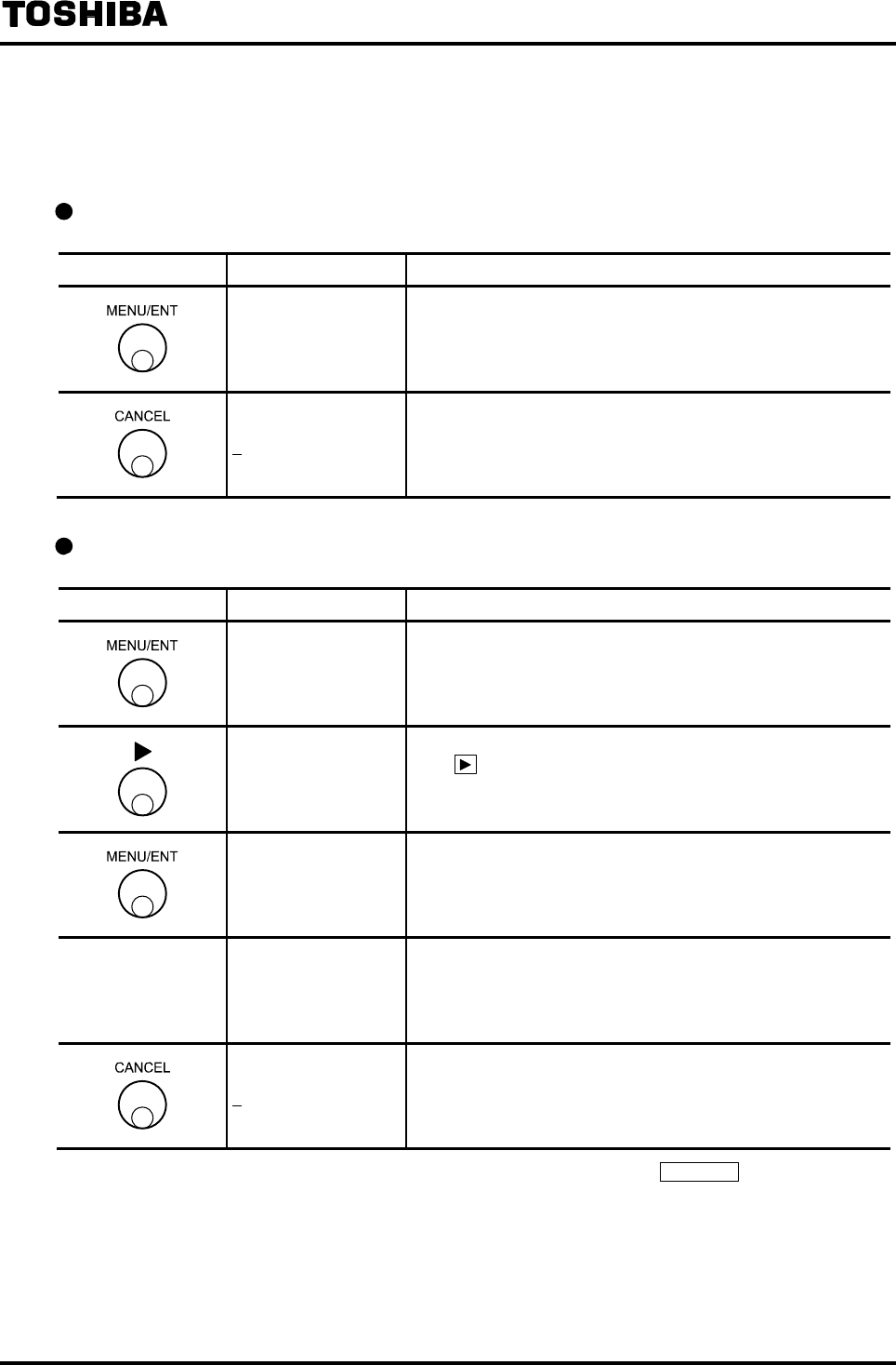
6F8A0917
-
125
-
9.2.3 100% Flow Rate Calibration (Span Calibration)
Using the Mag-Prover internal calibration circuit, 100% flow rate value (hereafter called the span
value) calibration can be performed.
Checking the span value
Switch operation Display example Description
P3:FLOW CAL100
100.1 %
Select P3:FLOW CAL 100 from the calibration item selection
menu.
Span value using the simulation input appears.
P3:FLOW CAL100 Returns to the menu of calibration item selection.
Calibrating the span value
Switch operation Display example Description
P3:FLOW CAL100%
100.1 %
Select P3:FLOW CAL 100 from the calibration item selection
menu.
Span value using the simulation input appears.
ADJUST READY
100.1 %
Press . Then the display shown left appears and the system
is ready for span calibration. (Note 1)
P3:FLOW CAL100
* CAL. 100% ADJ. The display shown left appears and the span calibration starts.
−
P3:FLOW SCAL100
100.0 %
About 3 to 6 seconds later (Note 2), the span calibration ends
and a new span value appears.
P3:FLOW CAL100 Returns to the menu of calibration item selection.
Note 1: To cancel the adjustment from the condition of ADJUST READY, press CANCEL . The display returns
to the condition where 100% flow rate value using the simulation input is displayed.
Note 2: Calibration time differs depending on the exciting frequency.
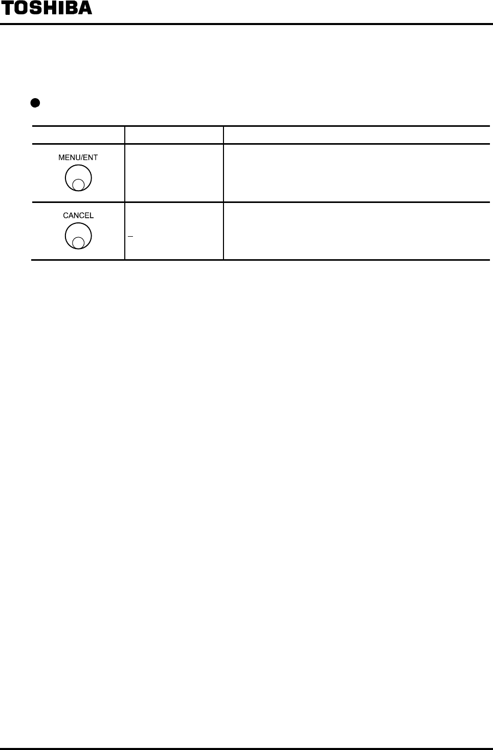
6F8A0917
-
126
-
9.2.4 Checking the Exciting Current Value
The monitor value of the exciting current can be checked.
Checking the exciting current value
Switch operation Display example Description
P4:EX CURR DSP
0.2100 A
Select P4:EX CURR DSP from the calibration item selection
menu.
Span value using the simulation input appears.
P4:EX CURR DSP Returns to the menu of calibration item selection.
* The exciting current value is adjusted when shipped from the factory. Contact your nearest Toshiba
representative if any change is necessary.

6F8A0917
-
127
-
10. Function Description
The LF232 flowmeter converter is equipped with 4 digital outputs and 2 digital inputs (1 digital output
as standard), enabling you to use these as various functions such as pulse output and alarm outputs.
Digital I/O functions are described below.
Functions Description
Flow totalization Totalizes flow volume in volumetric unit.
For totalized flow, a pulse output per each unit of flow volume can be
sent out.
The operation to start, stop and reset the totalizer and pulse output can
be controlled with Digital Input.
Multiple ranges Measuring ranges can be switched in accordance with flow rate.
Measuring ranges can be switched automatically or by control using
Digital Inputs.
Forward and reverse ranges Forward and reverse direction flows can be measured.
Forward and reverse ranges can be combined with multiple ranges.
Flow rate High/Low limit
(High-high limit/Low-low limit)
alarms
If the flow rate exceeds or lowers below the preset value, an alarm will
be output.
2 high limit alarm outputs and 2 low limit alarm outputs, 4 alarm
outputs in total, can be sent out.
Fluid empty alarm If the fluid to be measured flows out from the measuring pipe of the
detector, an alarm is output.
(In the case of LF232*F, fluid empty alarm function is not usable.)
Preset counter If the count of the totalizer exceeds the preset value, a signal is output.
Remote still water zero adjustment Still water zero adjustment can be controlled using Digital Inputs.
Fixed value output (loop output) Fixed value for current output and pulse output can be sent out to
perform a loop check for output lines.
The fixed value output mode can also be switched by control using
Digital Inputs.
Converter error alarm If an error is detected such as memory error or excitation circuit error,
an alarm is output.
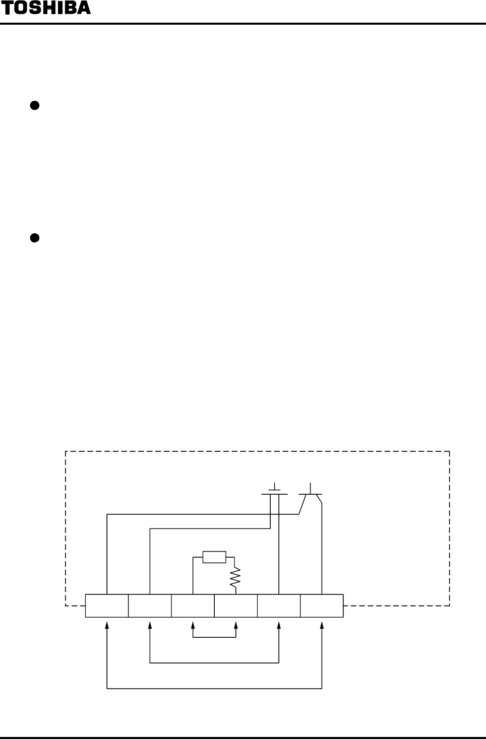
6F8A0917
-
128
-
10.1 Digital I/O Specifications
The specifications of the digital I/O terminals of the LF232 converter are as follows:
Digital Outputs:
(DO1) Output type Transistor open collector (standard)
Number of outputs 1
Capacity 30 VDC, 200 mA maximum
(DO2 to DO4) Output type Solid-state contact output (non polarity) (option)
Number of outputs 3
Capacity 150 VDC, 150 mA maximum
150 VAC (peal value), 100 mA maximum
Digital Input (option):
(DI1, DI2) Signal type Voltage signal of 20 to 30 VDC
• High input level: 20 to 30 VDC
• Low input level: 2 VDC maximum
Input resistance Approx. 2.7 kΩ
Number of inputs 2
• Each terminal can be set to select each function.
• Terminal “CO2” is the common terminal of DO2 to DO4 and “CI” is the common terminal of DI1
and DI2.
• Each terminal is isolated from internal circuit.
(Output terminals are not isolated between them.)
• In the case of the standard specification (without digital I/O specification), a solid-state contact,
photo-coupler and resistor are not provided internally.
Contact output 2 (DO2 to DO4)
Contact output 1 (DO1)
CI DI1, DI2 DO2 to
DO4 DO1CO2CO1
Photo-coupler (option)
Resistor
(option)
Converter inside
Voltage input
Solid-state contact
(option)
Transistor open collector
(standard)
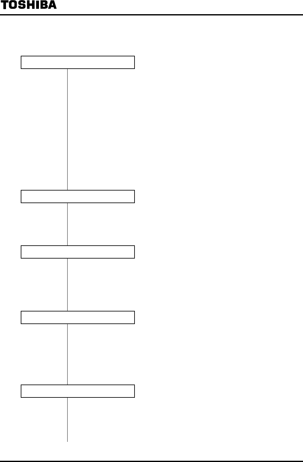
6F8A0917
-
129
-
10.2 Totalizer and Pulse Output
Proceed as follows to use the totalizer and pulse output.
Count Rate and Pulse Width Settings
Follow the procedure in 8.2.15 “Count Rate (Pulse Rate) and Pulse Width” and set
the flow rate per 1 count (1 pulse) (count rate), pulse width mode and pulse width.
* Count rate can be set within the range of 3.6 to 3,600,000 pulses/h (1/1000 to
1000 pulses/s) with respect to the set range. (Note 2)
* Pulse width will be set automatically if the pulse width mode is set to AUTO.
If you want to set the pulse width manually, the pulse width can be set between
0.3ms and 500ms. However, the pulse width must be 40% or less of the
full-scale period. (Note 3)
For pulse width, check the acceptable signal width of the receiving instruments
when you set the pulse width.
If the pulse output is not used, pulse width setting is not needed.
DO Setting
Follow the procedure in 8.2.14 “Digital I/O Function” and set the Digital Output 1
(DO1) or Digital Output 2 (DO2) for pulse output.
If the pulse output is not used, DO setting is not needed.
DI Setting
Follow the procedure in 8.2.14 “Digital I/O Function” and set the Digital Input
(DI) function.
In the case of the converter without Digital Input (9th digit of the product code is
“1”), set “NO USE” (factory setting).
Indicating Unit Setting
Follow the procedure in 8.2.6 “Normal Indicating Unit” and set a totalization unit
(m3, l, ml, gal, bbl, pt, qt or COUNT) for indicating unit.
If only the pulse output is used, pulse output can be sent out without setting an
indicating unit but it is recommended that you set a totalization unit as indicating
unit to check the operating condition.
Switching to the Measurement Mode
Follow the procedure in 7.3.1 “Mode Switching” and put the mode back to the
measurement mode.
* To be continued to the next page.

6F8A0917
-
130
-
* Continued from the previous page
Clear (reset) the totalizer. (Note1)
Press switch to clear the count.
If you have changed the count rate, clear (reset) the count before you start the
totalizer.
Start the totalizer. (Note1)
• Press to start the totalizer.
Check that “C” is shown on the display indicating that counting is in progress.
Note 1: The LF232 converter has the function to start/stop the totalizing operation or clear the
internal totalizer.
For details of how to operate the totalizer, see 7.3.4 “Totalizer Operation.”
Note 2: Example of count rate setting range
Count rate can be set in the range of minimum value (3,600,000 pulses/h) to maximum
value (3.6 pulses/h) with respect to the set range
Example: When the range is 3,600m3/h (1m3/s), settable count rate is as
follows:
Minimum value: 3,600m3/h ÷ 3,600,000 pulses/h = 0.001m3 = 1 l (liter)
Maximum value: 3,600m3/h ÷ 3.6 pulses/h = 1,000m3
Note 3: Example of pulse width setting range (in the case of manual setting)
Pulse width can be set within the range of 0.3ms to 500ms in increments of 0.1ms.
However, the pulse width must be 40% or less of the full-scale period.
Example 1: In the case of the following:
Range: 3600m3/h (1m3/s)
Count rate: 0.001m3
Since the count rate is 3,600 m3/h ÷ 0.001(m3) = 3,600,000 pulses
/
h (1000
pulse/s), the full scale period is 1s ÷ 1000 = 1ms.
Therefore, pulse width can only be set to 1ms x 0.4 = 0.4ms.
Example 2: In the case of the following
Range: 3,600m3/h (1m3/s)
Count rate: 1000m3
Since the count rate is 3,600m3/h ÷ 1000m3 = 3.6 pulses/h (0.001 pulse/s),
the full scale period is 1s ÷ 0.001 = 1000s.
Therefore, pulse width becomes 1000s × 0.4 = 400s.
However, since the maximum value is 500ms, pulse width becomes 500ms.
Example 3: In the case of the following
Range: 3,600m3/h (1m3/s)
Count rate: 1m3
Pulse width is set to 0ms
Since the count rate is 3,600m3/h ÷ 1m3 = 3600 pulses/h (1 pulse/s), the
full scale period is 1s ÷ 1 = 1s.
Therefore, pulse width becomes 1s × 0.4 = 400ms.
However, since the maximum value is 100ms, pulse width becomes 100ms.
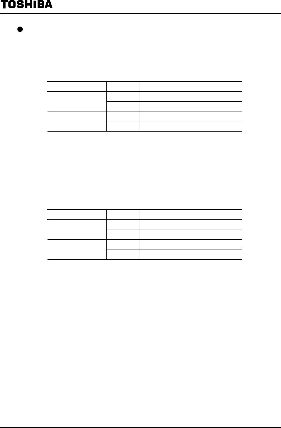
6F8A0917
-
131
-
Totalizer operation using digital input signals
Totalizer and pulse output can be operated.
Remote operations of the totalizer and pulse output can be performed using the Digital Input signals.
Follow the procedure in 8.2.14 “Digital I/O Function” and set the Digital Input (DI) functions.
Operation using Digital Input signals (Standard product, Control signal level: High level)
Digital Input function DI input Totalizer, pulse output operation
Low level Stops Totalizer Start/Stop
High level Outputs
High level Clears (resets) the totalizer and stops Totalizer Reset/Start
Low level Outputs
It is possible to reverse the DI control signal levels by setting the digital input control signal levels.
• When high level (1:H LEVEL) is selected: The operation with the signal level is the same as the
standard product shown in the above table.
• When low level (0:L LEVEL) is selected: The operation with the signal level becomes as shown
below.
Operation using Digital Input signals (Control signal level: Low level)
Digital input function DI input Totalizer and pulse output operation
Low level Outputs Totalizer Start/stop
High level Stops
High level Outputs Totalizer Reset/Start
Low level Clears (resets) the totalizer and stops.
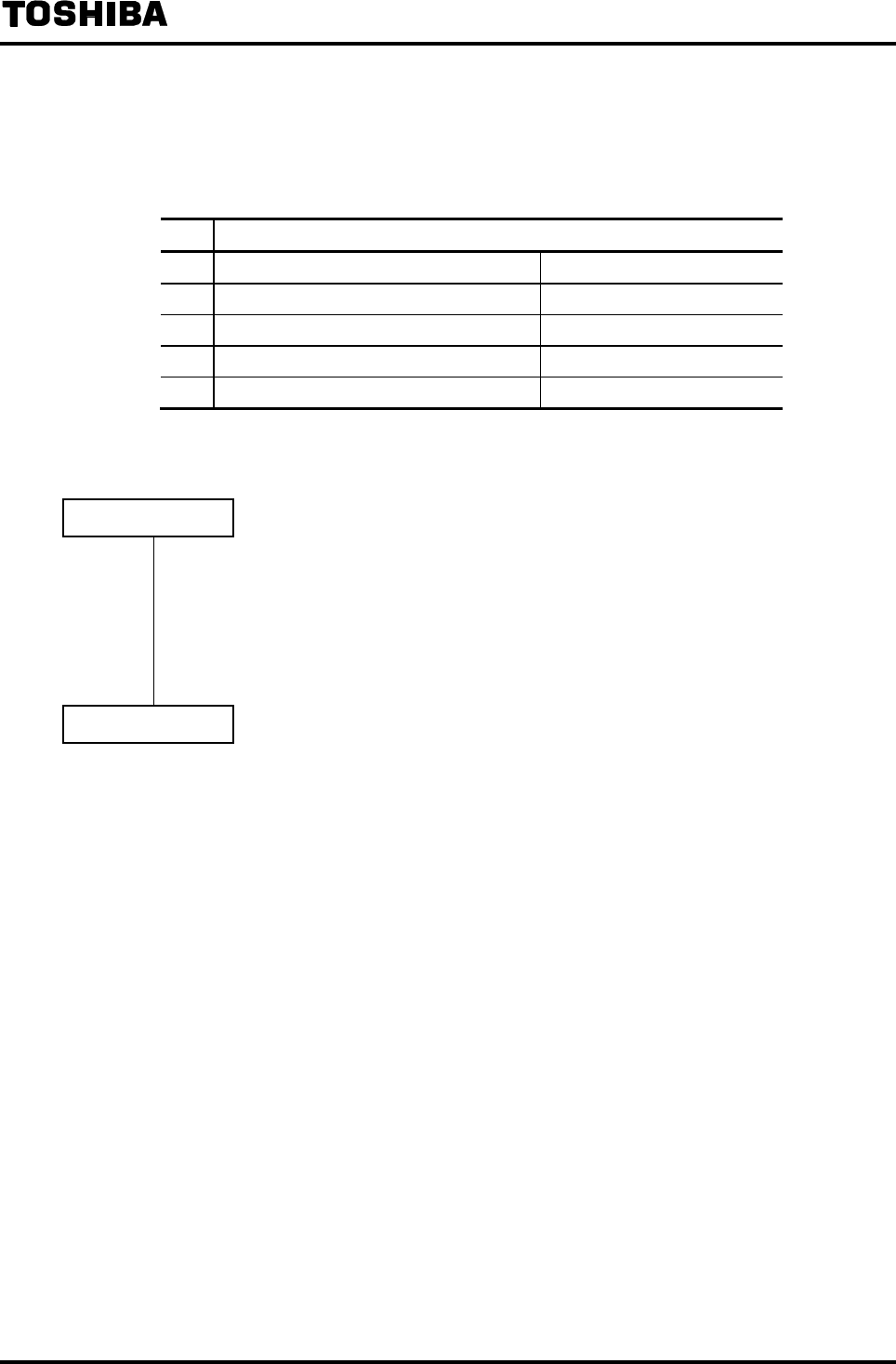
6F8A0917
-
132
-
10.3 Multi-Range Functions
Five types of multi-range functions can be set using the Range Type:
Range Typ
(1) Single direction, 4 ranges Internal automatic switching
(2) Forward and reverse directions, 2 ranges Internal automatic switching
(3) Single direction, 2 ranges External signal switching
(4) Forward and reverse directions, 2 ranges External signal switching
(5) Single direction, 4 ranges E xternal signal switching
To use the multi-range function, proceed as follows to set.
Range Setting
• Follow the procedure in 8.2.8 “Span Value (Range)” and set the range in the following
order.
1. Select the Range Type.
2. Set the span for Ranges 1 to 4.
3. Set the hysteresis value.
DO/DI Setting
• Follow the procedure in 8.2.14 “Digital I/O Function” and set the DO for Range output.
• When using the multi-range switching with external signals, set the DO for external
range switching signals.
• Requirements to combine the range signals (No.1 and No.2) to set the DO and DI differ
depending on the Range Type. For details, see the explanations (1) to (5) on the
following pages.
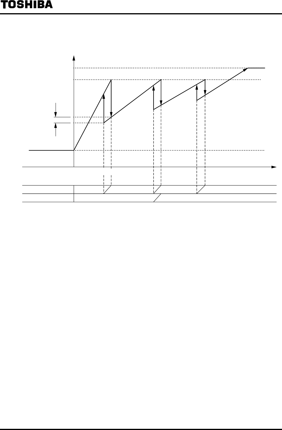
6F8A0917
-
133
-
Output performance when multiple ranges are used
(1) Single direction (internal automatic switching), 4 ranges
20mA
4mA
0
0
100
125
Output (%)
Range output No. 1
Range output No. 2
ON OFF ON OFF
ON OFF
Range 4 Range 3 Range 2
Range 1
Hysteresis
(0 to 25%)
Reverse direction Forward direction Flow rate
• Current output is 4mA as standard when fluid flows in reverse direction.
When the low cutoff function is not used (low cutoff setting is 0), it is possible to output the
current output signal in linear scale up to 3.2mA or 2.4mA when fluid flows in reverse direction.
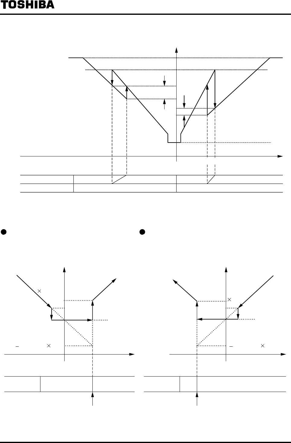
6F8A0917
-
134
-
(2) Forward and reverse directions (internal automatic switching), 2 ranges
Output when switched from Reverse to
Forward direction
Output when switched from Forward to Reverse
direction
OFFON
Range output
No. 2
Reverse direction Flow rate
4mA
0
0
Output
Forward
direction
Low cutoff
1.25
Low
cutoff
From reverse direction range to
forward direction range
(Low cutoff 1.25)
4mA
0
OFFON
0
Range output
No. 2
Reverse
direction
Forward
direction
Flow rate
Output
Low cutoff
1.25
Low cutoff
From forward direction range to
reverse direction range
(Low cutoff 1.25)
20m
A
4m
A
0
100
125
0
Output (%)
Range 4
Range 3
Range 2
Range 1
Range output No. 1
Range output No. 2
OFF ON ON OFF
ON OFF
Reverse direction Flow rate
Forward direction
Hysteresis
Hysteresis
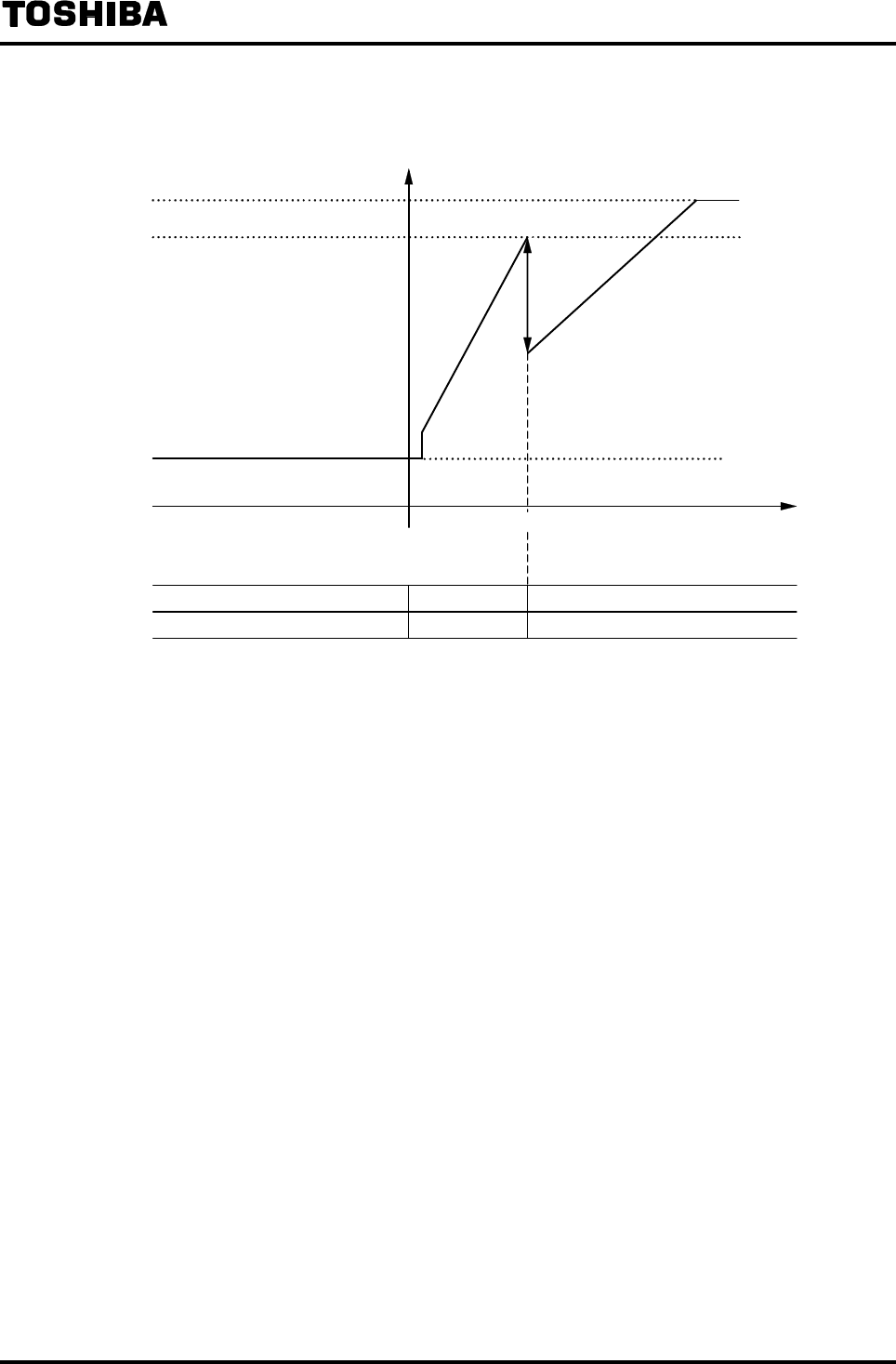
6F8A0917
-
135
-
(3) Single direction (external signal switching), 2 ranges
0
125
100
4mA
0
Output (%)
Range 2 Range 1
ON OFF
Reverse direction Flow rate
Forward direction
(Range output No. 1)
H level inputExternal range switching signal L level input
• Current output is 4mA as standard when fluid flows in reverse direction.
When the low cutoff function is not used (low cutoff setting is 0), it is possible to output the
current output signal in linear scale up to 3.2mA or 2.4mA when fluid flows in reverse direction.
• Works even if the range output is not used.
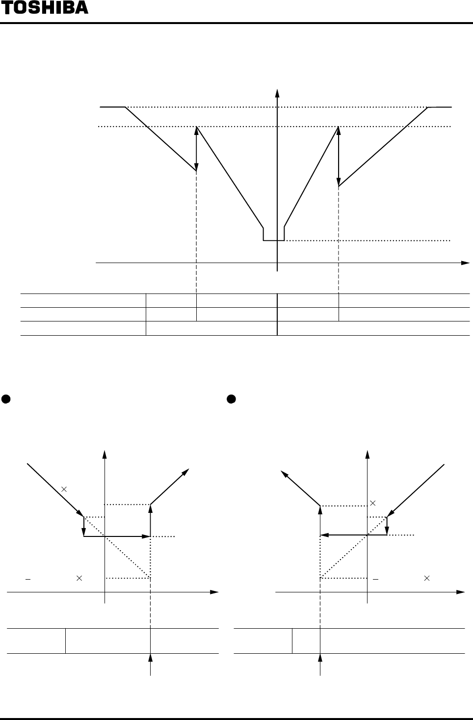
6F8A0917
-
136
-
(4) Forward and reverse directions (external signal switching), 2 ranges
4mA
0
100
125
0
Output (%)
Range 2 Range 1
Reverse direction Flow rate
Forward direction
Range 3 Range 4
ON OFF(Range output No. 1)
H level inputExternal range switching signal L level input
(Range output No. 2)
H level inputL level input
ON OFF
ONOFF
• Works even if the range output is not used.
Output when switched from Reverse to
Forward direction
Output when switched from Forward to Reverse
direction
OFFON
Range output
No. 2
Reverse direction Flow rate
4mA
0
0
Output
Forward
direction
Low cutoff
1.25
Low
cutoff
From reverse direction range to
forward direction range
(Low cutoff 1.25)
4mA
0
OFFON
0
Range output
No. 2
Reverse
direction
Forward
direction
Flow rate
Output
Low cutoff
1.25
Low cutoff
From forward direction range to
reverse direction range
(Low cutoff 1.25)
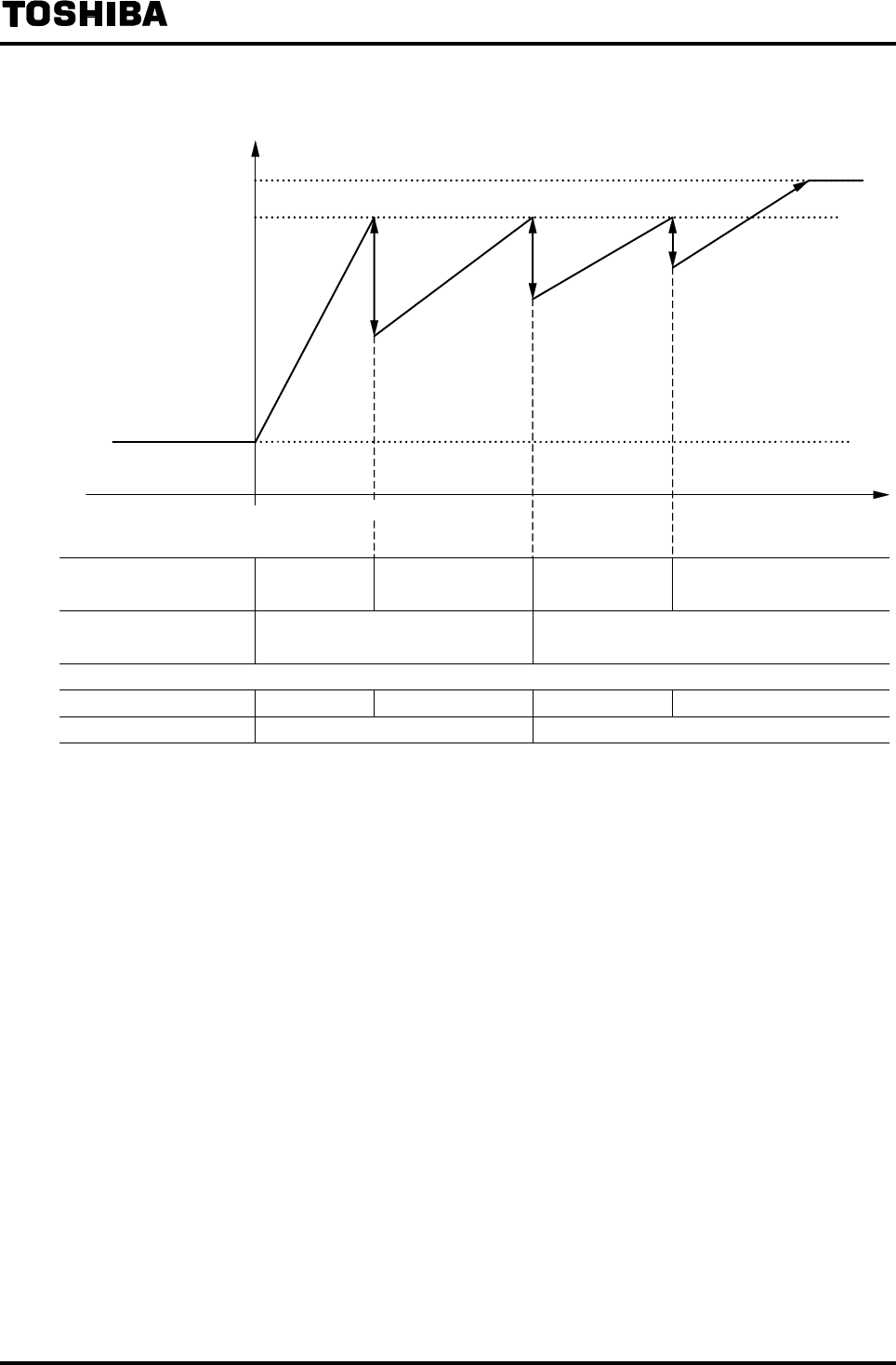
6F8A0917
-
137
-
(5) Single direction (external signal switching), 4 ranges
20mA
4mA
0
0
100
125
Output (%)
Range 4 Range 3 Range 2
Range 1
Reverse direction Forward direction Flow rate
External range switching
signal No. 1
External range switching
signal No. 2
L level input H level input
H level input
H level input L level input
L level input
(Range output No. 1)
(Range output No. 2)
ONOFF
ON
ON OFF
OFF
• Current output is 4mA as standard when fluid flows in reverse direction.
When the low cutoff function is not used (low cutoff setting is 0), it is possible to output the
current output signal in linear scale up to 3.2mA or 2.4mA when fluid flows in reverse direction.
• Works even if the range output is not used.
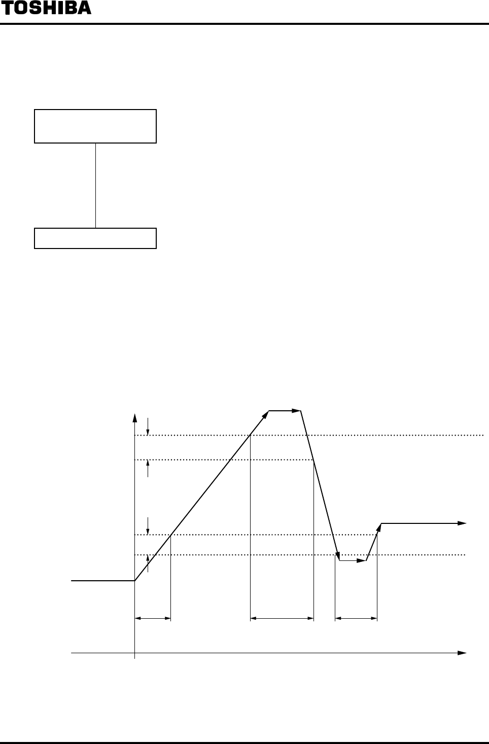
6F8A0917
-
138
-
10.4 Flow Rate High/Low Limit Alarm Output
Proceed as follows to use the flow rate high/low limit alarm.
High/Low Limit Alarm
Value Setting
• Follow the procedure in 8.2.17 “Flow Rate High/Low alarm” and set the high limit
alarm, high-high limit alarm, low limit alarm or low-low limit alarm to ON and set
the alarm value.
For the alarm not used, set OFF to that alarm setting.
DO Setting
• Follow the procedure in 8.2.14 “Digital I/O Function” and set the Digital Output
(DO) for high limit output, high-high limit alarm output, low limit alarm output or
low-low limit alarm output. In addition, for alarm output state, select Normally Open
or Normally Closed.
Flow rate high/low limit alarm output performance
• In the case of Single range
Output (%)
High limit set-point value
Hysteresis
2.5%
Low limit set-point value
Low limit alarm
generated
High limit alarm
generated
Low limit alarm
generated
Time
* The output state when an alarm occurs becomes the state set for alarm output of digital output.
When the power supply of the converter is turned off, the contact is open.

6F8A0917
-
139
-
• In the case of Multi-range setting
Output (%)
High limit set-
pout value
Low limit set-
point value
Range 2 Range 1 Range 2
Hysteresis
2.5%
Hysteresis
2.5%
Hysteresis
2.5%
Low limit alarm
generated
High limit alarm
generated Low limit alarm
generated
Time
* High/low limit alarm set-point value is a value indicated in percent of the Range 1.
* The output state when an alarm occurs becomes the state set for alarm output of digital output.
When the power supply of the converter is turned off, the contact is open.
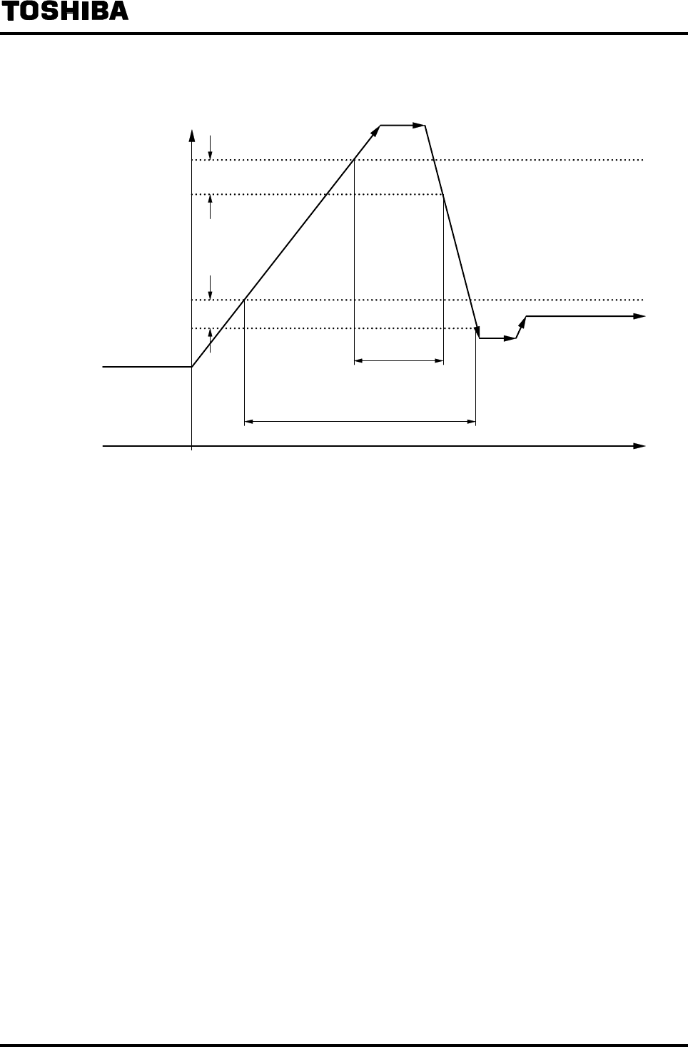
6F8A0917
-
140
-
• In the case of 2 high limit alarm points (high limit and high-high limit)
Output (%)
High-high limit set-
point
High limit set-point
Hysteresis
2.5%
High limit alarm generated
High-high limit alarm generated
Time
* The output state when an alarm occurs becomes the state set for alarm output of digital output.
When the power supply of the converter is turned off, the contact is open.

6F8A0917
-
141
-
10.5 Fluid Empty Alarm Output
Proceed as follows to use the fluid empty alarm.
(Note: In the case of LF232*F; Fluid empty alarm function is not usable. Set this function 'OFF'.)
Alarm Output Setting
• Follow the procedure in 8.2.18 “Fluid Empty Alarm” and set the fluid alarm setting
to ON (NORMAL, SENTITIVE or SENSITIVE-H).
DO Setting
• Follow the procedure in 8.2.14 “Digital I/O Function” and set the Digital Output
(DO) for fluid empty alarm output.
In addition, for alarm output state, select Normally Open or Normally Closed.
If only the fluid empty detection function is used and external contact output is not
used, DO setting is not needed.
Output when an alarm is generated
• 4 to 20mA output: 4mA (standard)
* Current output value when an alarm is generated can be set by
referring to 8.2.11 “Current Output Setting Used When an Alarm
Occurs.”
• Totalizer, pulse output: Totalizing operation and pulse output stopped
• Measured value display: Instantaneous flow rate is zero.
• Contact output: When an alarm occurs, output contact closes (standard).
* Contact operation when an alarm occurs can be set according to the
alarm output state described in 8.2.14 “Digital I/O Function”
Note: When the power supply of the converter is turned off, the contact is open.
* For how to use the fluid empty alarm, see Precautionary notes in 12. “Diagnosis and Alarms.”
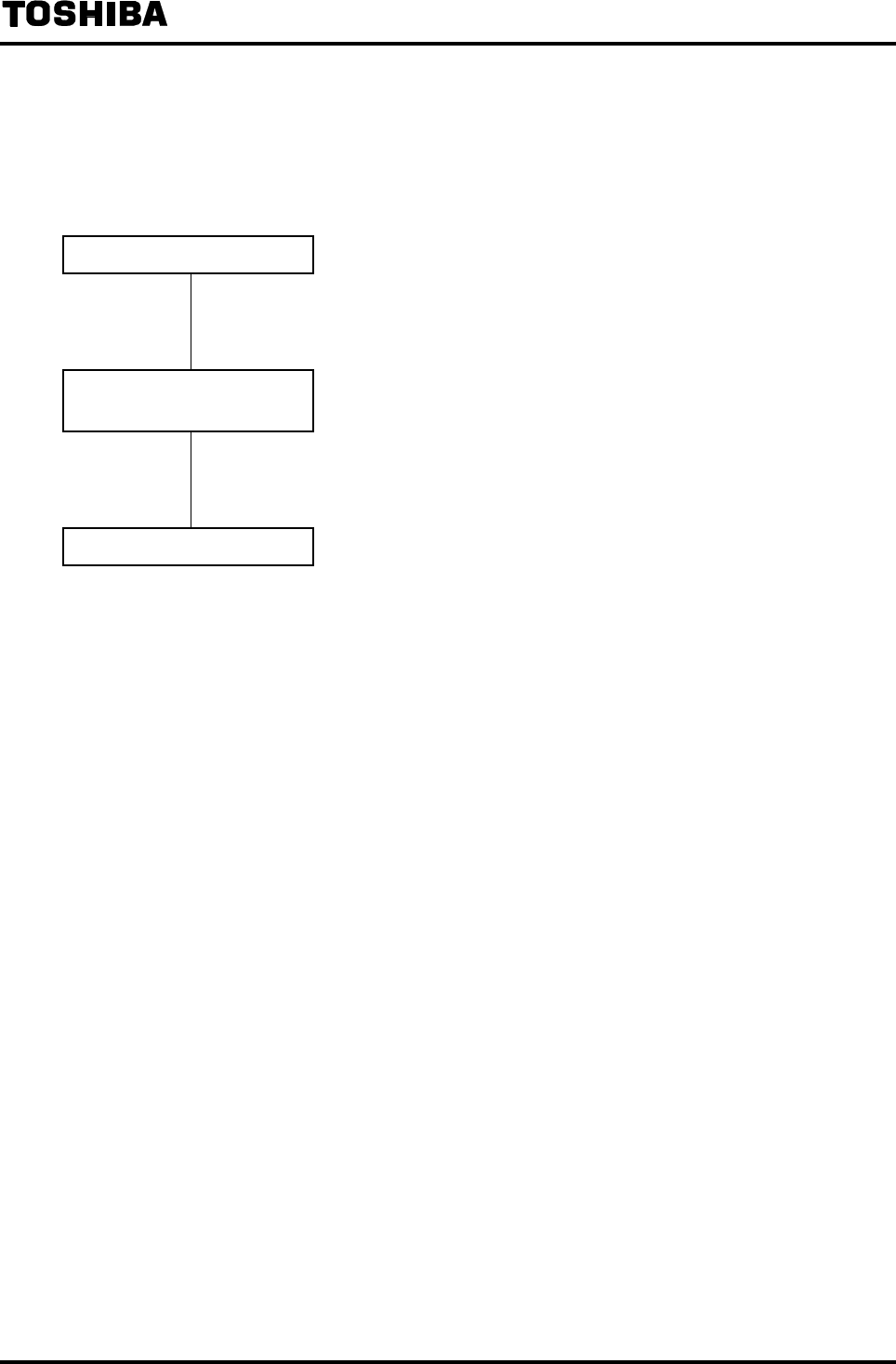
6F8A0917
-
142
-
10.6 Preset Counter Output Function
A contact signal is output when the totalized flow count exceeds the preset value (preset count value).
Proceed as follows to use the preset counter output.
Totalizer Setting
• Follows the procedure in 10.2 “Totalizer and Pulse Output” and set necessary
items to the totalizer.
Preset Count Value, Preset
Output Function Setting
• Follow the procedure in 8.2.16 “Preset Counter” and set the preset count value and
output function.
DO/DI Setting
• Follow the procedure in 8.2.14 “Digital I/O Function” and set the digital output
(DO) for use as a preset counter output.
In addition, if you want to reset the totalizer by an external signal, set the DI for
the totalizer counter Reset/Start signal. (Set F3: DI FUNCTN to 2: C RES/STA.)
* Operation for the totalizer control signal can be set using the control signal level
setting described in 8.2.14 “Digital I/O Function.”
When the operation switch in the converter is used to reset the counter, the digital
input function (DI) setting is not needed.
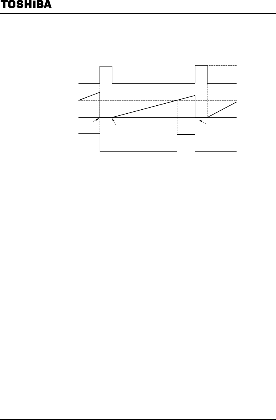
6F8A0917
-
143
-
Preset counter output performance
• Example to reset the totalizer using an external signal input
(When preset output level hold (Contact ON) is set)
ON
OFF
0
Reset/Start signal
(DI control signal level H)
Totalizer flow count
Preset output
Counter reset Counter start
H level input
L level input
Preset count
set-point value
Counter reset
Input/Output Timing Chart
* When the Reset/Start signal is in H level (DI counter control signal level: H), the totalizer is reset to
zero and stops counting. When the Reset/Start signal goes to L level, the totalizer starts counting.
The preset output goes ON when the totalizer count exceeds the preset value, and the output goes
OFF when the totalizer is reset to zero.

6F8A0917
-
144
-
• Example to reset the totalizer using an external signal input (When one-shot pulse output is set)
ON
OFF
0
Reset/Start signal
(DI control signal level L)
Totalizer flow count
Preset output
Counter reset Counter start
H level input
L level input
Preset count
set-point
Counter reset
Preset output is OFF
because Counter is reset.
Preset output OFF because
pulse width is reached.
Input/Output Timing Chart
* When the Reset/Start signal is in L level (DI counter control signal level: L), the totalizer is reset to
zero and stops counting. When the Reset/Start signal goes to H level, the totalizer starts counting.
The preset output goes ON when the totalizer count exceeds the preset value, and the output goes
OFF when the pulse width is reached or the totalizer is reset to zero.
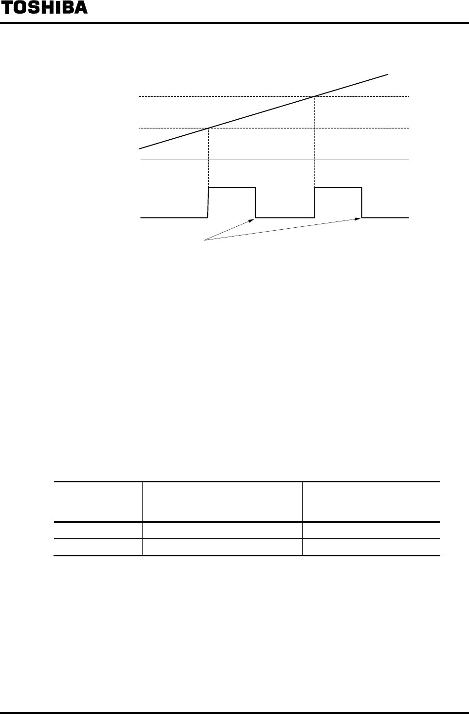
6F8A0917
-
145
-
• Output example of one-shot pulse output
ON
OFF
0
100
200
Preset count set-point value: 100
Totalizer count
Preset output
Preset output OFF because
pulse width is reached.
Input/Output Timing Chart
* Preset output goes ON when the count value exceeds the preset value of 100 and the preset output
goes OFF when its width reaches the set pulse width.
When the preset value exceeds 100, the preset value is changed to 200 (adding the preset count of
100 to the current preset value of 100).
Then, the preset output goes ON when the count value exceeds the preset value of 200, and the
preset output goes OFF when its width reaches the set pulse width.
When the preset value exceeds 200, the preset value is changed to 300 (adding the preset count of
100 to the current preset value of 200).
Note: When the one-shot pulse output function is selected, if its pulse width is large compared
with the update interval of the preset value, the output stays ON. To make sure to output
a one-shot pulse, set the preset value so that
the conditions in the table below are
satisfied.
Pulse width setting Preset count value condition
Interval that the preset value reaches
Example: Count rate: 0.01 l
Flow verosity: 10 l/s
Count-up rate:1ms/COUNT
50ms 100ms or more Preset count value: 100 or more
500ms 1000ms or more Preset count value: 1000 or more

6F8A0917
-
146
-
10.7 Remote Still Water Zero Adjustment
Still water zero adjustment can be performed using an external signal.
To use this function, follow the procedure in 8.2.14, “Digital I/O Function” and set the DI as a zero
adjustment start signal.
[Signal input condition]
Zero adjustment signal
10 seconds
20 seconds
Zero
adjustment
start
H level signal
L level signal
* The signal must be set to H level first and then it must go to L level 10 seconds later but not more
than 20 seconds, and then zero adjustment starts at the falling edge of the signal.
If the signal stays in H level less than 10 seconds or more than 20 seconds, the signal will be
ignored.
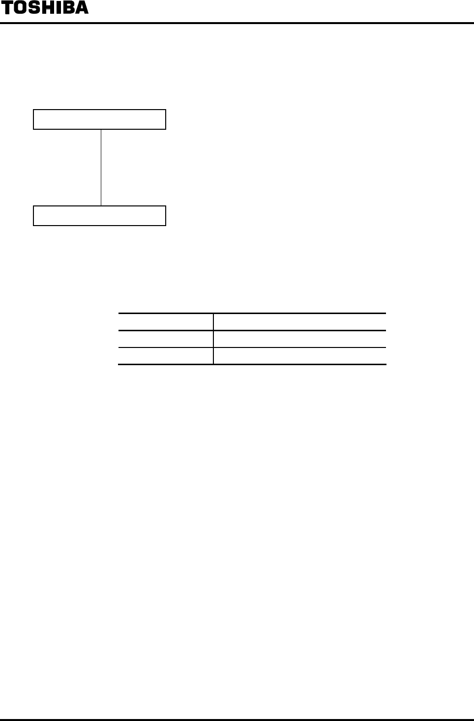
6F8A0917
-
147
-
10.8 Remote Selection of Fixed Value Output
4 to 20mA output and pulse output can be set to a fixed preset value using a remote signal input.
Proceed as follows to use this function.
Fixed Output Value Setting
• Follow the procedure in 8.4 “Fixed Value Output (Loop Check)” and set the
current output value and pulse output value to be used at the time of fixed output.
Set OFF for fixed output switching.
If the pulse output is not used, it is not necessary to set the pulse output value.
DI Setting
• Follow the procedure in 8.2.14 “Digital I/O Function” to set the Digital Input (DI)
to use it as fixed output mode control signal.
Signal input condition
External signal input 4 to 20mA and pulse output
L level input Measured value is output.
H level input Fixed preset value is output.
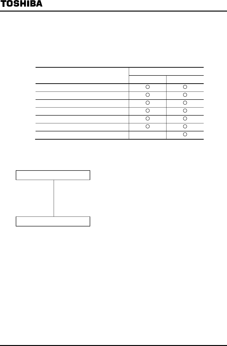
6F8A0917
-
148
-
10.9 Converter Error Alarm Output
If one or more of the following errors occur in a self-diagnosis sequence, an alarm signal will be
output using contact signals.
List of Alarm Output Factors
Diagnosis error alarm output (DO)
Diagnosis error item
WITHOUT EMP WITH EMP
RAM error
ROM error
Exciting current value error
Exciting current wire broken
ADC error (error of flow measurement circuit)
Parameter error
Fluid empty alarm
−
○: If an error is detected, DO diagnosis error alarm is output.
−
: Even if an error is detected, DO diagnosis error alarm will not be output.
(Alarm message is displayed)
Self-Diagnosis Function Setting
• Follow the procedure in 8.2.19 “Self-Diagnosis Function” and set whether the
self-diagnosis function is On or Off and set the alarm output factors.
For alarm output factors, set whether the fluid empty alarm should be included
(WITH EMP) or not included (WITHOUT EMP) for alarm output.
DO Setting
To use the converter error alarm output, follow the procedure in 8.2.14 “Digital
I/O Function” and set the Digital Output (DO) for converter error alarm output.
In addition, for alarm output state, select Normally Open or Normally Closed.
If the self-diagnosis function only is used and external contact output is not used,
DO setting is not needed.
• Contact output operation
NORMAL OPEN : If an error occurs, contact closes
NORMAL CLOSE : If an error occurs, contact opens
Note: When power supply is turned off, the contact is OFF (contact opens).
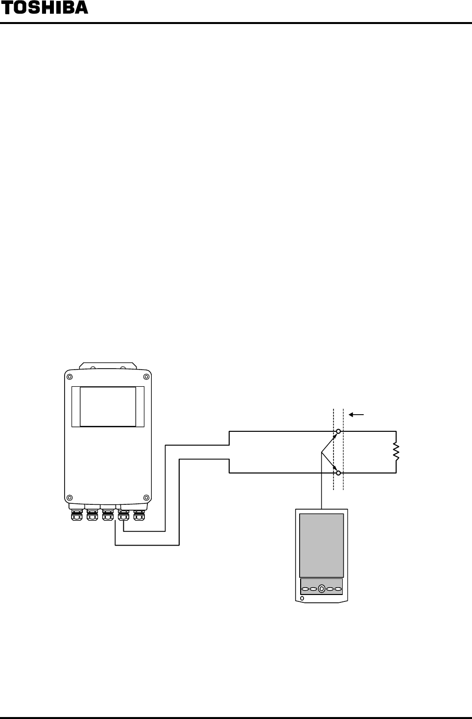
6F8A0917
-
149
-
11. Communications Function
The LF232 Series Converters are equipped with HART*1 protocol to transmit digital signals over the 4
to 20mA output line. The AF900 hand-held terminal (hereafter called HHT) can be used to check or
change various parameters, calibrate the flowmeter or monitor the measured value from a remote
place.
For the detailed operation and specification of HHT, refer to the "Hand-held Terminal for Sensor with
Communication Function AF900 Instruction Manual" (6F8A0849).
*1 HART protocol: The “HART protocol”, which stands for Highway Addressable Remote
Transducer, is the name of the communication protocol for industry sensors that is
recommended by HCF (HART Communication Foundation).
11.1 Connection with the HHT terminal
Connect the probe cable of the HHT terminal in parallel with the load resistor which is wired from the
current output terminals (+ and −) of the flowmeter. Since the tip end of the probe cable is a pair of
clips, use a junction terminal or a terminal block, etc. to connect with the clips of the probe. To
connect the HHT directly to the flowmeter, use the terminals + and − of the converter main unit
terminal block. Though the current output terminal has polarity, the HHT connection cable has no
polarity.
See Figure 11.1 and 11.2 for connection examples.
4 to 20 mADC
HHT
LF232 Converter
(Communication line)
Load resistor
Terminal block or
junction terminal
Figure 11.1 Connections to the Current Output Line
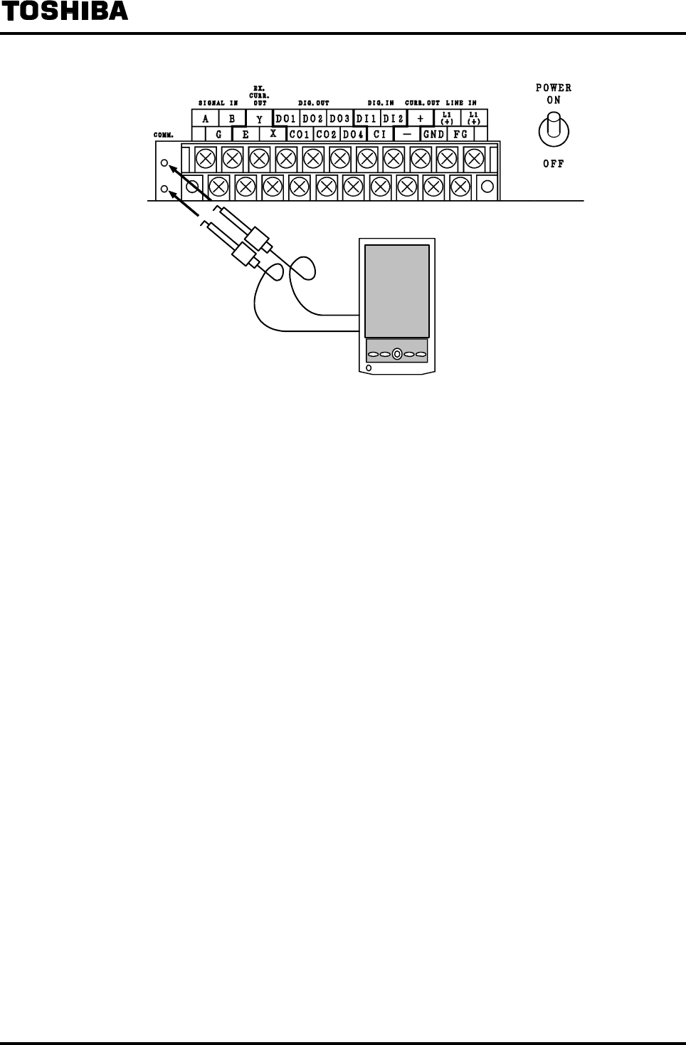
6F8A0917
-
150
-
Converter terminal block
HHT
Figure 11.2 Connection to the Converter Main Unit
6F8A0917
-
151
-
11.2 Procedure for Communication with HHT
This section describes the HHT basic operations for communication between the flowmeter and HHT.
For details, refer to the HHT instruction manual.
* Carrying out the following preparatory operations to a commercially available PDA (OS: Windows
CE), the PDA can be used as a HHT.
Procedure Operation
Prepare a hand-held terminal (1) Install the AF900 application software to a
commercially available PDA (OS: Windows CE) main
unit. Then insert the serial interface card supplied
with AF900 to the card slot of the PDA.
Prepare a hand-held terminal (2) Connect the HART interface cable and serial interface
card supplied with AF900 to each other.
Connect the HHT Connect the alligator clips at the end of the HART
interface cable to the current output line of the
converter via a load resistor.
Start the HHT Turn on the power supply of the PDA to start the
AF900 application software.
Preliminary communication Execute [sensor communication]. The model name of
the connected sensor product is automatically
identified and the converter menu screen appears.
Check or change the data Press the relevant parameter button and check or
change the desired data.
Exit the communication When all of the operations are complete, press the
[Exist Application] in the top screen to turn off the
power supply of the PDA.
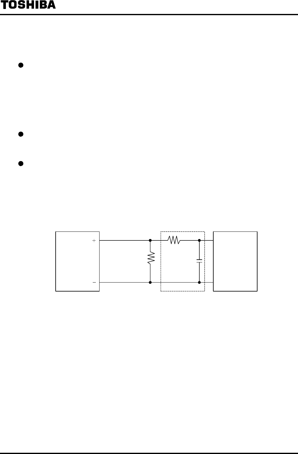
6F8A0917
-
152
-
11.3 Cautionary Notes on Communications
Observe the following limitations when you communicate with flowmeter using HHT.
Current output load
(1) Load resistance: 240Ω to 1kΩ (including communications line resistance)
(2) Load capacitance: 0.25 μF maximum (including communications line capacitance)
(3) Load inductance: 4mH maximum (including communications line inductance)
(For maximum cable length, about 2km is a guideline length when CVV-S
1.25mm2 is used.)
Wiring cable
Use a shielded cable (CVV-S, etc) for wiring.
Interference on 4 to 20mA current signal
To communicate with the flowmeter, a digital signal (amplitude 0.4 to 0.8 V in the case of 500Ω
load resistance) with a frequency of 1.2 to 2.2 kHz is superimposed on the 4 to 20mA current signal.
If a receiving instrument with fast response time is connected to the analog current output line, the
superimposed communications signal may interfere with the output. To prevent this interference,
put a low-pass filter with a time constant of about 100 ms into the input circuit of the receiving
instrument.
C
R
Current output line
Load resistor
Converter Filter Receiving instrument
Figure 11.3 Filter Connection Example
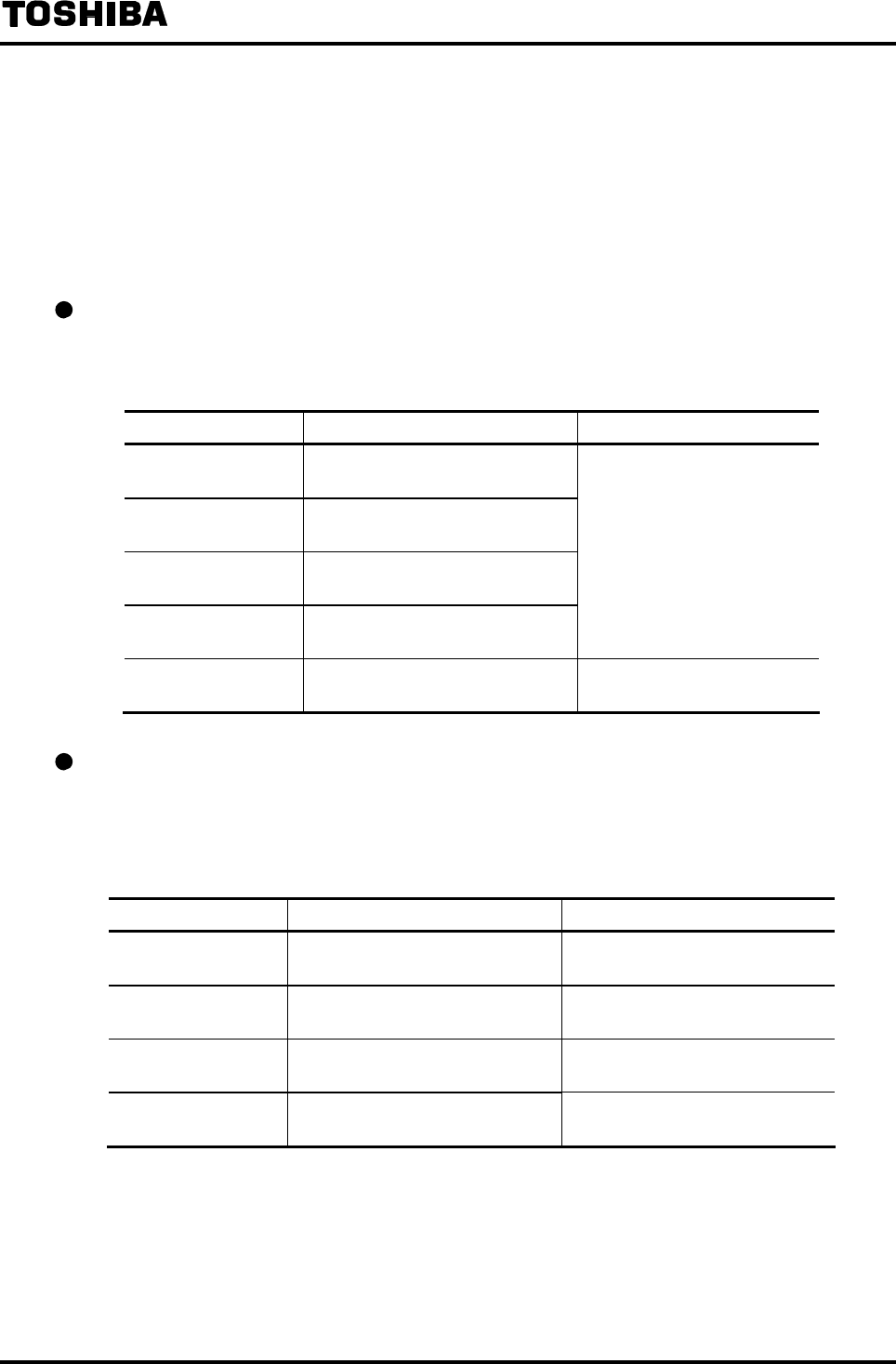
6F8A0917
-
153
-
12. Diagnosis and Alarms
12.1 Diagnostic messages
The LF232 converter is equipped with the function to diagnose such errors as setting errors, I/O errors
or internal errors of the instrument and shows the error messages on the LCD display or on the HHT
through communications. The diagnostic messages and their corrective actions are described below.
Setting error
If you try to set a constant or a unit exceeding the specified range in the setting mode, an error is
displayed to prevent erroneous setting.
LCD display Description Corrective action
* H.OVER SPEC. Setting value exceeds the settable
range.
* L.OVER SPEC. Setting value is below the settable
range.
* H.OVER C RATE Count rate exceeds the settable
range.
* L.OVER C RATE Count rate is below the settable
range.
Try to set a value within the
settable range again.
* MULTI RNG ERR Span value setting does not satisfy
the multi-range requirements.
Try to set a span value that
satisfies the requirements.
High/low limit alarm
An alarm message appears if the flow rate indication goes out of the set range.
If the alarm is set to OFF, this function does not work. For how to set this function, see 8.2
“Parameter Check/Change.”
LCD display Description Corrective action
HIGH ALARM Flow rate is above the high limit
set-point value.
Adjust so that the flow rate stays
below the set-point value.
H-HIGH ALARM Flow rate is above the high-high
limit set-point value.
Adjust so that the flow rate stays
below the set-point value.
L ALARM Flow rate is below the low limit
set-point value.
Adjust so that the flow rate stays
below the set-point value.
L-LOW ALARM Flow rate is below the low-low
limit set-point value.
Adjust so that the flow rate stays
below the set-point value.

6F8A0917
-
154
-
Process error alarm
LCD display Description Corrective action
OVER 125%
The measured value is above the
125% of the span.
The setting range for measured value
is narrow or the flow rate is
unexpectedly large. Check whether
the set value is correct or not and
check that there is no problem in the
process.
UNDER –125%
The measured value is below the
−125% of the span
The setting range of measured value
is narrow or the flow rate is
unexpectedly large. Check whether
the set value is correct or not and
check that there is no problem in the
process.
Fluid empty alarm
Detects that the fluid in the measuring pipe of the detector is empty and an alarm will be displayed.
If the alarm is set to OFF, this function does not work. For how to set this function, see 8.2
“Parameter Check/Change.”
(Note: In the case of LF232*F; Fluid empty alarm function is not usable. Set this function 'OFF'.)
LCD display Description Corrective action
EMPTY Fluid is not filled in the measuring
pipe of the detector.
Take measures to fill the pipe with
fluid.
Precautionary notes when using the fluid empty alarm
(1) Since the fluid empty alarm is detected using the impedance between the signal wires connected
to a pair of electrodes in the detector as well as the input signal level, a false alarm may be
detected by the following factors:
• Signal wire is broken or loose connection exists
• A large amount of air bubbles are mixed in the fluid
• Insulating materials are accumulated on the electrode
(2) In an environment where grounding is incomplete or excessive noise enters from the outside, the
fluid empty alarm may not work correctly.
In addition, under the condition like this, reliability of flow measurement itself decreases. Take
necessary measures to prevent the entry of noise such as making the ground complete
(independent Class D ground with grounding resistance 100Ω or less) or reviewing the cable
wiring route.
(3) If the fluid still remains in the measuring pipe or deposits of conductive materials remain in the
measuring pipe, the impedance between the signal wires does not increase and the fluid empty
alarm may not work. In this case, use other method (such as a pump stop signal or a signal from
valves) to check the fluid empty condition.
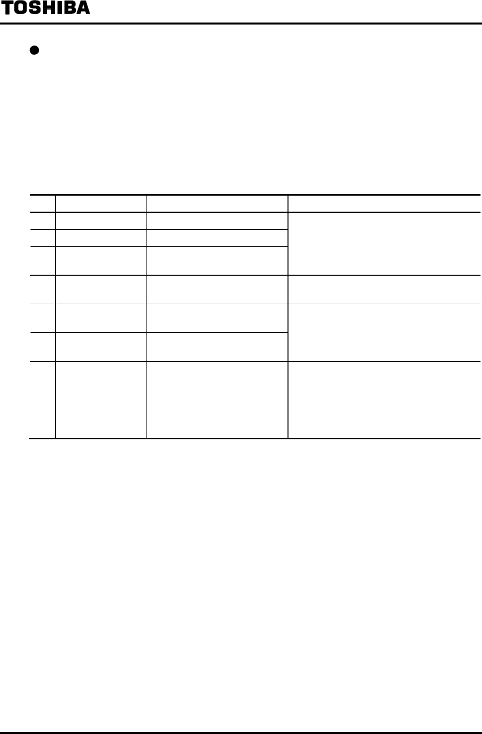
6F8A0917
-
155
-
Self-diagnosis error
The converter performs an operation check immediately after power is turned on and if an error is
found, a self-diagnosis error is generated.
If more than one error occurs at the same time, the contents of those errors will be displayed
cyclically. The diagnosis about excitation is carried out using the internal ADC function. Therefore,
if an error of No.6 internal ADC occurs, Excitation wire of No.4 and Excitation circuit of No.5
cannot be diagnosed correctly.
In addition, since the entire checking system is based on the CPU, if the CPU fails, accurate
diagnosis and indication cannot be obtained.
No. LCD display Description Corrective action
1 * ROM ERROR * ROM error occurred
2 * RAM ERROR * RAM error occurred
3 PARAMETER
FAIL
An error occurred in the internal
parameters in the memory
Internal parts or printed-circuit board must be
repaired or replaced.
Contact your nearest Toshiba representative.
4 EX. CURR. OPEN Excitation wires are not
connected.
Connect the excitation wires correctly.
5 EX. CURR. ERROR An error occurred in the
excitation circuit.
6 ADC. ERROR An error occurred in the ADC
circuit
Internal parts or printed-circuit board must be
repaired or replaced.
Contact your nearest Toshiba representative.
7 INVALID TOTAL
Totalized data in the memory
was destroyed caused by the
entry of noise.
(No message appears if the data
is not displayed in an indicating
unit of totalization.)
The error message disappears if you press the
reset key to clear the totalized data.
Note 1: Diagnosis for No. 1, No.2 and No. 3 is performed only immediately after power is turned on. If any of
these errors is indicated, the converter does not start measurement operation. If these errors occur after
power is turned on, the converter cannot detect these errors. In addition, if this happen, the indication
and output of the converter may become uncertain.
Note 2: Errors No. 4 to No. 6 may not be detected even if those errors cause accuracy problems because of the
characteristic variations in components constituting the circuits used for judgment standard to
determine these errors.
Note 3: CPU error cannot be detected. If the CPU stops, the watchdog timer resets the hardware and the
flowmeter starts again from the initial power-on condition. Depending on the condition of CPU error,
the indication and output of the converter may become uncertain.
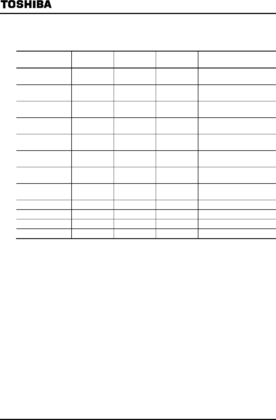
6F8A0917
-
156
-
12.2 Output When an Error or Alarm Occurs
Error indication Measured value
display
Current output
(4 to 20mA)
Totalizer pulse
output Remarks
ROM ERROR (Note 1)
−
4mA (standard)
(Note 3)
Stopped After power-up, measurement
does not start.
RAM ERROR
−
4mA (standard)
(Note 3)
Stopped After power-up, measurement
does not start.
PARAMETER FAIL
(Note 2)
Zero 4mA (standard)
(Note 3)
Stopped
−
EX.CURR OPEN Zero 4mA (standard)
(Note 3)
Stopped Still water zero adjustment
cannot be conducted.
EX.CURR ERROR Zero 4mA (standard)
(Note 3)
Stopped
−
ADC ERROR Zero 4mA (standard)
(Note 3)
Stopped
−
EMPTY Zero 4mA (standard)
(Note 3)
Stopped Still water zero adjustment
cannot be performed.
INVALID TOTAL Measured value Measured value Measured value The error message disappears if
you clear (reset) the totalizer.
HIGH ALARM Measured value Measured value Measured value
−
H-HIGH ALARM Measured value Measured value Measured value
−
L ALARM Measured value Measured value Measured value
−
L-LOW ALARM Measured value Measured value Measured value
−
Note 1: The display and output may be uncertain depending on the nature of the ROM error.
Note 2: If a parameter failure relating to the current output occurs, the current output may not become exactly
the set value of the current output used when an alarm occurs.
Note 3: The output becomes the value selected in 8.2.11 “Current Output Setting Used When an Alarm
Occurs.”
Note 4: If the fluid empty alarm not included (WITHOUT EMP) is selected (standard) in the setting for alarm
output factors in 8.2.19 “Self-Diagnosis Function,” the output becomes 4mA and if the fluid alarm
included (WITH EMP) is selected, the output becomes the same as the above in Note 3.
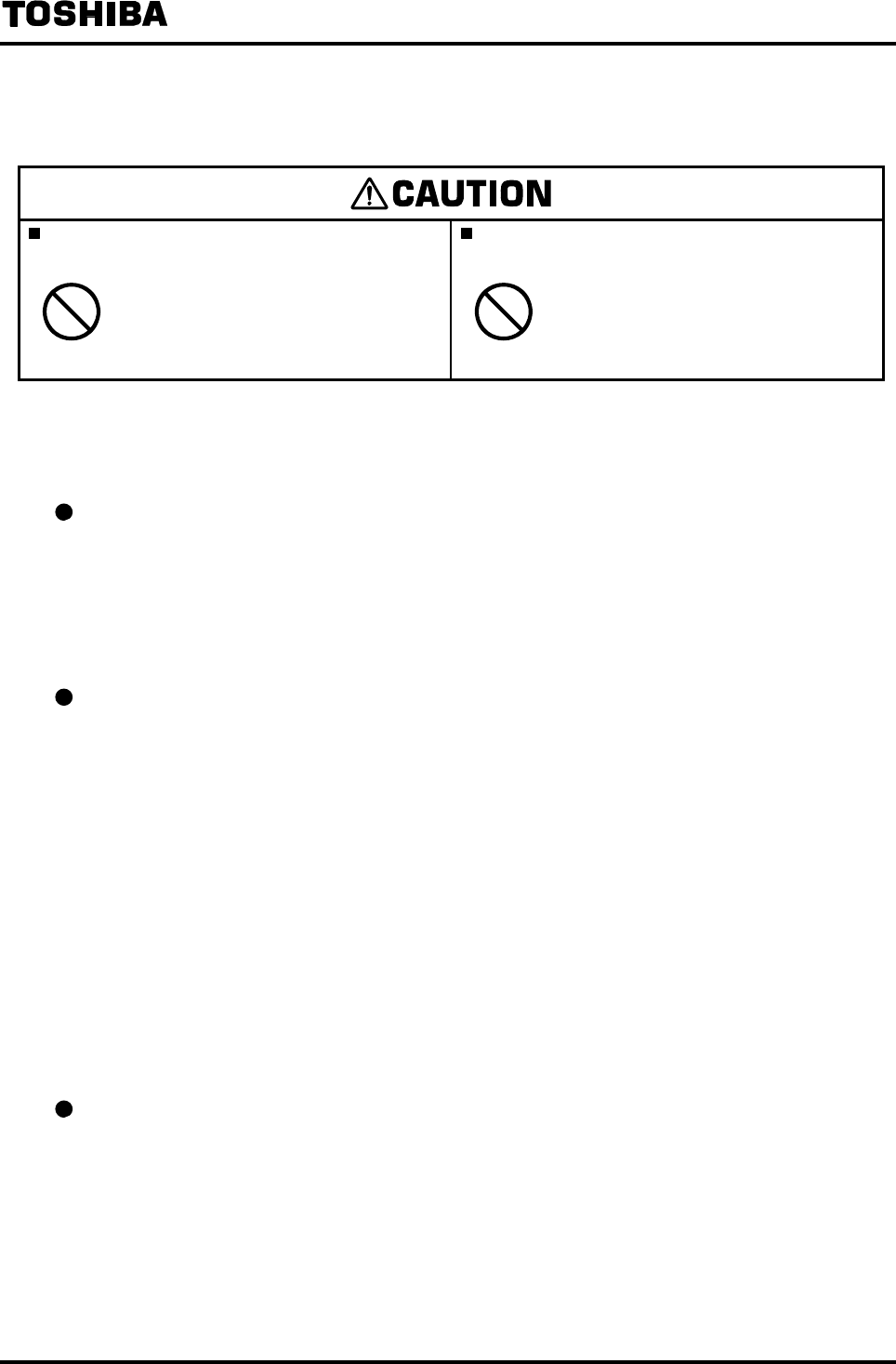
6F8A0917
-
157
-
13. Maintenance and Inspection
Do not conduct wiring work when power is
applied.
Do not touch the LF232 main body when high
temperature fluid is being measured.
DON’T
Wiring while power is applied can
cause electric shock.
DON’T
The fluid raises the main body
temperature and can cause burns
when touched.
13.1 Maintenance
Mag-Prover Calibration / Check
The LF232 converter has a built-in reference signal calibration and verification circuit that allows
you to re-verify the original flowmeter flow lab calibration without the need for external devices.
This reference signal can be used to check and adjust the circuit to perform zero and span
calibration of the converter itself and for the purpose of maintenance and periodical inspection. See
9. “Mag-Prover Calibration.”
Check / Replacement of fuse
Fuse can be taken out by turning the top of the fuse holder counterclockwise. Check that the fuse is
not damaged. In addition, fuse has its own life and it must to be replaced periodically.
(Recommended replacement cycle is about 3 years.)
Type of fuse used: Glass tube fuse (normal blow type)
Rating: In the case of power supply 100 to 240 VAC and 110VDC
1A, 250V 2 pieces
In the case of power supply 24VDC and 100 to 120 VAC for large meter size
detector
2A, 250V 2 pieces
In the case of power supply 24VDC for large meter size detector and 24VDC
for partially filled pipes detector
3A, 250V 2 pieces
Dimensions: Diameter 5.2 mm × 20 mm
Check / Replacement of display unit
If the characters displayed on the LCD become thin or blots come out, the life of the LCD is
reached. Replace the display unit with a new one. In order to use the display unit stably for a long
time, it is preferable to replace it early. For inspection and replacement, please contact your nearest
Toshiba representative.

6F8A0917
-
158
-
Check / Replacement of power supply unit
In general, electronic components deteriorate faster if the ambient temperature is high. The life of
the power supply unit is about 10 years if the ambient temperature is 40°C, and 5 to 6 years if the
temperature is 50°C or more. To extend the life of the flowmeter, it is recommended that you
replace the power supply unit early.
Contact your nearest Toshiba representative for a flowmeter inspection or unit replacement.
Product disposal
The main body or parts of the converter must be disposed of, according to the rules and regulations
of your local government.
Especially if you dispose of electrolytic capacitors to replace parts, have it done by an agency
which is licensed to handle industry waste materials.
Operative life
The operative life of this flowmeter is 10 years from the date of shipment.
The life of the flowmeter differs depending on the environmental conditions and the way it was
used. To extend the life of the flowmeter, inspect the flowmeter periodically and clean or replace
components if necessary.
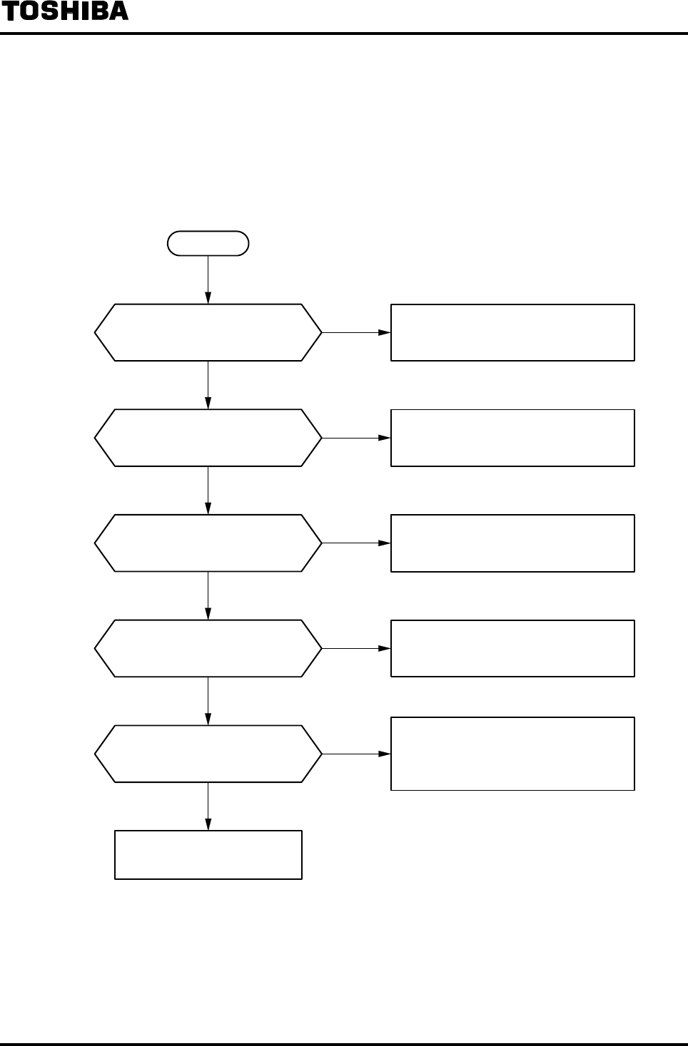
6F8A0917
-
159
-
13.2 Troubleshooting
If a problem occurs, you may find a cause of the problem by performing the simple inspection.
Before you call repair service personnel, inspect the flowmeter using the flowcharts shown below.
13.2.1 Flow rate is not indicated
Install the cables correctly according to
5. “Wiring.”
Replace the fuse with a new one.
NO Set the velocity range correctly
according to 8. “Parameter Settings.”
YES
Does the flow direction agree
with the arrow mark on the
detector?
NO
Install the detector correctly according to
4. “Installation.” In addition, set the
direction of flow correctly according to 8.
“Parameter Settings.”
Contact your nearest Toshiba
representative.
Is the velocity range set
correctly?
Isn't the fuse blown?
Are cables installed correctly?
NO
YES
YES
YES
NO
START
Use the rated power supply for each
device.
Is the rated power supplied for
each device?
YES
NO
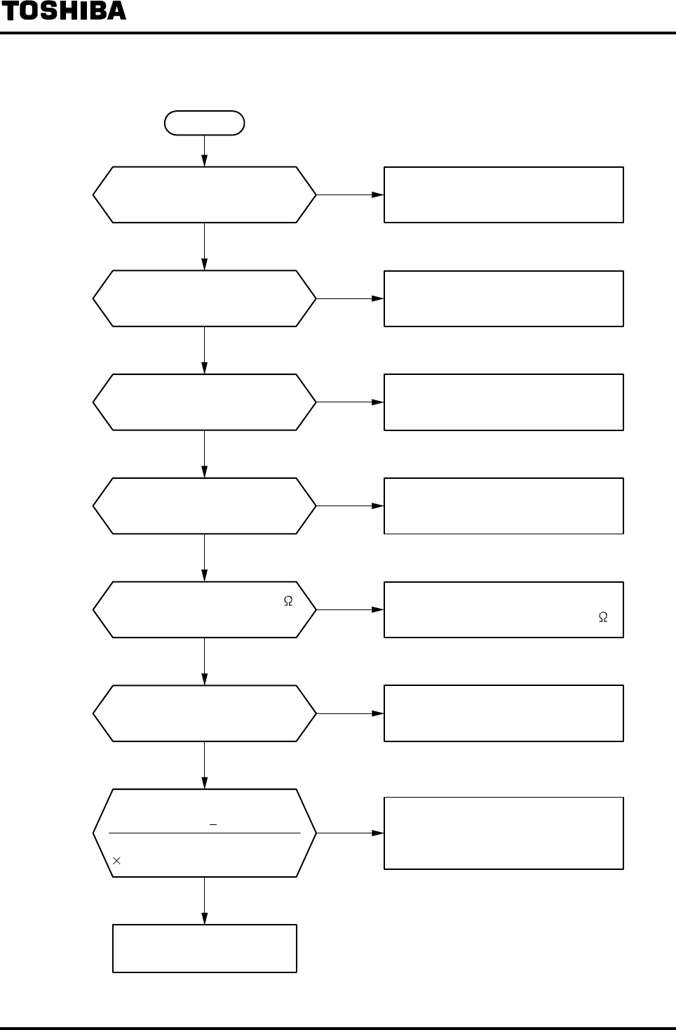
6F8A0917
-
160
-
13.2.2 Flow rate indication is not correct
YES Connect the two load resistors in series,
if necessary.
Contact your nearest Toshiba
representative.
Aren't there two load resistors
connected to the output in
parallel?
YES
NO
NO
Set it correctly according to 8.
“Parameter Settings/Adjustment.”
Perform zero adjustment according to 6.
“Operation” and 8.5 “Zero Adjustment.”
Is zero point correctly set?
Is the velocity range correctly
set?
YES
NO
YES
NO
START
Set the exciting current correctly
according to 8. “Parameter Settings.”
Clean the inside wall of the detector pipe
to remove the deposits.
Isn't the inside wall of detector
pipe or electrode contaminated?
Is the exciting current correct?
NO
YES
YES
NO
Design the output circuit so that the
output load resistance is less than 1 k .
Is the output load resistance 1k
or less?
Is accuracy calculated as follows?
NO Calculate as shown on the left.
100 (%)
YES
(Actual flow rate)(Measured flow rate)
Actual flow rate
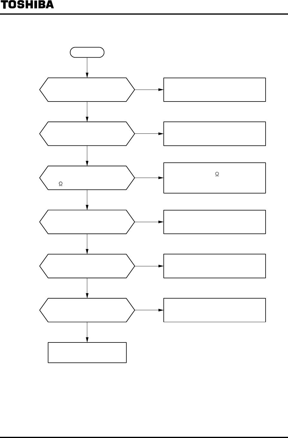
6F8A0917
-
161
-
13.2.3 Flow rate indication is not stable
Use a power supply within the specified
range.
Ground the converter/detector with
Class D ground (100 or less ground
resistance) using IV wire of 5.5 mm²
minimum.
Design piping so that the detector pipe
is filled with fluid all the time.
YES Design piping so that the fluid does not
carry bubbles.
NO
Isn't there large-current or high-
voltage cable or equipment near
the flowmeter?
YES Install the flowmeter away from the
equipment producing electromagnetic or
electrostatic interference.
Contact your nearest Toshiba
representative.
Isn't the fluid in the detector pipe
carrying bubbles?
Is the detector pipe filled with
fluid?
Are converter and detector
grounded with Class D ground
(100 or less ground resistance)?
Is power supply voltage within
the specified range?
YES
NO
NO
YES
NO
YES
NO
START
Connect each cable securely to the
terminal block.
Aren't the cables slackened?
NO
YES

6F8A0917
-
162
-
13.2.4 When switch operation is unable
START
NO
Place a cover to block the li
g
ht from
surroundin
g
s, or cover the control panel
by hand to block the light.
Does intense light shine on the control panel
such as direct sunli
g
ht or reflected sunli
g
ht b
y
window glass or metal sheet?
YES
Place a cover to block the li
g
ht from
surroundin
g
s, or cover the control panel
by hand to block the light.
Does the brightness change always by
ON/OFF of lighting?
NO
YES
A
re
y
ou workin
g
with unfixed li
g
htin
g
such as
a flashlight?
Operate the EMF converter fixin
g
a li
g
ht to
shine on the control panel as constantl
y
as
possible.
NO
YES
Does the control panel get rained?
Place a cover on the control panel to
protect from rain, and operate the EMF
converter.
NO
YES
Is the control panel attached with dewdrop,
snow, ice, mud or oil?
Is the control panel hazed by steam?
Clean the attached or haze and operate
the EMF converter.
Further, place a cover to prevent from
attaching.
NO
YES
Are you wearing dark color gloves?
Or are your finger or gloves stained?
Clean the stain on fin
g
ers or
g
loves, or
wear
g
loves in li
g
ht color and operate the
EMF converter.
NO
YES
Is there any light reflectin
g
ob
j
ect near the
control panel?
Secure a space in front of the control panel
to allow a person to stand.
NO
YES
Is there an
y
reflectin
g
ob
j
ect such as metal
plate placed opposing to the control panel?
Operate the EMF converter blocking the
light from the reflectin
g
ob
j
ect b
y
standin
g
in-between the control panel and the
reflecting object.
Contact your nearest Toshiba representative.
NO
YES
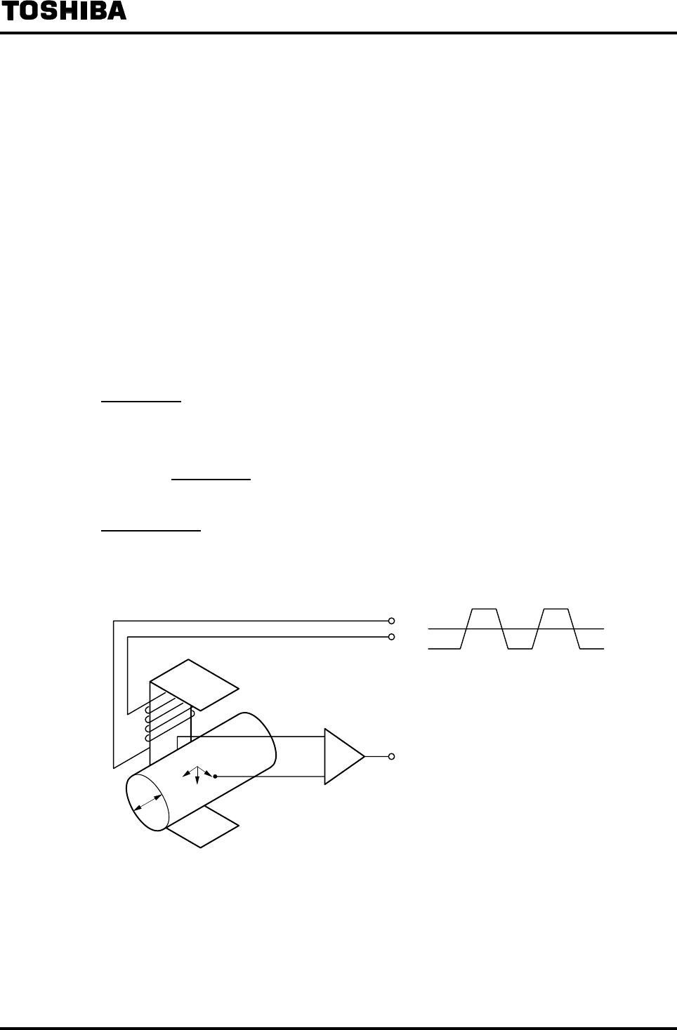
6F8A0917
-
163
-
14. Principle of Operation
The operating principle of the electromagnetic flowmeter is based on Faraday's Law of
electromagnetic induction. The principle of operation is that an insulated pipe with inner diameter D is
placed vertically to the direction of a magnetic field with flux density B (see Figure 14.1). When an
electrically conductive fluid flows in the pipe, an electromotive force signal E is induced between a
pair of electrodes placed at right angles to the direction of magnetic field. The electromotive force
signal E is directly proportional to the average fluid velocity V and this voltage signal is detected.
The following expression is applicable to the voltage.
E = K × B × D × V [V] ····································· (Eq. 14.1) E: Electromotive force signal [V]
K: Constant
B: Magnetic flux density [T]
D: Meter pipe inner diameter [m]
V: Fluid velocity [m/s]
Volumetric flow rate Q [m3/s] of fluid is:
π × D2
Q = 4 × V ··········································(Eq. 14.2)
Thus, we can obtain the equation below using Eq.14.1 and Eq.14.2,
4
E = K × B × D π × D2 × Q
4 × K × B
E = π × D × Q·····································(Eq. 14.3)
Therefore, the electromotive force signal E proportional to the flow rate can be obtained.
D
E
V
B
Square-Wave Excitation Method
Figure 14.1 Principle of Operation
The LF232 electromagnetic flowmeter converter uses the square-wave excitation method, which
provides long-term stable operations without being affected by electrostatic and electromagnetic
interferences.
6F8A0917
-
164
-
15. Specifications
15.1 Specifications
Detector Combined Specifications
1. Measuring range: (measuring range in terms of flow velocity)
0 –1.0 ft/s to 0 – 32.8 ft/s (0 – 0.3 m/s to 0 –10 m/s)
For partially filled pipes detectors (Combined detector is LF502)
Meter Measurement range
6” (150mm) 0 – 264 GPM(std) to 0 – 1320 GPM
(0 – 60 m3/h to 0 – 300 m3/h )
8” (200mm ) 0 – 484 GPM(std) to 0 – 2420 GPM
(0 – 110 m3/h to 0 – 550 m3/h )
10” (250mm ) 0 – 770 GPM(std) to 0 – 3850 GPM
(0 – 175 m3/h to 0 – 875 m3/h )
12” (300mm ) 0 – 1100 GPM(std) to 0 – 5500 GPM
(0 – 250 m3/h to 0 – 1250 m3/h )
14” (350mm ) 0 – 1540 GPM(std) to 0 – 7700 GPM
(0 – 350 m3/h to 0 – 1750 m3/h )
16” (400mm ) 0 – 1980 GPM(std) to 0 – 9900 GPM
(0 – 450 m3/h to 0 – 2250 m3/h )
20” (500mm ) 0 – 3124 GPM(std) to 0 – 15620 GPM
(0 – 710 m3/h to 0 – 3550 m3/h )
24” (600mm ) 0 – 4400 GPM(std) to 0 – 22000 GPM
(0 – 1000 m3/h to 0 – 5000 m3/h )
(Above flow rate is almost 0 – 3.28 ft/s (std) to 0 – 16.4 ft/s (0 – 1 m/s to 0 – 5 m/s ) flow velocity.)

6F8A0917
-
165
-
2. Measurement accuracy: (Accuracy when combined with detector)
• Combined detector: LF470 (Meter size 1/10” to 1/4” (2.5 to 6mm))
Range
Flow rate to the range (%) 1.0-3.3ft/s
(0.3-1.0m/s )
3.3-32.8ft/s
(1.0-10m/s )
0 to 50 % ± 0.8 % FS ± 0.4 % FS
50 to 100 % ± 0.8 % FS ± 0.8 % of rate
• Combined detector: LF150 (Meter size 20” to 120” (500 to 3000mm))
±0.5 % of Rate*
* This error is pulse output results calibrated under standard operating conditions at Toshiba’s
flow calibration facility.
* Individual meter’s measurement error mayvary up to ± 0.8 % of Rate at 3.28 ft/s (1.0 m/s) or
more and ± 0.4% of Rate ±0.157 inch/s (4mm/s) at 3.28 ft/s or less.
* Refer to individual calibration data for each meter’s measurement error.
• For partially filled pipes detectors (Combined detector is LF502)
± 2 % FS
Note: Accuracy is measured when detector and converter are newly combined under the basic
operating conditions in the Toshiba calibration facility.

6F8A0917
-
166
-
3. Other specifications
• Conductivity: 5μS/cm or more
(If detector is partially filled pipes type, conductivity is 100μS/cm or more)
• Power supply: 100 to 240VAC (allowable voltage range: 80 to 264VAC, 50/60Hz)*1 or
24VDC (allowable voltage range: 21 to 27VDC)*2
• Power consumption: 17W (27VA ) or less (when 7th digit of specification code is “A”)
35W (60VA ) or less (when 7th digit of specification code is “B”)
30W (50VA ) or less (when 7th digit of specification code is “F”)
*1 When the 7th digit of specification code is “B” and “F”, power supply is 100 to 120VAC
(allowable voltage range is 80 to 132VAC, 50/60Hz)
*2 When the 7th digit of specification code is “B” and “F”, 24VDC cannot be selected.
• For partially filled pipes detectors:
Fluid water level range:
Meter size 6”-12” (150-300mm) : Water level 1 1/4(30mm) to state to be filled with water
Meter size 14”-24” (350-600mm) : 10% of meter size to state to be filled with water
Note) State to be filled with water is water level 100%
Necessary straight pipe length:
Upstream side : 10D or more
Downstream side: 5D or more
Note) D is meter size.
Converter specifications
1. Input signal: Flow rate proportional signal from the detector
2. Output signal: 4 to 20mADC (current signal, load resistance 0 to 1kΩ)
3 Digital Input/Output
• Digital Output
Digital Output 1: Output type Transistor open collector
Number of outputs 1
Capacity 30VDC, 200mA max.
Digital Output 2 (option: added when 9th digit of specification code is “3”) :
Output type Solid-state contact output
Number of outputs 3
Capacity 150VDC, 150mA max.
150VAC (peak value), 100mA max.
* For digital output function, either of the following functions can be selected.
Digital Output function
• Totalizer pulse output DO1 or DO2 can be selected
(Forward direction pulse and reverse direction pulse can be assigned independently)
In the case of DO1 Pulse rate 3.6 to 3,600,000 pulses/h
Pulse width Settable within the range of 0.3 to 500ms
In the case of DO2 Pulse rate 3.6 to 360,000 pulses/h
Pulse width Settable within the range of 4 to 500ms

6F8A0917
-
167
-
• Range switching output One Digital Output (DO) is used
• Single direction, 2-range switching signal
• Forward/reverse direction switching signal
Two Digital Outputs (DO) are used
• Single direction, 4-range switching signals
• Forward/reverse 2-range switching signals
• High/low limit alarm output
An alarm is output when flow rate goes above or below the
set-point value
Setting range −10 to 110% of the settable maximum range
High limit 2 points, low limit 2 points can be set
At the time of alarm output, Normally Open or Normally Closed
contact can be selected
• Preset counter output
Contact ON when totalizer count exceeds the set value
Setting range 1 to 99999999 count
• Converter error alarm
An alarm is output when an operation error is detected by
self-diagnosis.
At the time of alarm output, Normally Open or Normally Closed
contact can be selected
• Digital Input (option: added when 9th digit of specification code is “3”): 2 Digital Inputs
Signal type: Voltage signal of 20 to 30 VDC (H level: 20 to 30 VDC, L level: 2 VDC :
or less)
Input resistance: About 2.7 kΩ
* For digital input function, either of the following functions can be selected.
Digital Input function
• Range switching input One Digital Input is used: switching between large and small ranges
of forward/reverse, 2-range measurement
Two Digital Inputs are used: switching between ranges of single
direction, 4-range measurement
• Totalizer control input Totalizer Start/Stop control or Reset/Start
• Output hold input Fixed with set value for current output and pulse output (loop check)
• Zero adjustment input Performs still water zero adjustment
4. Communication function
• Communication signal: Digital signal is superimposed on 4 to 20mA signal line (conforms to
HART*1 protocol)
• Load resistance 240Ω to 1kΩ
• Load capacitance 0.25μF or less
• Load inductance 4mH or less
(For maximum cable length, about 2km is a guideline length when CVV-S 1.25mm2 is used
under standard installation condition.)
*1 HART: “HART” stands for Highway Addressable Remote Transducer and is the name of the
communication protocol for industry sensors that is recommended by HCF (HART
Communication Foundation).

6F8A0917
-
168
-
5. Display/setting items
• Output display: 16-character × 2-line dot-matrix LCD (with back light)
Indicating unit: 2 units can be selected from the flowing units: flow velocity, instantaneous
flow rate, total flow (forward/reverse/difference flow), total count, %, custom
unit.
• Setting: Various parameters can be set without opening the converter housing using 4 infrared
switches (password can be set)
Settable also with AF900 Handheld terminal
• Damping: 0.5 to 60 seconds (settable in increments of 1 second)
• Zero adjustment: Adjustable with infrared switches
•“Field re-verification” Mag-Prover – Toshiba’s Zero span calibration tool :
Allows unit to be re-calibrated and verified using internal software program
(for more information contact Toshiba International Corp.)
• Operation at power failure: Various setting values are stored in non-volatile memory.
Current output 0mA
Digital Output OFF (contact open)
Display Unlit
6. Other items
• Mass: Approx. 18 lb (8kg) (including a mounting fitting)
• Ambient temperature: -4 to 140 °F (-20 to 60 °C)
(storage temperature: -13 to 149 °F (-25 to 65 °C))
• Arrester: Included in the power supply circuit, current signal output circuit and digital I/O
circuit.
• Terminal block structure: 21-pole, screw connection type (M4 screw)
• Housing material: Aluminum alloy
• Painting: Acryl resin baked painting with pearl gray color
• Structure: IP 67
• Cable ports: G (PF) 1/2 female thread with cable connection
Adaptable cable diameter: φ0.433 to 0.512 inch (φ11 to 13mm)
Material: Nylon 66
• Vibration resistance: No resonance point exists when the following vibration is applied:
10 to 55Hz with amplitude of 0.07mm,
No problem occurs when vibration of 30Hz, 29.4m/s2 is applied in each
direction for 4 hours each.
Note: If the flowmeter is intended to be used in a location where vibration is applied constantly,
contact Toshiba.
6F8A0917
-
169
-
15.2 Model Number Table
LF232*A, LF232*B Converter model number table
Model number Specification code
1 2 3 4 5 6 7 8 9 10 11 12
Description
L F 2 3 2 Separate type converter
Purpose
A Standard
Compatible detector (Note 1) (Note 2) (Note 3)
A Medium to small size (Meter size: 1/10” to 18”(2.5 to 450mm))
B Large size (Meter size 20” to 120” (500 to 3000mm))
Mounting nuts and bolts
C Panel, wall mounting (BNP material: SUS304)
E Pipe mounting (BNP material: SUS304)
Digital input/output
1 Current output
+ Digital outputs points (1 point)
3 Current output
+ Digital outputs points (4 point) + Digital nputs points (2 point)
Communication function
1 HART communication
Power supply
1 100 to 240VAC, 50/60Hz (Note 2)
2 24VDC (Note 3)
A Standard
• Note 1: For applicable detector code, select one from the following table.
To combine with an existing detector, select one depending on the type of replaceable converters.
For combination with detectors not listed below, contact Toshiba.
Applicable
detector code
Applicable
detector
Applicable detector
(discontinued model) Replaceable converters
A LF470 type
334,
335 type (Converters of
types shown right)
372, LF200, LF220,
LF420, LF230* A type
B LF150 type
337,
335 type (Converters of
types shown right)
373, 378, LF230* B type
• Note 2: When the 7th digit is “B” and power supply specification code is “1”, power supply specification
is 100 to 120VAC.
• Note 3: 24VDC can be specified only when the 7th digit is “A”.

6F8A0917
-
170
-
LF232*F (for partially filled pipes detectors) Converter model number table
Model number Specification code
1 2 3 4 5 6 7 8 9 10 11 12
Description
L F 2 3 2 Separate type converter
Purpose
A Standard
Compatible detector
F For Partially-filled pipes
(Meter size : 6” to 24” (150mm to 600mm) )
Mounting nuts and bolts
C Panel, wall mounting (BNP material: SUS304)
E Pipe mounting (BNP material: SUS304)
Digital input/output
1 Current output
+ Digital outputs points (1 point)
3 Current output
+ Digital outputs points (4 point) + Digital nputs points (2 point)
Communication function
1 HART communication
Power supply
1 100 to 120VAC, 50/60Hz
A Standard
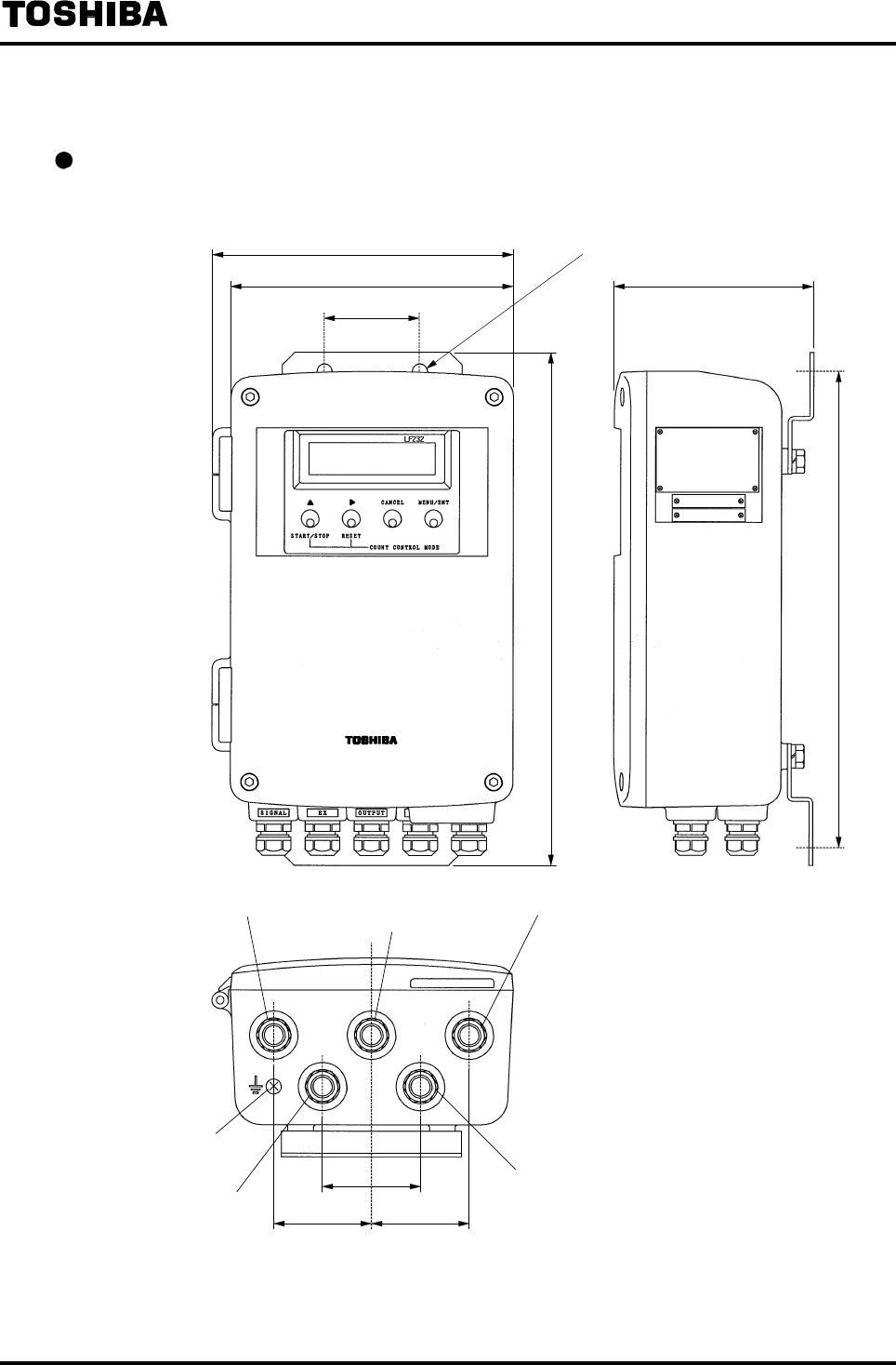
6F8A0917
-
171
-
16. Outline Drawing
Electromagnetic Flowmeter Converter LF232 Type Gross mass: approx. 18 lb(8kg)
(including a mounting plate)
Figure 16.1 Outline of Electromagnetic Flowmeter Converter 232 Type
2.94(74)
8.74(222)
9.33
(237)
6.10(155)
15.75(400)
φ0.47(φ12) hole (4 places)
2.99
(76)
2.99(76) 2.99(76)
Si
g
nal cable connection
Output cable connection
Power cable connection
Ground terminal
Excitation cable
connection
Digital I/O cable connection
Unit : inch (mm)
1
4.
14.
57
(
37

6F8A0917
-
172
-
Write down the address and phone number of the distributor from which you purchased this product,
the product code, SER.NO. and so on.
Distributor Address
Name
Phone number ( ) −
Product code LF
SER. NO.

FCF50017
