Toyota OM48A38U
User Manual: Toyota 2013 Toyota Highlander Owners Manual Pdf | Owner's Manual Pdf
Open the PDF directly: View PDF ![]() .
.
Page Count: 684 [warning: Documents this large are best viewed by clicking the View PDF Link!]

TABLE OF CONTENTS
1
1Before driving Adjusting and operating features such as door locks,
mirrors, and steering column.
2When driving Driving, stopping and safe-driving information.
3Interior
features
Air conditioning and audio systems, as well as other
interior features for a comfortable driving experience.
4Maintenance
and care
Cleaning and protecting your vehicle, performing do-it-
yourself maintenance, and maintenance information.
5When trouble
arises
What to do if the vehicle needs to be towed, gets a flat
tire, or is involved in an accident.
6Vehicle
specifications Detailed vehicle information.
7For owners Reporting safety defects for U.S. owners, and seat belt
and SRS airbag instructions for Canadian owners
Index Alphabetical listing of information contained in this
manual.

TABLE OF CONTENTS Index
2
1-1. Key information
Keys ..................................... 32
1-2. Opening, closing and
locking the doors
Smart key system................. 35
Wireless remote control ....... 48
Side doors ............................ 54
Back door ............................. 60
Glass hatch .......................... 70
1-3. Adjustable components
(seats, mirrors,
steering wheel)
Front seats ........................... 74
Rear seats............................ 77
Head restraints..................... 85
Seat belts ............................. 88
Steering wheel ..................... 94
Anti-glare inside rear
view mirror.......................... 95
Outside rear view mirrors ..... 98
1-4. Opening and closing the
windows and moon roof
Power windows .................. 101
Moon roof ........................... 104
1-5. Refueling
Opening the fuel tank
cap ................................... 109
1-6. Theft deterrent system
Engine immobilizer
system .............................. 113
Alarm .................................. 117
Theft prevention labels
(U.S.A.)............................. 121
1-7. Safety information
Correct driving posture ....... 122
SRS airbags ....................... 124
Front passenger occupant
classification system......... 136
Child restraint systems ....... 143
Installing child restraints ..... 148
2-1. Driving procedures
Driving the vehicle .............. 160
Engine (ignition) switch
(vehicles with smart
key system) ...................... 171
Engine (ignition) switch
(vehicles without smart
key system) ...................... 175
Automatic transmission ...... 178
Turn signal lever ................. 183
Parking brake ..................... 184
Horn.................................... 185
1Before driving
2When driving

1
2
3
4
5
6
7
3
2-2. Instrument cluster
Gauges and meters ............ 186
Indicators and warning
lights ................................. 188
Multi-information display ..... 193
2-3. Operating the lights and
wipers
Headlight switch.................. 203
Fog light switch ................... 210
Windshield wipers and
washer .............................. 212
Rear window wiper and
washer .............................. 216
2-4. Using other driving
systems
Cruise control...................... 219
Rear view monitor
system .............................. 223
Driving assist systems ........ 227
Hill-start assist control......... 232
Downhill assist control
system .............................. 234
2-5. Driving information
Off-road precautions ........... 237
Cargo and luggage ............. 242
Vehicle load limits ............... 247
Winter driving tips ............... 248
Trailer towing ...................... 252
Dinghy towing ..................... 270
3-1. Using the air conditioning
system and defogger
Front manual air
conditioning system.......... 274
Front automatic air
conditioning system.......... 281
Rear manual air
conditioning system.......... 289
Rear automatic air
conditioning system.......... 292
Rear window and
outside rear view
mirror defoggers............... 295
Windshield wiper de-icer .... 297
Using the steering wheel
climate remote control
switches ........................... 298
3-2. Using the audio system
Audio system...................... 299
Using the radio ................... 307
Using the CD player ........... 314
Playing back MP3 and
WMA discs ....................... 322
Operating an iPod .............. 330
Operating a USB
memory ............................ 337
Optimal use of the audio
system.............................. 345
Using the AUX port............. 349
Using the steering wheel
audio switches.................. 351
Detachable pole
antenna ............................ 354
3Interior features

TABLE OF CONTENTS Index
4
3-3. Using the Bluetooth®
audio system
Bluetooth® audio system.... 357
Using the Bluetooth®
audio system.................... 360
Operating a Bluetooth®
enabled portable player ... 365
Setting up a Bluetooth®
enabled portable player ... 367
Bluetooth® audio system
setup ................................ 372
3-4. Using the hands-free
phone system
(for cellular phone)
Hands-free phone system
(for cellular phone)
features ............................ 373
Using the hands-free
phone system................... 377
Making a phone call ........... 386
Setting a cellular phone...... 390
Security and system
setup ................................ 395
Using the phone book ........ 399
3-5. Using the rear audio
system
Rear seat entertainment
system features................ 406
Using the DVD player
(DVD video)...................... 413
Using the DVD player
(video CD)........................ 422
Using the DVD player
(audio CD/CD text)........... 425
Using the DVD player
(MP3 discs) ...................... 426
Using the video mode ........ 428
Changing the initial
setting............................... 429
3-6. Using the interior lights
Interior lights list.................. 436
• Personal/interior light
main switch....................... 437
• Personal/interior lights ...... 437
• Interior light....................... 438
3-7. Using the storage features
List of storage features ....... 439
• Glove box ......................... 440
• Console box ..................... 441
• Overhead console ............ 442
• Cup holders ...................... 443
• Bottle holders ................... 447
• Auxiliary boxes ................. 448
• Side table ......................... 450
3-8. Other interior features
Sun visors........................... 452
Vanity mirrors ..................... 453
Clock................................... 454
Conversation mirror ............ 455
Power outlets...................... 456
Seat heaters ....................... 460
Armrests ............................. 462
Assist grips ......................... 463
Floor mat ............................ 464
Luggage compartment
features ............................ 465
Garage door opener ........... 470
Compass ............................ 476

1
2
3
4
5
6
7
5
4-1. Maintenance and care
Cleaning and protecting
the vehicle exterior............ 482
Cleaning and protecting
the vehicle interior............. 485
4-2. Maintenance
Maintenance
requirements..................... 488
General maintenance.......... 491
Emission inspection and
maintenance (I/M)
programs........................... 494
4-3. Do-it-yourself maintenance
Do-it-yourself service
precautions ....................... 495
Hood ................................... 499
Positioning a floor jack ........ 501
Engine compartment........... 505
Tires .................................... 521
Tire inflation pressure ......... 530
Wheels ................................ 533
Air conditioning filter............ 536
Wireless remote control/
electronic key battery........ 539
Checking and replacing
fuses ................................. 542
Light bulbs........................... 553
5-1. Essential information
Emergency flashers............ 562
If your vehicle needs to
be towed........................... 564
If you think something is
wrong ............................... 571
Fuel pump shut off
system.............................. 572
5-2. Steps to take in an
emergency
If a warning light turns
on or a warning buzzer
sounds... .......................... 573
If a warning message is
displayed .......................... 584
If you have a flat tire ........... 586
If the engine will not start.... 600
If the shift lever cannot be
shifted from P ................... 602
If you lose your keys/
wireless remote control
transmitter ........................ 603
If the electronic key does
not operate properly ......... 604
If the battery is
discharged........................ 606
If your vehicle overheats .... 610
If the vehicle becomes
stuck................................. 613
If your vehicle has to
be stopped in an
emergency ....................... 615
4Maintenance and care 5When trouble arises

TABLE OF CONTENTS Index
6
6-1. Specifications
Maintenance data
(fuel, oil level, etc.) ........... 618
Fuel information ................. 633
Tire information .................. 636
6-2. Customization
Customizable features ....... 648
6-3. Initialization
Items to initialize................. 652
Reporting safety defects
for U.S. owners ................ 654
Seat belt instructions
for Canadian owners
(in French)........................ 655
SRS airbag instructions
for Canadian owners
(in French)........................ 657
Abbreviation list ........................ 668
Alphabetical index .................... 670
What to do if... .......................... 681
6Vehicle specifications
7For owners
Index

1
2
3
4
5
6
7
7
8
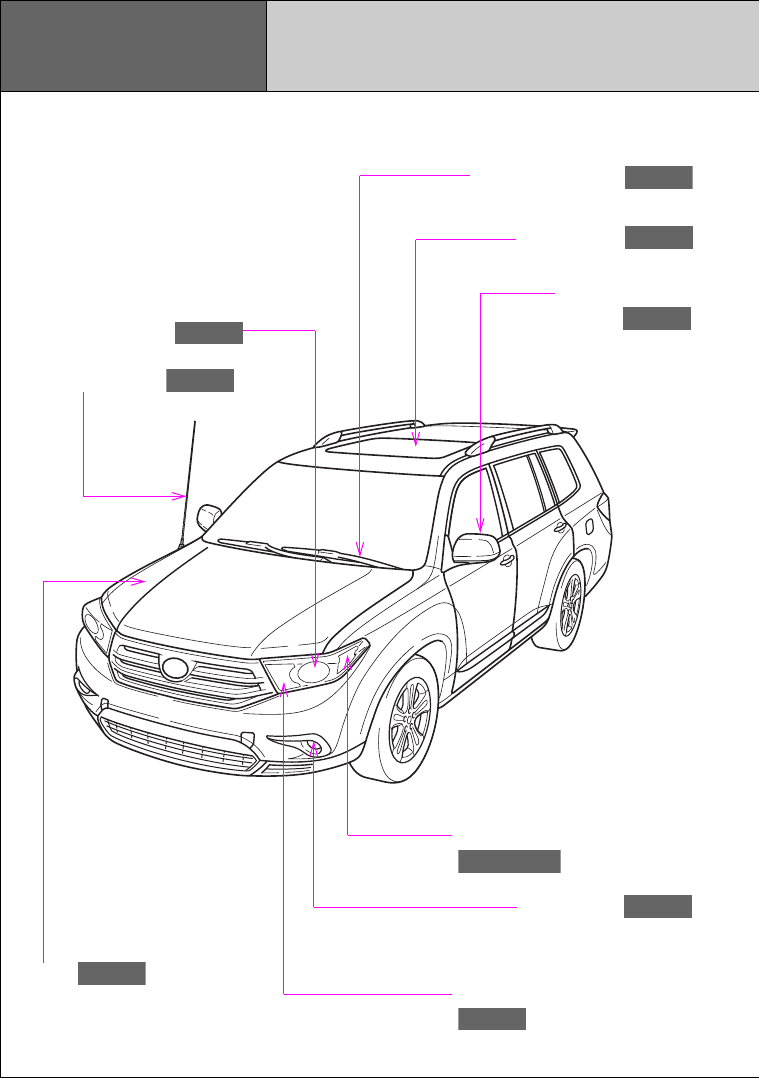
Pictorial index Exterior
Fog lights
P. 210
Parking, front side marker and
front turn signal lights
P. 183, 203
Hood
P. 499
Windshield wipers
P. 212
Moon roof
P. 104
Outside rear view
mirrors
P. 98
Headlights (low beam)
P. 203
Headlights (high beam) and
daytime running lights
P. 203
Pole antenna
P. 354
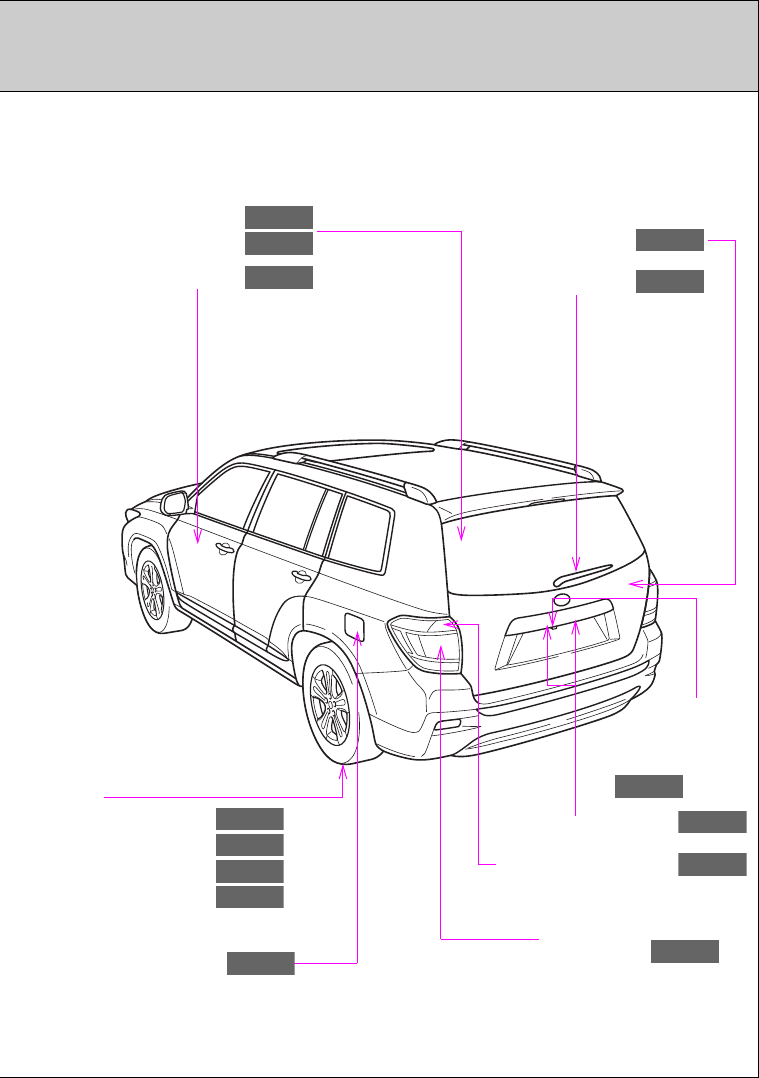
9
Back door
P. 60
Side doors
P. 54
Stop/tail and rear side
marker lights
P. 203
Rear window wiper
P. 216
Rear window defogger
Glass hatch
P. 295
P. 70
Rear turn signal lights
P. 183
: If equipped
*
1
: For vehicles with a Display Audio system, refer to the “Display Audio System Owner’s Manual”.
*
2
: For vehicles with a navigation system, refer to the “Navigation System Owner’s Manual”.
Tires
●Rotation
●Replacement
●Inflation pressure
●Information
P. 521
P. 586
P. 630
P. 636
Fuel filler door
P. 109
License plate lights
P. 203
Rear view
monitor system
camera , *1, *2
P. 223
10
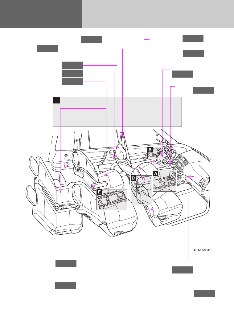
SRS side airbags
P. 124
Console box
P. 441
C
Cup holders
P. 443
Armrests
P. 462
SRS front passenger
airbag
P. 124
Seat belts
P. 88
Front seats
P. 74
Bottle holders
P. 447
SRS driver airbag
P. 124
SRS driver knee
airbag
P. 124
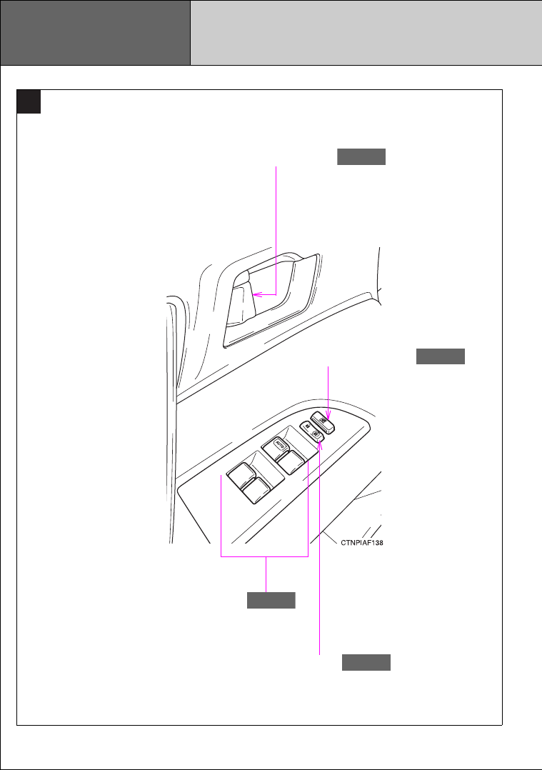
Head restraints
Power window switches
Rear seats
P. 85
P. 101
P. 77
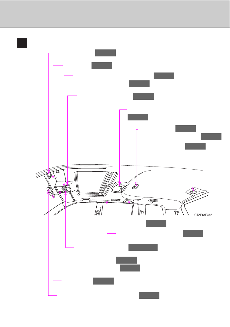
Pictorial index Interior
13
C
Overhead console
Conversation mirror
P. 442
P. 455
Garage door opener switches
Moon roof switches
P. 470
P. 104
Sun visors
P. 452
Personal/interior lights
P. 437
Rear seat entertainment system , *2
P. 406
SRS curtain shield airbags
P. 124
Compass
P. 476
Anti-glare inside rear view mirror
P. 95
Vanity mirrors
P. 453
Interior light
Personal/interior lights
P. 438
P. 437
Interior light
P. 438
Microphone , *1, *2
P. 360, 378
Assist grips
P. 463
: If equipped
*
1
:
For vehicles with a Display Audio system, refer to the “Display Audio System Owner’s Manual”.
*
2
:
For vehicles with a navigation system, refer to the “Navigation System Owner’s Manual”.
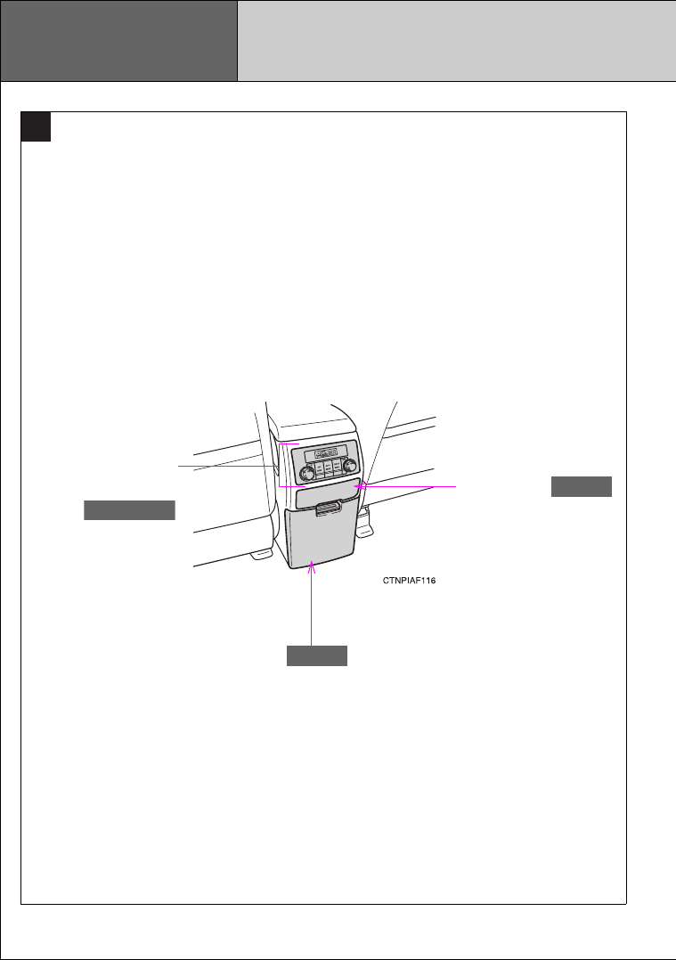
16
Rear view monitor system
(vehicles without a Display Audio sys-
tem or navigation system)
Multi-information display
Clock
P. 223
P. 193
P. 196, 454
Gauges and
meters
P. 186
Tilt and telescopic steering lock release
lever
P. 94
Glove box
P. 440
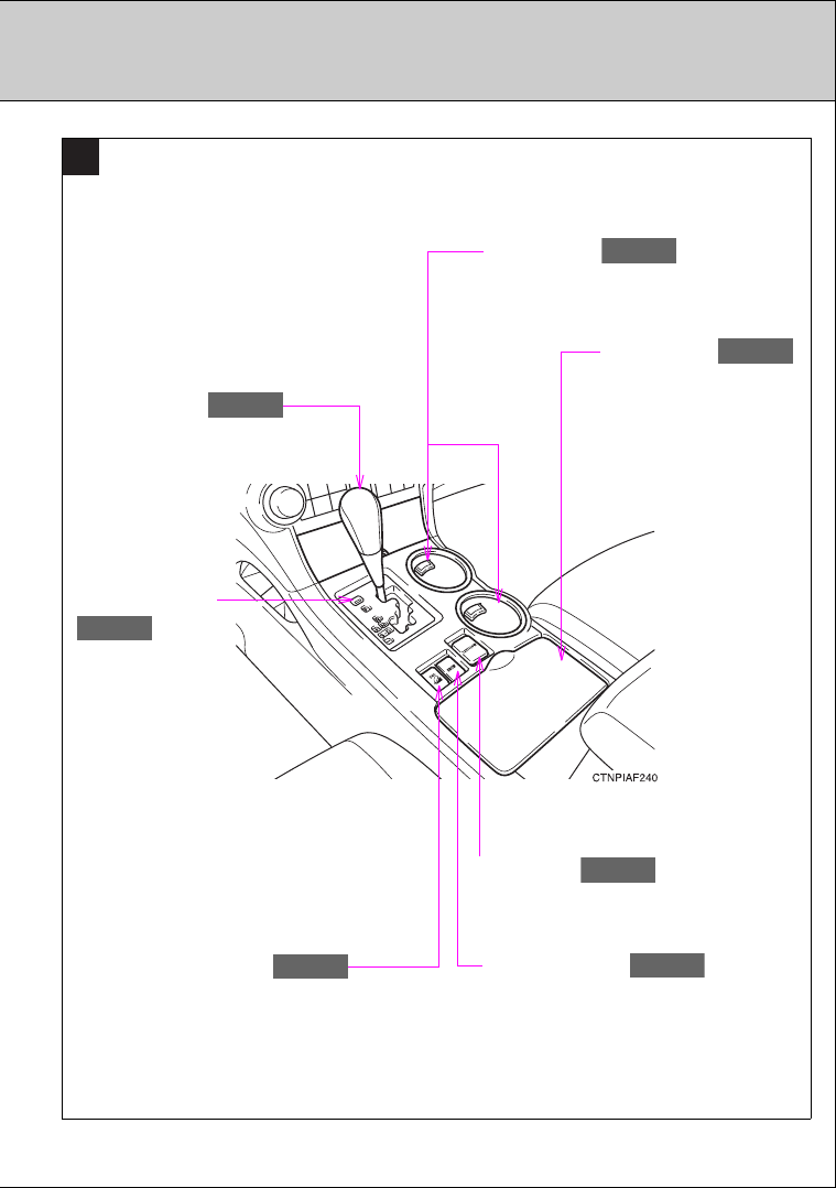
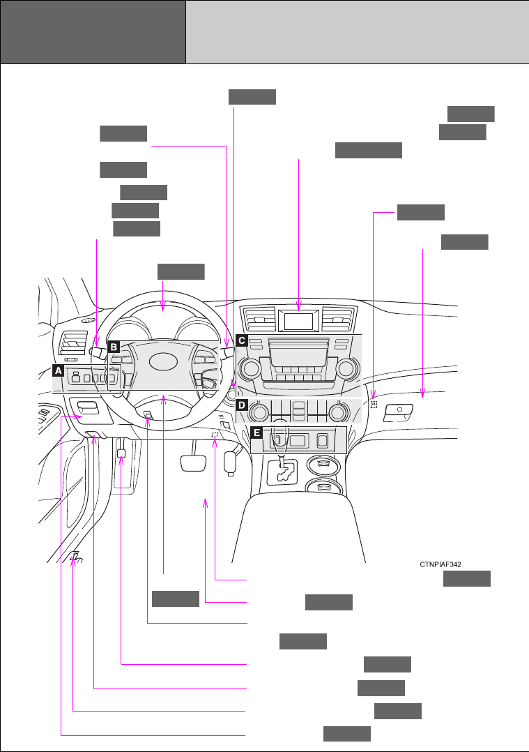
Pictorial index Instrument panel
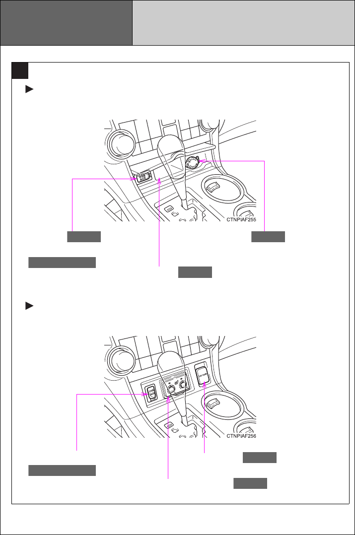
Power back door
main switch
P. 62
Tire pressure warning reset switch
P. 523
Parking brake pedal
P. 184
Hood release lever
P. 499
Auxiliary box
P. 448
Engine (ignition) switch
(vehicles with smart key system)
P. 171
Fog light switch
Headlight switch
Turn signal lever
P. 210
P. 203
P. 183
Windshield wiper and
washer switch
Rear window wiper and
washer switch
P. 212
P. 216
Horn
P. 185
Floor mat
P. 464
Fuel filler door opener
P. 109
18
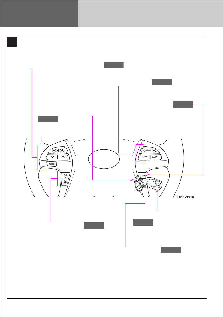
B
Talk switch , *1, *2
P. 378
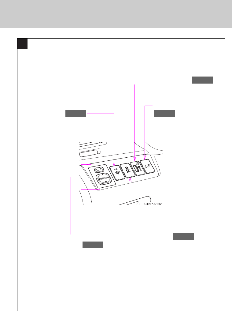
Pictorial index Instrument panel
Audio remote control switches , *1, *2
P. 351
Climate remote control switches
P. 298
Cruise control switch
P. 219
Telephone switch , *1, *2
P. 378
Engine (ignition) switch (vehicles
without smart key system)
P. 175
“DISP” switch
P. 194
19
: If equipped
*
1
:
For vehicles with a Display Audio system, refer to the “Display Audio System Owner’s Manual”.
*
2
:
For vehicles with a navigation system, refer to the “Navigation System Owner’s Manual”.
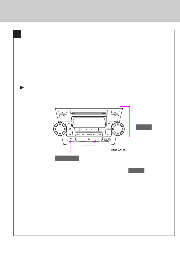
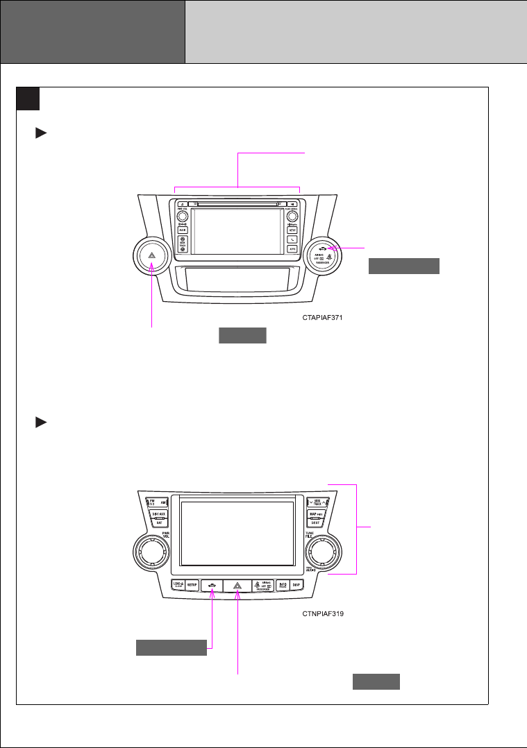
Vehicles without a Display Audio system or navigation system
C
Audio system
P. 299
Security indicator
P. 113, 117
Emergency flasher switch
P. 562
20
Vehicles with a navigation system
Vehicles with a Display Audio system
Emergency flasher switch
P. 562
Rear view monitor/Display
Audio system*4
Security indicator
P. 113, 117
Pictorial index Instrument panel
C
Rear view
monitor/navigation
system*5
Security indicator
P. 113, 117
Emergency flasher switch
P. 562
21
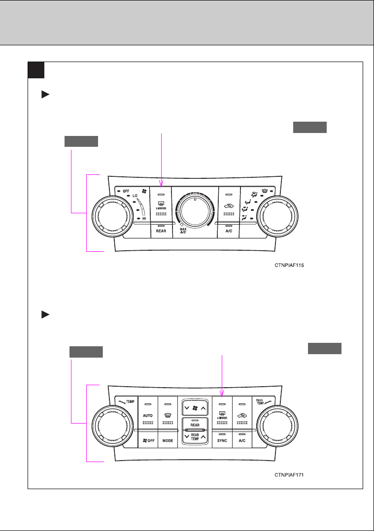
Rear window and outside rear view mirror defogger
switch /rear window defogger switch
P. 295
D
Vehicles with a front automatic air conditioning system
Vehicles with a front manual air conditioning system
Rear window and outside rear view mirror defogger
switch /rear window defogger switch
P. 295
Air conditioning
system
P. 281
Air conditioning
system
P. 274
: If equipped
*4: Refer to the “Display Audio System Owner’s Manual”.
*5: Refer to the “Navigation System Owner’s Manual”.
23
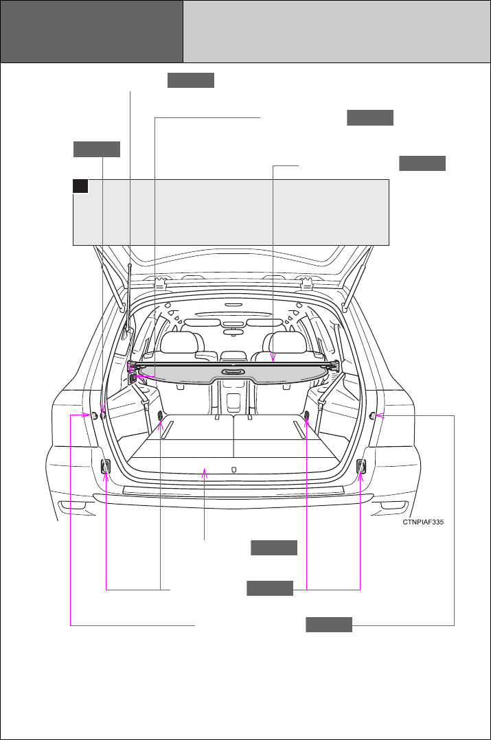
A
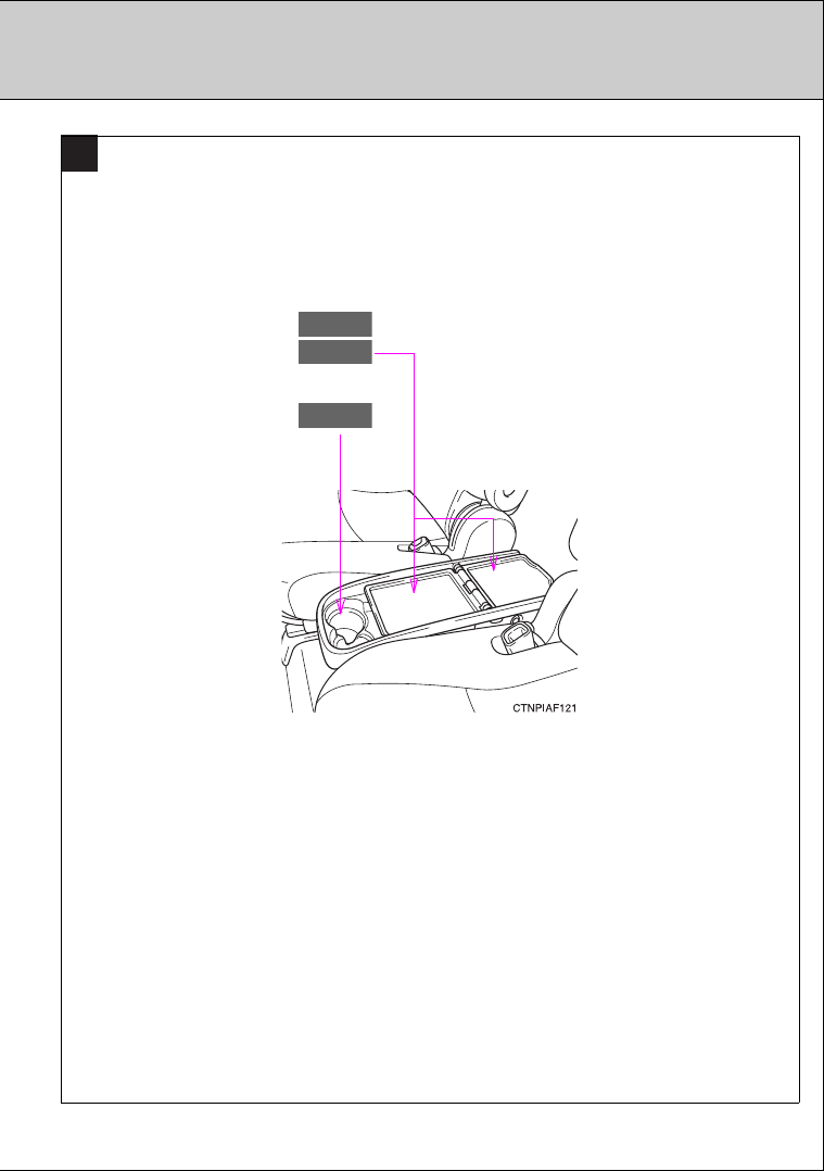
Pictorial index Luggage compartment
A/V input port , *2
P. 428
Power outlet
P. 456
Luggage cover
P. 466
Auxiliary box
P. 465
Cargo hooks
P. 465
Power outlet
P. 456
Grocery bag hooks
P. 465
: If equipped
*
1
: For vehicles with a Display Audio system, refer to the “Display Audio System Owner’s Manual”.
*
2
: For vehicles with a navigation system, refer to the “Navigation System Owner’s Manual”.

25
For your information
Main Owner’s Manual
Please note that this manual covers all models and all equipment, including
options. Therefore, you may find some explanations for equipment not
installed on your vehicle.
All specifications provided in this manual are current at the time of printing.
However, because of the Toyota policy of continual product improvement, we
reserve the right to make changes at any time without notice.
Depending on specifications, the vehicle shown in the illustrations may differ
from your vehicle in terms of equipment.
Noise from under vehicle after turning off the engine
Approximately five hours after the engine is turned off, you may hear sound
coming from under the vehicle for several minutes. This is the sound of a fuel
evaporation leakage check and, it does not indicate a malfunction.
Accessories, spare parts and modification of your Toyota
A wide variety of non-genuine spare parts and accessories for Toyota
vehicles are currently available on the market. You should know that these
parts are not covered by Toyota warranty and that Toyota is not responsible
for their performance, repair, or replacement, or for any damage they may
cause to, or adverse effect they may have on, your Toyota vehicle.
This vehicle should not be modified with non-genuine Toyota products.
Modification with non-genuine Toyota products may affect performance,
safety or durability, and may even violate governmental regulations. In
addition, damage or performance problems resulting from the modification
may not be covered under warranty.

26
Installation of a mobile two-way radio system
The installation of a mobile two-way radio system in your vehicle could affect
electronic systems such as:
●Multiport fuel injection system/sequential multiport fuel injection system
●Cruise control system
●Anti-lock brake system
●SRS airbag system
●Seat belt pretensioner system
Be sure to check with your Toyota dealer for precautionary measures or spe-
cial instructions regarding installation of a mobile two-way radio system.
Vehicle data recordings
Your Toyota is equipped with several sophisticated computers that will record
certain data, such as:
• Engine speed
• Accelerator status
• Brake status
• Vehicle speed
• Shift position
The recorded data varies according to the vehicle grade level and options
with which it is equipped. Furthermore, these computers do not record con-
versations, sounds or pictures.
●Data usage
Toyota may use the data recorded in these computers to diagnose malfunc-
tions, conduct research and development, and improve quality.
Toyota will not disclose the recorded data to a third party except:
• With the consent of the vehicle owner or with the consent of the lessee if
the vehicle is leased
• In response to an official request by the police, a court of law or a govern-
ment agency
• For use by Toyota in a lawsuit
• For research purposes where the data is not tied to a specific vehicle or
vehicle owner

27
Event data recorder
This vehicle is equipped with an event data recorder (EDR). The main pur-
pose of an EDR is to record, in certain crash or near crash-like situations,
such as an air bag deployment or hitting a road obstacle, data that will assist
in understanding how a vehicle’s systems performed. The EDR is designed
to record data related to vehicle dynamics and safety systems for a short
period of time, typically 30 seconds or less.
The EDR in this vehicle is designed to record such data as:
• How various systems in your vehicle were operating;
• Whether or not the driver and passenger safety belts were buckled/fas-
tened;
• How far (if at all) the driver was depressing the accelerator and/or brake
pedal; and,
• How fast the vehicle was traveling.
These data can help provide a better understanding of the circumstances in
which crashes and injuries occur.
NOTE: EDR data are recorded by your vehicle only if a non-trivial crash situ-
ation occurs; no data are recorded by the EDR under normal driving condi-
tions and no personal data (e.g., name, gender, age, and crash location) are
recorded. However, other parties, such as law enforcement, could combine
the EDR data with the type of personally identifying data routinely acquired
during a crash investigation.
To read data recorded by an EDR, special equipment is required, and access
to the vehicle or the EDR is needed. In addition to the vehicle manufacturer,
other parties, such as law enforcement, that have the special equipment, can
read the information if they have access to the vehicle or the EDR.

28
●Disclosure of the EDR data
Toyota will not disclose the data recorded in an EDR to a third party except
when:
• An agreement from the vehicle’s owner (or the lessee for a leased vehicle)
is obtained
• In response to an official request by the police, a court of law or a govern-
ment agency
• For use by Toyota in a lawsuit
However, if necessary, Toyota may:
• Use the data for research on vehicle safety performance
• Disclose the data to a third party for research purposes without disclosing
information about the specific vehicle or vehicle owner
Scrapping of your Toyota
The SRS airbag and seat belt pretensioner devices in your Toyota contain
explosive chemicals. If the vehicle is scrapped with the airbags and seat belt
pretensioners left as they are, this may cause an accident such as fire. Be
sure to have the systems of the SRS airbag and seat belt pretensioner
removed and disposed of by a qualified service shop or by your Toyota
dealer before you scrap your vehicle.
Perchlorate Material
Special handling may apply, See www.dtsc.ca.gov/hazardouswaste/perchlorate.
Your vehicle has components that may contain perchlorate. These compo-
nents may include airbag, seat belt pretensioners, and wireless remote con-
trol batteries.

29
CAUTION
■General precautions while driving
Driving under the influence: Never drive your vehicle when under the influ-
ence of alcohol or drugs that have impaired your ability to operate your vehi-
cle. Alcohol and certain drugs delay reaction time, impair judgment and
reduce coordination, which could lead to an accident that could result in
death or serious injury.
Defensive driving: Always drive defensively. Anticipate mistakes that other
drivers or pedestrians might make and be ready to avoid accidents.
Driver distraction: Always give your full attention to driving. Anything that dis-
tracts the driver, such as adjusting controls, talking on a cellular phone or
reading can result in a collision with resulting death or serious injury to you,
your occupants or others.
■General precaution regarding children’s safety
Never leave children unattended in the vehicle, and never allow children to
have or use the key.
Children may be able to start the vehicle or shift the vehicle into neutral.
There is also a danger that children may injure themselves by playing with
the windows, the moon roof, or other features of the vehicle. In addition, heat
build-up or extremely cold temperatures inside the vehicle can be fatal to
children.
30
Symbols used throughout this manual
Cautions & Notices
Symbols used in illustrations
CAUTION
This is a warning against anything which may cause death or injury to people if
the warning is ignored. You are informed about what you must or must not do
in order to reduce the risk of injury to yourself and others.
NOTICE
This is a warning against anything which may cause damage to the vehicle or
its equipment if the warning is ignored. You are informed about what you must
or must not do in order to avoid or reduce the risk of damage to your Toyota
and its equipment.
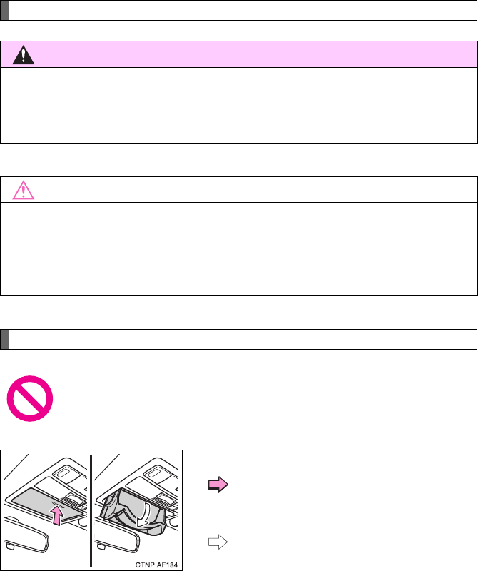
Safety symbol
The symbol of a circle with a slash through it means “Do not”, “Do
not do this”, or “Do not let this happen”.
Arrows indicating operations
Indicates the action (pushing, turning,
etc.) used to operate switches and other
devices.
Indicates the outcome of an operation
(e.g. a lid opens).

Before driving 1
31
1-1. Key information
Keys ................................... 32
1-2. Opening, closing and
locking the doors
Smart key system .............. 35
Wireless remote control ..... 48
Side doors.......................... 54
Back door........................... 60
Glass hatch ........................ 70
1-3. Adjustable components
(seats, mirrors,
steering wheel)
Front seats ......................... 74
Rear seats.......................... 77
Head restraints................... 85
Seat belts ........................... 88
Steering wheel ................... 94
Anti-glare inside rear
view mirror ....................... 95
Outside rear view
mirrors.............................. 98
1-4. Opening and closing the
windows and moon roof
Power windows ................ 101
Moon roof......................... 104
1-5. Refueling
Opening the fuel tank
cap ................................. 109
1-6. Theft deterrent system
Engine immobilizer
system ........................... 113
Alarm................................ 117
Theft prevention labels
(U.S.A.) .......................... 121
1-7. Safety information
Correct driving posture..... 122
SRS airbags..................... 124
Front passenger occupant
classification system ...... 136
Child restraint systems..... 143
Installing child
restraints ........................ 148
32
1-1. Key information
Keys
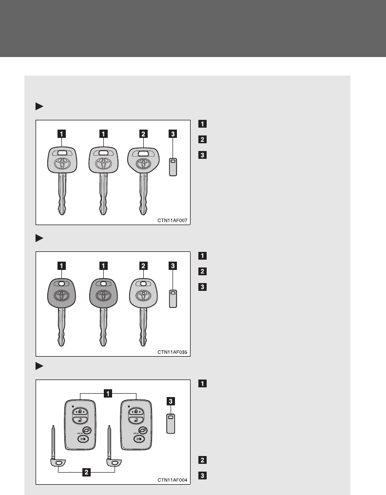
The following keys are provided with the vehicle.
Vehicles without smart key system (type A)
Master keys
Valet key
Key number plate
Vehicles without smart key system (type B)
Master keys
Valet key
Key number plate
Vehicles with smart key system
Electronic keys
• Operating the smart key
system (P. 35)
• Operating the wireless
remote control function
(P. 48)
Mechanical keys
Key number plate
33
1-1. Key information
1
Before driving
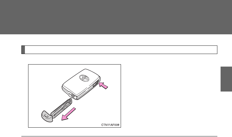
Using the mechanical key (vehicles with smart key system)
Take out the mechanical key.
After using the mechanical key,
store it in the electronic key. Carry
the mechanical key together with
the electronic key. If the electronic
key battery is depleted, you will
need the mechanical key.
(P. 604)
■When required to leave a key to the vehicle with a parking attendant
Lock the glove box as circumstances demand. (P. 440)
Vehicles without smart key system: Carry the master key for your own use
and provide the attendant with the valet key.
Vehicles with smart key system: Remove the mechanical key for your own
use and provide the attendant with the electronic key only.
■Key number plate
Keep the plate in a safe place such as your wallet, not in the vehicle. In the
event that a key is lost, a new key can be made by your Toyota dealer using
the key number plate. (P. 603)
■When riding in an aircraft (vehicles with smart key system)
When bringing an electronic key onto an aircraft, make sure you do not
press any buttons on the electronic key while inside the aircraft cabin. If you
are carrying an electronic key in your bag etc., ensure that the buttons are
not likely to be pressed accidentally. Pressing a button may cause the elec-
tronic key to emit radio waves that could interfere with the operation of the
aircraft.

34
1-1. Key information
NOTICE
■To prevent key damage
●Do not subject the keys to strong shocks, expose them to high tempera-
tures by placing them in direct sunlight, or get them wet.
●Do not expose the keys to electromagnetic materials or attach any mate-
rial that blocks electromagnetic waves to the key surface.
●Do not disassemble the key.
35
1
Before driving
1-2. Opening, closing and locking the doors
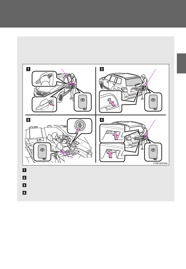
Smart key system
The following operations can be performed simply by carrying the
electronic key on your person, for example in your pocket.
(The driver should always carry the electronic key.)
Locks and unlocks the doors (P. 3 6 )
Starts the engine (P. 171)
Opens the glass hatch (P. 37)
Locks and unlocks the doors (P. 3 6 )
Electronic key
Electronic key
Electronic key
Electronic key
: If equipped
36
1-2. Opening, closing and locking the doors
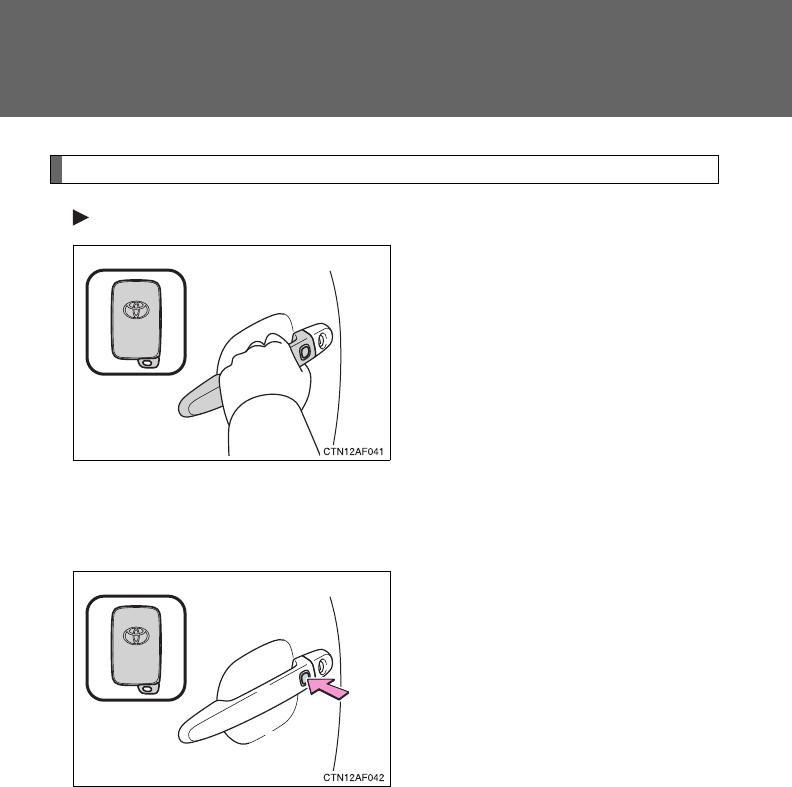
Unlocking and locking the doors
Front door handles
Grip the driver’s door handle to
unlock the door. Grip the passen-
ger’s door handle to unlock all
the doors.*
Make sure to touch the sensor on
the back of the handle.
The door cannot be unlocked for
3 seconds after the door is
locked.
*: The door unlock settings can be
changed. (P. 648)
Press the lock button to lock the
doors.
37
1-2. Opening, closing and locking the doors
1
Before driving
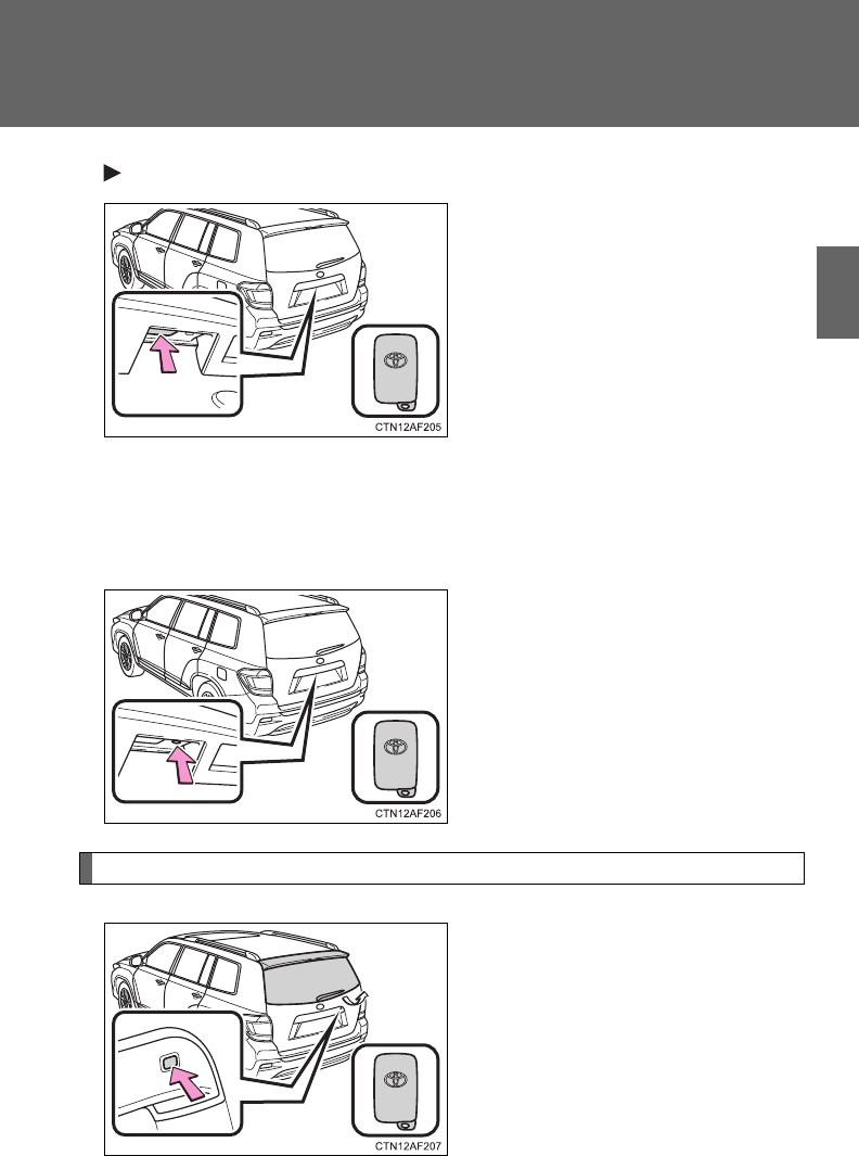
Back door handle
Press the button to unlock the
door.
The door cannot be unlocked for
3 seconds after the door is
locked.
If you carry the electronic key on
your person, the back door can
be opened even if it is locked.
Lock the back door again when
you leave the vehicle. The back
door will not lock automatically
after it has been opened and then
closed.
Press the button to lock the door.
Opening the glass hatch (if equipped)
Press and hold the button to
open the glass hatch. The glass
hatch will pop up.
The glass hatch can be unlocked
only when the back door is
closed.
38
1-2. Opening, closing and locking the doors
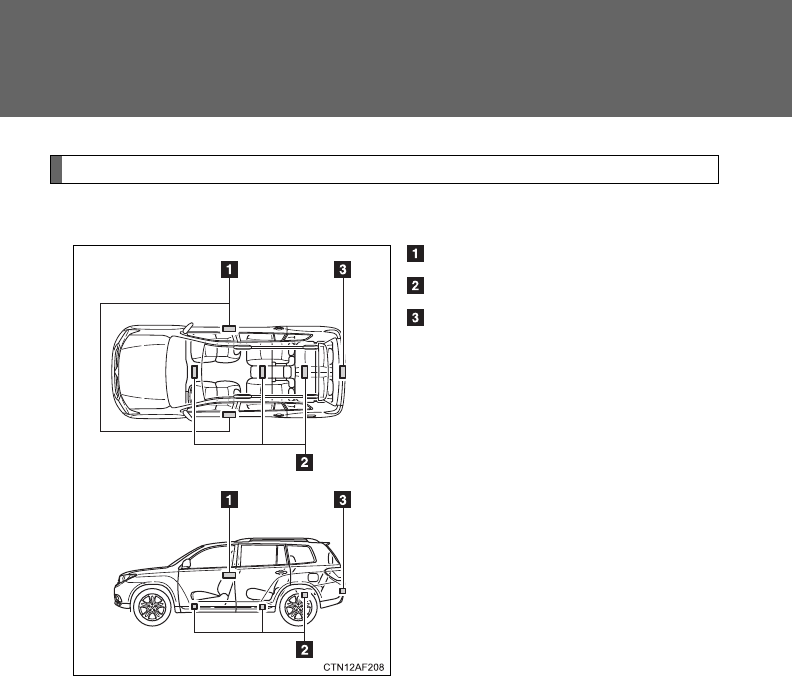
Antenna location and effective range
■Antenna location
Antennas outside the cabin
Antennas inside the cabin
Antenna outside the luggage
compartment
39
1-2. Opening, closing and locking the doors
1
Before driving
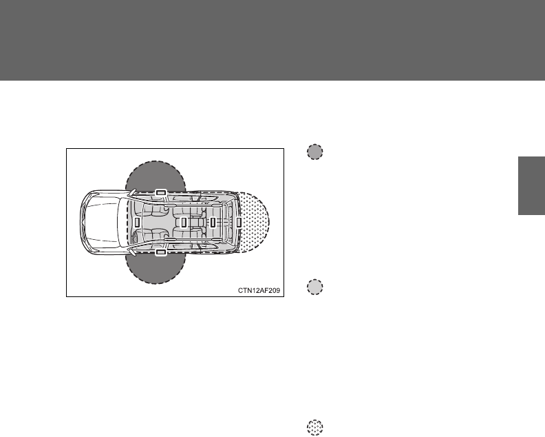
■Effective range (areas within which the electronic key is
detected)
When locking or unlocking
the doors
This system can be operated
when the electronic key is
within about 2.3 ft. (0.7 m) of
either of the outside front
door handles.
When starting the engine
or changing “ENGINE
START STOP” switch
modes
This system can be operated
when the electronic key is
inside the vehicle.
When opening the glass
hatch and locking or
unlocking the doors
This system can be operated
when the electronic key is
within about 2.3 ft. (0.7 m) of
the back door handle.

40
1-2. Opening, closing and locking the doors
■Operation signals
A buzzer sounds and the emergency flashers flash to indicate that the doors
have been locked/unlocked. (Locked: Once; Unlocked: Twice)
■Conditions affecting operation
The smart key system uses weak radio waves. In the following situations,
the communication between the electronic key and the vehicle may be
affected, preventing the smart key system and wireless remote control from
operating properly. (Ways of coping: P. 604)
●When the electronic key battery is depleted
●Near a TV tower, electric power plant, gas station, radio station, large dis-
play, airport or other facility that generates strong radio waves or electri-
cal noise
●When carrying a portable radio, cellular phone, cordless phone or other
wireless communication devices
●When the electronic key is in contact with, or is covered by a metallic
object
●When multiple electronic keys are in the vicinity
●When carrying or using the electronic key together with the following
devices that emit radio waves
• Another vehicle’s electronic key
• A wireless key that emits radio waves
• Personal computer
●If window tint with a metallic content or metallic objects are attached to
the rear window
■Switching the door unlock function
It is possible to set which doors the entry function unlocks.
Turn the “ENGINE START STOP” switch OFF.
When the indicator on the key surface is turned off, push and hold
, or for approximately 5 seconds while pushing
on the key.
STEP
1
STEP
2
41
1-2. Opening, closing and locking the doors
1
Before driving
The setting changes each time an operation is performed, as shown below.
(When changing the setting continuously, release the buttons, wait for at
least 5 seconds, and repeat step 2.)
To prevent unintended triggering of the alarm, unlock the doors using the
wireless remote control and open and close a door once after the settings
have been changed. (If a door is not opened within 60 seconds after is
pressed, the doors will be locked again and the alarm will automatically be
set.)
In case that the alarm is triggered, immediately stop the alarm. (P. 117 )
■Battery-saving function
In the following circumstances, the entry function is disabled in order to pre-
vent the vehicle and electronic key batteries from discharging.
●When the entry function has not been used for 2 weeks or more
●When the electronic key has been left within approximately 3 ft. (1 m) of
the vehicle for 10 minutes or more
The system will resume operation when...
●The vehicle is locked using the door handle lock button.
●The vehicle is locked/unlocked using the wireless remote control func-
tion. (P. 48)
●The vehicle is locked/unlocked using the mechanical key. (P. 604)
Multi-information
display Unlocking doors Beep
Hold the driver's door han-
dle to unlock only the
driver's door. Exterior: Beeps three
times
Interior: Pings once
Hold the front passenger’s
door handle to unlock all
doors.
Hold either front door han-
dle to unlock all doors.
Exterior: Beeps twice
Interior: Pings once

42
1-2. Opening, closing and locking the doors
■Electronic key battery depletion
●The standard battery life is 1 to 2 years. (The battery becomes depleted
even if the electronic key is not used.) If the smart key system or the
wireless remote control function does not operate, or the detection area
becomes smaller, the battery may be depleted. Replace the battery when
necessary. (P. 540)
●If the battery becomes low, an alarm will sound in the cabin when the
engine stops. (P. 43)
●To avoid serious deterioration, do not leave the electronic key within 3 ft.
(1 m) of the following electrical appliances that produce a magnetic field.
•TVs
• Personal computers
• Recharging cellular phones or cordless phones
• Table lamps
■To operate the system properly
Make sure to carry the electronic key when operating the system. Do not get
the electronic key too close to the vehicle when operating the system from
the outside of the vehicle.
Depending on the position and holding condition of the electronic key, the
key may not be detected correctly and the system may not operate properly.
(The alarm may go off accidentally, or the door lock prevention may not func-
tion.)
■Note for the entry function
●Even when the electronic key is within the effective range (detection
areas), the system may not operate properly in the following cases.
• The electronic key is too close to the window or outside door handle,
near the ground, or in a high place when the doors are locked or
unlocked.
• The electronic key is on the instrument panel, luggage cover, floor or in
the glove box when the engine is started or “ENGINE START STOP”
switch modes are changed.
●Do not leave the electronic key on top of the instrument panel or near the
door pockets when exiting the vehicle. Depending on the radio wave
reception conditions, it may be detected by the antenna outside the cabin
and the door will become lockable from the outside, possibly trapping the
electronic key inside the vehicle.

43
1-2. Opening, closing and locking the doors
1
Before driving
●As long as the electronic key is within the effective range, the doors may
be locked or unlocked by anyone.
●Even if the electronic key is not inside the vehicle, it may be possible to
start the engine if the electronic key is near the window.
●The doors may unlock if a large amount of water splashes on the door
handle, such as in the rain or in a car wash. (The doors will automatically
be locked after approximately 60 seconds if the doors are not opened
and closed.)
●Gripping the door handle when wearing a glove may not unlock the door.
●If the wireless remote control is used to lock the doors when the elec-
tronic key is near the vehicle, there is a possibility that the door may not
be unlocked by the entry function. (Use the wireless remote control to
unlock the doors.)
■When the vehicle is not driven for extended periods
To prevent theft of the vehicle, do not leave the electronic key within 6 ft. (2
m) of the vehicle.
■Security feature
If a door is not opened within approximately 60 seconds after the vehicle is
unlocked, the security feature automatically locks the vehicle again.
■Alarms and warning indicators
A combination of exterior and interior alarms as well as warning lights and
warning messages shown on the multi-information display are used to
reduce the chance of vehicle theft and accidents resulting from erroneous
operation.
●When any warning lights come on:
Take appropriate measures according to which warning light comes on.
(P. 573)
●When a warning message is shown on the multi-information display:
Take appropriate measures according to the warning message on the
multi-information display. (P. 584)

44
1-2. Opening, closing and locking the doors
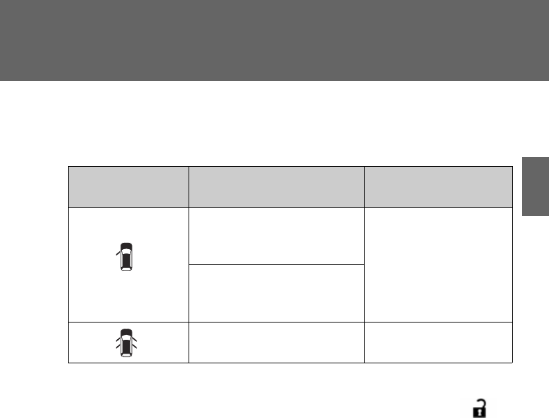
●When an alarm sounds:
Take appropriate measures according to the following table.
Alarm Situation Correction procedure
Exterior alarm
sounds once for
2 seconds
Tried to lock the doors
using the entry function
while the electronic key
was still inside the passen-
ger compartment.
Retrieve the elec-
tronic key from the
passenger compart-
ment and lock the
doors again.
Tried to close the glass
hatch with the electronic
key inside and all doors
locked.
Retrieve the elec-
tronic key and close
the glass hatch.
Exterior alarm
sounds once for
60 seconds
Tried to exit the vehicle
with the electronic key and
lock the doors without first
turning the “ENGINE
START STOP” switch OFF.
Turn the “ENGINE
START STOP” switch
OFF and lock the
doors again.
Exterior alarm
sounds once for
10 seconds
Tried to lock the vehicle
using the entry function
while a door was open.
Close all of the doors
and lock the doors
again.
Interior alarm
sounds continu-
ously
Tried to open the door and
exit the vehicle without
shifting the shift lever to P.
Shift the shift lever to
P.
Interior alarm
beeps repeatedly
Switched to ACCESSORY
mode while the driver's
door was open. (Opened
the driver's door when the
“ENGINE START STOP”
switch was in ACCES-
SORY mode.)
Turn the “ENGINE
START STOP” switch
OFF and close the
driver's door.
Turned the “ENGINE
START STOP” switch OFF
while the driver's door was
open.
Close the driver's
door.

45
1-2. Opening, closing and locking the doors
1
Before driving
*: A message will be shown on the multi-information display.
■If the smart key system does not operate properly
●Locking and unlocking the doors: Use the mechanical key. (P. 604)
●Starting the engine. (P. 604)
■When the electronic key battery is fully depleted
P. 540
Alarm Situation Correction procedure
Interior and exte-
rior alarms sound
continuously.*
Tried to close the driver’s
door after carrying the key
outside the vehicle with the
“ENGINE START STOP”
switch in IGNITION ON or
ACCESSORY mode and
without the shift lever
being in P.
Shift the shift lever to
P, turn the “ENGINE
START STOP” switch
OFF and close the
driver’s door again.
Interior alarm
beeps once.*
The electronic key has a
low battery.
Replace the electronic
key battery.
Tried to start the engine
without the electronic key
being present, or when the
electronic key was not
functioning normally.
Start the engine with
the electronic key
present.
Interior alarm
beeps once and
exterior alarm
sounds 3 times.*
Tried to close the driver’s
door after carrying the key
outside the vehicle without
turning the “ENGINE
START STOP” switch OFF.
Turn the “ENGINE
START STOP” switch
OFF and close the
driver’s door again.
An occupant carried the
electronic key outside the
vehicle and closed the
door when the “ENGINE
START STOP” switch was
in IGNITION ON or
ACCESSORY mode.
Bring the electronic
key back into the vehi-
cle.

46
1-2. Opening, closing and locking the doors
■Customization that can be configured at Toyota dealer
It is possible to deactivate the smart key system etc.
(Customizable features P. 648)
■Certification for the smart key system
For vehicles sold in the U.S.A.
FCC ID: NI4TMLF-3
HYQ14AAB
HYQ13BZS
HYQ14ABK
HYQ13CZA
NOTE:
This device complies with part 15 of the FCC Rules. Operation is subject to
the following two conditions: (1) This device may not cause harmful interfer-
ence, and (2) this device must accept any interference received, including
interference that may cause undesired operation.
FCC WARNING:
Changes or modifications not expressly approved by the party responsible
for compliance could void the user's authority to operate the equipment.
For vehicles sold in Canada
NOTE:
Operation is subject to the following two conditions: (1) this device may not
cause interference, and (2) this device must accept any interference, includ-
ing interference that may cause undesired operation of the device.

47
1-2. Opening, closing and locking the doors
1
Before driving
CAUTION
■Caution regarding interference with electronic devices
●People with implanted pacemakers or cardiac defibrillators should keep
away from the smart key system antennas. (P. 38) The radio waves may
affect the operation of such devices. If necessary, the entry function can
be disabled. Ask your Toyota dealer for details, such as the frequency of
radio waves and timing of emitting the radio waves. Then, consult your
doctor to see if you should disable the entry function.
●Users of any electrical medical device other than implanted pacemakers
and implanted cardiac defibrillators should consult the manufacturer of the
device for information about its operation under the influence of radio
waves.
Radio waves could have unexpected effects on the operation of such
medical devices.
Ask your Toyota dealer for details for disabling the entry function.
48
1-2. Opening, closing and locking the doors
Wireless remote control
The wireless remote control can be used to lock and unlock the vehi-
cle from outside the vehicle.
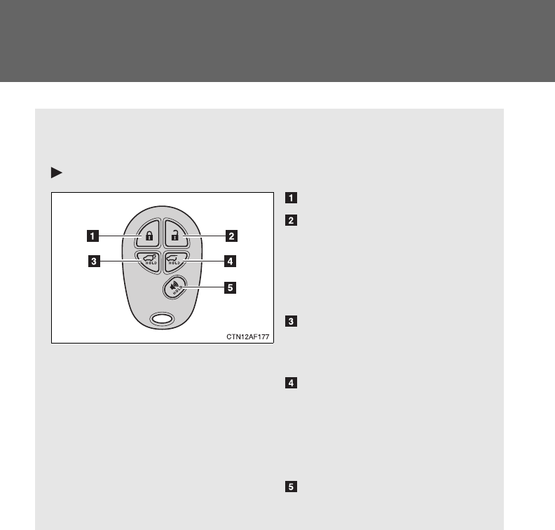
Vehicles without smart key system (type A)
Locks all doors
Unlocks all doors
Pressing the button unlocks
the driver’s door. Pressing the
button again within 3 seconds
unlocks the other doors.
Pushing and holding:
Opens and closes the
power back door
Pushing and holding:
Opens the glass hatch
The glass hatch can be
opened only when the back
door is closed.
Pushing and holding:
Sounds alarm
49
1-2. Opening, closing and locking the doors
1
Before driving
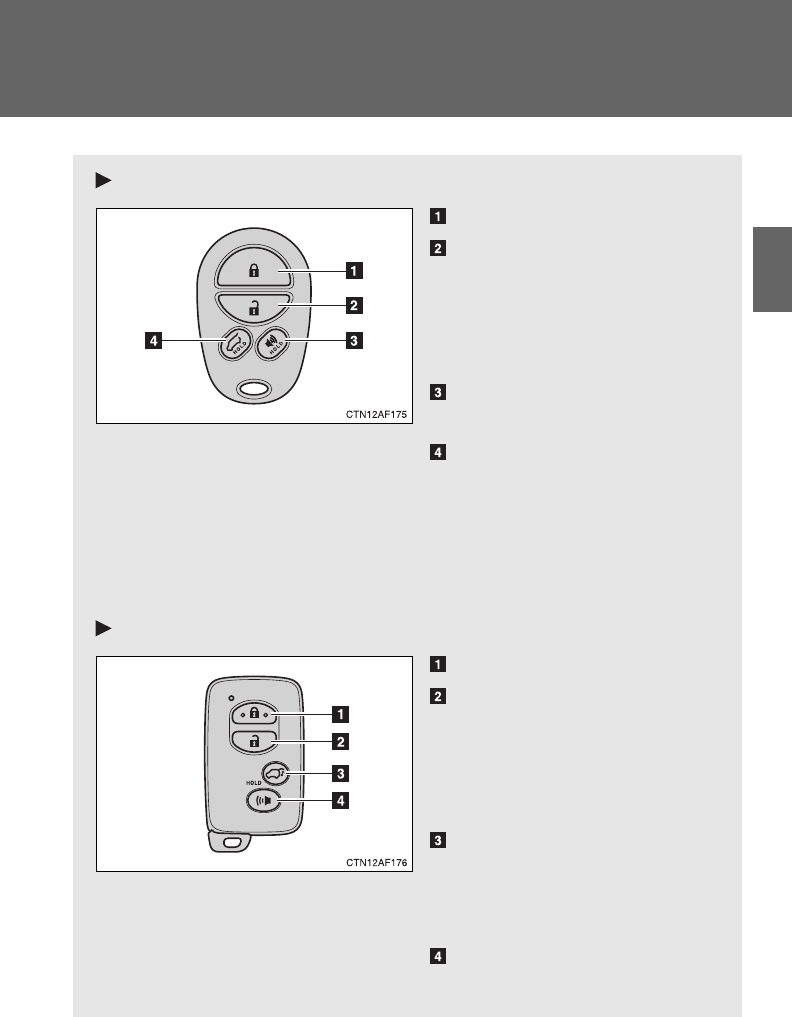
Vehicles without smart key system (type B)
Locks all doors
Unlocks all doors
Pressing the button unlocks
the driver’s door. Pressing the
button again within 3 seconds
unlocks the other doors.
Pushing and holding:
Sounds alarm
Pushing and holding:
Opens the glass hatch
(vehicles with glass hatch)
The glass hatch can be
opened only when the back
door is closed.
Vehicles with smart key system
Locks all doors
Unlocks all doors
Pressing the button unlocks
the driver’s door. Pressing the
button again within 3 seconds
unlocks the other doors.
Pushing and holding:
Opens and closes the
power back door (vehicles
with power back door)
Pushing and holding:
Sounds alarm
50
1-2. Opening, closing and locking the doors
■Operation signals
Doors: A buzzer sounds and the emergency flashers flash to indicate that
the doors have been locked/unlocked. (Locked: Once; Unlocked:
Twice)
Back door: A buzzer sounds and the emergency flashers flash twice to
indicate that the back door has been opened/closed.
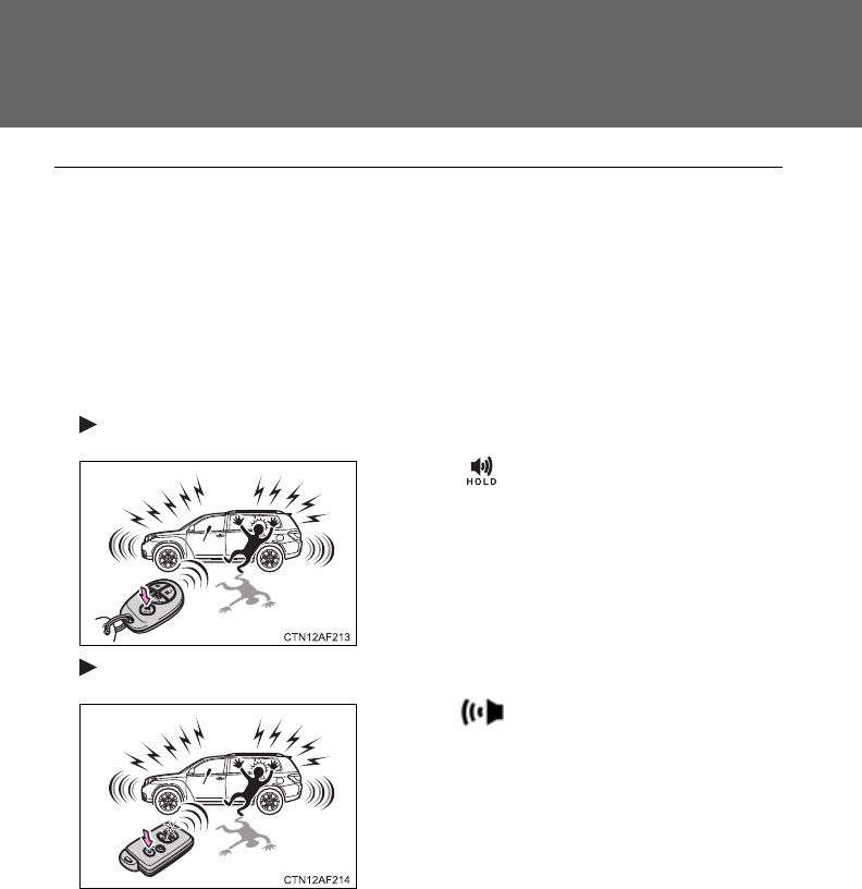
■Panic mode
Vehicles without smart key system
Vehicles with smart key system
■Door lock buzzer
If a door is not fully closed, a buzzer sounds continuously if an attempt to
lock the door is made. Fully close the door to stop the buzzer, and lock the
vehicle once more.
When is pushed for longer than
about one second, an alarm will sound for
about 60 seconds and the vehicle lights
will flash to deter any person from trying
to break into or damage your vehicle.
To stop the alarm, push any button on the
wireless remote control.
When is pushed for longer than
about one second, an alarm will sound for
about 60 seconds and the vehicle lights
will flash to deter any person from trying
to break into or damage your vehicle.
To stop the alarm, push any button on the
wireless remote control.

51
1-2. Opening, closing and locking the doors
1
Before driving
■Key battery depletion
Vehicles without smart key system
The standard battery life is 1 to 2 years. (The battery becomes depleted
even if the key is not used.) If the wireless remote control function does not
operate, the battery may be depleted. Replace the battery when necessary.
(P. 539)
Vehicles with smart key system
P. 540
■If the wireless remote control does not operate properly
Vehicles without smart key system
Locking and unlocking the doors: Use the key. (P. 54)
Vehicles with smart key system
●Locking and unlocking the doors: Use the mechanical key. (P. 604)
●Starting the engine. (P. 604)
■Security feature
If a door is not opened within approximately 60 seconds after the vehicle is
unlocked, the security feature automatically locks the vehicle again.
■Alarm
Using the wireless remote control to lock the doors will set the alarm system.
(P. 117)

52
1-2. Opening, closing and locking the doors
■Conditions affecting operation
Vehicles without smart key system
The wireless remote control function may not operate normally in the follow-
ing situations.
●Near a TV tower, radio station, electric power plant, airport or other facil-
ity that generates strong radio waves
●When carrying a portable radio, cellular phone or other wireless commu-
nication device
●When multiple wireless keys are in the vicinity
●When the wireless key is in contact with, or is covered by a metallic
object
●When a wireless key (that emits radio waves) is being used nearby
●When the wireless key has been left near an electrical appliance such as
a personal computer
Vehicles with smart key system
P. 40
■Customization that can be configured at Toyota dealer
Settings (e.g. wireless remote control) can be changed.
(Customizable features P. 648)
■Reversing the operation of the power back door
Pressing the wireless remote control switch again while the power back door
is operating will cause the operation to reverse.
■When riding in an aircraft (vehicle without smart key system)
When bringing a wireless remote control onto an aircraft, make sure you do
not press any buttons on the wireless remote control while inside the aircraft
cabin. If you are carrying a wireless remote control in your bag etc., ensure
that the buttons are not likely to be pressed accidentally. Pressing a button
may cause the wireless remote control to emit radio waves that could inter-
fere with the operation of the aircraft.

53
1-2. Opening, closing and locking the doors
1
Before driving
■Certification for wireless remote control
MODEL/FCC IDs:
Transmitter: GQ43VT20T
Receiver: GQ4-34R
IC (Canada) IDs:
Transmitter: 1470A-1T
Receiver: 1470A-6R
MADE IN U.S.A.
This device complies with Part 15 of the FCC Rules and with RSS-210 of
Industry Canada. Operation is subject to the following two conditions:
(1) This device may not cause harmful interference, and
(2) This device must accept any interference received, including interference
that may cause undesired operation.
WARNING:
Changes or modifications not expressively approved by the party responsi-
ble for compliance could void the user's authority to operate the equipment.
54
1-2. Opening, closing and locking the doors
Side doors
The vehicle can be locked and unlocked using the entry function,
wireless remote control, key or door lock switch.
■Entry function (vehicles with smart key system)
P. 35
■Wireless remote control
P. 48
■Key
Vehicles without smart key system
Locks all doors
Unlocks all doors
Turning the key unlocks the
driver's door. Turning the key
again unlocks the other doors.
Vehicles with smart key system
The doors can also be locked and unlocked with the mechanical
key. (P. 604)
55
1-2. Opening, closing and locking the doors
1
Before driving
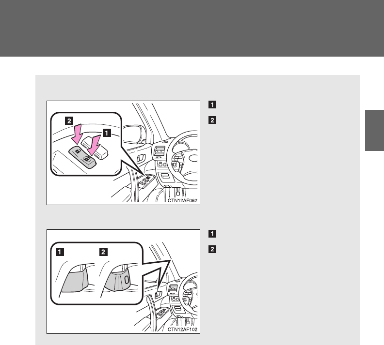
■Door lock switch
Locks all doors
Unlocks all doors
■Inside lock button
Locks the door
Unlocks the door
Pulling the door handle can
open the front door even if the
lock button is in the lock posi-
tion.
56
1-2. Opening, closing and locking the doors
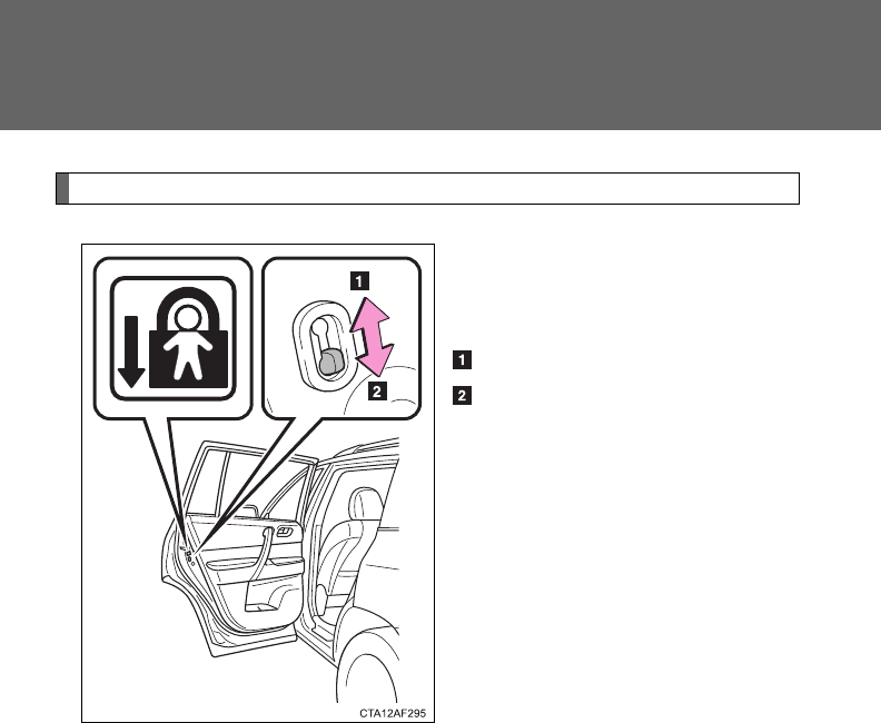
Rear door child-protector lock
The door cannot be opened from
inside the vehicle when the lock
is set.
Unlock
Lock
These locks can be set to prevent
children from opening the rear
doors. Push down on each rear
door switch to lock both rear
doors.

57
1-2. Opening, closing and locking the doors
1
Before driving
Automatic door locking and unlocking systems
The following functions can be set or canceled:
Function Operation
Shift position linked
door locking function
Shifting the shift lever out of P locks all
doors.
Shift position linked
door unlocking function Shifting the shift lever to P unlocks all doors.
Speed linked door lock-
ing function
All
the
doors are locked when the vehicle
speed is approximately 12 mph (20 km/h) or
higher.
Driver's door linked door
unlocking function
(
vehicles without smart
key system
)
All
the
doors are unlocked when the driver's
door is opened within 10 seconds after turning
the engine switch to “ACC” or “LOCK”.
Driver's door linked door
unlocking function
(
vehicles with smart key
system
)
All
the
doors are unlocked when the driver's
door is opened within 10 seconds after turning
the “ENGINE START STOP” switch off.

58
1-2. Opening, closing and locking the doors
■Setting and canceling the functions
To switch between setting and canceling, follow the procedure
below:
Vehicles without smart key system:
Close all the doors and turn the engine switch to the “ON”
position. (Perform step 2 within 10 seconds.)
Vehicles with smart key system:
Close all the doors and switch the “ENGINE START STOP”
switch to IGNITION ON mode. (Perform step 2 within 10 sec-
onds.)
Shift the shift lever to P or N, and
press and hold the driver's door
lock switch ( or ) for
approximately 5 seconds and
then release it.
The shift lever and switch posi-
tions corresponding to the
desired function to be set are
shown as follows.
Use the same procedure to can-
cel the function.
STEP
1
STEP
2
Function Shift lever position Driver’s door lock
switch position
Shift position linked door lock-
ing function P
Shift position linked door
unlocking function
Speed linked door locking func-
tion
N
Driver's door linked door unlock-
ing function
59
1-2. Opening, closing and locking the doors
1
Before driving
When the setting or canceling operation is complete, all doors are
locked and then unlocked.
■When locking the doors using the key
Vehicles without smart key system
The door cannot be locked if the key is in the engine switch.
Vehicles with smart key system
The door cannot be locked if the “ENGINE START STOP” switch is in
ACCESSORY or IGNITION ON mode, or the electronic key is left inside
the vehicle.
Depending on the position of the electronic key, the key may not be
detected correctly and the door may be locked.
■Customization that can be configured at Toyota dealer
Settings (e.g. door unlocking function) can be changed.
(Customizable features P. 648)
CAUTION
■To prevent an accident
Observe the following precautions while driving the vehicle.
Failing to do so may result in a door opening and an occupant falling out,
resulting in death or serious injury.
●Always use a seat belt.
●Always lock the doors.
●Ensure that all doors are properly closed.
●Do not pull the inside handle of the doors while driving.
The doors may be opened and the passengers are thrown out of the vehi-
cle and it may result in serious injury or death.
Be especially careful of the front doors, as they may be opened even if the
inside lock buttons are in the locked position.
●Set the rear door child protector locks when children are seated in the rear
seats.
60
1-2. Opening, closing and locking the doors
Back door
The back door can be locked/unlocked and opened by the following
procedures.
■Locking and unlocking the back door
Door lock switch
P. 55
Entry function (vehicles with smart key system)
P. 36
Wireless remote control
P. 48
Key
P. 54
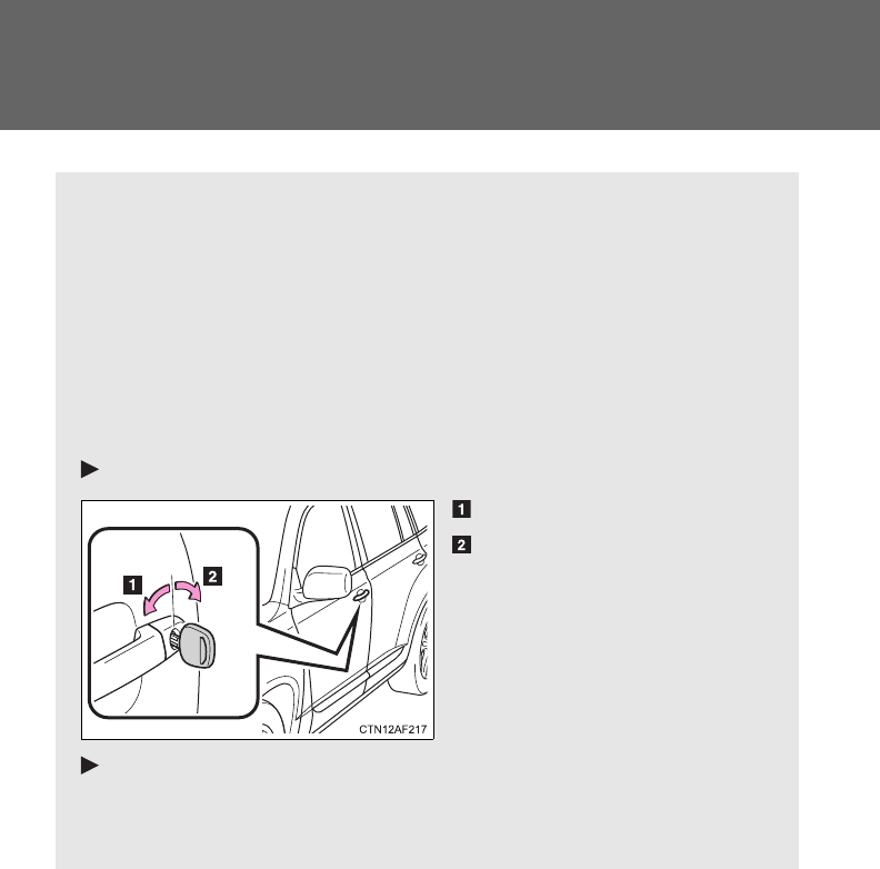
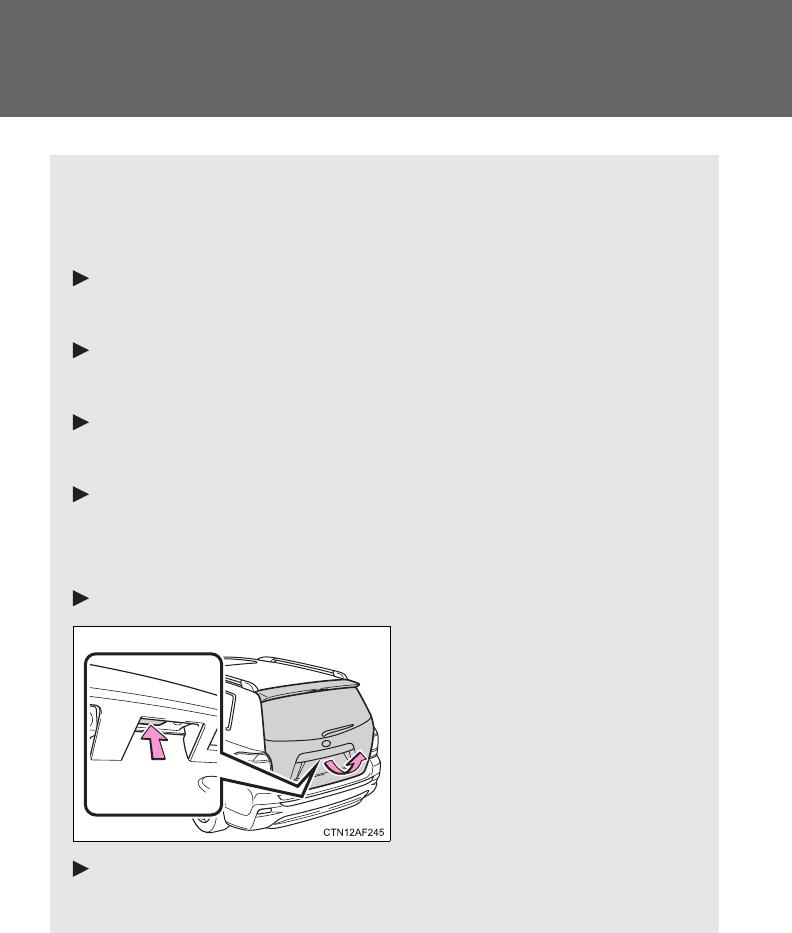
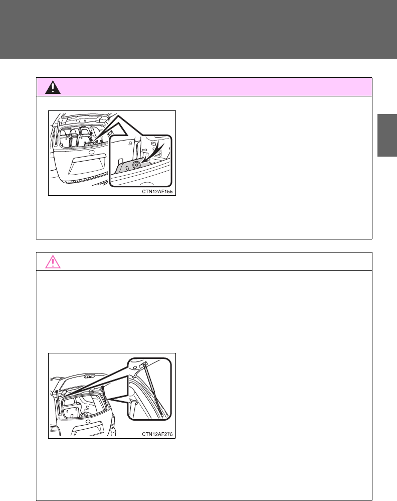
■Opening the back door from outside the vehicle
Back door opener
Raise the back door while
pushing up the back door
opener switch.
Wireless remote control (vehicles with power back door)
P. 48
61
1-2. Opening, closing and locking the doors
1
Before driving
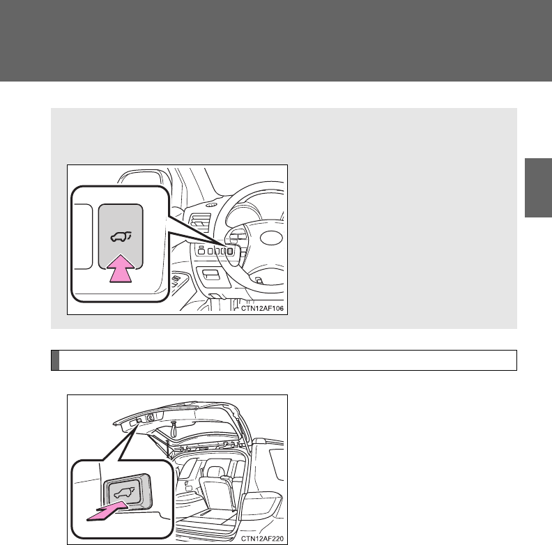
Power back door switch (vehicles with power back door)
Push the switch to close.
Pushing the switch again while
the power back door is closing
will cause it to open again.
A buzzer sounds and the emergency flashers flash twice to indicate
that the back door has been opened/closed.
The back door can be opened even if it is locked. Lock the back door
again when you leave the vehicle. The back door will not lock auto-
matically after it has been opened and then closed.
■Opening the back door from inside the vehicle (vehicles
with power back door)
Push and hold the switch to
open/close.
Pushing the switch again while
the power back door is operat-
ing will cause the operation to
reverse.
62
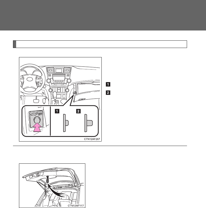
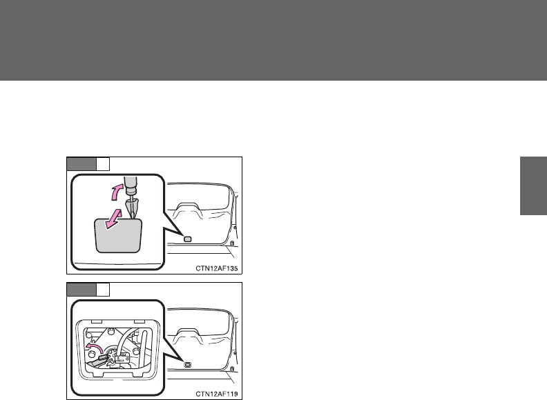
1-2. Opening, closing and locking the doors
Canceling the power back door system (vehicles with power back door)
Turn the main switch in the glove
box off to disable the power back
door system.
On
Off
A buzzer sounds twice and the
back door can then not be
opened with the wireless remote
control or power back door
switch.
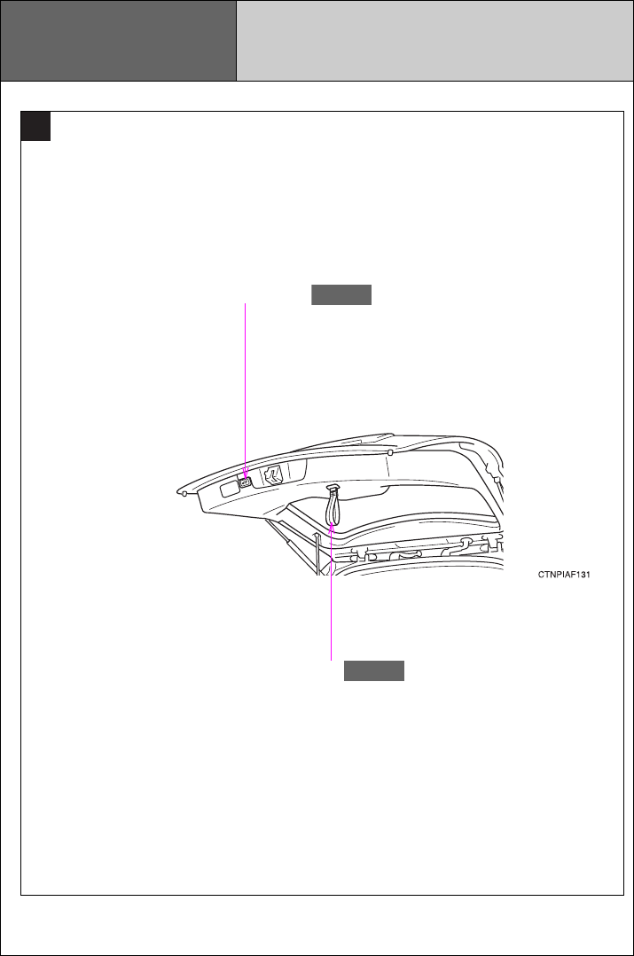
■Back door strap
Use the strap when closing.
63
1-2. Opening, closing and locking the doors
1
Before driving
■If the back door opener is inoperative
The back door can be operated from the inside.
■The power back door can be opened when
●The “ENGINE START STOP” switch is in IGNITION ON mode, and the
shift lever is in P.
●The “ENGINE START STOP” switch is in OFF or in ACCESSORY mode.
The power back door can be opened even when the glass hatch is opened.
The glass hatch will not be closed when the power back door is being
closed. Close the glass hatch manually.
■Jam protection function (vehicles with power back door)
If anything obstructs the power back door while it is closing/opening, the
back door will automatically operate in the opposite direction.
Remove the cover.
Turn the lever.
STEP
1
STEP
2

64
1-2. Opening, closing and locking the doors
■If the power back door does not work
The back door must be initialized. To initialize, close the back door com-
pletely by hand.
■Back door closer (vehicles with power back door)
In the event that the back door is left slightly open, the back door closer will
automatically close it to the fully closed position.
■Fall-down protection function (vehicles with power back door)
If excessive force is applied to the back door while it is opening automati-
cally, the power back door will stop at that position, preventing itself from fall-
ing down.
■Customization that can be configured at Toyota dealer
Settings (e.g. wireless remote control) can be changed.
(Customizable features P. 648)

65
1-2. Opening, closing and locking the doors
1
Before driving
CAUTION
■Caution while driving
●Keep the back door closed while driving.
If the back door is left open, it may hit near-by objects while driving or lug-
gage may be unexpectedly thrown out, causing an accident.
In addition, exhaust gases may enter the vehicle, causing death or a seri-
ous health hazard. Make sure to close the back door before driving.
●Before driving the vehicle, make sure that the back door is fully closed. If
the back door is not fully closed, it may open unexpectedly while driving,
causing an accident.
●Never let anyone sit in the luggage compartment. In the event of sudden
braking or a collision, they are susceptible to death or serious injury.
■When children are in the vehicle
Observe the following precautions.
Failure to do so may result in death or serious injury.
●Do not leave children alone in the luggage compartment.
If a child is accidentally locked in the luggage compartment, they could
have heat exhaustion.
●Do not allow a child to open or close the back door.
Doing so may cause the back door to operate unexpectedly, or cause the
child’s hands, head, or neck to be caught by the closing back door.
66
1-2. Opening, closing and locking the doors
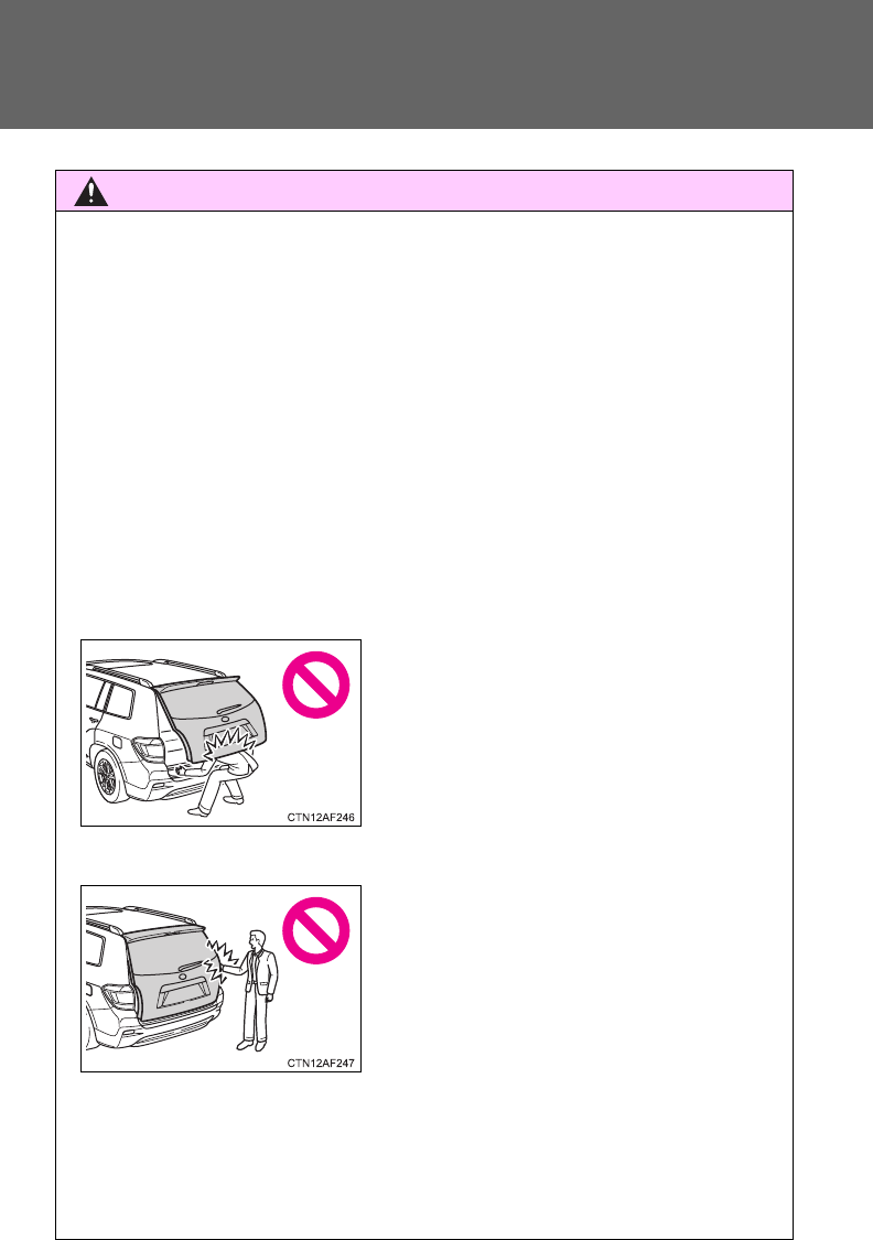
CAUTION
■Operating the back door
Observe the following precautions.
Failure to do so may cause parts of the body to be caught, resulting in death
or serious injury.
●Remove any heavy loads, such as snow and ice, from the back door
before opening it. Failure to do so may cause the back door to suddenly
shut again after it is opened.
●When opening or closing the back door, thoroughly check to make sure
the surrounding area is safe.
●If anyone is in the vicinity, make sure they are safe and let them know that
the back door is about to open or close.
●Use caution when opening or closing the back door in windy weather as it
may move abruptly in strong wind.
●Do not pull on the back door damper stay to close the back door, and do
not hang on the back door damper stay.
Doing so may cause hands to be caught or the back door damper stay to
break, causing an accident.
●The back door may suddenly shut if it is
not opened fully. It is more difficult to
open or close the back door on an
incline than on a level surface, so
beware of the back door unexpectedly
opening or closing by itself. Make sure
that the back door is fully open and
secure before using the luggage com-
partment.
●When closing the back door, take extra
care to prevent your fingers etc. from
being caught.
●When closing the back door, make sure
to press it lightly on its outer surface. If
the back door strap is used to fully
close the back door, it may result in
hands or arms being caught.
67
1-2. Opening, closing and locking the doors
1
Before driving
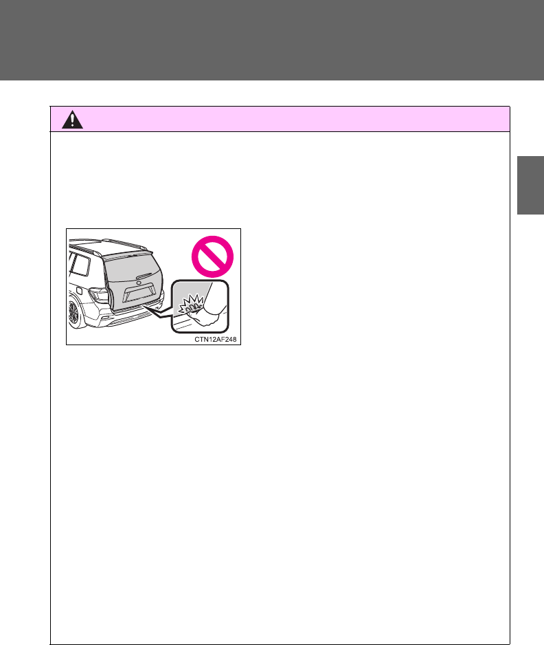
CAUTION
●Do not attach any accessories other than genuine Toyota parts to the back
door. Such additional weight on the back door may cause the back door to
suddenly shut again after it is opened.
■Back door closer (vehicles with power back door)
●Use caution when using the back door closer as it still operates when the
power back door system is canceled.
■Power back door
Observe the following precautions when operating the power back door.
Failure to do so may cause death or serious injury.
●Check the safety of the surrounding area to make sure there are no obsta-
cles or anything that could cause any of your belongings to get caught.
●If anyone is in the vicinity, make sure they are safe and let them know that
the back door is about to open or close.
●If the power back door main switch is turned off while the back door is
operating during automatic operation, the back door stops operating. Take
extra care when on an incline, as the back door may open or close sud-
denly.
●In the event that the back door is left
slightly open, the back door closer will
automatically close it to the fully closed
position. It takes several seconds
before the back door closer begins to
operate. Be careful not to catch fingers
or anything else in the back door, as
this may cause bone fractures or other
serious injuries.

68
1-2. Opening, closing and locking the doors
CAUTION
●On an incline, the back door may suddenly shut after it opens automati-
cally. Make sure the back door is fully open and secure.
●In the following situations, the power back door may detect an abnormality
and automatic operation may be stopped. In this case, the back door has
to be operated manually. Take extra care in this situation, as the stopped
back door may suddenly shut, causing an accident.
• When the back door contacts an obstacle
• Vehicles without smart key system: When the battery voltage suddenly
drops, such as when the engine switch is turned to the “ON” position or
the engine is started during automatic operation
• Vehicles with smart key system: When the battery voltage suddenly
drops, such as when the “ENGINE START STOP” switch is turned to
IGNITION ON mode or the engine is started during automatic opera-
tion
●Do not attach any accessories other than genuine Toyota parts to the back
door. The power back door may not operate, causing itself to malfunction,
or the back door may suddenly shut again after it is opened.
■Jam protection function (vehicles with power back door)
Observe the following precautions.
Failure to do so may cause death or serious injury.
●Never use any part of your body to intentionally activate the jam protection
function.
●The jam protection function may not work if something gets caught just
before the back door fully closes. Be careful not to catch fingers or any-
thing else.
●The jam protection function may not work depending on the shape of the
object that is caught. Be careful not to catch fingers or anything else.

69
1-2. Opening, closing and locking the doors
1
Before driving
NOTICE
■Back door damper stays
The back door is equipped with damper stays that hold the back door in
place.
Observe the following precautions.
Failure to do so may cause damage to the back door damper stay, resulting
in malfunction.
■To prevent back door closer malfunction
Do not apply excessive force to the back door while the back door closer is
operating.
■To prevent damage to the power back door
●Make sure that there is no ice between the back door and frame that
would prevent movement of the back door. Operating the power back door
when excessive load is present on the back door may cause a malfunc-
tion.
●Do not apply excessive force to the back door while the power back door
is operating.
●Take care not to damage the sensors (installed on the right and left edges
of the power back door) with a knife or other sharp object. If the sensor is
disconnected, the power back door will not operate in automatic operation.
●Do not attach any foreign objects, such
as stickers, plastic sheets, or adhesives
to the damper stay rod.
●Do not touch the damper stay rod with
gloves or other fabric items.
●Do not attach any accessories other
than genuine Toyota parts to the back
door.
●Do not place your hand on the damper
stay or apply lateral forces to it.

70
1-2. Opening, closing and locking the doors
Glass hatch
■Opening and closing the glass hatch
●Make sure that the rear wiper is switched off.
●Do not rotate the rear wiper arm while the glass hatch is opening. (If the
rear wiper arm is rotated, close the glass hatch as it is then switch on the
wiper. The rear wiper arm will return to the correct position automatically
after wiping.)
●Make sure that the back door is closed before closing the glass hatch.
The glass hatch can be opened using the glass hatch opener or wire-
less remote control.
■Wireless remote control (vehicles without smart key sys-
tem)
P. 48
■Entry function (vehicles with smart key system)
P. 36
■Glass hatch opener
Press and hold the button to
pop up the glass hatch.
Raise
The glass hatch can be
opened only when the back
door is closed.
: If equipped

71
1-2. Opening, closing and locking the doors
1
Before driving
CAUTION
■While driving
●Keep the glass hatch closed while driving.
If the glass hatch is left open, it may hit near-by objects while driving or
luggage may be unexpectedly thrown out, causing an accident.
In addition, exhaust gases may enter the vehicle, causing death or a seri-
ous health hazard. Make sure to close the glass hatch before driving.
●Before driving the vehicle, make sure that the glass hatch is fully closed. If
the glass hatch is not fully closed, it may open unexpectedly while driving,
causing an accident.
■When children are in the vehicle
Do not allow a child to open or close the glass hatch.
Doing so may cause the glass hatch to operate unexpectedly, or cause the
child's hands, head, or neck to be caught by the closing glass hatch.
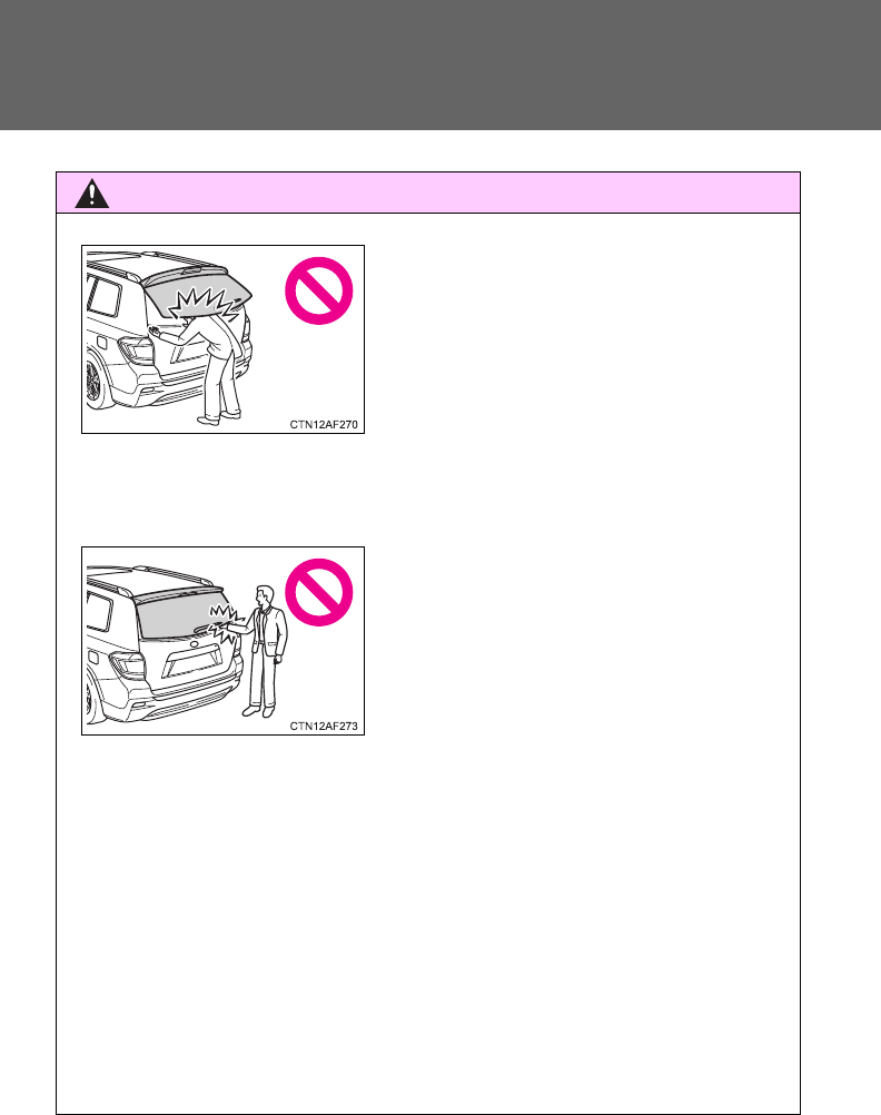
■Operating the glass hatch
Observe the following precautions.
Failure to do so may cause parts of the body to be caught, resulting in death
or serious injury.
●Remove any heavy loads, such as snow and ice, from the glass hatch
before opening it. Failure to do so may cause the glass hatch suddenly
shut again after it is opened.
●When opening or closing the glass hatch, thoroughly check to make sure
the surrounding area is safe.
●If anyone is in the vicinity, make sure they are safe and let them know that
the glass hatch is about to open or close.
●Use caution when opening or closing the glass hatch in windy weather as
it may move abruptly in strong wind.
72
1-2. Opening, closing and locking the doors
CAUTION
●Do not pull on the glass hatch damper stay to close the glass hatch, and
do not hang on the glass hatch damper stay.
Doing so may cause hands to be caught or the glass hatch damper stay to
break, causing an accident.
●Do not attach any accessories other than genuine Toyota parts to the
glass hatch. Such additional weight on the glass hatch may cause the
glass hatch to suddenly shut again after it is opened, resulting in death or
serious injury.
●Do not open the glass hatch while the rear wiper is switched on. (If the rear
wiper is switched on while the glass hatch is opening, the wiper motor
drive disc is swinging at the door panel.)
●The glass hatch may suddenly shut if it
is not opened fully. It is more difficult to
open or close the glass hatch on an
incline than on a level surface, so
beware of the glass hatch unexpectedly
opening or closing by itself. Make sure
that the glass hatch is fully open and
secure before using the luggage com-
partment. Also pay attention to your
personal belongings such as bags and
ties.
●When closing the glass hatch, take
extra care to prevent your fingers etc.
from being caught. Also pay attention to
your personal belongings such as bags
and ties.
●When closing the glass hatch, make
sure to press it lightly on its outer sur-
face.
73
1-2. Opening, closing and locking the doors
1
Before driving
CAUTION
●Do not close the glass hatch while the rear wiper is switched on. The rear
wiper arm may be restarted suddenly after closing the glass hatch.
NOTICE
■Glass hatch damper stays
The glass hatch is equipped with damper stays that hold the glass hatch in
place. Observe the following precautions.
Failure to do so may cause damage to the glass hatch damper stay, result-
ing in malfunction.
●Do not insert any object in the wiper
motor drive disc.
●Do not attach any foreign objects, such
as stickers, plastic sheets, or adhesives
to the damper stay rod.
●Do not touch the damper stay rod with
gloves or other fabric items.
●Do not attach any accessories other
than genuine Toyota parts to the glass
hatch.
●Do not place your hand or foot on the
damper stay or apply lateral forces to it.
74
1-3. Adjustable components (seats, mirrors, steering wheel)
Front seats
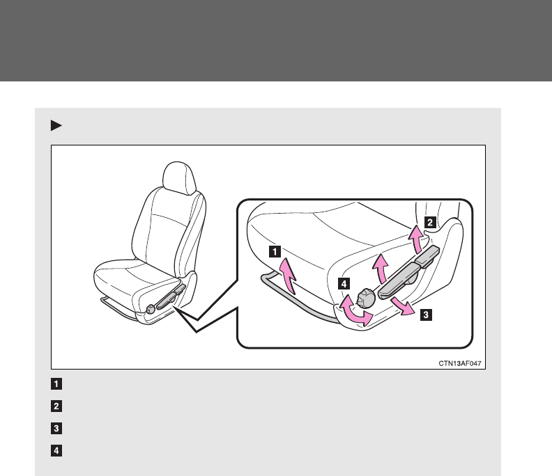
Manual seat
Seat position adjustment lever
Seatback angle adjustment lever
Vertical height adjustment lever (driver’s side only)
Seat cushion (front) angle adjustment knob (driver’s side only)

75
1-3. Adjustable components (seats, mirrors, steering wheel)
1
Before driving
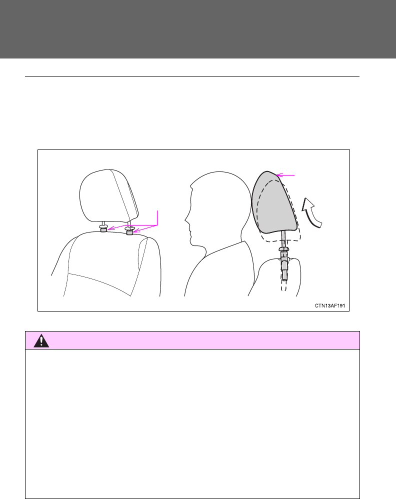
Active head restraints
When the occupant’s lower back
presses against the seatback
during a rear-end collision, the
head restraint moves slightly for-
ward and upward to help reduce
the risk of whiplash to the seat
occupant.
Power seat
Seat position adjustment switch
Seatback angle adjustment switch
Seat cushion (front) angle adjustment switch (driver’s side only)
Vertical height adjustment switch (driver’s side only)
Driver’s seat leg support adjustment switch (if equipped)
Seat lumbar support adjustment switch (driver’s side only)
76
1-3. Adjustable components (seats, mirrors, steering wheel)
■Active head restraints
Even small forces applied to the seatback may cause the head restraint to
move. Pushing up a locked head restraint forcibly may cause the inner struc-
ture of the head restraint to appear. This does not indicate a problem.
CAUTION
■Seat adjustment
●Be careful that the seat does not hit passengers or luggage.
●Do not recline the seat more than necessary when the vehicle is in motion
to reduce the risk of sliding under the lap belt.
If the seat is too reclined, the lap belt may slide past the hips and apply
restraint forces directly to the abdomen or your neck may contact the
shoulder belt, increasing the risk of death or serious injury in the event of
an accident.
●Manual seat only: After adjusting the seat, make sure that the seat is
locked in position.
Inner
structure
During
rear-end
collision
77
1
1-3. Adjustable components (seats, mirrors, steering wheel)
Before driving
Rear seats
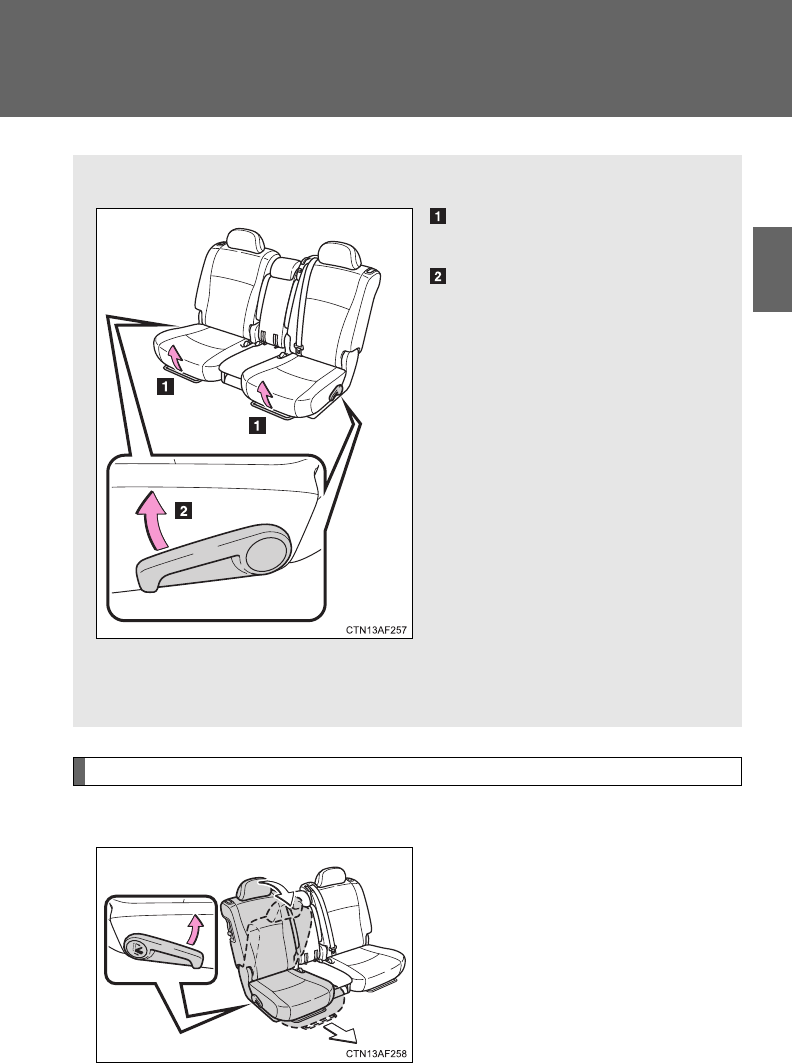
Moving a second seat for third seat access
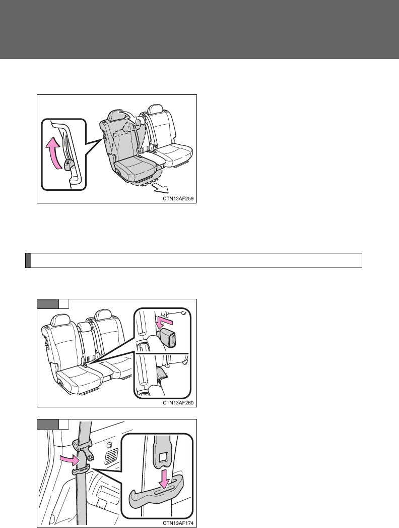
■Getting in the vehicle (right side only)
Pull up the lever and fold down
the seatback. The seat will slide
forward.
Move the seat to the front-most
position.
■Second seats
Seat position adjustment
lever
Seatback angle adjustment
lever
Pull up the lever until the lock
is completely released.
■Third seats
The third seats do not have a seat adjustment function.
78
1-3. Adjustable components (seats, mirrors, steering wheel)
■Getting out of the vehicle (right side only)
Lift the lever on the side of the
seatback and fold down the seat-
back. The seat will slide forward.
Move the seat to the front-most
position.
■After passengers have entered/exited the vehicle
Lift up the seatback and slide the seat backward until it locks.
Folding down the second seats
■Before folding down the second seats
Stow the rear center seat belt
buckle.
Pass the outer seat belts through
the seat belt hangers and secure
the seat belt plates.
This prevents the shoulder belt
from being damaged.
Make sure that the seat belts are
removed from the hangers before
using them.
STEP
1
STEP
2
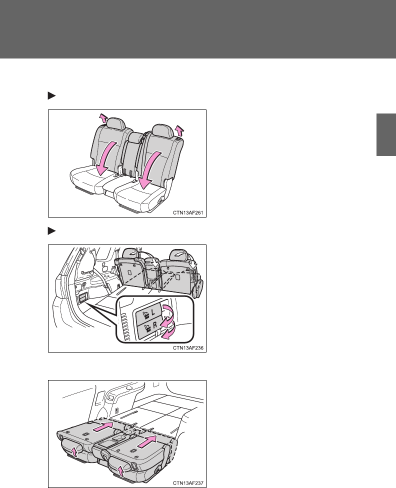
79
1-3. Adjustable components (seats, mirrors, steering wheel)
1
Before driving
■Folding down the second seats
From inside
Pull the lever to unlock the seat-
back and then fold the seatback
down.
From outside (if equipped)
Pull the lever.
L: Left side and center second
seats
R:Right side second seat
■After folding down the second seats
Slide the folded second seats to
the rear-most position.
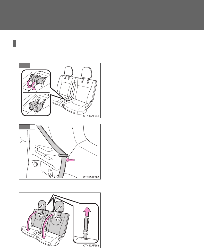
80
1-3. Adjustable components (seats, mirrors, steering wheel)
Folding down the third seats
■Before folding down the third seats
Stow the third seat belt buckles.
Pass the seat belts through the
seat belt hangers.
This helps to prevent the shoulder
belts from being damaged.
Make sure that the seat belts are
removed from the hangers before
using them.
■Folding down the third seats
While pulling the straps, fold
down the seatbacks.
The head restraints will fold down
automatically when the straps are
pulled.
STEP
1
STEP
2
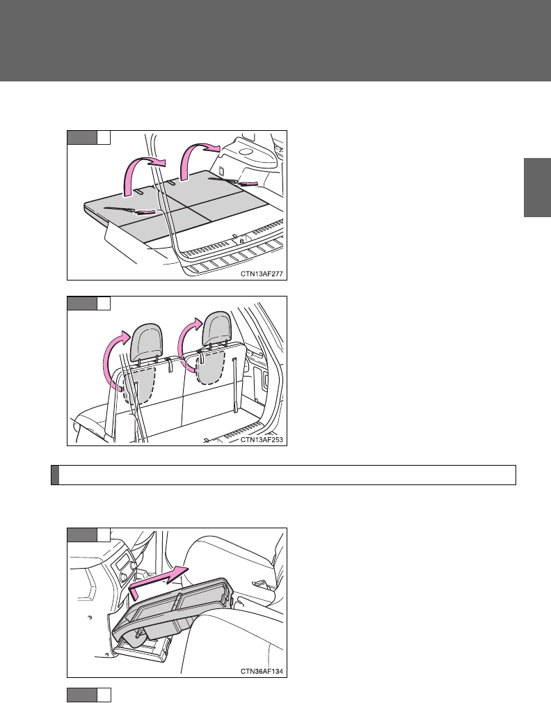
81
1-3. Adjustable components (seats, mirrors, steering wheel)
1
Before driving
■Returning the third seats
Pull the straps and raise the
seatbacks until they lock.
Raise the head restraints.
Removing the second center seat
■Before removing the second center seat
Take out the side table from the
console box.
Lower the second center seat head restraint to the lowest
position. (P. 85)
STEP
1
STEP
2
STEP
1
STEP
2
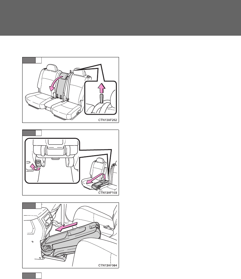
82
1-3. Adjustable components (seats, mirrors, steering wheel)
■Removing the second center seat
Fold down the second center
seatback while pulling the seat-
back lock release strap.
Pull the lock release lever to
remove the second center seat.
Stow the second center seat in
the console box.
Make sure that the seat is securely locked in position and
close the console box door.
STEP
1
STEP
2
STEP
3
STEP
4
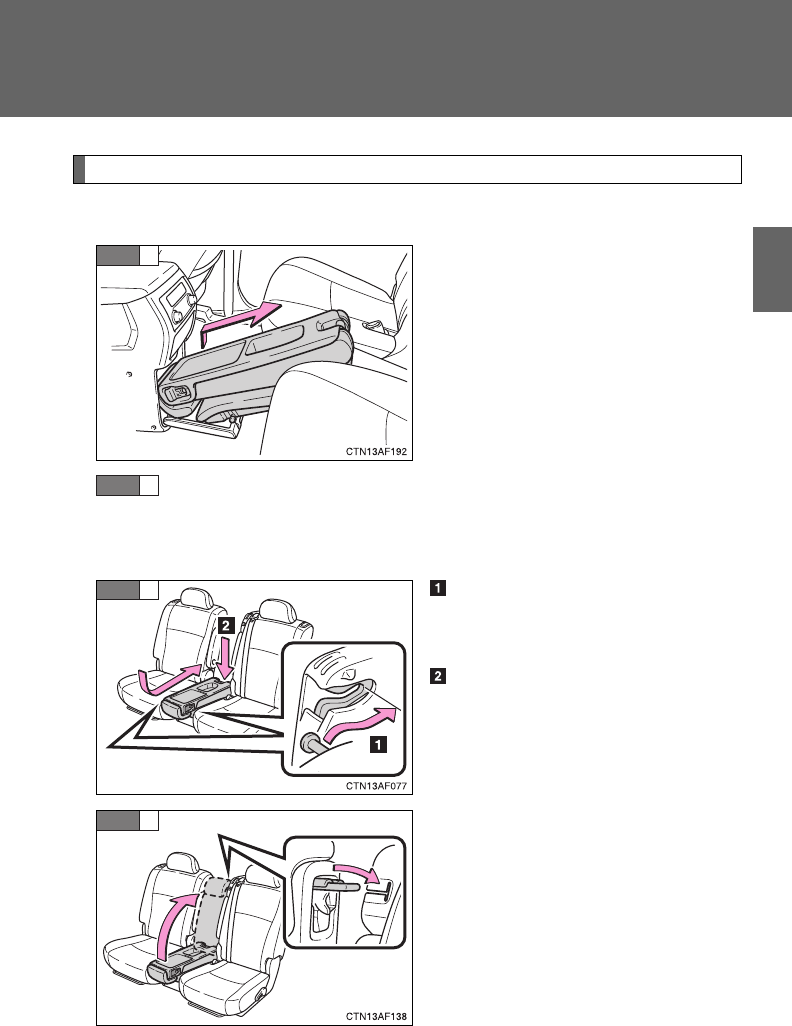
83
1-3. Adjustable components (seats, mirrors, steering wheel)
1
Before driving
Installing the second center seat
■Before installing the second center seat
Take out the second center seat
from the console box.
Remove the side table, if used, from the second seat.
(P. 450)
■Installing the second center seat
Fully engage the front pins
with the hooks, and swing the
second center seat downward.
Push down on the second
center seat to engage the rear
pin locks.
Unfold the seatback and lock it.
Stow the side table in the console
box.
STEP
1
STEP
2
STEP
1
STEP
2

84
1-3. Adjustable components (seats, mirrors, steering wheel)
CAUTION
■When adjusting a rear seat or removing the second center seat
●Be careful that the seat does not hit passengers or luggage.
●Do not recline the seat more than necessary when the vehicle is in motion
to reduce the risk of sliding under the lap belt. If the seat is too reclined,
the lap belt may slide past the hips and apply restraint forces directly to the
abdomen or your neck may contact the shoulder belt, increasing the risk of
death or serious injury in the event of an accident.
●Be careful not to get your hands or feet caught in the seat.
■Before folding down the rear seats
Do not fold down a rear seat when there are passengers sitting in the rear
seats or when there is luggage placed on the rear seats.
■After adjusting the seats
Observe the following precautions. Failure to do so may result in death or
serious injury.
●Make sure that the seat and seatback are securely locked in position by
lightly rocking them back and forth.
●Second center seat: Make sure the seat is locked in place by trying to
shake the seatback and lift up the rear part of the seat cushion.
●Check that the seat belts are not twisted or caught under the seat.
■Caution while driving
Keep the console box closed.
Injuries may result in the event of an accident or sudden braking.
NOTICE
■When folding down the second seats
Do not fold the seatback forward with the luggage cover hooks attached.
■Removed second center seat
Avoid putting heavy loads on the seat. The metallic seat pins may be dam-
aged, and you may be unable to correctly reinstall the seat.
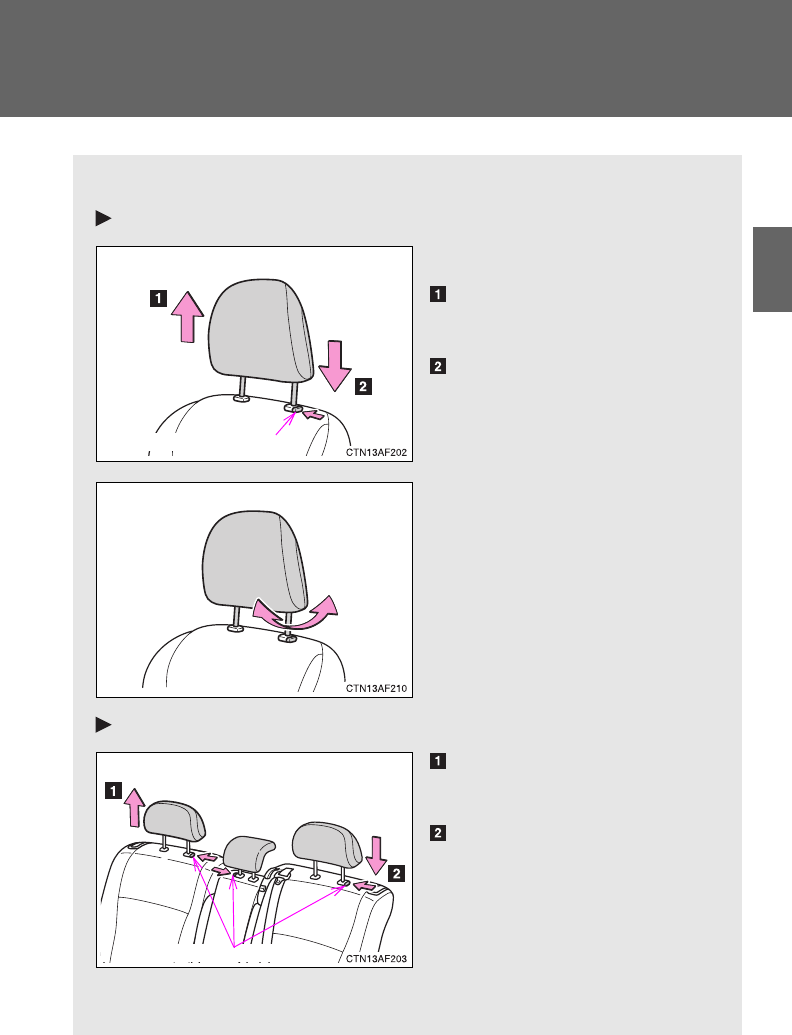
85
1
1-3. Adjustable components (seats, mirrors, steering wheel)
Before driving
Head restraints
Head restraints are provided for all seats.
Front seats
Vertical adjustment
Up
Pull the head restraints up.
Down
Push the head restraint down
while pushing the lock release
button.
Angle adjustment (if equipped)
Second seats
Up
Pull the head restraints up.
Down
Push the head restraint down
while pushing the lock release
button.
When using the center seat,
raise the head restraint from
the stowed position.
Lock release button
Lock release buttons
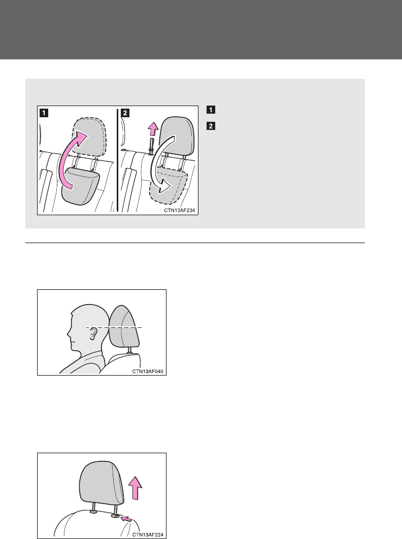
86
1-3. Adjustable components (seats, mirrors, steering wheel)
■Adjusting the height of the head restraints (except second center seat
and third seats)
■Adjusting the rear center seat head restraint
Always raise the head restraint one level from the stowed position when
using.
■Removing the front and second seat outer head restraints
■When using the third seat head restraints
To u se
To f ol d
Make sure that the head restraints are
adjusted so that the center of the head
restraint is closest to the top of your ears.
Pull the head restraint up while pushing
the lock release button.
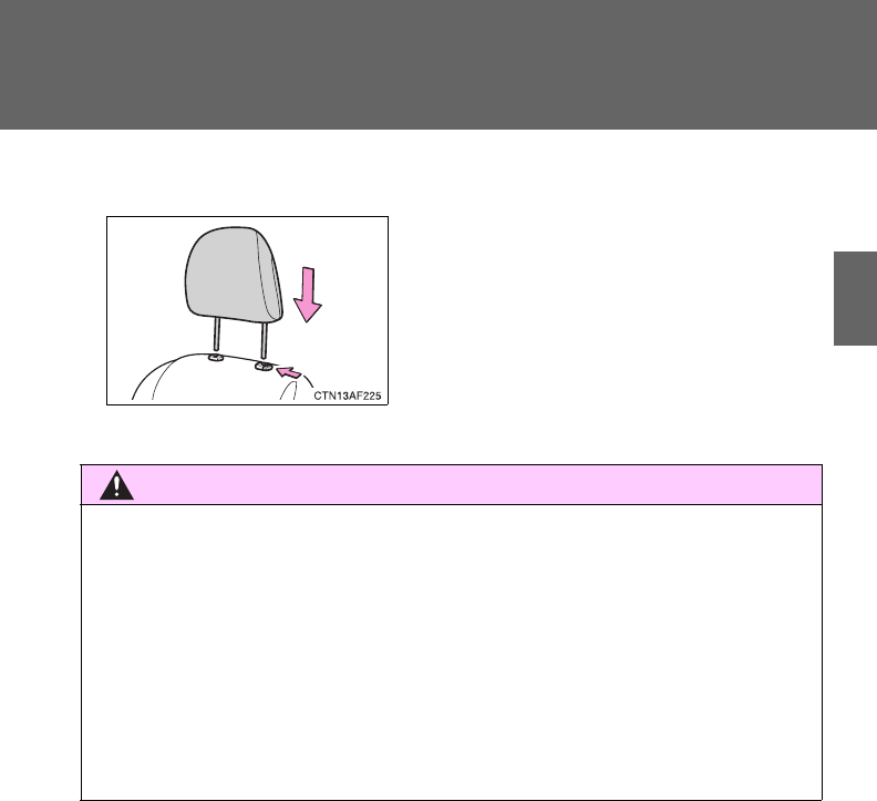
87
1-3. Adjustable components (seats, mirrors, steering wheel)
1
Before driving
■Installing the front and second seat outer head restraints
CAUTION
■Head restraint precautions
Observe the following precautions regarding the head restraints. Failure to
do so may result in death or serious injury.
●Use the head restraints designed for each respective seat.
●Adjust the head restraints to the correct position at all times.
●After adjusting the head restraints, push down on them and make sure
they are locked in position.
●Do not drive with the head restraints removed.
Align the head restraint with the installa-
tion holes and push it down to the lock
position.
Press and hold the lock release button
when lowering the head restraint.
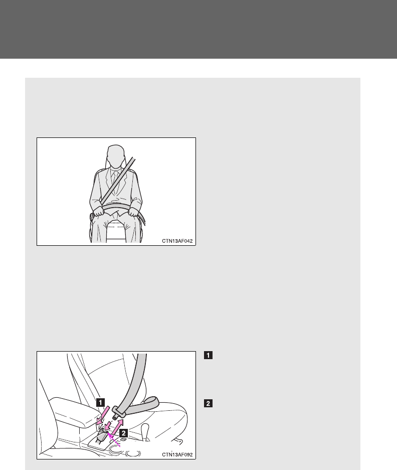
88
1-3. Adjustable components (seats, mirrors, steering wheel)
Seat belts
Make sure that all occupants are wearing their seat belts before driv-
ing the vehicle.
■Correct use of the seat belts
●Extend the shoulder belt so
that it comes fully over the
shoulder, but does not
come into contact with the
neck or slide off the shoul-
der.
●Position the lap belt as low
as possible over the hips.
●Adjust the position of the
seatback. Sit up straight
and well back in the seat.
●Do not twist the seat belt.
■Fastening and releasing the seat belt
Fastening the belt
Push the tab into the buckle
until a clicking sound is heard.
Releasing the belt
Press the release button.
Release button
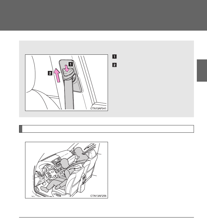
89
1-3. Adjustable components (seats, mirrors, steering wheel)
1
Before driving
Seat belt pretensioners (front seats)
The pretensioner helps the seat
belt to quickly restrain the occu-
pant by retracting the seat belt
when the vehicle is subjected to
certain types of severe frontal
collision or a vehicle rollover.
The pretensioner may not acti-
vate in the event of a minor frontal
impact, a side impact or a rear
impact.
■Adjusting the height of the belt (front seats)
Down
Up
Move the height adjuster up
and down as needed until you
hear a click.
■Emergency locking retractor (ELR)
The retractor will lock the belt during a sudden stop or on impact. It may also
lock if you lean forward too quickly. A slow, easy motion will allow the belt to
extend so that you can move around fully.
■Automatic locking retractor (ALR)
When a passenger's shoulder belt is completely extended and then
retracted even slightly, the belt is locked in that position and cannot be
extended. This feature is used to hold the child restraint system (CRS) firmly.
To free the belt again, fully retract the belt and then pull the belt out once
more. (P. 148)

90
1-3. Adjustable components (seats, mirrors, steering wheel)
■Pregnant women
■People suffering illness
Obtain medical advice and wear the seat belt in the proper way.
■When not using the rear seat belts
Second seat belts
Third seat belts
Obtain medical advice and wear the seat
belt in the proper way. (P. 88)
Women who are pregnant should position
the lap belt as low as possible over the
hips in the same manner as other occu-
pants. Extend the shoulder belt com-
pletely over the shoulder and position the
belt across the chest. Avoid belt contact
over the rounding of the abdominal area.
If the seat belt is not worn properly, not
only a pregnant woman, but also the fetus
could suffer death or serious injury as a
result of sudden braking or a collision.
Pass the outer seat belts through the seat
belt hangers and secure the seat belt
plates to prevent the shoulder belts from
being damaged.
Pass the outer seat belts through the seat
belt hangers to help prevent the shoulder
belts from being damaged.
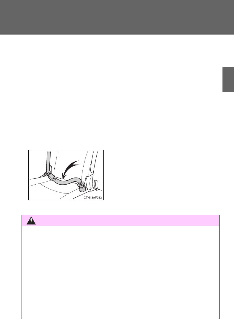
91
1-3. Adjustable components (seats, mirrors, steering wheel)
1
Before driving
■Child seat belt usage
The seat belts of your vehicle were principally designed for persons of adult
size.
●Use a child restraint system appropriate for the child, until the child
becomes large enough to properly wear the vehicle's seat belt. (P. 143)
●When the child becomes large enough to properly wear the vehicle's seat
belt, follow the instructions on P. 88 regarding seat belt usage.
■Replacing the belt after the pretensioner has been activated
If the vehicle is involved in multiple collisions, the pretensioner will activate
for the first collision, but will not activate for the second or subsequent colli-
sions.
■Seat belt extender
CAUTION
Observe the following precautions to reduce the risk of injury in the event of
sudden braking, sudden swerving or an accident.
Failure to do so may cause death or serious injury.
■Wearing a seat belt
●Ensure that all passengers wear a seat belt.
●Always wear a seat belt properly.
●Each seat belt should be used by one person only. Do not use a seat belt
for more than one person at once, including children.
●Toyota recommends that children be seated in the rear seat and always
use a seat belt and/or an appropriate child restraint system.
If your seat belts cannot be fastened
securely because they are not long
enough, a personalized seat belt
extender is available from your Toyota
dealer free of charge.

92
1-3. Adjustable components (seats, mirrors, steering wheel)
CAUTION
●Do not recline the seat any more than necessary to achieve a proper seat-
ing position. The seat belt is most effective when the occupants are sitting
up straight and well back in the seats.
●Do not wear the shoulder belt under your arm.
●Always wear your seat belt low and snug across your hips.
■When children are in the vehicle
Do not allow children to play with the seat belt. If the seat belt becomes
twisted around a child’s neck, it may lead to choking or other serious injuries
that could result in death. If this occurs and the buckle cannot be unfas-
tened, scissors should be used to cut the belt.
■Adjustable shoulder anchor
Always make sure the shoulder belt is positioned across the center of your
shoulder. The belt should be kept away from your neck, but not falling off
your shoulder. Failure to do so could reduce the amount of protection in an
accident and cause death or serious injuries in the event of a sudden stop,
sudden swerve or accident. (P. 89)
■Seat belt pretensioners
●Do not place anything, such as a cushion, on the front passenger's seat.
Doing so will disperse the passenger's weight, which prevents the sensor
from detecting the passenger's weight properly. As a result, the seat belt
pretensioner for the front passenger's seat may not activate in the event of
a collision.
●If the pretensioner has activated, the SRS warning light will come on. In
that case, the seat belt cannot be used again and must be replaced at
your Toyota dealer.

93
1-3. Adjustable components (seats, mirrors, steering wheel)
1
Before driving
CAUTION
■Seat belt damage and wear
●Do not damage the seat belts by allowing the belt, plate, or buckle to be
jammed in the door.
●Inspect the seat belt system periodically. Check for cuts, fraying, and loose
parts. Do not use a damaged seat belt until it is replaced. Damaged seat
belts cannot protect an occupant from death or serious injury.
●Ensure that the belt and tab are locked and the belt is not twisted.
If the seat belt does not function correctly, immediately contact your Toyota
dealer.
●Replace the seat assembly, including the belts, if your vehicle has been
involved in a serious accident, even if there is no obvious damage.
●Do not attempt to install, remove, modify, disassemble or dispose of the
seat belts. Have any necessary repairs carried out by your Toyota dealer.
Inappropriate handling of the pretensioner may prevent it from operating
properly resulting in death or serious injury.
■Using a seat belt extender
●Do not wear the seat belt extender if you can fasten the seat belt without
the extender.
●Do not use the seat belt extender when installing a child restraint system
because the belt will not securely hold the child restraint system, increas-
ing the risk of death or serious injury in the event of an accident.
●The personalized extender may not be safe on another vehicle, when
used by another person, or at a different seating position other than the
one originally intended.
NOTICE
■When using a seat belt extender
When releasing the seat belt, press on the buckle release button on the
extender, not on the seat belt.
This helps prevent damage to the vehicle interior and the extender itself.
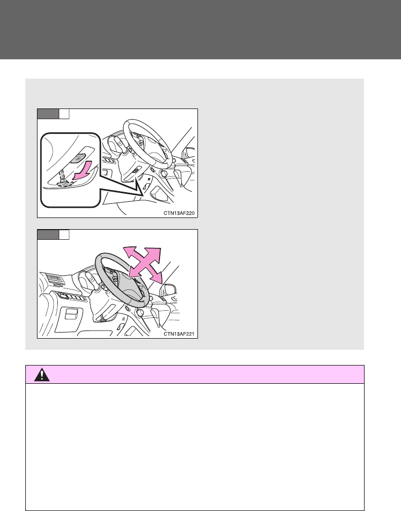
94
1-3. Adjustable components (seats, mirrors, steering wheel)
Steering wheel
CAUTION
■Caution while driving
Do not adjust the steering wheel while driving.
Doing so may cause the driver to mishandle the vehicle and an accident,
resulting in death or serious injury.
■After adjusting the steering wheel
Make sure that the steering wheel is securely locked.
Otherwise, the steering wheel may move suddenly, possibly causing an
accident and resulting in death or serious injury.
The steering wheel can be adjusted to a comfortable position.
Hold the steering wheel and
press the lever down.
Adjust to the ideal position by
moving the steering wheel
horizontally and vertically.
After adjustment, pull the lever
up to secure the steering
wheel.
STEP
1
STEP
2

95
1
1-3. Adjustable components (seats, mirrors, steering wheel)
Before driving
Anti-glare inside rear view mirror
Glare from the headlights of vehicles behind can be reduced by
using the following functions.
■Manual anti-glare inside rear view mirror
Normal position
Anti-glare position
■Auto anti-glare inside rear view mirror
In automatic mode, sensors are used to detect the headlights of
vehicles behind and the reflected light is automatically reduced.
Type A
Turns automatic mode on/off
The indicator comes on when
automatic mode is turned on.
Vehicles without smart key
system:
The mirror will revert to auto-
matic mode each time the
engine switch is turned to the
“ON” position.
Vehicles with smart key sys-
tem:
The mirror will revert to auto-
matic mode each time the
“ENGINE START STOP”
switch is turned to IGNITION
ON mode.
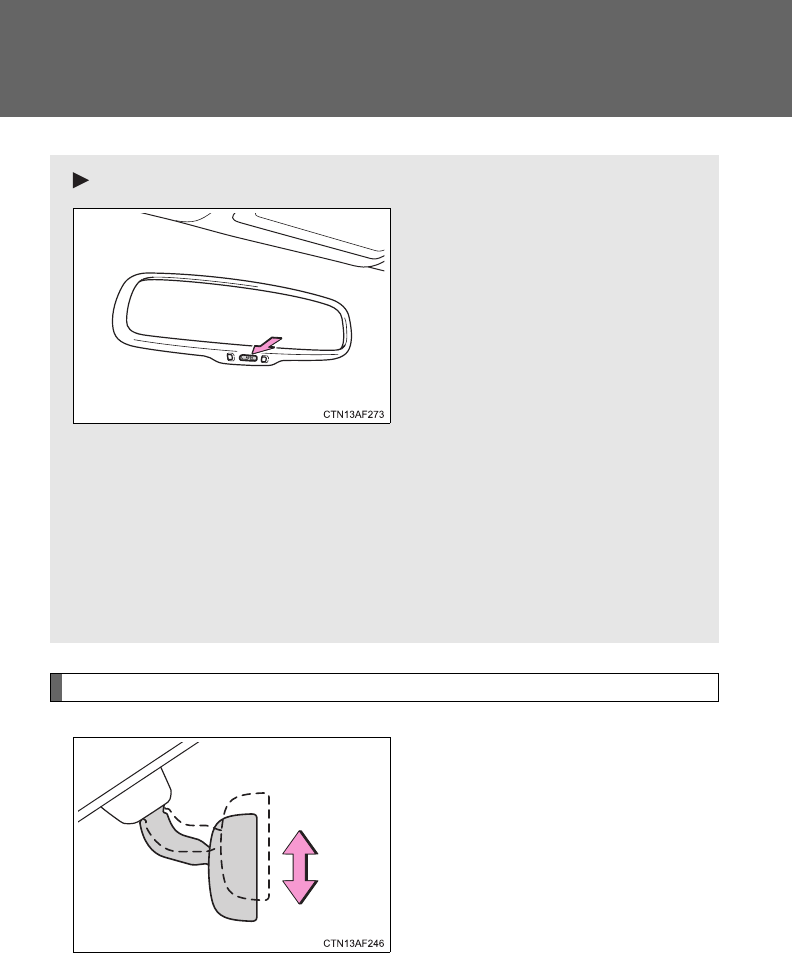
96
1-3. Adjustable components (seats, mirrors, steering wheel)
Adjusting the height of the rear view mirror
Adjust the height of the rear view
mirror by moving it up and down.
Type B
Turns automatic mode on/off
The indicator comes on when
automatic mode is turned on.
Vehicles without smart key
system:
The mirror will revert to auto-
matic mode each time the
engine switch is turned to the
“ON” position.
Vehicles with smart key sys-
tem:
The mirror will revert to auto-
matic mode each time the
“ENGINE START STOP”
switch is turned to IGNITION
ON mode.
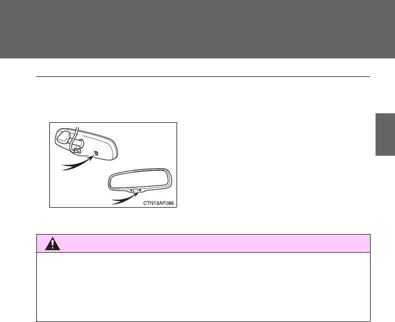
97
1-3. Adjustable components (seats, mirrors, steering wheel)
1
Before driving
■To prevent sensor error (vehicles with auto anti-glare inside rear view
mirror)
CAUTION
■Caution while driving
Do not adjust the position of the mirror while driving.
Doing so may lead to mishandling of the vehicle and an accident, resulting in
death or serious injury.
To ensure that the sensors operate prop-
erly, do not touch or cover them.
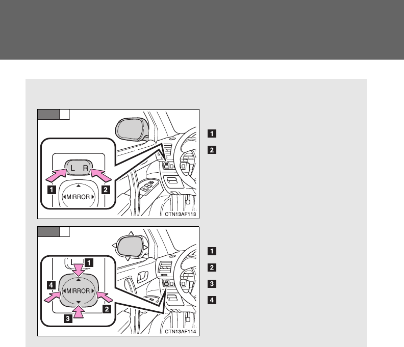
98
1-3. Adjustable components (seats, mirrors, steering wheel)
Outside rear view mirrors
Mirror angle can be adjusted using the switches.
Select a mirror to adjust.
Left
Right
Adjust the mirror.
Up
Right
Down
Left
STEP
1
STEP
2
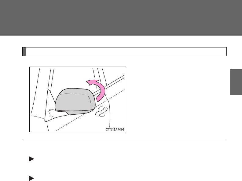
99
1-3. Adjustable components (seats, mirrors, steering wheel)
1
Before driving
Folding back the mirrors
Push backward to fold the mir-
rors.
■The outside rear view mirrors can be operated when
Vehicles without smart key system
The engine switch is in the “ACC” or “ON” position.
Vehicles with smart key system
The “ENGINE START STOP” switch is in ACCESSORY or IGNITION ON
mode.
■When the mirrors are fogged up (vehicles with outside rear view mirror
defoggers)
Turn on the mirror defoggers to defog the mirrors. (P. 295)

100
1-3. Adjustable components (seats, mirrors, steering wheel)
CAUTION
■When driving the vehicle
Observe the following precautions while driving.
Failing to do so may result in loss of control of the vehicle and cause an acci-
dent, resulting in death or serious injury.
●Do not adjust the mirrors while driving.
●Do not drive with the mirrors folded back.
●Both the driver and passenger side mirrors must be extended and properly
adjusted before driving.
■When the mirror defoggers are operating (vehicles with outside rear
view mirror defoggers)
Do not touch the rear view mirror surfaces, as they can become very hot and
burn you.
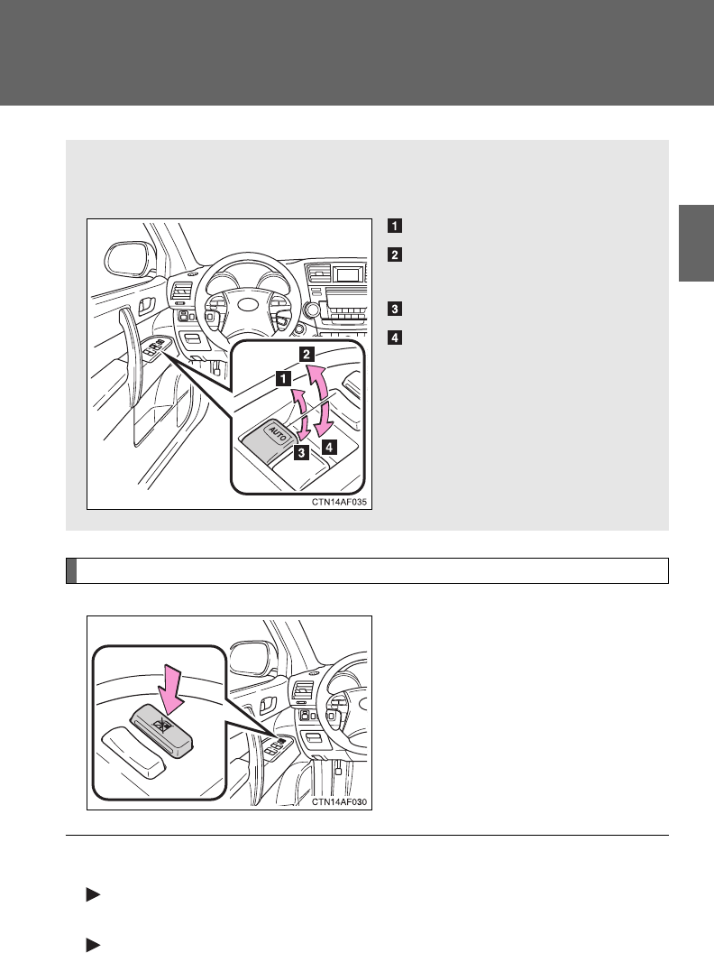
101
1
Before driving
1-4. Opening and closing the windows and moon roof
Power windows
Lock switch
Press the switch down to lock
the passenger window switches.
Use this switch to prevent chil-
dren from accidentally opening or
closing a passenger window.
The power windows can be opened and closed using the following
switches.
Closing
One-touch closing (driver’s
window only)*
Opening
One-touch opening (driver’s
window only)*
*: Pressing the switch in the
opposite direction will stop win-
dow travel partway.
■The power windows can be operated when
Vehicles without smart key system
The engine switch is in the “ON” position.
Vehicles with smart key system
The “ENGINE START STOP” switch is in IGNITION ON mode.

102
1-4. Opening and closing the windows and moon roof
■Operating the power windows after turning the engine off
Vehicles without smart key system
The power windows can be operated for approximately 45 seconds after the
engine switch is turned to the “ACC” or “LOCK” position. They cannot, how-
ever, be operated once either front door is opened.
Vehicles with smart key system
The power windows can be operated for approximately 45 seconds after the
“ENGINE START STOP” switch is turned to ACCESSORY mode or turned
OFF. They cannot, however, be operated once either front door is opened.
■Jam protection function (driver’s window only)
If an object becomes caught between the window and the window frame,
window travel is stopped and the window is opened slightly.
■When the power window does not close normally
If the jam protection function is operating abnormally and a window cannot
be closed, perform the following operations using the power window switch
on the driver’s door.
●Vehicles without a smart key system: After stopping the vehicle, the win-
dow can be closed by holding the power window switch in the one-touch
closing position while the engine switch is turned to the “ON” position.
●Vehicles with a smart key system: After stopping the vehicle, the window
can be closed by holding the power window switch in the one-touch clos-
ing position while the “ENGINE START STOP” switch is turned to IGNI-
TION ON mode.
●If the window still cannot be closed even by carrying out the operation
explained above, initialize the function by performing the following proce-
dure.
Hold the power window switch in the one-touch closing position.
Continue holding the switch for a further 6 seconds after the win-
dow has closed.
Hold the power window switch in the one-touch opening position.
Continue holding the switch for a further 2 seconds after the win-
dow has opened completely.
Hold the power window switch in the one-touch closing position
once again. Continue holding the switch for a further 2 seconds
after the window has closed.
STEP
1
STEP
2
STEP
3

103
1-4. Opening and closing the windows and moon roof
1
Before driving
If you release the switch while the window is moving, start again from the
beginning.
If the window continues to close but then re-open slightly even after perform-
ing the above procedure correctly, have the vehicle inspected by your Toyota
dealer.
CAUTION
■Closing the windows
Observe the following precautions.
Failing to do so may result in death or serious injury.
●Check to make sure that all passengers do not have any part of their body
in a position where it could be caught when a window is being operated.
●Do not allow children to operate the power windows.
Closing a power window on someone can cause serious injury, and in
some instances, even death.
■Jam protection function (driver’s window only)
●Never try jamming any part of your body to activate the jam protection
function intentionally.
●The jam protection function may not work if something gets caught just
before the window fully closes.
●The jam protection function may not work depending on the shape of the
object that is caught. Be careful not to catch fingers or anything else.
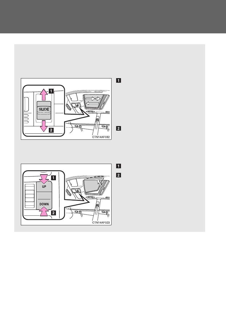
104
1-4. Opening and closing the windows and moon roof
Moon roof
Use the overhead switches to open, close, and tilt the moon roof up
and down.
■Opening and closing
Open
The moon roof stops slightly
before the fully open position
to reduce wind noise.
Move the switch backward
again to fully open.
Close
Move the switch forward to
stop the moon roof partway.
■Tilting up and down
Tilt up
Tilt down
Push the switch in either direc-
tion to stop the moon roof part-
way.
: If equipped

105
1-4. Opening and closing the windows and moon roof
1
Before driving
■The moon roof can be operated when
Vehicles without smart key system
The engine switch is in the “ON” position.
Vehicles with smart key system
The “ENGINE START STOP” switch is in IGNITION ON mode.
■Operating the moon roof after turning the engine off
Vehicles without smart key system
The moon roof can be operated for approximately 45 seconds after the
engine switch is turned to the “ACC” or “LOCK” position. It cannot, however,
be operated once either front door is opened.
Vehicles with smart key system
The moon roof can be operated for approximately 45 seconds after the
“ENGINE START STOP” switch is turned to ACCESSORY mode or turned
OFF. They cannot, however, be operated once either front door is opened.
■Jam protection function
If an object is detected between the moon roof and the frame while closing
or tilting down, travel is stopped and the moon roof opens slightly.
■To reduce moon roof wind noise
When the moon roof is opened automatically, it will stop slightly before the
fully open position. Driving with the moon roof in this position can help
reduce wind noise.

106
1-4. Opening and closing the windows and moon roof
■When the moon roof does not close normally
Perform the following procedure:
●If the moon roof closes but then re-opens slightly
Stop the vehicle.
Press and hold the “SLIDE (open/close)” switch in the close posi-
tion.*1
The moon roof will close, reopen and pause for approximately 10
seconds.*2 Then it will close again, tilt up and pause for approxi-
mately 1 second. Finally, it will tilt down, open and close.
Check to make sure that the moon roof is completely closed and
then release the switch.
●If the moon roof tilts down but then tilts back up
Stop the vehicle.
Press and hold the “UP” switch*1 until the moon roof moves into the
tilt up position and stops.
Release the “UP” switch once and then press and hold the “UP”
switch again.*1
The moon roof will pause for approximately 10 seconds in the tilt up
position.*2 Then it will adjust slightly and pause for approximately 1
second. Finally, it will tilt down, open and close.
Check to make sure that the moon roof is completely closed and
then release the switch.
*1: If the switch is released at the incorrect time, the procedure will
have to be performed again from the beginning.
*2: If the switch is released after the above mentioned 10 second
pause, automatic operation will be disabled. In that case, press
and hold the “SLIDE (open/close)” switch in the close position or
the “UP” switch, and the moon roof will tilt up and pause for
approximately 1 second. Then it will tilt down, open and close.
Check to make sure that the moon roof is completely closed and
then release the switch.
If the moon roof does not fully close even after performing the above proce-
dure correctly, have the vehicle inspected by your Toyota dealer.
STEP
1
STEP
2
STEP
3
STEP
1
STEP
2
STEP
3
STEP
4

107
1-4. Opening and closing the windows and moon roof
1
Before driving
■Sunshade
The sunshade can be opened and closed manually. However, the sunshade
will open automatically when the moon roof is opened.
■Moon roof open reminder function (vehicles with multi-information dis-
play)
Vehicles without smart key system
An alarm will sound when the driver’s door is opened with the moon roof not
fully closed and the engine switch OFF.
Vehicles with smart key system
An alarm will sound when the driver’s door is opened with the moon roof not
fully closed and the “ENGINE START STOP” switch OFF.
CAUTION
■Opening the moon roof
Observe the following precautions.
Failure to do so may cause death or serious injury.
●Do not allow any passengers to put their hands or heads outside the vehi-
cle while it is moving.
●Do not sit on top of the moon roof.
■Closing the moon roof
Observe the following precautions.
Failing to do so may result in death or serious injury.
●Check to make sure that all passengers do not have any part of their bod-
ies in a position where it could be caught when the moon roof is being
operated.
●Do not allow children to operate the moon roof.
Closing the moon roof on someone can cause death or serious injury.

108
1-4. Opening and closing the windows and moon roof
CAUTION
■Jam protection function
●Never try jamming any part of your body to activate the jam protection
function intentionally.
●The jam protection function may not work if something gets caught just
before the moon roof fully closes.
●The jam protection function may not work depending on the shape of the
object that is caught. Be careful not to catch fingers or anything else.
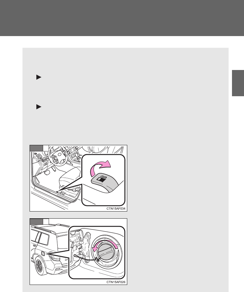
109
1
Before driving
1-5. Refueling
Opening the fuel tank cap
Perform the following steps to open the fuel tank cap.
■Before refueling the vehicle
Vehicles without smart key system
Turn the engine switch OFF and ensure that all the doors and
windows are closed.
Vehicles with smart key system
Turn the “ENGINE START STOP” switch OFF and ensure that
all the doors and windows are closed.
■Opening the fuel tank cap
Open the fuel filler door.
Turn the fuel tank cap slowly
to open.
STEP
1
STEP
2
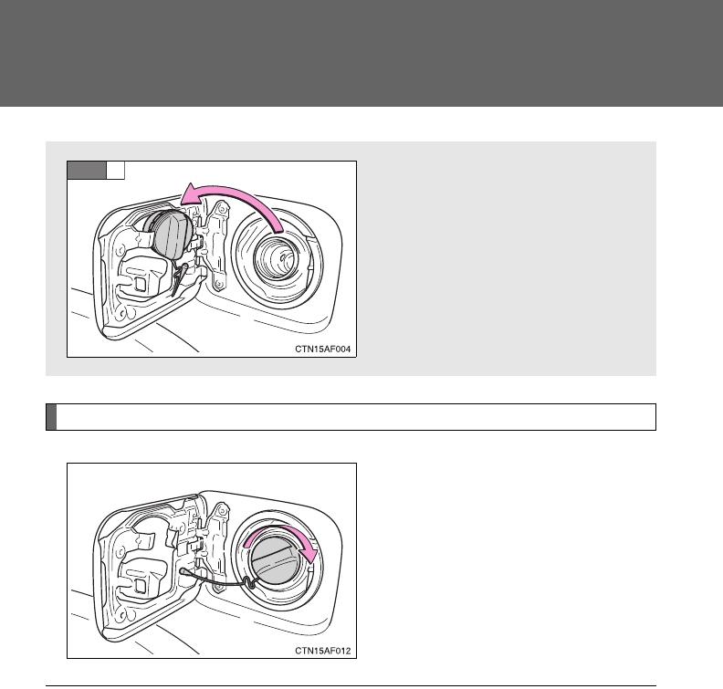
110
1-5. Refueling
Closing the fuel tank cap
When replacing the fuel tank
cap, turn it until a clicking sound
is heard.
Once the cap is released, it will
turn slightly in the opposite direc-
tion.
Hang the fuel tank cap on the
back of the fuel filler door.
STEP
3
■Fuel types
Use unleaded gasoline. (Octane rating 87 [Research Octane Number 91] or
higher)
■Fuel tank capacity
Approximately 19.2 gal. (72.5 L, 15.9 Imp. gal.)

111
1-5. Refueling
1
Before driving
CAUTION
■Refueling the vehicle
Observe the following precautions while refueling the vehicle.
Failure to do so may result in death or serious injury.
●Touch the vehicle or some other metal surface to discharge any static
electricity.
Sparks resulting from discharging static electricity may cause the fuel
vapors to ignite.
●Always hold the grips on the fuel tank cap and turn it slowly to remove it.
A whooshing sound may be heard when the fuel tank cap is loosened.
Wait until the sound cannot be heard before fully removing the cap.
In hot weather, pressurized fuel may spray out of the filler neck and cause
injury.
●Do not allow anyone that has not discharged static electricity from their
bodies to come close to an open fuel tank.
●Do not inhale vaporized fuel.
Fuel contains substances that are harmful if inhaled.
●Do not smoke while refueling the vehicle.
Doing so may cause the fuel to ignite and cause a fire.
●Do not return to the vehicle or touch any person or object that is statically
charged.
This may cause static electricity to build up, resulting in a possible ignition
hazard.
■When replacing the fuel cap
Do not use anything but a genuine Toyota fuel tank cap designed for your
vehicle. Doing so may cause a fire or other incident which may result in
death or serious injury.

112
1-5. Refueling
NOTICE
■Refueling
Do not spill fuel during refueling.
Doing so may damage the vehicle, such as causing the exhaust systems to
operate abnormally or damaging fuel system components or the vehicle's
painted surface.
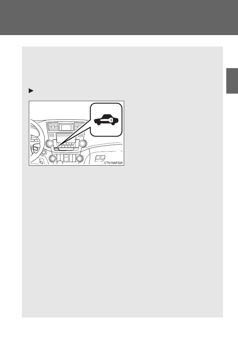
113
1
Before driving
1-6. Theft deterrent system
Engine immobilizer system
The vehicle's keys have built-in transponder chips that prevent the
engine from starting if the key has not been previously registered in
the vehicle's on-board computer.
Never leave the keys inside the vehicle when you leave the vehicle.
Vehicles without a Display Audio system or navigation system
Vehicles without smart key
system: The indicator light
flashes after the key has been
removed from the engine
switch to indicate that the sys-
tem is operating.
The indicator light stops flash-
ing after the registered key
has been inserted into the
engine switch to indicate that
the system has been can-
celed.
Vehicles with smart key sys-
tem: The indicator light flashes
after the “ENGINE START
STOP” switch has been turned
OFF to indicate that the sys-
tem is operating.
The indicator light stops flash-
ing after the “ENGINE START
STOP” switch has been turned
to ACCESSORY or IGNITION
ON mode to indicate that the
system has been canceled.
: If equipped
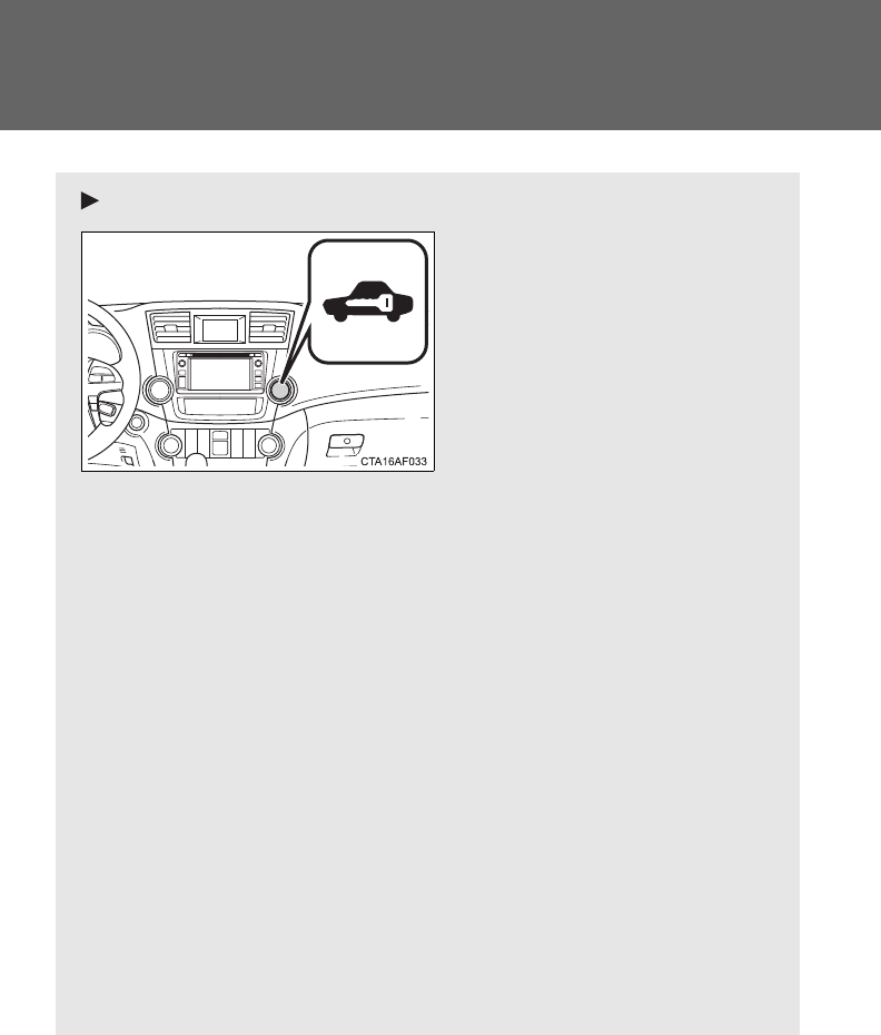
114
1-6. Theft deterrent system
Vehicles with a Display Audio system
Vehicles without smart key
system: The indicator light
flashes after the key has been
removed from the engine
switch to indicate that the sys-
tem is operating.
The indicator light stops flash-
ing after the registered key
has been inserted into the
engine switch to indicate that
the system has been can-
celed.
Vehicles with smart key sys-
tem: The indicator light flashes
after the “ENGINE START
STOP” switch has been turned
OFF to indicate that the sys-
tem is operating.
The indicator light stops flash-
ing after the “ENGINE START
STOP” switch has been turned
to ACCESSORY or IGNITION
ON mode to indicate that the
system has been canceled.
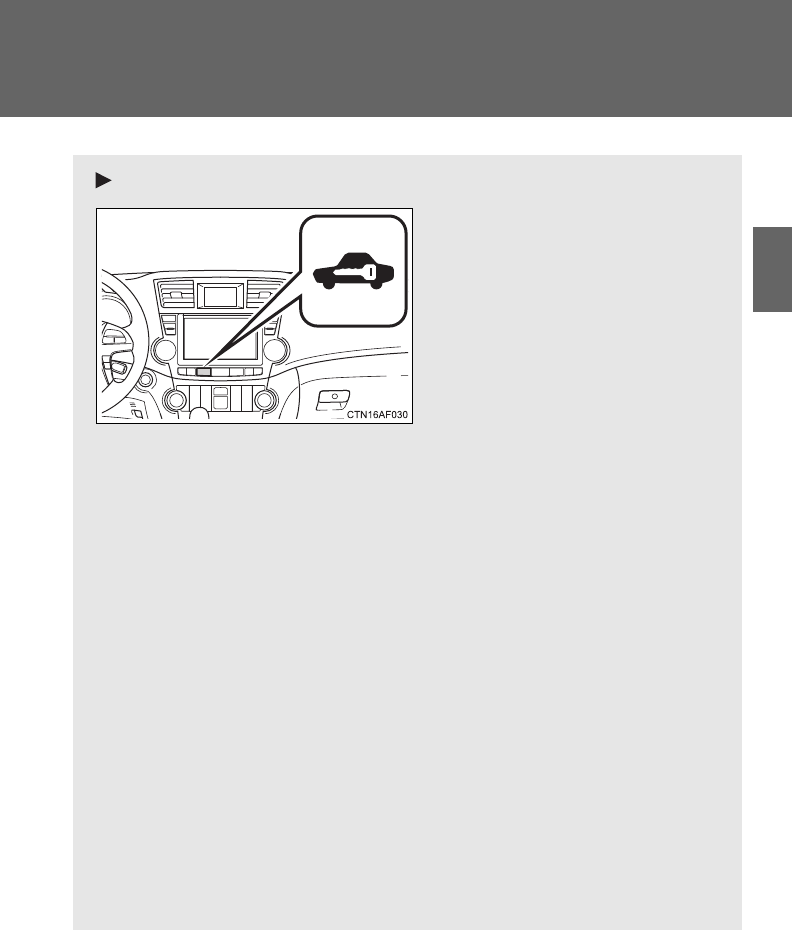
115
1-6. Theft deterrent system
1
Before driving
Vehicles with a navigation system
Vehicles without smart key
system: The indicator light
flashes after the key has been
removed from the engine
switch to indicate that the sys-
tem is operating.
The indicator light stops flash-
ing after the registered key
has been inserted into the
engine switch to indicate that
the system has been can-
celed.
Vehicles with smart key sys-
tem: The indicator light flashes
after the “ENGINE START
STOP” switch has been turned
OFF to indicate that the sys-
tem is operating.
The indicator light stops flash-
ing after the “ENGINE START
STOP” switch has been turned
to ACCESSORY or IGNITION
ON mode to indicate that the
system has been canceled.

116
1-6. Theft deterrent system
■System maintenance
The vehicle has a maintenance-free type engine immobilizer system.
■Conditions that may cause the system to malfunction
●If the key is in contact with a metallic object
●If the key is in close proximity to or touching a key with the security sys-
tem (key with a built-in transponder chip) of another vehicle
■Certifications for the engine immobilizer system
●For vehicles sold in the U.S.A.
Vehicles without smart key system
FCC ID: MOZRI-21BTY
Vehicles with smart key system
FCC ID: NI4TMIMB-1
This device complies with Part 15 of the FCC Rules. Operation is subject to
the following two conditions: (1) this device may not cause harmful interfer-
ence, and (2) this device must accept any interference received, including
interference that may cause undesired operation.
FCC WARNING:
Changes or modifications not expressly approved by the party responsible
for compliance could void the user's authority to operate the equipment.
●For vehicles sold in Canada
Operation is subject to the following two conditions: (1) this device may not
cause interference, and (2) this device must accept any interference, includ-
ing interference that may cause undesired operation of the device.
NOTICE
■To ensure the system operates correctly
Do not modify or remove the system.
If modified or removed, the proper operation of the system cannot be guar-
anteed.
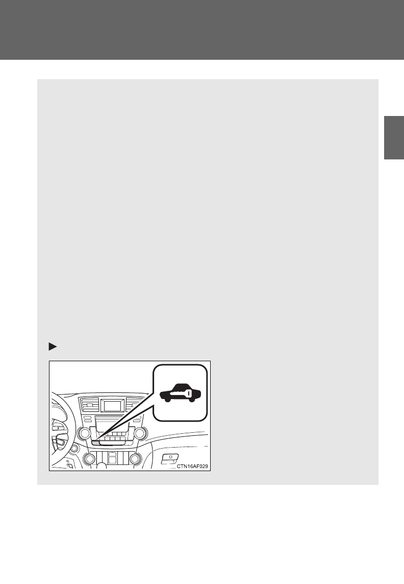
117
1
1-6. Theft deterrent system
Before driving
Alarm
: If equipped
The system sounds the alarm and flashes the lights when forcible
entry is detected.
■Triggering of the alarm
The alarm is triggered in the following situations when the alarm
is set.
●A locked door is unlocked or opened in any way other than
using the entry function (vehicles with smart key system) or
wireless remote control or mechanical key. (The doors will
lock again automatically.)
●The hood is opened.
●The locked glass hatch is opened in any way other than using
the wireless remote control door lock function or entry function
(vehicles with smart key system).
●The battery is reconnected.
■Setting the alarm system
Vehicles without a Display Audio system or navigation system
Close the doors, glass hatch
and hood, and lock all the
doors. The system will be set
automatically after 30 sec-
onds.
The indicator light changes
from being on to flashing when
the system is set.
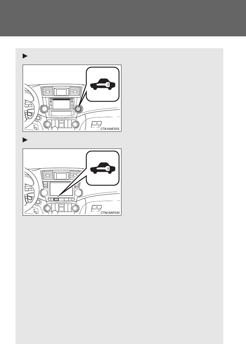
118
1-6. Theft deterrent system
Vehicles with a Display Audio system
Close the doors, glass hatch
and hood, and lock all the
doors. The system will be set
automatically after 30 sec-
onds.
The indicator light changes
from being on to flashing when
the system is set.
Vehicles with a navigation system
Close the doors, glass hatch
and hood, and lock all the
doors. The system will be set
automatically after 30 sec-
onds.
The indicator light changes
from being on to flashing when
the system is set.
■Deactivating or stopping the alarm
●Unlock the doors.
●Vehicles without smart key system: Turn the engine switch to
the “ON” position, or start the engine. (The alarm will be deac-
tivated or stopped after a few seconds.)
●Vehicles with smart key system: Turn the “ENGINE START
STOP” switch to IGNITION ON mode, or start the engine.
(The alarm will be deactivated or stopped after a few sec-
onds.)
●Open the glass hatch using the entry function (vehicles with
smart key system) or wireless remote control (vehicles with-
out smart key system).
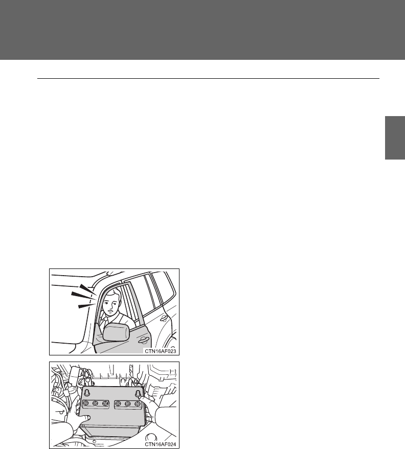
119
1-6. Theft deterrent system
1
Before driving
■System maintenance
The vehicle has a maintenance-free type alarm system.
■Items to check before locking the vehicle
To prevent unexpected triggering of the alarm and vehicle theft, make sure
of the following.
●Nobody is in the vehicle.
●The windows and moon roof are closed before the alarm is set.
●No valuables or other personal items are left in the vehicle.
■Triggering of the alarm
The alarm may be triggered in the following situations. (Stopping the alarm
deactivates the alarm system.)
■Panic mode
P. 50
■When the battery is disconnected
Be sure to cancel the alarm system.
If the battery is disconnected before canceling the alarm, the system may be
triggered when the battery is reconnected.
●A person inside the vehicle opens a
door or the hood when the vehicle is
locked.
●The battery is recharged or replaced
when the vehicle is locked.

120
1-6. Theft deterrent system
■Alarm-operated door lock
●When the alarm is operating, the doors are locked automatically to pre-
vent intruders.
●Do not leave the key inside the vehicle when the alarm is operating, and
make sure the key is not inside the vehicle when recharging or replacing
the battery.
■When using the key to unlock the doors
Deactivate the alarm.
NOTICE
■To ensure the system operates correctly
Do not modify or remove the system.
If modified or removed, the proper operation of the system cannot be guar-
anteed.
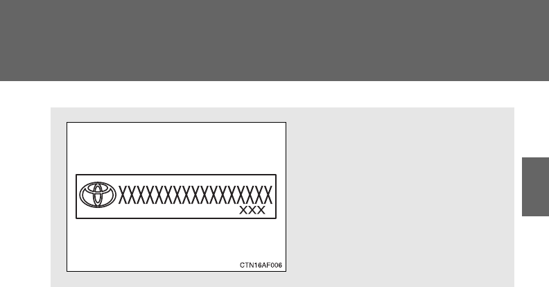
121
1
1-6. Theft deterrent system
Before driving
Theft prevention labels (U.S.A.)
These labels are attached to
the vehicle to reduce vehicle
theft by facilitating the tracing
and recovery of parts from sto-
len vehicles. Do not remove
under penalty of law.
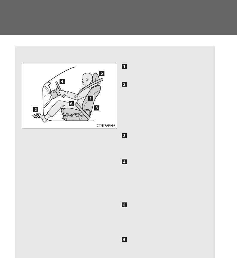
122
1-7. Safety information
Correct driving posture
Drive in a good posture as follows:
Sit upright and well back in
the seat. (P. 7 4 )
Adjust the position of the
seat forward or backward to
ensure the pedals can be
reached and easily
depressed to the extent
required. (P. 74)
Adjust the seatback so that
the controls are easily oper-
able.
Adjust the tilt and telescopic
positions of the steering
wheel downward so the air-
bag is facing your chest.
(P. 94)
Lock the head restraint in
place with the center of the
head restraint closest to the
top of your ears. (P. 85)
Wear the seat belt correctly.
(P. 88)

123
1-7. Safety information
1
Before driving
CAUTION
■While driving
●Do not adjust the position of the driver's seat while driving.
Doing so could cause the driver to lose control of the vehicle.
●Do not place a cushion between the driver or passenger and the seatback.
A cushion may prevent correct posture from being achieved, and reduce
the effectiveness of the seat belt and head restraint, increasing the risk of
death or serious injury to the driver or passenger.
●Do not place anything under the front seats.
Objects placed under the front seats may become jammed in the seat
tracks and stop the seat from locking in place. This may lead to an acci-
dent. The adjustment mechanism may also be damaged.
■Adjusting the seat position
●Take care when adjusting the seat position to ensure that other passen-
gers are not injured by the moving seat.
●Do not put your hands under the seat or near the moving parts to avoid
injury.
Fingers or hands may become jammed in the seat mechanism.
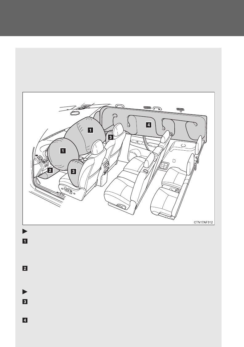
124
1-7. Safety information
SRS airbags
The SRS airbags inflate when the vehicle is subjected to certain
types of severe impacts that may cause significant injury to the
occupants. They work together with the seat belts to help reduce the
risk of death or serious injury.
Front airbags
Driver airbag/front passenger airbag
Can help protect the head and chest of the driver and front pas-
senger from impact with interior components.
Driver knee airbag
Can help provide driver protection.
Side and curtain shield airbags
Side airbags
Can help protect the torso of the front seat occupants.
Curtain shield airbags
Can help protect primarily the head of occupants in the outer
seats.
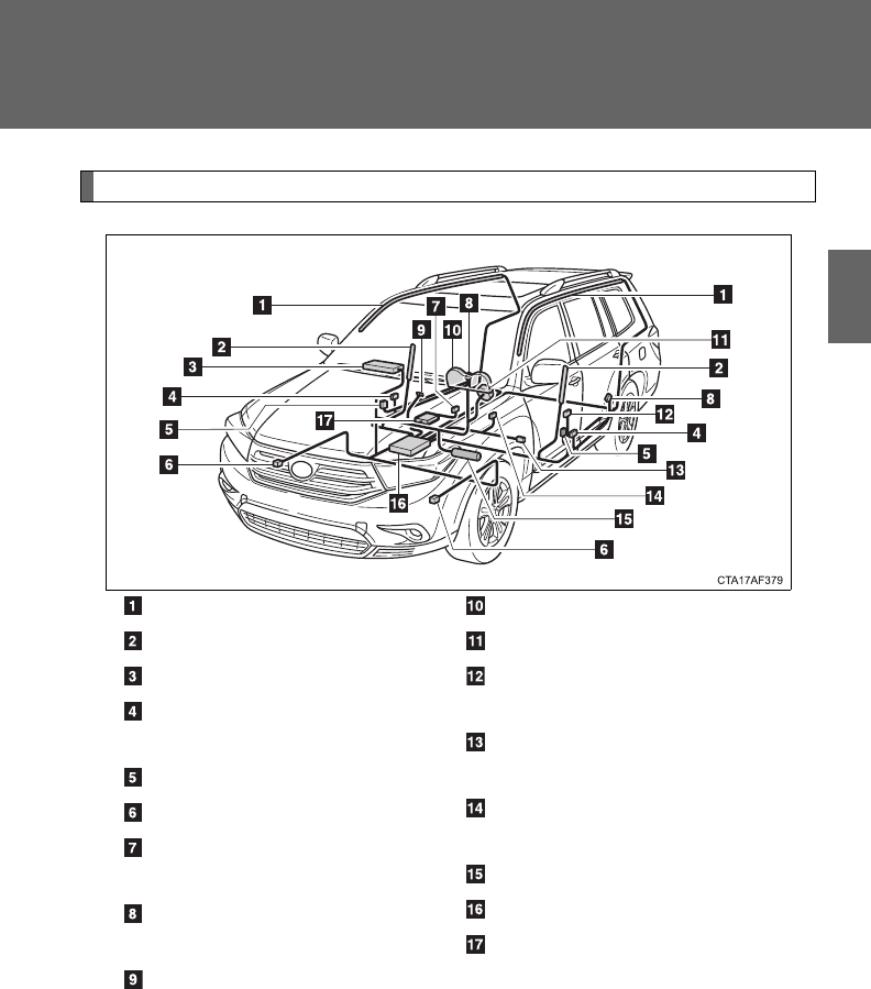
125
1-7. Safety information
1
Before driving
Airbag system components
Curtain shield airbags
Side airbags
Front passenger airbag
Side and curtain shield air-
bag sensors
Door sensors
Front airbag sensors
Front passenger’s seat belt
buckle switch
Curtain shield airbag sen-
sors
“AIR BAG ON” and “AIR
BAG OFF” indicator lights
SRS warning light
Driver airbag
Seat belt pretensioners and
force limiters
Driver’s seat position sen-
sor
Driver’s seat belt buckle
switch
Driver knee airbag
Airbag sensor assembly
Front passenger occupant
classification system (ECU
and sensors)

126
1-7. Safety information
Your vehicle is equipped with ADVANCED AIRBAGS designed based
on the US motor vehicle safety standards (FMVSS208). The airbag
sensor assembly (ECU) controls airbag deployment based on infor-
mation obtained from the sensors etc. shown in the system compo-
nents diagram above. This information includes crash severity and
occupant information. As the airbags deploy, a chemical reaction in
the inflators quickly fills the airbags with non-toxic gas to help restrain
the motion of the occupants.
■SRS warning light
This warning light system monitors the airbag sensor assembly, front airbag
sensors, side and curtain shield airbag sensor assemblies, curtain shield air-
bag sensor assemblies, door sensors, driver's seat position sensor, driver's
seat belt buckle switch, front passenger occupant classification system
(ECU and sensors), “AIR BAG ON” and “AIR BAG OFF” indicator lights,
front passenger’s seat belt buckle switch, front seat belt pretensioner
assemblies, airbags, interconnecting wiring and power sources. (P. 574)
■If the SRS airbags deploy (inflate)
●Bruising and slight abrasions may result from contact with a deploying
(inflating) SRS airbag.
●A loud noise and white powder will be emitted.
●Parts of the airbag module (steering wheel hub, airbag cover and inflator)
as well as the front seats, and parts of the front and rear pillars and roof
side rail, may be hot for several minutes. The airbag itself may also be
hot.
●The windshield may crack.

127
1-7. Safety information
1
Before driving
■SRS airbag deployment conditions (front airbags)
●The SRS front airbags will deploy in the event of an impact that exceeds
the set threshold level (the level of force corresponding to an approxi-
mately 12 - 18 mph [20 - 30 km/h] frontal collision with a fixed wall that
does not move or deform).
However, this threshold velocity will be considerably higher if the vehicle
strikes an object, such as a parked vehicle or sign pole, which can move or
deform on impact, or if the vehicle is involved in an underride collision (e.g.
a collision in which the front of the vehicle “underrides”, or goes under, the
bed of a truck, etc.).
●Depending on the type of collision, it is possible that only the seat belt
pretensioners will activate.
●The SRS front passenger airbag will not activate if there is no passenger
sitting in the front passenger seat. However, the front passenger airbag
may deploy if luggage is put in the seat, even if the seat is unoccupied.
(P. 136)
■SRS airbag deployment conditions (SRS side airbags)
The SRS side airbags will deploy in the event of an impact that exceeds the
set threshold level (the level of force corresponding to the impact force pro-
duced by an approximately 3300 lb. [1500 kg] vehicle colliding with the vehi-
cle cabin from a direction perpendicular to the vehicle orientation at an
approximate speed of 12 - 18 mph [20 - 30 km/h]).
■SRS airbag deployment conditions (SRS curtain shield airbags)
The SRS curtain shield airbags will deploy in the event of vehicle rollover or
an impact that exceeds the set threshold level (the level of force correspond-
ing to the impact force produced by an approximately 3300 lb. [1500 kg]
vehicle colliding with the vehicle cabin from a direction perpendicular to the
vehicle orientation at an approximate speed of 12 - 18 mph [20 - 30 km/h]).
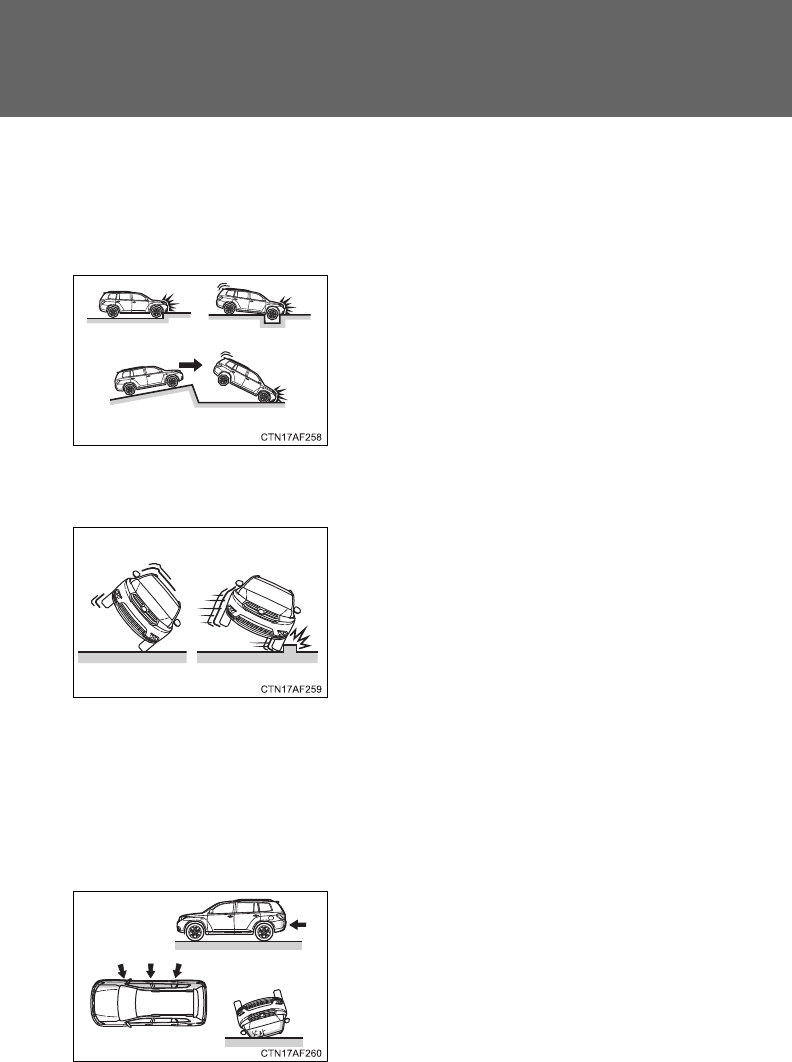
128
1-7. Safety information
■Conditions under which the SRS airbags may deploy (inflate), other
than a collision
The SRS front airbags may also deploy if a serious impact occurs to the
underside of your vehicle. Some examples are shown in the illustration.
The SRS curtain shield airbags may also deploy under the situation shown
in the illustration.
■Types of collisions that may not deploy the SRS airbag (front airbags)
The SRS front airbags are generally not designed to inflate if the vehicle is
involved in a side or rear collision, if it rolls over, or if it is involved in a low-
speed frontal collision. But, whenever a collision of any type causes suffi-
cient forward deceleration of the vehicle, deployment of the SRS front air-
bags may occur.
●Hitting a curb, edge of pavement or
hard surface
●Falling into or jumping over a deep hole
●Landing hard or vehicle falling
●The angle of vehicle tip-up is marginal.
●The vehicle skids and hits a curb stone.
●Collision from the side
●Collision from the rear
●Vehicle rollover
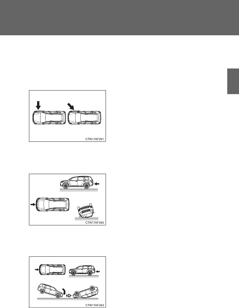
129
1-7. Safety information
1
Before driving
■Types of collisions that may not deploy the SRS airbag
(side airbags and curtain shield airbags)
The SRS side airbag and curtain shield airbag system may not activate if the
vehicle is subjected to a collision from the side at certain angles, or a colli-
sion to the side of the vehicle body other than the passenger compartment.
The SRS side airbags are not generally designed to inflate if the vehicle is
involved in a frontal or rear collision, if it rolls over, or if it is involved in a low-
speed side collision.
The SRS curtain shield airbags are not generally designed to inflate if the
vehicle is involved in a frontal or rear collision, if it pitches end over end, or if
it is involved in a low-speed side collision.
●Collision from the side to the vehicle
body other than the passenger com-
partment
●Collision from the side at an angle
●Collision from the front
●Collision from the rear
●Vehicle rollover
●Collision from the front
●Collision from the rear
●Pitching end over end
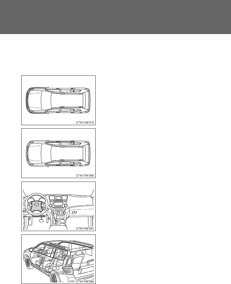
130
1-7. Safety information
■When to contact your Toyota dealer
In the following cases, contact your Toyota dealer as soon as possible.
●Any of the SRS airbags have been inflated.
●The front of the vehicle is damaged or
deformed, or was involved in an acci-
dent that was not severe enough to
cause the SRS airbags to inflate.
●A portion of a door is damaged or
deformed, or the vehicle was involved
in an accident that was not severe
enough to cause the SRS side airbags
and curtain shield airbags to inflate.
●The pad section of the steering wheel
or dashboard or lower portion of the
instrument panel is scratched, cracked,
or otherwise damaged.
●The surface of the seats with the side
airbag is scratched, cracked or other-
wise damaged.
●The portion of the front pillars, rear pil-
lars or roof side rail garnishes (padding)
containing the curtain shield airbags
inside is scratched, cracked or other-
wise damaged.

131
1-7. Safety information
1
Before driving
CAUTION
■SRS airbag precautions
Observe the following precautions regarding the airbags.
Failure to do so may cause death or serious injury.
●The driver and all passengers in the vehicle must wear their seat belts
properly.
The SRS airbags are supplemental devices to be used with the seat belts.
●The SRS driver airbag deploys with considerable force, and can cause
death or serious injury especially if the driver is very close to the airbag.
The National Highway Traffic Safety Administration (“NHTSA”) advises:
Since the risk zone for the driver’s airbag is the first 2 - 3 in. (50 - 75 mm) of
inflation, placing yourself 10 in. (250 mm) from your driver airbag provides
you with a clear margin of safety. This distance is measured from the center
of the steering wheel to your breastbone. If you sit less than 10 in. (250 mm)
away now, you can change your driving position in several ways:
• Move your seat to the rear as far as you can while still reaching the
pedals comfortably.
• Slightly recline the back of the seat.
Although vehicle designs vary, many drivers can achieve the 10 in.
(250 mm) distance, even with the driver seat all the way forward, sim-
ply by reclining the back of the seat somewhat. If reclining the back of
your seat makes it hard to see the road, raise yourself by using a firm,
non-slippery cushion, or raise the seat if your vehicle has that feature.
• If your steering wheel is adjustable, tilt it downward. This points the air-
bag toward your chest instead of your head and neck.
The seat should be adjusted as recommended by NHTSA above, while still
maintaining control of the foot pedals, steering wheel, and your view of the
instrument panel controls.
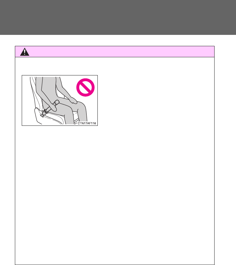
132
1-7. Safety information
CAUTION
■SRS airbag precautions
●The SRS front passenger airbag also deploys with considerable force, and
can cause death or serious injury especially if the front passenger is very
close to the airbag. The front passenger seat should be as far from the air-
bag as possible with the seatback adjusted, so the front passenger sits
upright.
●Improperly seated and/or restrained infants and children can be killed or
seriously injured by a deploying airbag. An infant or child who is too small
to use a seat belt should be properly secured using a child restraint sys-
tem. Toyota strongly recommends that all infants and children be placed in
the rear seats of the vehicle and properly restrained. The rear seats are
the safest for infants and children. (P. 143)
●If the seat belt extender has been con-
nected to the front seat belt buckles but
the seat belt extender has not also
been fastened to the latch plate of the
seat belt, the SRS front airbags will
judge that the driver and front passen-
ger are wearing the seat belt even
though the seat belt has not been con-
nected. In this case, the SRS front air-
bags may not activate correctly in a
collision, resulting in death or serious
injury in the event of a collision. Be sure
to wear the seat belt with the seat belt
extender.
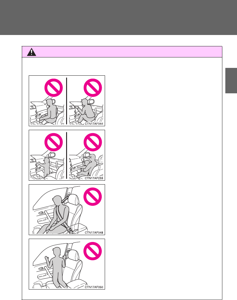
133
1-7. Safety information
1
Before driving
CAUTION
■SRS airbag precautions
●Do not sit on the edge of the seat or
lean against the dashboard.
●Do not allow a child to stand in front of
the SRS front passenger airbag unit or
sit on the knees of a front passenger.
●Do not drive the vehicle while the driver
or passenger has items resting on their
knees.
●Do not lean against the door, the roof
side rail or the front, side and rear pil-
lars.
●Do not allow anyone to kneel on the
passenger seat toward the door or put
their head or hands outside the vehicle.
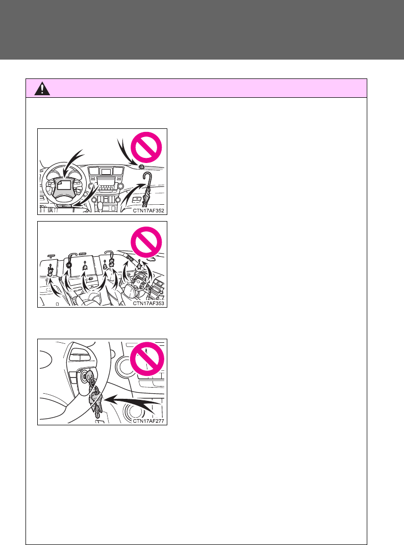
134
1-7. Safety information
CAUTION
■SRS airbag precautions
●If the vinyl cover is put on the area where the SRS knee airbag will deploy,
be sure to remove it.
●Do not use seat accessories which cover the parts where the SRS side
airbags inflate as they may interfere with inflation of the airbags.
●Do not strike or apply significant levels of force to the area of the SRS air-
bag components (P. 125).
Doing so can cause the SRS airbags to malfunction.
●Do not attach anything to or lean any-
thing against areas such as the dash-
board, steering wheel pad or lower
portion of the instrument panel.
These items can become projectiles
when SRS driver, front passenger and
knee airbags deploy.
●Do not attach anything to areas such as
the door, windshield glass, side door
glass, front and rear pillars, roof side
rail or assist grip.
●Do not hang coat hangers or other hard
objects on the coat hooks. All of these
items could become projectiles and
seriously injure or kill you, should the
SRS curtain shield airbag deploy.
●Vehicles without smart key system: Do
not attach any heavy, sharp or hard
objects such as keys or accessories to
the key. The objects may restrict the
SRS knee airbag inflation or be thrust
into the driver's seat area by the force
of the deploying airbag, thus causing a
danger.

135
1-7. Safety information
1
Before driving
CAUTION
■SRS airbag precautions
●Do not touch any of the component parts immediately after the SRS air-
bags have deployed (inflated) as they may be hot.
●If breathing becomes difficult after the SRS airbag has deployed, open a
door or window to allow fresh air in, or leave the vehicle if it is safe to do
so. Wash off any residue as soon as possible to prevent skin irritation.
●If the areas where the SRS airbags are stored, such as the steering wheel
pad and front and rear pillar garnishes, are damaged or cracked, have
them replaced by your Toyota dealer.
■Modification and disposal of SRS airbag system components
Do not dispose of your vehicle or perform any of the following modifications
without consulting your Toyota dealer.
The SRS airbags may malfunction or deploy (inflate) accidentally, causing
death or serious injury.
●Installation, removal, disassembly and repair of the SRS airbags.
●Repairs, modifications, removal or replacement of the steering wheel,
instrument panel, dashboard, seats or seat upholstery, front, side and rear
pillars or roof side rails.
●Repairs or modifications of the front fender, front bumper, or side of the
occupant compartment.
●Installation of snow plows, winches, etc. to the front grille (bull bars, kan-
garoo bar etc.).
●Modifications to the vehicle's suspension system.
●Installation of electronic devices such as mobile two-way radios or CD
players.
●Modifications to your vehicle for a person with a physical disability.
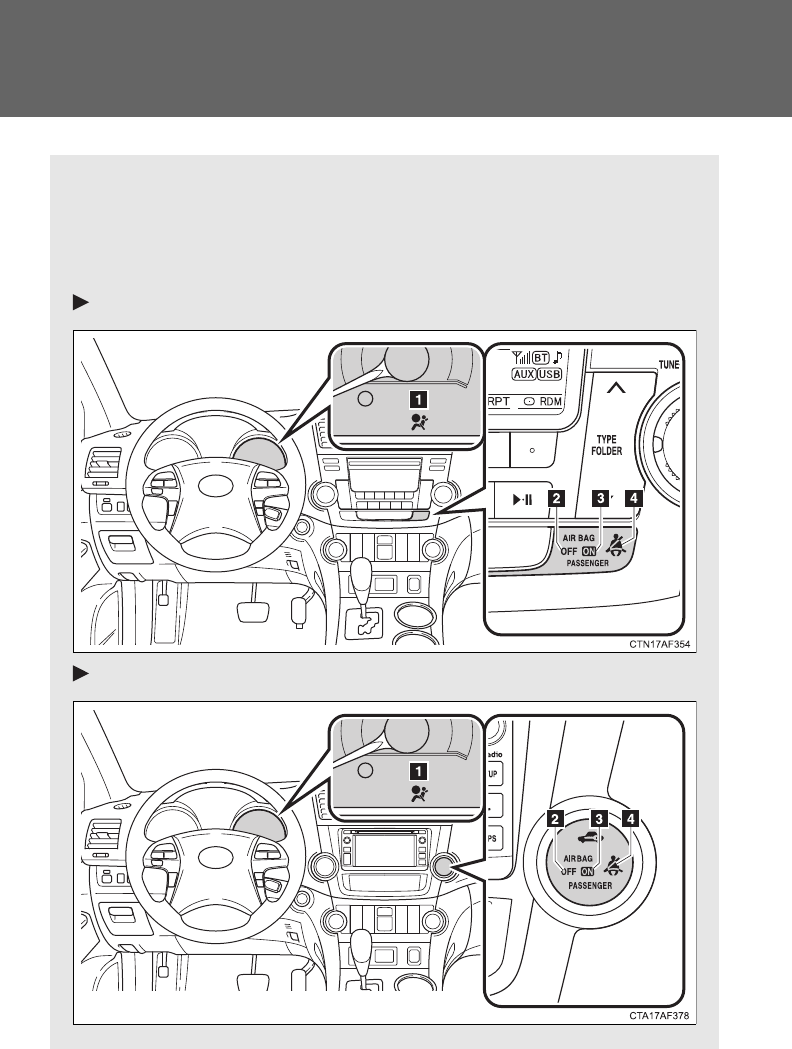
136
1-7. Safety information
Front passenger occupant classification system
Your vehicle is equipped with a front passenger occupant classifica-
tion system. This system detects the conditions of the front passen-
ger seat and activates or deactivates the devices for the front
passenger.
Vehicles without a Display Audio system or navigation system
Vehicles with a Display Audio system
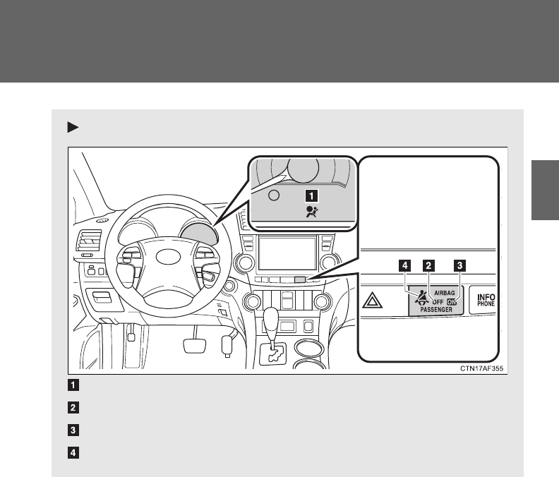
137
1-7. Safety information
1
Before driving
Vehicles with a navigation system
SRS warning light
“AIR BAG OFF” indicator light
“AIR BAG ON” indicator light
Front passenger's seat belt reminder light

138
1-7. Safety information
Conditions and operation of the front passenger occupant
classification system
■Adult*1
■Child*3 or child restraint system*4
Indicator/
warning light
“AIR BAG ON” and “AIR BAG OFF” indi-
cator lights
“AIR BAG
ON”
SRS warning light Off
Front passenger's seat belt reminder
light
Flashing*
2
Devices
Front passenger airbag
Activated
Side airbag on the front passenger seat
Curtain shield airbag in the front passen-
ger side
Front passenger's seat belt pretensioner
Indicator/
warning light
“AIR BAG ON” and “AIR BAG OFF” indi-
cator lights
“AIR BAG
OFF”*5
SRS warning light Off
Front passenger's seat belt reminder
light Flashing*2
Devices
Front passenger airbag Deactivated
Side airbag on the front passenger seat
Activated
Curtain shield airbag in the front passen-
ger side
Front passenger's seat belt pretensioner

139
1-7. Safety information
1
Before driving
■Unoccupied
■There is a malfunction in the system
*1: The system judges a person of adult size as an adult. When a
smaller adult sits in the front passenger seat, the system may rec-
ognize him/her as a child depending on his/her physique and pos-
ture.
*2: In the event the front passenger does not wear a seat belt.
*3: When a larger child who has outgrown a child restraint system
sits in the front passenger seat, the system may recognize him/
her as an adult depending on his/her physique or posture.
Indicator/
warning light
“AIR BAG ON” and “AIR BAG OFF” indi-
cator lights
Not illumi-
nated
SRS warning light
Off
Front passenger's seat belt reminder
light
Devices
Front passenger airbag Deactivated
Side airbag on the front passenger seat
Activated
Curtain shield airbag in the front passen-
ger side
Front passenger's seat belt pretensioner Deactivated
Indicator/
warning light
“AIR BAG ON” and “AIR BAG OFF” indi-
cator lights
“AIR BAG
OFF”
SRS warning light On
Front passenger's seat belt reminder
light Off
Devices
Front passenger airbag Deactivated
Side airbag on the front passenger seat
Activated
Curtain shield airbag in the front passen-
ger side
Front passenger's seat belt pretensioner

140
1-7. Safety information
*4: Never install a rear-facing child restraint system on the front pas-
senger seat. A forward-facing child restraint system should only
be installed on the front passenger seat when it is unavoidable.
(P. 144)
*5: In case the indicator is not illuminated, consult this manual as for
installing the child restraint system properly. (P. 148)

141
1-7. Safety information
1
Before driving
CAUTION
■Front passenger occupant classification system precautions
Observe the following precautions regarding front passenger occupant clas-
sification system.
Failure to do so may cause death or serious injury.
●Wear the seat belt properly.
●Make sure the front passenger's seat belt tab has not been left inserted
into the buckle before someone sits in the front passenger seat.
●Make sure the “AIR BAG OFF” indicator light is not illuminated when using
the seat belt extender for the front passenger seat. If the “AIR BAG OFF”
indicator light is illuminated, disconnect the extender tongue from the seat
belt buckle, then reconnect the seat belt. Reconnect the seat belt extender
after making sure the “AIR BAG ON” indicator light is illuminated. If you
use the seat belt extender while the “AIR BAG OFF” indicator light is illumi-
nated, the SRS airbags for the passenger may not activate correctly,
which could cause death or serious injury in the event of a collision.
●Do not apply a heavy load to the front passenger seat or equipment (e.g.
seatback pocket).
●Do not put weight on the front passenger seat by putting your hands or
feet on the front passenger seat seatback from the rear passenger seat.
●Do not let a rear passenger lift the front passenger seat with their feet or
press on the seatback with their legs.
●Do not put objects under the front passenger seat.
●Do not recline the front passenger seatback so far that it touches a rear
seat. This may cause the “AIR BAG OFF” indicator light to be illuminated,
which indicates that the passenger's airbags will not deploy in the event of
a severe accident. If the seatback touches the rear seat, return the seat-
back to a position where it does not touch the rear seat. Keep the front
passenger seatback as upright as possible when the vehicle is moving.
Reclining the seatback excessively may lessen the effectiveness of the
seat belt system.

142
1-7. Safety information
CAUTION
■Front passenger occupant classification system precautions
●If an adult sits in the front passenger seat, the “AIR BAG ON” indicator
light is illuminated. If the “AIR BAG OFF” indicator is illuminated, ask the
passenger to sit up straight, well back in the seat, feet on the floor, and
with the seat belt worn correctly. If the “AIR BAG OFF” indicator still
remains illuminated, either ask the passenger to move to the rear seat, or
if that is not possible, move the front passenger seat fully rearward.
●When it is unavoidable to install the forward-facing child restraint system
on the front passenger seat, install the child restraint system on the front
passenger seat in the proper order. (P. 148)
●Do not modify or remove the front seats.
●Do not kick the front passenger seat or subject it to severe impact. Other-
wise, the SRS warning light may come on to indicate a malfunction of the
detection system. In this case, contact your Toyota dealer immediately.
●Child restraint systems installed on the rear seat should not contact the
front seatbacks.
●Do not use a seat accessory, such as a cushion or seat cover, that covers
the seat cushion surface.
●Do not modify or replace the upholstery of the front seat.

143
1
1-7. Safety information
Before driving
Child restraint systems
Points to remember
Studies have shown that installing a child restraint on a rear seat is
much safer than installing one to the front passenger seat.
●Choose a child restraint system that suits your vehicle and is
appropriate to the age and size of the child.
●For installation details, follow the instructions provided with the
child restraint system.
General installation instructions are provided in this manual.
(P. 148)
A child restraint system for a small child or baby must itself be prop-
erly restrained on the seat with the lap portion of the lap/shoulder
belt.
The laws of all 50 states of the U.S.A. and Canada now require the
use of child restraint systems.
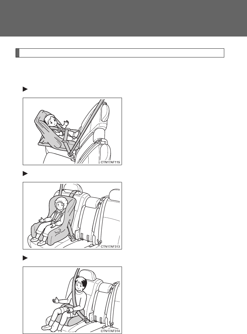
144
1-7. Safety information
Types of child restraints
Child restraint systems are classified into the following 3 types
according to the age and size of the child.
Rear facing Infant seat/convertible seat
Forward facing Convertible seat
Booster seat
145
1-7. Safety information
1
Before driving
■Selecting an appropriate child restraint system
●Use a child restraint system appropriate for the child until the child
becomes large enough to properly wear the vehicle’s seat belt.
●If a child is too large for a child restraint system, sit the child on a rear
seat and use the vehicle's seat belt. (P. 88)
CAUTION
■Child restraint precautions
●For effective protection in automobile accidents and sudden stops, a child
must be properly restrained, using a seat belt or child restraint system
depending on the age and size of the child. Holding a child in your arms is
not a substitute for a child restraint system. In an accident, the child can be
crushed against the windshield, or between you and the vehicle's interior.
●Toyota strongly urges the use of a proper child restraint system that con-
forms to the size of the child, installed on the rear seat. According to acci-
dent statistics, the child is safer when properly restrained in the rear seat
than in the front seat.
●Never install a rear-facing child restraint system on the front passenger
seat even if “AIR BAG OFF” indicator light is illuminated.
In the event of an accident, the force of the rapid inflation of the front pas-
senger airbag can cause death or serious injury to the child if the rear-fac-
ing child restraint system is installed on the front passenger seat.

146
1-7. Safety information
CAUTION
■Child restraint precautions
●A forward-facing child restraint system may be allowed to be installed on
the front passenger seat only when it is unavoidable. A child restraint sys-
tem that requires a top tether strap should not be used in the front passen-
ger seat since there is no top tether strap anchor for the front passenger
seat. Adjust the seatback as uprights as possible and always move the
seat as far back as possible even if the “AIR BAG OFF” indicator light is
illuminated, because the front passenger airbag could inflate with consid-
erable speed and force. Otherwise, the child may be killed or seriously
injured.
●Do not use the seat belt extender when installing a child restraint system
on the front or rear passenger seat. If installing a child restraint system
with the seat belt extender connected to the seat belt, the seat belt will not
securely hold the child restraint system, which could cause death or seri-
ous injury to the child or other passengers in the event of a sudden stop,
sudden swerve or accident.
●Do not allow the child to lean his/her head or any part of his/her body
against the door or the area of the seat, front and rear pillars or roof side
rail from which the side airbags or curtain shield airbags deploy even if the
child is seated in the child restraint system. It is dangerous if the side air-
bags and curtain shield airbags inflate, and the impact could cause death
or serious injury to the child.
●Make sure you have complied with all installation instructions provided by
the child restraint manufacturer and that the system is properly secured. If
it is not secured properly, it may cause death or serious injury to the child
in the event of a sudden stop, sudden swerve or accident.
■When children are in the vehicle
Do not allow children to play with the seat belt. If the seat belt becomes
twisted around a child’s neck, it may lead to choking or other serious injuries
that could result in death.
If this occurs and the buckle cannot be unfastened, scissors should be used
to cut the belt.

147
1-7. Safety information
1
Before driving
CAUTION
■When the child restraint system is not in use
●Keep the child restraint system properly secured on the seat even if it is
not in use.
Do not store the restraint unsecured in the passenger compartment.
●If it is necessary to detach the child restraint system, remove it from the
vehicle or store it securely in the luggage compartment. This will prevent it
from injuring passengers in the event of a sudden stop, sudden swerve or
accident.
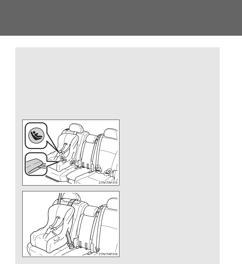
148
1-7. Safety information
Installing child restraints
Follow the child restraint system manufacturer's instructions. Firmly
secure child restraints to the rear seats using the LATCH anchors or
a seat belt. Attach the top tether strap when installing a child
restraint.
The lap/shoulder belt can be used if your child restraint system is
not compatible with the LATCH (Lower Anchors and Tethers for Chil-
dren) system.
Second seat: Child restraint
LATCH anchors
LATCH anchors are provided
for the rear outer seats. (But-
tons displaying the location of
the anchors are attached to the
seats.)
Seat belts equipped with a
child restraint locking mecha-
nism (ALR/ELR belts except
driver’s seat belt)
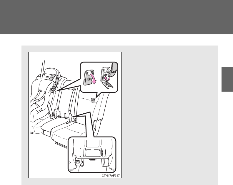
149
1-7. Safety information
1
Before driving
Second seat: Anchor brackets
(for top tether strap)
Anchor brackets are provided
for the second seats.
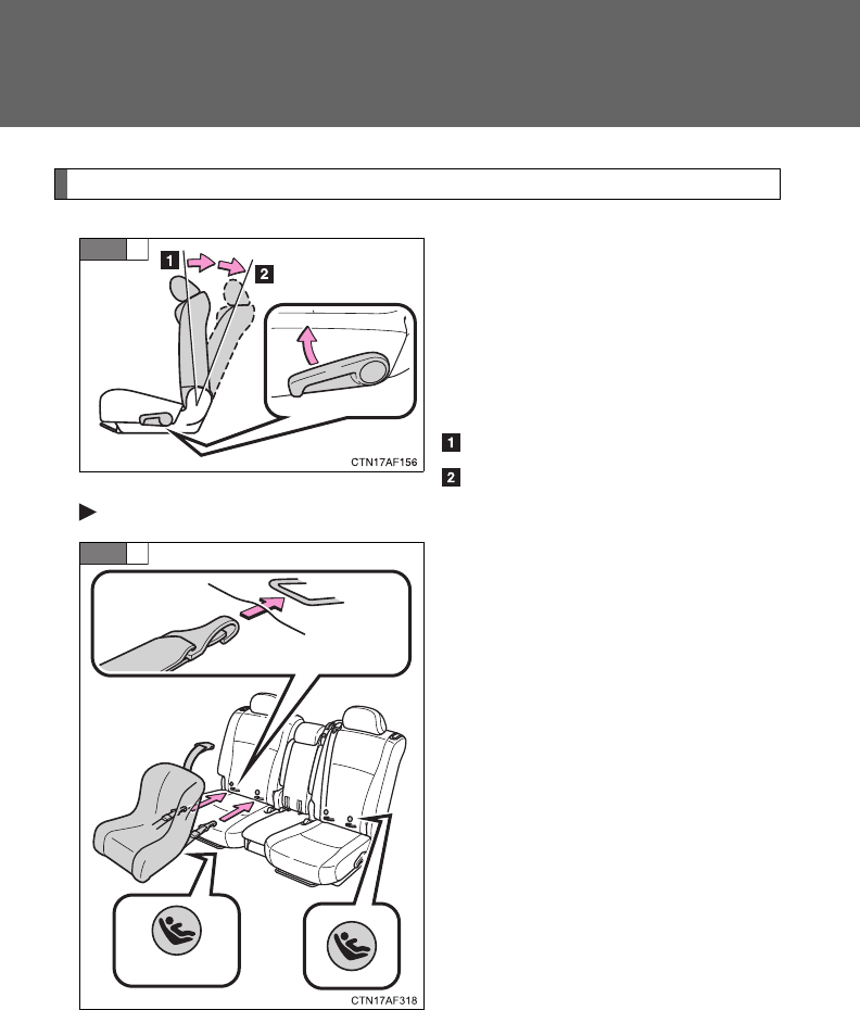
150
1-7. Safety information
Installation with LATCH system
Fold the seatback while pulling
the lever. Return the seatback
and secure it at the 1st lock posi-
tion (most upright position).
Adjust the seatback to the 3rd
lock position. (P. 77)
1st lock position
3rd lock position
Type A
Latch the hooks of the lower
straps onto the LATCH anchors.
The bars are installed in the
clearance between the seat cush-
ion and seatback.
If the child restraint has a top
tether strap, the top tether strap
should be latched onto the top
tether strap anchors.
For owners in Canada:
The symbol on a child restraint
system indicates the presence of
a lower connector system.
STEP
1
STEP
2
Canada only
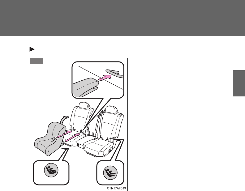
151
1-7. Safety information
1
Before driving
Type B
Latch the buckles onto the
LATCH anchors.
The bars are installed in the
clearance between the seat cush-
ion and seatback.
If the child restraint has a top
tether strap, the top tether strap
should be latched onto the top
tether strap anchors.
For owners in Canada:
The symbol on a child restraint
system indicates the presence of
a lower connector system.
Canada only
STEP
2
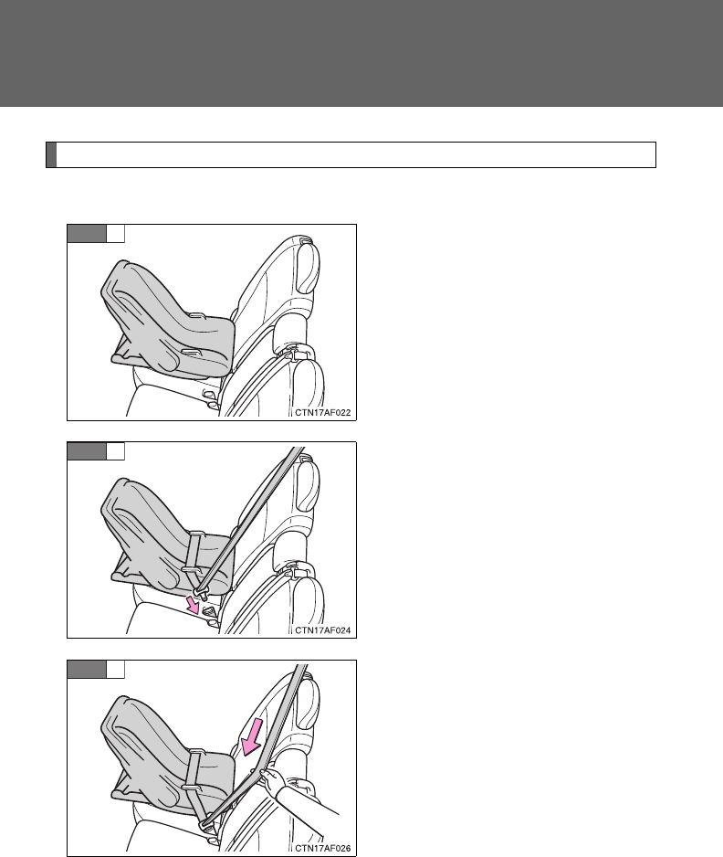
152
1-7. Safety information
Installing child restraints using a seat belt (child restraint lock function belt)
■Rear facing Infant seat/convertible seat
Place the child seat on the rear
seat facing the rear of the vehi-
cle.
Run the seat belt through the
child seat and insert the plate
into the buckle. Make sure that
the belt is not twisted.
Fully extend the shoulder belt
and then allow it to retract
slightly in order to activate the
ALR lock mode.
Lock mode allows the seat belt to
retract only.
STEP
1
STEP
2
STEP
3
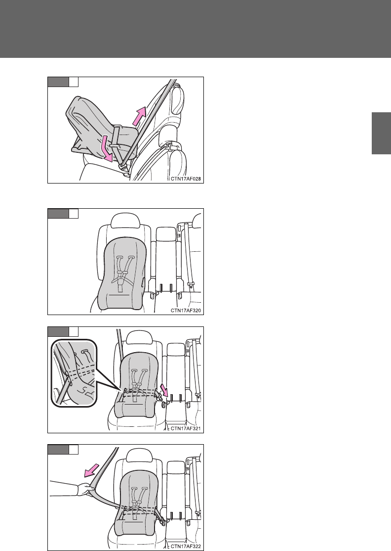
153
1-7. Safety information
1
Before driving
While pushing the child seat
down into the rear seat, allow the
shoulder belt to retract until the
child seat is securely in place.
After the shoulder belt has
retracted to a point where there is
no slack in the belt, pull the belt to
check that it cannot be extended.
■Forward facing Convertible seat
Place the child seat on the seat
facing the front of the vehicle.
Run the seat belt through the
child seat and insert the plate
into the buckle. Make sure that
the belt is not twisted.
Fully extend the shoulder strap
and then allow it to retract
slightly into the ALR lock mode.
Lock mode allows the seat belt to
retract only.
STEP
4
STEP
1
STEP
2
STEP
3
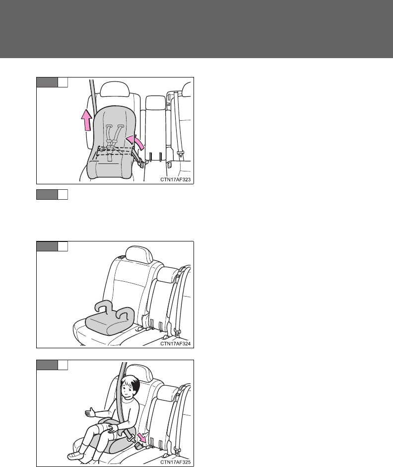
154
1-7. Safety information
While pushing the child seat into
the rear seat, allow the shoulder
belt to retract until the child seat
is securely in place.
After the shoulder belt has
retracted to a point where there is
no slack in the belt, pull the belt to
check that it cannot be extended.
If the child restraint has a top tether strap, the top tether strap
should be latched onto the top tether strap anchors.
■Booster seat
Place the booster seat on the
seat facing the front of the vehi-
cle.
Sit the child in the booster seat.
Fit the seat belt to the booster
seat according to the manufac-
turer's instructions and insert the
plate into the buckle. Make sure
that the belt is not twisted.
Check that the shoulder belt is
correctly positioned over the
child's shoulder, and that the lap
belt is as low as possible.
(P. 88)
STEP
4
STEP
5
STEP
1
STEP
2

155
1-7. Safety information
1
Before driving
Removing a child restraint installed with a seat belt
Push the buckle release button
and fully retract the seat belt.
Child restraint systems with a top tether strap (second seat only)
Secure the child restraint using
the seat belt or lower anchors,
and adjust the head restraint to
the upmost position.
STEP
1
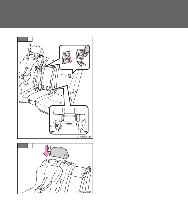
156
1-7. Safety information
Outer seat: Open the anchor
bracket cover, latch the hook
onto the anchor bracket and
tighten the top tether strap.
Center seat: Latch the hook onto
the anchor bracket and tighten
the top tether strap.
Make sure the top tether strap is
securely latched.
Adjust the head restraint to the
downmost position.
STEP
2
STEP
3
■Laws and regulations pertaining to anchorages
The LATCH system conforms to FMVSS225 or CMVSS210.2.
Child restraint systems conforming to FMVSS213 or CMVSS213 specifica-
tions can be used.
This vehicle is designed to conform to the SAE J1819.
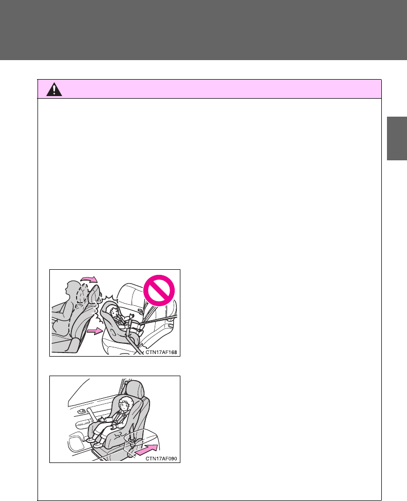
157
1-7. Safety information
1
Before driving
CAUTION
■When installing a booster seat
Do not fully extend the shoulder belt to prevent the belt from going to ALR
lock mode. (P. 89)
ALR mode causes the belt to tighten only which could cause injury or dis-
comfort to the child.
■When installing a child restraint system
Follow the directions given in the child restraint system installation manual
and fix the child restraint system securely in place.
If the child restraint system is not correctly fixed in place, the child or other
passengers may be seriously injured or even killed in the event of sudden
braking, sudden swerving or an accident.
●If the driver's seat interferes with the
child restraint system and prevents it
from being attached correctly, attach
the child restraint system to the right-
hand rear seat.
●Adjust the front passenger seat or sec-
ond seats so that it does not interfere
with the child restraint system.
●Only put a forward-facing or booster
child seat on the front seat when
unavoidable. When installing a forward-
facing or booster child seat on the front
passenger seat, move the seat as far
back as possible even if “AIR BAG
OFF” indicator light is illuminated. Fail-
ing to do so may result in death or seri-
ous injury if the airbags deploy (inflate).

158
1-7. Safety information
CAUTION
■When installing a child restraint system
●When installing a child restraint system in the rear center seat, adjust both
seat cushions to the same position and align seatbacks at the same angle.
The seatbacks must be adjusted to the same angle. Otherwise, the child
restraint system cannot be securely restrained and this may cause death
or serious injuries in the event of sudden braking, sudden swerving or an
accident.
●When using the LATCH anchors for a child restraint system, move the seat
as far back as possible (second seat only), with the seatback close to the
child restraint system.
●When a booster seat is installed, always ensure that the shoulder belt is
positioned across the center of the child's shoulder. The belt should be
kept away from the child's neck, but not so that it could fall off the child's
shoulder. Failing to do so may result in death or serious injury in the event
of sudden braking, sudden swerving or an accident.
●Ensure that the belt and tab are securely locked and the seat belt is not
twisted.
●Push and pull the child seat from side to side and forward to be sure it is
secure.
●After securing a child restraint system, never adjust the seat.
●Follow all installation instructions provided by the child restraint system
manufacturer.
■Do not use a seat belt extender
If a seat belt extender is used when installing a child restraint system, the
seat belt will not securely hold the child restraint system, which could cause
death or serious injury to the child or other passengers in the event of sud-
den braking, sudden swerving or an accident.
■To correctly attach a child restraint system to the anchors
When using the LATCH anchors, be sure that there are no foreign objects
around the anchors and that the seat belt is not caught behind the child
restraint. Make sure the child restraint system is securely attached, or it may
cause death or serious injury to the child or other passengers in the event of
a sudden stop, sudden swerve or accident.

When driving 2
159
2-1. Driving procedures
Driving the vehicle............ 160
Engine (ignition) switch
(vehicles with smart
key system).................... 171
Engine (ignition) switch
(vehicles without smart
key system).................... 175
Automatic transmission.... 178
Turn signal lever .............. 183
Parking brake................... 184
Horn ................................. 185
2-2. Instrument cluster
Gauges and meters ......... 186
Indicators and warning
lights .............................. 188
Multi-information
display............................ 193
2-3. Operating the lights and
wipers
Headlight switch............... 203
Fog light switch ................ 210
Windshield wipers and
washer ........................... 212
Rear window wiper and
washer ........................... 216
2-4. Using other driving
systems
Cruise control................... 219
Rear view monitor
system ........................... 223
Driving assist systems ..... 227
Hill-start assist control...... 232
Downhill assist control
system ........................... 234
2-5. Driving information
Off-road precautions ........ 237
Cargo and luggage .......... 242
Vehicle load limits ............ 247
Winter driving tips ............ 248
Trailer towing ................... 252
Dinghy towing .................. 270

160
2-1. Driving procedures
Driving the vehicle
The following procedures should be observed to ensure safe driv-
ing.
■Starting the engine
P. 171, 175
■Driving
With the brake pedal depressed, shift the shift lever to D.
(P. 178)
Release the parking brake. (P. 184)
Gradually release the brake pedal and gently depress the
accelerator pedal to accelerate the vehicle.
■Stopping
With the shift lever in D, depress the brake pedal.
If necessary, set the parking brake.
When the vehicle is stopped for an extended period of time, shift
the shift lever to P or N. (P. 178)
■Parking the vehicle
With the shift lever in D, depress the brake pedal.
Set the parking brake. (P. 184)
Shift the shift lever to P. (P. 178)
When parking on a hill, if necessary, block the wheels.
Vehicles without smart key system:
Turn the engine switch to the “LOCK” position to stop the
engine.
Vehicles with smart key system:
Turn the “ENGINE START STOP” switch OFF to stop the
engine.
Lock the door, making sure that you have the key on your
person.
STEP
1
STEP
2
STEP
3
STEP
1
STEP
2
STEP
1
STEP
2
STEP
3
STEP
4
STEP
5

161
2-1. Driving procedures
2
When driving
Starting on a steep uphill
Firmly set the parking brake and shift the shift lever to D.
Gently depress the accelerator pedal.
Release the parking brake.
■Driving in the rain
●Drive carefully when it is raining, because visibility will be reduced, the
windows may become fogged-up, and the road will be slippery.
●Drive carefully when it starts to rain, because the road surface will be
especially slippery.
●Refrain from high speeds when driving on an expressway in the rain,
because there may be a layer of water between the tires and the road
surface, preventing the steering and brakes from operating properly.
■Engine speed while driving
In the following conditions, the engine speed may become high while driving.
This is due to automatic up-shifting control or down-shifting implementation
to meet driving conditions. It does not indicate sudden acceleration.
●The vehicle is judged to be driving uphill or downhill
●When the accelerator pedal is released
STEP
1
STEP
2
STEP
3

162
2-1. Driving procedures
■Breaking in your new Toyota
To extend the life of the vehicle, observing the following precautions is rec-
ommended:
●For the first 186 miles (300 km):
Avoid sudden stops.
●For the first 500 miles (800 km):
Do not tow a trailer.
●For the first 621 miles (1000 km):
• Do not drive at extremely high speeds.
• Avoid sudden acceleration.
• Do not drive continuously in the low gears.
• Do not drive at a constant speed for extended periods.
■Drum-in-disc type parking brake system
Your vehicle has a drum-in-disc type parking brake system.
This type of brake system needs bedding-down of the brake shoes periodi-
cally or whenever the parking brake shoes and/or drums are replaced.
Have your Toyota dealer perform the bedding-down.
■Operating your vehicle in a foreign country
Comply with the relevant vehicle registration laws and confirm the availability
of the correct fuel. (P. 621)

163
2-1. Driving procedures
2
When driving
CAUTION
■When starting the vehicle
Always keep your foot on the brake pedal while stopped with the engine run-
ning. This prevents the vehicle from creeping.
■When driving the vehicle
●Do not drive if you are unfamiliar with the location of the brake and accel-
erator pedals to avoid depressing the wrong pedal.
• Accidentally depressing the accelerator pedal instead of the brake
pedal will result in sudden acceleration that may lead to an accident
that could result in death or serious injury.
• When backing up, you may twist your body around, leading to a diffi-
culty in operating the pedals. Make sure to operate the pedals properly.
• Make sure to keep a correct driving posture even when moving the
vehicle only slightly, allowing you to depress the brake and accelerator
pedals properly.
• Depress the brake pedal using your right foot. Depressing the brake
pedal using your left foot may delay response in an emergency, result-
ing in an accident.
●Do not drive the vehicle over or stop the vehicle near flammable materials.
The exhaust system and exhaust gases can be extremely hot. This may
cause a fire if there is any flammable material nearby.
●Do not let the vehicle roll backward while the shift lever is in a driving posi-
tion, or roll forward while the shift lever is in R.
Doing so may cause the engine to stall or lead to poor brake and steering
performance, resulting in an accident or damage to the vehicle.
●If the smell of exhaust is noticed inside the vehicle, open the windows and
check that the back door is closed. Large amounts of exhaust in the vehi-
cle can cause driver drowsiness and an accident, resulting in death or a
serious health hazard. Have the vehicle inspected by your Toyota dealer
immediately.

164
2-1. Driving procedures
CAUTION
●Do not shift the shift lever to P while the vehicle is moving.
Doing so can damage the transmission and may result in a loss of vehicle
control.
●Do not shift the shift lever to R while the vehicle is moving forward.
Doing so can damage the transmission and may result in a loss of vehicle
control.
●Do not shift the shift lever to D while the vehicle is moving backward.
Doing so can damage the transmission and may result in a loss of vehicle
control.
●Moving the shift lever to N while the vehicle is moving will disengage the
engine from the transmission. Engine braking is not available when N is
selected.
●During normal driving, do not turn off the engine. Turning the engine off
while driving will not cause loss of steering or braking control, but the
power assist to these systems will be lost. This will make it more difficult to
steer and brake, so you should pull over and stop the vehicle as soon as it
is safe to do so.
However, in the event of an emergency, such as if it becomes impossible
to stop the vehicle in the normal way: P. 615
●Use engine braking (downshift) to maintain a safe speed when driving
down a steep hill.
Using the brakes continuously may cause the brakes to overheat and lose
effectiveness. (P. 179)
●When stopped on an inclined surface, use the brake pedal and parking
brake to prevent the vehicle from rolling backward or forward and causing
an accident.
●Do not adjust the position of the steering wheel, the seat, or the inside or
outside rear view mirrors while driving.
Doing so may result in a loss of vehicle control that can cause accidents
that may result in death or serious injury.
●Always check that all passengers' arms, heads or other parts of their bod-
ies are not outside the vehicle, as this may result in death or serious injury.
●Do not drive the vehicle off-road.
This is not a 4WD vehicle designed for real off-road driving. Proceed with
all due caution if it becomes unavoidable to drive off-road.

165
2-1. Driving procedures
2
When driving
CAUTION
●4WD models: Do not drive across a river or through other bodies of water.
This may cause electric/electronic components to short circuit, damage
the engine or cause other serious damage to the vehicle.
●Do not drive in excess of the speed limit. Even if the legal speed limit per-
mits it, do not drive over 85 mph (140 km/h) unless your vehicle has high-
speed capability tires. Driving over 85 mph (140 km/h) may result in tire
failure, loss of control and possible injury. Be sure to consult a tire dealer
to determine whether the tires on your vehicle are high-speed capability
tires or not before driving at such speeds.
■When driving on slippery road surfaces
●Sudden braking, acceleration and steering may cause tire slippage and
reduce your ability to control the vehicle, resulting in an accident.
●Sudden changes in engine speed, such as engine braking caused by up-
shifting or down-shifting, may cause the vehicle to skid, resulting in an
accident.
●After driving through a puddle, lightly depress the brake pedal to make
sure that the brakes are functioning properly. Wet brake pads may prevent
the brakes from functioning properly. If the brakes on only one side are wet
and not functioning properly, steering control may be affected, resulting in
an accident.
■When shifting the shift lever
Be careful not to shift the shift lever with the accelerator pedal depressed.
This may lead to unexpected rapid acceleration of the vehicle that may
cause an accident and result in death or serious injury.
■When the vehicle is stopped
●Do not race the engine.
If the vehicle is in any gear other than P or N, the vehicle may accelerate
suddenly and unexpectedly, and may cause an accident.
●Do not leave the vehicle with the engine running for a long time.
If such a situation cannot be avoided, park the vehicle in an open space
and check that exhaust fumes do not enter the vehicle interior.

166
2-1. Driving procedures
CAUTION
●In order to prevent accidents due to the vehicle rolling away, always keep
depressing the brake pedal while the engine is running, and apply the
parking brake as necessary.
●If the vehicle is stopped on an incline, in order to prevent accidents caused
by the vehicle rolling forward or backward, always depress the brake pedal
and securely apply the parking brake as needed.
●Avoid revving or racing the engine.
Running the engine at high speed while the vehicle is stopped may cause
the exhaust system to overheat, which could result in a fire if combustible
material is nearby.
■When the vehicle is parked
●Do not leave glasses, cigarette lighters, spray cans, or soft drink cans in
the vehicle when it is in the sun.
Doing so may result in the following.
• Gas may leak from a cigarette lighter or spray can, and may lead to a
fire.
• The temperature inside the vehicle may cause the plastic lenses and
plastic material of eye glasses to deform or crack.
• Soft drink cans may fracture, causing the contents to spray over the
interior of the vehicle, and may also cause a short circuit in the vehi-
cle's electrical components.
●Do not leave cigarette lighters in the vehicle. If a cigarette lighter is in a
place such as the glove box or on the floor, it may be lit accidentally when
luggage is loaded or the seat is adjusted, causing a fire.
●Do not attach adhesive discs to the windshield or windows. Do not place
containers such as air fresheners on the instrument panel or dashboard.
Adhesive discs or containers may act as lenses, causing a fire in the vehi-
cle.
●Do not leave a door or window open if the curved glass is coated with a
metallized film such as a silver-colored one. Reflected sunlight may cause
the glass to act as a lens, causing a fire.

167
2-1. Driving procedures
2
When driving
CAUTION
●Always apply the parking brake, shift the shift lever to P, stop the engine
and lock the vehicle.
Do not leave the vehicle unattended while the engine is running.
●Do not touch the exhaust pipe while the engine is running or immediately
after turning the engine off.
Doing so may cause burns.
●Do not leave the engine running in an area with snow build-up, or where it
is snowing. If snowbanks build up around the vehicle while the engine is
running, exhaust gases may collect and enter the vehicle. This may lead
to death or a serious health hazard.
■Exhaust gases
Exhaust gases include harmful carbon monoxide (CO) that is colorless and
odorless. Inhaling exhaust gases may lead to death or a serious health haz-
ard.
●If the vehicle is in a poorly ventilated area, stop the engine. In a closed
area, such as a garage, exhaust gases may collect and enter the vehicle.
This may lead to death or a serious health hazard.
●The exhaust should be checked occasionally. If there is a hole or crack
caused by corrosion, damage to a joint or abnormal exhaust noise, be
sure to have the vehicle inspected and repaired by your Toyota dealer.
Failure to do so may allow exhaust gases to enter the vehicle, resulting in
death or a serious health hazard.
■When taking a nap in the vehicle
Always turn the engine off. Otherwise, you may accidentally move the shift
lever or depress the accelerator pedal, which could cause an accident or fire
due to engine overheating. Additionally, if the vehicle is parked in a poorly
ventilated area, exhaust gases may collect and enter the vehicle, leading to
death or a serious health hazard.

168
2-1. Driving procedures
CAUTION
■When braking the vehicle
●When the brakes are wet, drive more cautiously.
Braking distance increases when the brakes are wet, and may cause one
side of the vehicle to brake differently than the other side. Also the parking
brake may not securely hold the vehicle.
●If the power brake assist function does not operate, do not follow other
vehicles closely and avoid downhills or sharp turns that require braking.
In this case, braking is still possible, but it will require more force on the
pedal than usual. Braking distance may also increase.
●Do not pump the brake pedal if the engine stalls.
Each push on the brake pedal uses up the reserve for the power-assisted
brakes.
●The brake system consists of 2 individual hydraulic systems: If one of the
systems fails, the other will still operate. In this case, the brake pedal
should be depressed more firmly than usual and braking distance
becomes longer.
Do not drive your vehicle with only a single brake system. Have your
brakes fixed immediately.
■If the vehicle becomes stuck or bogged (4WD models)
Do not spin the wheels recklessly when any of the tires is up in the air, or
stuck in sand or mud etc. This may damage the drive system components or
propel the vehicle forward (or in another direction) and cause an accident.
■If you hear a squealing or scraping noise (brake pad wear limit indica-
tors)
Have the brake pads checked and replaced by your Toyota dealer as soon
as possible.
Rotor damage can result if the pads are not replaced when needed.
It is dangerous to drive the vehicle when the wear limits of the brake pads
and/or those of the brake discs are exceeded.
169
2-1. Driving procedures
2
When driving
CAUTION
■If you get a flat tire while driving
A flat or damaged tire may cause the following situations. Hold the steering
wheel firmly and gradually press the brake pedal to slow down the vehicle.
●It may be difficult to control your vehicle.
●The vehicle will make abnormal sounds.
●The vehicle will behave abnormally.
Replace a flat tire with a new one. (P. 591)
NOTICE
■When driving the vehicle
●Do not depress the accelerator and brake pedals at the same time during
driving, as this may restrain driving torque.
●Do not use the accelerator pedal or depress the accelerator and brake
pedals at the same time to hold the vehicle on a hill.
■When parking the vehicle
Always put the shift lever in P. Failure to do so may cause the vehicle to
move or the vehicle may accelerate suddenly if the accelerator pedal is acci-
dentally depressed.
■Avoiding damage to vehicle parts
●Do not turn the steering wheel fully in either direction and hold it there for
an extended period of time.
Doing so may damage the power steering motor.
●When driving over bumps in the road, drive as slowly as possible to avoid
damaging the wheels, underside of the vehicle, etc.

170
2-1. Driving procedures
NOTICE
■When encountering flooded roads
Do not drive on a road that has flooded after heavy rain etc. Doing so may
cause the following serious damage to the vehicle.
●Engine stalling
●Short in electrical components
●Engine damage caused by water immersion
In the event that you drive on a flooded road and the vehicle is flooded, be
sure to have your Toyota dealer check the following.
●Brake function
●Changes in quantity and quality of oil and fluid used for the engine, tran-
saxle, transfer (4WD models), differential (4WD models), etc.
●Lubricant condition for the propeller shaft (4WD models), bearings and
suspension joints (where possible) and the function of all joints, bearings,
etc.
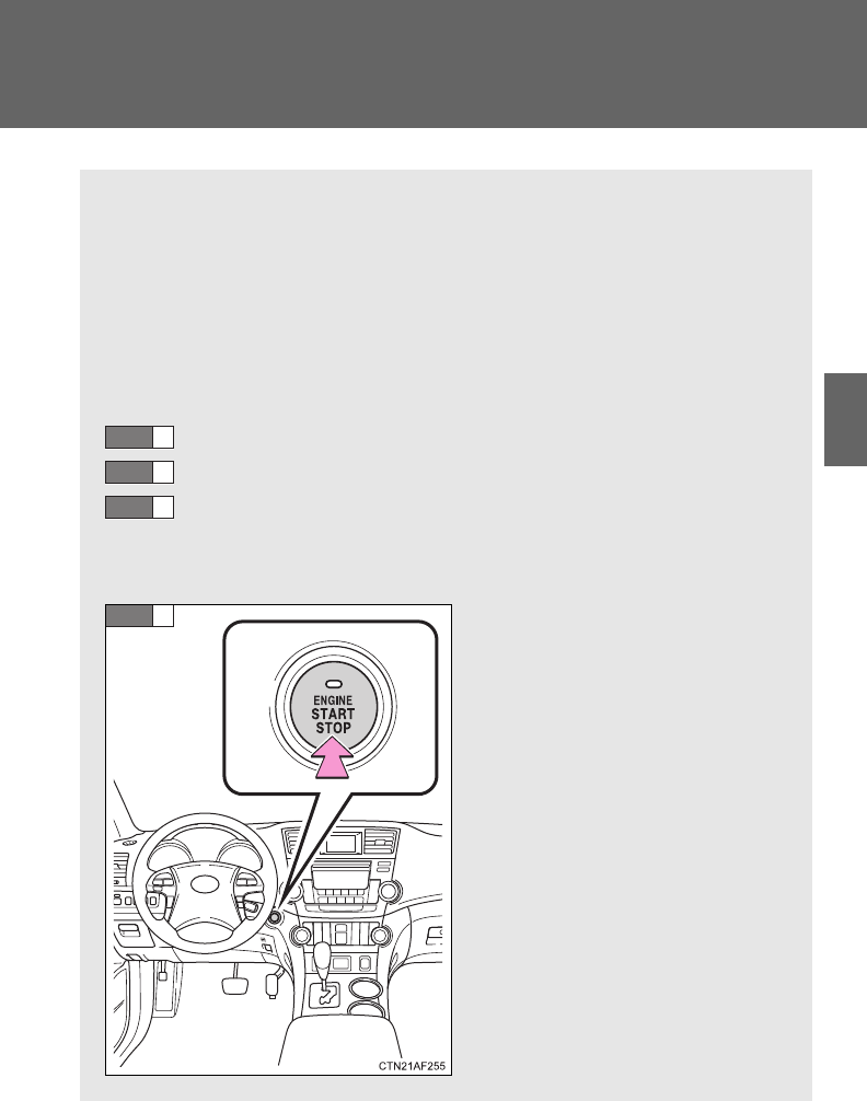
171
2-1. Driving procedures
2
When driving
Engine (ignition) switch (vehicles with smart key system)
Performing the following operations when carrying the electronic
key on your person starts the engine or changes “ENGINE START
STOP” switch mode.
■Starting the engine
The engine can be started in any mode by operating the “ENGINE
START STOP” switch at the same time as depressing the brake
pedal.
Check that the parking brake is set.
Check that the shift lever is set in P.
Sit in the driver’s seat and firmly depress the brake pedal.
The “ENGINE START STOP” switch indicator turns green. If the
indicator does not turn green, the engine cannot be started.
Press the “ENGINE START
STOP” switch.
The engine can be started
from any “ENGINE START
STOP” switch mode.
Continue depressing the brake
pedal until the engine is com-
pletely started.
The engine will crank until it
starts or for up to 30 seconds,
whichever is less.
STEP
1
STEP
2
STEP
3
STEP
4
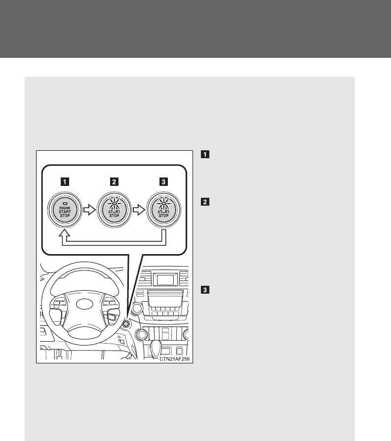
172
2-1. Driving procedures
■Changing “ENGINE START STOP” switch modes
Modes can be changed by pressing the “ENGINE START STOP”
switch with the brake pedal released. (The mode changes each
time the switch is pressed.)
OFF*
The emergency flashers can
be used.
ACCESSORY mode
Some electrical components
such as the audio system can
be used.
The “ENGINE START STOP”
switch indicator turns amber.
IGNITION ON mode
All electrical components can
be used.
The “ENGINE START STOP”
switch indicator turns amber.
*: If the shift lever is in a position
other than P when turning off
the engine, the “ENGINE
START STOP” switch will be
turned to ACCESSORY mode,
not to OFF.
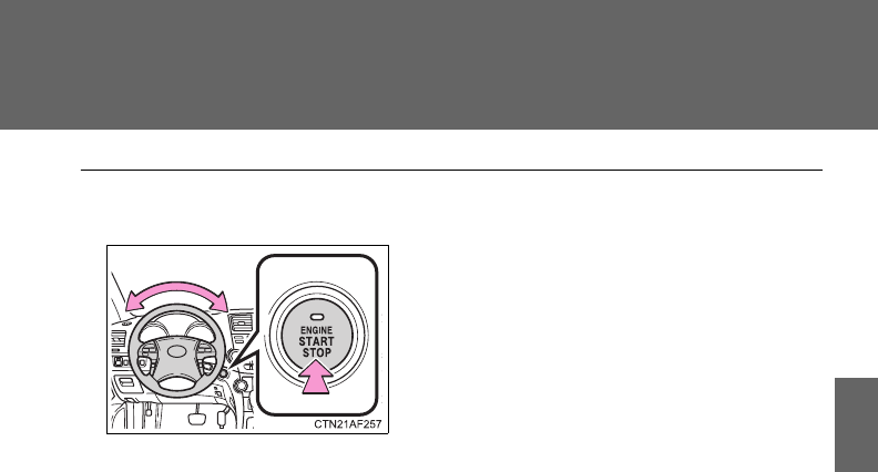
173
2-1. Driving procedures
2
When driving
■Steering lock release
■If the engine does not start
The engine immobilizer system may not have been deactivated. (P. 113)
■When the “ENGINE START STOP” switch indicator flashes in amber
The system may be malfunctioning. Have the vehicle inspected by your
Toyota dealer immediately.
■Auto power off function
If the vehicle is left in ACCESSORY mode for more than an hour with the
shift lever in P, the “ENGINE START STOP” switch will automatically turn off.
■Key battery depletion
P. 42
■When the electronic key battery is discharged
P. 540
■Conditions affecting operation
P. 40
■Note for the entry function
P. 42
Make sure that the steering wheel lock is
released.
To release the steering wheel lock, gently
turn the wheel left or right while pressing
the “ENGINE START STOP” switch.
When the steering wheel lock is not
released, the “ENGINE START STOP”
switch indicator will flash in green.
174
2-1. Driving procedures
CAUTION
■When starting the engine
Always start the engine while sitting in the driver's seat. Do not depress the
accelerator pedal while starting the engine under any circumstances.
Doing so may cause an accident resulting in death or serious injury.
■Caution while driving
If the vehicle begins to slide due to engine failure or other circumstances, do
not lock or open the doors until the vehicle reaches a safe and complete
stop. Activation of the steering lock in this circumstance may lead to an acci-
dent, resulting in death or serious injury.
■Stopping the engine in an emergency
If you want to stop the engine in an emergency while driving the vehicle,
press and hold the “ENGINE START STOP” switch for more than 2 seconds.
However, do not touch the “ENGINE START STOP” switch while driving
except in an emergency. Turning the engine off while driving will not cause
loss of steering or braking control, but the power assist to these systems will
be lost. This will make it more difficult to steer and brake, so you should pull
over and stop the vehicle as soon as it is safe to do so.
NOTICE
■To prevent battery discharge
Do not leave the “ENGINE START STOP” switch in ACCESSORY or IGNI-
TION ON mode for long periods without the engine running.
■When starting the engine
●Do not race a cold engine.
●If the engine becomes difficult to start or stalls frequently, have the engine
checked immediately.
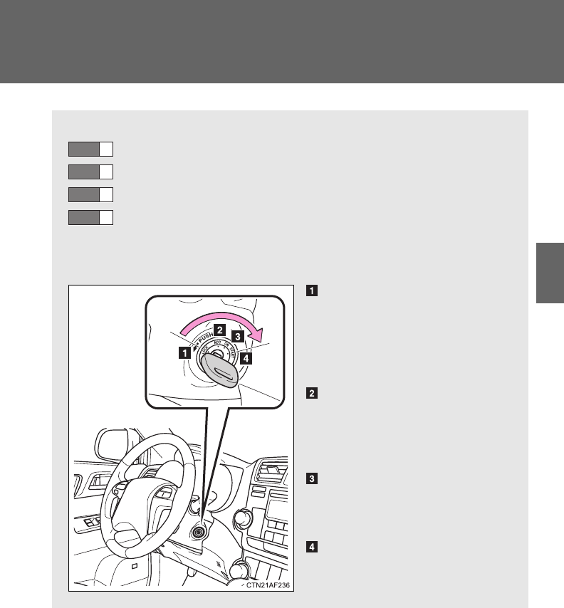
175
2-1. Driving procedures
2
When driving
Engine (ignition) switch (vehicles without smart key system)
■Starting the engine
Check that the parking brake is set.
Check that the shift lever is set in P.
Sit in the driver’s seat and firmly depress the brake pedal.
Turn the engine switch to the “START” position and start
the engine.
■Changing engine switch position
“LOCK”
The steering wheel is locked
and the key can be removed.
(The key can be removed only
when the shift lever is in P.)
“ACC”
Some electrical components
such as the audio system can
be used.
“ON”
All electrical components can
be used.
“START”
For starting the engine.
STEP
1
STEP
2
STEP
3
STEP
4
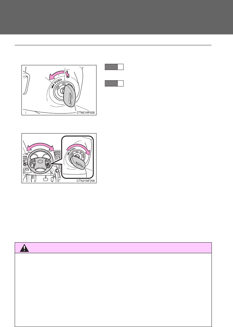
176
2-1. Driving procedures
■Turning the key from “ACC” to “LOCK”
■Steering lock release
■If the engine does not start (vehicles with engine immobilizer system)
The engine immobilizer system may not have been deactivated. (P. 113)
■Key reminder function
A buzzer sounds if the driver’s door is opened while the key is in the “LOCK”
or “ACC” position to remind you to remove the key.
CAUTION
■When starting the engine
Always start the engine while sitting in the driver's seat. Do not depress the
accelerator while starting the engine under any circumstances.
Doing so may cause an accident resulting in death or serious injury.
■Caution when driving
Do not turn the engine switch to the “LOCK” position while driving. If, in an
emergency, you must turn the engine off while the vehicle is moving, turn the
key only to the “ACC” position.
Shift the shift lever to P.
(P. 178)
Push in the key and turn to the
“LOCK” position.
STEP
1
STEP
2
When starting the engine, the engine
switch may seem stuck in the “LOCK”
position. To free it, turn the key while turn-
ing the steering wheel slightly in either
direction.

177
2-1. Driving procedures
2
When driving
NOTICE
■To prevent battery discharge
Do not leave the key in the “ACC” or “ON” position for long periods if the
engine is not running.
■When starting the engine
●Do not crank for more than 30 seconds at a time. This may overheat the
starter and wiring systems.
●Do not race a cold engine.
●If the engine becomes difficult to start or stalls frequently, have the engine
checked immediately.

178
2-1. Driving procedures
Automatic transmission
Select a shift position appropriate for the driving conditions.
■Shifting the shift lever
Vehicles without smart key system
While the engine switch is in the “ON” position, depress the
brake pedal and move the shift lever.
Vehicles with smart key system
While the “ENGINE START STOP” switch is in IGNITION
ON mode, depress the brake pedal and move the shift
lever.
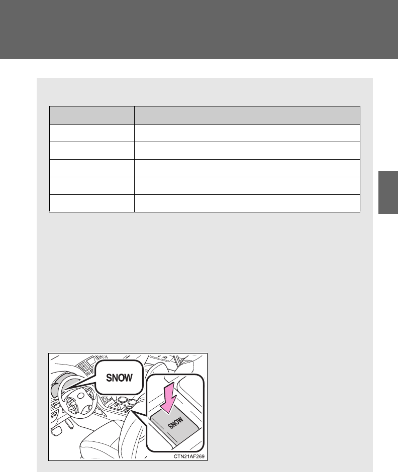
179
2-1. Driving procedures
2
When driving
■Shift position uses
*1: Shifting to the D position allows the system to select a gear suitable
for the driving conditions. Setting the shift lever to the D position is
recommended for normal driving.
*2: Selecting shift ranges using S mode restricts the upper limit of the
possible gear ranges, controls engine braking forces, and prevents
unnecessary upshifting.
■Selecting snow mode
Use snow mode for accelerating and driving on slippery road
surfaces, such as on snow.
Press the “SNOW” switch.
The indicator will come on.
Press the switch once more to
cancel snow mode.
Shift position Function
PParking the vehicle or starting the engine
RReversing
NNeutral
DNormal driving*1
SS mode driving (P. 180)*2
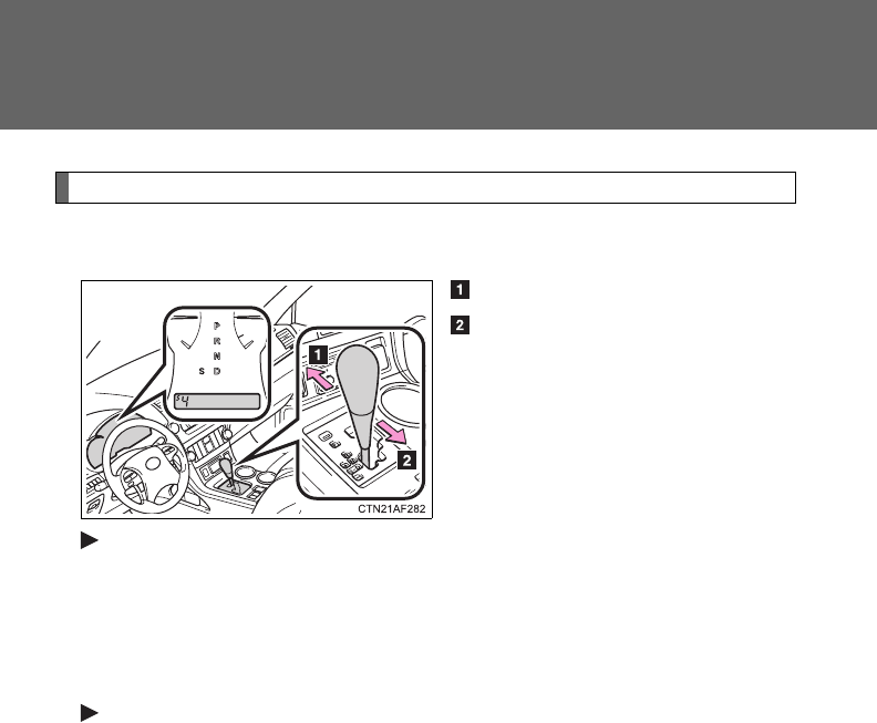
180
2-1. Driving procedures
Changing shift ranges in S mode
Shift the shift lever to the S position and operate the shift lever.
Upshifting
Downshifting
2.7 L 4-cylinder (1AR-FE) engine
The initial shift range in S mode is set automatically to “5” or “4”
according to the vehicle speed.
However, the initial shift range may be set to “3” if AI-SHIFT has oper-
ated while the shift lever was in the D position. (P. 182)
3.5 L V6 (2GR-FE) engine
The initial shift range in S mode is set automatically to “4”.
However, the initial shift range may be set to “3” if AI-SHIFT has oper-
ated while the shift lever was in the D position. (P. 182)

181
2-1. Driving procedures
2
When driving
■Shift ranges and their functions
2.7 L 4-cylinder (1AR-FE) engine
Automatically selecting gears between 1 and 6 according to vehicle
speed and driving conditions. But, the gear is limited according to
selected shift range.
●You can choose from 6 levels of engine braking force.
●A lower shift range will provide greater engine braking force than a
higher shift range, and the engine speed will also increase.
3.5 L V6 (2GR-FE) engine
Automatically selecting gears between 1 and 5 according to vehicle
speed and driving conditions. But, the gear is limited according to
selected shift range.
●You can choose from 5 levels of engine braking force.
●A lower shift range will provide greater engine braking force than a
higher shift range, and the engine speed will also increase.
■When driving with the cruise control system
2.7 L 4-cylinder (1AR-FE) engine
Engine braking will not operate in S mode, even when downshifting from “6”
to “5” or “5” to “4”. (P. 219)
3.5 L V6 (2GR-FE) engine
Engine braking will not operate in S mode, even when downshifting from “5”
to “4”. (P. 219)
■Snow mode automatic deactivation
Snow mode is automatically deactivated if the engine is turned off after driv-
ing in snow mode.

182
2-1. Driving procedures
■If the shift lever cannot be shifted from P
P. 602
■If the S indicator does not come on even after shifting the shift lever to
S
This may indicate a malfunction in the automatic transmission system. Have
the vehicle inspected by your Toyota dealer immediately.
(In this situation, the transmission will operate in the same manner as when
the shift lever is in D.)
■Downshift restriction warning buzzer (S mode)
To help ensure safety and driving performance, downshifting operation may
sometimes be restricted. In some circumstances, downshifting may not be
possible even when the shift lever is operated. (A buzzer will sound twice.)
■S mode
●2.7L 4-cylinder (1AR-FE) engine: when the shift range is “5” or lower,
holding the shift lever toward “+” sets the shift range to “6”.
●3.5L V6 (2GR-FE) engine: when the shift range is “4” or lower, holding
the shift lever toward “+” sets the shift range to “5”.
●2.7L 4-cylinder (1AR-FE) engine: To prevent excessive engine speed, a
function was adopted that automatically selects a higher shift range
before engine speed becomes too high.
●To protect the automatic transmission, a function is adopted that auto-
matically selects a higher shift range when the fluid temperature is high.
■AI-SHIFT
AI-SHIFT automatically selects the suitable gear according to driver perfor-
mance and driving conditions.
AI-SHIFT automatically operates when the shift lever is in the D position.
(Shifting the shift lever to the S mode driving position cancels the function.)
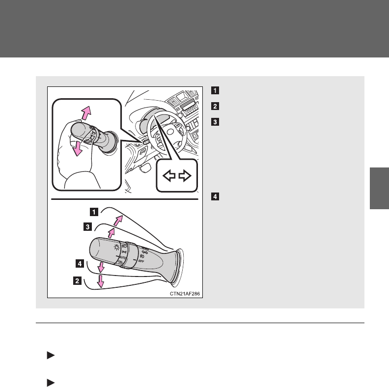
183
2-1. Driving procedures
2
When driving
Turn signal lever
■Turn signals can be operated when
Vehicles without smart key system
The engine switch is in the “ON” position.
Vehicles with smart key system
The “ENGINE START STOP” switch is in IGNITION ON mode.
■If the indicators flash faster than usual
Check that a light bulb in the front or rear turn signal lights has not burned
out.
Right turn
Left turn
Move and hold the lever
partway to signal a lane
change.
The right hand signal will flash
until you release the lever.
Move and hold the lever
partway to signal a lane
change.
The left hand signal will flash
until you release the lever.

184
2-1. Driving procedures
Parking brake
■Usage in winter time
See “Winter driving tips” for parking brake usage in winter time. (P. 248)
NOTICE
■Before driving
Fully release the parking brake.
Driving the vehicle with the parking brake set will lead to brake components
overheating, which may affect braking performance and increase brake
wear.
Sets the parking brake*
(Depressing the pedal again
releases the parking brake.)
*: Fully depress the parking
brake pedal with your left foot
while depressing the brake
pedal with your right foot.
U.S.A. Canada

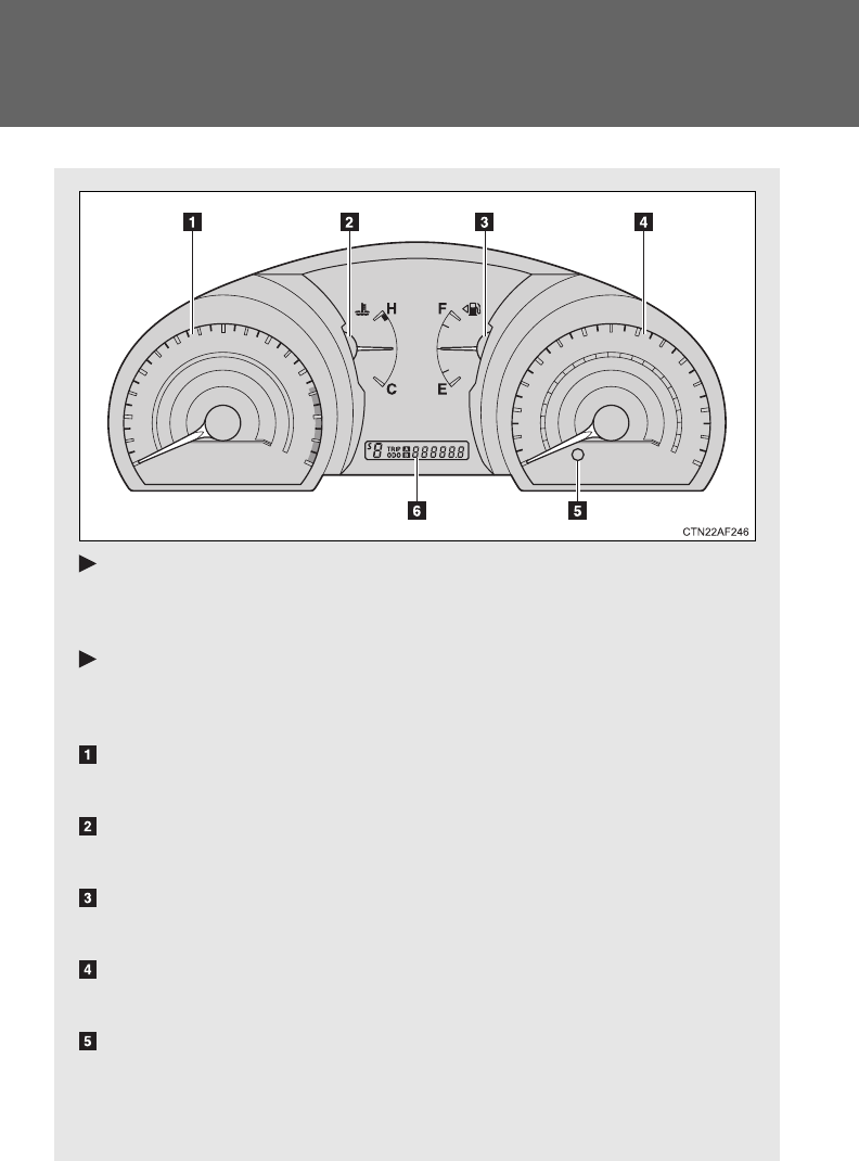
186
2-2. Instrument cluster
Gauges and meters
Vehicles without smart key system
The following gauges and meters illuminate when the engine
switch is in the “ON” position.
Vehicles with smart key system
The following gauges and meters illuminate when the “ENGINE
START STOP” switch is in IGNITION ON mode.
Tachometer
Displays the engine speed in revolutions per minute.
Engine coolant temperature gauge
Displays the engine coolant temperature.
Fuel gauge
Displays the quantity of fuel remaining in the tank.
Speedometer
Displays the vehicle speed.
Odometer/trip meter switching and trip meter resetting button
Switches between odometer and trip meter displays. Pushing and hold-
ing the button will reset the trip meter when the trip meter is being dis-
played.
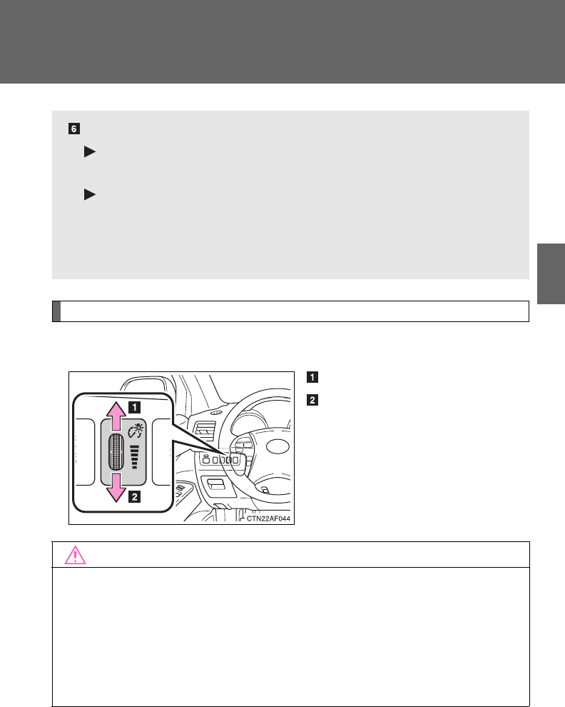
187
2-2. Instrument cluster
2
When driving
Instrument panel light control
The brightness of the instrument panel lights can be adjusted.
Brighter
Darker
When the headlight switch is
turned on, the brightness will
be reduced slightly unless the
control dial is turned fully up.
Odometer/Trip meter
Odometer
Displays the total distance the vehicle has been driven.
Trip meter
Displays the distance the vehicle has been driven since the
meter was last reset. Trip meters A and B can be used to
record and display different distances independently.
NOTICE
■To prevent damage to the engine and its components
●Do not let the indicator needle of the tachometer enter the red zone, which
indicates the maximum engine speed.
●The engine may be overheating if the temperature gauge is in the red
zone (H). In this case, immediately stop the vehicle in a safe place, and
check the engine after it has cooled completely. (P. 610)
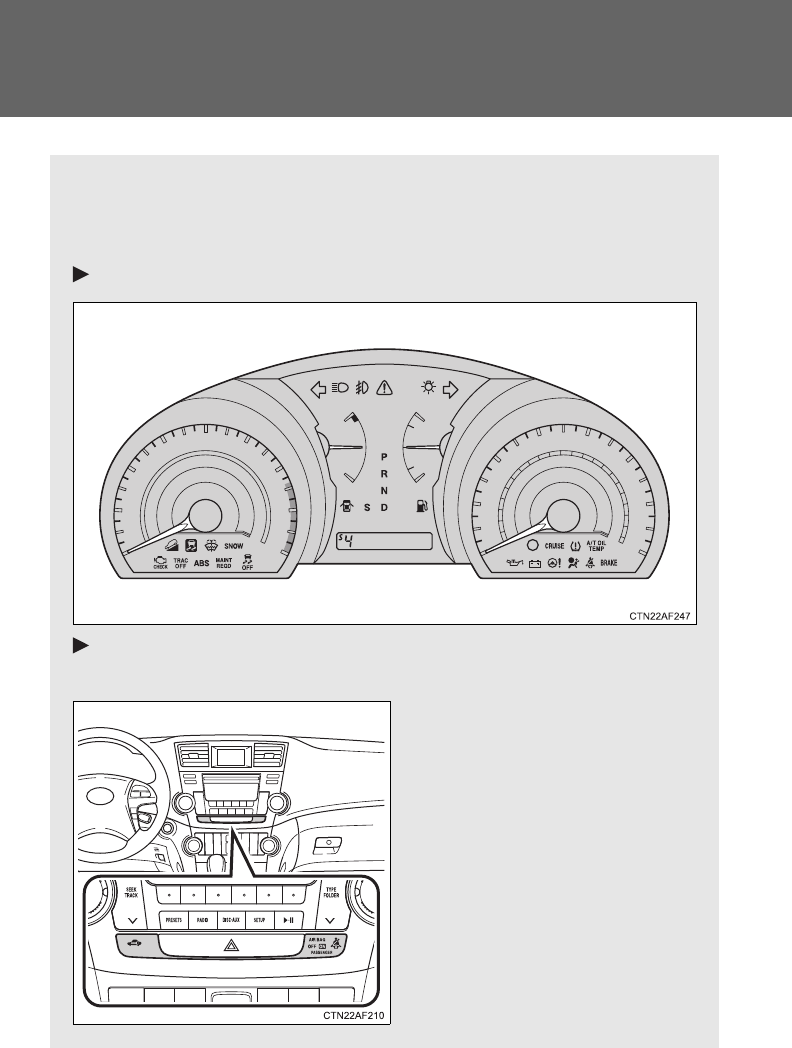
188
2-2. Instrument cluster
Indicators and warning lights
The indicator and warning lights on the instrument cluster and cen-
ter panel inform the driver of the status of the vehicle’s various sys-
tems.
Instrument cluster
Center panel (vehicles without a Display Audio system or navi-
gation system)
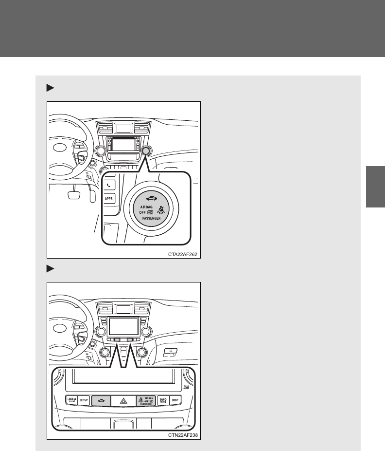
189
2-2. Instrument cluster
2
When driving
Center panel (vehicles with a Display Audio system)
Center panel (vehicles with a navigation system)

190
2-2. Instrument cluster
■Indicators
The indicators inform the driver of the operating state of the
vehicle’s various systems.
Turn signal indicator
(P. 183)
(U.S.A.)
Headlight indicator
(P. 203)
Headlight high beam
indicator (P. 208)
(Canada)
Tail light indicator
(P. 203)
(4WD models)
Downhill assist control
system indicator
(P. 234) (if equipped)
Front fog light indicator
(P. 210)
Slip indicator
(P. 228)
“SNOW” indicator
(P. 179)
Shift position and shift range indica-
tors (P. 178)
SRS airbag on-off indi-
cator (P. 136)
VSC off indicator
(P. 229)
(if equipped)
Cruise control indicator
(P. 219)
(if equipped)
Engine immobilizer/
alarm indicator
(P. 113, 117)
“TRAC OFF” indicator
(P. 228)
*1
*1, 2
*1
*1
*1
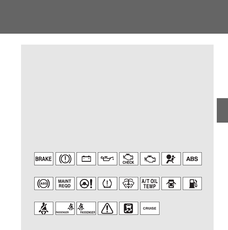
191
2-2. Instrument cluster
2
When driving
*1: These lights turn on when the engine switch is turned to the “ON”
position (vehicles without smart key system) or the “ENGINE
START STOP” switch is turned to IGNITION ON mode (vehicles
with smart key system) to indicate that a system check is being per-
formed. They will turn off after the engine is started, or after a few
seconds. There may be a malfunction in a system if a light does not
come on, or if the lights do not turn off. Have the vehicle inspected
by your Toyota dealer for details.
*2: The light flashes to indicate that the system is operating.
■Warning lights
Warning lights inform the driver of malfunctions in any of the
vehicle’s systems. (P. 573)
(U.S.A.) (Canada) (U.S.A.) (Canada) (U.S.A.)
(Canada) (U.S.A.)
(if equipped)
*1
*1
*1
*1, 2
*1
*1
*1
*1
*1
*1, 2
*1
*1
*1, 2
*1, 2
*4
*5
*3
*1
*6
192
2-2. Instrument cluster
CAUTION
■If a safety system warning light does not come on
Should a safety system light such as the ABS and SRS airbag warning light
not come on when you start the engine, this could mean that these systems
are not available to help protect you in an accident, which could result in
death or serious injury. Have the vehicle inspected by your Toyota dealer
immediately if this occurs.
*1: These lights turn on when the engine switch is turned to the “ON”
position (vehicles without smart key system) or the “ENGINE
START STOP” switch is turned to IGNITION ON mode (vehicles
with smart key system) to indicate that a system check is being per-
formed. They will turn off after the engine is started, or after a few
seconds. There may be a malfunction in a system if a light does not
come on, or if the lights do not turn off. Have the vehicle inspected
by your Toyota dealer for details.
*2: Vehicles without multi-information display
*3: Vehicles with multi-information display
*4: Vehicles without a navigation system
*5: Vehicles with a navigation system
*6: The light flashes to indicate a malfunction.
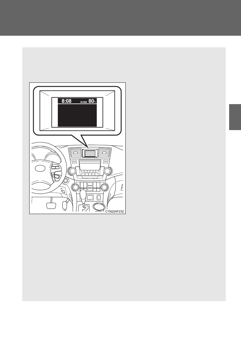
193
2-2. Instrument cluster
2
When driving
Multi-information display
The multi-information display presents the driver with a variety of
driving-related data, including the current outside temperature and
clock.
●Outside temperature
Indicates the outside tempera-
ture.
The temperature range that
can be displayed is from -40°F
(-40°C) to 122°F (50°C).
●Clock ( P. 196)
Indicates and sets the time.
●Trip information (P. 194)
Displays cruising range, fuel
consumption and other cruis-
ing-related information.
●Automatic air conditioning
system display (if equipped)
(P. 281)
Automatically displayed when
the automatic air conditioning
is turned on.
●Rear view monitor
(P. 223)
Automatically displayed when
the shift lever is moved into the
R position.
: If equipped
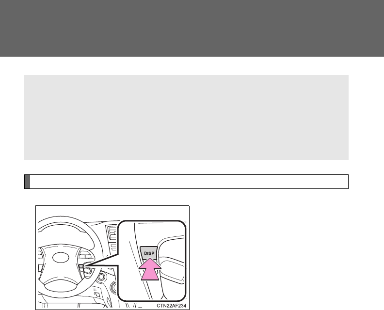
194
2-2. Instrument cluster
Trip information
Push the “DISP” button on the
steering wheel to display trip
information.
Display items can be switched
by pressing the “DISP” button.
■Average fuel consumption after refueling
Displays the average fuel consumption since the vehicle was last
refueled.
Use the displayed average fuel consumption as a reference.
■Instantaneous fuel consumption
Displays the instantaneous fuel consumption.
●Warning messages
(P. 584)
Automatically displayed when
a malfunction occurs in one of
the vehicle’s systems.

195
2-2. Instrument cluster
2
When driving
■Cruising range
Displays the estimated maximum distance that can be driven with
the quantity of fuel remaining.
• This distance is computed based on your average fuel consumption.
As a result, the actual distance that can be driven may differ from
that displayed.
• Vehicles without smart key system: When only a small amount of
fuel is added to the tank, the display may not be updated.
When refueling, turn the engine switch OFF. If the vehicle is refueled
without turning the engine switch OFF, the display may not be
updated.
• Vehicles with smart key system: When only a small amount of fuel is
added to the tank, the display may not be updated.
When refueling, turn the “ENGINE START STOP” switch OFF. If the
vehicle is refueled without turning the “ENGINE START STOP”
switch OFF, the display may not be updated.
■Driving distance
Displays the driving distance since the engine was started.
■Average fuel consumption
Displays the average fuel consumption since the function was
reset.
• This function can be reset by pressing the “DISP” button on the
steering wheel for longer than one second when the average fuel
consumption is displayed.
When the function is reset, the previous five average fuel consump-
tion values will automatically be displayed for six seconds.
• Use the displayed average fuel consumption as a reference.
■Average fuel consumption history
Displays the previous five average fuel consumption values.
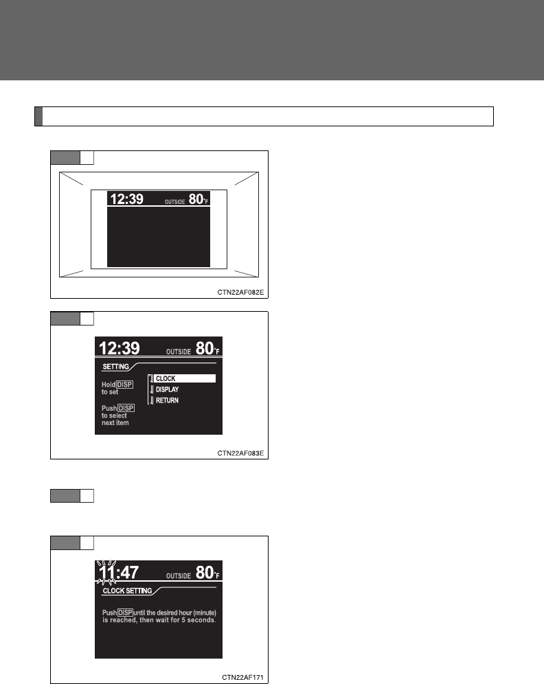
196
2-2. Instrument cluster
Setting up the displays
Display the set up screen on the
multi-information display when
the vehicle is stopped.
Press and hold the “DISP” button
on the steering wheel to display
the set up screen.
Select the desired item on the
menu screen.
Press and hold the “DISP” button
on the steering wheel to enter the
setting mode.
■Setting the clock
Select “CLOCK” on the menu screen. Press and hold the
“DISP” button on the steering wheel until the display changes.
Press the “DISP” button on the
steering wheel to adjust the
hours.
After adjusting the hours, wait 5
seconds to allow the hours to be
automatically input.
STEP
1
STEP
2
STEP
1
STEP
2
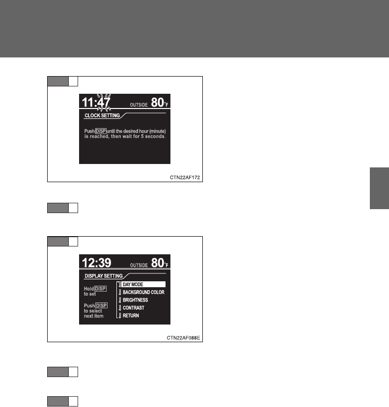
197
2-2. Instrument cluster
2
When driving
Press the “DISP” button on the
steering wheel to adjust the min-
utes.
After adjusting the minutes, wait 5
seconds to allow the minutes to
be automatically input.
■Setting the display
Select “DISPLAY” on the menu screen. Press and hold the
“DISP” button on the steering wheel until the display changes.
Select the desired item on the
menu screen.
Press and hold the “DISP” button
on the steering wheel to enter the
setting mode.
●Setting day mode
Select “DAY MODE” on the menu screen. Press and hold the
“DISP” button on the steering wheel until the display changes.
Press the “DISP” button on the steering wheel to select “ON”
or “OFF”.
After setting day mode, wait 5 seconds to allow the mode to be auto-
matically input.
STEP
3
STEP
1
STEP
2
STEP
1
STEP
2
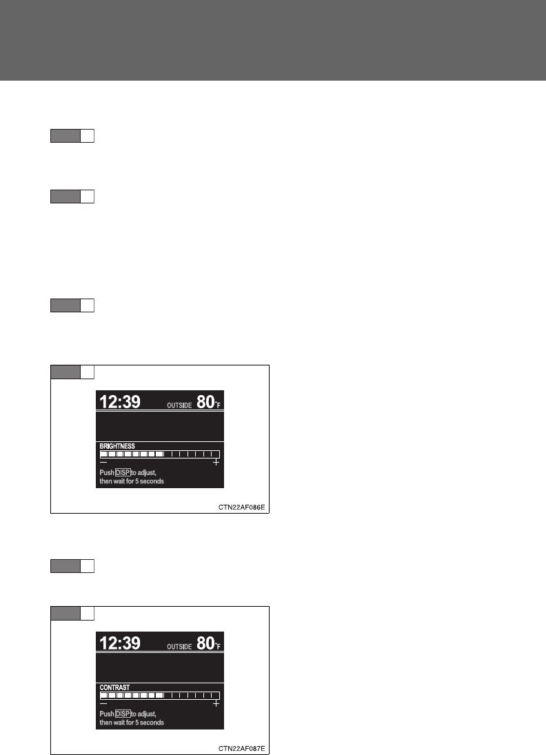
198
2-2. Instrument cluster
●Setting the background color
Select “BACKGROUND COLOR” on the menu screen. Press
and hold the “DISP” button on the steering wheel until the dis-
play changes.
Press the “DISP” button on the steering wheel to select
“BLACK” or “BLUE”.
After selecting a background color, wait 5 seconds to allow the color
to be automatically input.
●Setting the brightness
Select “BRIGHTNESS” on the menu screen. Press and hold
the “DISP” button on the steering wheel until the display
changes.
Press the “DISP” button on the
steering wheel to adjust the
brightness.
+: Brighter
-: Darker
After adjusting the brightness,
wait 5 seconds to allow the bright-
ness to be automatically input.
●Setting the contrast
Select “CONTRAST” on the menu screen. Press and hold the
“DISP” button on the steering wheel until the display changes.
Press the “DISP” button on the
steering wheel to adjust the con-
trast.
+: Strengthen
-: Weaken
After adjusting the contrast, wait 5
seconds to allow the contrast to
be automatically input.
STEP
1
STEP
2
STEP
1
STEP
2
STEP
1
STEP
2
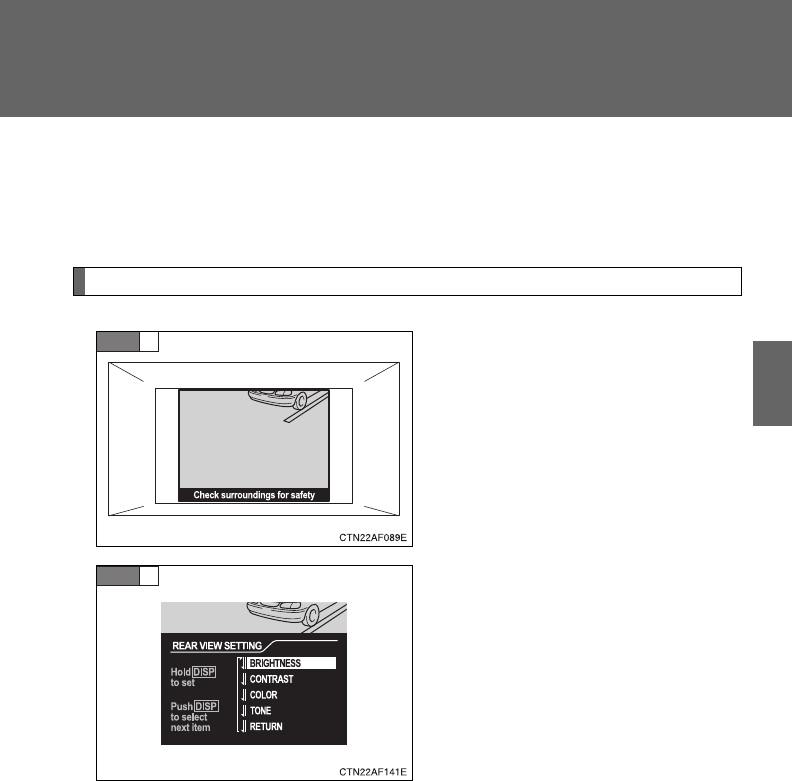
199
2-2. Instrument cluster
2
When driving
●Returning to the previous screen
Select “RETURN” on the menu screen. Press and hold the “DISP”
button on the steering wheel until the display changes.
Setting up the rear view monitor display
Display the set up screen on the
multi-information display when
the vehicle is stopped and the
rear view monitor is turned on.
Press and hold the “DISP” button
on the steering wheel to display
the set up screen.
Select the desired item on the
menu screen.
Press and hold the “DISP” button
on the steering wheel to enter the
adjustment mode.
STEP
1
STEP
2
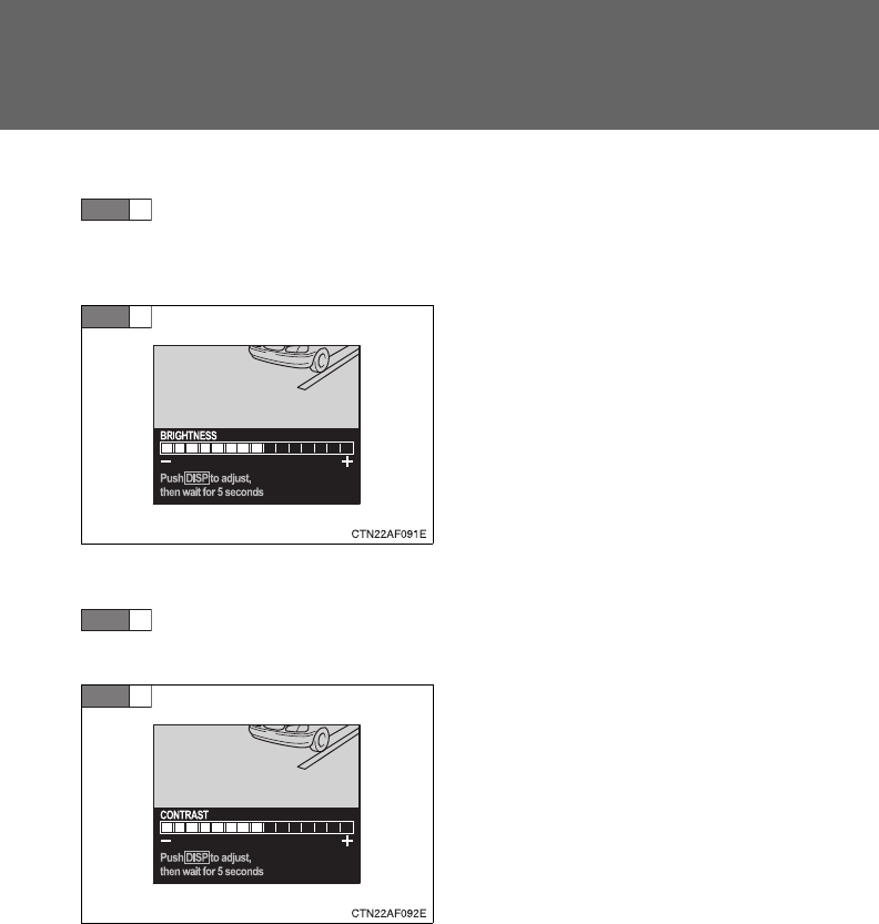
200
2-2. Instrument cluster
■Setting the brightness
Select “BRIGHTNESS” on the menu screen. Press and hold
the “DISP” button on the steering wheel until the display
changes.
Press the “DISP” button on the
steering wheel to adjust the
brightness.
+: Brighter
-: Darker
After adjusting the brightness,
wait 5 seconds to allow the bright-
ness to be automatically input.
■Setting the contrast
Select “CONTRAST” on the menu screen. Press and hold the
“DISP” button on the steering wheel until the display changes.
Press the “DISP” button on the
steering wheel to adjust the con-
trast.
+: Strengthen
-: Weaken
After adjusting the contrast, wait 5
seconds to allow the contrast to
be automatically input.
STEP
1
STEP
2
STEP
1
STEP
2
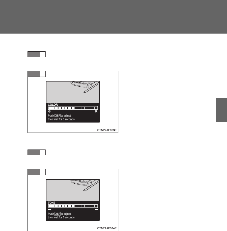
201
2-2. Instrument cluster
2
When driving
■Setting the color
Select “COLOR” on the menu screen. Press and hold the
“DISP” button on the steering wheel until the display changes.
Press the “DISP” button on the
steering wheel to adjust the
color.
G: Green
R: Red
After selecting a color, wait 5 sec-
onds to allow the color to be auto-
matically input.
■Setting the tone
Select “TONE” on the menu screen. Press and hold the
“DISP” button on the steering wheel until the display changes.
Press the “DISP” button on the
steering wheel to adjust the tone.
+: Brighter
-: Darker
After adjusting the tone, wait 5
seconds to allow the tone to be
automatically input.
■Returning to the previous screen
Select “RETURN” on the menu screen. Press and hold the “DISP”
button on the steering wheel until the display changes.
STEP
1
STEP
2
STEP
1
STEP
2
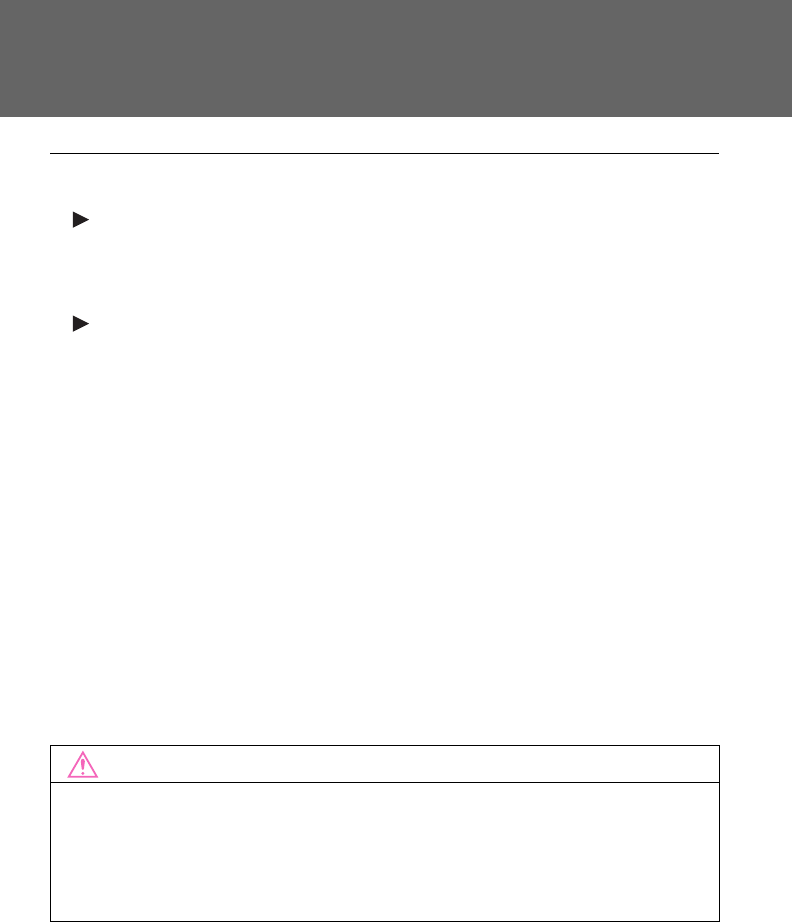
202
2-2. Instrument cluster
■System check display
Vehicles without smart key system
After the engine switch is turned to the “ON” position, “SYSTEM CHECK” is
displayed while system operation is checked. When the system check is
complete, the normal screen will return.
Vehicles with smart key system
After the “ENGINE START STOP” switch is turned to IGNITION ON mode,
“SYSTEM CHECK” is displayed while system operation is checked. When
the system check is complete, the normal screen will return.
■Liquid crystal display
Small bright spots or dots may appear on the liquid crystal display. This is a
particular characteristic of liquid crystal displays and does not indicate a mal-
function. No action is required.
■Outside temperature display
When stopped, or driving at low speeds (less than 12 mph [20 km/h]), the
correct outside temperature may not be displayed, or the display may take
longer than normal to change.
■Customization that can be configured at Toyota dealer
Setting of language selection can be changed.
(Customizable features P. 648)
NOTICE
■The multi-information display at low temperatures
Allow the interior of the vehicle to warm up before using the liquid crystal
information display. At extremely low temperatures, the information display
monitor may respond slowly, and display changes may be delayed.

203
2
When driving
2-3. Operating the lights and wipers
Headlight switch
The headlights can be operated manually or automatically.
Type A
The headlights and
parking lights turn on
and off automati-
cally.
(Vehicles without
smart key system:
When the engine
switch is turned to
the “ON” position.
Vehicles with smart
key system:
When the “ENGINE
START STOP”
switch is turned to
IGNITION ON
mode.)
The side marker,
parking, tail, license
plate and daytime
running lights and
instrument panel
lights turn on.
The headlights and
all lights listed above
(except daytime run-
ning lights) turn on.
The daytime run-
ning lights turn off.
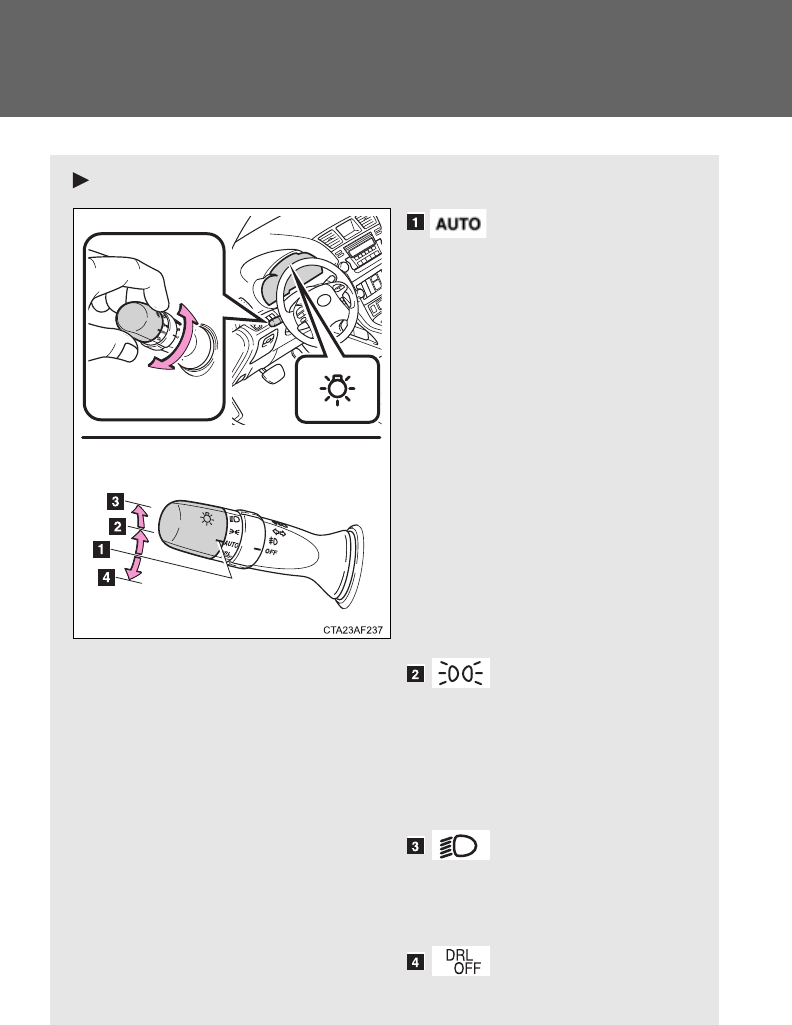
204
2-3. Operating the lights and wipers
Type B
The headlights and
parking lights turn on
and off automati-
cally.
(Vehicles without
smart key system:
When the engine
switch is turned to
the “ON” position.
Vehicles with smart
key system:
When the “ENGINE
START STOP”
switch is turned to
IGNITION ON
mode.)
The side marker,
parking, tail, license
plate and daytime
running lights and
instrument panel
lights turn on.
The headlights and
all lights listed above
(except daytime run-
ning lights) turn on.
The daytime run-
ning lights turn off.
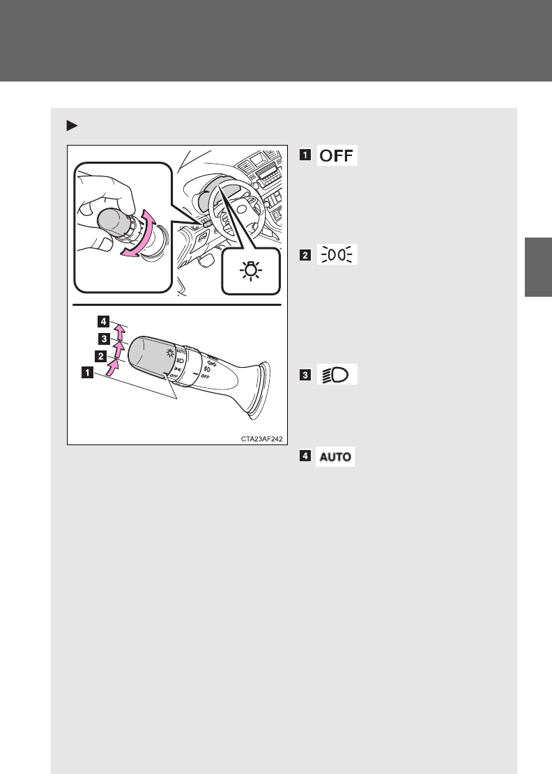
205
2-3. Operating the lights and wipers
2
When driving
Type C
Vehicles with day-
time running light
system: The daytime
running lights turn
on.
The side marker,
parking, tail, license
plate, daytime run-
ning lights and
instrument panel
lights turn on.
The headlights and
all lights listed above
(except daytime run-
ning lights) turn on.
The headlights and
parking lights turn on
and off automati-
cally.
(Vehicles without
smart key system:
When the engine
switch is turned to
the “ON” position.
Vehicles with smart
key system:
When the “ENGINE
START STOP”
switch is turned to
IGNITION ON
mode.)
(if equipped)
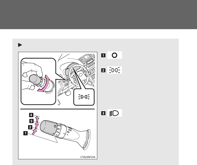
206
2-3. Operating the lights and wipers
Type D
The daytime run-
ning lights turn on.
The side marker,
parking, tail, license
plate, daytime run-
ning lights and
instrument panel
lights turn on.
The headlights and
all lights listed above
(except daytime run-
ning lights) turn on.
207
2-3. Operating the lights and wipers
2
When driving
The headlights and
parking lights turn on
and off automati-
cally.
(Vehicles without
smart key system:
When the engine
switch is turned to
the “ON” position.
Vehicles with smart
key system:
When the “ENGINE
START STOP”
switch is turned to
IGNITION ON
mode.)
(if equipped)
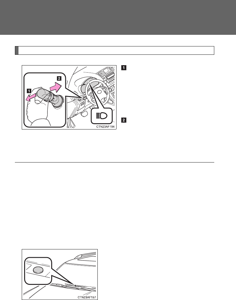
208
2-3. Operating the lights and wipers
Turning on the high beam headlights
With the headlights on, push
the lever forward to turn on the
high beams.
Pull the lever back to the center
position to turn the high beams
off.
Pull the lever toward you to
turn on the high beams.
Release the lever to turn them off.
You can flash the high beams
with the headlights on or off.
■Daytime running light system (if equipped)
●To help make your vehicle visible to other drivers, the headlights turn on
automatically (at a reduced intensity) whenever the engine is started and
the parking brake is released. Daytime running lights are not designed for
use at night.
U.S.A.: Daytime running lights can be turned off by operating the switch.
●The daytime running light system helps to offer great durability and con-
sumes less electricity, so it can help enhance fuel economy.
■Headlight control sensor (if equipped)
The sensor may not function properly if
an object is placed on the sensor, or any-
thing that blocks the sensor is affixed to
the windshield.
Doing so interferes with the sensor
detecting the level of ambient light and
may cause the automatic headlight sys-
tem to malfunction.
209
2-3. Operating the lights and wipers
2
When driving
■Automatic light off system
Vehicles without smart key system
●When the headlights come on: The headlights and tail lights turn off 30
seconds after a door is opened and closed if the engine switch is turned
to the “ACC” or “LOCK” position. (The lights turn off immediately if
on the wireless remote control is pressed after all the doors are
locked.)
●When only the tail lights come on: The tail lights turn off automatically if
the engine switch is turned to the “ACC” or “LOCK” position and the
driver’s door is opened.
To turn the lights on again, turn the engine switch to the “ON” position, or
turn the light switch off and then back to or .
Vehicles with smart key system
●When the headlights come on: The headlights and tail lights turn off 30
seconds after a door is opened and closed if the “ENGINE START
STOP” switch is turned to ACCESSORY mode or turned off. (The lights
turn off immediately if on the key is pressed after all the doors are
locked.)
●When only the tail lights come on: The tail lights turn off automatically if
the “ENGINE START STOP” switch is turned to ACCESSORY mode or
turned off and the driver’s door is opened.
To turn the lights on again, turn the “ENGINE START STOP” switch to IGNI-
TION ON mode, or turn the light switch off and then back to or
.
■Customization that can be configured at Toyota dealer
Settings (e.g. daytime running light system) can be changed.
(Customizable features P. 648)
NOTICE
■To prevent battery discharge
Do not leave the lights on longer than necessary when the engine is not run-
ning.
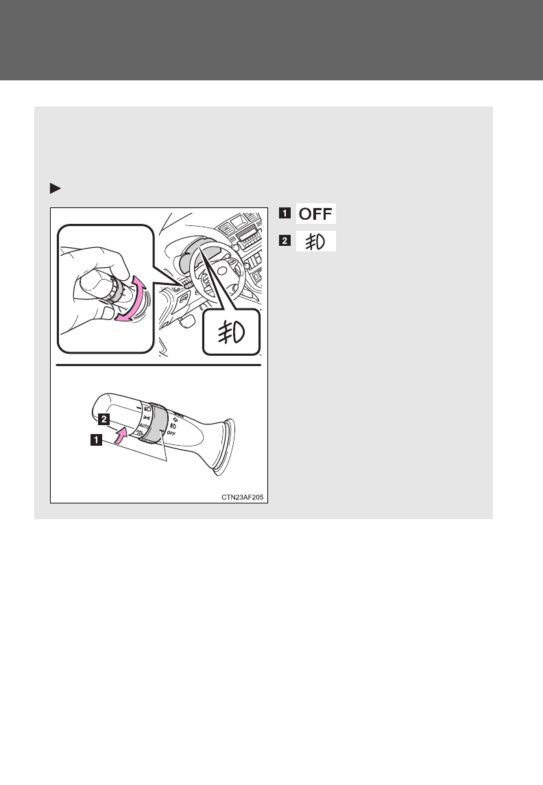
210
2-3. Operating the lights and wipers
Fog light switch
The fog lights improve visibility in difficult driving conditions, such
as in rain or fog. They can be turned on only when the headlights are
on in low beam.
Type A
Off
Front fog lights on
: If equipped
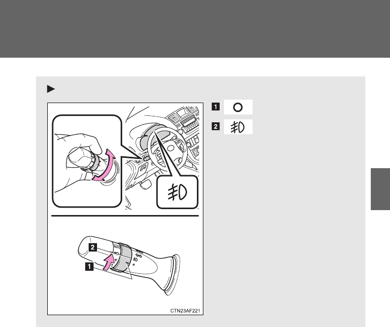
211
2-3. Operating the lights and wipers
2
When driving
Type B
Off
Front fog lights on
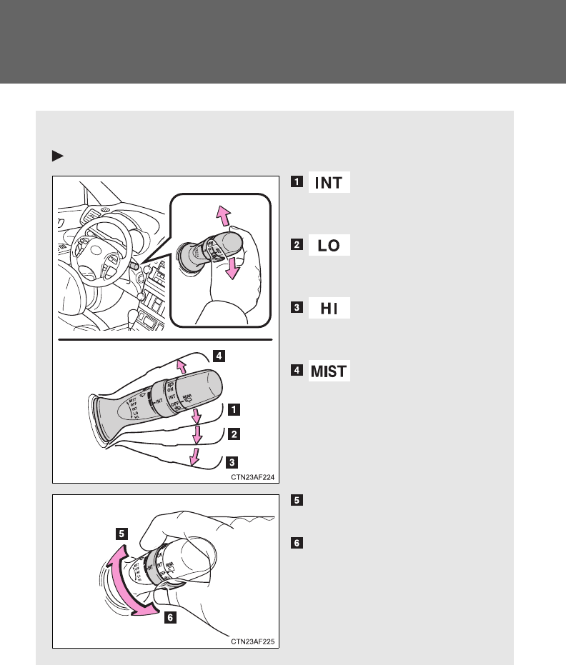
212
2-3. Operating the lights and wipers
Windshield wipers and washer
Wiper intervals can be adjusted for intermittent operation.
Type A
Intermittent wind-
shield wiper opera-
tion
Low speed wind-
shield wiper opera-
tion
High speed wind-
shield wiper opera-
tion
Temporary operation
Increases the intermittent
windshield wiper frequency
Decreases the intermittent
windshield wiper frequency
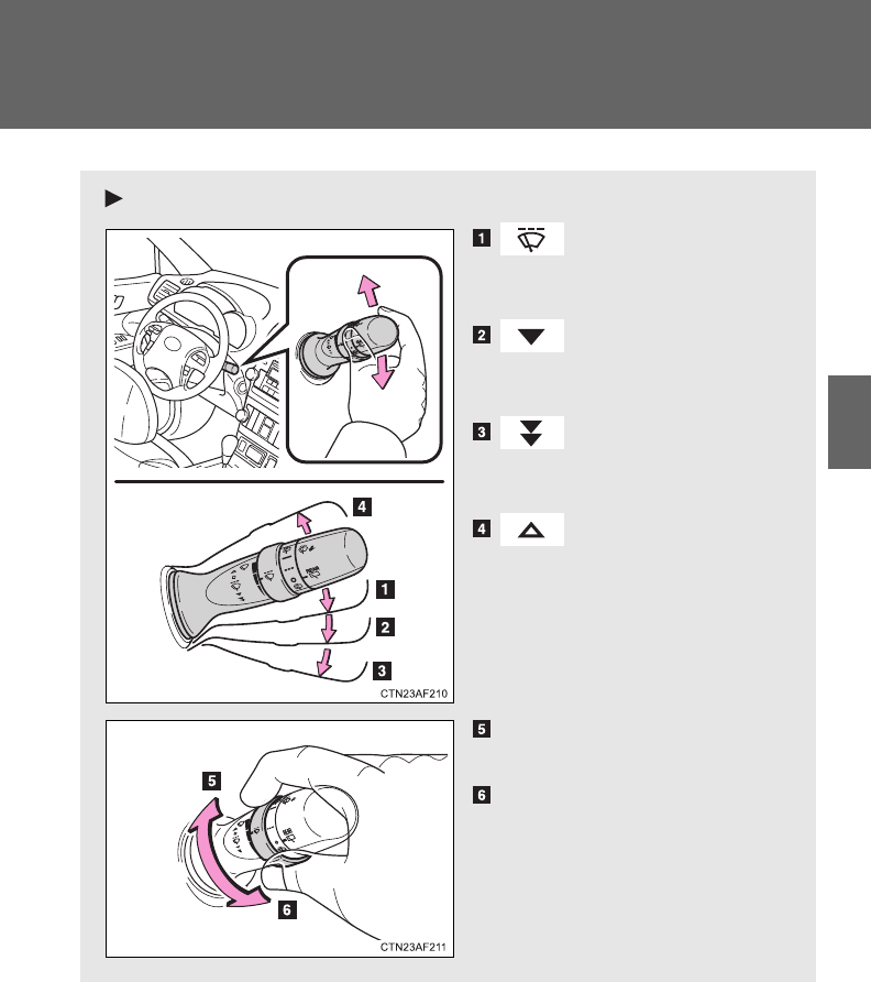
213
2-3. Operating the lights and wipers
2
When driving
Type B
Intermittent wind-
shield wiper opera-
tion
Low speed wind-
shield wiper opera-
tion
High speed wind-
shield wiper opera-
tion
Temporary operation
Increases the intermittent
windshield wiper frequency
Decreases the intermittent
windshield wiper frequency
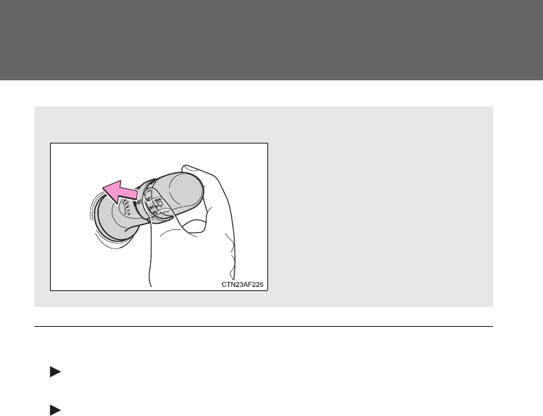
214
2-3. Operating the lights and wipers
■The windshield wipers and washer can be operated when
Vehicles without smart key system
The engine switch is in the “ON” position.
Vehicles with smart key system
The “ENGINE START STOP” switch is in IGNITION ON mode.
■If no windshield washer fluid sprays
Check that the washer nozzles are not blocked and if there is washer fluid in
the windshield washer fluid reservoir.
■Wash/wipe operation
Wipers operate automatically.

215
2-3. Operating the lights and wipers
2
When driving
NOTICE
■When the windshield is dry
Do not use the wipers, as they may damage the windshield.
■When there is no washer fluid spray from the nozzle
Damage to the washer fluid pump may be caused if the lever is pulled
toward you and held continually.
■When a nozzle is blocked
Do not try to clear it with a pin or other object. The nozzle will be damaged.

216
2-3. Operating the lights and wipers
Rear window wiper and washer
Type A
Intermittent window
wiper operation
Normal window
wiper operation
Washer/wiper dual
operation
Washer/wiper dual
operation
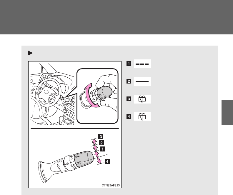
217
2-3. Operating the lights and wipers
2
When driving
Type B
Intermittent window
wiper operation
Normal window
wiper operation
Washer/wiper dual
operation
Washer/wiper dual
operation
218
2-3. Operating the lights and wipers
■The rear window wiper and washer can be operated when
Vehicles without smart key system
The engine switch is in the “ON” position.
Vehicles with smart key system
The “ENGINE START STOP” switch is in IGNITION ON mode.
NOTICE
■When the rear window is dry
Do not use the wipers, as they may damage the rear window.
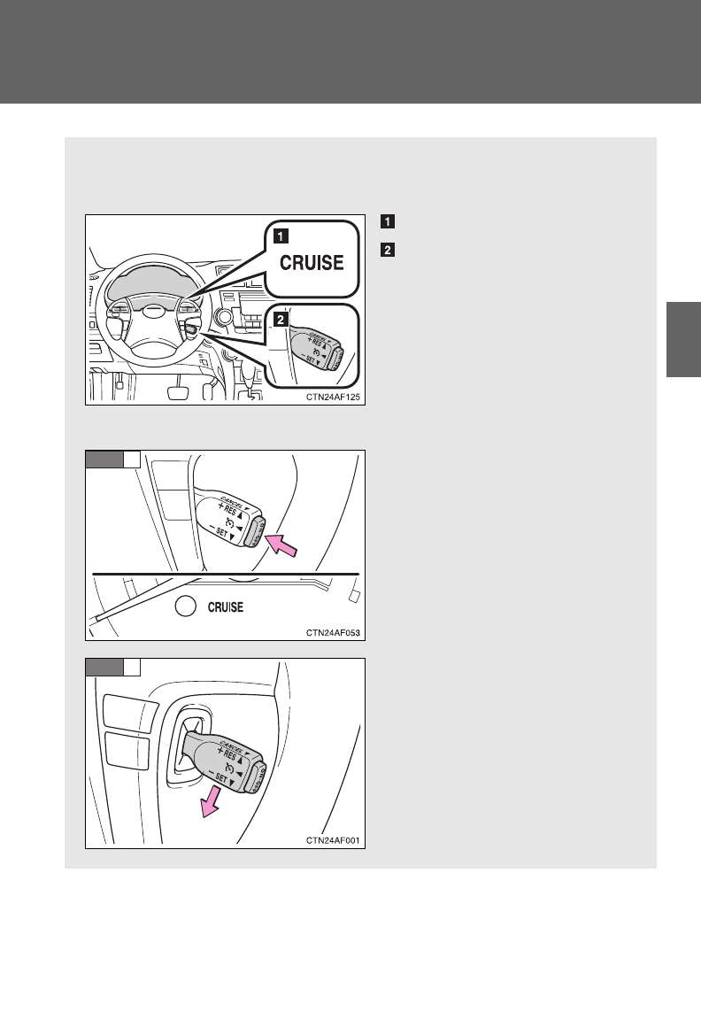
219
2
When driving
2-4. Using other driving systems
Cruise control
Use the cruise control to maintain a set speed without depressing
the accelerator pedal.
Indicator
Cruise control switch
■Setting the vehicle speed
Press the “ON-OFF” button to
activate the cruise control.
Cruise control indicator will
come on.
Press the button again to
deactivate the cruise control.
Accelerate or decelerate the
vehicle to the desired speed,
and push the lever down to set
the speed.
The vehicle speed at the
moment the lever is released
becomes the set speed.
STEP
1
STEP
2
: If equipped
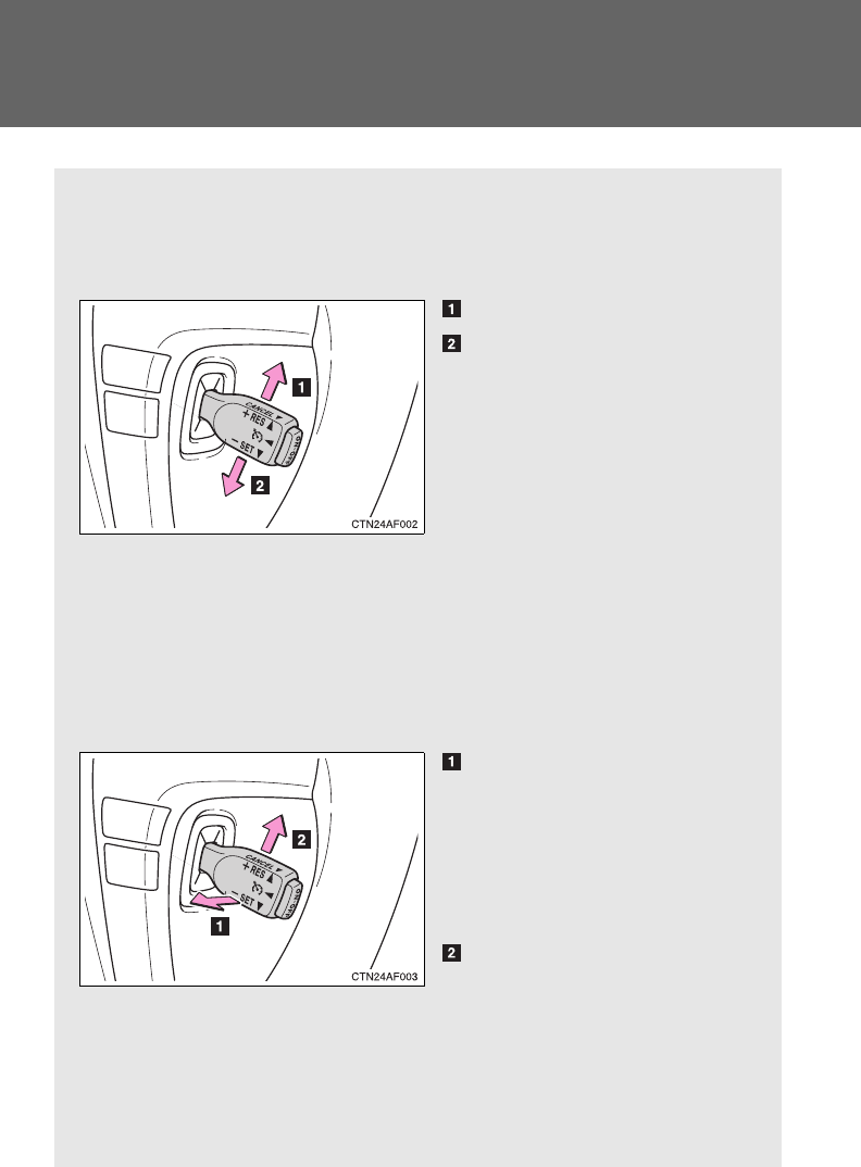
220
2-4. Using other driving systems
■Adjusting the set speed
To change the set speed, operate the lever until the desired set
speed is obtained.
Increases the speed
Decreases the speed
Fine adjustment: Momentarily
move the lever in the desired
direction.
Large adjustment: Hold the
lever in the desired direction.
The set speed will be increased or decreased as follows:
Fine adjustment: By approximately 1 mph (1.6 km/h) each time the
lever is operated.
Large adjustment: The set speed can be increased or decreased con-
tinually until the lever is released.
■Canceling and resuming the constant speed control
Pulling the lever toward you
cancels the constant speed
control.
The speed setting is also can-
celed when the brakes are
applied.
Pushing the lever up
resumes the constant
speed control.
Resuming is available when
the vehicle speed is more
than approximately 25 mph
(40 km/h).

221
2-4. Using other driving systems
2
When driving
■Cruise control can be set when
●The shift lever is in the D or range “4” or higher of S has been selected.
●Vehicle speed is above approximately 25 mph (40 km/h).
■Accelerating after setting the vehicle speed
●The vehicle can be accelerated normally. After acceleration, the set
speed resumes.
●Even without cancelling the cruise control, the set speed can be
increased by first accelerating the vehicle to the desired speed and then
pushing the lever down to set the new speed.
■Automatic cruise control cancelation
Cruise control will stop maintaining the vehicle speed in any of the following
situations.
●Actual vehicle speed falls more than approximately 10 mph (16 km/h)
below the preset vehicle speed.
At this time, the memorized set speed is not retained.
●Actual vehicle speed is below approximately 25 mph (40 km/h).
●VSC is activated.
■If the cruise control indicator light flashes
Press the “ON-OFF” button once to deactivate the system, and then press
the button again to reactivate the system.
If the cruise control speed cannot be set or if the cruise control cancels
immediately after being activated, there may be a malfunction in the cruise
control system. Have the vehicle inspected by your Toyota dealer.

222
2-4. Using other driving systems
CAUTION
■To avoid operating the cruise control by mistake
Switch the cruise control off using the “ON-OFF” button when not in use.
■Situations unsuitable for cruise control
Do not use cruise control in any of the following situations.
Doing so may result in loss of control and could cause an accident resulting
in death or serious injury.
●In heavy traffic
●On roads with sharp bends
●On winding roads
●On slippery roads, such as those covered with rain, ice or snow
●On steep hills
Vehicle speed may exceed the set speed when driving down a steep hill.
●When your vehicle is towing a trailer or during emergency towing
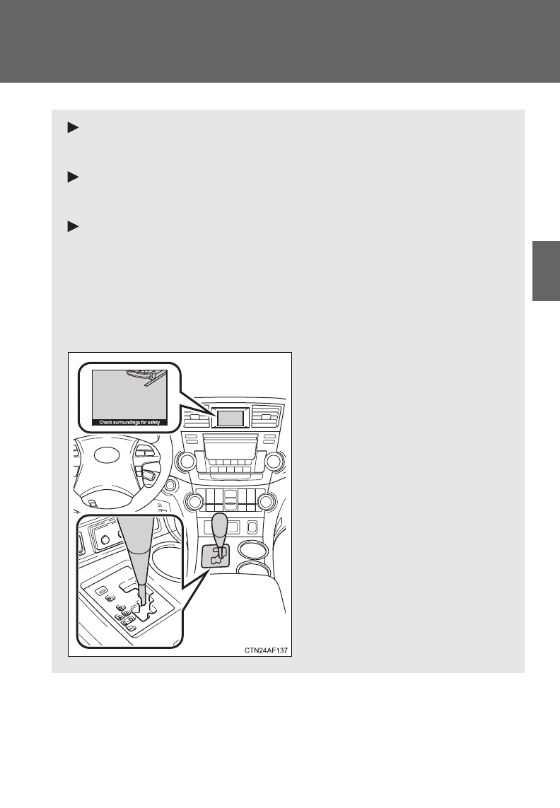
223
2-4. Using other driving systems
2
When driving
Rear view monitor system (vehicles with multi-information display)
: If equipped
Vehicles with a Display Audio system
Refer to the “Display Audio System Owner’s Manual”.
Vehicles with a navigation system
Refer to the “Navigation System Owner's Manual”.
Vehicles without a Display Audio system or navigation sys-
tem
The rear view monitor system assists the driver by displaying an
image of the area behind the vehicle. The image is displayed in
reverse on the screen. This reversed image is a similar image to the
one on the inside rear view mirror.
The rear view image is dis-
played when the shift lever is
in the R position.
If the shift lever is shifted out of
R, the screen returns to the
previous one.
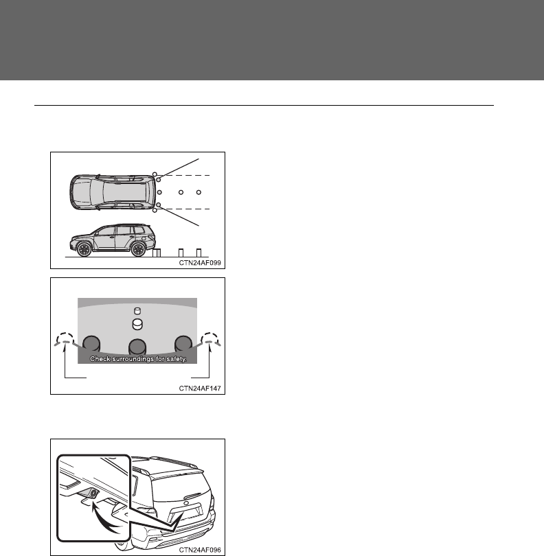
224
2-4. Using other driving systems
■Displayed area
■Rear view monitor system camera
The area covered by the camera is lim-
ited. Objects that are close to either
corner of the bumper or under the
bumper cannot be seen on the screen.
The area displayed on the screen may
vary according to vehicle orientation or
road conditions.
Corners of bumper
In the following cases, it may become
difficult to see the images on the
screen, even when the system is func-
tioning correctly.
●The vehicle is in a dark area, such
as at night.
●The temperature near the lens is
extremely high or low.
●Water droplets are on the camera
lens or humidity is high, such as
when it rains.
●Foreign matter, such as snow or
mud, adheres to the camera lens.
●When the camera has scratches or
dirt on it.
●The sun or headlights are shining
directly into the camera lens.

225
2-4. Using other driving systems
2
When driving
■Smear effect
■Flicker effect
When the camera is used under fluorescent light, sodium lights, or mercury
lights etc., the lights and the illuminated areas may appear to flicker.
■Setting the rear view monitor system display
P. 199
CAUTION
■When using the rear view monitor system, observe the following pre-
cautions to avoid an accident that could result in death or serious inju-
ries.
●Never depend solely on the monitor system when reversing.
●Always check visually and with the mirrors to confirm your intended path is
clear.
●Use your own eyes to confirm the vehicle’s surroundings, as the displayed
image may become faint or dark, and moving images will be distorted, or
not entirely visible when the outside temperature is low. When backing up,
be sure to check behind and all around the vehicle visually and with the
mirrors before proceeding.
●Depicted distances between objects and flat surfaces differ from actual
distances.
●Do not use the system if the back door is open.
If a bright light, such as sunlight
reflected off the vehicle body, is picked
up by the camera, a smear effect* char-
acteristic to the camera may occur.
*: Smear effect A phenomenon that
occurs when a bright light is picked
up by the camera; when transmitted
by the camera, the light source
appears to have a vertical streak
above and below it.

226
2-4. Using other driving systems
NOTICE
■Conditions which may affect the rear view monitor system
●If the back of the vehicle has been hit, the camera’s position and mounting
angle may have changed. Have the vehicle inspected by your Toyota
dealer.
●Rapid temperature changes, such as when hot water is poured on the
vehicle in cold weather, may cause the system to function abnormally.
●If the camera lens is dirty, it cannot transmit a clear image. Rinse with
water and wipe with a soft cloth. If extremely dirty, wash with a mild
cleanser and rinse.
●The displayed image may be darker and moving images may be slightly
distorted when the system is cold.
■Camera precautions
●As the camera has a water proof construction, do not detach, disassemble
or modify it. This may cause incorrect operation.
●Do not subject the camera to a strong impact.
●If the camera lens becomes dirty, it cannot transmit a clear image. If water
droplets, snow, or mud adhere to the lens, rinse with water and wipe with a
soft cloth. If the lens is extremely dirty, wash it with a mild cleanser and
rinse. Do not rub hard.
●Do not allow organic solvent, car wax, window cleaner or glass coat to
adhere to the camera. If this happens, wipe it off as soon as possible.
●Do not strongly rub the camera lens. If the camera lens is scratched, it
cannot transmit a clear image.
●When washing the vehicle, do not apply intensive bursts of water to the
camera or camera area. Doing so may result in the camera malfunction-
ing.
●When replacing tires, please consult your Toyota dealer. If you replace the
tires, the area displayed on the screen may change.

227
2-4. Using other driving systems
2
When driving
Driving assist systems
To help enhance driving safety and performance, the following sys-
tems operate automatically in response to various driving situations.
Be aware, however, that these systems are supplementary and
should not be relied upon too heavily when operating the vehicle.
■ABS (Anti-lock Brake System)
Helps to prevent wheel lock when the brakes are applied suddenly, or if
the brakes are applied while driving on a slippery road surface.
■Brake assist
Generates an increased level of braking force after the brake pedal is
depressed when the system detects a panic stop situation.
■VSC (Vehicle Stability Control)
Helps the driver to control skidding when swerving suddenly or turning
on slippery road surfaces.
■TRAC (Traction Control)
Helps to maintain drive power and prevent the front wheels (2WD mod-
els) or four wheels (4WD models) from spinning when starting the vehi-
cle or accelerating on slippery roads.
■Hill-start assist control
P. 232
■Downhill assist control system (4WD models only)
P. 234
■EPS (Electric Power Steering)
Employs an electric motor to reduce the amount of effort needed to turn
the steering wheel.
■Enhanced VSC (Enhanced Vehicle Stability Control)
Provides cooperative control of the ABS, TRAC, VSC and EPS.
Helps to maintain directional stability when swerving on slippery road
surfaces by controlling steering performance.
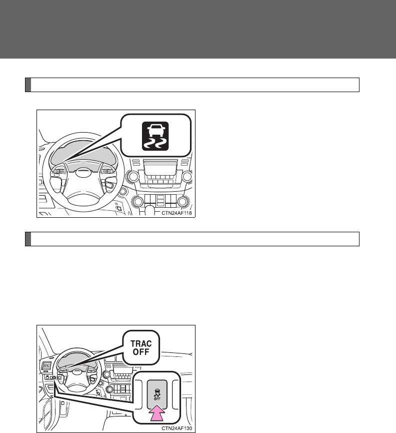
228
2-4. Using other driving systems
When the VSC/TRAC systems are operating
If the vehicle is in danger of slip-
ping, rolling backwards when
starting on an incline, or the front
wheels (2WD models) or four
wheels (4WD models) spin, the
indicator flashes to indicate that
the VSC/TRAC systems have
been engaged.
To disable TRAC and/or VSC
If the vehicle gets stuck in fresh snow or mud, TRAC and VSC may
reduce power from the engine to the wheels. You may need to turn
the system off to enable you to rock the vehicle in order to free it.
■Turning off TRAC
Quickly push and release the
button to turn off TRAC.
The “TRAC OFF” indicator light
should come on.
Push the button again to turn the
system back on.
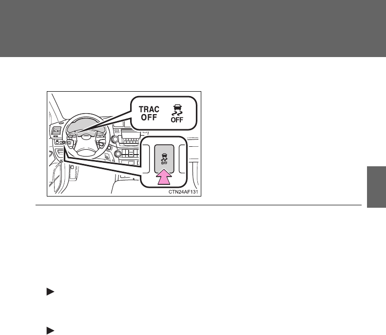
229
2-4. Using other driving systems
2
When driving
■Turning off TRAC and VSC
Push and hold the button while
the vehicle is stopped to turn off
TRAC and VSC.
The “TRAC OFF” and VSC off
indicator light should come on.
Push the button again to turn the
system back on.
■When the “TRAC OFF” indicator light comes on even if the VSC/TRAC
off switch has not been pressed
TRAC, hill-start assist control and downhill assist control cannot be oper-
ated. Contact your Toyota dealer.
■Automatic reactivation of TRAC and VSC
Vehicles without smart key system
Turning the engine switch OFF after turning off the TRAC and VSC sys-
tems will automatically re-enable them.
Vehicles with smart key system
Turning the “ENGINE START STOP” switch OFF after turning off the
TRAC and VSC systems will automatically re-enable them.
■Automatic TRAC reactivation
If only the TRAC system is turned off, the TRAC system will turn on when
vehicle speed increases.
■Automatic TRAC and VSC reactivation
If the TRAC and VSC systems are turned off, the systems will not turn on
even when vehicle speed increases.

230
2-4. Using other driving systems
■Sounds and vibrations caused by the ABS, TRAC, VSC and brake
assist
●A sound may be heard from the engine compartment when the engine is
started or just after the vehicle begins to move. This sound does not indi-
cate that a malfunction has occurred in any of these systems.
●Any of the following conditions may occur when the above systems are
operating. None of these indicates that a malfunction has occurred.
• Vibrations may be felt through the vehicle body and steering.
• A motor sound may be heard after the vehicle comes to a stop.
• The brake pedal may pulsate slightly when the ABS is activated.
• The brake pedal may move down slightly after the ABS is activated.
■EPS operation sound
When the steering is wheel operated, a motor sound (whirring sound) may
be heard. This does not indicate a malfunction.
■Reduced effectiveness of EPS system
The effectiveness of the EPS system is reduced to prevent the system from
overheating when there is frequent steering input over an extended period of
time. The steering wheel may feel heavy as a result. Should this occur,
refrain from excessive steering input or stop the vehicle and turn the engine
off. The EPS system should return to normal within 10 minutes.
■If the slip indicator comes on...
It may indicate a malfunction in the VSC and TRAC. Contact your Toyota
dealer.
CAUTION
■The ABS does not operate effectively when
●The limits of tire gripping performance have been exceeded (such as
excessively worn tires on a snow covered road).
●The vehicle hydroplanes while driving at high speed on wet or slick road.

231
2-4. Using other driving systems
2
When driving
CAUTION
■Stopping distance when the ABS is operating may exceed that of nor-
mal conditions
The ABS is not designed to shorten the vehicle's stopping distance. Always
maintain a safe distance from the vehicle in front of you, especially in the fol-
lowing situations.
●When driving on dirt, gravel or snow-covered roads
●When driving with tire chains
●When driving over bumps in the road
●When driving over roads with potholes or uneven roads
■TRAC may not operate effectively when
Directional control and power may not be achievable while driving on slip-
pery road surfaces even if the TRAC system is operating.
Do not drive the vehicle in conditions where stability and power may be lost.
■When the VSC is activated
The slip indicator light flashes. Always drive carefully. Reckless driving may
cause an accident. Exercise particular care when the indicator light flashes.
■When TRAC and VSC are off
Be especially careful and drive at a speed appropriate to the road condi-
tions. As these are systems to help ensure vehicle stability and driving force,
do not turn off TRAC and VSC unless necessary.
■Replacing tires
Make sure that all tires are of the same size, brand, tread pattern and total
load capacity. In addition, make sure that the tires are inflated to the appro-
priate tire pressure level.
The ABS and VSC systems will not function correctly if different tires are fit-
ted on the vehicle.
Contact your Toyota dealer for further information when replacing tires or
wheels.
■Handling of tires and suspension
Using tires with any kind of problem or modifying the suspension will affect
the driving assist systems, and may cause the system to malfunction.

232
2-4. Using other driving systems
Hill-start assist control
■Hill-start assist control operating conditions
The system operates in the following situations:
• The shift lever is in a position other than P.
• The parking brake is not applied.
• The accelerator pedal is not depressed.
■Hill-start assist control
●While hill-start assist control is operating, the brakes remain automati-
cally applied after the driver releases the brake pedal. The stop lights and
the high mounted stoplight turn on.
●Hill-start assist control operates for about 2 seconds after the brake pedal
is released.
●If the slip indicator does not flash and the buzzer does not sound when
the brake pedal is further depressed, slightly reduce the pressure on the
brake pedal (do not allow the vehicle to roll backward) and then firmly
depress it again. If the system still does not operate, check that the oper-
ating conditions explained above have been met.
Hill-start assist control helps to prevent the vehicle from rolling
backwards when starting on an incline or slippery slope.
To engage hill-start assist con-
trol, further depress the brake
pedal when the vehicle is
stopped completely.
A buzzer will sound once to
indicate the system is acti-
vated. The slip indicator will
also start flashing.

233
2-4. Using other driving systems
2
When driving
■Hill-start assist control buzzer
●When hill-start assist control is activated, the buzzer will sound once.
●In the following situations, hill-start assist control will be canceled and the
buzzer will sound twice.
• No attempt is made to drive the vehicle within approximately 2 seconds
of releasing the brake pedal.
• The shift lever is moved to P.
• The parking brake is applied.
• The brake pedal is depressed again.
• The brake pedal has been depressed for more than approximately 3
minutes.
■If the slip indicator comes on...
It may indicate a malfunction in the system. Contact your Toyota dealer.
CAUTION
■Hill-start assist control
●Do not overly rely on hill-start assist control. Hill-start assist control may
not operate effectively on extremely steep inclines or roads covered in ice.
●Unlike the parking brake, hill-start assist control is not intended to hold the
vehicle stationary for an extended period of time. Do not attempt to use
hill-start assist control to hold the vehicle on an incline for an extended
period of time, as doing so may lead to an accident.
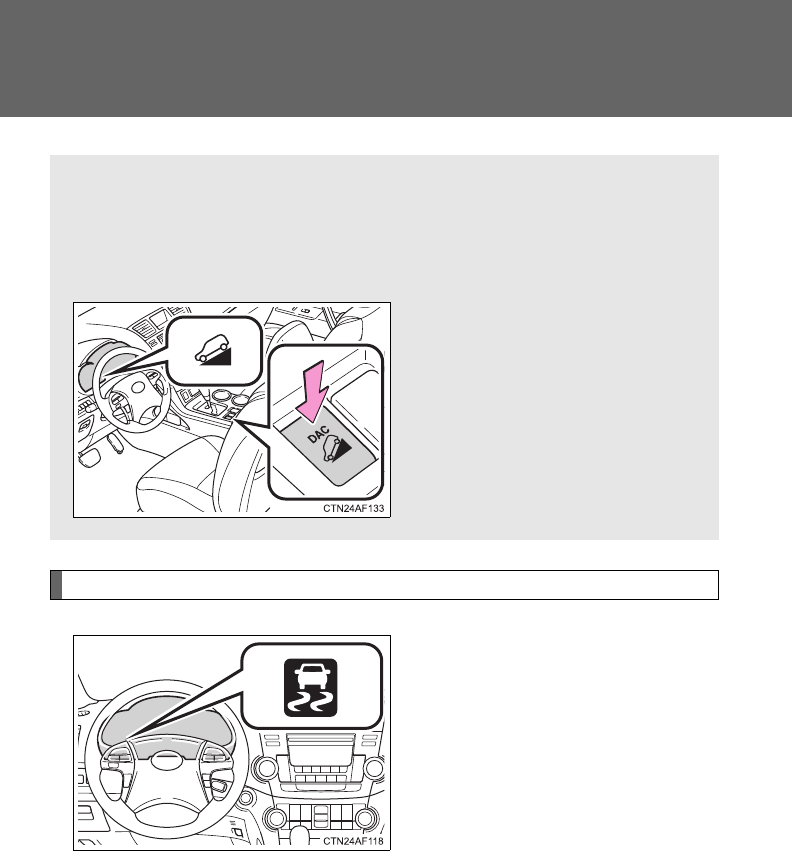
234
2-4. Using other driving systems
Downhill assist control system (4WD models)
While the downhill assist control system is operating
The slip indicator will flash to
indicate that the downhill assist
control system is operating, and
the stop lights and high mounted
stoplight will turn on.
With the downhill assist control system, the vehicle is able to
descend a steep hill, maintaining a constant low speed of about 3
mph (5 km/h) without brake pedal operation.
■Activating the downhill assist control system
Press the “DAC” switch.
The downhill assist control sys-
tem indicator will come on to
indicate that the downhill assist
control system is activated.
Pressing the switch again turns
the system off.

235
2-4. Using other driving systems
2
When driving
■Conditions in which the downhill assist control system does not oper-
ate
●In the following situations, the downhill assist control system indicator
flashes and the downhill assist control system does not operate or will
stop operating:
• The shift lever is not in “1” range of S mode or R.
• The vehicle speed is higher than 15 mph (25 km/h).
●If the accelerator or brake pedal is depressed, the downhill assist control
system will stop operating with the downhill assist control system indica-
tor still on.
■If the “DAC” switch is turned off during operation of the downhill assist
control system
The downhill assist control system gradually ceases operation. The downhill
assist control system indicator will flash during the canceling operation, and
then go off when the system is fully off.
■Downhill assist control system operation sound
●A sound may be heard from the engine compartment during operation of
the downhill assist control system. This sound does not indicate a mal-
function.
●If the accelerator or brake pedal is depressed during operation of the
downhill assist control system, a sound caused by the release of system
operation may be heard, or you may feel the brake pedal push-back. This
does not indicate a malfunction.
■When the downhill assist control system operates continuously
The brake actuator may overheat. In that case, the downhill assist control
system will stop operating, a buzzer will sound and the downhill assist con-
trol system indicator will start flashing. Refrain from using the system until
the downhill assist control system indicator stays on. (There is no problem
with continuing to drive normally.)
■If the slip indicator comes on...
It may indicate a malfunction in the system. Contact your Toyota dealer.

236
2-4. Using other driving systems
CAUTION
■Conditions which may affect the downhill assist control system opera-
tion
●Do not rely too heavily on the downhill assist control system. On extremely
steep inclines, icy surfaces or muddy roads, the vehicle may slip and the
system may not be able to maintain the constant low vehicle speed of
about 3 mph (5 km/h), leading to an accident causing death or serious
injury.
●Do not shift the shift lever to R while driving forward, or to D while driving
backward. Doing so may cause the wheels to lock up, leading to an acci-
dent causing death or serious injury. In addition, excessive stress will be
applied to the automatic transmission, possibly resulting in damage.

237
2
When driving
2-5. Driving information
Off-road precautions
Off-road vehicle feature
●Specific design characteristics give it a higher center of gravity
than ordinary passenger cars. This vehicle design feature causes
this type of vehicle to be more likely to rollover. And, utility vehicles
have a significantly higher rollover rate than other types of vehi-
cles.
●An advantage of the higher ground clearance is a better view of the
road allowing you to anticipate problems.
●It is not designed for cornering at the same speeds as an ordinary
passenger car. Sharp turns at excessive speeds may cause roll-
over.
This vehicle belongs to the utility vehicle class, which has higher
ground clearance and narrower tread in relation to the height of its
center of gravity to make it capable of performing in a wide variety
of off-road applications.

238
2-5. Driving information
CAUTION
■Off-road vehicle precautions
Always observe the following precautions to minimize the risk of serious per-
sonal injury or damage to your vehicle:
●In a rollover crash, an unbelted person is significantly more likely to die
than a person wearing a seat belt. Therefore, the driver and all passengers
should fasten their seat belts whenever the vehicle is moving.
●Avoid sharp turns or abrupt maneuvers, if at all possible.
Failure to operate this vehicle correctly may result in loss of control or
vehicle rollover causing death or serious injury.
●Loading cargo on the roof luggage carrier will make the center of the vehi-
cle gravity higher. Avoid high speeds, sudden starts, sharp turns, sudden
braking or abrupt maneuvers, otherwise it may result in loss of control or
vehicle rollover due to failure to operate this vehicle correctly.
●Always slow down in gusty crosswinds. Because of its profile and higher
center of gravity, your vehicle is more sensitive to side winds than an ordi-
nary passenger car. Slowing down will allow you to have better control.
●Do not drive horizontally across steep slopes. Driving straight up or
straight down is preferred. Your vehicle (or any similar off-road vehicle)
can tip over sideways much more easily than forward or backward.

239
2-5. Driving information
2
When driving
Off-road driving
When driving your vehicle off-road, please observe the following pre-
cautions to ensure your driving enjoyment and to help prevent the
closure of areas to off-road vehicles.
●Drive your vehicle only in areas where off-road vehicles are permit-
ted to travel.
●Respect private property. Get owner’s permission before entering
private property.
●Do not enter areas that are closed. Honor gates, barriers and signs
that restrict travel.
●Stay on established roads. When conditions are wet, driving tech-
niques should be changed or travel delayed to prevent damage to
roads.
■Additional information for off-road driving
For owners in U.S. mainland, Hawaii and Puerto Rico:
To obtain additional information pertaining to driving your vehicle off-road,
consult the following organizations.
●State and Local Parks and Recreation Departments
●State Motor Vehicle Bureau
●Recreational Vehicle Clubs
●U.S. Forest Service and Bureau of Land Management

240
2-5. Driving information
CAUTION
■Off-road driving precautions
Always observe the following precautions to minimize the risk of serious per-
sonal injury or damage to your vehicle:
●Drive carefully when off the road. Do not take unnecessary risks by driving
in dangerous places.
●Do not grip the steering wheel spokes when driving off-road. A bad bump
could jerk the wheel and injure your hands. Keep both hands and espe-
cially your thumbs on the outside of the rim.
●Always check your brakes for effectiveness immediately after driving in
sand, mud, water or snow.
●After driving through tall grass, mud, rock, sand, rivers, etc., check that
there is no grass, bush, paper, rags, stone, sand, etc. adhering or trapped
on the underbody. Clear off any such matter from the underbody. If the
vehicle is used with these materials trapped or adhering to the underbody,
a breakdown or fire could occur.
●When driving off-road or in rugged terrain, do not drive at excessive
speeds, jump, make sharp turns, strike objects, etc. This may cause loss
of control or vehicle rollover causing death or serious injury. You are also
risking expensive damage to your vehicle’s suspension and chassis.
NOTICE
■To prevent water damage
Take all necessary safety measures to ensure that water damage to the
engine or other components does not occur.
●Water entering the engine air intake will cause severe engine damage.
●Water entering the automatic transmission will cause deterioration in shift
quality, locking up of your transmission accompanied by vibration, and ulti-
mately damage.
●Water can wash the grease from wheel bearings, causing rusting and pre-
mature failure, and may also enter the differentials, transmission and
transfer case, reducing the gear oil’s lubricating qualities.

241
2-5. Driving information
2
When driving
NOTICE
■When you drive through water
If driving through water, such as when crossing shallow streams, first check
the depth of the water and the bottom of the river bed for firmness. Drive
slowly and avoid deep water.
■Inspection after off-road driving
●Sand and mud that has accumulated in brake drums and around brake
discs may affect braking efficiency and may damage brake system compo-
nents.
●Always perform a maintenance inspection after each day of off-road driv-
ing that has taken you through rough terrain, sand, mud, or water. For
scheduled maintenance information, refer to the “Scheduled Maintenance
Guide” or “Owner’s Manual Supplement”.

242
2-5. Driving information
Cargo and luggage
Capacity and distribution
Cargo capacity depends on the total weight of the occupants.
(Cargo capacity) = (Total load capacity) - (Total weight of occupants)
Steps for Determining Correct Load Limit
(1)Locate the statement “The combined weight of occupants and
cargo should never exceed XXX kg or XXX lbs.” on your vehicle's
placard.
(2)Determine the combined weight of the driver and passengers that
will be riding in your vehicle.
(3)Subtract the combined weight of the driver and passengers from
XXX kg or XXX lbs.
(4)The resulting figure equals the available amount of cargo and lug-
gage load capacity.
For example, if the “XXX” amount equals 1400 lbs. and there will
be five 150 lb passengers in your vehicle, the amount of available
cargo and luggage load capacity is 650 lbs. (1400 - 750 (5 150) =
650 lbs.)
(5)Determine the combined weight of luggage and cargo being
loaded on the vehicle. That weight may not safely exceed the avail-
able cargo and luggage load capacity calculated in Step 4.
Take notice of the following information about storage precau-
tions, cargo capacity and load.
●Stow cargo and luggage in the luggage compartment whenever
possible. Be sure all items are secured in place.
●Be careful to keep the vehicle level. Placing the weight as far for-
ward as possible helps maintain vehicle balance.
●For better fuel economy, do not carry unnecessary weight.
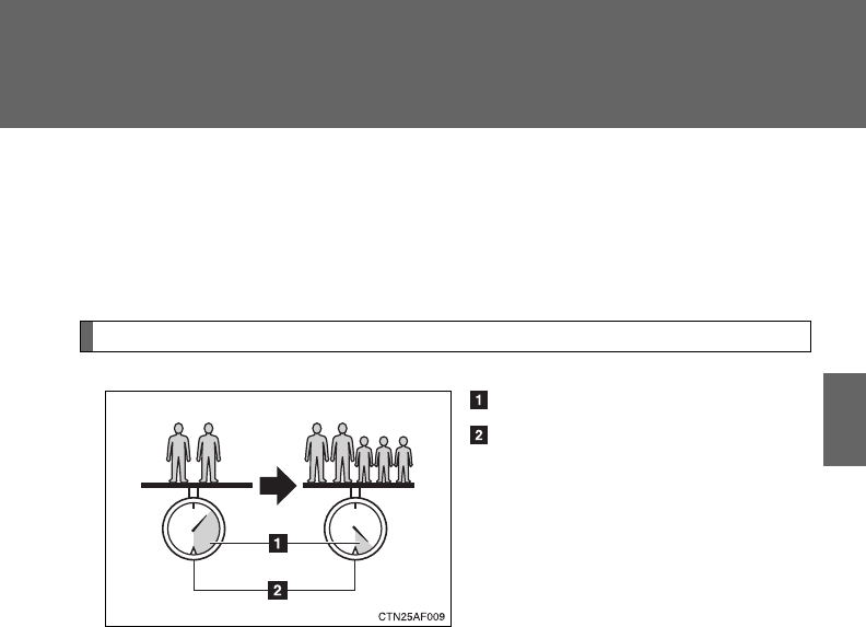
243
2-5. Driving information
2
When driving
(6)If your vehicle will be towing a trailer, load from your trailer will be
transferred to your vehicle. Consult this manual to determine how
this reduces the available cargo and luggage load capacity of your
vehicle.
Calculation formula for your vehicle
Cargo capacity
Total load capacity (vehicle
capacity weight) (P. 618)
When 2 people with the combined weight of A lb. (kg) are riding in
your vehicle, which has a total load capacity (vehicle capacity weight)
of B lb. (kg), the available amount of cargo and luggage load capacity
will be C lb. (kg) as follows:
B*2 lb. (kg) - A*1 lb. (kg) = C*3 lb. (kg)
*1: A =Weight of people
*2: B =Total load capacity
*3: C =Available cargo and luggage load
In this condition, if 3 more passengers with the combined weight of D lb.
(kg) get on, the available cargo and luggage load will be reduced E lb. (kg)
as follows:
C lb. (kg) - D*4 lb. (kg) = E*5 lb. (kg)
*4: D =Additional weight of people
*5: E =Available cargo and luggage load

244
2-5. Driving information
As shown in the above example, if the number of occupants
increases, the cargo and luggage load will be reduced by an amount
that equals the increased weight due to the additional occupants. In
other words, if an increase in the number of occupants causes an
excess of the total load capacity (combined weight of occupants plus
cargo and luggage load), you must reduce the cargo and luggage on
your vehicle.

245
2-5. Driving information
2
When driving
CAUTION
■Things that must not be carried in the luggage compartment
The following things may cause a fire if loaded in the luggage compart-
ment.
●Receptacles containing gasoline
●Aerosol cans
■Storage precautions
Observe the following precautions.
Failing to do so may result in death or serious injury.
●Do not place cargo or luggage in or on the following locations as the
item may get under the brake or accelerator pedal and prevent the
pedals from being depressed properly, block the driver’s vision, or hit
the driver or passengers, causing an accident.
• Driver’s feet
• Front passenger or rear seats (when stacking items)
• Luggage cover
• Instrument panel
• Dashboard
●Secure all items in the occupant compartment, as they may shift and
injure someone during sudden braking, sudden swerving or an acci-
dent.
●When you fold down the rear seats, long items should not be placed
directly behind the front seats.
●Never allow anyone to ride in the luggage compartment. It is not
designed for passengers. They should ride in their seats with their seat
belts properly fastened. Otherwise, they are much more likely to suffer
serious bodily injury, in the event of sudden braking, sudden swerving
or an accident.
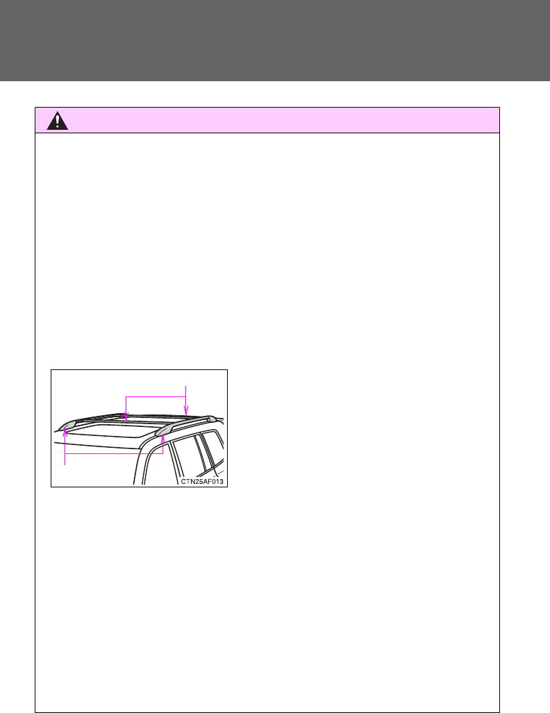
246
2-5. Driving information
CAUTION
■Capacity and distribution
●Do not exceed the maximum axle weight rating or the total vehicle
weight rating.
●Even if the total load of occupant's weight and the cargo load is less
than the total load capacity, do not apply the load unevenly.
Improper loading may cause deterioration of steering or braking con-
trol which may cause death or serious injury.
■Roof luggage carrier precautions (if equipped)
To use the roof rails as a roof luggage carrier, you must fit the roof rails
with two or more genuine Toyota cross rails or their equivalent.
When you load cargo on the roof luggage carrier, observe the following:
●Before driving, make sure the cargo is securely fastened on the roof
luggage carrier.
●Loading cargo on the roof luggage carrier will make the center of the
vehicle gravity higher. Avoid high speeds, sudden starts, sharp turns,
sudden braking or abrupt maneuvers, otherwise it may result in loss of
control or vehicle rollover due to failure to operate this vehicle correctly
and result in death or serious injury.
●If driving for a long distance, on rough roads, or at high speeds, stop
the vehicle now and then during the trip to make sure the cargo
remains in its place.
●Do not exceed 100 lb. (45 kg) cargo weight on the roof luggage carrier.
●Place the cargo so that its weight is
distributed evenly between the front
and rear axles.
●If loading long or wide cargo, never
exceed the vehicle overall length or
width. (P. 618)
Cross rails
Roof rails

247
2-5. Driving information
2
When driving
Vehicle load limits
■Total load capacity and seating capacity
These details are also described on the tire and loading information
label. (P. 530)
CAUTION
■Overloading the vehicle
Do not overload the vehicle.
It may not only cause damage to the tires, but also degrade steering and
braking ability, resulting in an accident.
Vehicle load limits include total load capacity, seating capacity,
trailer weight rating and cargo capacity.
■Total load capacity (vehicle capacity weight): (P. 618)
Total load capacity means the combined weight of occupants, cargo
and luggage.
■Seating capacity: 7 occupants (Front 2, Rear 5)
Seating capacity means the maximum number of occupants whose
estimated average weight is 150 lb. (68 kg) per person.
■TWR (Trailer Weight Rating): (P. 618, 256)
TWR means the maximum gross trailer weight (trailer weight plus its
cargo weight) that your vehicle is able to tow.
■Cargo capacity
Cargo capacity may increase or decrease depending on the weight
and the number of occupants.

248
2-5. Driving information
Winter driving tips
Carry out the necessary preparations and inspections before driving
the vehicle in winter. Always drive the vehicle in a manner appropri-
ate to the prevailing weather conditions.
■Pre-winter preparations
●Use fluids that are appropriate to the prevailing outside tem-
peratures.
• Engine oil
• Engine coolant
• Washer fluid
●Have a service technician inspect the level and specific grav-
ity of battery electrolyte.
●Have the vehicle fitted with four snow tires or purchase a set
of tire chains for the front tires.
Ensure that all tires are the same size and brand, and that chains
match the size of the tires.
■Before driving the vehicle
Observe the following according to the driving conditions.
●Do not try to forcibly open a window or move a wiper that is
frozen. Pour warm water over the frozen area to melt the ice.
Wipe away the water immediately to prevent it from freezing.
●To ensure proper operation of the climate control system fan,
remove any snow that has accumulated on the air inlet vents
in front of the windshield.
●Remove any ice that has accumulated on the vehicle chassis.
●Periodically check for and remove any excess ice or snow
that may have accumulated in the wheel well or on the
brakes.
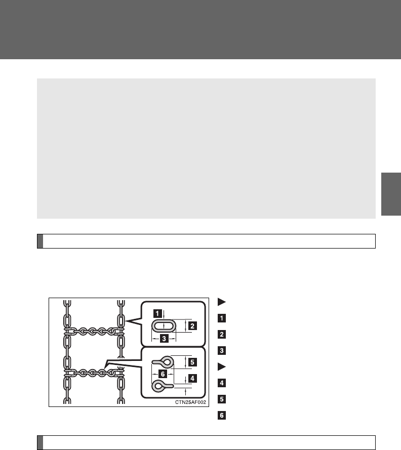
249
2-5. Driving information
2
When driving
Selecting tire chains
Use the correct tire chain size when mounting the snow chains.
Chain size is regulated for each tire size.
Side chain
0.12 in. (3 mm) in diameter
0.39 in. (10 mm) in width
1.18 in. (30 mm) in length
Cross chain
0.16 in. (4 mm) in diameter
0.55 in. (14 mm) in width
0.98 in. (25 mm) in length
Regulations on the use of snow chains
●Regulations regarding the use of tire chains vary according to loca-
tion and type of road. Always check local regulations before install-
ing chains.
●Install the chains on the front tires.
●Retighten the chains after driving 1/4 - 1/2 mile (0.5 - 1.0 km).
■When driving the vehicle
Accelerate the vehicle slowly and drive at a reduced speed suit-
able to road conditions.
■When parking the vehicle
Park the vehicle and move the shift lever to P without setting the
parking brake. The parking brake may freeze up, preventing it
from being released. If necessary, brake the wheels to prevent
inadvertent sliding or creeping.

250
2-5. Driving information
■Tire chains
Observe the following precautions when installing and removing chains.
●Install and remove tire chains in a safe location.
●Install tire chains on the front tires.
●Install tire chains following the instructions provided in the accompanying
manual.
CAUTION
■Driving with snow tires
Observe the following precautions to reduce the risk of accidents.
Failing to do so may result in a loss of vehicle control and cause death or
serious injury.
●Use tires of the specified size.
●Maintain the recommended level of air pressure.
●Do not drive in excess of 75 mph (120 km/h), regardless of the type of
snow tires being used.
●Snow tires should be installed on all wheels.
■Driving with tire chains
Observe the following precautions to reduce the risk of accidents.
Failing to do so may result in the vehicle being unable to be driven safely,
and may cause death or serious injury.
●Do not drive in excess of the speed limit specified for the tire chains being
used or 30 mph (50 km/h), whichever is lower.
●Avoid driving on bumpy road surfaces or over potholes.
●Avoid sudden turns and braking.
●Slow down sufficiently before entering a curve to ensure that vehicle con-
trol is maintained.

251
2-5. Driving information
2
When driving
NOTICE
■Repairing or replacing snow tires
Request repairs of and obtain replacement snow tires from Toyota dealers or
legitimate tire retailers.
This is because the removal and attachment of snow tires affects the opera-
tion of the tire pressure warning valves and transmitters.
■Fitting tire chains
The tire pressure warning valves and transmitters may not function correctly
when tire chains are fitted.
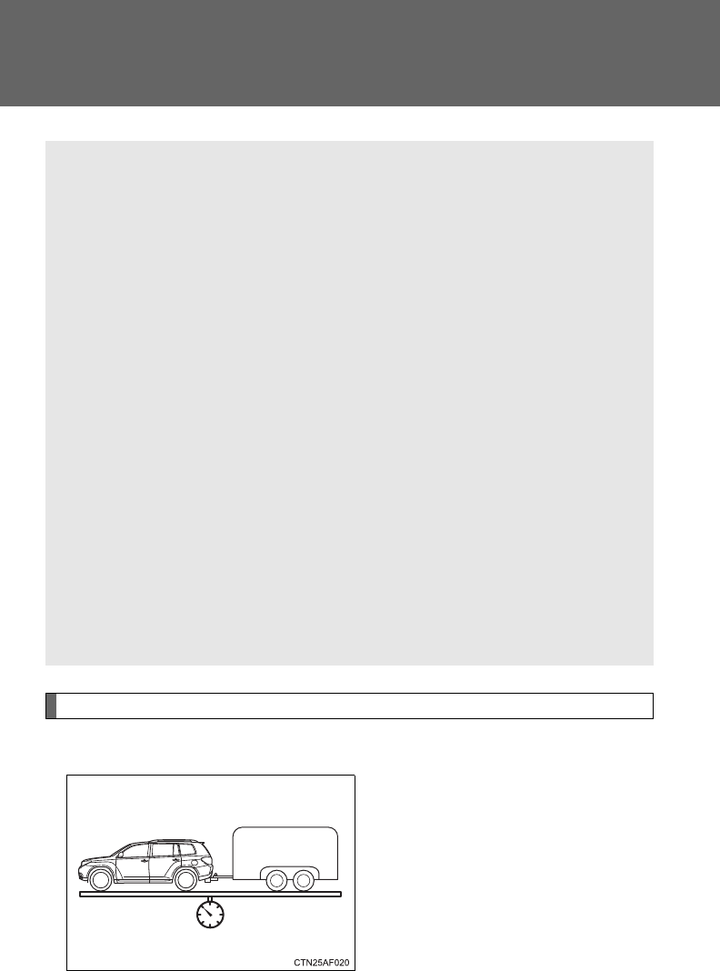
252
2-5. Driving information
Trailer towing
Towing related terms
■GCWR (Gross Combination Weight Rating)
The maximum allowable gross
combination weight. The gross
combination weight is the sum of
the total vehicle weight (including
the occupants, cargo and any
optional equipment installed on
the vehicle) and the weight of the
trailer being towed (including the
cargo in the trailer).
Your vehicle is designed primarily as a passenger-and-load-carrying
vehicle. Towing a trailer can have an adverse impact on handling,
performance, braking, durability, and fuel consumption. For your
safety and the safety of others, you must not overload your vehicle
or trailer. You must also ensure that you are using appropriate tow-
ing equipment, that the towing equipment has been installed cor-
rectly and used properly, and that you employ the requisite driving
habits.
Vehicle-trailer stability and braking performance are affected by
trailer stability, brake performance and setting, trailer brakes, the
hitch and hitch systems (if equipped).
To tow a trailer safely, use extreme care and drive the vehicle in
accordance with your trailer’s characteristics and operating condi-
tions.
Toyota warranties do not apply to damage or malfunction caused by
towing a trailer for commercial purposes.
Contact your Toyota dealer for further information about additional
requirements such as towing kits, etc.
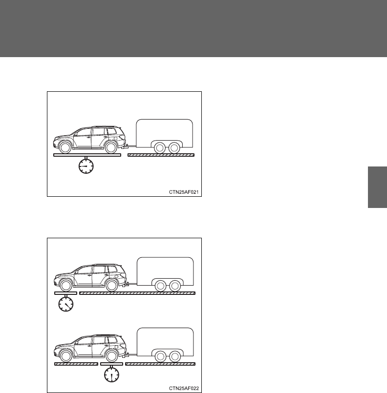
253
2-5. Driving information
2
When driving
■GVWR (Gross Vehicle Weight Rating)
The maximum allowable gross
vehicle weight. The gross vehicle
weight is the total weight of the
vehicle. When towing a trailer, it
is the sum of the vehicle weight
(including the occupants, cargo
and any optional equipment
installed on the vehicle) and the
tongue weight.
■GAWR (Gross Axle Weight Rating)
The maximum allowable gross
axle weight. The gross axle
weight is the load placed on
each axle (front and rear).
Front GAWR
Rear GAWR
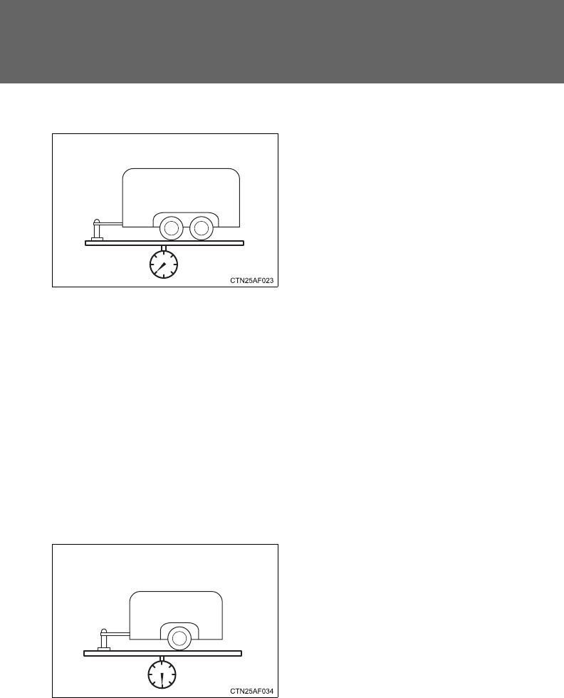
254
2-5. Driving information
■TWR (Trailer Weight Rating)
The maximum allowable gross
trailer weight. The gross trailer
weight is the sum of the trailer
weight and the weight of the
cargo in the trailer.
TWR is calculated assuming
base vehicle with one driver, one
front passenger, towing package
(if available), hitch and hitch sys-
tems (if required).
Additional optional equipment,
passengers and cargo in the vehi-
cle will reduce the trailer weight
rating so as not to exceed
GCWR, GVWR and GAWR.
If the gross trailer weight exceeds
3000 lb. (1360 kg), it is recom-
mended to use a trailer with 2 or
more axles.
■Unbraked TWR (Unbraked Trailer Weight Rating)
The trailer weight rating for tow-
ing a trailer without a trailer ser-
vice brake system.
(With brakes)
(Without brakes)
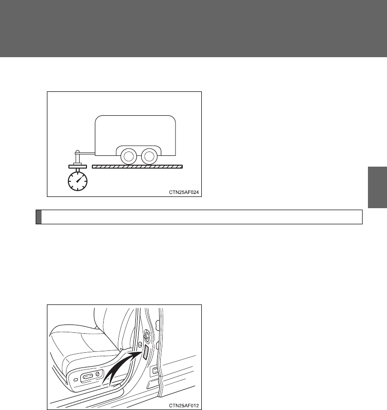
255
2-5. Driving information
2
When driving
■Tongue Weight
The load placed on the trailer
hitch ball. (P. 257)
Weight limits
●The gross trailer weight must never exceed the TWR described in
the table. (P. 256)
●The gross combination weight must never exceed the GCWR
described in the table. (P. 256)
●The gross vehicle weight must
never exceed the GVWR indi-
cated on the Certification
Label.
●The gross axle weight on each
axle must never exceed the
GAWR indicated on the Certi-
fication Label.
●If the gross trailer weight is over the unbraked TWR, trailer service
brakes are required.
●If the gross trailer weight is over 2000 lb. (907 kg), a sway control
device with sufficient capacity is required.
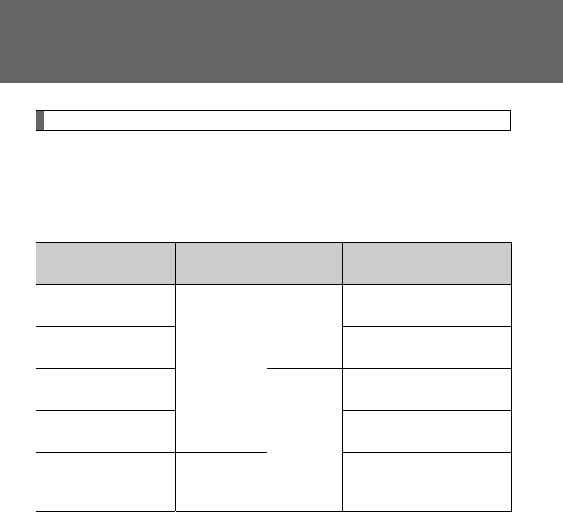
256
2-5. Driving information
GCWR, TWR, Unbraked TWR
Confirm that the gross trailer weight, gross combination weight, gross
vehicle weight, gross axle weight and tongue weight are all within the
limits.
■GCWR* and TWR*
■Unbraked TWR*
1000 lb. (453 kg)
*: These models meet the tow-vehicle trailering requirement of SAE Interna-
tional per SAE J2807.
Model code Engine Driving
system GCWR TWR
GSU45L-ARANKA
3.5L V6
(2GR-FE)
engine
4WD
9840 lb.
(4470 kg)
5000 lb.
(2000 kg)
GSU45L-ARAGKA 9930 lb.
(4510 kg)
5000 lb.
(2000 kg)
GSU40L-ARANKA
2WD
9620 lb.
(4370 kg)
5000 lb.
(2000 kg)
GSU40L-ARAGKA 9720 lb.
(4410 kg)
5000 lb.
(2000 kg)
ASU40L-ARTNKA
2.7L L4
(1AR-FE)
engine
7950 lb.
(3610 kg)
3500 lb.
(1500 kg)
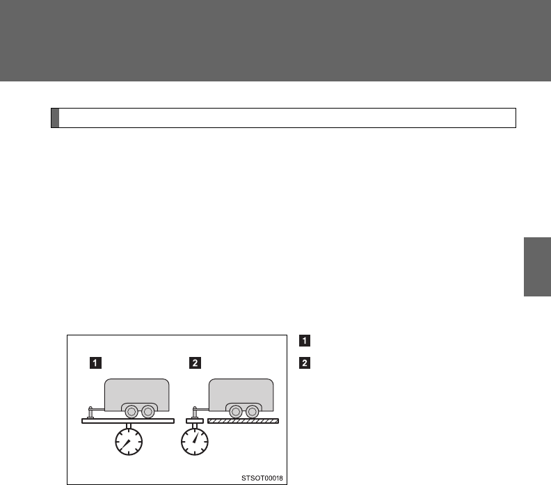
257
2-5. Driving information
2
When driving
Trailer Tongue Weight
●A recommended tongue weight varies in accordance with the types
of trailers or towing as described below.
●To ensure the recommended values shown below, the trailer must
be loaded by referring to the following instructions.
• Tongue Weight
The gross trailer weight should be distributed so that the tongue
weight is 9% to 11%. (Tongue weight /Gross trailer weight x 100
= 9% to 11%)
Gross trailer weight
Tongue weight
The gross trailer weight, gross axle weight and tongue weight
can be measured with platform scales found at a highway
weighing station, building supply company, trucking company,
junk yard, etc.
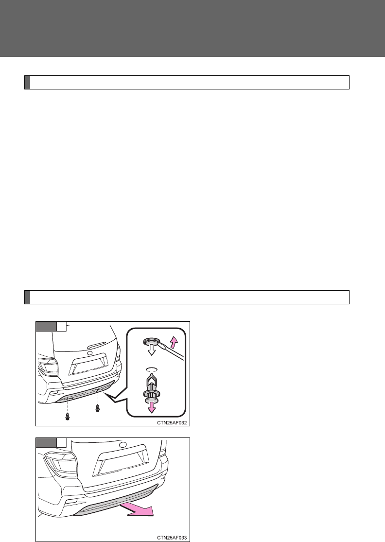
258
2-5. Driving information
Hitch
Trailer hitch assemblies have different weight capacities. Toyota rec-
ommends the use of Toyota hitch/bracket for your vehicle. For details,
contact your Toyota dealer.
●If you wish to install a trailer hitch, contact your Toyota dealer.
●Use only a hitch that conforms to the gross trailer weight require-
ment of your vehicle.
●Follow the directions supplied by the hitch manufacturer.
●Lubricate the hitch ball with a light coating of grease.
●Remove the trailer hitch whenever you are not towing a trailer.
After removing the hitch, seal any mounting hole in the vehicle
body to prevent entry of any substances into the vehicle.
Removing hitch cover
Remove the clip.
Grasp the lower edge of the hitch
cover and raise the cover.
When reattaching the cover,
reverse the steps listed.
STEP
1
STEP
2
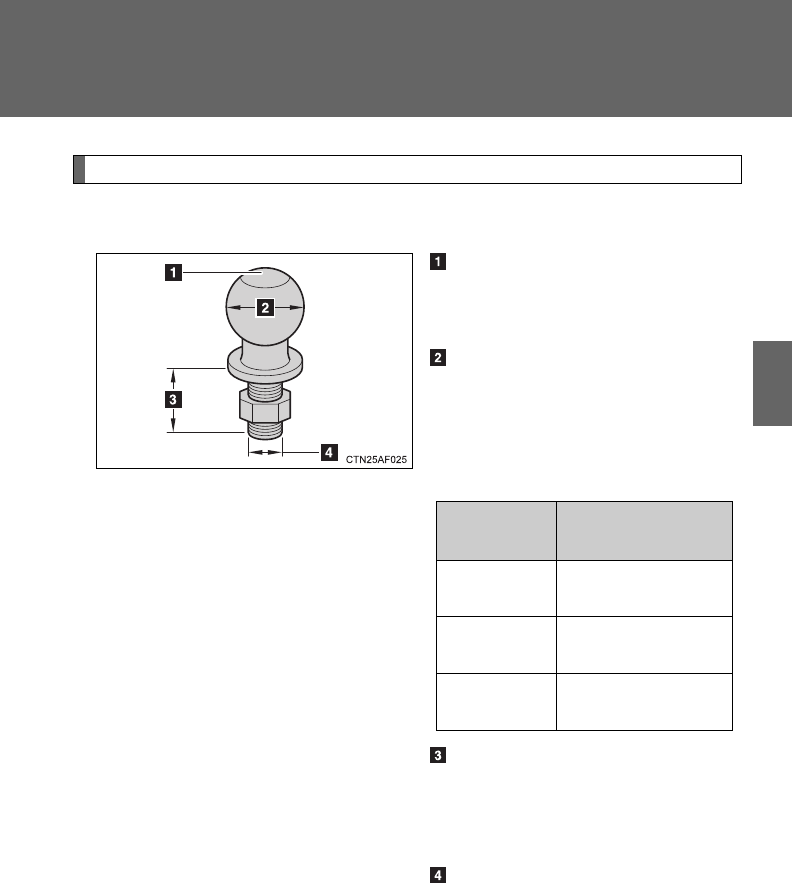
259
2-5. Driving information
2
When driving
Selecting trailer ball
Use the correct trailer ball for your application.
Trailer ball load rating
Matches or exceeds the gross
trailer weight rating of the trailer.
Ball diameter
Matches the size of the trailer
coupler. Most couplers are
stamped with the required trailer
ball size.
Shank length
Protrudes beyond the bottom of
the lock washer and nut by at
least 2 threads.
Shank diameter
Matches the ball mount hole
diameter size.
Trailer
class
Typical trailer ball
size
IV 2 5/16 in.
II and III 2 in.
I 1 7/8 in.
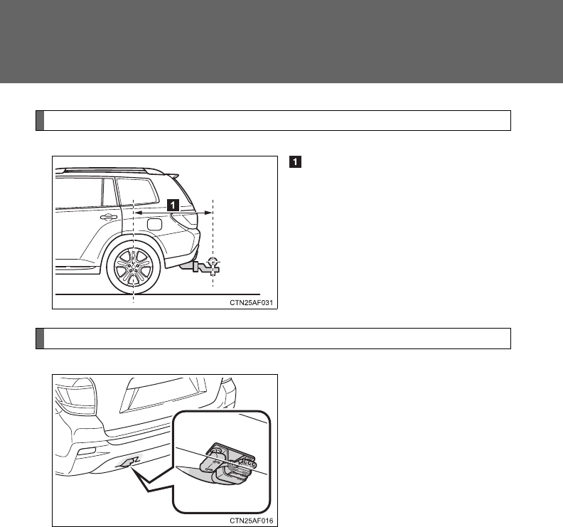
260
2-5. Driving information
Positions for towing hitch receiver and hitch ball
Weight carrying ball position:
48.1 in. (1221 mm)
Connecting trailer lights
Use the wire harness stored in
the rear end under body.

261
2-5. Driving information
2
When driving
Trailer towing tips
Your vehicle will handle differently when towing a trailer. Help to avoid
an accident, death or serious injury, keep the following in mind when
towing:
●Speed limits for towing a trailer vary by state or province. Do not
exceed the posted towing speed limit.
●Toyota recommends that the vehicle-trailer speed limit is 65 mph
(104 km/h) on a flat, straight, dry road. Do not exceed this limit, the
posted towing speed limit or the speed limit for your trailer as set
forth in your trailer owner’s manual, whichever is lowest. Instability
of the towing vehicle-trailer combination (trailer sway) increases as
speed increases. Exceeding speed limits may cause loss of con-
trol.
●Before starting out, check the trailer lights, tires and the vehicle-
trailer connections. Recheck after driving a short distance.
●Practice turning, stopping and reversing with the trailer attached in
an area away from traffic until you become accustomed to the feel
of the vehicle-trailer combination.
●Reversing with a trailer attached is difficult and requires practice.
Grip the bottom of the steering wheel and move your hand to the
left to move the trailer to the left. Move your hand to the right to
move the trailer to the right. (This is generally opposite to reversing
without a trailer attached.) Avoid sharp or prolonged turning. Have
someone guide you when reversing to reduce the risk of an acci-
dent.
●As stopping distance is increased when towing a trailer, vehicle-to-
vehicle distance should be increased. For each 10 mph (16 km/h)
of speed, allow at least one vehicle and trailer length.
●Avoid sudden braking as you may skid, resulting in the trailer jack-
knifing and a loss of vehicle control. This is especially true on wet
or slippery surfaces.

262
2-5. Driving information
●Avoid jerky starts or sudden acceleration.
●Avoid jerky steering and sharp turns, and slow down before mak-
ing a turn.
●Note that when making a turn, the trailer wheels will be closer than
the vehicle wheels to the inside of the turn. Compensate by making
a wider than normal turning radius.
●Slow down before making a turn, in cross winds, on wet or slippery
surfaces, etc.
Increasing vehicle speed can destabilize the trailer.
●Take care when passing other vehicles. Passing requires consider-
able distance. After passing a vehicle, do not forget the length of
your trailer, and be sure you have plenty of room before changing
lanes.
●To maintain engine braking efficiency and charging system perfor-
mance when using engine braking, do not put the transmission in
D.
●Instability happens more frequently when descending steep or long
downhill grades. Before descending, slow down and downshift. Do
not make sudden downshifts while descending steep or long down-
hill grades.
●Avoid holding the brake pedal down too long or applying the
brakes too frequently. This could cause the brakes to overheat and
result in reduced braking efficiency.
●Due to the added load of the trailer, your vehicle’s engine may
overheat on hot days (at temperatures over 85°F [30°C]) when
driving up a long or steep grade. If the engine coolant temperature
gauge indicates overheating, immediately turn off the air condition-
ing (if in use), pull your vehicle off the road and stop in a safe spot.
(P. 610)

263
2-5. Driving information
2
When driving
●Always place wheel blocks under both the vehicle’s and the
trailer’s wheels when parking. Apply the parking brake firmly, and
put the transmission in P. Avoid parking on a slope, but if unavoid-
able, do so only after performing the following:
Apply the brakes and keep them applied.
Have someone place wheel blocks under both the vehicle’s
and trailer’s wheels.
When the wheel blocks are in place, release the brakes slowly
until the blocks absorb the load.
Apply the parking brake firmly.
Shift into P and turn off the engine.
●When restarting after parking on a slope:
With the transmission in P, start the engine. Be sure to keep
the brake pedal depressed.
Shift into a forward gear. If reversing, shift into R.
Release the parking brake and also the brake pedal, and
slowly pull or back away from the wheel blocks. Stop and
apply the brakes.
Have someone retrieve the blocks.
STEP
1
STEP
2
STEP
3
STEP
4
STEP
5
STEP
1
STEP
2
STEP
3
STEP
4
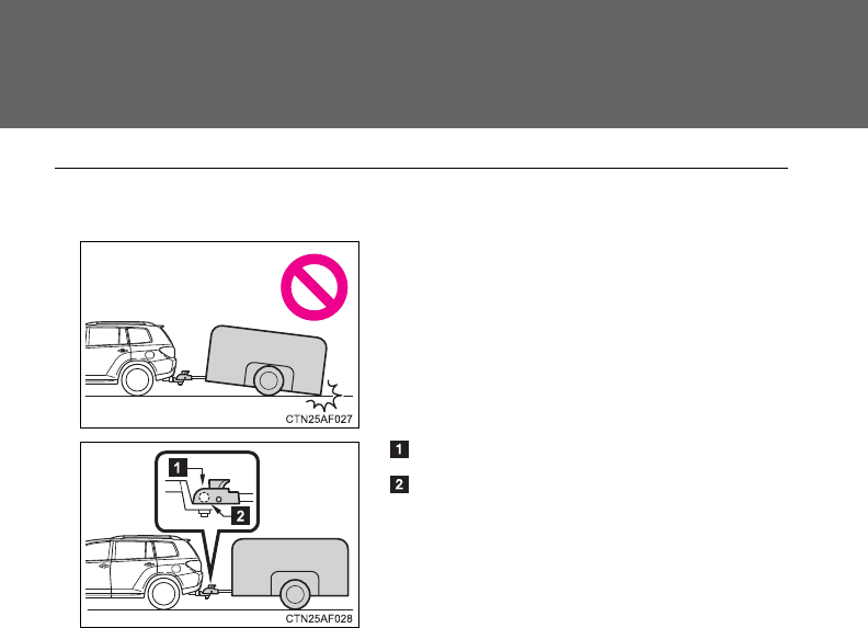
264
2-5. Driving information
■Matching trailer ball height to trailer coupler height
■Before towing
Check that the following conditions are met:
●Ensure that your vehicle’s tires are properly inflated. (P. 630)
●Trailer tires are inflated according to the trailer manufacturer’s recom-
mendation.
●All trailer lights work as required by law.
●All lights work each time you connect them.
●The trailer ball is set at the proper height for the coupler on the trailer.
●The trailer is level when it is hitched.
Do not drive if the trailer is not level, and check for improper tongue
weight, overloading, worn suspension, or other possible causes.
●The trailer cargo is securely loaded.
●The rear view mirrors conform to all applicable federal, state/provincial or
local regulations. If they do not, install rear view mirrors appropriate for
towing purposes.
No matter which class of tow hitch
applies, for a more safe trailer hookup,
the trailer ball setup must be the proper
height for the coupler on the trailer.
Coupler
Trailer ball

265
2-5. Driving information
2
When driving
■Break-in schedule
If your vehicle is new or equipped with any new power train components
(such as an engine, transmission, differential or wheel bearing), Toyota rec-
ommends that you do not tow a trailer until the vehicle has been driven for
over 500 miles (800 km).
After the vehicle has been driven for over 500 miles (800 km), you can start
towing. However, for the next 500 miles (800 km), drive the vehicle at a
speed of less than 50 mph (80 km/h) when towing a trailer, and avoid full
throttle acceleration.
■Maintenance
●If you tow a trailer, your vehicle will require more frequent maintenance
due to the additional load. (See “Scheduled Maintenance Guide” or
“Owner’s Manual Supplement”.)
●Retighten the fixing bolts of the towing ball and bracket after approxi-
mately 600 miles (1000 km) of trailer towing.

266
2-5. Driving information
■If trailer sway occurs
One or more factors (crosswinds, passing vehicles, rough roads, etc.) can
adversely affect handling of your vehicle and trailer, causing instability.
●If trailer swaying occurs:
• Firmly grip the steering wheel. Steer straight ahead.
Do not try to control trailer swaying by turning the steering wheel.
• Begin releasing the accelerator pedal immediately but very gradually to
reduce speed.
Do not increase speed. Do not apply vehicle brakes.
If you make no extreme correction with the steering or brakes, your vehicle
and trailer should stabilize.
●After the trailer swaying has stopped:
• Stop in a safe place. Get all occupants out of the vehicle.
• Check the tires of the vehicle and the trailer.
• Check the load in the trailer.
Make sure the load has not shifted.
Make sure the tongue weight is appropriate, if possible.
• Check the load in the vehicle.
Make sure the vehicle is not overloaded after occupants get in.
If you cannot find any problems, the speed at which trailer swaying occurred
is beyond the limit of your particular vehicle-trailer combination.
Drive at a lower speed to prevent instability. Remember that swaying of the
towing vehicle-trailer increases as speed increases.
CAUTION
■Trailer towing precautions
To tow a trailer safely, use extreme care and drive the vehicle in accordance
with the trailer’s characteristics and operating conditions. Failure to do so
could cause an accident resulting in death or serious injury. Vehicle stability
and braking performance are affected by trailer stability, brake setting and
performance, and the hitch. Your vehicle will handle differently when towing
a trailer.

267
2-5. Driving information
2
When driving
CAUTION
■To avoid accident or injury
●Do not exceed the TWR, unbraked TWR, GCWR, GVWR or GAWR.
●If the gross trailer weight is over 2000 lb. (907 kg), a sway control device
with sufficient capacity is required.
●Adjust the tongue weight within the appropriate range. Place heavier loads
as close to the trailer axle as possible.
●Do not exceed 65 mph (104 km/h), the posted towing speed limit or the
speed limit for your trailer as set forth in your trailer owner’s manual,
whichever is lowest. Slow down sufficiently before making a turn, in cross
winds, on wet or slippery surface, etc. to help avoid an accident. If you
experience a vehicle-trailer instability from reducing a certain speed, slow
down and make sure you keep your vehicle speed under the speed of
which you experience the instability.
●Do not make jerky, abrupt or sharp turns.
●Do not apply the brakes suddenly as you may skid, resulting in jackknifing
and loss of vehicle control. This is especially true on wet or slippery sur-
faces.
●Do not exceed the trailer hitch assembly weight, gross vehicle weight,
gross axle weight and trailer tongue weight capacities.
●Do not use cruise control when towing.
●Slow down and downshift before descending steep or long downhill
grades. Do not make sudden downshifts while descending steep or long
downhill grades.
●Vehicle-trailer instability is more likely on steep long downhills. Before
descending steep or long downhill grades, slow down and downshift. Do
not make sudden downshifts when descending steep or long downhill
grades. Avoid holding the brake pedal down too long or applying the
brakes too frequently. This could cause the brakes to overheat and result
in reduced braking efficiency.

268
2-5. Driving information
CAUTION
■Hitch
Trailer hitch assemblies have different weight capacities established by the
hitch manufacturer. Even though the vehicle may be physically capable of
towing a higher weight, the operator must determine the maximum weight
rating of the particular hitch assembly and never exceed the maximum
weight rating specified for the trailer-hitch. Exceeding the maximum weight
rating set by the trailer-hitch manufacturer can cause an accident resulting in
death or serious personal injuries.
■When towing a trailer
Toyota recommends trailers with brakes that conform to any applicable fed-
eral and state/provincial regulations.
●If the gross trailer weight exceeds unbraked TWR, trailer brakes are
required. Toyota recommends trailers with brakes that conform to all appli-
cable federal and state/provincial regulations.
●Never tap into your vehicle’s hydraulic system, as this will lower the vehi-
cle’s braking effectiveness.
●Never tow a trailer without using a safety chain securely attached to both
the trailer and the vehicle. If damage occurs to the coupling unit or hitch
ball, there is danger of the trailer wandering into another lane.

269
2-5. Driving information
2
When driving
NOTICE
■When installing a trailer hitch
Use only the position recommended by your Toyota dealer. Do not install the
trailer hitch on the bumper; this may cause body damage.
■Safety chain
A safety chain must always be used between the towing vehicle and the
trailer. Leave sufficient slack in the chain for turns. The chain should cross
under the trailer tongue to prevent the tongue from dropping to the ground in
the case that it becomes damaged or separated. For the correct safety chain
installation procedure, ask your Toyota dealer.
■Do not directly splice trailer lights
Do not directly splice trailer lights. Directly splicing trailer lights may damage
your vehicle’s electrical system and cause a malfunction.

270
2-5. Driving information
Dinghy towing
NOTICE
■To avoid serious damage to your vehicle
Do not tow your vehicle with 4 wheels on the ground.
Your vehicle is not designed to be dinghy towed (with 4 wheels on
the ground) behind a motor home.

271
2-5. Driving information
2
When driving

272
3-1. Using the air conditioning
system and defogger
Front manual air
conditioning system ....... 274
Front automatic air
conditioning system ....... 281
Rear manual air
conditioning system ....... 289
Rear automatic air
conditioning system ....... 292
Rear window and
outside rear view
mirror defoggers ............ 295
Windshield wiper
de-icer............................ 297
Using the steering wheel
climate remote control
switches ......................... 298
3-2. Using the audio system
Audio system ................... 299
Using the radio................. 307
Using the CD player......... 314
Playing back MP3 and
WMA discs..................... 322
Operating an iPod ............ 330
Operating a USB
memory.......................... 337
Optimal use of the audio
system ........................... 345
Using the AUX port .......... 349
Using the steering wheel
audio switches ............... 351
Detachable pole
antenna.......................... 354
3-3. Using the Bluetooth®
audio system
Bluetooth® audio
system ........................... 357
Using the Bluetooth®
audio system.................. 360
Operating a Bluetooth®
enabled portable
player ............................. 365
Setting up a Bluetooth®
enabled portable
player ............................. 367
Bluetooth® audio system
setup .............................. 372
3-4. Using the hands-free
phone system
(for cellular phone)
Hands-free phone system
(for cellular phone)
features.......................... 373
Using the hands-free
phone system ................ 377
Making a phone call ......... 386
Setting a cellular phone ... 390
Security and system
setup .............................. 395
Using the phone book ...... 399
Interior features 3

Interior features 3
273
3-5. Using the rear audio
system
Rear seat entertainment
system features ............. 406
Using the DVD player
(DVD video) ................... 413
Using the DVD player
(video CD)...................... 422
Using the DVD player
(audio CD/CD text) ........ 425
Using the DVD player
(MP3 discs).................... 426
Using the video mode ...... 428
Changing the initial
setting ............................ 429
3-6. Using the interior lights
Interior lights list ............... 436
• Personal/interior light
main switch .................... 437
• Personal/interior lights ... 437
• Interior light .................... 438
3-7. Using the storage features
List of storage features .... 439
• Glove box....................... 440
• Console box................... 441
• Overhead console.......... 442
• Cup holders ................... 443
• Bottle holders................. 447
• Auxiliary boxes............... 448
• Side table....................... 450
3-8. Other interior features
Sun visors ........................ 452
Vanity mirrors................... 453
Clock ................................ 454
Conversation mirror ......... 455
Power outlets ................... 456
Seat heaters..................... 460
Armrests........................... 462
Assist grips....................... 463
Floor mat.......................... 464
Luggage compartment
features.......................... 465
Garage door opener......... 470
Compass.......................... 476
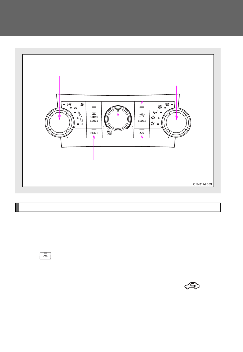
274
3-1. Using the air conditioning system and defogger
Front manual air conditioning system
Adjusting the settings
■Adjusting the temperature setting
Turn the temperature control dial clockwise (warm) or counter-
clockwise (cool).
If is not pressed, the system will blow ambient temperature air or
heated air.
For quick cooling, turn the temperature selector knob to the “MAX A/C”
position. The air conditioning will automatically turn on in (recir-
culated air) mode.
Fan speed control dial
Air outlet selection dial
Air conditioning on/off switch
Temperature control dial
Outside air or recirculated air mode
Rear air conditioning
on/off switch (if equipped)
: If equipped
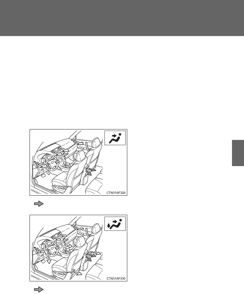
275
3-1. Using the air conditioning system and defogger
3
Interior features
■Adjusting the fan speed
Turn the fan speed control dial clockwise (increase) or counter-
clockwise (decrease).
Turn the dial to “OFF” to turn the fan off.
■Changing the air outlets
Set the air outlet selection dial to an appropriate position.
The positions between the air outlet selections shown below can be also
selected for more detailed adjustment.
Upper body
: Vehicles without rear air conditioning system
Upper body and feet
: Vehicles without rear air conditioning system
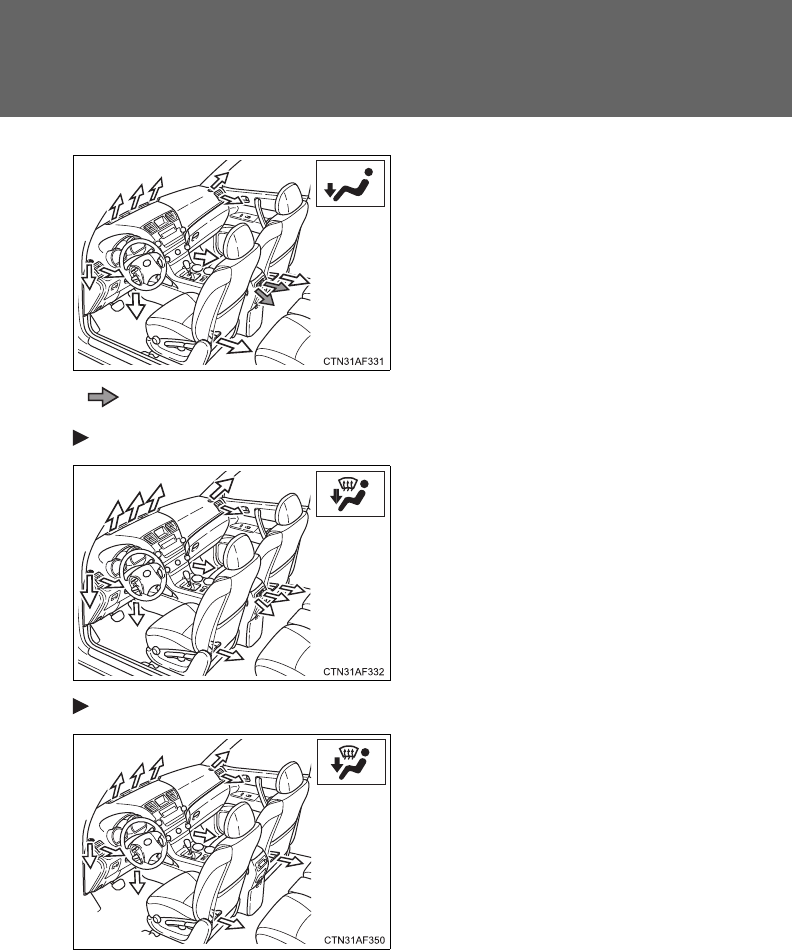
276
3-1. Using the air conditioning system and defogger
Feet
: Vehicles without rear air conditioning system
Without rear air conditioning system
Feet and windshield
Recirculated air mode may auto-
matically switch to outside air
mode.
With rear air conditioning system
Feet and windshield
Recirculated air mode may auto-
matically switch to outside air
mode.

277
3-1. Using the air conditioning system and defogger
3
Interior features
■Switching between outside air and recirculated air modes
Press .
The mode switches between outside air mode (indicator off) and recircu-
lated air mode (indicator on) modes each time is pressed.
Defogging the windshield
Set the air outlet selection dial to
position.
The air conditioning system oper-
ates automatically.
Recirculated air mode may auto-
matically switch to outside air
mode.
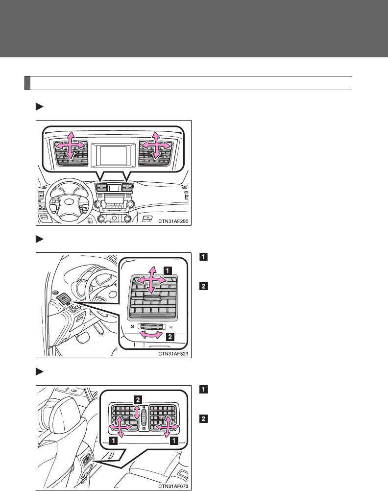
278
3-1. Using the air conditioning system and defogger
Adjusting the position of and opening and closing the air outlets
Front center outlets
Direct air flow to the left or right,
up or down.
Front side outlets
Direct air flow to the left or
right, up or down.
Turn the knob to open or close
the vent.
Rear center outlets (vehicles without rear air conditioning system)
Direct air flow to the left or
right, up or down.
Turn the knob to open or close
the vent.
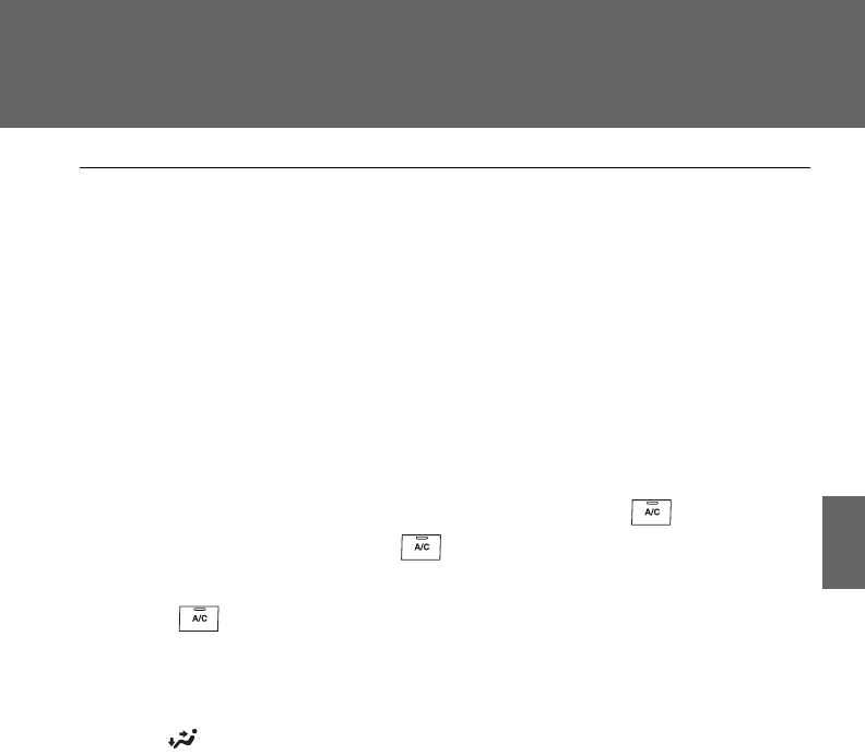
279
3-1. Using the air conditioning system and defogger
3
Interior features
■Using the system in recirculated air mode
The windows will fog up more easily if the recirculated air mode is used for
an extended period.
■Window defogger feature
In order to prevent the windows from fogging up, recirculated air mode may
automatically switch to outside air mode if the ambient temperature drops.
This feature can be canceled by pushing and holding the air intake mode
switch for longer than 2 seconds. The feature will be reactivated when the
engine switch is turned to the “ACC” or “LOCK” position.
■When outside air temperature approaches 32°F (0°C)
The air conditioning system may not operate even when is pressed.
■When the indicator light on flashes (2.7 L 4-cylinder [1AR-FE]
engine only)
Press and turn off the air conditioning system before turning it on
once more. There may be a problem in the air conditioning system if the indi-
cator light continues to flash. Turn the air conditioning system off and have it
inspected by your Toyota dealer.
■When is selected for the air outlets used
For your driving comfort, air flowing to the feet may be warmer than air flow-
ing to the upper body depending on the position of the temperature adjust-
ment dial.
■Air conditioning odors
●During use, various odors from inside and outside the vehicle may enter
into and accumulate in the air conditioning system. This may then cause
odor to be emitted from the vents.
●To reduce potential odors from occurring:
It is recommended that the air conditioning system be set to outside air
mode prior to turning the vehicle off.
280
3-1. Using the air conditioning system and defogger
CAUTION
■To prevent the windshield from fogging up
Do not set the air outlet selection dial to during cool air operation in
extremely humid weather. The difference between the temperature of the
outside air and that of the windshield can cause the outer surface of the
windshield to fog up, blocking your vision.
NOTICE
■To prevent battery discharge
Do not leave the air conditioning system on longer than necessary when the
engine is off.
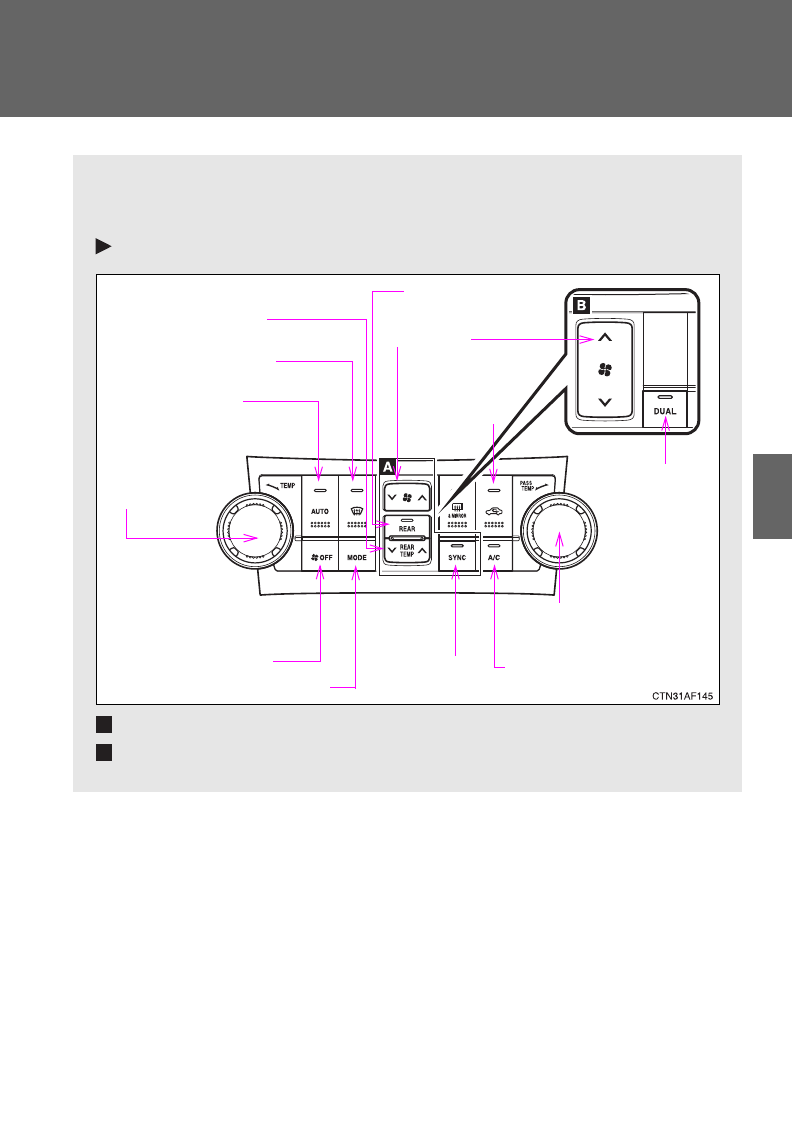
281
3-1. Using the air conditioning system and defogger
3
Interior features
Front automatic air conditioning system
Airflow and outlets are automatically adjusted according to the tem-
perature setting.
Control panel
Vehicles with rear air conditioning system
Vehicles without rear air conditioning system
Fan speed
Individual
mode
Front passenger’s side
temperature control dial
Air conditioning
on/off switch
Simultaneous
mode
Rear air conditioning
on/off switch
Temperature control
for rear passengers
Changes the air outlets used
Off
Driver's side
temperature
control dial
Automatic mode
Windshield defogger Outside air or
recirculated
air mode
A
B
: If equipped
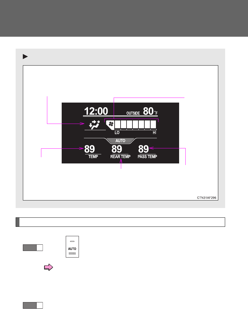
282
3-1. Using the air conditioning system and defogger
Using the automatic mode
Press .
The air conditioning system begins to operate. Air outlets
and fan speed are automatically adjusted according to the
temperature setting.
“AUTO” will be displayed on the multi-information display.
Turn the temperature control dial clockwise (warm) or coun-
terclockwise (cool).
Air outlets and fan speed for the right-hand and left-hand seats may
be set separately depending on the temperature setting.
Multi-information display
Front passenger’s side
temperature setting display
Fan speed
display
Airflow display
Driver’s side
temperature
setting
display
Temperature setting display
for rear passengers
STEP
1
STEP
2
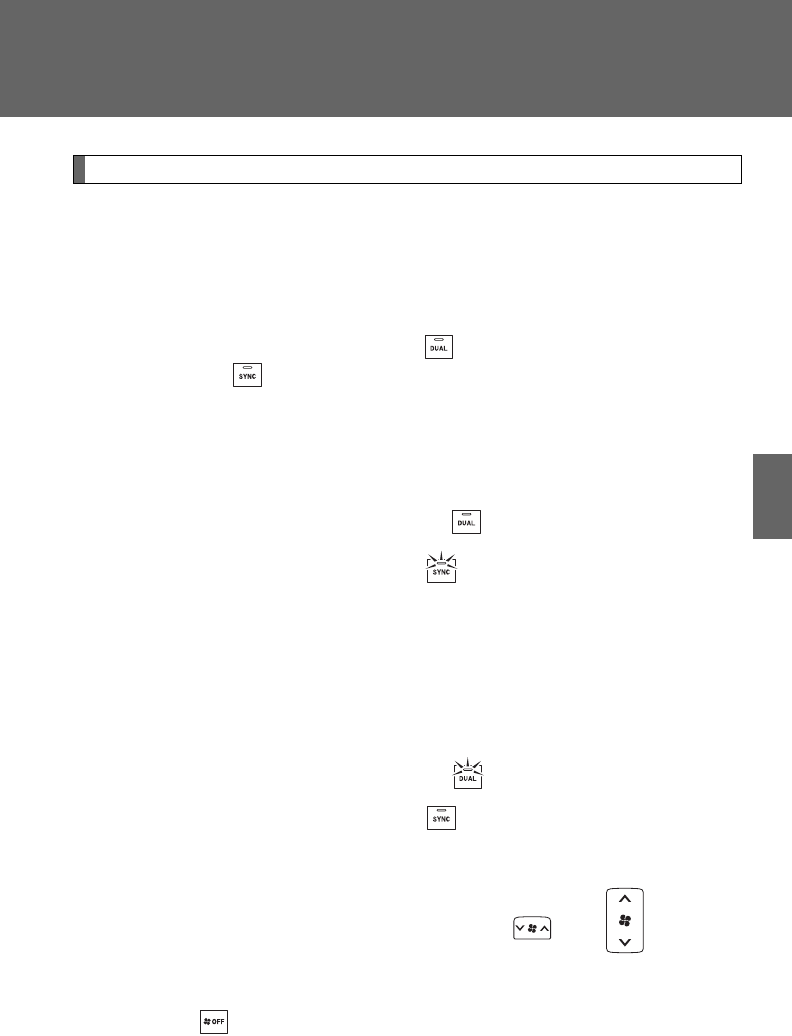
283
3-1. Using the air conditioning system and defogger
3
Interior features
Adjusting the settings
■Adjusting the temperature setting
Turn the temperature control dial clockwise (warm) or counter-
clockwise (cool).
The air conditioning system switches between individual and
simultaneous modes each time (without rear air conditioning
system) or (with rear air conditioning system) is pressed.
Simultaneous mode: Only the driver’s side temperature control dial
can be used to adjust the temperature for all seats.
The indicator status will be as follows:
Without rear air conditioning system: (off)
With rear air conditioning system: (on)
Individual mode: The temperature for the driver’s, front passen-
ger’s and rear seats (P. 292) can be adjusted separately. Operat-
ing the passenger's side or rear (with rear air conditioning system)
temperature control will enter individual mode.
The indicator status will be as follows:
Without rear air conditioning system: (on)
With rear air conditioning system: (off)
■Adjusting the fan speed
Press “” (increase) or “” (decrease) on or .
The fan speed is shown on the multi-information display. (7 levels)
Press to turn the fan off.
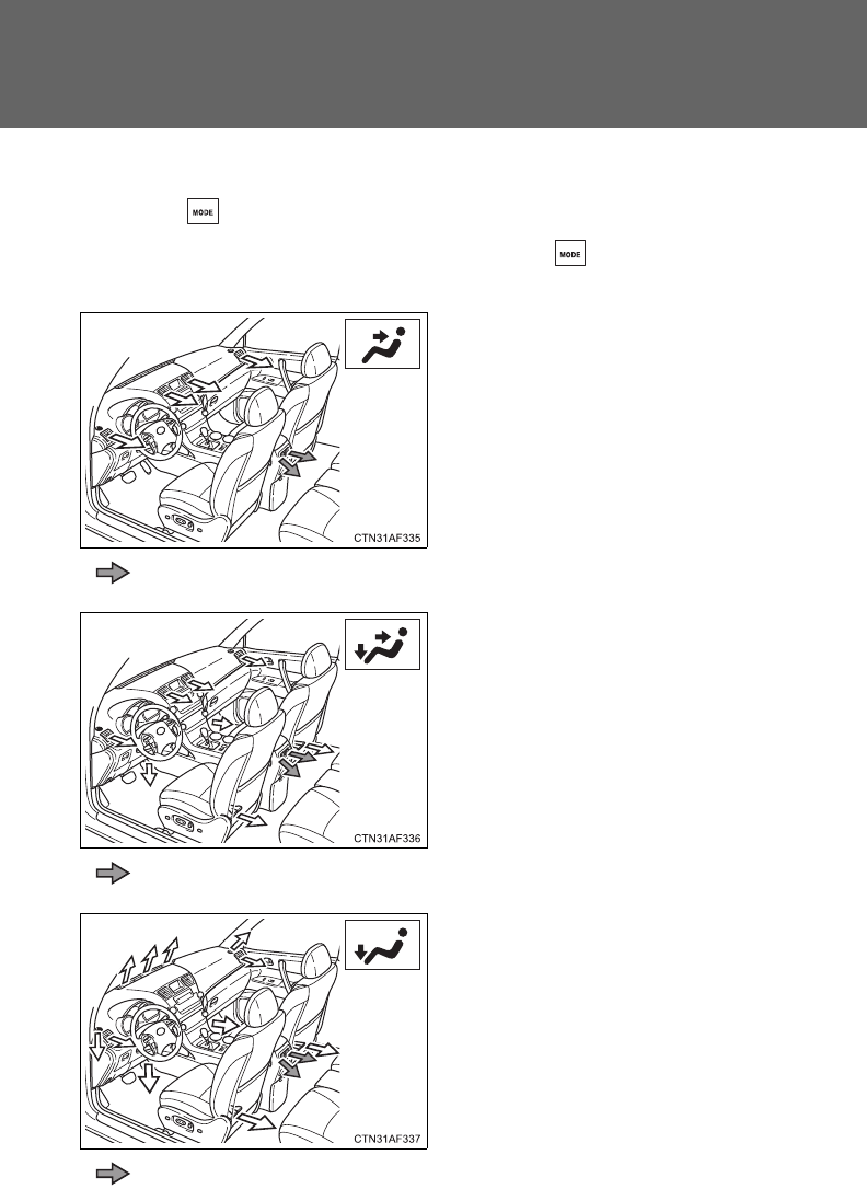
284
3-1. Using the air conditioning system and defogger
■Changing the air outlets
Press .
The air outlets switch each time either side of is pressed. The air
flow shown on the display indicates the following.
Upper body
: Vehicles without rear air conditioning system
Upper body and feet
: Vehicles without rear air conditioning system
Feet
: Vehicles without rear air conditioning system
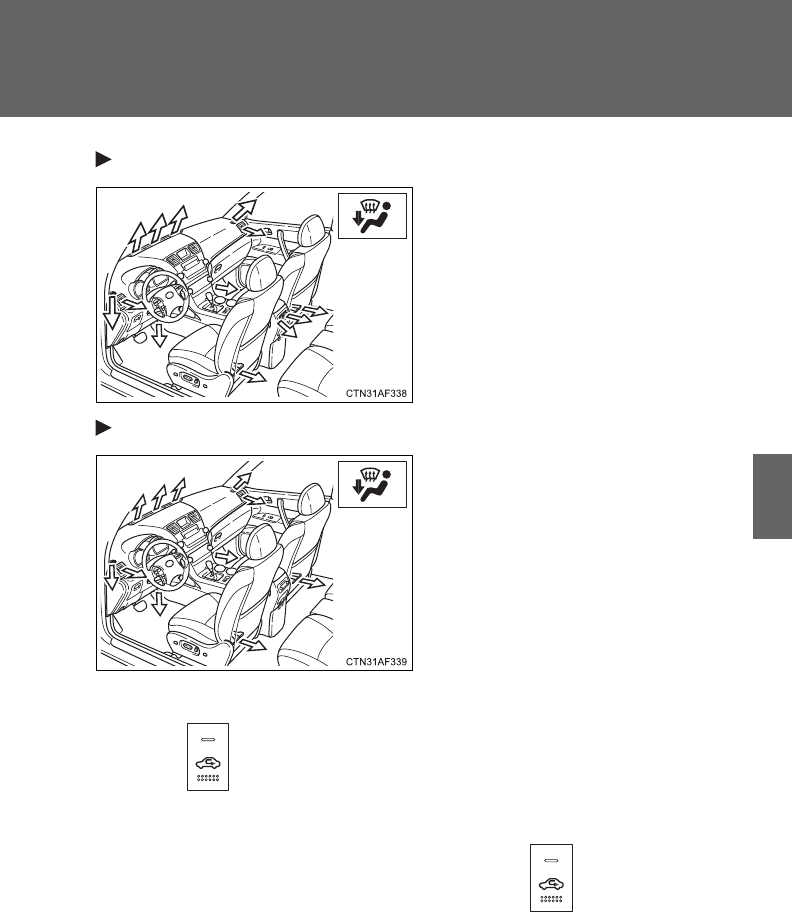
285
3-1. Using the air conditioning system and defogger
3
Interior features
Without rear air conditioning system
Feet and windshield
Recirculated air mode may auto-
matically switch to outside air
mode.
With rear air conditioning system
Feet and windshield
Recirculated air mode may auto-
matically switch to outside air
mode.
■Switching between outside air and recirculated air modes
Press .
The mode switches between outside air mode (indicator off) and recircu-
lated air mode (indicator on) modes each time is pressed.
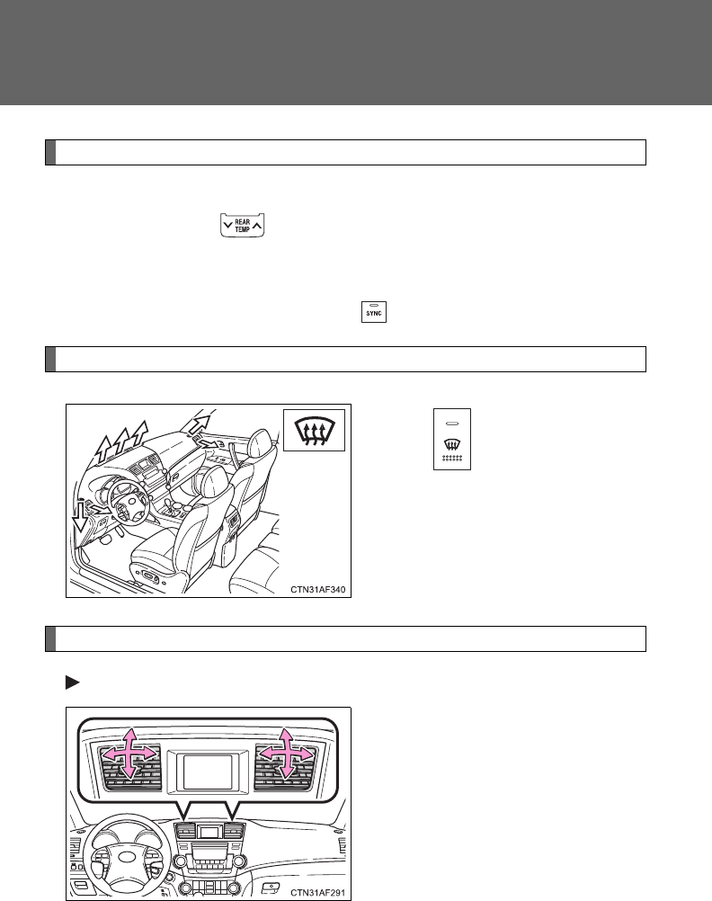
286
3-1. Using the air conditioning system and defogger
Changing the rear seat settings (if equipped)
■Adjusting the temperature setting
Press “” on to increase the temperature and “” to
decrease the temperature.
The air conditioning system switches between individual and
simultaneous modes each time is pressed.
Defogging the windshield
Press .
The air conditioning system oper-
ates automatically.
Recirculated air mode may auto-
matically switch to outside air
mode.
Adjusting the position of and opening and closing the air outlets
Front center outlets
Direct air flow to the left or right,
up or down.
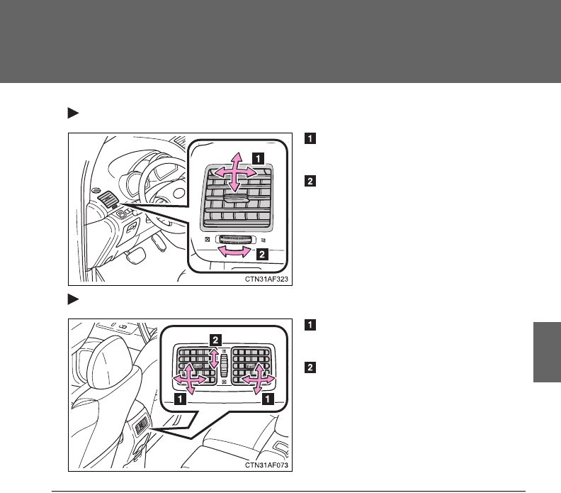
287
3-1. Using the air conditioning system and defogger
3
Interior features
Front side outlets
Direct air flow to the left or
right, up or down.
Turn the knob to open or close
the vent.
Rear center outlets (vehicles without rear air conditioning system)
Direct air flow to the left or
right, up or down.
Turn the knob to open or close
the vent.
■Using the automatic mode
Fan speed is adjusted automatically in accordance with the temperature set-
ting and ambient conditions. As a result, the following may occur.
●Immediately after the switch is pressed, the fan may stop for a while until
warm or cool air is ready to flow.
●Cool air may flow to the area around the upper body when the heater is
on.
■Using the system in recirculated air mode
The windows will fog up more easily if the recirculated air mode is used for
an extended period.
288
3-1. Using the air conditioning system and defogger
■Switching between outside air and recirculated air modes
Recirculated air mode or outside air mode may be automatically switched to
in accordance with the temperature setting and the inside temperature.
■Window defogger feature
Recirculated air mode may automatically switch to (outside air) mode
in situations where the windows need to be defogged.
■When outside temperature approaches 32F (0C)
The air conditioning system may not operate even when is pressed.
■Air conditioning odors
●During use, various odors from inside and outside the vehicle may enter
into and accumulate in the air conditioning system. This may then cause
odor to be emitted from the vents.
●To reduce potential odors from occurring:
• It is recommended that the air conditioning system be set to outside air
mode prior to turning the vehicle off.
• The start timing of the blower may be delayed for a short period of time
immediately after the air conditioning system is started in automatic
mode.
CAUTION
■To prevent the windshield from fogging up
Do not use during cool air operation in extremely humid weather. The
difference between the temperature of the outside air and that of the wind-
shield can cause the outer surface of the windshield to fog up, blocking your
vision.
NOTICE
■To prevent battery discharge
Do not leave the air conditioning system on longer than necessary when the
engine is off.
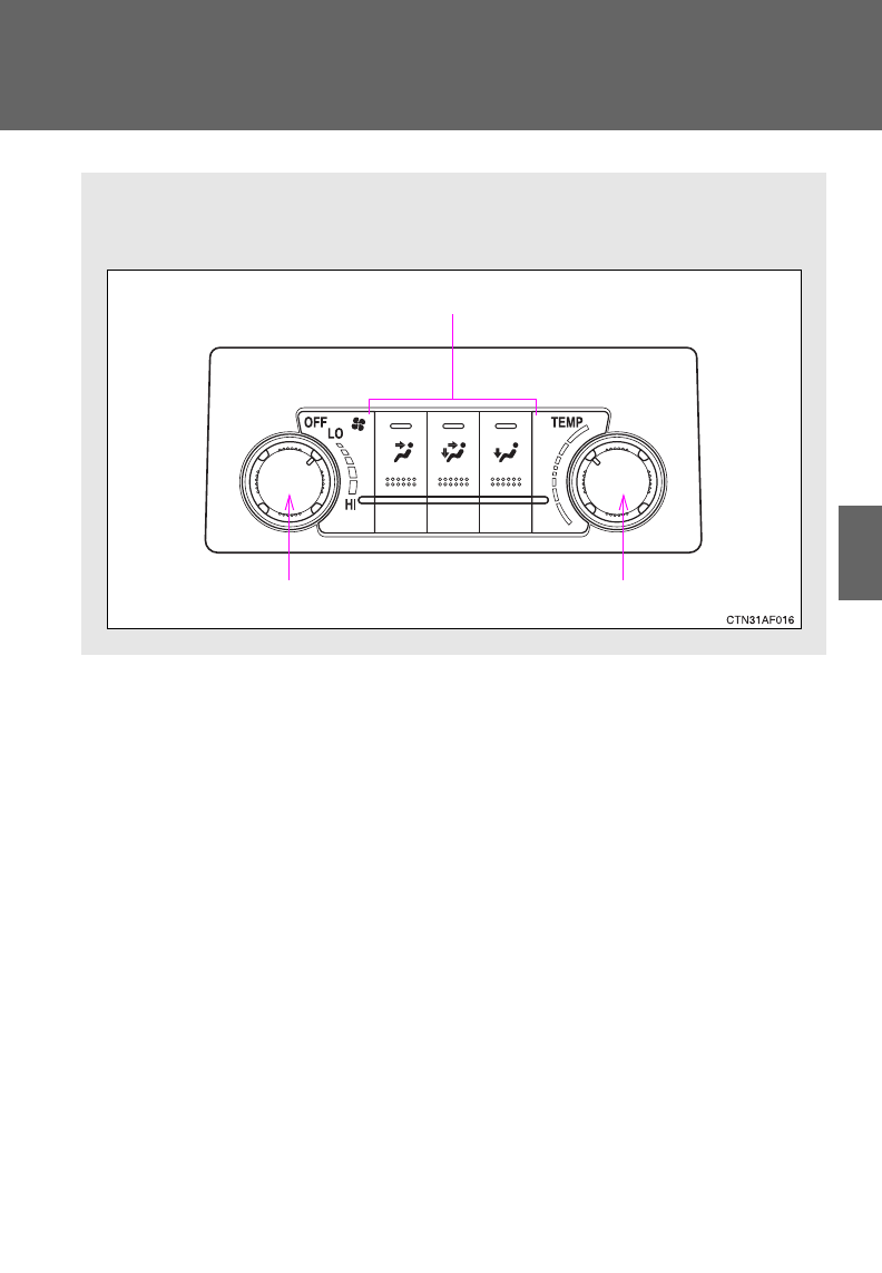
289
3-1. Using the air conditioning system and defogger
3
Interior features
Rear manual air conditioning system
Airflow and outlets are automatically adjusted according to the tem-
perature setting.
Temperature control dial
Changes the air outlets used
Fan speed control dial
: If equipped
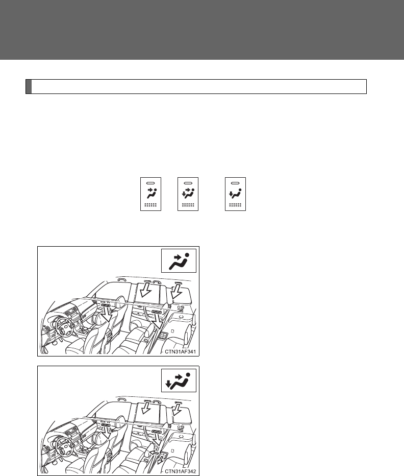
290
3-1. Using the air conditioning system and defogger
Adjusting the settings
■Adjusting the temperature setting
Turn the temperature control dial clockwise (warm) or counter-
clockwise (cool).
■Changing the air outlets
Press the desired , or .
Air flows as shown below according to the mode selected.
Upper body
Upper body and feet
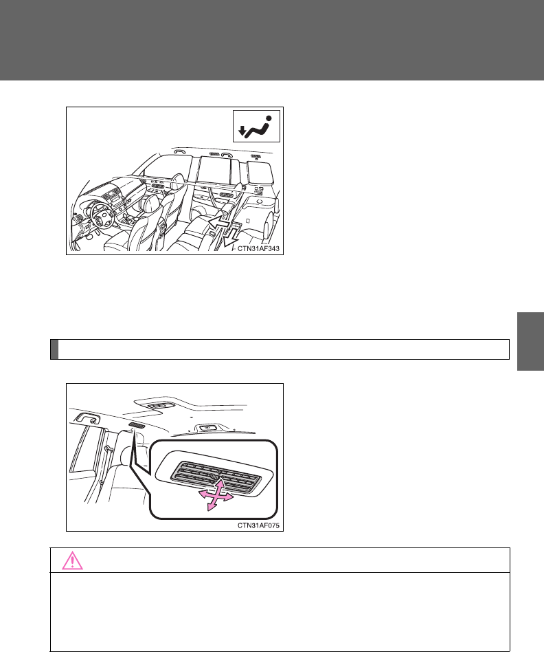
291
3-1. Using the air conditioning system and defogger
3
Interior features
Feet
■Adjusting the fan speed
Turn the fan speed control dial clockwise (increase) or counter-
clockwise (decrease).
Adjusting the position of and opening and closing the roof side air outlets
Direct air flow to the left or right,
up or down.
NOTICE
■To prevent battery discharge
Do not leave the air conditioning system on longer than necessary when the
engine is off.
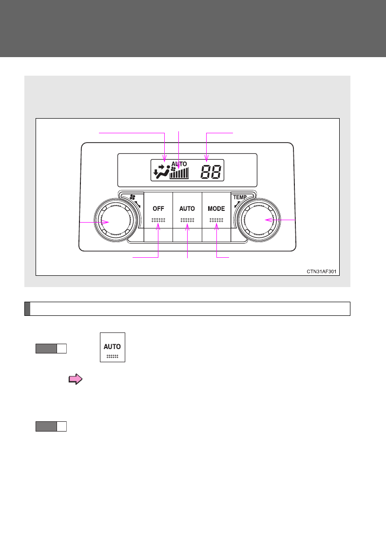
292
3-1. Using the air conditioning system and defogger
Rear automatic air conditioning system
Using the automatic mode
Press .
The air conditioning system will operate, and air outlets
and fan speed will be set automatically.
“AUTO” will be displayed on the control panel.
Turn the temperature control dial clockwise (warm) or coun-
terclockwise (cool).
Airflow and outlets are automatically adjusted according to the tem-
perature setting.
Airflow display Fan speed display
Temperature setting display
Fan speed
control dial
Off Automatic mode Changes the air
outlets used
Temperature
control dial
STEP
1
STEP
2
: If equipped
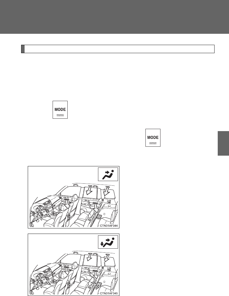
293
3-1. Using the air conditioning system and defogger
3
Interior features
Adjusting the settings
■Adjusting the temperature setting
Turn the temperature control dial clockwise (warm) or counter-
clockwise (cool).
■Changing the air outlets
Press .
The air outlets change as follows each time is pressed.
Air flows as shown below according to the mode selected.
Upper body
Upper body and feet
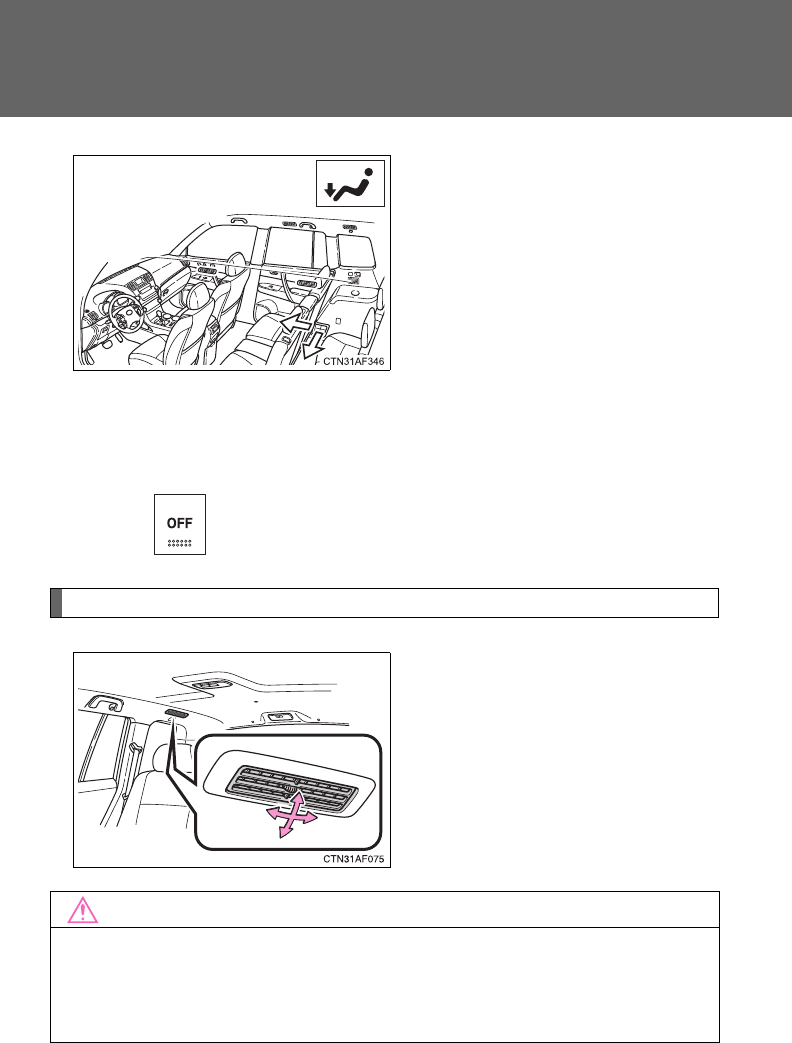
294
3-1. Using the air conditioning system and defogger
Feet
■Adjusting the fan speed
Turn the fan speed control dial clockwise (increase) or counter-
clockwise (decrease).
Press to turn the fan off.
Adjusting the position of and opening and closing the roof side air outlets
Direct air flow to the left or right,
up or down.
NOTICE
■To prevent battery discharge
Do not leave the air conditioning system on longer than necessary when the
engine is off.
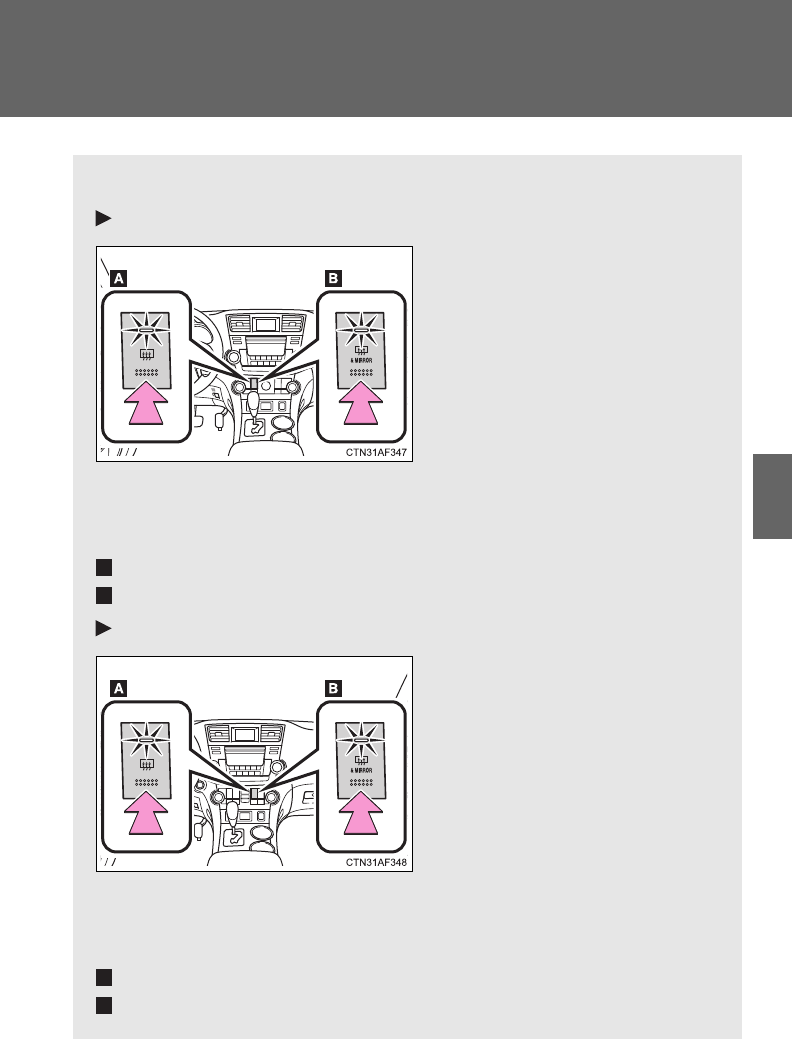
295
3-1. Using the air conditioning system and defogger
3
Interior features
Rear window and outside rear view mirror defoggers
Clear the rear window using the defogger.
Vehicles with manual air conditioning system
On/off
Press the button to turn on the
rear window defogger. The
indicator light will come on.
The defoggers will automati-
cally turn off after 15 to 60 min-
utes. The operation time
changes according to the
ambient temperature and vehi-
cle speed. Pressing the button
again also turns the defogger
off.
Vehicles without outside rear view mirror defoggers
Vehicles with outside rear view mirror defoggers
Vehicles with automatic air conditioning system
On/off
Press the button to turn on the
rear window defogger. The
indicator light will come on.
The defoggers will automati-
cally turn off after 15 to 60 min-
utes. The operation time
changes according to the
ambient temperature and vehi-
cle speed. Pressing the button
again also turns the defogger
off.
Vehicles without outside rear view mirror defoggers
Vehicles with outside rear view mirror defoggers
A
B
A
B
296
3-1. Using the air conditioning system and defogger
■The defogger can be operated when
Vehicles without smart key system
The engine switch is in the “ON” position.
Vehicles with smart key system
The “ENGINE START STOP” switch is in IGNITION ON mode.
■Outside rear view mirror defoggers (vehicles with outside rear view
mirror defoggers)
Turning the rear window defogger on will turn the outside rear view mirror
defoggers on.
CAUTION
■Outside rear view mirror defoggers (vehicles with outside rear view
mirror defoggers)
Do not touch the outside surface of the rear view mirrors, as they can
become very hot and cause burns.
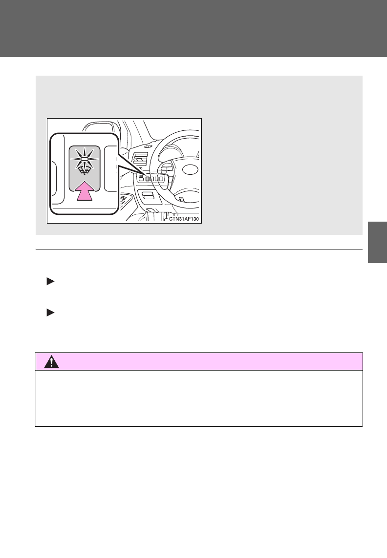
297
3-1. Using the air conditioning system and defogger
3
Interior features
Windshield wiper de-icer
■The de-icer can be operated when
Vehicles without smart key system
The engine switch is in the “ON” position.
Vehicles with smart key system
The “ENGINE START STOP” switch is in IGNITION ON mode.
CAUTION
■When the windshield wiper de-icer is on
Do not touch the lower part of the windshield or the side of the front pillars,
as the surfaces can become very hot and cause burns.
This feature is used to prevent ice from building up on the wind-
shield and wiper blades.
On/off
Press the button to turn on the
windshield wiper de-icer. The
indicator light will come on.
The windshield wiper de-icer
will automatically turn off after
approximately 15 minutes.
: If equipped
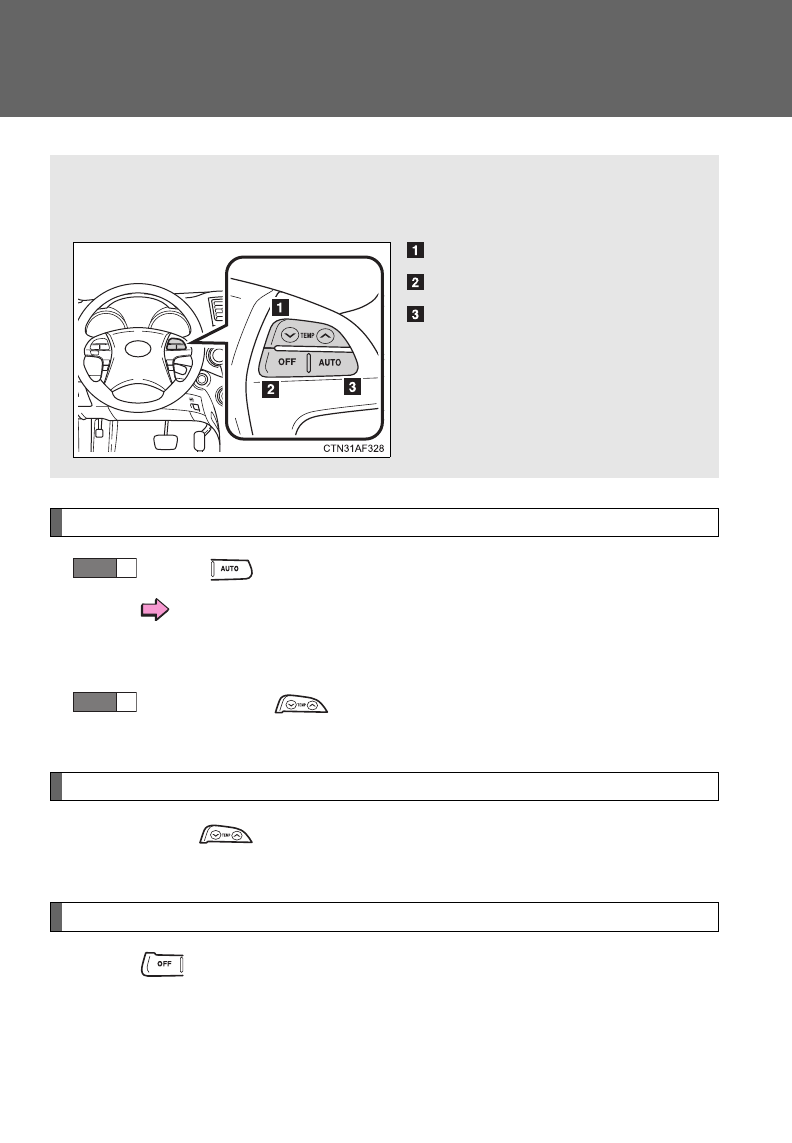
298
3-1. Using the air conditioning system and defogger
Using the steering wheel climate remote control switches
Using the automatic mode
Press .
The air conditioning system will operate, and air outlets
and fan speed will be set automatically.
“AUTO” will be displayed on the multi-information display.
Press “” on to increase the temperature and “” to
decrease the temperature.
Adjusting the temperature setting
Press “” on to increase the temperature and “” to decrease
the temperature.
Turning off the fan
Press .
Some air conditioning features can be controlled using the switches
on the steering wheel.
Temperature control
Off
Automatic mode
STEP
1
STEP
2
: If equipped
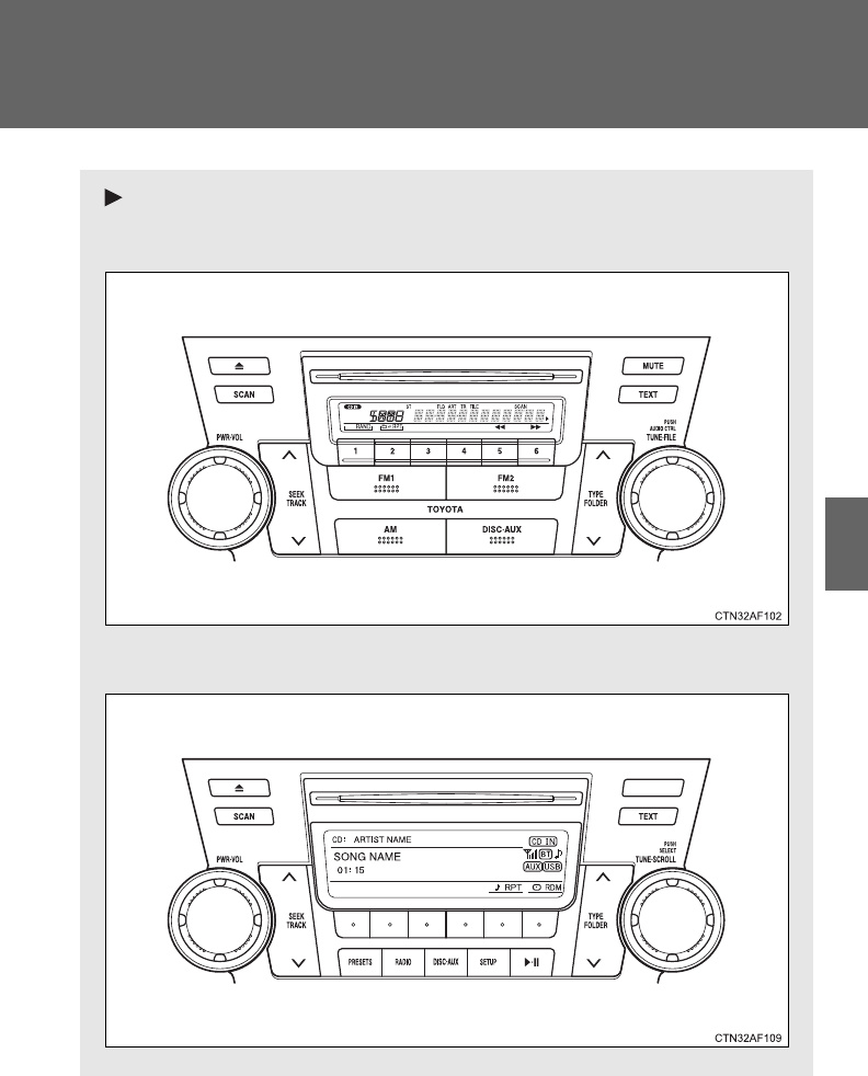
299
3
Interior features
3-2. Using the audio system
Audio system
Without Display Audio system or navigation system
Type A: CD player and AM/FM radio
Type B: CD player and AM/FM radio (with CD changer controller)
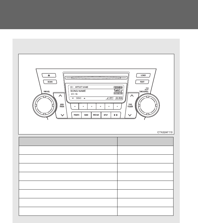
300
3-2. Using the audio system
Type C: CD player with changer and AM/FM radio
Title Page
Using the radio P. 307
Using the CD player P. 314
Playing back MP3 and WMA discs P. 322
Operating an iPod P. 330
Operating a USB memory P. 337
Optimal use of the audio system P. 345
Using the AUX port P. 349
Using the steering wheel audio switches P. 351
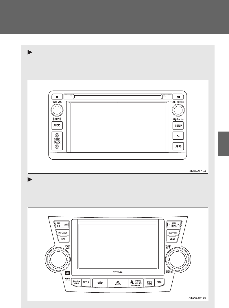
301
3-2. Using the audio system
3
Interior features
With Display Audio system
Owners of models equipped with a Display Audio system should
refer to the “Display Audio System Owner's Manual”.
With navigation system
Owners of models equipped with a navigation system should refer
to the “Navigation System Owner's Manual”.
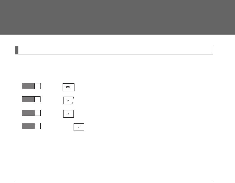
302
3-2. Using the audio system
Language settings (type B and C)
The language used for all voice guidance, voice recognition and mes-
sages may be changed.
Press .
Press (MORE).
Press (LANG).
Press the that corresponds to the desired language.
For vehicles sold in the U.S.A.
“ENG” (English) or “ESP” (Spanish)
For vehicles sold in Canada
“ENG” (English) or “FRAN” (French)
■Using cellular phones
Interference may be heard through the audio system's speakers if a cellular
phone is being used inside or close to the vehicle while the audio system is
operating.
STEP
1
STEP
2
STEP
3
STEP
4

303
3-2. Using the audio system
3
Interior features
■Trademark owned by SRS Labs, Inc. (if equipped)
The audio systems utilize SRS FOCUS® and SRS TruBass® audio
enhancement technologies, under license from SRS Labs, Inc., in all modes
except AM radio mode.
FOCUS, TruBass, SRS and symbol are trademarks of SRS Labs,
Inc.
FOCUS and TruBass technologies are incorporated under license from
SRS Labs, Inc.
TruBass® enhances the perception of bass frequencies to provide deep, rich
bass response from any size speaker.
SRS FOCUS® raises the audio image from non-optimally placed speakers
up to the natural listening height at ear level.

304
3-2. Using the audio system
CAUTION
■Certifications
●Part 15 of the FCC Rules
FCC Warning:
Any unauthorized changes or modifications to this equipment will void the
user’s authority to operate this device.
●Laser products
• Do not take this unit apart or attempt to make any changes yourself.
This is an intricate unit that uses a laser pickup to retrieve information
from the surface of compact discs. The laser is carefully shielded so
that its rays remain inside the cabinet. Therefore, never try to disas-
semble the player or alter any of its parts since you may be exposed to
laser rays and dangerous voltages.
• This product utilizes a laser.
Use of controls or adjustments or performance of procedures other
than those specified herein may result in hazardous radiation expo-
sure.
■Certifications for the Bluetooth® (with Display Audio system)
FCC ID: ACJ932CQ-US70G0
This device complies with Part 15 of FCC Rules.
Operation is subject to the following two conditions:
(1) this device may not cause interference, and
(2) this device must accept any interference, including interference that may
cause undesired operation of this device.
The antenna for Bluetooth® cannot be removed (or replaced) by user.

305
3-2. Using the audio system
3
Interior features
CAUTION
FCC Warning:
Changes or modifications not expressly approved by the party responsible
for compliance could void the user’s authority to operate the equipment.
This device complies with Part 15 of the FCC Rules. Operation is subject to
the following two conditions: (1) this device may not cause harmful interfer-
ence, and (2) this device must accept any interference received, including
interference that may cause undesired operation.
This equipment complies with FCC radiation exposure limits set forth for an
uncontrolled environment and meets the FCC radio frequency (RF) Expo-
sure Guidelines in Supplement C to OET65. This equipment has very low
levels of RF energy that it deemed to comply without maximum permissive
exposure evaluation (MPE). But it is desirable that it should be installed and
operated keeping the radiator at least 20cm or more away from person’s
body (excluding extremities: hands, wrists, feet and ankles).
NOTE: This equipment has been tested and found to comply with the limits
for a Class B digital device, pursuant to Part 15 of the FCC Rules. These lim-
its are designed to provide reasonable protection against harmful interfer-
ence in a residential installation. This equipment generates, uses and can
radiate radio frequency energy and, if not installed and used in accordance
with the instructions, may cause harmful interference to radio communica-
tions. However, there is no guarantee that interference will not occur in a
particular installation.
If this equipment does cause harmful interference to radio or television
reception, which can be determined by turning the equipment off and on, the
user is encouraged to try to correct the interference by one or more of the
following measures:
- Reorient or relocate the receiving antenna.
- Increase the separation between the equipment and receiver.
- Connect the equipment into an outlet on a circuit different from that to
which the receiver is connected.
- Consult the dealer or an experienced radio/TV technician for help.
This transmitter must not be co-located or operated in conjunction with any
other antenna or transmitter.

306
3-2. Using the audio system
NOTICE
■To prevent battery discharge
Do not leave the audio system on longer than necessary when the engine is
off.
■To avoid damaging the audio system
Take care not to spill drinks or other fluids over the audio system.
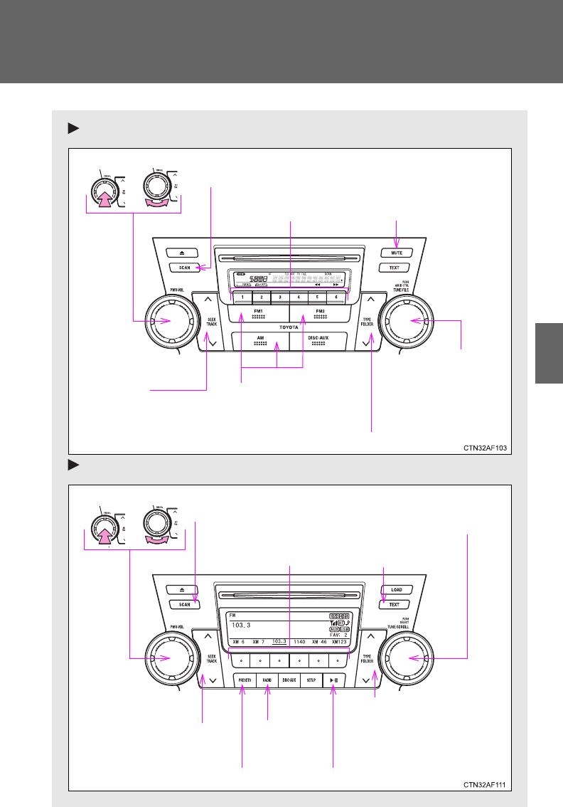
307
3-2. Using the audio system
3
Interior features
Using the radio
Type A
Type B and C
Volume
Seeking the
frequency
Station selector
AM/FM
mode buttons
Adjusting the
frequency
Power
Scanning for receivable stations
Changing the program type
Mute
Power Volume Adjusting the frequency
(AM, FM mode) or
channel (SAT mode)
Seeking a frequency
Displaying radio
text messages
AM/FM/SAT
mode button
Scanning for
receivable stations
Station selector
Setting preset buttons
Changing the
channel category
Mute
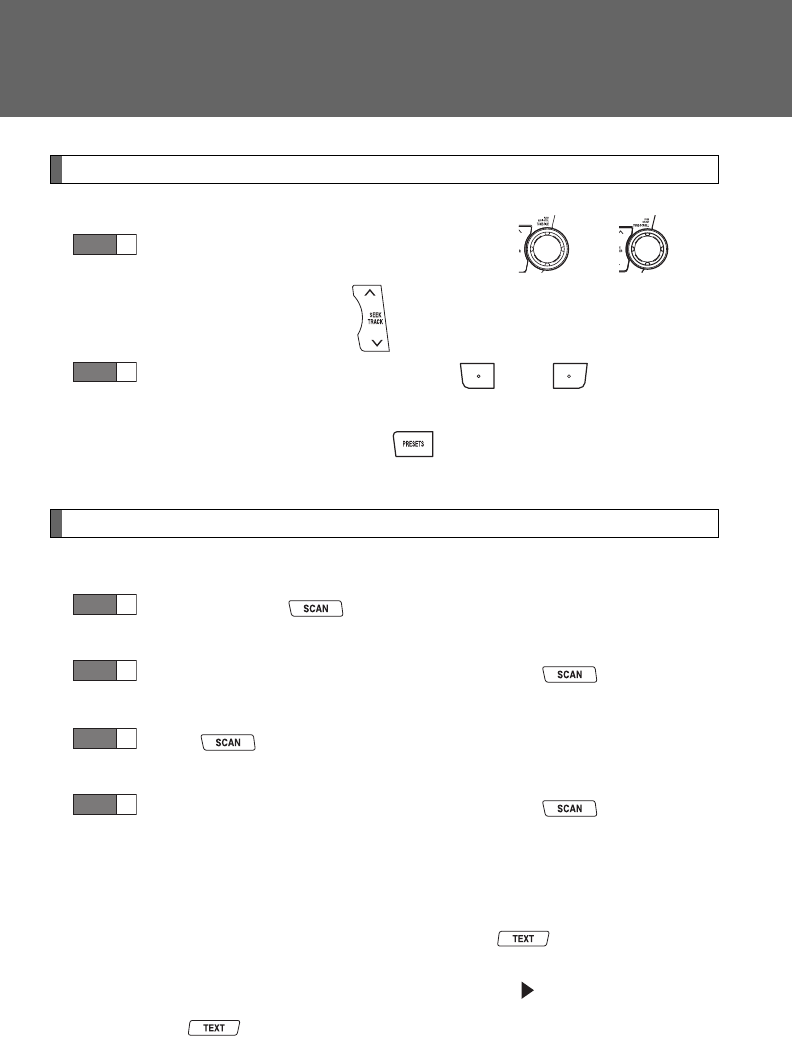
308
3-2. Using the audio system
Setting station presets (excluding XM® Satellite Radio)
Search for desired stations by turning or , or
pressing “”or “” on .
Press and hold the button (from to ) the station
is to be set to until you hear a beep.
Type B and C: Each time is pressed, station pages are
changed. There are a total of 6 pages.
Scanning radio stations (excluding XM® Satellite Radio)
■Scanning the preset radio stations
Press and hold until you hear a beep.
Preset stations will be played for 5 seconds each.
When the desired station is reached, press once again.
■Scanning all radio stations within range
Press .
All stations with reception will be played for 5 seconds each.
When the desired station is reached, press once again.
■Displaying radio text messages (for type B and C, FM mode
only)
When a new radio text message is received, “MSG” is shown on
the display. To display the message, press .
If the text continues past the end of the display, “ ” is displayed. Press
and hold until you hear a beep.
Text messages are not displayed while driving.
STEP
1
STEP
2
STEP
1
STEP
2
STEP
1
STEP
2
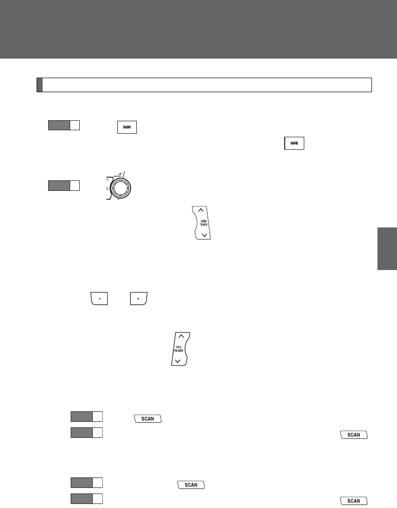
309
3-2. Using the audio system
3
Interior features
XM® Satellite Radio (type B and C)
■Receiving XM® Satellite Radio
Press .
The display changes as follows each time is pressed.
AM FM XM
Turn to select the desired channel in all the categories,
or press “” or “” on to select the desired channel in
the current category.
■Setting XM® Satellite Radio channel presets
Select the desired channel. Press and hold a button
(from to ) until you hear a beep.
■Changing the channel category
Press “” or “” on the .
■Scanning XM® Satellite Radio channels
●Scanning channels in the current category
Press .
When the desired channel is reached, press
again.
●Scanning preset channels
Press and hold until you hear a beep.
When the desired channel is reached, press
again.
STEP
1
STEP
2
STEP
1
STEP
2
STEP
1
STEP
2
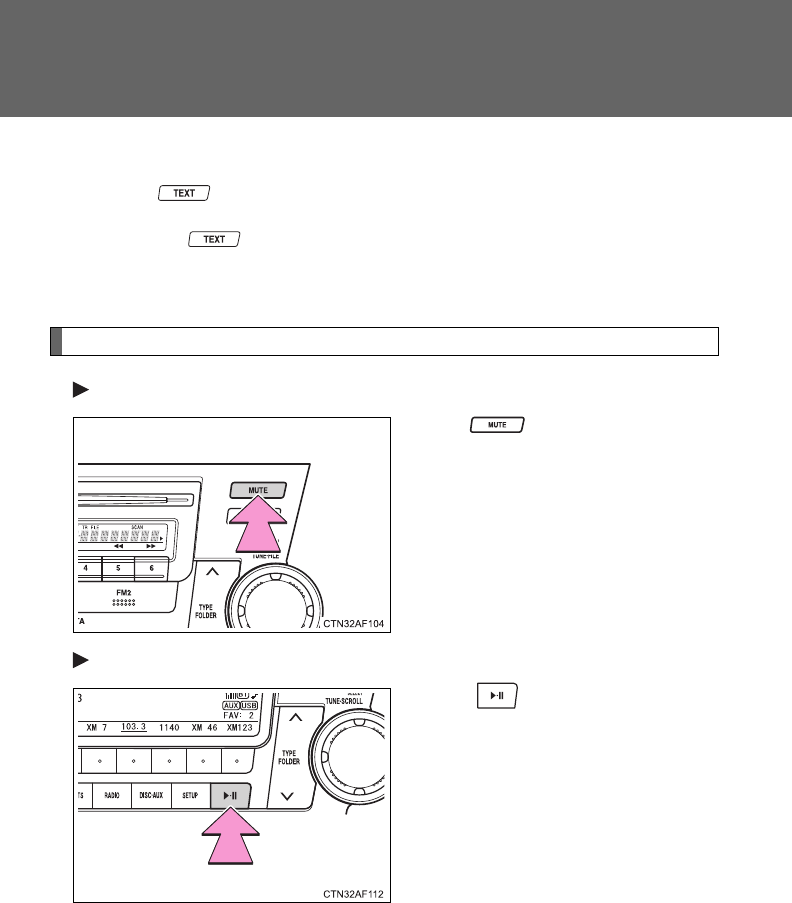
310
3-2. Using the audio system
■Displaying text information
Press .
Each time is pressed, the display changes in the following order:
Title (song/program title) Name (artist name/feature)Title (song/pro-
gram title).
Silencing the sound
Type A
Press .
Type B and C
Press .

311
3-2. Using the audio system
3
Interior features
■When the battery is disconnected
All preset stations are erased. (type A only)
■Reception sensitivity
●Type B and C Cargo loaded on the roof luggage carrier, especially
metal objects, may adversely affect the reception of XM® Satellite Radio.
●Maintaining perfect radio reception at all times is difficult due to the con-
tinually changing position of the antenna, differences in signal strength
and surrounding objects, such as trains and transmitters.
●Pole type antenna The radio antenna is mounted on the right-side
front fender. The antenna can be removed from the base by turning it.
●Print type antenna The radio antenna is mounted inside the left-side
rear quarter window. To maintain clear radio reception, do not attach
metallic window tinting or other metallic objects to the antenna wire
mounted inside the left-side rear quarter window.
■XM® Satellite Radio (type B and C)
An XM® Satellite Radio is a tuner designed exclusively to receive broadcasts
provided under a separate subscription. Availability is limited to the 48 con-
tiguous states and 10 Canadian provinces.
●XM® subscriptions
For detailed information about XM® Satellite Radio or to subscribe:
U.S.A.
Visit on the web at www.xmradio.com or call 1-800-967-2346.
Canada
Visit on the web at www.xmradio.ca or call 1-877-438-9677.
●Radio ID
You will need the radio ID when activating XM® service or reporting a
problem. Select “CH000” using , and the receiver's 8-character ID
number will appear.
●Satellite tuner
The tuner supports only Audio Services (Music and Talk) and the accom-
panying Text Information of XM® Satellite Radio.

312
3-2. Using the audio system
■If XM® Satellite Radio does not operate normally (type B and C)
If a problem occurs with the XM® tuner, a message will appear on the dis-
play. Refer to the table below to identify the problem, and take the suggested
corrective action.
ANTENNA
or
CHECK
ANTENNA
The XM® antenna is not connected. Check
whether the XM® antenna cable is attached
securely.
There is a short-circuit in the antenna or the sur-
rounding antenna cable. See a Toyota certified
dealer.
UPDATING
or
CHANNEL NOT
AUTHORIZED
You have not subscribed to the XM® Satellite
Radio. The radio is being updated with the latest
encryption code. Contact the XM® Satellite Radio
for subscription information. When a contract is
canceled, you can choose the “CH000” and all
free-to-air channels.
The premium channel you selected is not autho-
rized. Wait for about 2 seconds until the radio
returns to the previous channel or “CH001”. If it
does not change automatically, select another
channel. If you want to listen to the premium chan-
nel, contact the XM® Satellite Radio.
NO SIGNAL
The XM® signal is too weak at the current location.
Wait until your vehicle reaches a location with a
stronger signal.
LOADING The unit is acquiring audio or program information.
Wait until the unit has received the information.
OFF AIR
or
CHANNEL OFF
AIR
The channel you selected is not broadcasting any
programming. Select another channel.
-----
There is no song/program title or artist name/fea-
ture associated with the channel at that time. No
action needed.
313
3-2. Using the audio system
3
Interior features
Contact the XM® Listener Care Center at 1-800-967-2346 (U.S.A.) or 1-877-
438-9677 (Canada).
■Certifications for the radio tuner
This equipment has been tested and found to comply with the limits for a
class B digital device, pursuant to Part 15 of the FCC Rules. These limits are
designed to provide reasonable protection against harmful interference in a
residential installation. This equipment generates, uses and can radiate
radio frequency energy and, if not installed and used in accordance with the
instructions, may cause harmful interference to radio communications. How-
ever, there is no guarantee that interference will not occur in a particular
installation.
If this equipment does cause harmful interference to radio or television
reception, which can be determined by turning the equipment off and on, the
user is encouraged to try to correct the interference by trying one or more of
the following:
●Reorienting or relocating the receiving antenna.
●Increasing the separation between the equipment and receiver.
●Connecting the equipment into an outlet on a circuit different from that to
which the receiver is connected.
●Consulting the dealer or an experienced radio/TV technician for help.
NOTICE
■To prevent damage, remove the antenna in the following cases.
(pole type antenna)
●The antenna will touch the ceiling of a garage.
●A cover will be put on the vehicle.
---
or
CHANNEL NOT
AVAILABLE
The channel you selected is no longer available.
Wait for about 2 seconds until the radio returns to
the previous channel or “CH001”. If it does not
change automatically, select another channel.
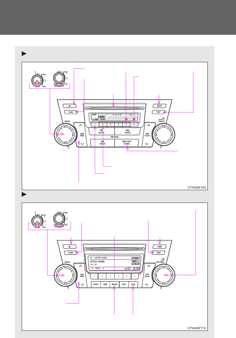
314
3-2. Using the audio system
Using the CD player
Type A
Type B and C
Volume
Random playback
Track selection
Repeat play
Playback
Power CD eject Displaying text message
Search playback
CD slot
Reverse
Fast-forward
Mute
Power Volume
CD load
(type C only)
Searching
playback
CD eject
Selecting a track/
fast-forwarding
and rewinding
Displaying text messages
Selector buttons
Playback Playback/pause
Selecting a track
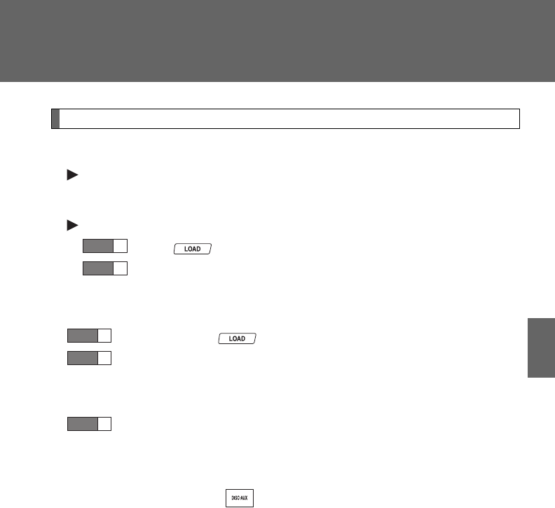
315
3-2. Using the audio system
3
Interior features
Loading CDs
■Loading a CD
Type A and B
Insert a CD.
Type C
Press .
When the indicator on the slot turns from amber to green,
insert a CD.
■Loading multiple CDs (type C only)
Press and hold until you hear a beep.
When the indicator on the slot turns from amber to green,
insert a CD.
The indicator on the slot turns to amber when the CD is inserted.
When the indicator on the slot turns from amber to green
again, insert the next CD.
Repeat the procedure for the remaining CDs.
To cancel, press . If you do not insert a disc within 15 sec-
onds, loading will be canceled automatically.
STEP
1
STEP
2
STEP
1
STEP
2
STEP
3
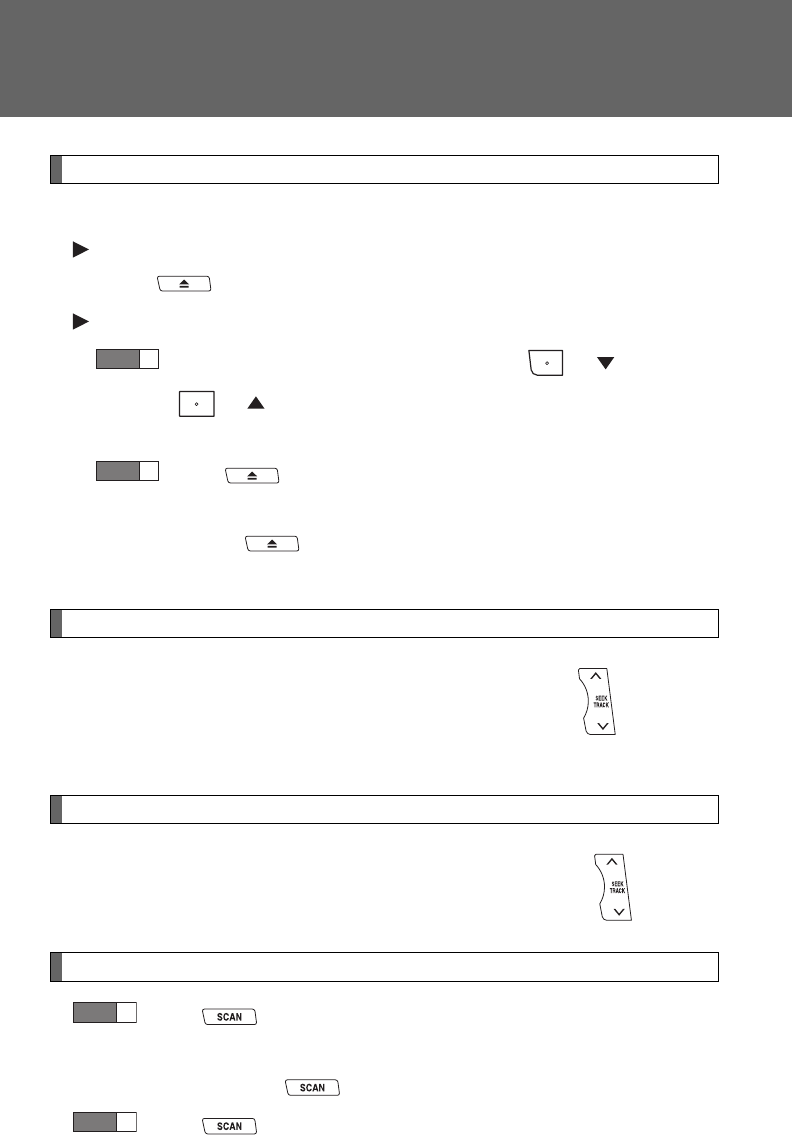
316
3-2. Using the audio system
Ejecting CDs
■Ejecting a CD
Type A and B
Press and remove the CD.
Type C
To select the CD to be ejected, press ( ) or
().
The selected CD number is shown on the display.
Press and remove the CD.
■Ejecting all the CDs (type C only)
Press and hold until you hear a beep, and then remove the
CDs.
Selecting a track
Press “” to move up or “” to move down using until the
desired track number is displayed.
Fast-forwarding and reversing tracks
To fast-forward or reverse, press and hold “” or “” on .
Scanning tracks
Press .
The first ten seconds of each track will be played.
To cancel, press again.
Press again when the desired track is reached.
STEP
1
STEP
2
STEP
1
STEP
2
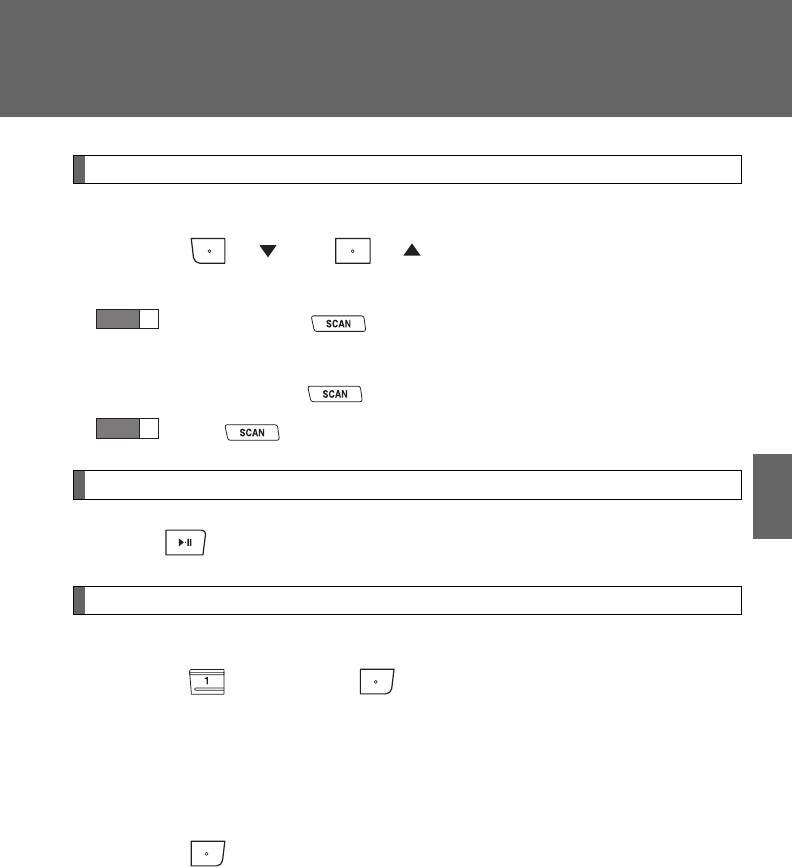
317
3-2. Using the audio system
3
Interior features
Selecting a CD (type B with a CD changer and type C)
■Selecting a CD to play
Press ( ) or ( ).
■Scanning loaded CDs
Press and hold until you hear a beep.
The first ten seconds of the first track on each CD will be played.
To cancel, press again.
Press again when the desired CD is reached.
Playing and pausing tracks (type B and C)
Press .
Random playback
■Current CD
Press (RAND) or (RDM).
Songs are played in random order.
To cancel, press the button once more (type A and type B without a CD
changer), or twice more (type B with a CD changer and type C).
■All CDs (type B with a CD changer and type C)
Press (RDM) twice.
Tracks on all loaded CDs are played in random order.
To cancel, press the button again.
STEP
1
STEP
2

318
3-2. Using the audio system
Repeat play
■Repeating a track
Press (RPT) or (RPT).
To cancel, press the button once more (type A and type B without a CD
changer), or twice more (type B with a CD changer and type C).
■Repeating all of the tracks on a CD (type B with a CD changer
and type C)
Press (RPT) twice.
To cancel, press the button again.
Switching the display
Press .
Each time is pressed, the display changes in the following order:
Type A: Track no./Elapsed time CD title Track name.
Type B and C: Track title Track name/Artist name Track name/
Elapsed time.
Silencing a sound (type A only)
P. 3 1 0
319
3-2. Using the audio system
3
Interior features
■Display
Up to 12 characters can be displayed at a time.
If there are 13 characters or more, pressing and holding for 1 second
or more will display the remaining characters.
A maximum of 24 characters can be displayed.
If is pressed for 1 second or more again or has not been pressed for
6 seconds or more, the display will return to the first 12 characters.
Depending on the contents recorded, the characters may not be displayed
properly or may not be displayed at all.
■Error messages
“CD CHECK”: This indicates a problem either in the CD or inside the player.
The CD may be dirty, damaged or inserted up-side down.
“WAIT” or “PLEASE WAIT”: Operation has stopped due to a high tempera-
ture inside the player. Wait for a while and then
press or . Contact your
Toyota dealer if the CD still cannot be played
back.
■Discs that can be used
Discs with the marks shown below can be used.
Playback may not be possible depending on recording format or disc fea-
tures, or due to scratches, dirt or deterioration.
CDs with copy-protect features may not be used.
■CD player protection feature
To protect the internal components, playback is automatically stopped when
a problem is detected while the CD player is being used.
■If CDs are left inside the CD player or in the ejected position for
extended periods
CDs may be damaged and may not play properly.
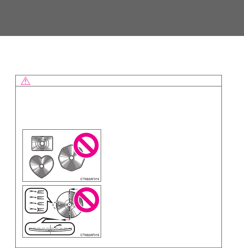
320
3-2. Using the audio system
■Lens cleaners
Do not use lens cleaners. Doing so may damage the CD player.
NOTICE
■CDs and adapters that cannot be used
Do not use the following types of CDs, 3 in. (8 cm) CD adapters or Dual
Disc.
Doing so may damage the CD player and/or the CD insert/eject function.
●CDs that have a diameter that is not 4.7
in. (12 cm)
●Low-quality and deformed CDs
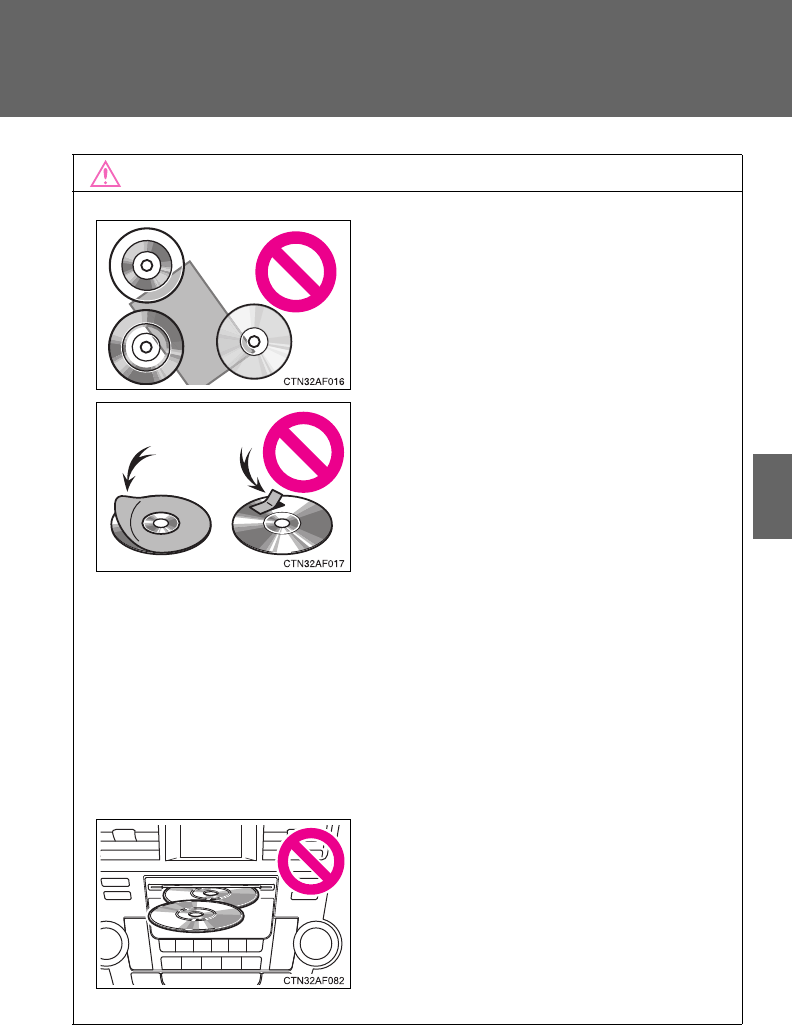
321
3-2. Using the audio system
3
Interior features
NOTICE
■CD player precautions
Failure to follow the precautions below may result in serious damage to the
CDs or the player itself.
●Do not insert anything other than CDs into the CD slot.
●Do not apply oil to the CD player.
●Store CDs away from direct sunlight.
●Never try to disassemble any part of the CD player.
●CDs with a transparent or translucent
recording area
●CDs that have had tape, stickers or CD-
R labels attached to them, or that have
had the label peeled off
●Do not insert more than one CD at a
time.
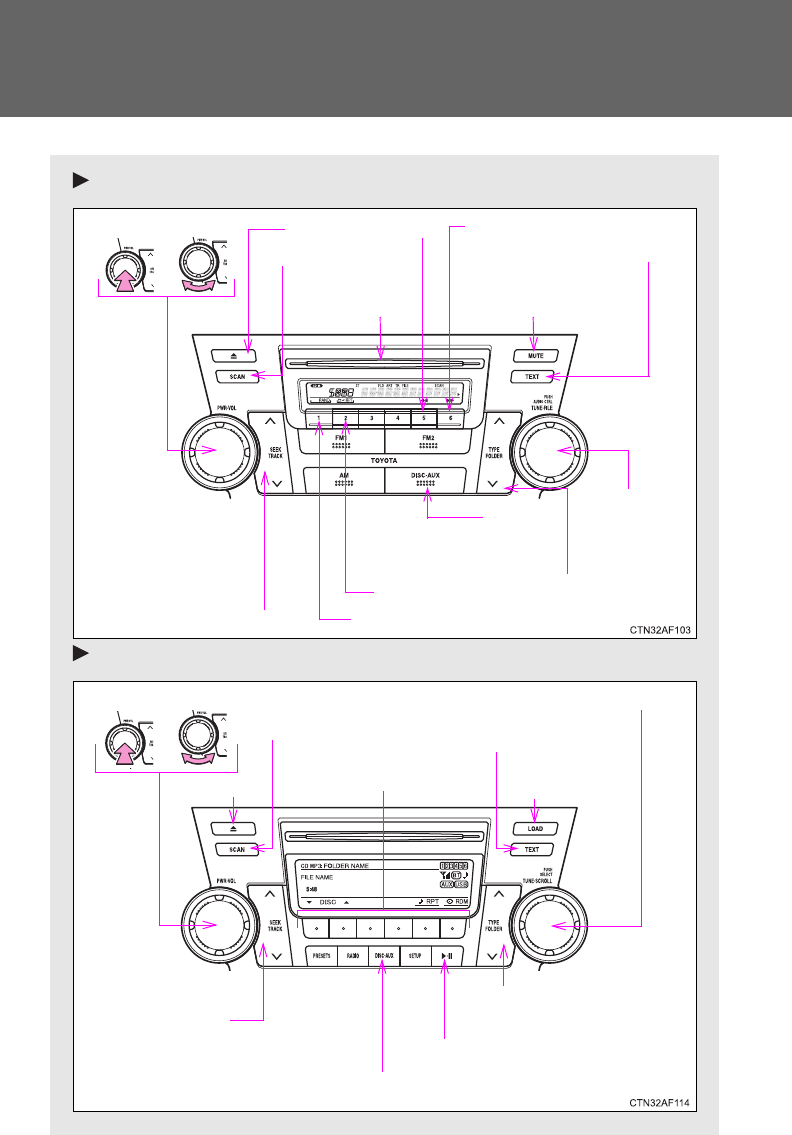
322
3-2. Using the audio system
Playing back MP3 and WMA discs
Type A
Type B and C
Volume
Random playback
File selection
Repeat play
Playback
Power CD eject
Displaying text message
Search playback
CD slot
Folder selection
File selection
Reverse Fast-forward
Mute
Power Volume
Displaying text
messages
CD eject
Playback
Playback/pause
Selecting a file
CD load
(type C only)
Selector buttons
Selecting a
folder and file
Searching playback
Selecting a file/
fast-forwarding
and rewinding
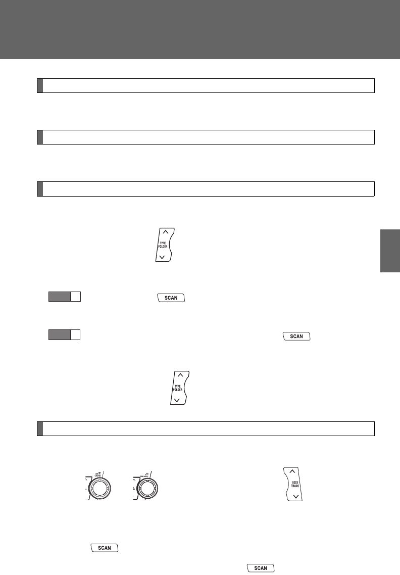
323
3-2. Using the audio system
3
Interior features
Loading and ejecting MP3 and WMA discs
P. 3 1 4
Selecting MP3 and WMA discs (type B with a CD changer and type C)
P. 3 1 7
Selecting and scanning a folder
■Selecting folders one at a time
Press “” or “” on to select the desired folder.
■Scanning the first file of all the folders
Press and hold until you hear a beep.
The first ten seconds of the first file in each folder will be played.
When the desired folder is reached, press again.
■Returning to the first folder
Press and hold “” on until you hear a beep.
Selecting and scanning files
■Selecting one file at a time
Turn or , or press “” or “” on to select the
desired file.
■Selecting the desired file by cueing the files in the folder
Press .
When the desired file is reached, press once again.
STEP
1
STEP
2
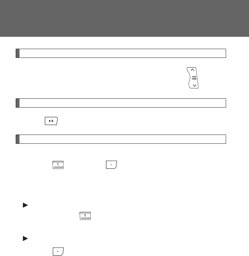
324
3-2. Using the audio system
Fast-forwarding and reversing files
To fast-forward or reverse, press and hold “” or “” on .
Playing and pausing files (type B and C)
Press .
Random playback
■Playing files from a particular folder in random order
Press (RAND) or (RDM).
To cancel, press the button once more (type A and type B without a CD
changer), or twice more (type B with a CD changer and type C).
■Playing all of the files on a disc in random order
Type A
Press and hold (RAND) until you hear a beep.
To cancel, press the button again.
Type B and C
Press (RDM) twice.
To cancel, press the button again.
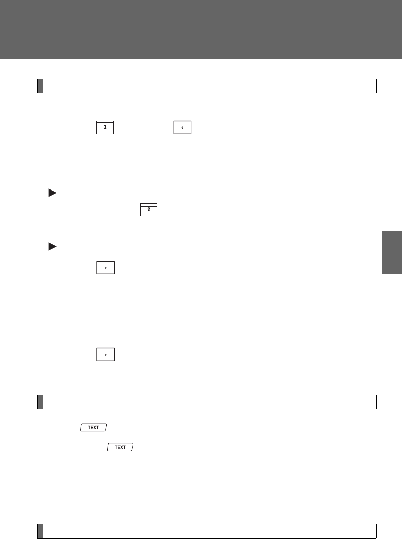
325
3-2. Using the audio system
3
Interior features
Repeat play
■Repeating a file
Press (RPT) or (RPT).
To cancel, press the button once more (type A and type B without a CD
changer), or twice more (type B with a CD changer and type C).
■Repeating all of the files on a folder
Type A
Press and hold (RPT) until you hear a beep.
To cancel, press the button again.
Type B and C
Press (RPT) twice.
To cancel, press the button once more (type A and type B without a CD
changer), or twice more (type B with a CD changer and type C).
■Repeating all of the files in a disc (type B with a CD changer
and type C)
Press (RPT) three times.
To cancel, press the same button again.
Switching the display
Press .
Each time is pressed, the display changes in the following order:
Type A: Folder no./File no./Elapsed time Folder name File name
Album title (MP3 only) Track title Artist name.
Type B and C: Track title Track title/Artist name Track title/Album
name (MP3 only) Track title/Elapsed time.
Silencing a sound (type A only)
P. 3 1 0
326
3-2. Using the audio system
■Display (type A only)
P. 319
■Error messages
“CD CHECK”:This indicates a problem either in the CD or inside the player.
The CD may be dirty, damaged or inserted up-side down.
“NO MUSIC”: This indicates that MP3/WMA files are not included in the CD.
“WAIT” or “PLEASE WAIT”: Operation has stopped due to a high tempera-
ture inside the player. Wait for a while and then
press or . Contact your
Toyota dealer if the CD still cannot be played.
■Discs that can be used
P. 319
■CD player protection feature
P. 319
■If CDs are left inside the CD player or in the ejected position for
extended periods
P. 319
■Lens cleaners
P. 320

327
3-2. Using the audio system
3
Interior features
■MP3 and WMA files
MP3 (MPEG Audio LAYER3) is a standard audio compression format.
Files can be compressed to approximately 1/10 of their original size by using
MP3 compression.
WMA (Windows Media Audio) is a Microsoft audio compression format.
This format compresses audio data to a size smaller than that of the MP3
format.
There is a limit to the MP3 and WMA file standards that can be used and to
the media/formats on which the files are recorded.
●MP3 file compatibility
• Compatible standards
MP3 (MPEG1 LAYER3, MPEG2 LSF LAYER3)
• Compatible sampling frequencies
MPEG1 LAYER3: 32, 44.1, 48 (kHz)
MPEG2 LSF LAYER3: 16, 22.05, 24 (kHz)
• Compatible bit rates (compatible with VBR)
MPEG1 LAYER3: 64, 80, 96, 112, 128, 160, 192, 224, 256, 320 (kbps)
MPEG2 LSF LAYER3: 64, 80, 96, 112, 128, 144, 160 (kbps)
• Compatible channel modes: stereo, joint stereo, dual channel and
monaural
●WMA file compatibility
• Compatible standards
WMA Ver. 7, 8, 9
• Compatible sampling frequencies
32, 44.1, 48 (kHz)
• Compatible bit rates (only compatible with 2-channel playback)
Ver. 7, 8: CBR 48, 64, 80, 96, 128, 160, 192 (kbps)
Ver. 9: CBR 48, 64, 80, 96, 128, 160, 192, 256, 320 (kbps)
●Compatible media
Media that can be used for MP3 and WMA playback are CD-Rs and CD-
RWs.
Playback in some instances may not be possible, depending on the status
of the CD-R or CD-RW. Playback may not be possible or the audio may
jump if the disc is scratched or marked with fingerprints.

328
3-2. Using the audio system
●Compatible disc formats
The following disc formats can be used.
• Disc formats: CD-ROM Mode 1 and Mode 2
CD-ROM XA Mode 2, Form 1 and Form 2
• File formats: ISO9660 Level 1, Level 2, (Romeo, Joliet)
MP3 and WMA files written in any format other than those listed above
may not play correctly, and their file names and folder names may not
be displayed correctly.
Items related to standards and limitations are as follows.
• Maximum directory hierarchy: 8 levels
• Maximum length of folder names/file names: 32 characters
• Maximum number of folders: 192 (including the root)
• Maximum number of files per disc: 255
●File names
The only files that can be recognized as MP3/WMA and played are those
with the extension .mp3 or .wma.
●Multi-sessions
As the audio system is compatible with multi-sessions, it is possible to play
discs that contain MP3 and WMA files. However, only the first session can
be played.
●ID3 and WMA tags
ID3 tags can be added to MP3 files, making it possible to record the track
title, artist name, etc.
The system is compatible with ID3 Ver. 1.0, 1.1, and Ver. 2.2, 2.3 ID3 tags.
(The number of characters is based on ID3 Ver. 1.0 and 1.1.)
WMA tags can be added to WMA files, making it possible to record the
track title and artist name in the same way as with ID3 tags.
●MP3 and WMA playback
When a disc containing MP3 or WMA files is inserted, all files on the disc
are first checked. Once the file check is finished, the first MP3 or WMA file
is played. To make the file check finish more quickly, we recommend you
do not write in any files other than MP3 or WMA files or create any unnec-
essary folders.
If the discs contain a mixture of music data and MP3 or WMA format data,
only music data can be played.
329
3-2. Using the audio system
3
Interior features
●Extensions
If the file extensions .mp3 and .wma are used for files other than MP3 and
WMA files, they will be mistakenly recognized and played as MP3 and
WMA files. This may result in large amounts of interference and damage
to the speakers.
●Playback
• To play MP3 file with steady sound quality, we recommend a fixed bit
rate of at least 128 kbps and a sampling frequency of 44.1 kHz.
• CD-R or CD-RW playback may not be possible in some instances,
depending on the characteristics of the disc.
• There is a wide variety of freeware and other encoding software for
MP3 and WMA files on the market, and depending on the status of the
encoding and the file format, poor sound quality or noise at the start of
playback may result. In some cases, playback may not be possible at
all.
• When files other than MP3 or WMA files are recorded on a disc, it may
take more time to recognize the disc and in some cases, playback may
not be possible at all.
• Microsoft, Windows, and Windows Media are the registered trade-
marks of Microsoft Corporation in the U.S. and other countries.
NOTICE
■CDs and adapters that cannot be used
P. 320
■CD player precautions
P. 321
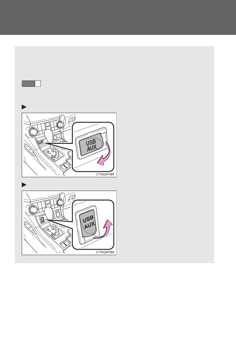
330
3-2. Using the audio system
Operating an iPod
: If equipped
Connecting an iPod enables you to enjoy music from the vehicle
speakers.
■Connecting an iPod
Open the cover and connect an iPod using an iPod cable.
Turn on the power of the iPod if it is not turned on.
STEP
1
Vehicles without seat heater
Vehicles with seat heater
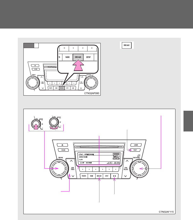
331
3-2. Using the audio system
3
Interior features
Press .
■Control panel
STEP
2
Power Volume Selector knob
Displaying text
messages
Selector buttons
Playback
Playback/pause
Selecting a track/
fast-forwarding
and rewinding
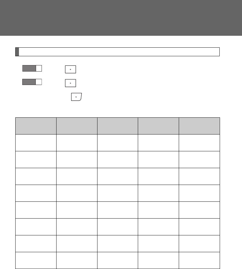
332
3-2. Using the audio system
Selecting a play mode
Press (BROWSE) to select iPod menu mode.
Press that corresponds to the desired play mode.
Pressing (MORE) to change to the second selection list.
■Play mode list
Depending on the model, the name of your iPod may be displayed at
the top of the list.
Play mode First
selection
Second
selection
Third
selection
Fourth
selection
PLIST Playlist
select
Songs
select --
ARTIST Artist select Albums
select
Songs
select -
ALBUM Albums
select
Songs
select --
GENRE Genre select Artists select Albums
select
Songs
select
SONGS Songs
select ---
PODCST Albums
select
Songs
select --
COMPSR Composers
select
Albums
select
Songs
select -
BOOK Songs
select ---
STEP
1
STEP
2
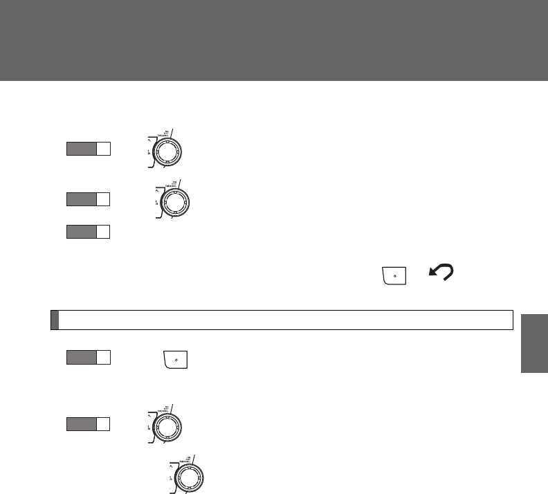
333
3-2. Using the audio system
3
Interior features
■Selecting a list
Turn to display the first selection list.
Press to select the desired item.
Repeat the same procedure to select the desired song name.
To return to the previous selection list, press ( ).
Selecting songs from a song list
Press (LIST).
The current playlist is displayed.
Turn to select the desired song.
Pressing returns the screen from list display to the previous
screen.
STEP
1
STEP
2
STEP
3
STEP
1
STEP
2
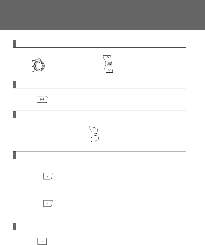
334
3-2. Using the audio system
Selecting songs
Turn or press “” or “” on to select the desired song.
Playing and pausing songs
Press .
Fast-forwarding and rewinding songs
Press and hold “” or “” on .
Shuffle playback
■Playing songs from one playlist or album in random order
Press (RDM).
To cancel, press the button twice.
■Playing songs from all the playlists or albums in random order
Press (RDM) twice.
To cancel, press the button again.
Repeat play
Press (RPT).
To cancel, press the button again.
Even when the repeat play option has not been selected, playback will
automatically continue from the first song in the current play list once the
last song has ended.
335
3-2. Using the audio system
3
Interior features
Switching the display
Press .
Each time is pressed, the display changes in the following order:
Track title Track title/Artist name Track title/Album name Track
title/Elapsed time
■About iPod
●Apple is not responsible for the operation of this device or its compliance
with safety and regulatory standards.
●iPod is a trademark of Apple Inc., registered in the U.S. and other coun-
tries.
■iPod functions
●When an iPod is connected and the audio source is changed to iPod
mode, the iPod will resume play from the same point in which it was last
used.
●Depending on the iPod that is connected to the system, certain functions
may not be available. Disconnecting the device and reconnecting it once
again may resolve some malfunctions.
■iPod problems
To resolve most problems encountered when using your iPod, disconnect
your iPod from the vehicle iPod connection and reset it.
For instructions on how to reset your iPod, refer to your iPod Owner's Man-
ual.
■Error messages
“iPod ERROR”: This indicates a problem in the iPod, inside the
USB box or the connection between them.
“NO SONGS”: This indicates that there is no music data in the
iPod.
“UPDATE YOUR iPod”: This indicates that the version of the iPod is not
compatible.
336
3-2. Using the audio system
■Compatible models
Depending on differences between models or software version etc., some
models listed above might be incompatible with this system.
iPod 4th generation and earlier models are not compatible with this system.
iPhone, iPod mini, iPod shuffle and iPod photo are not compatible with this
system.
Items related to standards and limitations are as follows:
●Maximum number of lists in a device: 9999
●Maximum number of songs in a device: 65025
●Maximum number of songs per list: 65025
CAUTION
■Caution while driving
Do not connect the iPod or operate the controls.
NOTICE
■To prevent damage to iPod
●Do not leave the iPod in the vehicle. The temperature inside may become
high, resulting in damage to the player.
●Do not push down on or apply unnecessary pressure to the iPod while it is
connected as this may damage the iPod or its terminal.
●Do not insert foreign objects into the port as this may damage the iPod or
its terminal.
Model Generation Software version
iPod 5th generation Ver. 1.2.0 or higher
iPod nano 1st generation Ver. 1.3.0 or higher
2nd generation Ver. 1.1.2 or higher
3rd generation Ver. 1.0.0 or higher
iPod touch 1st generation Ver. 1.1.0 or higher
iPod classic 1st generation Ver. 1.0.0 or higher
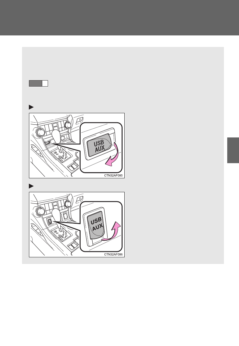
337
3-2. Using the audio system
3
Interior features
Operating a USB memory
Connecting a USB memory enables you to enjoy music from the
vehicle speakers.
■Connecting a USB memory
Open the cover and connect a USB memory.
Turn on the power of the USB memory if it is not turned on.
STEP
1
Vehicles without seat heater
Vehicles with seat heater
: If equipped
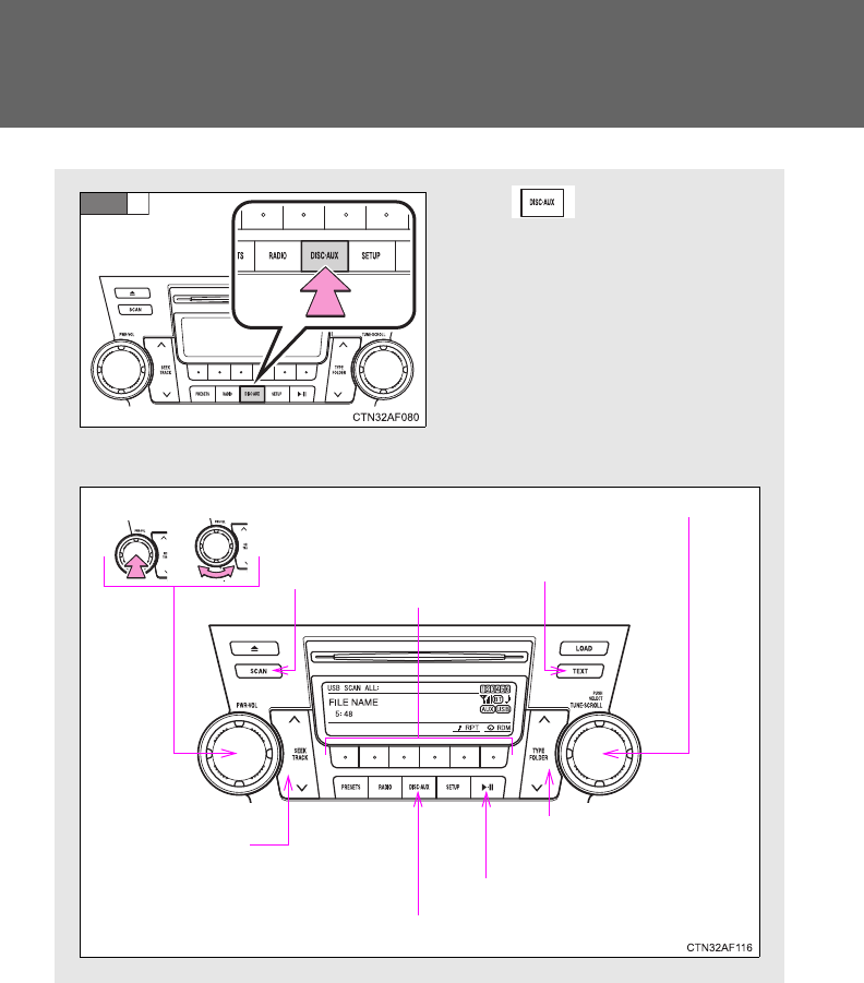
338
3-2. Using the audio system
Press .
■Control panel
STEP
2
Power Volume Selector knob
Displaying text
messages
Playback
Playback/pause
Searching
playback
Selector buttons
Selecting a
folder and file
Selecting a track/
fast-forwarding
and rewinding
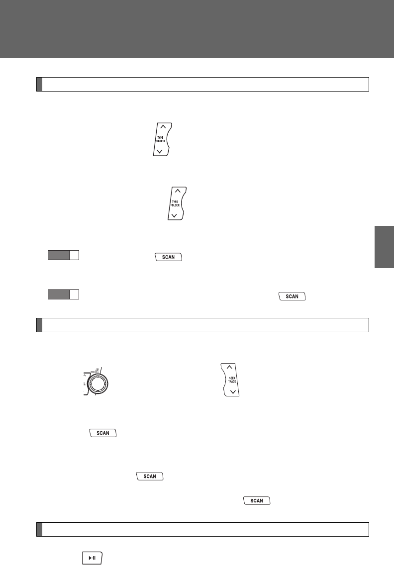
339
3-2. Using the audio system
3
Interior features
Selecting and scanning a folder
■Selecting a folder
Press “” or “” on to select the desired folder.
■Returning to the first file of the first folder
Press and hold “” on until you hear a beep.
■Scanning the first file of all the folders
Press and hold until you hear a beep.
The first ten seconds of the first file in each folder will be played.
When the desired folder is reached, press again.
Selecting and scanning files
■Selecting a file
Turn or press “” or “” on to select the desired file.
■Scanning the files in a folder
Press .
The first ten seconds of each file will be played.
To cancel, press again.
When the desired file is reached, press again.
Playing and pausing files
Press .
STEP
1
STEP
2
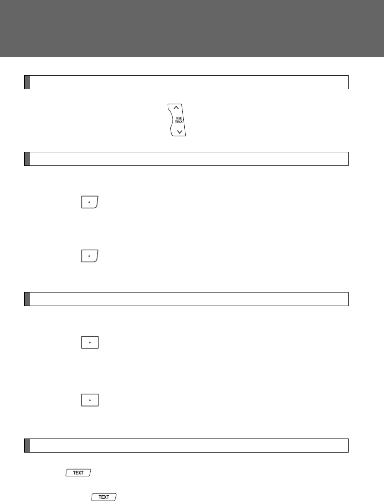
340
3-2. Using the audio system
Fast-forwarding and rewinding files
Press and hold “” or “” on .
Random playback
■Playing files from a folder in random order
Press (RDM).
To cancel, press the button twice.
■Playing all the files from a USB memory in random order
Press (RDM) twice.
To cancel, press the button again.
Repeat play
■Repeating a file
Press (RPT).
To cancel, press the button twice.
■Repeating all the files in a folder
Press (RPT) twice.
To cancel, press the button again.
Switching the display
Press .
Each time is pressed, the display changes in the following order:
Track title Track title/Artist name Track title/Album name Track
title/Elapsed time

341
3-2. Using the audio system
3
Interior features
■USB memory functions
Depending on the USB memory that is connected to the system, certain
functions may not be available. Disconnecting the device and reconnecting it
once again may resolve some malfunctions.
■Error messages
“USB ERROR”: This indicates a problem either in the USB memory or
inside the USB box or connection between them.
“NO SUPPORT”: This indicates that no MP3/WMA files are included in the
USB memory.
■USB memory
●Compatible device
USB memory that can be used for MP3 and WMA playback.
Depending on the type of USB device, playback may not be possible.
●Compatible device formats
The following device formats can be used:
• USB communication formats: USB2.0 FS (12 mbps)
• File formats: FAT16/32 (Windows)
• Correspondence class: Mass storage class
MP3 and WMA files written in any format other than those listed above
may not play correctly, and their file names and folder names may not
be displayed correctly.
Items related to standards and limitations are as follows:
• Maximum directory hierarchy: 8 levels
• Maximum number of folder in device: 999 (including the root)
• Maximum number of files in device: 65025
• Maximum number of files per folder: 255

342
3-2. Using the audio system
●MP3 and WMA files
MP3 (MPEG Audio LAYER 3) is a standard audio compression format.
Files can be compressed to approximately 1/10 of their original size using
MP3 compression.
WMA (Windows Media Audio) is a Microsoft audio compression format.
This format compresses audio data to a size smaller than that of the MP3
format.
There is a limit to the MP3 and WMA file standards that can be used and to
the media/formats on which the files are recorded.
●MP3 file compatibility
• Compatible standards
MP3 (MPEG1 AUDIO LAYERII, III, MPEG2 AUDIO LAYERII, III,
MPEG2.5)
• Compatible sampling frequencies
MPEG1 AUDIO LAYERII, III: 32, 44.1, 48 (kHz)
MPEG2 AUDIO LAYERII, III: 16, 22.05, 24 (kHz)
MPEG2.5: 8, 11.025, 12 (kHz)
• Compatible bit rates (compatible with VBR)
MPEG1 AUDIO LAYERII, III: 32-320 (kbps)
MPEG2 AUDIO LAYERII, III: 32-160 (kbps)
MPEG2.5: 32-160 (kbps)
• Compatible channel modes: stereo, joint stereo, dual channel and
monaural
●WMA file compatibility
• Compatible standards
WMA Ver. 9
• Compatible sampling frequencies
HIGH PROFILE 32, 44.1, 48 (kHz)
• Compatible bit rates
HIGH PROFILE 32-320 (kbps, VBR)
●File names
The only files that can be recognized as MP3/WMA and played are those
with the extension .mp3 or .wma.

343
3-2. Using the audio system
3
Interior features
●ID3 and WMA tags
ID3 tags can be added to MP3 files, making it possible to record the track
title, artist name, etc.
The system is compatible with ID3 Ver. 1.0, 1.1, and Ver. 2.2, 2.3, 2.4 ID3
tags. (The number of characters is based on ID3 Ver. 1.0 and 1.1.)
WMA tags can be added to WMA files, making it possible to record the
track title and artist name in the same way as with ID3 tags.
●MP3 and WMA playback
When a device containing MP3 or WMA files is plugged in, all files in the
USB memory device are first checked. Once the file check is finished, the
first MP3 or WMA file is played. To make the file check finish more quickly,
we recommend you do not write in any files other than MP3 or WMA files
or create any unnecessary folders.
●Extensions
If the file extensions .mp3 and .wma are used for files other than MP3 and
WMA files, they will be mistakenly recognized and played as MP3 and
WMA files. This may result in large amounts of interference and damage
to the speakers.
●Playback
• To play MP3 files with steady sound quality, we recommend a fixed bit
rate of at least 128 kbps and a sampling frequency of 44.1 kHz.
• There is a wide variety of freeware and other encoding software for
MP3 and WMA files on the market, and depending on the status of the
encoding and the file format, poor sound quality or noise at the start of
playback may result. In some cases, playback may not be possible at
all.
• Microsoft, Windows, and Windows Media are the registered trade-
marks of Microsoft Corporation in the U.S.A. and other countries.
CAUTION
■Caution while driving
Do not use a USB memory, or connect a USB memory.

344
3-2. Using the audio system
NOTICE
■To prevent damage to a USB memory
●Do not leave a USB memory in the vehicle. The temperature inside may
become high, resulting in damage to the player.
●Do not push down on or apply unnecessary pressure to the USB memory
while it is connected as this may damage the USB memory or its terminal.
●Do not insert foreign objects into the port as this may damage the USB
memory or its terminal.
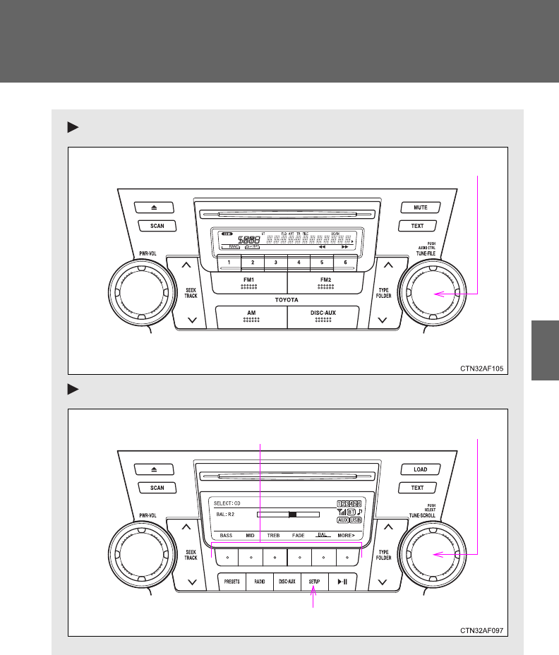
345
3-2. Using the audio system
3
Interior features
Optimal use of the audio system
Type A
Type B and C
Adjusting the sound quality and ASL
Adjusting the sound quality and ASL
Selector buttons
Menu button
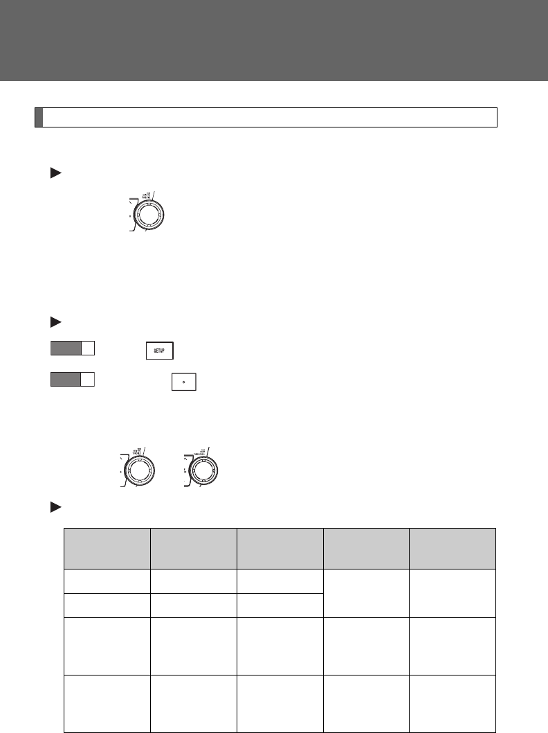
346
3-2. Using the audio system
Using the audio control function
■Changing sound quality modes
Type A
Pressing selects the mode to be changed in the following
order.
“BAS”“TRE”“FAD”“BAL”“ASL”“RSE”*
*: Vehicles with rear seat entertainment system
Type B and C
Press .
Press the that corresponds to the desired mode.
“BASS”, “MID” (type C only), “TREB”, “FADE”, or “BAL”
■Adjusting sound quality
Turning or adjusts the level.
Type A
*: The sound quality level is adjusted individually in each radio mode or
CD mode.
STEP
1
STEP
2
Mode
displayed
Sound qual-
ity mode Level Turn to the
left
Turn to the
right
BAS Bass* -5 to 5 Low High
TRE Treble* -5 to 5
FAD
Front/rear
volume
balance
R7 to F7 Shifts to rear Shifts to
front
BAL
Left/right
volume
balance
L7 to R7 Shifts to left Shifts to right

347
3-2. Using the audio system
3
Interior features
Type B and C
*: The sound quality level is adjusted individually in each audio
mode.
■Adjusting the Automatic Sound Levelizer (ASL)
Type A
When “ASL” is selected, turning to the right changes the
amount of “ASL” in the order of “LOW”, “MID” and “HIGH”.
Turning to the left turns “ASL” off.
ASL automatically adjusts the volume and tone quality according to vehi-
cle speed.
Mode
displayed
Sound qual-
ity mode Level Turn to the
left
Turn to the
right
BASS Bass* -5 to 5
Low HighMID Mid-range*
(type C only) -5 to 5
TREB Treble* -5 to 5
FADE
Front/rear
volume
balance
F7 to R7 Shifts to rear Shifts to
front
BAL
Left/right
volume
balance
L7 to R7 Shifts to left Shifts to right
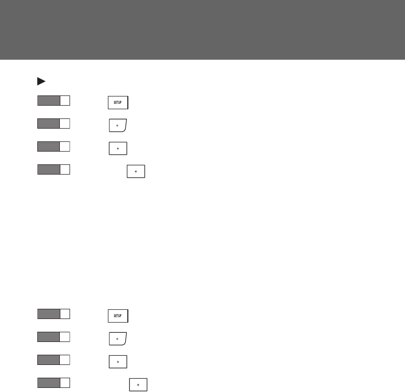
348
3-2. Using the audio system
Type B and C
Press .
Press (MORE).
Press (ASL).
Press the that corresponds to the desired mode.
Type B: “LOW”, “MID”, “HIGH”, or “OFF”
Type C: “ON” or “OFF”
ASL automatically adjusts the volume and tone quality according
to vehicle speed.
■Setting the number of preset pages (type B and C)
The number of preset pages desired can be set from 1 to 6. The initial
setting is 6 pages.
Press .
Press (MORE).
Press (PRESET).
Press the that corresponds to the desired number of
preset pages.
■Language settings (type B and C)
P. 3 0 2
STEP
1
STEP
2
STEP
3
STEP
4
STEP
1
STEP
2
STEP
3
STEP
4
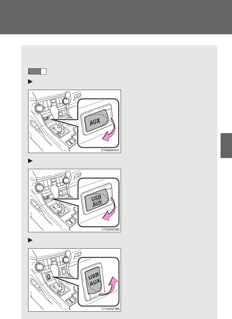
349
3-2. Using the audio system
3
Interior features
Using the AUX port
This port can be used to connect a portable audio device and listen
to it through the vehicle’s speakers.
Open the cover and connect the portable audio device.
Vehicles without seat heater (type A)
Vehicles without seat heater (type B and C)
Vehicles with seat heater
STEP
1

350
3-2. Using the audio system
■Operating portable audio devices connected to the audio system
The volume can be adjusted using the vehicle's audio controls. All other
adjustments must be made on the portable audio device itself.
■When using a portable audio device connected to the power outlet
Noise may occur during playback. Use the power source of the portable
audio device.
Type A
Press .
Type B and C
Press .
STEP
2
STEP
2
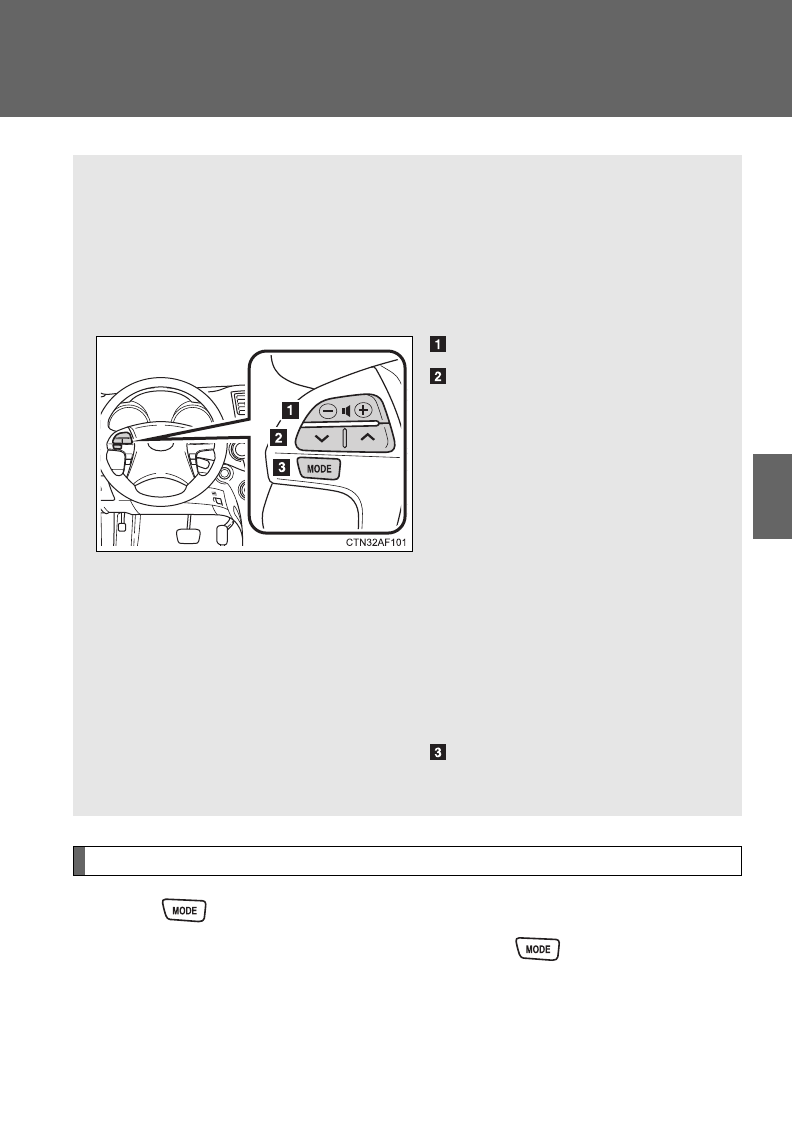
351
3-2. Using the audio system
3
Interior features
Using the steering wheel audio switches
Turning on the power
Press when the audio system is turned off.
The audio system can be turned off by holding down until you hear
a beep.
: If equipped
Some audio features can be controlled using the switches on the
steering wheel.
Operation may differ depending on the type of audio system or navi-
gation system. For details, refer to the manual provided with the
audio system or navigation system.
Volume
Radio mode: Selects radio
stations
CD mode: Selects tracks,
files (MP3 and WMA) and
discs (type C only)
iPod mode: Selects songs
USB memory mode:
Selects files and fold-
ers
Bluetooth® audio mode:
Selects tracks and
albums
Turns the power on, selects
audio source
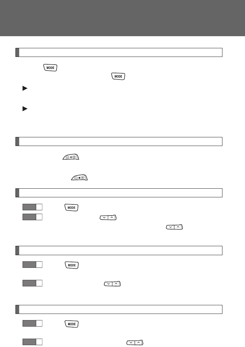
352
3-2. Using the audio system
Changing the audio source
Press when the audio system is turned on. The audio source
changes as follows each time is pressed.
Type A
FMCDAUXAM
Type B and C
FMSATCD (type B only)CD changer (with a CD changer)
Bluetooth® AudioAUXUSB/iPodAM
Adjusting the volume
Press “+” on to increase the volume and “-” to decrease the
volume.
Press and hold to continue increasing or decreasing the volume.
Selecting a radio station
Press to select radio mode.
Press “” or “” on to select a preset station.
To scan for receivable stations, press and hold until you hear
a beep.
Selecting a track/file or song
Press to select CD, iPod, USB memory or Bluetooth®
audio mode.
Press “” or “” on to select the desired track/file or
song.
Selecting a folder or album
Press to select CD, USB memory or Bluetooth® audio
mode.
Press and hold “” or “” on until you hear a beep.
STEP
1
STEP
2
STEP
1
STEP
2
STEP
1
STEP
2
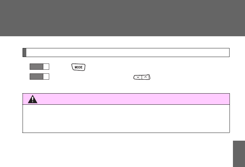
353
3-2. Using the audio system
3
Interior features
Selecting a disc in the CD player (CD player with changer only)
Press to select CD mode.
Press and hold “” or “” on until you hear a beep.
CAUTION
■To reduce the risk of an accident
Exercise care when operating the audio switches on the steering wheel.
STEP
1
STEP
2
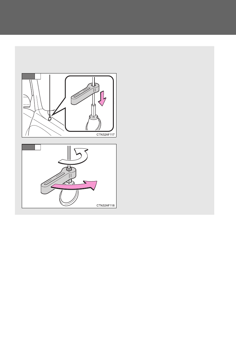
354
3-2. Using the audio system
Detachable pole antenna
: If equipped
The antenna can be removed.
■Removing the antenna
Place the included wrench
around the antenna.
When not in use, the wrench is
stored in glove box.
Loosen the antenna with the
wrench and remove it.
STEP
1
STEP
2
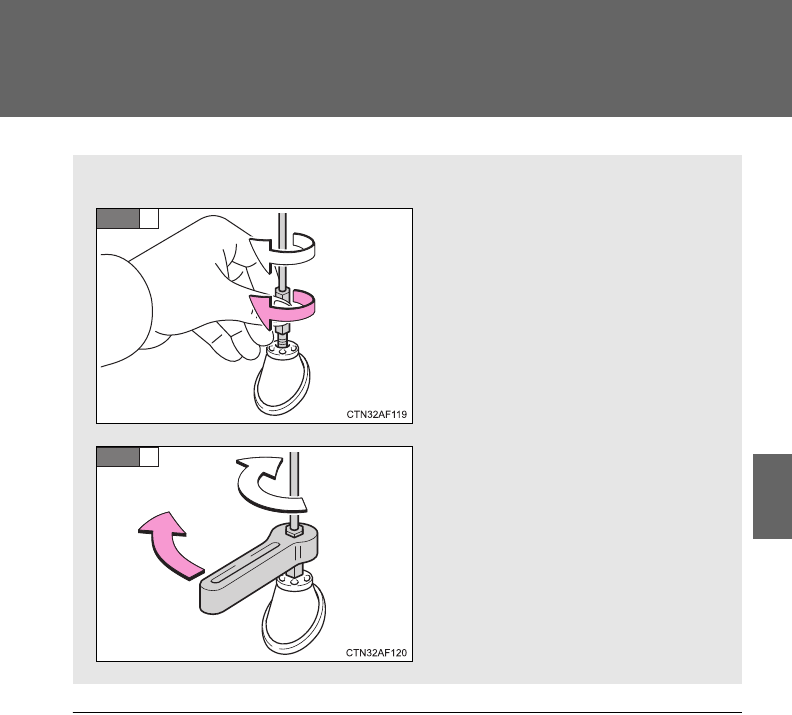
355
3-2. Using the audio system
3
Interior features
■About the wrench
After using the included wrench, store it in the glove box for safekeeping.
■Installing the antenna
Tighten the antenna by one
hand until it will not turn any
more.
Using the wrench, tighten the
antenna an additional 1/8th
turn (20 to 45 degrees) to
secure it in place.
After tightening the antenna,
remove the wrench.
STEP
1
STEP
2

356
3-2. Using the audio system
NOTICE
■To avoid damaging the antenna
Remove the antenna in the following situations.
●When using an automatic carwash.
●When the antenna will touch the ceiling of a garage, etc.
●When covering the vehicle with a car cover.
■Removing the antenna
●For normal driving, make sure the antenna is installed.
●When removing the antenna to use an automatic carwash, etc., be careful
not to lose the antenna. Also, make sure to reinstall the antenna before
driving the vehicle.
■Using the wrench
●When installing or removing the antenna, use the included wrench.
●Be careful not to scratch or damage the vehicle body with the wrench.
●Do not over-tighten the antenna.
Over-tightening may damage the antenna.
●Do not use any tools other than the included wrench to install or remove
the antenna.
Otherwise damage may result on the antenna’s finish.
357
3
Interior features
3-3. Using the Bluetooth® audio system
Bluetooth® audio system
: If equipped
With Display Audio system
Owners of models equipped with a Display Audio system should
refer to the “Display Audio System Owner’s Manual”.
With navigation system
Owners of models equipped with a navigation system should refer to
the “Navigation System Owner’s Manual”.
Without navigation system or Display Audio system
The Bluetooth® audio system enables you to enjoy music played on
a portable digital audio player (portable player) from the vehicle
speakers via wireless communication.
This audio system supports Bluetooth®, a wireless data system
capable of playing portable audio music without cables. If your por-
table player does not support Bluetooth®, the Bluetooth® audio sys-
tem will not function.
Title Page
Using the Bluetooth® audio system P. 360
Operating a Bluetooth® enabled portable player P. 365
Setting up a Bluetooth® enabled portable player P. 367
Bluetooth® audio system setup P. 372

358
3-3. Using the Bluetooth® audio system
■Conditions under which the system will not operate
●If using a portable player that does not support Bluetooth®
●If the portable player is switched off
●If the portable player is not connected
●If the portable player’s battery is low
●If the portable player is behind the seat or in the glove box or console box
●If metal is covering or touching the portable player
■When transferring ownership of the vehicle
Be sure to initialize the system to prevent personal data from being improp-
erly accessed. (P. 397)
■About Bluetooth®
■Compatible models
●Bluetooth® specifications:
Ver. 1.2
●Following Profiles:
• A2DP (Advanced Audio Distribution Profile) Ver. 1.0
• AVRCP (Audio/Video Remote Control Profile) Ver. 1.0 or higher (Ver.
1.3 or higher recommended)
Portable players must correspond to the above specifications in order to be
connected to the Bluetooth® audio system. However, please note that some
functions may be limited depending on the type of portable player.
Bluetooth is a registered trademark of
Bluetooth SIG. Inc.
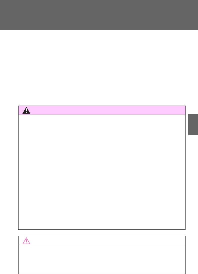
359
3-3. Using the Bluetooth® audio system
3
Interior features
■Certification for the Bluetooth® audio system
FCC ID: ACJ932C5ZZZ035
IC ID: 216J-C5ZZZ035
MADE IN JAPAN
This device complies with Part 15 of the FCC Rules and RSS-Gen of IC
Rules. Operation is subject to the following two conditions: (1) this device
may not cause harmful interference, and (2) this device must accept any
interference received, including interference that may cause undesired oper-
ation.
CAUTION
■FCC WARNING
Changes or modifications not expressly approved by the party responsible
for compliance could void the user's authority to operate the equipment.
Radio Frequency Radiation Exposure. This equipment complies with FCC/
IC radiation exposure limits set forth for uncontrolled equipment and meets
the FCC radio frequency (RF) Exposure Guidelines in Supplement C to
OET65 and RSS-102 of the IC radio frequency (RF) Exposure rules. This
equipment has very low levels of RF energy that it deemed to comply with-
out maximum permissive exposure evaluation (MPE). But it is desirable that
it should be installed and operated with at least 7.9 in. (20 cm) and more
between the radiator and person’s body (excluding extremities: hands,
wrists, feet and ankles).
This transmitter must not be co-located or operated in conjunction with any
other antenna or transmitter.
■Caution while driving
Do not connect portable players or operate the controls.
NOTICE
■To prevent damage to portable players
Do not leave portable players in the vehicle. The temperature inside the
vehicle may become high, resulting in damage to the player.
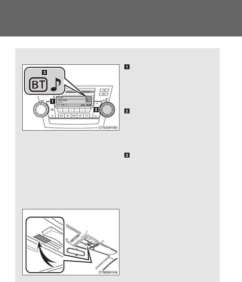
360
3-3. Using the Bluetooth® audio system
Using the Bluetooth® audio system
■Audio unit
Display
Track title, Artist name,
Album name, Elapsed time,
“Streaming Audio”, etc. is
displayed.
Selects items such as menu
and number
Turn: Selects an item
Press: Inputs the selected
item
Bluetooth-Audio connec-
tion condition
If “BT” is not displayed, the
Bluetooth® audio system
cannot be used.
■Microphone
361
3-3. Using the Bluetooth® audio system
3
Interior features
Operating the system using voice commands
By following voice guidance instructions output from the speaker,
voice commands enable the operation of the Bluetooth® audio sys-
tem without the need to check the display or operate .
■Operation procedure when using voice commands
Press the talk switch and follow voice guidance instructions.
■Auxiliary commands when using voice commands
The following auxiliary commands can be used when operating the
system using a voice command:
“Cancel”: Exits the Bluetooth® audio setup
“Repeat”: Repeats the previous voice guidance instruction
“Go back”: Returns to the previous procedure
“Help”: Reads aloud the function summary if a help comment is
registered for the selected function
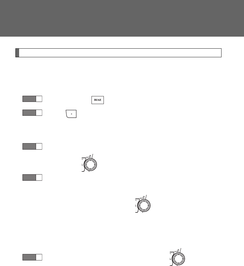
362
3-3. Using the Bluetooth® audio system
Using the Bluetooth® audio system for the first time
Before using the Bluetooth® audio system, it is necessary to register
a Bluetooth® enabled portable player in the system. Follow the proce-
dure below to register (pair) a portable player:
Press and hold until “BT AUDIO” is displayed.
Press (SETUP).
The introductory guidance and portable player name registration
instructions are heard.
Select “Pair Audio Players (Pair audio player)” using a voice
command or .
Register a portable player name by either of the following
methods:
a. Select “Record Name” using , and say the name to
be registered.
b. Press the talk switch and say the name to be registered.
A voice guidance instruction to confirm the input is heard.
Select “Confirm” using a voice command or .
A passkey is displayed and heard, and a voice guidance instruction
for inputting the passkey into the portable player is heard.
STEP
1
STEP
2
STEP
3
STEP
4
STEP
5
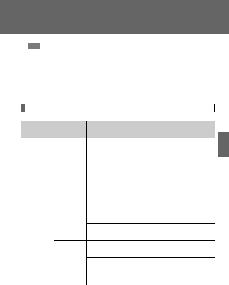
363
3-3. Using the Bluetooth® audio system
3
Interior features
Input the passkey into the portable player.
Refer to the manual that comes with the portable player for the oper-
ation of the portable player.
Guidance for registration completion is heard.
If the portable player has a Bluetooth® phone, the phone can be reg-
istered at the same time. (P. 380)
Menu list of the Bluetooth® audio system
“BT Audio Setup” can be canceled by pressing the on-hook switch or
saying the voice command, “Cancel”.
First menu Second
menu Third menu Operation details
Setup
(Setup)
BT Audio
Setup
(BT audio
setup)
Pair Audio
Players (Pair
audio player)
Registering a portable player
Select Audio
Player
Selecting a portable player to
be used
Change Name Changing the registered
name of a portable player
List Audio
Players
Listing the registered porta-
ble players
Set Passkey Changing the passkey
Delete Audio
Player
Deleting a registered porta-
ble player
System
Setup
Guidance Vol-
ume
Setting voice guidance vol-
ume
Device Name Displaying the Bluetooth®
device address and name
Reset Setting Initializing the system
STEP
6

364
3-3. Using the Bluetooth® audio system
■When using a voice command
For numbers, say a combination of single digits from zero to nine.
Say the command correctly and clearly.
■Situations where the system may not recognize your voice
●When driving on rough roads
●When driving at high speeds
●When air is blowing out of the vents onto the microphone
●When the air conditioning fan emits a loud noise
■Operations that cannot be performed while driving
●Operating the system with
●Registering a portable player to the system
■Changing the passkey
P. 370
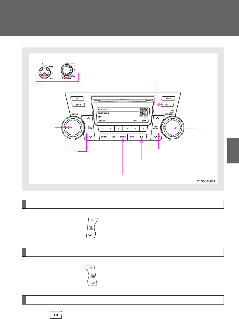
365
3-3. Using the Bluetooth® audio system
3
Interior features
Operating a Bluetooth
®
enabled portable player
Selecting an album
Press “” or “” on .
Selecting tracks
Press “” or “” on .
Playing and pausing tracks
Press .
VolumePower
Playback/pause
Displaying text
messages
Selector knob
Selecting tracks
Fast-forwarding
and reversing
Playback
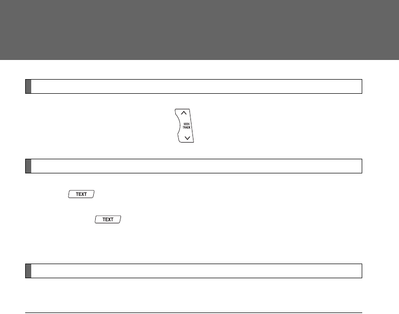
366
3-3. Using the Bluetooth® audio system
Fast-forwarding and reversing tracks
Press and hold “” or “” on .
Switching the display
Press .
Each time is pressed, the display changes in the following order:
Track title Track title/Artist name Track title/Album name Track
title/Elapsed time
Using the steering wheel audio switches
P. 3 5 1
■Bluetooth® audio system functions
Depending on the portable player that is connected to the system, certain
functions may not be available.
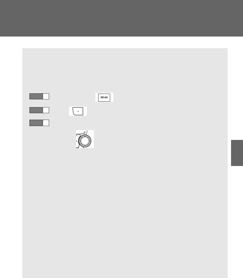
367
3-3. Using the Bluetooth® audio system
3
Interior features
Setting up a Bluetooth
®
enabled portable player
Registering a portable player in the Bluetooth® audio system allows
the system to function. The following functions can be used for reg-
istered portable players:
■Functions and operation procedures
Press and hold until “BT AUDIO” is displayed.
Press (SETUP).
Select one of the following functions using a voice com-
mand or .
●Registering a portable player
“Pair Audio Players (Pair audio player)”
●Selecting a portable player to be used
“Select Audio Player”
●Changing the registered name of a portable player
“Change Name”
●Listing the registered portable players
“List Audio Players”
●Changing the passkey
“Set Passkey”
●Deleting a registered portable player
“Delete Audio Player”
STEP
1
STEP
2
STEP
3
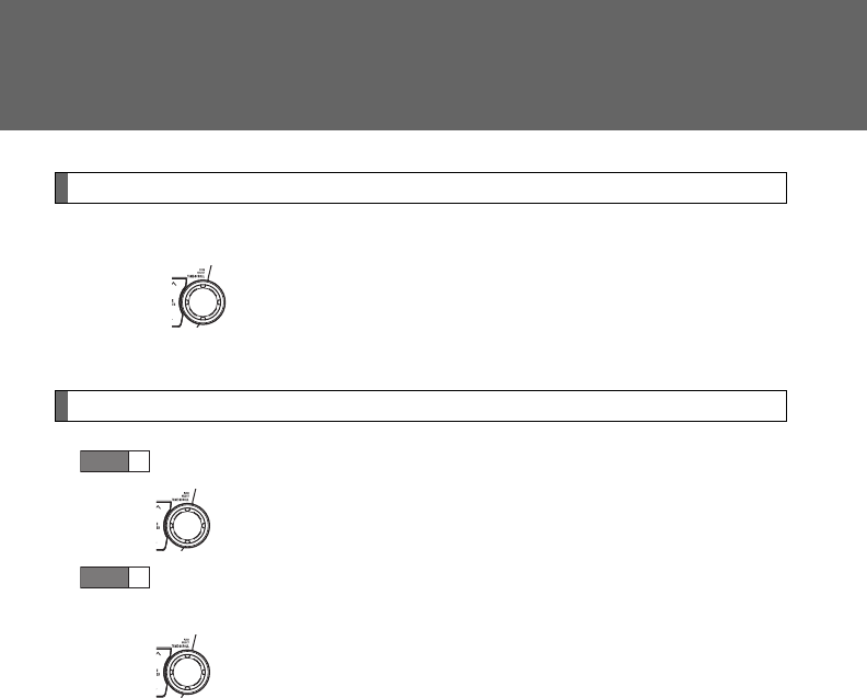
368
3-3. Using the Bluetooth® audio system
Registering a portable player
Select “Pair Audio Players (Pair audio player)” using a voice com-
mand or , and perform the procedure for registering a portable
player. (P. 362)
Selecting a portable player to be used
Select “Select Audio Player” using a voice command or
.
Select the portable player to be used by either of the following
methods, and select “Confirm” using a voice command or
:
a. Press the talk switch and say the name of the desired por-
table player.
b. Press the talk switch and say “List audio players”. When the
name of the desired portable player is read aloud, press the
talk switch.
STEP
1
STEP
2
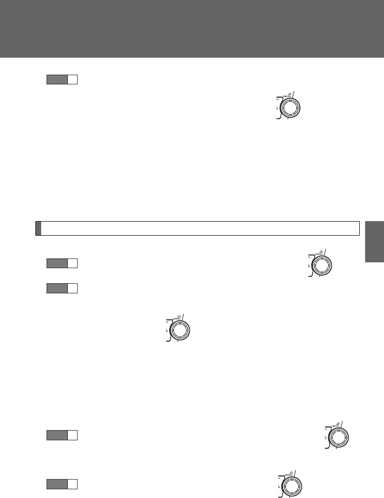
369
3-3. Using the Bluetooth® audio system
3
Interior features
Press the talk switch and say “From car” or “From audio”, and
select “Confirm” using a voice command or .
Vehicles with smart key system: If “From car” is selected, the porta-
ble player will be automatically connected whenever the “ENGINE
START STOP” switch is in either ACCESSORY or IGNITION ON
mode.
Vehicles without smart key system: If “From car” is selected, the por-
table player will be automatically connected whenever the engine
switch is in either the “ACC” or “ON” position.
Changing the registered name of a portable player
Select “Change Name” using a voice command or .
Select the name of the portable player to be changed by
either of the following methods, and select “Confirm” using a
voice command or :
a. Press the talk switch and say the name of the desired por-
table player.
b. Press the talk switch and say “List audio players”. When the
name of the desired portable player is read aloud, press the
talk switch.
Press the talk switch or select “Record Name” using ,
and say the new name.
Select “Confirm” using a voice command or .
STEP
3
STEP
1
STEP
2
STEP
3
STEP
4
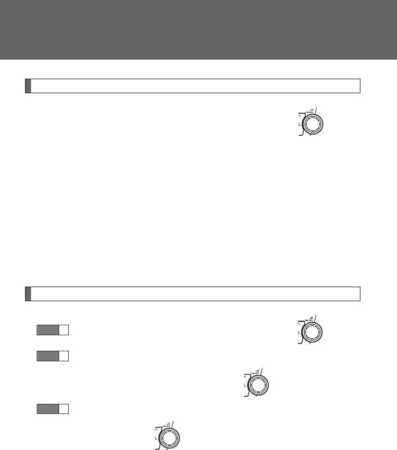
370
3-3. Using the Bluetooth® audio system
Listing the registered portable players
Select “List Audio Players” using a voice command or . The
list of registered portable players will be read aloud.
When listing is complete, the system returns to “BT Audio Setup”.
Pressing the talk switch while the name of a portable player is being
read aloud selects the portable player, and the following functions will
become available:
●Selecting a portable player: “Select Audio Player”
●Changing a registered name: “Change Name”
●Deleting a portable player: “Delete Audio Player”
Changing the passkey
Select “Set Passkey” using a voice command or .
Press the talk switch, say a 4 to 8-digit number, and select
“Confirm” using a voice command or .
When the entire number to be registered as a passkey has
been input, press again.
STEP
1
STEP
2
STEP
3
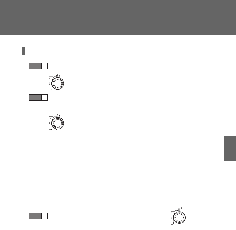
371
3-3. Using the Bluetooth® audio system
3
Interior features
Deleting a registered portable player
Select “Delete Audio Player” using a voice command or
.
Select the portable player to be deleted by either of the follow-
ing methods and select “Confirm” using a voice command or
:
a. Press the talk switch and say the name of the desired por-
table player.
b. Press the talk switch and say “List audio players”. When the
name of the desired portable player is read aloud, press the
talk switch.
If the portable player to be deleted is paired as a Bluetooth® phone,
the registration of the mobile phone can be deleted at the same time.
A voice guidance instruction to delete a mobile phone is heard.
Select “Confirm” using a voice command or .
■The number of portable players that can be registered
Up to 2 portable players can be registered in the system.
STEP
1
STEP
2
STEP
3


373
3
Interior features
3-4. Using the hands-free phone system (for cellular phone)
Hands-free phone system (for cellular phone) features
With Display Audio system
Owners of models equipped with a Display Audio system should
refer to the “Display Audio System Owner’s Manual”.
With navigation system
Owners of models equipped with a navigation system should refer to
the “Navigation System Owner’s Manual”.
Without navigation system or Display Audio system
This system supports Bluetooth®, which allows you to make or
receive calls without using cables to connect a cellular phone and
the system, and without operating the cellular phone.
■Hands-free system quick guide
Setting a cellular phone. (P. 377)
Adding an entry to the phonebook (Up to 20 names can be
stored). (P. 399)
Dialing by inputting a name. (P. 387)
STEP
1
STEP
2
STEP
3
: If equipped

374
3-4. Using the hands-free phone system (for cellular phone)
Title Page
Using the hands-free phone system
■Operating the system using a voice
command
■Using the hands-free phone system for
the first time
■Menu list of the hands-free phone
system
P. 377
Making a phone call
■Dialing by inputting a number
■Dialing by inputting a name
■Speed dialing
■When receiving a phone call
■Transferring a phone call
■Using the call history
P. 386
Setting a cellular phone
■Registering a cellular phone
■Selecting a cellular phone to be used
■Changing a registered name
■Listing the registered cellular phones
■Deleting a cellular phone
■Changing the passkey
■Turning the hands-free phone
automatic connection on/off
P. 390
Security and system setup
■Setting or changing the PIN
■Locking or unlocking the phone book
■Setting voice guidance volume
■Initialization
P. 395
Using the phone book
■Adding a new phone number
■Setting speed dials
■Changing a registered name
■Deleting registered data
■Deleting speed dials
■Listing the registered data
P. 399

375
3-4. Using the hands-free phone system (for cellular phone)
3
Interior features
■Conditions under which the system will not operate
●If using a cellular phone that does not support Bluetooth®
●If the cellular phone is switched off
●If you are outside service range
●If the cellular phone is not connected
●If the cellular phone's battery is low
●If the cellular phone is behind the seat or in the glove box or console box
●If metal is covering or touching the cellular phone
■When transferring ownership of the vehicle
Be sure to initialize the system to prevent personal data from being improp-
erly accessed.
■Required profiles for the cellular phone
●HFP (Hands Free Profile) Ver. 1.0
●OPP (Object Push Profile) Ver. 1.1
■About Bluetooth®
■Certification for the hands-free phone system
FCC ID: ACJ932C5ZZZ035
IC ID: 216J-C5ZZZ035
MADE IN JAPAN
This device complies with Part 15 of the FCC Rules and RSS-Gen of IC
Rules. Operation is subject to the following two conditions: (1) this device
may not cause harmful interference, and (2) this device must accept any
interference received, including interference that may cause undesired oper-
ation.
Bluetooth is a registered trademark of
Bluetooth SIG. Inc.
376
3-4. Using the hands-free phone system (for cellular phone)
CAUTION
■FCC WARNING
Changes or modifications not expressly approved by the party responsible
for compliance could void the user's authority to operate the equipment.
Radio Frequency Radiation Exposure. This equipment complies with FCC/
IC radiation exposure limits set forth for uncontrolled equipment and meets
the FCC radio frequency (RF) Exposure Guidelines in Supplement C to
OET65 and RSS-102 of the IC radio frequency (RF) Exposure rules. This
equipment has very low levels of RF energy that it deemed to comply with-
out maximum permissive exposure evaluation (MPE). But it is desirable that
it should be installed and operated with at least 7.9 in. (20 cm) and more
between the radiator and person’s body (excluding extremities: hands,
wrists, feet and ankles).
This transmitter must not be co-located or operated in conjunction with any
other antenna or transmitter.
■Caution while driving
Do not use a cellular phone, or connect the Bluetooth® phone.
NOTICE
■To prevent damage to a cellular phone
Do not leave a cellular phone in the vehicle. The temperature inside may
become high resulting in damage to the phone.

377
3-4. Using the hands-free phone system (for cellular phone)
3
Interior features
Using the hands-free phone system
■Audio unit
Display
A message, name, phone
number, etc. is displayed.
Lower-case characters and
special characters, such as
an umlaut, cannot be dis-
played.
Selects speed dials
Selects items such as menu
or number
Turn: Selects an item
Press: Inputs the selected
item
Bluetooth® connection con-
dition and reception level
If “BT” is not displayed, the
hands-free phone system
cannot be used.
: If equipped
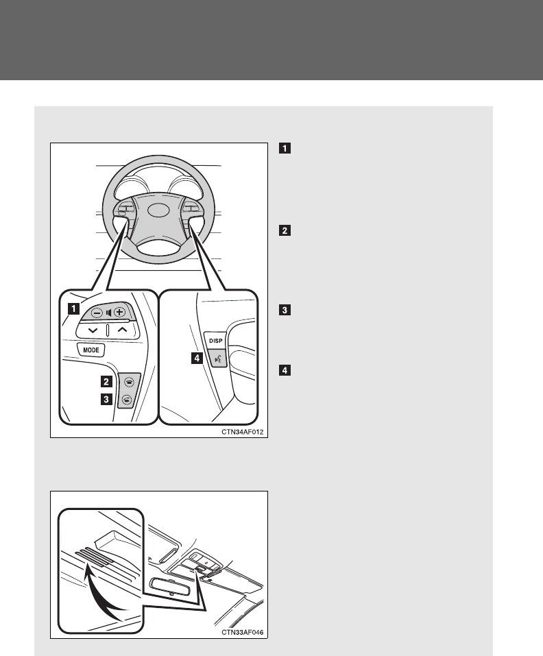
378
3-4. Using the hands-free phone system (for cellular phone)
■Steering wheel telephone switches
Volume
The voice guidance volume
cannot be adjusted by using
this switch.
On-hook switch
Turns the hands-free sys-
tem off/ends a call/refuses a
call
Off-hook switch
Turns the hands-free sys-
tem on/starts a call
Talk switch
Turns the voice command
system on (press)/turns the
voice command system off
(press and hold)
■Microphone

379
3-4. Using the hands-free phone system (for cellular phone)
3
Interior features
Operating the system using a voice command
By following voice guidance instructions output from the speaker,
voice commands enable the operation of the hands-free phone sys-
tem without the need to check the display or operate .
■Operation procedure when using a voice command
Press the talk switch and follow voice guidance instructions.
■Auxiliary commands when using a voice command
The following auxiliary commands can be used when operating the
system using a voice command:
“Cancel”: Exits the hands-free phone system
“Repeat”: Repeats the previous voice guidance instruction
“Go back”: Returns to the previous procedure
“Help”: Reads aloud the function summary if a help comment is
registered for the selected function
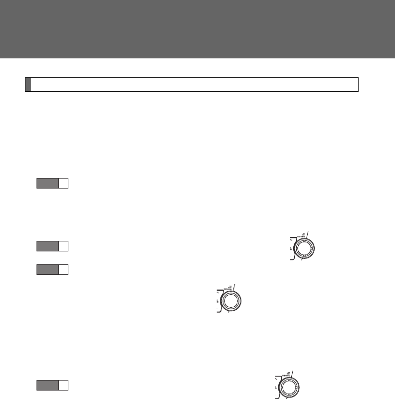
380
3-4. Using the hands-free phone system (for cellular phone)
Using the hands-free phone system for the first time
Before using the hands-free phone system, it is necessary to register
a cellular phone in the system. The phone registration mode will be
entered automatically when starting the system with no cellular
phone registered. Follow the procedure below to register a cellular
phone:
Press the off-hook switch or the talk switch.
The introductory guidance and phone name registration instructions
are heard.
Select “Pair Phone” using a voice command or .
Register a phone name by either of the following methods.
a. Select “Record Name” using , and say a name to be
registered.
b. Press the talk switch and say a name to be registered.
Voice guidance instruction to confirm the input is heard.
Select “Confirm” using a voice command or .
STEP
1
STEP
2
STEP
3
STEP
4
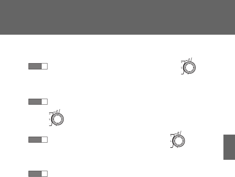
381
3-4. Using the hands-free phone system (for cellular phone)
3
Interior features
Registration to the hands-free phone system only
Select “Phone Only” using a voice command or .
Registration to the hands-free phone system and Bluetooth®
audio system at the same time
Select “Int. Audio (Internal audio)” using a voice command or
.
Select “Confirm” using a voice command or .
A passkey is displayed and heard, and a voice guidance instruction
for inputting the passkey into the cellular phone is heard.
Input the passkey into the cellular phone.
Refer to the manual that comes with the cellular phone for the oper-
ation of the phone.
Guidance for registration completion is heard.
STEP
5
STEP
5
STEP
6
STEP
7

382
3-4. Using the hands-free phone system (for cellular phone)
Menu list of the hands-free phone system
■Normal operation
First menu Second
menu Third menu Operation detail
CallBack
(Call
back)
--
Dialing a number stored in
the incoming call history
Redial - - Dialing a number stored in
the outgoing call history
Dial by
Number - - Dialing by inputting a number
Dial by
Name
(Dial by
name)
--
Dialing by inputting a name
registered in the phone book
Phonebook
Add Entry - Adding a new number
Change
Name -Changing a name in the
phone book
Delete
Entry -Deleting the phone book
data
Delete
Speed
Dial
-Deleting a registered speed
dial
List
Names - Listing the phone book data
Speed
Dial
(Set
speed
dial)
- Registering a speed dial

383
3-4. Using the hands-free phone system (for cellular phone)
3
Interior features
Setup
(Setup)
Security
Set PIN Setting a PIN code
Phonebook Lock
(Phone book
lock)
Locking the phone book
Phonebook
Unlock (Phone
book unlock)
Unlocking the phone book
Phone
Setup
Pair Phone Registering the cellular
phone to be used
Change Phone
Name (Change
name)
Changing the registered
name of a cellular phone
Delete Phone Deleting a registered cellular
phone
List Phones Listing the registered cellular
phones
Select Phone Selecting a cellular phone to
be used
Set Passkey Changing the passkey
Handsfree
Power
Turning the Hands-free
power on/off
System
Setup
Guidance Vol-
ume
Setting voice guidance vol-
ume
Device Name Displaying a device’s infor-
mation
Reset Setting Initialization
First menu Second
menu Third menu Operation detail

384
3-4. Using the hands-free phone system (for cellular phone)
■Using a short cut key
First menu Second menu Operation detail
Dial “XXX (name)” - Dialing a number registered
in the phone book
Dial “XXX (number)” - Dialing the input numbers
Phone book add
entry - Adding a new number
Phone book change
name -
Changing the name of a
phone number in the phone
book
Phone book delete
entry - Deleting phone book data
Phone book set
speed dial - Registering a speed dial
Phone book delete
speed dial - Deleting a speed dial
Phone book List
names - Listing the phone book data

385
3-4. Using the hands-free phone system (for cellular phone)
3
Interior features
■Automatic volume adjustment
When vehicle speed reaches 50 mph (80 km/h) or more, the volume auto-
matically increases. The volume returns to the previous volume setting when
vehicle speed drops to 43 mph (70 km/h) or less.
■When using a voice command
For numbers, say a combination of single digits from zero to nine, # (pound),
(star), and + (plus).
Say the command correctly and clearly.
■Situations that the system may not recognize your voice
●When driving on a rough road
●When driving at high speeds
●When air is blowing out of the vents onto the microphone
●When the air conditioning fan emits a loud noise
■Operations that cannot be performed while driving
●Operating the system with
●Registering a cellular phone to the system
■Changing the passkey
P. 393

386
3-4. Using the hands-free phone system (for cellular phone)
Making a phone call
Dialing by inputting a number
Press the talk switch and say “Dial by number”.
Press the talk switch and say the phone number.
■Making a phone call
●Dialing by inputting a number
“Dial by Number”
●Dialing by inputting a name
“Dial by Name (Dial by name)”
●Speed dialing
●Dialing a number stored in the outgoing history
“Redial”
●Dialing a number stored in the incoming history
“CallBack (Callback)”
■Receiving a phone call
●Answering the phone
●Refusing the call
■Transferring a phone call
■Using the call history
●Dialing
●Storing data in the phone book
●Deleting
STEP
1
STEP
2
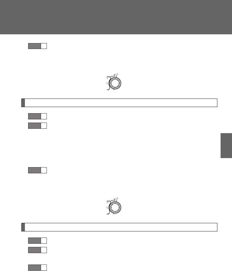
387
3-4. Using the hands-free phone system (for cellular phone)
3
Interior features
Dial by one of the following methods:
a. Press the off-hook switch.
b. Press the talk switch and say “Dial”.
c. Select “Dial” using .
Dialing by inputting a name
Press the talk switch and say “Dial by name”.
Select a registered name to be input by either of the following
methods:
a. Press the talk switch and say a registered name.
b. Press the talk switch and say “List names”. Press the talk
switch while the desired name is being read aloud.
Dial by one of the following methods:
a. Press the off-hook switch.
b. Press the talk switch and say “Dial”.
c. Select “Dial” using .
Speed dialing
Press the off-hook switch.
Press the preset button to which the desired number is regis-
tered.
Press the off-hook switch.
STEP
3
STEP
1
STEP
2
STEP
3
STEP
1
STEP
2
STEP
3

388
3-4. Using the hands-free phone system (for cellular phone)
When receiving a phone call
■Answering a phone call
Press the off-hook switch.
■Refusing a phone call
Press the on-hook switch.
Transferring a phone call
A call can be transferred between the cellular phone and system
while dialing, receiving a call, or during a call. Use one of the follow-
ing methods:
a. Operate the cellular phone.
Refer to the manual that comes with the cellular phone for the oper-
ation of the phone.
b. Press the off-hook switch*1.
c. Press the talk switch and say “Call transfer”*2.
*1: This operation can be performed only when transferring a call
from the cellular phone to the system during a call.
*2: While the vehicle is in motion, a call cannot be transferred from
the system to the cellular phone. Also, this operation is invalid
while dialing or receiving a call.
Using the call history
Follow the procedure below to use a number stored in the call history:
Press the talk switch and say “Redial” (when using a number
stored in the outgoing call history) or “Callback” (when using a
number stored in the incoming call history).
STEP
1
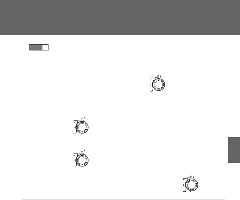
389
3-4. Using the hands-free phone system (for cellular phone)
3
Interior features
Select the number by either of the following methods:
a. Say “Previous” or “Go back” until the desired number is dis-
played.
b. Select the desired number using .
The following operations can be performed:
Dialing: Press the off-hook switch or select “Dial” using a voice
command or .
Storing the number in the phone book: Select “Store” using a voice
command or .
Deleting: Select “Delete” using a voice command or .
■Call history
Up to 5 numbers can be stored in each of the outgoing and incoming call his-
tory memories.
■When talking on the phone
●Do not talk at the same time as the other party.
●Keep the volume of the incoming voice down. Otherwise, voice echo will
increase.
STEP
2

390
3-4. Using the hands-free phone system (for cellular phone)
Setting a cellular phone
Registering a cellular phone
Select “Pair Phone” using a voice command or , and perform
the procedure for registering a cellular phone. (P. 380)
Registering a cellular phone in the hands-free phone system allows
the system to function. The following functions can be used for reg-
istered cellular phones:
■Functions and operation procedures
To enter the menu for each function, follow the steps below using a
voice command or :
●Registering a cellular phone
1. “Setup (Setup)” 2. “Phone Setup” 3. “Pair Phone”
●Selecting the cellular phone to be used
1. “Setup (Setup)” 2. “Phone Setup” 3. “Select Phone”
●Changing a registered name
1. “Setup (Setup)” 2. “Phone Setup” 3. “Change Phone
Name (Change name)”
●Listing the registered cellular phones
1. “Setup (Setup)” 2. “Phone Setup” 3. “List Phones”
●Deleting a cellular phone
1. “Setup (Setup)” 2. “Phone Setup” 3. “Delete Phone”
●Changing the passkey
1. “Setup (Setup)” 2. “Phone Setup” 3. “Set Passkey”
●Turning the hands-free phone automatic connection on/off
1. “Setup (Setup)” 2. “Phone Setup” 3. “Handsfree
Power”
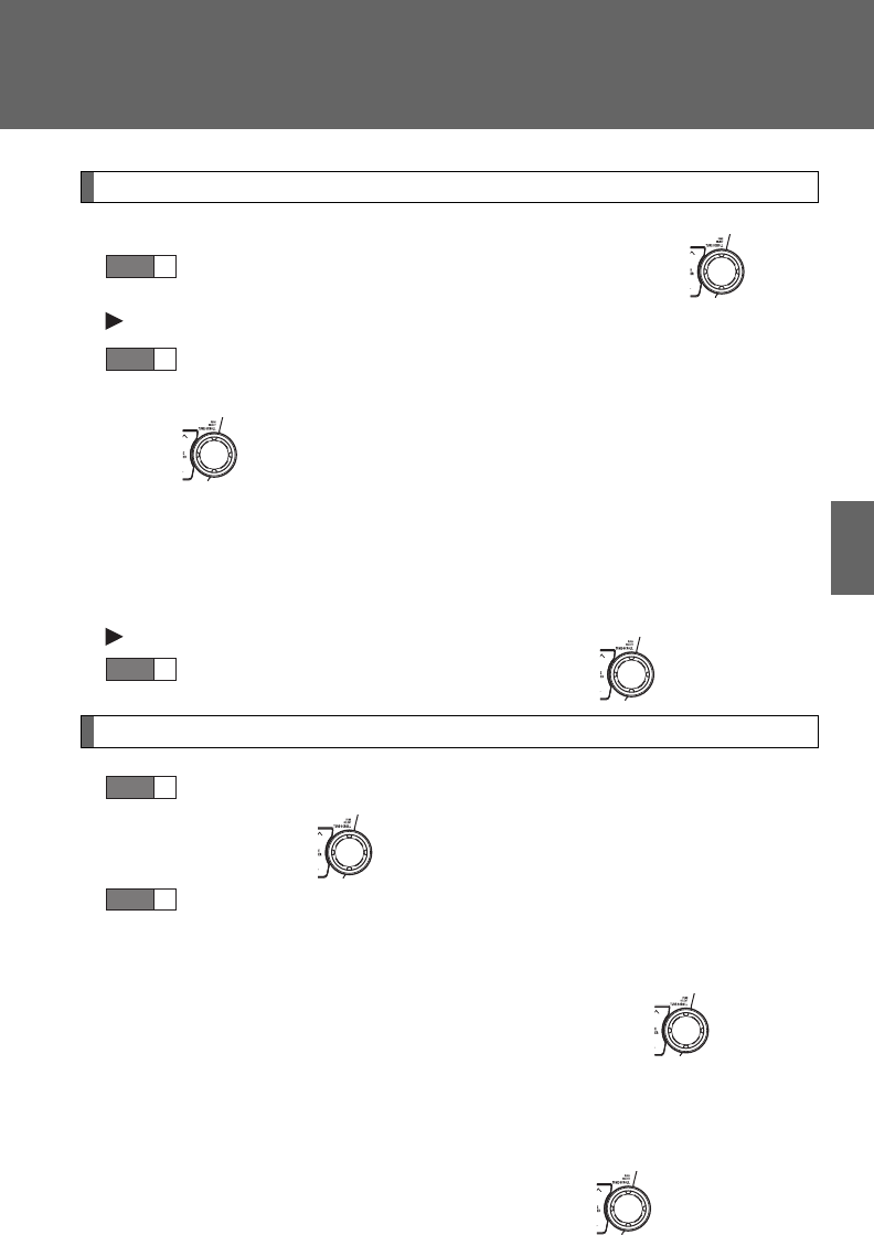
391
3-4. Using the hands-free phone system (for cellular phone)
3
Interior features
Selecting a cellular phone to be used
Select “Select Phone” using a voice command or .
Pattern A
Select a cellular phone to be used by either of the following
methods, and select “Confirm” using a voice command or
:
a. Press the talk switch and say the desired phone name.
b. Press the talk switch and say “List phones”. While the name
of the desired cellular phone is being read aloud, press the
talk switch.
Pattern B
Select a cellular phone to be used using .
Changing a registered name
Select “Change Phone Name (Change name)” using a voice
command or .
Select the name of the cellular phone to be changed by either
of the following methods:
a. Press the talk switch and say the desired phone name, and
select “Confirm” using a voice command or .
b. Press the talk switch and say “List phones”. While the
desired phone name is being read aloud, press the talk
switch.
c. Select the desired phone name using .
STEP
1
STEP
2
STEP
2
STEP
1
STEP
2
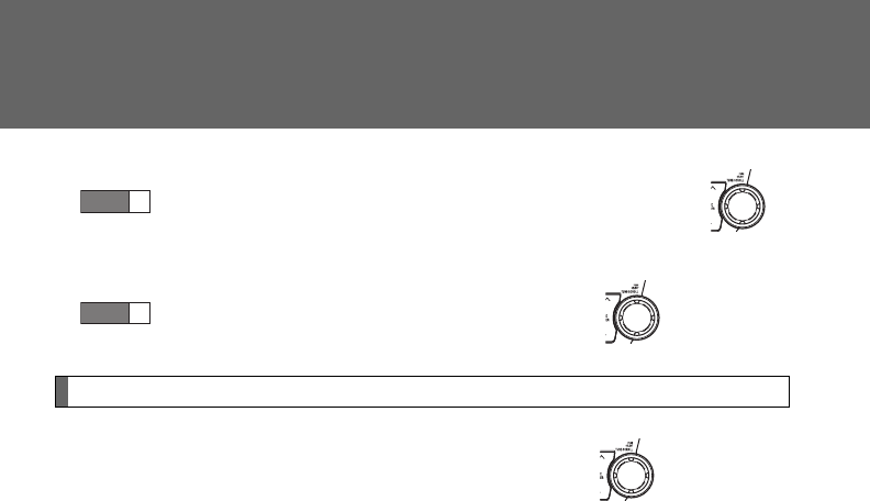
392
3-4. Using the hands-free phone system (for cellular phone)
Press the talk switch or select “Record Name” using ,
and say a new name.
Select “Confirm” using a voice command or .
Listing the registered cellular phones
Selecting “List Phones” using a voice command or causes the
list of registered cellular phones to be read aloud.
When listing is complete, the system returns to “Phone Setup”.
Pressing the talk switch while the name of a cellular phone is being
read selects the cellular phone, and the following functions will be
available:
• Selecting a cellular phone: “Select Phone”
• Changing a registered name: “Change Name”
• Deleting a cellular phone: “Delete Phone”
STEP
3
STEP
4
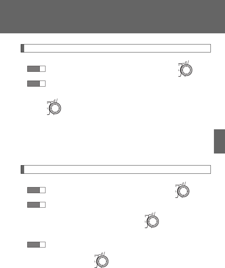
393
3-4. Using the hands-free phone system (for cellular phone)
3
Interior features
Deleting a cellular phone
Select “Delete Phone” using a voice command or .
Select a cellular phone to be deleted by either of the following
methods and select “Confirm” using a voice command or
:
a. Press the talk switch and say the name of the desired cellu-
lar phone.
b. Press the talk switch and say “List phones”. While the name
of the desired cellular phone is being read aloud, press the
talk switch.
Changing the passkey
Select “Set Passkey” using a voice command or .
Press the talk switch, say a 4 to 8-digit number, and select
“Confirm” using a voice command or .
The number should be input 1 digit at a time.
When the entire number to be registered as a passkey has
been input, press again.
STEP
1
STEP
2
STEP
1
STEP
2
STEP
3
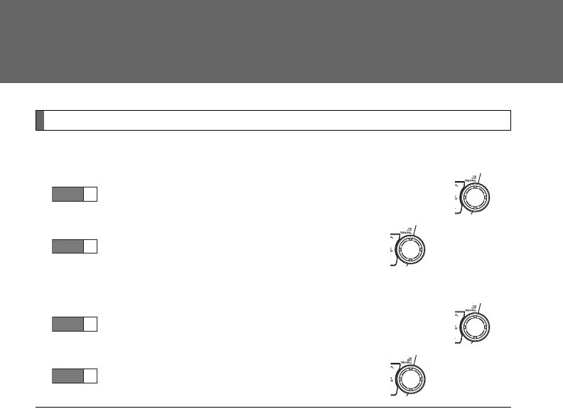
394
3-4. Using the hands-free phone system (for cellular phone)
Turning the hands-free phone automatic connection on/off
■Turning off the automatic connection
Select “Handsfree Power” using a voice command or .
Select “Turn off” using a voice command or .
■Turning on the automatic connection
Select “Handsfree Power” using a voice command or .
Select “Turn on” using a voice command or .
■The number of cellular phones that can be registered
Up to 6 cellular phones can be registered in the system.
STEP
1
STEP
2
STEP
1
STEP
2

395
3-4. Using the hands-free phone system (for cellular phone)
3
Interior features
Security and system setup
Setting or changing the PIN
■Setting a PIN
Select “Set PIN” using a voice command or .
Enter a PIN using a voice command or .
When using , input the code 1 digit at a time.
To enter the menu of each setting, follow the steps below:
■Security setting items and operation procedure
●Setting or changing the PIN (Personal Identification Number)
1. “Setup (Setup)” 2. “Security” 3. “Set PIN”
●Locking the phone book
1. “Setup (Setup)” 2. “Security” 3. “Phonebook Lock
(Phone book lock)”
●Unlocking the phone book
1. “Setup (Setup)” 2. “Security” 3. “Phonebook Unlock
(Phone book unlock)”
■System setup items and operation procedure
●Setting voice guidance volume
1. “Setup (Setup)” 2. “System Setup” 3. “Guidance Vol-
ume”
●Initialization
1. “Setup (Setup)” 2. “System Setup” 3. “Reset Settings”
can only be used for system setup operation.
STEP
1
STEP
2
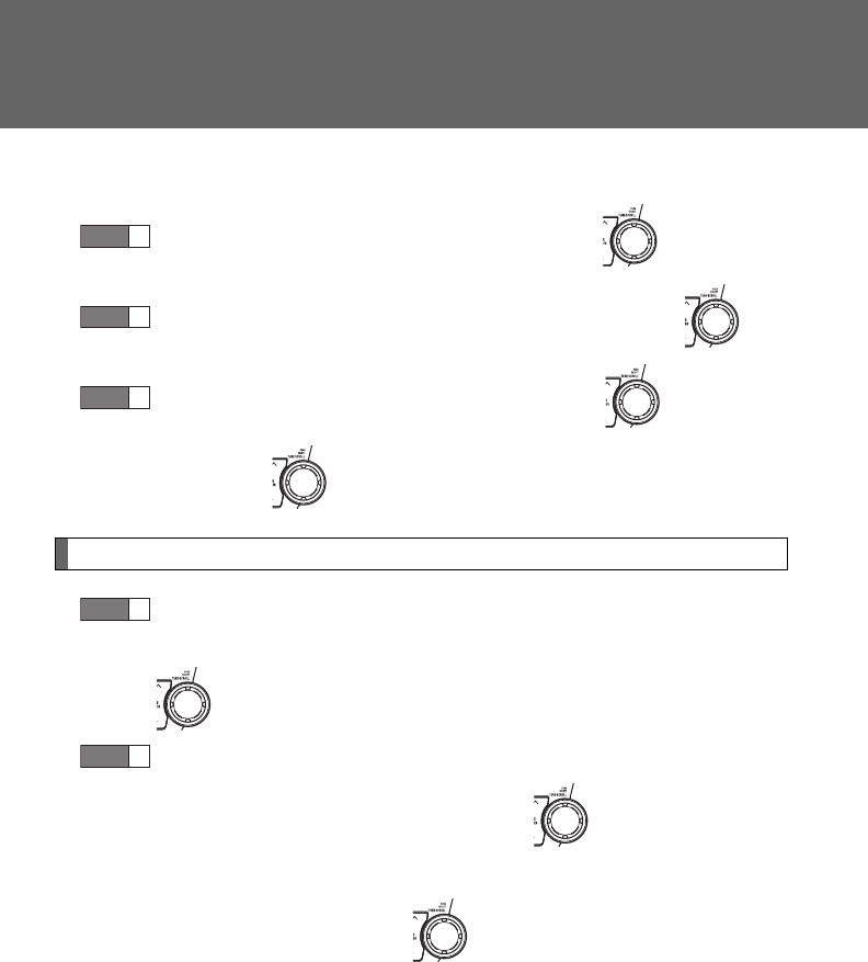
396
3-4. Using the hands-free phone system (for cellular phone)
■Changing the PIN
Select “Set PIN” using a voice command or .
Enter the registered PIN using a voice command or .
Enter a new PIN using a voice command or .
When using , input the code 1 digit at a time.
Locking or unlocking the phone book
Select “Phonebook Lock (Phone book lock)” or “Phonebook
Unlock (Phone book unlock)” using a voice command or
.
Input the PIN by either of the following methods and select
“Confirm” using a voice command or :
a. Press the talk switch and say the registered PIN.
b. Input a new PIN using .
STEP
1
STEP
2
STEP
3
STEP
1
STEP
2
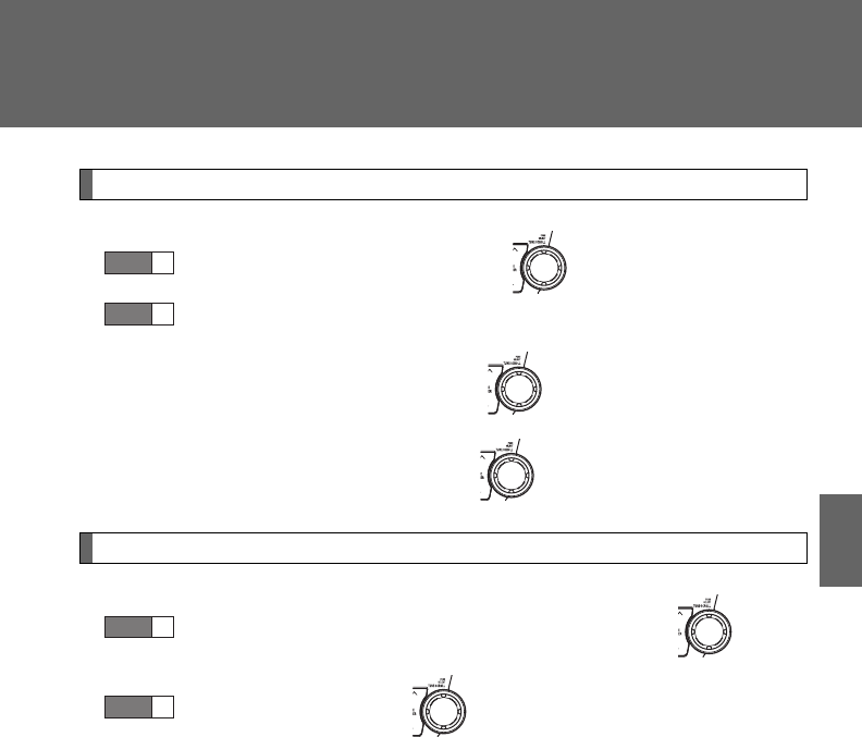
397
3-4. Using the hands-free phone system (for cellular phone)
3
Interior features
Setting voice guidance volume
Select “Guidance Volume” using .
Change the voice guidance volume.
To decrease the volume: Turn counterclockwise.
To increase the volume: Turn clockwise.
Initialization
Select “Reset Settings” and then “Confirm” using .
Select “Confirm” using .
STEP
1
STEP
2
STEP
1
STEP
2

398
3-4. Using the hands-free phone system (for cellular phone)
■Initialization
●The following data in the system can be initialized:
• Phone book
• Outgoing and incoming call history
• Speed dials
• Registered cellular phone data
• Security code
●Once the initialization has been completed, the data cannot be restored
to its original state.
■When the phone book is locked
The following functions cannot be used:
●Dialing by inputting a name
●Speed dialing
●Dialing a number stored in the call history
●Using the phone book
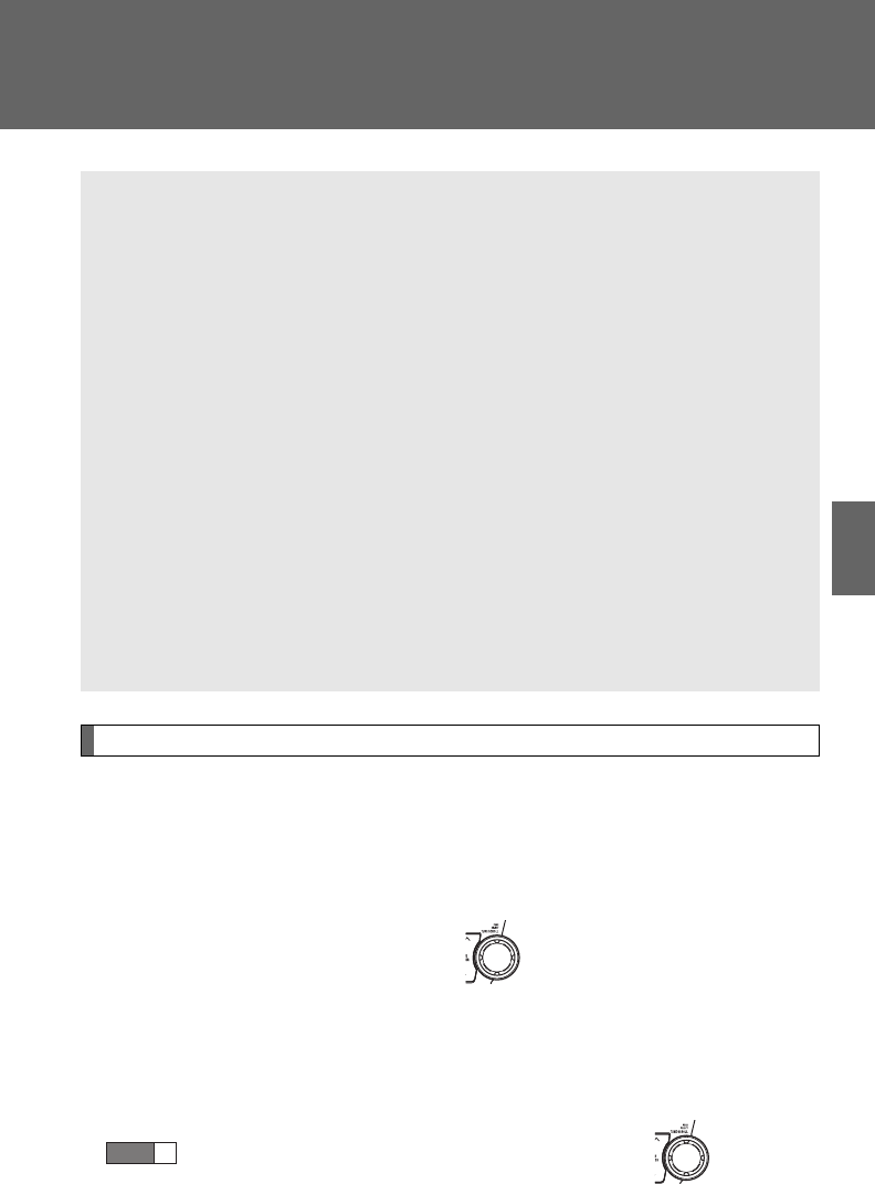
399
3-4. Using the hands-free phone system (for cellular phone)
3
Interior features
Using the phone book
Adding a new phone number
The following methods can be used to add a new phone number:
●Inputting a phone number by using a voice command
●Transferring data from the cellular phone
●Inputting a phone number using
●Selecting a phone number from the outgoing or incoming call his-
tory
■Adding procedure
Select “Add Entry” using a voice command or .
To enter the menu of each setting, follow the steps below:
●Adding a new phone number
1. “Phonebook” 2. “Add Entry”
●Setting speed dial
1. “Phonebook” 2. “Speed Dial (Set speed dial)”
●Changing a registered name
1. “Phonebook” 2. “Change Name”
●Deleting registered data
1. “Phonebook” 2. “Delete Entry”
●Deleting speed dial
1. “Phonebook” 2. “Delete Speed Dial”
●Listing the registered data
1. “Phonebook” 2. “List Names”
STEP
1
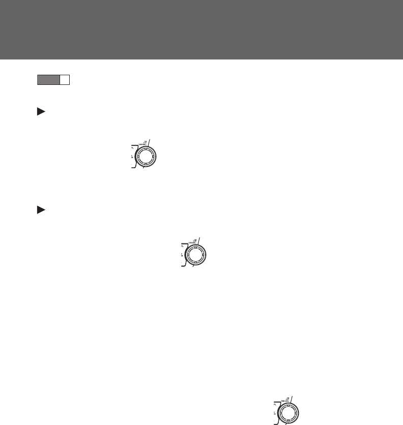
400
3-4. Using the hands-free phone system (for cellular phone)
Use one of the following methods to input a telephone num-
ber:
Inputting a telephone number using a voice command
STEP2-1 Select “By Voice (By voice)” using a voice command
or .
STEP2-2 Press the talk switch, say the desired number, and
select “Confirm” using a voice command.
Transferring data from the cellular phone
STEP2-1 Select “By Phone” and then “Confirm” using a voice
command or .
STEP2-2 Transfer the data from the cellular phone.
Refer to the manual that comes with the cellular phone for
the details of transferring data.
STEP2-3 Select the data to be registered by either of the fol-
lowing methods:
a. Say “Previous” or “Next” until the desired data is
displayed, and select “Confirm” using a voice
command.
b. Select the desired data using .
STEP
2
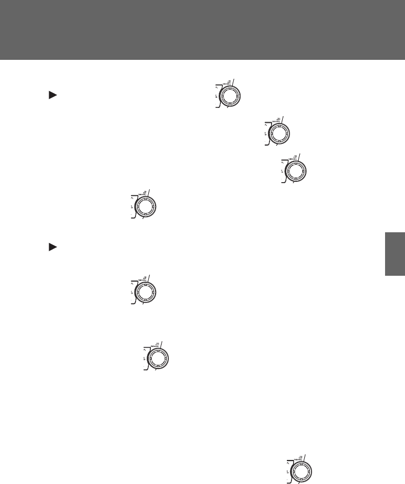
401
3-4. Using the hands-free phone system (for cellular phone)
3
Interior features
Inputting a phone number using
STEP2-1 Select “Manual Input” using .
STEP2-2 Input a phone number using , and press
once again.
Input the phone number 1 digit at a time.
Selecting a phone number from outgoing or incoming call history
STEP2-1 Select “Call History” using a voice command or
.
STEP2-2 Select “Outgoing Call History (Outgoing)” or “Incom-
ing Call History (Incoming)” using a voice command
or .
STEP2-3 Select the data to be registered by either of the fol-
lowing methods:
a. Say “Previous” or “Go back” until the desired
data is displayed, and select “Confirm” using a
voice command.
b. Select the desired data using .
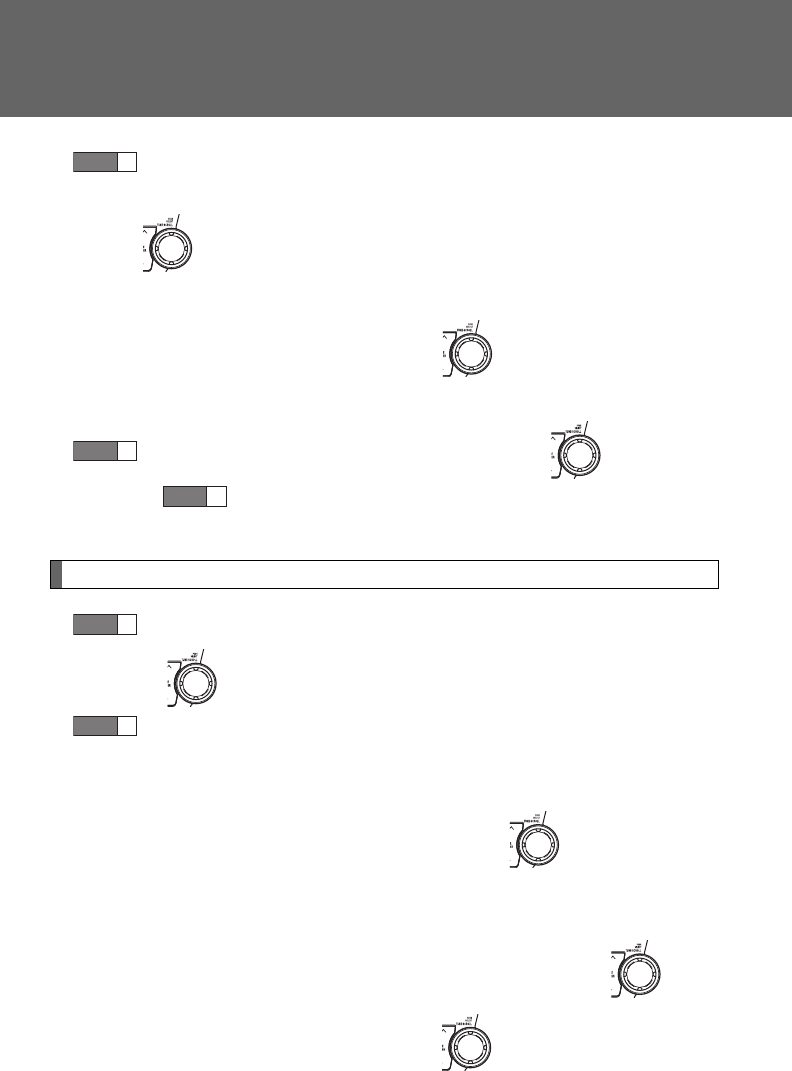
402
3-4. Using the hands-free phone system (for cellular phone)
Select the name to be registered by either of the following
methods, and select “Confirm” using a voice command or
:
a. Press the talk switch and say the desired name.
b. Select “Record Name” using , and say the desired
name.
Select “Confirm” using a voice command or .
In , selecting “Speed Dial (Set speed dial)” instead of “Con-
firm” registers the newly added phone number as a speed dial.
Setting speed dials
Select “Speed Dial (Set speed dial)” using a voice command
or .
Select data to be registered as a speed dial by either of the
following methods:
a. Press the talk switch, say the desired number, and select
“Confirm” using a voice command or .
b. Press the talk switch, and say “List names”. While the
desired name is being read aloud, press the talk switch,
and select “Confirm” using a voice command or .
c. Select the desired data using .
STEP
3
STEP
4
STEP
3
STEP
1
STEP
2
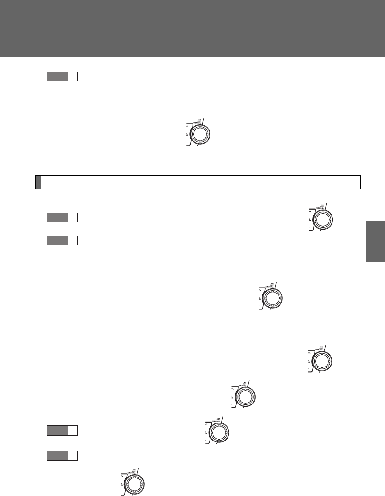
403
3-4. Using the hands-free phone system (for cellular phone)
3
Interior features
Select a desired preset button, and register the data into
speed dial by either of the following methods:
a. Press the desired preset button, and select “Confirm” using
a voice command or .
b. Press and hold the desired preset button.
Changing a registered name
Select “Change Name” using a voice command or .
Select a name to be changed by either of the following meth-
ods:
a. Press the talk switch, say the desired name, and select
“Confirm” using a voice command or .
b. Press the talk switch, and say “List names”. While the
desired name is being read aloud, press the talk switch,
and select “Confirm” using a voice command or .
c. Select the desired name using .
Select “Record Name” with or the talk switch.
Say a new name, and select “Confirm” using a voice com-
mand or .
STEP
3
STEP
1
STEP
2
STEP
3
STEP
4

404
3-4. Using the hands-free phone system (for cellular phone)
Deleting registered data
Select “Delete Entry” using a voice command or .
Select the data to be deleted by either of the following meth-
ods, and select “Confirm” using a voice command or :
a. Press the talk switch, and say the name of the desired
phone number to be deleted.
b. Press the talk switch, say “List phones”. While the name of
the desired phone number is being read aloud, press the
talk switch.
Deleting speed dials
Select “Delete Speed Dial” using a voice command or .
Press the preset button in which the desired speed dial is reg-
istered, and select “Confirm” using a voice command or
.
STEP
1
STEP
2
STEP
1
STEP
2

405
3-4. Using the hands-free phone system (for cellular phone)
3
Interior features
Listing the registered data
Selecting “List names” using a voice command causes a list of the
registered data to be read aloud.
When listing is complete, the system returns to “Phonebook”.
Pressing the talk switch while the desired data is being read aloud
selects the data, and the following function will become available.
• Dialing: “Dial”
• Changing a registered name: “Change Name”
• Deleting an entry: “Delete Entry”
• Setting a speed dial: “Speed Dial (Set speed dial)”
■Limitation of number of digits
A phone number that exceeds 24 digits cannot be registered.
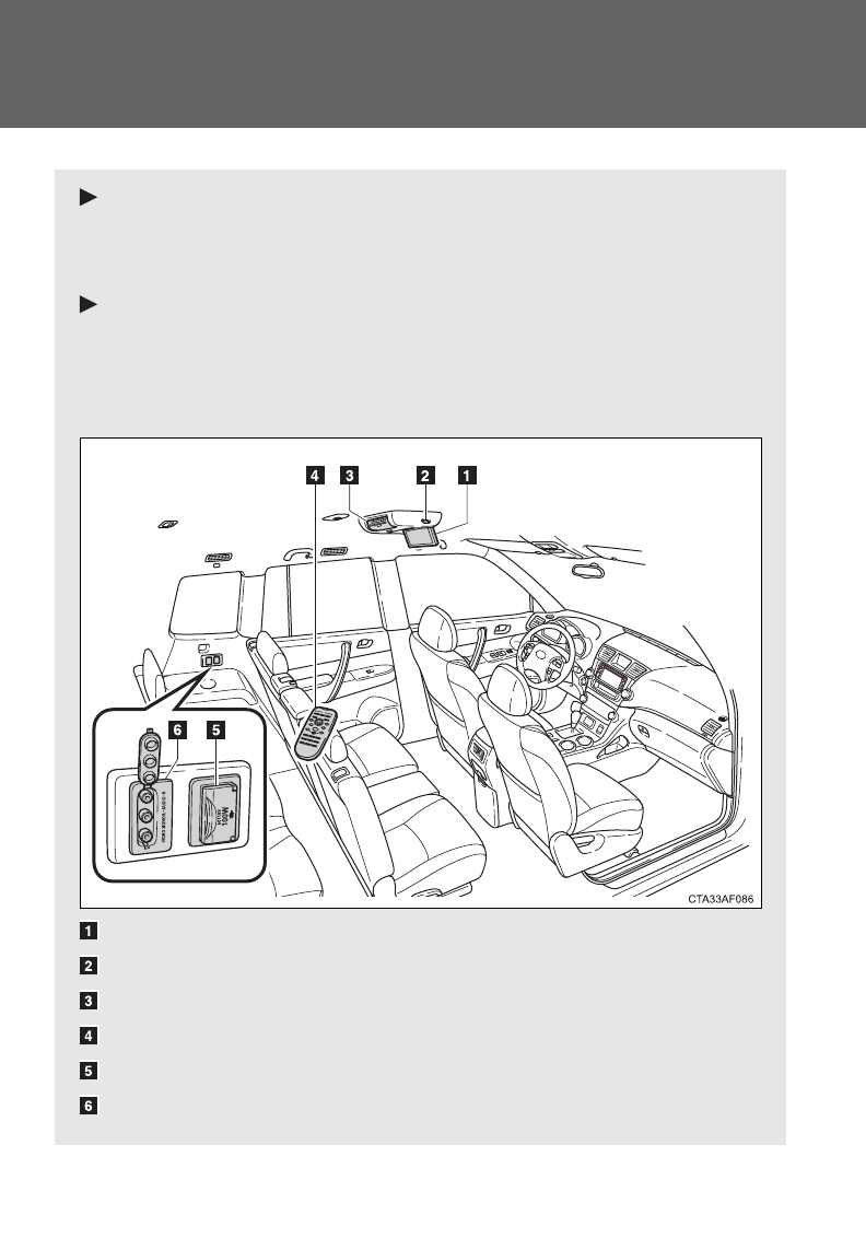
406
3-5. Using the rear audio system
Rear seat entertainment system features
With navigation system
Owners of models equipped with a navigation system should refer to
the “Navigation System Owner’s Manual”.
Without navigation system
The rear seat entertainment system is designed for the rear passen-
gers to enjoy audio and DVD video separately from the front audio
system.
Display
Headphone volume control dials and headphone jacks
DVD player
Rear seat entertainment system controller
Power outlet
A/V input port
: If equipped
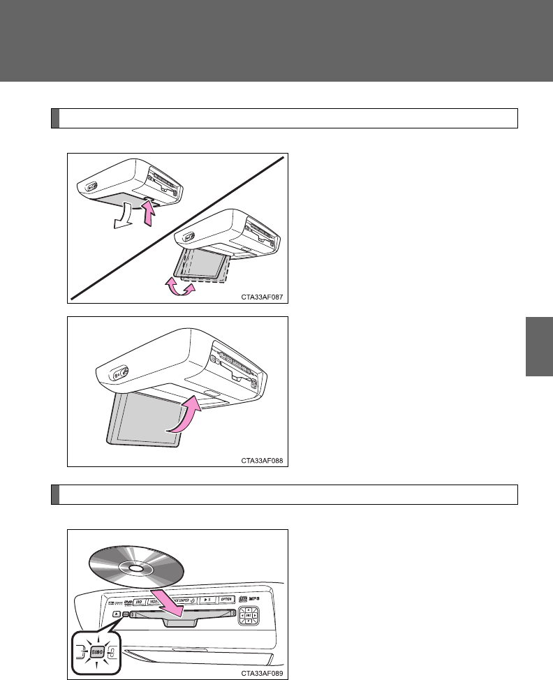
407
3-5. Using the rear audio system
3
Interior features
Opening and closing the display
Press the lock release button to
open the display.
Pull the display down to an easily
viewable angle (between 90 and
125).
To close the display, push the
display up until a click is heard.
The illumination of the screen is
automatically turned off when the
display is closed. However, the
rear seat entertainment system is
not turned off.
Loading a disc
Insert the disc into the slot with
the label side up.
The “DISC” indicator light turns
on while the disc is loaded.
The player will play the track or
chapter, and will repeat it after it
reaches the end.
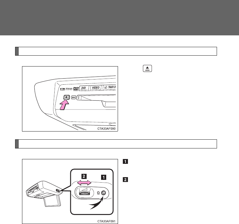
408
3-5. Using the rear audio system
Ejecting a disc
Press and remove the disc.
Headphone jacks
To use the headphones, con-
nect them to the jack.
To adjust the volume
Right side dial: Turn it toward
the front of the vehicle to
increase the volume. Turn it
toward the rear of the vehicle
to decrease the volume.
Left side dial: Turn it toward
the rear of the vehicle to
increase the volume. Turn it
toward the front of the vehicle
to decrease the volume.
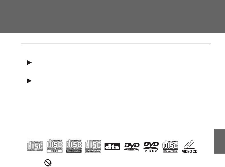
409
3-5. Using the rear audio system
3
Interior features
■The rear seat entertainment system can be used when
Vehicles without smart key system
The engine switch is in the “ACC” or “ON” position.
Vehicles with smart key system
The “ENGINE START STOP” switch is in ACCESSORY or IGNITION ON
mode.
■Discs that can be used
Discs with the marks shown below can be used.
Playback may not be possible depending on recording format or disc fea-
tures, or due to scratches, dirt or deterioration.
■When appears on the screen
It indicates that the selected switch cannot work.
■Error messages
“DISC CHECK”: Indicates that the disc is dirty, damaged or was inserted
upside down. Clean the disc or insert it correctly.
“REGION ERROR”: Indicates that the DVD region code is not set properly.
“DVD ERROR”: Indicates that there is a problem inside the player. Eject
the disc. Set the disc again.
If the malfunction still exists, take the vehicle to your
Toyota dealer.

410
3-5. Using the rear audio system
■Before using the remote controller (for new vehicle owners)
■When the remote controller battery is fully depleted
■If the remote controller batteries are discharged
The following symptoms may occur:
●The rear seat entertainment system control will not function properly.
●The operational range is reduced.
■When using AA batteries
Batteries can be purchased at your Toyota dealer, electric appliance shop, or
camera stores.
Replace only with the same or equivalent type recommended by a Toyota
dealer.
Dispose of used batteries according to the local laws.
Remove the cover.
Remove the insulating sheet.
STEP
1
STEP
2
Remove the depleted batteries and install
3 new AA batteries.

411
3-5. Using the rear audio system
3
Interior features
■Headphones
With some headphones generally available in the market, it may be difficult
to catch signals properly. Toyota recommends the use of Toyota genuine
wireless headphones.
Please contact your Toyota dealer for further details.
■Volume
●Adjust the volume when you connect the headphones to the jack. Loud
sounds may have a significant impact on the human body.
●Conversational speech on some DVDs is recorded at a low volume to
emphasize the impact of sound effects. If you adjust the volume assum-
ing that the conversations represent the maximum volume level that the
DVD will play, you may be startled by louder sound effects or when you
change to a different audio source. Be sure to adjust the volume with this
in mind.
CAUTION
■While driving
Do not use headphones.
Doing so may cause an accident, resulting in death or serious injury.
■When the rear seat entertainment system is not used
Keep the display closed.
In the event of an accident or sudden braking, the opened display may hit an
occupant's body, resulting in injury.
■To prevent accidents and electric shock
Do not disassemble or modify the remote controller.
■When the remote controller is not used
Stow the remote controller.
Injuries may result in the event of an accident or sudden braking.
■Removed battery and other parts
These parts are small and if swallowed by a child, they can cause choking.
Keep away from children. Failure to do so could result in death or serious
injury.

412
3-5. Using the rear audio system
NOTICE
■For normal operation after replacing the battery
Observe the following precautions to prevent accidents.
●Always work with dry hands.
Moisture may cause the battery to rust.
●Do not touch or move any other components inside the remote control.
●Do not bend either of the battery terminals.
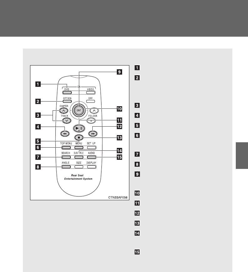
413
3-5. Using the rear audio system
3
Interior features
Using the DVD player (DVD video)
■Remote controller
Turning on the DVD mode
Turning on or off the opera-
tion switches (icon) on the
display
Selecting a chapter
Reversing a disc
Turning on the menu screen
Turning on the title selection
screen
Searching the title
Changing the screen angle
Inputting the selected
switch (icon)
Selecting a switch (icon)
Playing/pausing a disc
Fast forwarding a disc
Stopping a disc
Changing the subtitle lan-
guage
Changing the audio lan-
guage
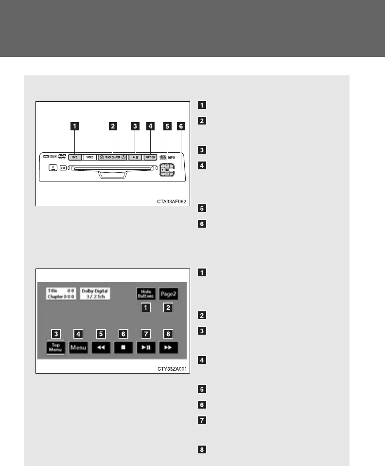
414
3-5. Using the rear audio system
■Unit
Turning on the DVD mode
Skipping to the desired
chapter
Playing/pausing a disc
Turning on or off the opera-
tion switches (icon) on the
display
Selecting a switch (icon)
Inputting the selected
switch (icon)
■Display (page 1)
Turning off the operation
switches (icon) on the dis-
play
Displaying page 2
Turning on or off the title
selection screen for the disc
Turning on or off the menu
screen for the disc
Reversing a disc
Stopping a disc
Pausing the disc/canceling
the pause
Fast forwarding a disc
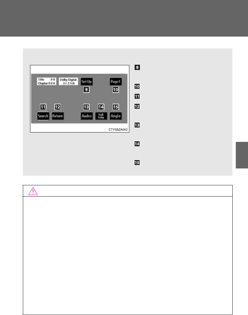
415
3-5. Using the rear audio system
3
Interior features
NOTICE
■Cleaning the display
Wipe the display with a dry soft cloth.
If the screen is wiped with a rough cloth, the surface of the screen may be
scratched.
■To prevent damage to the remote controller
●Keep the remote control away from direct sunlight, temperature heat and
high humidity.
●Do not drop or knock the remote controller against hard objects.
●Do not sit on or place heavy objects on the remote controller.
■DVD player
Never try to disassemble or oil any part of the DVD player. Do not insert any-
thing other than a disc into the slot.
■Display (page 2)
Displaying the initial setting
screen
Displaying page 1
Search for a title
Returning to the previous
screen
Changing the audio lan-
guage
Changing the subtitle lan-
guage
Changing the angle
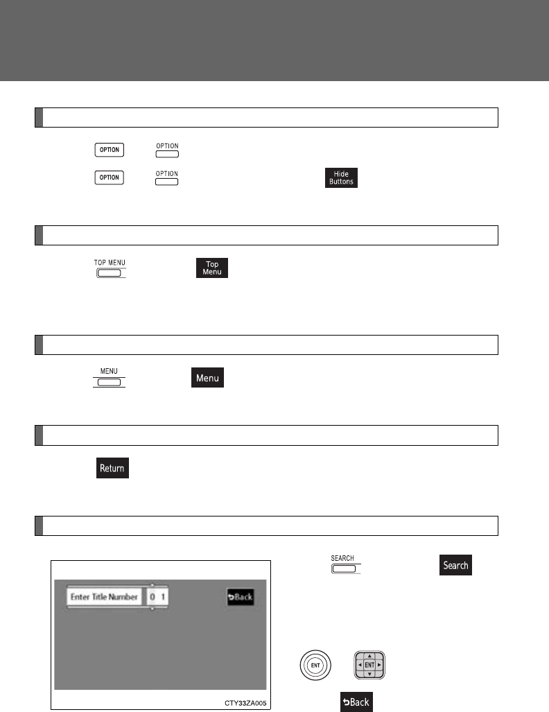
416
3-5. Using the rear audio system
Turning on or off the operation switches
Press or to turn on the operation switches.
Press or once again or select to turn off the opera-
tion switches.
Turning on the title selection screen
Press or select to turn on the title selection screen. For
the operation of the title selection screen, see the separate manual
for the DVD disc.
Turning on the menu screen
Press or select to turn on the menu screen. For the oper-
ation of the menu screen, see the separate manual for the DVD disc.
Returning to the previous screen
Select to return to the previous screen. For the operation of the
menu screen, see the separate manual for the DVD disc.
Searching for a title
Press or select to
display the screen to search for a
title.
Select the title number, and press
or to input it.
Select to return to the pre-
vious screen.
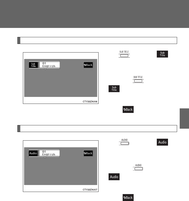
417
3-5. Using the rear audio system
3
Interior features
Changing the subtitle language
Press or select to
display the subtitle language
screen.
Each time is pressed or
is selected, another lan-
guage stored on the disc is
selected.
Select to return to the pre-
vious screen.
Changing the audio language
Press or select to
display the audio language
screen.
Each time is pressed or
is selected, another lan-
guage stored on the disc is
selected.
Select to return to the pre-
vious screen.
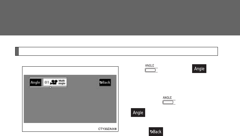
418
3-5. Using the rear audio system
Changing the angle
Press or select to
display the screen to change the
angle.
Each time is pressed or
is selected, the angle
changes.
Select to return to the pre-
vious screen.
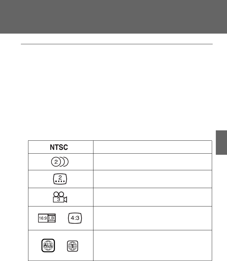
419
3-5. Using the rear audio system
3
Interior features
■DVD player and DVD video discs
This DVD player is compatible with NTSC color TV formats. DVD video discs
conforming to other formats such as PAL or SECAM cannot be used.
■Region codes
Some DVD video discs have a region code indicating a country where you
can use the DVD video disc on this DVD player. If the DVD video disc is not
labeled as “ALL” or “1”, you cannot use it on this DVD player. If you attempt
to play an inappropriate DVD video disc on this player, “REGION CODE
ERROR” appears on the screen. Even if the DVD video disc does not have a
region code, there is a case that you cannot use it.
■Marks shown on DVD video discs
Indicates NTSC format of colour TV.
Indicates the number of audio tracks.
Indicates the number of language subtitles.
Indicates the number of angles.
Indicates the screen to be selected.
Wide screen: 16:9
Standard: 4:3
Indicates a region code by which this video disc
can be played.
ALL: in all countries
Number: region code

420
3-5. Using the rear audio system
■DVD video disc glossary
●DVD video discs: Digital Versatile Discs that hold world’s standard video.
DVD video discs have adopted “MPEG2”, one of the world standards of
digital compression technologies. The picture data is compressed by 1/
40 on average and stored. Variable rate encoded technology has been
adopted in which the volume of data assigned to the picture is changed
depending on the picture format. Audio data is stored using PCM and
Dolby digital, which enables higher sound. Furthermore, multi-angle and
multi-language features will also help you enjoy the more advanced tech-
nology of DVD video.
●Viewer restrictions: This feature limits what can be viewed in conformity
with the level of restrictions of the country. The level of restrictions varies
depending on the DVD video disc. Some DVD video discs cannot be
played at all, or violent scenes are skipped or replaced with other scenes.
• Level 1: DVD video discs for children can be played.
• Level 2 - 7: DVD video discs for children and G-rated movies can be
played.
• Level 8: All types of DVD video discs can be played.
●Multi-angle feature: Allows you to enjoy the same scene at different
angles.
●Multi-language feature: Allows you to select the language of the subtitles
and audio.
●Region codes: Region codes are provided on DVD players and DVD
discs. If the DVD video disc does not have the same region code as the
DVD player, you cannot play the disc on the DVD player.
●Audio: This DVD player can play linear PCM, Dolby digital, dts and
MPEG audio format DVD. Other decoded types cannot be played.
●Title and chapter: Video and audio programs stored on DVD video discs
are divided into sections by title and chapter.
●Title: The largest unit of the video and audio programs stored on DVD
video discs. Usually, one piece of a movie, one album, or one audio pro-
gram is assigned as a title.
●Chapter: A unit smaller than a title. A title comprises multiple chapters.

421
3-5. Using the rear audio system
3
Interior features
■Audio
Manufactured under license from Dolby Laboratories. “Dolby”, “Pro Logic”,
and are trademarks of Dolby Laboratories. Confidential unpublished
works.
1992-1997 Dolby Laboratories. All rights reserved.
“dts” is a trademark of Digital Theater Systems, Inc.
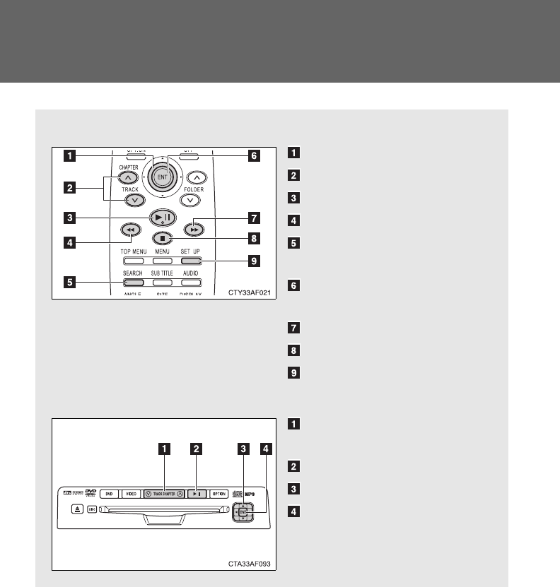
422
3-5. Using the rear audio system
Using the DVD player (video CD)
■Remote controller
Selecting a switch (icon)
Selecting a chapter
Playing/pausing a disc
Reversing a disc
Displaying operation
switches (icon)
Inputting the selected
switch (icon)
Fast forwarding a disc
Stopping a disc
Changing the initial setting
■Unit
Skipping to the desired
chapter
Playing/pausing a disc
Selecting a switch (icon)
Inputting the selected
switch (icon)
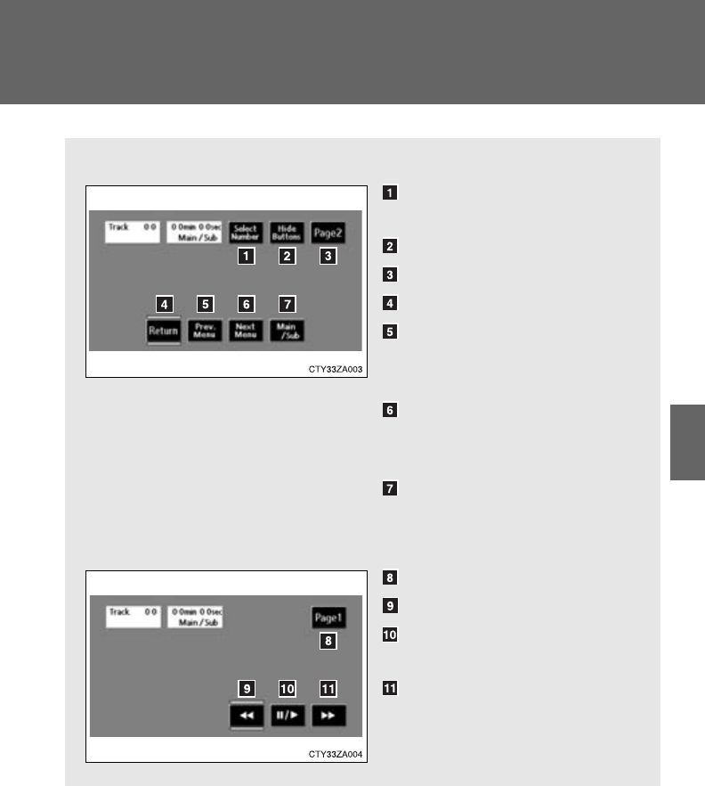
423
3-5. Using the rear audio system
3
Interior features
■Display (page 1)
Selecting a disc menu num-
ber
Turning off the menu screen
Displaying page 2
Turning on the disc menu
Returning to the previous
page screen (with the disc
menu displayed)
Proceeding to the next page
screen (with the disc menu
displayed)
Changing to a multiplex
transmission
■Display (page 2)
Displaying page 1
Reversing a disc
Pausing the disc/canceling
the pause
Fast forwarding a disc
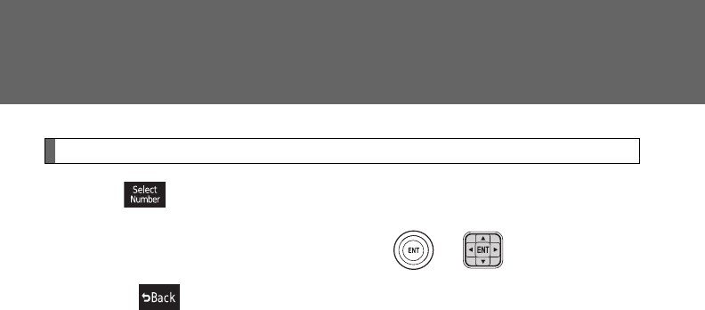
424
3-5. Using the rear audio system
Selecting a disc menu number
Select to display the disc menu number search screen.
Select the disc menu number, and press or to input it.
Select to return to the previous screen.
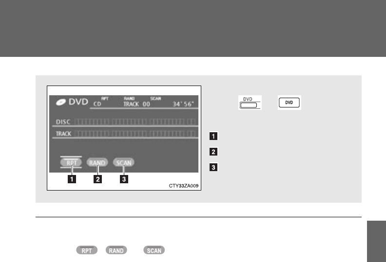
425
3-5. Using the rear audio system
3
Interior features
Using the DVD player (audio CD/CD text)
■Canceling random, repeat and scan play
Select , or again.
Using the control screen,
press or to display
the control screen.
Repeat play
Random playback
Search playback
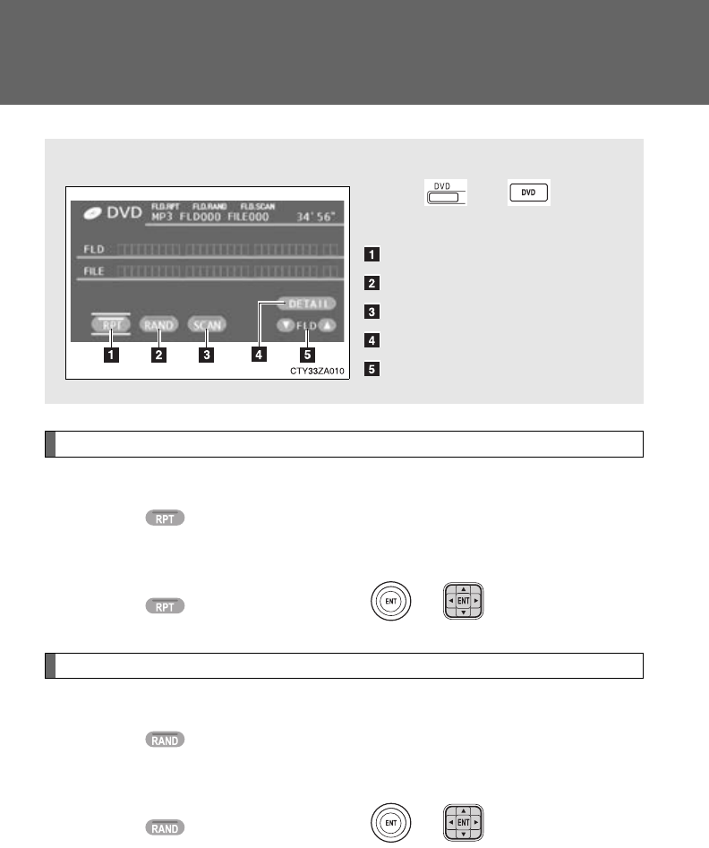
426
3-5. Using the rear audio system
Using the DVD player (MP3 discs)
Repeat play
■Repeat a file
Select .
■Repeat all of files in a folder
Select , and press and hold or .
Random playback
■Playing files from a particular folder in random order
Select .
■Playing all of the files on a disc in random order
Select , and press and hold or .
■Using the control screen
Press or to dis-
play the control screen.
Repeat play
Random playback
Search playback
Display file information
Select a folder
427
3-5. Using the rear audio system
3
Interior features
Search playback
■Selecting the desired file by cueing the files in the folder
Select .
The player will scan all the files in the folder. Each file will be
played for 10 seconds.
■Selecting the desired file by cueing the folders on the disc
Select , and press and hold or .
The player will scan all the folders on the disc. The first file in each
folder will be played for 10 seconds.
■Canceling random, repeat and play back
Select , or again.
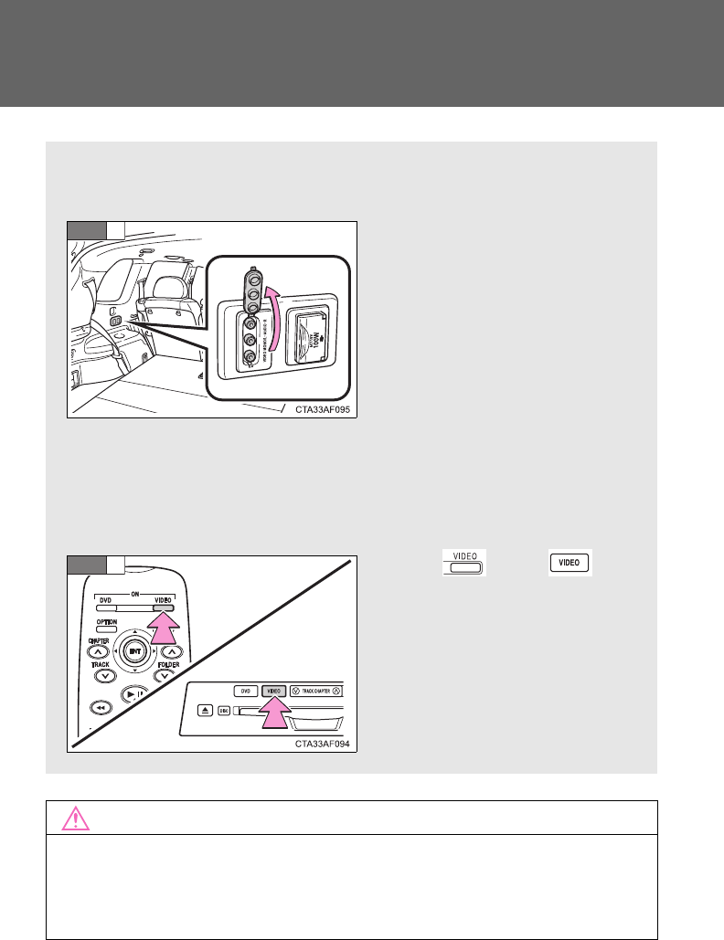
428
3-5. Using the rear audio system
Using the video mode
NOTICE
■When not in use
Keep the A/V input port cover closed. Inserting anything other than an
appropriate plug may cause electrical failure or a short circuit.
The rear seat entertainment system plays videos and sound when
audio-video equipment is connected to the A/V input port.
Open the cover, and connect
the audio source to the A/V
input port.
The A/V input port is com-
posed of 3 input ports.
Yellow: Image input port
White: Left channel audio input
port
Red: Right channel audio input
port
For details, refer to the manu-
facturer's instructions.
Press or to
select the video mode.
STEP
1
STEP
2
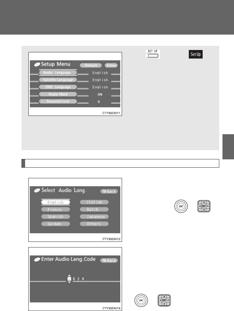
429
3-5. Using the rear audio system
3
Interior features
Changing the initial setting
Changing the audio language
Select “Audio Language”.
Select the language you want to
hear, and press or to
input it.
Select “Others” if you cannot find
the language you want to hear.
Enter the appropriate 4-digit lan-
guage code. (P. 433)
Select a number, and press
or to input it.
If a code that is not in the list is
entered, “Incorrect Code” will
appear on the screen.
Press or select to
display the initial setting
screen.
The following initialization can
be changed here.
●“Audio Language”
●“Subtitle Language”
●“DVD Language”
●“Angle Mark”
●“Parental Lock”
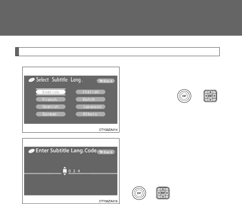
430
3-5. Using the rear audio system
Changing the subtitle language
Select “Subtitle Language”.
Select the language you want to
read, and press or
to input it.
Select “Others” if you cannot find
the language you want to read.
Enter the appropriate 4-digit lan-
guage code. (P. 433)
Select a number, and press
or to input it.
If a code that is not in the list is
entered, “Incorrect Code” will
appear on the screen.
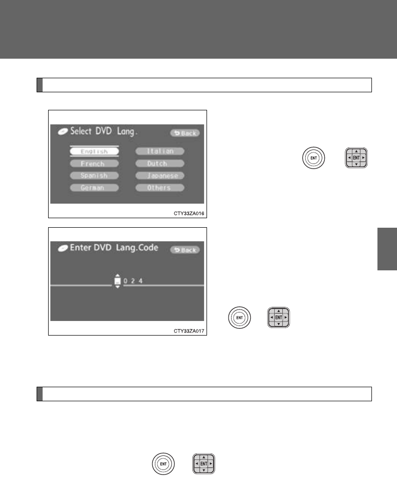
431
3-5. Using the rear audio system
3
Interior features
Changing the DVD language
Select “DVD Language”.
Select the language you want to
read, and press or
to input it.
Select “Others” if you cannot find
the language you want to read.
Enter the appropriate 4-digit lan-
guage code. (P. 433)
Select a number, and press
or to input it.
If a code that is not in the list is
entered, “Incorrect Code” will
appear on the screen.
Turning on or off the angle mark
The angle mark can be turned on for discs that are multi-angle com-
patible.
Each time you press or when “Angle Mark” is selected, the
angle mark turns on or off alternately.
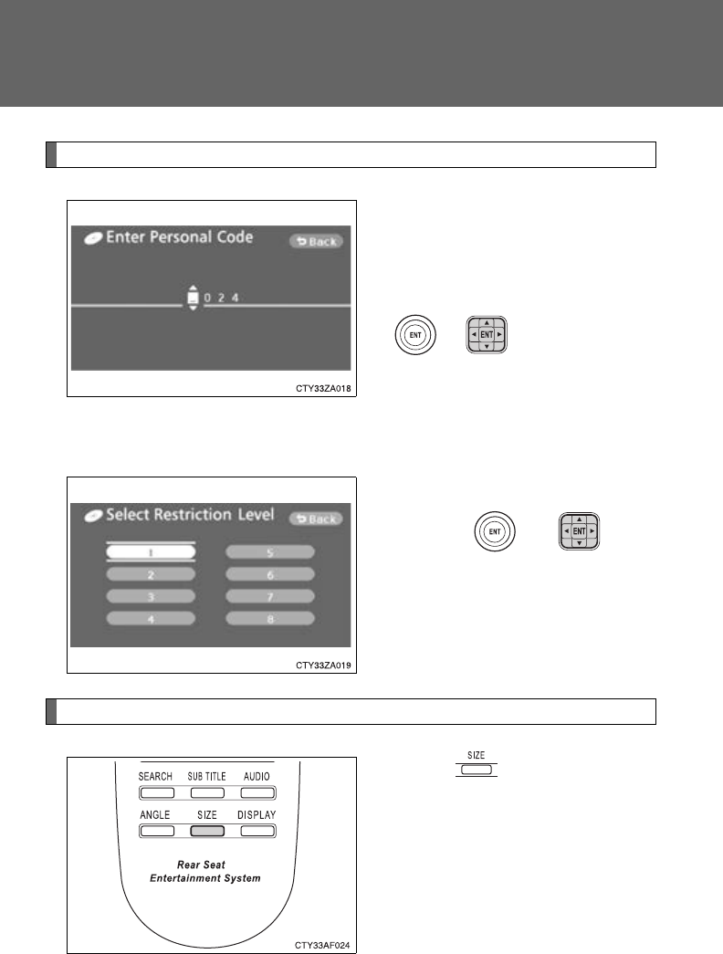
432
3-5. Using the rear audio system
Setting viewer restriction levels
Setting a password allows the
viewer restriction to be effective.
Select “Parental Lock”.
Enter the password and press
or .
The setting cannot be changed
unless the password is entered.
If you forget the password, initial-
ize the password. (P. 433)
Select a restriction level (1-8),
and press or . The
lower the level number, the
stricter the age limit.
Setting the display mode
Pressing changes the dis-
play modes sequentially as fol-
lows:
NormalWide 1 Wide 2
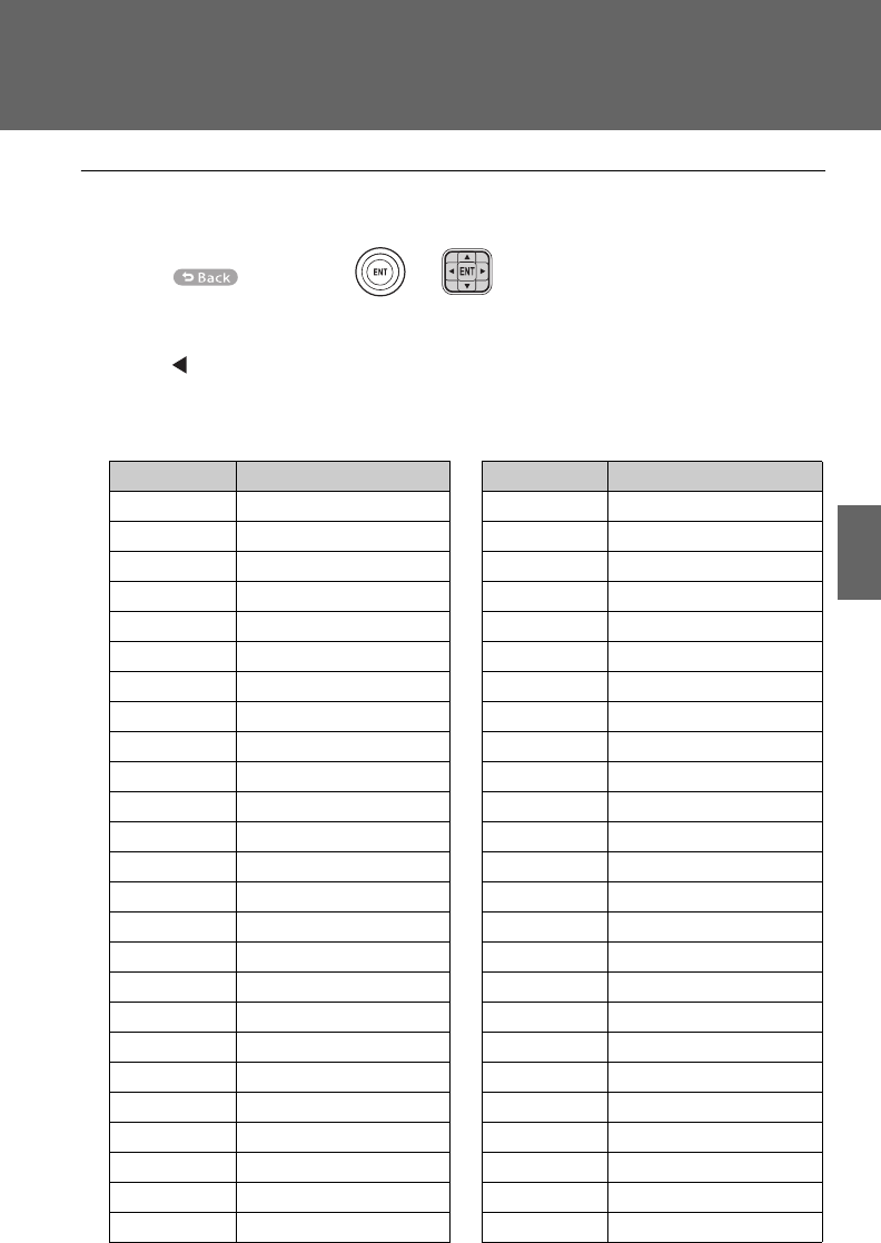
433
3-5. Using the rear audio system
3
Interior features
■Returning to the previous screen
Select , and press or .
■To initialize the password
Press on the remote controller or unit ten times when the screen to enter
the personal code is displayed.
■Language code list
Code Language
0514 English
0618 French
0405 German
0920 Italian
0519 Spanish
2608 Chinese
1412 Dutch
1620 Portuguese
1922 Swedish
1821 Russian
1115 Korean
0512 Greek
0101 Afar
0102 Abkhazian
0106 Afrikaans
0113 Amharic
0118 Arabic
0119 Assamese
0125 Aymara
0126 Azerbaijani
0201 Bashkir
0205 Byelorussian
0207 Bulgarian
0208 Bihari
0209 Bislama
0214 Bengali
0215 Tibetan
0218 Breton
0301 Catalan
0315 Corsican
0319 Czech
0325 Welsh
0401 Danish
0426 Bhutani
0515 Esperanto
0520 Estonian
0521 Basque
0601 Persian
0609 Finnish
0610 Fiji
0615 Faroese
0625 Frisian
0701 Irish
0704 Scots-Gaelic
0712 Galician
0714 Guarani
0721 Gujarati
0801 Hausa
0809 Hindi
0818 Croatian
Code Language

434
3-5. Using the rear audio system
Code Language
1821 Hungarian
1825 Armenian
0901 Interlingua
0905 Interlingue
0911 Inupiak
0914 Indonesian
0919 Icelandic
0923 Hebrew
1001 Japanese
1009 Yiddish
1023 Javanese
1101 Georgian
1111 Kazakh
1112 Greenlandic
1113 Cambodian
1114 Kannada
1119 Kashmiri
1121 Kurdish
1125 Kirghiz
1201 Latin
1214 Lingala
1215 Laothian
1220 Lithuanian
1222 Latvian
1307 Malagasy
1309 Maori
1311 Macedonian
1312 Malayalam
1314 Mongolian
1315 Moldavian
1318 Marathi
1319 Malay
1320 Maltese
1325 Burmese
1401 Nauru
1405 Nepali
1415 Norwegian
1503 Occitan
1513 (Afan) Oromo
1518 Oriya
1601 Punjabi
1612 Polish
1619 Pashto, Pushto
1721 Quechua
1813 Rhaeto-Romance
1814 Kirundi
1815 Romanian
1823 Kinyarwanda
1901 Sanskrit
1904 Sindhi
1907 Sangho
1908 Serbo-Croatian
1909 Sinhalese
1911 Slovak
1912 Slovenian
1913 Samoan
1914 Shona
1915 Somali
1917 Albanian
1918 Serbian
1919 Siswati
1920 Sesotho
Code Language
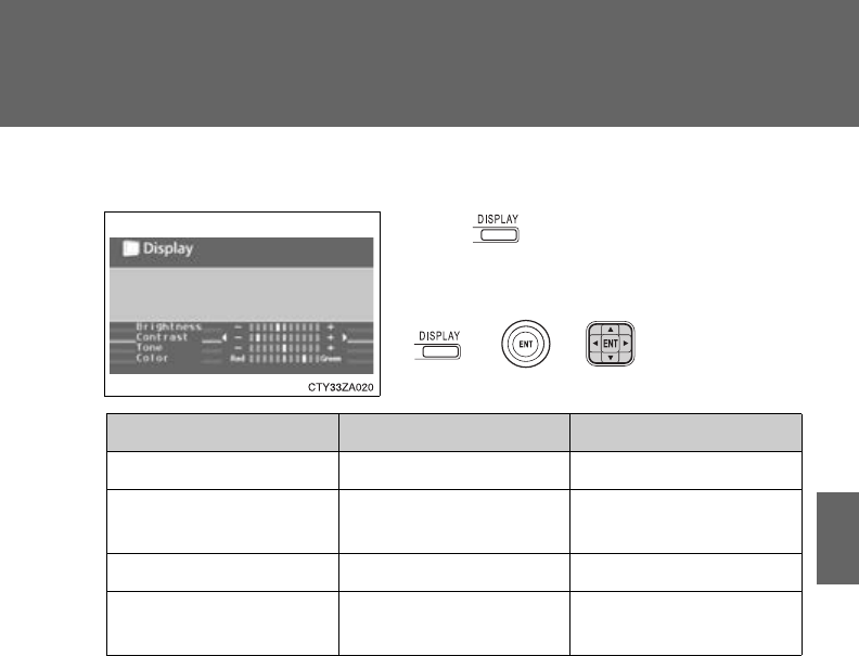
435
3-5. Using the rear audio system
3
Interior features
■Adjusting the screen
Press .
Select “Brightness”, “Contrast”, “Tone” or
“Color”, and make adjustments. Press
or or to input it.
“-” or “Red” “+” or “Green”
“Brightness” Darkens Brightens
“Contrast” Weakens the contrast Strengthens the con-
trast
“Tone” (if displayed) Weakens the tone Strengthens the tone
“Color” (if displayed) Strengthens the red
color
Strengthens the green
color
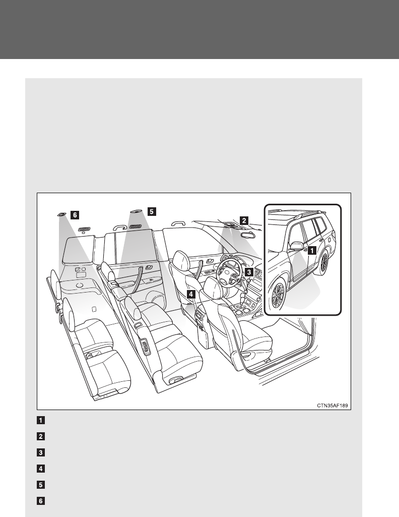
436
3-6. Using the interior lights
Interior lights list
Your Toyota is equipped with an illuminated entry system to assist in
entering the vehicle. Owing to the function of the system, the lights
shown in the following illustration automatically turn on/off accord-
ing to the presence of the electronic key (vehicles with smart key
system), whether the doors are locked/unlocked, whether the doors
or glass hatch (if equipped) are opened/closed, the “ENGINE START
STOP” switch mode and engine switch position.
Outer foot lights (vehicles with smart key system)
Personal/interior lights (P. 437)
Engine switch light (vehicles without smart key system)
Front door courtesy light
Personal/interior light or interior light (P. 437, 438)
Interior light (P. 438)
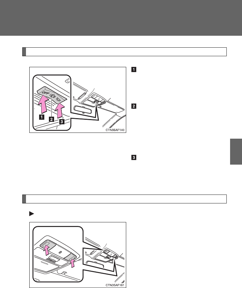
437
3-6. Using the interior lights
3
Interior features
Personal/interior light main switch
“OFF”
The personal/interior lights and
interior light can be individually
turned on or off.
Door position
The personal/interior lights and
interior light come on when a door
or the glass hatch (if equipped) is
opened. They turn off when the
doors and glass hatch are closed.
On
The personal/interior lights and
interior light cannot be individually
turned off.
Personal/interior lights
Front
On/off
The illuminated entry system is
activated even if the light is
turned off when the personal/inte-
rior light main switch is in door
position.
Personal/interior light main switch and personal/interior lights
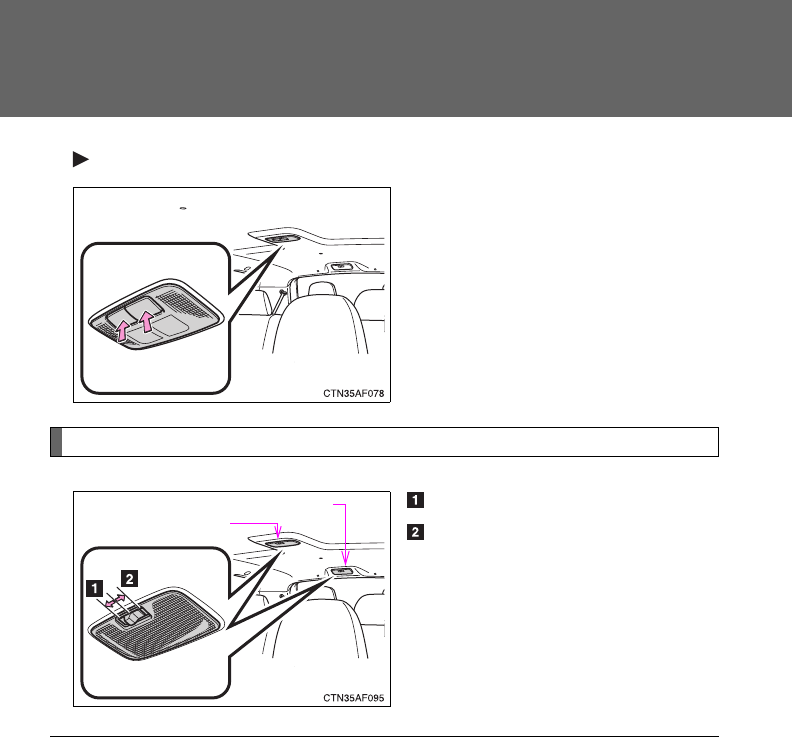
438
3-6. Using the interior lights
Center (if equipped)
On/off
The illuminated entry system is
activated even if the light is
turned off when the personal/inte-
rior light main switch is in door
position.
Interior light
On
Off
The illuminated entry system is
activated even if the light is
turned off when the personal/inte-
rior light main switch is in door
position.
Rear
Center (if equipped)
■To prevent battery discharge
If the lights remain on when the door is not fully closed and the personal/inte-
rior light main switch is in the door position, the lights will go off automatically
after 20 minutes.
■Customization that can be configured at Toyota dealer
Settings (e.g. The time elapsed before lights turn off) can be changed.
(Customizable features P. 648)
Personal/interior lights and interior light
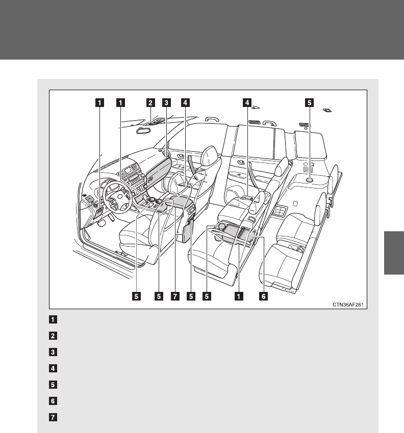
439
3
Interior features
3-7. Using the storage features
List of storage features
Auxiliary boxes
Overhead console
Glove box
Bottle holders
Cup holders
Side table
Console box
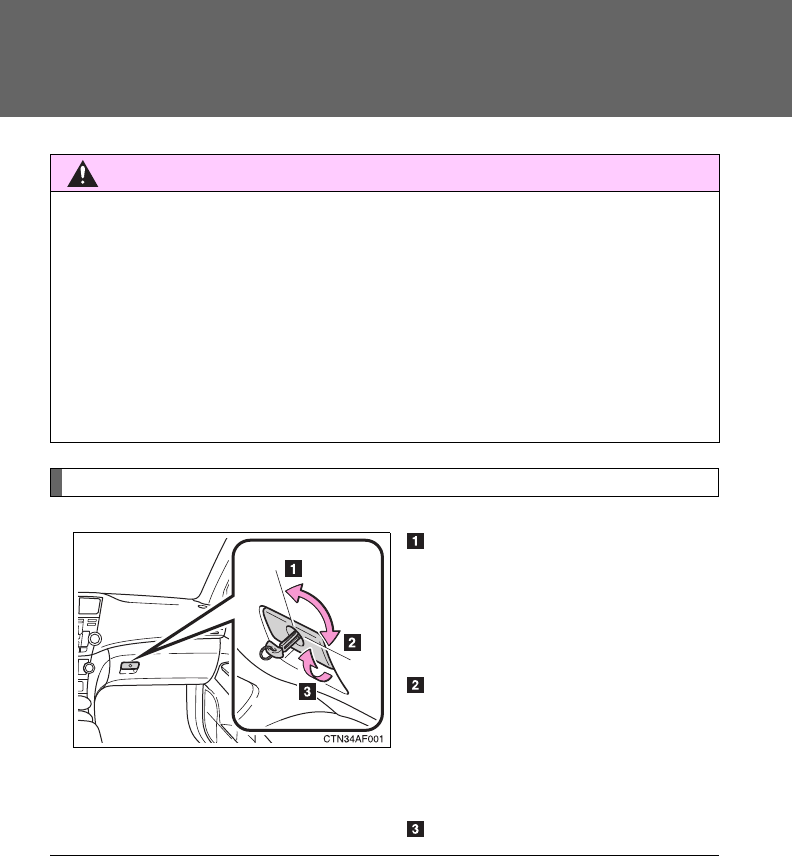
440
3-7. Using the storage features
Glove box
Unlock with the master key
(vehicles without smart key
system) or mechanical key
(vehicles with smart key sys-
tem)
Lock with the master key
(vehicles without smart key
system) or mechanical key
(vehicles with smart key sys-
tem)
Open (pull lever)
CAUTION
■Items that should not be left in the storage spaces
Do not leave glasses, lighters or spray cans in the storage spaces, as this
may cause the following when cabin temperature becomes high:
●Glasses may be deformed by heat or cracked if they come into contact
with other stored items.
●Lighters or spray cans may explode. If they come into contact with other
stored items, the lighter may catch fire or the spray can may release gas,
causing a fire hazard.
■Power back door main switch (vehicles with power back door)
The power back door main switch is located in the glove box. (P. 62)
Glove box
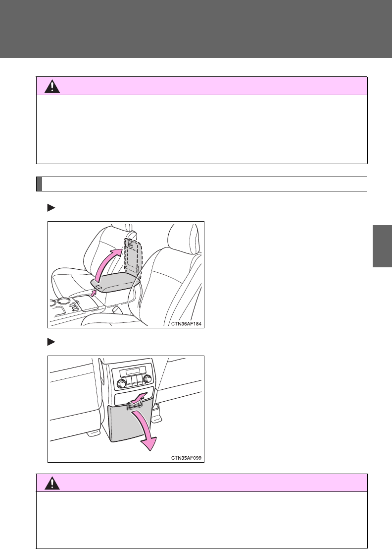
441
3-7. Using the storage features
3
Interior features
Console box
Upper
Pull up the knob to release the
lock. Lift the lid.
Lower
Push down the lever.
CAUTION
■Caution while driving
Keep the glove box closed. In the event of sudden braking or sudden swerv-
ing, an accident may occur due to an occupant being struck by the open
glove box or the items stored inside.
CAUTION
■Caution while driving
Keep the console box closed.
Injuries may result in the event of an accident or sudden braking.
Glove box and console box
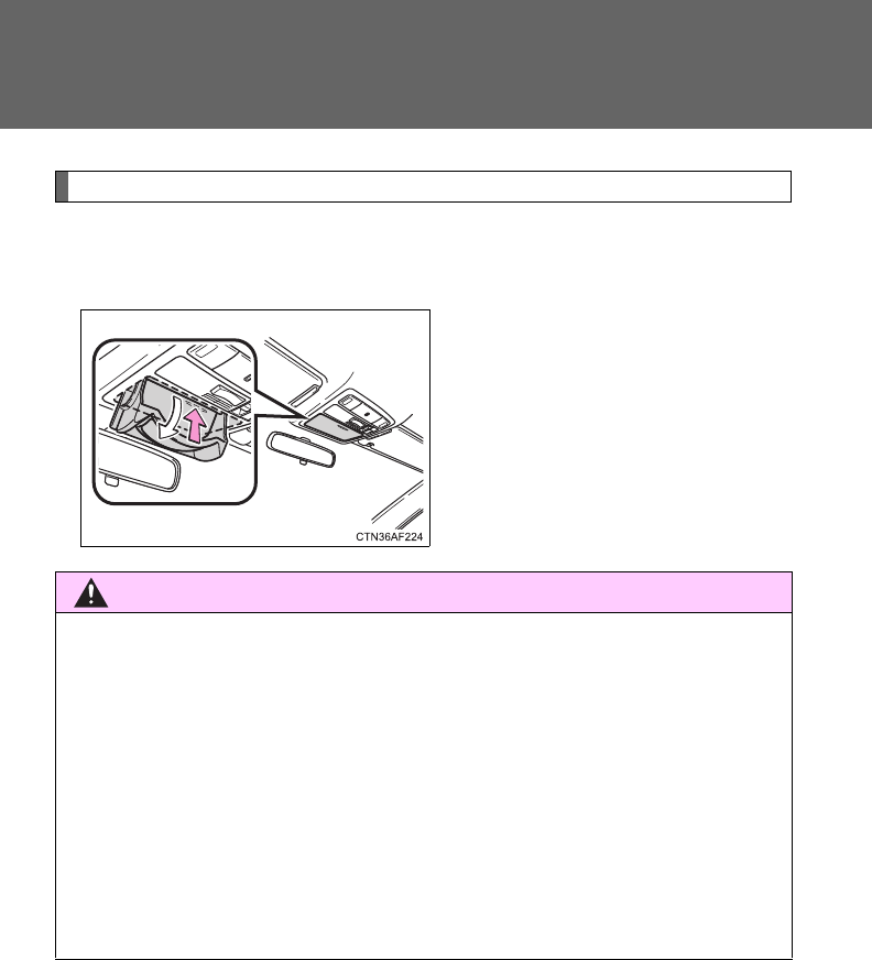
442
3-7. Using the storage features
Overhead console
The overhead console is useful for temporarily storing sunglasses
and similar small items.
Press in the lid.
CAUTION
■Caution while driving
Do not leave the overhead console open while driving.
Items stored in it may fall out and cause injury.
■Size of stored items
Do not put large items in the overhead console.
The overhead console may not be able to be shut from the conversation mir-
ror position.
■Maximum storage weight
Do not place any object heavier than 0.4 lb. (200 g) in it. The console may
be opened and cause injury.
Overhead console

443
3-7. Using the storage features
3
Interior features
Cup holders
Front (type A)
Front (type B)
Lift the lid.
Console box
Pull out the cup holder.
Cup holders
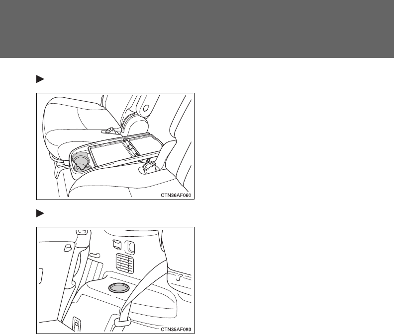
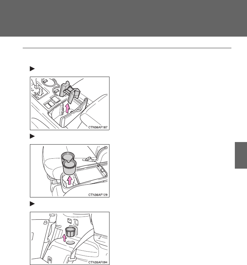
445
3-7. Using the storage features
3
Interior features
■Adjusting size of the cup holder (front [type B], side table and rear)
Front (type B)
Side table
Rear
Remove the separator.
The separator may be removed for clean-
ing.
Remove the adapter.
Remove the adapter.
Cup holders

446
3-7. Using the storage features
CAUTION
■Items unsuitable for the cup holder
Do not place anything other than cups or beverage cans in the cup holders.
Even when the lid is closed, items must not be stored in the cup holders.
Other items may be thrown out of the holders in the event of an accident or
sudden braking and cause injury. If possible, cover hot drinks to prevent
burns.
■When not in use
Front (type B) and console box cup holders: Keep the cup holders closed.
Injuries may result in the event of an accident or sudden braking.
Cup holders
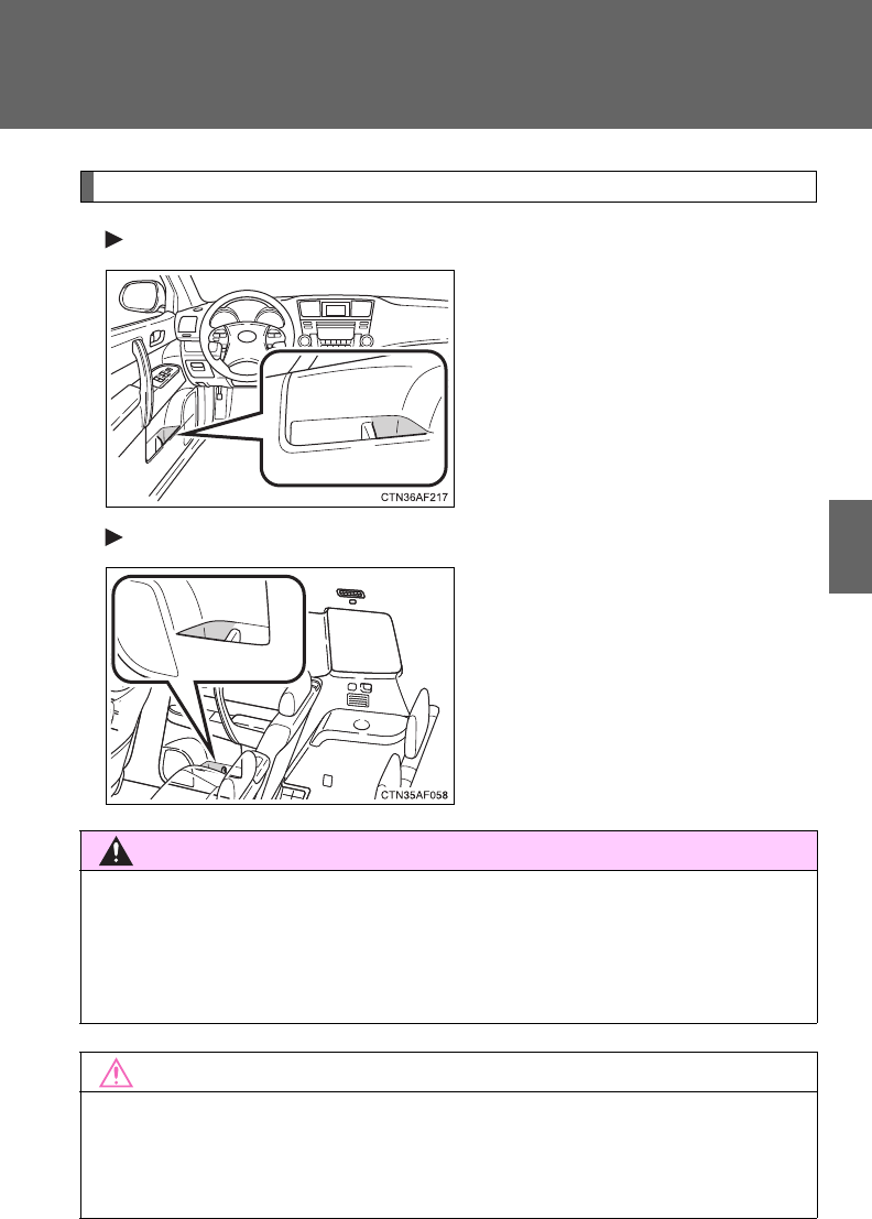
447
3-7. Using the storage features
3
Interior features
Bottle holders
Front
Rear
CAUTION
■Items unsuitable for the bottle holder
Do not place anything other than a bottle in the bottle holders.
Other items may be thrown out of the holders in the event of an accident or
sudden braking and cause injury.
NOTICE
■When stowing a bottle
Put the cap on before stowing a bottle. Do not place open bottles in the bot-
tle holders. The contents may spill.
Bottle holders
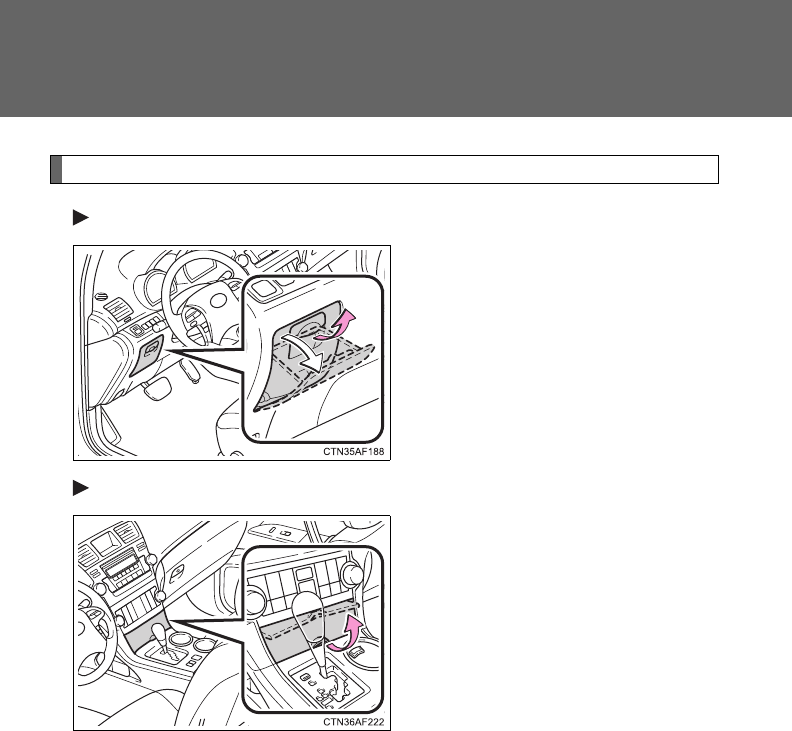
448
3-7. Using the storage features
Auxiliary boxes
Type A
Pull up the lever.
Type B (if equipped)
Lift the lid.
Auxiliary boxes
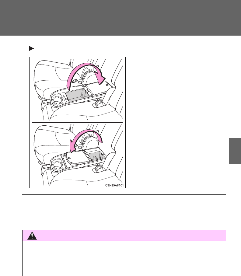
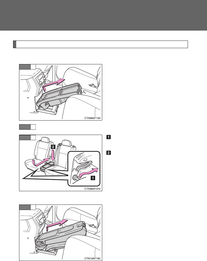
450
3-7. Using the storage features
Side table
■Installing the side table
Take out the side table from the
console box.
Remove the second center seat. (P. 82)
Engage the front pins of the
side table with the hooks.
Push down on the side table to
engage the rear pin locks.
■Removing the side table
Take out the second center seat
from the console box.
STEP
1
STEP
2
STEP
3
STEP
1
Side table
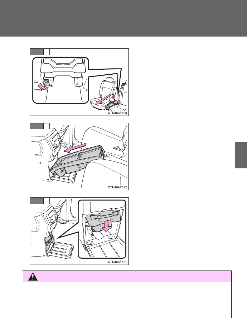
451
3-7. Using the storage features
3
Interior features
Pull the lock release lever to
remove the side table.
Stow the side table in the con-
sole box.
Push down on the end to engage
the pins in the holes and close
the console box door.
Make sure that the side table is
securely locked in position.
STEP
2
STEP
3
STEP
4
CAUTION
■Caution while driving
Keep the console box closed.
Injuries may result in the event of an accident or sudden braking.
Side table
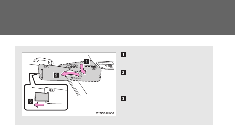
452
3-8. Other interior features
Sun visors
Forward position
Flip down.
Side position
Flip down, unhook, and
swing to the side.
Side extender
Place in side position then
slide backwards.
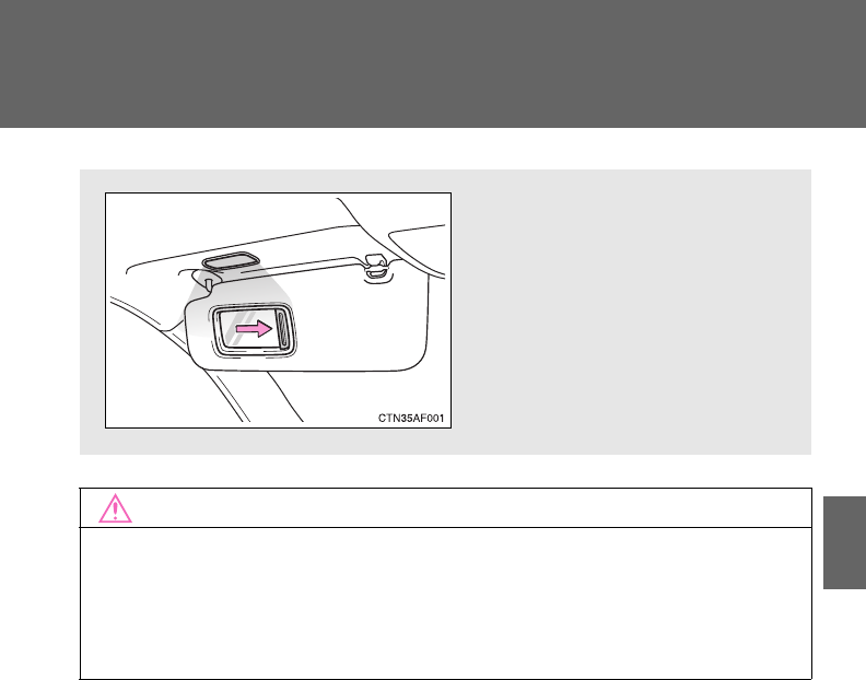
453
3-8. Other interior features
3
Interior features
Vanity mirrors
NOTICE
■To prevent the battery from being discharged (vehicles with vanity mir-
ror light)
Do not leave the vanity lights on for extended periods while the engine is
stopped.
Slide the cover.
The light turns on when the
cover is opened. (Vehicles with
vanity mirror light)
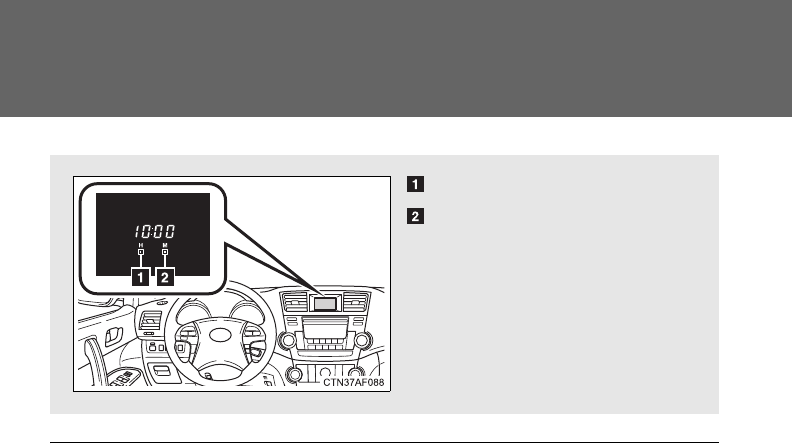
454
3-8. Other interior features
Clock (vehicles without multi-information display)
■The clock is displayed when
The engine switch is in the “ACC” or “ON” position.
Adjusts the hours.
Adjusts the minutes.
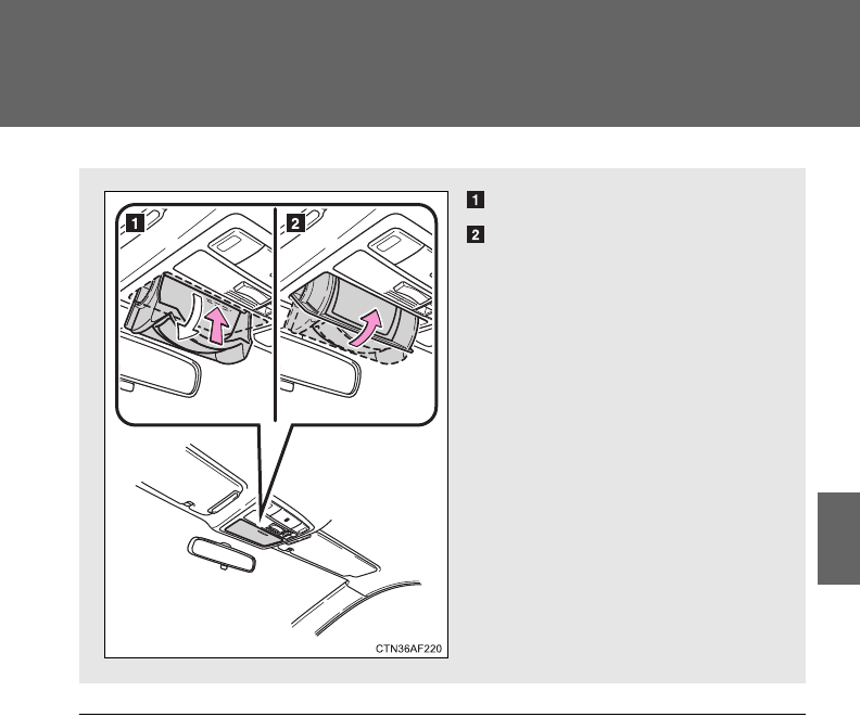
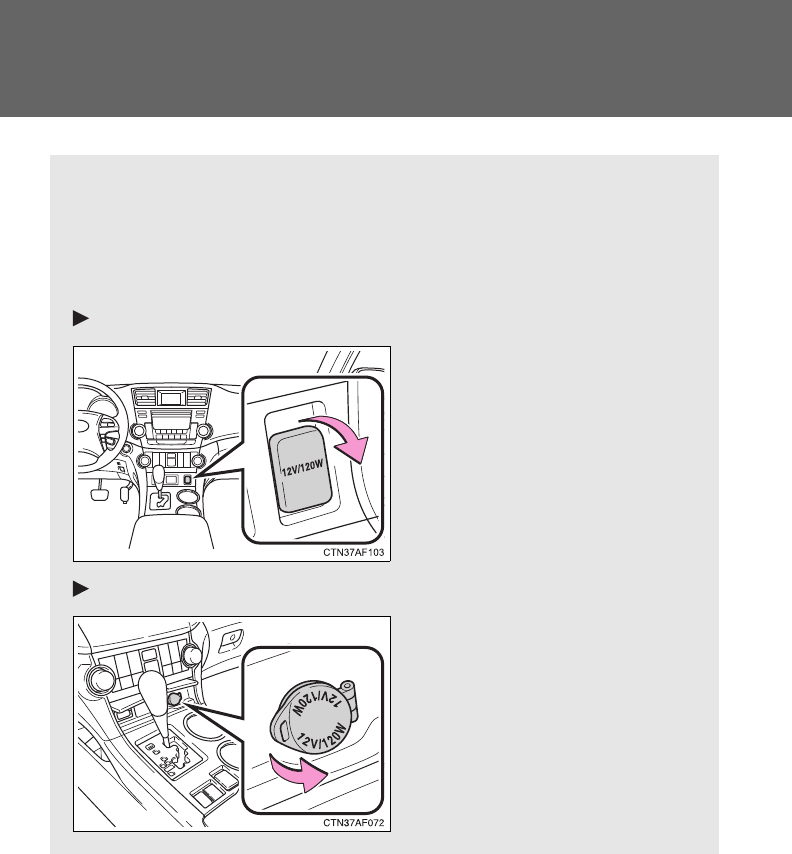
456
3-8. Other interior features
Power outlets
The power outlet can be used for the following components.
12 V: Accessories that run on less than 10 A.
120 VAC: Accessories that use less than 100 W.
■12 V
Type A (vehicles with seat heater)
Type B (vehicles without seat heater)
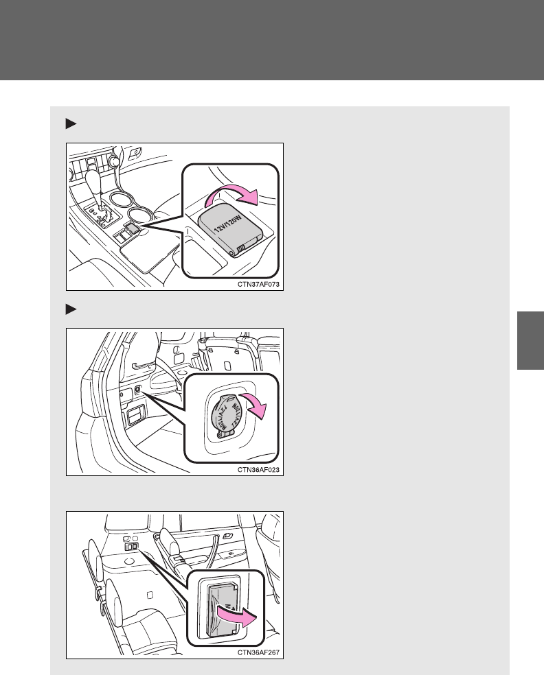
457
3-8. Other interior features
3
Interior features
Type C
Type D
■120 VAC (vehicles with rear entertainment system)

458
3-8. Other interior features
■The power outlet can be used when
12 V
Vehicles without smart key system:
The engine switch is in the “ACC” or “ON” position.
Vehicles with smart key system:
The “ENGINE START STOP” switch is in ACCESSORY or IGNITION ON
mode.
120 VAC
Vehicles without smart key system:
The engine switch is in the “ON” position.
Vehicles with smart key system:
The “ENGINE START STOP” switch is in IGNITION ON mode.
459
3-8. Other interior features
3
Interior features
NOTICE
■To avoid damaging the power outlet
Close the power outlet lid when the power outlet is not in use.
Foreign objects or liquids that enter the power outlet may cause a short cir-
cuit.
■To prevent the fuse from being blown
12 V
Do not use an accessory that uses more than 12 V 10 A.
120 VAC
Do not use a 120 VAC appliance that requires more than 100 W.
If a 120 VAC appliance that consumes more than 100 W is used, the pro-
tection circuit will cut the power supply.
■To prevent the battery discharge
Do not use the power outlet longer than necessary when the engine is off.
■Appliances that may not operate properly (120 VAC)
The following 120 VAC appliances may not operate properly even if their
power consumption is under 100 W.
●Appliances with high initial peak wattage
●Measuring devices that process precise data
●Other appliances that require an extremely stable power supply
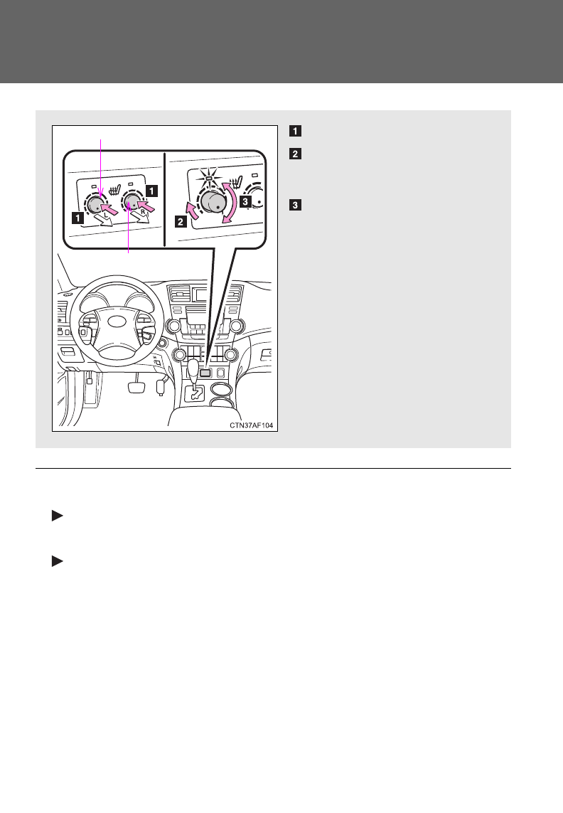
460
3-8. Other interior features
Seat heaters
■The seat heaters can be used when
Vehicles without smart key system
The engine switch is in the “ON” position.
Vehicles with smart key system
The “ENGINE START STOP” switch is in IGNITION ON mode.
■When not in use
Turn the knob fully counterclockwise. The indicator light turns off.
Press the knob into the recessed position.
Pops the knob out
On
The indicator light comes on.
Adjusts the seat tempera-
ture
The further you turn the knob
clockwise, the warmer the seat
becomes.
Front passenger's seat
Driver's seat
: If equipped

461
3-8. Other interior features
3
Interior features
CAUTION
■Burns
●Use caution when seating the following persons in a seat with the seat
heater on to avoid the possibility of burns:
• Babies, small children, the elderly, the sick and the disabled
• Persons with sensitive skin
• Persons who are fatigued
• Persons who have taken alcohol or drugs that induce sleep (sleeping
drugs, cold remedies, etc.)
●Do not cover the seat with anything when using the seat heater.
Using the seat heater with a blanket or cushion increases the temperature
of the seat and may lead to overheating.
NOTICE
■To prevent seat heater damage
Do not put unevenly weighted objects on the seat and do not stick sharp
objects (needles, nails, etc.) into the seat.
■To prevent battery discharge
Turn the switches off when the engine is not running.
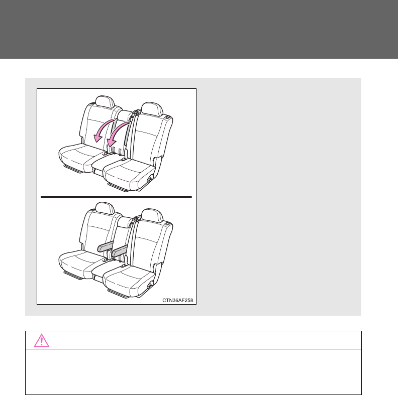
462
3-8. Other interior features
Armrests
NOTICE
■To prevent damage to the armrest
Do not place too much strain on the armrest.
Pull the armrest down for use.
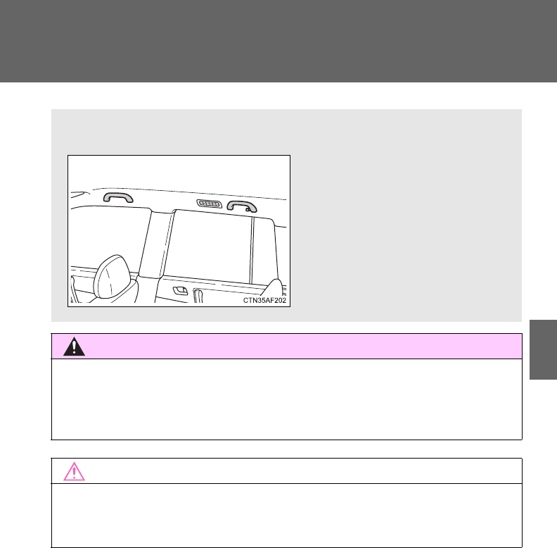
463
3-8. Other interior features
3
Interior features
Assist grips (folding type)
CAUTION
■Assist grip
Do not use the assist grip when getting in or out of the vehicle or rising from
your seat.
NOTICE
■To prevent damage to the assist grip
Do not hang any heavy object or put a heavy load on the assist grip.
An assist grip installed on the ceiling can be used to support your
body while sitting on the seat.
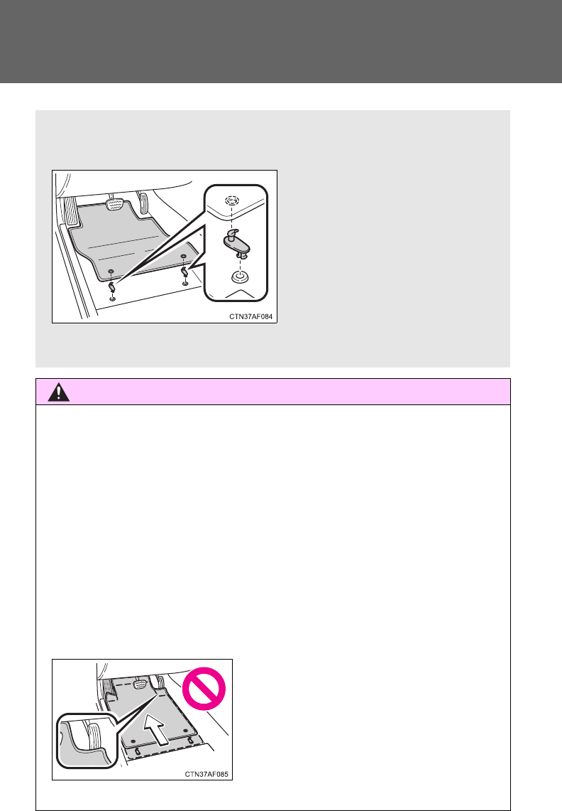
464
3-8. Other interior features
Floor mat
CAUTION
Observe the following precautions.
Failure to do so may cause the driver's floor mat to slip, possibly interfering
with the pedals while driving. An unexpectedly high speed may result or it may
become difficult to stop the vehicle, leading to a serious accident.
■When installing the driver's floor mat
●Do not use floor mats designed for other models or different model year
vehicles, even if they are Toyota Genuine floor mats.
●Only use floor mats designed for the driver's seat.
●Always install the floor mat securely using the retaining hooks (clips) pro-
vided.
●Do not use two or more floor mats on top of each other.
●Do not place the floor mat bottom-side up or upside-down.
■Before driving
Use only floor mats designed specifically for vehicles of the same
model and model year as your vehicle. Fix them securely in place
onto the carpet.
Fix the floor mat in place using
the retaining hooks (clips) pro-
vided.
The shape of the retaining
hooks (clips) and the fixing
procedure of the floor mat for
your vehicle may differ from
those shown in the illustration.
For details, refer to the floor
mat retention clip installation
instructions supplied with the
clips.
●Check that the floor mat is securely
fixed in the correct place with all the
provided retaining hooks (clips). Be
especially careful to perform this check
after cleaning the floor.
●With the engine stopped and the shift
lever in P, fully depress each pedal to
the floor to make sure it does not inter-
fere with the floor mat.
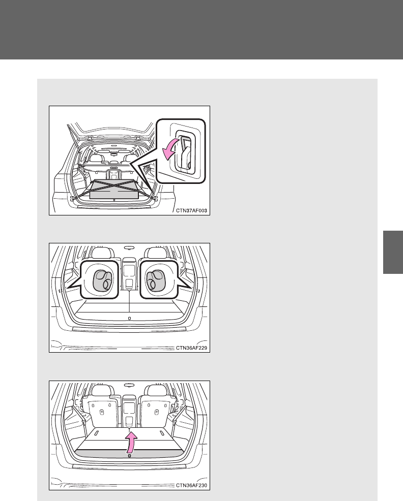
465
3-8. Other interior features
3
Interior features
Luggage compartment features
■Cargo hooks
Cargo hooks are provided for
securing loose items.
■Grocery bag hooks
■Auxiliary box
Lift the center deck board.
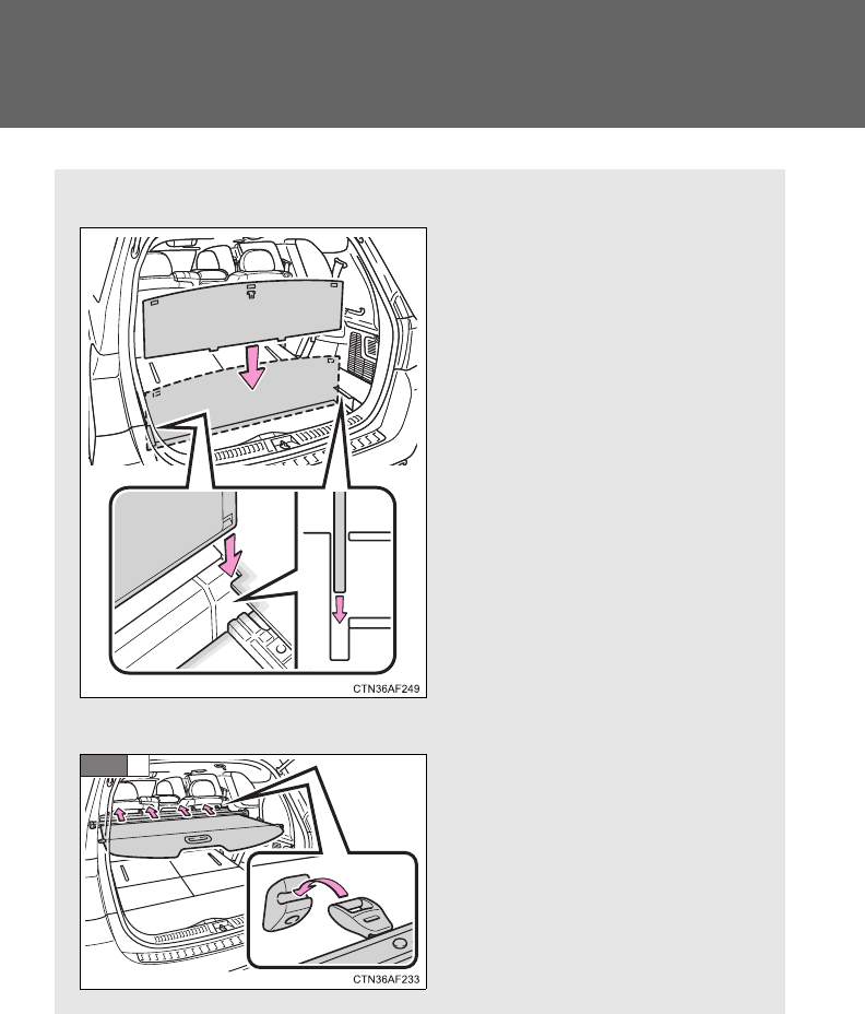
466
3-8. Other interior features
■Separating the luggage compartment
The center deck board can be
used to separate the luggage
compartment.
Remove the center deck
board and insert it upright into
the groove.
The board cannot be inserted
when the luggage cover is
stowed.
■Luggage cover (vehicles with luggage cover)
Hang the hooks on the hook
brackets on the second seat
seatback.
When using the luggage cover,
the third seat must be folded
down. (P. 80)
STEP
1
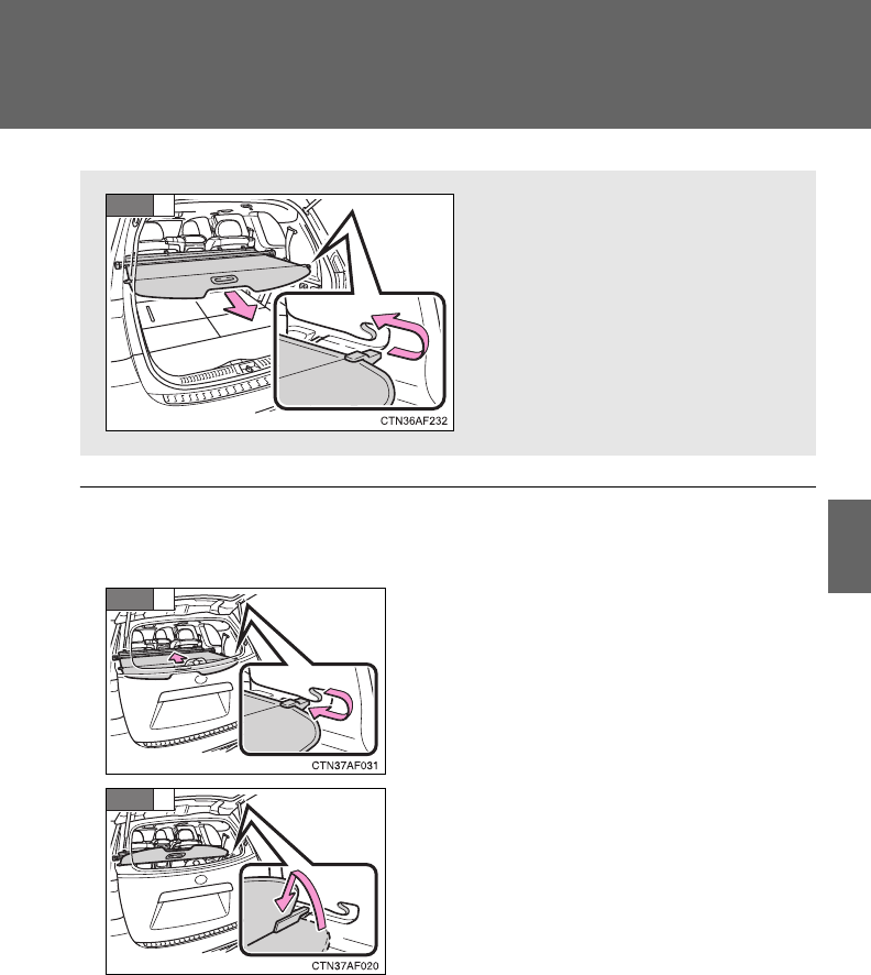
467
3-8. Other interior features
3
Interior features
■When taking out luggage through the glass hatch (vehicles with glass
hatch)
Pull out the luggage cover and
engage both ends to secure it.
STEP
2
Pull the luggage cover to disengage both
ends.
Engage both ends of the luggage cover
with the grooves shown in the illustration
and stand the cover upright.
STEP
1
STEP
2
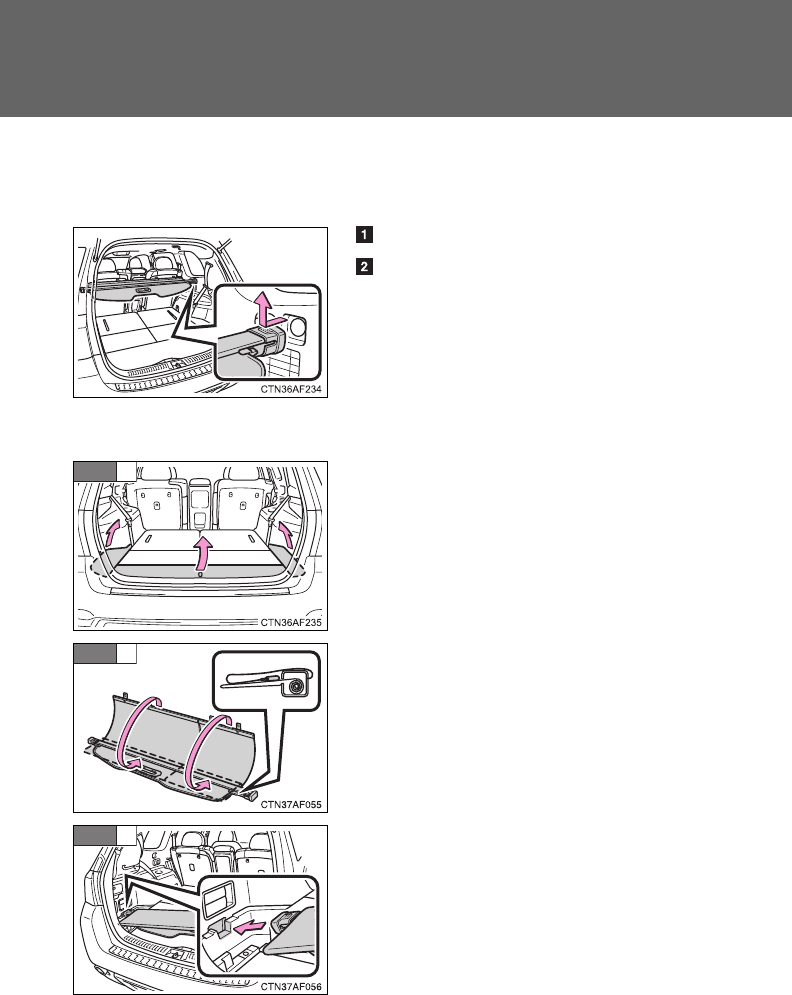
468
3-8. Other interior features
■Removing the luggage cover (vehicles with luggage cover)
The luggage cover can be removed by following the procedure below.
■Stowing the luggage cover (vehicles with luggage cover)
Detach the hooks.
Push in the left side of the luggage
cover while keeping hold of the right
side. Then raise the right side and pull
the luggage cover out.
Remove the side deck boards and open
the center deck board.
Fold the flaps on top of the luggage cover
with the hooks rolled inside.
Place the left end of the luggage cover in
the recess on the left-hand side and then
lower the right end into the recess on the
right-hand side.
STEP
1
STEP
2
STEP
3
469
3-8. Other interior features
3
Interior features
CAUTION
■When the cargo hooks are not in use
To avoid injury, always return the cargo hooks to their positions when they
are not in use.
■Caution while driving
Do not drive with any of the deck boards opened. Items may fall out and
cause injury.
NOTICE
■Grocery bag hook weight capacity
Do not hang any object heavier than 4 lb. (2 kg) on grocery bag hooks.
■While driving
Do not drive with the luggage cover standing upright in the grooves as the
luggage cover may fall down.
■Before inserting the center deck board into the luggage compartment
Make sure the luggage cover is not stowed.
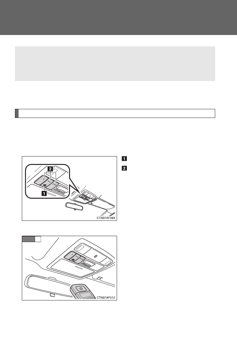
470
3-8. Other interior features
Garage door opener
The garage door opener (HomeLink Universal Transceiver) is manufac-
tured under license from HomeLink.
Programming the HomeLink (for U.S.A. owners)
The HomeLink compatible transceiver in your vehicle has 3 buttons
which can be programmed to operate 3 different devices. Refer to the
programming method below appropriate for the device.
Indicator
Buttons
■Programming the HomeLink
Point the remote control for the
device 1 to 3 in. (25 to 75 mm)
from the HomeLink control but-
tons.
Keep the indicator light on the
HomeLink in view while pro-
gramming.
The garage door opener can be programmed to operate garage
doors, gates, entry doors, door locks, home lighting systems, secu-
rity systems, and other devices.
STEP
1
: If equipped
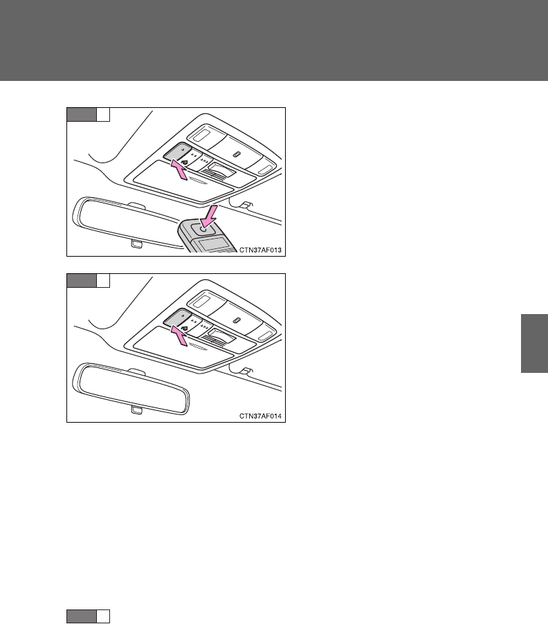
471
3-8. Other interior features
3
Interior features
Press and hold down one of the
buttons on the HomeLink and
the button on the transmitter.
When the indicator light on the
HomeLink changes from a slow
to a rapid flash within 20 sec-
onds, you can release both but-
tons.
Test the operation of the
HomeLink by pressing the
newly programmed button.
If programming a garage door
opener, check to see if the garage
door opens and closes. If the
garage door does not operate,
see if your garage transmitter is
of the Rolling Code type. Press
and hold the programmed
HomeLink button. The garage
door has the rolling code feature
if the indicator light (on the
HomeLink) flashes rapidly for 2
seconds and then remains lit. If
your transmitter is the Rolling
Code type, proceed to the head-
ing “Programming a rolling code
system”.
Repeat the steps above to program another device for each of
the remaining HomeLink buttons.
STEP
2
STEP
3
STEP
4

472
3-8. Other interior features
■Programming a Rolling Code system (for U.S.A. owners)
If your device is Rolling Code equipped, follow the steps under the
heading “Programming the HomeLink” before proceeding with
the steps listed below.
Locate the learn button on the ceiling mounted garage door
opener motor. The exact location and color of the button may
vary by brand of garage door opener.
Refer to the operation manual supplied with the garage door opener
for the location of the learn button.
Press the learn button.
Following this step, you have 30 seconds in which to initiate step 3
below.
Press and release the vehicle’s programmed HomeLink but-
ton twice. The garage door may open.
If the garage door opens, the programming process is complete. If
the door does not open, press and release the button a third time.
This third press and release will complete the programming process
by opening the garage door.
The ceiling mounted garage door opener motor should now recog-
nize the HomeLink transceiver and operate the garage door.
Repeat the steps above to program another rolling code sys-
tem for any of the remaining HomeLink buttons.
■Programming an entry gate (for U.S.A. owners)/Programming
all devices in the Canadian market
Place your transmitter 1 to 3 in. (25 to 75 mm) away from the
surface of the HomeLink.
Keep the indicator light on the HomeLink in view while program-
ming.
Press and hold the selected HomeLink button.
Repeatedly press and release (cycle) the device’s remote
control button for two seconds each until step 4 is complete.
When the indicator light on the HomeLink compatible trans-
ceiver starts flashing rapidly, release the buttons.
STEP
1
STEP
2
STEP
3
STEP
4
STEP
1
STEP
2
STEP
3
STEP
4
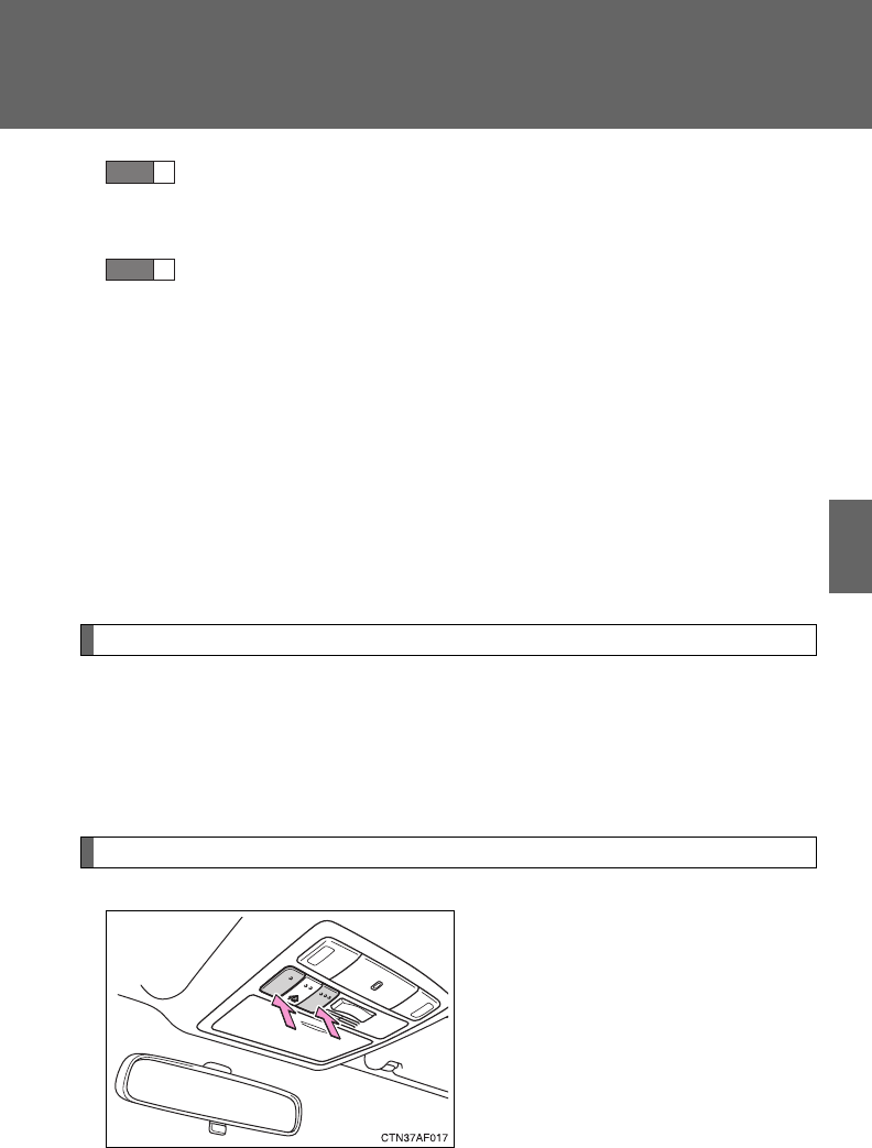
473
3-8. Other interior features
3
Interior features
Test the operation of the HomeLink by pressing the newly
programmed button. Check to see if the gate/device operates
correctly.
Repeat the steps above to program another device for each of
the remaining HomeLink buttons.
■Programming other devices
To program other devices such as home security systems, home
door locks or lighting, contact your authorized Toyota dealer for
assistance.
■Reprogramming a button
The individual HomeLink buttons cannot be erased but can be
reprogrammed. To reprogram a button, follow the programming
instructions.
Operating the HomeLink
Press the appropriate HomeLink button. The HomeLink indicator
light on the HomeLink transceiver should turn on.
The HomeLink continues to send a signal for up to 20 seconds as long
as the button is pressed.
Erasing the entire HomeLink memory (all three programs)
Press and hold down the 2 out-
side buttons for 10 seconds (or
20 seconds depending on the
model) until the indicator light
flashes.
If you sell your vehicle, be sure to
erase the programs stored in the
HomeLink memory.
STEP
5
STEP
6

474
3-8. Other interior features
■Before programming
●Install a new battery in the transmitter.
●The battery side of the transmitter must be pointed away from the
HomeLink.
■When programming
Depending on radio wave conditions, the direction the remote control trans-
mitter is pointed and the remaining charge of the transmitter’s batteries,
there are cases when programming may be difficult.
■Certification for the garage door opener
For vehicles sold in the U.S.A.
FCC ID: CB2300NHL3
FCC ID: CB2281AHL4
NOTE:
This device complies with Part 15 of the FCC Rules. Operation is subject to
the following two conditions: (1) this device may not cause harmful interfer-
ence, and (2) this device must accept any interference received, including
interference that may cause undesired operation.
FCC WARNING:
Changes or modifications not expressly approved by the party responsible
for compliance could void the user's authority to operate the equipment.
For vehicles sold in Canada
NOTE:
Operation is subject to the following two conditions: (1) this device may not
cause interference, and (2) this device must accept any interference, includ-
ing interference that may cause undesired operation of the device.
■When support is necessary
Visit on the web at www.homelink.com or call 1-800-355-3515.

475
3-8. Other interior features
3
Interior features
CAUTION
■When programming a garage door or other remote control device
The garage door may operate, so ensure people and objects are out of dan-
ger to prevent potential harm.
■Conforming to federal safety standards
Do not use the HomeLink Compatible Transceiver with any garage door
opener or device that lacks safety stop and reverse features as required by
federal safety standards.
This includes any garage door that cannot detect an obstruction object. A
door or device without these features increases the risk of death or serious
injury.
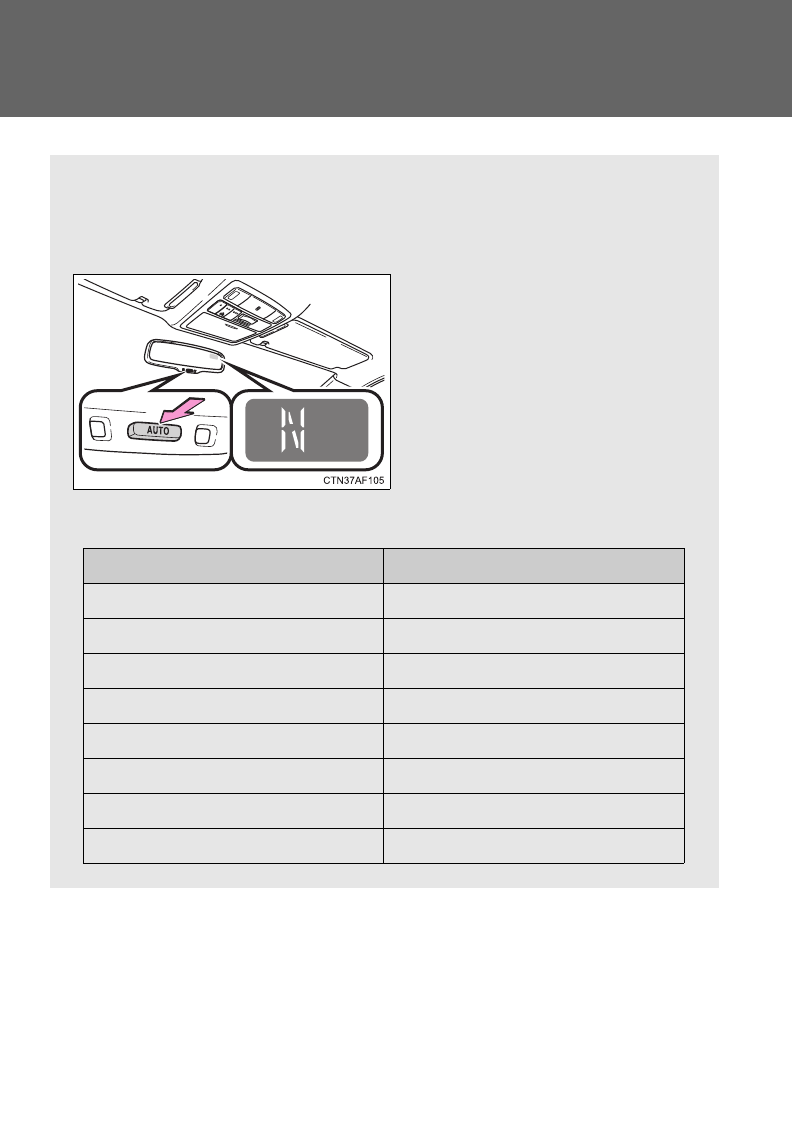
476
3-8. Other interior features
Compass
The compass on the inside rear view mirror indicates the direction in
which the vehicle is heading.
■Operation
To turn the compass on or off,
press “AUTO”.
■Displays and directions
Display Direction
NNorth
NE Northeast
EEast
SE Southeast
S South
SW Southwest
WWest
NW Northwest
: If equipped
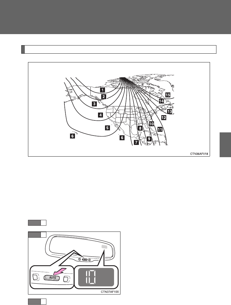
477
3-8. Other interior features
3
Interior features
Calibrating the compass
The direction display deviates from the true direction determined by
the earth’s magnetic field. The amount of deviation varies according
to the geographic position of the vehicle.
If you cross over a map boundary shown in illustration, the compass will
deviate.
To obtain higher precision or perfect calibration, refer to the following.
■Deviation calibration
Stop the vehicle.
Press “AUTO” until a number
(1 to 15) appears on the com-
pass display.
Press the switch, and referring to the map above, select the
number of the zone where you are.
If the direction is displayed several seconds after adjustment, the
calibration is complete.
STEP
1
STEP
2
STEP
3
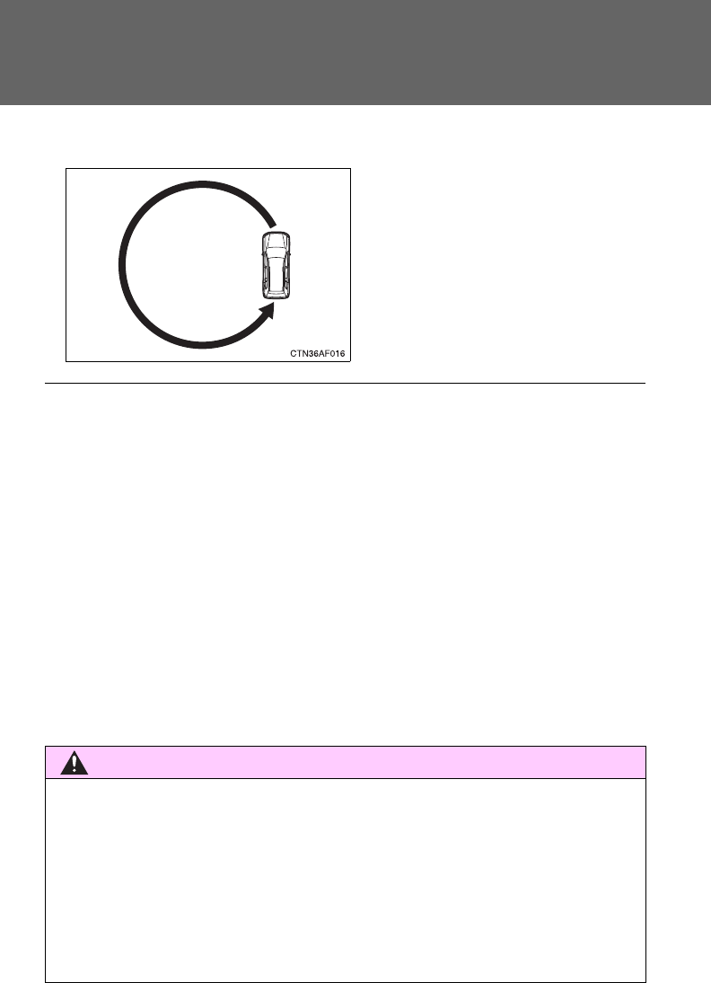
478
3-8. Other interior features
■Circling calibration
When C appears on the display,
drive the vehicle at 5 mph (8 km/h)
or less in a circle until a direction is
displayed.
If there is not enough space to
drive in a circle, drive around the
block until the direction is dis-
played.
■Conditions unfavorable to correct operation
The compass may not show the correct direction in the following conditions:
●The vehicle is stopped immediately after turning.
●The vehicle is on an inclined surface.
●The vehicle is in a place where the earth's magnetic field is subject to
interference by artificial magnetic fields (underground car park/parking
lot, under a steel tower, between buildings, roof car park/parking lot, near
an intersection, near a large vehicle, etc.).
●The vehicle has become magnetized.
(There is a magnet or metal object near the inside rear view mirror.)
●The battery has been disconnected.
●A door is open.
CAUTION
■While driving the vehicle
Do not adjust the display. Be sure to adjust the display only when the vehicle
is stopped.
■When doing the circling calibration
Be sure to secure a wide space, and watch out for people and vehicles in the
neighborhood. Do not violate any local traffic rules while performing circling
calibration.

479
3-8. Other interior features
3
Interior features
NOTICE
■To avoid compass malfunctions
Do not place magnets or any metal objects near the inside rear view mirror.
Doing this may cause a malfunction of the compass sensor.
■To ensure normal operation of the compass
●Do not perform circling calibration of the compass in a place where the
earth's magnetic field is subject to interference by artificial magnetic fields.
●During calibration, do not operate electric systems (moon roof, power win-
dows, etc.) as they may interfere with the calibration.

480
3-8. Other interior features

Maintenance and care 4
481
4-1. Maintenance and care
Cleaning and protecting
the vehicle exterior......... 482
Cleaning and protecting
the vehicle interior.......... 485
4-2. Maintenance
Maintenance
requirements.................. 488
General maintenance....... 491
Emission inspection and
maintenance (I/M)
programs........................ 494
4-3. Do-it-yourself
maintenance
Do-it-yourself service
precautions .................... 495
Hood ................................ 499
Positioning a floor jack ..... 501
Engine compartment........ 505
Tires ................................. 521
Tire inflation pressure ...... 530
Wheels ............................. 533
Air conditioning filter......... 536
Wireless remote control/
electronic key battery..... 539
Checking and replacing
fuses .............................. 542
Light bulbs........................ 553

482
4-1. Maintenance and care
Cleaning and protecting the vehicle exterior
■Automatic car washes
●Before washing the vehicle, do the following:
• Fold the mirrors back.
• Remove the antenna. (Pole type only)
• Turn the power back door system off.
●Brushes used in automatic car washes may scratch the vehicle surface
and harm your vehicle’s paint.
■High pressure car washes
●Do not allow the nozzles of the car wash to come within close proximity
of the windows.
●Before using the car wash, check that the fuel filler door on your vehicle
is closed properly.
Perform the following to protect the vehicle and maintain it in prime
condition.
●Working from top to bottom, liberally apply water to the vehicle
body, wheel wells and underside of the vehicle to remove any
dirt and dust.
Wash the vehicle body using a sponge or soft cloth, such as a
chamois.
●For hard-to-remove marks, use car wash soap and rinse thor-
oughly with water.
●Wipe away any water.
●Wax the vehicle when the waterproof coating deteriorates.
If water does not bead on a clean surface, apply wax when the vehicle
body is cool.

483
4-1. Maintenance and care
4
Maintenance and care
■Aluminum wheels
●Remove any dirt immediately by using a neutral detergent. Do not use
hard brushes or abrasive cleaners. Do not use strong or harsh chemical
cleaners.
Use the same mild detergent and wax as used on the paint.
●Do not use detergent on the wheels when they are hot, for example after
driving for long distance in the hot weather.
●Wash detergent from the wheels immediately after use.
■Bumpers
Do not scrub with abrasive cleaners.
CAUTION
■Caution about the exhaust pipe
Exhaust gasses cause the exhaust pipe to become quite hot.
When washing the vehicle, be careful not to touch the pipe until it has cooled
sufficiently, as touching a hot exhaust pipe can cause burns.

484
4-1. Maintenance and care
NOTICE
■To prevent paint deterioration and corrosion on the body and compo-
nents (aluminum wheels etc.)
●Wash the vehicle immediately in the following cases:
• After driving near the sea coast
• After driving on salted roads
• If you see coal tar or tree sap on the paint surface
• If you see dead insects or insect droppings on the paint
• After driving in an area contaminated with soot, oily smoke, mine dust,
iron powder or chemical substances
• If the vehicle becomes heavily soiled in dust or mud
• If liquids such as benzene and gasoline are spilled on the paint surface
●If the paint is chipped or scratched, have it repaired immediately.
●To prevent the wheels from corroding, remove any dirt and store in a place
with low humidity when storing the wheels.
■If the windshield washer nozzle become blocked
Contact your Toyota dealer. Do not try to clear it with a pin or other object.
This may damage the nozzle.
■Cleaning the exterior lights
●Wash carefully. Do not use organic substances or scrub with a hard brush.
This may damage the surfaces of the lights.
●Do not apply wax on the surfaces of the lights.
Wax may cause damage to the lenses.
■Pole type antenna installation and removal precautions
●Before driving, ensure that the antenna is installed.
●When the antenna is removed, such as before entering an automatic car
wash, make sure to store it in a suitable place so as not to lose it. Also,
before driving, make sure to reinstall the antenna in its original position.
■To prevent damage to the windshield wiper arms
When lifting the wiper arms away from the windshield, pull the driver side
wiper arm upward first, and repeat for the passenger side. When returning
the wipers to their original position, do so from the passenger side first.

485
4-1. Maintenance and care
4
Maintenance and care
Cleaning and protecting the vehicle interior
The following procedures will help protect your vehicle's interior and
keep it in top condition:
■Protecting the vehicle interior
Remove dirt and dust using a vacuum cleaner. Wipe dirty sur-
faces with a cloth dampened with lukewarm water.
■Cleaning the leather areas
●Remove dirt and dust using a vacuum cleaner.
●Wipe any excess dirt and dust with a soft cloth dampened with
diluted detergent.
Use a diluted water solution of approximately 5% neutral wool deter-
gent.
●Wring out any excess water from the cloth and thoroughly
wipe off all remaining traces of detergent.
●Wipe the surface with a dry, soft cloth to remove any remain-
ing moisture. Allow the leather to dry in a shaded ventilated
area.
■Synthetic leather areas
●Remove loose dirt using a vacuum cleaner.
●Apply a mild soap solution to the synthetic leather.
●Allow the solution to soak in for a few minutes. Remove the
dirt and wipe off the solution with a clean, damp cloth.

486
4-1. Maintenance and care
■Caring for leather areas
Toyota recommends cleaning the interior of the vehicle at least twice a year
to maintain the quality of the vehicle's interior.
■Shampooing the carpets
There are several commercial foaming-type cleaners available. Use a
sponge or brush to apply the foam. Rub in overlapping circles. Do not apply
water. Excellent results are obtained by keeping the carpet as dry as possi-
ble.
■Seat belts
Clean with mild soap and lukewarm water using a cloth or sponge. Also
check the belts periodically for excessive wear, fraying or cuts.
CAUTION
■Water in the vehicle
●Do not splash or spill liquid in the vehicle.
Doing so may cause electrical components etc. to malfunction or catch
fire.
●Do not get any of the SRS components or wiring in the vehicle interior wet.
(P. 125)
Electrical malfunction may cause the airbags to deploy or not function
properly, resulting in death or severe injury.
■Cleaning the interior (especially instrument panel)
Do not use polish wax or polish cleaner. The instrument panel may reflect
off the windshield, obstructing the driver’s view and leading to an accident,
resulting in death or serious injury.

487
4-1. Maintenance and care
4
Maintenance and care
NOTICE
■Cleaning detergents
●Do not use organic substances such as benzene or gasoline, acidic or
alkaline solutions, dye, bleach or other detergent. Doing so may discolor
the vehicle interior or cause streaks or damage to painted surfaces.
●Do not use polish wax or polish cleaner. The instrument panel’s or other
interior part’s painted surface may be damaged.
■Preventing damage to leather surfaces
Observe the following precautions to avoid damage to and deterioration of
leather surfaces:
●Remove any dust or dirt on leather surfaces immediately.
●Do not expose the vehicle to direct sunlight for extended periods of time.
Park the vehicle in the shade, especially during summer.
●Do not place items made of vinyl, plastic, or that contain wax on the uphol-
stery, as they may stick to the leather surface if the vehicle interior heats
up significantly.
■Water on the floor
Do not wash the vehicle floor with water.
Vehicle systems such as the audio system may be damaged if water comes
into contact with electrical components under the floor of the vehicle, and
may also cause the body to rust.
■Cleaning the inside of the rear window or left-side rear quarter window
●Do not use glass cleaner to clean the rear window or left-side rear quarter
window, as this may cause damage to the rear window defogger heater
wires or print type antenna (if equipped). Use a cloth dampened with luke-
warm water to gently wipe the windows clean. Wipe the windows in
strokes running parallel to the heater wires or print type antenna (if
equipped).
●Be careful not to scratch or damage the heater wires or print type antenna
(if equipped).

488
4-2. Maintenance
Maintenance requirements
■Repair and replacement
It is recommended that genuine Toyota parts be used for repair to ensure
performance of each system. If non-Toyota parts are used in replacement or
if a repair shop other than a Toyota dealer performs repairs, confirm the war-
ranty coverage.
To ensure safe and economical driving, day-to-day care and regular
maintenance is essential. It is the owner’s responsibility to perform
regular checks. Toyota recommends the following maintenance.
■General maintenance
General maintenance should be performed on a daily basis.
This can be done by yourself or by a Toyota dealer.
■Scheduled maintenance
Scheduled maintenance should be performed at specified inter-
vals according to the maintenance schedule.
For details about maintenance items and schedules, refer to the
“Scheduled Maintenance Guide” or “Owner’s Manual Supplement”.
■Do-it-yourself maintenance
You can perform some maintenance procedures yourself.
Please be aware that do-it-yourself maintenance may affect war-
ranty coverage.
The use of Toyota Repair Manuals is recommended.
For details about warranty coverage, see the separate “Owner’s
Warranty Information Booklet” or “Owner’s Manual Supplement”.

489
4-2. Maintenance
4
Maintenance and care
■Reset the maintenance data (U.S.A. only)
After the required maintenance is performed according to the maintenance
schedule, please reset the maintenance data.
To reset the data, follow the procedures described below:
Vehicles without smart key system
Set the engine switch to the “LOCK” position with the trip meter A
reading shown. (P. 186)
While pressing the trip meter reset button, set the engine switch to
the “ON” position.
Vehicles with smart key system
Set the “ENGINE START STOP” switch OFF with the trip meter A
reading shown. (P. 186)
While pressing the trip meter reset button, set the “ENGINE START
STOP” switch to the IGNITION ON mode.
Without multi-information display: Continue to press and hold the
button until the trip meter displays “000000”.
With multi-information display: Continue to press and hold the but-
ton until “COMPLETE” appears on the multi-information display.
■Allow inspection and repairs to be performed by a Toyota dealer
●Toyota technicians are well-trained specialists and are kept up to date
with the latest service information. They are well informed about the
operations of all systems on your vehicle.
●Keep a copy of the repair order. It proves that the maintenance that has
been performed is under warranty coverage. If any problem should arise
while your vehicle is under warranty, your Toyota dealer will promptly
take care of it.
STEP
1
STEP
2
STEP
1
STEP
2
STEP
3

490
4-2. Maintenance
CAUTION
■Warning in handling of battery
●Engine exhaust, some of its constituents, and a wide variety of automobile
components contain or emit chemicals known to the State of California to
cause cancer and birth defects and other reproductive harm. Work in a
well ventilated area.
●Oils, fuels and fluids contained in vehicles as well as waste produced by
component wear contain or emit chemicals known to the State of Califor-
nia to cause cancer and birth defects or other reproductive harm. Avoid
exposure and wash any affected area immediately.
●Battery posts, terminals and related accessories contain lead and lead
compounds which are known to cause brain damage. Wash your hands
after handling. (P. 516)
491
4-2. Maintenance
4
Maintenance and care
General maintenance
Engine compartment
Items Check points
Battery Maintenance-free. (P. 516)
Brake fluid At the correct level? (P. 515)
Engine coolant At the correct level? (P. 512)
Engine oil At the correct level? (P. 508)
Exhaust system No fumes or strange sounds?
Radiator/condenser/hoses Not blocked with foreign matter?
(P. 514)
Washer fluid At the correct level? (P. 520)
Listed below are the general maintenance items that should be per-
formed at the intervals specified in the “Scheduled Maintenance
Guide” or “Owner’s Manual Supplement”. It is recommended that
any problem you notice should be brought to the attention of your
Toyota dealer or qualified service shop for advice.

492
4-2. Maintenance
Vehicle interior
Items Check points
Accelerator pedal • Moves smoothly (without uneven
pedal effort or catching)?
Automatic transmission “Park”
mechanism
• Can the vehicle be held securely
on an incline with the shift lever in
P?
Brake pedal
• Moves smoothly?
• Does it have appropriate clear-
ance and correct amount of free
play?
Brakes
• Not pull to one side when
applied?
• Loss of brake effectiveness?
• Spongy feeling brake pedal?
• Pedal almost touches floor?
Head restraints • Move smoothly and lock
securely?
Indicators/buzzers • Function properly?
Lights • Do all the lights come on?
• Headlights aimed correctly?
Parking brake
• Moves smoothly?
• Can hold the vehicle securely on
an incline?
Seat belts
• Does the seat belt system oper-
ate smoothly?
• Are the belts undamaged?
Seats • Do the seat controls operate
properly?
Steering wheel
• Moves smoothly?
• Has correct free play?
• No strange noises?
493
4-2. Maintenance
4
Maintenance and care
Vehicle exterior
Items Check points
Door • Operate smoothly?
Engine hood • The lock system works properly?
Fluid leaks • Is there any leakage after park-
ing?
Tire
• Inflation pressure is correct?
• Tire surfaces not worn or dam-
aged?
• Tires rotated according to the
maintenance schedule?
• Wheel nuts are not loose?
Wiper blades • Is there any wear or cracks?
CAUTION
■If the engine is running
Turn the engine off and ensure that there is adequate ventilation before per-
forming maintenance checks.

494
4-2. Maintenance
Emission inspection and maintenance (I/M) programs
Some states have vehicle emission inspection programs which
include OBD (On Board Diagnostics) checks. The OBD system moni-
tors the operation of the emission control system.
■If the malfunction indicator lamp comes on
The OBD system determines that a problem exists somewhere
in the emission control system. Your vehicle may not pass the I/
M test and may need to be repaired. Contact your Toyota dealer
to service the vehicle.
■Your vehicle may not pass the I/M test:
●When the battery is disconnected or discharged
Readiness codes that are set during ordinary driving are
erased.
Also, depending on your driving habits, the readiness codes
may not be completely set.
●When the fuel tank cap is loose
The malfunction indicator lamp comes on as a temporary mal-
function and your vehicle may not pass the I/M test.
■When the malfunction indicator lamp goes off after several
driving trips
The error code in the OBD system will not be cleared unless the
vehicle is driven 40 or more times.
■If your vehicle does not pass the I/M test
Contact your Toyota dealer to prepare the vehicle for re-testing.

495
4
Maintenance and care
4-3. Do-it-yourself maintenance
Do-it-yourself service precautions
If you perform maintenance yourself, be sure to follow the correct
procedures as given in these sections.
Items Parts and tools
Battery condition (P. 516)
•Warm water
• Baking soda
• Grease
• Conventional wrench
(for terminal clamp bolts)
Brake fluid level (P. 515)
• FMVSS No.116 DOT 3 or SAE
J1703 brake fluid
• Rag or paper towel
• Funnel (used only for adding
brake fluid)
Engine coolant level (P. 512)
• “Toyota Super Long Life Coolant”
or similar high quality ethylene
glycol based non-silicate, non-
amine, non-nitrite and non-borate
coolant with long-life hybrid
organic acid technology.
For the U.S.A.:
“Toyota Super Long Life
Coolant” is pre-mixed with 50%
coolant and 50% deionized
water.
For Canada:
“Toyota Super Long Life
Coolant” is pre-mixed with 55%
coolant and 45% deionized
water.
• Funnel (used only for adding
engine coolant)
Engine oil level (P. 508)
• “Toyota Genuine Motor Oil” or
equivalent
• Rag or paper towel, funnel
(used only for adding oil)

496
4-3. Do-it-yourself maintenance
Items Parts and tools
Fuses (P. 542) • Fuse with same amperage rating
as original
Radiator and condenser
(P. 514)
Tire inflation pressure (P. 530) • Tire pressure gauge
• Compressed air source
Washer fluid (P. 520)
• Water or washer fluid containing
antifreeze (for winter use)
• Funnel

497
4-3. Do-it-yourself maintenance
4
Maintenance and care
CAUTION
The engine compartment contains many mechanisms and fluids that may
move suddenly, become hot, or become electrically energized. To avoid death
or serious injury observe the following precautions.
■When working on the engine compartment
●Keep hands, clothing, and tools away from the moving fan and engine
drive belt.
●Be careful not to touch the engine, radiator, exhaust manifold, etc. right
after driving as they may be hot. Oil and other fluids may also be hot.
●Do not leave anything that may burn easily, such as paper or rags, in the
engine compartment.
●Do not smoke, cause sparks or expose an open flame to fuel or the bat-
tery. Fuel and battery fumes are flammable.
●Be extremely cautious when working on the battery. It contains poisonous
and corrosive sulfuric acid.
●Take care because brake fluid can harm your hands or eyes and damage
painted surfaces.
If fluid gets on your hands or in your eyes, flush the affected area with
clean water immediately.
If you still experience discomfort, see a doctor.
●Do not touch the engine compartment when the electric cooling fan is
operating.
Vehicles without smart key system: The electric cooling fan may keep
rotating for about 3 minutes even after the engine switch is turned to the
“LOCK” position.
With the engine switch in the “ON” position, the electric cooling fan may
automatically start to run if the air conditioning is on and/or the coolant
temperature is high. Be sure the engine switch is in the “LOCK” position
when working near the electric cooling fan or radiator grille.
Vehicles with smart key system: The electric cooling fan may keep rotating
for about 3 minutes even after the “ENGINE START STOP” switch is OFF.
With the “ENGINE START STOP” switch in IGNITION ON mode, the elec-
tric cooling fan may automatically start to run if the air conditioning is on
and/or the coolant temperature is high. Be sure the “ENGINE START
STOP” switch is OFF when working near the electric cooling fan or radia-
tor grille.
498
4-3. Do-it-yourself maintenance
CAUTION
■Safety glasses
Wear safety glasses to prevent flying or falling material, fluid spray, etc. from
getting in the eyes.
NOTICE
■If you remove the air cleaner filter
Driving with the air cleaner filter removed may cause excessive engine wear
due to dirt in the air.
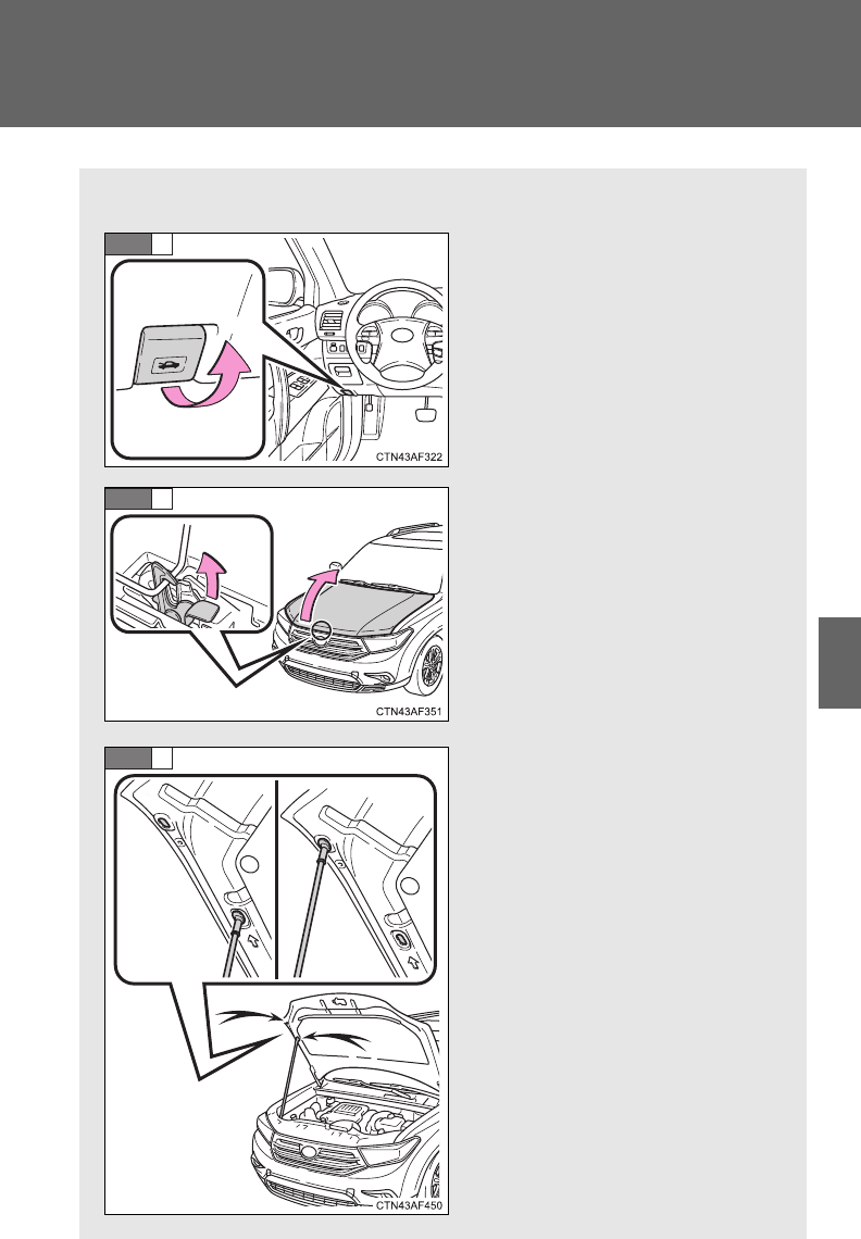
499
4-3. Do-it-yourself maintenance
4
Maintenance and care
Hood
Release the lock from the inside of the vehicle to open the hood.
Pull the hood release lever.
The hood will pop up slightly.
Lift the auxiliary catch lever
and lift the hood.
Hold the hood open by insert-
ing the supporting rod into
either of the slots.
STEP
1
STEP
2
STEP
3
500
4-3. Do-it-yourself maintenance
CAUTION
■Pre-driving check
Check that the hood is fully closed and locked.
If the hood is not locked properly, it may open while the vehicle is in motion
and cause an accident, which may result in death or serious injury.
■After installing the support rod into the slot
Make sure the rod supports the hood securely from falling down on to your
head or body.
NOTICE
■When closing the hood
Be sure to return the support rod to its clip before closing the hood. Closing
the hood with the support rod up could cause the hood to bend.
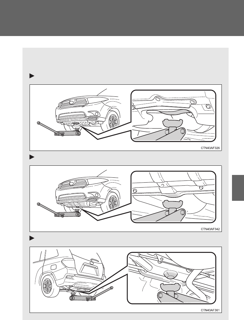
501
4-3. Do-it-yourself maintenance
4
Maintenance and care
Positioning a floor jack
When raising your vehicle with a floor jack, position the jack cor-
rectly. Improper placement may damage your vehicle or cause injury.
Front (2.7 L 4-cylinder [1AR-FE] engine)
Front (3.5 L V6 [2GR-FE] engine)
Rear (2WD models)
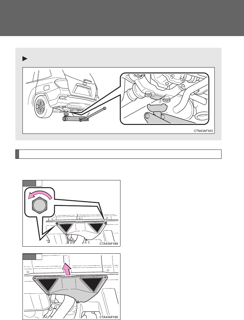
502
4-3. Do-it-yourself maintenance
Removing the front jack point cover (3.5 L V6 [2GR-FE] engine)
Before jacking up the vehicle, remove the jack point cover.
Turn the bolts counterclockwise
and remove them.
Remove the cover.
Rear (4WD models)
STEP
1
STEP
2
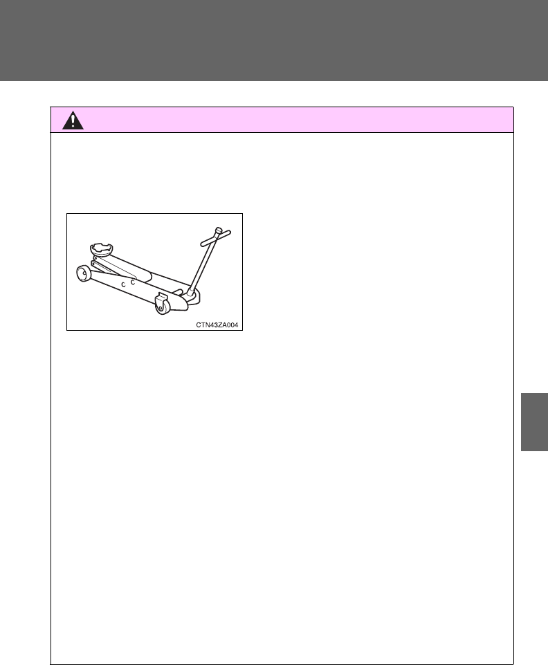
503
4-3. Do-it-yourself maintenance
4
Maintenance and care
CAUTION
■When raising your vehicle
Make sure to observe the following to reduce the possibility of death or seri-
ous injury.
●When using a floor jack, follow the instructions of the manual provided with
the jack.
●Do not use the jack that was supplied with your vehicle.
●Do not put any part of your body or get underneath the vehicle supported
only by the floor jack.
●Always use floor jack and/or automotive jack stands on a solid, flat, level
surface.
●Do not start the engine while the vehicle is supported by the floor jack.
●Stop the vehicle on level firm ground, firmly set the parking brake and shift
the shift lever in P.
●Make sure to set the floor jack properly at the jack point.
Raising the vehicle with an improperly positioned floor jack will damage
the vehicle and may cause the vehicle to fall off the floor jack.
●Do not raise the vehicle while someone is in the vehicle.
●When raising the vehicle, do not place any objects on top of or underneath
the floor jack.
●Lift up the vehicle using a floor jack
such as the one shown in the illustra-
tion.

504
4-3. Do-it-yourself maintenance
NOTICE
■Front jack point cover (3.5 L V6 [2GR-FE] engine)
●Before jacking up your vehicles, remove the front jack point cover. Other-
wise, the cover may be damaged.
●After installing the front jack point cover, make sure it is securely in its orig-
inal position.
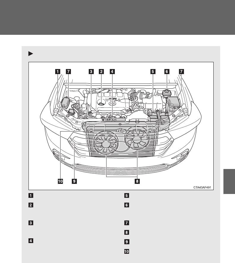
505
4-3. Do-it-yourself maintenance
4
Maintenance and care
Engine compartment
2.7 L 4-cylinder (1AR-FE) engine
Washer fluid tank (P. 520)
Engine oil filler cap
(P. 509)
Engine oil level dipstick
(P. 508)
Engine coolant reservoir
(P. 512)
Battery (P. 516)
Brake fluid reservoir
(P. 515)
Fuse boxes (P. 542)
Electric cooling fans
Condenser (P. 514)
Radiator (P. 514)
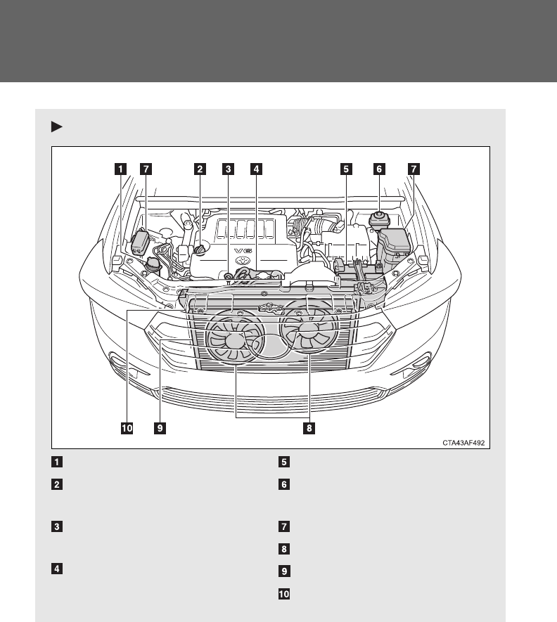
506
4-3. Do-it-yourself maintenance
3.5 L V6 (2GR-FE) engine
Washer fluid tank (P. 520)
Engine oil filler cap
(P. 509)
Engine oil level dipstick
(P. 508)
Engine coolant reservoir
(P. 512)
Battery (P. 516)
Brake fluid reservoir
(P. 515)
Fuse boxes (P. 542)
Electric cooling fans
Condenser (P. 514)
Radiator (P. 514)
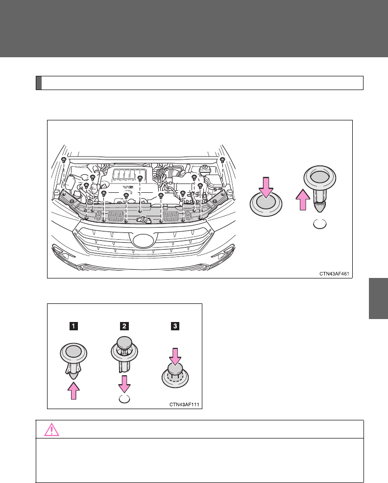
507
4-3. Do-it-yourself maintenance
4
Maintenance and care
Engine compartment cover
■Removing the engine compartment cover
■Installing the clips
NOTICE
■After installing an engine compartment cover
Make sure that the cover is securely installed in its original position.
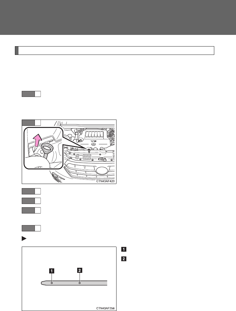
508
4-3. Do-it-yourself maintenance
Engine oil
With the engine at operating temperature and turned off, check the oil
level on the dipstick.
■Checking the engine oil
Park the vehicle on level ground. After warming up the engine
and turning it off, wait more than five minutes for the oil to
drain back into the bottom of the engine.
Hold a rag under the end and
pull the dipstick out.
Wipe the dipstick clean.
Reinsert the dipstick fully.
Holding a rag under the end, pull the dipstick out and check
the oil level.
Wipe the dipstick and reinsert it fully.
2.7 L 4-cylinder (1AR-FE) engine with flat dipstick
Low
Full
STEP
1
STEP
2
STEP
3
STEP
4
STEP
5
STEP
6
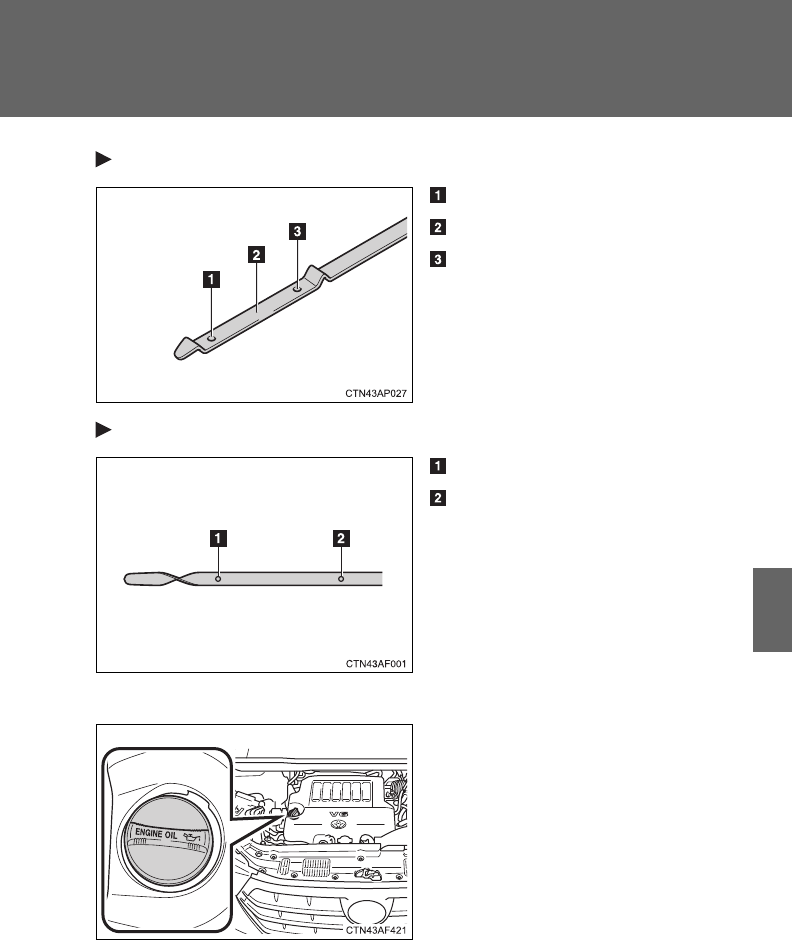
509
4-3. Do-it-yourself maintenance
4
Maintenance and care
2.7 L 4-cylinder (1AR-FE) engine with non-flat dipstick
Low
Measuring side
Full
3.5 L V6 (2GR-FE) engine
Low
Full
■Adding engine oil
If the oil level is below or near
the low level mark, add engine
oil of the same type as that
already in the engine.

510
4-3. Do-it-yourself maintenance
Make sure to check the oil type and prepare the items needed before
adding oil.
Remove the oil filler cap.
Add engine oil slowly, checking the dipstick.
Install the filler cap, turning it clockwise.
Engine oil selection P. 622
Oil quantity
(Low Full) 1.6 qt. (1.5 L, 1.3 Imp. qt.)
Items Clean funnel
■Engine oil consumption
A certain amount of engine oil will be consumed while driving. In the follow-
ing situations, oil consumption may increase, and engine oil may need to be
refilled in between oil maintenance intervals.
●When the engine is new, for example directly after purchasing the vehicle
or after replacing the engine
●If low quality oil or oil of an inappropriate viscosity is used
●When driving at high engine speeds or with a heavy load, when towing,
or when driving while accelerating or decelerating frequently
●When leaving the engine idling for a long time, or when driving frequently
through heavy traffic
STEP
1
STEP
2
STEP
3
511
4-3. Do-it-yourself maintenance
4
Maintenance and care
CAUTION
■Used engine oil
●Used engine oil contains potentially harmful contaminants which may
cause skin disorders such as inflammation or skin cancer, so care should
be taken to avoid prolonged and repeated contact. To remove used engine
oil from your skin, wash thoroughly with soap and water.
●Dispose of used oil and filters only in a safe and acceptable manner. Do
not dispose of used oil and filters in household trash, in sewers or onto the
ground. Call your Toyota dealer, service station or auto parts store for
information concerning recycling or disposal.
●Do not leave used engine oil within the reach of children.
NOTICE
■To prevent serious engine damage
Check the oil level on a regular basis.
■When replacing the engine oil
●Be careful not to spill engine oil on the vehicle components.
●Avoid overfilling, as the engine could be damaged.
●Check the oil level on the dipstick every time you refill the vehicle.
●Be sure the engine oil filler cap is properly tightened.
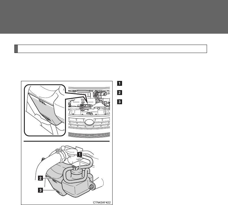
512
4-3. Do-it-yourself maintenance
Engine coolant
The coolant level is satisfactory if it is between the “FULL” and “LOW”
lines on the reservoir when the engine is cold.
Reservoir cap
“FULL”
“LOW”
If the level is on or below the
“LOW” line, add coolant up to the
“FULL” line.

513
4-3. Do-it-yourself maintenance
4
Maintenance and care
■If the coolant level drops within a short time after replenishing
Visually check the radiator, hoses, engine coolant filler cap, radiator cap,
drain cock and water pump.
If you cannot find a leak, have your Toyota dealer test the cap opening pres-
sure and check for leaks in the cooling system.
■Coolant selection
Only use “Toyota Super Long Life Coolant” or similar high quality ethylene
glycol based non-silicate, non-amine, non-nitrite, and non-borate coolant
with long-life hybrid organic acid technology.
U.S.A.: Toyota Super Long Life Coolant is a mixture of 50% coolant and
50% deionized water. (Enabled: -31F [-35C])
Canada: Toyota Super Long Life Coolant is a mixture of 55% coolant and
45% deionized water. (Enabled: -44F [-42C])
For more details about engine coolant, contact your Toyota dealer.
CAUTION
■When the engine is hot
Do not remove the coolant reservoir cap.
The cooling system may be under pressure and may spray hot coolant if the
cap is removed, causing burns or other injuries.
NOTICE
■When adding engine coolant
Coolant is neither plain water nor straight antifreeze. The correct mixture of
water and antifreeze must be used to provide proper lubrication, corrosion
protection and cooling. Be sure to read the antifreeze or coolant label.
■If you spill coolant
Be sure to wash it off with water to prevent damage to parts or paint.

514
4-3. Do-it-yourself maintenance
Radiator and condenser
Check the radiator and condenser, and clear away any foreign
objects.
If either of the above parts are extremely dirty or you are not sure of
their condition, have your vehicle checked by your Toyota dealer.
CAUTION
■When the engine is hot
Do not touch the radiator or condenser as they may be hot and may cause
burns.
■When the electric cooling fans are operating
Do not touch the engine compartment.
Vehicles without smart key system: The electric cooling fans may keep rotat-
ing for about 3 minutes after the engine switch is turned to the “LOCK” posi-
tion.
With the engine switch in the “ON” position, the electric cooling fans may
automatically start to run if the air conditioning is on and/or the coolant tem-
perature is high. Be sure the engine switch is in the “LOCK” position when
working near the electric cooling fan or radiator grille.
Vehicles with smart key system: The electric cooling fan may keep rotating
for about 3 minutes even after the “ENGINE START STOP” switch is OFF.
With the “ENGINE START STOP” switch in IGNITION ON mode, the electric
cooling fans may automatically start to run if the air conditioning is on and/or
the coolant temperature is high. Be sure the “ENGINE START STOP” switch
is OFF when working near the electric cooling fans or radiator grille.
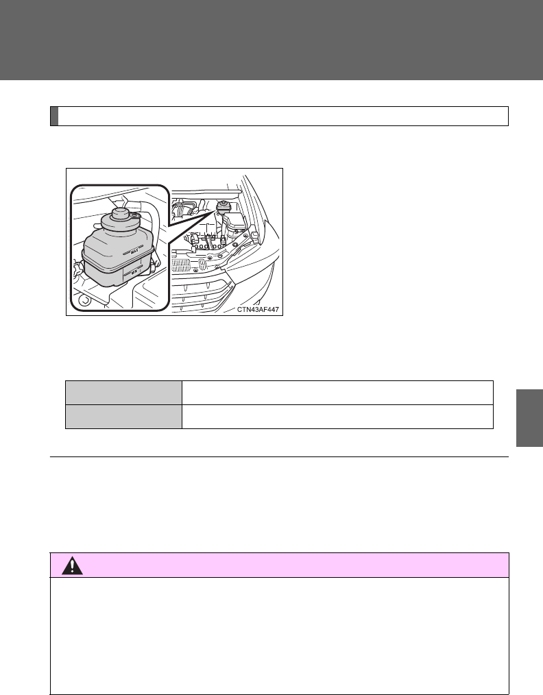
515
4-3. Do-it-yourself maintenance
4
Maintenance and care
Brake fluid
■Checking fluid level
The brake fluid level should be
between the “MAX” and “MIN”
lines on the tank.
Make sure to check the fluid type and prepare the necessary items.
■Adding fluid
Fluid type SAE J1703 or FMVSS No.116 DOT 3
Items Clean funnel
■Brake fluid can absorb moisture from the air
Excess moisture in the fluid can cause a dangerous loss of braking effi-
ciency. Use only newly opened brake fluid.
CAUTION
■When filling the reservoir
Take care because brake fluid can harm your hands or eyes and damage
painted surfaces.
If fluid gets in your eyes, flush your eyes with clean water immediately.
If you still experience discomfort, see a doctor.

516
4-3. Do-it-yourself maintenance
Battery
■Battery exterior
Make sure that the battery terminals are not corroded and that
there are no loose connections, cracks, or loose clamps.
Ter mi na ls
Hold-down clamp
NOTICE
■If the fluid level is low or high
It is normal for the brake fluid level to go down slightly as the brake pads
wear or when the fluid level in the accumulator is high.
If the reservoir needs frequent refilling, it may indicate a serious problem.

517
4-3. Do-it-yourself maintenance
4
Maintenance and care
■Before recharging
When recharging, the battery produces hydrogen gas which is flammable
and explosive. Therefore, before recharging:
●If recharging with the battery installed on the vehicle, be sure to discon-
nect the ground cable.
●Make sure the power switch on the charger is off when connecting and
disconnecting the charger cables to the battery.
■After recharging the battery (vehicles with smart key system)
The engine may not start. Follow the procedure below to initialize the sys-
tem.
Shift the shift lever to P.
Open and close any of the doors.
Restart the engine.
STEP
1
STEP
2
STEP
3

518
4-3. Do-it-yourself maintenance
CAUTION
■Chemicals in the battery
A battery contains poisonous and corrosive sulfuric acid and may produce
hydrogen gas which is flammable and explosive. To reduce the risk of death
or serious injury, take the following precautions while working on or near the
battery:
●Do not cause sparks by touching the battery terminals with tools.
●Do not smoke or light a match near the battery.
●Avoid contact with eyes, skin and clothes.
●Never inhale or swallow electrolyte.
●Wear protective safety glasses when working near the battery.
●Keep children away from the battery.
■Where to safely charge the battery
Always charge the battery in an open area. Do not charge the battery in a
garage or closed room where there is not sufficient ventilation.
■How to recharge the battery
Only perform a slow charge (5 A or less). The battery may explode if
charged at a quicker rate.
■Emergency measures regarding electrolyte
●If electrolyte gets in your eyes
Flush your eyes with clean water for at least 15 minutes and get immedi-
ate medical attention. If possible, continue to apply water with a sponge or
cloth while traveling to the nearest medical facility.
●If electrolyte gets on your skin
Wash the affected area thoroughly. If you feel pain or burning, get medical
attention immediately.
519
4-3. Do-it-yourself maintenance
4
Maintenance and care
CAUTION
●If electrolyte gets on your clothes
It can soak through clothing on to your skin. Immediately take off the cloth-
ing and follow the procedure above if necessary.
●If you accidentally swallow electrolyte
Drink a large quantity of water or milk. Get emergency medical attention
immediately.
NOTICE
■When recharging the battery
Never recharge the battery while the engine is running. Also, be sure all
accessories are turned off.
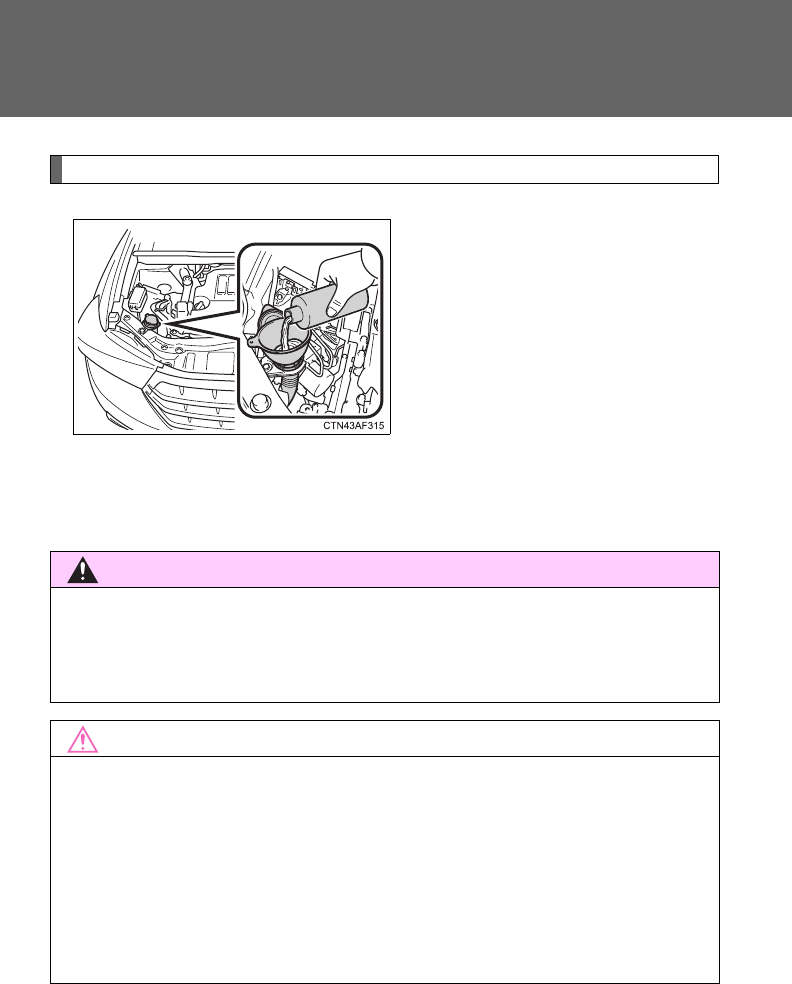
520
4-3. Do-it-yourself maintenance
Washer fluid
Add washer fluid in the following
situations.
●Any washer does not work.
●The low washer fluid warning
light comes on (vehicles with-
out multi-information display).
●The warning message
appears on the multi-informa-
tion display (vehicles with
multi-information display).
CAUTION
■When adding washer fluid
Do not add the washer fluid when the engine is hot or running, as the washer
fluid contains alcohol and may catch fire if spilled on the engine etc.
NOTICE
■Do not use any fluid other than washer fluid
Do not use soapy water or engine antifreeze instead of washer fluid.
Doing so may cause streaking on the vehicle’s painted surfaces.
■Diluting washer fluid
Dilute washer fluid with water as necessary.
Refer to the freezing temperatures listed on the label of the washer fluid bot-
tle.
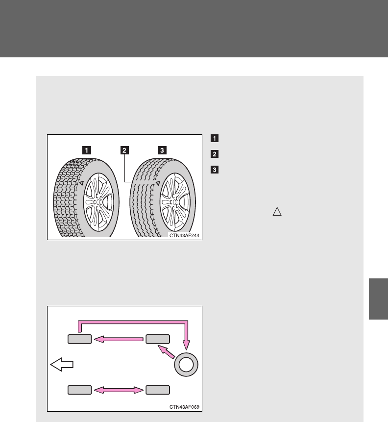
521
4-3. Do-it-yourself maintenance
4
Maintenance and care
Tires
Replace or rotate tires in accordance with maintenance sched-
ules and treadwear.
■Checking tires
New tread
Treadwear indicator
Worn tread
The location of treadwear
indicators is shown by the
“TWI” or “ ” marks, etc.,
molded on the sidewall of
each tire.
Check spare tire condition
and inflation pressure if not
rotated.
■Tire rotation
Rotate the tires in the order
shown.
To equalize tire wear and
extend tire life, Toyota recom-
mends that tire rotation is
carried out at the same inter-
val as tire inspection.
Front

523
4-3. Do-it-yourself maintenance
4
Maintenance and care
Installing tire pressure warning valves and transmitters
When replacing tires or wheels, tire pressure warning valves and
transmitters must also be installed.
When new tire pressure warning valves and transmitters are
installed, new tire pressure warning valve and transmitter ID codes
must be registered in the tire pressure warning computer and the tire
pressure warning system must be initialized. Have tire pressure
warning valve and transmitter ID codes registered by your Toyota
dealer. (P. 524)
Initializing the tire pressure warning system
■The tire pressure warning system must be initialized when the
tire inflation pressure is changed (such as when changing
traveling speed or towing a trailer.)
When the tire pressure warning system is initialized, the current tire
inflation pressure is set as the benchmark pressure.
■How to initialize the tire pressure warning system
Park the vehicle in a safe place and turn the “ENGINE START
STOP” switch or the engine switch OFF.
While the vehicle is moving, initialization is not performed.
Adjust the tire inflation pressure to the specified cold tire infla-
tion pressure level. (P. 630)
Make sure to adjust the tire pressure to the specified cold tire
inflation pressure level. The tire pressure warning system will
operate based on this pressure level.
Turn the “ENGINE START STOP” switch to IGNITION ON
mode (vehicles with smart key system) or the engine switch to
the “ON” position (vehicles without smart key system).
STEP
1
STEP
2
STEP
3
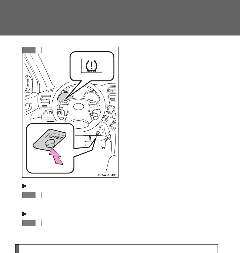
524
4-3. Do-it-yourself maintenance
Push and hold the tire pressure
warning reset switch until the tire
pressure warning light blinks
slowly 3 times.
Vehicles without smart key system
Wait for a few minutes with the engine switch in the “ON” posi-
tion, and then turn the engine switch to the “LOCK” position.
Vehicles with smart key system
Wait for a few minutes with IGNITION ON mode, and then
turn the “ENGINE START STOP” switch OFF.
Registering ID codes
The tire pressure warning valve and transmitter is equipped with a
unique ID code. When replacing a tire pressure warning valve and
transmitter, it is necessary to register the ID code of the tire pressure
warning valve and transmitter. Have the ID code registered by your
Toyota dealer.
STEP
4
STEP
5
STEP
5

525
4-3. Do-it-yourself maintenance
4
Maintenance and care
■When to replace your vehicle's tires
Tires should be replaced if:
●You have tire damage such as cuts, splits, cracks deep enough to
expose the fabric, or bulges indicating internal damage
●A tire goes flat repeatedly or cannot be properly repaired due to the
size or location of a cut or other damage
If you are not sure, consult with your Toyota dealer.
■Replacing tires and wheels
If the ID code of the tire pressure warning valve and transmitter is not
registered, the tire pressure warning system will not work properly. After
driving for about 20 minutes, the tire pressure warning light comes on
after blinking for 1 minute to indicate a system malfunction.
■Tire life
Any tire over 6 years old must be checked by a qualified technician even
if they have seldom or never been used or damage is not obvious.
■If the tread wears down below 0.16 in. (4 mm) on snow tires
The effectiveness of snow tires is lost.
■When the tire pressure warning valves and transmitter are removed
from the wheel on occasions such as when replacing tires
The tire inflation pressure data updated before servicing is retained.
■Maximum load of tire
Check that the number given by dividing the maximum load by 1.10 of
the replacement tire is greater than 1/2 of the Gross Axle Weight Ratings
(GAWR) of either the front axle or the rear axle, whichever is greater.
For the GAWR, see the Certification
Label. For the maximum load of the
tire, see the load limit at maximum cold
tire inflation pressure mentioned on the
sidewall of the tire. (P. 636)

526
4-3. Do-it-yourself maintenance
■Tire types
1 Summer tires
Summer tires are high-speed performance tires best suited to highway
driving under dry conditions. Since summer tires do not have the same
traction performance as snow tires, summer tires are inadequate for
driving on snow-covered or icy roads. For driving on snow-covered
roads or icy roads, the use of snow tires is recommended. When
installing snow tires, be sure to replace all four tires.
2 All season tires
All season tires are designed to provide better traction in snow and to
be adequate for driving in most winter conditions, as well as for use
year round. All season tires, however, do not have adequate traction
performance compared with snow tires in heavy or loose snow. Also,
all season tires fall short in acceleration and handling performance
compared with summer tires in highway driving.
3Snow tires
For driving on snow-covered roads or icy roads, we recommend using
snow tires. If you need snow tires, select tires of the same size, con-
struction and load capacity as the originally installed tires. Since your
vehicle has radial tires as original equipment, make sure your snow
tires also have radial construction. Do not install studded tires without
first checking local regulations for possible restriction. Snow tires
should be installed on all wheels. (P. 248)
■Initializing the tire pressure warning system
Initialize the tire pressure warning system with the tire inflation pressure
adjusted to the specified level.
■If you push the tire pressure warning reset switch accidentally
If initialization is performed, adjust the tire inflation pressure to the speci-
fied level and initialize the tire pressure warning system again.

527
4-3. Do-it-yourself maintenance
4
Maintenance and care
■When the initialization of the tire pressure warning system has
failed
Initialization can be completed in a few minutes. However, in the follow-
ing cases, the settings have not been recorded and the system will not
operate properly. If repeated attempts to record tire inflation pressure
settings are unsuccessful, have the vehicle inspected by your Toyota
dealer.
●When operating the tire pressure warning reset switch, the tire pres-
sure warning light does not blink 3 times.
●After carrying out the initialization procedure, the tire pressure warn-
ing light blinks for 1 minute then stays on after driving for about 20
minutes.
■Routine tire inflation pressure checks
The tire pressure warning system does not replace routine tire inflation
pressure checks. Make sure to check tire inflation pressure as part of
your routine of daily vehicle checks.
■Tire pressure warning system certification
For vehicles sold in the U.S.A.
FCC ID: PAXPMV107J
FCC ID: HYQ13BCX
This device complies with Part 15 of the FCC Rules. Operation is subject
to the following two conditions: (1) this device may not cause harmful
interference, and (2) this device must accept any interference received,
including interference that may cause undesired operation.
FCC WARNING:
Changes or modifications not expressly approved by the party responsi-
ble for compliance could void the user's authority to operate the equip-
ment.
For vehicles sold in Canada
Operation is subject to the following two conditions: (1) this device may
not cause interference, and (2) this device must accept any interference,
including interference that may cause undesired operation of the device.

528
4-3. Do-it-yourself maintenance
CAUTION
■When inspecting or replacing tires
Observe the following precautions to prevent accidents. Failure to do so
may cause damage to parts of the drive train, as well as dangerous han-
dling characteristics, which may lead to an accident resulting in death or
serious injury.
●Do not mix tires of different makes, models or tread patterns.
Also, do not mix tires of remarkably different treadwear.
●Do not use tire sizes other than those recommended by Toyota.
●Do not mix differently constructed tires (radial, bias-belted or bias-ply
tires).
●Do not mix summer, all season and winter tires.
●Do not tow the vehicle with the spare tire installed.
■When initializing the tire pressure warning system
Do not push the tire pressure warning reset switch without first adjusting
the tire inflation pressure to the specified level. Otherwise, the tire pres-
sure warning light may not come on even if the tire inflation pressure is
low, or it may come on when the tire inflation pressure is actually normal.

529
4-3. Do-it-yourself maintenance
4
Maintenance and care
NOTICE
■Repairing or replacing tires, wheels, tire pressure warning valves,
transmitters and tire valve caps
●When removing or fitting the wheels, tires or the tire pressure warning
valve and transmitter, contact your Toyota dealer as the tire pressure
warning valve and transmitter may be damaged if not handled correctly.
●When replacing tire valve caps, do not use tire valve caps other than those
specified. The cap may become stuck.
■To avoid damage to the tire pressure warning valves and transmit-
ters
When a tire is repaired with liquid sealants, the tire pressure warning
valve and transmitter may not operate properly. If a liquid sealant is
used, contact your Toyota dealer or other qualified service shop as soon
as possible. Make sure to replace the tire pressure warning valve and
transmitter when replacing the tire. (P. 523)
■Do not use puncture sealant sprays to repair flats
Puncture sealant sprays may damage tire pressure warning valves and
transmitters.
■Driving on rough roads
Take particular care when driving on roads with loose surfaces or pot-
holes.
These conditions may cause losses in tire inflation pressure, reducing
the cushioning ability of the tires. In addition, driving on rough roads may
cause damage to the tires themselves, as well as the vehicle's wheels
and body.
■If tire inflation pressures become low while driving
Do not continue driving, or your tires and/or wheels may be ruined.
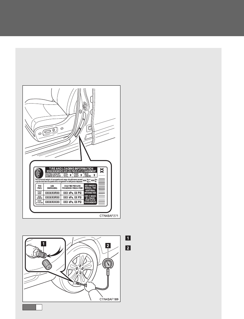
530
4-3. Do-it-yourself maintenance
Tire inflation pressure
■Tire inflation pressure
The recommended cold tire inflation pressure and tire size is dis-
played on the tire and loading information label. (P. 636)
■Inspection and adjustment procedure
Tire valve
Tire pressure gauge
Remove the tire valve cap.
STEP
1
531
4-3. Do-it-yourself maintenance
4
Maintenance and care
■Tire inflation pressure check interval
You should check tire inflation pressure every two weeks, or at least
once a month.
Do not forget to check the spare.
■Effects of incorrect tire inflation pressure
Driving with incorrect tire inflation pressure may result in the following:
●Reduced fuel efficiency
●Reduced driving comfort and tire life
●Reduced safety
●Damage to the drive train
If a tire needs frequent reinflating, have it checked by your Toyota dealer.
■Instructions for checking tire inflation pressure
When checking tire inflation pressure, observe the following:
●Check only when the tires are cold.
If your vehicle has been parked for at least 3 hours and has not been
driven for more than 1 mile or 1.5 km, you will get an accurate cold
tire inflation pressure reading.
Press the tip of the tire pressure gauge onto the tire valve.
Read the pressure using the graduations of the gauge.
If the tire inflation pressure is not within the recommended
levels, adjust the pressure.
If you add too much air, press the center of the valve to
lower.
After completing the tire inflation pressure measurement
and adjustment, apply soapy water to the valve and check
for leakage.
Reinstall the tire valve cap.
STEP
2
STEP
3
STEP
4
STEP
5
STEP
6
532
4-3. Do-it-yourself maintenance
●Always use a tire pressure gauge.
The appearance of the tire can be misleading. In addition, tire infla-
tion pressures that are even just a few pounds off can degrade ride
and handling.
●Do not bleed or reduce tire inflation pressure after driving. It is normal
for the tire inflation pressure to be higher after driving.
●Never exceed the vehicle capacity weight.
Passengers and luggage weight should be placed so that the vehicle
is balanced.
CAUTION
■Proper inflation is critical to save tire performance
Keep your tires properly inflated.
Otherwise, the following conditions may occur and result in an accident
causing death or serious injury.
●Excessive wear
●Uneven wear
●Poor handling
●Possibility of blowouts resulting from overheated tires
●Poor sealing of the tire bead
●Wheel deformation and/or tire separation
●A greater possibility of tire damage from road hazards
NOTICE
■When inspecting and adjusting tire inflation pressure
Be sure to reinstall the tire valve caps.
Without the valve caps, dirt or moisture could get into the valve and
cause air leakage, which could result in an accident. If the caps have
been lost, replace them as soon as possible.

533
4-3. Do-it-yourself maintenance
4
Maintenance and care
Wheels
If a wheel is bent, cracked or heavily corroded, it should be
replaced.
Otherwise, the tire may separate from the wheel or cause loss of
handling control.
■Wheel selection
When replacing wheels, care should be taken to ensure that
they are equivalent to those removed in load capacity, diameter,
rim width, and inset*.
Replacement wheels are available at your Toyota dealer.
*: Conventionally referred to as “offset”.
Toyota does not recommend using:
●Wheels of different sizes or types
●Used wheels
●Bent wheels that have been straightened
■Aluminum wheel precautions
●Use only Toyota wheel nuts and wrenches designed for use
with your aluminum wheels.
●When rotating, repairing or changing your tires, check that the
wheel nuts are still tight after driving 1000 miles (1600 km).
●Be careful not to damage the aluminum wheels when using
tire chains.
●Use only Toyota genuine balance weights or equivalent and a
plastic or rubber hammer when balancing your wheels.
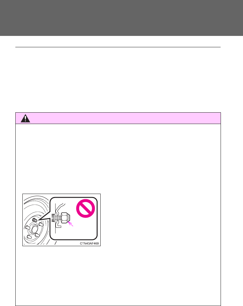
534
4-3. Do-it-yourself maintenance
■When replacing wheels
The wheels of your Toyota are equipped with tire pressure warning
valves and transmitters that allow the tire pressure warning system to
provide advanced warning in the event of a loss in tire inflation pressure.
Whenever wheels are replaced, the tire pressure warning valves and
transmitters must be installed. (P. 523)
CAUTION
■When replacing wheels
●Do not use wheels that are a different size from those recommended in
the Owner’s Manual, as this may result in loss of handling control.
●Never use an inner tube in a leaking wheel which is designed for a
tubeless tire. Doing so may result in an accident, causing serious
injury or death.
■When installing the wheel nuts
●Never use oil or grease on the wheel bolts or wheel nuts.
Oil and grease may cause the wheel nuts to be excessively tightened,
leading to bolt or disc wheel damage. In addition, the oil or grease can
cause the wheel nuts to loosen and the wheel may fall off, causing an acci-
dent and resulting in death or serious injury. Remove any oil or grease
from the wheel bolts or wheel nuts.
●Be sure to install the wheel nuts with
the tapered end facing inward. Install-
ing the nuts with the tapered end facing
outward can cause wheel to break and
eventually cause a wheel to come off
while driving, which could lead to an
accident resulting in death or serious
injury.
Taper ed
portion

535
4-3. Do-it-yourself maintenance
4
Maintenance and care
NOTICE
■Replacing tire pressure warning valves and transmitters
●Because tire repair or replacement may affect the tire pressure
warning valves and transmitters, make sure to have tires serviced by
your Toyota dealer or other qualified service shop. In addition, make
sure to purchase your tire pressure warning valves and transmitters at
your Toyota dealer.
●Ensure that only genuine Toyota wheels are used on your vehicle.
Tire pressure warning valves and transmitters may not work properly
with non-genuine wheels.
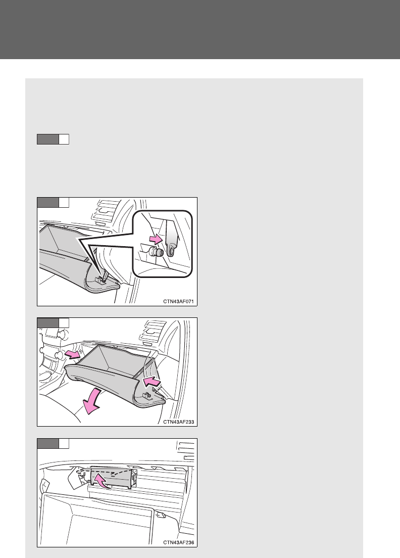
536
4-3. Do-it-yourself maintenance
Air conditioning filter
The air conditioning filter must be changed regularly to maintain air
conditioning efficiency.
■Removal method
Vehicles without smart key system: Turn the engine switch
OFF.
Vehicles with smart key system: Turn the “ENGINE START
STOP” switch OFF.
Open the glove box. Slide off
the damper.
Push each side of the glove
box to release the pins. Then
pull the glove box down
toward you.
Lift up the cover.
STEP
1
STEP
2
STEP
3
STEP
4
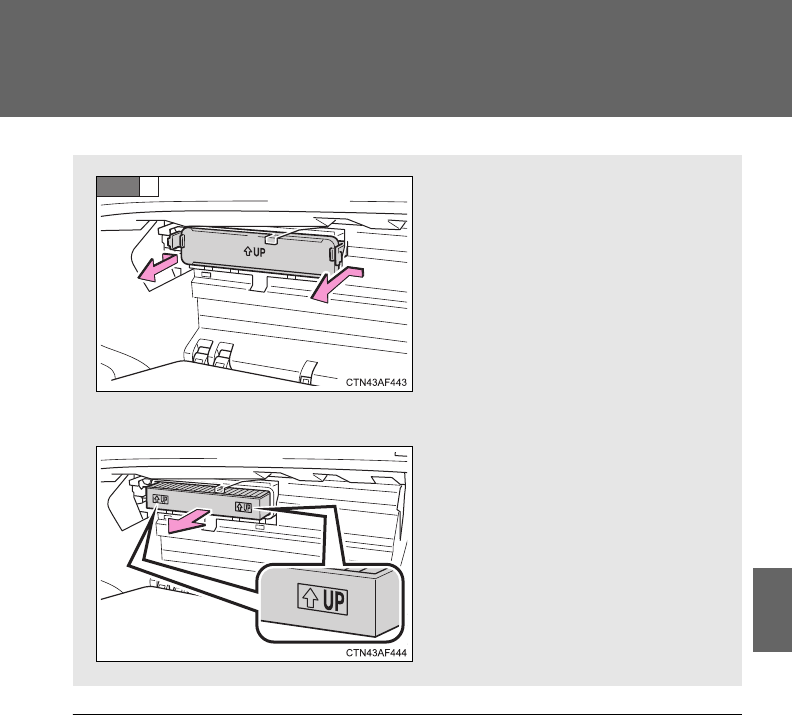
537
4-3. Do-it-yourself maintenance
4
Maintenance and care
■Checking interval
Inspect and replace the air conditioning filter according to the maintenance
schedule. In dusty areas or areas with heavy traffic flow, replacement may
be required. (For scheduled maintenance information, please refer to the
“Scheduled Maintenance Guide” or “Owner’s Manual Supplement”.)
■If air flow from the vents decreases dramatically
The filter may be clogged. Check the filter and replace if necessary.
Remove the filter cover.
■Replacement method
Remove the air conditioning
filter and replace it with a new
one.
The“UP” marks shown on the
filter should be pointing up.
STEP
5

538
4-3. Do-it-yourself maintenance
NOTICE
■When using the air conditioning system
Make sure that a filter is always installed.
Using the air conditioning system without a filter may cause damage to the
system.
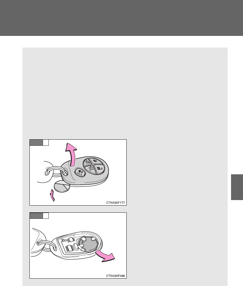
539
4-3. Do-it-yourself maintenance
4
Maintenance and care
Wireless remote control/electronic key battery
Replace the battery with a new one if it is discharged.
■You will need the following items:
●Flathead screwdriver (To prevent damage to the key, cover
the tip of the screwdriver with a rag.)
●Small Phillips-head screwdriver
●Lithium battery CR2032 (vehicles without smart key system),
CR1632 (vehicles with smart key system)
■Replacing the battery (vehicles without smart key system)
Remove the cover using a
coin protected with tape etc.
Remove the discharged trans-
mitter battery.
Insert a new battery with the
“+” terminal facing up.
STEP
1
STEP
2
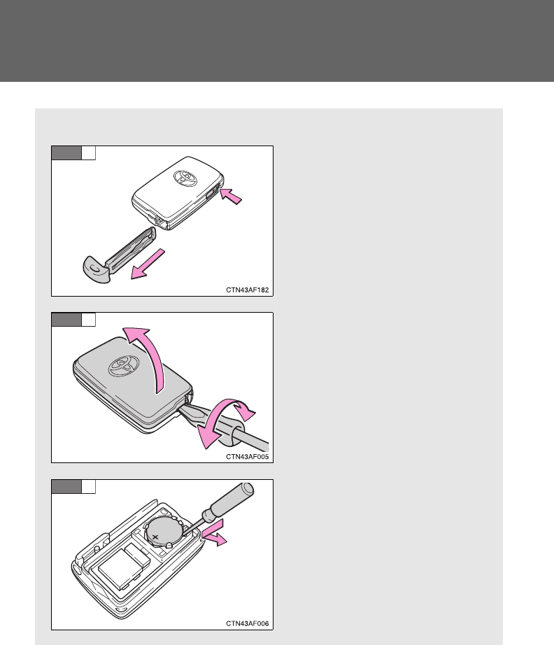
540
4-3. Do-it-yourself maintenance
■Replacing the battery (vehicles with smart key system)
Take out the mechanical key.
Remove the cover.
Remove the depleted battery.
Insert a new battery with the
“+” terminal facing up.
STEP
1
STEP
2
STEP
3
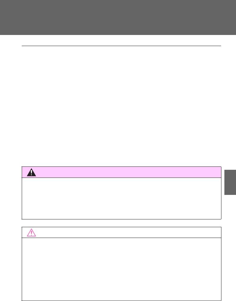
541
4-3. Do-it-yourself maintenance
4
Maintenance and care
■If the electronic key battery is discharged
The following symptoms may occur.
●The smart key system and wireless remote control will not function prop-
erly.
●The operational range is reduced.
■Use a CR2032 (vehicles without smart key system) or CR1632 (vehicles
with smart key system) lithium battery
●Batteries can be purchased at your Toyota dealer, jewelers, or camera
stores.
●Replace only with the same or equivalent type recommended by your
Toyota dealer.
●Dispose of used batteries according to the local laws.
CAUTION
■Removed battery and other parts
These parts are small and if swallowed by a child, they can cause choking.
Keep away from children. Failure to do so could result in death or serious
injury.
NOTICE
■For normal operation after replacing the battery
Observe the following precautions to prevent accidents.
●Always work with dry hands.
Moisture may cause the battery to rust.
●Do not touch or move any other components inside the remote control.
●Do not bend either of the battery terminals.
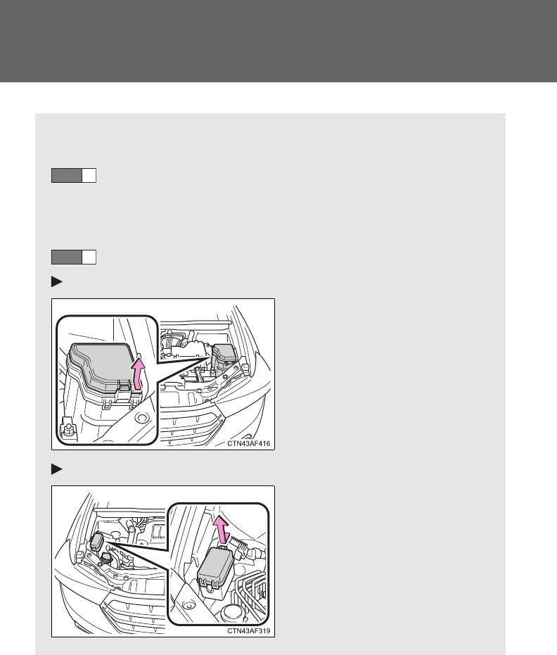
542
4-3. Do-it-yourself maintenance
Checking and replacing fuses
If any of the electrical components do not operate, a fuse may have
blown. If this happens, check and replace the fuses as necessary.
Vehicles without smart key system: Turn the engine switch
OFF.
Vehicles with smart key system: Turn the “ENGINE START
STOP” switch OFF.
Open the fuse box cover.
Engine compartment (type A)
Push the tab in and lift the
fuse box cover off.
Engine compartment (type B)
Push the tab in and lift the
fuse box cover off. (if
equipped)
STEP
1
STEP
2
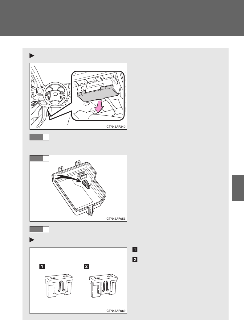
543
4-3. Do-it-yourself maintenance
4
Maintenance and care
Under the instrument panel
Remove the lid.
After a system failure, see “Fuse layout and amperage rat-
ings” (P. 545) for details about which fuse to check.
Remove the fuse with the pull-
out tool.
Check if the fuse has blown.
Type A
Normal fuse
Blown fuse
Replace it with one of an
appropriate amperage rating.
The amperage rating can be
found on the fuse box lid.
STEP
3
STEP
4
STEP
5
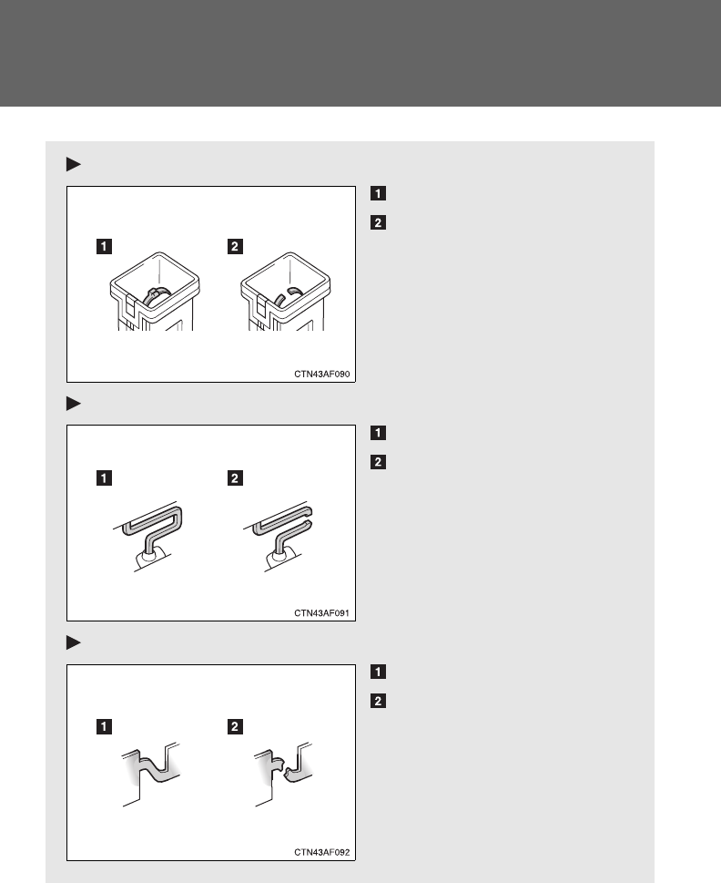
544
4-3. Do-it-yourself maintenance
Type B
Normal fuse
Blown fuse
Replace it with one of an
appropriate amperage rating.
The amperage rating can be
found on the fuse box lid.
Type C
Normal fuse
Blown fuse
Contact your Toyota dealer.
Type D
Normal fuse
Blown fuse
Contact your Toyota dealer.
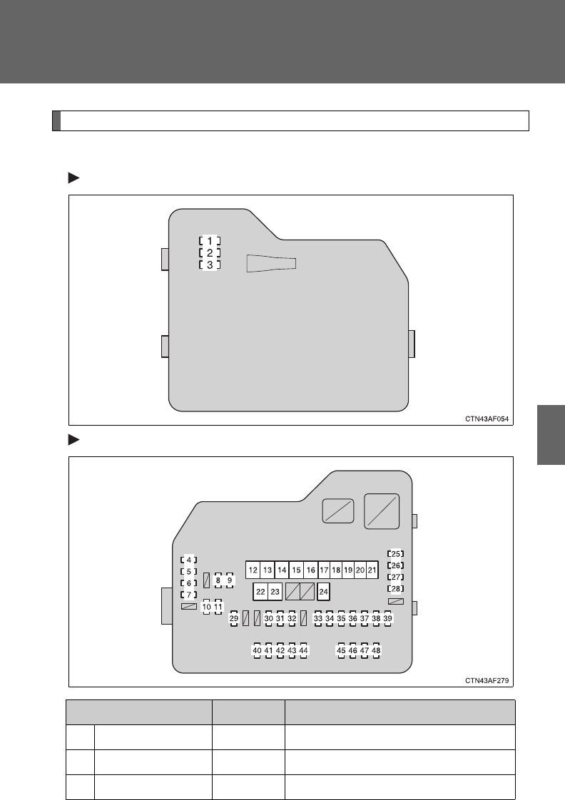
545
4-3. Do-it-yourself maintenance
4
Maintenance and care
Fuse layout and amperage ratings
■Engine compartment
Type A (fuse block on the back of the cover)
Type A (fuse block)
Fuse Ampere Circuit
1 SPARE 7.5 A Spare fuse
2 SPARE 15 A Spare fuse
3 SPARE 25 A Spare fuse

546
4-3. Do-it-yourself maintenance
4 DEF RLY 10 A Rear window defogger
5 MIR HTR 10 A Outside rear view mirror defoggers
6 PWR OUTLET 20 A Power outlet
7 DOOR NO.1 25 A Multiplex communication system
8 EFI NO.2 10 A
Multiport fuel injection system/
sequential multiport fuel injection
system
9 EFI NO.3 10 A
Multiport fuel injection system/
sequential multiport fuel injection
system
10 INJ NO.1 15 A Starting system
11 INJ NO.2 10 A
Multiport fuel injection system/
sequential multiport fuel injection
system
12 HTR 50 A Air conditioning system
13 VSC NO.1 50 A Vehicle stability control system
14 FAN MAIN 50 A Electric cooling fans
15 VSC NO.2 30 A Vehicle stability control system
16 PTC NO.1 50 A Air conditioning system
17 PTC NO.2 30 A Air conditioning system
18 PTC NO.3 30 A Air conditioning system
19 RR CLR 40 A Air conditioning system
20 RR DEF 30 A Rear window defogger
21 PBD 30 A Power back door
22 ALT 140 A
MIR HTR, PWR OUTLET, DOOR
NO.1, HTR, RR DEF, FAN MAIN,
VSC NO.1, PTC NO.1, RR CLR,
PTC NO.2, PTC NO.3, VSC NO.2,
PBD
23 EPS 80 A Electric power steering
Fuse Ampere Circuit

547
4-3. Do-it-yourself maintenance
4
Maintenance and care
24 ST 30 A Starting system
25 CRT 10 A Rear seat entertainment system,
audio system
26 RADIO NO.1 20 A Audio system
27 ECU-B NO.1 10 A
Steering sensor, gauges and
meters, clock, main body ECU,
wireless remote control, smart key
system, power back door, multi-
information display, front passen-
ger occupant classification system
28 DOME 10 A
Vanity lights, personal lights, inte-
rior light, gauges and meters,
engine switch light, door courtesy
lights
29 TOWING 30 A Trailer lights
30 STR LOCK 20 A Steering lock system
31 EFI MAIN 25 A
Multiport fuel injection system/
sequential multiport fuel injection
system, EFI NO.2, EFI NO.3
32 HAZ 15 A Turn signal lights
33 IG2 25 A INJ NO.1, INJ NO.2, IGN, GAUGE
NO.2
34 AMP 15 A Audio system
35 RR FOG 7.5 A No circuit
36 DEICER 15 A Windshield wiper de-icer
37 G/H 10 A Glass hatch, multiplex communica-
tion system, outer foot lights
38 ALT-S 7.5 A Charging system
39 AM2 7.5 A Multiplex communication system
40 H-LP LH HI 15 A Left-hand headlight (high beam)
41 H-LP RH HI 15 A Right-hand headlight (high beam)
Fuse Ampere Circuit
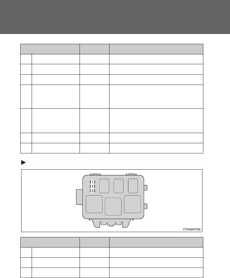
548
4-3. Do-it-yourself maintenance
Type B (if equipped)
42 H-LP LH LO 15 A Left-hand headlight (low beam)
43 H-LP RH LO 15 A Right-hand headlight (low beam)
44 HORN 10 A Horn
45 EFI NO.1 10 A
Multiport fuel injection system/
sequential multiport fuel injection
system, smart key system
46 ETCS 10 A
Multiport fuel injection system/
sequential multiport fuel injection
system
47 A/F 20 A Air fuel ratio sensor
48 S-HORN 7.5 A S-HORN
Fuse Ampere Circuit
1 INV-W/P 15 A No circuit
2 IGCT NO.2 7.5 A No circuit
3 A/C 10 A No circuit
Fuse Ampere Circuit
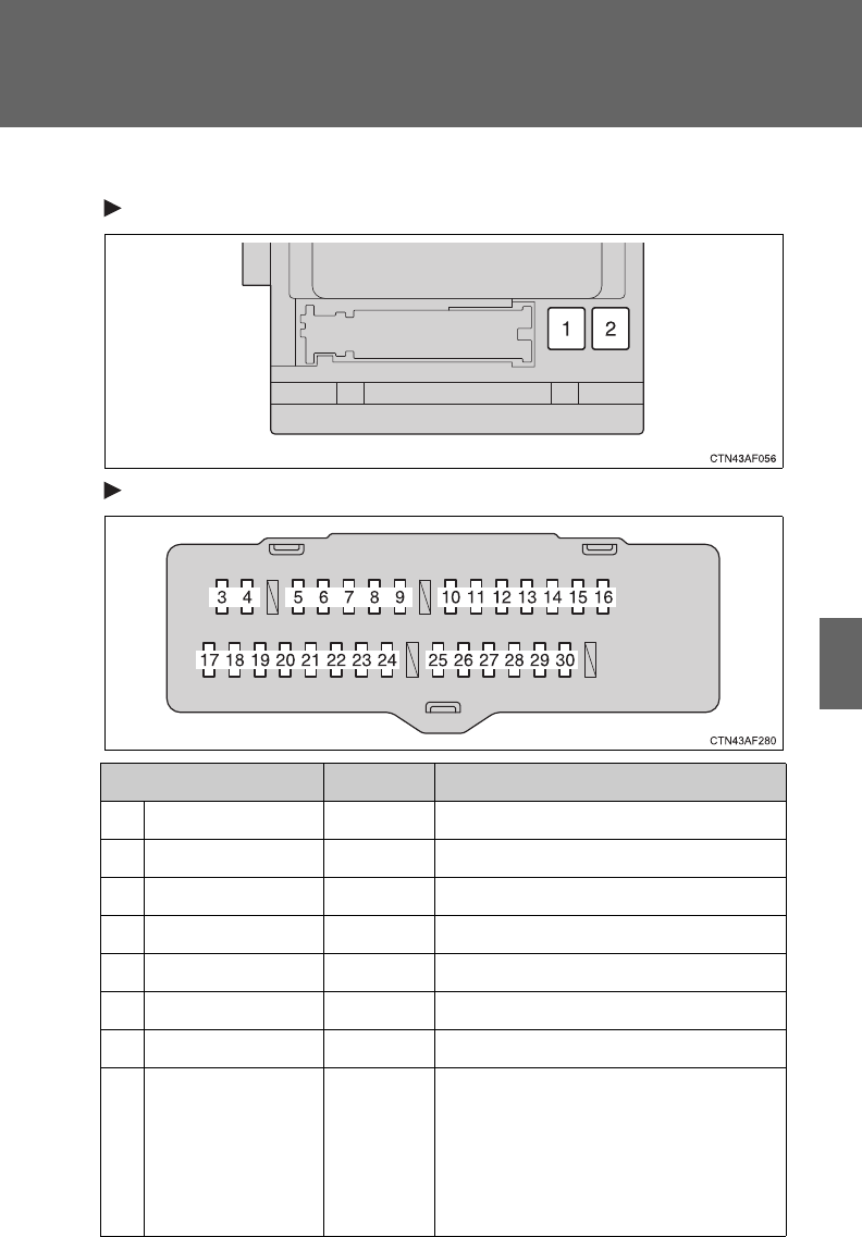
549
4-3. Do-it-yourself maintenance
4
Maintenance and care
■Under the instrument panel
Front side of the fuse block
Fuse block
Fuse Ampere Circuit
1 P/SEAT 30 A Power seat
2 POWER 30 A Power windows
3 RR DOOR RH 25 A Power windows
4 RR DOOR LH 25 A Power windows
5 FR FOG 10 A Fog lights
6 OBD 7.5 A On-board diagnosis system
7 A/C W/PMP 7.5 A No circuit
8 STOP 10 A
Vehicle stability control system,
multiplex communication system,
multiport fuel injection system/
sequential multiport fuel injection
system, shift lock system, stop
lights

550
4-3. Do-it-yourself maintenance
9 DOOR NO.2 25 A Power windows
10 AM1 7.5 A Starting system
11 P/SEAT (PS) 30 A Power seat
12 A/C NO.1 10 A Air conditioning system
13 FUEL OPN 7.5 A No circuit
14 S/ROOF 20 A Electric moon roof
15 TAIL 15 A Parking lights, tail lights, license
plate lights, fog lights, trailer lights
16 PANEL 7.5 A Glove box light, instrument panel
lights, switch illumination
17 ECU IG NO.1 10 A
Multiplex communication system,
electric moon roof, electronically
controlled automatic transmission
system, power back door, seat
heaters, tire pressure warning sys-
tem, electric power steering, anti-
glare inside rear view mirror, shift
lock system, tire pressure warning
system
18 ECU IG NO.2 7.5 A Vehicle stability control system
19 A/C NO.2 10 A Air conditioning system
20 WASH 20 A Windshield and rear window
washer
21 S-HTR 20 A Seat heaters
22 GAUGE NO.1 10 A
Audio system, back-up lights,
charging system, emergency flash-
ers, traction control system, wind-
shield wiper de-icer, air
conditioning system, charging sys-
tem, rear view monitor system,
trailer lights, multiport fuel injection
system/sequential multiport fuel
injection system
Fuse Ampere Circuit

551
4-3. Do-it-yourself maintenance
4
Maintenance and care
23 FR WIP 30 A Windshield wipers and washer
24 RR WIP 15 A Rear window wiper and washer
25 IGN 10 A
Multiport fuel injection system/
sequential multiport fuel injection
system, steering lock system,
smart key system, SRS airbag sys-
tem
26 GAUGE NO.2 7.5 A Gauges and meters, rear view
monitor system
27 ECU-ACC 7.5 A
Outside rear view mirrors, shift lock
system, smart key system, multi-
plex communication system
28 ACC SOCK
NO.1 15 A Power outlet
29 ACC SOCK
NO.2 15 A Power outlet
30 RADIO NO.2 7.5 A
Audio system, clock, rear seat
entertainment system, interior
lights, personal lights
Fuse Ampere Circuit
552
4-3. Do-it-yourself maintenance
■After a fuse is replaced
●If the lights do not turn on even after the fuse has been replaced, a bulb
may need replacement. (P. 553)
●If the replaced fuse blows again, have the vehicle inspected by your
Toyota dealer.
■If there is an overload in the circuits
The fuses are designed to blow, protecting the wiring harness from damage.
CAUTION
■To prevent system breakdowns and vehicle fire
Observe the following precautions.
Failing to do so may cause damage to the vehicle, and possibly a fire or
injury.
●Never use a fuse of a higher amperage rating than indicated, or use any
other object in place of a fuse.
●Always use a genuine Toyota fuse or equivalent.
Never replace a fuse with a wire, even as a temporary fix.
●Do not modify fuses or the fuse box.
NOTICE
■Before replacing fuses
Have the cause of electrical overload determined and repaired by your
Toyota dealer as soon as possible.
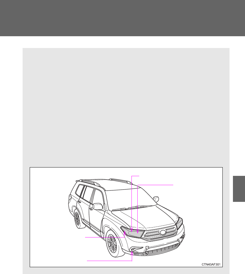
553
4-3. Do-it-yourself maintenance
4
Maintenance and care
Light bulbs
You may replace the following bulbs yourself. The difficulty level of
replacement varies depending on the bulb. If necessary bulb
replacement seems difficult to perform, contact your Toyota dealer.
For more information about replacing other light bulbs, contact your
Toyota dealer.
■Prepare a replacement light bulb.
Check the wattage of the light bulb being replaced. (P. 632)
■Turn the power back door main switch OFF. (vehicles with
power back door)
P. 6 2
■Front bulb locations
Headlight high
beams and
daytime running
lights (if equipped)
Headlight low beams
Fog lights (if equipped)
Parking, front side
marker and front turn
signal lights
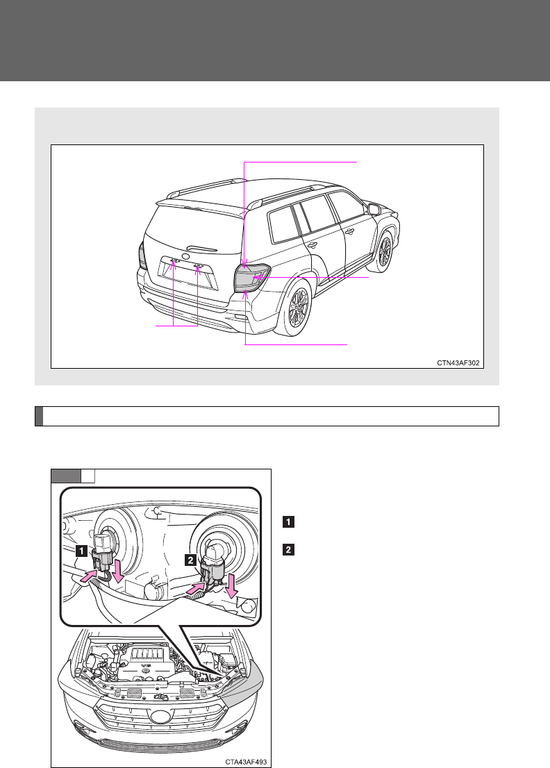
554
4-3. Do-it-yourself maintenance
Replacing light bulbs
■Headlights
Unplug the connector while
depressing the lock release.
Low beam (outside)
High beam (inside)
■Rear bulb locations
Back-up lights
Rear turn signal lights
Stop/tail and rear
side marker
lights
License plate lights
STEP
1
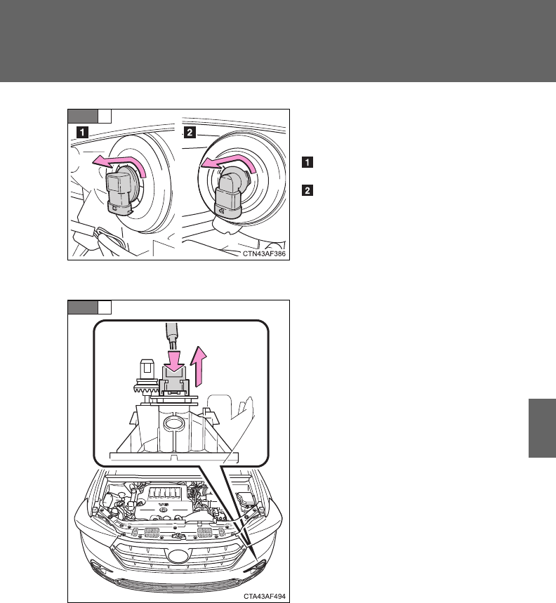
555
4-3. Do-it-yourself maintenance
4
Maintenance and care
Turn the bulb base counterclock-
wise.
Low beam
High beam
■Fog lights (if equipped)
Unplug the connector while
depressing the lock release.
STEP
2
STEP
1
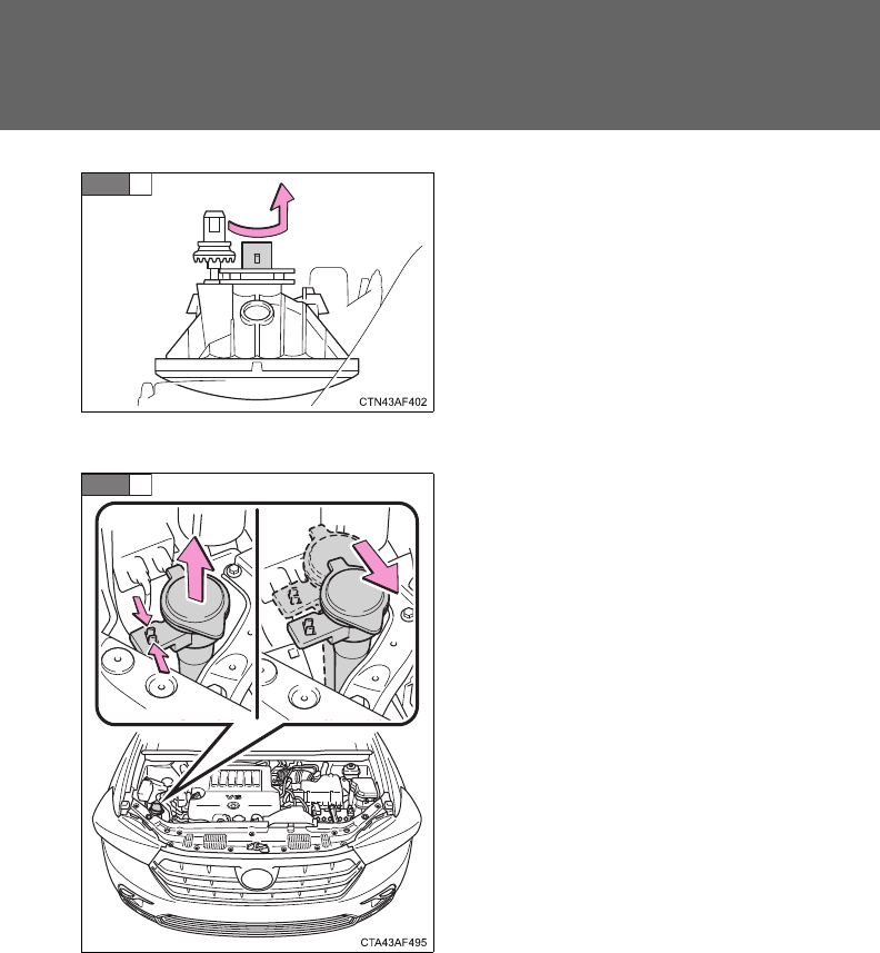
556
4-3. Do-it-yourself maintenance
Turn the bulb counterclockwise.
■Parking, front side marker and front turn signal lights
Right side only: Move the
washer fluid tank opening.
STEP
2
STEP
1
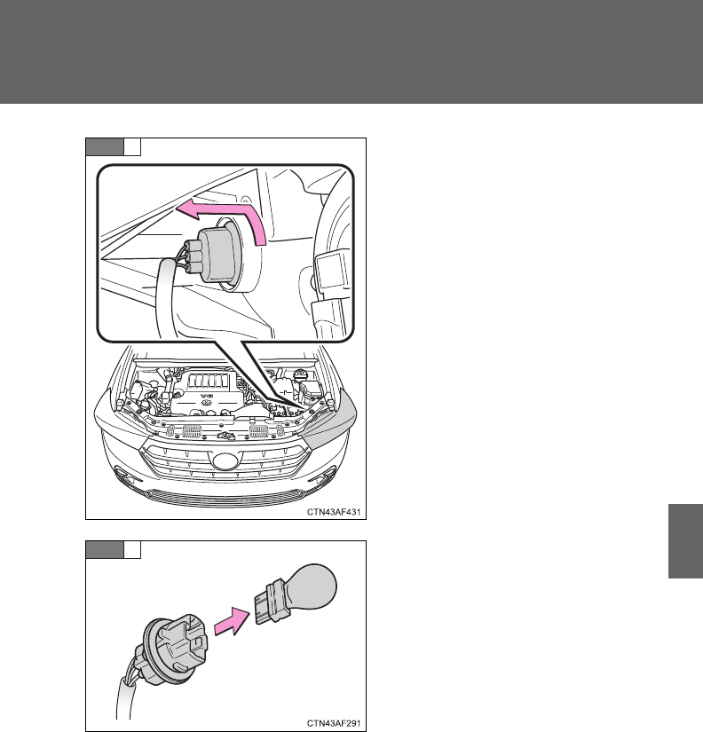
557
4-3. Do-it-yourself maintenance
4
Maintenance and care
Turn the bulb base counterclock-
wise.
Remove the light bulb.
STEP
2
STEP
3
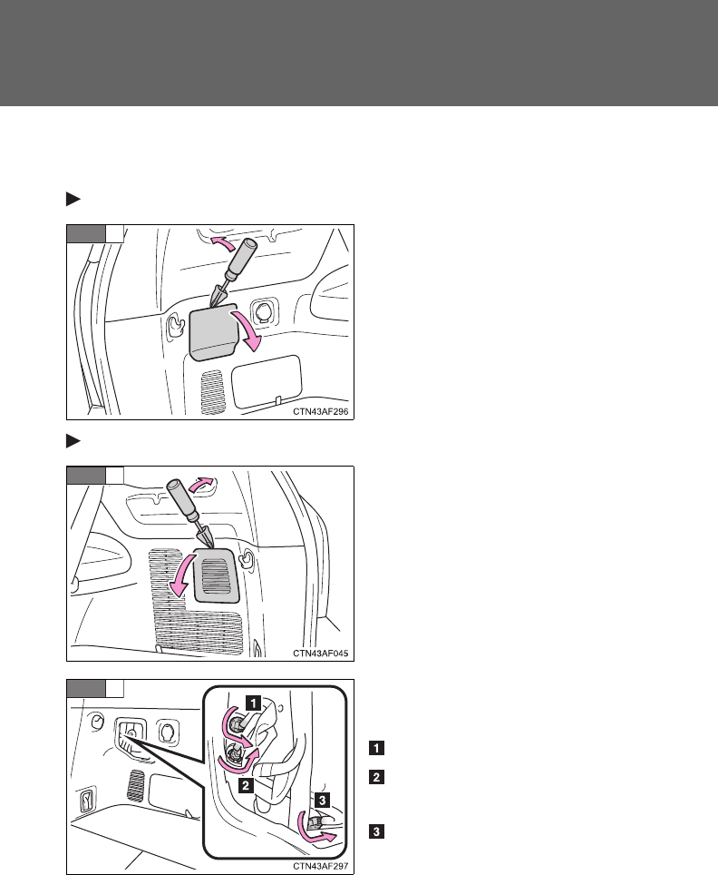
558
4-3. Do-it-yourself maintenance
■Back-up lights, stop/tail and rear side marker, and rear turn
signal lights
Left side
Open the back door and remove
the cover.
To protect the cover, place a rag
between the flathead screwdriver
and cover as shown in the illus-
trations.
Right side
Open the back door and remove
the cover.
To protect the cover, place a rag
between the flathead screwdriver
and cover as shown in the illus-
trations.
Turn the bulb base counterclock-
wise.
Rear turn signal light
Stop/tail and rear side marker
light
Back-up light
STEP
1
STEP
1
STEP
2
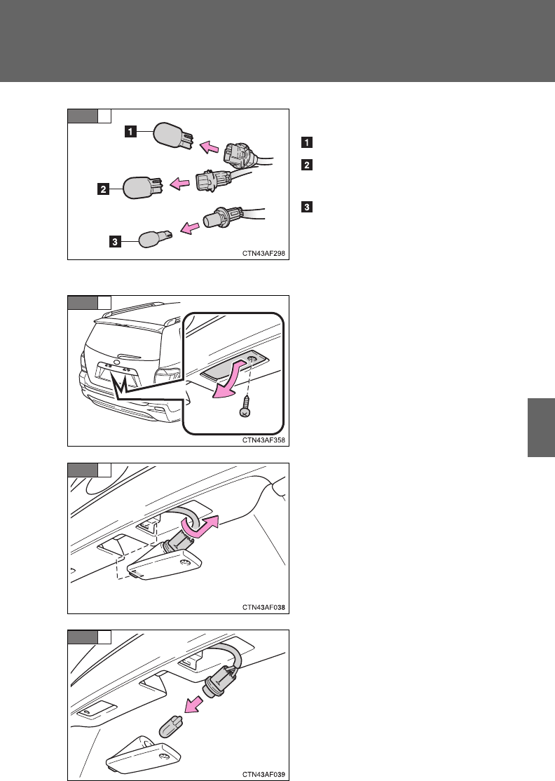
559
4-3. Do-it-yourself maintenance
4
Maintenance and care
Remove the light bulb.
Rear turn signal light
Stop/tail and rear side marker
light
Back-up light
■License plate lights
Remove the screw and remove
the unit.
Turn the bulb base counterclock-
wise.
Remove the light bulb.
STEP
3
STEP
1
STEP
2
STEP
3

560
4-3. Do-it-yourself maintenance
■High mounted stoplight and outer foot lights
If the high mounted stoplight or outer foot light has burnt out, have
it replaced by your Toyota dealer.
■Condensation build-up on the inside of the lens
Contact your Toyota dealer for more information in the following situations.
Temporary condensation build-up on the inside of the headlight lens does
not indicate a malfunction.
●Large drops of water are built up on the inside of the lens.
●Water has built up inside the headlight.
■LED high mounted stoplight
The high mounted stoplight consists of a number of LEDs. If any of the LEDs
burn out, take your vehicle to your Toyota dealer to have the light replaced.
CAUTION
■Replacing light bulbs
●Turn off the headlights. Do not attempt to replace the bulb immediately
after turning off the headlights.
The bulbs become very hot and may cause burns.
●Do not touch the glass portion of the light bulb with bare hands. Hold the
bulb by the plastic or metal portion.
If the bulb is scratched or dropped it may blow out or crack.
●Fully install light bulbs and any parts used to secure them. Failing to do so
may result in heat damage, fire, or water entering the headlight unit. This
may damage the headlights or cause condensation to build up on the lens.
■To prevent damage or fire
Make sure bulbs are fully seated and locked.

When trouble arises 5
561
5-1. Essential information
Emergency flashers ......... 562
If your vehicle needs to
be towed ........................ 564
If you think something is
wrong ............................. 571
Fuel pump shut off
system ........................... 572
5-2. Steps to take in an
emergency
If a warning light turns
on or a warning buzzer
sounds... ....................... 573
If a warning message is
displayed........................ 584
If you have a flat tire......... 586
If the engine will not
start................................ 600
If the shift lever cannot
be shifted from P............ 602
If you lose your keys/
wireless remote control
transmitter...................... 603
If the electronic key does
not operate properly....... 604
If the battery is
discharged ..................... 606
If your vehicle
overheats ....................... 610
If the vehicle becomes
stuck .............................. 613
If your vehicle has to
be stopped in an
emergency ..................... 615

562
5-1. Essential information
Emergency flashers
Use the emergency flashers if the vehicle malfunctions or is
involved in an accident.
Vehicles without a Display Audio system or navigation system
Press the switch to flash all
the turn signal lights. To turn
them off, press the switch
once again.
Vehicles with a Display Audio system
Press the switch to flash all
the turn signal lights. To turn
them off, press the switch
once again.
Vehicles with a navigation system
Press the switch to flash all
the turn signal lights. To turn
them off, press the switch
once again.

5
When trouble arises
563
5-1. Essential information
NOTICE
■To prevent battery discharge
Do not leave the emergency flashers on longer than necessary when the
engine is not running.

564
5-1. Essential information
If your vehicle needs to be towed
Before towing
The following may indicate a problem with your transmission. Contact
your Toyota dealer before towing.
●The engine is running, but the vehicle will not move.
●The vehicle makes an abnormal sound.
If towing is necessary, we recommend having your vehicle towed by
your Toyota dealer or a commercial towing service, using a lift-type
truck or a flat bed truck.
Use a safety chain system for all towing, and abide by all state/pro-
vincial and local laws.
2WD models: If towing from the front, the vehicle's rear wheels and
axles must be in good condition. (P. 568)
If they are damaged, use a towing dolly or flat bed truck.
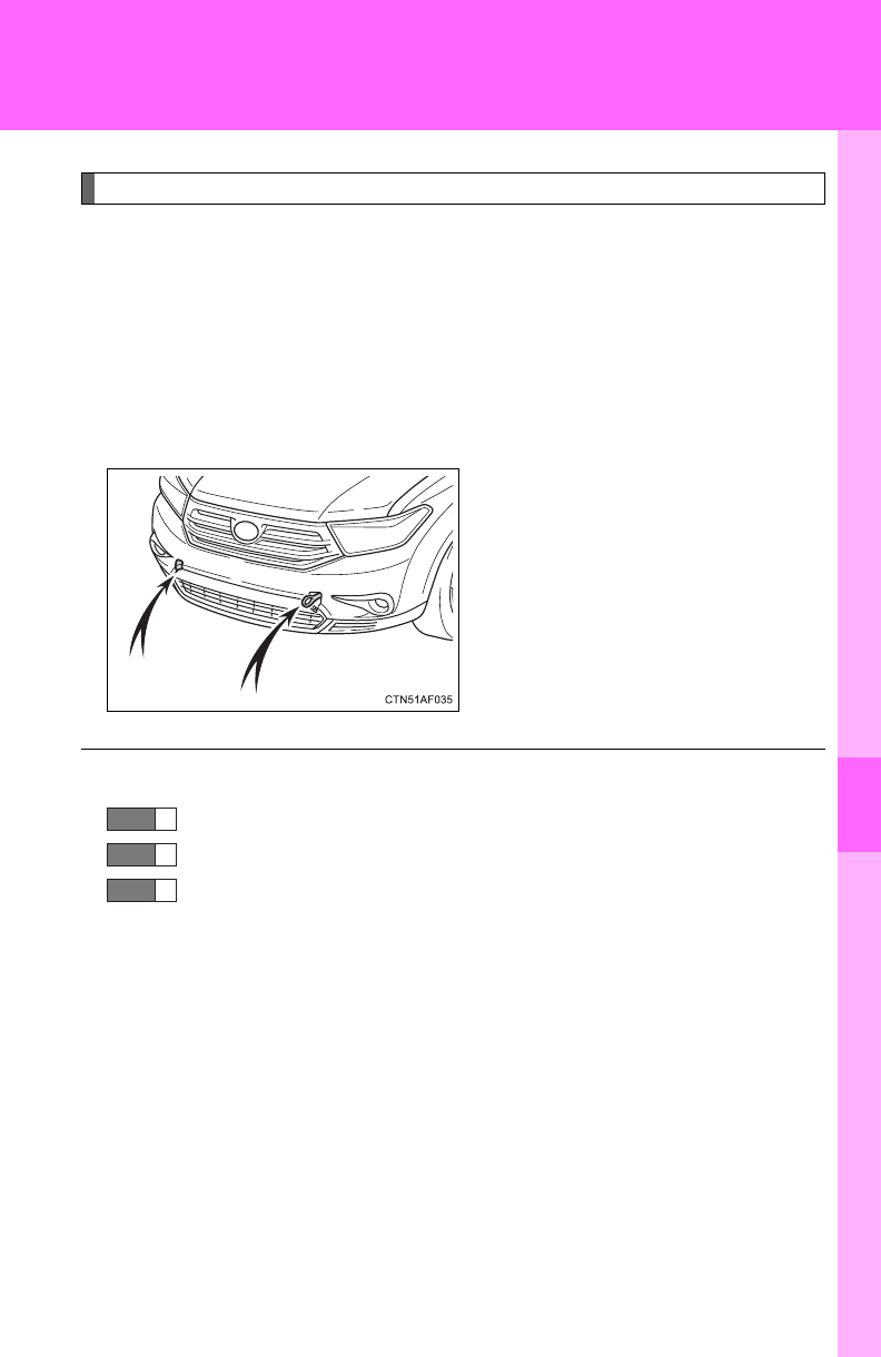
5
When trouble arises
565
5-1. Essential information
Emergency towing
If a tow truck is not available, in an emergency your vehicle may be
temporarily towed using a cable or chain secured to the emergency
towing eyelet(s). This should only be attempted on hard surfaced
roads for short distances at low speeds.
A driver must be in the vehicle to steer and operate the brakes. The
vehicle’s wheels, drive train, axles, steering and brakes must be in
good condition.
Towing eyelets
■Emergency towing procedure
Release the parking brake.
Shift the shift lever to N.
Vehicles without smart key system:
Turn the engine switch to “ACC” (engine off) or “ON” (engine run-
ning) position.
Vehicles with smart key system:
Turn the “ENGINE START STOP” switch to ACCESSORY (engine
off) or IGNITION ON (engine running) mode.
STEP
1
STEP
2
STEP
3
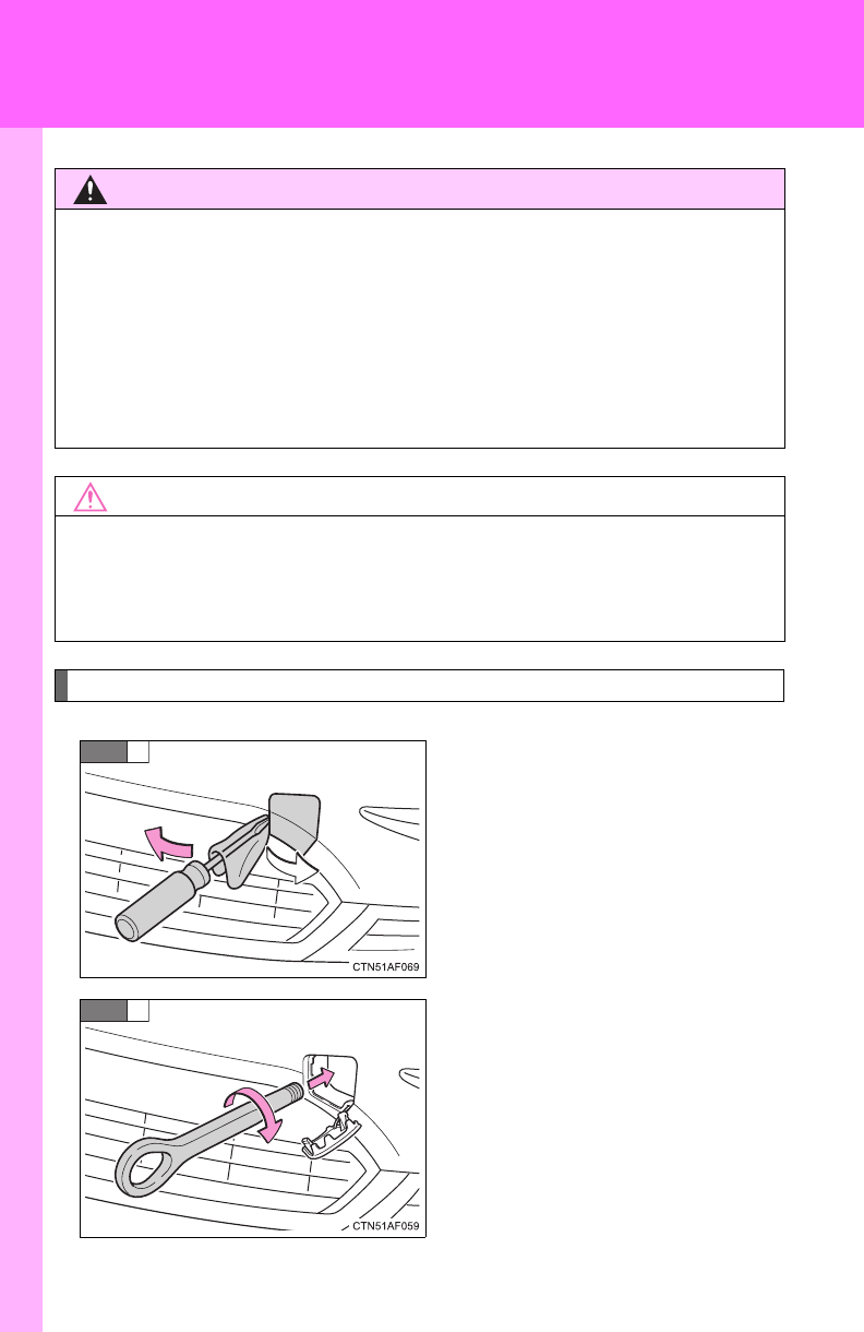
566
5-1. Essential information
Installing a towing eyelet
Remove the eyelet cover using a
flathead screwdriver.
To protect the bodywork, place a
rag between the screwdriver and
the vehicle body, as shown in the
illustration.
Insert the towing eyelet into the
hole and tighten partially by
hand.
CAUTION
■Caution while towing
●Use extreme caution when towing the vehicle.
Avoid sudden starts or erratic driving maneuvers which place excessive
stress on the emergency towing eyelets and the cables or chains. Always
be cautious of the surroundings and other vehicles while towing.
●If the engine is not running, the power assist for the brakes and steering
will not function, making steering and braking more difficult.
NOTICE
■To prevent causing serious damage to the transmission
Never tow this vehicle from the rear with the front wheels on the ground.
This may cause serious damage to the transmission.
STEP
1
STEP
2

5
When trouble arises
567
5-1. Essential information
Tighten down the towing eyelet
securely using a wheel nut
wrench.
STEP
3
■Location of the emergency towing eyelet
P. 586
CAUTION
■Installing towing eyelet to the vehicle
Make sure that towing eyelet is installed securely.
If not securely installed, towing eyelet may come loose during towing. This
may lead to accidents that cause serious injury or even death.
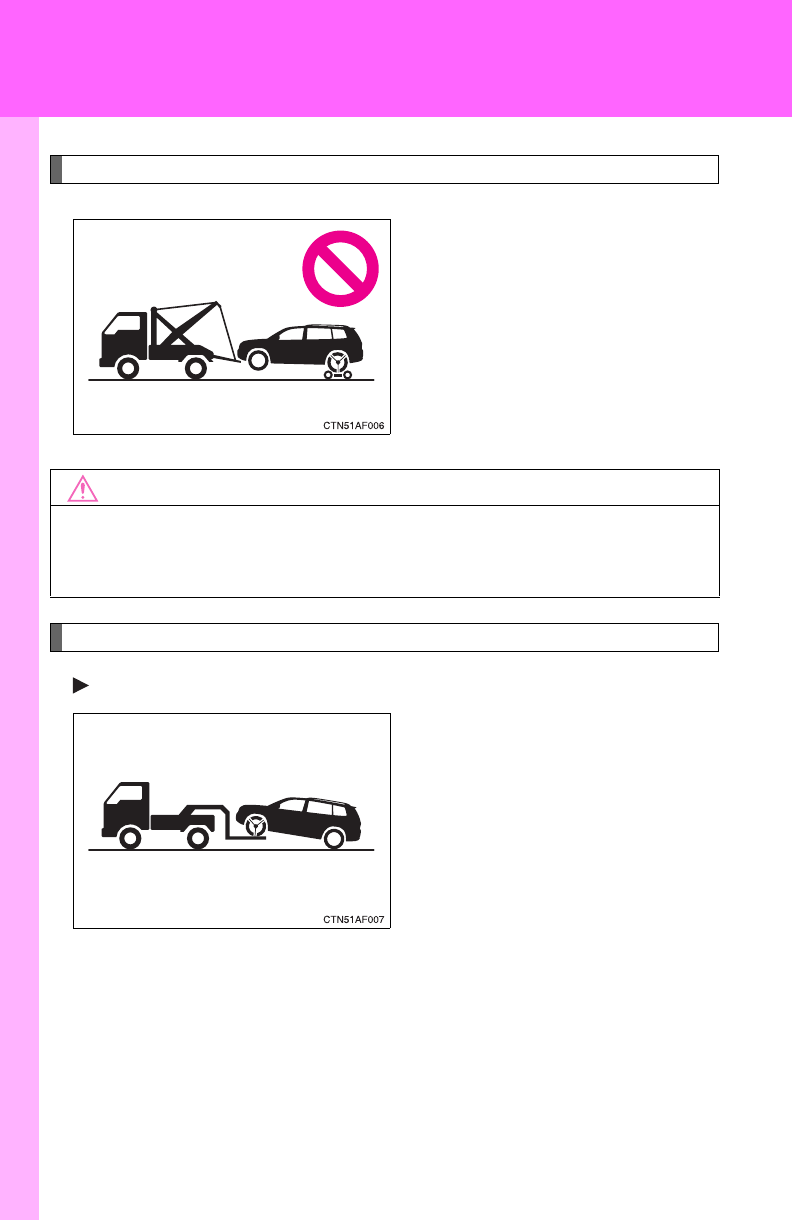
568
5-1. Essential information
Towing with a sling-type truck
Towing with a wheel lift-type truck
From front (2WD models)
Release the parking brake.
NOTICE
■To prevent body damage
Do not tow with a sling-type truck, either from the front or rear.
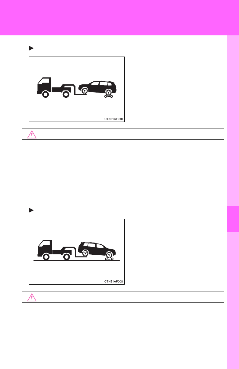
5
When trouble arises
569
5-1. Essential information
From front (4WD models)
Use a towing dolly under the rear
wheels.
From rear
Use a towing dolly under the
front wheels.
NOTICE
■To prevent damaging the vehicle
When raising the vehicle, ensure adequate ground clearance for towing at
the opposite end of the raised vehicle. Without adequate clearance, the
vehicle could be damaged while being towed.
■To prevent causing serious damage to the transmission (4WD models)
Never tow this vehicle from the front with the rear wheels on the ground.
NOTICE
■To prevent causing serious damage to the transmission
Never tow this vehicle from the rear with the front wheels on the ground.
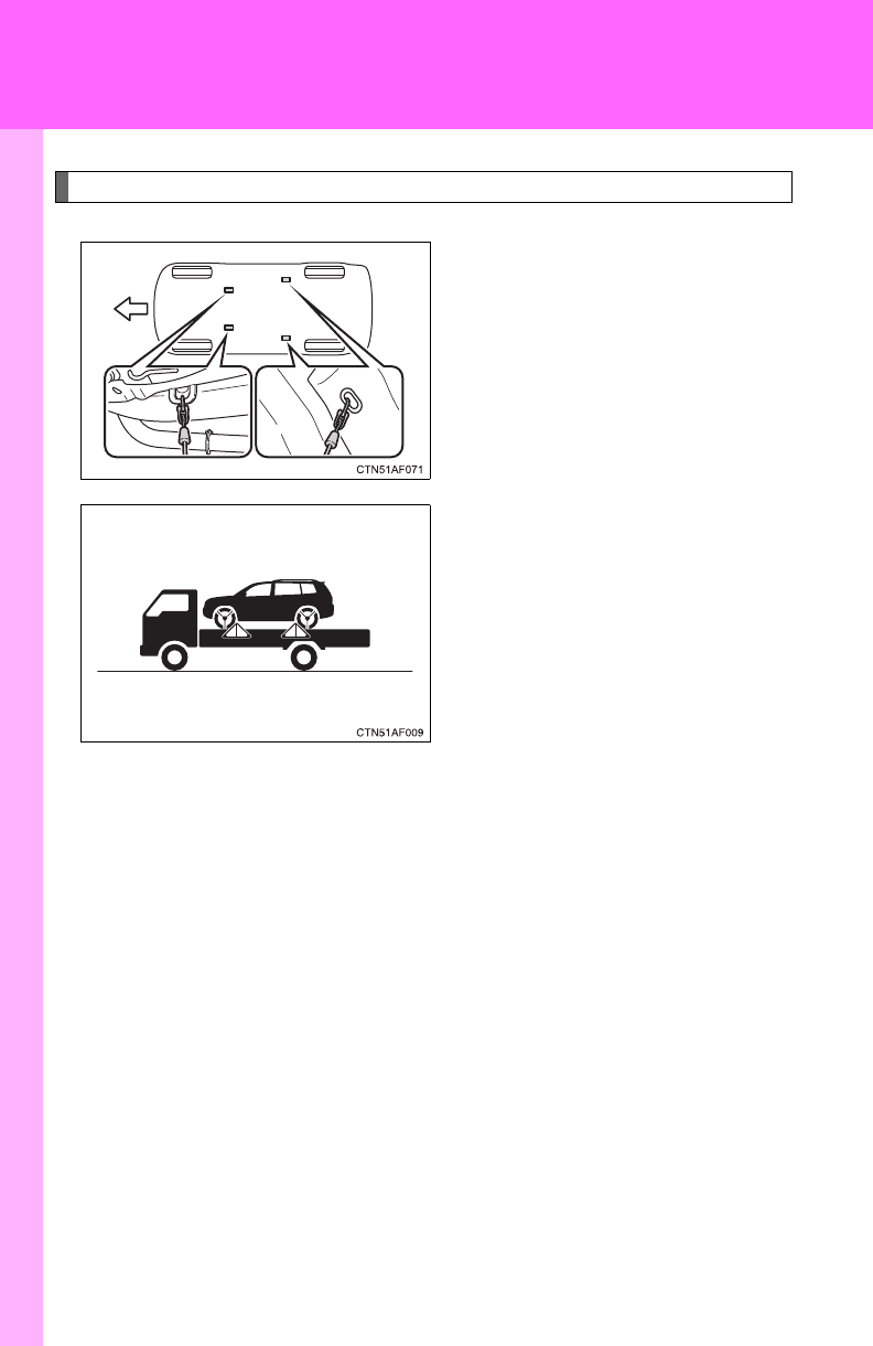
570
5-1. Essential information
Using a flat bed truck
If your Toyota is transported by a
flatbed truck, it should be tied
down at the locations shown in
the illustration.
If you use chains or cables to tie
down your vehicle, the angles
shaded in black must be 45.
Do not overly tighten the tie
downs or the vehicle may be
damaged.

5
When trouble arises
571
5-1. Essential information
If you think something is wrong
If you notice any of the following symptoms, your vehicle probably
needs adjustment or repair. Contact your Toyota dealer as soon as
possible.
■Visible symptoms
●Fluid leaks under the vehicle
(Water dripping from the air conditioning after use is normal.)
●Flat-looking tires or uneven tire wear
●Engine coolant temperature gauge needle continually points
higher than normal
■Audible symptoms
●Changes in exhaust sound
●Excessive tire squeal when cornering
●Strange noises related to the suspension system
●Pinging or other noises related to the engine
■Operational symptoms
●Engine missing, stumbling or running rough
●Appreciable loss of power
●Vehicle pulls heavily to one side when braking
●Vehicle pulls heavily to one side when driving on a level road
●Loss of brake effectiveness, spongy feeling, pedal almost
touches the floor
572
5-1. Essential information
Fuel pump shut off system
Follow the procedure below to restart the engine after the system is
activated.
Vehicles without smart key system
Turn the engine switch to the “ACC” or “LOCK” position.
Restart the engine.
Vehicles with smart key system
Turn the “ENGINE START STOP” switch OFF.
Restart the engine.
NOTICE
■Before starting the engine
Inspect the ground under the vehicle.
If you find that fuel has leaked onto the ground, the fuel system has been
damaged and is in need of repair. Do not restart the engine.
To minimize the risk of fuel leakage when the engine stalls or an air-
bag inflates upon collision, the fuel pump shut off system stops sup-
plying fuel to the engine.
STEP
1
STEP
2
STEP
1
STEP
2

5
When trouble arises
573
5-2. Steps to take in an emergency
If a warning light turns on or a warning buzzer sounds...
Stop the vehicle immediately. Continuing to drive the vehicle may be dangerous.
The following warning indicates a possible problem in the brake sys-
tem. Immediately stop the vehicle in a safe place and contact your
Toyota dealer.
*: Parking brake engaged warning buzzer:
A buzzer sounds to indicate that the parking brake is still engaged (with the
vehicle having reached a speed of 3 mph [5 km/h]).
Warning light Warning light/Details
(U.S.A.)
(Canada)
Brake system warning light (warning buzzer)*
• Low brake fluid
• Malfunction in the brake system
This light also comes on when the parking brake is not
released. If the light turns off after the parking brake is
fully released, the system is operating normally.
Calmly perform the following actions if any of the warning lights turn
on or flash. If a light turns on or flashes, but then turns off, this does
not necessarily indicate a malfunction in the system.
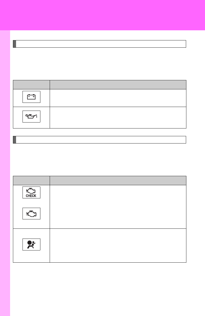
574
5-2. Steps to take in an emergency
Stop the vehicle immediately.
The following warnings indicate the possibility of damage to the vehi-
cle that may lead to an accident. Immediately stop the vehicle in a
safe place and contact your Toyota dealer.
Have the vehicle inspected immediately.
Failing to investigate the cause of the following warnings may lead to
the system operating abnormally and possibly cause an accident.
Have the vehicle inspected by your Toyota dealer immediately.
Warning light Warning light/Details
Charging system warning light
Indicates a malfunction in the vehicle’s charging system.
Low engine oil pressure warning light (vehicles without
multi-information display)
Indicates that the engine oil pressure is too low.
Warning light Warning light/Details
(U.S.A.)
(Canada)
Malfunction indicator lamp
Indicates a malfunction in:
• The electronic engine control system;
• The electronic throttle control system; or
• The electronic automatic transmission control system.
SRS warning light
Indicates a malfunction in:
• The SRS airbag system;
• The front passenger occupant classification system; or
• The seat belt pretensioner system.
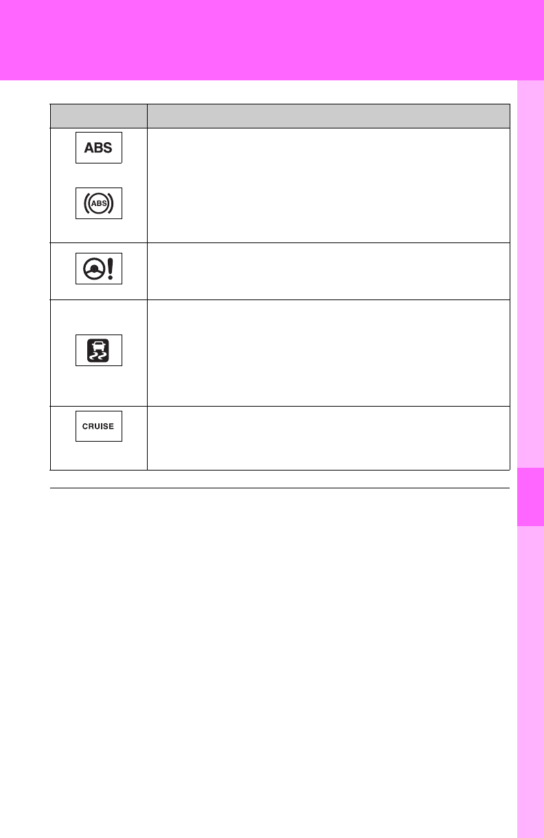
5
When trouble arises
575
5-2. Steps to take in an emergency
(U.S.A.)
(Canada)
ABS warning light
Indicates a malfunction in:
• The ABS; or
• The brake assist system.
Electric power steering system warning light
Indicates a malfunction in the EPS (Electric Power Steer-
ing) system.
Slip indicator light
Indicates a malfunction in:
• The VSC system;
• The TRAC system;
• The hill-start assist control system; or
• The downhill assist control system (4WD models).
(Flashes)
Cruise control indicator light (if equipped)
Indicates a malfunction in the cruise control system.
■If the malfunction indicator lamp comes on while driving
First check the following:
●Is the fuel tank low or empty?
If it is, fill the fuel tank immediately.
●Is the fuel tank cap loose?
If it is, tighten it securely.
The light will go off after taking several driving trips.
If the light does not go off even after several trips, contact your Toyota dealer
as soon as possible.
Warning light Warning light/Details
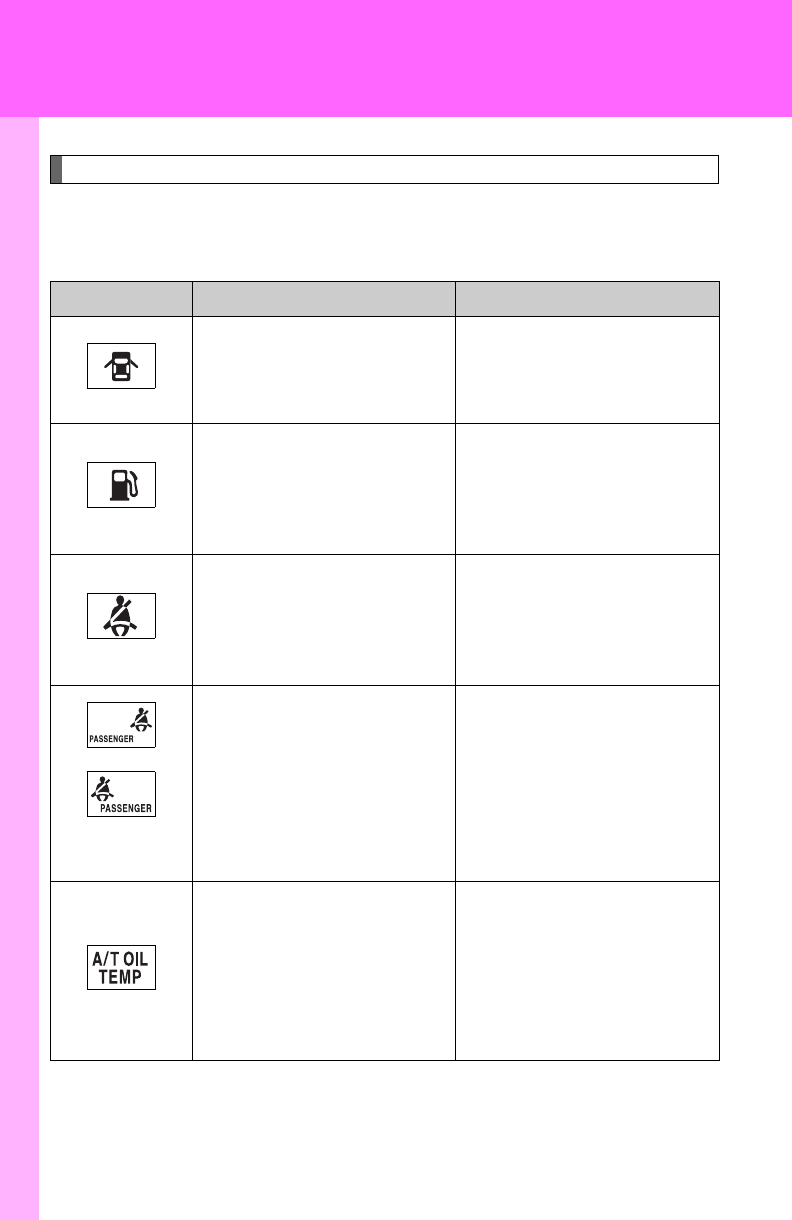
576
5-2. Steps to take in an emergency
Follow the correction procedures.
After taking the specified steps to correct the suspected problem,
check that the warning light turns off.
Warning light Warning light/Details Correction procedure
Open door warning light
(warning buzzer)*1
Indicates that a door is not
fully closed.
Check that all doors are
closed.
Low fuel level warning
light
Indicates that remaining
fuel is about 2.2 gal. (8.3
L, 1.8 Imp. gal.) or less
Refuel the vehicle.
Driver’s seat belt
reminder light
(warning buzzer)*2
Warns the driver to fasten
his/her seat belt.
Fasten the seat belt.
*3
*4
(On the center
panel)
Front passenger’s seat
belt reminder light
(warning buzzer)*2
Warns the front passen-
ger to fasten his or her
seat belt.
Fasten the seat belt.
Automatic transmission
fluid temperature warning
light (vehicles without
multi-information display)
Indicates that the auto-
matic transmission fluid
temperature is too high.
Stop the vehicle in a safe
place and shift the shift
lever to P.
If the light does not go off,
contact your Toyota dealer.

5
When trouble arises
577
5-2. Steps to take in an emergency
Low washer fluid warning
light (vehicles without
multi-information display)
Low level of washer fluid
Fill the tank.
(U.S.A.)
Maintenance required
reminder light
Indicates that mainte-
nance is required accord-
ing to the driven distance
on the maintenance
schedule.*5
Illuminates for about 3 sec-
onds and then flashes for
about 15 seconds approxi-
mately 4500 miles (7200
km) after the maintenance
data has been reset.
If necessary, perform main-
tenance.
Comes on and remains on if
the distance driven exceeds
5000 miles (8000 km) after
the maintenance data has
been reset.
(The indicator will not work
properly unless the mainte-
nance data has been reset.)
Perform the necessary
maintenance.
Please reset the mainte-
nance data after the mainte-
nance is performed.
(P. 489)
Warning light Warning light/Details Correction procedure
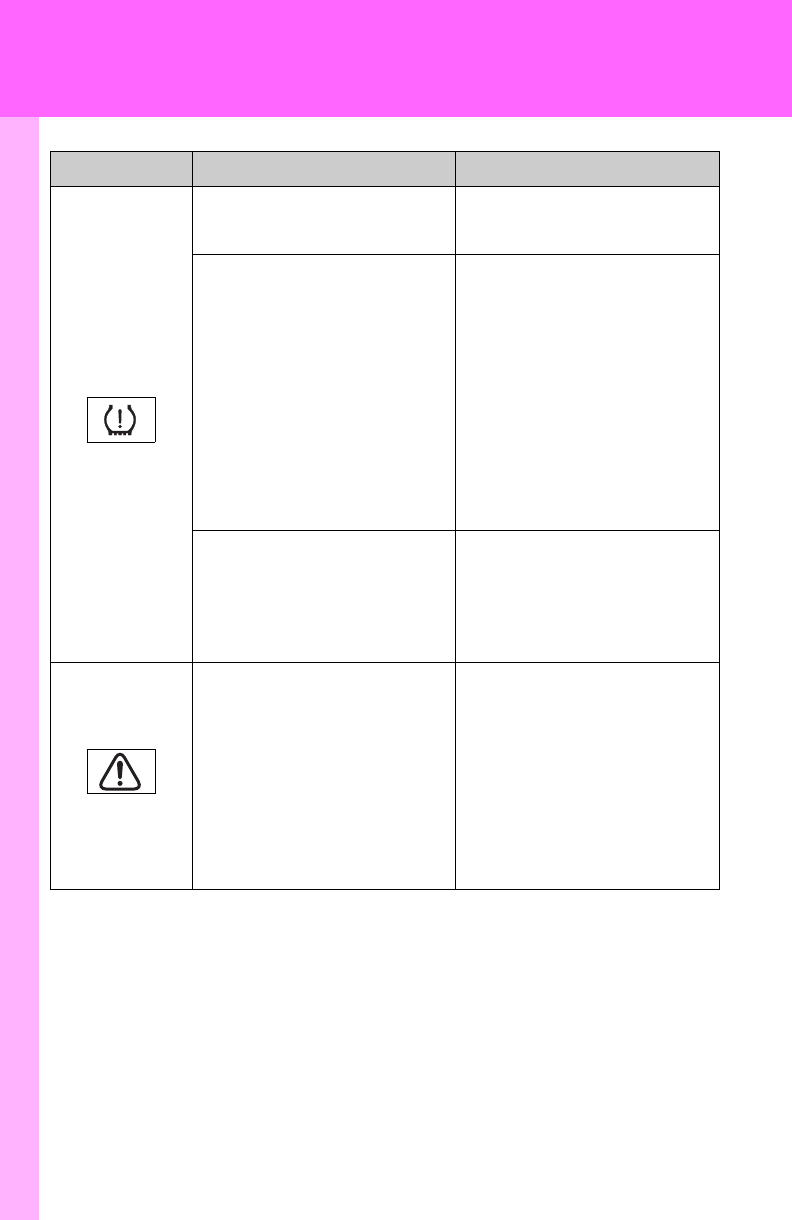
578
5-2. Steps to take in an emergency
Tire pressure warning
light
When the light comes on:
Low tire inflation pressure
such as
• Natural causes (P. 580)
• Flat tire (P. 586)
Adjust the tire inflation
pressure (including the
spare tire) to the specified
level.
The light will turn off after
a few minutes. In case
the light does not turn off
even if the tire inflation
pressure is adjusted,
have the system checked
by your Toyota dealer.
When the light comes on
after blinking for 1 minute:
Malfunction in the tire
pressure warning system
(P. 581)
Have the system checked
by your Toyota dealer.
Master warning light
(vehicles with multi-infor-
mation display)
A buzzer sounds and the
warning light comes on
and flashes to indicate that
the master warning system
has detected a malfunc-
tion.
P. 58 4
Warning light Warning light/Details Correction procedure

5
When trouble arises
579
5-2. Steps to take in an emergency
*1: Open door warning buzzer:
The open door warning buzzer sounds to alert one or more of the doors is
not fully closed (with the vehicle having reached a speed of 3 mph [5 km/h]).
*2: Driver's and front passenger’s seat belt reminders:
The driver’s and front passenger’s seat belt reminders sound to alert the
driver and front passenger that his or her seat belt is not fastened. These
buzzers sound for 10 seconds after the vehicle has reached a speed of at
least 12 mph (20 km/h). Then, if the seat belt is still unfastened, the buzzer
will sound in a different tone for 20 more seconds.
*3: Vehicles without a navigation system
*4: Vehicles with a navigation system
*5: Refer to the separate “Scheduled Maintenance Guide” or “Owner’s Manual
Supplement” for the maintenance interval applicable to your vehicle.
■Key reminder buzzer (vehicles without smart key system)
The buzzer indicates that the key has not been removed with the engine off
and the driver’s door opened.
■Open moon roof reminder buzzer (vehicles with multi-information dis-
play)
The buzzer indicates that the moon roof is not fully closed with the engine off
and the driver’s door opened.
■Front passenger detection sensor and passenger seat belt reminder
●If luggage is placed on the front passenger seat, the front passenger
detection sensor may cause the warning light to flash, even if a passen-
ger is not sitting in the seat.
●If a cushion is placed on the seat, the sensor may not detect a passen-
ger, and the warning light may not operate properly.

580
5-2. Steps to take in an emergency
■When the tire pressure warning light comes on
Check the tire inflation pressure and adjust to the appropriate level.
Pushing the tire pressure warning reset switch does not turn off the tire
pressure warning light.
■The tire pressure warning light may turn on due to natural causes
The tire pressure warning light may turn on due to natural causes such
as natural air leaks or tire inflation pressure changes caused by temper-
ature. In this case, adjusting the tire inflation pressure will turn off the
warning light (after a few minutes).
■When a tire is replaced with a spare tire
The spare tire is also equipped with the tire pressure warning valve and
transmitter. The tire pressure warning light will turn on if the tire inflation
pressure of the spare tire is low. If a tire goes flat, even though the flat
tire is replaced with the spare tire, the tire pressure warning light does
not turn off. Replace the spare tire with the repaired tire and adjust the
proper tire inflation pressure. The tire pressure warning light will turn off
after a few minutes.
■If the tire pressure warning system is inoperative
The tire pressure warning system will be disabled in the following condi-
tions:
(When the condition becomes normal, the system will work properly.)
●If tires not equipped with tire pressure warning valves and transmit-
ters are used.
●If the ID code on the tire pressure warning valves and transmitters is
not registered in the tire pressure warning computer.
●If the tire inflation pressure is 73 psi (500 kPa, 5.1 kgf/cm2 or bar) or
higher.

5
When trouble arises
581
5-2. Steps to take in an emergency
The tire pressure warning system may be disabled in the following condi-
tions:
(When the condition becomes normal, the system will work properly.)
●If electronic devices or facilities using similar radio wave frequencies
are nearby.
●If a radio set at similar frequencies is in use in the vehicle.
●If a window tint that affects the radio wave signals is installed.
●If there is a lot of snow or ice on the vehicle, in particular around the
wheels or wheel housings.
●If non-genuine Toyota wheels are used. (Even if you use Toyota
wheels, the tire pressure warning system may not work properly with
some types of tires.)
●If tire chains are used.
●If the spare tire is in a location subject to poor radio wave signal
reception.
●If a large metallic object which can interfere with signal reception is
put in the luggage room.
■If the tire pressure warning light frequently comes on after blinking
for 1 minute
Vehicles without smart key system
If the tire pressure warning light comes on after blinking for 1 minute fre-
quently when the engine switch is turned to the “ON” position, have it
checked by your Toyota dealer.
Vehicles with smart key system
If the tire pressure warning light comes on after blinking for 1 minute fre-
quently when the “ENGINE START STOP” switch is turned to IGNITION
ON mode, have it checked by your Toyota dealer.

582
5-2. Steps to take in an emergency
CAUTION
■If the tire pressure warning light comes on
Be sure to observe the following precautions. Failure to do so could
cause loss of vehicle control and result in death or serious injury.
●Stop your vehicle in a safe place as soon as possible. Adjust the tire
inflation pressure immediately.
●If the tire pressure warning light comes on even after tire inflation pres-
sure adjustment, it is probable that you have a flat tire. Check the tires.
If the tire is flat, change to the spare tire and have the flat tire repaired
by the nearest Toyota dealer.
●Avoid abrupt maneuvering and braking. If the vehicle tires deteriorate,
you could lose control of the steering wheel or the brakes.
■If a blowout or sudden air leakage should occur
The tire pressure warning system may not activate immediately.
■Maintenance of the tires
Each tire, including the spare (if provided), should be checked monthly
when cold and inflated to the inflation pressure recommended by the
vehicle manufacturer on the vehicle placard or tire inflation pressure
label (tire and load information label). (If your vehicle has tires of a differ-
ent size than the size indicated on the vehicle placard or tire inflation
pressure label [tire and load information label], you should determine the
proper tire inflation pressure for those tires.)
As an added safety feature, your vehicle has been equipped with a tire
pressure monitoring system (TPMS-tire pressure warning system) that
illuminates a low tire pressure telltale (tire pressure warning light) when
one or more of your tires is significantly under-inflated. Accordingly,
when the low tire pressure telltale (tire pressure warning light) illumi-
nates, you should stop and check your tires as soon as possible, and
inflate them to the proper pressure. Driving on a significantly under-
inflated tire causes the tire to overheat and can lead to tire failure.
Under-inflation also reduces fuel efficiency and tire tread life, and may
affect the vehicle's handling and stopping ability.

5
When trouble arises
583
5-2. Steps to take in an emergency
CAUTION
Please note that the TPMS (tire pressure warning system) is not a sub-
stitute for proper tire maintenance, and it is the driver's responsibility to
maintain correct tire pressure, even if under-inflation has not reached the
level to trigger illumination of the TPMS low tire pressure telltale (tire
pressure warning light).
Your vehicle has also been equipped with a TPMS (tire pressure warning
system) malfunction indicator to indicate when the system is not operat-
ing properly. The TPMS (tire pressure warning system) malfunction indi-
cator is combined with the low tire pressure telltale (tire pressure
warning light). When the system detects a malfunction, the telltale will
flash for approximately one minute and then remain continuously illumi-
nated. This sequence will continue upon subsequent vehicle start-ups as
long as the malfunction exists. When the malfunction indicator is illumi-
nated, the system may not be able to detect or signal low tire pressure
as intended.
TPMS (tire pressure warning system) malfunctions may occur for a vari-
ety of reasons, including the installation of replacement or alternate tires
or wheels on the vehicle that prevent the TPMS (tire pressure warning
system) from functioning properly. Always check the TPMS (tire pres-
sure warning system) malfunction telltale after replacing one or more
tires or wheels on your vehicle to ensure that the replacement or alter-
nate tires and wheels allow the TPMS (tire pressure warning system) to
continue to function properly.
NOTICE
■Precaution when installing a different tire
When a tire of a different specification or maker is installed, the tire pres-
sure warning system may not operate properly.
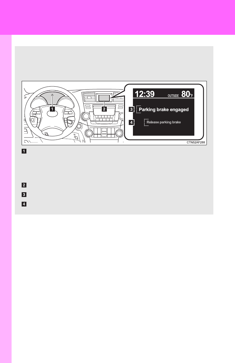
584
5-2. Steps to take in an emergency
If a warning message is displayed (vehicles with multi-information display)
■Warning buzzer
A buzzer may sound when a warning message is shown on the
multi-information display.
The multi-information display shows warnings of system malfunc-
tions or incorrectly performed operations. When a message is
shown, perform corrections as indicated in the message.
Master warning light
The master warning light also comes on or flashes in order to indicate
that a message is currently being displayed on the multi-information
display.
Multi-information display
Warning message
Correction procedure
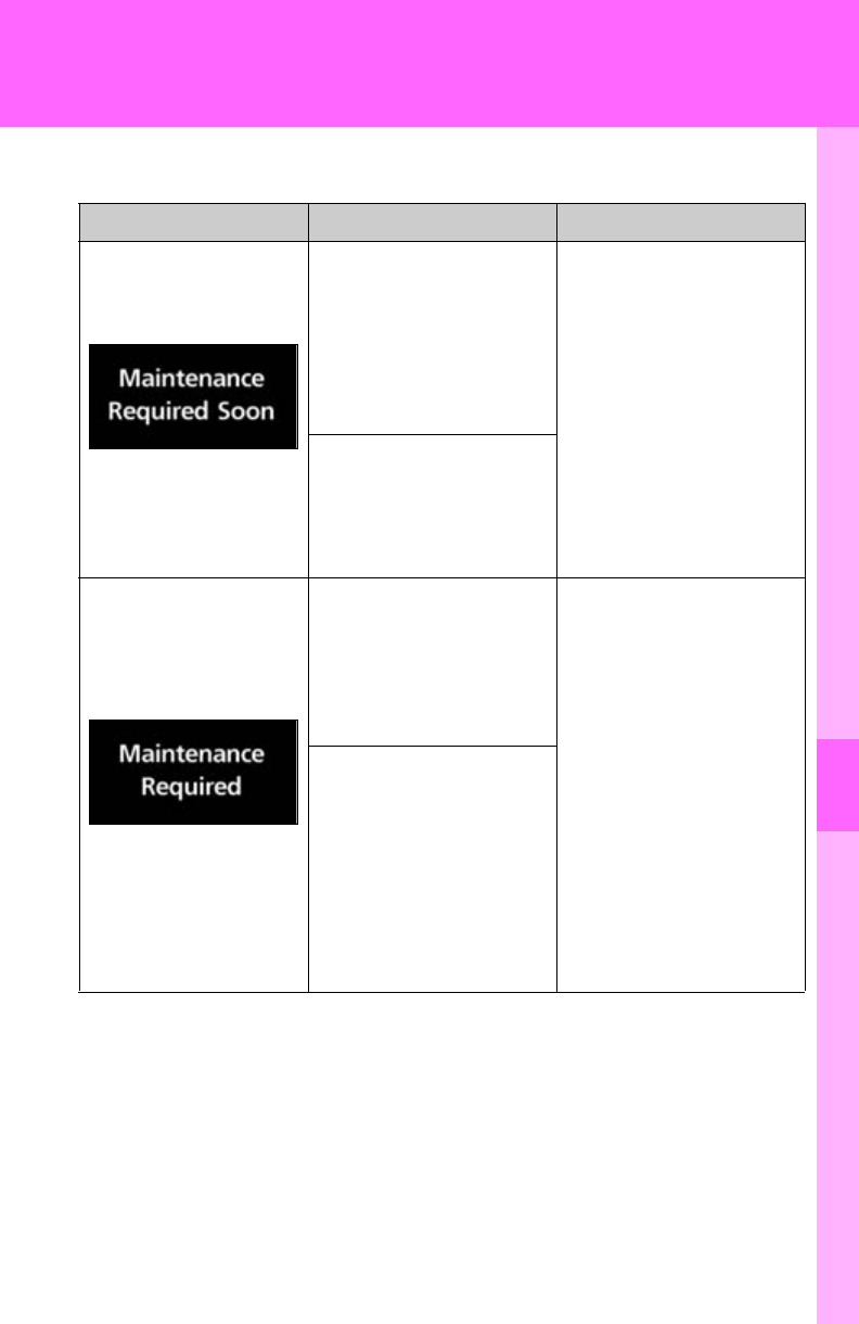
5
When trouble arises
585
5-2. Steps to take in an emergency
■If the following message is displayed
*: Refer to the separate “Scheduled Maintenance” or “Owner's Manual Sup-
plement” for the maintenance interval applicable to your vehicle.
■If the warning message is shown again after its correction
procedure has been performed
Contact your Toyota dealer as soon as possible.
Message Details Correction procedure
(U.S.A. only)
Indicates that all
maintenance accord-
ing to the driven dis-
tance on the
maintenance sched-
ule* should be per-
formed soon.
If necessary, perform
maintenance.
Comes on approxi-
mately 4500 miles
(7200 km) after the
maintenance data has
been reset.
(U.S.A. only)
Indicates that all
maintenance is
required to corre-
spond to the driven
distance on the main-
tenance schedule*. Perform the necessary
maintenance. Please
reset the maintenance
data after the mainte-
nance is performed.
(P. 489)
Comes on approxi-
mately 5000 miles
(8000 km) after the
maintenance data has
been reset.
(The indicator will not
work properly unless
the maintenance data
has been reset.)
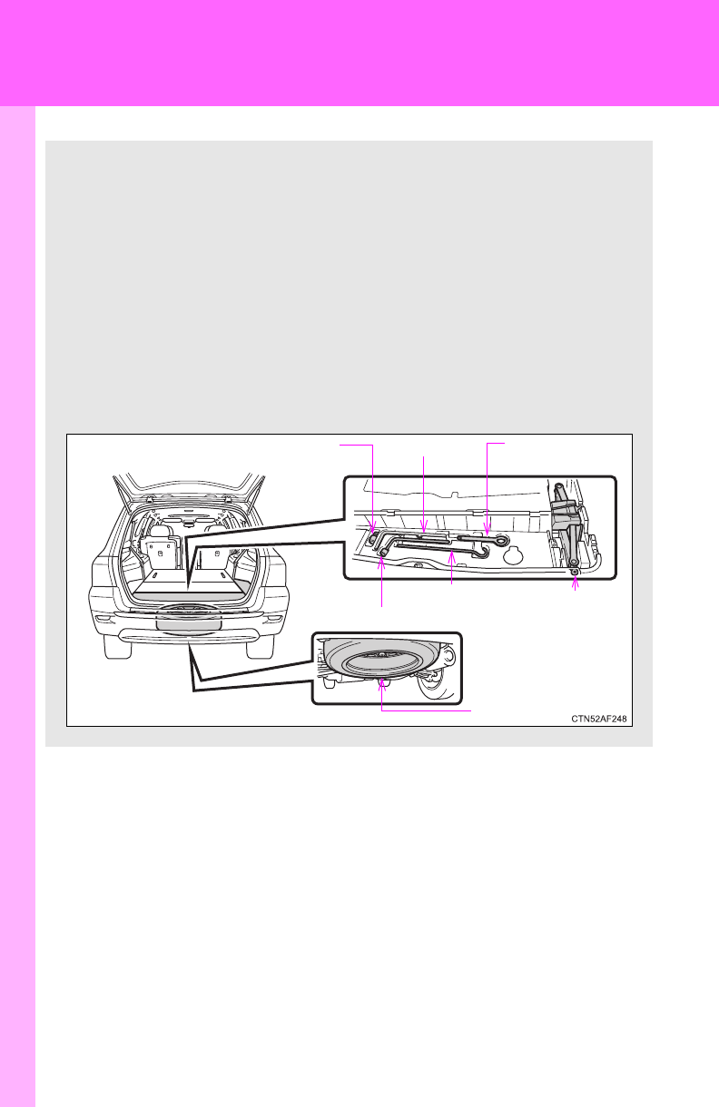
586
5-2. Steps to take in an emergency
If you have a flat tire
Remove the flat tire and replace it with the spare provided.
■Before jacking up the vehicle
●Stop the vehicle on a hard, flat surface.
●Set the parking brake.
●Shift the shift lever to P.
●Stop the engine.
●Turn on the emergency flashers.
■Location of the spare tire, jack and tools
Jack handle
Adapter
socket
Towing eyelet
Jack handle
Wheel nut wrench
Spare tire
Jack

5
When trouble arises
587
5-2. Steps to take in an emergency
Taking out the jack
Remove the right side deck
board.
Unhook the tightening strap and
remove the pad.
After storing the jack, make
sure it is securely held by the
tightening strap.
Loosen
Tighten
STEP
1
STEP
2
STEP
3
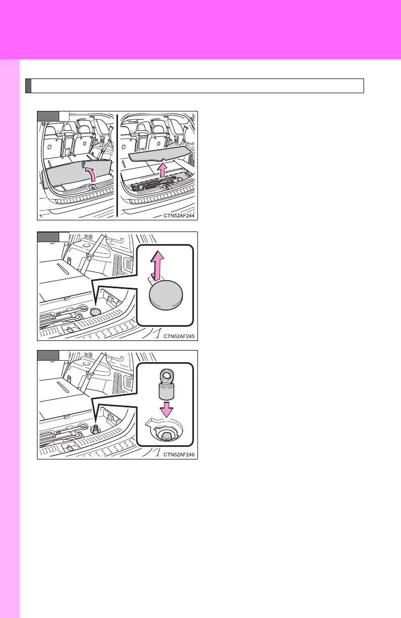
588
5-2. Steps to take in an emergency
Taking out the spare tire
Open the center deck board and
remove the cover.
Remove the cover.
If it is difficult to remove the
cover, you can use the key.
Attach the adapter socket (for
removing a spare tire) to the
spare tire clamp bolt.
STEP
1
STEP
2
STEP
3
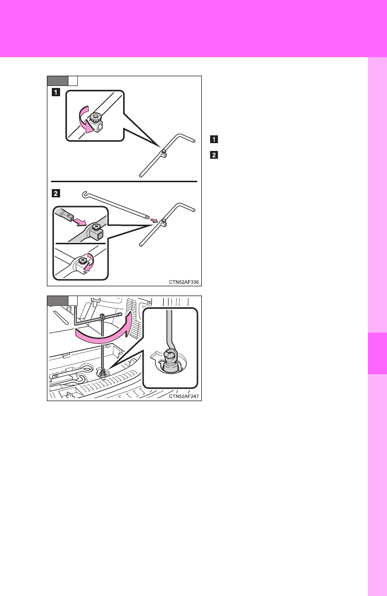
5
When trouble arises
589
5-2. Steps to take in an emergency
Assembling the jack handle.
Remove the jack handle and
assemble it by following these
steps.
Loosen the screw.
Assemble the jack handle and
tighten the screw.
Check that the screw is firmly
tightened.
Connect the jack handle and the
adapter socket. Turn the jack
handle.
The tire will be lowered com-
pletely to the ground.
STEP
4
STEP
5
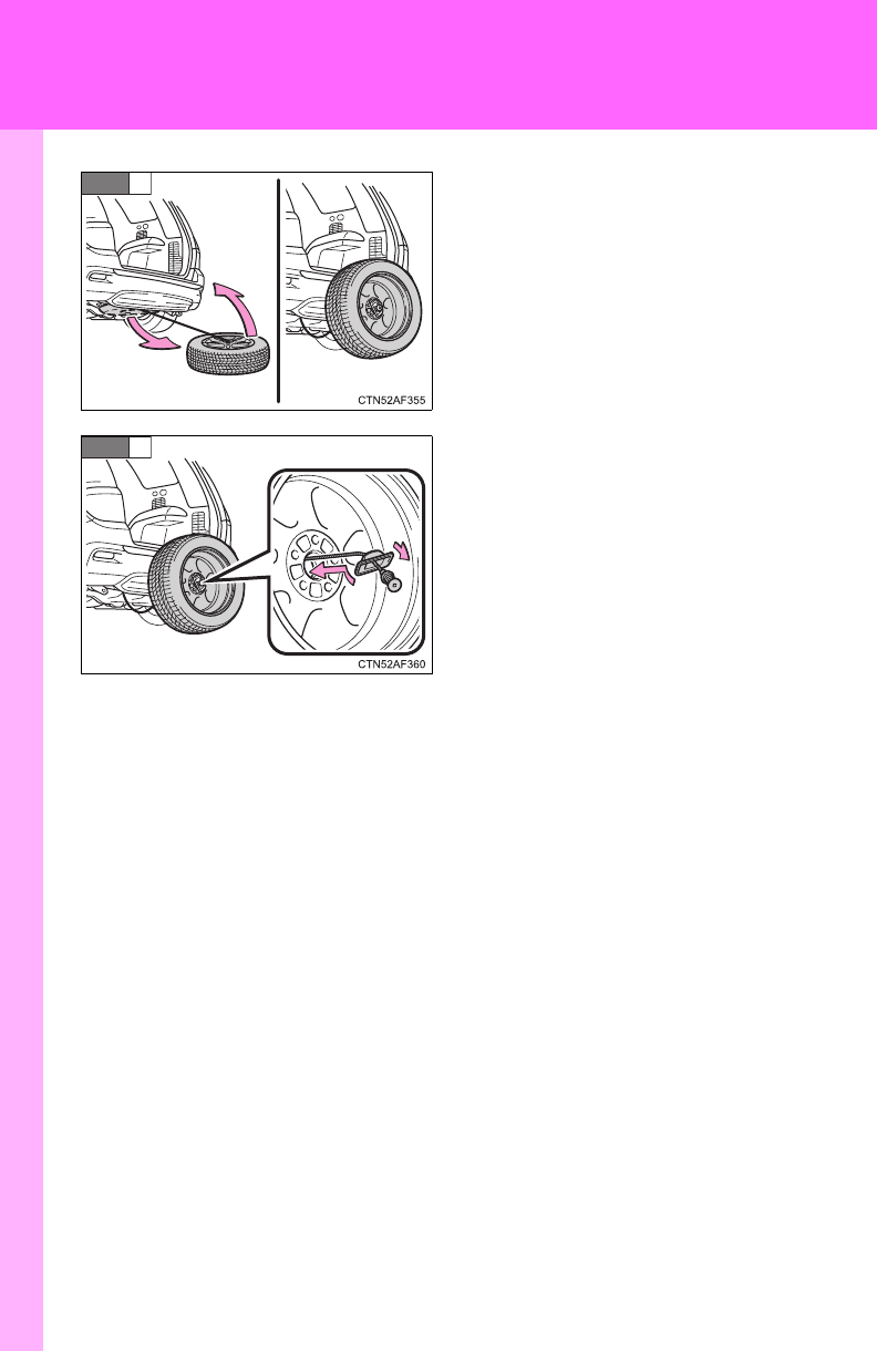
590
5-2. Steps to take in an emergency
Pull out the spare tire and stand
it against the bumper.
Remove the holding bracket.
STEP
6
STEP
7
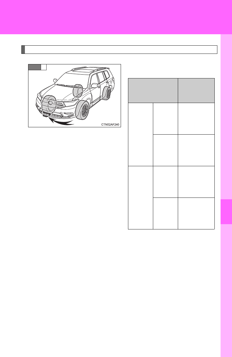
5
When trouble arises
591
5-2. Steps to take in an emergency
Replacing a flat tire
Chock the tires.
STEP
1
STEP
1
Flat tire
Wheel
chock
positions
Front
Left-
hand
side
Behind the
rear right-
hand side
tire
Right-
hand
side
Behind the
rear left-
hand side
tire
Rear
Left-
hand
side
In front of
the front
right-hand
side tire
Right-
hand
side
In front of
the front
left-hand
side tire
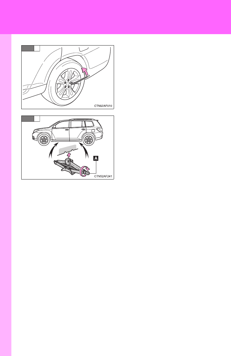
592
5-2. Steps to take in an emergency
Slightly loosen the wheel nuts
(one turn).
Turn the tire jack portion “A” by
hand until the notch of the jack is
in contact with the jack point.
STEP
2
STEP
3

5
When trouble arises
593
5-2. Steps to take in an emergency
Raise the vehicle until the tire is
slightly raised off the ground.
Remove all the wheel nuts and
the tire.
When resting the tire on the
ground, place the tire so that the
wheel design faces up to avoid
scratching the wheel surface.
STEP
4
STEP
5
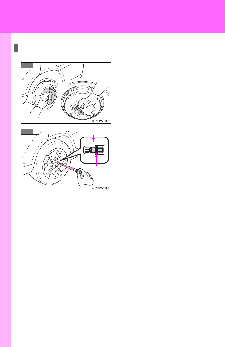
594
5-2. Steps to take in an emergency
Installing the tire
Remove any dirt or foreign mat-
ter from the wheel contact sur-
face.
If foreign matter is on the wheel
contact surface, the wheel nuts
may loosen while the vehicle is
in motion, and the tire may
come off the vehicle.
Install the tire and loosely tighten
each wheel nut by hand by
approximately the same amount.
Turn the nut washers until they
come into contact with the disc
wheel.
STEP
1
Disc wheel
Washer
STEP
2
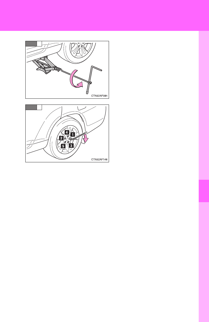
5
When trouble arises
595
5-2. Steps to take in an emergency
Lower the vehicle.
Firmly tighten each nut two or
three times in the order shown in
the illustration.
Tightening torque:
76 ft•lbf (103 N•m, 10.5 kgf•m)
STEP
3
STEP
4
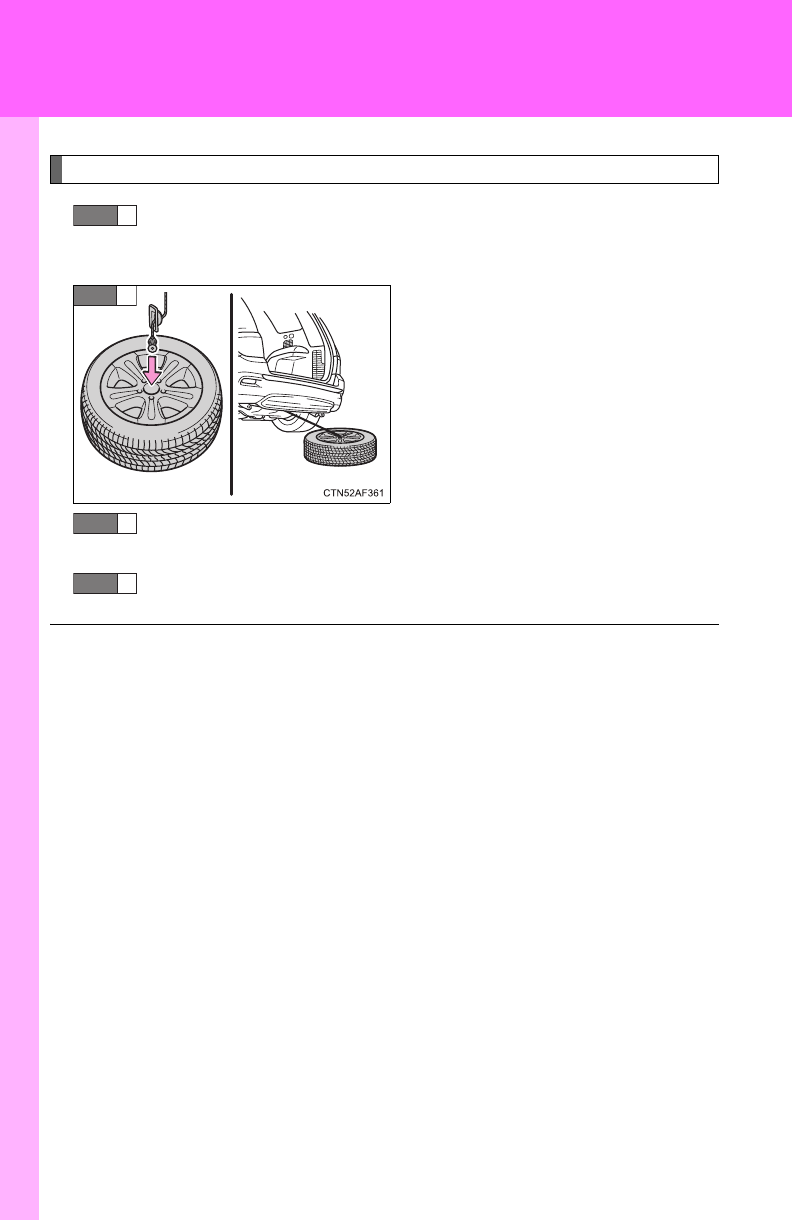
596
5-2. Steps to take in an emergency
Stowing the flat tire, jack and all tools
Remove the center wheel ornament by pushing from the
reverse side.
Put the flat tire on the ground
with the outer side facing up and
install the holding bracket.
Be careful not to lose the wheel
ornament.
Turn the spare tire clamp bolt clockwise with a jack handle
and adapter socket until you hear a click.
Stow the jack and all tools.
STEP
1
STEP
2
■After completing the tire change
The tire pressure warning system must be reset. (P. 523)
STEP
3
STEP
4

5
When trouble arises
597
5-2. Steps to take in an emergency
CAUTION
■Using the tire jack
Improper use of the tire jack may lead to death or serious injuries due to
the vehicle suddenly falling off the jack.
●Do not use the tire jack for any purpose other than replacing tires or
installing and removing tire chains.
●Only use the tire jack that comes with this vehicle for replacing a flat
tire.
Do not use it on other vehicles, and do not use other tire jacks for
replacing tires on this vehicle.
●Always check that the tire jack is securely set to the jack point.
●Do not put any part of your body under the vehicle supported by a jack.
●Do not start or run the engine while your vehicle is supported by the
jack.
●Do not raise the vehicle while someone is in it.
●When raising the vehicle, do not put an object on or under the jack.
●Do not raise the vehicle to a height greater than that required to
replace the tire.
●Use a jack stand if it is necessary to get under the vehicle.
Take particular care when lowering the vehicle to ensure that no one
working on or near the vehicle will be injured.

598
5-2. Steps to take in an emergency
CAUTION
■Replacing a flat tire
Failure to follow these precautions could cause the wheel nuts to loosen
and the tire to fall off, resulting in death or serious injury.
●Have the wheel nuts tightened with a torque wrench to 76 ft•lbf (103
N•m, 10.5 kgf•m) as soon as possible after changing wheels.
●When installing the wheel nuts, be sure to install them with the tapered
ends facing inward. (P. 534)
■Replacing a flat tire for vehicles with power back door
In cases such as when replacing tires, make sure to turn off the power
back door main switch (P. 62). Failure to do so may cause the back
door to operate unintentionally if the power back door switch is acciden-
tally touched, resulting in hands and fingers being caught and injured.

5
When trouble arises
599
5-2. Steps to take in an emergency
NOTICE
■Do not drive the vehicle with a flat tire.
Do not continue driving with a flat tire.
Driving even a short distance with a flat tire can damage the tire and the
wheel beyond repair.
■When replacing the tires
When removing or fitting the wheels, tires or the tire pressure warning
valve and transmitter, contact your Toyota dealer as the tire pressure
warning valve and transmitter may be damaged if not handled correctly.
■To avoid damage to the tire pressure warning valves and transmit-
ters
When a tire is repaired with liquid sealants, the tire pressure warning
valve and transmitter may not operate properly. If a liquid sealant is
used, contact your Toyota dealer or other qualified service shop as soon
as possible. Make sure to replace the tire pressure warning valve and
transmitter when replacing the tire. (P. 523)
■When stowing the flat tire
●Ensure that there is no object caught between the tire and the vehicle
underbody.
●Tighten the spare tire clamp bolt to hold the spare wheel carrier by the
hook securely.

600
5-2. Steps to take in an emergency
If the engine will not start
If the engine still does not start after following the correct starting
procedure (P. 171, 175) or releasing the steering lock (P. 173,
176), confirm the following points.
■The engine will not start even when the starter motor oper-
ates normally.
One of the following may be the cause of the problem.
●There may not be sufficient fuel in the vehicle’s tank.
Refuel the vehicle.
●The engine may be flooded.
Try to restart the engine once more following correct starting
procedures. (P. 171, 175)
●There may be a malfunction in the engine immobilizer system
(if equipped). (P. 11 3 )
■The starter motor turns over slowly, the interior lights and
headlights are dim, or the horn does not sound or sounds at
a low volume.
One of the following may be the cause of the problem.
●The battery may be discharged. (P. 606)
●The battery terminal connections may be loose or corroded.
■The starter motor does not turn over (vehicles with smart
key system).
The engine starting system may be malfunctioning due to an
electrical problem such as an open circuit or a blown fuse. How-
ever, an interim measure is available to start the engine.
(P. 601)

5
When trouble arises
601
5-2. Steps to take in an emergency
Emergency start function (vehicles with smart key system)
When the engine does not start, the following steps can be used as
an interim measure to start the engine if the “ENGINE START STOP”
switch is functioning normally.
Set the parking brake.
Shift the shift lever to P.
Set the “ENGINE START STOP” switch to ACCESSORY
mode.
Push and hold the “ENGINE START STOP” switch about 15
seconds while depressing the brake pedal firmly.
Even if the engine can be started using the above steps, the system
may be malfunctioning. Have the vehicle checked by your Toyota
dealer.
■The starter motor does not turn over, the interior lights and
headlights do not turn on, or the horn does not sound.
One of the following may be the cause of the problem.
●One or both of the battery terminals may be disconnected.
●The battery may be discharged. (P. 606)
●There may be a malfunction in the steering lock system (vehi-
cles with smart key system).
Contact your Toyota dealer if the problem cannot be repaired, or if
repair procedures are unknown.
STEP
1
STEP
2
STEP
3
STEP
4
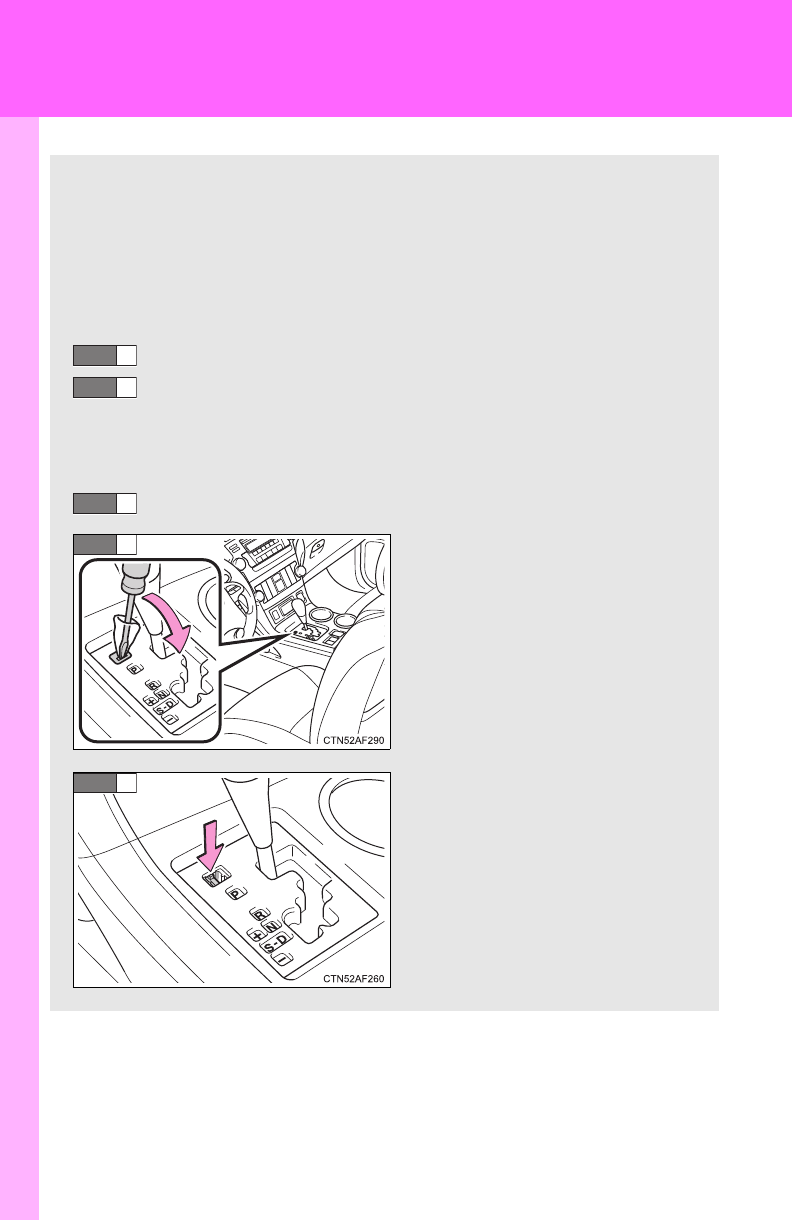
602
5-2. Steps to take in an emergency
If the shift lever cannot be shifted from P
If the shift lever cannot be shifted with your foot on the brake, there
may be a problem with the shift lock system (a system to prevent
accidental operation of the shift lever). Have the vehicle inspected by
your Toyota dealer immediately.
The following steps may be used as an emergency measure to
ensure that the shift lever can be shifted.
Set the parking brake.
Vehicles without smart key system: Turn the engine switch
to the “ACC” position.
Vehicles with smart key system: Turn the “ENGINE START
STOP” switch to ACCESSORY mode.
Depress the brake pedal.
Pry the cover up with a flat-
head screwdriver or equiva-
lent.
Press the shift lock override
button.
The shift lever can be shifted
while the button is pressed.
STEP
1
STEP
2
STEP
3
STEP
4
STEP
5

5
When trouble arises
603
5-2. Steps to take in an emergency
If you lose your keys/wireless remote control transmitter
■Keys
New genuine keys can be made by your Toyota dealer.
For vehicles with the smart key system, bring the other key and
the key number stamped on the key number plate.
For vehicles without the smart key system, bring a master key
and the key number stamped on the key number plate.
■Wireless remote control transmitter (vehicles without smart
key system)
New genuine wireless remote control transmitters can be pur-
chased and programmed by your Toyota dealer. If a wireless
remote control transmitter has been lost, bring the other wireless
remote control transmitter when going to pick up the new trans-
mitter.
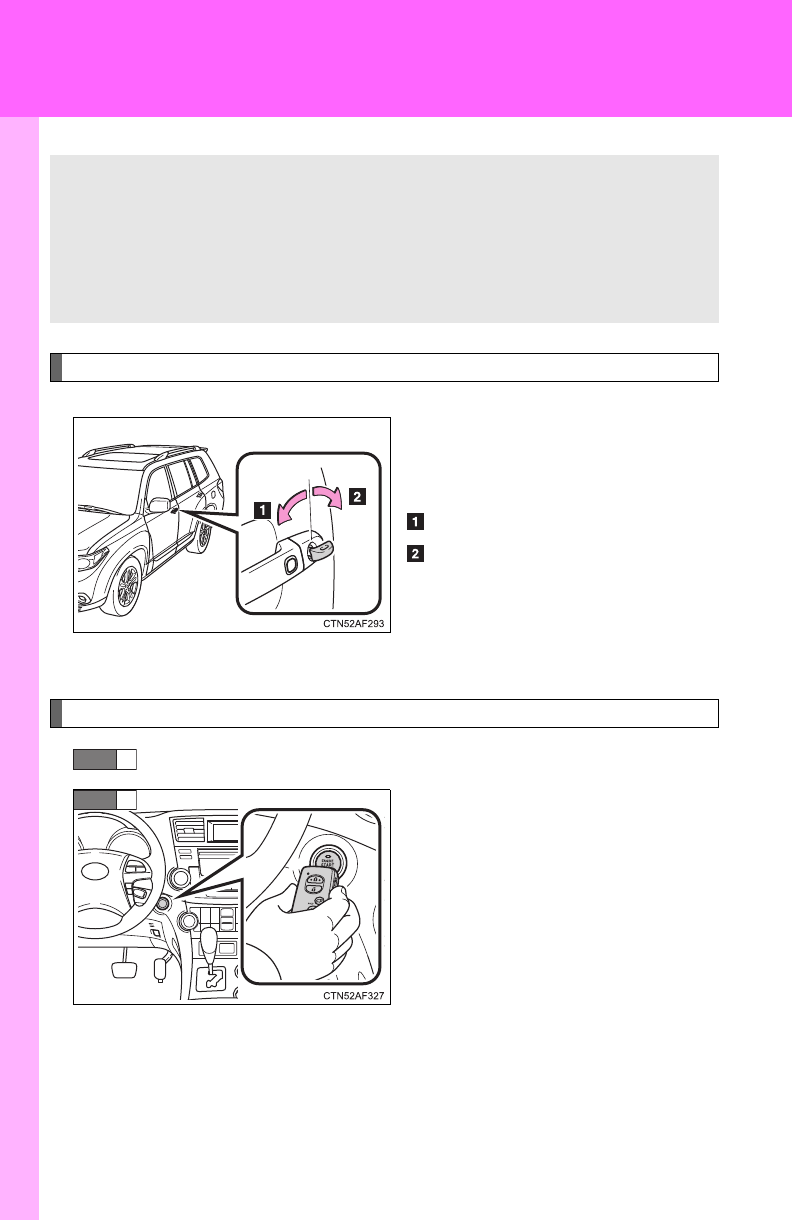
604
5-2. Steps to take in an emergency
If the electronic key does not operate properly (vehicles with smart key system)
Locking and unlocking the doors, and mechanical key linked functions
Using the mechanical key (P. 33)
in order to perform the following
operations:
Locks all doors
Unlocks all doors
Turning the key rearward unlocks
the driver’s door. Turning the key
once again unlocks the other
doors.
Starting the engine
Shift the shift lever to P and apply the brakes.
Touch the Toyota emblem side of
the electronic key to the
“ENGINE START STOP” switch.
If any of the doors is opened and
closed while the key is being
touched to the switch, an alarm
will sound to indicate that the start
function cannot detect the elec-
tronic key.
If communication between the electronic key and vehicle is inter-
rupted (P. 40) or the electronic key cannot be used because the
battery is depleted, the smart key system and wireless remote con-
trol cannot be used. In such cases, the doors can be opened or the
engine can be started by following the procedure below.
STEP
1
STEP
2

5
When trouble arises
605
5-2. Steps to take in an emergency
Press the “ENGINE START STOP” switch within 5 seconds
after the buzzer sounds, keeping the brake pedal depressed.
In the event that the “ENGINE START STOP” switch still cannot be
operated, contact your Toyota dealer.
■Stopping the engine
Shift the shift lever to P and press the “ENGINE START STOP” switch as
you normally do when stopping the engine.
■Replacing the electronic key battery
As the above procedure is a temporary measure, it is recommended that the
electronic key battery be replaced immediately when the battery depletes.
(P. 540)
■Changing “ENGINE START STOP” switch modes
Within 5 seconds of the buzzer sounding, release the brake pedal and press
the “ENGINE START STOP” switch.
The engine does not start and modes will be changed each time the switch
is pressed. (P. 172)
STEP
3
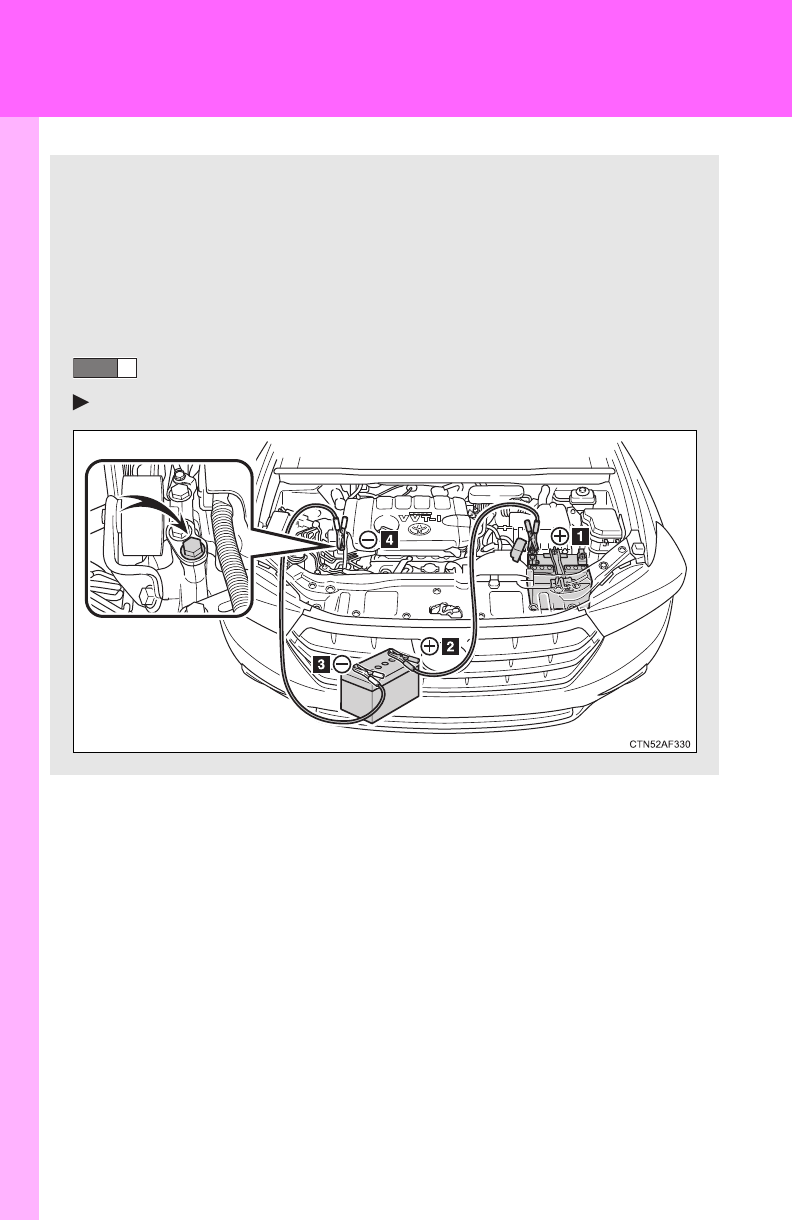
606
5-2. Steps to take in an emergency
If the battery is discharged
The following procedures may be used to start the engine if the vehi-
cle's battery is discharged.
You can call your Toyota dealer or qualified repair shop.
If you have a set of jumper (or booster) cables and a second vehi-
cle with a 12-volt battery, you can jump start your Toyota following
the steps below.
Connect the jumper cables.
2.7 L 4-cylinder (1AR-FE) engine
STEP
1
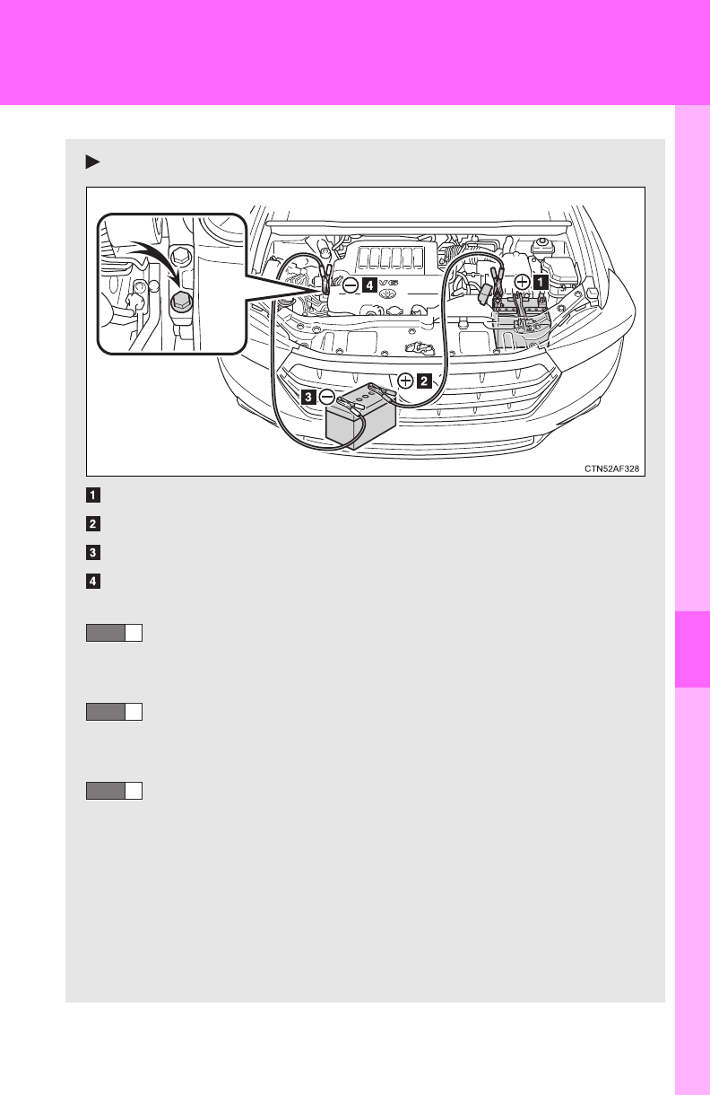
5
When trouble arises
607
5-2. Steps to take in an emergency
3.5 L V6 (2GR-FE) engine
Positive (+) battery terminal on your vehicle
Positive (+) battery terminal on the second vehicle
Negative (-) battery terminal on the second vehicle
Connect the jumper cable to ground on your vehicle as shown in
the illustration.
Start the engine of the second vehicle. Increase the engine
speed slightly and maintain at that level for approximately 5
minutes to recharge the battery of your vehicle.
Vehicles with smart key system:
Open and close any of the doors with the “ENGINE START
STOP” switch OFF.
Vehicles without smart key system:
Maintain the engine speed of the second vehicle, and turn
the engine switch to the “ON” position, then start the vehi-
cle's engine.
Vehicles with smart key system:
Maintain the engine speed of the second vehicle, and turn
the “ENGINE START STOP” switch to IGNITION ON mode,
then start the vehicle's engine.
STEP
2
STEP
3
STEP
4

608
5-2. Steps to take in an emergency
■Starting the engine when the battery is discharged
The engine cannot be started by push-starting.
■To prevent battery discharge
●Turn off the headlights and the audio system while the engine is turned
off.
●Turn off any unnecessary electrical components when the vehicle is run-
ning at a low speed for an extended period, such as in heavy traffic, etc.
■When the battery is removed or discharged
●The power back door must be initialized (P. 6 4 )
●The tire inflation pressure warning system must be initialized. (P. 523)
●Make sure that the key is not inside the vehicle when recharging or
replacing the battery. The key may be locked in the vehicle if the alarm is
activated. (P. 119)
■Charging the battery
The electricity stored in the battery will discharge gradually even when the
vehicle is not in use, due to natural discharge and the draining effects of cer-
tain electrical appliances. If the vehicle is left for a long time, the battery may
discharge, and the engine may be unable to start. (The battery recharges
automatically during driving.)
Once the vehicle’s engine has started, remove the jumper
cables in the exact reverse order in which they were con-
nected.
Once the engine starts, have the vehicle checked at your Toyota
dealer as soon as possible.
STEP
5

5
When trouble arises
609
5-2. Steps to take in an emergency
CAUTION
■Avoiding battery fires or explosions
Observe the following precautions to prevent accidentally igniting the flam-
mable gas that may be emitted from the battery.
●Make sure the jumper cable is connected to the correct terminal and that it
is not unintentionally in contact with any part other than the intended termi-
nal.
●Do not allow the + and - clamps of the jumper cables to come into contact
with each other.
●Do not smoke, use matches, cigarette lighters or allow open flame near
the battery.
■Battery precautions
The battery contains poisonous and corrosive acidic electrolyte, while
related parts contain lead and lead compounds. Observe the following pre-
cautions when handling the battery.
●When working with the battery, always wear safety glasses and take care
not to allow any battery fluids (acid) to come into contact with skin, clothing
or the vehicle body.
●Do not lean over the battery.
●In the event that battery fluid comes into contact with the skin or eyes,
immediately wash the affected area with water and seek medical attention.
Place a wet sponge or cloth over the affected area until medical attention
can be received.
●Always wash your hands after handling the battery support, terminals, and
other battery-related parts.
●Do not allow children near the battery.
NOTICE
■When handling jumper cables
Be careful that the jumper cables do not become tangled in the cooling fan
or any of the belts when connecting or disconnecting them.
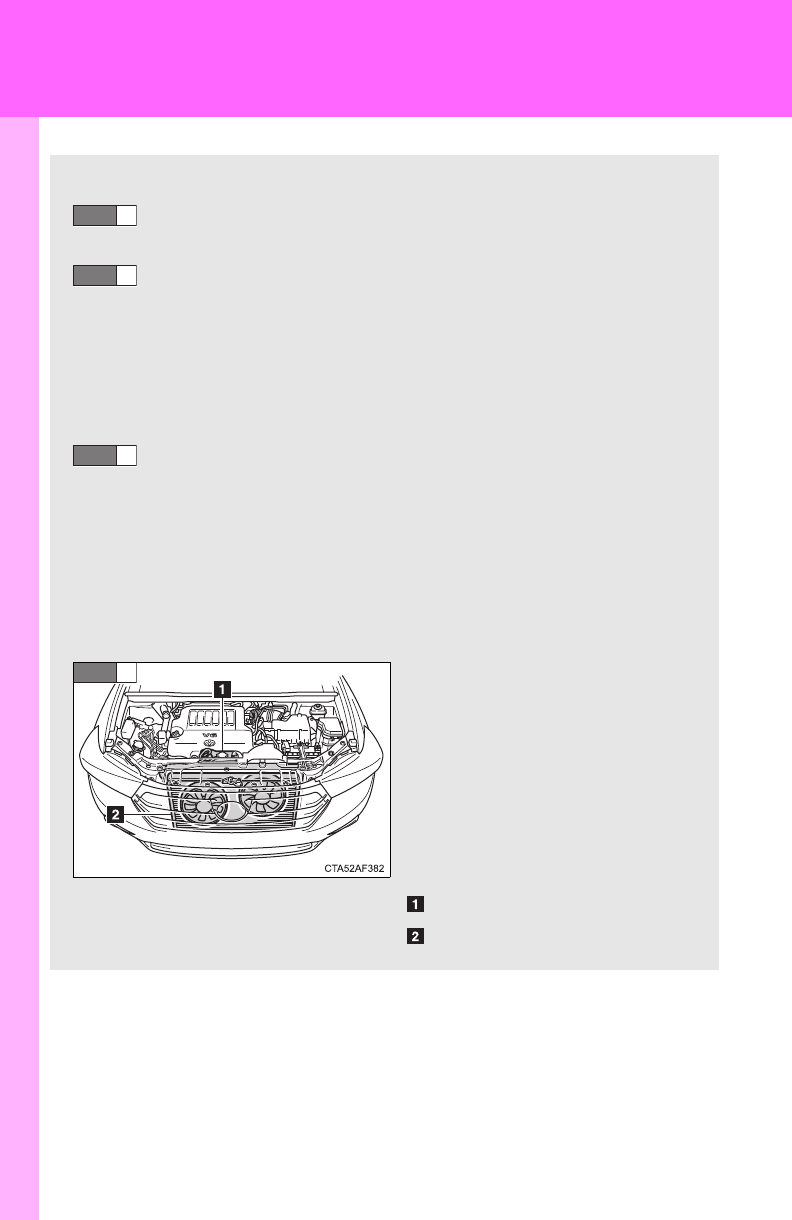
610
5-2. Steps to take in an emergency
If your vehicle overheats
If your engine overheats:
Stop the vehicle in a safe place and turn off the air condi-
tioning system.
Check to see if steam is coming out from under the hood.
If you see steam:
Stop the engine. Carefully lift the hood after the steam
subsides and then restart the engine.
If you do not see steam:
Leave the engine running and carefully lift the hood.
Check to see if the cooling fans are operating.
If the fans are operating:
Wait until the temperature of the engine (shown on the
instrument cluster) begins to fall and then stop the
engine.
If the fans are not operating:
Stop the engine and call your Toyota dealer.
After the engine has cooled
down sufficiently, check the
engine coolant level and
inspect the radiator core (radi-
ator) for any leaks.
If the engine compartment
cover needs to be removed.
(P. 507)
Engine coolant reservoir
Radiator
STEP
1
STEP
2
STEP
3
STEP
4
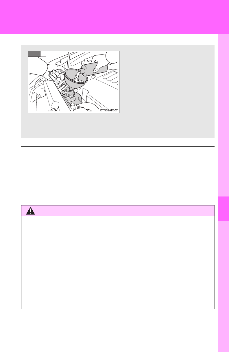
5
When trouble arises
611
5-2. Steps to take in an emergency
■Overheating
If you observe the following, your vehicle may be overheating.
●The engine coolant temperature gauge enters the red zone or a loss of
power is experienced.
●Steam comes from under the hood.
CAUTION
■To prevent an accident or injury when inspecting under the hood of
your vehicle
●If steam is seen coming from under the hood, do not open the hood until
the steam has subsided. The engine compartment may be very hot, caus-
ing serious injury such as burns.
●Keep hands and clothing away from the fan and other belts while the
engine is running.
●Do not loosen the coolant reservoir cap while the engine and radiator are
hot.
Serious injury, such as burns, may result from hot coolant and steam
released under pressure.
Add engine coolant if neces-
sary.
Water can be used in an emer-
gency if engine coolant is
unavailable. (P. 626)
Have the vehicle checked at the nearest Toyota dealer as soon as
possible.
STEP
5

612
5-2. Steps to take in an emergency
NOTICE
■When adding engine coolant
Wait until the engine has cooled down before adding engine coolant.
When adding coolant, do so slowly. Adding cool coolant to a hot engine too
quickly can cause damage to the engine.

5
When trouble arises
613
5-2. Steps to take in an emergency
If the vehicle becomes stuck
CAUTION
■When attempting to free a stuck vehicle
If you choose to rock the vehicle back and forth to free it, make sure the sur-
rounding area is clear, to avoid striking other vehicles, objects or persons.
The vehicle may also lunge forward or lunge back suddenly as it becomes
free. Use extreme caution.
■When shifting the shift lever
Be careful not to shift the shift lever with the accelerator pedal depressed.
This may lead to unexpected rapid acceleration of the vehicle that may
cause an accident and result in death or serious injury.
Carry out the following procedures if the tires spin or the vehicle
becomes stuck in mud, dirt, or snow.
Stop the engine. Set the parking brake and put the shift
lever to P.
Remove the mud, snow, or sand from around the stuck tire.
Place wood, stones or some other material to help provide
traction under the tires.
Restart the engine.
Shift the shift lever to the D or R position and carefully apply
the accelerator to free the vehicle.
Turn off TRAC and/or VSC if these functions are hampering your
attempts to free the vehicle. (P. 228)
STEP
1
STEP
2
STEP
3
STEP
4
STEP
5

614
5-2. Steps to take in an emergency
NOTICE
■To avoid damaging the transmission and other components
●Avoid spinning the wheels and do not rev the engine.
●If the vehicle remains stuck after trying these procedures, the vehicle may
require towing to be freed.
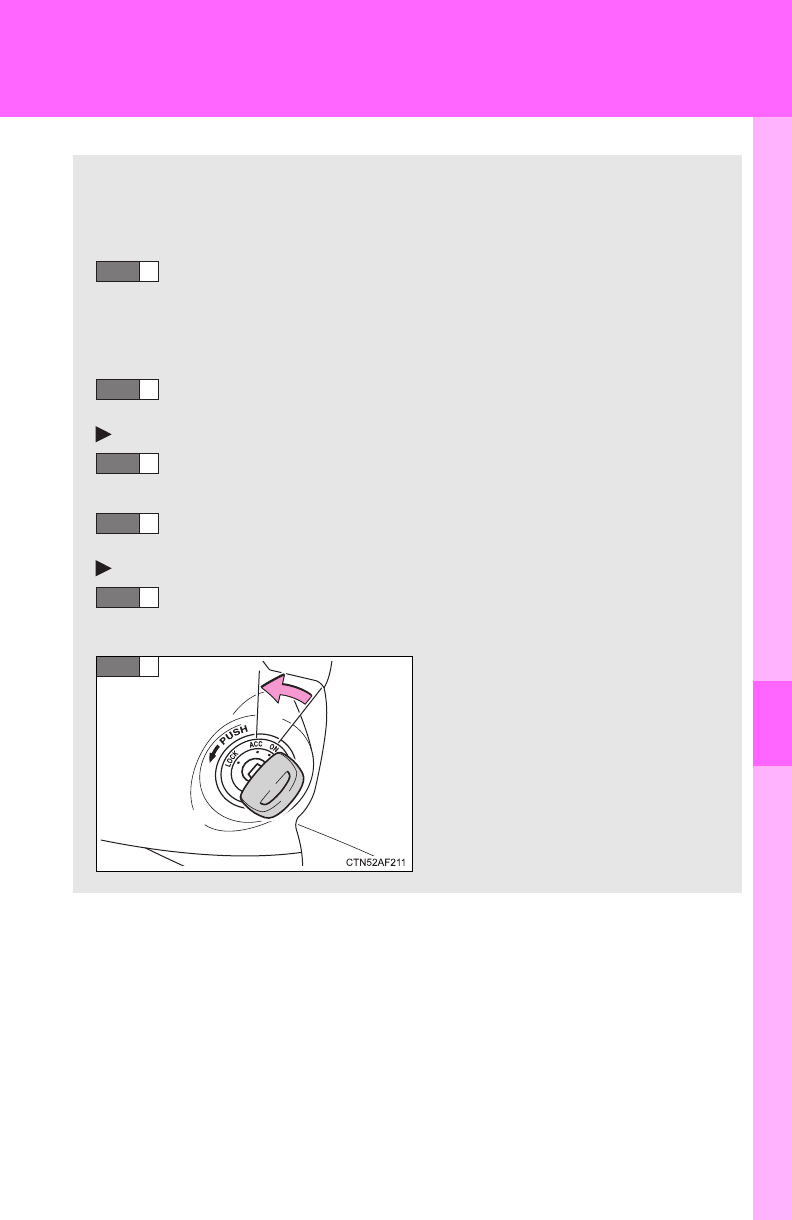
5
When trouble arises
615
5-2. Steps to take in an emergency
If your vehicle has to be stopped in an emergency
Only in an emergency, such as if it becomes impossible to stop the
vehicle in the normal way, stop the vehicle using the following pro-
cedure:
Steadily step on the brake pedal with both feet and firmly
depress it.
Do not pump the brake pedal repeatedly as this will increase the
effort required to slow the vehicle.
Shift the shift lever to N.
If the shift lever is shifted to N
After slowing down, stop the vehicle in a safe place by the
road.
Stop the engine.
If the shift lever cannot be shifted to N
Keep depressing the brake pedal with both feet to reduce
vehicle speed as much as possible.
Vehicles without a smart key
system: Stop the engine by
turning the engine switch to
the “ACC” position.
STEP
1
STEP
2
STEP
3
STEP
4
STEP
3
STEP
4
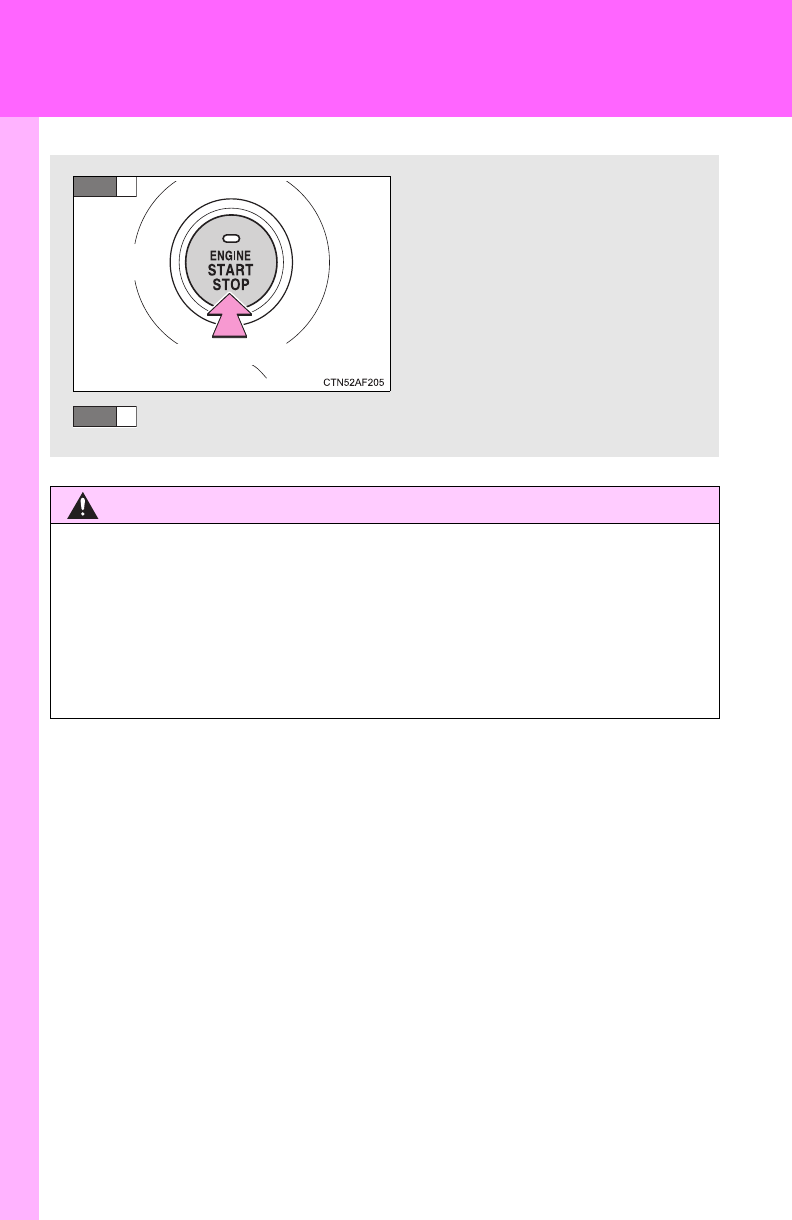
616
5-2. Steps to take in an emergency
CAUTION
■If the engine has to be turned off while driving
●Power assist for the brakes and steering wheel will be lost, making the
brake pedal harder to depress and the steering wheel heavier to turn.
Decelerate as much as possible before turning off the engine.
●Vehicles without a smart key system: Never attempt to remove the key, as
doing so will lock the steering wheel.
Vehicles with a smart key sys-
tem: Stop the engine by press-
ing and holding the “ENGINE
START STOP” switch for 2
consecutive seconds or more.
Stop the vehicle in a safe place by the road.
Press and hold for 2 seconds or more
STEP
4
STEP
5

618
6-1. Specifications
Maintenance data (fuel, oil level, etc.)
Dimensions and weights
*1: Without towing package
*2: With towing package
Overall length 188.4 in. (4785 mm)
Overall width 75.2 in. (1910 mm)
Overall height
Without roof rails
68.1 in. (1730 mm)
With roof rails
69.3 in. (1760 mm)
Wheelbase 109.8 in. (2790 mm)
Front tread 64.0 in. (1625 mm)
Rear tread 2WD models 64.2 in. (1630 mm)
4WD models 64.0 in. (1625 mm)
Vehicle capacity weight
(Occupant + luggage) 1200 lb. (544 kg)
Trailer
Weight Rat-
ing (Trailer
weight +
cargo)
2.7 L 4-cylin-
der (1AR-FE)
engine
1500 lb. (680 kg)*1
3500 lb. (1500 kg)*2
3.5 L V6
(2GR-FE)
engine
2000 lb. (900 kg)*1
5000 lb. (2000 kg)*2

619
6-1. Specifications
6
Vehicle specifications
Vehicle identification
■Vehicle identification number
The vehicle identification number (VIN) is the legal identifier for your
vehicle. This is the primary identification number for your Toyota. It is
used in registering the ownership of your vehicle.
This number is also stamped on
the top left of the instrument
panel.
■Certification Label
This number is also on the Certi-
fication Label on the driver’s side
center pillar.
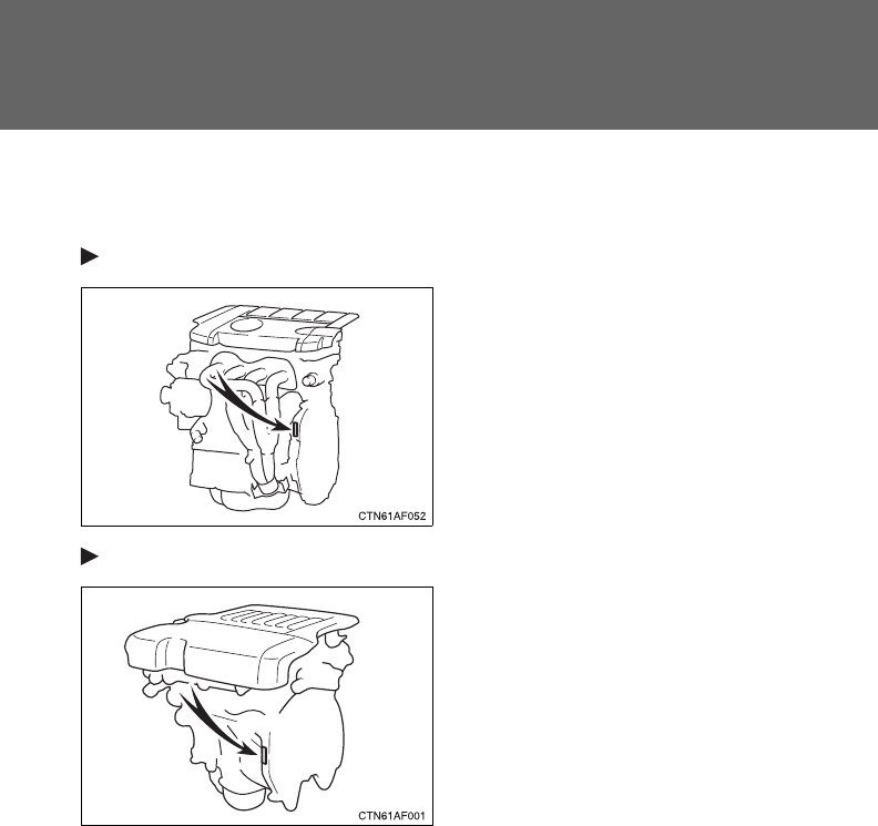
620
6-1. Specifications
■Engine number
The engine number is stamped on the engine block as shown.
2.7 L 4-cylinder (1AR-FE) engine
3.5 L V6 (2GR-FE) engine
621
6-1. Specifications
6
Vehicle specifications
Engine
Fuel
Model 1AR-FE 2GR-FE
Type 4-cylinder in line,
4-cycle, gasoline
6-cylinder V type,
4-cycle, gasoline
Bore and stroke 3.54 4.13 in.
(90.0 105.0 mm)
3.70 3.27 in.
(94.0 83.0 mm)
Displacement 163.1 cu.in. (2672 cm3) 210.9 cu.in. (3456 cm3)
Drive belt tension Automatic adjustment
Fuel type Unleaded gasoline only
Octane rating 87 (Research Octane Number 91) or higher
Fuel tank capacity
(Reference) 19.2 gal. (72.5 L, 15.9 Imp. gal.)

622
6-1. Specifications
Lubrication system (2.7 L 4-cylinder [1AR-FE] engine)
*: The engine oil capacity is a reference quantity to be used when exchanging.
Warm up and turn off the engine, wait more than 5 minutes, and check the oil
level on the dipstick.
■Engine oil selection
“Toyota Genuine Motor Oil” is used in your Toyota vehicle. Use
Toyota approved “Toyota Genuine Motor Oil” or equivalent to satisfy
the following grade and viscosity.
Oil grade: ILSAC multigrade engine oil
Recommended viscosity: SAE 5W-20 or 0W-20
SAE 5W-20 or 0W-20 engine oil
may be used. However, SAE
0W-20 is the best choice for
good fuel economy and good
starting in cold weather.
Oil viscosity (0W-20 is explained here as an example):
• The 0W in 0W-20 indicates the characteristic of the oil which allows
cold startability. Oils with a lower value before the W allow for easier
starting of the engine in cold weather.
• The 20 in 0W-20 indicates the viscosity characteristic of the oil when
the oil is at high temperature. An oil with a higher viscosity (one with a
higher value) may be better suited if the vehicle is operated at high
speeds, or under extreme load conditions.
Oil capacity
(Drain and refill
reference*)
Without filter
With filter
4.2 qt. (4.0 L, 3.5 Imp. qt.)
4.6 qt. (4.4 L, 3.9 Imp. qt.)
Outside temperature
623
6-1. Specifications
6
Vehicle specifications
How to read oil container label:
The ILSAC (International Lubricant Standardization and Approval
Committee) Certification Mark is added to some oil containers to help
you select the oil you should use.
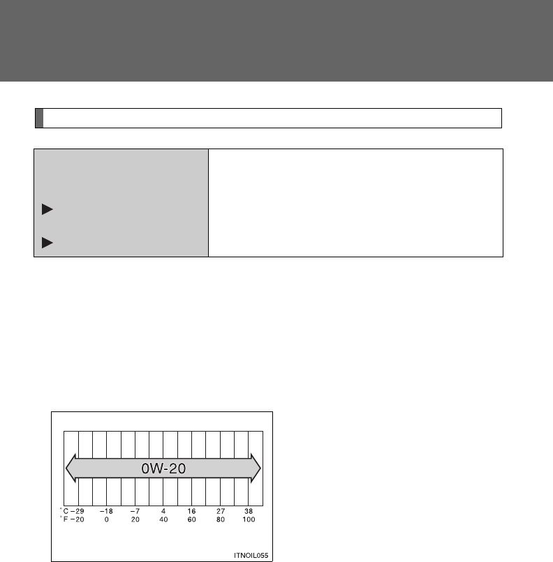
624
6-1. Specifications
Lubrication system (3.5 L V6 [2GR-FE] engine)
■Engine oil selection
“Toyota Genuine Motor Oil” is used in your Toyota vehicle. Use
Toyota approved “Toyota Genuine Motor Oil” or equivalent to satisfy
the following grade and viscosity.
Oil grade: ILSAC multigrade engine oil
Recommended viscosity: SAE 0W-20
SAE 0W-20 is the best choice for
good fuel economy and good
starting in cold weather.
If SAE 0W-20 is not available,
SAE 5W-20 oil may be used.
However, it must be replaced
with SAE 0W-20 at the next oil
change.
Oil viscosity (0W-20 is explained here as an example):
• The 0W in 0W-20 indicates the characteristic of the oil which allows
cold startability. Oils with a lower value before the W allow for easier
starting of the engine in cold weather.
• The 20 in 0W-20 indicates the viscosity characteristic of the oil when
the oil is at high temperature. An oil with a higher viscosity (one with a
higher value) may be better suited if the vehicle is operated at high
speeds, or under extreme load conditions.
Oil capacity
(Drain and refill
reference)
Without filter
With filter
6.0 qt. (5.7 L, 5.0 Imp. qt.)
6.4 qt. (6.1 L, 5.4 Imp. qt.)
Outside temperature

625
6-1. Specifications
6
Vehicle specifications
How to read oil container label:
The ILSAC (International Lubricant Standardization and Approval
Committee) Certification Mark is added to some oil containers to help
you select the oil you should use.
626
6-1. Specifications
Cooling system
*: With towing package
Capacity
(Reference)
2.7 L 4-cylin-
der (1AR-FE)
engine
Without rear air conditioning system
7.3 qt. (6.9 L, 6.1 Imp. qt.)
8.0 qt. (7.6 L, 6.7 Imp. qt.)*
With rear air conditioning system
9.6 qt. (9.1 L, 8.0 Imp. qt.)
10.4 qt. (9.8 L, 8.6 Imp. qt.)*
3.5 L V6
(2GR-FE)
engine
Without rear air conditioning system
9.3 qt. (8.8 L, 7.7 Imp. qt.)
10.0 qt. (9.5 L, 8.4 Imp. qt.)*
With rear air conditioning system
11.6 qt. (11.0 L, 9.7 Imp. qt.)
12.4 qt. (11.7 L, 10.3 Imp. qt.)*
Coolant type
Use either of the following.
• “Toyota Super Long Life Coolant”
• Similar high-quality ethylene glycol-based
non-silicate, non-amine, non-nitrite, and
non-borate coolant with long-life hybrid
organic acid technology
Do not use plain water alone.
627
6-1. Specifications
6
Vehicle specifications
Ignition system
Electrical system
Spark plug
Make
Gap
2.7 L 4-cylinder (1AR-FE) engine
DENSO SK16HR11
3.5 L V6 (2GR-FE) engine
DENSO FK20HR11
0.043 in. (1.1 mm)
NOTICE
■Iridium-tipped spark plugs
Use only iridium-tipped spark plugs. Do not adjust gap when tuning engine.
Battery
Open voltage* at
68F (20C):
12.6 12.8 V Fully charged
12.2 12.4 V Half charged
11.8 12.0 V Discharged
(*: Voltage is checked 20 minutes after the engine
and all the lights are turned off)
Charging rates 5 A max.
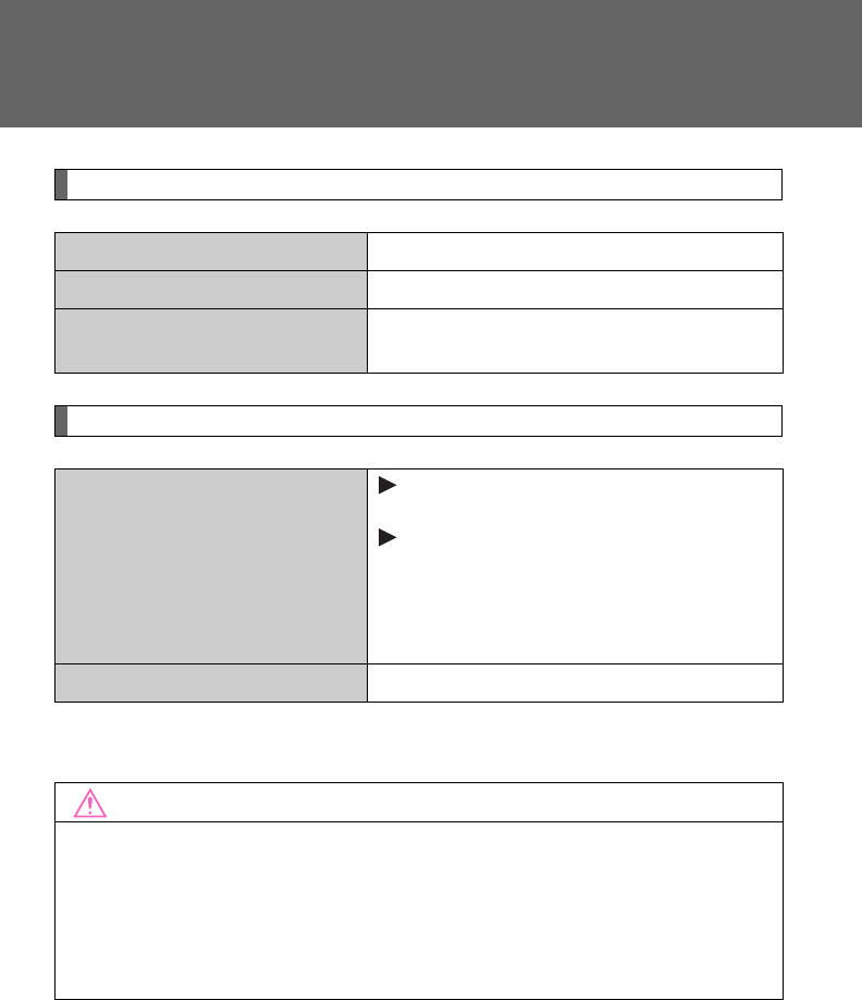
628
6-1. Specifications
Rear differential (4WD models)
Automatic transaxle
*: The fluid capacity is a reference quantity. If replacement is necessary, con-
tact your Toyota dealer.
Oil capacity 1.0 qt. (0.9 L, 0.8 Imp. qt.)
Oil type Hypoid gear oil API GL-5
Recommended oil viscosity Above 0F (-18C): SAE 90
Below 0F (-18C): SAE 80W or 80W-90
Fluid capacity*
2.7 L 4-cylinder (1AR-FE) engine
6.9 qt. (6.5 L, 5.7 Imp. qt.)
3.5 L V6 (2GR-FE) engine
2WD models:
9.3 qt. (8.8 L, 7.7 Imp. qt.)
4WD models:
9.5 qt. (9.0 L, 7.9 Imp. qt.)
Fluid type Toyota Genuine ATF WS
NOTICE
■Automatic transmission fluid type
Using automatic transmission fluid other than “Toyota Genuine ATF WS”
may cause deterioration in shift quality, locking up of your transmission
accompanied by vibration, and ultimately damage the automatic transmis-
sion of your vehicle.
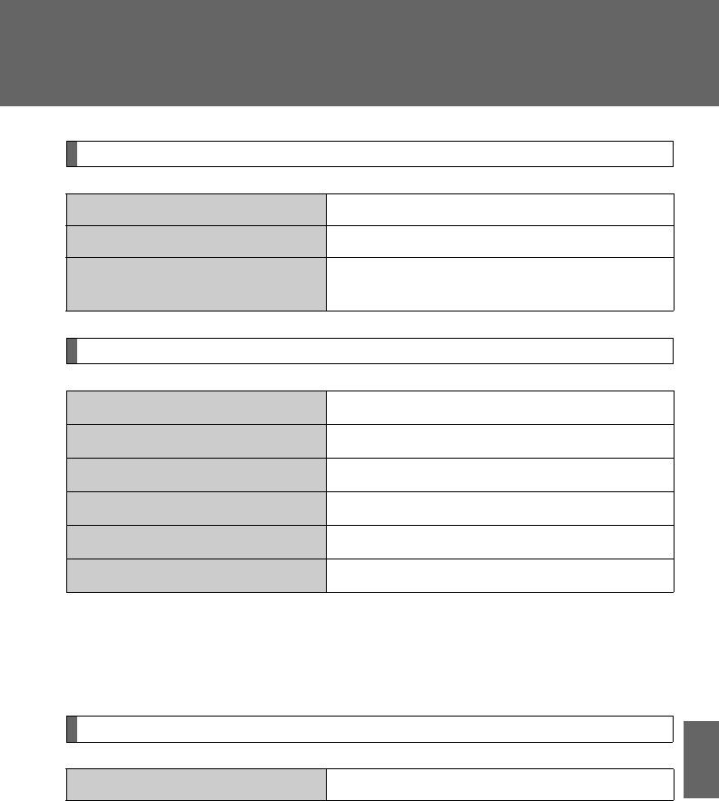
629
6-1. Specifications
6
Vehicle specifications
Transfer (4WD models)
Brakes
*1: Minimum pedal clearance when depressed with a force of 110 lbf (490 N,
50 kgf) while the engine is running
*2: Parking brake pedal travel when depressed with a force of 67 lbf (300 N, 31
kgf)
Steering
Oil capacity 1.0 qt. (0.9 L, 0.8 Imp. qt.)
Oil type Hypoid gear oil API GL-5
Recommended oil viscosity Above 0F (-18C): SAE 90
Below 0F (-18C): SAE 80W or 80W-90
Pedal clearance*13.3 in. (84.4 mm) Min.
Pedal free play 0.08 0.12 in. (2 3 mm)
Brake pad wear limit 0.04 in. (1.0 mm)
Parking brake lining wear limit 0.04 in. (1.0 mm)
Parking brake pedal travel*28 10 clicks
Fluid type SAE J1703 or FMVSS No.116 DOT 3
Free play Less than 1.2 in. (30 mm)
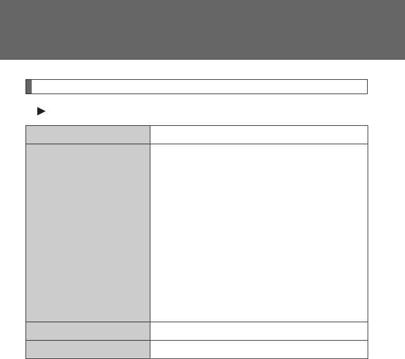
630
6-1. Specifications
Tires and wheels
Type A
Tire size P245/65R17 105S
Tire inflation pressure
(Recommended cold tire
inflation pressure)
Driving under normal conditions
Front:
30 psi (210 kPa, 2.1 kgf/cm2 or bar)
Rear:
30 psi (210 kPa, 2.1 kgf/cm2 or bar)
Spare:
30 psi (210 kPa, 2.1 kgf/cm2 or bar)
Driving at high speeds above 100 mph
(160 km/h) (in countries where such speeds
are permitted by law)
Add 5 psi (30 kPa, 0.3 kgf/cm2 or bar) to the
front tires and rear tires. Never exceed the
maximum cold tire inflation pressure indi-
cated on the tire sidewall.
Wheel size 17 7 1/2 J
Wheel nut torque 76 ft•lbf (103 N•m, 10.5 kgf•m)
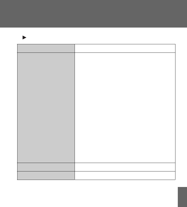
631
6-1. Specifications
6
Vehicle specifications
Type B
Tire size P245/55R19 103S
Tire inflation pressure
(Recommended cold tire
inflation pressure)
Driving under normal conditions
Front:
30 psi (210 kPa, 2.1 kgf/cm2 or bar)
Rear:
30 psi (210 kPa, 2.1 kgf/cm2 or bar)
Spare:
30 psi (210 kPa, 2.1 kgf/cm2 or bar)
Driving at high speeds above 100 mph
(160 km/h) (in countries where such speeds
are permitted by law)
Add 5 psi (30 kPa, 0.3 kgf/cm2 or bar) to the
front tires and rear tires. Never exceed the
maximum cold tire inflation pressure indi-
cated on the tire sidewall.
When towing trailer
Add 6 psi (40 kPa, 0.4 kgf/cm2 or bar) to the
rear tires. Never exceed the maximum cold
tire inflation pressure indicated on the tire
sidewall.
Wheel size 19 7 1/2 J
Wheel nut torque 76 ft•lbf (103 N•m, 10.5 kgf•m)
632
6-1. Specifications
Light bulbs
A: H11 halogen bulbs B: Wedge base bulbs (amber)
C: HB3 halogen bulbs D: Wedge base bulbs (clear)
E: PSX26W F: Double end bulbs
*: If equipped
Light Bulbs Bulb No. WType
Exterior
Headlights
High beam
Low beam
9005
60
55
C
A
Parking, front side marker and
front turn signal lights 3457NA 28/8 B
Fog lights* 24 E
Rear turn signal lights 21 B
Back-up lights 921 16 D
Stop/tail and rear side marker
lights 7443 21/5 D
License plate lights 5D
Outer foot lights* 5D
Interior
Vanity lights 8D
Personal/interior lights (front) 5D
Personal lights (center)* 5D
Interior lights (center*/rear) 8F
Door courtesy lights 168 5 D

633
6-1. Specifications
6
Vehicle specifications
Fuel information
■Fuel tank opening for unleaded gasoline
To help prevent incorrect fueling, your Toyota has a fuel tank opening that
only accommodates the special nozzle on unleaded fuel pumps.
■If your engine knocks
●Consult your Toyota dealer.
●You may occasionally notice light knocking for a short time while acceler-
ating or driving uphill. This is normal and there is no need for concern.
■Gasoline quality
In very few cases, driveability problems may be caused by the brand of gas-
oline you are using. If driveability problems persist, try changing the brand of
gasoline. If this does not correct the problem, consult your Toyota dealer.
■Gasoline quality standards
●Automotive manufacturers in the US, Europe and Japan have developed
a specification for fuel quality called the World-Wide Fuel Charter
(WWFC) that is expected to be applied worldwide.
●The WWFC consists of four categories that are based on required emis-
sion levels. In the US, category 4 has been adopted.
●The WWFC improves air quality by lowering emissions in vehicle fleets,
and customer satisfaction through better performance.
Your vehicle must use only unleaded gasoline.
Select octane rating 87 (Research Octane Number 91) or higher. Use
of unleaded gasoline with an octane rating lower than 87 may result
in engine knocking. Persistent knocking can lead to engine damage.
At minimum, the gasoline you use should meet the specifications
of ASTM D4814 in the U.S.A. and CGSB3.5-M93 in Canada.

634
6-1. Specifications
■Toyota recommends the use of gasoline containing detergent additives
●Toyota recommends the use of gasoline that contains detergent additives
to avoid build-up of engine deposits.
●All gasoline sold in the US contains minimum detergent additives to
clean and/or keep clean intake systems, per EPA’s lowest additives con-
centration program.
●Toyota strongly recommends the use of Top Tier Detergent Gasoline. For
more information on Top Tier Detergent Gasoline and a list of marketers,
please go to the official website www.toptiergas.com.
■Toyota recommends the use of cleaner burning gasoline
Cleaner burning gasoline, including reformulated gasoline that contains oxy-
genates such as ethanol or MTBE (Methyl Tertiary Butyl Ether) is available in
many areas.
Toyota recommends the use of cleaner burning gasoline and appropriately
blended reformulated gasoline. These types of gasoline provide excellent
vehicle performance, reduce vehicle emissions and improve air quality.
■Toyota does not recommend blended gasoline
●If you use gasohol in your Toyota, be sure that it has an octane rating no
lower than 87.
●Toyota does not recommend the use of gasoline containing methanol.
●Use only gasoline containing a maxi-
mum of 10% ethanol.
DO NOT use any flex-fuel or gasoline
that could contain more than 10% etha-
nol, including from any pump labeled
E15, E30, E50, E85 (which are only
some examples of fuel containing more
than 10% ethanol).
DO NOT use gasoline
containing more than 10%
ethanol.
(15% ethanol)
(50% ethanol)
(85% ethanol)
635
6-1. Specifications
6
Vehicle specifications
■Toyota does not recommend gasoline containing MMT
Some gasoline contains octane enhancing additive called MMT (Methylcy-
clopentadienyl Manganese Tricarbonyl).
Toyota does not recommend the use of gasoline that contains MMT. If fuel
containing MMT is used, your emission control system may be adversely
affected.
The malfunction indicator lamp on the instrument cluster may come on. If
this happens, contact your Toyota dealer for service.
NOTICE
■Notice on fuel quality
●Do not use improper fuels. If improper fuels are used the engine will be
damaged.
●Do not use leaded gasoline.
Leaded gasoline will cause the three-way catalytic converter to lose its
effectiveness and the emission control system to function improperly.
●Do not use gasohol other than that stated here.
Other gasohol may cause fuel system damage or vehicle performance
problems.
■Fuel-related poor driveability
If after using a different type of fuel, poor driveability is encountered (poor
hot starting, vaporization, engine knocking, etc.), discontinue the use of that
type of fuel.
■When refueling with gasohol
Take care not to spill gasohol. It can damage your vehicle's paint.
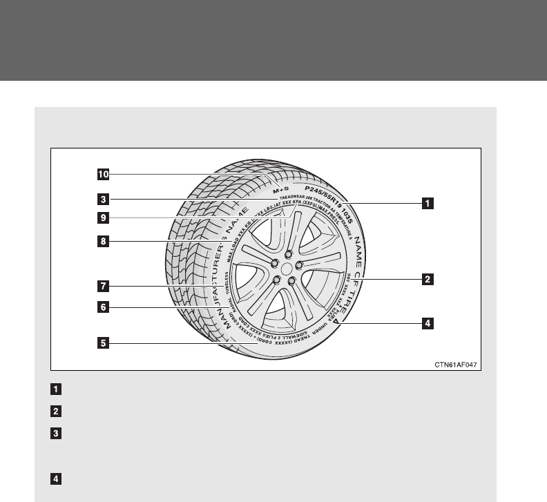

637
6-1. Specifications
6
Vehicle specifications
Tire ply composition and materials
Plies are layers of rubber-coated parallel cords. Cords are the
strands which form the plies in a tire.
Radial tires or bias-ply tires
A radial tire has “RADIAL” on the sidewall. A tire not marked
“RADIAL” is a bias-ply tire.
TUBELESS or TUBE TYPE
A tubeless tire does not have a tube and air is directly filled in the
tire. A tube type tire has a tube inside the tire and the tube main-
tains the air pressure.
Load limit at maximum cold tire inflation pressure (P. 525)
Maximum cold tire inflation pressure (P. 630)
This means the pressure to which a tire may be inflated.
Summer tire or all season tire (P. 526)
An all season tire has “M+S” on the sidewall. A tire not marked
“M+S” is a summer tire.

638
6-1. Specifications
Typical DOT and tire identification number (TIN)
DOT symbol*
Tire Identification Number
(TIN)
Tire manufacturer's identifica-
tion mark
Tire size code
Manufacturer's optional tire
type code (3 or 4 letters)
Manufacturing week
Manufacturing year
*: The DOT symbol certifies that
the tire conforms to applicable
Federal Motor Vehicle Safety
Standards.
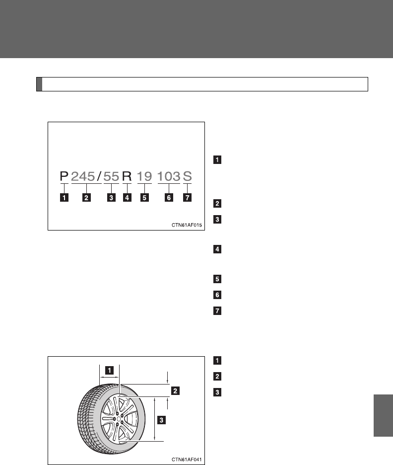
639
6-1. Specifications
6
Vehicle specifications
Tire size
■Typical tire size information
The illustration indicates typical
tire size.
Tire use
(P = Passenger car,
T = Temporary use)
Section width (millimeters)
Aspect ratio
(tire height to section width)
Tire construction code
(R = Radial, D = Diagonal)
Wheel diameter (inches)
Load index (2 digits or 3 digits)
Speed symbol
(alphabet with one letter)
■Tire dimensions
Section width
Tire height
Wheel diameter
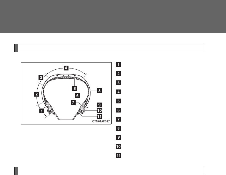
640
6-1. Specifications
Tire section names
Bead
Sidewall
Shoulder
Tread
Belt
Inner liner
Reinforcing rubber
Carcass
Rim lines
Bead wires
Chafer
Uniform Tire Quality Grading
This information has been prepared in accordance with regulations
issued by the National Highway Traffic Safety Administration of the
U.S. Department of Transportation.
It provides the purchasers and/or prospective purchasers of Toyota
vehicles with information on uniform tire quality grading.
Your Toyota dealer will help answer any questions you may have as
you read this information.
■DOT quality grades
All passenger vehicle tires must conform to Federal Safety
Requirements in addition to these grades. Quality grades can be
found where applicable on the tire sidewall between tread shoulder
and maximum section width.
For example: Treadwear 200 Traction AA Temperature A

641
6-1. Specifications
6
Vehicle specifications
■Treadwear
The treadwear grade is a comparative rating based on the wear
rate of the tire when tested under controlled conditions on a speci-
fied government test course.
For example, a tire graded 150 would wear one and a half (1 - 1/2)
times as well on the government course as a tire graded 100.
The relative performance of tires depends upon the actual conditions
of their use, however, and may depart significantly from the norm due
to variations in driving habits, service practices and differences in
road characteristics and climate.
■Traction AA, A, B, C
The traction grades, from highest to lowest, are AA, A, B and C,
and they represent the tire's ability to stop on wet pavement as
measured under controlled conditions on specified government
test surfaces of asphalt and concrete.
A tire marked C may have poor traction performance.
Warning: The traction grade assigned to this tire is based on braking
(straight ahead) traction tests and does not include cornering (turn-
ing) traction.
■Temperature A, B, C
The temperature grades are A (the highest), B, and C, represent-
ing the tire's resistance to the generation of heat and its ability to
dissipate heat when tested under controlled conditions on a speci-
fied indoor laboratory test wheel.
Sustained high temperature can cause the material of the tire to
degenerate and reduce tire life, and excessive temperature can lead
to sudden tire failure.
The grade C corresponds to a level of performance which all passen-
ger car tires must meet under the Federal Motor Vehicle Safety Stan-
dard No. 109.
Grades B and A represent higher levels of performance on the labo-
ratory test wheel than the minimum required by law.
642
6-1. Specifications
Warning: The temperature grades for this tire are established for a
tire that is properly inflated and not overloaded.
Excessive speed, underinflation, or excessive loading, either sepa-
rately or in combination, can cause heat buildup and possible tire fail-
ure.
Glossary of tire terminology
Tire related term Meaning
Cold tire inflation pres-
sure
Tire pressure when the vehicle has been
parked for three hours or more, or has not
been driven more than 1 mile or 1.5 km under
that condition
Maximum inflation
pressure
The maximum cold inflated pressure to which a
tire may be inflated, shown on the sidewall of
the tire
Recommended infla-
tion pressure
Cold tire inflation pressure recommended by a
manufacturer
Accessory weight
The combined weight (in excess of those stan-
dard items which may be replaced) of auto-
matic transmission, power steering, power
brakes, power windows, power seats, radio
and heater, to the extent that these items are
available as factory-installed equipment
(whether installed or not)
Curb weight
The weight of a motor vehicle with standard
equipment, including the maximum capacity of
fuel, oil and coolant, and if so equipped, air
conditioning and additional weight optional
engine
Maximum loaded vehi-
cle weight
The sum of:
(a) Curb weight
(b) Accessory weight
(c) Vehicle capacity weight
(d) Production options weight

643
6-1. Specifications
6
Vehicle specifications
Tire related term Meaning
Normal occupant
weight
150 lb. (68 kg) times the number of occupants
specified in the second column of Table 1* that
follows
Occupant distribution Distribution of occupants in a vehicle as speci-
fied in the third column of Table 1* below
Production options
weight
The combined weight of installed regular pro-
duction options weighing over 5 lb. (2.3 kg) in
excess of the standard items which they
replace, not previously considered in curb
weight or accessory weight, including heavy
duty brakes, ride levelers, roof rack, heavy duty
12-volt battery, and special trim
Rim A metal support for a tire or a tire and tube
assembly upon which the tire beads are seated
Rim diameter
(Wheel diameter) Nominal diameter of the bead seat
Rim size designation Rim diameter and width
Rim type designation The industry manufacturer's designation for a
rim by style or code
Rim width Nominal distance between rim flanges
Vehicle capacity
weight (Total load
capacity)
The rated cargo and luggage load plus 150 lb.
(68 kg) times the vehicle's designated seating
capacity
Vehicle maximum load
on the tire
The load on an individual tire that is determined
by distributing to each axle its share of the
maximum loaded vehicle weight, and dividing
by two
Vehicle normal load
on the tire
The load on an individual tire that is determined
by distributing to each axle its share of curb
weight, accessory weight, and normal occu-
pant weight (distributed in accordance with
Tab le 1* below), and dividing by two

644
6-1. Specifications
Tire related term Meaning
Weather side The surface area of the rim not covered by the
inflated tire
Bead
The part of the tire that is made of steel wires,
wrapped or reinforced by ply cords and that is
shaped to fit the rim
Bead separation A breakdown of the bond between components
in the bead
Bias ply tire
A pneumatic tire in which the ply cords that
extend to the beads are laid at alternate angles
substantially less than 90 degrees to the cen-
terline of the tread
Carcass The tire structure, except tread and sidewall
rubber which, when inflated, bears the load
Chunking The breaking away of pieces of the tread or
sidewall
Cord The strands forming the plies in the tire
Cord separation The parting of cords from adjacent rubber com-
pounds
Cracking Any parting within the tread, sidewall, or inner-
liner of the tire extending to cord material
CT
A pneumatic tire with an inverted flange tire
and rim system in which the rim is designed
with rim flanges pointed radially inward and the
tire is designed to fit on the underside of the
rim in a manner that encloses the rim flanges
inside the air cavity of the tire
Extra load tire
A tire designed to operate at higher loads and
at higher inflation pressures than the corre-
sponding standard tire
Groove The space between two adjacent tread ribs
Innerliner
The layer(s) forming the inside surface of a
tubeless tire that contains the inflating medium
within the tire

645
6-1. Specifications
6
Vehicle specifications
Tire related term Meaning
Innerliner separation The parting of the innerliner from cord material
in the carcass
Intended outboard
sidewall
(a) The sidewall that contains a whitewall,
bears white lettering, or bears manufac-
turer, brand, and/or model name molding
that is higher or deeper than the same
molding on the other sidewall of the tire, or
(b) The outward facing sidewall of an asym-
metrical tire that has a particular side that
must always face outward when mounted
on a vehicle
Light truck (LT) tire
A tire designated by its manufacturer as prima-
rily intended for use on lightweight trucks or
multipurpose passenger vehicles
Load rating The maximum load that a tire is rated to carry
for a given inflation pressure
Maximum load rating The load rating for a tire at the maximum per-
missible inflation pressure for that tire
Maximum permissible
inflation pressure
The maximum cold inflation pressure to which
a tire may be inflated
Measuring rim The rim on which a tire is fitted for physical
dimension requirements
Open splice Any parting at any junction of tread, sidewall, or
innerliner that extends to cord material
Outer diameter The overall diameter of an inflated new tire
Overall width
The linear distance between the exteriors of
the sidewalls of an inflated tire, including eleva-
tions due to labeling, decorations, or protective
bands or ribs
Passenger car tire
A tire intended for use on passenger cars, mul-
tipurpose passenger vehicles, and trucks, that
have a gross vehicle weight rating (GVWR) of
10000 lb. or less.

646
6-1. Specifications
Tire related term Meaning
Ply A layer of rubber-coated parallel cords
Ply separation A parting of rubber compound between adja-
cent plies
Pneumatic tire
A mechanical device made of rubber, chemi-
cals, fabric and steel or other materials, that,
when mounted on an automotive wheel, pro-
vides the traction and contains the gas or fluid
that sustains the load
Radial ply tire
A pneumatic tire in which the ply cords that
extend to the beads are laid at substantially 90
degrees to the centerline of the tread
Reinforced tire
A tire designed to operate at higher loads and
at higher inflation pressures than the corre-
sponding standard tire
Section width
The linear distance between the exteriors of
the sidewalls of an inflated tire, excluding ele-
vations due to labeling, decoration, or protec-
tive bands
Sidewall That portion of a tire between the tread and
bead
Sidewall separation The parting of the rubber compound from the
cord material in the sidewall
Snow tire
A tire that attains a traction index equal to or
greater than 110, compared to the ASTM
E-1136 Standard Reference Test Tire, when
using the snow traction test as described in
ASTM F-1805-00, Standard Test Method for
Single Wheel Driving Traction in a Straight Line
on Snow-and Ice-Covered Surfaces, and which
is marked with an Alpine Symbol ( ) on at
least one sidewall
Tes t ri m
The rim on which a tire is fitted for testing, and
may be any rim listed as appropriate for use
with that tire

647
6-1. Specifications
6
Vehicle specifications
*: Table 1 Occupant loading and distribution for vehicle normal load
for various designated seating capacities
Tire related term Meaning
Tread That portion of a tire that comes into contact
with the road
Tread rib A tread section running circumferentially
around a tire
Tread separation Pulling away of the tread from the tire carcass
Treadwear indicators
(TWI)
The projections within the principal grooves
designed to give a visual indication of the
degrees of wear of the tread
Wheel-holding fixture The fixture used to hold the wheel and tire
assembly securely during testing
Designated seating
capacity, Number of
occupants
Vehicle normal load,
Number of occupants
Occupant distribution in
a normally loaded vehi-
cle
2 through 4 2 2 in front
5 through 10 3 2 in front, 1 in second
seat
11 through 15 5
2 in front, 1 in second
seat, 1 in third seat, 1
in fourth seat
16 through 20 7
2 in front, 2 in second
seat, 2 in third seat, 1
in fourth seat

648
6-2. Customization
Customizable features
Item Function Default setting Customized
setting
Door lock
(P. 54,
604)
Speed-detecting auto-
matic door lock function Off On
Opening driver's door
unlocks all doors Off On
Shifting gears to a P
unlocks all doors On Off
Shifting gears to posi-
tion other than P locks
all doors
On Off
Unlocking using a key
Driver's door
unlocked in one
step, all doors
unlocked in two
steps
All doors
unlocked in one
step
Smart key
system
(P. 35)
Smart key system On Off
Operation signal
(Emergency flashers) On Off
Your vehicle includes a variety of electronic features that can be
personalized to your preferences. Programming these preferences
requires specialized equipment and may be performed by your
Toyota dealer.
Some function settings are changed simultaneously with other functions
being customized. Contact your Toyota dealer.

649
6-2. Customization
6
Vehicle specifications
Wireless
remote con-
trol
(P. 48 )
Wireless remote control On Off
Unlocking operation
Driver's door
unlocked in one
step, all doors
unlocked in two
steps
All doors
unlocked in one
step
Automatic door lock
function to be activated
if door is not opened
after being unlocked
On Off
Time elapsed before
automatic door lock
function is activated if
door is not opened after
being unlocked
60 seconds
30 seconds
120 seconds
Operation signal
(Emergency flashers) On Off
Door lock buzzer On Off
Operation signal
(Buzzer) On Off
Panic function On Off
Glass hatch opening
operation Push and hold Push twice
One short push
Item Function Default setting Customized
setting

650
6-2. Customization
Automatic
light control
system
(P. 203)
Light sensor sensitivity Level 3 Level 1 to 5
Time elapsed before
headlights automati-
cally turn off after doors
are closed
30 seconds
0 seconds
60 seconds
90 seconds
Ambient light level at
which instrument illumi-
nation begins to dim
(meter light etc.)
Standard -2 (darker) to
2 (brighter)
Ambient light level at
which instrument illumi-
nation begins to
brighten (meter light
etc.)
Standard -2 (darker) to
2 (brighter)
Lights
(P. 203)
Daytime running light
system (U.S.A. only) On Off
Multi-infor-
mation dis-
play
(P. 193)
Language selection English
French
Spanish
Chinese
Illumination
(P. 436)
Time elapsed before
lights turn off 15 seconds 7.5 seconds
30 seconds
Operation when the
doors are unlocked On Off
Operation after the
“ENGINE START
STOP” switch or the
engine switch is turned
OFF
On Off
Item Function Default setting Customized
setting

651
6-2. Customization
6
Vehicle specifications
Outer foot
lights
(if equipped)
(P. 436)
Operation when you
approach the vehicle
with the electronic key
on your person
On Off
Operation when the
doors are unlocked
using the wireless
remote control, key or
entry function
On Off
Operation when the
doors are unlocked
using the door lock
function
On Off
Time period before
lights turn off 15 seconds 7.5 seconds
30 seconds
Lighting control On Off
Item Function Default setting Customized
setting

652
6-3. Initialization
Items to initialize
Item When to initialize Reference
Power back door
• After reconnecting or changing the
battery
• After changing a fuse
P. 60
Maintenance data
(U.S.A. only) After the maintenance is performed P. 489
Tire pressure warning
system
When changing the tire inflation
pressure by changing traveling
speed or towing trailer, etc.
P. 521
The following items must be initialized for normal system operation
in cases such as after the battery is reconnected, or maintenance is
performed on the vehicle.


654
Reporting safety defects for U.S. owners
If you believe that your vehicle has a defect which could cause a
crash or could cause injury or death, you should immediately
inform the National Highway Traffic Safety Administration (NHTSA)
in addition to notifying Toyota Motor Sales, U.S.A., Inc. (Toll-free:
1-800-331-4331).
If NHTSA receives similar complaints, it may open an investigation,
and if it finds that a safety defect exists in a group of vehicles, it
may order a recall and remedy campaign. However, NHTSA can-
not become involved in individual problems between you, your
dealer, or Toyota Motor Sales, U.S.A., Inc.
To contact NHTSA, you may call the Vehicle Safety Hotline
toll-free at 1-888-327-4236 (TTY: 1-800-424-9153); go to
http://www.safercar.gov; or write to: Administrator, NHTSA,
1200 New Jersey Ave, S.E., Washington, DC 20590. You can
also obtain other information about motor vehicle safety from
http://www.safercar.gov.
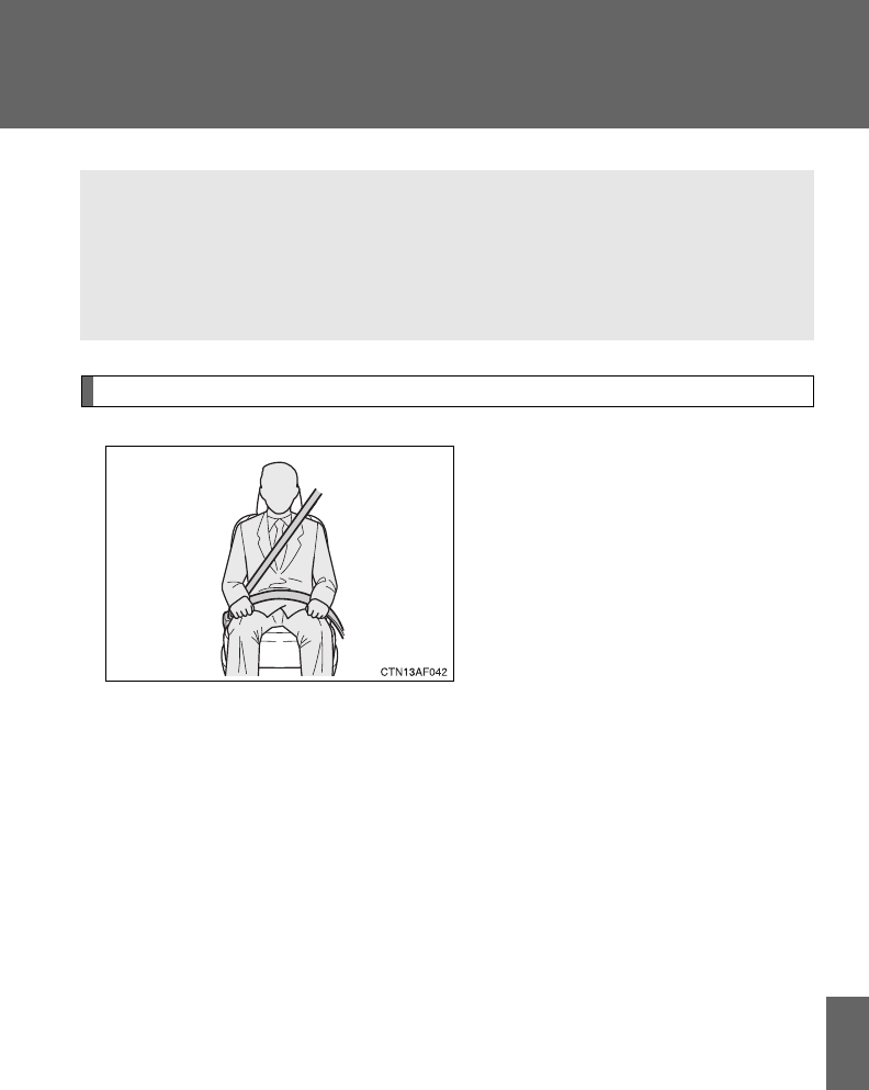
655
7
For owners
Seat belt instructions for Canadian owners (in French)
The following is a French explanation of seat belt instructions
extracted from the seat belt section in this manual.
See the seat belt section for more detailed seat belt instructions in
English.
Utilisation correcte des ceintures de sécurité
●Tendez la sangle diagonale de
sorte qu'elle couvre
complètement l'épaule, sans
entrer en contact avec le cou
ou glisser de l'épaule.
●Placez la sangle abdominale
le plus bas possible sur les
hanches.
●Réglez la position du dossier
de siège. Asseyez-vous le dos
le plus droit possible et calez-
vous bien dans le siège.
●Ne vrillez pas la ceinture de
sécurité.
656
Entretien et soin
■Ceintures de sécurité
Nettoyez avec un chiffon ou une éponge humectée d'eau savonneuse tiède.
Profitez de l'occasion pour vérifier régulièrement que les ceintures ne sont
pas effilochées, entaillées, ou ne paraissent pas exagérément usées.
ATTENTION
■Détérioration et usure des ceintures de sécurité
Inspectez les ceintures de sécurité périodiquement. Contrôlez qu'elles ne
sont pas entaillées, effilochées, et que leurs ancrages ne sont pas
desserrés. N'utilisez pas une ceinture de sécurité défectueuse avant qu'elle
ne soit remplacée. Une ceinture de sécurité défectueuse n'apporte aucune
garantie de protection de l'occupant en cas d'accident.
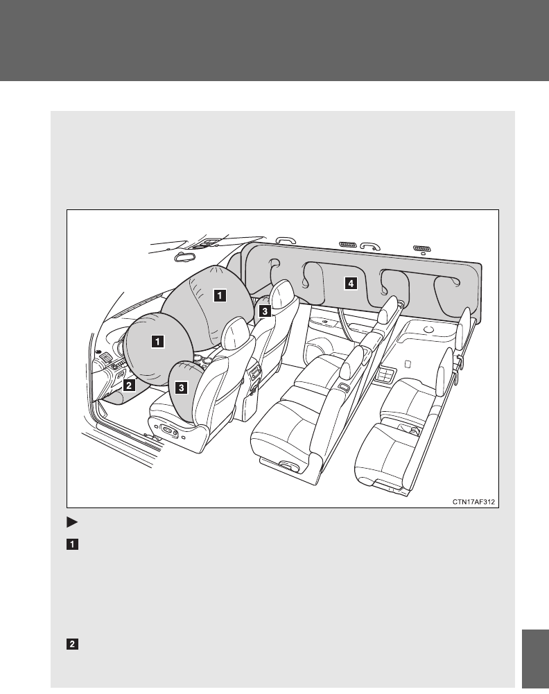
657
7
For owners
SRS airbag instructions for Canadian owners (in French)
The following is a French explanation of SRS airbag instructions
extracted from the SRS airbag section in this manual.
See the SRS airbag section for more detailed SRS airbag instruc-
tions in English.
Sacs de sécurité gonflables frontaux
Sac de sécurité gonflable conducteur/sac de sécurité gonflable
passager avant
Participent à la protection de la tête et du thorax du conducteur
et du passager contre les chocs avec les éléments de
l'habitacle.
Sac de sécurité gonflable de genoux conducteur
Contribue à accroître la protection du conducteur.

658
Sacs de sécurité gonflables latéraux et rideau
Sacs de sécurité gonflables latéraux
Participent à la protection du thorax des occupants des sièges
avant.
Sacs de sécurité gonflables rideau
Participent principalement à la protection de la tête des
occupants assis dans les sièges des places extérieures.
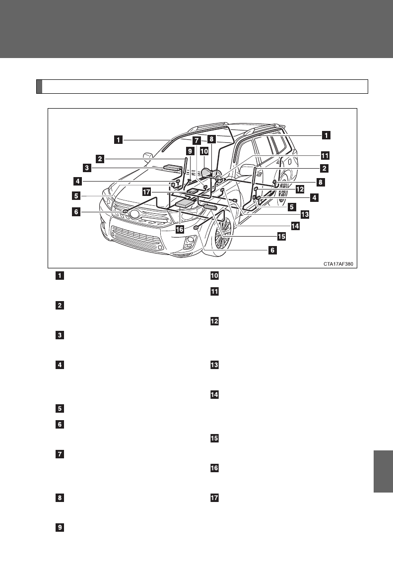
659
7
For owners
Composition du système de sacs de sécurité gonflables
Sacs de sécurité gonflables
rideau
Sacs de sécurité gonflables
latéraux
Sac de sécurité gonflable
passager avant
Capteurs de sacs de
sécurité gonflables latéraux
et rideau
Capteurs de porte
Capteurs de sacs de
sécurité gonflables frontaux
Contacteur de boucle de
ceinture de sécurité
passager avant
Capteurs de sacs de
sécurité gonflables rideau
Témoins indicateurs “AIR
BAG ON” et “AIR BAG
OFF”
Témoin d'alerte SRS
Sac de sécurité gonflable
conducteur
Prétensionneurs de
ceintures de sécurité et
limiteurs de force
Capteur de la position du
siège conducteur
Contacteur de boucle de
ceinture de sécurité
conducteur
Sac de sécurité gonflable
genoux conducteur
Boîtier électronique de sacs
de sécurité gonflables
Système de classification
de l'occupant du siège
passager avant (ECU et
capteurs)

660
Votre véhicule est équipé d'AIRBAGS INTELLIGENTS conçus selon
les normes de sécurité américaines applicables aux véhicules à
moteur (FMVSS208). Le boîtier électronique (ECU) des airbags
régule le déploiement de ces derniers sur la base des informations
qu'il reçoit des capteurs, etc. indiqués ci-dessus dans le schéma
illustrant les composants du système. Parmi ces informations figurent
la gravité du choc et les informations sur l'occupant du siège. Le
déploiement rapide des airbags est obtenu au moyen d'une réaction
chimique dans les dispositifs de gonflage, qui produit un gaz
inoffensif remplissant rapidement les airbags qui permet d'amortir le
mouvement des occupants.

661
7
For owners
ATTENTION
■Précautions avec les sacs de sécurité gonflables SRS
Respectez les précautions suivantes avec les sacs de sécurité gonflables.
À défaut, des blessures graves, voire mortelles, pourraient s'ensuivre.
●Le conducteur et tous les passagers à bord du véhicule doivent porter leur
ceinture de sécurité correctement.
Les sacs de sécurité gonflables SRS sont des dispositifs de protection
complémentaires aux ceintures de sécurité.
●Le sac de sécurité gonflable SRS conducteur se déploie avec une
violence considérable, qui peut être très dangereuse voire mortelle si le
conducteur se trouve très près du sac de sécurité gonflable. L'autorité
fédérale chargée de la sécurité routière aux États-Unis, la NHTSA
(National Highway Traffic Safety Administration) conseille:
Sachant que la zone de danger pour le sac de sécurité gonflable conducteur
se trouve dans les premiers 2 à 3 in. (50 - 75 mm) de déploiement, vous
disposez d'une marge de sécurité confortable en vous plaçant à 10 in. (250
mm) de votre sac de sécurité gonflable conducteur. Cette distance est à
mesurer entre le moyeu du volant de direction et le sternum. Si vous êtes
actuellement assis à moins de 10 in. (250 mm), vous pouvez changer votre
position de conduite de différentes façons:
• Reculez votre siège le plus possible, tout en continuant à pouvoir
atteindre confortablement les pédales.
• Inclinez légèrement le dossier du siège.
Bien que les véhicules puissent être différents les uns des autres, la
plupart des conducteurs peuvent s'asseoir à une distance de 10 in.
(250 mm), même avec le siège conducteur complètement avancé,
simplement en inclinant un peu le dossier de siège. Si vous avez des
difficultés à voir la route après avoir incliné votre siège, utilisez un
coussin ferme et antidérapant pour vous rehausser ou, si votre
véhicule est équipé du réglage en hauteur du siège, remontez-le.
• Si votre volant de direction est réglable, inclinez-le vers le bas. Cela a
pour effet d'orienter le sac de sécurité gonflable en direction de votre
poitrine plutôt que de votre tête et de votre cou.
Réglez votre siège selon ces recommandations de la NHTSA, tout en
conservant le contrôle des pédales, du volant de direction et la vue des
commandes du tableau de bord.
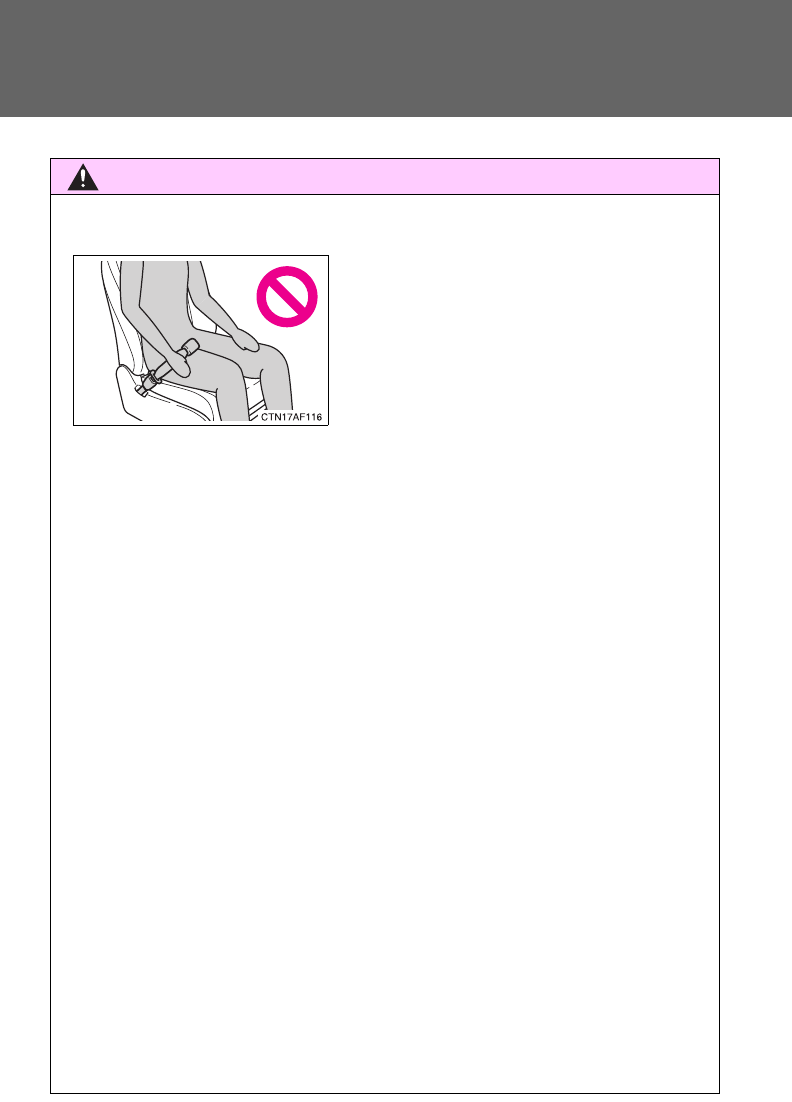
662
ATTENTION
■Précautions avec les sacs de sécurité gonflables SRS
●Le sac de sécurité gonflable SRS passager avant se déploie également
avec une violence considérable, qui peut être très dangereuse voire
mortelle si le passager avant se trouve très près du sac de sécurité
gonflable. Éloignez le siège passager avant au maximum du sac de
sécurité gonflable, et réglez le dossier de siège de sorte à être assis bien
droit dans le siège.
●Les nourrissons et les enfants qui ne sont pas correctement assis et/ou
protégés peuvent être grièvement blessés ou tués par le déploiement d'un
sac de sécurité gonflable. Installez dans un siège de sécurité enfant les
enfants trop jeunes pour pouvoir utiliser la ceinture de sécurité. Toyota
recommande vivement que les nourrissons et les jeunes enfants soient
installés sur le siège arrière du véhicule et convenablement attachés.
C'est à l'arrière que les nourrissons et les enfants sont les mieux protégés.
●N'installez jamais un siège de sécurité enfant type dos à la route sur le
siège passager avant, même si le témoin “AIR BAG OFF” est allumé.
En cas d'accident, par la violence et la vitesse de son déploiement, le sac
de sécurité gonflable passager avant peut blesser grièvement, voire tuer
l'enfant si vous l'avez installé à la place du passager avant dans un siège
de sécurité enfant type dos à la route.
●Si vous attachez la rallonge de ceinture
de sécurité aux boucles de ceinture de
sécurité avant, mais pas au pêne de la
ceinture de sécurité, les airbags SRS
frontaux détectent que le conducteur et
le passager avant ont attaché leur
ceinture de sécurité, alors même que
ce n'est pas le cas. Dans ce cas, il se
peut que les airbags SRS frontaux ne
se déploient pas correctement en cas
d'accident, et vous risquez d'être tué ou
grièvement blessé. Veillez à porter la
ceinture de sécurité avec la rallonge de
ceinture de sécurité.
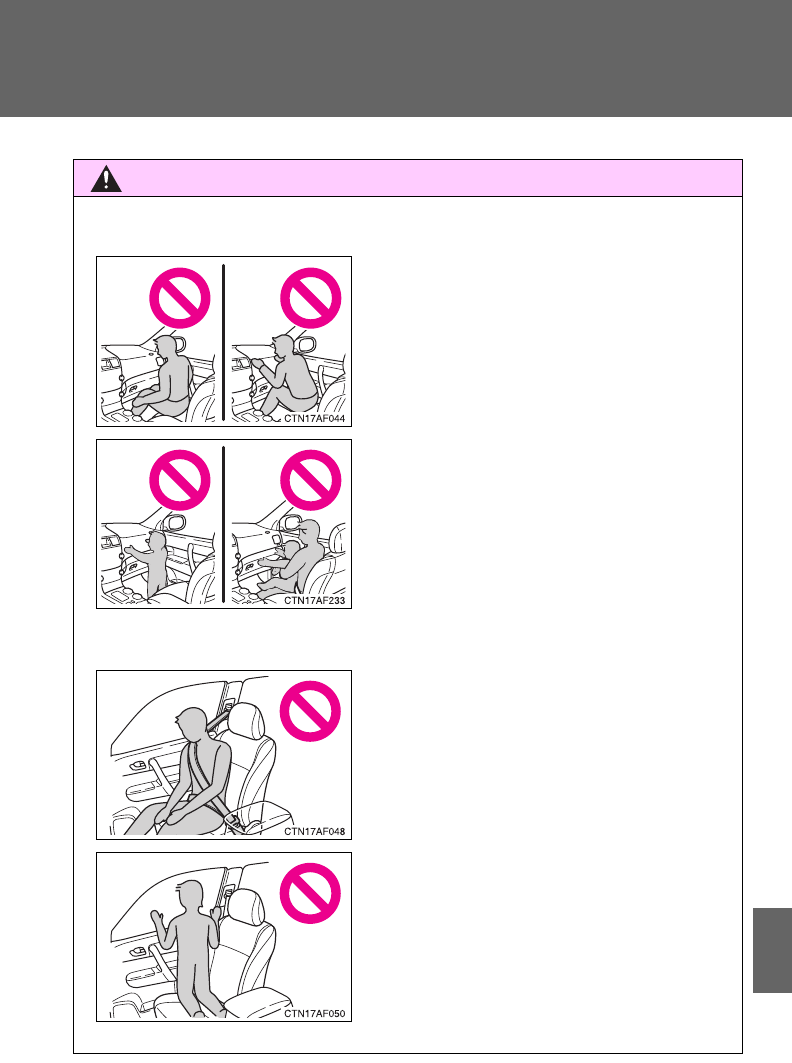
663
7
For owners
ATTENTION
■Précautions avec les sacs de sécurité gonflables SRS
●Ne pas s'asseoir sur le bord du siège et
ne pas s'appuyer contre la planche de
bord.
●Ne laissez pas un enfant rester debout
devant le sac de sécurité gonflable
SRS passager avant ou bien s'asseoir
sur les genoux du passager avant.
●Ne conduisez pas le véhicule avec
quelque chose sur les genoux, et
n'autorisez pas non plus le passager à
voyager avec quelque chose sur les
genoux.
●Ne vous appuyez pas contre la porte,
contre le rail latéral de toit ou contre les
montants avant, latéraux et arrière.
●Interdisez à quiconque de s'agenouiller
sur le siège passager en appui contre
la porte ou de sortir la tête ou les mains
à l'extérieur du véhicule.
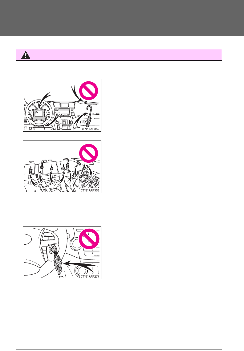
664
ATTENTION
■Précautions avec les sacs de sécurité gonflables SRS
●Si le cache en vinyle recouvre la partie où le sac de sécurité gonflable
SRS de genoux se déploie, veillez à l'enlever.
●N'utilisez aucun accessoire de siège venant recouvrir les zones de
déploiement des sacs de sécurité gonflables SRS latéraux, car il risquerait
d'en gêner le déploiement.
●Ne rien fixer ou disposer sur le tableau
de bord, la garniture centrale du moyeu
de volant de direction ou la partie
inférieure de la planche de bord.
Au déploiement des sacs de sécurité
gonflables SRS conducteur, passager
avant et genoux, tout objet risque de se
transformer en projectile.
●Ne fixez aucun objet sur les portes, la
vitre de pare-brise, les vitres latérales,
les montants avant et arrière, le rail
latéral de toit et la poignée de maintien.
●Ne suspendez aux crochets à
vêtements aucun cintre nu ni aucun
objet dur. En cas de déploiement du
sac de sécurité gonflable SRS rideau,
ces objets peuvent se transformer en
projectiles capables de vous blesser
grièvement, voire de vous tuer.
●Véhicules sans système d'accès et de
démarrage “mains libres”: Évitez
d'attacher au porte-clés de la clé des
objets lourds, pointus ou très durs. Ces
objets risquent d'entraver le
déploiement du sac de sécurité
gonflable SRS de genoux ou d'être
projetés vers le siège conducteur par la
force de déploiement, constituant ainsi
un danger potentiel.

665
7
For owners
ATTENTION
■Précautions avec les sacs de sécurité gonflables SRS
●Évitez de faire subir des chocs ou des pressions excessives aux zones
renfermant les composants des sacs de sécurité gonflables SRS
(oP. 613).
En effet, cela pourrait entraîner un fonctionnement anormal des sacs de
sécurité gonflables SRS.
●Ne touchez aucun composant du système immédiatement après le
déclenchement (déploiement) des sacs de sécurité gonflables SRS, car ils
sont alors encore très chauds.
●Si vous avez des difficultés à respirer après le déploiement d'un sac de
sécurité gonflable SRS, ouvrez une porte ou une vitre pour faire entrer de
l'air frais, ou bien descendez du véhicule si cela ne présente pas de
danger. Essuyez tout résidu dès que possible afin d'éviter d'éventuelles
irritations de la peau.
●Si les parties renfermant les sacs de sécurité gonflables SRS, telles que la
garniture du moyeu de volant et les garnitures de montants avant et
arrière, apparaissent abîmées ou craquelées, faites-les remplacer par
votre concessionnaire Toyota.

666
ATTENTION
■Modification et mise au rebut des éléments du système de sacs de
sécurité gonflables SRS
Consultez impérativement votre concessionnaire Toyota si vous avez besoin
d'intervenir sur votre véhicule ou de procéder à l'une des modifications
suivantes.
Les sacs de sécurité gonflables SRS risquent de ne pas fonctionner
correctement ou de se déployer (gonfler) accidentellement, provoquant ainsi
des blessures graves, voire mortelles.
●Installation, dépose, démontage et réparations des sacs de sécurité
gonflables SRS.
●Réparation, modification, dépose ou remplacement du volant, du combiné
d'instruments, du tableau de bord, des sièges ou de leur sellerie, des
montants avant, latéraux et arrière ou des rails latéraux de toit.
●Réparations ou modifications de l'aile avant, du bouclier avant, ou du côté
de l'habitacle.
●Installation de chasse-neige, de treuils, etc. sur la calandre (pare-buffle,
pare-kangourou, etc.).
●Modifications des suspensions du véhicule.
●Installation d'appareils électroniques tels que radio émetteur/récepteur ou
lecteurs CD.
●Aménagements apportés au véhicule pour une personne atteinte d'un
handicap physique.

Index
667
Abbreviation list ..................... 668
Alphabetical index.................. 670
What to do if... ........................ 681
For details of equipment related to the navigation sys-
tem and touch screen, such as the audio system, refer
to the “Display Audio System Owner’s Manual” or
“Navigation System Owner’s Manual”.

668
Abbreviation list
Abbreviation/Acronym list
ABBREVIATIONS MEANING
2WD 2 Wheel Drive
4WD 4 Wheel Drive
A/C Air Conditioning
ABS Anti-lock Brake System
ACC Accessory
AI-SHIFT Artificial Intelligence Shift control
ALR Automatic Locking Retractor
CRS Child Restraint System
DAC Downhill Assist Control
DISP Display
ECU Electronic Control Unit
EDR Event Data Recorder
ELR Emergency Locking Retractor
EPS Electric Power Steering
GAWR Gross Axle Weight Rating
GCWR Gross Combination Weight Rating
GVWR Gross Vehicle Weight Rating
I/M Emission Inspection and Maintenance
LATCH Lower Anchors and Tethers for Children
LED Light Emitting Diode
MMT Methylcyclopentadienyl Manganese Tricarbonyl
MTBE Methyl Tertiary Butyl Ether

669
Abbreviation list
OBD On Board Diagnostics
SRS Supplemental Restraint System
TIN Tire Identification Number
TPMS Tire Pressure Warning System
TRAC Traction Control
TWR Trailer Weight Rating
VIN Vehicle Identification Number
VSC Vehicle Stability Control
ABBREVIATIONS MEANING

670
Alphabetical index
Alphabetical index
A/C.....................274, 281, 289, 292
A/V input port ...........................428
ABS ...........................................227
Active head restraints ...............75
Air conditioning filter...............536
Air conditioning system
Air conditioning filter..............536
Front automatic air
conditioning system ............281
Front manual air
conditioning system ............274
Rear automatic air
conditioning system ............292
Rear manual air
conditioning system ............289
Airbags
Airbag operating
conditions............................127
Airbag precautions for your
child ....................................131
Airbag warning light...............574
Curtain shield airbag
operating conditions............127
Curtain shield airbag
precautions .........................131
Front passenger occupant
classification system ...........136
General airbag
precautions .........................131
Locations of airbags ..............124
Modification and disposal
of airbags............................135
Proper driving
posture........................122, 131
Side airbag operating
conditions............................127
Side airbag precautions ........131
SRS airbags ..........................124
Alarm.........................................117
Antenna ............................311, 354
Anti-lock brake system ...........227
Armrest ..................................... 462
Assist grips ..............................463
Audio input............................... 349
Audio system
A/V input port ........................428
Antenna.........................311, 354
Audio input............................ 349
AUX port ...............................349
CD player/changer................314
iPod....................................... 330
MP3/WMA disc .....................322
Optimal use...........................345
Portable music player ...........349
Radio..................................... 307
Rear seat entertainment
system ................................406
Steering wheel audio
switch.................................. 351
Type ...................................... 299
USB memory.........................337
Automatic light control
system .................................... 203
Automatic transmission.......... 178
AUX port ................................... 349
Auxiliary box ........................... 448
A

671
Alphabetical index
Back-up lights
Replacing light bulbs ............ 553
Wattage ................................ 632
Back door
Back door ............................... 60
Smart key system................... 35
Wireless remote control.......... 48
Battery
Checking .............................. 516
If the vehicle has a
discharged battery ............. 606
Preparing and checking
before winter ...................... 248
Bluetooth® audio..................... 377
Bluetooth® phone ................... 373
Bottle holder............................ 447
Brake assist............................. 227
Brakes
Fluid...................................... 515
Parking brake ....................... 184
Break-in tips ............................ 162
Brightness control
Instrument panel light
control ................................ 187
Care
Exterior..................................482
Interior ...................................485
Seat belts ..............................486
Cargo capacity .........................247
Cargo hooks .............................465
CD changer...............................314
CD player ..................................314
Chains .......................................248
Child restraint system
Booster seats, definition........143
Booster seats, installation .....148
Convertible seats,
definition .............................143
Convertible seats,
installation...........................148
Front passenger occupant
classification system ...........136
Infant seats, definition ...........143
Infant seats, installation.........148
Installing CRS with a top
tether straps........................155
Installing CRS with LATCH
anchors ...............................150
Installing CRS with seat
belts ....................................152
Child safety
Airbag precautions ................131
Battery precautions .......518, 609
Child restraint system............143
Child-protectors.......................56
How your child should wear
the seat belt ..........................91
Installing child restraints........148
Moon roof precautions ..........107
Power window lock switch.....101
Power window precautions ...103
Removed key battery
precautions .........................541
Seat belt extender
precautions ...........................93
Seat belt precautions ..............91
Seat heater precautions........461
B
C

672
Alphabetical index
Child-protectors .........................56
Cleaning
Exterior..................................482
Interior ...................................485
Seat belts ..............................486
Clock .................................193, 454
Compass...................................476
Condenser ................................514
Console box .............................441
Conversation mirror ................455
Cooling system
Engine overheating ...............610
Cruise control...........................219
Cup holders..............................443
Curtain shield airbags .............124
Customizable features.............648
Daytime running light
system .................................... 208
Defogger
Rear window .........................295
Side mirrors........................... 295
Dimension ................................ 618
Dinghy towing.......................... 270
Display
Trip information ..................... 193
Warning message .................584
Do-it-yourself maintenance .... 495
Door courtesy lights
Door courtesy lights .............. 436
Wattage................................. 632
Doors
Door lock.....................35, 48, 54
Door windows .......................101
Side mirrors............................. 98
Downhill assist control
system .................................... 234
Driver's seat belt reminder
light.........................................576
Driving
Break-in tips.......................... 162
Correct posture .....................122
Procedures............................160
Winter driving tips ................. 248
D

673
Alphabetical index
Electric power steering........... 227
Electronic key
If your electronic key
battery is discharged.......... 604
Emergency flashers
Switch................................... 562
Emergency, in case of
If a warning message is
displayed............................ 584
If the back door opener is
inoperative ........................... 63
If the electronic key does
not operate properly........... 604
If the engine will not start...... 600
If the shift lever cannot be
shifted from P..................... 602
If the vehicle has a
discharged battery ............. 606
If the warning buzzer
sounds... ........................... 573
If the warning light turns
on ....................................... 573
If you have a flat tire ............ 586
If you lose your keys/
wireless remote control
transmitter.......................... 603
If you think something is
wrong ................................. 571
If your vehicle becomes
stuck................................... 613
If your vehicle has to be
stopped in an
emergency ......................... 615
If your vehicle needs to be
towed ................................. 564
If your vehicle overheats ...... 610
Engine
Compartment ........................505
Engine switch................171, 175
Hood......................................499
How to start the
engine .........................171, 175
Identification number.............619
If the engine will not start ......600
Ignition switch................171, 175
Overheating...........................610
Engine compartment cover.....507
Engine coolant
Capacity ................................626
Checking ...............................512
Preparing and checking
before winter .......................248
Engine coolant temperature
gauge ......................................186
Engine immobilizer system.....113
Engine oil
Capacity ................................622
Checking ...............................508
Preparing and checking
before winter .......................248
Enhanced vehicle stability
control ....................................227
Enhanced VSC .........................227
EPS............................................227
Event data recorder ...................26
E

674
Alphabetical index
Floor mat...................................464
Fluid
Brake.....................................515
Washer..................................520
Fog lights
Replacing light bulbs .............553
Switch....................................210
Wattage.................................632
Front automatic air
conditioning system..............281
Front fog lights
Replacing light bulbs .............553
Switch....................................210
Wattage.................................632
Front manual air
conditioning system..............274
Front passenger occupant
classification system ............136
Front passenger's seat belt
reminder light.........................576
Front seats
Adjustment ..............................74
Front side marker lights
Replacing light bulbs .............553
Switch....................................203
Wattage.................................632
Front turn signal lights
Replacing light bulbs .............553
Wattage.................................632
Fuel
Capacity ................................621
Fuel gauge ............................186
Fuel pump shut off system ....572
Gas station information .........684
Information ............................633
Refueling ...............................109
Type ......................................621
Fuel door...................................109
Fuel filler door..........................109
Fuel pump shut off system .....572
Fuses.........................................542
Garage door opener ................470
Gas station information ..........684
Gauges...................................... 186
Glove box ................................. 440
Grocery bag hooks ..................465
Hands-free system
(for cellular phone)................373
Hazard lights switch................562
Head restraints
Active head restraints .............75
Adjusting ................................ 85
Headlights
Replacing light bulbs............. 553
Switch ...................................203
Wattage................................. 632
Heaters
Seat heaters.......................... 460
Side mirror ............................295
Hood..........................................499
Hooks
Cargo hook ...........................465
Shopping bag........................465
Horn .......................................... 185
F
G
H

675
Alphabetical index
I/M test...................................... 494
Identification
Engine .................................. 619
Vehicle.................................. 619
Ignition switch ................. 171, 175
Illuminated entry system........ 436
Indicator lights ........................ 188
Initialization
Items to initialize................... 652
Inside rear view mirror.............. 95
Instrument panel light
control.................................... 187
Interior lights
Interior lights......................... 436
Switch........................... 437, 438
Wattage ................................ 632
Jack
Positioning a floor jack ......... 501
Vehicle-equipped jack .......... 586
Jack handle.............................. 586
Keyless entry............................. 48
Keys
Electronic key ......................... 32
Engine switch ............... 171, 175
If the electronic key does
not operate properly........... 604
If you lose your keys/
wireless remote control
transmitter.......................... 603
Ignition switch............... 171, 175
Key number ............................ 32
Keyless entry.......................... 48
Keys ....................................... 32
Mechanical key....................... 32
Wireless remote control
key ....................................... 48
License plate lights
Replacing light bulbs .............553
Wattage.................................632
Light bulbs
Replacing ..............................553
Wattage.................................632
Lights
Door courtesy lights ..............436
Emergency flasher switch .....562
Fog light switch .....................210
Hazard light switch ................562
Headlight switch....................203
Interior light switch ........437, 438
Outer foot lights.....................436
Personal light switch .............437
Replacing light bulbs .............553
Turn signal lever....................183
Vanity lights...........................453
Wattage.................................632
Load capacity...........................247
Lock steering column......173, 176
Luggage cover .........................466
I
J
K
L

676
Alphabetical index
Maintenance
Do-it-yourself
maintenance .......................495
General maintenance............491
Maintenance data..................618
Maintenance requirements....488
Meter
Instrument panel light
control .................................187
Meters ...................................186
Mirrors
Conversation mirror...............455
Inside rear view mirror.............95
Side mirror heaters................295
Side mirrors.............................98
Vanity mirrors........................453
Moon roof .................................104
MP3 disc ...................................322
Multi-information
display ....................................193
Noise from under vehicle ..........25
Odometer.................................. 186
Off-road precautions ...............237
Oil
Engine oil .............................. 508
Opener
Back door................................60
Fuel filler door ....................... 109
Glass hatch .............................70
Hood .....................................499
Outside rear view mirrors
Adjusting and folding............... 98
Outside temperature
display .................................... 193
Overhead console.................... 442
Overheating, Engine................610
Parking brake...........................184
Parking lights
Replacing light bulbs............. 553
Switch ...................................203
Wattage................................. 632
Personal/interior lights
Switch ...................................437
Wattage................................. 632
Power outlet ............................. 456
Power windows........................101
M
N
O
P

677
Alphabetical index
Radiator.................................... 514
Radio ........................................ 307
Rear automatic air
conditioning system............. 292
Rear manual air conditioning
system ................................... 289
Rear seat
Adjustment ............................. 77
Folding down second
seatback............................... 78
Folding down third
seatback............................... 80
Removing the second
center seat ........................... 81
Stowing the second
center seat ........................... 81
Rear seat entertainment
system ................................... 406
Rear turn signal lights
Replacing light bulbs ............ 553
Wattage ................................ 632
Rear view mirror
Compass .............................. 476
Rear view monitor system...... 223
Rear window defogger............ 295
Rear window wiper.................. 216
Replacing
Fuses.................................... 542
Key battery ........................... 539
Light bulbs ............................ 553
Tires ..................................... 586
Reporting safety defects for
U.S. owners ........................... 654
Reset the maintenance
data ........................................ 489
Roof luggage carrier ............... 246
Seat belts
Adjusting the seat belt.............88
Automatic Locking
Retractor ...............................89
Child restraint system
installation...........................148
Cleaning and maintaining
the seat belts ......................486
Emergency Locking
Retractor ...............................89
How to wear your seat belt......88
How your child should wear
the seat belt ..........................91
Pregnant women,
proper seat belt use ..............90
Reminder light .......................576
Seat belt extenders .................91
Seat belt pretensioners ...........89
Seat heaters..............................460
Seating capacity.......................247
Seats
Adjustment ........................74, 77
Adjustment precaution ......76, 84
Child seats/child restraint
system installation ..............148
Cleaning ................................485
Head restraint..........................85
Properly sitting in the seat.....122
Seat heaters..........................460
R
S

678
Alphabetical index
Service reminder
indicators ..............................188
Shift lever
Automatic transmission .........178
If the shift lever cannot
be shifted from P.................602
Shift lock system .....................602
Shopping bag hooks ...............465
Side airbags..............................124
Side marker lights
Replacing ..............................553
Switch....................................203
Wattage.................................632
Side mirrors
Adjusting and folding...............98
Side table ..................................450
Smart key system
Entry function ..........................35
Starting the engine ................171
Spare tire
Inflation pressure...................630
Storage location ....................586
Spark plug ................................627
Specifications...........................618
Speech command switch........378
Speedometer ............................186
Steering
Column lock release......173, 176
Steering wheel
Adjustment .............................. 94
Audio switches......................351
Climate remote control
switches.............................. 298
Stop lights
Replacing light bulbs............. 553
Wattage................................. 632
Storage feature ........................439
Storage precautions ................ 245
Stuck
If your vehicle becomes
stuck ...................................613
Sun visors ................................452
Switch
Emergency flasher switch.....562
Engine switch................171, 175
Fog light switch .....................210
Hazard light switch................ 562
Ignition switch ...............171, 175
Light switches .......................203
Power door lock switch ........... 55
Power window switch............101
SNOW switch........................179
Window lock switch...............101
Wiper and washer
switch..........................212, 216

679
Alphabetical index
Tachometer.............................. 186
Tail lights
Replacing light bulbs ............ 553
Switch................................... 203
Wattage ................................ 632
Talk switch............................... 378
Telephone switch .................... 378
Theft deterrent system
Alarm .................................... 117
Engine immobilizer system... 113
Theft prevention labels........... 121
Tire inflation pressure ............ 530
Tire information
Glossary ............................... 642
Size ...................................... 639
Tire identification number..... 638
Uniform tire quality
grading ............................... 640
Tires
Chains .................................. 248
Checking .............................. 521
If you have a flat tire ............. 586
Inflation pressure.................. 530
Information ........................... 636
Replacing ............................. 586
Rotating tires ........................ 521
Size ...................................... 630
Snow tires............................. 248
Tire pressure warning
system........................ 521, 576
Tools .........................................586
Total load capacity...................247
Towing
Dinghy towing........................270
Emergency towing.................565
Trailer towing.........................252
Traction control........................227
TRAC .........................................227
Trip information .......................193
Trip meter .................................186
Turn signal lights
Replacing light bulbs .............553
Switch....................................183
Wattage.................................632
Valet key .....................................32
Vanity lights
Vanity lights...........................453
Wattage.................................632
Vanity mirrors...........................453
Vehicle data recordings ............26
Vehicle identification
number ...................................619
Vehicle stability control...........227
VSC............................................227
T
V

680
Alphabetical index
Warning buzzers
Brake system ........................573
Open door .............................576
Seat belt reminder.................576
Warning lights
Anti-lock brake system ..........574
Brake assist system ..............574
Brake system ........................573
Charging system ...................574
Electric power steering
system ................................574
Electronic engine control
system ................................574
Engine oil pressure ...............574
Malfunction indicator lamp ....574
Master warning light ..............576
Open door .............................576
Pretensioners ........................574
Seat belt reminder light .........576
SRS airbags ..........................574
Tire pressure warning light....576
Warning messages .................. 584
Washer
Checking ...............................520
Preparing and checking
before winter.......................248
Switch ...........................212, 216
Washing and waxing ...............482
Weight
Cargo capacity ......................242
Load limits............................. 247
Weight................................... 618
Wheels ...................................... 533
Window glasses ......................101
Window lock switch.................101
Windows
Power windows..................... 101
Rear window defogger..........295
Washer..........................212, 216
Windshield wiper de-icer ........297
Windshield wipers ................... 212
Wireless remote control key
Replacing the battery............539
Wireless remote control key....48
WMA disc.................................. 322
W
681
What to do if...
What to do if...
A tire punctures
P. 586 If you have a flat tire
The engine does not start
P. 600 If the engine will not start
P. 11 3 Engine immobilizer system
P. 606 If the battery is discharged
The shift lever cannot be
moved out
P. 602
If the shift lever cannot be shifted
from P
The engine coolant temperature
gauge enters the red zone
Steam can be seen coming
from under the hood
P. 610 If your vehicle overheats
The key is lost
P. 603 If you lose your keys/wireless
remote control transmitter
The battery runs out
P. 606 If the battery is discharged
The doors cannot be locked
P. 5 4 Side doors
P. 6 0 Back door
The horn begins to sound
P. 11 7 Alarm
The vehicle is stuck in
mud or sand
P. 613 If the vehicle becomes stuck
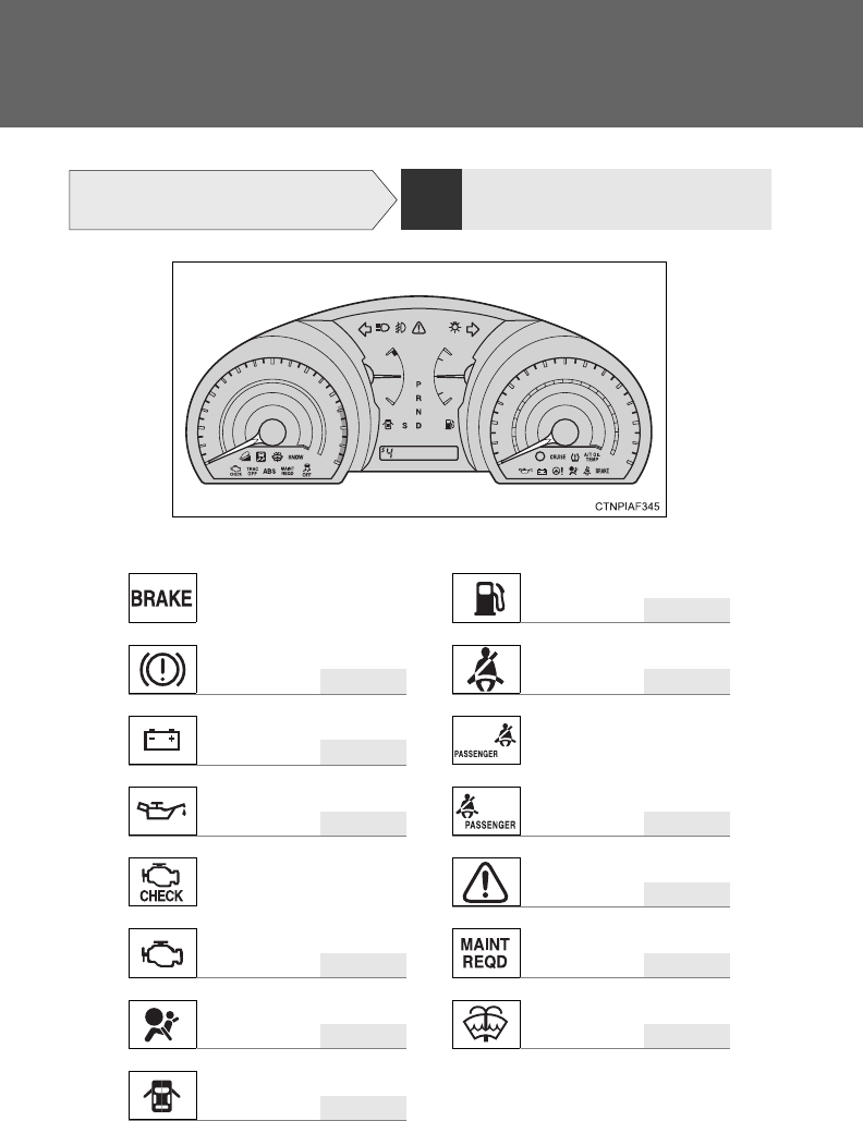
682
What to do if...
A warning light or indicator light
comes on
P. 573 If a warning light turns on or a
warning buzzer sounds...
■Warning lights
P. 576
or
P. 5 7 3 P. 576
P. 5 7 4
or
P. 5 7 4 P. 576
P. 576
or
P. 5 7 4 P. 576
P. 5 7 4 P. 576
P. 5 7 6
Brake system warning
light
Low fuel level warning
light
Driver’s seat belt
reminder light
Charging system warn-
ing light
Front passenger’s seat belt
reminder light
Low engine oil pressure
warning light
Malfunction indicator
lamp
Master warning light
Maintenance required
reminder light
SRS warning light
Low washer fluid warn-
ing light
Open door warning light
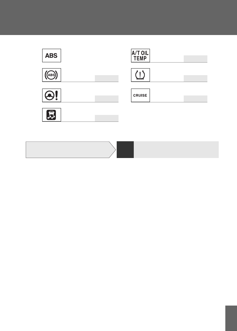
683
What to do if...
P. 576
or
P. 5 7 4 P. 576
P. 5 7 4 P. 574
P. 5 7 4
*: The light flashes to indicate a malfunction.
ABS warning light
Automatic transmission fluid temper-
ature warning light
Tire pressure warning
light
Electric power steering
warning light
Cruise control indicator
light*
Slip indicator
light
A warning message is
displayed
P. 584 If a warning message is displayed
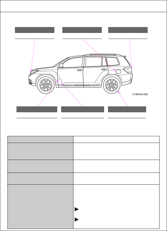
684
GAS STATION INFORMATION
Auxiliary catch lever
P. 499
Fuel filler door
P. 109
Back door opener
P. 6 0
Hood release lever
P. 4 9 9
Fuel filler door opener
P. 1 0 9
Tire inflation pressure
P. 630
Fuel tank capacity (Reference) 19.2 gal. (72.5 L, 15.9 Imp. gal.)
Fuel type
Unleaded gasoline with an Octane Rating
of 87 (Research Octane Number 91) or
higher
Cold tire inflation
pressure P. 6 3 0
Engine oil capacity
(Drain and refill reference) P. 622
Engine oil type
Toyota Genuine Motor Oil or equivalent
Oil grade: P. 622
ILSAC multigrade engine oil
Recommended oil viscosity:
2.7 L 4-cylinder (1AR-FE) engine
5W-20 and 0W-20
3.5 L V6 (2GR-FE) engine
0W-20
