Toyota P1600 Users Manual
p1600 to the manual a0b5c66d-714b-46f9-b1ee-a94247b689f9
2015-01-26
: Toyota Toyota-P1600-Users-Manual-338467 toyota-p1600-users-manual-338467 toyota pdf
Open the PDF directly: View PDF ![]() .
.
Page Count: 2
A05723
EFI
B–R 2A 2F
Engine Room J/B
WE2
FL Main
Battery
1
ECM
BATT
8
1
–DIAGNOSTICS ENGINE
DI–133
2000 CELICA (RM744U)
DTC P1600 ECM BATT Malfunction
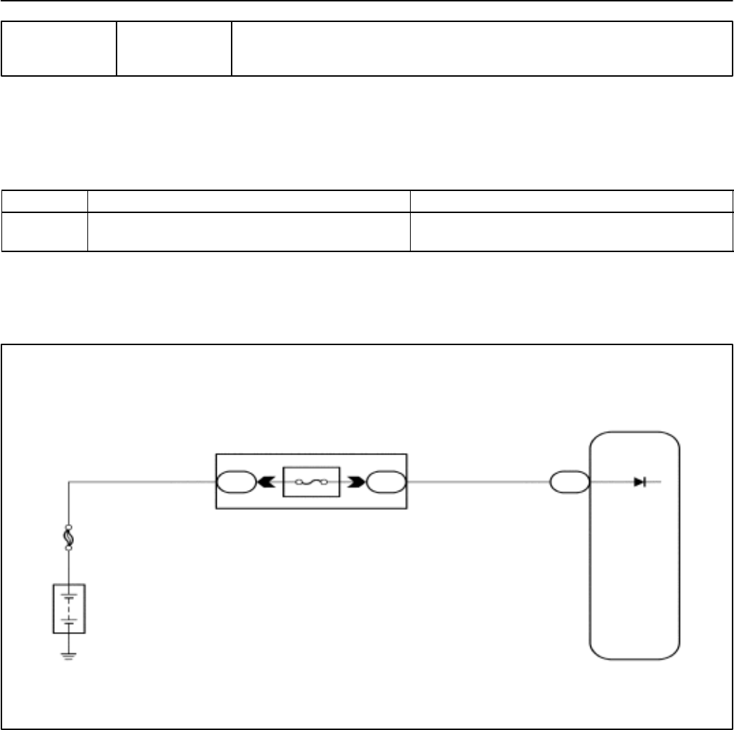
CIRCUIT DESCRIPTION
Battery positive voltage is supplied to terminal BATT of the ECM even when the ignition switch is OFF for
use by the DTC memory and air–fuel ratio adaptive control value memory, etc.
DTC No. DTC Detecting Condition Trouble Area
P1600 Open in back up power source circuit
SOpen in back up power source circuit
SECM
HINT:
If DTC P1600 appear, the ECM does not store another DTC.
WIRING DIAGRAM
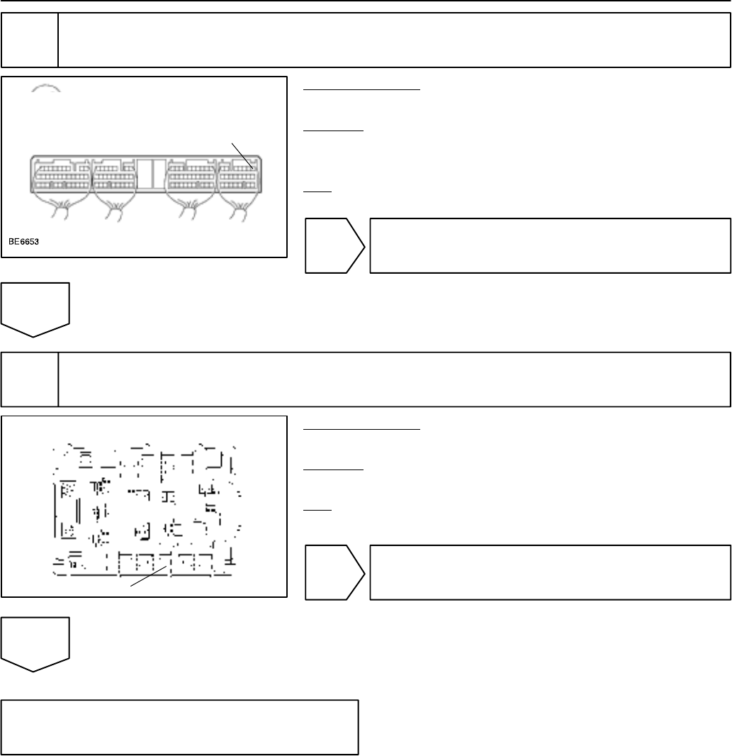
INSPECTION PROCEDURE
HINT:
Read freeze frame data using TOYOTA hand–held tester or OBD II scan tool. Because freeze frame records
the engine conditions when the malfunction is detected, when troubleshooting it is useful for determining
whether the vehicle was running or stopped, the engine warmed up or not, the air–fuel ratio lean or rich, etc.
at the time of the malfunction.
DI38N–03
A09084 A09092
ON
BATT (+)
I11732 A11409
Engine Room J/B
EFI Fuse
DI–134
–DIAGNOSTICS ENGINE
2000 CELICA (RM744U)
1 Check voltage between terminal BATT of ECM connector and body ground.
PREPARATION:
Remove the ECM cover.
CHECK:
Measure voltage between terminal BATT of the ECM connector
and body ground.
OK:
Voltage 9 – 14 V
OK Check and replace ECM (See page IN–30).
NG
2 Check EFI fuse.
PREPARATION:
Remove the EFI fuse from the engine room J/B.
CHECK:
Check continuity of EFI fuse.
OK:
Continuity
NG Check for short in all the harness and
components connected to EFI fuse.
OK
Check and repair harness or connector
between battery and EFI fuse and ECM
(See page IN–30).
