Managing Physical Interface
2018-03-22
: Tp-Link Managing Physical Interface managing_physical_interface configurationguide
Open the PDF directly: View PDF ![]() .
.
Page Count: 20


This guide applies to:
T1500G-10PS v2 or above, T1500G-8T v2 or above, T1500G-10MPS v2 or above, T1500-28PCT v3 or above,
T1600G-52TS v3 or above, T1600G-52PS v3 or above, T1600G-28PS v3 or above, T1600G-28TS v3 or above,
T1600G-18TS v2 or above, T2600G-52TS v3 or above, T2600G-28TS v3 or above, T2600G-28MPS v3 or
above, T2600G-28SQ v1 or above.
1 Physical Interface
1.1 Overview
Interfaces are used to exchange data and interact with interfaces of other network devices.
Interfaces are classified into physical interfaces and Layer 3 interfaces.
Physical interfaces are the ports on the switch panel. They forward packets based on
MAC address table.
Layer 3 interfaces are used to forward IPv4 and IPv6 packets using static or dynamic
routing protocols. You can use Layer 3 interfaces for IP routing and inter-VLAN routing.
This chapter introduces the configurations for physical interfaces.
1.2 Supported Features
The switch supports the following features about physical interfaces:
Basic Parameters
You can configure port status, speed mode, duplex mode, flow control and other basic
parameters for ports.
Port Isolation
You can use this feature to restrict a specific port to send packets to only the ports in the
forwarding port list that you configure.
Loopback Detection
This function allows the switch to detect loops in the network. When a loop is detected on
a port or VLAN, the switch will display an alert on the management interface and block the
corresponding port or VLAN according to your configurations.
2 Basic Parameters Configurations
2.1 Using the GUI
Choose the menu L2 FEATURES > Switching > Port > Port Config to load the following
page.
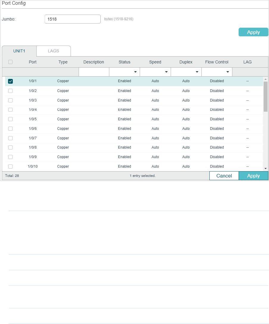
Figure 2-1 Configuring Basic Parameters
Follow these steps to configure basic parameters for the ports:
1) Configure the MTU size of jumbo frames for all the ports, then click Apply.
Jumbo Configure the size of jumbo frames. By default, it is 1518 bytes.
Generally, the MTU (Maximum Transmission Unit) size of a normal frame is 1518
bytes. If you want the switch supports to transmit frames of which the MTU size is
greater than 1518 bytes, you can configure the MTU size manually here.
2) Select one or more ports to configure the basic parameters. Then click Apply.
UNIT/LAGS Click the UNIT number to configure physical ports. Click LAGS to configure LAGs.
Type Displays the port type. Copper indicates an Ethernet port, and Fiber indicates an
SFP port.
Description (Optional) Enter a description for the port.

Status With this option enabled, the port forwards packets normally. Otherwise, the port
cannot work. By default, it is enabled.
Speed Select the appropriate speed mode for the port. When Auto is selected, the
port automatically negotiates speed mode with the neighbor device. The default
setting is Auto. It is recommended to select Auto if both ends of the link support
auto-negotiation.
Duplex Select the appropriate duplex mode for the port. There are three options: Half,
Full and Auto. The default setting is Auto.
Half: The port can send and receive packets, but only one-way at a time.
Full: The port can send and receive packets simultaneously.
Auto: The port automatically negotiates duplex mode with the peer device.
Flow Control With this option enabled, when a device gets overloaded it will send a PAUSE
frame to notify the peer device to stop sending data for a specified period
of time, thus avoiding the packet loss caused by congestion. By default, it is
disabled.
Note:
We recommend that you set the ports on both ends of a link as the same speed and duplex mode.
2.2 Using the CLI
Follow these steps to set basic parameters for the ports.
Step 1 configure
Enter global configuration mode.
Step 2 jumbo-size
size
Change the MTU (Maximum Transmission Unit) size to support jumbo frames. The default
MTU size for frames received and sent on all ports is 1518 bytes. To transmit jumbo
frames, you can manually configure MTU size of frames up to 9216 bytes.
size
: Configure the MTU size of jumbo frames. The value ranges from 1518 to 9216bytes.
Step 3 interface { fastEthernet
port
| range fastEthernet
port-list
| gigabitEthernet
port
| range
gigabitEthernet
port-list
| ten-gigabitEthernet
port
| ten-range gigabitEthernet
port-list
|
port-channel
port-channel
| range port-channel
port-channel-list
|}
Enter interface configuration mode.

Step 4 Configure basic parameters for the port:
description
string
Give a port description for identification.
string
: Content of a port description, ranging from 1 to 16 characters.
shutdown
no shutdown
Use shutdown to disable the port, and use no shutdown to enable the port. When the
status is enabled, the port can forward packets normally, otherwise it will discard the
received packets. By default, all ports are enabled.
speed { 10 | 100 | 1000 | 10000 | auto }
Set the appropriate speed mode for the port.
10 | 100 | 1000 | 10000 | auto: Speed mode of the port. The options are subject to your
actual product. The device connected to the port should be in the same speed and duplex
mode with the port. When auto is selected, the speed mode will be determined by auto-
negotiation.
duplex { auto | full | half }
Set the appropriate duplex mode for the port.
auto | full | half: Duplex mode of the port. The device connected to the port should be in the
same speed and duplex mode with the port. When auto is selected, the duplex mode will be
determined by auto-negotiation.
flow-control
Enable the switch to synchronize the data transmission speed with the peer device,
avoiding the packet loss caused by congestion. By default, it is disabled.
Step 5 show interface configuration [ fastEthernet
port
| gigabitEthernet
port
| | ten-
gigabitEthernet
port
| port-channel
port-channel-id
]
Verify the configuration of the port or LAG.
Step 6 end
Return to privileged EXEC mode.
Step 7 copy running-config startup-config
Save the settings in the configuration file.
The following example shows how to implement the basic configurations of port1/0/1,
including setting a description for the port, configuring the jumbo frame, making the port
automatically negotiate speed and duplex with the neighboring port, and enabling the flow-
control:
Switch#configure
Switch#jumbo-size 9216
Switch(config)#interface gigabitEthernet 1/0/1
Switch(config-if)#no shutdown
Switch(config-if)#description router connection
Switch(config-if)#speed auto
Switch(config-if)#duplex auto
Switch(config-if)#flow-control
Switch(config-if)#show interface configuration gigabitEthernet 1/0/1
Port State Speed Duplex FlowCtrl Jumbo Description
-------- ----- -------- ------ -------- -------- -----------
Gi1/0/1 Enable Auto Auto Enable Disable router connection
Switch(config-if)#show jumbo-size
Global jumbo size : 9216
Switch(config-if)#end
Switch#copy running-config startup-config
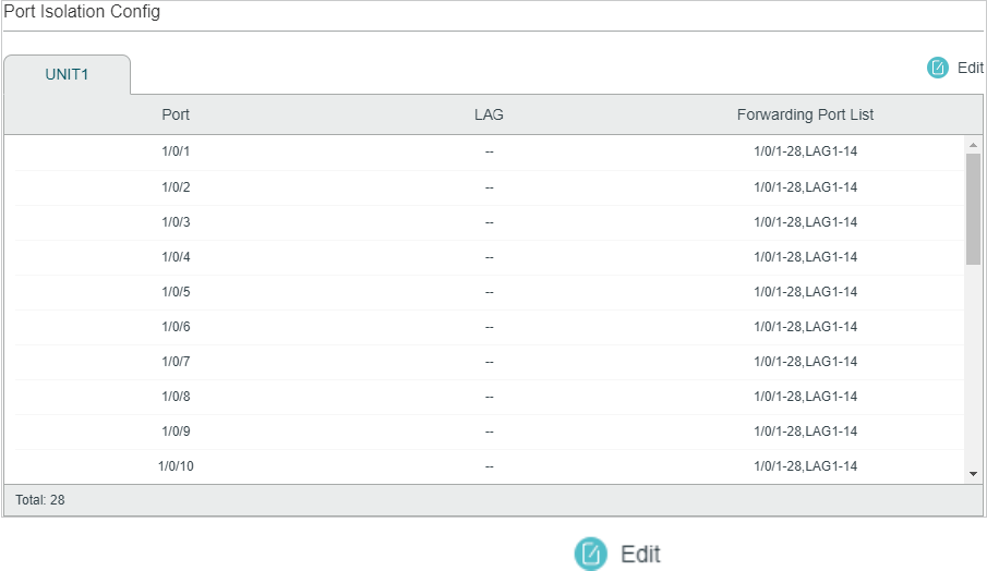
3 Port Isolation Configurations
3.1 Using the GUI
Port Isolation is used to limit the data transmitted by a port. The isolated port can only send
packets to the ports specified in its forwarding Port list.
Choose the menu L2 FEATURES > Switching > Port > Port Isolation to load the following
page.
Figure 3-1 Port Isolation List
The above page displays the port isolation list. Click to configure Port Isolation on
the following page.
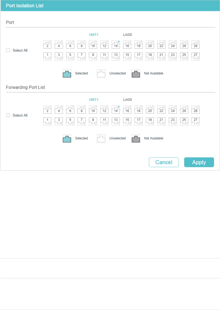
Figure 3-2 Port Isolation
Follow these steps to configure Port Isolation:
1) In the Port section, select one or multiple ports to be isolated.
2) In the Forwarding Port List section, select the forwarding ports or LAGs which the
isolated ports can only communicate with. It is multi-optional.
3) Click Apply.
3.2 Using the CLI
Follow these steps to configure Port Isolation:
Step 1 configure
Enter global configuration mode.
Step 2 interface { fastEthernet
port
| range fastEthernet
port-list
| gigabitEthernet
port
| range
gigabitEthernet
port-list
| ten-gigabitEthernet
port
| ten-range gigabitEthernet
port-list
|
port-channel
port-channel
| range port-channel
port-channel-list
|}
Specify the port to be isolated and enter interface configuration mode.

Step 3 port isolation { [fa-forward-list
fa-forward-list
] [gi-forward-list
gi-forward-list
] [te-forward-
list
te-forward-list
] [ po-forward-list
po-forward-list
] }
Add ports or LAGs to the forwarding port list of the isolated port. It is multi-optional.
fa-forward-list / gi-forward-list / te-forward-list
: Specify the forwarding Ethernet ports.
po-forward-list:
Specify the forwarding LAGs.
Step 4 show port isolation interface { fastEthernet
port
| gigabitEthernet
port
| ten-
gigabitEthernet
port
| port-channel
port-channel
}
Verify the Port Isolation configuration of the specified port.
Step 5 end
Return to privileged EXEC mode.
Step 6 copy running-config startup-config
Save the settings in the configuration file.
The following example shows how to add ports 1/0/1-3 and LAG 4 to the forwarding list of
port 1/0/5:
Switch#configure
Switch(config)#interface gigabitEthernet 1/0/5
Switch(config-if)#port isolation gi-forward-list 1/0/1-3 po-forward-list 4
Switch(config-if)#show port isolation interface gigabitEthernet 1/0/5
Port LAG Forward-List
---- --- -----------------------
Gi1/0/5 N/A Gi1/0/1-3,Po4
Switch(config-if)#end
Switch#copy running-config startup-config
4 Loopback Detection Configuration
4.1 Using the GUI
To avoid broadcast storm, we recommend that you enable storm control before loopback
detection is enabled. To get detailed introductions about storm control, refer to Configuring
QoS_T1500&T1500G&T1600G (for T1500G-10PS v2, T1500G-8T v2, T1500G-10MPS v2,
T1500-28PCT v3, T1600G-18TS v2, T1600G-28TS v3, T1600G-28PS v3, T1600G-52TS
v4, T1600G-52PS v4) series switches; refer to Configuring QoS_T2600G&T1600G-52TS
v3&T1600G_52PS v3 (for T1600G-52TS v3, T1600G-52PS v3, T2600G-28TS v3, T2600G-
52ST v3, T2600G-28MPS v3, T2600G-28SQ v1).
Choose the menu L2 FEATURES > Switching > Port > Loopback Detection to load the
following page.
Figure 4-1 Configuring Loopback Detection
Follow these steps to configure loopback detection:

1) In the Loopback Detection section, enable loopback detection and configure the
global parameters. Then click Apply.
Loopback
Detection Status
Enable loopback detection globally.
Detection
Interval
Set the interval of sending loopback detection packets in seconds.
The valid value ranges from 1 to 1000 and the default value is 30.
Auto-recovery
Time
Set the recovery time globally. The blocked port in Auto Recovery mode will
automatically be recovered to normal status after the Auto-recovery Time
expires. The value ranges from 2 to 100,000 in seconds, and the default value is
90.
Web Refresh
Status
With this option enabled, the switch will refresh the web timely. By default, it is
disabled.
Web Refresh
Interval
If you enabled web refresh status, set the refresh interval in seconds between 3
and 100. The default value is 6.
2) In the Port Config section, select one or more ports to configure the loopback
detection parameters. Then click Apply.
Status Enable loopback detection for the port.
Operation Mode Select the operation mode when a loopback is detected on the port:
Alert: The Loop Status will display whether there is a loop detected on the
corresponding port. It is the default setting.
Port Based: In addition to displaying alerts, the switch will block the port on which
the loop is detected.
VLAN-Based: If a loop is detected in a VLAN on that port, in addition to displaying
alerts, the switch will block that VLAN. The traffic of the other VLANs can still be
normally forwarded by the port.
Recovery Mode If you select Port Based or VLAN-Based as the operation mode, you also need to
configure the recovery mode for the blocked port:
Auto: The blocked port will automatically be recovered to normal status after the
automatic recovery time expires. It is the default setting.
Manual: You need to manually release the blocked port. Click Recovery to
release the selected port.
3) (Optional) View the loopback detection information.
Loop Status Displays whether a loop is detected on the port.
Block Status Displays whether the port is blocked.
Block VLAN Displays the blocked VLANs.

4.2 Using the CLI
Follow these steps to configure loopback detection:
Step 1 configure
Enter global configuration mode.
Step 2 loopback-detection
Enable the loopback detection feature globally. By default, it is disabled.
Step 3 loopback-detection interval
interval-time
Set the interval of sending loopback detection packets which is used to detect the loops in
the network.
interval-time:
The interval of sending loopback detection packets. The valid values are from
1 to 1000 seconds. By default, the value is 30 seconds.
Step 4 loopback-detection recovery-time
recovery-time
Set the auto-recovery time, after which the blocked port in Auto Recovery mode can
automatically be recovered to normal status.
recovery-time
: Specify the detection interval, ranging from 2 to 100,000 seconds. The
default value is 90.
Step 5 interface { fastEthernet
port
| range fastEthernet
port-list
| gigabitEthernet
port
| range
gigabitEthernet
port-list
| ten-gigabitEthernet
port
| ten-range gigabitEthernet
port-list
|
port-channel
port-channel
| range port-channel
port-channel-list
|}
Enter interface configuration mode.
Step 6 loopback-detection
Enable loopback detection for the port. By default, it is disabled.
Step 7 loopback-detection config process-mode { alert | port-based | vlan-based } recovery-
mode { auto | manual }
Set the process mode when a loopback is detected on the port. There are three modes:
alert: The switch will only display alerts when a loopback is detected. It is the default setting.
port-based: In addition to displaying alerts, the switch will block the port on which the loop
is detected.
vlan-based: In addition to displaying alerts, the switch will block the VLAN of the port in
which the loop is detected.
Set the recovery mode for the blocked port. There are two modes:
auto: After the recovery time expires, the blocked port will automatically recover to normal
status and restart to detect loops in the network.
manual: The blocked port can only be released manually. You can use the command
‘loopback-detection recover’ to recover the blocked port to normal status.
Step 9 show loopback-detection global
Verify the global configuration of Loopback Detection.

Step 10 show loopback-detection interface { fastEthernet
port
| gigabitEthernet
port
| ten-
gigabitEthernet
port
| port-channel
port-channel
}
Verify the Loopback Detection configuration of the specified port.
Step 11 end
Return to privileged EXEC mode.
Step 12 copy running-config startup-config
Save the settings in the configuration file.
The following example shows how to enable loopback detection globally (keep the default
parameters):
Switch#configure
Switch(config)#loopback-detection
Switch(config)#show loopback-detection global
Loopback detection global status : enable
Loopback detection interval : 30s
Loopback detection recovery time : 3 intervals
Switch(config-if)#end
Switch#copy running-config startup-config
The following example shows how to enable loopback detection of port 1/0/3 and set the
process mode as alert and recovery mode as auto:
Switch#configure
Switch(config)#interface gigabitEthernet 1/0/3
Switch(config-if)#loopback-detection
Switch(config-if)#loopback-detection config process-mode alert recovery-mode auto
Switch(config-if)#show loopback-detection interface gigabitEthernet 1/0/3
Port Enable Process Mode Recovery Mode Loopback Block LAG
---- ------ ------------ ------------- -------- ----- ----
Gi1/0/3 enable alert auto N/A N/A N/A
Switch(config-if)#end
Switch#copy running-config startup-config
5 Configuration Examples
5.1 Example for Port Isolation
5.1.1 Network Requirements
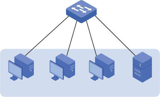
As shown below, three hosts and a server are connected to the switch and all belong to
VLAN 10. Without changing the VLAN configuration, Host A is not allowed to communicate
with the other hosts except the server, even if the MAC address or IP address of Host A is
changed.
Figure 5-1 Network Topology
VLAN 10
Switch
Gi1/0/1
Gi1/0/2
Gi1/0/4
Gi1/0/3
Host A Host B Host C Server
5.1.2 Configuration Scheme
You can configure port isolation to implement the requirement. Set port 1/0/4 as the only
forwarding port for port 1/0/1, thus forbidding Host A to forward packets to the other
hosts.
Since communications are bidirectional, if you want Host A and the server to communicate
normally, you also need to add port 1/0/1 as the forwarding port for port 1/0/4.
Demonstrated with T2600G-28TS, the following sections provide configuration procedure
in two ways: using the GUI and using the CLI.
5.1.3 Using the GUI
1) Choose the menu L2 FEATURES > Switching > Port > Port Isolation to load the
following page. It displays the port isolation list.
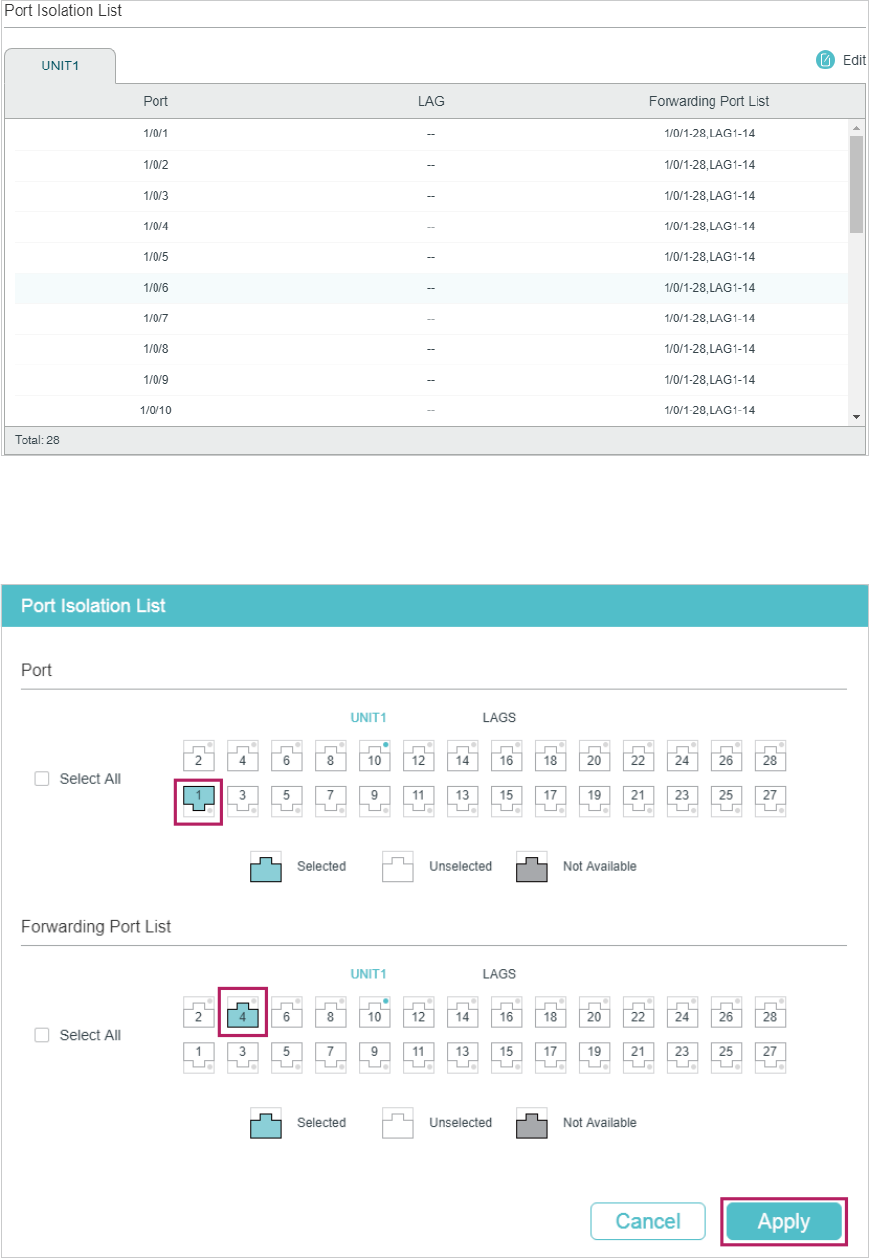
Figure 5-2 Port Isolation List
2) Click Edit on the above page to load the following page. Select port 1/0/1 as the port to
be isolated, and select port 1/0/4 as the forwarding port. Click Apply.
Figure 5-3 Port Isolation Configuration
3) Select port 1/0/4 as the port to be isolated, and select port 1/0/1 as the forwarding port.
Click Apply.
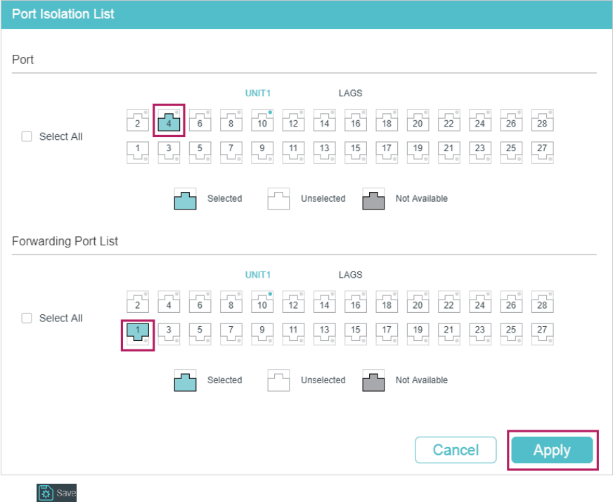
Figure 5-4 Port Isolation Configuration
4) Click to save the settings.
5.1.4 Using the CLI
Switch#configure
Switch(config)#interface gigabitEthernet 1/0/1
Switch(config-if)#port isolation gi-forward-list 1/0/4
Switch(config-if)#exit
Switch(config)#interface gigabitEthernet 1/0/4
Switch(config-if)#port isolation gi-forward-list 1/0/1
Switch(config-if)#end
Switch#copy running-config startup-config
Verify the Configuration
Switch#show port isolation interface
Port LAG Forward-List
---- --- ------------
Gi1/0/1 N/A Gi1/0/4
Gi1/0/2 N/A Gi1/0/1-28,Po1-14
Gi1/0/3 N/A Gi1/0/1-28,Po1-14
Gi1/0/4 N/A Gi1/0/1
...
5.2 Example for Loopback Detection
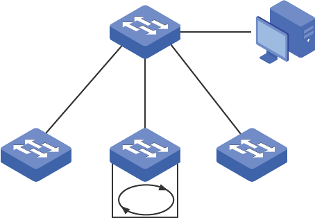
5.2.1 Network Requirements
As shown below, Switch A is a convergence-layer switch connecting to several access-
layer switches. Loops can be easily caused in case of misoperation on the access-
layer switches. If there is a loop on an access-layer switch, broadcast storms will occur
on Switch A or even in the entire network, creating excessive traffic and degrading the
network performance.
To reduce the impacts of broadcast storms, users need to detect loops in the network via
Switch A and timely block the port on which a loop is detected.
Figure 5-5 Network Topology
Switch A
Management Host
Access-layer Switches
Gi1/0/1
Gi1/0/2
Loop
Gi1/0/3
5.2.2 Configuration Scheme
Enable loopback detection on ports 1/0/1-3 and configure SNMP to receive the trap
notifications. For detailed instructions about SNMP, refer to Configuring SNMP & RMON.
Here we introduce how to configure loopback detection and monitor the detection result
on the management interface of the switch.
Demonstrated with T2600G-28TS, the following sections provide configuration procedure
in two ways: using the GUI and using the CLI.
5.2.3 Using the GUI
1) Choose the menu L2 FEATURES > Switching > Port > Loopback Detection to load the
configuration page.
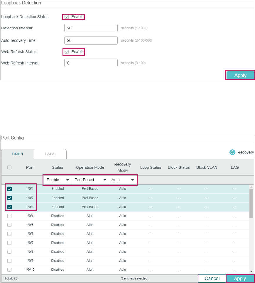
2) In the Loopback Detection section, enable loopback detection and web refresh
globally. Keep the other parameters as default values and click Apply.
Figure 5-6 Global Configuration
3) In the Port Config section, enable ports 1/0/1-3, select the operation mode as Port
-Based so that the port will be blocked when a loop is detected, and keep the recovery
mode as Auto so that the port will automatically be recovered to normal status after the
auto-recovery time. Click Apply.
Figure 5-7 Port Configuration
4) Monitor the detection result on the above page. The Loop status and Block status are
displayed on the right side of ports.
5.2.4 Using the CLI
1) Enable loopback detection globally and configure the detection interval and recovery
time.
Switch#configure
Switch(config)#loopback-detection
Switch(config)#loopback-detection interval 30
Switch(config)#loopback-detection recovery-time 3
2) Enable loopback detection on ports 1/0/1-3 and set the process mode and recovery
mode.
Switch(config)#interface range gigabitEthernet 1/0/1-3
Switch(config-if-range)#loopback-detection
Switch(config-if-range)#loopback-detection config process-mode port-based
recovery-mode auto
Switch(config-if-range)#end
Switch#copy running-config startup-config
Verify the Configuration
Verify the global configuration:
Switch#show loopback-detection global
Loopback detection global status : enable
Loopback detection interval: 30 s
Loopback detection recovery time : 90 s
Verify the loopback detection configuration on ports:
Switch#show loopback-detection interface
Port Enable Process Mode Recovery Mode Loopback Block LAG
---- -------- ----------------- ------------ ------------ -- ---- -----
Gi1/0/1 enable port-based auto N/A N/A N/A
Gi1/0/2 enable port-based auto N/A N/A N/A
Gi1/0/3 enable port-based auto N/A N/A N/A

6 Appendix: Default Parameters
Default settings of ports are listed in th following tables.
Table 6-1 Default Parameters for Switching
Parameter Default Setting
Port Config
Jumbo 1518 bytes
Type
Copper (For RJ45 Ports)
Fiber (For SFP Ports)
Status Enabled
Speed
Auto (For RJ45 Ports)
1000M (For SFP Ports)
Duplex
Auto (For RJ45 Ports)
Full (For SFP Ports)
Flow Control Disabled
Loopback Detection
Loopback Detection Status Disabled
Detection Interval 30 seconds
Auto-recovery Time 90 seconds
Web Refresh Status Disabled
Web Refresh Interval 6 seconds
Port Status Disable
Operation mode Alert
Recovery mode Auto
