Trafcon 50074 Traffic Safety Light Control User Manual

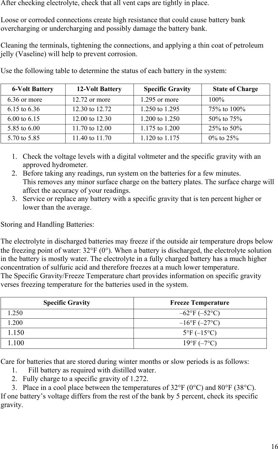
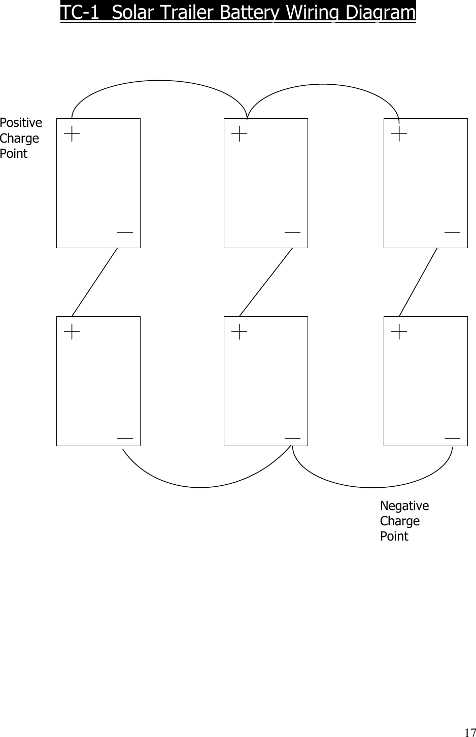
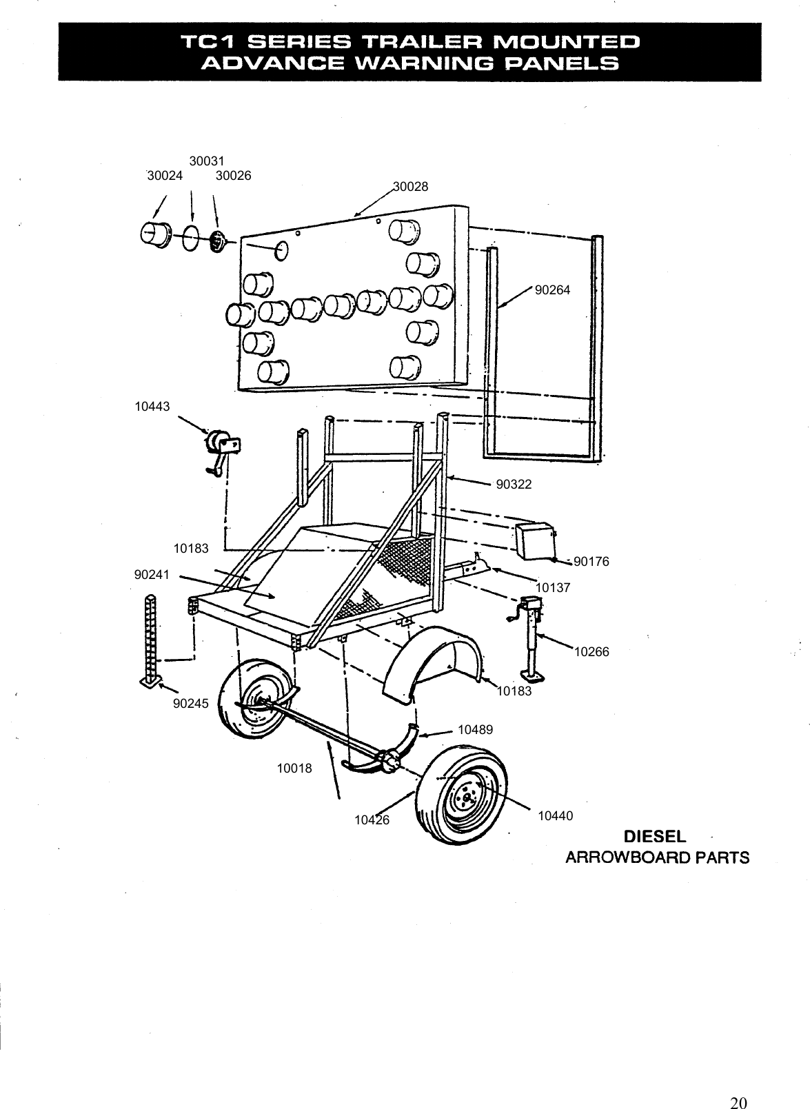
Trafcon Industries, Inc. Traffic Safety Light Control Users Manual

Users Manual

   SmartFlash Arrowboard Controller Installation & Operation Manual             81 Texaco Road Mechanicsburg, PA 17050 717-691-8007 717-697-0813 FAX www.trafcon.com  Revised:  March, 2003
The Basics  There are two variations of the SmartFlash controller.  Vehicle mounted units consist of two parts, the remote control head, which includes a keypad mounted within a black enclosure and is equipped with a mounting bracket.  The second part, the controller, is a plain black box, with mounting ears, and equipped with four receptacles.  The controller also houses most of the electronics.  Trailer mounted units consist of a controller unit with the keypad mounted within.     Main Features  Features common to both controllers include the following:  •  Solid state circuitry •  Short circuit protected output circuitry •  Polarity protected circuitry •  Keypad operation with back lighting •  Ability to “hot-swap” controls and plugs •  Intensity and battery monitoring •  Automatic dimming •  Manual dimming (special option) •  Automatic raise/lower operation (optional) •  Support for electric and hydraulic actuators •  Low battery warning (LED display alternates between mode and “LB”)  •  Audible confirmation of keyboard operation •  Text and graphic markings                   1
     Operating Instructions    Controller Layout       The “On and Off” Buttons  The ON and OFF buttons work as expected, when the Arrowboard is turned off the main positive (common) feed to the Arrowboard is turned off and the current draw of the system is about 10mA.  There is also a power LED that is on when the Arrowboard is turned on.  Lamp Sequence Control Buttons     The “Select Mode” button is used to scroll through the selectable sequences.  Each time this button is pressed the LED display on the controller or remote will scroll to the next sequence.  When in this mode the display will flash rapidly.    2
   The “Enter” button is used to set the “new” sequence as the displayed sequence.  Once this button has been pressed the sequence on the Arrowboard will change to the ‘new’ sequence.       Other Buttons    “Toggle Display” button.   This button is used to change the “bulb brightness and battery level display” between its two modes.  Each time it is pressed it toggles to the other mode.       Bulb brightness and Battery level Display.   This display gives accurate readings of both bulb brightness and battery voltage levels.      MODE 1  Bulb Brightness.  This mode displays the level of brightness that the bulbs on the Arrowboard are illuminated too.  The scale is from 10% to 100% and is marked above the display.    MODE 2  Battery Voltage.  This mode displays the voltage level of the power source. The scale is from 10 to 14 volts and is displayed underneath the display.  The two readings are displayed independently; the operator can alternate between the two by pressing the “Toggle display” button.  The current mode of the display is shown by the display indication LEDs; these are located to the right of the “Toggle Display” button.          3
Function Buttons (Optional)  •  Auto/manual dimming control:  Holding both the “brightness down” and “brightness up” optional buttons down for approximately five seconds results in a change from auto to manual dimming, or vice versa.  This procedure will not work when in “battery level” mode, or if the optional buttons have not been configured.     Option Stickers     “Lamp Brightness UP” button:    Used to proceed upwards through the brightness options 1-10, and Auto.    “Lamp Brightness DOWN” button:    Used to proceed downwards through the brightness options 1-10, and Auto.      “Sign UP” button:        Used to move the Arrowboard into the up position.       “Sign Down” button: Used to move the Arrowboard into the down                             position.      4
 Display Features     The “Arrowboard Sequence Display” is the main display on the controller.   The primary purpose of this display is to show a flashing sequence that is identical to that on the arrowboard, this is the “real” sequence.  Once the “Select Mode” button has been pressed the flashing “real” sequence disappears and a “new” sequence will appear on the display, this sequence flashes at twice the rate of the “real” sequence.  Once a “new” sequence is shown on the display it will remain there until one of the following occurs:  1)  The “Select Mode” button is pressed again, in this case the  “new” sequence will scroll to the next “new” sequence  2)  The “Enter” button is pressed, in this case the controller sends a change sequence request to the “arrowboard driver” which then changes the sequence, which is displayed on the arrowboard.  At this point the “new” sequence on the controller display will begin to flash slower and become the “real” sequence.   If no buttons are pressed for a time period of 5 seconds the “new” sequence will disappear and the “real” sequence will be displayed  The “Auto Dimming” LED:  This is located just above the “Bulb brightness and battery level” display.  Its purpose is to alert the operator when the Arrowboard is set in auto-dimming mode.   The “Sign Up” LED:  This is located above option button four. It is on when the Arrowboard is in the UP position.         5
 20 Way D-3100 Plug  TOPSmart Flash   MB Series Controller 10 Way D-3100 Plug   (2) 4 Way D-5200 PlugSmart Flash         MB Series Remote 10 Way D-3100 Plug(2) 4 Way D-5200 Plug0 Way D-3100 Smart Flash  TC Series Controller    6
        7
   Controller D-3100 Plug Wiring    Circuit Wire Color  Gauge  1 Red 16  2 Red 18  3 White 18  4 White/Red 22  5 Option   6 NC   7 Black 18  8 Green 18  9 White/Green 22  10 Option      Remote Cable 4 Way Plug Wiring    Circuit Wire Color Gauge  1 Red 18  2 Black 18  3 White 18  4 Green 18  NOTE: Use only shielded cable.               8
  Top Plug  Pin Wire Color  Gauge  Function  1  Green/Yellow  or  White 16  16  Actuator – Positive  2 Black/Yellow  or  Black 16  16  Actuator - Negative 3  Red  14  Power – Positive 4  Orange  14  Common to Lamps  Bottom Plug  Pin Wire Color  Gauge  Function 1  Black  14  Ground - Negative 2  Black  14  Ground - Negative 3  Red  14  Power - Positive 4  Orange  14  Common to Lamps     9
       10
    Lamp Wiring Circuits    Circuit Wire Color  Gauge  Function  Application 1 Brown 18 Lamp circuit  All 2 Red 18 Lamp circuit  All 3 Yellow 18 Lamp circuit  15,25 4 Green 18 Lamp circuit  All 5 Blue 18 Lamp circuit  25 6 White 18 Lamp circuit  All 7 Gray 18 Lamp circuit  25 8 Black 18 Lamp circuit  All 9 Brown/White 18 Lamp circuit  25 10 Red/White 18 Lamp circuit  25 11 Yellow/White 18  Lamp circuit  All 12 Green/White 18 Lamp circuit 25 13 Blue/White 18 Lamp circuit  15,25 14 White/Black 18 Lamp circuit  All 15 Gray/White 18 Lamp circuit  All 16 Black/White 18 Lamp circuit  All 17  Red/Black  18  Mode lamp  All except some miniboards 18  Tan  18  Mode lamp  All except some miniboards 19  Purple  18  Mode lamp  All except some miniboards 20  Pink  18  Low battery lamp Solar models     Orange 14 Gauge Lead, Common (+12VDC) to all Lamps.           11
 Troubleshooting                                                                 Symptom   Possible cause    No display – No backlight    Dead battery     Plug(s) not connected    Defective controller    No display – Backlight works    No mode selected     Plug(s) not connected   Defective controller    No dimming    Defective photocell     Shorted photocell wires   Defective controller    Lamps stay dim    Defective photocell     Broken photocell wire   Defective controller    Some lamps do not light    Defective lamp(s)   Short at lamp   Broken wire(s)   Defective controller    Power tilt does not work    Broken wire(s)     Defective actuator or control   Defective controller                       12
MB Series – Smart Flash  Installation of Vehicle Mounted Controllers   1.  Connect one 8 gauge red wire to the positive terminal of the battery. Do NOT use a smaller wire gauge.  2.  Connect the one 8 gauge black wire to the negative terminal of the battery or a        suitable ground connection.  Do NOT use a smaller wire gauge.  3.  If fusing is preferred it is recommended that a 35A fuse be installed on the red wire at the battery.  4.  Mount the remote control head in a convenient location within the vehicle cab.  5.  Route the gray four-conductor cable from the sign panel to the remote control head and connect.  Installation is now complete. See Operating Instructions section.  Test all mode and arrowboard functions thoroughly before use.    Installation for Wireless Option for Remote Control Head and Arrowboard Panel   1.  Locate suitable mounting location for the Smart Flash Remote with Internal RF option. The manufacturer preferred mounting locations are on or above the dash of the vehicle where there is access to a 12VDC power point. Mounting in locations other than these may affect the performance of the internal wireless module.  2.  Insert the power plug into a cigarette plug receptacle or a power point of your vehicle. It is recommended that you leave the plug connected at all times. If you prefer to hard wire the remote to a permanent power source, proceed with the following step otherwise proceed to step 6.  3.  Cut the power plug off directly behind the plug. Separate the two wires and strip the ends. Terminate the ends with the appropriate terminals for the desired power connection  4.  Connect the positive wire to a point that is connected to the positive terminal of a 12volt DC battery.  Alternatively, connecting the positive wire to the ignition switch will only enable arrowboard operation when the ignition is on. This configuration is not normally used.     13
5.  Connect the negative wire to a point that is connected to the negative terminal of a 12volt DC battery.  6.  Installation is now complete of the Smart Flash Remote with Internal RF option. If your arrowboard panel has a factory-installed External RF module, proceed to step 10. If your arrowboard panel does not have a factory-installed External RF module, proceed to the next set of installation steps.  7.  Locate a suitable mounting location for the External RF module on the arrowboard back panel.  Must be close enough to the 4-way receptacle to allow the 4-way plug from the External RF module to connect. The antenna on the External RF module should be pointing towards the top of the sign panel.  8.  After mounting is complete, connect 4-way plug to External RF module and connect the opposite end with the 4-way plug to the 4-way receptacle located on the arrowboard.  9.  This completes installation of the External RF module.  10. Turn power on at Remote Control Head and test all modes. If unit tests ok it is now ready to be put in service.   AGENCY NOTICE Changes or modifications not expressly approved by the manufacturer could void the user’s authority to operate the equipment.            14
TC Series – Smart Flash Solar  Battery Maintenance  Batteries should be carefully inspected on a regular basis; the system can become discharged for a number of reasons, for example:  • Operating conditions during the “winter” months of November through February, when      the power provided by the array is reduced. • Improper maintenance, such as not cleaning the PV array. • Electrolyte in the battery cells not maintained at the proper level. • Loose or corroded battery terminal connections. • Improper position of the system where the PV array is in the shadow of an object, or       tilted away from the sun. • Prolonged cloudy weather where the system is operating.  Maintenance of batteries, especially the proper voltage level, in the above situations should be performed as required. In some instances, it will be necessary to provide multiple recharges from an external source or replace with fresh batteries.  Caution !  It is important to maintain the proper level of electrolyte in the     batteries at all times. If the level is too high the electrolyte will      “boil” out of the top of the battery during charging and corrode the     terminal connections. If the level is too low the battery life will be   severely shortened.  Warning !  Charging batteries produce hydrogen, which can explode when     proper operating procedures are not followed. To prevent severe     personal injury, death, or substantial property damage when working     around batteries, be extremely careful. Always use approved eye     protection, face shield, rubber gloves, and insulated tools.  Electrolyte levels should be just below the bottom of the vent well, about ½ to ¾ inch above the tops of the separators. The electrolyte level should not drop below the top of the plates. See figure 1 for additional information.        Figure 1. Battery (showing inside elements)      15
After checking electrolyte, check that all vent caps are tightly in place.  Loose or corroded connections create high resistance that could cause battery bank overcharging or undercharging and possibly damage the battery bank.  Cleaning the terminals, tightening the connections, and applying a thin coat of petroleum jelly (Vaseline) will help to prevent corrosion.  Use the following table to determine the status of each battery in the system:  6-Volt Battery  12-Volt Battery  Specific Gravity  State of Charge 6.36 or more  12.72 or more  1.295 or more  100% 6.15 to 6.36  12.30 to 12.72  1.250 to 1.295  75% to 100% 6.00 to 6.15  12.00 to 12.30  1.200 to 1.250  50% to 75% 5.85 to 6.00  11.70 to 12.00  1.175 to 1.200  25% to 50% 5.70 to 5.85  11.40 to 11.70  1.120 to 1.175  0% to 25%  1.  Check the voltage levels with a digital voltmeter and the specific gravity with an approved hydrometer.  2.  Before taking any readings, run system on the batteries for a few minutes.             This removes any minor surface charge on the battery plates. The surface charge will              affect the accuracy of your readings. 3.   Service or replace any battery with a specific gravity that is ten percent higher or lower than the average.  Storing and Handling Batteries:  The electrolyte in discharged batteries may freeze if the outside air temperature drops below the freezing point of water: 32°F (0°). When a battery is discharged, the electrolyte solution in the battery is mostly water. The electrolyte in a fully charged battery has a much higher concentration of sulfuric acid and therefore freezes at a much lower temperature. The Specific Gravity/Freeze Temperature chart provides information on specific gravity verses freezing temperature for the batteries used in the system.  Specific Gravity  Freeze Temperature 1.250 –62°F (–52°C) 1.200 –16°F (–27°C) 1.150 5°F (–15°C) 1.100 19°F (–7°C)  Care for batteries that are stored during winter months or slow periods is as follows: 1.  Fill battery as required with distilled water. 2.  Fully charge to a specific gravity of 1.272. 3.  Place in a cool place between the temperatures of 32°F (0°C) and 80°F (38°C). If one battery’s voltage differs from the rest of the bank by 5 percent, check its specific gravity.       16
  TC-1  Solar Trailer Battery Wiring Diagram      Positive  Charge Point                                      Negative           Charge           Point                              17
 TC Series – Smart Flash Diesel  This manual was written to assist the mechanic or technician in troubleshooting the electrical systems of the Trafcon TC Series diesel arrowboard.  In order to efficiently troubleshoot these systems, an explanation of each is included in addition to the normal troubleshooting chart.  The appropriate section should be read thoroughly prior to an attempt to make repairs.  STARTING  The starting system consists of a toggle switch and a momentary contact starter switch.  When the toggle switch is moved to the “on” position, current flows to the electric fuel pump, the alternator voltage regulator and one side of the starter switch.  Pushing the starter switch allows current to flow to the starter solenoid and engages the starter.  CHARGING  When the toggle switch is in the “on” position, current flows from the battery to the alternator voltage regulator allowing the alternator to charge.  The normal charge rate under “no load” conditions is 13.8 – 14.2 volts.  When troubleshooting a charging system it is important to check the basics first.  The batter connections should be checked, as well as the electrolyte level in the battery.  Low electrolyte in only one cell can indicate that the cell is bad.  A battery in which all the cells are dry can indicate an overcharging problem and a possible bad battery.  If the battery is suspect, check each cell using a hydrometer.  Before attempting the check the alternator, allow the engine to run for approximately 15 minutes.  This will eliminate false voltmeter readings due to a low battery.  This step is absolutely necessary after “jump starting” a unit.  If a calibrated voltmeter is not available, move the caution bar switch of the controller to the “on” position and observe the unit’s voltage regulator.  Remove the four screws that secure the voltage regulator to the alternator and unplug the green wire from the brushholder assembly.  Momentarily connect a jumper wire from the brushholder terminal to the output terminal of the alternator and observe the meter reading.  A reading in the upper portion of the green scale or higher indicates that the voltage regulator is defective.  A reading that does not change indicates a bad alternator.  FUEL PUMP  The electric fuel pump is energized when the toggle switch is in the “on” position.  When operating normally a steady “clicking” sound can be heard.  If the fuel pump does not “click,” check for the presence of voltage with a test light.  Also, check the fuse next to the toggle switch.  This fuse completes a ground circuit to the volt/hourmeter panel.  The purpose of this fuse is to protect the wiring harness in the sign panel from damage if the common lead should come in contact with ground and also provides protection for the gauges.     18
    19
    20 DIESEL 30031 30024         30026 30028 90264 10443 10183 90241 90322 90176 10137 10266 10183 10489 10440 10426 10018 90245
   50435 10216 50438 10044 90317 10310 10197 90249 10043 90242 10193    21
 TRAFCON INDUSTRIES, INC.  MANUFACTURER’S WARRANTY  LIMITED WARRANTY POLICY Trafcon Industries, Inc. (Trafcon) hereby warrants to the original purchaser (customer), sold directly or through an authorized dealer, the product(s) listed for the time period(s) listed, from the date of purchase. Trafcon warrants the product(s) against defects in material and workmanship provided the products are installed and maintained properly, and operated under normal conditions. This warranty does not apply to product(s) that have been improperly applied, installed or maintained. The customer will be responsible for removing any defective item(s) from the product and returning the item(s), or the entire product, transportation costs prepaid, to Trafcon 81 Texaco Rd, Mechanicsburg, PA 17050. The customer will be responsible for reinstallation of item(s) upon return. All returns must have a Return Material Authorization (RMA) number prior to shipping. RMA numbers can be obtained by contacting Trafcon at 717-691-8007, or on the Internet at www.Trafcon.com. Proof of purchase will be required to obtain the RMA. Trafcon will, at its option, repair or replace defective product(s) or component part(s). Such item(s) will be returned by Trafcon, transportation costs paid (normal ground delivery), within the United States. Repaired or replaced product(s) or component part(s) will carry the remainder of their respective original warranty term(s). Exclusions from this warranty are: unauthorized sale outside the United States, the finish, tires, incandescent lamps, any condition(s) caused by abnormal use or service, negligent operation, act of God, and product specific limitations, if any, listed below.  THE LOSS OF USE OF THE PRODUCT, LOSS OF TIME, INCONVENIENCE, COMMERCIAL LOSS OR CONSEQUENTIAL DAMAGES ARE NOT COVERED. TRAFCON RESERVES THE RIGHT TO CHANGE THE DESIGN OF ANY PRODUCT WITHOUT ASSUMING ANY OBLIGATION TO MODIFY ANY PRODUCT PREVIOUSLY MANUFACTURED. This warranty gives you specific legal rights and you may have other rights, which may vary from state to state.  THERE ARE NO WARRANTIES, EXPRESSED OR IMPLIED, INCLUDING ANY IMPLIED WARRANTIES OF MERCHANTABILITY AND FITNESS, WHICH EXTEND BEYOND THIS WARRANTY PERIOD. THERE ARE NO WARRANTIES THAT EXTEND BEYOND THE FACE HEREOF. SELLER DISCLAIMS IMPLIED WARRENTY OF MERCHANTABILITY.  THE WARRANTY SHALL NOT APPLY TO ANY TRAFCON PRODUCT WHICH HAS BEEN MODIFIED, IMPROPERLY INSTALLED, IMPROPERLY MAINTAINED OR IMPROPERLY USED.  The product(s) and time period(s) under this warranty are as follows:  1.   FLASHING ARROW BOARDS, TRAILER MOUNTED, SOLAR (TC1) LIMITED 3 YEAR WARRANTY Limited 3 year warranty on these Trafcon products. Trafcon warrants each new unit against factory defects in material and workmanship for a 3 year period from the original date of purchase. EXCEPTIONS: Batteries- 18 months.  THIS WARRENTY DOES NOT COVER THE FOLLOWING: Tires, Finish.  2.   FLASHING ARROW BOARDS, TRAILER MOUNTED, DIESEL (TC3)        LIMITED 1 YEAR WARRANTY        Limited 1 year warranty on these Trafcon products. Trafcon warrants each new unit against factory         defects in material and workmanship for a 1 year period from the original date of purchase.        EXCEPTIONS: Batteries- 60 months (pro-rated).         THIS WARRANTY DOES NOT COVER THE FOLLOWING: Tires, Finish, Incandescent lamps.  3.   FLASHING ARROW BOARDS-VEHICLE MOUNTED  (MB & TM)        LIMITED 1 YEAR WARRANTY        Limited 1 year warranty on these Trafcon products. Trafcon warrants each new unit against factory         defects in material and workmanship for a 1 year period from the original date of purchase.    22
   23         THIS WARRANTY DOES NOT COVER THE FOLLOWING: Finish, Incandescent lamps.            4.  ARROW DYNAMIC SIGNS-TRAILER MOUNTED (TC-ADS) LIMITED 1 YEAR WARRANTY  Limited 1 year warranty on these Trafcon products. Trafcon warrants each new unit against factory defects in material and workmanship for a 1 year period from the original date of purchase.    EXCEPTIONS: Solar modules- 36 months, Batteries- 18 months. THIS WARRANTY DOES NOT COVER THE FOLLOWING: Tires, Finish.  5.   ARROW DYNAMIC SIGNS- VEHICLE MOUNTED (MB-ADS)        LIMITED 1 YEAR WARRANTY        Limited 1 year warranty on these Trafcon products. Trafcon warrants each new unit against factory         defects in material and workmanship for a 1 year period from the original date of purchase.        THIS WARRANTY DOES NOT COVER THE FOLLOWING; Finish.  6.  SPEED DISPLAY SIGNS- STATIONARY, VEHICLE & TRAILER MOUNTED (SST) LIMITED 1 YEAR WARRANTY    Limited 1 year warranty on these Trafcon products. Trafcon warrants each new unit against factory defects in material and workmanship for a 1 year period from the original date of purchase. EXCEPTIONS: Solar modules- 36 months, Batteries- 18 months. THIS WARRANTY DOES NOT COVER THE FOLLOWING: Tires, Finish.    7.    WORK ZONE RADIOS- STATIONARY, VEHICLE & TRAILER MOUNTED (WIZARD)        LIMITED 1 YEAR WARRANTY        Limited 1 year warranty on these Trafcon products. Trafcon warrants each new unit against factory        defects in material and workmanship for a 1 year period from the original date of purchase.        EXCEPTIONS: Solar modules-36 months, Batteries- 18 months.        THIS WARRANTY DOES NOT COVER THE FOLLOWING: Tires, Finish.  7.  PORTABLE EQUIPMENT PLATFORMS (PEP) LIMITED 1 YEAR WARRANTY Limited 1 year warranty on these Trafcon products. Trafcon warrants each new unit against factory defects in material and workmanship for a 1 year period from the original date of purchase. EXCEPTIONS: Solar modules- 36 months, Batteries- 18 months. THIS WARRANTY DOES NOT COVER THE FOLLOWING: Tires, Finish.  RIGHTS RESERVED Trafcon reserves the right to make changes in design, materials and specifications or to make product  changes as deemed necessary without prior notice. Obligations or liabilities will not be assumed with  respect to similar products previously advertised or produced.  PRINTING ERRORS Every effort has been made to avoid printing errors in our printed literature and on our website. Should there have been any specification or application errors, we must disclaim responsibility.  OMISSIONS Any product(s) or component(s) not specifically covered or excluded herein, will be covered for a 1 year period from date of purchase or by the Original Equipment Manufacturer’s warranty, whichever is greater.

Navigation menu