TranSystem 960710101 2.5 GHz Integrated CPE Transmitter User Manual UserMan20081008
TranSystem 2.5 GHz Integrated CPE Transmitter UserMan20081008
UserMan20081008

M
MM
MD
DS
S
Transmitter
Operation Manual
Copyright 2007, TRANSYSTEM, INC.
All rights reserved
TRANSYSTEM INC.
No.1-2 Li-Hsin Rd.I Science-Based
Industrial Park, Hsinchu, Taiwan
Tel:+886-3-5780393 Fax:+886-3-5784111
e-mail: sales@transystem.com.tw
website: www.transystem.com.tw
8029607101A

2
*Contact Us:
The Headquarter
Tel : + 886-3-578-0393
Fax: + 886-3-578-4111
Website: http://www.transystem.com.tw
E-mail: sales@transystem.com.tw
Address: NO. 1-2, LI-HSIN RD.I, SCIENCE-BASED INDUSTRIAL PARK, HSINCHU,
TAIWAN

3
TABLE OF CONTENTS
Chapter 1. General Information 4
1.1 Module Features and Specifications 4
Chapter 2. Installation 5
2.1 Step by Step Installation 5
2.2 Connection to the Power Inserter and Cable Modem 8
2.3 Waterproofing Connections 10
Chapter 3. Accessories 12
3.1 MMDS Antenna 12

4
Chapter 1. General Information
1.1 Module Features and Specifications
PLC100 PLC200
Input Frequency 22~34 MHz 12~42 MHz
Output
Frequency
2170~2182MHz
2500~2530MHz
Output 1 dB
Compression
Point
24dBm Typ. 24dBm Typ.
Output
Transmitting
Noise
-122dBm/Hz Max -116dBm/Hz Max
Output Spurious
(+22dBm TX Out) -60dBc Max -60dBc Max
Output Power
Blanking
Threshold
-40dBm±1dB -40dBm±1dB
TX Switching
Latency <1.2uS <1.2uS
LO Stability ±10kHz ±10kHz
Phase Noise <- 65 dBc/Hz @100Hz
-85 dBc/Hz @lKHz
-90 dBc/Hz@10kHz
-95 dBc/Hz@100kHz
<- 65 dBc/Hz @100Hz
-85 dBc/Hz @lKHz
-90 dBc/Hz@10kHz
-95 dBc/Hz@100kHz
Input and Output
Return Loss 6.0dB min 6.0dB min
Input Impedance F-type 75 ohms F-type 75 ohms
Output
Impedance Dipole or N-type 50
ohms Dipole or N-type 50
ohms
Supply Voltage +15VDC to +24VDC +15VDC to +24VDC
Supply Current 350 mA max 350 mA max
Temperature -10 ~ +70℃ -10 ~ +70℃
Humidity 100% weatherproof 100% weatherproof
Lightning &
Surge Protection Meets IEEE
specifications Meets IEEE
specifications
Note: Typical value @25℃, unless otherwise specified. Technical specifications are
subject to change without prior notice.
5
Chapter 2. Installation
2.1 Step by Step Installation
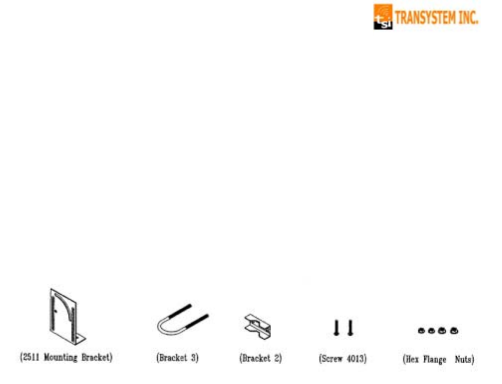
2.1.1 Mounting Bracket Assembly Suite
The following hardwares are suggested for mounting the Transmitter to
the pole. A set of mounting bracket includes ONE 2511 mounting bracket,
ONE bracket 3, ONE bracket 2, TWO screws 4013, and FOUR hex flange
nuts. Please contact TSI sales department for this accessory.
6
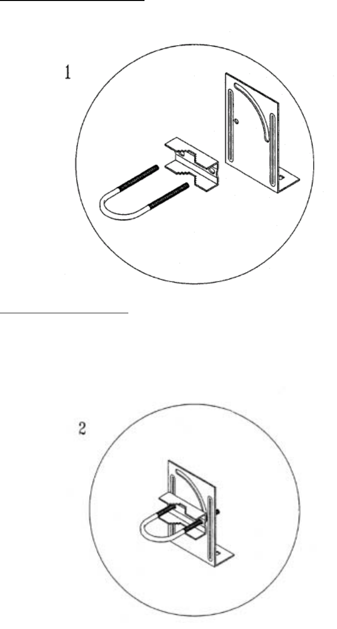
2.1.2 Step by Step Installation
Step 1 – Attach sequence
Left to right: Bracket 3, Bracket 2, and 2511 Mounting Bracket.
Step 2 – How to Attach
The concave of Bracket 2 is for holding onto the pole.
7
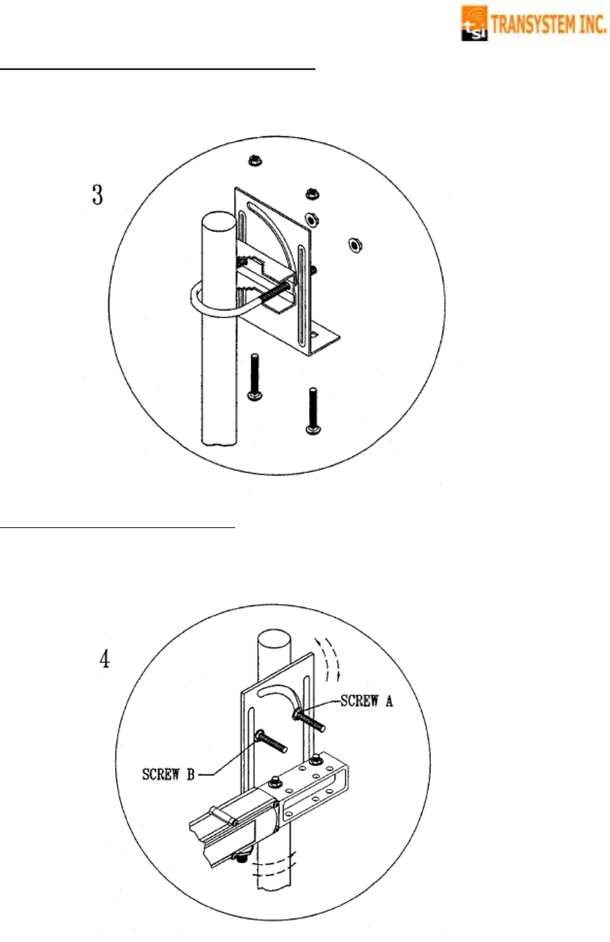
Step 3 – Tighten the bracket against pole
Step 4 – Installation Complete
Loosen Screws A & B for left-and-right and up-and-down angle adjustments.
Tighten up Screws A & B after fixing the directions.

8
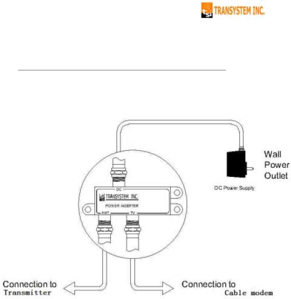
2.2 Connection to the Power Inserter and Cable Modem
Connections to the Transmitter are shown in diagram 2.2. Please note:
① The power inserter normally has 3 ports:
DC Connect to wall adapter with RG-59 cable
ANT Connect to the Transmitter
TV Connect to Cable modem
VERY IMPORTANT NOTICE!
a. The power inserter should be correctly connected, or the Transmitter
will not operate.
b. Ensure that all wires and cables are hooked up before plugging into
the AC adapter/power supply (i.e. you must hook up the power supply
last).
9
② After connection, the F connector of Transmitter must be sealed with an
asphalt sealing tape. (For details, please refer to Section 2.3 Waterproofing
Connections)
Diagram 2.2: Connection to Cable modem & Power Inserter
10
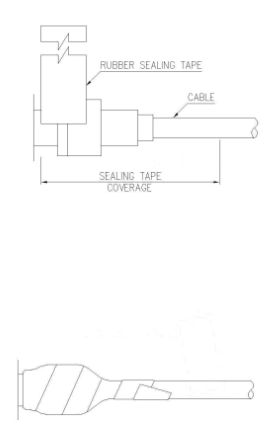
2.3 Waterproofing Connections
Water-proofing is very important during installation of Transmitter.
Please use the included water-proof asphalt tape to seal off the
F-connector as shown below:
① After you plug in the coaxial cable into the F-connector, use the included
water-proofing asphalt tape to seal off the F-connector from the bottom (i.e.
the part close to Transmitter). Note that the tape must wrap up all the thread
of the F-connector.
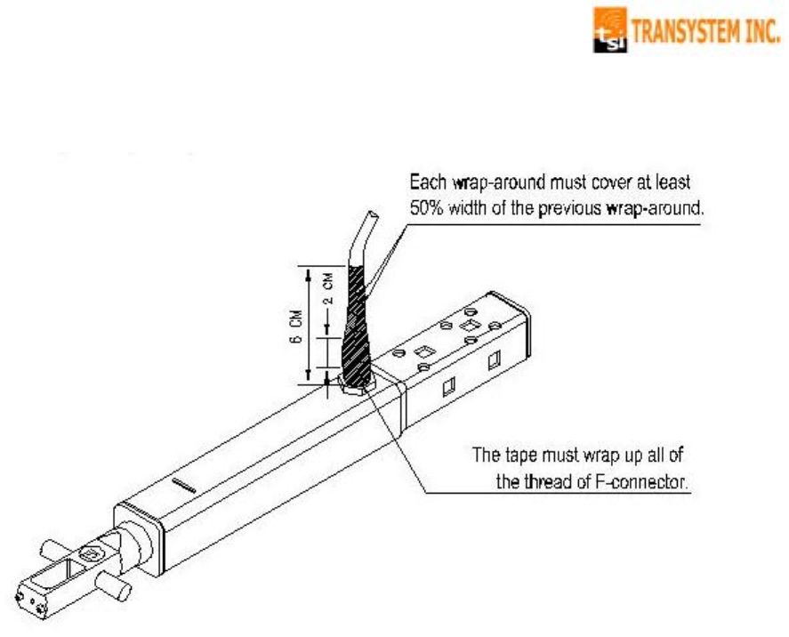
② The wrap up of the tape must be tight and sturdy. Each wrap-around must
cover at least 50% width of the previous wrap-around.
11
③ The total width of the wrap-around is about 6cm, which corresponds to 7
to 8 rounds of tapes.
* Warning: If you do not follow the above procedure, the Transmitter could
become malfunctioning due to water leakage.
FCC Notices
This device complies with Part 15 of the FCC Rules. Operation is subject to the condition
that this device does not cause harmful interference.
CAUTION: Change or modification not expressly approved by the party responsible for
compliance could void the user’s authority to operate this equipment.
This equipment must be installed and operated in accordance with provided instructions
and the antenna(s) used for this transmitter must be installed to provide a separation
distance of at least 20 cm from all persons and must not be co-located or operating in
conjunction with any other antenna or transmitter. End-users and installers must be
provide with antenna installation instructions and transmitter operating conditions for
satisfying RF exposure compliance.
This equipment has been tested and found to comply with the limits for a Class B
digital device, pursuant to Part 15 of the FCC Rules. These limits are designed to provide
reasonable protection against harmful interference in a residential installation. This
equipment generates, uses and can radiate radio frequency energy and, if not installed
and used in accordance with the instructions, may cause harmful interference to radio
communications. However, there is no guarantee that interference will not occur in a
particular installation. If this equipment does cause harmful interference to radio or
television reception, which can be determined by turning the equipment off and on, the
user is encouraged to try to correct the interference by one or more of the following
measures:
--Reorient or relocate the receiving antenna.
--Increase the separation between the equipment and receiver.
--Connect the equipment into an outlet on a circuit different from that to which the receiver
is connected.
--Consult the dealer or an experienced radio/TV technician for help.
CAUTION:
Any changes or modifications not expressly approved by the grantee of this device could
void the user's authority to operate the equipment.

P
PL
LC
C-
-2
20
00
0
Rev: 0.7
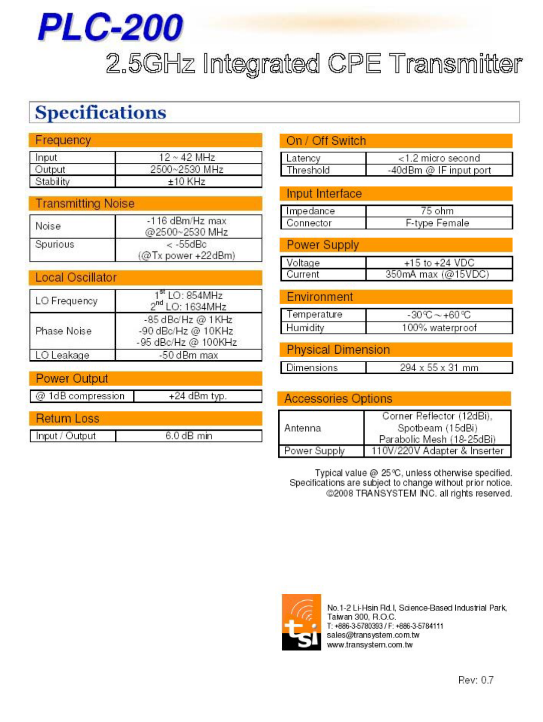
Overview
PLC-200 is TSI’s latest offering for 2-way
wireless broadband Internet application. It
accepts an IF signal of 12~42MHz from cable
modem, upconverts the signal to 2500~2530MHz
and transmits it back to the MMDS headend site.
With a built-in automatic on/off switch, PLC-200
will enter sleep mode to eliminate broadband
noise when there is no data packet transmission.
Without exception, PLC-200 embodies the long
term stability and reliability common to all TSI
products.
Together with TSI’s high quality downconverters,
PLC-200 provides the best cost / performance
solution for your 2-way MMDS operation.
Key Features
• QPSK, 16 QAM Transmission Compatible
• Automatic On/Off switch
• Up to 50Km cell coverage
• Integrated dipole, saves a passive dipole
• Easy installation with various antennas
• Low phase noise
• High frequency stability
• Low power consumption
• Meet FCC spectral mask requirement
• Light-weighted, saves shipping cost
• RoHS compliant
Application
• MMDS CPE Internet access
TRANSYSTEM INC.
An A
+
supplier of RF microwave & GPS products