Trane CG PRC011 EN User Manual To The Ee80ad62 E613 4981 B548 Ed53a0a6498f
User Manual: Trane CG-PRC011-EN to the manual
Open the PDF directly: View PDF ![]() .
.
Page Count: 40
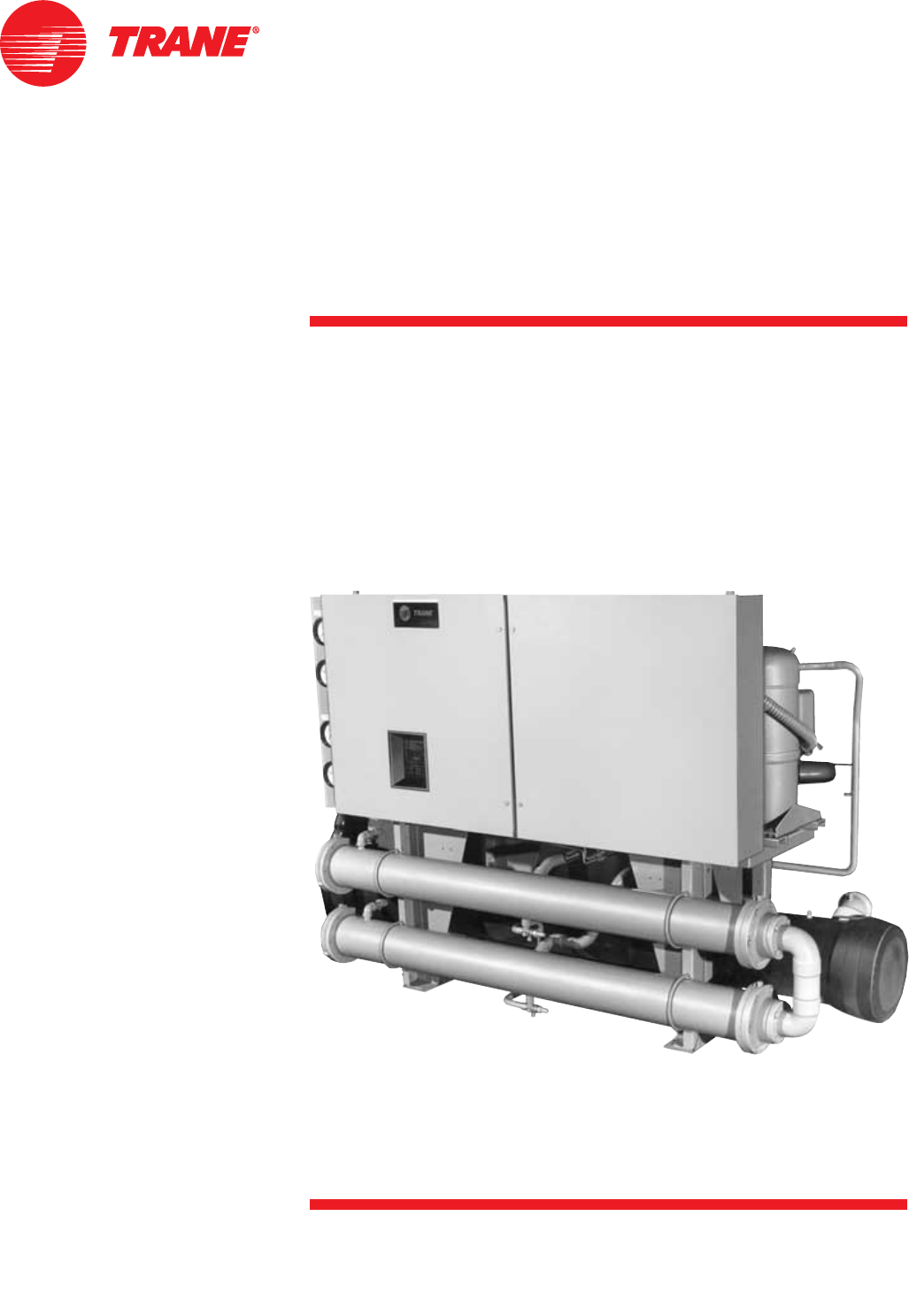
Scroll Liquid Chillers
20 to 60 Tons (60 Hz)
17 to 50 Tons (50 Hz)
Water-Cooled and Condenserless
CG-PRC011-EN
January 2002
Built For the Industrial and Commercial Markets

CG-PRC011-EN© 2002 American Standard Inc. All rights reserved.
Features and
Benefits
More Than Just Another “Improved”
Chiller
— Advanced Design
— Better Reliability
— Superior Efficiency
— Smarter Microprocessor Control
— Better Availability
— Easier To Install and Operate
The Trane 20-60 Ton Scroll Liquid Chiller
Evaporator Leaving
Water Piping
Design
The Trane scroll compressor is the most
advanced compressor in the industry.
Reliability
64 percent fewer compressor parts,
compared to reciprocating compressors,
mean long and reliable life.
Efficiency
CGWE scroll chillers meet and exceed
ASHRAE Standard 90.1 full and part load
efficiencies. Part load efficiencies are
simply unmatched by reciprocating
chillers.
Control
Advanced and complete safety and
control algorithms available.
Availability
Fast ship cycles on both stock and built-
to-order specials.
Installation
Small unit size, factory wiring, easy
lifting provisions, and start-up control
logic mean quick and easy setup.
Chillers fit through standard single-
width door.
Operation
Smart safety features and over 40
diagnostic displays mean easy and
virtually trouble-free operation.
Power Supply Monitor Protects
Compressors From Phase Loss, Phase
Reversal, Phase Imbalance, Incorrect Phase
Sequence and Under and Over Voltage
Rugged Trane
Scroll
Compressor
Control
Panel
Microprocessor
Operator
Interface
Condenser
Leaving
Water Piping
Condenser
Entering
Water Piping
3
CG-PRC011-EN
Contents
Features and Benefits
Model Number Description
General Data
Application Considerations
Selection Procedure
Performance Adjustment Factors
Performance Data
Electrical Data
Jobsite Connection
Controls
Dimensional Data
Weights
Options
Typical Wiring Diagrams
Features Summary
Mechanical Specifications
2
9
10
11
12
13
15
24
26
28
29
34
35
36
38
39

CG-PRC011-EN4
Standard Features
Microprocessor Control
Microprocessor control means the scroll
chiller maintains chilled water
temperature more accurately, resulting in
less temperature drift in the building. The
microprocessor control also incorporates
optimal chiller start-up logic (low and
high ambient), load limiting, compressor
anti-recycle timing, auto lead/lag
function, compressor protection, and
many other safety features. The “smart”
safety features provide complete fault
protection without nuisance tripping.
BENEFIT: consistent, reliable operation,
longer life.
Leaving Chilled Water
Temperature Control
The microprocessor actually monitors
temperature and the rate of change over
time, effectively controlling compressor
loading for efficient chiller operation.
BENEFIT: accurate and efficient building
comfort, less energy wasted.
Diagnostics and Display
The microprocessor’s operator interface
is a menu-driven digital display. The
display provides temperatures,
pressures, setpoints and diagnostics
readouts. Flashing display notifies
operator of fault condition and
diagnostics are saved until manually
reset.
BENEFIT: easy troubleshooting and
control
Compressor Protection
All compressors are individually
protected against starting and running
overload, under and over voltages,
phase loss, phase reversal, high winding
temperature and rapid recycling.
BENEFIT: long unit life and added
reliability.
External Control
Several external contacts are provided
for custom control requirements
including time of day scheduling and kW
demand limiting.
BENEFIT: more standard control and
more flexible owner upgrades.
Other Standard Features
•Control power transformer
•Auto lead/lag (on or off)
•Solid-state motor protection
•Insulation (Armaflex II or equal)
•Evaporator and condenser water pump
interlocks
•Filter-dryer
•Built-in loss of chilled water flow
sensors
•Chillers fit through standard single
width door.
The standard ARI rating condition
(54/44°F and 85°F/3.0 gpm per ton) and
IPLV are ARI certified. All other ratings,
including the following, are outside the
scope of the certification program and
are excluded:
• Glycol.
• 50 Hz.
• Condenserless models CCAD.
Options
•Trane Integrated Comfort™ systems
communication
•Generic building automation systems
(BAS) interface
•Chilled water reset (ambient, zone,
return)
•Ice making
•Hot gas bypass
•Remote display/control panel
•Remote running indication and alarm
contact
•Unit-mounted disconnect
•Gauges
•Sound Attenuation
•Neoprene Isolators
•Compressor cycle counter/hour meter
•Water regulating valves
•Condenser water temperature sensors
Water Chiller Systems Business Unit
Features and
Benefits

5
CG-PRC011-EN
Leading in Efficiency and Reliability with State-Of-The-Art
Scroll Compressor Technology
Efficiency
The energy efficiency of the scroll chiller
results in energy costs lower than any
other comparable chiller. Full load
efficiencies are improved beyond
reciprocating chillers, but part load
efficiencies are simply unmatched by any
other manufacturer.
Superior efficiencies are obtained by
combining many of the traditional scroll
chiller energy efficient features with the
Trane scroll compressor technology.
HERE’S HOW:
• Scroll compressor’s positive
displacement design
• Dual refrigerant circuits (40-60 ton units)
• Multiple compressors
• Optimum system design
• Reduced friction
• No valves
• Advanced heat transfer surfaces
Chart illustrates low torque variation of the
Trane scroll compressor vs reciprocating
compressor.
Graph illustrates Trane scroll chiller’s superior annual energy costs vs typical reciprocating
chillers.
Features and
Benefits
Operating Torque
Reliability
The Trane scroll chiller with many new
improvements, now brings an exciting
new compressor to the commercial
market — the Trane scroll compressor.
Trane has designed the scroll
compressor to be a leader in reliability.
HERE’S HOW:
• Simple design with 64 percent fewer
parts than equal capacity reciprocating
compressor.
• Scroll compliance allows liquid and dirt
to pass through without damaging
compressor (liquid slugging resistant).
• Advanced microelectronics protect both
compressor and motor from typical
electrical fault conditions.
• Scroll compressors have less than a
third the torque variations of a
reciprocating compressor.
• Years of laboratory testing have
optimized compressor and chiller
systems reliability.
• Water-cooled scroll chillers are factory
tested.
ASHRAE Standard 90.1
All Trane
chillers meet and exceed the new
efficiency levels mandated by ASHRAE
Standard 90.1. This new standard
requires higher efficiencies than past
technologies can deliver. In fact, energy
efficiency is so paramount the US
Federal Government has adopted
standard 90.1. Federal Executive Order
mandates energy consuming devices
procured must be in the top 25% of their
class. In the case of chillers, ASHRAE
90.1 is the product standard for
measurement.
Risk.
Not only has ASHRAE 90.1 been
adopted by the US Federal Government,
it’s expected to be adopted domestically,
if not globally, in the future. Make sure
that your chillers as well as your entire
HVAC system complies, or you may be
caught retrofitting your project with new
equipment and paying extra design
dollars if the code changes during
construction.
Trane’s CGWE was designed with the
end user’s requirements in mind.
Efficiency and reliability were primary
design concerns with this latest
generation machine.
Scroll Chiller Energy Usage Savings
Kilowatt Hours
Chiller Load (%)
Typical Reciprocating
Chiller
Scroll Chiller
10-20% Annual Energy Savings
CG-PRC011-EN6
Trane Scroll Compressor
— Maximum Efficiency with Enhanced Reliability
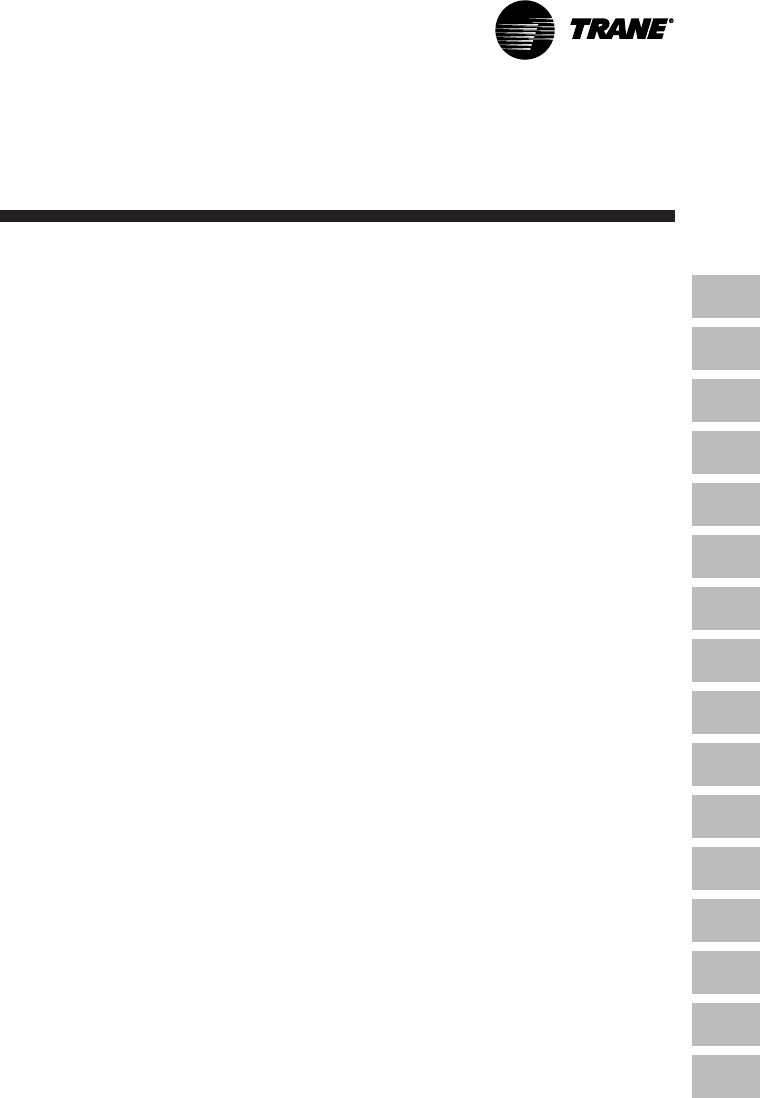
General
The scroll compressor has two scrolls.
The top scroll is fixed and the bottom
scroll orbits. Each scroll has walls in a
spiral shape that intermesh.
Inlet-First Orbit
As the bottom scroll orbits, two
refrigerant gas pockets are formed and
enclosed.
Compression-Second Orbit
The refrigerant gas is compressed as the
volume is reduced closer to the center of
the scroll.
Discharge-Third Orbit
The gas is compressed further and
discharged through a small port in the
center of the fixed scroll.
Scroll Principal Components
This is a cutaway view of a hermetic,
scroll compressor, showing the relative
positions of the principal components.
Shown is a Trane 10-ton, 3600 rpm, 60 Hz
[3000 rpm, 50 Hz] scroll compressor as
an example.
The principle of operation of this
example compressor is as follows: The
suction gas is drawn into the compressor
at A. The gas then passes through the
gap between the rotor and stator, B,
cooling the motor, before it enters the
compressor housing, C. Here, the
velocity of the gas is reduced, causing a
separation of the entrained oil from the
gas stream. The gas then enters the
intake chamber, D, that encircles the
scrolls.
Finally, the suction gas is drawn into the
scroll assembly where it is compressed
and discharged into the dome of the
compressor. The dome of this example
compressor acts as a hot gas muffler
which dampens the pulsations before the
gas enters the discharge line, E.
Features and
Benefits

7
CG-PRC011-EN
Packed Stock For Fast Delivery
When your project is a fast-track job,
Trane can help. A wide range of chillers
are stocked and can be shipped soon
after receipt of your order.
Build To Order
Need a special chiller fast? Think Trane
scroll chillers. New manufacturing
technology and inventory control means
the fastest delivery schedule in the
industry. Wide array of standard options
provides the right chiller for the job fast.
Installation
• Only one power connection hook-up —
for fast and inexpensive installation.
• Integrated Comfort™ system means
only single pair connections are
required for control interfaces and
therefore, lower total installation costs.
• Factory refrigerant and oil charged
units help speed installation.
• All units easily fit through a standard
single width door.
• Built-in chilled water flow sensors
mean no field-installed flow switches
are required.
• Microprocessor displays both entering
and leaving chilled water temperatures.
No chilled water thermometers are
required.
Easy Serviceability
Trane 20 through 60 ton scroll chillers
are designed with service personnel in
mind. All major components are
replaceable without complete unit
disassembly. Plus, the microprocessor
control panel provides diagnostic
capability to aid service personnel in
analyzing problems. Therefore, if a
problem does occur, the chiller can be up
and running in a shorter period of time.
Quick and Complete Submittals
The Trane commitment to value-added
products doesn’t stop at just the
products, we are committed to total
customer satisfaction. Part of this
commitment is to provide quick,
complete, readable and accurate
drawings.
Trane Value Means Fast Availability,
Easy Installation and Quality Service
Single-Source Responsibility
A wide range of products designed for
complete compatibility are available with
the scroll chillers. Your entire building
comfort system can be completed using
components from Trane.
The Added Value of Applications
Expertise
With the scroll chiller you get
applications expertise and know-how
from a Trane sales engineer. Trane has
more than 1500 sales engineers across
the country — each one a degreed
engineer. Trane sales engineers have
creative ideas and solutions to difficult
building comfort system design
problems. You can take full advantage of
their knowledge in designing a quality,
dependable comfort system.
There’s more. Your Trane sales engineer
is backed by the Trane world
headquarters staff of applications
experts, regarded as the best in the
industry. The C.D.S. Network provides
Trane sales engineers — and many
independent design and consulting firms
— direct access to many comfort system
application, selection and design
programs.
You get a quality chiller, properly
selected and applied in a properly
designed system. That means a comfort
system that works, the first time!
Features and
Benefits

CG-PRC011-EN8
Trane Integrated Comfort
System
The Future Is Now!
Simple
•Factory packaging for smooth start-up.
•Easy to install with only a single twisted
wire pair to the central Tracer building
management system.
•Constant, comprehensive monitoring
tracks equipment operation and takes
control to keep tenants comfortable.
•Optional override buttons on each floor
allow tenants to have control after
hours. After-hours use is automatically
logged to allow tenant billing.
•Review building performance at a
glance with automatically generated
reports and logs.
•Enhanced service and building
management capability through remote
diagnostics and control.
•Trane Building Management Network
allows control from across town or
across the country.
A Dependable System From A Single,
Reliable Source
•System design, equipment supply and
service support all available from Trane.
•Factory testing of all Trane equipment
ensures the system works.
The Trane Difference —
The Integrated Comfort™ System
No Other Microprocessor Does More So
You Can Do Less
The new microprocessor control system
enhances the Trane scroll chiller by
providing advanced technology to
control chiller operation and associated
sensors, actuators, relays and switches.
•Operator interface is improved and
easy to use. Panel displays all operating
and safety codes with complete
diagnostic information. Over 40
diagnostics are included.
•Smart safety features shut down
cooling only if absolutely necessary,
preventing nuisance safety trip outs.
•Microprocessor easily interfaces with
Trane Tracer™ building management
computer for Integrated Comfort
system benefits; all with a single
twisted pair wire!
Twisted Pair
Communications
Connects To:
Trane Integrated
Comfort Systems
(No System Control Panel
(SCP) is necessary)
At A Lower Cost
•Factory packaged controls and sensors
reduce jobsite labor costs while
assuring proper installation.
•Single twisted pair wire
communication technology
dramatically simplifies installation and
reduces jobsite installation costs.
•Because the unit has been factory
tested, there are no system problems;
allowing smoother start-up, reducing
follow-up costs.
•Building block approach allows you to
change your system without
redundancy and wasted cost.
No Bad Jobs
There is another benefit from single-
source responsibility and the Trane
Integrated Comfort systems. With Trane
ICS, you get a single-source supplier of
the system — from the chillers to the air
handlers to the controls. Trane is the
only HVAC manufacturer which can
provide the entire system.
For more information on how Trane
scroll chillers and an Integrated Comfort
system can benefit your next HVAC
project, contact your nearest Trane sales
office.
Features and
Benefits
9
CG-PRC011-EN
Model Number
Description
Digits 01, 02, 03, – Chiller Series
CGW = Water-Cooled Scroll Chiller
CCA = Scroll Compressor Chiller
Digits 04, – Development Sequence
Digits 05, 06, 07 – Nominal Capacity
020 = 20 Tons (Simplex Circuit,
2 Compressors)
025 = 25 Tons (Simplex Circuit,
2 Compressors)
030 = 30 Tons (Simplex Circuit,
2 Compressors)
040 = 40 Tons (Duplex Circuit,
4 Compressors)
050 = 50 Tons (Duplex Circuit,
4 Compressors)
060 = 60 Tons (Duplex Circuit,
4 Compressors)
Digit 08 – Unit Voltage
D = 380/60/3
G = 200-230/60/3
N = 400/50/3
S = Special Customer Option
4 = 460/60/3
5 = 575/60/3
Digit 09 – Cooling Type
C = Standard Cooling
S = Special Customer Option
Digit 10, 11 – Design Sequence
XX = Factory Assigned
Digit 12 – Condenser Configuration
H = High Efficiency Condenser
0 = No Unit Condenser
(CCA, CUA Units)
Digit 13 – Control Interface
A = Standard Microprocessor Interface
B = Multi-Wire Interface (GBAS)
C = Chilled Water Reset Return Water,
No Comm.
D = Chilled Water Reset – Zone Air,
No Comm.
E = Ice-Making Control
F = Remote Display
G = Chilled Water Reset – Outside Air
S = Special Customer Options
T = Bi-Directional Interface (Tracer)
Digit 14 – Panel Connections
D = Disconnect Switch
S = Special Customer Option
T = Terminal Block
Model Number Description
CGW E020 4 C XX H A T 1 0 0 0 0 0 L A
1,2,3 4 5,6,7 8 9 10,11 12 13 14 15 16 17 18 19 20 21 22+
Digit 15 – Evaporator Leaving
Temperature
1 = Standard 40-60 F
2 = Low Temperature 25-39 F
3 = Low Temperature 10-25 F
4 = Icemaking 20-60 F
S = Special Customer Option
Digit 16 – Remote Alarm Contacts
0 = No Remote Alarm Contacts
R = Remote Alarm Contacts
Digit 17 – Condenser Entering
Temperature
0 = Remote Condenser
1 = Standard Temperature 60-90 F
4 = High Temperature 90-130 F
S = Special Customer Option
Digit 18 – Evap Tube Type
F = Standard Finned Tubes
S = Special Customer Option
Digit 19 – Cond Tube Type
0 = Remote Cond
F = Standard Finned Tubes
S = Special Customer Option
Digit 20 – Hot Gas Bypass
0 = Without Hot Gas Bypass
B = With Hot Gas Bypass
Digit 21 – Water Box Orientation
L = Left Hand
R = Right Hand
S = Special Customer Option
Digit 22+ – Add-on Options
A = Unit Sound Attenuator
C = CSA Listing
G = Unit Gauges
H = Hour Meter and Cycle Counter
L = Low Ambient Lock-Out Thermostat
P = Phase Reversal Protection
R = Remote Display
T = Tracer Monitoring Package
U = UL Listing
CG-PRC011-EN10
Table GD-1 — General Data — CGWE Water-Cooled Chiller
Size 20 25 30 40 50 60
Compressor
Quantity (1) 2 2 2 2/2 2/2 2/2
Nominal Size (tons) (2) 10/10 10/15 15/15 10-10/10-10 10-15/10-15 15-15/15-15
Steps of Unloading (%) 100,50 100,60 100,50 100,75,50,25 100,80,60,30 100,75,50,25
Evaporator
Water Storage (Gallons) 12 11 16 13 21 40
(Liters) 45 42 61 49 80 151
Min. Flow (GPM) 24 30 36 48 60 84
(L/Sec) 1.5 1.9 2.3 3.0 3.8 4.7
Max. Flow (GPM) 72 90 108 144 180 252
(L/Sec) 4.5 5.7 6.8 9.1 11.4 17.3
Condenser
Water Storage (Gallons) 8.9 8.0 11.7 19.9 18.2 23.5
(Liters) 33.7 30.3 44.3 75.3 68.9 88.9
Min. Flow (GPM) 30 36 50 60 72 90
(L/Sec) 1.9 2.3 3.2 3.8 4.5 5.7
Max. Flow (GPM) 90 108 146 180 216 325
(L/Sec) 5.7 6.8 9.2 11.4 13.6 20.5
General Unit
Refrigerant R-22 R-22 R-22 R-22 R-22 R-22
No. of Independent
Refrigerant Circuits 1 1 1 2 2 2
Refrigerant (lb) 50 50 90 50/50 50/50 75/75
Charge (kg) 22.7 22.7 40.8 22.7/22.7 22.7/22.7 34/34
Oil Charge (Pints) 16 22 28 16/16 22/22 28/28
(L) 7.6 10.4 13.2 7.6/7.6 10.4/10.4 13.3/13.3
Notes
1. Data containing information on two circuits shown as follows: CKT 1/CKT 2
2. Nominal compressor sizes based on 69 Hz.
Table GD-2 — General Data — CCAD Compressor-Chiller
Size 20 25 30 40 50 60
Compressor
Quantity (1) 2 2 2 2/2 2/2 2/2
Nominal Size (tons) (2) 10/10 10/15 15/15 10-10/10-10 10-15/10-15 15-15/15-15
Steps of Unloading (%) 100,50 100,60 100,50 100,75,50,25 100,80,60,30 100,75,50,25
Evaporator
Water Storage (Gallons) 12 11 16 13 21 19
(Liters) 45 42 61 49 80 72
Min. Flow (GPM) 24 30 36 48 60 84
(L/Sec) 1.5 1.9 2.3 3.0 3.8 4.7
Max. Flow (GPM) 72 90 108 144 180 252
(L/Sec) 4.5 5.7 6.8 9.1 11.4 17.3
General Unit
Refrigerant R-22 R-22 R-22 R-22 R-22 R-22
No. of Independent
Refrigerant Circuits 1 1 1 2 2 2
Refrigerant (lb) 6 8 12 6/6 8/8 12/12
Charge (kg) 2.7 3.6 5.4 2.7/2.7 3.6/3.6 5.5/5.5
Oil Charge (Pints) 16 22 28 16/16 22/22 28/28
(L) 7.6 10.4 13.2 7.6/7.6 10.4/10.4 13.3/13.3
Notes:
1. Data containing information on two circuits shown as follows: CKT 1/CKT 2
2. Nominal compressor sizes based on 69 Hz.
General Data

11
CG-PRC011-EN
Unit Location
Units should be installed indoors where
exposure to rain or water splash is
minimal. A level foundation or flooring
must be provided which will support at
least 150 percent of the operating weight
of the unit. The chiller foundation must be
rigid to reduce vibration transmission to a
minimum. Use of vibration isolators is
recommended for applications with
sensitive vibration and noise criteria.
Allow service clearance for compressor
removal as well as evaporator and
condenser tube removal.
Condenser Water Limitations
Water-cooled scroll chillers start and
operate satisfactorily over a range of load
conditions with uncontrolled entering
water temperature.
Reducing the condenser water
temperature is an effective method of
lowering the power input required.
However, by reducing the condenser
water temperature beyond certain limits,
the effect causes a reduction in the
pressure drop across the thermal
expansion valve to a point when system
instability may occur.
In general, continuous machine operation
with entering condenser water
temperature below 60°F [15.5°C] is not
recommended. When the condenser
water temperature is expected to drop
below 60°F [15.5°C], it is recommended
that some form of condenser water
temperature control be used to ensure
optimal machine performance.
Water Treatment
Use of untreated or improperly treated
water in chillers may result in scaling,
erosion, corrosion, algae or slime. It is
recommended that the services of a
qualified water treatment specialist be
engaged to determine what treatment, if
any, is advisable. Trane assumes no
responsibility for the results of untreated,
or improperly treated water.
Water Pumps
Avoid specifying or using 3600 rpm, 60
Hz [3000 rpm, 50 Hz] condenser water
and chilled water pumps. Such pumps
may operate with objectional noise and
vibration. In addition, a low frequency
beat may occur due to the slight
difference in operating rpm between
water pumps and scroll compressor
motors. Where noise and vibration-free
operation is important, Trane
encourages the use of 1750 rpm, 60 Hz
[1450 rpm, 50 Hz] pumps.
Remote Condenser
Remote condensers should be located
as close as possible to the chiller to
ensure minimum pressure drops of
discharge refrigerant. If non-Trane
condensers are provided, a subcooling
circuit must be provided in order to
achieve cataloged performances
(16°F [-8.9°C] subcooling).
Application
Considerations
CG-PRC011-EN12
Selection
Procedures
The chiller capacity tables on the
following pages cover the most
frequently encountered leaving water
temperatures. For temperature drops
other than 10°F [5.6°C], refer to Table
SP-1, Performance Adjustment Factors,
shown below.
Additional chiller selections and
performance information can be
obtained through your local Trane sales
office.
To select a Trane water-cooled scroll
chiller, the following information is
required:
1. Design load in tons of refrigeration
2. Design chilled water temperature drop
3. Design leaving chilled water
temperature
4. Entering condenser water temperature
Evaporator flow rate (gpm) can be
determined by using the following
formula:
gpm = Tons x 24
Chilled Water T (°F)
Condenser flow rate (gpm) can be
determined by using the following
formula:
gpm =
24 x (tons + (0.285 x compressor kW)
Condenser Water T (°F)
Scroll Liquid Chiller — (CGWE) —
Selection Example:
Given:
System Load = 40 tons
Leaving Chilled Water Temperature
(LCWT) = 44°F [6.7°C]
Entering Condenser Water Temperature
(EWT) = 85°F [29.4°C]
Leaving Condenser Water Temperature
(LWT) = 95°F [35°C]
Chilled Water Temperature Drop
= 10°F [5.6°C]
1. From Table PD-2 (Performance Data), a
CGWE 40 at the given conditions will
produce 39.4 tons with a compressor
power input of 30.3 kW and a unit EER
of 15.6.
2. To determine the evaporator and
condenser water pressure drops, the
flow rates (gpm) must be determined.
Using the formula above, this unit
would require an evaporator flow rate
of 95 gpm and a condenser flow rate
of 115 gpm. (Compressor kW is found
in the same table as the capacity.) The
Evaporator Pressure Drop Curve,
Figure PD-1, indicates that 95 gpm
through a 40 ton evaporator results in
a pressure drop of 13.8 feet of water.
The Condenser Pressure Drop curve,
Chart PD-2, indicates 115 gpm through
a 40 ton condenser results in a
pressure drop of 14 feet of water.
3. The final unit selection is:
— Qty (1) CGWE 40
— Cooling Capacity = 39.4 tons
— Entering/Leaving Chilled Water
Temperatures = 54/44°F [12.2/6.7°C]
— Chilled water flow rate = 95 gpm
— Evaporator water pressure drop =
13.8 feet
— Cooling water flow = 115 gpm
— Condenser water pressure drop =
14 feet
— Compressor power input = 30.3 kW
— Unit EER = 15.6
Compressor Chiller – (CCAD) – Selection
Example:
Select the unit for the following
conditions:
A compressor chiller is required to
produce 45 tons when matched with an
air-cooled condenser. The leaving chilled
water temperature is 44°F [6.7°C]. The
evaporator temperature differential is
10°F [5.6°C]. The ambient temperature is
95°F [35°C].
1. Select the nominal unit size. The
performance data is tabulated by
leaving chilled water temperature. For
example, the standard unit capacities
at 44°F [6.7°C] leaving chilled water
temperature are found on page 21.
The system that best meets the
tonnage requirement is a CCAD 50
matched with a CAUC C50. The unit
capacity is 47.1 tons with a kW input of
56.3. The compressor chiller EER is
10.0.
2. Calculate the required chilled water
flow rate.
3. gpm = Tons x 24
Chilled Water T (°F)
From this example,
gpm = 47.1 x 24 = 113
10
4. Determine the evaporator water
pressure drop. The evaporator water
pressure drop is located on page 22.
Entering the evaporator chart at 113
gpm, the pressure drop for a CCAD 50
evaporator is 7.9 feet.
5. Unit Selection
The above procedure shows the
proper selection for this example is a
CCAD 50 with a CAUB C50 condenser
operating as follows:
— Capacity = 47.1
— Entering/leaving chilled water
temperature = 54/44°F [12.2/6.7°C]
— Chilled water flow rate = 113 gpm
— Evaporator water pressure drop =
7.9 feet
— Compressor power input = 56.3
— Unit EER = 10.0
Table SP-1 – Performance Adjustment
Factors
Fouling Water Evap. Cond.
Factor Delta T Capacity GPM kW GPM
8 0.997 1.231 1.000 0.997
0.00010 10 1.000 1.000 1.000 1.000
12 1.007 0.829 1.001 1.006
14 1.012 0.714 1.001 1.010
16 1.017 0.628 1.002 1.014
Note:
This selection procedure is for water only as the
solution.
13
CG-PRC011-EN
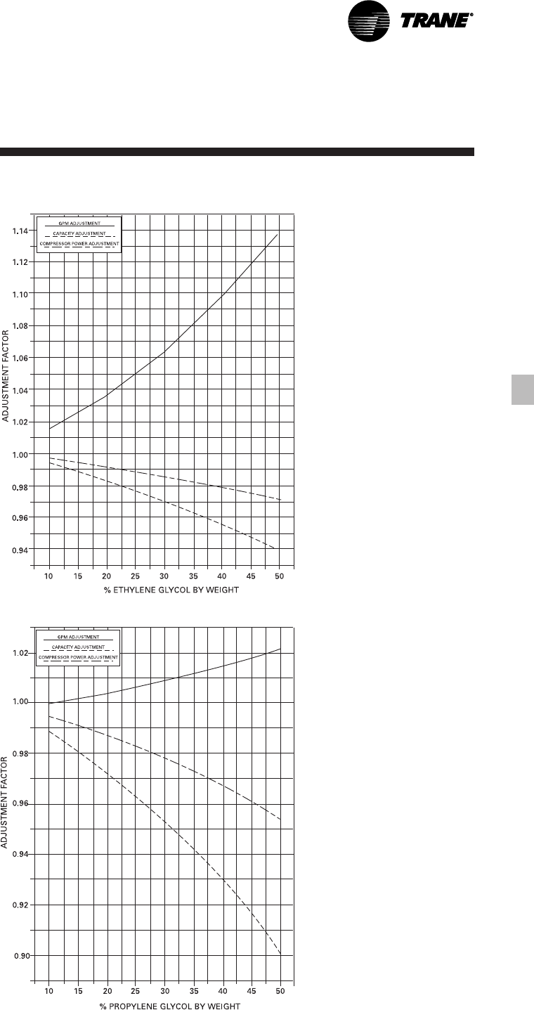
Figure PAF-1 – Ethylene Glycol Performance Adjustment Factors
Figure PAF-2 – Propylene Glycol Performance Adjustment Factors
Performance
Adjustment Factors
CG-PRC011-EN14
Table PAF-1 – Pressure Drop Correction Factor
Leaving
Water Percent Of Ethylene Glycol
Temperature 0 10 20 30 40 50
0 NA NA NA NA 1.50 1.60
10 NA NA NA 1.38 1.46 1.55
20 NA NA 1.26 1.34 1.42 1.51
30 NA 1.15 1.22 1.30 1.38 1.47
40 1.00 1.12 1.19 1.26 1.34 1.42
50 1.00 1.09 1.16 1.23 1.31 1.39
60 1.00 1.05 1.09 1.12 1.16 1.21
Table PAF-2 – Pressure Drop Correction Factor
Leaving
Water Percent Of Propylene Glycol
Temperature 0 10 20 30 40 50
0 NA NA NA NA 1.63 1.90
10 NA NA NA 1.42 1.55 1.74
20 NA NA 1.24 1.34 1.46 1.62
30 NA 1.11 1.19 1.28 1.39 1.53
40 1.00 1.07 1.15 1.23 1.33 1.45
50 1.00 1.04 1.11 1.19 1.28 1.39
60 1.00 1.00 1.03 1.08 1.13 1.20
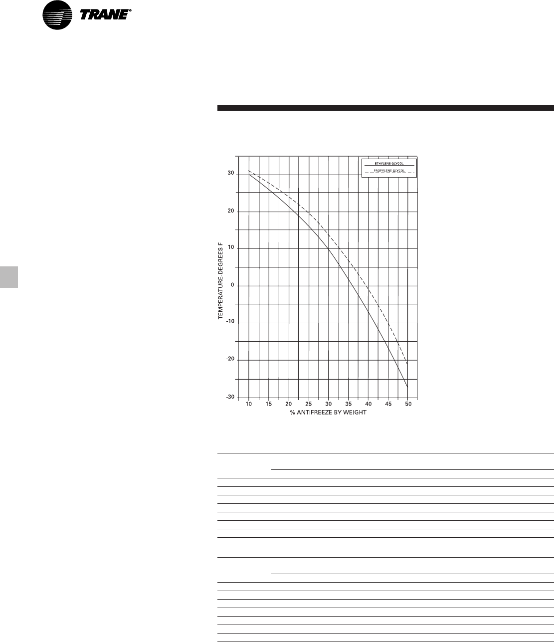
Figure PAF-3 – Ethylene Glycol and Propylene Glycol Solution Freezing Points
Performance
Adjustment Factors

15
CG-PRC011-EN
Table PD-1 – 60 Hz CGWE Performance Data in English Units
Evaporator Entering Condenser Water Temperature (F)
Leaving Wate Unit 75 80 85 90 95
Temperature (F) Size Tons kW EER Tons kW EER Tons kW EER Tons kW EER Tons kW EER
20 19.2 13.8 16.7 19.0 14.5 15.7 18.6 15.4 14.6 18.1 16.1 13.5 17.7 17.1 12.4
25 23.8 17.2 16.5 23.2 18.1 15.4 22.7 19.1 14.3 22.1 20.1 13.2 21.6 21.2 12.2
40 30 28.3 20.7 16.4 27.6 21.7 15.3 27.0 22.9 14.1 26.3 24.1 13.1 25.6 25.4 12.1
40 38.0 27.3 16.8 37.2 28.7 15.6 36.5 30.2 14.5 35.5 31.8 13.4 34.6 33.6 12.4
50 47.0 34.1 16.6 46.0 35.8 15.4 44.9 37.7 14.3 43.8 39.7 13.2 42.7 41.0 12.2
60 57.7 42.1 16.4 56.4 44.2 15.3 55.0 46.5 14.2 53.7 49.0 13.1 52.3 51.7 12.1
20 20.0 13.9 17.3 19.8 14.6 16.3 19.3 15.4 15.1 18.9 16.2 14.0 18.4 17.1 12.9
25 24.7 17.3 17.1 24.2 18.2 15.9 23.6 19.2 14.8 23.0 20.2 13.7 22.4 21.3 12.6
42 30 29.4 20.8 17.0 28.7 21.8 15.8 28.0 23.0 14.7 27.3 24.2 13.6 26.6 25.5 12.5
40 39.5 27.4 17.3 38.7 28.8 16.1 37.8 30.3 15.0 36.9 32.0 13.9 36.0 33.8 12.8
50 48.9 34.2 17.2 47.8 36.0 16.0 46.7 37.9 14.8 45.6 39.9 13.7 44.4 42.1 12.7
60 59.9 42.3 17.0 58.5 44.4 15.8 57.2 46.7 14.7 55.7 49.2 13.6 54.3 51.9 12.6
20 20.8 13.9 17.3 20.5 14.7 16.8 19.9 15.4 15.5 19.6 16.3 14.5 19.1 17.2 12.9
25 25.7 17.4 17.7 25.1 18.3 16.5 24.5 19.1 15.4 23.9 20.3 14.2 23.3 21.4 13.1
44 30 30.6 20.8 17.6 29.9 21.9 16.4 29.2 22.9 15.3 28.4 24.3 14.0 27.7 25.6 13.0
40 41.1 27.5 17.9 40.2 28.9 16.7 39.4 30.3 15.6 38.4 32.1 14.4 37.4 33.9 13.3
50 50.8 34.4 17.7 49.7 35.1 16.5 48.6 37.8 15.4 47.4 40.1 14.2 46.2 42.3 13.1
60 62.1 42.5 17.6 60.7 44.6 16.3 59.4 46.8 15.2 57.9 49.4 14.1 56.4 52.1 13.0
20 21.5 14.0 18.5 21.3 14.7 17.4 20.9 15.5 16.2 20.4 16.3 15.0 19.9 17.3 13.8
25 26.6 17.4 18.3 26.1 18.3 17.1 25.5 19.3 15.8 24.9 20.3 14.7 24.2 21.5 13.5
46 30 31.7 20.9 18.2 31.0 22.0 16.9 30.3 23.1 15.7 29.5 24.4 14.5 28.7 25.7 13.4
40 42.6 27.6 18.5 41.7 29.0 17.3 40.8 30.6 16.0 39.9 32.3 14.8 38.9 34.1 13.7
50 52.8 34.5 18.4 51.6 36.3 17.1 50.4 38.2 15.9 49.2 40.2 14.7 48.0 42.4 13.6
60 64.4 42.6 18.1 63.0 44.8 16.9 61.5 47.1 15.7 60.0 49.6 14.5 58.5 52.3 13.4
20 22.4 14.0 19.1 22.1 14.8 18.0 21.6 15.6 16.7 21.1 16.4 15.5 20.6 17.3 14.3
25 27.6 17.5 19.0 27.0 18.4 17.6 26.4 19.4 16.4 25.8 20.4 15.2 25.2 21.6 14.0
48 30 32.9 21.0 18.8 32.2 22.1 17.5 31.4 23.2 16.2 30.7 24.5 15.0 29.9 25.8 13.9
40 44.2 27.8 19.1 43.3 29.2 17.8 42.4 30.7 16.6 41.4 32.4 15.3 40.4 34.2 14.2
50 54.7 34.6 19.0 53.6 35.4 17.7 52.3 38.3 16.4 51.1 40.4 15.2 49.8 42.6 14.0
60 66.7 42.8 18.7 65.2 45.0 17.4 63.7 47.3 16.2 62.2 49.8 15.0 60.7 52.5 13.9
20 23.2 14.1 19.7 22.9 14.8 18.6 22.4 15.6 17.2 21.9 16.5 16.0 21.4 17.4 14.8
25 28.7 17.6 19.6 28.0 18.5 18.2 27.4 19.4 16.9 26.8 20.5 15.7 26.1 21.6 14.5
50 30 34.1 21.1 19.5 33.4 22.1 18.1 32.6 23.3 16.8 31.8 24.6 15.6 31.0 25.0 14.4
40 45.9 27.9 19.8 44.9 29.3 18.4 43.9 30.8 17.1 42.9 32.5 15.8 41.9 34.3 14.6
50 56.8 34.8 19.6 55.5 36.5 18.2 54.3 38.5 16.9 53.0 40.5 15.7 51.7 42.8 14.5
60 69.1 43.0 19.3 67.6 45.1 18.0 66.0 47.5 16.7 64.5 50.0 15.5 62.9 52.8 14.3
Notes:
1. Rated in accordance with ARI Standard 550/590-98 with fouling factors of 0.0001 in the evaporator and 0.00025 in the condenser.
2. Consult Trane representative for performance at temperatures outside of the ranges shown.
3. kW input is for compressors only.
4. EER = Energy Efficiency Ratio (Btu/watt-hout). Power inputs include compressors and control power.
5. Ratings are based on an evaporator temperature drop of 10°F.
6. Interpolation between points is permissible. Extrapolation is not permitted.
Performance
Data
Full Load
Performance
CG-PRC011-EN16
Table PD-2 – 60 Hz CGWE Performance Data in Metric Units
Evaporator Entering Condenser Water Temperature (C)
Leaving Water Unit 25 30 35
Temperature (C) Size kWo kWi COP kWo kWi COP kWo kWi COP
20 70.4 14.2 5.0 67.7 15.5 4.4 64.7 17.1 3.8
25 87.1 17.7 4.9 83.5 19.4 4.3 79.8 21.8 3.7
6 30 104.0 21.2 4.9 99.6 23.2 4.3 95.1 25.6 3.7
40 139.5 28.0 5.0 133.9 30.7 4.4 128.1 33.8 3.8
50 172.4 35.0 4.9 165.3 38.3 4.3 157.9 42.2 3.7
60 211.0 43.2 4.9 202.2 47.3 4.3 193.1 52.0 3.7
20 75.7 14.3 5.3 72.7 15.7 4.6 69.6 17.3 4.0
25 93.5 17.8 5.3 89.8 19.5 4.6 85.8 21.5 4.0
8 30 111.4 21.4 5.2 106.8 23.4 4.6 102.0 25.7 4.0
40 150.3 28.2 5.3 144.5 30.9 4.7 138.3 34.1 4.1
50 185.3 35.2 5.3 177.7 38.6 4.6 169.9 42.5 4.0
60 226.0 43.5 5.2 216.8 47.6 4.6 207.2 52.4 4.0
20 80.8 14.4 5.6 77.7 15.8 21.7 74.4 17.4 4.3
25 99.9 17.9 5.6 95.9 19.6 21.5 91.8 21.6 4.8
10 30 119.0 21.5 5.5 114.1 23.6 21.4 109.1 25.9 4.2
40 159.9 28.4 5.6 153.8 31.2 21.8 147.3 34.3 4.3
50 197.9 35.5 5.6 185.9 35.2 23.3 181.7 42.8 4.2
60 240.7 43.8 5.5 231.0 48.0 21.2 221.0 52.8 4.2
Notes:
1. Rated in accordance with ARI Standard 550/590-98 with fouling factors of 0.0000176 in the evaporator and
0.000044 in the condenser.
2. Consult Trane representative for performance at temperatures outside of the ranges shown.
3. kWi input is for compressors only.
4. COP = Coefficient of Performance (kWo/total kW). Total kW include compressors and control power.
5. Ratings are based on an evaporator temperature drop of 5.6 C.
6. Interpolation between points is permissible. Extrapolation is not permitted.
Performance
Data
Full Load
Performance
17
CG-PRC011-EN
Performance
Data
Table PD-3– 50 Hz CGWE Performance Data in English Units
Evaporator Entering Condenser Water Temperature (F)
Leaving Wate Unit 75 80 85 90 95
Temperature (F) Size Tons kW EER Tons kW EER Tons kW EER Tons kW EER Tons kW EER
20 19.2 13.8 16.7 19.0 14.5 15.7 18.6 15.4 14.6 18.1 16.1 13.5 17.7 17.1 12.4
20 16.8 11.1 18.1 16.4 11.7 16.8 16.0 12.4 15.5 15.6 13.1 14.3 15.3 13.9 13.1
25 20.7 13.9 17.9 20.3 14.6 16.6 19.8 15.5 15.4 19.4 16.3 14.2 18.9 17.3 13.1
42 30 24.6 16.7 17.7 24.1 17.5 16.5 23.6 18.5 15.3 23.0 19.5 14.1 22.5 20.7 13.0
40 33.2 21.9 18.2 32.5 23.1 16.9 31.8 24.4 15.6 31.0 25.9 14.4 30.2 27.4 13.2
50 41.0 27.4 17.9 40.1 28.9 16.7 39.2 30.5 15.5 38.3 32.2 14.3 37.4 34.1 13.1
60 50.4 33.8 17.9 49.3 35.6 16.7 48.2 37.5 15.4 47.1 39.6 14.3 46.0 41.9 13.2
20 17.4 11.1 18.8 17.1 11.7 17.4 16.7 12.4 16.1 16.3 13.2 14.9 15.9 13.9 13.7
25 21.5 13.9 18.6 21.1 14.7 17.3 20.6 15.5 16.0 20.1 16.4 14.8 19.6 17.3 13.6
44 30 25.6 16.7 18.4 25.1 17.6 17.1 24.5 18.5 15.9 24.0 19.6 14.7 23.4 20.7 13.5
40 34.5 22.0 18.9 33.8 23.2 17.5 33.0 24.5 16.2 32.2 25.9 14.9 31.4 27.5 13.7
50 42.6 27.5 18.6 41.7 29.0 17.3 40.8 30.6 16.0 39.9 32.3 14.8 38.9 34.2 13.6
60 52.3 33.9 18.5 51.2 35.7 17.2 50.1 37.6 16.0 48.9 39.7 14.8 47.7 42.0 13.7
20 18.1 11.2 19.5 17.7 11.8 18.1 17.3 12.4 16.7 16.9 13.2 15.4 16.5 14.0 14.2
25 22.4 13.9 19.2 21.9 14.7 17.9 21.4 15.5 16.6 20.9 16.4 15.3 20.4 17.4 14.1
46 30 26.6 16.7 19.1 26.0 17.6 17.7 25.5 18.6 16.5 24.9 19.6 15.2 24.3 20.8 14.0
40 35.8 22.0 19.6 35.1 23.2 18.2 34.3 24.5 16.8 33.5 26.0 15.5 32.7 27.5 14.2
50 44.3 27.6 19.3 43.3 29.0 17.9 42.4 30.6 16.6 41.4 32.4 15.4 40.4 34.3 14.2
60 54.2 34.0 19.1 53.1 35.8 17.8 51.9 37.7 16.5 50.8 39.8 15.3 49.5 42.1 14.1
20 18.8 11.2 20.2 18.4 11.8 18.8 18.0 12.5 17.3 17.6 13.2 16.0 17.2 14.0 14.7
25 23.2 14.0 19.9 22.7 14.7 18.5 22.2 15.5 17.2 21.7 16.4 15.9 21.2 17.4 14.6
48 30 27.6 16.8 19.7 27.0 17.7 18.4 26.5 18.6 17.0 25.9 19.7 15.8 25.2 20.8 14.5
40 37.2 22.0 20.3 36.4 23.2 18.8 35.6 24.6 17.4 34.8 26.0 16.1 34.0 27.6 14.8
50 45.9 27.6 20.0 45.0 29.1 18.6 44.0 30.7 17.2 43.0 32.4 15.9 42.0 34.3 14.7
60 56.1 34.1 19.8 55.0 35.9 18.4 53.9 37.8 17.1 52.6 40.0 15.8 51.4 42.2 14.6
20 19.5 11.2 20.9 19.1 11.8 19.4 18.7 12.5 18.0 18.3 13.2 16.6 17.8 14.0 15.3
25 24.1 14.0 20.6 23.6 14.8 19.2 23.1 15.6 17.8 22.6 16.5 16.4 22.0 17.4 15.1
50 30 28.6 16.8 20.4 28.0 17.7 19.0 27.5 18.7 17.6 26.8 19.7 16.3 26.2 20.9 15.1
40 38.6 22.1 21.0 37.8 23.3 19.5 37.0 24.6 18.0 36.1 26.1 16.6 35.3 27.6 15.3
50 47.6 27.7 20.7 46.7 29.1 19.2 45.7 30.8 17.8 44.6 32.5 16.5 43.6 34.4 15.2
60 58.1 34.2 20.4 57.0 36.0 19.0 55.8 37.9 17.7 54.5 40.1 16.3 53.3 42.3 15.1
Notes:
1. Rated in accordance with ARI Standard 550/590-98 with fouling factors of 0.00010 in the evaporator and 0.00025 in the condenser.
2. Consult Trane representative for performance at temperatures outside of the ranges shown.
3. kW input is for compressors only.
4. EER = Energy Efficiency Ratio (Btu/watt-hour). Power inputs include compressors and control power.
5. Ratings are based on an evaporator temperature drop of 10°F.
6. Interpolation between points is permissible. Extrapolation is not permitted.
Full Load
Performance

CG-PRC011-EN18
Table PD-4 – 50 Hz CGWE Performance Data in Metric Units
Evaporator Entering Condenser Water Temperature (C)
Leaving Water Unit 25 30 35
Temperature (C) Size kWo kWi COP kWo kWi COP kWo kWi COP
20 70.4 14.2 5.0 67.7 15.5 4.4 64.7 17.1 3.8
20 59.4 11.4 5.2 57.0 12.6 4.5 54.5 14.0 3.9
25 73.4 14.2 5.2 70.5 15.7 4.5 67.5 17.3 3.9
6 30 87.3 17.0 5.1 83.9 18.7 4.5 80.3 20.7 3.9
40 117.6 22.4 5.2 112.9 24.8 4.6 108.0 27.5 3.9
50 145.3 28.0 5.2 139.7 30.9 4.5 133.7 34.2 3.9
60 178.4 34.5 5.2 171.7 38.0 4.5 164.0 41.9 3.9
20 63.7 11.4 5.6 61.2 12.6 4.9 58.5 14.0 4.2
25 78.6 14.3 5.5 75.6 15.7 4.8 72.3 17.4 4.2
8 30 93.5 17.1 5.5 89.9 18.8 4.8 86.1 20.8 4.1
40 126.0 22.5 5.6 121.0 24.8 4.9 115.8 27.8 4.2
50 155.6 28.2 5.5 149.5 31.0 4.8 143.2 34.3 4.2
60 190.4 34.7 5.5 183.3 38.2 4.8 175.6 42.2 4.2
20 68.1 11.4 6.0 65.4 12.6 5.2 62.7 14.0 4.5
25 84.0 14.3 5.9 80.8 15.8 5.1 77.4 17.5 4.4
10 30 99.9 17.2 5.8 96.2 18.9 5.1 92.2 20.9 4.4
40 134.8 22.6 6.0 129.5 24.9 5.2 124.2 27.7 4.5
50 166.4 28.3 5.9 160.1 31.1 5.1 153.4 34.5 4.4
60 203.0 34.9 5.8 195.3 38.4 5.1 187.2 42.4 4.4
Notes:
1. Rated in accordance with ARI Standard 550/590-98 with fouling factors of 0.0000176 in the evaporator and
0.000044 in the condenser.
2. Consult Trane representative for performance at temperatures outside of the ranges shown.
3. kWi input is for compressors only.
4. COP = Coefficient of Performance (kWo/total kW). Total kW include compressors and control power.
5. Ratings are based on an evaporator and condenser temperature drop of 5.6°C.
6. Interpolation between points is permissible. Extrapolation is not permitted.
Performance
Data
Full Load
Performance
19
CG-PRC011-EN
Performance
Data
Part Load
Performance
Table PD-5 – Part-Load Performance for CGWE 20-60 Ton – 60 Hz in English Units
Unit Size 100% 75% 50% 25% IPLV
Tons 19.9 14.9 9.9 5.0
20 kW 15.2 9.4 5.3 2.7 20.3
EER 15.5 18.6 21.9 20.7
Tons 24.5 18.4 12.3 6.1
25 kW 19.0 11.6 6.5 3.4 20.5
EER 15.4 18.8 22.1 20.9
Tons 29.2 21.9 14.6 7.3
30 kW 22.8 14.1 7.8 4.0 20.3
EER 15.3 18.5 22.0 20.8
Tons 39.4 29.5 19.7 9.8
40 kW 30.1 18.7 10.3 5.2 20.7
EER 15.6 18.7 22.4 21.6
Tons 48.6 36.5 24.3 12.2
50 kW 37.6 23.6 14.4 6.7 19.6
EER 15.4 18.3 20.3 21.7
Tons 59.4 44.5 29.7 14.8
60 kW 46.5 28.3 17.4 7.8 19.8
EER 15.2 18.7 20.2 22.3
Notes:
1. IPLV values are rated in accordance with ARI Standard 550/590-98.
2. EER and IPLV values include compressor and control kW.
3. kW input is for compressors only.
Table PD-6 – Part-Load Performance for CGWE 20-60 Ton – 50 Hz in English Units
Unit Size 100% 75% 50% 25% IPLV
Tons 16.7 12.5 8.3 4.2
20 kW 12.4 7.8 4.4 2.3 21.0
EER 16.1 19.2 22.6 21.9
Tons 20.6 15.5 10.3 5.2
25 kW 15.5 9.7 5.5 2.9 20.9
EER 16.0 19.2 22.5 21.5
Tons 24.5 18.4 12.3 6.1
30 kW 18.5 11.7 6.6 3.5 20.7
EER 15.9 18.9 22.4 20.9
Tons 33.0 24.8 16.5 8.3
40 kW 24.5 15.3 8.6 4.5 21.3
EER 16.2 19.5 23.0 22.1
Tons 40.8 30.6 20.4 10.2
50 kW 30.6 19.0 11.7 5.6 20.3
EER 16.0 19.3 20.9 21.9
Tons 50.1 37.6 25.1 12.5
60 kW 37.6 23.3 14.4 6.6 20.4
EER 16.0 19.4 20.9 22.7
Notes:
1. IPLV values are rated in accordance with ARI Standard 550/590-98.
2. EER and IPLV values include compressor and control kW.
3. kW input is for compressors only.
CG-PRC011-EN20
Performance
Data
Table PD-7 – 60 Hz CCAD Performance Data in English Units
Evaporator Entering Condenser Air Temperature
Leaving Water Unit Condenser 85 95 105 115
Temperature (°F) Size Size Tons kW EER Tons kW EER Tons kW EER Tons kW EER
20 CAUC-C20 19.4 19.5 11.8 18.4 21.6 10.1 17.3 23.9 8.6 16.1 26.6 7.2
20 CAUC-C25 19.7 18.6 12.6 18.7 20.6 10.8 17.6 23.0 9.1 16.5 25.5 7.7
25 CAUC-C25 24.1 24.9 11.5 22.8 27.6 9.9 21.5 30.6 8.4 20.0 34.0 7.0
25 CAUC-C30 24.5 23.4 12.5 23.3 26.0 10.7 22.0 28.9 9.1 20.6 32.1 7.7
42 30 CAUC-C30 28.8 29.1 11.8 27.3 32.2 10.1 25.7 35.7 8.6 24.1 39.6 7.3
30 CAUC-C40 29.2 27.0 12.9 27.8 29.9 11.1 26.3 33.2 9.5 24.7 36.9 8.0
40 CAUC-C40 38.7 38.8 11.9 36.7 43.0 10.2 34.5 47.8 8.6 32.2 53.2 7.2
40 CAUC-C50 39.1 37.4 12.5 37.1 41.6 10.6 35.0 46.2 9.0 32.7 51.4 7.6
50 CAUC-C50 47.6 50.2 11.3 45.1 55.6 9.7 42.5 61.8 8.2 39.7 68.4 6.9
50 CAUC-C60 48.4 47.0 12.3 46.0 52.2 10.5 43.5 58.2 8.9 40.8 64.6 7.6
60 CAUC-C60 56.9 58.4 11.6 54.0 64.8 10.0 50.9 71.8 8.5 47.6 79.8 7.1
60 CAUC-C80 57.5 53.6 12.8 54.7 59.6 11.0 51.8 66.4 9.3 48.6 73.8 7.9
20 CAUC-C20 20.0 19.7 12.1 19.0 21.8 10.4 17.8 24.2 8.8 16.6 26.8 7.4
20 CAUC-C25 20.4 18.8 12.9 19.3 20.8 11.0 18.2 23.2 9.3 17.1 25.7 7.9
25 CAUC-C25 24.9 25.1 11.8 23.6 27.9 10.1 22.2 30.9 8.6 20.7 34.3 7.2
25 CAUC-C30 25.3 23.7 12.7 24.1 26.3 10.9 22.7 29.2 9.3 21.3 32.4 7.9
44 30 CAUC-C30 29.7 29.4 12.1 28.2 32.6 10.3 26.6 36.1 8.8 24.9 40.0 7.4
30 CAUC-C40 30.2 27.2 13.2 28.8 30.2 11.4 27.2 33.5 9.7 25.6 37.2 8.2
40 CAUC-C40 39.9 39.2 12.1 37.8 43.4 10.4 35.6 48.2 8.8 33.3 53.6 7.4
40 CAUC-C50 40.3 37.8 12.7 38.3 42.0 10.9 36.1 46.6 9.2 33.8 51.8 7.8
50 CAUC-C50 49.1 50.6 11.6 46.6 56.2 9.9 43.9 62.2 8.4 41.0 69.0 7.1
50 CAUC-C60 50.0 47.4 12.6 47.5 52.6 10.8 44.9 58.6 9.2 42.2 65.2 7.7
60 CAUC-C60 58.7 58.5 12.0 55.7 65.4 10.2 52.6 72.6 8.7 49.2 80.6 7.3
60 CAUC-C80 59.3 54.0 13.1 56.5 60.0 11.3 53.5 66.8 9.6 50.3 74.4 8.1
20 CAUC-C20 20.7 19.9 12.4 19.6 22.0 10.6 18.4 24.4 9.0 17.2 27.1 7.6
20 CAUC-C25 21.0 18.9 13.2 20.0 21.0 11.3 18.8 23.4 9.6 17.6 25.9 8.1
25 CAUC-C25 25.7 25.4 12.1 24.3 28.2 10.3 22.9 31.2 8.8 21.4 34.6 7.4
25 CAUC-C30 26.2 23.9 13.1 24.9 26.5 11.2 23.5 29.5 9.5 22.0 32.6 8.1
46 30 CAUC-C30 30.7 29.7 12.3 29.1 32.9 10.6 27.5 36.4 9.0 25.7 40.4 7.6
30 CAUC-C40 31.2 27.4 13.6 29.7 30.4 11.7 28.2 33.8 10.0 26.5 37.5 8.4
40 CAUC-C40 41.1 38.6 12.7 39.0 43.8 10.6 36.8 48.8 9.0 34.4 54.0 7.6
40 CAUC-C50 41.6 38.0 13.1 39.5 42.2 11.2 37.3 47.0 9.5 35.0 52.2 8.0
50 CAUC-C50 50.6 51.2 11.8 48.0 56.6 10.1 45.3 62.8 8.6 42.3 69.8 7.2
50 CAUC-C60 51.6 47.8 12.9 49.1 53.2 11.0 46.4 59.0 9.4 43.6 65.6 7.9
60 CAUC-C60 60.5 59.4 12.2 57.5 66.0 10.4 54.3 73.2 8.9 50.9 81.2 7.5
60 CAUC-C80 61.2 54.4 13.4 58.3 60.6 11.5 55.2 67.4 9.8 52.0 75.0 8.3
Notes:
1. Ratings based on sea level altitude and evaporator fouling factor of 0.00010.
2. Consult Trane representative for performance at temperatures outside of the ranges shown.
3. kW input is for compressors only.
4. EER = Energy Efficiency Ratio (Btu/watt-hour). Power inputs include compressors and control power.
5. Ratings are based on an evaporator temperature drop of 10°F.
6. Interpolation between points is permissible. Extrapolation is not permitted.
7. Rated in accordance with ARI Standard 550/590-98.
Full Load
Performance
21
CG-PRC011-EN
Performance
Data
Table PD-8 – 60 Hz CCAD Performance Data in English Units
Evaporator Entering Condenser Air Temperature
Leaving Water Unit Condenser 85 95 105 115
Temperature (°F) Size Size Tons kW EER Tons kW EER Tons kW EER Tons kW EER
20 CAUC-C20 21.3 20.1 12.6 20.2 22.2 10.8 19.0 24.6 9.2 17.7 27.3 7.7
20 CAUC-C25 21.7 19.1 13.5 20.6 21.2 11.6 19.4 23.6 9.8 18.2 26.2 8.3
25 CAUC-C25 26.5 25.7 12.3 25.1 28.4 10.5 23.7 31.5 9.0 22.1 34.9 7.6
25 CAUC-C30 27.0 24.1 13.4 25.7 26.7 11.5 24.3 29.6 9.8 22.8 32.9 8.3
48 30 CAUC-C30 31.6 30.0 12.6 30.1 33.2 10.8 28.4 36.8 9.2 26.6 40.7 7.8
30 CAUC-C40 32.2 27.7 13.9 30.7 30.7 11.9 29.1 34.1 10.2 27.4 37.8 8.7
40 CAUC-C40 42.4 40.0 12.6 40.2 44.4 10.8 37.9 49.2 9.2 35.5 54.6 7.8
40 CAUC-C50 42.8 38.4 13.3 40.7 42.6 11.4 38.5 47.4 9.7 36.1 52.6 8.2
50 CAUC-C50 52.2 51.6 12.1 49.5 57.2 10.3 46.7 63.4 8.8 43.7 70.2 7.4
50 CAUC-C60 53.2 48.2 13.2 50.6 53.6 11.3 47.9 59.6 9.6 45.0 66.2 8.1
60 CAUC-C60 62.4 60.2 12.4 59.3 66.6 10.6 56.0 74.0 9.1 52.5 82.0 7.7
60 CAUC-C80 63.1 54.8 13.8 60.2 61.8 11.8 57.0 67.8 10.1 53.7 75.4 8.5
20 CAUC-C20 21.9 20.3 12.8 20.8 22.5 11.0 19.6 24.9 9.4 18.3 27.6 7.9
20 CAUC-C25 22.3 19.3 13.8 21.2 21.4 11.8 20.1 23.8 10.1 18.8 26.4 8.5
25 CAUC-C25 27.3 25.9 12.6 25.9 28.7 10.8 24.4 31.8 9.2 22.9 35.2 7.8
25 CAUC-C30 27.9 24.3 13.7 26.5 26.9 11.8 25.1 29.9 10.0 23.5 33.1 8.5
50 30 CAUC-C30 32.6 30.3 12.8 31.0 33.6 11.0 29.3 37.2 9.4 27.5 41.1 8.0
30 CAUC-C40 33.2 27.9 14.2 31.7 30.9 12.2 30.0 34.3 10.4 28.3 38.1 8.9
40 CAUC-C40 43.6 40.4 12.9 41.4 44.8 11.0 39.1 49.6 9.4 36.6 55.0 8.0
40 CAUC-C50 44.1 38.8 13.6 42.0 43.0 11.7 39.7 47.8 9.9 37.2 53.0 8.4
50 CAUC-C50 53.7 52.2 12.3 51.0 57.8 10.5 48.1 64.0 9.0 45.1 71.0 7.6
50 CAUC-C60 54.8 48.6 13.5 52.2 54.0 11.5 49.4 60.0 9.8 46.4 66.6 8.3
60 CAUC-C60 64.3 60.8 12.6 61.1 67.4 10.8 57.8 74.6 9.3 54.2 82.8 7.8
60 CAUC-C80 65.1 55.4 14.0 62.1 61.4 12.1 58.8 68.4 10.3 55.4 76.0 8.7
Notes:
1. Ratings based on sea level altitude and evaporator fouling factor of 0.00010.
2. Consult Trane representative for performance at temperatures outside of the ranges shown.
3. kW input is for compressors only.
4. EER = Energy Efficiency Ratio (Btu/watt-hour). Power inputs include compressors and control power.
5. Ratings are based on an evaporator temperature drop of 10°F.
6. Interpolation between points is permissible. Extrapolation is not permitted.
7. Rated in accordance with ARI Standard 550/590-98.
Full Load
Performance
CG-PRC011-EN22
Performance
Data
Table PD-9 – 60 Hz. CCAD Performance Data in Metric Units
Evaporator Entering Condenser Air Temperature (°C)
Leaving Water Unit Condenser 30 35 40 45
Temperature (°F) Size Size kWo kWi COP kWo kWi COP kWo kWi COP kWo kWi COP
20 CAUC-C20 69.4 19.8 3.5 66.2 21.7 3.0 62.5 23.8 2.6 58.7 26.2 2.2
20 CAUC-C25 70.7 18.9 3.7 67.3 20.7 3.2 63.8 22.9 2.8 60.3 25.1 2.4
25 CAUC-C25 86.2 25.3 3.4 82.1 27.8 2.9 77.8 30.5 2.5 73.1 33.5 2.2
25 CAUC-C30 87.8 23.8 3.7 84.0 26.2 3.2 79.7 28.8 2.8 75.2 31.7 2.4
6 30 CAUC-C30 103.0 29.6 3.5 98.2 32.4 3.0 93.1 35.6 2.6 87.9 39.1 2.2
30 CAUC-C40 104.7 27.4 3.8 100.3 30.1 3.3 95.3 33.1 2.9 90.2 36.4 2.5
40 CAUC-C40 138.4 39.5 3.5 131.9 43.3 3.0 124.8 47.6 2.6 117.5 52.4 2.2
40 CAUC-C50 140.0 38.1 3.7 133.6 41.9 3.2 126.8 46.0 2.7 119.5 50.7 2.3
50 CAUC-C50 170.2 51.0 3.3 162.3 56.0 2.9 153.8 61.5 2.5 144.8 67.5 2.1
50 CAUC-C60 173.5 47.8 3.6 165.7 52.5 3.1 157.6 57.9 2.7 149.0 63.7 2.3
60 CAUC-C60 203.5 59.2 3.4 194.1 65.2 3.0 184.2 71.6 2.6 173.6 78.7 2.2
60 CAUC-C80 206.0 54.5 3.8 197.0 59.9 3.3 187.6 66.1 2.8 177.5 72.7 2.4
20 CAUC-C20 73.5 20.2 3.6 70.0 22.1 3.1 66.2 24.3 2.7 62.3 26.7 2.3
20 CAUC-C25 74.8 19.2 3.9 71.5 21.1 3.4 67.7 23.3 2.9 63.9 25.5 2.5
25 CAUC-C25 91.3 25.8 3.5 86.8 28.3 3.1 82.4 31.0 2.6 77.6 34.1 2.3
25 CAUC-C30 93.3 24.3 3.8 89.1 26.6 3.3 84.6 29.3 2.9 79.9 32.1 2.5
8 30 CAUC-C30 109.1 30.2 3.6 104.0 33.0 3.1 98.9 36.2 2.7 93.2 39.8 2.3
30 CAUC-C40 111.1 27.8 4.0 106.3 30.5 3.5 101.4 33.6 3.0 96.1 36.9 2.6
40 CAUC-C40 146.1 39.5 3.7 139.3 44.0 3.1 132.2 48.5 2.7 124.6 53.2 2.3
40 CAUC-C50 148.0 38.6 3.8 141.3 42.4 3.3 134.3 46.7 2.9 126.9 51.4 2.5
50 CAUC-C50 179.9 52.0 3.4 171.5 56.9 3.0 162.8 62.5 2.6 153.3 68.7 2.2
50 CAUC-C60 183.7 48.5 3.8 175.6 53.4 3.3 167.0 58.7 2.8 158.0 64.6 2.4
60 CAUC-C60 215.1 60.4 3.5 205.4 66.3 3.1 195.1 72.8 2.7 184.3 80.0 2.3
60 CAUC-C80 217.9 55.3 3.9 208.6 61.0 3.4 198.6 67.0 3.0 188.4 73.8 2.5
20 CAUC-C20 77.4 20.6 3.7 73.8 22.6 3.3 70.0 24.7 2.8 65.9 27.1 2.4
20 CAUC-C25 78.9 19.6 4.0 75.4 21.5 3.5 71.9 23.6 3.0 67.8 25.9 2.6
25 CAUC-C25 96.4 26.2 3.7 92.0 28.8 3.2 87.2 31.6 2.7 82.4 34.6 2.4
25 CAUC-C30 98.7 24.6 4.0 94.2 27.0 3.5 89.7 29.7 3.0 84.7 32.5 2.6
10 30 CAUC-C30 115.2 30.7 3.7 110.1 33.7 3.3 104.6 36.9 2.8 98.9 40.4 2.4
30 CAUC-C40 117.5 28.3 4.1 112.7 31.0 3.6 107.3 34.0 3.1 101.8 37.4 2.7
40 CAUC-C40 154.0 40.9 3.7 147.0 44.9 3.3 139.6 49.2 2.8 131.7 54.1 2.4
40 CAUC-C50 156.0 39.3 3.9 149.3 43.1 3.4 142.0 47.4 3.0 134.0 52.1 2.6
50 CAUC-C50 189.7 52.9 3.6 181.1 57.9 3.1 171.8 63.5 2.7 162.3 69.8 2.3
50 CAUC-C60 193.9 49.3 3.9 185.6 54.1 3.4 176.6 59.6 3.0 167.1 65.4 2.5
60 CAUC-C60 227.2 61.6 3.7 216.9 67.6 3.2 206.4 74.1 2.8 195.0 81.4 2.4
60 CAUC-C80 230.4 56.1 4.1 220.8 61.6 3.6 210.2 67.9 3.1 199.4 74.7 2.7
Notes:
1. Ratings based on sea level altitude and evaporator fouling factor of 0.0000176.
2. Consult Trane representative for performance at temperatures outside of the ranges shown.
3. kWi input is for compressors only.
4. COP = Coefficient of Performance (kWo/total kW). Total kW include compressors and control power.
5. Ratings are based on an evaporator temperature drop of 5.6°C.
6. Interpolation between points is permissible. Extrapolation is not permitted.
7. Rated in accordance with ARI Standard 550/590-98.
Full Load
Performance

23
CG-PRC011-EN
Performance
Data
Chart PD-1 – CGWE Evaporator
Chart PD-2 – CGWE Condenser
Pressure Drops
CG-PRC011-EN24
Electrical Data
Table E-1 - Electrical Data for CGWE Water-Cooled Chillers
Unit Wiring Data Compressor Controls
Unit Rated Minimum Maximum Recommended RLA LRA
Size Voltage Circuit Ampacity Fuse Size Dual Element Fuse Size Quantity Each Each kW
200-230/60 77 110 90 34 251 0.16
380/60 39 50 45 2-10 17 142 0.16
20 460/60 32 45 35 14 117 0.16
575/60 29 40 35 13 94 0.16
400/50 41 50 45 18 110 0.16
200-230/60 99 150 125 52/34 376/251 0.16
380/60 51 70 60 1-10 27/17 215/142 0.16
25 460/60 43 60 50 1-15 23/14 178/117 0.16
575/60 36 50 40 18/13 143/94 0.16
400/50 52 70 60 27/18 174/110 0.16
200-230/60 117 150 150 52 376 0.16
380/60 61 80 70 2-15 27 215 0.16
30 460/60 52 70 60 23 178 0.16
575/60 41 50 45 18 143 0.16
400/50 61 80 70 27 174 0.16
200-230/60 145 175 175 34 251 0.24
380/60 73 80 80 4-10 17 142 0.24
40 460/60 60 70 70 14 117 0.24
575/60 55 60 60 13 94 0.24
400/50 77 90 90 18 110 0.24
200-230/60 185 225 200 52/34 376/251 0.24
380/60 95 125 110 2-10 27/17 215/142 0.24
50 460/60 80 100 90 2-15 23/14 178/117 0.24
575/60 67 80 80 18/13 143/94 0.24
400/50 97 110 110 27/18 174/110 0.24
200-230/60 221 250 250 52 376 0.24
380/60 115 125 125 4-15 27 215 0.24
60 460/60 98 110 110 23 178 0.24
575/60 77 90 90 18 143 0.24
400/50 115 125 125 27 174 0.24
Notes:
1. Minimum circuit ampacityis 125% of the largest compressor RLA, plus 100% of the remaining compressor(s) RLA, per NEC 440-32 and NEC 440-33.
2. Maximum fuse size is 225% of the largest compressor RLA, plus 100% of the remaining compressor(s) RLA, per NEC 440-33.
3. Recommended dual element fuse size is 150% of the largest compressor RLA, plus 100% of remaining compressor(s) RLA, per NEC 440-33.
4. Use copper conductors only.
5. Voltage Utilization Range: Rated Voltage Utilization Range
200-230/60 180-253
380/60 342-418
460/60 414-506
575/60 517-633
400/50 360-440
6. Local codes may take precedence.
7. If unit is ordered with the High Condenser Entering Water Temperature Range (90-130), use CCAD electrical information.
25
CG-PRC011-EN
Electrical Data
Table E-2 - Electrical Data for High Temperature Condenser CGWE Chillers and CCAD Compressor-Chillers
Unit Wiring Data Compressor Controls
Unit Rated Minimum Maximum Recommended RLA LRA
Size Voltage Circuit Ampacity Fuse Size Dual Element Fuse Size Quantity Each Each kW
200-230/60 88 125 100 39 251 0.16
20 380/60 45 60 50 2-10 20 142 0.16
460/60 39 50 45 17 117 0.16
575/60 32 45 35 14 94 0.16
200-230/60 112 150 150 58/39 376/251 0.16
25 380/60 59 80 70 1-10 31/20 215/142 0.16
460/60 50 70 60 1-15 26/17 178/117 0.16
575/60 41 60 50 21/14 143/94 0.16
200-230/60 131 175 150 58 376 0.16
30 380/60 70 100 80 2-15 31 215 0.16
460/60 59 80 70 26 178 0.16
575/60 48 60 60 21 143 0.16
200-230/60 166 200 200 39 251 0.24
40 380/60 85 100 90 4-10 20 142 0.24
460/60 73 80 80 17 117 0.24
575/60 60 70 70 14 94 0.24
200-230/60 209 250 225 58/39 376/251 0.24
50 380/60 110 125 125 2-10 31/20 215/142 0.24
460/60 93 110 100 2-15 26/17 178/117 0.24
575/60 76 90 90 21/14 143/94 0.24
200-230/60 247 300 300 58 376 0.24
60 380/60 132 150 140 4-15 31 215 0.24
460/60 111 125 125 26 178 0.24
575/60 90 110 100 21 143 0.24
Notes:
1. Minimum circuit ampacityis 125% of the largest compressor RLA, plus 100% of the remaining compressor(s) RLA, per NEC 440-32 and NEC 440-33.
2. Maximum fuse size is 225% of the largest compressor RLA, plus 100% of the remaining compressor(s) RLA, per NEC 440-33.
3. Recommended dual element fuse size is 150% of the largest compressor RLA, plus 100% of remaining compressor(s) RLA, per NEC 440-33.
4. Use copper conductors only.
5. Voltage Utilization Range: Rated Voltage Utilization Range
200-230/60 180-253
380/60 342-418
460/60 414-506
575/60 517-633
400/50 360-440
6. Local codes may take precedence.
7. If unit is ordered with the High Condenser Entering Water Temperature Range (90-130), use CCAD electrical information.

CG-PRC011-EN26
NOTES:
1. DASHED LINES INDICATE RECOMMENDED FIELD WIRING BY OTHERS. PHANTOM LINES INDICATE
ALTERNATE CIRCUITRY OR AVAILABLE SALES OPTION. CHECK SALES ORDER TO DETERMINE IF
WIRING IS REQUIRED FOR SPECIFIC OPTIONS.
2. ALL THREE PHASE MOTORS SUPPLIED WITH THE UNIT ARE PROTECTED UNDER PRIMARY SINGLE
PHASE FAILURE CONDITIONS.
3. CAUTION - DO NOT ENERGIZE UNIT UNTIL CHECK OUT AND START-UP PROCEDURES HAVE BEEN
COMPLETED.
4. THE FOLLOWING CAPABILITIES ARE OPTIONAL - THEY ARE IMPLEMENTED AND WIRED AS
REQUIRED FOR A SPECIFIC SYSTEM APPLICATION.
A ICE-MACHINE CONTROL
B COMMUNICATIONS INTERFACE
G REMOTE RUNNING INDICATION AND ALARM CONTACTS
H UNIT DISCONNECT, NON-FUSED
J CHILLED WATER RESET - RETURN WATER
K CHILLED WATER RESET - OUTDOOR AIR TEMP. SENSOR OPTIONAL ON CGWE AND
STANDARD ON CCAD.
L CHILLED WATER RESET - ZONE AIR
O LOW AMBIENT THERMOSTAT
P HIGH AMBIENT LOAD LIMIT THERMOSTAT
Q ENTERING AND LEAVING CONDENSER WATER TEMP. SENSOR. MATCHED PAIR OF
THERMISTORS. SENSOR KIT SHIPPED WITH UNIT AND FACTORY INSTALLED.
5. NOT USED ON 20-30 TON UNITS.
6. AUXILIARY CONTROLS FOR A CUSTOMER SPECIFIED OR INSTALLED LATCHING TRIPOUT. THE
CHILLER WILL RUN NORMALLY WHEN THE CONTACT IS CLOSED AND TRIP THE CHILLER OFF ON
MANUALLY RESETTABLE DIAGNOSTIC WHEN THE CONTACT OPENS. MANUAL RESET IS
ACCOMPLISHED AT THE CHILLER SWITCH ON THE FRONT OF THE UNIT CONTROL MODULE
(UCM).
7. AUXILIARY CONTROLS FOR A CUSTOMER SPECIFIED OR INSTALLED REMOTE AUTO/STOP
FUNCTION. THE CHILLER WILL RUN NORMALLY WHEN THE CONTACT IS CLOSED AND STOP THE
CHILLER WHEN THE CONTACT IS OPEN. RE-CLOSURE OF THE CONTACT WILL PERMIT THE
CHILLER TO AUTOMATICALLY RETURN TO NORMAL OPERATION.
8. AUXILIARY CONTROLS FOR A CUSTOMER SPECIFIED OR INSTALLED DEMAND LIMIT FUNCTION.
THE CHILLER WILL RUN NORMALLY WHEN THE CONTACT IS CLOSED AND LIMIT CHILLER
OPERATION TO ONE COMPRESSOR PER CIRCUIT WHEN THE CONTACT OPENS. . RE-CLOSURE OF
THE CONTACT WILL PERMIT THE CHILLER TO AUTOMATICALLY RETURN TO NORMAL
OPERATION.
Jobsite
Connections
27
CG-PRC011-EN
WIRING :
10. ALL FIELD WIRING MUST BE IN ACCORDANCE WITH THE NATIONAL ELECTRICAL CODE (NEC),
STATE, AND LOCAL REQUIREMENTS. OUTSIDE THE UNITED STATES, OTHER COUNTRIES
APPLICABLE NATIONAL AND/OR LOCAL REQUIREMENTS SHALL APPLY.
REQUIRED WIRING:
11 COPPER WIRE ONLY - SIZED PER N.E.C. - BASED ON NAMEPLATE RLA. SEE CUSTOMER WIRE
SELECTION TABLE.
12 2 WIRES, 115 VAC CIRCUIT. MINIMUM CONTACT RATING AT 115 VAC - 6.9 VA INRUSH. 1.3 VA
SEALED.
13 CCAD UNITS WITH AIR COOLED CONDENSER ONLY. 2 WIRES, 30 VOLT OR LESS CIRCUIT. DO NOT
RUN IN CONDUIT WITH HIGHER VOLTAGE CIRCUITS. SEE CUSTOMER WIRE SELECTION TABLE.
OPTIONAL WIRING:
14 3 WIRES. 115 VAC CIRCUIT. SEPARATE 115 VAC POWER SUPPLY IS REQUIRED. LOAD NOT TO
EXCEED 115 VA SEALED, 1150 VA INRUSH.
16 2 WIRES. 115 VAC CIRCUIT. MINIMUM CONTACT RATING AT 115 VAC - 6.9 VA INRUSH, 1.3 VA
SEALED.
17 3 WIRES ON 20-30 TON UNITS. 6 WIRES ON 40-60 TON UNITS. 115 VAC CIRCUIT. SEPARATE 115
VAC POWER SUPPLY REQUIRED. LOAD NOT TO EXCEED 115 VA SEALED, 1150 VA INRUSH.
18 2 WIRES. 115 VAC CIRCUIT. SEPARATE 115 VAC POWER SUPPLY IS REQUIRED. LOAD NOT TO
EXCEED 1150 VA INRUSH, 115 VA SEALED.
19 2 WIRES. 30 VOLT OR LESS CIRCUIT. DO NOT RUN IN CONDUIT WITH HIGHER VOLTAGE
CIRCUITS. SEE CUSTOMER WIRE SELECTION TABLE.
20 SHIELDED TWISTED PAIR, 30 V OR LESS CIRCUIT. MAXIMUM LENGTH 5000 FT. DO NOT RUN IN
CONDUIT WITH HIGHER VOLTAGE WIRE. SEE CUSTOMER WIRE SELECTION TABLE.
22 CUSTOMER SUPPLIED CONTACTS MUST BE COMPATIBLE WITH DRY CIRCUIT 12 VDC, 45 mA
RESISTIVE LOAD. SILVER OR GOLD PLATED CONTACTS ARE RECOMMENDED.
23 SENSOR LEADS TO REACH CONTROL PANEL. 30 VOLT OR LESS CIRCUIT. DO NOT RUN IN
CONDUIT WITH HIGHER VOLTAGE CIRCUITS.
Jobsite
Connections
CG-PRC011-EN28
Controls
A microcomputer-based controller
controls the CGWE and CCAD scroll
chiller. The microcomputer controller
provides better control than past
controls with several new, important
benefits.
Customized Control
The microcomputer-based controller
allows Trane to customize controls
around the chiller application and the
specific components used in the scroll
chiller. For instance, the compressor
protection system is specifically
designed for the Trane scroll
compressor. The leaving chilled water
temperature control algorithm maintains
accurate temperature control, minimizes
the drift from set point and provides
better building comfort. The
microcomputer control incorporates
improved chiller start-up, load limiting,
compressor anti-recycle timing and lead/
lag functions into standard chiller
operation.
Simple Interface with Other
Control Systems
Microcomputer controls afford simple
interface with other control systems,
such as time clocks, building automation
systems and ice storage systems. Wiring
to the unit can be as simple as two
wires! You can have the flexibility to
meet job requirements without learning
a complicated control system.
Safety Controls
A centralized microcomputer offers a
higher level of machine protection. Since
the safety controls are smarter,
compressor operation can be limited to
avoid compressor or evaporator failures,
minimizing nuisance shutdown. For
instance, if the head pressure on a unit is
approaching the trip point, the controller
will turn off a compressor and display an
alarm to indicate a head pressure
problem. This keeps cooling capacity
available until the problem can be
solved. Whenever possible, the chiller is
allowed to perform its function: make
chilled water. In addition, microcomputer
controls allow for more types of
protection as standard, such as over and
under voltage! Overall, the safety
controls help keep the building running
and out of trouble.
Monitoring and Diagnostics
The microcomputer provides all control
functions and can easily indicate such
parameters as leaving chilled water
temperature and capacity stage. If a
failure does occur, one of over 40
individual diagnostic codes will be used
to indicate the problem, giving more
specific information about the failure.
The repair of the unit can occur in a
shorter period of time. All of the
monitoring and diagnostic information is
displayed directly on a microcomputer
display.
Interface with the Trane Integrated
Comfort™ System (ICS)
When the scroll chiller is used in
conjunction with a Trane Tracer™ system,
the unit can be monitored and controlled
from a remote location. The scroll chiller
can be controlled to fit into the overall
building control strategy by using auto/
stop, compressor inhibit and chilled
water reset functions.
All of the monitoring information
indicated on the microcomputer can be
read off the Tracer system display. In
addition, all the powerful diagnostic
information can be read back at the
Tracer system.
Best of all, this powerful capability
comes over a single twisted pair of
wires!

29
CG-PRC011-EN
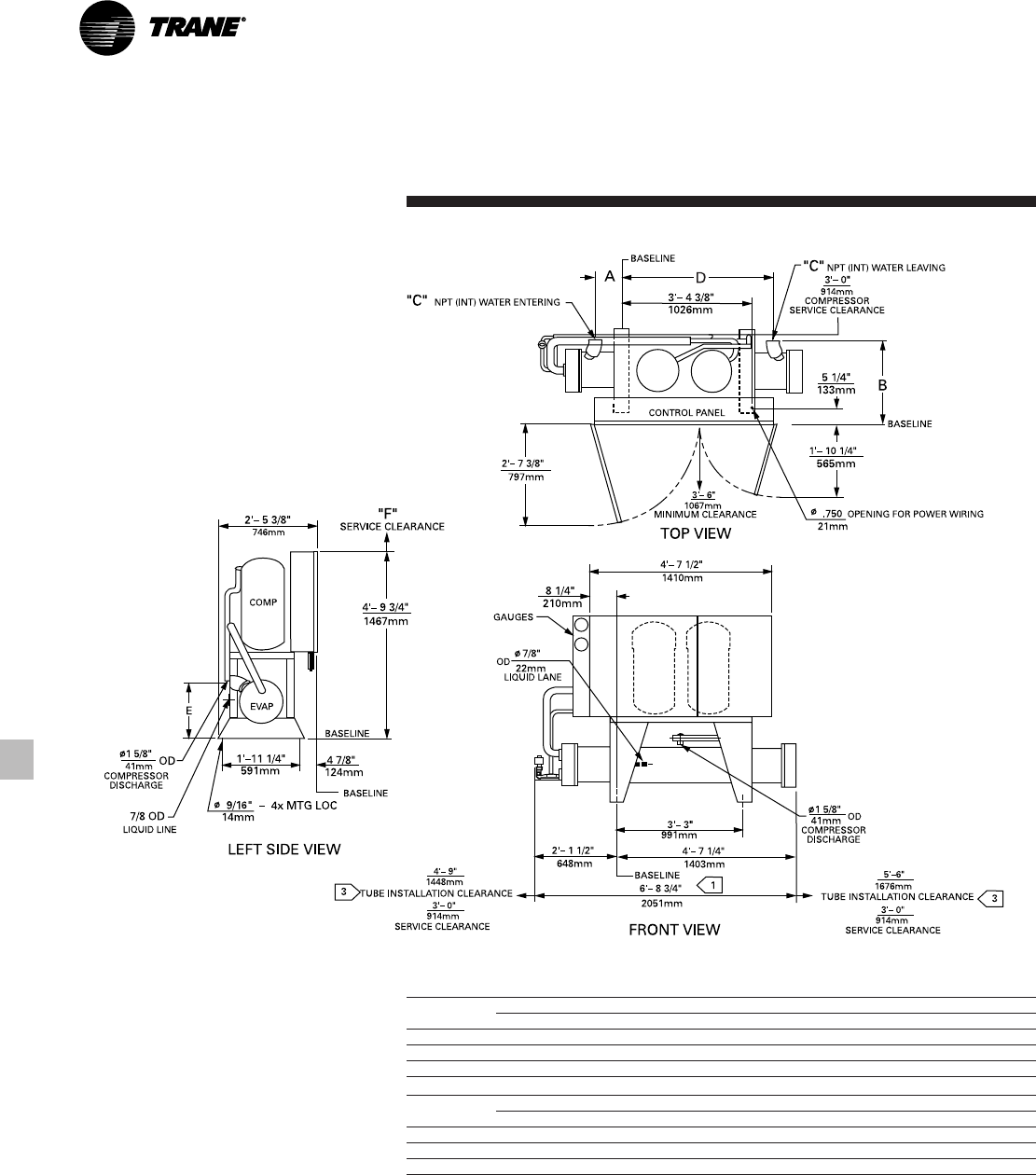
Dimensional
Data
Size A B C D E F G H
20 Ton 2" 8 1/2" 4'-8" 1'-3 3/8" 4 1/8" 8 5/8" 5 5/8" 2' 7 3/8"
(51) (216) (1423) (391) (105) (218) (143) (797)
25 Ton 2" 8 1/2" 4'-8" 1'-3 3/8" 4 1/8" 8 5/8" 5 5/8" 2' 7 3/8"
(51) (216) (1423) (391) (105) (218) (143) (797)
30 Ton 2 1/2" 7 3/4" 4'-6 1/2" 1'-5 3/8" 2 1/4" 12" 8" 2' 8 3/16"
(64) (197) (1384) (441) (57) (305) (203) (818)
Notes:
1. Dimensions in ( ) are in millimeters.
2. Dimensional tolerance ± 1/4” (3).
CGWE 20-30 Ton
CG-PRC011-EN30
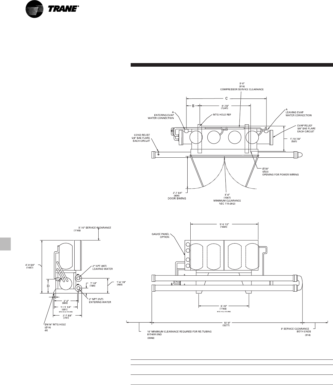
Dimensional
Data
CGWE 40-50 Ton
Size A B C D E
40 Ton 2 1/2" 1'-3 3/4" 6'-5 1/2" 1'-4 1/4" 4 3/8"
(64) (400) (1968) (413) (111)
50 Ton 3" 1'-3 1/2" 6'-5" 1'-6 1/8" 2 1/2"
(76) (394) (1956) (480) (64)
Notes:
1. Dimensions in ( ) are in millimeters.
2. Dimensional tolerance ± 1/4” (3).
31
CG-PRC011-EN
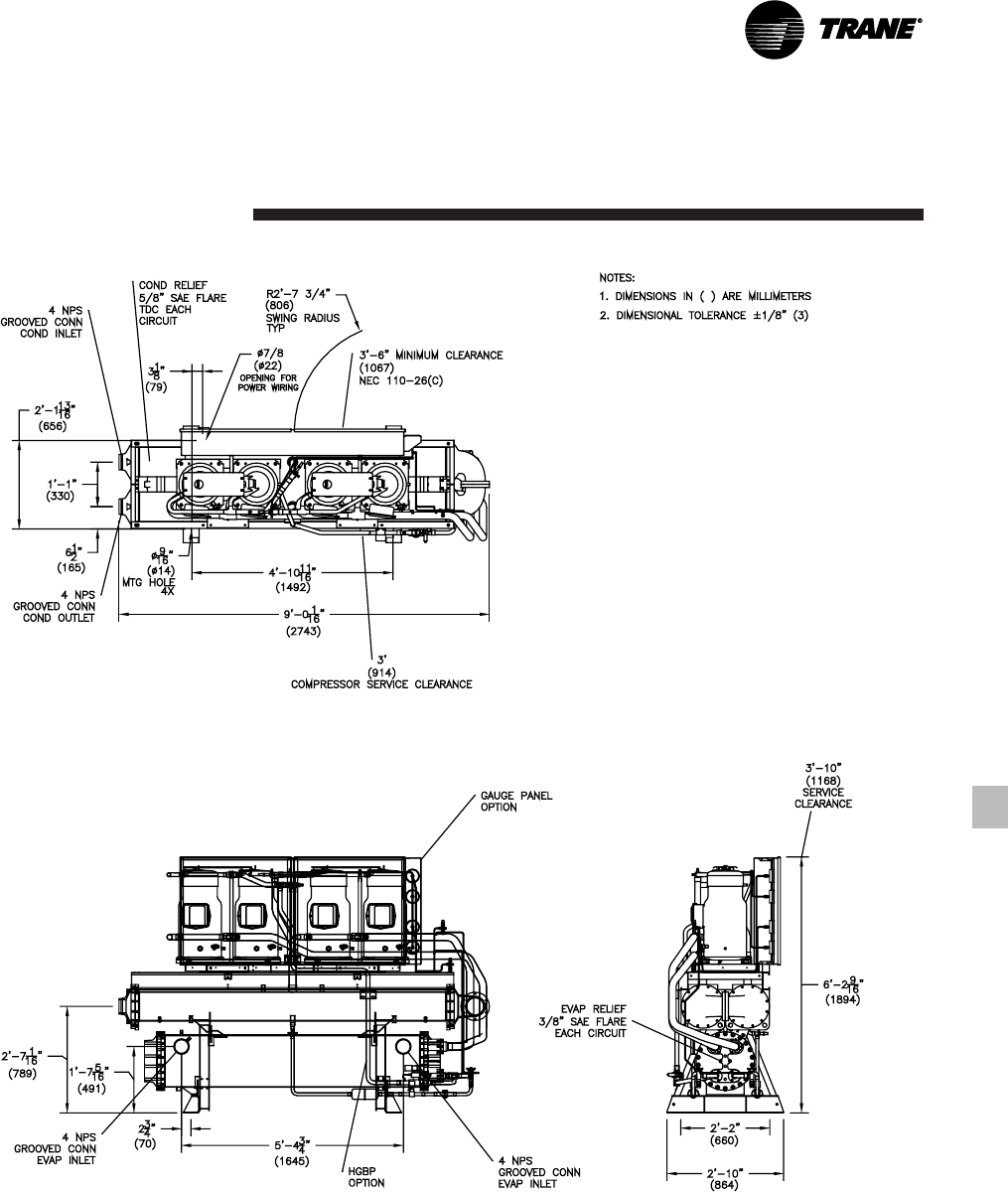
Dimensional
Data
CGWE 60 Ton
CG-PRC011-EN32
English Dimensions
Unit Size A B C D E F
20 Ton 8 1/2”3’-11 1/2”2”2’-0”1’-3 1/2”3’-3”
25 Ton 8 1/2”3’-11 1/2”2”1’-11 3/4”1’-3 1/2”3’-10”
30 Ton 7 3/4”3’-10 3/4”2 1/2”2’-1 7/8”1’-5 3/8”3’-10”
Metric Dimensions (mm)
Unit Size A B C D E F
20 Ton 216 1207 51 610 394 1041
25 Ton 216 1207 51 603 394 1041
30 Ton 197 1187 64 657 441 1168
Notes:
1. Add 3/4” (19 mm) for units with insulation.
2. Dimensional tolerance ± 1/4” (3 mm).
3. Tube installation at either end of evaporator.
Dimensional
Data
CCAD 20-30 Ton

33
CG-PRC011-EN
English Dimensions
Unit Size A B C D E F
40 Ton 5’-1 3/4”1’-3 3/4”1’-11 1/4”2 1/2”3’-5”1’-4 1/4”
50 Ton 5’-1 1/2”1’-3 1/2”2’-1 1/8”3”3’-10”1’-6 1/8”
60 Ton 5’-1 1/2”1’-3 1/2”2’-0 7/8”3”3’-10”1’-6 1/8”
Metric Dimensions (mm)
Unit Size A B C D E F
40 Ton 1568 400 591 64 1041 413
50 Ton 1562 394 638 76 1168 480
60 Ton 1562 394 632 76 1168 460
Notes:
1. Add 3/4” (19 mm) for units with insulation.
2. Dimensional tolerance ± 1/4” (3 mm).
3. Tube installation at either end of evaporator.
Dimensional
Data
CCAD 40-60 Ton
CG-PRC011-EN34
Weights
Table W-1 – Weights, CGWE Chillers
Unit 20 25 30 405060
Operating Wt. (lb.) 1454 1517 2009 2506 2727 3753
(kg) 660 689 912 1138 1238 1704
Shipping Wt. (lb.) 1282 1360 1774 2126 2376 3224
(kg) 582 618 806 965 1079 1464
Table W-2 – Weights, CCAD Compressor-Chillers
Unit 20 25 30 405060
Operating Wt. (lb.) 1004 1079 1274 1509 1808 1982
(kg) 456 490 579 685 821 900
Shipping Wt. (lb.) 1430 1605 1836 1792 2166 2494
(kg) 649 729 834 814 984 1133

35
CG-PRC011-EN
Options
Hot Gas Bypass: Hot gas bypass option
allows unit operation below the
minimum step of unit unloading. The
regulator valve, along with all associated
refrigerant piping and electrical wiring,
are factory installed and tested on one
refrigeration circuit. Unit does not start in
hot gas bypass mode. If the unit operates
in bypass mode for 30 minutes without a
call for cooling, it will pump down and
shut off. Unit starts immediately upon a
further call for cooling.
Chilled Water Reset: Front panel settable
control, microprocessor based control
strategy, and field-installed sensor for
temperature based (ambient or zone)
reset are included in this option. Return
water reset sensor is standard, but panel
controller and control strategy must be
ordered as an option.
Communications Interface:
Bi-directional (Trane ICS) and generic
BAS (external chilled water setpoint)
communication interfaces are available
for external control applications.
Remote Display Panel: The remote panel
has the same digital display that is on the
unit control panel as well as an auto/stop
switch. Another auto/stop switch can be
wired from pump contactor or time clock
(scheduling). Remote display is mutually
exclusive with Trane ICS and generic
BAS.
Remote Running Indication and Alarm
Contacts: Two separate single pole/
double throw contacts are provided to
indicate when the compressors are
running and if a unit failure has occurred.
A failure will be indicated if the unit has a
manual reset fault. A failure is not
indicated on an automatic reset fault.
Ice Making Controls: In ice-making
mode, the unit will operate fully loaded
in response to jobsite supplied contact
closure. Ice making will terminate when
the return fluid temperature falls below
an adjustable setpoint (minimum 20°F
[-6.7°C]). When not in ice making mode,
unit will provide modulating capacity
control based on leaving chilled fluid
temperature (20-55°F) [-6.7°C to 12.8°C].
Cycle Counter and Hour Meter: One
cycle counter and hour meter per
compressor.
Unit Mounted Disconnect Switch: Non-
fused molded case disconnect switch
factory installed in control panel for
disconnecting main three-phase power.
Isolators: Neoprene-in-shear isolators for
field installation under unit frame.
Gauges: Factory-installed gauges
monitor suction and discharge pressure.
One set of gauges per refrigeration
circuit.
Sound Attenuation: Factory-installed
acoustical attenuation for applications
where extremely low sound level is
required.
Water Regulating Valves: Field-installed
valves provide means for control of head
pressure.
Low Ambient Thermostat: Field-installed
outdoor thermostat with an adjustable
setpoint provides means for low ambient
lockout.
Condenser Water Temperature Sensor:
Field-installed matched pair temperature
sensors provide for microprocessor
display.
Options

CG-PRC011-EN36
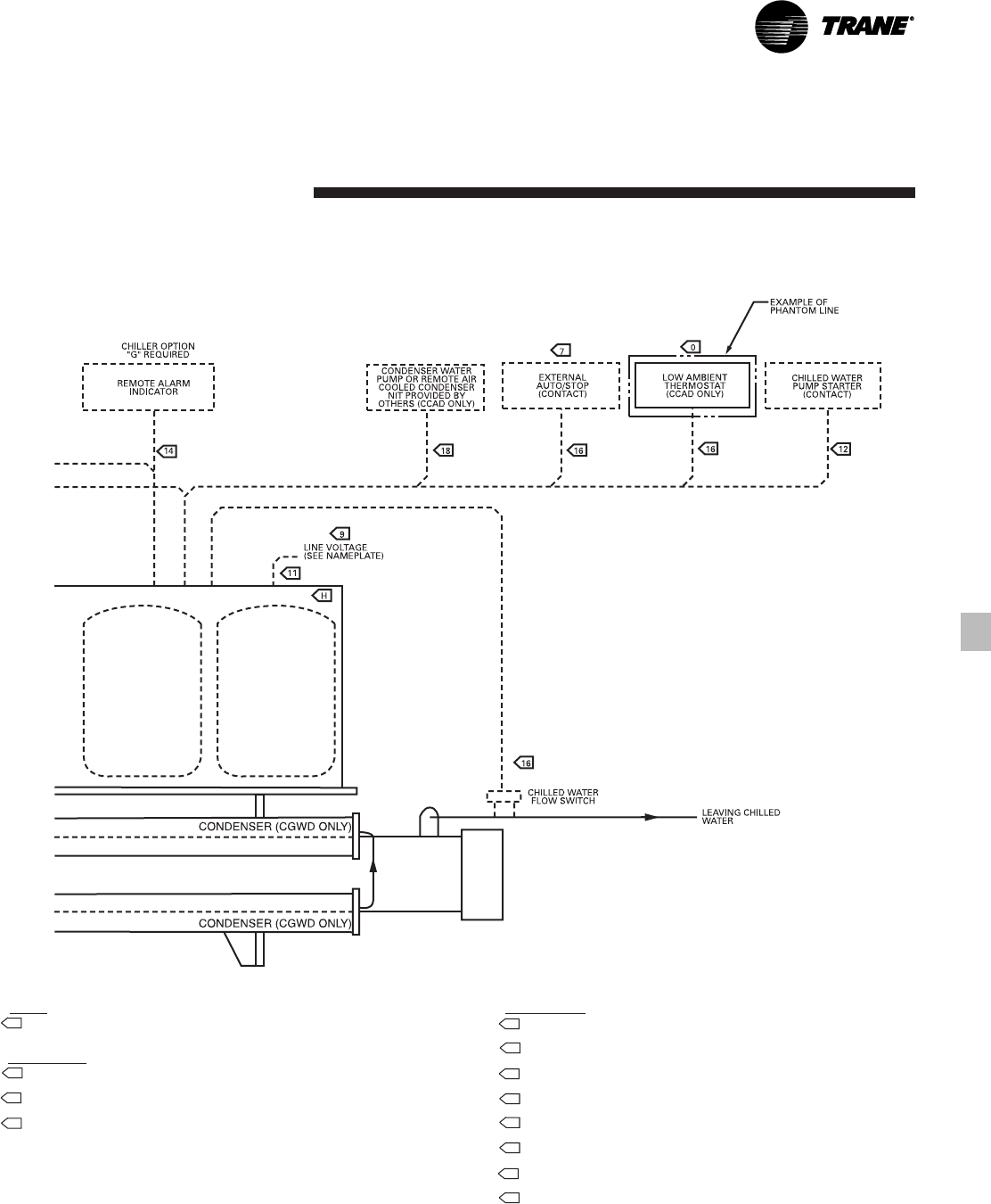
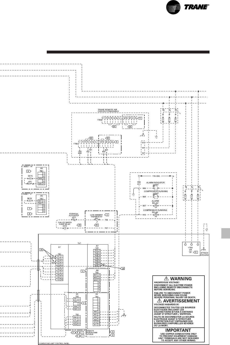
Typical Wiring
Diagrams
NOTES:
1. DASHED LINES INDICATE RECOMMENDED FIELD WIRING BY OTHERS. PHANTOM LINES INDICATE
ALTERNATE CIRCUITRY OR AVAILABLE SALES OPTION. CHECK SALES ORDER TO DETERMINE IF
WIRING IS REQUIRED FOR SPECIFIC OPTIONS.
2. ALL THREE PHASE MOTORS SUPPLIED WITH THE UNIT ARE PROTECTED UNDER PRIMARY SINGLE
PHASE FAILURE CONDITIONS.
4. CAUTION - DO NOT ENERGIZE UNIT UNTIL CHECK OUT AND START-UP PROCEDURES HAVE BEEN
COMPLETED.
5. USED ON 40, 50 AND 60 TON UNITS ONLY.
6. SEE INSET “A” FOR PROGRAMMING RESISTOR CONNECTIONS . TO PROGRAM AN EXTERNAL
CHILLED WATER SETPOINT WHEN A 4-20 mA/0-10 VDC SIGNAL IS NOT USED. SEE THE OPERATORS
MANUAL FOR PROGRAMMING RESISTOR CONNECTIONS FOR USE ON NORMAL COOLING OR ICE
MAKING APPLICATIONS.
7. SEE INSET “C” FOR CONTACTS (IN PLACE OF ZONE TEMP. SENSOR) FOR OPTIONAL ICE MACHINE
CONTROL.
8. THE FOLLOWING CAPABILITIES ARE OPTIONAL - THEY ARE IMPLEMENTED AND WIRED AS
REQUIRED FOR A SPECIFIC SYSTEM APPLICATION.
A ICE-MACHINE CONTROL (CANNOT BE USED WITH OPT. L)
B COMMUNICATIONS INTERFACE
G REMOTE RUNNING INDICATION AND ALARM CONTACTS
H UNIT DISCONNECT, NON-FUSED
J CHILLED WATER RESET - RETURN WATER
K CHILLED WATER RESET - OUTDOOR AIR TEMP. SENSOR OPTIONAL ON CGWE AND
STANDARD ON CCAD.
L CHILLED WATER RESET - ZONE AIR (CANNOT BE USED WITH OPT. A)
O LOW AMBIENT THERMOSTAT
P HIGH AMBIENT LOAD LIMIT THERMOSTAT
Q ENTERING AND LEAVING CONDENSER WATER TEMP. SENSOR. MATCHED PAIR OF
THERMISTOR FOR 4RT1 AND 4RT2.
WIRING AND CONTACT REQUIREMENTS:
21. ALL FIELD WIRING MUST BE IN ACCORDANCE WITH THE NATIONAL ELECTRICAL CODE (NEC),
STATE, AND LOCAL REQUIREMENTS. OUTSIDE THE UNITED STATES, OTHER COUNTRIES
APPLICABLE NATIONAL AND/OR LOCAL REQUIREMENTS SHALL APPLY.
24. CUSTOMER SUPPLIED CONTACTS MUST BE COMPATIBLE WITH DRY CIRCUIT 12 VDC, 45 mA
RESISTIVE LOAD. SILVER OR GOLD PLATED CONTACTS ARE RECOMMENDED.
25. 30 VOLT OR LESS CIRCUIT. DO NOT RUN IN CONDUIT WITH HIGHER VOLTAGE CIRCUITS. USE #14-
18 AWG. SEE SELECTION TABLE.
26. MINIMUM CONTACT RATING AT 115 VAC: 6.9 VA INRUSH, 6.9 V A SEALED.
28. WHEN CUSTOMER INPUT IS REQUIRED, REMOVE JUMPER AND INSTALL CUSTOMER WIRING.
29. LOSS OF CHILLED WATER FLOW PROTECTION IS PROVIDED BY THE UNIT WITHOUT THE NEED
FOR A CHILLED WATER FLOW SWITCH. THE USE OF A CHILLED WATER FLOW SWITCH IS AT THE
CUSTOMER’S DISCRETION.
30. FAN STAGING IS CONTROLLED BY THE COMPRESSOR CHILLER. TO INSURE PROPER FAN
OPERATION ADD JUMPER TERMINALS ON 1TB3 AS SHOWN. REMOVE JUMPER FROM 1TB2-4 TO
1TB2-3 ON ALL CAUC UNITS. REMOVE JUMPER FROM 1TB2-9 TO 1TB2-8 ON ALL 40, 50 AND 60
TON CAUC UNITS. IF LOW AMBIENT OPTION, ADD JUMPER FROM 1TB3-6 TO 1TB3-7 AND FROM
1TB3-11 TO 1TB3-12.
37
CG-PRC011-EN
Typical Wiring
Diagrams
CG-PRC011-EN38
Advanced Design for Efficiency and
Reliability
•Trane scroll compressor has 64 percent
fewer parts than equal capacity
reciprocating compressors for greater
reliability. Part load efficiency is
unmatched by any reciprocating
compressor.
•Factory installed microprocessor
controls provides accurate chilled water
temperature control. The
microprocessor also incorporates
optimal start-up logic, load limiting,
compressor anti-recycle timing,
automatic lead-lag function and
compressor protection features.
•Easy operation provided by menu-
driven digital display. Display provides
temperatures, pressures, setpoints and
over 40 diagnostic readouts.
•Compressor protection from start and
run overloads, under and over voltage,
phase loss and phase reversal, and
rapid recycling.
•Easy installation through small size,
factory wiring, easy lifting provisions
and start-up control logic.
•Availability. Trane has the industry’s
fastest ship cycles on both stock and
built-to-order units.
•Other standard features include:
— Control power transformer
— Auto lead-lag (on or off)
— Solid-state motor protection
— Insulation
— Condenser water pump interlock
— Filter-dryer
— Built-in loss of chilled water flow
sensors
— Chillers fit through standard single-
width door
•Options
— Trane Integrated Comfort™ systems
communication
— Generic building automation
systems (BAS) interface
— Chilled water reset (ambient, zone,
return)
— Unit mounted disconnect
— Ice making
— Hot gas bypass
— Remote display/control panel
— Remote running indication and
alarm contact
— Gauges
— Sound attenuation
— Neoprene isolators
— Compressor cycle counter/hour
meter
— Water regulating valves
— Condenser water temperature
sensors
Features
Summary

39
CG-PRC011-EN
Water-Cooled Liquid Chillers and
Compressor Chillers CGWE and CCAD
Models 20 to 60 Tons
General
All scroll chillers are factory tested and
monitored for power and control
operation (CGWE only). CGWE units
ship with a full operating charge of
refrigerant and oil. Exposed surfaces are
painted with an air-dry beige primer-
finisher prior to shipment.
Compressor-Motor
Direct-drive, hermetic, 3600 rpm, 60 Hz
[300 rpm, 60 Hz] fixed compression,
scroll compressors (20 to 30 tons - two
compressors; 40 to 60 tons - four
compressors). Each compressor has:
centrifugal oil pump, oil level sightglass,
oil charging valve, two point lubrication
for each motor bearing, flooded
lubrication for the journal and thrust
bearings, and a check valve on the scroll
discharge port.
Motor is suction gas-cooled,
hermetically sealed, two-pole, squirrel
cage induction type.
Evaporator
Shell and tube design with seamless
copper tubes roller expanded into tube
sheets. Designed, tested and stamped in
accordance with ASME Code for
refrigerant side working pressure of 300
psig. Water side working pressure is 300
psig for CGWE 20-50 and CCAD 20-60,
215 psig for CGWE 60. One water pass
with a series of internal baffles. Each
shell includes drain connections,
entering and leaving temperature
sensors, and ¾ inch Armaflex II (or
equal) insulation (K= 0.26).
Condenser (CGWE only)
Shell and tube design with seamless
internally enhanced copper tubes.
Designed and tested for refrigerant side
working pressure of 450 psig. Water
side working pressure is 300 psig for
CGWE 20-50, 150 psig for CGWE 60.
Two pass construction with six-inch
diameter shell (20 to 30 tons). One pass
construction with two separate
condensers connected in series (40 to 60
tons). Each condenser includes a
subcooler circuit. Tubes are cleanable
and replaceable.
Refrigerant Circuit
Each refrigeration circuit shall be
completely independent and shall
include liquid line and discharge line
service valves, filter dryer, combination
moisture indicator-sightglass, charging
port, insulated suction line, liquid line
solenoid valve and thermal expansion
valve.
Isolation valves provide means of
isolating refrigerant charge in either the
high or low pressure side while
servicing. One refrigerant circuit on
20 to 30 tons; two refrigerant circuits on
40 to 60 tons.
Condenserless units (CCAD) shall be
equipped with discharge check valve
and moisture indicator sightglass.
Control Panel
Factory-mounted microprocessor based
control panel uses 120/60/1 power.
Automatic shutdown protection with
manual reset is provided for low
evaporator outlet refrigerant
temperature and pressure, high
condenser refrigerant pressure, motor
current overload, and phase reversal.
Automatic shutdown protection with
automatic reset after condition is
corrected is provided for low line voltage
and loss of chilled water flow.
The unit control module (UCM)
automatically takes action to prevent
complete shutdown by shedding
compressors one at a time. This occurs
in the event of low evaporator refrigerant
temperature, high condenser refrigerant
pressure, motor current overload;
preventing the motor current from
exceeding setpoint.
Solid-state chilled water temperature
sensors are included for precise and
accurate control. A menu driven display
indicates the operating code, the last
diagnostic code, chilled water setpoint,
current limit setpoint, condenser water
and chilled water temperature sensors.
Factory-installed entering and leaving
condenser water temperature sensors
(optional) are available for
microprocessor display or Trane Tracer™
monitoring. Over 40 diagnostic checks
are made and will be displayed when a
problem is detected.
Starter
The unit control panel contains both a
control section and a starter section. The
panel is a painted, NEMA 1 enclosure.
The starter section contains: top access
for power wiring, single point power
hook-up, three-phase solid-state
overload protection, customer wired
grounding lug, and control power
transformer with fused protection.
Mechanical
Specifications

Since Trane has a policy of continuous product and product data improvement, it reserves the right to
change design and specifications without notice.
Literature Order Number
File Number
Supersedes
Stocking Location
Trane
An American Standard Company
www.trane.com
For more information contact
your local sales office or
e-mail us at comfort@trane.com
CG-PRC011-EN
CG-PRC011-EN-0102
New
La Crosse
