Trane RLC PRC006 EN User Manual To The 52913a1f F14a 476c 80b9 73162bb05e73
User Manual: Trane RLC-PRC006-EN to the manual
Open the PDF directly: View PDF ![]() .
.
Page Count: 54
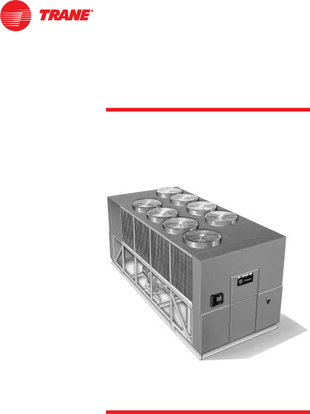
Air-Cooled Series R™
Rotary Liquid Chiller
Model RTAC
140 to 500 Tons (60 Hz)
140 to 400 Tons (50 Hz)
Built For the Industrial and Commercial Markets
RLC-PRC006-ENDecember 2003

© 2003 American Standard Inc. All rights reserved. RLC-PRC006-EN
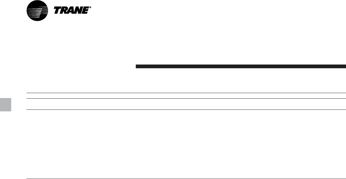
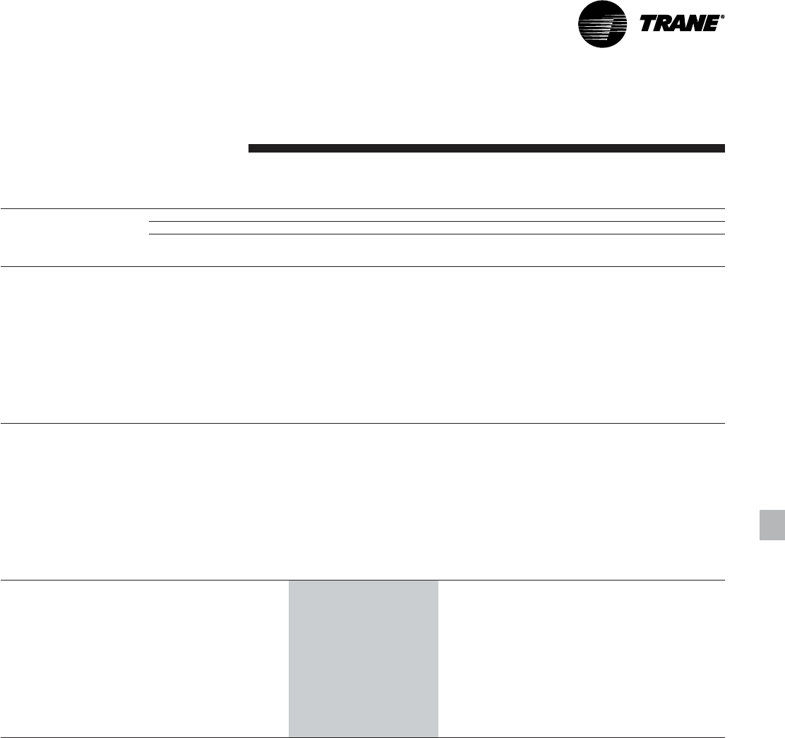
Figure 1. Cutaway of RTAC air-cooled chiller
1
2
3
4
5
6
5
5
You…
Like its chillers, Trane wants its
relationships with customers to last.
Trane is interested in maintaining long
term, loyal relationships. This
perspective means the point in time that
a customer purchases a chiller is the
beginning of a relationship, not the end.
Your business is important, but your
satisfaction is paramount.
Designed by Customers….
Trane’s RTAC was designed with the end
user’s requirements in mind. Reliability,
sound, efficiency and physical size were
primary design concerns with this latest
generation machine. New technologies
were applied to literally every major
component. The result is an unparalleled
engineering achievement in chiller
design and manufacturing.
What’s New
The RTAC offers the same high reliability
of Trane’s previous air-cooled helical
rotary design coupled with lowered
sound levels, increased energy
efficiency, reduced physical footprint due
to its advanced design, low speed/direct
drive compressor and proven Series R
performance.
Some of the major advantages of the
Model RTAC are:
• Over 99% reliable
• Lower sound levels
• Higher energy efficiency
• Smaller physical footprint
• HFC-134a optimized design
The Series R Model RTAC is an industrial
grade design built for both the industrial
and commercial markets. It is ideal for
schools, hospitals, retailers, office
buildings, Internet service providers and
manufacturing facilities.
Introduction
1. Flooded Style Evaporator
2. Trane Helical-Rotary Compressor
3. Oil Separator
4. Low Sound Condenser Fans
5. Factory Installed and Tested Unit
Controls and Starter
6. Smaller Physical Footprint
3
Introduction
Features and Benefits
World Class Energy Efficiency
Simple Installation
Options
Controls
Application Considerations
Model Number Description
General Data
Selection Procedure
Performance Data
Full Load
Part Load
Adjustment Factors
Electrical Data and Connection
Wire Size
Typical Wiring Diagram
Field Layout
Dimensions
Weights
Mechanical Specifications
Contents
RLC-PRC006-EN
2
4
8
12
17
18
22
23
37
63
73
77
RLC-PRC006-EN4
Table 1. RTAC efficiency vs Ashrae 90.1
RTAC - Exceeding the Efficiency Standard
Full Load Efficiency (EER*) Part Load Efficiency (EER*)
Tonnage ASHRAE 90.1 Standard Efficiency High Efficiency ASHRAE 90.1 Standard Efficiency High Efficiency
140 9.6 9.7 10.3 10.4 13.2 13.6
155 9.6 9.8 10.4 10.4 13.5 13.9
170 9.6 9.9 10.5 10.4 13.2 13.7
185 9.6 9.7 10.3 10.4 13.1 13.5
200 9.6 9.6 10.1 10.4 12.9 13.3
225 9.6 9.6 10.2 10.4 13.2 13.6
250 9.6 9.6 10.1 10.4 12.8 13.0
275 9.6 9.7 10.4 10.4 13.3 13.8
300 9.6 9.6 10.1 10.4 13.7 13.8
350 9.6 9.6 10.4 10.4 13.2 14.5
400 9.6 9.6 10.0 10.4 13.7 13.9
450 9.6 9.6 n/a 10.4 14.0 n/a
500 9.6 9.6 n/a 10.4 13.9 n/a
COP = EER/3.414.
Efficiencies given for 60 Hz units
Features and
Benefits
ASHRAE Standard 90.1 and
RTAC World Class Energy
Efficiency…
The importance of energy efficiency
cannot be understated. Fortunately,
ASHRAE has created a guideline
emphasizing its importance.
Nonetheless, energy is often dismissed
as an operational cost over which the
owner has little control. That perception
results in missed opportunities for
energy efficiency, reduced utility bills,
and higher profits. Lower utility bills
directly affect profitability. Every dollar
saved in energy goes directly to the
bottom line. Trane’s RTAC is one way to
maximize your profits.
ASHRAE Standard 90.1 & Executive
Order - New technology applied to the
design, controls, and manufacturing
have created excellent efficiency levels in
the RTAC that are helping to push
industry minimums to new heights. All
Trane air-cooled chillers meet the new
efficiency levels mandated by ASHRAE
Standard 90.1. This new standard
requires higher efficiencies than past
technologies can deliver. The US Federal
Government has adopted standard 90.1
and, in some cases, requires even higher
efficiencies. Federal Executive Order
mandates energy consuming devices
procured must be in the top 25% of their
class. In the case of chillers, that product
standard is ASHRAE 90.1. Trane’s RTAC
meets and exceeds the efficiency
requirements of 90.1, while the high
efficiency RTAC can meet the “stretch
goals” of Executive Order.
Precise Capacity Control. Trane’s
patented unloading system allows the
compressor to modulate infinitely and
exactly match building loads. At the
same time chilled water temperatures
will be maintained within +/- 1/2ºF
[0.28°C] of setpoint. Reciprocating and
screw chillers with stepped capacity
control do well to maintain chilled water
temperatures within 2ºF [1.1°C] of
setpoint. Stepped control also results in
overcooling your space because rarely
does the capacity of the machine match
the building load. The result can be 10%
higher energy bills. Trane’s RTAC
optimizes the part load performance of
your machine for energy efficiency,
precise control for process applications,
and your personal comfort regardless of
the weather outside.
5RLC-PRC006-EN
Excellent Reliability…
A buildings environment is expected to
be comfortable. When it is, no one says
a word. If it’s not… that’s a different
story. The same is true with chillers. No
one ever talks about chillers, yet alone
compressors, until they fail, and tenants
are uncomfortable and productivity is
lost. Trane’s helical rotary compressors
have a first year reliability rate of over
99%, which means our chillers stay
running when you need them.
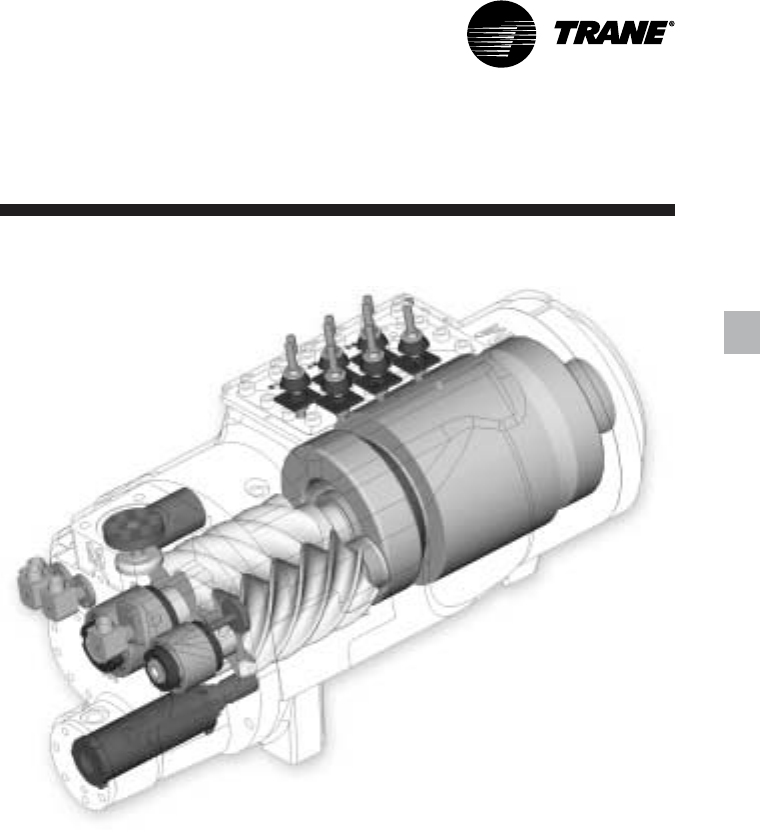
Fewer moving parts. Trane’s helical
rotary compressors have only two major
rotating parts: the male and female rotor.
A reciprocating compressor can have
more than 15 times that number of
critical parts. Multiples of pistons, valves,
crankshafts, and connecting rods in a
reciprocating unit all represent different
failure paths for the compressor. In fact,
reciprocating compressors can easily
have a failure rate four times of a helical
rotor. Combine that with two to three
reciprocating compressors for each
helical rotary compressor on chillers of
equal tonnage, and statistics tell you it’s
a matter of time before you lose a
reciprocating compressor.
Robust components. Helical rotary
compressors are precisely machined
using state of the art processes from
solid metal bar stock. Tolerances are
maintained within a micron or less than
a tenth of the diameter of a human hair.
The resulting compressor is a robust yet
highly sophisticated assembly capable of
ingesting liquid refrigerant without risk
of damage. Contrast this to a
reciprocating compressor, which can be
destroyed by a single slug of liquid.
Condenser coils. Trane’s condenser
coils are manufactured with the same
philosophy as the compressors; they’re
built to last. Even though manufacturing
processes have allowed thinner and
thinner materials in their assembly, with
obvious material and manufacturing
savings, Trane’s coil material did not
change with the RTAC generation of air
cooled chillers. Substantial condenser
fins, that do not require additional
coating in non-corrosive environments,
contribute to the highest reliability
standards for air-cooled chillers in the
industry.
Features and
Benefits
Figure 2. Cutaway of a compressor

RLC-PRC006-EN6
Simple Installation
• Compact Physical Size. The Trane
Model RTAC chiller averages a 20%
reduction in physical footprint, while
the greatest change is actually 40%
smaller when compared against the
previous design. This improvement
makes the RTAC the smallest air-cooled
chiller in the industry and a prime
candidate for installations that have
space constraints. All physical sizes
were changed without sacrificing the
side clearances needed to supply fresh
airflow without coil starvation.
• Close Spacing Installation. The air-
cooled Series R™ Chiller has the tightest
recommended side clearance in the
industry, four feet for maximum
performance. In situations where
equipment must be installed with less
clearance than recommended, which
frequently occurs in retrofit
applications, restricted airflow is
common. Conventional chillers may
not work at all. However, the air-cooled
Series R chiller with Adaptive Control™
microprocessor will make as much
chilled water as possible given the
actual installed conditions, stay on line
during unforeseen abnormal
conditions, and optimize the unit
performance. Consult your Trane sales
engineer for more details.
• Factory Testing Means Trouble-Free
Start-Up. All air-cooled Series R chillers
are given a complete functional test at
the factory. This computer-based test
program completely checks the
sensors, wiring, electrical components,
microprocessor function,
communication capability, expansion
valve performance and fans. In
addition, each compressor is run and
tested to verify capacity and efficiency.
Where applicable, each unit is factory
preset to the customer’s design
conditions; an example would be
leaving liquid temperature setpoint.
The result of this test program is that
the chiller arrives at the job site fully
tested and ready for operation.
• Factory Installed and Tested Controls/
Options Speed Installation. All Series R
chiller options, including main power
supply disconnect, low ambient
control, ambient temperature sensor,
low ambient lockout, communication
interface and ice making controls, are
factory installed and tested. Some
manufacturers send accessories in
pieces to be field installed. With Trane,
the customer saves on installation
expense and has assurance that ALL
chiller controls/options have been
tested and will function as intended.
Features and
Benefits
Superior Control
The Adaptive Control™ microprocessor
system enhances the air-cooled Series R
chiller by providing the very latest chiller
control technology. With the Adaptive
Control microprocessor, unnecessary
service calls and unhappy tenants are
avoided. The unit is designed not to trip
or unnecessarily shut down. Only when
the Tracer™ chiller controllers have
exhausted all possible corrective actions
and the unit is still violating an operating
limit will the chiller shut down. Controls
on other equipment typically shut down
the chiller, usually just when it is needed
the most.
For example:
A typical five-year-old chiller with dirty
coils might trip-out on high pressure
cutout on a 100°F [38°C] day in August. A
hot day is just when comfort cooling is
needed the most. In contrast, the air-
cooled Series R chiller with an Adaptive
Control microprocessor will stage fans
on, modulate electronic expansion valve,
and modulate slide valve position as it
approaches a high pressure cutout,
thereby keeping the chiller on-line when
you need it the most.

7RLC-PRC006-EN
High Efficiency/Performance Option
This option provides oversized heat
exchangers for two purposes. One, it
allows the unit to be more energy
efficient. Two, the unit will have
enhanced operation in high ambient
conditions.
Low Temperature Brine
The hardware and software on the unit
are factory set to handle low
temperature brine applications (less than
40°F [4.4°C]).
Ice Making
The unit controls are factory set to
handle ice making for thermal storage
applications.
Tracer Summit Communication
Interface
Permits bi-directional communication to
the Trane Integrated Comfort™ system.
LonTalk (LCI-C) Communications
Interface
Provides the LonMark chiller profile
inputs/outputs for use with a generic
building automation system.
Remote Input Options
Permits remote chilled liquid setpoint,
remote current limit setpoint, or both by
accepting a 4-20 mA or 2-10 Vdc analog
signal.
Remote Output Options
Permits alarm relay outputs, ice making
outputs, or both.
Architectural Louvered Panels
Louvered panels cover the complete
condensing coil and service area
beneath the condenser.
Coil Protection
Louvered panels protect the condenser
coils only.
Access Protection
A coated wire mesh that covers the
access area under the condenser coils.
Wye-Delta Compressor Start Type
This option provides a reduced inrush
starter. Wye-Delta starters are standard
on 200-230 volt machines.
Condenser Corrosion Protection
Copper fins and CompleteCoat are
available on all size units for corrosion
protection. Job site conditions should be
matched with the appropriate condenser
fin materials to inhibit coil corrosion and
ensure extended equipment life. The
CompleteCoat option provides fully
assembled coils with a flexible dip and
bake epoxy coating.
TEAO Condenser Fan Motors
Totally enclosed air-over (TEAO) motors
completely seal the motor windings to
prevent exposure to ambient conditions.
Low Ambient Option
The low ambient option provides special
control logic and variable frequency
drives on the condenser fan circuits to
permit low temperature start-up and
operation down to 0°F [-18°C].
Single/Dual Incoming Power Line
Connection
Single or dual points of termination are
available for incoming power line
connections*. Units with 3-4
compressors must order circuit breakers
with the single point connection option.
*Some restrictions may apply.
Convenience Outlet
Provides a 15 amp, 115 volt (60 Hz)
convenience outlet on the unit.
Remote Evaporator
The remote evaporator option is
available on the RTAC 140-250 ton units.
This option provides a pre-engineered
method of installing the evaporator and
all related components indoors.
Remote evaporator installations allow
the water loop to remain indoors to
prevent freezing, thus eliminating the
addition of glycol to the system and the
resulting performance degradation.
High Ambient Option
The high ambient option consists of
special control logic to permit high
ambient (up to 125°F [51°C]) operation.
This option offers the best performance
when coupled with the high efficiency
performance option.
Non-Fused Power Disconnect Switch
The non-fused molded case disconnect
switch (UL approved) is used to
disconnect the chiller from main power
and comes pre-wired from the factory
with terminal block power connections.
The external operator handle is lockable.
Circuit Breaker
A HACR rated molded case capacity
circuit breaker (UL approved) is
available. The circuit breaker can also be
used to disconnect the chiller from main
power with a through-the-door handle
and comes pre-wired from the factory
with terminal block power connections.
The external operator handle is lockable.
Neoprene Isolators
Isolators provide isolation between
chiller and structure to help eliminate
vibration transmission. Neoprene
isolators are more effective and
recommended over spring isolators.
Flange Kit
Provides a raised-face flange kit that
converts the grooved pipe evaporator
water connections to flange connectors.
Options
Features and
Benefits
RLC-PRC006-EN8
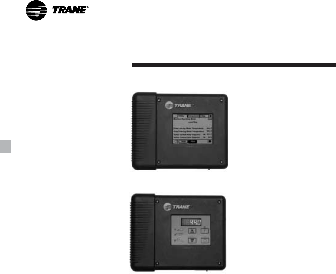
Human Interfaces
The Trane air-cooled Model RTAC chiller
offers two easy-to-use operator interface
panels, the EasyView and the DynaView.
EasyView is a coded display that allows
the user to access the current leaving
water temperature, its setpoint, and any
recent diagnostics.
DynaView is an LCD touchscreen display
that is navigated by file tabs. This is an
advanced interface that allows the user
to access any important information
concerning setpoints, active
temperatures, modes, electrical data,
pressures, and diagnostics.
Adaptive Safety Controls
A centralized microcomputer offers a
higher level of machine protection. Since
the safety controls are smarter, they limit
compressor operation to avoid
compressor or evaporator failures,
thereby minimizing nuisance shutdown.
Tracer™ Chiller Controls directly senses
the control variables that govern the
operation of the chiller: motor current
draw, evaporator pressure and
condenser pressure. When any one of
these variables approaches a limit
condition where damage may occur to
the unit or shutdown on a safety, Tracer
Chiller Controls takes corrective action to
avoid shutdown and keep the chiller
operating. This happens through
combined actions of compressor slide
valve modulation, electronic expansion
valve modulation and fan staging. Tracer
Chiller Controls optimizes total chiller
power consumption during normal
operating conditions. During abnormal
operating conditions, the
microprocessor will continue to optimize
chiller performance by taking the
corrective action necessary to avoid
shutdown. This keeps cooling capacity
available until the problem can be
solved. Whenever possible, the chiller is
allowed to perform its function; making
Controls
chilled water. In addition, microcomputer
controls allow for more types of
protection such as over and under
voltage. Overall, the safety controls help
keep the building or process running and
out of trouble.
Standalone Controls
Interface to standalone units is very
simple; only a remote auto/stop for
scheduling is required for unit operation.
Signals from the chilled water pump
contactor auxiliary or a flow switch are
wired to the chilled waterflow interlock.
Signals from a time clock or some other
remote device are wired to the external
auto/stop input.
Standalone Controls
Standard Features
• External Auto/Stop — A jobsite
provided contact closure will turn the
unit on and off.
• Chilled Waterflow Interlock — A jobsite
provided contact closure from a chilled
water pump contactor or a flow switch
is required and will allow unit operation
if a load exists. This feature will allow
the unit to run in conjunction with the
pump system.
• External Interlock — A jobsite supplied
contact opening wired to this input will
turn the unit off and require a manual
reset of the unit microcomputer. This
closure is typically triggered by a
jobsite supplied system such as a fire
alarm.
• Chilled Water Pump Control — Unit
controls provide an output to control
the chilled water pump(s). One contact
closure to the chiller is all that is
required to initiate the chilled water
system. Chilled water pump control by
the chiller is a requirement on the Air-
Cooled Series R.
• Chilled Water Temperature Reset —
Reset can be based on return water
temperature or outdoor air
temperature.
Figure C1. DynaView operator interface
Figure C2. EasyView operator interface
9RLC-PRC006-EN
Generic Building Automation
System Controls
Controls
Easy Interface to A Generic Building
Management System
Controlling the air-cooled Series R chiller
with building management systems is
state-of-the-art, yet simple with either the
LonTalk Communications Interface for
Chillers (LCI-C) or Generic Building
Management System Hardwire Points.
What are LonTalk, Echelon, and
LonMark?
LonTalk is a communications protocol
developed by the Echelon Corporation.
The LonMark association develops
control profiles using the LonTalk
communication protocol. LonTalk is a
unit level communications protocol,
unlike BACNet used at the system level.
LonTalk Communications
Interface for Chillers (LCI-C)
LonTalk Communications Interface for
Chillers (LCI-C) provides a generic
automation system with the LonMark
chiller profile inputs/outputs. The inputs/
outputs include both mandatory and
optional network variables. Note:
LonMark network variable names are in
parentheses when different from chiller
naming convention.
Chiller Inputs:
• Chiller Enable/Disable
• Chilled Liquid Setpoint (Cool Setpoint)
• Current Limit Setpoint (Capacity Limit
Input)
• Ice Making (Chiller Mode)
Chiller Enable/Disable
Allows for chiller to be started or
stopped depending on if certain
operating conditions are met.
Chilled Liquid Setpoint
Allows for the external setting
independent of the front panel setpoint
to adjust the leaving water temperature
setpoint.
Current Limit Setpoints
Allows for the external setting
independent of the front panel setpoint
to limit the capacity level of the chiller.
Ice Making
Provides interface with ice making
control systems.
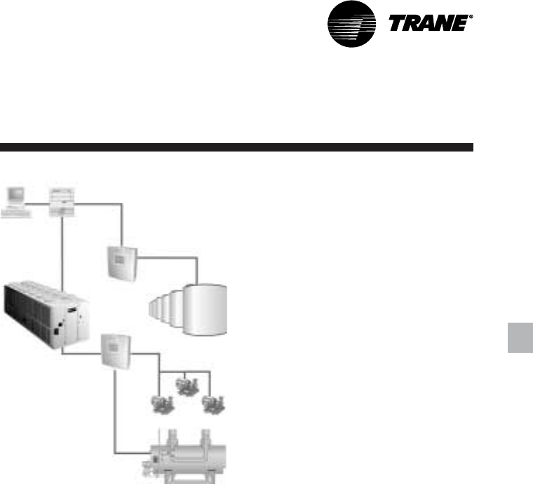
PC Workstation System Level
Controller
MP581 Programmable
Controller
Air-cooled
Series R™ Chiller
MP581
Programmable
Controller
Ice Tanks
Boiler
Chiller Outputs:
• On/Off
• Active Setpoint
• Average Percent RLA (Actual Capacity
Level)
• Active Current Limit Setpoint (Capacity
Limit)
• Leaving Chilled Water Temperature
• Entering Chilled Water Temperature
• Alarm Descriptor
• Chiller Status
On/Off
Indicates the current state of the chiller
Active Setpoint
Indicates the current value of the leaving
water temperature setpoint
Average Percent RLA
Provides the current capacity level via
%RLA
Active Current Limit Setpoint
Provides the current capacity level
setpoint via %RLA
Alarm Descriptor
Provides alarm messages based on pre-
determined criteria
Chiller Status
Indicates the running modes and states
of the chiller, i.e. Running in alarm mode,
chiller enabled, chiller being locally
controlled, etc…
Generic Building Management
System Hardwire Points
GBAS may be achieved via hardware
input/output as well. The input/outputs
are as follows:
Chiller hardwire inputs include:
• Chiller enable/disable
• Circuit enable/disable
• External chilled water setpoint
• External current limit setpoint
• Ice making enable
External Chilled Water Setpoint
Allows the external setting independent
of the front panel setpoint by one of two
means:
a) 2-10 VDC input, or
b) 4-20 mA input
External Current Limit Setpoint
Allows the external setting independent
of the front panel setpoint by one of two
means:
c) 2-10 VDC input, or
b) 4-20 mA input
Chiller hardwire outputs include:
• Compressor running indication
• Alarm indication (Ckt1/Ckt 2)
• Maximum capacity
• Ice making status
Alarm Indication Contacts
The unit provides three single-pole/
double-throw contact closures to
indicate:
a) Compressor on/off status
b) Compressor running at maximum
capacity
c) Failure has occurred (Ckt 1/Ckt 2)
These contact closures may be used to
trigger jobsite supplied alarm lights or
alarm bells.
Ice Making Control
Provides interface with ice making
control systems.
RLC-PRC006-EN10
Controls
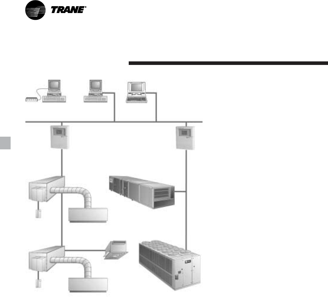
Trane Integrated Comfort
System Controls
Modem
Remote PC Workstation PC Workstation Notebook
PC Workstation
LAN
Building
Control Unit
Building
Control Unit
VariTrane®
Variable Air Volume
Terminal
Room temperature
sensor Diffuser
VariTrane®
Variable Air Volume
Terminal
Room temperature
sensor Diffuser
Exhaust Fan
Air-cooled Series R® Chiller
Modular Climate Changer®
Air Handler
Tracer Summit controls — Interface
With The Trane Integrated Comfort
System (ICS)
Trane Chiller Plant Control
The Tracer Summit Chiller Plant Building
Management System with Chiller Plant
Control provides building automation
and energy management functions
through stand-alone control. The Chiller
Plant Control is capable of monitoring
and controlling your entire chiller plant
system.
Application software available:
• Time-of-day scheduling
• Demand limiting
• Chiller sequencing
• Process control language
• Boolean processing
• Zone control
• Reports and logs
• Custom messages
• Run time and maintenance
• Trend log
• PID control loops
And of course, the Trane Chiller Plant
Control can be used on a stand-alone
basis or tied into a complete building
automation system.
When the air-cooled Series R™ chiller is
used in conjunction with a Trane Tracer™
Summit system, the unit can be
monitored and controlled from a remote
location. The air-cooled Series R chiller
can be controlled to fit into the overall
building automation strategy by using
time of day scheduling, timed override,
demand limiting, and chiller sequencing.
A building owner can completely
monitor the air-cooled Series R chiller
from the Tracer system, since all of the
monitoring information indicated on the
unit controller’s microcomputer can be
read off the Tracer system display. In
addition, all the powerful diagnostic
information can be read back at the
Tracer system. Best of all, this powerful
capability comes over a single twisted
pair of wires! Air-cooled Series R chillers
can interface with many different
external control systems, from simple
stand-alone units to ice making systems.
Each unit requires a single-source, three-
phase power supply and a single-phase
115V/60Hz, [220V/50Hz] power supply.
The added power supply powers the
evaporator heaters.
A single twisted pair of wires tied directly
between the air-cooled Series R™ chiller
and a Tracer™ Summit system provides
control, monitoring and diagnostic
capabilities. Control functions include
auto/stop, adjustment of leaving water
temperature setpoint, compressor
operation lockout for kW demand
limiting and control of ice making mode.
The Tracer system reads monitoring
information such as entering and leaving
evaporator water temperatures and
outdoor air temperature. Over 60
individual diagnostic codes can be read
by the Tracer system. In addition, the
Tracer system can provide sequencing
control for up to 25 units on the same
chilled water loop. Pump sequencing
control can be provided from the Tracer
system. Tracer ICS is not available in
conjunction with the remote display or
the external setpoint capability.
Required Options
Tracer Interface
External Trane Devices Required
Tracer Summit™, Tracer 100 System or
Tracer Chiller Plant Control
Additional Features That May Be Used
Ice Making Control

11RLC-PRC006-EN
Controls
Trane Chiller Plant Automation
Trane’s depth of experience in chillers
and controls makes us a well-qualified
choice for automation of chiller plants
using air-cooled Series R® chillers®. The
chiller plant control capabilities of the
Trane Tracer Summit® building
automation system are unequaled in the
industry. Our chiller plant automation
software is fully pre-engineered and
tested. It is a standard software
application, not custom programming
which can prove to be difficult to
support, maintain, and modify.
Energy Efficiency
Trane chiller plant automation
intelligently sequences starting of
chillers to optimize the overall chiller
plant energy efficiency. Individual chillers
are designated to operate as base, peak,
or swing based on capacity and
efficiency. Sophisticated software
automatically determines which chiller
to run in response to current conditions.
The software also automatically rotates
individual chiller operation to equalize
runtime and wear between chillers.
Trane chiller plant automation enables
unique energy-saving strategies. An
example is controlling pumps, and
chillers from the perspective of overall
system energy consumption. The
software intelligently evaluates and
selects the lowest energy consumption
alternative.
Trane Integrated Comfort
System Controls
Keeping Operators Informed
A crucial part of efficiently running a
chiller plant is assuring that the
operations staff is instantly aware of
what is happening in the plant. Graphics
showing schematics of chillers, piping,
pumps, and towers clearly depict the
chiller plant system, enabling building
operators to easily monitor overall
conditions. Status screens display both
current conditions and upcoming
automated control actions to add or
subtract chiller capacity. Series R and
other chillers can be monitored and
controlled from a remote location.
Tracer Summit features standard report
templates listing key operating data for
troubleshooting and verifying
performance. Reports for each type of
Trane chiller and three and six-chiller
systems are also standard. Detailed
reports showing chiller runtimes aid in
planning for preventative maintenance.
Swift Emergency Response
We understand the importance of
maintaining chilled water production
while protecting your chillers from costly
damage. If no water flow is detected to a
chiller’s piping, the start sequence is
aborted to protect the chiller. The next
chiller in the sequence is immediately
started to maintain cooling.
In the event of a problem, the operator
receives an alarm notification and
diagnostic message to aid in quick and
accurate troubleshooting. A snapshot
report showing system status just prior
to an emergency shutdown helps
operators determine the cause. If
emergency conditions justify an
immediate manual shutdown, the
operator can override the automatic
control.
Easy Documentation for Regulatory
Compliance
Comprehensive documentation of
refrigerant management practices is
now a fact of life. Trane chiller plant
automation generates the reports
mandated in ASHRAE Guideline 3.
Integrated Comfort™ Capabilities
When integrated with a Tracer Summit
building management system
performing building control, Trane chiller
plant automation coordinates with
Tracer Summit applications to optimize
the total building operation. With this
system option, the full breadth of Trane’s
HVAC and controls experience are
applied to offer solutions to many facility
issues. If your project calls for an
interface to other systems, Tracer
Summit can share data via BACnet™, the
ASHRAE open systems protocol.
Ice Making Systems Controls
Simple and smart control strategies are
another advantage the Model RTAC
chiller offers for ice storage applications.
Trane Tracer™ building management
systems can actually anticipate how
much ice needs to be made at night and
operate the system accordingly. The
controls are integrated right into the
chiller. Two wires and preprogrammed
software dramatically reduce field
installation cost and complex
programming.
When the ice making option is ordered,
the air-cooled Series R chiller will have
two operating modes, ice making and
normal daytime cooling. In the ice
making mode, the air-cooled Series R
chiller will operate at full compressor
capacity until the return chilled fluid
temperature entering the evaporator
meets the ice making setpoint. This ice
making setpoint is manually adjusted on
the unit’s microcomputer. Two input
signals are required to the air-cooled
Series R chiller for the ice making option.
The first is an auto/stop signal for
scheduling and the second is required to
switch the unit in between the ice
making mode and normal daytime
operation. The signals are provided by a
remote job site building automation
device such as a time clock or a manual
switch. In addition, the signals may be
provided over the twisted wire pair from
a Tracer system or LonTalk
Communication Interface but will require
the communication boards provided
with the Ice Making Control Option.
RLC-PRC006-EN12
Important
Certain application constraints should be
considered when sizing, selecting and
installing Trane air-cooled Series R
chillers. Unit and system reliability is
often dependent upon proper and
complete compliance with these
considerations. When the application
varies from the guidelines presented, it
should be reviewed with your local
Trane sales engineer.
Unit Sizing
Unit capacities are listed in the
performance data section. Intentionally
over-sizing a unit to assure adequate
capacity is not recommended. Erratic
system operation and excessive
compressor cycling are often a direct
result of an oversized chiller. In addition,
an oversized unit is usually more
expensive to purchase, install, and
operate. If over-sizing is desired,
consider using multiple units.
Water Treatment
Dirt, scale, products of corrosion and
other foreign material will adversely
affect heat transfer between the water
and system components. Foreign matter
in the chilled water system can also
increase pressure drop and
consequently, reduce water flow. Proper
water treatment must be determined
locally, depending on the type of system
and local water characteristics. Neither
salt nor brackish water is recommended
for use in Trane air-cooled Series R
chillers. Use of either will lead to a
shortened life to an indeterminable
degree. The Trane Company encourages
Application
Considerations
the employment of a reputable water
treatment specialist, familiar with local
water conditions, to assist in this
determination and in the establishment
of a proper water treatment program.
Effect Of Altitude On Capacity
Air-cooled Series R chiller capacities
given in the performance data tables are
for use at sea level. At elevations
substantially above sea level, the
decreased air density will reduce
condenser capacity and, therefore, unit
capacity and efficiency.
Ambient Limitations
Trane air-cooled Series R chillers are
designed for year-round operation over
a range of ambient temperatures. The
Model RTAC chiller will operature as
standard in ambient temperatures of 25
to 115°F [-4 to 46°C]. With the low
ambient option, these units will operate
down to 0°F [-18°C]. If an ambient
temperature as high as 125°F [51°C] is
the basis for design, the high ambient
option will permit the chiller to run
without going into a limiting condition.
For installations in areas with large
ambient differences, the wide ambient
option will allow the chiller to perform
uninhibited from 0 to 125°F [-18 to 51°C].
For operation outside these ranges,
contact the local Trane sales office.
Water Flow Limits
The minimum and maximum water flow
rates are given in Tables G-1 through
G-4. Evaporator flow rates below the
tabulated values will result in laminar
flow causing freeze-up problems,
scaling, stratification and poor control.
Flow rates exceeding those listed may
result in excessive tube erosion.
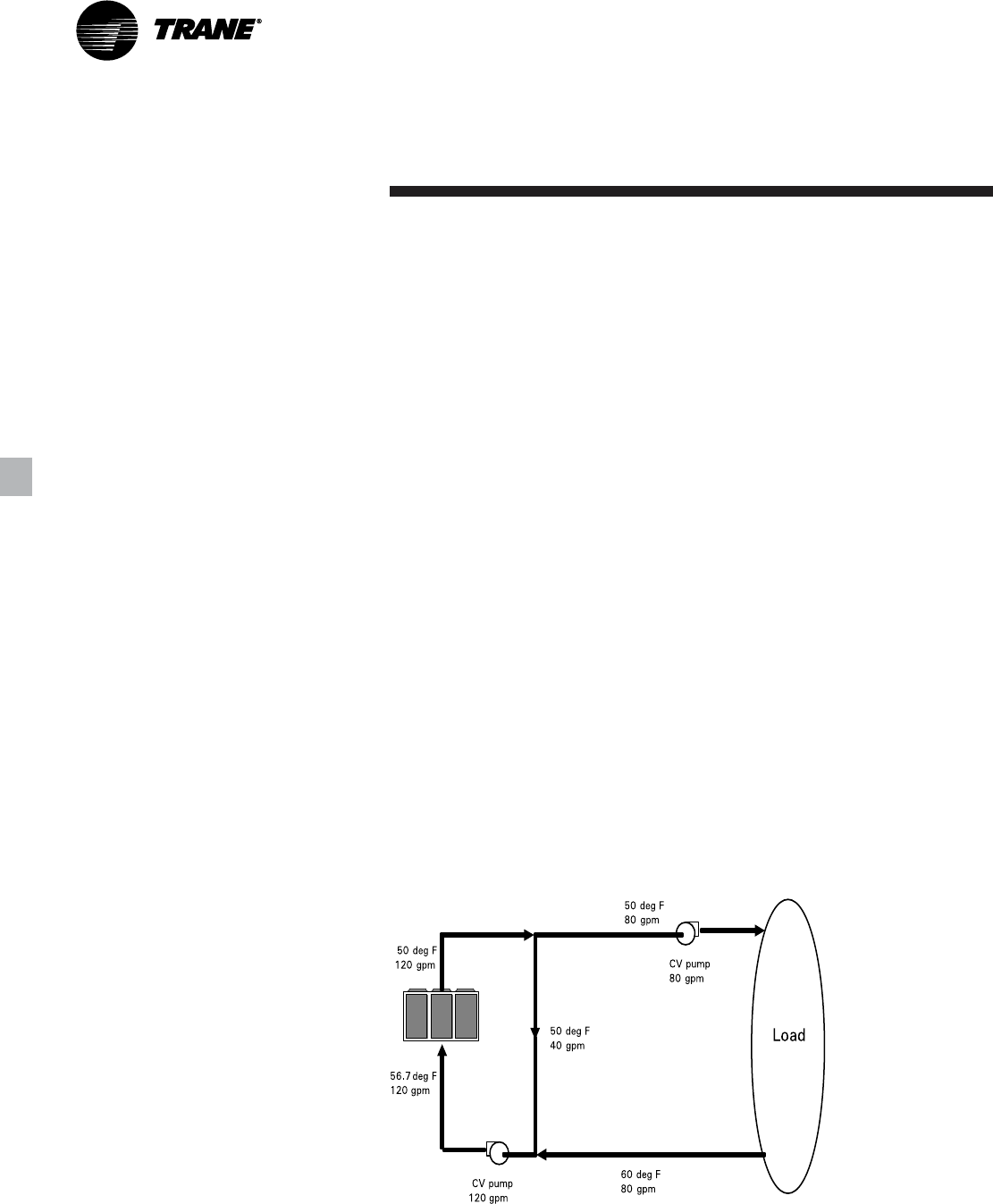
Flow Rates out of Range
Many process cooling jobs require flow
rates that cannot be met with the
minimum and maximum published
values for the Model RTAC evaporator. A
simple piping change can alleviate this
problem. For example: A plastic injection
molding process requires 80 gpm
[5.1 l/s] of 50°F [10°C] water and returns
that water at 60°F [15.6°C]. The selected
chiller can operate at these
temperatures, but has a minimum flow
rate of 120 gpm [7.6 l/s]. The system
layout in Figure A1 can satisfy the
process.
Flow Control
Trane requires the chilled water flow
control in conjunction with the Air-
Cooled Series R Chiller to be done by the
chiller. This will allow the chiller to
protect itself in potentially harmful
conditions.
Figure A1. GPM out of range system layout
13RLC-PRC006-EN
Application
Considerations
Leaving Water Temperature Limits
Trane air-cooled Series R chillers have
three distinct leaving water categories:
standard, low temperature, and ice
making. The standard leaving solution
temperature range is 40 to 60°F [4.4 to
15.6°C]. Low temperature machines
produce leaving liquid temperatures less
than 40°F [4.4°C]. Since liquid supply
temperature setpoints less than
40°F [4.4°C] result in suction
temperatures at or below the freezing
point of water, a glycol solution is
required for all low temperature
machines. Ice making machines have a
leaving liquid temperature range of 20 to
60°F [-6.7 to 15.6°C]. Ice making controls
include dual setpoint controls and
safeties for ice making and standard
cooling capabilities. Consult your local
Trane sales engineer for applications or
selections involving low temperature or
ice making machines. The maximum
water temperature that can be circulated
through an evaporator when the unit is
not operating is 108°F [42°C].
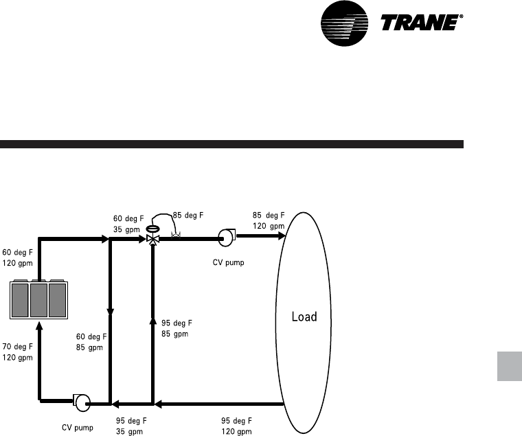
Leaving Water Temperature out of
Range
Many process cooling jobs require
temperature ranges that cannot be met
with the minimum and maximum
published values for the Model RTAC
evaporator. A simple piping change can
alleviate this problem. For example: A
laboratory load requires 120 gpm
[7.6 l/s] of water entering the process at
85°F [29.4°C] and returning at 95°F
[35°C]. The accuracy required is better
than the cooling tower can give. The
selected chiller has adequate capacity,
but a maximum leaving chilled water
temperature of 60°F [15.6°C].
In Figure A2, both the chiller and process
flow rates are equal. This is not
necessary. For example, if the chiller had
a higher flow rate, there would simply be
more water bypassing and mixing with
warm water.
Supply Water Temperature Drop
The performance data for the Trane air-
cooled Series R chiller is based on a
chilled water temperature drop of 10°F
[5.6°C]. Chilled water temperature drops
from 6 to 18°F [3.3 to 10°C] may be used
as long as minimum and maximum
water temperatures and flow rates are
not violated. Temperature drops outside
this range are beyond the optimum
range for control and may adversely
affect the microcomputer’s ability to
maintain an acceptable supply water
temperature range. Further, temperature
drops of less than 6°F [3.3°C] may result
in inadequate refrigerant superheat.
Sufficient superheat is always a primary
concern in any refrigerant system and is
especially important in a package chiller
where the evaporator is closely coupled
to the compressor. When temperature
drops are less than 6°F [3.3°C], an
evaporator runaround loop may be
required.
Variable Flow in the Evaporator
An attractive chilled water system option
may be a variable primary flow (VPF)
system. VPF systems present building
owners with several cost-saving benefits
that are directly related to the pumps.
The most obvious cost savings result
from eliminating the secondary
distribution pump, which in turn avoids
the expense incurred with the associated
piping connections (material, labor),
electrical service, and variable-frequency
drive. Building owners often cite pump-
related energy savings as the reason that
prompted them to install a VPF system.
With the help of a software analysis tool
such as System Analyzer™ or DOE-2, you
can determine whether the anticipated
energy savings justify the use of variable
primary flow in a particular application. It
may also be easier to apply variable
primary flow in an existing chilled-water
plant. Unlike the “decoupled” system
design, the bypass can be positioned at
various points in the chilled-water loop
and an additional pump is unnecessary.
The evaporator on the Model RTAC can
withstand up to 50 percent water flow
reduction as long as this flow is equal to
or above the minimum flow rate
requirements. The microprocessor and
capacity control algorithms are designed
to handle a maximum of 10% change in
water flow rate per minute in order to
maintain ± 0.5°F [0.28°C] leaving
evaporator temperature control. For
applications in which system energy
savings is most important and tight
temperature control is classified as
+/- 2°F [1.1°C], up to 30 percent changes
in flow per minute are possible.
Figure A2. Temperature out of range system layout
RLC-PRC006-EN14
Application
Considerations
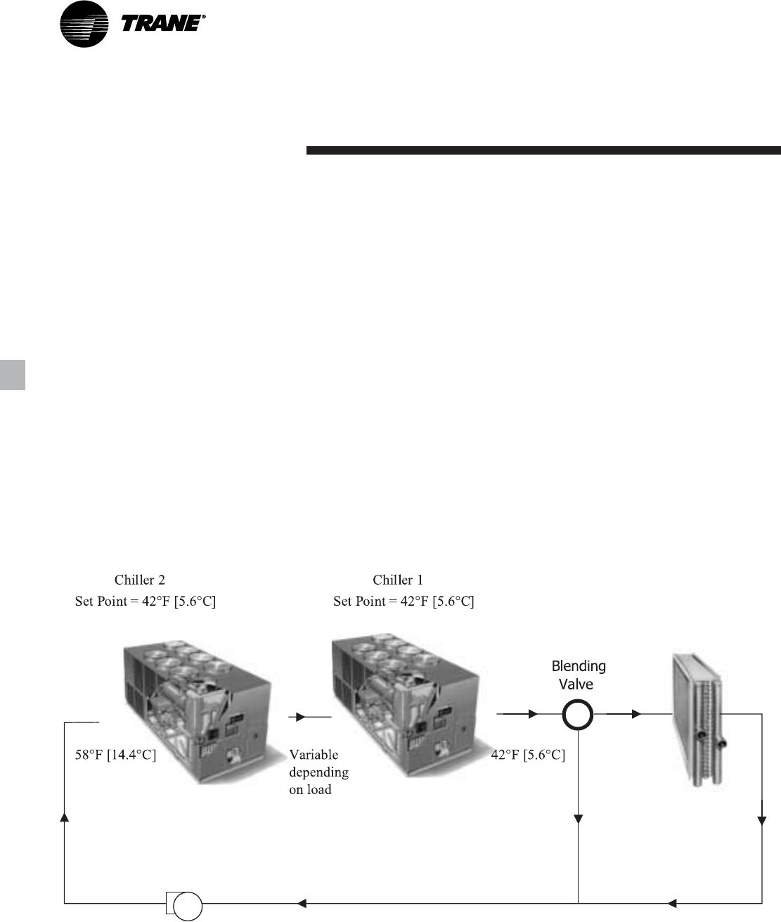
Figure A3. Typical series chiller arrangement
Series chiller arrangements can be
controlled in several ways. Figure A3
shows a strategy where each chiller is
trying to achieve the system design set
point. If the cooling load is less than 50
percent of the systems capabilities,
either chiller can fulfill the demand. As
system loads increase, the Chiller 2
becomes preferentially loaded as it
attempts to meet the leaving chilled
water setpoint. Chiller 1 will finish
cooling the leaving water from Chiller 2
down to the system design setpoint.
Staggering the chiller set points is
another control technique that works
well for preferentially loading Chiller 1. If
the cooling load is less than 50 percent
of the system capacity, Chiller 1 would
be able to satisfy the entire call for
cooling. As system loads increase,
Chiller 2 is started to meet any portion of
the load that Chiller 1 can not meet.
Typical Water Piping
All building water piping must be
flushed prior to making the final
connections to the chiller. To reduce heat
loss and prevent condensation,
insulation should be installed. Expansion
tanks are also usually required so that
chilled water volume changes can be
accommodated.
Series Chiller Arrangements
Another energy-saving strategy is to
design the system around chillers
arranged in series. The actual savings
possible with such strategies depends
on the application dynamics and should
be researched by consulting your Trane
Systems Solutions Representative and
applying the Trane System Analyzer
program. It is possible to operate a pair
of chillers more efficiently in a series
chiller arrangement than in a parallel
arrangement. It is also possible to
achieve higher entering-to-leaving chiller
differentials, which may, in turn, provide
the opportunity for lower chilled water
design temperature, lower design flow,
and resulting installation and operational
cost savings. The Trance screw
compressor also has excellent
capabilities for “lift,” which affords an
opportunity for savings on the
evaporator water loop.
15RLC-PRC006-EN
Application
Considerations
Short Water Loops
The proper location of the temperature
control sensor is in the supply (outlet)
water connection or pipe. This location
allows the building to act as a buffer and
assures a slowly changing return water
temperature. If there is not a sufficient
volume of water in the system to provide
an adequate buffer, temperature control
can be lost, resulting in erratic system
operation and excessive compressor
cycling. A short water loop has the same
effect as attempting to control from the
building return water. Typically, a two-
minute water loop is sufficient to prevent
problems. Therefore, as a guideline,
ensure the volume of water in the
evaporator loop equals or exceeds two
times the evaporator flow rate. For a
rapidly changing load profile, the
amount of volume should be increased.
To prevent the effect of a short water
loop, the following items should be
given careful consideration: A storage
tank or larger header pipe to increase the
volume of water in the system and,
therefore, reduce the rate of change of
the return water temperature.
Applications Types
• Comfort cooling.
• Industrial process cooling.
• Ice/thermal storage.
• Low temperature process cooling.
Typical Unit Installation
Outdoor HVAC equipment must be
located to minimize noise and vibration
transmission to the occupied spaces of
the building structure it serves. If the
equipment must be located in close
proximity to a building, it could be
placed next to an unoccupied space such
as a storage room, mechanical room,
etc. It is not recommended to locate the
equipment near occupied, sound
sensitive areas of the building or near
windows. Locating the equipment away
from structures will also prevent sound
reflection, which can increase levels at
property lines, or other sensitive points.
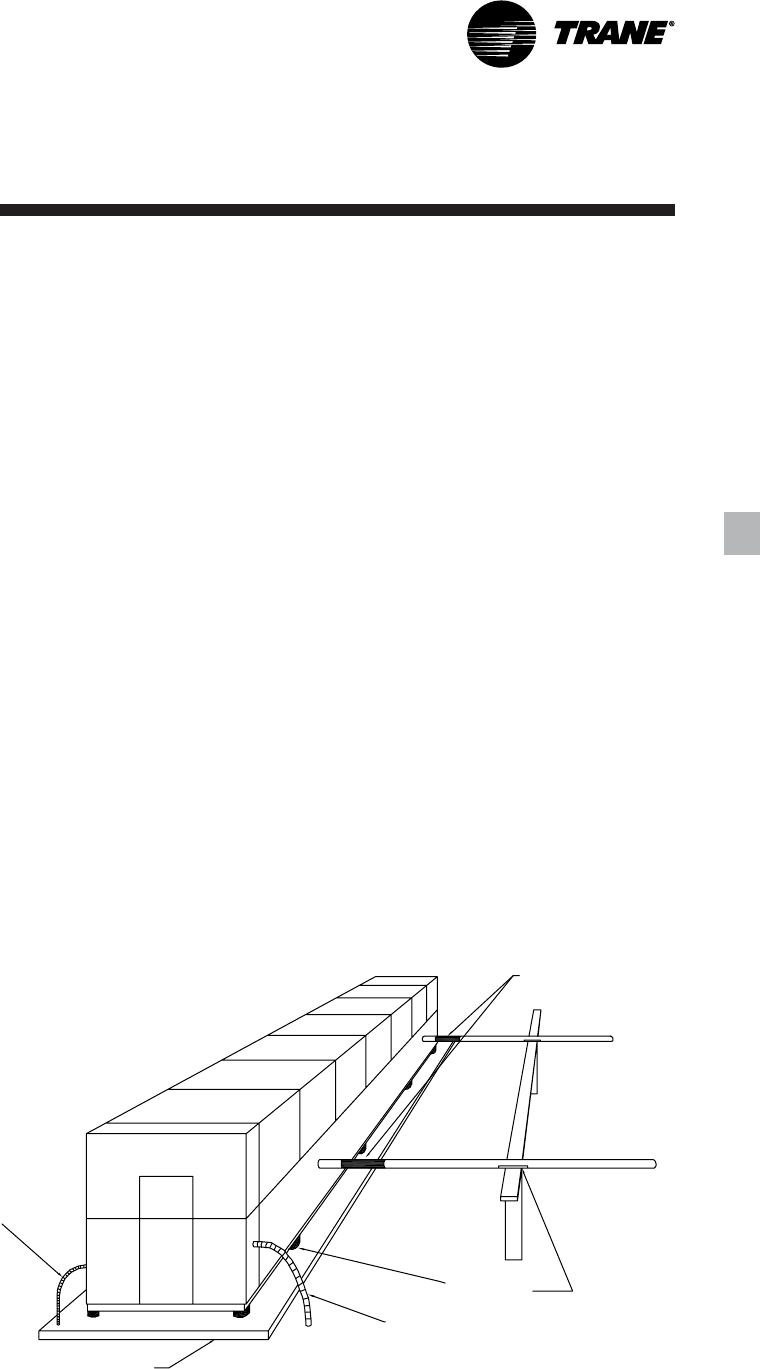
When physically isolating the unit from
structures, it is a good idea to not use
rigid supports, and to eliminate any
metal-to-metal or hard material contact,
when possible. This includes replacing
spring or metal weave isolation with
elastomeric isolators. Figure A4
illustrates isolation recommendations for
the RTAC.
For chiller sound ratings, installation tips
and considerations on chiller location,
pipe isolation, etc., refer to the
Trane Air-
Cooled Series R Chillers Sound Data and
Application Guide for Noise- Sensitive
Installations.
Elastomeric
Vibration
Eliminators
Avoid using the
chiller to support
chiller water
piping.
Neoprene
Isolators
Flex Conduit
Power Wiring
Concrete Base
Flex Conduit
Control Power
Figure A4. Unit isolation recommendations
RLC-PRC006-EN16
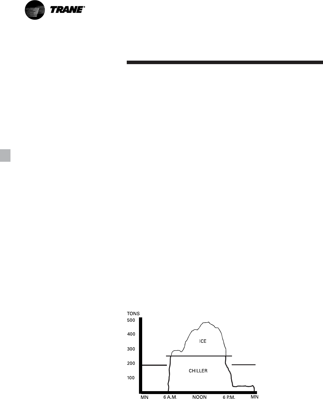
Figure A5. Ice storage demand cost savings
System Options — Ice Storage
Trane air-cooled Series R Chillers are
well suited for ice production. An air-
cooled machine typically switches to ice
production at night. Two things happen
under this assumption. First, the leaving
brine temperature from the evaporator is
lowered to around 22 to 24°F
[-5.5 to –4.4°C]. Second, the ambient
temperature has typically dropped about
15 to 20°F [8.3 to 11°C] from the peak
daytime ambient. This effectively places
a lift on the compressors that is similar
to daytime running conditions. The
chiller can operate in lower ambient at
night and successfully produce ice to
supplement the next day’s cooling
demands.
The Model RTAC produces ice by
supplying ice storage tanks with a
constant supply of glycol solution. Air-
cooled chillers selected for these lower
leaving fluid temperatures are also
selected for efficient production of
chilled fluid at nominal comfort cooling
conditions. The ability of Trane chillers to
serve “double duty” in ice production
and comfort cooling greatly reduces the
capital cost of ice storage systems.
When cooling is required, ice chilled
glycol is pumped from the ice storage
tanks directly to the cooling coils. No
expensive heat exchanger is required.
The glycol loop is a sealed system,
eliminating expensive annual chemical
treatment costs. The air-cooled chiller is
also available for comfort cooling duty at
nominal cooling conditions and
efficiencies. The modular concept of
glycol ice storage systems and the
proven simplicity of Trane Tracer
controllers allow the successful blend of
reliability and energy saving
performance in any ice storage
application.
The ice storage system is operated in six
different modes: each optimized for the
utility cost of the hour.
1. Provide comfort cooling with chiller
2. Provide comfort cooling with ice
3. Provide comfort cooling with ice and
chiller
4. Freeze ice storage
5. Freeze ice storage when comfort
cooling is required
6. Off
Tracer optimization software controls
operation of the required equipment and
accessories to easily transition from one
mode of operation to another. For
example:
Even with ice storage systems there are
numerous hours when ice is neither
produced or consumed, but saved. In
this mode the chiller is the sole source of
cooling. For example, to cool the
building after all ice is produced but
before high electrical demand charges
take effect, Tracer sets the air-cooled
chiller leaving fluid setpoint to its most
efficient setting and starts the chiller,
chiller pump, and load pump.
When electrical demand is high, the ice
pump is started and the chiller is either
demand limited or shut down
completely. Tracer controls have the
intelligence to optimally balance the
contribution of ice and chiller in meeting
the cooling load.
The capacity of the chiller plant is
extended by operating the chiller and ice
in tandem. Tracer rations the ice,
augmenting chiller capacity while
reducing cooling costs. When ice is
produced, Tracer will lower the air-
cooled chiller leaving fluid setpoint and
start the chiller, ice and chiller pumps,
and other accessories. Any incidental
loads that persist while producing ice
can be addressed by starting the load
pump and drawing spent cooling fluid
from the ice storage tanks.
For specific information on ice storage
applications, contact your local Trane
sales office.
Application
Considerations
17RLC-PRC006-EN
Model
Number
Description
140-500 Tons
Digits 1, 2 — Unit model
RT Rotary chiller
Digit 3 — Unit type
A Air cooled
Digit 4 — Development sequence
C First sequence
Digit 5, 6 & 7 — Nominal capacity
140 140 Nominal tons
155 155 Nominal tons
170 170 Nominal tons
185 185 Nominal tons
200 200 Nominal tons
225 225 Nominal tons
250 250 Nominal tons
275 275 Nominal tons
300 300 Nominal tons
350 350 Nominal tons
375 375 Nominal tons
400 400 Nominal tons
450 450 Nominal tons
500 500 Nominal tons
Digit 8 — Unit voltage
A 200/60/3
C 230/60/3
J 380/60/3
D 400/50/3
4 460/60/3
5 575/60/3
Digit 9 – Manufacturing location
U Water Chiller Business Unit,
Pueblo, CO USA
Digit 10, 11 — Design sequence
CO Factory Input
Digit 12 — Unit basic configuration
N Standard efficiency/performance
configuration
H High efficiency/performance
configuration
Digit 13 — Agency listing
N No agency listing
U UL/CUL listing
Digit 14 — Pressure vessel code
A ASME pressure vessel code
Digit 15 — Evaporator application
F Standard (40-60 F) leaving temp
G Low (Less than 40 F) leaving temp
R Remote (40-60 F) leaving temp
Digit 16 — Evaporator configuration
N Standard pass arrangement, insulated
Digit 17 — Condenser application
N Standard ambient range (25-115 F)
H High ambient capability (25-125 F)
L Low ambient capability (0-115 F)
W Wide ambient capability (0-125 F)
Digit 18 — Condenser fin material
1 Standard aluminum slit fins
2 Copper fins
4 CompleteCoat epoxy coated fins
Digit 19 — Condenser fan/motor
configuration
N STD fans with ODP motors
T STD fans with TEAO motors
W Low noise fans
Digit 20 — Compressor motor starter
type
X Across-the-line starter
Y Wye-delta closed transition starter
Digit 21 — Incoming power line
connection
1 Single point power connection
2 Dual point power connection
Digit 22 — Power line connection type
T Terminal block connection for
incoming line(s)
D Non-fused disconnect switch(es)
for incoming line(s)
C HACR rated circuit breaker(s) for
incoming line(s)
Digit 23 — Unit operator interface
E EasyView operator interface
D DynaView operator interface
Digit 24 — Remote operator interface
N No remote interface
C Tracer Comm 3 interface
L LonTalk compatible (LCI-C) interface
Digit 25 — Control input accessories/
options
N No remote inputs
R Ext. evaporator leaving water
setpoint
C Ext. current limit setpoint
B Ext. leaving water and current limit
setpoint
Digit 26 — Control output accessories/
options
N No output options
A Alarm relay outputs
C Icemaking I/O
D Alarm relay outputs and icemaking
I/O
Digit 27 — Electrical protection options
0 No short circuit rating
5 10,000 Amp short circuit rating
4 35,000 Amp short circuit rating
6 65,000 Amp short circuit rating
Digit 28 — Electrical accessories
N No electrical accessories
F Vapor proof flow switch – 150 psi
E Nema-1 flow switch –150 psi
Digit 29 — Control panel accessories
N No convenience outlet
A 15A 115V convenience outlet (60Hz)
Digit 30 — Service valves
1 With suction service valves
Digit 31 —- Compressor sound
attenuation option
0 No compressor sound attenuation
1 Factory installed compressor sound
attenuation
2 Field installed compressor sound
attenuation
Digit 32 — Appearance options
N No appearance options
A Architectural louvered panels
C Half louvers
G Access guards
B Access guards and half louvers
Digit 33 — Installation accessories
N No installation accessories
R Neoprene in shear unit isolators
F Flange kit for water connections
G Neoprene isolators and flange kit
RTAC350AUCONNA FNN1 N X 1 T E NN N 0NN10 NN
1,2 3 4 5,6,7 8 9 10,11 12 13 14 15 16 17 18 19 20 21 22 23 24 25 26 27 28 29 30 31 32 33

RLC-PRC006-EN18
General Data
Table G-1. General data — 140-500 ton 60 Hz units - standard efficiency
Size 140 155 170 185 200 225 250 275 300 350 400 450 500
Type STD STD STD STD STD STD STD STD STD STD STD STD STD
Compressor
Quantity (1) 2222222333444
Nominal Size (tons) 85 / 100 / 120 / 100-100 / 120-120 / 120-120 /
@ 60 Hz 70/70 85/70 85/85 100/85 100/100 120/100 120/120 85-100 100-100 120-100 100-100 100-100 120-120
Evaporator
Water storage(gallons)29323335393842606671818793
(liters) 111 121 127 134 146 145 158 227 249 267 304 327 350
Minimum flow (gpm) 197 221 209 221 250 221 250 275 308 342 457 501 545
(L/s) 12141314161416172022293234
Maximum flow (gpm) 700 787 765 787 853 787 853 908 1070 1192 1656 1818 1979
(L/s) 44504850545054576875105115125
Condenser
Qty of coils 4444444888888
Coil length (inches) 156/156 180/156 180/180 216/180 216/216 252/216 252/252 180/108 216/108 252/108 216/216 252/216 252/252
(millimeters) 3962/3962 4572/3962 4572/4572 5486/4572 5486/5486 6401/5486 6401/6401 4572/2743 5486/2743 6401/4572 5486/5486 6401/5486 6401/6401
Coil height (inches) 42 42 42 42 42 42 42 42 42 42 42 42 42
(millimeters) 1067 1067 1067 1067 1067 1067 1067 1067 1067 1067 1067 1067 1067
Fins/Ft 192 192 192 192 192 192 192 192 192 192 192 192 192
Number of rows 3333333333333
Condenser fans
Quantity (1) 4/4 5/4 5/5 6/5 6/6 7/6 7/7 10/6 12/6 14/6 12/12 14/12 14/14
Diameter (inches) 30 30 30 30 30 30 30 30 30 30 30 30 30
(millimeters) 762 762 762 762 762 762 762 762 762 762 762 762 762
Total airflow (cfm) 77000 84542 92087 101296 110506 119725 128946 147340 165766 184151 221016 239456 257991
(m^3/hr) 130811 143623 156441 172086 187732 203394 219059 250307 281610 312843 375471 406797 438285
Nominal fan speed rpm 1140 1140 1140 1140 1140 1140 1140 1140 1140 1140 1140 1140 1140
rps 19191919191919191919191919
Tip speed (ft/min) 8954 8954 8954 8954 8954 8954 8954 8954 8954 8954 8954 8954 8954
M/S 45454545454545454545454545
Minimum starting/operating ambient (2)
Standard unit (F) 25 25 25 25 25 25 25 25 25 25 25 25 25
(C) -3.9 -3.9 -3.9 -3.9 -3.9 -3.9 -3.9 -3.9 -3.9 -3.9 -3.9 -3.9 -3.9
Low ambient(F) 0000000000000
(C) -17.8 -17.8 -17.8 -17.8 -17.8 -17.8 -17.8 -17.8 -17.8 -17.8 -17.8 -17.8 -17.8
General unit
Refrigerant HFC-134a HFC-134a HFC-134a HFC-134a HFC-134a HFC-134a HFC-134a HFC-134a HFC-134a HFC-134a HFC-134a HFC-134a HFC-134a
No. of independent
refrigerant circuits 2222222222222
% Minimum load 15 15 15 15 15 15 15 15 15 15 15 15 15
Refrigerant charge (1) (pounds) 175/175 185/175 185/185 215/185 215/215 235/215 235/235 335/195 385/195 430/215 385/385 430/385 430/430
(kilograms) 79/79 84/79 84/84 98/84 98/98 107/98 107/107 152/88 175/88 195/97 175/175 195/175 195/195
Oil charge (1) [gallons] 1.5/1.5 1.5/1.5 1.5/1.5 2.1/1.5 2.1/2.1 2.1/2.1 2.1/2.1 4.6/2.6 5.0/2.6 4.6/4.6 5.0/5.0 5.0/5.0 5.0/5.0
[liters] 5.7/5.7 5.7/5.7 5.7/5.7 5.7/7.9 7.9/7.9 7.9/7.9 7.9/7.9 17.4/9.8 18.9/9.8 17.4/17.4 18.9/18.9 18.9/18.9 18.9/18.9
Notes:
1. Data containing information on two circuits shown as follows: CKT 1/CKT 2
2. Minimum start-up/operating ambient based on a 5 mph wind across the condenser

19RLC-PRC006-EN
Table G-2. General data — 140-400 ton 60 Hz units - high efficiency
Size 140 155 170 185 200 225 250 275 300 350 400
Type HIGH HIGH HIGH HIGH HIGH HIGH HIGH HIGH HIGH HIGH HIGH
Compressor
Quantity (1) 2 2 2 2 2 2 2 3 3 4 4
Nominal Size (tons) 100 / 85-85 / 100-100 /
@ 60 Hz 70/70 85/70 85/85 100/85 100/100 120/100 120/120 85-85/100 100-100 85-85 100-100
Evaporator
Water storage(gallons)3335393842 42 41.771718193
(liters) 127 134 146 145 158 158 157.8 267 267 304 351
Minimum flow (gpm) 209 221 250 221 250 250 250 342 342 457 545
(L/s) 1314161416 16 1622222934
Maximum flow (gpm) 765 787 853 787 853 853 853 1192 1192 1656 1979
(L/s) 4850545054 54 547575105125
Condenser
Qty of coils 44444 8 88888
Coil length (inches) 180/180 216/180 216/216 252/216 252/252 144/144 144/144 216/144 252/144 216/216 252/252
(millimeters) 4572/4572 5486/4572 5486/5486 6401/5486 6401/6401 3658/3658 4572/2743 5486/3658 6401/3658 5486/5486 6401/6401
Coil height(inches)4242424242 42 4242424242
(millimeters) 1067 1067 1067 1067 1067 1067 1067 1067 1067 1067 1067
Fins/Ft 192 192 192 192 192 192 192 192 192 192 192
Number of rows 3 3 3 3 3 3 3 3 3 3 3
Condenser fans
Quantity (1) 5/5 6/5 6/6 7/6 7/7 8/6 8/8 12/6 14/6 12/12 14/14
Diameter (inches)3030303030 30 3030303030
(millimeters) 762 762 762 762 762 762 762 762 762 762 762
Total airflow (cfm) 91993 101190 110387 119598 128812 136958 147242 173733 192098 220778 257626
(m^3/hr) 156281 171906 187530 203178 218831 232670 250141 295145 326344 375066 437665
Nominal fan speed rpm 1140 1140 1140 1140 1140 1140 1140 1140 1140 1140 1140
rps 1919191919 19 1919191919
Tip speed (ft/min) 8954 8954 8954 8954 8954 8954 8954 8954 8954 8954 8954
M/S 4545454545 45 4545454545
Minimum starting/operating ambient (2)
Standard unit (F) 25 25 25 25 25 25 25 25 25 25 25
(C) -3.9 -3.9 -3.9 -3.9 -3.9 -3.9 -3.9 -3.9 -3.9 -3.9 -3.9
Low ambient (F) 0 0 0 0 0 0 0 0 0 0 0
(C) -17.8 -17.8 -17.8 -17.8 -17.8 -17.8 -17.8 -17.8 -17.8 -17.8 -17.8
General unit
Refrigerant HFC-134a HFC-134a HFC-134a HFC-134a HFC-134a HFC-134a HFC-134a HFC-134a HFC-134a HFC-134a HFC-134a
No. of independent
refrigerant circuits 2 2 2 2 2 2 2 2 2 2 2
% Minimum load 15 15 15 15 15 15 15 15 15 15 15
Refrigerant charge (1) (pounds) 185/185 210/185 210/210 235/210 235/235 245/245 245/245 385/215 430/215 385/385 430/430
(kilograms) 84/84 95/87 95/95 107/95 107/107 111/111 111/111 175/97 195/97 175/175 195/195
Oil charge (1) [gallons] 1.5/1.5 1.5/1.5 1.5/1.5 2.1/1.5 2.1/2.1 2.1/2.1 2.1/2.1 4.6/2.7 5.0/2.7 4.6/4.6 5.0/5.0
[liters] 5.7/5.7 5.7/5.7 5.7/5.7 5.7/7.9 7.9/7.9 7.9/7.9 7.9/7.9 17.4/10.2 18.9/10.2 17.4/17.4 18.9/18.9
Notes:
1. Data containing information on two circuits shown as follows: CKT 1/CKT 2
2. Minimum start-up/operating ambient based on a 5 mph wind across the condenser
General Data
RLC-PRC006-EN20
General Data
Table G-3. General data — 140-400 ton 50 Hz units - standard efficiency
Size 140 155 170 185 200 250 275 300 350 375 400
Type STD STD STD STD STD STD STD STD STD STD STD
Compressor
Quantity (1) 2 2222 3 33444
Nominal Size (tons) 70-70 / 85-85 / 100-100 / 85-85 / 100-100 / 100-100 /
@ 50 Hz 70/70 85/70 85/85 100/85 100/100 100 100 100 85-85 85-85 100-100
Evaporator
Water storage(gallons)2932333539 54 6066717381
(liters) 111 121 127 134 146 205 227 249 265 276 304
Minimum flow (gpm) 197 221 209 221 250 242 275 308 457 501 545
(L/s) 1214131416 15 1720293234
Maximum flow (gpm) 700 787 765 787 853 747 909 1070 1313 1454 1656
(L/s) 4450485054 47 57688392105
Condenser
Qty of coils 44444 8 88888
Coil length (inches) 156/156 180/156 180/180 216/180 216/216 156/108 180/108 216/108 180/180 216/180 252/216
(millimeters) 3962/3962 4572/3962 4572/4572 5486/4572 5486/5486 3962/4572 4572/2743 5486/2743 4572/4572 5486/4572 6401/5486
Coil height (inches) 42 42 42 42 42 42 42 42 42 42 42
(millimeters) 1067 1067 1067 1067 1067 1067 1067 1067 1067 1067 1067
Fins/Ft 192 192 192 192 192 192 192 192 192 192 192
Number of rows 33333 3 33333
Condenser fans
Quantity (1) 4/4 5/4 5/5 6/5 6/6 8/6 10/6 12/6 10/10 12/10 12/12
Diameter (inches) 30 30 30 30 30 30 30 30 30 30 30
(millimeters) 762 762 762 762 762 762 762 762 762 762 762
Total airflow (cfm) 63346 69507 75671 83236 90803 108698 121056 136210 151332 166467 181611
(m^3/hr) 107615 118081 128553 141405 154260 184661 205655 231399 257089 282801 308528
Nominal fan speed rpm 950 950 950 950 950 950 950 950 950 950 950
rps 15.8 15.8 15.8 15.8 15.8 15.8 15.8 15.8 15.8 15.8 15.8
Tip speed (ft/min) 7461 7461 7461 7461 7461 7461 7461 7461 7461 7461 7461
M/S 3838383838 38 3838383838
Minimum starting/operating ambient (2)
Standard unit (F) 25 25 25 25 25 25 25 25 25 25 25
(C) -3.9 -3.9 -3.9 -3.9 -3.9 -3.9 -3.9 -3.9 -3.9 -3.9 -3.9
Low ambient(F) 00000 0 00000
(C) -17.8 -17.8 -17.8 -17.8 -17.8 -17.8 -17.8 -17.8 -17.8 -17.8 -17.8
General unit
Refrigerant HFC-134a HFC-134a HFC-134a HFC-134a HFC-134a HFC-134a HFC-134a HFC-134a HFC-134a HFC-134a HFC-134a
No. of independent
refrigerant circuits 22222 2 22222
% Minimum load 15 15 15 15 15 15 15 15 15 15 15
Refrigerant charge (1) (pounds) 175/175 185/175 185/185 215/185 215/215 305/195 335/195 385/195 335/335 385/335 385/385
(kilograms) 79/79 84/79 84/84 98/84 98/98 138/88 152/88 175/88 152/152 175/152 175/175
Oil charge (1) [gallons] 1.5/1.5 1.5/1.5 1.5/1.5 2.1/1.5 2.1/2.1 4.6/2.6 4.6/2.6 5.0/2.6 4.6/4.6 5.0/4.6 5.0/5.0
[liters] 5.7/5.7 5.7/5.7 5.7/5.7 5.7/7.9 7.9/7.9 17.4/9.8 17.4/9.8 18.9/9.8 17.4/17.4 18.9/17.4 18.9/18.9
Notes:
1. Data containing information on two circuits shown as follows: CKT 1/CKT 2
2. Minimum start-up/operating ambient based on a 5 mph wind across the condenser
21RLC-PRC006-EN
General Data
Table G-4. General data — 140-400 ton 50 Hz units - high efficiency
Size 140 155 170 185 200 250 275 300 350 375 400
Type HIGH HIGH HIGH HIGH HIGH HIGH HIGH HIGH HIGH HIGH HIGH
Compressor
Quantity (1) 22222 3 33444
Nominal Size (tons) 70-70 / 85-85 / 100-100 / 85-85 / 100-100 / 100-100 /
@ 50 Hz 70/70 85/70 85/85 100/85 100/100 100 100 100 85-85 85-85 100-100
Evaporator
Water storage (gallons) 33 35 39 38 42 66 71 71 81 87 93
(liters) 127 134 146 145 158 249 267 267 304 327 350
Minimum flow (gpm) 209 221 250 221 250 308 342 342 457 501 545
(L/s)1314161416 20 2222293234
Maximum flow (gpm) 765 787 853 787 853 1070 1192 1192 1656 1818 1979
(L/s) 48 50 54 50 54 68 75 75 105 115 125
Condenser
Qty of coils 44444 8 88888
Coil length (inches) 180/180 216/180 216/216 252/216 252/252 180/108 216/144 252/144 216/216 252/216 252/252
(millimeters) 4572/4572 5486/4572 5486/5486 6401/5486 6401/6401 4572/2743 5486/3658 6401/3658 5486/5486 6401/5486 6401/6401
Coil height (inches) 42 42 42 42 42 42 42 42 42 42 42
(millimeters) 1067 1067 1067 1067 1067 1067 1067 1067 1067 1067 1067
Fins/Ft 192 192 192 192 192 192 192 192 192 192 192
Number of rows 33333 3 33333
Condenser fans
Quantity (1) 5/5 6/5 6/6 7/6 7/7 10/6 12/6 14/6 12/12 14/12 14/14
Diameter (inches) 30 30 30 30 30 30 30 30 30 30 30
(millimeters) 762 762 762 762 762 762 762 762 762 762 762
Total airflow (cfm) 75575 83130 90687 98256 105826 120971 142969 158112 181371 194731 211648
(m^3/hr) 128390 141225 154063 166921 179781 205510 242881 268607 308120 330817 359556
Nominal fan speed rpm 950 950 950 950 950 950 950 950 950 950 950
rps 15.8 15.8 15.8 15.8 15.8 15.8 15.8 15.8 15.8 15.8 15.8
Tip speed (ft/min) 7461 7461 7461 7461 7461 7461 7461 7461 7461 7461 7461
M/S3838383838 38 3838383838
Minimum starting/operating ambient (2)
Standard unit (F) 25 25 25 25 25 25 25 25 25 25 25
(C) -3.9 -3.9 -3.9 -3.9 -3.9 -3.9 -3.9 -3.9 -3.9 -3.9 -3.9
Low ambient(F) 00000 0 00000
(C) -17.8 -17.8 -17.8 -17.8 -17.8 -17.8 -17.8 -17.8 -17.8 -17.8 -17.8
General unit
Refrigerant HFC-134a HFC-134a HFC-134a HFC-134a HFC-134a HFC-134a HFC-134a HFC-134a HFC-134a HFC-134a HFC-134a
No. of independent
refrigerant circuits 22222 2 22222
% Minimum load 15 15 15 15 15 15 15 15 15 15 15
Refrigerant charge (1) (pounds) 185/185 210/185 210/210 235/210 235/235 335/195 385/215 430/215 385/385 430/385 430/430
(kilograms) 84/84 95/87 95/95 107/95 107/107 152/88 175/97 195/97 175/175 195/175 195/195
Oil charge (1) (pounds) 15.3/15.3 21.8/20.8 21.8/21.8 22.8/21.8 22.8/22.8 33.7/20.3 39.1/24.3 42.6/24.3 39.1/39.1 42.6/39.1 42.6/42.6
(kilograms) 5.7/5.7 5.7/5.7 5.7/5.7 5.7/7.9 7.9/7.9 17.4/9.8 17.4/9.8 18.9/9.8 17.4/17.4 18.9/18.9 18.9/18.9
Notes:
1. Data containing information on two circuits shown as follows: CKT 1/CKT 2
2. Minimum start-up/operating ambient based on a 5 mph wind across the condenser
RLC-PRC006-EN22
Trane air-cooled Series R chiller
performance is rated in accordance with
the ARI Standard 550/590-1998
Certification Program. Chiller selection
assistance and performance information
can be obtained by using the Series R
chiller selection program, available
through local Trane sales offices.
The chiller capacity tables cover the
most frequently encountered leaving
liquid temperatures. The tables reflect a
10°F [5.6°C] temperature drop through
the evaporator. For other temperature
drops, apply the appropriate
Performance Data Adjustment Factors
from Table A-1. For chilled brine
selections, contact your local Trane sales
engineer. To select a Trane air-cooled
Series R™ chiller, the following
information is required:
1
Design load in tons of refrigeration
2
Design chilled water temperature drop
3
Design leaving chilled water temperature
4
Design ambient temperature
Evaporator flow rates can be determined
by using the following formulas:
GPM = (Tons x 24) / Temperature Drop
(Degrees F)
OR
L/S = (kW (Capacity) x .239) /
Temperature Drop (Degrees C)
NOTE: Flow rates must fall within the
limits specified in Tables G-1 through G-4
(for GPM or for L/s).
Selection
Procedure
Selection Example
Given:
Required System Load = 140 Tons
Leaving Chilled Water Temperature
(LCWT) = 44°F Chilled Water
Temperature Drop = 10°F Design
Ambient Temperature = 95°F
Evaporator Fouling Factor = 0.0001
1
To calculate the required chilled water
flow rate we use the formula given
below:
GPM = (140 Tons x 24) / 10°F = 336 GPM
2
From Table P-1 (RTAC performance
data), an RTAC 140 standard at the given
conditions will produce 138.2 tons with
compressor power input of 158.6 kW
and a unit EER of 9.7.
3
To determine the evaporator pressure
drop use the flow rate (GPM) and
pressure drop chart on page 16. Entering
the curve at 336 gpm, the pressure drop
for a nominal 140 standard evaporator is
16 feet.
Minimum Leaving Chilled Water
Temperature Setpoint
The minimum leaving chilled water
temperature setpoint for water is 40°F.
For those applications requiring lower
setpoints, a glycol solution must be
used. Contact the local Trane sales
engineer for additional information.
Table S-1. Performance data adjustment factors
Chilled Elevation
Fouling Water Sea Level 2000 ft 4000 ft 6000 ft
Factor Temp. CAP GPM KW CAP GPM KW CAP GPM KW CAP GPM KW
0.0001 8 0.997 1.246 0.999 0.987 1.233 1.012 0.975 1.217 1.027 0.960 1.200 1.045
10 1.000 1.000 1.000 0.989 0.989 1.013 0.977 0.977 1.028 0.963 0.963 1.047
12 1.003 0.835 1.001 0.992 0.826 1.014 0.979 0.816 1.030 0.965 0.804 1.048
14 1.004 0.717 1.002 0.993 0.710 1.016 0.981 0.701 1.031 0.966 0.690 1.049
16 1.006 0.629 1.003 0.995 0.622 1.016 0.982 0.614 1.032 0.968 0.605 1.050
0.00025 8 0.982 1.227 0.991 0.972 1.215 1.003 0.961 1.200 1.018 0.947 1.183 1.036
10 0.986 0.985 0.992 0.975 0.975 1.005 0.963 0.963 1.020 0.950 0.950 1.038
12 0.988 0.823 0.994 0.978 0.815 1.006 0.966 0.805 1.022 0.952 0.793 1.040
14 0.991 0.708 0.995 0.980 0.700 1.008 0.968 0.692 1.023 0.954 0.682 1.041
16 0.992 0.621 0.996 0.982 0.614 1.009 0.970 0.606 1.024 0.956 0.598 1.042
23RLC-PRC006-EN
Table P-1. 60 Hz standard efficiency machines in English units
Condenser Entering Air Temperature (F)
85 95 105 115
Evaporator
Leaving Water Unit Size
Temperature (F) Model RTAC Tons kW input EER Tons kW input EER Ton kW input EER Tons kW input EER
140 STD 138.0 139.9 10.9 128.4 152.4 9.4 118.5 166.4 8.0 108.3 182.1 6.7
155 STD 151.7 152.4 10.9 141.3 166.0 9.4 130.7 181.4 8.1 119.7 198.5 6.8
170 STD 165.6 165.0 11.0 154.6 179.9 9.5 143.2 196.5 8.1 131.5 215.1 6.9
185 STD 180.9 183.7 10.8 168.9 199.7 9.4 156.5 217.8 8.0 143.8 238.1 6.8
200 STD 196.6 202.7 10.7 183.6 219.9 9.3 170.2 239.4 7.9 156.2 261.3 6.7
40 225 STD 216.1 222.2 10.7 202.1 241.1 9.3 187.5 262.5 8.0 172.5 286.6 6.8
250 STD 236.2 242.2 10.8 221.0 262.7 9.4 205.2 286.0 8.0 188.8 312.1 6.8
275 STD 266.9 272.0 10.8 249.9 296.1 9.4 232.1 323.3 8.0 213.8 353.7 6.8
300 STD 299.3 312.5 10.6 280.1 339.0 9.2 260.2 369.1 7.9 239.4 402.9 6.7
350 STD 338.6 354.0 10.6 317.3 383.8 9.2 295.1 417.7 7.9 272.0 455.8 6.7
400 STD 400.0 416.3 10.6 374.4 451.5 9.2 347.6 491.4 7.9 319.9 536.3 6.7
450 STD 436.5 458.1 10.5 408.9 496.5 9.2 380.0 540.3 7.9 350.0 589.3 6.7
500 STD 477.0 500.1 10.6 447.0 541.8 9.2 415.7 589.1 7.9 383.1 642.3 6.7
140 STD 143.2 142.9 11.1 133.3 155.5 9.5 123.1 169.6 8.1 112.6 185.4 6.9
155 STD 157.4 155.7 11.1 146.7 169.4 9.6 135.7 184.8 8.2 124.4 202.0 6.9
170 STD 171.7 168.5 11.2 160.4 183.4 9.7 148.6 200.2 8.3 136.6 218.8 7.0
185 STD 187.5 187.7 11.0 175.2 203.8 9.5 162.4 222.0 8.2 149.3 242.4 6.9
200 STD 203.8 207.2 10.9 190.4 224.5 9.4 176.5 244.1 8.1 162.1 266.1 6.9
42 225 STD 223.9 227.3 10.9 209.4 246.3 9.5 194.4 267.9 8.1 178.8 292.1 6.9
250 STD 244.9 248.0 10.9 229.1 268.6 9.5 212.7 292.0 8.2 195.8 318.3 6.9
275 STD 276.4 277.7 11.0 258.9 301.9 9.5 240.6 329.3 8.2 221.7 359.9 6.9
300 STD 309.8 319.3 10.7 290.1 346.0 9.3 269.5 376.3 8.0 248.2 410.3 6.8
350 STD 350.6 362.0 10.7 328.6 392.1 9.3 305.7 426.3 8.1 281.8 464.6 6.9
400 STD 414.2 425.4 10.8 387.8 460.8 9.4 360.2 501.1 8.1 331.6 546.3 6.9
450 STD 452.0 468.4 10.7 423.5 507.2 9.3 393.7 551.3 8.0 362.7 600.7 6.8
500 STD 494.0 511.8 10.7 463.1 553.9 9.3 430.7 601.6 8.0 396.9 655.1 6.9
140 STD 148.4 146.0 11.3 138.2 158.6 9.7 127.7 172.9 8.3 116.9 188.7 7.0
155 STD 163.2 159.0 11.3 152.1 172.8 9.8 140.8 188.3 8.4 129.2 205.6 7.1
170 STD 178.0 172.0 11.4 166.2 187.1 9.9 154.2 203.9 8.5 141.8 222.7 7.2
185 STD 194.2 191.7 11.2 181.5 208.0 9.7 168.4 226.3 8.3 154.8 246.8 7.1
200 STD 211.1 211.8 11.0 197.2 229.2 9.6 182.9 249.0 8.2 168.1 271.1 7.0
44 225 STD 231.8 232.5 11.0 216.9 251.6 9.6 201.4 273.4 8.3 185.3 297.7 7.0
250 STD 253.6 253.8 11.1 237.3 274.6 9.6 220.4 298.2 8.3 202.8 324.6 7.1
275 STD 286.0 283.4 11.2 268.0 307.9 9.7 249.2 335.5 8.3 229.8 366.2 7.1
300 STD 320.5 326.2 10.9 300.2 353.1 9.6 279.0 383.6 8.2 257.0 417.8 6.9
350 STD 362.7 370.3 10.9 340.0 400.6 9.6 316.3 435.0 8.2 291.6 473.5 7.0
400 STD 428.5 434.7 10.9 401.3 470.4 9.6 372.9 510.9 8.2 343.5 556.4 7.0
450 STD 467.7 479.1 10.8 438.3 518.2 9.6 407.6 562.5 8.1 375.6 612.2 6.9
500 STD 511.3 523.8 10.8 479.3 566.3 9.6 445.8 614.3 8.2 410.9 668.1 7.0
Notes:
1. Ratings based on sea level altitude and evaporator fouling factor of 0.00010.
2. Consult Trane representative for performance at temperatures outside of the ranges shown.
3. kW input is for compressors only.
4. EER = Energy Efficiency Ratio (Btu/watt-hour). Power inputs include compressors, condenser fans and control power.
5. Ratings are based on an evaporator temperature drop of 10°F.
6. Ambient temperatures 115°F and greater reflect the high ambient condenser option.
7. Interpolation between points is permissible. Extrapolation is not permitted.
8. Rated in accordance with ARI Standard 550/590-98.
Performance
Data
Full Load
Performance

RLC-PRC006-EN24
Performance
Data
Table P-1 (Continued). 60 Hz standard efficiency machines in English units
Condenser Entering Air Temperature (F)
85 95 105 115
Evaporator
Leaving Water Unit Size
Temperature (F) Model RTAC Tons kW input EER Tons kW input EER Ton kW input EER Tons kW input EER
140 STD 153.8 149.1 11.4 143.3 161.9 9.9 132.4 176.2 8.4 121.2 192.1 7.1
155 STD 169.0 162.4 11.5 157.7 176.3 10.0 146.0 191.9 8.5 134.0 209.2 7.2
170 STD 184.3 175.7 11.6 172.2 190.8 10.0 159.8 207.7 8.6 147.1 226.6 7.3
185 STD 201.1 195.9 11.4 187.9 212.2 9.9 174.4 230.7 8.5 160.5 251.3 7.2
200 STD 218.4 216.5 11.2 204.2 234.0 9.7 189.4 253.9 8.4 174.1 276.2 7.1
46 225 STD 239.9 237.8 11.2 224.5 257.1 9.7 208.4 279.0 8.4 191.8 303.4 7.1
250 STD 262.5 259.8 11.2 245.6 280.8 9.8 228.1 304.5 8.4 209.8 331.1 7.2
275 STD 295.7 289.3 11.3 277.2 314.0 9.8 257.9 341.7 8.5 238.0 372.6 7.2
300 STD 331.2 333.3 11.0 310.3 360.4 9.6 288.6 391.1 8.3 265.9 425.5 7.1
350 STD 374.9 378.7 11.0 351.5 409.3 9.6 327.1 443.9 8.3 301.6 482.6 7.1
400 STD 443.0 444.1 11.1 415.0 480.1 9.7 385.8 520.9 8.3 355.5 566.7 7.1
450 STD 483.5 489.9 11.0 453.2 529.3 9.6 421.6 574.0 8.3 388.6 624.0 7.1
500 STD 528.7 536.1 11.0 495.7 578.9 9.6 461.1 627.3 8.3 423.3 677.7 7.1
140 STD 159.2 152.4 11.6 148.4 165.2 10.0 137.1 179.6 8.6 125.6 195.6 7.3
155 STD 175.0 165.9 11.7 163.3 179.8 10.1 151.2 195.5 8.7 138.9 212.9 7.4
170 STD 190.7 179.4 11.8 178.3 194.6 10.2 165.5 211.6 8.8 152.4 230.5 7.5
185 STD 208.0 200.1 11.5 194.5 216.6 10.0 180.5 235.1 8.6 166.2 255.8 7.3
200 STD 225.9 221.3 11.3 211.2 239.0 9.9 195.9 258.9 8.5 180.2 281.3 7.2
48 225 STD 248.1 243.2 11.3 232.1 262.7 9.9 215.5 284.7 8.5 198.4 309.3 7.3
250 STD 271.5 266.0 11.4 254.1 287.2 9.9 235.9 311.0 8.5 217.0 337.6 7.3
275 STD 305.6 295.4 11.5 286.5 320.2 10 266.7 348.1 8.6 246.3 379.1 7.3
300 STD 342.1 340.5 11.2 320.6 367.8 9.8 298.2 398.7 8.4 275.0 433.3 7.2
350 STD 387.3 387.3 11.1 363.2 418.1 9.7 338.0 453.0 8.4 304.6 476.3 7.2
400 STD 457.6 453.8 11.2 428.8 490 9.8 398.8 531.1 8.5 367.6 577.1 7.2
450 STD 499.5 501.0 11.1 468.3 540.7 9.7 435.7 585.7 8.4 392.5 616.2 7.2
500 STD 546.3 548.7 11.1 512.2 591.9 9.7 476.5 640.6 8.4 425.5 664.2 7.3
140 STD 164.7 155.7 11.8 153.5 168.5 10.2 142.0 183.0 8.7 130.1 199.1 7.4
155 STD 181.0 169.5 11.9 169.0 183.5 10.3 156.6 199.2 8.8 143.8 216.7 7.5
170 STD 197.2 183.2 11.9 184.4 198.4 10.4 171.3 215.5 8.9 157.9 234.5 7.6
185 STD 214.9 204.4 11.7 201.0 221.0 10.2 186.7 239.6 8.8 171.9 260.4 7.5
200 STD 233.4 226.2 11.5 218.2 244.0 10.0 202.5 264.1 8.6 186.3 286.6 7.4
50 225 STD 256.3 248.8 11.5 239.9 268.4 10.0 222.7 290.5 8.6 202.0 308.5 7.4
250 STD 280.7 272.4 11.5 262.6 293.6 10.0 243.8 317.6 8.7 219.1 332.7 7.5
275 STD 315.5 301.5 11.6 296.0 326.4 10.1 275.6 354.5 8.8 250.2 377.2 7.5
300 STD 353.1 347.9 11.3 331.0 375.3 9.9 308.0 406.4 8.5 278.0 428.3 7.3
350 STD 399.7 396.0 11.3 374.9 427.1 9.9 349.0 462.2 8.5 307.4 468.9 7.4
400 STD 472.4 463.6 11.3 442.8 500.1 9.9 411.9 541.5 8.6 373.1 573.4 7.4
450 STD 515.7 512.2 11.2 483.6 552.3 9.8 449.9 597.6 8.5 396.3 607.0 7.4
500 STD 564.1 561.5 11.2 528.9 605.0 9.8 492.0 654.0 8.5 429.1 652.8 7.4
Notes:
1. Ratings based on sea level altitude and evaporator fouling factor of 0.00010.
2. Consult Trane representative for performance at temperatures outside of the ranges shown.
3. kW input is for compressors only.
4. EER = Energy Efficiency Ratio (Btu/watt-hour). Power inputs include compressors, condenser fans and control power.
5. Ratings are based on an evaporator temperature drop of 10°F.
6. Ambient temperatures 115°F and greater reflect the high ambient condenser option.
7. Interpolation between points is permissible. Extrapolation is not permitted.
8. Rated in accordance with ARI Standard 550/590-98.
Full Load
Performance

25RLC-PRC006-EN
Table P-2. 60 Hz high efficiency machines in English units
Condenser Entering Air Temperature (F)
85 95 105 115
Evaporator
Leaving Water Unit Size
Temperature (F) Model RTAC Tons kW input EER Tons kW input EER Ton kW input EER Tons kW input EER
140 HIGH 142.9 134.5 11.4 133.3 146.1 9.9 123.4 159.4 8.5 113.1 174.3 7.2
155 HIGH 156.3 146.0 11.5 145.9 158.8 10.0 135.2 173.4 8.5 124.2 189.7 7.2
170 HIGH 169.9 157.7 11.6 158.8 171.7 10.0 147.3 187.5 8.6 135.4 205.3 7.3
185 HIGH 186.1 176.8 11.4 174.1 191.9 9.9 161.7 209.1 8.5 148.9 228.4 7.2
200 HIGH 202.6 196.1 11.2 189.6 212.1 9.8 176.1 230.6 8.4 162.2 251.4 7.2
40 225 HIGH 222.4 216.4 11.2 208.5 234.0 9.8 194.0 254.2 8.5 178.9 277.0 7.2
250 HIGH 241.0 235.7 11.1 226.1 254.9 9.7 210.6 277.0 8.4 194.4 301.8 7.2
275 HIGH 276.7 262.5 11.5 259.2 285.0 10.0 241.0 310.7 8.6 222.3 339.4 7.3
300 HIGH 307.8 302.1 11.1 288.7 326.8 9.7 268.8 355.1 8.4 248.1 387.1 7.2
350 HIGH 343.3 322.8 11.5 321.4 351.4 9.9 298.7 383.7 8.5 275.3 420.0 7.3
400 HIGH 409.8 404.1 11.0 384.1 436.7 9.6 357.2 474.2 8.3 329.3 516.6 7.1
140 HIGH 148.4 137.3 11.7 138.6 149.0 10.1 128.3 162.3 8.7 117.7 177.3 7.4
155 HIGH 162.3 149.0 11.7 151.6 161.9 10.2 140.6 176.6 8.7 129.3 193.0 7.4
170 HIGH 176.4 160.9 11.8 165.0 175.0 10.3 153.1 190.9 8.8 141.0 208.7 7.5
185 HIGH 193.1 180.5 11.6 180.8 195.7 10.1 168.0 213.0 8.7 154.7 232.4 7.4
200 HIGH 210.2 200.4 11.4 196.8 216.5 9.9 182.9 235.0 8.6 168.5 256.0 7.3
42 225 HIGH 230.8 221.3 11.4 216.4 239.0 10.0 201.4 259.3 8.6 185.8 282.2 7.4
250 HIGH 250.0 241.2 11.3 234.6 260.5 9.9 218.5 282.7 8.6 201.8 307.7 7.3
275 HIGH 287.1 268.0 11.7 269.0 290.6 10.2 250.3 316.4 8.8 231.0 345.3 7.5
300 HIGH 319.1 308.6 11.3 299.4 333.5 9.9 278.8 361.9 8.6 257.5 394.1 7.3
350 HIGH 356.2 329.4 11.7 333.6 358.1 10.2 310.3 390.6 8.7 286.3 427.0 7.4
400 HIGH 425.1 412.9 11.2 398.5 445.8 9.8 370.8 483.5 8.5 342.0 526.1 7.2
140 HIGH 154.1 140.2 11.9 143.9 151.9 10.3 133.4 165.3 8.9 122.4 180.4 7.5
155 HIGH 168.4 152.1 12.0 157.5 165.1 10.4 146.1 179.8 8.9 134.4 196.3 7.6
170 HIGH 183.1 164.2 12.0 171.3 178.4 10.5 159.1 194.4 9.0 146.6 212.3 7.7
185 HIGH 200.3 184.3 11.8 187.5 199.6 10.3 174.3 216.9 8.9 160.7 236.5 7.6
200 HIGH 218.0 204.8 11.6 204.2 221.0 10.1 189.8 239.6 8.8 174.9 260.6 7.5
44 225 HIGH 239.3 226.3 11.6 224.4 244.1 10.2 208.9 264.6 8.8 192.8 287.6 7.5
250 HIGH 259.3 246.8 11.5 243.3 266.3 10.1 226.7 288.6 8.7 209.4 313.7 7.5
275 HIGH 297.5 273.6 11.9 279.0 296.4 10.4 259.7 322.2 8.9 239.8 351.3 7.6
300 HIGH 330.5 315.3 11.5 310.2 340.3 10.1 289.1 368.9 8.7 267.1 401.2 7.5
350 HIGH 369.3 336.0 11.9 346.1 364.9 10.4 322.2 397.6 8.9 297.5 434.2 7.6
400 HIGH 440.5 422.0 11.4 413.1 455.0 10.0 384.6 492.9 8.6 354.9 535.7 7.4
Notes:
1. Ratings based on sea level altitude and evaporator fouling factor of 0.00010.
2. Consult Trane representative for performance at temperatures outside of the ranges shown.
3. kW input is for compressors only.
4. EER = Energy Efficiency Ratio (Btu/watt-hour). Power inputs include compressors, condenser fans and control power.
5. Ratings are based on an evaporator temperature drop of 10°F.
6. Ambient temperatures 115°F and greater reflect the high ambient condenser option.
7. Interpolation between points is permissible. Extrapolation is not permitted.
8. Rated in accordance with ARI Standard 550/590-98.
Performance
Data
Full Load
Performance
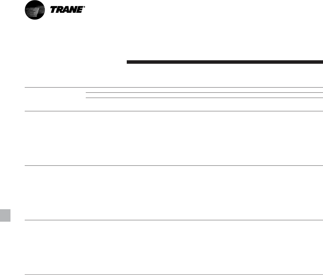
RLC-PRC006-EN26
Performance
Data
Full Load
Performance
Table P-2 (Continued). 60 Hz high efficiency machines in English units
Condenser Entering Air Temperature (F)
85 95 105 115
Evaporator
Leaving Water Unit Size
Temperature (F) Model RTAC Tons kW input EER Tons kW input EER Ton kW input EER Tons kW input EER
140 HIGH 159.9 143.1 12.1 149.4 154.9 10.5 138.5 168.4 9.1 127.2 183.5 7.7
155 HIGH 174.7 155.2 12.2 163.4 168.3 10.6 151.7 183.1 9.1 139.7 199.6 7.8
170 HIGH 189.9 167.6 12.3 177.7 181.8 10.7 165.1 197.9 9.2 152.3 215.9 7.8
185 HIGH 207.6 188.3 12.0 194.4 203.6 10.5 180.8 221.0 9.0 166.8 240.6 7.7
200 HIGH 225.9 209.3 11.8 211.6 225.6 10.3 196.8 244.3 8.9 181.4 265.4 7.6
46 225 HIGH 248.0 231.5 11.8 232.6 249.4 10.3 216.6 269.9 9.0 199.9 293.1 7.7
250 HIGH 268.7 252.6 11.7 252.1 272.2 10.2 234.9 294.6 8.9 217.0 319.9 7.6
275 HIGH 308.2 279.3 12.1 289.1 302.2 10.5 269.3 328.2 9.1 248.8 357.4 7.8
300 HIGH 342.1 322.1 11.7 321.2 347.2 10.2 299.4 376.0 8.9 276.8 408.5 7.6
350 HIGH 382.6 342.9 12.1 358.8 371.9 10.6 334.2 404.8 9.1 308.8 441.5 7.8
400 HIGH 456.1 431.2 11.6 427.9 464.4 10.1 398.5 502.5 8.8 368.0 545.6 7.5
140 HIGH 165.8 146.1 12.3 155.0 158.0 10.7 143.7 171.5 9.3 132.1 186.7 7.9
155 HIGH 181.0 158.5 12.4 169.4 171.6 10.8 157.4 186.4 9.3 145.0 203.1 7.9
170 HIGH 196.8 171.0 12.5 184.2 185.3 10.9 171.3 201.5 9.4 158.1 219.5 8.0
185 HIGH 215.0 192.3 12.2 201.4 207.6 10.6 187.4 225.1 9.2 173.0 244.8 7.9
200 HIGH 233.9 213.9 11.9 219.2 230.3 10.5 203.9 249.0 9.1 188.1 270.2 7.8
48 225 HIGH 256.8 236.8 12.0 240.9 254.8 10.5 224.3 275.4 9.1 207.1 298.7 7.8
250 HIGH 278.2 258.5 11.8 261.1 278.2 10.4 243.3 300.8 9.0 224.7 326.1 7.7
275 HIGH 319.0 285.1 12.3 299.3 308.1 10.7 279.0 334.2 9.3 257.9 363.5 7.9
300 HIGH 353.8 329.0 11.8 332.3 354.2 10.4 309.9 383.2 9.0 286.6 415.8 7.7
350 HIGH 396.1 349.8 12.3 371.6 379.0 10.7 346.3 412.0 9.3 320.3 448.9 7.9
400 HIGH 472.0 440.6 11.7 442.9 474.0 10.3 412.7 512.3 9.0 381.3 555.5 7.7
140 HIGH 171.7 149.2 12.5 160.6 161.2 10.9 149.0 174.8 9.4 137.0 190.0 8.0
155 HIGH 187.5 161.8 12.6 175.5 174.9 11.0 163.1 189.9 9.5 150.4 206.5 8.1
170 HIGH 203.7 174.6 12.7 190.8 188.9 11.1 177.6 205.1 9.6 164.0 223.2 8.2
185 HIGH 222.5 196.3 12.4 208.5 211.8 10.8 194.1 229.4 9.4 179.2 249.1 8.0
200 HIGH 242.0 218.6 12.1 226.8 235.0 10.6 211.1 253.9 9.2 194.8 275.2 7.9
50 225 HIGH 265.7 242.2 12.1 249.3 260.3 10.7 232.2 281.0 9.3 214.4 304.3 7.9
250 HIGH 287.9 264.5 12.0 270.2 284.4 10.5 251.7 307.1 9.1 232.5 332.5 7.9
275 HIGH 329.9 291.1 12.4 309.7 314.2 10.9 288.8 340.4 9.5 267.2 369.8 8.1
300 HIGH 365.7 336.0 12.0 343.6 361.4 10.5 320.6 390.5 9.2 296.6 423.3 7.9
350 HIGH 409.8 356.9 12.5 384.7 386.3 10.9 358.7 419.4 9.5 332.0 456.3 8.1
400 HIGH 488.0 450.2 11.9 458.1 483.8 10.5 427.0 522.2 9.1 394.7 565.7 7.8
Notes:
1. Ratings based on sea level altitude and evaporator fouling factor of 0.00010.
2. Consult Trane representative for performance at temperatures outside of the ranges shown.
3. kW input is for compressors only.
4. EER = Energy Efficiency Ratio (Btu/watt-hour). Power inputs include compressors, condenser fans and control power.
5. Ratings are based on an evaporator temperature drop of 10°F.
6. Ambient temperatures 115°F and greater reflect the high ambient condenser option.
7. Interpolation between points is permissible. Extrapolation is not permitted.
8. Rated in accordance with ARI Standard 550/590-98.
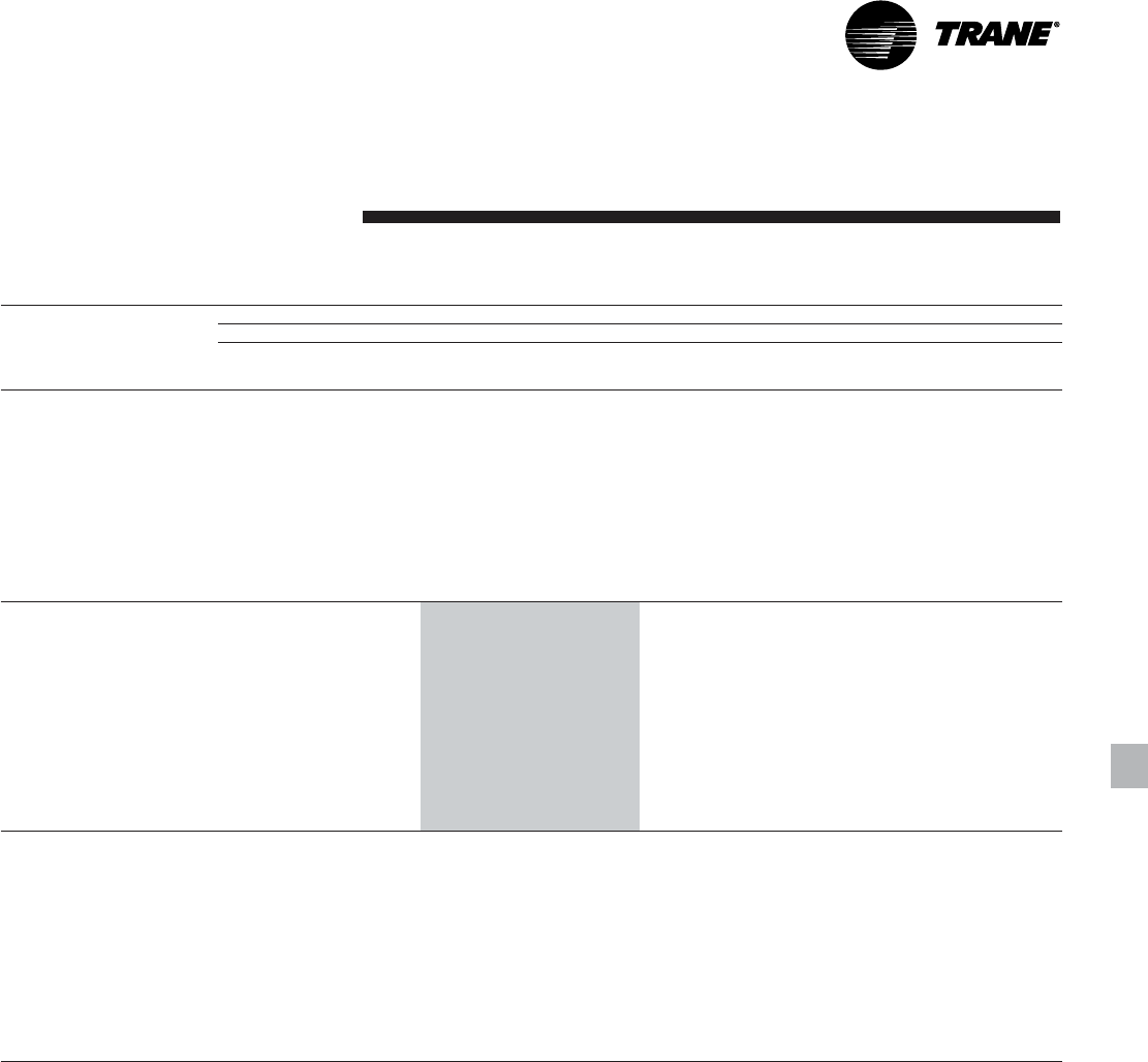
27RLC-PRC006-EN
Table P-3. 60 Hz standard efficiency machines in SI units
Condenser Entering Air Temperature (C)
30 35 40 45
Evaporator
Leaving Water Unit Size kW kW kW kW kW kW kW kW
Temperature (C) Model RTAC cooling input COP output input COP output input COP output input COP
155 STD 153.5 155.3 3.4 144.0 167.7 3.2 134.3 181.5 2.8 124.3 196.7 2.4
170 STD 167.6 168.2 3.5 157.5 181.6 3.2 147.1 196.6 2.8 136.4 213.1 2.4
185 STD 183.0 187.2 3.4 172.1 201.8 3.2 160.8 218.0 2.7 149.1 236.0 2.4
200 STD 198.9 206.6 3.4 187.0 222.2 3.1 174.7 239.7 2.7 162.0 259.1 2.3
5 225 STD 218.6 226.5 3.4 205.8 243.7 3.1 192.5 263.0 2.7 178.8 284.3 2.4
250 STD 239.0 247.0 3.4 225.1 265.7 3.1 210.6 286.5 2.7 195.7 309.7 2.4
275 STD 270.0 277.1 3.4 254.4 299.0 3.1 238.2 323.4 2.7 221.5 350.4 2.4
300 STD 302.6 318.4 3.3 285.1 342.5 3.1 266.9 369.5 2.7 248.1 399.5 2.3
350 STD 342.5 360.8 3.3 323.0 388.0 3.1 302.7 418.4 2.7 281.7 452.2 2.3
400 STD 404.5 424.1 3.3 381.1 456.1 3.1 356.7 492.0 2.7 331.4 531.9 2.3
450 STD 441.5 466.9 3.3 416.2 501.9 3.1 389.9 541.1 2.7 362.6 584.7 2.3
500 STD 482.5 509.9 3.3 455.1 547.8 3.1 426.4 590.4 2.7 396.7 637.6 2.3
140 STD 149.0 148.1 3.5 139.8 159.6 3.3 130.2 172.4 2.8 120.4 186.4 2.4
155 STD 163.8 161.3 3.5 153.8 173.8 3.3 143.5 187.7 2.9 133.0 203.1 2.5
170 STD 178.7 174.5 3.6 168.0 188.2 3.3 157.1 203.3 2.9 145.9 219.9 2.5
185 STD 195.0 194.5 3.5 183.5 209.2 3.3 171.5 225.7 2.8 159.3 243.9 2.5
200 STD 211.9 214.9 3.4 199.3 230.7 3.2 186.3 248.4 2.8 172.9 268.0 2.4
7 225 STD 232.8 235.9 3.4 219.2 253.3 3.2 205.1 272.8 2.8 190.5 294.4 2.4
250 STD 254.7 257.6 3.5 239.8 276.5 3.2 224.4 297.6 2.8 208.5 321.0 2.4
275 STD 287.2 287.5 3.4 270.8 309.7 3.2 253.8 334.4 2.8 236.2 361.7 2.5
300 STD 321.7 330.9 3.4 303.2 355.3 3.2 284.0 382.7 2.8 264.2 413.0 2.4
350 STD 364.1 375.7 3.4 343.5 403.2 3.2 322.0 434.1 2.8 299.7 468.2 2.4
400 STD 430.2 440.9 3.4 405.4 473.3 3.2 379.7 509.6 2.8 353.1 550.0 2.4
450 STD 469.5 486.0 3.4 442.8 521.5 3.2 414.9 561.3 2.8 386.0 605.4 2.4
500 STD 513.4 531.5 3.4 484.2 570.1 3.2 453.8 613.2 2.8 422.3 660.9 2.4
140 STD 158.7 153.9 3.6 148.9 165.5 3.4 138.8 178.4 2.9 128.4 192.6 2.5
155 STD 174.4 167.6 3.6 163.9 180.2 3.4 153.0 194.3 2.9 141.9 209.7 2.5
170 STD 190.1 181.2 3.7 178.9 195.0 3.4 167.4 210.2 3.0 155.6 227.0 2.6
185 STD 207.3 202.1 3.6 195.1 217.0 3.3 182.6 233.6 2.9 169.7 251.9 2.5
200 STD 225.2 223.5 3.5 211.9 239.5 3.3 198.1 257.4 2.9 184.0 277.2 2.5
9 225 STD 247.3 245.6 3.5 232.9 263.3 3.3 218.0 283.0 2.9 202.5 304.7 2.5
250 STD 270.7 268.7 3.5 254.9 287.8 3.3 238.5 309.2 2.9 221.6 332.8 2.5
275 STD 304.7 298.3 3.5 287.5 320.8 3.3 253.8 334.4 2.8 251.3 373.3 2.5
300 STD 341.2 343.9 3.5 321.7 368.6 3.3 284.0 382.7 2.8 280.6 426.9 2.5
350 STD 386.2 391.1 3.4 364.4 419.1 3.2 322.0 434.1 2.8 318.1 484.8 2.5
400 STD 456.3 458.2 3.5 430.2 491.0 3.3 379.7 509.6 2.8 375.2 568.6 2.5
450 STD 498.1 505.9 3.4 469.9 541.9 3.2 414.9 561.3 2.8 409.9 626.7 2.5
500 STD 544.8 554.1 3.4 513.9 593.2 3.2 453.8 613.2 2.8 448.2 685.0 2.5
Notes:
1. Ratings based on sea level altitude and evaporator fouling factor of 0.0176.
2. Consult Trane representative for performance at temperatures outside of the ranges shown.
3. kW input is for compressors only.
4. COP = Coefficient of Performance (kWo/kWi). Power inputs include compressors, condenser fans and control power.
5. Ratings are based on an evaporator temperature drop of 5.6°C.
6. Ambient temperatures 40°C and greater reflect the high ambient condenser option.
7. Interpolation between points is permissible. Extrapolation is not permitted.
8. Rated in accordance with ARI Standard 550/590-98.
Performance
Data
Full Load
Performance

RLC-PRC006-EN28
Performance
Data
Full Load
Performance
Table P-4. 60 Hz high efficiency machines in SI units
Condenser Entering Air Temperature (C)
30 35 40 45
Evaporator
Leaving Water Unit Size kW kW kW kW kW kW kW kW
Temperature (C) Model RTAC cooling input COP output input COP output input COP output input COP
140 HIGH 144.7 137.0 3.3 135.9 147.5 3.0 126.9 159.4 2.6 117.5 172.6 2.2
155 HIGH 158.2 148.7 3.4 148.8 160.4 3.0 139.0 173.4 2.6 129.0 187.9 2.3
170 HIGH 172.1 160.6 3.4 161.8 173.3 3.0 151.4 187.6 2.6 140.6 203.3 2.3
185 HIGH 188.4 180.1 3.4 177.4 193.8 3.0 166.1 209.2 2.6 154.4 226.3 2.3
200 HIGH 205.1 199.7 3.3 193.2 214.3 3.0 180.9 230.8 2.6 168.2 249.3 2.2
5 225 HIGH 225.2 220.5 3.4 212.4 236.5 3.0 199.2 254.6 2.6 185.5 274.8 2.2
250 HIGH 244.0 240.2 3.3 230.4 257.7 2.9 216.2 277.5 2.6 201.5 299.6 2.2
275 HIGH 280.2 267.4 3.4 264.1 287.8 3.0 247.5 310.8 2.6 230.5 336.3 2.3
300 HIGH 311.5 307.7 3.3 294.1 330.1 2.9 275.9 355.5 2.6 257.0 383.9 2.2
350 HIGH 347.5 328.8 3.4 327.5 354.7 3.0 306.8 383.8 2.6 285.6 415.9 2.3
400 HIGH 414.9 411.5 3.3 391.3 441.2 2.9 366.8 474.9 2.5 341.4 512.4 2.2
140 HIGH 154.9 142.1 3.5 145.6 152.8 3.1 136.0 164.8 2.7 126.1 178.2 2.3
155 HIGH 169.2 154.3 3.6 159.2 166.0 3.1 149.0 179.2 2.7 138.4 193.8 2.4
170 HIGH 184.0 166.5 3.6 173.2 179.4 3.1 162.1 193.7 2.8 150.8 209.6 2.4
185 HIGH 201.2 187.0 3.5 189.6 200.8 3.1 177.6 216.3 2.7 165.3 233.6 2.4
200 HIGH 219.0 207.7 3.4 206.4 222.4 3.1 193.4 239.0 2.7 179.9 257.7 2.3
7 225 HIGH 240.5 229.5 3.4 226.9 245.7 3.1 212.8 264.0 2.7 198.3 284.4 2.3
250 HIGH 260.5 250.3 3.4 246.0 268.1 3.0 230.9 288.0 2.7 215.2 310.3 2.3
275 HIGH 298.9 277.5 3.5 282.0 298.1 3.1 264.6 321.3 2.7 246.6 347.0 2.4
300 HIGH 332.0 319.7 3.4 313.5 342.3 3.0 294.4 368.0 2.7 274.5 396.6 2.3
350 HIGH 371.0 340.8 3.5 349.9 367.0 3.1 328.2 396.3 2.7 305.9 428.7 2.4
400 HIGH 442.5 427.8 3.4 417.6 457.8 3.0 391.7 491.8 2.6 364.9 529.7 2.3
140 HIGH 165.3 147.6 3.7 155.5 158.3 3.2 145.4 170.4 2.8 135.0 183.9 2.5
155 HIGH 180.6 160.0 3.7 170.0 171.9 3.2 159.2 185.2 2.8 148.0 199.9 2.5
170 HIGH 196.2 172.7 3.7 184.9 185.7 3.3 173.2 200.2 2.8 161.3 216.1 2.5
185 HIGH 214.4 194.1 3.6 202.1 208.1 3.2 189.5 223.7 2.8 176.5 241.1 2.4
200 HIGH 233.3 215.9 3.5 220.0 230.7 3.1 206.2 247.5 2.8 192.0 266.3 2.4
9 225 HIGH 256.1 239.0 3.5 241.7 255.4 3.1 226.8 273.8 2.8 211.4 294.4 2.4
250 HIGH 277.5 261.0 3.5 262.1 278.9 3.1 246.0 299.0 2.8 229.3 321.5 2.4
275 HIGH 318.2 287.9 3.6 300.4 308.8 3.2 282.0 332.1 2.8 263.1 358.1 2.5
300 HIGH 352.9 332.1 3.5 333.5 355.0 3.1 313.3 380.9 2.8 292.4 409.8 2.4
350 HIGH 395.1 353.3 3.7 372.9 379.8 3.2 350.2 409.3 2.8 326.8 441.9 2.5
400 HIGH 470.8 444.7 3.5 444.5 475.0 3.1 417.2 509.2 2.7 389.0 547.5 2.4
Notes:
1. Ratings based on sea level altitude and evaporator fouling factor of 0.0176.
2. Consult Trane representative for performance at temperatures outside of the ranges shown.
3. kW input is for compressors only.
4. COP = Coefficient of Performance (kWo/kWi). Power inputs include compressors, condenser fans and control power.
5. Ratings are based on an evaporator temperature drop of 5.6°C.
6. Ambient temperatures 40°C and greater reflect the high ambient condenser option.
7. Interpolation between points is permissible. Extrapolation is not permitted.
8. Rated in accordance with ARI Standard 550/590-98.
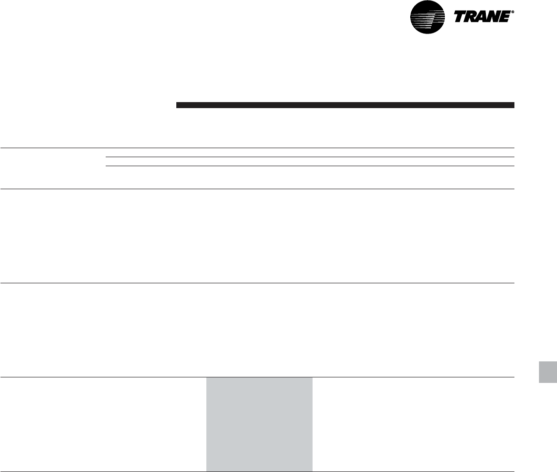
29RLC-PRC006-EN
Performance
Data
Table P-5. 50 Hz standard efficiency machines in English units
Condenser Entering Air Temperature (F)
85 95 105 115
Evaporator
Leaving Water Unit Size
Temperature (F) Model RTAC Tons kW input EER Tons kW input EER Ton kW input EER Tons kW input EER
140 STD 134.2 144.4 10.6 124.5 158.0 9.0 114.5 173.1 7.6 104.3 189.7 6.4
155 STD 146.9 159.5 10.5 136.3 174.0 9.0 125.5 190.1 7.6 114.4 208.0 6.4
170 STD 159.8 174.7 10.4 148.4 190.1 8.9 136.7 207.4 7.6 124.8 226.6 6.4
185 STD 176.9 190.6 10.6 164.6 207.3 9.1 152.0 226.1 7.7 139.0 246.8 6.5
200 STD 194.4 206.8 10.7 181.1 224.8 9.2 167.5 244.9 7.9 153.3 267.2 6.6
40 250 STD 235.2 251.7 10.7 219.4 275.1 9.2 203.0 301.2 7.8 185.0 327.9 6.5
275 STD 262.8 284.5 10.6 245.1 309.7 9.1 226.7 337.9 7.7 206.7 367.2 6.5
300 STD 299.0 318.8 10.7 279.2 346.5 9.2 258.7 377.6 7.9 232.8 402.2 6.7
350 STD 325.2 357.0 10.4 302.7 388.8 8.9 279.5 424.4 7.6 255.6 464.0 6.4
375 STD 359.1 389.7 10.5 335.1 424.1 9.1 310.1 462.6 7.7 281.6 499.7 6.5
400 STD 395.8 424.5 10.7 369.7 461.3 9.2 342.4 502.5 7.9 308.1 535.3 6.7
140 STD 139.1 147.6 10.8 129.0 161.3 9.2 118.8 176.5 7.8 107.1 190.7 6.5
155 STD 152.2 163.1 10.7 141.3 177.7 9.1 130.1 194.0 7.7 118.1 210.7 6.5
170 STD 165.4 178.7 10.6 153.7 194.3 9.1 141.7 211.7 7.7 127.6 227.1 6.5
185 STD 183.1 195.0 10.7 170.4 211.9 9.2 157.4 230.8 7.9 141.9 247.3 6.6
200 STD 201.2 211.7 10.9 187.5 229.8 9.4 173.4 250.2 8.0 155.0 264.5 6.8
42 250 STD 243.3 257.1 10.8 227.0 280.7 9.3 210.1 307.1 7.9 186.8 323.4 6.7
275 STD 271.8 290.8 10.7 253.5 316.3 9.2 234.5 344.8 7.8 208.1 361.3 6.7
300 STD 309.1 326.0 10.8 288.8 354.1 9.4 267.6 385.5 8.0 235.1 397.5 6.8
350 STD 336.3 365.0 10.5 313.2 397.0 9.1 289.3 433.0 7.7 257.7 457.0 6.5
375 STD 371.3 398.4 10.7 346.5 433.2 9.2 320.8 472.2 7.8 284.7 494.4 6.7
400 STD 409.3 434.2 10.8 382.4 471.5 9.3 354.3 513.2 8.0 311.1 529.1 6.8
140 STD 144.0 150.8 10.9 133.7 164.6 9.3 123.1 180.0 7.9 108.1 187.6 6.7
155 STD 157.5 166.7 10.8 146.2 181.4 9.3 134.7 197.9 7.9 118.8 206.7 6.6
170 STD 171.1 182.8 10.7 159.0 198.5 9.2 146.6 216.0 7.8 129.1 224.7 6.6
185 STD 189.3 199.5 10.9 176.3 216.6 9.4 162.8 235.6 8.0 142.8 243.1 6.8
200 STD 208.0 216.6 11.0 194.0 235.0 9.5 179.4 255.6 8.1 156.5 261.2 6.9
44 250 STD 251.4 262.6 11.0 234.7 286.5 9.4 217.3 313.1 8.0 188.4 318.3 6.8
275 STD 280.7 297.3 10.8 261.9 323.0 9.3 242.4 351.8 8.0 209.2 354.6 6.8
300 STD 319.3 333.5 11.0 298.4 361.9 9.5 276.6 393.7 8.1 235.9 389.3 7.0
350 STD 347.6 373.2 10.7 323.8 405.5 9.2 299.2 441.7 7.8 259.5 449.0 6.7
375 STD 383.6 407.4 10.8 358.1 442.5 9.3 331.7 481.9 7.9 287.6 488.3 6.8
400 STD 422.9 444.1 10.9 395.2 481.9 9.4 366.3 524.1 8.1 313.9 521.8 6.9
Notes:
1. Ratings based on sea level altitude and evaporator fouling factor of 0.00010.
2. Consult Trane representative for performance at temperatures outside of the ranges shown.
3. kW input is for compressors only.
4. EER = Energy Efficiency Ratio (Btu/watt-hour). Power inputs include compressors, condenser fans and control power.
5. Ratings are based on an evaporator temperature drop of 10°F.
6. Ambient temperatures 115°F and greater reflect the high ambient condenser option.
7. Interpolation between points is permissible. Extrapolation is not permitted.
8. Rated in accordance with ARI Standard 550/590-98.
Full Load
Performance

RLC-PRC006-EN30
Performance
Data
Full Load
Performance
Table P-5 (Continued). 50 Hz standard efficiency machines in English units
Condenser Entering Air Temperature (F)
85 95 105 115
Evaporator
Leaving Water Unit Size
Temperature (F) Model RTAC Tons kW input EER Tons kW input EER Ton kW input EER Tons kW input EER
140 STD 149.0 154.1 11.1 138.4 168.0 9.5 127.5 183.5 8.0 109.0 184.2 6.8
155 STD 162.9 170.5 10.9 151.3 185.3 9.4 139.4 201.8 8.0 119.3 202.2 6.8
170 STD 176.8 187.0 10.8 164.4 202.8 9.3 151.6 220.4 7.9 130.0 220.6 6.8
185 STD 195.6 204.1 11.0 182.2 221.3 9.5 168.4 240.6 8.1 144.3 239.8 6.9
200 STD 215.0 221.7 11.1 200.5 240.3 9.6 185.5 261.1 8.2 157.0 255.6 7.1
46 250 STD 259.6 268.2 11.1 242.4 292.3 9.5 224.5 319.2 8.1 189.8 312.6 7.0
275 STD 289.8 304.0 10.9 270.5 329.9 9.4 250.4 358.9 8.1 211.2 349.4 7.0
300 STD 329.6 341.1 11.1 308.1 369.8 9.6 285.7 402.0 8.2 237.7 382.8 7.2
350 STD 358.9 381.5 10.8 334.5 414.1 9.3 309.2 450.5 7.9 262.2 443.0 6.8
375 STD 396.0 416.5 10.9 369.8 452.0 9.4 342.6 491.7 8.0 288.8 478.0 7.0
400 STD 436.7 454.3 11.0 408.1 492.5 9.5 378.4 535.2 8.2 316.4 513.3 7.1
140 STD 154.0 157.4 11.2 143.1 171.5 9.6 131.9 187.1 8.2 109.7 180.4 7.0
155 STD 168.3 174.3 11.1 156.4 189.3 9.5 144.2 205.9 8.1 120.4 198.8 7.0
170 STD 182.6 191.2 10.9 169.8 207.1 9.4 156.6 224.9 8.0 131.3 217.4 7.0
185 STD 202.0 208.8 11.1 188.2 226.2 9.6 173.9 245.6 8.2 145.6 236.0 7.1
200 STD 222.0 226.8 11.2 207.1 245.7 9.7 191.6 266.7 8.3 158.3 251.1 7.3
48 250 STD 267.8 273.9 11.2 250.2 298.3 9.7 229.7 321.0 8.3 192.0 308.6 7.2
275 STD 299.0 310.7 11.0 279.1 336.9 9.5 256.3 361.6 8.2 213.0 343.5 7.2
300 STD 340.1 348.8 11.2 317.9 378.0 9.7 289.7 399.6 8.4 240.7 378.2 7.3
350 STD 370.3 390.0 10.9 345.2 422.8 9.4 319.2 459.5 8.0 264.7 436.2 7.0
375 STD 408.5 425.8 11.0 381.6 461.7 9.5 352.1 498.6 8.2 292.8 473.1 7.1
400 STD 450.6 464.7 11.1 421.2 503.4 9.6 383.7 532.1 8.3 318.7 503.7 7.3
140 STD 159.2 160.9 11.4 147.9 175.0 9.7 134.3 186.6 8.3 111.0 177.7 7.2
155 STD 173.8 178.2 11.2 161.6 193.3 9.6 147.0 205.8 8.3 121.2 194.9 7.2
170 STD 188.5 195.6 11.1 175.3 211.6 9.5 159.1 223.7 8.2 131.8 212.3 7.2
185 STD 208.5 213.6 11.2 194.2 231.1 9.7 176.5 244.2 8.4 146.8 231.8 7.3
200 STD 229.2 232.1 11.3 213.8 251.2 9.8 192.6 261.3 8.5 160.3 247.9 7.5
50 250 STD 276.2 279.7 11.3 258.1 304.4 9.8 231.6 315.6 8.5 194.2 304.1 7.4
275 STD 308.2 317.6 11.1 287.8 344.1 9.6 257.8 354.5 8.4 214.5 337.6 7.3
300 STD 350.6 356.8 11.3 327.8 386.3 9.8 290.9 390.8 8.6 241.9 371.5 7.5
350 STD 381.8 398.6 11.0 356.0 431.7 9.5 321.4 451.3 8.2 266.4 427.8 7.2
375 STD 421.1 435.3 11.1 393.5 471.6 9.6 354.1 489.0 8.4 294.6 464.2 7.3
400 STD 464.6 475.3 11.2 434.4 514.5 9.7 385.3 520.5 8.5 320.4 494.8 7.5
Notes:
1. Ratings based on sea level altitude and evaporator fouling factor of 0.00010.
2. Consult Trane representative for performance at temperatures outside of the ranges shown.
3. kW input is for compressors only.
4. EER = Energy Efficiency Ratio (Btu/watt-hour). Power inputs include compressors, condenser fans and control power.
5. Ratings are based on an evaporator temperature drop of 10°F.
6. Ambient temperatures 115°F and greater reflect the high ambient condenser option.
7. Interpolation between points is permissible. Extrapolation is not permitted.
8. Rated in accordance with ARI Standard 550/590-98.
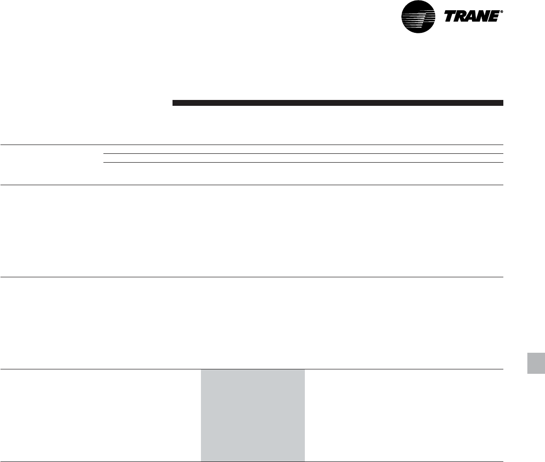
31RLC-PRC006-EN
Performance
Data
Full Load
Performance
Table P-6. 50 Hz high efficiency machines in English units
Condenser Entering Air Temperature (F)
85 95 105 115
Evaporator
Leaving Water Unit Size
Temperature (F) Model RTAC Tons kW input EER Tons kW input EER Ton kW input EER Tons kW input EER
140 HIGH 140.0 137.2 11.5 130.3 150.0 9.8 120.3 164.2 8.3 110.0 180.0 7.0
155 HIGH 152.5 151.6 11.3 141.9 165.1 9.7 131.0 180.4 8.3 119.8 197.4 6.9
170 HIGH 165.1 166.0 11.2 153.6 180.4 9.6 141.9 196.7 8.2 129.8 214.9 6.9
185 HIGH 183.2 182.2 11.3 170.9 197.9 9.8 158.3 215.6 8.4 145.2 235.3 7.1
200 HIGH 201.5 198.5 11.5 188.3 215.4 9.9 174.6 234.4 8.5 160.5 255.6 7.2
40 250 HIGH 245.1 246.8 11.3 228.6 269.0 9.7 211.5 293.9 8.2 193.9 321.5 6.9
275 HIGH 274.1 272.9 11.4 256.0 296.3 9.8 237.2 322.8 8.4 217.8 352.4 7.1
300 HIGH 309.4 305.8 11.5 289.8 331.8 10.0 269.3 361.0 8.5 248.1 393.7 7.3
350 HIGH 337.3 340.5 11.2 314.5 370.1 9.6 291.0 403.5 8.2 266.7 440.9 6.9
375 HIGH 374.6 374.9 11.3 350.0 406.9 9.8 324.5 443.0 8.4 298.1 483.4 7.1
400 HIGH 411.9 408.8 11.4 385.5 443.1 9.9 357.9 481.8 8.5 329.3 525.0 7.2
140 HIGH 145.4 140.1 11.7 135.3 152.9 10.0 125.0 167.3 8.5 114.4 183.2 7.2
155 HIGH 158.1 154.8 11.5 147.3 168.5 9.9 136.0 183.9 8.4 124.5 201.0 7.1
170 HIGH 171.2 169.7 11.4 159.4 184.3 9.8 147.2 200.7 8.4 134.8 219.0 7.1
185 HIGH 189.8 186.3 11.5 177.2 202.1 10.0 164.1 219.9 8.5 150.7 239.9 7.2
200 HIGH 208.9 203.1 11.6 195.2 220.1 10.1 181.1 239.3 8.6 166.5 260.7 7.3
42 250 HIGH 254.0 252.2 11.4 236.9 274.6 9.8 219.3 299.7 8.4 196.9 319.2 7.1
275 HIGH 283.9 279.0 11.5 265.2 302.6 10.0 245.9 329.3 8.6 225.9 359.0 7.2
300 HIGH 320.4 312.7 11.6 300.1 338.9 10.1 279.0 368.4 8.7 257.1 401.4 7.4
350 HIGH 349.5 348.0 11.3 326.0 377.8 9.8 301.8 411.4 8.4 276.8 449.0 7.1
375 HIGH 388.1 383.3 11.5 362.8 415.6 9.9 336.5 452.0 8.5 309.3 492.7 7.2
400 HIGH 426.8 418.1 11.6 399.5 452.7 10.0 371.0 491.8 8.6 341.6 535.5 7.3
140 HIGH 150.8 143.1 11.9 140.4 156.0 10.2 129.8 170.4 8.7 118.9 186.4 7.3
155 HIGH 163.9 158.2 11.7 152.7 172.0 10.1 141.2 187.5 8.6 129.3 204.7 7.2
170 HIGH 177.4 173.5 11.5 165.2 188.1 10.0 152.7 204.6 8.5 139.8 223.1 7.2
185 HIGH 196.6 190.5 11.7 183.6 206.4 10.1 170.1 224.4 8.7 156.2 244.5 7.3
200 HIGH 216.4 207.7 11.8 202.3 224.9 10.2 187.7 244.2 8.8 172.6 265.9 7.5
44 250 HIGH 262.9 257.6 11.6 245.4 280.3 10.0 227.2 305.6 8.5 197.5 312.2 7.3
275 HIGH 293.9 285.2 11.7 274.6 309.0 10.1 254.7 335.9 8.7 234.1 365.8 7.4
300 HIGH 331.5 319.7 11.8 310.6 346.1 10.3 288.9 376.0 8.8 266.4 409.3 7.5
350 HIGH 361.8 355.7 11.5 337.7 385.7 10.0 312.7 419.5 8.5 287.0 457.3 7.2
375 HIGH 401.8 391.9 11.6 375.7 424.4 10.1 348.6 461.2 8.6 320.6 502.2 7.3
400 HIGH 441.8 427.6 11.7 413.6 462.6 10.2 384.3 502.1 8.8 354.0 546.2 7.5
Notes:
1. Ratings based on sea level altitude and evaporator fouling factor of 0.00010.
2. Consult Trane representative for performance at temperatures outside of the ranges shown.
3. kW input is for compressors only.
4. EER = Energy Efficiency Ratio (Btu/watt-hour). Power inputs include compressors, condenser fans and control power.
5. Ratings are based on an evaporator temperature drop of 10°F.
6. Ambient temperatures 115°F and greater reflect the high ambient condenser option.
7. Interpolation between points is permissible. Extrapolation is not permitted.
8. Rated in accordance with ARI Standard 550/590-98.
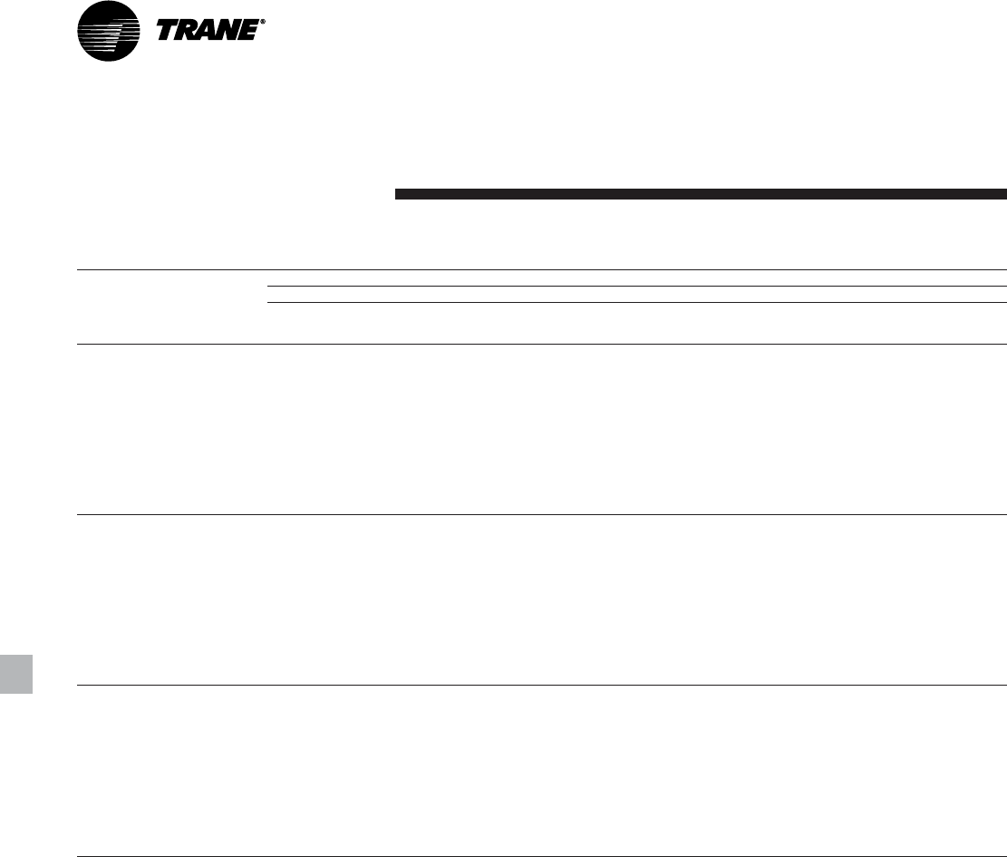
RLC-PRC006-EN32
Performance
Data
Full Load
Performance
Table P-6 (Continued). 50 Hz high efficiency machines in English units
Condenser Entering Air Temperature (F)
85 95 105 115
Evaporator
Leaving Water Unit Size
Temperature (F) Model RTAC Tons kW input EER Tons kW input EER Ton kW input EER Tons kW input EER
140 HIGH 156.2 146.1 12.1 145.6 159.1 10.4 134.7 173.6 8.9 123.4 189.7 7.5
155 HIGH 169.8 161.6 11.9 158.2 175.5 10.2 146.3 191.1 8.7 134.1 208.4 7.4
170 HIGH 183.6 177.4 11.7 171.1 192.1 10.1 158.2 208.7 8.7 145.0 227.2 7.3
185 HIGH 203.5 194.7 11.8 190.1 210.8 10.3 176.2 228.9 8.8 161.9 249.2 7.5
200 HIGH 223.9 212.4 12.0 209.4 229.7 10.4 194.4 249.3 8.9 178.9 271.2 7.6
46 250 HIGH 272.0 263.2 11.8 253.9 286.1 10.1 235.2 311.7 8.7 199.0 306.6 7.5
275 HIGH 304.0 291.5 11.9 284.2 315.5 10.3 263.6 342.6 8.8 242.4 372.8 7.5
300 HIGH 342.8 326.8 11.9 321.3 353.6 10.4 298.9 383.7 9.0 275.7 417.4 7.6
350 HIGH 374.3 363.5 11.7 349.5 393.7 10.1 323.8 427.8 8.7 297.3 465.8 7.3
375 HIGH 415.6 400.6 11.8 388.7 433.5 10.2 360.8 470.5 8.8 332.0 511.9 7.5
400 HIGH 457.0 437.3 11.9 428.0 472.7 10.3 397.8 512.6 8.9 366.6 557.1 7.6
140 HIGH 161.8 149.1 12.3 150.9 162.2 10.6 139.6 176.9 9.0 128.0 193.1 7.6
155 HIGH 175.7 165.1 12.0 163.8 179.1 10.4 151.6 194.8 8.9 139.0 212.2 7.5
170 HIGH 190.0 181.3 11.9 177.1 196.1 10.3 163.8 212.8 8.8 150.2 231.4 7.5
185 HIGH 210.5 199.1 12.0 196.6 215.3 10.4 182.3 233.6 8.9 167.6 253.9 7.6
200 HIGH 231.6 217.3 12.1 216.7 234.8 10.5 201.2 254.5 9.1 185.2 276.6 7.7
48 250 HIGH 281.2 269.0 11.9 253.9 286.1 10.1 243.4 317.8 8.8 200.2 300.4 7.6
275 HIGH 314.2 298.0 12.0 284.2 315.5 10.3 272.7 349.4 9.0 250.8 379.8 7.6
300 HIGH 354.2 334.1 12.1 321.3 353.6 10.4 309.1 391.6 9.1 283.8 423.0 7.7
350 HIGH 386.9 371.4 11.8 349.5 393.7 10.1 335.0 436.1 8.8 307.7 474.3 7.5
375 HIGH 429.6 409.6 11.9 388.7 433.5 10.2 373.3 480.0 8.9 343.6 521.7 7.6
400 HIGH 472.4 447.3 12.0 428.0 472.7 10.3 411.5 523.3 9.0 375.7 561.1 7.7
140 HIGH 167.5 152.3 12.5 156.2 165.5 10.7 144.6 180.2 9.2 132.7 196.5 7.8
155 HIGH 181.7 168.7 12.2 169.5 182.8 10.6 156.9 198.5 9.0 144.0 216.0 7.7
170 HIGH 196.4 185.4 12.0 183.1 200.3 10.4 169.4 217.0 8.9 155.4 235.7 7.6
185 HIGH 217.5 203.6 12.1 203.3 219.9 10.5 188.6 238.3 9.1 173.4 258.8 7.7
200 HIGH 239.4 222.2 12.2 224.0 239.9 10.7 208.0 259.9 9.2 189.8 278.5 7.8
50 250 HIGH 290.4 274.8 12.1 271.3 298.1 10.4 246.7 314.9 9.0 201.3 293.5 7.9
275 HIGH 324.5 304.6 12.2 303.5 328.9 10.6 281.8 356.4 9.1 257.1 382.2 7.8
300 HIGH 365.7 341.6 12.2 343.0 368.9 10.7 319.3 399.7 9.2 286.5 417.3 7.9
350 HIGH 399.7 379.6 12.0 373.4 410.2 10.4 346.3 444.6 8.9 318.3 482.9 7.6
375 HIGH 443.7 418.7 12.1 415.3 452.1 10.5 385.8 489.7 9.0 347.3 515.3 7.8
400 HIGH 488.0 457.4 12.1 457.3 493.5 10.6 425.4 534.2 9.1 379.3 553.4 7.9
Notes:
1. Ratings based on sea level altitude and evaporator fouling factor of 0.00010.
2. Consult Trane representative for performance at temperatures outside of the ranges shown.
3. kW input is for compressors only.
4. EER = Energy Efficiency Ratio (Btu/watt-hour). Power inputs include compressors, condenser fans and control power.
5. Ratings are based on an evaporator temperature drop of 10°F.
6. Ambient temperatures 115°F and greater reflect the high ambient condenser option.
7. Interpolation between points is permissible. Extrapolation is not permitted.
8. Rated in accordance with ARI Standard 550/590-98.
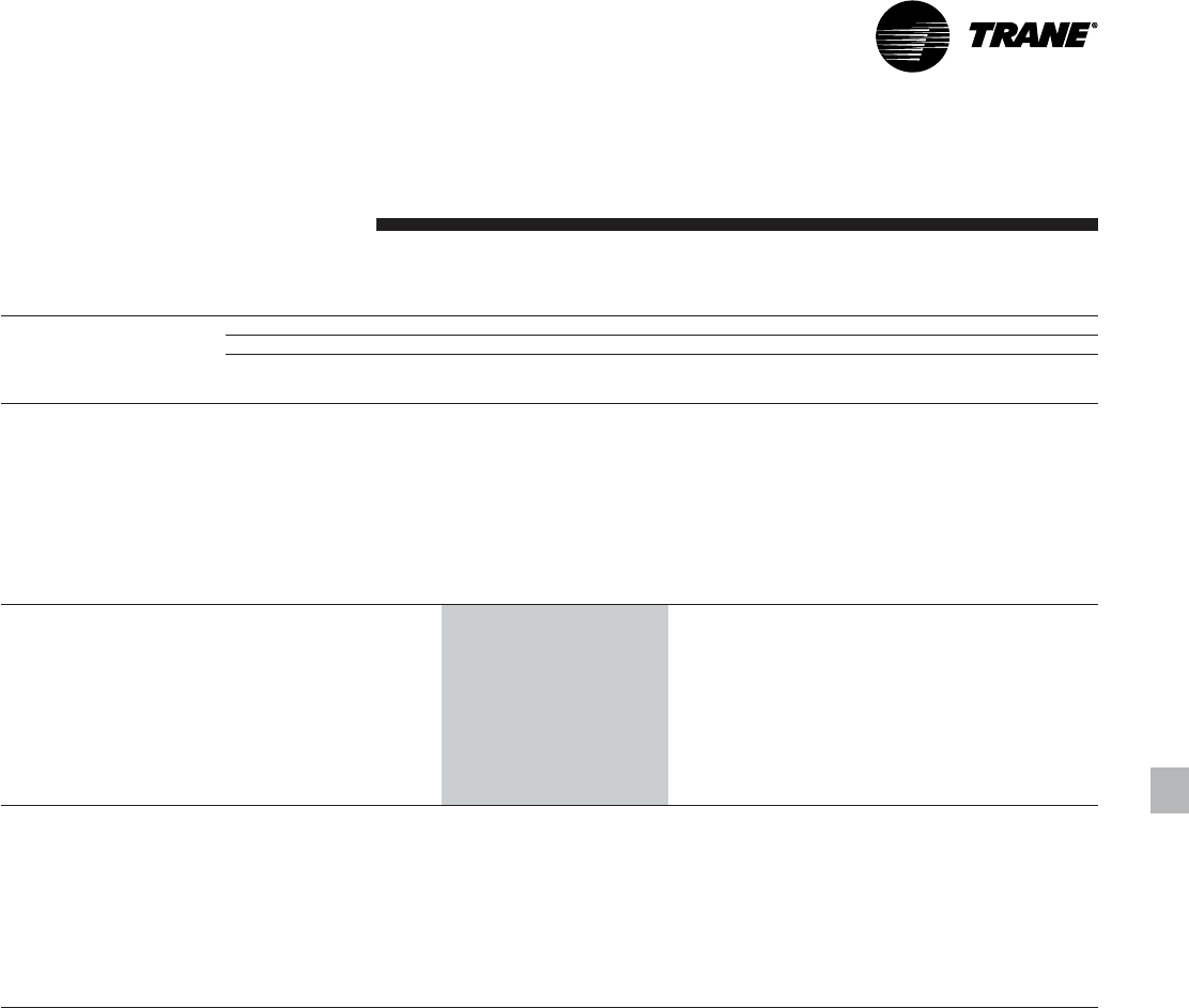
33RLC-PRC006-EN
Performance
Data
Table P-7. 50 Hz standard efficiency machines in SI units
Condenser Entering Air Temperature (C)
30 35 40 45
Evaporator
Leaving Water Unit Size kW kW kW kW kW kW kW kW
Temperature (C) Model RTAC cooling input COP output input COP output input COP output input COP
140 STD 135.7 147.3 4.8 126.8 159.6 4.1 117.7 173.2 3.6 108.4 188.0 3.0
155 STD 148.5 162.7 4.7 138.8 175.8 4.1 128.9 190.3 3.6 118.8 206.3 3.0
170 STD 161.5 178.2 4.7 151.1 192.2 4.1 140.4 207.7 3.6 129.5 224.8 3.0
185 STD 178.7 194.4 4.8 167.5 209.6 4.2 156.0 226.5 3.6 144.1 244.9 3.1
200 STD 196.4 211.0 4.8 184.3 227.3 4.2 171.8 245.4 3.7 159.0 265.3 3.1
5 250 STD 237.7 256.6 4.8 223.2 277.9 4.2 208.2 301.4 3.6 192.8 327.1 3.1
275 STD 265.5 290.1 4.8 249.3 313.0 4.1 232.5 338.4 3.6 215.2 366.3 3.1
300 STD 302.1 325.0 4.8 284.0 350.3 4.2 265.3 378.3 3.7 245.9 409.0 3.2
350 STD 328.5 364.0 4.7 308.0 392.9 4.1 286.8 424.9 3.6 265.0 460.1 3.0
375 STD 362.8 397.3 4.7 340.8 428.6 4.1 318.0 463.3 3.6 294.5 501.4 3.1
400 STD 400.0 432.8 4.8 376.0 466.4 4.2 351.2 503.5 3.6 325.5 544.3 3.1
140 STD 144.5 153.1 4.9 135.1 165.6 4.3 125.5 179.4 3.7 115.1 193.1 3.1
155 STD 158.0 169.3 4.9 147.8 182.6 4.2 137.3 197.3 3.6 126.6 213.5 3.1
170 STD 171.6 185.5 4.8 160.6 199.8 4.2 149.4 215.5 3.6 137.3 231.4 3.1
185 STD 189.9 202.5 4.9 178.1 218.0 4.3 165.9 235.1 3.7 152.0 250.8 3.2
200 STD 208.7 219.9 5.0 195.9 236.6 4.3 182.7 255.0 3.8 166.0 268.4 3.2
7 250 STD 252.2 266.5 4.9 237.0 288.2 4.3 221.3 312.1 3.7 200.0 327.3 3.2
275 STD 281.6 301.8 4.9 264.5 325.1 4.3 246.8 350.9 3.7 223.6 368.0 3.2
300 STD 320.4 338.5 4.9 301.3 364.3 4.3 281.6 392.8 3.8 251.5 403.0 3.3
350 STD 348.6 378.7 4.8 327.0 408.1 4.2 304.7 440.5 3.6 277.0 465.2 3.1
375 STD 384.8 413.5 4.9 361.6 445.4 4.2 337.7 480.7 3.7 306.0 504.0 3.2
400 STD 424.3 450.8 4.9 399.1 485.0 4.3 372.9 523.0 3.7 332.9 536.5 3.3
140 STD 153.5 159.1 5.1 143.6 171.9 4.4 133.5 185.8 3.8 116.9 187.1 3.3
155 STD 167.7 176.1 5.0 156.9 189.7 4.3 145.9 204.6 3.7 128.4 206.7 3.3
170 STD 181.9 193.2 4.9 170.4 207.6 4.3 158.5 223.5 3.7 139.5 225.2 3.3
185 STD 201.3 210.9 5.0 188.8 226.7 4.4 176.0 244.1 3.8 154.9 245.2 3.3
200 STD 221.3 229.2 5.1 207.8 246.2 4.4 193.8 265.1 3.8 168.8 261.8 3.4
9 250 STD 267.0 276.8 5.1 251.0 298.9 4.4 234.5 323.3 3.8 202.9 317.3 3.4
275 STD 298.0 313.9 5.0 280.0 337.7 4.4 261.4 363.9 3.8 226.5 356.9 3.3
300 STD 339.0 352.4 5.0 318.9 378.8 4.4 298.2 408.0 3.9 255.3 391.8 3.4
350 STD 369.0 394.0 4.9 346.3 423.7 4.3 322.9 456.6 3.7 281.2 452.1 3.3
375 STD 407.1 430.2 5.0 382.8 462.7 4.3 357.6 498.7 3.8 309.9 488.5 3.3
400 STD 449.1 469.4 5.0 422.5 504.5 4.4 395.0 543.3 3.8 338.1 521.8 2.2
Notes:
1. Ratings based on sea level altitude and evaporator fouling factor of 0.0176.
2. Consult Trane representative for performance at temperatures outside of the ranges shown.
3. kW input is for compressors only.
4. COP = Coefficient of Performance (kWo/kWi). Power inputs include compressors, condenser fans and control power.
5. Ratings are based on an evaporator temperature drop of 5.6°C.
6. Ambient temperatures 40°C and greater reflect the high ambient condenser option.
7. Interpolation between points is permissible. Extrapolation is not permitted.
8. Rated in accordance with ARI Standard 550/590-98.
Full Load
Performance
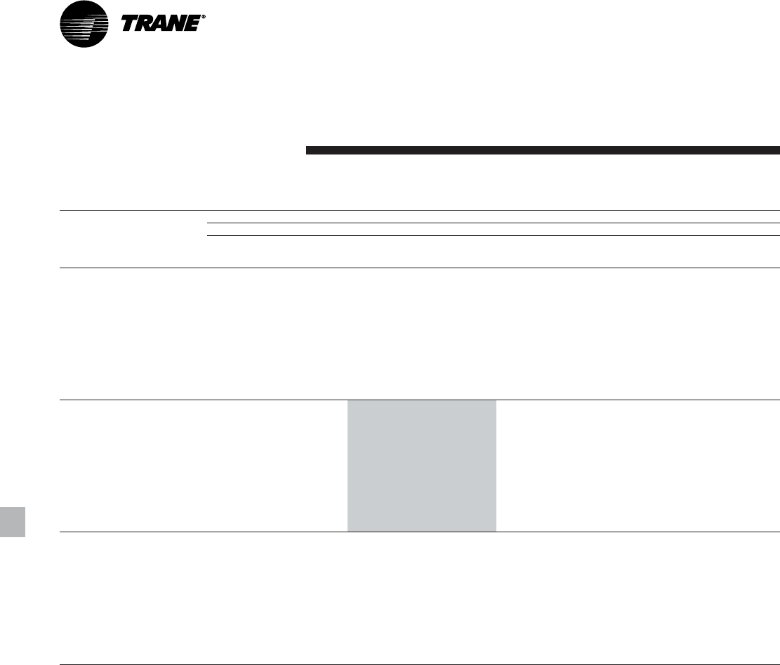
RLC-PRC006-EN34
Performance
Data
Full Load
Performance
Table P-8. 50 Hz high efficiency machines in SI units
Condenser Entering Air Temperature (C)
30 35 40 45
Evaporator
Leaving Water Unit Size kW kW kW kW kW kW kW kW
Temperature (C) Model RTAC cooling input COP output input COP output input COP output input COP
140 HIGH 141.7 139.9 4.9 132.8 151.4 4.2 123.6 164.2 3.7 114.3 178.3 3.1
155 HIGH 154.2 154.5 4.8 144.6 166.8 4.2 134.6 180.6 3.6 124.5 195.7 3.1
170 HIGH 167.0 169.2 4.7 156.5 182.3 4.1 145.8 197.0 3.6 134.7 213.1 3.1
185 HIGH 185.3 185.7 4.8 174.1 200.0 4.2 162.5 215.9 3.7 150.6 233.5 3.2
200 HIGH 203.9 202.4 4.9 191.8 217.7 4.3 179.3 234.8 3.7 166.4 253.7 3.2
5 250 HIGH 247.9 251.6 4.8 232.8 271.8 4.2 217.2 294.2 3.6 201.1 318.8 3.1
275 HIGH 277.2 278.1 4.8 260.6 299.5 4.2 243.4 323.2 3.7 225.8 349.5 3.2
300 HIGH 313.0 311.7 4.9 295.0 335.3 4.3 276.3 361.6 3.8 257.0 390.7 3.2
350 HIGH 341.1 347.0 4.7 320.3 373.9 4.1 298.8 403.9 3.6 276.7 437.1 3.1
375 HIGH 378.9 382.1 4.8 356.4 411.2 4.2 333.1 443.7 3.7 309.1 479.6 3.2
400 HIGH 416.7 416.7 4.8 392.4 447.9 4.3 367.3 482.7 3.7 341.3 521.1 3.2
140 HIGH 151.4 145.2 5.0 142.0 156.9 4.4 132.3 169.9 3.8 122.5 184.1 3.2
155 HIGH 164.6 160.5 5.0 154.4 173.0 4.3 143.9 186.9 3.8 133.2 202.2 3.2
170 HIGH 178.0 176.1 4.9 167.0 189.3 4.3 155.6 204.1 3.7 144.0 220.5 3.2
185 HIGH 197.4 193.3 5.0 185.5 207.7 4.4 173.3 223.9 3.8 160.8 241.7 3.2
200 HIGH 217.2 210.7 5.0 204.4 226.3 4.4 191.2 243.7 3.8 177.6 262.9 3.3
7 250 HIGH 263.9 261.5 4.9 247.9 282.0 4.3 231.5 304.8 3.7 211.3 323.3 3.2
275 HIGH 295.0 289.3 5.0 277.5 310.9 4.4 259.4 335.0 3.8 240.8 361.7 3.3
300 HIGH 332.8 324.3 5.0 313.9 348.4 4.4 294.2 375.2 3.8 273.8 404.8 3.3
350 HIGH 363.2 360.8 4.9 341.2 388.1 4.3 318.6 418.4 3.7 295.3 452.0 3.2
375 HIGH 403.4 397.6 4.9 379.6 427.1 4.3 355.0 460.1 3.8 329.7 496.5 3.2
400 HIGH 443.6 433.8 5.0 418.0 465.6 4.4 391.4 501.0 3.8 364.0 540.2 3.3
140 HIGH 161.3 150.7 5.2 151.4 162.6 4.5 141.2 175.7 3.9 130.9 190.1 3.4
155 HIGH 175.2 166.8 5.1 164.4 179.5 4.4 153.4 193.5 3.9 142.1 209.0 3.3
170 HIGH 189.4 183.2 5.0 177.7 196.6 4.4 165.7 211.5 3.8 153.5 228.0 3.3
185 HIGH 209.8 201.1 5.0 197.3 215.8 4.4 184.4 232.1 3.9 171.2 250.2 3.4
200 HIGH 231.0 219.4 5.1 217.4 235.3 4.5 203.4 253.0 3.9 189.1 272.6 3.4
9 250 HIGH 280.3 271.7 5.0 263.5 292.7 4.4 246.2 315.8 3.8 214.4 313.6 3.4
275 HIGH 313.3 300.9 5.1 294.8 322.8 4.4 275.7 347.3 3.9 256.1 374.2 3.4
300 HIGH 353.2 337.4 5.1 333.2 361.9 4.5 312.5 389.3 3.9 291.0 419.4 3.4
350 HIGH 385.7 375.1 5.0 362.6 402.7 4.4 338.8 433.4 3.8 314.3 467.2 3.3
375 HIGH 428.3 413.6 5.0 403.3 443.6 4.4 377.5 477.1 3.9 350.8 514.1 3.4
400 HIGH 471.1 451.7 5.1 444.1 484.0 4.5 416.1 520.1 3.9 387.2 560.1 2.3
Notes:
1. Ratings based on sea level altitude and evaporator fouling factor of 0.0176.
2. Consult Trane representative for performance at temperatures outside of the ranges shown.
3. kW input is for compressors only.
4. COP = Coefficient of Performance (kWo/kWi). Power inputs include compressors, condenser fans and control power.
5. Ratings are based on an evaporator temperature drop of 5.6°C.
6. Ambient temperatures 40°C and greater reflect the high ambient condenser option.
7. Interpolation between points is permissible. Extrapolation is not permitted.
8. Rated in accordance with ARI Standard 550/590-98.
35RLC-PRC006-EN
Table P-12. ARI part-load performance for
50 Hz high efficiency
machines in English units
Full Load Full Load
Unit Size Tons EER IPLV
140 140.4 10.2 14.2
155 152.7 10.1 14.2
170 165.2 10.0 14.0
185 183.6 10.1 14.5
200 202.3 10.2 13.9
250 245.5 10.2 15.9
275 274.8 10.3 15.6
300 310.8 10.5 14.7
350 337.9 10.1 15.2
375 375.9 10.3 15.6
400 413.9 10.4 15.5
Table P-11. ARI part-load performance for
50 Hz standard efficiency
machines in English units
Full Load Full Load
Unit Size Tons EER IPLV
140 133.7 9.3 13.4
155 146.2 9.3 13.5
170 159.0 9.2 13.3
185 176.3 9.4 13.8
200 194.0 9.5 13.2
250 234.8 9.6 15.4
275 262.1 9.5 14.7
300 298.6 9.7 14.1
350 324.0 9.4 14.6
375 358.4 9.5 15.0
400 395.5 9.6 14.9
Notes:
1. IPLV values are rated in accordance with ARI Standard
550/590-98.
2. EER and IPLV values include compressors, condenser
fans and control kW.
Performance
Data
Table P-9.ARI part-load performance for
60 Hz standard efficiency
machines in English units
Full Load Full Load
Unit Size Tons EER IPLV
140 138.2 9.7 12.9
155 152.1 9.8 13.3
170 166.2 9.9 13.0
185 181.5 9.7 12.8
200 197.2 9.6 12.7
225 216.9 9.6 13.0
250 237.3 9.6 12.6
275 268.0 9.7 13.3
300 300.2 9.6 13.2
350 340.0 9.6 13.2
400 401.3 9.6 13.7
450 438.3 9.6 13.9
500 479.3 9.6 13.8
Notes:
1. IPLV values are rated in accordance with ARI Standard
550/590-98.
2. EER and IPLV values include compressors, condenser
fans and control kW.
Part Load
Performance
Table P-10. ARI part-load performance for
60 Hz high efficiency
machines in English units
Full Load Full Load
Unit Size Tons EER IPLV
140 143.9 10.3 13.3
155 157.5 10.4 13.6
170 171.3 10.5 13.4
185 187.5 10.3 13.2
200 204.2 10.1 13.0
225 224.4 10.2 13.3
250 243.3 10.1 12.8
275 279.0 10.4 13.8
300 310.2 10.1 13.6
350 346.1 10.4 14.5
400 413.1 10.0 13.9
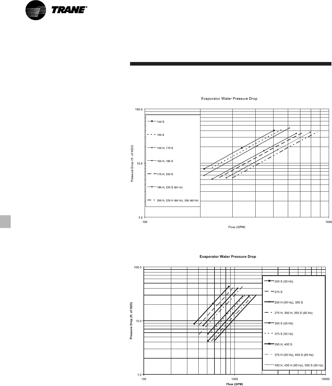
RLC-PRC006-EN36
Performance
Data
Adjustment
Factors
Figure P-1. Evaporator water pressure drop, all units

37RLC-PRC006-EN
Electrical Data
and Connection
Table E-1. Unit electrical data for standard efficiency at all ambient operation
Unit Wiring Motor Data
# of Max. Fuse, HACR Rec. Time Compressor (Each) Fans (Each)
Unit Rated Power MCA (3) Breaker or MOP (11) Delay or RDE (4) RLA (5) XLRA (8) YLRA (8) Qty. Control
Size Voltage Conns (1) Ckt 1/Ckt 2 Ckt 1/Ckt 2 Ckt 1/Ckt 2 Qty Ckt 1/Ckt 2 Ckt 1/Ckt 2 Ckt 1/Ckt 2 Ckt 1/Ckt 2 kW FLA kW (7)
200/60/3 1 660 800 800 2 270-270 NA 487-487 8 1.5 6.5 0.83
200/60/3 2 364/364 600/600 450/450 2 270/270 NA 487/487 4/4 1.5 6.5 0.83
230/60/3 1 581 800 700 2 235-235 NA 427-427 8 1.5 6.5 0.83
230/60/3 2 320/320 500/500 400/400 2 235/235 NA 427/427 4/4 1.5 6.5 0.83
RTAC 380/60/3 1 348 450 400 2 142-142 801-801 260-260 8 1.5 3.5 0.83
140 380/60/3 2 192/192 300/300 250/250 2 142/142 801/801 260/260 4/4 1.5 3.5 0.83
460/60/3 1 288 400 350 2 118-118 652-652 212-212 8 1.5 2.8 0.83
460/60/3 2 159/159 250/250 200/200 2 118/118 652/652 212/212 4/4 1.5 2.8 0.83
575/60/3 1 230 300 300 2 94-94 520-520 172-172 8 1.5 2.3 0.83
575/60/3 2 127/127 200/200 175/175 2 94/94 520/520 172/172 4/4 1.5 2.3 0.83
400/50/3 1 333 450 400 2 138-138 774-774 259-259 8 0.8 2.8 0.83
400/50/3 2 184/184 300/300 250/250 2 138/138 774/774 259/259 4/4 0.8 2.8 0.83
200/60/3 1 730 1000 1000 2 320-270 NA 600-701 9 1.5 6.5 0.83
200/60/3 2 433/364 700/600 600/450 2 320/270 NA 600/701 5/4 1.5 6.5 0.83
230/60/3 1 641 800 800 2 278-235 NA 506-571 9 1.5 6.5 0.83
230/60/3 2 380/320 600/500 450/400 2 278/235 NA 506/571 5/4 1.5 6.5 0.83
RTAC 380/60/3 1 380 500 450 2 168-142 973-801 316-260 9 1.5 3.5 0.83
155 380/60/3 2 228/192 350/300 300/250 2 168/142 973/801 316/260 5/4 1.5 3.5 0.83
460/60/3 1 317 450 400 2 139-118 774-652 252-212 9 1.5 2.8 0.83
460/60/3 2 188/159 300/250 225/200 2 139/118 774/652 252/212 5/4 1.5 2.8 0.83
575/60/3 1 254 350 300 2 111-94 631-528 205-172 9 1.5 2.3 0.83
575/60/3 2 150/127 250/200 200/175 2 111/94 631/528 205/172 5/4 1.5 2.3 0.83
400/50/3 1 373 500 450 2 168-138 896-796 291-259 9 0.8 2.8 0.83
400/50/3 2 224/184 350/300 300/250 2 168/138 896/796 291/259 5/4 0.8 2.8 0.83
200/60/3 1 785 1000 1000 2 320-320 NA 600-600 10 1.5 6.5 0.83
200/60/3 2 433/433 700/700 600/600 2 320/320 NA 600/600 5/5 1.5 6.5 0.83
230/60/3 1 691 800 800 2 278-278 NA 506-506 10 1.5 6.5 0.83
230/60/3 2 380/380 600/600 450/450 2 278/278 NA 506/506 5/5 1.5 6.5 0.83
RTAC 380/60/3 1 413 500 500 2 168-168 973-973 316-316 10 1.5 3.5 0.83
170 380/60/3 2 228/228 350/350 300/300 2 168/168 973/973 316/316 5/5 1.5 3.5 0.83
460/60/3 1 341 450 400 2 139-139 774-774 252-252 10 1.5 2.8 0.83
460/60/3 2 188/188 300/300 225/225 2 139/139 774/774 252/252 5/5 1.5 2.8 0.83
575/60/3 1 273 350 350 2 111-111 631-631 205-205 10 1.5 2.3 0.83
575/60/3 2 150/150 250/250 200/200 2 111/111 631/631 205/205 5/5 1.5 2.3 0.83
400/50/3 1 406 500 450 2 168-168 896-896 291-291 10 0.8 2.8 0.83
400/50/3 2 224/224 350/350 300/300 2 168/168 896/896 291/291 5/5 0.8 2.8 0.83
RLC-PRC006-EN38
Table E-1 (Continued). Unit electrical data for standard efficiency at all ambient operation
Unit Wiring Motor Data
# of Max. Fuse, HACR Rec. Time Compressor (Each) Fans (Each)
Unit Rated Power MCA (3) Breaker or MOP (11) Delay or RDE (4) RLA (5) XLRA (8) YLRA (8) Qty. Control
Size Voltage Conns (1) Ckt 1/Ckt 2 Ckt 1/Ckt 2 Ckt 1/Ckt 2 Qty Ckt 1/Ckt 2 Ckt 1/Ckt 2 Ckt 1/Ckt 2 Ckt 1/Ckt 2 kW FLA kW (7)
200/60/3 1 874 1200 1000 2 386-320 NA 701-600 11 1.5 6.5 0.83
200/60/3 2 522/433 800/700 700/600 2 386/320 NA 701/600 6/5 1.5 6.5 0.83
230/60/3 1 770 1000 1000 2 336-278 NA 571-506 11 1.5 6.5 0.83
230/60/3 2 459/380 700/600 600/450 2 336/278 NA 571/506 6/5 1.5 6.5 0.83
RTAC 380/60/3 1 460 600 600 2 203-168 1060-973 345-316 11 1.5 3.5 0.83
185 380/60/3 2 275/228 450/350 350/300 2 203/168 1060/973 345/316 6/5 1.5 3.5 0.83
460/60/3 1 380 500 450 2 168-139 878-774 285-252 11 1.5 2.8 0.83
460/60/3 2 227/188 350/300 300/225 2 168/139 878/774 285/252 6/5 1.5 2.8 0.83
575/60/3 1 304 400 350 2 134-111 705-631 229-205 11 1.5 2.3 0.83
575/60/3 2 181/150 300/250 225/200 2 134/111 705/631 229/205 6/5 1.5 2.3 0.83
400/50/3 1 446 600 500 2 198-168 1089-896 354-291 11 0.8 2.8 0.83
400/50/3 2 264/224 450/350 350/300 2 198/168 1089/896 354/291 6/5 0.8 2.8 0.83
200/60/3 1 947 1200 1200 2 386-386 NA 701-701 12 1.5 6.5 0.83
200/60/3 2 522/522 800/800 700/700 2 386/386 NA 701/701 6/6 1.5 6.5 0.83
230/60/3 1 834 1000 1000 2 336-336 NA 571-571 12 1.5 6.5 0.83
230/60/3 2 459/459 700/700 600/600 2 336/336 NA 571/571 6/6 1.5 6.5 0.83
RTAC 380/60/3 1 499 700 600 2 203-203 1060-1060 345-345 12 1.5 3.5 0.83
200 380/60/3 2 275/275 450/450 350/350 2 203/203 1060/1060 345/345 6/6 1.5 3.5 0.83
460/60/3 1 412 500 500 2 168-168 878-878 285-285 12 1.5 2.8 0.83
460/60/3 2 227/227 350/350 300/300 2 168/168 878/878 285/285 6/6 1.5 2.8 0.83
575/60/3 1 329 450 400 2 134-134 705-705 229-229 12 1.5 2.3 0.83
575/60/3 2 181/181 300/300 225/225 2 134/134 705/705 229/229 6/6 1.5 2.3 0.83
400/50/3 1 479 600 600 2 198-198 1089-1089 354-354 12 0.8 2.8 0.83
400/50/3 2 264/264 450/450 350/350 2 198/198 1089/1089 354/354 6/6 0.8 2.8 0.83
200/60/3 1 1045 1200 1200 2 459-386 NA 821-701 13 1.5 6.5 0.83
200/60/3 2 620/522 1000/800 800/700 2 459/386 NA 821/701 7/6 1.5 6.5 0.83
230/60/3 1 920 1200 1200 2 399-336 NA 691-571 13 1.5 6.5 0.83
230/60/3 2 545/459 800/700 700/600 2 399/336 NA 691/571 7/6 1.5 6.5 0.83
RTAC 380/60/3 1 551 700 700 2 242-203 1306-1060 424-345 13 1.5 3.5 0.83
225 380/60/3 2 327/275 500/450 400/350 2 242/203 1306/1060 424/345 7/6 1.5 3.5 0.83
460/60/3 1 454 600 600 2 200-168 1065-878 346-285 13 1.5 2.8 0.83
460/60/3 2 270/227 450/350 350/300 2 200/168 1065/878 346/285 7/6 1.5 2.8 0.83
575/60/3 1 364 500 450 2 160-134 853-705 277-229 13 1.5 2.3 0.83
575/60/3 2 216/181 350/300 300/225 2 160/134 853/705 277/229 7/6 1.5 2.3 0.83
200/60/3 1 1124 1200 1200 2 459-459 NA 821-821 14 1.5 6.5 0.83
200/60/3 2 620/620 1000/1000 800/800 2 459/459 NA 821/821 7/7 1.5 6.5 0.83
230/60/3 1 989 1200 1200 2 399-399 NA 691-691 14 1.5 6.5 0.83
230/60/3 2 545/545 800/800 700/700 2 399/399 NA 691/691 7/7 1.5 6.5 0.83
RTAC 380/60/3 1 594 800 700 2 242-242 1306-1306 424-424 14 1.5 3.5 0.83
250 380/60/3 2 327/327 500/500 400/400 2 242/242 1306/1306 424/424 7/7 1.5 3.5 0.83
460/60/3 1 489 600 600 2 200-200 1065-1065 346-346 14 1.5 2.8 0.83
460/60/3 2 270/270 450/450 350/350 2 200/200 1065/1065 346/346 7/7 1.5 2.8 0.83
575/60/3 1 392 500 500 2 160-160 853-853 277-277 14 1.5 2.3 0.83
575/60/3 2 216/216 350/350 300/300 2 160/160 853/853 277/277 7/7 1.5 2.3 0.83
400/50/3 1 563 700 700 3 138-138-198 796-796-1089 259-259-354 14 0.8 2.8 1.2
400/50/3 2 333/265 450/450 400/350 3 138/138/198 796/796/1089 259/259/354 8/6 0.8 2.8 1.2
Electrical Data
and Connection

39RLC-PRC006-EN
Table E-1 (Continued). Unit electrical data for standard efficiency at all ambient operation
Unit Wiring Motor Data
# of Max. Fuse, HACR Rec. Time Compressor (Each) Fans (Each)
Unit Rated Power MCA (3) Breaker or MOP (11) Delay or RDE (4) RLA (5) XLRA (8) YLRA (8) Qty. Control
Size Voltage Conns (1) Ckt 1/Ckt 2 Ckt 1/Ckt 2 Ckt 1/Ckt 2 Qty Ckt 1/Ckt 2 Ckt 1/Ckt 2 Ckt 1/Ckt 2 Ckt 1/Ckt 2 kW FLA kW (7)
200/60/3 1 NA
200/60/3 2 785/522 1000/800 1000/700 3 320/320/386 NA 600/600/701 10/6 1.5 6.5 1.2
230/60/3 1 NA
230/60/3 2 681/459 800/700 800/600 3 278/278/336 NA 506/506/571 10/6 1.5 6.5 1.2
RTAC 380/60/3 1 NA
275 380/60/3 2 413/275 500/450 500/350 3 168/168/203 973/973/1060 316/316/345 10/6 1.5 3.5 1.2
460/60/3 1 533 700 600 3 139-139-168 774-774-878 252-252-285 16 1.5 2.8 1.2
460/60/3 2 341/227 450/350 400/300 3 139/139/168 774/774/878 252/252/285 10/6 1.5 2.8 1.2
575/60/3 1 427 500 500 3 111-111-134 631-631-705 205-205-229 16 1.5 2.3 1.2
575/60/3 2 273/182 350/300 350/225 3 111/111/134 631/631/705 205/205/229 10/6 1.5 2.3 1.2
400/50/3 1 629 800 700 3 168-168-198 896-896-1089 291-291-354 16 0.8 2.8 1.2
400/50/3 2 406/265 500/450 450/350 3 168/168/198 896/896/1089 291/291/254 10/6 0.8 2.8 1.2
200/60/3 1 NA
200/60/3 2 947/522 1200/800 1200/700 3 386/386/386 NA 701/701/701 12/6 1.5 6.5 1.2
230/60/3 1 NA
230/60/3 2 834/459 1000/700 1000/600 3 336/336/336 NA 571/571/571 12/6 1.5 6.5 1.2
RTAC 380/60/3 1 NA
300 380/60/3 2 499/275 700/450 600/350 3 203/203/203 1060/1060/1060 345/345/345 12/6 1.5 3.5 1.2
460/60/3 1 597 700 700 3 168-168-168 878-878-878 285-285-285 18 1.5 2.8 1.2
460/60/3 2 412/227 500/350 500/300 3 168/168/168 878/878/878 285/285/285 12/6 1.5 2.8 1.2
575/60/3 1 477 600 600 3 134-134-134 705-705-705 229-229-229 18 1.5 2.3 1.2
575/60/3 2 330/182 450/300 400/225 3 134/134/134 705/705/705 229/229/229 12/6 1.5 2.3 1.2
400/50/3 1 694 800 800 3 198-198-198 1089-1089-1089 354-354-354 18 0.8 2.8 1.2
400/50/3 2 480/265 600/450 600/350 3 198/198/198 1089/1089/1089 354/354/354 12/6 0.8 2.8 1.2
200/60/3 1 NA
200/60/3 2 1124/522 1200/800 1200/700 3 459/459/386 NA 821/821/701 14/6 1.5 6.5 1.2
230/60/3 1 NA
230/60/3 2 989/459 1200/700 1200/600 3 399/399/336 NA 691/691/571 14/6 1.5 6.5 1.2
RTAC 380/60/3 1 NA
350 380/60/3 2 594/275 800/450 700/350 3 242/242/203 973/973/973/973 424/424/345 14/6 1.5 3.5 1.2
460/60/3 1 674 800 800 3 200-200-168 774-774-774-774 346-346-285 20 1.5 2.8 1.2
460/60/3 2 490/227 600/350 600/300 3 200/200/168 774/774/774/774 346/346/285 14/6 1.5 2.8 1.2
575/60/3 1 540 700 600 3 160-160-134 631-631-631-631 277-277-229 20 1.5 2.3 1.2
575/60/3 2 393/182 500/300 450/225 3 160/160/134 631/631/631/631 277/277/229 14/6 1.5 2.3 1.2
400/50/3 1 770 800 800 4 168-168-168-168 896-896-896-896 291-291-291-291 20 0.8 2.8 1.59
400/50/3 2 406/406 500/500 450/450 4 168/168/168/168 896/896/896/896 291/291/291/291 10/10 0.8 2.8 1.59
RTAC 400/50/3 1 844 1000 1000 4 198-198-168-168 1089-1089-896-896 354-354-291-291 22 0.8 2.8 1.59
375 400/50/3 2 480/406 600/500 600/450 4 198/198/168/168 1089/1089/896/896 354/354/291/291 12/10 0.8 2.8 1.59
200/60/3 1 NA
200/60/3 2 947/947 1200/1200 1200/1200 4 386/386/386/386 NA 701/701/701/701 12/12 1.5 6.5 1.59
230/60/3 1 NA
230/60/3 2 834/834 1000/1000 1000/1000 4 336/336/336/336 NA 571/571/571/571 12/12 1.5 6.5 1.59
RTAC 380/60/3 1 NA
400 380/60/3 2 499/499 700/700 600/600 4 203/203/203/203 1060/1060/1060/1060 345/345/345/345 12/12 1.5 3.5 1.59
460/60/3 1 782 800 800 4 168-168-168-168 878-878-878-878 285-285-285-285 24 1.5 2.8 1.59
460/60/3 2 412/412 500/500 500/500 4 168/168/168/168 878/878/878/878 285/285/285/285 12/12 1.5 2.8 1.59
575/60/3 1 628 700 700 4 134-134-134-134 705-705-705-705 229-229-229-229 24 1.5 2.3 1.59
575/60/3 2 330/330 450/450 400/400 4 134/134/134/134 705/705/705/705 229/229/229/229 12/12 1.5 2.3 1.59
400/50/3 1 909 1000 1000 4 198-198-198-198 1089-1089-1089-1089 354-354-354-354 24 0.8 2.8 1.59
400/50/3 2 480/480 600/600 600/600 4 198/198/198/198 1089/1089/1089/1089 354/354/354/354 12/12 0.8 2.8 1.59
Electrical Data
and Connection
RLC-PRC006-EN40
Table E-1 (Continued). Unit electrical data for standard efficiency at all ambient operation
Unit Wiring Motor Data
# of Max. Fuse, HACR Rec. Time Compressor (Each) Fans (Each)
Unit Rated Power MCA (3) Breaker or MOP (11) Delay or RDE (4) RLA (5) XLRA (8) YLRA (8) Qty. Control
Size Voltage Conns (1) Ckt 1/Ckt 2 Ckt 1/Ckt 2 Ckt 1/Ckt 2 Qty Ckt 1/Ckt 2 Ckt 1/Ckt 2 Ckt 1/Ckt 2 Ckt 1/Ckt 2 kW FLA kW (7)
200/60/3 1 NA
200/60/3 2 1124/947 1200/1200 1200/1200 4 459/459/386/386 NA 821/821/701/701 14/12 1.5 6.5 1.59
230/60/3 1 NA
230/60/3 2 989/834 1200/1000 1200/1000 4 399/399/336/336 NA 691/691/571/571 14/12 1.5 6.5 1.59
RTAC 380/60/3 1 NA
450 380/60/3 2 594/499 800/700 700/600 4 242/242/203/203 1306/1306/1060/1060 424/424/345/345 14/12 1.5 3.5 1.59
460/60/3 1 859 1000 1000 4 200-200-168-168 1065-1065-878-878 346-346-285-285 26 1.5 2.8 1.59
460/60/3 2 490/412 600/500 600/500 4 200/200/168/168 1065/1065/878/878 346/346/285/285 14/12 1.5 2.8 1.59
575/60/3 1 688 800 800 4 160-160-134-134 853-853-705-705 277-277-229-229 26 1.5 2.3 1.59
575/60/3 2 393/330 500/450 450/400 4 160/160/134/134 853/853/705/705 277/277/229/229 14/12 1.5 2.3 1.59
200/60/3 1 NA
200/60/3 2 1124/1124 1200/1200 1200/1200 4 459/459/459/459 NA 821/821/821/821 14/14 1.5 6.5 1.59
230/60/3 1 NA
230/60/3 2 989/989 1200/1200 1200/1200 4 399/399/399/399 NA 691/691/691/691 14/14 1.5 6.5 1.59
RTAC 380/60/3 1 NA
500 380/60/3 2 594/594 800/800 700/700 4 242/242/242/242 1306/1306/1306/1306 424/424/424/424 14/14 1.5 3.5 1.59
460/60/3 1 929 1000 100 4 200-200-200-200 1065-1065-1065-1065 346-346-346-346 28 1.5 2.8 1.59
460/60/3 2 490/490 600/600 600/600 4 200/200/200/200 1065/1065/1065/1065 346/346/346/346 14/14 1.5 2.8 1.59
575/60/3 1 745 800 800 4 160-160-160-160 853-853-853-853 277-277-277-277 28 1.5 2.3 1.59
575/60/3 2 393/393 500/500 450/450 4 160/160/160/160 853/853/853/853 277/277/277/277 14/14 1.5 2.3 1.59
Notes:
1. As standard, all units have single point power connection. Optional dual point power connections are available.
2. Max Fuse or HACR type breaker = 225 percent of the largest compressor RLA plus 100 percent of the second compressor RLA, plus the sum of the condenser fan FLA per NEC 440-22.
Use FLA per circuit, NOT FLA for the entire unit).
3. MCA - Minimum Circuit Ampacity - 125 percent of largest compressor RLA plus 100 percent of the second compressor RLA plus the sum of the condenser fans FLAs per NEC 440-33.
4. RECOMMENDED TIME DELAY OR DUAL ELEMENT (RDE) FUSE SIZE: 150 percent of the largest compressor RLA plus 100 percent of the second compressor RLA and the sum of the condenser
fan FLAs.
5. RLA - Rated Load Amps - rated in accordance with UL Standard 1995.
6. Local codes may take precedence.
7. Control kW includes operational controls only. Does not include evaporator heaters.
8. XLRA - Locked Rotor Amps - based on full winding (x-line) start units. YLRA for wye-delta starters is ~1/3 of LRA of x-line units.
9. VOLTAGE UTILIZATION RANGE:
Rated Voltage Utilization Range
200/60/3 180-220
230/60/3 208-254
380/60/3 342-418
460/60/3 414-506
575/60/3 516-633
400/50/3 360-440
10. A separate 115/60/1, 20 amp or 220/50/1, 15 amp customer provided power connection is needed to power the evaporator heaters (1640 watts).
11. If factory circuit breakers are supplied with the chiller, then these values represent Maximum Overcurrent Protection (MOP).
12. When the circuit breaker option is ordered, two circuit breakers will be provided (one per circuit) for both single and dual point power.
13. Motor kW is for standard fans. Low noise fans at 50 Hz are rated at 1.1 kW/fan.
Electrical Data
and Connection

41RLC-PRC006-EN
Table E-2. Unit electrical data for high efficiency at std. ambient operation
Unit Wiring Motor Data
# of Max. Fuse, HACR Rec. Time Compressor (Each) Fans (Each)
Unit Rated Power MCA (3) Breaker or MOP (11) Delay or RDE (4) RLA (5) XLRA (8) YLRA (8) Qty. Control
Size Voltage Conns (1) Ckt 1/Ckt 2 Ckt 1/Ckt 2 Ckt 1/Ckt 2 Qty Ckt 1/Ckt 2 Ckt 1/Ckt 2 Ckt 1/Ckt 2 Ckt 1/Ckt 2 kW FLA kW (7)
200/60/3 1 648 800 800 2 259-259 NA 487-487 10 1.5 6.5 0.83
200/60/3 2 356/356 600/600 450/450 2 259/259 NA 487/487 5/5 1.5 6.5 0.83
230/60/3 1 572 700 700 2 225-225 NA 427-427 10 1.5 6.5 0.83
230/60/3 2 314/314 500/500 400/400 2 225/225 NA 427/427 5/5 1.5 6.5 0.83
RTAC 380/60/3 1 341 450 400 2 136-136 801-801 260-260 10 1.5 3.5 0.83
140 380/60/3 2 188/188 300/300 225/225 2 136/136 801/801 260/260 5/5 1.5 3.5 0.83
460/60/3 1 282 350 350 2 113-113 652-652 212-212 10 1.5 2.8 0.83
460/60/3 2 155/155 250/250 200/200 2 113/113 652/652 212/212 5/5 1.5 2.8 0.83
575/60/3 1 226 300 250 2 90-90 520-520 172-172 10 1.5 2.3 0.83
575/60/3 2 124/124 200/200 150/150 2 90/90 520/520 172/172 5/5 1.5 2.3 0.83
400/50/3 1 325 450 400 2 132-132 774-774 259-259 10 0.8 2.8 0.83
400/50/3 2 179/179 300/300 225/225 2 132/132 774/774 259/259 5/5 0.8 2.8 0.83
200/60/3 1 712 1000 800 2 305-259 NA 600-487 11 1.5 6.5 0.83
200/60/3 2 421/356 700/600 500/450 2 305/259 NA 600/487 6/5 1.5 6.5 0.83
230/60/3 1 628 800 700 2 265-225 NA 506-427 11 1.5 6.5 0.83
230/60/3 2 371/314 600/500 450/400 2 265/225 NA 506/427 6/5 1.5 6.5 0.83
RTAC 380/60/3 1 376 500 416 2 161-136 973-801 316-260 11 1.5 3.5 0.83
155 380/60/3 2 222/188 350/300 300/225 2 161/136 973/801 316/260 6/5 1.5 3.5 0.83
460/60/3 1 310 400 350 2 133-113 774-652 252-212 11 1.5 2.8 0.83
460/60/3 2 183/155 300/250 225/200 2 133/113 774/652 252/212 6/5 1.5 2.8 0.83
575/60/3 1 248 350 300 2 106-90 631-528 205-172 11 1.5 2.3 0.83
575/60/3 2 146/124 250/200 175/150 2 106/90 631/528 205/172 6/5 1.5 2.3 0.83
400/50/3 1 363 500 450 2 160-132 896-796 291-259 11 0.8 2.8 0.83
400/50/3 2 217/179 350/300 300/225 2 160/132 896/796 291/259
6/5 0.8 2.8 0.83
200/60/3 1 765 1000 1000 2 305-305 NA 600-600 12 1.5 6.5 0.83
200/60/3 2 421/421 700/700 500/500 2 305/305 NA 600/600 6/6 1.5 6.5 0.83
230/60/3 1 675 800 800 2 265-265 NA 506-506 12 1.5 6.5 0.83
230/60/3 2 371/371 600/600 450/450 2 265/265 NA 506/506 6/6 1.5 6.5 0.83
RTAC 380/60/3 1 404 500 450 2 161-161 973-973 316-316 12 1.5 3.5 0.83
170 380/60/3 2 222/222 350/350 300/300 2 161/161 973/973 316/316 6/6 1.5 3.5 0.83
460/60/3 1 333 450 400 2 133-133 774-774 252-252 12 1.5 2.8 0.83
460/60/3 2 183/183 300/300 225/225 2 133/133 774/774 252/252 6/6 1.5 2.8 0.83
575/60/3 1 266 350 300 2 106-106 631-631 205-205 12 1.5 2.3 0.83
575/60/3 2 146/146 250/250 175/175 2 106/106 631/631 205/205 6/6 1.5 2.3 0.83
400/50/3 1 394 500 450 2 160-160 896-896 291-291 12 0.8 2.8 0.83
400/50/3 2 217/217 350/350 300/300 2 160/160 896/896 291/291 6/6 0.8 2.8 0.83
Electrical Data
and Connection

RLC-PRC006-EN42
Table E-2 (Continued). Unit electrical data for high efficiency at std. ambient operation
Unit Wiring Motor Data
# of Max. Fuse, HACR Rec. Time Compressor (Each) Fans (Each)
Unit Rated Power MCA (3) Breaker or MOP (11) Delay or RDE (4) RLA (5) XLRA (8) YLRA (8) Qty. Control
Size Voltage Conns (1) Ckt 1/Ckt 2 Ckt 1/Ckt 2 Ckt 1/Ckt 2 Qty Ckt 1/Ckt 2 Ckt 1/Ckt 2 Ckt 1/Ckt 2 Ckt 1/Ckt 2 kW FLA kW (7)
200/60/3 1 856 1200 1000 2 373-305 NA 701-600 13 1.5 6.5 0.83
200/60/3 2 512/421 800/700 700/500 2 373/305 NA 701/600 7/6 1.5 6.5 0.83
230/60/3 1 755 1000 1000 2 324-265 NA 571-506 13 1.5 6.5 0.83
230/60/3 2 451/371 700/600 600/450 2 324/265 NA 571/506 7/6 1.5 6.5 0.83
RTAC 380/60/3 1 452 600 500 2 196-161 1060-973 345-316 13 1.5 3.5 0.83
185 380/60/3 2 270/222 450/350 350/300 2 196/161 1060/973 345/316 7/6 1.5 3.5 0.83
460/60/3 1 372 500 450 2 162-133 878-774 285-252 13 1.5 2.8 0.83
460/60/3 2 222/183 350/300 300/225 2 162/133 878/774 285/252 7/6 1.5 2.8 0.83
575/60/3 1 298 400 350 2 130-106 705-631 229-205 13 1.5 2.3 0.83
575/60/3 2 179/146 300/250 225/175 2 130/106 705/631 229/205 7/6 1.5 2.3 0.83
400/50/3 1 433 600 500 2 189-160 1089-896 354-291 13 0.8 2.8 0.83
400/50/3 2 256/217 400/350 350/300 2 189/160 1089/896 354/291 7/6 0.8 2.8 0.83
200/60/3 1 931 1200 1200 2 373-373 NA 701-701 14 1.5 6.5 0.83
200/60/3 2 512/512 800/800 700/700 2 373/373 NA 701/701 7/7 1.5 6.5 0.83
230/60/3 1 820 1000 1000 2 324-324 NA 571-571 14 1.5 6.5 0.83
230/60/3 2 451/451 700/700 600/600 2 324/324 NA 571/571 7/7 1.5 6.5 0.83
RTAC 380/60/3 1 490 600 600 2 196-196 1060-1060 345-345 14 1.5 3.5 0.83
200 380/60/3 2 270/270 450/450 350/350 2 196/196 1060/1060 345/345 7/7 1.5 3.5 0.83
460/60/3 1 404 500 450 2 162-162 878-878 285-285 14 1.5 2.8 0.83
460/60/3 2 222/222 350/350 300/300 2 162/162 878/878 285/285 7/7 1.5 2.8 0.83
575/60/3 1 325 450 400 2 130-130 705-705 229-229 14 1.5 2.3 0.83
575/60/3 2 179/179 300/300 225/225 2 130/130 705/705 229/229 7/7 1.5 2.3 0.83
400/50/3 1 464 600 600 2 189-189 1089-1089 354-354 14 0.8 2.8 0.83
400/50/3 2 256/256 400/400 350/350 2 189/189 1089/1089 354/354 7/7 0.8 2.8 0.83
200/60/3 1 1023 1200 1200 2 447-373 NA 821-701 14 1.5 6.5 0.83
200/60/3 2 611/506 1000/800 800/600 2 447/373 NA 821/701 8/6 1.5 6.5 0.83
230/60/3 1 900 1200 1000 2 388-224 NA 691-571 14 1.5 6.5 0.83
230/60/3 2 537/544 800/700 700/600 2 388/324 NA 691/571 8/6 1.5 6.5 0.83
RTAC 380/60/3 1 539 700 600 2 235-196 1306-1060 424-345 14 1.5 3.5 0.83
225 380/60/3 2 322/266 500/450 400/350 2 235/196 1306/1060 424/345 8/6 1.5 3.5 0.83
460/60/3 1 444 600 500 2 194-162 1065-878 346-285 14 1.5 2.8 0.83
460/60/3 2 265/220 450/350 350/300 2 194/162 1065/878 346/285 8/6 1.5 2.8 0.83
575/60/3 1 356 500 400 2 155-130 853-705 277-229 14 1.5 2.3 0.83
575/60/3 2 213/177 350/300 300/225 2 155/130 853/705 277/229 8/6 1.5 2.3 0.83
Electrical Data
and Connection

43RLC-PRC006-EN
Table E-2 (Continued). Unit electrical data for high efficiency at std. ambient operation
Unit Wiring Motor Data
# of Max. Fuse, HACR Rec. Time Compressor (Each) Fans (Each)
Unit Rated Power MCA (3) Breaker or MOP (11) Delay or RDE (4) RLA (5) XLRA (8) YLRA (8) Qty. Control
Size Voltage Conns (1) Ckt 1/Ckt 2 Ckt 1/Ckt 2 Ckt 1/Ckt 2 Qty Ckt 1/Ckt 2 Ckt 1/Ckt 2 Ckt 1/Ckt 2 Ckt 1/Ckt 2 kW FLA kW (7)
200/60/3 1 1110 1200 1200 2 447-447 NA 821-821 16 1.5 6.5 0.83
200/60/3 2 611/611 1000/1000 800/800 2 447/447 NA 821/821 8/8 1.5 6.5 0.83
230/60/3 1 977 1200 1200 2 388-388 NA 691-691 16 1.5 6.5 0.83
230/60/3 2 537/537 800/800 700/700 2 388/388 NA 691/691 8/8 1.5 6.5 0.83
RTAC 380/60/3 1 585 800 700 2 235-235 1306-1306 424-424 16 1.5 3.5 0.83
250 380/60/3 2 322/322 500/500 400/400 2 235/235 1306/1306 424/424 8/8 1.5 3.5 0.83
460/60/3 1 482 600 600 2 194/-194 1065-1065 346-346 16 1.5 2.8 0.83
460/60/3 2 265/265 450/450 350/350 2 194/194 1065/1065 346/346 8/8 1.5 2.8 0.83
575/60/3 1 386 500 450 2 155-155 853-853 277-277 794 1.5 2.3 0.83
575/60/3 2 213/213 350/350 300/300 2 155/155 853/853 277/277 8/8 1.5 2.3 0.83
400/50/3 1 546 700 600 3 132-132-189 796-796-1089 259-259-354 16 0.8 2.8 0.75
400/50/3 2 325/254 450/400 400/350 3 132/132/189 796/796/1089 259/259/354 10/6 0.8 2.8 0.75
200/60/3 1 NA
200/60/3 2 765/506 1000/800 1000/600 3 305/305/373 NA 600/600/701 12/6 1.5 6.5 1.2
230/60/3 1 NA
230/60/3 2 675/444 800/700 800/600 3 265/265/324 NA 506/506/571 12/6 1.5 6.5 1.2
RTAC 380/60/3 1 NA
275 380/60/3 2 405/266 500/450 450/350 3 161/161/196 973/973/1060 316/316/345 12/6 1.5 3.5 1.2
460/60/3 1 519 600 600 3 133-133-162 774-774-878 252-252-285 18 1.5 2.8 1.2
460/60/3 2 333/220 450/350 400/300 3 133/133/162 77/-774/878 252/252/285 12/6 1.5 2.8 1.2
575/60/3 1 416 500 450 3 106-106-130 631-631-705 205-205-229 18 1.5 2.3 1.2
575/60/3 2 267/177 350/300 300/225 3 106/106/130 631/631/705 205/205/229 12/6 1.5 2.3 1.2
400/50/3 1 607 700 700 3 160-160-189 896-896-1089 291-291-354 18 0.8 2.8 1.2
400/50/3 2 394/254 500/400 450/350 3 160/160/189 896/896/1089 291/291/254 12/6 0.8 2.8 1.2
200/60/3 1 NA
200/60/3 2 931/506 1200/800 1200/600 3 373/373/373 NA 701/701/701 14/6 1.5 6.5 1.2
230/60/3 1 NA
230/60/3 2 820/444 1000/700 1000/600 3 324/324/324 NA 571/571/571 14/6 1.5 6.5 1.2
RTAC 380/60/3 1 NA
300 380/60/3 2 490/266 600/450 600/350 3 196/196/196 1060/1060/1060 345/345/345 14/6 1.5 3.5 1.2
460/60/3 1 583 700 700 3 162-162 - 162 878-878-878 285-285-285 20 1.5 2.8 1.2
460/60/3 2 404/220 500/350 450/300 3 162/162/162 878/878/878 285/285/285 14/6 1.5 2.8 1.2
575/60/3 1 469 500 500 3 130-130-130 705-705-705 229-229-229 20 1.5 2.3 1.2
575/60/3 2 325/177 450/300 400/225 3 130/130/130 705/705/705 229/229/229 14/6 1.5 2.3 1.2
400/50/3 1 671 800 800 3 189-189-189 1089-1089-1089 354-354-354 20 0.8 2.8 1.2
400/50/3 2 465/254 600/400 600/350 3 189/189/189 1089/1089/1089 354/354/354 14/6 0.8 2.8 1.2
200/60/3 1 NA
200/60/3 2 765/765 1000/1000 1000/1000 4 305/305/305/305 NA 600/600/600/600 12/12 1.5 6.5 1.2
230/60/3 1 NA
230/60/3 2 675/675 800/800 800/800 4 265/265/265/265 NA 506/506/506/506 12/12 1.5 6.5 1.2
RTAC 380/60/3 1 NA
350 380/60/3 2 405/405 500/500 450/450 4 161/161/161/161 973/973/973/973 316/316/316/316 12/12 1.5 3.5 1.2
460/60/3 1 633 700 700 4 133-133-133-133 774-774-774-774 252-252-252-252 24 1.5 2.8 1.2
460/60/3 2 333/333 450/450 400/400 4 133/133/133/133 774/774/774/774 252/252/252/252 12/12 1.5 2.8 1.2
575/60/3 1 506 600 600 4 106-106-106-106 631-631-631-631 205-205-205-205 24 1.5 2.3 1.2
575/60/3 2 267/267 350/350 300/300 4 106/106/106/106 631/631/631/631 205/205/205/205 12/12 1.5 2.3 1.2
400/50/3 1 748 800 800 4 160-160-160-160 896-896-896-896 291-291-291-291 24 0.8 2.8 1.59
400/50/3 2 394/394 500/500 450/450 4 160/160/160/160 896/896/896/896 291/291/291/291 12/12 0.8 2.8 1.59
Electrical Data
and Connection
RLC-PRC006-EN44
Table E-2 (Continued). Unit electrical data for high efficiency at std. ambient operation
Unit Wiring Motor Data
# of Max. Fuse, HACR Rec. Time Compressor (Each) Fans (Each)
Unit Rated Power MCA (3) Breaker or MOP (11) Delay or RDE (4) RLA (5) XLRA (8) YLRA (8) Qty. Control
Size Voltage Conns (1) Ckt 1/Ckt 2 Ckt 1/Ckt 2 Ckt 1/Ckt 2 Qty Ckt 1/Ckt 2 Ckt 1/Ckt 2 Ckt 1/Ckt 2 Ckt 1/Ckt 2 kW FLA kW (7)
RTAC 400/50/3 1 819 1000 ## 4 189-189-160-160 1089-1089-896-896 354-354-291-291 26 0.8 2.8 1.59
375 400/50/3 2 465/394 600/500 600/450 4 189/189/160/160 1089/1089/896/896 254/254/291/291 14/12 0.8 2.8 1.59
200/60/3 1 NA
200/60/3 2 931/931 1200/1200 1200/1200 4 373/373/373/373 NA 701/701/701/701 14/14 1.5 6.5 1.59
230/60/3 1 NA
230/60/3 2 820/820 1000/1000 1000/1000 4 324/324/324/324 NA 571/571/571/571 14/14 1.5 6.5 1.59
RTAC 380/60/3 1 NA
400 380/60/3 2 490/490 600/600 600/600 4 196/196/196/196 1060/1060/1060/1060 345/345/345/345 14/14 1.5 3.5 1.59
460/60/3 1 767 800 800 4 162-162-162-162 878-878-878-878 285-285-285-285 28 1.5 2.8 1.59
460/60/3 2 404/404 500/500 450/450 4 162/162/162/162 878/878/878/878 285/285/285/285 14/14 1.5 2.8 1.59
575/60/3 1 617 700 700 4 130-130-130-130 705-705-705-705 229-229-229-229 28 1.5 2.3 1.59
575/60/3 2 325/325 450/450 400/400 4 130/130/130/130 705/705/705/705 229/229/229/229 14/14 1.5 2.3 1.59
400/50/3 1 882 1000 1000 4 189-189-189-189 1089-1089-1089-1089 354-354-354-354 28 0.8 2.8 1.59
400/50/3 2 465/465 600/600 600/600 4 189/189/189/189 1089/1089/1089/1089 354/354/354/354 14/14 0.8 2.8 1.59
Notes:
1. As standard, all units have single point power connection. Optional dual point power connections are available.
2. Max Fuse or HACR type breaker = 225 percent of the largest compressor RLA plus 100 percent of the second compressor RLA, plus the sum of the condenser fan FLA per NEC 440-22.
Use FLA per circuit, NOT FLA for the entire unit).
3. MCA - Minimum Circuit Ampacity - 125 percent of largest compressor RLA plus 100 percent of the second compressor RLA plus the sum of the condenser fans FLAs per NEC 440-33.
4. RECOMMENDED TIME DELAY OR DUAL ELEMENT (RDE) FUSE SIZE: 150 percent of the largest compressor RLA plus 100 percent of the second compressor RLA and the sum of the condenser fan
FLAs.
5. RLA - Rated Load Amps - rated in accordance with UL Standard 1995.
6. Local codes may take precedence.
7. Control kW includes operational controls only. Does not include evaporator heaters.
8. XLRA - Locked Rotor Amps - based on full winding (x-line) start units. YLRA for wye-delta starters is ~1/3 of LRA of x-line units.
9. VOLTAGE UTILIZATION RANGE:
Rated Voltage Utilization Range
200/60/3 180-220
230/60/3 208-254
380/60/3 342-418
460/60/3 414-506
575/60/3 516-633
400/50/3 360-440
10. A separate 115/60/1, 20 amp or 220/50/1, 15 amp customer provided power connection is needed to power the evaporator heaters (1640 watts).
11. If factory circuit breakers are supplied with the chiller, then these values represent Maximum Overcurrent Protection (MOP).
12. When the circuit breaker option is ordered, two circuit breakers will be provided (one per circuit) for both single and dual point power.
13. Motor kW is for standard fans. Low noise fans at 50 Hz are rated at 1.1 kW/fan.
Electrical Data
and Connection

45RLC-PRC006-EN
Table E-3. Unit electrical data for high efficiency at high ambient operation
Unit Wiring Motor Data
# of Max. Fuse, HACR Rec. Time Compressor (Each) Fans (Each)
Unit Rated Power MCA (3) Breaker or MOP (11) Delay or RDE (4) RLA (5) XLRA (8) YLRA (8) Qty. Control
Size Voltage Conns (1) Ckt 1/Ckt 2 Ckt 1/Ckt 2 Ckt 1/Ckt 2 Qty Ckt 1/Ckt 2 Ckt 1/Ckt 2 Ckt 1/Ckt 2 Ckt 1/Ckt 2 kW FLA kW (7)
200/60/3 1 673 800 800 2 270-270 NA 487-487 10 1.5 6.5 0.83
200/60/3 2 370/370 600/600 450/450 2 270/270 NA 487/487 5/5 1.5 6.5 0.83
230/60/3 1 594 700 700 2 235-235 NA 427-427 10 1.5 6.5 0.83
230/60/3 2 327/327 500/500 400/400 2 235/235 NA 427/427 5/5 1.5 6.5 0.83
RTAC 380/60/3 1 355 400 400 2 142-142 801-801 260-260 10 1.5 3.5 0.83
140 380/60/3 2 195/195 300/300 250/250 2 142/142 801/801 260/260 5/5 1.5 3.5 0.83
460/60/3 1 294 400 350 2 118-118 652-652 212-212 10 1.5 2.8 0.83
460/60/3 2 162/162 250/250 200/200 2 118/118 652/652 212/212 5/5 1.5 2.8 0.83
575/60/3 1 235 300 300 2 94-94 520-520 172-172 10 1.5 2.3 0.83
575/60/3 2 129/129 200/200 175/175 2 94/94 520/520 172/172 5/5 1.5 2.3 0.83
400/50/3 1 339 450 400 2 138-138 774-774 259-259 10 0.8 2.8 0.83
400/50/3 2 187/187 300/300 225/225 2 138/138 774/774 259/259 5/5 0.8 2.8 0.83
200/60/3 1 742 1000 1000 2 320-270 NA 600-487 11 1.5 6.5 0.83
200/60/3 2 439/370 700/600 600/450 2 320/270 NA 600/487 6/5 1.5 6.5 0.83
230/60/3 1 654 800 800 2 278-235 NA 506-427 11 1.5 6.5 0.83
230/60/3 2 387/327 600/500 500/400 2 278/235 NA 506/427 6/5 1.5 6.5 0.83
RTAC 380/60/3 1 391 500 450 2 168-142 973-801 316-260 11 1.5 3.5 0.83
155 380/60/3 2 231/195 350/300 300/250 2 168/142 973/801 316/260 6/5 1.5 3.5 0.83
460/60/3 1 323 450 400 2 139-118 774-652 252-212 11 1.5 2.8 0.83
460/60/3 2 191/162 300/250 225/200 2 139/118 774/652 252/212 6/5 1.5 2.8 0.83
575/60/3 1 258 350 300 2 111-94 631-528 205-172 11 1.5 2.3 0.83
575/60/3 2 153/129 250/200 200/175 2 111/94 631/528 205/172 6/5 1.5 2.3 0.83
400/50/3 1 379 500 450 2 168-138 896-796 291-259 11 0.8 2.8 0.83
400/50/3 2 227/187 350/300 300/225 2 168/138 896/796 291/259 6/5 0.8 2.8 0.83
200/60/3 1 798 1000 1000 2 320-320 NA 600-600 12 1.5 6.5 0.83
200/60/3 2 439/439 700/700 600/600 2 320/320 NA 600/600 6/6 1.5 6.5 0.83
230/60/3 1 704 800 800 2 278-278 NA 506-506 12 1.5 6.5 0.83
230/60/3 2 387/387 600/600 500/500 2 278/278 NA 506/506 6/6 1.5 6.5 0.83
RTAC 380/60/3 1 420 500 500 2 168-168 973-973 316-316 12 1.5 3.5 0.83
170 380/60/3 2 231/231 350/350 300/300 2 168/168 973/973 316/316 6/6 1.5 3.5 0.83
460/60/3 1 346 450 400 2 139-139 774-774 252-252 12 1.5 2.8 0.83
460/60/3 2 191/191 300/300 225/225 2 139/139 774/774 252/252 6/6 1.5 2.8 0.83
575/60/3 1 277 350 350 2 111-111 631-631 205-205 12 1.5 2.3 0.83
575/60/3 2 153/153 250/250 200/200 2 111/111 631/631 205/205 6/6 1.5 2.3 0.83
400/50/3 1 412 500 500 2 168-168 896-896 291-291 12 0.8 2.8 0.83
400/50/3 2 227/227 350/350 300/300 2 168/168 896/896 291/291 6/6 0.8 2.8 0.83
Electrical Data
and Connection
RLC-PRC006-EN46
Table E-3 (Continued). Unit electrical data for high efficiency at high ambient operation
Unit Wiring Motor Data
# of Max. Fuse, HACR Rec. Time Compressor (Each) Fans (Each)
Unit Rated Power MCA (3) Breaker or MOP (11) Delay or RDE (4) RLA (5) XLRA (8) YLRA (8) Qty. Control
Size Voltage Conns (1) Ckt 1/Ckt 2 Ckt 1/Ckt 2 Ckt 1/Ckt 2 Qty Ckt 1/Ckt 2 Ckt 1/Ckt 2 Ckt 1/Ckt 2 Ckt 1/Ckt 2 kW FLA kW (7)
200/60/3 1 887 1200 1000 2 386-320 NA 701-600 13 1.5 6.5 0.83
200/60/3 2 528/439 800/700 700/600 2 386/320 NA 701/600 7/6 1.5 6.5 0.83
230/60/3 1 783 1000 1000 2 336-278 NA 571-506 13 1.5 6.5 0.83
230/60/3 2 466/387 800/600 600/500 2 336/278 NA 571/506 7/6 1.5 6.5 0.83
RTAC 380/60/3 1 467 600 600 2 203-168 1060-973 345-316 13 1.5 3.5 0.83
185 380/60/3 2 278/231 450/350 350/300 2 203/168 1060/973 345/316 7/6 1.5 3.5 0.83
460/60/3 1 385 500 450 2 168-139 878-774 285-252 13 1.5 2.8 0.83
460/60/3 2 230/191 350/300 300/225 2 168/139 878/774 285/252 7/6 1.5 2.8 0.83
575/60/3 1 308 450 350 2 134-111 705-631 229-205 13 1.5 2.3 0.83
575/60/3 2 184/153 300/250 225/200 2 134/111 705/631 229/205 7/6 1.5 2.3 0.83
400/50/3 1 445 600 500 2 198-168 1089-896 354-291 13 0.8 2.8 0.83
400/50/3 2 267/227 450/350 350/300 2 198/168 1089/896 354/291 7/6 0.8 2.8 0.83
200/60/3 1 960 1200 1200 2 386-386 NA 701-701 14 1.5 6.5 0.83
200/60/3 2 528/528 800/800 700/700 2 386/386 NA 701/701 7/7 1.5 6.5 0.83
230/60/3 1 847 1000 1000 2 336-336 NA 571-571 14 1.5 6.5 0.83
230/60/3 2 466/466 800/800 600/600 2 336/336 NA 571/571 7/7 1.5 6.5 0.83
RTAC 380/60/3 1 506 700 600 2 203-203 1060-1060 345-345 14 1.5 3.5 0.83
200 380/60/3 2 278/278 450/450 350/350 2 203/203 1060/1060 345/345 7/7 1.5 3.5 0.83
460/60/3 1 417 500 500 2 168-168 878-878 285-285 14 1.5 2.8 0.83
460/60/3 2 230/230 350/350 300/300 2 168/168 878/878 285/285 7/7 1.5 2.8 0.83
575/60/3 1 334 450 400 2 134-134 705-705 229-229 14 1.5 2.3 0.83
575/60/3 2 184/184 300/300 225/225 2 134/134 705/705 229/229 7/7 1.5 2.3 0.83
400/50/3 1 485 600 600 2 198-198 1089-1089 354-354 14 0.8 2.8 0.83
400/50/3 2 267/267 450/450 350/350 2 198/198 1089/1089 354/354 7/7 0.8 2.8 0.83
200/60/3 1 1051 1200 1200 2 459-358 NA 821-701 14 1.5 6.5 0.83
200/60/3 2 626/522 1000/800 800/700 2 459/358 NA 821/701 8/6 1.5 6.5 0.83
230/60/3 1 926 1200 1200 2 399-336 NA 691-571 14 1.5 6.5 0.83
230/60/3 2 551/459 800/700 700/600 2 399/336 NA 691/571 8/6 1.5 6.5 0.83
RTAC 380/60/3 1 555 700 700 2 242-203 1306-1060 424-345 14 1.5 3.5 0.83
225 380/60/3 2 331/275 500/450 400/350 2 242/203 1306/1060 424/345 8/6 1.5 3.5 0.83
460/60/3 1 458 600 600 2 200-168 1065-878 346-285 14 1.5 2.8 0.83
460/60/3 2 273/227 450/350 350/300 2 200/168 1065/878 346/285 8/6 1.5 2.8 0.83
575/60/3 1 367 500 450 2 160-134 853-705 277-229 14 1.5 2.3 0.83
575/60/3 2 219/182 350/300 300/225 2 160/134 853/705 277/229 8/6 1.5 2.3 0.83
Electrical Data
and Connection

47RLC-PRC006-EN
Table E-3 (Continued). Unit electrical data for high efficiency at high ambient operation
Unit Wiring Motor Data
# of Max. Fuse, HACR Rec. Time Compressor (Each) Fans (Each)
Unit Rated Power MCA (3) Breaker or MOP (11) Delay or RDE (4) RLA (5) XLRA (8) YLRA (8) Qty. Control
Size Voltage Conns (1) Ckt 1/Ckt 2 Ckt 1/Ckt 2 Ckt 1/Ckt 2 Qty Ckt 1/Ckt 2 Ckt 1/Ckt 2 Ckt 1/Ckt 2 Ckt 1/Ckt 2 kW FLA kW (7)
200/60/3 1 1137 1200 1200 2 459-459 NA 821-821 16 1.5 6.5 0.83
200/60/3 2 626/626 1000/1000 800/800 2 459/459 NA 821/821 8/8 1.5 6.5 0.83
230/60/3 1 1002 1200 1200 2 399-399 NA 691-691 16 1.5 6.5 0.83
230/60/3 2 551/551 800/800 700/700 2 399/399 NA 691/691 8/8 1.5 6.5 0.83
RTAC 380/60/3 1 601 800 700 2 242-242 1306-1306 424-424 16 1.5 3.5 0.83
250 380/60/3 2 331/331 500/500 400/400 2 242/242 1306/1306 424/424 8/8 1.5 3.5 0.83
460/60/3 1 495 600 600 2 200-200 1065-1065 346-346 16 1.5 2.8 0.83
460/60/3 2 273/273 450/450 350/350 2 200/200 1065/1065 346/346 8/8 1.5 2.8 0.83
575/60/3 1 397 500 450 2 160-160 853-853 277-277 16 1.5 2.3 0.83
575/60/3 2 219/219 350/350 300/300 2 160/160 853/853 277/277 8/8 1.5 2.3 0.83
400/50/3 1 569 700 700 3 138-138-198 796-796-1089 259-259-354 16 0.8 2.8 1.2
400/50/3 2 339/265 450/450 400/350 3 138/138/198 796/796/1089
259/259/354 10/6 0.8 2.8 1.2
200/60/3 1 NA
200/60/3 2 798/522 1000/800 1000/700 3 320/320/386 NA 600/600/701 12/6 1.5 6.5 1.2
230/60/3 1 NA
230/60/3 2 704/459 800/700 800/600 3 278/278/336 NA 506/506/571 12/6 1.5 6.5 1.2
RTAC 380/60/3 1 NA
275 380/60/3 2 420/275 500/450 500/350 3 168/168/203 973/973/1060 316/316/345 12/6 1.5 3.5 1.2
460/60/3 1 539 700 600 3 139-139-168 774-774-878 252-252-285 18 1.5 2.8 1.2
460/60/3 2 347/227 450/350 400/300 3 139/139/168 774/774/878 252/252/285 12/6 1.5 2.8 1.2
575/60/3 1 431 500 500 3 111-111-134 631-631-705 205-205-229 18 1.5 2.3 1.2
575/60/3 2 278/182 350/300 350/225 3 111/111/134 631/631/705 205/205/229 12/6 1.5 2.3 1.2
400/50/3 1 634 800 700 3 168-168-168 896-896-1089 291-291-354 18 0.8 2.8 1.2
400/50/3 2 412/265 500/450 500/350 3 168/168/168 896/896/1089 291/291/254 12/6 0.8 2.8 1.2
200/60/3 1 NA
200/60/3 2 960522 1200/800 1200/700 3 386/386/386 NA 701/701/701 14/6 1.5 6.5 1.2
230/60/3 1 NA
230/60/3 2 847/459 1000/700 1000/600 3 336/336/336 NA 571/571/571 14/6 1.5 6.5 1.2
RTAC 380/60/3 1 NA
300 380/60/3 2 506/275 700/450 600/350 3 203/203/203 1060/1060/1060 345/345/345 14/6 1.5 3.5 1.2
460/60/3 1 602 700 700 3 168-168-168 878-878-878 285-285-285 20 1.5 2.8 1.2
460/60/3 2 418/227 500/350 500/300 3 168/168/168 878/878/87/ 285/285/285 14/6 1.5 2.8 1.2
575/60/3 1 484 600 600 3 134-134-134 705-705-705 229-229-229 20 1.5 2.3 1.2
575/60/3 2 334/182 450/300 400/225 3 134/134/134 705/705/705 229/229/229 14/6 1.5 2.3 1.2
400/50/3 1 700 800 800 3 198-198-198 1089-1089-1089 354-354-354 20 0.8 2.8 1.2
400/50/3 2 485/265 600/450 600/350 3 198/198/198 1089/1089/1089 354/354/354 14/6 0.8 2.8 1.2
200/60/3 1 NA
200/60/3 2 798/798 1000/1000 1000/1000 4 320/320/320/320 NA 600/600/600/600 12/12 1.5 6.5 1.2
230/60/3 1 NA
230/60/3 2 704/704 800/800 800/800 4 278/278/278/278 NA 506/506/506/506 12/12 1.5 6.5 1.2
RTAC 380/60/3 1 NA
350 380/60/3 2 420/420 500/500 500/500 4 168/168/168/168 973/973/973/973 316/316/316/316 12/12 1.5 3.5 1.2
460/60/3 1 658 700 700 4 139-139-139-139 774-774-774-774 252-252-252-252 24 1.5 2.8 1.2
460/60/3 2 347/347 450/450 400/400 4 139/139/139/139 774/774/774/774 252/252/252/252 12/12 1.5 2.8 1.2
575/60/3 1 527 600 600 4 111-111-111-111 631-631-631-631 205-205-205-205 24 1.5 2.3 1.2
575/60/3 2 278/278 350/350 350/350 4 111/111/111/111 631/631/631/631 205/205/205/205 12/12 1.5 2.3 1.2
400/50/3 1 782 800 800 4 168-168-168-168 896-896-896-896 291-291-291-291 24 0.8 2.8 1.59
400/50/3 2 412/412 500/500 500/500 4 168/168/168/168 896/896/896/896 291/291/291/291 12/12 0.8 2.8 1.59
Electrical Data
and Connection

RLC-PRC006-EN48
Table E-3 (Continued). Unit electrical data for high efficiency at high ambient operation
Unit Wiring Motor Data
# of Max. Fuse, HACR Rec. Time Compressor (Each) Fans (Each)
Unit Rated Power MCA (3) Breaker or MOP (11) Delay or RDE (4) RLA (5) XLRA (8) YLRA (8) Qty. Control
Size Voltage Conns (1) Ckt 1/Ckt 2 Ckt 1/Ckt 2 Ckt 1/Ckt 2 Qty Ckt 1/Ckt 2 Ckt 1/Ckt 2 Ckt 1/Ckt 2 Ckt 1/Ckt 2 kW FLA kW (7)
RTAC 400/50/3 1 855 1000 1000 4 198-198-168-168 1089-1089-896-896 354-354-291-291 26 0.8 2.8 1.59
375 400/50/3 2 485/412 600/500 600/500 4 198/198/168/168 1089/1089/896/896 254/254/291/291 14/12 0.8 2.8 1.59
200/60/3 1 NA
200/60/3 2 960/960 1200/1200 1200/1200 4 386/386/386/386 NA 701/701/701/701 14/14 1.5 6.5 1.59
230/60/3 1 NA
230/60/3 2 847/847 1000/1000 1000/1000 4 336/336/336/336 NA 571/571/571/571 14/14 1.5 6.5 1.59
RTAC 380/60/3 1 NA
400 380/60/3 2 505/506 700/700 600/600 4 203/203/203/203 1060/1060/1060/1060 345/345/345/345 14/14 1.5 3.5 1.59
460/60/3 1 793 800 800 4 168-168-168-168 878-878-878-878 285-285-285-285 28 1.5 2.8 1.59
460/60/3 2 418/418 500/500 500/500 4 168/168/168/16/ 878/878/878/878 285/285/285/285 14/14 1.5 2.8 1.59
575/60/3 1 634 700 700 4 134-134-134-134 705-705-705-705 229-229-229-229 28 1.5 2.3 1.59
575/60/3 2 334/334 450/450 400/400 4 134/134/134/134/ 705/705/705/705 229/229/229/229 14/14 1.5 2.3 1.59
400/50/3 1 920 1000 1000 4 198-198-198-198 1089-1089-1089-1089 354-354-354-354 28 0.8 2.8 1.59
400/50/3 2 485/485 600/600 600/600 4 198/198/198/198 1089/1089/1089 354/354/354/354 14/14 0.8 2.8 1.59
Notes:
1. As standard, all units have single point power connection. Optional dual point power connections are available.
2. Max Fuse or HACR type breaker = 225 percent of the largest compressor RLA plus 100 percent of the second compressor RLA, plus the sum of the condenser fan FLA per NEC 440-22.
Use FLA per circuit, NOT FLA for the entire unit).
3. MCA - Minimum Circuit Ampacity - 125 percent of largest compressor RLA plus 100 percent of the second compressor RLA plus the sum of the condenser fans FLAs per NEC 440-33.
4. RECOMMENDED TIME DELAY OR DUAL ELEMENT (RDE) FUSE SIZE: 150 percent of the largest compressor RLA plus 100 percent of the second compressor RLA and the sum of the condenser fan
FLAs.
5. RLA - Rated Load Amps - rated in accordance with UL Standard 1995.
6. Local codes may take precedence.
7. Control kW includes operational controls only. Does not include evaporator heaters.
8. XLRA - Locked Rotor Amps - based on full winding (x-line) start units. YLRA for wye-delta starters is ~1/3 of LRA of x-line units.
9. VOLTAGE UTILIZATION RANGE:
Rated Voltage Utilization Range
200/60/3 180-220
230/60/3 208-254
380/60/3 342-418
460/60/3 414-506
575/60/3 516-633
400/50/3 360-440
10. A separate 115/60/1, 20 amp or 220/50/1, 15 amp customer provided power connection is needed to power the evaporator heaters (1640 watts).
11. If factory circuit breakers are supplied with the chiller, then these values represent Maximum Overcurrent Protection (MOP).
12. When the circuit breaker option is ordered, two circuit breakers will be provided (one per circuit) for both single and dual point power.
13. Motor kW is for standard fans. Low noise fans at 50 Hz are rated at 1.1 kW/fan.
Electrical Data
and Connection
49RLC-PRC006-EN
Table E-4. Customer wire selection for single point units
Wire Selection Size Wire Selection Size Wire Selection Size Wire Selection Size
to Main Terminal Block to Main Terminal Block to Disconnect (2) to Circuit Breaker (2)
Unit Rated XL Starter YD Starter
Size Voltage Connector Wire Range Connector Wire Range Connector Wire Range Connector Wire Range
200V-60Hz NA Lug Size G Lug Size B Lug Size B
230V-60Hz NA Lug Size G Lug Size B Lug Size B
RTAC 380V-60Hz Lug Size F Lug Size F Lug Size A Lug Size A
140 460V-60Hz Lug Size E or I Lug Size F Lug Size A Lug Size A
STD 575V-60Hz Lug Size F Lug Size F Lug Size C Lug Size C
400V-50Hz Lug Size F Lug Size F Lug Size A Lug Size A
200V-60Hz NA Lug Size G Lug Size B Lug Size B
230V-60Hz NA Lug Size G Lug Size B Lug Size B
RTAC 380V-60Hz Lug Size F Lug Size F Lug Size A Lug Size A
140 460V-60Hz Lug Size E or I Lug Size F Lug Size A Lug Size A
HIGH 575V-60Hz Lug Size F Lug Size F Lug Size C Lug Size C
400V-50Hz Lug Size F Lug Size F Lug Size A Lug Size A
200V-60Hz NA Lug Size G Lug Size B Lug Size B
230V-60Hz NA Lug Size G Lug Size B Lug Size B
RTAC 380V-60Hz Lug Size G Lug Size G Lug Size B Lug Size B
155 460V-60Hz Lug Size E or I Lug Size F Lug Size A Lug Size A
STD 575V-60Hz Lug Size E or I Lug Size F Lug Size C Lug Size C
400V-50Hz Lug Size E or I Lug Size E or I Lug Size A Lug Size A
200V-60Hz NA Lug Size G Lug Size B Lug Size B
230V-60Hz NA Lug Size G Lug Size B Lug Size B
RTAC 380V-60Hz Lug Size G Lug Size G Lug Size B Lug Size B
155 460V-60Hz Lug Size E or I Lug Size F Lug Size A Lug Size A
HIGH 575V-60Hz Lug Size E or I Lug Size F Lug Size C Lug Size C
400V-50Hz Lug Size E or I Lug Size E or I Lug Size A Lug Size A
200V-60Hz NA Lug Size L Lug Size B Lug Size B
230V-60Hz NA Lug Size G Lug Size B Lug Size B
RTAC 380V-60Hz Lug Size G Lug Size G Lug Size B Lug Size B
170 460V-60Hz Lug Size E or I Lug Size F Lug Size A Lug Size A
STD 575V-60Hz Lug Size E or I Lug Size F Lug Size A Lug Size A
400V-50Hz Lug Size G Lug Size G Lug Size B Lug Size B
200V-60Hz NA Lug Size L Lug Size B Lug Size B
230V-60Hz NA Lug Size G Lug Size B Lug Size B
RTAC 380V-60Hz Lug Size G Lug Size G Lug Size B Lug Size B
170 460V-60Hz Lug Size E or I Lug Size F Lug Size A Lug Size A
HIGH 575V-60Hz Lug Size E or I Lug Size F Lug Size A Lug Size A
400V-50Hz Lug Size G Lug Size G Lug Size B Lug Size B
200V-60Hz NA Lug Size L Lug Size B Lug Size B
230V-60Hz NA Lug Size L Lug Size B Lug Size B
RTAC 380V-60Hz Lug Size G Lug Size G Lug Size B Lug Size B
185 460V-60Hz Lug Size G Lug Size G Lug Size B Lug Size B
STD 575V-60Hz Lug Size E or I Lug Size F Lug Size A Lug Size A
400V-50Hz Lug Size G Lug Size G Lug Size B Lug Size B
200V-60Hz NA Lug Size L Lug Size B Lug Size B
230V-60Hz NA Lug Size L Lug Size B Lug Size B
RTAC 380V-60Hz Lug Size G Lug Size G Lug Size B Lug Size B
185 460V-60Hz Lug Size G Lug Size G Lug Size B Lug Size B
HIGH 575V-60Hz Lug Size E or I Lug Size F Lug Size A Lug Size A
400V-50Hz Lug Size G Lug Size G Lug Size B Lug Size B
200V-60Hz NA Lug Size L Lug Size B Lug Size B
230V-60Hz NA Lug Size L Lug Size B Lug Size B
RTAC 380V-60Hz Lug Size G Lug Size G Lug Size H Lug Size H
200 460V-60Hz Lug Size G Lug Size G Lug Size B Lug Size B
STD 575V-60Hz Lug Size E or I Lug Size F Lug Size A Lug Size A
400V-50Hz Lug Size G Lug Size G Lug Size B Lug Size B
200V-60Hz NA Lug Size L Lug Size B Lug Size B
230V-60Hz NA Lug Size L Lug Size B Lug Size B
RTAC 380V-60Hz Lug Size G Lug Size G Lug Size H Lug Size H
200 460V-60Hz Lug Size G Lug Size G Lug Size B Lug Size B
HIGH 575V-60Hz Lug Size E or I Lug Size F Lug Size A Lug Size A
400V-50Hz Lug Size G Lug Size G Lug Size B Lug Size B
Electrical Data
and Connection Wire Size

RLC-PRC006-EN50
Table E-4 (Continued). Customer wire selection for single point units
Wire Selection Size Wire Selection Size Wire Selection Size Wire Selection Size
to Main Terminal Block to Main Terminal Block to Disconnect (2) to Circuit Breaker (2)
Unit Rated XL Starter YD Starter
Size Voltage Connector Wire Range Connector Wire Range Connector Wire Range Connector Wire Range
200V-60Hz NA Lug Size L Lug Size B Lug Size B
RTAC 230V-60Hz NA Lug Size L Lug Size B Lug Size B
225 380V-60Hz Lug Size G Lug Size G Lug Size H Lug Size H
STD 460V-60Hz Lug Size G Lug Size G Lug Size B Lug Size B
575V-60Hz Lug Size E or I Lug Size E or I Lug Size A Lug Size A
200V-60Hz NA Lug Size L Lug Size B Lug Size B
RTAC 230V-60Hz NA Lug Size L Lug Size B Lug Size B
225 380V-60Hz Lug Size G Lug Size G Lug Size H Lug Size H
HIGH 460V-60Hz Lug Size G Lug Size G Lug Size B Lug Size B
575V-60Hz Lug Size E or I Lug Size E or I Lug Size A Lug Size A
200V-60Hz NA Lug Size L Lug Size B Lug Size B
230V-60Hz NA Lug Size L Lug Size B Lug Size B
RTAC 380V-60Hz Lug Size G Lug Size G Lug Size B Lug Size B
250 460V-60Hz Lug Size G Lug Size G Lug Size B Lug Size B
STD 575V-60Hz Lug Size G Lug Size N Lug Size A Lug Size A
400V-50Hz NA NA NA NA
200V-60Hz NA Lug Size L Lug Size B Lug Size B
230V-60Hz NA Lug Size L Lug Size B Lug Size B
RTAC 380V-60Hz Lug Size G Lug Size G Lug Size B Lug Size B
250 460V-60Hz Lug Size G Lug Size G Lug Size B Lug Size B
HIGH 575V-60Hz Lug Size G Lug Size N Lug Size B Lug Size B
400V-50Hz NA NA NA NA
RTAC 460V-60Hz NA NA NA Lug Size L
275 575V-60Hz NA NA NA Lug Size L
STD 400V-50Hz NA NA NA Lug Size L
RTAC 460V-60Hz NA NA NA Lug Size L
275 575V-60Hz NA NA NA Lug Size L
HIGH 400V-50Hz NA NA NA Lug Size L
RTAC 460V-60Hz NA NA NA Lug Size L
300 575V-60Hz NA NA NA Lug Size L
STD 400V-50Hz NA NA NA Lug Size L
RTAC 460V-60Hz NA NA NA Lug Size L
300 575V-60Hz NA NA NA Lug Size L
HIGH 400V-50Hz NA NA NA Lug Size L
RTAC 460V-60Hz NA NA NA Lug Size L
350 575V-60Hz NA NA NA Lug Size L
STD 400V-50Hz NA NA NA Lug Size L
RTAC 460V-60Hz NA NA NA Lug Size L
350 575V-60Hz NA NA NA Lug Size L
HIGH 400V-50Hz NA NA NA Lug Size L
RTAC 400V-50Hz NA NA NA Lug Size L
375 STD
RTAC 400V-50Hz NA NA NA Lug Size L
375 HIGH
RTAC 460V-60Hz NA NA NA Lug Size L
400 575V-60Hz NA NA NA Lug Size L
STD 400V-50Hz NA NA NA Lug Size L
RTAC 460V-60Hz NA NA NA Lug Size L
400 575V-60Hz NA NA NA Lug Size L
HIGH 400V-50Hz NA NA NA Lug Size L
RTAC 460V-60Hz NA NA NA Lug Size L
450 STD 575V-60Hz NA NA NA Lug Size L
RTAC 460V-60Hz NA NA NA Lug Size L
500 STD 575V-60Hz NA NA NA Lug Size L
Lug Size A = (1) 4/0 to 600 MCM per phase
Lug Size B = (4) 4/0 to 500 MCM per phase
Lug Size C = (1) #3 to 350 MCM per phase
Lug Size D = (1) #2 to 500 MCM per phase
Lug Size E (5) = (2) 1/0 to 250 MCM per phase
Lug Size F = (2) #4 to 500 MCM per phase
Lug Size G = (2) #1 to 500 MCM per phase
Lug Size H = (2) 400 to 500 MCM per phase
Lug Size I (5) = (1) #2 to 750 MCM per phase
Lug Size J = (1) 250 to 500 MCM per phase
Lug Size K = (2) 3/0 to 350 MCM per phase
Lug Size L = (4) #2 to 600 MCM per phase
Lug Size M = (2) #4 to 600 MCM per phase
Lug Size N = (2) #2 to 600 MCM per phase
Lug Size O = (1) #2 to 250 MCM per phase
1. As standard, 140-250 ton (60 Hz) units and 140-200 ton (50 Hz) units have single point power
connections. Optional dual point power connections are available. As standard, 275-500 ton
(60 Hz) units and 250-400 ton (50 Hz) units have dual point power connections. Optional single
point power connections are available on 380V, 460V, 575 V/60 Hz and 400V/50 Hz units.
2. Non-fused unit disconnect and circuit breaker are optional.
3. Copper wire only, sized per N.E.C., based on nameplate minimum circuit ampacity (MCA).
4. Circuit Breaker sizes are for factory mounted only. Field installed circuit breakers need to be sized
using HACR breaker recommendations from Table E-1.
5. A single, dual-rated lug is associated with the “Lug Size E or I” designation. Each phase of the
lug has a single, oval-shaped hole, into which a single #2 to 750 MCM wire OR two 1/0 to 250
MCM wires can be inserted.
Electrical Data
and Connection Wire Size
51RLC-PRC006-EN
Table E-5. Customer wire selection for dual point units
Wire Selection Size Wire Selection Size Wire Selection Size Wire Selection Size
to Main Terminal Block to Main Terminal Block to Disconnect (2) to Circuit Breaker (2)
XL Starter YD Starter
Unit Rated Connector Wire Range Connector Wire Range Connector Wire Range Connector Wire Range
Size Voltage Ckt 1 / Ckt 2 Ckt 1 / Ckt 2 Ckt 1 / Ckt 2 Ckt 1 / Ckt 2
200V-60Hz NA Lug Size I or E/Lug Size I or E Lug Size J/Lug Size J Lug Size J/Lug Size J
230V-60Hz NA Lug Size I or E/Lug Size I or E Lug Size J/Lug Size J Lug Size J/Lug Size J
RTAC 380V-60Hz Lug Size I or E/Lug Size I or E Lug Size F/Lug Size F Lug Size C/Lug Size C Lug Size C/Lug Size C
140 460V-60Hz Lug Size I or E/Lug Size I or E Lug Size F/Lug Size F Lug Size C/Lug Size C Lug Size C/Lug Size C
STD 575V-60Hz Lug Size F/Lug Size F Lug Size F/Lug Size F Lug Size C/Lug Size C Lug Size C/Lug Size C
400V-50Hz Lug Size I or E/Lug Size I or E Lug Size F/Lug Size F Lug Size C/Lug Size C Lug Size C/Lug Size C
200V-60Hz NA Lug Size I or E/Lug Size I or E Lug Size J/Lug Size J Lug Size J/Lug Size J
230V-60Hz NA Lug Size I or E/Lug Size I or E Lug Size J/Lug Size J Lug Size J/Lug Size J
RTAC 380V-60Hz Lug Size I or E/Lug Size I or E Lug Size F/Lug Size F Lug Size C/Lug Size C Lug Size C/Lug Size C
140 460V-60Hz Lug Size I or E/Lug Size I or E Lug Size F/Lug Size F Lug Size C/Lug Size C Lug Size C/Lug Size C
HIGH 575V-60Hz Lug Size F/Lug Size F Lug Size F/Lug Size F Lug Size C/Lug Size C Lug Size C/Lug Size C
400V-50Hz Lug Size I or E/Lug Size I or E Lug Size F/Lug Size F Lug Size C/Lug Size C Lug Size C/Lug Size C
200V-60Hz NA Lug Size G/Lug Size G Lug Size K/Lug Size K Lug Size K/Lug Size K
230V-60Hz NA Lug Size I or E/Lug Size I or E Lug Size J/Lug Size J Lug Size J/Lug Size J
RTAC 380V-60Hz Lug Size I or E/Lug Size I or E Lug Size I or E/Lug Size I or E Lug Size C/Lug Size C Lug Size C/Lug Size C
155 460V-60Hz Lug Size I or E/Lug Size I or E Lug Size F/Lug Size F Lug Size C/Lug Size C Lug Size C/Lug Size C
STD 575V-60Hz Lug Size I or E/Lug Size I or E Lug Size F/Lug Size F Lug Size C/Lug Size C Lug Size C/Lug Size C
400V-50Hz Lug Size I or E/Lug Size I or E Lug Size I or E/Lug Size I or E Lug Size C/Lug Size C Lug Size C/Lug Size C
200V-60Hz NA Lug Size G/Lug Size G Lug Size K/Lug Size K Lug Size K/Lug Size K
230V-60Hz NA Lug Size I or E/Lug Size I or E Lug Size J/Lug Size J Lug Size J/Lug Size J
RTAC 380V-60Hz Lug Size I or E/Lug Size I or E Lug Size I or E/Lug Size I or E Lug Size C/Lug Size C Lug Size C/Lug Size C
155 460V-60Hz Lug Size I or E/Lug Size I or E Lug Size F/Lug Size F Lug Size C/Lug Size C Lug Size C/Lug Size C
HIGH 575V-60Hz Lug Size I or E/Lug Size I or E Lug Size F/Lug Size F Lug Size C/Lug Size C Lug Size C/Lug Size C
400V-50Hz Lug Size I or E/Lug Size I or E Lug Size I or E/Lug Size I or E Lug Size C/Lug Size C Lug Size C/Lug Size C
200V-60Hz NA Lug Size G/Lug Size G Lug Size K/Lug Size K Lug Size K/Lug Size K
230V-60Hz NA Lug Size I or E/Lug Size I or E Lug Size J/Lug Size J Lug Size J/Lug Size J
RTAC 380V-60Hz Lug Size I or E/Lug Size I or E Lug Size I or E/Lug Size I or E Lug Size C/Lug Size C Lug Size C/Lug Size C
170 460V-60Hz Lug Size I or E/Lug Size I or E Lug Size F/Lug Size F Lug Size C/Lug Size C Lug Size C/Lug Size C
STD 575V-60Hz Lug Size I or E/Lug Size I or E Lug Size F/Lug Size F Lug Szie C/Lug Size C Lug Szie C/Lug Size C
400V-50Hz Lug Size I or E/Lug Size I or E Lug Size I or E/Lug Size I or E Lug Size C/Lug Size C Lug Size C/Lug Size C
200V-60Hz NA Lug Size G/Lug Size G Lug Size K/Lug Size K Lug Size K/Lug Size K
230V-60Hz NA Lug Size I or E/Lug Size I or E Lug Size J/Lug Size J Lug Size J/Lug Size J
RTAC 380V-60Hz Lug Size I or E/Lug Size I or E Lug Size I or E/Lug Size I or E Lug Size C/Lug Size C Lug Size C/Lug Size C
170 460V-60Hz Lug Size I or E/Lug Size I or E Lug Size F/Lug Size F Lug Size C/Lug Size C Lug Size C/Lug Size C
HIGH 575V-60Hz Lug Size I or E/Lug Size I or E Lug Size F/Lug Size F Lug Size C/Lug Size C Lug Size C/Lug Size C
400V-50Hz Lug Size I or E/Lug Size I or E Lug Size I or E/Lug Size I or E Lug Size C/Lug Size C Lug Size C/Lug Size C
200V-60Hz NA Lug Size G/Lug Size G Lug Size H/Lug Size H Lug Size H/Lug Size H
230V-60Hz NA Lug Size G/Lug Size G Lug Size K/Lug Size K Lug Size K/Lug Size K
RTAC 380V-60Hz Lug Size I or E/Lug Size I or E Lug Size I or E/Lug Size I or E Lug Size J/Lug Size J Lug Size J/Lug Size J
185 460V-60Hz Lug Size I or E/Lug Size I or E Lug Size I or E/Lug Size I or E Lug Size C/Lug Size C Lug Size C/Lug Size C
STD 575V-60Hz Lug Size I or E/Lug Size I or E Lug Size F/Lug Size F Lug Size C/Lug Size C Lug Size C/Lug Size C
400V-50Hz Lug Size I or E/Lug Size I or E Lug Size I or E/Lug Size I or E Lug Size C/Lug Size C Lug Size C/Lug Size C
200V-60Hz NA Lug Size G/Lug Size G Lug Size H/Lug Size H Lug Size H/Lug Size H
230V-60Hz NA Lug Size G/Lug Size G Lug Size K/Lug Size K Lug Size K/Lug Size K
RTAC 380V-60Hz Lug Size I or E/Lug Size I or E Lug Size I or E/Lug Size I or E Lug Size J/Lug Size J Lug Size J/Lug Size J
185 460V-60Hz Lug Size I or E/Lug Size I or E Lug Size I or E/Lug Size I or E Lug Size C/Lug Size C Lug Size C/Lug Size C
HIGH 575V-60Hz Lug Size I or E/Lug Size I or E Lug Size F/Lug Size F Lug Size C/Lug Size C Lug Size C/Lug Size C
400V-50Hz Lug Size I or E/Lug Size I or E Lug Size I or E/Lug Size I or E Lug Size C/Lug Size C Lug Size C/Lug Size C
200V-60Hz NA Lug Size G/Lug Size G Lug Size H/Lug Size H Lug Size H/Lug Size H
230V-60Hz NA Lug Size G/Lug Size G Lug Size K/Lug Size K Lug Size K/Lug Size K
RTAC 380V-60Hz Lug Size I or E/Lug Size I or E Lug Size I or E/Lug Size I or E Lug Size J/Lug Size J Lug Size J/Lug Size J
200 460V-60Hz Lug Size I or E/Lug Size I or E Lug Size I or E/Lug Size I or E Lug Size C/Lug Size C Lug Size C/Lug Size C
STD 575V-60Hz Lug Size I or E/Lug Size I or E Lug Size F/Lug Size F Lug Size C/Lug Size C Lug Size C/Lug Size C
400V-50Hz Lug Size I or E/Lug Size I or E Lug Size I or E/Lug Size I or E Lug Size C/Lug Size C Lug Size C/Lug Size C
200V-60Hz NA Lug Size G/Lug Size G Lug Size H/Lug Size H Lug Size H/Lug Size H
230V-60Hz NA Lug Size G/Lug Size G Lug Size K/Lug Size K Lug Size K/Lug Size K
RTAC 380V-60Hz Lug Size I or E/Lug Size I or E Lug Size I or E/Lug Size I or E Lug Size J/Lug Size J Lug Size J/Lug Size J
200 460V-60Hz Lug Size I or E/Lug Size I or E Lug Size I or E/Lug Size I or E Lug Size C/Lug Size C Lug Size C/Lug Size C
HIGH 575V-60Hz Lug Size I or E/Lug Size I or E Lug Size F/Lug Size F Lug Size C/Lug Size C Lug Size C/Lug Size C
400V-50Hz Lug Size I or E/Lug Size I or E Lug Size I or E/Lug Size I or E Lug Size C/Lug Size C Lug Size C/Lug Size C
Electrical Data
and Connection Wire Size
RLC-PRC006-EN52
Table E-5 (Continued). Customer wire selection for dual point units
Wire Selection Size Wire Selection Size Wire Selection Size Wire Selection Size
to Main Terminal Block to Main Terminal Block to Disconnect (2) to Circuit Breaker (2)
XL Starter YD Starter
Unit Rated Connector Wire Range Connector Wire Range Connector Wire Range Connector Wire Range
Size Voltage Ckt 1 / Ckt 2 Ckt 1 / Ckt 2 Ckt 1 / Ckt 2 Ckt 1 / Ckt 2
200V-60Hz NA Lug Size G/Lug Size G Lug Size B/Lug Size B Lug Size B/Lug Size B
RTAC 230V-60Hz NA Lug Size G/Lug Size G Lug Size H/Lug Size H Lug Size H/Lug Size H
225 380V-60Hz Lug Size I or E/Lug Size I or E Lug Size I or E/Lug Size I or E Lug Size J/Lug Size J Lug Size J/Lug Size J
STD 460V-60Hz Lug Size I or E/Lug Size I or E Lug Size I or E/Lug Size I or E Lug Size A/Lug Size A Lug Size A/Lug Size A
575V-60Hz Lug Size I or E/Lug Size I or E Lug Size I or E/Lug Size I or E Lug Size C/Lug Size C Lug Size C/Lug Size C
200V-60Hz NA Lug Size G/Lug Size G Lug Size B/Lug Size B Lug Size B/Lug Size B
RTAC 230V-60Hz NA Lug Size G/Lug Size G Lug Size H/Lug Size H Lug Size H/Lug Size H
225 380V-60Hz Lug Size I or E/Lug Size I or E Lug Size I or E/Lug Size I or E Lug Size J/Lug Size J Lug Size J/Lug Size J
HIGH 460V-60Hz Lug Size I or E/Lug Size I or E Lug Size I or E/Lug Size I or E Lug Size A/Lug Size A Lug Size A/Lug Size A
575V-60Hz Lug Size I or E/Lug Size I or E Lug Size I or E/Lug Size I or E Lug Size C/Lug Size C Lug Size C/Lug Size C
200V-60Hz NA Lug Size G/Lug Size G Lug Size B/Lug Size B Lug Size B/Lug Size B
230V-60Hz NA Lug Size G/Lug Size G Lug Size H/Lug Size H Lug Size H/Lug Size H
RTAC 380V-60Hz Lug Size I or E/Lug Size I or E Lug Size I or E/Lug Size I or E Lug Size J/Lug Size J Lug Size J/Lug Size J
250 460V-60Hz Lug Size I or E/Lug Size I or E Lug Size I or E/Lug Size I or E Lug Size A/Lug Size A Lug Size A/Lug Size A
STD 575V-60Hz Lug Size I or E/Lug Size I or E Lug Size I or E/Lug Size I or E Lug Size C/Lug Size C Lug Size C/Lug Size C
400V-50Hz Lug Size G/Lug Size I or E Lug Size I or E/Lug Size I or E Lug Size C/Lug Size C Lug Size C/Lug Size C
200V-60Hz NA Lug Size G/Lug Size G Lug Size B/Lug Size B Lug Size B/Lug Size B
230V-60Hz NA Lug Size G/Lug Size G Lug Size H/Lug Size H Lug Size H/Lug Size H
RTAC 380V-60Hz Lug Size I or E/Lug Size I or E Lug Size I or E/Lug Size I or E Lug Size J/Lug Size J Lug Size J/Lug Size J
250 460V-60Hz Lug Size I or E/Lug Size I or E Lug Size I or E/Lug Size I or E Lug Size A/Lug Size A Lug Size A/Lug Size A
HIGH 575V-60Hz Lug Size I or E/Lug Size I or E Lug Size I or E/Lug Size I or E Lug Size C/Lug Size C Lug Size C/Lug Size C
400V-50Hz Lug Size G/Lug Size I or E Lug Size I or E/Lug Size I or E Lug Size C/Lug Size C Lug Size C/Lug Size C
200V-60Hz NA Lug Size L/Lug Size G Lug Size B/Lug Size B Lug Size B/Lug Size B
230V-60Hz NA Lug Size G/Lug Size G Lug Size B/Lug Size B Lug Size B/Lug Size B
RTAC 380V-60Hz Lug Size G/Lug Size I or E Lug Size G/Lug Size I or E Lug Size B/Lug Size A Lug Size B/Lug Size A
275 460V-60Hz Lug Size I or E/Lug Size I or E Lug Size F/Lug Size I or E Lug Size A/Lug Size C Lug Size A/Lug Size C
STD 575V-60Hz Lug Size I or E/Lug Size I or E Lug Size F/Lug Size F Lug Size A/Lug Size C Lug Size A/Lug Size C
400V-50Hz Lug Size G/Lug Size I or E Lug Size N/Lug Size I or E Lug Size B/Lug Size C Lug Size B/Lug Size C
200V-60Hz NA Lug Size L/Lug Size G Lug Size B/Lug Size B Lug Size B/Lug Size B
230V-60Hz NA Lug Size G/Lug Size G Lug Size B/Lug Size B Lug Size B/Lug Size B
RTAC 380V-60Hz Lug Size G/Lug Size I or E Lug Size G/Lug Size I or E Lug Size B/Lug Size A Lug Size B/Lug Size A
275 460V-60Hz Lug Size I or E/Lug Size I or E Lug Size F/Lug Size I or E Lug Size A/Lug Size C Lug Size A/Lug Size C
HIGH 575V-60Hz Lug Size I or E/Lug Size I or E Lug Size F/Lug Size F Lug Size A/Lug Size C Lug Size A/Lug Size C
400V-50Hz Lug Size G/Lug Size I or E Lug Size N/Lug Size I or E Lug Size B/Lug Size C Lug Size B/Lug Size C
200V-60Hz NA Lug Size L/Lug Size G Lug Size B/Lug Size B Lug Size B/Lug Size B
230V-60Hz NA Lug Size L/Lug Size L Lug Size B/Lug Size B Lug Size B/Lug Size B
RTAC 380V-60Hz Lug Size G/Lug Size I or E Lug Size G/Lug Size I or E Lug Size H/Lug Size A Lug Size H/Lug Size A
300 460V-60Hz Lug Size L/Lug Size L Lug Size M/Lug Size I or E Lug Size B/Lug Size C Lug Size B/Lug Size C
STD 575V-60Hz Lug Size I or E/Lug Size I or E Lug Size F/Lug Size F Lug Size A/Lug Size C Lug Size A/Lug Size C
400V-50Hz Lug Size G/Lug Size I or E Lug Size N/Lug Size I or E Lug Size B/Lug Size C Lug Size B/Lug Size C
200V-60Hz NA Lug Size L/Lug Size G Lug Size B/Lug Size B Lug Size B/Lug Size B
230V-60Hz NA Lug Size L/Lug Size L Lug Size B/Lug Size B Lug Size B/Lug Size B
RTAC 380V-60Hz Lug Size G/Lug Size I or E Lug Size G/Lug Size I or E Lug Size H/Lug Size A Lug Size H/Lug Size A
300 460V-60Hz Lug Size L/Lug Size L Lug Size M/Lug Size I or E Lug Size B/Lug Size C Lug Size B/Lug Size C
HIGH 575V-60Hz Lug Size I or E/Lug Size I or E Lug Size F/Lug Size F Lug Size A/Lug Size C Lug Size A/Lug Size C
400V-50Hz Lug Size G/Lug Size I or E Lug Size N/Lug Size I or E Lug Size B/Lug Size C Lug Size B/Lug Size C
200V-60Hz NA Lug Size L/Lug Size L Lug Size B/Lug Size B Lug Size B/Lug Size B
230V-60Hz NA Lug Size G/Lug Size G Lug Size B/Lug Size B Lug Size B/Lug Size B
RTAC 380V-60Hz Lug Size G/Lug Size G Lug Size G/Lug Size G Lug Size B/Lug Size B Lug Size B/Lug Size B
350 460V-60Hz Lug Size I or E/Lug Size I or E Lug Size F/Lug Size F Lug Size A/Lug Size A Lug Size A/Lug Size A
STD 575V-60Hz Lug Size I or E/Lug Size I or E Lug Size F/Lug Size F Lug Size A/Lug Size A Lug Size A/Lug Size A
400V-50Hz Lug Size G/Lug Size G Lug Size N/Lug Size G Lug Size B/Lug Size B Lug Size B/Lug Size B
200V-60Hz NA Lug Size L/Lug Size L Lug Size B/Lug Size B Lug Size B/Lug Size B
230V-60Hz NA Lug Size G/Lug Size G Lug Size B/Lug Size B Lug Size B/Lug Size B
RTAC 380V-60Hz Lug Size G/Lug Size G Lug Size G/Lug Size G Lug Size B/Lug Size B Lug Size B/Lug Size B
350 460V-60Hz Lug Size I or E/Lug Size I or E Lug Size F/Lug Size F Lug Size A/Lug Size A Lug Size A/Lug Size A
HIGH 575V-60Hz Lug Size I or E/Lug Size I or E Lug Size F/Lug Size F Lug Size A/Lug Size A Lug Size A/Lug Size A
400V-50Hz Lug Size G/Lug Size G Lug Size N/Lug Size G Lug Size B/Lug Size B Lug Size B/Lug Size B
Electrical Data
and Connection Wire Size

53RLC-PRC006-EN
Table E-5 (Continued). Customer wire selection for dual point units
Wire Selection Size Wire Selection Size Wire Selection Size Wire Selection Size
to Main Terminal Block to Main Terminal Block to Disconnect (2) to Circuit Breaker (2)
XL Starter YD Starter
Unit Rated Connector Wire Range Connector Wire Range Connector Wire Range Connector Wire Range
Size Voltage Ckt 1 / Ckt 2 Ckt 1 / Ckt 2 Ckt 1 / Ckt 2 Ckt 1 / Ckt 2
RTAC 400V-50Hz Lug Size G/Lug Size G Lug Size N/Lug Size G Lug Size B/Lug Size B Lug Size B/Lug Size B
375 STD
RTAC 400V-50Hz Lug Size G/Lug Size G Lug Size N/Lug Size G Lug Size B/Lug Size B Lug Size B/Lug Size B
375 HIGH
200V-60Hz NA Lug Size L/Lug Size L Lug Size B/Lug Size B Lug Size B/Lug Size B
230V-60Hz NA Lug Size L/Lug Size L Lug Size B/Lug Size B Lug Size B/Lug Size B
RTAC 380V-60Hz Lug Size G/Lug Size G Lug Size G/Lug Size G Lug Size H/Lug Size H Lug Size H/Lug Size H
400 460V-60Hz Lug Size L/Lug Size L Lug Size M/Lug Size M Lug Size B/Lug Size B Lug Size B/Lug Size B
STD 575V-60Hz Lug Size I or E/Lug Size I or E Lug Size F/Lug Size F Lug Size A/Lug Size A Lug Size A/Lug Size A
400V-50Hz Lug Size G/Lug Size G Lug Size N/Lug Size G Lug Size B/Lug Size B Lug Size B/Lug Size B
200V-60Hz NA Lug Size L/Lug Size L Lug Size B/Lug Size B Lug Size B/Lug Size B
230V-60Hz NA Lug Size L/Lug Size L Lug Size B/Lug Size B Lug Size B/Lug Size B
RTAC 380V-60Hz Lug Size G/Lug Size G Lug Size G/Lug Size G Lug Size H/Lug Size H Lug Size H/Lug Size H
400 460V-60Hz Lug Size L/Lug Size L Lug Size M/Lug Size M Lug Size B/Lug Size B Lug Size B/Lug Size B
HIGH 575V-60Hz Lug Size I or E/Lug Size I or E Lug Size F/Lug Size F Lug Size A/Lug Size A Lug Size A/Lug Size A
400V-50Hz Lug Size G/Lug Size G Lug Size N/Lug Size G Lug Size B/Lug Size B Lug Size B/Lug Size B
200V-60Hz NA Lug Size L/Lug Size L Lug Size B/Lug Size B Lug Size B/Lug Size B
RTAC 230V-60Hz NA Lug Size L/Lug Size L Lug Size B/Lug Size B Lug Size B/Lug Size B
450 380V-60Hz Lug Size G/Lug Size G Lug Size G/Lug Size G Lug Size B/Lug Size H Lug Size B/Lug Size H
STD 460V-60Hz Lug Size L/Lug Size L Lug Size N/Lug Size M Lug Size B/Lug Size B Lug Size B/Lug Size B
575V-60Hz Lug Size G/Lug Size G Lug Size N/Lug Size F Lug Size B/Lug Size A Lug Size B/Lug Size A
200V-60Hz NA Lug Size L/Lug Size L Lug Size B/Lug Size B Lug Size B/Lug Size B
RTAC 230V-60Hz NA Lug Size L/Lug Size L Lug Size B/Lug Size B Lug Size B/Lug Size B
500 380V-60Hz Lug Size G/Lug Size G Lug Size G/Lug Size G Lug Size B/Lug Size B Lug Size B/Lug Size B
STD 460V-60Hz Lug Size L/Lug Size L Lug Size N/Lug Size N Lug Size B/Lug Size B Lug Size B/Lug Size B
575V-60Hz Lug Size G/Lug Size G Lug Size F/Lug Size L Lug Size B/Lug Size A Lug Size B/Lug Size A
Lug Size A = (1) 4/0 to 600 MCM per phase
Lug Size B = (4) 4/0 to 500 MCM per phase
Lug Size C = (1) #3 to 350 MCM per phase
Lug Size D = (1) #2 to 500 MCM per phase
Lug Size E (5) = (2) 1/0 to 250 MCM per phase
Lug Size F = (2) #4 to 500 MCM per phase
Lug Size G = (2) #1 to 500 MCM per phase
Lug Size H = (2) 400 to 500 MCM per phase
Lug Size I (5) = (1) #2 to 750 MCM per phase
Lug Size J = (1) 250 to 500 MCM per phase
Lug Size K = (2) 3/0 to 350 MCM per phase
Lug Size L = (4) #2 to 600 MCM per phase
Lug Size M = (2) #4 to 600 MCM per phase
Lug Size N = (2) #2 to 600 MCM per phase
Lug Size O = (1) #2 to 250 MCM per phase
1. As standard, 140-250 ton (60 Hz) units and 140-200 ton (50 Hz) units have single point power connections. Optional dual point power connections are available. As standard,
275-500 ton (60 Hz) units and 250-400 ton (50 Hz) units have dual point power connections. Optional single point power connections are available on 380V, 460V, 575 V/60 Hz and
400V/50 Hz units.
2. Non-fused unit disconnect and circuit breaker are optional.
3. Copper wire only, sized per N.E.C., based on nameplate minimum circuit ampacity (MCA).
4. Circuit Breaker sizes are for factory mounted only. Field installed circuit breakers need to be sized using HACR breaker recommendations from Table E-1.
5. A single, dual-rated lug is associated with the “Lug Size E or I” designation. Each phase of the lug has a single, oval-shaped hole, into which a single #2 to 750 MCM wire OR two 1/
0 to 250 MCM wires can be inserted.
Electrical Data
and Connection Wire Size
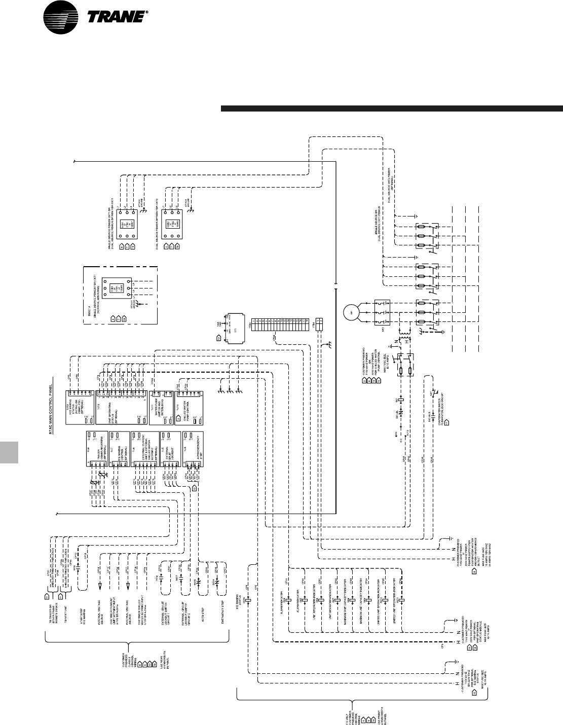
RLC-PRC006-EN54
Field Wiring, 2-Compressor Units
Typical Wiring
Diagram
Electrical Data
and Connection
