Trane RTAA User Manual To The E02cdd52 8813 47c4 Bd8f 23c7b397fd7f
User Manual: Trane RTAA to the manual
Open the PDF directly: View PDF ![]() .
.
Page Count: 52
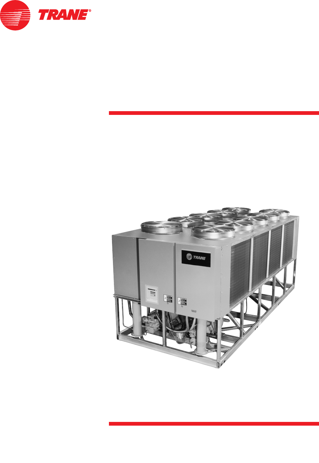
Air-Cooled Series R™
Rotary Liquid Chiller
Model RTAA
70 to 125 Tons
Built for the Industrial and Commercial Markets
RLC-PRC016-ENAugust 2002
RLC-PRC016-EN2
Features and
Benefits
You…
Like its chillers, Trane wants its
relationships with customers to last.
Trane is interested in maintaining long
term, loyal relationships. This
perspective means the point in time that
a customer purchases a chiller is the
beginning of a relationship, not the end.
Your business is important, but your
satisfaction is paramount.
Designed by Customers….
Trane’s RTAA 70-125 was designed with
the end user’s requirements in mind.
Reliability, efficiency, sound, and
physical size were primary design
concerns in expanding the RTAA product
line down to 70 tons. The result is a
reliable chiller that will help you achieve
your bottom line goals.
© 2002 American Standard Inc. All rights reserved.
3
RLC-PRC016-EN
Contents
Features and Benefits
Model Number Description
General Data
Selection Procedure
Application Considerations
Performance Adjustment Factors
Performance Data
Electrical Data
Jobsite Connections
Controls
Dimensional Data
Weights
Options
Typical Wiring Diagrams
Features Summary
Mechanical Specifications
2
13
14
15
16
20
22
29
30
32
40
41
42
43
45
46
The standard ARI rating condition
(54/44°F and 95°F) and IPLV are ARI
certified. All other ratings, including the
following, are outside the scope of the
certification program and are excluded:
• Glycol.
• 50 Hz.
• Remote evaporator models.
Water Chiller
Systems Business Unit
RLC-PRC016-EN4
Features and
Benefits
Improvements
The RTAA 70-125 offers the same high
reliability of its larger predecessor
coupled with lowered sound levels,
increased energy efficiency, and reduced
physical footprint, all due to its advanced
design, low speed/direct drive
compressor and proven Series R™
performance.
Some of the major advantages of the
Model RTAA 70-125 vs its larger
predecessor are:
•Higher energy efficiency
•Lower sound levels
•Smaller physical footprint
The Series R™ Model RTAA 70-125 is an
industrial grade design built for both the
industrial and commercial markets. It is
ideal for schools, hospitals, retailers,
office buildings, Internet service
providers and industrials.
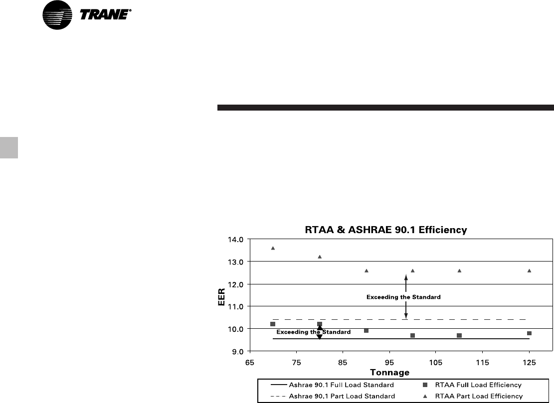
ASHRAE Standard 90.1 and RTAA 70-
125 World Class Energy Efficiency…
The importance of energy efficiency
cannot be understated. Fortunately,
ASHRAE has created a guideline
emphasizing its importance.
Nonetheless, energy is often dismissed
as an operational cost over which the
owner has little control. That perception
results in missed opportunities for
energy efficiency, reduced utility bills,
and higher profits. Lower utility bills
directly affect profitability. Every dollar
saved in energy goes directly to the
bottom line. Trane’s RTAA 70-125 is one
way to maximize your profits.
ASHRAE Standard 90.1 & Executive
Order
- New technology applied to the
design, controls, and manufacturing
have created superior efficiency levels in
the RTAA 70-125 that are unmatched in
the industry. All Trane air-cooled chillers
meet the new efficiency levels mandated
by ASHRAE Standard 90.1. This new
standard requires higher efficiencies
than past technologies can deliver. The
US Federal Government has adopted
standard 90.1 and, in some cases,
requires even higher efficiencies.
Federal Executive Order mandates
energy consuming devices procured
must be in the top 25% of their class or
be at least 10% better than any product
standard for that product. In the case of
chillers, that product standard is
ASHRAE 90.1. Trane’s RTAA 70-125
meets and exceeds the efficiency
requirements of 90.1, with some units
meeting the “stretch goals” of Executive
Order.
Risk.
The US Federal Government has
adopted ASHRAE 90.1, and it’s expected
to be adopted domestically, if not
globally, in the future. Domestic
acceptance has already begun. Make
sure that your chillers as well as your
entire HVAC system complies, or you
may be caught retrofitting your project
with new equipment and paying extra
design dollars if the code is adopted
during construction.
Precise Capacity Control.
Trane’s
patented unloading system allows the
compressor to modulate infinitely and
exactly match building loads. At the
same time chilled water temperatures
will be maintained within +/- 1/2ºF of
setpoint, potentially eliminating the need
for external considerations to maintain
temperatures. Reciprocating and screw
chillers with stepped capacity control do
well to maintain chilled water
temperatures within 2ºF of setpoint.
Stepped control also results in
overcooling or undercooling your space
because rarely does the capacity of the
machine match the building load. The
result can be 10% higher energy bills.
Trane’s RTAA optimizes the part load
performance of your machine for energy
efficiency, precise temperature control
for all modes of operation, and your
personal comfort regardless of changing
conditions.
5
RLC-PRC016-EN
Features and
Benefits
Excellent Reliability
A building environment is expected to
be comfortable. When it is, no one says
a word. If it’s not… that’s a different
story. The same is true with chillers. No
one ever talks about chillers, yet alone
compressors, until they fail, and tenets
are uncomfortable and productivity is
lost. Trane’s helical rotary compressors
have a first year reliability rate of over
99%, which means our chillers stay
running when you need them.
Screw compressors were designed to
replace the inherent design flaws of a
reciprocating compressor. Trane’s helical
rotary compressor has successfully
achieved this goal, proven by the over
99% reliability rating of our compressor
in the first year of operation. A good
design like Trane’s should maintain this
level of reliability for several years of
chiller operation. Not all screw
compressors maintain a high reliability
and Trane is the only manufacturer that
will publish a reliability number. The
point is to make sure that you are getting
a reliable screw chiller design so that you
don’t end up with the downtime and lost
earnings that the industry is trying to
avoid by getting away from
reciprocating technology.
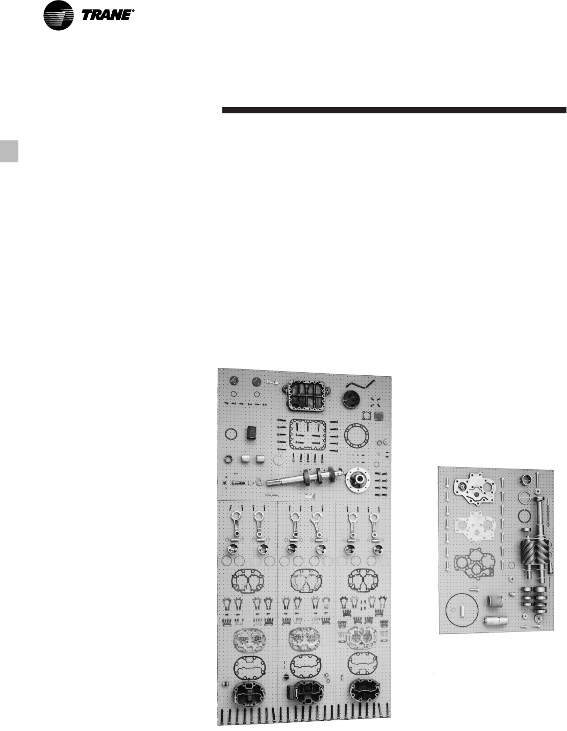
Fewer moving parts.
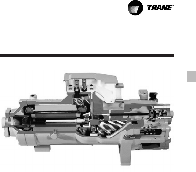
Trane’s helical
rotary compressors have only two major
rotating parts: the male and female rotor.
A reciprocating compressor can have
more than 15 times that number of
critical parts. Multiples of pistons,
valves, crankshafts, and connecting rods
in a reciprocating unit all represent
different failure paths for the
compressor. In fact, reciprocating
compressors can easily have a failure
rate four times that of a helical rotor.
Combine this with two to three
reciprocating compressors for each
helical rotary compressor on chillers of
equal tonnage, and statistics tell you it’s
a matter of time before you lose a
reciprocating compressor.
Robust parts.
Helical rotary
compressors are precisely machined
using state of the art processes from
solid metal bar stock. Tolerances are
maintained within a micron or less than
a tenth of the diameter of a human hair.
The resulting compressor is a robust yet
highly sophisticated assembly capable of
ingesting liquid refrigerant without risk
of damage. Contrast this to a
reciprocating compressor, which can be
destroyed by a single slug of liquid.
Series R™ Compressor Highlights
•Direct-drive, low speed for high
efficiency and reliability.
•Simple design with only four moving
parts, resulting in high reliability and
low maintenance.
•Field serviceable compressor for easy
maintenance.
•Precise rotor tip clearance for optimal
efficiency.
•Suction gas-cooled motor, resulting in
lower operating temperatures for
increased motor life, and giving the
capability for:
•Five-minute start-to-start/two minute
stop-to-start capability, which allows
for closer water loop temperature
control.
RLC-PRC016-EN6
Features and
Benefits
RTAA 70-125 Chiller Highlights
•High Reliability, with over 99%
compressor reliability rate in the first
year of operation, and Adaptive
Controls to keep the chiller on line
producing cold water during adverse
conditions.
•High Efficiency (all units exceed
ASHRAE 90.1 efficiency standard).
•Low sound levels.
•Small footprint, with smallest required
application space (operating footprint)
in the industry.
•Years of research, testing, and
successful applications. The Trane
helical rotary compressor has amassed
thousands of hours of testing, much of
it at severe operating conditions. Not
to mention the successful application
of RTAA chillers for over 11 years, with
a developed reputation as the industry
standard.
•Trouble free startup through factory
testing of compressor and completed
chiller and factory installation of chiller
accessories.
•+/- ½°F leaving water temperature
control, resulting from PID feed-
forward controls, and linear load
matching, also allowing for 10% flow
rate change per minute while
maintaining ± ½°F leaving water
temperature control.
Trane helical rotary screw compressor
component parts versus reciprocating
compressor components.
7
RLC-PRC016-EN
Features and
Benefits
Superior Full Load Efficiency
Precise Rotor Tip Clearances
Higher energy efficiency in a helical
rotary compressor is obtained by
reducing the rotor tip clearances. This
reduces the leakage between high and
low pressure cavities during
compression. Precise rotor tip clearance
is achieved with the latest manufacturing
and machining technology. Trane is the
first helical rotary compressor
manufacturer to electronically check
compressor parts machining accuracy as
part of the standard production process.
Optimized Compressor Parts Profiles
Rotor and slide valves are unique
designs, optimized for the air
conditioning application. The rotors are
designed for the pressure ranges in the
air conditioning application. The unloader
valve has a unique profile that resulted
from computer performance modeling in
typical part-load situations.
Advanced Heat Transfer Surfaces
Condenser and evaporator tubes use the
latest heat transfer technology for
increased efficiency.
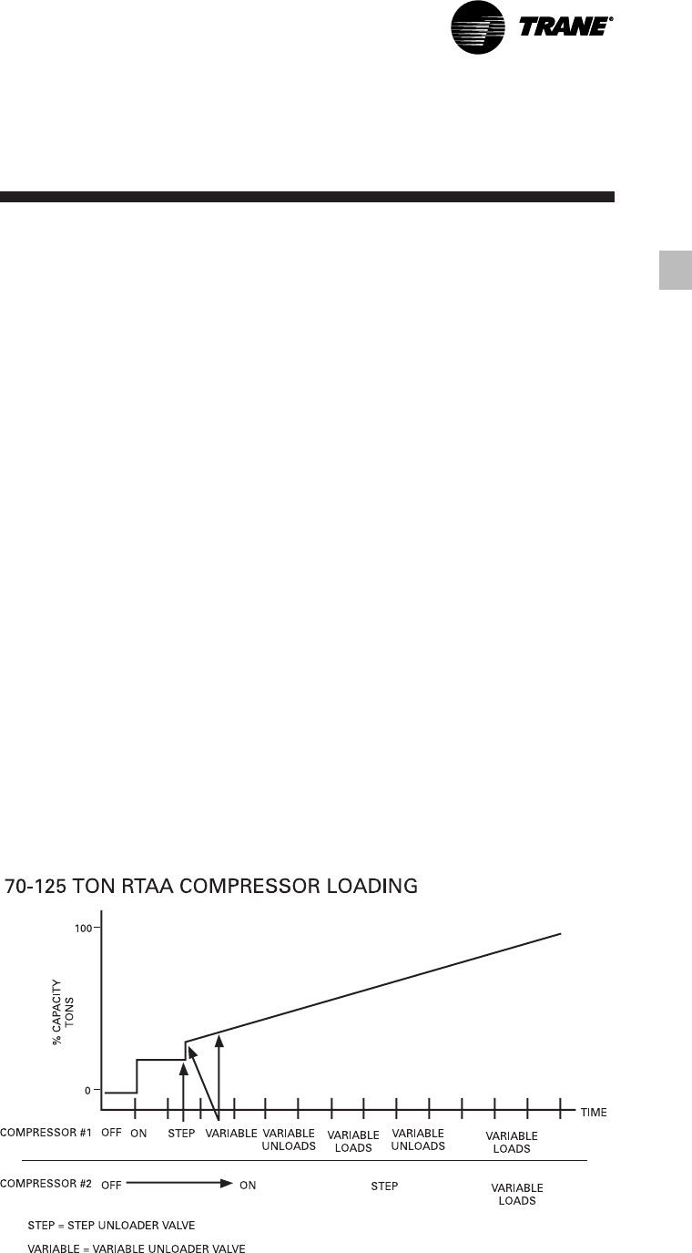
Great Part Load Efficiency
With Trane Helical Rotary
Screw Compressors and
Electronic Expansion Valve
Trane Helical Rotary Screw Compressor
Means Superior Part Load Performance
The air-cooled Series R™ chiller has great
part-load performance. The combination
patented unloading system on the
“general purpose” compressor utilizes
the variable unloading valve for the
majority of the unloading function
similar to that of the slide valve. The
“general purpose” compressor also
uses a step unloader valve which is a
single unloading step to achieve the
minimum unloading point of the
compressor. The result of both of these
designs is optimized part-load
performance far superior to single
reciprocating compressors.
Optimum
Efficiencies
RLC-PRC016-EN8
Features and
Benefits
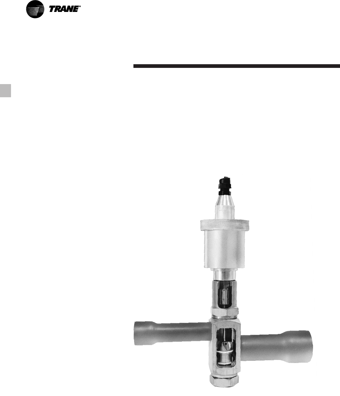
Electronic Expansion Valve
When coupled with Trane’s Adaptive
Control™ microprocessor, our electronic
expansion valve significantly improves
part-load performance of the Series R™
chiller by minimizing superheat in the
evaporator and allowing the chiller to
run at reduced condensing
temperatures. Chillers which use
conventional TXV’s must run at higher
head pressures and consume more
power than necessary at part-loads.
Additionally, the electronic expansion
valve and its controls allow much better
stability and control over dynamic load
and head changes. Under these
conditions a conventional TXV may
never achieve control stability and
extended periods of TXV “hunting” and
liquid slugging are common.
Capacity Control and Load Matching
Infinitely variable compressor
modulation allows the compressor
capacity to exactly match the building
cooling load. Reciprocating and screw
chillers that rely on stepped capacity
control must run at a capacity equal to or
greater than the load. Much of this
excess capacity is lost because
overcooling goes toward building latent
heat removal, causing the building to be
dried beyond normal comfort
requirements. The result is an increase in
chiller energy costs, particularly at the
part-load conditions at which the chiller
operates most of the time.
PID Chilled Water Setpoint
Control Through Slide Valve
Modulation
Maintain Chilled Water Supply Within
± 1/2°F of Setpoint
Chillers that have step capacity control
typically can only maintain water
temperature to around ± 2°F. With the
air-cooled Series R™ chiller, maintaining
temperature control has never been so
accurate.
Reduce Compressor Cycling
Modulating capacity control offers better
compressor reliability. Compressor
cycling, typical of reciprocating
compressors, will decrease compressor
component life. Parts like motors and
valves do not stand up well to excessive
compressor cycling.
Cutaway view of Trane’s electronic expansion valve.
9
RLC-PRC016-EN
Features and
Benefits
Trouble-Free Installation,
Start-Up and Operation
Adaptive Control™ Microprocessor
The RTAA 70-125 chiller offers advanced
microprocessor control and features the
Adaptive Control microprocessor. So
what is the Adaptive Control
microprocessor? Adaptive Control
means the Unit Control Module (UCM)
directly senses the control variables that
govern operation of the chiller: motor
current draw, evaporator temperature,
condenser temperature, etc.
When any of the variables approaches a
limit condition where the unit may be
damaged or shut down on a safety, the
UCM takes corrective action to avoid
shutdown and keep the chiller operating.
It does this through combined actions of
compressor slide valve modulation,
electronic expansion valve modulation
and fan staging. Additionally, the UCM
optimizes total unit power consumption
during normal operating conditions. No
other chiller control system in the
marketplace duplicates this
performance.
The End Of Most Nuisance Trip-Outs
And Unnecessary Service Calls?
Unnecessary service calls and unhappy
tenants are reduced. Only when the
UCM has exhausted the corrective
actions it can take and the unit is still
violating an operating limit will the unit
shut down. CONTROLS ON OTHER
CHILLERS TYPICALLY SHUT DOWN THE
CHILLER, QUITE PROBABLY JUST
WHEN IT IS NEEDED THE MOST.
For example:
A typical five-year-old chiller with dirty
coils might trip-out on high pressure
cutout on a 100°F day in August. A hot
day is just when comfort cooling is
needed the most. In contrast, the air-
cooled Series R™ chiller with an Adaptive
Control microprocessor will stage fans
on, modulate electronic expansion valve,
and modulate slide valve as it
approaches a high pressure cutout.
Thereby KEEPING THE CHILLER ON-
LINE JUST WHEN YOU NEED IT THE
MOST.
RLC-PRC016-EN10
Close Spacing Of Chiller
The air-cooled Series R™ chiller has the
tightest recommended side clearance in
the industry, four feet, but that is not all.
In situations where equipment must be
installed with less clearance than
recommended, such as frequently
occurs in retrofit and rooftop
applications, restricted air flow is
common. Conventional chillers may not
work at all. However, the air-cooled
Series R™ chiller with Adaptive Control™
microprocessor will simply make as
much chilled water as it can given the
actual installed conditions, stay on line
during any unforeseen abnormal
conditions, and optimize its
performance. Consult your Trane sales
engineer for more details.
Lower Service Expense
Nuisance service calls are avoided.
When there is a real problem that must
be corrected, the UCM’s extensive
diagnostics help assure that the problem
is quickly identified. Down time and
service expense are minimized. And with
the ability to communicate with the
Trane Integrated Comfort™ system or a
remote display panel, service problems
can be identified and diagnosed remote
to the installation.
Factory Testing Means Trouble-Free
Start-Up
All air-cooled Series R™ chillers are given
a complete functional test at the factory.
This computer-based test program
completely checks the sensors, wiring,
electrical components, microprocessor
function, communication capability,
expansion valve performance and fans.
In addition, each compressor is run
tested to verify capacity and power
consumption. The end result of this test
program is that the chiller arrives at the
jobsite fully tested and ready to go to
work.
Factory Installed And Tested Controls/
Options Speed Installation
All Series R™ chiller options, including
control power transformer, starter
disconnect, low ambient control,
ambient temperature sensor, low
ambient lockout, communication
interface and ice making controls are
factory installed and tested. Some
manufacturers send options in pieces to
be field installed. With Trane, the
customer saves on installation expense
and has assurance that ALL chiller
controls/options have been tested and
will function as expected.
Features and
Benefits
11
RLC-PRC016-EN
Features and
Benefits
Superior Control
Unit Control Module
Trane’s Adaptive Control™
microprocessor control system enhances
the air-cooled Series R™ chiller by
providing the very latest chiller control
technology.
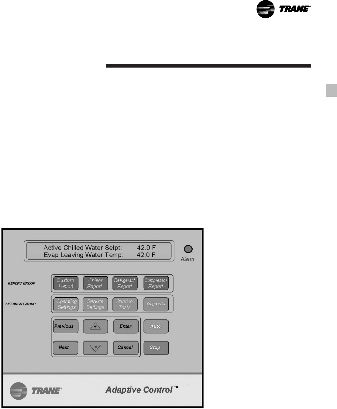
State-of-the-Art Equipment
The 70 to 125 ton air-cooled chillers offer
the exclusive Trane Adaptive Control
logic with the Clear Language Display
(UCM). The Clear Language Display has
various functions that allow the operator
to read unit information and adjust
setpoints. The Clear Language Display
panel has 16 keys, the readout screen is a
two-line, 40 character liquid crystal with a
backlight. The backlight allows the
operator to read the display in low-light
conditions.
Unit Control Module Features
Equal Compressor Sequencing
Trane maximizes both compressor and
motor life by equalizing both the number
of starts and the operating hours. The
UCM will start the compressor with the
least number of starts and turn off the
compressor with the most operating
hours. Conventional “auto” lead-lag
control will equalize starts, but running
hours will typically be unequal.
Equalizing both starts and running hours
will provide equal compressor wear.
Internal “Built-In” Chiller Flow
Protection
The UCM automatically detects a no
waterflow condition. An external flow
switch is not required, which lowers
costs versus typical chillers. Built-in flow
protection also eliminates nuisance flow
switch problems.
Remote Clear Language Display Panel
for 70 to 125-ton air-cooled chillers.
RLC-PRC016-EN12
Easy Chiller System Logging
The UCM displays data required to log
the chiller system. The following
information is available either as
standard or as an option with the Air-
Cooled Series R™ Chiller microprocessor:
•Entering and leaving chilled water
temperatures
•Ambient air temperature
•Evaporator and condenser refrigerant
temperatures and pressures
•Compressor suction temperature
•Percent RLA for each compressor
•Percent line voltage
•Compressor starts and running hours
•Active setpoints:
chilled water setpoint
current limit setpoint
ice termination setpoint
low ambient lockout setpoint
•Over 90 diagnostic and operating
conditions
•Part failure diagnostics:
water temperature sensors
refrigerant temperature sensors
compressor contactors
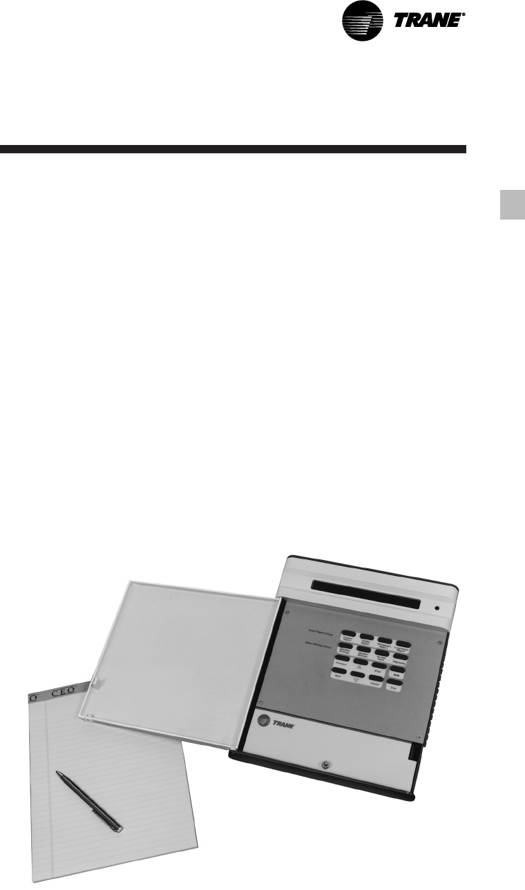
Remote Display Panel
Trane air-cooled Series R™ 70-125 ton
chillers are available with a twisted pair
connection to an optional remote display
panel. Chiller operation can be controlled
similarly to the control interface on the
chiller itself. Through a twisted pair of
wires the unit can be turned on or off,
change the chilled water setpoint, and
display over 90 operating and diagnostic
conditions. The remote display panel can
be mounted indoors so access to chiller
information is just steps away,
eliminating any need to go outdoors or
on the roof.
The clear language display for chiller
sizes of 70-125 tons has the ability to
control multiple units. In a multiple unit
configuration, the Remote Clear
Language Display Panel has the
capability to communicate with up to
four units. Each unit requires a separate
communication link with the Remote
Display Panel.
Easy Interface To The Building
Management System
Controlling the air-cooled Series R™
chiller with building management
systems is state-of-the-art yet simple.
Chiller inputs include:
•Chiller enable/disable
•Circuit enable/disable
•Chilled water setpoint
•Current limit setpoint
•Ice making enable
Chiller outputs include:
•Compressor running indication
•Alarm indication (CKt 1/CKt2)
•Maximum capacity
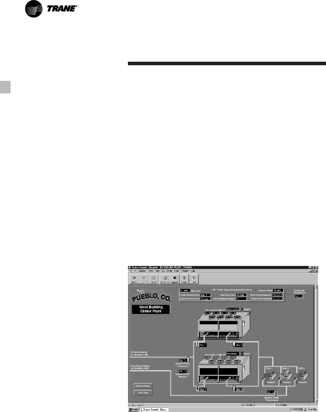
Trane Chiller Plant Manager/ICS
The Tracer™ Chiller Plant Manager
Building Management System
provides building automation and
energy management functions
through stand- alone control. The
Chiller Plant Manager is capable of
monitoring and controlling your entire
chiller plant system.
Application software available:
•Time-of-day scheduling
•Duty cycle
•Demand limiting
•Chiller sequencing
•Process control language
•Boolean processing
•Zone control
•Reports and logs
•Custom messages
•Run time and maintenance
•Trend log
•Totalizing
•PID control loops
And of course, Trane’s Chiller Plant
Manager Panel can be used on a
stand- alone basis or tied into a
complete building automation
system.
Features and
Benefits
13
RLC-PRC016-EN
Model Number
Description
Model Nomenclature Digit Number
1 2 3 4 5 6 7 8 9 10 11 12 13 14 15 16 17
70-125 Tons
Digits 1,2 — Unit Model
RT = Rotary Chiller
Digit 3 — Unit Type
A = Air Cooled
Digit 4 — Development Sequence
A = First Sequence
Digit 5, 6 & 7 — Nominal Capacity
070 = 70 tons
080 = 80 tons
090 = 90 tons
100 = 100 tons
110 = 110 tons
125 = 125 tons
Digit 8 — Unit Voltage
A = 200/60/3
C = 230/60/3
D = 380/60/3
4 = 460/60/3
5 = 575/60/3
S = Special
Digit 9 — Compressor Starter Type
Y = Y-Delta Closed Transition
X = X-Line (Across the Line)
S = Special
Digit 10, 11 — Design Sequence
** = Factory Input
Digit 12 — Evaporator Leaving Temperature
1 = Standard 40 to 65°F
2 = Low 0 to 39°F
3 = Ice-Making 20 to 65°F
S = Special
Digit 13 — Condenser Coil Fin Material
A = Aluminum
S = Special
2 = Copper Fins
4 = CompleteCoat
Digit 14 — Agency Listing
0 = No Agency Listing
3 = C/UL Listing
Digit 15 — Control Interface
C = Deluxe without Communication
D = Deluxe with Communication
Digit 16 — Chilled Water Reset
0 = No Chilled Water Reset
1 = Based on Return Water Temperature
2 = Based on Outside Air Temperature
Digit 17 —Miscellaneous Factory Installed
Options
A = Architectural Louvered Panels
B = Control Power Transformer
C = Convenience Outlet
D = Low Ambient Lockout Sensor
F = Mech. Disconnect Switch
G = Low Ambient Operation
K = Coil Protection
M = Access Guard
P = Circuit Breaker (Single Point Power)
Z = Circuit Breaker (Dual Point Power)
Field Installed Options
Q = Spring Isolators
N = Neoprene Isolators
R = Remote Display Panel
3 = 5 Year Compressor Warranty
8 = Architectural Louvered Panels
9 = Coil Protection
0 = Access Guard
J = Remote Evaporator
H = Sound Attenuator
RLC-PRC016-EN14
General Data
Table G-1 — General Data RTAA — 70-125 Ton
Size 70 80 90 100 110 125
Compressor
Quantity 2 2 2 2 2 2
Nominal Size (1) (Tons) 35/35 40/40 50/40 50/50 60/50 60/60
Evaporator
Water Storage (Gallons) 39.8 37.3 34.4 32.1 53.4 45.8
(Liters) 150.6 143.1 130.2 121.5 202.11 173.4
Min. Flow (GPM) 84 96 108 120 132 150
(L/Sec) 5.3 6.1 6.8 7.6 8.3 9.5
Max. Flow (GPM) 252 288 324 360 396 450
(L/Sec) 15.9 18.2 20.4 22.7 25.0 28.4
Condenser
Qty of Coils 4 4 4 4 4 4
Coil Length (In) 156/156 156/156 168/156 168/168 204/168 204/204
Coil Height (In) 42 42 42 42 42 42
Fins/Ft. 192 192 192 192 192 192
Number of Rows 2 2 2 2 2 2
Condenser Fans
Quantity (1) 4/4 4/4 5/4 5/5 5/5 5/5
Diameter (In) 30 30 30 30 30 30
Total Airflow (CFM) 71750 71750 77640 83530 87505 91480
Nominal RPM 850 850 850 850 850 850
Tip Speed (Ft/Min) 6675 6675 6675 6675 6675 6675
Motor HP (Ea) 1.0 1.0 1.0 1.0 1.0 1.0
Min Starting/Oper Ambient (2)
Std Unit (Deg F) 25 25 25 25 25 25
Low Ambient (Deg F) -10 -10 -10 -10 -10 -10
General Unit
Refrigerant HCFC-22 HCFC-22 HCFC-22 HCFC-22 HCFC-22 HCFC-22
No. of Independent
Refrigerant Circuits 2 2 2 2 2 2
% Min. Load (3) 15 15 15 15 15 15
Refrigerant Charge (1) (Lb) 58/58 61/61 73/61 73/73 98/73 98/98
(Kg) 26/26 28/28 34/28 34/34 44/34 44/44
Oil Charge (1) (Gallons) 2.5/2.5 2.5/2.5 3/2.5 3/3 3/3 3/3
(Liters) 10.6/10.6 10.6/10.6 12.7/10.6 12.7/12.7 12.7/12.7 12.7/12.7
1. Data containing information on two circuits shown as follows: ckt 1/ckt2.
2. Minimum start-up/operating ambient based on a 5 mph wind across the condenser.
3. Percent minimum load is for total machine at 50°F ambient and 44°F LWT, not each individual circuit.
15
RLC-PRC016-EN
Selection
Procedure
The chiller capacity tables, P-1 through
P-12, cover the most frequently
encountered leaving water
temperatures. The tables reflect a 10°F
(6°C) temperature drop through the
evaporator. For temperature drops other
than 10°F (6°C), refer to Table F-1, and
apply the appropriate Performance Data
Adjustment Factors. For chilled brine
selections, refer to Figures F-2 and 3 for
Ethylene and Propylene Glycol
Adjustment Factors.
To select a Trane air-cooled Series R™
chiller, the following information is
required:
1. Design load in tons of refrigeration
2. Design chilled water temperature drop
3. Design leaving chilled water
temperature
4. Design ambient temperature
Evaporator flow rates can be determined
by using the following formulas:
GPM = Tons x 24
Temperature Drop (Degrees F)
OR L/S = kW (Capacity) x .239
Temperature Drop (Degrees C)
NOTE: Flow rates must fall within the
limits specified in Table G-1 (for GPM or
for l/s).
Selection Example
Given:
Required System Load = 115 Tons
Leaving Chilled Water Temperature
(LCWT) = 44°F Chilled Water
Temperature Drop = 10°F Design
Ambient Temperature = 95°F
Evaporator Fouling Factor = 0.0001
1. To calculate the required chilled water
flow rate we use the formula given
below:
GPM = 115 Tons x 24 = 276 GPM
10°F
2. From Table P-6 (RTAA Performance
Data), an RTAA 125 at the given
conditions will produce 120.1 tons
with a compressor power input of
136.3 kW and a unit EER of 9.8.
3. To determine the evaporator pressure
drop we use the flow rate (GPM) and
the evaporator water pressure drop
curves, Figure F-1. Entering the curve
at 276 GPM, the pressure drop for a
nominal 125 ton evaporator is 18 feet.
4. For selection of chilled brine units or
applications where the altitude is
significantly greater than sea level or
the temperature drop is different than
10°F, the performance adjustment
factors from Tables F-1, F-2, and/or F-3
should be applied at this point.
For example:
Corrected Capacity = Capacity
(unadjusted) x Glycol Flow Rate
Adjustment Factor
5. The final unit selection is:
•QTY (1) RTAA 125
•Cooling Capacity = 120.1 tons
•Entering/Leaving Chilled Water
Temperatures = 54/44°F
•Chilled Water Flow Rate = 276 GPM
•Evaporator Water Pressure Drop = 18
feet
•Compressor Power Input = 136.3 kW
•Unit EER = 9.8
Minimum Leaving Chilled Water
Temperature Setpoint
The minimum leaving chilled water
temperature setpoint for water is 40°F.
For those applications requiring lower
setpoints, a glycol solution must be used.
Contact the local Trane sales engineer for
additional information.
RLC-PRC016-EN16
Application
Considerations
Application Considerations
Certain application constraints should be
considered when sizing, selecting and
installing Trane air-cooled Series R™
chillers. Unit and system reliability is
often dependent upon properly and
completely complying with these
considerations. Where the application
varies from the guidelines presented, it
should be reviewed with your local
Trane sales engineer.
Unit Sizing
Unit capacities are listed in the
performance data section. Intentionally
oversizing a unit to assure adequate
capacity is not recommended. Erratic
system operation and excessive
compressor cycling are often a direct
result of an oversized chiller. In addition,
an oversized unit is usually more
expensive to purchase, install, and
operate. If oversizing is desired, consider
using two units.
Unit Placement
1. Setting The Unit
A base or foundation is not required if
the selected unit location is level and the
base is strong enough to support the
unit’s operating weight as listed in Tables
W-1 and W-2.
2. Isolation and Sound Emission
The most effective form of isolation is to
locate the unit away from any sound-
sensitive area. Structurally transmitted
sound can be reduced by
ELASTOMERIC vibration eliminators.
Spring isolators have proven to be of
little benefit on air-cooled Series R™
chiller installations and are not
recommended. An acoustical engineer
should always be consulted in critical
sound applications.
For maximum isolation effect, water
lines and electrical conduit should also
be isolated. Wall sleeves and rubber
isolated piping hangers can be used to
reduce the sound transmitted through
water piping. To reduce the sound
transmitted through electrical conduit,
use flexible electrical conduit.
State and local codes on sound
emissions should always be considered.
Since the environment in which a sound
source is located affects sound pressure,
unit placement must be carefully
evaluated. Sound power levels for Trane
air-cooled Series R™ chillers are available
on request.
3. Servicing
Adequate clearance for evaporator and
compressor servicing should be
provided. Recommended minimum
space envelopes for servicing are
located in the dimensional data section
and can serve as a guideline for
providing adequate clearance. The
minimum space envelopes also allow
for control panel swing and routine
maintenance requirements. Local code
requirements may take precedence.
4. Unit Location
a. General
Unobstructed flow of condenser air is
essential to maintain chiller capacity and
operating efficiency. When determining
unit placement, careful consideration
must be given to assuring a sufficient
flow of air across the condenser heat
transfer surface. Two detrimental
conditions are possible and must be
avoided if optimum performance is to be
achieved: warm air recirculation and coil
starvation.
Warm air recirculation occurs when
discharge air from the condenser fans is
recycled back to the condenser coil inlet.
Coil starvation occurs when free airflow
to (or from) the condenser is restricted.
Both warm air recirculation and coil
starvation cause reductions in unit
efficiency and capacity because of the
higher head pressures associated with
them. The air-cooled Series R™ chiller
offers an advantage over competitive
equipment in these situations.
Performance is minimally affected in
many restricted air flow situations due to
its unique condensing coil geometry.
Also, through its advanced Adaptive
Control™ microprocessor logic, the
chiller will attempt to stay on-line where
competitive chillers would usually shut
down.
Trane’s unique Adaptive Control
microprocessor has the ability to
understand the operating environment
of the chiller and adapt to it by first
optimizing its performance and second,
staying on line through abnormal
conditions. For example, high ambient
temperatures combined with a restricted
air flow situation will generally not cause
the air-cooled Series R™ chiller to shut
down. Competitive chillers would
typically shut down on a high pressure
nuisance cut-out in these conditions.
Debris, trash, supplies, etc. should not be
allowed to accumulate in the vicinity of
the air-cooled Series R™ chiller. Supply
air movement may draw debris into the
condenser coil, blocking spaces between
coil fins and causing coil starvation.
Special consideration should be given to
low ambient units. Condenser coils and
fan discharge must be kept free of
obstructions to permit adequate airflow
for satisfactory unit operation.
17
RLC-PRC016-EN
Application
Considerations
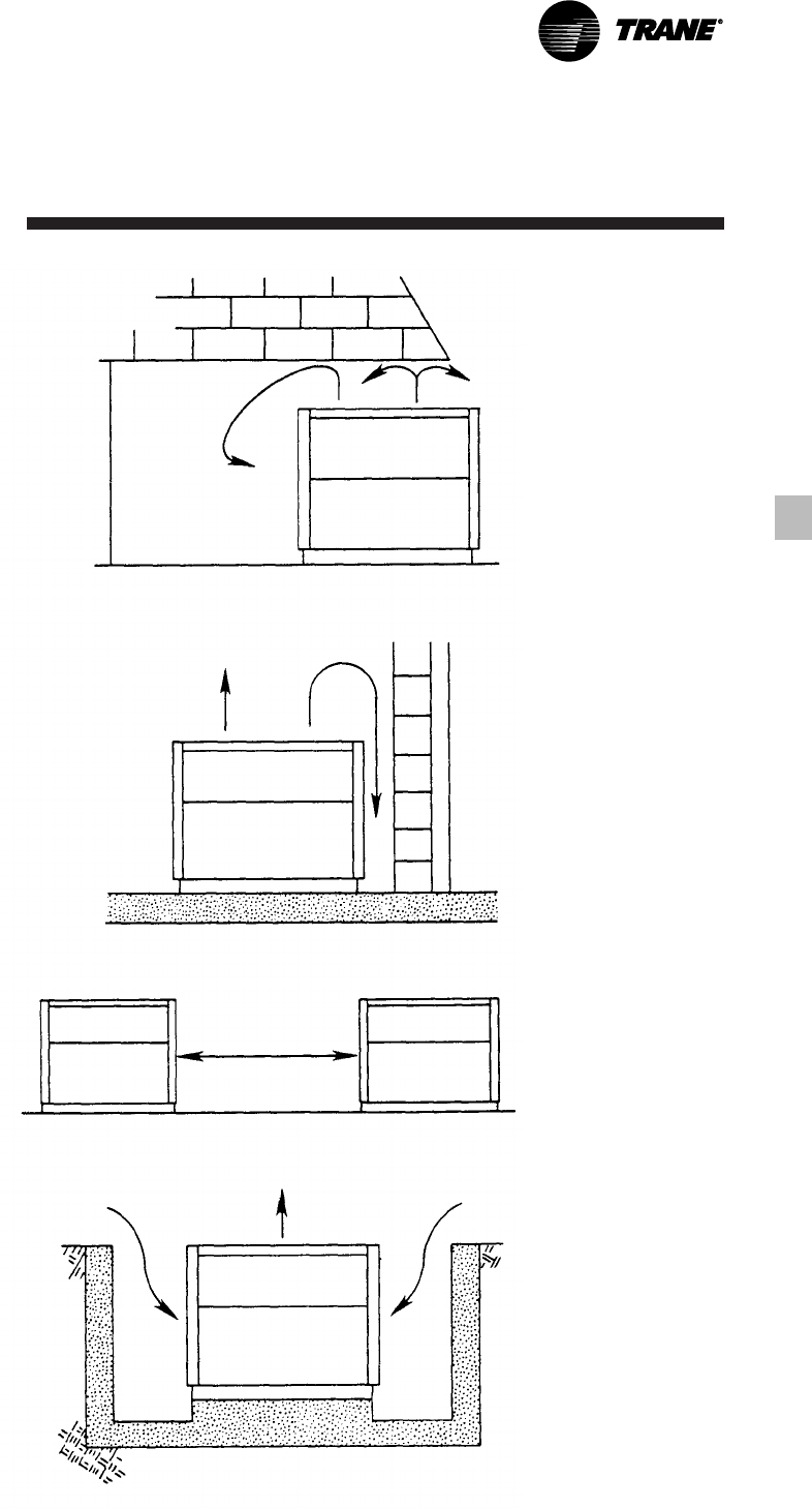
b. Provide Vertical Clearance
Vertical condenser air discharge must be
unobstructed. While it is difficult to
predict the degree of warm air
circulation, a unit installed as shown on
the left would have its capacity and
efficiency significantly reduced.
Performance data is based on free air
discharge.
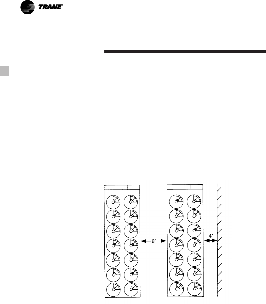
c. Provide Lateral Clearance
The condenser coil inlet must not be
obstructed. A unit installed closer than
the minimum recommended distance to
a wall or other vertical riser may
experience a combination coil starvation
and warm air recirculation, resulting in
unit capacity and efficiency reductions.
Once again, the Adaptive Control™
microprocessor will allow the chiller to
stay on line, producing the maximum
available capacity, even at less than
recommended lateral clearances.
The recommended lateral clearances are
depicted in the dimensional data section.
These are estimates and should be
reviewed with the local Trane sales
engineer at the jobsite.
d. Provide Sufficient Unit-to-Unit
Clearance
Units should be separated from each
other by a sufficient distance to prevent
warm air recirculation or coil starvation.
The air-cooled Series R™ chiller has the
lowest recommended unit-to-unit
clearance in the industry, eight feet.
Consult the local Trane sales engineer for
applications concerning close spacing
and restricted airflows.
e. Walled Enclosure Installations
When the unit is placed in an enclosure
or small depression, the top of the fans
should be no lower than the top of the
enclosure or depression. If they are,
consideration should be given to ducting
the top of the unit. Ducting individual
fans, however, is not recommended.
Such applications should always be
reviewed with the local Trane sales
engineer.

RLC-PRC016-EN18
Application
Considerations
Water Treatment
Dirt, scale, products of corrosion and
other foreign material will adversely
affect heat transfer between the water
and system components. Foreign matter
in the chilled water system can also
increase pressure drop and,
consequently, reduce waterflow. Proper
water treatment must be determined
locally, depending on the type of system
and local water characteristics.
Neither salt nor brackish water is
recommended for use in Trane air-
cooled Series R™ chillers. Use of either
will lead to a shortened life to an
indeterminable degree. The Trane
Company encourages the employment
of a reputable water treatment specialist,
familiar with local water conditions, to
assist in this determination and in the
establishment of a proper water
treatment program.
The capacities given in the performance
data section of this catalog are based on
water with a fouling factor of .00010. For
capacities at other fouling factors, see
adjustment factors in Table F-1.
Effect Of Altitude On Capacity
Air-cooled Series R™ chiller capacities
given in the performance data tables, P-1
through P-12, are for use at sea level. At
elevations substantially above sea level,
the decreased air density will decrease
condenser capacity and, therefore, unit
capacity and efficiency. The adjustment
factors in Table F-1 can be applied
directly to the catalog performance data
to determine the unit’s adjusted
performance.
Ambient Limitations
Trane air-cooled Series R™ chillers are
designed for year-round applications
over a range of ambients. Chillers from
70-125 tons offer operation for ambients
from 25 to 115°F as standard, and will
operate down to -10°F with the low
ambient option.
The minimum ambient temperatures are
based on still conditions (winds not
exceeding five mph). Greater wind
velocities will result in a drop in head
pressure, therefore increasing the
minimum starting and operating
ambient temperature. Once again, the
Adaptive Control™ microprocessor will
attempt to keep the chiller on-line when
high or low ambient conditions exist,
making every effort to avoid nuisance
trip-outs and provide the maximum
allowable tonnage.
Waterflow Limits
The minimum waterflow rates are given
in Table G-1. Evaporator flow rates
below the tabulated values will result in
laminar flow causing freeze-up
problems, scaling, stratification and poor
control.
The maximum evaporator waterflow
rate is also given in the general data
section. Flow rates exceeding those
listed may result in excessive tube and
baffle erosion.
The evaporator can withstand up to 50
percent water flow reduction as long as
this flow is equal or above the minimum
gpm requirements.
Variable Evaporator Flow
Air-cooled Series R™ chillers have the
capability to handle variable evaporator
flow without losing leaving water
temperature control. Flow rates can be
varied up to 10% of design without
decreasing the leaving water
temperature control capabilities.
Temperature Limits
1. Leaving Water Temperature Range
Trane air-cooled Series R™ chillers have
three distinct leaving water categories:
standard, low temperature, and ice
making.
The standard leaving water temperature
range is 40 to 65°F. Low temperature
machines produce leaving water
temperatures between 0°F and 39°F.
Since water supply temperature
setpoints from 0 to 39°F result in suction
temperatures at or below the freezing
point of water, a glycol solution is
required for all low temperature
machines. Ice making machines have a
leaving water temperature range of 20 to
65°F. Ice making controls include dual
setpoint controls and safeties for ice
making and standard cooling
capabilities. Consult your local Trane
sales engineer for applications or
selections involving low temperature or
ice making machines.
The maximum water temperature that
can be circulated through an evaporator
when the unit is not operating is 108°F.
The evaporator becomes thermal stress
limited at this temperature.
2. Supply Water Temperature Drop
The performance data for the Trane air-
cooled Series R™ chiller is based on a
chilled water temperature drop of 10°F.
Temperature drops outside this range
will result in unit performance that
differs from that cataloged. For
performance data outside the 10°F
range, see Table F-1 for adjustment
factors. Chilled water temperature drops
from 6 to 18°F may be used as long as
minimum and maximum water
temperature and minimum and
maximum flow rates are not violated.
Temperature drops outside 6 to 18°F are
beyond the optimum range for control
and may adversely affect the
microcomputer’s ability to maintain an
acceptable supply water temperature
range.
Further, temperature drops of less than
6°F may result in inadequate refrigerant
superheat. Sufficient superheat is always
a primary concern in any direct
expansion refrigerant system and is
especially important in a package chiller
where the evaporator is closely coupled
to the compressor. When temperature
drops are less than 6°F, an evaporator
runaround loop may be required.
19
RLC-PRC016-EN
Application
Considerations
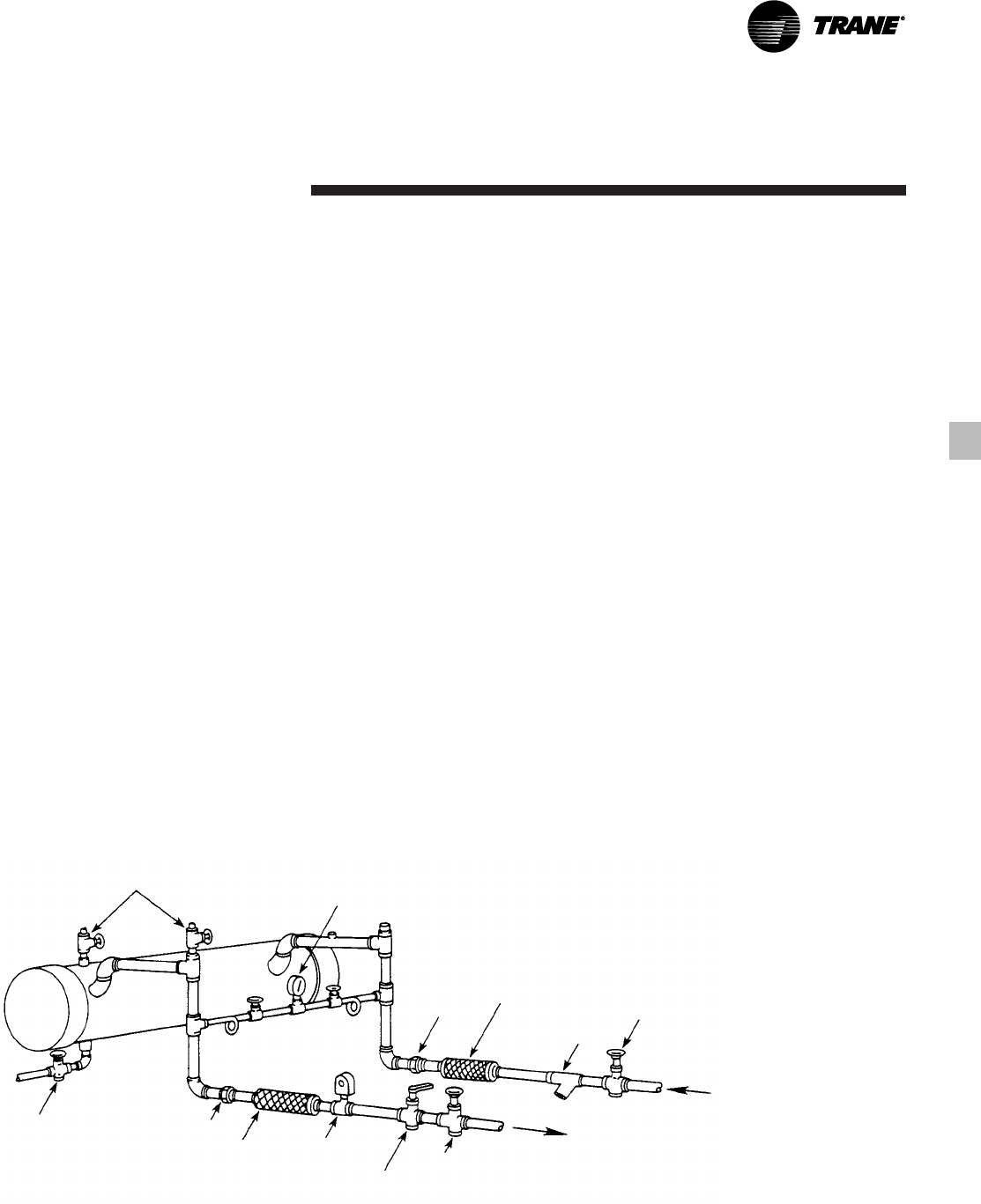
Typical Water Piping
All building water piping must be
flushed prior to making final connections
to the chiller. To reduce heat loss and
prevent condensation, insulation should
be installed. Expansion tanks are also
usually required so that chilled water
volume changes can be accommodated.
A typical piping arrangement is shown in
Figure A-1.
Short Water Loops
The proper location of the temperature
control sensor is in the supply (outlet)
water. This location allows the building
to act as a buffer and assures a slowly
changing return water temperature. If
there is not a sufficient volume of water
in the system to provide an adequate
buffer, temperature control can be lost,
resulting in erratic system operation and
excessive compressor cycling. A short
water loop has the same effect as
attempting to control from the building
return water.
The Air-Cooled Series R™ 70-125 ton
chiller has excellent leaving chilled water
control capabilities because of
exceptional controls, EXV and linear
unloading. However, it is still a good idea
to make sure the evaporator water loop
is sized sufficiently to help maintain
temperature control.
As a guideline, ensure the volume of
water in the evaporator loop equals or
exceeds two times the evaporator flow
rate. For a rapidly changing load profile,
the amount of volume should be
increased.
To prevent the effect of a short water
loop, the following items should be
given careful consideration:
A storage tank or larger header pipe to
increase the volume of water in the
system and, therefore, reduce the rate of
change of the return water temperature.
Multiple Unit Operation
Whenever two or more units are used
on one chilled water loop, Trane
recommends that their operation be
controlled from a single control device,
such as a Trane Tracer™ system.
1. Series Operation
Some systems require large chilled
water temperature drops (16 to 24°F).
For those installations, two units with
their evaporators in series are usually
required. Control of the units should be
from a common temperature controller
to prevent the separate thermostats
fighting one another and continually
hunting. It is possible to control from the
two individual unit controls, but a
common temperature controller
provides a positive method for
preventing control overlap, more closely
matches system load, and simplifies
compressor lead-lag capability.
2. Parallel Operation
Some systems require more capacity or
standby capability than a single machine
can provide. For those installations, two
units with their evaporators in a parallel
configuration are typical. The only
effective way of controlling two units in
parallel is with a single temperature
controller. Two individual temperature
controllers are not capable of providing
reliable system control and will often
result in unsatisfactory operation.
Figure A-1 — Recommended Piping Components For Typical Evaporator Installation
Vents Valved
Pressure
Gauge
Drain Union
Vibration
Eliminator
Flow
Switch
(Optional) Balancing Valve
Gate Valve
Union Water
Strainer
Vibration
Eliminator
Gate Valve
RLC-PRC016-EN20
Performance
Adjustment
Factors
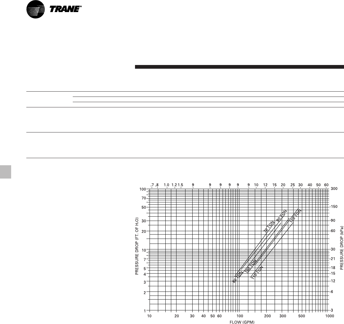
Figure F-1 — Evaporator Water Pressure Drops, 70-125 Ton Units
Table F-1 — Performance Data Adjustment Factors
Chilled Altitude
Fouling Water Sea Level 2000 Feet 4000 Feet 6000 Feet
Factor Temp. Drop CAP GPM KW CAP GPM KW CAP GPM KW CAP GPM KW
8 1.000 1.249 1.000 0.996 1.245 1.004 0.991 1.240 1.007 0.987 1.234 1.014
0.00010 10 1.000 1.000 1.000 0.997 0.996 1.004 0.993 0.992 1.007 0.988 0.988 1.015
12 1.001 0.835 1.001 0.997 0.832 1.004 0.993 0.828 1.009 0.988 0.824 1.015
14 1.003 0.716 1.001 0.999 0.714 1.004 0.994 0.711 1.009 0.990 0.708 1.015
16 1.004 0.628 1.001 1.000 0.626 1.005 0.997 0.623 1.009 0.991 0.620 1.016
8 0.988 1.235 0.996 0.984 1.230 1.000 0.980 1.225 1.004 0.975 1.220 1.010
0.00025 10 0.988 0.989 0.998 0.986 0.985 1.000 0.981 0.981 1.004 0.977 0.976 1.011
12 0.990 0.825 0.998 0.987 0.822 1.000 0.983 0.819 1.005 0.978 0.815 1.011
14 0.991 0.708 0.998 0.988 0.706 1.001 0.984 0.703 1.005 0.980 0.700 1.011
16 0.993 0.621 0.999 0.990 0.619 1.001 0.986 0.617 1.006 0.981 0.614 1.012
FLOW (L/s)
21
RLC-PRC016-EN
Performance
Adjustment
Factors
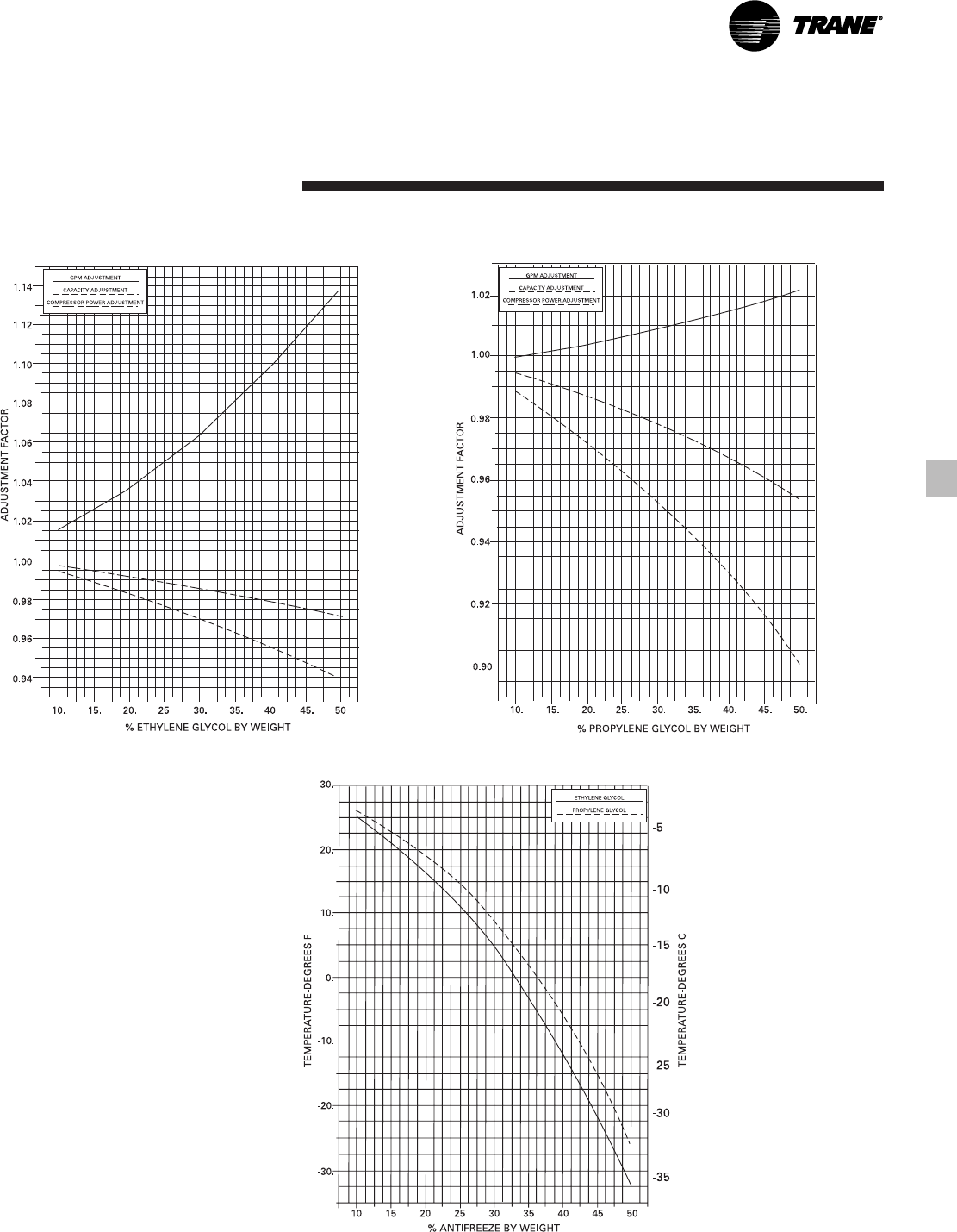
Figure F-2 — Ethylene Glycol Performance Factors Figure F-3 — Propylene Glycol Performance Factors
Figure F-4 — Ethylene Glycol and Propylene Glycol Freeze Point

RLC-PRC016-EN22
Table P-2 — 60 Hz RTAA 80 Performance Data English
Entering Condenser Air Temperature (Degrees F)
LWT 75 85 95 105 115
(Deg. F) Tons kW EER Tons kW EER Tons kW EER Tons kW EER Tons kW EER
40 83.0 68.9 12.8 78.8 75.6 11.2 74.4 83.1 9.7 69.8 91.3 8.4 65.0 100.4 7.2
42 86.0 70.1 13.0 81.6 76.8 11.4 77.1 84.2 9.9 72.3 92.5 8.6 67.4 101.6 7.3
44 89.0 71.3 13.3 84.5 78.0 11.7 79.8 85.4 10.2 74.9 93.7 8.8 69.9 102.8 7.5
46 92.0 72.5 13.5 87.4 79.2 11.9 82.6 86.6 10.4 77.6 94.9 9.0 72.4 104.1 7.7
48 95.2 73.8 13.8 90.4 80.4 12.1 85.4 87.9 10.6 80.3 96.2 9.2 74.4 104.7 7.9
50 98.3 75.1 14.0 93.4 81.7 12.4 88.3 89.1 10.8 83.0 97.4 9.4 75.9 104.8 8.0
55 106.5 78.3 14.6 101.3 84.9 13.0 95.8 92.4 11.4 90.1 100.7 9.9 80.0 105.0 8.5
Notes:
1. Ratings based on sea level altitude and evaporator fouling factor of 0.00010.
2. Consult Trane representative for performance at temperatures outside of the ranges shown.
3. kW input is for compressors only.
4. EER = Energy Efficiency Ratio (Btu/watt-hour). Power inputs include compressors, condenser fans and control power.
5. Ratings are based on an evaporator temperature drop of 10°F.
6. 115°F performance data reflects Adaptive Control Microprocessor control algorithms.
7. Interpolation between points is permissible. Extrapolation is not permitted.
8. Rated in accordance with ARI Standard 550/590-98.
Table P-1 — 60 Hz RTAA 70 Performance Data English
Entering Condenser Air Temperature (Degrees F)
LWT 75 85 95 105 115
(Deg. F) Tons kW EER Tons kW EER Tons kW EER Tons kW EER Tons kW EER
40 72.6 58.6 12.9 68.7 64.3 11.2 64.6 70.8 9.7 60.4 77.9 8.4 55.5 84.8 7.1
42 75.0 59.4 13.1 71.1 65.1 11.5 66.9 71.6 10.0 62.6 78.7 8.6 57.1 84.8 7.3
44 77.6 60.2 13.4 73.5 65.9 11.8 69.3 72.4 10.2 64.9 79.6 8.8 58.6 84.8 7.5
46 80.2 61.1 13.7 76.0 66.8 12.0 71.7 73.2 10.5 67.2 80.5 9.0 60.2 84.8 7.7
48 82.8 61.9 14.0 78.5 67.6 12.3 74.1 74.1 10.7 69.5 81.4 9.3 61.8 84.8 7.9
50 85.4 62.8 14.3 81.1 68.5 12.6 76.5 75.0 11.0 71.8 82.3 9.5 63.4 84.8 8.1
55 92.2 64.9 14.9 87.6 70.6 13.2 82.8 77.2 11.6 77.8 84.7 10.0 67.3 84.6 8.7
Notes:
1. Ratings based on sea level altitude and evaporator fouling factor of 0.00010.
2. Consult Trane representative for performance at temperatures outside of the ranges shown.
3. kW input is for compressors only.
4. EER = Energy Efficiency Ratio (Btu/watt-hour). Power inputs include compressors, condenser fans and control power.
5. Ratings are based on an evaporator temperature drop of 10°F.
6. 115°F performance data reflects Adaptive Control Microprocessor control algorithms.
7. Interpolation between points is permissible. Extrapolation is not permitted.
8. Rated in accordance with ARI Standard 550/590-98.
Performance Data
Metric
Entering Condenser Air Temperature (Degrees C)
LWT 30 35 40 45
(Deg. C) kWo kWi COP kWo kWi COP kWo kWi COP kWo kWi COP
6 251.7 66.1 3.4 238.7 71.9 3.0 225.0 78.3 2.6 209.6 84.8 2.2
8 267.6 67.6 3.5 253.5 73.4 3.1 239.4 79.9 2.7 219.8 84.9 2.4
10 283.4 69.1 3.6 269.0 75.0 3.2 254.2 81.5 2.8 229.6 84.8 2.5
Notes:
1. Ratings based on sea level altitude and evaporator fouling factor of 0.0000176.
2. Consult Trane representative for performance at temperatures outside of the ranges shown.
3. kWi input is for compressors only.
4. COP = Coefficient of Performance (kWo/kWi). Power inputs include compressors, condenser fans and control power.
5. Ratings are based on an evaporator temperature drop of 5.6°C.
6. 115°F performance data reflects Adaptive Control Microprocessor control algorithms.
7. Interpolation between points is permissible. Extrapolation is not permitted.
8. Rated in accordance with ARI Standard 550/590-98.
Metric
Entering Condenser Air Temperature (Degrees C)
LWT 30 35 40 45
(Deg. C) kWo kWi COP kWo kWi COP kWo kWi COP kWo kWi COP
6 289.4 77.9 3.3 275.0 84.7 2.9 259.8 92.1 2.6 244.0 100.2 2.2
8 307.7 80.1 3.5 292.5 86.9 3.1 276.4 94.3 2.7 259.8 102.4 2.3
10 326.6 82.4 3.6 310.5 89.1 3.2 293.9 96.6 2.8 276.4 104.7 2.4
Notes:
1. Ratings based on sea level altitude and evaporator fouling factor of 0.0000176.
2. Consult Trane representative for performance at temperatures outside of the ranges shown.
3. kWi input is for compressors only.
4. COP = Coefficient of Performance (kWo/kWi). Power inputs include compressors, condenser fans and control power.
5. Ratings are based on an evaporator temperature drop of 5.6°C.
6. 115°F performance data reflects Adaptive Control Microprocessor control algorithms.
7. Interpolation between points is permissible. Extrapolation is not permitted.
8. Rated in accordance with ARI Standard 550/590-98.

23
RLC-PRC016-EN
Table P-3 — 60 Hz RTAA 90 Performance Data English
Entering Condenser Air Temperature (Degrees F)
LWT 75 85 95 105 115
(Deg. F) Tons kW EER Tons kW EER Tons kW EER Tons kW EER Tons kW EER
40 94.7 81.9 12.3 89.9 88.9 10.9 84.8 97.0 9.5 79.5 106.2 8.2 73.9 116.4 7.0
42 97.9 83.3 12.6 93.0 90.3 11.1 87.8 98.4 9.7 82.3 107.5 8.4 76.5 117.8 7.2
44 101.2 84.7 12.8 96.2 91.7 11.3 90.8 99.8 9.9 85.1 108.9 8.6 79.2 119.2 7.4
46 104.6 86.2 13.0 99.4 93.2 11.6 93.8 101.2 10.1 88.0 110.4 8.8 81.7 120.4 7.5
48 108.1 87.7 13.3 102.6 94.6 11.8 96.9 102.7 10.3 91.0 111.8 9.0 82.9 120.1 7.7
50 111.5 89.2 13.5 106.0 96.2 12.0 100.1 104.2 10.5 93.9 113.3 9.2 84.3 120.0 7.8
55 120.5 93.2 14.0 114.5 100.1 12.5 108.2 108.1 11.0 101.6 117.2 9.6 88.4 119.6 8.2
Notes:
1. Ratings based on sea level altitude and evaporator fouling factor of 0.00010.
2. Consult Trane representative for performance at temperatures outside of the ranges shown.
3. kW input is for compressors only.
4. EER = Energy Efficiency Ratio (Btu/watt-hour). Power inputs include compressors, condenser fans and control power.
5. Ratings are based on an evaporator temperature drop of 10°F.
6. 115°F performance data reflects Adaptive Control Microprocessor control algorithms.
7. Interpolation between points is permissible. Extrapolation is not permitted.
8. Rated in accordance with ARI Standard 550/590-98.
Table P-4 — 60 Hz RTAA 100 Performance Data English
Entering Condenser Air Temperature (Degrees F)
LWT 75 85 95 105 115
(Deg. F) Tons kW EER Tons kW EER Tons kW EER Tons kW EER Tons kW EER
40 105.1 94.3 12.0 99.9 101.7 10.6 94.2 110.5 9.3 88.2 120.5 8.1 81.9 131.9 6.9
42 108.6 95.9 12.2 103.2 103.3 10.8 97.4 112.0 9.5 91.2 122.1 8.2 84.7 133.5 7.1
44 112.2 97.5 12.4 106.6 104.9 11.0 100.6 113.6 9.7 94.3 123.7 8.4 87.6 135.1 7.2
46 115.9 99.2 12.6 110.1 106.6 11.2 103.9 115.3 9.9 97.4 125.3 8.6 90.6 136.7 7.4
48 119.6 101.0 12.8 113.6 108.3 11.4 107.3 117.0 10.1 100.6 127.0 8.8 92.0 136.7 7.5
50 123.4 102.8 13.0 117.2 110.1 11.6 110.7 118.7 10.3 103.8 128.7 8.9 93.4 136.6 7.6
55 133.1 107.5 13.5 126.5 114.7 12.1 119.4 123.2 10.7 112.0 133.1 9.3 98.1 136.6 8.0
Notes:
1. Ratings based on sea level altitude and evaporator fouling factor of 0.00010.
2. Consult Trane representative for performance at temperatures outside of the ranges shown.
3. kW input is for compressors only.
4. EER = Energy Efficiency Ratio (Btu/watt-hour). Power inputs include compressors, condenser fans and control power.
5. Ratings are based on an evaporator temperature drop of 10°F.
6. 115°F performance data reflects Adaptive Control Microprocessor control algorithms.
7. Interpolation between points is permissible. Extrapolation is not permitted.
8. Rated in accordance with ARI Standard 550/590-98.
Performance Data
Metric
Entering Condenser Air Temperature (Degrees C)
LWT 30 35 40 45
(Deg. C) kWo kWi COP kWo kWi COP kWo kWi COP kWo kWi COP
6 329.4 91.6 3.2 312.9 98.9 2.9 295.3 107.1 2.5 277.1 116.2 2.2
8 349.8 94.2 3.4 332.3 101.5 3.0 313.6 109.7 2.6 294.3 118.8 2.3
10 370.6 96.9 3.5 352.0 104.2 3.1 332.6 112.4 2.7 307.7 120.0 2.4
Notes:
1. Ratings based on sea level altitude and evaporator fouling factor of 0.0000176.
2. Consult Trane representative for performance at temperatures outside of the ranges shown.
3. kWi input is for compressors only.
4. COP = Coefficient of Performance (kWo/kWi). Power inputs include compressors, condenser fans and control power.
5. Ratings are based on an evaporator temperature drop of 5.6°C.
6. 115°F performance data reflects Adaptive Control Microprocessor control algorithms.
7. Interpolation between points is permissible. Extrapolation is not permitted.
8. Rated in accordance with ARI Standard 550/590-98.
Metric
Entering Condenser Air Temperature (Degrees C)
LWT 30 35 40 45
(Deg. C) kWo kWi COP kWo kWi COP kWo kWi COP kWo kWi COP
6 365.7 104.8 3.2 347.0 112.7 2.8 327.3 121.6 2.5 306.6 131.7 2.2
8 387.5 107.7 3.3 367.8 115.6 2.9 347.0 124.6 2.6 325.6 134.7 2.2
10 410.0 110.9 3.4 389.2 118.7 3.0 367.4 127.7 2.7 341.1 136.5 2.3
Notes:
1. Ratings based on sea level altitude and evaporator fouling factor of 0.0000176.
2. Consult Trane representative for performance at temperatures outside of the ranges shown.
3. kWi input is for compressors only.
4. COP = Coefficient of Performance (kWo/kWi). Power inputs include compressors, condenser fans and control power.
5. Ratings are based on an evaporator temperature drop of 5.6°C.
6. 115°F performance data reflects Adaptive Control Microprocessor control algorithms.
7. Interpolation between points is permissible. Extrapolation is not permitted.
8. Rated in accordance with ARI Standard 550/590-98.
RLC-PRC016-EN24
Table P-6 — 60 Hz RTAA 125 Performance Data English
Entering Condenser Air Temperature (Degrees F)
LWT 75 85 95 105 115
(Deg. F) Tons kW EER Tons kW EER Tons kW EER Tons kW EER Tons kW EER
40 125.7 113.2 12.1 119.3 122.0 10.8 112.4 132.3 9.4 105.2 144.1 8.2 97.6 157.5 7.0
42 129.9 115.2 12.3 123.3 124.0 11.0 116.2 134.3 9.6 108.8 146.1 8.3 100.9 159.5 7.1
44 134.1 117.2 12.5 127.3 126.0 11.2 120.1 136.3 9.8 112.4 148.1 8.5 104.3 161.5 7.3
46 138.5 119.4 12.7 131.4 128.1 11.3 124.0 138.3 10.0 116.1 150.1 8.7 106.7 162.2 7.4
48 142.9 121.5 12.9 135.6 130.2 11.5 127.9 140.4 10.2 119.8 152.2 8.8 107.2 160.2 7.5
50 147.4 123.7 13.1 139.9 132.4 11.7 132.0 142.6 10.3 123.6 154.4 9.0 107.6 158.0 7.7
55 159.0 129.5 13.6 150.9 138.0 12.2 142.3 148.1 10.7 133.2 159.8 9.4 109.5 152.1 8.1
Notes:
1. Ratings based on sea level altitude and evaporator fouling factor of 0.00010.
2. Consult Trane representative for performance at temperatures outside of the ranges shown.
3. kW input is for compressors only.
4. EER = Energy Efficiency Ratio (Btu/watt-hour). Power inputs include compressors, condenser fans and control power.
5. Ratings are based on an evaporator temperature drop of 10°F.
6. 115°F performance data reflects Adaptive Control Microprocessor control algorithms.
7. Interpolation between points is permissible. Extrapolation is not permitted.
8. Rated in accordance with ARI Standard 550/590-98.
Table P-5 — 60 Hz RTAA 110 Performance Data English
Entering Condenser Air Temperature (Degrees F)
LWT 75 85 95 105 115
(Deg. F) Tons kW EER Tons kW EER Tons kW EER Tons kW EER Tons kW EER
40 113.3 102.5 11.9 107.7 110.7 10.6 101.7 120.3 9.3 95.2 131.2 8.1 88.4 143.6 6.9
42 117.1 104.3 12.2 111.3 112.4 10.8 105.1 122.0 9.5 98.4 132.9 8.2 91.5 145.3 7.0
44 120.9 106.1 12.4 114.9 114.2 11.0 108.5 123.7 9.7 101.7 134.7 8.4 94.6 147.1 7.2
46 124.8 107.9 12.6 118.6 116.0 11.2 112.0 125.5 9.9 105.1 136.4 8.6 97.7 148.9 7.4
48 128.8 109.8 12.8 122.4 117.8 11.4 115.6 127.3 10.0 108.5 138.3 8.7 99.4 148.9 7.5
50 132.8 111.7 13.0 126.2 119.7 11.6 119.3 129.2 10.2 111.9 140.1 8.9 101.0 148.7 7.6
55 143.1 116.7 13.4 136.1 124.7 12.0 128.6 134.1 10.7 120.6 144.9 9.3 103.6 145.4 8.0
Notes:
1. Ratings based on sea level altitude and evaporator fouling factor of 0.00010.
2. Consult Trane representative for performance at temperatures outside of the ranges shown.
3. kW input is for compressors only.
4. EER = Energy Efficiency Ratio (Btu/watt-hour). Power inputs include compressors, condenser fans and control power.
5. Ratings are based on an evaporator temperature drop of 10°F.
6. 115°F performance data reflects Adaptive Control Microprocessor control algorithms.
7. Interpolation between points is permissible. Extrapolation is not permitted.
8. Rated in accordance with ARI Standard 550/590-98.
Metric
Entering Condenser Air Temperature (Degrees C)
LWT 30 35 40 45
(Deg. C) kWo kWi COP kWo kWi COP kWo kWi COP kWo kWi COP
6 394.1 114.0 3.2 374.1 122.6 2.8 353.0 132.4 2.5 331.2 143.4 2.2
8 417.3 117.2 3.3 396.6 125.8 2.9 374.5 135.6 2.6 351.2 146.7 2.2
10 441.6 120.6 3.4 419.5 129.2 3.0 395.9 139.0 2.7 369.5 149.2 2.3
Notes:
1. Ratings based on sea level altitude and evaporator fouling factor of 0.0000176.
2. Consult Trane representative for performance at temperatures outside of the ranges shown.
3. kWi input is for compressors only.
4. COP = Coefficient of Performance (kWo/kWi). Power inputs include compressors, condenser fans and control power.
5. Ratings are based on an evaporator temperature drop of 5.6°C.
6. 115°F performance data reflects Adaptive Control Microprocessor control algorithms.
7. Interpolation between points is permissible. Extrapolation is not permitted.
8. Rated in accordance with ARI Standard 550/590-98.
Metric
Entering Condenser Air Temperature (Degrees C)
LWT 30 35 40 45
(Deg. C) kWo kWi COP kWo kWi COP kWo kWi COP kWo kWi COP
6 436.7 125.7 3.2 414.2 135.1 2.8 390.3 145.6 2.5 365.3 157.5 2.2
8 462.7 129.4 3.3 438.8 138.7 2.9 413.5 149.3 2.6 387.5 161.2 2.3
10 489.1 133.3 3.4 464.1 142.6 3.0 437.7 153.1 2.7 410.0 165.0 2.3
Notes:
1. Ratings based on sea level altitude and evaporator fouling factor of 0.0000176.
2. Consult Trane representative for performance at temperatures outside of the ranges shown.
3. kWi input is for compressors only.
4. COP = Coefficient of Performance (kWo/kWi). Power inputs include compressors, condenser fans and control power.
5. Ratings are based on an evaporator temperature drop of 5.6°C.
6. 115°F performance data reflects Adaptive Control Microprocessor control algorithms.
7. Interpolation between points is permissible. Extrapolation is not permitted.
8. Rated in accordance with ARI Standard 550/590-98.
Performance Data
25
RLC-PRC016-EN
Performance Data
Table P-7 — 50 Hz RTAA 70 Performance Data English
Entering Condenser Air Temperature (Degrees F)
LWT 75 85 95 105 115
(Deg. F) Tons kW EER Tons kW EER Tons kW EER Tons kW EER Tons kW EER
40 62.9 48.7 14.0 59.5 53.4 12.2 56.0 58.7 10.5 52.3 64.7 9.0 48.6 71.2 7.6
42 65.1 49.4 14.3 61.6 54.1 12.4 58.0 59.4 10.8 54.3 65.4 9.2 50.4 71.9 7.9
44 67.3 50.1 14.6 63.7 54.8 12.7 60.1 60.1 11.0 56.2 66.1 9.5 52.3 72.7 8.1
46 69.5 50.8 14.9 65.9 55.5 13.0 62.1 60.8 11.3 58.2 66.8 9.7 54.2 73.5 8.3
48 71.8 51.5 15.2 68.1 56.2 13.3 64.2 61.5 11.5 60.3 67.6 9.9 56.1 74.3 8.5
50 74.2 52.2 15.5 70.4 56.9 13.6 66.4 62.3 11.8 62.3 68.4 10.2 58.1 75.2 8.7
55 80.1 54.0 16.2 76.1 58.7 14.3 71.9 64.1 12.4 67.5 70.4 10.7 63.0 77.5 9.2
Notes:
1. Ratings based on sea level altitude and evaporator fouling factor of 0.00010.
2. Consult Trane representative for performance at temperatures outside of the ranges shown.
3. kW input is for compressors only.
4. EER = Energy Efficiency Ratio (Btu/watt-hour). Power inputs include compressors, condenser fans and control power.
5. Ratings are based on an evaporator temperature drop of 10°F.
6. 115°F performance data reflects Adaptive Control Microprocessor control algorithms.
7. Interpolation between points is permissible. Extrapolation is not permitted.
8. Rated in accordance with ARI Standard 550/590-98. Metric
Entering Condenser Air Temperature (Degrees C)
LWT 30 35 40 45
(Deg. C) kWo kWi COP kWo kWi COP kWo kWi COP kWo kWi COP
6 218.3 54.9 3.6 206.7 59.7 3.2 194.8 65.0 2.8 182.8 70.9 2.4
8 232.1 56.1 3.8 220.1 61.0 3.3 207.4 66.3 2.9 194.8 72.3 2.5
10 246.1 57.4 3.9 233.5 62.3 3.5 220.5 67.7 3.0 207.1 73.8 2.6
Notes:
1. Ratings based on sea level altitude and evaporator fouling factor of 0.0176.
2. Consult Trane representative for performance at temperatures outside of the ranges shown.
3. kWi input is for compressors only.
4. COP = Coefficient of Performance (kWo/kWi). Power inputs include compressors, condenser fans and control power.
5. Ratings are based on an evaporator temperature drop of 5.6°C.
6. 115°F performance data reflects Adaptive Control Microprocessor control algorithms.
7. Interpolation between points is permissible. Extrapolation is not permitted.
8. Rated in accordance with ARI Standard 550/590-98.
Table P-8 — 50 Hz RTAA 80 Performance Data English
Entering Condenser Air Temperature (Degrees F)
LWT 75 85 95 105 115
(Deg. F) Tons kW EER Tons kW EER Tons kW EER Tons kW EER Tons kW EER
40 72.1 57.4 13.8 68.4 62.9 12.0 64.6 69.0 10.4 60.5 75.9 9.0 56.4 83.4 7.7
42 74.7 58.4 14.1 70.9 63.9 12.3 66.9 70.0 10.7 62.8 76.9 9.2 58.5 84.4 7.8
44 77.4 59.4 14.3 73.4 64.9 12.6 69.3 71.0 10.9 65.1 77.9 9.4 60.7 85.4 8.0
46 80.1 60.4 14.6 76.0 65.9 12.8 71.8 72.1 11.2 67.4 78.9 9.6 62.8 86.5 8.2
48 82.8 61.5 14.9 78.7 66.9 13.1 74.3 73.1 11.4 69.8 80.0 9.8 65.1 87.5 8.4
50 85.7 62.6 15.1 81.4 68.0 13.3 76.9 74.2 11.6 72.2 81.0 10.1 67.4 88.6 8.6
55 92.9 65.3 15.8 88.3 70.8 13.9 83.4 77.0 12.2 78.4 83.8 10.6 73.2 91.5 9.1
Notes:
1. Ratings based on sea level altitude and evaporator fouling factor of 0.00010.
2. Consult Trane representative for performance at temperatures outside of the ranges shown.
3. kW input is for compressors only.
4. EER = Energy Efficiency Ratio (Btu/watt-hour). Power inputs include compressors, condenser fans and control power.
5. Ratings are based on an evaporator temperature drop of 10°F.
6. 115°F performance data reflects Adaptive Control Microprocessor control algorithms.
7. Interpolation between points is permissible. Extrapolation is not permitted.
8. Rated in accordance with ARI Standard 550/590-98.
Metric
Entering Condenser Air Temperature (Degrees C)
LWT 30 35 40 45
(Deg. C) kWo kWi COP kWo kWi COP kWo kWi COP kWo kWi COP
6 251.4 64.8 3.6 238.7 70.4 3.2 225.4 76.5 2.8 206.4 81.6 2.4
8 267.6 66.7 3.7 254.2 72.3 3.3 240.1 78.4 2.9 225.0 84.9 2.5
10 284.4 68.6 3.9 270.4 74.2 3.4 255.6 80.3 3.0 240.1 87.1 2.6
Notes:
1. Ratings based on sea level altitude and evaporator fouling factor of 0.0176.
2. Consult Trane representative for performance at temperatures outside of the ranges shown.
3. kWi input is for compressors only.
4. COP = Coefficient of Performance (kWo/kWi). Power inputs include compressors, condenser fans and control power.
5. Ratings are based on an evaporator temperature drop of 5.6°C.
6. 115°F performance data reflects Adaptive Control Microprocessor control algorithms.
7. Interpolation between points is permissible. Extrapolation is not permitted.
8. Rated in accordance with ARI Standard 550/590-98.

RLC-PRC016-EN26
Performance Data
Table P-9 — 50 Hz RTAA 90 Performance Data English
Entering Condenser Air Temperature (Degrees F)
LWT 75 85 95 105 115
(Deg. F) Tons kW EER Tons kW EER Tons kW EER Tons kW EER Tons kW EER
40 82.1 68.1 13.3 78.0 73.9 11.7 73.5 80.6 10.2 68.9 88.1 8.8 64.0 96.6 7.5
42 85.0 69.3 13.5 80.7 75.1 12.0 76.1 81.7 10.4 71.3 89.3 9.0 66.3 97.7 7.7
44 87.9 70.5 13.8 83.5 76.3 12.2 78.8 82.9 10.7 73.8 90.5 9.2 68.7 98.9 7.9
46 90.9 71.8 14.0 86.3 77.5 12.4 81.5 84.1 10.9 76.4 91.7 9.4 71.1 100.2 8.1
48 93.9 73.1 14.3 89.2 78.8 12.6 84.2 85.4 11.1 79.0 92.9 9.6 73.5 101.4 8.2
50 97.0 74.4 14.5 92.1 80.1 12.9 87.0 86.7 11.3 81.6 94.2 9.8 76.0 102.7 8.4
55 105.0 77.8 15.0 99.7 83.4 13.4 94.2 90.0 11.8 88.3 97.5 10.3 79.9 103.0 8.8
Notes:
1. Ratings based on sea level altitude and evaporator fouling factor of 0.00010.
2. Consult Trane representative for performance at temperatures outside of the ranges shown.
3. kW input is for compressors only.
4. EER = Energy Efficiency Ratio (Btu/watt-hour). Power inputs include compressors, condenser fans and control power.
5. Ratings are based on an evaporator temperature drop of 10°F.
6. 115°F performance data reflects Adaptive Control Microprocessor control algorithms.
7. Interpolation between points is permissible. Extrapolation is not permitted.
8. Rated in accordance with ARI Standard 550/590-98. Metric
Entering Condenser Air Temperature (Degrees C)
LWT 30 35 40 45
(Deg. C) kWo kWi COP kWo kWi COP kWo kWi COP kWo kWi COP
6 286.2 76.2 3.5 271.4 82.2 3.1 256.0 89.0 2.7 240.1 96.5 2.4
8 303.8 78.4 3.6 288.3 84.4 3.2 272.1 91.1 2.8 255.6 98.6 2.5
10 322.1 80.7 3.7 305.9 86.7 3.3 289.0 93.4 2.9 271.1 100.9 2.5
Notes:
1. Ratings based on sea level altitude and evaporator fouling factor of 0.0176.
2. Consult Trane representative for performance at temperatures outside of the ranges shown.
3. kWi input is for compressors only.
4. COP = Coefficient of Performance (kWo/kWi). Power inputs include compressors, condenser fans and control power.
5. Ratings are based on an evaporator temperature drop of 5.6°C.
6. 115°F performance data reflects Adaptive Control Microprocessor control algorithms.
7. Interpolation between points is permissible. Extrapolation is not permitted.
8. Rated in accordance with ARI Standard 550/590-98.
Table P-10 — 50 Hz RTAA 100 Performance Data English
Entering Condenser Air Temperature (Degrees F)
LWT 75 85 95 105 115
(Deg. F) Tons kW EER Tons kW EER Tons kW EER Tons kW EER Tons kW EER
40 91.1 78.4 12.9 86.6 84.6 11.4 81.7 91.7 10.0 76.5 100.0 8.6 71.0 109.4 7.4
42 94.2 79.8 13.1 89.5 85.9 11.6 84.5 93.1 10.2 79.1 101.3 8.8 73.5 110.7 7.5
44 97.4 81.2 13.3 92.5 87.3 11.8 87.3 94.4 10.4 81.8 102.7 9.0 76.0 112.1 7.7
46 100.6 82.7 13.5 95.6 88.7 12.0 90.2 95.8 10.6 84.5 104.1 9.2 78.6 113.5 7.9
48 103.9 84.2 13.7 98.7 90.2 12.3 93.2 97.3 10.8 87.3 105.5 9.4 81.2 114.9 8.0
50 107.3 85.7 13.9 101.9 91.7 12.5 96.2 98.7 11.0 90.1 106.9 9.6 83.8 116.3 8.2
55 115.9 89.7 14.4 110.1 95.6 12.9 103.9 102.6 11.4 97.4 110.7 10.0 88.6 117.6 8.6
Notes:
1. Ratings based on sea level altitude and evaporator fouling factor of 0.00010.
2. Consult Trane representative for performance at temperatures outside of the ranges shown.
3. kW input is for compressors only.
4. EER = Energy Efficiency Ratio (Btu/watt-hour). Power inputs include compressors, condenser fans and control power.
5. Ratings are based on an evaporator temperature drop of 10°F.
6. 115°F performance data reflects Adaptive Control Microprocessor control algorithms.
7. Interpolation between points is permissible. Extrapolation is not permitted.
8. Rated in accordance with ARI Standard 550/590-98. Metric
Entering Condenser Air Temperature (Degrees C)
LWT 30 35 40 45
(Deg. C) kWo kWi COP kWo kWi COP kWo kWi COP kWo kWi COP
6 317.1 87.1 3.4 301.0 100.0 3.0 283.7 101.0 2.6 265.8 109.3 2.3
8 336.5 89.7 3.5 319.3 102.5 3.1 301.3 103.5 2.7 282.3 111.8 2.4
10 356.2 92.3 3.6 338.2 105.1 3.2 319.3 106.1 2.8 299.2 114.4 2.5
Notes:
1. Ratings based on sea level altitude and evaporator fouling factor of 0.0176.
2. Consult Trane representative for performance at temperatures outside of the ranges shown.
3. kWi input is for compressors only.
4. COP = Coefficient of Performance (kWo/kWi). Power inputs include compressors, condenser fans and control power.
5. Ratings are based on an evaporator temperature drop of 5.6°C.
6. 115°F performance data reflects Adaptive Control Microprocessor control algorithms.
7. Interpolation between points is permissible. Extrapolation is not permitted.
8. Rated in accordance with ARI Standard 550/590-98.

27
RLC-PRC016-EN
Table P-12 — 50 Hz RTAA 125 Performance Data English
Entering Condenser Air Temperature (Degrees F)
LWT 75 85 95 105 115
(Deg. F) Tons kW EER Tons kW EER Tons kW EER Tons kW EER Tons kW EER
40 108.8 93.9 13.0 103.2 101.2 11.5 97.3 109.7 10.1 91.0 119.4 8.7 84.4 130.5 7.4
42 112.5 95.6 13.2 106.7 102.8 11.7 100.6 111.3 10.3 94.1 121.1 8.9 87.3 132.2 7.6
44 116.2 97.3 13.4 110.3 104.5 11.9 104.0 113.0 10.5 97.3 122.7 9.1 90.3 133.8 7.7
46 120.0 99.1 13.6 113.9 106.2 12.1 107.4 114.7 10.6 100.5 124.5 9.2 93.4 135.6 7.9
48 123.9 100.9 13.8 117.6 108.0 12.3 110.9 116.5 10.8 103.8 126.2 9.4 95.8 136.5 8.1
50 127.9 102.8 14.0 121.4 109.9 12.5 114.4 118.3 11.0 107.1 128.0 9.6 96.5 135.1 8.2
55 138.1 107.7 14.5 131.0 114.7 13.0 123.5 123.0 11.5 115.6 132.6 10.0 97.7 129.8 8.6
Notes:
1. Ratings based on sea level altitude and evaporator fouling factor of 0.00010.
2. Consult Trane representative for performance at temperatures outside of the ranges shown.
3. kW input is for compressors only.
4. EER = Energy Efficiency Ratio (Btu/watt-hour). Power inputs include compressors, condenser fans and control power.
5. Ratings are based on an evaporator temperature drop of 10°F.
6. 115°F performance data reflects Adaptive Control Microprocessor control algorithms.
7. Interpolation between points is permissible. Extrapolation is not permitted.
8. Rated in accordance with ARI Standard 550/590-98.
Performance Data
Table P-11 — 50 Hz RTAA 110 Performance Data English
Entering Condenser Air Temperature (Degrees F)
LWT 75 85 95 105 115
(Deg. F) Tons kW EER Tons kW EER Tons kW EER Tons kW EER Tons kW EER
40 98.4 85.3 12.8 93.5 92.0 11.4 88.2 99.9 10.0 82.6 108.9 8.6 76.7 119.1 7.3
42 101.7 86.8 13.1 96.7 93.5 11.6 91.2 101.3 10.2 85.5 110.3 8.8 79.4 120.6 7.5
44 105.1 88.3 13.3 99.9 95.0 11.8 94.3 102.8 10.4 88.3 111.8 9.0 82.1 122.1 7.7
46 108.5 89.9 13.5 103.1 96.5 12.0 97.4 104.3 10.6 91.3 113.3 9.2 84.9 123.6 7.8
48 112.1 91.5 13.7 106.5 98.1 12.2 100.5 105.9 10.7 94.3 114.9 9.3 87.7 125.2 8.0
50 115.6 93.2 13.9 109.9 99.7 12.4 103.8 107.5 10.9 97.3 116.5 9.5 90.5 126.7 8.2
55 124.8 97.5 14.4 118.6 103.9 12.9 112.0 111.6 11.4 105.0 120.5 9.9 92.3 123.5 8.5
Notes:
1. Ratings based on sea level altitude and evaporator fouling factor of 0.00010.
2. Consult Trane representative for performance at temperatures outside of the ranges shown.
3. kW input is for compressors only.
4. EER = Energy Efficiency Ratio (Btu/watt-hour). Power inputs include compressors, condenser fans and control power.
5. Ratings are based on an evaporator temperature drop of 10°F.
6. 115°F performance data reflects Adaptive Control Microprocessor control algorithms.
7. Interpolation between points is permissible. Extrapolation is not permitted.
8. Rated in accordance with ARI Standard 550/590-98. Metric
Entering Condenser Air Temperature (Degrees C)
LWT 30 35 40 45
(Deg. C) kWo kWi COP kWo kWi COP kWo kWi COP kWo kWi COP
6 342.5 94.8 3.4 324.9 101.9 3.0 306.6 110.0 2.6 287.3 119.0 2.3
8 362.9 97.5 3.5 344.6 104.6 3.1 325.2 112.7 2.7 304.8 121.8 2.4
10 384.3 100.4 3.6 365.0 107.5 3.2 344.6 115.5 2.8 323.1 124.6 2.5
1. Ratings based on sea level altitude and evaporator fouling factor of 0.0176.
2. Consult Trane representative for performance at temperatures outside of the ranges shown.
3. kWi input is for compressors only.
4. COP = Coefficient of Performance (kWo/kWi). Power inputs include compressors, condenser fans and control power.
5. Ratings are based on an evaporator temperature drop of 5.6°C.
6. 115°F performance data reflects Adaptive Control Microprocessor control algorithms.
7. Interpolation between points is permissible. Extrapolation is not permitted.
8. Rated in accordance with ARI Standard 550/590-98.
Metric
Entering Condenser Air Temperature (Degrees C)
LWT 30 35 40 45
(Deg. C) kWo kWi COP kWo kWi COP kWo kWi COP kWo kWi COP
6 378.3 104.3 3.4 358.6 112.0 3.0 337.9 120.7 2.7 316.1 130.5 2.3
8 400.8 107.4 3.5 380.1 115.0 3.1 358.3 123.8 2.8 335.4 133.6 2.4
10 424.4 110.7 3.6 402.6 118.3 3.2 379.4 127.0 2.9 355.5 136.7 2.5
Notes:
1. Ratings based on sea level altitude and evaporator fouling factor of 0.0176.
2. Consult Trane representative for performance at temperatures outside of the ranges shown.
3. kWi input is for compressors only.
4. COP = Coefficient of Performance (kWo/kWi). Power inputs include compressors, condenser fans and control power.
5. Ratings are based on an evaporator temperature drop of 5.6°C.
6. 115°F performance data reflects Adaptive Control Microprocessor control algorithms.
7. Interpolation between points is permissible. Extrapolation is not permitted.
8. Rated in accordance with ARI Standard 550/590-98.
RLC-PRC016-EN28
Performance Data
Table P-14 — ARI Part-Load Values (50 Hz)
Unit % Load Tons EER IPLV
RTAA 70 100 60.1 11.0 15.0
75 45.0 13.2
50 30.0 15.9
25 15.0 17.9
RTAA 80 100 69.3 10.9 14.5
75 52.0 12.8
50 34.7 16.3
25 17.3 13.8
RTAA 90 100 78.8 10.7 13.8
75 59.1 12.4
50 39.4 14.8
25 19.7 15.0
RTAA 100 100 87.3 10.4 13.7
75 65.5 12.0
50 43.7 14.6
25 21.8 16.0
RTAA 110 100 94.3 10.4 13.8
75 70.7 12.0
50 47.1 14.8
25 23.6 16.6
RTAA125 100 104.0 10.5 13.7
75 78.0 12.1
50 52.0 14.8
25 26.0 15.3
Table P-13 — ARI Part-Load Values (60 Hz)
Unit % Load Tons EER IPLV
RTAA 70 100 69.3 10.2 13.6
75 51.9 12.0
50 34.6 14.6
25 17.3 16.1
RTAA 80 100 79.8 10.2 13.2
75 59.8 11.7
50 39.8 14.9
25 19.9 12.6
RTAA 90 100 90.8 9.9 12.6
75 68.0 11.3
50 45.3 13.5
25 22.7 13.6
RTAA 100 100 100.6 9.7 12.6
75 75.5 11.0
50 50.3 13.5
25 25.2 14.8
RTAA 110 100 108.5 9.7 12.6
75 81.2 11.0
50 54.2 13.7
25 27.1 14.8
RTAA125 100 120.1 9.8 12.6
75 89.7 11.2
50 59.8 13.7
25 29.9 13.4
29
RLC-PRC016-EN
Electrical Data
Table E-1 — Electrical Data (50 & 60 Hz, 3 Phase)
Unit Wiring Motor Data
Fans
Unit Rated # of Power Max. Fuse, HACR Rec. Time Compressor (Each) (Each) Control
Size Voltage (9)
Connections (1)
MCA (3) Breaker or MOP (2,11) Delay or RDE (4) Qty RLA (5) LRA (8) Qty. kW FLA kW (7, 10)
RTAA 70 200/60 1 300 400 350 2 115 - 115 800 - 800 8 1.0 5.1 0.75
230/60 1 265 350 300 2 100 - 100 690 - 690 8 1.0 5.0 0.75
380/60 1 163 200 200 2 61 - 61 400 - 400 8 1.0 3.2 0.75
460/60 1 133 175 150 2 50 - 50 330 - 330 8 1.0 2.5 0.75
575/60 1 108 125 125 2 40 - 40 270 - 270 8 1.0 2.2 0.75
380/50 1 140 175 150 2 53 - 53 308 - 308 8 0.7 2.5 0.75
400/50 1 133 175 150 2 50 - 50 325 - 325 8 0.7 2.5 0.75
415/50 1 128 175 150 2 48 - 48 337 - 337 8 0.7 2.5 0.75
RTAA 80 200/60 1 361 500 400 2 142 - 142 800 - 800 8 1.0 5.1 0.75
230/60 1 319 400 350 2 124 - 124 760 - 760 8 1.0 5.0 0.75
380/60 1 194 250 225 2 75 - 75 465 - 465 8 1.0 3.2 0.75
460/60 1 160 200 175 2 62 - 62 380 - 380 8 1.0 2.5 0.75
575/60 1 131 175 150 2 50 - 50 304 - 304 8 1.0 2.2 0.75
380/50 1 167 200 175 2 65 - 65 356 - 356 8 0.7 2.5 0.75
400/50 1 160 200 175 2 62 - 62 375 - 375 8 0.7 2.5 0.75
415/50 1 155 200 175 2 60 - 60 389 - 389 8 0.7 2.5 0.75
RTAA 90 200/60 1 428 600 500 2 192 - 142 990 - 800 9 1.0 5.1 0.75
230/60 1 378 500 450 2 167 - 124 820 - 760 9 1.0 5.0 0.75
380/60 1 230 300 300 2 101 - 75 497 - 465 9 1.0 3.2 0.75
460/60 1 190 250 225 2 84 - 62 410 - 380 9 1.0 2.5 0.75
575/60 1 154 200 175 2 67 - 50 328 - 304 9 1.0 2.2 0.75
380/50 1 195 250 225 2 88 - 65 386 - 356 9 0.7 2.5 0.75
400/50 1 190 250 225 2 84 - 62 402 - 375 9 0.7 2.5 0.75
415/50 1 182 250 225 2 81 - 60 417 -389 9 0.7 2.5 0.75
RTAA 100 200/60 1 483 600 600 2 192 - 192 990 - 990 10 1.0 5.1 0.75
230/60 1 426 500 500 2 167 - 167 820 - 820 10 1.0 5.0 0.75
380/60 1 259 350 300 2 101 - 101 497 - 497 10 1.0 3.2 0.75
460/60 1 214 250 250 2 84 - 84 410 - 410 10 1.0 2.5 0.75
575/60 1 173 225 200 2 67 - 67 328 - 328 10 1.0 2.2 0.75
380/50 1 223 250 250 2 88 - 88 382 - 382 10 0.7 2.5 0.75
400/50 1 214 250 250 2 84 - 84 402 - 402 10 0.7 2.5 0.75
415/50 1 208 250 250 2 81 - 81 417 - 417 10 0.7 2.5 0.75
RTAA 110 200/60 1 535 700 600 2 233 - 192 1190 - 990 10 1.0 5.1 0.75
230/60 1 471 600 600 2 203 - 167 1044 - 820 10 1.0 5.0 0.75
380/60 1 287 400 350 2 123 - 101 632 - 497 10 1.0 3.2 0.75
460/60 1 235 300 300 2 101 - 84 522 - 410 10 1.0 2.5 0.75
575/60 1 191 250 225 2 81 - 67 420 - 328 10 1.0 2.2 0.75
380/50 1 245 300 300 2 106 - 88 487 - 382 10 0.7 2.5 0.75
400/50 1 236 300 300 2 101 - 84 512 - 402 10 0.7 2.5 0.75
415/50 1 228 300 300 2 97 - 81 531 - 417 10 0.7 2.5 0.75
RTAA 125 200/60 1 576 800 700 2 233 - 233 1190 - 1190 10 1.0 5.1 0.75
230/60 1 507 700 600 2 203 - 203 1044 - 1044 10 1.0 5.0 0.75
380/60 1 309 400 350 2 123 - 123 632 - 632 10 1.0 3.2 0.75
460/60 1 253 350 300 2 101 - 101 522 - 522 10 1.0 2.5 0.75
575/60 1 205 250 225 2 81 - 81 420 - 420 10 1.0 2.2 0.75
380/50 1 264 350 300 2 106 - 106 487 - 487 10 0.7 2.5 0.75
400/50 1 253 350 300 2 101 - 101 512 - 512 10 0.7 2.5 0.75
415/50 1 244 350 300 2 97 - 97 531 - 531 10 0.7 2.5 0.75
Notes:
1. As standard, all 70-215 ton units require a single point power connection.
2. Max Fuse or HACR type breaker = 225 percent of the largest compressor RLA plus 100 percent of the second compressor RLA, plus the sum of the condenser fan
FLA per NEC 440-22. Use FLA per circuit, NOT FLA for the entire unit).
3. MCA - Minimum Circuit Ampacity - 125 percent of largest compressor RLA plus 100 percent of the second compressor RLA plus the sum of the condenser fans
FLAs per NEC 440-33.
4. RECOMMENDED TIME DELAY OR DUAL ELEMENT (RDE) FUSE SIZE: 150 percent of the largest compressor RLA plus 100 percent of the second compressor RLA
and the sum of the condenser fan FLAs.
5. RLA - Rated Load Amps - rated in accordance with UL Standard 1995.
6. Local codes may take precedence.
7. Control kW includes operational controls only. Does not include evaporator heat tape.
8. LRA - Locked Rotor Amps - based on full winding (x-line) start units. LRA for wye-delta starters is 1/3 of LRA of x-line units.
9. VOLTAGE UTILIZATION RANGE:
Rated Voltage Utilization Range
200 180-220
230 208-254
380 342-418
460 414-506
575 516-633
10. A 115/60/1, 15 amp customer provided power connection is required to operate the unit controls. A
separate 115/60/1, 15 amp customer provided power connection is also needed to power the evaporator
heat tape (420 watts @ 120 volts). If the optional control power transformer is used, the customer needs
only to provide a power connection for the evaporator heat tape.
11. If factory circuit breakers are supplied with the chiller, then these values represent Maximum Overcurrent
Protection (MOP).
RLC-PRC016-EN30
Jobsite
Connections
Table J-1 – Customer Wire Selection
Wire Selection Size Wire Selection Size Wire Selection Size
to Main Terminal Block to Disconnect (1) to Circuit Breaker (1)
Connector Connector Factory Mounted Internal Connector
Unit Rated Terminal Size Wire Range Disconnect Size Wire Range Circuit Breaker Size (3) Wire Range
Size Voltage Ckt 1 Ckt 1 Ckt 1 Ckt 1 Ckt 1 Ckt 1
RTAA 70 200/60 760 Amp Lug Size D 400 Amp Lug Size B 350 Amp Lug Size B
230/60 760 Amp Lug Size D 400 Amp Lug Size B 300 Amp Lug Size B
380/60 335 Amp Lug Size E 250 Amp Lug Size A 200 Amp Lug Size A
460/60 335 Amp Lug Size E 250 Amp Lug Size A 150 Amp Lug Size A
575/60 335 Amp Lug Size E 250 Amp Lug Size A 125 Amp Lug Size A
380/50 335 Amp Lug Size E 250 Amp Lug Size A 150 Amp Lug Size A
400/50 335 Amp Lug Size E 250 Amp Lug Size A 150 Amp Lug Size A
415/50 335 Amp Lug Size E 250 Amp Lug Size A 150 Amp Lug Size A
RTAA 80 200/60 760 Amp Lug Size D 400 Amp Lug Size B 400 Amp Lug Size B
230/60 760 Amp Lug Size D 400 Amp Lug Size B 350 Amp Lug Size B
380/60 335 Amp Lug Size E 250 Amp Lug Size A 225 Amp Lug Size A
460/60 335 Amp Lug Size E 250 Amp Lug Size A 175 Amp Lug Size A
575/60 335 Amp Lug Size E 250 Amp Lug Size A 150 Amp Lug Size A
380/50 335 Amp Lug Size E 250 Amp Lug Size A 175 Amp Lug Size A
400/50 335 Amp Lug Size E 250 Amp Lug Size A 175 Amp Lug Size A
415/50 335 Amp Lug Size E 250 Amp Lug Size A 175 Amp Lug Size A
RTAA 90 200/60 760 Amp Lug Size D 600 Amp Lug Size C 500 Amp Lug Size C
230/60 760 Amp Lug Size D 400 Amp Lug Size B 450 Amp Lug Size C
380/60 335 Amp Lug Size E 400 Amp Lug Size B 300 Amp Lug Size B
460/60 335 Amp Lug Size E 250 Amp Lug Size A 225 Amp Lug Size A
575/60 335 Amp Lug Size E 250 Amp Lug Size A 175 Amp Lug Size A
380/50 335 Amp Lug Size E 250 Amp Lug Size A 225 Amp Lug Size A
400/50 335 Amp Lug Size E 250 Amp Lug Size A 225 Amp Lug Size A
415/50 335 Amp Lug Size E 250 Amp Lug Size A 225 Amp Lug Size A
RTAA 100 200/60 760 Amp Lug Size D 600 Amp Lug Size C 600 Amp Lug Size C
230/60 760 Amp Lug Size D 600 Amp Lug Size C 500 Amp Lug Size C
380/60 335 Amp Lug Size E 400 Amp Lug Size B 300 Amp Lug Size B
460/60 335 Amp Lug Size E 250 Amp Lug Size A 250 Amp Lug Size A
575/60 335 Amp Lug Size E 250 Amp Lug Size A 200 Amp Lug Size A
380/50 335 Amp Lug Size E 250 Amp Lug Size A 250 Amp Lug Size A
400/50 335 Amp Lug Size E 250 Amp Lug Size A 250 Amp Lug Size A
415/50 335 Amp Lug Size E 250 Amp Lug Size A 250 Amp Lug Size A
RTAA 110 200/60 760 Amp Lug Size D 600 Amp Lug Size C 600 Amp Lug Size C
230/60 760 Amp Lug Size D 600 Amp Lug Size C 600 Amp Lug Size C
380/60 335 Amp Lug Size E 400 Amp Lug Size B 350 Amp Lug Size B
460/60 335 Amp Lug Size E 400 Amp Lug Size B 300 Amp Lug Size B
575/60 335 Amp Lug Size E 250 Amp Lug Size A 225 Amp Lug Size A
380/50 335 Amp Lug Size E 400 Amp Lug Size B 300 Amp Lug Size B
400/50 335 Amp Lug Size E 400 Amp Lug Size B 300 Amp Lug Size B
415/50 335 Amp Lug Size E 400 Amp Lug Size B 300 Amp Lug Size B
RTAA 125 200/60 760 Amp Lug Size D 600 Amp Lug Size C N/A N/A
230/60 760 Amp Lug Size D 600 Amp Lug Size C 600 Amp Lug Size C
380/60 335 Amp Lug Size E 400 Amp Lug Size B 350 Amp Lug Size B
460/60 335 Amp Lug Size E 400 Amp Lug Size B 300 Amp Lug Size B
575/60 335 Amp Lug Size E 250 Amp Lug Size A 225 Amp Lug Size A
380/50 335 Amp Lug Size E 400 Amp Lug Size B 300 Amp Lug Size B
400/50 335 Amp Lug Size E 400 Amp Lug Size B 300 Amp Lug Size B
415/50 335 Amp Lug Size E 400 Amp Lug Size B 300 Amp Lug Size B
Lug Size A = #4 to 350 MCM per phase
Lug Size B = 2/0 to 250 MCM & 2/0 to 500 MCM per phase
Lug Size C = (2) 400 MCM to 500 MCM per phase
Lug Size D = (2) #4 to 500 MCM per phase
Lug Size E = #6 to 400 MCM per phase
Lug Size F = (2) #2 to 600 MCM per phase
Lug Size G = (2) #1 to 500 MCM per phase
Lug Size H = (4) #2 to 600 MCM per phase
Notes
1. Non-fused unit disconnect and circuit breaker are optional.
2. Copper wire only, sized per N.E.C., based on nameplate minimum circuit ampacity (MCA).
3. Circuit Breaker sizes are for factory mounted only. Field installed circuit breakers need to be sized using HACR breaker recommendations from Table E-1.
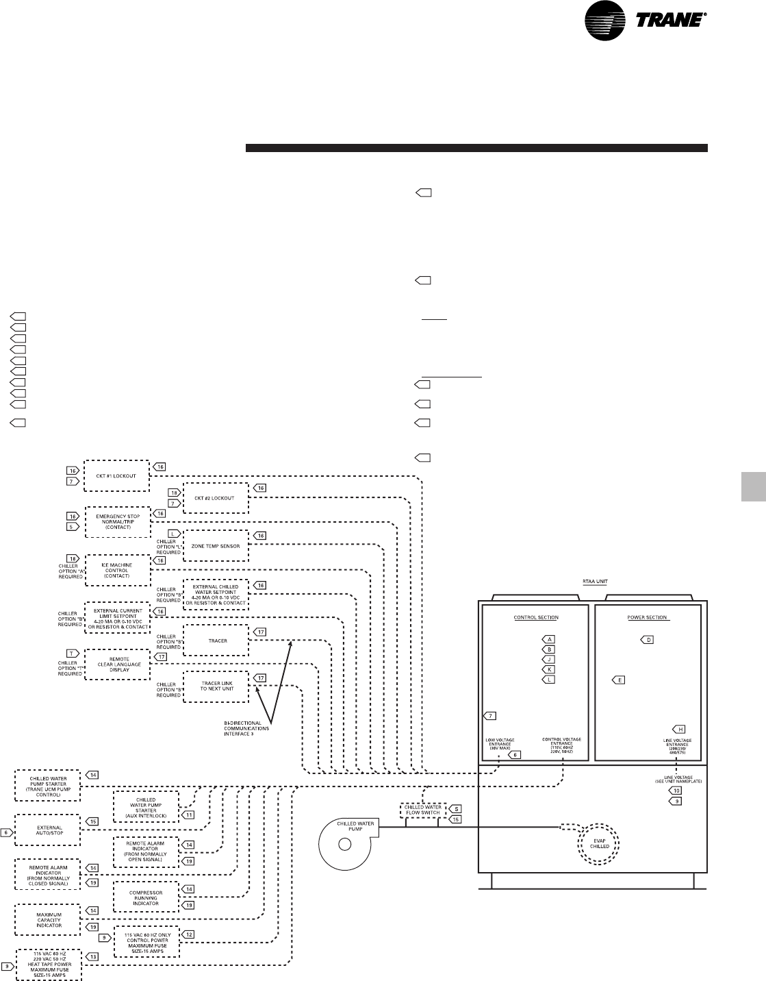
31
RLC-PRC016-EN
Jobsite
Connections
Figure J-1 — Typical Jobsite Wiring
NOTES:
1. DASHED LINES INDICATE RECOMMENDED FIELD WIRING BY OTHERS.
CHECK SALES ORDER TO DETERMINE IF WIRING IS REQUIRED FOR
SPECIFIC OPTIONS.
2. ALL THREE PHASE MOTORS SUPPLIED WITH THE UNIT ARE PROTECTED
UNDER PRIMARY SINGLE PHASE FAILURE CONDITIONS.
3. CAUTION - DO NOT ENERGIZE UNIT UNTIL CHECK OUT AND START-UP
PROCEDURES HAVE BEEN COMPLETED.
4 THE FOLLOWING CAPABILITIES ARE OPTIONAL - THEY ARE
IMPLEMENTED AND WIRED AS REQUIRED FOR A SPECIFIC SYSTEM
APPLICATION.
A ICE-MACHINE CONTROL (CANNOT BE USED WITH OPT. L)
B COMMUNICATIONS INTERFACE
D WYE-DELTA CLOSED TRANSITION STARTER
E CONTROL POWER TRANSFORMER.
H UNIT DISCONNECT, NON-FUSED
J CHILLED WATER RESET - RETURN WATER
K CHILLED WATER RESET - OUTDOOR AIR
L CHILLED WATER RESET - ZONE AIR (CANNOT BE USED WITH OPT. A)
S CHILLED WATER FLOW SWITCH (NOT REQUIRED FOR CHILLER
PROTECTION)
T REMOTE CLEAR LANGUAGE DISPLAY.
(BUFFER FOR DISPLAY LOCATED IN UNIT CONTROL PANEL.)
5. AUXILIARY CONTROLS FOR A CUSTOMER SPECIFIED OR INSTALLED LATCHING
TRIPOUT. THE CHILLER WILL RUN NORMALLY WHEN THE CONTACT IS CLOSED AND
TRIP THE CHILLER OFF ON MANUALLY RESETTABLE DIAGNOSTIC WHEN THE
CONTACT OPENS. MANUAL RESET IS ACCOMPLISHED AT THE LOCAL OR REMOTE
CLEAR LANGUAGE DISPLAY.
6 AUXILIARY CONTROLS FOR A CUSTOMER SPECIFIED OR INSTALLED REMOTE AUTO/
STOP FUNCTION. THE CHILLER WILL RUN NORMALLY WHEN THE CONTACT IS
CLOSED AND STOP THE CHILLER WHEN THE CONTACT IS OPEN. RE-CLOSURE OF THE
CONTACT WILL PERMIT THE CHILLER TO AUTOMATICALLY RETURN TO NORMAL
OPERATION. TO BE IN SERIES WITH WATER PUMP RELAY (3K21).
7 NORMALLY OPEN CONTACTS FOR REMOTE SHUTDOWN OR REFRIGERANT CIRCUIT
OPERATION. THE REFRIGERANT CIRCUIT WILL GO THRU A NORMAL SHUTDOWN
WHEN THE CONTACTS ARE CLOSED AND WILL AUTOMATICALLY RESUME NORMAL
START AND RUN MODES WHEN CONTACTS ARE OPEN.
WIRING
8 ALL CUSTOMER CONTROL CIRCUIT WIRING MUST HAVE A MINIMUM RATING OF 150
VOLTS.
9. ALL FIELD WIRING MUST BE IN ACCORDANCE WITH THE NATIONAL ELECTRICAL CODE
(NEC), STATE, AND LOCAL REQUIREMENTS. OUTSIDE THE UNITED STATES, OTHER
COUNTRIES APPLICABLE NATIONAL AND/OR LOCAL REQUIREMENTS SHALL APPLY.
REQUIRED WIRING
10 COPPER WIRE ONLY – SIZED PER N.E.C. – BASED ON NAMEPLATE MINIMUM CIRCUIT
AMPACITY (MCA). SEE CUSTOMER WIRE SELECTION TABLE.
11 2 WIRES, 115 VAC CIRCUIT. MINIMUM CONTACT RATING AT 115 VAC – 5.9 VA INRUSH.
1.3 VA SEALED.
12 FOR UNITS WITHOUT THE CONTROL POWER TRANSFORMER (1T1) OPTION, THE
CUSTOMER MUST PROVIDE CONTROL POWER OF 115 VAC, 60 HERTZ, SINGLE PHASE,
750 VA. THE CONTROL POWER TRANSFORMER (1T1) IS STANDARD ON 50 HERTZ
UNITS.
13 FOR ALL UNITS, THE HEAT TAPE MUST BE POWERED FROM A SEPARATE CUSTOMER
PROVIDED 115V, 60 HZ; OR 220V, 50 HZ, 420 WATT SOURCE.
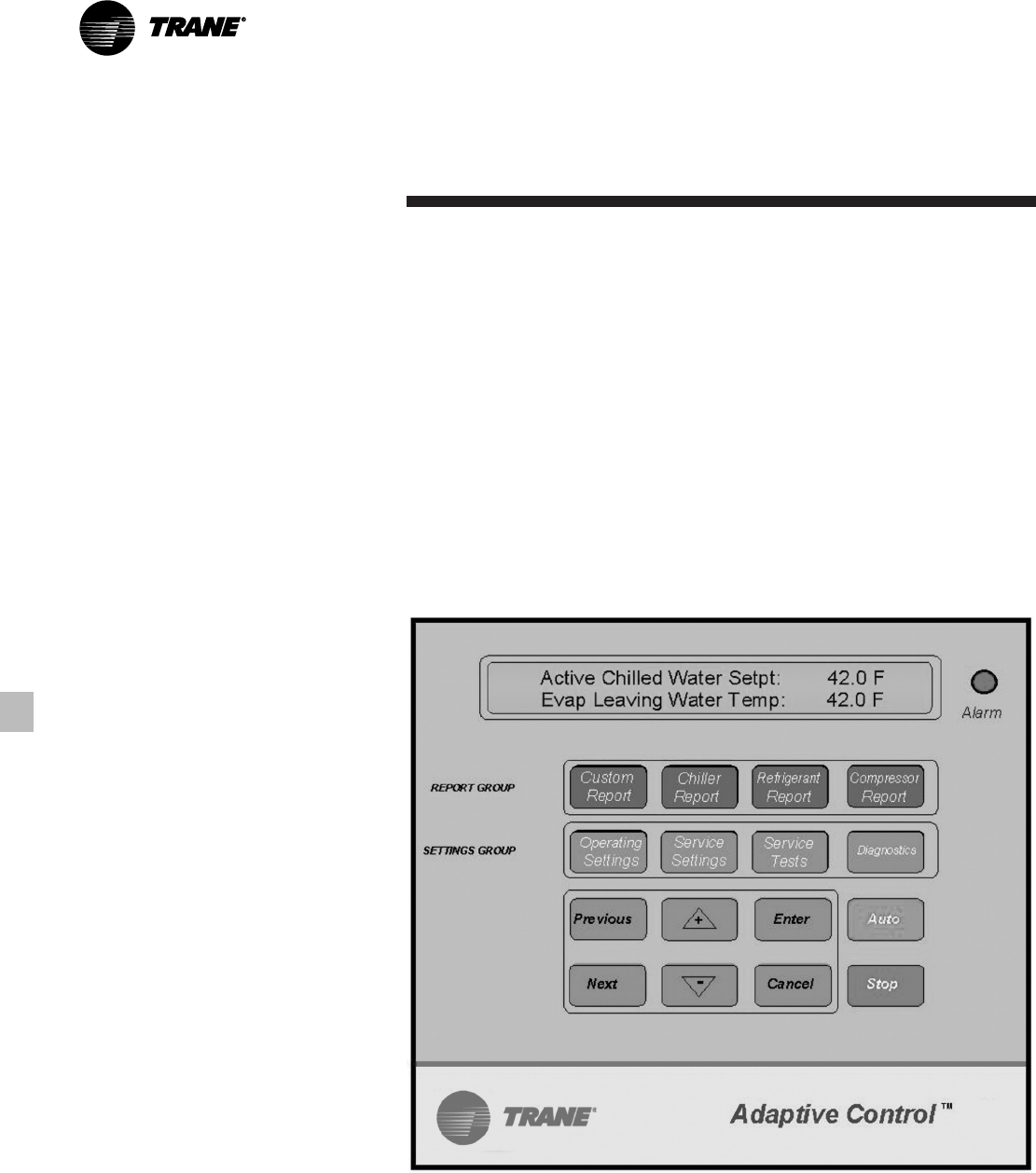
RLC-PRC016-EN32
Controls
Microcomputer Controls
A microcomputer-based controller
controls the air-cooled Series R™ 70-125
ton chiller. The microcomputer controller
provides better control than past
controls as well as several new,
important benefits.
Adaptive Control™ Microprocessor
The microcomputer-based controller
allows Trane to optimize controls around
the chiller application and the specific
components used in the air-cooled
Series R™ chiller. For instance, the
compressor protection system is
specifically designed for the air-cooled
Series R™ chiller. A new leaving chilled
water temperature control algorithm
maintains accurate temperature control,
minimizes the drift from setpoint and
provides better building comfort. This
control, combined with linear
compressor unloading, also allows the
chiller to be applied in wider array of
applications, including variable primary
flow. The microcomputer control
incorporates improved chiller start-up,
load limiting, lead/lag, and compressor
run time equalization functions into
standard chiller operation. Interface with
outside systems such as building
automation controls is flexible and easy.
33
RLC-PRC016-EN
Controls
Simple Interface With Other Control
Systems
Microcomputer controls afford simple
interface with other control systems,
such as time clocks, building automation
systems and ice storage systems. Wiring
to the unit can be as simple as two
wires! This means you can have the
flexibility to meet job requirements while
not having to learn a complicated control
system.
Safety Controls
A centralized microcomputer offers a
higher level of machine protection. Since
the safety controls are smarter, they limit
compressor loading to avoid
compressor or evaporator failures,
thereby minimizing nuisance shutdown.
The Unit Control Module (UCM) directly
senses the control variables that govern
the loading of the chiller: motor current
draw, evaporator temperature,
condenser temperature, etc. When any
one of the variables approaches a limit
condition where the unit may be
damaged or shutdown on a safety, the
UCM takes corrective action to avoid
shutdown and keep the chiller operating.
It does this through combined actions of
compressor slide valve modulation,
electronic expansion valve modulation
and fan staging. The UCM optimizes
total chiller power consumption during
normal operating conditions. During
abnormal operating conditions, the UCM
will continue to optimize chiller
performance by taking the corrective
action necessary to avoid shutdown.
This keeps cooling capacity available
until the problem can be solved.
Whenever possible, the chiller is allowed
to perform its function; make chilled
water. In addition, microcomputer
controls allow for more types of
protection such as over and under
voltage. Overall, the safety controls help
keep the building running and out of
trouble.
Monitoring And Diagnostics
Since the microcomputer provides all
control functions, it can easily indicate
such parameters as leaving chilled water
temperature and capacity stage.
If a failure does occur, one of over 90
individual diagnostic and operating
codes will be used to indicate the
problem, giving more specific
information about the failure. All of the
monitoring and diagnostic information is
displayed directly on a microcomputer
display.
Interface With The Trane Integrated
Comfort™ System (ICS)
When the air-cooled Series R™ chiller is
used in conjunction with a Trane Tracer™
system, the unit can be monitored and
controlled from a remote location. The
air-cooled Series R™ chiller can be
controlled to fit into the overall building
automation strategy by using time of
day scheduling, timed override, duty
cycling, demand limiting, and chiller
sequencing. A building owner can
completely monitor the air-cooled Series
R™ chiller from the Tracer system, as all
of the monitoring information indicated
on the microcomputer can be read off
the Tracer system display. In addition, all
the powerful diagnostic information can
be read back at the Tracer system. Best
of all, this powerful capability comes
over a single twisted pair of wires!
Air-cooled Series R™ chillers can
interface with many different external
control systems, from simple stand-
alone units to ice making systems. Each
unit requires a single-source, three-
phase power supply and two 115-volt
power supplies. When an optional
control power transformer is used, a
single 115-volt supply handles the
evaporator heat tape. For basic stand-
alone applications, the interface with
outside control is no different than for
other Trane chillers. However, the RTAA
units have many features that can be
used to interface with building control
systems.
Standard Features
1. External Auto/Stop
A jobsite provided contact closure will
turn the unit on and off.
Note: Do not use the chilled water pump
to stop the chiller.
2. Chilled Waterflow Interlock
A jobsite provided contact closure from
a chilled water pump contactor or a flow
switch is required and will allow unit
operation if a load exists. This feature
will allow the unit to run in conjunction
with the pump system.
3. External Interlock
A jobsite supplied contact opening wired
to this input will turn the unit off and
require a manual reset of the unit
microcomputer. This closure is typically
triggered by a jobsite supplied system
such as a fire alarm.
4. Chilled Water Pump Control
Unit controls provide an output to
control chilled water pump(s). One
contact closure to the chiller is all that is
required to initiate the chilled water
system.
5. Remote Running and Alarm Indication
Contacts
The unit provides three single-pole/
double-throw contact closures to
indicate that a failure has occurred, if any
compressors are running, or if the
compressors are running at maximum
capacity. These contact closures may be
used to trigger jobsite supplied alarm
lights or alarm bells.
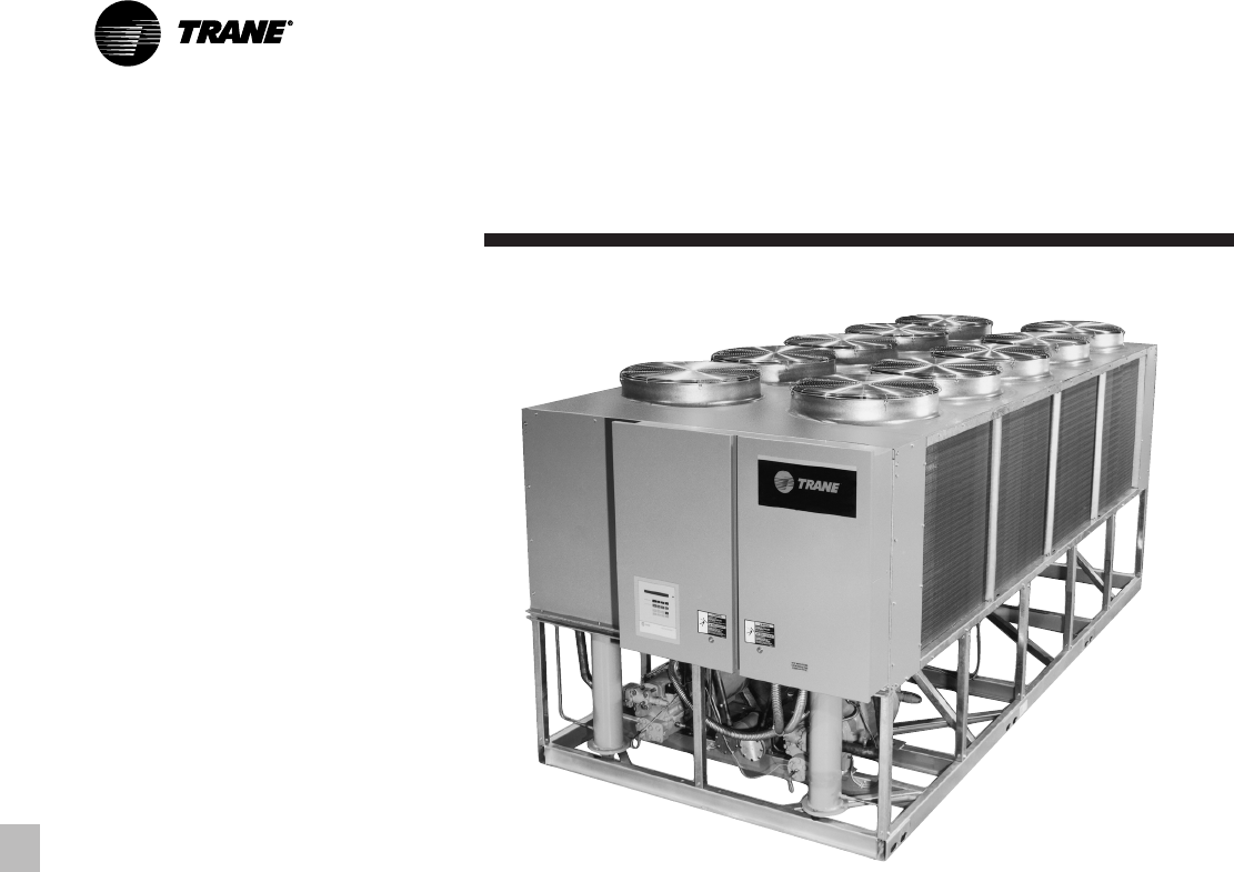
RLC-PRC016-EN34
Controls
Optional Features
1. Communication Interface
Capability for communication with one
of the following control devices:
a
Trane Tracer™ Building Automation
Systems
b
Remote Display
2. External Chilled Water Setpoint
Allows the external setting independent
of the front panel setpoint by one of
three means:
a) a remote resistor input (fixed or
adjustable), b) a 2-10 VDC input, or
c) a 4-20 mA input.
3. External Current Limit Setpoint
Allows the external setting independent
of the front panel set point by one of
three means:
a) a remote resistor input (fixed or
adjustable), b) a 2-10 VDC input, or
c) a 4-20 mA input.
4. Ice Making Control
Provides interface with ice making
control systems.
5. Chilled Water Temperature Reset
Reset can be based on return water
temperature or outdoor air temperature.
The next section reviews the
recommended interface with the
following control systems:
Stand-Alone Unit
Integrated Comfort™ System Interface
Non-Trane Building Automation
Systems
Ice Making Systems
Remote Display
Each system description includes a list of
those features which must be used,
those features which can be used and
which external Trane device is required.
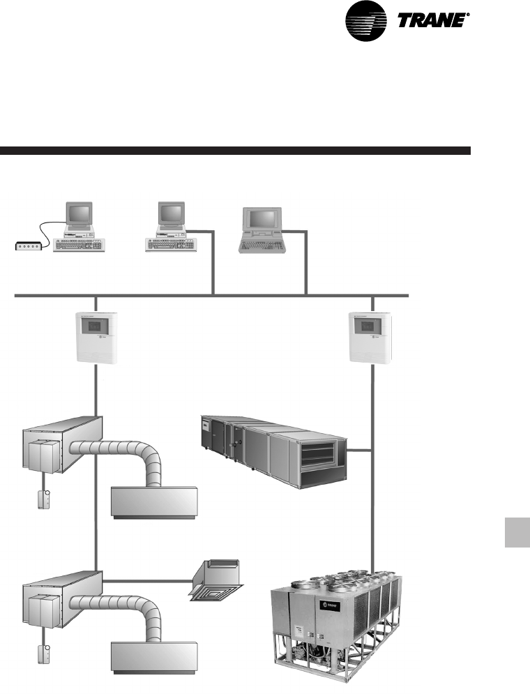
35
RLC-PRC016-EN
Trane Controls System
Tracer Summit controls — Interface With
The Trane Integrated Comfort System
(ICS)
Trane Chiller Plant Control
The Tracer Summit Chiller Plant Building
Management System with Chiller Plant
Control provides building automation
and energy management functions
through stand-alone control. The Chiller
Plant Control is capable of monitoring
and controlling your entire chiller plant
system.
Application software available:
• Time-of-day scheduling
• Demand limiting
• Chiller sequencing
• Process control language
• Boolean processing
• Zone control
• Reports and logs
• Custom messages
• Run time and maintenance
• Trend log
• PID control loops
And of course, the Trane Chiller Plant
Control can be used on a stand-alone
basis or tied into a complete building
automation system.
When the air-cooled Series R™ 70-125 ton
chiller is used in conjunction with a Trane
Tracer™ Summit system, the unit can be
monitored and controlled from a remote
location. The air-cooled Series R™ 70-125
ton chiller can be controlled to fit into the
overall building automation strategy by
using time of day scheduling, timed
override, demand limiting, and chiller
sequencing. A building owner can
completely monitor the air-cooled Series
R™ 70-125 ton chiller from the Tracer
system, since all of the monitoring
information indicated on the unit
controller’s microcomputer can be read
off the Tracer system display. In addition,
all the powerful diagnostic information
can be read back at the Tracer system.
Best of all, this powerful capability comes
over a single twisted pair of wires! Air-
Controls
Modem
Remote PC Workstation PC Workstation Notebook
PC Workstation
LAN
Building
Control Unit
Building
Control Unit
VariTrane®
Variable Air Volume
Terminal
Room temperature
sensor Diffuser
VariTrane®
Variable Air Volume
Terminal
Room temperature
sensor Diffuser
Exhaust Fan
Air-cooled Series R™ Chiller
Modular Climate Changer®
Air Handler
cooled Series R™ 70-125 ton chillers can
interface with many different external
control systems, from simple stand-
alone units to ice making systems. Each
unit requires a single-source, three-
phase power supply and a 115V/60Hz,
220V/50Hz power supply. The added
power supply powers the evaporator
heaters.
A single twisted pair of wires tied directly
between the air-cooled Series R™ 70-125
ton chiller and a Tracer™ Summit system
provides control, monitoring and
diagnostic capabilities. Control functions
include auto/stop, adjustment of leaving
water temperature setpoint, compressor
operation lockout for kW demand
limiting and control of ice making mode.
The Tracer system reads monitoring
information such as entering and leaving
evaporator water temperatures and
outdoor air temperature. Over 60
individual diagnostic codes can be read
by the Tracer system. In addition, the
Tracer system can provide sequencing
control for up to 25 units on the same
chilled water loop. Pump sequencing
control can be provided from the Tracer
system. Tracer ICS is not available in
conjunction with the remote display or
the external setpoint capability.
RLC-PRC016-EN36
Required Options
1
Tracer Interface
Additional Options That May Be Used
Ice Making Control
External Trane Devices Required
Tracer Summit™, Tracer 100 System or
Tracer Chiller Plant Control
Ice Making Systems Controls
An ice making option may be ordered
with the air-cooled Series R™ chiller. The
unit will have two operating modes, ice
making and normal daytime cooling. In
the ice making mode, the air-cooled
Series R™ 70-125 ton chiller will operate
at full compressor capacity until the
return chilled fluid temperature entering
the evaporator meets the ice making
setpoint. This ice making setpoint is
manually adjusted on the unit’s
Controls
microcomputer. Two input signals are
required to the air-cooled Series R™ 70-
125 ton chiller for the ice making option.
The first is an auto/stop signal for
scheduling and the second is required to
switch the unit in between the ice
making mode and normal daytime
operation. The signals are provided by a
remote job site building automation
device such as a time clock or a manual
switch. In addition, the signals may be
provided over the twisted wire pair from
a Tracer™ system.
Required Options
External Auto/Stop (Standard)
Ice Making Control
Additional Options That May Be Used
Failure Indication Contacts
Communications Interface (For Tracer
Systems)
Chilled Water Temperature Reset
External Trane Devices Required —
None
Note: All wiring outside the unit is
supplied at the job site.
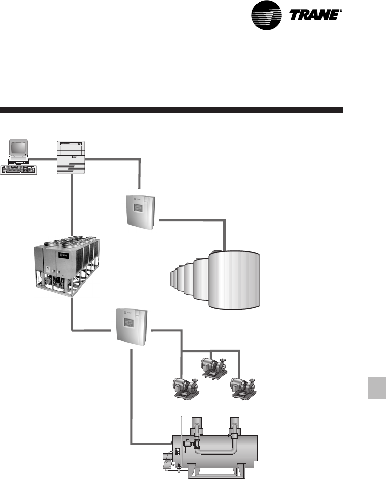
37
RLC-PRC016-EN
Controls
PC Workstation System Level
Controller
MP581 Programmable
Controller
Air-cooled Series R™
Chiller
MP581 Programmable
Controller
Ice Tanks
Boiler
Pumps
Simple Interface With Other Control
Systems
Microcomputer controls afford simple
interface with other control systems,
such as time clocks, building automation
systems and ice storage systems. This
means you have the flexibility to meet
job requirements while not having to
learn a complicated control system. This
setup has the same standard features as
a stand-alone water chiller, with the
possibility of having the following
optional features.
Alarm Indication Contacts
The unit provides three single-pole/
double-throw contact closures to
indicate that a failure has occurred,
compressor on/off status, or if the
compressors are running at maximum
capacity. These contact closures may be
used to trigger jobsite supplied alarm
lights or alarm bells.
Other Control Systems
Interface With Other Control Systems
Stand-alone Unit
Interface to stand-alone units is very
simple; only a remote auto/stop for
scheduling is required for unit operation.
Signals from the chilled water pump
contactor auxiliary or a flow switch are
wired to the chilled waterflow interlock.
Signals from a timeclock or some other
remote device are wired to the external
auto/stop input.
Note: Do not use the chilled water pump
to stop the chiller.
Required Features
1. External Auto/Stop (Standard)
2. Chilled Waterflow Interlock (Standard)
Additional Features That May Be Used
1. Remote Running and Alarm Indication
Contacts
2. External Interlock (Standard)
3. Chilled Water Temperature Reset
External Trane Devices Required —
None
External Chilled Water Setpoint
Allows the external setting independent
of the front panel setpoint by one of two
means:
a) 2-10 VDC input, or
b) 4-20 mA input.
External Current Limit Setpoint
Allows the external setting independent
of the front panel setpoint by one of two
means:
a) 2-10 VDC input, or
b) 4-20 mA input.
Ice Making Control
Provides interface with ice making
control systems.
Chilled Water Temperature Reset
Reset can be based on return water
temperature or outdoor air temperature.
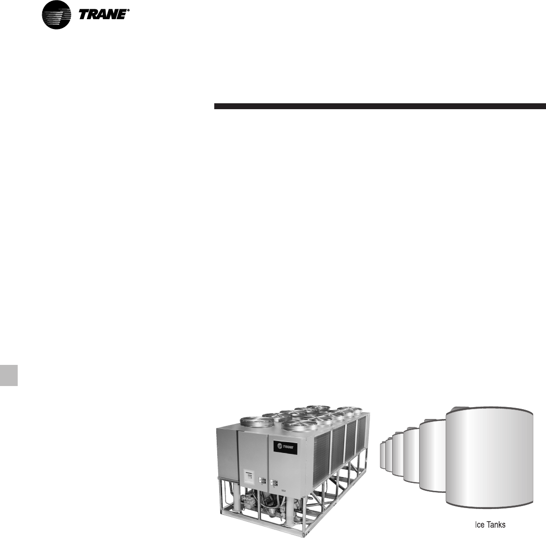
RLC-PRC016-EN38
Controls
Ice Making Systems
An ice making option may be ordered
with the air-cooled Series R™ chiller. The
unit will have two operating modes, ice
making and normal daytime cooling. In
the ice making mode, the air-cooled
Series R™ chiller will operate at full
compressor capacity until the return
chilled fluid temperature entering the
evaporator meets the ice making set
point. This ice making setpoint is
manually adjusted on the unit’s
microcomputer. Two input signals are
required to the air-cooled Series R™
chiller for the ice making option. The first
is an auto/stop signal for scheduling and
the second is required to switch the unit
in between the ice making mode and
normal daytime operation. The signals
are provided by a remote jobsite building
automation device such as a time clock
or a manual switch. In addition, the
signals may be provided over the twisted
wire pair from a Tracer™ system.
Required Features
1. External Auto/Stop (Standard)
2. Ice Making Control
Additional Features That May Be Used
1. Remote Running and Failure
Indication Contacts
2. Communications Interface (For Tracer
Systems)
3. Chilled Water Temperature Reset
(Indoor zone reset not available with
ice making option).
External Trane Devices Required —
None
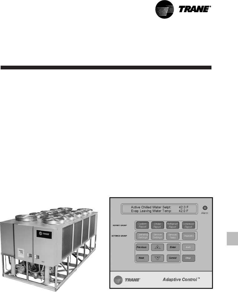
39
RLC-PRC016-EN
Remote Display
The remote display option allows the
operator to monitor chiller operation
from a remote location. Over 60 essential
chiller operating parameters can be
transmitted between the unit control
module on the chiller and the remote
display via a bi-directional
communications link. Only one twisted
wire pair is required between the chiller
and the remote display. In addition to
monitoring chiller operation, alarms and
unit diagnostics can be read from the
remote display. Furthermore, the chilled
water temperature setpoint can be
adjusted and the chiller can be turned on
or off from the remote display.
Required Features
1. Communications Interface
Additional Features That May Be Used
1. External Interlock (Standard)
2. Chilled Water Temperature Reset
3. Chilled Waterflow Interlock
(Standard)
4. Remote Running and Failure
Indication Contacts
External Trane Devices Required
1. Remote Display Panel
Controls
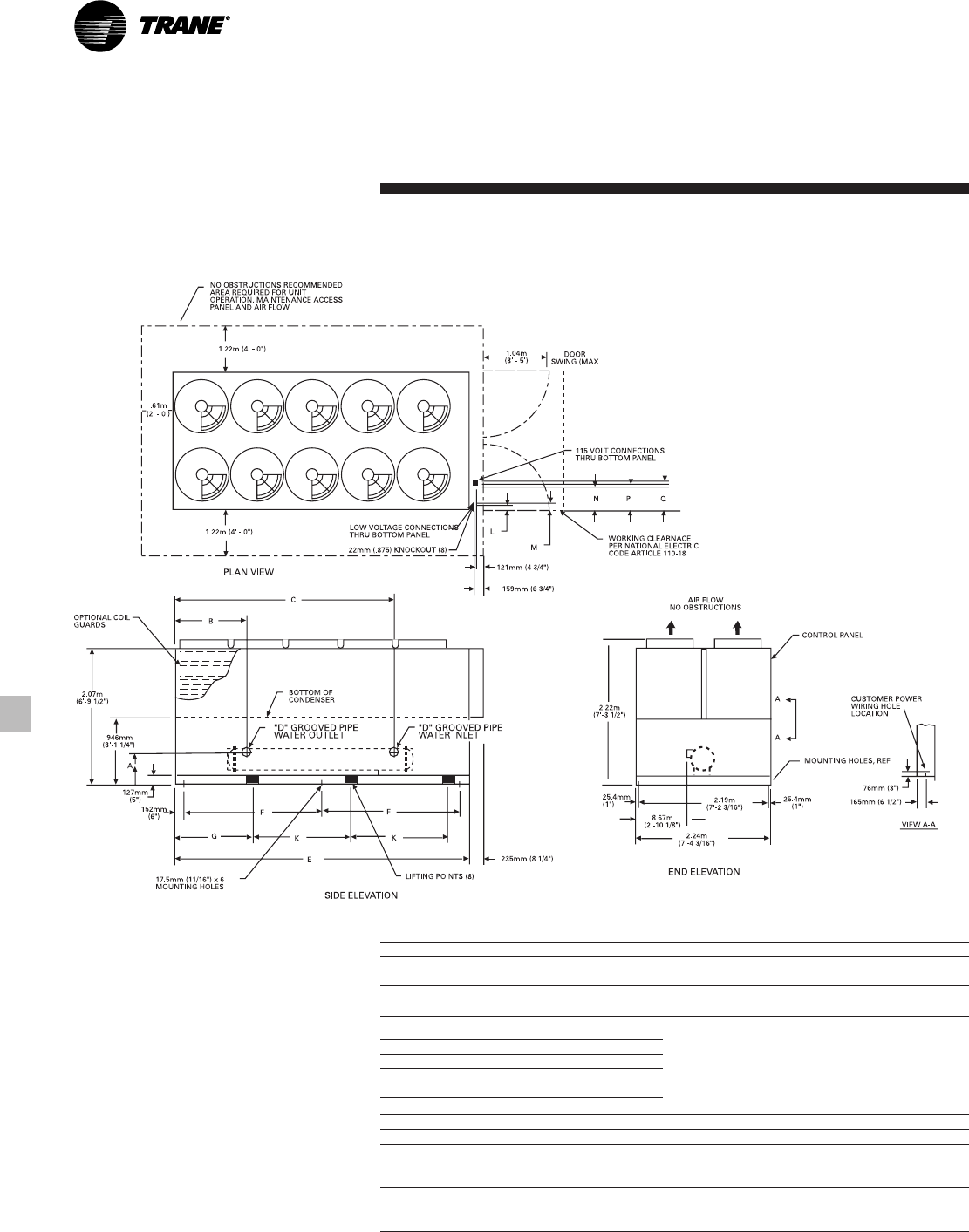
RLC-PRC016-EN40
Dimensional Data
Figure D-1 — RTAA 70-125 Unit Dimensions
UNIT SIZE A B C D E F G K
70-100 .492m 1.213m 2.851m 102mm 4.940m 2.317m 1.549m 1.626m
(1’-7 3/8”)(3’-11 3/4”)(9’-4 1/4”)(4”) (16’-2 1/2”)(7’-7 1/4”)(5’-1”)(5’-4”)
110-125 .479m 1.032m 3.499m 152mm 5.626m 2.661m 1.511m 1.930m
(1’-6 7/8”)(3’-4 5/8”) (11’-5 3/4”)(6”) (18’-5 1/2”)(8’-8 3/4”)(4’-11 1/2”)(6’-4”)
NO. OF FANS PER UNIT
UNIT SIZE 70 80 90 100 110 125
NO. FANS
STD UNIT 8 8 9 10 10 10
115 VOLT & LOW VOLTAGE CONNECTIONS
PANEL TYPE L M N P Q
X-LINE
CONTROL .889m .927m 1.206m 1.245m 1.283m
PANEL (2’-11”)(3’-0 1/2”)(3’-11 1/2”)(4’-1”)(4’-2 1/2”)
WYE DELTA
CONTROL 76mm 114mm .39m .43m .47m
PANEL (3”) (4 1/2”)(1’-3 1/2”)(1’-5”)(1’-8 1/2”)

41
RLC-PRC016-EN
Weights
Table W-1 — Packaged Unit Weights (Aluminum)
Isolator Location Operating Shipping
Unit Size Units 1 2 3 4 5 6 Weight Weight
RTAA 70 lbs. 1582 1608 1212 1232 842 856 7332 7000
kg 718 729 550 559 382 388 3326 3175
RTAA 80 lbs. 1587 1613 1218 1237 848 862 7365 7049
kg 720 732 552 561 385 391 3341 3197
RTAA 90 lbs. 1639 1596 1271 1237 903 879 7525 7234
kg 743 724 577 561 410 399 3413 3281
RTAA 100 lbs. 1640 1668 1281 1303 922 937 7751 7483
kg 744 757 581 591 418 425 3516 3394
RTAA 110 lbs. 1933 1885 1480 1443 1027 1001 8769 8326
kg 877 855 671 655 466 454 3978 3777
RTAA 125 lbs. 1871 1902 1445 1469 1019 1036 8742 8360
kg 849 863 655 666 462 470 3965 3792
Table W-2 — Packaged Unit Weights (Copper)
Isolator Location Operating Shipping
Unit Size Units 1 2 3 4 5 6 Weight Weight
RTAA 70 lbs. 1693 1719 1323 1343 953 966 7997 7665
kg 768 780 600 609 432 438 3627 3477
RTAA 80 lbs. 1698 1724 1329 1348 959 972 8030 7714
kg 770 782 603 611 435 441 3642 3499
RTAA 90 lbs. 1754 1711 1386 1352 1018 993 8214 7923
kg 796 776 629 613 462 450 3726 3594
RTAA 100 lbs. 1759 1787 1400 1422 1041 1056 8465 8197
kg 798 811 635 645 472 479 3840 3718
RTAA 110 lbs. 2065 2017 1612 1575 1159 1133 9561 9118
kg 937 915 731 714 526 514 4337 4136
RTAA 125 lbs. 2016 2047 1590 1614 1164 1181 9612 9230
kg 914 928 721 732 528 536 4360 4187
RLC-PRC016-EN42
Options
Low Temperature Brine
The unit controls can be factory set to
handle low temperature brine
applications (0°F to 39°F).
Ice Making
The unit controls can be factory set to
handle ice making for thermal storage
applications.
Building Automation System
Communication Interface
Permits either bi-directional
communication to the Trane Integrated
Comfort™ system or permits remote
chilled water setpoint and demand
limiting by accepting a 4-20 mA or 2-10
Vdc analog signal.
Remote Display
In addition to controlling chiller
operation from remote location, the
remote display shall provide the
capability to monitor unit alarms and
diagnostics. Only one twisted pair is
required between the chiller and the
remote display .
Remote Evaporator
The remote evaporator is available as a
standard option.
This option provides an easily installed,
pre-engineered method of installing the
evaporator remotely indoors.
The remote evaporator is skid-mounted
and is shipped separately from the
outdoor (condensing) unit. Refrigerant
accessories, including electronic
expansion valve, moisture indicating
sightglass and removable core filter
drier, are shipped with the evaporator
skid. All refrigerant connections are
routed to one end of the evaporator skid
for easy connection. All electrical wiring
is factory installed and routed to a
terminal box (entering and leaving water
temperature sensor, evaporator
refrigerant temperature sensor and
electronic expansion valve control
wiring). Suction refrigerant temperature
sensors (two) must be field installed in
the field suction line piping next to the
evaporator connections.
Chilled Water Reset
This option provides the control logic
and field installed sensors for either load
based (return water temperature) or
temperature based (ambient or zone)
reset of leaving chilled water
temperature (requires Communication
Package).
Architectural Louvered Panels
Louvered panels cover the complete
condensing coil and the service area
beneath the coils.
Coil Protection
Louvered panels which protect the
condenser coils only.
Access Protection
A coated wire mesh which covers access
area underneath the condenser coils.
Control Power Transformer
This option eliminates the need to run
separate 115 volt control power to the
unit. A control power transformer is
factory installed and wired. A separate
115 volt power source is required for
60 Hz heat tape.
Low Ambient Option
The low ambient option consists of a
variable speed drive on the first fan of
each circuit and special control logic to
permit low temperature operation.
Low Ambient Lockout
A factory installed ambient sensor and
control logic can prevent starting below
the recommended temperature.
Non-Fused Power Disconnect Switch
A non-fused disconnect switch with a
through the door handle is provided to
disconnect main power.
Circuit Breaker
A standard interrupting molded case
capacity circuit breaker (UL approved) is
available. The circuit breaker can also be
used to disconnect the chiller from main
power with a through the door handle
and comes pre-wired from the factory
with terminal block power connections.
Neoprene Isolators
Isolators provide isolation between
chiller and structure to help eliminate
frequency transmission. Neoprene
isolators are more effective and
recommended over spring isolators.
Spring Isolators
Spring isolators help isolate the chiller
from the building structure.
Condenser Corrosion Protection
Copper fins and CompleteCoat are
available on all size units for corrosion
protection. Job site conditions should be
matched with the appropriate condenser
fin materials to inhibit coil corrosion and
ensure extended equipment life. The
CompleteCoat option provides fully
assembled coils with a flexible dip and
bake epoxy coating.
Convenience Outlet
Provides a 15 amp, 115 volt (60 Hz)
convenience outlet on the unit.
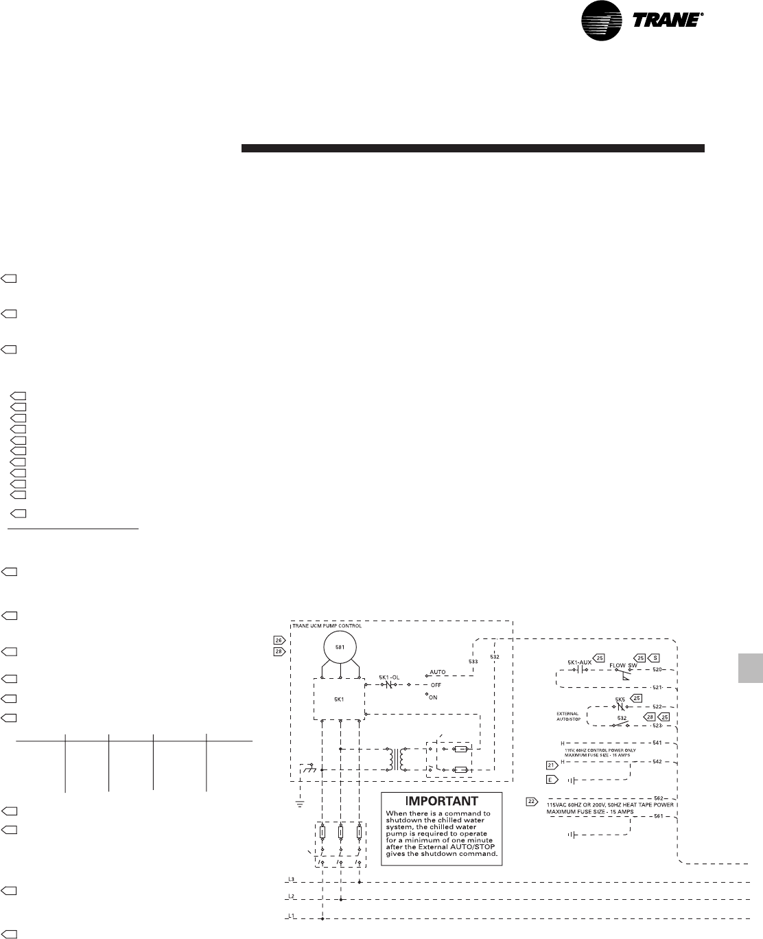
43
RLC-PRC016-EN
Typical Wiring
Diagram 70-125 Tons
NOTES:
1. DASHED LINES INDICATE RECOMMENDED FIELD WIRING BY OTHERS.
PHANTOM LINES INDICATE ALTERNATE CIRCUITRY OR AVAILABLE SALES
OPTION. CHECK SALES ORDER TO DETERMINE IF WIRING IS REQUIRED
FOR SPECIFIC OPTIONS.
2. ALL THREE PHASE MOTORS SUPPLIED WITH THE UNIT ARE PROTECTED
UNDER PRIMARY SINGLE PHASE FAILURE CONDITIONS.
3. CAUTION - DO NOT ENERGIZE UNIT UNTIL CHECK OUT AND START-UP
PROCEDURES HAVE BEEN COMPLETED.
4 SEE INSERT “A” FOR RESISTOR CONNECTIONS TO PROGRAM AN
EXTERNAL CHILLED WATER SETPOINT WHEN 4 - 20 mA OR A 2 - 10 VDC
SIGNAL IS NOT USED. SEE THE OPERATORS MANUAL FOR RESISTOR
VALUES.
5 SEE INSERT “B” FOR RESISTOR CONNECTIONS TO PROGRAM AN
EXTERNAL CURRENT LIMIT SETPOINT WHEN 4 - 20 mA OR A 2 - 10 VDC
SIGNAL IS NOT USED. SEE THE OPERATORS MANUAL FOR RESISTOR
VALUES.
6 SEE INSERT “C” FOR CONTACTS (IN PLACE OF THE ZONE TEMP. SENSOR)
FOR OPTIONAL ICE MACHINE CONTROL - OPTION “A”.
7. THE FOLLOWING CAPABILITIES ARE OPTIONAL - THEY ARE
IMPLEMENTED AND WIRED AS REQUIRED FOR A SPECIFIC SYSTEM
APPLICATION.
A ICE-MACHINE CONTROL (CANNOT BE USED WITH OPT. L)
B COMMUNICATIONS INTERFACE
D WYE-DELTA CLOSED TRANSITION STARTER
E CONTROL POWER TRANSFORMER.
H UNIT DISCONNECT, NON-FUSED
J CHILLED WATER RESET - RETURN WATER
K CHILLED WATER RESET - OUTDOOR AIR
L CHILLED WATER RESET - ZONE AIR (CANNOT BE USED WITH OPT. A)
O LOW AMBIENT LOCKOUT
S CHILLED WATER FLOW SWITCH (NOT REQUIRED FOR CHILLER
PROTECTION)
T REMOTE CLEAR LANGUAGE DISPLAY
WIRING AND CONTACT REQUIREMENTS:
20. ALL FIELD WIRING MUST BE IN ACCORDANCE WITH THE NATIONAL
ELECTRICAL CODE (NEC), STATE, AND LOCAL REQUIREMENTS. OUTSIDE
THE UNITED STATES, OTHER COUNTRIES APPLICABLE NATIONAL AND/
OR LOCAL REQUIREMENTS SHALL APPLY.
21 FOR UNITS WITHOUT THE CONTROL POWER TRANSFORMER (1T1)
OPTION, THE CUSTOMER MUST PROVIDE CONTROL POWER OF 115 VAC,
60 HERTZ, SINGLE PHASE, 750 VA ON 130 THRU 215 TON UNITS. THE
CONTROL POWER TRANSFORMER (1T1) IS STANDARD ON 50 HERTZ
UNITS.
22 FOR ALL UNITS, THE HEAT TAPE MUST BE POWERED FROM A SEPARATE
CUSTOMER PROVIDED 115 VAC, 420 WATT SOURCE FOR 200/230/420/575
60 HZ UNITS: 220 VAC, 420 WATT SOURCE FOR 346/1380/415 50 HZ UNITS.
FOR THE OPTIONAL HEAT RECOVERY HEAT TAPE IS 420 WATTS.
23 CUSTOMER SUPPLIED CONTACTS MUST BE COMPATIBLE WITH DRY
CIRCUIT 12 VDC, 45 mA RESISTIVE LOAD. SILVER OR GOLD PLATED
CONTACTS ARE RECOMMENDED.
24 30 VOLT OR LESS CIRCUIT. DO NOT RUN IN CONDUIT WITH HIGHER
VOLTAGE CIRCUITS. USE #14-18 AWG. SEE SELECTION TABLE.
25 MINIMUM PILOT DUTY CONTACT RATING AT 115 VAC; 5.9 VA INRUSH, 1.3
VA SEALED.
26 FIELD WIRED ELECTRICAL LOADING IS NOT TO EXCEED THE FOLLOWING
RATINGS:
TERMINALS DEVICE VOLTAGE SEALED VA INRUSH VA
1U1-TB4-1,2 1U1K1,NO 115 180 1150*
1U1-TB4-3 1U1K1,NC 115 180 1150*
1U1-TB4-5,4 1U1K2,NO 115 180 1150*
1U1-TB4-6,7 1U1K3,NC 115 180 1150*
1U1-TB4-8,9 1U1K2,NO 115 250 1150*
1U1-TB4-10,11 1U1K3,NC 115 180 1150*
*STANDARD PILOT DUTY RATING (35% POWER FACTOR).
27 WHEN CUSTOMER INPUT IS REQUIRED, REMOVE JUMPER AND INSTALL
CUSTOMER WIRING.
28 CHILLED WATER PUMP CONTROL FROM TRANE UNIT UCM MODULE
CHILLED WATER PUMP IS REQUIRED TO OPERATE A MINIMUM OF 1
MINUTE AFTER A COMMAND TO TERMINATE CHILLER OPERATION (UCM
WILL PROVIDE THE DELAY CONTACTS). CHILLED WATER SYSTEM
DEMAND SWITCH (5S2) IS CONNECTED TO THE UCM EXTERNAL AUTO/
STOP INPUT. NOTE: DO NOT USE THE CHILLED WATER PUMP TO STOP
THE CHILLER.
29 AS SHIPPED 380/415 50 HZ VOLT UNIT TRANSFORMER 1T1-(OPTIONAL) IS
WIRED FOR 415 VOLT OPERATION. IF UNIT IS TO BE OPERATED ON A 380
VOLT POWER SUPPLY, RE-CONNECT AS SHOWN IN INSET “D”.
REPROGRAM “UNIT LINE VOLTAGE” IN SERVICE SETTING MENU OF
CLEAR LANGUAGE DISPLAY FROM 415 TO 380.
30 K1, K2, K3 RELAY OUTPUTS CAN BE PROGRAMMED TO PERFORM
ALTERNATE FUNCTIONS. SEE INSTALLATION, OPERATION AND
MAINTENANCE MANUAL FOR DETAILS. FUNCTION #1 IS SHOWN.
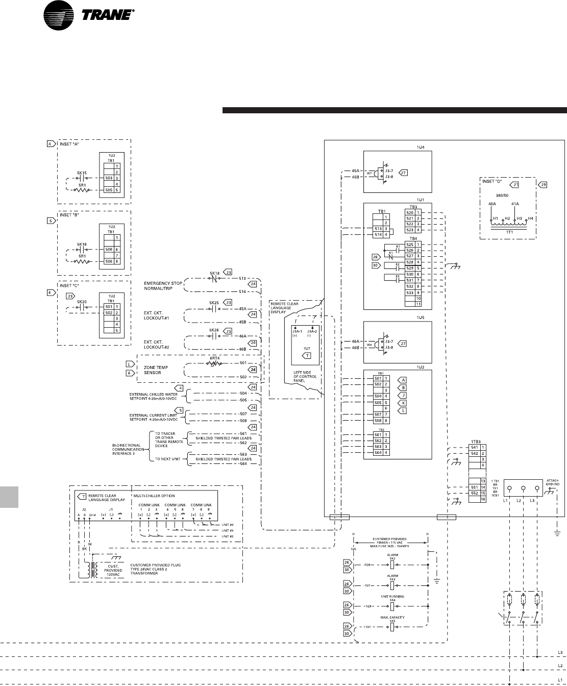
RLC-PRC016-EN44
Typical Wiring
Diagram 70-125 Tons

45
RLC-PRC016-EN
Features
Summary
Reliability
• Proven Trane helical rotary screw
compressor design for longer life and
greater dependability.
• Fewer moving parts means less parts to
fail. Typical reciprocating compressors
have 4 times as many total parts and 15
times as many critical parts.
• Adaptive Control™ protects the chiller
when any of the system variables
approaches a limit condition that may
damage the unit or cause a shutdown.
The Unit Control Module takes
corrective action to keep the unit
running.
• Dual circuit design increases overall
system reliability.
• Unlike reciprocating designs, this
compressor can handle liquid slugging.
• Suction gas cooling allows the motor to
operate at lower temperatures for
longer life.
Trane RTAA Air-Cooled
Series R™ Chiller
Designed To Perform, Built To Last
Performance
• Superior full load efficiency. All units
meet ASHRAE 90.1-2001 Standard.
• Excellent part load performance is
achieved without resorting to
manifolded multiple reciprocating
compressors.
• Use of an electronic expansion valve
significantly improves part load
performance by minimizing superheat
in the evaporator and allowing the
chiller to run at reduced condensing
temperatures.
• Unique compressor sequencing
equalizes not only starts, but operating
hours as well.
Trouble-Free Operation and Start-Up
• Adaptive Control™ microprocessor
keeps the Series R™ chiller on-line
when others would shut down.
• Fewer nuisance trips means less
expense from unnecessary service
calls.
• Factory installed and tested options
keep start-up time and expenses
minimized.
• Easy interface capability with the Trane
Integrated Comfort™ system via a
single twisted pair of wires.
• Optional remote display panel
simplifies chiller monitoring/ control.
• Packed stock availability for your
ordering convenience.
RLC-PRC016-EN46
Mechanical
Specifications
General
Units are leak and pressure tested at 450
psig high side, 300 psig low side, then
evacuated and charged. Packaged units
ship with a full operating charge of oil
and refrigerant. Unit panels, structural
elements and control boxes are
constructed of 12-gauge galvanized steel
and mounted on a welded structural
steel base. Unit panels and control boxes
are finished with a baked on powder
paint, and the structural base with an air
dry paint. All paint meets the
requirement for outdoor equipment of
the U.S. Navy and other federal
government agencies.
Evaporator
The evaporator is a tube-in-shell heat
exchanger design with internally finned
copper tubes roller expanded into the
tube sheet. The evaporator is designed,
tested and stamped in accordance with
ASME for a refrigerant side working
pressure of 300 psig. The evaporator is
designed for a water side working
pressure of 215 psig. Water connections
are grooved pipe. The evaporator has
one water pass with a series of internal
baffles. Each shell includes a vent, a
drain and fittings for temperature control
sensors and is insulated with 3/4-inch
Armaflex II or equal insulation (K=0.26).
Heat tape with thermostat is provided to
protect the evaporator from freezing at
ambient temperatures down to -20°F.
Condenser and Fans
Air-cooled condenser coils have
aluminum fins mechanically bonded to
internally finned seamless copper
tubing. The condenser coil has an
integral subcooling circuit and also
provides oil cooling for the compressor
bearing and injection oil. Condensers are
factory proof and leak tested at
506 psig.
Direct-drive vertical discharge condenser
fans are dynamically balanced. Three-
phase condenser fan motors with
permanently lubricated ball bearing and
internal thermal overload protection are
provided. Standard units will start and
operate down to 25°F ambient.
Compressor and Lube Oil System
The rotary screw compressor is semi-
hermetic, direct drive, 3600 rpm, with
capacity control slide valve, rolling
element bearings, differential refrigerant
pressure oil pump and oil heater. The
motor is a suction gas cooled,
hermetically sealed, two-pole squirrel
cage induction motor.
Oil separator and filtration devices are
provided separate from the compressor.
Check valves in the compressor
discharge and lube oil system and a
solenoid valve in the lube system are
provided.
Remote Evaporator
The evaporator is a tube-in-shell heat
exchanger, designed with internally-
finned copper tubes that are rolled
expanded into the tube sheet. The
evaporator is designed, tested and
stamped for a refrigerant side working
pressure of 300 psig, in accordance with
ASME. The evaporator is designed for a
water side working pressure of 215 psig.
Water connections are victaulic. The
evaporator has one water pass, with a
series of internal baffles.
Each shell includes a vent and drain
connection, as well as factory-mounted
entering and leaving water temperature
control sensors and evaporator
refrigerant temperature sensors. The
evaporator is insulated with 3/4-inch
Armaflex II or equal insulation (K=0.26).
The evaporator is skid-mounted and is
shipped separately from the outdoor
(condensing) unit. Refrigerant
accessories, including electronic
expansion valve, moisture indicating
sightglass and removable core filter
drier, are shipped with the evaporator
skid. All refrigerant connections are
routed to one end of evaporator skid for
easy connection. All electrical wiring is
factory installed and routed to a terminal
box (entering and leaving water
temperature sensor, evaporator
refrigerant temperature sensor and
electronic expansion valve control
wiring). Suction refrigerant temperature
sensors (two) must be field installed in
the field suction line piping next to the
evaporator connections.
47
RLC-PRC016-EN
Mechanical
Specifications
Refrigeration Circuits
Each unit has two refrigerant circuits,
with one rotary screw compressor per
circuit. Each refrigerant circuit includes a
compressor suction and discharge
service valve, liquid line shutoff valve,
removable core filter drier, liquid line
sight glass with moisture indicator,
charging port and an electronic
expansion valve. Fully modulating
compressors and electronic expansion
valves provide variable capacity
modulation over the entire operating
range.
Unit Controls
All unit controls are housed in a
weathertight enclosure with removable
plates to allow for customer connection
of power wiring and remote interlocks.
All controls, including sensors, are
factory mounted and tested prior to
shipment. All cataloged units are
UL listed.
Microcomputer controls provide all
control functions including start-up and
shut down, leaving chilled water
temperature control, compressor and
electronic expansion valve modulation,
fan sequencing, antirecycle logic,
automatic lead/lag compressor starting
and load limiting.
The unit control module, utilizing
Adaptive Control™ microprocessor,
automatically takes action to avoid unit
shutdown due to abnormal operating
conditions associated with low
refrigerant temperature, high condensing
temperature and motor current overload.
Should the abnormal operating condition
continue until a protective limit is
violated, the unit will be shut down.
Unit protective functions include loss of
chilled water flow, evaporator freezing,
loss of refrigerant, low refrigerant
pressure, high refrigerant pressure,
reverse rotation, compressor starting
and running over current, phase loss,
phase imbalance, phase reversal, and
loss of oil flow.
A menu driven digital display indicates
over 20 operating data points including
chilled water setpoint, current limit
setpoint, leaving chilled water
temperature, evaporator and condenser
refrigerant pressures and temperatures.
Over 60 diagnostic checks are made and
displayed when a problem is detected.
The digital display can be read and
advanced on the unit without opening
any control panel doors.
Standard power connections include
main three phase power and two 115
volt single phase power connections for
control power and heat tape.
Starters
Starters are housed in a weathertight
enclosure with removable cover plate to
allow for customer connection of power
wiring. Across-the-line starters are
standard on all 460-575 volt units. An
optional Wye Delta closed transition
starter (33 percent of LRA inrush) is
available. Typically, Trane helical rotary
compressors are up to full speed in one
second when started across-the-line and
have equivalent inrush with similar size
reciprocating compressor with part wind
starters.
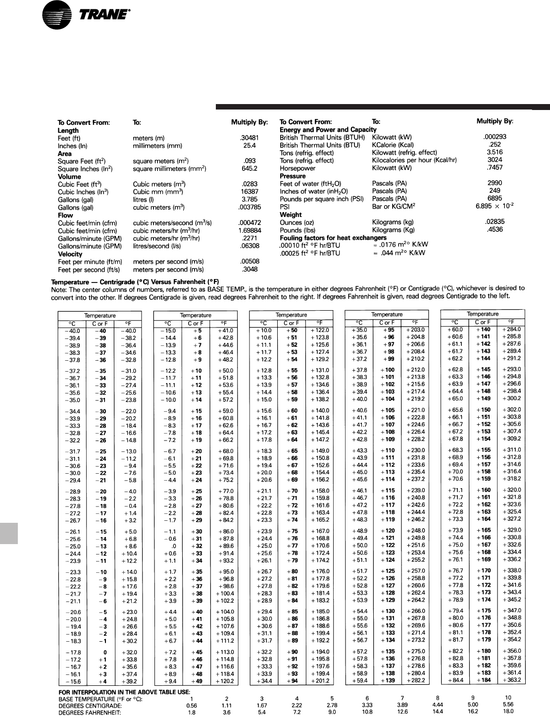
RLC-PRC016-EN48
Standard
Conversion Table
Trane has a policy of continuous product and product data improvement and reserves the right to change
design and specifications without notice.
Literature Order Number
File Number
Supersedes
Stocking Location
Trane
A business of American Standard Companies
www.trane.com
For more information contact your local district
office or e-mail us at comfort@trane.com
RLC-PRC016-EN
PL-RF-RLC-PRC016-EN-08 02
RLC-DS-2
Inland-La Crosse
