Trane 4Ttx6024 036 048 And 060E Users Manual 22 1752 10 10/01/2010 Split System Cooling Product Data XL16i 4TTX6024, 036, 048, 2,3,4 5 Tons
4ttx6060e 31ee965b-56fa-42b3-b137-a7358b87fb8b Trane Air Conditioner 4TTX6060E User Guide |
2015-01-21
: Trane Trane-4Ttx6024-036-048-And-060E-Users-Manual-236092 trane-4ttx6024-036-048-and-060e-users-manual-236092 trane pdf
Open the PDF directly: View PDF ![]() .
.
Page Count: 12
XL16i
4TTX6024, 036, 048 & 060E
2, 3, 4 & 5 Tons
Split System
Cooling
Product Data
PUB. NO. 22-1752-10

© 2010 Trane 2 22-1752-10
Features and
Benefits
• CLIMATUFF™ 2-stage scroll
compressor
• Efficiency up to 18.50 SEER
• All Aluminum SPINE FIN™ coil
• WEATHERGUARD™ II top shields
unit
• DURATUFF™ weather proof and
rust proof base
• COMFORT ”R”™ mode approved
for better comfort indoors
• QUICK-SESS™ cabinet,
service access and refrigerant
connections with full coil
protection
• WEATHERGUARD™ fasteners
• Glossy corrosion resistant finish
tarpaulin gray cabinet with
anthracite gray top
• Internal compressor high/low
pressure & temperature protection
• Liquid line filter/drier
• Low sound with advanced variable
speed fan motor
• Service valve cover
• R-410A refrigerant
• From 70 to 100% capacity
modulation
• 100% run test in the factory
• Low ambient cooling to 55° as
shipped
• Extended warranties available

22-1752-10 3
Contents
Features and Benefits 2
General Data 4
Product Specifications 4
A-weighted Sound Power Level [dB(A)] 4
Accessory Description and Usage 5
AHRI Standard Capacity Rating Conditions 5
Model Nomenclature 6
Electrical Data 7
Dimensions 8
Mechanical Specifications 9
4 22-1752-10
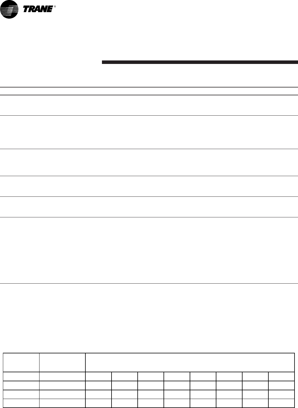
Product Specifications
Model No. 1 4TTX6024E1 4TTX6036E1 4TTX6048E1 4TTX6060E1
Electrical Data V/Ph/Hz 2 230/1/60 230/1/60 230/1/60 230/1/60
Min Cir Ampacity 14 22 29 39
Max Fuse Size (Amps) 20 35 50 60
Compressor CLIMATUFF® - SCROLL CLIMATUFF® - SCROLL CLIMATUFF® - SCROLL CLIMATUFF® - SCROLL
RL AMPS - LR AMPS 10.3 - 52 16.7 - 82 21.2 - 104 28.8 - 152.9
Outdoor Fan FL Amps 0.74 0.74 2.80 2.80
Fan HP 1/8 1/8 1/3 1/3
Fan Dia (inches) 27.6 27.6 27.6 27.6
Coil Spine Fin™ Spine Fin™ Spine Fin™ Spine Fin™
Refrigerant R-410A 9/13-LB/OZ 9/13-LB/OZ 12/9-LB/OZ 12/9-LB/OZ
Line Size - (in.) O.D. Gas 3 5/8 3/4 7/8 1-1/8
Line Size - (in.) O.D. Liquid 3 3/8 3/8 3/8 3/8
Dimensions H x W x D (Crated) 53.4 x 35.1 x 38.7 57.4 x 35.1 x 38.7 57.4 x 35.1 x 38.7 57.4 x 35.1 x 38.7
Weight - Shipping 309 316 328 332
Weight - Net 261 266 291 295
Start Components NO NO NO NO
Sound Enclosure NO NO NO NO
Compressor Sump Heat NO NO NO NO
Optional Accessories: 4
Rubber Isolator Kit BAYISLT101 BAYISLT101 BAYISLT101 BAYISLT101
Snow Leg - Base & Cap 4" High BAYLEGS002 BAYLEGS002 BAYLEGS002 BAYLEGS002
Snow Leg - 4" Extension BAYLEGS003 BAYLEGS003 BAYLEGS003 BAYLEGS003
Hard Start Kit Scroll BAYKSKT260 BAYKSKT260 BAYKSKT260 BAYKSKT260
Crankcase Heater Kit BAYCCHT301 BAYCCHT301 BAYCCHT301 BAYCCHT301
Extreme Condition Mounting Kit BAYECMT023 BAYECMT004 BAYECMT004 BAYECMT004
Vertical Discharge Air Kit Base 4 BAYVDTA003 BAYVDTA004 BAYVDTA004 BAYVDTA004
Auto Charge Solenoid Kit BAYCAKT001 BAYCAKT001 BAYCAKT001 BAYCAKT001
Refrigerant Lineset 5 TAYREFLN9* TAYREFLN7* TAYREFLN3* TAYREFLN4*
1 Certified in accordance with the Air-Source Unitary Heat Pump Equipment certification program which is based on AHRI Standard 210/240.
2 Calculated in accordance with N.E.C. Only use HACR circuit breakers or fuses.
3 Standard line lengths - 60'. Standard lift - 25' Suction and Liquid line.
For Greater lengths and lifts refer to refrigerant piping software Pub# 32-3312-0†. (†denotes latest revision)
4 For accessory description and usage, see page 5.
5 * = 15, 20, 25, 30, 40 and 50 foot lineset available.
General
Data
A-weighted Sound Power Level [dB(A)]
A-WEIGHTED FULL OCTAVE SOUND POWER LEVEL dB - [dB(A)]
63 125 250 500 1000 2000 4000 8000
4TTX6024E 72 43.7 52.6 54.3 62.4 60.4 57 54.1 46.6
4TTX6036E 72 38 50.4 56.8 60.4 59.8 57.2 55.2 49.2
4TTX6048E 73 44.2 50.4 58.9 63.1 63 57.4 53.6 47.4
4TTX6060E 74 42.2 53.8 57.8 66 65.7 57.7 58.4 51.7
Note: Rated in accordance with AHRI Standard 270-2008.
SOUND POWER
LEVEL [dB(A)]
MODEL
22-1752-10 5
General
Data
AHRI Standard Capacity Rating Conditions
AHRI STANDARD 210/240 RATING CONDITIONS —
(A) Cooling 80°F DB, 67°F WB air entering indoor coil,
95°F DB air entering outdoor coil.
(B) High Temperature Heating 47°F DB, 43°F WB air entering
outdoor coil, 70°F DB air entering indoor coil.
(C) Low Temperature Heating 17°F DB, 15°F WB air entering
outdoor coil, 70°F DB air entering indoor coil.
(D) Rated indoor airflow for heating is the same as for cooling.
AHRI STANDARD 270 RATING CONDITIONS — (Noise
rating numbers are determined with the unit in cooling opera-
tion.) Standard Noise Rating number is at 95°F outdoor air.
Accessory Description and Usage
Rubber Isolators — 5 rubber donuts to isolate condens-
ing unit from mounting frame or pad. Use on any application
where sound transmission needs to be minimized.
Extreme Conditions Mounting Kit — Bracket kits to secure-
ly mount condensing unit to a frame or pad without removing
any panels. Use in areas with high winds, or on commercial
rooftops, etc.
Low Ambient Cooling — For low ambient cooling below 55°
see Application Guide APP-APG013-EN.
6 22-1752-10
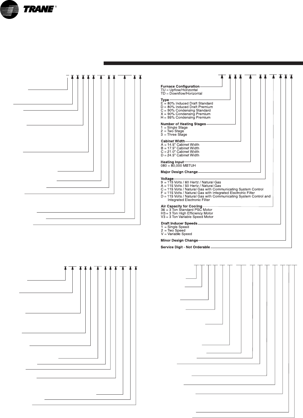
Model
Nomenclature
Refrigerant Type
4 = R-410A
TRANE
Product Type
W = Split Heat Pump
T = Split Cooling
Product Family
Z = Leadership – Tw o Stage
X = Leadership
R = Replacement/Retail
M or B = Basic
A = Light Commercial
Family SEER
3 = 13 6 = 16 0 = 20
4 = 14 8 = 18
5 = 15 9 = 19
Split System Connections 1-6 Tons
0 = Brazed
Nominal Capacity in 000s of BTUs
Major Design Modifications
Power Supply
1 = 200-230/1/60 or 208-230/1/60
3 = 200-230/3/60
4 = 460/3/60
Secondary Function
Minor Design Modifications
Unit Parts Identifier
Outdoor Units
4TTX6036E1000AA
Refrigerant Type
4 = R-410A
Application
TE = Fully Convertible
TG = Semi Convertible
TF = Front Return
Product Family
E = Leadership – Variable Speed
P = Leadership
C = Replacement/Retail
B = Basic
Flow Control
0 = No Flow Control
3 = Nonbleed TXV
Feature Identifier
0 = Standard Unit
F = Air-Tite™
Nominal Capacity in 1000’s (BTUH)
Major Design Change
Power Supply
1 = Single Phase
Electrical Connection
0 = Pig Tails
B = Circuit Breaker
D = Pull Disconnect
Future Option – Factory Installed Heater Nominal KW Value
Minor Design Modifications
Unit Parts Identifier
NOTE: There will be a phase-in of new model numbers for new
air handlers over next 2 years.
Air Handlers –
Residential
4TEE3F36A1 AA000
Gas Furnaces
TU D2B080AC AAV32
4TXCB001 C C3 H CAA
Refrigerant Type
4 - R410A
Product Family
T-Premium
(Heat Pump or Convertible Coil)
Coil Design
X - Direct Expansion Evaporator Coil
Product Family
C - Cased A Coil
A - Uncased A Coil
F - Cased Horizontal Flat Coil
Coil Width (Cased/Uncased)
A - 14.5" / 13.3"
B - 17.5" / 16.3"
C - 21.0" / 19.8"
D - 24.5" / 23.3"
H - 10.5"
Refrigerant Line Coupling
0 - Brazed
Model Number Distinguisher
Major Design Change
Efficiency
C - Standard
S - Hi Efficiency (Derived from 10 SEER products)
Refrigerant Control
3 - TXV - Non-Bleed
Coil Circuitry
H - Heat Pump
Airflow Configuration
A - Upflow Only
U - Upflow / Downflow
H - Horizontal Only
C - Convertible - Upflow, Downflow, Left or Right Airflow
Minor Design Change
Unit Parts Identifier
Coils –
Residential
22-1752-10 7
Printed from D156630P02 Rev 00
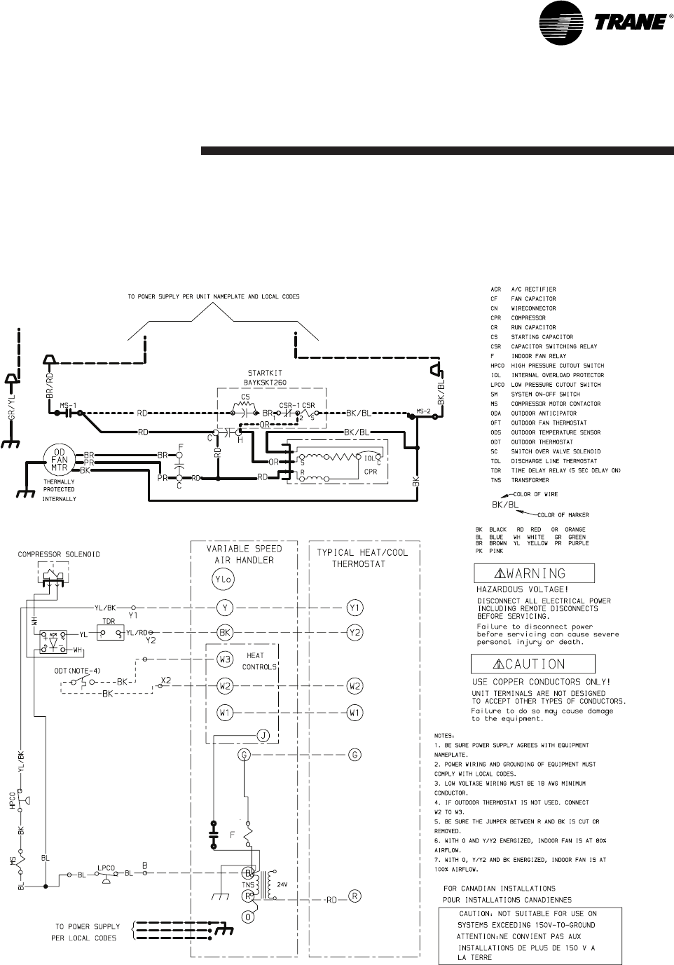
4TTX6024E, 036E
Electrical
Data
Schematic Diagrams
(SEE LEGEND)
8 22-1752-10
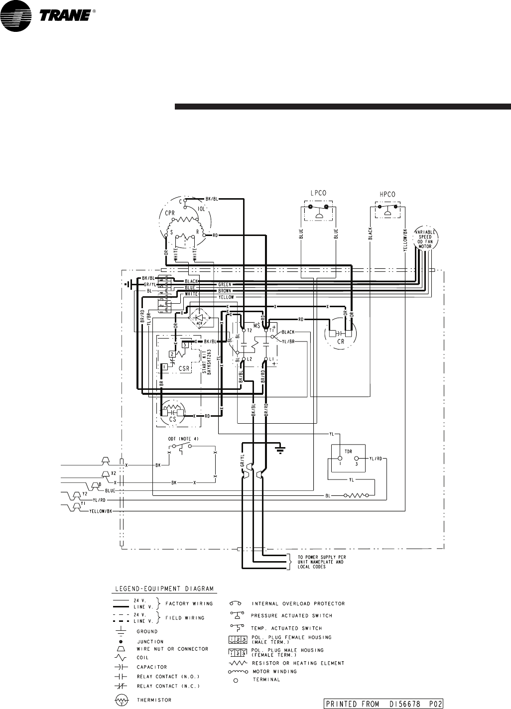
4TTX6048E, 060E
Electrical
Data
Schematic Diagrams
(SEE LEGEND)
22-1752-10 9
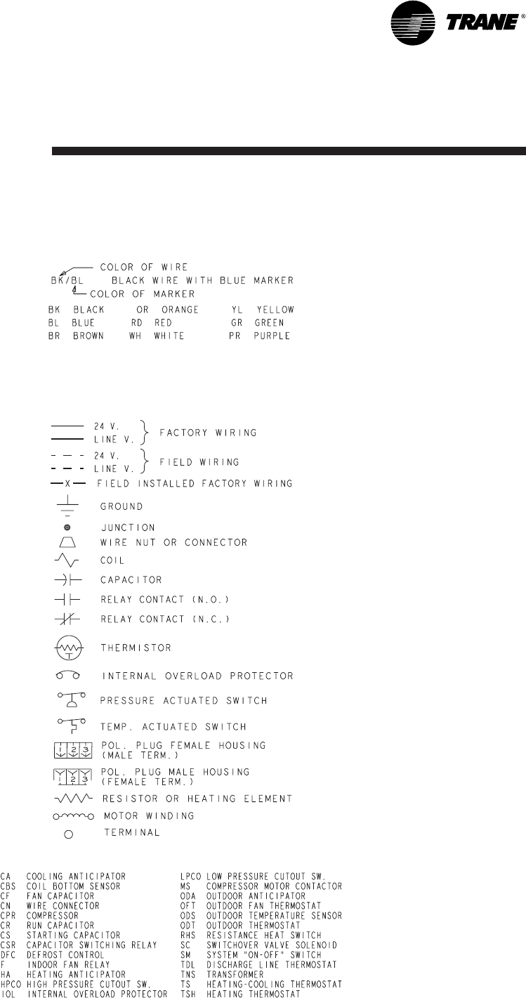
Electrical
Data
LEGEND
Schematic Diagrams
10 22-1752-10
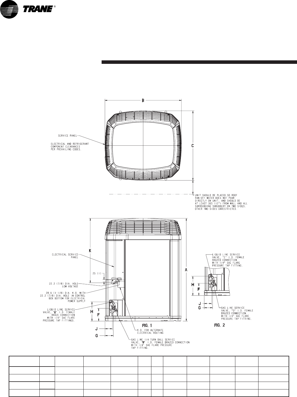
Dimensions
4TTX6 Outline Drawing
Note: All dimensions are in MM (Inches).
MODELS BASE A B C D E F G H J K
4TTX6024E 4 1267 (49-7/8) 946 (37-1/4) 870 (34-1/4) 5/8 3/8 152 (6) 98 (3-7/8) 219 (8-5/8) 86 (3-3/8) 730 (28-3/4)
4TTX6036E 4 1369 (53-7/8) 946 (37-1/4) 870 (34-1/4) 3/4 3/8 152 (6) 98 (3-7/8) 219 (8-5/8) 86 (3-3/8) 1035 (40-3/4)
4TTX6048E 4 1369 (53-7/8) 946 (37-1/4) 870 (34-1/4) 7/8 3/8 152 (6) 98 (3-7/8) 219 (8-5/8) 86 (3-3/8) 730 (28-3/4)
4TTX6060E 4 1369 (53-7/8) 946 (37-1/4) 870 (34-1/4) 1-1/8 3/8 152 (6) 98 (3-7/8) 219 (8-5/8) 86 (3-3/8) 730 (28-3/4)
From Dwg. D152635 Rev. 16
22-1752-10 11
Mechanical
Specifications
General
The 4TTX6 is fully charged from the fac-
tory for matched indoor section and up
to 15 feet of piping. This unit is designed
to operate at outdoor ambient tempera-
tures as high as 115°F. Cooling capaci-
ties are matched with a wide selection
of air handlers and furnace coils that are
AHRI certified. The unit shall be certi-
fied to UL 1995. Exterior is designed for
outdoor application.
Casing
Unit casing is constructed of heavy
gauge, G60 galvanized steel and
painted with a weather-resistant powder
paint on all louvers and panels. Cor-
rosion and weatherproof CMBP-G30
DuraTuff™ base.
Refrigerant Controls
Refrigeration system controls include
condenser fan, compressor contactor
and high pressure switch. High and low
pressure controls are inherent to the
compressor. A factory installed liquid line
drier is standard.
Compressor
The Climatuff® 2-stage compressor
features internal over temperature and
pressure protection and hermetic motor.
Other features include: roto lock suction
and discharge refrigerant connections,
centrifugal oil pump and modular plugs
for electrical connections.
Condenser Coil
The outdoor coil provides low airflow
resistance and efficient heat transfer.
The coil is protected on all four sides by
louvered panels.
Low Ambient Cooling
As manufactured, this unit has a cool-
ing capability to 55°F. For low ambient
cooling below 55° see Application Guide
APP-APG013-EN.

Trane
www.trane.com
10/10
Trane has a policy of continuous product and product data improvement and it reserves the right to change
design and specifications without notice.
