Trane Bacnet Bas Svp10A En Users Manual Communicating Thermostats (BACnet) Integration
Trane Thermostat Trane Communicating Thermostats (BACnet) BAS-SVP10A-EN_082611
bassvp10aen 4602cc43-0acd-427c-b9e2-340b60c756f1 Trane Thermostat BAS-SVP10A-EN User Guide |
2015-01-21
: Trane Trane-Bacnet-Bas-Svp10A-En-Users-Manual-236260 trane-bacnet-bas-svp10a-en-users-manual-236260 trane pdf
Open the PDF directly: View PDF ![]() .
.
Page Count: 48
SAFETY WARNING
Only qualified personnel should install and service the equipment. The installation, starting up, and
servicing of heating, ventilating, and air-conditioning equipment can be hazardous and requires specific
knowledge and training. Improperly installed, adjusted or altered equipment by an unqualified person could
result in death or serious injury. When working on the equipment, observe all precautions in the literature
and on the tags, stickers, and labels that are attached to the equipment.
Trane Communicating Thermostats (BACnet)
August 2011 BAS-SVP10A-EN
Building Automation System
Integration Manual

Copyright
© 2011 Trane All rights reserved
This document and the information in it are the property of Trane and may not be used
or reproduced in whole or in part, without the written permission of Trane. Trane reserves
the right to revise this publication at any time and to make changes to its content without
obligation to notify any person of such revision or change.
Trademarks
Trane and its logo are trademarks of Trane in the United States and other countries. All
trademarks referenced in this document are the trademarks of their respective owners.
Warnings, Cautions, and Notices
Warnings, cautions, and notices are provided in appropriate places throughout this
document:
WARNING Indicates a potentially hazardous situation which, if not avoided, could result in
death or serious injury.
CAUTIONsIndicates a potentially hazardous situation which, if not avoided, could result in
minor or moderate injury. It could also be used to alert against unsafe practices.
NOTICE: Indicates a situation that could result in equipment or property-damage only
accidents.

Table of Contents
BAS-SVP10A-EN 3
Overview .............................................................. 5
Product Description ................................................ 5
Related Documents ................................................ 6
Planning Your Integration ........................................... 6
“How To” Information .............................................. 6
Summary of BACnet Objects ............................................ 7
Supported BACnet Services ......................................... 7
Default Device Name and Default Device ID ........................... 7
Fan Coil Objects ................................................... 8
Rooftop and Heat Pump Objects .................................... 10
Standard Object Types Supported .................................. 12
List of Proprietary Properties ....................................... 13
Configuration Objects for Fan Coils .................................. 13
Configuration Objects for Rooftop and Heat Pump Units ............... 13
BACnet Object Properties .............................................. 14
Fan Coil Object Properties .......................................... 14
Rooftop and Heat Pump Object Properties ........................... 19
Objects You Can Use in Site Graphics ................................... 23
Fan Coils ......................................................... 23
Rooftop and Heat Pump Units ...................................... 24
Wiring Requirements for Communicating Thermostats ................... 25
BACnet MS/TP Link Wiring ......................................... 25
BACnet Configuration Requirements ............................ 25
BACnet Wiring Best Practices ................................... 25
BACnet Wiring Procedure ...................................... 26
Trane BACnet Termination for BACnet Links ...................... 26
Product Specifications ............................................. 27
Network Adapter .................................................. 27
Communicating Thermostat Status LEDs ............................ 28
Troubleshooting .................................................. 28
Additional Information and Considerations .............................. 29
MS/TP Network Integration ......................................... 29
Site Graphics ................................................ 29
Free Programmed Objects or Loops (Supervisory Controllers Other
Than Tracer SC) ........................................... 29
Retries and Timeouts (Supervisory Controllers Other Than Tracer SC) . 30

4BAS-SVP10A-EN
Objects and Parameters ........................................... 30
Tracer SC Network Configuration ................................... 32
Data Normalization .................................................... 36
Example: Occupancy Request ...................................... 36
Template: TStat_FanCoil_Trane ..................................... 36
Template: TStat_HeatPump_Trane .................................. 39
Template: TStat_RTU_Trane ........................................ 40
Trane Communicating Thermostat Points List ............................ 42
TStat_Fan_Coil_Trane ............................................. 42
TStat_HeatPump_Trane Template ................................... 43
TStat_RTU_Trane Template ........................................ 44
BAS-SVP10A-EN 5
Overview
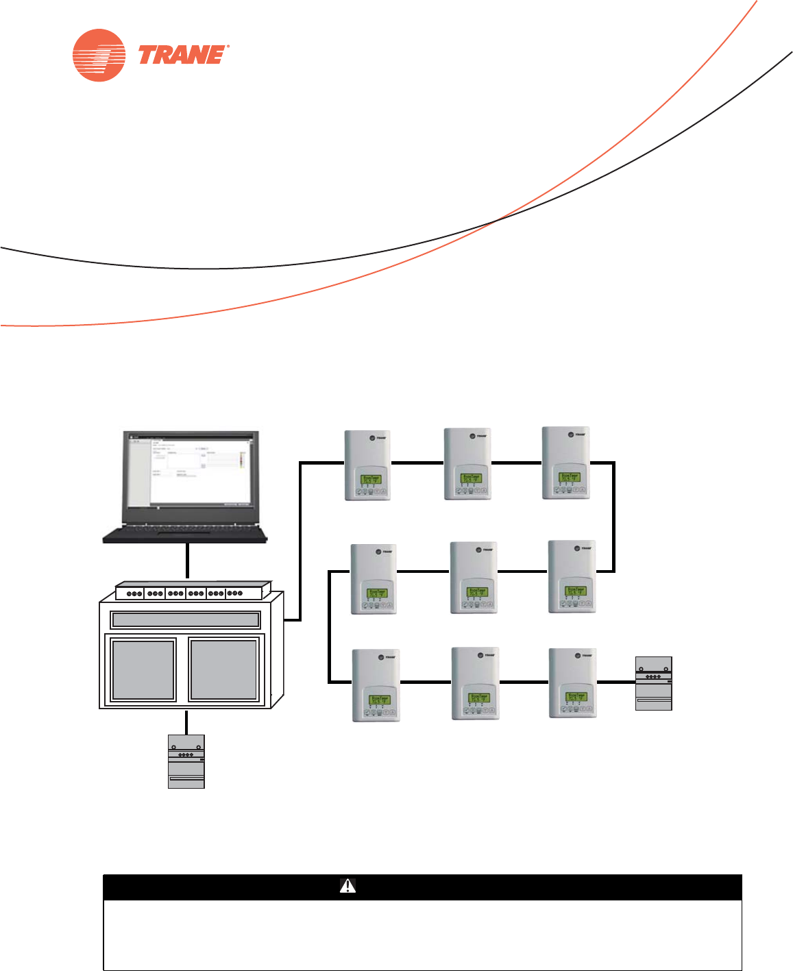
This document is written to guide you through integration of the Trane Communicating
Thermostats into an MS/TP network using the BACnet protocol and managed by a Tracer SC.
Product Description
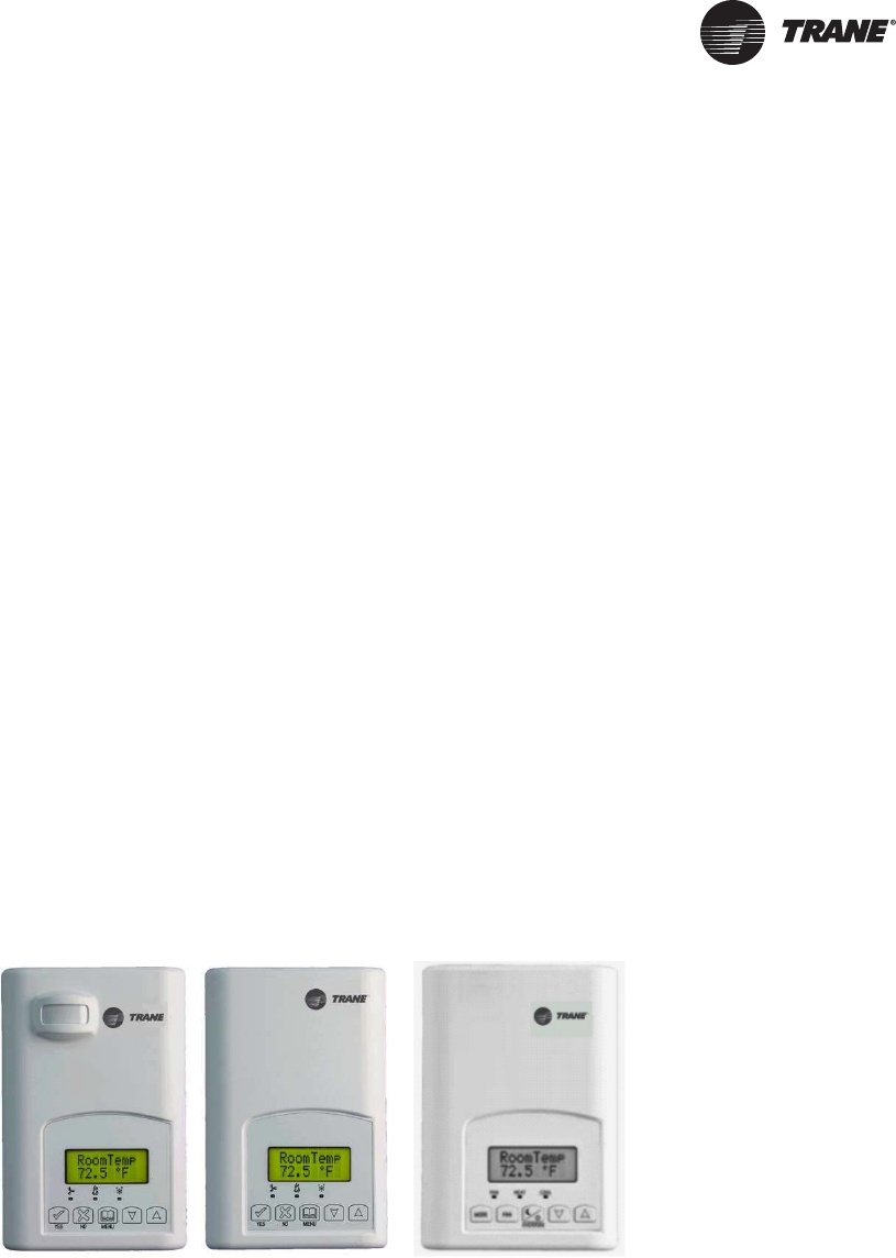
The Trane Communicating Thermostats are available for heat pump, rooftop, and fan coil
applications.
• X13511541010 and -2010 (Heat Pump and Rooftop)
These Trane Communicating Thermostats are BACnet MS/TP devices specifically designed for
single stage and multi-stage control of heating/cooling equipment such as rooftop and self-
contained units. The products feature an intuitive, menu-driven, back-lit LCD display, which
walks users through the programming steps, making the process extremely simple.
• X13511543010 (Fan Coil)
This Trane Communicating thermostat is specifically designed for fan coil control. The product
features a backlit LCD display with dedicated function menu buttons for simple operation.
Three additional inputs are also provided for monitoring and / or various advanced functions.
All models feature configurable System and Fan button functions to meet a variety of
applications.
Accurate temperature control is achieved due to the product’s PI proportional control algorithm,
which virtually eliminates temperature offset associated with traditional, differential-based
thermostats.
The Communicating Thermostats contain an SPST auxiliary switch that can be used to control
lighting or auxiliary reheat. Three additional inputs are also provided for monitoring and / or
various advanced functions.
The thermostats are also compatible with the occupancy sensor cover accessories. Thermostats
equipped with an occupancy sensor cover provide advanced active occupancy logic, which will
automatically switch occupancy levels from Occupied to Unoccupied as required by local activity
being present or not. This advanced occupancy functionality provides advantageous energy
savings during occupied hours without sacrificing occupant comfort.

6BAS-SVP10A-EN
Overview
Related Documents
See the following documents for Communicating Thermostat installation and configuration
information.
•Trane Communicating Thermostats for Heat Pump Control User Guide (BAS-SVU10x-EN)
•Trane Communicating Thermostats for Rooftop Control User Guide (BAS-SVU11x-EN)
•Trane Communicating Thermostats for Fan Coil Control User Guide (BAS-SVU12x-EN)
See the following documents for Tracer SC network integration information.
•Tracer™ SC System Controller Installation and Setup (BAS-SVX31x-EN)
•Tracer™ BACnet™ Terminator Installation (X39641151-01x)
•Unit Controller Wiring Guide For the Tracer SC™ System Controller (BAS-SVN03x-EN
Finally, see the following documents for information about equipment including fan coils, rooftop
units, and heat pumps.
• Communicating Thermostats for Rooftop and Heat Pump Control Product Data Sheet
(BAS-PRC064-EN)
• Communicating Thermostats for Fan Coil Control Product Data Sheet
(BAS-PRC065-EN)
All these documents are available from your Trane distributor.
Planning Your Integration
Study the following information presented in the chapters of this guide as you plan the work:
• Communicating Thermostat BACnet objects (points) and their properties (ranges, values, and
enumeration sets for points). (See “Summary of BACnet Objects,” p. 7. and “BACnet Object
Properties,” p. 14.)
• Tips and considerations presented in “Additional Information and Considerations,” p. 29.If
your network is managed by a Tracer SC, pay special attention to “Tracer SC Network
Configuration,” p. 32.
• Wiring instructions in “Wiring Requirements for Communicating Thermostats,” p. 25.
• Available Graphical User Interface (GUI) objects that you can use in graphics presented in
“Objects You Can Use in Site Graphics,” p. 23.
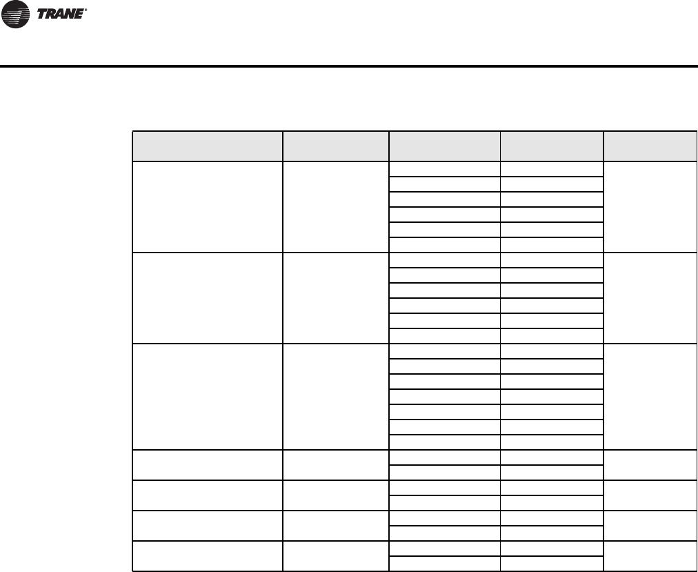
“How To” Information
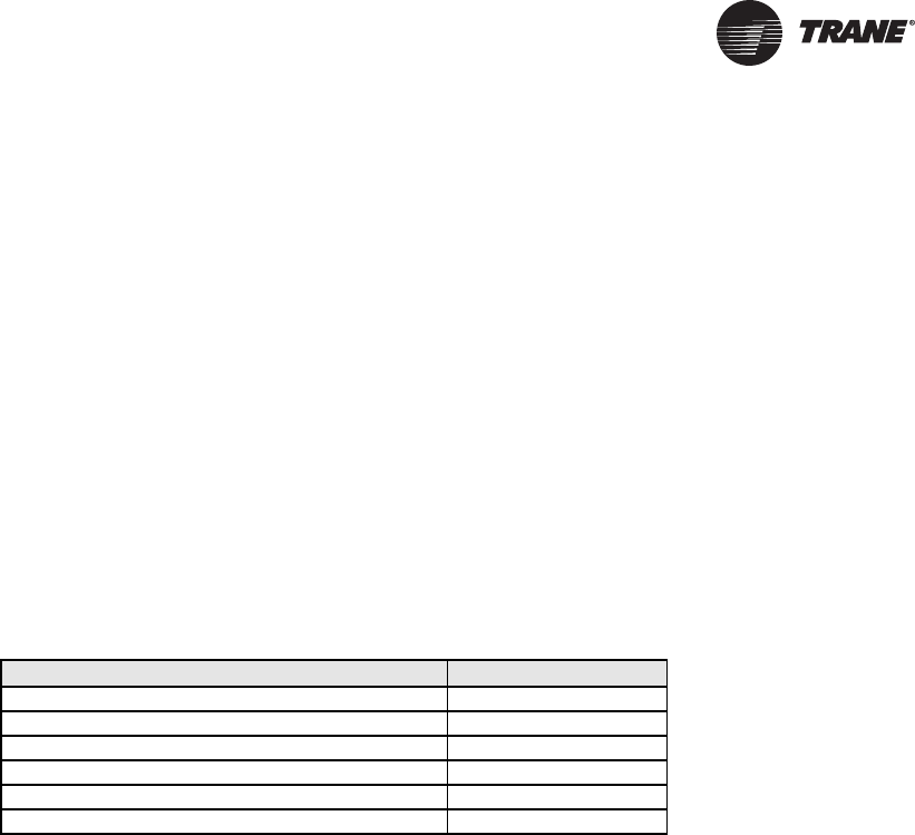
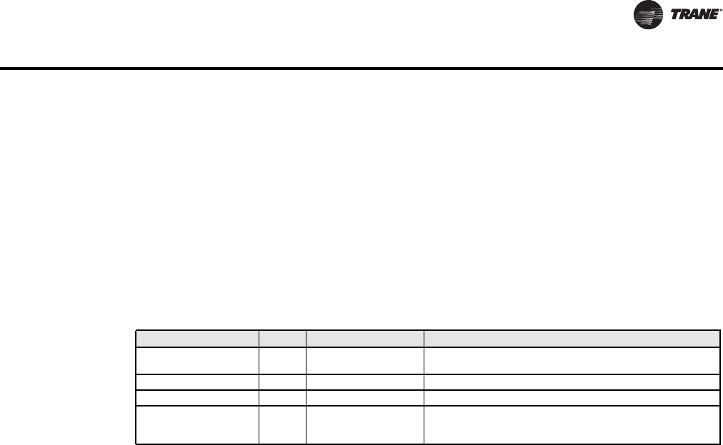
The following “how to” questions are described or clarified either in this manual or in other
documents cited in this table.
Question Information Location or Answer
How do I set up alarming in Tracer SC? See the Tracer™ SC System Controller Installation and
Setup Manual (BAS-SVX31x-EN)
How do I set the MAC address of the Trane Communicating
Thermostat?
See “Default Device Name and Default Device ID,” p. 7.
Also, see the appropriate User Guide listed in “Related
Documents” on this page.
How do I install a Trane Communicating Thermostat on the
Tracer SC link?
See “No automatic installation,” p. 32.
BAS-SVP10A-EN 7
Summary of BACnet Objects
The Building Automation and Control Network (BACnet and ANSI/ASHRAE Standard 135-2004)
protocol is a standard that allows building automation systems or components from different
manufacturers to share information and control functions. BACnet provides building owners the
capability to connect various types of building control systems or subsystems together for many
uses. In addition, multiple vendors can use this protocol to share information for monitoring and
supervisory control between systems and devices in a multi-vendor interconnected system.
The BACnet protocol identifies standard objects (data points) called BACnet objects. Each object
has a defined list of properties that provide information about that object. BACnet also defines a
number of standard application services that are used to access data and manipulate these objects
and provides a client/server communication between devices.
Supported BACnet Services
The BACnet communicating thermostat meets all requirements for designation as an Application
Specific Controller (B-ASC). The BACnet thermostat series supports the following BACnet
Interoperability Building Blocks (BIBBs).
Notes:
• The thermostat does not support seqmented requests or responses.
•Models X13511541010 and -2010—Time synchronization can be made through a network even
if the thermostat does not support the full date. Therefore, the device cannot claim
conformance to the DeviceManagement – TimeSynchronization - B (DM-TS-B) service. The
device object does not have the Local_Time or Local_Date properties.
Default Device Name and Default Device ID
The Default Device Name is set to: TStat_EquipType_Trane_MAC where: EquipType is FanCoil,
RTU, or HeatPump and MAC is the current MAC address of the device.
• The Device Name is changed if you change the device MAC address.
• The Device Name and Device ID properties are writable in the Device object. Both properties
can be changed from any BACnet network management tool as long as the tool itself can write
to these properties.
(X13511543010) Fan Coil Models
• Default Device ID is set to: 7300MAC where MAC is the current MAC address of the device that
you set from the Installer Configuration Parameter menu on the Trane Communicating
Thermostat.
• The Device ID changes if the device’s MAC address is changed. For example, when a fan coil
communicating thermostat with a MAC address of 41 is connected to a network, its default
Device Name will be TStat_FanCoil_Trane_41 and its default Device ID will be 730041.
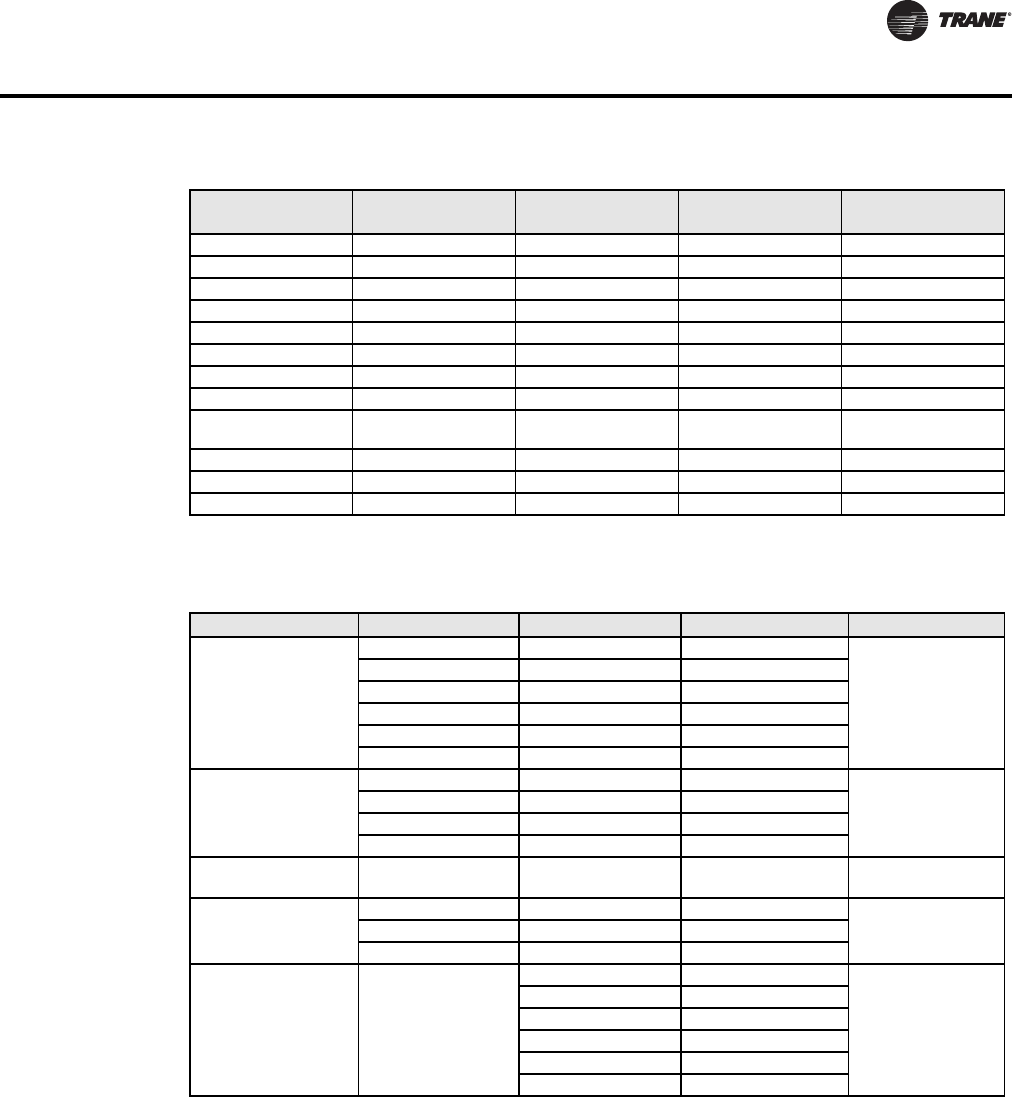
Table 1. BACnet Interoperability Building Blocks
Application Service Designation
Data Sharing – Read Property - B DS-RP-B
Data Sharing – Read Property Multiple - B DS-RPM-B
Data Sharing – Write Property - B DS-WP-B
Device Management - Device Communication Control - B DM-DCC-B
Device Management – Dynamic Device Binding - B DM-DDB-B
Device Management – Dynamic Object Binding - B DM-DOB-B

8BAS-SVP10A-EN
Summary of BACnet Objects
(X13511541010 and -2010) Rooftop and Heat Pump Models
• Default Device ID is set to: 7600MAC where MAC is the current MAC address of the device.
• The device ID and the Device Name change if you change the device’s MAC address. For
example, when a heat pump communicating thermostat with a MAC address of 63 is connected
to a network, its default Device Name will be TStat_HeatPump_Trane_63 and its default Device
ID will be 760063.
Fan Coil Objects
Table 2. Objects table for fan coils (X13511543010)
Object Name Type and Instance Object Property
Room Temperature AV 7 Present_Value (R,W)
Room Temp Override BV 8 Present_Value (R,W)
Outdoor Temperature AV 9 Present_Value (R,W)
Supply Temperature AI 12 Present_Value (R)
AUX Command BV 14 Present_Value (R,W)
Sequence of Operation MV 15 Present_Value (R,W)
System Mode MV 16 Present_Value (R,W)
Fan Mode MV 17 Present_Value (R,W)
Occupancy Command MV 18 Present_Value (R,W)
Keypad Lockout MV 19 Present_Value (R,W)
Control Output GRP 20 Present_Value (R)
PI Heating Demand AV 21 Present_Value (R)
PI Cooling Demand AV 22 Present_Value (R)
Controller Status GRP 24 Present_Value (R)
AUX Status BI 25 Present_Value (R)
Heating Valve Status MV 26 Present_Value (R)
Cooling Valve Status MV 27 Present_Value (R)
Fan Status MV 28 Present_Value (R)
BI 1 Status BI 29 Present_Value (R)
BI 2 Status BI 30 Present_Value (R)
UI 3 Status BI 31 Present_Value (R)
Local Motion BI 32 Present_Value (R)
Effective Occupancy MV 33 Present_Value (R)
Controller Alarms GRP 34 Present_Value (R)
Window Alarm BI 35 Present_Value (R)
Filter Alarm BI 36 Present_Value (R)
Service Alarm BI 37 Present_Value (R)
Temperature Setpoints GRP 38 Present_Value (R)
Occupied Heat Setpoint AV 39 Present_Value (R,W)
Occupied Cool Setpoint AV 40 Present_Value (R,W)
Stand-by Heat Setpoint AV 41 Present_Value (R,W)
Stand-by Cool Setpoint AV 42 Present_Value (R,W)

BAS-SVP10A-EN 9
Summary of BACnet Objects
Unoccupied Heat Setpoint AV 43 Present_Value (R,W)
Unoccupied Cool Setpoint AV 44 Present_Value (R,W)
General Options 1 GRP 45 Present_Value (R)
BI 1 Configuration MV 46 Present_Value (R,W)
BI 2 Configuration MV 47 Present_Value (R,W)
UI 3 configuration MV 48 Present_Value (R,W)
Menu Scroll BV 49 Present_Value (R,W)
Auto Mode Enable BV 50 Present_Value (R,W)
Temperature Scale BV 51 Present_Value (R,W)
Pipe Number MV 52 Present_Value (R,W)
AUX Configuration MV 54 Present_Value (R,W)
General Options 2 GRP 55 Present_Value (R)
Password Value AV 56 Present_Value (R,W)
Fan Mode Sequence MV 58 Present_Value (R,W)
Heating Setpoint Limit AV 58 Present_Value (R,W)
Cooling Setpoint Limit AV 59 Present_Value (R,W)
Setpoint Type BV 60 Present_Value (R,W)
Setpoint Function BV 61 Present_Value (R,W)
Temporary Occupancy Time MV 62 Present_Value (R,W)
Deadband AV 63 Present_Value (R,W)
Reheat Time Base BV 64 Present_Value (R,W)
Proportional Band MV 65 Present_Value (R,W)
Auto Fan BV 66 Present_Value (R,W)
Stand-by Time AV 67 Present_Value (R,W)
Unoccupied Time AV 68 Present_Value (R,W)
Output Configuration Options GRP 74 Present_Value (R)
Control Type BV 75 Present_Value (R,W)
Floating Motor Timing MV 76 Present_Value (R,W)
On Off Control CPH MV 77 Present_Value (R,W)
Table 2. Objects table for fan coils (X13511543010) (continued)
Object Name Type and Instance Object Property

10 BAS-SVP10A-EN
Summary of BACnet Objects
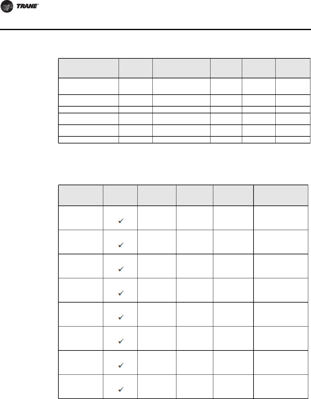
Rooftop and Heat Pump Objects
Table 3. Rooftop and heat pump ungrouped objects
Object Name
Type and
Instance Object Property
Rooftop
-1010
Heat Pump
-2010
Dehumidifi-
cation
-1050
Room Temperature AV 7 Present_Value (R,W) √√ √
Room Temp Override BV 8 Present_Value (R,W) √√ √
Outdoor Temperature AV 9 Present_Value (R,W) √√ √
Outdoor Temp Override BV 10 Present_Value (R,W) √√ √
Room Humidity AV 11 Present_Value (R) √
Occupancy Command MV 12 Present_Value (R,W) √√ √
System Mode HP MV 13 Present_Value (R,W) √
System Mode RTU MV 14 Present_Value (R,W) √√
Fan Mode MV 15 Present_Value (R,W) √√ √
Supply Temp AI 16 Present_Value (R) √√
Supply RH AV 17 Present_Value (R) √
Keypad Lockout MV 18 Present_Value (R,W) √√ √
Control Output GR 19 Present_Value (R) √√
PI Heating Demand AV 20 Present_Value (R) √√ √
PI Cooling Demand AV 21 Present_Value (R) √√ √
Economizer Output AV 22 Present_Value (R) √
Controller Status GRP 23 Present_Value (R) √√
AUX BI 24 Present_Value (R) √√ √
G Fan BI 25 Present_Value (R) √√ √
Y1 Cool BI 26 Present_Value (R) √√ √
Y2 Cool BI 27 Present_Value (R) √√
W1 Heat BI 28 Present_Value (R) √√ √
W2 Heat BI 29 Present_Value (R) √√
Reversing Valve BI 30 Present_Value (R) √
DI 1 Status BI 31 Present_Value (R) √√ √
DI 2 Status BI 32 Present_Value (R) √√
Local Motion BI 33 Present_Value (R) √√ √
Effective Occupancy MV 34 Present_Value (R) √√ √
Controller Alarms GRP 35 Present_Value (R) √
Frost Alarm BI 36 Present_Value (R) √√ √
Filter Alarm BI 38 Present_Value (R) √√ √
Service Alarm BI 39 Present_Value (R) √√ √
Fan Lock Alarm BI 40 Present_Value (R) √√ √
Temperature Setpoints GRP 41 Present_Value (R) √√ √
Occupied Heat Setpoint AV 42 Present_Value (R,W) √√ √
Occupied Cool Setpoint AV 43 Present_Value (R,W) √√ √
Unoccupied Heat Setpoint AV 44 Present_Value (R,W) √√ √
Unoccupied Cool Setpoint AV 45 Present_Value (R,W) √√ √
General Options 1- GRP 46 Present_Value (R) √√ √
Temperature Scale BV 47 Present_Value (R,W) √√ √
Heating Setpoint Limit AV 48 Present_Value (R,W) √√ √
Cooling Setpoint Limit AV 49 Present_Value (R,W) √√ √
Heating Lockout
Temperature AV 50 Present_Value (R,W) √√ √
Cooling Lockout
Temperature AV 51 Present_Value (R,W) √√ √
Deadband AV 52 Present_Value (R,W) √√ √
Heating CPH MV 53 Present_Value (R,W) √√ √

BAS-SVP10A-EN 11
Summary of BACnet Objects
Cooling CPH MV 54 Present_Value (R,W) √√ √
Frost Protection BV 55 Present_Value (R,W) √√ √
Aux Contact BV 56 Present_Value (R,W) √√ √
Menu Scroll BV 57 Present_Value (R,W) √√ √
General Options 2- GRP 58 Present_Value (R) √√ √
Password Value AV 59 Present_Value (R,W) √√ √
Power-up Delay AV 60 Present_Value (R,W) √√ √
Temporary Occupancy
Time MV 61 Present_Value (R,W) √√ √
Fan Control BV 62 Present_Value (R,W) √√ √
Anticycle MV 63 Present_Value (R,W) √√ √
Fan Purge Delay BV 64 Present_Value (R,W) √√ √
DI 1 Configuration MV 65 Present_Value (R,W) √√ √
DI 2 Configuration MV 66 Present_Value (R,W) √√
Proportional Band MV 67 Present_Value (R,W) √√ √
Unoccupied Time AV 68 Present_Value (R,W) √√ √
Stages Configuration
Options GRP 72 Present_Value (R) √
Heating Stages MV 73 Present_Value (R,W) √√
Cooling Stages MV 74 Present_Value (R,W) √√
Heatpump Stages MV 75 Present_Value (R,W) √
Economizer Model
Configuration Options GRP 76 Present_Value (R) √
Economizer Changeover
Setpoint AV 77 Present_Value (R,W) √
Economizer Minimum
Position AV 78 Present_Value (R,W) √
Mechanical Cooling
Enabled BV 79 Present_Value (R,W) √
Mixed Air Setpoint AV 80 Present_Value (R,W) √
Heatpump Model
Configuration Options GRP 81 Present_Value (R) √√
High Balance Point AV 82 Present_Value (R,W) √√
Low Balance Point AV 83 Present_Value (R,W) √√
Comfort Mode BV 84 Present_Value (R,W) √√
Reversing Valve
Configuration BV 85 Present_Value (R,W) √
Compressor Interlock BV 86 Present_Value (R,W) √
Dehumidification Model
Configuration Options GRP 87 Present_Value (R) √
RH Display BV 88 Present_Value (R,W) √
Dehumidification RH
Setpoint AV 89 Present_Value (R,W) √
Dehumidification
Hysterisys AV 90 Present_Value (R,W) √
Dehumidification Low OA
Lockout AV 91 Present_Value (R,W) √
Dehumidification Lockout
Functions BV 92 Present_Value (R,W) √
Dehumidification Output
Status BI 93 Present_Value (R) √
Humidification Model
Configuration Options GRP 94 Present_Value (R) √
Humidification RH Setpoint AV 95 Present_Value (R,W) √
Table 3. Rooftop and heat pump ungrouped objects
Object Name
Type and
Instance Object Property
Rooftop
-1010
Heat Pump
-2010
Dehumidifi-
cation
-1050
12 BAS-SVP10A-EN
Summary of BACnet Objects
Standard Object Types Supported
Footnotes for fan coils:
a : Present_Value and Out_of_Service properties are writable for every AV objects except PI Heating Demand (AV21) and
PI Cooling Demand (AV22).
b : Present_Value property for Room Temperature (AV7) and Room Humidity (AV10) is writable only if Room Temp Override
(BV8) is enabled and Room Humidity Override (BV11) is enabled respectively.
Eff (Effective) Reset
Humidification RH Spt
(Setpoint)
AV 96 Present_Value (R) √
Humidification High Limit
Spt (Setpoint) AV 97 Present_Value (R,W) √
Low RH Setpoint AV 98 Present_Value (R,W) √
Low Temp Reset RH
Setpoint AV 99 Present_Value (R,W) √
High Temp Reset RH
Setpoint AV 100 Present_Value (R,W) √
Humidifier Output AV 101 Present_Value (R) √
Table 3. Rooftop and heat pump ungrouped objects
Object Name
Type and
Instance Object Property
Rooftop
-1010
Heat Pump
-2010
Dehumidifi-
cation
-1050
Table 4. Standard object types supported
Object Type
Supported
Objects
Dynamically
Creatable
Dynamically
Deletable
Optional
Properties
Supported Writable Properties
Analog Input Reliability Out_of_Service
Analog Value Reliability Present_Value (a,b,e)
Out_of_Service (a,e)
Object_Name (c ,f)
Binary Input Reliability
Active_Text
Inactive_Text
Out_of_Service
Binary Value Reliability
Active_Text
Inactive_Text
Present_Value
Out_of_Service
Device Max_Master
Max_Info_frames
Object_Identifier
Object_name
Max_Master
Group N/A N/A
Multi-state Value Reliability
States_Text
Present_Value (d)
Out_of_Service (d)
Schedule
(Rooftop and heat
pump only)
Weekly_schedule Present_Value
Weekly_Schedule
BAS-SVP10A-EN 13
Summary of BACnet Objects
c : Object_Name property is writable only for Room Temperature (AV7).
d : Present_Value and Out_of_Service properties are writable for every MV objects except Heating Valve Status (MV26), Cooling
Valve Status (MV27), Fan Status (MV28), and Effective Occupancy (MV33)
Footnotes for rooftop units and heat pumps
e: The following AV’s are defined as read only. When Out_of_Service properties is set to true, the Present_Value, if written,
is not derived to the application level of the thermostat.
- Room Humidity (AV11)
- PI Heating Demand (AV20)
- PI Cooling Demand (AV21)
- Economizer Output (AV22)
- Eff Reset Humidification RH Spt (AV96)
- Humidifier Output (AV101)
f: Object_Name property is writable for 1 object only: Room_Temperature (AV7).
List of Proprietary Properties
Configuration Objects for Fan Coils
The following objects and group objects listed in Table 2, p. 8 should be typically used for
configuration purposes:
• General Options 1 Group GRP 45 and its complete list of objects
• General Options 2 Group GRP 55 and its complete list of objects
• Output Configuration Options Group GRP 74 and its complete list of objects
Configuration Objects for Rooftop and Heat Pump Units
The following objects and group objects listed in Table 2, p. 8 should be typically used for
configuration purposes:
• General Options 1 Group GRP 46 and its complete list of objects
• General Options 2 Group GRP 58 and its complete list of objects
• Programmable Model Configuration Options Group GRP 69 and its complete list of objects
• Stages Configuration Options Group GRP 72 and its complete list of objects;
• Economizer Model Configuration Option Group GRP 76 and its complete list of objects;
• Heatpump Model Configuration Option Group GRP 81 and its complete list of objects;
• Dehumidification Model Configuration Option Group GRP 87 and its complete list of objects;
• Humidification Model Configuration Option Group GRP 94 and its complete list of objects;
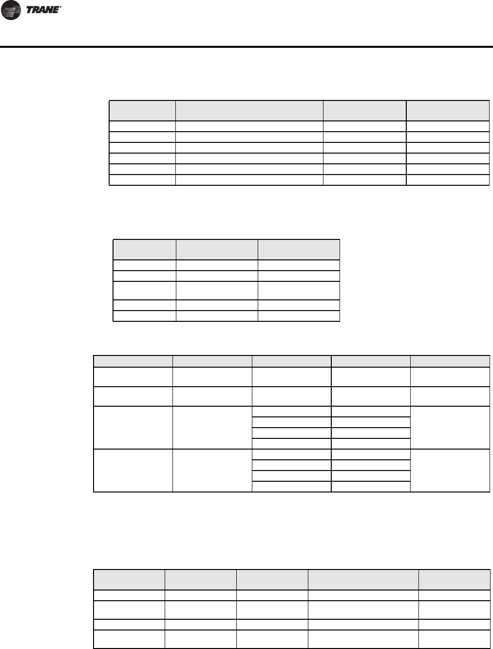
Table 5. Proprietary Properties
Property Name ID BACnet Data Type Description
Major_Version 1000 CharacterString The version number of the BACnet communications
module. This the hardware version number
MS/TP_Address 1001 Unsigned Display the MAC layer address of the module
MS/TP_Baud_Rate 1002 Unsigned Display the communication baud rate of the module
Sensor_Offset 1005 REAL Display the temperature or humidity calibration value. The
range is –5.0 deg F to 5.0 deg F for a temperature and –
15% to 15% for humidity.

14 BAS-SVP10A-EN
BACnet Object Properties
This section lists ranges, enumerations, and values for the set of Communicating Thermostat
objects.
Fan Coil Object Properties
Table 6. List of property value range restrictions
Object Name
Object Type and
Instance
Minimum Range
Value
Maximum Range
Value Default Value
Room Temperature AV 7 -39.9°F (-40°C) 121.9°F (50°C) N/A
Outdoor Temperature AV 9 -39°F (-40°C) 121.9°F (50°C) N/A
Room Humidity AV 10 5% 90% N/A
Supply Temperature AI 12 -39.9°F (-40°C) 121.9°F (50°C) N/A
PI Heating demand AV 21 0% 100% 0%
PI Cooling demand AV 22 0% 100% 0%
Occupied Heat
Setpoint AV 39 40°F (4.5°C) 90°F (32°C) 72°F (22°C)
Occupied Cool
Setpoint AV 40 54°F (12°C) 100°F (37.5°C) 74°F (24°C)
Stand-by Heat
Setpoint AV 41 40°F (4.5°C) 90°F (32°C) 72°F (22°C)
Stand-by Cool
Setpoint AV 42 54°F (12°C) 100°F (37.5°C) 74°F (24°C)
Unoccupied Heat
Setpoint AV 43 40°F (4.5°C) 90°F (32°C) 62°F (16.5°C)
Unoccupied Cool
Setpoint AV 44 54°F (12°C) 100°F (37.5°C) 80°F (26.5°C)
Password Value AV 56 0 1000 0
Heating Setpoint Limit AV 58 40°F (4.5°C) 90°F (32°C) 90°F (32°C)
Cooling Setpoint Limit AV 59 54°F (12°C) 100°F (37.5°C) 54°F (12°C)
Deadband AV 63 2°F (1°C) 5°F (2.5°C) 2°F (1°C)
Stand-by Time AV 67 0.5 Hours 24.0 Hours 0.5 Hours
Unoccupied Time AV 68 0.0 Hours 24.0 Hours 0.0 Hours
RH Setpoint AV 45 30% 100% 50%
Dehumidification
Hysterisys AV 46 2% 20% 5%
Dehumidification MAX
cooling AV 47 20% 100% 100%
Table 7. List of property enumeration sets for BV objects and BI objects
Object Name
Object Type and
instance Inactive_Text Active_Text Default value
Room Temp Override BV 8 Normal Override Normal
Room Humidity
Override BV 11 Normal Override Normal
Dehumidification
Lockout BV 13 Disabled Enabled Enabled
AUX Command BV 14 Off On Off
Dehumidification
Status BI 23 Off On Off
Aux Status BI 25 Off On Off
BI 1 Status BI 29 Deactivated Activated Deactivated
BI 2 Status BI 30 Deactivated Activated Deactivated
UI 3 Status(*) BI 31 Deactivated Activated Deactivated
Local Motion BI 32 No Motion Motion No Motion
Window Alarm BI 35 Off On Off
BAS-SVP10A-EN 15
BACnet Object Properties
* This object will be linked to the value of the ‘UI 3 Configuration’ object. When the ‘UI 3 Configuration’ object value is 0, 3
or 4, the value will be set to ‘Deactivated.’
Table 8. List of property enumeration sets for MV objects
Table Notes:
1 Enumeration sets for MV16 depends on Sequence of Operation (MV15) value upon device discovery. If required enumeration
is not present, set MV15 to desired value and rediscover MV16 object. Available enumeration will now reflect required
configuration.
2 Default value of MV16 depends on MV15 value upon device discovery. (See Table 9.)
Filter Alarm BI 36 Off On Off
Service Alarm BI 37 Off On Off
Menu Scroll BV 49 No Scroll Scroll Active Scroll Active
Auto Mode Enable BV 50 Disabled Enabled Enabled
Temperature Scale BV 51 °C °F °F
Setpoint Type BV 60 Permanent Temporary Permanent
Setpoint Function BV 61 Dual Setpoints Attached Setpoints Dual Setpoints
Reheat Time Base BV 64 15 minutes 10 seconds 15 minutes
Auto Fan BV 66 Auto Speed Auto Speed / Auto
Demand Auto Speed
RH Display BV 70 Disabled Enabled Disabled
Control Type BV 75 On/Off Floating On/Off
Direct/ Reverse Acting BV 78 Direct Acting Reverse Acting Direst Acting
Table 7. List of property enumeration sets for BV objects and BI objects (continued)
Object Name
Object Type and
instance Inactive_Text Active_Text Default value
Object Name Object ID BACnet Index Text Default value
Sequence of
Operation
1 Cooling Only
Heating Only
2 Heating Only
MV 15 3 Cooling & Reheat
4 Heating & Reheat
5 Cool/Heat4P
6 Cool/Heat4P&Reht
System Mode
Table Note 1
1 Off
Table Note 2
MV 16 2 Auto
3 Cool
4 Heat
Fan Mode
Table Note 3 MV 17 1, 2, 3 or 4 Table Note 4 Table Note 5
Occupancy Command
MV 18 1 Local Occupancy Depends on network
command
2 Occupied
3 Unoccupied
Keypad Lockout MV 19
1 Level 0
Level 0
2 Level 1
3 Level 2
4 Level 3
5 Level 4
6 Level 5
16 BAS-SVP10A-EN
BACnet Object Properties
Table Notes: (continued)
3 Enumeration sets for MV17 depends on Fan Mode Sequence (MV58) value upon device discovery. If required enumeration
is not present, set MV58 to desired value and rediscover MV17 object. Available enumeration will now reflect required
configuration.
4, 5 Available state text and default value depends on Fan Mode Sequence (MV58) value upon device discovery.
Table Notes:
6 Enumeration sets for MV26 depends on Control Type (BV75) value and Pipe Number (MV52) value upon device discovery.
If required enumeration is not present, set BV75 and MV52 to desired value and rediscover MV26 object. Available enu-
meration will now reflect required configuration.
7 Available object name, state text and default value depends on Control Type (BV75) value and Pipe Number (MV52) upon
device discovery as shown in Table 11.
On/Off 1 (2 pipe) Unused Output N/A N/A
2 (4 pipe) Heating Valve
Status 1 Closed – 2 Open Closed
Floating 1 (2 pipe) Unused Output N/A N/A
2 (4 pipe) Heating Valve
Status
1 Stopped - 2 Opening - 3
Closing Stopped
8 Enumeration sets for MV27 depends on Control Type (BV75) value and Pipe Number (MV52) value upon device discovery.
If required enumeration is not present, set BV75 and MV52 to desired value and rediscover MV27 object. Available enu-
Table 9. MV15 (Sequence of Operation) values for Note 2
MV15 Index Function
Default Value is
BV50 Enabled
Default Value is
BV50 Disabled
1 Cooling Only Cool Cool
2 Cooling with Reheat Auto Heat
3 Heating Only Heat Heat
4 Heating with Reheat Heat Heat
5 Cooling/Heating 4 Pipes Auto Heat
6 Cooling/Heating 4 Pipes with Reheat Auto Heat
MV17 Index
Function MV58
State Text Index Default Value
1 1 Low - 2 Med - 3 High High
2 1 Low - 2 High High
3 1 Low - 2 Med - 3 High
- 4 Auto High
4 1 Low - 2 High - 3 Auto High
5 1 Auto -2 On Auto
Table 10. Additional MV values
Object Name Object ID BACnet Index Text Default value
Heating Valve Status
Table Note 6 MV 26 Table
Note 7
Table
Note 7
Table
Note 7
Cooling Valve Status
Table Note 8 MV 27 Table
Note 9
Table
Note 9
Table
Note 9
Fan Status MV 28
1 Off
Off
2 Low
3 Med
4 High
Effective Occupancy MV 33
1 Occupied
Depends on local
occupancy
2 Unoccupied
3 Temporary Occupied
4 Stand-by
Table 11. Various object indexes and values for Note 7
BV75 Value MV52 Index
MV26 Object
Name
Function MV26 State Text
Index Default Value
BAS-SVP10A-EN 17
BACnet Object Properties
meration will now reflect required configuration.
9 Available object name, state text and default value depends on Control Type (BV75) value and Pipe Number (MV52) upon
device discovery. (See Table 12.)
BV75 Value MV52 Index MV27 Object Name
Function MV26
State Text Index Default Value
On/Off 1 (2 pipe) Heat/Cool Valve Status 1 Closed – 2 Open Closed
2 (4 pipe) Cooling Valve Status 1 Closed – 2 Open Closed
Floating
1 (2 pipe) Heat/Cool Valve Status 1 Stopped - 2 Opening -
3 Closing Stopped
2 (4 pipe) Cooling Valve Status 1 Stopped - 2 Opening -
3 Closing Stopped
Table 12. Various object indexes and values for Note 9
Table 13. Additional MV Values
Object Name Object ID BACnet Index Text Default Value
BI1 Configuration MV 46
1 None
None
2 Rem NSB
3 Motion NO
4 Motion NC
5 Window
BI2 Configuration MV 47
1 None
None
2 Door Dry
3 Override
4 Filter
5 Service
UI3 Configuration MV 48
1 None
None
2 COC/NH
3 COC/NC
4 COS
5 SS
Pipe Number MV 52 1 2 Pipe
4 Pipes
2 4 Pipe
Out#1 Cfg MV 53 1 2 4
2 4
AUX Configuration MV 54
1 Not used
Not Used
2 NO with Occ
3 NC with Occ
4 NO with Occ & Fan
5 NC with Occ & Fan
6 Network controlled
Fan Mode Sequence MV 58
1 Low-Med-High
On-Auto
2 Low-High
3 Low-Med-High-Auto
4 Low-High-Auto
5 On-Auto

18 BAS-SVP10A-EN
BACnet Object Properties
Temporary Occupancy
Time MV 62
1 0 hour
2 hours
2 1 hour
3 2 hours
4 3 hours
5 4 hours
6 5 hours
7 6 hours
8 7 hours
9 8 hours
10 9 hours
11 10 hours
12 11 hours
13 12 hours
14 13 hours
15 14 hours
16 15 hours
17 16 hours
18 17 hours
19 18 hours
20 19 hours
21 20 hours
22 21 hours
23 22 hours
24 23 hours
25 24 hours
Proportional Band MV 65
1 3 3 F 1.2 C
3
2 4 4 F 1.7 C
3 5 5 F 2.2 C
4 6 6 F 2.8 C
5 7 7 F 3.3 C
6 8 8 F 3.9 C
7 9 9 F 5.0 C
8 10 10 F 5.6 C
Floating Motor
Timing MV 76
1 0.5 minute
1.5 minutes
2 1 minute
3 1.5 minutes
4 2 minutes
5 2.5 minutes
6 3 minutes
7 3.5 minutes
8 4 minutes
9 4.5 minutes
10 5 minutes
11 5.5 minutes
12 6 minutes
13 6.5 minutes
14 7 minutes
15 7.5 minutes
16 8 minutes
17 8.5 minutes
18 9 minutes
Table 13. Additional MV Values (continued)
Object Name Object ID BACnet Index Text Default Value

BAS-SVP10A-EN 19
BACnet Object Properties
Rooftop and Heat Pump Object Properties
On-Off Control
CPH MV 77
1 3 CPH
4 CPH
2 4 CPH
3 5 CPH
4 6 CPH
5 7 CPH
6 8 CPH
Table 13. Additional MV Values (continued)
Object Name Object ID BACnet Index Text Default Value
Table 14. List of property value range restrictions for AI and AV objects
Object Name
Object Type
and Instance
Under Range
Value Over Range Value Default Value
Room Temperature AV 7 -40°F (-40°C) 122°F (50°C) N/A
Outdoor Temperature AV 9 -40°F (-40°C) 122°F (50°C) N/A
Room Humidity AV 11 0% 100% N/A
Supply Temp AI 16 -40°F (-40°C) 122°F (50°C) N/A
Supply RH AV 17 0% 100% N/A
PI Heating Demand AV 20 0% 100% N/A
PI Cooling Demand AV 21 0% 100% N/A
Economizer Output AV 22 0% 100% N/A
Occupied Heat Setpoint AV 42 40°F (4.5°C) 90°F (32°C) 72°F (22°C)
Occupied Cool Setpoint AV 43 54°F (12°C) 100°F (37.5°C) 75°F (24°C)
Unoccupied Heat Setpoint AV 44 40°F (4.5°C) 90°F (32°C) 62°F (16.5°C)
Unoccupied Cool Setpoint AV 45 54°F (12°C) 100°F (37.5) 80°F (26.5°C)
Heating Setpoint Limit AV 48 40°F (4.5°C) 90°F (32°C) 90°F (32°C)
Cooling Setpoint Limit AV 49 54°F (12°C) 100°F (37.5) 54°F (12°C)
Heating Lockout
Temperature AV 50 -15°F (-26°C) 120°F (49°C) 120°F (49°C)
Cooling Lockout Temperature AV 51 -40°F (-40°C) 95°F (35°C) -40°F (-40°C)
Deadband AV 52 2°F (1°C) 4°F (2°C) 2°F (1°C)
Password Value AV 59 0 1000 0
Power-up Delay AV 60 10 sec 120 sec 10 sec
Unoccupied Time AV 68 0.5 hrs 24.0. hrs 0.5 hrs
Economizer Changeover
Setpoint AV 77 14°F (-10°C) 70°F (21°C) 55°F (13°C)
Economizer Minimum
Position AV 78 0% 100% 0%
Mixed Air Setpoint AV 80 50°F (10°C) 90°F (32°C) 55°F (13°C)
High Balance Point AV 82 34°F (1°C) 90°F (32°C) 90°F (32°C)
Low Balance Point AV 83 -40°F (-40°C) 30°F (-1°C) -12°F (-24°C)
Dehumidification RH
Setpoint AV 89 15% 95% 70%
Dehumidification Hysterisys AV 90 2% 20% 5%
Dehumidification Low OA
Lockout AV 91 -40°F (-40°C) 122°F (50°C) 32°F (0°C)
Humidification RH Setpoint AV 95 10% 90% 50%
Eff (Effective) Reset
Humidification RH Spt
(Setpoint)
AV 96 0% 100% N/A
Humidification High Limit Spt
(Setpoint) AV 97 50% 90% 85%
Low RH Setpoint AV 98 10% 90% 20%
Low Temp Reset RH Setpoint AV 99 -40°F (-40°C) 15°F (-9.5°C) -20°F (-29°C)
High Temp Reset RH Setpoint AV 100 20°F (-6.5°C) 55°F (13°C) 32°F (0.0°C)

20 BAS-SVP10A-EN
BACnet Object Properties
Humidifier Output AV 101 0% 100% N/A
Table 15. List of property enumeration sets for BI and BV objects
Object Name
Object Type
and Instance Inactive_Text Active_Text Default Value
Room Temp Override BV 8 Normal Override Normal
Outdoor Temp Override BV 10 Normal Override Normal
AUX BI 24 Off On Off
G Fan BI 25 Off On Off
Y1 Cool BI 26 Off On Off
Y2 Cool BI 27 Off On Off
W1 Heat BI 28 Off On Off
W2 Heat BI 29 Off On Off
Reversing Valve BI 30 Off On Off
DI 1 Status BI 31 Not Activated Activated Not Activated
DI 2 Status BI 32 Not Activated Activated Not Activated
Local Motion BI 33 No Motion Motion No Motion
Frost Alarm BI 36 Off On Off
Clock Alarm BI 37 Off On Off
Filter Alarm BI 38 Off On Off
Service Alarm BI 39 Off On Off
Fan Lock Alarm BI 40 Off On Off
Temperature Scale BV 47 °C °F °F
Frost Protection BV 55 Off On Off
Aux Contact BV 56 N.O. N.C. N.O.
Menu Scroll BV 57 No Scroll Scroll Active Scroll Active
Fan Control BV 62 Off On On
Fan Purge Delay BV 64 Off On Off
Progressive Recovery BV 70 Off Active Off
Mechanical Cooling Enabled BV 79 Off On Off
Comfort Mode BV 84 Comfort Economy Comfort
Reversing Valve
Configuration BV 85 Normally Cool
Energized in Heating
Normally Heat
Energized in
Cooling
Normally Heat
Energized in
Cooling
Compressor Interlock BV 86 Off On Off
RH Display BV 88 Disabled Enabled Disabled
Dehumidification Lockout
Functions BV 92 Disabled Enabled Enabled
Dehumidification Output
Status BI 93 Off On N/A
Table 14. List of property value range restrictions for AI and AV objects (continued)
Object Name
Object Type
and Instance
Under Range
Value Over Range Value Default Value

BAS-SVP10A-EN 21
BACnet Object Properties
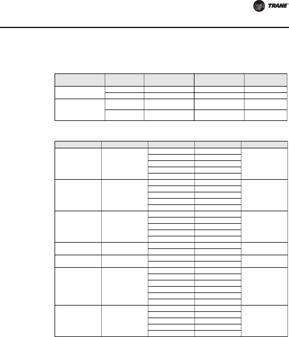
Table 16. List of property enumeration sets for MV objects
Object Name
Object Type and
instance BACnet Index Text Default Value
Occupancy Command MV12
1 Local Occupancy
Local Occupancy 2 Occupied
3 Unoccupied
System Mode HPU MV13
1 Off
Auto
2 Auto
3 Cool
4 Heat
5 Emergency
System Mode RTU MV14
1 Off
Auto
2 Auto
3 Cool
4 Heat
Fan Mode MV15
1 On
Smart2 Auto
3 Smart
Keypad Lockout MV18
1 Level 0
Level 02 Level 1
3 Level 2
Effective Occupancy MV 34
1 Occupied
Depends on local
occupancy
2 3 Unoccupied
3 Temporary Occupied
Heating CPH MV53
1 3 CPH
4 CPH
2 4 CPH
3 5 CPH
4 6 CPH
5 7 CPH
6 8 CPH
Cooling CPH MV54 1 3 CPH
4 CPH
2 4 CPH
Temporary Occupancy Time MV61
1 0 hour
3 hours
2 1 hour
3 2 hours
4 3 hours
5 4 hours
6 5 hours
7 6 hours
8 7 hours
9 8 hours
10 9 hours
11 10 hours
12 11 hours
13 12 hours
Anticycle MV63
1 0 minute
2 minutes
2 1 minute
3 2 minutes
4 3 minutes
5 4 minutes
6 5 minutes
22 BAS-SVP10A-EN
BACnet Object Properties
DI1 Configuration MV65
1 None
None
2 RemNSB
3 RemOVR
4 Filter
5 Service
6 Fan lock
DI2 Configuration MV66
1 None
None
2 RemNSB
3 RemOVR
4 Filter
5 Service
6 Fan lock
Proportional Band MV 67
1 2 2 F 0.6 C
2
2 3 3 F 1.2 C
3 4 4 F 1.7 C
4 5 5 F 2.2 C
5 6 6 F 2.8 C
6 7 7 F 3.3 C
7 8 8 F 3.9 C
Event Display MV71 1 2 Events
2 Event
2 4 Events
Heating Stages MV73 1 1 Stage
2 Stages
2 2 Stages
Cooling Stages MV74 1 1 Stage
2 Stages
2 2 Stages
Heat Pump Stages MV75 1 1 Stage
2 Stages
2 2 Stages
Table 16. List of property enumeration sets for MV objects (continued)
Object Name
Object Type and
instance BACnet Index Text Default Value
BAS-SVP10A-EN 23
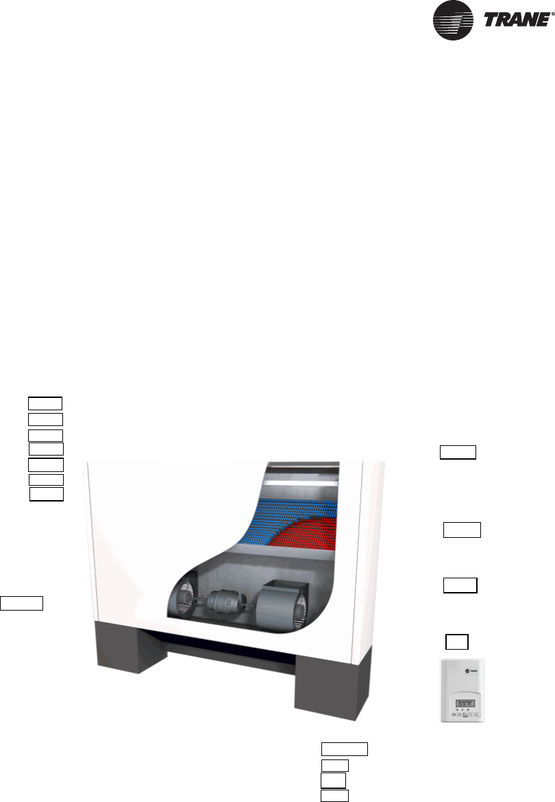
Objects You Can Use in Site Graphics
Fan Coils
You can use the following objects in site graphics:
Figure 1. Sample Fan Coil Graphic
Room Temperature (AV7) Heating Valve Status (MV26)
Occupied and Unoccupied Heat Setpoints (AV39 and AV43) Cooling Valve Status (MV28)
Occupied and Unoccupied Cool Setpoints (AV40 and AV34) PI Heating Demand (AV21)
Outdoor Temperature (AV9) PI Cooling Demand (AV22)
Supply Temperature (AI12) (If available) Window Alarm (BI35)
Occupancy Command (MV18) Filter Alarm (BI36)
System Mode (MV16) Service Alarm (BI37)
Room Humidity (AV10) (If available) Fan Mode (MV17)
Room Humidity Setpoint (AV71) (If available) Fan Status (MV28)
Occupancy
System Mode
Fan Mode
Outdoor Temperature
Occupied
Heat
High
42 ºF
Filter Alarm
Normal
Fan Status
On
Heating Valve Status
Open
Cooling Valve Status
Closed
Room Temperature
Occupied Heating Setpoint
Occupied Cooling Setpoint
Unoccupied Heating Setpoint
Unoccupied Cooling Setpoint
Room Humidity
Room Humidity Setpoint
71.2 ºF
71.0 ºF
73.0 ºF
62.0 ºF
82.0 ºF
49.7 ºF
50.0 %
Supply
Temperature
65.2ºF
24 BAS-SVP10A-EN
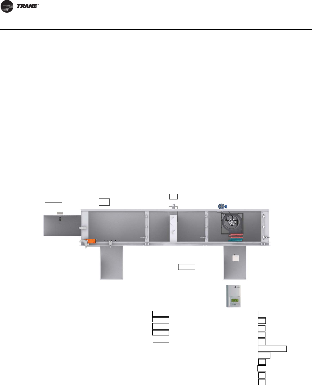
Objects You Can Use in Site Graphics
Rooftop and Heat Pump Units
You can use the following objects in site graphics:
Room Temperature (AV7) W1 Heat (BI28)
Occupied and Unoccupied Heat Setpoints (AV 42 and
AV44) W2 Heat (BI29) or Reversing Valve (BI30)
Occupied and Unoccupied Cool Setpoints (AV 43 and
AV45) Economizer Output (AV22) (if available)
Outdoor Temperature (AV9) Aux (BI24)
Supply Temperature (AI16) (If available) DI 1 Status (BI31)
Occupancy Command (MV12) DI 2 Status (BI 32)
Effective Occupancy (MV34) Frost Alarm (BI36) (if available)
System Mode RTU (MV14) or System Mode HPU (MV13) Filter Alarm (BI38) (if available)
G Fan (BI25) Service Alarm (BI39) (if available)
Y1 Cool (BI26) Fan Lock Alarm (BI40) (if available)
Y2 Cool (BI27)
Filter Alarm (BI 38)
Off
Outdoor
Temperature (AV9)
52.4 ºF
Economizer (AV22)
10%
Supply Temperature (AI16)
65.2 ºF
G Fan (BI25)
Y1 Cool (BI26)
Y2 Cool (BI27)
W1 Heat (BI28)
W2 Heat (BI29)
Occupancy (MV12)
System Mode RTU (MV14)
Aux (BI24)
DI 1 Status (BI31)
DI 2 Status (BI 32)
Frost Alarm (BI36)
Service Alarm (BI39)
On
Off
Off
On
Off
Occupied
Heat
On
Off
Off
Off
Room Temperature (AV7)
Occupied Heat Setpoint (AV 42)
Occupied Cool Setpoint (AV 43)
Unoccupied Heat Setpoint (AV 44)
Unoccupied Cool Setpoint (AV 45)
68.2 ºF
69.0 ºF
72.0 ºF
62.0 ºF
82.0 ºF
BAS-SVP10A-EN 25
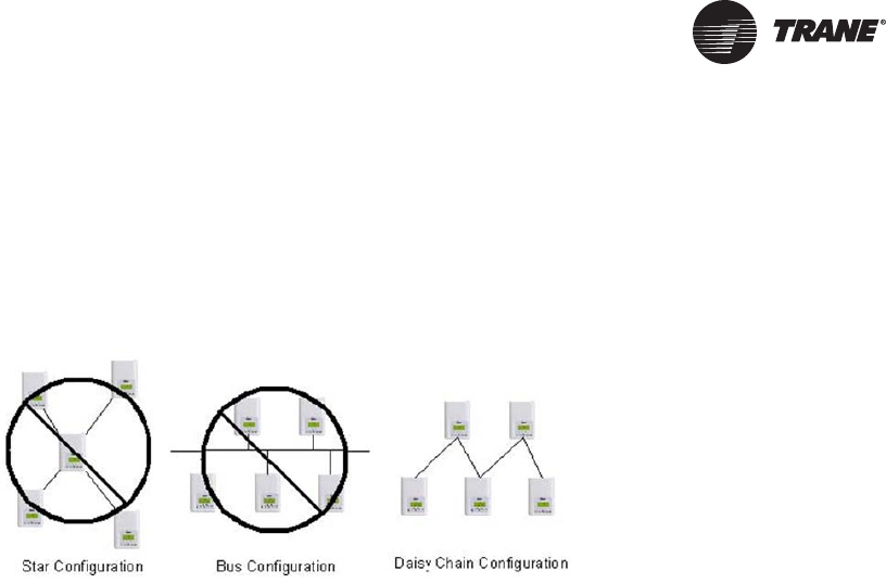
Wiring Requirements for Communicating Thermostats
BACnet networks use a daisy chain configuration. A daisy chain means that there is only one main
cable and every network device is connected directly along its path.
Figure 2 illustrates two improper network configurations and the proper daisy chain configuration.
Figure 2. Incorrect and correct network configurations
BACnet MS/TP Link Wiring
BACnet MS/TP link wiring must be field-supplied and installed in compliance with the National
Electric Code (NEC) and local codes.
BACnet Configuration Requirements
• Follow these configuration requirements:
• BACnet wiring must use daisy-chain configuration. Maximum length is 4,000 ft (1219 m).
• BACnet links are polarity sensitive; consistent wiring polarity must be maintained between
devices.
• Limit each link to 30 controllers or 60 total controllers per Tracer SC.
BACnet Wiring Best Practices
The following wiring practices are recommended:
• Use 18 AWG, (24 pF/ft. max.), shielded, twisted pair communication wire (Trane purple wire).
• Strip no more than 2 in. (5 cm) of the outer conductor of shielded wire.
• Avoid sharing 24 Vac power between unit controllers.
• Ensure that 24 Vac power supplies are consistently grounded. If grounds are not maintained,
intermittent or failed communication could result.
• Connect the shield portion of the communication wire at the first unit controller in the link.
• Use a Tracer BACnet terminator at each end of the link.
For additional best practices, see the Unit Controller Wiring Guide For the Tracer SC™ System
Controller (BAS-SVN03x-EN).
26 BAS-SVP10A-EN
Wiring Requirements for Communicating Thermostats
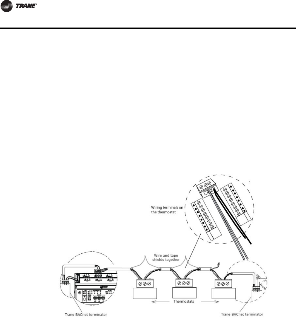
BACnet Wiring Procedure
Follow these steps to connect communication wiring as shown in Figure 3, p. 26.
1. Attach the communication link wiring to the Tracer SC at Link 1 or Link 2.
Note: It is not necessary to place the Tracer SC at the end of the of the communication link.
2. Attach the wiring from the first unit controller to the first set of communication terminals on the
next unit controller.
Note: Some unit controllers have only one set of communication terminals. In that case, attach
the wiring to the same set of terminals.
3. Wire and tape shields together at each unit controller between the Tracer SC and the BACnet
terminator.
4. Repeat steps 1 through 3 for each unit controller on the link.
Note: For more information about the specific unit controller you are wiring, see the
Installation Guide for the specific controller.
Figure 3. Daisy chain configuration for BACnet wiring
Trane BACnet Termination for BACnet Links
For correct termination placement, follow these guidelines:
• All BACnet links must be properly terminated. Use a Tracer BACnet terminator at each end of
the link.
• Connect the communication wire shield to the ground terminal of the link termination block at
the Tracer SC as shown in Figure 2. The Tracer SC provides the ground for the BACnet/MSTP
link.
• Tape back the shield at each of the BACnet terminators.
• During installation, compile a set of as-built drawings or a map of the communication wire
layout. Sketches of the communication layout should feature the BACnet terminators.
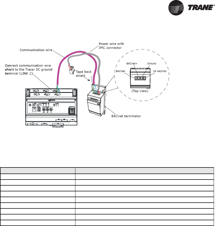
BAS-SVP10A-EN 27
Figure 4. Terminating BACnet links using BACnet terminators
Product Specifications
Specifications for Communicating Thermostats are as follows.
Network Adapter
The polarity of the connection to the cable is important. From one module to the other it is
important that the same colored wire be connected to “plus” or “+” and the other colored wire be
connected to the “minus” or ”-“.
Important: The Ref terminal should NEVER be used to wire shields. The 2 shields from each feed
of the network connection to a thermostat should be wired together in the back of
the thermostat and properly protected to prevent any accidental connection to the
ground.
The joined shield connection should then be grounded at a SINGLE point on the
whole segment. More than one ground connection to a shielded wire may induce
ground loop noises and affect communication.
Table 17. Communicating Thermostat Specifications
Item Details
Media Twisted pair 22AWG-24 AWG, shielded recommended
Characteristic Impedance 100-130 ohms
Distributed capacitance Less than 100 pF per meter (30 pF per foot)
Maximum length per segment 1200 meters (4000 feet) Note: AWG 18 cable
Polarity Polarity sensitive
Multi-drop Daisy-chain (no T connections)
Terminations Always use Trane BACnet terminators at each end of the link.
Maximum number of nodes per segment 30
Baud rate 9600, 19200, 38400, 76800 (Auto detect)
28 BAS-SVP10A-EN
Wiring Requirements for Communicating Thermostats
Communicating Thermostat Status LEDs
Table 18 shows the different possibilities with the Status LED behaviour for a BACnet module.
Troubleshooting
Table 18. Status LED conditions with causes and possible solutions (fan coil)
Condition of the Status LED Possible Cause Solution
1 short blink
BACnet communication NOT
active at default MAC address =
254
Change MAC address to another
value from 0 to 127
2 short blinks (no wires connected
to the module)
Normal operation until BACnet link
is connected.
N/A
2 short blinks (wires connected to
the module)
Thermostat is not at the same
baud rate as the network
Power off and on the thermostat
2 short blinks and a longer blink
(wires connected to the module)
The thermostat has detected the
presence of a network
N/A
Right after power is applied: 2 long
blinks and then no blinking
Polarity has been reversed at the
thermostat.
Reverse polarity at the thermostat
Table 19. Causes and solutions for error condition
Error / Trouble Condition Possible Cause Solution
Thermostat does not come online
Two or more controllers have the
same MAC address.
Modify each duplicate address to a
unique number.
The MS/TP network has too many
devices.
Do not exceed the maximum number
of devices and maximum length
allowed by the EIA-485 specifications.
Too many devices were installed
without any repeaters.
Repeaters need to be installed as
specified in this document.
The MS/TP cable runs are broken Locate the break and correct wiring
MS/TP connections at the module
are reversed
Respect polarity of the wires on a MS/
TP network.
The thermostat does not have
power Apply power to the thermostat

BAS-SVP10A-EN 29
Additional Information and Considerations
This chapter explains some special tips and considerations that apply to the Trane Communicating
Thermostats. These tips and considerations are grouped in the following categories:
• MS/TP network integration
• Objects and parameters
• Tracer SC network configuration
MS/TP Network Integration
Before doing any BACnet integration, make sure to have Trane PICS (Protocol Implementation
Conformance Statement). This PICS document lists all the BACnet Services and Object types
supported by a device and can be found on the Trane portal.
The Trane Communicating Thermostats do not support the Change of Value (COV) service. COV
reporting allows an object to send out notices when its Present-Value property is incremented by
a pre-defined value. Since this is not supported at the thermostat, you should pay special attention
to the polling time settings at the Supervisory Controller and Workstation level when using a
graphical interface or an application program to read or write to the BACnet objects.
Site Graphics
For example, some site graphics might poll every data item linked to the graphic page on a COV
basis. If the third party device does not support COV, the graphic interface then relies on a pre-
configured polling interval, which is usually in hundredths of milliseconds. Any device containing
a monitored object could be subject to network traffic congestion if such a polling interval is used.
Trane strongly recommends a polling interval of 5 seconds or more for any graphic interface. This
becomes even more critical in area graphics where a single representation might poll many
devices. If proper poll rate is not respected, devices may be reported offline by certain front ends
by saturating the traffic handling capacity of BACnet MS/TP without COV subscription.
Free Programmed Objects or Loops (Supervisory Controllers Other Than Tracer SC)
As for the application program, you might want to read and write any MS/TP data on an “If Once”
basis or a “Do Every” loop basis instead of reading or writing to a third party device’s object directly
in the program. Otherwise, any read or write request will occur at the Supervisory Controller’s
program scan rate, which might be in hundredths of milliseconds. This can easily bog down a
network as single commands can be sent to all ASC devices down the MS/TP trunks every
hundredth of a millisecond.
Fan Coils
Programs writing to the devices should have a structure similar to the following:
If Once Schedule = On then
MV13 = Occupied
End If
If Once Schedule = Off
Then
MV13 = Unoccupied
End If
OR
Do Every 5min
If Schedule = On Then
MV13= Occupied
Else
MV13 = Unoccupied
End If
End Do

30 BAS-SVP10A-EN
Additional Information and Considerations
Rooftop and Heat Pump Units
Programs writing to the devices should have a structure similar to the following:
Retries and Timeouts (Supervisory Controllers Other Than Tracer SC)
Another thing to look for in a BACnet integration is the Device object of the Supervisory Controller
(and the Operator’s Workstation). This object contains the 2 following required properties:
• Retry Timeout
The Retry Timeout property specifies the time between re-transmissions if the
acknowledgement has not been received. When you are experiencing problems with
controllers dropping off-line, increasing this value may help.
• Number of APDU Retries;
The Number of APDU Retries property specifies the number of times unsuccessful
transmissions will be repeated. If the receiving controller has not received the transmission
successfully after this many attempts, no further attempts will be made.
For example, if one of the thermostats does not reply to a Supervisory Controller (Tracer SC)
request, and the Retry Timeout is set to 2000 msec and the Number of APDU Retries is set to 1 (still
at the Tracer SC level), then the Tracer SC will send one other request, 2 seconds later. If the MS/
TP device does not reply, it will be considered Off-line by the workstation.
So having a Retry Timeout value of 10000 msec and a Number of APDU Retries property set to 3
at the SC level may prevent device from dropping Off-line. These properties should also be
changed at the Workstation level since the workstation will likely issue requests to any MS/TP
devices when the graphics are used.
Objects and Parameters
The following items apply to all equipment types.
• Each thermostat is delivered from the factory with the default MAC address set at 254. At this
value, the BACnet communication is NOT active and the device will not participate in the token
pass either. The local LED status (located on the backside of the board) is one short flash only.
To enable the BACnet communication, set the local MAC address configuration property of the
thermostat to any valid value from 0 to 127 using the Installer Configuration Parameter menuon
the Thermostat. (Refer to the Trane Communicating Thermostats for Heat Pump Control User
Guide (BAS-SVU10A-EN), Trane Communicating Thermostats for Rooftop Control User Guide
(BAS-SVU11A-EN), or the Trane Communicating Thermostats for Fan Coil Control User Guide
(BAS-SVU12A-EN) for details.)
• All configuration objects are available and can be edited locally from the device itself using the
local configuration routine. (See the Communicating Thermostat User Guides mentioned
previously in this section or in “Related Documents,” p. 6.)
• In its default mode of operation, the device will automatically match its baud rate to the baud
rate of the network. Automatic baud rate detection will occur when the MS/TP communication
port is initialized (on power up). If the network speed is changed, the device will keep listening
at the previously detected speed for 10 minutes before resuming automatic baud rate detection.
Re-powering the devices will force immediate auto-detection.
If Once Schedule = On then
MV11 = Occupied
End If
If Once Schedule = Off
Then
MV11 = Unoccupied
End If
OR
Do Every 5min
If Schedule = On Then
MV11= Occupied
Else
MV11 = Unoccupied
End If
End Do

BAS-SVP10A-EN 31
Additional Information and Considerations
• If the device should go offline, the communicated value from the front-end Tracer SC will be
released:
– Room Temperature
– Outdoor Temperature
– Occupancy
• Device Name and Device ID properties are writable in BACnet device object. Both properties can
be renamed from any BACnet network management tool as long as the tool itself give access
to write to these properties.
• The BACnet Data Link layer has two key parameters: the device object name and the device
object ID. The device object name must be a unique BACnet device object name within the
BACnet network (i.e. not just the MS/TP sub-network). The device object ID must also be a
unique BACnet device object ID in the entire BACnet network (i.e. not just the MS/TP sub-
network).
The following items apply to fan coils only.
• Enumeration sets for System Mode MV16 depends on Sequence of Operation (MV15) value
upon device discovery. If required enumerations are not present, set MV15 to desired value and
rediscover MV16 object. Available enumeration will now reflect required configuration.
• Enumeration sets for MV16 depends on Fan Mode Sequence (MV58) value upon device
discovery. If required enumerations are not present, set MV58 to desired value and rediscover
MV16 object. Available enumeration will now reflect required configuration.
• Enumeration sets for MV26 and MV27 depend on Control Type (BV75) value and Pipe Number
(MV52) value upon device discovery. If required enumeration is not present, set BV75 and MV52
to desired value and rediscover MV26 and BV27 object. Available enumeration will now reflect
required configuration.
• To assign manually a Room Temperature (AV7) value, users must first enable the Override
mode in the Room Temp Override (BV8) object.
• To assign manually a Room Humidity (AV10) value, users must first enable the Override mode
in the Room Humidity Override (BV11) object.
32 BAS-SVP10A-EN
Additional Information and Considerations
Tracer SC Network Configuration
You should be aware of these important facts about Communicating Thermostat capabilities in the
Tracer SC network.
No automatic installation
The Trane Communicating Thermostats do not automatically install on the Tracer SC. Custom
templates are available and you can select one of these templates (“Template: TStat_RTU_Trane,”
p. 40,“Template:TStat_FanCoil_Trane,”p. 36,or“Template: TStat_HeatPump_Trane,” p. 39) toget
the unit ready to install. Refer to the Tracer™ SC System Controller Installation and Setup Manual
(BAS-SVX31x-EN) for details about using a template to install a Communicating Thermostat on a
BACnet link.
No priority array
Binary, Analog, and Multistate Values do not use a priority array. In order to reliably control these
points, they must be controlled by only one source (for example, Area control). If they are being
controlled from multiple sources, the most recent source to control the point will be in control.
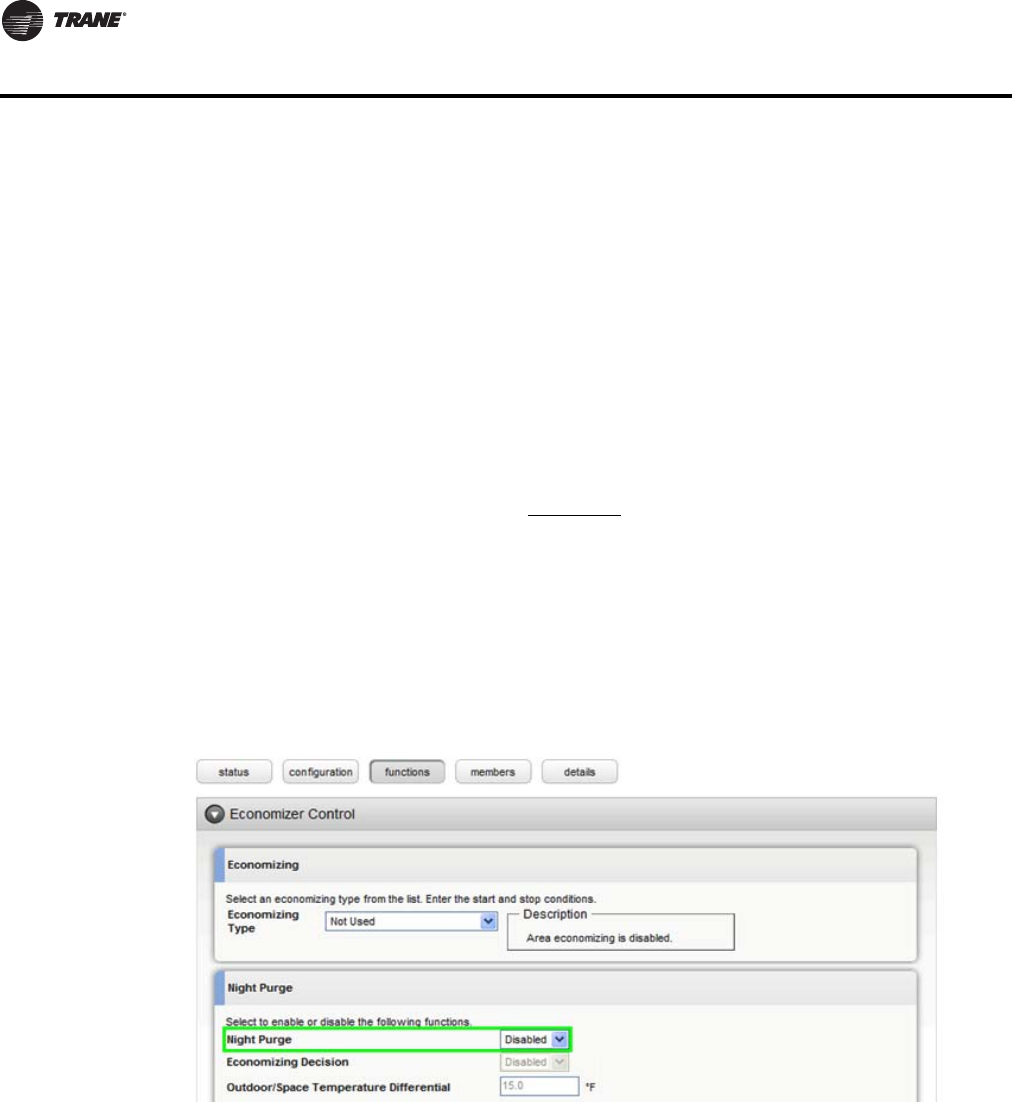
Night Purge disabled
A Trane Communicating Thermostat as a member of Area should have Night Purge disabled.
Using Night Purge could result in the Heat Cool Mode Request being controlled incorrectly on a
transition from Night Purge to another state. You can disable Night Purge for the entire area on the
functions page of Area in the Economizer Control section (Figure 5).
Figure 5. The Economizer Control section of the Area Functions page
Night purge can also be disabled from the members page by checking the box next to certain
members and going to actions > edit configuration (Figure 6).
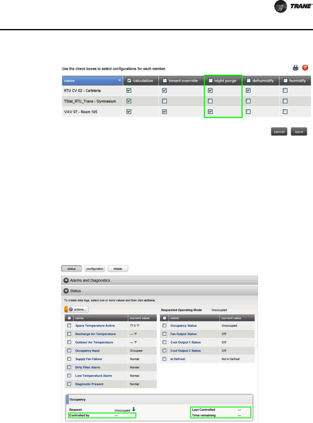
BAS-SVP10A-EN 33
Additional Information and Considerations
Figure 6. Area members page (actions > edit configuration)
Heat only/cool only
If the thermostat is configured as cool only, it will not accept its Heat Cool Mode Request to be
controlled to any heating mode. The converse applies if the thermostat is configured for heat only,
it will not accept its Heat Cool Mode Request to be controlled to any cooling mode. If the point is
controlled to an invalid state, it will quickly revert to the previous state.
Parameters not supported
In the Occupancy frame of the Equipment/Space status page, the following properties will not be
displayed:
• Last Controlled
• Controlled by
• Time Remaining
These are parameters that the thermostat points do not support.
Figure 7. Occupancy section of the Equipment/Space status page
34 BAS-SVP10A-EN
Additional Information and Considerations
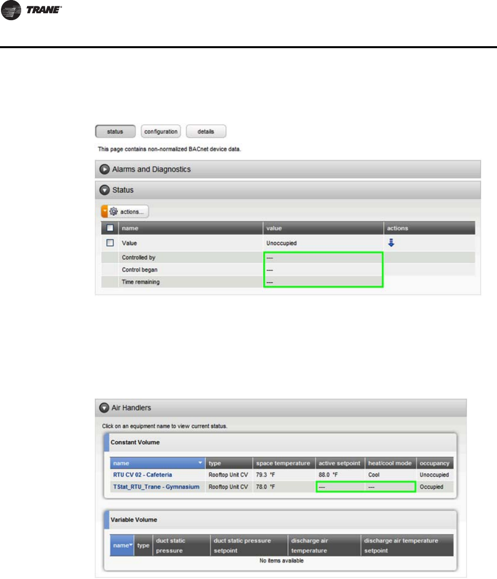
These properties are also shown but not populated on point status pages (Figure 8, p. 34 ).
Figure 8. Status section of the Point Status page
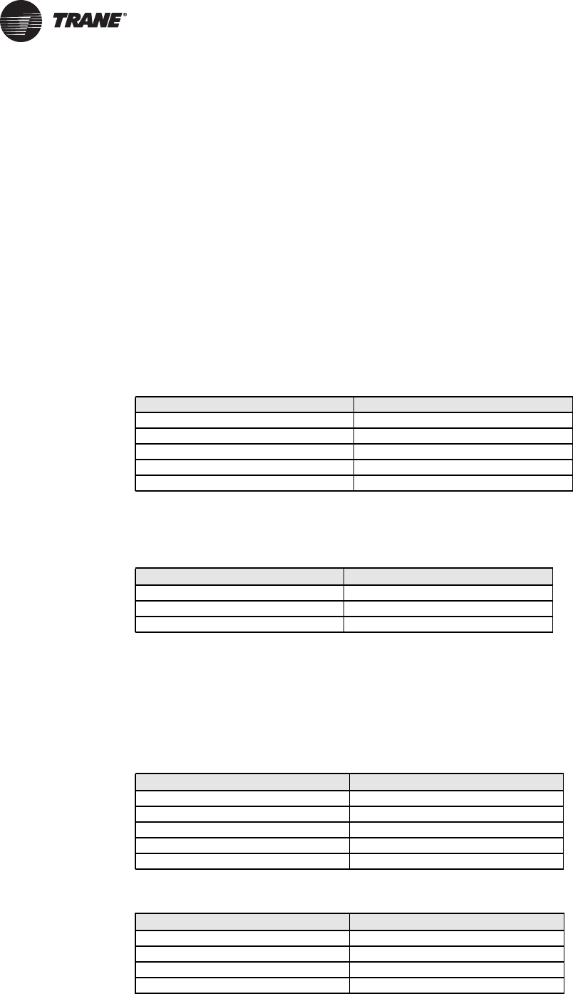
No active setpoint or heat/cool mode data
The Spaces Summary and Equipment Summary pages do not show data for active setpoint or heat/
cool mode as these devices do not have Space Temperature Setpoint Active and Heat Cool Mode
Status points ( ).
Figure 9. Air Handlers section of the Equipment Status page
Discharge air temp requirements
The point Discharge Air Temperature on all of these devices only reports data if the respective input
is configured as a discharge air sensor and a valid sensor is connected.
Inappropriate text on graphic displays
In some cases, Binary and Multistate points on a Tracer SC custom graphic display state text that
does not match the space or equipment pages.

BAS-SVP10A-EN 35
Additional Information and Considerations
Outdoor air temperature
On the TStat_FanCoil, the point Outdoor Air Temperature is only controlled from a BAS. It is not
used in the control sequence of the device. If this value is to be shown on the LCD display on the
thermostat, it’s recommended to use global referencing to send the Facility Outdoor Air
Temperature to this point.
36 BAS-SVP10A-EN
Data Normalization
Special data normalization has been applied to various points in the factory loaded equipment
templates. This data normalization serves to make a consistent interface to equipment across
Tracer SC. This chapter lists special data normalizations for each equipment template.
Example: Occupancy Request
The following example of the Occupancy Request point in the TStat_FanCoil_Trane template
indicates how to interpret the special data normalization.
• The point name in Tracer SC is Occupancy Request.
• The point name in the BACnet device is Occupancy Command (Multistate Value instance 18
(MV18)).
Table 20 and Table 21 show the corresponding Tracer SC and fan coil states.
When Tracer SC writes the state in the left hand column to the Occupancy Request point, the
BACnet point is controlled to the corresponding state on the right hand column.
When Tracer SC reads the state and text in the left hand column from the BACnet device, it reports
the state and text in the right hand column in the Occupancy Request point.
Table 21. Reading from Fan Coil to Tracer SC (Occupancy Request)
Template: TStat_FanCoil_Trane
This section lists special data normalizations for points in this template.
The Tracer SC Point name: Occupancy Status
The BACnet point name, type, and instance: Effective Occupancy (MV 33)
Table 20. Tracer SC writing to the fan coil (Occupancy Request)
Tracer SC state and text Fan coil state and text
1 - Occupied 2 - Occupied
2 - Unoccupied 3 - Unoccupied
3 - Occupied Bypass 2 - Occupied
4 - Occupied Standby 2 - Occupied
5 - Auto 1 - Local Occupancy
Fan Coil state and text Tracer SC state and text
1 - Local Occupancy 5 - Auto
2 - Occupied 1 - Occupied
3 - Unoccupied 2 - Unoccupied
Table 22. Tracer SC writing to the fan coil (Occupancy Status)
Tracer SC state and text Fan coil state and text
1 - Occupied 1 - Occupied
2 - Unoccupied 2 - Unoccupied
3 - Occupied Bypass 1 - Occupied
4 - Occupied Standby 4 - Stand-by
5 - Auto 1 - Occupied
Table 23. Reading from fan coil to Tracer SC (Occupancy Status)
Fan Coil state and text Tracer SC state and text
1 - Occupied 1 - Occupied
2 - Unoccupied 2 - Unoccupied
3 - Temporary Occupied 1 - Occupied
4 - Stand-by 4 - Occupied Standby
BAS-SVP10A-EN 37
Data Normalization
Tracer SC point name: Occupancy Request
BACnet point name, type, and instance: Occupancy Command (MV 18)
Table 24. Tracer SC writing to the fan coil (Occupancy Request)
Tracer SC Point name: Heat Cool Mode Request
BACnet point name, type and instance: System Mode (MV 16)
Table 26. Tracer SC writing to the fan coil (Heat Cool Mode Request)
Tracer SC state and text Fan coil state and text
1 - Occupied 2 - Occupied
2 - Unoccupied 3 - Unoccupied
3 - Occupied Bypass 2 - Occupied
4 - Occupied Standby 2 - Occupied
5 - Auto 1 - Local Occupancy
Table 25. Reading from fan coil to Tracer SC (Occupancy Request)
Fan coil state and text Tracer SC state and text
1 - Local Occupancy 5 - Auto
2 - Occupied 1 - Occupied
3 - Unoccupied 2 - Unoccupied
Tracer SC state and text Fan coil state and text
1 - Auto 2 - Auto
2 - Heat 4 - Heat
3 - Morning Warm-up 4 - Heat
4 - Cool 3 - Cool
5 - Night Purge 3 - Cool
6 - Pre Cool 3 - Cool
7 - Off 1 - Off
8 - Test 2 - Auto
9 - Emergency Heat 4 - Heat
10 - Fan Only 2 - Auto
11 - Free Cool 3 - Cool
12 - Ice-Making 3 - Cool
13 - Max Heat 4 - Heat
14 - Economizer 3 - Cool
15 - Dehumidify 3 - Cool
16 - Calibrate 2 - Auto
Table 27. Reading from fan coil to Tracer SC (Heat Cool Mode Request)
Fan coil state and text Tracer SC state and text
1 - Off 7 - Off
2 - Auto 1 - Auto
3 - Cool 4 - Cool
4 - Heat 2 - Heat
38 BAS-SVP10A-EN
Data Normalization
Tracer SC Point name: Supply Fan Staged Speed Status
BACnet point name, type, and instance: Fan Status (MV 28)
Tracer SC Point name: Fan Mode BAS
BACnet point name, type, and instance: Fan Mode (MV 17)
Table 28. Tracer SC writing to the fan coil (Supply Fan Staged Speed Status)
Tracer SC state and text Fan coil state and text
1 - Auto 4 - High
2 - Off 1 - Off
3 - Low 2 - Low
4 - Medium 3 - Medium
5 - High 4 - High
Table 29. Reading from fan coil to Tracer SC (Supply Fan Staged Speed Status)
Fan coil state and text Tracer SC state and text
1 - Off 2 - Off
2 - Low 3 - Low
3 - Medium 4 - Medium
4 - High 5 - High
Table 30. Tracer SC writing to the fan coil (Fan Mode BAS)
Tracer SC state and text Fan coil state and text
1 - On 2 - On
2 - Auto 1 - Auto
3 - Smart 1 - Auto
Table 31. Reading from fan coil to tracer SC (Fan Mode BAS)
Fan Coil state and text Tracer SC state and text
1 - Auto 2 - Auto
2 - On 1 - On
BAS-SVP10A-EN 39
Data Normalization
Template: TStat_HeatPump_Trane
This section lists special data normalizations for points in this template.
• Tracer SC Point name: Occupancy Status
• BACnet point name, type, and instance: Effective Occupancy (MV 34)
Tracer SC state and text Heat pump state and text
1 - Occupied 1 - Occupied
2 - Unoccupied 2 - Unoccupied
3 - Occupied Bypass 1 - Occupied
4 - Occupied Standby 1 - Occupied
5 - Auto 1 - Occupied
Tracer SC Point name: Occupancy Request
BACnet point name, type and instance: Occupancy Command (MV 12)
Tracer SC Point name: Heat Cool Mode Request
BACnet point name, type and instance: System Mode (MV 13)
Table 32. Tracer SC writing to the heat pump (Occupancy Status)
Table 33. Reading from heat pump to Tracer SC (Occupancy Status)
Heat pump state and text Tracer SC state and text
1 - Occupied 1 - Occupied
2 - Unoccupied 2 - Unoccupied
3 - Temporary Occupied 1 - Occupied
Table 34. Tracer SC writing to the heat pump (Occupancy Request)
Tracer SC state and text Heat pump state and text
1 - Occupied 2 - Occupied
2 - Unoccupied 3 - Unoccupied
3 - Occupied Bypass 2 - Occupied
4 - Occupied Standby 2 - Occupied
5 - Auto 1 - Local Occupancy
Table 35. Reading from heat pump to Tracer SC (Occupancy Request)
Heat pump state and text Tracer SC state and text
1 - Local Occupancy 5 - Auto
2 - Occupied 1 - Occupied
3 - Unoccupied 2 - Unoccupied
40 BAS-SVP10A-EN
Data Normalization
Template: TStat_RTU_Trane
This section lists special data normalizations for points in this template.
Tracer SC Point name: Occupancy Status
BACnet point name, type, and instance: Effective Occupancy (MV 34)
Table 36. Tracer SC writing to the heat pump (Heat Cool Mode Request)
Tracer SC state and text Heat pump state and text
1 - Auto 2 - Auto
2 - Heat 4 - Heat
3 - Morning Warm-up 4 - Heat
4 - Cool 3 - Cool
5 - Night Purge 3 - Cool
6 - Pre Cool 3 - Cool
7 - Off 1 - Off
8 - Test 2 - Auto
9 - Emergency Heat 5 - Emergency
10 - Fan Only 2 - Auto
11 - Free Cool 3 - Cool
12 - Ice-Making 3 - Cool
13 - Max Heat 4 - Heat
14 - Economizer 3 - Cool
15 - Dehumidify 3 - Cool
16 - Calibrate 2 - Auto
Table 37. Reading from Heat Pump to Tracer SC (Heat Cool Mode Request)
Heat pump state and text Tracer SC state and text
1 - Off 7 - Off
2 - Auto 1 - Auto
3 - Cool 4 - Cool
4 - Heat 2 - Heat
5 - Emergency 9 - Emergency Heat
Table 38. Tracer SC writing to the rooftop unit (Occupancy Status)
Tracer SC state and text Rooftop unit state and text
1 - Occupied 1 - Occupied
2 - Unoccupied 2 - Unoccupied
3 - Occupied Bypass 1 - Occupied
4 - Occupied Standby 1 - Occupied
5 - Auto 1 - Occupied
Table 39. Reading from rooftop unit to Tracer SC (Occupancy Status)
Rooftop unit state and text Tracer SC state and text
1 - Occupied 1 - Occupied
2 - Unoccupied 2 - Unoccupied
3 - Temporary Occupied 1 - Occupied
BAS-SVP10A-EN 41
Data Normalization
Tracer SC Point name: Occupancy Request
BACnet point name, type, and instance: Occupancy Command (MV 12)
Tracer SC Point name: Heat Cool Mode Request
BACnet point name, type and instance: System Mode (MV 14)
Table 40. Tracer SC writing to the rooftop unit (Occupancy Request)
Tracer SC state and text Rooftop unit state and text
1 - Occupied 2 - Occupied
2 - Unoccupied 3 - Unoccupied
3 - Occupied Bypass 2 - Occupied
4 - Occupied Standby 2 - Occupied
5 - Auto 1 - Local Occupancy
Table 41. Reading from rooftop unit to Tracer SC (Occupancy Request)
Rooftop unit state and text Tracer SC state and text
1 - Local Occupancy 5 - Auto
2 - Occupied 1 - Occupied
3 - Unoccupied 2 - Unoccupied
Table 42. Tracer SC writing to the rooftop unit (Heat Cool Mode Request)
Tracer SC state and text Rooftop unit state and text
1 - Auto 2 - Auto
2 - Heat 4 - Heat
3 - Morning Warm-up 4 - Heat
4 - Cool 3 - Cool
5 - Night Purge 3 - Cool
6 - Pre Cool 3 - Cool
7 - Off 1 - Off
8 - Test 2 - Auto
9 - Emergency Heat 4 - Heat
10 - Fan Only 2 - Auto
11 - Free Cool 3 - Cool
12 - Ice-Making 3 - Cool
13 - Max Heat 4 - Heat
14 - Economizer 3 - Cool
15 - Dehumidify 3 - Cool
16 - Calibrate 2 - Auto
Table 43. Reading from rooftop unit to Tracer SC (Heat Cool Mode Request)
Rooftop unit state and text Tracer SC state and text
1 - Off 7 - Off
2 - Auto 1 - Auto
3 - Cool 4 - Cool
4 - Heat 2 - Heat

42 BAS-SVP10A-EN
Trane Communicating Thermostat Points List
The following tables provide side by side lists of Tracer SC points and Communicating Thermostat
device point names and related information.
TStat_Fan_Coil_Trane
Table 44. Points Available in the TStat_Fan_Coil_Trane Template
Tracer SC Point Name
TStat Device Point
Name
Point
Type
Point
Instance
Data
Normaliza-
tion
Diagnostic Present Service Alarm BI 37
Dirty Filter Alarm Filter Alarm BI 36
Discharge Air Temperature Supply Temperature AI 12
Display Temperature Scale Temperature Scale BV 51
Emergency Heat Status AUX Status BI 25
Fan Mode BAS Fan Mode MV 17 Yes
Heat Cool Mode Request System Mode MV 16 Yes
Keypad Lockout Keypad Lockout MV 19
Minimum Heating Cooling Setpoint
Differential Deadband AV 63
Occupancy Input Local Motion BI 32
Occupancy Request Occupancy Command MV 18 Yes
Occupancy Status Effective Occupancy MV 33 Yes
Occupied Cooling Setpoint Occupied Cool Setpoint AV 40
Occupied Heating Setpoint Occupied Heat Setpoint AV 39
Occupied Standby Cooling Setpoint Stand-by Cool Setpoint AV 42
Occupied Standby Heating Setpoint Stand-by Heat Setpoint AV 41
Outdoor Air Temperature Outdoor Temperature AV 9
Space Temperature Active Room Temperature AV 7
Supply Fan Staged Speed Status Fan Status MV 28 Yes
Timed Override Duration Setpoint Temporary Occupancy Time MV 62
Unoccupied Cooling Setpoint Unoccupied Heat Setpoint AV 43
Unoccupied Cooling Setpoint Unoccupied Cool Setpoint AV 44
PI Heating Demand AV 21
PI Cooling Demand AV 22
Password Value AV 56
Heating Setpoint Limit AV 58
Cooling Setpoint Limit AV 59
Stand-by Time AV 67
Unoccupied Time AV 68
BI 1 Status BI 29
BI 2 Status BI 30
UI 3 Status BI 31
Window Alarm BI 35
Room Temp Override BV 8
AUX Command BV 14
Menu Scroll BV 49
Auto Mode Enable BV 50
Setpoint Type BV 60
Setpoint Function BV 61
Reheat Time Base BV 64
Auto Fan BV 66
Control Type BV 75
Sequence of Operation MV 15
Heating Valve Status MV 26
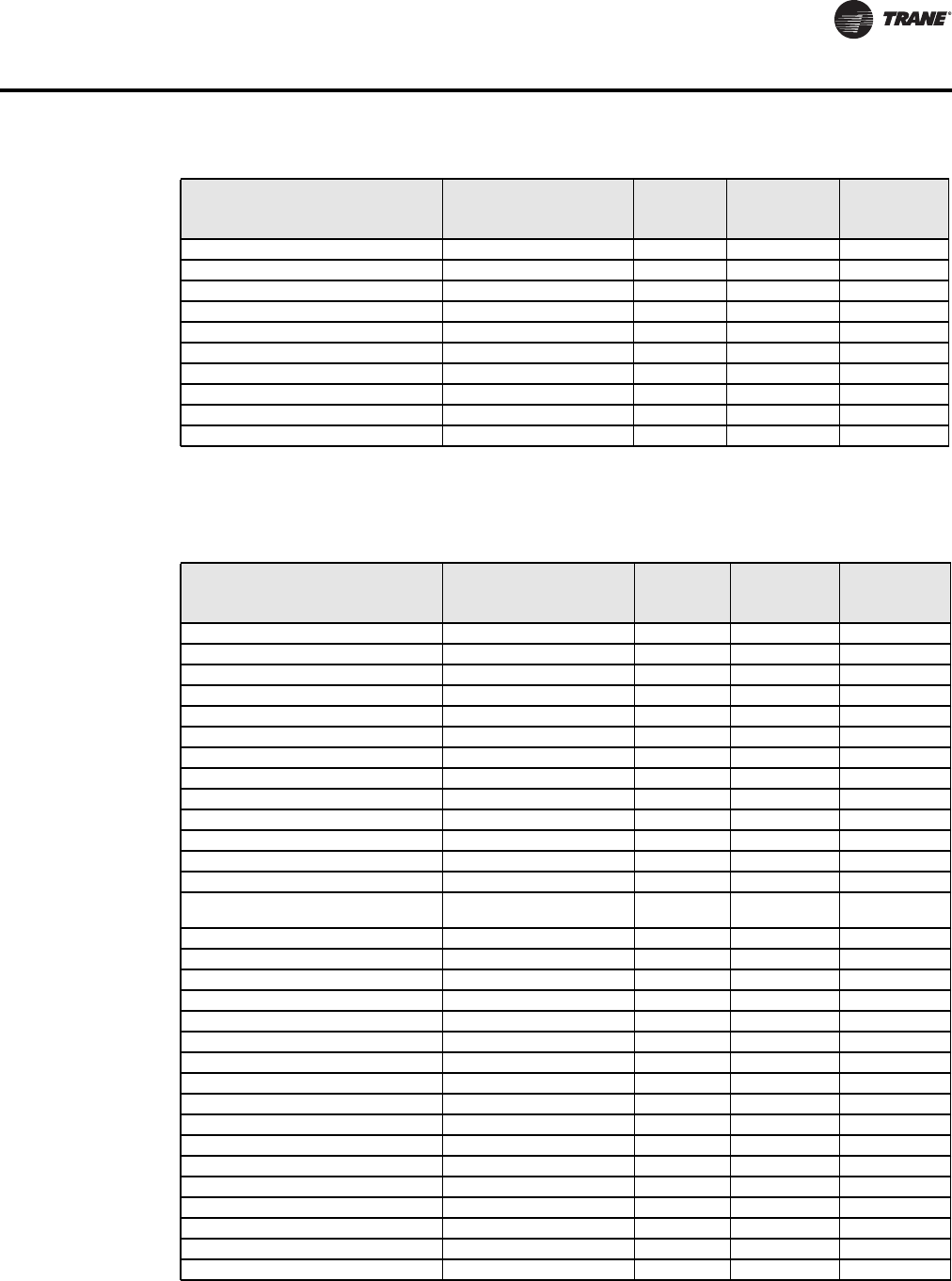
BAS-SVP10A-EN 43
Trane Communicating Thermostat Points List
TStat_HeatPump_Trane Template
Cooling Valve Status MV 27
BI 1 Configuration MV 46
BI 2 Configuration MV 47
UI 3 Configuration MV 48
Pipe Number MV 52
AUX Configuration MV 54
Fan Mode Sequence MV 57
Proportional Band MV 65
Floating Motor Timing MV 76
On Off Control CPH MV 77
Table 44. Points Available in the TStat_Fan_Coil_Trane Template (continued)
Tracer SC Point Name
TStat Device Point
Name
Point
Type
Point
Instance
Data
Normaliza-
tion
Table 45. Points Available in the TStat_HeatPump_Trane Template
Tracer SC Point Name
TStat Device Point
Name Point Type
Point
Instance
Data
Normaliza-
tion
Cool Output 1 Status Y1 Cool BI 26
Cool Output 2 Status Y2 Cool BI 27
Diagnostic Present Service Alarm BI 39
Dirty Filter Alarm Filter Alarm BI 38
Discharge Air Temperature Supply Temperature AI 16
Display Temperature Scale Temperature Scale BV 47
Fan Mode BAS Fan Mode MV 15
Fan Output Status G Fan BI 25
Heat Cool Mode Request System Mode HP MV 13 Yes
Heat Output 1 Status W1 Heat BI 28
In Defrost Frost Protection BV 55
Keypad Lockout Keypad Lockout MV 18
Low Temperature Alarm Frost Alarm BI 36
Minimum Heating Cooling Setpoint
Differential Deadband AV 52
Occupancy Input Local Motion BI 33
Occupancy Request Occupancy Command MV 12 Yes
Occupancy Status Effective Occupancy MV 34 Yes
Occupied Cooling Setpoint Occupied Cool Setpoint AV 43
Occupied Heating Setpoint Occupied Heat Setpoint AV 42
Outdoor Air Temperature Outdoor Temperature AV 9
Reversing Valve Reversing Valve BI 30
Space Temperature Active Room Temperature AV 7
Supply Fan Configuration Command Fan Control BV 62
Supply Fan Failure Fan Lockout Alarm BI 40
Timed Override Duration Setpoint Temporary Occupancy Time MV 61
Unoccupied Cooling Setpoint Unoccupied Cool Setpoint AV 45
Unoccupied Heating Setpoint Unoccupied Heat Setpoint AV 44
PI Heating Demand AV 20
PI Cooling Demand AV 21
Heating Setpoint Limit AV 48
Cooling Setpoint Limit AV 49
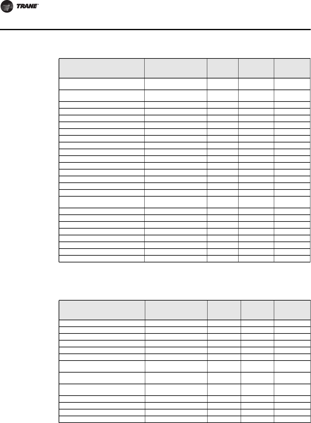
44 BAS-SVP10A-EN
Trane Communicating Thermostat Points List
TStat_RTU_Trane Template
Heating Lockout
Temperature AV 50
Cooling Lockout
Temperature AV 51
Password Value AV 59
Power-up Delay AV 60
Unoccupied Time AV 68
High Balance Point AV 82
Low Balance Point AV 83
AUX BI 24
DI 1 Status BI 31
DI 2 Status BI 32
Room Temp Override BV 8
Outdoor Temp Override BV 10
Aux Contact BV 56
Menu Scroll BV 57
Fan Purge Delay BV 64
Comfort Mode BV 84
Reversing Valve
Configuration BV 85
Compressor Interlock BV 86
Heating CPH MV 53
Cooling CPH MV 54
Anticycle MV 63
DI 1 Configuration MV 65
DI 2 Configuration MV 66
Proportional Band MV 67
Heat Pump Stages MV 75
Table 45. Points Available in the TStat_HeatPump_Trane Template (continued)
Tracer SC Point Name
TStat Device Point
Name Point Type
Point
Instance
Data
Normaliza-
tion
Table 46. Points Available in the TStat_RTU_Trane Template
Tracer SC Point Name
TStat Device Point
Name Point Type
Point
Instance
Data
Normaliza-
tion
Cool Output 1 Status Y1 Cool BI 26
Cool Output 2 Status Y2 Cool BI 27
Diagnostic Present Service Alarm BI 39
Dirty Filter Alarm Filter Alarm BI 38
Discharge Air Temperature Supply Temperature AI 16
Display Temperature Scale Temperature Scale BV 47
Economizer Minimum Position Setpoint
BAS
Economizer Minimum
Position AV 78
Economizer Mixed Air Enable Setpoint
BAS Mixed Air Setpoint AV 80
Economizer Outdoor Air Enable
Setpoint BAS
Economizer Changeover
Setpoint AV 77
Fan Mode BAS Fan Mode MV 15
Fan Output Status G Fan BI 25
Heat Cool Mode Request System Mode RTU MV 14 Yes
Heat Output 1 Status W1 Heat BI 28

BAS-SVP10A-EN 45
Trane Communicating Thermostat Points List
Heat Output 2 Status W2 Heat BI 29
In Defrost Frost Protection BV 55
Keypad Lockout Keypad Lockout MV 18
Low Temperature Alarm Frost Alarm BI 36
Minimum Heating Cooling Setpoint
Differential Deadband AV 52
Occupancy Input Local Motion BI 33
Occupancy Request Occupancy Command MV 12 Yes
Occupancy Status Effective Occupancy MV 34 Yes
Occupied Cooling Setpoint Occupied Cool Setpoint AV 43
Occupied Heating Setpoint Occupied Heat Setpoint AV 42
Outdoor Air Damper Position Economizer Output AV 22
Outdoor Air Temperature Outdoor Temperature AV 9
Space Temperature Active Room Temperature AV 7
Supply Fan Configuration Command Fan Control BV 62
Supply Fan Failure Fan Lockout Alarm BI 40
Timed Override Duration Setpoint Temporary Occupancy Time MV 61
Unoccupied Cooling Setpoint Unoccupied Cool Setpoint AV 45
Unoccupied Heating Setpoint Unoccupied Heat Setpoint AV 44
PI Heating Demand AV 20
PI Cooling Demand AV 21
Heating Setpoint Limit AV 48
Cooling Setpoint Limit AV 49
Heating Lockout
Temperature AV 50
Cooling Lockout
Temperature AV 51
Password Value AV 59
Power-up Delay AV 60
Unoccupied Time AV 68
AUX BI 24
DI 1 Status BI 31
DI 2 Status BI 32
Room Temp Override BV 8
Outdoor Temp Override BV 10
Aux Contact BV 56
Menu Scroll BV 57
Fan Purge Delay BV 64
Mechanical Cooling Enabled BV 79
Heating CPH MV 53
Cooling CPH MV 54
Anticycle MV 63
DI 1 Configuration MV 65
DI 2 Configuration MV 66
Proportional Band MV 67
Heating Stages MV 73
Cooling Stages MV 74
Table 46. Points Available in the TStat_RTU_Trane Template (continued)
Tracer SC Point Name
TStat Device Point
Name Point Type
Point
Instance
Data
Normaliza-
tion
Notes
Notes

Trane optimizes the performance of homes and buildings around the world. A business of Ingersoll Rand, the
leader in creating and sustaining safe, comfortable and energy efficient environments, Trane offers a broad
portfolio of advanced controls and HVAC systems, comprehensive building services, and parts. For more
information, visit www.Trane.com.
Trane has a policy of continuous product and product data improvement and reserves the right to change design and specifications without notice.
We are committed to using environmentally
conscious print practices that reduce waste.
© 2011 Trane All rights reserved
BAS-SVP10A-EN 26 Aug 2011
New
