Trane Gas Unit Heaters Installation And Maintenance Manual GHND SVX01C EN 03/16/2012 Installation, Operation, Heater High Efficiency Propeller Fan S GH
2015-04-02
: Trane Trane-Gas-Unit-Heaters-Installation-And-Maintenance-Manual-684283 trane-gas-unit-heaters-installation-and-maintenance-manual-684283 trane pdf
Open the PDF directly: View PDF ![]() .
.
Page Count: 43
SAFETY WARNING
Only qualified personnel should install and service the equipment. The installation, starting up, and
servicing of heating, ventilating, and air-conditioning equipment can be hazardous and requires specific
knowledge and training. Improperly installed, adjusted or altered equipment by an unqualified person could
result in death or serious injury. When working on the equipment, observe all precautions in the literature
and on the tags, stickers, and labels that are attached to the equipment.
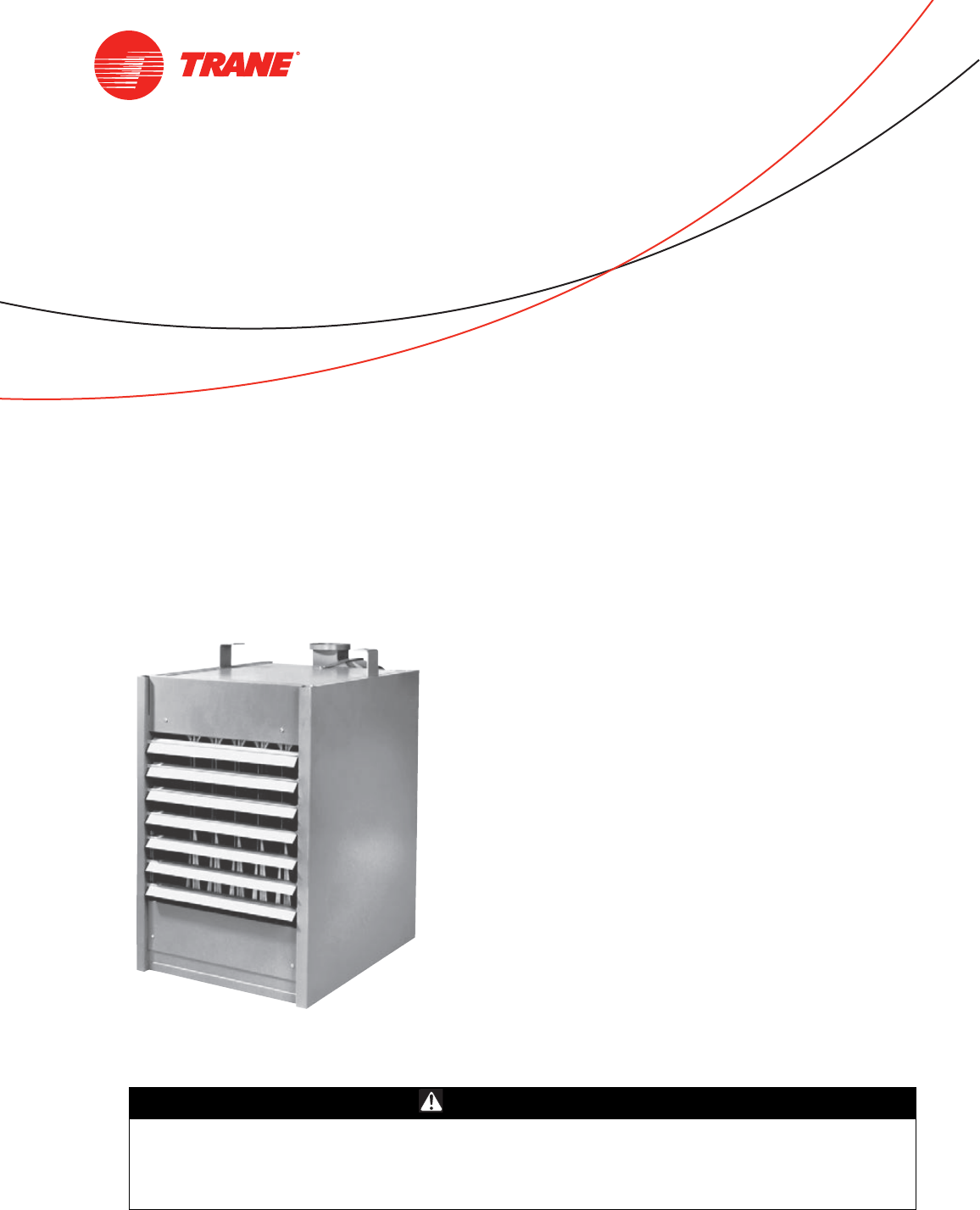
Gas Unit Heater
High Efficiency Propeller Fan
March 2012 GHND-SVX01C-EN
Installation, Operation,
and Maintenance
© 2012 Trane All rights reserved GHND-SVX01C-EN
Warnings, Cautions and Notices
Warnings, Cautions and Notices. Note that warnings,
cautions and notices appear at appropriate intervals
throughout this manual. Warnings are provide to alert
installing contractors to potential hazards that could result
in death or personal injury. Cautions are designed to alert
personnel to hazardous situations that could result in
personal injury, while notices indicate a situation that
could result in equipment or property-damage-only
accidents.
Your personal safety and the proper operation of this
machine depend upon the strict observance of these
precautions.
Read this manual thoroughly before operating or servicing
this unit.
Important
Environmental Concerns!
Scientific research has shown that certain man-made
chemicals can affect the earth’s naturally occurring
stratospheric ozone layer when released to the
atmosphere. In particular, several of the identified
chemicals that may affect the ozone layer are refrigerants
that contain Chlorine, Fluorine and Carbon (CFCs) and
those containing Hydrogen, Chlorine, Fluorine and
Carbon (HCFCs). Not all refrigerants containing these
compounds have the same potential impact to the
environment. Trane advocates the responsible handling of
all refrigerants-including industry replacements for CFCs
such as HCFCs and HFCs.
Responsible Refrigerant Practices!
Trane believes that responsible refrigerant practices are
important to the environment, our customers, and the air
conditioning industry. All technicians who handle
refrigerants must be certified. The Federal Clean Air Act
(Section 608) sets forth the requirements for handling,
reclaiming, recovering and recycling of certain
refrigerants and the equipment that is used in these
service procedures. In addition, some states or
municipalities may have additional requirements that
must also be adhered to for responsible management of
refrigerants. Know the applicable laws and follow them.
ATTENTION: READ THIS MANUAL AND ALL LABELS
ATTACHED TO THE UNIT CAREFULLY BEFORE
ATTEMPTING TO INSTALL, OPERATE OR SERVICE THESE
UNITS! CHECK UNIT DATA PLATE FOR TYPE OF GAS AND
ELECTRICAL SPECIFICATIONS AND MAKE CERTAIN THAT
THESE AGREE WITH THOSE AT POINT OF INSTALLATION.
RECORD THE UNIT MODEL AND SERIAL No.(s) IN THE
SPACE PROVIDED. RETAIN FOR FUTURE REFERENCE.
ATTE NT ION : Warnings, Cautions and Notices appear at
appropriate sections throughout this literature. Read
these carefully:
WARNING Indicates a potentially hazardous
situation which, if not avoided, could
result in death or serious injury.
CAUTIONsIndicates a potentially hazardous
situation which, if not avoided, could
result in minor or moderate injury. It
could also be used to alert against
unsafe practices.
NOTICE: Indicates a situation that could result in
equipment or property-damage only
WARNING
Proper Field Wiring and Grounding
Required!
All field wiring MUST be performed by qualified
personnel. Improperly installed and grounded field
wiring poses FIRE and ELECTROCUTION hazards. To
avoid these hazards, you MUST follow requirements for
field wiring installation and grounding as described in
NEC and your local/state electrical codes. Failure to
follow code could result in death or serious injury.
WARNING
Personal Protective Equipment (PPE)
Required!
Installing/servicing this unit could result in exposure to
electrical, mechanical and chemical hazards.
• Before installing/servicing this unit, technicians
MUST put on all Personal Protective Equipment (PPE)
recommended for the work being undertaken.
ALWAYS refer to appropriate MSDS sheets and OSHA
guidelines for proper PPE.
• When working with or around hazardous chemicals,
ALWAYS refer to the appropriate MSDS sheets and
OSHA guidelines for information on allowable
personal exposure levels, proper respiratory
protection and handling recommendations.
• If there is a risk of arc or flash, technicians MUST put
on all Personal Protective Equipment (PPE) in
accordance with NFPA 70E or other country-specific
requirements for arc flash protection, PRIOR to
servicing the unit.
Failure to follow recommendations could result in death
or serious injury.
Warnings, Cautions and Notices
GHND-SVX01C-EN 3
Trademarks
Trane and the Trane logo are trademarks of Trane in the
United States and other countries. All trademarks
referenced in this document are the trademarks of their
respective owners.
Dow Corning is a registered trademark of Dow Corning
Corporation.
WARNING
Hazardous Service Procedures!
The maintenance and troubleshooting procedures
recommended in this manual could result in exposure
to electrical, mechanical or other potential safety
hazards. Always refer to the safety warnings provided
throughout this manual concerning these procedures.
When possible, disconnect all electrical power
including remote disconnect and discharge all energy
storing devices such as capacitors before servicing.
Follow proper lockout/tagout procedures to ensure the
power can not be inadvertently energized. When
necessary to work with live electrical components,
have a qualified licensed electrician or other individual
who has been trained in handling live electrical
components perform these tasks. Failure to follow all of
the recommended safety warnings provided, could
result in death or serious injury.
WARNING
Overheating or Flooding Could Cause Fire
or Explosion!
Overheating or flooding (where any part of the unit
heater has been under water) could result in fire or
explosion. Should overheating occur, or the gas supply
fails to shut off, shut off the manual gas valve to the
unit heater before shutting off the electrical supply. Do
not use the unit heater if any part has been under
water. Immediately call a qualified service technician to
inspect the unit heater and replace any gas control
which has been underwater. Failure to follow these
recommendations could result in death or serious
injury.
WARNING
Hazardous Gases and Flammable
Vapors!
Exposure to hazardous gases from fuel substances
have been shown to cause cancer, birth defects or
other reproductive harm. Improper installation,
adjustment, alteration, service or use of this product
could cause flammable mixtures. To avoid hazardous
gases and flammable vapors follow proper
installation and set up of this product and all
warnings as provided in this manual. Failure to follow
all instructions could result in death or serious injury.
4GHND-SVX01C-EN
Introduction
For Your Safety
The use and storage of gasoline or other flammable
vapors and liquids in open containers in the vicinity
of this appliance is hazardous.
If you smell gas:
1. Open windows.
2. Do not touch electrical switches.
3. Extinguish any open flame.
4. Immediately call your gas supplier from a
neighbor’s phone. Follow the gas supplier’s
instructions.
Approved For Use in California
Installer’s Responsibility
Installer Please Note: This equipment has been test fired
and inspected. It has been shipped free from defects from
our factory. However, during shipment and installation,
problems such as loose wires, leaks, or loose fasteners
may occur. It is the installer’s responsibility to inspect and
correct any problems that may be found.
Receiving Instructions
Inspect shipment immediately when received to
determine if any damage has occurred to the unit during
shipment. After the unit has been uncrated, check for any
visible damage to the unit. If any damage is found, the
consignee should sign the bill of lading indicating such
damage and immediately file claim for damage with the
transportation company.
Important: It is the equipment owner’s responsibility to
provide any scaffolding or other apparatus
required to perform emergency service or
annual/periodic maintenance to this
equipment.
WARNING
Safety Alert!
You MUST follow all recommendations below. Failure
to do so could result in death or serious injury.
WARNING
Toxic Hazard!
Install, operate and maintain unit in accordance with
manufacturer’s instructions to avoid exposure to fuel
substances or substances from incomplete combustion
which could result in death or serious illness. The state
of California has determined that these substances may
cause cancer, birth defects, or other reproductive harm.

Table of Contents
GHND-SVX01C-EN 5
Warnings, Cautions and Notices . . . . . . . . . . 2
Model Number Descriptions . . . . . . . . . . . . . . 6
Indoor Gas Heating Units . . . . . . . . . . . . . . . 6
General Information . . . . . . . . . . . . . . . . . . . . . 7
Description . . . . . . . . . . . . . . . . . . . . . . . . . . . 7
General Safety Information . . . . . . . . . . . . . 7
Identification of Parts . . . . . . . . . . . . . . . . . . 8
Unit Dimensions and Weights . . . . . . . . . . . 10
Installation: Mechanical . . . . . . . . . . . . . . . . . 12
Air Distribution . . . . . . . . . . . . . . . . . . . . . 12
Clearances . . . . . . . . . . . . . . . . . . . . . . . . . 13
Nozzle Assembly . . . . . . . . . . . . . . . . . . . 14
Installation: Piping . . . . . . . . . . . . . . . . . . . . . . 16
Gas Supply Piping . . . . . . . . . . . . . . . . . . . . 16
Pipe Sizing . . . . . . . . . . . . . . . . . . . . . . . . 16
Pipe Installation . . . . . . . . . . . . . . . . . . . . . . 17
Installation: Venting . . . . . . . . . . . . . . . . . . . 18
Venting for Power Vented (Category III) Unit
Heaters . . . . . . . . . . . . . . . . . . . . . . . . . . . 18
Installation: Electrical . . . . . . . . . . . . . . . . . . . 24
Electrical Connections . . . . . . . . . . . . . . . . . 24
Thermostat Wiring and Location . . . . . . 24
Start-Up . . . . . . . . . . . . . . . . . . . . . . . . . . . . . . . 26
Operation . . . . . . . . . . . . . . . . . . . . . . . . . . . . 27
Power Vented Propeller Units with Intermit-
tent (Spark) Pilot Ignition . . . . . . . . . . . . . 27
Gas Equipment Start-Up . . . . . . . . . . . . . . . 32
Maintenance . . . . . . . . . . . . . . . . . . . . . . . . . . . 33
Periodic Service . . . . . . . . . . . . . . . . . . . . 33
Installation Instructions for Field Replace-
ment of Power Venter Motor . . . . . . . . . . 36
How to Order Replacement Parts . . . . . . 37
Diagnostics . . . . . . . . . . . . . . . . . . . . . . . . . . . . 38
Troubleshooting . . . . . . . . . . . . . . . . . . . . . . 38
Wiring Diagrams . . . . . . . . . . . . . . . . . . . . . . . 42

6 GHND-SVX01C-EN
Model Number Descriptions
Indoor Gas Heating
Units
Note: All units are AGA approved. For
CGA approved units, contact Air
Handling Product Support.
Digit 1 — Gas Heating
Equipment
G = Gas Heating Equipment
Digit 2 — Product Type
H = High Efficiency Propeller Fan
Unit Heater
Digit 3 — Fuel
N= Natural Gas
P=LP Gas (Propane)
Digit 4 — Development
Sequence
D = Fourth Generation
Digits 5, 6, 7 — Input Capacity
Single Furnace
Digit 8 — Main Power Supply
Digit 9 — Gas Control Option
D = Single-Stage, Intermittent Pilot
Ignition
E = Two-Stage, Intermittent Pilot
Ignition
H = Electronic Modulating with
Room
T-Stat, Intermittent Pilot Ignition
J = Electronic Modulating with
Duct-Stat, Intermittent Pilot
Ignition
L = Electronic Modulating with
External 4–20 mA Input
N = Electronic Modulating with
External 0–10 Vdc Input
T = Single Stage Direct Spark
Ignition
V = Two-Stage, Direct Spark Ignition
Digit 10 — Design Sequence
G = Seventh Design
Digit 11 — Heat Exchanger
Material
1 = Aluminized Steel
3 = #321 Stainless Steel
Digit 12 — Rooftop
Arrangements
0 = None (Indoor Unit)
Digit 13 — Rooftop Heating Unit
Motor Selection
0 = None (Indoor Unit and Rooftop
Duct Furnace)
Digit 14 — Rooftop Fan Section
0 = None (Indoor Unit and Rooftop
Duct Furnace)
Digit 15 — Miscellaneous
Options
0=None
A = #409 Stainless Steel Burners
B = Orifices For Elevation Above
2000 Feet (Specify Elevation)
C = #409 Stainless Steel Draft
Diverter
D = Summer-Winter Switch
E = Vertical Louvers
J = Totally Enclosed Motor
7 = OSHA Fan Guard
010 = 100 MBh 022 = 225 MBh
012 = 125 MBh 025 = 250 MBh
015 = 150 MBh 030 = 300 MBh
017 = 175 MBh 035 = 350 MBh
020 = 200 MBh 040 = 400 MBh
A = 115/60/1 D = 230/60/3
B = 230/60/1 E = 460/60/3
C = 208/60/3 F = 575/60/3
GHND-SVX01C-EN 7
General Information
Description
The Power Vented Gas Unit Heater is a factory assembled,
power vented, low static pressure type propeller fan
heater designed to be suspended within the space to be
heated. THESE HEATERS ARE NOT TO BE CONNECTED TO
DUCTWORK. The designs are certified by ETL as providing
a minimum of 80 percent thermal efficiency, and approved
for use in California. Do not alter these units in any
way. If you have any questions after reading this manual,
contact the manufacturer.
General Safety Information
Important: This product must be installed by a licensed
plumber or gas fitter when installed within
the Commonwealth of Massachusetts.
• Installation must be made in accordance with
local codes, or in absence of local codes with the
latest edition of ANSI Standard Z223.1 (N.F.P.A.
No. 54) National Fuel Gas Code.
All of the ANSI and NFPA Standards referred to
in these installation instructions are those that
were applicable at the time the design of this
appliance was certified. The ANSI Standards are
available from the American National Standards
Institute, INC.,11 West 42nd Street, New York,
NY., 10036 or www.ansi.org. The NFPA
Standards are available from the National Fire
Protection Association, Batterymarch Park,
Quincy, MA 02269. These unit heaters are
designed for use in airplane hangars when
installed in accordance with current ANSI/NFPA
No. 409 and in public garages when installed in
accordance with current NFPA No. 88A and
NFPA No. 88B.
If installed in Canada, the installation must
conform with local building codes, or in absence
of local building codes, with CSA-B149.1
“Installation Codes for Natural Gas Burning
Appliances and Equipment” or CSA-B149.2
“Installation Codes for Propane Gas Burning
Appliances and Equipment”. These unit heaters
have been designed and certified to comply with
CSA 2.6. Also see sections on installation in
“Aircraft Hangers,” p. 12 and “Public Garages,”
p. 12.
• Do not alter the unit heater in any way or damage
to the unit and/or severe personal injury or death
could occur!
• Turn off the gas supply and disconnect all
electric power, including remote disconnects
before servicing unit. Follow proper lockout/
tagout procedures to ensure the power can not
be inadvertently energized and the gas can not
be inadvertently turned on. Failure to turn off
gas or disconnect power before servicing could
result in death or serious injury.
• Follow installation instructions CAREFULLY to
avoid creating unsafe conditions. All wiring
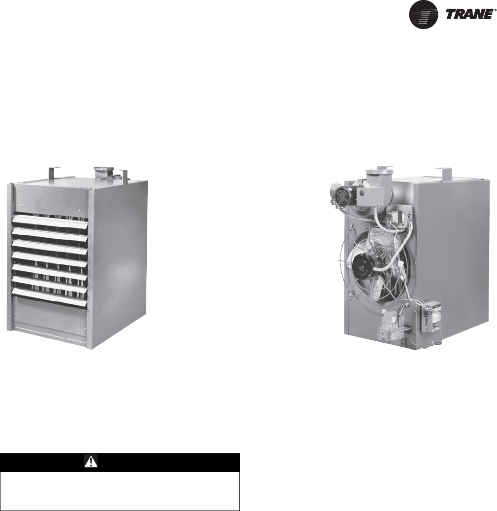
Figure 1. Power Vented Propeller Unit Heaters
Front view Rear view
See “Identification of Parts,” p. 8 for unit components.
WARNING
Safety Alert!
You MUST follow all recommendations below. Failure
to do so could result in death or serious injury.
General Information
8 GHND-SVX01C-EN
should be done and checked by a qualified
electrician, using copper wire only. All external
wiring must conform to applicable local codes
and to the latest edition of the National
Electrical Code ANSI/NFPA No. 70. In Canada, all
external wiring must conform to the Canadian
Electric Code, Part 1 CSA Standard C22.1.
• All gas connections should be made and leak-
tested by a suitably qualified individual, per
instructions in this manual. Also follow
procedures listed in “Gas Equipment Start-Up,”
p. 32.
• Use only the fuel for which the unit heater is
designed (see rating plate). Using LP gas in a
heater that requires natural gas, or vice versa,
will create the risk of gas leaks, carbon
monoxide poisoning and explosion.
Important: Do not attempt to convert the heater
for use with a fuel other than the one
intended. Such conversion is
dangerous, as it could create the risks
listed previously.
• Make certain that the power source conforms to
the electrical requirements of the heater.
• All field-installed wiring must be completed by
qualified personnel. All field-installed wiring
must comply with NEC and applicable local
codes. Failure to follow this instruction could
result in death or serious injuries.
• Special attention must be given to any
grounding information pertaining to this heater.
To prevent the risk of electrocution, the heater
must be securely and adequately grounded. This
should be accomplished by connecting a
grounded conductor between the service panel
and the heater. To ensure a proper ground, the
grounding means must be tested by a qualified
electrician.
• Do not insert fingers or foreign objects into the
heater or its air moving device. Do not block or
tamper with the heater in any manner while in
operation or just after it has been turned off, as
some parts may be hot enough to cause injury.
• This heater is intended for general heating
applications ONLY. It must NOT be used in
potentially dangerous locations such as
flammable, explosive, chemical-laden or wet
atmospheres.
• Do not attach ductwork to this product or use it
as a makeup air heater. Such usage voids the
warranty and will create unsafe operation.
• In cases in which property damage may result
from malfunction of the heater, a backup system
or a temperature sensitive alarm should be used.
• When connecting to existing gas lines be sure to
valve off the gas supply ahead of connection
point. To avoid explosion or possible fire, always
purge all residual gas from piping before cutting
into existing line or removing threaded fittings.
Failure to remove all gas vapors could result in
death or serious injury or equipment or property-
only-damage.
Unless otherwise specified, the following conversions
may be used for calculating SI unit measurements:
Identification of Parts
1 foot = 0.305 m 1 inch water column = 0.249 kPa
1 inch = 25.4 mm 1 meter/second = FPM ÷ 196.8
1 psig = 6.894 kPa 1 liter/second = CFM x 0.472
1 pound = 0.453 kg 1000 Btu per hour = 0.293 kW
1 gallon = 3.785 L 1000 Btu/Cu. Ft. = 37.5 MJ/m3
1 cubic foot = 0.028 m3
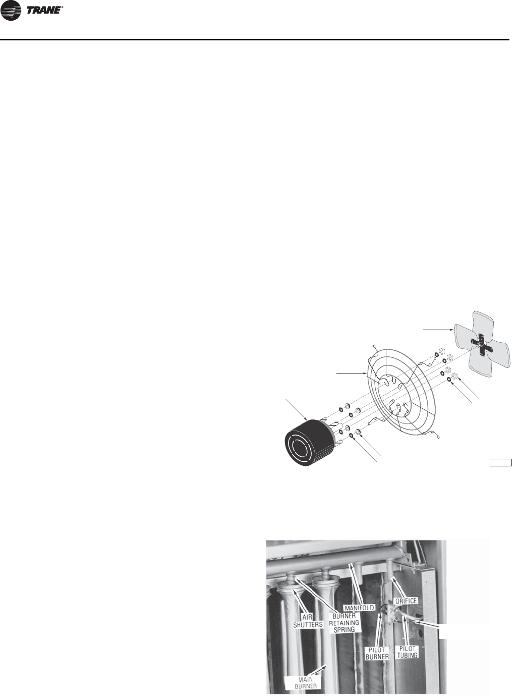
Figure 2. Propeller parts (115/1/60 motor, fan guard,
fan blade, hardware)
Figure 3. Burner assembly parts
D4430
Fan Guard
Fan Blade
Hardware
Hardware
Motor
ELECTRODE/SENSING
LEAD LOCATION
General Information
GHND-SVX01C-EN 9
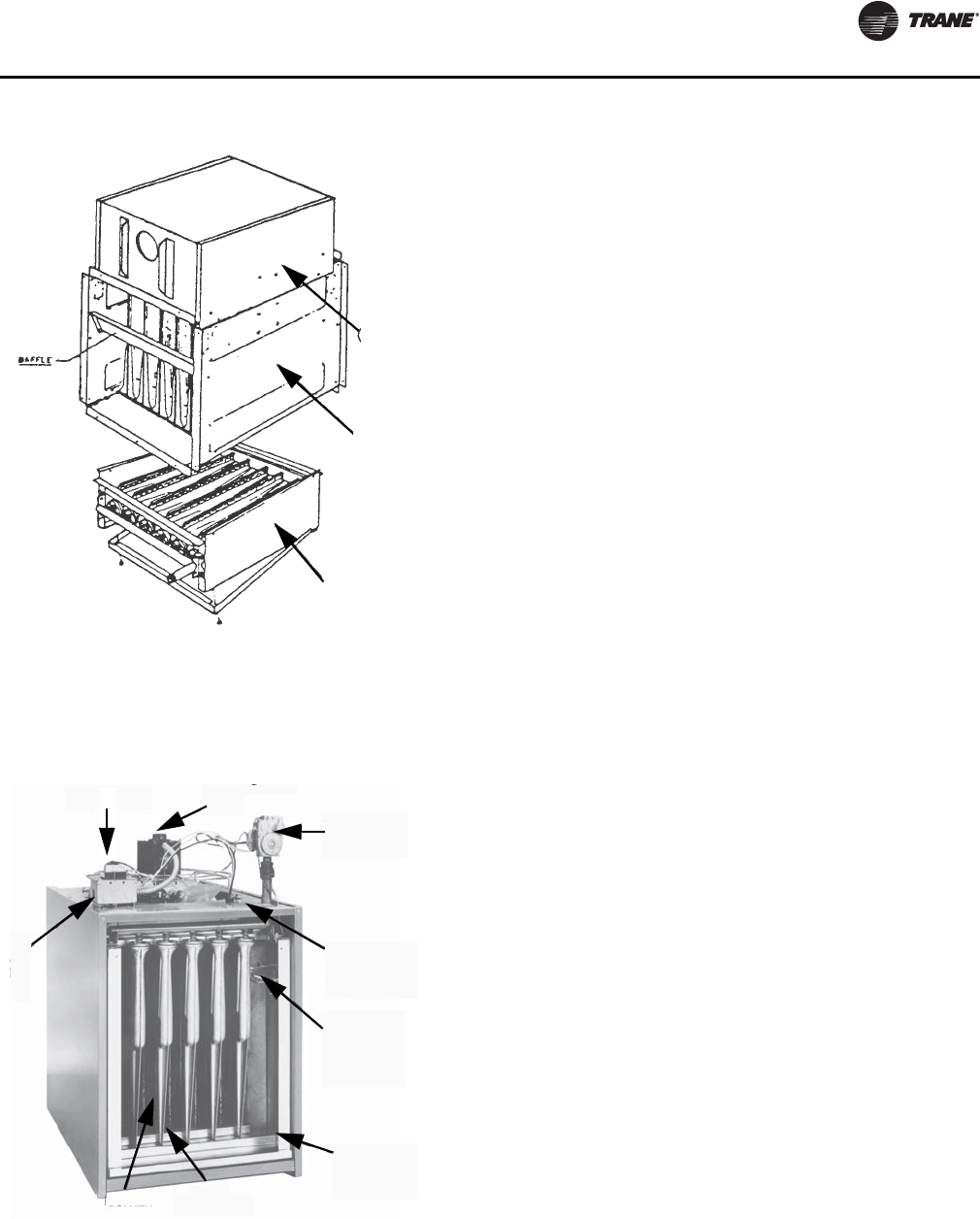
Figure 4. Internal furnace components
1. Flue Collector
2. Heat Exchanger
3. Burner Drawer
Figure 5. Component parts (bottom view)
1. Fan/Guard/Motor Assy.
2. “Packaged” Gas Valve
3. Pilot Observation Port
4. Pilot Burner Assembly Parts
5. Burner “Drawer”
6. Flame Carryover
7. Main Burner
8. Junction Box
9. Transformer
1
3
2
1
2
3
4
5
6
7
8
9
10 GHND-SVX01C-EN
Unit Dimensions and Weights
Table 1. Performance and dimensional data: Power Vented Propeller Unit Heater
Unit Size 100 125 150 175 200 225 250 300 350 400
PERFORMANCE DATA(a)
Input BTU/Hr 100,000 125,000 150,000 175,000 200,000 225,000 250,000 300,000 350,000 400,000
(kW) (29.3) (36.6) (43.9) (51.2) (58.6) (65.9) (73.2) (87.8) (102.5) (117.1)
Output BTU/Hr 80,000 100,000 120,000 140,000 160,000 180,000 200,000 240,000 280,000 320,000
(kW) (23.4) (29.3) (35.1) (41.0) (46.9) (52.7) (58.6) (70.3) (82.0) (93.7)
Thermal Efficiency %80808080808080808080
Free Air Delivery CFM cfm 1,480 1,650 2,200 2,530 2,640 2,700 3,100 4,400 5,000 5,300
(m3/s) (0.699) (0.779) (1.038) (1.194) (1.246) (1.274) (1.463) (2.077) (2.360) (2.502)
Air Temperature Rise °F 50 56 50 51 56 61 60 50 52 56
(°C) (28) (31) (28) (28) (31) (34) (33) (28) (29) (31)
Outlet Velocity fpm 775 910 1,045 1,070 1,010 950 980 1,100 1,150 1,050
(m/s) (3.94) (4.62) (5.31) (5.44) (5.13) (4.83) (4.98) (5.59) (5.84) (5.33)
Full Load Amps at 115V 5.2 7.2 7.8 9.2 9.2 9.2 9.2 12.5 15.0 15.0
MOTOR DATA:
Motor hp 1/20 1/10 1/4 1/3 1/3 1/3 1/3 1/4 1/3 1/3
(kW) (0.037) (0.075) (0.186) (0.249) (0.249) (0.249) (0.249) (0.186) (0.249) (0.249)
Type SP SP PSC PSC PSC PSC PSC PSC PSC PSC
RPM 1,050 1,050 1,140 1,140 1,140 1,140 1,140 1,140 1,140 1,140
Amps @ 115V 2.6 4.2 4.7 5.8 5.8 5.8 5.8 9.4 11.6 11.6
DIMENSIONAL DATA
“A” Height to Top of Unit in. 31-1/4 31-1/4 36-1/4 36-1/4 36-1/4 36-1/4 36-1/4 36-1/4 36-1/4 36-1/4
(mm) (794) (794) (921) (921) (921) (921) (921) (921) (921) (921)
“B” Width of Unit in. 17-7/8 20-5/8 20-5/8 23-3/8 26-1/8 28-7/8 31-5/8 37-1/8 42-5/8 48-1/8
(mm) (454) (524) (524) (594) (664) (733) (803) (943) (1083) (1222)
“C” Height to Top of Hanger in. 34-1/8 34-1/8 39-1/8 39-1/8 39-1/8 39-1/8 39-1/8 39-1/8 39-1/8 39-1/8
(mm) (867) (867) (994) (994) (994) (994) (994) (994) (994) (994)
“D” Depth to Rear of Housing in. 37-1/2 37-1/2 37-1/2 37-1/2 37-1/2 37-1/2 37-1/2 37-1/2 37-1/2 37-1/2
(mm) (952) (952) (952) (952) (952) (952) (952) (952) (952) (952)
“E” Hanging Distance Width in. 14-1/2 17-1/4 17-1/4 20 22-3/4 25-1/2 28-1/4 33-3/4 39-1/4 44-3/4
(mm) (368) (438) (438) (508) (578) (648) (718) (857) (997) (1137)
“F” Discharge Opening Width in. 15-3/8 18-1/8 18-1/8 20-7/8 23-5/8 26-3/8 29-1/8 34-5/8 40-1/8 45-5/8
(mm) (391) (460) (460) (530) (600) (670) (740) (879) (1019) (1159)
“G” Depth to Unit Side Jacket in. 26-3/4 26-3/4 26-3/4 26-3/4 26-3/4 26-3/4 26-3/4 26-3/4 26-3/4 26-3/4
(mm) (679) (679) (679) (679) (679) (679) (679) (679) (679) (679)
“H” Discharge Opening Heightin.18181818181818181818
(mm) (457) (457) (457) (457) (457) (457) (457) (457) (457) (457)
“J” to Centerline of Flue in. 5-7/8 7-1/4 7-1/4 8-5/8 10 11-1/4 12-3/4 15-1/2 18-1/4 21
(mm) (149) (184) (184) (219) (254) (286) (324) (394) (464) (533)
“K” Depth to Centerline of Fluein. 30-5/8 30-5/8 30-5/8 30-5/8 30-5/8 30-5/8 30-5/8 30-5/8 30-5/8 30-5/8
(mm) (778) (778) (778) (778) (778) (778) (778) (778) (778) (778)
“L” Hanger Location in. 16-1/4 16-3/4 16-3/8 16-3/8 16-3/8 16-3/4 16-3/4 16-3/4 16-3/4 16-3/4
(mm) (413) (425) (416) (416) (416) (425) (425) (425) (425) (425)
Flue Size Dia. in.*4444555666
(mm) (102) (102) (102) (102) (127) (127) (127) (152) (152) (152)
Fan Diameter in.14161618181818(2) 16(2) 18(2) 18
Gas Inlet-Natural Gas in. 100,000 125,000 150,000 175,000 200,000 225,000 250,000 300,000 350,000 400,000
Gas Inlet-LP Gas in. 1/2 1/2 1/2 1/2 1/2 1/2 or 3/4
Approx. Shipping Wt. lb 174 197 219 238 249 275 305 350 414 461
(kg) (79) (89) (99) (108) (113) (125) (138) (159) (188) (209)
Notes:
1. For installations in Canada, any references to deration at altitudes in excess of 2000 ft. (610m) are to be ignored. At altitudes of 2000 to 4500 ft.
(610m to 1372m), the unit must be derated to 90% of the normal altitude rating, and be so marked in accordance with the ETL certification.
2. Legend: SPH = SPLIT PHASE, CAP. START = CAPACITOR START
(a) Ratings shown are for unit installations at elevations between 0 and 2000 ft. (610 m). For unit installations in USA above 2000 ft. (610 m), the unit
input must be derated 4% for each 1000 ft. (305 m) above sea level; refer to local codes, or in absence of local codes, refer to the latest edition of the
National Gas Code, ANSI Standard Z223.1 (N.F.P.A. No. 54).
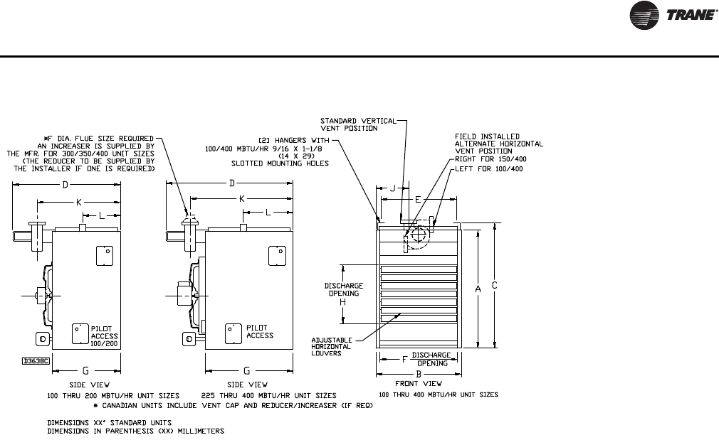
** Refer to corresponding ** in Figure 6, p. 11.
Unit Dimensions and Weights
GHND-SVX01C-EN 11
Figure 6. Dimensions, standard units
12 GHND-SVX01C-EN
Installation: Mechanical
Since the unit is equipped with an automatic gas ignition
system, the unit heaters must be installed such that the
gas ignition control system is not directly exposed to water
spray, rain, or dripping water.
Note: Location of unit heaters is related directly to the
selection of sizes (refer to Figure 7). Basic rules are
as follows:
Mounting Height. Unit heaters must be installed at a
minimum of 8 feet (2.4 m) above the floor, measured to the
bottom of the unit. At heights above 8 feet (2.4 m), less
efficient air distribution will result. Occasionally unit
heaters must be mounted at heights of 12 to 16 feet (3.7 to
4.9 m) in order to clear obstacles. When this is the case, it
is advisable to use centrifugal blower unit heaters.
Aircraft Hangers. Unit heaters must be installed in
aircraft hangars and public garages as follows: in aircraft
hangars, unit heaters must be at least 10 feet (3.0 m) above
the upper surface of wings or engine enclosures of the
highest aircraft to be stored in the hangar, and 8 feet
(2.4 m) above the floor in shops, offices and other sections
of the hangar where aircraft are not stored or housed.
Refer to current ANSI/NFPA No. 409, Aircraft Hangars. In
Canada, installation is suitable in aircraft hangars when
acceptable to the enforcing authorities.
Public Garages. In repair garages, unit heaters must be
located at least 8 feet (2.4 m) above the floor. Refer to the
latest edition of NFPA 88B, Repair Garages.
In parking structures, unit heaters must be installed so that
the burner flames are located a minimum of 18 inches
(457 mm) above the floor or protected by a partition not
less than 18 inches (457 mm) high. However, any unit
heater mounted in a parking structure less than 8 feet
(2.4 m) above the floor must be equipped with an OSHA
approved fan guard. Refer to the latest edition of
NFPA 88A, Parking Structures.
In Canada, installation must be in accordance with the
latest edition of CSAB149 “Installation Codes for Gas
Burning Appliances and Equipment.”
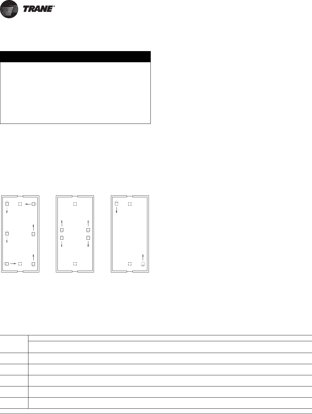
Air Distribution
Direct air towards areas of maximum heat loss. When
multiple heaters are involved, circulation of air around the
perimeter is recommended where heated air flows along
exposed walls. Satisfactory results can also be obtained
where multiple heaters are located toward the center of
the area with heated air directed toward the outside walls.
Be careful to avoid all obstacles and obstructions which
could impede the warm air distribution patterns. Heat
throw distances are presented in Table 2, p. 12 and
Figure 8.
NOTICE:
Equipment Damage!
Do not install unit heaters in corrosive or flammable
atmospheres! Premature failure of, or severe damage to
the unit could result! Avoid locations where extreme
drafts can affect burner operation. Unit heaters must
not be installed in locations where air for combustion
would contain chlorinated, halogenated or acidic
vapors. If located in such an environment, premature
failure of the unit could occur!
Figure 7. Heater location
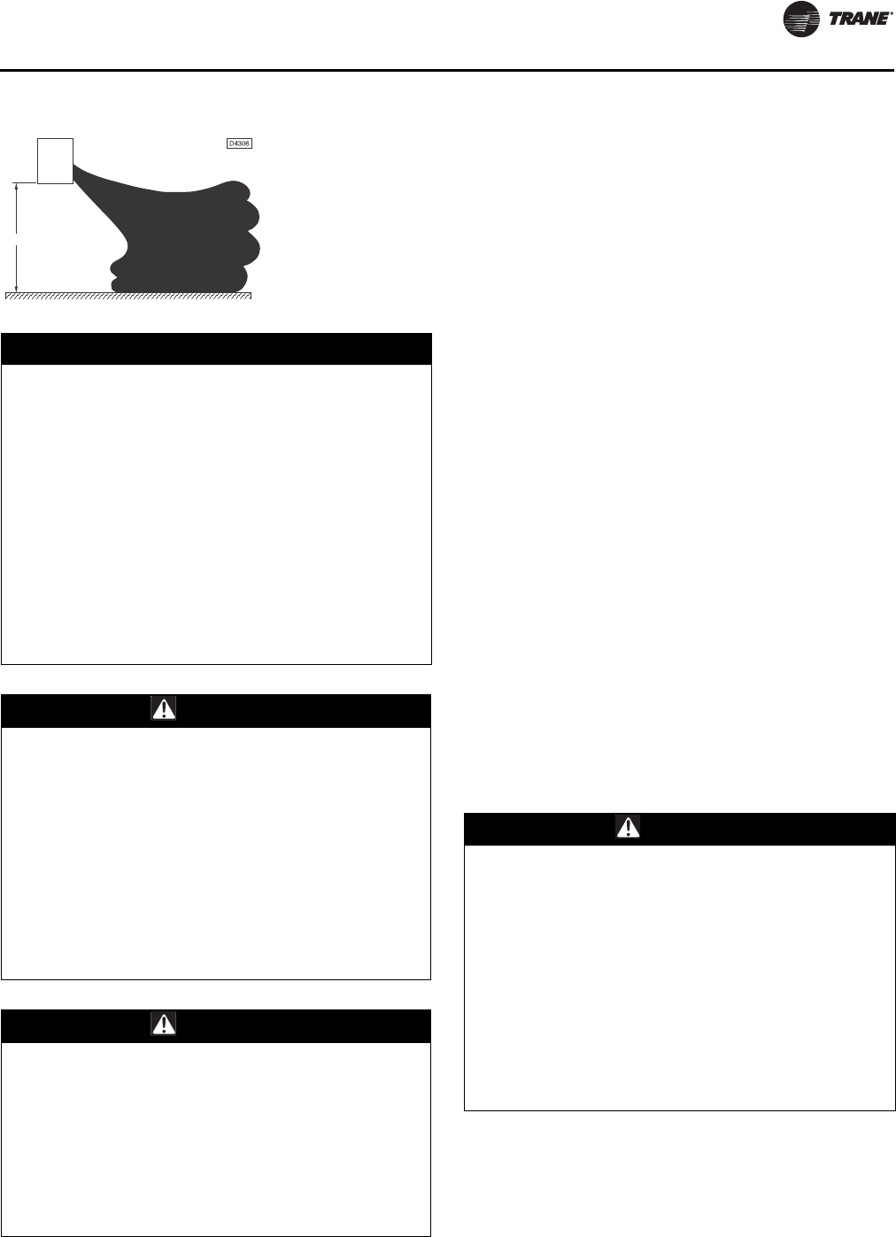
Table 2. Standard applications approximate heat throw distances (see Figure 8)
“H”(a) Unit Size Btu/h (kW)
ft. 100,000 125,000 150,000 175,000 200,000 225,000 250,000 300,000 350,000 400,000
(m) (29.3) (36.6) (43.9) (51.2) (58.6) (65.9) (73.2) (87.8) (102.5) (117.1)
8 60657075808590105110120
(2.4) (18.3) (19.8) (21.3) (22.9) (24.4) (25.9) (27.4) (32.0) (33.5) (36.6)
10 54 56 60 64 68 72 78 90 95 100
(3.0) (16.5) (17.1) (18.3) (19.5) (20.7) (21.9) (23.8) (27.4) (29.0) (30.5)
12 44 46 49 57 61 65 68 80 84 90
(3.7) (13.4) (14.0) (20.7) (17.4) (18.6) (19.8) (20.7) (24.4) (25.6) (27.4)
15 NR NR 45 49 52 56 60 70 74 80
(4.6) (22.6) (14.9) (15.8) (17.1) (18.3) (21.3) (22.6) (24.4)
20 NR NR NR NR 46 50 54 63 66 70
(6.1) (14.0) (15.2) (16.5) (19.2) (20.1) (21.3)
Note: NR = Not recommended.
(a) H = Distance from floor to bottom of the unit.
Installation: Mechanical
GHND-SVX01C-EN 13
Air for Combustion. The unit heater shall be installed in
a location in which the facilities for ventilation permit
satisfactory combustion of gas, proper venting, and the
maintenance of ambient temperature at safe limits under
normal conditions of use. The unit heater shall be located
in such a manner as not to interfere with proper circulation
of air within the confined space. When buildings are so
tight that normal infiltration does not meet air
requirements, outside air shall be introduced per Sections
1.3.4.2 and 1.3.4.3 of ANSI Z223.1 for combustion
requirements. A permanent opening or openings having a
total free area of not less than one square inch per
5,000 Btu/h (1.5 Kw) of total input rating of all appliances
within the space shall be provided.
Note: Unit heater sizing should be based on heat loss
calculations where the unit heater output equals or
exceeds heat loss. Heater output is approximately
80 percent of input Btu/hr rating.
Clearances
Each gas unit heater shall be located with respect to
building construction and other equipment so as to permit
access to the Unit Heater. Clearance between walls and the
vertical sides of the Unit Heater shall be no less than
18 inches (457 mm). A minimum clearance of 6 inches
(152 mm) must be maintained between the top of the Unit
Heater and the ceiling. The bottom of the Unit Heater must
be no less than 12 inches (305 mm) from any combustible.
The distance between the flue collector and any
combustible must be no less than 6 inches (152 mm). Also
see “Air for Combustion,” p. 13 and “Venting for Power
Vented (Category III) Unit Heaters,” p. 18.
Note: Increasing the clearance distances may be
necessary if there is a possibility of distortion or
discoloration of adjacent materials.
Figure 8. Heat throw distances
NOTICE:
Maintain Minimum Thermostat Setting!
Unit heaters should not be installed to maintain low
temperatures and/or freeze protection of buildings. A
minimum of 50°F (10°C) thermostat setting must be
maintained. If unit heaters are operated to maintain
lower than 50°F (10°C), hot flue gases are cooled inside
the heat exchanger to a point where water vapor (a flue
gas by-product) condenses onto the heat exchanger
walls. The result is a mildly corrosive acid that
prematurely corrodes the aluminized heat exchanger
and can actually drip water down from the unit heater
onto the floor surface. Additional unit heaters should
be installed if a minimum 50°F (10°C) thermostat
setting cannot be maintained. Failure to follow these
recommendations could result in equipment or
property damage.
WARNING
Overheating or Flooding Could Cause Fire
or Explosion!
Overheating or flooding (where any part of the unit
heater has been under water) could result in fire or
explosion. Should overheating occur, or the gas supply
fails to shut off, shut off the manual gas valve to the
unit heater before shutting off the electrical supply. Do
not use the unit heater if any part has been under
water. Immediately call a qualified service technician to
inspect the unit heater and replace any gas control
which has been underwater. Failure to follow these
recommendations could result in death or serious
injury.
WARNING
Hazardous Gases and Flammable Vapors!
Exposure to hazardous gases from fuel substances
have been shown to cause cancer, birth defects or other
reproductive harm. Improper installation, adjustment,
alteration, service or use of this product could cause
flammable mixtures. To avoid hazardous gases and
flammable vapors follow proper installation and set up
of this product and all warnings as provided in this
manual. Failure to follow all instructions could result in
death or serious injury.
“H”
Unit
Heater
Floor Line
WARNING
Heavy Objects!
Make certain that the lifting methods used to lift the
heater and the method of suspension used in the field
installation of the heater are capable of uniformly
supporting the weight of the heater at all times. Make
certain that the structure to which the heater is
mounted is capable of supporting its weight. Under no
circumstances must the gas lines, the venting system
or the electrical conduit be used to support the heater;
or should any other objects (i.e. ladder, person) lean
against the heater, gas lines, venting system or the
electrical conduit for support. Failure to follow
recommendations could result in death or serious
injury.
Installation: Mechanical
14 GHND-SVX01C-EN
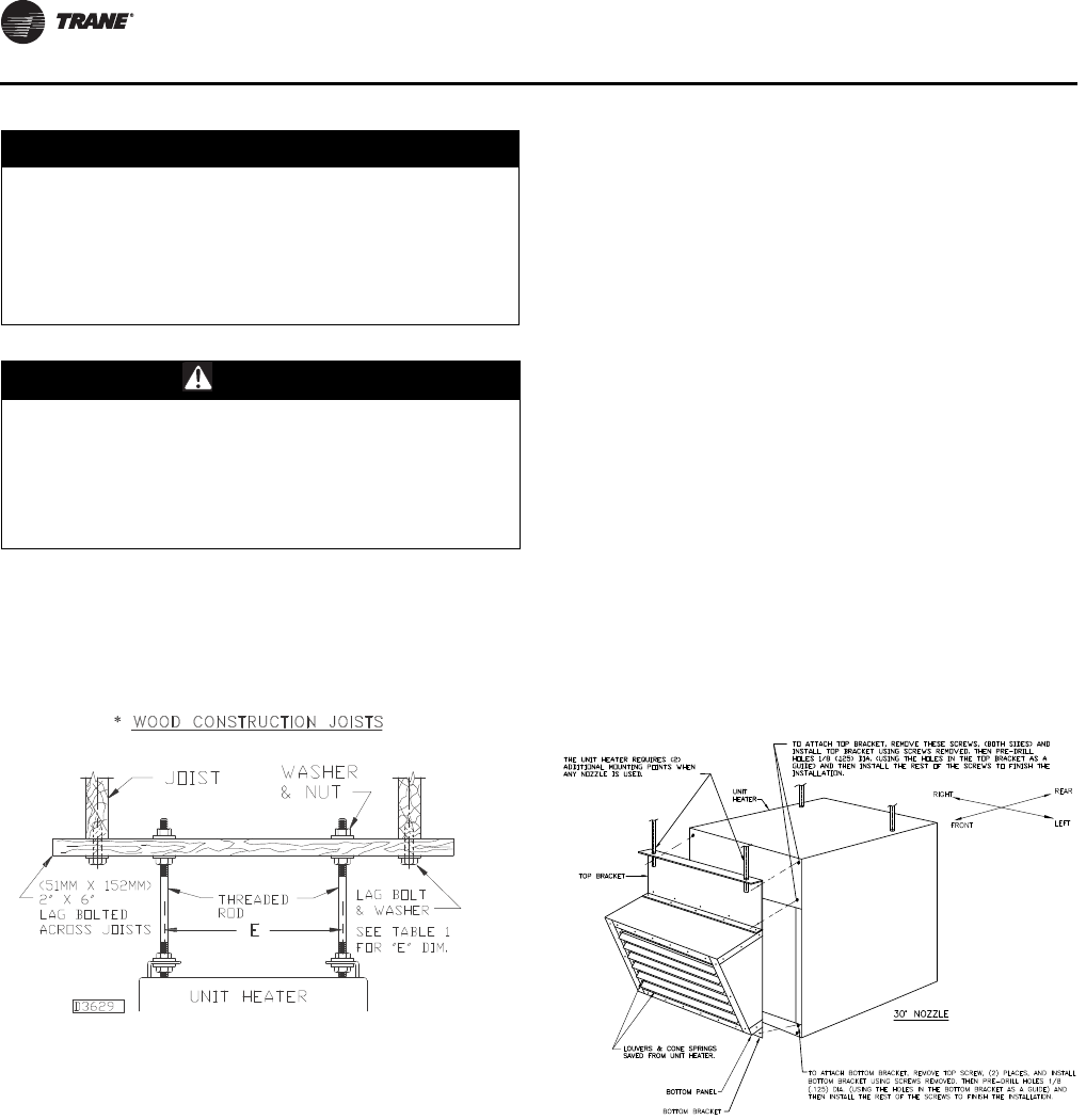
Note: Refer to Figure 1, p. 7 through Figure 9, p. 14, and
dimensional data per Table 1, p. 10 for suspension
of units.
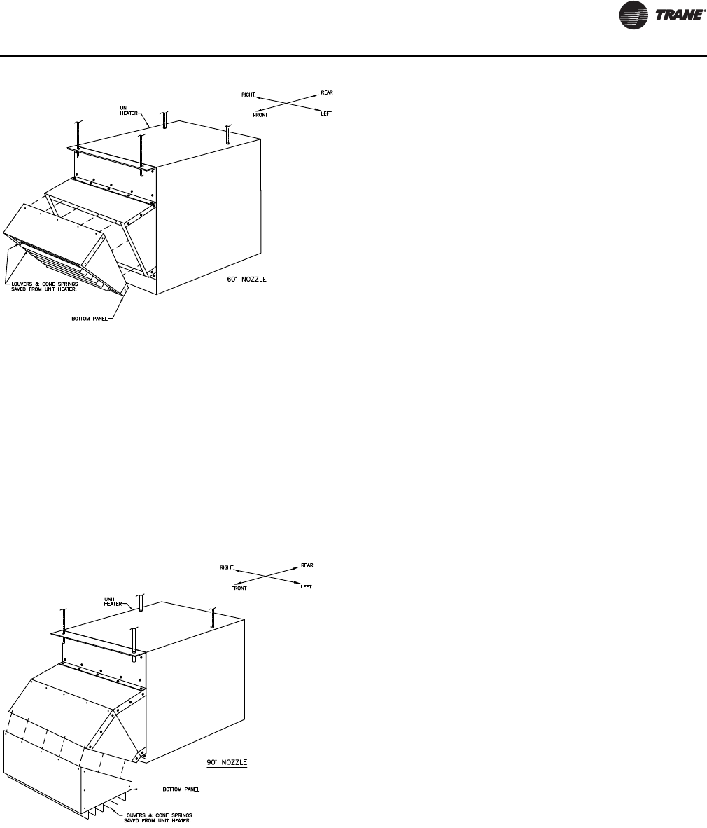
Nozzle Assembly
Use the following procedure for assembling the 30-, 60-, or
90-degree nozzle assembly to your unit heater.
1. Remove the louvers and the cone springs from the unit
heater.
2. Remove the four (4) screws from the upper section of
the front of the unit heater and use these same screws
to temporarily attach the top bracket
(P/N 252-07948-00X).
a. Using the holes in the top bracket as a guide, pre-
drill a 1/8” (0.125”) hole at each location across the
front panel of the unit heater.
b. Using the enclosed screws, permanently attach the
top bracket.
3. Remove the upper two (2) screws from the lower
section on the front of the unit heater. Repeat the
procedure described in Step 2 using the bottom
bracket (P/N 252-07949-00X).
4. Using the sixteen (16) 5/16-12 x 1/2 screws, attach the
left and right side panel (P/N 251-07944 and 251-07946)
to the unit heater using the holes to which the louvers
were attached.
5. Using the enclosed #8-18 x 1/2 screws and with the top
panel oriented such that the side with the larger holes
is facing the unit heater, attach the top panel
(P/N 251-07942-00X) to the top bracket and the two (2)
side panels.
Note: The top panel must be attached so that the side
with the larger holes is facing the unit heater;
this is a requirement for later steps in this
installation procedure.
6. Using the enclosed #8-18 x 1/2 screws and with the
bottom panel oriented such that the side with the larger
holes is facing the unit heater, attach the bottom panel
(P/N 251-07943-00X) to the bottom bracket and the two
(2) side panels.
Note: The bottom panel must be attached so that the
side with the larger holes is facing the unit
heater; this is a requirement for later steps in
this installation procedure.
7. For 30-degree nozzle assemblies: Go to Step 10.
8. For 60- and 90-degree nozzle assemblies: Using the
enclosed #8-18 x 1/2 screws and with the top and
bottom panels oriented such that the sides with the
larger holes are facing the unit heater, create a
sub-assembly by attaching the top panel
(P/N 251-07942-00X) and the bottom panel
(P/N 251-07943-00X) to the left side panel
(P/N 251-07945) and to the right side panel
(P/N 251-07947).
Note: The top and bottom panels must be attached so
that the sides with the larger holes are facing
the unit heater; this makes the assembly easier.
NOTICE:
Equipment Damage!
Unit heaters must be hung level from side to side and
from front to back, see Figure 1, p. 7 and Figure 6, p. 11
through Figure 9, p. 14. Failure to do so could result in
poor performance and/or premature failure of the unit.
WARNING
Heavy Objects!
Ensure that all hardware used in the suspension of each
unit heater is capable of supporting the unit weight.
Failure to do so could result in unit falling off its
mounting location, which could result in death or
serious injury.
Figure 9. Heater mounting 100/400 MBtu unit sizes
Installation: Mechanical
GHND-SVX01C-EN 15
Note: For 90-degree nozzle assemblies, repeat Step 8
to create a second sub-assembly.
9. For 60- and 90-degree nozzle assemblies: Using the
enclosed #8-18 x 1/2 screws, attach the sub-assembly
created in Step 8 to the 30-degree assembly installed to
the unit (in Step 1 through Step 6 of this procedure).
Attach the corresponding panels (i.e., top panel to top
panel, right side panel to right side panel, etc).
Note: For 90-degree nozzle assemblies, install the
second sub-assembly by attaching it to the first
sub-assembly. Attach the corresponding panels
(i.e., top panel to top panel, right side panel to
right side panel, etc).
10. Install the louvers and cone springs.
16 GHND-SVX01C-EN
Installation: Piping
Gas Supply Piping
Pipe Sizing
To provide adequate gas pressure at the gas unit heater,
size the gas piping as follows:
1. Find the ft3/hr by using the following formula:
2. Refer to Ta b l e 3, p. 17. Match “Length of Pipe” with
appropriate “Gas Input - Ft3/Hr” value. This value can
then be matched to the pipe size at the left of the table.
Example: It is determined that a 67 foot (20.4 m) run of
gas pipe is required to connect a 200 MBtu gas unit
heater to a 1,000 Btu/ft3 (0.29 kW) natural gas supply.
Using Table 3, p. 17, a 1-inch pipe is needed.
Notes:
•See “General Safety Information,” p. 7 for English/SI
(metric) unit conversion factors.
•If more than one gas unit heater is to be served by the
same piping arrangement, the total cubic feet per hour
input and length of pipe must be considered.
•If the gas unit heater is to be fired with LP gas, consult
the local LP gas dealer for pipe size information.
Before any connection is made to an existing line
supplying other gas appliances, contact the local gas
company to make certain that the existing line is of
adequate size to handle the combined load.
WARNING
Flammable Vapors!
When connecting to existing gas lines be sure to valve
off the gas supply ahead of connection point. To avoid
explosion or possible fire, always purge all residual gas
from piping before cutting into existing line or
removing threaded fittings. Failure to remove all gas
vapors could result in death or serious injury or
equipment or property-only damage.
ft3/hr = Input
Btu per ft3
200,000 Btu/hr = 200 ft3/hr
1,000 Btu/ft3
WARNING
Hazard of Explosion and Fire!
Heater installation for use with propane (LP gas) must
be made by a qualified LP Gas Dealer or LP Gas Installer
to ensure that all appropriate codes, installation
procedures, and precautions have been followed.
Failure to follow these instructions could result in death
or serious injury.
Installation: Piping
GHND-SVX01C-EN 17
Pipe Installation
1. Install the gas piping in accordance with applicable
local codes.
2. Check gas supply pressure. Each unit heater must be
connected to a gas supply capable of supplying its full
rated capacity as specified in Tab l e 4, p. 18. A field LP
tank regulator must be used to limit the supply
pressure to maximum of 14 in. wc (3.5 kPa). All piping
should be sized in accordance with the latest edition of
ANSI Standard Z223.1 National Fuel Gas Code; in
Canada, according to CSA-B149. See Ta b l e 1, p. 10,
Ta b l e 3, p. 17, and Ta b l e 4, p. 18 for correct gas supply
piping size.
If gas pressure is excessive on natural gas applications,
install a pressure regulating valve in the line upstream
from the main shutoff valve.
3. To prevent the mixing of moisture with gas, run the
take-off piping from the top, or side, of the main.
4. Standard gas duct furnaces, optional two-stage units,
and hydraulic modulating units are supplied with a
combination valve which includes:
a. Manual “A” valve
b. Manual “B” valve
c. Solenoid valve
d. Pilot safety
e. Pressure regulator
Table 3. Gas pipe size(a)
Nominal
Iron Pipe
Size, in.
Internal
Diameter,
in. (mm)
Length of Pipe, ft (m)
10 20 30 40 50 60 70 80 90 100 125 150 175 200
(3.0) (6.1) (9.1) (12.2) (15.2) (18.3) (21.3) (24.4) (27.4) (30.5) (38.1) (45.7) (53.3) (61.0)
1/2 0.622 175 120 97 82 73 66 61 57 53 50 44 40 37 35
(16) (4.96) (3.40) (2.75) (2.32) (2.07) (1.87) (1.73) (1.61) (1.50) (1.42) (1.25) (1.13) (1.05) (0.99)
3/4 0.824 360 250 200 170 151 138 125 118 110 103 93 84 77 72
(21) (10.2) (7.08) (5.66) (4.81) (4.28) (3.91) (3.54) (3.34) (3.11) (2.92) (2.63) (2.38) (2.18) (2.04)
1 1.049 680 465 375 320 285 260 240 220 205 195 175 160 145 135
(27) (19.3) (13.2) (10.6) (9.06) (8.07) (7.36) (6.80) (6.23) (5.80) (5.52) (4.96) (4.53) (4.11) (3.82)
1-1/4 1.380 1400 950 770 660 580 530 490 460 430 400 360 325 300 280
(35) (39.6) (26.9) (21.8) (18.7) (16.4) (15.0) (13.9) (13.0) (12.2) (11.3) (10.2) (9.20) (8.50) (7.93)
1-1/2 1.610 2100 1460 1180 990 900 810 750 690 650 620 550 500 460 430
(41) (59.5) (41.3) (33.4) (28.0) (25.5) (22.9) (21.2) (19.5) (18.4) (17.6) (15.6) (14.2) (13.0) (12.2)
2 2.067 3950 2750 2200 1900 1680 1520 1400 1300 1220 1150 1020 950 850 800
(53) (112) (77.9) (62.3) (53.8) (47.6) (43.0) (39.6) (36.8) (34.5) (32.6) (28.9) (26.9) (24.1) (22.7)
2-1/2 2.469 6300 4350 3520 3000 2650 2400 2250 2050 1950 1850 1650 1500 1370 1280
(63) (178) (123) (99.7) (85.0) (75.0) (68.0) (63.7) (58.0) (55.2) (52.4) (46.7) (42.5) (38.8) (36.2)
3 3.068 11000 7700 6250 5300 4750 4300 3900 3700 3450 3250 2950 2650 2450 2280
(78) (311) (218) (177) (150) (135) (122) (110) (105) (97.7) (92.0) (83.5) (75.0) (69.4) (64.6)
4 4.026 23000 15800 12800 10900 9700 8800 8100 7500 7200 6700 6000 5500 5000 4600
(102) (651) (447) (362) (309) (275) (249) (229) (212) (204) (190) (170) (156) (142) (130)
Notes:
1. Determine the required ft3/h by dividing the rated heater input by 1000. For SI / Metric measurements: Convert unit Btu/h to kilowatts. Multiply the
unit input (kW) by 0.0965 to determine m3/h.
2. FOR NATURAL GAS: Select the pipe size directly from the table.
3. FOR PROPANE GAS: Multiply the ft3/h (m3/h) value by 0.633; then use the table.
4. Refer to the metric conversion factors listed in “General Safety Information,” p. 7 for more SI unit measurements/conversions.
(a)Maximum capacity of pipe in cubic feet of gas per hour (cubic meters per hour) for gas pressures of 0.5 psig (3.5 kPa) or less, and a pressure drop of
0.5 inch water column (124.4 Pa) (based on a 0.60 specific gravity gas).
WARNING
Hazard of Explosion!
Adequately support the piping to prevent strain on the
gas manifold and controls. To prevent explosion, fire, or
gas leaks, support piping so that piping does not sag or
put pressure on the burners internal to the unit. Failure
to follow these recommendations could result in death
or serious injury or equipment or property-only-
damage.
Installation: Piping
18 GHND-SVX01C-EN
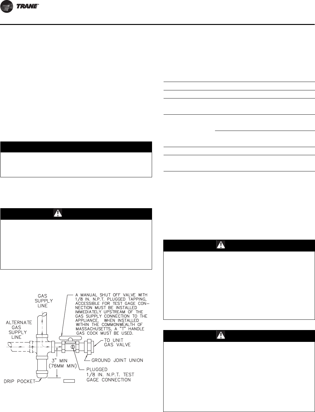
Pipe directly in to combination valve (see Figure 10,
p. 18).
5. A 1/8 in. N.P.T. plugged tapping, accessible for test
gauge connection, must be installed immediately
upstream of the gas supply connection to the
appliance.
6. Provide a drip leg in the gas piping near the gas unit
heater. A ground joint union and a manual gas shutoff
valve should be installed ahead of the unit heater
controls to permit servicing. The manual main shutoff
valve must be located external to the jacket (see
Figure 10, p. 18).
7. Make certain that all connections have been
adequately doped and tightened.
Note: Use pipe joint sealant resistant to the action of
liquefied petroleum gases regardless of gas
conducted.
The appliance and its individual shutoff valve must be
disconnected from the gas supply piping system during
any pressure testing of that system at test pressures in
excess of 1/2 psig (3.5 kPa).
The appliance must be isolated from the gas supply piping
system by closing its individual manual shutoff valve
during any pressure testing of the gas supply piping
system at test pressures equal to or less than 1/2 psig
(3.5 kPa).
Installation: Venting
Venting for Power Vented (Category III)
Unit Heaters
All unit heaters must be vented!
All venting installations shall be in accordance with the
latest edition of Part 7, venting of Equipment of the
National Fuel Gas Code, ANSI Z223.1, or applicable
NOTICE:
Overtightening!
Do not overtighten the inlet gas piping into the valve.
This may cause stresses that could crack the valve!
WARNING
Hazard of Explosion!
Never use an open flame to detect gas leaks. Explosive
conditions may occur. Use a leak test solution or other
approved methods for leak testing. Failure to follow
recommended safe leak test procedures could result in
death or serious injury or equipment or property-only-
damage.
Figure 10. Pipe installation, standard controls
D 3 6 31 C
Table 4. Gas piping requirements
Gas Type Natural Gas Propane (LP) Gas
Single Stage Gas Piping Requirements(a)
(a)For single stage applications only, at normal altitudes.
Manifold Pressure 3.5 in. wc 10.0 in. wc
(0.9 kPa) (2.5 kPa)
Supply Inlet Pressure 14.0 in. wc Max. 14.0 in. wc Max.
(3.5 kPa) (3.5 kPa)
5.0 in wc Min. 11.0 in wc Min.
(1.2 kPa) (2.7 kPa)
Two Stage Gas Piping Requirements(b)
(b)For two stage applications only, at normal altitudes.
Supply Inlet Pressure 6.5 in. wc Min. 11.5 in. wc Min.
(1.6 kPa) (2.9 kPa)
WARNING
Carbon Monoxide!
Your venting system must not be blocked by any snow,
snow drifts, or any foreign matter. Inspect your venting
system to ensure adequate ventilation exists at all
times! A blocked venting system could result in carbon
monoxide poisoning. Symptoms of such condition
include grogginess, lethargy, inappropriate tiredness,
or flu-like symptoms. Failure to follow these
recommendations could result in death or serious
injury.
WARNING
Risk of Fire and Carbon Monoxide
Poisoning with Improper Piping!
Never use a pipe of a diameter other than that specified
in Table 1, p. 10! To prevent pipe from melting and
introducing exhaust fumes into the air supply, never
use PVC, ABS or any other non-metallic pipe for
venting! To prevent fan restriction, an elbow should
never be attached directly to the venter. Failure to
follow recommendations could result in death or
serious injury or equipment damage.
Installation: Piping
GHND-SVX01C-EN 19
provisions of local building codes for natural or power
vented units.
Power vented units are designed to be used with single
wall vent pipe utilizing horizontal or vertical venting
arrangements (see Figure 16, p. 23 through Figure 18).
These arrangements may terminate external to the
building using either a single wall or double wall vent. See
Figure 11, p. 20 through Figure 18, p. 23 for special
installation requirements regarding these venting
conditions.
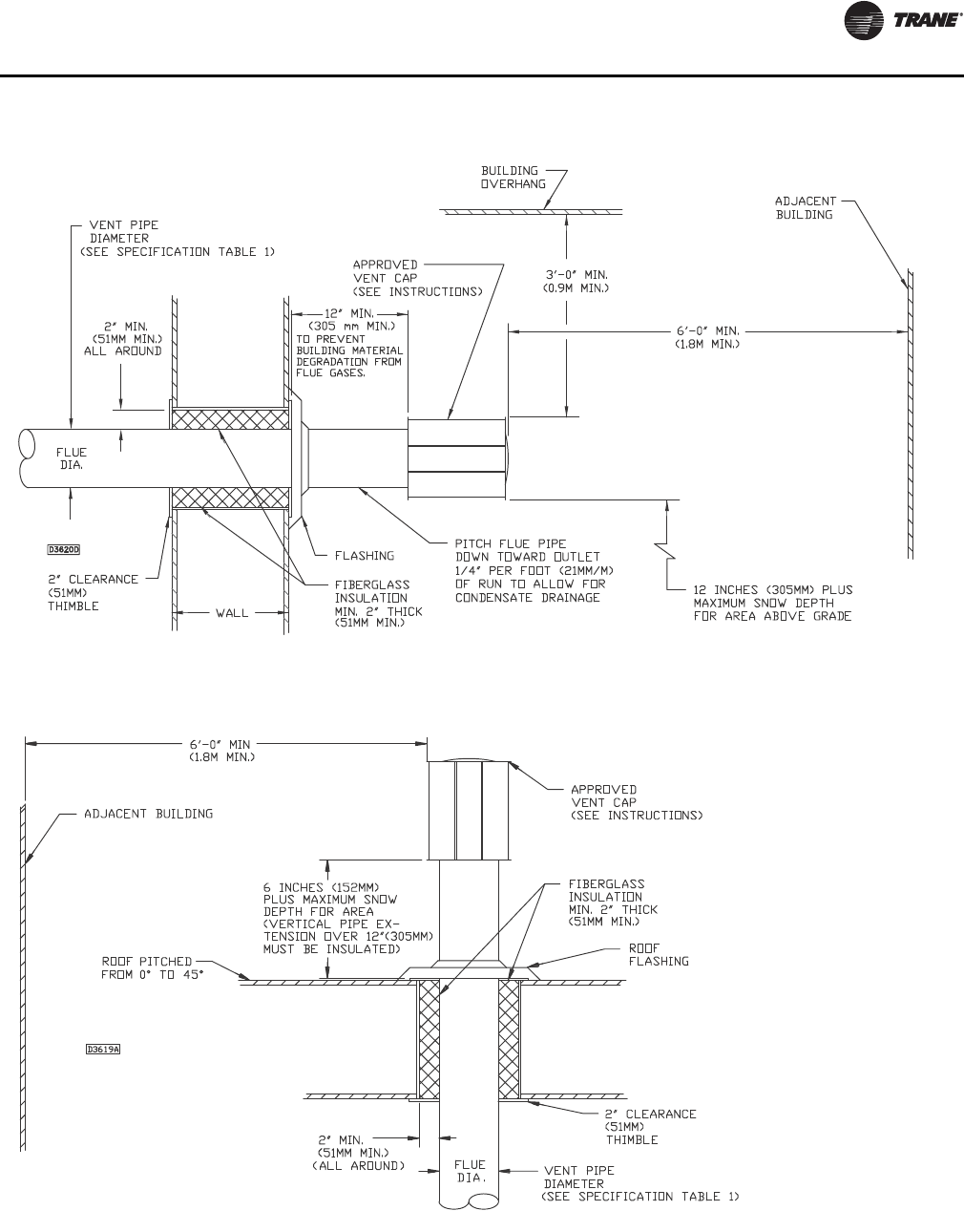
If double wall venting (other than Type B; see preceding
warning) is used, components which are UL Listed and
approved for Category III positive pressure venting
systems MUST be used.
A Briedart Type L, Field Starkap or an equivalent vent cap
must be supplied by the customer for each power vented
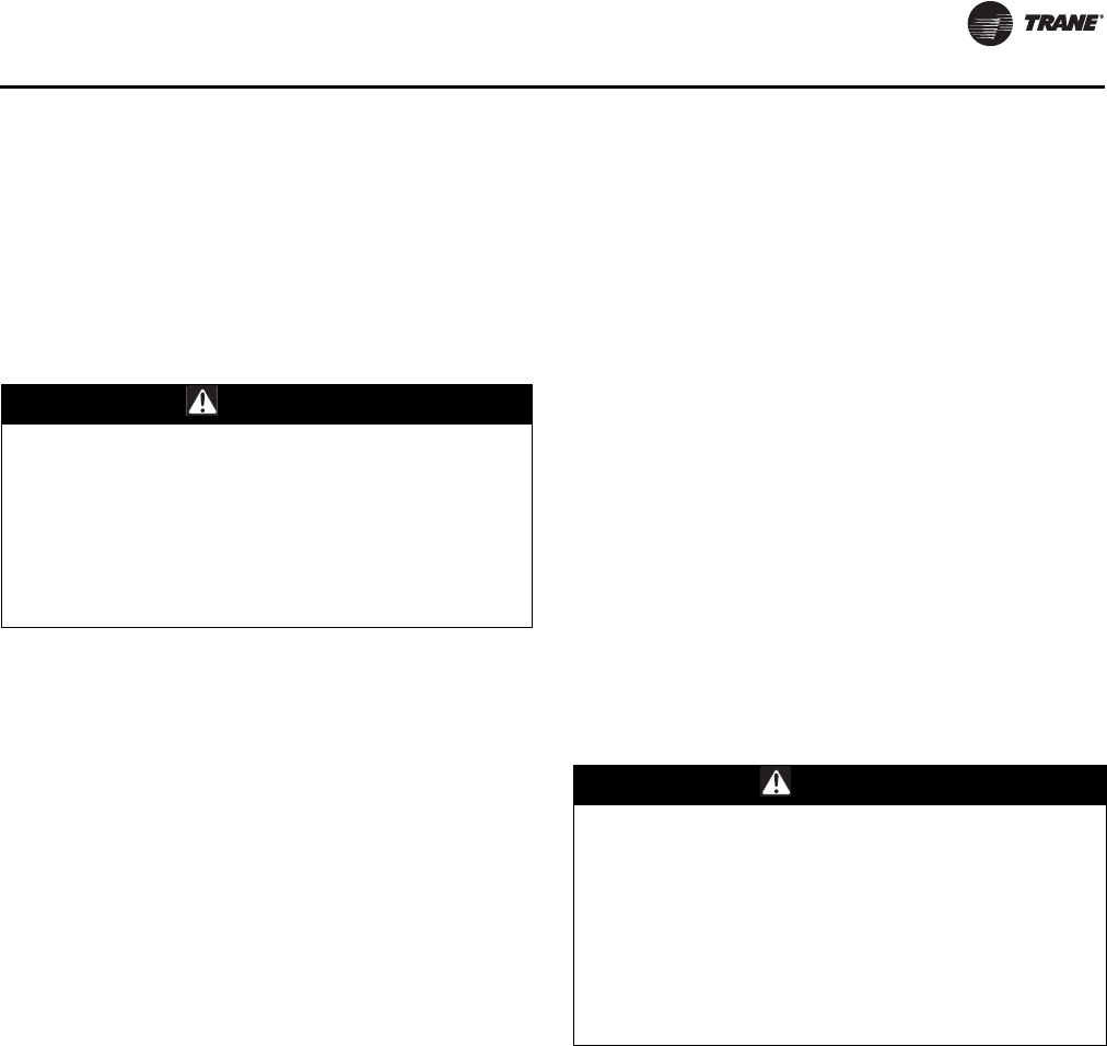
unit. The vent pipe diameter MUST be as specified in
Tab l e 1 , p. 10 (“D” Dia. Flue Opening). A reducer must be
field installed for 100 through 175 MBh Unit Sizes. All 300
through 400 MBh Unit sizes are factory equipped with the
required flue increaser. Refer to Figure 11, p. 20 through
Figure 15, p. 22 for additional requirements.
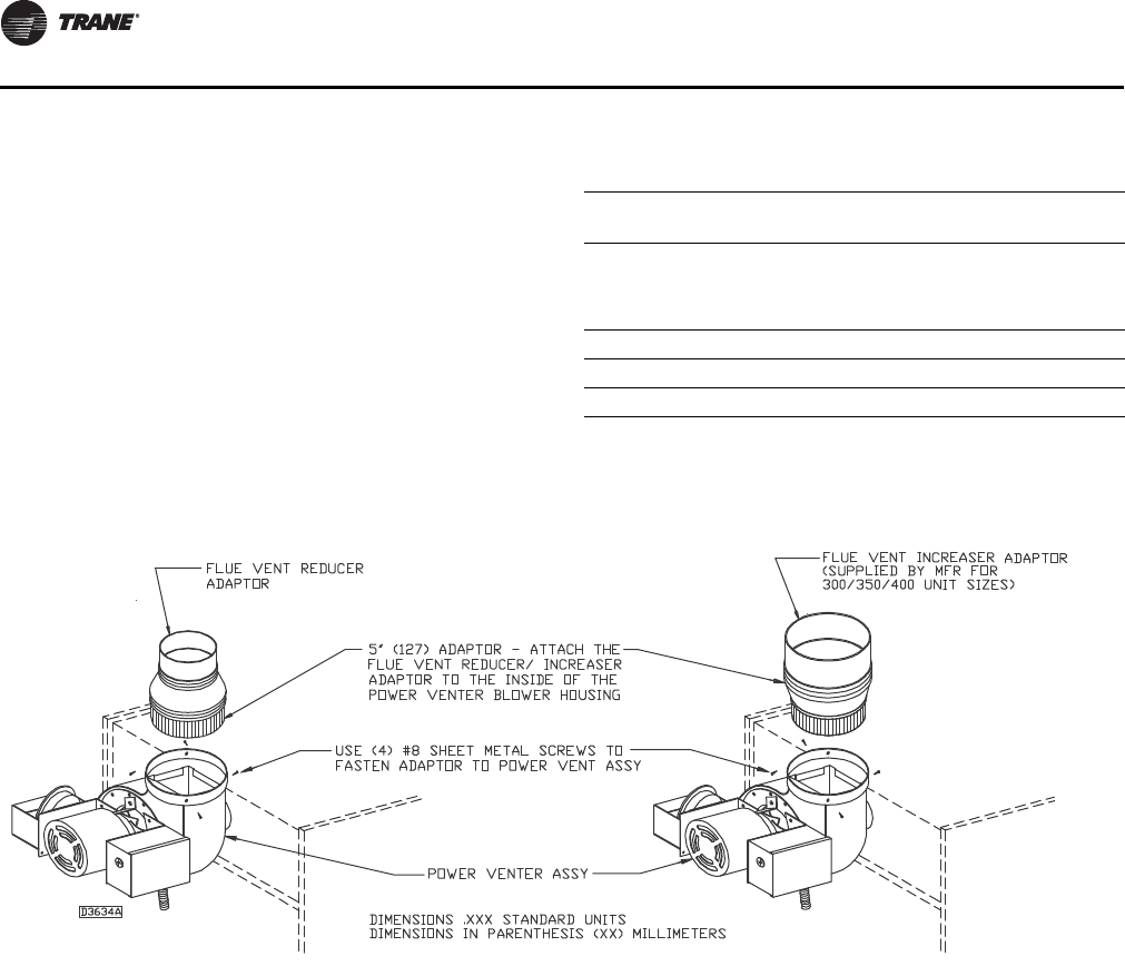
The venting system for these appliances shall terminate at
least four feet (1.2 m) below, four feet (1.2 m) horizontal
from, or one foot (0.3 m) above any door, window, or
gravity air inlet into any building.
Through the wall vents for these appliances shall NOT
terminate over public walkways, or over an area where
condensate or vapor could create a nuisance or hazard or
could be detrimental to the operation of regulators, relief
valves, or other equipment.
The vent pipe equivalent length must be five feet (1.5 m)
minimum and must not exceed 50 feet (15.2 m).
Equivalent length is the total length of straight sections
PLUS 15 feet (4.6 m) for each 90 degree elbow, eight feet
(2.4 m) for each 45 degree elbow, and 10 feet (3.0 m) for
the vent cap.
Maintain six inches (152 mm) between vent pipe and
combustible materials. A minimum of 12 inches (305 mm)
of straight pipe is required from the venter outlet before
installing an elbow in the vent system. Never attach an
elbow directly to the venter (see preceding warning).
Use single wall pipe constructed of 26 gauge galvanized
steel or material of equivalent durability and corrosion
resistance for the vent system. For installation in Canada,
use pipe constructed from 0.025-inch thick aluminum or
0.018-inch thick stainless steel.
Any run of single wall vent pipe passing through an
unheated space must be insulated with an insulation
suitable to 550°F.
The vent terminal must be installed with a minimum
clearance of four feet (1.2 m) from electric meters, gas
meters, regulators and relief equipment.
Seal ALL vent pipe joints and seams to prevent leakage.
Use General Electric RTV-108 or Dow Corning® RTV-732
silicone sealant (or equivalent) or 3M #425 aluminum foil
tape or equivalent.
The vent system must be installed to prevent collection of
condensate. Vertical vent pipes should be equipped with
condensate drains. Pitch horizontal pipes downward 1/4
inch per foot (21 mm per m) toward outlet for condensate
drainage
Horizontal portions of the venting system shall be
supported at maximum intervals of four feet (1.2 m) to
prevent sagging (in Canada, support at three feet (1 m)
minimum intervals).
Insulate single wall vent pipe exposed to cold air or
running through unheated areas.
Units are shipped from the factory set up for vertical
venting. To convert the power venter for horizontal
venting, remove the shipping support bracket; refer to
Figure 11, p. 20, Figure 16, p. 23 through Figure 18, and
Figure 23, p. 35, and follow this procedure:
1. Hold power venter motor in position.
2. Remove the three Phillips-head screws from the motor
adaptor plate.
3. Remove the three screws which connect the power
venter stack to the power venter housing.
4. Rotate the power venter housing to the horizontal
position.
5. Replace screws accordingly.
Note: The motor, pressure switch, and junction box
bracket MUST remain located as shipped from the
factory for safe operation. Rotate only the blower
housing! If the power venter housing is to be
WARNING
Risk of Carbon Monoxide Poisoning with
Type B Vent!
Do not use a type B double wall vent internally within
the building on power vented units! Type B vent does
not seal well under positive pressure and could result in
exhaust fume leaks. Failure to follow these
recommendations could result in death or serious
injury.
WARNING
Carbon Monoxide!
Never operate unit heaters without combustion air and
flue gas piping in place. Each unit heater MUST have its
own combustion air system and MUST NOT be
connected to other vent systems or to a chimney. Your
venting system must not be blocked by any snow, snow
drifts, or any foreign matter. Inspect your venting
system to ensure adequate ventilation exists at all
times! Failure to follow these recommendations could
result in death or serious injury.
Installation: Piping
20 GHND-SVX01C-EN
moved to the right horizontal position, the junction
box must be rotated 90 degrees CCW to clear the
connection. To do this, remove all wires, conduit
and conduit connector from the junction box,
noting location of wires. Move box, using holes
provided. Move
7/8-inch plug from bottom of box to side.
Reconnect all wires according to the unit’s wiring
diagram.
The following instructions apply to Canadian installations
in addition to installation and operating instructions:
1. Installation must conform with local building codes, or
in absence of local codes, with current CSA B149.1,
“Installation Codes for Natural Gas Burning
Appliances and Equipment”, or CSA B149.2,
“Installation Codes for Propane Gas Burning
Appliances and Equipment”.
2. Any references to U.S. standards or codes in these
instructions are to be ignored and the applicable
Canadian standards or codes applied.
3. If using a metal vent system under positive gauge
pressure in Canada, a slip fit vent connection must be
secured by at least two corrosion-resistant screws, or
other mechanical locking means.
4. The vent shall not terminate:
a. Less than six feet (1.8 m) from a combustion air inlet
or another appliance.
b. Less than three feet (1 m) from any other building
opening or any gas service regulator.
c. Directly above a gas utility meter or service
regulator.
Table 5. Vent systems—termination clearance
requirements(a)
(a) If the vent terminal is to be installed near ground level, the vent terminal
must be positioned at least twelve inches above the maximum antici-
pated snow depth (see following for Canadian requirements).
Structure
Minimum for
Termination Locations
Door, window or any gravity air inlet 4 feet below
4 feet horizontally
1 foot above
Forced air inlet within 10 ft. 3 feet above
Adjoining building or parapet 6 feet
Adjacent public walkways 7 feet above grade
Figure 11. Adaptor installation
Refer to specification table and installation manual for proper usage.
Note: The reducer must be field supplied for 100, 125, 150, and
175 MBh unit sizes.
Installation: Piping
GHND-SVX01C-EN 21
Figure 12. Horizontal arrangement—single wall vent system to single wall termination
Figure 13. Vertical arrangement—single wall vent system to single wall termination
Installation: Piping
22 GHND-SVX01C-EN
Figure 14. Horizontal arrangement—single wall vent system to double wall termination
Figure 15. Vertical arrangement—single wall vent system to double wall termination
Installation: Piping
GHND-SVX01C-EN 23
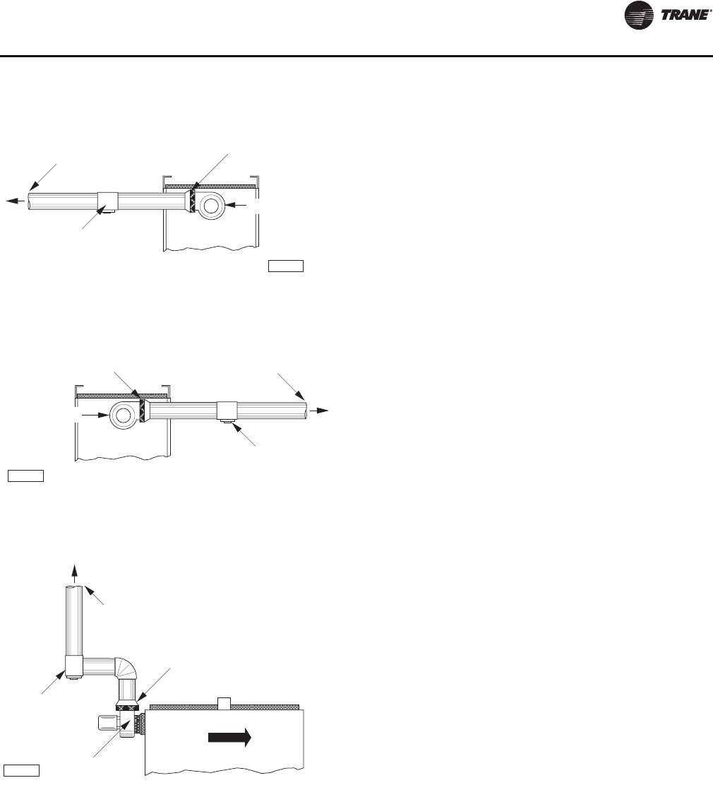
Figure 16. Horizontal left vent position (rear view of
unit heater)
Figure 17. Horizontal right vent position (rear view of
unit heater)
Figure 18. Vertical vent position (side view of unit
heater)
Tee With Drip Leg &
Cleanout Cap At Lowes t
Point Of Vent System (Typ.) D4072
To Horizontal Flue
Vent Termination
Reducer/Increaser
Where Applicable
Power Venter
Power Venter
Tee With Drip Leg &
Cleanout Cap At Lowes t
Point Of Vent System (Typ.)
D4073
To Horizontal Flue
Vent Termination
Reducer/Increaser
Where Applicabl e
D4071
AI R FLO W
Power Venter
Tee With
Drip Leg &
Cleanout Cap
To Vertical Flue
Vent Termination
Reducer/Increaser
Where Applicable
24 GHND-SVX01C-EN
Installation: Electrical
Electrical Connections
Standard units are shipped for use on 115 volt, 60 hertz
single phase electric power. The motor nameplate and
electrical rating of the transformer should be checked
before energizing the unit heater electrical system. All
external wiring must conform to the latest edition of ANSI/
NFPA No. 70 National Electrical Code and applicable local
codes; in Canada, to the Canadian Electrical Code, Part 1
CSA Standard C22.1.
It is recommended that the electrical power supply to each
unit heater be provided by a separate, fused, and
permanently live electrical circuit. A disconnect switch of
suitable electrical rating for each unit heater should be
located as close to the gas valve and controls as possible.
Each unit heater must be electrically grounded in
accordance with the latest edition of the National Electric
Code, ANSI/NFPA No. 70 or CSA Standard C22.1.
The transformer supplied with this unit heater is internally
fused. Any overload or short circuit will ruin the
transformer.
Thermostat Wiring and Location
Note: The thermostat must be mounted on a vertical,
vibration-free surface, free from air currents, and in
accordance with the furnished instructions.
Mount the thermostat approximately 5 feet (1.5 m) above
the floor in an area where it will be exposed to a free
circulation of average temperature air. Always refer to the
thermostat instructions as well as our unit wiring diagram,
and wire accordingly. Avoid mounting the thermostat in
the following locations:
1. Cold areas—Outside walls or areas where drafts may
affect the operation of the control.
2. Hot areas—Areas where the sun’s rays, radiation, or
warm air currents may affect control operation.
3. Dead areas—Areas where air cannot circulate freely,
such as behind doors or in corners.
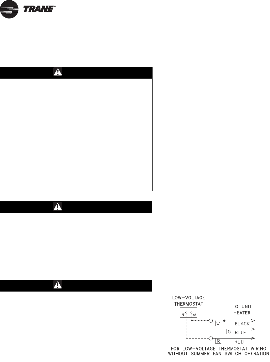
Note: Thermostat wires tagged “W” and “G” must be
connected together except when using a general
purpose “SPDT” 24 Vac relay and a standard
thermostat with subbase, or when using
Honeywell T834H or T834 thermostats. Also refer
to Figure 19, p. 24 for other wiring connections.
Thermostat Heat Anticipator Adjustments. The
initial heat anticipator setpoint should equal the
thermostat’s current amperage draw when the unit is
firing. This setpoint should be measured for the best
results. Use the recommended ranges as a guide. If further
information is needed, consult your thermostat
manufacturer’s instructions.
WARNING
Hazardous Service Procedures!
The maintenance and troubleshooting procedures
recommended in this section of the manual could result
in exposure to electrical, mechanical or other potential
safety hazards. Always refer to the safety warnings
provided throughout this manual concerning these
procedures. When possible, disconnect all electrical
power including remote disconnect and discharge all
energy storing devices such as capacitors before
servicing. Follow proper lockout/tagout procedures to
ensure the power can not be inadvertently energized.
When necessary to work with live electrical
components, have a qualified licensed electrician or
other individual who has been trained in handling live
electrical components perform these tasks. Failure to
follow all of the recommended safety warnings
provided, could result in death or serious injury.
WARNING
Hazardous Voltage and Gas!
Turn off the gas supply and disconnect all electric
power, including remote disconnects before servicing
unit. Follow proper lockout/tagout procedures to
ensure the power can not be inadvertently energized
and the gas can not be inadvertently turned on. Failure
to turn off gas or disconnect power before servicing
could result in death or serious injury.
WARNING
Proper Field Wiring and Grounding
Required!
All field wiring MUST be performed by qualified
personnel. Improperly installed and grounded field
wiring poses FIRE & ELECTROCUTION hazards. To
avoid these hazards, you MUST follow requirements for
field wiring installation and grounding as described in
NEC and your local/state electrical codes. Failure to
follow these requirements could result in death or
serious injury.
Figure 19. C1267G, thermostat wiring diagram
Installation: Electrical
GHND-SVX01C-EN 25
Recommended Heat Anticipator Setting Ranges:
Fan Time Delay Control
Leads from the time delay controls are factory wired to the
junction box. The fan control is a time delay relay
(approximately 45 seconds ON, 65 seconds OFF). The fan
control is rated at 17 amps.
Notes:
•The start-up fan delay must not exceed 90 seconds
from a cold start.
•For all wiring connections, refer to the wiring diagram
shipped with your unit (either affixed to the side jacket
or enclosed in your unit’s installation instruction
envelope). Should any original wire supplied with the
heater have to be replaced, it must be replaced with
wiring material having a temperature rating of at least
105°C.
Should any high limit switch wires have to be replaced,
they must be replaced with wiring material having a
temperature rating of 200°C minimum.
25 ft. (7.6 m) T’stat
Wiring 50 ft. (15.2 m) T’stat Wiring
0.85 to 0.90 A 0.90 to 1.1 A Max. Setting on T’stat
26 GHND-SVX01C-EN
Start-Up
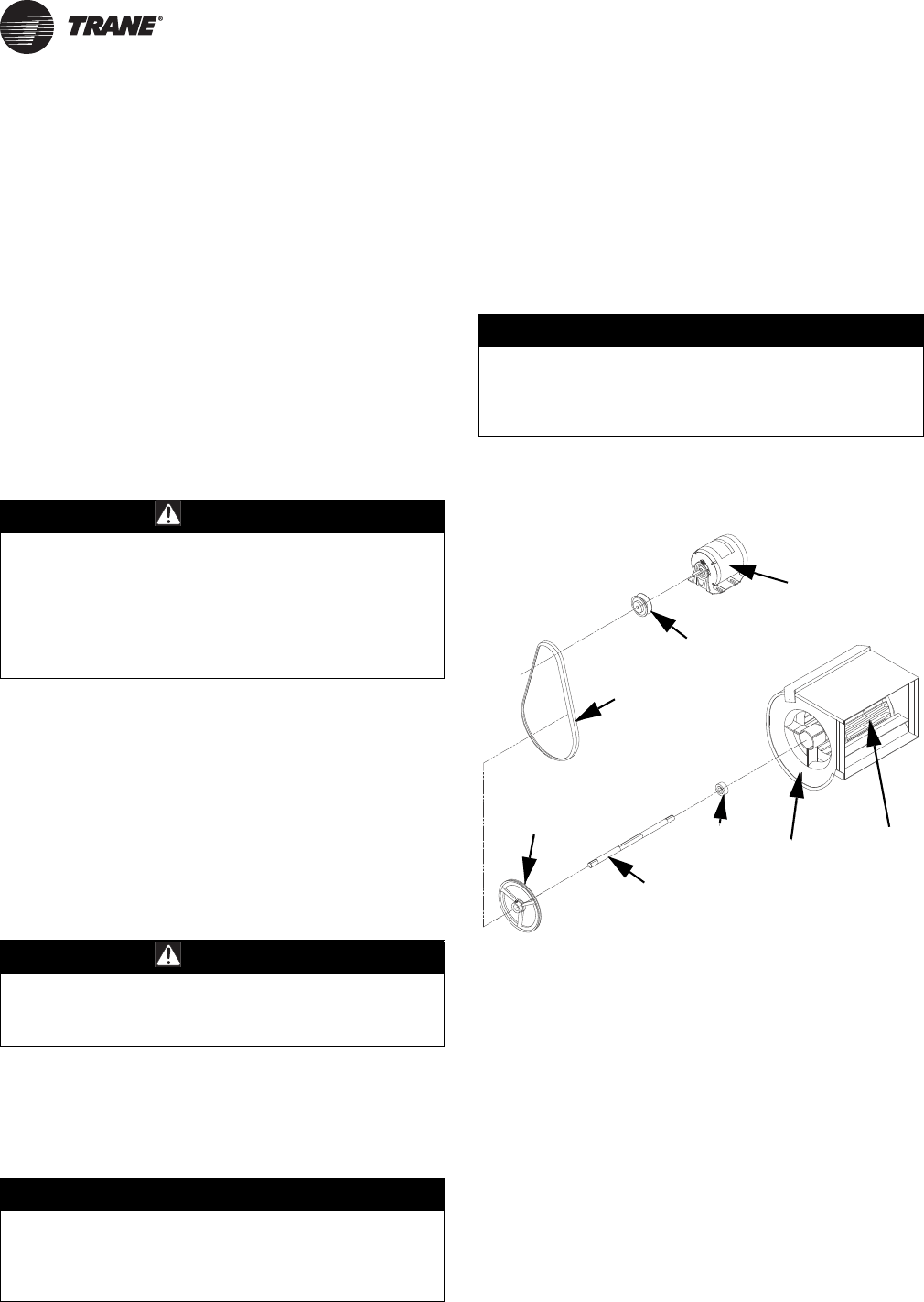
Blower Set Up
The drive ratio of the motor and blower sheaves has been
preset at the factory for a temperature rise of 65°F at 0” wc.
If the unit is to be operated under different air flow or
pressure requirements, the drive ratio must be altered by
means of the adjustable sheave on the blower motor (see
Figure 20, p. 26).
1. Ensure that all packing material, support blocks, etc.
have been removed from the unit.
2. Adjust the blower drive belt tension by means of the
two tension bolts on the blower motor base. When
proper tension has been achieved, the mid-point
deflection of the belt will be 3/4” when subjected to a
5 lb. force.
3. Recheck all electrical connections.
4. When power is applied, ensure that the motor and
blower are rotating in a clockwise direction when
viewed from the drive side.
5. Measure the current draw of the motor.
Blower Drive Adjustment
1. Remove the belt guard and loosen the belt tension
bolts on the blower motor base.
2. Loosen the set screw on the adjustable half of the
motor sheave. To increase the blower speed, turn the
adjustable half of the sheave clockwise, counter
clockwise to slow the blower. Retighten the set screw.
3. Realign the blower and motor sheaves if necessary.
4. Adjust the belt tension as specified in “Blower Set Up,”
p. 26, Step 2.
5. Replace the belt guard.
6. Check that the air flow of the unit, the rpm and current
draw of the blower motor and the temperature rise are
within the limits specified in Tab l e 1, p. 10, the blower
motor rating plate and the rating plate on the unit,
respectively.
Note: The blower assembly for 100/250 units consists of
1 wheel, 1 housing, 1 shaft, and 1 bearing set. For
300/400 units, the blower assembly consists of
2 wheels, 2 housings, 1 shaft, and 1 bearing set.
NOTICE:
Equipment Damage!
The “at speed” current draw of the motor must never
exceed that specified on the motor rating plate or
severe damage to the motor could result!
WARNING
Drive Belt!
Disconnect all electrical power including remote
disconnect before adjusting the drive belt. Follow
proper lockout/tagout procedures to ensure the power
can not be inadvertently energized. Failure to do so
could result in drive belt turning on unexpectedly,
which could result in serious injury.
WARNING
Belt Guard!
Never operate the unit without the belt guard in place
or severe personal injury could result!
NOTICE:
Equipment Damage!
Never operate the unit beyond the specified limits or
severe damage to, and/or premature failure of, the unit
could result!
Figure 20. Motor and blower assembly
12
4
3
6
7
5
8
Start-Up
GHND-SVX01C-EN 27
Operation
Explanation of Controls (see Figure 20, p. 26)
1. Each Separated Combustion Unit Heater comes
equipped with a power vent system that consists of a
power venter motor and blower, pressure switch, and
sealed flue collector.
2. The power venter motor is energized by the room
thermostat when a demand for heat is sensed. The
pressure switch measures the pressure differential
between the air inlet and exhaust vent systems. If the
differential is correct, the indirect spark ignition system
is energized.
3. The indirect spark ignition system consists of an
ignition module, a dual combination valve, and a
spark-ignited pilot burner. When the pressure switch is
closed, the pilot valve opens as a spark is generated to
light the pilot. When the flame is sensed by the flame
sensing circuit, the spark ceases, and the main gas
valve is opened to supply gas to the main burners.
Once the thermostat has been satisfied, the vent
system and gas valve are simultaneously de-
energized, stopping all gas flow to the unit.
4. The limit switch interrupts the flow of electric current to
the main gas valve if the unit heater becomes
overheated.
5. The fan switch delays the operation of the fan is
delayed for approximately 45 seconds once the
thermostat is closed, and continues fan operation for
approximately 65 seconds after the thermostat opens.
Note: The start-up fan delay must not exceed 90
seconds from a cold start.
6. The wall thermostat, supplied optionally, is a
temperature sensitive switch that operates the vent
and ignition systems to control the temperature of the
space being heated.
Note: The thermostat must be mounted on a vertical,
vibration-free surface, free from air currents,
and in accordance with the furnished
instructions.
Initial Lighting
1. Open the manual gas valve, in the gas supply line to the
unit heater. Loosen the union in the gas supply line to
purge it of air. Tighten the union and check for leaks.
2. Turn on the electrical power. The unit heater should
now be under the control of the thermostat. Set the
thermostat to its highest setting; the power venter
motor should start and burner ignition occur. Allow the
unit heater to operate until the fan starts, then set the
thermostat to its lowest setting. The burners and
power venter motor should stop operating
immediately while the fan continues to operate until
the fan time delay times out, shutting it off. Reset the
thermostat to the desired operational setting.
Power Vented Propeller Units with
Intermittent (Spark) Pilot Ignition
Explanation of Controls
1. The unit heater is equipped with a power venter
system consisting of a power venter motor and blower,
pressure switch, and sealed flue collector in place of
the conventional draft diverter.
a. The power venter motor is energized by the room
thermostat on a call for heat. The pressure switch
measures the flow through the vent system and
energizes the indirect spark ignition system when
the flow is correct.
WARNING
Carbon Monoxide!
Never operate unit heaters if the power venter is not
operable. Your venting system must not be blocked by
any snow, snow drifts, or any foreign matter. Inspect
your venting system to ensure adequate ventilation
exists at all times! Failure to follow these
recommendations could result in death or serious
injury due to Carbon Monoxide Poisoning (symptoms
include grogginess, lethargy, inappropriate tiredness, or
flu-like symptoms).
NOTICE:
Additional Devices!
The addition of external draft hoods or power venters is
not permitted. Addition of such devices could cause
severe unit malfunction or failure!
WARNING
Hazard of Explosion!
Never use an open flame to detect gas leaks. Explosive
conditions may occur. Use a leak test solution or other
approved methods for leak testing. Before attempting
to light or relight the pilot, wait 5 minutes to allow gas
which may have accumulated in the burner
compartment to escape. Failure to follow
recommended safe leak test procedures or pilot
lighting/relighting instructions could result in death or
serious injury or equipment or property-only-damage.
WARNING
Risk of Fire and Carbon Monoxide
Poisoning!
The pressure switch MUST NOT be bypassed. The unit
MUST NOT be fired unless the power venter is
operating. Failure to follow these recommendations
could result in death or serious injury.
Start-Up
28 GHND-SVX01C-EN
b. The indirect spark ignition system consists of an
ignition control module, a dual combination gas
valve, and a spark-ignited pilot burner. When the
pressure switch closes, the pilot valve opens and a
spark is generated to light the pilot burner. When
the flame sensing circuit senses that pilot flame is
established, the main gas valve is opened to supply
gas to the main burners. When the thermostat is
satisfied, the vent system is de-energized and both
valves are closed to stop all flow of gas to the unit.
2. The limit switch interrupts the flow of electric current to
the main gas valve in case the heater becomes
overheated.
3. The fan switch delays the operation of the fan until the
heater is warmed, then keeps the fan running after the
gas has been turned off until the useful heat has been
removed. The start-up fan delay must not exceed
90 seconds from a cold start.
4. The wall thermostat (supplied optionally) is a
temperature sensitive switch which operates the vent
system and ignition system to control the temperature
of the space being heated. It must be mounted on a
vibration free, vertical surface away from air currents,
in accordance with the instructions furnished with the
thermostat (also refer to “Installation: Electrical,”
p. 24).
Start-Up
Note: Also refer to the lighting instruction plate equipped
on the unit.
1. Open the manual valve supplying gas to the unit
heater, and with the union connection loose, purge air
from the gas line. Tighten the union and check for gas
leaks, using a soapy water solution only.
2. Open the manual valve on the unit heater.
3. Turn ON electrical power.
4. The unit should be under the control of the thermostat.
Turn the thermostat to the highest point and determine
that the power venter motor starts and the pilot and
main burners ignite. Turn the thermostat to the lowest
point and determine that the power venter motor shuts
off and pilot and main burners are extinguished.
5. If pilot adjustment is required, remove the pilot
adjustment seal cap and adjust the pilot screw to
obtain proper flame. Clockwise rotation decreases
pilot flame size. Replace the cap.
6. Turn the thermostat to the desired position.
7. Refer to “Gas Input Rate,” p. 30 and “Gas Pressure
Adjustments,” p. 30 for more specifications.
Shut-Down
1. Turn the valve selector knob to the “OFF” position.
2. Turn off the electricity.
3. To relight, follow the instructions in “Start-Up,” p. 28
(preceding section).
See Figure 21, p. 29 for parts/identification.
NOTICE:
Additional Devices!
The addition of external draft hoods or power venters is
not permitted. Addition of such devices could cause
severe unit malfunction or failure!
WARNING
Hazard of Explosion!
Never use an open flame to detect gas leaks. Explosive
conditions may occur. Use a leak test solution or other
approved methods for leak testing. Before attempting
to light or relight the pilot, wait 5 minutes to allow gas
which may have accumulated in the burner
compartment to escape. Failure to follow
recommended safe leak test procedures or pilot
lighting/relighting instructions could result in death or
serious injury or equipment or property-only-damage.
Start-Up
GHND-SVX01C-EN 29
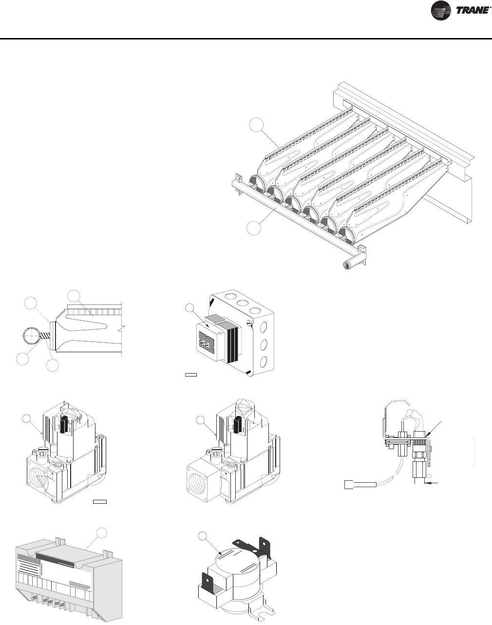
Figure 21. Burner components—intermittent pilot ignition(a)
(a) Also refer to Figure 6, p. 11, Figure 10, p. 18, and Figure 3, p. 8 through Figure 5, p. 9 for component locations.
1
2
Burner Drawer Common Parts:
1. Main Burners
2. Burner Manifold
3. Air Shutters
4. Burner Springs
5. Main Burner Orifice
6. Transformer
7. Pilot Tubing
Controls:
8A.Main Gas Valve (Honeywell)
8B.Main Gas Valve (White-Rodgers)
9. Honeywell Ignitor
10. Honeywell Pilot Burner
13. High Limit (Safety device located on the rear
header plate of the heat exchanger, air inlet side.)
1
3
54
D4298A
8A
C
10
7
SPARK
1
M
V
2
MV/PV
34
GND
(BURNER)
P
V
56
7
8
9
24V
(GND
)
24V
TH-W
(OPT.)
Honeywell
WARNING
S8600M
CONTINUOUS RE-TRY
100% SHUTOFF IP
90 SEC. TRIAL FOR IGNITION
9
8B
13
D3684A
6
Start-Up
30 GHND-SVX01C-EN
Gas Input Rate
Check the gas input rate as follows:
1. Turn off all gas appliances that utilize gas through the
same gas meter as the unit heater.
2. Turn gas on to the unit heater.
3. Using the gas meter, clock the time that it takes to burn
one cubic foot of gas (Heating Value).
4. Insert the time, in seconds, into the formula below:
Example: If the heating value = 1000 BTU/ft3 and the time/
ft3 = 18 s/ft3 then
Input Rate = 200,000 BTU/hr
(Refer to “General Safety Information,” p. 7 for metric
conversions.)
Note: If the computation exceeds, or is less than 95
percent of the gas Btu/h input rating (see “Unit
Dimensions and Weights,” p. 10), adjust the gas
pressure:.
Gas Pressure Adjustments
Adjust the gas pressure as follows:
1. NATURAL GAS: Optimum results are obtained when
the heater is operating at its full input rating with the
manifold pressure of 3.5 inches wc (0.9 kPa).
Adjustment of the pressure regulator is not normally
necessary since it is preset at the factory.
However, field adjustment may be made as follows:
a. Attach manometer at pressure tap plug adjacent to
control outlet.
b. Remove the regulator adjustment screw cap,
located on the combination gas valve.
c. With a small screwdriver, rotate the adjustment
screw counterclockwise to decrease or clockwise to
increase pressure. Do not force beyond stop limits.
d. Replace regulator adjustment screw cap.
2. PROPANE GAS: An exact manifold pressure of
10.0 inches wc (2.5 kPa) must be maintained for proper
operation of the heater. If the unit is equipped with a
pressure regulator on the combination gas valve,
follow Step a through Step d (above). If the unit is not
so equipped, the propane gas supply system pressure
must be regulated to attain this manifold operating
pressure.
3. The adjusted manifold pressure should not vary more
than 10 percent from the pressure specified in Tab l e 6,
p. 30.
Primary Air Shutter Adjustment
After the unit has been operating for at least 15 minutes,
adjust the primary air flow to the burners. Turn the friction-
locked, manually-rotated air shutters clockwise to close, or
counterclockwise to open (see Figure 21, p. 29, Figure 3,
p. 8, and Figure 5, p. 9).
For correct air adjustment, close the air shutter until yellow
tips in the flame appear. Then open the air shutter to the
point just beyond the position where yellow tipping
disappears. Refer to Figure 22.
Note: There may be momentary and spasmodic orange
flashes in the flame. This is caused by the burning
of airborne dust particles, and should not be
confused with the yellow tipping, which is a stable
NOTICE:
Overfiring!
Never overfire the unit heater, as this could cause
unsatisfactory operation, or shorten the life of the
heater.
Input Rate = Heating Value (Btu/ft3) (3600 s/hr)
Time (s/ft3)
Input Rate = (1000 BTU/ft3) (3600 s/hr)
18 s/ft3
Table 6. Main burner orifice schedule(a)
(a) This schedule is for units operating at normal altitudes of 2000 feet
(610 m) or less. SPECIAL ORIFICES ARE REQUIRED FOR INSTALLA-
TIONS ABOVE 2,000 FEET (610 m).
Input in
1000
BTU(a)
Type of Gas Natural Propane
No. of
Burner
Orifices
Heating
Value
1075 BTU/ft3
(40.1 MJ/m3)
2500 BTU/ft3
(93.1 MJ/m3)
Manifold
Pressure 3.5” wc (0.9 kPA)
10” wc (2.5 kPA)
100 ft3/hr 96 40 4
Orifice Drill 42 54
125 ft3/hr 120 50 5
Orifice Drill 42 54
150 ft3/hr 140 60 6
Orifice Drill 42 54
175 ft3/hr 163 70 7
Orifice Drill 42 54
200 ft3/hr 186 80 8
Orifice Drill 42 54
225 ft3/hr 210 90 9
Orifice Drill 42 54
250 ft3/hr 233 100 10
Orifice Drill 42 54
300 ft3/hr 280 120 12
Orifice Drill 42 54
350 ft3/hr 326 140 14
Orifice Drill 42 54
400 ft3/hr 372 160 16
Orifice Drill 42 54
Note: When installed in Canada, any references to deration at altitudes in
excess of 2000 feet (610 m) are to be ignored. At altitudes of 2000
to 4500 feet (610 to 1372 m), the unit heaters must be orificed to
90 percent of the normal altitude rating, and be so marked in
accordance with the ETL certification.
Start-Up
GHND-SVX01C-EN 31
or permanent situation when there is insufficient
primary air.
Pilot Adjustment
1. Remove the pilot adjustment cap.
2. Adjust the pilot screw to provide a properly sized
flame.
3. A proper pilot flame is a soft steady flame that
envelops 3/8- to 1/2-inch (9.5 to 12.7 mm) of the flame
sensor.
4. Replace the pilot adjustment cap.
Manifold Pressure Adjustment
If the manifold pressure requires minor adjustment,
remove the cap from the pressure regulator and turn the
adjustment screw clockwise to increase the pressure, or
counterclockwise to decrease the pressure. The adjusted
manifold pressure should not vary more than 10 percent
from the pressures specified in Table 6, p. 30.
Figure 22. Main burner flames
LIFTING
(TOO MUCH AIR)
NORMAL
(HARD FLAME)
YELLOW TIPPING
(MARGINAL)
YELLOW FLAME
(TOO LITTLE AIR)

Start-Up
32 GHND-SVX01C-EN
Gas Equipment Start-Up
Customer _____________________________________________ Job Name & Number _________________________
Pre-Inspection Information with Power and Gas Off
Type of Equip: Unit Heater
Serial Number: _________________________ Model Number: _____________________________
Name Plate Voltage: ____________________ Name Plate Amperage: ______________________
Type of Gas: Natural LP Tank Capacity: _______ lb Rating: _______ Btu @ ____ °F
_______ kg ________ kW @ ____ °C
Are all panels, doors, vent caps in place?
Has the unit suffered any external damage? Damage ______________________________
Does the gas piping and electric wiring appear to be installed in a professional manner?
Has the gas and electric been inspected by the local authority having jurisdiction?
Is the gas supply properly sized for the equipment?
Were the installation instructions followed when the equipment was installed?
Have all field installed controls been installed?
Do you understand all the controls on this equipment? If not, contact your wholesaler or rep. (DO NOT START
this equipment unless you fully understand the controls.)
Remarks: _____________________________________________________________________________________________________
_______________________________________________________________________________________________________________
_______________________________________________________________________________________________________________
GENERAL
With power and gas off.
Make certain all packing has been removed.
Tighten all electrical terminals and connections.
Check all fans and blowers for free movement.
Check all controls for proper settings.
BLOWER
With power on and gas off.
Check voltage L1 _____ L2 _____ L3 _____
Check rotation of main fan.
Check motor amps L1 _____ L2 _____ L3 _____
GAS HEATING
With power and gas on.
Inlet gas pressure. ____ in. wc or ____ kPa
Pilot and main burner ignition.
Manifold gas pressure. ____ in. wc or ____ kPa
Check electronic modulation. Set at: __________
Cycle and check all other controls not listed.
Entering air temp. _____ °F or ____ °C
Discharge air temp. (high fire) ____ °F. or ____ °C
GHND-SVX01C-EN 33
Maintenance
Periodic Service
All Maintenance/Service information should be recorded
accordingly on the inspection sheet provided in this
manual (see “Gas Equipment Start-Up,” p. 32).
Note: The heater and vent system should be checked
once a year by a qualified technician.
Important: Gas tightness of the safety shut-off valves
must be checked on at least an annual basis.
To check gas tightness of the safety shut-off valves, turn off
the manual valve upstream of the appliance combination
control. Remove the 1/8-inch pipe plug on the inlet side of
the combination control and connect a manometer to that
tapping. Turn the manual valve on to apply pressure to the
combination control. Note the pressure reading on the
manometer, then turn the valve off. A loss of pressure
indicates a leak. If a leak is detected, use a soap solution to
check all threaded connections. If no leak is found,
combination control is faulty and must be replaced before
putting appliance back in service.
Should maintenance be required, perform the following
inspection and service routine:
1. Inspect the area near the unit to be sure that there is no
combustible material located within the minimum
clearance requirements listed in this manual.
2. Turn off the manual gas valve and electrical power to
the gas unit heater.
3. To clean or replace the main burners, remove the
bottom panel and compress the spring by moving the
burner toward the manifold. Slide the opposite end of
the burner downward from the locating slot while
retaining spring is still compressed. Pull the burners
away from the heat.
4. With the burners removed, wire brush the inside
surfaces of the heat exchanger.
5. Remove any dirt, dust, or other foreign matter from the
burners using a wire brush and/or compressed air.
Ensure that all parts are unobstructed. Inspect and
clean pilot burner if necessary.
6. Reassemble the gas unit heater by replacing all parts in
reverse order.
7. Complete the appropriate unit start-up procedure as
given in “Operation,” p. 27 (see lighting instruction
plate ).
8. Check the burner adjustment (see “Primary Air Shutter
Adjustment,” p. 30).
9. Check all gas control valves and pipe connections for
leaks.
10. Check the operation of the automatic gas valve by
lowering the setting of the thermostat, stopping the
operation of the gas unit heater. The gas valve should
close tightly, completely extinguishing the flame on
the main burners.
11. Inspect and service the motor/fan assemblies. To
maintain efficient air flow, inspect and clean the fan
blades and guard to prevent buildup of foreign matter.
WARNING
Hazardous Service Procedures!
The maintenance and troubleshooting procedures
recommended in this section of the manual could
result in exposure to electrical, mechanical or other
potential safety hazards. Always refer to the safety
warnings provided throughout this manual concerning
these procedures. When possible, disconnect all
electrical power including remote disconnect and
discharge all energy storing devices such as capacitors
before servicing. Follow proper lockout/tagout
procedures to ensure the power can not be
inadvertently energized. When necessary to work with
live electrical components, have a qualified licensed
electrician or other individual who has been trained in
handling live electrical components perform these
tasks. Failure to follow all of the recommended safety
warnings provided, could result in death or serious
injury.
WARNING
Hazardous Voltage and Gas!
Turn off the gas supply and disconnect all electric
power, including remote disconnects before servicing
unit. Follow proper lockout/tagout procedures to
ensure the power can not be inadvertently energized
and the gas can not be inadvertently turned on. Failure
to turn off gas or disconnect power before servicing
could result in death or serious injury.
WARNING
Hazard of Explosion!
Never use an open flame to detect gas leaks. Explosive
conditions may occur. Use a leak test solution or other
approved methods for leak testing. Failure to follow
recommended safe leak test procedures could result in
death or serious injury or equipment or property-only-
damage.
WARNING
Combustible Materials!
Maintain proper clearance between the unit heat
exchanger, vent surfaces and combustible materials.
Refer to unit nameplate and installation instructions for
proper clearances. Improper clearances could result in a
fire hazard. Failure to maintain proper clearances could
result in death or serious injury or property damage.
Maintenance
34 GHND-SVX01C-EN
12. Check lubrication instructions on the motor. If oiling is
required, add 3 to 4 drops of electric motor oil as
follows:
a. Light Duty—After 3 years or 25,000 hours of
operation.
b. Average Duty—Annually after 3 years or
8,000 hours of operation.
c. Heavy Duty—Annually after 1 year or at least every
1,500 hours of operation.
13. Check and test the operational functions of all safety
devices supplied with your unit.
NOTICE:
Equipment Damage!
Never over oil the motor or premature failure could
occur!
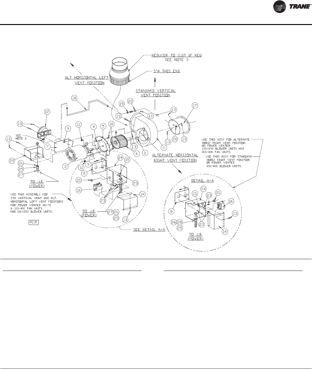
Maintenance
GHND-SVX01C-EN 35
Figure 23. Power venter assembly
Notes:
1. For item No. 6, use counter-clockwise rotation.
2. DO NOT OVERTIGHTEN CELCON NUT! HAND TIGHTEN ONLY! DO NOT USE TOOLS! Approximate 1/3 turn maximum or 8 inch pounds is sufficient from
the point where the tube does not slip in or out.
3. Flue Sizes:
100/175 units: 4” dia. flue outlet Reducer required—to be supplied by installer.
200/250 units: 5” dia. flue outlet (no adapter required).
300/400 units: 6” dia. flue outlet Increaser required—to be supplied by manufacturer.
Ref. No. Description
1 Blower Housing Assembly
2Speed Nut
3 Motor
4 Washer, Plain
5 Plate Adapter
6 Blower Wheel (see Note 1)
7 Mounting Bracket (Pressure Switch)
8 Mounting Bracket (Junction Box)
9Screw, S.T.
10 Screw, Machine (L = 3/4”)
11 Nut, Keps (Ext. Lock Washer)
12 Air Pressure Switch
13 Drill Screw
14 Junction Box Cover
Ref. No. Description
15 Snap Bushing
16 Relay (Motor)
17 Draftor Stack Assembly
18 Tubing (Aluminum) Formation
19 Male Connector
20 Locknut
21 Hole Plug
22 Pressure Switch Cover
23 Drill Screw
24 Junction Box Base
25–28 Power Connection
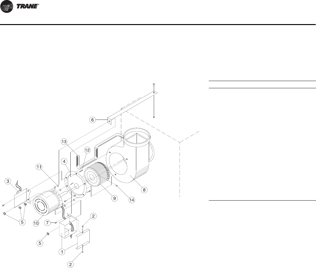
Maintenance
36 GHND-SVX01C-EN
Installation Instructions for Field
Replacement of Power Venter Motor
Important: This replacement must be performed only
by a qualified technician.
Note: All hardware (screws, nuts, washers) that will be
removed from the unit will be reused for this motor
replacement. DO NOT LOSE ANY OF THESE
PARTS.
Tools and Parts Needed
Wire Stripper and Crimper; Slotted Head and #2 Phillips
Head Screwdriver; 3/8-in. Wrench; 1/8-in. Allen Wrench
(long handle); marker; (1) 1/4-in. push on terminal for Wire.
Notes:
•Remove the cover from the Relay Junction Box (Item 1)
by removing two screws (Item 2) top and bottom.
Disconnect both wires from the motor lead ends. One
is connected to terminal #4 on the venter relay, and the
other is connected with a wire nut to a black wire.
•Remove the sensing tube (Item 3) from the Pressure
Switch/Mounting Bracket (Item 3) at motor end only.
Separated Combustion Units: Remove both tubes at
motor end only—note location.
•Mark locations of the Relay Junction Box and Pressure
Switch Mounting Brackets along with the Motor (Item
10) mounts on the Mounting Adapter Plate (Item 4)—
using a marker.
•Remove nut (Item 5) that secures the Motor Support
Shipping Bracket (Item 6) to the Mounting Adapter
Plate. Pull this bracket away from the Motor Mounting
Adapter Plate.
•Remove three phillips head screws (Item 7) on the
Motor mounting Adapter Plate. Remove the Motor/
Blower Wheel/Adapter Plate assembly from the Power
Venter Blower Housing (Item 8).
•Remove the Blower Wheel (Item 9) from the motor
shaft by removing the set screw (Item 14) using a 1/8-in.
Allen Wrench.
•Remove the three Motor Mounting Nuts (Item 5),
Space Washers (Item 11), and Screws (Item 12). Do not
lose these parts! Using caution—the motor will
disengage from the Mounting Adapter Plate, along
with the Relay Junction Box and Pressure Switch
Mounting Brackets will also disengage.
•Reverse order to install the new Power Venter Motor.
•TEST FIRE THE UNIT FOR A FEW CYCLES, MAKING
SURE THAT THE UNIT IS OPERATING
SATISFACTORILY.
Figure 24. Identification of parts
Ref. No. Description
1 Relay Junction Box/Mounting
Bracket Assembly
2 #8 Drill Screws (2 required)
3 Pressure/Mounting Bracket
Assembly
4 Mounting Plate Adapter
5 Keps Nut w/External Tooth
Lockwasher (4 required)
6 Motor Support Shipping Bracket
7 Phillips Head Screws (3 required)
8 Power Venter Blower Housing
9Blower Wheel
10 Motor
11 Space Washers (3 required)
12 Machine Screw (3 required)
13 Sensing Tube
14 Set Screw

Maintenance
GHND-SVX01C-EN 37
How to Order Replacement Parts
Please send the following information to your local Parts
center; If further assistance is needed, contact the
manufacturer’s customer service department.
•Model number
• Serial Number
• Part description and Number as shown in the
Replacement Parts Catalog.
38 GHND-SVX01C-EN
Diagnostics
Troubleshooting
WARNING
Hazardous Service Procedures!
The maintenance and troubleshooting procedures
recommended in this section of the manual could result
in exposure to electrical, mechanical or other potential
safety hazards. Always refer to the safety warnings
provided throughout this manual concerning these
procedures. When possible, disconnect all electrical
power including remote disconnect and discharge all
energy storing devices such as capacitors before
servicing. Follow proper lockout/tagout procedures to
ensure the power can not be inadvertently energized.
When necessary to work with live electrical
components, have a qualified licensed electrician or
other individual who has been trained in handling live
electrical components perform these tasks. Failure to
follow all of the recommended safety warnings
provided, could result in death or serious injury.
Table 7. Troubleshooting guide
Symptoms Possible Cause(s) Corrective Action
A. Flame lifting from burner ports. 1. Pressure regulator set too high. 1. Reset manifold pressure. Refer to “Operation,” p. 27.
2. Defective regulator. 2. Replace regulator section of combination gas valve or
complete valve.
3. Burner orifice too large. 3. Check with local gas supplier for proper orifice size and
replace. Refer to “Operation,” p. 27.
B. Flame pops back. 1. Excessive primary air. 1. Close air shutter. Refer to “Operation,” p. 27.
2. Burner orifice too small. 2. Check with local gas supplier for proper orifice size and
replace. Refer to “Operation,” p. 27.
C. Noisy flame. 1. Too much primary air. 1. Close air shutter.
2. Noisy pilot. 2. Reduce pilot gas. Refer to “Operation,” p. 27.
3. Irregular orifice causing whistle or
resonance. 3. Replace orifice.
4. Excessive gas input. 4. Reset manifold pressure. Refer to “Operation,” p. 27;
Replace regulator section of combination gas valve or
complete valve; or check with local gas supplier for proper
orifice size and replace. Refer to “Operation,” p. 27.
D. Yellow tip flame (some yellow
tipping on propane gas is
permissible).
1. Insufficient primary air. 1. Open air shutters. Refer to “Operation,” p. 27.
2. Clogged main burner ports. 2. Clean main burner ports.
3. Misaligned orifices. 3. Replace manifold assembly.
4. Clogged flue collector. 4. Clean flue collector.
5. Air shutter linted. 5. Check for dust or lint at air mixer opening and around the
air shutter.
6. Insufficient combustion air. 6. Clean combustion air inlet openings in bottom panel; see
“Installation: Piping,” p. 16.
E. Floating flame. 1. Blocked venting. 1. Clean flue. Refer to “Installation: Piping,” p. 16.
2. Insufficient combustion air. 2. Clean combustion air inlet openings in bottom panel; see
“Installation: Piping,” p. 16.
3. Blocked heat exchanger. 3. Clean heat exchanger.
4. Air leak into combustion chamber
or flue collector. 4. Determine cause and repair accordingly.
Diagnostics
GHND-SVX01C-EN 39
F. Gas Odor. 1. Shut off gas supply
immediately!
1. Inspect all gas piping and repair.
2. Blocked heat exchanger/venting. 2. Clean heat exchanger/flue.
3. Drafts around heater. 3. Eliminate drafts. Refer to “Installation: Mechanical,” p. 12.
4. Negative pressure in building. 4. See “Installation: Piping,” p. 16.
5. Blocked flue collector. 5. Clean flue collector.
G. Delayed ignition. 1. Excessive primary air. 1. Close air shutter. Refer to “Operation,” p. 27.
2. Main burner ports clogged near
pilot. 2. Clean main burner ports.
3. Pressure regulator set too low. 3. Reset manifold pressure. Refer to “Operation,” p. 27.
4. Pilot decreases in size when main
burners come on. 4. Supply piping is inadequately sized. Refer to “Installation:
Piping,” p. 16.
5. Pilot flame too small. 5. Clean pilot orifice. Refer to “Operation,” p. 27.
6. Drafts around heater. 6. Eliminate drafts. Refer to “Installation: Mechanical,” p. 12.
7. Improper venting. 7. Refer to “Installation: Piping,” p. 16.
H. Failure to ignite. 1. Main gas off. 1. Open all manual gas valves.
2. Lack of power at unit. 2. Replace fuse or turn on power supply.
3. Thermostat not calling for heat. 3. Turn up thermostat.
4. Defective limit switch. 4. Check limit switch with continuity tester. If open, replace
limit switch.
5. Improper thermostat or
transformer wiring. 5. Check wiring per diagrams.
6. Defective gas valve. 6. Replace gas valve.
7. Defective thermostat. 7. Check thermostat and replace if defective.
8. Defective transformer. 8. Be sure 115 volts is supplied to the transformer primary,
then check for 24 volts at secondary terminal before
replacing.
9. Loose wiring. 9. Check and tighten all wiring connections per diagrams.
10. Defective ignition control. 10. Replace, if necessary. Also see U, V, and W symptoms.
I. Condensation of water vapor. 1. Improper venting 1. Refer to “Installation: Venting,” p. 18.
J. Burner won't turn off. 1. Poor thermostat location. 1. Relocate thermostat away from drafts.
2. Defective thermostat. 2. Replace thermostat.
3. Improper thermostat or
transformer wiring at gas valve. 3. Check wiring per diagrams.
4. Short circuit. 4. Check operation at valve. Check for short (such as staples
piercing thermostat wiring), and correct.
5. Defective or sticking gas valve. 5. Replace gas valve.
6. Excessive gas supply pressure. 6. Refer to “Installation: Piping,” p. 16.
K. Rapid burner cycling. 1. Loose electrical connections at gas
valve or thermostat. 1. Tighten all electrical connections.
2. Excessive thermostat heat
anticipator. 2. Adjust thermostat heat anticipator for longer cycles. Refer
to “Installation: Electrical,” p. 24.
3. Unit cycling on high limit. 3. Check for proper air supply across heat exchanger.
4. Poor thermostat location. 4. Relocate thermostat. (Do not mount thermostat on unit).
5. Draft on pilot. 5. Eliminate drafts. Refer to “Installation: Mechanical,” p. 12.
6. Defective ignitor control. 6. Replace ignitor.
7. Defective high limit switch. 7. Jumper high limit switch terminals 1 and 2. If burner
operates normally, replace switch.
L. Noisy. 1. Fan blades loose. 1. Replace or tighten.
2. Fan blades dirty. 2. Clean fan wheel.
3. Vibration isolators deteriorated. 3. Replace vibration isolators.
4. Bearings are dry. 4. Oil bearings on fan motor. (Refer to label on motor.)
M. Pilot will not light or will not stay
lit. 1. Main gas off. 1. Open all manual gas valves.
Table 7. Troubleshooting guide (continued)
Symptoms Possible Cause(s) Corrective Action
Diagnostics
40 GHND-SVX01C-EN
2. Pilot adjustment screw turned too
low on combination/automatic
main gas valve.
2. Refer to “Operation,” p. 27.
3. Air in gas line. 3. Purge air from gas supply.
4. Incorrect lighting procedure. 4. Follow lighting instruction label adjacent to gas valve.
5. Dirt in pilot orifice. 5. Remove pilot orifice. Clean with compressed air or solvent.
(Do not ream.)
6. Extremely high or low gas
pressure. 6. Refer to “Operation,” p. 27.
7. Defective thermocouple. 7. Check thermocouple connection, and replace if defective.
8. Drafts around unit. 8. Eliminate drafts. Refer to “Installation: Mechanical,” p. 12.
9. Pilot valve not opening (faulty
wiring). 9. Inspect and correct all wiring.
10. No spark (faulty wiring). 10. Inspect and correct ignition system wiring. See symptoms
U, V, and W.
11. Defective gas valve. 11. Replace.
N. Fan will not run. 1. Loose wiring. 1. Check and tighten all wiring connections per diagrams.
Thermostat wires tagged “W” and “G” must be connected
together (unless special thermostats are used; if so, see
thermostat wiring diagram, “Electrical Connections,” p. 24).
2. Defective motor overload
protector or defective motor. 2. Replace motor.
3. Defective fan switch. 3. Check for 24V across 1 and 3 terminals on fan time delay
switch. If 24V is present, jumper terminals numbered 2 and
4. If motor runs, the fan switch is defective and must be
replaced. If 24V is not present, check wiring per diagrams.
O. Fan motor turns on and off while
burner is operating. 1. Fan switch heater element
improperly wired. 1. Be sure fan switch heater terminals are connected per
diagrams.
2. Defective fan switch. 2. Replace fan switch.
3. Motor overload protector cycling
on and off. 3. Check motor amps against motor name plate rating, check
voltage, replace fan motor if defective.
4. Motor not properly oiled. 4. Refer to label on motor.
P. Fan motor will not stop. 1. Improperly wired fan control. 1. Check all wiring.
2. Main burners not lighting while
thermostat calls for heat. 2. Refer to H and N symptoms.
3. Defective fan switch. 3. Replace fan switch.
Q. Not enough heat. 1. Incorrect gas input. 1. Refer to “Operation,” p. 27.
2. Heater undersized. 2. This is especially true when the heated space is enlarged.
Have the heat loss calculated and compare to the heater
output (80 percent of input). Your gas supplier or installer
can furnish this information. If heater is undersized, add
additional heaters.
3. Thermostat malfunction. 3. Replace thermostat.
4. Heater cycling on limit control. 4. There should be NO ducts attached to the front of this
heater. Check air movement through heat exchanger. Check
voltage to fan motor. Clean fan blade and heat exchanger
and oil fan motor.
R. Too much heat. 1. Thermostat malfunction. 1. Replace thermostat.
2. Heater runs continuously. 2. Check wiring per diagrams; check operation at valve. Look
for short (such as staples piercing thermostat wiring), and
correct; replace gas valve. Refer to “Operation,” p. 27.
S. Cold air is delivered on start up. 1. Fan switch heater element
improperly wired. 1. Be sure fan switch heater terminals are connected per
diagrams.
T. Cold air is delivered during heater
operation. 1. Incorrect manifold pressure or
input. 1. Refer to “Operation,” p. 27.
2. Voltage to unit too high. 2. Check motor voltage with fan running. Should be 115 volts
AC.
3. Air throughput too high. 3. Refer to “Operation,” p. 27.
Table 7. Troubleshooting guide (continued)
Symptoms Possible Cause(s) Corrective Action
Diagnostics
GHND-SVX01C-EN 41
U. No Spark. 1. Thermostat not calling for heat. 1. Close thermostat contacts.
2. No low voltage. 2. Check for 24V across 24V terminals of S8600.
3. Spark gap closed or too wide. 3. Set gap to 0.1.
4. Broken or cracked ceramic on
spark electrode. 4. Replace pilot assembly.
V. Spark present but pilot does not
light. 1. Loose S8600 connections. 1. Check all connections, term. PV feeds 24V to pilot valve.
2. Improper gas pressure. 2. Check pressure—pressure that is either too high or too low
may cause a problem.
3. Is spark in pilot gas stream? 3. Spark should arc from electrode.
4. No pilot gas — do not use match to
test - presence of gas is easily
detected by the odor.
4. Check pilot line for kinks. Ensure there are no drafts.
W. Pilot lights — Main valve does not
energize. 1. Loose S8600 connections. 1. Check connections-term. MV feeds main valve.
2. Cracked or broken sensor
ceramic. 2. Replace pilot assembly.
3. Check sensor/spark lead for
continuity. 3. Replace if needed.
4. Measure 24 volts from term. MV to
term. MV/PV. 4. If present, replace main valve; if not, replace S8600 Igniter.
X. Hi-Limit switch tripping 1. Vertical run of flue is too short. 1. Lengthen vertical run of flue pipe (see “Installation:
Venting,” p. 18).
2. Unit is overfiring. 2. Burner orifice may be too large: verify/replace if required.
3. Air flow too low. 3. Increase air flow; check fan size. Check for proper voltage.
4. Defective switch. 4. Replace.
Y. Noisy power venter. 1. Power venter wheel loose. 1. Replace or tighten.
2. Power venter wheel dirty. 2. Clean power venter wheel.
3. Power venter wheel rubbing
housing. 3. Realign power venter wheel.
4. Bearings are dry. 4. Oil bearings on power venter motor. (Refer to label on
motor).
Z. Power venter will not run. 1. Lack of power at unit. 1. Replace fuse or turn on power.
2. Loose wiring. 2. Check and tighten all wiring connections per diagrams.
Thermostat wires tagged “W” and “G” must be connected
together (unless special thermostats are used; if so see
thermostat wiring diagram, “Electrical Connections,” p. 24).
3. Defective motor overload
protector or defective motor. 3. Replace motor.
4. Defective power venter relay. 4. Check for 24V across 1 and 3 terminals on fan relay. If 24V
is present, jumper terminals numbered 2 and 4. If motor
runs, the relay is defective and must be replaced. If 24V is
not present, check wiring per diagrams.
AA. Power venter motor turns on and
off while burner is operating. 1. Fan relay heater element
improperly wired. 1. Be sure relay terminals are connected per diagrams.
2. Defective venter relay switch. 2. Replace venter relay.
3. Motor overload protector cycling
on and off. 3. Check motor amps against motor name plate rating, check
voltage; replace power venter motor if defective.
4. Motor not properly oiled. 4. Refer to label on motor.
AB. Power venter motor will not stop. 1. Improperly wired venter relay. 1. Check all wiring.
2. Main burner not lighting while
thermostat calls for heat. 2. Refer to H and N symptoms.
3. Defective venter relay. 3. Replace venter relay.
Table 7. Troubleshooting guide (continued)
Symptoms Possible Cause(s) Corrective Action
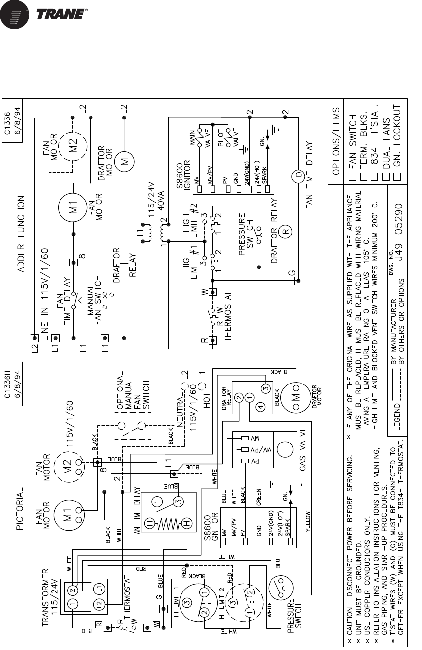
42 GHND-SVX01C-EN
Wiring Diagrams
Figure 25. High Efficiency Propeller Fan
Trane optimizes the performance of homes and buildings around the world. A business of Ingersoll Rand, the
leader in creating and sustaining safe, comfortable and energy efficient environments, Trane offers a broad
portfolio of advanced controls and HVAC systems, comprehensive building services, and parts.
For more information, visit www.Trane.com.
Trane has a policy of continuous product and product data improvement and reserves the right to change design and specifications without notice.
We are committed to using environmentally
conscious print practices that reduce waste.
© 2012 Trane All rights reserved
GHND-SVX01C-EN 16 Mar 2012
Supersedes GHND-SVX01B-EN (01 Mar 2010)
