Trane H V Wshp 5 To 25 Tons Catalogue Water Source Heat Pump Axiom Horizontal/Vertical GEH/GEV 6 60 Hz PRC016E EN August 2014
2015-04-02
: Trane Trane-H-V-Wshp-5-To-25-Tons-Catalogue-684242 trane-h-v-wshp-5-to-25-tons-catalogue-684242 trane pdf
Open the PDF directly: View PDF ![]() .
.
Page Count: 124 [warning: Documents this large are best viewed by clicking the View PDF Link!]
Water Source Heat Pump
Axiom™ Horizontal/Vertical—GEH/GEV
6 to 25Tons—60 Hz
August 2014 WSHP-PRC016E-EN
Product Catalog
© 2014Trane All rights reserved WSHP-PRC016E-EN
Introduction
The 6 through 25 ton horizontal and vertical water-source heat pump is used in a broad range of
applications. Schools, office buildings, health care/rehabilitation facilities, condominiums and
retirement facilities are just a few of the types of buildings utilizing the energy conscious water-
source design.
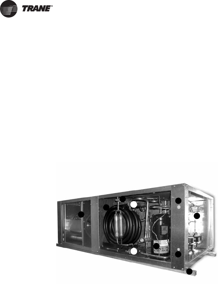
Model GEH (pictured below) is a ceiling hung product that provides a serviceability to maintenance
components; indoor air quality standards; sound attenuation; and best of all, higher efficiencies
rated in accordance to ARI-ISO 13256-1 performance and ASHRAE 90.1 standards.
Trane’s design incorporates system advantages such as
Copyright
This document and the information in it are the property ofTrane, and may not be used or
reproduced in whole or in part without written permission.Trane reserves the right to revise this
publication at any time, and to make changes to its content without obligation to notify any person
of such revision or change.
Trademarks
All trademarks referenced in this document are the trademarks of their respective owners.
Axiom, ReliaTel,TOPSS,Tracer,Trane, and theTrane logo are trademarks or registered trademarks
ofTrane in the United States and other countries. Trane is a business of Ingersoll Rand. All
trademarks referenced in this document are the trademarks of their respective owners.
LonTalk is a registered trademark of Echelon Corporation.
BACnet is a registered trademark of ASHRAE.
• Superior maintenance accessibility • Dual circuit design
• Dual-sloped, plastic drain pan • High and low pressure safeties as standard
• Maximum return-air and supply-air flexibility • Dehumidification option
• Multiple fan speed motor packages • Waterside economizing option
• Quiet unit design • Supplemental electric heat option
• Integrated controls
1. Fan Blower Section
2. Co-axial Heat Exchanger
3. Water Connections
4. Thermal Expansion Valve
5. Dual Compressor
6. Low Voltage
7. High Voltage
8. Integrated Controls
9. Hanging Rails
3
3
1
2
4
5
7
9
6
8

WSHP-PRC016E-EN 3
Introduction
Revision History
WSHP-PRC016E-EN (08 August 2014)
• Edited Model Number, Electrical Data, Fan Performance - 2 speed motor change
WSHP-PRC016D-EN (15 November 2013)
• Added BACnet®

4 WSHP-PRC016E-EN
Table of Contents
Introduction ......................................................2
Table of Contents ..................................................4
Features and Benefits ..............................................5
Cabinet Description ............................................ 5
Airflow Combinations ............................................ 5
How it Works ................................................. 8
Application Considerations .........................................11
Model Number Description .........................................14
General Data .....................................................15
Performance Data ................................................17
Fan Performance Data .............................................45
Waterside Economizer Performance Data ......................... 66
Electrical Data ....................................................68
Dimensional Data .................................................77
Weights ........................................................102
Controls .......................................................103
Deluxe 24V features include: .................................. 103
Tracer™ UC400 / ZN524 functions include: ....................... 105
Dimensions ................................................ 109
Specifications ............................................... 109
Wireless Receiver/Wireless Zone Sensor ........................ 110
Specifications ............................................... 110
Thermostats and Zone Sensors ....................................112
Accessories .....................................................114
Control Wiring ..................................................116
Mechanical Specifications .........................................120
WSHP-PRC016E-EN 5
Features and Benefits
Cabinet Description
The cabinet design incorporates sturdy (non-painted) galvanized metal for maximum durability
and corrosive resistive exterior.The equipment offers superior installation flexibility with service
accessibility.
The cabinet front allows service access for the controls.The horizontal and vertical design offers
four product variations of return-air and supply-air combinations. All combinations are order
specific and may not be modified at the job site. See Figure 1, p. 5 for airside combinations.
Hanging the horizontal configuration is accomplished through the robust metal stiffeners located
beneath the unit. Optional vibration isolators are available to help decrease sound vibration during
equipment operation.
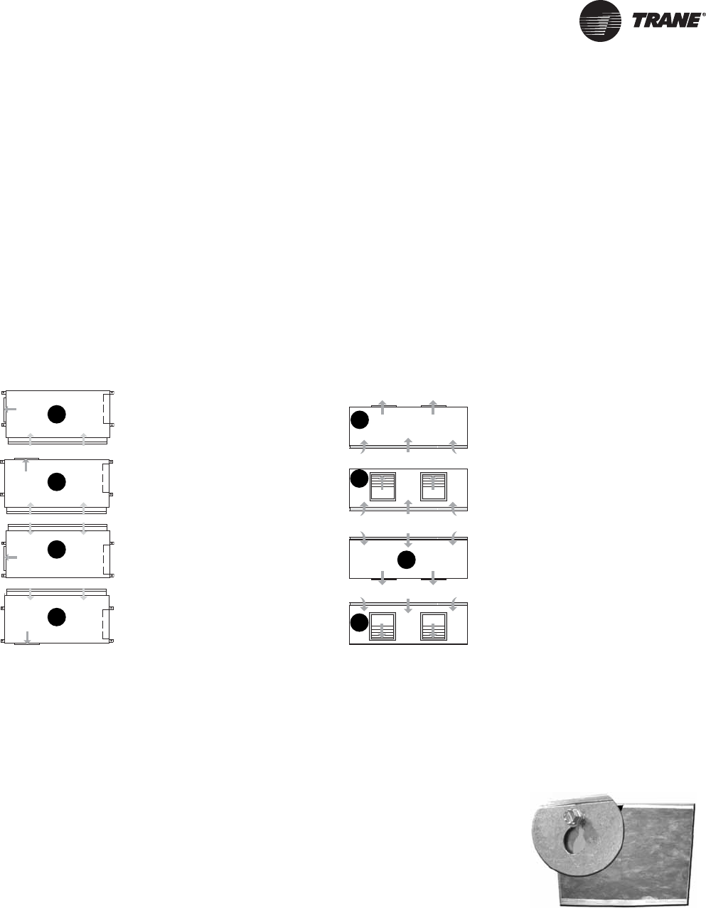
Airflow Combinations
Figure 1. GEH airflow options (left), GEV airflow options (right)
The 6–15 ton horizontal
cabinet airflow flexibility
includes the following
combinations to aid in
applications where the
equipment is required to hug
a corridor or wall.
The four configurations are:
1. Left return-air with back
supply-air combination
2. Left return-air with right
supply-air combination
3. Right return-air with back
supply-air combination
4. Right return-air with left
supply-air combination
The sleek, narrow cabinet of
the 6–25 ton vertical cabinet is
designed to fit through a
standard 36 in. doorway for
installation during new or
retrofit construction.The
equipment is available in four
supply-air/return-air
combinations.These
combinations are order
specific via the unit model
number.
The four configurations are:
1. Front return-air with back
supply-air combination
2. Front return-air with top
supply-air combination
3. Back return-air with front
supply-air combination
4. Back return-air with top
supply-air combination
Control Box
Control Box
Control Box Control Box
LEFT RETURN-AIR
LEFT RETURN-AIR
RIGHT RETURN-AIR
RIGHT RETURN-AIR
BACK
SUPPLY-AIR
BACK
SUPPLY-AIR
LEFT
SUPPLY-AIR
RIGHT
SUPPLY-AIR
1
2
3
4
FRONT RETURN-AIR
FRONT RETURN-AIR
TOP
SUPPLY
BACK RETURN-AIR
BACK RETURN-AIR
BACK SUPPLY-AIR
FRONT SUPPLY-AIR
TOP
SUPPLY
1
2
3
4
Access Panels
The upper panels of the 12½–25 ton verticals feature a key hole
hanging design for ease of maintenance of the unit, allowing the
panel to be hooked into place when attaching the panel to the unit.
The panels are also sealed with a rubber gasket at all four edges to
help eliminate air from escaping around the panel edge.
.
6 WSHP-PRC016E-EN
Features and Benefits
Air-side filter
The air-side filter incorporates a 1-inch thick (nominal) or 2-inch thick (nominal), MERV 8 or MERV
13 disposable fiberglass option.These filters include an average synthetic dust weight arrestance
of approximately 75%.This dust holding capability includes a colorless, odorless adhesive to retain
dirt particles within the filter media after fiber contact.
Blower housing
The blower housing is constructed of non-corrosive galvanized steel. It is a double wide/double
inlet, forward curved wheel moved by an integral horsepower motor with sealed bearings.
Cabinet insulation
The cabinet insulation design meets UL 181 requirements.The air-stream surface of the insulation
is fabricated of a non-biodegradable source.
Compressor
Dual circuit designs of the GEH and GEV models feature scroll compressors.The compressors are
highly efficient and incorporate external vibration isolators and thermal overload protection.
Drain pan
The unit drain pan is composed of plastic, corrosive resistive material.The pan is positively sloped
to comply with ASHRAE 62 for indoor air quality (IAQ) conformity.
Access to the drain pan is provided through two access panels for cleaning purposes for all models.
Hanging device
The hanging channel for the horizontal unit runs the length of the equipment.The structural
integrity of the design helps ensure that bracket deflection or unit bowing does not occur as a result
of the weight of the unit.
Co-axial Water-to-Refrigerant Coil
The unit’s internal heat exchanging water coil is engineered for
maximum heat transfer.
The copper or cupro-nickel seamless tubing is a tube within a tube
design.The inner-water tube contains a deep fluted curve to
enhance heat transfer and minimize fouling and scaling. It is
available in either copper or cupro-nickel (selectable option)
coil.The outer refrigerant gas tube is made from steel material.
The coil is leak tested to assure there is no cross leakage between
the water tube and the refrigerant gas (steel tube) coil. Co-axial heat
exchangers are more tolerant to freeze rupture.
Expansion Valve
The refrigerant flow metering is made through the thermal
expansion valve (TXV). It allows the unit to operate with an entering
fluid temperature from 25°F to 120°F and entering air temperatures
from 55°F to 85°F.The valve is designed to meter refrigerant flow
through the circuitry to achieve desired heating or cooling.
Unlike cap-tube assemblies, the expansion valve device allows the
exact amount of refrigerant required to meet the coil load
demands.This precise metering by theTXV increases the efficiency
of the unit.
WSHP-PRC016E-EN 7
Features and Benefits
Isolation for the hanging bracket is provided with a rubber grommet design as an accessory.This
isolation device helps prevent sound vibration from reaching the structural support members of
the building during compressor start and stop.
Refrigeration piping
Unit copper tubing is created from a 99% pure copper formation that conforms to the American
Society ofTesting Materials (ASTM) B743 for seamless, light-annealed processing.
The unit’s copper refrigeration system is designed to be free from contaminants and conditions
such as drilling fragments, dirt, or oil.This excludes the possibility of these contaminants from
damaging the compressor motor.
Boilerless control/Electric heat (option)
In cooling dominant regions where heat may be used 15 to 30 days out of the winter season,
eliminating the boiler may be an economical advantage to the building owner. Eliminating a boiler
from the system reduces costs associated with the mechanical system installation, as well as the
maintenance and service of the boiler.
How can heat be provided for the few days of the year when heat is necessary?Through the water-
source heat pump of course.The advantage of the water-source heat pump is its ability to provide
heat recovery within the closed water-loop. While some WSHPs may be extracting heat from the
closed water loop, otherWSHPs may be adding heat to the closed water loop.This creates a perfect
system balance for heat sharing or movement from one space to another.
But when water temperatures fall in a boilerless system, and no further heat recovery may be made
using the closed loop, heat may be added to the space through a boilerless control electric heat
option.
Reversing valve
A system reversing valve (4-way valve) is included with all heating/
cooling units.This valve is piped to be energized in the cooling
mode to allow the system to provide heat if valve failure were to
occur.
Once the valve is energized for cooling, it will remain energized
until the control system is turned to the OFF position, or a heating
cycle is initiated.
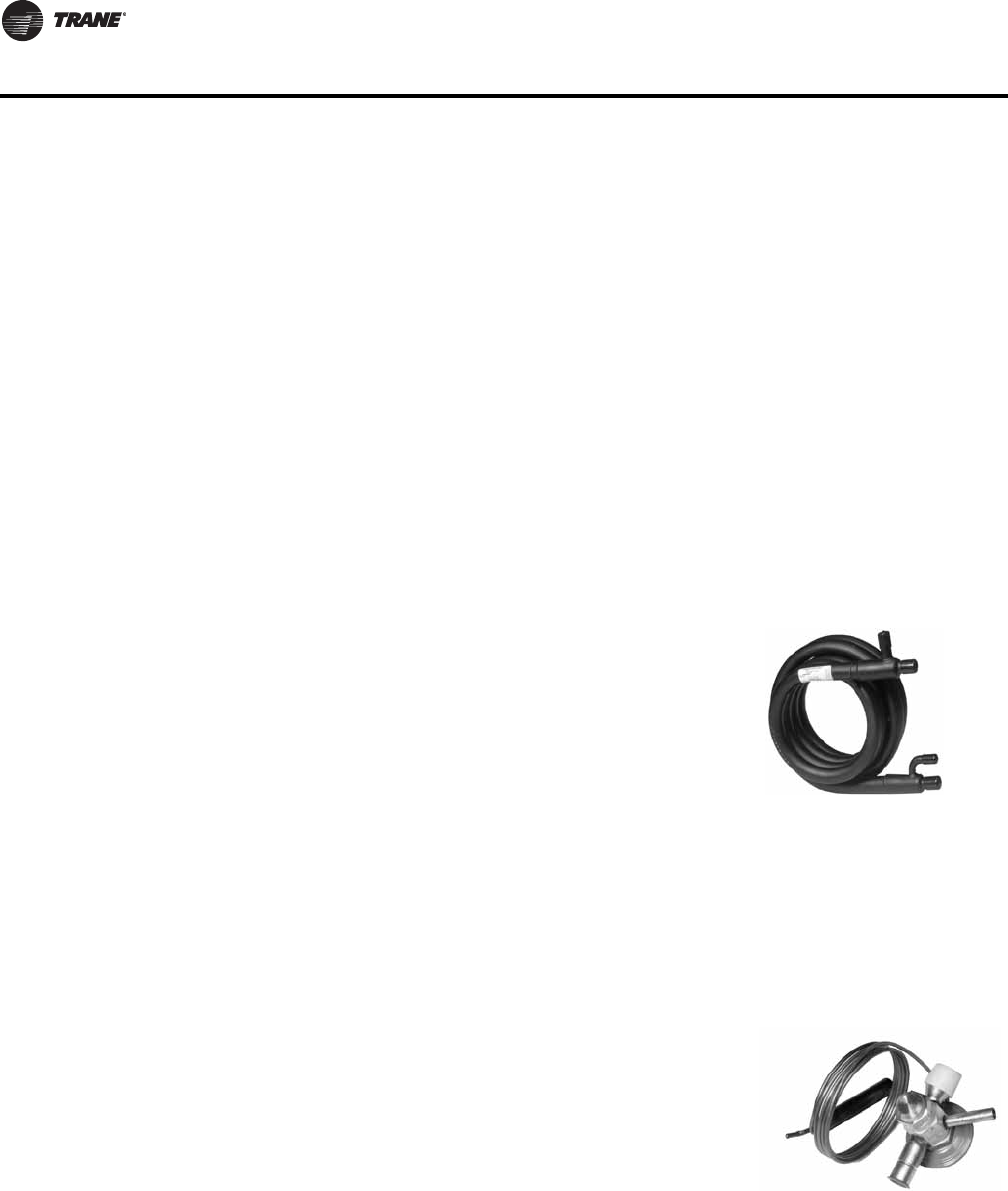
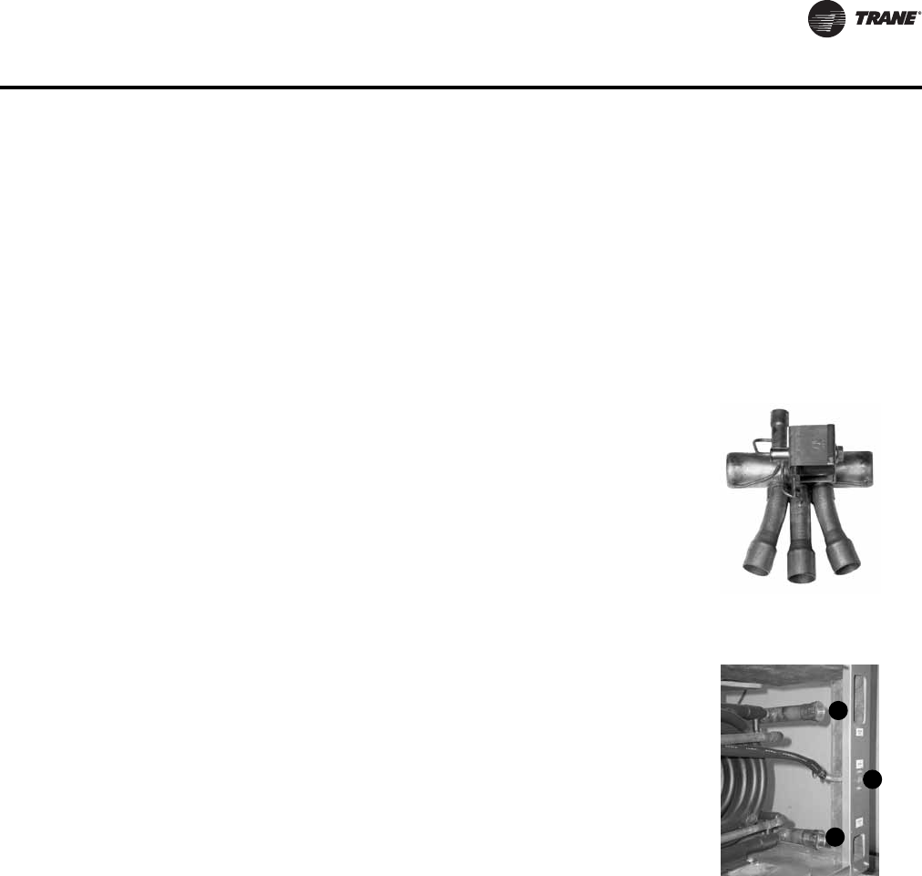
Water Connections
Water hookups for the 6–25 ton units are located internal to the
equipment to help alleviate damage to the water copper during
shipment or job storage of units prior to installation. Each unit
(although dual circuit) contains a single supply and return water
connection.The following figure provides large tonnage water
hook-up information for model GEV.
1. Water-out
2. Drain
3. Water-in
Fittings for the supply and return are internally threaded.
2
1
3
8 WSHP-PRC016E-EN
Features and Benefits
With the boilerless electric heat option, the 6–25 ton models will contain boilerless controls ONLY
to interface for a field provided supplemental electric heat selection.The heater for this model shall
be placed external to the equipment by the contractor for ease of installation. All power
connections for the electric heater will be completely separate from the unit for field supplied
electric heat.
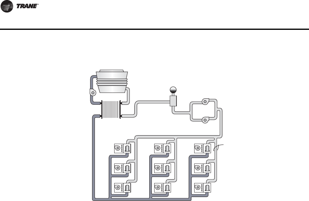
How it Works
In heating mode, when the water temperature falls below 55°F (factory setting), the electric heater
is energized, locking out the compressor.The systems electric heat source will continue to be
utilized for primary heating until the loop temperature rises above 60°F. Once the entering water
temperature rises above 60°F, the boilerless controller returns the unit to normal compressor
heating operation and locks out the electric heater.This maximizes efficiency from the unit during
the few days requiring heat from the mechanical system.
For geothermal applications, the boilerless controller has an adjustable setting of 25, 35, 45, 55 and
60°F.
What is NOT available with the boilerless electric heat option?
• Hot gas reheat
• 575 V ratings
• Supplemental or emergency heat applications
• A factory-installed heater
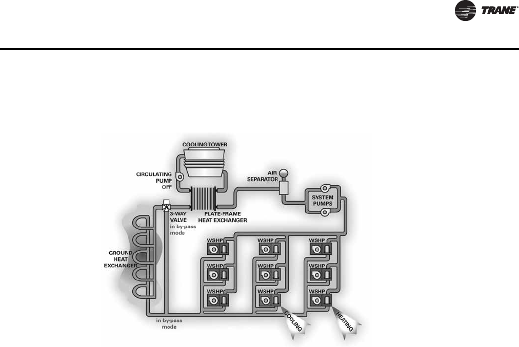
Waterside economizer (option)
The beauty of the waterside economizer is its ability to take advantage of any loop condition that
results in cool water temperatures. A prime example would be during fall, winter, and spring when
cooling towers have more capacity than required and could be controlled to lower temperatures
for economizer support.
Another more common inexpensive means of free comfort cooling includes buildings systems
where perimeter heating and core cooling are needed. In this system, the perimeter units extract
heat from the building loop while in the heating mode, forcing the building loop temperature to
Electric heat system
WSHP
WSHP
WSHP
WSHP
WSHP
WSHP
WSHP
WSHP
WSHP
PLATE-FRAME
HEAT EXCHANGER
BELOW 55 F,
ELECTRIC HEAT
IS ENERGIZED.
ABOVE 60 F,
COMPRESSOR
IS ENERGIZED.
CIRCULATING
PUMP
COOLING TOWER
AIR
SEPARATOR
SYSTEM
PUMPS
WSHP-PRC016E-EN 9
Features and Benefits
drop. Where as, the core are of a building may require cooling in summer or in winter based upon
lighting, people, and equipment.
If the water-source system design contained an economizing coil option, the moderate temperature
loop water circulated through a core water-source system can provide an inexpensive means to
satisfy room comfort without operating the water-source heat pump’s compressor.
During economizer mode, fluid enters the unit, and passes by a water temperature sensing bulb.
This temperature sensing bulb determines whether the two position, three-way valve will direct the
water through the waterside economizing coil, and to the heat pump condenser, or through the
condenser only. If the water temperature is 55°F or less, fluid will flow into the economizing coil,
while simultaneously halting mechanical operation of the compressor. Mechanical cooling will
continue on a call for second stage from the thermostat.
The factory built waterside economizer is available on all 6–15 ton GEH models and 6–25 GEV
models.
Note: Condensate overflow protection for the waterside economizer coil is field provided.
Hot gas reheat (option)
For space conditioning and climate control,Trane provides an accurate and cost effective
dehumidification control through a hot gas reheat option.
With this reheat option, the return air from the space is conditioned by the air-to-refrigerant coil,
then reheated by the reheat coil to control not only the space temperature, but to also reduce the
relative humidity of the space.The moisture removal capability of a specific heat pump is
determined by the units latent capacity rating.
When operating in the reheat mode (meaning the sensible temperature has been met in the space),
the humidistat signals the reheat relay coil to energize, allowing the high pressure refrigerant gas
to flow from the compressor, through the reheat valve, into the reversing valve and through the
reheat coil for dehumidification.
Trane places an air separation space between the air-to-refrigerant coil and the reheat coil to allow
for maximum moisture removal.
Waterside economizer system
10 WSHP-PRC016E-EN
Features and Benefits
Common reheat applications
The hot gas reheat option is designed to support building applications requiring fresh-air
ventilation units delivering unconditioned-air directly to the space. It also provides
dehumidification to large latent load spaces such as auditoriums, theaters and classrooms, or
anywhere humidity control is a problem.
Dos and Don’ts in Design
Water-source heat pumps with hot gas reheat should not be used as a make-up air unit.
2 Speed Blower Motor (option)
The 6 to 25Ton GEH/V models have indoor blowers that are available with 2 speed motors,
selectable in the model number (Digit 12, drive packages 1-9). High speed airflow matches the
single speed motor airflow, referenced in the Fan Performance tables. Low fan speed airflow is
approximately 50% of high fan speed airflow.
The 6 to 25Ton GEH/V 2 speed blower motors are available with the following options: Deluxe 24V
or UC400 controls, Heat Pump (HP) or HP w/Hot Gas Reheat or HP w/Waterside Economizer. Not
available with Boilerless or Supplemental Electric Heat.
Table 1. 6 to 25 ton GEH/V fan speed for 2 speed drive packages 1 to 9
RV State Fan Compressor 1 Compressor 2 Fan Speed
Heat OFF OFF OFF OFF
Heat ON OFF OFF HIGH
Heat ON ON OFF HIGH
Heat ON ON ON HIGH
Cool OFF OFF OFF OFF
Cool ON OFF OFF LOW
Cool ON ON OFF LOW
Cool ON ON ON HIGH
WSHP-PRC016E-EN 11
Application Considerations
Water-source heat pump systems are used to provide comfort in a wide range of building types and
climates.The system utilizes energy-conserving, heat-recovery capabilities to transfer heat from
one area to another to meet individual zone requirements. When used with system design and
control strategies, these high-performance systems reduce operating costs for the building owner
and improve occupant comfort.
Heat pump units are available in many different configurations and the design simplicity can be
adapted to suit almost any building plan.The vertical and horizontal water-source heat pump
system is versatile for installation in a boiler/cooling tower applications, as well as ground source
(geothermal) applications.
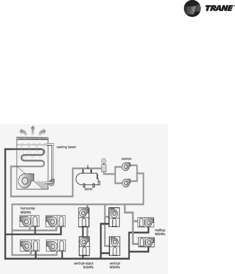
Boiler/cooling tower
In this type of system, units are distributed throughout the building to provide cooling and heating
to the space. Units are connected to a water distribution loop which circulated water throughout
the building to transfer heat from one area to another. This common water loop yields what is
essentially a heat-recovery system. Units providing heating extract heat from loop water while
units providing cooling reject heat to the loop. In effect the system recovers and redistributes heat
where needed.
Also connected to this water loop are a“heat rejecter” such as a cooling tower, a “heat adder” such
as a boiler, circulation pumps, and related accessories. Typically, outdoor air is conditioned and
delivered by a separate, dedicated ventilation system.
During warm weather when all or most of the units are cooling, the cooling tower is used to
dissipate heat from the condensing process.The condensing water is cooled for recirculation back
to the water-to-refrigerant heat exchanger by using a combination of heat and mass transfer by
evaporation.
A boiler is also used to add heat to the water loop during winter months when most units are
heating.The boiler is typically enabled when the water loop temperature falls to a minimum value.
Conventional water-source heat pump system
12 WSHP-PRC016E-EN
Application Considerations
During moderate weather, such as spring or fall, the heat pumps serving the sunny side and interior
of the building often operate in cooling mode and reject heat into the water loop.The heat pumps
serving the shady side of the building often operate in heating mode and absorb heat from the
water loop.
Heat rejected by the units operating in cooling mode is used to offset the heat absorbed by the units
in heating mode. In this manner, a WSHP system provides a form of heat recovery and an
opportunity to save energy by reducing the need to operate the boiler or cooling tower. For
example, if the water temperature stays in the desired range-between 60ºF (16ºC) and 90ºF (32ºC)-
neither the boiler nor the cooling tower need to operate.
In applications such as office buildings, heat generated by lights, people, and office equipment
often results in the need to provide year-round cooling in the interior zones of the building. In these
applications, the benefit of this heat recovery further reduces boiler energy use during the winter
months.
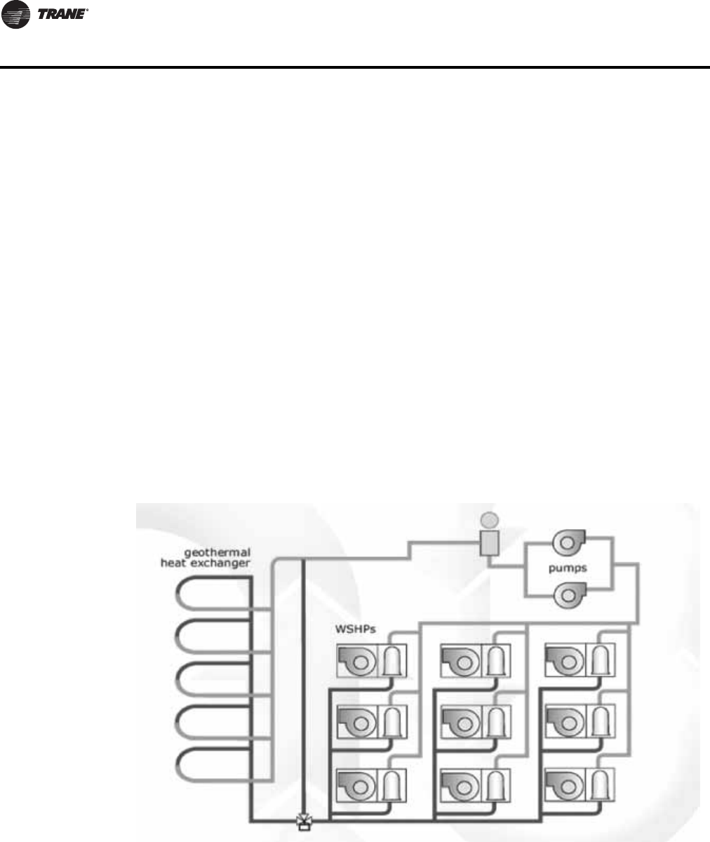
Ground Source
A geothermal heat pump system can potentially minimize heating and cooling cost by 30 to 40
percent. In this application the cooling tower and boiler are replaced with a ground heat exchanger.
The ground heat exchanger is a series of pipes buried in the earth.The earth is used as an energy
storage tank. Ground-source heat pump systems offer the potential for saving energy because they
can reduce (or eliminate) the energy needed to operate a cooling tower and/or boiler. Eliminating
the cooling tower has architectural and maintenance advantages, and eliminating the boiler frees
up floor space in the building.
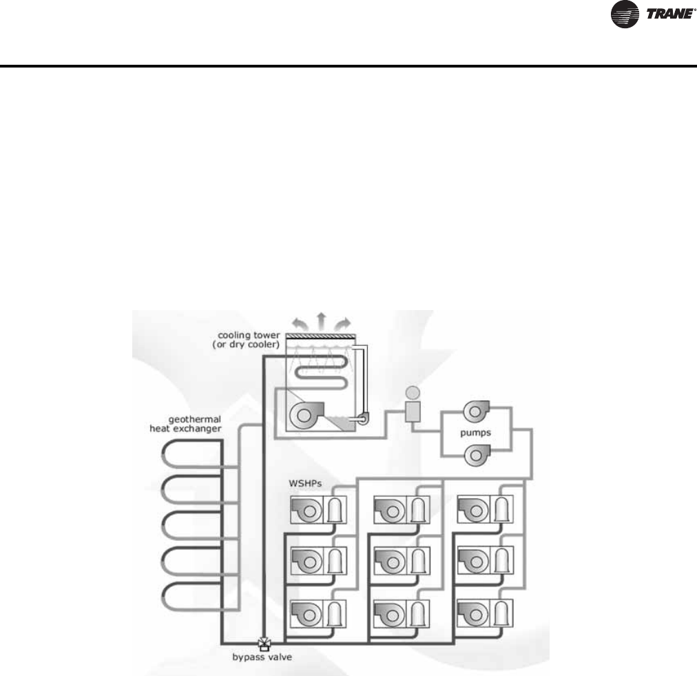
Hybrid Systems
Hybrid systems involve adding a small cooling tower or dry cooler to a ground source system that
is installed in a cooling -dominated climate or adding a small boiler to a system in a heating-
dominated climate. In either case, the geothermal heat exchanger is sized based on the smaller of
the two loads: for the total heat absorbed in a cooling-dominated climate or the total heat rejected
in a heating-dominated climate.Then, a small cooling tower (or boiler) is added to reject (or add)
the remaining heat.
Ground source heat pump system
WSHP-PRC016E-EN 13
Application Considerations
A hybrid system may also be used in existing buildings with existing ground loops as additional
rooms or buildings are added to the system. A cooling tower may be the solution to off-load the
peak demand of the new building addition as an example. Other additions may include a
requirement for fresh-air ventilation. A fresh-air, air handler, along with a water to water unit may
be introduced to the closed loop system to allow tempered fresh-air into the building.
The buildings heating and cooling needs are not based off of one type of component, but perform
harmonious of each other. Heat recovery from the loop itself can be shared with the other major
components.
Hybrid systems can often make the system more economical, opening up the possibility to reap
the potential energy savings.
Central Pumping System
A central pumping design involves a single pump design, usually located within a basement or
mechanical room to fulfill pumping requirements for the entire building system.An auxiliary pump
is typically applied to lessen the likelihood of system downtime if the main pump malfunctions.
Distributed Pumping System
A distributed pumping system contains a single pump module connected directly to the units
supply and return.This module is field installed and piped to the unit.This design requires
individual pump modules specifically sized for each water-source heat pump.
Hybrid system

14 WSHP-PRC016E-EN
Digits 1-3 - Unit Configuration
GEH = High Efficiency Horizontal
GEV = High Efficiency Vertical
Digit4-Development Sequence
E = R-410A
Digits 5-7 - Nominal Capacity
Digit 8 - Voltage (Volts/Hz/Phase)
1 = 208/60/1
2 = 230/60/1
3 = 208/60/3
4 = 460/60/3
5 = 575/60/3
6 = 220-240/50/1
7 = 265/60/1
8 = 230/60/3
9 = 380-415/50/3
Digit 9 - Heat Exchanger
1 = Copper-Water Coil
2 = Cupro-Nickel Water Coil
7 = Insulated Copper-Water Coil
8 = Insulated Cupro-Nickel Water Coil
Digit 10 - Current Design
Sequence
Digit 11 - Refrigeration Circuit
0 = Heating and Cooling Circuit
2 = Heating and Cooling Circuit with
Hot Gas Reheat
3 = Heating and Cooling Circuit with
Waterside Economizer
4 = Heating and Cooling Circuit with
HGR and WSE
Digit 12 - Blower Configuration
A = Drive Package A (GEH/GEV)
B = Drive Package B (GEH/GEV)
C = Drive Package C (GEH/GEV)
D = Drive Package D (GEH/GEV)
E = Drive Package E (GEH/GEV)
F = Drive Package F (GEH/GEV)
G = Drive Package G (GEH/GEV)
H = Drive Package H (GEH/GEV)
J = Drive Package J (GEH/GEV)
1 = 2 Speed Drive Package A (GEH/GEV)
2 = 2 Speed Drive Package B (GEH/GEV)
3 = 2 Speed Drive Package C (GEH/GEV)
4 = 2 Speed Drive Package D (GEH/GEV)
5 = 2 Speed Drive Package E (GEH/GEV)
6 = 2 Speed Drive Package F (GEH/GEV)
7 = 2 Speed Drive Package G (GEH/GEV)
8 = 2 Speed Drive Package H (GEH/GEV)
9= 2 Speed Drive Package J (GEH/GEV)
Digit 13 - Freeze Protection
A = 20°F Freezestat
B = 35°F Freezestat
Digit 14 - Open Digit = 0
072=6Ton 180=15Ton
090 = 7½Ton 240 = 20Ton
120=10Ton 300=25Ton
150 = 12½Ton
Digit 15 - Supply-Air
Arrangement
B = Back Supply-Air Arrangement
F = Front Supply-Air Arrangement
L = Left Supply-Air Arrangement
R = Right Supply-Air Arrangement
T =Top Supply-Air Arrangement
Digit 16 - Return-Air
Arrangement
B = Back Return-Air Arrangement
F = Front Return-Air Arrangement
L = Left Return-Air Arrangement
R = Right Return-Air Arrangement
Digit 17 - Control Types
D = Deluxe 24V Controls
B = Tracer ZN524 Controls
F = UC400
G = UC400 w/ Wireless Comm
Digit 18 - Open
0 = Wall Mounted Location
Digit 19 - Fault Sensors
0 = No Fault Sensor
1 = Condensate Overflow Sensor
2 = Filter MaintenanceTimer
3 = Condensate Overflow and Filter
MaintenanceTimer
4 = Fan Status Sensor
6 = Condensate Overflow and Fan
Status
H = Fan Status and Filter
MaintenanceTimer
J = Fan Status, Filter Maintenance
Timer and Condensate Overflow
Sensor
Digit 20 - Open
0 = No AdditionalTemperature Sensor
Digit 21 - Open
Digit 22 - Electric Heat
0 = No Electric Heat
4 = External Boilerless Electric Heat
5 = External Supplemental Electric
Heat
Digit 23 - Open
Digit 24 - Filter Type
1 = 1 in.Throwaway Filter
2 = 2 in.Throwaway Filter
Digit 25-36 - Does Not Apply to
GEH or GEV
00000000000 = Digits 25-36 are not
applicable to the GEH or GEV products
Model Number Description
WSHP-PRC016E-EN 15
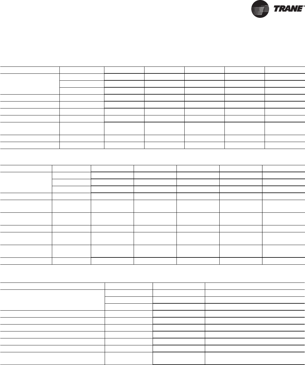
General Data
Table 2. General data - GEH072-180 (6-15 tons)
Model GEH 072 090 120 150 180
Unit Size Length (in) 40 3/4 40 3/4 40 3/4 46 3/4 46 3/4
Height (in) 21 21 21 28 28
Width (in) 79 79 79 85 85
Compressor Type Scroll (2) Scroll (2) Scroll (2) Scroll (2) Scroll (2)
Approximate Weight with Pallet (lb) 714 724 827 899 997
Approximate Weight without Pallet (lb) 665 676 785 857 955
Filter Size Actual (in) 19 5/8 x 24 5/8 (3) 19 5/8 x 24 5/8 (3)19 5/8 x 24 5/8 (3) 24 5/8 x 24 5/8 (3) 24 5/8 x 24 5/8 (3)
Water in/out size
(FPT) inches 1 1/4 1 1/4 1 1/2 1 1/2 1 1/2
Condensate size (PVC) inches 1/2 1/2 1/2 1/2 1/2
Blower Wheel Size Belt Drive (in) 12.62 x 12.62 12.62 x 12.62 12.62 x 12.62 15.00 x 15.00 15.00 x 15.00
Table 3. General data - GEV072-180 (6-15 tons)
Model GEV 072 090 120 150 180
Unit Size Length (in) 42 42 42 81 5/8 81 5/8
Height (in) 62 5/8 62 5/8 62 5/8 68 68
Width (in) 36 1/4 36 1/4 36 1/4 36 1/4 36 1/4
Compressor Type Scroll (2) Scroll (2) Scroll (2) Scroll (2) Scroll (2)
Approximate
Weight with Pallet (lb) 630 658 857 1207 1223
Approximate
Weight without Pallet (lb) 590 618 817 1162 1178
Filter Size Actual (in) 19 5/8 x 19 5/8 (4) 19 5/8 x 19 5/8 (4) 19 5/8 x 19 5/8 (4) 19 5/8 x 24 5/8 (6) 19 5/8 x 24 5/8 (6)
Water in/out size
(FPT) inches 1 1/4 FPT 1 1/4 FPT 1 1/2 FPT 1 1/2 FPT 1 1/2 FPT
Condensate size
(PVC) inches 3/4 3/4 3/4 3/4 3/4
Blower Wheel Size Belt Drive (in) 12.62 x 12.62 12.62 x 12.62 12.62 x 12.62 15.00 x 15.00 15.00 x 15.00
Table 4. General data - GEV240-300 (20-25 tons)
Model GEV 240 300
Unit Size Length (in) 81 5/8 81 5/8
Height (in) 68 68
Width (in) 36 1/4 36 1/4
Compressor Type Scroll (2) Scroll (2)
Approximate Weight with Pallet (lb) 1644 1665
Approximate Weight without Pallet (lb) 1599 1620
Filter Size Actual (in) 19 5/8 x 24 5/8 (6) 19 5/8 x 24 5/8 (6)
Water in/out size (sweat) inches 2 FPT 2 FPT
Condensate size (NPTI) inches 3/4 3/4
Blower Wheel Size and quantity (regular-
low static/high static) Belt Drive (in) (2) 12.62 x 12.62 (2) 15.00 x 11.00/(2) 12.62 x 12.62
16 WSHP-PRC016E-EN
General Data
Table 5. Air-to-Refrigerant coil (2-compressor circuit) - 6-25 tons
Unit Size 072 090 120 150 180 240 300
Working
Pressure 650 650 650 650 650 650 650
Tubes High (GEH) 18
(GEV) 24 (GEH) 18
(GEV) 28 (GEH) 18
(GEV) 36 (GEH) 24
(GEV) 28 (GEH) 24
(GEV) 32 (GEV) 36 (GEV) 36
Tubes Deep 444
(GEH) 4
(GEV) 2 (GEH) 4
(GEV) 3 (GEV) 4 (GEV) 4
No. of
Circuits
(GEH) 6 refrig
flow paths (2X)
(GEV) 6 refrig
flow paths (2X)
(GEH) 6 refrig
flow paths (2X)
(GEV) 7 refrig
flow paths (2X)
(GEH) 9 refrig
flow paths (2X)
(GEV) 9 refrig
flow paths (2X)
(GEH) 8 refrig
flow paths (2X)
(GEV) 7 refrig
flow paths (2X)
(GEH) 6 refrig
flow paths (2X)
(GEV) 8 refrig
flow paths (2X)
(GEV) 18 refrig
flow paths (2X) (GEV) 18 refrig
flow paths (2X)
Finned vol.
(h,w,d)
(GEH)
18 x 48 x 3.464
(GEV)
24 x 34 x 3.464
(GEH)
18 x 54 x 3.464
(GEV)
28 x 34 x 3.464
(GEH)
18 x 73 x 3.464
(GEV)
36 x 34 x 3.464
(GEH)
24 x 73 x 3.464
(GEV)
28 x 73 x 1.734
(GEH) 24 x 73 x
3.464
(GEV) 32 x 73 x
2.598
(GEV) 36x 73 x
3.464 (GEV) 36x 73 x
3.464
Coil Surface
Area (Ft2)(GEH) 6.00
(GEV) 5.67 (GEH) 6.75
(GEV) 6.61 (GEH) 9.125
(GEV) 8.50 (GEH) 12.167
(GEV) 14.19 (GEH) 12.167
(GEV) 16.22 (GEV) 18.25 (GEV) 18.25
Fins Per Inch 14 14 14 14 14 14 14
Tube
Material Copper Copper Copper Copper Copper Copper Copper
Tube OD (in) 3/8 3/8 3/8 3/8 3/8 3/8 3/8
Wall
Thickness 0.014 0.014 0.014 0.014 0.014 0.014 0.014
Return Bends Copper Copper Copper Copper Copper Copper Copper
WSHP-PRC016E-EN 17
Performance Data
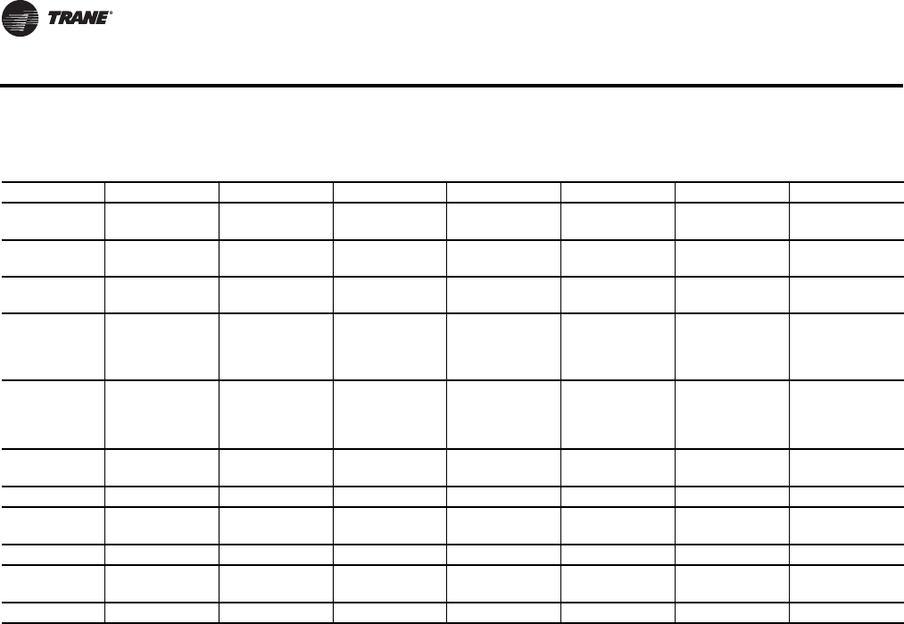
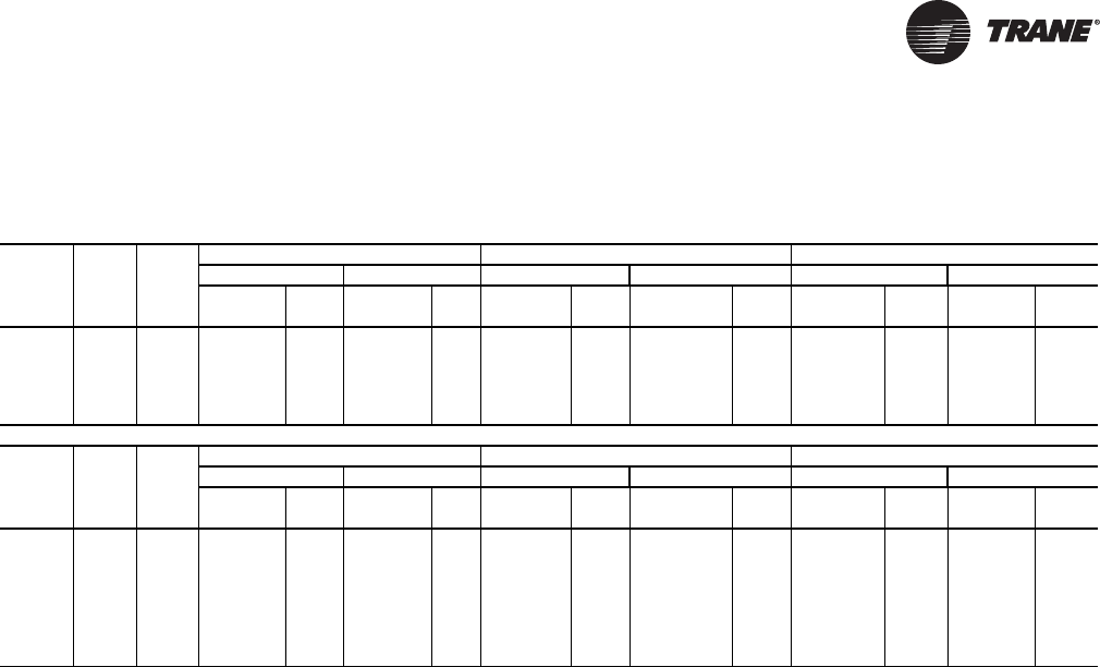
Table 6. ARI-ISO WLHP, GWHP and GLHP performance(a)
Model Rated
GPM Rated
CFM
Water Loop Heat Pump Ground Water Heat Pump Ground Loop Heat Pump
Cooling 86°F Heating 68°F Cooling 59°F Heating 50°F Full Cool 77°F Full Heat 32°F
Capacity
Btuh EER Capacity
Btuh COP Capacity
Btuh EER Capacity
Btuh EER Capacity
Btuh EER Capacity
Btuh EER
GEH072 18.0 2100 75,500 13.40 83,800 4.80 83,200 21.90 69,100 4.20 74,600 16.00 54,400 3.50
GEH090 22.5 2625 88,100 14.10 99,200 4.68 94,600 20.67 83,000 4.07 88,100 15.80 64,500 3.40
GEH120 30.0 3500 115,900 13.35 147,100 4.60 129,000 19.30 122,600 4.10 120,600 14.90 99,200 3.20
GEH150 37.5 4375 152,800 14.30 175,000 4.40 166,800 20.60 147,800 4.10 158,000 16.40 118,000 3.40
GEH180 45.0 5250 180,800 13.10 222,700 4.40 204,700 18.50 183,100 4.00 188,500 14.70 147,900 3.50
Model Rated
GPM Rated
CFM
Water Loop Heat Pump Ground Water Heat Pump Ground Loop Heat Pump
Cooling 86°F Heating 68°F Cooling 59°F Heating 50°F Full Cool 77°F Full Heat 32°F
Capacity
Btuh EER Capacity
Btuh COP Capacity
Btuh EER Capacity
Btuh EER Capacity
Btuh EER Capacity
Btuh EER
GEV072 18.0 2100 74,900 15.24 82,800 4.64 84,800 22.85 70,200 4.18 78,800 17.50 54,500 3.44
GEV090 22.5 2625 89,700 15.10 103,600 4.50 98,600 22.91 83,600 4.10 92,100 17.40 65,600 3.40
GEV120 30.0 3500 119,300 14.54 134,300 4.50 131,400 21.05 113,900 4.06 123,200 16.60 90,400 3.40
GEV150 37.5 4375 154,300 15.40 185,300 4.80 170,400 22.20 152,900 4.30 158,900 17.30 120,600 3.60
GEV180 45.0 5250 185,700 14.10 221,500 4.40 205,000 20.10 180,400 4.10 192,200 16.10 143,500 3.50
GEV240 60.0 7000 249,800 15.10 270,800 4.60 280,200 22.10 223,800 4.20 258,000 17.00 177,900 3.50
GEV300 75.0 8750 305,700 13.90 350,400 4.30 339,400 19.50 286,400 3.80 315,500 15.70 234,600 3.30
Note: Models with capacities greater than 135,000 BTUH are not included in the
ARI water-to-air and brine-to-air heat pump certification program.
(a)Rated in accordance with ISO Standard 13256-1: 1998 (Water Loop Heat Pumps, Ground Water Heat Pumps, Ground Loop Heat Pumps). Certified
conditions are 80.6F DB/66.2F WB EAT in cooling and 68F DB/59F WB EAT in heating.

18 WSHP-PRC016E-EN
Performance Data
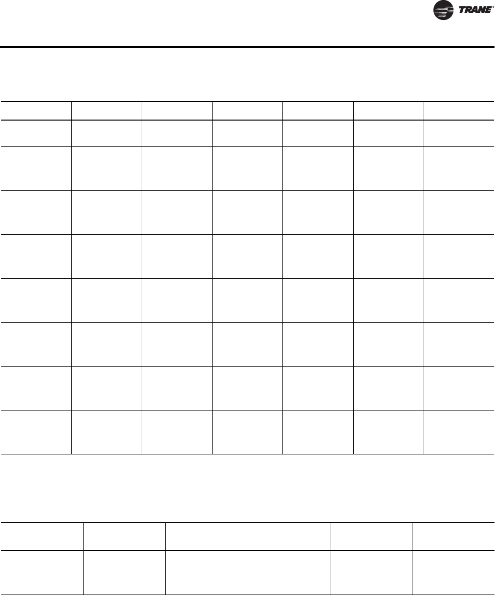
Table 7. Gross cooling capacities-6tonsGEH*072
EWT GPM Gross Cap.
Mbtuh Gross Sen.
Mbtuh SHR Comp Power
kW Reject Mbtuh LWT Feet Head
45 9.0 91.3 67.3 0.74 3.03 101.6 67.6 4.0
45 12.0 92.1 67.6 0.73 2.74 101.5 61.9 6.7
45 15.0 92.6 67.9 0.73 2.56 101.4 58.5 10.0
45 18.0 93.0 68.1 0.73 2.43 101.3 56.3 13.8
45 21.0 93.3 68.1 0.73 2.34 101.3 54.6 18.2
55 9.0 88.0 66.0 0.75 3.68 100.5 77.3 3.9
55 12.0 88.6 66.3 0.75 3.39 100.1 71.7 6.5
55 15.0 88.9 66.4 0.75 3.22 99.9 68.3 9.6
55 18.0 89.2 66.5 0.75 3.10 99.8 66.1 13.3
55 21.0 89.4 66.7 0.75 3.01 99.7 64.5 17.5
59 9.0 86.6 65.5 0.76 3.94 100.1 81.2 3.8
59 12.0 87.2 65.7 0.75 3.65 99.6 75.6 6.4
59 15.0 87.5 65.9 0.75 3.48 99.4 72.3 9.5
59 18.0 87.8 66.0 0.75 3.36 99.2 70.0 13.1
59 21.0 87.9 66.0 0.75 3.28 99.1 68.4 17.2
68 9.0 83.6 64.3 0.77 4.56 99.2 90.0 3.7
68 12.0 84.1 64.5 0.77 4.26 98.6 84.4 6.2
68 15.0 84.3 64.6 0.77 4.08 98.3 81.1 9.2
68 18.0 84.5 64.7 0.77 3.96 98.1 78.9 12.7
68 21.0 84.7 64.8 0.76 3.87 97.9 77.3 16.7
77 9.0 80.3 63.0 0.78 5.48 99.0 99.0 3.6
77 12.0 80.8 63.2 0.78 5.09 98.2 93.4 6.0
77 15.0 81.0 63.3 0.78 4.87 97.6 90.0 8.9
77 18.0 81.2 63.4 0.78 4.72 97.3 87.8 12.3
77 21.0 81.3 63.4 0.78 4.62 97.1 86.2 16.2
86 9.0 76.9 61.5 0.80 6.11 97.7 107.7 3.5
86 12.0 77.4 61.7 0.80 5.74 97.0 102.2 5.9
86 15.0 77.6 61.8 0.80 5.52 96.5 98.9 8.7
86 18.0 77.8 61.9 0.80 5.39 96.2 96.7 12.0
86 21.0 77.9 61.9 0.79 5.29 96.0 95.1 15.7
95 9.0 72.9 60.1 0.82 7.15 97.3 116.6 3.4
95 12.0 73.5 60.5 0.82 6.73 96.4 111.1 5.7
95 15.0 73.8 60.4 0.82 6.48 96.0 107.8 8.5
95 18.0 74.1 60.5 0.82 6.32 95.6 105.6 11.7
95 21.0 74.3 60.3 0.81 6.19 95.4 104.1 15.3
105 9.0 68.7 57.7 0.84 8.230 96.8 126.5 3.1
105 12.0 69.5 58.9 0.85 7.745 95.9 121.0 5.3
105 15.0 70.0 58.4 0.83 7.460 95.5 117.7 7.9
105 18.0 70.2 59.0 0.84 7.281 95.1 115.6 10.9
105 21.0 70.6 58.6 0.83 7.114 94.9 114.0 14.1
115 9.0 64.0 55.7 0.87 9.300 95.7 136.3 2.8
115 12.0 65.0 56.6 0.87 9.000 95.7 131.0 4.6
115 15.0 66.0 56.8 0.86 8.700 95.7 127.8 6.9
115 18.0 66.5 57.5 0.87 8.300 94.8 125.5 9.7
115 21.0 68.0 57.1 0.84 8.100 95.6 124.1 12.5
120 18.0 64.0 56.3 0.88 8.950 94.5 130.5 8.8
120 21.0 65.0 55.9 0.86 8.700 94.7 129.0 11.5
Performance data is tabulated for cooling at 80.6°F DB/66.2°F WB entering air.
For conditions other than what is tabulated, multipliers must be used to correct performance. See the fan correction factors table for CFM other than
rated and the cooling correction factors for variations in entering air temperature. WLHP data shown in bold type is performance data at ARI/ISO 13256
The bold type for GLHP is a rating point only. For ARI 13256-1 GLHP conditions, apply 15% methanol by volume per the antifreeze correction factors
found on Table 77, p. 67. The minimum gpm/ton is 3.0 when the EWT is greater than 115°F and the EAT is less than 67°F WB.
Rated GPM: 18.0 Minimum CFM 1920; Nominal CFM 2400, Maximum CFM 2880

WSHP-PRC016E-EN 19
Performance Data
Table 8. Heating capacities (gross)-6tonsGEH*072
EWT GPM Gross Cap Mbtuh Absorb
Mbtuh Comp Power kW LWT Feet Head
25 15.0 43.7 30.6 3.84 20.9 11.8
25 18.0 44.2 31.1 3.85 21.5 16.2
25 21.0 44.9 31.7 3.86 22.0 21.2
32 9.0 47.2 33.9 3.90 24.5 4.7
32 12.0 48.8 35.4 3.93 26.1 7.8
32 15.0 49.9 36.5 3.94 27.1 11.4
32 18.0 50.7 37.2 3.95 27.9 15.7
32 21.0 51.3 37.8 3.96 28.4 20.6
45 9.0 57.2 43.4 4.04 35.4 4.6
45 12.0 59.2 45.4 4.07 37.4 7.6
45 15.0 60.7 46.7 4.09 38.8 11.1
45 18.0 61.7 47.6 4.11 39.7 15.3
45 21.0 62.4 48.3 4.11 40.4 20.0
50 9.0 62.1 48.0 4.12 39.3 4.5
50 12.0 64.4 50.2 4.15 41.6 7.3
50 15.0 65.8 51.5 4.17 43.1 10.8
50 18.0 66.8 52.5 4.18 44.2 14.9
50 21.0 67.6 53.2 4.21 44.9 19.4
55 9.0 66.1 51.8 4.18 43.5 4.4
55 12.0 68.7 54.3 4.23 46.0 7.2
55 15.0 70.5 55.9 4.26 47.5 10.6
55 18.0 71.4 56.8 4.27 48.7 14.6
55 21.0 72.2 57.6 4.28 49.5 19.0
68 9.0 77.2 62.3 4.37 54.2 4.2
68 12.0 80.2 65.2 4.41 57.1 6.9
68 15.0 82.1 67.0 4.44 59.1 10.1
68 18.0 83.8 68.5 4.48 60.4 13.9
68 21.0 84.5 69.2 4.48 61.4 18.2
75 9.0 83.2 68.0 4.47 59.9 4.1
75 12.0 86.6 71.1 4.53 63.1 6.7
75 15.0 88.8 73.2 4.56 65.2 9.9
75 18.0 90.1 74.5 4.58 66.7 13.6
75 21.0 91.2 75.5 4.60 67.8 17.7
86 9.0 93.0 77.2 4.65 68.9 3.9
86 12.0 96.6 80.6 4.69 72.6 6.5
86 15.0 99.1 82.9 4.73 74.9 9.5
86 18.0 100.5 84.3 4.75 76.6 13.1
86 21.0 101.7 85.5 4.77 77.9 17.1
Performance data is tabulated for heating at 68°F DB entering air.For conditions other than what is tabulated, multipliers must be used to correct
performance. See the fan correction factors table for CFM other than rated and the heating correction factors for variations in entering air temperature.
WLHP data shown in bold type is performance data at ARI/ISO 13256-1. The bold type for GLHP is a rating point only. For ARI 13256-1 GLHP conditions,
apply 15% methanol by volume per the antifreeze correction factors found on Table 77, p. 67.
Rated GPM: 18.0 Minimum CFM 1920; Nominal CFM 2400, Maximum CFM 2880
Table 9. Fan correction factors-6tonsGEH*072
Entering
CFM Cooling
Capacity Sensible
Capacity
Cooling
Input
Watts Heating
Capacity
Heating
Input
Watts
1920 0.953 0.879 1.008 0.980 1.082
2160 0.979 0.940 1.004 0.989 1.035
2400 1.000 1.000 1.000 1.000 1.000
2640 1.019 1.060 0.996 1.003 0.967
2880 1.034 1.116 0.994 1.008 0.941

20 WSHP-PRC016E-EN
Performance Data
Table 10. Gross cooling capacities - 7½ tons GEH*090
EWT GPM Gross Cap
Mbtuh Gross Sen
Mbtuh SHR Comp Power
kW Reject Mbtuh LWT Feet Head
45 11.3 107.5 80.6 0.75 3.31 118.7 66.0 4.7
45 15.0 108.4 80.9 0.75 3.04 118.7 60.8 7.7
45 18.8 109.0 81.2 0.74 2.86 118.8 57.6 11.6
45 22.5 109.4 81.4 0.74 2.75 118.8 55.6 15.9
45 26.3 109.7 81.5 0.74 2.66 118.8 54.0 21.0
55 11.3 104.1 79.4 0.76 3.90 117.4 75.8 4.5
55 15.0 104.9 79.5 0.76 3.62 117.3 70.6 7.4
55 18.8 105.5 79.8 0.76 3.46 117.3 67.5 11.1
55 22.5 105.8 79.9 0.75 3.35 117.2 65.4 15.3
55 26.3 106.0 79.9 0.75 3.27 117.2 63.9 20.2
59 11.3 102.7 78.8 0.77 4.13 116.8 79.7 4.4
59 15.0 103.5 79.1 0.76 3.87 116.7 74.6 7.3
59 18.8 104.0 79.3 0.76 3.70 116.6 71.4 11.0
59 22.5 104.3 79.2 0.76 3.59 116.5 69.4 15.1
59 26.3 104.5 79.3 0.76 3.51 116.5 67.9 19.9
68 11.3 99.4 77.4 0.78 4.69 115.3 88.4 4.3
68 15.0 100.1 77.6 0.78 4.41 115.1 83.3 7.1
68 18.8 100.5 77.8 0.77 4.25 115.0 80.2 10.6
68 22.5 100.8 77.8 0.77 4.14 114.9 78.2 14.6
68 26.3 101.0 78.0 0.77 4.07 114.9 76.7 19.2
77 11.3 95.8 75.7 0.79 5.28 113.8 97.2 4.2
77 15.0 96.5 76.0 0.79 5.00 113.6 92.1 6.9
77 18.8 96.9 76.3 0.79 4.83 113.4 89.1 10.3
77 22.5 97.2 76.4 0.79 4.71 113.3 87.1 14.2
77 26.3 97.3 76.4 0.79 4.64 113.2 85.6 18.7
86 11.3 91.9 74.4 0.81 5.96 112.2 105.9 4.1
86 15.0 92.5 74.7 0.81 5.65 111.8 100.9 6.7
86 18.8 93.0 74.9 0.81 5.47 111.6 97.9 10.0
86 22.5 93.2 74.9 0.80 5.35 111.4 95.9 13.8
86 26.3 93.4 75.1 0.80 5.27 111.3 94.5 18.1
95 11.3 87.9 72.9 0.83 6.70 110.8 114.6 4.0
95 15.0 88.5 73.1 0.83 6.37 110.3 109.7 6.6
95 18.8 88.9 73.3 0.82 6.18 110.0 106.7 9.8
95 22.5 89.1 73.4 0.82 6.06 109.8 104.8 13.4
95 26.3 89.3 73.4 0.82 5.97 109.7 103.3 17.7
105 11.3 83.0 71.9 0.87 7.636 109.1 124.3 3.9
105 15.0 83.6 72.1 0.86 7.291 108.5 119.5 6.4
105 18.8 84.0 71.8 0.85 7.075 108.1 116.5 9.5
105 22.5 84.2 71.9 0.85 6.946 107.9 114.6 13.0
105 26.3 84.5 72.1 0.85 6.852 107.9 113.2 17.2
115 11.3 77.7 69.3 0.89 8.697 107.4 134.0 3.8
115 15.0 78.3 69.6 0.89 8.322 106.7 129.2 6.2
115 18.8 78.6 69.7 0.89 8.105 106.3 126.3 9.3
115 22.5 78.9 70.2 0.89 7.960 106.1 124.4 12.7
115 26.3 79.1 70.2 0.89 7.857 105.9 123.1 16.7
120 22.5 76.1 68.5 0.90 8.539 105.2 129.4 12.6
120 26.3 76.2 68.5 0.90 8.431 105.0 128.0 16.5
Performance data is tabulated for cooling at 80.6°F DB/66.2°F WB entering air.
For conditions other than what is tabulated, multipliers must be used to correct performance. See the fan correction factors table for CFM other than rated
and the cooling correction factors for variations in entering air temperature. WLHP data shown in bold type is performance data at ARI/ISO 13256. The
bold type for GLHP is a rating point only. For ARI 13256-1 GLHP conditions, apply 15% methanol by volume per the antifreeze correction factors found
on Table 77, p. 67. The minimum gpm/ton is 3.0 when the EWT is greater than 115°F and the EAT is less than 67°F WB.
Rated GPM: 22.5 Minimum CFM 2400; Nominal CFM 3000, Maximum CFM 3600
WSHP-PRC016E-EN 21
Performance Data
Table 11. Heating capacities (gross) - 7½ tons GEH*090
EWT GPM Gross Cap
Mbtuh Absorb
Mbtuh Comp Power
kW LWT Feet Head
25 18.8 58.5 42.9 4.58 20.4 13.4
25 22.5 59.6 43.9 4.59 21.1 18.3
25 26.3 60.7 45.0 4.60 21.6 24.1
32 11.3 60.9 45.1 4.62 24.0 5.4
32 15.0 62.3 46.5 4.64 25.8 8.8
32 18.8 64.2 48.3 4.66 26.9 13.0
32 22.5 65.2 49.3 4.67 27.6 17.8
32 26.3 65.8 49.8 4.68 28.2 23.4
45 11.3 72.8 56.5 4.77 35.0 5.2
45 15.0 75.5 59.1 4.81 37.1 8.6
45 18.8 77.2 60.7 4.83 38.5 12.7
45 22.5 78.6 62.0 4.86 39.5 17.3
45 26.3 79.3 62.7 4.86 40.2 22.7
50 11.3 79.2 62.5 4.89 38.9 5.1
50 15.0 81.9 65.1 4.92 41.3 8.3
50 18.8 83.8 66.9 4.95 42.9 12.3
50 22.5 84.9 68.0 4.96 44.0 16.8
50 26.3 85.8 68.8 4.97 44.8 22.1
55 11.3 84.3 67.3 4.97 43.1 5.0
55 15.0 87.3 70.2 5.01 45.6 8.2
55 18.8 89.2 72.1 5.03 47.3 12.1
55 22.5 90.4 73.2 5.04 48.5 16.5
55 26.3 91.5 74.3 5.06 49.4 21.7
68 11.3 98.4 80.6 5.20 53.7 4.8
68 15.0 102.0 84.1 5.26 56.8 7.8
68 18.8 104.4 86.4 5.28 58.8 11.5
68 22.5 106.0 87.9 5.30 60.2 15.7
68 26.3 107.2 89.1 5.32 61.2 20.7
75 11.3 106.1 87.9 5.34 59.4 4.7
75 15.0 110.0 91.6 5.38 62.8 7.6
75 18.8 113.4 94.8 5.45 64.9 11.3
75 22.5 115.1 96.4 5.47 66.4 15.4
75 26.3 116.4 97.7 5.49 67.6 20.2
86 11.3 118.6 99.7 5.55 68.4 4.5
86 15.0 123.8 104.6 5.63 72.1 7.4
86 18.8 127.1 107.7 5.69 74.5 10.9
86 22.5 129.2 109.7 5.72 76.2 14.8
86 26.3 130.7 111.1 5.74 77.5 19.5
Performance data is tabulated for heating at 68°F DB entering air. For conditions other than what is tabulated, multipliers must be used to correct
performance. See the fan correction factors table for CFM other than rated and the heating correction factors for variations in entering air temperature.
WLHP data shown in bold type is performance data at ARI/ISO 13256-1. The bold type for GLHP is a rating point only. For ARI 13256-1 GLHP conditions,
apply 15% methanol by volume per the antifreeze correction factors found on Table 77, p. 67.
Rated GPM: 22.5 Minimum CFM 2400; Rated CFM 3000, Maximum CFM 3600
Table 12. Fan correction factors - 7½ tons GEH*090
Entering
CFM Cooling
Capacity Sensible
Capacity
Cooling
Input
Watts Heating
Capacity
Heating
Input
Watts
2400 0.959 0.878 1.002 0.989 1.090
2700 0.981 0.939 1.002 0.997 1.043
3000 1.000 1.000 1.000 1.000 1.000
3300 1.016 1.059 0.999 1.006 0.968
3600 1.030 1.121 0.996 1.013 0.944

22 WSHP-PRC016E-EN
Performance Data
Table 13. Gross cooling capacities - 10 tons - GEH*120
EWT GPM Gross Cap
Mbtuh Gross Sen
Mbtuh SHR Comp Power
kW Reject Mbtuh LWT Feet Head
45 15.0 142.9 108.1 0.76 4.54 158.4 66.1 4.7
45 20.0 143.9 108.5 0.75 4.19 158.2 60.8 7.9
45 25.0 144.4 108.7 0.75 3.99 158.0 57.6 11.7
45 30.0 144.8 108.9 0.75 3.85 157.9 55.5 16.2
45 35.0 145.1 109.0 0.75 3.75 157.9 54.0 21.3
55 15.0 138.5 106.2 0.77 5.29 156.5 75.9 4.6
55 20.0 139.4 106.6 0.77 4.94 156.3 70.6 7.6
55 25.0 139.9 106.8 0.76 4.74 156.1 67.5 11.3
55 30.0 140.2 107.0 0.76 4.60 155.9 65.4 15.6
55 35.0 140.5 107.1 0.76 4.51 155.9 63.9 20.5
59 15.0 136.6 105.5 0.77 5.60 155.7 79.8 4.5
59 20.0 137.5 105.8 0.77 5.25 155.4 74.5 7.5
59 25.0 138.0 106.1 0.77 5.05 155.2 71.4 11.1
59 30.0 138.4 106.3 0.77 4.91 155.1 69.3 15.4
59 35.0 138.6 106.3 0.77 4.81 155.0 67.9 20.2
68 15.0 132.2 103.6 0.78 6.34 153.8 88.5 4.4
68 20.0 133.1 104.0 0.78 5.97 153.5 83.3 7.3
68 25.0 133.6 104.1 0.78 5.76 153.2 80.3 10.8
68 30.0 133.9 104.3 0.78 5.62 153.1 78.2 14.9
68 35.0 134.1 104.5 0.78 5.52 153.0 76.7 19.6
77 15.0 127.6 101.7 0.80 7.11 151.8 97.2 4.2
77 20.0 128.4 102.0 0.79 6.74 151.4 92.1 7.1
77 25.0 128.9 102.2 0.79 6.53 151.2 89.1 10.5
77 30.0 129.2 102.4 0.79 6.39 151.0 87.1 14.5
77 35.0 129.5 102.4 0.79 6.29 150.9 85.6 19.0
86 15.0 122.7 99.6 0.81 7.95 149.8 106.0 4.1
86 20.0 123.5 100.0 0.81 7.57 149.3 100.9 6.9
86 25.0 124.0 100.2 0.81 7.34 149.1 97.9 10.2
86 30.0 124.3 100.3 0.81 7.19 148.8 95.9 14.1
86 35.0 124.5 100.4 0.81 7.08 148.7 94.5 18.4
95 15.0 117.5 97.4 0.83 8.86 147.7 114.7 4.0
95 20.0 118.3 97.8 0.83 8.46 147.2 109.7 6.7
95 25.0 118.8 98.0 0.82 8.23 146.9 106.8 9.9
95 30.0 119.1 98.1 0.82 8.08 146.7 104.8 13.7
95 35.0 119.4 98.2 0.82 7.97 146.6 103.4 18.0
105 15.0 110.8 95.9 0.87 9.960 144.8 124.3 3.9
105 20.0 112.3 95.4 0.85 9.576 144.9 119.5 6.5
105 25.0 112.7 95.5 0.85 9.309 144.5 116.6 9.6
105 30.0 113.0 95.6 0.85 9.147 144.2 114.6 13.3
105 35.0 113.2 95.7 0.84 9.033 144.0 113.2 17.5
115 15.0 103.7 93.4 0.90 11.231 142.0 133.9 3.8
115 20.0 104.6 93.6 0.90 10.795 141.4 129.1 6.3
115 25.0 105.1 93.9 0.89 10.539 141.0 126.3 9.4
115 30.0 105.3 94.0 0.89 10.370 140.7 124.4 13.0
115 35.0 105.6 94.0 0.89 10.250 140.5 123.0 17.0
120 30.0 101.7 92.7 0.91 11.030 139.4 129.3 12.8
120 35.0 102.0 92.7 0.91 10.907 139.2 128.0 16.8
Performance data is tabulated for cooling at 80.6°F DB/66.2°F WB entering air.
For conditions other than what is tabulated, multipliers must be used to correct performance. See the fan correction factors table for CFM other than rated
and the cooling correction factors for variations in entering air temperature. WLHP data shown in bold type is performance data at ARI/ISO 13256. The
bold type for GLHP is a rating point only. For ARI 13256-1 GLHP conditions, apply 15% methanol by volume per the antifreeze correction factors found on
Table 77, p. 67. The minimum gpm/ton is 3.0 when the EWT is greater than 115°F and the EAT is less than 67°F WB.
Rated GPM: 30.0 Minimum CFM 3200; Nominal CFM 4000, Maximum CFM 4800

WSHP-PRC016E-EN 23
Performance Data
Table 14. Heating capacities (gross) - 10 tons GEH*120
EWT GPM Gross Cap
Mbtuh Absorb
Mbtuh Comp Power
kW LWT Feet Head
25 25.0 73.7 54.5 5.63 20.6 13.6
25 30.0 74.5 55.3 5.62 21.3 18.7
25 35.0 75.4 56.2 5.62 21.8 24.4
32 15.0 79.2 59.7 5.71 24.0 5.4
32 20.0 80.6 61.1 5.72 25.9 9.0
32 25.0 81.5 62.0 5.72 27.0 13.2
32 30.0 81.4 61.9 5.71 27.9 18.1
32 35.0 81.9 62.3 5.72 28.4 23.7
45 15.0 94.3 74.0 5.93 35.1 5.3
45 20.0 95.5 75.3 5.93 37.5 8.7
45 25.0 96.1 75.9 5.93 38.9 12.8
45 30.0 97.3 77.0 5.95 39.9 17.6
45 35.0 96.3 76.1 5.91 40.7 23.0
50 15.0 103.5 82.6 6.10 39.0 5.1
50 20.0 104.4 83.6 6.09 41.6 8.5
50 25.0 104.2 83.5 6.06 43.3 12.5
50 30.0 104.1 83.5 6.05 44.4 17.1
50 35.0 103.8 83.2 6.03 45.2 22.4
55 15.0 109.7 88.5 6.21 43.2 5.1
55 20.0 111.4 90.2 6.21 46.0 8.3
55 25.0 110.8 89.7 6.17 47.8 12.2
55 30.0 110.3 89.4 6.14 49.0 16.8
55 35.0 110.0 89.1 6.13 49.9 21.9
68 15.0 127.7 105.5 6.51 53.9 4.8
68 20.0 129.1 106.9 6.51 57.3 7.9
68 25.0 129.2 107.0 6.49 59.4 11.7
68 30.0 129.3 107.2 6.48 60.9 16.0
68 35.0 127.7 105.8 6.43 62.0 20.9
75 15.0 137.9 115.0 6.71 59.7 4.7
75 20.0 139.6 116.7 6.72 63.3 7.7
75 25.0 139.8 116.9 6.70 65.6 11.4
75 30.0 140.2 117.3 6.71 67.2 15.6
75 35.0 137.6 115.0 6.63 68.4 20.4
86 15.0 154.9 130.7 7.07 68.6 4.6
86 20.0 157.0 132.8 7.11 72.7 7.5
86 25.0 158.2 133.8 7.13 75.3 11.0
86 30.0 155.3 131.3 7.05 77.2 15.1
86 35.0 153.7 129.8 7.00 78.6 19.7
Performance data is tabulated for heating at 68°F DB entering air.
For conditions other than what is tabulated, multipliers must be used to correct performance. See the fan correction factors table for CFM other than rated
and the heating correction factors for variations in entering air temperature. WLHP data shown in bold type is performance data at ARI/ISO 13256-1. The
bold type for GLHP is a rating point only. For ARI 13256-1 GLHP conditions, apply 15% methanol by volume per the antifreeze correction factors found on
Table 77, p. 67.
Rated GPM: 30.0 Minimum CFM 3200; Nominal CFM 4000, Maximum CFM 4800
Table 15. Fan correction factors - 10 tons GEH*120
Entering
CFM Cooling
Capacity Sensible
Capacity
Cooling
Input
Watts Heating
Capacity
Heating
Input
Watts
3200 0.958 0.881 0.999 0.971 0.961
3600 0.981 0.941 1.001 0.986 0.928
4000 1.000 1.000 1.000 1.000 1.000
4400 1.016 1.057 1.001 1.003 0.876
4800 1.031 1.112 1.001 1.019 0.860

24 WSHP-PRC016E-EN
Performance Data
Table 16. Gross cooling capacities - 12½ tons GEH*150
EWT GPM Gross Cap
Mbtuh Gross Sen
Mbtuh SHR Comp Power
kW Reject Mbtuh LWT Feet Head
45 18.8 182.2 135.2 0.74 6.52 204.5 66.8 4.5
45 25.0 183.8 135.8 0.74 6.16 204.9 61.4 7.5
45 31.3 184.8 136.2 0.74 5.94 205.1 58.1 11.2
45 37.5 185.5 136.5 0.74 5.80 205.3 56.0 15.4
45 43.8 186.1 136.7 0.73 5.70 205.5 54.4 20.3
55 18.8 177.1 133.3 0.75 7.34 202.2 76.5 4.4
55 25.0 178.6 133.8 0.75 6.94 202.2 71.2 7.2
55 31.3 179.5 134.2 0.75 6.71 202.4 67.9 10.8
55 37.5 180.1 134.4 0.75 6.57 202.5 65.8 14.9
55 43.8 180.5 134.6 0.75 6.46 202.6 64.2 19.6
59 18.8 175.0 132.4 0.76 7.68 201.2 80.4 4.3
59 25.0 176.4 133.0 0.75 7.29 201.3 75.1 7.1
59 31.3 177.2 133.3 0.75 7.04 201.3 71.9 10.6
59 37.5 177.8 133.5 0.75 6.89 201.3 69.7 14.6
59 43.8 178.2 133.7 0.75 6.79 201.4 68.2 19.3
68 18.8 169.9 130.5 0.77 8.52 199.0 89.2 4.2
68 25.0 171.2 131.0 0.77 8.10 198.8 83.9 6.9
68 31.3 172.0 131.3 0.76 7.85 198.8 80.7 10.3
68 37.5 172.5 131.5 0.76 7.69 198.8 78.6 14.2
68 43.8 172.9 131.6 0.76 7.58 198.7 77.1 18.7
77 18.8 164.4 128.4 0.78 9.44 196.6 97.9 4.0
77 25.0 165.7 128.9 0.78 9.00 196.4 92.7 6.7
77 31.3 166.4 129.2 0.78 8.72 196.2 89.5 10.0
77 37.5 166.9 129.3 0.78 8.56 196.1 87.5 13.8
77 43.8 167.2 129.5 0.77 8.43 196.0 85.9 18.1
86 18.8 158.5 126.3 0.80 10.47 194.2 106.7 3.9
86 25.0 159.7 126.7 0.79 9.99 193.8 101.5 6.5
86 31.3 160.4 127.0 0.79 9.71 193.6 98.4 9.7
86 37.5 160.9 127.1 0.79 9.52 193.4 96.3 13.4
86 43.8 161.2 127.3 0.79 9.39 193.3 94.8 17.6
95 18.8 152.0 123.9 0.82 11.55 191.4 115.4 3.8
95 25.0 153.2 124.3 0.81 11.07 191.0 110.3 6.4
95 31.3 153.9 124.6 0.81 10.78 190.7 107.2 9.5
95 37.5 154.3 124.7 0.81 10.59 190.5 105.2 13.0
95 43.8 154.6 124.8 0.81 10.46 190.3 103.7 17.1
105 18.8 144.1 121.2 0.84 12.896 188.1 125.0 3.7
105 25.0 145.3 121.6 0.84 12.377 187.6 120.0 6.2
105 31.3 146.0 121.9 0.83 12.072 187.2 117.0 9.2
105 37.5 146.5 122.0 0.83 11.874 187.0 115.0 12.7
105 43.8 146.8 122.1 0.83 11.733 186.9 113.5 16.7
115 18.8 135.4 118.4 0.87 14.355 184.4 134.6 3.6
115 25.0 136.7 118.8 0.87 13.828 183.9 129.7 6.0
115 31.3 137.4 119.0 0.87 13.511 183.5 126.7 9.0
115 37.5 137.9 119.2 0.86 13.306 183.3 124.8 12.3
115 43.8 138.2 119.3 0.86 13.158 183.1 123.4 16.2
120 37.5 133.2 117.7 0.88 14.081 181.2 129.7 12.2
120 43.8 133.5 117.8 0.88 13.959 181.2 128.3 16.0
Performance data is tabulated for cooling at 80.6°F DB/66.2°F WB entering air.
For conditions other than what is tabulated, multipliers must be used to correct performance. See the fan correction factors table for CFM other than
rated and the cooling correction factors for variations in entering air temperature. WLHP data shown in bold type is performance data at ARI/ISO 13256.
The bold type for GLHP is a rating point only. For ARI 13256-1 GLHP conditions, apply 15% methanol by volume per the antifreeze correction factors
found on Table 77, p. 67. The minimum gpm/ton is 3.0 when the EWT is greater than 115°F and the EAT is less than 67°F WB.
Rated GPM: 37.5 Minimum CFM 4000; Nominal CFM 5000, Maximum CFM 6000

WSHP-PRC016E-EN 25
Performance Data
Table 17. Heating capacities (gross) - 12½ tons GEH*150
EWT GPM Gross Cap
Mbtuh Absorb
Mbtuh Comp Power
kW LWT Feet Head
25 31.3 104.1 75.2 8.47 20.2 12.6
25 37.5 105.2 76.3 8.47 20.9 17.3
25 43.8 106.1 77.2 8.48 21.5 22.6
32 18.8 109.0 79.7 8.58 23.5 5.1
32 25.0 112.6 83.2 8.62 25.3 8.3
32 31.3 114.8 85.3 8.64 26.6 12.2
32 37.5 116.4 86.9 8.64 27.4 16.8
32 43.8 117.6 88.1 8.65 28.0 22.0
45 18.8 128.7 98.9 8.74 34.5 4.9
45 25.0 133.3 103.3 8.79 36.7 8.1
45 31.3 136.2 106.2 8.82 38.2 11.9
45 37.5 138.4 108.2 8.84 39.2 16.3
45 43.8 139.9 109.7 8.85 40.0 21.4
50 18.8 138.7 108.3 8.91 38.5 4.8
50 25.0 143.6 113.1 8.94 41.0 7.8
50 31.3 146.8 116.2 8.96 42.6 11.6
50 37.5 148.9 118.2 8.98 43.7 15.8
50 43.8 150.4 119.7 9.00 44.5 20.8
55 18.8 147.1 116.4 9.00 42.6 4.7
55 25.0 152.6 121.7 9.06 45.3 7.7
55 31.3 156.1 125.0 9.09 47.0 11.4
55 37.5 158.4 127.3 9.12 48.2 15.5
55 43.8 160.2 129.0 9.13 49.1 20.4
68 18.8 170.4 138.5 9.33 53.3 4.5
68 25.0 177.2 145.1 9.40 56.4 7.3
68 31.3 181.7 149.5 9.44 58.4 10.8
68 37.5 184.9 152.5 9.47 59.9 14.8
68 43.8 187.1 154.7 9.49 60.9 19.4
75 18.8 183.2 150.8 9.50 59.0 4.4
75 25.0 191.1 158.3 9.61 62.3 7.2
75 31.3 196.6 163.5 9.69 64.6 10.6
75 37.5 200.6 167.3 9.75 66.1 14.5
75 43.8 203.1 169.9 9.75 67.2 19.0
86 18.8 205.2 171.4 9.89 67.8 4.2
86 25.0 214.9 180.8 10.01 71.5 6.9
86 31.3 221.3 186.8 10.09 74.1 10.2
86 37.5 225.6 191.0 10.14 75.8 14.0
86 43.8 228.8 194.1 10.17 77.1 18.3
Performance data is tabulated for heating at 68°F DB entering air.
For conditions other than what is tabulated, multipliers must be used to correct performance. See the fan correction factors table for CFM other than rated
and the heating correction factors for variations in entering air temperature. WLHP data shown in bold type is performance data at ARI/ISO 13256-1. The
bold type for GLHP is a rating point only. For ARI 13256-1 GLHP conditions, apply 15% methanol by volume per the antifreeze correction factors found on
Table 77, p. 67.
Rated GPM: 37.5 Minimum CFM 4000; Nominal CFM 5000, Maximum CFM 6000
Table 18. Fan correction factors - 12½ tons GEH*150
Entering
CFM Cooling
Capacity Sensible
Capacity
Cooling
Input
Watts Heating
Capacity
Heating
Input
Watts
4000 0.959 0.880 1.003 1.075 1.144
4500 0.981 0.940 1.003 0.987 1.040
5000 1.000 1.000 1.000 1.000 1.000
5500 1.016 1.059 0.999 1.011 0.968
6000 1.030 1.118 0.997 1.020 0.943

26 WSHP-PRC016E-EN
Performance Data
Table 19. Gross cooling capacities - 15 tons GEH*180
EWT GPM Gross Cap
Mbtuh Gross Sen
Mbtuh SHR Comp Power
kW Reject Mbtuh LWT Feet Head
45 22.5 218.6 160.0 0.73 8.99 249.3 67.2 6.2
45 30.0 219.2 160.2 0.73 8.63 248.6 61.6 10.2
45 37.5 219.9 160.7 0.73 8.33 248.3 58.2 14.8
45 45.0 220.5 161.0 0.73 8.16 248.3 56.0 20.8
45 52.5 221.2 161.3 0.73 8.03 248.6 54.5 27.0
55 22.5 215.1 159.4 0.74 9.79 248.5 77.1 5.9
55 30.0 215.6 159.6 0.74 9.32 247.4 71.5 9.8
55 37.5 215.9 159.7 0.74 9.04 246.8 68.2 14.6
55 45.0 216.3 159.8 0.74 8.86 246.5 66.0 20.2
55 52.5 216.4 159.8 0.74 8.73 246.2 64.4 26.6
59 22.5 212.2 158.2 0.75 10.22 247.1 81.0 5.8
59 30.0 212.9 158.5 0.74 9.73 246.1 75.4 9.7
59 37.5 213.5 158.7 0.74 9.45 245.7 72.1 14.4
59 45.0 213.6 158.5 0.74 9.27 245.2 69.9 19.9
59 52.5 213.9 158.9 0.74 9.13 245.1 68.3 26.2
68 22.5 205.6 155.7 0.76 11.26 244.0 89.7 5.6
68 30.0 206.8 155.8 0.75 10.74 243.4 84.2 9.4
68 37.5 207.0 156.2 0.75 10.42 242.6 80.9 14.0
68 45.0 207.5 156.1 0.75 10.23 242.4 78.8 19.3
68 52.5 207.3 156.3 0.75 10.09 241.7 77.2 25.4
77 22.5 198.8 153.2 0.77 12.44 241.2 98.4 5.5
77 30.0 199.7 153.5 0.77 11.85 240.1 93.0 9.1
77 37.5 200.1 153.6 0.77 11.51 239.4 89.8 13.6
77 45.0 200.4 153.8 0.77 11.30 239.0 87.6 18.7
77 52.5 200.6 153.8 0.77 11.14 238.7 86.1 24.6
86 22.5 191.1 150.3 0.79 13.70 237.8 107.1 5.3
86 30.0 192.6 150.9 0.78 13.09 237.2 101.8 8.9
86 37.5 193.2 151.1 0.78 12.73 236.6 98.6 13.2
86 45.0 192.6 150.9 0.78 12.49 235.2 96.5 18.2
86 52.5 193.3 151.2 0.78 12.35 235.4 95.0 23.9
95 22.5 183.3 147.8 0.81 15.20 235.1 115.9 5.2
95 30.0 184.1 148.0 0.80 14.53 233.7 110.6 8.7
95 37.5 184.6 148.2 0.80 14.13 232.9 107.4 12.9
95 45.0 185.0 148.3 0.80 13.87 232.3 105.3 17.7
95 52.5 185.2 148.3 0.80 13.70 231.9 103.8 23.3
105 22.5 174.0 144.8 0.83 17.109 232.4 125.7 5.1
105 30.0 174.9 145.1 0.83 16.361 230.7 120.4 8.4
105 37.5 175.3 145.2 0.83 15.925 229.7 117.2 12.5
105 45.0 175.6 145.3 0.83 15.659 229.1 115.2 17.2
105 52.5 175.8 145.4 0.83 15.460 228.6 113.7 22.6
115 22.5 164.0 141.8 0.86 19.355 230.1 135.5 4.9
115 30.0 164.7 141.9 0.86 18.532 227.9 130.2 8.2
115 37.5 165.5 142.3 0.86 18.060 227.1 127.1 12.2
115 45.0 165.7 142.4 0.86 17.758 226.3 125.1 16.8
115 52.5 165.8 142.3 0.86 17.538 225.6 123.6 22.0
120 45.0 160.1 140.5 0.88 18.972 224.8 130.0 16.6
120 52.5 160.4 140.6 0.88 18.741 224.3 128.5 21.8
Performance data is tabulated for cooling at 80.6°F DB/66.2°F WB entering air.
For conditions other than what is tabulated, multipliers must be used to correct performance. See the fan correction factors table for CFM other than rated
and the cooling correction factors for variations in entering air temperature. WLHP data shown in bold type is performance data at ARI/ISO 13256. The
bold type for GLHP is a rating point only. For ARI 13256-1 GLHP conditions, apply 15% methanol by volume per the antifreeze correction factors found
on Table 77, p. 67. The minimum gpm/ton is 3.0 when the EWT is greater than 115°F and the EAT is less than 67°F WB.
Rated GPM: 45.0 Minimum CFM 4800; Nominal CFM 6000, Maximum CFM 7200

WSHP-PRC016E-EN 27
Performance Data
Table 20. Heating capacities (gross) - 15 tons GEH*180
EWT GPM Gross Cap
Mbtuh Absorb
Mbtuh Comp Power
kW LWT Feet Head
25 45.0 133.1 99.1 9.98 20.6 23.6
25 52.5 133.9 99.8 9.99 21.2 30.9
32 22.5 138.7 104.2 10.11 22.7 6.9
32 30.0 142.6 107.8 10.18 24.8 11.3
32 37.5 144.3 109.5 10.20 26.2 16.7
32 45.0 145.9 111.0 10.22 27.1 22.9
32 52.5 146.3 111.5 10.21 27.8 30.0
45 22.5 161.7 125.6 10.56 33.8 6.7
45 30.0 166.5 130.2 10.65 36.3 11.0
45 37.5 169.2 132.7 10.70 37.9 16.3
45 45.0 170.7 134.1 10.73 39.0 22.3
45 52.5 171.6 134.9 10.74 39.9 29.2
50 22.5 175.2 138.1 10.86 37.7 6.5
50 30.0 179.9 142.5 10.94 40.5 10.7
50 37.5 182.3 144.8 10.99 42.3 15.8
50 45.0 183.5 145.9 11.02 43.5 21.7
50 52.5 184.2 146.5 11.03 44.4 28.3
55 22.5 185.4 147.6 11.08 41.9 6.4
55 30.0 190.7 152.4 11.20 44.8 10.5
55 37.5 193.3 154.9 11.26 46.7 15.5
55 45.0 194.6 156.1 11.29 48.1 21.3
55 52.5 195.4 156.9 11.30 49.0 27.8
68 22.5 214.2 173.9 11.80 52.5 6.1
68 30.0 220.6 179.8 11.96 56.0 10.0
68 37.5 223.9 182.8 12.03 58.3 14.8
68 45.0 225.9 184.7 12.07 59.8 20.3
68 52.5 226.9 185.6 12.10 60.9 26.5
75 22.5 230.8 189.1 12.23 58.2 6.0
75 30.0 238.4 196.1 12.41 61.9 9.8
75 37.5 243.0 200.2 12.54 64.3 14.4
75 45.0 244.2 201.3 12.58 66.1 19.8
75 52.5 244.9 201.9 12.60 67.3 25.9
86 22.5 258.1 213.8 12.97 67.0 5.8
86 30.0 266.8 221.8 13.18 71.2 9.5
86 37.5 271.5 226.0 13.33 73.9 13.9
86 45.0 273.5 227.8 13.39 75.9 19.1
86 52.5 274.2 228.3 13.43 77.3 25.0
Performance data is tabulated for heating at 68°F DB entering air.
For conditions other than what is tabulated, multipliers must be used to correct performance. See the fan correction factors table for CFM other than rated
and the heating correction factors for variations in entering air temperature. WLHP data shown in bold type is performance data at ARI/ISO 13256-1. The
bold type for GLHP is a rating point only. For ARI 13256-1 GLHP conditions, apply 15% methanol by volume per the antifreeze correction factors found on
Table 77, p. 67.
Rated GPM: 45.0 Minimum CFM 4800; Nominal CFM 6000, Maximum CFM 7200
Table 21. Fan correction factors - 15 tons GEH*180
Entering
CFM Cooling
Capacity Sensible
Capacity
Cooling
Input
Watts Heating
Capacity
Heating
Input
Watts
4800 0.960 0.877 1.002 0.978 1.080
5400 0.983 0.939 1.003 0.991 1.002
6000 1.000 1.000 1.000 1.000 1.000
6600 1.018 1.063 1.002 1.007 0.940
7200 1.034 1.126 1.003 1.011 0.917

28 WSHP-PRC016E-EN
Performance Data
Table 22. Gross cooling capacities-6tonsGEV*072
EWT GPM Gross Cap
Mbtuh Gross Sen
Mbtuh SHR Comp Power
kW Reject Mbtuh LWT Feet Head
45 9.0 88.8 65.9 0.74 2.56 97.5 66.7 4.0
45 12.0 90.5 66.5 0.74 2.30 98.3 61.4 6.7
45 15.0 91.4 67.0 0.73 2.14 98.7 58.2 10.0
45 18.0 92.0 67.2 0.73 2.02 98.9 56.0 13.8
45 21.0 92.9 67.5 0.73 1.94 99.6 54.5 18.2
55 9.0 85.5 64.6 0.76 3.11 96.2 76.4 3.9
55 12.0 87.0 65.1 0.75 2.86 96.7 71.1 6.5
55 15.0 87.9 65.5 0.74 2.71 97.1 68.0 9.6
55 18.0 88.6 65.7 0.74 2.61 97.5 65.8 13.3
55 21.0 88.9 65.8 0.74 2.54 97.6 64.3 17.5
59 9.0 84.3 64.1 0.76 3.33 95.6 80.3 3.8
59 12.0 85.6 64.6 0.75 3.08 96.2 75.0 6.4
59 15.0 86.5 64.9 0.75 2.94 96.5 71.9 9.5
59 18.0 87.1 65.2 0.75 2.84 96.8 69.8 13.1
59 21.0 87.6 65.3 0.75 2.76 97.0 68.2 17.2
68 9.0 81.5 63.1 0.77 3.84 94.6 89.0 3.7
68 12.0 82.7 63.5 0.77 3.59 95.0 83.8 6.2
68 15.0 83.5 63.8 0.76 3.44 95.3 80.7 9.2
68 18.0 84.0 64.0 0.76 3.34 95.4 78.6 12.7
68 21.0 84.4 64.2 0.76 3.28 95.6 77.1 16.7
77 9.0 78.6 62.1 0.79 4.37 93.6 97.8 3.6
77 12.0 79.8 62.5 0.78 4.13 93.9 92.7 6.0
77 15.0 80.5 62.7 0.78 3.98 94.1 89.5 8.9
77 18.0 81.0 63.0 0.78 3.87 94.2 87.5 12.3
77 21.0 81.4 63.0 0.77 3.80 94.3 86.0 16.2
86 9.0 75.9 61.2 0.81 4.96 92.8 106.6 3.5
86 12.0 77.0 61.6 0.80 4.69 93.0 101.5 5.9
86 15.0 77.6 61.8 0.80 4.54 93.1 98.4 8.7
86 18.0 78.0 61.9 0.79 4.44 93.1 96.3 12.0
86 21.0 78.4 62.1 0.79 4.36 93.3 94.9 15.7
95 9.0 72.7 60.0 0.83 5.60 91.8 115.4 3.4
95 12.0 73.8 60.4 0.82 5.32 91.9 110.3 5.7
95 15.0 74.4 60.6 0.81 5.16 92.0 107.3 8.5
95 18.0 75.0 60.9 0.81 5.05 92.2 105.2 11.7
95 21.0 75.3 61.0 0.81 4.97 92.2 103.8 15.3
105 9.0 69.1 58.9 0.85 6.389 90.9 125.2 3.3
105 12.0 70.1 59.2 0.84 6.093 90.9 120.1 5.5
105 15.0 70.7 59.4 0.84 5.920 90.9 117.1 8.2
105 18.0 71.1 59.5 0.84 5.806 90.9 115.1 11.4
105 21.0 71.3 59.6 0.84 5.726 90.9 113.7 14.9
115 9.0 64.9 57.6 0.89 7.290 89.8 135.0 3.2
115 12.0 66.0 57.9 0.88 6.975 89.8 130.0 5.4
115 15.0 66.6 58.1 0.87 6.789 89.7 127.0 8.0
115 18.0 66.9 58.3 0.87 6.661 89.7 125.0 11.1
115 21.0 67.2 58.3 0.87 6.581 89.7 123.5 14.5
120 18.0 64.7 57.6 0.89 7.145 89.1 129.9 10.9
120 21.0 64.9 57.6 0.89 7.056 89.0 128.5 14.3
Performance data is tabulated for cooling at 80.6°F DB/66.2°F WB entering air.
For conditions other than what is tabulated, multipliers must be used to correct performance. See the fan correction factors table for CFM other than
rated and the cooling correction factors for variations in entering air temperature. WLHP data shown in bold type is performance data at ARI/ISO 13256.
The bold type for GLHP is a rating point only. For ARI 13256-1 GLHP conditions, apply 15% methanol by volume per the antifreeze correction factors
found on Table 77, p. 67. The minimum gpm/ton is 3.0 when the EWT is greater than 115°F and the EAT is less than 67°F WB.
Rated GPM: 18.0 Minimum CFM 1920; Nominal CFM 2400, Maximum CFM 2880

WSHP-PRC016E-EN 29
Performance Data
Table 23. Heating capacities (gross)-6tonsGEV*072
EWT GPM Gross Cap
Mbtuh Absorb
Mbtuh Comp Power
kW LWT Feet Head
25 15.0 46.2 32.7 3.96 20.6 11.8
25 18.0 47.1 33.6 3.97 21.3 16.2
25 21.0 47.8 34.2 3.98 21.7 21.2
32 9.0 49.1 35.5 3.98 24.1 4.7
32 12.0 50.9 37.2 4.01 25.8 7.8
32 15.0 51.8 38.1 4.01 26.9 11.5
32 18.0 52.6 38.9 4.02 27.7 15.7
32 21.0 53.1 39.4 4.03 28.3 20.6
45 9.0 58.9 44.9 4.11 35.0 4.6
45 12.0 61.2 47.0 4.14 37.2 7.6
45 15.0 62.5 48.3 4.16 38.6 11.1
45 18.0 63.4 49.2 4.17 39.5 15.3
45 21.0 64.1 49.8 4.18 40.3 20.0
50 9.0 64.0 49.7 4.19 39.0 4.5
50 12.0 66.4 52.0 4.23 41.3 7.3
50 15.0 67.6 53.1 4.24 42.9 10.8
50 18.0 68.6 54.1 4.26 44.0 14.9
50 21.0 69.3 54.7 4.27 44.8 19.4
55 9.0 68.2 53.6 4.26 43.1 4.4
55 12.0 70.7 56.0 4.30 45.7 7.2
55 15.0 72.2 57.4 4.32 47.3 10.6
55 18.0 73.2 58.4 4.33 48.5 14.6
55 21.0 73.8 59.0 4.34 49.4 19.0
68 9.0 79.4 64.3 4.44 53.7 4.2
68 12.0 82.4 67.1 4.49 56.8 6.9
68 15.0 84.2 68.8 4.51 58.8 10.1
68 18.0 85.4 69.9 4.53 60.2 13.9
68 21.0 86.2 70.7 4.54 61.3 18.2
75 9.0 85.6 70.1 4.55 59.4 4.1
75 12.0 88.9 73.2 4.60 62.8 6.7
75 15.0 90.7 75.0 4.61 65.0 9.9
75 18.0 92.1 76.3 4.63 66.5 13.6
75 21.0 93.0 77.2 4.65 67.7 17.7
86 9.0 95.4 79.3 4.71 68.4 3.9
86 12.0 99.0 82.8 4.76 72.2 6.5
86 15.0 101.1 84.8 4.79 74.7 9.5
86 18.0 102.5 86.1 4.81 76.4 13.1
86 21.0 103.3 86.9 4.81 77.7 17.1
Performance data is tabulated for heating at 68°F DB entering air.
For conditions other than what is tabulated, multipliers must be used to correct performance. See the fan correction factors table for CFM other than rated
and the heating correction factors for variations in entering air temperature. WLHP data shown in bold type is performance data at ARI/ISO 13256-1. The
bold type for GLHP is a rating point only. For ARI 13256-1 GLHP conditions, apply 15% methanol by volume per the antifreeze correction factors found on
Table 77, p. 67.
Rated GPM: 18.0 Minimum CFM 1920; Nominal CFM 2400, Maximum CFM 2800
Table 24. Fan correction factors-6tonsGEV*072
Entering
CFM Cooling
Capacity Sensible
Capacity
Cooling
Input
Watts Heating
Capacity
Heating
Input
Watts
1920 0.962 0.880 1.004 0.978 1.098
2160 0.983 0.939 1.003 0.994 1.068
2400 1.000 1.000 1.000 1.000 1.000
2640 1.013 1.059 0.997 1.008 0.986
2880 1.026 1.122 0.996 1.015 0.957

30 WSHP-PRC016E-EN
Performance Data
Table 25. Gross cooling capacities - 7½ tons - GEV*090
EWT GPM Gross Cap
Mbtuh Gross Sen
Mbtuh SHR Comp Power
kW Reject Mbtuh LWT Feet Head
45 11.3 108.3 80.0 0.74 3.40 119.9 66.2 4.5
45 15.0 109.3 80.4 0.74 3.13 120.0 61.0 7.5
45 18.8 109.9 80.6 0.73 2.96 120.0 57.8 11.3
45 22.5 110.4 80.8 0.73 2.85 120.1 55.7 15.5
45 26.3 110.7 80.9 0.73 2.77 120.1 54.1 20.4
55 11.3 105.1 78.8 0.75 3.98 118.7 76.0 4.4
55 15.0 106.0 79.1 0.75 3.72 118.7 70.8 7.3
55 18.8 106.5 79.3 0.74 3.54 118.6 67.6 10.8
55 22.5 106.9 79.5 0.74 3.44 118.7 65.5 14.9
55 26.3 107.2 79.6 0.74 3.36 118.7 64.0 19.6
59 11.3 103.8 78.4 0.76 4.22 118.2 79.9 4.3
59 15.0 104.6 78.6 0.75 3.95 118.1 74.7 7.2
59 18.8 105.1 78.8 0.75 3.79 118.1 71.6 10.7
59 22.5 105.5 78.9 0.75 3.68 118.1 69.5 14.7
59 26.3 105.7 79.0 0.75 3.60 118.0 68.0 19.4
68 11.3 100.6 77.1 0.77 4.77 116.9 88.7 4.2
68 15.0 101.3 77.4 0.76 4.49 116.7 83.6 6.9
68 18.8 101.8 77.6 0.76 4.33 116.6 80.4 10.4
68 22.5 102.1 77.7 0.76 4.22 116.5 78.4 14.2
68 26.3 102.3 77.7 0.76 4.15 116.5 76.9 18.7
77 11.3 97.2 76.0 0.78 5.38 115.5 97.5 4.1
77 15.0 97.9 76.2 0.78 5.09 115.3 92.4 6.7
77 18.8 98.3 76.3 0.78 4.91 115.1 89.2 10.0
77 22.5 98.6 76.4 0.77 4.80 115.0 87.2 13.8
77 26.3 98.8 76.5 0.77 4.72 114.9 85.7 18.2
86 11.3 93.4 74.5 0.80 6.05 114.1 106.2 4.0
86 15.0 94.1 74.8 0.79 5.74 113.7 101.2 6.6
86 18.8 94.5 74.9 0.79 5.54 113.5 98.1 9.8
86 22.5 94.8 75.0 0.79 5.43 113.3 96.1 13.4
86 26.3 95.0 75.1 0.79 5.34 113.2 94.6 17.7
95 11.3 89.6 73.3 0.82 6.81 112.8 115.0 3.9
95 15.0 90.2 73.4 0.81 6.47 112.3 110.0 6.4
95 18.8 90.6 73.5 0.81 6.28 112.0 106.9 9.5
95 22.5 90.8 73.6 0.81 6.15 111.8 104.9 13.1
95 26.3 91.0 73.7 0.81 6.05 111.7 103.5 17.2
105 11.3 85.0 71.8 0.84 7.770 111.5 124.7 3.8
105 15.0 85.6 71.8 0.84 7.409 110.9 119.8 6.2
105 18.8 86.0 72.0 0.84 7.187 110.5 116.8 9.3
105 22.5 86.2 72.1 0.84 7.050 110.3 114.8 12.7
105 26.3 86.4 72.2 0.84 6.951 110.1 113.4 16.7
115 11.3 80.0 69.9 0.87 8.904 110.4 134.5 3.7
115 15.0 80.7 70.3 0.87 8.504 109.7 129.6 6.1
115 18.8 81.1 70.5 0.87 8.261 109.3 126.6 9.0
115 22.5 81.3 70.6 0.87 8.111 109.0 124.7 12.4
115 26.3 81.5 70.7 0.87 8.008 108.8 123.3 16.3
120 22.5 78.6 69.6 0.89 8.722 108.4 129.6 12.2
120 26.3 78.7 69.7 0.88 8.611 108.1 128.2 16.1
Performance data is tabulated for cooling at 80.6°F DB/66.2°F WB entering air.
For conditions other than what is tabulated, multipliers must be used to correct performance. See the fan correction factors table for CFM other than
rated and the cooling correction factors for variations in entering air temperature. WLHP data shown in bold type is performance data at ARI/ISO 13256.
The bold type for GLHP is a rating point only. For ARI 13256-1 GLHP conditions, apply 15% methanol by volume per the antifreeze correction factors
found on Table 77, p. 67. The minimum gpm/ton is 3.0 when the EWT is greater than 115°F and the EAT is less than 67°F WB.
Rated GPM: 22.5 Minimum CFM 2400; Nominal CFM 3000, Maximum CFM 3600

WSHP-PRC016E-EN 31
Performance Data
Table 26. Heating capacities (gross) - 7½ tons GEV*090
EWT GPM Gross Cap
Mbtuh Absorb
Mbtuh Comp Power
kW LWT Feet Head
25 18.8 55.7 40.0 4.61 20.7 13.1
25 22.5 57.0 41.2 4.62 21.3 17.9
25 26.3 58.9 43.1 4.63 21.7 23.4
32 11.3 59.1 43.2 4.66 24.3 5.2
32 15.0 61.1 45.1 4.68 26.0 8.6
32 18.8 62.4 62.4 0.00 25.4 12.7
32 22.5 63.3 47.3 4.70 27.8 17.4
32 26.3 64.5 64.5 0.00 27.1 22.8
45 11.3 70.7 54.4 4.78 35.4 5.1
45 15.0 73.1 56.6 4.81 37.4 8.3
45 18.8 74.7 58.2 4.82 38.8 12.3
45 22.5 75.8 59.2 4.84 39.7 16.9
45 26.3 76.7 60.1 4.85 40.4 22.1
50 11.3 76.3 59.7 4.86 39.4 5.0
50 15.0 79.0 62.3 4.89 41.7 8.1
50 18.8 80.8 64.0 4.91 43.2 12.0
50 22.5 82.0 65.1 4.93 44.2 16.4
50 26.3 82.8 65.9 4.94 45.0 21.5
55 11.3 81.1 64.3 4.92 43.6 4.9
55 15.0 84.0 67.1 4.96 46.1 8.0
55 18.8 85.9 68.9 4.99 47.7 11.8
55 22.5 87.1 70.1 5.00 48.8 16.1
55 26.3 88.0 70.9 5.01 49.6 21.1
68 11.3 94.0 76.6 5.11 54.4 4.7
68 15.0 97.6 80.0 5.15 57.3 7.6
68 18.8 99.9 82.2 5.18 59.3 11.2
68 22.5 101.4 83.6 5.20 60.6 15.3
68 26.3 102.6 84.8 5.21 61.6 20.1
75 11.3 101.2 83.4 5.21 60.2 4.5
75 15.0 105.1 87.1 5.26 63.4 7.4
75 18.8 107.6 89.5 5.29 65.5 11.0
75 22.5 109.2 91.1 5.32 66.9 15.0
75 26.3 110.4 92.2 5.33 68.0 19.6
86 11.3 112.6 94.3 5.39 69.3 4.4
86 15.0 116.9 98.4 5.44 72.9 7.2
86 18.8 120.0 101.2 5.49 75.2 10.6
86 22.5 121.9 103.0 5.51 76.8 14.5
86 26.3 122.7 103.9 5.52 78.1 18.9
Performance data is tabulated for heating at 68°F DB entering air.
For conditions other than what is tabulated, multipliers must be used to correct performance. See the fan correction factors table for CFM other than rated
and the heating correction factors for variations in entering air temperature. WLHP data shown in bold type is performance data at ARI/ISO 13256-1. The
bold type for GLHP is a rating point only. For ARI 13256-1 GLHP conditions, apply 15% methanol by volume per the antifreeze correction factors found on
Table 77, p. 67.
Rated GPM: 22.5 Minimum CFM 2400; Nominal CFM 3000, Maximum CFM 3600
Table 27. Fan correction factors - 7½ tons GEV*090
Entering
CFM Cooling
Capacity Sensible
Capacity
Cooling
Input
Watts Heating
Capacity
Heating
Input
Watts
2400 0.960 0.876 1.006 0.978 1.091
2700 0.982 0.938 1.003 0.990 1.039
3000 1.000 1.000 1.000 1.000 1.000
3300 1.016 1.062 0.999 1.009 0.968
3600 1.031 1.124 0.997 1.016 0.942

32 WSHP-PRC016E-EN
Performance Data
Table 28. Gross cooling capacities - 10 tons GEV*120
EWT GPM Gross Cap
Mbtuh Gross Sen
Mbtuh SHR Comp Power
kW Reject Mbtuh LWT Feet Head
45 15.0 144.4 105.4 0.73 4.25 158.9 66.2 4.7
45 20.0 145.9 106.0 0.73 3.87 159.1 60.9 7.9
45 25.0 146.8 106.4 0.72 3.65 159.3 57.7 11.7
45 30.0 147.4 106.6 0.72 3.50 159.4 55.6 16.2
45 35.0 147.9 106.8 0.72 3.40 159.5 54.1 21.3
55 15.0 139.9 103.8 0.74 5.02 157.1 75.9 4.6
55 20.0 141.4 104.3 0.74 4.68 157.4 70.7 7.6
55 25.0 142.3 104.6 0.74 4.46 157.5 67.6 11.3
55 30.0 142.9 104.8 0.73 4.32 157.6 65.5 15.6
55 35.0 143.3 105.0 0.73 4.22 157.7 64.0 20.5
59 15.0 138.0 102.9 0.75 5.34 156.2 79.8 4.5
59 20.0 139.4 103.5 0.74 4.99 156.4 74.6 7.5
59 25.0 140.4 103.9 0.74 4.79 156.7 71.5 11.1
59 30.0 141.0 104.1 0.74 4.65 156.8 69.5 15.4
59 35.0 141.4 104.3 0.74 4.54 156.9 68.0 20.2
68 15.0 133.4 101.3 0.76 6.05 154.0 88.5 4.4
68 20.0 134.8 101.8 0.76 5.71 154.3 83.4 7.3
68 25.0 135.8 102.3 0.75 5.50 154.6 80.4 10.8
68 30.0 136.3 102.5 0.75 5.37 154.6 78.3 14.9
68 35.0 136.7 102.5 0.75 5.27 154.7 76.8 19.6
77 15.0 128.7 99.5 0.77 6.81 152.0 97.3 4.2
77 20.0 130.1 99.9 0.77 6.46 152.1 92.2 7.1
77 25.0 130.9 100.2 0.77 6.25 152.2 89.2 10.5
77 30.0 131.4 100.5 0.76 6.11 152.3 87.2 14.5
77 35.0 131.8 100.6 0.76 6.02 152.3 85.7 19.0
86 15.0 123.8 97.9 0.79 7.62 149.8 106.0 4.1
86 20.0 125.1 98.3 0.79 7.26 149.9 101.0 6.9
86 25.0 125.9 98.5 0.78 7.04 149.9 98.0 10.2
86 30.0 126.4 98.7 0.78 6.90 150.0 96.0 14.1
86 35.0 126.8 98.9 0.78 6.80 150.0 94.6 18.4
95 15.0 118.5 96.1 0.81 8.51 147.5 114.7 4.0
95 20.0 119.9 96.6 0.81 8.13 147.6 109.8 6.7
95 25.0 120.6 96.8 0.80 7.92 147.7 106.8 9.9
95 30.0 121.2 96.9 0.80 7.77 147.7 104.8 13.7
95 35.0 121.5 97.0 0.80 7.65 147.6 103.4 18.0
105 15.0 112.1 94.0 0.84 9.555 144.7 124.3 3.9
105 20.0 113.6 94.6 0.83 9.174 144.9 119.5 6.5
105 25.0 114.4 94.8 0.83 8.947 144.9 116.6 9.6
105 30.0 114.9 95.0 0.83 8.798 144.9 114.7 13.3
105 35.0 115.3 95.1 0.83 8.696 145.0 113.3 17.5
115 15.0 105.2 91.8 0.87 10.713 141.8 133.9 3.8
115 20.0 106.6 92.4 0.87 10.316 141.8 129.2 6.3
115 25.0 107.4 92.6 0.86 10.093 141.9 126.3 9.4
115 30.0 107.9 92.6 0.86 9.930 141.8 124.5 13.0
115 35.0 108.3 92.8 0.86 9.821 141.8 123.1 17.0
120 30.0 104.2 91.5 0.88 10.546 140.2 129.3 12.8
120 35.0 104.6 91.7 0.88 10.437 140.2 128.0 16.8
Performance data is tabulated for cooling at 80.6°F DB/66.2°F WB entering air.
For conditions other than what is tabulated, multipliers must be used to correct performance. See the fan correction factors table for CFM other than rated
and the cooling correction factors for variations in entering air temperature. WLHP data shown in bold type is performance data at ARI/ISO 13256. The
bold type for GLHP is a rating point only. For ARI 13256-1 GLHP conditions, apply 15% methanol by volume per the antifreeze correction factors found on
Table 77, p. 67. The minimum gpm/ton is 3.0 when the EWT is greater than 115°F and the EAT is less than 67°F WB.
Rated GPM: 30.0 Minimum CFM 3200; Nominal CFM 4000, Maximum CFM 4800

WSHP-PRC016E-EN 33
Performance Data
Table 29. Heating capacities (gross) - 10 tons GEV*120
EWT GPM Gross Cap
Mbtuh Absorb
Mbtuh Comp Power
kW LWT Feet Head
25 25.0 74.7 54.2 5.99 20.7 13.6
25 30.0 75.8 55.3 6.01 21.3 18.7
25 35.0 76.5 56.0 6.02 21.8 24.4
32 15.0 78.5 57.9 6.03 24.3 5.4
32 20.0 81.1 60.4 6.06 26.0 9.0
32 25.0 82.8 62.1 6.08 27.0 13.2
32 30.0 84.0 63.2 6.10 27.8 18.1
32 35.0 84.9 64.0 6.11 28.3 23.7
45 15.0 93.1 71.9 6.21 35.4 5.3
45 20.0 96.2 74.9 6.25 37.5 8.7
45 25.0 98.5 77.1 6.28 38.8 12.8
45 30.0 100.0 78.5 6.30 39.8 17.6
45 35.0 101.2 79.6 6.33 40.5 23.1
50 15.0 101.3 79.6 6.34 39.4 5.1
50 20.0 104.8 83.0 6.41 41.7 8.5
50 25.0 106.9 85.0 6.44 43.2 12.5
50 30.0 108.6 86.5 6.47 44.2 17.1
50 35.0 109.7 87.6 6.49 45.0 22.4
55 15.0 107.7 85.7 6.46 43.6 5.0
55 20.0 111.3 89.0 6.51 46.1 8.3
55 25.0 113.8 91.4 6.56 47.7 12.2
55 30.0 115.4 92.9 6.58 48.8 16.8
55 35.0 116.6 94.1 6.60 49.6 22.0
68 15.0 124.6 101.6 6.74 54.5 4.8
68 20.0 129.1 105.8 6.82 57.4 7.9
68 25.0 132.0 108.5 6.87 59.3 11.7
68 30.0 133.9 110.3 6.91 60.6 16.0
68 35.0 135.2 111.6 6.93 61.6 20.9
75 15.0 134.3 110.6 6.93 60.3 4.7
75 20.0 139.2 115.2 7.02 63.5 7.7
75 25.0 142.4 118.2 7.09 65.5 11.4
75 30.0 144.5 120.1 7.13 67.0 15.6
75 35.0 145.8 121.4 7.13 68.1 20.4
86 15.0 149.7 125.0 7.24 69.3 4.5
86 20.0 155.3 130.2 7.36 73.0 7.5
86 25.0 158.8 133.4 7.44 75.3 11.0
86 30.0 161.1 135.5 7.49 77.0 15.1
86 35.0 162.7 137.0 7.53 78.2 19.7
Performance data is tabulated for heating at 68°F DB entering air.
For conditions other than what is tabulated, multipliers must be used to correct performance. See the fan correction factors table for CFM other than rated
and the heating correction factors for variations in entering air temperature. WLHP data shown in bold type is performance data at ARI/ISO 13256-1. The
bold type for GLHP is a rating point only. For ARI 13256-1 GLHP conditions, apply 15% methanol by volume per the antifreeze correction factors found on
Table 77, p. 67.
Rated GPM: 30.0 Minimum CFM 3200; Nominal CFM 4000, Maximum CFM 4800
Table 30. Fan correction factors - 10 tons GEV*120
Entering
CFM Cooling
Capacity Sensible
Capacity
Cooling
Input
Watts Heating
Capacity
Heating
Input
Watts
3200 0.960 0.873 0.998 0.980 1.086
3600 0.981 0.936 0.999 0.991 1.038
4000 1.000 1.000 1.000 1.000 1.000
4400 1.016 1.063 1.001 1.008 0.970
4800 1.031 1.127 1.001 1.017 0.947

34 WSHP-PRC016E-EN
Performance Data
Table 31. Gross cooling capacities - 12½ tons GEV*150
EWT GPM Gross Cap
Mbtuh Gross Sen
Mbtuh SHR Comp Power
kW Reject Mbtuh LWT Feet Head
45 18.8 183.1 131.4 0.72 6.72 206.0 66.9 4.5
45 25.0 184.8 132.1 0.71 6.31 206.4 61.5 7.5
45 31.3 186.0 132.6 0.71 6.08 206.8 58.2 11.2
45 37.5 186.8 132.9 0.71 5.93 207.0 56.0 15.4
45 43.8 188.2 133.8 0.71 5.61 207.3 54.5 20.1
55 18.8 177.3 129.4 0.73 7.47 202.8 76.6 4.4
55 25.0 179.0 130.0 0.73 7.06 203.1 71.2 7.2
55 31.3 180.1 130.4 0.72 6.81 203.3 68.0 10.8
55 37.5 180.8 130.6 0.72 6.65 203.5 65.9 14.9
55 43.8 181.3 130.8 0.72 6.54 203.6 64.3 19.6
59 18.8 174.9 128.6 0.74 7.79 201.5 80.4 4.3
59 25.0 176.6 129.2 0.73 7.38 201.8 75.1 7.1
59 31.3 177.6 129.5 0.73 7.13 202.0 71.9 10.6
59 37.5 178.3 129.8 0.73 6.96 202.1 69.8 14.6
59 43.8 178.8 129.9 0.73 6.85 202.2 68.2 19.3
68 18.8 169.5 126.8 0.75 8.60 198.8 89.1 4.2
68 25.0 171.0 127.3 0.74 8.14 198.8 83.9 6.9
68 31.3 172.0 127.6 0.74 7.88 198.9 80.7 10.3
68 37.5 172.6 127.8 0.74 7.71 198.9 78.6 14.2
68 43.8 173.1 128.0 0.74 7.58 199.0 77.1 18.7
77 18.8 163.7 124.8 0.76 9.47 196.0 97.9 4.0
77 25.0 165.2 125.4 0.76 9.00 196.0 92.7 6.7
77 31.3 166.2 125.7 0.76 8.72 195.9 89.5 10.0
77 37.5 166.8 125.9 0.75 8.53 195.9 87.4 13.8
77 43.8 167.2 126.0 0.75 8.40 195.8 85.9 18.1
86 18.8 157.4 122.9 0.78 10.43 193.0 106.5 3.9
86 25.0 159.1 123.4 0.78 9.96 193.1 101.4 6.5
86 31.3 160.0 123.7 0.77 9.64 192.9 98.3 9.7
86 37.5 160.6 123.9 0.77 9.46 192.8 96.3 13.4
86 43.8 161.0 124.0 0.77 9.32 192.8 94.8 17.6
95 18.8 150.5 120.1 0.80 11.46 189.6 115.2 3.8
95 25.0 152.1 121.1 0.80 10.95 189.5 110.2 6.4
95 31.3 152.8 120.9 0.79 10.66 189.2 107.1 9.5
95 37.5 153.6 121.3 0.79 10.47 189.3 105.1 13.0
95 43.8 154.3 121.8 0.79 10.32 189.5 103.7 17.1
105 18.8 142.5 117.7 0.83 12.691 185.8 124.8 3.7
105 25.0 144.1 118.1 0.82 12.178 185.6 119.9 6.2
105 31.3 145.0 118.3 0.82 11.871 185.5 116.9 9.2
105 37.5 145.7 118.6 0.81 11.670 185.5 114.9 12.7
105 43.8 146.0 118.7 0.81 11.522 185.3 113.5 16.7
115 18.8 133.5 114.8 0.86 14.028 181.4 134.3 3.6
115 25.0 135.4 115.3 0.85 13.513 181.5 129.5 6.0
115 31.3 136.3 115.7 0.85 13.197 181.4 126.6 9.0
115 37.5 137.0 116.0 0.85 12.986 181.3 124.7 12.4
115 43.8 137.4 116.1 0.85 12.834 181.2 123.3 16.2
120 37.5 132.2 114.4 0.87 13.689 178.9 129.5 12.2
120 43.8 133.1 114.7 0.86 13.543 179.3 128.2 16.0
Performance data is tabulated for cooling at 80.6°F DB/66.2°F WB entering air.
For conditions other than what is tabulated, multipliers must be used to correct performance. See the fan correction factors table for CFM other than rated
and the cooling correction factors for variations in entering air temperature. WLHP data shown in bold type is performance data at ARI/ISO 13256. The
bold type for GLHP is a rating point only. For ARI 13256-1 GLHP conditions, apply 15% methanol by volume per the antifreeze correction factors found on
Table 77, p. 67. The minimum gpm/ton is 3.0 when the EWT is greater than 115°F and the EAT is less than 67°F WB.
Rated GPM: 37.5 Minimum CFM 4000; Nominal CFM 5000, Maximum CFM 6000

WSHP-PRC016E-EN 35
Performance Data
Table 32. Heating capacities (gross) - 12½ tons GEV*150
EWT GPM Gross Cap
Mbtuh Absorb
Mbtuh Comp Power
kW LWT Feet Head
25 31.3 106.0 76.8 8.54 20.1 12.6
25 37.5 107.2 78.0 8.54 20.8 17.3
25 43.8 108.3 79.1 8.56 21.4 22.6
32 18.8 111.2 81.9 8.60 23.3 5.1
32 25.0 114.8 85.4 8.63 25.2 8.3
32 31.3 116.5 87.0 8.62 26.4 12.3
32 37.5 118.1 88.6 8.65 27.3 16.8
32 43.8 119.1 89.6 8.65 27.9 22.0
45 18.8 131.3 101.2 8.83 34.2 4.9
45 25.0 135.4 105.1 8.87 36.6 8.1
45 31.3 138.0 107.7 8.88 38.1 11.9
45 37.5 139.5 109.2 8.89 39.2 16.3
45 43.8 140.7 110.4 8.90 40.0 21.4
50 18.8 142.2 111.5 8.99 38.1 4.8
50 25.0 146.7 115.9 9.05 40.7 7.8
50 31.3 149.4 118.5 9.07 42.4 11.6
50 37.5 151.0 120.0 9.08 43.6 15.9
50 43.8 151.9 120.9 9.08 44.5 20.8
55 18.8 150.8 119.7 9.12 42.3 4.7
55 25.0 155.9 124.5 9.18 45.0 7.7
55 31.3 158.6 127.2 9.21 46.9 11.4
55 37.5 160.1 128.7 9.22 48.1 15.5
55 43.8 161.3 129.8 9.22 49.1 20.4
68 18.8 174.1 141.7 9.49 52.9 4.5
68 25.0 180.1 147.4 9.56 56.2 7.3
68 31.3 183.6 150.9 9.59 58.4 10.8
68 37.5 185.7 152.9 9.61 59.8 14.8
68 43.8 186.9 154.1 9.62 61.0 19.4
75 18.8 187.3 154.2 9.70 58.6 4.4
75 25.0 194.0 160.6 9.79 62.2 7.2
75 31.3 198.1 164.5 9.83 64.5 10.6
75 37.5 200.4 166.8 9.86 66.1 14.5
75 43.8 201.5 167.9 9.84 67.3 19.0
86 18.8 209.0 174.6 10.06 67.4 4.2
86 25.0 217.2 182.4 10.18 71.4 6.9
86 31.3 222.0 187.1 10.25 74.0 10.2
86 37.5 224.5 189.4 10.27 75.9 14.0
86 43.8 225.7 190.6 10.27 77.3 18.3
Performance data is tabulated for heating at 68°F DB entering air.
For conditions other than what is tabulated, multipliers must be used to correct performance. See the fan correction factors table for CFM other than rated
and the heating correction factors for variations in entering air temperature. WLHP data shown in bold type is performance data at ARI/ISO 13256-1. The
bold type for GLHP is a rating point only. For ARI 13256-1 GLHP conditions, apply 15% methanol by volume per the antifreeze correction factors found on
Table 77, p. 67.
Rated GPM: 37.5 Minimum CFM 4000; Nominal CFM 5000, Maximum CFM 6000
Table 33. Fan correction factors - 12½ tons GEV*150
Entering
CFM Cooling
Capacity Sensible
Capacity
Cooling
Input
Watts Heating
Capacity
Heating
Input
Watts
4000 0.958 0.873 0.998 0.980 1.086
4500 0.980 0.936 0.999 0.991 1.038
5000 1.000 1.000 1.000 1.000 1.000
5500 1.017 1.063 1.001 1.008 0.970
6000 1.032 1.127 1.001 1.017 0.947

36 WSHP-PRC016E-EN
Performance Data
Table 34. Gross cooling capacities - 15 tons GEV*180
EWT GPM Gross Cap
Mbtuh Gross Sen
Mbtuh SHR Comp Power
kW Reject Mbtuh LWT Feet Head
45 22.5 221.9 156.8 0.71 8.71 251.6 67.4 6.1
45 30.0 222.5 157.2 0.71 8.26 250.7 61.7 10.2
45 37.5 222.9 157.1 0.71 7.82 249.6 58.3 15.0
45 45.0 223.4 157.3 0.70 7.61 249.4 56.1 20.8
45 52.5 223.8 157.6 0.70 7.43 249.2 54.5 27.0
55 22.5 216.0 154.7 0.72 9.69 249.1 77.1 5.9
55 30.0 216.9 155.1 0.72 9.23 248.4 71.6 9.8
55 37.5 217.3 155.3 0.71 8.93 247.8 68.2 14.6
55 45.0 217.6 155.2 0.71 8.75 247.4 66.0 20.2
55 52.5 217.8 155.5 0.71 8.63 247.2 64.4 26.6
59 22.5 213.4 153.7 0.72 10.09 247.9 81.0 5.8
59 30.0 214.3 154.0 0.72 9.62 247.2 75.5 9.7
59 37.5 214.8 154.4 0.72 9.35 246.7 72.2 14.4
59 45.0 215.1 154.5 0.72 9.17 246.4 70.0 19.9
59 52.5 215.3 154.4 0.72 9.03 246.1 68.4 26.2
68 22.5 207.3 151.8 0.73 11.06 245.1 89.8 5.6
68 30.0 208.2 151.9 0.73 10.56 244.3 84.3 9.4
68 37.5 208.8 152.3 0.73 10.27 243.8 81.0 14.0
68 45.0 209.1 152.2 0.73 10.08 243.5 78.8 19.3
68 52.5 209.3 152.5 0.73 9.94 243.2 77.3 25.4
77 22.5 200.6 149.6 0.75 12.18 242.1 98.5 5.5
77 30.0 201.2 149.4 0.74 11.61 240.8 93.1 9.1
77 37.5 202.1 150.2 0.74 11.29 240.7 89.8 13.6
77 45.0 202.5 150.2 0.74 11.08 240.3 87.7 18.7
77 52.5 202.7 150.3 0.74 10.94 240.0 86.1 24.6
86 22.5 192.8 146.5 0.76 13.39 238.5 107.2 5.3
86 30.0 193.8 146.8 0.76 12.81 237.5 101.8 8.9
86 37.5 194.3 147.0 0.76 12.47 236.9 98.6 13.2
86 45.0 194.7 147.0 0.76 12.26 236.5 96.5 18.2
86 52.5 194.9 147.1 0.75 12.11 236.2 95.0 23.9
95 22.5 185.1 144.0 0.78 14.76 235.5 115.9 5.2
95 30.0 186.1 144.3 0.78 14.13 234.3 110.6 8.7
95 37.5 186.6 144.5 0.77 13.76 233.6 107.5 12.9
95 45.0 187.0 144.6 0.77 13.53 233.2 105.4 17.7
95 52.5 187.2 144.7 0.77 13.36 232.8 103.9 23.3
105 22.5 176.0 141.3 0.80 16.496 232.3 125.6 5.1
105 30.0 177.0 141.6 0.80 15.809 231.0 120.4 8.4
105 37.5 177.6 141.8 0.80 15.411 230.2 117.3 12.5
105 45.0 177.9 141.9 0.80 15.150 229.6 115.2 17.2
105 52.5 178.2 141.9 0.80 14.980 229.3 113.7 22.6
115 22.5 166.1 138.4 0.83 18.418 228.9 135.4 4.9
115 30.0 167.1 138.7 0.83 17.737 227.7 130.2 8.2
115 37.5 167.7 138.9 0.83 17.308 226.7 127.1 12.2
115 45.0 168.0 139.0 0.83 17.026 226.1 125.1 16.8
115 52.5 168.2 139.1 0.83 16.828 225.7 123.6 22.0
120 45.0 162.6 137.3 0.84 18.090 224.4 130.0 16.6
120 52.5 162.9 137.4 0.84 17.881 223.9 128.5 21.8
Performance data is tabulated for cooling at 80.6°F DB/66.2°F WB entering air.
For conditions other than what is tabulated, multipliers must be used to correct performance. See the fan correction factors table for CFM other than rated
and the cooling correction factors for variations in entering air temperature. WLHP data shown in bold type is performance data at ARI/ISO 13256. The
bold type for GLHP is a rating point only. For ARI 13256-1 GLHP conditions, apply 15% methanol by volume per the antifreeze correction factors found on
Table 77, p. 67. The minimum gpm/ton is 3.0 when the EWT is greater than 115°F and the EAT is less than 67°F WB.
Rated GPM: 45.0 Minimum CFM 4800; Nominal CFM 6000, Maximum CFM 7200

WSHP-PRC016E-EN 37
Performance Data
Table 35. Heating capacities (gross) - 15 tons GEV*180
EWT GPM Gross Cap
Mbtuh Absorb
Mbtuh Comp Power
kW LWT Feet Head
25 45.0 132.2 98.1 9.99 20.6 23.6
25 52.5 133.2 99.1 10.01 21.2 30.9
32 22.5 137.3 102.7 10.13 22.9 6.9
32 30.0 141.0 106.1 10.20 24.9 11.3
32 37.5 143.6 108.6 10.25 26.2 16.7
32 45.0 144.8 109.8 10.26 27.1 22.9
32 52.5 145.9 110.8 10.28 27.8 30.0
45 22.5 160.8 124.5 10.63 33.9 6.7
45 30.0 165.4 128.8 10.71 36.4 11.0
45 37.5 168.5 131.7 10.77 38.0 16.3
45 45.0 170.3 133.4 10.81 39.1 22.3
45 52.5 171.4 134.5 10.84 39.9 29.2
50 22.5 173.3 136.0 10.93 37.9 6.5
50 30.0 178.7 141.0 11.03 40.6 10.7
50 37.5 181.7 143.8 11.09 42.3 15.8
50 45.0 183.5 145.4 11.14 43.5 21.7
50 52.5 184.5 146.5 11.15 44.4 28.3
55 22.5 183.6 145.5 11.16 42.1 6.4
55 30.0 189.5 150.9 11.30 44.9 10.5
55 37.5 192.8 154.0 11.37 46.8 15.5
55 45.0 194.6 155.7 11.41 48.1 21.3
55 52.5 195.4 156.5 11.42 49.0 27.8
68 22.5 211.7 171.2 11.88 52.8 6.1
68 30.0 219.1 177.9 12.07 56.1 10.0
68 37.5 223.2 181.6 12.18 58.3 14.8
68 45.0 225.3 183.6 12.22 59.8 20.3
68 52.5 227.3 185.5 12.25 60.9 26.5
75 22.5 227.8 185.7 12.32 58.5 6.0
75 30.0 236.7 194.0 12.53 62.1 9.8
75 37.5 241.4 198.2 12.66 64.4 14.4
75 45.0 244.1 200.7 12.73 66.1 19.8
75 52.5 245.5 201.9 12.77 67.3 25.9
86 22.5 254.7 210.2 13.06 67.3 5.8
86 30.0 264.8 219.2 13.35 71.4 9.5
86 37.5 270.3 224.3 13.48 74.0 13.9
86 45.0 273.3 227.0 13.57 75.9 19.1
86 52.5 274.6 228.1 13.61 77.3 25.0
Performance data is tabulated for heating at 68°F DB entering air.
For conditions other than what is tabulated, multipliers must be used to correct performance. See the fan correction factors table for CFM other than rated
and the heating correction factors for variations in entering air temperature. WLHP data shown in bold type is performance data at ARI/ISO 13256-1. The
bold type for GLHP is a rating point only. For ARI 13256-1 GLHP conditions, apply 15% methanol by volume per the antifreeze correction factors found on
Table 77, p. 67.
Rated GPM: 45.0 Minimum CFM 4800; Nominal CFM 6000, Maximum CFM 7200
Table 36. Fan correction factors - 15 tons GEV*180
Entering
CFM Cooling
Capacity Sensible
Capacity
Cooling
Input
Watts Heating
Capacity
Heating
Input
Watts
4800 0.955 0.877 1.004 0.976 1.083
5400 0.980 0.938 1.001 0.989 1.036
6000 1.000 1.000 1.000 1.000 1.000
6600 1.018 1.061 0.998 1.008 0.971
7200 1.032 1.123 0.997 1.016 0.947

38 WSHP-PRC016E-EN
Performance Data
Table 37. Gross cooling capacities - 20 tons GEV*240
EWT GPM Gross Cap
Mbtuh Gross Sen
Mbtuh SHR Comp Power
kW Reject Mbtuh LWT Feet Head
45 30.0 296.8 219.9 0.74 9.96 330.8 67.1 4.7
45 40.0 298.7 220.8 0.74 9.40 330.8 61.5 7.9
45 50.0 299.5 220.7 0.74 9.11 330.6 58.2 11.5
45 60.0 301.5 221.7 0.74 8.82 331.6 56.1 16.2
45 70.0 303.2 222.2 0.73 8.59 332.5 54.5 20.8
55 30.0 288.5 217.3 0.75 11.23 326.9 76.8 4.5
55 40.0 290.6 218.1 0.75 10.65 326.9 71.3 7.6
55 50.0 291.9 218.5 0.75 10.30 327.0 68.1 11.3
55 60.0 292.7 218.8 0.75 10.07 327.1 65.9 15.6
55 70.0 293.4 219.0 0.75 9.91 327.2 64.3 20.5
59 30.0 285.2 215.9 0.76 11.78 325.4 80.7 4.5
59 40.0 287.2 216.8 0.75 11.16 325.3 75.3 7.5
59 50.0 288.3 217.0 0.75 10.81 325.2 72.0 11.1
59 60.0 289.1 217.5 0.75 10.58 325.2 69.8 15.4
59 70.0 289.7 217.5 0.75 10.42 325.2 68.3 20.2
68 30.0 277.5 213.1 0.77 13.04 322.0 89.5 4.3
68 40.0 279.1 213.7 0.77 12.42 321.5 84.1 7.3
68 50.0 280.2 214.1 0.76 12.04 321.3 80.9 10.8
68 60.0 280.8 214.3 0.76 11.81 321.1 78.7 14.9
68 70.0 281.3 214.5 0.76 11.64 321.0 77.2 19.5
77 30.0 269.1 210.1 0.78 14.44 318.4 98.2 4.2
77 40.0 270.7 210.6 0.78 13.78 317.7 92.9 7.0
77 50.0 271.5 210.9 0.78 13.40 317.3 89.7 10.5
77 60.0 272.2 211.1 0.78 13.15 317.0 87.6 14.4
77 70.0 272.6 211.3 0.78 12.97 316.8 86.1 19.0
86 30.0 260.0 206.8 0.80 15.98 314.6 107.0 4.1
86 40.0 261.5 207.3 0.79 15.23 313.5 101.7 6.9
86 50.0 262.4 207.6 0.79 14.82 312.9 98.5 10.2
86 60.0 262.9 207.8 0.79 14.55 312.6 96.4 14.0
86 70.0 263.3 207.9 0.79 14.36 312.3 94.9 18.4
95 30.0 250.2 203.5 0.81 17.68 310.6 115.7 4.0
95 40.0 251.6 204.0 0.81 16.92 309.4 110.5 6.7
95 50.0 252.4 204.3 0.81 16.48 308.7 107.3 9.9
95 60.0 253.0 204.5 0.81 16.20 308.2 105.3 13.7
95 70.0 253.3 204.6 0.81 16.00 307.9 103.8 17.9
105 30.0 238.2 199.5 0.84 19.841 305.9 125.4 3.9
105 40.0 239.6 200.0 0.83 18.996 304.4 120.2 6.5
105 50.0 240.4 200.2 0.83 18.516 303.6 117.1 9.6
105 60.0 240.9 200.4 0.83 18.205 303.0 115.1 13.3
105 70.0 241.3 200.5 0.83 17.987 302.7 113.6 17.4
115 30.0 224.7 195.4 0.87 22.283 300.8 135.1 3.8
115 40.0 226.3 195.9 0.87 21.396 299.3 130.0 6.3
115 50.0 227.1 196.2 0.86 20.879 298.4 126.9 9.4
115 60.0 227.6 196.4 0.86 20.540 297.7 124.9 13.0
115 70.0 228.0 196.5 0.86 20.303 297.3 123.5 17.0
120 60.0 220.2 193.9 0.88 21.893 294.9 129.8 12.8
120 70.0 219.9 193.9 0.88 21.602 293.6 128.4 16.8
Performance data is tabulated for cooling at 80.6°F DB/66.2°F WB entering air.
For conditions other than what is tabulated, multipliers must be used to correct performance. See the fan correction factors table for CFM other than
rated and the cooling correction factors for variations in entering air temperature. WLHP data shown in bold type is performance data at ARI/ISO 13256.
The bold type for GLHP is a rating point only. For ARI 13256-1 GLHP conditions, apply 15% methanol by volume per the antifreeze correction factors
found on Table 77, p. 67. The minimum gpm/ton is 3.0 when the EWT is greater than 115°F and the EAT is less than 67°F WB.
Rated GPM: 60.0 Minimum CFM 6400; Nominal CFM 8000, Maximum CFM 9600
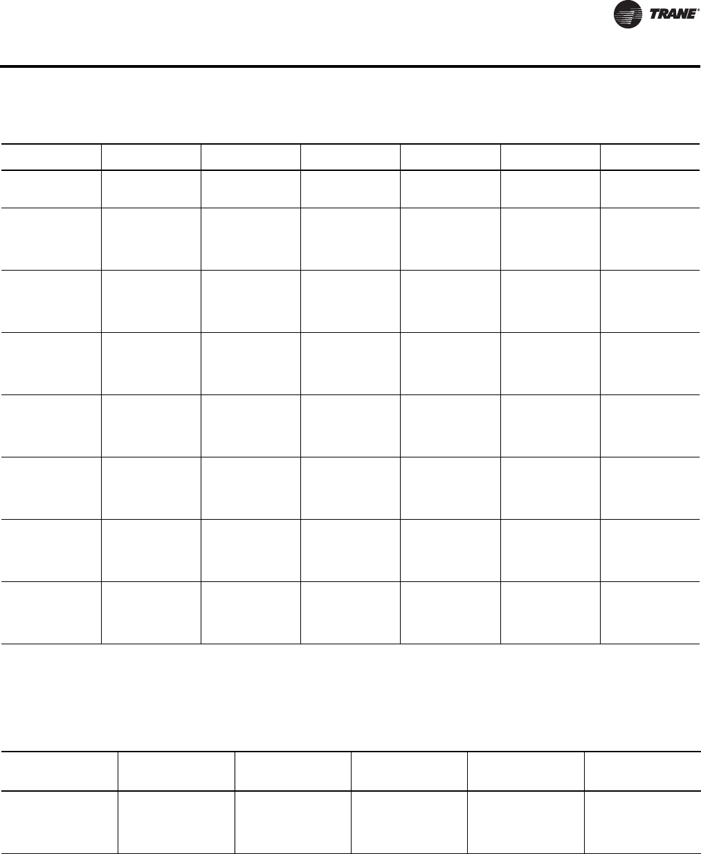
WSHP-PRC016E-EN 39
Performance Data
Table 38. Heating capacities (gross) - 20 tons GEV*240
EWT GPM Gross Cap
Mbtuh Absorb
Mbtuh Comp Power
kW LWT Feet Head
25 50.0 154.9 113.2 12.24 20.5 13.6
25 60.0 157.0 115.1 12.29 21.2 18.7
25 70.0 158.6 116.5 12.33 21.7 24.4
32 30.0 162.8 120.7 12.36 24.0 5.4
32 40.0 168.1 125.6 12.45 25.7 9.0
32 50.0 171.6 128.8 12.51 26.8 13.2
32 60.0 173.9 131.1 12.54 27.6 18.1
32 70.0 175.7 132.8 12.58 28.2 23.7
45 30.0 192.9 149.1 12.82 35.1 5.3
45 40.0 199.9 155.7 12.95 37.2 8.7
45 50.0 204.5 160.0 13.04 38.6 12.8
45 60.0 207.7 163.0 13.10 39.6 17.6
45 70.0 210.1 165.3 13.14 40.3 23.1
50 30.0 208.1 163.2 13.14 39.1 5.1
50 40.0 215.5 170.2 13.26 41.5 8.5
50 50.0 220.3 174.7 13.35 43.0 12.5
50 60.0 223.7 177.9 13.43 44.1 17.1
50 70.0 226.3 180.3 13.48 44.8 22.4
55 30.0 221.0 175.4 13.38 43.3 5.1
55 40.0 229.2 183.0 13.54 45.8 8.3
55 50.0 234.6 188.1 13.64 47.5 12.2
55 60.0 238.4 191.6 13.72 48.6 16.8
55 70.0 241.3 194.2 13.78 49.5 22.0
68 30.0 256.8 208.6 14.13 54.1 4.8
68 40.0 267.2 218.3 14.33 57.1 7.9
68 50.0 274.1 224.7 14.48 59.0 11.7
68 60.0 279.1 229.3 14.60 60.4 16.0
68 70.0 282.8 232.7 14.69 61.4 21.0
75 30.0 277.2 227.5 14.56 59.8 4.7
75 40.0 289.1 238.4 14.85 63.1 7.7
75 50.0 297.2 245.8 15.05 65.2 11.4
75 60.0 302.7 250.8 15.19 66.6 15.7
75 70.0 307.0 254.7 15.31 67.7 20.5
86 30.0 310.9 258.3 15.42 68.8 4.6
86 40.0 325.4 271.5 15.77 72.4 7.5
86 50.0 334.7 280.0 16.03 74.8 11.0
86 60.0 341.1 285.8 16.21 76.5 15.1
86 70.0 345.9 290.1 16.35 77.7 19.7
Performance data is tabulated for heating at 68°F DB entering air.
For conditions other than what is tabulated, multipliers must be used to correct performance. See the fan correction factors table for CFM other than rated
and the heating correction factors for variations in entering air temperature. WLHP data shown in bold type is performance data at ARI/ISO 13256-1. The
bold type for GLHP is a rating point only. For ARI 13256-1 GLHP conditions, apply 15% methanol by volume per the antifreeze correction factors found on
Table 77, p. 67.
Rated GPM: 60.0 Minimum CFM 6400; Nominal CFM 8000, Maximum CFM 9600
Table 39. Fan correction factors - 20 tons GEV*240
Entering
CFM Cooling
Capacity Sensible
Capacity
Cooling
Input
Watts Heating
Capacity
Heating
Input
Watts
6400 0.958 0.872 0.997 0.973 1.074
7200 0.981 0.936 0.998 0.988 1.031
8000 1.000 1.000 1.000 1.000 1.000
8800 1.017 1.065 1.001 1.010 0.975
9600 1.032 1.130 1.003 1.018 0.955

40 WSHP-PRC016E-EN
Performance Data
Table 40. Gross cooling capacities - 25 tons GEV*300
EWT GPM Gross Cap
Mbtuh Gross Sen
Mbtuh SHR Comp Power
kW Reject Mbtuh LWT Feet Head
45 37.5 368.3 268.9 0.73 13.6 414.6 67.1 4.4
45 50.0 372.3 270.5 0.73 13.0 416.6 61.7 7.4
45 62.5 374.9 271.4 0.72 12.6 418.0 58.4 11.1
45 75.0 376.6 272.1 0.72 12.4 418.9 56.2 15.3
45 87.5 377.9 272.5 0.72 12.3 419.7 54.6 20.1
55 37.5 356.8 264.6 0.74 14.9 407.8 76.7 4.3
55 50.0 360.5 266.3 0.74 14.3 409.2 71.4 7.2
55 62.5 362.7 267.2 0.74 13.9 410.1 68.1 10.6
55 75.0 364.2 267.3 0.73 13.6 410.8 66.0 14.7
55 87.5 365.4 268.0 0.73 13.5 411.4 64.4 19.3
59 37.5 352.1 263.4 0.75 15.5 405.0 80.6 4.2
59 50.0 355.7 264.6 0.74 14.8 406.3 75.3 7.1
59 62.5 357.8 265.4 0.74 14.4 407.1 72.0 10.5
59 75.0 359.3 265.9 0.74 14.2 407.8 69.9 14.5
59 87.5 360.4 266.3 0.74 14.0 408.2 68.3 19.0
68 37.5 341.1 259.3 0.76 17.0 399.2 89.3 4.1
68 50.0 344.6 260.7 0.76 16.3 400.1 84.0 6.8
68 62.5 346.5 261.3 0.75 15.8 400.5 80.8 10.2
68 75.0 347.9 261.8 0.75 15.5 400.8 78.7 14.0
68 87.5 348.8 262.1 0.75 15.3 401.1 77.2 18.4
77 37.5 329.5 255.2 0.77 18.6 393.0 98.0 4.0
77 50.0 332.8 256.5 0.77 17.8 393.6 92.7 6.6
77 62.5 334.8 257.2 0.77 17.4 394.0 89.6 9.9
77 75.0 336.0 257.7 0.77 17.1 394.3 87.5 13.6
77 87.5 336.9 257.9 0.77 16.9 394.5 86.0 17.9
86 37.5 317.1 251.0 0.79 20.5 387.0 106.6 3.9
86 50.0 320.4 252.1 0.79 19.6 387.2 101.5 6.5
86 62.5 322.3 252.7 0.78 19.1 387.4 98.4 9.6
86 75.0 323.4 253.1 0.78 18.7 387.3 96.3 13.2
86 87.5 324.3 253.5 0.78 18.5 387.5 94.9 17.4
95 37.5 303.9 246.7 0.81 22.4 380.4 115.3 3.8
95 50.0 307.1 247.7 0.81 21.5 380.6 110.2 6.3
95 62.5 309.0 248.3 0.80 21.0 380.7 107.2 9.3
95 75.0 310.2 248.7 0.80 20.7 380.8 105.2 12.9
95 87.5 311.0 249.0 0.80 20.5 380.8 103.7 16.9
105 37.5 288.2 241.9 0.84 24.9 373.0 124.9 3.7
105 50.0 291.4 242.9 0.83 23.9 373.1 119.9 6.1
105 62.5 293.2 243.4 0.83 23.4 373.0 116.9 9.1
105 75.0 294.4 243.8 0.83 23.0 373.0 114.9 12.5
105 87.5 295.3 244.0 0.83 22.8 373.0 113.5 16.5
115 37.5 270.7 236.8 0.87 27.5 364.7 134.5 3.6
115 50.0 274.1 237.8 0.87 26.6 364.9 129.6 6.0
115 62.5 276.1 238.3 0.86 26.0 364.8 126.7 8.9
115 75.0 277.3 238.7 0.86 25.6 364.8 124.7 12.2
115 87.5 278.1 239.0 0.86 25.4 364.7 123.3 16.0
120 75.0 267.9 236.0 0.88 27.1 360.3 129.6 12.1
120 87.5 268.8 236.2 0.88 26.8 360.2 128.2 15.8
Performance data is tabulated for cooling at 80.6°F DB/66.2°F WB entering air.
For conditions other than what is tabulated, multipliers must be used to correct performance. See the fan correction factors table for CFM other than rated
and the cooling correction factors for variations in entering air temperature. WLHP data shown in bold type is performance data at ARI/ISO 13256. The
bold type for GLHP is a rating point only. For ARI 13256-1 GLHP conditions, apply 15% methanol by volume per the antifreeze correction factors found
on Table 77, p. 67. The minimum gpm/ton is 3.0 when the EWT is greater than 115°F and the EAT is less than 67°F WB.
Rated GPM: 75.0 Minimum CFM 8000; Nominal CFM 10000, Maximum CFM 12000
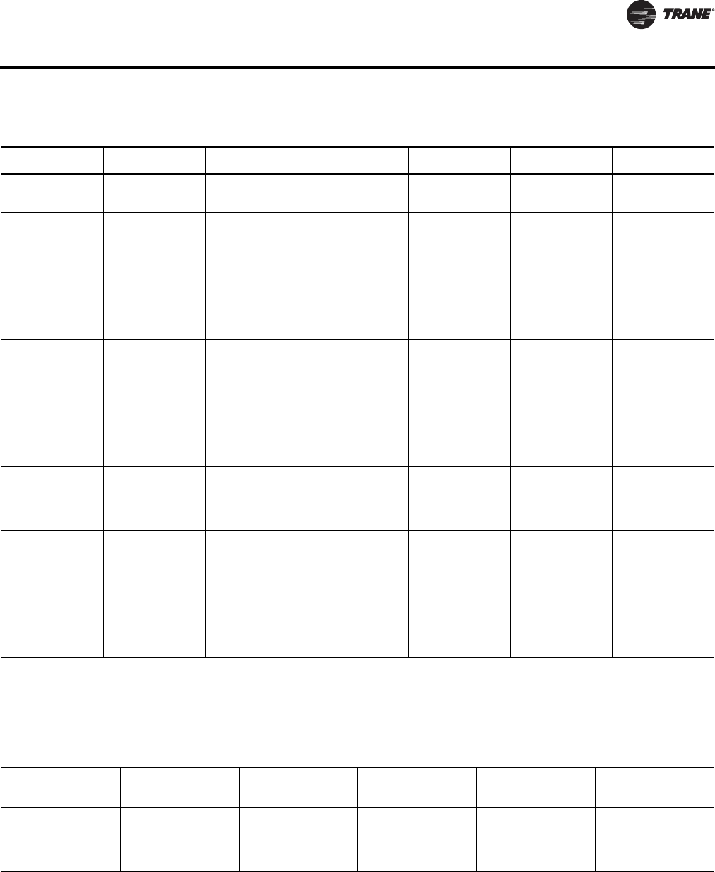
WSHP-PRC016E-EN 41
Performance Data
Table 41. Heating capacities (gross) - 25 tons GEV*300
EWT GPM Gross Cap
Mbtuh Absorb
Mbtuh Comp Power
kW LWT Feet Head
25 62.5 206.6 148.8 16.9 20.2 12.6
25 75.0 209.3 151.3 17.0 21.0 17.3
25 87.5 211.4 153.1 17.1 21.5 22.6
32 37.5 216.0 157.8 17.04 23.6 5.0
32 50.0 223.0 164.3 17.22 25.4 8.3
32 62.5 227.6 168.5 17.33 26.6 12.2
32 75.0 230.9 171.4 17.41 27.4 16.8
32 87.5 233.3 173.7 17.48 28.0 21.9
45 37.5 254.4 193.5 17.83 34.7 4.9
45 50.0 263.6 202.1 18.02 36.9 8.1
45 62.5 269.6 207.6 18.17 38.4 11.9
45 75.0 273.7 211.5 18.25 39.4 16.3
45 87.5 276.9 214.4 18.31 40.1 21.3
50 37.5 273.9 211.1 18.41 38.7 4.8
50 50.0 283.6 220.1 18.62 41.2 7.8
50 62.5 289.9 225.9 18.74 42.8 11.5
50 75.0 294.2 230.0 18.83 43.9 15.8
50 87.5 297.6 233.0 18.90 44.7 20.7
55 37.5 290.3 226.2 18.77 42.9 4.7
55 50.0 300.9 236.1 19.00 45.6 7.7
55 62.5 307.8 242.5 19.14 47.2 11.3
55 75.0 312.7 247.0 19.26 48.4 15.5
55 87.5 316.5 250.5 19.34 49.3 20.3
68 37.5 335.3 267.4 19.87 53.7 4.5
68 50.0 348.7 279.8 20.19 56.8 7.3
68 62.5 357.6 287.9 20.40 58.8 10.8
68 75.0 363.7 293.6 20.56 60.2 14.8
68 87.5 368.2 297.7 20.66 61.2 19.4
75 37.5 360.7 290.6 20.55 59.5 4.4
75 50.0 375.8 304.5 20.90 62.8 7.2
75 62.5 385.6 313.5 21.15 65.0 10.5
75 75.0 392.4 319.7 21.28 66.5 14.5
75 87.5 397.4 324.4 21.41 67.6 18.9
86 37.5 402.2 328.3 21.65 68.5 4.2
86 50.0 419.9 344.4 22.13 72.2 6.9
86 62.5 432.0 355.2 22.49 74.6 10.2
86 75.0 440.0 362.5 22.71 76.3 14.0
86 87.5 445.9 368.0 22.83 77.6 18.3
Performance data is tabulated for heating at 68°F DB entering air.
For conditions other than what is tabulated, multipliers must be used to correct performance. See the fan correction factors table for CFM other than rated
and the heating correction factors for variations in entering air temperature. WLHP data shown in bold type is performance data at ARI/ISO 13256-1. The
bold type for GLHP is a rating point only. For ARI 13256-1 GLHP conditions, apply 15% methanol by volume per the antifreeze correction factors found on
Table 77, p. 67.
Rated GPM: 75.0 Minimum CFM 8000; Nominal CFM 10000, Maximum CFM 12000
Table 42. Fan correction factors - 25 tons GEV*300
Entering
CFM Cooling
Capacity Sensible
Capacity
Cooling
Input
Watts Heating
Capacity
Heating
Input
Watts
8000 0.958 0.872 0.997 0.973 1.074
9000 0.981 0.936 0.998 0.988 1.031
10000 1.000 1.000 1.000 1.000 1.000
11000 1.017 1.065 1.001 1.010 0.975
12000 1.032 1.130 1.003 1.018 0.955

42 WSHP-PRC016E-EN
Performance Data
Table 43. Correction factors for variation in entering air temperature-6tonsGEH*072
Cooling
Entering
Air WB F Cooling
Capacity
Cooling
Comp
Power
Watts
Sensible vs. Entering Dry Bulb Multipliers Heating
Entering
Air DB F Heating
Capacity
Heating
Comp
Power
Watts65.6 70.6 75.6 80.6 85.6
44.5 0.926 0.982 0.951 1.020 1.092 * * 43 1.048 0.703
49.4 0.926 0.982 0.952 1.021 1.093 * * 48 1.038 0.760
56.3 0.927 0.982 0.798 0.997 1.094 * * 53 1.028 0.817
60.3 0.928 0.983 0.619 0.835 1.049 * * 58 1.018 0.879
63.2 0.953 0.989 0.492 0.705 0.922 1.140 * 63 1.009 0.938
66.2 1.000 1.000 — 0.573 0.789 1.000 1.208 68 1.000 1.000
72.1 1.114 1.020 — — 0.518 0.731 0.945 73 0.989 1.065
77.1 1.214 1.029 — — — 0.496 0.713 78 0.980 1.134
1. * = Sensible equals total capacity
Table 44. Correction factors for variation in entering air temperature - 7½ tons GEH*090
Cooling
Entering
Air WB F Cooling
Capacity
Cooling
Comp
Power
Watts
Sensible vs. Entering Dry Bulb Multipliers Heating
Entering
Air DB F Heating
Capacity
Heating
Comp
Power
Watts65.6 70.6 75.6 80.6 85.6
44.5 0.934 0.977 0.963 1.027 1.094 * * 43 1.056 0.728
49.4 0.934 0.977 0.963 1.028 1.094 * * 48 1.043 0.779
56.3 0.935 0.978 0.801 1.002 1.095 * * 53 1.033 0.831
60.3 0.938 0.979 0.612 0.835 1.045 * * 58 1.022 0.887
63.2 0.957 0.987 0.477 0.698 0.921 1.124 * 63 1.012 0.943
66.2 1.000 1.000 — 0.555 0.779 1.000 1.195 68 1.000 1.000
72.1 1.100 1.024 — — 0.490 0.718 0.937 73 0.988 1.061
77.1 1.188 1.039 — — — 0.466 0.695 78 0.976 1.123
1. * = Sensible equals total capacity
Table 45. Correction factors for variation in entering air temperature - 10 tons GEH*120
Cooling
Entering
Air WB F Cooling
Capacity
Cooling
Comp
Power
Watts
Sensible vs. Entering Dry Bulb Multipliers Heating
Entering
Air DB F Heating
Capacity
Heating
Comp
Power
Watts65.6 70.6 75.6 80.6 85.6
44.5 0.937 0.987 0.966 1.029 1.094 * * 43 1.119 0.748
49.4 0.937 0.987 0.967 1.029 1.095 * * 48 1.088 0.794
56.3 0.938 0.987 0.803 1.005 1.096 * * 53 1.065 0.843
60.3 0.939 0.987 0.618 0.838 1.047 * * 58 1.041 0.893
63.2 0.954 0.992 0.479 0.702 0.922 1.130 * 63 1.021 0.946
66.2 1.000 1.000 — 0.557 0.780 1.000 1.202 68 1.000 1.000
72.1 1.096 1.016 — — 0.489 0.714 0.937 73 0.967 1.049
77.1 1.184 1.028 — — — 0.461 0.687 78 0.940 1.103
1. * = Sensible equals total capacity
Table 46. Correction factors for variation in entering air temperature - 15 tons GEH*150
Cooling
Entering
Air WB F Cooling
Capacity
Cooling
Comp
Power
Watts
Sensible vs. Entering Dry Bulb Multipliers Heating
Entering
Air DB F Heating
Capacity
Heating
Comp
Power
Watts65.6 70.6 75.6 80.6 85.6
44.5 0.934 0.994 0.991 1.053 1.117 * * 43 1.050 0.748
49.4 0.935 0.994 0.991 1.054 1.118 * * 48 1.040 0.793
56.3 0.936 0.995 0.810 1.031 1.119 * * 53 1.030 0.840
60.3 0.936 0.995 0.621 0.842 1.064 * * 58 1.020 0.891
63.2 0.957 0.996 0.476 0.701 0.924 1.148 1.252 63 1.010 0.945
66.2 1.000 1.000 — 0.553 0.778 1.000 1.225 68 1.000 1.000
72.1 1.098 1.009 — — 0.480 0.704 0.929 73 0.990 1.060
77.1 1.189 1.016 — — — 0.442 0.673 78 0.980 1.124
1. * = Sensible equals total capacity
WSHP-PRC016E-EN 43
Performance Data
Table 47. Correction factors for variation in entering air temperature - 15 tons GEH*180
Cooling
Entering
Air WB F Cooling
Capacity
Cooling
Comp
Power
Watts
Sensible vs. Entering Dry Bulb Multipliers Heating
Entering
Air DB F Heating
Capacity
Heating
Comp
Power
Watts65.6 70.6 75.6 80.6 85.6
44.5 0.940 0.985 1.004 1.067 1.132 * * 43 1.052 0.783
49.4 0.941 0.985 1.005 1.068 1.133 * * 48 1.041 0.821
56.3 0.942 0.986 0.808 1.038 1.135 * * 53 1.032 0.862
60.3 0.943 0.986 0.607 0.839 1.072 * * 58 1.021 0.907
63.2 0.962 0.991 0.461 0.689 0.923 1.158 * 63 1.011 0.953
66.2 1.000 1.000 — 0.536 0.766 1.000 1.238 68 1.000 1.000
72.1 1.094 1.022 — — 0.457 0.687 0.922 73 0.986 1.051
77.1 1.185 1.038 — — — 0.419 0.648 78 0.972 1.103
1. * = Sensible equals total capacity
Table 48. Correction factors for variation in entering air temperature-6tonsGEV*072
Cooling
Entering
Air WB F Cooling
Capacity
Cooling
Comp
Power
Watts
Sensible vs. Entering Dry Bulb Multipliers Heating
Entering
Air DB F Heating
Capacity
Heating
Comp
Power
Watts65.6 70.6 75.6 80.6 85.6
44.5 0.949 0.983 1.005 1.068 1.131 * * 43 1.063 0.692
49.4 0.950 0.983 1.005 1.068 1.132 * * 48 1.047 0.748
56.3 0.951 0.983 0.813 1.040 1.134 * * 53 1.035 0.808
60.3 0.951 0.984 0.623 0.843 1.070 * * 58 1.023 0.869
63.2 0.962 0.989 0.481 0.702 0.924 1.154 * 63 1.012 0.934
66.2 1.000 1.000 — 0.553 0.775 1.000 1.233 68 1.000 1.000
72.1 1.083 1.019 — — 0.477 0.700 0.922 73 0.989 1.068
77.1 1.154 1.030 — — — 0.437 0.658 78 0.976 1.143
1. * = Sensible equals total capacity
Table 49. Correction factors for variation in entering air temperature - 7½ tons GEV*090
Cooling
Entering
Air WB F Cooling
Capacity
Cooling
Comp
Power
Watts
Sensible vs. Entering Dry Bulb Multipliers Heating
Entering
Air DB F Heating
Capacity
Heating
Comp
Power
Watts65.6 70.6 75.6 80.6 85.6
44.5 0.943 0.981 0.994 1.058 1.125 * * 43 1.068 0.713
49.4 0.944 0.981 0.995 1.059 1.125 * * 48 1.057 0.768
56.3 0.945 0.981 0.806 1.020 1.127 * * 53 1.042 0.824
60.3 0.946 0.982 0.615 0.837 1.067 * * 58 1.028 0.880
63.2 0.963 0.988 0.459 0.690 0.920 1.140 * 63 1.014 0.938
66.2 1.000 1.000 — 0.535 0.767 1.000 1.210 68 1.000 1.000
72.1 1.088 1.023 — — 0.455 0.688 0.920 73 0.988 1.066
77.1 1.169 1.037 — — — 0.415 0.652 78 0.974 1.133
1. * = Sensible equals total capacity
Table 50. Correction factors for variation in entering air temperature - 10 tons GEV*120
Cooling
Entering
Air WB F Cooling
Capacity
Cooling
Comp
Power
Watts
Sensible vs. Entering Dry Bulb Multipliers Heating
Entering
Air DB F Heating
Capacity
Heating
Comp
Power
Watts65.6 70.6 75.6 80.6 85.6
44.5 0.943 0.997 1.007 1.073 1.140 * * 43 1.077 0.718
49.4 0.944 0.997 1.008 1.073 1.141 * * 48 1.057 0.769
56.3 0.945 0.997 0.803 1.041 1.142 * * 53 1.042 0.824
60.3 0.946 0.997 0.594 0.834 1.077 * * 58 1.030 0.881
63.2 0.962 0.997 0.439 0.679 0.920 1.164 * 63 1.015 0.941
66.2 1.000 1.000 — 0.515 0.756 1.000 1.245 68 1.000 1.000
72.1 1.088 1.004 — — 0.430 0.672 0.913 73 0.985 1.062
77.1 1.169 1.010 — — — 0.385 0.630 78 0.970 1.126
1. * = Sensible equals total capacity
44 WSHP-PRC016E-EN
Performance Data
Table 51. Correction factors for variation in entering air temperature - 12½ tons GEV*150
Cooling
Entering
Air WB F Cooling
Capacity
Cooling
Comp
Power
Watts
Sensible vs. Entering Dry Bulb Multipliers Heating
Entering
Air DB F Heating
Capacity
Heating
Comp
Power
Watts65.6 70.6 75.6 80.6 85.6
44.5 0.936 0.994 1.018 1.081 1.147 * * 43 1.056 0.763
49.4 0.937 0.994 1.018 1.214 1.147 * * 48 1.047 0.807
56.3 0.938 0.994 0.809 1.047 1.149 * * 53 1.035 0.851
60.3 0.938 0.994 0.603 0.841 1.077 * * 58 1.023 0.897
63.2 0.961 0.996 0.449 0.683 0.924 1.162 * 63 1.015 0.951
66.2 1.000 1.000 — 0.522 0.758 1.000 1.240 68 1.000 1.000
72.1 1.088 1.008 — — 0.431 0.672 0.908 73 0.987 1.054
77.1 1.171 1.015 — — — 0.383 0.625 78 0.975 1.111
1. * = Sensible equals total capacity
Table 52. Correction factors for variation in entering air temperature - 15 tons GEV*180
Cooling
Entering
Air WB F Cooling
Capacity
Cooling
Comp
Power
Watts
Sensible vs. Entering Dry Bulb Multipliers Heating
Entering
Air DB F Heating
Capacity
Heating
Comp
Power
Watts65.6 70.6 75.6 80.6 85.6
44.5 0.938 0.995 1.041 1.105 1.172 * * 48 1.052 0.783
49.4 0.938 0.995 1.041 1.105 1.173 * * 53 1.043 0.822
56.3 0.939 0.995 0.814 1.055 1.176 * * 58 1.033 0.865
60.3 0.940 0.995 0.601 0.841 1.087 * * 63 1.025 0.908
63.2 0.965 0.994 0.444 0.683 0.923 1.174 * 68 1.011 0.951
66.2 1.000 1.000 — 0.517 0.758 1.000 1.253 73 1.000 1.000
72.1 1.095 1.004 — — 0.423 0.677 0.903 78 0.987 1.049
77.1 1.174 1.010 — — — 0.377 0.643 83 0.975 1.102
1. * = Sensible equals total capacity
Table 53. Correction factors for variation in entering air temperature - 20 tons GEV*240
Cooling
Entering
Air WB F Cooling
Capacity
Cooling
Comp
Power
Watts
Sensible vs. Entering Dry Bulb Multipliers Heating
Entering
Air DB F Heating
Capacity
Heating
Comp
Power
Watts65.6 70.6 75.6 80.6 85.6
44.5 0.941 0.991 0.996 1.059 1.124 * * 43 1.059 0.769
49.4 0.942 0.991 0.997 1.060 1.125 * * 48 1.047 0.811
56.3 0.943 0.991 0.805 1.036 1.126 * * 53 1.036 0.856
60.3 0.943 0.991 0.610 0.838 1.068 * * 58 1.024 0.903
63.2 0.958 0.993 0.468 0.690 0.922 1.155 * 63 1.012 0.950
66.2 1.000 1.000 — 0.549 0.770 1.000 1.234 68 1.000 1.000
72.1 1.102 1.019 — — 0.459 0.702 0.927 73 0.988 1.055
77.1 1.188 1.032 — — — 0.423 0.674 78 0.977 1.112
1. * = Sensible equals total capacity
Table 54. Correction factors for variation in entering air temperature - 25 tons GEV*300
Cooling
Entering
Air WB F Cooling
Capacity
Cooling
Comp
Power
Watts
Sensible vs. Entering Dry Bulb Multipliers Heating
Entering
Air DB F Heating
Capacity
Heating
Comp
Power
Watts65.6 70.6 75.6 80.6 85.6
44.5 0.939 0.993 1.014 1.075 1.137 * * 43 1.059 0.775
49.4 0.940 0.993 1.015 1.076 1.138 * * 48 1.048 0.816
56.3 0.941 0.992 0.812 1.047 1.139 * * 53 1.035 0.857
60.3 0.942 0.993 0.606 0.841 1.077 * * 58 1.023 0.901
63.2 0.962 0.994 0.457 0.688 0.923 1.161 * 63 1.011 0.949
66.2 1.000 1.000 — 0.532 0.764 1.000 1.237 68 1.000 1.000
72.1 1.093 1.012 — — 0.452 0.687 0.919 73 0.988 1.053
77.1 1.177 1.024 — — — 0.421 0.653 78 0.977 1.109
1. * = Sensible equals total capacity
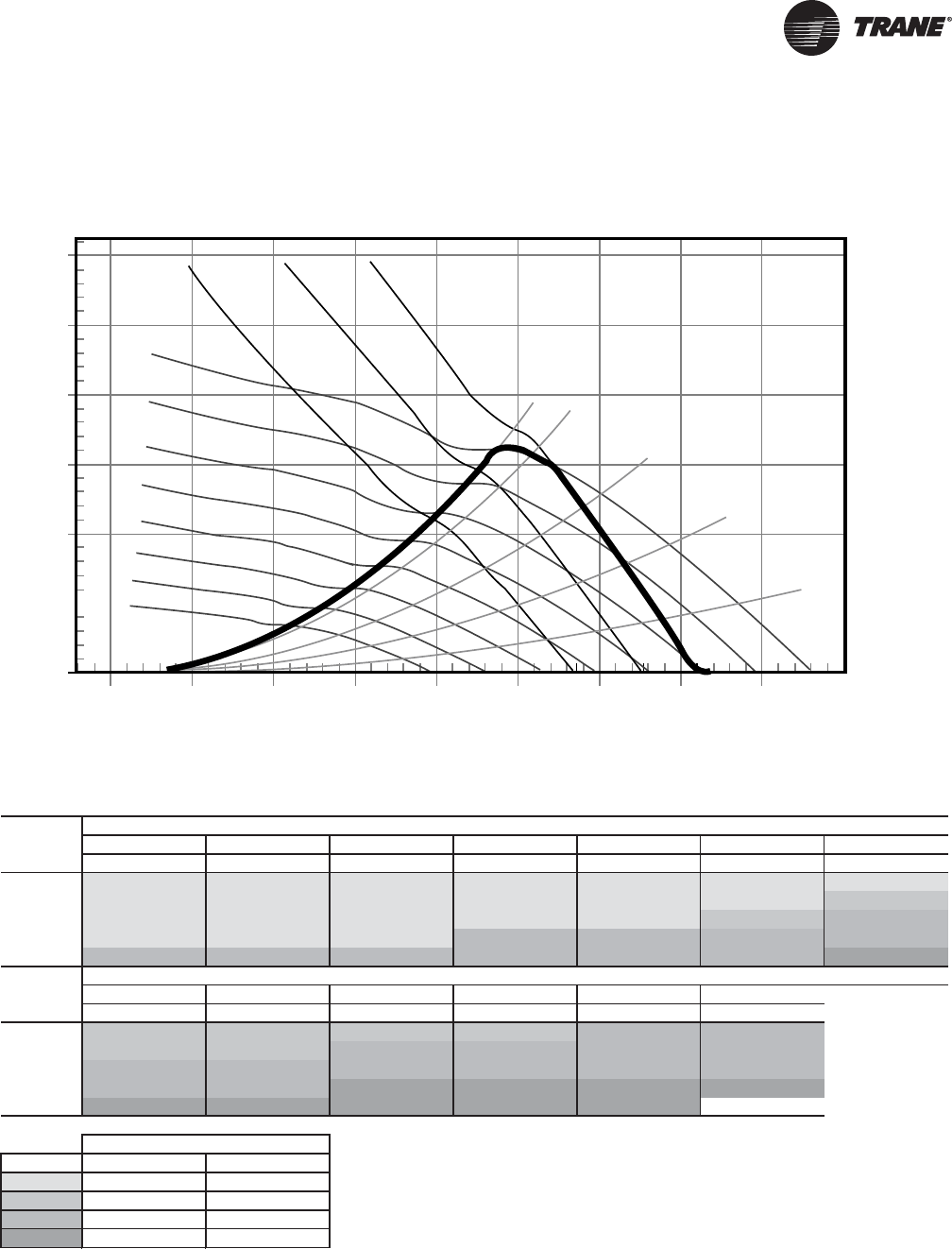
WSHP-PRC016E-EN 45
Fan Performance Data
Figure 2. Fan performance curve - GEH*072(a)
(a)Includes wet coil, no filter
MPR006
3.0
2.5
2.0
1.5
1.0
0.5
0.0
0 500 1000 1500 2000 2500 3000 3500 4000 4500
Airflow (cfm)
Total Static Pressure (in H20)
1.00 bhp
1.50 bhp
2.00 bhp
55%WO60%WO
70% WO
80% WO
90% WO
700 RPM
800 RPM
900 RPM
1000 RPM
1100 RPM
1200 RPM
1300 RPM
Table 55. Fan performance curve - GEH*072 (includes wet coil, no filter)
Std
Airflow
CFM RPM BHP RPM BHP RPM BHP RPM BHP RPM BHP RPM BHP RPM BHP
1920 632(a) 0.35(a) 682(a) 0.40(a) 729(a) 0.46(a) 774(a) 0.51(a) 818(a) 0.57(a) 860(a) 0.62(a) 901(a) 0.68(a)
2160 699(a) 0.49(a) 745(a) 0.55(a) 787(a) 0.60(a) 829(a) 0.66(a) 869(a) 0.72(a) 907(a) 0.79(a) 945(b) 0.85(b)
2400 767(a) 0.66(a) 808(a) 0.72(a) 848(a) 0.78(a) 886(a) 0.85(a) 923(a) 0.91(a) 959(b) 0.98(b) 994(c) 1.05(c)
2640 836(a) 0.86(a) 874(a) 0.93(a) 911(a) 1.00(a) 946(c) 1.07(c) 980(c) 1.14(c) 1014(c) 1.21(c) 1047(c) 1.28(c)
2880 905(c) 1.10(c) 940(c) 1.17(c) 974(c) 1.25(c) 1008(c) 1.33(c) 1039(c) 1.40(c) 1071(c) 1.48(c) 1102(d) 1.56(d)
Std
Airflow
CFM RPM BHP RPM BHP RPM BHP RPM BHP RPM BHP RPM BHP
1920 941(b) 0.74(b) 979(b) 0.80(b) 1027(b) 0.89(b) 1077(b) 0.98(b) 1120(c) 1.06(c) 1159(c) 1.14(c)
2160 982(b) 0.91(b) 1018(b) 0.98(b) 1053(c) 1.05(c) 1087(c) 1.12(c) 1122(c) 1.19(c) 1171(c) 1.30(c)
2400 1029(c) 1.12(c) 1062(c) 1.19(c) 1095(c) 1.26(c) 1128(c) 1.33(c) 1159(c) 1.41(c) 1191(c) 1.49(c)
2640 1078(c) 1.36(c) 1111(c) 1.44(c) 1142(d) 1.51(d) 1171(d) 1.59(d) 1202(d) 1.67(d) 1231(d) 1.75(d)
2880 1132(d) 1.64(d) 1161(d) 1.72(d) 1191(d) 1.80(d) 1220(d) 1.89(d) 1248(d) 1.97(d) — —
Legend
(a)
(b)
(c)
(d)
0.8 1.2
Unit External Static Pressure inches W.G. (Wet Coil, No Drive Loss Included & No Return Air Filter)
Unit External Static Pressure inches W.G. (Wet Coil, No Drive Loss Included & No Return Air Filter)
0.1 0.5 0.6 0.7
1.3
0.2 0.3 0.4
0.9 1.0 1.1
Digit 12 - Drive Package
single speed motor two speed motor
A1
B2
C3
D4
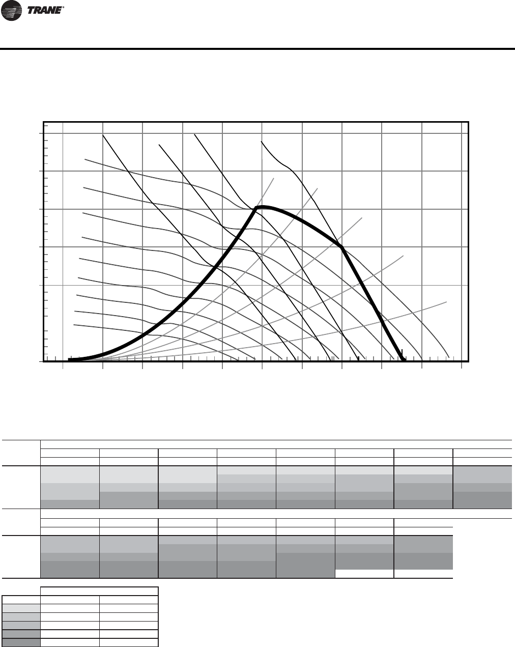
46 WSHP-PRC016E-EN
Fan Performance Data
Figure 3. Fan performance curve - GEH*090(a)
(a)Includes wet coil, no filter
MPR006
3.0
2.5
2.0
1.5
1.0
0.5
0.0
0 500 1000 1500 2000 2500 3000 3500 4000 4500 5000
Airflow (cfm)
Total Static Pressure (in H20)
1.00 bhp
1.50 bhp
2.00 bhp
3.00 bhp
55%WO
60%WO
70% WO
80% WO
90% WO
700 RPM
800 RPM
900 RPM
1000 RPM
1100 RPM
1200 RPM
1300 RPM
1400 RPM
Table 56. Fan performance curve - GEH*090 (includes wet coil, no filter)
Airflow
CFM RPM BHP RPM BHP RPM BHP RPM BHP RPM BHP RPM BHP RPM BHP RPM BHP
2400 727(a) 0.59(a) 769(a) 0.65(a) 810(a) 0.72(a) 849(a) 0.78(a) 886(a) 0.84(a) 923(a) 0.90(a) 958(a) 0.96(a) 993(c) 1.03(c)
2700 809(a) 0.82(a) 845(a) 0.89(a) 883(a) 0.96(a) 919(b) 1.03(b) 953(b) 1.10(b) 986(c) 1.17(c) 1018(c) 1.24(c) 1051(c) 1.31(c)
3000 891(b) 1.11(b) 924(b) 1.19(b) 957(b) 1.26(b) 991(c) 1.34(c) 1023(c) 1.42(c) 1053(c) 1.50(c) 1083(d) 1.57(d) 1113(d) 1.65(d)
3300 975(b) 1.47(b) 1003(d) 1.54(d) 1033(d) 1.63(d) 1064(d) 1.71(d) 1095(d) 1.80(d) 1124(d) 1.89(d) 1152(d) 1.97(d) 1179(e) 2.06(e)
3600 1059(d) 1.89(d) 1084(d) 1.97(d) 1111(e) 2.06(e) 1140(e) 2.15(e) 1168(e) 2.25(e) 1196(e) 2.35(e) 1222(e) 2.44(e) 1248(e) 2.53(e)
Std
Airflow
CFM RPM BHP RPM BHP RPM BHP RPM BHP RPM BHP RPM BHP RPM BHP
2400 1026(c) 1.09(c) 1059(c) 1.16(c) 1091(c) 1.23(c) 1123(c) 1.30(c) 1154(c) 1.37(c) 1185(c) 1.45(c) 1217(d) 1.53(d)
2700 1082(c) 1.38(c) 1113(c) 1.45(c) 1143(d) 1.53(d) 1172(d) 1.60(d) 1202(d) 1.68(d) 1230(d) 1.76(d) 1257(d) 1.83(d)
3000 1143(d) 1.73(d) 1171(d) 1.81(d) 1199(d) 1.89(d) 1228(d) 1.97(d) 1255(e) 2.05(e) 1281(e) 2.13(e) 1308(e) 2.21(e)
3300 1206(e) 2.14(e) 1233(e) 2.22(e) 1259(e) 2.31(e) 1286(e) 2.40(e) 1312(e) 2.49(e) 1337(e) 2.57(e) 1362(e) 2.66(e)
3600 1273(e) 2.62(e) 1298(e) 2.71(e) 1323(e) 2.81(e) 1348(e) 2.90(e) 1372(e) 2.99(e) ————
Legend
(a)
(b)
(c)
(d)
(e)
Unit External Static Pressure inches W.G. (Wet Coil, No Drive Loss Included & No Return Air Filter)
E5
B2
C3
D4
Digit 12 - Drive Package
single speed motor two speed motor
A1
Unit External Static Pressure inches W.G. (Wet Coil, No Drive Loss Included & No Return Air Filter)
0.7 0.8
1.0 1.1 1.2 1.3 1.4 1.5
0.1 0.2 0.3 0.4 0.5 0.6
0.9
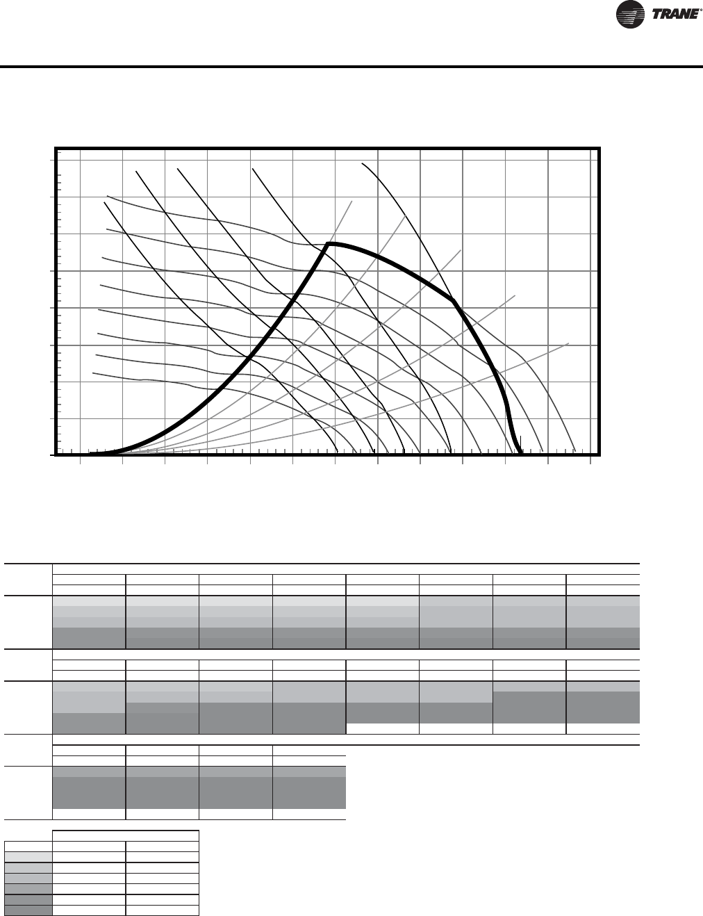
WSHP-PRC016E-EN 47
Fan Performance Data
Figure 4. Fan performance curve - GEH*120(a)
(a)Includes wet coil, no filter
3.0
3.5
4.0
2.5
2.0
1.5
1.0
0.5
0.0
0 500 1000 1500 2000 2500 3000 3500 4000 4500 5000 5500 6000
Airflow (cfm)
Total Static Pressure (in H20)
1.00 bhp
1.50 bhp
2.00 bhp
3.00 bhp
5.00 bhp
55%WO
60%WO
70% WO
80% WO
90% WO
900 RPM
1000 RPM
110 0 RP M
1200 RPM
1300 RPM
1400 RPM
1500 RPM
1600 RPM
Table 57. Fan performance curve - GEH*120 (includes wet coil, no filter)
RPM BHP RPM BHP RPM BHP RPM BHP RPM BHP RPM BHP RPM BHP RPM BHP
3200 897(a) 1.23(a) 916(a) 1.27(a) 935(a) 1.31(a) 958(a) 1.36(a) 987(a) 1.43(a) 1018(b) 1.51(b) 1051(b) 1.60(b) 1081(b) 1.68(b)
3600 1005(b) 1.74(b) 1022(b) 1.78(b) 1038(b) 1.83(b) 1055(b) 1.87(b) 1076(b) 1.94(b) 1102(c) 2.01(c) 1129(c) 2.10(c) 1158(c) 2.20(c)
4000 1114(c) 2.37(c) 1128(c) 2.42(c) 1143(c) 2.47(c) 1158(c) 2.52(c) 1173(c) 2.57(c) 1192(c) 2.64(c) 1214(c) 2.72(c) 1238(c) 2.82(c)
4400 1222(e) 3.15(e) 1235(e) 3.20(e) 1249(e) 3.26(e) 1262(e) 3.31(e) 1276(e) 3.37(e) 1290(e) 3.42(e) 1306(e) 3.49(e) 1326(e) 3.58(e)
4800 1331(e) 4.08(e) 1343(f) 4.14(f) 1355(f) 4.19(f) 1367(f) 4.25(f) 1380(f) 4.31(f) 1392(f) 4.37(f) 1405(f) 4.43(f) 1419(f) 4.50(f)
Std
Airflow
CFM RPM BHP RPM BHP RPM BHP RPM BHP RPM BHP RPM BHP RPM BHP RPM BHP
3200 1109(b) 1.76(b) 1138(b) 1.84(b) 1164(b) 1.92(b) 1192(c) 2.01(c) 1219(c) 2.09(c) 1246(c) 2.17(c) 1272( c) 2.25(c) 1298(c) 2.34(c)
3600 1186(c) 2.29(c) 1213(c) 2.39(c) 1239(c) 2.48(c) 1264(c) 2.57(c) 1288(c) 2.65(c) 1312(c) 2.74(c) 1336(f) 2.83(f) 1361(f) 2.93(f)
4000 1264(c) 2.92(c) 1289(e) 3.02(e) 1315(f) 3.13(f) 1340(f) 3.24(f) 1363(f) 3.34(f) 1385(f) 3.43(f) 1408(f) 3.54(f) 1429(f) 3.63(f)
4400 1347(e) 3.68(e) 1369(f) 3.78(f) 1392(f) 3.90(f) 1416(f) 4.02(f) 1440(f) 4.13(f) 1463(f) 4.25(f) 1484(f) 4.36(f) 1505(f) 4.47(f)
4800 1437(e) 4.60(e) 1455(f) 4.70(f) 1475(f) 4.81(f) 1496(f) 4.93(f) — — — — — — — —
Std
Airflow
CFM RPM BHP RPM BHP RPM BHP RPM BHP
3200 1323(d) 2.42(d) 1349(d) 2.51(d) 1374(d) 2.60(d) 1398(d) 2.68(d)
3600 1384(f) 3.02(f) 1408(f) 3.12(f) 1431(f) 3.21(f) 1454(f) 3.30(f)
4000 1452(f) 3.74(f) 1474(f) 3.84(f) 1496(f) 3.94(f) 1517(f) 4.04(f)
4400 1526(f) 4.58(f) 1546(f) 4.69(f) 1565(f) 4.80(f) 1586(f) 4.91(f)
4800————————
Legend
(a)
(b)
(c)
(d)
(e)
(f)
4
5
6
D
E
F
A
B
C
single speed motor
Digit 12 - Drive Package
1
two speed motor
2
3
Std
Airflow
CFM
0.1 0.2 0.4
0.9 1.0 1.1
Unit External Static Pressure inches W.G. (Wet Coil, No Drive Loss Included & No Return Air Filter)
Unit External Static Pressure inches W.G. (Wet Coil, No Drive Loss Included & No Return Air Filter)
1.5 1.6
0.6 0.7 0.80.50.3
1.2 1.41.3
1.7 1.8 1.9 2.0
Unit External Static Pressure inches W.G. (Wet Coil, No Drive Loss Included & No Return Air Filter)
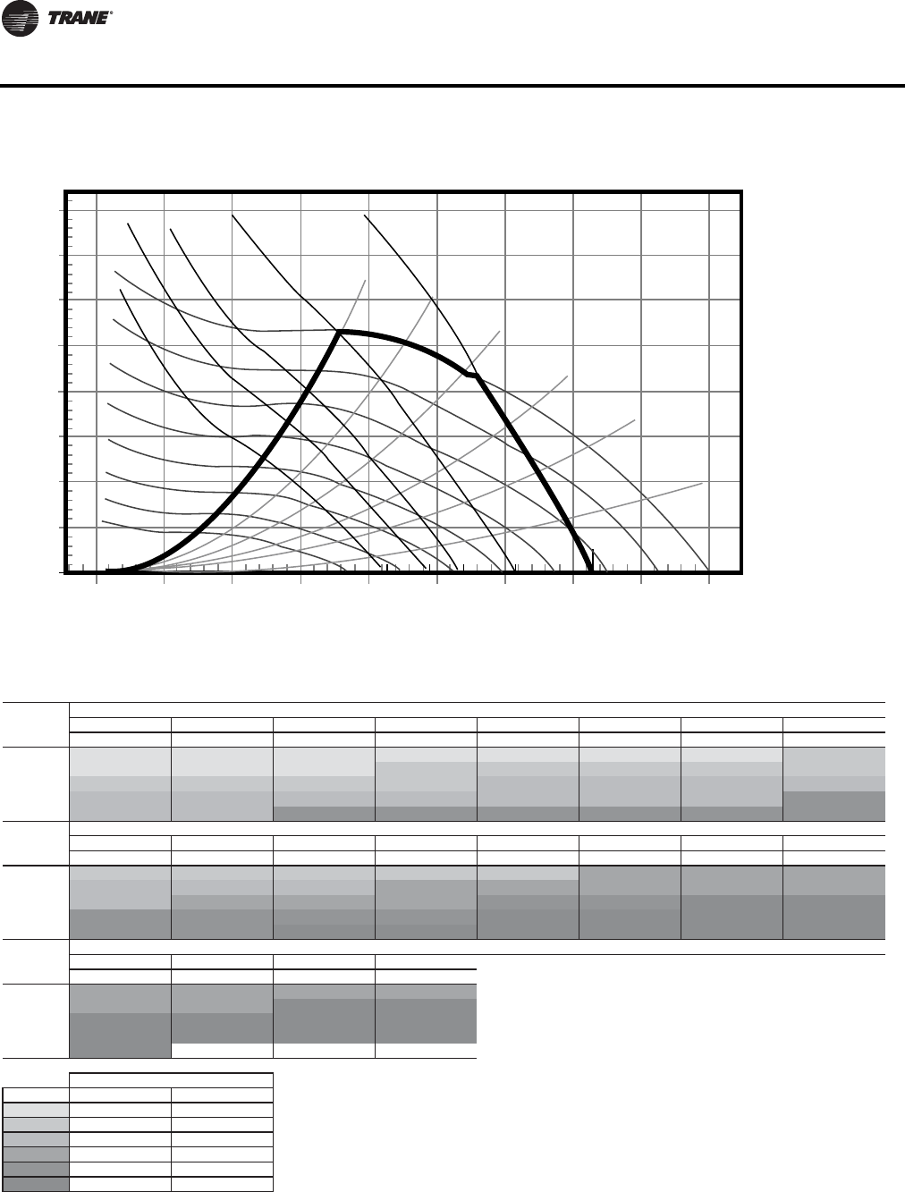
48 WSHP-PRC016E-EN
Fan Performance Data
Figure 5. Fan performance curve - GEH*150(a)
(a)Includes wet coil, no filter
3.0
3.5
4.0
2.5
2.0
1.5
1.0
0.5
0.0
0 1000 2000 3000 4000 70005000 8000 90006000
Airflow (cfm)
Total Static Pressure (in H20)
1.00 bhp
1.50 bhp
2.00 bhp
3.00 bhp
5.00 bhp
50%WO
40%WO
60%WO
70% WO
80% WO
90% WO
500 RPM
600 RPM
700 RPM
800 RPM
900 RPM
1000 RPM
1100 RPM
1200 RPM
Table 58. Fan performance curve - GEH*150 (includes wet coil, no filter)
RPM BHP RPM BHP RPM BHP RPM BHP RPM BHP RPM BHP RPM BHP RPM BHP
4000 559(a) 0.89(a) 590(a) 0.96(a) 622(a) 1.05(a) 654(a) 1.14(a) 685(a) 1.23(a) 717(a) 1.32(a) 749(a) 1.42(a) 779(b) 1.52(b)
4500 622(a) 1.24(a) 648(a) 1.33(a) 677(a) 1.42(a) 706(b) 1.52(b) 734(b) 1.62(b) 761(b) 1.72(b) 790(b) 1.82(b) 819(b) 1.93(b)
5000 686(b) 1.69(b) 709(b) 1.77(b) 734(b) 1.87(b) 760(b) 1.98(b) 786(c) 2.09(c) 811(c) 2.20(c) 836(c) 2.31(c) 861(c) 2.42(c)
5500 750(c) 2.23(c) 771(c) 2.32(c) 793(c) 2.42(c) 816(c) 2.53(c) 840(c) 2.65(c) 863(c) 2.77(c) 886(c) 2.89(c) 909(e) 3.02(e)
6000 815(c) 2.88(c) 833(c) 2.97(c) 853(e) 3.08(e) 874(e) 3.20(e) 895(e) 3.32(e) 917(e) 3.45(e) 939(e) 3.58(e) 960(e) 3.71(e)
RPM BHP RPM BHP RPM BHP RPM BHP RPM BHP RPM BHP RPM BHP RPM BHP
4000 807(b) 1.61(b) 833(b) 1.71(b) 857(b) 1.80(b) 881(b) 1.89(b) 905(b) 1.98(b) 928(d) 2.07(d) 951(d) 2.16(d) 974(d) 2.26(d)
4500 846(c) 2.04(c) 872(c) 2.15(c) 898(c) 2.26(c) 921(d) 2.36(d) 944(d) 2.46(d) 965(d) 2.56(d) 987(d) 2.66(d) 1009(d) 2.77(d)
5000 887(c) 2.54(c) 912(d) 2.66(d) 937(d) 2.78(d) 962(d) 2.91(d) 985(e) 3.03(e) 1007(e) 3.14(e) 1027(f) 3.26(f) 1047(f) 3.37(f)
5500 932(e) 3.14(e) 954(e) 3.26(e) 978(e) 3.40(e) 1002(e) 3.53(e) 1024(f) 3.66(f) 1047(f) 3.80(f) 1068(f) 3.93(f) 1090(f) 4.07(f)
6000 981(e) 3.85(e) 1002(e) 3.98(e) 1022(f) 4.11(f) 1044(f) 4.26(f) 1065(f) 4.40(f) 1086(f) 4.54(f) 1108(f) 4.69(f) 1128(f) 4.83(f)
RPM BHP RPM BHP RPM BHP RPM BHP
4000 996(d) 2.36(d) 1018(d) 2.46(d) 1040(d) 2.57(d) 1061(d) 2.67(d)
4500 1030(d) 2.88(d) 1049(d) 2.97(d) 1069(f) 3.08(f) 1090(f) 3.19(f)
5000 1067(f) 3.48(f) 1087(f) 3.60(f) 1106(f) 3.71(f) 1125(f) 3.83(f)
5500 1109(f) 4.19(f) 1127(f) 4.32(f) 1146(f) 4.44(f) 1164(f) 4.57(f)
6000 1148(f) 4.98(f) ——————
Legend
(a)
(b)
(c)
(d)
(e)
(f)
Std
Airflow
CFM
Unit External Static Pressure inches W.G. (Wet Coil, No Drive Loss Included & No Return Air Filter)
Unit External Static Pressure inches W.G. (Wet Coil, No Drive Loss Included & No Return Air Filter)
0.1 0.2 0.3
Unit External Static Pressure inches W.G. (Wet Coil, No Drive Loss Included & No Return Air Filter)
Std
Airflow
CFM
Std
Airflow
CFM
0.4 0.5 0.6
1.9 2.0
0.7 0.8
1.4 1.5 1.6
Digit 12 - Drive Package
0.9 1.0 1.1 1.2 1.3
single speed motor two speed motor
1.7 1.8
A1
B2
C3
D4
E5
F6
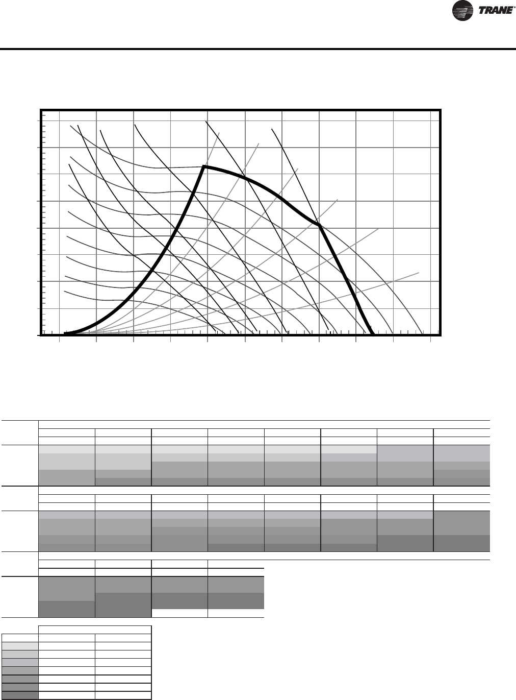
WSHP-PRC016E-EN 49
Fan Performance Data
Figure 6. Fan performance curve - GEH*180(a)
(a)Includes wet coil, no filter
3.0
3.5
4.0
2.5
2.0
1.5
1.0
0.5
0.0
0 1000 2000 3000 4000 70005000 8000 9000 100006000
Airflow (cfm)
Total Static Pressure (in H20)
1.00 bhp
1.50 bhp
2.00 bhp
3.00 bhp
5.00 bhp
7.50 bhp
50%WO
40%WO
60%WO
70% WO
80% WO
90% WO
600 RPM
700 RPM
800 RPM
900 RPM
1000 RPM
1100 RPM
1300 RPM
1200 RPM
Table 59. Fan performance curve - GEH*180 (includes wet coil, no filter)
RPM BHP RPM BHP RPM BHP RPM BHP RPM BHP RPM BHP RPM BHP RPM BHP
4800 660(a) 1.50(a) 685(a) 1.58(a) 711(a) 1.68(a) 738(a) 1.78(a) 765(a) 1.89(a) 791(a) 1.99(a) 817(c) 2.10(c) 844(c) 2.22(c)
5400 737(b) 2.11(b) 758(b) 2.20(b) 781(b) 2.30(b) 805(b) 2.41(b) 828(b) 2.53(b) 853(c) 2.65(c) 876(c) 2.77(c) 899(c) 2.89(c)
6000 815(b) 2.88(b) 833(b) 2.97(b) 853(d) 3.08(d) 874(d) 3.20(d) 895(d) 3.32(d) 917(d) 3.45(d) 939(d) 3.58(d) 960(d) 3.71(d)
6600 892(d) 3.81(d) 909(d) 3.91(d) 927(d) 4.02(d) 945(d) 4.14(d) 965(d) 4.27(d) 984(d) 4.41(d) 1004(d) 4.55(d) 1023(e) 4.69(e)
7200 971(d) 4.92(d) 986(f) 5.03(f) 1002(f) 5.15(f) 1018(f) 5.27(f) 1036(f) 5.41(f) 1053(f) 5.55(f) 1071(f) 5.70(f) 1089(f) 5.86(f)
RPM BHP RPM BHP RPM BHP RPM BHP RPM BHP RPM BHP RPM BHP RPM BHP
4800 870(c) 2.33(c) 896(c) 2.45(c) 921(c) 2.56(c) 946(c) 2.68(c) 969(c) 2.79(c) 990(c) 2.90(c) 1011(c) 3.00(c) 1031(e) 3.12(e)
5400 922(d) 3.01(d) 946(d) 3.14(d) 969(d) 3.26(d) 993(d) 3.40(d) 1016(d) 3.53(d) 1039(e) 3.66(e) 1060(e) 3.79(e) 1081(e) 3.92(e)
6000 981(d) 3.85(d) 1002(d) 3.98(d) 1022(e) 4.11(e) 1044(e) 4.26(e) 1065(e) 4.40(e) 1086(e) 4.54(e) 1108(e) 4.69(e) 1128(e) 4.83(e)
6600 1043(e) 4.84(e) 1062(e) 4.99(e) 1081(f) 5.13(f) 1100(f) 5.28(f) 1119(f) 5.43(f) 1138(f) 5.58(f) 1157(g) 5.74(g) 1177(g) 5.90(g)
7200 1107(f) 6.01(f) 1125(f) 6.17(f) 1143(f) 6.33(f) 1160(g) 6.49(g) 1178(g) 6.65(g) 1195(g) 6.81(g) 1212(g) 6.97(g) 1229(g) 7.13(g)
RPM BHP RPM BHP RPM BHP RPM BHP
4800 1051(e) 3.23(e) 1071(e) 3.34(e) 1091(e) 3.45(e) 1111(e) 3.56(e)
5400 1100(e) 4.04(e) 1119(e) 4.16(e) 1138(e) 4.29(e) 1156(e) 4.41(e)
6000 1148(e) 4.98(e) 1168(g) 5.13(g) 1187(g) 5.27(g) 1205(g) 5.41(g)
6600 1196(g) 6.05(g) 1215(g) 6.22(g) 1234(g) 6.37(g) 1253(g) 6.54(g)
7200 1248(g) 7.31(g) 1266(g) 7.48(g) ————
Legend
(a)
(b)
(c)
(d)
(e)
(f)
(g)
Unit External Static Pressure inches W.G. (Wet Coil, No Drive Loss Included & No Return Air Filter)
0.1 0.2 0.3 0.4 0.5 0.6 0.7
1.3 1.4 1.5 1.61.1 1.2
Unit External Static Pressure inches W.G. (Wet Coil, No Drive Loss Included & No Return Air Filter)
Unit External Static Pressure inches W.G. (Wet Coil, No Drive Loss Included & No Return Air Filter)
Std
Airflow
CFM
1.7 1.8 1.9 2.0
Std
Airflow
CFM
Std
Airflow
CFM
0.8
0.9 1.0
Digit 12 - Drive Package
single speed motor two speed motor
A1
B2
C3
D4
E5
F6
G7
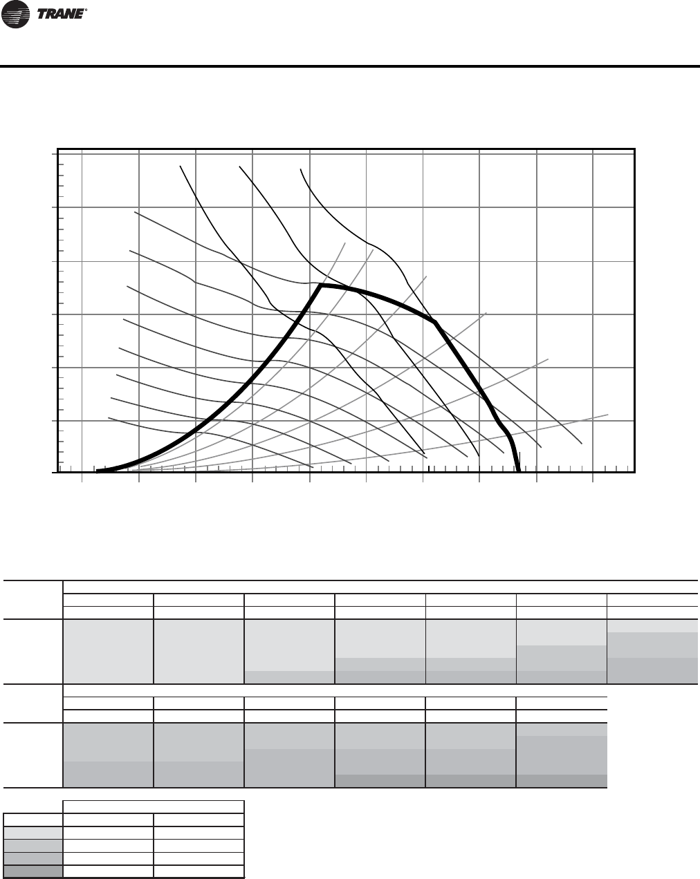
50 WSHP-PRC016E-EN
Fan Performance Data
Figure 7. Fan performance curve (top supply) - GEV*072(a)
(a)Includes wet coil, no filter
3.0
2.5
2.0
1.5
1.0
0.5
0.0
0 500 1000 1500 2000 2500 3000 3500 4000 4500
Airflow (cfm)
Total Static Pressure (in H20)
1.00 bhp
1.50 bhp
2.00 bhp
50%WO
45%WO
60%WO
70% WO
80% WO
90% WO
700 RPM
600 RPM
800 RPM
900 RPM
1000 RPM
1100 RPM
1200 RPM
1300 RPM
Table 60. Fan performance curve (top supply) - GEV*072 (includes wet coil, no filter)
RPM BHP RPM BHP RPM BHP RPM BHP RPM BHP RPM BHP RPM BHP
1920 595(a) 0.27(a) 649(a) 0.32(a) 698(a) 0.36(a) 744(a) 0.40(a) 788(a) 0.45(a) 830(a) 0.50(a) 871(a) 0.55(a)
2160 655(a) 0.37(a) 705(a) 0.42(a) 751(a) 0.47(a) 794(a) 0.52(a) 835(a) 0.57(a) 874(a) 0.63(a) 912(b) 0.68(b)
2400 717(a) 0.50(a) 763(a) 0.56(a) 806(a) 0.61(a) 846(a) 0.67(a) 884(a) 0.72(a) 921(b) 0.78(b) 957(b) 0.83(b)
2640 780(a) 0.65(a) 822(a) 0.71(a) 862(a) 0.78(a) 900(b) 0.84(b) 937(b) 0.90(b) 971(b) 0.96(b) 1005(c) 1.02(c)
2880 844(a) 0.84(a) 882(a) 0.90(a) 920(b) 0.97(b) 956(c) 1.04(c) 990(c) 1.10(c) 1023(c) 1.17(c) 1055(c) 1.23(c)
RPM BHP RPM BHP RPM BHP RPM BHP RPM BHP RPM BHP
1920 912(b) 0.60(b) 953(b) 0.65(b) 993(b) 0.70(b) 1034(b) 0.76(b) 1072(b) 0.84(b) 1111(b) 0.92(b)
2160 949(b) 0.74(b) 985(b) 0.79(b) 1021(b) 0.85(b) 1058(b) 0.90(b) 1094(b) 0.95(b) 1129(c) 1.02(c)
2400 991(b) 0.89(b) 1024(b) 0.96(b) 1057(c) 1.02(c) 1091(c) 1.08(c) 1123(c) 1.14(c) 1157(c) 1.20(c)
2640 1038(c) 1.08(c) 1069(c) 1.15(c) 1100(c) 1.21(c) 1130(c) 1.28(c) 1161(c) 1.35(c) 1191(c) 1.42(c)
2880 1086(c) 1.30(c) 1116(c) 1.36(c) 1145(c) 1.43(c) 1175(d) 1.51(d) 1203(d) 1.58(d) 1231(d) 1.66(d)
Legend
(a)
(b)
(c)
(d)
Std
Airflow
CFM
Unit External Static Pressure inches W.G. (Wet Coil, No Drive Loss Included & No Return Air Filter)
Unit External Static Pressure inches W.G. (Wet Coil, No Drive Loss Included & No Return Air Filter)
0.9 1.0 1.1 1.2
0.1 0.2 0.3 0.4 0.5 0.6 0.7
1.3
Digit 12 - Drive Package
single speed motor two speed motor
0.8
Std
Airflow
CFM
D4
A1
B2
C3
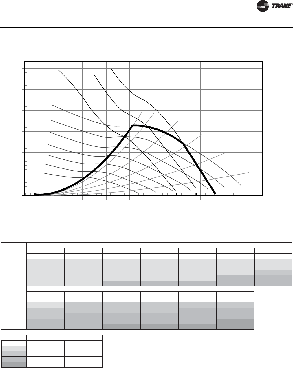
WSHP-PRC016E-EN 51
Fan Performance Data
Figure 8. Fan performance curve (front/back supply) - GEV*072(a)
(a)Includes wet coil, no filter
3.0
2.5
2.0
1.5
1.0
0.5
0.0
0 500 1000 1500 2000 2500 3000 3500 4000 4500
Airflow (cfm)
Total Static Pressure (in H20)
1.00 bhp
1.50 bhp
2.00 bhp
50%WO
45%WO
60%WO
70% WO
80% WO
90% WO
700 RPM
600 RPM
800 RPM
900 RPM
1000 RPM
1100 RPM
1200 RPM
1300 RPM
Table 61. Fan performance curve (front/back supply) - GEV*072 (includes wet coil, no filter)
RPM BHP RPM BHP RPM BHP RPM BHP RPM BHP RPM BHP RPM BHP
1920 559(a) 0.30(a) 611(a) 0.34(a) 660(a) 0.39(a) 706(a) 0.44(a) 749(a) 0.48(a) 790(a) 0.53(a) 831(a) 0.59(a)
2160 616(a) 0.41(a) 663(a) 0.46(a) 708(a) 0.51(a) 751(a) 0.56(a) 792(a) 0.62(a) 830(a) 0.67(a) 867(a) 0.73(a)
2400 674(a) 0.55(a) 717(a) 0.60(a) 759(a) 0.66(a) 799(a) 0.72(a) 837(a) 0.78(a) 873(a) 0.84(a) 909(b) 0.90(b)
2640 733(a) 0.71(a) 773(a) 0.78(a) 811(a) 0.84(a) 849(a) 0.90(a) 884(a) 0.97(a) 919(c) 1.03(c) 953(c) 1.10(c)
2880 793(a) 0.91(a) 830(a) 0.98(a) 865(c) 1.05(c) 900(c) 1.12(c) 934(c) 1.19(c) 966(c) 1.26(c) 998(c) 1.33(c)
RPM BHP RPM BHP RPM BHP RPM BHP RPM BHP RPM BHP
1920 869(a) 0.64(a) 907(b) 0.70(b) 947(b) 0.76(b) 988(b) 0.83(b) 1030(b) 0.90(b) 1068(b) 0.97(b)
2160 904(b) 0.78(b) 939(b) 0.84(b) 974(b) 0.91(b) 1008(b) 0.97(b) 1042(c) 1.04(c) 1079(c) 1.11(c)
2400 943(b) 0.96(b) 975(c) 1.02(c) 1007(c) 1.08(c) 1040(c) 1.15(c) 1071(c) 1.22(c) 1102(c) 1.29(c)
2640 985(c) 1.16(c) 1016(c) 1.23(c) 1046(c) 1.29(c) 1076(c) 1.36(c) 1106(c) 1.43(c) 1135(d) 1.51(d)
2880 1029(c) 1.40(c) 1060(c) 1.47(c) 1088(d) 1.54(d) 1116(d) 1.61(d) 1144(d) 1.69(d) 1172(d) 1.77(d)
Legend
(a)
(b)
(c)
(d)
Std
Airflow
CFM
Unit External Static Pressure inches W.G. (Wet Coil, No Drive Loss Included & No Return Air Filter)
0.8 0.9 1.0 1.1 1.2 1.3
0.6 0.7
Unit External Static Pressure inches W.G. (Wet Coil, No Drive Loss Included & No Return Air Filter)
Std
Airflow
CFM
0.1 0.2 0.3 0.4 0.5
Digit 12 - Drive Package
single speed motor two speed motor
A1
B2
C3
D4
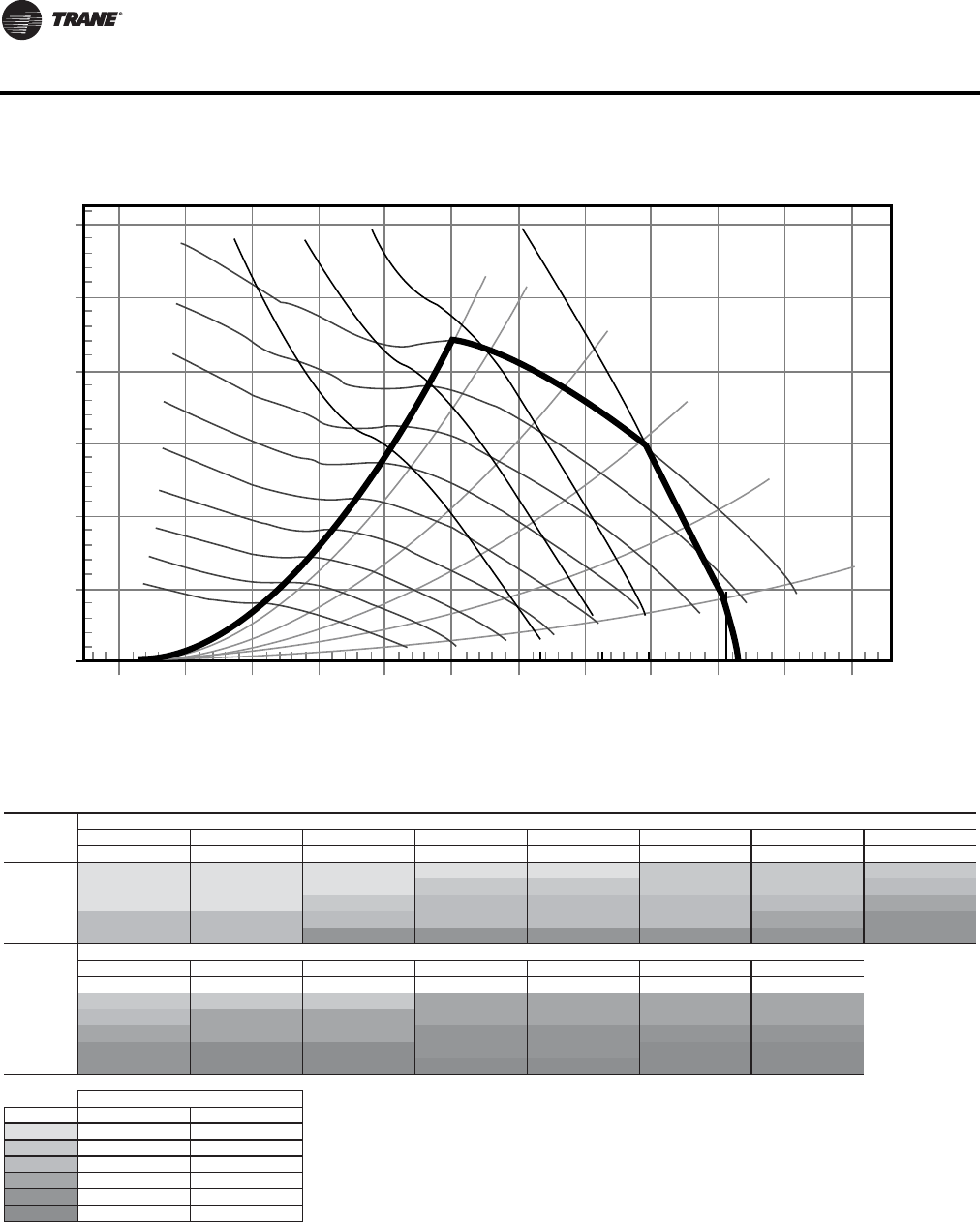
52 WSHP-PRC016E-EN
Fan Performance Data
Figure 9. Fan performance curve (top supply) - GEV*090(a)
(a)Includes wet coil, no filter
3.0
2.5
2.0
1.5
1.0
0.5
0.0
0 500 1000 1500 2000 2500 3000 3500 4000 4500 55005000
Airflow (cfm)
Total Static Pressure (in H20)
1.00 bhp
50%WO
45%WO
60%WO
70% WO
80% WO
90% WO
700 RPM
600 RPM
800 RPM
900 RPM
1000 RPM
1100 RPM
1200 RPM
1300 RPM
1400 RPM
1.50 bhp
2.00 bhp
3.00 bhp
Table 62. Fan performance curve (top supply) - GEV*090 (includes wet coil, no filter)
RPM BHP RPM BHP RPM BHP RPM BHP RPM BHP RPM BHP RPM BHP RPM BHP
2400 655(a) 0.44(a) 703(a) 0.49(a) 748(a) 0.54(a) 790(a) 0.59(a) 830(a) 0.64(a) 868(b) 0.70(b) 905(b) 0.75(b) 941(b) 0.81(b)
2700 725(a) 0.61(a) 768(a) 0.66(a) 809(a) 0.72(a) 849(b) 0.78(b) 886(b) 0.84(b) 922(b) 0.90(b) 957(b) 0.96(b) 990(c) 1.02(c)
3000 797(a) 0.82(a) 836(a) 0.88(a) 873(b) 0.94(b) 910(c) 1.01(c) 945(c) 1.07(c) 979(c) 1.14(c) 1012(c) 1.20(c) 1043(d) 1.27(d)
3300 869(c) 1.07(c) 904(c) 1.14(c) 939(c) 1.21(c) 973(c) 1.28(c) 1006(c) 1.35(c) 1039(c) 1.43(c) 1069(d) 1.50(d) 1099(e) 1.57(e)
3600 942(c) 1.38(c) 974(c) 1.45(c) 1007(e) 1.53(e) 1038(e) 1.61(e) 1069(e) 1.68(e) 1099(e) 1.76(e) 1129(e) 1.84(e) 1157(e) 1.92(e)
RPM BHP RPM BHP RPM BHP RPM BHP RPM BHP RPM BHP RPM BHP
2400 977(b) 0.86(b) 1012(b) 0.92(b) 1045(b) 0.98(b) 1078(d) 1.04(d) 1111(d) 1.11(d) 1144(d) 1.17(d) 1177(d) 1.24(d)
2700 1023(c) 1.08(c) 1055(d) 1.14(d) 1087(d) 1.21(d) 1118(d) 1.27(d) 1147(d) 1.34(d) 1178(d) 1.41(d) 1207(d) 1.47(d)
3000 1074(d) 1.33(d) 1104(d) 1.40(d) 1133(d) 1.47(d) 1162(e) 1.54(e) 1191(e) 1.61(e) 1219(e) 1.68(e) 1246(e) 1.76(e)
3300 1128(e) 1.64(e) 1157(e) 1.71(e) 1184(e) 1.79(e) 1211(e) 1.86(e) 1238(e) 1.94(e) 1265(f) 2.01(f) 1291(f) 2.09(f)
3600 1185(e) 1.99(e) 1212(f) 2.07(f) 1239(f) 2.15(f) 1264(f) 2.23(f) 1290(f) 2.31(f) 1315(f) 2.39(f) 1340(f) 2.48(f)
Legend
(a)
(b)
(c)
(d)
(e)
(f)
1.51.0 1.1 1.2 1.3 1.4
Digit 12 - Drive Package
single speed motor two speed motor
0.1
Std
Airflow
CFM
Std
Airflow
CFM
Unit External Static Pressure inches W.G. (Wet Coil, No Drive Loss Included & No Return Air Filter)
Unit External Static Pressure inches W.G. (Wet Coil, No Drive Loss Included & No Return Air Filter)
0.2 0.3 0.4 0.5 0.6 0.7 0.8
0.9
A1
B2
C3
D4
E5
F6
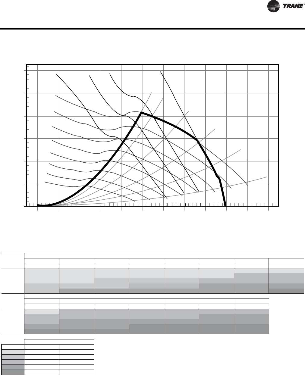
WSHP-PRC016E-EN 53
Fan Performance Data
Figure 10. Fan performance curve (front/back supply) - GEV*090(a)
(a)Includes wet coil, no filter
3.0
2.5
2.0
1.5
1.0
0.5
0.0
0 500 1000 1500 2000 2500 3000 3500 4000 4500 55005000
Airflow (cfm)
Total Static Pressure (in H20)
50%WO
45%WO
60%WO
70% WO
80% WO
90% WO
700 RPM
600 RPM
800 RPM
900 RPM
1000 RPM
1100 RPM
1200 RPM
1300 RPM
1.00 bhp
1.50 bhp
2.00 bhp
3.00 bhp
Table 63. Fan performance curve (front/back supply) - GEV*090 (includes wet coil, no filter)
RPM BHP RPM BHP RPM BHP RPM BHP RPM BHP RPM BHP RPM BHP RPM BHP
2400 620(a) 0.47(a) 666(a) 0.53(a) 709(a) 0.58(a) 750(a) 0.64(a) 790(a) 0.70(a) 828(a) 0.76(a) 864(a) 0.82(a) 900(a) 0.88(a)
2700 687(a) 0.66(a) 728(a) 0.72(a) 767(a) 0.78(a) 805(a) 0.84(a) 842(a) 0.91(a) 877(a) 0.97(a) 912(c) 1.04(c) 945(c) 1.11(c)
3000 754(a) 0.88(a) 792(a) 0.95(a) 828(b) 1.02(b) 863(b) 1.09(b) 897(b) 1.16(b) 930(c) 1.23(c) 962(c) 1.31(c) 993(c) 1.38(c)
3300 822(b) 1.16(b) 857(b) 1.24(b) 890(b) 1.31(b) 922(c) 1.39(c) 954(c) 1.46(c) 984(d) 1.54(d) 1015(d) 1.62(d) 1044(d) 1.70(d)
3600 891(b) 1.49(b) 922(d) 1.57(d) 954(d) 1.66(d) 984(d) 1.74(d) 1013(d) 1.82(d) 1042(d) 1.90(d) 1070(d) 1.98(d) 1098(e) 2.07(e)
RPM BHP RPM BHP RPM BHP RPM BHP RPM BHP RPM BHP RPM BHP
2400 934(a) 0.95(a) 966(c) 1.01(c) 999(c) 1.07(c) 1031(c) 1.13(c) 1063(c) 1.19(c) 1093(c) 1.25(c) 1124(c) 1.31(c)
2700 977(c) 1.18(c) 1008(c) 1.25(c) 1039(c) 1.32(c) 1068(c) 1.39(c) 1098(c) 1.46(c) 1126(d) 1.53(d) 1154(d) 1.59(d)
3000 1024(c) 1.46(c) 1053(d) 1.53(d) 1083(d) 1.61(d) 1111(d) 1.69(d) 1138(d) 1.77(d) 1166(d) 1.84(d) 1192(d) 1.92(d)
3300 1074(d) 1.78(d) 1102(d) 1.86D(d) 1129(d) 1.95(d) 1156(e) 2.03(e) 1182(e) 2.12(e) 1208(e) 2.20(e) 1233(e) 2.28(e)
3600 1125(e) 2.16(e) 1152(e) 2.25(e) 1178(e) 2.34(e) 1204(e) 2.43(e) 1230(e) 2.52(e) 1255(e) 2.61(e) 1279(e) 2.70(e)
Legend
(a)
(b)
(c)
(d)
(e)
0.5 0.6
Unit External Static Pressure inches W.G. (Wet Coil, No Drive Loss Included & No Return Air Filter)
Std
Airflow
CFM
Std
Airflow
CFM
Unit External Static Pressure inches W.G. (Wet Coil, No Drive Loss Included & No Return Air Filter)
0.7 0.8
0.9 1 1.1 1.2 1.3 1.4 1.5
0.1 0.2 0.3 0.4
Digit 12 - Drive Package
single speed motor two speed motor
A1
E5
B2
C3
D4
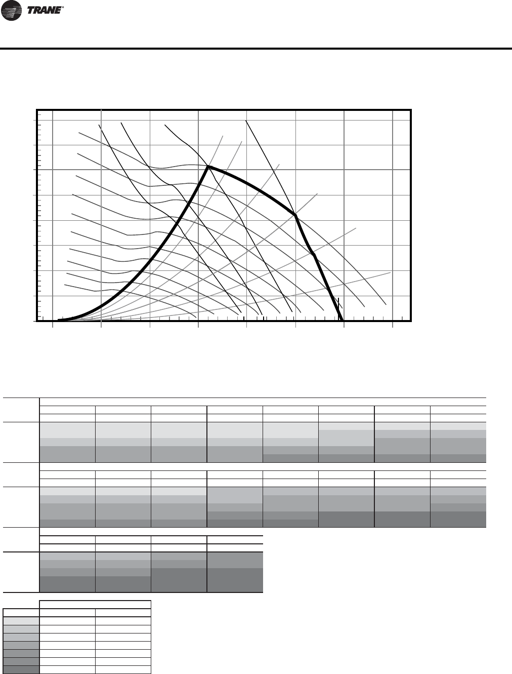
54 WSHP-PRC016E-EN
Fan Performance Data
Figure 11. Fan performance curve (top supply) - GEV*120(a)
(a)Includes wet coil, no filter
3.0
3.5
4.0
2.5
2.0
1.5
1.0
0.5
0.0
0 1000 2000 3000 4000 70005000 6000
Airflow (cfm)
Total Static Pressure (in H20)
1.50 bhp
2.00 bhp
3.00 bhp
5.00 bhp
50%WO
45%WO
60%WO
70% WO
80% WO
90% WO
700 RPM
800 RPM
900 RPM
1000 RPM
1100 RPM
1200 RPM
1300 RPM
1400 RPM
1500 RPM
1600 RPM
Table 64. Fan performance curve (top supply) - GEV*120 (includes wet coil, no filter)
RPM BHP RPM BHP RPM BHP RPM BHP RPM BHP RPM BHP RPM BHP RPM BHP
3200 759(a) 0.83(a) 797(a) 0.89(a) 833(a) 0.95(a) 868(a) 1.01(a) 903(a) 1.08(a) 937(a) 1.16(a) 970(a) 1.22(a) 1003(a) 1.29(a)
3600 845(a) 1.16(a) 878(a) 1.23(a) 912(a) 1.30(a) 944(a) 1.36(a) 975(a) 1.44(a) 1006(b) 1.51(b) 1036(c) 1.59(c) 1066(c) 1.68(c)
4000 932(b) 1.58(b) 962(b) 1.66(b) 992(b) 1.73(b) 1021(b) 1.80(b) 1050(b) 1.87(b) 1079(b) 1.95(b) 1106(d) 2.04(d) 1134(d) 2.13(d)
4400 1019(d) 2.08(d) 1046(d) 2.17(d) 1074(d) 2.25(d) 1101(d) 2.33(d) 1128(d) 2.41(d) 1154(d) 2.49(d) 1180(d) 2.58(d) 1205(d) 2.67(d)
4800 1108(d) 2.69(d) 1132(d) 2.78(d) 1157(d) 2.87(d) 1182(d) 2.96(d) 1207(f) 3.05(f) 1232(f) 3.14(f) 1256(f) 3.22(f) 1279(f) 3.31(f)
RPM BHP RPM BHP RPM BHP RPM BHP RPM BHP RPM BHP RPM BHP RPM BHP
3200 1035(a) 1.35(a) 1065(a) 1.42(a) 1095(a) 1.49(a) 1124(c) 1.56(c) 1153(c) 1.63(c) 1181(c) 1.70(c) 1208(c) 1.77(c) 1234(c) 1.84(c)
3600 1096(c) 1.75(c) 1125(c) 1.82(c) 1154(c) 1.89(c) 1181(c) 1.97(c) 1207(d) 2.04(d) 1234(d) 2.13(d) 1260(d) 2.21(d) 1285(d) 2.29(d)
4000 1161(d) 2.22(d) 1188(d) 2.32(d) 1215(d) 2.40(d) 1241(d) 2.47(d) 1266(d) 2.55(d) 1293(d) 2.63(d) 1316(d) 2.71(d) 1341(e) 2.81(e)
4400 1230(d) 2.76(d) 1255(d) 2.87(d) 1280(d) 2.97(d) 1304(f) 3.07(f) 1329(f) 3.16(f) 1353(g) 3.25(g) 1376(g) 3.33(g) 1399(g) 3.41(g)
4800 1303(f) 3.41(f) 1326(f) 3.51(f) 1349(f) 3.62(f) 1371(g) 3.73(g) 1394(g) 3.85(g) 1417(g) 3.96(g) 1439(g) 4.06(g) 1461(g) 4.16(g)
Unit External Static Pressure inches W.G. (Wet Coil, No Drive Loss Included & No Return Air Filter)
RPM BHP RPM BHP RPM BHP RPM BHP
3200 1261(c) 1.91(c) 1286(c) 1.98(c) 1313(d) 2.06(d) 1336(e) 2.13(e)
3600 1310(d) 2.37(d) 1335(d) 2.45(d) 1359(e) 2.52(e) 1382(e) 2.60(e)
4000 1365(e) 2.90(e) 1387(e) 2.99(e) 1411(g) 3.08(g) 1434(g) 3.16(g)
4400 1422(g) 3.50(g) 1445(g) 3.60(g) 1467(g) 3.69(g) 1488(g) 3.79(g)
4800 1483(g) 4.25(g) 1505(g) 4.34(g) 1525(g) 4.43(g) 1547(g) 4.52(g)
Legend
(a)
(b)
(c)
(d)
(e)
(f)
(g)
Std
Airflow
CFM
1.7 1.8 1.9 2.0
1.6
Std
Airflow
CFM
Unit External Static Pressure inches W.G. (Wet Coil, No Drive Loss Included & No Return Air Filter)
0.9 1.0 1.1 1.2
Digit 12 - Drive Package
single speed motor two speed motor
Std
Airflow
CFM
Unit External Static Pressure inches W.G. (Wet Coil, No Drive Loss Included & No Return Air Filter)
0.1 0.2 0.3 0.4 0.5 0.6 0.7 0.8
1.3 1.4 1.5
A1
B2
C3
G7
D4
E5
F6

WSHP-PRC016E-EN 55
Fan Performance Data
Figure 12. Fan performance curve (front/back supply) - GEV*120(a)
(a)Includes wet coil, no filter
3.0
3.5
4.0
2.5
2.0
1.5
1.0
0.5
0.0
0 1000 2000 3000 4000 70005000 6000
Airflow (cfm)
Total Static Pressure (in H20)
1.50 bhp
2.00 bhp
3.00 bhp
5.00 bhp
50%WO
45%WO
60%WO
70% WO
80% WO
90% WO
700 RPM
800 RPM
900 RPM
1000 RPM
1100 RPM
1200 RPM
1300 RPM
1400 RPM
1500 RPM
Table 65. Fan performance curve (front/back supply) - GEV*120 (includes wet coil, no filter)
RPM BHP RPM BHP RPM BHP RPM BHP RPM BHP RPM BHP RPM BHP RPM BHP
3200 727(a) 0.90(a) 761(a) 0.96(a) 794(a) 1.03(a) 829(a) 1.10(a) 863(a) 1.17(a) 896(a) 1.24(a) 929(a) 1.31(a) 962(a) 1.38(a)
3600 809(a) 1.26(a) 840(a) 1.33(a) 870(a) 1.41(a) 900(a) 1.48(a) 931(b) 1.56(b) 961(b) 1.64(b) 991(b) 1.71(b) 1021(c) 1.79(c)
4000 893(b) 1.71(b) 920(b) 1.79(b) 947(b) 1.87(b) 974(b) 1.96(b) 1001(d) 2.04(d) 1029(d) 2.12(d) 1057(d) 2.21(d) 1084(d) 2.30(d)
4400 977(d) 2.25(d) 1002(d) 2.34(d) 1027(d) 2.44(d) 1051(d) 2.53(d) 1076(d) 2.62(d) 1100(d) 2.71(d) 1126(d) 2.80(d) 1151(d) 2.90(d)
4800 1061(d) 2.91(d) 1084(f) 3.01(f) 1107(f) 3.11(f) 1130(f) 3.21(f) 1152(f) 3.30(f) 1175(f) 3.40(f) 1198(f) 3.51(f) 1220(f) 3.61(f)
RPM BHP RPM BHP RPM BHP RPM BHP RPM BHP RPM BHP RPM BHP RPM BHP
3200 993(a) 1.45(a) 1023(c) 1.52(c) 1053(c) 1.60(c) 1081(c) 1.67(c) 1109(c) 1.74(c) 1136(c) 1.81(c) 1162(c) 1.88(c) 1189(c) 1.96(c)
3600 1049(c) 1.87(c) 1078(c) 1.95(c) 1106(d) 2.03(d) 1133(d) 2.11(d) 1160(d) 2.20(d) 1187(d) 2.28(d) 1212(d) 2.36(d) 1237(d) 2.44(d)
4000 1111(d) 2.38(d) 1138(d) 2.47(d) 1163(d) 2.56(d) 1190(d) 2.65(d) 1214(d) 2.74(d) 1239(d) 2.83(d) 1264(e) 2.92(e) 1288(e) 3.01(e)
4400 1176(d) 2.99(d) 1201(f) 3.09(f) 1225(f) 3.18(f) 1248(f) 3.28(f) 1273(g) 3.38(g) 1296(g) 3.47(g) 1319(g) 3.57(g) 1343(g) 3.67(g)
4800 1243(f) 3.71(f) 1266(g) 3.81(g) 1289(g) 3.91(g) 1311(g) 4.02(g) 1334(g) 4.12(g) 1356(g) 4.23(g) 1378(g) 4.33(g) 1399(g) 4.44(g)
Unit External Static Pressure inches W.G. (Wet Coil, No Drive Loss Included & No Return Air Filter)
RPM BHP RPM BHP RPM BHP RPM BHP
3200 1214(d) 2.03(d) 1239(d) 2.11(d) 1264(e) 2.18(e) 1289(e) 2.27(e)
3600 1260(e) 2.52(e) 1284(e) 2.60(e) 1308(e) 2.68(e) 1332(e) 2.77(e)
4000 1311(g) 3.10(g) 1335(g) 3.19(g) 1357(g) 3.28(g) 1378(g) 3.37(g)
4400 1365(g) 3.77(g) 1387(g) 3.87(g) 1409(g) 3.97(g) 1430(g) 4.07(g)
4800 1422(g) 4.55(g) 1443(g) 4.66(g) 1463(g) 4.76(g) 1483(g) 4.87(g)
Legend
(a)
(b)
(c)
(d)
(e)
(f)
(g)
1.9 2.0
Std
Airflow
CFM
Unit External Static Pressure inches W.G. (Wet Coil, No Drive Loss Included & No Return Air Filter)
0.9 1.0 1.1 1.2 1.3 1.4 1.5 1.6
Digit 12 - Drive Package
single speed motor two speed motor
Std
Airflow
CFM
Unit External Static Pressure inches W.G. (Wet Coil, No Drive Loss Included & No Return Air Filter)
0.1 0.2 0.3 0.4 0.5 0.6 0.7 0.8
Std
Airflow
CFM
1.7 1.8
A1
B2
C3
G7
D4
E5
F6
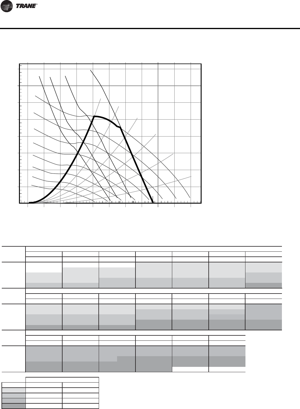
56 WSHP-PRC016E-EN
Fan Performance Data
Figure 13. Fan performance curve (top supply) - GEV*150(a)
(a)Includes wet coil, no filter
4.0
3.5
3.0
2.5
2.0
1.5
1.0
0.5
0.0
01000 2000 3000 4000 5000 6000 7000 8000 9000 10000
Airflow (cfm)
Total Static Pressure (in H20)
1.50 bhp
2.00 bhp
3.00 bhp
5.00 bhp
50%WO
40%WO
60%WO
70% WO
80% WO
90% WO
700 RPM
600 RPM
500 RPM
800 RPM
900 RPM
1000 RPM
1100 RPM
1200 RPM
Table 66. Fan performance curve (top supply) - GEV*150 (includes wet coil, no filter)
RPM BHP RPM BHP RPM BHP RPM BHP RPM BHP RPM BHP RPM BHP
4000 ——————626(a) 1.07(a) 660(a) 1.16(a) 692(a) 1.25(a) 724(a) 1.34(a)
4500 — — 607(a) 1.22(a) 639(a) 1.31(a) 671(a) 1.41(a) 702(a) 1.52(a) 733(a) 1.62(a) 762(a) 1.72(a)
5000 630(a) 1.50(a) 661(a) 1.62(a) 690(a) 1.72(a) 718(a) 1.83(a) 747(a) 1.94(a) 776(a) 2.06(a) 803(b) 2.17(b)
5500 686(a) 1.96(a) 716(a) 2.10(a) 742(b) 2.22(b) 768(b) 2.33(b) 794(b) 2.45(b) 820(b) 2.58(b) 847(b) 2.71(b)
6000 743(b) 2.52(b) 771(b) 2.68(b) 796(b) 2.81(b) 820(b) 2.94(b) 844(b) 3.06(b) 868(b) 3.19(b) 892(d) 3.33(d)
RPM BHP RPM BHP RPM BHP RPM BHP RPM BHP RPM BHP RPM BHP
4000 754(a) 1.43(a) 783(a) 1.52(a) 810(a) 1.62(a) 837(a) 1.72(a) 864(a) 1.81(a) 890(a) 1.90(a) 915(c) 1.99(c)
4500 791(a) 1.82(a) 818(a) 1.92(a) 845(a) 2.02(a) 871(b) 2.12(b) 896(b) 2.23(b) 920(b) 2.34(b) 943(c) 2.45(c)
5000 830(b) 2.29(b) 856(b) 2.40(b) 882(b) 2.51(b) 906(b) 2.62(b) 931(b) 2.73(b) 954(c) 2.84(c) 977(c) 2.96(c)
5500 872(b) 2.83(b) 897(b) 2.96(b) 921(b) 3.08(b) 944(d) 3.21(d) 967(d) 3.33(d) 990(d) 3.45(d) 1013(d) 3.57(d)
6000 916(d) 3.47(d) 939(d) 3.61(d) 962(d) 3.75(d) 985(d) 3.88(d) 1007(d) 4.02(d) 1028(d) 4.15(d) 1050(d) 4.29(d)
Unit External Static Pressure inches W.G. (Wet Coil, 3% Drive Loss Included & No Return Air Filter)
RPM BHP RPM BHP RPM BHP RPM BHP RPM BHP RPM BHP
4000 939(c) 2.09(c) 963(c) 2.19(c) 987(c) 2.29(c) 1010(c) 2.39(c) 1034(c) 2.50(c) 1059(c) 2.61(c)
4500 967(c) 2.56(c) 991(c) 2.19(c) 1013(c) 2.76(c) 1035(c) 2.87(c) 1057(c) 2.98(c) 1077(c) 3.09(c)
5000 999(c) 3.08(c) 1021(c) 3.21(c) 1043(d) 3.33(d) 1065(d) 3.45(d) 1085(d) 3.56(d) 1106(d) 3.68(d)
5500 1034(d) 3.69(d) 1056(d) 3.82(d) 1076(d) 3.95(d) 1097(d) 4.09(d) 1117(d) 4.22(d) 1136(d) 4.35(d)
6000 1070(d) 4.42(d) 1091(d) 4.55(d) 1111(d) 4.68(d) 1131(d) 4.81(d) ————
Legend
(a)
(b)
(c)
(d)
Digit 12 - Drive Package
single speed motor two speed motor
D4
A1
B2
C3
Std
Airflow
CFM
Unit External Static Pressure inches W.G. (Wet Coil, 3% Drive Loss Included & No Return Air Filter)
0.1 0.2 0.3 0.4 0.5 0.6 0.7
Std
Airflow
CFM
Unit External Static Pressure inches W.G. (Wet Coil, 3% Drive Loss Included & No Return Air Filter)
0.8 0.9 1.0 1.1 1.2 1.3 1.4
2.0
Std
Airflow
CFM
1.5 1.6 1.7 1.8 1.9
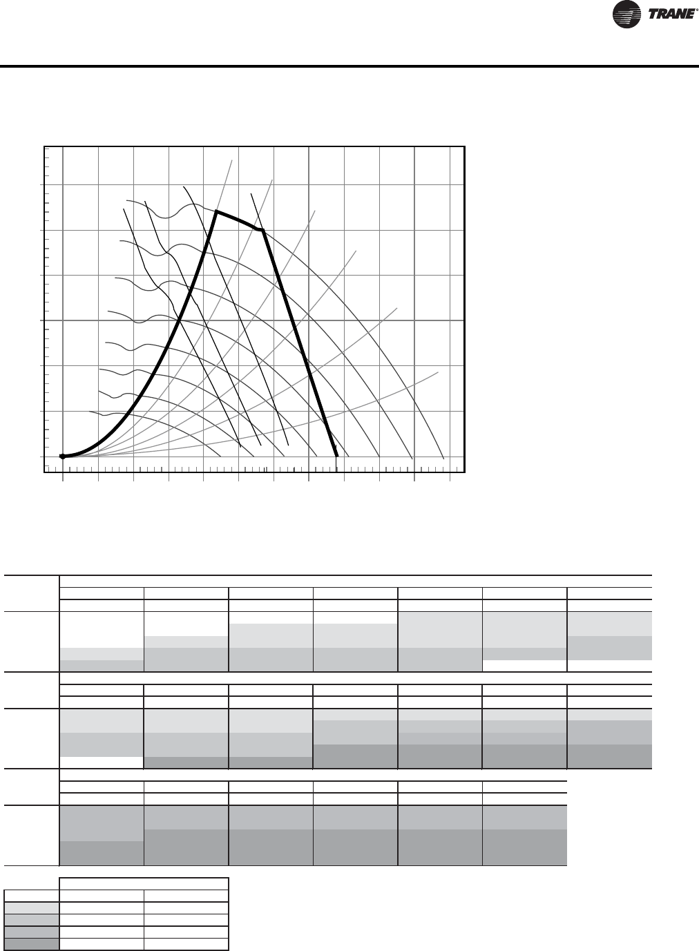
WSHP-PRC016E-EN 57
Fan Performance Data
Figure 14. Fan performance curve (front/back supply) - GEV*150(a)
(a)Includes wet coil, no filter
3.0
2.5
2.0
1.5
1.0
0.5
0.0
0
27
1000 2000 3000 4000 5000 6000 7000 8000 9000 10000 11000
Airflow (cfm)
Total Static Pressure (in H20)
1.50 bhp
2.00 bhp
3.00 bhp
5.00 bhp
50%WO
40%WO
60%WO
70% WO
80% WO
90% WO
700 RPM
600 RPM
500 RPM
800 RPM
900 RPM
1000 RPM
1100 RPM
1200 RPM
Table 67. Fan performance curve (front/back supply) - GEV*150 (includes wet coil, no filter)
RPM BHP RPM BHP RPM BHP RPM BHP RPM BHP RPM BHP RPM BHP
4000 ————————626(a) 1.11(a) 658(a) 1.20(a) 689(a) 1.28(a)
4500 ————606(a)1.28(a)636(a)1.37(a)666(a) 1.46(a) 695(a) 1.55(a) 723(a) 1.64(a)
5000 — — 626(a) 1.58(a) 654(a) 1.68(a) 681(a) 1.78(a) 708(a) 1.88(a) 735(a) 1.98(a) 761(b) 2.08(b)
5500 652(a) 1.95(a) 677(b) 2.06(b) 703(b) 2.17(b) 728(b) 2.28(b) 753(b) 2.39(b) 778(b) 2.50(b) 802(b) 2.61(b)
6000 707(b) 2.51(b) 730(b) 2.63(b) 753(b) 2.75(b) 777(b) 2.87(b) 800(b) 2.99(b) ————
RPM BHP RPM BHP RPM BHP RPM BHP RPM BHP RPM BHP RPM BHP
4000 719(a) 1.36(a) 749(a) 1.45(a) 778(a) 1.54(a) 805(a) 1.62(a) 832(a) 1.71(a) 858(a) 1.80(a) 884(a) 1.89(a)
4500 751(a) 1.74(a) 779(a) 1.84(a) 806(a) 1.93(a) 833(b) 2.03(b) 858(b) 2.12(b) 884(b) 2.22(b) 908(c) 2.32(c)
5000 787(b) 2.19(b) 812(b) 2.29(b) 838(b) 2.40(b) 863(b) 2.51(b) 888(c) 2.62(c) 911(c) 2.72(c) 935(c) 2.83(c)
5500 826(b) 2.72(b) 850(b) 2.83(b) 873(b) 2.95(b) 897(d) 3.07(d) 919(d) 3.18(d) 942(d) 3.30(d) 965(d) 3.42(d)
6000 — — 890(d) 3.46(d) 912(d) 3.59(d) 933(d) 3.71(d) 955(d) 3.84(d) 976(d) 3.97(d) 997(d) 4.10(d)
Unit External Static Pressure inches W.G. (Wet Coil, 3% Drive Loss Included & No Return Air Filter)
RPM BHP RPM BHP RPM BHP RPM BHP RPM BHP RPM BHP
4000 910(c) 1.98(c) 936(c) 2.08(c) 962(c) 2.18(c) 987(c) 2.29(c) 1011(c) 2.39(c) 1035(c) 2.49(c)
4500 932(c) 2.42(c) 955(c) 2.51(c) 978(c) 2.61(c) 1002(c) 2.72(c) 1025(c) 2.83(c) 1048(c) 2.94(c)
5000 958(c) 2.93(c) 980(d) 3.04(d) 1002(d) 3.15(d) 1024(d) 3.25(d) 1046(d) 3.37(d) 1067(d) 3.48(d)
5500 987(d) 3.54(d) 1009(d) 3.65(d) 1030(d) 3.77(d) 1050(d) 3.88(d) 1071(d) 4.00(d) 1091(d) 4.12(d)
6000 1017(d) 4.22(d) 1038(d) 4.35(d) 1059(d) 4.48(d) 1078(d) 4.60(d) 1099(d) 4.73(d) 1118(d) 4.86(d)
Legend
(a)
(b)
(c)
(d)
Std
Airflow
CFM
Unit External Static Pressure inches W.G. (Wet Coil, 3% Drive Loss Included & No Return Air Filter)
0.1 0.2 0.3 0.4 0.5 0.6 0.7
Std
Airflow
CFM
Unit External Static Pressure inches W.G. (Wet Coil, 3% Drive Loss Included & No Return Air Filter)
0.8 0.9 1.0 1.1 1.2 1.3 1.4
Digit 12 - Drive Package
single speed motor two speed motor
2.0
Std
Airflow
CFM
1.5 1.6 1.7 1.8 1.9
D4
A1
B2
C3
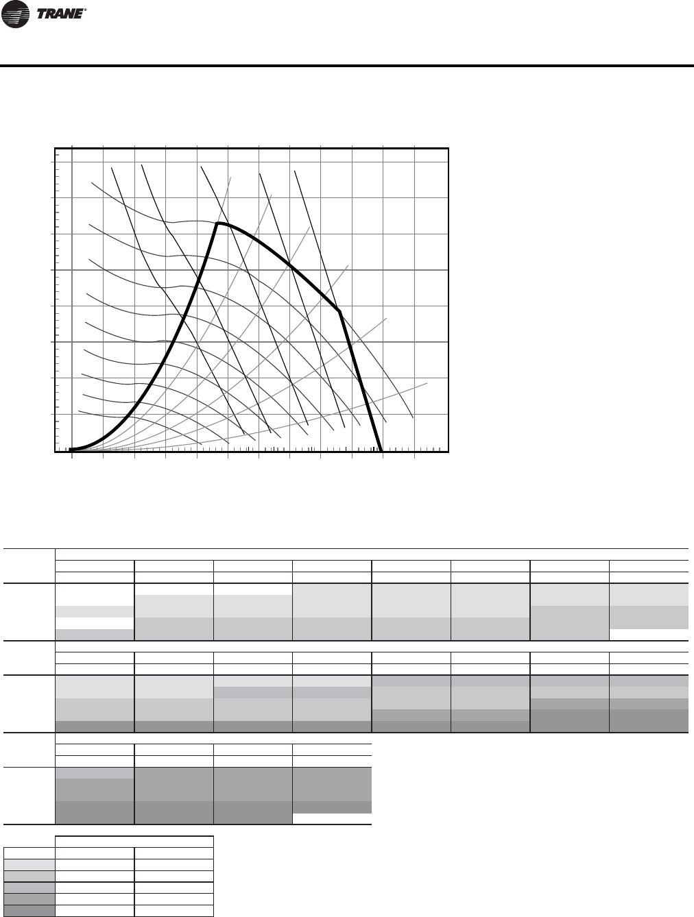
58 WSHP-PRC016E-EN
Fan Performance Data
Figure 15. Fan performance curve (top supply) - GEV*180(a)
(a)Includes wet coil, no filter
4.0
3.5
3.0
2.5
2.0
1.5
1.0
0.5
0.0
01000 2000 3000 4000 5000 6000
7000 8000 9000 10000 11000 12000
Airflow (cfm)
Total Static Pressure (in H20)
2.00 bhp
3.00 bhp
5.00 bhp
7.50 bhp
10.0 bhp
50%WO
40%WO
60%WO
70% WO
80% WO
90% WO
700 RPM
600 RPM
500 RPM
800 RPM
900 RPM
1000 RPM
1100 RPM
1200 RPM
1300 RPM
Table 68. Fan performance curve (top supply) - GEV*180 (includes wet coil, no filter)
RPM BHP RPM BHP RPM BHP RPM BHP RPM BHP RPM BHP RPM BHP RPM BHP
4800 — — — — — — 669(a) 1.55(a) 698(a) 1.66(a) 727(a) 1.77(a) 754(a) 1.87(a) 781(a) 1.98(a)
5400 — — 670(a) 1.84(a) 698(a) 1.96(a) 724(a) 2.08(a) 750(a) 2.20(a) 777(a) 2.32(a) 802(a) 2.44(a) 827(a) 2.56(a)
6000 710(a) 2.37(a) 731(a) 2.47(a) 758(a) 2.60(a) 782(a) 2.73(a) 806(a) 2.86(a) 830(a) 3.00(a) 853(b) 3.13(b) 877(b) 3.26(b)
6600 — — 794(b) 3.23(b) 819(b) 3.37(b) 843(b) 3.52(b) 864(b) 3.66(b) 886(b) 3.81(b) 907(b) 3.95(b) 928(b) 4.09(b)
7200 848(b) 4.06(b) 860(b) 4.14(b) 880(b) 4.28(b) 904(b) 4.45(b) 924(b) 4.60(b) 943(b) 4.76(b) 963(b) 4.92(b) — —
RPM BHP RPM BHP RPM BHP RPM BHP RPM BHP RPM BHP RPM BHP RPM BHP
4800 808(a) 2.08(a) 834(a) 2.19(a) 860(a) 2.30(a) 885(a) 2.41(a) 909(c) 2.52(c) 933(c) 2.63(c) 956(c) 2.73(c) 979(c) 2.84(c)
5400 852(a) 2.68(a) 876(a) 2.80(a) 900(c) 2.92(c) 923(c) 3.04(c) 946(b) 3.17(b) 969(b) 3.29(b) 991(b) 3.41(b) 1013(b) 3.53(b)
6000 899(b) 3.40(b) 922(b) 3.53(b) 944(b) 3.66(b) 966(b) 3.80(b) 987(b) 3.93(b) 1008(b) 4.06(b) 1030(d) 4.20(d) 1050(d) 4.34(d)
6600 950(b) 4.24(b) 971(b) 4.39(b) 992(b) 4.54(b) 1012(b) 4.69(b) 1032(d) 4.83(d) 1053(d) 4.98(d) 1072(e) 5.12(e) 1091(e) 5.27(e)
7200 1003(e) 5.23(e) 1023(e) 5.39(e) 1042(e) 5.56(e) 1061(e) 5.72(e) 1080(e) 5.88(e) 1099(e) 6.04(e) 1118(e) 6.20(e) 1136(e) 6.36(e)
Unit External Static Pressure inches W.G. (Wet Coil, 3% Drive Loss Included & No Return Air Filter)
RPM BHP RPM BHP RPM BHP RPM BHP
4800 1001(c) 2.96(c) 1023(d) 3.07(d) 1045(d) 3.19(d) 1065(d) 3.30(d)
5400 1034(d) 3.65(d) 1056(d) 3.78(d) 1075(d) 3.89(d) 1096(d) 4.02(d)
6000 1071(d) 4.47(d) 1091(d) 4.61(d) 1111(d) 4.75(d) 1131(d) 4.88(d)
6600 1111(e) 5.42(e) 1130(e) 5.57(e) 1149(e) 5.72(e) 1167(e) 5.87(e)
7200 1154(e) 6.52(e) 1172(e) 6.67(e) 1190(e) 6.83(e) — —
Legend
(a)
(b)
(c)
(d)
(e)
1.9 2.0
Std
Airflow
CFM
Unit External Static Pressure inches W.G. (Wet Coil, 3% Drive Loss Included & No Return Air Filter)
0.1 0.2 0.3 0.4 0.5 0.6 0.7 0.8
Digit 12 - Drive Package
single speed motor two speed motor
Std
Airflow
CFM
Unit External Static Pressure inches W.G. (Wet Coil, 3% Drive Loss Included & No Return Air Filter)
0.9 1.0 1.1 1.2 1.3 1.4 1.5 1.6
Std
Airflow
CFM
1.7 1.8
D4
E5
A1
B2
C3
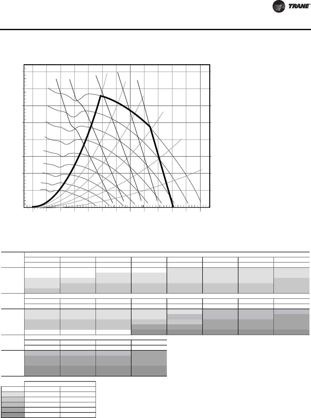
WSHP-PRC016E-EN 59
Fan Performance Data
Figure 16. Fan performance curve (front/back supply) - GEV*180(a)
(a)Includes wet coil, no filter
4.0
3.5
3.0
2.5
2.0
1.5
1.0
0.5
0.0
01000 2000 3000 4000 5000 6000 7000 8000 9000 10000 11000 12000
Airflow (cfm)
Total Static Pressure (in H20)
2.00 bhp
3.00 bhp
5.00 bhp
10.0 bhp
7.50 bhp
50%WO
40%WO
60%WO
70% WO
80% WO
90% WO
700 RPM
600 RPM
500 RPM
800 RPM
900 RPM
1000 RPM
110 0 RP M
1200 RPM
1300 RPM
Table 69. Fan performance curve (front/back supply) - GEV*180 (includes wet coil, no filter)
RPM BHP RPM BHP RPM BHP RPM BHP RPM BHP RPM BHP RPM BHP RPM BHP
4800————————668(a) 1.60(a) 696(a) 1.70(a) 724(a) 1.79(a) 750(a) 1.89(a)
5400 — — — — 665(a) 1.92(a) 692(a) 2.03(a) 717(a) 2.13(a) 743(a) 2.24(a) 768(a) 2.35(a) 793(a) 2.46(a)
6000 670(a) 2.28(a) 696(a) 2.41(a) 722(a) 2.54(a) 746(a) 2.66(a) 770(a) 2.78(a) 793(a) 2.91(a) 816(a) 3.02(a) 839(b) 3.14(b)
6600 732(a) 3.01(a) 755(b) 3.15(b) 780(b) 3.30(b) 802(b) 3.43(b) 824(b) 3.56(b) 846(b) 3.70(b) 867(b) 3.83(b) 888(b) 3.96(b)
7200 795(b) 3.89(b) 815(b) 4.03(b) 838(b) 4.19(b) 860(b) 4.35(b) 880(b) 4.49(b) 900(b) 4.63(b) 920(b) 4.78(b) 940(b) 4.93(b)
RPM BHP RPM BHP RPM BHP RPM BHP RPM BHP RPM BHP RPM BHP RPM BHP
4800 776(a) 1.98(a) 802(a) 2.08(a) 827(a) 2.18(a) 853(a) 2.28(a) 878(a) 2.38(a) 902(c) 2.48(c) 925(c) 2.59(c) 949(c) 2.69(c)
5400 818(a) 2.57(a) 841(a) 2.67(a) 864(a) 2.78(a) 887(a) 2.88(a) 910(c) 3.00(c) 934(c) 3.12(c) 955(c) 3.22(c) 978(d) 3.34(d)
6000 861(b) 3.27(b) 884(b) 3.39(b) 906(b) 3.51(b) 927(b) 3.63(b) 947(b) 3.74(b) 969(d) 3.86(d) 990(d) 3.98(d) 1011(d) 4.11(d)
6600 908(b) 4.09(b) 929(b) 4.23(b) 950(b) 4.36(b) 970(d) 4.50(d) 990(d) 4.63(d) 1010(d) 4.76(d) 1029(d) 4.89(d) 1048(d) 5.02(d)
7200 — — — — — — 1016(e) 5.50(e) 1035(e) 5.65(e) 1053(e) 5.80(e) 1071(e) 5.94(e) 1090(e) 6.09(e)
Unit External Static Pressure inches W.G. (Wet Coil, No Drive Loss Included & No Return Air Filter)
RPM BHP RPM BHP RPM BHP RPM BHP
4800 972(c) 2.79(c) 995(c) 2.90(c) 1018(c) 3.01(c) 1040(d) 3.11(d)
5400 999(d) 3.45(d) 1021(d) 3.57(d) 1041(d) 3.68(d) 1063(d) 3.80(d)
6000 1031(d) 4.23(d) 1051(d) 4.35(d) 1071(d) 4.48(d) 1090(d) 4.61(d)
6600 1066(e) 5.14(e) 1085(e) 5.28(e) 1105(e) 5.42(e) 1124(e) 5.56(e)
7200 1107(e) 6.22(e) 1125(e) 6.36(e) 1142(e) 6.50(e) 1160(e) 6.65(e)
Legend
(a)
(b)
(c)
(d)
(e)
Std
Airflow
CFM
Unit External Static Pressure inches W.G. (Wet Coil, No Drive Loss Included & No Return Air Filter)
0.1 0.2 0.3 0.4 0.5 0.6 0.7 0.8
Std
Airflow
CFM
1.7 1.8 1.9 2.0
Std
Airflow
CFM
Unit External Static Pressure inches W.G. (Wet Coil, No Drive Loss Included & No Return Air Filter)
0.9 1.0 1.1 1.2 1.3 1.4 1.5 1.6
Digit 12 - Drive Package
single speed motor two speed motor
A1
E5
B2
C3
D4
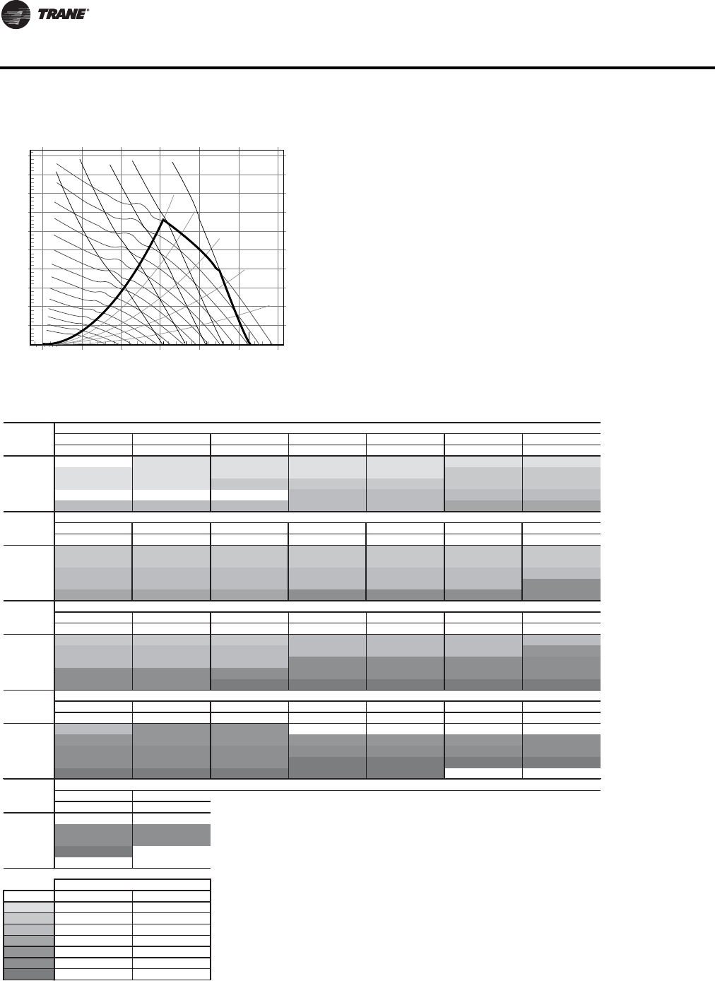
60 WSHP-PRC016E-EN
Fan Performance Data
Figure 17. Fan performance curve (top supply) - GEV*240(a)
(a)Includes wet coil, no filter
4.0
4.5
5.0
3.5
3.0
2.5
2.0
1.5
1.0
0.5
0.0
0 2500 5000 7500 10000 12500 15000
Airflow (cfm)
Total Static Pressure (in H20)
3.00 bhp
5.00 bhp
15.0 bhp
7.50 bhp
10.0hp
52%WO
60%WO
70% WO
80% WO
90% WO
700 RPM
600 RPM
500 RPM
800 RPM
900 RPM
1000 RPM
1100 RPM
1200 RPM
1300 RPM
1400 RPM
1500 RPM
1600 RPM
1700 RPM
1800 RPM
Table 70. Fan performance curve (top supply) - GEV*240 (includes wet coil, no filter)
RPM BHP RPM BHP RPM BHP RPM BHP RPM BHP RPM BHP RPM BHP
6400 — — 893(a) 2.17(a) 928(a) 2.31(a) 962(a) 2.46(a) 995(a) 2.61(a) 1028(a) 2.76(a) 1059(a) 2.91(a)
7200 956(a) 2.83(a) 988(a) 3.00(a) 1019(a) 3.16(a) 1049(a) 3.32(a) 1080(a) 3.49(a) 1110(b) 3.66(b) 1139(b) 3.83(b)
8000 1055(a) 3.84(a) 1085(a) 4.03(a) 1113(b) 4.21(b) 1141(b) 4.39(b) 1168(b) 4.57(b) 1195(b) 4.76(b) 1222(b) 4.95(b)
8800 — — — — — — 1234(c) 5.67(c) 1259(c) 5.87(c) 1283(c) 6.07(c) 1308(c) 6.27(c)
9600 1255(c) 6.54(c) 1280(c) 6.76(c) 1305(c) 6.98(c) 1328(c) 7.20(c) 1352(c) 7.42(c) 1374(d) 7.63(d) 1397(d) 7.85(d)
RPM BHP RPM BHP RPM BHP RPM BHP RPM BHP RPM BHP RPM BHP
6400 1091(b) 3.07(b) 1120(b) 3.22(b) 1149(b) 3.37(b) 1179(b) 3.53(b) 1207(b) 3.69(b) 1236(b) 3.85(b) 1263(b) 4.01(b)
7200 1168(b) 4.00(b) 1196(b) 4.17(b) 1224(b) 4.34(b) 1250(b) 4.52(b) 1277(b) 4.69(b) 1302(b) 4.86(b) 1328(b) 5.03(b)
8000 1249(c) 5.13(c) 1275(c) 5.32(c) 1301(c) 5.52(c) 1326(c) 5.70(c) 1352(c) 5.90(c) 1376(c) 6.08(c) 1399(c) 6.28(c)
8800 1333(c) 6.48(c) 1357(c) 6.69(c) 1382(c) 6.90(c) 1405(c) 7.11(c) 1429(c) 7.32(c) 1452(c) 7.53(c) 1474(f) 7.73(f)
9600 1420(d) 8.07(d) 1443(d) 8.30(d) 1465(d) 8.53(d) 1487(f) 8.75(f) 1509(f) 8.98(f) 1531(f) 9.21(f) 1553(f) 9.44(f)
RPM BHP RPM BHP RPM BHP RPM BHP RPM BHP RPM BHP RPM BHP
6400 1289(b) 4.17(b) 1317(b) 4.35(b) 1343(b) 4.51(b) 1369(c) 4.68(c) 1394(c) 4.85(c) 1420(c) 5.04(c) 1444(c) 5.21(c)
7200 1353(c) 5.22(c) 1378(c) 5.39(c) 1403(c) 5.57(c) 1428(c) 5.77(c) 1451(c) 5.95(c) 1475(c) 6.13(c) 1498(e) 6.32(e)
8000 1423(c) 6.47(c) 1447(c) 6.66(c) 1469(c) 6.85(c) 1492(f) 7.05(f) 1515(f) 7.25(f) 1537(f) 7.45(f) 1559(f) 7.65(f)
8800 1496(f) 7.94(f) 1519(f) 8.16(f) 1540(f) 8.36(f) 1562(f) 8.58(f) 1583(f) 8.78(f) 1605(f) 9.01(f) 1625(f) 9.22(f)
9600 1574(f) 9.67(f) 1595(f) 9.90(f) 1616(g) 10.12(g) 1637(g) 10.36(g) 1656(g) 10.58(g) 1676(g) 10.80(g) 1696(g) 11.04(g)
RPM BHP RPM BHP RPM BHP RPM BHP RPM BHP RPM BHP RPM BHP
6400 1470(c) 5.40(c) 1496(e) 5.59(e) 1523(e) 5.80(e) ————————
7200 1523(e) 6.52(e) 1545(e) 6.71(e) 1568(e) 6.91(e) 1589(e) 7.10(e) 1612(e) 7.31(e) 1635(e) 7.51(e) 1656(f) 7.71(f)
8000 1581(f) 7.85(f) 1603(f) 8.06(f) 1624(f) 8.26(f) 1647(f) 8.49(f) 1668(f) 8.70(f) 1688(f) 8.91(f) 1708(f) 9.12(f)
8800 1646(f) 9.43(f) 1666(f) 9.65(f) 1687(f) 9.87(f) 1707(g) 10.09(g) 1727(g) 10.32(g) 1747(g) 10.54(g) 1767(g) 10.78(g)
9600 1715(g) 11.26(g) 1735(g) 11.50(g) 1754(g) 11.74(g) 1773(g) 11.96(g) 1793(g) 12.22(g) — — — —
RPM BHP RPM BHP
6400 — — — —
7200 1680(f) 7.94(f) 1704(f) 8.17(f)
8000 1728(f) 9.33(f) 1748(f) 9.54(f)
8800 1786(g) 11.00(g) — —
9600 — — — —
Legend
(a)
(b)
(c)
(d)
(e)
(f)
(g)
1.1 1.2 1.3 1.4
Std
Airflow
CFM
Unit External Static Pressure inches W.G. (Wet Coil, 3% Drive Loss Included & No Return Air Filter)
0.1 0.2 0.3 0.4 0.5 0.6 0.7
Std
Airflow
CFM
Unit External Static Pressure inches W.G. (Wet Coil, 3% Drive Loss Included & No Return Air Filter)
0.8
2.1
Std
Airflow
CFM
Unit External Static Pressure inches W.G. (Wet Coil, 3% Drive Loss Included & No Return Air Filter)
2.2
Unit External Static Pressure inches W.G. (Wet Coil, 3% Drive Loss Included & No Return Air Filter)
2.8
1.9
Std
Airflow
CFM
1.5 1.6 1.7 1.8 2.0
2.3 2.4 2.4
Std
Airflow
CFM
2.9 3.0
Unit External Static Pressure inches W.G. (Wet Coil, 3% Drive Loss Included & No Return Air Filter)
2.6 2.7
0.9 1.0
B2
C3
Digit 12 - Drive Package
single speed motor two speed motor
A1
G7
D4
E5
F6
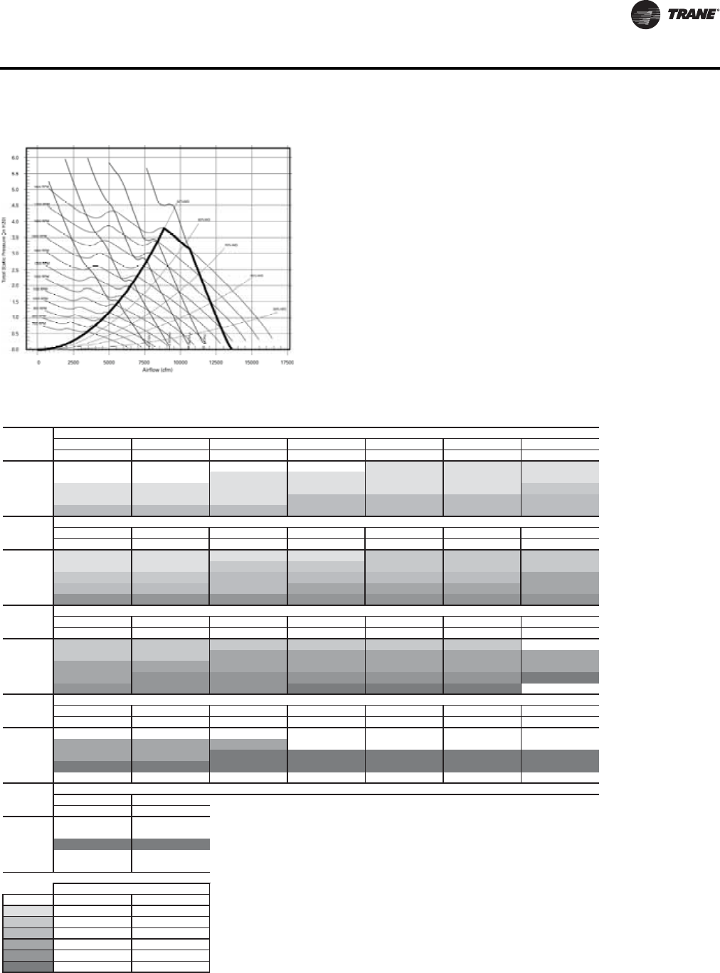
WSHP-PRC016E-EN 61
Fan Performance Data
Figure 18. Fan performance curve (front/back supply) - GEV*240(a)
(a)Includes wet coil, no filter
Table 71. Fan performance curve (front/back supply) - GEV*240 (includes wet coil, no filter)
RPM BHP RPM BHP RPM BHP RPM BHP RPM BHP RPM BHP RPM BHP
6400 ————————899(a) 2.43(a) 931(a) 2.57(a) 962(a) 2.70(a)
7200 ————910(a)2.94(a)941(a)3.10(a)972(a) 3.25(a) 1001(a) 3.41(a) 1030(a) 3.56(a)
8000 933(a) 3.58(a) 962(a) 3.75(a) 990(a) 3.91(a) 1019(a) 4.09(a) 1048(a) 4.26(a) 1075(a) 4.43(a) 1102(b) 4.60(b)
8800 1021(a) 4.73(a) 1047(a) 4.91(a) 1073(a) 5.09(a) 1100(c) 5.28(c) 1126(c) 5.48(c) 1151(c) 5.67(c) 1176(c) 5.86(c)
9600 1109(c) 6.10(c) 1133(c) 6.30(c) 1157(c) 6.50(c) 1181(c) 6.70(c) 1205(c) 6.91(c) 1229(c) 7.12(c) 1253(c) 7.33(c)
RPM BHP RPM BHP RPM BHP RPM BHP RPM BHP RPM BHP RPM BHP
6400 993(a) 2.85(a) 1023(a) 2.99(a) 1052(a) 3.13(a) 1080(a) 3.27(a) 1107(b) 3.41(b) 1134(b) 3.55(b) 1160(b) 3.69(b)
7200 1059(a) 3.72(a) 1086(a) 3.87(a) 1114(b) 4.03(b) 1140(b) 4.19(b) 1166(b) 4.35(b) 1192(b) 4.51(b) 1217(b) 4.66(b)
8000 1128(b) 4.77(b) 1154(b) 4.95(b) 1179(c) 5.12(c) 1204(c) 5.29(c) 1230(c) 5.47(c) 1253(c) 5.64(c) 1277(d) 5.82(d)
8800 1201(c) 6.04(c) 1225(c) 6.23(c) 1249(c) 6.42(c) 1272(d) 6.61(d) 1295(d) 6.79(d) 1317(d) 6.98(d) 1340(d) 7.18(d)
9600 1276(e) 7.54(e) 1298(e) 7.74(e) 1320(e) 7.94(e) 1342(e) 8.14(e) 1364(e) 8.35(e) 1385(e) 8.55(e) 1406(e) 8.76(e)
RPM BHP RPM BHP RPM BHP RPM BHP RPM BHP RPM BHP RPM BHP
6400 1186(b) 3.83(b) 1211(b) 3.97(b) 1235(b) 4.10(b) 1258(b) 4.24(b) 1282(b) 4.38(b) 1307(b) 4.54(b) — —
7200 1241(b) 4.82(b) 1265(b) 4.97(b) 1288(d) 5.13(d) 1313(d) 5.30(d) 1335(d) 5.45(d) 1357(d) 5.62(d) 1378(d) 5.76(d)
8000 1300(d) 6.00(d) 1323(d) 6.17(d) 1346(d) 6.35(d) 1368(d) 6.52(d) 1390(d) 6.70(d) 1412(d) 6.88(d) 1432(d) 7.05(d)
8800 1362(d) 7.37(d) 1384(e) 7.56(e) 1406(e) 7.76(e) 1426(e) 7.95(e) 1449(e) 8.15(e) 1469(e) 8.34(e) 1489(g) 8.53(g)
9600 1428(e) 8.97(e) 1448(e) 9.18(e) 1470(e) 9.40(e) 1489(g) 9.60(g) 1510(g) 9.82(g) 1529(g) 10.03(g) — —
RPM BHP RPM BHP RPM BHP RPM BHP RPM BHP RPM BHP RPM BHP
6400 ——————————————
7200 1399(d) 5.91(d) 1420(d) 6.07(d) 1442(d) 6.24(d) ————————
8000 1454(d) 7.23(d) 1475(d) 7.41(d) 1494(g) 7.58(g) 1513(g) 7.75(g) 1533(g) 7.92(g) 1551(g) 8.08(g) 1570(g) 8.25(g)
8800 1509(g) 8.72(g) 1529(g) 8.92(g) 1548(g) 9.11(g) 1567(g) 9.30(g) 1587(g) 9.50(g) 1605(g) 9.69(g) 1625(g) 9.89(g)
9600——————————————
RPM BHP RPM BHP
6400 — — — —
7200 — — — —
8000 1589(g) 8.43(g) 1608(g) 8.61(g)
8800 — — — —
9600 — — — —
Legend
(a)
(b)
(c)
(d)
(e)
(g) G7
D4
E5
A1
B2
C3
Digit 12 - Drive Package
single speed motor two speed motor
Std
Airflow
CFM
Unit External Static Pressure inches W.G. (Wet Coil, 3% Drive Loss Included & No Return Air Filter)
0.1 0.2 0.3 0.4 0.5 0.6 0.7
Std
Airflow
CFM
Unit External Static Pressure inches W.G. (Wet Coil, 3% Drive Loss Included & No Return Air Filter)
0.8 0.9 1.0 1.1 1.2 1.3 1.4
Std
Airflow
CFM
Unit External Static Pressure inches W.G. (Wet Coil, 3% Drive Loss Included & No Return Air Filter)
2.9 3.0
2.3 2.4 2.4 2.6 2.7
2.1
Std
Airflow
CFM
Unit External Static Pressure inches W.G. (Wet Coil, 3% Drive Loss Included & No Return Air Filter)
2.2
Unit External Static Pressure inches W.G. (Wet Coil, 3% Drive Loss Included & No Return Air Filter)
2.8
1.9
Std
Airflow
CFM
1.5 1.6 1.7 1.8 2.0
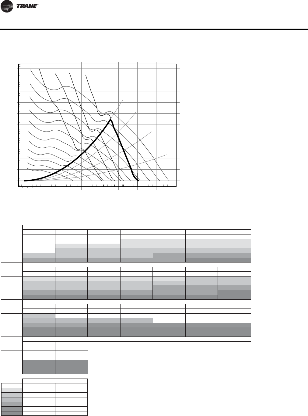
62 WSHP-PRC016E-EN
Fan Performance Data
Figure 19. Fan performance curve (with 11x15 blower wheel) - GEV*300(a)
(a)Includes wet coil, no filter
4.0
4.5
5.0
3.5
3.0
2.5
2.0
1.5
1.0
0.5
0.0
0 2500 5000 7500 10000 12500 15000 17500 20000
Airflow (cfm)
Total Static Pressure (in H20)
5.00 bhp
15.0 bhp
7.50 bhp
10.0hp
62%WO
70% WO
80% WO
90% WO
500 RPM
800 RPM
700 RPM
600 RPM
900 RPM
1000 RPM
1100 RPM
1200 RPM
1300 RPM
1400 RPM
1500 RPM
Table 72. Fan performance curve (top supply with 11x15 blower wheel) - GEV*300 (includes wet coil, no filter)
RPM BHP RPM BHP RPM BHP RPM BHP RPM BHP RPM BHP RPM BHP
8000 ——————760(a) 3.23(a) 787(a) 3.42(a) 814(a) 3.60(a) 839(a) 3.79(a)
9000 — — 781(a) 3.98(a) 805(a) 4.17(a) 829(a) 4.36(a) 853(a) 4.57(a) 878(a) 4.79(a) 901(a) 5.00(a)
10000 — — 858(b) 5.36(b) 879(b) 5.57(b) 901(b) 5.78(b) 923(b) 6.00(b) 945(b) 6.23(b) 966(b) 6.48(b)
11000 917(b) 6.81(b) 936(b) 7.04(b) 955(b) 7.26(b) 975(b) 7.50(b) 994(d) 7.73(d) 1014(d) 7.98(d) 1034(d) 8.23(d)
12000 997(d) 8.79(d) 1015(d) 9.05(d) 1032(d) 9.29(d) 1050(d) 9.54(d) 1068(d) 9.79(d) 1086(f) 10.05(f) 1104(f) 10.31(f)
RPM BHP RPM BHP RPM BHP RPM BHP RPM BHP RPM BHP RPM BHP
8000 866(a) 3.99(a) 891(a) 4.19(a) 916(a) 4.38(a) 939(a) 4.57(a) 963(a) 4.76(a) 987(b) 4.97(b) 1011(b) 5.19(b)
9000 925(b) 5.21(b) 948(b) 5.43(b) 971(b) 5.65(b) 993(b) 5.87(b) 1016(b) 6.10(b) 1037(b) 6.31(b) 1058(b) 6.52(b)
10000 988(b) 6.72(b) 1009(b) 6.95(b) 1030(b) 7.18(b) 1051(b) 7.41(b) 1072(d) 7.66(d) 1092(d) 7.91(d) 1112(d) 8.16(d)
11000 1054(d) 8.50(d) 1074(d) 8.76(d) 1093(d) 9.02(d) 1112(d) 9.27(d) 1131(d) 9.53(d) 1150(d) 9.78(d) 1169(f) 10.06(f)
12000 1122(f) 10.59(f) 1141(f) 10.88(f) 1158(f) 11.17(f) 1177(f) 11.47(f) 1194(f) 11.74(f) 1212(f) 12.02(f) 1229(f) 12.29(f)
RPM BHP RPM BHP RPM BHP RPM BHP RPM BHP RPM BHP RPM BHP
8000 1037(b) 5.43(b) ————————————
9000 1080(c) 6.74(c) 1101(c) 6.97(c) 1122(c) 7.21(c) 1144(c) 7.46(c) ——————
10000 1132(d) 8.41(d) 1151(d) 8.65(d) 1170(e) 8.88(e) 1190(e) 9.13(e) 1209(e) 9.37(e) 1227(e) 9.60(e) 1247(e) 9.88(e)
11000 1187(f) 10.32(f) 1206(f) 10.60(f) 1224(f) 10.88(f) 1243(f) 11.16(f) 1261(f) 11.42(f) 1278(f) 11.68(f) 1295(f) 11.94(f)
12000 1247(f) 12.57(f) 1264(f) 12.86(f) 1281(f) 13.15(f) 1298(f) 13.46(f) 1315(f) 13.76(f) 1331(f) 14.04(f) 1349(f) 14.37(f)
RPM BHP RPM BHP
8000 ————
9000 — — — —
10000 1266(f) 10.16(f) 1286(f) 10.45(f)
11000 1313(f) 12.21(f) 1330(f) 12.47(f)
12000 1365(f) 14.65(f) 1381(f) 14.93(f)
Legend
(a)
(b)
(c)
(d)
(e)
(f)
E5
F6
B2
C3
D4
Digit 12 - Drive Package
single speed motor two speed motor
A1
Std
Airflow
CFM
Unit External Static Pressure inches W.G. (Wet Coil, 3% Drive Loss Included & No Return Air Filter)
0.1 0.2 0.3 0.4 0.5 0.6 0.7
Std
Airflow
CFM
Unit External Static Pressure inches W.G. (Wet Coil, 3% Drive Loss Included & No Return Air Filter)
0.8 0.9 1.0 1.1 1.2 1.3 1.4
Std
Airflow
CFM
Unit External Static Pressure inches W.G. (Wet Coil, 3% Drive Loss Included & No Return Air Filter)
2.2 2.3
2.0 2.1
Std
Airflow
CFM
1.5 1.6 1.7
Unit External Static Pressure inches W.G. (Wet Coil, 3% Drive Loss Included & No Return Air Filter)
1.8 1.9
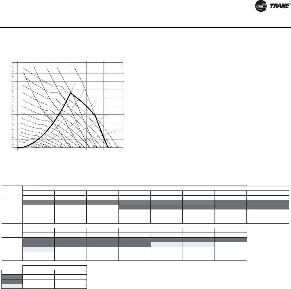
WSHP-PRC016E-EN 63
Fan Performance Data
Figure 20. Fan performance curve (top supply with 12x12 blower wheel) - GEV*300(a)
(a)Includes wet coil, no filter
4.0
4.5
5.0
3.5
3.0
2.5
2.0
1.5
1.0
0.5
0.0
0 2500 5000 7500 10000 12500 15000
Airflow (cfm)
Total Static Pressure (in H20)
3.00 bhp
5.00 bhp
15.0 bhp
7.50 bhp
10.0hp
52%WO
60%WO
70% WO
80% WO
90% WO
700 RPM
600 RPM
500 RPM
800 RPM
900 RPM
1000 RPM
1100 RPM
1200 RPM
1300 RPM
1400 RPM
1500 RPM
1600 RPM
1700 RPM
1800 RPM
Table 73. Fan performance curve (top supply with 12x12 blower wheel) - GEV*300 (includes wet coil, no filter)
RPM BHP RPM BHP RPM BHP RPM BHP RPM BHP RPM BHP RPM BHP RPM BHP
8000 1434(g) 6.56(g) 1458(g) 6.76(g) 1481(g) 6.96(g) 1503(g) 7.14(g) 1525(g) 7.34(g) 1548(g) 7.55(g) 1569(h) 7.74(h) 1592(h) 7.96(h)
9000 — — — — — — 1588(h) 9.07(h) 1609(h) 9.29(h) 1629(h) 9.50(h) 1650(h) 9.73(h) 1670(h) 9.94(h)
10000—————————————— — —
11000—————————————— — —
12000—————————————— — —
RPM BHP RPM BHP RPM BHP RPM BHP RPM BHP RPM BHP RPM BHP
8000 1613(h) 8.16(h) 1635(h) 8.37(h) 1657(h) 8.60(h) 1677(h) 8.80(h) 1698(h) 9.01(h) 1718(h) 9.22(h) 1738(h) 9.43(h)
9000 1691(h) 10.17(h) 1710(h) 10.39(h) 1731(h) 10.63(h) 1749(h) 10.84(h) 1769(j) 11.07(j) 1790(j) 11.32(j) — —
100001775(j)12.58(j)————————————
11000——————————————
12000——————————————
Legend
(g)
(h)
(j)
H8
J9
G7
Digit 12 - Drive Package
single speed motor two speed motor
Std
Airflow
CFM
Unit External Static Pressure inches W.G. (Wet Coil, 3% Drive Loss Included & No Return Air Filter)
1.6 1.7 1.8
Std
Airflow
CFM
Unit External Static Pressure inches W.G. (Wet Coil, 3% Drive Loss Included & No Return Air Filter)
2.4 2.5 2.6 2.7 2.8 2.9
2.3
3.0
1.92.02.12.2
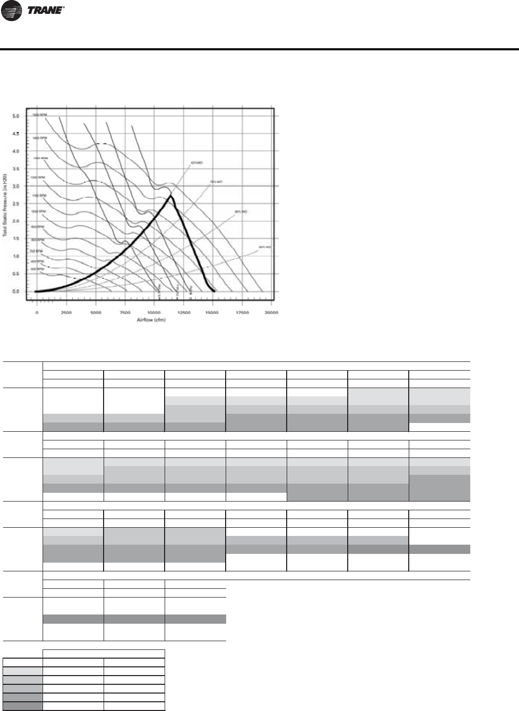
64 WSHP-PRC016E-EN
Fan Performance Data
Figure 21. Fan performance curve (front/back supply with 11x15 blower wheel) - GEV*300(a)
(a)Includes wet coil, no filter
Table 74. Fan performance curve (front/back supply with 11x15 blower wheel) - GEV*300 (includes wet coil, no filter)
RPM BHP RPM BHP RPM BHP RPM BHP RPM BHP RPM BHP RPM BHP
8000 — —————————755(a) 3.42(a) 780(a) 3.59(a)
9000 ————760(a) 4.18(a) 777(a) 4.31(a) 795(a) 4.44(a) 814(a) 4.58(a) 836(a) 4.75(a)
10000 ————835(b) 5.64(b) 849(b) 5.78(b) 864(b) 5.92(b) 880(b) 6.06(b) 897(b) 6.21(b)
11000 885(b) 7.09(b) 898(b) 7.25(b) 910(b) 7.41(b) 923(d) 7.56(d) 936(d) 7.72(d) 950(d) 7.87(d) 965(d) 8.02(d)
12000 963(d) 9.17(d) 975(d) 9.35(d) 987(d) 9.52(d) 998(d) 9.69(d) 1010(d) 9.86(d) 1022(d) 10.02(d) — —
RPM BHP RPM BHP RPM BHP RPM BHP RPM BHP RPM BHP RPM BHP
8000 804(a) 3.75(a) 829(a) 3.93(a) 853(a) 4.10(a) 876(a) 4.27(a) 898(a) 4.43(a) 921(a) 4.61(a) 944(a) 4.80(a)
9000 859(a) 4.95(a) 881(b) 5.14(b) 903(b) 5.33(b) 925(b) 5.52(b) 946(b) 5.71(b) 966(b) 5.90(b) 987(b) 6.09(b)
10000 916(b) 6.39(b) 936(b) 6.59(b) 957(b) 6.82(b) 976(b) 7.02(b) 996(b) 7.23(b) 1016(b) 7.44(b) 1035(d) 7.65(d)
11000 980(d) 8.18(d) 996(d) 8.37(d) 1014(d) 8.58(d) 1032(d) 8.81(d) 1050(d) 9.04(d) 1069(d) 9.28(d) 1087(d) 9.51(d)
12000 ————————1107(d) 11.16(d) 1124(d) 11.41(d) 1141(d) 11.67(d)
RPM BHP RPM BHP RPM BHP RPM BHP RPM BHP RPM BHP RPM BHP
8000 967(a) 4.99(a) 990(b) 5.21(b) 1015(b) 5.47(b) — — — — — — — —
9000 1008(b) 6.29(b) 1028(b) 6.48(b) 1047(b) 6.67(b) 1067(c) 6.88(c) 1087(c) 7.11(c) 1109(c) 7.36(c) — —
10000 1054(d) 7.87(d) 1073(d) 8.08(d) 1091(d) 8.29(d) 1110(d) 8.52(d) 1127(d) 8.72(d) 1146(e) 8.94(e) 1164(e) 9.16(e)
11000 1105(d) 9.74(d) 1122(d) 9.97(d) 1140(d) 10.21(d) ————————
12000 ——————————————
RPM BHP RPM BHP RPM BHP
8000 ——————
9000 ——————
10000 1182(e) 9.40(e) 1200(e) 9.64(e) 1219(e) 9.91(e)
11000 — — — — — —
12000 ——————
Legend
(a)
(b)
(c)
(d)
(e) E5
B2
C3
D4
Digit 12 - Drive Package
single speed motor two speed motor
A1
Std
Airflow
CFM
Unit External Static Pressure inches W.G. (Wet Coil, 3% Drive Loss Included & No Return Air Filter)
0.1 0.2 0.3 0.4 0.5 0.6 0.7
Std
Airflow
CFM
Unit External Static Pressure inches W.G. (Wet Coil, 3% Drive Loss Included & No Return Air Filter)
0.8 0.9 1.0 1.1 1.2 1.3 1.4
Unit External Static Pressure inches W.G. (Wet Coil, 3% Drive Loss Included & No Return Air Filter)
2.0 2.1
Std
Airflow
CFM
Unit External Static Pressure inches W.G. (Wet Coil, 3% Drive Loss Included & No Return Air Filter)
2.2 2.3 2.4
Std
Airflow
CFM
1.5 1.6 1.7 1.8 1.9
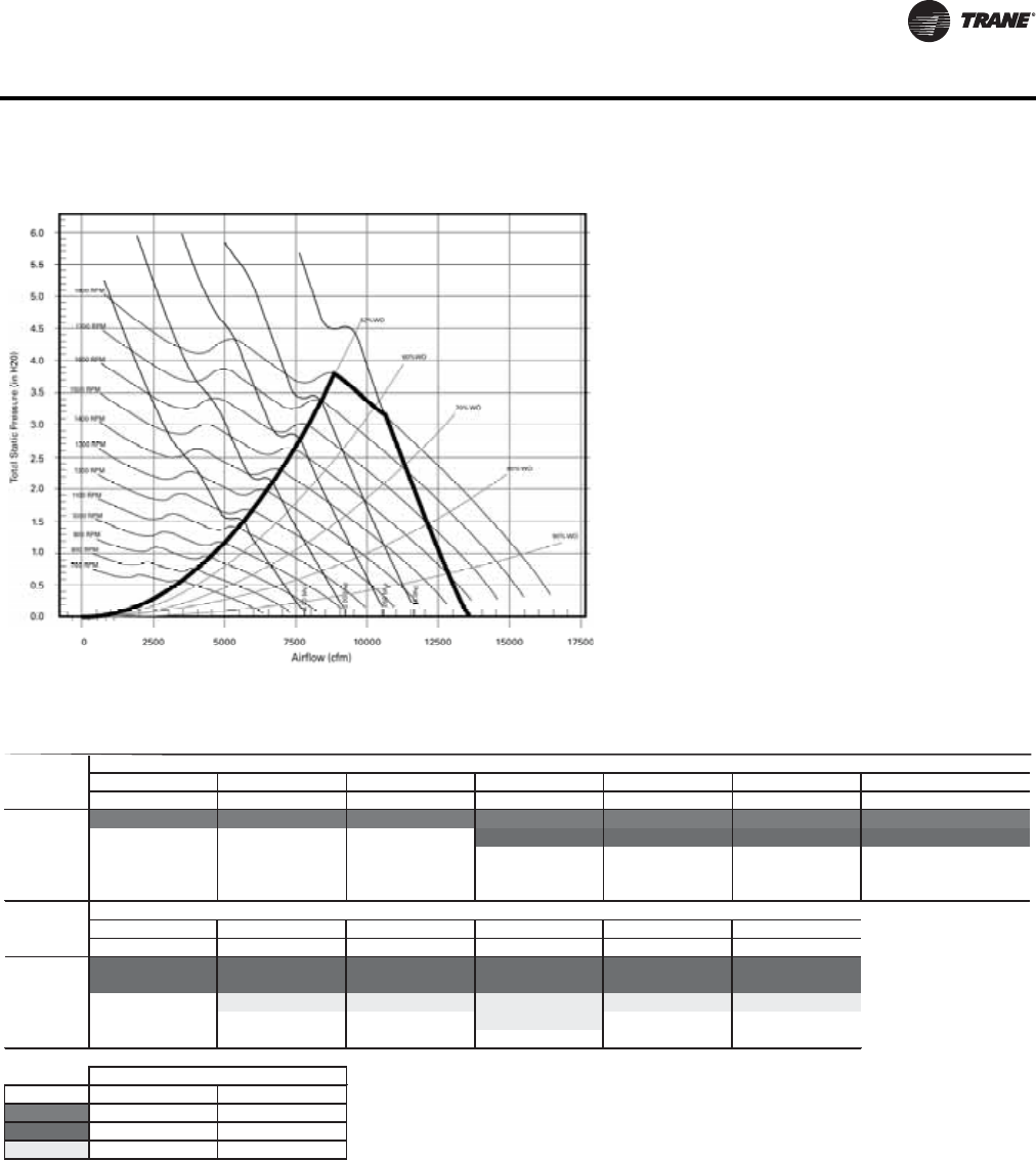
WSHP-PRC016E-EN 65
Fan Performance Data
Figure 22. Fan performance curve (front/back supply with 12x12 blower wheel) - GEV*300(a)
(a)Includes wet coil, no filter
Table 75. Fan performance curve (front/back supply with 12x12 blower wheel) - GEV*300 (includes wet coil, no filter)
RPM BHP RPM BHP RPM BHP RPM BHP RPM BHP RPM BHP RPM BHP
8000 1356(g) 6.25(g) 1379(g) 6.42(g) 1400(g) 6.59(g) 1422(g) 6.76(g) 1443(g) 6.93(g) 1463(g) 7.1(g) 1484(g) 7.27(g)
9000——————1490(h)8.55(h)1510(h)8.74(h)1531(h)8.94(h)1549(h)9.12(h)
10000———————————— — —
11000———————————— — —
12000———————————— — —
RPM BHP RPM BHP RPM BHP RPM BHP RPM BHP RPM BHP
8000 1505(h) 7.45(h) 1522(h) 7.6(h) 1542(h) 7.76(h) 1562(h) 7.94(h) 1581(h) 8.11(h) 1600(h) 8.29(h)
9000 1569(h) 9.32(h) 1588(h) 9.5(h) 1608(h) 9.71(h) 1625(h) 9.89(h) 1644(h) 10.08(h) 1662(h) 10.28(h)
10000 — — 1658(j) 11.76(j) 1676(j) 11.96(j) 1693(j) 12.17(j) 1711(j) 12.38(j) 1729(j) 12.6(j)
11000——————1765(j)14.82(j)————
12000————————————
Legend
(g)
(h)
(j)
2.32.0 2.1 2.2
J9
G7
H8
2.4
single speed motor two speed motor
Std
Airflow
CFM
Unit External Static Pressure inches W.G. (Wet Coil, 3% Drive Loss Included & No Return Air Filter)
1.8 1.9
Digit 12 - Drive Package
Std
Airflow
CFM
Unit External Static Pressure inches W.G. (Wet Coil, 3% Drive Loss Included & No Return Air Filter)
2.5 2.6 2.7 2.8 2.9 3.0
66 WSHP-PRC016E-EN
Fan Performance Data
Waterside Economizer Performance Data
Table 76. Waterside economizer performance data(a) (6 to 25 Tons)
Input Data Output Data
Tonnage
of Heat
Pump
Unit
Model
Number SCFM GPM
Air
Velocity
(SFPM)
Total
Capacity
(MBh)
Sensible
Capacity
(MBh)
LVG. Air
DB
(Deg F)
LVG. Air
WB
(Deg F)
Standard
APD
(IN WG)
LVG.Fluid
Temp.
(Deg F)
Fluid PD
Coil In
(FT H2O)
Fluid PD
Coil Out
(FT H2O)
6.00 GEH*072 2400 13.2 400 65.2 52.3 60.1 58.6 0.26 54.8 3.8 1.1
GEH*072 2400 16.8 400 73.1 55.3 58.9 57.4 0.27 53.7 6.1 1.7
GEH*072 2400 18.6 400 76.2 56.5 58.5 57.0 0.27 53.2 7.5 2.1
7.50 GEH*090 3000 16.5 444 83.4 52.5 60.0 58.3 0.31 55.1 6.1 1.7
GEH*090 3000 21.0 444 92.2 55.2 59.0 57.3 0.32 53.8 9.8 2.7
GEH*090 3000 23.3 444 95.6 56.3 58.6 56.9 0.32 53.2 12.0 3.3
10.00 GEH*120 4000 22.0 438 119.8 54.5 59.2 57.6 0.31 55.9 9.3 1.2
GEH*120 4000 28.0 438 130.3 57.0 58.3 56.7 0.32 54.3 15.1 1.9
GEH*120 4000 31.0 438 134.4 58.0 57.9 56.3 0.32 53.6 18.5 2.3
12.50 GEH*150 5000 27.5 411 153.5 116.2 58.7 57.3 0.28 56.1 10.7 1.6
GEH*150 5000 35.0 411 167.5 121.8 57.7 56.4 0.28 54.5 17.4 2.6
GEH*150 5000 38.8 411 172.9 123.9 57.3 56.0 0.29 53.9 21.3 3.1
15.00 GEH*180 6000 33.0 493 176.9 135.0 59.4 57.8 0.37 55.7 15.5 2.3
GEH*180 6000 42.0 493 191.8 140.8 58.5 56.9 0.38 54.1 25.0 3.7
GEH*180 6000 46.5 493 197.8 143.2 58.2 56.6 0.38 53.5 30.7 4.5
6.00 GEV*072 2400 13.2 424 72.1 55.0 59.1 57.6 0.29 55.9 8.3 1.1
GEV*072 2400 16.8 424 78.7 57.6 58.1 56.6 0.30 54.3 13.4 1.7
GEV*072 2400 18.6 424 81.3 58.6 57.7 56.2 0.30 53.7 16.4 2.1
7.50 GEV*090 3000 16.5 454 88.8 67.9 59.3 57.7 0.32 55.7 10.0 1.7
GEV*090 3000 21.0 454 96.7 71.0 58.4 56.8 0.33 54.2 16.2 2.7
GEV*090 3000 23.3 454 99.8 72.2 58.0 56.4 0.34 53.6 19.9 3.3
10.00 GEV*120 4000 22.0 471 117.4 89.9 59.4 57.8 0.34 55.6 10.1 1.4
GEV*120 4000 28.0 471 127.7 94.0 58.5 56.9 0.35 54.1 16.3 2.2
GEV*120 4000 31.0 471 131.8 95.6 58.2 56.6 0.36 53.5 20.0 2.7
12.50 GEV*150 5000 27.5 308 160.4 120.6 58.0 56.9 0.18 56.6 6.9 0.9
GEV*150 5000 35.0 308 177.4 127.3 56.7 55.7 0.18 55.1 11.2 1.5
GEV*150 5000 38.8 308 184.0 130.0 56.2 55.2 0.19 54.5 13.8 1.8
15.00 GEV*180 6000 33.0 370 187.3 141.4 58.5 57.2 0.23 56.3 9.8 1.3
GEV*180 6000 42.0 370 205.4 148.5 57.4 56.1 0.24 54.8 15.9 2.2
GEV*180 6000 46.5 370 212.3 151.3 56.9 55.7 0.25 54.1 19.5 2.7
20.00 GEV*240 8000 44.0 438 241.7 183.4 59.0 57.5 0.30 56.0 8.6 0.7
GEV*240 8000 56.0 438 263.0 191.8 58.1 56.6 0.32 54.4 13.9 1.1
GEV*240 8000 62.0 438 271.3 195.1 57.7 56.2 0.32 53.7 17.0 1.4
25.00 GEV*300 10000 55.0 548 280.8 219.5 60.1 58.2 0.52 55.2 9.8 1.1
GEV*300 10000 70.0 548 299.0 228.4 59.3 57.5 0.52 53.5 15.8 1.8
GEV*300 10000 77.5 548 306.8 232.1 58.9 57.3 0.53 52.9 19.4 2.2
Note: Rated in compliance with ARI 410. Airflow is in SCFM. Entering air DB/WB (80/67). Entering fluid 45°F.
(a)Performance data is tabulated for cooling at 80°F DB/67°F WB entering air and 45°F entering fluid at ARI 410 rated SCFM.
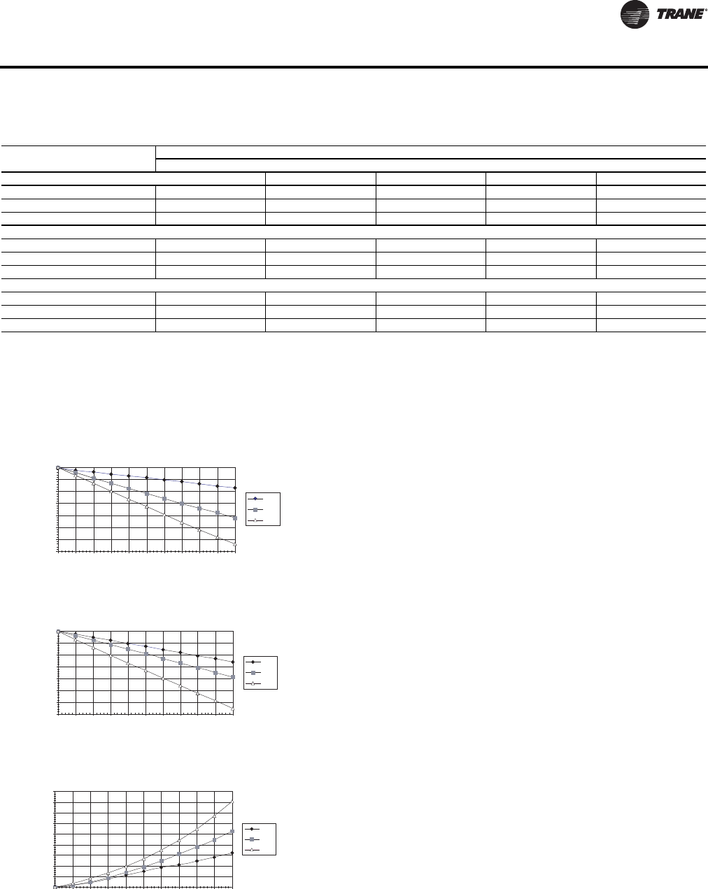
WSHP-PRC016E-EN 67
Fan Performance Data
Table 77. Antifreeze correction factors
Methanol
Item Concentration by Volume
10% 20% 30% 40% 50%
Cool Capacity .9980 .9965 .9949 .9932 .9915
Heat Capacity .9950 .9898 .9846 .9794 .9742
Pressure Drop 1.023 1.057 1.091 1.122 1.160
Ethylene Glycol
Cool Capacity .9955 .9912 .9870 .9830 .9790
Heat Capacity .9925 .9848 .9770 .9690 .9610
Pressure Drop 1.024 1.068 1.124 1.188 1.263
Propylene Glycol
Cool Capacity .9934 .9869 .9804 .9739 .9681
Heat Capacity .9863 .9732 .9603 .9477 .9350
Pressure Drop 1.040 1.098 1.174 1.273 1.405
Note: Performance data is tabulated for cooling at 80°F DB/67 F WB entering air and 45°F entering fluid at ARI 410 rated SCFM.
Note: *Rated in Compliance with ARI 410
Note: *Airflow is in SCFM
Note: *Entering Air DB/WB (80/67)
Note: *Entering Fluid 45°F
Figure 23. Correction factors
Example 1 - (Ethylene Glycol):The antifreeze solution is
20% by volume of Ethylene Glycol. Determine the corrected
cooling capacity and waterside pressure drop for a GEHE 072
when the EWT is 86°F and the GPM is 18.0.
From the catalog data, the cooling capacity at these
conditions with 100% water is 77.8 MBTUH, and the
waterside pressure drop is 12.0 feet of head.At 20% Ethylene
Glycol, the correction factor for cool capacity is 0.9912 and
the pressure drop is 1.068.
The corrected cooling capacity (MBTUH) = 77.8 * 0.9912 =
77.1.The corrected water side pressure drop (Ft. head) = 12.0
* 1.068 = 12.8.
Example 2 - (Propylene Glycol):The antifreeze solution
is 30% by volume of Propylene Glycol. Determine the
corrected heating capacity and waterside pressure drop for
a GEHE 072 when the EWT is 45°F and the GPM is 18.0.
From the catalog data, the heating capacity at these
conditions with 100% water is 61.7 MBTUH, and the
waterside pressure drop is 15.3 feet of head. At 30%
Propylene Glycol, the correction factor for heat capacity is
0.9603 and the pressure drop is 1.174.
The corrected cooling capacity (MBTUH) = 61.7 * 0.9603 =
59.3.The corrected water side pressure drop (Ft. head) = 15.3
* 1.174 = 18.0.
Cooling Capacity Correction Factor
0.965
0.970
0.975
0.980
0.985
0.990
0.995
1.000
0 5 10 15 20 25 30 35 40 45 50
Percent Volume of Antifreeze
Meth
EG
PG
Correction Factor
Heating Capacity Correction Factor
0.930
0.940
0.950
0.960
0.970
0.980
0.990
1.000
0 5 10 15 20 25 30 35 40 45 50
Percent Volume Antifreeze
Meth
EG
PG
Correction Factor
Water Pressure Drop Correction Factor
1.00
1.05
1.10
1.15
1.20
1.25
1.30
1.35
1.40
1.45
0 5 10 15 20 25 30 35 40 45 50
Percent Volume of Antifreeze
Meth
EG
PG
Correction Factor

68 WSHP-PRC016E-EN
Electrical Data
Table 78. Electrical data: 6 to 25 tons - single speed blower motor
Model
No. Volts Total
FLA Comp RLA
(ea)
Comp
LRA
(ea) No. of
Comp. Cmp MCC
Blower
Motor
FLA
Blower
Motor
HP
Fan
Motor
No.
Minimum
Circuit
Ampacity
Maximum
Overcurrent
Protective
Device
GEH - Horizontal Units
GEH072 208/60/1 39.9 16.7 79 2 26 6.5 1.0 1 44.08 60
GEH072 230/60/1 39.9 16.7 79 2 26 6.5 1.0 1 44.08 60
GEH072 208/60/1 42.7 16.7 79 2 26 9.3 1.5 1 46.88 60
GEH072 230/60/1 42.3 16.7 79 2 26 8.9 1.5 1 46.48 60
GEH072 208/60/1 44.6 16.7 79 2 26 11.2 2.0 1 48.78 60
GEH072 230/60/1 43.6 16.7 79 2 26 10.2 2.0 1 47.78 60
GEH072 380-415/50/3 13.9 7.1/5.1 48/35 2 11/8 1.7 0.75 1 15.68 20
GEH072 208/60/3 24.3 10.4 73 2 16.3 3.5 1.0 1 26.90 35
GEH072 230/60/3 24.6 10.4 73 2 16.3 3.8 1.0 1 27.20 35
GEH072 460/60/3 13.4 5.8 38 2 9 1.8 1.0 1 14.85 20
GEH072 380-415/50/3 14.3 7.1/5.1 48/35 2 11/8 2.1 1.0 1 16.08 20
GEH072 208/60/3 26.4 10.4 73 2 16.3 5.6 1.5 1 29.00 35
GEH072 230/60/3 25.6 10.4 73 2 16.3 4.8 1.5 1 28.20 35
GEH072 380-415/50/3 15.2 7.1/5.1 48/35 2 11/8 3.0 1.5 1 16.98 20
GEH072 460/60/3 14.0 5.8 38 2 9 2.4 1.5 1 15.45 20
GEH072 208/60/3 27.9 10.4 73 2 16.3 7.1 2.0 1 30.50 40
GEH072 230/60/3 27.0 10.4 73 2 16.3 6.2 2.0 1 29.60 40
GEH072 380-415/50/3 15.6 7.1/5.1 48/35 2 11/8 3.4 2.0 1 17.38 20
GEH072 460/60/3 14.7 5.8 38 2 9 3.1 2.0 1 16.15 20
GEH072 380-415/50/3 17.4 7.1/5.1 48/35 2 11/8 5.2 3.0 1 19.18 25
GEH090 208/60/3 28.4 14.5/10.4 98/73 2 22.6/16.3 3.5 1.0 1 32.03 45
GEH090 230/60/3 28.7 14.5/10.4 98/73 2 22.6/16.3 3.8 1.0 1 32.33 45
GEH090 460/60/3 13.9 6.3/5.8 55/38 2 9.9/9 1.8 1.0 1 15.48 20
GEH090 208/60/3 30.5 14.5/10.4 98/73 2 22.6/16.3 5.6 1.5 1 34.13 45
GEH090 230/60/3 29.7 14.5/10.4 98/73 2 22.6/16.3 4.8 1.5 1 33.33 45
GEH090 380-415/50/3 22.2 9.6 64 2 15 3.0 1.5 1 24.60 30
GEH090 460/60/3 14.5 6.3/5.8 55/38 2 9.9/9 2.4 1.5 1 16.08 20
GEH090 208/60/3 32.0 14.5/10.4 98/73 2 22.6/16.3 7.1 2.0 1 35.63 50
GEH090 230/60/3 31.1 14.5/10.4 98/73 2 22.6/16.3 6.2 2.0 1 34.73 45
GEH090 380-415/50/3 22.6 9.6 64 2 15 3.4 2.0 1 25.00 30
GEH090 460/60/3 15.2 6.3/5.8 55/38 2 9.9/9 3.1 2.0 1 16.78 20
GEH090 575/60/3 12.1 6/3.8 41/36.5 2 9.4/5.9 2.3 2.0 1 13.60 15
GEH090 208/60/3 34.3 14.5/10.4 98/73 2 22.6/16.3 9.4 3.0 1 37.93 50
GEH090 230/60/3 33.1 14.5/10.4 98/73 2 22.6/16.3 8.2 3.0 1 36.73 50
GEH090 380-415/50/3 24.4 9.6 64 2 15 5.2 3.0 1 26.80 35
GEH090 460/60/3 16.7 6.3 55 2 9.9 4.1 3.0 1 18.28 20
GEH090 575/60/3 13.1 6/3.8 41/36.5 2 9.4/5.9 3.3 3.0 1 14.60 20
GEH120 380-415/50/3 23.3 10.6 74 2 16.5 2.1 1.0 1 25.95 35
GEH120 208/60/3 37.6 16 110 2 24.9 5.6 1.5 1 41.60 50
continued on next page

WSHP-PRC016E-EN 69
Electrical Data
GEH - Horizontal Units
GEH120 230/60/3 36.8 16 110 2 24.9 4.8 1.5 1 40.80 50
GEH120 380-415/50/3 24.2 10.6 74 2 16.5 3.0 1.5 1 26.85 35
GEH120 460/60/3 18.0 7.8 52 2 12.1 2.4 1.5 1 19.95 25
GEH120 208/60/3 39.1 16 110 2 24.9 7.1 2.0 1 43.10 50
GEH120 230/60/3 38.2 16 110 2 24.9 6.2 2.0 1 42.20 50
GEH120 380-415/50/3 24.6 10.6 74 2 16.5 3.4 2.0 1 27.25 35
GEH120 460/60/3 18.7 7.8 52 2 12.1 3.1 2.0 1 20.65 25
GEH120 575/60/3 13.7 5.7 38.9 2 8.9 2.3 2.0 1 15.13 20
GEH120 208/60/3 41.4 16 110 2 24.9 9.4 3.0 1 45.40 60
GEH120 230/60/3 40.2 16 110 2 24.9 8.2 3.0 1 44.20 60
GEH120 380-415/50/3 26.4 10.6 74 2 16.5 5.2 3.0 1 29.05 35
GEH120 460/60/3 19.7 7.8 52 2 12.1 4.1 3.0 1 21.65 25
GEH120 575/60/3 14.7 5.7 38.9 2 8.9 3.3 3.0 1 16.13 20
GEH120 208/60/3 46.0 16 110 2 24.9 14.0 5.0 1 50.00 60
GEH120 230/60/3 45.0 16 110 2 24.9 13.0 5.0 1 49.00 60
GEH120 460/60/3 22.1 7.8 52 2 12.1 6.5 5.0 1 24.05 30
GEH120 575/60/3 16.7 5.7 38.9 2 8.9 5.3 5.0 1 18.13 20
GEH150 208/60/3 50.4 22.4 149 2 35 5.6 1.5 1 56.00 70
GEH150 230/60/3 49.6 22.4 149 2 35 4.8 1.5 1 55.20 70
GEH150 380-415/50/3 27.4 12.2 101 2 19 3.0 1.5 1 30.45 40
GEH150 460/60/3 23.6 10.6 75 2 16.5 2.4 1.5 1 26.25 35
GEH150 575/60/3 17.3 7.7 54 2 12 1.9 1.5 1 19.23 25
GEH150 208/60/3 51.9 22.4 149 2 35 7.1 2.0 1 57.50 70
GEH150 230/60/3 51.0 22.4 149 2 35 6.2 2.0 1 56.60 70
GEH150 380-415/50/3 27.8 12.2 101 2 19 3.4 2.0 1 30.85 40
GEH150 460/60/3 24.3 10.6 75 2 16.5 3.1 2.0 1 26.96 35
GEH150 575/60/3 17.7 7.7 54 2 12 2.3 2.0 1 19.63 25
GEH150 208/60/3 54.2 22.4 149 2 35 9.4 3.0 1 59.80 80
GEH150 230/60/3 53.0 22.4 149 2 35 8.2 3.0 1 58.60 80
GEH150 380-415/50/3 29.6 12.2 101 2 19 5.2 3.0 1 32.65 40
GEH150 460/60/3 25.3 10.6 75 2 16.5 4.1 3.0 1 27.95 35
GEH150 575/60/3 18.7 7.7 54 2 12 3.3 3.0 1 20.63 25
GEH150 208/60/3 58.8 22.4 149 2 35 14.0 5.0 1 64.40 80
GEH150 230/60/3 57.8 22.4 149 2 35 13.0 5.0 1 63.40 80
GEH150 380-415/50/3 32.6 12.2 101 2 19 8.2 5.0 1 35.65 45
GEH150 460/60/3 27.7 10.6 75 2 16.5 6.5 5.0 1 30.35 40
GEH150 575/60/3 20.7 7.7 54 2 12 5.3 5.0 1 22.63 30
GEH180 208/60/3 57.1 25 164 2 39 7.1 2.0 1 63.35 80
GEH180 230/60/3 56.2 25 164 2 39 6.2 2.0 1 62.45 80
GEH180 460/60/3 27.5 12.2 100 2 19 3.1 2.0 1 30.56 40
GEH180 575/60/3 20.3 9 78 2 14 2.3 2.0 1 22.55 30
GEH180 208/60/3 59.4 25 164 2 39 9.4 3.0 1 65.65 90
continued on next page
Table 78. Electrical data: 6 to 25 tons - single speed blower motor (continued)
Model
No. Volts Total
FLA Comp RLA
(ea)
Comp
LRA
(ea) No. of
Comp. Cmp MCC
Blower
Motor
FLA
Blower
Motor
HP
Fan
Motor
No.
Minimum
Circuit
Ampacity
Maximum
Overcurrent
Protective
Device

70 WSHP-PRC016E-EN
Electrical Data
GEH - Horizontal Units
GEH180 230/60/3 58.2 25 164 2 39 8.2 3.0 1 64.45 80
GEH180 460/60/3 28.5 12.2 100 2 19 4.1 3.0 1 31.55 40
GEH180 575/60/3 21.3 9 78 2 14 3.3 3.0 1 23.55 30
GEH180 208/60/3 64.0 25 164 2 39 14.0 5.0 1 70.25 90
GEH180 230/60/3 63.0 25 164 2 39 13.0 5.0 1 69.25 90
GEH180 460/60/3 30.9 12.2 100 2 19 6.5 5.0 1 33.95 45
GEH180 575/60/3 23.3 9 78 2 14 5.3 5.0 1 25.55 30
GEH180 208/60/3 70.0 25 164 2 39 20.0 7.5 1 76.25 100
GEH180 230/60/3 69.4 25 164 2 39 19.4 7.5 1 75.65 100
GEH180 460/60/3 34.1 12.2 100 2 19 9.7 7.5 1 37.15 45
GEH180 575/60/3 26.0 9 78 2 14 8.0 7.5 1 28.25 35
GEV - Vertical Units
GEV072 208/60/1 40.0 16.7 79 2 26 6.6 1.0 1 44.13 60
GEV072 230/60/1 39.9 16.7 79 2 26 6.5 1.0 1 44.08 60
GEV072 208/60/1 42.7 16.7 79 2 26 9.3 1.5 1 46.88 60
GEV072 230/60/1 42.3 16.7 79 2 26 8.9 1.5 1 46.48 60
GEV072 208/60/1 44.6 16.7 79 2 26 11.2 2.0 1 48.78 60
GEV072 230/60/1 43.6 16.7 79 2 26 10.2 2.0 1 47.81 60
GEV072 380-415/50/3 13.9 7.1/5.1 48/35 2 11/8 1.7 0.75 1 15.68 20
GEV072 208/60/3 24.3 10.4 73 2 16.3 3.5 1.0 1 26.90 35
GEV072 230/60/3 24.6 10.4 73 2 16.3 3.8 1.0 1 27.20 35
GEV072 460/60/3 13.4 5.8 38 2 9 1.8 1.0 1 14.85 20
GEV072 380-415/50/3 14.3 7.1/5.1 48/35 2 11/8 2.1 1.0 1 16.08 20
GEV072 208/60/3 26.4 10.4 73 2 16.3 5.6 1.5 1 29.00 35
GEV072 230/60/3 25.6 10.4 73 2 16.3 4.8 1.5 1 28.20 35
GEV072 380-415/50/3 15.2 7.1/5.1 48/35 2 11/8 3.0 1.5 1 16.98 20
GEV072 460/60/3 14.0 5.8 38 2 9 2.4 1.5 1 15.45 20
GEV072 208/60/3 27.9 10.4 73 2 16.3 7.1 2.0 1 30.50 40
GEV072 230/60/3 27.0 10.4 73 2 16.3 6.2 2.0 1 29.60 40
GEV072 380-415/50/3 15.6 7.1/5.1 48/35 2 11/8 3.4 2.0 1 17.38 20
GEV072 460/60/3 14.7 5.8 38 2 9 3.1 2.0 1 16.16 20
GEV072 380-415/50/3 17.7 7.1/5.1 48/35 2 11/8 5.5 3.0 1 19.48 25
GEVE090 380-415/50/3 21.3 9.6 64 2 15 2.1 1.0 1 23.70 30
GEV090 208/60/3 28.4 14.5/10.4 98/73 2 22.6/16.3 3.5 1.0 1 32.03 45
GEV090 230/60/3 28.7 14.5/10.4 98/73 2 22.6/16.3 3.8 1.0 1 32.33 45
GEV090 460/60/3 13.9 6.3/5.8 55/38 2 9.9/9 1.8 1.0 1 15.48 20
GEV090 208/60/3 30.5 14.5/10.4 98/73 2 22.6/16.3 5.6 1.5 1 34.13 45
GEV090 230/60/3 29.7 14.5/10.4 98/73 2 22.6/16.3 4.8 1.5 1 33.33 45
GEV090 380-415/50/3 22.2 9.6 64 2 15 3.0 1.5 1 24.60 30
GEV090 460/60/3 14.5 6.3/5.8 55/38 2 9.9/9 2.4 1.5 1 16.08 20
continued on next page
Table 78. Electrical data: 6 to 25 tons - single speed blower motor (continued)
Model
No. Volts Total
FLA Comp RLA
(ea)
Comp
LRA
(ea) No. of
Comp. Cmp MCC
Blower
Motor
FLA
Blower
Motor
HP
Fan
Motor
No.
Minimum
Circuit
Ampacity
Maximum
Overcurrent
Protective
Device

WSHP-PRC016E-EN 71
Electrical Data
GEV - Vertical Units
GEV090 208/60/3 32.0 14.5/10.4 98/73 2 22.6/16.3 7.1 2.0 1 35.63 50
GEV090 230/60/3 31.1 14.5/10.4 98/73 2 22.6/16.3 6.2 2.0 1 34.73 45
GEV090 380-415/50/3 22.6 9.6 64 2 15 3.4 2.0 1 25.00 30
GEV090 460/60/3 15.2 6.3/5.8 55/38 2 9.9/9 3.1 2.0 1 16.79 20
GEV090 575/60/3 12.1 6/3.8 41/36.5 2 9.4/5.9 2.3 2.0 1 13.60 15
GEV090 208/60/3 34.3 14.5/10.4 98/73 2 22.6/16.3 9.4 3.0 1 37.93 50
GEV090 230/60/3 33.1 14.5/10.4 98/73 2 22.6/16.3 8.2 3.0 1 36.73 50
GEV090 380-415/50/3 24.4 9.6 64 2 15 5.2 3.0 1 26.80 35
GEV090 460/60/3 16.2 6.3/5.8 55/38 2 9.9/9 4.1 3.0 1 17.78 20
GEV090 575/60/3 13.1 6/3.8 41/36.5 2 9.4/5.9 3.3 3.0 1 14.60 20
GEV120 208/60/3 37.6 16 110 2 24.9 5.6 1.5 1 41.60 50
GEV120 230/60/3 36.8 16 110 2 24.9 4.8 1.5 1 40.80 50
GEV120 460/60/3 18.0 7.8 52 2 12.1 2.4 1.5 1 19.95 25
GEV120 208/60/3 39.1 16 110 2 24.9 7.1 2.0 1 43.10 50
GEV120 230/60/3 38.2 16 110 2 24.9 6.2 2.0 1 42.20 50
GEV120 460/60/3 18.7 7.8 52 2 12.1 3.1 2.0 1 20.66 25
GEV120 575/60/3 13.7 5.7 38.9 2 8.9 2.3 2.0 1 15.13 20
GEV120 208/60/3 41.4 16 110 2 24.9 9.4 3.0 1 45.40 60
GEV120 230/60/3 40.2 16 110 2 24.9 8.2 3.0 1 44.20 60
GEV120 460/60/3 19.7 7.8 52 2 12.1 4.1 3.0 1 21.65 25
GEV120 575/60/3 14.7 5.7 38.9 2 8.9 3.3 3.0 1 16.13 20
GEV120 208/60/3 46.0 16 110 2 24.9 14.0 5.0 1 50.00 60
GEV120 230/60/3 45.0 16 110 2 24.9 13.0 5.0 1 49.00 60
GEV120 460/60/3 22.1 7.8 52 2 12.1 6.5 5.0 1 24.05 30
GEV120 575/60/3 16.7 5.7 38.9 2 8.9 5.3 5.0 1 18.13 20
GEV120 380-415/50/3 24.2 10.6 74 2 16.5 3.0 1.5 1 26.85 35
GEV120 380-415/50/3 24.6 10.6 74 2 16.5 3.4 2.0 1 27.25 35
GEV120 380-415/50/3 26.4 10.6 74 2 16.5 5.2 3.0 1 29.05 35
GEV150 208/60/3 51.9 22.4 149 2 35 7.1 2.0 1 57.50 70
GEV150 230/60/3 51.0 22.4 149 2 35 6.2 2.0 1 56.60 70
GEV150 380-415/50/3 27.8 12.2 101 2 19 3.4 2.0 1 30.85 40
GEV150 460/60/3 24.3 10.6 75 2 16.5 3.1 2.0 1 26.96 35
GEV150 575/60/3 17.7 7.7 54 2 12 2.3 2.0 1 19.63 25
GEV150 208/60/3 54.2 22.4 149 2 35 9.4 3.0 1 59.80 80
GEV150 230/60/3 53.0 22.4 149 2 35 8.2 3.0 1 58.60 80
GEV150 380-415/50/3 29.6 12.2 101 2 19 5.2 3.0 1 32.65 40
GEV150 460/60/3 25.3 10.6 75 2 16.5 4.1 3.0 1 27.95 35
GEV150 575/60/3 18.7 7.7 54 2 12 3.3 3.0 1 20.63 25
GEV150 208/60/3 58.8 22.4 149 2 35 14.0 5.0 1 64.40 80
GEV150 230/60/3 57.8 22.4 149 2 35 13.0 5.0 1 63.40 80
continued on next page
Table 78. Electrical data: 6 to 25 tons - single speed blower motor (continued)
Model
No. Volts Total
FLA Comp RLA
(ea)
Comp
LRA
(ea) No. of
Comp. Cmp MCC
Blower
Motor
FLA
Blower
Motor
HP
Fan
Motor
No.
Minimum
Circuit
Ampacity
Maximum
Overcurrent
Protective
Device

72 WSHP-PRC016E-EN
Electrical Data
GEV - Vertical Units
GEV150 380-415/50/3 32.6 12.2 101 2 19 8.2 5.0 1 35.65 45
GEV150 460/60/3 27.7 10.6 75 2 16.5 6.5 5.0 1 30.35 40
GEV150 575/60/3 20.7 7.7 54 2 12 5.3 5.0 1 22.63 30
GEV180 208/60/3 59.4 25 164 2 39 9.4 3.0 1 65.65 90
GEV180 230/60/3 58.2 25 164 2 39 8.2 3.0 1 64.45 80
GEV180 380-415/50/3 38.6 16.7 111 2 26 5.2 3.0 1 42.78 50
GEV180 460/60/3 28.5 12.2 100 2 19 4.1 3.0 1 31.55 40
GEV180 575/60/3 21.3 9 78 2 14 3.3 3.0 1 23.55 30
GEV180 208/60/3 64.0 25 164 2 39 14.0 5.0 1 70.25 90
GEV180 230/60/3 63.0 25 164 2 39 13.0 5.0 1 69.25 90
GEV180 380-415/50/3 41.6 16.7 111 2 26 8.2 5.0 1 45.78 60
GEV180 460/60/3 30.9 12.2 100 2 19 6.5 5.0 1 33.95 45
GEV180 575/60/3 23.3 9 78 2 14 5.3 5.0 1 25.55 30
GEV180 208/60/3 70.0 25 164 2 39 20.0 7.5 1 76.25 100
GEV180 230/60/3 69.4 25 164 2 39 19.4 7.5 1 75.65 100
GEV180 380-415/50/3 44.9 16.7 111 2 26 11.5 7.5 1 49.08 60
GEV180 460/60/3 34.1 12.2 100 2 19 9.7 7.5 1 37.15 45
GEV180 575/60/3 26.0 9 78 2 14 8.0 7.5 1 28.25 35
GEV240 380-415/50/3 42.4 18.6 118 2 29 5.2 3.0 1 47.05 60
GEV240 208/60/3 74.2 30.1 225 2 47 14.0 5.0 1 81.73 110
GEV240 230/60/3 73.2 30.1 225 2 47 13.0 5.0 1 80.73 110
GEV240 380-415/50/3 45.4 18.6 118 2 29 8.2 5.0 1 50.05 60
GEV240 460/60/3 39.9 16.7 114 2 26 6.5 5.0 1 44.08 60
GEV240 575/60/3 29.7 12.2 80 2 19 5.3 5.0 1 32.75 40
GEV240 208/60/3 80.2 30.1 225 2 47 20.0 7.5 1 87.73 110
GEV240 230/60/3 79.6 30.1 225 2 47 19.4 7.5 1 87.13 110
GEV240 380-415/50/3 48.7 18.6 118 2 29 11.5 7.5 1 53.35 70
GEV240 460/60/3 43.1 16.7 114 2 26 9.7 7.5 1 47.28 60
GEV240 575/60/3 32.4 12.2 80 2 19 8.0 7.5 1 35.45 45
GEV240 208/60/3 86.2 30.1 225 2 47 26.0 10.0 1 93.73 110
GEV240 230/60/3 85.2 30.1 225 2 47 25.0 10.0 1 92.73 110
GEV240 460/60/3 45.9 16.7 114 2 26 12.5 10.0 1 50.08 60
GEV240 575/60/3 34.4 12.2 80 2 19 10.0 10.0 1 37.45 45
GEV240 208/60/3 97.2 30.1 225 2 47 37.0 15.0 1 106.45 125
GEV240 230/60/3 96.2 30.1 225 2 47 36.0 15.0 1 105.20 125
GEV240 380-415/50/3 52.2 18.6 118 2 29 15.0 10.0 1 56.85 70
GEV240 460/60/3 51.4 16.7 114 2 26 18.0 15.0 1 55.90 70
GEV240 575/60/3 38.5 12.2 80 2 19 14.1 15.0 1 42.03 50
GEV300 208/60/3 110.2 48.1 245 2 75 14.0 5.0 1 122.23 150
GEV300 230/60/3 109.2 48.1 245 2 75 13.0 5.0 1 121.23 150
continued on next page
Table 78. Electrical data: 6 to 25 tons - single speed blower motor (continued)
Model
No. Volts Total
FLA Comp RLA
(ea)
Comp
LRA
(ea) No. of
Comp. Cmp MCC
Blower
Motor
FLA
Blower
Motor
HP
Fan
Motor
No.
Minimum
Circuit
Ampacity
Maximum
Overcurrent
Protective
Device
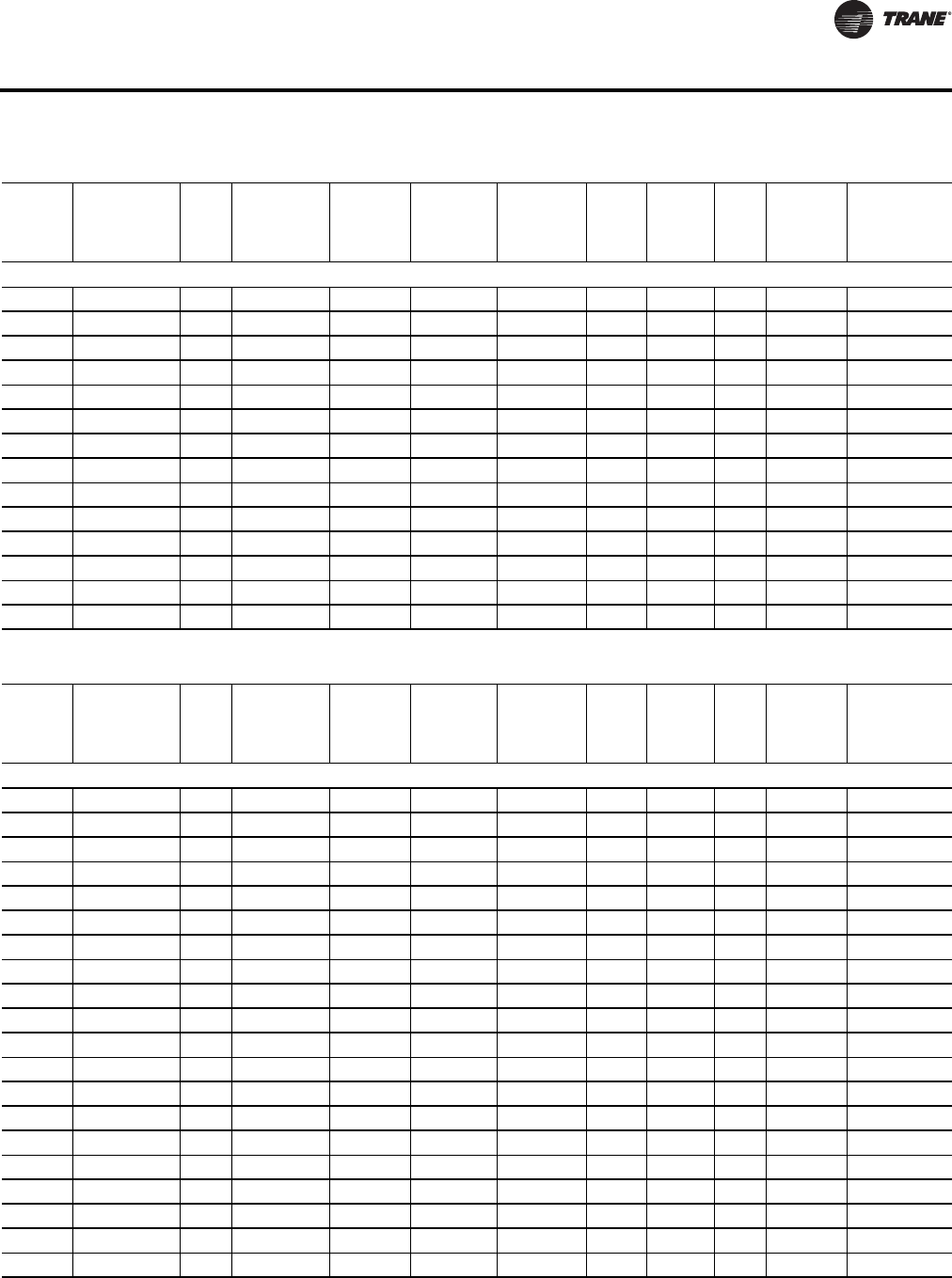
WSHP-PRC016E-EN 73
Electrical Data
GEV - Vertical Units
GEV300 460/60/3 43.7 18.6 125 2 29 6.5 5.0 1 48.35 60
GEV300 575/60/3 34.7 14.7 100 2 23 5.3 5.0 1 38.38 50
GEV300 208/60/3 116.2 48.1 245 2 75 20.0 7.5 1 128.23 175
GEV300 230/60/3 115.6 48.1 245 2 75 19.4 7.5 1 127.63 175
GEV300 460/60/3 46.9 18.6 125 2 29 9.7 7.5 1 51.55 70
GEV300 575/60/3 37.4 14.7 100 2 23 8.0 7.5 1 41.08 50
GEV300 208/60/3 122.2 48.1 245 2 75 26.0 10.0 1 134.23 175
GEV300 230/60/3 121.2 48.1 245 2 75 25.0 10.0 1 133.23 175
GEV300 460/60/3 49.7 18.6 125 2 29 12.5 10.0 1 54.35 70
GEV300 575/60/3 39.4 14.7 100 2 23 10.0 10.0 1 43.08 50
GEV300 208/60/3 133.2 48.1 245 2 75 37.0 15.0 1 145.23 175
GEV300 230/60/3 132.2 48.1 245 2 75 36.0 15.0 1 144.23 175
GEV300 460/60/3 55.2 18.6 125 2 29 18.0 15.0 1 59.85 70
GEV300 575/60/3 43.5 14.7 100 2 23 14.1 15.0 1 47.18 60
Table 78. Electrical data: 6 to 25 tons - single speed blower motor (continued)
Model
No. Volts Total
FLA Comp RLA
(ea)
Comp
LRA
(ea) No. of
Comp. Cmp MCC
Blower
Motor
FLA
Blower
Motor
HP
Fan
Motor
No.
Minimum
Circuit
Ampacity
Maximum
Overcurrent
Protective
Device
Table 79. Electrical data: 6 to 25 tons - two speed blower motor
Model
No. Volts Total
FLA Comp RLA
(ea)
Comp
LRA
(ea) No. of
Comp. Cmp MCC
Blower
Motor
FLA
Blower
Motor
HP
Fan
Motor
No.
Minimum
Circuit
Ampacity
Maximum
Overcurrent
Protective
Device
GEH - Horizontal Units
GEH072 208/60/3 24.1 10.4 73 2 16.3 3.3 1.0 1 26.70 35
GEH072 230/60/3 23.8 10.4 73 2 16.3 3.0 1.0 1 26.40 35
GEH072 460/60/3 13.1 5.8 38 2 9 1.5 1.0 1 14.55 20
GEH072 208/60/3 25.7 10.4 73 2 16.3 4.9 1.5 1 28.30 35
GEH072 230/60/3 25.2 10.4 73 2 16.3 4.4 1.5 1 27.80 35
GEH072 460/60/3 13.8 5.8 38 2 9 2.2 1.5 1 15.25 20
GEH072 208/60/3 27.5 10.4 73 2 16.3 6.7 2.0 1 30.10 40
GEH072 230/60/3 26.9 10.4 73 2 16.3 6.1 2.0 1 29.50 35
GEH072 460/60/3 14.7 5.8 38 2 9 3.1 2.0 1 16.15 20
GEH090 208/60/3 28.2 14.5/10.4 98/73 2 22.6/16.3 3.3 1.0 1 31.83 45
GEH090 230/60/3 27.9 14.5/10.4 98/73 2 22.6/16.3 3.0 1.0 1 31.53 45
GEH090 460/60/3 13.6 6.3/5.8 55/38 2 9.9/9 1.5 1.0 1 15.18 20
GEH090 208/60/3 29.8 14.5/10.4 98/73 2 22.6/16.3 4.9 1.5 1 33.43 45
GEH090 230/60/3 29.3 14.5/10.4 98/73 2 22.6/16.3 4.4 1.5 1 32.93 45
GEH090 460/60/3 14.3 6.3/5.8 55/38 2 9.9/9 2.2 1.5 1 15.88 20
GEH090 208/60/3 31.6 14.5/10.4 98/73 2 22.6/16.3 6.7 2.0 1 35.23 45
GEH090 230/60/3 31.0 14.5/10.4 98/73 2 22.6/16.3 6.1 2.0 1 34.63 45
GEH090 460/60/3 15.2 6.3/5.8 55/38 2 9.9/9 3.1 2.0 1 16.78 20
GEH090 208/60/3 33.7 14.5/10.4 98/73 2 22.6/16.3 8.8 3.0 1 37.33 50
GEH090 230/60/3 32.9 14.5/10.4 98/73 2 22.6/16.3 8.0 3.0 1 36.53 50
continued on next page

74 WSHP-PRC016E-EN
Electrical Data
GEH - Horizontal Units
GEH090 460/60/3 16.6 6.3 55 2 9.9 4.0 3.0 1 18.18 20
GEH120 208/60/3 36.9 16 110 2 24.9 4.9 1.5 1 40.90 50
GEH120 230/60/3 36.4 16 110 2 24.9 4.4 1.5 1 40.40 50
GEH120 460/60/3 17.8 7.8 52 2 12.1 2.2 1.5 1 19.75 25
GEH120 208/60/3 38.7 16 110 2 24.9 6.7 2.0 1 42.70 50
GEH120 230/60/3 38.1 16 110 2 24.9 6.1 2.0 1 42.10 50
GEH120 460/60/3 18.7 7.8 52 2 12.1 3.1 2.0 1 20.65 25
GEH120 208/60/3 40.8 16 110 2 24.9 8.8 3.0 1 44.80 60
GEH120 230/60/3 40.0 16 110 2 24.9 8.0 3.0 1 44.00 60
GEH120 460/60/3 19.6 7.8 52 2 12.1 4.0 3.0 1 21.55 25
GEH120 208/60/3 46.6 16 110 2 24.9 14.6 5.0 1 50.60 60
GEH120 230/60/3 45.2 16 110 2 24.9 13.2 5.0 1 49.20 60
GEH120 460/60/3 22.2 7.8 52 2 12.1 6.6 5.0 1 24.15 30
GEH150 208/60/3 49.7 22.4 149 2 35 4.9 1.5 1 55.30 70
GEH150 230/60/3 49.2 22.4 149 2 35 4.4 1.5 1 54.80 70
GEH150 460/60/3 23.4 10.6 75 2 16.5 2.2 1.5 1 26.05 35
GEH150 208/60/3 51.5 22.4 149 2 35 6.7 2.0 1 57.10 70
GEH150 230/60/3 50.9 22.4 149 2 35 6.1 2.0 1 56.50 70
GEH150 460/60/3 24.3 10.6 75 2 16.5 3.1 2.0 1 26.95 35
GEH150 208/60/3 53.6 22.4 149 2 35 8.8 3.0 1 59.20 80
GEH150 230/60/3 52.8 22.4 149 2 35 8.0 3.0 1 58.40 80
GEH150 460/60/3 25.2 10.6 75 2 16.5 4.0 3.0 1 27.85 35
GEH150 208/60/3 59.4 22.4 149 2 35 14.6 5.0 1 65.00 80
GEH150 230/60/3 58.0 22.4 149 2 35 13.2 5.0 1 63.60 80
GEH150 460/60/3 27.8 10.6 75 2 16.5 6.6 5.0 1 30.45 40
GEH180 208/60/3 56.7 25 164 2 39 6.7 2.0 1 62.95 80
GEH180 230/60/3 56.1 25 164 2 39 6.1 2.0 1 62.35 80
GEH180 460/60/3 27.5 12.2 100 2 19 3.1 2.0 1 30.55 40
GEH180 208/60/3 58.8 25 164 2 39 8.8 3.0 1 65.05 90
GEH180 230/60/3 58.0 25 164 2 39 8.0 3.0 1 64.25 80
GEH180 460/60/3 28.4 12.2 100 2 19 4.0 3.0 1 31.45 40
GEH180 208/60/3 64.6 25 164 2 39 14.6 5.0 1 70.85 90
GEH180 230/60/3 63.2 25 164 2 39 13.2 5.0 1 69.45 90
GEH180 460/60/3 31.0 12.2 100 2 19 6.6 5.0 1 34.05 45
GEH180 208/60/3 72.1 25 164 2 39 22.1 7.5 1 78.35 100
GEH180 230/60/3 70.0 25 164 2 39 20.0 7.5 1 76.25 100
GEH180 460/60/3 34.4 12.2 100 2 19 10.0 7.5 1 37.45 45
GEV - Vertical Units
GEV072 208/60/3 24.1 10.4 73 2 16.3 3.3 1.0 1 26.70 35
GEV072 230/60/3 23.8 10.4 73 2 16.3 3.0 1.0 1 26.40 35
continued on next page
Table 79. Electrical data: 6 to 25 tons - two speed blower motor (continued)
Model
No. Volts Total
FLA Comp RLA
(ea)
Comp
LRA
(ea) No. of
Comp. Cmp MCC
Blower
Motor
FLA
Blower
Motor
HP
Fan
Motor
No.
Minimum
Circuit
Ampacity
Maximum
Overcurrent
Protective
Device

WSHP-PRC016E-EN 75
Electrical Data
GEV - Vertical Units
GEV072 460/60/3 13.1 5.8 38 2 9 1.5 1.0 1 14.55 20
GEV072 208/60/3 25.7 10.4 73 2 16.3 4.9 1.5 1 28.30 35
GEV072 230/60/3 25.2 10.4 73 2 16.3 4.4 1.5 1 27.80 35
GEV072 460/60/3 13.8 5.8 38 2 9 2.2 1.5 1 15.25 20
GEV072 208/60/3 27.5 10.4 73 2 16.3 6.7 2.0 1 30.10 40
GEV072 230/60/3 26.9 10.4 73 2 16.3 6.1 2.0 1 29.50 35
GEV072 460/60/3 14.7 5.8 38 2 9 3.1 2.0 1 16.15 20
GEV090 208/60/3 28.2 14.5/10.4 98/73 2 22.6/16.3 3.3 1.0 1 31.83 45
GEV090 230/60/3 27.9 14.5/10.4 98/73 2 22.6/16.3 3.0 1.0 1 31.53 45
GEV090 460/60/3 13.6 6.3/5.8 55/38 2 9.9/9 1.5 1.0 1 15.18 20
GEV090 208/60/3 29.8 14.5/10.4 98/73 2 22.6/16.3 4.9 1.5 1 33.43 45
GEV090 230/60/3 29.3 14.5/10.4 98/73 2 22.6/16.3 4.4 1.5 1 32.93 45
GEV090 460/60/3 14.3 6.3/5.8 55/38 2 9.9/9 2.2 1.5 1 15.88 20
GEV090 208/60/3 31.6 14.5/10.4 98/73 2 22.6/16.3 6.7 2.0 1 35.23 45
GEV090 230/60/3 31.0 14.5/10.4 98/73 2 22.6/16.3 6.1 2.0 1 34.63 45
GEV090 460/60/3 15.2 6.3/5.8 55/38 2 9.9/9 3.1 2.0 1 16.78 20
GEV090 208/60/3 33.7 14.5/10.4 98/73 2 22.6/16.3 8.8 3.0 1 37.33 50
GEV090 230/60/3 32.9 14.5/10.4 98/73 2 22.6/16.3 8.0 3.0 1 36.53 50
GEV090 460/60/3 16.1 6.3/5.8 55/38 2 9.9/9 4.0 3.0 1 17.68 20
GEV120 208/60/3 36.9 16 110 2 24.9 4.9 1.5 1 40.90 50
GEV120 230/60/3 36.4 16 110 2 24.9 4.4 1.5 1 40.40 50
GEV120 460/60/3 17.8 7.8 52 2 12.1 2.2 1.5 1 19.75 25
GEV120 208/60/3 38.7 16 110 2 24.9 6.7 2.0 1 42.70 50
GEV120 230/60/3 38.1 16 110 2 24.9 6.1 2.0 1 42.10 50
GEV120 460/60/3 18.7 7.8 52 2 12.1 3.1 2.0 1 20.65 25
GEV120 208/60/3 40.8 16 110 2 24.9 8.8 3.0 1 44.80 60
GEV120 230/60/3 40.0 16 110 2 24.9 8.0 3.0 1 44.00 60
GEV120 460/60/3 19.6 7.8 52 2 12.1 4.0 3.0 1 21.55 25
GEV120 208/60/3 46.6 16 110 2 24.9 14.6 5.0 1 50.60 60
GEV120 230/60/3 45.2 16 110 2 24.9 13.2 5.0 1 49.20 60
GEV120 460/60/3 22.2 7.8 52 2 12.1 6.6 5.0 1 24.15 30
GEV150 208/60/3 51.5 22.4 149 2 35 6.7 2.0 1 57.10 70
GEV150 230/60/3 50.9 22.4 149 2 35 6.1 2.0 1 56.50 70
GEV150 460/60/3 24.3 10.6 75 2 16.5 3.1 2.0 1 26.95 35
GEV150 208/60/3 53.6 22.4 149 2 35 8.8 3.0 1 59.20 80
GEV150 230/60/3 52.8 22.4 149 2 35 8.0 3.0 1 58.40 80
GEV150 460/60/3 25.2 10.6 75 2 16.5 4.0 3.0 1 27.85 35
GEV150 208/60/3 59.4 22.4 149 2 35 14.6 5.0 1 65.00 80
GEV150 230/60/3 58.0 22.4 149 2 35 13.2 5.0 1 63.60 80
GEV150 460/60/3 27.8 10.6 75 2 16.5 6.6 5.0 1 30.45 40
continued on next page
Table 79. Electrical data: 6 to 25 tons - two speed blower motor (continued)
Model
No. Volts Total
FLA Comp RLA
(ea)
Comp
LRA
(ea) No. of
Comp. Cmp MCC
Blower
Motor
FLA
Blower
Motor
HP
Fan
Motor
No.
Minimum
Circuit
Ampacity
Maximum
Overcurrent
Protective
Device
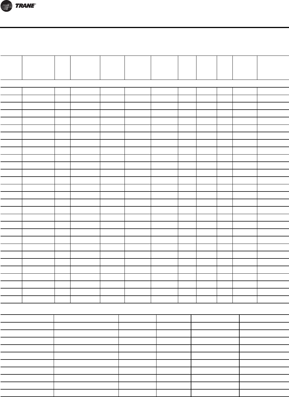
76 WSHP-PRC016E-EN
Electrical Data
GEV - Vertical Units
GEV180 208/60/3 58.8 25 164 2 39 8.8 3.0 1 65.05 90
GEV180 230/60/3 58.0 25 164 2 39 8.0 3.0 1 64.25 80
GEV180 460/60/3 28.4 12.2 100 2 19 4.0 3.0 1 31.45 40
GEV180 208/60/3 64.6 25 164 2 39 14.6 5.0 1 70.85 90
GEV180 230/60/3 63.2 25 164 2 39 13.2 5.0 1 69.45 90
GEV180 460/60/3 31.0 12.2 100 2 19 6.6 5.0 1 34.05 45
GEV180 208/60/3 72.1 25 164 2 39 22.1 7.5 1 78.35 100
GEV180 230/60/3 70.0 25 164 2 39 20.0 7.5 1 76.25 100
GEV180 460/60/3 34.4 12.2 100 2 19 10.0 7.5 1 37.45 45
GEV240 208/60/3 74.8 30.1 225 2 47 14.6 5.0 1 82.33 110
GEV240 230/60/3 73.4 30.1 225 2 47 13.2 5.0 1 80.93 110
GEV240 460/60/3 40.0 16.7 114 2 26 6.6 5.0 1 44.18 60
GEV240 208/60/3 82.3 30.1 225 2 47 22.1 7.5 1 89.83 110
GEV240 230/60/3 80.2 30.1 225 2 47 20.0 7.5 1 87.73 110
GEV240 460/60/3 43.4 16.7 114 2 26 10.0 7.5 1 47.58 60
GEV240 208/60/3 87.8 30.1 225 2 47 27.6 10.0 1 95.33 125
GEV240 230/60/3 85.2 30.1 225 2 47 25.0 10.0 1 92.73 110
GEV240 460/60/3 46.4 16.7 114 2 26 13.0 10.0 1 50.58 60
GEV240 460/60/3 53.4 16.7 114 2 26 20.0 15.0 1 58.40 70
GEV300 208/60/3 110.8 48.1 245 2 75 14.6 5.0 1 122.83 150
GEV300 230/60/3 109.4 48.1 245 2 75 13.2 5.0 1 121.43 150
GEV300 460/60/3 43.8 18.6 125 2 29 6.6 5.0 1 48.45 60
GEV300 208/60/3 118.3 48.1 245 2 75 22.1 7.5 1 130.33 175
GEV300 230/60/3 116.2 48.1 245 2 75 20.0 7.5 1 128.23 175
GEV300 460/60/3 47.2 18.6 125 2 29 10.0 7.5 1 51.85 70
GEV300 208/60/3 123.8 48.1 245 2 75 27.6 10.0 1 135.83 175
GEV300 230/60/3 121.2 48.1 245 2 75 25.0 10.0 1 133.23 175
GEV300 460/60/3 50.2 18.6 125 2 29 13.0 10.0 1 54.85 70
GEV300 460/60/3 57.2 18.6 125 2 29 20.0 15.0 1 62.20 80
Table 79. Electrical data: 6 to 25 tons - two speed blower motor (continued)
Model
No. Volts Total
FLA Comp RLA
(ea)
Comp
LRA
(ea) No. of
Comp. Cmp MCC
Blower
Motor
FLA
Blower
Motor
HP
Fan
Motor
No.
Minimum
Circuit
Ampacity
Maximum
Overcurrent
Protective
Device
Table 80. Electrical minimum and maximum
Digit 8 Rated Voltage Hz Ph Min Utiliz. Volts Max Utiliz. Volts
0 115 60 1 104 126
1 208 60 1 197 229
2 230 60 1 207 253
3 208 60 3 187 229
4 460 60 3 414 506
5 575 60 3 518 633
6 220-240 50 1 198 264
7 265 60 1 239 292
8 230 60 3 207 253
9 380-415 50 3 342 456
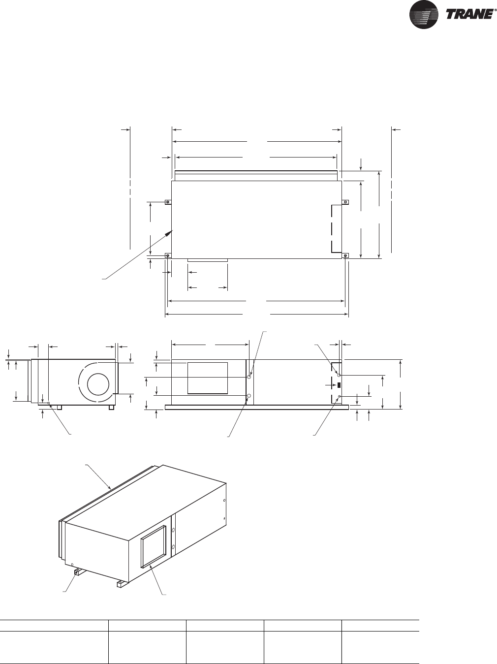
WSHP-PRC016E-EN 77
Dimensional Data
Figure 24. GEH 6-10 tons (072-120)—right return, left supply
WCI mounting location
20"
(508)
SERVICE
CLEARANCE 79"
(2007)
74 1/2"
(1892)
1 3/4"
(44)
36"
(914)
SERVICE
CLEARANCE
4 5/8"
(117)
36"
(914)
40 5/8"
(1032)
7 5/8"
(194)
18 3/8"
(467)
81"
(2057)
2 1/8"
(54)
23 7/8"
(606)
BLOWER ACCESS
PANEL
3 1/8"
(79)
(79 )
4 7/8"
(124)
1"
(25.4)
5/8"
(16)
18 3/4"
(476)
14 1/2"
(368)
DRAIN CONNECTION
1/2" (22) SCHEDULE 40 PVC
1 1/4"
(32)
C
B
A
W.O. "D" NPTI
W.I. "D" NPTI
24 VOLT
1 1/8" (28.6) DIA.
HIGH VOLTAGE
7/8" (22.2) DIA.
23 1/4"
(591)
16 1/2"
(419)
2 1/4"
(57)
6 1/2"
(165)
1 1/2"
(38)
RETURN AIR
OPENING
1" (25.4) DIA.
MOUNTING HOLE
4X'S SUPPLY OPENING
1" (25.4) DUCT FLANGE
TOP VIEW
BACK SIDE LEFT SIDE
85"
(2159)
Unit GEH A (in.) B (in.) C (in.) D (in.)
072 36-1/4 (921) 15-3/4 (400) 6-7/8 (175) 1-1/4 (32)
090 36-1/8 (917) 13 (330) 7 (178) 1-1/4 (32)
120 36-1/8 (917) 13-1/4 (337) 7-3/8 (187) 1-1/2 (38)
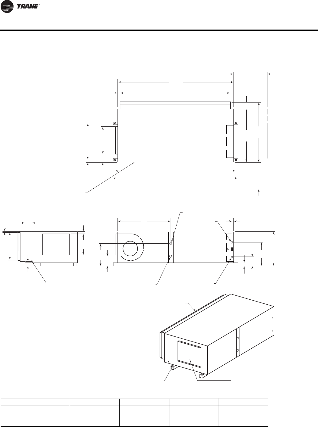
78 WSHP-PRC016E-EN
Dimensional Data
Figure 25. GEH 6-10 tons (072-120)—right return/back supply
79"
(2007)
74 1/2"
(1892)
36"
(914)
40 5/8"
(1032)
81"
(2057)
85"
(2159)
2 1/8"
(54)
23 7/8"
(606)
TOP VIEW
18 3/8"
(467)
6 1/8"
(156)
4 5/8"
(117)
36"
(914)
SERVICE
CLEARANCE
1 3/4"
(44)
20"
(508)
SERVICE
CLEARANCE
BLOWER ACCESS
PANEL
3 1/8"
(79)
4 7/8"
(124)
5/8"
(16)
18 3/4"
(476)
DRAIN CONNECTION
1/2" (22) SCHEDULE 40 PVC
1 1/4"
(32)
14 1/2"
(368)
C
B
A
W.O. "D" NPTI
W.I. "D" NPTI
24 VOLT
1 1/8" (28.6) DIA.
HIGH VOLTAGE
7/8" (22.2) DIA.
23 1/4"
(591)
16 1/2"
(419)
2 1/4"
(57)
6 1/2"
(165)
1 1/2"
(38)
LEFT SIDE
RETURN AIR
OPENING
1" (25.4) DIA.
MOUNTING HOLE
4X'S
SUPPLY OPENING
1" (25.4) DUCT FLANGE
WCI mounting location
Unit GEH A (in.) B (in.) C (in.) D (in.)
072 36-1/4 (921) 15-3/4 (400) 6-7/8 (175) 1-1/4 (32)
090 36-1/8 (917) 13 (330) 7 (178) 1-1/4 (32)
120 36-1/8 (917) 13-1/4 (337) 7-3/8 (187) 1-1/2 (38)
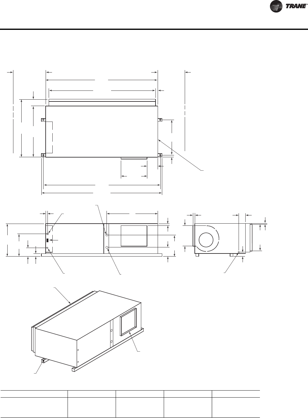
WSHP-PRC016E-EN 79
Dimensional Data
Figure 26. GEH 6-10 tons (072-120) - left return/right supply
20"
(508)
SERVICE
CLEARANCE
79"
(2007)
74 1/2"
(1892) 1 3/4"
(44)
36"
(914)
SERVICE
CLEARANCE
4 5/8"
(117)
36"
(914)
40 5/8"
(1032)
7 5/8"
(194)
18 3/8"
(467)
81"
(2057)
85"
(2159)
1 1/4"
(32)
24 3/4"
(629)
BLOWER ACCESS
PANEL
3 1/8"
(79)
4 7/8"
(124)
1"
(25.4)
5/8"
(16)
18 3/4"
(476)
14 1/2"
(368)
DRAIN CONNECTION
1/2" (22) SCHEDULE 40 PVC
1 1/4"
(32)
C
B
A
W.O. "D" NPTI
W.I. "D" NPTI
24 VOLT
1 1/8" (28.6) DIA.
HIGH VOLTAGE
7/8" (22.2) DIA.
23 1/4"
(591) 16 1/2"
(419)
2 1/4"
(57)
6 1/2"
(165)
1 1/2"
(38)
TOP VIEW
BACK SIDE
LEFT SIDE
RETURN AIR
OPENING
1" (25.4) DIA.
MOUNTING HOLE
4X'S
SUPPLY OPENING
1" (25.4) DUCT FLANGE
WCI mounting location
Unit GEH A (in.) B (in.) C (in.) D (in.)
072 36-1/8 (917) 17-1/8 (435) 8-1/8 (206) 1-1/4 (32)
090 36-1/8 (917) 13-7/8 (352) 7-7/8 (200) 1-1/4 (32)
120 36-1/8 (917) 13-1/4 (337) 7-3/8 (187) 1-1/2 (38)
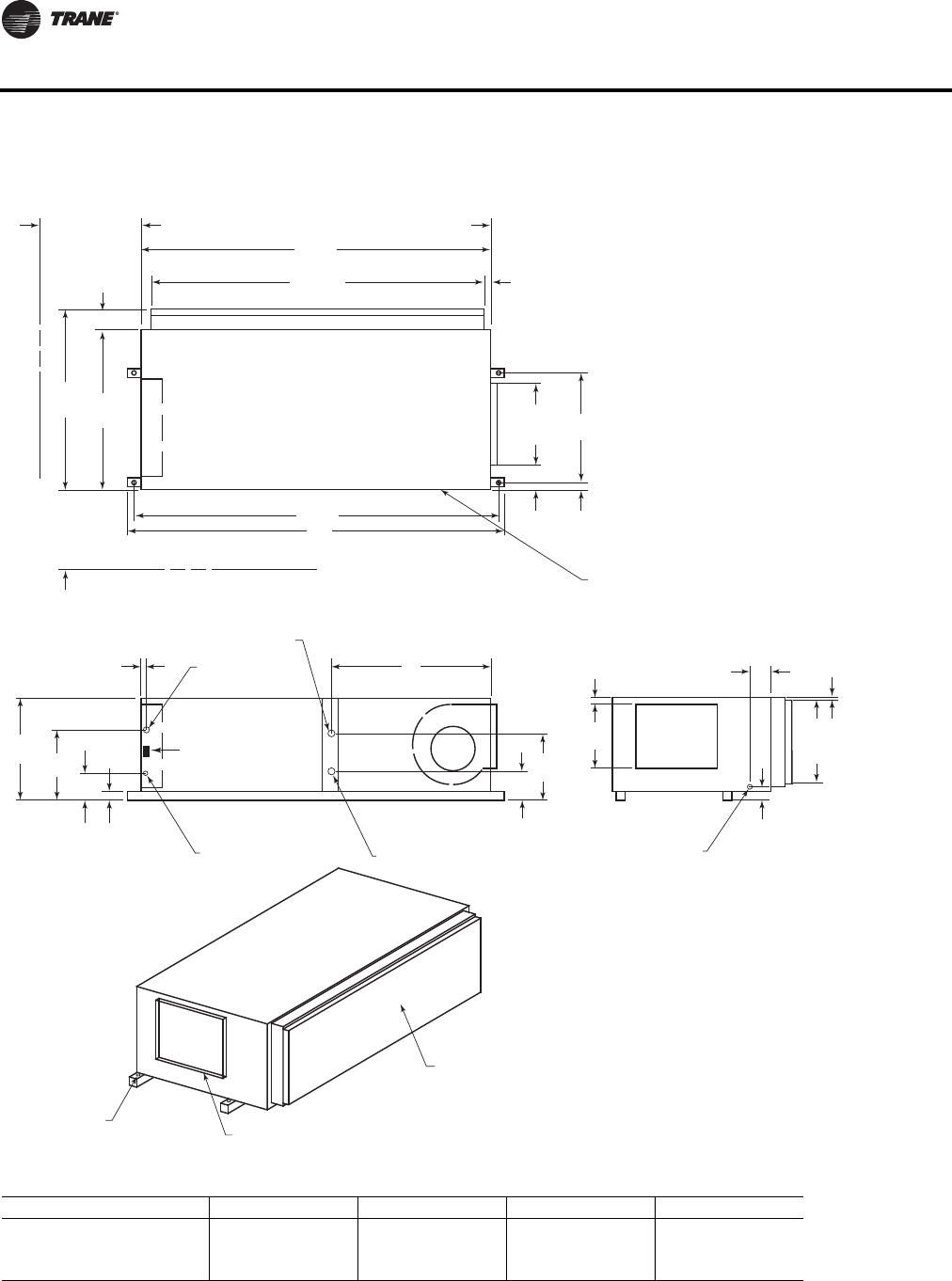
80 WSHP-PRC016E-EN
Dimensional Data
Figure 27. GEH 6-10 tons (072-120) - left return/back supply
79"
(2007)
74 1/2"
(1892)
36"
(914)
40 5/8"
(1032)
81"
(2057)
85"
(2159)
1 1/4"
(32)
24 3/4"
(629)
TOP VIEW
18 3/8"
(467)
6 1/8"
(156)
4 5/8"
(117)
36"
(914)
SERVICE
CLEARANCE
1 3/4"
(44)
20"
(508)
SERVICE
CLEARANCE
BLOWER ACCESS
PANEL
3 1/8"
(79)
4 7/8"
(124)
5/8"
(16)
18 3/4"
(476)
DRAIN CONNECTION
1/2" (22) SCHEDULE 40 PVC
1 1/4"
(32)
14 1/2"
(368)
C
B
A
W.O. "D" NPTI
W.I. "D" NPTI
24 VOLT
1 1/8" (28.6) DIA.
HIGH VOLTAGE
7/8" (22.2) DIA.
23 1/4"
(591) 16 1/2"
(419)
2 1/4"
(57)
6 1/2"
(159)
1 1/2"
(38)
LEFT SIDE
RETURN AIR
OPENING
1" (25.4) DIA.
MOUNTING HOLE
4X'S SUPPLY OPENING
1" (25.4) DUCT FLANGE
WCI mounting location
Unit GEH A (in.) B (in.) C (in.) D (in.)
072 36-1/8 (917) 17-1/8 (435) 8-1/8 (206) 1-1/4 (32)
090 36-1/8 (917) 13-7/8 (352) 7-7/8 (200) 1-1/4 (32)
120 36-1/8 (917) 13-1/4 (337) 7-3/8 (187) 1-1/2 (38)
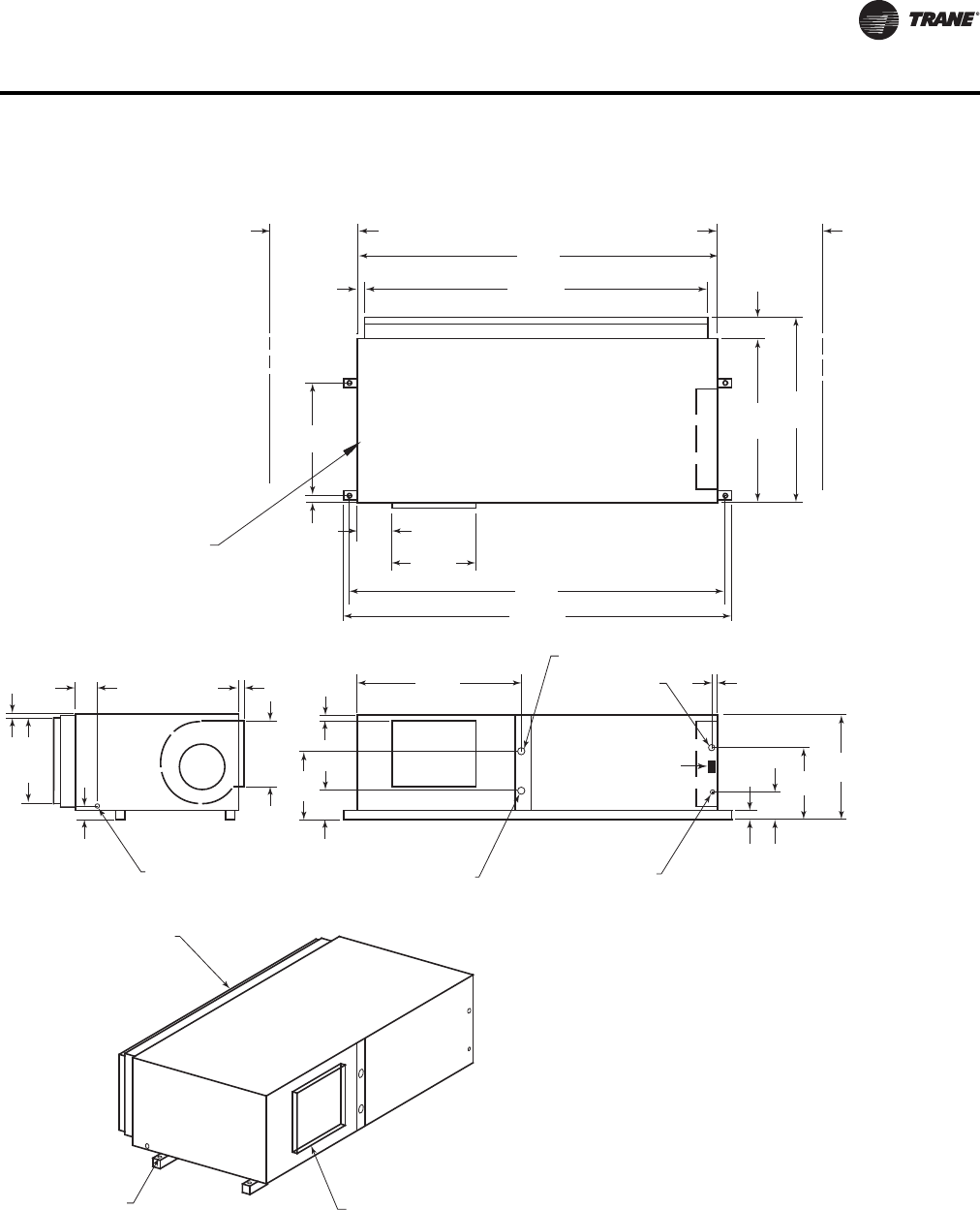
WSHP-PRC016E-EN 81
Dimensional Data
Figure 28. GEH 12½-15 tons (150-180) - right return/left supply
20"
(508)
SERVICE
CLEARANCE 85"
(2159)
74 1/2"
(1892)
2"
(51)
36"
(914)
SERVICE
CLEARANCE
4 5/8"
(117)
42"
(1067)
46 5/8"
(1184)
7 1/8"
(181)
21 3/8"
(467)
87"
(2210)
91"
(2311)
2 1/4"
(57)
29 3/4"
(756)
BLOWER ACCESS
PANEL
3 1/8"
(79)
4 7/8"
(124)
1"
(25.4)
1 3/8"
(35)
23 3/4"
(603)
16 3/4"
(425)
DRAIN CONNECTION
1/2" (22) SCHEDULE 40 PVC
2"
(51)
5 5/8"
(143)
24 7/8"
(632)
61 1/4"
(1556)
W.O. 1 1/2" (38)
NPTI
W.I. 1 1/2" (38)
NPTI
24 VOLT
1 1/8" (28.6) DIA.
HIGH VOLTAGE
7/8" (22.2) DIA.
30 1/4"
(768)
22 3/4"
(578)
2 1/4"
(57)
9 1/8"
(232)
2 1/4"
(57)
RETURN AIR
OPENING
1" (25.4) DIA.
MOUNTING HOLE
4X'S SUPPLY OPENING
1" (25.4) DUCT FLANGE
TOP VIEW
BACK SIDE LEFT SIDE
WCI mounting location
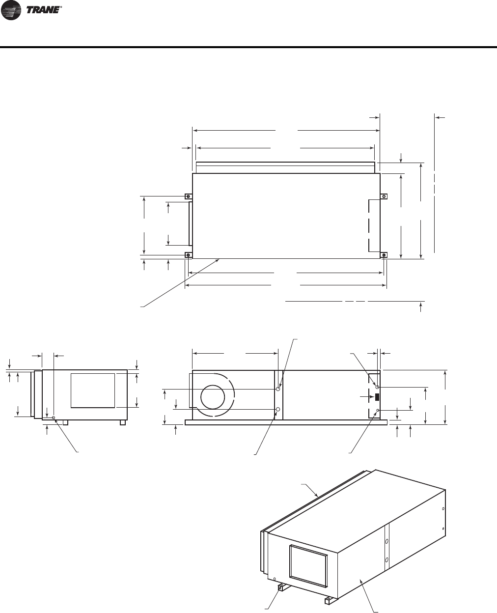
82 WSHP-PRC016E-EN
Dimensional Data
Figure 29. GEH 12½-15 tons (150-180) - right return/back supply
85"
(2159)
74 1/2"
(1892)
42"
(1067)
46 5/8"
(1184)
87"
(2210)
91"
(2311)
2 1/4"
(57)
29 3/4"
(756)
TOP VIEW
21 3/8"
(543)
7 1/8"
(181)
4 5/8"
(117)
36"
(914)
SERVICE
CLEARANCE
2"
(41)
20"
(508)
SERVICE
CLEARANCE
BLOWER ACCESS
PANEL
3 1/8"
(79)
4 7/8"
(124)
1 3/8"
(35)
23 3/4"
(603)
DRAIN CONNECTION
1/2" (22) SCHEDULE 40 PVC
2"
(51)
16 3/4"
(425)
5 5/8"
(143)
24 7/8"
(632)
61 1/4"
(1556)
W.O. 1 1/2" (38)
NPTI
W.I. 1 1/2" (38)
NPTI
24 VOLT
1 1/8" (28.6) DIA.
HIGH VOLTAGE
7/8" (22.2) DIA.
30 1/4"
(768)
22 3/4"
(578)
2 1/4"
(57)
9 1/8"
(232)
1 1/2"
(38)
LEFT SIDE
RETURN AIR
OPENING
1" (25.4) DIA.
MOUNTING HOLE
4X'S SUPPLY OPENING
1" (25.4) DUCT FLANGE
WCI mounting location
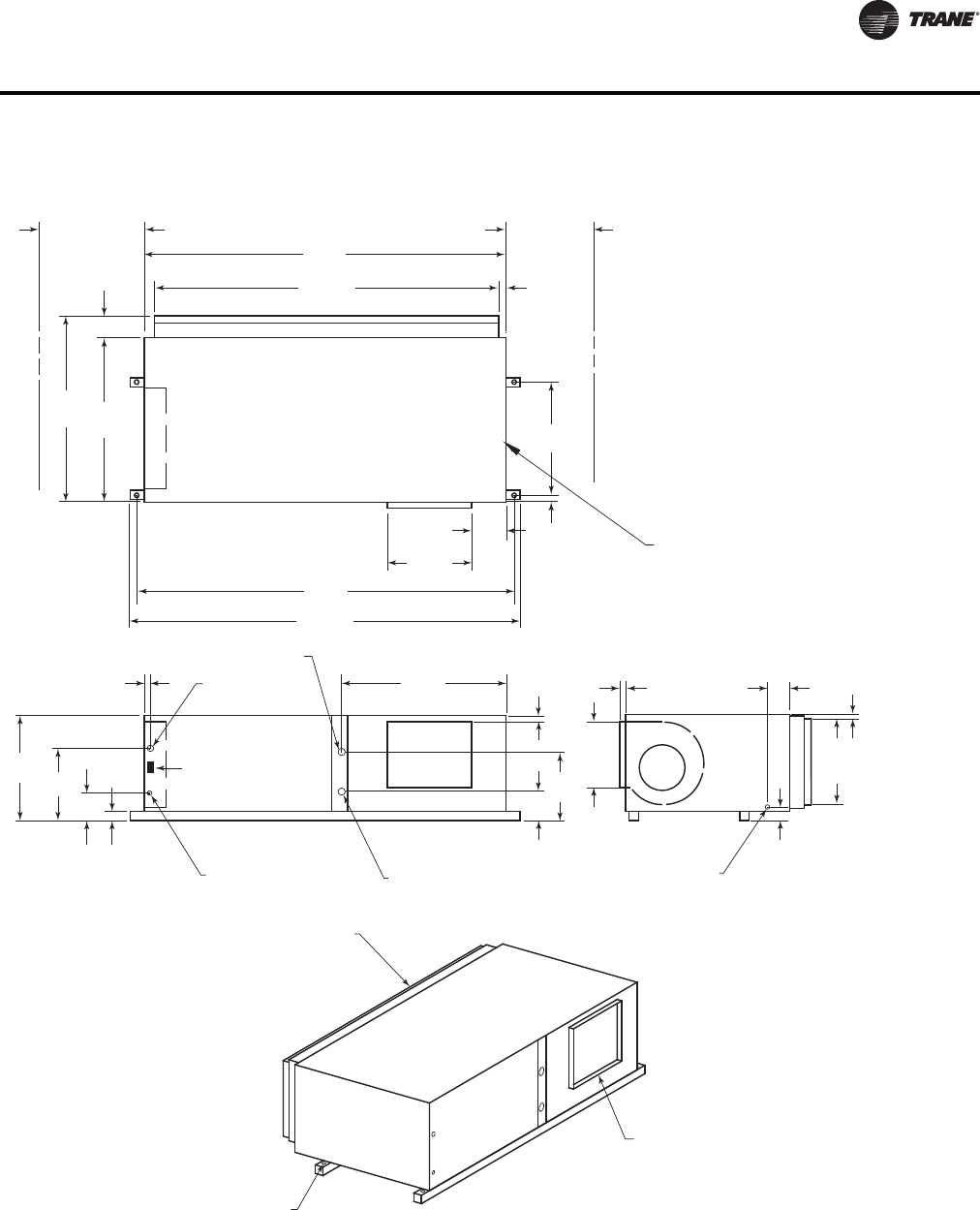
WSHP-PRC016E-EN 83
Dimensional Data
Figure 30. GEH 12½-15 tons (150-180) - left return/right supply
20"
(508)
SERVICE
CLEARANCE
85"
(2159)
74 1/2"
(1892) 2"
(51)
36"
(914)
SERVICE
CLEARANCE
4 5/8"
(117)
42"
(1067)
46 5/8"
(1184)
7 1/8"
(181)
21 3/8"
(543)
87"
(2210)
91"
(2311)
2 1/4"
(57)
29 3/4"
(756)
BLOWER ACCESS
PANEL
3 1/8"
(79)
4 7/8"
(124)
1"
(25.4)
1 3/8"
(35)
23 3/4"
(603)
16 3/4"
(425)
DRAIN CONNECTION
1/2" (22) SCHEDULE 40 PVC
2"
(51)
5 5/8"
(143)
24 7/8"
(632)
39 1/2"
(1003)
W.O. 1 1/2" (38)
NPTI
W.I. 1 1/2" (38)
NPTI
24 VOLT
1 1/8" (28.6) DIA.
HIGH VOLTAGE
7/8" (22.2) DIA.
30 1/4"
(768) 22 3/4"
(578)
2 1/4"
(57)
9 1/8"
(232)
2 1/8"
(54)
TOP VIEW
BACK SIDE
LEFT SIDE
RETURN AIR
OPENING
1" (25.4) DIA.
MOUNTING HOLE
4X'S
SUPPLY OPENING
1" (25.4) DUCT FLANGE
WCI mounting location
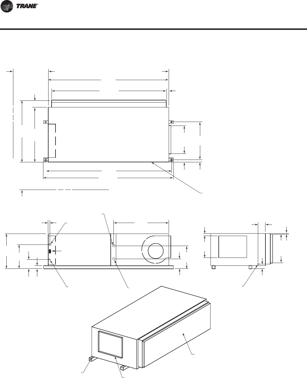
84 WSHP-PRC016E-EN
Dimensional Data
Figure 31. GEH 12½-15 tons (150-180) - left return/back supply
85"
(2159)
74 1/2"
(1892)
42"
(1067)
46 5/8"
(1184)
87"
(2210)
91"
(2311)
2 1/4"
(57)
29 3/4"
(756)
TOP VIEW
21 3/8"
(543)
7 1/8"
(181)
4 5/8"
(117)
36"
(914)
SERVICE
CLEARANCE
2"
(51)
20"
(508)
SERVICE
CLEARANCE
BLOWER ACCESS
PANEL
3 1/8"
(79)
4 7/8"
(124)
1 3/8"
(35)
23 3/4"
(603)
DRAIN CONNECTION
1/2" (22) SCHEDULE 40 PVC
2"
(51)
16 3/4"
(425)
5 5/8"
(143)
24 7/8"
(632)
39 1/2"
(1003)
W.O. 1 1/2" (38) NPTI
W.I. 1 1/2" (38)
NPTI
24 VOLT
1 1/8" (28.6) DIA.
HIGH VOLTAGE
7/8" (22.2) DIA.
30 1/4"
(768) 22 3/4"
(578)
2 1/4"
(57)
9 1/8"
(232)
2 1/8"
(54)
LEFT SIDE
RETURN AIR
OPENING
1" (25.4) DIA.
MOUNTING HOLE
4X'S SUPPLY OPENING
1" (25.4) DUCT FLANGE
WCI mounting location
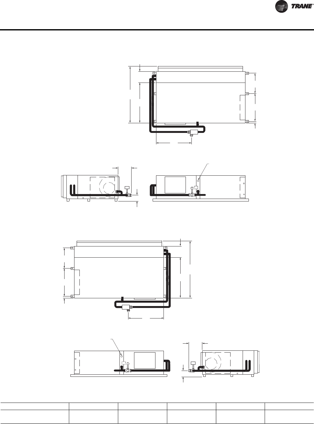
WSHP-PRC016E-EN 85
Dimensional Data
Figure 32. GEH 6-10 tons (072-120) - right return with waterside economizer(a)
(a)See Figure 50, p. 101 for waterside economizer coil piping diagram.
Figure 33. GEH 6-10 tons (072-120) - left return with waterside economizer(a)
(a)See Figure 50, p. 101 for waterside economizer coil piping diagram.
C
9 7/8"
(251)
36"
(914)
50 5/8"
(1286)
18 1/2"
(470)
23 7/8"
(606)
2 1/8"
(54)
D
E
"A" NPTI FOR
FIELD RETURN PIPING
C
9 7/8"
(251)
36"
(914)
50 5/8"
(1286)
18 1/2"
(470)
24 3/4"
(629)
1 1/4"
(32)
D
E
"A" NPTI FOR
FIELD RETURN PIPING
Unit GEH A (in.) B (in.) C (in.) D (in.) E (in.)
072-090 1-1/4 (32) 1-3/8 (35) 31 (787) 9-7/8 (251) 3-7/8 (98)
120 1-1/2 (38) 1-5/8 (41) 30-3/4 (781) 12-1/2 (318) 4-1/2 (114)
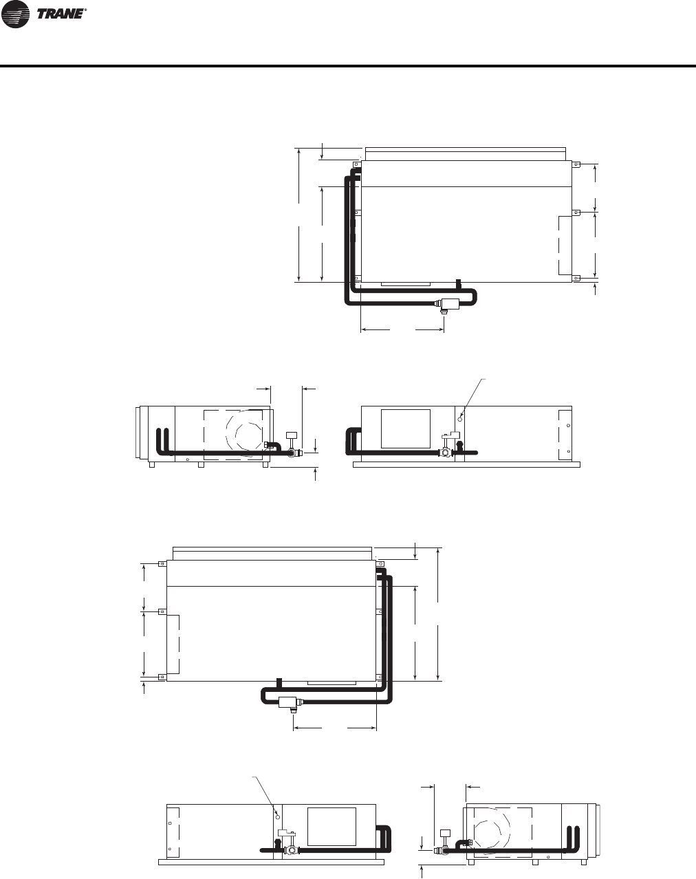
86 WSHP-PRC016E-EN
Dimensional Data
Figure 34. GEH 12½-15 tons (150-180) - right return with waterside economizer(a)
(a)See Figure 50, p. 101 for waterside economizer coil piping diagram.
Figure 35. GEH 12½-15 tons (150-180) - left return with waterside economizer(a)
(a)See Figure 50, p. 101 for waterside economizer coil piping diagram.
48 3/4"
(1238)
9 7/8"
(251)
42"
(1067)
56 1/2"
(1435)
18 1/2"
(470)
29 3/4"
(756)
2 1/4"
(57)
12"
(305)
5 3/8"
(137)
1 1/2" (38) NPTI FOR
FIELD RETURN PIPING
27 1/8"
(689)
9 7/8"
(251)
42"
(1067)
56 1/2"
(1435)
18 1/2"
(470)
29 3/4"
(756)
2 1/4"
(57)
12"
(305)
5 3/8"
(137)
1 1/2" (38) NPTI FOR
FIELD RETURN PIPING
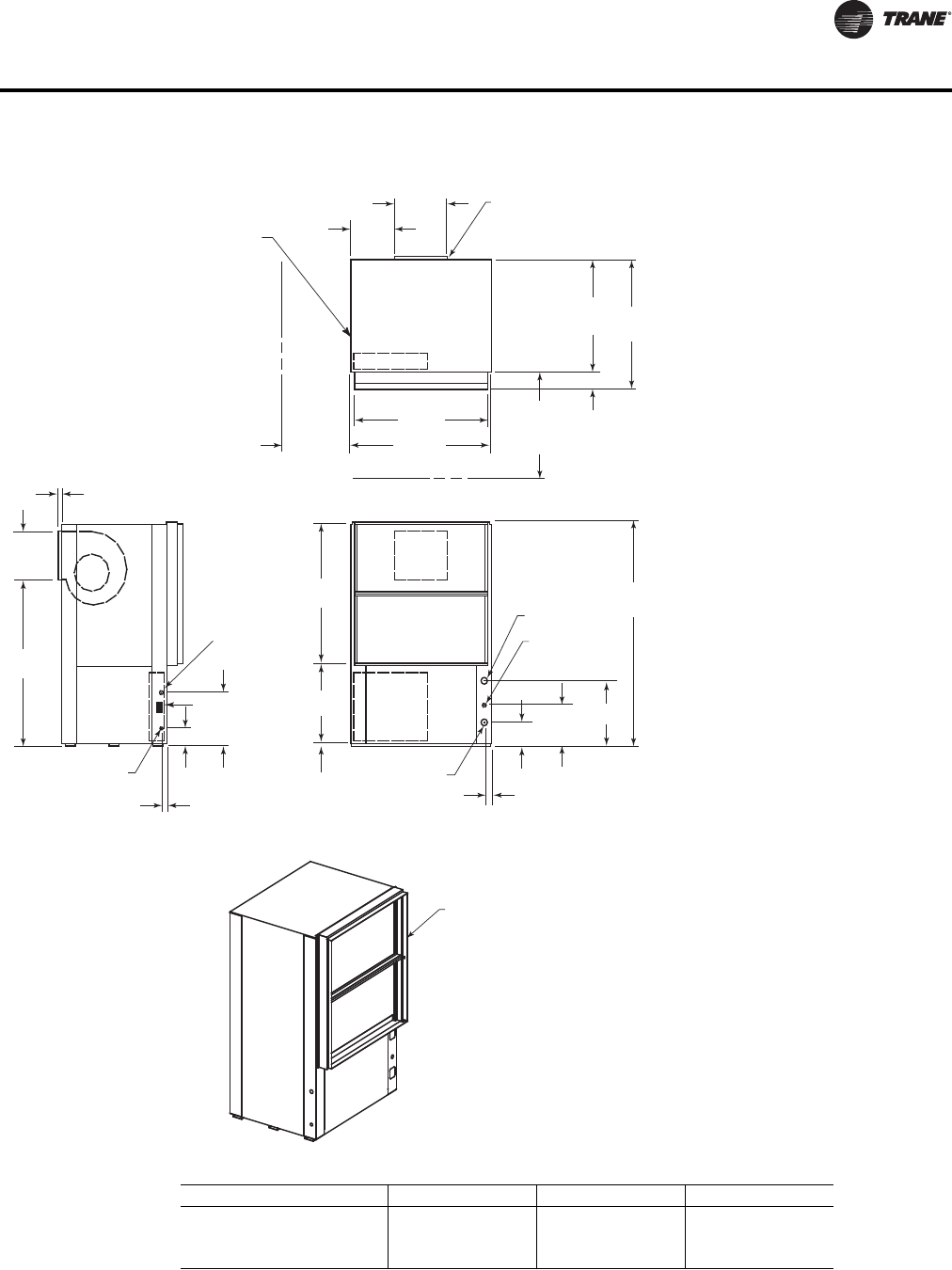
WSHP-PRC016E-EN 87
Dimensional Data
Figure 36. GEV 6-10 tons (072-120) - front return/back supply
39 5/8"
(1006)
ACCESS PANEL FOR
SHEAVES AND BELTS
13 18"
(333)
15 3/4
(400)
20"
(508)
SERVICE
CLEARANCE
42"
(1067)
4 7/8"
(124)
1
(25.4)
31 3/8"
(797) 36 1/4"
(921)
13 1/2"
(343)
46 1/2"
(1181)
36"
(914)
SERVICE
CLEARANCE
62 5/8"
(1591)
B
W.O. "C" NPTI
DRAIN 3/4" NPTI
A
11 1/2"
(292)
1 7/8"
(48)
W.I. "C" NPTI
HIGH VOLTAGE
7/8" (22.2) DIA.
1 5/8"
(41)
5"
(127)
15"
(381)
24 VOLT
1 1/8" (28.6)
22 3/8"
(568)
38 7/8"
(987)
3/4"
(19)
SUPPLY OPENING
1" (25.4) DUCT FLANGE
RETURN AIR
OPENING
WCI mounting location
Unit GEV A (in.) B (in.) C (in.)
072 6-5/8”(168) 18-3/8 (467) 1-1/4
090 6-5/8 (168) 18-3/8 (467) 1-1/4
120 5-7/8 (149) 18 (457) 1-1/2
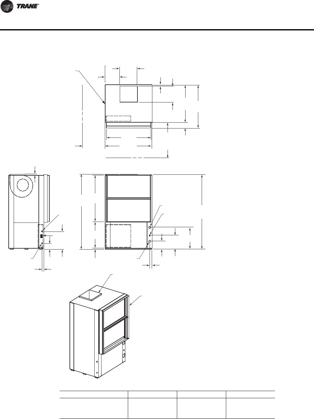
88 WSHP-PRC016E-EN
Dimensional Data
Figure 37. GEV 6-10 tons (072-120) - front return/top supply
39 5/8"
(1006)
ACCESS PANEL FOR
SHEAVES AND BELTS
13 1/4"
(337)
15 5/8
(397)
20"
(508)
SERVICE
CLEARANCE
42"
(1067)
4 7/8"
(124)
1 1/8"
(29)
31 3/8"
(797) 36 1/4"
(921)
13 3/8"
(343)
36"
(914)
SERVICE
CLEARANCE
63"
(1600)
62 5/8"
(1591)
B
W.O. "C" NPTI
DRAIN 3/4" NPTI
A
11 1/2"
(292)
1 7/8"
(48)
W.I. "C" NPTI
HIGH VOLTAGE
7/8" (22.2) DIA.
1 5/8"
(41)
5"
(127)
15"
(381)
24 VOLT
1 1/8" (28.6)
22 3/8"
(568)
38 7/8"
(987)
3/4"
(19)
1"
(25.4)
SUPPLY OPENING
1" (25.4) DUCT FLANGE
RETURN AIR
OPENING
WCI mounting location
Unit GEV A (in.) B (in.) C (in.)
072 6-5/8 (168) 18-3/8 (467) 1-1/4
090 6-5/8 (168) 18-3/8 (467) 1-1/4
120 5-7/8 (149) 18 (457) 1-1/2
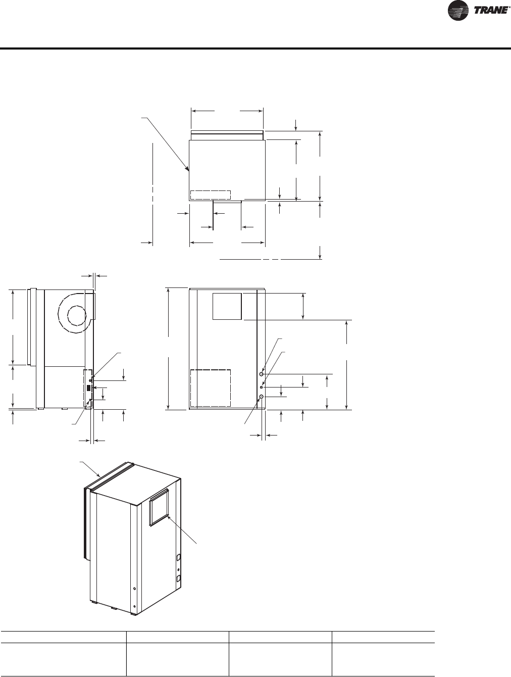
WSHP-PRC016E-EN 89
Dimensional Data
Figure 38. GEV 6-10 tons (072-120)—back return/front supply
1" (25.4)
20"
(508)
SERVICE
CLEARANCE
39 5/8"
(1006)
ACCESS PANEL FOR
SHEAVES AND BELTS
13 1/8"
(333)
15 3/4
(400)
42"
(1067)
4 7/8"
(124)
1 1/8"
(29)
36 1/4"
(921)
31 3/8"
(797)
36"
(914)
SERVICE
CLEARANCE
62 5/8"
(1591) 46 1/2"
(1181)
B
W.O. "C" NPTI
DRAIN 3/4" NPTI
A
11 1/2"
(292)
1 7/8"
(48)
W.I. "C" NPTI
HIGH VOLTAGE
7/8" (22.2) DIA.
1 5/8"
(41)
5"
(127)
15"
(381)
38 7/8"
(987)
22 3/8"
(568)
3/4"
(19)
SUPPLY OPENING
1" (25.4) DUCT FLANGE
RETURN AIR
OPENING
24 VOLT
1 1/8" (28.6)
13 1/2"
(343)
WCI mounting location
Unit GEV A (in.) B (in.) C (in.)
072 6-5/8 (168) 18-3/8 (467) 1-1/4
090 6-5/8 (168) 18-3/8 (467) 1-1/4
120 5-7/8 (149) 18 (457) 1-1/2
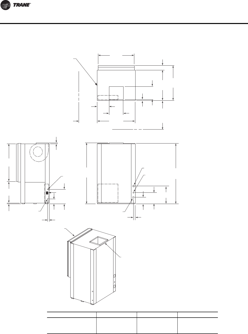
90 WSHP-PRC016E-EN
Dimensional Data
Figure 39. GEV 6-10 tons (072-120) - back return/top supply
20"
(508)
SERVICE
CLEARANCE
39 5/8"
(1006)
ACCESS PANEL FOR
SHEAVES AND BELTS
13 1/4"
(337)
15 5/8
(397)
42"
(1067)
4 7/8"
(124)
1 1/8"
(29)
31 3/8"
(797)
36 1/4"
(921)
13 1/2"
(343)
36"
(914)
SERVICE
CLEARANCE
63"
(1600) 62 5/8"
(1591)
B
W.O. "C" NPTI
DRAIN 3/4" NPTI
A
11 1/2"
(292)
1 7/8"
(48)
W.I. "C" NPTI
HIGH VOLTAGE
7/8" (22.2) DIA.
1 5/8"
(41)
5"
(127)
15"
(381)
24 VOLT
1 1/8" (28.6)
38 7/8"
(987)
22 3/8"
(568)
3/4"
(19)
1"
(25.4)
SUPPLY OPENING
1" (25.4) DUCT FLANGE
RETURN AIR
OPENING
WCI mounting location
Unit GEV A (in.) B (in.) C (in.)
072 6-5/8 (168) 18-3/8 (467) 1-1/4
090 6-5/8 (168) 18-3/8 (467) 1-1/4
120 5-7/8 (149) 18 (457) 1-1/2
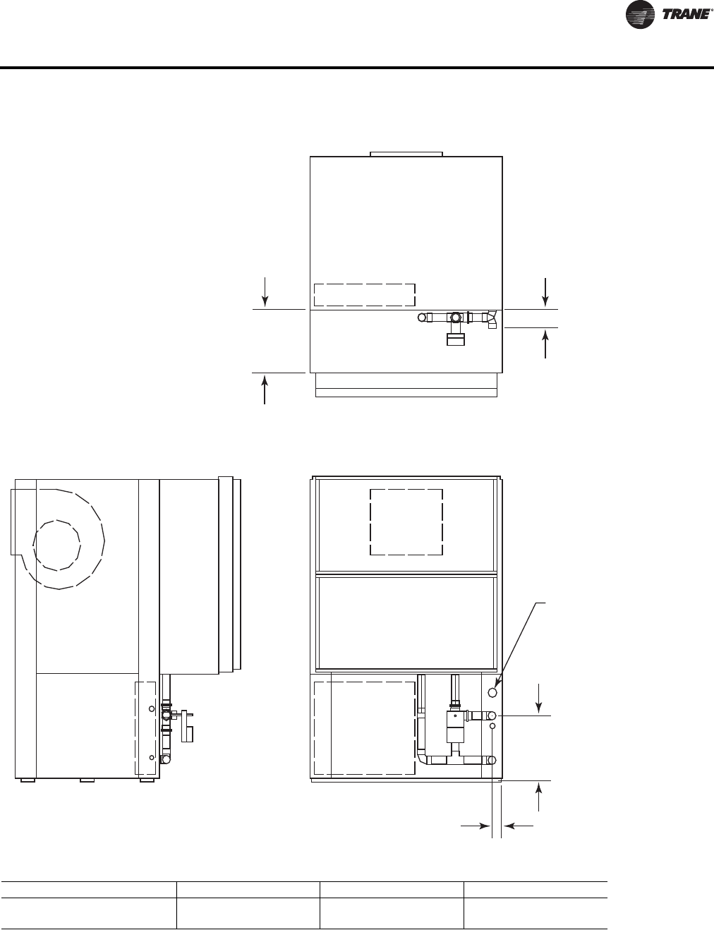
WSHP-PRC016E-EN 91
Dimensional Data
Figure 40. GEV 6-10 tons (072-120) - waterside economizer
A = TO FIELD
RETURN PIPING
13 1/4"
(337)
13"
(330)
C
2 1/4"
(57)
Unit GEV A (in.) B (in.) C (in.)
072,090 1-3/8 (35) 1-3/8 (35) 4 (102)
120 1-5/8 (41) 1-5/8 (41) 4-3/8 (111)
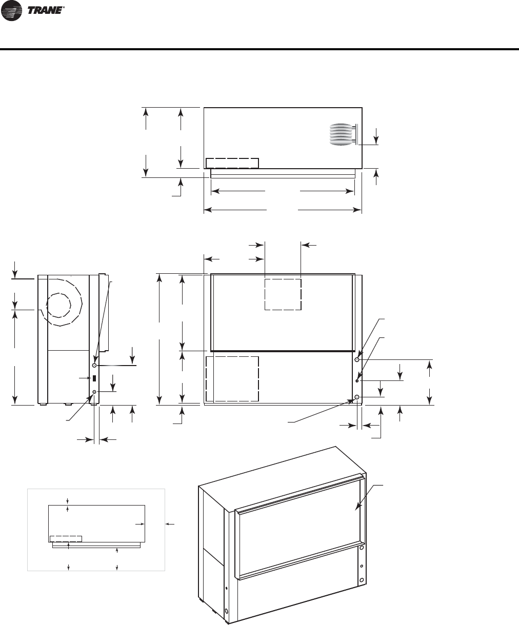
92 WSHP-PRC016E-EN
Dimensional Data
Figure 41. GEV 12½-15 tons (150-180) - front return/back supply
RETURN AIR
OPENING
W.I. 1 1/2"
(38) NPTI 2 5/8"
(67)
4 1/4"
(108)
12 1/2"
(318)
23 1/2
(597)
DRAIN 3/4"
(19) NPTI
W.O. 1 1/2"
(38) NPTI
38 7/8"
(987)
27 1/8"
(537)
67 5/8"
(1718)
31 1/2"
(800)
18 5/8"
(473)
1"
(25.4)
HIGH VOLTAGE
7/8" (22) O.D.
20 1/2"
(521)
20 1
/
2"
(
521
)
6 7/8" (175)
2 3/8"
(60)
15 7/8"
(403)
49 1/8"
(1248)
24 VOLT
1 1/8" (29) O.D.
74 1/2"
(1892)
81 5/8"
(2073)
31 1/2"
(800)
36 1/4"
(921)
4 3/4"
(121)
CONTROL
BOX ACCESS
TOP VIEW
FRONT VIEW
SIDE VIEW
10"
(254)
SERVICE CLEARANCE
CONTROL BOX
UNIT FRONT
NEC REQ.
36" (914)
C.B.TO WALL
CLEARANCE
16" (406) TO
FILTER FRAME
FOR RETURN-AIR
MIN. SERVICE
CLEARANCE FOR
EITHER LEFT
OR RIGHT SIDE
IS 18" (457). FOR
FAN SHAFT REMOVAL,
A 22" (559) CLEARANCE
MUST BE PROVIDED
ON EITHER THE
LEFT OR RIGHT SIDE.
MIN. SERVICE ON BACK
FOR COMPRESSOR ACCESS IS 24”
WCI mounting
location
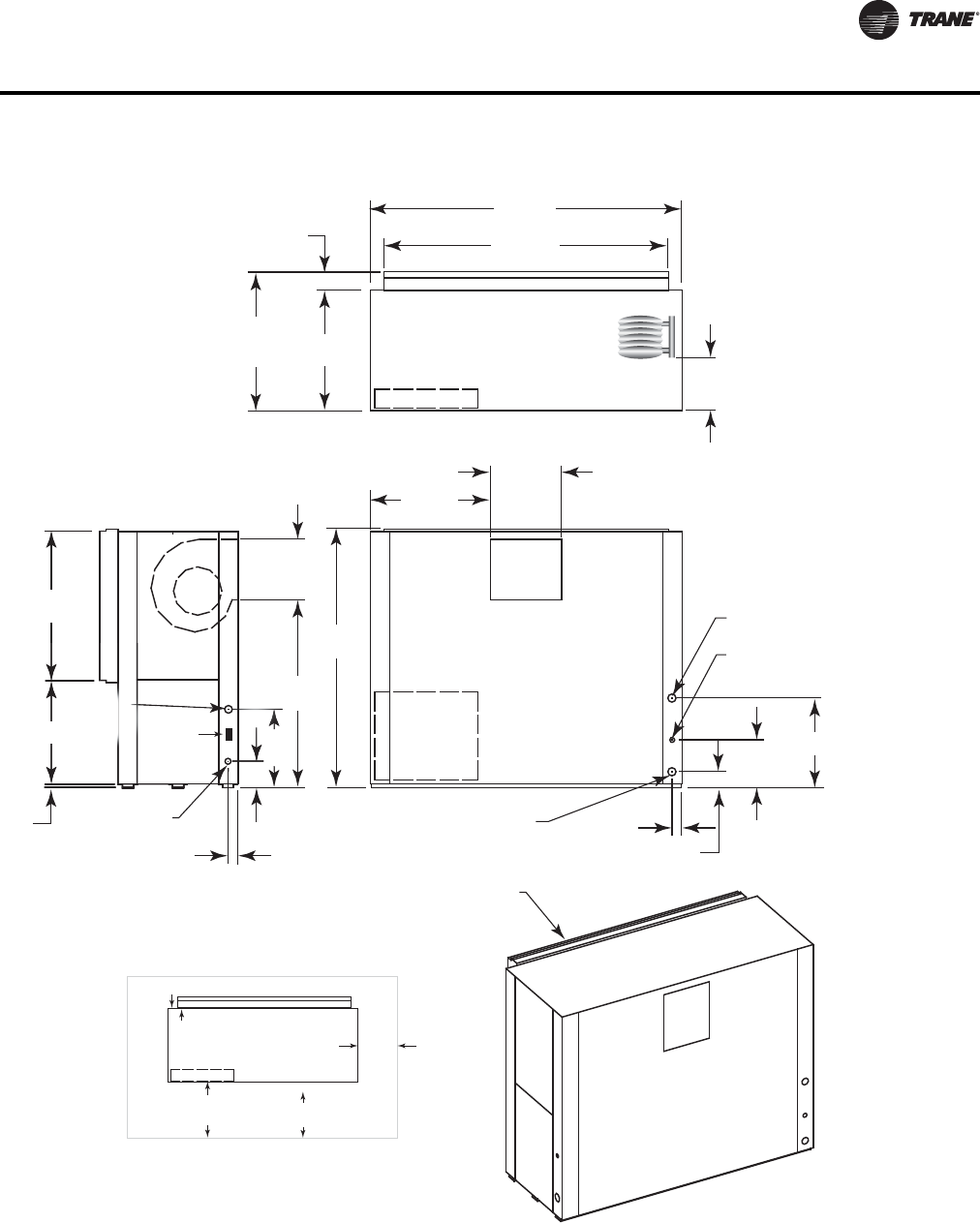
WSHP-PRC016E-EN 93
Dimensional Data
Figure 42. GEV 12½-15 tons (150-180) - back return/front supply
RETURN AIR
OPENING
W.I. 1 1/2"
(38) NPTI 2 5/8"
(67)
4 1/4"
(108)
12 1/2"
(318)
10"
(254)
23 1/2
(597)
DRAIN 3/4"
(19) NPTI
W.O. 1 1/2"
(38) NPTI
38 7/8"
(987)
27 1/8"
(537)
67 5/8"
(1718)
31 1/2"
(800)
18 5/8"
(473)
1"
(25.4)
HIGH VOLTAGE
7/8" (22) O.D.
20 1/2"
(521)
2
0
2
1/2
"
(521)
6 7/8" (175)
2 3/8"
(60)
15 7/8"
(403)
49 1/8"
(1248)
74 1/2"
(1892)
81 5/8"
(2073)
31 1/2"
(800)
36 1/4"
(921)
4 3/4"
(121)
CONTROL
BOX ACCESS
TOP VIEW
FRONT VIEW
SIDE VIEW
SERVICE CLEARANCE
27 1/8"
(537)
24 VOLT
1 1/8"
(29) O.D.
CONTROL BOX
UNIT FRONT
NEC REQ.
36" (914)
C.B.TO WALL
CLEARANCE
16" (406) TO
FILTER FRAME
FOR RETURN-AIR
MIN. SERVICE
CLEARANCE FOR
EITHER LEFT
OR RIGHT SIDE
IS 18" (457). FOR
FAN SHAFT REMOVAL,
A 22" (559) CLEARANCE
MUST BE PROVIDED
ON EITHER THE
LEFT OR RIGHT SIDE.
MIN. SERVICE ON BACK
FOR COMPRESSOR ACCESS IS 24”
WCI mounting
location
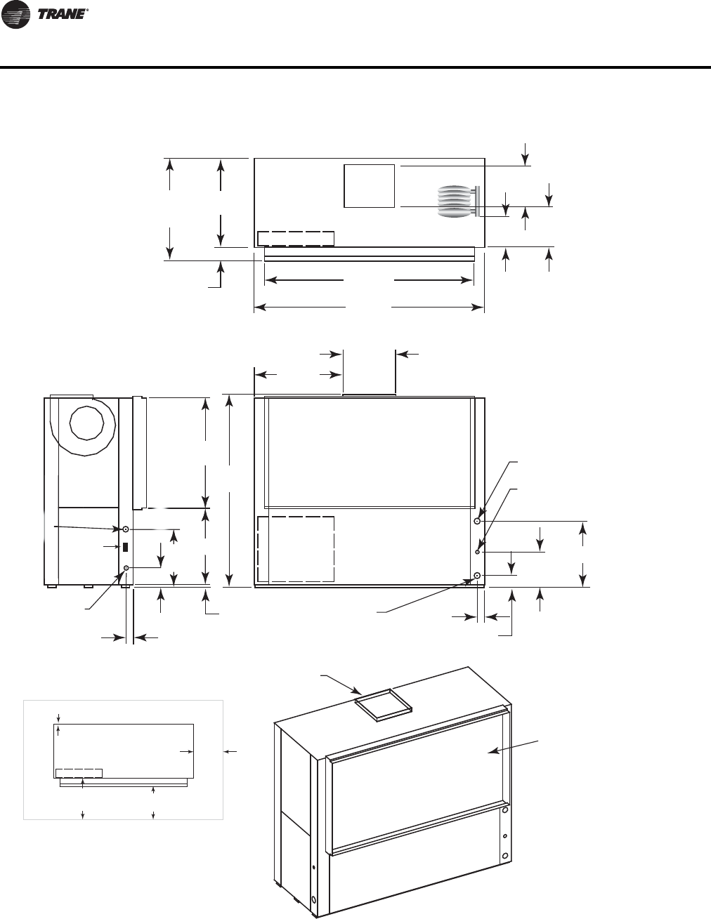
94 WSHP-PRC016E-EN
Dimensional Data
Figure 43. GEV 12½-15 tons (150-180) - front return/top supply
RETURN AIR
OPENING
SUPPLY OPENING
WITH 1" (25.4) DUCT
FLANGE
W.I. 1 1/2"
(38) NPTI 2 5/8"
(67)
4 1/4"
(108)
12 1/2"
(318)
23 1/2
(597)
15 7/8"
(403)
14 3/8"
(365)
DRAIN 3/4"
(19) NPTI
W.O. 1 1/2"
(38) NPTI
38 7/8"
(987)
27 1/8"
(537)
68"
(1727)
31 1/2"
(800)
18 5/8"
(473)
1"
(25.4)
HIGH VOLTAGE
7/8" (22) O.D.
20 1/2"
(521)
2 3/8"
(60)
74 1/2"
(1892)
81 5/8"
(2073)
31 1/2"
(800)
36 1/4"
(921)
4 3/4"
(121)
(98
27 1
(53
20 1/2
"
(
521
)
6 7/8" (175)
10"
(254)
CONTROL
BOX ACCESS
TOP VIEW
FRONT VIEW
SIDE VIEW
24 VOLT
1 1/8"
(29) O.D.
SERVICE CLEARANCE
CONTROL BOX
UNIT FRONT
NEC REQ.
36" (914)
C.B.TO WALL
CLEARANCE
16" (406) TO
FILTER FRAME
FOR RETURN-AIR
MIN. SERVICE
CLEARANCE FOR
EITHER LEFT
OR RIGHT SIDE
IS 18" (457). FOR
FAN SHAFT REMOVAL,
A 22" (559) CLEARANCE
MUST BE PROVIDED
ON EITHER THE
LEFT OR RIGHT SIDE.
MIN. SERVICE ON BACK
FOR COMPRESSOR ACCESS IS 24”
WCI mounting
location
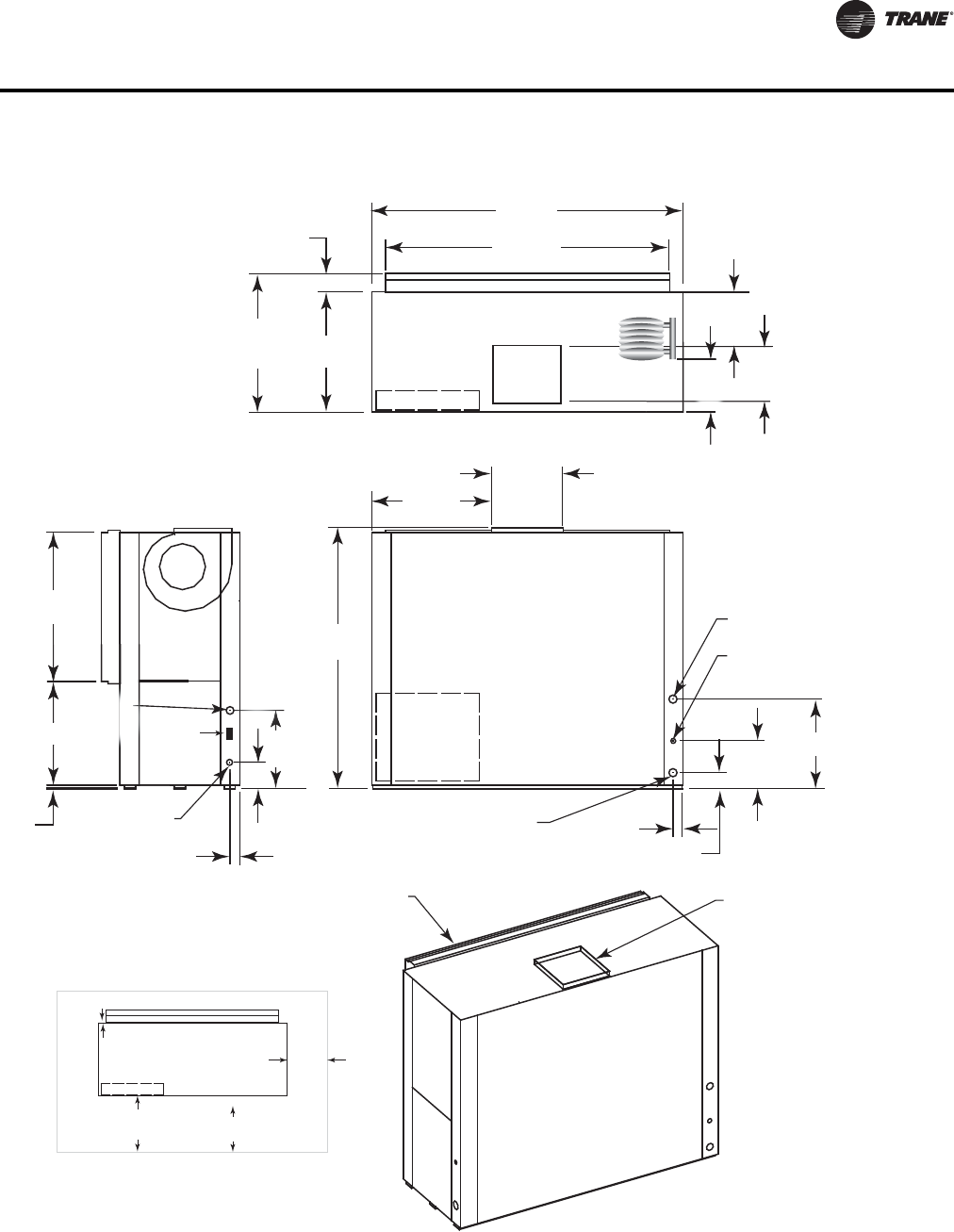
WSHP-PRC016E-EN 95
Dimensional Data
Figure 44. GEV 12½-15 tons (150-180) - back return/top supply
RETURN AIR
OPENING SUPPLY OPENING
WITH 1" (25.4) DUCT
FLANGE
W.I. 1 1/2"
(38) NPTI 2 5/8"
(67)
4 1/4"
(108)
12 1/2"
(318)
23 1/2
(597)
15 7/8"
(403)
14 3/8"
(365)
DRAIN 3/4"
(19) NPTI
W.O. 1 1/2"
(38) NPTI
38 7/8"
(987)
27 1/8"
(537)
68"
(1727)
31 1/2"
(800)
18 5/8"
(473)
1"
(25.4)
HIGH VOLTAGE
7/8" (22) O.D.
20 1/2"
(521)
2
0
2
1/2
"
(
521
)
6 7/8" (175)
2 3/8"
(60)
74 1/2"
(1892)
81 5/8"
(2073)
31 1/2"
(800)
36 1/4"
(921)
4 3/4"
(121)
CONTROL
BOX ACCESS
TOP VIEW
FRONT VIEW
SIDE VIEW
7 1/8"
(537)
24 VOLT
1 1/8"
(29) O.D.
1
5
7
/8
(40
3
10"
(254)
SERVICE CLEARANCE
CONTROL BOX
UNIT FRONT
NEC REQ.
36" (914)
C.B.TO WALL
CLEARANCE
16" (406) TO
FILTER FRAME
FOR RETURN-AIR
MIN. SERVICE
CLEARANCE FOR
EITHER LEFT
OR RIGHT SIDE
IS 18" (457). FOR
FAN SHAFT REMOVAL,
A 22" (559) CLEARANCE
MUST BE PROVIDED
ON EITHER THE
LEFT OR RIGHT SIDE.
MIN. SERVICE ON BACK
FOR COMPRESSOR ACCESS IS 24”
WCI mounting
location
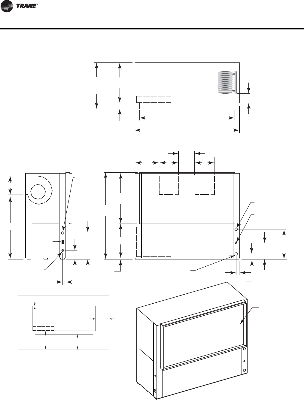
96 WSHP-PRC016E-EN
Dimensional Data
Figure 45. GEV 20-25 tons (240-300) - front return/back supply
RETURN AIR
OPENING
W.I. 2"
(51) NPTI 2 5/8"
(67)
4 1/4"
(108)
12 1/2"
(318)
E
DRAIN 3/4"
(19) NPTI
W.O. 2"
(51) NPTI
38 7/8"
(987)
27 1/8"
(537)
67 5/8"
(1718)
19 1/8"
(486)
AA
C
1"
(25.4)
HIGH VOLTAGE
7/8" (22) O.D.
20 1/2"
(521)
2
0 1
/
2
"
(
521
)
6 7/8" (175)
2 3/8"
(60)
B
D
24 VOLT
1 1/8" (29) O.D.
74 1/2"
(1892)
81 5/8"
(2073)
31 1/2"
(800)
36 1/4"
(921)
4 3/4"
(121)
6 1/4"
(159)
CONTROL
BOX ACCESS
TOP VIEW
FRONT VIEW
SIDE VIEW
SERVICE CLEARANCE
CONTROL BOX
UNIT FRONT
NEC REQ.
36" (914)
C.B.TO WALL
CLEARANCE
16" (406) TO
FILTER FRAME
FOR RETURN-AIR
MIN. SERVICE
CLEARANCE FOR
EITHER LEFT
OR RIGHT SIDE
IS 18" (457). FOR
FAN SHAFT REMOVAL,
A 22" (559) CLEARANCE
MUST BE PROVIDED
ON EITHER THE
LEFT OR RIGHT SIDE.
MIN. SERVICE ON BACK
FOR COMPRESSOR ACCESS IS 24”
WCI mounting
location
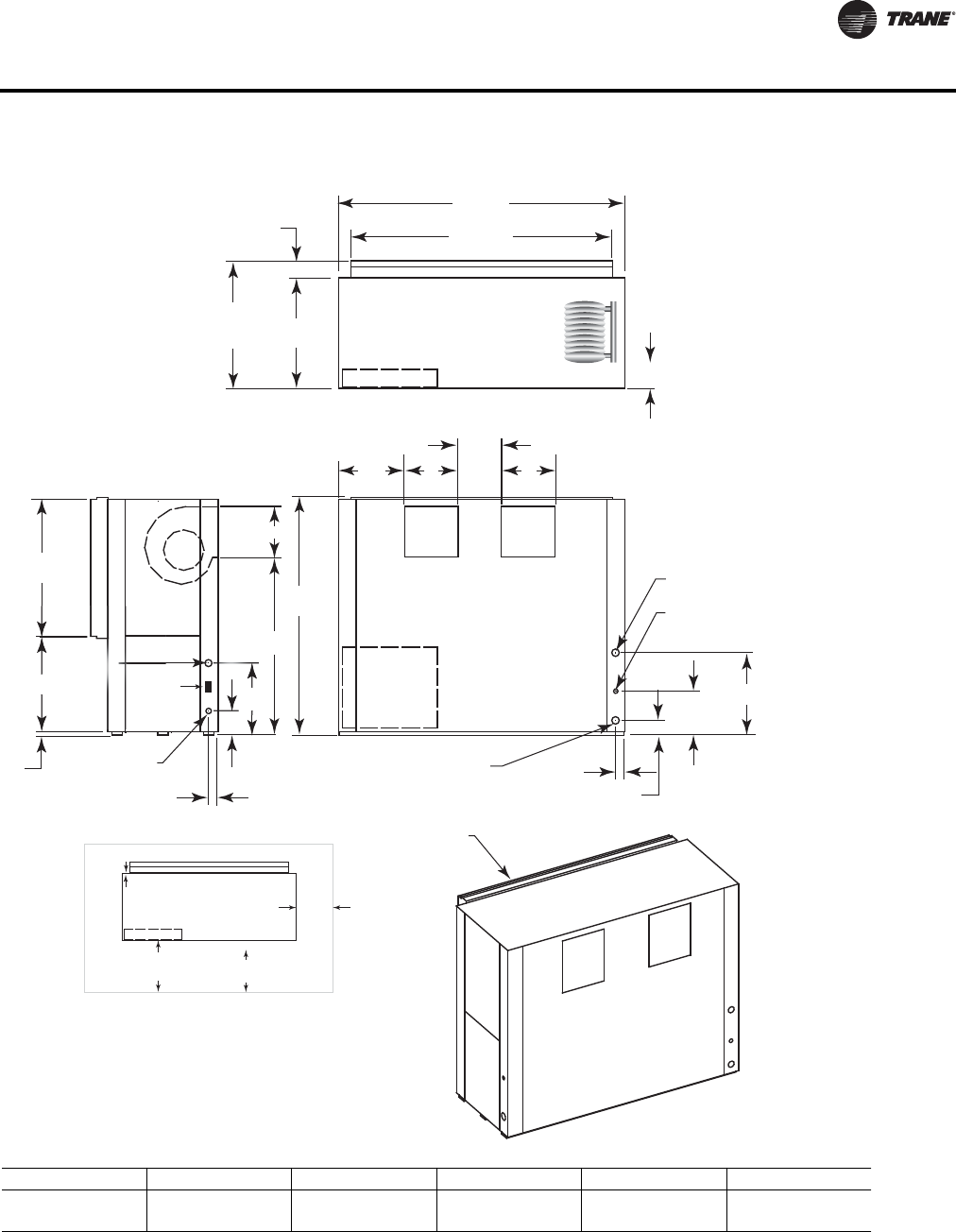
WSHP-PRC016E-EN 97
Dimensional Data
Figure 46. GEV 20-25 tons (240-300) - back return/front supply
W.I. 2"
(51) NPTI 2 5/8"
(67)
4 1/4"
(108)
12 1/2"
(318)
E
DRAIN 3/4"
(19) NPTI
W.O. 2"
(51) NPTI
38 7/8"
(987)
27 1/8"
(537)
67 5/8"
(1718)
19 1/8"
(486)
AA
C
1"
(25.4)
HIGH VOLTAGE
7/8" (22) O.D.
20 1/2"
(521)
6
(
20 1
/
2"
(521)
6 7/8" (175)
2 3/8"
(60)
B
D
74 1/2"
(1892)
81 5/8"
(2073)
31 1/2"
(800)
36 1/4"
(921)
4 3/4"
(121)
6 1/4"
(159)
CONTROL
BOX ACCESS
TOP VIEW
FRONT VIEW
SIDE VIEW
RETURN AIR
OPENING
1/8"
537)
24 VOLT
1 1/8"
(29) O.D.
SERVICE CLEARANCE
CONTROL BOX
UNIT FRONT
NEC REQ.
36" (914)
C.B.TO WALL
CLEARANCE
16" (406) TO
FILTER FRAME
FOR RETURN-AIR
MIN. SERVICE
CLEARANCE FOR
EITHER LEFT
OR RIGHT SIDE
IS 18" (457). FOR
FAN SHAFT REMOVAL,
A 22" (559) CLEARANCE
MUST BE PROVIDED
ON EITHER THE
LEFT OR RIGHT SIDE.
MIN. SERVICE ON BACK
FOR COMPRESSOR ACCESS IS 24”
WCI mounting
location
Unit GEV A (in.) B (in.) C (in.) D (in.) E (in.)
240 15-5/8 (397) 13-1/2 (341) 12 (305) 51-5/8 (1310) 20-7/8 (530)
300 (Std. Static) 14-3/4 (375) 15-7/8 (403) 13-7/8 (352) 49-1/8 (1248) 23-1/2 (597)
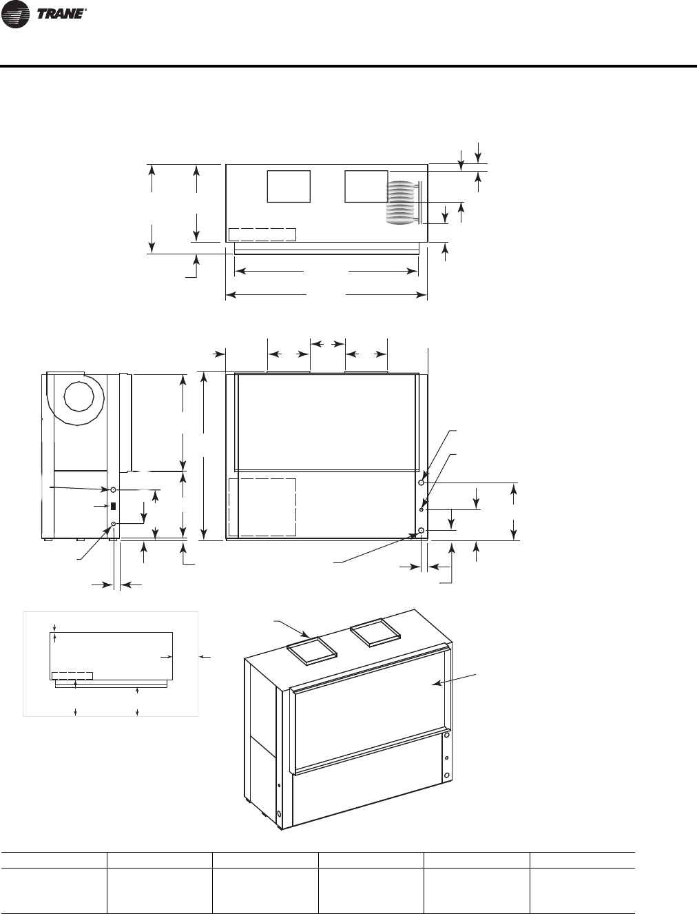
98 WSHP-PRC016E-EN
Dimensional Data
Figure 47. GEV 20-25 tons (240-300) - front return/top supply
RETURN AIR
OPENING
SUPPLY OPENINGS
WITH 1" (25.4) DUCT
FLANGE
W.I. 2"
(51) NPTI 2 5/8"
(67)
4 1/4"
(108)
12 1/2"
(318)
D
B
DRAIN 3/4"
(19) NPTI
W.O. 2"
(51) NPTI
38 7/8"
(987)
27 1/8"
(537)
68"
(1727)
A
C
A
1"
(25.4)
HIGH VOLTAGE
7/8" (22) O.D.
20 1/2"
(521)
2 3/8"
(60)
74 1/2"
(1892)
81 5/8"
(2073)
31 1/2"
(800)
36 1/4"
(921)
4 3/4"
(121)
(98
27 1
(53
2
0 1/2"
(
521
)
6 7/8" (175)
19 1/8"
(486)
1 1/4" (32)
6 1/4"
(159)
CONTROL
BOX ACCESS
TOP VIEW
FRONT VIEW
SIDE VIEW
24 VOLT
1 1/8"
(29) O.D.
SERVICE CLEARANCE
CONTROL BOX
UNIT FRONT
NEC REQ.
36" (914)
C.B.TO WALL
CLEARANCE
16" (406) TO
FILTER FRAME
FOR RETURN-AIR
MIN. SERVICE
CLEARANCE FOR
EITHER LEFT
OR RIGHT SIDE
IS 18" (457). FOR
FAN SHAFT REMOVAL,
A 22" (559) CLEARANCE
MUST BE PROVIDED
ON EITHER THE
LEFT OR RIGHT SIDE.
MIN. SERVICE ON BACK
FOR COMPRESSOR ACCESS IS 24”
WCI mounting
location
Unit GEV A (in.) B (in.) C (in.) D (in.) E (in.)
240 15-5/8 (397) 13-1/2 (341) 12 (305) 51-5/8 (1310) 20-7/8 (530)
300 (Std. Static) 14-3/4 (375) 15-7/8 (403) 13-7/8 (352) 49-1/8 (1248) 23-1/2 (597)
300 (High Static) 15-5/8 (397) 13-1/2 (341) 12 (305) 51-5/8 (1310) 23-1/2 (597)
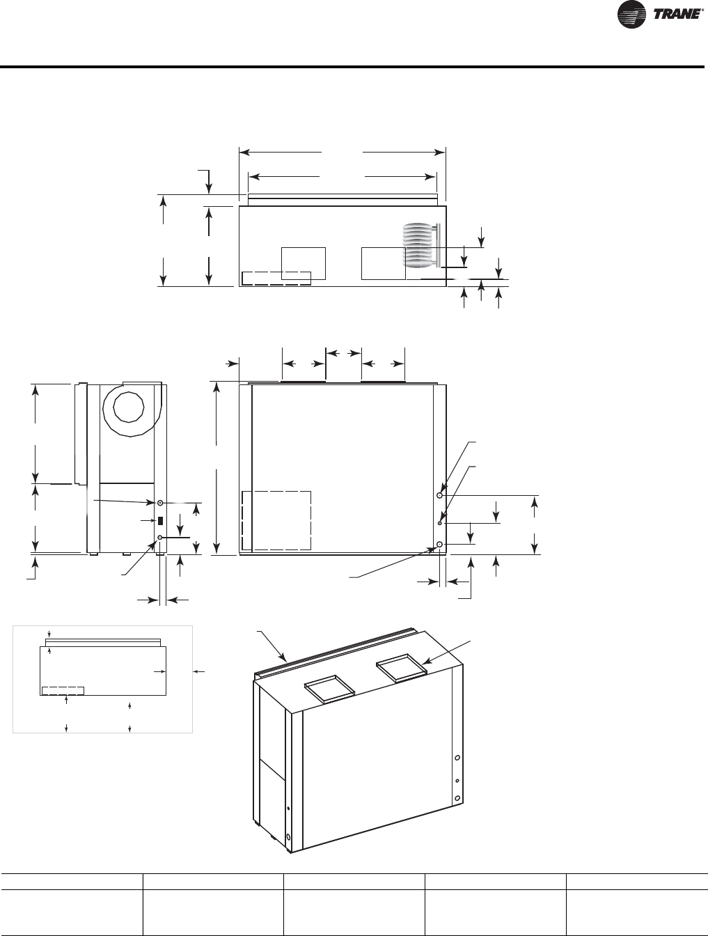
WSHP-PRC016E-EN 99
Dimensional Data
Figure 48. GEV 20-25 tons (240-300) - back return/top supply
W.I. 2"
(51) NPTI 2 5/8"
(67)
4 1/4"
(108)
12 1/2"
(318)
D
B
DRAIN 3/4"
(19) NPTI
W.O. 2"
(51) NPTI
38 7/8"
(987)
27 1/8"
(537)
68"
(1727)
A
C
A
1"
(25.4)
HIGH VOLTAGE
7/8" (22) O.D.
20 1/2"
(521)
2 3/8"
(60)
74 1/2"
(1892)
81 5/8"
(2073)
31 1/2"
(800)
36 1/4"
(921)
4 3/4"
(121)
6
8
"
(
17
2
2
0 1
/
2
"
(
521
)
6 7/8" (175)
19 1/8"
(486)
1 1/4" (32)
RETURN AIR
OPENING SUPPLY OPENING
WITH 1" (25.4) DUCT
FLANGE
B
1 1/
4
6 1/4"
(159)
SERVICE CLEARANCE
CONTROL BOX
UNIT FRONT
NEC REQ.
36" (914)
C.B.TO WALL
CLEARANCE
16" (406) TO
FILTER FRAME
FOR RETURN-AIR
MIN. SERVICE
CLEARANCE FOR
EITHER LEFT
OR RIGHT SIDE
IS 18" (457). FOR
FAN SHAFT REMOVAL,
A 22" (559) CLEARANCE
MUST BE PROVIDED
ON EITHER THE
LEFT OR RIGHT SIDE.
CONTROL
BOX ACCESS
TOP VIEW
FRONT VIEW
SIDE VIEW
24 VOLT
1 1/8"
(29) O.D.
MIN. SERVICE ON BACK
FOR COMPRESSOR ACCESS IS 24”
WCI mounting
location
Unit GEV A (in.) B (in.) C (in.) D (in.)
240 15-5/8 (397) 13-1/2 (341) 12 (305) 20-7/8 (530)
300 (Std. Static) 14-3/4 (375) 15-7/8 (403) 13-7/8 (352) 23-1/2 (597)
300 (High Static) 15-5/8 (397) 13-1/2 (341) 12 (305) 23-1/2 (597)
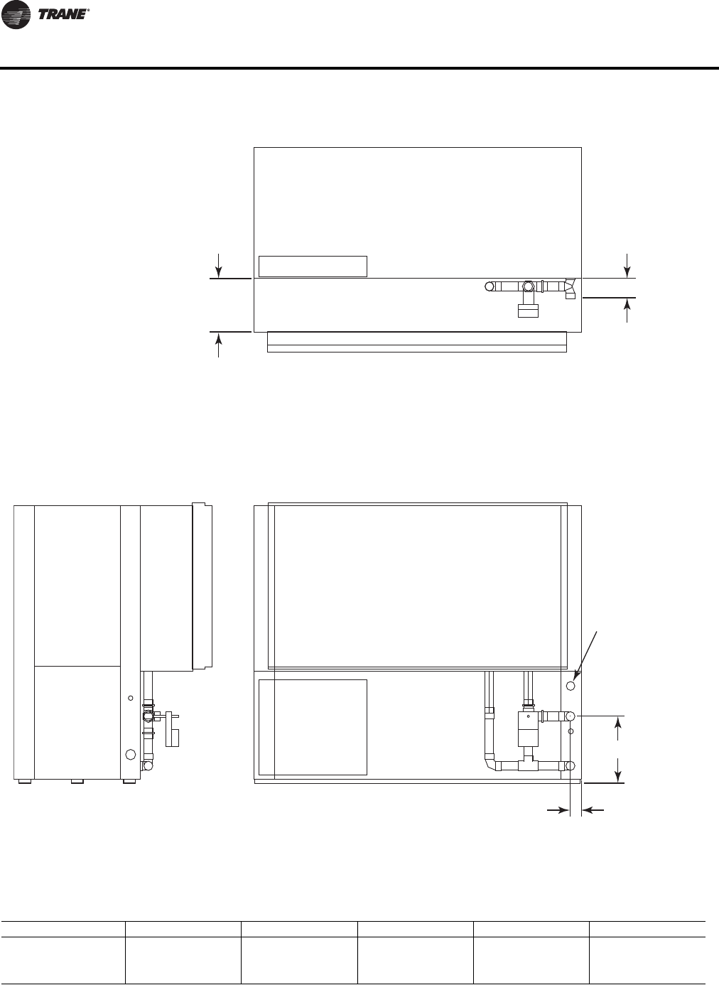
100 WSHP-PRC016E-EN
Dimensional Data
Figure 49. GEV 12½-25 tons (150-300) - waterside economizer(a)
(a)See Figure 50, p. 101 for waterside economizer coil piping diagram.
TOP VIEW
FRONT VIEWSIDE VIEW
13"
(330)
D
C
A = TO FIELD
RETURN PIPING
2 3/4"
(70)
Unit GEV A (in.) B (in.) C (in.) D (in.) Operating Weight
150,180 1-1/2 (38) 1-5/8 (41) 15-7/8 (403) 4-3/8 (111) 275 lb (125 kg)
240 2 (51) 2-1/8 (54) 16-1/4 (413) 4-7/8 (124) 310 lb (141 kg)
300 2 (51) 2-1/8 (54) 16-1/4 (413) 4-7/8 (124) 395 lb (179 kg)
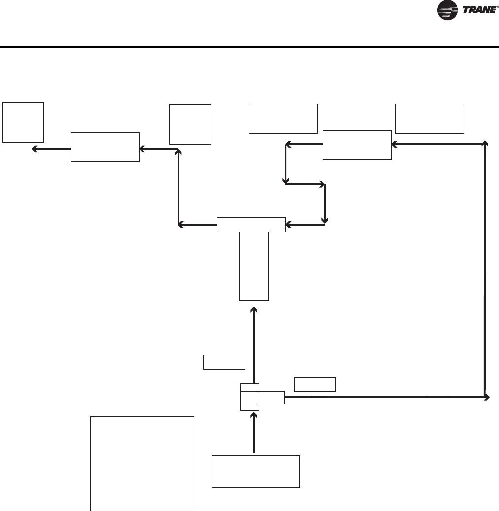
WSHP-PRC016E-EN 101
Dimensional Data
Figure 50. Waterside economizer coil piping diagram
Unit
Water
Outlet Unit Heat
Exchanger
Unit
Water
Inlet
TEE
WSE Coil
Outlet WSE
Coil
WSE Coil
Inlet
Port A
3 Way Valve
Port AB
Port B
Entering Water
Please match the
entering water
port marking with
the marking label
on the valve prior
to using this
diagram.
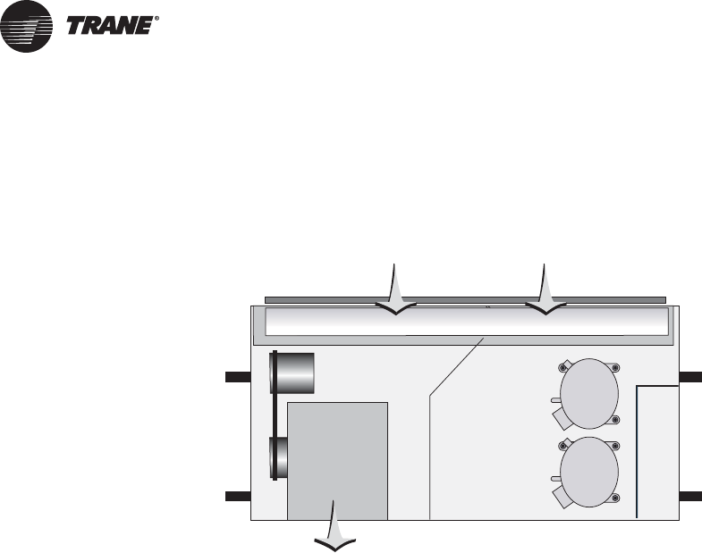
102 WSHP-PRC016E-EN
Weights
Weight Distribution
Approximate weight distribution for the GEH model is indicated in the graphic below.
Tolerance on the weights determined are ±15%.
Total weights for each unit are available in “General Data,” p. 15
COMPRESSOR
CONTROL
BOX
INTERNAL AIR COIL
PLASTIC DRAIN PAN
BLOWER
HOUSING, MOTOR,
BELT AND SHEAVE
35%
20%
30%
15%
COMPRESSOR
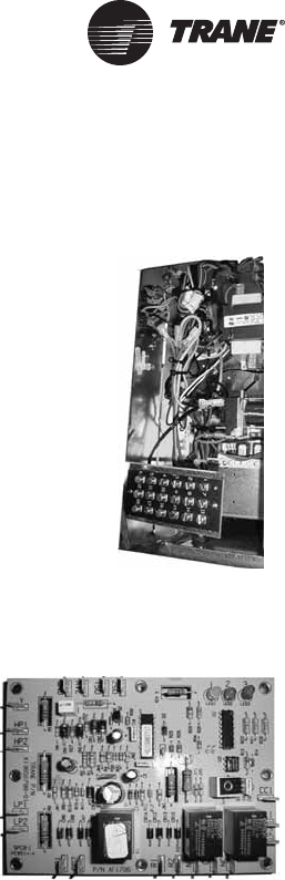
WSHP-PRC016E-EN 103
Controls
Deluxe 24V features include:
Anti-short Cycle Timer
The anti-short cycle timer provides a three minute time delay between compressor stop and
compressor restart.
Brown-out Protection
The brown-out protection function measures the input voltage to the controller and halts the
compressor operation. Once a brown-out situation has occurred, the anti-short cycle timer will
become energized.The general fault contact will not be affected by this condition.The voltage will
continue to be monitored until the voltage increases.The compressors will be enabled at this time
if all start-up time delays have expired, and all safeties have been satisfied.
Compressor Disable
The compressor disable relay provides a temporary disable in compressor operation.The signal
would be provided from a water loop controller in the system. It would disable the compressor
because of low water flow, peak limiting or if the unit goes into an unoccupied state. Once the
compressor has been disabled, the anti-short cycle time period will begin. Once the compressor
disable signal is no longer present, and all safeties are satisfied, the control will allow the
compressor to restart.
Diagnostics
Component device connections to the microprocessor board are referenced in “Deluxe 24V Control
Board - Microprocessor Design,” p. 103.Three LEDs (light emitting diodes) are provided for
Deluxe 24V Electronic Controls
The deluxe 24V electronic unit control provides component protection devices
to maximize system performance to extend the system life. Each device, is
factory mounted, wired, and tested in the unit. Features include a 75VA
transformer, compressor contactor, compressor lockout relay, compressor
run capacitor (for 1-phase units only), anti-short cycle compressor protection,
random start delay, brown-out protection, low pressure time delay, low
pressure switch, high pressure switch, compressor delay on start, reversing
valve coil , multi-speed fan motor, soft lockout mode, and 18-pole terminal
strip (for low voltage field wiring). Optional features include condensate
overflow, hot gas reheat for dehumidification, electric heat and compressor
enable.
Deluxe 24V Control Board - Microprocessor Design
TheTrane microprocessor board is factory wired to a terminal
strip to provide all necessary terminals for field connections.
The 24V deluxe design is a microprocessor-based control board
conveniently located in the control box.The board is unique to
Trane water-source products and is designed to control the unit as
well as provide outputs for unit status and fault detection.
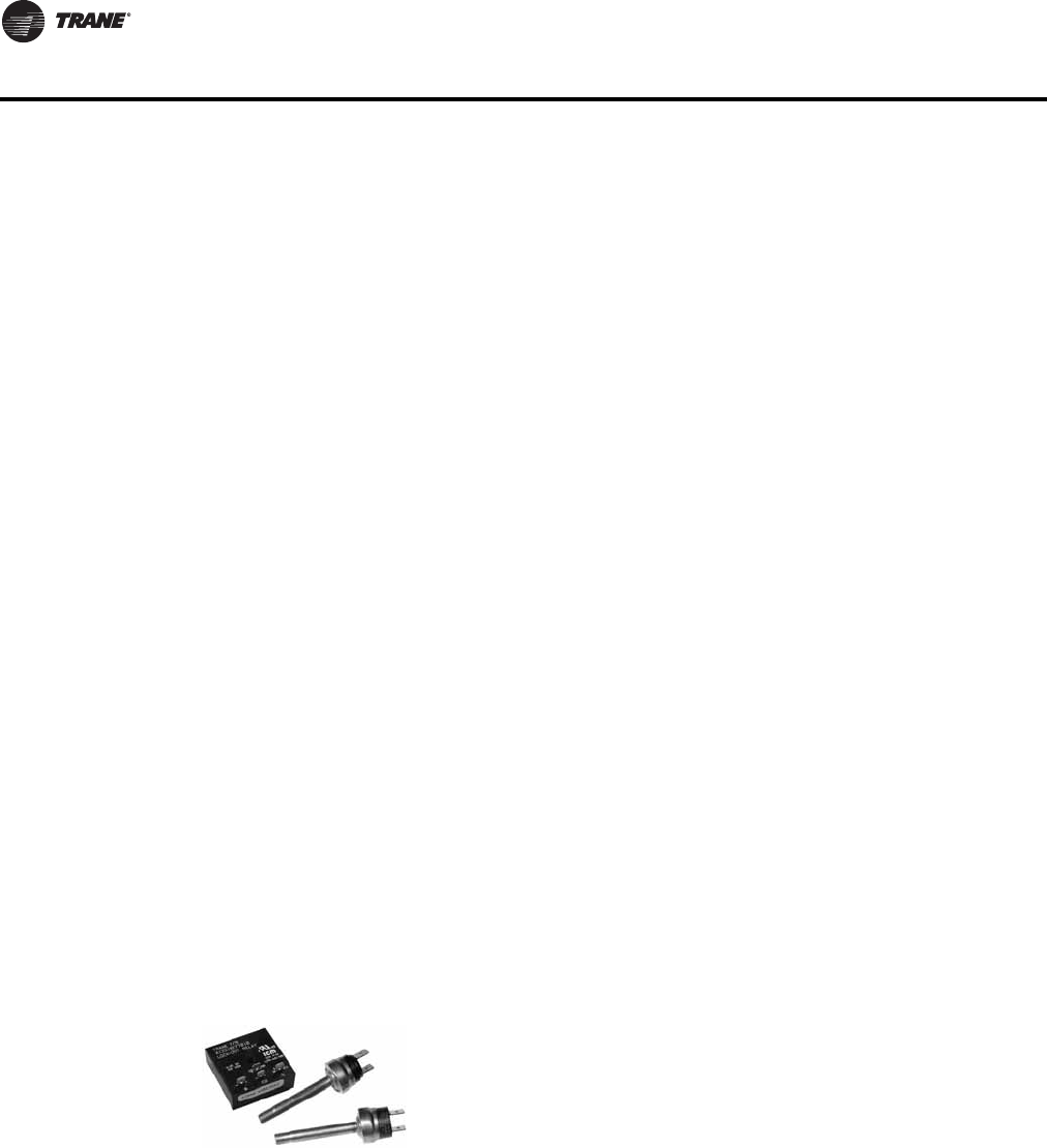
104 WSHP-PRC016E-EN
Controls
indicating the operating mode of the controller. See the unit IOM for diagnostics or troubleshooting
through the use of the LEDs.
Generic Relay
The generic relay is provided for field use. Night setback or pump restart are two options that may
be wired to the available relay.
An external Class II 24VAC signal will energize the relay coil on terminals R1 and R2.Terminals C
(common), NO (normally open), and NC (normally closed) will be provided for the relay contacts.
Random Start
The random start relay provides a time delay start-up of the compressor when cycling in the
occupied mode. A new start delay time between 3 and 10 seconds is applied each time power is
enabled to the unit.
Safety Control
The deluxe microprocessor receives separate input signals from the refrigerant high pressure
switch, low suction pressure switch and condensate overflow.
In a high pressure situation, the compressor contactor is de-energized, which suspends
compressor operation.The control will go into soft lockout mode initializing a three minute time
delay and a random start of 3 to 10 second time delays. Once these delays have expired, the unit
will be allowed to run. If a high pressure situation occurs within one hour of the first situation, the
control will be placed into a manual lockout mode, halting compressor operation, and initiating the
general alarm.
In a low temperature situation, the low pressure switch will transition open after the compressor
starts. If the switch is open for 45 seconds during compressor start, the unit will go into soft lockout
mode initializing a three minute time delay and a random start of 3 to 10 second time delays. Once
these delays have expired, the unit will be allowed to run. If the low pressure situation occurs again
within 30 minutes, and the device is open for more than 45 seconds, the control will be placed into
a manual lockout mode, halting compressor operation, and initiating the general alarm.
In a condensate overflow situation, the control will go into manual lockout mode, halting
compressor operation, and initiating the general alarm.
The general alarm is initiated when the control goes into a manual lockout mode for either high
pressure, low pressure or condensate overflow conditions.
Safety Devices
System safety devices are provided through the use of low/high
pressure switches in the refrigeration circuit to help prevent compressor
damage.
The low pressure switch is set to activate at refrigerant pressures of 40
psig to fit most applications.
In cases where a low charge, or excessive loss of charge occurs, each
compressor comes equipped with an external overload device to halt the compressor operation.
The high pressure switch prevents compressor operation during high or excessive discharge
pressures that exceed 650 psig.
A lockout relay provides the mechanical communication of the low and high pressure switches to
prevent compressor operation if the unit is under low or high refrigerant circuit pressure, or during
a condensate overflow condition.The lockout relay may be reset at the thermostat, or by cycling
power to the unit.
General alarm is accomplished through the lockout relay and will drive dry contacts only, and
cannot be used to drive field installed control inputs.
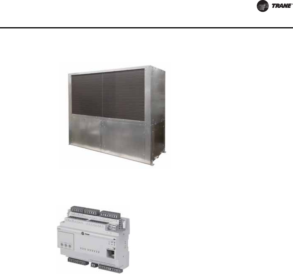
WSHP-PRC016E-EN 105
Controls
Tracer™ Direct Digital Controllers DDC Controls
TheTracer™ UC400 and ZN524 direct digital control (DDC)
systems are specifically designed for single and dual circuited
water-source equipment to provide control of the entire unit,
as well as outputs for unit status and fault detection. Each
device is factory installed, commissioned, and tested to ensure
the highest level of quality in unit design.
Each of the controller's features and options were selected to
coordinate with the unit hardware to provide greater energy
efficiency and equipment safety to prolong the equipment life.
Trane WSHP with DDC controllers features include 75 VA
transformer, compressor contactor, compressor lockout relay,
compressor run capacitor (for 1-phase units only), random start delay, heating/cooling status,
occupied/unoccupied mode, low pressure switch, high pressure switch, fan and filter status,
reversing valve coil (for heating and cooling units), multi-speed fan motor, 18-pole terminal strip
(for low voltage field wiring) and optional: condensate overflow. Additional features include water
isolation valve support (for variable speed pumping), as well as optional features including
boilerless control for electric heat, waterside economizer and hot gas reheat for dehumidification.
Tracer™ ZN524TheTracer™ ZN524 is LonTalk® certified. It is capable of working with, and talking
to other LonTalk® certified controllers providing the building owner more choices, and the design
engineers more flexibility to meet the challenges of building automation.
Tracer™ UC400TheTracer™ UC400 is a BTL Listed BACnet controller that can operate stand-
alone or within a Building Automations system such asTracer™ SC.
Tracer™ UC400 / ZN524 functions include:
Boilerless Control Electric Heat and Supplemental Electric Heat
The controller supports a single stage of boilerless electric heat operation or concurrent heating.
When the unit is configured for boilerless control, the EWT will be used to determine whether DX
heating should be disabled and the electric heater enabled. When these conditions are met, the
Stand-alone System
The 24V controller may be applied as a stand-
alone control system.The stand-alone design
provides accurate temperature control directly
through a wall-mounted mercury bulb or
electronic thermostat.This system set-up may
be utilized in a replacement design where a
single unit retrofit is needed. It may be easily
interfaced with a field provided control system
by way of the factory installed 18-pole terminal
strip.This stand-alone control is frequently
utilized on small jobs where a building
controller may not be necessary, or where field
installed direct digital controls are specified.
This type of control design does require a
constant flow of water to the water source heat
pump.With a positive way to sense flow to the
unit, the units safety devices will trigger the
unit off.The stand-alone system design
provides a low cost option of installation while
still allowing room control for each unit.
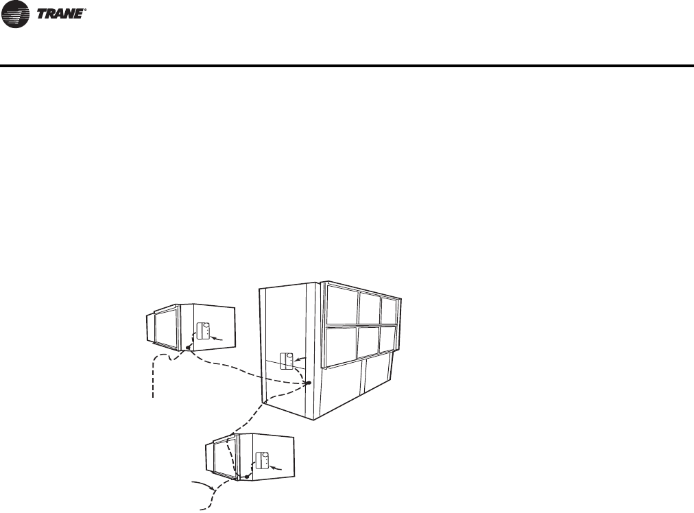
106 WSHP-PRC016E-EN
Controls
isolation valve(s) are driven open for three minutes and the entering water temperature reading
is taken.The determination as to whether or not to utilize electric heat will be made and the
controller will take appropriate action. If boilerless electric heat is enabled, then the isolation valve
will be closed, shutting down the water flow to the unit.
When the unit is configured for concurrent operation of DX heating (compressor in heat pump
mode) and electric heat, the electric heat will act as a second stage of heat for single compressor
units, and a third stage of heat for dual compressor units.
Note: With concurrent (or supplemental) electric heat, the electric heater is field provided.
Integrating the controller on water-source equipment, and tying it to aTracer™ SC or other building
automation system provides a complete building management system. With a Building
Automation system like aTracer™ SC, the system can initiate an alarm on a loss of performance
on equipment malfunctions; allowing problems to be handled in a timely manner before
compromising comfort.
This type of application would most commonly be used for a large space(s) that may require more
than one unit. In addition to this application design, the controller provides a way for units located
within the same space to share the same zone sensor to prevent units from simultaneously heating
and cooling in the same space.
Compressor Operation
The compressor is cycled on and off to meet heating or cooling zone demands. Single and dual
compressor units use the unit capacity and pulse width modulation (PWM) logic along with
minimum on/off timers to determine the compressor's operation.The compressor is controlled ON
for longer periods as capacity increases and shorter periods as capacity decreases.
Condensate Overflow
When condensate reaches the trip point, a condensate overflow signal generates a diagnostic
which disables the fan, unit water valves (if present), and compressor.The unit will remain in a
halted state until the condensation returns to a normal level. At this time, the switch in the drain
pan will automatically reset. However, the controller's condensate overflow diagnostic must be
manually reset to clear the diagnostic and restart the unit.
Data Sharing
TheTracer™ UC400 and ZN524 controller is capable of sending or receiving data (setpoints, fan
request, or space temperature) to and from other controllers on the communication link.This
Building Control Advantages
TheTracer™ UC400 or ZN524 controllers have
the ability to share information with one or
several units on the same communication link.
This sharing of information is made possible
via a twisted pair of wire and a building
automation system or throughTrane's
Rover™ service tool.
An advantage of installing a UC400 or ZN524 is
its capability to work with other BACnet or
LonTalk® certified controllers.This provides
greater flexibility to the building owner, as well
as greater flexibility in design.
ZONE SENSOR
ZONE SENSOR
TRACER SUMMIT
SINGLE
COMMUNICATION
WIRE
(FIELD PROVIDED)
TO
OTHER
UNITS
ZONE SENSOR

WSHP-PRC016E-EN 107
Controls
allows multiple units to share a common space temperature sensor in both stand-alone and
building automation applications.
Dehumidification
Dehumidification for the single and dual circuited water-source heat pump is applicable with the
UC400 and ZN524 controller. The controller is capable of directing one stage of DX cooling in
conjunction with one stage of reheat (hot gas reheat).
Dehumidification can only occur when the controller is in the cooling mode.A humidity transmitter
is used to measure the zone's relative humidity (RH), then compares the zone relative humidity to
the relative humidity enable/disable setpoint parameters.The dehumidification enable and disable
points are configurable.
Fan Operation
The supply air fan operates at the factory wired speed in the occupied or occupied standby mode.
When switch is set to AUTO, the fan is configured for cycling ON with heating or cooling. In heat
mode, the fan will run for 30 seconds beyond compressor shutdown in both occupied and
unoccupied mode.
Filter Maintenance Timer
The controller's filter status is based on the unit fan's cumulative run hours.The controller
compares the fan run time against an adjustable fan run hours limit and recommends unit
maintenance as required.
High and Low Pressure Safety Controls
TheTracer™ ZN524 controller detects the state of the high pressure or low pressure switches.
When a fault is sensed by one of these switches, the corresponding message is sent to the
controller to be logged into the fault log. When the circuit returns to normal, the high pressure
control and low pressure control automatically reset. If a second fault is detected within a thirty-
minute time span, the unit must be manually reset.
Occupancy Modes
The four operations of theTracer™ ZN524 controller include occupied, occupied standby, occupied
bypass and unoccupied.
In an occupied situation, the controller uses occupied heating and cooling setpoints to provide
heating and cooling to the building.This occupied operation is normally used during the daytime
hours when the building is at the highest occupancy level.
In an occupied standby situation, the controllers heating and cooling setpoints are usually wider
than the occupied setpoints.This occupied standby operation is used during daytime hours when
people are not present in the space (such as lunchtime or recess). To determine the space
occupancy, an occupancy sensor is applied.
In an unoccupied situation, the controller assumes the building is vacant, which normally falls in
evening hours when a space may be empty. In the unoccupied mode, the controller uses the default
unoccupied heating and cooling setpoints stored in the controller. When the building is in
unoccupied mode, individual units may be manually placed into timed override of the unoccupied
mode at the units wall sensor. During timed override, the controller interprets the request and
initiates the occupied setpoint operation, then reports the effective occupancy mode as occupied
bypass.
In the occupied bypass mode, the controller applies the occupied heating and cooling setpoint for
a 120 minute time limit.

108 WSHP-PRC016E-EN
Controls
Random Start
To prevent all of the units in a building from energizing major loads at the same time, the controller
observes a random start from 0 to 25 seconds.This timer halts the controller until the random start
time expires.
Reversing Valve Operation
For cooling, the reversing valve output is energized simultaneously with the compressor. It will
remain energized until the controller turns on the compressor for heating. At this time, the
reversing valve moves to a de-energized state. In the event of a power failure or controller OFF
situation, the reversing valve output will default to the heating (de-energized) state.
Entering Water Temperature Sampling
The controller will sample the entering water temperature to determine proper control action for
units equipped with boilerless electric heat or waterside economizer.
Waterside Economizer
Entering water temperature (EWT) sampling will automatically occur at power up when the unit is
equipped with a waterside economizer (WSE).The EWT is used to determine if economizing is
feasible.When the conditions are met, the isolation valve(s) are driven open for three minutes and
the EWT reading is taken.The determination as to whether or not the economizer can be enabled
will be made and the controller will take appropriate action.The isolation valve will remain open
regardless if the WSE or the DX cooling is enabled.
The unit's waterside economizer will contain a 2-position water valve wired to the controller.The
economizing water coil will be optimized to provide 100% of the unit capacity at 80.6°F/66.2°F return
air temperature with 45°F entering water.The flow rate is established at 86 F entering water
temperature and 96°F leaving water temperature.
Low leaving air protection will be furnished to protect the unit against delivering air that is cold
enough to sweat discharge air grilles. Coil icing protection will also be provided.
Waterside economizer cooling will be active during occupied, unoccupied and standby cooling
modes.
Water Isolation Valves
Variable speed pumping systems are supported by the controller when water isolation valves are
present. Up to two isolation valves are supported by the controller (one for each compressor
circuit).
The valves are normally closed unless DX heating, DX cooling, waterside economizer or
dehumidification is requested.When the isolation valves are driven open for operation, the outputs
will be driven for 20 seconds to ensure adequate water flow before the compressor outputs are
energized. Once an isolation valve has been opened, it will remain open for a 10 minute minimum
to reduce excessive cycling of the valve.
Wireless Comm Interface (WCI)
TheTrane® wireless Comm Interface (WCI) enables wireless communication between system
controls, unit controls, and wireless sensors for the new generation ofTrane ®control products.The
WCI replaces the need for communication wire in all system applications.
Note: See BAS-SVX40*-EN, Installation, Operation and Maintenance, Wireless Comm for more
information.
Quantity of WCIs per Network. EachTrane® wireless network can have a total of 31 WCIs (30
member WCIs plus 1 coordinator WCI). Each network requires one WCI to function as network
coordinator.
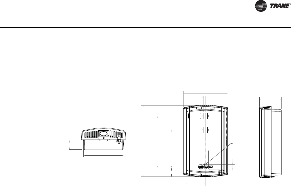
WSHP-PRC016E-EN 109
Controls
Quantity of Networks per Tracer™ Wireless Zone Sensors. The WCI also communicates
withTrane wireless zone sensors, eliminating the need for analog receivers.
Wired Zone Sensors. Systems using Wireless Comm can also use wired zone sensors.
Dimensions
Specifications
Operating Temperature
-40 to 158ºF (-40 to 70ºC)
Storage temperature
-40 to 185ºF (-40 to 85°C)
Storage and operating humidity range
5% to 95% relative humidity (RH), non-condensing
Voltage
24 Vac/Vdc nominal ± 10%. If using 24 Vac, polarity must be maintained.
Receiver power consumption
<2.5 VA
Housing material
Polycarbonate/ABS (suitable for plenum mounting), UV protected, UL 94: 5 VA flammability rating
Mounting
3.2 in (83 mm) with 2 supplied mounting screws
Range
Open range: 2,500 ft (762 m) with packet error rate of 2%
Indoor:Typical range is 200 ft (61 mm); actual range is dependent on the environment. See BAS-
SVX55*-EN for more detail.
Note: Range values are estimated transmission distances for satisfactory operation. Actual
distance is job specific and must be determined during site evaluation. Placement of WCI
is critical to proper system operation. In most general office space installations, distance is
2.896 in (73.55 mm)
0.118 in
(3.00 mm)
4.677 in (118.8 mm)
3.385 in (86.0 mm)
2.480 in (63.0 mm)
R0.71 in
(R1.80 mm) TYP
0.236 in
(6.0 mm)
1.344 in (34.14 mm)
1.419 in (36.03 mm)
0.650 in (16.50 mm)
2.62 in (66.55 mm)
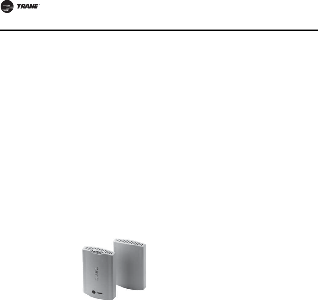
110 WSHP-PRC016E-EN
Controls
not the limiting factor for proper signal quality. Signal quality is affected by walls, barriers,
and general clutter.
Output power
North America: 100 mW
Radio frequency
2.4 GHz (IEEE Std 802.15.4-2003 compliant) (2405–2480 MHz, 5 MHz spacing)
Radio channels
16
Address range
Group 0–8, Network 1–9
Mounting
Fits a standard 2 in. by 4 in. junction box (vertical mount only). Mounting holes are spaced 3.2 in.
(83 mm) apart on vertical center line. Includes mounting screws for junction box or wall anchors
for sheet-rock walls. Overall dimensions: 2.9 in. (74 mm) by 4.7 in. (119 mm)
Wireless protocol
ZigBee PRO—ZigBee Building Automation Profile, ANSI/ASHRAE Standard 135-2008 Addendum
q (BACnet®/ZigBee)
Wireless Receiver/Wireless Zone Sensor
The spread spectrum receiver/translator can be field or factory installed and functions as a
communication translator between spread spectrum radio communications and the unit
communications link.
Specifications
Power Requirements
Receiver: 24 V nominal AC/DC ± 10% < 1VA
Zone Sensor: (2) AA lithium batteries
Sensor Operating Environments
32 to 122°F, (0 to 50°C); 5 to 95%RH, Non-condensing
Receiver Operating Environments
-40 to 158°F, (-40 to 70°C); 5 to 95%RH, Non-condensing
Storage Environment—Sensor/Receiver
-40 to 185°F, (-40 to 85°C); 5 to 95%RH, Non-condensing
The wireless zone sensor system eliminates the
wiring problems associated with unit temperature
sensors. It provides the flexibility to move zone
sensors after the occupants have revised the space
floor plan layout.The zone sensor houses the space
temperature sensor, local setpoint adjustment thumb
wheel, OCCUPIED/UNOCCUPIED button, battery life,
signal strength indicators, and spread spectrum
transmitter.

WSHP-PRC016E-EN 111
Controls
Mounting
Receiver: Suitable for mounting above or below ceiling grid. Requires 24V power. Factory installed
receiver comes mounted to the unit with power provided by associated unit controller transformer.
Field installed option provided with associated wire harness for similar power and communication
connection.
Sensor: Mounts to a 2x4 handi-box or directly to the wall by attaching the back plate and then
snapping the sensor body into place.
Dimensions
Receiver/Translator
Enclosure: Plastic
Height: 4.75" (120.6 mm)
Width: 2.90" (73.5 mm)
Depth: 1.08" (27.5 mm)
Sensor/Transmitter
Enclosure: Plastic
Height: 4.78" (121.4 mm)
Width: 2.90" (73.5 mm)
Depth: 1.08" (27.5 mm)
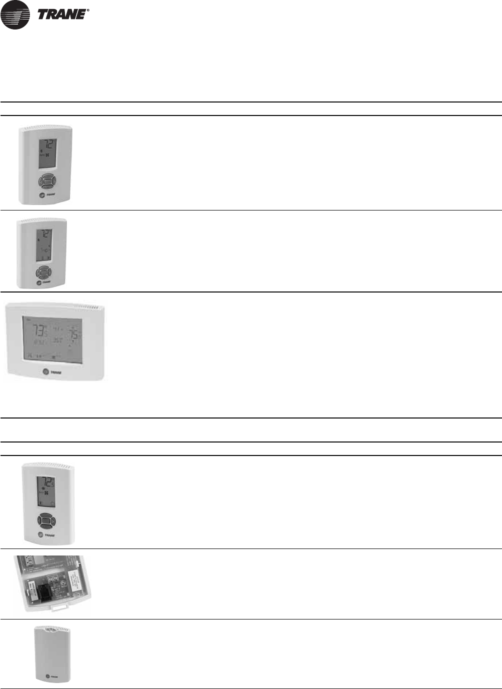
11 2 WSHP-PRC016E-EN
Thermostats and Zone Sensors
Table 81. Thermostat selection for use with the Deluxe Controller
Thermostat Part Number Description
X13511536010 3 Heat/2 Cool, Non-programmable commercial thermostat for
conventional (rooftop) air conditioners and heat pumps that are
configured with or without auxiliary heat.
• 3 H/2 C
X13511537010 3 Heat/2 Cool, Programmable commercial thermostat for
conventional (rooftop) air conditioners and heat pumps that are
configured with or without auxiliary heat.
• 3 H/2 C
X13511538010 3Heat/2 Cool, Programmable touch screen thermostat for
conventional air conditioners and heat pump systems.
The thermostat will provide the human interface, zone
temperature sensing both local and optional remote
temperature sensing, and set point scheduling on a daily/weekly
basis.
This thermostat can also display humidity with a control signal
for dehumidification with a local humidity sensor or optional
remote humidity sensor.
• 3 H/2 C
Table 82. Zone sensor selection for use with Tracer™ ZN524 and UC400 Controller
Sensor Part Number Description
X13790886010 Wired temperature sensor with an LCD display
• Allows an occupant to control the temperature setpoint,
request timed override of system operation, and provides a
COMM module to service technicians.Tracer™ ZN524 and
UC400 Compatible
X13651467020 Communication Module
• Sold in packs of 12
• Provides local RJ22 connection toTrane service tools for
easy, low cost maintenance.
X13511529010 Zone Sensor
• Tracer™ UC400 and ZN524 compatible
• External setpoint adjustment wheel
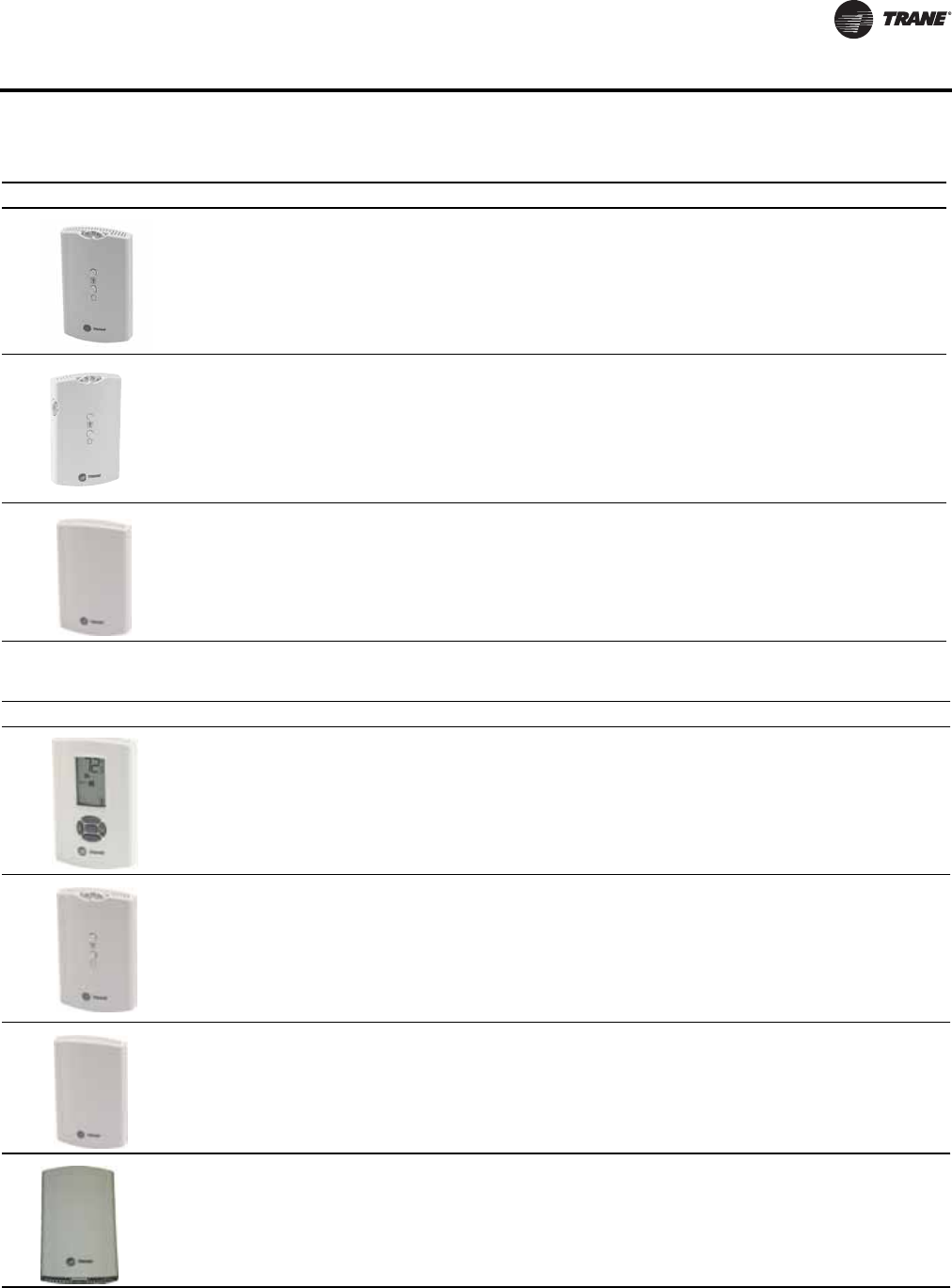
WSHP-PRC016E-EN 11 3
Thermostats and Zone Sensors
X13511527010 Zone Sensor
• Tracer™ UC400 and ZN524 compatible
• External setpoint adjustment wheel
• ON and CANCEL buttons
X1379084501 Zone Sensor
• Tracer™ UC400 and ZN524 compatible
• External setpoint adjustment wheel
• ON and CANCEL buttons
• Fan switch AUTO-OFF
X1379044401 • Temperature and relative humidity sensor
• Tracer™ UC400 and ZN524 compatible
Table 82. Zone sensor selection for use with Tracer™ ZN524 and UC400 Controller (continued)
Sensor Part Number Description
Table 83. Wireless zone sensor selection for use with Tracer™ UC400 controller
Sensor Part Number Description
X1379082201 Universal Display Sensor
• Clear and simple monitoring and control
Tracer™ UC400 Compatible
X13790492 Wireless Zone Sensor
• Local control
• Limited occupant temp. control
Timed occupancy overrides
X13790821 Wireless Zone Sensor
• Simplicity
Eliminates local temperature control when higher control level is
required
WCI - UC400 compatible
Provides wireless communication between theTracer™ SC,
Tracer™ Unit Controllers, and BACnet® Communication
Interface (BCI) modules
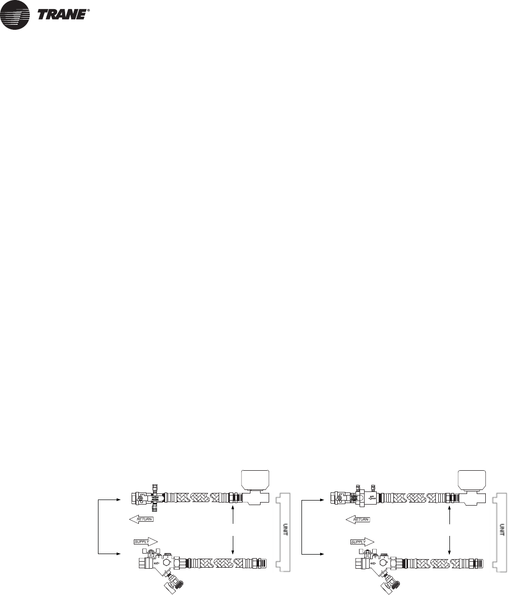
114 WSHP-PRC016E-EN
Accessories
Automatic and Manual Balancing Kits
Superior circuit balancing of the HVAC equipment is an important aspect to the overall layout and
design of the HVAC system. Proper balance of the system can protect the WSHP equipment while
providing a longer equipment life.
Trane provides three hose kit selections for equipment balancing.
• Ball valve flow control (manual)
• Circuit setter flow control (manual)
• Automatic, Self Balancing Flow Control Hose Kit
Each selection provides some accuracy in equipment balancing. Range of accuracy consist of ±25%
for the ball valve method, ±20% for the manual flow control method, and ±10% for the automatic
flow control method.
Utilizing the ball valve flow control method, the pressure/temperature measurement on the leaving
and entering side of the heat pump is measured within the water piping.The ball valve is then
throttled to change the amount of flow to the unit to reach the desired temperature or pressure
differential.
The circuit setter manual flow control method uses an in-line flow measurement device an and
adjustment feature to measure and set flow rates at each heat pump.
For automatic system balancing of a water source heat pump, the Mesurflo® self-balancing hose
kit provides a constant flow rate over the pressure differential rage of 2 to 80 psid. As system
pressure changes (through further addition of heat pumps, for example) each individual flow
control valve will automatically adjust to the new system conditions. In variable water volume
applications, a self-balancing hose kit can provide continuous balancing because of its ability to
automatically adjust to the varying system conditions.
Note: At low differential pressure the flow area required to achieve higher flow can exceed the
flow area available for the respective series.Therefore, the minimum pressure differential
requirement is increased for the higher flow ranges of each series Mesurflo valve.
Figure 51. Ball valve kit (manual)/MeasurfloVac kit (automatic)
Flex Hose
Mesurmeter w/PT’s
Optional Yball Strainer
w/Blowdown Valve &
Hose Connector
PT
FLOW
Ball Valve
Optional Isolation Valve
2-Position Valve
AUTOMATIC
TEMPERATURE
CONTROL
VALVE
Flex Hose
Optional Yball Strainer
w/Blowdown Valve &
Hose Connector
PT
FLOW
Ball Valve
Optional Isolation Valve
2-Position Valve
2510 Mesurflo w/PT’s
AUTOMATIC
TEMPERATURE
CONTROL
VALVE
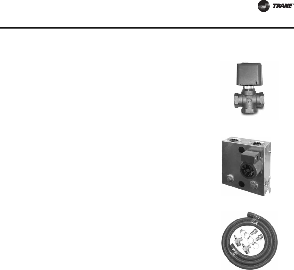
WSHP-PRC016E-EN 11 5
Accessories
Motorized water valve
The motorized water valve is installed on the return line of the water loop system between
the loop and the loop’s pump module.This isolation device is less expensive and a very
effective alternative to the water regulating valve.
When the compressor begins running, the valve will open, allowing water to flow through
the unit. As the compressor shuts down, the valve slowly closes off.The main purpose
of the motorized valve is to shut-off the flow of water through the unit when the unit is
off, thus reducing water consumption.The motorized valve is fast opening to prevent
compressor trip-out, and slow closing to prevent water hammer.
Pump module
The pump module and hose kit make a complete self-contained pumping package for
distributed pumping systems.These kits contain all the necessary components for the
installation, operation and maintenance of the water circuit of a closed loop geothermal
application. Standard pump module features include insulated Grundfos pumps,
insulated cabinet, bronze or cast iron pump, and 3-way brass valves. Literature number
WSHPC-IN-5 will provide electrical and dimensional requirements for the PMCA and
PMBA products.
Pump module hose kit
The pump module hose kit consists of two brass, ¾ or 1-inch male pipe thread (MPT) -by-
barb fittings; two brass 90° 1-inch, MPT-by-barb elbows with pressure/temperature ports;
and 10 feet of rubber hose with 4 hose clamps. The pump module hose kit is available
separately from the pump module.
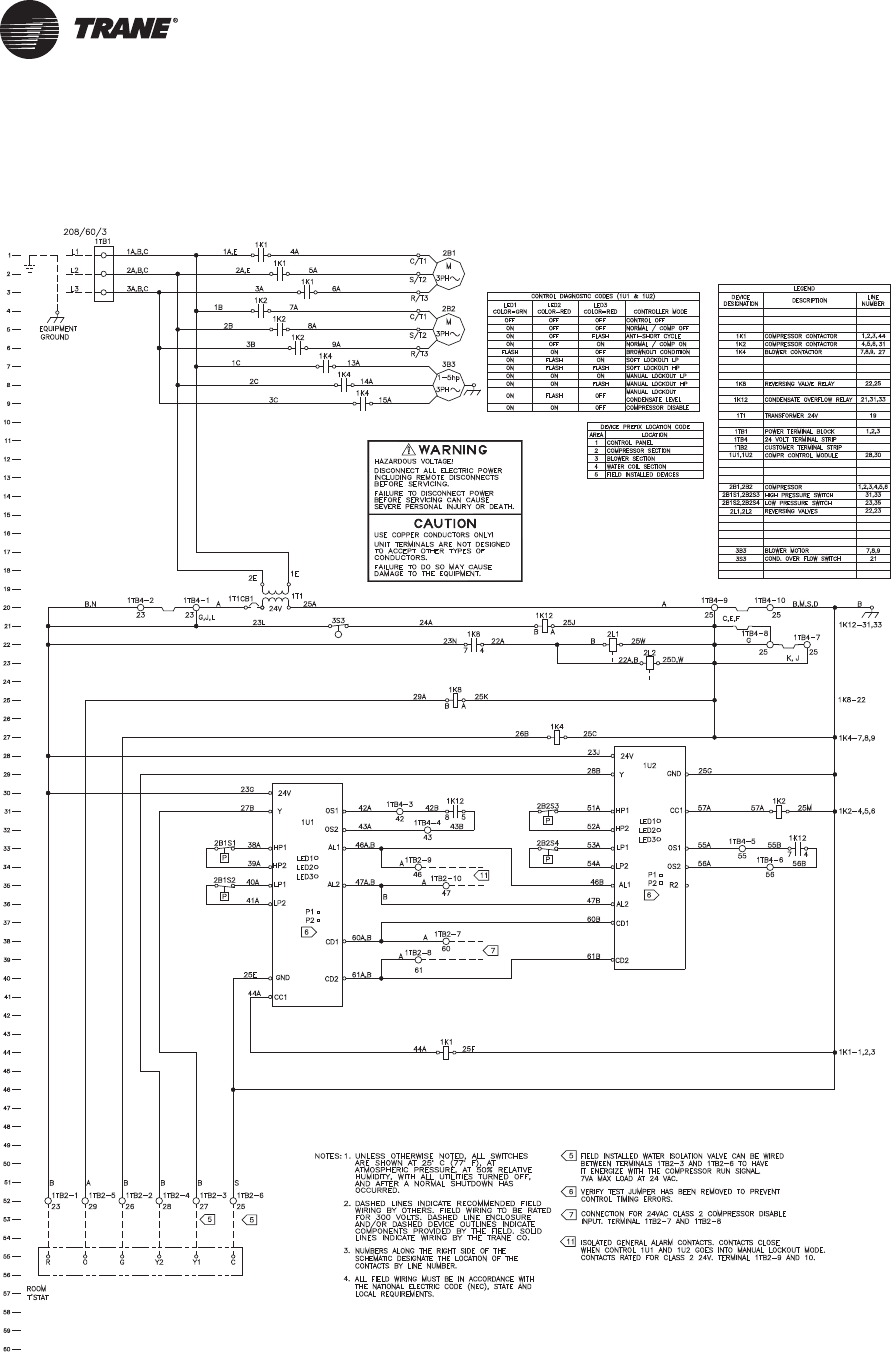
11 6 WSHP-PRC016E-EN
Control Wiring
Figure 52. Deluxe 24V - 208-230V-60 Hz-3ph
(a)
(a)Wiring diagrams provided in the catalog are generic. A unit specific As Built wiring diagram is located on the unit control panel.
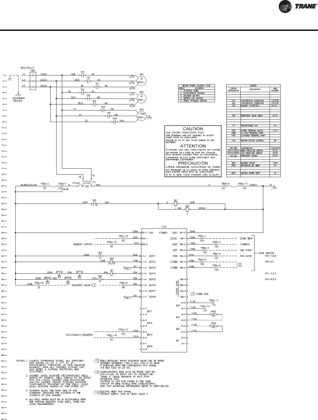
WSHP-PRC016E-EN 11 7
Control Wiring
Figure 53. Tracer™ ZN524 460V-60 Hz-3ph
(a)
(a)Wiring diagrams provided in the catalog are generic. A unit specific As Built wiring diagram is located on the unit control panel.
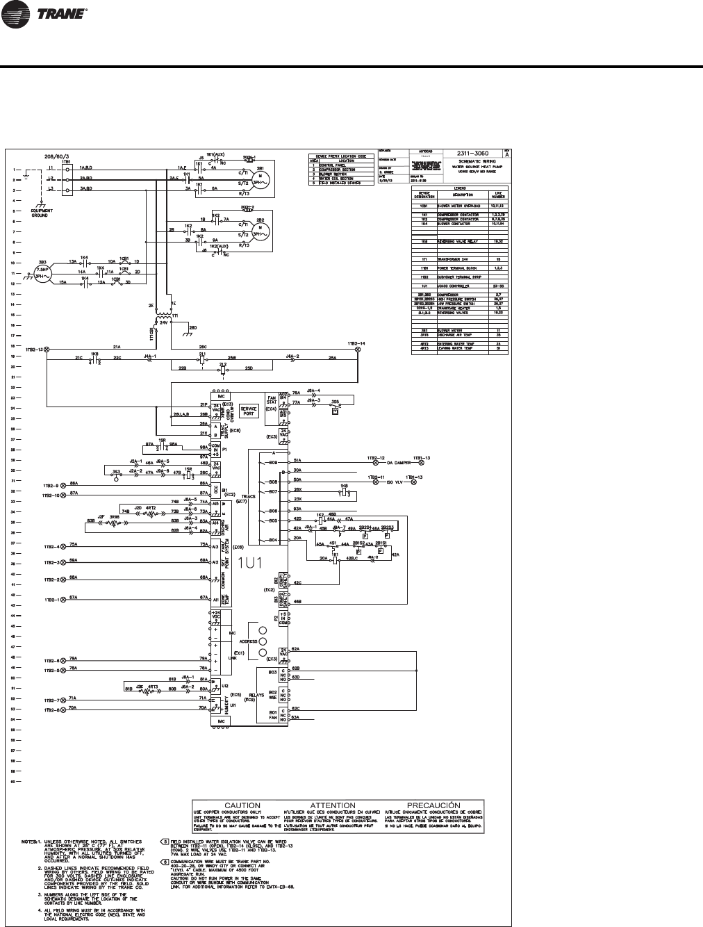
11 8 WSHP-PRC016E-EN
Control Wiring
Figure 54. UC400(a)
(a)Wiring diagrams provided in the catalog are generic. A unit specific As Built wiring diagram is located on the unit control panel.
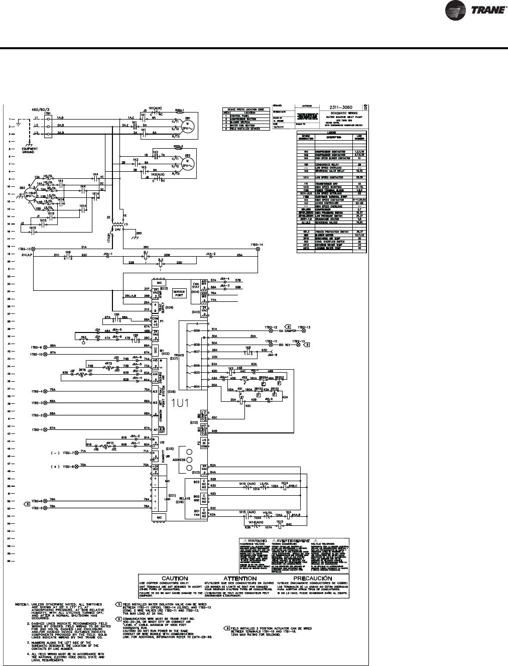
WSHP-PRC016E-EN 119
Control Wiring
Figure 55. UC400 with 2 speed motor(a)
(a)Wiring diagrams provided in the catalog are generic. A unit specific As Built wiring diagram is located on the unit control panel.

120 WSHP-PRC016E-EN
Mechanical Specifications
General
Equipment is completely assembled, piped, internally wired, fully charged with R-410A and test
operated at the factory. Filters, thermostat field interface terminal strip, and all safety controls are
furnished and factory installed.
The system water inlet and outlet connections are female NPT composed of copper.
All units are ETL certified and under 10 tons are AHRI certified. Larger units are rated in accordance
with ISO-ARI 13256-1. Service and caution area labels are placed on the unit in their appropriate
locations.
Cabinet
Unit casing is constructed of zinc coated, heavy gauge, galvanized steel.
Access to the refrigerant and controls is provided through the front and side access panels.
All panels are insulated with 1/2-inch thick dual density bonded glass fiber.The exposed side is a
high density erosion proof material suitable for use in air streams up to 3600 feet per minute (FPM).
The insulation meets the erosion requirements of UL 181. It has a flame spread of less than 25 and
a smoke developed classification of less than 50 per ASTM E-84 and UL 723.
Access for inspection and cleaning of the unit drain pan, coils and fan section are provided.The
unit shall be installed for proper access.
Procedures for proper access inspection and cleaning of the unit shall be included in the
maintenance manual.
Filters
One inch or two inch, throwaway filters are standard and factory installed.The filters have an
average arrestance of 75% and dust holding capacity of 26-grams per square foot.
Sound Attenuation
Sound attenuation is applied as a standard feature in the product design. All units are tested and
rated in accordance with ARI 260.
Compressors
The unit contains a high efficiency scroll compressor. External vibration isolation is provided by
rubber mounting devices located underneath the mounting base of the compressor. A second
isolation of the refrigeration assembly is supported under the compressor mounting base.
Internal thermal overload protection is provided. Protection against excessive discharge pressure
is provided by means of a high pressure switch. A loss of charge is provided by a low pressure
switch. Crankcase heaters are provided standard on all units.
Refrigerant Tubing
The refrigerant tubing is of 99% pure copper. This system shall be free from contaminants and
conditions such as drilling fragments, dirt and oil. All refrigerant and water lines are insulated with
an elastomeric insulation that has a 3/8-inch thick wall in the air-side section of the unit.
Refrigerant Circuits
The refrigerant circuit contains a thermal expansion device. Service pressure ports are factory
supplied on the high and low pressure sides for easy refrigerant pressure.
Air-to-Refrigerant Coil
Internally finned, 3/8-inch copper tubes mechanically bonded to a configured aluminum plate fin
are standard. Coils are leak tested at the factory to ensure the pressure integrity. The coil is leak
tested to 450 psig and pressure tested to 650 psig.The tubes are to be completely evacuated of air
and correctly charged with proper volume of refrigerant prior to shipment.

WSHP-PRC016E-EN 121
Mechanical Specifications
The refrigerant coil distributor assembly is of orifice style with round copper distributor tubes.The
tubes are sized consistently with the capacity of the coil. Suction header is fabricated from rounded
copper pipe.
A thermostatic expansion valve is factory selected and installed for a wide range of control.
Drain Pan
The condensate pan is constructed of corrosion resistant material and insulated to prevent
sweating.The bottom of the drain pan is sloped on two planes which pitches the condensate to the
drain connection.The drain pan is flame rated per UL945V-B.
Water-to-Refrigerant Heat Exchanger
The water-to-refrigerant heat exchanger is of a high quality co-axial coil for maximum heat transfer.
The copper or optional cupro-nickel coil shall be deeply fluted to enhance heat transfer and
minimize fouling and scaling.The coil has a working pressure of 650 psig on both the refrigerant
side and 400 psig on the water side.
Water-to-Refrigerant Heat Exchanger and Suction Lines - Insulated Option
The water-to-refrigerant heat exchanger(s), water lines, and refrigerant suction lines shall be
insulated to prevent condensation at low temperatures below 60F degrees.
Indoor Fan
The blower shall have multiple blower motor/sheave combinations available. Options of the
blower motor/fan packages shall be selected and wired from the factory to match performance
criteria suggested in the performance section.The fan(s) shall be placed in a draw-through
configuration.They shall be constructed of corrosion resistant galvanized material. On units
provided with 2-speed motors, fan speed reduces down to provide 50% of the selected sheave
setting when the zone set point temperature is satisfied or when the unit runs in fan only mode,
provided unit is in cooling mode.
Electrical
The unit control box contains all necessary devices to allow heating and cooling operation to occur
from a remote wall thermostat.These devices are as follows:
• 24 VAC energy limiting class II
• 75 VA (minimum) transformer.
• 24 VAC blower motor relay.
• 24 VAC compressor contactor for compressor control.
• Field thermostat connections shall be provided for ease of hook-up to a terminal strip located
in the unit’s control box.
• A high pressure switch shall protect the compressor against operation at refrigerant system
pressures exceeding 650 psig.
• A low pressure switch shall protect the compressor against operation at refrigerant system
pressures below 40 psig.
• Freeze protection (option) shall protect the compressor against operation at low water
temperature.
• Factory installed wire harness shall be available for the Deluxe, UC400 and ZN524 control
packages.
Nameplate information shall be provided for the application of either time-delay fuses or HACR
circuit breakers for branch circuit protection from the primary source of power.

122 WSHP-PRC016E-EN
Mechanical Specifications
Deluxe Controls (option)
The deluxe control package provides a 75 VA transformer with circuit breaker.The controller
includes a lockout relay, anti-short cycle compressor protection, random start delay, brown-out
protection, low pressure time delay, compressor delay on start and an open relay for night setback
or pump request. Optional wiring from the factory for condensate overflow, hot gas reheat, electric
heat, and compressor enable is also provided.Three LEDs (light emitting diodes) are included for
diagnostics of the equipment.
DDC Controller (option)
The UC400 and ZN524 controller utilizes factory furnished and mounted DDC controls.The DDC
control package includes a 75 VA (minimum) transformer.The controller provides random start
delay, heating/cooling status, occupied/unoccupied mode, fan status and filter maintenance
options. Optional wiring from the factory for condensate overflow is available.Three LEDs (light
emitting diodes) are included for diagnostics of the equipment.
The controller is capable of a standalone application, or as applied to a full building automation
installation.
With this controller, the unit is capable of a hot gas reheat (for dehumidification), boilerless control
for electric heat, waterside economizing, and support of variable speed pump control applications.
Economizing Coil (option)
The waterside economizing package is an external unit accessory for field installation.The
economizing coil is designed to perform with the WSHP at unit measured flow rate of 80.6°F DB/
66.2°F WB with 45°F EWT.
All hydronic coils are of 3/8 in. (6-20 ton units), 1/2 in. (25 ton unit) copper and aluminum plate fin
combination. All coils are proof and leak tested from the manufacturer.
The proof test is performed at 1.5 times the maximum operating pressure and the leak test at the
maximum operating pressure.
A dual sloped non corrosive drain pan is easily accessible and cleanable for the hydronic
economizing coil.
An electronic two-position, 3-way valve meters water flow to the economizing coil during the
economizing mode. It is factory set to energize the economizing mode at 55°F, while simultaneously
halting mechanical operation of the compressor.
The economizer is field attached to the equipment.
Electric Heat (option)
Boilerless control electric heat is factory wired and tested.
The boilerless control option is composed of a controls interface for a field provided boilerless or
supplemental electric heat selection.The heater for this model is placed external to the equipment
by the contractor for ease of installation. All power connections for the electric heater will be
completely separate from the unit for field supplied electric heat.
Hot Gas Reheat (option)
Dehumidification is provided through a hot gas reheat option.The coil consists of 3/8 in./1/2 in.
copper tubes mechanically expanded into evenly spaced aluminum fins.All coils are proof and leak
tested.The proof test must be performed at 1.5 time the maximum operating pressure and the leak
test performed at the maximum operating pressure.
Ball Valves (option)
Ball valves are field installed between the unit and the supply and return lines of the loop to stop
water flow to the unit in a maintenance or service situation.

WSHP-PRC016E-EN 123
Mechanical Specifications
Motorized Water Valve (option)
When extreme fluid temperature conditions do not exist with an open loop system, a motorized
water valve may be applied to each water-source heat pump.The motorized valve shall stop flow
to the unit, causing pressures to rise.This rise in pressure will halt pump operation to provide
greater energy savings of the entire system.
Hoses (option)
Hoses consists of a stainless steel outer braid with an inner core of tube made of a nontoxic
synthetic polymer material.The hoses are suitable for water temperatures ranging between 33°F
and 211°F without the use of glycol.
Automatic Flow Devices (option)
The automatic flow kit contains a Hays Mesurflo® automatic flow control valve, two ball valves,
two flexible hoses, a high flowY-strainer, and may include a strainer blow-down and various other
accessories.
The automatic flow control valve is factory set to a rated flow, and shall automatically control the
flow to within 10% of the rated value over a 40 to 1 differential pressure, operating range (2 to 80
PSID). Operational temperature is rated from fluid freezing, to 225°F.The valve body shall be
constructed from hot forged brass UNS C37700 per ASTM B-283 latest revision. For more
information pertaining to the automatic balancing hose kits, see literature documentation WSHP-
PRC025*-EN.

Trane optimizes the performance of homes and buildings around the world. A business of Ingersoll Rand, the leader in
creating and sustaining safe, comfortable and energy efficient environments,Trane offers a broad portfolio of advanced
controls and HVAC systems, comprehensive building services, and parts. For more information, visit www.Trane.com.
Trane has a policy of continuous product and product data improvement and reserves the right to change design and specifications without notice.
We are committed to using environmentally
conscious print practices that reduce waste.
© 2014Trane All rights reserved
WSHP-PRC016E-EN 08 Aug 2014
Supersedes WSHP-PRC016D-EN (15 Nov 2013)
