Trane Huvc Horizontal Classroom Unit Ventilator Catalogue UV PRC004 EN (04 Feb 2013)
2015-04-02
: Trane Trane-Huvc-Horizontal-Classroom-Unit-Ventilator-Catalogue-684293 trane-huvc-horizontal-classroom-unit-ventilator-catalogue-684293 trane pdf
Open the PDF directly: View PDF ![]() .
.
Page Count: 65
Horizontal Classroom Unit Ventilator
750 cfm to 2000 cfm
February 2013 UV-PRC004-EN
Product Catalog
UV-PRC004-EN.book Page 1 Monday, February 4, 2013 11:01 AM
© 2013 Trane All rights reserved UV-PRC004-EN
Introduction
Trane Horizontal Classroom Unit Ventilator
A Classroom Choice in HVAC
Classroom unit ventilators have been cost effective way to heat and cool schools for over half a
century. Many schools choose classroom unit ventilators because of their ability to heat, cool and
ventilate, as well as their durable cabinet design and small foot print. Because the unit ventilator
is a single-space system, one unit installed in the classroom handles only that room’s airflow, thus
minimizing the potential for cross contamination between classrooms.
The ceiling-hung, ducted, horizontal unit ventilator may provide benefits in sound sensitive
applications. The horizontal equipment can be located above the ceiling and away from direct
contact with students. They may also be located in a corridor or mezzanine, then ducted into the
classroom. Properly designed supply- and return-air ducts can help attenuate HVAC equipment and
air noise. Locating the units outside of the classroom can also improve access and serviceability
of the equipment.
Trane’s commitment to providing premium quality products has led to the exclusive use of
Electronically Commutated Motors (ECM) in all Unit Ventilator models. These brushless DC motors
incorporate the latest technology for optimized energy efficiency, acoustical abatement,
UV-PRC004-EN.book Page 2 Monday, February 4, 2013 11:01 AM

UV-PRC004-EN 3
Introduction
maintenance free and extended motor life. Each motor has a built-in microprocessor that allows
for programmability, soft ramp-up, better airflow control, and serial communication.
Additionally, this is the industry’s first solution that is factory-mounted, -wired, and -programmed
for infinite modulation of fan speed based on space loads, using the Tracer UC400.
Trane unit ventilators are ETL listed, and AHRI-840 certified insuring peek performance to meet
today’s classroom habitat.
Trademarks
Integrated Comfort, Rover, TOPSS, Tracer, Tracer Summit, Trane, and the Trane logo are
trademarks or registered trademarks of Trane in the United States and other countries. All
trademarks referenced in this document are the trademarks of their respective owners.
BACnet is a registered trademark of American Society of Heating, Refrigerating and Air-
Conditioning Engineers (ASHRAE); Echelon®, LONMARK, LonTalk, and LONWORKS are registered
trademarks of Echelon Corporation; UL and the UL logo are trademarks of UL LLC.
UV-PRC004-EN.book Page 3 Monday, February 4, 2013 11:01 AM

4 UV-PRC004-EN
Table of Contents
Introduction . . . . . . . . . . . . . . . . . . . . . . . . . . . . . . . . . . . . . . . . . . . . . . . . . . . . . . . . . . . . 2
Trane Horizontal Classroom Unit Ventilator . . . . . . . . . . . . . . . . . . . . . . . . . . . 2
A Classroom Choice in HVAC . . . . . . . . . . . . . . . . . . . . . . . . . . . . . . . . . . . . 2
Features and Benefits . . . . . . . . . . . . . . . . . . . . . . . . . . . . . . . . . . . . . . . . . . . . . . . . . . . 5
Made for the Classroom . . . . . . . . . . . . . . . . . . . . . . . . . . . . . . . . . . . . . . . . 5
Application Considerations . . . . . . . . . . . . . . . . . . . . . . . . . . . . . . . . . . . . . . . . . . . . . 10
The Applied Unit Ventilator . . . . . . . . . . . . . . . . . . . . . . . . . . . . . . . . . . . . 12
Selection Procedures . . . . . . . . . . . . . . . . . . . . . . . . . . . . . . . . . . . . . . . . . . . . . . . . . . 16
Selecting a Unit Ventilator . . . . . . . . . . . . . . . . . . . . . . . . . . . . . . . . . . . . . 16
Model Number Descriptions . . . . . . . . . . . . . . . . . . . . . . . . . . . . . . . . . . . . . . . . . . . . 18
General Data . . . . . . . . . . . . . . . . . . . . . . . . . . . . . . . . . . . . . . . . . . . . . . . . . . . . . . . . . . 20
Performance Data . . . . . . . . . . . . . . . . . . . . . . . . . . . . . . . . . . . . . . . . . . . . . . . . . . . . . 27
Glycol in an HVAC System . . . . . . . . . . . . . . . . . . . . . . . . . . . . . . . . . . . . . 37
Piping . . . . . . . . . . . . . . . . . . . . . . . . . . . . . . . . . . . . . . . . . . . . . . . . . . . . . . . . . . . . . . . . 39
Factory Installed Piping Packages . . . . . . . . . . . . . . . . . . . . . . . . . . . . . . . 39
Controls . . . . . . . . . . . . . . . . . . . . . . . . . . . . . . . . . . . . . . . . . . . . . . . . . . . . . . . . . . . . . . 40
Why Trane Controls? . . . . . . . . . . . . . . . . . . . . . . . . . . . . . . . . . . . . . . . . . . 40
ECM Engine Controller . . . . . . . . . . . . . . . . . . . . . . . . . . . . . . . . . . . . . . . . 41
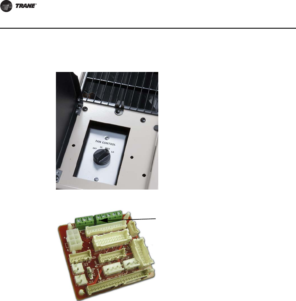
Unit-Mounted Speed Switch . . . . . . . . . . . . . . . . . . . . . . . . . . . . . . . . . . . 42
Customer Supplied Terminal Interface (CSTI) . . . . . . . . . . . . . . . . . . . . . 44
Tracer ZN520 Zone Controller . . . . . . . . . . . . . . . . . . . . . . . . . . . . . . . . . . 45
Tracer UC400 . . . . . . . . . . . . . . . . . . . . . . . . . . . . . . . . . . . . . . . . . . . . . . . . 49
Zone Sensors . . . . . . . . . . . . . . . . . . . . . . . . . . . . . . . . . . . . . . . . . . . . . . . . . . . . 51
Dimensional Data . . . . . . . . . . . . . . . . . . . . . . . . . . . . . . . . . . . . . . . . . . . . . . . . . . . . . . 54
Mechanical Specifications . . . . . . . . . . . . . . . . . . . . . . . . . . . . . . . . . . . . . . . . . . . . . . 61
General . . . . . . . . . . . . . . . . . . . . . . . . . . . . . . . . . . . . . . . . . . . . . . . . . . . . . 61
Controls . . . . . . . . . . . . . . . . . . . . . . . . . . . . . . . . . . . . . . . . . . . . . . . . . . . . 63
Filter . . . . . . . . . . . . . . . . . . . . . . . . . . . . . . . . . . . . . . . . . . . . . . . . . . . . . . . 64
UV-PRC004-EN.book Page 4 Monday, February 4, 2013 11:01 AM
UV-PRC004-EN 5
Features and Benefits
Made for the Classroom
Equipment Size
The horizontal unit ventilator delivers from 750 cfm to 2000 cfm. Trane’s unit ventilator is sized to
fit any replacement or new construction application.
Cabinet Finish
The unit cabinetry is made of durable industrial grade metal for hard wearing applications. All steel
surfaces are cleaned, phosphatized, rinsed and dried before applying a final paint finished on metal
that may be exposed to the room decor.
Access
Access to the air filter is made through the bottom of the unit providing effortless access for filter
change-out. The access panel is available with a safety chain option for protection from dropping
the panel during normal maintenance situations.
Spacious End Pockets
The 13-1/2-inch wide by 30-inch high by 15-1/4-inch deep (standard) to provide uncomplicated field
installation of valves, piping, and controls. Several large knockouts are provided in both the left and
right end pockets for electrical and piping connections.
Control Connections
All electrical connections are made in the left-hand end pocket for equipment not specified with
electric heat. Units equipped with the electric heat option have in-coming power connections made
in the right-hand end pocket.
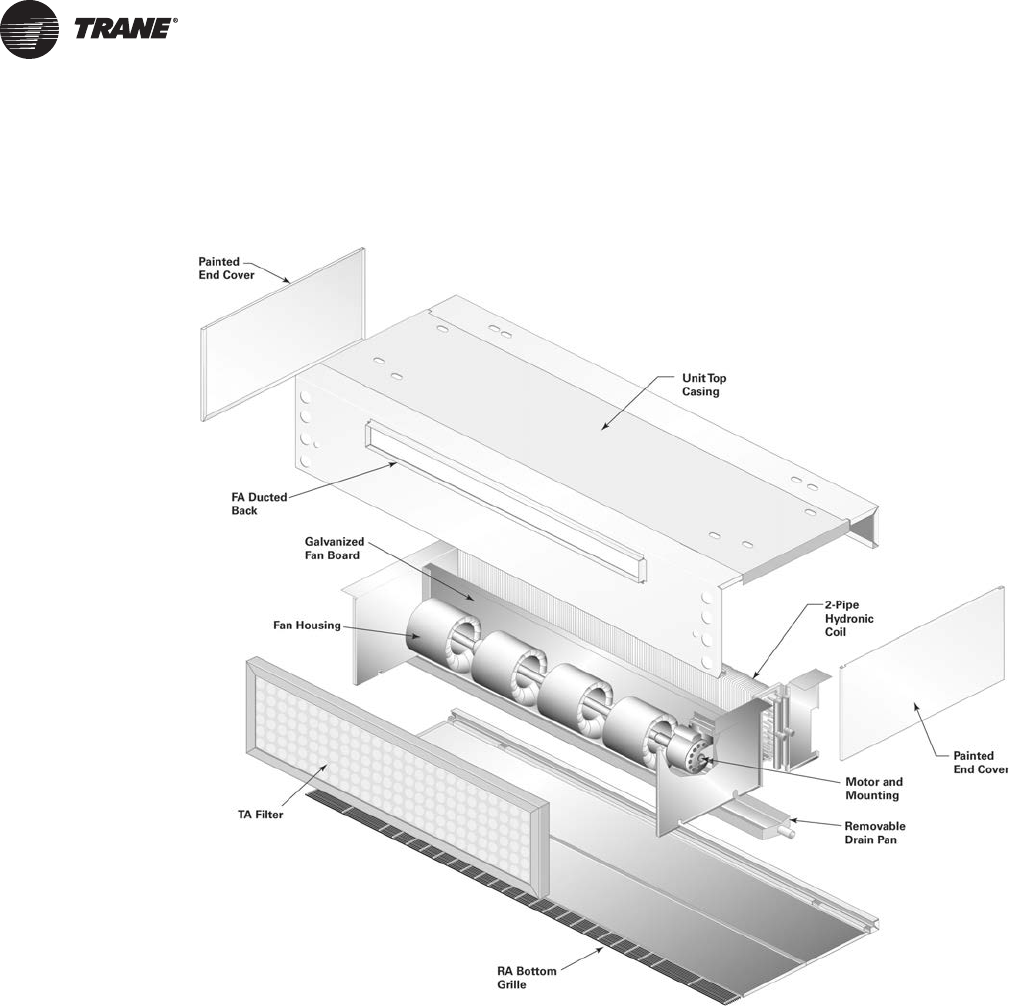
Fan Board
The fan board assembly is acoustically designed in a single, rigid assembly that includes the fans,
fan housing, bearings, fan shaft and motor. The fan motor is mounted on the heavy gauge,
galvanized fan board assembly to help resist corrosion while increasing strength and rigidity. The
fan board is removable through two metal screws for service or maintenance/cleaning of the fan
housings.
Figure 1. Cabinet access
UV-PRC004-EN.book Page 5 Monday, February 4, 2013 11:01 AM
6 UV-PRC004-EN
Features and Benefits
Energy Efficiency
Trane’s commitment to providing premium quality products has led to the exclusive use of
Electronically Commutated Motors (ECM) in all Unit Ventilators. These brushless DC motors
incorporate the latest technology for optimized energy efficiency, acoustical abatement,
maintenance free and extended motor life. Each motor has a built-in microprocessor that allows
for programmability, soft ramp-up, better airflow control, and serial communication.
• Trane units equipped with ECMs are significantly more efficient than the standard Permanent
Split Capacitor (PSC) motor.
• Lower operating costs on average of 50 percent (versus a PSC motor).
• The Reduced FLA feature allows units to ship with a nameplate FLA rating much lower than a
typical ECM unit.
Electronically Commutate Motor (ECM)
The fan motor is a variable speed electronically commutated motor with overload protection. The
motor is wired to either termination board so the unit can be control with either three fan speeds
or 0 Vdc to 10 Vdc. The motor speed is not affected by damper positions. Standard motors are rated
up to 0.25 ESP (external static pressure). High static motors are rated from 0.25 ESP to 0.45 ESP.
Bearings for the motor are permanently lubricated requiring little maintenance over the lifetime of
the equipment.
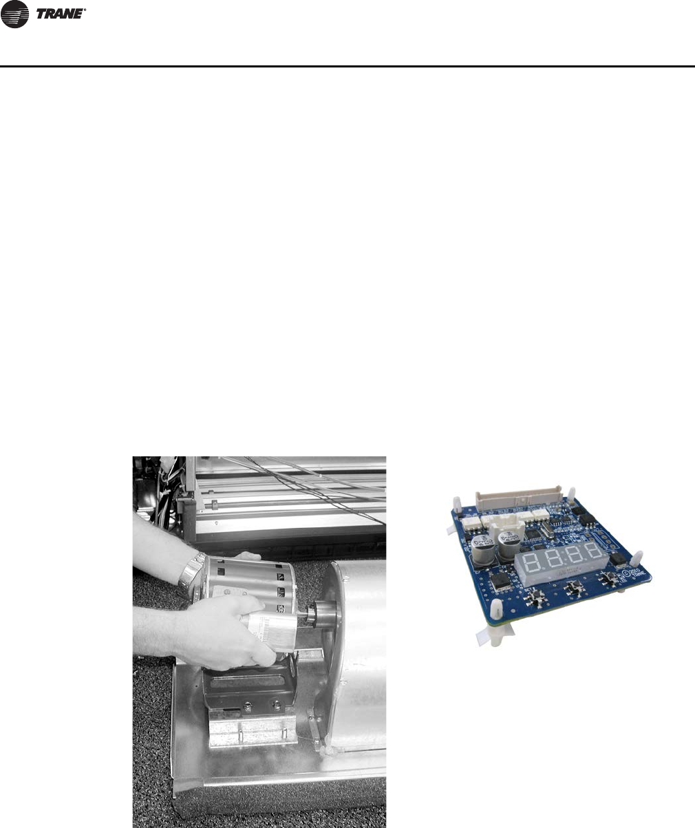
The motor is removable without complete disassembly of the fan board. Simply remove the two
motor quick-connects and loosen the shaft coupling.
Filter
Filters for the horizontal unit ventilator are of 1-inch, throwaway, MERV 8, or MERV 13. They are
shipped with the equipment for installation/start-up purposes. Extra filters may be ordered
separately for maintenance of the equipment.
Figure 2. Fan motor
UV-PRC004-EN.book Page 6 Monday, February 4, 2013 11:01 AM

UV-PRC004-EN 7
Features and Benefits
Drain Pan
The unit drain pan is positively sloped to assure proper drainage. The pan is insulated on the
bottom to help prevent condensate formation. The pan is simple to remove for cleaning purposes
by loosening two front screws.
Piping
Hydronic piping for the unit ventilator may be factory installed or field provided. It fits painlessly
inside the unit end pockets, permitting quick hook-up during the installing phase. The motorized
valves include a trouble-free, pop-top actuator allowing the maintenance or service technician
access to the motor without removing the valve body from the piping package.
Coils
Through the various coil combinations offered by Trane, room conditions can be met. Two-pipe
and four pipe combinations are available to support any application. Coil selections include
hydronic, steam, direct expansion (DX) and electric. For heating coils, Trane provides steam, hot
water and electric options. Cooling coils are available as cold water and DX. Access to the coil for
cleaning purposes is fundamentally one of the greatest features Trane provides as part of the
equipment. Maintaining a clean coil inherently increases the efficiency adds to the life of the
equipment, and helps to maintain proper indoor air quality.
Outside/Return-Air Damper Design
The outside/return air (OA/RA) damper is a dual blade system to ensure proper modulation and
mixing of the air to AHRI-840 economizing standards.
The optional outside air actuator is spring return. The spring return system closes the OA damper
if power is lost to the building and provides for a positive seal. This helps inhibit over cooling or
freeze-up of the system during electrical outages or system shut-down.
When ordered with factory mounted Trane® controls, the actuator is 3-point floating arrangement.
A 2–10 Vdc or 3-point floating actuator is available when Customer Supplied Terminal Interface
(CSTI) are specified.
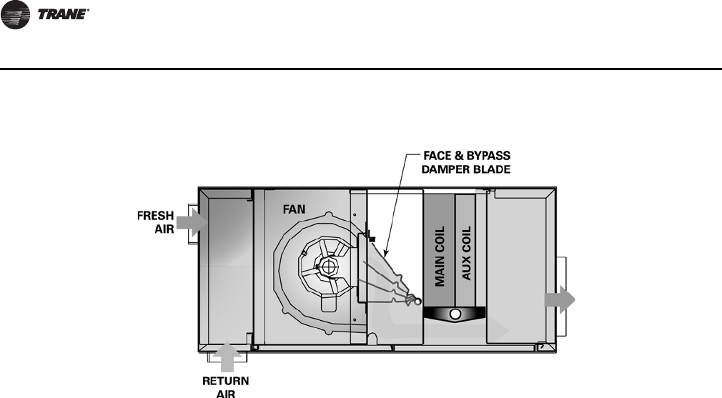
Face and Bypass
The optional face and bypass design can provide active energy savings to the owner. This design
works best during seasonal changeover when outside air temperature are in their prime. It also
supports morning warm-up when lighter temperatures can easily be drawn into the system before
normal classroom operation begins.
The design allows the damper to bypass the cooing coil to supply cool, untreated OA into the room.
An optional 2-position isolation valve enhances this system by closing off water to the coil to
prevent the room temperature from rising to far above or below the intended setpoint.
UV-PRC004-EN.book Page 7 Monday, February 4, 2013 11:01 AM
8 UV-PRC004-EN
Features and Benefits
Controls
• This is the industry’s first solution that is factory-mounted, -wired, and -programmed for infinite
modulation of fan speed based on space loads, using the Tracer™ UC400.
• Auto Fan Speed control with the Tracer ZN520 ramps the fan speed up and down to meet space
loads.
• All controls are factory-mounted and tested to minimize field setup and improve reliability.
• Controls are wired with a 24-Vac transformer to keep only a single source power connection
requirement to the unit.
• All wall-mounted zone sensors require only low voltage control wiring from the device to the
unit control box. (No line voltage.)
• The controller automatically determines the unit’s correct operating mode (heat/cool) by
utilizing a proportional/integral (PI) control algorithm to maintain the space temperature at the
active setpoint, allowing total comfort control.
• Entering water temperature sampling eliminates the need for inefficient bleedlines to sense
automatic changeover on two-pipe changeover units.
• The random start-up feature helps reduce electrical demand peaks by randomly staggering
multiple units at start-up.
• Occupied/unoccupied operation allows the controller to utilize unoccupied temperature
setpoints for energy savings.
• Warm-up and cool-down energy features are standard with Trane controls.
• To customize unit control, Tracer TU or Rover™ software will allow field modification of Tracer
ZN520 default settings. Tracer UC400 uses Tracer TU.
• Maximize system efficiency with free cooling economizers and modulating valves on units with
Tracer ZN520 and Tracer UC400.
Trane offers a broad range in control packages to fit both retrofit and new applications. From the
field convertible end-device package to a complete building automation system, Trane controls
integrate the highest quality components within their unit ventilator to allow greater optimization
of the entire system.
Certification Standards
Comfort, energy and IAQ are all major issues that need to be considered in today’s school designs.
Therefore, it is important that designers of these systems have accurate information to make
Figure 3. Face and bypass damper
UV-PRC004-EN.book Page 8 Monday, February 4, 2013 11:01 AM

UV-PRC004-EN 9
Features and Benefits
system decisions. That is why the industry has developed performance standards and certification
programs which ensure that the equipment information provided to the design community is
correct and comparable across different manufacturers. The following list of certifications
identifies Trane’s commitment in providing the highest quality equipment to their customers.
• AHRI-840
•UL
®
• Rated in accordance to AHRI 350 (sound)
•L
ONMARK®
UV-PRC004-EN.book Page 9 Monday, February 4, 2013 11:01 AM
10 UV-PRC004-EN
Application Considerations
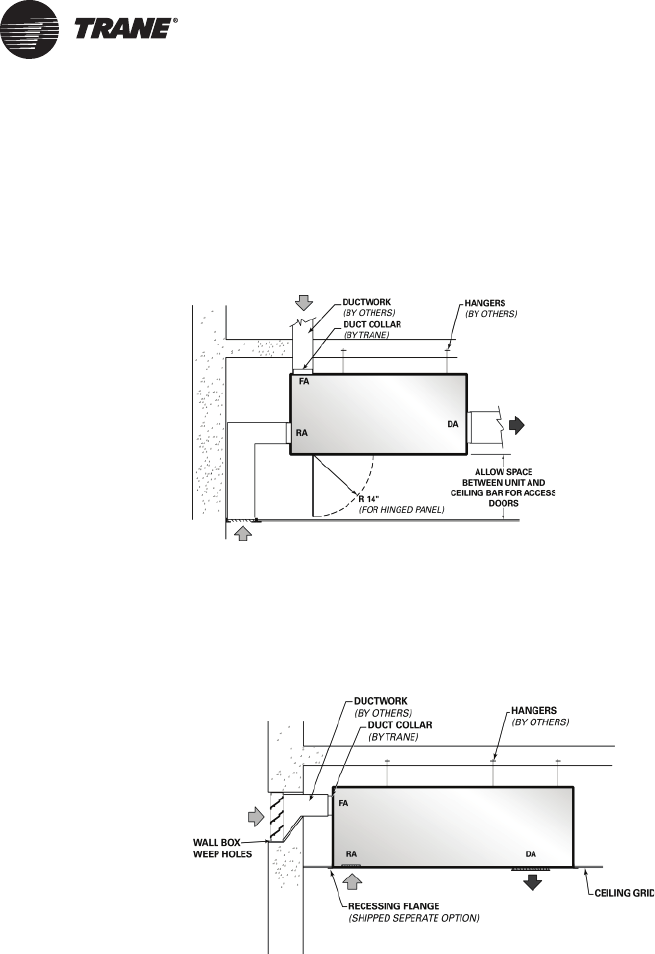
Fully Recessed Unit
The horizontal unit ventilator may be fully recessed into the ceiling space to provide greater noise
reduction to the space. With this application, duct collars on the outside air inlet, return air inlet and
discharge air outlet are available for ease of duct work connection to the equipment.
Partially Exposed Unit
In situations where greater access to system components is a must (such as filter change-out), a
partially exposed unit may be a practical solution. With the partially exposed return/discharge air
bottom arrangement, the unit cabinet width increases by 13-1/8 inches for 075–150 unit sizes, and
by 14-1/8 inches on the size 200 unit.
Fully Exposed Unit
The horizontal unit ventilator may be fully exposed to the classroom or institution. The most typical
arrangement for this application includes a fresh air, ducted upper back with a return air, bar grille
on the bottom. Combined with a front discharge grille, this arrangement provides a cost effective
way to support individual fresh-air ventilation, while freeing up precious floor space.
Note: All horizontal units have an appliance grade paint finish.
UV-PRC004-EN.book Page 10 Monday, February 4, 2013 11:01 AM
UV-PRC004-EN 11
Application Considerations
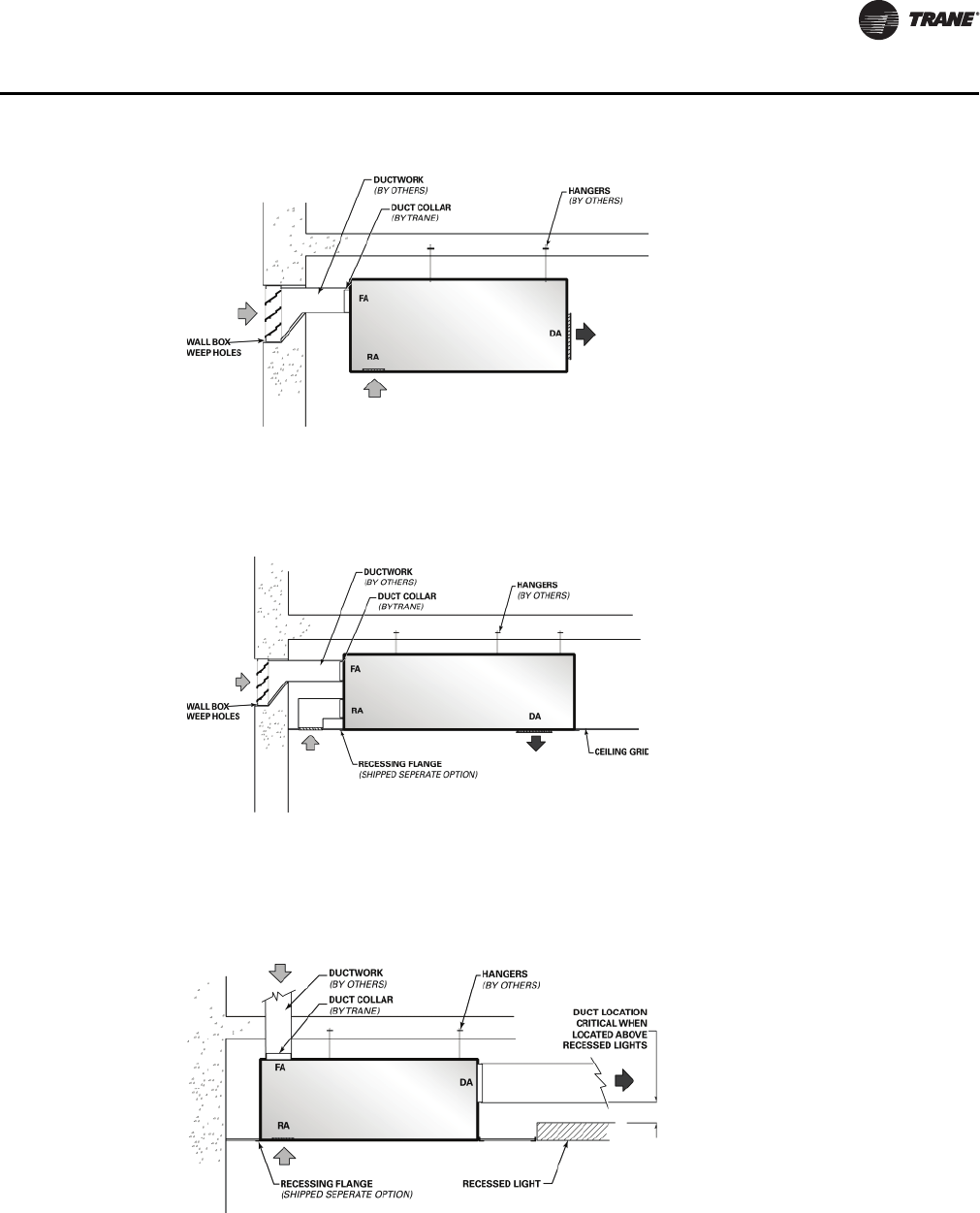
Partially Exposed Unit
Another example of a partially exposed unit ventilator includes a fresh air upper back, with a return
air lower back, combined with a bottom, double-deflection discharge. This application requires
field supplied duct work to the added to the return air side of the unit ventilator.
Partially Exposed Unit
A ducted discharge option is available to support the many design layouts expected of the
mechanical system. The location of the discharge ducting could be critical during installation due
to such issues as recessed lighting. Trane provides three selectable ducted discharge locations to
reduce interference of other trades on the job site.
Note: When a high ESP motor is used on the ducted system, the return air should enter through
a rear duct connection. The return-air should pass through a lined return air duct with at
least one 90° elbow to lessen airflow noise.
Digit 20 = H
Digit 20 = F
UV-PRC004-EN.book Page 11 Monday, February 4, 2013 11:01 AM
12 UV-PRC004-EN
Application Considerations
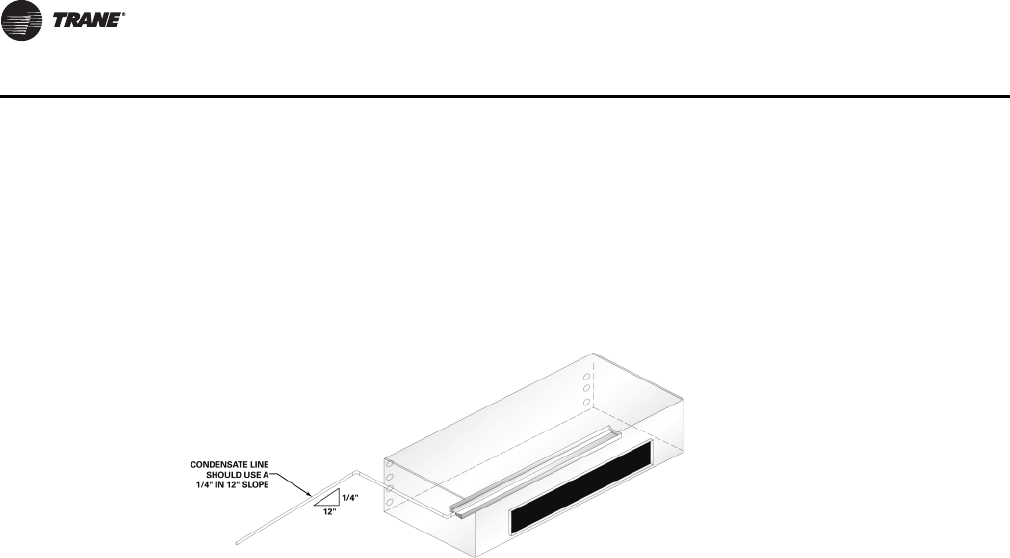
Condensate Piping
The horizontal unit ventilator drain pan connection is located on the same side as the cooling coil
connections (hydronic and DX coils). The stubout size is 3 /4” outside diameter.
All field supplied condensate lines to the unit should contain 1/4” in 12” slope away from the unit
ventilator to aid in condensate removal. This is typical for most local codes. A trap is also
recommended somewhere in the condensate system.
Note: Drain pan connections are field convertible.
Ducted Applications
A well designed duct system is beneficial to obtaining satisfactory fan performance. Determining
resistance losses for the duct work system is also necessary for acceptable fan performance.
Assistance in the design of duct work can be found in the ASHRAE Handbook. The unit ventilator
is designed to operate against ESP thru 0.45”. The ESP is determined by adding the discharge air
static pressure to the greater of either the outdoor air static pressure or the return air static
pressure.
The Applied Unit Ventilator
A Choice in System Design
The beauty of the classroom unit ventilator stems beyond its ability to heat and cool. The Trane unit
ventilator design provides an opportunity to create a comfortable atmosphere for living, learning
and playing, while providing energy efficiency savings with market-leading technology. Some of
the featured benefits of a unit ventilator are:
• Individual room control.
• Fresh air ventilation and filtration.
• Individual dehumidification sequences per zone.
• Energy savings solutions through economizing functions.
• A choice in heating/cooling applied systems.
• And, because the equipment is mounted directly in the space, installation costs are minimal
compared to other HVAC systems.
UV-PRC004-EN.book Page 12 Monday, February 4, 2013 11:01 AM
UV-PRC004-EN 13
Application Considerations
Wide Variety of Heating/Cooling Coils
Trane’s unit ventilator offers a wide variety of coil configurations.
In environments where cooling needs are of main interest, a two-pipe coil coupled with a chiller,
or a direct expansion coil joined with a condensing unit may be used.
For heat specific applications, Trane offers a two-pipe hot water only unit to be combined with a
boiler. Electric heat and steam options are also available for heat fixed conditions.
When there is seasonal heating and cooling, a two-pipe chilled water/hot water changeover system
may be applicable to the mechanical design. This system requires a chiller and a boiler to support
the changeover necessity. However, where space constraints may present a concern, the Trane unit
ventilator may be equipped with a direct expansion coil for cooling, with an auxiliary electric heat
coil, hot water coil, or steam coil for heating.
Four-pipe chilled water/hot water systems are also available. This system is typically applied when
both heating and cooling may be simultaneously called for in the school structure.
Building Automation
As part of the building automation system, the mechanical HVAC system may be optimized to lower
energy consumption. By running only the mechanical devices that are required to support the
building load at a given time of day or night, true energy consumption savings may be achieved.
Maintenance and serviceability faults through the unit sensing devices are easily defined and cured
with an automated system.
With factory shipped direct digital controls, installation and start-up of the system are more simple.
Condensate
Proper condensate trapping is required for the classroom unit ventilator’s with hydronic and direct
expansion coils. In a properly trapped system, when condensate forms during normal operation,
the water level in the trap rises until there is a constant flow of water through the pipe. It is
imperative to maintain water in the trap, and not allow the trap to dry out during heating season.
Equipment should be installed level to avoid condensate build-up around the coil.
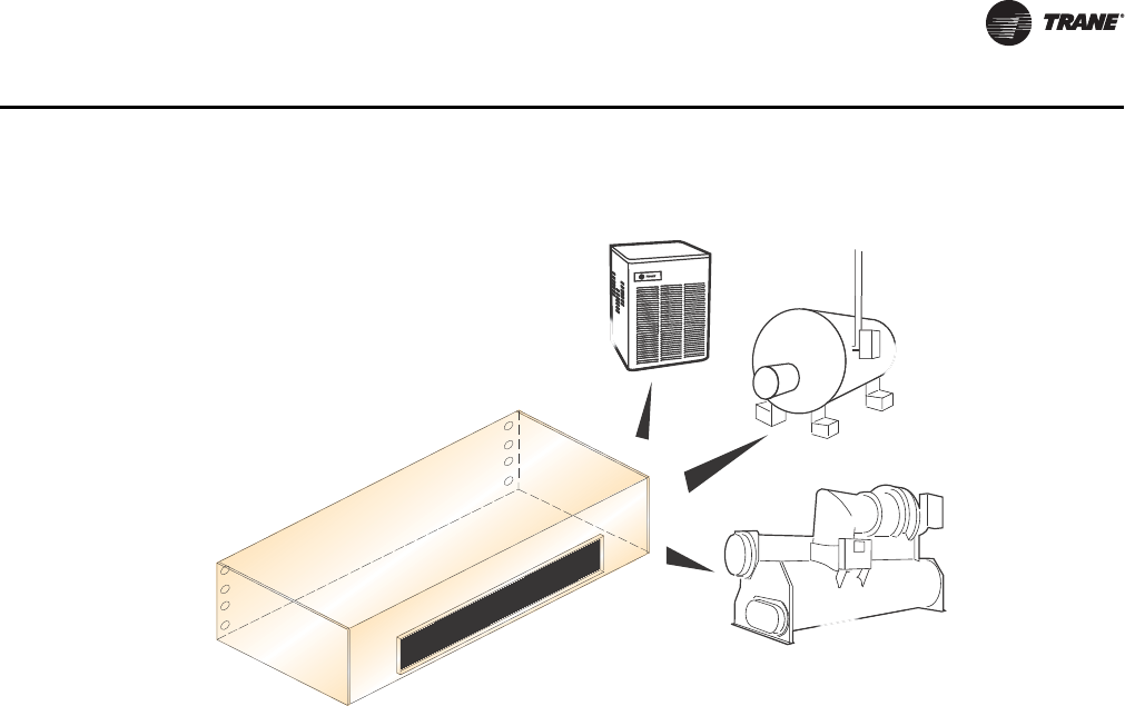
System choice for the classroom unit ventilator
AND/OR
AND/OR
CHILLER FOR
COOLING
BOILER
FOR HEAT ADD
CONDENSER
FOR COOLING
CLASSROOM UNIT VENTILATOR
UV-PRC004-EN.book Page 13 Monday, February 4, 2013 11:01 AM

14 UV-PRC004-EN
Application Considerations
Performance
Application of this product should be within the catalogs airflow and unit performance. The Trane
Official Product Selection System (TOPSS™) will aid in the selection process for a set of given
conditions. If this program has not been made available, ask a local Trane sales account manager
to supply the desired selections or provide a copy of the program.
Ventilation for Acceptable IAQ
Supplying proper ventilation to a classroom is challenging. The various rooms that make up a
school are forever changing in their proper ventilation needs. Building occupants and their
activities generate pollutants that heighten the ventilation requirements. And because of this
intermittent occupancy, the ventilation frequency of a classroom is constantly on the move.
Ventilation systems dilute and remove indoor contaminants, while mechanical heating and cooling
systems control the indoor temperature and humidity. Supplying an adequate amount of fresh air
to an occupied classroom is necessary for good indoor air quality. IAQ should be considered a top
priority in the school environment because children are still developing physically and are more
likely to suffer the consequences of indoor pollutants. For this reason, air quality in schools is of
particular concern. Proper conditioning of the indoor air is more than a quality issue; it
encompasses the safety and stewardship of our investment in the students, staff and facility. The
beauty of a classroom unit ventilator is its ability to provide heating, cooling, ventilation and
dehumidification as a single-zone system.
ASHRAE Control Cycles
There are a variety of control systems available in unit ventilators. The exact method of controlling
the amount of outside air and heating capacity can vary. However, all systems provide a sequence
of operation designed to provide rapid classroom warm-up and increasing amount of ventilation
air to offset classroom overheating. Reasons for classroom overheating can include:
• Sun or solar heat produced through large glass areas in a school.
• Lighting.
•Students
To help supply proper ventilation to these fluctuating heat gains, the Trane unit ventilator is
designed to provide rapid classroom warm-up and increasing amounts of ventilation air to offset
classroom overheating.
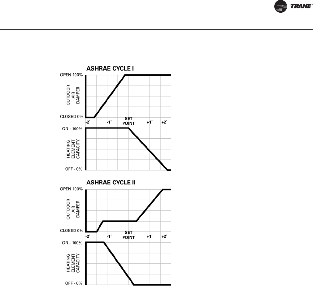
ASHRAE Cycle I. All standard unit ventilator cycles automatically close the outside air damper
whenever maximum heating capacity is required. As room temperature approaches the comfort
setpoint, the outside air damper opens fully, and the unit handles 100 percent outside air. Unit
capacity is then controlled by modulating the heating element capacity.
ASHRAE Cycle I is typically used in areas where a large quantity of outdoor air is required to offset
the air being exhausted to relieve the room of unpleasant odors and particles.
ASHRAE Cycle II. ASHRAE Cycle II is the most widely used ventilation control. Similar to Cycle
I, the outside air damper is closed during warm-up. But with Cycle II, the unit handles recirculated
air through the return air system. As temperature approaches the comfort setting, the outside air
damper opens to admit a predetermined minimum amount of outside air. This minimum has been
established by local code requirements and good engineering practices per AHRI-840. Unit
capacity is controlled by varying the heating element output. If room temperature rises above the
comfort setting, the heating element is turned off and an increasing amount of outside air is
admitted until only outside air is being delivered.
ASHRAE Cycle II is a very economical control sequence often referred to as integrated
economizing. This design supports optimum ventilation and provides the greatest energy savings.
This is further proof of why AHRI-840 certification is important in minimizing energy consumption
through economizer performance.
UV-PRC004-EN.book Page 14 Monday, February 4, 2013 11:01 AM
UV-PRC004-EN 15
Application Considerations
Freeze Protection
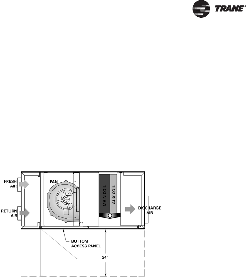
The most important advantage the Trane blow-thru design provides is additional protection against
coil freeze-up. In contrast, draw-thru configurations allow little mixing of the return and outside air
stream while locating the coil very close to the outside air inlet. This process creates “cold spots”
on the coil which could lead to coil freeze-up.
With a blow-thru design, face and bypass with isolation valve control is not necessary (as with other
manufacturers) to provide proper freeze protection to the unit ventilator. This adds cost and more
mechanical components that could break down. The placement of the coil above the fan allows
enough space for the coil to avoid “cold spots” that could cause freezing.
Figure 4. ASHRAE cycle graph
UV-PRC004-EN.book Page 15 Monday, February 4, 2013 11:01 AM

16 UV-PRC004-EN
Selection Procedures
Selecting a Unit Ventilator
Trane horizontal classroom unit ventilators provide air delivery and capacities necessary to meet
the requirements of modern school classrooms. They are available with the industry’s widest
selection of coils to precisely satisfy heating, ventilating and air conditioning loads with the best
individual type of system. Unit ventilator selection involves three basic steps.
• Determine the classroom/space unit cooling and/or heating loads.
• Determine the unit size.
• Select the coil.
Capacity Required
The first step in unit ventilator selection is to determine room heating and air conditioning loads.
The calculation of this load is essential if the equipment is to be economical in first cost and
operating cost.
Adequate ventilation is mandatory in classroom air conditioning design. The amount is often
specified by local or state codes and, in air conditioned schools, may be either the same or less than
that specified for heating systems. The usual requirement is between 15 and 25 cfm of outside air
per occupant, based on the intended use of the room. For instance, a chemistry laboratory normally
requires more ventilation for odor control than a low occupancy speech clinic.
Ventilation is an important concern and should be accurately determined to assure good indoor air
quality. Purposely oversizing units should be avoided, since it can cause comfort and control
issues.
Unit Size
Unit ventilator size is determined by three factors:
• Total air circulation.
• Ventilation cooling economizer capacity required.
• Total cooling or heating capacity required.
Total air circulation, if not specified by code, should be sufficient to ensure comfort conditions
throughout the room. This is usually from six to nine air changes per hour, but can vary with room
design and exposure. Often rooms with large sun exposure require additional circulation to avoid
hot spots.
Ventilation cooling capacity is determined by the amount of outside air delivered with the outside
air damper fully open, and the temperature difference between the outside air and the classroom.
In air conditioning applications, ventilation cooling capacities should maintain the comfort setting
in the classroom whenever the outside air temperature is below the unit or system changeover
temperature.
Example:
Ventilation cooling capacity = 1.085 x cfmt x (T1 - T2)
cfmt = Total air capacity of unit with outside air damper open 100%
T1 = Room temperature
T2 = Outside air temperature
In classrooms with exceptionally heavy air conditioning loads, unit size may be determined by the
total cooling requirement. Good practice dictates 375 to 425 cfm per ton of hydronic cooling
capacity. Normally, however, Trane classroom air conditioner coils have sufficient capacities.
UV-PRC004-EN.book Page 16 Monday, February 4, 2013 11:01 AM

UV-PRC004-EN 17
Selection Procedures
Example:
Given: Air circulation specified = 8 air changes per hour
Classroom size = 35 ft long x 25 ft wide x 10 ft high
Inside design air temperature = 75°F
Ventilation cooling required at 58°F = 29,000 BTU
CFM required = [8 changes/hr x (35 x 25 x 10) ft3] / (60 minutes/hr) = 1170 cfm
Checking ventilation cooling capacity:
29,800 BTU = 1.085 x CFM x (80-58)
CFM = 1250
This indicates that a 1250 cfm unit would have satisfactory ventilation cooling capacity at the
design changeover point of 58°F. Coil capacity will become confirmed when the coil is selected.
Coil Selection
Selecting the correct coil is done through Trane’s Official Product Selection System (TOPSS).
For your convenience, TOPSS has a mixed air calculator built into the program.
UV-PRC004-EN.book Page 17 Monday, February 4, 2013 11:01 AM

18 UV-PRC004-EN
Digit 1, 2, 3 — Unit
Configuration
HUV = Horizontal Unit Ventilator
Digit 4 — Development
Sequence
C = Third Generation
Digit 5, 6, 7 — Development
Sequence
075 = 750 CFM
100 = 1000 CFM
125 = 1250 CFM
150 = 1500 CFM
200 = 2000 CFM
Digit 8 — Unit Incoming Power
Supply
1 = 120V/60/1
2 = 208V/60/1
3 = 208V/60/3
4 = 240V/60/1
5 = 240V/60/3
6 = 277V/60/1
8 = 480V/60/3-Phase 4-Wire Power
Supply
Digit 9 — Motor
0 = Free Discharge ECM
4 = Free Discharge ECM, Low
Acoustics
7 = Free Discharge ECM, Low FLA
Option
N = Free Discharge, Low Acoustics,
Low FLA
A = High Static ECM
E = High Static ECM, Low Acoustics
H = High Static ECM, Low FLA Option
K = High Static ECM, Low Acoustics,
Low FLA
Digit 10, 11 — Design Sequence
** = Design Sequence
Digit 12, 13 — Coil Letter
Designation
(Single Coil Options)
AA = 2 R, 12 FPI CW/HW Changeover
AB = 2 R, 16 FPI CW/HW Changeover
AC = 3 R, 12 FPI CW/HW Changeover
AD = 4 R, 12 FPI CW/HW Changeover
AE = 4 R, 16 FPI CW/HW Changeover
H1 = 1 R, 12 FPI Heating Coil
H2 = 1 R, 14 FPI Heating Coil
H3 = 1 R, 16 FPI Heating Coil
H4 = 2 R, 12 FPI Heating Coil
H5 = 2 R, 14 FPI Heating Coil
H6 = 2 R, 16 FPI Heating Coil
K1 = 1 R Low Capacity Steam Coil
K2 = 1 R High Capacity Steam Coil
E4 = 4 Element Heating Only Coil
E6 = 6 Element Heating Only Coil
E8 = 8 Element Heating Only Coil
G0 = 2 R, 12 FPI DX Coil
(Coupled Coil Options)
DA = 1 R, 12 FPI HW Coil with 2 R,
12 FPI CW Coil
DC = 1 R, 12 FPI HW Coil with 2 R,
14 FPI CW Coil
DD = 1 R, 12 FPI HW Coil with 3 R,
12 FPI CW Coil
DE = 1 R, 14 FPI HW Coil with 3 R,
14 FPI CW Coil
DK = 1 R Steam with 3 R CW Coil
X3 = 3 Element Elec Coil with
3 R CW Coil (2 R on Sz 125)
X4 = 4 Element Elec Coil with
3 R CW Coil (2 R on Sz 125)
X6 = 6 Element Elec Coil with
3 R CW Coil (2 R on Sz 125)
GK = 1 R Steam Coil with 2 R DX Coil
GA = 1 R Heating coil with 2 R DX Coil
G3 = 3 Element Elec Heat Coil with
2 R DX Coil
G4 = 4 Element Elec Heat Coil with
2 R DX Coil
G6 = 6 Element Elec Heat Coil with
2 R DX Coil
R1 = 3 R, 12 FPI CW Coil with 1 R,
12 FPI HW Coil
R2 = 3 R, 14 FPI CW Coil with 1 R,
12 FPI HW Coil
Digit 14 — Coil Connections
A = Right Hand Supply
B = Left Hand Supply
C = Left Hand Cool/Right Hand Heat
D = Right Hand Cool/Left Hand Heat
Digit 15 — Control Types
0 = Unit-Mounted Speed Switch
Q = Tracer ZN520
R = Tracer ZN520 w/Low Temp
T = Tracer ZN520 w/Time Clock
U = Tracer ZN520 w/Low Temp &
Time Clock
X = Tracer ZN520 ICS w/Fan Status
Y = Tracer ZN520 ICS w/Low Temp &
Fan Status
8=CSTI
9 = CSTI w/Low Temp
L = Tracer UC400
M = Tracer UC400 w/Time Clock
Digit 16 — Heating/Change Over
Coil Control
0=None
1 = Face & Bypass Damper Actuator
2 = 2-Pipe Face & Bypass Damper
Control
3 = 4-Pipe Face & Bypass Damper
Control & Isolation Valve
4 = Single Stage Electric Heat Control
5 = Dual Stage Electric Heat
7 = Face & Bypass Damper w/2-Pipe
Control & Isolation Valve
9 = 2-Way 1/2-in. 3.3 CV; 3-Wire Mod
W = 2-Way 1/2-in. 1.9 CV; 3-Wire Mod
G = 2-Way 3/4-in. 4.7 CV; 3-Wire Mod
H = 2-Way 1-in. 6.6 CV; 3-Wire Mod
Z = 3-Way 1/2-in. 1.9 CV; 3-Wire Mod
Q = 3-Way 1/2-in. 3.8 CV; 3-Wire Mod
R = 3-Way 3/4-in. 6.6 CV; 3-Wire Mod
T = Steam: 3-Wire Mod 1/2-in. 1.9 CV
U = Steam: 3-Wire Mod 1/2-in. 4.7 CV
V = Steam: 3-Wire Mod 3/4-in. 8.6 CV
Digit 17 — Cooling Coil Control
0=None
1 = Single Stage DX Controls
A = Field-Supplied Analog Valves
W = 2-Way 1/2-in. 1.9 CV; 3-Wire Mod
G = 2-Way 3/4-in. 4.7 CV; 3-Wire Mod
H = 2-Way 1-in. 6.6 CV; 3-Wire Mod
Z = 3-Way 1/2-in. 1.5 CV; 3-Wire Mod
Q = 3-Way 1/2-in. 3.8 CV; 3-Wire Mod
R = 3-Way 3/4-in. 6.6 CV; 3-Wire Mod
Digit 18 — Damper
Configuration
0 = Field Installed Damper Actuator
1 = 100% Return Air/No Damper or
Actuator
(Modulating ASHRAE Cycle II)
F = RA/OA Damper and Actuator
(2–10 Vdc)
A = RA/OA Damper and Actuator
(3-Point Modulating)
E = RA/OA Damper and Actuator with
Exhaust (3-Point Mod)
(Two Position Control)
D = Damper w/Manual Quad Adjust
Model Number Descriptions
UV-PRC004-EN.book Page 18 Monday, February 4, 2013 11:01 AM

UV-PRC004-EN 19
Model Number Descriptions
Digit 19 — Zone Sensor/Fan
Speed Switch
0 = No Sensor - Unit Mounted Fan
Speed Switch
J = Wall Mt Zone Sensor (OALMH;
Setpoint Dial; On/Cancel)
K = Wall Mt Zone Sensor (OALMH;
Setpoint Dial)
L = UNIT Mt Zone Sensor (OALMH;
Setpoint Dial)
M = Wall Mount Display Sensor
w/Setpoint Adjust
P = Wall Mt Sensor (Setpoint dial;
On/Cancel) w/Unit-Mt Speed
Switch
Q = Wall Mt Sensor (Setpoint Dial)
w/Unit Speed Switch
3 = Wireless Display Sensor (H-L-A-O)
4 = Wireless Sensor - Ext Adjust
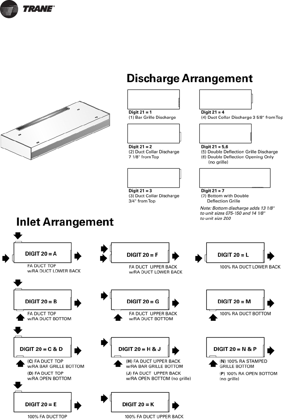
Digit 20 — Inlet Arrangement
A = FA Duct Top/RA Duct Lower Back
B = FA Duct Top/RA Duct Bottom
C = FA Duct Top/RA Bar Grille Bottom
D = FA Duct Top/RA Open Bottom
E=100% FA Duct Top
F = FA Duct Upper Back/RA Duct
Lower Back
G = FA Duct Upper Back/RA Duct
Bottom
H = FA Duct Upper Back/RA Bar Grille
Bottom
J = FA Duct Upper Back/RA Open
Bottom (no grille)
K=100% FA Duct Upper Back
L = 100% RA Duct Lower Back
M = 100% RA Duct Bottom
N = 100% RA Bar Grille Bottom
P = 100% RA Open Bottom (no grille)
Digit 21 — Discharge
Arrangement
1 = Bar Grille Discharge
2 = Duct Collar Discharge 7-1/8 in.
from Top
3 = Duct Collar Discharge 3/4 in.
from Top
4 = Duct Collar Discharge 3-5/8 in.
from Top
5 = Front Double Deflection Grille
Discharge
6 = Front Double Deflection Opening
Only (no grille)
7 = Bottom w/Double Deflection
Grille
Digit 22 — Unit Access Panel
0 = Std. Horizontal Access Panel
1 = Safety Chain/Std. Access Panel
2 = Removable Access Panel
3 = Safety Chain/Removable
Access Panel
Digit 23 — Recessing Flange
0 = No Recessing Flange
1 = Standard Recessing Flange
Digit 24 — Piping Package
0 = No Factory Installed Piping
Package
A = Package 1; Standard Package
C = Package 2; Standard Package
w/Circuit Setter
D = Package 3; Standard Package
w/Strainer and Circuit Setter
Digit 25 — Filter
1 = Throwaway Filter
2 = MERV 8 Filter
3 = MERV 13 Filter
Digit 26 — Color Selection
1 = Deluxe Beige Cabinet
2 = Cameo White Cabinet
3 = Soft Dove Cabinet
4 = Stone Gray Cabinet
5 = Driftwood Gray Cabinet
Digit 27 — Motor Disconnect
0 = No Disconnect
A = Non-Fused Toggle
B=Circuit Breaker
Digit 28 — Control Accessories
0=None
A= C0
2 Sensor
B = Wall Mounted Relative Humidity
Sensor
UV-PRC004-EN.book Page 19 Monday, February 4, 2013 11:01 AM
20 UV-PRC004-EN
General Data
Discharge and Inlet Arrangements
UV-PRC004-EN.book Page 20 Monday, February 4, 2013 11:01 AM
UV-PRC004-EN 21
General Data
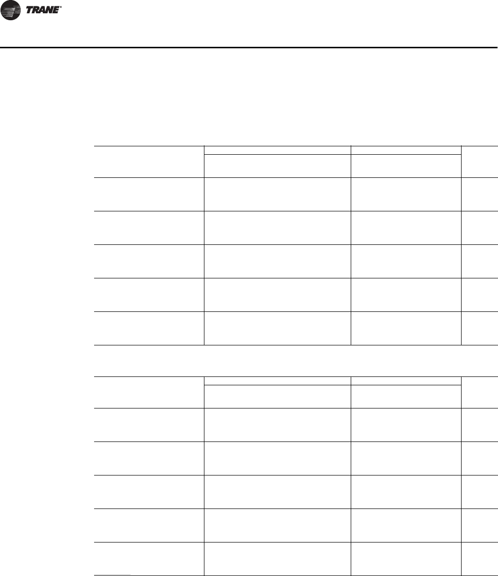
Table 1. Weights and measurements: horizontal unit ventilators
Unit Size 075 100 125 150 200
Unit Length (in.) 70-1/4 82-1/4 94-1/4 106-1/4 106-1/4
Unit Height (in.) 16-5/8 16-5/8 16-5/8 16-5/8 17-5/8
Unit Width (Front Discharge) (in.) 35-5/8 35-5/8 35-5/8 35-5/8 43-1/8
Unit Width (Bottom Discharge) (in.) 48-3/4 48-3/4 48-3/4 48-3/4 57-1/4
Shipping Weight (lb)(a) 340* 375* 435* 500* 600*
Filter Size (inches-actual) 41-1/2 x 15-1/4 x 1 53-1/2 x 15-1/4 x 1 65-1/2 x 15-1/4 x 1 77-1/2 x 15-1/4 x 1 77-1/2 x 15-1/4 x 1
(a) Working weight is approximately 10% less than shipping weight. Trane recommends 1/4-inch rods for hanging suspension
Table 2. Standard motor data (typical for AA coil)
Unit Size Volts RPM (Nominal) CFM (Nominal) Amps (FLA) Watts HP
75 115/60/1 1050 750 13 135 1
100 115/60/1 1050 1000 13 180 1
125 115/60/1 1050 1250 13 191 1
150 115/60/1 1050 1500 13 221 1
200 115/60/1 875 2000 13 311 1
Table 3. Hi-ESP motor data (typical for AA coil)
Unit Size Volts RPM (Nominal) CFM (Nominal) Amps (FLA) Watts HP
75 115/60/1 1330 750 13 198 1
100 115/60/1 1330 1000 13 287 1
125 115/60/1 1330 1250 13 305 1
150 115/60/1 1330 1500 13 357 1
200 115/60/1 1200 2000 13 770 1
Table 4. Coil area
Unit Size Length (in) Width (in) Face Area (in2)
075 42 12 504
100 54 12 648
125 66 12 792
150 78 12 936
200 78 12 936
Table 5. Inlet grille free area
Unit Size
Horizontal Minimum Free Area
Outlet (in2)Inlet (in
2)
075 232 144
100 296 192
125 364 240
150 and 200 430 288
UV-PRC004-EN.book Page 21 Monday, February 4, 2013 11:01 AM

22 UV-PRC004-EN
General Data
Table 6. Coil volume (gallons)
Coil Type Unit Size Volume (gal)
AA, AB 075 0.72
100 0.85
125 0.99
150–200 1.57
AC 075 0.97
100 1.17
125 1.40
150–200 2.27
AD & AE 075 1.25
100 1.51
125 1.80
150–200 2.96
DA–DC 075 0.86
100 0.98
125 1.13
150–200 1.71
DD–DE 075 1.11
100 1.30
125 1.53
150–200 2.39
DK 075 0.97
100 1.17
125 1.39
150-200 2.25
H1–H3 075 0.24
100 0.30
125 0.35
150–200 0.68
H4–H6 075 0.72
100 0.85
125 0.99
150–200 1.57
R1–R2 075 1.21
100 1.47
125 1.73
150–200 2.94
X3–X6 075 0.97
100 1.17
125 0.99
150–200 2.26
UV-PRC004-EN.book Page 22 Monday, February 4, 2013 11:01 AM
UV-PRC004-EN 23
General Data
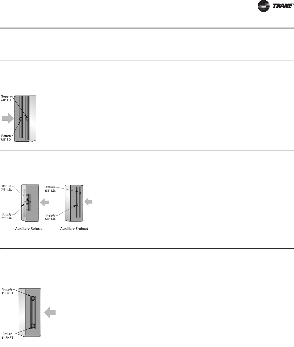
Table 7. Coil specifications
Hydronic Main Coil
• Wavy plate finned
• Hydrostatically tested at 350 psi
Piping packages for the main coil assembly are always supplied as a 3/4-inch package.
Left-hand configuration shown.
Coil Type: AA, AB, AC, AD, AE, H1, H2, H3, H4, H5, H6, DA, DC, DD, DE, X3–X6, DK, R1, R2
Hydronic Auxiliary Coil
• Wavy plate finned
• Hydrostatically tested at 350 psi
Piping packages for the main coil assembly are always supplied as a 3/4-inch package.
Right-hand configuration shown.
Coil Type: DA, DC, DD, DE, FA, R1, R2
Note: A manual air vent is provided on all hydronic coils. The vent allows air to be purged from the coil during start-up, or maintenance. The air vent is
located on the return header. Similarly, a drain plug is located at the bottom of the MAIN coil return header.
Steam Main Coil
• 1-Row, tube-in-tube distributing coil
• 1-inch female pipe connection
Piping packages for steam coils are field provided. Equipment specified with Trane controls will benefit from an optional 2-position isolation valve
to be used for close-off to the steam coil when the damper is in full bypass position.
Right-hand configuration shown.
Coil Type: K1, K2
Coils
UV-PRC004-EN.book Page 23 Monday, February 4, 2013 11:01 AM
24 UV-PRC004-EN
General Data
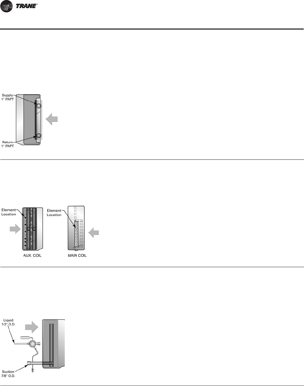
Steam Auxiliary Coil
• 1-Row, tube-in-tube distributing coil
• 1-inch female pipe connection
Piping packages for steam coils are field provided. The modulating piping valve (option) is shipped loose and field installed.
Right-hand configuration shown.
Coil Type: DK, FK
Electric Heat Coil
• Electric preheat coils consist of special resistance elements inserted in the coils fin surface for maximum element life, heat transfer and safety.
• Units include a high temperature cut-out with a continuous sensing element. This device interrupts electrical power whenever excessive
temperatures are sensed along the leaving air side of the coil.
• Electric heat units include a panel interlock switch to disconnect power to the heating element when the access panel is opened.
• Power connection is made in the right hand end pocket.
• A circuit breaker option is available through the equipment model number.
Coil Type: X3, X4, X6, E4, E6, E7, E9
Direct Expansion Coil—R-410A
• The R-410A direct expansion (DX) refrigerant coil includes a factory mounted adjustable thermal expansion valve (TXV) set to 90 psig superheat
and an equalizing tube.
•50 VA transformer
• Time delay relay
• Frost detection sensor
• Outside air sensor
Available in a left-hand configuration only.
Coil Type: G3–G6, G0, GA
Table 7. Coil specifications (continued)
Coils
UV-PRC004-EN.book Page 24 Monday, February 4, 2013 11:01 AM
UV-PRC004-EN 25
General Data
Table 8. Coil row-fin information
Style Coil Type Size Type
Cooling Heating
Rows fpi Rows fpi
2-PipeChangeover Cool or Heat AA 212212
AB 214214
AC 312312
AD 412412
AE 414414
2-Pipe Heating Only H1 NA NA 1 12
H2 NA NA 1 14
H3 NA NA 1 16
H4 NA NA 2 12
H5 NA NA 2 14
H6 NA NA 2 16
2-Pipe DX Cooling Only 075 G0 2 12 NA NA
100 G0 2 12 NA NA
125 G0 2 12 NA NA
150 G0 2 12 NA NA
200 G0 2 14 NA NA
2-Pipe Steam Heating Only—Standard Capacity K1 NA NA 1 8
2-Pipe Steam Heating Only—High Capacity 075 K2 NA NA 1 10
100 K2 NA NA 1 13
125 K2 NA NA 1 10
150 K2 NA NA 1 14
200 K2 NA NA 1 14
4-PipeCold Water Cool / Hot Water Heat DA 212112
DC 214114
DD 312112
DE 314114
4-Pipe Cold Water Cool / Hot Water Re-Heat R1 3 12 1 12
R2 314112
4-PipeCold Water Cool / Steam Heating 075DK 312111
100DK 312112
125DK 312111
150DK 312114
200DK 412114
4-Pipe Cold Water Cool / Electric Heating 075 X3–X6 3 12 Electric
100 X3–X6 3 12 Electric
125 X3–X6 2 14 Electric
150 X3–X6 3 12 Electric
200 X3–X6 3 14 Electric
4-Pipe DX Cool / Hot Water Heat 075 GA 2 12 1 12
200GA 214114
4-PipeDX Cool / Steam Heating 075GK 212111
100GK 212112
125GK 212111
150GK 212114
200GK 214114
4-Pipe DX Cool / Electric Heating 075 G3–G6 2 12 Electric
200 G3–G6 2 14 Electric
Coils
UV-PRC004-EN.book Page 25 Monday, February 4, 2013 11:01 AM
26 UV-PRC004-EN
General Data
Table 9. Control methodology
Fan Speed
FSS 3 or infinite(a)
(a)With a field-supplied 2–10 Vdc controller.
CSTI 3 or infinite(a)
Tracer ZN520 3
Tracer UC400 Infinite
Table 10. Control sequences
Fan Speeds
DX operation(a)
(a)Fan speed during sequence operation.
1
Electric heat operation(a) 1
Sidewall Exhaust(b)
(b)Unit Ventilator when operating with option.
2
ERSA(b) 2
Controls
UV-PRC004-EN.book Page 26 Monday, February 4, 2013 11:01 AM

UV-PRC004-EN 27
Performance Data
A-Coils
AHRI Cooling performance is based on 80/67°F entering air temperature, 45°F entering chilled
water temperature with a 10°F ΔT. Heating performance is based on 70°F entering air temp, 180°F
entering water temperature with a 40°F ΔT. All performance measured on high speed tap, 115 V.
Free discharge units: 0.0 ESP, with throwaway filter. High static units: 0.20 ESP, without filter.
Table 11. A-Coils, 2-pipe coil with free discharge EC motor
Size Coil Type
Airflow
(cfm)
Cooling Heating
Motor
Power
(W)
Total
Capacity
(MBh)
Sensible
Capacity
(MBh)
Flow Rate
(gpm)
WPD
(ft H20)
Total
Capacity
(MBh)
Flow Rate
(gpm)
WPD
(ft H20)
075
AA 875 19.12 15.62 3.81 1.49 52.00 2.60 0.70 135
AB 825 21.80 16.49 4.34 1.88 57.80 2.89 0.80 135
AC 815 27.63 19.28 5.51 4.09 63.90 3.19 1.40 135
AD 780 21.13 16.70 4.21 0.67 67.20 3.36 0.40 135
AE 760 19.64 15.28 3.91 0.59 71.70 3.58 0.50 135
100
AA 1090 25.18 9.02 5.02 2.89 67.00 3.35 1.20 180
AB 1030 28.47 20.09 5.67 3.60 74.40 3.72 1.50 180
AC 1025 33.88 22.89 6.75 7.02 81.90 4.09 2.50 180
AD 975 30.23 21.17 6.02 1.49 96.60 4.33 0.70 180
AE 1015 32.03 21.56 6.38 1.65 97.30 4.87 0.90 180
125
AA 1240 33.47 25.57 6.67 5.55 79.00 3.95 1.90 191
AB 1300 40.07 28.39 7.99 7.64 94.40 4.75 2.70 191
AC 1290 42.72 30.03 8.51 4.45 101.20 5.06 1.60 191
AD 1240 46.56 31.33 9.28 3.66 110.70 5.54 1.30 191
AE 1265 48.38 31.40 9.64 3.93 122.30 6.11 1.60 191
150
AA 1600 42.25 31.85 8.42 9.53 100.30 5.01 3.30 221
AB 1525 46.68 32.38 9.30 11.38 112.10 5.60 4.10 221
AC 1510 50.09 34.12 9.98 6.66 119.90 5.99 2.40 221
AD 1600 56.11 36.64 11.18 5.70 141.80 7.09 2.30 221
AE 1485 56.68 35.73 11.30 5.81 144.80 7.24 2.30 221
200
AA 2085 51.50 40.18 10.26 13.55 120.00 6.00 4.60 311
AB 1985 58.90 42.59 11.74 17.21 135.40 6.77 5.70 311
AC 1970 64.10 44.91 12.78 10.34 146.40 7.32 3.40 311
AD 1885 71.18 47.35 14.19 8.78 161.70 8.08 2.90 311
AE 1785 70.97 45.41 14.14 8.73 169.30 8.47 3.10 311
Table 12. A-coil, 2-pipe coil with high static EC motor
Size Coil Type
Airflow
(cfm)
Cooling Heating
Motor
Power
(W)
Total
Capacity
(MBh)
Sensible
Capacity
(MBh)
Flow Rate
(gpm)
WPD
(ft H20)
Total
Capacity
(MBh)
Flow Rate
(gpm)
WPD
(ft H20)
075
AA 780 17.24 14.07 3.44 1.24 48.00 2.40 0.60 198
AB 760 20.09 15.16 4.00 1.62 54.40 2.72 0.70 198
AC 755 25.81 17.92 5.14 3.62 60.20 3.01 1.20 198
AD 740 18.96 15.35 3.78 0.55 64.20 3.21 0.40 198
AE 795 22.56 16.92 4.50 0.76 74.50 3.73 0.50 198
100
AA 1115 28.38 21.70 5.66 3.57 68.00 3.40 1.30 287
AB 1090 32.67 23.42 6.51 4.59 77.50 3.88 1.60 287
AC 1085 38.77 26.52 7.73 8.91 85.50 4.28 2.70 287
AD 1055 37.26 25.97 7.43 2.17 92.40 4.62 0.80 287
AE 1005 36.82 24.68 7.34 2.13 96.40 4.82 0.90 287
125
AA 1255 34.55 26.50 6.88 5.87 79.60 3.98 2.00 305
AB 1225 39.67 28.07 7.91 7.51 90.40 4.52 2.50 305
AC 1220 42.27 29.69 8.42 4.37 96.90 4.85 1.40 305
AD 1350 51.35 34.70 10.23 4.38 118.70 5.93 1.50 305
AE 1295 51.45 33.47 10.25 4.39 124.80 6.24 1.60 305
150
AA 1490 37.40 27.72 7.45 7.68 95.40 4.77 3.10 357
AB 1450 42.55 29.09 8.48 9.65 108.00 5.40 3.80 357
AC 1445 45.63 30.84 9.09 5.65 115.80 5.79 2.20 357
AD 1715 55.74 36.38 11.11 5.63 150.00 7.50 2.50 357
AE 1635 55.39 34.88 11.04 5.57 157.20 7.86 2.70 357
200
AA 2095 50.67 39.43 10.10 13.16 120.40 6.02 4.60 770
AB 2005 57.94 41.78 11.55 16.71 136.40 6.82 5.80 770
AC 1990 62.87 43.94 12.53 9.99 147.40 7.37 3.40 770
AD 1895 69.14 45.88 13.78 8.32 162.40 8.12 2.90 770
AE 1770 68.74 43.88 13.70 8.24 168.10 8.40 3.10 770
UV-PRC004-EN.book Page 27 Monday, February 4, 2013 11:01 AM
28 UV-PRC004-EN
Performance Data
AHRI Cooling performance is based on 80/67° F entering air temperature, 45°F entering chilled
water temperature with a 10°F ΔT. Heating performance is based on 70°F entering air temp, 180°F
entering water temperature with a 40°F ΔT. All performance measured on high speed tap, 115 V.
Free discharge units: 0.0 ESP, with throwaway filter. High static units: 0.20 ESP, without filter.
Table 13. D-coil, 4-pipe with free discharge EC motor
Size Coil Type
Airflow
(cfm)
Cooling Heating
Motor
Power
(W)
Total
Capacity
(MBh)
Sensible
Capacity
(MBh)
Flow Rate
(gpm)
WPD
(ft H20)
Total
Capacity
(MBh)
Flow Rate
(gpm)
WPD
(ft H20)
075
DA 815 18.16 14.82 3.62 1.36 51.20 2.56 0.50 135
DC 780 19.20 14.93 3.83 1.50 56.70 2.83 0.70 135
DD 780 26.73 18.60 5.33 3.85 49.70 2.48 0.50 135
DE 760 26.81 18.21 5.34 3.87 55.60 2.78 0.60 135
100
DA 1025 24.21 18.20 4.83 2.70 66.30 3.32 1.00 180
DC 975 24.95 17.96 4.97 2.84 73.00 3.65 1.20 180
DD 975 32.41 21.82 6.46 6.49 64.00 3.20 0.90 180
DE 1015 34.38 22.76 6.85 7.21 73.90 3.69 1.20 180
125
DA 1290 34.12 26.13 6.80 5.74 84.00 4.20 1.70 191
DC 1240 36.25 26.17 7.22 6.40 93.10 4.66 2.00 191
DD 1240 41.81 29.35 8.33 4.46 81.60 4.08 1.60 191
DE 1265 46.51 31.39 9.27 5.62 94.50 4.73 2.10 191
150
DA 1510 40.06 29.98 7.98 8.67 99.60 4.98 2.50 221
DC 1600 43.37 30.73 8.64 9.98 118.60 5.93 3.40 221
DD 1600 50.24 34.23 10.01 6.96 103.70 5.19 2.70 221
DE 1485 54.23 35.59 10.81 8.28 112.30 5.61 3.10 221
200
DA 1970 49.82 38.66 9.93 12.77 119.80 5.99 3.50 311
DC 1885 52.99 38.79 10.59 14.25 133.60 6.68 4.30 311
DD 1885 62.56 43.67 12.47 10.31 116.20 5.81 3.30 311
DE 1785 67.01 44.90 13.35 12.13 128.50 6.43 4.00 311
Table 14. D-coils, 4-pipe with high static EC motor
Size Coil Type
Airflow
(cfm)
Cooling Heating
Motor
Power
(W)
Total
Capacity
(MBh)
Sensible
Capacity
(MBh)
Flow Rate
(gpm)
WPD
(ft H20)
Total
Capacity
(MBh)
Flow Rate
(gpm)
WPD
(ft H20)
075
DA 755 16.75 13.68 3.34 1.18 48.50 2.43 0.50 198
DC 740 17.99 13.99 3.59 1.34 54.40 2.72 0.60 198
DD 740 25.33 17.57 5.05 3.50 47.80 2.39 0.50 198
DE 795 28.38 19.35 5.66 4.28 57.50 2.87 0.70 198
100
DA 1085 27.68 21.10 5.52 3.42 69.00 3.45 1.10 287
DC 1055 29.55 21.60 5.89 3.84 77.40 3.87 1.30 287
DD 1055 38.03 25.97 7.58 8.61 67.70 3.39 1.00 287
DE 1005 38.15 25.45 7.60 8.66 73.30 3.66 1.20 287
125
DA 1220 33.80 25.85 6.74 5.65 80.70 4.03 1.50 305
DC 1350 39.46 28.79 7.86 7.43 99.20 4.96 2.30 305
DD 1350 45.76 32.35 9.12 5.24 86.70 4.34 1.80 305
DE 1295 49.25 33.38 9.81 6.23 96.20 4.81 2.10 305
150
DA 1445 36.80 27.22 7.33 7.46 96.50 4.83 2.30 357
DC 1715 43.12 30.52 8.59 9.88 124.80 6.24 3.80 357
DD 1715 49.93 34.00 9.95 6.88 108.90 5.45 2.90 357
DE 1635 53.07 34.77 10.58 7.97 120.60 6.03 3.50 357
200
DA 1990 48.96 37.88 9.76 12.38 120.60 6.03 3.50 770
DC 1895 51.69 37.68 10.30 13.63 134.10 6.71 4.30 770
DD 1895 60.89 42.37 12.14 9.82 116.70 5.83 3.30 770
DE 1770 65.04 43.44 12.96 11.49 127.70 6.38 3.90 770
D-Coils
UV-PRC004-EN.book Page 28 Monday, February 4, 2013 11:01 AM
UV-PRC004-EN 29
Performance Data
AHRI Cooling performance is based on 80/67° F entering air temperature, 45°F entering chilled
water temperature with a 10°F ΔT. Heating performance is based on 70°F entering air temp, 180°F
entering water temperature with a 40°F ΔT. All performance measured on high speed tap, 115 V.
Free discharge units: 0.0 ESP, with throwaway filter. High static units: 0.20 ESP, without filter.
Table 15. 2-Pipe coil, HW data
HUV Size Coil Type
Heating
Total
Capacity Flow Rate WPD
(MBh) (gpm) (ft H20)
075
H1 41.18 2.06 2.85
H2 45.12 2.26 3.36
H3 48.74 2.44 3.86
H4 53.49 2.67 0.70
H5 57.95 2.90 0.81
H6 61.84 3.09 0.91
100
H1 52.90 2.65 0.97
H2 57.98 2.90 1.15
H3 62.65 3.13 1.33
H4 71.90 3.59 1.41
H5 77.92 3.90 1.63
H6 83.19 4.16 1.84
125
H1 66.45 3.32 1.67
H2 72.85 3.64 1.98
H3 78.73 3.94 2.28
H4 90.36 4.52 2.45
H5 97.97 4.90 2.83
H6 104.61 5.23 3.19
150
H1 99.89 4.99 2.70
H2 124.35 6.22 4.03
H3 131.66 6.58 4.48
H4 108.87 5.44 3.88
H5 118.05 5.90 4.49
H6 126.08 6.30 5.05
200
H1 120.35 6.02 3.80
H2 152.05 7.60 5.84
H3 161.68 8.08 6.54
H4 132.52 6.63 5.52
H5 144.37 7.22 6.44
H6 154.87 7.74 7.32
Table 16. X-coils, 2-pipe with free discharge EC motor
Size Coil Type
Cooling
Total
Capacity
(MBh)
Sensible
Capacity
(MBh)
Flow Rate
(gpm)
WPD
(ft H20)
075 X3 26.73 18.60 5.33 3.85
X4 26.73 18.60 5.33 3.85
X6 26.73 18.60 5.33 3.85
100 X3 32.41 21.82 6.46 6.49
X4 32.41 21.82 6.46 6.49
X6 32.41 21.82 6.46 6.49
125 X3 39.67 27.73 7.91 7.51
X4 39.67 27.73 7.91 7.51
X6 39.67 27.73 7.91 7.51
150 X3 50.24 34.23 10.01 6.96
X4 50.24 34.23 10.01 6.96
X6 50.24 34.23 10.01 6.96
200 X3 72.21 48.78 14.39 13.34
X4 72.21 48.78 14.39 13.34
X6 72.21 48.78 14.39 13.34
H-, X-Coils
UV-PRC004-EN.book Page 29 Monday, February 4, 2013 11:01 AM
30 UV-PRC004-EN
Performance Data
AHRI Cooling performance is based on 80/67 °F entering air temperature, 45°F entering chilled
water temperature with a 10°F ΔT. Heating performance is based on 70°F entering air temp, 180°F
entering water temperature with a 40°F ΔT. All performance measured on high speed tap, 115 V.
Free discharge units: 0.0 ESP, with throwaway filter. High static units: 0.20 ESP, without filter.
Table 17. R1-, R2-, GA-coils, 4-pipe with free discharge EC motor, heating data
Unit Size Coil Type
Heating
Total
Capacity
(MBh)
Flow Rate
(gpm)
WPD
(ft H20)
075 R1 30.38 1.52 1.66
R2 36.27 1.81 2.29
GA 53.61 2.68 0.59
100 R1 38.03 1.90 0.54
R2 45.30 2.27 0.74
GA 72.06 3.60 1.14
125 R1 48.31 2.42 0.94
R2 57.62 2.88 1.30
GA 90.57 4.53 1.91
150 R1 68.42 3.42 1.36
R2 81.16 4.06 1.85
GA 102.98 5.15 2.63
200 R1 81.33 4.07 1.86
R2 96.80 4.84 2.56
GA 136.30 6.81 4.45
Table 18. R1-, R2-, DK-coils, 4-pipe with free discharge EC motor, cooling data
Unit Size Coil Type
Cooling
Total
Capacity
(MBh)
Sensible
Capacity
(MBh)
Flow Rate
(gpm)
WPD
(ft H20)
075 R1 26.73 18.60 5.33 3.85
R2 26.81 18.21 5.34 3.87
DK 17.47 13.97 3.48 1.27
100 R1 32.41 21.82 6.46 6.49
R2 34.38 22.76 6.85 7.21
DK 23.03 16.94 4.59 2.47
125 R1 41.81 29.35 8.33 4.46
R2 46.51 31.39 9.27 5.40
DK 33.47 24.34 6.67 5.55
150 R1 50.24 34.23 10.01 6.96
R2 54.23 35.59 10.81 7.98
DK 40.17 28.34 8.01 8.71
200 R1 62.56 43.67 12.47 10.31
R2 67.07 44.90 13.35 11.67
DK 48.70 35.47 9.71 12.26
GA-, DK-, R1-, R2-Coils
UV-PRC004-EN.book Page 30 Monday, February 4, 2013 11:01 AM
UV-PRC004-EN 31
Performance Data
Table 19. R-410A cooling only(a)
HUV
Unit Size Condensing Unit EWB (°F) T-Btu/hr(b)
S-Btu/hr
EDB 72°F EDB 76°F EDB 80°F
075 4TTB3018 63 18865 12052 15467 18574
67 19919 7972 11532 15060
71 21029 3638 7170 10878
4TTB3024 63 23108 13307 16931 20805
67 24057 9023 12633 16291
71 25428 4477 7832 11784
100 4TTB3024 63 24820 15965 20784 24543
67 26117 10448 15251 19950
71 27544 4735 9536 14353
4TTB3030 63 28395 17201 21904 26087
67 29886 11643 16360 21069
71 31529 5709 10447 15301
125 4TTB3030 63 30441 19769 25504 30266
67 31903 12951 18875 24723
71 33583 5690 11569 17730
4TTB3036 63 35117 21393 27320 32571
67 36701 14277 20254 26132
71 38881 6927 13004 19506
150 4TTB3036 63 36851 23892 31008 36531
67 38641 15616 22735 29964
71 40353 6867 14159 21323
4TTB3042 63 41204 25231 32327 39155
67 42745 16873 23916 30966
71 44884 7964 15092 22325
200 4TTB3042 63 43734 30169 38934 43734
67 45733 19218 28689 38535
71 47505 7509 17362 26976
4TTB3048 63 47482 30769 39826 47125
67 49200 20140 29313 38635
71 51420 8828 17852 27549
(a) R-410A DX coils are rated at 95°F dry bulb/80°F wet bulb ambient outside air temperature, 25 feet of suction and liquid line, 400 cfm per Ton nominal.
(b)Total Capacity calculated from outdoor 95°F dry bulb/80°F wet bulb and 80°F indoor DB standard air conditions.
DX-Coils
UV-PRC004-EN.book Page 31 Monday, February 4, 2013 11:01 AM
32 UV-PRC004-EN
Performance Data
Table 20. Electric heat capacity
Unit Size Coil Type No of Elem. Elem. kW Total kW TMBH
075 G3, X3 3 1.95 5.85 19.98
E4, G4, X4 4 1.95 7.80 26.64
E6, G6, X6 6 1.95 11.70 39.96
E7 7 1.95 13.65 46.61
E9 9 1.95 17.55 59.93
100 G3, X3 3 2.60 7.80 26.64
E4, G4, X4 4 2.60 10.40 35.52
E6, G6, X6 6 2.60 15.60 53.27
E7 7 2.60 18.20 62.15
E9 9 2.60 23.40 79.91
125 G3, X3 3 3.25 9.75 33.30
E4, G4, X4 4 3.25 13.00 44.40
E6, G6, X6 6 3.25 19.50 66.60
E7 7 3.25 22.75 77.69
E9 9 3.25 29.25 99.89
150 G3, X3 3 3.80 11.40 38.91
E4, G4, X4 4 3.80 15.20 51.91
E6, G6, X6 6 3.80 22.80 77.86
E7 7 3.80 26.60 90.84
E9 9 3.80 34.20 116.79
200 G3, X3 3 3.80 11.40 38.93
E4, G4, X4 4 3.80 15.20 51.91
E6, G6, X6 6 3.80 22.80 77.86
E7 7 3.80 26.60 90.84
E9 9 3.80 34.20 116.79
Electric Heat
UV-PRC004-EN.book Page 32 Monday, February 4, 2013 11:01 AM
UV-PRC004-EN 33
Performance Data
Table 21. Steam coil capacity
Unit Size Coil Type EAT
TMBH
5 PSIG 10 PSIG 15 PSIG
075 K1 -20 85.89 89.98 93.48
0 78.94 83.04 86.54
20 72.00 76.10 79.59
40 65.06 69.16 72.65
60 58.12 62.21 65.71
70 54.65 58.74 62.24
K2 -20 101.18 106.01 110.12
0 93.00 97.83 101.94
20 84.82 89.65 93.77
40 76.64 81.47 85.59
60 68.46 73.29 77.41
70 64.38 69.20 73.32
100 K1 -20 112.93 118.31 122.91
0 103.80 109.19 113.78
20 94.67 100.06 104.65
40 85.54 90.93 95.52
60 76.41 81.80 86.40
70 71.85 77.24 81.83
K2 -20 158.08 165.61 172.05
0 145.30 152.84 159.27
20 132.52 140.06 146.49
40 119.74 127.28 133.71
60 106.96 114.50 120.93
70 100.57 108.11 114.55
125 K1 -20 139.94 146.61 152.31
0 128.63 135.30 140.99
20 117.31 123.99 129.68
40 106.00 112.68 118.37
60 94.69 101.36 107.06
70 89.03 95.71 101.40
K2 -20 164.93 172.79 179.50
0 151.60 159.46 166.17
20 138.26 146.13 152.84
40 131.78 132.80 139.51
60 111.60 119.47 126.18
70 104.93 112.80 119.51
150 K1 -20 166.93 174.89 181.68
0 153.44 161.40 168.19
20 139.94 147.90 154.70
40 126.45 134.41 141.20
60 112.96 120.92 127.71
70 106.21 114.17 120.96
K2 -20 243.70 256.14 263.74
0 224.72 236.38 246.33
20 204.96 216.62 226.57
40 185.20 196.86 206.80
60 165.43 177.09 187.04
70 155.55 167.21 177.16
200 K2 -20 286.51 306.05 317.93
0 266.20 282.43 294.32
20 244.09 258.82 270.71
40 221.28 235.21 274.09
60 197.66 211.59 223.48
70 185.86 199.79 211.67
Notes:
1. Condensate trap for the steam coil option is field installed.
2. Static pressure for the K1, K2 options should be modeled after the H1 coil option.
3. Steam coils that function at 5 psig or less should not utilize valve control. Valve control may starve the coil, causing
stratification.
K1-, K2-Steam Coils
UV-PRC004-EN.book Page 33 Monday, February 4, 2013 11:01 AM
34 UV-PRC004-EN
Performance Data
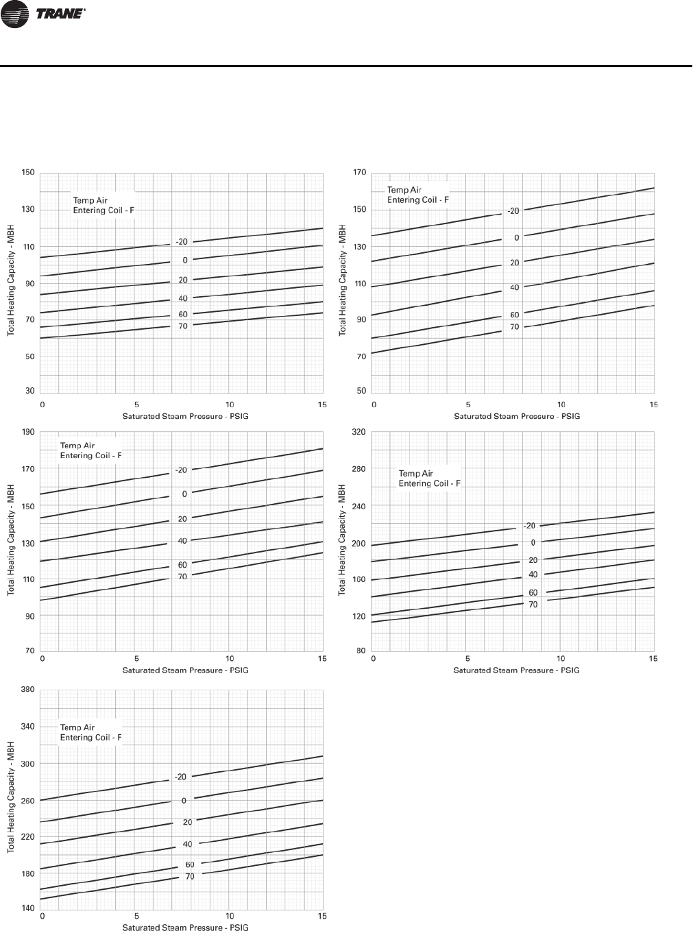
Figure 5. DK, GK Steam coils performance data
Size 075 Unit Size 100 Unit
Size 125 Unit Size 150 Unit
Size 200 Unit
Note: Steam pressure below 8 psi is not recommended.
DK-, GK-Steam Coils
UV-PRC004-EN.book Page 34 Monday, February 4, 2013 11:01 AM
UV-PRC004-EN 35
Performance Data
Table 22. Minimum Circuit Ampacity (MCA) for standard and high static motors (115 V)
Unit Size HP Amps
75 1 16.25
100 1 16.25
120 1 16.25
150 1 16.25
200 1 16.25
Table 23. Minimum Circuit Ampacity (MCA) for electric heat coils with standard motors
Unit Size No. of Elem Coil kW 208 V 1ph 240 V 1ph 277 V 1ph 208 V 3ph 240 V 3ph 480 V 3ph
75 3 5.85 43.84 38.53 32.59 29.01 25.67 14.99
100 7.8 55.56 48.69 41.39 35.78 31.55 17.93
120 9.75 67.28 58.84 50.19 42.56 37.42 20.86
150 11.4 77.2 67.44 57.63 48.29 42.38 23.35
200 11.4 77.2 67.44 57.63 48.29 42.38 23.35
75 4 7.8 55.56 48.69 41.39 35.78 31.55 17.93
100 10.4 71.19 62.23 53.12 44.81 39.37 21.84
120 13 86.81 75.77 64.85 53.85 47.20 25.76
150 15.2 100.03 87.23 74.78 61.49 53.82 29.07
200 15.2 100.03 87.23 74.78 61.49 53.82 29.07
75 6 11.7 NA 69.00 58.99 49.33 43.29 23.80
100 15.6 NA 89.31 76.58 62.88 55.03 29.67
120 19.5 NA 109.63 94.18 76.43 66.77 35.54
150 22.8 NA 126.81 109.08 87.89 76.70 40.51
200 22.8 NA 126.81 109.08 87.89 76.70 40.51
Table 24. Additional Minimum Circuit Ampacity (MCA)
Volts Amps
120 0.94
208 0.55
240 0.48
277 0.41
480 0.41
Table 25. Minimum Circuit Ampacity (MCA) for electric heat coils with high static motor
Unit Size No. of Elem Coil kW 208 V 1ph 240 V 1ph 277 V 1ph 208 V 3ph 240 V 3ph 480 V 3ph
75 3 5.85 43.84 38.53 32.59 29.01 25.67 14.99
100 7.8 55.56 48.69 41.39 35.78 31.55 17.93
120 9.75 67.28 58.84 50.19 42.56 37.42 20.86
150 11.4 77.2 67.44 57.63 48.29 42.38 23.35
200 11.4 77.2 67.44 57.63 48.29 42.38 23.35
75 4 7.8 55.56 48.69 41.39 35.78 31.55 17.93
100 10.4 71.19 62.23 53.12 44.81 39.37 21.84
120 13 86.81 75.77 64.85 53.85 47.20 25.76
150 15.2 100.03 87.23 74.78 61.49 53.82 29.07
200 15.2 100.03 87.23 74.78 61.49 53.82 29.07
75 6 11.7 NA 69.00 58.99 49.33 43.29 23.80
100 15.6 NA 89.31 76.58 62.88 55.03 29.67
120 19.5 NA 109.63 94.18 76.43 66.77 35.54
150 22.8 NA 126.81 109.08 87.89 76.70 40.51
200 22.8 NA 126.81 109.08 87.89 76.70 40.51
Table 26. Minimum Circuit Ampacity (FLA) for EC motors
Motor Type HP Amps
Standard EC motors 1 13
High Static EC motors 1 13
Electrical
UV-PRC004-EN.book Page 35 Monday, February 4, 2013 11:01 AM
36 UV-PRC004-EN
Performance Data
Minimum Circuit Ampacity (MCA) and Maximum Fuse Size (MFS) Calculations
for Unit Ventilators with Electric Heat (Single Phase) Heater Amps =
(Heater kW x 1000)/Heater Voltage
Note: Use 120 V heater voltage for 115 V units. Use 240 V heater voltage for 230V units.
MCA = 1.25 x (heater amps + all motor FLAs)
MFS or HACR Type Circuit Breaker = (2.25 x Largest Motor FLA) + Second Motor FLA + Heater Amps
(If Applicable)
HACR (Heating, Air-Conditioning and Refrigeration) type circuit breakers are required in the branch
circuit wiring for all Unit Ventilators with electric heat.
Refer to Figure 26, p. 35 for motor FLAs.
Select a standard fuse size or HACR type circuit breaker equal to the MCA. Use the next larger
standard size if the MCA does not equal a standard size. Standard Fuse Sizes are: 15, 20, 25, 30, 35,
40, 45, 50, 60 amps (increase to 150 amps)
Unit Ventilator electric heat MBh = (Heater kW) (3.413)
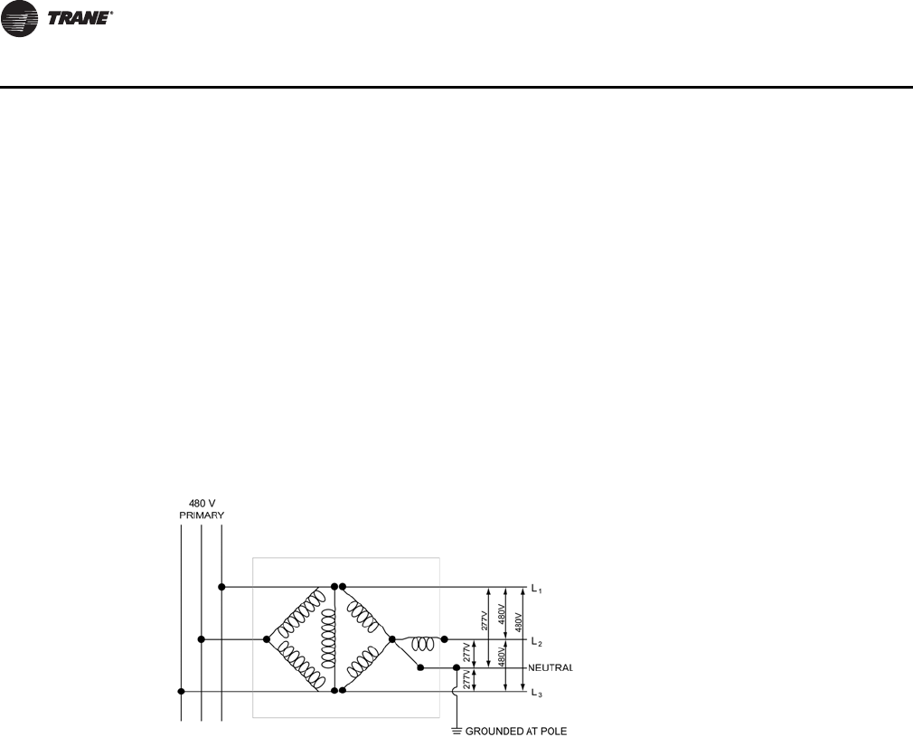
Note: Incoming power to the unit ventilator is 3-phase, 4-wire for a 480 Volt system (3-hot, 1-neutral). This does not include
an equipment ground.
Electrical
UV-PRC004-EN.book Page 36 Monday, February 4, 2013 11:01 AM

UV-PRC004-EN 37
Performance Data
Glycol in an HVAC System
Because the detrimental effects of glycol are lower at high temperatures, little concern is given to
capacity loss or increased pump power when glycol is added to heating systems. This is why it is
not uncommon to see glycol percentages up to 40 percent in the heating loop of a system.
However, the same is not true for cooling systems. Concentrations of this level are intolerable in
cooling systems where fluid temperatures are lower. The viscosity of the glycol increases as the
temperature of the mixture drops. This not only decreases the effectiveness of the heat transfer,
but it also makes the mixture more difficult to pump. To make things worse, as the percentage of
glycol increases, the risk of having laminar flow in the coil increases. This again is because glycol
is more viscous than water.
With these effects in mind it is important to use a minimum amount of glycol to protect the HVAC
system.
Burst Protection vs. Freeze Protection
Burst protection is sufficient in systems where there is adequate space to accommodate the
expansion of an ice/slush mixture. The protection works as follows: As the temperature drops
below the solution’s freeze point, ice crystals begin to form. Because the water freezes first, the
remaining glycol solution is further concentrated and remains fluid. The combination of ice crystals
and fluid make a flowable slush. The volume increases as this slush forms and flows into the
available expansion volume (usually an expansion tank). When a sufficient concentration of glycol
is present, no damage to the system will occur.
Freeze protection is required in cases where no ice crystals can be permitted to form or where there
is inadequate expansion volume available. HVAC systems intended to start-up in cold weather after
prolonged winter shutdowns may require freeze protection. Table 27 is provided by Dow Chemical
Co. for its ethylene and propylene glycol products.
Ta b l e 27 shows that a 30 percent ethylene glycol solution is enough to protect a system down to
-60°F. Because of the benefits of burst protection, excessive glycol only degrades the heat transfer
and increases the pressure drop of the fluid without providing additional system protection. Use
glycol correctly.
Table 27. Percentage volume glycol concentration
Temperature (°F)
For Freeze Protection For Burst Protection
Ethylene Glycol Propylene Glycol Ethylene Glycol Propylene Glycol
20 16% 17% 11% 11%
10 25% 26% 17% 18%
0 33% 34% 22% 23%
-10 39% 41% 26% 28%
-20 44% 45% 30% 30%
-30 48% 49% 30% 33%
-40 52% 51% 30% 35%
-50 56% 53% 30% 35%
-60 60% 55% 30% 35%
Glycol Correction Factors
UV-PRC004-EN.book Page 37 Monday, February 4, 2013 11:01 AM
38 UV-PRC004-EN
Performance Data
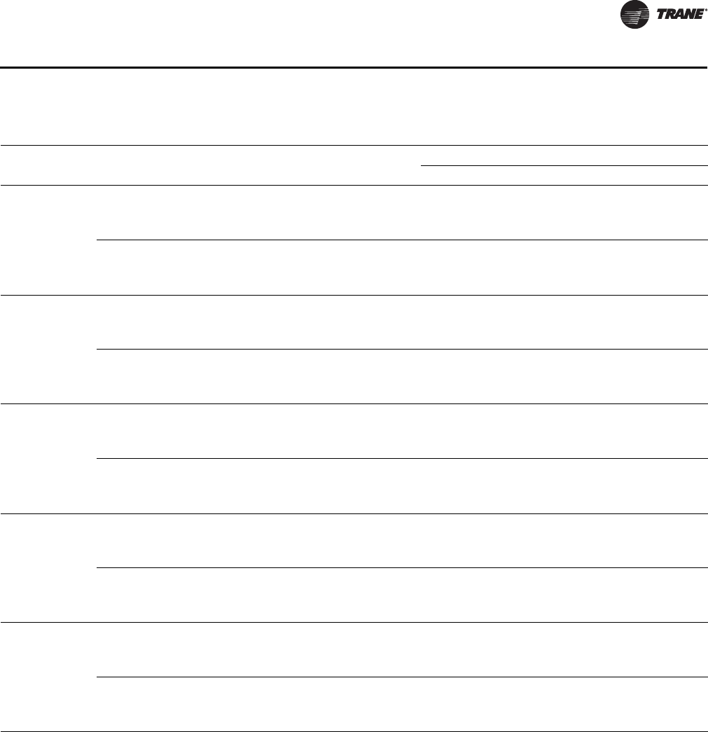
Table 28 reflects sound power ratings for the horizontal classroom unit ventilator. To calculate the
noise criteria (NC) for a unit, subtract the actual room effect from the sound power number in each
octave band. These numbers may be graphed on a NC chart.
Note: Because room affects vary greatly, request exact numbers per the specific job from the
design engineer. By obtaining these exact numbers, the most accurate results of the
installed unit may be calculated.
Data obtained in the reverberant rooms conforming to ANSI S12.31 and ANSI S12.32
Table 28. Horizontal octave band sound power ratings (sound power in db ref: 10-12 watts)
Octave Band12345678
Center of Frequency 63 125 250 500 1000 2000 4000 8000
075 High Speed 66 67 61 60 56 53 48 41
075 Med Speed 62 63 57 56 52 49 44 37
075 Low Speed 59 60 54 53 49 46 41 34
100 High Speed 66 67 61 60 56 52 48 41
100 Med Speed 62 63 57 56 52 48 44 37
100 Low Speed 59 61 55 54 43 45 38 29
120 High Speed 70 71 65 64 60 56 51 44
120 Med Speed 66 67 61 60 56 52 47 40
120 Low Speed 63 64 58 57 53 49 44 37
150 High Speed 65 68 62 60 56 52 45 38
150 Med Speed 61 64 58 56 52 48 41 34
150 Low Speed 57 63 54 53 47 42 33 25
200 High Speed 73 75 68 64 60 57 53 45
200 Med Speed 67 69 62 58 54 51 47 39
200 Low Speed 64 74 59 60 49 45 37 29
Acoustical
UV-PRC004-EN.book Page 38 Monday, February 4, 2013 11:01 AM
UV-PRC004-EN 39
Piping
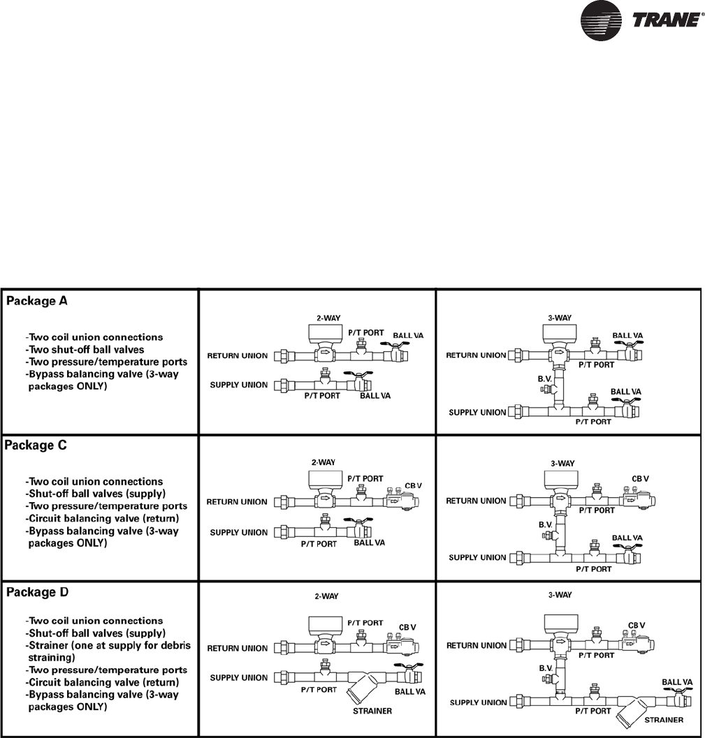
Factory Installed Piping Packages
Trane’s factory mounts piping packages for hydronic specified coils when Tracer™ ZN520, Tracer
UC400, or CSTI controls are designated.
Note: Valves for steam coils are not factory piped.
Piping packages are available in either 2-way, or 3-way configurations. The 3-point floating valve
is piped on the return side of the coil. Piping packages are factory leak tested to 300 psig to ensure
joint integrity.
Note: Insulation for the piping packages is field provided and field installed.
UV-PRC004-EN.book Page 39 Monday, February 4, 2013 11:01 AM

40 UV-PRC004-EN
Controls
Why Trane Controls?
Whether involved in a retrofit or in new construction applications, Trane has the control design to
fit the systems requirements. The broad range of control packages offer a range from a field
convertible end-device package, to a complete building automation system solution with LonTalk®
controls.
The good news is Trane® controls are factory-mounted, -wired, -tested and configured or
programmed with Trane® application expertise to provide comfort, efficiency, and reliability, as
well as, single-source warranty and service. With Trane’s integrated controls, the installed costs are
lower because the equipment has turn-key factory controls and every component of the system is
optimized to fit with the controller. Trane installs not only the controller, but also the hardware that
works intimately with the controller to allow the system to function properly (i.e., piping package,
valves, dampers, actuators, etc.). When a classroom unit ventilator with Trane® controls arrives to
the jobsite, it is completely ready for quick installation.
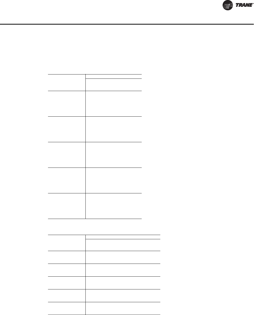
Table 29. Controller input/output summary
ZN520 UC400
Binary Outputs X
3-Speed Fan X X
2-Position Hydronic Valve X X
2-Position Fresh Air Damper X
1-Stage Electric Heat X X
3-Wire Economizer Damper X X
3-Wire Hydronic Valve X X
2-Stage Electric Heat X X
Reheat (hydronic or electric) X X
Generic X (a)
(a)The generic input and output are for use with a Tracer Summit system only.
Binary Inputs
Condensate Overflow Detection X X
Low Temperature Detection X X
Occupancy X X
Generic Input X (a)
Analog Inputs
Zone Temperature X X
Setpoint X X
Fan Mode: Auto, High, Medium, Low X X
Entering Water X X
Discharge Air X X
Outside Air X X
Generic X (a)
Analog Outputs
Variable speed fan X
Field supplied analog valves X
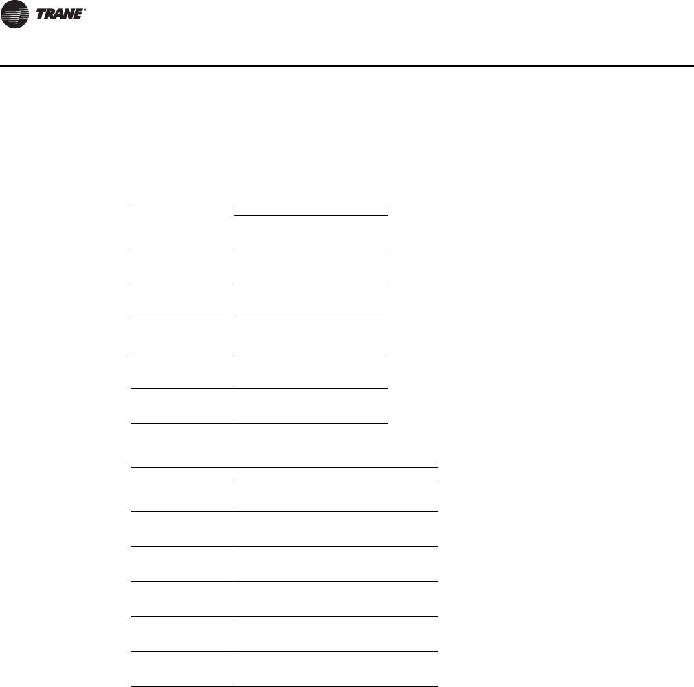
Table 30. Controller function summary
ZN520 UC400
Control Functions
Entering Water Temp. Sampling (Purge) X X
Auto Changeover X X
Fan Cycling
Warm-Up X
Pre-Cool X
Data Sharing (Master/Slave) X
Random Start X X
Dehumidification X X
Single Zone VAV X
Staged Capacity (2-Stage Electric Supplementary) X X
Other Functions
Manual Test X in TU
Maintenance Timer X X
Setpoint Limits X X
UV-PRC004-EN.book Page 40 Monday, February 4, 2013 11:01 AM
UV-PRC004-EN 41
Controls
ECM Engine Controller
The Electronically Commutated Motor (ECM) engine controls and reports the performance of up
to two Trane Brushless DC (BLDC) motors.
• The engine also coordinates the operation of the fan in response to electric heat behavior and
electric behavior in response to hydronic heat behavior.
• The engine incorporates a user interface that allows adjustment of certain unit parameters and
provides constant feedback on motor operation.
• The engine integrates service and troubleshooting tools.
• The engine integrates a versatile configurable auxiliary temperature sensor.
• The engine incorporates various safety and lockout features, such as maintaining proper fan
speeds if electric heat is called for.
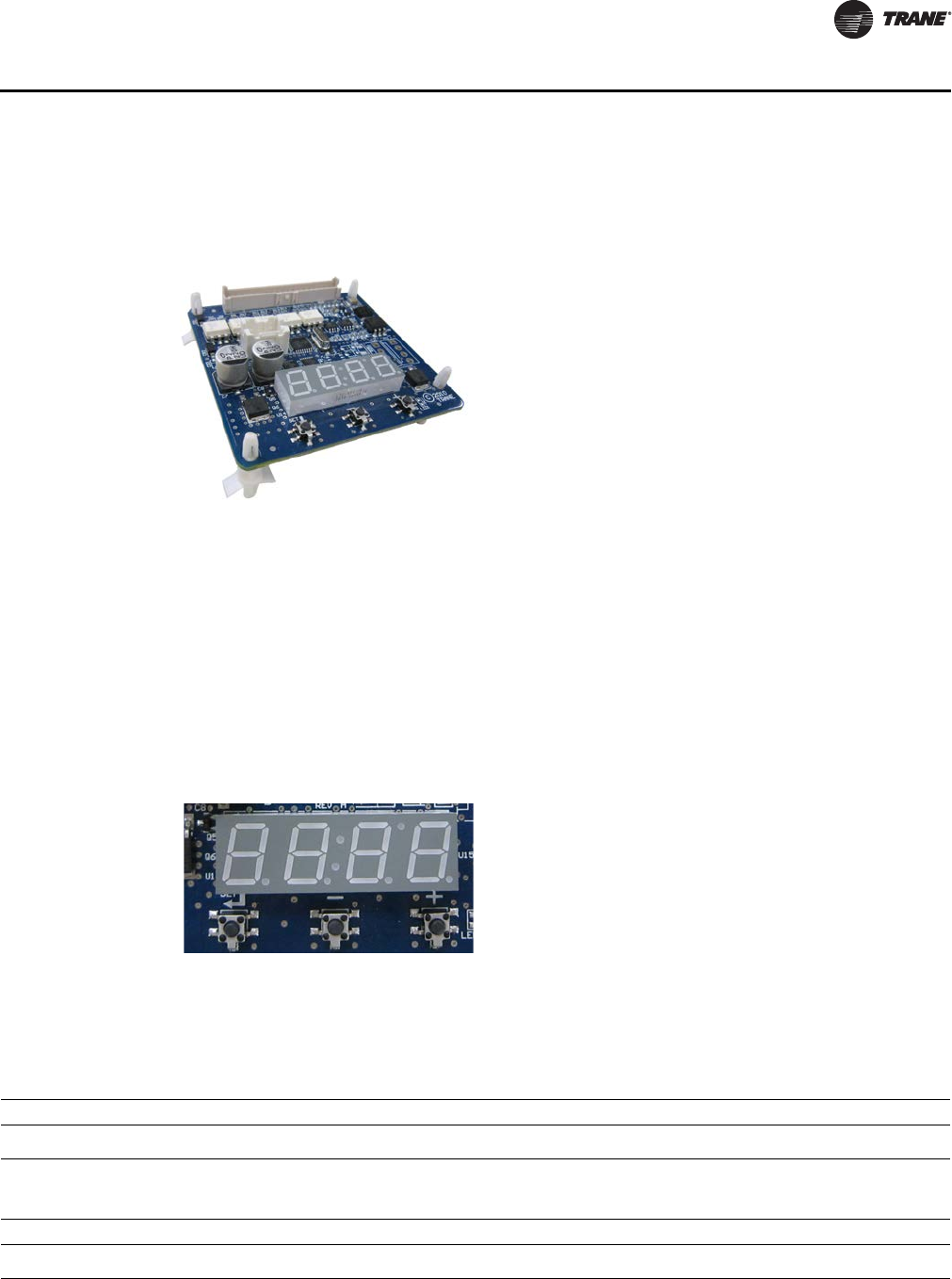
Status Display
The ECM engine board contains a four-digit, seven-segment display that is used to present
information in a format close to real-world language, while having a small-form factor. Most
characters are immediately recognizable; however, please consult Table 31 and Table 32 for the
graphical representation of each alphanumeric character.
Figure 6. ECM engine controller
Figure 7. Status display
Table 31. Screen representation of alphabetical characters
ABCDEFGHI JKLMNOPQRSTUVWXYZ
Table 32. Screen representation of numeric characters
1234567890
ECM Engine Controller
UV-PRC004-EN.book Page 41 Monday, February 4, 2013 11:01 AM
42 UV-PRC004-EN
Controls
Unit-Mounted Speed Switch
Figure 8. Fan speed switch
Figure 9. Adapter board
Note: Customer Low-Voltage Interface for
Fan Speeds, Variable Fan Speed, and
24 Vac Supply
Unit-Mounted Speed Switch
UV-PRC004-EN.book Page 42 Monday, February 4, 2013 11:01 AM

UV-PRC004-EN 43
Controls
The adapter allows direct customer interfacing through the use of terminal strips. Standard
interfacing includes:
• Fan Speeds (H, M, L) (for wall mounted fan speed switches)
• Variable speed (0–10V) inputs
The standard adapter board eliminates many separate wiring harnesses in the panel and allows
simple, mistake-proofed single-plug interfacing of:
• The ECM engine controller
•Transformers
•Motors
• Valves
•Dampers
• Electric heat control
• Fan speed switches
• Main power (except electric heat)
The manual fan mode switch is available for unit ventilators that do not have Trane factory-
mounted control packages. This four-position switch (off, high, medium, low) allows manual fan
mode selection and is available unit or wall mounted. The unit-mounted option operates on line
voltage. The wall-mounted option is low-voltage and has three 24-volt relays using a factory-wired
transformer and relays to control the fan motor.
Unit-Mounted Speed Switch
UV-PRC004-EN.book Page 43 Monday, February 4, 2013 11:01 AM
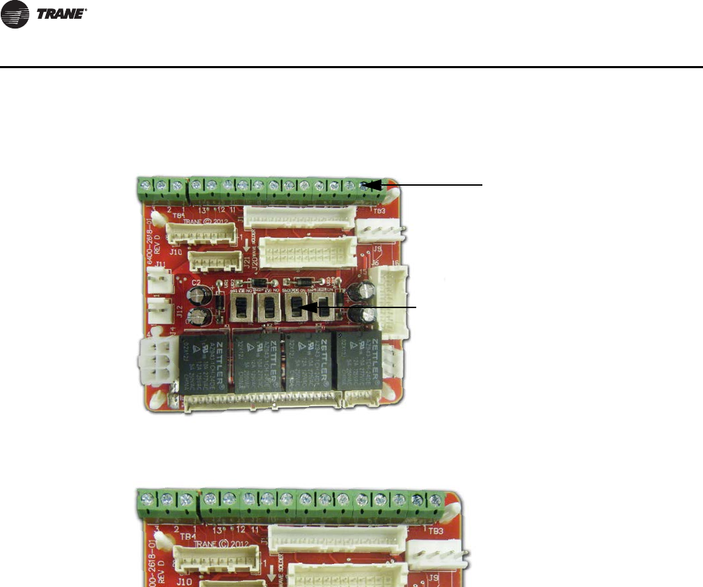
44 UV-PRC004-EN
Controls
Customer Supplied Terminal Interface (CSTI)
The control interface is intended to be used with a field-supplied, low-voltage thermostat or
controller. The control box contains a relay board which includes a line voltage to 24-volt
transformer, quiet contactors (for electric heat units), and an optional disconnect switch. All end
devices are wired to a low-voltage terminal block and are run-tested, so the only a power
connection and thermostat connection is needed to commission the unit. Changeover sensors and
controls are provided whenever a change-over coil is selected. When N.O. valves are selected,
inverting relays are provided for use with standard thermostats.
The CSTI adapter board provides all the hookups of the standard adapter board, but in addition,
provides hookups for valve control (main and auxiliary coils), electric heat control, and damper
control. Screw terminal blocks provide convenient access to fan controls and to end device control.
In addition, a courtesy 10-Vdc supply is provided for use with an external potentiometer or rheostat.
The 10-Vdc supply supports up to 10 mA draw.
Figure 10. CSTI adapter board
Figure 11. CSTI adapter board field connections
1. VSP 10V
2. VSP 0–10V
3. VSP DC COM
1. 24 Vac Y (hot)
2. 24 Vac Y (gnd)
3. High
4. Medium
5. Low
6. V1Op/Cooling
7. V1C1 (not std)
8. Not used
9. Not used
10. V2Op/EH1St/Heating
11. V2C1/EH2St (not std)
12. Damper Open
13. Dmp Cl (not std)
Customer Low-Voltage Interface for
Valves, Electric Heat, Dampers, Fan
Speeds, Variable Fan Speed, and
24 Vac Supply
Valve(s), Electric Heat, and Changeover
Configuration Switches (Factory-Set)
321 1098 7654321
11
12
13
CSTI
UV-PRC004-EN.book Page 44 Monday, February 4, 2013 11:01 AM
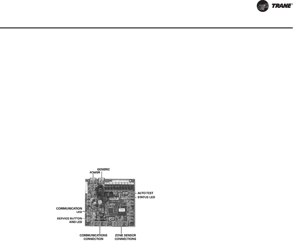
UV-PRC004-EN 45
Controls
Tracer ZN520 Zone Controller
Features Include
• Automatic fan-speed reset
• Automatic ventilation reset
• Active dehumidification
• Manual output test
• Filter maintenance
• Master slave
• Water valve override
• Freeze avoidance
• Interoperability
• Three generic I/O ports
The Tracer ZN520 is a factory-installed, -tested and -commissioned LonTalk® control designed to
provide control of the classroom unit ventilator and the fan-coil products (see Figure 12).
The Tracer ZN520 controller is designed to be used in the following applications:
• As part of the Trane Tracer Summit™ building automation system, the Tracer ZN520 becomes
an important part of the Trane Integrated Comfort™ system (ICS).
• The Tracer ZN520 can function as a completely standalone controller in situations where a
building automation system (BAS) is not present.
• For situations when a non-Trane BAS is present, the Tracer ZN520 can be used as an
interoperable unit controller.
Through building management of the HVAC system, optimizing energy consumption becomes
possible at a classroom level. Each unit is capable of functioning independently of one another
during occupied and unoccupied hours of the day. This allows the temperature setpoint and
ventilation setting to be changed automatically based on classroom usage (see Figure 13, p. 46).
Figure 12. Tracer ZN520 control board
Tracer ZN520
UV-PRC004-EN.book Page 45 Monday, February 4, 2013 11:01 AM
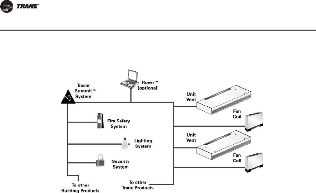
46 UV-PRC004-EN
Controls
Two Systems in One
In an ICS environment, the Tracer ZN520 is pre-designed to install quickly and easily into the
system. Since the controller and the unit are factory tested and commissioned, the start-up time
for the entire system is minimized. Trane becomes the single source of responsibility for the
equipment, unit controls, and building automation system.
As a standalone controller, the Tracer ZN520 is ideally suited for fix-on-fail replacement of units
with old pneumatic controllers, or in situations where a BAS will be added at a later date. Once
power is applied to the controller, it will automatically start up and run based upon the setpoint on
the local zone sensor. An individual time clock can be added to the unit for local scheduling.
The Tracer ZN520 is certified to the interoperable LONMARK® Space Comfort Controller profile. This
allows the controller to be used with another vendor’s BAS and thereby still provide the high quality
of factory installation and testing. In addition, the Tracer ZN520 provides one of the most extensive
interoperable data lists of any controller of its type in the industry.
Tracer ZN520 Features Include:
Automatic Fan and Ventilation Reset. With the Tracer ZN520 controller, a two speed fan
control for the unit ventilator delivers the airflow output customized to support the cfm space
needs. When less cfm is necessary to meet the load of the classroom (typically 75 to 80 percent of
the time), the equipment operates on low speed. However, if the room temperature rises, the
controller will switch to high speed, and the outside air damper will adjust to satisfy the space
needs. This helps maintain the proper amount of ventilation air to the occupants independent of
the fan speed. As part of the ventilation strategy, the controller will reposition the outside air
damper to confirm the minimum outside air cfm is met at both operating conditions.
Manual Output Test . The Tracer ZN520 controller includes a manual output test function. This
function may be initiated from the blue test push button on the controller or through the Rover
service tool. This feature is used to manually exercise the outputs in a defined sequence.
The purpose of this test sequence is to verify output and end device operation. The manual output
test function may also be used in the following situations:
• Reset latching diagnostics
• Verify output wiring and operation
Figure 13. Tracer ZN520 system
Tracer ZN520
UV-PRC004-EN.book Page 46 Monday, February 4, 2013 11:01 AM
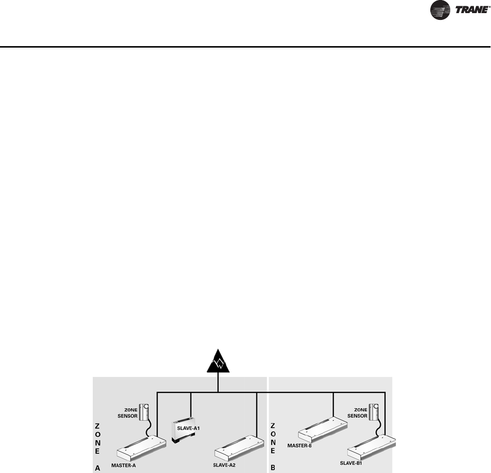
UV-PRC004-EN 47
Controls
• Force the water valve(s) open to balance the hydronic system during installation set-up or
service.
Filter Maintenance. Filter status for the controller is based on the cumulative run hours of the
unit fan. The controller compares the amount of fan run time against an adjustable fan run hour
(stored in the controller) to determine when maintenance is recommended for the unit. The run-
hours value may be user edited as required (through Rover). The valid range for the fan run hours
limit is 0 to 5000 hours with a default of 600 hours. Once the run hours limit has been exceeded,
the controller generates a maintenance required diagnostic (unit will not shut-down). The user will
be notified of this diagnostic through the building automation system or when a Trane Service Tool
is communicating with the controller.
Active Dehumidification. On unit ventilators with reheat coils, the Tracer ZN520 can provide
active dehumidification to the classroom. This means that the classroom relative humidity can be
kept below an adjustable setpoint independent outdoor weather conditions. Indoor humidity levels
are recommended by ASHRAE to be kept below 60% in order to minimize microbial growth and
the life span of airborne illness causing germs.
Master Slave (Data Sharing). Because the Tracer ZN520 controller utilizes LONWORKS®
technology, the controller can send or receive data (setpoint, heat/cool mode, fan request, space
temperature, etc.) to and from other controllers on the communication link with or without the
existence of a building automation system. This applies to applications where multiple units might
share one zone sensor for both stand-alone (with communication wiring between units) and a
building automation system (see Figure 14).
Water Valve Override. The Tracer ZN520 can be commanded via the Rover service tool to open
all hydronic valves 100%. This allows for the faster water balancing of each unit and the entire
system when the command is sent globally to all controllers. A properly balanced system is
essential for proper and efficient operation.
Hydronic Coil Freeze Protection (Freeze Avoidance). Unit ventilator systems in cold
climates need to take precautions to avoid hydronic coil freeze-up. The Tracer ZN520 does this from
three different aspects. Any of these methods of protections will result in the unit fan being
disabled, the outside air damper being shut, and the hydronic valves being opened 100 percent.
The three methods of freeze avoidance include:
1. A binary freeze protection thermostat is mounted on the coil and will cause a latching diagnostic
if the coil temperature falls below 35°F.
2. An analog discharge air sensor monitors the temperature of the air coming off of the coil and
if the temperature falls below 40°F the outside air damper is closed, the fan is turned off and
the valves are fully opened.
Figure 14. Master slave system layout
Tracer ZN520
UV-PRC004-EN.book Page 47 Monday, February 4, 2013 11:01 AM

48 UV-PRC004-EN
Controls
3. When in the unoccupied mode the Tracer ZN520 has an adjustable freeze avoidance setpoint.
If the outside air temperature is below the setpoint the unit will open the valves to allow water
to flow through the coils.
Interoperability. Interoperability allows the owner freedom to select multiple vendors, and
multiple products. With this advantage, the owner can choose the best products, the best
application, and the best service from a variety of suppliers to meet their evolving building control
needs in a cost effective manner.
Generic Binary Input/Output. The three generic binary inputs/outputs are not part of the
normal control, but are actually controlled through he Tracer Summit system (when present) to
issue commands to the Tracer ZN520 control to turn the generic inputs/outputs of add-on
equipment (such as baseboard heating, exhaust fans, occupancy sensor, lighting, etc.) on and off.
This binary port is not affected when other binary diagnostics interrupt unit operation.
Tracer ZN520
UV-PRC004-EN.book Page 48 Monday, February 4, 2013 11:01 AM
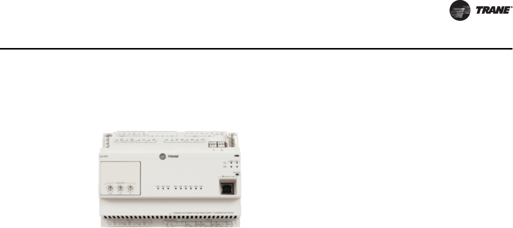
UV-PRC004-EN 49
Controls
Tracer UC400
The Tracer UC400 controller delivers single zone VAV control and can be used in a stand-alone
application or as part of a Trane Integrated Comfort System (ICS).
In the stand-alone configuration, Tracer UC400 receives operation commands from the zone sensor
and/or the auto changeover sensor (on auto changeover units). The entering water temperature is
read from the auto changeover sensor and determines if the unit is capable of cooling or heating.
The zone sensor module is capable of transmitting the following information to the controller:
• Timed override on/cancel request
• Zone setpoint
• Current zone temperature
• Fan mode selection (off-auto-high-med-low)
For optimal system performance, unit ventilators can operate as part of an Integrated Comfort
System (ICS) building automation system controlled by Tracer Summit. The controller is linked
directly to the Summit control panel via a twisted pair communication wire, requiring no additional
interface device (i.e., a command unit). The Trane ICS system can monitor or override Tracer UC400
control points. This includes such points as temperature and output positions.
Tracer UC400 Zone Controller Features Include
• Single Zone VAV
• Automatic ventilation reset
• Active dehumidification
• Filter maintenance
• Water valve override
• Freeze avoidance
• Interoperability
• Unused I/O can be as generic I/O
The Tracer UC400 is a factory-installed, -tested, and -commissioned BACnet® MS/TP control
designed to provide control of the classroom unit ventilator (see Figure 15). The Tracer UC400
controller is designed to be used in the following applications: as stand-alone operation, part of the
Trane Tracer SC building automation system, or part of another BACnet MS/TP Building
Automation System. The Tracer UC400 can function as a completely standalone controller in
situations where a building automation system (BAS) is not present.
The Tracer UC400 is designed to install quickly and easily into the system. Since the controller and
the unit are factory-tested and -commissioned, the start-up time for the entire system is minimized.
Trane becomes the single source of responsibility for the equipment, unit controls, and building
automation system. As a standalone controller, the Tracer UC400 is ideally suited for fix-on-fail
replacement of units with old pneumatic controllers, or in situations where a BAS will be added at
Figure 15.
Tracer UC400
UV-PRC004-EN.book Page 49 Monday, February 4, 2013 11:01 AM
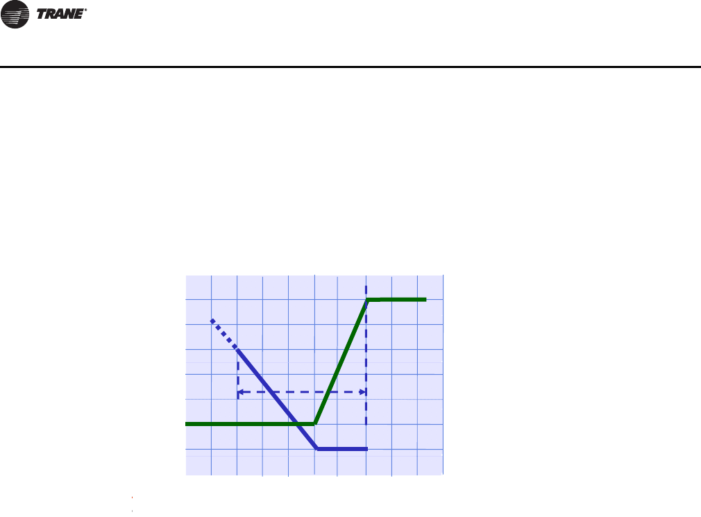
50 UV-PRC004-EN
Controls
a later date. Once power is applied to the controller, it will automatically start up and run based
upon the setpoint on the local zone sensor. An individual time clock can be added to the unit for
local scheduling. The Tracer UC400 is BTL listed as B-ASC profile. This ensures the controller to be
used with other BACnet® building automation systems.
Tracer UC400 Features Include
Single Zone VAV with Fully Modulating Fan Speed. The Tracer UC400 will minimize fan
speed, and in turn energy usage, by only delivering the air flow needed.
Ventilation Reset. With the Tracer UC400 the unit ventilator delivers the airflow the space needs.
When the air flow adjusts the outside air damper will also adjust to satisfy the space needs. This
helps maintain the proper amount of ventilation air to the occupants independent of the fan speed.
As part of the ventilation strategy, the controller will reposition the outside air damper to confirm
the minimum outside airflow is met at both operating conditions.
Filter Maintenance. Filter status for the controller is based on the cumulative run hours of the
unit fan. The controller compares the amount of fan run time against an adjustable fan run hour
(stored in the controller) to determine when maintenance is recommended for the unit. The run-
hours value may be user edited as required. The valid range for the fan run hours limit is 0 to
5000 hours with a default of 600 hours. Once the run hours limit has been exceeded, the controller
generates a maintenance required diagnostic (unit will not shut-down). The user will be notified
of this diagnostic through the building automation system or when a Trane® service tool is
communicating with the controller.
Active Dehumidification. On unit ventilators with reheat coils, the controller can provide active
dehumidification to the classroom. This means that the classroom relative humidity can be kept
below an adjustable setpoint independent outdoor weather conditions. Indoor humidity levels are
recommended by ASHRAE to be kept below 60 percent in order to minimize microbial growth and
the life span of airborne illness causing germs.
Hydronic Coil Freeze Protection (Freeze Avoidance). Unit ventilator systems in cold
climates need to take precautions to avoid hydronic coil freeze-up. The controller does this from
three different aspects. Any of these methods of protections will result in the unit fan being
disabled, the outside air damper being shut, and the hydronic valves being opened 100 percent.
The three methods of freeze avoidance include:
1. A binary freeze protection thermostat is mounted on the coil and will cause a latching diagnostic
if the coil temperature falls below 35°F.
Figure 16. Cool mode nominal hydronic cooling control
t
(°F)
80
Fa
n
Max. Flow = 100% 100
s
etpoin
t
70
80
60
n
speed
0
100
%
Cooling
e
temp
s
60
40
comma
n
0
100
%
Cooling
20
ischarg
e
50
n
d (%)
Min. discharge
setpoint = 50°F
Min. Flow = 0% 0
D
45 Csp
Siblld
No cooling load Design cooling
load (demand)
S
pace sens
ibl
e
l
oa
d
load
(demand)
Tracer UC400
UV-PRC004-EN.book Page 50 Monday, February 4, 2013 11:01 AM
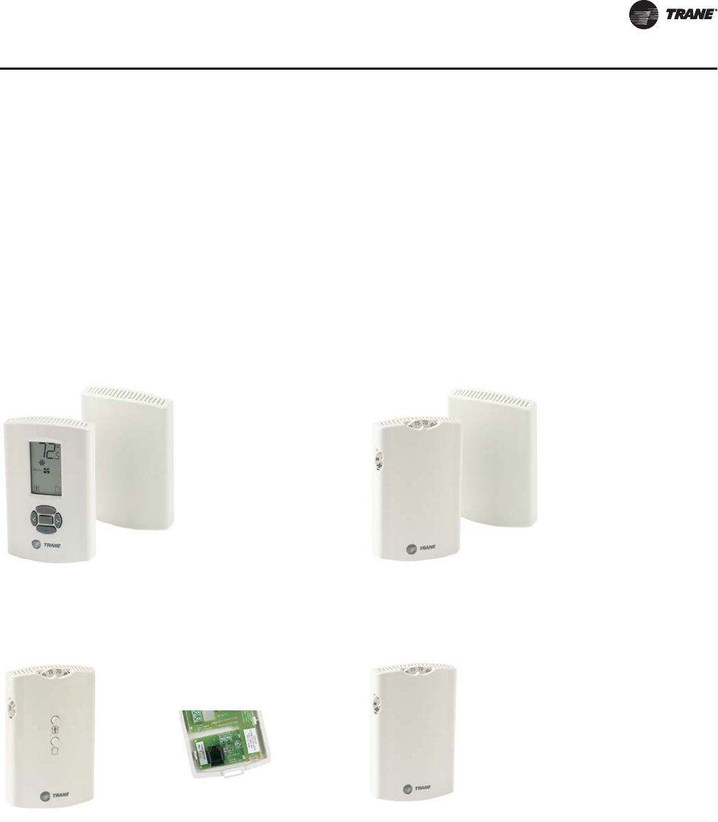
UV-PRC004-EN 51
Controls
2. An analog discharge air sensor monitors the temperature of the air coming off of the coil and
if the temperature falls below 40°F the outside air damper is closed, the fan is turned off and
the valves are fully opened.
3. When in the unoccupied mode, the controller has an adjustable freeze avoidance setpoint. If the
outside air temperature is below the setpoint, the unit will open the valves to allow water to flow
through the coils.
Zone Sensors
Zone sensors are available as either unit, wall, or split-mounted options for design flexibility. Unit
ventilators with the unit-mounted zone sensor option include a thermistor in the unit’s return air
path. Wall-mounted zone sensor options have an internal thermistor. Zone sensors operate on
24 Vac.
Figure 17. Wireless temp sensor with display
(SP, OALH, COMM)
Digit 19 = 3
Figure 18. Wireless temp sensor
(SP, OALMH, COMM)
Digit 19 = 4
Figure 19. Wall mtd temp sensor
(SP, OCC/UNOCC, OA, LMH, COMM)
Digit 19 = J
Figure 20. Unit mtd temp sensor
(SP, OALH, COMM)
Digit 19 = L
X13790822-04 (wall)
X13790855-01 (unit)
X13790492-01 (wall)
X13790855-01 (unit)
X13790842-01 (wall)
X13651467-02 (comm)
X13790843-01 (unit)
Zone Sensors
UV-PRC004-EN.book Page 51 Monday, February 4, 2013 11:01 AM
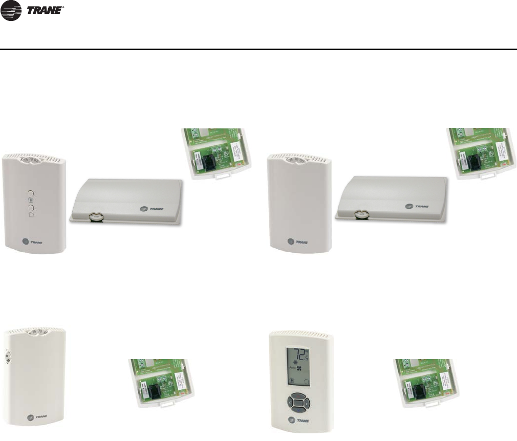
52 UV-PRC004-EN
Controls
Figure 21. Split mtd zone sensor, unit mtd fan speed
switch, and wall mtd setpoint dial
with On/Cancel
Digit 19 = P
Figure 22. Split mtd zone sensor,
unit mtd fan speed switch, and
wall mtd setpoint dial
Digit 19 = Q
Figure 23. Wall mtd temp sensor
(SP, OALMH, COMM)
Digit 19 = K
Figure 24. Wall mtd display temp sensor
(SP, OCC/UNOCC, OALMH, COMM)
Digit 19 = M
X13511527-01 (wall)
X13790849-01 (unit)
X13651467-02 (comm)
X13511529-01 (wall)
X13790849-01 (unit)
X13651467-02 (comm)
X13790841-01 (wall)
X13651467-02 (comm)
X13790886-04 (wall)
X13651467-02 (comm)
Zone Sensors
UV-PRC004-EN.book Page 52 Monday, February 4, 2013 11:01 AM
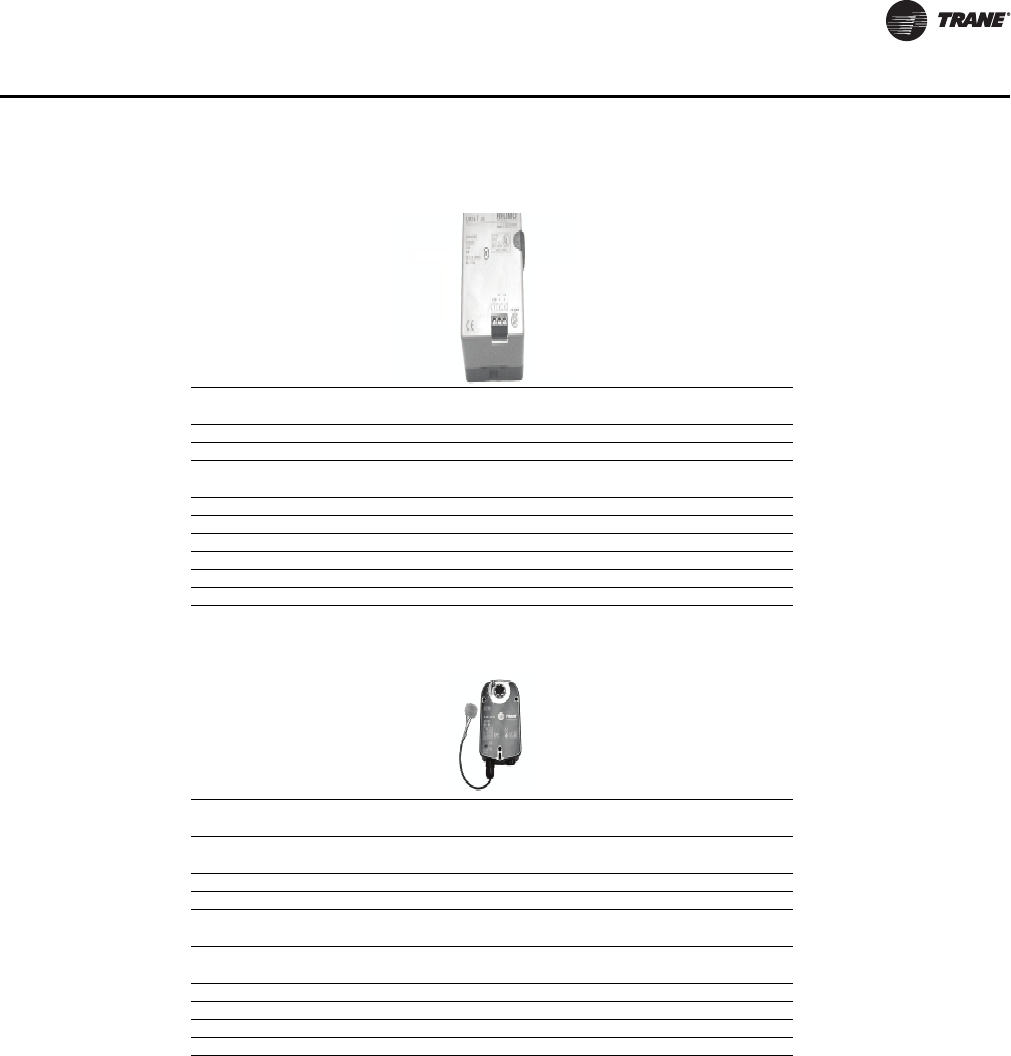
UV-PRC004-EN 53
Controls
Table 33. Face and bypass actuator specification
Power Supply 24 Vac ± 20% 50/60 Hz
24 Vac ± 10%
Power Consumption 2 W
Transformer Sizing 3 VA (class 2-power source)
Angle of Rotation Maximum 95°
Adjustable with mechanical stop
Torque 35 inch/lb
Direction of Rotation Reversible with switch L/R
Position Indication Clip-on indicator
Manual Override External push button
Noise Level Less than 35 dB
Control Signal 3-point floating
Table 34. Outside air actuator specification
Power Supply 24 Vac ± 20% 50/60 HZ
24 Vac ± 10%
Power Consumption Running: 2.5 W
Holding: 1 W
Tranformer Sizing 5 VA (class 2-power source)
Overload Protection Electronic throughout 0° to 95° rotation
Control Signal 2 to 10 Vdc
3-point floating with Trane controls
Angle of Rotation Maximum 95°
Adjustable with mechanical stop
Torque 35 inch/lb
Direction of Rotation Spring return reversible with CW/CCW mounting
Position Indication Visual indicator, 0° to 95°
Noise Level Running: 30 dB
Actuators
UV-PRC004-EN.book Page 53 Monday, February 4, 2013 11:01 AM
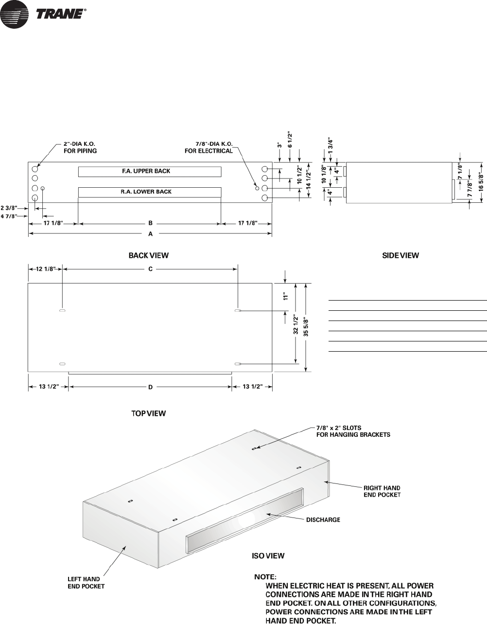
54 UV-PRC004-EN
Dimensional Data
Ducted Front Discharge
Horizontal Unit Sizes 075–150
Size A B C D
075 70-1/4” 36” 46” 43-1/4”
100 82-1/4” 48” 58” 55-1/4”
125 94-1/4” 60” 70” 67-1/4”
150 106-1/4” 72” 82” 79-1/4”
UV-PRC004-EN.book Page 54 Monday, February 4, 2013 11:01 AM
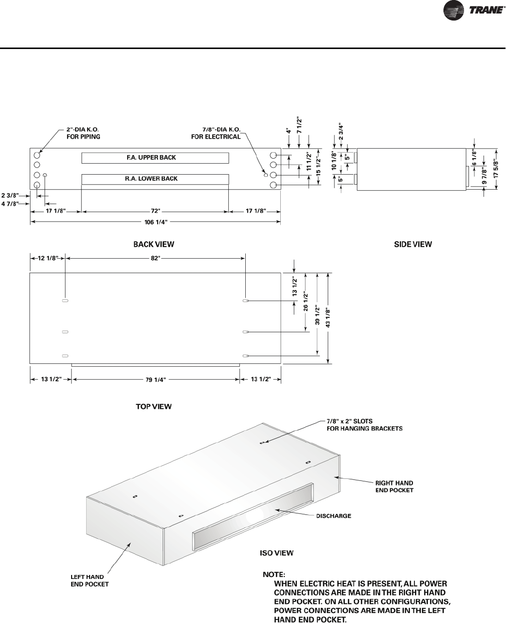
UV-PRC004-EN 55
Dimensional Data
Horizontal Unit Size 200
Ducted Front Discharge
UV-PRC004-EN.book Page 55 Monday, February 4, 2013 11:01 AM
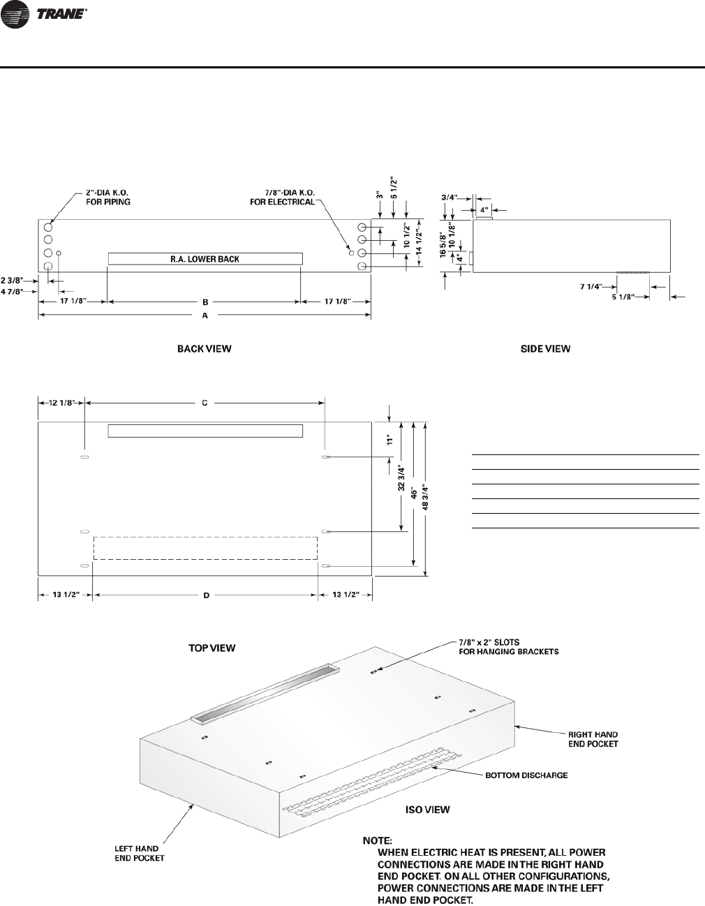
56 UV-PRC004-EN
Dimensional Data
Horizontal Unit Sizes 075–150
Bottom Double Deflection Discharge
Size A B C D
075 70-1/4” 36” 46” 43-1/4”
100 82-1/4” 48” 58” 55-1/4”
125 94-1/4” 60” 70” 67-1/4”
150 106-1/4” 72” 82” 79-1/4”
Double Deflection Discharge
UV-PRC004-EN.book Page 56 Monday, February 4, 2013 11:01 AM
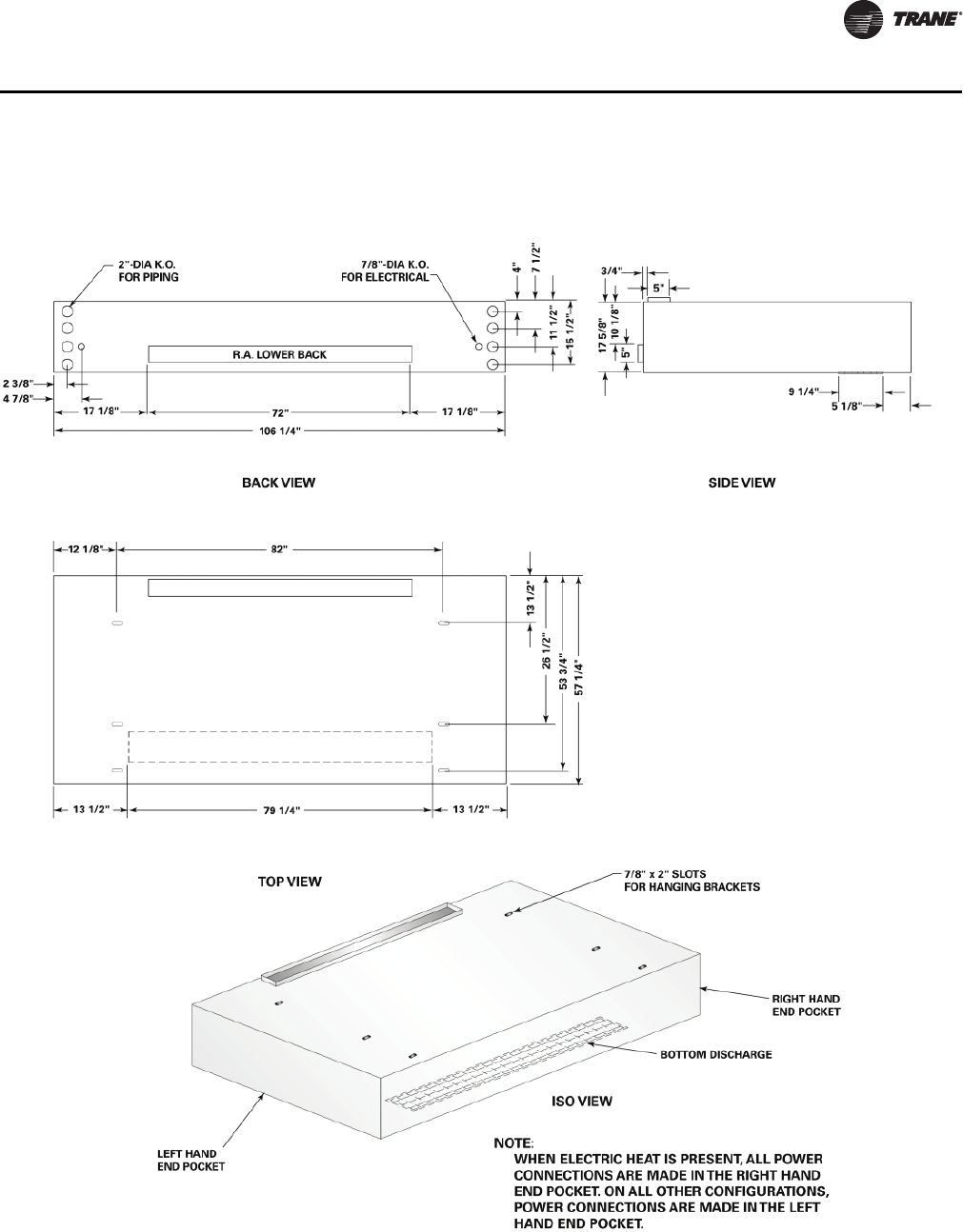
UV-PRC004-EN 57
Dimensional Data
Horizontal Unit Size 200
Bottom Double Deflection Discharge
Double Deflection Discharge
UV-PRC004-EN.book Page 57 Monday, February 4, 2013 11:01 AM
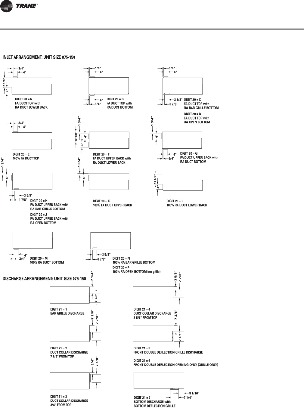
58 UV-PRC004-EN
Dimensional Data
Inlet/Discharge Arrangements
UV-PRC004-EN.book Page 58 Monday, February 4, 2013 11:01 AM
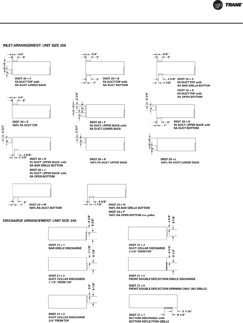
UV-PRC004-EN 59
Dimensional Data
Inlet/Discharge Arrangements
UV-PRC004-EN.book Page 59 Monday, February 4, 2013 11:01 AM
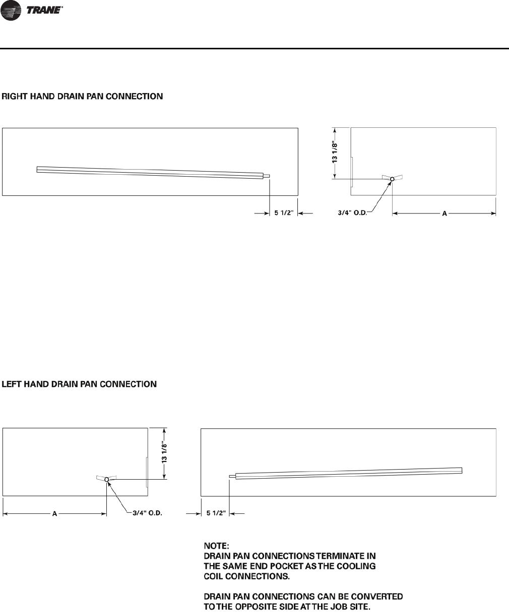
60 UV-PRC004-EN
Dimensional Data
Drain Pan Connection
UV-PRC004-EN.book Page 60 Monday, February 4, 2013 11:01 AM

UV-PRC004-EN 61
Mechanical Specifications
General
Deliver and install a complete unit ventilator certified for ventilation at AHRI-840, or tested by an
independent testing and balancing lab witnessed by owner’s representative. All non-AHRI
manufacturers shall be within 10 percent of catalog airflow and capacities, or removal of these
units from the jobsite may be required at the expense of the manufacturer or contractor.
Safety
All standard units are UL-listed in the United States and Canada and comply with NFPA 90A
requirements.
The unit ventilator is certified or rated in accordance to the following listings for performance proof
and safety: UL, AHRI-840, AHRI-350, LONMARK®, BACnet®
Equipment Construction
Exterior cabinetry is constructed of heavy-gauge metal for strength and durability. All exposed
edges are rounded to safeguard against injury. All interior sheet metal is galvanized steel to restrain
against deterioration.
The bottom plane of the unit shall consist of a two panel design. A hinged panel option is provided
as part of the equipment options to help alleviate hazards from falling panels during maintenance
or inspection purposes. The control compartment is accessible without removing the entire bottom
panel. The unit discharge grilles are welded or screwed in-place to become an integral part of the
unit structure. The rounded edge steel bars are placed at a 10° slope to provide proper airflow
deflection.
Access for inspection and cleaning of the unit drain pan, coils, and fan section are provided. The
unit shall be installed for proper access. Procedures for proper maintenance of the unit are included
in the installing, operation manual.
Cabinet insulation is 1/2-inch thick, dual density bonded glass fiber. The exposed side is a high
density, erosion proof material suitable for use in air streams up to 4500 feet per minute (FPM).
Insulation shall meet the Underwriters’ Laboratories Fire Hazard Classification.
Piping and control end pockets are a minimum of 12 inches wide to facilitate coil piping and service
access. If standard end pock is less than 12 inches wide, an extended cabinet are provided.
Final finish is cleaned, phosphatized and painted with an electrostatic powder spray system, with
a minimum thickness of 1.5 mil to avoid visible runs and resist abrasion.
Unit Fans
The unit fan board assembly shall ship from the factory wired to the commission schedule for
engineered cfm expectancy. A motor speed switch is on the unit or wall for motor speed
adjustment.
The fan board is a single, rigid construction, made from corrosion resistive material. It is a trouble-
free slide design to provide cleaning and serviceability ease to maintenance personnel.
The fans contain a double width/double inlet, forward curved centrifugal design to sustain
appropriate air throw into the space. The wheels are galvanized metal to resist corrosion. The
dynamically balanced fan and motor are of direct drive style.
The fan and coil arrangement are of a blow-thru configuration to supply unvarying coil face velocity
avoiding cold spots on the coil.
Motors
All motors are brushless DC (BLDC)/electronically commutated motors (ECM) factory-
programmed and run-tested in assembled units. The motor controller is mounted in a touch-safe
control box with a built-in integrated user interface and LED tachometer. If adjustments are needed,
motor parameters can be adjusted through momentary contact switches accessible without
factory service personnel on the motor control board. Motors will soft-ramp between speeds to
UV-PRC004-EN.book Page 61 Monday, February 4, 2013 11:01 AM

62 UV-PRC004-EN
Mechanical Specifications
lessen the acoustics due to sudden speed changes. Motors can be operated at three speeds or with
a field-supplied variable speed controller. The motor will choose the highest speed if there are
simultaneous/conflicting speed requests. All motors have integral thermal overload protection
with a maximum ambient operating temperature of 104°F and are permanently lubricated. Motors
are capable of starting at 50 percent of rated voltage and operating at 90 percent of rated voltage
on all speed settings. Motors can operate up to 10 percent over voltage.
Drain Pan(s)
The unit drain pan consist of a corrosion resistant, environmentally friendly design to facilitate
condensate removal quickly. It is insulated on the bottom to prevent sweating. The pan is
removable for cleaning. The drain connection is easy for the field to reverse to the opposite end.
Hydronic Coils (option)
All hydronic coils are plate-fin type, mechanically bonded to tubes. The coils are hydrostatically
tested to 350 psi and burst tested to 450 psi. The coils are rated in accordance with AHRI-440 or 220.
A threaded drain plug is provided at the header’s lowest point, and a manual air vent provided at
its highest point.
The standard four-pipe heating coil is in the preheat location. Optional four-pipe heating coils have
the heating coil in the reheat position for dehumidification control.
Refrigerant Coils (option)
Direct expansion coils contain copper tubes mechanically expanded into evenly spaced aluminum
fins. All coils are proof and leak tested before leaving the manufacturer. The proof test is performed
at 1.5 times the maximum operating pressure, and leak tested at the maximum operating pressure.
In addition, the tubes are completely evacuated of air to check for leaks in the vacuum.
The refrigerant coil distributor assemblies Venturi or orifice style with round copper distributor
tubes.
Distributors are sized consistently with capacity of coil. Suction headers are fabricated from round
copper pipe.
A thermostatic expansion valve (TXV) are factory selected and installed for a wide-range of control
to maintain optimum control of superheat.
Refrigerant access ports are factory supplied on high and low side for ease of refrigerant pressure
or temperature testing. All coils are shipped with a dry-nitrogen charge.
Electric Coil (option)
Units equipped for electric heat have a special resistance heating element design inserted in an
extended surface fin-tube bundle for maximum element life and safety. Units specifying electric
heat include (as standard) a high temperature cut out with a continuous sensing element. This
device interrupts electrical power whenever excessive temperatures are sensed anywhere along
the leaving side of the coil. A contactor is included to ensure positive disconnect of electrical power
whenever the fan motor power is interrupted. A dead front switch disconnects power to the unit
when the access panel is opened. All electric heat units have a power wiring console in the right
hand end-pocket to facilitate field wiring of the unit.
Steam Coil (option)
Units including a steam coil are of a a 5/8-inch, sigma-flow, tube-in-tube, distributing coil design.
Steam coil tubing is mechanically expanded into evenly spaced aluminum fins. The supply and
return connections are on the same side, and include a 1 inch female pipe thread (FPT) termination.
The coil is pitched by the manufacturer to provide condensate drainage.
UV-PRC004-EN.book Page 62 Monday, February 4, 2013 11:01 AM

UV-PRC004-EN 63
Mechanical Specifications
Outside Air/Return Air Damper
Each unit ventilator design results in a fixed air, compressible seal to ensure proper modulation and
mixing of the return and outdoor air. The damper is capable of varying proportion of mixed air from
100 percent room air to 100 percent outside air.
Face and Bypass Damper (option)
Face and bypass damper control is provided on the unit ventilator. This bypass damper design is
utilized for economizing and dehumidification of the equipment during seasonal or morning warm-
up. The damper is constructed of aluminum grade. The damper is tightly sealed and designed to
minimize heat pickup in the bypass position.
A coil isolation valve is a selectable option. It is a 2-position, 2-way valve with 24 Vac, 60 Hz
electrical, and a stroke time of 10 seconds ON/5 seconds OFF. Close off pressures include
30 psig - 1/2”, 15 psig - 3/4”, and 9 psig = 1”.
Controls
Controls options are: unit-mounted fan speed switch, customer supplied terminal interface (CSTI),
Tracer ZN520, and Tracer UC400. A variety of inputs and outputs are available for the CSTI and
Tracer controller options. A disconnect switch (for non-electric heat units), fused transformer,
contactor(s), and terminal strip are provided with the CSTI and Tracer controller options.
Customer Supplied Terminal Interface (CSTI)
The control interface is intended to be used with a field-supplied, low-voltage thermostat or
controller. The control box contains a relay board which includes a line voltage to 24-volt
transformer, and an optional disconnect switch. All end devices are wired to a low-voltage terminal
block and are run-tested, so the only a power connection and thermostat/controller connection is
needed to commission the unit. Changeover sensors and controls are provided whenever a
change-over coil is selected. When N.O. valves are selected, inverting relays are provided for use
with standard thermostats.
Unit-mounted Fan Speed Switch (FSS)
The fan speed switch is available with or without the control interface option. The unit-mounted
FSS will employ a low-voltage fan switch. The low-voltage fan speed option will provide an
interface to factory wiring, including variable speed/high-medium-low (HML) control. The control
box contains a line voltage to 24-volt transformer, EC motor controller, and an optional disconnect
switch.
Tracer ZN520
The Tracer ZN520 discrete speed controller can be used in a stand-alone application or used as part
of a Trane Integrated Comfort System (ICS) with LonTalk® communication. The Tracer ZN520 offers
the combined advantages of simple and dependable operation. Standard control features include
options normally available on more elaborate control systems. All control options are available
factory-mounted, -wired, and -configured and can also be field-configured using a service tool.
Tracer UC400
The Tracer UC400 controller delivers single zone VAV control in a stand-alone application or as part
of a Trane Integrated Comfort system with BACnet® communication. The Trace UC400 offers the
combined advantages of a factory-mounted, -wired, and -programmed controller for dependable
out-of-the box operation. Standard control features include options normally available on more
elaborate control systems. All control options are available factory-programmed with additional
configuration and programming in the field using a service tool.
Zone Sensors (option)
Trane offers a full line of wired and wireless temperature sensors. Wired temperature sensors are
the suitable alternative for locations that cannot accommodate wireless sensors or that require a
UV-PRC004-EN.book Page 63 Monday, February 4, 2013 11:01 AM

64 UV-PRC004-EN
Mechanical Specifications
service tool connection. Wireless temperature sensors, which provide easy and flexible
installation, are a cost-effective alternative to wired sensors.
Some additional options available with the sensors include:
• Easy-to-use display interface for clear and simple monitoring and control.
• Temperature setpoint control to allow the tenant to choose a temperature setpoint that satisfies
their personal preference.
• Fan speed switch to allow the tenant to locally control the fan speed to better satisfy their
preference.
• Occupancy override to allow the tenant to request temporary timed override system operation
that keeps the building conditions in occupied comfort conditions.
• COMM module that is compatible with all Trane® wired temperature sensors. This accessory
provides a local RJ22 connection to Trane® service tools for easy, low-cost maintenance.
Factory Mounted Piping (option)
Factory mounted piping is available when selecting Trane® controls or Customer Supplied
Terminal Interface (CSTI). Packages are available in 2-way or 3-way configurations with a 3-point
floating valve piped to the return side of the coil. Packages are leak tested to 90 psig to ensure joint
integrity.
Filter
Units equipped with a standard throwaway filter have an average resistance of 76 percent and dust
holding capacity of 26 grams per square foot.
Units equipped with 1-in. MERV 8 filters have a rating based on ASHRAE Standard 52.2. The
average dust spot efficiency is no less than 35 to 40 percent when tested in accordance with
ASHRAE Standard 52.1 atmospheric dust spot method.
Units equipped with 1-in. MERV 13 filters have a rating based on ASHRAE Standard 52.2. The
average dust spot efficiency is no less than 90 percent efficiency on 1–3 micron particles and
greater than 90 percent efficiency on 3–10 micron particles when tested in accordance with
ASHRAE Test Standard 52.2.
UV-PRC004-EN.book Page 64 Monday, February 4, 2013 11:01 AM

Trane optimizes the performance of homes and buildings around the world. A business of Ingersoll Rand, the
leader in creating and sustaining safe, comfortable and energy efficient environments, Trane offers a broad
portfolio of advanced controls and HVAC systems, comprehensive building services, and parts.
For more information, visit www.Trane.com.
Trane has a policy of continuous product and product data improvement and reserves the right to change design and specifications without notice.
We are committed to using environmentally
conscious print practices that reduce waste.
© 2013 Trane All rights reserved
UV-PRC004-EN 04 Feb 2013
Supersedes UV-PRC004-EN (18 Jun 2012)
UV-PRC004-EN.book Page 65 Monday, February 4, 2013 11:01 AM
