Trane Intellipak Ii 90 To 162 Tons Catalogue Packaged Rooftop Air Conditioners S*HJ 150 Cooled Condensers, 100 Evaporative Con
2015-04-02
: Trane Trane-Intellipak-Ii-90-To-162-Tons-Catalogue-684187 trane-intellipak-ii-90-to-162-tons-catalogue-684187 trane pdf
Open the PDF directly: View PDF ![]() .
.
Page Count: 206 [warning: Documents this large are best viewed by clicking the View PDF Link!]
Packaged Rooftop Air Conditioners
IntelliPak™ II — S*HJ
90 to 150Tons — Air-Cooled Condensers
100 to 162Tons — Evaporative Condensers
October 2014 RT-PRC027T-EN
Product Catalog
RT-PRC027.book Page 1 Tuesday, October 7, 2014 9:03 AM

© 2014Trane All rights reserved RT-PRC027T-EN
Introduction
IntelliPak™ II Rooftops Designed ForToday,Tomorrow and Beyond
Built on the legacy ofTrane's industry leading IntelliPak, the IntelliPak II 90 to 162 ton platform is
designed for the future. Expanded features and benefits, controls enhancements and world class
energy efficiencies make the IntelliPak II the right choice for demanding applications today, and
tomorrow.
Trane's rooftop unit control module (UCM), an innovative, modular microprocessor control design,
coordinates the actions of the IntelliPak II rooftop for reliable and efficient operation and allows for
standalone operation of the unit.
Access to the unit controls, via a human interface panel, provides a high degree of control, superior
monitoring capability, and unmatched diagnostic information.
Optionally, for centralized building control on-site, or from a remote location, IntelliPak II can be
configured for direct communication with aTraneTracer™ or a 3rd party building management
system using LonTalk® or BACnet®. With any of these systems, the IntelliPak II operating status
data and control adjustment features can be conveniently monitored from a central location.
TheTrane IntelliPak II has the technology and flexibility to bring total comfort to every building
space.
Note: AHRI certifies up to 63Ton units
Copyright
This document and the information in it are the property ofTrane, and may not be used or
reproduced in whole or in part without written permission.Trane reserves the right to revise this
publication at any time, and to make changes to its content without obligation to notify any person
of such revision or change.
Trademarks
All trademarks referenced in this document are the trademarks of their respective owners.
Revision History
This version includes the addition of the Fault Detection and Diagnostics (FDD) and the AMCA 1A
Ultra Low Leak economizer.
RT-PRC027.book Page 2 Tuesday, October 7, 2014 9:03 AM

RT-PRC027T-EN 3
Introduction ............................................................ 2
IntelliPak™ II Rooftops Designed For Today, Tomorrow and Beyond ..... 2
Features & Benefits ..................................................... 5
Standard Features ............................................. 6
Optional Features ............................................. 7
Field Installed Accessories ...................................... 9
Features Summary ............................................ 9
Energy Savings, Improved IAQ and Comfort ...................... 12
Superior Control Options ...................................... 15
Interoperability with LCI and BCI ................................ 17
Variable Frequency Drives (VFD) ................................ 20
Rapid Restart ................................................ 20
Controls .............................................................. 21
Variable Air Volume (VAV) Only .................................... 21
Supply Air Pressure Control .................................... 21
Supply Air Temperature Controls ............................... 21
Heating ..................................................... 22
Zone Temperature Control ..................................... 23
Single Zone Variable Air Volume (SZVAV) Only ....................... 24
Supply Fan Output Control ..................................... 24
Ventilation Control ........................................... 25
Space Pressure Control ........................................ 25
Occupied Cooling Operation ................................... 25
Default Economizer Operation .................................. 25
Unoccupied Mode ............................................ 25
Occupied Heating Operation ................................... 25
Compressor (DX) Cooling ...................................... 26
Cooling Sequence ............................................ 26
Constant Volume (CV) Only ........................................ 26
Occupied Zone Temperature Control ............................ 26
Heating ..................................................... 27
Unoccupied Zone Temperature Control .......................... 28
CV, SZVAV, and VAV .............................................. 28
Application Considerations ............................................. 41
Exhaust/Return Fan Options .................................... 41
Application Recommendations ................................. 41
Other Cooling Options ........................................ 43
Low Ambient Operation— Remote Human Interface Recommendation 49
Selection Procedure ................................................... 50
Air-Cooled Rooftop ................................................ 50
Cooling Capacity Selection ..................................... 51
Supply Air Fan ............................................... 51
Table of Contents
RT-PRC027.book Page 3 Tuesday, October 7, 2014 9:03 AM

4 RT-PRC027T-EN
Table of Contents
Heating Capacity Selection ..................................... 52
Evaporative Condensing Rooftop ............................... 55
Total Energy Recovery Wheel .................................. 55
Hot Gas Reheat Dehumidification Selection ....................... 56
Model Number Descriptions ............................................ 57
General Data .......................................................... 60
Performance Adjustment Factors ....................................... 64
Performance Data ..................................................... 66
Air-Cooled 60 Hz Gross Cooling Capacities—Standard Capacity Evaporator
Coils ............................................................ 66
Air-Cooled 50 Hz Gross Cooling Capacities—Standard Capacity Evaporator
Coils ............................................................ 84
Evaporative Condensing 60 Hz Gross Cooling Capacities .............. 102
Supply Fan (with or without Variable Frequency Drive) ............... 112
Exhaust Fan (with or without Energy Recovery Wheel) ................ 125
Return Fan ...................................................... 131
Heating Capacities ............................................... 137
Component Static Pressure Drops .................................. 141
Fan Drive Selections .............................................. 147
Electrical Data ........................................................ 149
Electrical Service Sizing ...................................... 149
Dimensional Data ..................................................... 154
Weights ............................................................. 185
Mechanical Specs .................................................... 189
Refrigeration System ........................................ 190
Air-Cooled Condensing ....................................... 191
Evaporative Condensing ...................................... 191
Controls ................................................... 192
Control Options ............................................. 193
System Control Options ...................................... 194
Electrical System ............................................ 194
Filters ..................................................... 195
Exhaust Air ................................................. 197
Return Air .................................................. 198
Outside Air ................................................. 199
Heating System ............................................. 200
Energy Saving Options ....................................... 201
Accessories ................................................ 202
Trane Startup ............................................... 203
Trane Unit Startup ........................................... 204
RT-PRC027.book Page 4 Tuesday, October 7, 2014 9:03 AM
RT-PRC027T-EN 5
Features & Benefits
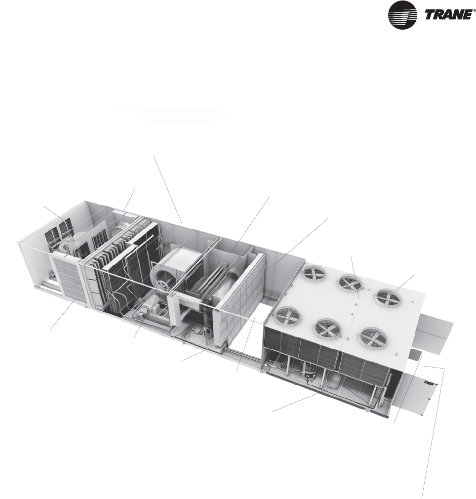
Return/Exhaust
Fan Options
Pre-Evaporator
Filtration
Options
Supply Fan
Options
Final Filtration
Options Blank
Section Options
R-410A Scroll Compressors
Access for Human
Interface Panels for
Rooftop and
Variable Frequency
Drives
Quiet Condenser Fans
Flexible Airflow Paths
Downflow and Horizontal
Supply and Return
Gas, Electric, Hot Water
or Steam Heat Options
Solid Double Wall, Foam Injected
R8 Insulating Value,
Air Handler Construction
Outside Air
Measurement
Main Control Box
Located at End of Unit
for Installation Flexibility
Ports for Condenser Coil Cleaning
Tried and True Controls Platform—
LonTalk® Communication Flexibility
BACnet® Communication Flexibility
Wireless Comm Interface Option
Single Point Latching, Adjustable Handle Height, Hinged Access
Doors on Serviceable Compartments
Single and Multi-Piece Construction for Installation Flexibility
Evaporative Condensing Option Available
RT-PRC027.book Page 5 Tuesday, October 7, 2014 9:03 AM
6 RT-PRC027T-EN
Features & Benefits
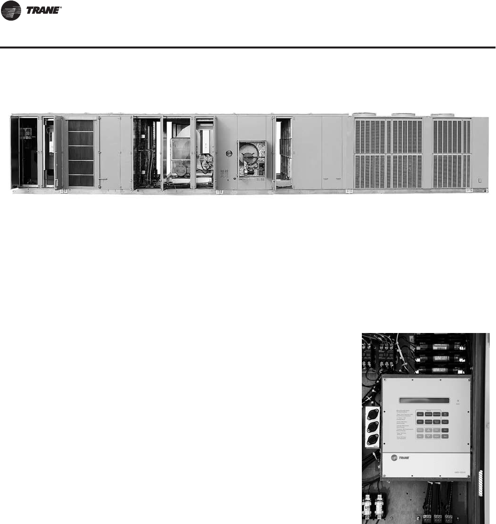
Standard Features
• 90 to 162 ton industrial/ commercial packaged rooftops
• R-410A HFC Refrigerant
• ASHRAE 90.1 - 2010 Efficiency Compliant
• IBC (International Building Code) Seismic compliance in select configurations
• cULus approval on standard options
Figure 1. Standard unit with 8 ft blank space—panels removed
Controls
• Fully integrated, factory installed/commissioned
microelectronic controls
• Unit mounted human interface panel witha2linex40
character English display and a 16 function keypad that
includes custom, diagnostics, and service test mode menu
keys
• Low charge indication and lockout
• Superheat monitoring and indication on each circuit
• CV, VAV, or SZVAV control
• Daytime warm-up (Occupied mode) on VAV models and
morning warm-up operation on all units with heating options
• Low ambient compressor lockout control on units with
economizers
• Frostat coil frost protection on all units
• Supply air static over-pressurization protection on units with
VFD's
• Supply airflow proving
• Exhaust/return airflow proving on units with exhaust or
return fan options
• Supply air tempering control
• Supply air heating control on SZVAV andVAV units with heat:
modulating gas, electric, steam and hot water
• Emergency stop input
• Mappable sensors and setpoint sources
• Occupied/unoccupied switching
• Timed override activation
Figure 2. Human Interface Panel
RT-PRC027.book Page 6 Tuesday, October 7, 2014 9:03 AM
RT-PRC027T-EN 7
Features & Benefits
Optional Features
• BACnet Communication Interface module
• Wireless Comm Interface, field installed
• Single Zone VAV
• Rapid Restart
• Five ventilation override sequences
Refrigeration
• Scroll compressors
• Compressor lead/lag for run- time equalization
• Intertwined evaporator coil circuiting for full face area
operation at part load conditions
• Liquid and discharge service valves
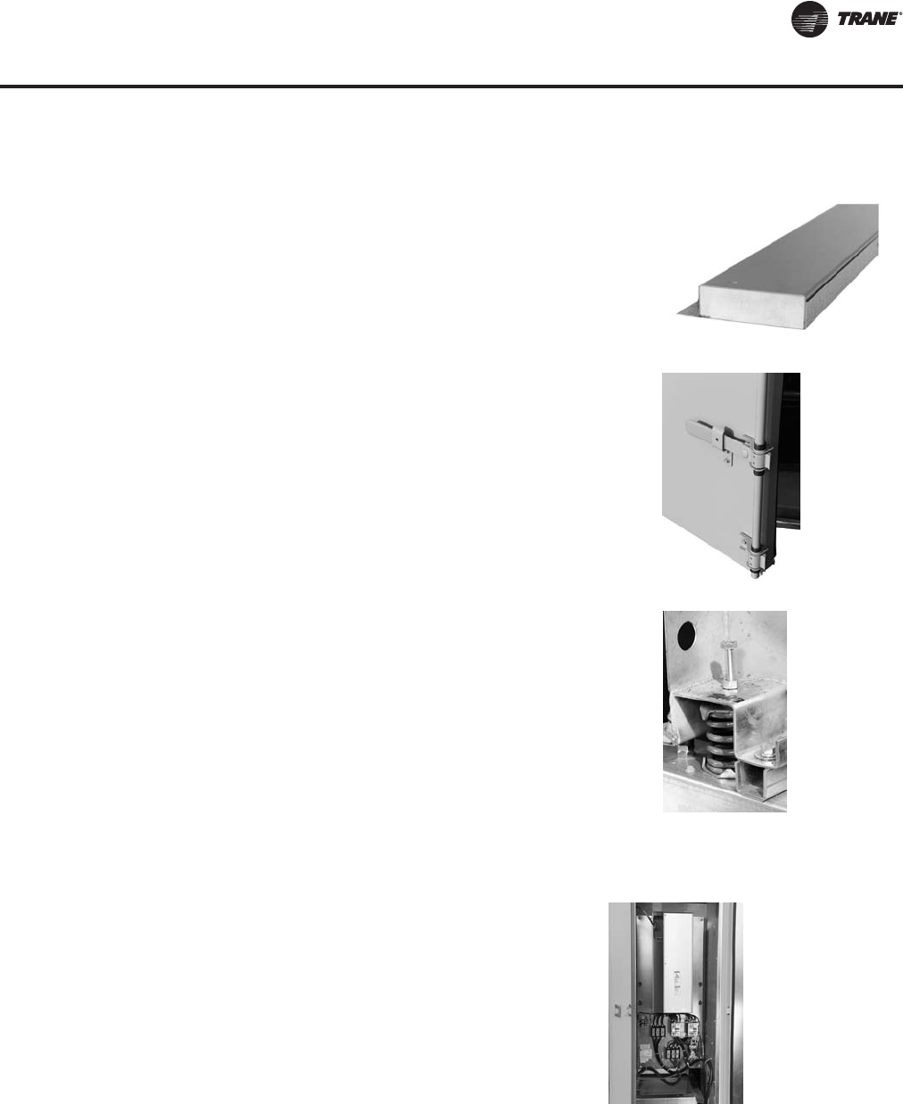
Cabinet
• Solid double wall construction with foam injected R8
insulation throughout air handler section
• Single point latching, hinged access doors on control panel,
filter, supply and exhaust/return fan section as well as gas heat
section
• Flexible downflow and horizontal discharge/return paths
• Double sloped galvanized drain pans
• Extended casing, cooling only models
• Pitched roof over air handler section
• Heavy-gauge, continuous construction base rails
• Meets salt spray testing in accordance toASTM B117 Standard
Mechanical
• Airfoil supply fan—standard and low CFM
• Totally enclosed condenser fan motors (TEFC)
• Stainless steel flue stack on gas heat units
• Two-inch spring fan isolation standard
• Two-inch MERV 8 high efficiency throwaway filters
Figure 3. Solid double wall
Figure 4. Latching access door
Figure 5. Spring isolation
Controls
• Demand control ventilation (energy saving CO2
economizer control)
• Twinning of up to four units for applications on
common supply and return ducts
• Variable frequency drive (VFD) control of supply/
exhaust/return fan motor
• High duct temperature thermostats
• Low ambient control to 0°F
• LonTalk Communication Interface module
Figure 6. Variable frequency drive
RT-PRC027.book Page 7 Tuesday, October 7, 2014 9:03 AM

8 RT-PRC027T-EN
Features & Benefits
• Generic BAS interfaces—0-5 VDC and 0-10 VDC
• Remote human interface panel (controls up to 4 units)
• SZ VAV - Modulated Supply Fan for more efficient operation
• Rapid Restart - 100% cooling mode after power loss
• Fault Detection and Diagnostics (FDD)
Refrigeration
• High capacity evaporator coils
• Hot gas bypass to the evaporator inlet
• Suction service valves
• Replaceable core filter driers
Cabinet
• Blank section options
– Four foot blank—cooling only
– Eight foot blank—cooling and heating
• Two or three-piece construction
• Single point access doors on both sides of the unit
• Double sloped stainless steel drain pans
• Belt guards for supply and exhaust/return fans
• Burglar bars on select configured units
Mechanical
• Hot gas reheat in accordance with ASHRAE Standard 90.1-2001
• Evaporative condensers
• Total energy recovery wheels rated in accordance to ARI Standard 1060
• Airfoil plenum return fan—standard and low CFM
• Modulating plenum return fan with Statitrac™ direct space sensing building pressurization
control
• Forward curved exhaust fan—standard and low CFM
• 100 percent modulating exhaust
• 100 percent modulating exhaust with Statitrac™ direct space sensing building pressurization
control
• Outside air CFM compensation on SZVAV and VAV units with VFD and economizer
• Trane air quality (Traq™) outside air measurement damper system
• 0-100% modulating outside air economizer
• 0-25% motorized outside air damper
• Low Leak, Standard Ultra Low Leak, and Ultra Low Leak AMCA 1A Economizer dampers
Filtration
– Pre-evaporator coil filter options
– Filter rack only (no filters)
– Two-inch throwaway filters
– 90-95% bag filters
RT-PRC027.book Page 8 Tuesday, October 7, 2014 9:03 AM

RT-PRC027T-EN 9
Features & Benefits
– 90-95% cartridge filters
• Final filters
– Bag filters
– Standard and high temperature cartridge filters
– Standard and high temperature HEPA filters
Heat Options
• Electric, gas, steam or hot water
• Gas heat options:
– 10:1 modulating gas heat 850 MBh
– 20:1 modulating gas heat 1100, 1800, and 2500 MBh
– 10 year limited warranty on modulating gas heat
Electrical
• Unit interrupt rating of 65000 amp (480V) and 25000 amp (600V)
• Totally enclosed fan-cooled supply and exhaust/return fan motors
• Supply and exhaust/return motors with Internal Shaft Grounding Ring for VFD applications
• EISA-rated supply and exhaust/return fan motors as standard (60 Hz)
• Marine lights in serviceable compartments
• Electrical convenience outlet
• Through the door non-fused disconnect with external handle
Field Installed Accessories
• Roof curbs
• Wireless zone sensor
• Wireless Comm Interface
• Programmable sensors with night setback—CV and VAV
• Sensors without night setback— CV and VAV
• Remote zone sensors—used for remote sensing with remote panels
• ICS zone sensors used withTracer system for zone control
• Outdoor temperature sensor for units without economizers
• Remote minimum position control for economizer
• Module kits available for field upgrade of controls
Features Summary
IntelliPak II rooftop features make installation and servicing easy and operation extremely reliable.
Installation and Service
• Loss of refrigerant charge diagnostics warns of a slightly undercharged situation followed by
a warning and a lock out of an undercharged circuit for overall unit performance and
compressor protection
• Superheat reading for each circuit displayed at the human interface panel to assist the service
technician in troubleshooting
• Microprocessor unit controls coordinate the operation of the rooftop with quality, industry-
accepted components for service ease
RT-PRC027.book Page 9 Tuesday, October 7, 2014 9:03 AM
10 RT-PRC027T-EN
Features & Benefits
• Controls are factory installed/commissioned for ease of start up
• Condenser coil cleaning ports conveniently located on the roof of the condenser for efficient
servicing
• Full unit points access—no field wiring of required points
• Modularity of unit control design
• Individual replaceable functional boards
• Unit mounted human interface panel standard
– User-friendly keypad edit parameters
– Dedicated Human Interface access panel
– Start up adjustments
– Advanced diagnostics
• Modular control design
• cULus approval as standard
• All supply, exhaust, and return fans are factory balanced
• Fully insulated floor, roof, panels, and gasketed interfaces reduce ambient air infiltration.
• Fixed-speed evaporator, exhaust/return drives for smooth fan operation and belt durability.
• 200,000 average life fan bearings enhance unit durability.
• Gas heater with free-floating stainless steel heat exchanger relieves the stresses of expansion
and contraction. Stainless steel provides corrosion resistance through the entire material
thickness.
• Factory-wired and commissioned controls assure efficient and reliable rooftop operation.
• Scroll compressors are designed for tough industrial operation and meet demanding operating
conditions both in efficiency and reliability.
• Roll-formed construction enhances cabinet integrity and assures a leak-proof casing.
• Unit-mounted and remote interface panel key pads are
identical
• Single twisted wire pair communication for ICS interface
• Sturdy, double wall, foam injected, hinged access doors
with height adjustable single point latches on main
compartments for service ease
• Main control box conveniently located on end of unit for
layout flexibility in tight spaces
• Built-in, optional features like high withstand rated
breakers, belt guards and burglar bars contribute to safety
• Convenience outlet and marine lights for enhanced service
capability
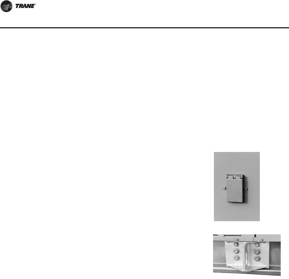
• Unit-mounted lifting lugs facilitate installation and can be
used as unit tie-down points
Reliability
• Advanced diagnostics
• Microprocessor controls
• Built-in safeties
Figure 7. Convenience outlet
Figure 8. Lifting lugs
RT-PRC027.book Page 10 Tuesday, October 7, 2014 9:03 AM
RT-PRC027T-EN 11
Features & Benefits
• AMCA 1A Ultra Low Leak economizer, including linkages and actuators, have a 5 year limited
warranty and functional life of 60,000 opening and closed cycles.
• AMCA 1A Ultra Low Leak Economizer includes Fault Detection Diagnostics (FDD) to signal the
IntelliPak controls for economizer faults.
• Three-phase, direct-drive totally enclosed condenser fan motors enhance dependability and
increase rooftop life.
• Trane industrial quality evaporator and condenser coils help increase rooftop life.
Application Flexibility
• Low CFM fans for low leaving air temperature applications
• Multiple downflow and horizontal air path options
• An array of heating options are available, including electric, natural gas, steam and hot water.
The gas heating option provides a choice of two-stage gas heat, as well as full modulating gas
heat. Electric heating options provide four to six steps of capacity.
• Indoor Air Quality (IAQ)
– Traq Damper System for precise outside air measurement
– Demand Control Ventilation for CO2economizer control
– Compensated outdoor air control
– Statitrac direct space building pressure control
– Multiple factory installed filter types, pre evaporator and final filters
– Humidification control output
– Comparative enthalpy, reference enthalpy, or dry bulb control for economizers
• Superior building automation interface through LonTalk
• Superior building automation interface through BACnet
• Generic BAS interfaces
• Unit mounted or remote human interface panels
• All parameters are editable from the human interface panel
• Five factory preset ventilation override sequences which can be redefined in the field
• Variable Frequency Drives (VFD) included with or without bypass control for supply and
exhaust/return fans
• CV controls stage both compressors and heat based on space requirements
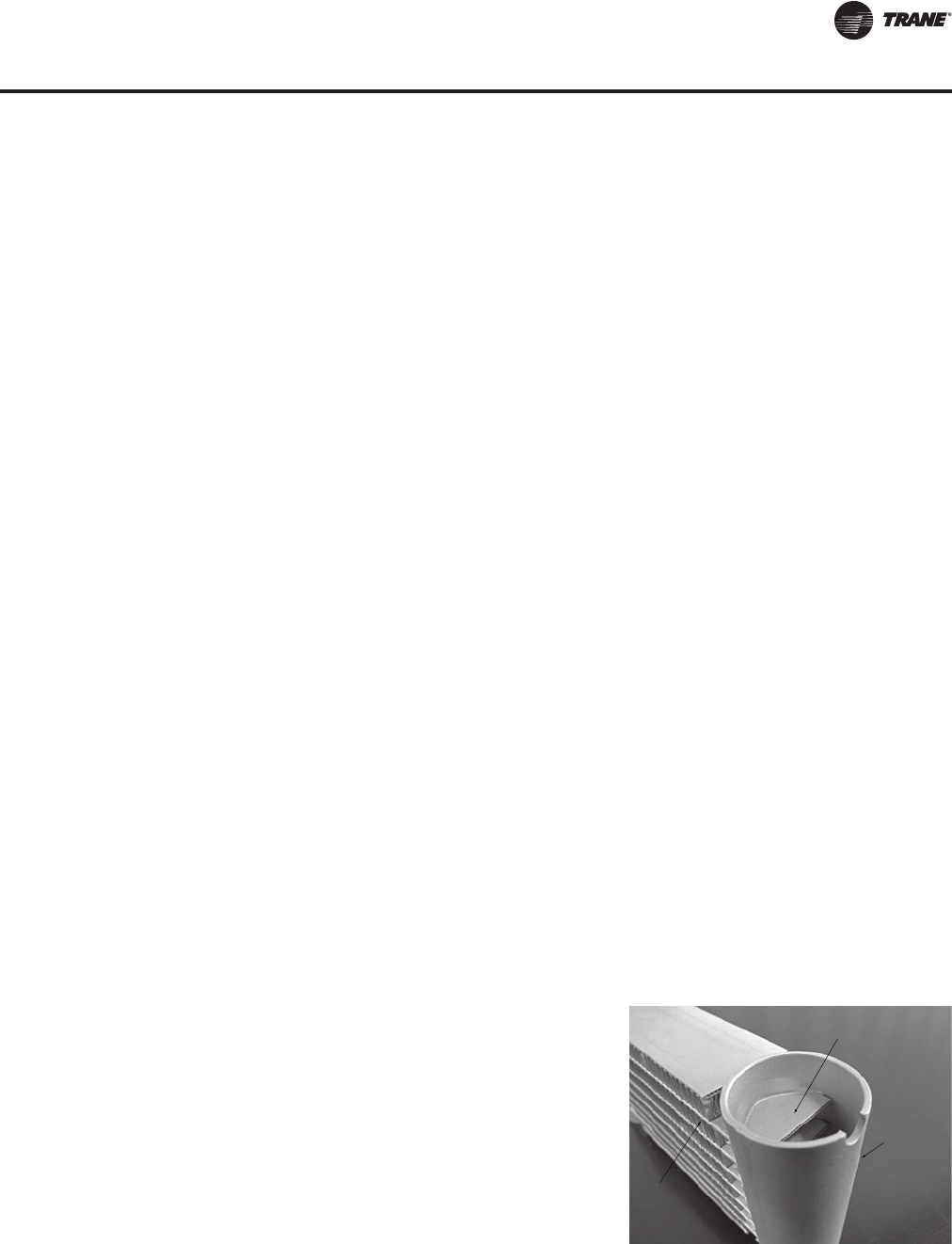
Microchannel Condenser Coils
Microchannel coils are an all aluminum coil that has
been successfully used in the automotive industry for
many years, and is now being applied in the HVAC
industry. The coils have a fully-brazed construction
which increases coil rigidity making them more
rugged to withstand the rigors of jobsite handling.
Additionally, the light weight simplifies coil handling.
The all aluminum construction creates an exceptional
heat transfer capability, allowing the refrigerant
charge to be reduced to levels that exceed LEED EA-
Credit 4 requirements. Bottom line, less refrigerant is
being used, which creates a healthier and greener
environment.
Microchannel Flat Tube
Header
(top removed)
Ribbon Fin
RT-PRC027.book Page 11 Tuesday, October 7, 2014 9:03 AM

12 RT-PRC027T-EN
Features & Benefits
Energy Savings, Improved IAQ and Comfort
IntelliPak II offers several ways to save energy while improving indoor air quality (IAQ) and zone
comfort. Standard factory installed options for energy savings include the energy recovery wheel,
hot gas reheat, and evaporative condensers.
Single Zone VAV (SZVAV)
Single Zone VAV (SZVAV) is designed for use in single zone applications such as gymnasiums,
auditoriums, manufacturing facilities, retail box stores, and any large open spaces where there is
a diversity in the load profile. It is an ideal replacement to "yesterday's" constant-volume (CV)
systems, as it reduces operating costs while improving occupant comfort.
SZVAV systems combineTrane application, control and system integration knowledge to exactly
match fan speed with cooling and heating loads, regardless of the operating condition.Trane
algorithms meet and/or exceed ASHRAE 90.1- 2010 SZVAV energy-saving recommendations and
those of CATitle 24. The result is an optimized balance between zone temperature control and
system energy savings. Depending on your specific application, energy savings can be as much
as 20+%.
Note: Building system modeling in energy simulation software such asTRACE is recommended
to evaluate performance improvements for your application.
SZVAV is fully integrated into the IntelliPak Control system. It provides the simplest and fastest
commissioning in the industry through proven factory-installed, wired, and tested system
controllers. All control modules, logic boards and sensors are factory installed and tested to ensure
the highest quality and most reliable system available.This means no special programming of
algorithms, or hunting at the jobsite for field installed sensors, boards, etc. Single zone VAV is a
quick and simple solution for many applications and is available from your most trusted rooftop
VAV system solution provider -Trane.
Ultra Low Leak, AMCA 1A Economizer Damper
The pre-engineered design special Ultra Low Leak AMCA 1A Economizer Damper package will
meet or exceed requirements of CaliforniaTitle 24, ASHRAE 90.1, and IECC.The economizer,
including linkages and actuators, will have a 5 year limited warranty and functional life of 60,000
opening and closed cycles.
Dampers are AMCA 511 Class 1A certified with a maximum leakage rate of 3 CFM/sq-ft at 1.0 in.WC
pressure differential. As part of this design special package, Fault Detection and Diagnostics (FDD)
control is included to meet California requirements. FDD control monitors the commanded
position of the economizer compared to the feedback position of the damper. If the damper position
is outside of ±10% of the commanded position, a diagnostic is generated.
Figure 9. Ultra low leak economizer
RT-PRC027.book Page 12 Tuesday, October 7, 2014 9:03 AM
RT-PRC027T-EN 13
Features & Benefits
Energy Recovery Wheel
Because the energy recovery wheel has the capability to hold and transfer sensible and latent
energy, this option can significantly reduce HVAC system operating energy costs. IntelliPak II offers
the total energy wheel option to recover energy from the building exhaust. Benefits of the total
energy recovery feature include:
• Energy efficient ventilation to reduce operating costs
• The ability to increase ventilation, allowing for improved indoor air quality (IAQ)
• High efficiency, which permits increased outdoor air quantity without increasing heating or
cooling
Hot Gas Reheat
By its very nature, the colder the air, the less moisture it contains. With hot gas reheat, the cold air
that passes through the DX coil is reheated to an acceptable temperature and returned as
dehumidified air to the facility space.The result is both temperature and humidity are maintained
while reducing unit operating costs and saving energy.
This energy efficiency helps to meet local energy codes and ASHRAE Standard 90.1 compliance.
Figure 10. Energy recovery wheel in economizer mode
Damper 4
Supply Fan
Top View
Damper 1 Damper 3
Damper 2
Side View
Wheel
Supply Fan
Damper 1 Damper 2
Damper 3
Damper 4
RT-PRC027.book Page 13 Tuesday, October 7, 2014 9:03 AM
14 RT-PRC027T-EN
Features & Benefits
Evaporative Condensing Units
Unlike air-cooled condensers, evaporative condensers are dependent on the ambient wet bulb,
rather than dry bulb, temperature. Wet bulb temperature is generally several degrees lower than
dry bulb.
Utilizing the lower wet bulb temperature to condense refrigerant vapor can dramatically decrease
compressor power consumption by reducing compressor discharge pressure, thereby increasing
unit efficiency.
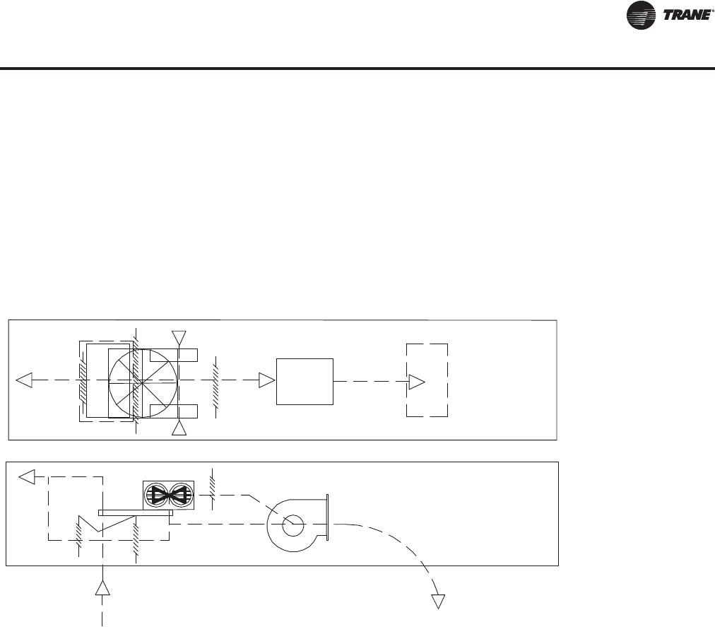
Figure 11. Hot gas reheat
Condenser section
Modulating
cooling valve
Modulating
reheat valve
Compressors
Check valve
Solenoid indoor
pumpout valve
Check valve
Evaporator Coil
Reheat Coil
TXV
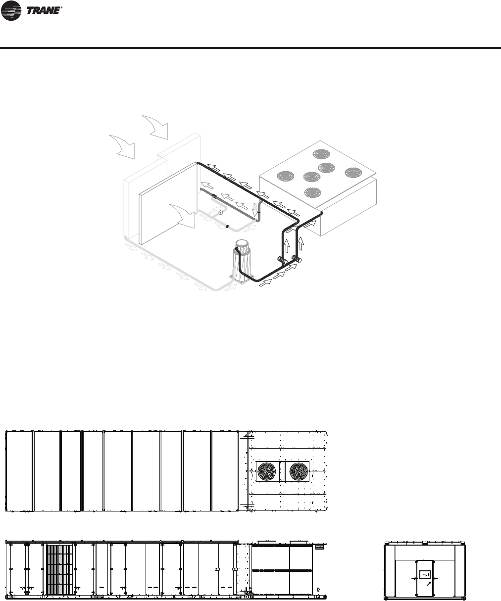
Figure 12. Unit top/left side view—evaporator-cooled condenser
RT-PRC027.book Page 14 Tuesday, October 7, 2014 9:03 AM
RT-PRC027T-EN 15
Features & Benefits
Superior Control Options
Integrated Comfort with TraneTracer LCI and BCI
TheTracer Integrated Comfort™ System (ICS) or System Controller (SC) improves job profit and
increases job control by combiningTrane rooftop units with theTraneTracer building management
system.These integrated systems provide total building comfort and control. Some of the primary
motivations for building owners/managers in deciding to purchase a HVAC controls system are
energy savings, cost control, and the convenience of facility automation.
Simplifying the Comfort System
Trane technology and innovation brings more capabilities, more flexibility, and offers equipment
and systems that are easy to use, easy to install, commission and service.TheTracer Integrated
Comfort system and System Controller save time and money by simplifying system design and
system installation.
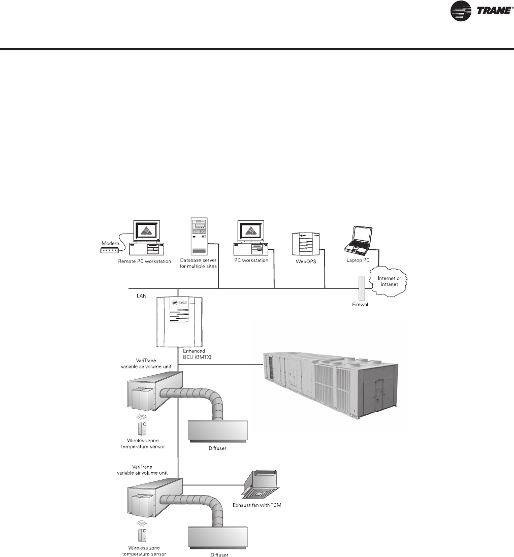
When used withTrane DDC/VAV terminals (or VariTrane), system balancing almost goes away
because each VAV box is commissioned and tested before it leaves the factory. All the status
information and editing data from the rooftop units, VAV terminals, lighting, exhaust and other
auxiliary equipment is available fromTracer for facility control, monitoring and service support.
Tracer, a family of building automation products fromTrane, is designed with robust, application
specific software packages to minimize custom programming requirements and enable system
setup and control through simple editing of parameters in the standard applications software.
Figure 13. Trane complete comfort system
IntelliPak II Rooftop
RT-PRC027.book Page 15 Tuesday, October 7, 2014 9:03 AM
16 RT-PRC027T-EN
Features & Benefits
When selecting an Integrated Comfort system for a facility, the accountability for equipment,
automation and controls lies withTrane. In addition to high quality, high performance, packaged
rooftop equipment,Trane provides precise air delivery management withVariTraneVAV terminals.
Wireless zone sensors minimize the installation costs of theVariTrane terminals and the packaged
rooftop system in general.
The IntelliPak II rooftop, as a part of an Integrated Comfort system or System Controller (SC),
provides powerful maintenance monitoring, control and reporting capabilities.TheTracer places
the rooftop in the appropriate operating mode for: system on/off, night setback, demand limiting,
setpoint adjustment based on outside parameters and much more.
Many different unit diagnostic conditions can be monitored throughTracer: sensor failures, loss
of supply airflow, and a compressor trip out. Further, the addition of Building Management
Network software offers remote scanning, automatic receipt of alarms, and easy dial-up access to
over 100 variousTracer sites across town or across the country.
IntelliPak II rooftops monitoring points available throughTracer
• All active rooftop diagnostics
• history of last 20 unit diagnostics
• All system setpoints
• System sensor inputs
• Supply fan mode and status
• VFD speed
• Unit heat/cool mode
• Exhaust/return fan status
• Exhaust/return damper position
• Economizer position, minimum position setpoint, economizing setpoint
• Refrigerant evaporator and saturated condenser temperatures
• Electric heat stage status
• Ventilation override mode status
Tracer control points
Setup and configuration information throughTracer
• Supply fan mode
• Configuration of supply air reset
• Ventilation override mode configuration
• Default system setpoint values
• On/off status of each compressor
• Sensor calibration offsets cooling and heating setpoints
• Zone setpoint offsets for use with demand limiting
• VAV discharge air setpoints
• Supply air pressure setpoint
• Space pressure setpoint
• zone and outdoor temperature values
• Cooling and heating enable/disable
• Economizer enable/disable
• Economizer setpoint
• Economizer minimum position
• Activation of ventilation override modes
• Diagnostics reset
• Unit priority shutdown
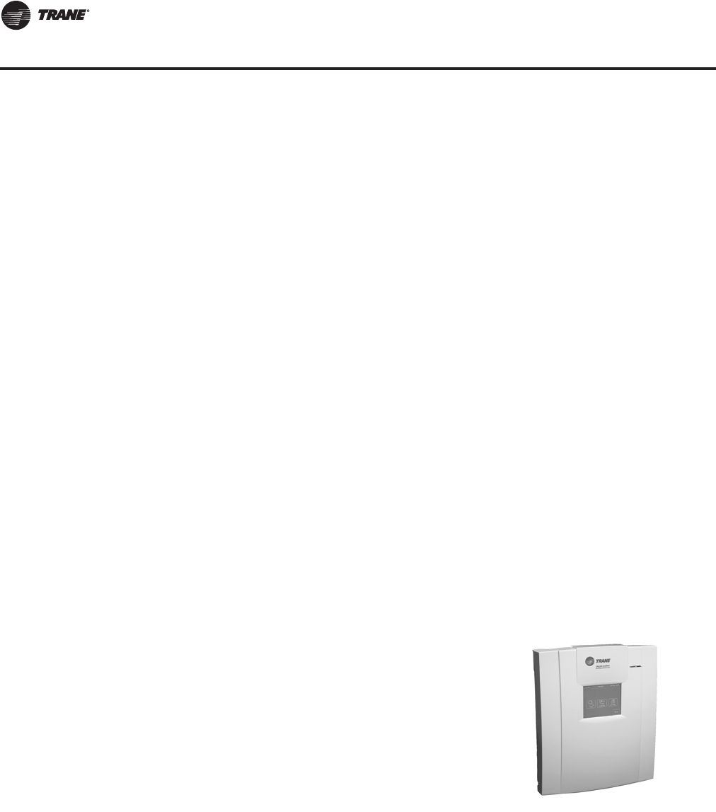
Figure 14. Tracer
RT-PRC027.book Page 16 Tuesday, October 7, 2014 9:03 AM

RT-PRC027T-EN 17
Features & Benefits
Interoperability with LCI and BCI
Integrated Comfort with LonTalk Communication
TraneTracer LonTalk Control Interface (LCI) for IntelliPak II offers a building automation control
system with outstanding interoperability benefits.
LonTalk, which is an industry standard, is an open, secure and reliable network communication
protocol for controls, created by Echelon Corporation and adopted by the LonMark Interoperability
Association. It has been adopted by several standards, such as: EIA-709.1, the Electronic Industries
Alliance (EIA) Control Network Protocol Specification and ANSI/ASHRAE 135, part of the American
Society of Heating, Refrigeration, and Air Conditioning Engineer's BACnet control standard for
buildings.
Interoperability allows application or project engineers to specify the best products of a given type,
rather than one individual supplier's entire system. It reduces product training and installation
costs by standardizing communications across products. Interoperable systems allow building
managers to monitor and control IntelliPak II equipment with aTraneTracer Summit or a 3rd party
building automation system. It enables integration with many different building controls such as
access/intrusion monitoring, lighting, fire and smoke devices, energy management, and a wide
variety of sensors (temperature, pressure, light, humidity, occupancy, CO2and air velocity). For
more information on LonMark, visit www.lonmark.org or Echelon, www.echelon.com.
Integrated Comfort with BACnet Communication
TheTrane SC BACnet Control Interface (BCI-I) for IntelliPak II offers a building automation control
system with outstanding interoperability benefits. BACnet, which is an industry standard, is an
open, secure and reliable network communication protocol for controls, created by American
Society of Heating, refrigerating and Air-Conditioning Engineers, Inc. (ASHRAE)
Interoperability allows application or project engineers to specify the best products of a given type,
rather than one individual supplier's entire system. It reduces product training and installation
costs by standardizing communications across products. Interoperable systems allow building
managers to monitor and control IntelliPak equipment withTracer SC or a 3rd party building
automation system. It enables integration with many different building controls such as access/
intrusion monitoring, lighting, fire and smoke devices, energy management, and a wide variety of
sensors (temperature, pressure, light, humidity, occupancy, CO2and air velocity).
Diagnostic Points:
•All rooftop diagnostics
•System setpoints
•System sensor inputs
•Supply fan mode and status
•VFD speed
•Unit heat/cool mode
•Exhaust/return fan status
•Exhaust/return damper position
•Economizer position, minimum position setpoint, economizing setpoint
•On/off status of each compressor
•Refrigerant evaporator and saturated condenser temperatures
•Hydronic heat valve position
•Electric heat stage status
•Ventilation override mode status
Control Points:
•Cooling and heating setpoints
•Zone setpoint offsets for use with demand limiting
•VAV discharge air setpoints
RT-PRC027.book Page 17 Tuesday, October 7, 2014 9:03 AM

18 RT-PRC027T-EN
Features & Benefits
•Supply air pressure setpoint
•Space pressure setpoint
•Zone and outdoor temperature values
•Cooling and heating enable/disable
•Economizer enable/disable
•Economizer setpoint
•Economizer minimum position
•Activation of ventilation override modes
•Diagnostics reset
•Unit priority shutdown
•Timed override activation
Setup and Configuration:
•Supply fan mode
•Configuration of supply air reset
•Ventilation override mode configuration
•Default system setpoint values
•Sensor calibration offsets
Trane Wireless Comm Interface (WCI)
TheTrane Wireless Comm Interface (WCI) is the perfect alternative to BACnet wired
communication links (for example, WCI connection between aTracer SC and aTracer UC400).
Minimizing communication wires between terminal products, zone sensors, and system
controllers has substantial benefits. Installation time and associated risks are reduced. Projects are
completed with fewer disruptions. Future re-configurations, expansions, and upgrades are easier
and more cost effective.
Optimum Building Comfort Control
The modular control design of the UCM allows for greater application flexibility. Customers can
order exactly the options required for the job, rather than one large control package. Unit features
are distributed among multiple field replaceable printed circuit boards.TheTrane UCM can be
setup to operate under one of three control applications:
1. Standalone
2. Interface withTraneTracer building management system
3. Interface with a generic (non-Trane) building management system. All setup parameters are
preset from the factory, requiring less start-up time during installation
The unit mounted human interface and the remote human interface panels' functions are identical,
with the exception of the Service mode which is not available on the remote human interface panel.
This common interface feature requires less time for building maintenance personnel to learn to
interact with the unit.
All rooftop control parameters are adjustable and can be setup through the remote human
interface panel such as, but not limited to: system on/off, demand limiting type, night setback
setpoints, and many other setpoints. No potentiometers are required for setpoint adjustment; all
adjustments are done through the remote human interface keypad.
Up to 56 different rooftop diagnostic points can be monitored through the human interfaces such
as: sensor failures, loss of supply airflow, and compressor trip. No special tools are required for
servicing the unit. All diagnostic displays are available in clear English at the remote human
interface and will be held in memory, so that the operator/service person can diagnose the root
cause of failures.
RT-PRC027.book Page 18 Tuesday, October 7, 2014 9:03 AM
RT-PRC027T-EN 19
Features & Benefits
Most of the operating hours of the 100 percent modulating exhaust system are at part load,
resulting in energy savings.
Statitrac, with the 100 percent modulating exhaust system, provides comfort and economy for
buildings with large rooftop air conditioning systems. Statitrac, with the 100% modulating plenum
return fan provides comfort and space pressure control in more demanding applications with high
return static pressure, and applications requiring duct returns.
Statitrac control with exhaust fan is simple!The space pressure control turns the exhaust fans on
and off as required and modulates exhaust dampers, or fan speed, to maintain space pressure
within the space pressure deadband. Economizer and return air dampers are modulated based on
ventilation control and economizer cooling request.
The unit mounted human interface panel can be used to:
1. Adjust space pressure setpoint
2. Adjust space pressure deadband
3. Measure and read building static pressure
The modulating exhaust system maintains the desired building pressure, while saving energy and
keeping the building at the right pressure. Proper building pressurization eliminates annoying door
whistling, doors standing open, and odors from other zones.The Statitrac direct space building
control sequence will also be maintained when a variable frequency drive is used.
Statitrac Control with Plenum Return Fan is State of the Art!
Other manufacturers utilize a fan tracking control scheme whereby the return fan speed tracks the
supply fan speed in a linear fashion.This scheme works well at minimum and maximum CFM
airflow. However, due to the dissimilar performance characteristics of the supply and return fan,
building pressure is difficult to control at points between minimum and maximum CFM airflow.
TheTrane return fan/building pressurization control system eliminates the effects of dissimilar
supply/return fan characteristics experienced in a linear tracking control system by modulating the
exhaust dampers based on space pressure, the return/economizer dampers based on ventilation
requirements, and the return fan speed based on return plenum static pressure.The supply fan,
return fan, exhaust damper, and return/economizer damper systems act independently from one
another to maintain comfort and building pressure.
The return fan operates whenever the supply fan is in operation.The unit exhaust dampers are
modulated in response to the space pressure signal to maintain space pressure within the space
pressure deadband.The unit economizer and return air dampers are modulated based on
ventilation control, minimum outside air economizer position, and economizer cooling request.
The return fan speed is modulated based on a return duct static pressure deadband control. Using
the unit mounted Human Interface, the operator can:
1. Adjust space pressure setpoint
2. Adjust space pressure deadband
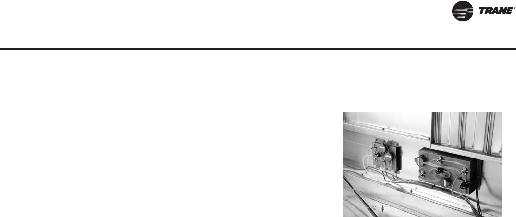
Statitrac Direct Space Building
Pressurization Control
Trane Statitrac control is a highly accurate and
efficient method of maintaining building pressure
control with a large rooftop air conditioner.
Building space pressurization control is achieved with
a 100 percent modulating exhaust system that
features a single forward curved fan, with modulating
discharge dampers that operates only when needed
or a 100% modulating plenum return fan with airfoil
wheel that operates continuously with the supply fan.
Figure 15. Statitrac
RT-PRC027.book Page 19 Tuesday, October 7, 2014 9:03 AM

20 RT-PRC027T-EN
Features & Benefits
3. Measure and read building space pressure
4. Measure and read return duct static pressure.
Proper building pressurization eliminates annoying door whistling, doors standing open, and
odors from other zones.
Variable Frequency Drives (VFD)
Variable Frequency Drives are factory installed and tested to provide supply/exhaust/return fan
motor speed modulation. VFD's, as compared to discharge dampers, are quieter, more efficient,
and may be eligible for utility rebates.The VFD's are available with or without a bypass option.
Bypass control will simply provide full nominal airflow in the event of drive failure.
Rapid Restart
Trane understands that every second counts.Trane equipment, controls, and control sequences
are designed to get the system back online and properly functioning should the facility experience
a power cycle event.
• Trane HVAC system design is optimized for fast restart.
• IntelliPak Rooftop System controls and equipment provide an integrated, pre-engineered
solution for fast restart.
• Proven operational procedures maximize uptime outside of critical outages and get the system
up and running as quickly as possible.
With Rapid Restart and use of a backup generator, the IntelliPak Rooftop System can provide full
cooling in 120 seconds or less after regaining electrical power.This option is fully integrated into
the IntelliPak controls logic via standard human interface. Rapid Restart is a perfect fit in time-
sensitive applications where extended down time is not an option and heating/cooling is crucial.
RT-PRC027.book Page 20 Tuesday, October 7, 2014 9:03 AM
RT-PRC027T-EN 21
Controls
Variable Air Volume (VAV) Only
Note: When noted in this sequence “human interface panel,” the reference is to both the unit
mounted and remote mounted human interface panel. All setpoint adjustments can be
accomplished at the unit or remote human interface panel.
Supply Air Pressure Control
Variable Frequency Drive (VFD) Control
Variable frequency drives are driven by a modulating 0-10 VDC signal from the Rooftop Module
(RTM). A pressure transducer measures duct static pressure, and theVFD is modulated to maintain
the supply air static pressure within an adjustable user-defined range.The range is determined by
the supply air pressure setpoint and supply air pressure deadband, which are set through the
human interface panel or BAS/Network.
Variable frequency drives provide supply fan motor speed modulation.The drive will accelerate or
decelerate as required to maintain the supply static pressure setpoint. When subjected to high
ambient return conditions the VFD will reduce its output frequency to maintain operation. Bypass
control is offered to provide full nominal airflow in the event of drive failure.
Supply Air Static Pressure Limit
The opening of VAV terminals, and the amount of supply air provided by the variable frequency
drive are coordinated during start up and transition to/from Occupied/Unoccupied modes to
prevent over pressurization of the supply air ductwork. However, if for any reason the supply air
pressure exceeds the user-defined supply air static pressure limit that was set at the human
interface panel, the supply fan and VFD are shut down.The unit is then allowed to restart three
times. If the over pressurization condition occurs on the third time, the unit is shut down and a
manual reset diagnostic is set and displayed at the human interface panel and BAS/network.
Supply Air Temperature Controls
Cooling/Economizer
During Occupied cooling mode of operation, the economizer (if available) and mechanical cooling
are used to control the supply air temperature.The supply air temperature setpoint and deadband
are user-defined at the human interface panel.The supply air temperature setpoint may be user-
defined from the BAS/network. If the conditions of the outside air are appropriate to use “free
cooling,” the economizer will first be used in an attempt to satisfy the supply air setpoint; then, if
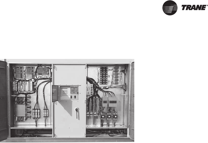
Figure 16. IntelliPak II control panel
RT-PRC027.book Page 21 Tuesday, October 7, 2014 9:03 AM

22 RT-PRC027T-EN
Controls
required, the mechanical cooling will be staged on to maintain supply air temperature setpoint.
Minimum On/Off timing of the mechanical cooling prevents rapid cycling.
On units with economizer, a call for cooling will modulate the outside air dampers open.The rate
of economizer modulation is based on deviation of the supply air temperature from setpoint, i.e.,
the further away from setpoint, the faster the outside air damper will open. First stage of cooling
will be allowed to start after the economizer reaches full open.
Note: The economizer is only allowed to function freely if one of the following conditions is met.
For dry bulb economizer control the ambient temperature must be below the dry bulb
temperature control setting. For reference enthalpy economizer control, outdoor air
enthalpy must be below the enthalpy control setting. At outdoor air conditions above the
enthalpy control setting, mechanical cooling only is used and the outside air dampers
remain at minimum position. For comparative enthalpy economizer control, outdoor air
enthalpy must be below the enthalpy of the return air.
If the unit does not include an economizer, mechanical cooling only is used to satisfy cooling
requirements.The outdoor air dampers may be set for a maximum of 25% outdoor air, through the
unit mounted human interface panel or a signal from the BAS/network, if the rooftop is equipped
with 0 to 25% motorized outside air dampers.
Heating
Modulating Gas
Upon a call for heating, the HEAT module closes the heating contacts, beginning the firing
sequence. First, the heat exchanger combustion blower begins operation. Upon positive proving
of combustion airflow, a 60 second pre-purge cycle is executed.Then the ignition sequence takes
place.
If ignition is not proven, the safety control locks out and must be manually reset. As long as there
is a call for heat, the safety control can be reset, which starts another purge cycle and try for ignition.
Once ignited, as additional heat is required, the combustion air damper opens, increasing the firing
rate.
During heating operation, an electronic flame safety control provides continuous flame
supervision. If combustion should become unstable for any reason, heating will automatically shut
down and be locked out until reset at the unit mounted Human Interface panel.
As the heating requirement is satisfied, the HEAT module will modulate the combustion air damper
closed and the firing rate will lower to maintain the desired outlet temperature. When the
requirement is fully satisfied, the heating contacts are opened, de-energizing the heat.The specific
sequence of operation of the gas heat will depend on the size of the heat exchanger.
Electric Heating
The individual stages of electric heat will be sequenced on the zone demand.The number of
available stages will depend on the unit size and heat capacity selected.
Hot Water or Steam
On units with hot water or steam heating, the supply air temperature can be controlled to a heating
setpoint during the Occupied mode.The supply air temperature heating setpoint and deadband are
user-defined at the Human Interface Panel. VAV Occupied heating on hot water and steam heat
units is enabled by closing a field-supplied switch or On units with hot water or steam heating, the
supply air temperature can be controlled to a heating setpoint during the Occupied mode.The
supply air temperature heating setpoint and deadband are user-defined at the Human Interface
Panel. VAV Occupied heating on hot water and steam heat units is enabled by closing a field-
supplied switch or contacts connected to an changeover input on the RTM.
RT-PRC027.book Page 22 Tuesday, October 7, 2014 9:03 AM
RT-PRC027T-EN 23
Controls
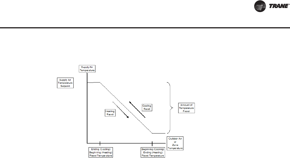
Supply Air Setpoint Reset
Supply air setpoint reset can be used to adjust the supply air temperature setpoint on the basis of
a zone temperature or on outdoor air temperature. Supply air setpoint reset adjustment is available
from the Human Interface Panel for supply air heating and supply air cooling control.
Outdoor air cooling reset is sometimes used in applications where the outdoor temperature has
a large effect on building load. When the outside air temperature is low and the building cooling
load is low, the supply air setpoint can be raised, thereby preventing subcooling of critical zones.
This reset can lower usage of mechanical cooling, thus savings in compressor kW, but an increase
in supply fan kW may occur.
Outdoor air heating reset is the inverse of cooling, with the same principles applied.
For both outdoor air cooling reset and heating reset, there are three user-defined parameters that
are adjustable through the Human Interface Panel:
– Beginning reset temperature
– Ending reset temperature
– Amount of temperature reset
Zone reset is applied to the zone(s) in a building that tend to over cool or overheat.The supply air
temperature setpoint is adjusted based on the temperature of the critical zone(s).This can have the
effect of improving comfort and/or lowering energy usage.The user-defined parameters are the
same as for outdoor air reset. See Figure 16, p. 16
Supply Air Tempering
Modulating gas, electric, hot water and steam heat units only—when supply air temperature falls
below the supply air temperature deadband low end, the heat valve is modulated open to maintain
the set minimum supply air temperature.
Zone Temperature Control
Unoccupied Zone Heating and Cooling
During Unoccupied mode, the unit is operated as a CV unit. VFDs operate at 100% and VAV boxes
are driven full open.The unit controls zone temperature within the Unoccupied zone cooling and
heating (heating units only) setpoints.
Figure 17. Supply air temperature reset
RT-PRC027.book Page 23 Tuesday, October 7, 2014 9:03 AM

24 RT-PRC027T-EN
Controls
Daytime warm-up
This feature is available on all types of heating units. During Occupied mode, if the zone
temperature falls to a preset, user-defined zone low limit temperature setpoint, the unit is put into
Unoccupied mode and Daytime Warm-up is initiated.The system changes over to CV heating (full
unit airflow), theVAV boxes are fully opened and full heating capacity is provided until the Daytime
Warm-up setpoint is reached.The unit is then returned to normal Occupied mode.
Outside Air Measurement
Trane air quality (Traq) outside air measurement damper system utilizes velocity pressure sensing
rings. Based on unit design CFM, the ventilation control module (VCM) monitors and controls the
quantity of outside air entering the unit.The outside airflow can be calibrated to accommodate for
altitude.
a. An optional temperature sensor may be connected to the ventilation control module to
enable it to control a field-installed pre-heater.
b. An optional CO2sensor may be connected to the ventilation control module to control
outside air based on CO2Demand Control Ventilation (DCV).
Outside Air CFM Compensation
As the supply fan modulates, this function proportionally adjusts the economizer minimum
position to compensate for the change in total airflow, in order to maintain a constant percent of
outside air. The modified economizer minimum position is computed as a linear function, based
on VFD position, given the two endpoints,
a. Minimum Position with VFD @ 0%
b. Minimum Position with VFD @ 100%
Both are user adjustable at the Human Interface Panel.
Single Zone Variable Air Volume (SZVAV) Only
The IntelliPak controls platform will support Single Zone VAV as an optional unit control type in
order to meet ASHRAE 90.1.The basic control will be a hybridVAV/CV configured unit that provides
discharge temperature control to a varying discharge air temperature target setpoint based on the
space temperature and/or humidity conditions. Concurrently, the unit will control and optimize the
supply fan speed to maintain the zone temperature to a zone temperature setpoint.
Supply Fan Output Control
Units configured for Single ZoneVAV control will utilize the same supply fan output control scheme
as on traditionalVAV units except theVFD signal will be based on zone heating and cooling demand
instead of the supply air pressure.
VFD Control
Single Zone VAV units will be equipped with a VFD-controlled supply fan which will be controlled
via a 0-10 VDC signal from the Rooftop Module (RTM). With the RTM supply fan output energized
and the RTM VFD output at 0 VDC, the fan speed output is 37% (22Hz) from theVFD by default; and
at 10 VDC the fan speed output is 100% (60Hz).The control scales the 0-10 VDC VFD output from
the RTM linearly to control between the 37-100% range.The VFD will modulate the supply fan
motor speed, accelerating or decelerating as required to maintain the zone temperature to the zone
temperature setpoint. When subjected to high ambient return conditions the VFD will reduce its
output frequency to maintain operation. Bypass control is offered to provide full nominal airflow
in the event of drive failure.
RT-PRC027.book Page 24 Tuesday, October 7, 2014 9:03 AM

RT-PRC027T-EN 25
Controls
Ventilation Control
Units configured for Single Zone VAV control will require special handling of the OA Damper
Minimum Position control in order to compensate for the non-linearity of airflow associated with
the variable supply fan speed and damper combinations. Units configured forTRAQ with or
without DCV will operate identically to traditional units with no control changes.
Space Pressure Control
For units configured with Space Pressure Control with or without Statitrac, the new schemes
implemented for economizer minimum position handling require changes to the existing Space
Pressure Control scheme in order to prevent over/under pressurization.The overall scheme will
remain very similar to VAV units with Space Pressure Control with the exception of the dynamic
Exhaust Enable Setpoint.
For SZVAV an Exhaust Enable Setpoint must be selected during the 100% Fan Speed Command.
Once selected, the difference between the Exhaust Enable Setpoint and Design OA Damper
Minimum Position at 100% Fan Speed Command will be calculated.The difference calculated will
be used as an offset and added to the Active Building Design OA Minimum PositionTarget in order
to calculate the dynamic Exhaust EnableTarget, which will be used throughout the Supply Fan
Speed/OA Damper Position range.
The Exhaust EnableTarget could be above or below the Active Building Design OA Minimum
PositionTarget Setpoint, based on the Active Exhaust Enable Setpoint being set above or below
the Building Design Minimum Position at 100% Fan Speed Command. Note that an Exhaust Enable
Setpoint of 0% will result in the same effect on Exhaust Fan control as onVAV applications with and
without Statitrac.
Occupied Cooling Operation
For normal cooling operation, cooling capacity will be staged or modulated in order to meet the
calculated discharge air target setpoint. If the current active cooling capacity is controlling the
discharge air within the deadband, no additional cooling capacity change will be requested. As the
Discharge AirTemperature rises above the deadband, the algorithm will request additional
capacity as required (additional compressors or economizer). As the Discharge AirTemperature
falls below the deadband, the algorithm will request a reduction in active capacity.
Default Economizer Operation
By default, the unit will be setup to optimize the minimum supply fan speed capability during
Economizer Only operation. If the economizer is able to meet the demand alone, due to desirable
ambient conditions, the supply fan speed will be allowed to increase above the minimum prior to
utilizing mechanical cooling if discharge air setpoint falls below the discharge air Lower Limit
(Cooling) setpoint.
Unoccupied Mode
In Unoccupied periods the unit will utilize setback setpoints, 0% Minimum OA Damper position, and
Auto Fan Mode operation as on normal ConstantVolume units.The Supply Fan speed will be forced
to 100% for all active heating and cooling requests in this mode.
Occupied Heating Operation
Occupied heating operation will utilize two separate control methodologies based on heating
configurations. For all “Staged” Heating types, the unit will utilize full airflow during all active
heating periods exactly like traditional ConstantVolume units. For “Modulating” Heating types the
unit will have the ability to utilize SZVAV Heating, much like Active Cooling, in order to maintain
the ZoneTemperature to the Zone Heating setpoint. Also, on units configured with a Modulating
Heat type, the customer will have the ability to select between the new SZVAV Heating control, or
to utilize traditional Constant Volume, full airflow heating based on the associated unit setup.
RT-PRC027.book Page 25 Tuesday, October 7, 2014 9:03 AM

26 RT-PRC027T-EN
Controls
Compressor (DX) Cooling
Compressor control and protection schemes will function identical to that of a traditional unit.
Normal compressor proving and disable input monitoring will remain in effect as well as normal
3-minute minimum on, off, and inter-stage timers. Also, all existing head pressure control schemes
will be in effect.
Cooling Sequence
If the control determines that there is a need for active cooling capacity in order to meet the
calculated discharge air target setpoint, once supply fan proving has been made, the unit will begin
to stage compressors accordingly. Note that the compressor staging order will be based on unit
configuration and compressor lead/lag status.
Once the discharge air target setpoint calculation has reached the Minimum Setpoint and
compressors are being utilized to meet the demand, as the discharge air target setpoint value
continues to calculate lower the algorithm will begin to ramp the supply fan speed up toward 100%.
Note that the supply fan speed will remain at the compressor stage’s associated minimum value
(as described below) until the discharge air target setpoint value is calculated below the discharge
air temperature Minimum Setpoint (limited discharge air target setpoint).
As the cooling load in the zone decreases the zone cooling algorithm will reduce the speed of the
fan down to minimum per compressor stage and control the compressors accordingly. As the
compressors begin to de-energize, the supply fan speed will fall back to the Cooling Stage’s
associated minimum fan speed, but not below. As the load in the zone continues to drop, cooling
capacity will be reduced in order to maintain the discharge air within the ±½ discharge air target
deadband.
Constant Volume (CV) Only
Occupied Zone Temperature Control
Cooling/Economizer
During Occupied cooling mode, the economizer (if provided) and mechanical cooling are used to
control zone temperature.The zone temperature cooling setpoint is user-defined at the Human
Interface Panel or from the BAS/Network. If the conditions of outside air is appropriate to use “free
cooling”, the economizer will be used first to attempt to satisfy the cooling zone temperature
setpoint; then the compressors will be staged up as necessary. Minimum on/off timing of
compressors prevents rapid cycling.
On units with economizer, a call for cooling will modulate the outside air dampers open.The rate
of economizer modulation is based on deviation of the zone temperature from setpoint, i.e., the
further away from setpoint, the faster the outside air damper will open. First stage of cooling will
be allowed to start after the economizer reaches full open.
Note: The economizer is only allowed to function freely if one of the following conditions is met:
For dry bulb economizer control, the ambient temperature must be below the dry bulb
temperature control setting. For reference enthalpy economizer control, outdoor air
enthalpy must be below the enthalpy control setting. At outdoor air conditions above the
enthalpy control setting, mechanical cooling only is used and the outdoor air dampers
remain at minimum position. For comparative enthalpy economizer control, outdoor air
enthalpy must be below the enthalpy of the return air.
If the unit does not include an economizer, mechanical cooling only is used to satisfy cooling
requirements.
The outdoor air dampers may be set for a maximum of 25% outdoor air, through the unit mounted
Human Interface Panel or a signal from the BAS/network, if the rooftop is equipped with 0 to 25%
motorized outside air dampers.
RT-PRC027.book Page 26 Tuesday, October 7, 2014 9:03 AM

RT-PRC027T-EN 27
Controls
Heating
Gas Heating: Two-Stage
Upon a call for heating, the HEAT module closes the first stage heating contacts beginning the firing
sequence. First, the heat exchanger combustion blower begins operation. Upon positive proving
of combustion airflow, a 60 second pre-purge cycle is executed.Then the ignition sequence takes
place.
If ignition is not proven, the safety control locks out and must be manually reset. As long as there
is a call for heat, the safety control can be reset, which starts another purge cycle and try for ignition.
As additional heat is required, the HEAT module will close the second stage heating contacts and
depending on heat module size, will open either the second stage of the gas valve, or a second
stage gas valve.
During heating operation, an electronic flame safety control provides continuous flame
supervision. If combustion should become unstable for any reason, heating will automatically shut
down. On the low heat for all unit sizes and the medium heat for the 90 and 105 ton, after a one
minute delay, plus another 60 second pre-purge cycle the ignition cycle begins. On all other heat
sizes the heating section will be shutdown and locked out until manually reset at the ignition
module and unit mounted Human Interface Panel after the first shutdown due to flame instability.
As the heating requirement is satisfied, the HEAT module will open the second stage heating relay,
de-energizing the second stage of heat. When the requirement is fully satisfied, the first stage
contacts are opened, de-energizing the first stage of heat.
Gas Heating: Modulating Gas
Upon a call for heating, the HEAT module closes the heating contacts, beginning the firing
sequence. First, the heat exchanger combustion blower begins operation. Upon positive proving
of combustion airflow, a pre-purge cycle is executed.Then the ignition sequence takes place.
If ignition is not proven, the safety control locks out and must be manually reset. As long as there
is a call for heat, the safety control can be reset, which starts another purge cycle and try for ignition.
Once ignited, as additional heat is required, the combustion air damper opens, increasing the firing
rate. During heating operation, an electronic flame safety control provides continuous flame
supervision. If combustion should become unstable for any reason, heating will automatically shut
down and be blocked out until reset at the unit mounted Human Interface panel.
As the heating requirement is satisfied, the HEAT module will modulate the combustion air damper
closed, and the firing rate will lower to maintain the desired outlet temperature. When the
requirement is fully satisfied, the heating contacts are opened, de-energizing the heat.The specific
sequence of operation of the gas heat will depend on the size of the heat exchanger.
Electric Heating
The individual stages of electric heat will be sequenced on the zone demand.The number of
available stages will depend on the unit size and heat capacity selected.
Hot Water or Steam Heating
Upon a call for heat, the UCM will send a varying voltage signal to the valve actuator.The valve
will modulate to meet building demand as indicated by the voltage signal. When heating is
satisfied, the valve will modulate closed. A temperature sensor is located on the coldest section of
the coil.When it senses an impending freeze condition, a signal is sent to the hydronic valve to drive
it full open. If the supply fan is on, or if the outside air damper is open when this freezing condition
is sensed, the supply fan is turned off and the outside air damper is closed.
Supply Air Tempering
For staged gas and electric heat units in the occupied Heating mode but not actively heating, if the
supply air temperature drops to 10°F below the Occupied zone heating temperature setpoint, one
stage of heat will be brought on to maintain a minimum supply air temperature.The heat stage is
RT-PRC027.book Page 27 Tuesday, October 7, 2014 9:03 AM

28 RT-PRC027T-EN
Controls
turned off if the supply air temperature rises to 10°F above the Occupied zone heating temperature
setpoint. On units with hot water or steam heating, if the supply air temperature drops below 48°F,
the heating valve is modulated to maintain 50°F supply air temperature with a 4°F deadband.
Auto Changeover
When the System Mode is“Auto,” the mode will change to cooling or heating as necessary to satisfy
the zone cooling and heating setpoints.The zone cooling and heating setpoints can be as close as
2°F apart.
Unoccupied Zone Temperature Control
Cooling and Heating
Cooling and/or heating modes can be selected to maintain Unoccupied zone temperature
setpoints. For Unoccupied periods, heating, economizer operation or compressor operation can be
selectively locked out at the Human Interface Panels.
CV, SZVAV, and VAV
Note: SZVAV exceptions are noted in parenthesis.
Space Pressure Control - Statitrac
A pressure transducer is used to measure and report direct space (building) static pressure.The
user-defined control parameters used in this control scheme are space static pressure setpoint,
space pressure deadband and exhaust enable point. As the economizer opens, the building
pressure rises and once above the exhaust enable point, enables the exhaust fan and dampers or
exhaust VFD.The exhaust dampers or VFD then modulate to maintain space pressure within the
deadband.
Morning Warm-up Options (Not applicable to SZVAV)
This feature may be enabled on all types of factory installed heat units as well as cooling only units
configured as “External Heat” (for example, VAV boxes with reheat). At the conclusion of
Unoccupied mode, while the economizer (if supplied) is kept closed, the selected zone is heated
to the user-defined Morning Warm-up setpoint.The unit is then released to Occupied mode.There
are two types of Morning Warm-up: full capacity or cycling capacity.
1. Full Capacity Morning Warm-up (MWU)
Full capacity Morning Warm-up uses full heating capacity, and heats the zone up as quickly as
possible. Full heating capacity is provided until the MorningWarm-up setpoint is met. At this point,
the unit is released to occupied mode.
2. Cycling Capacity Morning Warm-up (MWU)
Cycling capacity Morning Warm-up provides a more gradual heating of the zone. Normal zone
temperature control with varying capacity is used to raise the zone temperature to the MWU zone
temperature setpoint.This method of warm-up is used to overcome the “building sink” effect.
Cycling capacity MWU will operate until the MWU setpoint is reached or for 60 minutes, then the
unit switches to Occupied mode. A control algorithm is used to increase or decrease the amount
of heat in order to achieve the MWU zone temperature setpoint.
Note: When using the Morning Warm-up option in a VAV heating/cooling rooftop, airflow must
be maintained through the rooftop unit.This can be accomplished by electrically tying the
VAV boxes to the VAV box output relay contacts on the Rooftop Module (RTM) or by using
changeover thermostats. Either of these methods will assure adequate airflow through the
unit and satisfactory heating of the building.
RT-PRC027.book Page 28 Tuesday, October 7, 2014 9:03 AM

RT-PRC027T-EN 29
Controls
Emergency Override
When a LonTalk or BACnet communication module is installed, the user can initiate from theTrane
Tracer Summit (in the case of LCI),Tracer SC or 3rd Party BAS (with either BCI or LCI) one of five
(5) predefined, not available to configure, Emergency Override sequences. All compressors,
condenser fans and the Humidification output are deenergized for any Emergency Override
sequence. Each Emergency Override sequence commands the unit operation as follows:
1. PRESSURIZE_EMERG:
– Supply Fan - On
– Supply Fan VFD - Max (if so equipped)
– Exhaust Fan - Off; Exhaust Dampers - Closed (if so equipped)
– OA Dampers - Open; Return Damper - Closed
– Heat - All heat stages off; Mod Heat output at 0 VDC
– Occupied/Unoccupied/VAV box output - Energized
– VOM Relay - Energized (if so equipped)
– Preheat Output - Off
– Return Fan - Off; Exhaust Dampers - Closed (if so equipped)
– Return VFD - Min (if so equipped)
2. EMERG_DEPRESSURIZE:
– Supply Fan - Off
– Supply Fan VFD - Min (if so equipped)
– Exhaust Fan - On; Exhaust Dampers - Open/Max (if so equipped)
– OA Dampers - Closed; Return Damper - Open
– Heat - All heat stages off; Mod Heat output at 0 VDC
– Occupied/Unoccupied/VAV box output - Energized
– VOM Relay - Energized (if so equipped)
– Preheat Output - Off
– Return Fan - On; Exhaust Dampers - Open (if so equipped)
– Return VFD - Max (if so equipped)
3. EMERG_PURGE:
– Supply Fan - On
– Supply Fan VFD - Max (if so equipped)
– Exhaust Fan - On; Exhaust Dampers Open (if so equipped)
– OA Dampers - Open; Return Damper - Closed
– Heat - All heat stages off; Mod Heat output at 0 VDC
– Occupied/Unoccupied/VAV box output - Energized
– VOM Relay - Energized (if so equipped)
– Preheat Output - Off
– Return Fan - On; Exhaust Dampers - Open (if so equipped)
– Return VFD - Max (if so equipped)
4. EMERG_SHUTDOWN:
– Supply Fan - Off
– Supply Fan VFD - Min (if so equipped)
RT-PRC027.book Page 29 Tuesday, October 7, 2014 9:03 AM

30 RT-PRC027T-EN
Controls
– Exhaust Fan - Off; Exhaust Dampers Closed (if so equipped)
– OA Dampers - Closed; Return Damper - Open
– Heat - All heat stages off; Mod Heat output at 0 VDC
– Occupied/Unoccupied/VAV box output - Energized
– VOM Relay - Energized (if so equipped)
– Preheat Output - Off
– Return Fan - Off; Exhaust Dampers - Closed (if so equipped)
– Return VFD - Min (if so equipped)
5. EMERG_FIRE - Input from fire pull box/system:
– Supply Fan - Off
– Supply Fan VFD - Min (if so equipped)
– Exhaust Fan - Off; Exhaust Dampers Closed (if so equipped)
– OA Dampers - Closed; Return Damper - Open
– Heat - All heat stages off; Mod Heat output at 0 VDC
– Occupied/Unoccupied/VAV box output - Energized
– VOM Relay - Energized (if so equipped)
– Preheat Output - Off
– Return Fan - Off; Exhaust Dampers - Closed (if so equipped)
– Return VFD - Min (if so equipped)
Ventilation Override Module (VOM)
The user can customize up to five (5) different override sequences for purposes of ventilation
override control. If more than oneVOM sequence is being requested, the sequence with the highest
priority is initiated first. Sequence hierarchy is the sequence “A” (UNIT OFF) is first, with sequence
“E” (PURGE with Duct Pressure Control) last. A ventilation override mode can be initiated by
closing any of the five (5) corresponding binary input on the VOM module. A binary output is
provided on the VOM module to provide remote indication of an active VOM mode. All
compressors, condenser fans and the Humidification output are deenergized for any VOM
sequence.The factory default definitions for each mode are as follows:
1. UNIT OFF sequence “A”
– When complete system shutdown is required the following sequence can be used.
– Supply Fan - Off
– Supply Fan VFD - Min (if so equipped)
– Exhaust Fan - Off; Exhaust Dampers - Closed (if so equipped)
– OA Dampers - Closed; Return Damper - Open
– Heat - All heat stages off; Mod Heat output at 0 VDC
– Occupied/Unoccupied/VAV box output - Deenergized
– VOM Relay - Energized
– Preheat Output - Off
– Return Fan - Off; Exhaust Dampers - Closed (if so equipped)
– Return VFD - Min (if so equipped)
– OA Bypass Dampers - Open (if so equipped)
– Exhaust Bypass Dampers - Open (if so equipped)
RT-PRC027.book Page 30 Tuesday, October 7, 2014 9:03 AM

RT-PRC027T-EN 31
Controls
2. PRESSURIZE sequence “B”
Perhaps a positively pressurized space is desired instead of a negatively pressurized space. In this
case, the supply fan should be turned on withVFD at 100% speed and exhaust fan should be turned
off.
– Supply Fan - On
– Supply Fan VFD - Max (if so equipped)
– Exhaust Fan - Off; Exhaust Dampers - Closed (if so equipped)
– OA Dampers - Open; Return Damper - Closed
– Heat - All heat stages off; Mod Heat output at 0 VDC
– Occupied/Unoccupied/VAV box output - Energized
– VOM Relay - Energized
– Preheat Output - Off
– Return Fan - Off; Exhaust Dampers - Closed (if so equipped)
– Return VFD - Min (if so equipped)
– OA Bypass Dampers - Open (if so equipped)
– Exhaust Bypass Dampers - Open (if so equipped)
3. EXHAUST sequence “C”
With only the exhaust fans running (supply fan off), the space that is conditioned by the rooftop
would become negatively pressurized.This is desirable for clearing the area of smoke from the
now-extinguished fire, possibly keeping smoke out of areas that were not damaged.
– Supply Fan - Off
– Supply Fan VFD - Min (if so equipped)
– Exhaust Fan - On; Exhaust Dampers Open (if so equipped)
– OA Dampers - Closed; Return Damper - Open
– Heat - All heat stages off; Mod Heat output at 0 VDC
– Occupied/Unoccupied/VAV box output - Deenergized
– VOM Relay - Energized
– Preheat Output - Off
– Return Fan - On; Exhaust Dampers - Open (if so equipped)
– Return VFD - Max (if so equipped)
– OA Bypass Dampers - Open (if so equipped)
– Exhaust Bypass Dampers - Open (if so equipped)
4. PURGE sequence “D”
Possibly this sequence could be used for purging the air out of a building before coming out of
Unoccupied mode of operation onVAV units or for the purging of smoke or stale air if required after
a fire.
– Supply Fan - On
– Supply Fan VFD - Max (if so equipped)
– Exhaust Fan - On; Exhaust Dampers Open (if so equipped)
– OA Dampers - Open; Return Damper - Closed
– Heat - All heat stages off; Mod Heat output at 0 VDC
– Occupied/Unoccupied/VAV box output - Energized
RT-PRC027.book Page 31 Tuesday, October 7, 2014 9:03 AM
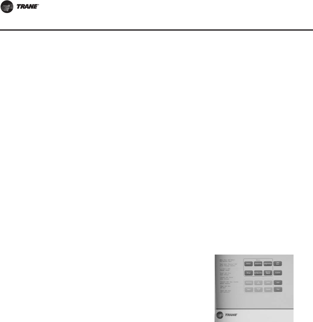
32 RT-PRC027T-EN
Controls
– VOM Relay - Energized
– Preheat Output - Off
– Return Fan - On; Exhaust Dampers - Open (if so equipped)
– Return VFD - Max (if so equipped)
– OA Bypass Dampers - Open (if so equipped)
– Exhaust Bypass Dampers - Open (if so equipped)
5. PURGE with duct pressure control sequence “E”
This sequence can be used when supply air control is required for smoke control.
– Supply Fan - On
– Supply Fan VFD - (If so equipped) Controlled by Supply Air Pressure Control function;
Supply Air Pressure High Limit disabled
– Exhaust Fan - On; Exhaust Dampers Open (if so equipped)
– OA Dampers - Open; Return Damper - Closed
– Heat - All heat stages off; Mod Heat output at 0 VDC
– Occupied/Unoccupied/VAV box output - Energized
– VOM Relay - Energized
– Preheat Output - Off
– Return Fan - On; Exhaust Dampers - Open (if so equipped)
– Return VFD - Max (if so equipped)
– OA Bypass Dampers - Open (if so equipped)
– Exhaust Bypass Dampers - Open (if so equipped)
To use a RHI the unit must be equipped with an optional Inter-Processor Communications Bridge
(IPCB) module.The RHI can be located up to 1,000 feet from the unit. A single RHI can be used to
monitor and control up to four (4) rooftops, each containing an IPCB.
Human Interface Panel Main Menu
• STATUS - used to monitor all temperatures, pressures, humidities, setpoints, input and output
status.
• CUSTOM - allows the user to create a custom status menu consisting of up to four (4) screens
of the data available in the Status menu.
• SETPOINTS - used to review and/or modify all the factory preset Default setpoints and setpoint
source selections.
• DIAGNOSTICS - used to review active and historical lists of diagnostic conditions. Over one
hundred different diagnostics can be read at the Human Interface Panel. The last 20 unique
diagnostics can be held in an active history buffer log.
Human Interface Panel (HI)
The Human Interface (HI) Panel providesa2lineX40
character clear English liquid crystal display and a 16
button keypad for monitoring, setting, editing and
controlling.The Human Interface Panel is mounted in the
unit's main control panel and is accessible through an
independent door, see Figure 18.
The optional remote mount version of the Human
Interface (RHI) Panel has all the functions of the unit
mount version except Service Mode.
Figure 18. Human interface panel (HI)
RT-PRC027.book Page 32 Tuesday, October 7, 2014 9:03 AM

RT-PRC027T-EN 33
Controls
• SETUP - Control parameters, sensor source selections, function enable/disable, output
definitions, and numerous other points can be edited in this menu. All points have factory
preset values so unnecessary editing is kept to a minimum.
• CONFIGURATION - Preset with the proper configuration for the unit as it ships from the factory,
this information would be edited only if certain features were physically added or deleted from
the unit. For example, if a field supplied Ventilation Override Module was added to the unit in
the field, the unit configuration would need to be edited to reflect that feature.
• SERVICE - used to selectively control outputs (for compressors, fans, damper position, etc.) for
servicing or troubleshooting the unit.This menu is accessible only at the unit mounted Human
Interface Panel.
Demand Limit (Not applicable to SZVAV)
This mode is used to reduce electrical consumption at peak load times. When demand limiting is
needed, mechanical cooling and/or heating operation are either partially or completely disabled in
order to save energy.
The definition of Demand Limit is user-definable at the Human Interface Panel. Demand Limit mode
is initiated via a field supplied switch or contact closure (GBAS 0-5 VDC module or GBAS 0-10 VDC
module) or via a communicated request (LCI or BCI). When the request for demand limit has been
cancelled, the unit cooling and/or heating functions will become fully enabled.
Generic Building Automation System Module (GBAS 0-5 VDC)
The Generic Building Automation System Module (GBAS 0-5VDC) is used to provide broad control
capabilities for building automation systems other thanTrane's Tracer system.The following
inputs and outputs are provided:
Analog Inputs - Four analog inputs, controlled via a field provided potentiometer or a 0-5 VDC
signal, that can be configured to be any of the following:
1. Occupied Zone Cooling Setpoint (CV & SZVAV)
2. Unoccupied Zone Cooling Setpoint (CV & SZVAV)
3. Occupied Zone Heating Setpoint (CV & SZVAV)
4. Unoccupied Zone Heating Setpoint (CV & SZVAV)
5. Supply Air Cooling Setpoint (VAV & SZVAV)
6. Supply Air Heating Setpoint (VAV & SZVAV)
7. Space Static Pressure Setpoint
8. Supply Air Static Pressure Setpoint (CV & VAV)
9. Minimum Outside Air Flow Setpoint
10. Morning Warm Up Setpoint (CV & VAV)
11. Economizer Dry Bulb Enable Setpoint
12. Supply Air Reheat Setpoint
13. Minimum Outside Air Position Setpoint
14. Occupied Dehumidification Setpoint
15. Unoccupied Dehumidification Setpoint
16. Occupied Humidification Setpoint
17. Unoccupied Humidification Setpoint
Binary Outputs - each of the five (5) relay outputs can be mapped to any/all of the available
diagnostics.
Binary Input - the single binary input can initiate or terminate the Demand Limit mode of operation
via a field supplied switch or contact closure.
RT-PRC027.book Page 33 Tuesday, October 7, 2014 9:03 AM

34 RT-PRC027T-EN
Controls
Generic Building Automation System Module (GBAS 0-10 VDC)
The Generic Building Automation System Module (GBAS 0-10 VDC) is used to provide broad
control capabilities for building automation systems other thanTrane's Tracer system.The
following inputs and outputs are provided:
Analog Inputs—Four analog inputs, controlled via a field provided potentiometer or a 0-10 VDC
signal that can be configured to be any of the following:
1. Occupied Zone Cooling Setpoint (CV & SZVAV)
2. Unoccupied Zone Cooling Setpoint (CV & SZVAV)
3. Occupied Zone Heating Setpoint (CV & SZVAV)
4. Unoccupied Zone Heating Setpoint (CV & SZVAV)
5. Supply Air Cooling Setpoint (VAV & SZVAV)
6. Supply Air Heating Setpoint (VAV & SZVAV)
7. Space Static Pressure Setpoint
8. Supply Air Static Pressure Setpoint (CV & VAV)
9. Minimum Outside Air Flow Setpoint
10. Morning Warm Up Setpoint (CV & VAV)
11. Economizer Dry Bulb Enable Setpoint
12. Supply Air Reheat Setpoint
13. Minimum Outside Air Position Setpoint
14. Occupied Dehumidification Setpoint
15. Unoccupied Dehumidification Setpoint
16. Occupied Humidification Setpoint
17. Unoccupied Humidification Setpoint
Analog Outputs—Four analog outputs that can be configured to be any of the following:
1. Outdoor AirTemperature
2. ZoneTemperature
3. Supply AirTemperature (VAV & SZVAV)
4. Supply Air Pressure (VAV & SZVAV)
5. Space Pressure
6. Space Relative Humidity
7. Outdoor Air Relative Humidity
8. Space CO2Level
9. Compressor Staging (%)
10. Heat Staging (%)
11. Outdoor Air Damper Position
12. Outdoor Airflow
Binary Output - the single relay output can be mapped to any/all of the available diagnostics.
Binary Input - the single binary input can initiate or terminate the Demand Limit mode of operation,
via a field supplied switch or contact closure.
Evaporator Coil Frost Protection - Frostat
A temperature sensor on each evaporator circuit is used to determine if the coil is getting close to
a freezing condition. Mechanical cooling capacity is shed as necessary to prevent icing.
RT-PRC027.book Page 34 Tuesday, October 7, 2014 9:03 AM

RT-PRC027T-EN 35
Controls
The Frostat system eliminates the need for hot gas bypass and adds a suction line surface
temperature sensor near theTXV bulb location to shed cooling when coil frosting conditions occur.
The supply fans are not shut off and will de-ice the coil.Timers prevent the compressors from rapid
cycling.
Steam and Hot Water Coil - Freeze Avoidance
Freeze Avoidance is a feature which helps prevent freezing of steam or hot water heat coils during
periods of unit inactivity and low ambient temperatures. Whenever the unit supply fan is off, the
outdoor air temperature is monitored. If the temperature falls below a predetermined value, the
heating valve is opened to a position selected at the unit mounted Human Interface to allow a
minimum amount of steam or hot water to flow through the coil and avoid freezing conditions.
Occupied/Unoccupied Switching
Description-3waystoswitch Occupied/Unoccupied:
1. Night Setback (NSB) Panel
2. Field-supplied contact closure (hard wired binary input to RTM) (CV, SZVAV & VAV)
3. Tracer (or 3rd Party BAS with LCI or BCI module)
Night Setback Sensors
Trane's night setback sensors are programmable with a time clock function that provides
communication to the rooftop unit through a 2-wire communications link.The desired transition
times are programmed at the night setback sensor and communicated to the rooftop.
Night setback (unoccupied mode) is operated through the time clock provided in the sensors with
night setback. When the time clock switches to night setback operation, the outdoor air dampers
close and heating/cooling can be enabled or disabled depending on setup parameters. As the
building load changes, the night setback sensor energizes the rooftop heating/cooling (if enabled)
function and the evaporator fan.The rooftop unit will cycle through the evening as heating/cooling
(if enabled) is required in the space. When the time clock switches from night setback to occupied
mode, all heating/cooling functions begin normal operation.
When using the night setback options with a VAV heating/cooling rooftop, airflow must be
maintained through the rooftop unit.This can be accomplished by electrically tying the VAV boxes
to the VAV Box output relay contacts on the Rooftop Module (RTM) or by using changeover
thermostats. Either of these methods will assure adequate airflow through the unit and satisfactory
temperature control of the building.
Occupied/Unoccupied input on the RTM
This input accepts a field supplied switch or contacts closure such as a time clock.
Trane Tracer or BAS System
TheTrane Tracer System or a 3rd party BAS (with LCI or BCI module) can control the Occupied/
Unoccupied status of the rooftop.
Timed Override Activation - ICS
This function is operational when the RTM is selected as the ZoneTemperature Sensor source at
the Human Interface Panel. When this function is initiated by the push of a override button on the
ICS sensor, theTracer will switch the unit to the Occupied mode. Unit operation (Occupied mode)
during timed override is terminated by a signal fromTracer.
Timed Override Activation - Non-ICS
This function is active whenever the RTM is selected as the ZoneTemperature Sensor source at the
Human Interface Panel.When this function is initiated by the push of an override button on the zone
sensor, the unit will switch to the Occupied mode. Automatic Cancellation of theTimed Override
Mode occurs after three hours of operation.
RT-PRC027.book Page 35 Tuesday, October 7, 2014 9:03 AM

36 RT-PRC027T-EN
Controls
Comparative Enthalpy Control of Economizer
An optional Comparative Enthalpy system is used to control the operation of the economizer, and
measures the temperature and humidity of both return air and outside air to determine which
source has lower enthalpy. This system allows true comparison of outdoor air and return air
enthalpy by measurement of outdoor air and return air temperatures and humidities.
Reference Enthalpy Control of Economizer
The optional reference enthalpy compares outdoor air temperature and humidity to the
economizer enthalpy control setpoint. If outdoor air temperature and humidity are below the
economizer enthalpy control setpoint, the economizer will operate freely.
This system provides more sophisticated control where outdoor air humidity levels may not be
acceptable for building comfort and indoor air quality.
Dry Bulb Temperature Control of Economizer
The optional dry bulb system measures outdoor temperature comparing it to the economizer
control temperature setpoint. If the outdoor temperature is below the economizer dry bulb
temperature control setpoint, the economizer will operate freely.This system is best suited for arid
regions where the humidity levels of outside air would not be detrimental to building comfort and
indoor air quality.
Refrigeration Circuit Lead/Lag
Refrigeration Circuit lead/lag is a user-selectable feature through the Human Interface Panel
available on all units. After each request for compressor operation, the lead refrigeration circuit
switches, thereby causing a more equitable or balanced run time among compressors.
Emergency Stop Input
A binary input is provided on the Rooftop Module (RTM) for installation of field provided switch or
contacts for immediate shutdown of all unit functions.
Anti-short Recycle Protection
A standard feature provided to prevent excessive cycling, and premature wear, of the compressors,
contactors and related components.
High Duct Temperature Sensor
Two manual reset, high temperature limit thermostats are provided. One is located in the discharge
section of the unit set at 240ºF and the other in the return air section of the unit set at 135ºF. If either
setpoint is reached, the rooftop unit is shut down.
CO2Control - Demand Control Ventilation (DCV)
A ventilation reset function that provides the necessary ventilation for occupants and reduces
energy consumption by minimizing the outdoor air damper position (or the OA flow setpoint with
TRAQ) below the Building Design Minimum, while still meeting the ASHRAE Std 62.1-2004
ventilation requirements.
If the space CO2level is greater than or equal to the CO2Design Setpoint, the outdoor air damper
will open to the Design Min Outdoor Air Damper (or OA Flow) Setpoint. If there is a call for
economizer cooling, the outdoor air damper may be opened further to satisfy the cooling request.
If the space CO2level is less than or equal to the CO2Minimum Setpoint, the outdoor air damper
will close to the DCV Minimum Outdoor Air Damper (or OA Flow) Setpoint. If there is a call for
economizer cooling, the outdoor air damper may be opened further to satisfy the cooling request.
If the space CO2level is greater than the CO2Minimum Setpoint and less than the CO2Design
Setpoint, the outdoor air damper position is (or OA flow) modulated proportionally to the Space
CO2level relative to a point between the CO2Min Setpoint and the CO2Design Setpoint. If there
RT-PRC027.book Page 36 Tuesday, October 7, 2014 9:03 AM
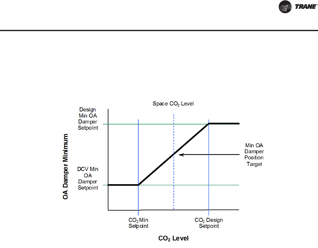
RT-PRC027T-EN 37
Controls
is a call for economizer cooling, the outdoor air damper may be opened further to satisfy the
cooling request. See Figure 19, p. 37.
Note: CO2sensor used with Demand ControlVentilation must be powered from an external power
source or separate 24 VAC transformer.
Humidification Control
A relay output is provided to control an externally connected, field supplied humidifier. Logic is
provided for Occupied and Unoccupied humidification control with safeguards to prevent cycling
between humidification and dehumidification
Return Fan Control
A return fan reduces the load on the supply fan motor or can allow a unit to operate at a higher static
pressure.The return fan VFD is modulated independently to maintain desired return air plenum
pressure. In all other cases the return fan is turned on or off with the supply fan.
Low Charge Protection
The low charge feature measures the entering and leaving evaporator temperatures on each circuit
to calculate a superheat value for each circuit.The superheat value is used for multiple purposes:
1. Displayed at the Human Interface panel to assist the service technician with unit charging and
diagnostics
2. A diagnostic message displayed at the Human Interface panel, warning of a low charge
situation when the unit is just slightly undercharged.The unit will be allowed to run.
3. A diagnostic message displayed at the Human Interface panel, warning of a low charge
situation when the unit is undercharged.The undercharged circuit will be locked out to protect
the compressors.
Condenser Fan Cycling
The IntelliPak II controller cycles condenser fans based on ambient temperature and saturated
condensing temperature to ensure the optimum operating conditions for the unit.
Figure 19. CO2control
RT-PRC027.book Page 37 Tuesday, October 7, 2014 9:03 AM

38 RT-PRC027T-EN
Controls
LonTalk Building Automation System
The LonTalk Communication Interface for IntelliPak II (LCI-I) controller expands communications
from the unit UCM network to aTraneTracer Summit or a 3rd party building automation system,
utilizing LonTalk, and allows external setpoint and configuration adjustment and monitoring of
status and diagnostics.The LCI-I utilizes an FTT-10A free topology transceiver, which supports non-
polarity sensitive, free topology wiring, which allows the system installer to utilize star, bus, and
loop architectures.This controller works in standalone mode, peer-to-peer with one or more other
units, or when connected to aTraneTracer Summit or a 3rd party building automation system that
supports LonTalk.The LCI-I controller is available as a factory or field-installed kit.
BACnet Building Automation System
The BACnet Communication Interface for IntelliPak II (BCI-I) controller expands communications
from the unit UCM network toTracer SC or a 3rd party building automation system, utilizing
BACnet, and allows external setpoint and configuration adjustment and monitoring of status and
diagnostics.The BCI-I utilizes the BACnet defined MS/TP protocol as defined in ASHRAE standard
135-2004. This controller works in standalone mode, withTracer SC or when connected to a 3rd
party building automation system that supports BACnet.The BCI-I controller is available as a
factory or field-installed kit.
Wireless Comm Interface
Trane Wireless Comm replaces the BACnet communication link and sensor wire onTracer building
automation systems for faster, easier, lower-risk installation and life-cycle savings.
Twinning
Twinning is a master unit and one or more similarly configured slave unit(s) operating
cooperatively, to provide higher capacity and/or redundancy at partial capacity.
Twinning requires an LCI module be installed in each unit and is accomplished by binding variables
between unit communication modules, communicating common setpoints and conditions
(temperatures, pressures, fan speeds, damper positions, occupancy, states, etc.), and allowing
each unit to run independent algorithms.
Note: BCI-I does not have twinning capabilities.
Twinned units must share a common supply and return duct network.
Twinned units operate:
a. as part of aTrane Integrated Comfort System installation, withTracer Summit.
b. on an inter-operable project with a 3rd party LonTalk.
c. as an independent group (bound via Rover or 3rd party tool).
Energy Recovery Wheel
Variable effectiveness is a means to control the capacity of an energy wheel. Normal wheel sizing
is for worst case winter/summer load; therefore, at part load the wheel may be oversized and
variable effectiveness is justifiable.
Variable effectiveness control can be used in any application where the outdoor air temperature
may fall between the discharge air setpoint and the temperature at which heating is required.
RT-PRC027.book Page 38 Tuesday, October 7, 2014 9:03 AM
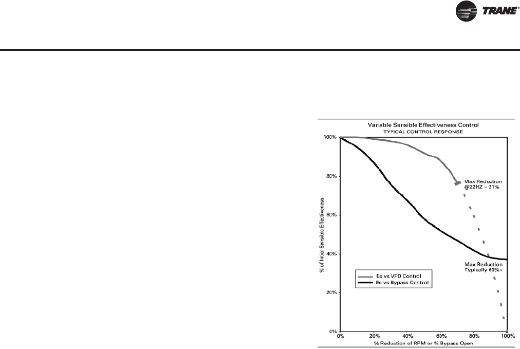
RT-PRC027T-EN 39
Controls
Hot Gas Reheat (Modulating Reheat Dehumidification)
When space conditions allow, the modulating dehumidification function activates the reheat mode
providing dehumidification of the space.
The reheat valve and cooling valve are modulated to control the discharge air temperature to the
discharge air temperature reheat setpoint (default 70F).
In reheat mode, the reheat valve is commanded (5 to 85%) to control to the discharge air reheat
setpoint and the cooling valve mirrors the reheat valve position (85 to 5%).
Low Ambient Function
The low ambient function is a head pressure control scheme to allow compressor operation at
lower ambient temperatures without tripping the low pressure cutout switch (LPC). For this
function, normal condenser fan staging applies.The first condenser fan on each circuit is
modulated by aVFD.The fan speed is modulated to control to the saturated condenser temperature
control Setpoint.
Low Ambient Compressor Lockout
This function will lock out the compressor if the outdoor air temperature is below the low ambient
compressor lock out temperature setpoint.The factory setpoint is 50°F on standard units and 0°F
on low ambient units.This setpoint is adjustable at the Human Interface Panel. Compressors will
be locked out when outdoor air temperatures falls below that selected temperature and will be
allowed to start again when the temperature rises 5°F above the setpoint.
For example, a job may have a required supply
air set point of 55°F. A typical return air
temperature may be 70°F and the outside air
temperature 40°F.The energy wheel could heat
the supply air to over 60°F, but by employing
variable effectiveness, the energy wheel
capacity can be modulated to exactly match the
required supply air temperature without using
additional heating or cooling.Therefore,
variable effectiveness control can significantly
add to the amount of energy saved in a year.
Variable effectiveness can be accomplished by
varying the wheel rotational speed or by
bypassing a portion of the exhaust air around
the wheel matrix. IntelliPak II utilizes an exhaust
air bypass damper for capacity control.
When unit mode and psychrometric conditions
allow, the energy recovery wheel will turn "ON".
The wheel uses energy from the return air
stream to temper the outside air stream,
thereby reducing the load of the space without
utilizing mechanical cooling and heating.
Figure 20. Variable sensible effectiveness
control
RT-PRC027.book Page 39 Tuesday, October 7, 2014 9:03 AM
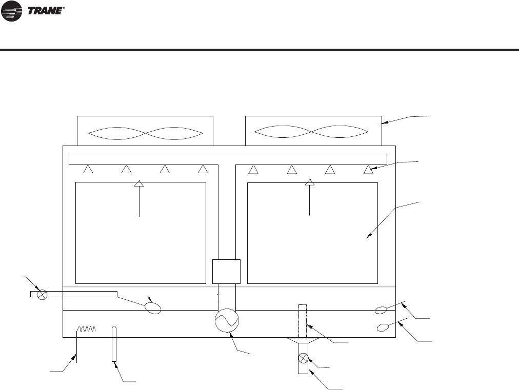
40 RT-PRC027T-EN
Controls
Evaporative Condenser
The evaporative condenser function is a method of head pressure control utilizing water as the
condensing medium rather than air.This method of head pressure control provides increased unit
efficiency.
The function activates whenever a compressor is active on a circuit.The function modulates the
condenser fan speed to control to Saturated CondenserTemperature (SCT) Control Setpoint. If the
saturated condenser temperature continues to rise above the SCT upper limit, sump pump will be
energized.
Once the temperature falls below the SCT lower limit, the sump pump will be de-energized.
The function has sump water freeze protection, periodic partial water flush to reduce contaminant
build up, external drain request, and optional water treatment.
Figure 21. Evaporative condenser flow schematic
Max. Level
Float
Min. Level
Float
Drain
Drain Valve
(Controlled by an actuator)
Sump Temperature
Sensor
Sump Pump
Condensor
Coil
Water Spray
Nozzles
Condenser Fan
Sump Heater
Water Distribution Pipeline
Air Flow
Air Flow
Dolphin
Treatment
System
Overflow
Mechanical Float
Fill Solenoid
Valve
RT-PRC027.book Page 40 Tuesday, October 7, 2014 9:03 AM

RT-PRC027T-EN 41
Application Considerations
Exhaust/Return Fan Options
When is it necessary to provide building exhaust? Whenever an outdoor air economizer is used,
a building generally requires an exhaust system.The purpose of the exhaust system is to exhaust
the proper amount of air to prevent over or under-pressurization of the building.The goal is to
exhaust approximately 10% less air than the amount of outside air going into the building.This
maintains a slightly positive building pressure.
The reason for applying either a return, or exhaust fan is to control building pressure.TheTrane
100% modulating exhaust system with Statitrac is an excellent choice for controlling building
pressure in the majority of applications. For more demanding applications,Trane's 100%
modulating return fan system with Statitrac is an excellent choice for systems with high return
static pressure losses, or duct returns. Both systems employ direct digital control technology to
maintain building pressure. Either return or exhaust fan systems with Statitrac may be used on any
rooftop application that has an outdoor air economizer.
A building may have all or part of its exhaust system in the rooftop unit. Often, a building provides
exhaust external to the air conditioning equipment.This external exhaust must be considered
when selecting the rooftop exhaust system.
With an exhaust fan system, the supply fan motor and drives must be sized to overcome the total
system static pressure, including return losses, and pull return air back to the unit during non-
economizer operation. However, a supply fan can typically overcome return duct losses more
efficiently than a return air fan system. Essentially, one large fan by itself is normally more efficient
than two fans in series because of only one drive loss, not two as with return fan systems.
In a return fan system, the return fan is in series with the supply fan, and operates continuously
whenever the supply fan is operating to maintain return air volume.The supply fan motor and
drives are sized to deliver the design CFM based on internal and discharge static pressure losses
only. The return fan motor and drives are sized to pull the return CFM back to the unit based on
return duct static.Therefore, with a return fan system, the supply fan ordinarily requires less
horsepower than a system with an exhaust fan
Exhaust/Return Fan Systems
1. 100% modulating exhaust with Statitrac direct space sensing building pressurization control
(with or without exhaust variable frequency drives)
2. 100% modulating exhaust without Statitrac
3. 100% modulating plenum return airfoil fan with Statitrac direct space sensing building
pressurization control with variable frequency drive
4. 100% modulating plenum return airfoil fan without Statitrac
Drivers for applying either return or exhaust fan systems include economy, building pressure
control, code requirements, and generally accepted engineering practices.
Application Recommendations
100% Modulating Exhaust with Statitrac Control, CV and VAV Units
For both CV and VAV rooftops, the 100% modulating exhaust discharge dampers (or VFD) are
modulated in response to building pressure. A differential pressure control system, Statitrac, uses
a differential pressure transducer to compare indoor building pressure to atmospheric pressure.
The FC exhaust fan is turned on when required to lower building static pressure to setpoint.The
Statitrac control system then modulates the discharge dampers (or VFD) to control the building
pressure to within the adjustable, specified deadband that is set at the human interface panel.
Economizer and return air dampers are modulated independent of the exhaust dampers (or VFD)
based on ventilation control and economizer cooling requests.
RT-PRC027.book Page 41 Tuesday, October 7, 2014 9:03 AM

42 RT-PRC027T-EN
Application Considerations
Advantages:
• The exhaust fan runs only when needed to lower building static pressure.
• Statitrac compensates for pressure variations within the building from remote exhaust fans and
makeup air units.
• The exhaust fan discharges in a single direction resulting in more efficient fan operation
compared to return fan systems.
• When discharge dampers are utilized to modulate the exhaust airflow, the exhaust fan may be
running unloaded whenever the economizer dampers are less than 100% open.
TheTrane 100% modulating exhaust system with Statitrac provides efficient control of building
pressure in most applications simply because 100 percent modulating exhaust discharge dampers
(or VFD) are controlled directly from building pressure, rather than from an indirect indicator of
building pressure, such as outdoor air damper position.
100% Modulating Exhaust System without Statitrac, CV Units Only
This fan system has performance capabilities equal to the supply fan.The FC exhaust fans are
started by the economizer's outdoor air damper position and the exhaust dampers track the
economizer outdoor air damper position.The amount of air exhausted by this fan is controlled by
modulating discharge dampers at the fan outlet.The discharge damper position is controlled by
a signal that varies with the position of the economizer dampers. When the exhaust fans start, the
modulating discharge dampers are fully closed, and exhaust airflow is 15 to 20% of total exhaust
capabilities.
100% Modulating Exhaust with or without Statitrac Control, SZVAV Units
The overall scheme will remain very similar to non-Single Zone VAV units with Space Pressure
Control with the exception of the dynamic Exhaust Enable Setpoint.
For SZVAV the user will select an Exhaust Enable Setpoint during the 100% Fan Speed Command.
Once selected, the difference between the Exhaust Enable Setpoint and Design OA Damper
Minimum Position at 100% Fan Speed Command will be calculated.The difference calculated will
be used as an offset to be added to the Active Building Design OA Minimum Position Target to
calculate the dynamic Exhaust EnableTarget to be used throughout the Supply Fan Speed/OA
Damper Position range.
Advantages:
• The exhaust fan runs only when the economizer reaches the desired exhaust enable point.
• Exhaust dampers are modulated based on the economizer position.
• The exhaust fan discharges in a single direction resulting in more efficient fan operation
compared to return fan systems.
• When discharge dampers are utilized to modulate the exhaust airflow, the exhaust fan may be
running unloaded whenever the economizer dampers are less than 100% open.
TheTrane 100% modulating exhaust system provides excellent linear control of building exhaust
in most applications where maintaining building pressure is not important.
100% Modulating Return Fan Systems with Statitrac Control, CV and
VAV units
For both CV and VAV applications, the IntelliPak II rooftop unit offers 100% modulating return fan
systems. A differential pressure control system, Statitrac, uses a differential pressure transducer
to compare indoor building pressure to atmospheric pressure.
The return fan exhaust dampers are modulated, based on space pressure, to control the building
pressure to within the adjustable, specified deadband that is set at the Human Interface Panel. A
VFD modulates the return fan speed based on return duct static pressure.
RT-PRC027.book Page 42 Tuesday, October 7, 2014 9:03 AM

RT-PRC027T-EN 43
Application Considerations
Economizer and return air dampers are modulated independent of the exhaust dampers based on
ventilation control and economizer cooling requests.
Advantages:
• The return fan operates independently of the supply fan to provide proper balance throughout
the airflow envelope.
• Statitrac compensates for pressure variations within the building from remote exhaust fans and
makeup air units.
• The return fan acts as both exhaust and return fan based on operation requirements.
TheTrane 100% modulating return system with Statitrac provides efficient control of building
pressure in applications with higher return duct static pressure and applications requiring duct
returns. Exhaust discharge dampers are controlled directly from building pressure, return fanVFD
is controlled from return static pressure, and return/economizer dampers are controlled based on
ventilation control and economizer cooling requests.
100% Modulating Return Fan without Statitrac Control, CV Units Only
The exhaust discharge dampers are modulated in response to building pressure.The return fan
runs continuously while the supply fan is energized. Economizer and return air dampers are
modulated independent of the exhaust dampers based on ventilation control, and economizer
cooling requests.
Advantages:
• The exhaust dampers are modulated as needed through a space pressure sensor input to
maintain building pressure.
• The return fan discharges in two directions, thereby balancing exhaust and unit return air
volumes.
Other Cooling Options
Cooling, Rapid Restart Units Only
This is for applications where the space has a high heat load with critical temperature control
requirements. A typical application is a computer room that has a large number of routers and
servers. If the cooling capacity is lost due to a power interruption, the temperature in the room can
rise as much as 3-4°F per minute. Once power is restored (e.g., backup generator has started), the
cooling capacity needs to be maximized as soon as possible to help get the space under control.
Once cooling capacity has been maximized, the unit can then manage the load using its normal
capacity control algorithms.
Supply and Return Airflow Configurations
The typical rooftop installation has both the supply and return air paths routed through the roof
curb and building roof. However, many rooftop installations require horizontal supply and/or return
from the rooftop because of a building's unique design or for acoustic considerations.
With IntelliPak II, there are several ways to accomplish horizontal supply, see Table 1, p. 44 and/or
return, see Table 2, p. 45.
RT-PRC027.book Page 43 Tuesday, October 7, 2014 9:03 AM
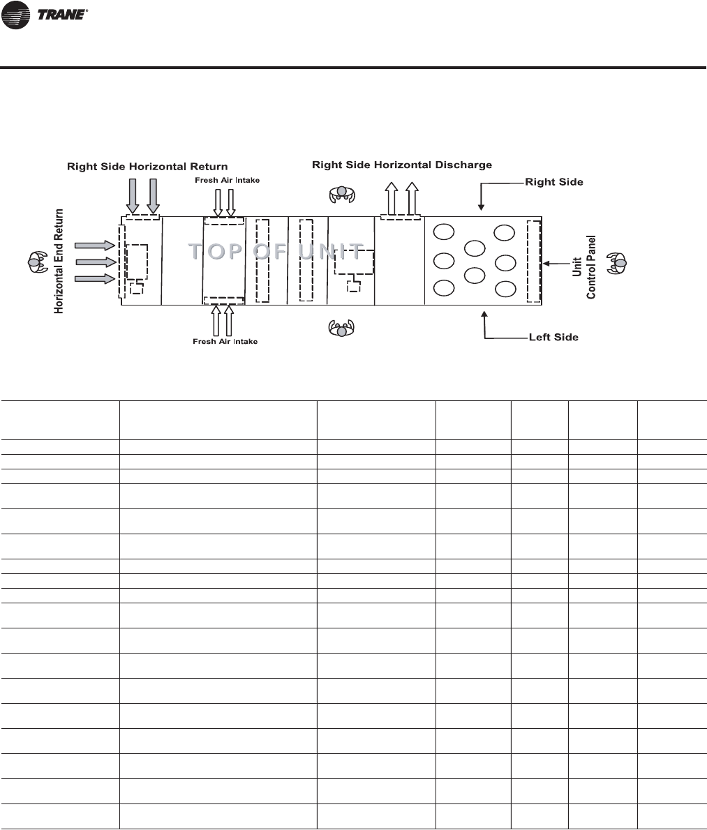
44 RT-PRC027T-EN
Application Considerations
Figure 22. Left/right unit orientation and horizontal airflow
Table 1. Supply airflow configuration
Cabinet
Configuration Supply Airflow Discharge
Direction(a) Type Acceptable
Application
With Bag
Final
Filters
With
Cartridge
Final Filters
With HEPA
Final Filters
Standard Length Downflow - Standard Option Cooling Only Yes No No No
Standard Length Horizontal - Right Side - Standard Option Cooling Only Yes No No No
Standard Length Horizontal - Left Side - Field Convertible Cooling Only Field Convert No No No
Standard Length Downflow - Standard Option Gas, Electric, Steam, Hot
Water Heat Yes No No No
Standard Length Horizontal - Right Side - Standard Option Gas, Electric, Steam, Hot
Water Heat Yes No No No
Standard Length Horizontal - Left Side - Field Convertible Gas, Electric, Steam, Hot
Water Heat No No No No
Four Foot Blank Section Downflow - Standard Option Cooling Only Yes Yes Yes Yes
Four Foot Blank Section Horizontal - Right Side - Standard Option Cooling Only Yes Yes Yes Yes
Four Foot Blank Section Horizontal - Left Side - Field Convertible Cooling Only Field Convert Yes Yes Yes
Four Foot Blank Section Downflow - Standard Option Gas, Electric, Steam, Hot
Water Heat No No No No
Four Foot Blank Section Horizontal - Right Side - Standard Option Gas, Electric, Steam, Hot
Water Heat No No No No
Four Foot Blank Section Horizontal - Left Side - Field Convertible Gas, Electric, Steam, Hot
Water Heat No No No No
Eight Foot Blank Section Downflow - Standard Option Cooling Only, Steam Heat,
Hot Water Heat Yes Yes Yes Yes
Eight Foot Blank Section Horizontal - Right Side - Standard Option Cooling Only, Steam Heat,
Hot Water Heat Yes Yes Yes Yes
Eight Foot Blank Section Horizontal - Left Side - Field Convertible Cooling Only, Steam Heat,
Hot Water Heat Field Convert Yes Yes Yes
Eight Foot Blank Section Downflow - Standard Option Gas(b) or Electric(c) Yes No High
Temperature High
Temperature
Eight Foot Blank Section Horizontal - Right Side - Standard Option Gas(ii) or Electric(iii) Yes No High
Temperature High
Temperature
Eight Foot Blank Section Horizontal - Left Side - Field Convertible Gas(ii) or Electric(iii) Field Convert No High
Temperature High
Temperature
(a)For left/right unit orientation, see Figure 22, p. 44
(b)Not available with 2.5M MBh heater
(c) Multi-piece units with electric heat and eight foot blank section are not field convertible from right side horizontal to left side horizontal configuration.
RT-PRC027.book Page 44 Tuesday, October 7, 2014 9:03 AM
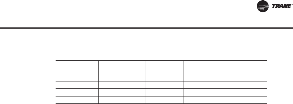
RT-PRC027T-EN 45
Application Considerations
When using an IntelliPak II rooftop for horizontal supply and/or return, an additional pressure drop
must be added to the supply external static to account for the 90 degree turn the air is making.This
additional pressure drop depends on airflow and rooftop size, but a range of 0.10 inches to 0.30
inches can be expected.The openings on the rooftop all have a one inch lip around the perimeter
to facilitate ductwork attachment.
Corrosive Atmospheres
Trane's IntelliPak rooftops are designed and built to industrial standards and will perform to those
standards for an extended period depending on the hours of use, the quality of maintenance
performed, and the regularity of that maintenance. One factor that can have an adverse effect on
unit life is its operation in a corrosive environment. Since the microchannel condenser coil is an
all-aluminum design, it provides a high level of corrosion protection on its own. Uncoated, it
withstands a salt spray test in accordance with ASTM B117 for 1,000 hours. When rooftops are
operated in highly corrosive environments,Trane recommends the corrosion protected condenser
coil option.
This corrosion protection option meets the most stringent testing in the industry, including ASTM
B117 Salt Spray test for 6,000 hours and ASTM G85 A2 Cyclic Acidified Salt Fog test for 2,400 hours.
The acid fog test is the most stringent available today.This coating is added after coil construction
covering all tubes, headers, fins and edges.The design provides superior protection from any
corrosive agent. For evaporator coils, copper fins can be utilized as a design special.
Note: Field coating is not allowed on Microchannel coils.
Ventilation Override Sequences
One of the benefits of using an exhaust fan rather than a return fan, in addition to the benefits of
lower energy usage and improved building pressurization control, is that the rooftop can be used
as part of a ventilation override system. Several types of sequences can be easily done when
exhaust fans are a part of the rooftop system.
What would initiate the ventilation override control sequence?Typically, a manual switch is used
and located near the fire protection control panel.This enables the fire department access to the
control for use during or after a fire. It is also possible to initiate the sequence from a field-installed
automatic smoke detector. In either case, a contact closure begins the ventilation override control
sequence.
Trane can provide five (5) different ventilation override sequences on both CV and VAV IntelliPak
II rooftops. For convenience, the sequences are factory preset but are fully field edited from the
Human Interface Panel orTracer. Any or all five sequences may be “locked” in by the user at the
Human Interface Panel.
The user can customize up to five (5) different override sequences for purposes such as smoke
control.The following parameters within the unit can be defined for each of the five sequences:
• Supply Fan - on/off
• Variable Frequency Drives - on (60 Hz)/off (0 Hz)/controlling
• Exhaust/Return Fan - on/off
• Exhaust Dampers - open/closed
Table 2. Return airflow configuration
Airflow Config(a)
(a)For left/right unit orientation, see Figure 22, p. 44.
Exhaust Fan VFD Exhaust Fan
No VFD Return Fan VFD Return Fan
No VFD
Vertical Yes Yes Yes Yes
Horizontal - Right Yes Yes Yes Yes
Horizontal - Left No Field Convert No No
Horizontal - End Yes Yes No No
RT-PRC027.book Page 45 Tuesday, October 7, 2014 9:03 AM

46 RT-PRC027T-EN
Application Considerations
• Economizer dampers - open/closed
• Heat - off/controlling (output for) VAV Boxes - open/controlling
Compressors and condenser fans are shut down for any Ventilation Override sequence. Factory
preset sequences include unit Off, Exhaust, Purge, Purge with duct pressure control, and
Pressurization. Any of the user-defined Ventilation Override sequences can be initiated by closing
a field supplied switch or contacts connected to an input on the Ventilation Override Module. If
more than one ventilation override sequence is being requested, the sequence with the highest
priority is initiated. Refer to the Ventilation Override Module (VOM) information in the Control
section of this catalog for more details on each override sequence.
Natural Gas Heating Considerations
Trane uses heavy gauge 304 L stainless steel throughout the construction of its natural gas drum
and tube heat exchangers for the IntelliPak II product.These heat exchangers can be applied with
confidence, particularly with full modulation control, when mixed air temperatures are below
50°F, and low ambient temperatures can cause condensation to form on the heat exchanger.
IntelliPak II natural gas heat exchangers are not recommended for applications with mixed air
conditions entering the heat exchanger below 30°F to ensure adequate leaving air heating
temperature. For airflow limitations and temperature rise across the heat exchanger information,
see Table 42, p. 137.
Acoustical Considerations
The ideal time to make provisions to reduce sound transmission to the space is during the project
design phase. Proper placement of rooftop equipment is critical to reducing transmitted sound
levels to the building.The most economical means of avoiding an acoustical problem is to place
any rooftop equipment away from acoustically critical areas. If possible, rooftop equipment should
not be located directly above areas such as: offices, conference rooms, executive office areas and
classrooms. Ideal locations are above corridors, utility rooms, toilet facilities, or other areas where
higher sound levels are acceptable.
Several basic guidelines for unit placement should be followed to minimize sound transmission
through the building structure:
1. Never cantilever the condensing section of the unit. A structural cross member must support
this end of the unit.
2. Locate the unit's center of gravity close to or over a column or main support beam to minimize
roof deflection and vibratory noise.
3. If the roof structure is very light, roof joists should be replaced by a structural shape in the critical
areas described above.
4. If several units are to be placed on one span, they should be staggered to reduce deflection over
that span.
It is impossible to totally quantify the effect of building structure on sound transmission, since this
depends on the response of the roof and building members to the sound and vibration of the unit
components. However, the guidelines listed above are experience proven guidelines which will
help reduce sound transmission.The ASHRAE publication "A Practical Guide to Noise and
Vibration Control for HVAC Systems" also provides valuable information.
There are several other sources of unit sound, i.e., supply fan, compressors, exhaust/return fans,
condenser fans and aerodynamic noise generated at the duct fittings. Refer to the ASHRAE
Applications Handbook, Chapter 47, 2003 edition for guidelines for minimizing the generation of
aerodynamic noise associated with duct fittings. A good source of information on general
acoustical considerations for rooftops is the 2000 ASHRAE Journal article titled, "Controlling Noise
from Large Rooftop Units".
TheTrane Acoustic Program (TAP) allows complete modeling of rooftop acoustical installation
parameters.The software models airborne sound from supply and return ducts, as well as duct
RT-PRC027.book Page 46 Tuesday, October 7, 2014 9:03 AM
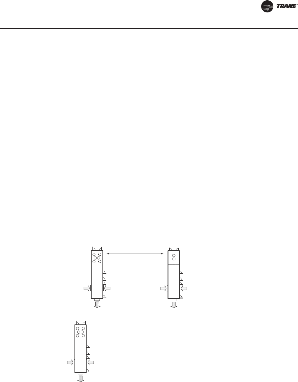
RT-PRC027T-EN 47
Application Considerations
breakout and roof transmission sound, so that the designer can identify potential sound problems
and make design alterations before equipment installation. Output of the program shows the
resulting NC (or RC) level for any point in the occupied space.TAP is also capable of modeling the
effect of outdoor sound on the surrounding area.This program is available fromTrane's Customer
Direct Service Network (C.D.S.), ask your localTrane representative for additional information on
this program.
Clearance Requirements
The recommended clearances identified in Figure 40, p. 176 should be maintained to assure
adequate service capability, maximum capacity and peak operating efficiency. A reduction in unit
clearance could result in condenser coil starvation or warm condenser air recirculation. If the
clearances shown are not possible on a particular job, consider the following:
• Do the clearances available allow for major service work such as changing compressors or
coils?
• Do the clearances available allow for proper outside air intake, exhaust air removal and
condenser airflow?
• If screening around the unit is being used, is there a possibility of air recirculation from the
exhaust to the outside air intake or from condenser exhaust to condenser intake?
Actual clearances which appear inadequate should be reviewed with a localTrane sales engineer.
When two or more units are to be placed side by side, the distance between the units should be
increased to 150 percent of the recommended single unit clearance.The units should also be
staggered, see Figure 23, for two reasons:
1. To reduce span deflection if more than one unit is placed on a single span. Reducing deflection
discourages sound transmission.
2. To assure proper diffusion of exhaust air before contact with the outside air intake of adjacent
unit.
Figure 23. Unit placement
Outdoor
Air Intake
Outdoor
Air Intake
Exhaust
Air
Outdoor
Air Intake
Outdoor
Air Intake
Exhaust
Air
Outdoor
Air Intake
Outdoor
Air Intake
Exhaust
Air
Minimum distance between units must be 16’!
RT-PRC027.book Page 47 Tuesday, October 7, 2014 9:03 AM
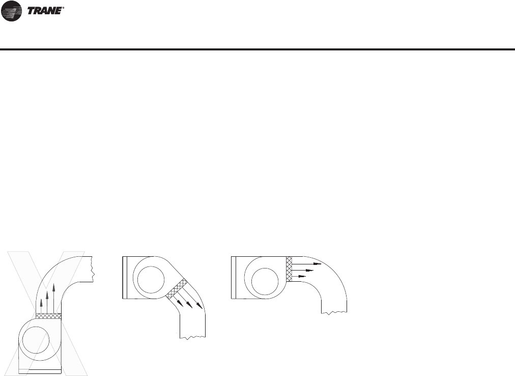
48 RT-PRC027T-EN
Application Considerations
Duct Design
It is important to note that the rated capacities of the rooftop can be met only if the rooftop is
properly installed in the field. A well-designed duct system is essential in meeting these capacities.
The satisfactory distribution of air throughout the system requires that there be an unrestricted and
uniform airflow from the rooftop discharge duct.This discharge section should be straight for at
least several duct diameters to allow the conversion of fan energy from velocity pressure to static
pressure.
However, when job conditions dictate elbows be installed near the rooftop outlet, the loss of
capacity and static pressure may be reduced through the use of guide vanes and proper direction
of the bend in the elbow.The high velocity side of the rooftop outlet should be directed at the
outside radius of the elbow rather than the inside as illustrated in Figure 24.
Energy Recovery Wheel
For applications where the air streams within the rooftop must be isolated, consider using
alternative technologies that guarantee separation of the air streams.
Important: Do not use energy wheels in applications where the exhaust air is contaminated with
harmful toxins or biohazards or where even a minor mixing of the air streams
presents a health risk. See Installation Operation Maintenance (RT-SVX24*-EN) for
more information.
The energy recovery option was designed as a partial flow outside air system, where the required
outside air is less than 100 percent. IntelliPak II monitors outside air, return air, and zone conditions.
It compares them with setpoints (set in the rooftop human interface) and checks for suitable energy
recovery system operation. Energy recovery can be activated when both supply and exhaust fans
are in operation. Heat can be recovered when the return air dry bulb temperature is greater than
the outside air dry bulb temperature.
Energy recovery is disabled when economizer cooling operation is requested. Economizer cooling
in energy recovery wheel equipped units requires the exhaust air and outside air bypass dampers
to be open and the recovery wheel motor to be off.The energy recovery wheel can provide free
cooling when outside air enthalpy is greater than return air enthalpy. In general, energy recovery
works well in applications where a high outside airflow minimum is required, often because of high
occupancy.
Hot Gas Reheat
In general, applications where non-peak load conditions can be dominated by latent loads are
candidates for the dehumidification option.This includes many applications subject to ASHRAE
Standard 62 requirements.
Figure 24. Duct design
IMPROPER
PROPER
RT-PRC027.book Page 48 Tuesday, October 7, 2014 9:03 AM

RT-PRC027T-EN 49
Application Considerations
For applications where the unit is utilized as a make-up air or 100% outside air unit, please consider
using an alternate solution.These applications are not appropriate for theTrane dehumidification
option with hot gas reheat.
Evaporative Condenser
Water Supply—Suspended particulate matter, mineral concentrations, trash and debris can
adversely affect performance of any water-cooled device. If not managed, mineral concentrations
can result in clogged water system hardware, heat exchanger restriction and heat transfer loss.
Trane's evaporative condenser is designed to greatly minimize performance problems that may
occur from the by-products of water evaporation.
Incoming Water Supply Line—A float valve is provided to maintain sump water level during
condenser operation. A field installed gate valve may be installed on the condenser water supply
line. An 80 to 100 mesh field supplied strainer may be installed in the condenser water supply line
to help prevent the introduction of debris.The condenser water supply line should be flushed
thoroughly prior to connection to the unit. Local codes may require back-flow prevention on the
condenser water supply line.
Water Discharge and Drain Line—Care and judgment should be exercised in selecting a water
discharge site.
Local Site Discharge—Rooftop or simple storm sewer discharge is generally acceptable. Do not
routinely direct sump discharge onto areas where the byproducts of water evaporation or water
treatment products are undesirable.
Sewer Discharge—The quantities of mineral and debris in the discharge water are actually very
small, and do not cause problems when diluted in normal sewer flow. Check local codes to identify
any special requirements for sewer discharge.
Regardless of the disposal method used, local codes, state or federal standards for water disposal
must be followed.
Freeze Protection—For operation in ambient temperatures below 32°F, optional sump heater and
controls are available to provide operation down to 10°F. In colder climates water supply line and
drain piping will require field installed freeze protection. Generally low wattage heat tape on the
water lines is sufficient protection.
Make-up Water Considerations:
Water Saving Methods—A programmable flush cycle is initiated to remove mineral deposits and
particulates from the sump.
Fresh water can be cycled into the sump as a portion of the existing water is drained.The intervals
between drains are adjustable from 0 - 12 hours.When set to 0, the periodic blowdown is disabled.
A more efficient approach is utilizing the Conductivity Controller option, which performs
blowdowns based on water quality readings from the conductivity sensor in the sampling tube.
Users can set a limit based on water quality testing they have performed in their area, when this
adjustable setpoint is exceeded the unit will conduct a blowdown for a period of time set by the
user. This allows the user to save water by only performing blowdowns when they are required.
Water level is maintained by the internal float valve.
WaterTreatment—Water treatment is required on all evaporative condensing units. Even when an
optional Dolphin WaterCare System is utilized, water must still be maintained and monitored
throughout the unit life cycle.
Note: Local codes may require the use of chemicals for water treatment. Different chemical feeder
systems are available to fit a wide variety of requirements and budgets. Check with local
code officials to determine installation requirements.
Low Ambient Operation— Remote Human Interface Recommendation
For low ambient operation, the use of a remote mounted human interface panel is recommend for
service and troubleshooting.
RT-PRC027.book Page 49 Tuesday, October 7, 2014 9:03 AM

50 RT-PRC027T-EN
Selection Procedure
Air-Cooled Rooftop
This section outlines a step-by-step procedure that may be used to select aTrane air-cooled single-
zone air conditioner. Air-cooled models should be selected based on dry bulb (DB) conditions.
For specific model selection, utilizeTOPSS or contact the localTrane Sales Office.This sample
selection is based on the following conditions:
Note: When calculating capacities for evaporative condensers, use ambient wet
bulb (WB).
Summer Design:
• Summer outdoor design conditions - 95 DB/76 WB ambient temperature
• Summer room design conditions -78 DB/65 WB
• Total cooling load - 980 MBh (81.6 tons)
• Sensible cooling load - 735 MBh (61.25 tons)
• Outdoor air ventilation load - 154.0 MBh (12.8 tons)
• Return air temperature - 78 DB / 65 WB
Winter Design:
• Winter outdoor design conditions - 0°F
• Return air temperature - 70°F
• Total heating load - 720 MBh
• Winter outdoor air ventilation load - 288.6 MBh
• Total winter heating load - 1008.6 MBh
Air Delivery Data:
• Supply fan CFM - 36,000 CFM
• Supply duct static pressure - 1.86 in wg
• Minimum outdoor air ventilation - 3,600 CFM
• Exhaust fan CFM - 36,000 CFM
• Return air duct negative static pressure - 0.3 in wg
Electrical Characteristics:
• Voltage/cycle/phase - 460/60/3
Unit Accessories:
• Gas fired heat exchanger - high heat
• Downflow supply and upflow return
• High efficiency throwaway filters
• Economizer
• Modulating 100% exhaust
RT-PRC027.book Page 50 Tuesday, October 7, 2014 9:03 AM
RT-PRC027T-EN 51
Selection Procedure
Cooling Capacity Selection
Step 1—Nominal Unit Size Selection
A summation of the peak cooling load and the outside air ventilation load shows: 980 MBh + 154.0
MBh = 1134.0 MBh required unit capacity.
From Table 10, p. 68, a 105 ton unit with standard capacity evaporator coil at 80 DB / 65 WB, 95°F
outdoor air temperature and 36,000 total supply CFM is 1,237 MBh total and 1,037 MBh sensible.
Thus, a nominal 105 ton unit with standard capacity evaporator coil is selected.
Step 2—Evaporator Coil Entering Conditions
Mixed air dry bulb temperature determination:
Using the minimum percent of OA (3,600 CFM ÷ 36,000 CFM = 10%), determine the mixture dry bulb
to the evaporator.
RADB+%OA(OADB-RADB) = 78 + (0.10) (95 - 78) = 78 + 1.5 = 79.5°F
Approximate wet bulb mixture temperature:
RAWB+%OA(OAWB-RAWB)=65+(0.10) (76 - 65) = 65 + 1.1 = 66.1°F
Step 3 - Determine Supply Fan Motor Heat Gain
Having selected a nominal 105 ton unit, the supply fan bhp can be calculated.The supply fan motor
heat gain must be considered in final determination of unit capacity.
Supply Air Fan
Determine unit total static pressure at design supply CFM:
Using total of 36,000 CFM and total static pressure of 4.0 inches, enter Table 33, p. 114.The table
shows 40.4 bhp with 1,097 rpm required for the 36" supply fan.
From Figure 25, p. 53 supply fan motor heat gain =
109.0 MBh, or 109.0 MBh ÷ 36000 CFM x 1.085 = 2.8°F supply fan motor heat
Step 4 - Determine Total Required Cooling Capacity
Required capacity =Total peak load + OA load + supply air fan motor heat
Required capacity = 980.0 + 154.0 + 109.0 = 1243.0 MBh (103.6 tons)
Step 5 - Determine Unit Capacity
From Table 10, p. 68, unit total capacity at 79.5 DB/66.1 WB entering the evaporator, 36,000 supply
air CFM, 95°F outdoor ambient is 1,251 MBh (104.2 tons) with 996 MBh (83 tons) sensible capacity.
Step 6 - Determine Leaving Air Temperature
Unit sensible heat capacity corrected for supply air fan motor heat = 996 MBh sensible - 109.0 MBh
motor heat = 887 MBh.
Supply Duct Static Pressure 2.2 inches
Evaporator Coil Table 49, p. 142 0.64 inches
Return Duct Negative Static Pressure 0.30
Heat Exchanger Table 49, p. 142 0.03
Throwaway Filter Table 49, p. 142 0.26
Economizer Damper(a) Table 49, p. 142
(a)Add either the economizer damper value or return damper value,
depending on which static pressure is greater. (Do not use both.)
0.57
Unit Total Static Pressure 4.0
RT-PRC027.book Page 51 Tuesday, October 7, 2014 9:03 AM
52 RT-PRC027T-EN
Selection Procedure
Supply air dry bulb temperature difference =
Sensible Btu = 887 MBh /(1.085 x 36,000 CFM) = 23.0
Supply air dry bulb = 79.5 DB - 23.0 = 56.5 leaving evaporator coil
Unit enthalpy difference = 1,251 MBh ÷ (4.5 x 36,000 CFM) = 7.72 Btu/lb.
Leaving enthalpy = h (ent WB) - h (diff). From Table 6, p. 64 h (ent WB) = 30.9 Btu/lb.
Leaving enthalpy = 30.9 Btu/lb. - 7.72 Btu/lb. = 23.18 Btu/lb.
Supply air wet bulb = 54.9 leaving evaporator coil.
Leaving air temperature = 56.5 DB/54.9 WB
Heating Capacity Selection
Step 1 - Determine Air Temperature Entering Heating Module
Mixed air temperature = RADB+%OA(OADB-RADB) = 70 + (0.10) (0 - 70) = 63°F
Supply air fan motor heat temperature rise = 109000 Btu ÷ (1.085 x 36000 CFM) = 2.8°F
Air temperature entering heating module = 63.0 + 2.8 = 65.8°F
Step 2 - Determine Total Winter Heating Load
Total winter heating load =
peak heating load + ventilation load - supply fan motor heat = 720 + 288.6 - 109.0 = 899.6 MBh
Electric Heating System
Unit operating on 460/60/3 power supply.
From Table 58, p. 151, kW may be selected for a nominal 105 ton unit operating 460-volt power.The
265 kW heat module (904.4 MBh) will satisfy the winter heating load of 899.6 MBh.
Table 42, p. 137 shows an air temperature rise of 23.2°F for 36,000 CFM through the 265 kW heat
module.
Unit supply temperature at design heating conditions = mixed air temperature +
air temperature rise = 65.8°F + 23.2°F = 89.0°F.
Gas Heating System (Natural Gas)
From Table 42, p. 137 select the high heat module (1,440 MBh output) to satisfy winter heating load
of 899.6 MBh at unit CFM.
Table Table 42, p. 137 also shows an air temperature rise of 37.0°F for 36,000 CFM through the
heating module.
Unit supply temperature at design heating conditions =
mixed air temperature + air temperature rise = 65.8°F + 37.0°F = 102.8°F.
Hot Water Heating System
Assume a hot water supply temperature of 190°F and an entering coil temperature of 65.8°F.
Subtract the mixed air temperature from the hot water temperature to determine the ITD (initial
temperature difference).
ITD = 190°F - 65.0°F = 125°F. Divide the winter heating load by ITD = 1008.6 MBh ÷ 125°F = 8.0 Q/ITD.
From Table 45, p. 138, select the low heat module. By interpolation, a Q/ITD of 8.0 can be obtained
at a gpm of 40.0. Water pressure drop at 40.0 gpm is 0.33 ft. of water.
Sensible Btu =
1.085 x Supply CFM
Total Btu =
4.5 x Supply CFM
RT-PRC027.book Page 52 Tuesday, October 7, 2014 9:03 AM
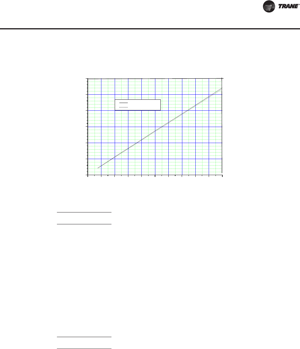
RT-PRC027T-EN 53
Selection Procedure
Heat module temperature rise is determined by:
Unit supply air temperature = mixed air temperature + air temperature rise = 65.4 + 25.8 = 91.2°F.
Steam Heating System
Assume a 15 psig steam supply.
From Table 46, p. 139, the saturated temperature steam is 250°F. Subtract mixed air temperature
from the steam temperature to determine ITD.
ITD = 250°F - 65.0°F = 185°F.
Divide winter heating load by ITD = 1008.6 MBh ÷ 185°F = 5.45 Q/ITD.
From Table 46, p. 139, select the low heat module.The low heat module at 36,000 CFM has a
Q/ITD = 7.45.
Heat module capacity, Q = ITD x Q/ITD = 185°F x 7.45 Q/ITD = 1378 MBh
Heat module air temperature rise is determined by:
Unit supply temperature at design conditions =
mixed air temperature + air temperature rise = 65.4°F + 35.3°F = 100.7°F.
Air Delivery Procedure
Supply fan performance tables include internal resistance of rooftop. For total static pressure
determination, system external static must be added to appropriate component static pressure
drop (evaporator coil, filters, optional economizer, optional exhaust fan, optional heating system,
optional cooling only extended casing).
Figure 25. Fan motor heat
Total Btu =T
1.085 x Supply CFM
1008600
1.085 x 36000 =25.8
Total Btu =T
1.085 x Supply CFM
1378000
1.085 x 36000 =35.3
0 102030405060708090100
0
50
100
150
200
250
300
PM1206
FAN MOTOR HEAT
50 Hz Motor
60 Hz Motor
Fan Motor Heat MBH
Motor Brake Horse Power
RT-PRC027.book Page 53 Tuesday, October 7, 2014 9:03 AM

54 RT-PRC027T-EN
Selection Procedure
Supply Fan Motor Sizing
The supply fan motor selected in the cooling capacity determination was 40.4 bhp and 1,097 rpm.
Thus, a 40 hp supply fan motor is selected.
Enter Table 53, p. 147 to select the proper drive. For a 105 ton rooftop with 40 hp motor, a drive letter
A - 1,100 rpm is selected.
Exhaust Fan Motor Sizing
The exhaust/return fan is selected based on total return system negative static pressure and
exhaust fan CFM. Return system negative static includes return duct static, and any other job site
applicable static pressure drop.
Return duct static pressure = 0.30 inches.
Total return system negative static pressure = 0.30 inches.
Exhaust fan CFM = 36,000 CFM
From Table 38, p. 129 the required bhp is 21.44 bhp at 400 rpm.Thus, the exhaust fan motor
selected is 25 hp.
To select a drive, enter Table 54, p. 148 for a 25 hp motor for a 105 ton unit. Drive selection number
4 - 400 rpm.
Return Fan Motor Sizing
Return fan drive selection is shown on Table 55, p. 148.The same static pressure and CFM
considerations must be taken for return fan size, horsepower, and drive selection as are required
for exhaust fan sizing. However, since the return fan runs continuously the sensible heat generated
by the return fan motor must be included in the entering evaporator coil mixed air temperature
equation.
In this selection, if the return motor bhp is equal to the exhaust motor bhp, 21.44 bhp = 58.1 MBh
÷ (1.085 x 36,000 Return CFM) = 1.5°F added to the return air temperature.
Where altitudes are significantly above sea level, use Table 7, p. 65 Table 8, p. 65 and Figure 26,
p. 64 for applicable correction factors.
Unit Electrical Requirements
Selection procedures for electrical requirements for wire sizing amps, maximum fuse sizing, and
dual element fuses are given in the electrical service section of this catalog.
Altitude Corrections
The rooftop performance tables and curves of this catalog are based on standard air (.075 lbs/ft).
If the rooftop airflow requirements are at other than standard conditions (sea level), an air density
correction is needed to project accurate unit performance.
Figure 26, p. 64 shows the air density ratio at various temperatures and elevations.Trane rooftops
are designed to operate between 40° and 90°F leaving air temperature.
The procedure to use when selecting a supply or exhaust/return fan on a rooftop for elevations and
temperatures other than standard is as follows:
1. First, determine the air density ratio using Figure 26, p. 64.
2. Divide the static pressure at the nonstandard condition by the air density ratio to obtain the
corrected static pressure.
3. Use the actual CFM and the corrected static pressure to determine the fan rpm and bhp from
the rooftop performance tables or curves.
4. The fan rpm is correct as selected.
5. bhp must be multiplied by the air density ratio to obtain the actual operating bhp.
RT-PRC027.book Page 54 Tuesday, October 7, 2014 9:03 AM

RT-PRC027T-EN 55
Selection Procedure
In order to better illustrate this procedure, the following example is used:
Consider a 90 ton rooftop unit that is to deliver 32,000 actual CFM at 3-inches total static pressure
(tsp), 55°F leaving air temperature, at an elevation of 5,000 ft.
1. From Figure 26, p. 64, the air density ratio is 0.86.
2. Tsp = 3.0-inches / 0.86 = 3.49 inches tsp.
3. From fan performance table Table 33, p. 114 a 90 ton rooftop will deliver 32,000 CFM at 3.49
inchesTSP at 997 rpm and 30.27 bhp.
4. The rpm is correct as selected - 997 rpm.
5. bhp = 30.27 x 0.86 = 26.3 bhp actual.
Compressor MBh, SHR, and kW should be calculated at standard and then converted to actual
using the correction factors in Table 7, p. 65. Apply these factors to the capacities selected at
standard CFM so as to correct for the reduced mass flow rate across the condenser.
Heat selections other than gas heat will not be affected by altitude. Nominal gas capacity (output)
should be multiplied by the factors given in Table 8, p. 65 before calculating the heating supply air
temperature.
Evaporative Condensing Rooftop
For unit selection, air-cooled or evaporative condensers can be selected using the same
calculations, however evaporative condenser capacities should be calculated based on Wet Bulb
(WB) temperatures. For specific model selection, utilizeTOPSS or contact the localTrane Sales
Office.
Total Energy Recovery Wheel
UtilizeTOPSS or contact the local Trane sales office to calculate required return air preheat
temperature for the given minimum outdoor air temperature and return air relative humidity.
To calculate the supply and exhaust air conditions leaving the wheel, you must know the wheel
effectiveness. Refer to Table 52, p. 146 for total effectiveness measurements.
Note: The effectiveness numbers shown assume equal supply and exhaust airflows. If the
airflows are unbalanced, the effectiveness changes. UseTOPSS to determine effectiveness
values for these conditions.
Calculate Wheel Performance
Use the following equations to calculate supply air conditions. UseTOPSS to calculate exhaust air
conditions and to obtain actual dry bulb temperature and enthalpy values for coil and equipment
sizing.
Dry Bulb Temperature:
Cooling:Tsa =Toa - (E x (Toa-Tra))
Heating:Tsa =Toa + (E x (Tra-Toa))
where:
Tsa = Dry bulb temperature of supply air (°F)
Toa = Dry bulb temperature of outside air (°F)
Tra = Dry bulb temperature of return air (°F)
E = Sensible Effectiveness
Enthalpy:
Cooling: Hsa = Hoa - (E x (Hoa-Hra))
RT-PRC027.book Page 55 Tuesday, October 7, 2014 9:03 AM

56 RT-PRC027T-EN
Selection Procedure
Heating: Hsa = Hoa + (E x (Hra-Hoa))
where:
Hsa = Enthalpy of supply air (Btu/ lb)
Hoa = Enthalpy of outside air (Btu/ lb)
Hra = Enthalpy of return air (Btu/lb)
E =Total Effectiveness
After calculating these two points, use a psychrometric chart to obtain the supply air wet bulb
temperature and/or grains moisture.
Energy Wheel Application Example
In this example, a wheel sized for nominal 10,500 CFM will be used for the initial evaluation.The
air pressure drop is 1.07 in. wg and the total effectiveness is 73% (see Table 52, p. 146).The total
and latent effectiveness values are close to equal forTrane energy wheels. For this example, total
effectiveness is assumed to be 73% in cooling mode and 75% in heating mode.TOPSS could be
used to obtain the exact values.
Supply Air Conditions, Cooling Mode:
Tsa =Toa - (E x (Toa -Tra)) = 95°F - (.73 x (95°F - 75°F))= 81°F
Hsa = Hoa - (E x (Hoa - Hra)) = 38.4 Btu/lb - (.73 x (38.4 Btu/ lb - 26.0 Btu/lb) = 29.3 Btu/lb
According to a psychrometric chart, the supply air wet bulb temperature is 64.4°F, 64 grains/lbm.
Tsa =Toa + (E x (Tra - Toa)) = 10°F + (.75 x (70°F - 10°F)) = 55°F
Hsa = Hoa + (E x (Hra - Hoa)) = 3.2 Btu/lb + (.75 x (22.7 Btu/lb -3.2 Btu/lb)) = 17.8 Btu/lb
According to a psychrometric chart, the supply air wet bulb temperature is 45.5°F, 30 grains/lbm.
When designing the remainder of the air-handling system, remember to account for the air
pressure drop imposed by the energy wheel.
Hot Gas Reheat Dehumidification Selection
This option allows for increased outdoor air ventilation. It reduces humidity levels while increasing
comfort level in the air space. Cooling can operate without a demand for dehumidification.The hot
gas reheat coil is designed to deliver maximum reheat temperatures.
Contact the localTrane Sales Office or refer to the IntelliPak IITOPSS selection program to
determine leaving air temperature, latent capacity, reheat sensible capacity, leaving unit dew point,
and moisture removal when the unit is in reheat operation. Please note that reheat operation will
not be allowed when there is a call for cooling or heating.
RT-PRC027.book Page 56 Tuesday, October 7, 2014 9:03 AM

RT-PRC027T-EN 57
DIGIT 1 — UNIT TYPE
S Self-Contained (Packaged
Rooftop)
DIGIT 2 — UNIT FUNCTION
E DX Cooling, Electric Heat
F DX Cooling, Natural Gas Heat
L DX Cooling, Hot Water Heat
S DX Cooling, Steam Heat
X DX Cooling, No Heat,
Extended Casing
DIGIT3—SYSTEMTYPE
H Single Zone
DIGIT 4 — DEVELOPMENT
SEQUENCE
J Ninth
DIGIT 5, 6, 7 — NOMINAL
CAPACITY
090 90Ton Air-Cooled
105 105Ton Air-Cooled
120 120Ton Air-Cooled
130 130Ton Air-Cooled
150 150Ton Air-Cooled
100 100 Ton Evap Condenser
118 118Ton Evap Condenser
128 128Ton Evap Condenser
140 140Ton Evap Condenser
162 162Ton Evap Condenser
DIGIT 8 — VOLTAGE SELECTION
4 460/60/3 XL
5 575/60/3 XL
C 380/50/3 XL
DIGIT 9 — HEATING CAPACITY
SELECTION
0 No Heat
1 Electric heat 90/56 kW 60/50 Hz
2 Electric heat 140/88 kW 60/50 Hz
3 Electric heat 265/166 kW 60/50 Hz
4 Electric Heat 300/188 kW 60/50 Hz
A Low Gas Heat — 2-stage
B Medium Gas Heat — 2-stage
C High Gas Heat — 2-stage
D Low Gas Heat — Modulating
E Medium Gas Heat — Modulating
F High Gas Heat — Modulating
Steam or Hot Water Heat:
G Low Heat - 1.0" (25mm) Valve
H Low Heat - 1.25" (32mm) Valve
J Low Heat - 1.5" (38mm) Valve
K Low Heat - 2.0" (50mm) Valve
L Low Heat - 2.50" (64mm) Valve
M Low Heat - 3.0" (76mm) Valve
N High Heat - 1.0" (25mm) Valve
P High Heat - 1.25" (32mm) Valve
Q High Heat - 1.5" (38mm) Valve
R High Heat - 2.0" (50mm) Valve
T High Heat - 2.50" (64mm) Valve
U High Heat - 3.0" (76mm) Valve
DIGIT 10, 11 — DESIGN
SEQUENCE
A-ZZ (Factory Assigned) Sequence may
be any letter A to Z, or any digit 1 to 9.
DIGIT 12 — UNIT
CONFIGURATION SELECTION
1 One-Piece Unit w/o Blank Section
2 One-Piece Unit w/4' Blank Section
3 One-Piece Unit w/8' Blank Section
4 Two-Piece Unit w/o Blank Section
5 Two-Piece Unit w/4' Blank Section
6 Two-Piece Unit w/8' Blank Section
7 Three-Piece unit w/o Blank Section
8 Three-Piece Unit w/4' Blank Section
9 Three-Piece Unit w/8' Blank Section
DIGIT 13 — AIRFLOW DIRECTION
1 Downflow Supply /Upflow Return
2 Downflow Supply / Horiz End Return
3 Downflow Supply / Horiz Right Return
4 Right Side Horiz Supply/Upflow
Return
5 Right Side Horiz Supply / Horizontal
End Return
6 Right Side Horiz Supply / Horizontal
Right Return
DIGIT 14 — SUPPLY FAN
OPTIONS
1 Standard CFM
3 Standard CFM -TEFC Motor(s)
4 Low CFM
6 Low CFM -TEFC Motor(s)
7 = Standard CFM - w/ Motor Shaft
Grounding
9 = Standard CFM -TEFC Motor(s) w/
Shaft Grounding
A = Low CFM - w/ Motor Shaft Grounding
C = Low CFM -TEFC Motor(s) w/ Shaft
Grounding
DIGIT 15 — SUPPLY FAN MOTOR
SELECTION
F15hp
G20Hp
H25Hp
J30Hp
K40Hp
L50Hp
M60Hp
N75Hp
P100Hp
DIGIT 16 — SUPPLY FAN RPM
SELECTION
7700
8800
9900
A 1000
B1100
C 1200
D 1300
E 1400
F 1500
G 1600
H 1700
J 1800
K 1900
L2000
DIGIT 17 — EXHAUST/RETURN
FAN OPTIONS
0 None
1 Std CFM Exhaust Fan
w/o Statitrac CV Only
2 Low CFM Exhaust Fan
w/o Statitrac CV Only
3 Std CFM Exhaust w/o VFD
w/ Statitrac
4 Low CFM Exhaust w/o VFD
w/ Statitrac
5 Std CFM Exhaust w/ VFD w/
Bypass w/ Statitrac
6 Low CFM Exhaust w/ VFD w/
Bypass w/ Statitrac
7 Std CFM Exhaust w/ VFD w/o
Bypass w/ Statitrac
8 Low CFM Exhaust w/ VFD w/o
Bypass w/ Statitrac
A Std CFM Return w/o Statitrac CV
Only
B Low CFM Return w/o Statitrac CV
Only
C Std CFM Return w/ VFD w/
Bypass w/ Statitrac
D Low CFM Return w/ VFD w/
Bypass w/ Statitrac
E Std CFM Return w/ VFD w/o
Bypass w/ Statitrac
F Low CFM Return w/ VFD w/o
Bypass w/ Statitrac
Model Number Descriptions
SXHJ10540AA715MFDE81D1100A1BA1000AA1A1
1 2 3 4 567 8 9 10 11 12 13 14 15 16 17 18 19 20 21 22 23 24 25 26 27 28 29 30 31 32 33 34 35 36 37 38
RT-PRC027.book Page 57 Tuesday, October 7, 2014 9:03 AM

58 RT-PRC027T-EN
Model Number Descriptions
DIGIT 18 — EXHAUST/RETURN
FAN MOTOR SELECTION
0 None
D 7.5 Hp
E10Hp
F15Hp
G20Hp
H25Hp
J30Hp
K40Hp
L50Hp
M60Hp
DIGIT 19 — EXHAUST/RETURN
RPM SELECTION
0 None
3300
4400
5500
6600
7700
8800
9900
A 1000
B1100
C 1200
D 1300
E 1400
DIGIT 20 — SYSTEM CONTROL
SELECTION
1 Constant Volume (CV) (Zone
Temperature Control)
2 CV w/ DischargeTemp Control
4 VAV w/ VFD Supply w/o Bypass
(DischargeTemp Control)
5 VAV w/ VFD Supply w/ Bypass
(DischargeTemp Control)
6 VAV – Single Zone VAV w/VFD w/o
Bypass (ZoneTemperature Control)
7 VAV – Single Zone VAV w/VFD w/
Bypass (ZoneTemperature Control)
DIGIT 21 — OUTSIDE AIR and
ECONOMIZER OPTION/
CONTROLS
A 0-25% Motorized Damper
B Economizer w/Dry Bulb
C Economizer w/Reference
Enthalpy
D Economizer w/Comparative
Enthalpy
E Econ w/Outside
Air Measure/Dry Bulb
F Econ w/Outside Air Measure/Ref
Enthalpy
G Econ w/Outside Air
Measure/Comp Enthalpy
H Econ w/DCV/Dry Bulb1
J Econ w/DCV/Ref Enthalpy1
K Econ w/DCV/Comp Enthalpy1
1Requires CO2 Zone Sensor(s)
DIGIT 22 — DAMPER OPTION
0 Standard
1 Low Leak
2 Ultra Low Leak
U Ultra Low Leak, AMCA 1A, w/ FDD
(Design Special)
DIGIT 23— PRE-EVAPORATOR
COIL FILTER SELECTION
0 Two Inch High Efficiency
Throwaway
1 Two InchThrowaway Rack/Less
Filters
2 90-95% Bag Filters w/Prefilters
3 Bag Filter Rack/Less Filters
4 90-95% Cartridge Filters w/
Prefilters
5 Cartridge Rack/Less Filters
6 90-95% Low Pressure Drop
Cartridge Filters w/ Prefilters
7 Low Pressure Drop Cartridge
Rack/Less Filters
DIGIT 24 — BLANK SECTION
APPLICATION OPTIONS
0 None
A 90-95% Bag w/Prefilters
B 90-95% Low Pressure Drop
Cartridge w/ Prefilters
C 90-95%, Cartridge Filters w/
Prefilters
D 90-95% HighTemp Cartridge
w/ Prefilters
E HEPA w/Prefilters
F HighTemp HEPA w/Prefilters
DIGIT 25 — ENERGY RECOVERY
WHEEL
0 None
1 Low CFM ERW w/ Bypass Defrost
2 Standard CFM ERW w/ Bypass
Defrost
DIGIT 26 — UNIT MOUNTED
POWER CONNECTION
SELECTION
A Terminal Block
B Non-Fused Disconnect
C Non-Fused Disconnect w/
Powered Convenience Outlet
D Circuit Breaker w/ high fault SCCR
E Circuit Breaker w/ high fault SCCR/
Powered Convenience Outlet
DIGIT 27 — CONDENSER COIL
SELECTION
0 Air-Cooled Aluminum
A Evap Condenser
B Evap Condenser w/ Sump Heater
C Evap Condenser w/ Dolphin
WaterCare System
D Evap Condenser w/ Dolphin
WaterCare System & Sump Heater
E Evap Condenser w/ Conductivity
Controller
F Evap Condenser w/ Conductivity
Controller and Sump Heater
J Corrosion Protected Condenser Coil
DIGIT 28 — EVAPORATOR COIL
AND DRAIN PAN
0 Standard Evap Coil w/Galvanized
Drain Pan
A Standard Evap Coil w/ Stainless
Steel Drain Pan
B High Cap Evap Coil w/Galvanized
Drain Pan
C High Cap Evap Coil w/Stainless
Steel Drain Pan
DIGIT 29 — REFRIGERATION
SYSTEM SELECTION A
0 Standard
A Suction Service Valves
B Replaceable Core Liquid Filter
Driers
C Suction Service Valves &
Replaceable Core Liquid Filter
Driers
DIGIT 30 — REFRIGERATION
SYSTEM SELECTION B
0 Standard
1 Hot Gas Reheat2
2 Hot Gas By-Pass
3 Hot Gas Reheat2/Hot Gas By-Pass
DIGIT 31 — AMBIENT CONTROL
OPTION
0 Standard Ambient
1 Low Ambient
DIGIT 32 — HIGH DUCTTEMP
THERMOSTAT
0 None
1 High DuctTempThermostat
DIGIT 33 — CONTROLS OPTION
0 None
1 Remote Human Interface (RHI) &
Inter-Processor Communication
Bridge (IPCB)
2 IPCB
3 Rapid Restart
2Humidity sensor required
RT-PRC027.book Page 58 Tuesday, October 7, 2014 9:03 AM

RT-PRC027T-EN 59
Model Number Descriptions
DIGIT 34 — MODULE OPTIONS
0 None
A 0-5 volt Generic Building
Automation System (GBAS)
B 0-10 volt GBAS
C 0-5 volt GBAS and 0-10 volt GBAS
F LonTalk® Communication
Interface (LCI)
D Ventilation Override
G 0-5 volt GBAS volt & Ventilation
Override
H 0-10 volt GBAS & Ventilation
Override
J 0-5 volt GBAS and 0-10 volt GBAS
& Ventilation Override
L LCI & Ventilation Override
M BACnet Communication Interface
(BCI)
N BCI & Ventilation Override
DIGIT 35 — ZONE SENSOR
OPTION
0 None
A Dual Setpoint w/Man/Auto
Changeover — BAYSENS108
B Dual Setpoint w/Man/Auto
Chgovr & Sys Lights —
BAYSENS110
C Room Sensor w/timed Override &
Cancel — BAYSENS073
D Room Sensor w/TO (Timed
Override) & Cancel &
Local Stpt Adj — BAYSENS074
G VAV w/System Lights —
BAYSENS021
L Programmable
Night Setback — BAYSENS119
DIGIT 36 — AGENCY APPROVAL
OPTION
0 None
1 cULus
DIGIT 37 — SERVICE
ENHANCEMENTS
0 Single Side Access Door
A Dual Side Access Door
B Single Side Access Doors/
Marine Lights
C Dual Side Access Doors/
Marine Lights
DIGIT 38 — MISCELLANEOUS
OPTIONS
0 None
1 Belt Guards
2 Burglar Bars
3 Belt Guards/Burglar Bars
Tip: EXAMPLE
Model number
SXHJ10540AA715MFDE81D1100A
1BA1000AA1A1
describes a unit with the following
characteristics:
DX Cooling, No Heat, Extended
Casing, 105Ton nominal capacity,
with 460/3/60 power supply,
3 piece construction with
downflow supply and upflow
return, low CFM fans, a 60 hp
supply fan w/ a 1500 rpm drive, a
10 Hp return fan with VFD, bypass
and statitrac, with CV control, and
economizer w/ comparative
enthalpy, low leak dampers,
2” throwaway rack less filters,
terminal blank connection, Air
Cooled Copper Condenser coil,
high cap evap with galvanized
drain pan, suction service valves,
hot gas reheat, 0-5V GBAS, dual
setpoint with Manual/Auto
Changeover, cULus approval,
Dual side access, and belt guards.
The service digit for each model
number contains 38 digits; all 38
digits must be referenced.
RT-PRC027.book Page 59 Tuesday, October 7, 2014 9:03 AM
60 RT-PRC027T-EN
General Data
Table 3. General data (All dimensions in inches)
90/100 Tons(a) 105/118 Tons(a) 120/128 Tons(a) 130/140 Tons(a) 150/162 Tons(a)
Compressor Data
Number/Size (Nominal)
Type
Unit Capacity Steps
rpm
No. of Circuits
4/20 Ton
Scroll
100/75/50/25
3450
2
2/20 Ton 2/25 Ton
Scroll
100/72/44/22
3450
2
4/25 Ton
Scroll
100/75/50/25
3450
2
2/25 Ton 2/32 Ton
Scroll
100/72/44/22
3450
2
4/32 Ton
Scroll
100/75/50/25
3450
2
Evaporator Coil Std.
Dimensions
Size (Ft2)
Rows/Fin Series
Tube Diameter
Surface
118 x 90
73.75
3/168
1/2
Enhanced
118 x 90
73.75
4/168
1/2
Enhanced
170 x 90
106.25
3/168
1/2
Enhanced
170 x 90
106.25
4/168
1/2
Enhanced
170 x 90
106.25
6/168
1/2
Enhanced
Evaporator Coil Hi Cap.
Dimensions
Size (Ft2)
Rows/Fin Series
Tube Diameter
Surface
118 x 90
73.75
5/168
1/2
Enhanced
118 x 90
73.75
6/168
1/2
Enhanced
170 x 90
106.25
6/168
1/2
Enhanced
170 x 90
106.25
6/168
1/2
Enhanced
N/A
Air-Cooled Condenser Fans
Number/Size/Type
Hp (each)
CFM
6/30/Prop
1.5
58500
6/30/Prop
1.5
58500
8/30/Prop
1.5
87750
8 /30/Prop
1.5
87750
8/30/Prop
1.5
87750
Air-Cooled Condenser Coil
Size (Ft2)
Rows/Fin Series
Type
134
1/240
Microchannel
161
1/240
Microchannel
161
2/276
Microchannel
161
2/276
Microchannel
161
2/276
Microchannel
Evaporative Condenser - Condenser Fans
Number/Type 2/Prop 2/Prop 2/Prop 2/Prop 2/Prop
hp (each) 5.4 5.4 5.4 5.4 5.4
rpm/CFM 1365/26000 1365/26000 1365/26000 1365/26000 1365/26000
Cycle/Phase 60/3 60/3 60/3 60/3 60/3
Evaporative Condenser - Condenser Coil
Size (Ft2)
Rows
Tube Diameter
36
212
5/16
36
212
5/16
36
212
5/16
36
212
5/16
36
212
5/16
Evaporative Condensing Sump Pump
Number/Type 1 / Sump, Drainage 1 / Sump, Drainage 1 / Sump, Drainage 1 / Sump, Drainage 1 / Sump, Drainage
hp 1.5 1.5 1.5 1.5 1.5
rpm 3600 3600 3600 3600 3600
Cycle/Phase 60/3 60/3 60/3 60/3 60/3
Sump Pump GPM 80 80 80 80 80
Supply Fans Std CFM
Number/Size/Type
Number of Motors
hp Range
CFM Range
Total SP Range-(In. WG)
1 /36 DW AF
1
15 - 60
20000 - 40000
7.5
1 / 36 DW AF
1
20 - 75
23000 - 45000
7.5
1 /40 DW AF
1
20 - 75
27000 - 54000
7.5
1 /40 DW AF
1
20 - 100
29000 - 58000
7.5
1 /40 DW AF
1
20 - 100
29000 - 58000
7.5
Supply Fans Low CFM
Number/Size/Type
Number of Motors
hp Range
CFM Range
ESP Range-(In. WG)
1/25 DW AF
1
15 - 50
16000 - 31000
7.5
1/32/ DW AF
1
15 - 60
19000 - 36000
7.5
1/32/ DW AF
1
15 - 60
21000 - 42000
7.5
1/32/ DW AF
1
20 - 60
23000 - 45000
7.5
1/32/ DW AF
1
20 - 60
23000 - 45000
7.5
Exhaust Fans Std CFM
Number/Size/Type
Number of Motors
hp Range
CFM Range
ESP Range-(In. WG)
1/28 DW FC
1
10 - 50 hp
20000 - 36000
2.5
1/32 DW FC
1
15 - 50 hp
23000 - 40000
2.5
1/32 DW FC
1
15 - 60 hp
27000 - 48000
2.5
1/32 DW FC
1
15 - 60 hp
29000 - 52000
2.5
1/32/ DW FC
1
15 - 60 hp
29000 - 52000
2.5
Exhaust Fans Low CFM
Number/Size/Type
Number of Motors
hp Range
CFM Range
ESP Range-(In. WG)
1/25/ DW FC
1
7.5 - 25 hp
10000 - 28000
2.5
1/28/ DW FC
1
7.5 - 25 hp
12000 - 33000
2.5
1/28/ DW FC
1
7.5 - 30 hp
14000-37000
2.5
1/28/ DW FC
1
7.5 - 50 hp
15000 - 41000
2.5
1/28 DW FC
1
7.5 - 50 hp
15000 - 41000
2.5
Continued on next page
RT-PRC027.book Page 60 Tuesday, October 7, 2014 9:03 AM
RT-PRC027T-EN 61
General Data
Return Fans Std CFM
Number/Size/Type
Number of Motors
hp Range
CFM Range
ESP Range-(In. WG)
1 /40 Plenum AF
1
10 - 30 hp
20000 - 40000
2.5
1 / 40 Plenum AF
1
15 - 40 hp
24000 - 44000
2.5
1 /44 Plenum AF
1
15 - 40 hp
27000 - 51000
2.5
1 /44 Plenum AF
1
20 - 50 hp
29000 - 54000
2.5
1 /44 Plenum AF
1
20 - 50 hp
29000 - 54000
2.5
Return Fans Low CFM
Number/Size/Type
Number of Motors
hp Range
CFM Range
ESP Range-(In. WG)
1/36.5/ Plenum
1
7.5 - 20 hp
16000 - 28000
2.5
1/36.5/ Plenum
1
10 - 25 hp
19000 - 33000
2.5
1/36.5/ Plenum
1
10 - 40 hp
21000 - 36000
2.5
1/36.5/ Plenum
1
15 - 40 hp
23000 - 36000
2.5
1/36.5/ Plenum
1
15 - 40 hp
23000 - 36000
2.5
Energy Recovery Std CFM
Cassette Dimensions (LxWxH) 104 x 104 x 10 108 x 108 x 14 115 x 115 x 14 115 x 115 x 14 115 x 115 x 14
Wheel Segments 16 16 16 16 16
Motor (V/ph/Hz)
hp
460/3/60
575/3/60
0.33
460/3/60
575/3/60
0.33
460/3/60
575/3/60
0.33
460/3/60
575/3/60
0.33
460/3/60
575/3/60
0.33
Galv. Steel RA Filters
Number/Size 10/24 x 24 x1 10/24 x 24 x 1 10/24 x 24 x 1 10/24 x 24 x 1 10/24 x 24 x 1
Galv. Steel FA Filters
Number/Size 8/24 x 24 x 1 8/24 x 24 x 1 8/24 x 24 x 1 8/24 x 24 x 1 8/24 x 24 x 1
CFM Range 8500 - 18000 9000 - 21000 10000 - 24000 13000 - 29000 13000 - 29000
Energy Recovery Low CFM
Cassette Dimensions (LxWxH) 85 x 85 x 7.07 85 x 85 x 7.07 91 x 91 x 10 96 x 96 x 10 96 x 96 x 10
Wheel Segments 8 8 8 16 16
Motor Information (V/ph/Hz)
hp
460/3/60
575/3/60
0.25
460/3/60
575/3/60
0.25
460/3/60
575/3/60
0.25
460/3/60
575/3/60
0.33
460/3/60
575/3/60
0.33
Galv. Steel RA Filters
Number/Size 10/24 x 24 x 1 10/24 x 24 x 1 10/24 x 24 x 1 10/24 x 24 x 1 10/24 x 24 x 1
Galv. Steel FA Filters
Number/Size 8/24 x 24 x 1 8/24 x 24 x 1 6/24 x 24 x 1
2/12 x 24 x 1 6/24 x 24 x 1
2/12 x 24 x 1 6/24 x 24 x 1
2/12 x 24 x 1
CFM Range 8500 - 14000 9000 - 14000 9000 - 15000 9000 - 16000 9000 - 16000
Electric Heat (60 Hz)
KW
Circuit Capacity Steps 90-265
30 - 37.5 KW 90-265
30 - 37.5 KW 140-300
35 - 37.5 KW 140-300
35 - 37.5 KW 140-300
35 - 37.5 KW
Electric Heat (50 Hz)
KW
Circuit Capacity Steps 56-166
18.8 - 23.5 KW 56-166
18.8 - 23.5 KW 88-188
21.9 - 23.5 KW 88-188
21.9 - 23.5 KW 88-188
21.9 - 23.5 KW
Natural Gas Heat
2-Stage Gas Heat
Low Heat Input (mbh)
Mid Heat Input (mbh)
High Heat Input (mbh)
850
1100
1800
850
1100
1800
1100
1800
2500
1100
1800
2500
1100
1800
2500
Fully Modulating Steps
Low Heat Input (mbh)
Mid Heat Input (mbh)
High Heat Input (mbh)
10:1
20:1
20:1
10:1
20:1
20:1
20:1
20:1
20:1
20:1
20:1
20:1
20:1
20:1
20:1
Heat Exchanger Material Stainless Steel Stainless Steel Stainless Steel Stainless Steel Stainless Steel
Hot Water Coil
Size
Quantity
Type
High Heat (fins/ft)
Low Heat (fins/ft)
33 x 88 x 2 rows
2
5W, PrimaFlo
122
80
33 x 88 x 2 rows
2
5W, PrimaFlo
122
80
33 x 110 x 2 rows
2
5W, PrimaFlo
122
80
33 x 110 x 2 rows
2
5W, PrimaFlo
122
80
33 x 110 x 2 rows
2
5W, PrimaFlo
122
80
Steam Coil
Size
Quantity
Type
High Heat (fins/ft)
Low Heat (fins/ft)
33 x 88 x 1 row
2
NS, SigmaFlo
112
62
33 x 88 x 1 row
2
NS, SigmaFlo
112
62
33 x 110 x 1 row
2
NS, SigmaFlo
112
62
33 x 110 x 1 row
2
NS, SigmaFlo
112
62
33 x 110 x 1 row
2
NS, SigmaFlo
112
62
Filters
Standard 2" High Efficiency
Throwaway Filters
Number/Size
Face area (Ft2)
21-20 x 24 x 2
5-12 x 24 x 2
80
21-20 x 24 x 2
5-12 x 24 x 2
80
28-20 x 24 x 2
93
28-20 x 24 x 2
93
28-20 x 24 x 2
93
Continued on next page
Table 3. General data (All dimensions in inches) (continued)
90/100 Tons(a) 105/118 Tons(a) 120/128 Tons(a) 130/140 Tons(a) 150/162 Tons(a)
RT-PRC027.book Page 61 Tuesday, October 7, 2014 9:03 AM
62 RT-PRC027T-EN
General Data
90-95% Bag Filters
w/Prefilters
Number/Size
Face area (Ft2)
21-20 x 24 x 19
5-12 x 24 x 19
80
21-20 x 24 x 19
5-12 x 24 x 19
80
21-20 x 24 x 19
5-12 x 24 x 19
80
21-20 x 24 x 19
5-12 x 24 x 19
80
21-20 x 24 x 19
5-12 x 24 x 19
80
Prefilters
Number/Size 21-20 x 24 x 2
5-12 x 24 x 2 21-20 x 24 x 2
5-12 x 24 x 2 21-20 x 24 x 2
5-12 x 24 x 2 21-20 x 24 x 2
5-12 x 24 x 2 21-20 x 24 x 2
5-12 x 24 x 2
90-95% Cartridge Filters
w/Prefilters
Number/Size
Face area (Ft2)
21-20 x 24 x 12
5-12 x 24 x 12
80
21-20 x 24 x 12
5-12 x 24 x 12
80
21-20 x 24 x 12
5-12 x 24 x 12
80
21-20 x 24 x 12
5-12 x 24 x 12
80
21-20 x 24 x 12
5-12 x 24 x 12
80
Prefilters
Number/Size 21-20 x 24 x 2
5-12 x 24 x 2 21-20 x 24 x 2
5-12 x 24 x 2 21-20 x 24 x 2
5-12 x 24 x 2 21-20 x 24 x 2
5-12 x 24 x 2 21-20 x 24 x 2
5-12 x 24 x 2
90-95% Low Pressure Drop
Cartridge Filters
w/Prefilters
Number/Size
Face area (Ft2)
21-20 x 24 x 12
5-12 x 24 x 12
80
21-20 x 24 x 12
5-12 x 24 x 12
80
21-20 x 24 x 12
5-12 x 24 x 12
80
21-20 x 24 x 12
5-12 x 24 x 12
80
21-20 x 24 x 12
5-12 x 24 x 12
80
Prefilters
Number/Size 21-20 x 24 x 2
5-12 x 24 x 2 21-20 x 24 x 2
5-12 x 24 x 2 21-20 x 24 x 4
5-12 x 24 x 4 21-20 x 24 x 4
5-12 x 24 x 4 21-20 x 24 x 4
5-12 x 24 x 4
Final Filters
90-95% Low Pressure Drop
Cartridge Filters
w/Prefilters(b)
Number/Size
Face area (Ft2)
15-24 x 24 x 12
7-12 x 24 x 12
74
15-24 x 24 x 12
7-12 x 24 x 12
74
15-24 x 24 x 12
7-12 x 24 x 12
74
15-24 x 24 x 12
7-12 x 24 x 12
74
15-24 x 24 x 12
7-12 x 24 x 12
74
Prefilters
Number/Size 15-24 x 24 x 4
7-12 x 24 x 4 15-24 x 24 x 4
7-12 x 24 x 4 15-24 x 24 x 4
7-12 x 24 x 4 15-24 x 24 x 4
7-12 x 24 x 4 15-24 x 24 x 4
7-12 x 24 x 4
90-95% Bag Filters
w/Prefilters(c)
Number/Size
Face area (Ft2)
15-24 x 24 x 19
7-12 x 24 x 19
74
15-24 x 24 x 19
7-12 x 24 x 19
74
15-24 x 24 x 19
7-12 x 24 x 19
74
15-24 x 24 x 19
7-12 x 24 x 19
74
15-24 x 24 x 19
7-12 x 24 x 19
74
Prefilters
Number/Size 15-24 x 24 x 2
7-12 x 24 x 2 15-24 x 24 x 2
7-12 x 24 x 2 15-24 x 24 x 2
7-12 x 24 x 2 15-24 x 24 x 2
7-12 x 24 x 2 15-24 x 24 x 2
7-12 x 24 x 2
Final Filters
90-95% Cartridge Filters(c)
Number/Size
Face area (Ft2)
15-24 x 24 x 12
7-12 x 24 x 12
74
15-24 x 24 x 12
7-12 x 24 x 12
74
15-24 x 24 x 12
7-12 x 24 x 12
74
15-24 x 24 x 12
7-12 x 24 x 12
74
15-24 x 24 x 12
7-12 x 24 x 12
74
Prefilters
Number/Size 15-24 x 24 x 2
7-12 x 24 x 2 15-24 x 24 x 2
7-12 x 24 x 2 15-24 x 24 x 2
7-12 x 24 x 2 15-24 x 24 x 2
7-12 x 24 x 2 15-24 x 24 x 2
7-12 x 24 x 2
90-95% High Temp
Cartridge Filters(d)
Number/Size
Face area (Ft2)
15-24 x 24 x 12
7-12 x 24 x 12
74
15-24 x 24 x 12
7-12 x 24 x 12
74
15-24 x 24 x 12
7-12 x 24 x 12
74
15-24 x 24 x 12
7-12 x 24 x 12
74
15-24 x 24 x 12
7-12 x 24 x 12
74
Prefilters
Number/Size 15-24 x 24 x 2
7-12 x 24 x 2 15-24 x 24 x 2
7-12 x 24 x 2 15-24 x 24 x 2
7-12 x 24 x 2 15-24 x 24 x 2
7-12 x 24 x 2 15-24 x 24 x 2
7-12 x 24 x 2
HEPA Filters (c)
w/Prefilters
Number/Size
Face area (Ft2)
15-24 x 24 x 12
7-12 x 24 x 12
74
15-24 x 24 x 12
7-12 x 24 x 12
74
15-24 x 24 x 12
7-12 x 24 x 12
74
15-24 x 24 x 12
7-12 x 24 x 12
74
15-24 x 24 x 12
7-12 x 24 x 12
74
Prefilters
Number/Size 15-24 x 24 x 2
7-12 x 24 x 2 15-24 x 24 x 2
7-12 x 24 x 2 15-24 x 24 x 2
7-12 x 24 x 2 15-24 x 24 x 2
7-12 x 24 x 2 15-24 x 24 x 2
7-12 x 24 x 2
High Temp HEPA Cartridge
Filters w/Prefilters(d)
Number/Size
Face area (Ft2)
15-24 x 24 x 12
7-12 x 24 x 12
74
15-24 x 24 x 12
7-12 x 24 x 12
74
15-24 x 24 x 12
7-12 x 24 x 12
74
15-24 x 24 x 12
7-12 x 24 x 12
74
15-24 x 24 x 12
7-12 x 24 x 12
74
Prefilters
Number/Size 15-24 x 24 x 2
7-12 x 24 x 2 15-24 x 24 x 2
7-12 x 24 x 2 15-24 x 24 x 2
7-12 x 24 x 2 15-24 x 24 x 2
7-12 x 24 x 2 15-24 x 24 x 2
7-12 x 24 x 2
Standard Unit Minimum Outside Air Temperature for Mechanical Cooling
Without Hot Gas Bypass 40 40 40 40 40
With Hot Gas Bypass 55 55 55 55 55
Low Unit Minimum Outside Air Temperature for Mechanical Cooling
Without Hot Gas Bypass 00000
With Hot Gas Bypass 10 10 10 10 10
Evaporative Condenser Minimum Outside Temperature for Mechanical Cooling
Without Sump Heater 40 40 40 40 40
With Sump Heater 10 10 10 10 10
(a)Air-Cooled/Evaporative Condensers; Not all data applies to both.
(b)Standard airflow applications of cooling only units require High Efficiency Throwaway Prefilters with the 90-95% Low PD Cartridge Filter Option.
(c)Standard airflow applications of cooling only units include 2" High Efficiency Throwaway Prefilters with the 90-95% Bag and HEPA Filter Options.
(d)Gas/Electric Units require 2" High Efficiency High Temperature Rated Throwaway Prefilters with High Temperature Rated 90-95% Cartridge and HEPA filter options.
Table 3. General data (All dimensions in inches) (continued)
90/100 Tons(a) 105/118 Tons(a) 120/128 Tons(a) 130/140 Tons(a) 150/162 Tons(a)
RT-PRC027.book Page 62 Tuesday, October 7, 2014 9:03 AM
RT-PRC027T-EN 63
General Data
Table 4. Gas heat inputs/input ranges/inlet sizes
TWO-STAGE GAS HEAT
Standard Gas Heat
Input (mbh) Low Gas Heat
Inputs (mbh) High Fire Heat
Input (mbh) Modulating Gas
Heat Range (mbh) Gas Heat Inlet
Sizes (in.)
850 425 850 85-850 1
1100 550 1100 55-1100 1 1/4
1800 900 1800 90-1800 1 1/2
2500 1250 2500 125-2500 1 1/2
Table 5. Economizer outdoor air damper leakage (at rated airflow)(a)
(a)Leakage/ft^2 at 1.0 in WC pressure difference
Standard Damper 20
Optional “Low Leak" Damper 10 (Class 2 AMCA 511-99)
Optional “Ultra Low Leak” Damper 4 (Class 1 AMCA 511-99)
RT-PRC027.book Page 63 Tuesday, October 7, 2014 9:03 AM
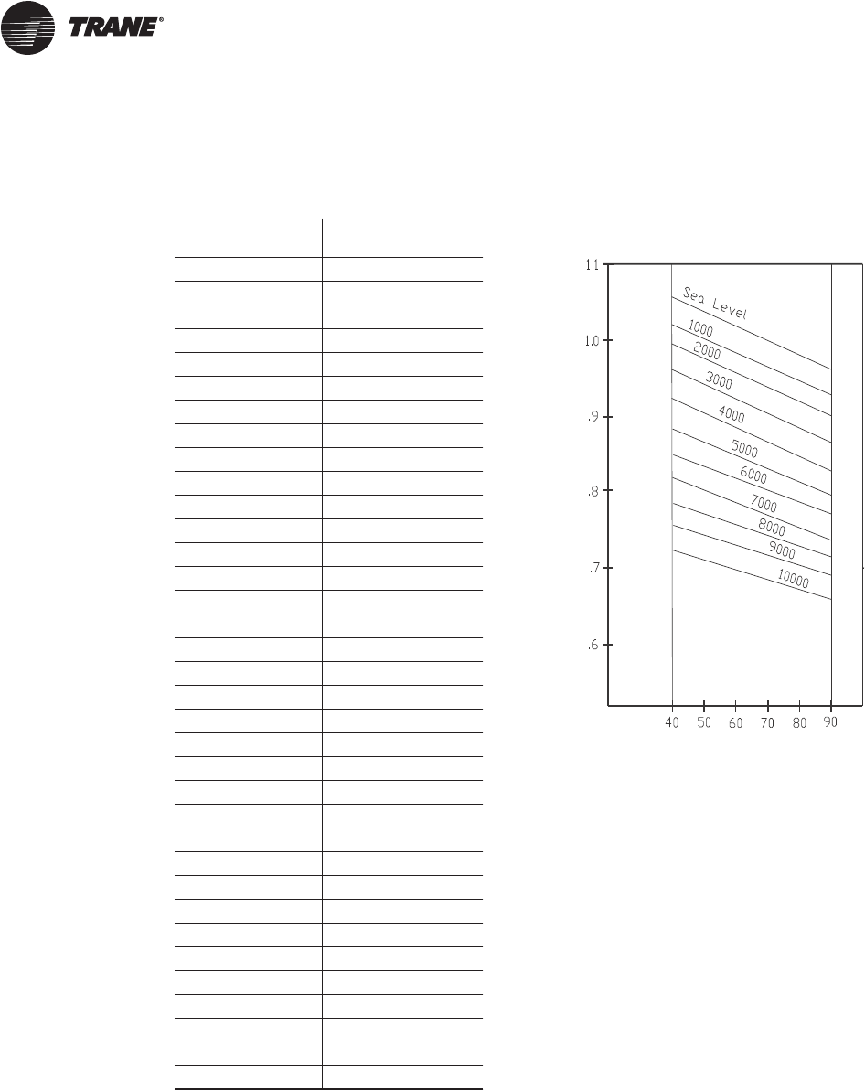
64 RT-PRC027T-EN
Performance Adjustment Factors
Table 6. Enthalpy of saturated air Figure 26. Air density ratios
Wet Bulb
Temperature Btu per Pound
41 15.70
43 16.66
42 16.17
43 16.66
44 17.15
45 17.65
46 18.16
47 18.68
48 19.21
49 19.75
50 20.30
51 20.86
52 21.44
53 22.02
54 22.62
55 23.22
56 23.84
57 24.48
58 25.12
59 25.78
60 26.46
61 27.15
62 27.85
63 28.57
64 29.31
65 30.06
66 30.83
67 31.62
68 32.42
69 33.25
70 34.09
71 34.95
72 35.83
73 36.74
74 37.66
Altitude/Temperature Correction
Air Density
Ratio (Density
at New
Air Density)
Condition/Std.
Roofto
p
Leavin
g
Air Tem
p
erature (de
g
rees F)
RT-PRC027.book Page 64 Tuesday, October 7, 2014 9:03 AM
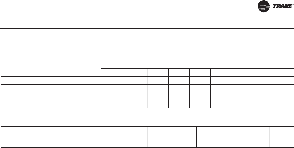
RT-PRC027T-EN 65
Performance Adjustment Factors
Table 7. Cooling capacity altitude correction factors
Altitude (Ft.)
Sea Level 1000 2000 3000 4000 5000 6000 7000
Cooling Capacity Multiplier 1.00 0.99 0.99 0.98 0.97 0.96 0.95 0.94
KW Correction Multiplier (Compressors) 1.00 1.01 1.02 1.03 1.04 1.05 1.06 1.07
Sensible Heat Ratio Correction Multiplier 1.00 .98 .95 .93 .91 .89 .87 .85
Maximum Condenser Ambient 115°F 114°F 113°F 112°F 111°F 110°F 109°F 108°F
Table 8. Gas heating capacity altitude correction factors
Sea Level to
2000 2001 to
2500 2501 to
3500 3501 to
4500 4501 to
5500 5501 to
6500 6501 to
7500
Capacity Multiplier 1.00 .92 .88 .84 .80 .76 .72
RT-PRC027.book Page 65 Tuesday, October 7, 2014 9:03 AM
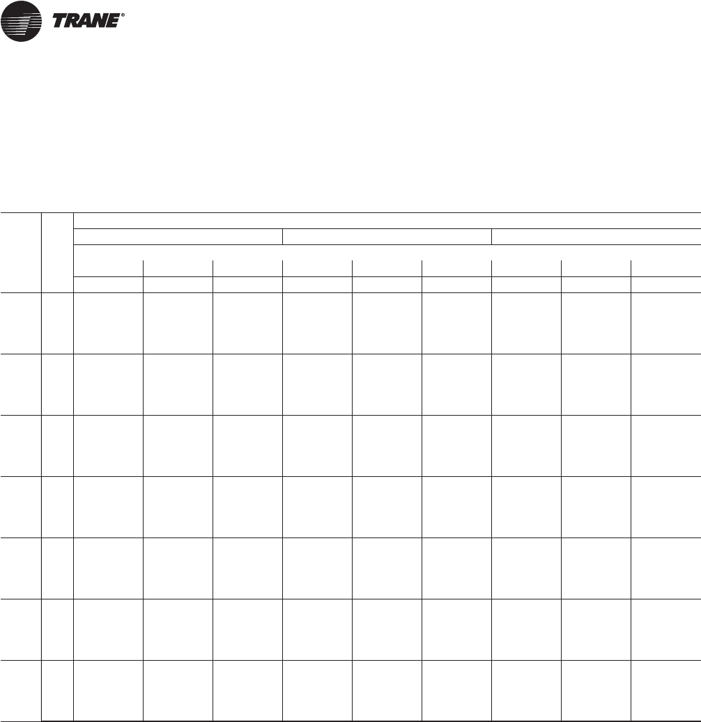
66 RT-PRC027T-EN
Performance Data
Air-Cooled 60 Hz Gross Cooling Capacities—Standard Capacity
Evaporator Coils
Table 9. Gross cooling capacities—90 tons—standard evaporator coil
Air
Flow
CFM
Ent
DB
(°F)
Ambient Temperature
85 95 105
Entering Wet Bulb
61 67 73 61 67 73 61 67 73
CAP SHC CAP SHC CAP SHC CAP SHC CAP SHC CAP SHC CAP SHC CAP SHC CAP SHC
16000
75 898 648 997 532 1096 407 864 630 959 514 1054 390 830 611 918 495 1009 371
80 905 747 996 624 1097 502 871 727 957 606 1055 484 834 707 916 586 1010 466
85 913 841 1003 717 1097 594 879 822 962 698 1055 576 844 801 922 677 1009 557
90 923 923 1004 815 1101 686 894 894 966 795 1060 668 864 864 926 775 1015 648
20000
75 956 718 1051 575 1148 421 918 698 1009 556 1103 404 877 676 964 536 1054 385
80 963 841 1049 688 1150 538 926 821 1006 669 1105 519 886 799 965 649 1057 501
85 976 960 1056 797 1153 651 932 932 1015 777 1108 633 898 898 971 755 1060 614
90 1010 1010 1060 921 1154 763 977 977 1021 902 1108 743 942 942 979 880 1061 723
25000
75 1003 794 1096 623 1192 435 961 773 1051 603 1143 418 917 750 1003 582 1092 399
80 1015 952 1099 758 1194 577 975 931 1054 738 1146 559 932 908 1006 715 1096 540
85 1041 1041 1103 889 1197 717 1005 1005 1059 868 1149 698 966 966 1011 845 1099 680
90 1090 1090 1117 1051 1199 846 1053 1053 1074 1030 1151 826 1013 1013 1028 1007 1102 805
30000
75 1035 864 1128 666 1221 448 992 842 1081 647 1170 430 945 818 1030 626 1117 412
80 1046 1046 1131 821 1224 614 1008 1008 1085 800 1174 596 967 967 1034 777 1122 577
85 1098 1098 1135 976 1227 779 1059 1059 1089 954 1178 761 1017 1017 1039 931 1126 739
90 1149 1149 1149 1149 1229 925 1110 1110 1109 1109 1180 905 1067 1067 1067 1067 1128 883
33000
75 1050 904 1142 692 1234 455 1006 882 1094 672 1183 437 958 858 1043 651 1129 419
80 1072 1072 1146 857 1238 635 1033 1033 1098 835 1188 617 991 991 1048 812 1134 599
85 1126 1126 1150 1026 1241 812 1086 1086 1102 1004 1191 794 1043 1043 1052 981 1137 775
90 1178 1178 1178 1178 1243 970 1137 1137 1136 1136 1193 950 1093 1093 1093 1093 1140 928
36000
75 1063 943 1155 716 1246 462 1018 920 1105 696 1194 444 969 896 1053 676 1139 426
80 1096 1095 1159 892 1250 656 1055 1055 1110 870 1199 638 1011 1011 1059 847 1144 619
85 1150 1150 1162 1074 1252 847 1108 1108 1114 1052 1201 829 1064 1064 1063 1029 1147 810
90 1203 1203 1202 1202 1254 1015 1160 1160 1160 1160 1204 994 1115 1115 1115 1115 1150 972
40000
75 1077 993 1168 748 1259 471 1031 970 1118 728 1206 453 981 945 1065 708 1150 435
80 1122 1122 1172 937 1263 683 1080 1080 1123 914 1211 665 1035 1035 1071 891 1156 646
85 1177 1177 1175 1137 1265 893 1134 1134 1126 1115 1213 875 1089 1089 1075 1075 1158 856
90 1230 1230 1230 1230 1267 1073 1187 1187 1186 1186 1215 1052 1140 1140 1139 1139 1160 1030
RT-PRC027.book Page 66 Tuesday, October 7, 2014 9:03 AM

RT-PRC027T-EN 67
Performance Data
Ambient Temperature
115
Air Ent Entering Wet Bulb
Flow DB 61 67 73
CFM (°F) CAP SHC CAP SHC CAP SHC
16000
75 793 590 875 475 964 353
80 797 686 873 566 965 448
85 807 781 879 656 964 539
90 831 831 883 753 971 630
20000
75 835 654 918 516 1005 367
80 844 776 919 627 1008 482
85 862 862 925 733 1011 595
90 904 904 935 859 1013 702
25000
75 872 726 955 562 1039 380
80 885 875 958 693 1043 521
85 926 926 964 823 1047 660
90 973 973 973 973 1050 783
30000
75 897 793 980 606 1062 393
80 926 926 985 754 1067 558
85 976 976 989 908 1070 719
90 1024 1024 1023 1023 1073 861
33000
75 909 833 992 631 1072 400
80 948 948 997 789 1078 579
85 999 999 1001 957 1081 755
90 1047 1047 1047 1047 1084 905
36000
75 919 871 1002 656 1081 407
80 968 968 1007 823 1087 600
85 1019 1019 1011 1005 1090 790
90 1067 1067 1067 1067 1092 949
40000
75 931 920 1012 687 1091 416
80 990 990 1018 867 1097 627
85 1041 1041 1021 1021 1100 810
90 1090 1090 1089 1089 1102 1006
Table 9. Gross cooling capacities—90 tons—standard evaporator coil (continued)
Air-Cooled 60 Hz Gross Cooling Capacities—Standard Capacity Evaporator Coils
RT-PRC027.book Page 67 Tuesday, October 7, 2014 9:03 AM

68 RT-PRC027T-EN
Performance Data
Table 10. Gross cooling capacities—105 tons—standard evaporator coil
Air
Flow
CFM
Ent
DB
(°F)
Ambient Temperature
85 95 105
Entering Wet Bulb
61 67 73 61 67 73 61 67 73
CAP SHC CAP SHC CAP SHC CAP SHC CAP SHC CAP SHC CAP SHC CAP SHC CAP SHC
19000
75 1058 770 1166 625 1278 475 1021 746 1125 605 1232 456 978 726 1079 584 1184 436
80 1117 908 1179 739 1280 588 1022 859 1136 718 1234 569 980 836 1072 694 1186 549
85 1124 1020 1172 850 1281 701 1069 989 1129 828 1232 680 1040 971 1084 806 1181 659
90 1094 1093 1177 960 1286 811 1061 1060 1134 938 1238 795 1025 1025 1090 916 1189 773
23000
75 1110 838 1218 669 1327 488 1067 816 1171 648 1278 469 1022 792 1124 627 1226 449
80 1119 975 1220 805 1330 623 1075 951 1172 783 1281 604 1090 950 1125 760 1229 584
85 1135 1111 1225 930 1334 757 1093 1088 1178 908 1284 737 1050 1050 1131 885 1229 715
90 1178 1177 1236 1068 1335 890 1141 1141 1188 1045 1286 867 1103 1103 1142 1022 1234 845
28000
75 1156 916 1262 718 1370 502 1110 893 1214 697 1318 483 1062 868 1163 676 1262 462
80 1171 1084 1265 874 1373 665 1123 1058 1217 852 1322 645 1077 1034 1166 828 1266 625
85 1202 1201 1270 1025 1372 826 1162 1162 1222 1003 1322 806 1122 1122 1172 979 1267 785
90 1258 1257 1288 1195 1378 976 1218 1218 1240 1171 1326 953 1176 1176 1187 1146 1271 929
33000
75 1189 990 1294 764 1400 514 1142 966 1246 744 1346 495 1092 941 1196 724 1288 475
80 1213 1191 1298 939 1403 703 1161 1160 1249 917 1350 684 1118 1118 1196 893 1294 664
85 1261 1260 1302 1116 1399 886 1219 1219 1252 1093 1351 870 1175 1175 1199 1069 1294 849
90 1320 1320 1320 1319 1406 1057 1276 1276 1276 1275 1353 1034 1230 1230 1230 1229 1296 1010
38000
75 1214 1060 1316 808 1423 526 1164 1035 1268 789 1367 507 1114 1010 1217 767 1307 487
80 1247 1246 1323 1001 1426 740 1204 1203 1272 979 1371 721 1159 1159 1218 955 1311 700
85 1308 1307 1325 1203 1424 952 1264 1264 1275 1180 1372 933 1217 1217 1220 1156 1313 912
90 1367 1366 1367 1366 1429 1137 1321 1321 1320 1320 1372 1114 1272 1272 1272 1271 1314 1089
43000
75 1233 1127 1336 850 1441 538 1182 1102 1284 830 1384 519 1131 1077 1227 808 1323 498
80 1283 1282 1341 1063 1441 776 1239 1238 1289 1039 1386 757 1191 1191 1234 1015 1323 735
85 1345 1345 1343 1289 1443 1012 1299 1299 1291 1265 1388 974 1249 1249 1235 1235 1328 951
90 1403 1403 1403 1402 1446 1215 1356 1355 1355 1354 1386 1191 1306 1306 1302 1302 1327 1166
45000
75 1239 1153 1343 867 1447 542 1189 1129 1289 846 1389 523 1137 1103 1233 825 1328 503
80 1296 1294 1347 1086 1448 790 1251 1251 1330 1068 1391 771 1202 1202 1306 1059 1328 750
85 1358 1358 1350 1323 1480 1038 1311 1311 1296 1296 1447 1027 1261 1261 1240 1240 1412 1017
90 1417 1417 1416 1416 1452 1246 1351 1254 1366 1366 1390 1221 1323 1188 1315 1315 1332 1197
Air-Cooled 60 Hz Gross Cooling Capacities—Standard Capacity Evaporator Coils
RT-PRC027.book Page 68 Tuesday, October 7, 2014 9:03 AM

RT-PRC027T-EN 69
Performance Data
Ambient Temperature
115
Air Ent Entering Wet Bulb
Flow DB 61 67 73
CFM (°F) CAP SHC CAP SHC CAP SHC
19000
75 933 702 1031 562 1130 415
80 936 811 1023 672 1134 528
85 949 923 1038 782 1127 637
90 989 989 1037 890 1137 750
23000
75 975 767 1072 604 1168 427
80 983 902 1076 736 1172 562
85 1011 1011 1080 861 1170 692
90 1061 1061 1092 996 1178 820
28000
75 1013 843 1109 653 1201 441
80 1030 1009 1113 804 1206 603
85 1077 1077 1117 954 1207 762
90 1129 1129 1134 1120 1211 904
33000
75 1041 915 1134 699 1224 453
80 1072 1072 1139 867 1230 641
85 1127 1127 1142 1043 1231 826
90 1180 1180 1179 1178 1229 984
38000
75 1060 983 1152 742 1242 465
80 1109 1109 1157 928 1246 678
85 1166 1166 1160 1129 1248 890
90 1219 1219 1217 1217 1245 1062
43000
75 1076 1049 1166 784 1256 477
80 1139 1139 1173 988 1256 713
85 1195 1195 1174 1174 1262 924
90 1248 1248 1247 1247 1257 1139
45000
75 1081 1075 1171 801 1261 481
80 1149 1149 1254 1041 1261 727
85 1205 1205 1280 1280 1266 945
90 1258 1258 1257 1257 1261 1169
Table 10. Gross cooling capacities—105 tons—standard evaporator coil (continued)
Air-Cooled 60 Hz Gross Cooling Capacities—Standard Capacity Evaporator Coils
RT-PRC027.book Page 69 Tuesday, October 7, 2014 9:03 AM

70 RT-PRC027T-EN
Performance Data
Table 11. Gross cooling capacities—120 tons—standard evaporator coil
Air
Flow
CFM
Ent
DB
(°F)
Ambient Temperature
85 95 105
Entering Wet Bulb
61 67 73 61 67 73 61 67 73
CAP SHC CAP SHC CAP SHC CAP SHC CAP SHC CAP SHC CAP SHC CAP SHC CAP SHC
21000
75 1156 837 1288 688 1426 527 1113 813 1241 665 1374 506 1064 788 1188 641 1317 483
80 1161 978 1291 810 1426 654 1119 954 1244 787 1375 632 1072 928 1192 762 1318 608
85 1173 1106 1294 930 1428 772 1132 1082 1247 907 1377 750 1086 1057 1196 883 1320 726
90 1189 1189 1294 1072 1431 893 1154 1154 1249 1049 1380 871 1116 1116 1198 1024 1323 847
26000
75 1225 928 1358 742 1495 547 1178 903 1306 719 1439 525 1126 875 1249 693 1377 502
80 1236 1102 1362 891 1496 698 1189 1077 1305 867 1440 676 1139 1050 1247 841 1378 651
85 1239 1239 1362 1035 1499 843 1200 1200 1311 1010 1443 820 1157 1157 1255 983 1382 796
90 1301 1301 1366 1212 1501 990 1261 1261 1323 1190 1446 968 1217 1217 1268 1164 1385 943
31000
75 1276 1007 1408 791 1543 563 1225 981 1353 767 1483 541 1170 952 1292 741 1418 517
80 1293 1221 1406 966 1544 738 1245 1195 1354 942 1485 716 1192 1167 1294 914 1420 691
85 1322 1322 1414 1130 1547 909 1280 1280 1360 1104 1488 886 1232 1232 1300 1076 1424 861
90 1389 1389 1434 1352 1548 1081 1345 1345 1381 1327 1489 1056 1297 1297 1324 1299 1425 1029
36000
75 1313 1081 1445 836 1578 576 1261 1054 1388 812 1516 554 1203 1025 1325 786 1448 530
80 1318 1318 1447 1033 1580 776 1274 1274 1390 1007 1518 753 1225 1225 1327 979 1451 729
85 1389 1389 1452 1220 1583 971 1343 1343 1396 1194 1522 948 1292 1292 1334 1166 1455 923
90 1458 1458 1457 1457 1585 1163 1411 1411 1410 1410 1523 1138 1359 1359 1358 1358 1457 1110
41000
75 1343 1151 1474 879 1606 589 1288 1123 1414 855 1541 567 1228 1093 1349 829 1471 543
80 1370 1370 1476 1096 1608 812 1323 1323 1418 1070 1544 789 1271 1271 1353 1041 1474 764
85 1443 1443 1482 1307 1612 1032 1395 1395 1423 1280 1547 1008 1341 1341 1359 1251 1478 983
90 1514 1514 1513 1513 1614 1242 1464 1464 1463 1463 1549 1216 1409 1409 1409 1409 1480 1188
46000
75 1366 1217 1497 920 1627 602 1310 1190 1436 896 1561 579 1248 1159 1369 869 1489 555
80 1413 1413 1500 1156 1630 847 1364 1364 1439 1130 1563 824 1309 1309 1373 1100 1493 799
85 1488 1488 1504 1389 1634 1090 1437 1437 1444 1363 1566 1066 1381 1381 1378 1333 1496 1041
90 1560 1560 1560 1560 1637 1319 1508 1508 1507 1507 1569 1292 1450 1450 1449 1449 1498 1264
51000
75 1385 1281 1515 959 1645 614 1328 1253 1453 935 1577 591 1265 1222 1385 909 1504 566
80 1449 1449 1518 1214 1648 881 1398 1398 1457 1187 1577 857 1342 1342 1390 1158 1504 832
85 1525 1525 1522 1469 1652 1147 1472 1472 1461 1442 1582 1122 1414 1414 1394 1394 1510 1097
90 1600 1600 1599 1599 1655 1393 1543 1543 1543 1543 1585 1365 1483 1483 1483 1483 1512 1337
54000
75 1395 1318 1524 982 1654 620 1337 1290 1462 958 1585 596 1273 1259 1393 931 1511 572
80 1468 1468 1528 1247 1654 900 1416 1416 1466 1220 1585 877 1358 1358 1398 1191 1511 852
85 1544 1544 1531 1516 1662 1180 1491 1491 1470 1470 1591 1155 1432 1432 1402 1402 1518 1130
90 1621 1621 1620 1620 1665 1436 1562 1562 1561 1561 1593 1408 1501 1501 1500 1500 1519 1379
Air-Cooled 60 Hz Gross Cooling Capacities—Standard Capacity Evaporator Coils
RT-PRC027.book Page 70 Tuesday, October 7, 2014 9:03 AM
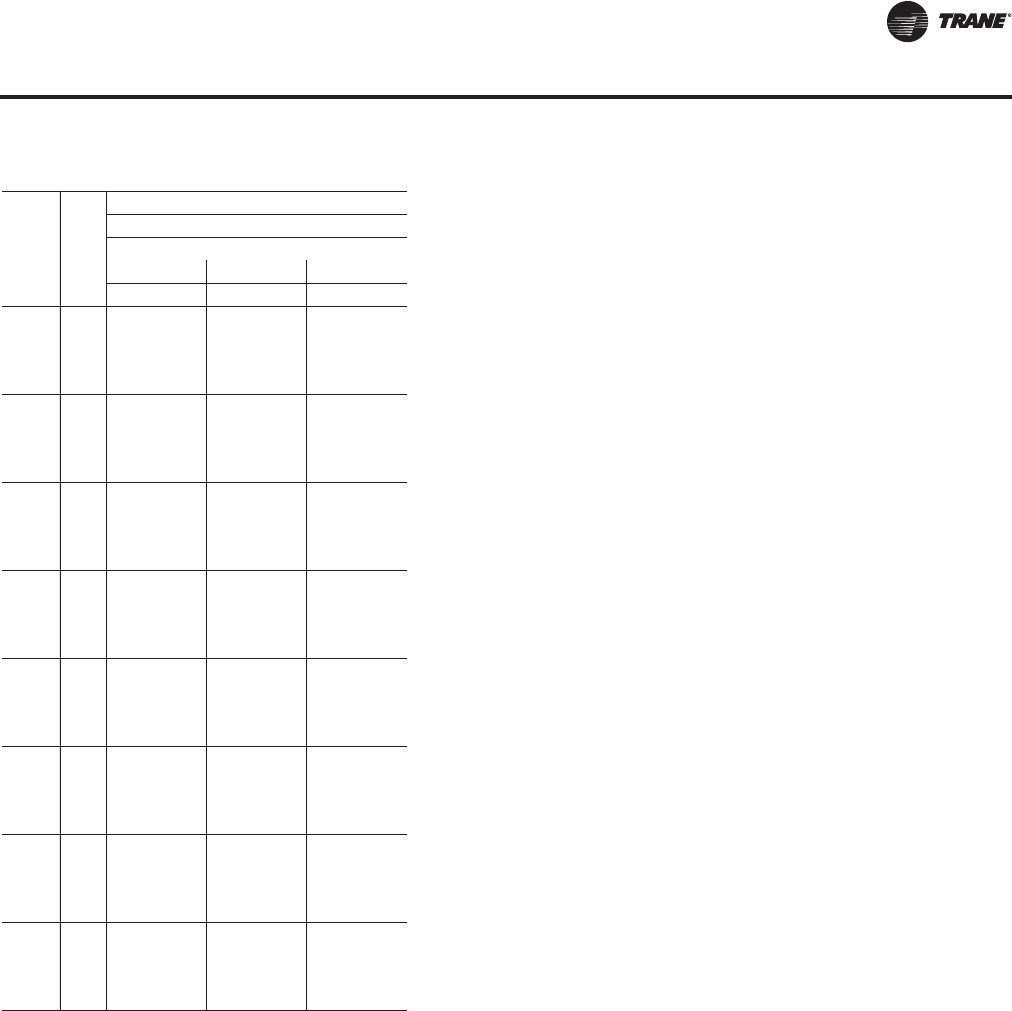
RT-PRC027T-EN 71
Performance Data
Air
Flow
CFM
Ent
DB
(°F)
Ambient Temperature
115
Entering Wet Bulb
61 67 73
CAP SHC CAP SHC CAP SHC
21000
75 1016 765 1133 615 1255 459
80 1024 902 1137 737 1256 582
85 1021 1021 1137 855 1259 701
90 1074 1074 1144 997 1262 821
26000
75 1072 847 1188 667 1309 476
80 1086 1022 1186 814 1311 625
85 1111 1111 1195 954 1315 770
90 1170 1170 1210 1135 1314 916
31000
75 1112 922 1228 714 1346 491
80 1119 1119 1230 885 1349 665
85 1182 1182 1236 1047 1353 834
90 1244 1244 1243 1243 1355 1000
36000
75 1141 994 1257 758 1373 504
80 1172 1172 1260 949 1377 702
85 1238 1238 1266 1135 1381 896
90 1302 1302 1301 1301 1383 1081
41000
75 1165 1062 1280 801 1394 517
80 1215 1215 1284 1010 1398 738
85 1283 1283 1289 1220 1402 956
90 1348 1348 1348 1348 1405 1158
46000
75 1183 1127 1297 841 1410 529
80 1251 1251 1302 1069 1415 772
85 1320 1320 1307 1302 1418 1014
90 1386 1386 1385 1385 1421 1233
51000
75 1198 1190 1312 880 1423 539
80 1280 1280 1317 1126 1424 805
85 1350 1350 1321 1321 1431 1070
90 1417 1417 1416 1416 1434 1306
54000
75 1206 1206 1319 903 1430 545
80 1296 1296 1324 1159 1431 825
85 1366 1366 1329 1329 1438 1103
90 1432 1432 1432 1432 1440 1348
Table 11. Gross cooling capacities—120 tons—standard evaporator coil (continued)
Air-Cooled 60 Hz Gross Cooling Capacities—Standard Capacity Evaporator Coils
RT-PRC027.book Page 71 Tuesday, October 7, 2014 9:03 AM

72 RT-PRC027T-EN
Performance Data
Table 12. Gross cooling capacities—130 tons—standard evaporator coil
Air
Flow
CFM
Ent
DB
(°F)
Ambient Temperature
85 95 105
Entering Wet Bulb
61 67 73 61 67 73 61 67 73
CAP SHC CAP SHC CAP SHC CAP SHC CAP SHC CAP SHC CAP SHC CAP SHC CAP SHC
23000
75 1335 964 1485 792 1634 607 1283 936 1429 766 1575 583 1226 906 1368 737 1510 556
80 1342 1110 1488 930 1634 747 1291 1082 1433 904 1576 723 1236 1051 1372 875 1511 696
85 1354 1251 1491 1068 1635 885 1305 1222 1437 1041 1579 860 1251 1191 1376 1012 1514 833
90 1373 1373 1493 1213 1640 1021 1331 1331 1439 1185 1582 995 1285 1285 1379 1155 1517 968
26000
75 1379 1021 1531 827 1678 618 1324 992 1473 800 1616 594 1270 964 1409 771 1548 567
80 1389 1184 1534 981 1679 776 1339 1156 1477 955 1618 751 1281 1125 1406 924 1550 724
85 1408 1345 1538 1135 1682 929 1356 1316 1481 1108 1621 904 1300 1284 1414 1077 1553 876
90 1446 1446 1543 1298 1684 1081 1402 1402 1487 1270 1624 1056 1352 1352 1425 1239 1557 1028
30000
75 1433 1094 1579 869 1724 631 1376 1064 1518 842 1659 606 1314 1031 1451 812 1588 580
80 1446 1282 1577 1045 1726 811 1390 1252 1515 1018 1661 785 1330 1220 1447 988 1590 758
85 1458 1458 1584 1218 1729 986 1411 1411 1525 1189 1664 960 1359 1359 1459 1158 1594 932
90 1529 1529 1597 1408 1732 1160 1481 1481 1539 1379 1666 1133 1428 1428 1475 1348 1597 1105
35000
75 1481 1175 1625 918 1769 646 1421 1144 1562 891 1699 620 1356 1111 1492 861 1625 593
80 1501 1398 1622 1122 1771 852 1444 1368 1563 1095 1701 826 1381 1335 1494 1063 1628 798
85 1538 1538 1631 1316 1775 1053 1488 1488 1569 1287 1704 1026 1432 1432 1500 1254 1631 998
90 1611 1611 1652 1541 1776 1254 1560 1560 1592 1512 1705 1224 1504 1504 1526 1481 1632 1194
40000
75 1518 1252 1660 965 1803 659 1456 1221 1595 938 1729 633 1388 1186 1523 908 1653 606
80 1547 1511 1662 1192 1806 892 1474 1474 1597 1162 1732 864 1416 1416 1526 1130 1656 837
85 1603 1603 1666 1409 1810 1119 1550 1550 1602 1380 1735 1091 1491 1491 1531 1347 1659 1063
90 1678 1678 1690 1664 1812 1340 1624 1624 1623 1623 1737 1309 1564 1564 1563 1563 1660 1278
45000
75 1546 1326 1687 1010 1830 672 1483 1294 1620 982 1753 645 1414 1259 1547 953 1675 618
80 1578 1578 1689 1257 1834 930 1523 1523 1623 1228 1756 902 1463 1463 1550 1195 1678 875
85 1656 1656 1693 1500 1838 1183 1601 1601 1627 1470 1759 1155 1539 1539 1555 1437 1680 1126
90 1734 1734 1733 1733 1840 1424 1674 1674 1674 1674 1761 1392 1612 1612 1611 1611 1682 1371
50000
75 1570 1397 1709 1053 1852 684 1505 1365 1641 1026 1773 657 1434 1329 1566 996 1693 630
80 1621 1621 1712 1321 1857 968 1564 1564 1644 1291 1776 939 1502 1502 1570 1258 1696 911
85 1701 1701 1715 1589 1860 1246 1642 1642 1647 1558 1779 1217 1579 1579 1573 1525 1697 1188
90 1782 1782 1781 1781 1862 1505 1718 1718 1717 1717 1781 1473 1651 1651 1650 1650 1699 1440
55000
75 1589 1465 1727 1095 1871 696 1523 1433 1658 1068 1789 669 1451 1398 1582 1039 1708 642
80 1657 1657 1730 1383 1875 1004 1599 1599 1661 1352 1793 975 1535 1535 1586 1319 1710 947
85 1739 1739 1733 1675 1878 1307 1677 1677 1663 1644 1796 1279 1612 1612 1588 1588 1712 1249
90 1823 1823 1822 1822 1880 1585 1755 1755 1754 1754 1798 1553 1685 1685 1684 1684 1713 1519
58000
75 1598 1506 1737 1120 1880 703 1532 1473 1666 1093 1798 676 1460 1438 1590 1063 1716 649
80 1676 1676 1740 1419 1885 1025 1617 1617 1669 1388 1801 997 1552 1552 1594 1355 1718 968
85 1760 1760 1743 1727 1887 1344 1696 1696 1671 1671 1804 1315 1629 1629 1596 1596 1719 1285
90 1845 1845 1844 1844 1889 1632 1775 1775 1774 1774 1806 1599 1702 1702 1702 1702 1720 1566
Air-Cooled 60 Hz Gross Cooling Capacities—Standard Capacity Evaporator Coils
RT-PRC027.book Page 72 Tuesday, October 7, 2014 9:03 AM

RT-PRC027T-EN 73
Performance Data
Air
Flow
CFM
Ambient Temperature
115
Ent Entering Wet Bulb
DB 61 67 73
(°F) CAP SHC CAP SHC CAP SHC
23000
75 1167 875 1304 708 1439 528
80 1178 1019 1309 845 1440 667
85 1195 1160 1313 982 1444 803
90 1237 1237 1317 1123 1447 938
26000
75 1210 932 1341 741 1474 538
80 1216 1090 1338 893 1476 695
85 1237 1237 1348 1044 1480 847
90 1301 1301 1359 1206 1483 998
30000
75 1250 998 1381 782 1510 551
80 1267 1186 1375 957 1513 728
85 1304 1304 1388 1124 1517 903
90 1371 1371 1406 1314 1518 1074
35000
75 1288 1076 1418 830 1544 564
80 1315 1300 1420 1029 1548 768
85 1373 1373 1426 1220 1551 968
90 1442 1442 1441 1441 1553 1161
40000
75 1318 1151 1446 876 1569 577
80 1355 1355 1449 1095 1574 807
85 1428 1428 1454 1312 1576 1033
90 1498 1498 1497 1497 1578 1244
45000
75 1341 1223 1468 921 1589 589
80 1398 1398 1472 1159 1594 845
85 1472 1472 1476 1402 1596 1096
90 1542 1542 1542 1542 1597 1326
50000
75 1360 1292 1485 965 1606 601
80 1435 1435 1489 1222 1610 882
85 1509 1509 1493 1489 1611 1158
90 1578 1578 1578 1578 1611 1405
55000
75 1375 1360 1500 1007 1620 613
80 1465 1465 1504 1283 1623 917
85 1539 1539 1507 1507 1623 1219
90 1608 1608 1608 1608 1624 1484
58000
75 1383 1383 1507 1032 1627 620
80 1481 1481 1511 1318 1630 939
85 1555 1555 1513 1513 1630 1255
90 1624 1624 1624 1624 1630 1530
Table 12. Gross cooling capacities—130 tons—standard evaporator coil (continued)
Air-Cooled 60 Hz Gross Cooling Capacities—Standard Capacity Evaporator Coils
RT-PRC027.book Page 73 Tuesday, October 7, 2014 9:03 AM

74 RT-PRC027T-EN
Performance Data
Table 13. Gross cooling capacities—150 tons—standard evaporator coil
Air
Flow
CFM
Ent
DB
(°F)
Ambient Temperature
85 95 105
Entering Wet Bulb
61 67 73 61 67 73 61 67 73
CAP SHC CAP SHC CAP SHC CAP SHC CAP SHC CAP SHC CAP SHC CAP SHC CAP SHC
23000
75 1471 1041 1627 860 1782 668 1407 1007 1569 831 1723 643 1345 974 1504 800 1656 615
80 1474 1185 1626 1002 1783 810 1418 1154 1567 972 1724 785 1358 1121 1502 941 1658 756
85 1479 1327 1633 1145 1783 951 1423 1294 1575 1116 1725 925 1364 1260 1511 1084 1658 896
90 1494 1471 1636 1287 1787 1091 1443 1441 1579 1258 1729 1065 1392 1392 1515 1241 1663 1037
26000
75 1517 1100 1679 895 1831 679 1456 1068 1619 867 1769 654 1390 1034 1551 836 1699 626
80 1529 1265 1678 1055 1833 838 1471 1234 1622 1027 1771 813 1405 1196 1555 996 1702 784
85 1537 1423 1685 1215 1833 997 1480 1390 1626 1187 1771 971 1419 1355 1559 1155 1705 942
90 1569 1569 1689 1375 1838 1154 1521 1521 1629 1346 1775 1128 1469 1469 1563 1312 1707 1099
30000
75 1571 1177 1732 939 1883 692 1507 1145 1670 911 1815 666 1438 1110 1600 880 1744 638
80 1583 1360 1731 1122 1886 875 1522 1327 1667 1094 1817 847 1461 1293 1596 1061 1747 820
85 1604 1546 1738 1305 1889 1056 1546 1514 1677 1277 1820 1028 1484 1480 1605 1245 1750 1000
90 1660 1660 1744 1485 1891 1237 1610 1610 1685 1455 1822 1208 1555 1555 1617 1422 1751 1180
35000
75 1631 1269 1782 990 1933 707 1568 1236 1719 963 1859 679 1497 1199 1646 932 1786 652
80 1646 1479 1780 1203 1936 918 1585 1447 1715 1175 1862 889 1517 1410 1640 1143 1789 861
85 1676 1676 1786 1411 1939 1127 1624 1624 1723 1381 1864 1099 1565 1565 1652 1348 1790 1070
90 1750 1750 1801 1619 1940 1336 1699 1699 1740 1589 1866 1307 1640 1640 1671 1556 1791 1278
40000
75 1672 1352 1820 1040 1971 720 1607 1318 1755 1012 1894 692 1535 1282 1681 981 1818 665
80 1695 1593 1818 1282 1974 959 1633 1561 1756 1253 1896 930 1565 1525 1683 1220 1819 902
85 1747 1747 1824 1511 1976 1197 1693 1693 1759 1480 1898 1168 1632 1632 1686 1447 1820 1139
90 1824 1824 1851 1751 1976 1433 1768 1768 1784 1720 1899 1402 1707 1707 1717 1687 1820 1369
45000
75 1704 1430 1850 1088 2001 733 1638 1397 1782 1060 1922 705 1564 1360 1708 1030 1844 678
80 1736 1705 1852 1353 2003 1000 1670 1670 1784 1323 1923 971 1607 1607 1710 1289 1843 942
85 1806 1806 1855 1608 2004 1266 1749 1749 1785 1577 1925 1237 1686 1686 1712 1543 1843 1208
90 1887 1887 1893 1875 2005 1522 1824 1824 1824 1824 1926 1490 1760 1760 1760 1760 1844 1457
50000
75 1728 1507 1875 1136 2026 745 1662 1474 1805 1107 1945 717 1587 1437 1729 1077 1865 690
80 1772 1772 1877 1422 2027 1040 1716 1716 1806 1390 1946 1011 1651 1651 1731 1357 1863 982
85 1856 1856 1879 1705 2026 1333 1794 1794 1806 1672 1946 1304 1730 1730 1732 1639 1862 1274
90 1939 1939 1939 1939 2026 1610 1873 1873 1872 1872 1946 1578 1804 1804 1803 1803 1861 1544
55000
75 1748 1582 1895 1183 2047 758 1682 1549 1823 1154 1964 730 1606 1512 1746 1124 1883 703
80 1813 1813 1897 1490 2046 1080 1754 1754 1823 1457 1964 1051 1688 1688 1748 1424 1879 1022
85 1900 1900 1898 1800 2044 1416 1834 1834 1823 1766 1963 1371 1767 1767 1747 1733 1877 1341
90 1983 1983 1982 1982 2045 1697 1914 1914 1913 1913 1962 1664 1841 1841 1841 1841 1876 1630
58000
75 1759 1626 1906 1211 2058 765 1691 1593 1832 1182 1975 737 1615 1556 1755 1152 1893 710
80 1835 1835 1908 1530 2056 1104 1774 1774 1832 1497 1973 1075 1707 1707 1756 1463 1888 1046
85 1923 1923 1908 1856 2054 1440 1854 1854 1832 1822 1972 1411 1786 1786 1755 1755 1885 1381
90 2006 2006 2005 2005 2055 1749 1936 1936 1935 1935 1970 1716 1861 1861 1861 1861 1884 1682
Air-Cooled 60 Hz Gross Cooling Capacities—Standard Capacity Evaporator Coils
RT-PRC027.book Page 74 Tuesday, October 7, 2014 9:03 AM
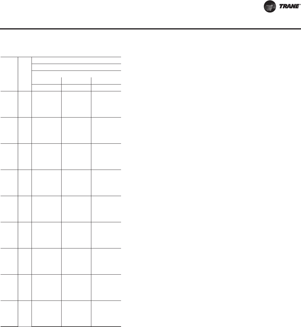
RT-PRC027T-EN 75
Performance Data
Air
Flow
CFM
Ent
DB
(°F)
Ambient Temperature
115
Entering Wet Bulb
61 67 73
CAP SHC CAP SHC CAP SHC
23000
75 1286 943 1438 769 1583 585
80 1300 1090 1436 910 1586 726
85 1307 1227 1446 1053 1585 866
90 1344 1344 1450 1194 1592 1006
26000
75 1328 1002 1482 804 1624 596
80 1341 1161 1486 964 1627 754
85 1359 1322 1490 1122 1630 911
90 1416 1416 1494 1278 1633 1068
30000
75 1382 1079 1527 848 1665 608
80 1395 1258 1522 1029 1669 789
85 1425 1425 1533 1210 1672 969
90 1497 1497 1545 1387 1674 1148
35000
75 1427 1163 1569 899 1704 622
80 1448 1374 1563 1110 1708 831
85 1504 1504 1576 1312 1709 1039
90 1577 1577 1597 1520 1710 1247
40000
75 1462 1244 1601 949 1734 636
80 1495 1488 1604 1183 1737 872
85 1567 1567 1607 1410 1737 1109
90 1640 1640 1640 1640 1737 1335
45000
75 1488 1322 1626 997 1758 649
80 1540 1540 1629 1253 1759 913
85 1618 1618 1631 1507 1758 1177
90 1690 1690 1690 1690 1757 1422
50000
75 1509 1398 1646 1045 1778 661
80 1581 1581 1648 1320 1777 953
85 1659 1659 1650 1602 1775 1244
90 1730 1730 1730 1730 1773 1508
55000
75 1526 1473 1662 1092 1795 674
80 1616 1616 1664 1386 1792 993
85 1693 1693 1664 1664 1788 1310
90 1764 1764 1763 1763 1785 1594
58000
75 1535 1517 1671 1120 1804 682
80 1634 1634 1672 1426 1800 1017
85 1711 1711 1671 1671 1795 1350
90 1782 1782 1781 1781 1792 1645
Table 13. Gross cooling capacities—150 tons—standard evaporator coil (continued)
Air-Cooled 60 Hz Gross Cooling Capacities—Standard Capacity Evaporator Coils
RT-PRC027.book Page 75 Tuesday, October 7, 2014 9:03 AM

76 RT-PRC027T-EN
Performance Data
Table 14. Gross cooling capacities—90 tons—high capacity evaporator coil
Air
Flow
CFM
Ent
DB
(°F)
Ambient Temperature
85 95 105
Entering Wet Bulb
61 67 73 61 67 73 61 67 73
CAP SHC CAP SHC CAP SHC CAP SHC CAP SHC CAP SHC CAP SHC CAP SHC CAP SHC
16000
75 950 680 1052 558 1153 430 911 659 1011 538 1112 413 874 640 969 518 1067 394
80 958 779 1052 654 1155 525 919 756 1012 634 1114 508 882 735 969 614 1069 489
85 960 871 1058 750 1157 620 927 852 1019 731 1113 603 890 830 977 711 1068 584
90 972 961 1061 846 1158 715 943 943 1021 826 1118 697 911 911 980 804 1075 679
20000
75 1010 757 1110 602 1206 443 970 735 1067 583 1162 426 928 713 1021 563 1115 408
80 1014 871 1107 721 1208 561 975 850 1063 701 1165 544 933 827 1017 680 1119 525
85 1029 992 1113 838 1210 678 991 970 1072 818 1167 661 951 948 1026 796 1122 642
90 1065 1065 1116 951 1211 795 1031 1031 1075 931 1169 777 995 995 1030 908 1123 759
25000
75 1059 839 1156 652 1249 457 1017 816 1112 633 1204 440 971 793 1064 613 1154 422
80 1072 984 1157 798 1251 601 1030 962 1113 778 1207 585 986 939 1066 756 1158 567
85 1099 1099 1160 937 1250 748 1063 1063 1117 916 1205 731 1023 1023 1070 894 1160 711
90 1148 1148 1173 1081 1252 888 1112 1112 1131 1060 1209 869 1073 1073 1086 1039 1161 849
30000
75 1093 915 1188 700 1279 469 1048 893 1142 681 1232 453 1000 868 1093 661 1181 435
80 1113 1092 1189 866 1280 641 1069 1069 1144 846 1235 625 1027 1027 1096 824 1185 607
85 1159 1159 1191 1030 1280 813 1121 1121 1146 1010 1235 797 1080 1080 1098 988 1185 779
90 1209 1209 1213 1205 1280 972 1171 1171 1171 1171 1235 953 1130 1130 1130 1130 1186 933
33000
75 1108 960 1202 728 1294 477 1063 937 1155 709 1245 460 1014 912 1106 689 1193 442
80 1135 1135 1203 905 1293 664 1096 1096 1157 885 1247 648 1053 1053 1109 863 1197 631
85 1187 1187 1204 1085 1293 847 1148 1148 1159 1065 1247 829 1107 1107 1111 1043 1197 819
90 1237 1237 1236 1236 1293 1022 1198 1198 1198 1198 1246 1003 1156 1156 1156 1156 1196 983
36000
75 1120 1003 1214 755 1306 484 1075 980 1166 737 1257 467 1025 955 1117 717 1204 450
80 1159 1159 1215 944 1304 688 1119 1119 1169 923 1258 672 1076 1076 1120 901 1207 654
85 1211 1211 1215 1140 1304 882 1172 1172 1170 1119 1257 863 1129 1129 1121 1097 1207 843
90 1261 1261 1261 1261 1303 1072 1221 1221 1221 1221 1254 1052 1178 1178 1178 1178 1204 1032
40000
75 1134 1060 1227 792 1320 494 1088 1037 1179 774 1270 477 1037 1011 1129 754 1216 460
80 1186 1186 1227 994 1317 719 1145 1145 1181 974 1270 703 1102 1102 1132 951 1218 686
85 1238 1238 1227 1211 1316 925 1199 1199 1181 1181 1268 906 1155 1155 1132 1132 1217 885
90 1290 1290 1289 1289 1314 1138 1246 1246 1246 1246 1264 1118 1202 1202 1202 1202 1213 1097
Air-Cooled 60 Hz Gross Cooling Capacities—High Capacity Evaporator Coils
RT-PRC027.book Page 76 Tuesday, October 7, 2014 9:03 AM

RT-PRC027T-EN 77
Performance Data
Air
Flow
CFM
Ambient Temperature
115
Ent Entering Wet Bulb
DB 61 67 73
(°F) CAP SHC CAP SHC CAP SHC
16000
75 843 623 932 501 1024 377
80 849 717 929 595 1026 472
85 856 811 937 692 1025 566
90 881 881 940 784 1031 660
20000
75 890 692 979 544 1068 390
80 893 805 974 662 1071 507
85 914 914 984 775 1074 624
90 960 960 992 889 1075 740
25000
75 928 771 1018 594 1103 404
80 944 916 1020 735 1107 548
85 986 986 1023 872 1109 692
90 1034 1034 1040 1017 1110 828
30000
75 956 846 1044 642 1128 417
80 987 987 1047 801 1132 588
85 1038 1038 1049 965 1132 760
90 1086 1086 1086 1086 1133 912
33000
75 968 889 1056 670 1140 425
80 1012 1012 1059 840 1143 612
85 1063 1063 1061 1020 1143 786
90 1111 1111 1110 1110 1142 961
36000
75 979 932 1066 698 1150 432
80 1033 1033 1069 878 1152 636
85 1084 1084 1070 1070 1152 820
90 1131 1131 1131 1131 1150 1010
40000
75 990 988 1077 735 1161 442
80 1057 1057 1079 928 1163 667
85 1108 1108 1080 1080 1161 863
90 1154 1154 1153 1153 1158 1075
Table 14. Gross cooling capacities—90 tons—high capacity evaporator coil (continued)
Air-Cooled 60 Hz Gross Cooling Capacities—High Capacity Evaporator Coils
RT-PRC027.book Page 77 Tuesday, October 7, 2014 9:03 AM

78 RT-PRC027T-EN
Performance Data
Table 15. Gross cooling capacities—105 tons—high capacity evaporator coil
Air
Flow
CFM
Ent
DB
(°F)
Ambient Temperature
85 95 105
Entering Wet Bulb
61 67 73 61 67 73 61 67 73
CAP SHC CAP SHC CAP SHC CAP SHC CAP SHC CAP SHC CAP SHC CAP SHC CAP SHC
19000
75 1104 793 1207 644 1320 491 1055 769 1162 623 1279 474 1010 745 1119 602 1230 454
80 1125 916 1212 759 1326 605 1091 897 1166 738 1283 586 1060 879 1118 715 1237 567
85 1144 1033 1216 872 1327 718 1098 1008 1172 850 1277 698 1056 984 1127 829 1234 678
90 1130 1129 1220 985 1329 830 1097 1096 1191 970 1283 810 1061 1061 1131 940 1234 789
23000
75 1153 865 1262 688 1370 504 1109 842 1218 668 1327 487 1064 818 1171 647 1274 467
80 1156 997 1262 825 1375 639 1111 973 1215 804 1329 621 1065 948 1164 781 1279 601
85 1216 1154 1267 957 1377 771 1131 1112 1224 936 1325 756 1090 1089 1177 914 1272 735
90 1217 1216 1270 1088 1377 908 1180 1180 1271 1082 1330 889 1143 1143 1184 1045 1277 867
28000
75 1200 946 1307 739 1414 518 1155 922 1261 719 1367 501 1108 898 1211 697 1313 482
80 1214 1110 1311 900 1413 679 1258 1117 1265 879 1370 663 1121 1061 1216 856 1321 645
85 1244 1243 1314 1055 1411 843 1205 1205 1268 1034 1369 824 1165 1165 1218 1011 1310 806
90 1300 1300 1575 1303 1418 1001 1261 1261 1280 1194 1369 980 1220 1220 1232 1171 1315 957
33000
75 1234 1022 1339 784 1448 532 1187 999 1295 766 1397 514 1139 975 1247 746 1342 495
80 1255 1216 1344 968 1448 720 1210 1192 1297 946 1399 703 1164 1164 1245 924 1349 685
85 1305 1304 1345 1150 1450 915 1265 1265 1298 1129 1397 887 1222 1222 1247 1106 1341 873
90 1361 1360 1367 1341 1448 1087 1321 1320 1320 1319 1394 1064 1276 1276 1276 1275 1339 1042
38000
75 1259 1097 1363 831 1473 545 1211 1073 1318 812 1420 527 1162 1049 1268 793 1364 508
80 1293 1292 1368 1034 1470 759 1252 1252 1319 1012 1418 741 1208 1208 1267 989 1362 721
85 1353 1352 1368 1244 1469 971 1311 1311 1319 1222 1421 953 1265 1265 1267 1198 1370 934
90 1409 1409 1409 1409 1469 1171 1365 1365 1364 1363 1411 1148 1319 1319 1316 1316 1355 1125
43000
75 1278 1170 1382 877 1493 557 1230 1146 1336 859 1439 540 1179 1121 1286 839 1381 521
80 1331 1330 1386 1100 1485 797 1289 1288 1336 1077 1434 780 1242 1242 1282 1054 1375 760
85 1389 1388 1381 1333 1487 1032 1347 1347 1335 1312 1438 1013 1299 1299 1281 1281 1385 994
90 1449 1448 1448 1448 1484 1254 1399 1399 1398 1397 1426 1231 1352 1352 1351 1351 1367 1207
45000
75 1284 1198 1389 895 1500 562 1236 1175 1342 877 1446 545 1185 1149 1292 858 1387 526
80 1344 1343 1392 1125 1494 814 1301 1301 1342 1103 1439 795 1254 1254 1288 1079 1381 775
85 1403 1402 1389 1370 1494 1050 1359 1359 1340 1340 1549 1069 1311 1311 1286 1286 1502 1055
90 1437 1402 1462 1462 1490 1287 1412 1412 1410 1410 1431 1174 1363 1363 1362 1362 1369 1239
Air-Cooled 60 Hz Gross Cooling Capacities—High Capacity Evaporator Coils
RT-PRC027.book Page 78 Tuesday, October 7, 2014 9:03 AM
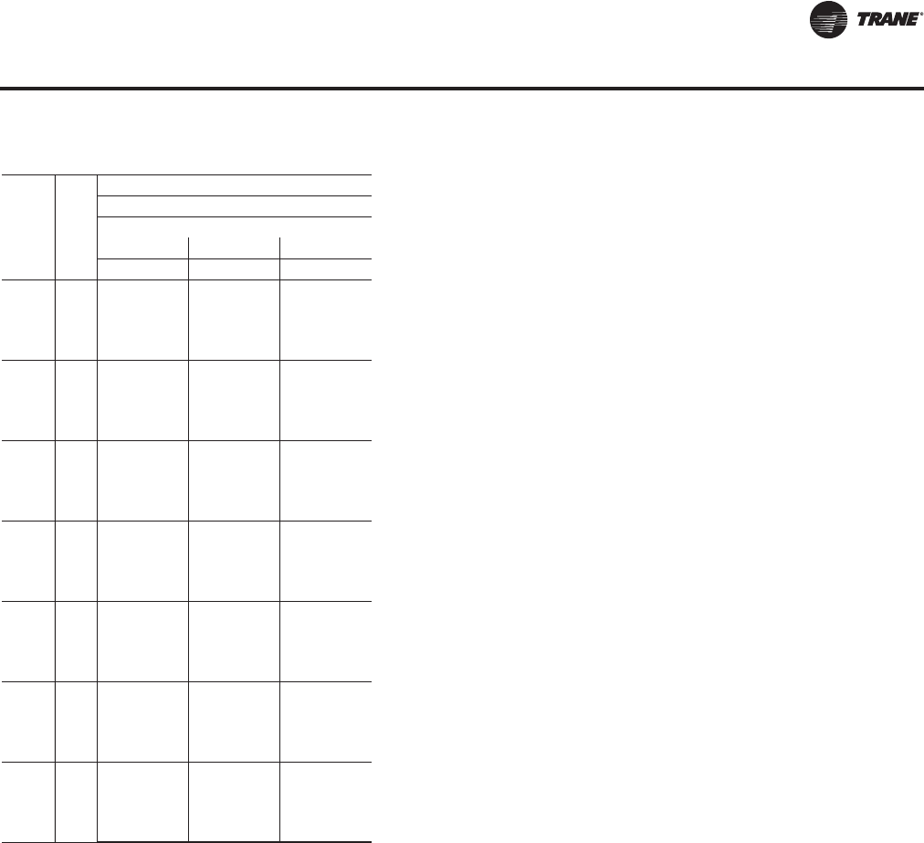
RT-PRC027T-EN 79
Performance Data
Air
Flow
CFM
Ent
DB
(°F)
Ambient Temperature
115
Entering Wet Bulb
61 67 73
CAP SHC CAP SHC CAP SHC
19000
75 979 726 1078 582 1178 434
80 1004 848 1071 693 1185 546
85 992 950 1082 809 1175 656
90 1026 1026 1115 928 1183 767
23000
75 1020 795 1121 625 1219 446
80 1021 924 1113 759 1224 580
85 1051 1051 1127 890 1220 712
90 1103 1103 1135 1021 1222 847
28000
75 1060 874 1158 675 1255 461
80 1073 1035 1162 832 1264 624
85 1122 1122 1165 986 1254 781
90 1174 1174 1178 1145 1256 933
33000
75 1088 949 1192 725 1281 474
80 1119 1119 1189 898 1292 665
85 1174 1174 1191 1080 1284 844
90 1227 1227 1227 1226 1278 1017
38000
75 1109 1022 1212 771 1301 487
80 1159 1159 1209 963 1299 700
85 1215 1215 1209 1172 1301 902
90 1267 1267 1263 1263 1293 1100
43000
75 1124 1094 1229 818 1314 499
80 1191 1191 1224 1027 1312 738
85 1246 1246 1222 1222 1324 970
90 1298 1298 1293 1293 1304 1182
45000
75 1130 1122 1225 833 1319 504
80 1202 1202 1228 1053 1317 754
85 1257 1257 1227 1227 1417 1028
90 1351 1148 1303 1303 1307 1214
Table 15. Gross cooling capacities—105 tons—high capacity evaporator coil (continued)
Air-Cooled 60 Hz Gross Cooling Capacities—High Capacity Evaporator Coils
RT-PRC027.book Page 79 Tuesday, October 7, 2014 9:03 AM
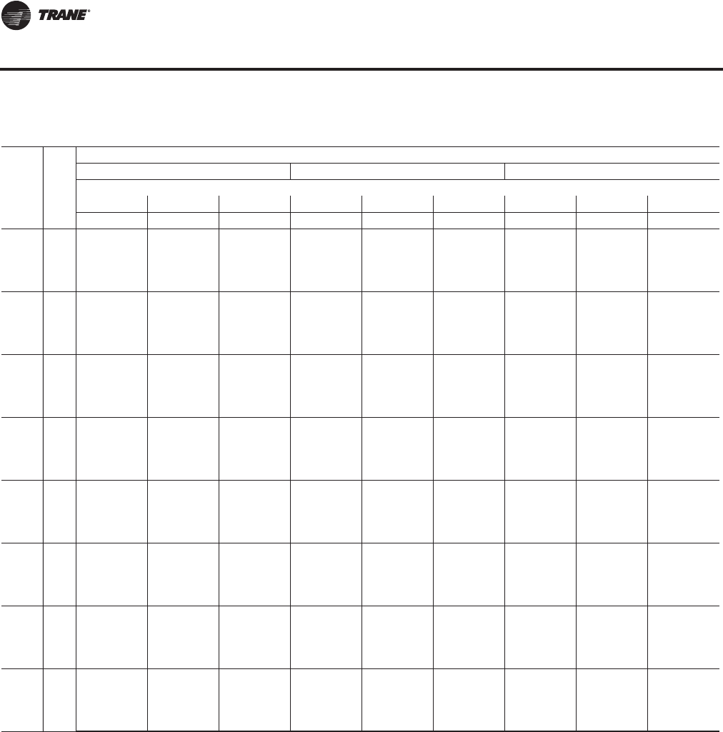
80 RT-PRC027T-EN
Performance Data
Table 16. Gross cooling capacities—120 tons—high capacity evaporator coil
Air
Flow
CFM
Ent
DB
(°F)
Ambient Temperature
85 95 105
Entering Wet Bulb
61 67 73 61 67 73 61 67 73
CAP SHC CAP SHC CAP SHC CAP SHC CAP SHC CAP SHC CAP SHC CAP SHC CAP SHC
21000
75 1225 879 1366 723 1500 559 1176 852 1316 700 1450 538 1123 824 1260 673 1392 514
80 1235 1007 1366 848 1501 683 1187 981 1314 823 1452 662 1133 951 1264 798 1394 638
85 1240 1130 1371 973 1502 806 1193 1103 1322 949 1451 785 1142 1074 1267 923 1394 760
90 1256 1256 1374 1098 1505 929 1217 1217 1326 1074 1456 908 1175 1175 1271 1047 1400 884
26000
75 1296 974 1439 780 1567 575 1243 947 1386 756 1514 555 1194 920 1326 729 1453 531
80 1308 1126 1436 932 1570 727 1257 1099 1382 908 1516 706 1201 1068 1321 880 1457 683
85 1324 1281 1444 1085 1573 879 1276 1255 1393 1062 1518 857 1224 1224 1332 1033 1460 833
90 1375 1375 1449 1234 1575 1029 1333 1333 1399 1209 1519 1007 1287 1287 1341 1181 1462 983
31000
75 1357 1062 1489 830 1616 590 1303 1034 1435 807 1558 569 1243 1003 1373 781 1495 546
80 1370 1242 1486 1012 1619 770 1318 1214 1429 987 1560 747 1259 1183 1364 959 1499 724
85 1422 1358 1493 1187 1622 948 1356 1356 1440 1162 1560 925 1306 1306 1380 1134 1501 902
90 1465 1465 1504 1363 1623 1126 1422 1422 1453 1339 1562 1102 1372 1372 1395 1311 1501 1079
36000
75 1396 1143 1526 878 1652 604 1341 1114 1470 855 1591 582 1279 1083 1407 829 1525 559
80 1416 1352 1527 1086 1655 810 1364 1325 1472 1060 1591 786 1306 1294 1409 1032 1529 764
85 1468 1468 1528 1283 1656 1016 1423 1423 1475 1258 1593 992 1372 1372 1413 1230 1530 969
90 1534 1534 1550 1491 1657 1217 1488 1488 1496 1465 1594 1191 1437 1437 1437 1437 1530 1165
41000
75 1426 1219 1553 925 1680 617 1370 1191 1497 902 1617 595 1306 1159 1432 876 1549 572
80 1454 1454 1554 1153 1683 850 1407 1407 1498 1128 1617 826 1353 1353 1435 1100 1552 803
85 1522 1522 1556 1378 1683 1083 1476 1476 1499 1352 1617 1059 1423 1423 1438 1324 1551 1035
90 1592 1592 1592 1592 1684 1303 1539 1539 1539 1539 1618 1276 1488 1488 1487 1487 1550 1249
46000
75 1449 1293 1574 971 1703 629 1393 1265 1517 948 1639 608 1328 1233 1452 923 1568 584
80 1497 1497 1576 1219 1704 889 1449 1449 1518 1193 1637 865 1394 1394 1455 1165 1570 842
85 1569 1569 1578 1471 1704 1149 1518 1518 1518 1444 1636 1125 1464 1464 1456 1416 1567 1101
90 1640 1640 1639 1639 1704 1388 1584 1584 1584 1584 1636 1361 1527 1527 1526 1526 1565 1333
51000
75 1468 1366 1593 1017 1721 641 1411 1338 1534 994 1657 620 1345 1306 1468 968 1584 597
80 1533 1533 1594 1285 1721 927 1484 1484 1534 1258 1653 904 1428 1428 1470 1229 1585 881
85 1608 1608 1595 1562 1721 1214 1552 1552 1532 1531 1652 1191 1497 1497 1470 1470 1580 1167
90 1680 1680 1680 1680 1721 1473 1621 1621 1620 1620 1649 1444 1560 1560 1559 1559 1578 1416
54000
75 1477 1409 1602 1044 1731 649 1420 1381 1542 1021 1666 628 1354 1349 1476 996 1591 604
80 1553 1553 1603 1323 1731 951 1502 1502 1542 1296 1662 927 1446 1446 1478 1268 1592 904
85 1628 1628 1603 1603 1730 1252 1571 1571 1539 1539 1660 1230 1514 1514 1477 1477 1587 1207
90 1701 1701 1701 1701 1730 1523 1640 1640 1639 1639 1656 1494 1578 1578 1577 1577 1585 1466
Air-Cooled 60 Hz Gross Cooling Capacities—High Capacity Evaporator Coils
RT-PRC027.book Page 80 Tuesday, October 7, 2014 9:03 AM

RT-PRC027T-EN 81
Performance Data
Air
Flow
CFM
Ent
DB
(°F)
Ambient Temperature
115
Entering Wet Bulb
61 67 73
CAP SHC CAP SHC CAP SHC
21000
75 1070 797 1202 646 1328 488
80 1082 923 1206 771 1332 612
85 1091 1046 1210 895 1330 734
90 1132 1132 1211 1017 1338 857
26000
75 1137 890 1263 702 1385 505
80 1148 1040 1256 852 1390 657
85 1175 1175 1270 1003 1394 807
90 1237 1237 1280 1151 1396 957
31000
75 1182 972 1307 753 1424 520
80 1200 1152 1308 931 1430 698
85 1254 1254 1314 1103 1433 876
90 1318 1318 1332 1281 1434 1050
36000
75 1215 1050 1338 801 1452 533
80 1246 1246 1341 1001 1459 739
85 1315 1315 1345 1199 1460 943
90 1380 1380 1380 1380 1461 1136
41000
75 1240 1126 1361 848 1473 546
80 1294 1294 1365 1068 1481 778
85 1364 1364 1368 1293 1480 1010
90 1428 1428 1428 1428 1480 1221
46000
75 1260 1199 1380 894 1490 559
80 1333 1333 1384 1133 1498 817
85 1403 1403 1386 1384 1496 1076
90 1466 1466 1465 1465 1494 1304
51000
75 1276 1271 1395 940 1504 571
80 1366 1366 1398 1197 1512 856
85 1435 1435 1399 1399 1509 1141
90 1496 1496 1495 1495 1504 1387
54000
75 1284 1284 1402 968 1511 578
80 1382 1382 1406 1235 1519 880
85 1451 1451 1406 1406 1516 1149
90 1511 1511 1511 1511 1509 1436
Table 16. Gross cooling capacities—120 tons—high capacity evaporator coil (continued)
Air-Cooled 60 Hz Gross Cooling Capacities—High Capacity Evaporator Coils
RT-PRC027.book Page 81 Tuesday, October 7, 2014 9:03 AM

82 RT-PRC027T-EN
Performance Data
Table 17. Gross cooling capacities—130 tons—high capacity evaporator coil
Air
Flow
CFM
Ent
DB
(°F)
Ambient Temperature
85 95 105
Entering Wet Bulb
61 67 73 61 67 73 61 67 73
CAP SHC CAP SHC CAP SHC CAP SHC CAP SHC CAP SHC CAP SHC CAP SHC CAP SHC
23000
75 1396 1000 1553 823 1701 634 1340 970 1496 796 1644 610 1280 938 1433 766 1579 584
80 1406 1146 1552 964 1702 775 1352 1116 1494 936 1645 751 1293 1084 1437 908 1581 724
85 1412 1285 1559 1106 1702 915 1359 1255 1503 1079 1645 890 1301 1222 1441 1048 1580 863
90 1431 1431 1562 1247 1706 1054 1386 1386 1507 1220 1650 1029 1338 1338 1445 1189 1587 1002
26000
75 1443 1060 1601 858 1746 645 1384 1029 1542 831 1686 621 1321 997 1477 801 1619 594
80 1457 1223 1604 1017 1748 803 1399 1191 1546 990 1688 778 1335 1156 1472 958 1622 752
85 1467 1380 1607 1176 1748 960 1413 1349 1550 1149 1690 935 1353 1316 1485 1118 1625 908
90 1508 1508 1610 1333 1753 1116 1462 1462 1554 1305 1692 1091 1411 1411 1490 1273 1628 1064
30000
75 1493 1136 1650 901 1793 657 1441 1108 1590 875 1729 633 1376 1073 1522 845 1660 607
80 1506 1316 1648 1083 1796 838 1454 1287 1586 1056 1731 813 1390 1253 1516 1025 1664 787
85 1531 1503 1655 1265 1799 1018 1477 1473 1595 1237 1733 992 1420 1420 1528 1205 1666 966
90 1593 1593 1663 1441 1801 1198 1546 1546 1606 1413 1735 1171 1492 1492 1541 1382 1668 1144
35000
75 1551 1225 1696 952 1839 672 1490 1193 1635 926 1770 646 1422 1158 1565 896 1699 621
80 1568 1435 1694 1164 1842 881 1509 1403 1630 1136 1772 854 1443 1369 1557 1105 1702 828
85 1606 1606 1700 1367 1845 1089 1556 1556 1640 1339 1774 1062 1499 1499 1571 1307 1704 1035
90 1678 1678 1716 1574 1846 1297 1628 1628 1657 1546 1775 1269 1572 1572 1592 1514 1704 1241
40000
75 1589 1307 1731 1001 1874 685 1527 1275 1668 975 1801 659 1456 1239 1597 945 1729 634
80 1614 1547 1732 1239 1877 922 1555 1517 1669 1211 1803 895 1490 1482 1599 1178 1731 869
85 1672 1672 1735 1465 1878 1159 1621 1621 1672 1437 1805 1131 1562 1562 1603 1405 1731 1104
90 1747 1747 1763 1706 1879 1389 1692 1692 1701 1676 1806 1359 1635 1635 1634 1634 1731 1329
45000
75 1618 1384 1759 1049 1902 698 1555 1352 1694 1022 1827 672 1483 1317 1622 993 1752 647
80 1650 1650 1760 1309 1904 963 1596 1596 1695 1279 1828 936 1535 1535 1624 1247 1753 909
85 1727 1727 1762 1562 1904 1227 1673 1673 1696 1532 1829 1200 1613 1613 1626 1501 1752 1172
90 1806 1806 1805 1805 1905 1477 1745 1745 1745 1745 1829 1447 1684 1684 1683 1683 1752 1416
50000
75 1641 1460 1781 1096 1925 711 1577 1428 1714 1070 1849 685 1505 1393 1641 1041 1772 659
80 1693 1693 1782 1377 1926 1003 1639 1639 1715 1347 1848 976 1577 1577 1644 1315 1771 949
85 1774 1774 1784 1658 1925 1294 1715 1715 1715 1627 1848 1267 1654 1654 1645 1596 1769 1239
90 1854 1854 1853 1853 1925 1565 1790 1790 1790 1790 1848 1534 1724 1724 1724 1724 1768 1502
55000
75 1659 1535 1799 1143 1944 723 1595 1503 1731 1116 1868 698 1522 1467 1657 1088 1789 672
80 1731 1731 1801 1444 1944 1043 1674 1674 1731 1413 1865 1016 1611 1611 1659 1381 1786 989
85 1815 1815 1802 1752 1942 1360 1751 1751 1730 1721 1864 1333 1687 1687 1659 1659 1783 1305
90 1895 1895 1907 1859 1942 1652 1828 1828 1828 1828 1862 1620 1759 1759 1758 1758 1781 1588
58000
75 1669 1579 1809 1171 1954 730 1604 1547 1740 1144 1878 705 1531 1511 1666 1116 1798 679
80 1751 1751 1811 1484 1953 1067 1693 1693 1739 1452 1874 1040 1629 1629 1667 1420 1794 1013
85 1836 1836 1811 1808 1951 1400 1770 1770 1738 1738 1872 1373 1705 1705 1666 1666 1791 1345
90 1916 1916 1916 1916 1952 1704 1848 1848 1847 1847 1869 1671 1777 1777 1777 1777 1788 1639
Air-Cooled 60 Hz Gross Cooling Capacities—High Capacity Evaporator Coils
RT-PRC027.book Page 82 Tuesday, October 7, 2014 9:03 AM
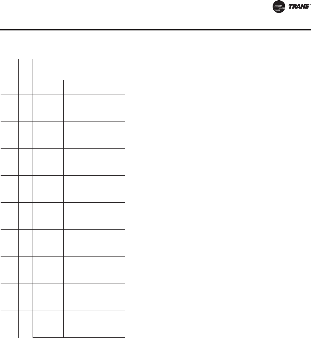
RT-PRC027T-EN 83
Performance Data
Air
Flow
CFM
Ent
DB
(°F)
Ambient Temperature
115
Entering Wet Bulb
61 67 73
CAP SHC CAP SHC CAP SHC
23000
75 1221 908 1369 736 1508 555
80 1234 1051 1373 878 1511 695
85 1245 1190 1377 1018 1510 834
90 1291 1291 1379 1156 1517 973
26000
75 1259 966 1409 771 1545 566
80 1275 1123 1404 927 1549 723
85 1296 1284 1417 1087 1553 879
90 1359 1359 1423 1239 1555 1034
30000
75 1312 1040 1451 814 1584 578
80 1326 1219 1444 993 1588 758
85 1365 1365 1457 1171 1591 936
90 1435 1435 1471 1348 1593 1114
35000
75 1353 1123 1490 865 1620 592
80 1377 1334 1492 1073 1624 800
85 1439 1439 1497 1272 1626 1006
90 1510 1510 1521 1480 1627 1209
40000
75 1385 1203 1520 914 1647 606
80 1423 1423 1523 1144 1652 840
85 1498 1498 1527 1370 1652 1075
90 1569 1569 1569 1569 1652 1297
45000
75 1410 1280 1543 962 1670 619
80 1470 1470 1546 1212 1673 881
85 1546 1546 1549 1466 1672 1144
90 1616 1616 1616 1616 1671 1383
50000
75 1429 1355 1561 1010 1688 631
80 1509 1509 1564 1279 1690 921
85 1585 1585 1566 1561 1687 1210
90 1654 1654 1654 1654 1685 1469
55000
75 1445 1429 1577 1057 1703 644
80 1542 1542 1579 1345 1704 961
85 1617 1617 1579 1579 1700 1277
90 1685 1685 1684 1684 1696 1554
58000
75 1453 1453 1584 1085 1711 652
80 1559 1559 1586 1384 1711 985
85 1634 1634 1586 1586 1707 1317
90 1702 1702 1701 1701 1701 1605
Table 17. Gross cooling capacities—130 tons—high capacity evaporator coil (continued)
Air-Cooled 60 Hz Gross Cooling Capacities—High Capacity Evaporator Coils
RT-PRC027.book Page 83 Tuesday, October 7, 2014 9:03 AM
84 RT-PRC027T-EN
Performance Data
Air-Cooled 50 Hz Gross Cooling Capacities—Standard Capacity
Evaporator Coils
Table 18. Gross cooling capacities—90 tons—standard evaporator coil
Air
Flow
CFM
Ent
DB
(°F)
Ambient Temperature
85 95 105
Entering Wet Bulb
61 67 73 61 67 73 61 67 73
CAP SHC CAP SHC CAP SHC CAP SHC CAP SHC CAP SHC CAP SHC CAP SHC CAP SHC
16000
75 792 589 875 475 959 352 760 572 840 459 921 337 727 554 804 443 881 321
80 797 686 873 566 960 446 766 669 838 550 923 430 734 651 801 533 883 415
85 807 781 879 655 963 537 776 764 845 638 926 522 739 739 809 620 886 506
90 831 831 883 753 965 627 805 805 849 736 926 612 777 777 813 718 887 594
20000
75 835 653 917 515 997 364 801 635 879 499 957 349 764 616 840 483 914 333
80 842 776 918 625 1000 478 810 759 881 608 960 463 775 740 842 590 918 447
85 861 861 923 731 1002 591 832 832 886 713 963 576 801 801 847 695 921 560
90 903 903 931 857 1004 697 873 873 895 840 965 680 841 841 857 821 923 662
25000
75 871 726 951 560 1029 377 834 707 911 544 986 362 796 687 869 527 941 346
80 879 879 954 690 1032 517 848 848 915 672 991 501 814 814 873 653 946 485
85 924 924 957 820 1034 655 892 892 918 802 993 640 857 857 877 783 949 624
90 967 967 967 967 1036 777 934 934 934 934 995 760 899 899 898 898 951 742
30000
75 896 794 974 603 1051 389 857 774 933 587 1006 374 817 754 889 570 959 358
80 923 923 977 750 1054 553 889 889 937 732 1011 538 853 853 894 712 965 522
85 969 969 980 905 1056 716 935 935 940 886 1013 699 898 898 897 867 968 683
90 1014 1014 1013 1013 1058 854 978 978 978 978 1015 837 940 940 940 940 970 818
33000
75 907 833 985 628 1061 396 868 813 943 612 1016 381 827 792 899 595 967 365
80 944 944 988 785 1064 574 909 909 947 767 1021 559 872 872 903 747 974 543
85 991 991 991 954 1066 750 955 955 950 935 1023 735 917 917 906 906 977 698
90 1035 1035 1035 1035 1067 899 999 999 998 998 1024 882 959 959 959 959 978 863
36000
75 917 871 994 652 1070 403 877 851 951 636 1023 388 835 830 906 619 974 372
80 962 962 997 819 1073 595 926 926 955 801 1029 580 888 888 911 780 982 564
85 1009 1009 999 999 1074 764 973 973 958 958 1031 747 933 933 914 914 984 728
90 1054 1054 1053 1053 1075 943 1016 1016 1016 1016 1031 925 976 976 976 976 985 907
40000
75 927 920 1004 684 1079 412 887 887 961 667 1032 397 844 844 915 627 982 381
80 983 982 1007 863 1079 623 946 946 965 844 1032 608 906 906 920 824 982 591
85 1030 1029 1009 1009 1083 803 992 992 967 967 1039 786 951 951 922 922 993 767
90 1074 1074 1074 1074 1084 1000 1036 1036 1035 1035 1039 982 994 994 994 994 993 963
RT-PRC027.book Page 84 Tuesday, October 7, 2014 9:03 AM

RT-PRC027T-EN 85
Performance Data
Air
Flow
CFM
Ent
DB
(°F)
Ambient Temperature
115
Entering Wet Bulb
61 67 73
CAP SHC CAP SHC CAP SHC
16000
75 694 536 766 426 839 305
80 701 633 767 517 842 398
85 711 711 772 602 845 489
90 747 747 776 699 846 577
20000
75 728 597 799 465 869 317
80 739 721 802 571 874 431
85 769 769 806 676 877 543
90 808 808 818 802 880 644
25000
75 756 667 826 510 894 330
80 779 779 830 633 901 469
85 821 821 834 763 904 608
90 861 861 861 861 907 723
30000
75 776 733 844 552 911 342
80 816 816 849 692 919 506
85 858 858 852 846 922 667
90 901 901 900 900 924 799
33000
75 785 771 852 577 919 349
80 833 833 857 726 927 527
85 877 877 860 860 930 679
90 919 919 919 919 931 844
36000
75 792 792 859 601 926 356
80 848 848 865 759 930 548
85 892 892 868 868 937 709
90 934 934 934 934 938 887
40000
75 800 800 868 606 933 365
80 864 864 873 803 934 576
85 910 910 875 875 944 747
90 951 951 951 951 944 943
Table 18. Gross cooling capacities—90 tons—standard evaporator coil
Air-Cooled 50 Hz Gross Cooling Capacities—Standard Capacity Evaporator Coils
RT-PRC027.book Page 85 Tuesday, October 7, 2014 9:03 AM
86 RT-PRC027T-EN
Performance Data
Table 19. Gross cooling capacities—105 tons—standard evaporator coil
Air
Flow
CFM
Ent
DB
(°F)
Ambient Temperature
85 95 105
Entering Wet Bulb
61 67 73 61 67 73 61 67 73
CAP SHC CAP SHC CAP SHC CAP SHC CAP SHC CAP SHC CAP SHC CAP SHC CAP SHC
19000
75 941 813 1022 671 1123 523 906 794 980 652 1081 507 868 774 936 633 1035 489
80 953 926 1033 780 1123 633 919 907 994 761 1075 616 879 879 951 740 1035 599
85 987 987 1039 890 1124 742 956 956 1001 871 1082 726 922 922 957 850 1038 707
90 1028 561 1121 412 897 683 986 542 1078 395 0 0 942 523 1031 377 816 639
23000
75 985 902 1066 732 1160 557 946 881 1024 712 1115 540 906 860 980 691 1065 522
80 1009 1009 1072 857 1154 689 975 975 1031 838 1117 699 939 939 985 816 1071 655
85 1056 1056 1082 993 1160 814 1022 1022 1043 973 1119 796 984 984 999 952 1071 776
90 1066 601 1157 423 936 747 1024 584 1111 406 894 725 978 564 1061 388 848 701
28000
75 1028 1010 1101 798 1191 597 985 985 1056 777 1145 580 945 945 1009 756 1094 562
80 1070 1070 1104 949 1192 755 1035 1035 1062 929 1147 738 994 994 1015 908 1096 720
85 1119 1119 1121 1109 1190 896 1082 1082 1082 1082 1148 879 1042 1042 1040 1040 1098 859
90 1099 649 1188 436 967 820 1055 631 1140 419 924 798 1007 611 1088 401 877 774
33000
75 1065 1065 1126 861 1213 635 1027 1027 1079 840 1166 618 985 985 1031 819 1113 600
80 1116 1116 1127 1037 1213 819 1077 1077 1084 1018 1168 803 1036 1036 1036 996 1117 786
85 1164 1164 1164 1164 1211 977 1126 1126 1127 1127 1165 958 1083 1083 1084 1084 1116 939
90 1123 694 1210 448 990 891 1077 675 1161 431 946 868 1028 656 1108 414 896 843
38000
75 1100 1100 1144 923 1230 672 1061 1061 1095 901 1183 656 1016 1016 1047 879 1129 638
80 1153 1153 1145 1124 1227 859 1112 1112 1100 1100 1183 842 1067 1067 1051 1051 1128 820
85 1199 1199 1198 1198 1227 1056 1157 1157 1158 1158 1177 1036 1113 1113 1115 1115 1128 1017
90 1141 737 1229 460 1007 959 1093 719 1179 444 958 934 1042 699 1125 426 911 910
43000
75 1129 1129 1159 983 1241 707 1087 1087 1108 960 1195 692 1041 1041 1059 938 1142 674
80 1181 1181 1158 1158 1239 912 1139 1139 1112 1112 1194 894 1094 1094 1062 1062 1138 871
85 1229 1229 1229 1229 1238 1133 1184 1184 1188 1188 1186 1112 1141 1141 1138 1138 1138 1093
90 1154 780 1242 472 1021 1021 1106 761 1191 455 973 973 1055 719 1136 438 923 923
45000
75 1136 1136 1163 987 1244 721 1096 1096 1112 964 1199 706 1050 1050 1063 942 1146 689
80 1189 1189 1162 1162 1246 934 1149 1149 1116 1116 1198 915 1103 1103 1065 1065 1143 892
85 1234 1246 1229 1232 1242 1163 1188 1183 1192 1192 1190 1116 1145 1153 1146 1146 1141 1123
90 1159 796 1242 475 1024 1051 1110 761 1195 460 977 977 1060 731 1140 442 926 926
Air-Cooled 50 Hz Gross Cooling Capacities—Standard Capacity Evaporator Coils
RT-PRC027.book Page 86 Tuesday, October 7, 2014 9:03 AM

RT-PRC027T-EN 87
Performance Data
Air
Flow
CFM
Ent
DB
(°F)
Ambient Temperature
115
Entering Wet Bulb
61 67 73
CAP SHC CAP SHC CAP SHC
19000
75 826 750 900 614 985 470
80 842 842 903 717 985 581
85 883 883 914 828 990 686
90 898 503 979 358 974 766
23000
75 861 836 932 669 1014 503
80 898 898 937 793 1018 635
85 942 942 952 930 1018 753
90 931 544 1008 369 1008 841
28000
75 902 902 964 735 1038 542
80 952 952 964 884 1041 700
85 999 999 996 996 1042 835
90 956 590 1032 382 1032 912
33000
75 941 941 981 796 1056 580
80 991 991 983 972 1057 743
85 1037 1037 1038 1038 1058 915
90 975 635 1050 394 1050 980
38000
75 970 970 997 857 1070 618
80 1018 1018 995 995 1070 795
85 1068 1068 1068 1068 1069 992
90 990 679 1064 406 1064 1046
43000
75 993 993 1010 916 1082 655
80 1046 1046 1005 1005 1080 847
85 1096 1096 1088 1088 1077 1068
90 1000 692 1075 418 932 691
45000
75 1001 1001 1013 938 1085 669
80 1054 1054 1008 1008 1083 866
85 1099 1108 1021 1678 1080 1080
90 1004 704 1008 1008 935 703
Table 19. Gross cooling capacities—105 tons—standard evaporator coil (continued)
Air-Cooled 50 Hz Gross Cooling Capacities—Standard Capacity Evaporator Coils
RT-PRC027.book Page 87 Tuesday, October 7, 2014 9:03 AM
88 RT-PRC027T-EN
Performance Data
Table 20. Gross cooling capacities—120 tons—standard evaporator coil
Air
Flow
CFM
Ent
DB
(°F)
Ambient Temperature
85 95 105
Entering Wet Bulb
61 67 73 61 67 73 61 67 73
CAP SHC CAP SHC CAP SHC CAP SHC CAP SHC CAP SHC CAP SHC CAP SHC CAP SHC
21000
75 1035 773 1150 623 1271 465 994 751 1107 603 1224 447 951 728 1059 582 1172 427
80 1041 911 1149 743 1272 589 1002 890 1105 723 1225 570 959 867 1057 702 1174 549
85 1047 1031 1154 861 1274 707 1002 1002 1111 840 1228 688 967 967 1064 817 1177 667
90 1087 1087 1158 1003 1277 827 1054 1054 1118 983 1231 808 1018 1018 1072 960 1180 787
26000
75 1090 855 1206 674 1325 482 1047 832 1159 654 1275 464 1000 808 1108 632 1219 443
80 1102 1030 1206 822 1327 631 1060 1008 1160 801 1277 612 1015 984 1109 777 1222 591
85 1125 1125 1212 960 1330 775 1089 1089 1166 939 1280 756 1049 1049 1116 915 1226 735
90 1183 1183 1225 1142 1330 920 1146 1146 1180 1121 1281 899 1106 1106 1131 1097 1227 876
31000
75 1130 930 1245 721 1362 497 1085 907 1196 701 1310 478 1035 882 1142 678 1252 458
80 1133 1133 1248 890 1365 670 1095 1095 1199 868 1313 651 1053 1053 1146 844 1256 630
85 1195 1195 1253 1053 1368 840 1156 1156 1205 1031 1316 820 1113 1113 1151 1006 1260 799
90 1257 1257 1256 1256 1369 1004 1217 1217 1216 1216 1318 983 1173 1173 1172 1172 1262 960
36000
75 1160 1002 1275 766 1390 510 1113 978 1224 745 1335 491 1061 952 1168 722 1275 471
80 1187 1187 1278 955 1393 707 1146 1146 1228 932 1339 688 1101 1101 1172 907 1280 667
85 1251 1251 1283 1141 1396 902 1210 1210 1233 1119 1342 882 1164 1164 1178 1094 1284 861
90 1314 1314 1314 1314 1399 1085 1272 1272 1271 1271 1344 1063 1225 1225 1224 1224 1286 1039
41000
75 1183 1070 1297 808 1411 522 1134 1046 1245 787 1355 504 1081 1020 1188 764 1293 483
80 1230 1230 1301 1016 1415 743 1187 1187 1249 993 1359 724 1140 1140 1193 968 1299 703
85 1296 1296 1305 1226 1418 962 1252 1252 1254 1203 1362 942 1204 1204 1197 1178 1302 921
90 1360 1360 1359 1359 1421 1163 1315 1315 1315 1315 1364 1140 1266 1266 1266 1266 1305 1116
46000
75 1202 1135 1315 848 1427 534 1152 1111 1262 827 1370 516 1097 1084 1203 805 1307 495
80 1265 1265 1319 1075 1432 778 1221 1221 1266 1051 1375 758 1172 1172 1209 1026 1307 737
85 1333 1333 1323 1308 1436 1020 1287 1287 1270 1270 1377 999 1237 1237 1213 1213 1316 978
90 1399 1399 1398 1398 1439 1239 1350 1350 1350 1350 1379 1215 1299 1299 1299 1299 1318 1191
51000
75 1216 1198 1330 887 1441 545 1166 1166 1275 866 1383 526 1110 1110 1216 843 1319 505
80 1295 1295 1334 1131 1441 811 1249 1249 1280 1108 1383 792 1198 1198 1221 1082 1319 771
85 1363 1363 1337 1337 1450 1076 1316 1316 1283 1283 1390 1055 1264 1264 1225 1225 1328 1034
90 1432 1432 1431 1431 1453 1312 1380 1380 1379 1379 1392 1288 1326 1326 1325 1325 1329 1263
54000
75 1224 1224 1337 910 1448 551 1173 1173 1282 889 1390 532 1117 1117 1223 866 1325 511
80 1310 1310 1341 1165 1449 831 1263 1263 1287 1141 1390 811 1212 1212 1228 1115 1325 790
85 1379 1379 1344 1344 1457 1109 1331 1331 1290 1290 1396 1088 1278 1278 1231 1231 1333 1067
90 1449 1449 1448 1448 1460 1355 1395 1395 1395 1395 1398 1331 1340 1340 1339 1339 1335 1306
Air-Cooled 50 Hz Gross Cooling Capacities—Standard Capacity Evaporator Coils
RT-PRC027.book Page 88 Tuesday, October 7, 2014 9:03 AM
RT-PRC027T-EN 89
Performance Data
Air
Flow
CFM
Ent
DB
(°F)
Ambient Temperature
115
Entering Wet Bulb
61 67 73
CAP SHC CAP SHC CAP SHC
21000
75 905 703 1008 559 1116 406
80 913 842 1005 679 1118 527
85 929 929 1014 793 1122 645
90 979 979 1022 936 1121 764
26000
75 950 782 1053 609 1159 422
80 966 959 1055 752 1162 569
85 1007 1007 1061 889 1167 713
90 1062 1062 1061 1061 1168 852
31000
75 982 855 1084 655 1188 436
80 1008 1008 1088 818 1193 608
85 1067 1067 1094 980 1198 777
90 1125 1125 1124 1124 1200 934
36000
75 1006 925 1108 698 1209 448
80 1053 1053 1113 881 1216 645
85 1114 1114 1118 1067 1220 838
90 1173 1173 1173 1173 1223 1014
41000
75 1024 991 1126 740 1225 461
80 1089 1089 1131 941 1233 680
85 1152 1152 1136 1136 1237 898
90 1212 1212 1211 1211 1239 1091
46000
75 1039 1039 1140 780 1238 472
80 1119 1119 1146 998 1239 714
85 1182 1182 1150 1150 1250 956
90 1243 1243 1242 1242 1252 1165
51000
75 1051 1051 1152 819 1248 482
80 1143 1143 1158 1054 1249 748
85 1208 1208 1162 1162 1260 1012
90 1268 1268 1267 1267 1262 1237
54000
75 1057 1057 1158 842 1254 488
80 1156 1156 1164 1087 1254 767
85 1221 1221 1167 1167 1266 1015
90 1280 1280 1280 1280 1267 1267
Table 20. Gross cooling capacities—120 tons—standard evaporator coil (continued)
Air-Cooled 50 Hz Gross Cooling Capacities—Standard Capacity Evaporator Coils
RT-PRC027.book Page 89 Tuesday, October 7, 2014 9:03 AM

90 RT-PRC027T-EN
Performance Data
Table 21. Gross cooling capacities—130 tons—standard evaporator coil
Air
Flow
CFM
Ent
DB
(°F)
Ambient Temperature
85 95 105
Entering Wet Bulb
61 67 73 61 67 73 61 67 73
CAP SHC CAP SHC CAP SHC CAP SHC CAP SHC CAP SHC CAP SHC CAP SHC CAP SHC
23000
75 1176 880 1307 709 1429 525 1133 857 1255 686 1375 503 1081 829 1199 660 1314 480
80 1187 1023 1305 845 1431 663 1139 997 1253 821 1376 642 1090 971 1195 795 1316 618
85 1202 1164 1311 981 1433 799 1157 1139 1260 956 1379 777 1102 1102 1204 928 1319 753
90 1242 1242 1318 1123 1435 933 1202 1202 1264 1097 1382 911 1158 1158 1213 1071 1322 887
26000
75 1218 935 1342 741 1461 534 1168 908 1288 717 1404 512 1113 879 1229 691 1342 489
80 1228 1096 1339 893 1463 689 1179 1070 1284 869 1407 667 1125 1041 1224 843 1345 643
85 1241 1241 1346 1042 1465 841 1200 1200 1294 1017 1409 819 1154 1154 1236 989 1348 795
90 1301 1301 1356 1204 1467 991 1259 1259 1304 1179 1411 969 1212 1212 1247 1151 1348 944
30000
75 1256 1000 1377 780 1494 545 1204 973 1322 756 1435 523 1146 943 1260 730 1370 500
80 1271 1188 1379 955 1496 722 1221 1162 1323 929 1438 700 1165 1132 1263 901 1374 676
85 1305 1305 1383 1120 1498 895 1261 1261 1328 1095 1440 873 1212 1212 1268 1066 1376 849
90 1367 1367 1397 1310 1499 1064 1322 1322 1345 1285 1441 1040 1272 1272 1287 1257 1377 1013
35000
75 1292 1077 1411 827 1525 558 1238 1050 1353 804 1464 536 1178 1019 1290 778 1397 513
80 1315 1301 1413 1023 1527 761 1257 1257 1356 997 1466 739 1206 1206 1293 969 1401 715
85 1368 1368 1416 1214 1529 962 1321 1321 1360 1188 1467 939 1269 1269 1297 1160 1402 915
90 1430 1430 1430 1430 1531 1150 1383 1383 1382 1382 1468 1124 1329 1329 1329 1329 1403 1097
40000
75 1319 1151 1436 873 1549 570 1263 1123 1377 849 1486 549 1202 1092 1312 823 1417 526
80 1352 1352 1438 1089 1552 799 1304 1304 1380 1062 1488 777 1250 1250 1316 1033 1421 753
85 1418 1418 1440 1306 1554 1027 1369 1369 1382 1279 1488 1004 1314 1314 1319 1251 1421 980
90 1480 1480 1480 1480 1556 1234 1429 1429 1429 1429 1489 1207 1374 1374 1373 1373 1422 1179
45000
75 1340 1222 1456 917 1568 582 1283 1194 1396 893 1504 561 1220 1163 1329 867 1434 538
80 1392 1392 1458 1152 1571 837 1342 1342 1398 1125 1505 814 1286 1286 1333 1096 1437 790
85 1458 1458 1458 1394 1573 1088 1406 1406 1400 1368 1505 1064 1350 1350 1335 1335 1436 1040
90 1523 1523 1522 1522 1575 1316 1467 1467 1466 1466 1505 1288 1409 1409 1408 1408 1435 1260
50000
75 1357 1291 1472 959 1584 595 1299 1263 1411 936 1519 573 1235 1231 1343 910 1447 550
80 1424 1424 1473 1214 1587 874 1373 1373 1413 1187 1518 850 1315 1315 1346 1158 1449 827
85 1491 1491 1473 1473 1589 1151 1437 1437 1413 1413 1518 1126 1379 1379 1348 1348 1448 1102
90 1559 1559 1559 1559 1590 1396 1498 1498 1498 1498 1518 1368 1436 1436 1436 1436 1446 1339
55000
75 1370 1359 1485 1001 1598 606 1312 1312 1423 977 1532 585 1247 1247 1355 952 1458 562
80 1452 1452 1485 1274 1601 910 1398 1398 1424 1247 1530 886 1339 1339 1357 1217 1460 863
85 1520 1520 1485 1485 1601 1211 1462 1462 1424 1424 1529 1187 1403 1403 1358 1358 1458 1130
90 1589 1589 1589 1589 1601 1475 1526 1526 1526 1526 1529 1446 1461 1461 1460 1460 1455 1417
58000
75 1377 1377 1492 1026 1605 613 1318 1318 1429 1002 1539 592 1253 1253 1361 976 1464 569
80 1466 1466 1491 1309 1607 931 1412 1412 1430 1282 1539 913 1352 1352 1363 1253 1464 889
85 1535 1535 1492 1492 1608 1247 1476 1476 1430 1430 1535 1190 1415 1415 1363 1363 1462 1161
90 1605 1605 1604 1604 1607 1521 1541 1541 1540 1540 1535 1493 1473 1473 1473 1473 1459 1459
Air-Cooled 50 Hz Gross Cooling Capacities—Standard Capacity Evaporator Coils
RT-PRC027.book Page 90 Tuesday, October 7, 2014 9:03 AM

RT-PRC027T-EN 91
Performance Data
Air
Flow
CFM
Ent
DB
(°F)
Ambient Temperature
115
Entering Wet Bulb
61 67 73
CAP SHC CAP SHC CAP SHC
23000
75 1027 800 1139 634 1248 455
80 1037 942 1134 768 1251 592
85 1057 1057 1145 899 1254 727
90 1112 1112 1154 1042 1257 860
26000
75 1056 850 1166 664 1273 463
80 1070 1011 1168 816 1277 618
85 1106 1106 1174 959 1280 769
90 1162 1162 1187 1122 1281 915
30000
75 1087 913 1195 703 1298 475
80 1108 1102 1198 871 1303 650
85 1159 1159 1203 1036 1306 823
90 1217 1217 1217 1217 1307 984
35000
75 1115 988 1222 750 1323 488
80 1151 1151 1225 938 1328 689
85 1212 1212 1229 1129 1330 889
90 1270 1270 1270 1270 1331 1068
40000
75 1137 1060 1242 795 1341 500
80 1192 1192 1246 1002 1346 727
85 1254 1254 1249 1219 1347 951
90 1311 1311 1311 1311 1347 1150
45000
75 1154 1130 1258 839 1356 513
80 1225 1225 1262 1065 1361 765
85 1287 1287 1264 1264 1361 1014
90 1343 1343 1343 1343 1360 1230
50000
75 1167 1167 1270 882 1368 525
80 1252 1252 1274 1125 1373 801
85 1314 1314 1275 1275 1372 1047
90 1369 1369 1369 1369 1369 1309
55000
75 1178 1178 1281 924 1378 536
80 1275 1275 1284 1185 1382 837
85 1336 1336 1285 1285 1380 1099
90 1390 1390 1390 1390 1377 1377
58000
75 1184 1184 1286 949 1383 543
80 1286 1286 1289 1220 1384 863
85 1347 1347 1289 1289 1385 1130
90 1402 1402 1401 1401 1380 1380
Table 21. Gross cooling capacities—130 tons—standard evaporator coil (continued)
Air-Cooled 50 Hz Gross Cooling Capacities—Standard Capacity Evaporator Coils
RT-PRC027.book Page 91 Tuesday, October 7, 2014 9:03 AM

92 RT-PRC027T-EN
Performance Data
Table 22. Gross cooling capacities—150 tons—standard evaporator coil
Air
Flow
CFM
Ent
DB
(°F)
Ambient Temperature
85 95 105
Entering Wet Bulb
61 67 73 61 67 73 61 67 73
CAP SHC CAP SHC CAP SHC CAP SHC CAP SHC CAP SHC CAP SHC CAP SHC CAP SHC
23000
75 1296 946 1427 764 1552 573 1246 920 1375 739 1500 552 1193 892 1320 714 1441 528
80 1359 1117 1427 905 1551 711 1304 1087 1374 881 1502 691 1213 1040 1314 853 1444 668
85 1306 1226 1431 1045 1554 853 1265 1204 1381 1021 1501 831 1210 1173 1323 994 1441 806
90 1341 1340 1433 1185 1555 990 1302 1301 1422 1176 1504 969 1258 1258 1328 1132 1445 944
26000
75 1334 1003 1465 796 1586 581 1281 977 1411 772 1533 561 1227 948 1351 746 1473 538
80 1337 1159 1464 955 1587 738 1284 1131 1410 932 1535 717 1227 1100 1347 904 1476 694
85 1353 1319 1467 1113 1589 895 1300 1291 1416 1088 1535 873 1259 1258 1357 1060 1476 850
90 1406 1406 1474 1267 1588 1049 1365 1365 1423 1241 1535 1028 1318 1318 1366 1214 1474 1003
30000
75 1375 1073 1504 838 1624 593 1323 1046 1449 814 1567 572 1265 1017 1387 787 1505 549
80 1389 1255 1504 1021 1625 772 1338 1228 1446 996 1568 751 1277 1196 1381 968 1505 727
85 1414 1414 1506 1195 1627 952 1370 1370 1453 1170 1568 929 1321 1321 1394 1142 1507 906
90 1477 1476 1516 1372 1627 1130 1433 1433 1465 1347 1566 1107 1384 1384 1407 1320 1507 1082
35000
75 1415 1155 1540 887 1659 606 1361 1128 1484 863 1600 585 1301 1098 1420 837 1534 562
80 1433 1366 1540 1094 1662 814 1381 1339 1486 1070 1600 791 1318 1309 1425 1042 1534 768
85 1483 1482 1540 1293 1662 1022 1437 1437 1487 1269 1598 998 1385 1385 1426 1241 1535 974
90 1544 1543 1557 1501 1661 1224 1499 1499 1507 1477 1595 1195 1447 1447 1447 1446 1533 1171
40000
75 1444 1235 1567 935 1686 619 1390 1208 1510 911 1627 599 1328 1177 1445 885 1561 577
80 1471 1469 1565 1163 1690 855 1424 1423 1511 1139 1622 831 1370 1370 1449 1112 1556 808
85 1536 1535 1566 1390 1688 1091 1489 1489 1511 1366 1621 1066 1435 1435 1449 1338 1555 1043
90 1601 1601 1600 1598 1686 1311 1549 1549 1548 1547 1618 1283 1495 1495 1495 1494 1550 1257
45000
75 1467 1311 1588 982 1709 632 1411 1284 1530 959 1650 613 1349 1253 1464 933 1582 590
80 1513 1512 1585 1231 1710 895 1465 1465 1530 1207 1640 871 1411 1411 1468 1179 1574 848
85 1580 1579 1585 1486 1708 1159 1530 1530 1528 1461 1639 1135 1474 1474 1466 1433 1571 1111
90 1649 1649 1647 1646 1705 1400 1591 1591 1589 1589 1635 1371 1532 1532 1532 1532 1564 1343
50000
75 1485 1386 1605 1029 1730 646 1429 1358 1546 1006 1669 626 1365 1328 1480 980 1599 603
80 1547 1546 1601 1297 1727 935 1499 1499 1545 1273 1653 910 1443 1443 1480 1244 1588 888
85 1618 1618 1602 1581 1723 1226 1563 1563 1542 1542 1654 1202 1506 1506 1478 1478 1584 1178
90 1686 1686 1685 1685 1720 1487 1627 1627 1625 1625 1649 1458 1566 1566 1562 1562 1576 1430
55000
75 1499 1460 1619 1075 1747 659 1442 1432 1560 1053 1686 639 1376 1376 1493 1027 1614 615
80 1577 1576 1616 1364 1739 975 1527 1527 1557 1338 1666 950 1470 1470 1491 1309 1600 928
85 1651 1651 1617 1617 1736 1293 1592 1592 1552 1552 1666 1269 1532 1532 1488 1488 1596 1221
90 1718 1718 1718 1718 1734 1573 1656 1656 1656 1656 1660 1544 1594 1594 1589 1589 1584 1514
58000
75 1507 1504 1627 1103 1757 667 1449 1449 1567 1081 1694 646 1385 1385 1500 1056 1616 623
80 1593 1593 1624 1404 1747 999 1541 1541 1562 1377 1673 975 1484 1484 1497 1348 1619 965
85 1667 1667 1624 1624 1743 1311 1608 1608 1557 1557 1674 1308 1545 1545 1493 1493 1601 1256
90 1737 1737 1736 1736 1740 1625 1671 1671 1670 1670 1665 1595 1604 1604 1603 1603 1588 1566
Air-Cooled 50 Hz Gross Cooling Capacities—Standard Capacity Evaporator Coils
RT-PRC027.book Page 92 Tuesday, October 7, 2014 9:03 AM

RT-PRC027T-EN 93
Performance Data
Air
Flow
CFM
Ent
DB
(°F)
Ambient Temperature
115
Entering Wet Bulb
61 67 73
CAP SHC CAP SHC CAP SHC
23000
75 1121 859 1259 687 1375 503
80 1135 998 1250 824 1379 642
85 1153 1142 1261 967 1380 780
90 1211 1211 1291 1110 1379 917
26000
75 1168 917 1291 719 1404 512
80 1175 1071 1280 874 1408 668
85 1208 1208 1294 1030 1409 823
90 1269 1268 1304 1183 1409 981
30000
75 1203 985 1320 759 1435 524
80 1242 1175 1325 940 1438 702
85 1267 1267 1327 1112 1438 879
90 1329 1329 1343 1289 1438 1053
35000
75 1236 1065 1354 810 1464 538
80 1264 1264 1356 1011 1462 742
85 1328 1328 1357 1210 1464 949
90 1389 1389 1388 1388 1462 1142
40000
75 1261 1143 1374 857 1487 552
80 1311 1311 1379 1080 1483 782
85 1375 1375 1379 1306 1482 1017
90 1434 1434 1433 1433 1479 1228
45000
75 1280 1219 1392 905 1506 565
80 1349 1349 1396 1147 1500 823
85 1412 1412 1394 1394 1498 1086
90 1469 1469 1468 1468 1491 1314
50000
75 1296 1294 1406 952 1522 578
80 1380 1380 1410 1213 1514 863
85 1442 1442 1407 1407 1510 1153
90 1496 1496 1497 1497 1499 1399
55000
75 1308 1308 1419 1000 1530 590
80 1405 1405 1420 1279 1529 914
85 1466 1466 1416 1416 1520 1192
90 1520 1520 1521 1521 1507 1484
58000
75 1314 1314 1426 1004 1537 598
80 1419 1419 1426 1317 1536 939
85 1479 1479 1421 1421 1525 1219
90 1533 1533 1534 1534 1510 1510
Table 22. Gross cooling capacities—150 tons—standard evaporator coil (continued)
Air-Cooled 50 Hz Gross Cooling Capacities—Standard Capacity Evaporator Coils
RT-PRC027.book Page 93 Tuesday, October 7, 2014 9:03 AM

94 RT-PRC027T-EN
Performance Data
Table 23. Gross cooling capacities—90 tons—high capacity evaporator coil
Air
Flow
CFM
Ent
DB
(°F)
Ambient Temperature
85 95 105
Entering Wet Bulb
61 67 73 61 67 73 61 67 73
CAP SHC CAP SHC CAP SHC CAP SHC CAP SHC CAP SHC CAP SHC CAP SHC CAP SHC
16000
75 829 616 918 494 1000 367 800 600 884 479 965 353 767 582 848 462 926 338
80 837 710 916 589 1002 462 804 692 881 573 967 448 771 674 844 556 929 432
85 847 806 921 685 1004 556 815 788 887 668 969 542 783 770 851 650 931 526
90 873 873 924 775 1005 649 846 846 890 759 971 635 817 817 854 741 933 620
20000
75 877 685 960 536 1039 379 842 667 924 520 1002 365 806 648 885 504 961 350
80 886 802 961 654 1041 495 852 783 925 637 1005 482 816 764 886 619 965 466
85 904 904 963 765 1040 613 875 875 928 748 1003 599 844 844 890 730 962 584
90 946 946 971 879 1042 726 917 917 937 863 1007 711 885 885 900 845 967 694
25000
75 913 763 994 584 1073 393 877 745 956 569 1033 379 838 725 915 552 989 364
80 929 910 995 722 1072 535 893 893 958 706 1035 522 859 859 918 687 994 507
85 968 968 996 860 1072 677 937 937 960 843 1036 662 903 903 920 825 995 646
90 1010 1010 1012 1004 1072 811 979 979 979 979 1035 796 945 945 945 945 995 780
30000
75 937 837 1017 631 1096 406 900 819 978 615 1054 392 859 799 936 599 1009 377
80 969 969 1017 788 1094 575 936 936 980 771 1056 562 901 901 939 753 1014 547
85 1013 1013 1017 952 1093 735 981 981 980 936 1055 720 945 945 940 917 1014 703
90 1054 1054 1054 1054 1092 895 1022 1022 1022 1022 1052 879 987 987 987 987 1012 863
33000
75 948 881 1027 658 1108 414 910 862 988 643 1064 399 869 841 945 627 1018 385
80 990 990 1027 826 1104 599 957 957 989 809 1066 585 920 920 948 791 1024 571
85 1034 1034 1026 1007 1103 769 1001 1001 989 989 1064 754 965 965 948 948 1023 737
90 1077 1077 1076 1076 1101 945 1042 1042 1042 1042 1060 929 1007 1007 1007 1007 1020 913
36000
75 957 923 1036 686 1118 421 919 904 997 671 1073 407 877 877 954 635 1026 392
80 1008 1008 1035 864 1113 622 975 975 997 847 1074 609 937 937 955 828 1032 595
85 1052 1052 1034 1034 1110 804 1019 1019 996 996 1071 787 982 982 955 955 1030 771
90 1096 1096 1096 1096 1110 995 1059 1059 1059 1059 1066 978 1023 1023 1023 1023 1025 962
40000
75 966 966 1047 702 1129 431 928 928 1007 683 1082 417 886 886 963 663 1035 402
80 1028 1028 1044 914 1123 654 994 994 1006 897 1084 641 956 956 964 878 1041 627
85 1073 1073 1042 1042 1119 846 1038 1038 1004 1004 1078 832 1002 1002 963 963 1037 813
90 1120 1120 1120 1120 1119 1061 1079 1079 1079 1079 1073 1043 1041 1041 1041 1041 1031 1026
Air-Cooled 50 Hz Gross Cooling Capacities—High Capacity Evaporator Coils
RT-PRC027.book Page 94 Tuesday, October 7, 2014 9:03 AM

RT-PRC027T-EN 95
Performance Data
Air
Flow
CFM
Ent
DB
(°F)
Ambient Temperature
115
Entering Wet Bulb
61 67 73
CAP SHC CAP SHC CAP SHC
16000
75 738 566 812 447 886 323
80 741 657 809 541 890 417
85 753 753 816 633 888 511
90 789 789 818 723 894 604
20000
75 772 630 846 487 920 336
80 782 746 848 601 924 452
85 813 813 851 712 921 568
90 852 852 861 826 928 677
25000
75 801 706 874 535 948 350
80 825 825 876 668 953 493
85 868 868 879 806 954 629
90 910 910 910 910 954 763
30000
75 820 779 894 583 968 364
80 864 864 897 733 972 533
85 909 909 898 898 972 686
90 951 951 950 950 970 846
33000
75 829 821 903 611 977 371
80 883 883 906 771 981 557
85 928 928 906 906 980 719
90 969 969 969 969 977 895
36000
75 836 836 911 615 986 379
80 899 899 913 809 987 586
85 945 945 913 913 986 753
90 985 985 985 985 982 944
40000
75 844 844 920 643 996 390
80 918 918 921 858 997 613
85 963 963 920 920 993 797
90 1002 1002 1002 1002 988 988
Table 23. Gross cooling capacities—90 tons—high capacity evaporator coil (continued)
Air-Cooled 50 Hz Gross Cooling Capacities—High Capacity Evaporator Coils
RT-PRC027.book Page 95 Tuesday, October 7, 2014 9:03 AM

96 RT-PRC027T-EN
Performance Data
Table 24. Gross cooling capacities—105 tons—high capacity evaporator coil
Air
Flow
CFM
Ent
DB
(°F)
Ambient Temperature
85 95 105
Entering Wet Bulb
61 67 73 61 67 73 61 67 73
CAP SHC CAP SHC CAP SHC CAP SHC CAP SHC CAP SHC CAP SHC CAP SHC CAP SHC
19000
75 967 723 1061 575 1151 423 927 701 1021 556 1111 407 886 679 977 537 1066 390
80 973 832 1062 686 1151 534 938 813 1016 669 1113 519 898 791 973 649 1071 502
85 982 945 1064 799 1152 647 947 925 1026 781 1108 629 909 904 984 760 1064 612
90 1016 1016 1072 930 1153 755 987 987 1036 912 1113 739 952 952 992 869 1071 722
23000
75 1007 788 1098 614 1188 435 969 768 1060 598 1146 419 927 747 1014 579 1100 402
80 1018 922 1099 750 1189 568 980 902 1058 731 1148 552 938 880 1014 711 1105 536
85 1039 1039 1103 878 1190 704 1007 1007 1064 860 1143 686 970 970 1019 839 1097 669
90 1084 1084 1110 1008 1186 830 1052 1052 1073 991 1148 814 1015 1015 1031 970 1106 796
28000
75 1041 864 1131 662 1222 449 1002 844 1091 646 1178 434 958 823 1044 627 1131 417
80 1059 1029 1132 818 1219 607 1022 1009 1090 799 1177 592 978 978 1046 779 1133 576
85 1102 1102 1133 972 1218 766 1067 1067 1094 955 1178 750 1027 1027 1050 934 1132 731
90 1146 1146 1150 1132 1216 916 1113 1113 1113 1113 1183 878 1074 1074 1075 1075 1130 880
33000
75 1065 939 1156 709 1247 462 1025 919 1112 692 1201 447 979 896 1066 674 1152 430
80 1098 1098 1155 883 1242 647 1062 1062 1112 864 1195 630 1021 1021 1068 844 1154 616
85 1147 1147 1154 1065 1240 805 1111 1111 1115 1048 1195 788 1071 1071 1070 1027 1153 790
90 1191 1191 1190 1190 1239 955 1158 1158 1155 1155 1191 982 1118 1118 1117 1117 1149 965
38000
75 1083 1011 1172 755 1264 474 1042 991 1130 739 1219 460 995 968 1083 721 1169 443
80 1134 1134 1171 947 1259 686 1096 1096 1128 928 1218 672 1054 1054 1084 909 1170 656
85 1180 1180 1169 1157 1257 881 1146 1146 1130 1130 1214 864 1103 1103 1084 1084 1167 846
90 1228 1228 1228 1228 1255 1031 1187 1187 1186 1186 1203 1065 1149 1149 1147 1147 1157 1047
43000
75 1097 1083 1188 787 1280 487 1054 1054 1144 764 1235 473 1008 1008 1096 741 1184 456
80 1162 1162 1183 1011 1271 725 1123 1123 1141 992 1231 711 1080 1080 1096 972 1183 695
85 1209 1209 1179 1179 1268 937 1173 1173 1138 1138 1222 918 1129 1129 1094 1094 1177 900
90 1260 1260 1260 1260 1266 1087 1217 1217 1214 1214 1212 1147 1170 1170 1170 1170 1163 1128
45000
75 1129 1116 1220 819 1285 492 1083 1083 1149 777 1240 477 1012 1012 1101 755 1188 461
80 1170 1170 1216 1043 1276 729 1133 1133 1145 1006 1236 727 1061 1061 1100 986 1187 711
85 1217 1217 1182 1182 1270 958 1183 1183 1145 1145 1223 939 1138 1138 1098 1098 1179 921
90 1272 1272 1271 1271 1268 1108 1225 1225 1220 1220 1214 1168 1178 1178 1178 1178 1166 1160
Air-Cooled 50 Hz Gross Cooling Capacities—High Capacity Evaporator Coils
RT-PRC027.book Page 96 Tuesday, October 7, 2014 9:03 AM

RT-PRC027T-EN 97
Performance Data
Air
Flow
CFM
Ent
DB
(°F)
Ambient Temperature
115
Entering Wet Bulb
61 67 73
CAP SHC CAP SHC CAP SHC
19000
75 849 659 935 519 1018 372
80 857 769 928 629 1026 484
85 871 871 939 739 1024 596
90 916 916 949 848 1026 704
23000
75 882 723 969 560 1048 384
80 894 856 970 690 1055 517
85 931 931 972 817 1054 649
90 977 977 987 949 1055 775
28000
75 912 799 997 607 1077 399
80 938 938 1002 759 1080 557
85 985 985 1000 911 1084 712
90 1033 1033 1031 1031 1079 860
33000
75 934 873 1016 655 1098 413
80 978 978 1023 824 1103 598
85 1026 1026 1019 1004 1102 768
90 1077 1077 1074 1074 1095 943
38000
75 949 945 1032 681 1115 426
80 1009 1009 1033 886 1117 638
85 1056 1056 1032 1032 1116 825
90 1103 1103 1105 1105 1105 1026
43000
75 961 961 1043 714 1130 439
80 1034 1034 1047 950 1128 678
85 1080 1080 1040 1040 1120 876
90 1126 1126 1128 1128 1112 1107
45000
75 963 963 1048 728 1134 444
80 1041 1041 1050 975 1134 694
85 1088 1088 1043 1043 1123 897
90 1138 1138 1132 1132 1114 1114
Table 24. Gross cooling capacities—105 tons—high capacity evaporator coil (continued)
Air-Cooled 50 Hz Gross Cooling Capacities—High Capacity Evaporator Coils
RT-PRC027.book Page 97 Tuesday, October 7, 2014 9:03 AM

98 RT-PRC027T-EN
Performance Data
Table 25. Gross cooling capacities—120 tons—high capacity evaporator coil
Air
Flow
CFM
Ent
DB
(°F)
Ambient Temperature
85 95 105
Entering Wet Bulb
61 67 73 61 67 73 61 67 73
CAP SHC CAP SHC CAP SHC CAP SHC CAP SHC CAP SHC CAP SHC CAP SHC CAP SHC
21000
75 1083 802 1198 645 1310 481 1043 781 1155 625 1268 464 984 754 1111 605 1221 446
80 1101 933 1197 768 1312 604 1061 910 1155 749 1271 587 998 876 1102 725 1225 569
85 1094 1047 1204 892 1313 727 1083 1038 1162 873 1270 710 1009 1002 1117 851 1221 690
90 1133 1132 1205 1013 1315 848 1101 1100 1167 994 1274 831 1067 1066 1156 984 1228 812
26000
75 1137 888 1253 697 1361 496 1095 867 1209 678 1317 480 1048 843 1159 657 1268 462
80 1147 1040 1252 850 1361 645 1106 1018 1204 829 1320 630 1057 993 1162 809 1271 611
85 1173 1172 1256 996 1364 795 1138 1137 1214 976 1321 779 1101 1101 1166 953 1273 761
90 1229 1229 1266 1144 1363 944 1195 1194 1224 1124 1321 928 1158 1158 1178 1102 1275 908
31000
75 1178 969 1291 746 1397 510 1134 947 1245 727 1352 495 1085 923 1194 706 1300 476
80 1195 1150 1291 921 1398 686 1153 1128 1248 901 1353 670 1105 1104 1199 880 1303 652
85 1243 1243 1293 1093 1400 864 1207 1207 1250 1073 1353 846 1165 1165 1202 1051 1304 828
90 1299 1298 1308 1270 1398 1034 1263 1263 1268 1251 1350 1014 1224 1224 1224 1223 1304 995
36000
75 1207 1046 1318 793 1425 524 1162 1024 1272 774 1379 509 1112 1000 1219 753 1324 490
80 1237 1236 1318 989 1424 726 1199 1198 1274 969 1377 709 1156 1156 1225 948 1327 692
85 1296 1296 1317 1186 1424 931 1259 1259 1275 1167 1375 913 1218 1218 1227 1146 1326 895
90 1352 1351 1352 1351 1424 1121 1314 1314 1314 1313 1370 1098 1274 1274 1274 1273 1324 1080
41000
75 1229 1121 1339 839 1448 538 1183 1099 1292 821 1400 522 1133 1074 1239 800 1342 503
80 1279 1278 1336 1055 1444 765 1240 1240 1293 1036 1396 749 1197 1197 1244 1014 1345 731
85 1337 1337 1335 1279 1445 998 1299 1299 1292 1260 1392 979 1257 1257 1244 1239 1342 962
90 1397 1397 1397 1395 1442 1205 1354 1354 1352 1351 1388 1184 1312 1312 1311 1311 1338 1164
46000
75 1246 1194 1356 885 1468 552 1200 1172 1308 867 1418 534 1149 1147 1254 846 1351 514
80 1312 1311 1351 1119 1461 805 1273 1273 1308 1100 1410 788 1229 1229 1258 1078 1360 771
85 1373 1373 1350 1350 1460 1064 1332 1332 1306 1306 1406 1028 1288 1288 1257 1257 1357 1009
90 1434 1434 1433 1433 1456 1290 1387 1387 1387 1387 1400 1267 1342 1342 1341 1341 1347 1246
51000
75 1259 1259 1369 931 1484 565 1213 1213 1322 913 1427 547 1162 1162 1266 872 1362 526
80 1339 1338 1364 1183 1474 844 1300 1300 1320 1164 1428 832 1256 1256 1268 1141 1362 816
85 1404 1404 1362 1362 1472 1102 1359 1359 1316 1316 1420 1083 1314 1314 1268 1268 1365 1060
90 1465 1465 1464 1464 1468 1374 1416 1416 1415 1415 1411 1351 1367 1367 1366 1366 1355 1329
54000
75 1266 1266 1377 958 1492 573 1220 1220 1329 919 1433 554 1168 1168 1274 889 1369 533
80 1354 1353 1370 1221 1482 867 1314 1314 1325 1202 1430 850 1269 1269 1274 1179 1367 839
85 1419 1419 1369 1369 1477 1136 1373 1373 1321 1321 1424 1115 1327 1327 1271 1271 1370 1094
90 1482 1482 1481 1481 1474 1424 1430 1430 1430 1430 1416 1401 1381 1381 1377 1377 1360 1360
Air-Cooled 50 Hz Gross Cooling Capacities—High Capacity Evaporator Coils
RT-PRC027.book Page 98 Tuesday, October 7, 2014 9:03 AM

RT-PRC027T-EN 99
Performance Data
Air
Flow
CFM
Ent
DB
(°F)
Ambient Temperature
115
Entering Wet Bulb
61 67 73
CAP SHC CAP SHC CAP SHC
21000
75 947 732 1061 583 1168 426
80 952 852 1051 703 1173 548
85 972 972 1068 827 1175 670
90 1026 1026 1089 954 1176 791
26000
75 999 818 1110 635 1211 442
80 1011 968 1110 785 1216 591
85 1059 1059 1117 929 1220 740
90 1116 1116 1127 1078 1222 885
31000
75 1033 896 1141 684 1241 456
80 1066 1064 1144 855 1247 632
85 1123 1123 1147 1026 1249 809
90 1178 1178 1179 1178 1250 972
36000
75 1063 974 1162 731 1262 470
80 1109 1109 1169 923 1269 672
85 1169 1169 1170 1121 1270 876
90 1226 1226 1227 1226 1270 1057
41000
75 1077 1047 1180 778 1279 482
80 1148 1148 1187 989 1287 712
85 1208 1208 1187 1187 1287 943
90 1264 1264 1264 1264 1283 1141
46000
75 1092 1092 1195 824 1287 494
80 1179 1179 1201 1053 1294 755
85 1239 1239 1200 1200 1300 982
90 1293 1293 1291 1291 1292 1225
51000
75 1104 1104 1207 840 1298 506
80 1204 1204 1212 1116 1299 782
85 1264 1264 1210 1210 1309 1037
90 1315 1315 1315 1315 1299 1299
54000
75 1111 1111 1213 863 1301 513
80 1218 1218 1218 1154 1322 815
85 1277 1277 1215 1215 1314 1070
90 1327 1327 1326 1326 1303 1303
Table 25. Gross cooling capacities—120 tons—high capacity evaporator coil (continued)
Air-Cooled 50 Hz Gross Cooling Capacities—High Capacity Evaporator Coils
RT-PRC027.book Page 99 Tuesday, October 7, 2014 9:03 AM

100 RT-PRC027T-EN
Performance Data
Table 26. Gross cooling capacities—130 tons—high capacity evaporator coil
Air
Flow
CFM
Ent
DB
(°F)
Ambient Temperature
85 95 105
Entering Wet Bulb
61 67 73 61 67 73 61 67 73
CAP SHC CAP SHC CAP SHC CAP SHC CAP SHC CAP SHC CAP SHC CAP SHC CAP SHC
23000
75 1230 911 1356 730 1475 542 1182 886 1306 708 1425 522 1133 860 1253 683 1369 500
80 1249 1058 1357 872 1475 680 1182 1023 1303 847 1428 661 1130 994 1245 821 1372 639
85 1244 1189 1361 1010 1477 820 1235 1180 1312 987 1427 800 1143 1136 1255 962 1374 777
90 1286 1285 1364 1147 1479 956 1249 1247 1314 1122 1430 936 1208 1206 1287 1107 1374 913
26000
75 1265 966 1391 763 1507 551 1215 940 1340 740 1456 531 1163 913 1282 715 1398 510
80 1269 1120 1390 921 1509 707 1219 1093 1337 898 1458 687 1170 1066 1275 871 1399 664
85 1286 1280 1394 1075 1510 862 1246 1246 1344 1052 1459 842 1204 1204 1288 1025 1402 819
90 1347 1346 1402 1228 1509 1016 1307 1307 1353 1204 1458 995 1261 1261 1298 1178 1403 975
30000
75 1303 1034 1427 803 1541 562 1253 1008 1374 781 1488 543 1197 980 1314 756 1428 521
80 1318 1215 1427 985 1543 740 1268 1189 1376 961 1489 720 1250 1174 1320 935 1429 698
85 1352 1352 1429 1156 1545 918 1310 1310 1378 1133 1488 897 1262 1262 1321 1106 1431 875
90 1412 1412 1440 1333 1544 1095 1370 1370 1391 1309 1487 1071 1323 1323 1337 1283 1430 1048
35000
75 1340 1115 1460 852 1574 576 1288 1089 1406 830 1519 557 1230 1060 1345 805 1457 535
80 1362 1326 1460 1055 1577 782 1307 1300 1408 1032 1516 760 1259 1259 1350 1006 1456 739
85 1416 1415 1459 1254 1577 988 1372 1372 1409 1231 1516 966 1322 1322 1351 1204 1456 944
90 1473 1473 1480 1461 1575 1185 1431 1431 1431 1431 1511 1158 1382 1382 1382 1381 1454 1136
40000
75 1367 1194 1485 900 1600 589 1314 1168 1430 878 1545 571 1255 1138 1368 853 1480 549
80 1402 1401 1482 1123 1602 823 1357 1356 1432 1101 1538 800 1306 1306 1372 1075 1477 779
85 1464 1464 1483 1350 1600 1057 1420 1420 1431 1327 1537 1034 1369 1369 1372 1300 1474 1012
90 1529 1529 1527 1526 1596 1272 1477 1477 1476 1475 1533 1246 1427 1427 1426 1426 1469 1220
45000
75 1388 1269 1505 947 1621 603 1334 1243 1449 925 1566 585 1274 1214 1386 901 1498 563
80 1441 1440 1502 1191 1620 863 1395 1395 1449 1168 1554 840 1343 1343 1389 1142 1493 819
85 1506 1506 1501 1445 1618 1125 1458 1458 1447 1421 1553 1102 1405 1405 1388 1388 1490 1081
90 1572 1572 1570 1570 1615 1360 1517 1517 1515 1514 1549 1333 1461 1461 1460 1460 1482 1307
50000
75 1404 1344 1521 994 1639 616 1350 1317 1464 972 1583 598 1289 1288 1400 948 1515 574
80 1473 1472 1516 1257 1635 903 1427 1427 1463 1234 1568 880 1374 1374 1401 1207 1507 859
85 1542 1542 1517 1517 1633 1193 1489 1489 1459 1459 1567 1171 1434 1434 1399 1399 1502 1128
90 1606 1606 1606 1606 1630 1447 1550 1550 1548 1548 1561 1420 1489 1489 1488 1488 1493 1393
55000
75 1417 1417 1534 1041 1660 631 1362 1362 1477 1019 1597 611 1302 1302 1413 995 1520 587
80 1500 1500 1529 1323 1649 943 1453 1453 1474 1299 1582 920 1399 1399 1411 1271 1518 900
85 1571 1571 1529 1529 1644 1229 1515 1515 1469 1469 1579 1211 1458 1458 1409 1409 1510 1176
90 1638 1638 1638 1638 1642 1534 1576 1576 1576 1576 1571 1505 1517 1517 1514 1514 1499 1478
58000
75 1423 1423 1541 1069 1668 637 1369 1369 1484 1047 1602 618 1307 1307 1420 999 1526 594
80 1516 1515 1536 1362 1656 967 1466 1466 1479 1338 1588 944 1412 1412 1417 1310 1524 907
85 1587 1587 1535 1535 1650 1264 1530 1530 1474 1474 1586 1241 1470 1470 1413 1413 1515 1210
90 1655 1655 1655 1655 1648 1585 1590 1590 1590 1590 1576 1556 1528 1528 1526 1526 1503 1503
Air-Cooled 50 Hz Gross Cooling Capacities—High Capacity Evaporator Coils
RT-PRC027.book Page 100 Tuesday, October 7, 2014 9:03 AM

RT-PRC027T-EN 101
Performance Data
Air
Flow
CFM
Ent
DB
(°F)
Ambient Temperature
115
Entering Wet Bulb
61 67 73
CAP SHC CAP SHC CAP SHC
23000
75 1074 831 1193 657 1305 476
80 1076 964 1183 793 1310 614
85 1104 1103 1201 934 1311 752
90 1162 1160 1204 1068 1310 888
26000
75 1105 883 1224 689 1332 486
80 1114 1037 1228 845 1337 641
85 1156 1156 1231 996 1338 795
90 1215 1215 1234 1149 1339 948
30000
75 1137 949 1253 730 1360 498
80 1193 1142 1255 906 1362 673
85 1214 1214 1257 1077 1364 850
90 1270 1270 1274 1253 1365 1020
35000
75 1168 1029 1281 779 1386 511
80 1204 1204 1284 976 1387 714
85 1267 1267 1285 1175 1388 920
90 1326 1326 1325 1325 1388 1108
40000
75 1191 1106 1299 826 1407 525
80 1249 1249 1305 1045 1407 755
85 1311 1311 1305 1271 1406 988
90 1368 1368 1368 1368 1402 1194
45000
75 1208 1181 1316 874 1424 538
80 1284 1284 1321 1112 1423 795
85 1345 1345 1320 1320 1420 1057
90 1401 1401 1401 1401 1414 1280
50000
75 1222 1222 1330 921 1432 550
80 1313 1313 1334 1177 1433 840
85 1373 1373 1331 1331 1433 1099
90 1426 1426 1425 1425 1422 1365
55000
75 1233 1233 1341 944 1444 562
80 1337 1337 1344 1242 1447 876
85 1396 1396 1340 1340 1441 1150
90 1448 1448 1446 1446 1429 1429
58000
75 1239 1239 1348 961 1449 570
80 1349 1349 1349 1280 1454 901
85 1408 1408 1344 1344 1445 1184
90 1460 1460 1458 1458 1432 1432
Table 26. Gross cooling capacities—130 tons—high capacity evaporator coil
Air-Cooled 50 Hz Gross Cooling Capacities—High Capacity Evaporator Coils
RT-PRC027.book Page 101 Tuesday, October 7, 2014 9:03 AM
102 RT-PRC027T-EN
Performance Data
Evaporative Condensing 60 Hz Gross Cooling Capacities
Table 27. Gross cooling capacities—100 tons—high capacity evaporator coil
Air
Flow
CFM
Ent
DB
(°F)
Ambient Temperature WB
60 65 70
Entering Wet Bulb
61 67 73 61 67 73 61 67 73
CAP SHC CAP SHC CAP SHC CAP SHC CAP SHC CAP SHC CAP SHC CAP SHC CAP SHC
16000
75 1042 733 1153 640 1277 531 1030 744 1140 634 1262 522 1017 736 1125 627 1246 514
80 1046 845 1157 734 --- --- 1034 838 1144 727 1263 613 1021 830 1130 720 1250 607
85 1049 934 1161 827 1284 715 1037 927 1148 820 1270 708 1025 919 1134 812 1254 701
90 1053 1024 1165 919 1288 807 1041 1017 1152 912 1274 800 1028 1008 1138 905 1258 792
20000
75 1111 831 1227 692 1350 549 1098 823 1212 685 1333 542 1084 815 1196 677 1314 534
80 1116 942 1233 808 1351 662 1102 934 1218 800 1342 660 1088 926 1202 792 1323 650
85 1128 1056 1238 922 1364 781 1115 1048 1224 915 1348 773 1100 1040 1208 907 1331 765
90 1139 1139 1242 1032 1370 895 1127 1127 1228 1024 1354 888 1113 1113 1212 1016 1336 880
25000
75 1170 915 1291 748 1408 567 1155 907 1275 741 1389 559 1139 898 1257 732 1368 550
80 1184 1055 1299 891 1410 707 1170 1047 1283 883 1406 706 1154 1038 1265 875 1382 695
85 1206 1200 1303 1026 1433 856 1192 1192 1288 1018 1416 849 1178 1178 1270 1009 1396 840
90 1228 1228 1317 1164 1440 997 1255 1255 1302 1156 1423 990 1201 1201 1285 1147 1403 981
30000
75 1217 994 1336 798 1444 580 1202 985 1318 791 1423 572 1185 976 1299 782 1400 563
80 1237 1163 1340 961 1449 753 1222 1154 1323 952 1426 739 1205 1144 1304 943 1430 741
85 1282 1282 1356 1124 1481 927 1268 1268 1339 1116 1462 919 1253 1253 1321 1106 1442 911
90 1349 1349 1376 1291 1486 1085 1315 1315 1359 1282 1468 1077 1302 1302 1341 1273 1447 1067
33000
75 1240 1039 1344 824 1458 587 1224 1030 1325 814 1437 578 1207 1021 1306 805 1413 569
80 1264 1226 1363 1001 1491 782 1249 1217 1346 992 1472 774 1232 1207 1327 982 1424 757
85 1322 1322 1382 1181 1494 962 1308 1308 1365 1173 1475 953 1292 1292 1345 1163 1454 944
90 1380 1380 1406 1366 1512 1138 1367 1367 1389 1357 1493 1129 1353 1353 1371 1347 1472 1119
36000
75 1260 1081 1362 849 1469 593 1244 1072 1344 840 1447 584 1226 1062 1323 830 1422 575
80 1290 1288 1384 1039 1510 808 1274 1274 1366 1030 1489 799 1257 1257 1346 1020 1438 779
85 1358 1358 1404 1238 1514 996 1343 1343 1387 1228 1495 987 1327 1326 1367 1218 1473 977
90 1426 1428 1435 1435 1534 1189 1411 1411 1418 1418 1514 1180 1396 1396 1398 1398 1493 1170
40000
75 1284 1137 1383 879 1479 600 1267 1128 1364 869 1456 591 1248 1117 1343 859 1431 582
80 1323 1323 1406 1090 1529 839 1308 1308 1388 1080 1508 831 1292 1291 1368 1070 1485 822
85 1399 1399 1431 1311 1538 1041 1383 1383 1412 1302 1518 1032 1366 1366 1393 1292 1495 1021
90 1475 1475 1475 1475 1559 1256 1458 1458 1458 1458 1539 1247 1441 1441 1441 1441 1517 1237
RT-PRC027.book Page 102 Tuesday, October 7, 2014 9:03 AM
RT-PRC027T-EN 103
Performance Data
Air
Flow
CFM
Ambient Temperature WB
75 80
Ent Entering Wet Bulb
DB 61 67 73 61 67 73
(°F) CAP SHC CAP SHC CAP SHC CAP SHC CAP SHC CAP SHC
16000
75 1003 728 1110 619 1228 506 988 720 1093 609 1210 498
80 1007 822 1115 712 1232 601 993 813 1099 703 1215 590
85 1011 911 1119 804 1237 693 997 902 1103 796 1219 683
90 1015 1000 1123 897 1241 784 1001 990 1107 888 1224 775
20000
75 1068 807 1179 669 1295 525 1052 798 1160 658 1274 516
80 1073 917 1185 784 1296 638 1057 907 1168 775 1285 635
85 1086 1031 1191 898 1312 757 1070 1021 1172 889 1293 749
90 1098 1098 1195 1007 1318 871 1083 1083 1178 997 1298 862
25000
75 1123 888 1238 723 1346 541 1105 878 1218 713 1323 532
80 1138 1028 1246 866 1361 686 1120 1018 1227 857 1345 682
85 1162 1162 1252 999 1376 832 1147 1147 1233 989 1355 823
90 1187 1187 1266 1137 1383 972 1174 1174 1248 1127 1361 963
30000
75 1167 966 1279 773 1376 553 1148 955 1243 756 1351 543
80 1188 1134 1284 932 1409 734 1169 1124 1264 922 1386 724
85 1238 1238 1301 1096 1420 902 1221 1221 1281 1086 1387 888
90 1288 1288 1322 1263 1426 1057 1287 1287 1302 1253 1401 1046
33000
75 1188 1010 1285 796 1388 559 1169 999 1264 786 1362 549
80 1214 1197 1306 972 1428 757 1196 1186 1286 961 1405 749
85 1276 1275 1325 1152 1432 933 1259 1259 1305 1142 1408 923
90 1344 1344 1352 1337 1450 1109 1321 1321 1332 1326 1427 1099
36000
75 1207 1051 1302 819 1396 565 1187 1040 1280 808 1370 554
80 1238 1238 1325 1010 1424 766 1221 1221 1304 999 1412 769
85 1309 1309 1346 1208 1451 967 1291 1291 1326 1197 1427 956
90 1380 1380 1380 1380 1471 1160 1362 1362 1361 1361 1447 1149
40000
75 1229 1106 1321 847 1404 572 1209 1095 1298 836 1378 571
80 1274 1274 1346 1059 1461 813 1256 1256 1324 1048 1436 803
85 1348 1348 1372 1281 1472 1011 1329 1329 1350 1270 1448 1000
90 1422 1421 1422 1422 1494 1226 1402 1402 1402 1402 1470 1216
Table 27. Gross cooling capacities—100 tons—high capacity evaporator coil (continued)
Evaporative Condensing 60 Hz Gross Cooling Capacities—High Capacity Evaporator Coils
RT-PRC027.book Page 103 Tuesday, October 7, 2014 9:03 AM
104 RT-PRC027T-EN
Performance Data
Table 28. Gross cooling capacities—118 tons—high capacity evaporator coil
Air
Flow
CFM
Ent
DB
(°F)
Ambient Temperature WB
60 65 70
Entering Wet Bulb
61 67 73 61 67 73 61 67 73
CAP SHC CAP SHC CAP SHC CAP SHC CAP SHC CAP SHC CAP SHC CAP SHC CAP SHC
19000
75 1229 874 1360 778 1502 648 1214 895 1343 769 1483 642 1197 885 1324 758 1461 627
80 1235 1016 1365 889 1508 761 1220 1007 1349 880 1489 749 1202 996 1330 868 1467 738
85 1240 1122 1370 999 1513 869 1226 1113 1354 989 1496 860 1209 1101 1335 979 1475 850
90 1246 1228 1376 1109 1519 978 1232 1218 1360 1100 1501 970 1215 1207 1341 1088 1481 959
23000
75 1297 985 1430 830 1570 668 1281 976 1413 821 1549 659 1262 964 1391 807 1525 647
80 1303 1112 1438 962 1583 806 1287 1103 1420 953 1561 794 1268 1091 1400 942 1540 785
85 1317 1244 1445 1095 1591 937 1301 1234 1427 1085 1572 927 1283 1222 1407 1074 1549 916
90 1332 1332 1450 1221 1598 1068 1316 1316 1433 1211 1578 1058 1298 1298 1413 1199 1556 1047
28000
75 1355 1069 1495 887 1626 687 1338 1059 1475 876 1603 676 1318 1046 1452 865 1577 664
80 1372 1227 1504 1047 1650 856 1355 1216 1485 1037 1628 843 1335 1204 1462 1026 1604 834
85 1397 1390 1510 1199 1661 1014 1381 1380 1492 1188 1640 1004 1362 1362 1469 1176 1615 992
90 1422 1422 1527 1354 1670 1172 1407 1407 1508 1344 1649 1162 1390 1390 1486 1331 1624 1151
33000
75 1405 1149 1522 928 1661 700 1386 1138 1501 920 1637 689 1365 1125 1480 914 1608 685
80 1427 1336 1546 1117 1697 898 1409 1325 1526 1107 1676 888 1388 1312 1502 1093 1649 879
85 1478 1478 1565 1298 1711 1086 1461 1461 1545 1287 1689 1076 1442 1442 1522 1274 1663 1064
90 1555 1555 1587 1483 1717 1261 1514 1514 1568 1472 1696 1250 1497 1497 1545 1459 1670 1237
38000
75 1443 1225 1560 980 1683 710 1424 1214 1538 970 1657 699 1402 1200 1513 956 1626 696
80 1473 1441 1586 1186 1733 941 1455 1430 1565 1174 1710 931 1433 1417 1540 1161 1682 919
85 1546 1546 1609 1394 1739 1145 1529 1529 1588 1383 1716 1134 1509 1508 1564 1369 1689 1120
90 1629 1629 1640 1608 1761 1349 1603 1603 1620 1597 1739 1338 1584 1584 1596 1583 1712 1324
43000
75 1475 1298 1588 1019 1696 719 1456 1287 1566 1008 1669 708 1432 1273 1541 993 1638 706
80 1517 1517 1618 1251 1737 972 1499 1499 1596 1240 1713 962 1478 1478 1571 1226 1685 950
85 1604 1604 1645 1488 1771 1203 1586 1586 1624 1476 1748 1192 1564 1564 1599 1462 1720 1178
90 1692 1692 1691 1691 1796 1434 1673 1673 1673 1673 1773 1423 1650 1649 1650 1650 1746 1409
45000
75 1487 1327 1598 1034 1700 723 1467 1316 1576 1022 1673 712 1443 1301 1550 1008 1641 698
80 1536 1536 1629 1277 1748 990 1518 1518 1607 1265 1723 978 1496 1496 1582 1251 1694 964
85 1624 1624 1659 1525 1783 1226 1606 1606 1637 1513 1759 1215 1584 1584 1612 1499 1731 1201
90 1714 1714 1714 1714 1809 1468 1695 1695 1694 1694 1785 1457 1671 1671 1672 1672 1758 1443
Evaporative Condensing 60 Hz Gross Cooling Capacities—High Capacity Evaporator Coils
RT-PRC027.book Page 104 Tuesday, October 7, 2014 9:03 AM

RT-PRC027T-EN 105
Performance Data
Air
Flow
CFM
Ent
DB
(°F)
Ambient Temperature WB
75 80
Entering Wet Bulb
61 67 73 61 67 73
CAP SHC CAP SHC CAP SHC CAP SHC CAP SHC CAP SHC
19000
75 1180 874 1305 748 1440 620 1163 864 1286 738 1418 610
80 1185 986 1311 858 1447 728 1168 976 1293 849 1427 721
85 1192 1090 1316 968 1454 838 1175 1080 1298 958 1434 830
90 1198 1195 1322 1078 1460 948 1182 1182 1304 1068 1440 938
23000
75 1243 953 1371 798 1501 636 1224 943 1351 788 1477 625
80 1250 1079 1379 931 1517 774 1231 1068 1359 921 1494 761
85 1265 1211 1386 1063 1526 905 1247 1200 1364 1052 1503 894
90 1280 1280 1392 1187 1533 1036 1262 1262 1373 1176 1511 1025
28000
75 1297 1034 1430 853 1550 652 1277 1023 1408 844 1523 641
80 1315 1192 1440 1014 1579 823 1295 1181 1418 1004 1554 809
85 1345 1345 1448 1164 1591 981 1328 1328 1426 1152 1566 970
90 1374 1374 1464 1319 1600 1139 1330 1330 1443 1308 1574 1127
33000
75 1343 1113 1456 901 1579 673 1323 1101 1430 885 1550 652
80 1367 1299 1479 1081 1623 865 1346 1287 1456 1069 1596 854
85 1424 1424 1499 1262 1637 1053 1405 1405 1476 1250 1598 1036
90 1500 1500 1522 1446 1645 1225 1464 1464 1500 1434 1616 1211
38000
75 1380 1187 1489 943 1597 684 1358 1175 1464 930 1566 661
80 1412 1404 1516 1148 1656 909 1391 1391 1492 1135 1627 895
85 1489 1488 1540 1356 1663 1107 1468 1468 1516 1344 1636 1094
90 1565 1565 1574 1571 1686 1311 1549 1549 1551 1551 1659 1298
43000
75 1410 1259 1515 979 1607 694 1387 1246 1489 966 1575 669
80 1458 1457 1546 1212 1657 938 1437 1437 1521 1199 1628 924
85 1543 1542 1575 1449 1693 1164 1521 1521 1550 1436 1665 1150
90 1628 1627 1628 1628 1718 1395 1606 1606 1606 1606 1691 1382
45000
75 1420 1288 1524 994 1610 685 1398 1274 1498 980 1578 673
80 1475 1475 1557 1237 1666 950 1454 1454 1531 1224 1637 936
85 1562 1562 1587 1486 1703 1187 1540 1540 1562 1472 1675 1173
90 1649 1649 1649 1649 1730 1429 1627 1627 1626 1626 1702 1415
Table 28. Gross cooling capacities—118 tons—high capacity evaporator coil (continued)
Evaporative Condensing 60 Hz Gross Cooling Capacities—High Capacity Evaporator Coils
RT-PRC027.book Page 105 Tuesday, October 7, 2014 9:03 AM
106 RT-PRC027T-EN
Performance Data
Table 29. Gross cooling capacities—128 tons—high capacity evaporator coil
Air
Flow
CFM
Ent
DB
(°F)
Ambient Temperature WB
60 65 70
Entering Wet Bulb
61 67 73 61 67 73 61 67 73
CAP SHC CAP SHC CAP SHC CAP SHC CAP SHC CAP SHC CAP SHC CAP SHC CAP SHC
21000
75 1372 971 1516 862 1677 719 1355 993 1498 853 1657 709 1335 981 1477 840 1632 697
80 1376 1126 1523 985 1679 840 1360 1116 1505 975 1662 831 1340 1104 1483 963 1637 818
85 1378 1244 1528 1106 1688 963 1362 1233 1510 1096 1668 953 1343 1221 1488 1084 1644 940
90 1381 1362 1532 1227 1682 1078 1365 1351 1514 1217 2749 2247 1345 1337 1493 1205 1650 1061
26000
75 1458 1105 1607 927 1764 745 1440 1094 1587 917 1741 734 1418 1081 1563 904 1713 721
80 1516 1278 1616 1078 1776 897 1448 1240 1596 1067 1754 888 1474 1251 1572 1055 1726 872
85 1475 1397 1622 1227 1786 1047 1457 1386 1603 1216 1764 1037 1436 1373 1579 1203 1738 1024
90 1433 1433 1625 1370 1793 1195 1465 1465 1605 1359 1771 1184 1398 1398 1582 1345 1745 1171
31000
75 1514 1191 1674 985 1821 763 1495 1179 1652 975 1795 752 1472 1165 1626 961 1765 738
80 1530 1365 1684 1163 1843 947 1511 1353 1663 1152 1821 938 1488 1339 1637 1139 1792 922
85 1555 1545 1686 1333 1857 1125 1536 1533 1665 1321 1833 1114 1515 1515 1639 1307 1805 1100
90 1579 1579 1701 1505 1865 1299 1562 1562 1680 1493 1841 1288 1542 1542 1655 1479 1814 1275
36000
75 1566 1273 1723 1039 1857 776 1545 1260 1701 1028 1829 764 1521 1246 1674 1014 1797 750
80 1587 1476 1735 1244 1883 987 1567 1464 1701 1225 1870 983 1542 1449 1674 1210 1840 968
85 1636 1636 1742 1434 1910 1197 1619 1619 1720 1422 1885 1186 1597 1597 1694 1407 1856 1172
90 1686 1686 1763 1635 1910 1392 1708 1708 1741 1622 1886 1380 1652 1652 1715 1608 1857 1365
41000
75 1607 1350 1740 1083 1879 787 1586 1338 1715 1067 1850 774 1560 1323 1686 1053 1816 759
80 1635 1583 1766 1306 1934 1036 1614 1571 1743 1294 1908 1025 1590 1556 1715 1279 1877 1011
85 1709 1709 1788 1532 1950 1267 1690 1690 1765 1519 1908 1248 1667 1667 1737 1504 1878 1233
90 1783 1783 1816 1762 1956 1481 1766 1766 1793 1749 1931 1468 1745 1749 1767 1734 1901 1453
46000
75 1642 1426 1770 1123 1893 795 1620 1412 1745 1110 1863 789 1594 1397 1716 1094 1828 768
80 1680 1680 1800 1373 2057 1114 1658 1657 1776 1360 2027 1102 1634 1634 1748 1344 1992 1087
85 1771 1771 1826 1627 1969 1320 1750 1750 1803 1614 1942 1307 1726 1726 1774 1599 1911 1291
90 1865 1865 1864 1864 1994 1568 1844 1844 1844 1843 1968 1555 1819 1819 1819 1819 1937 1540
51000
75 1671 1495 1795 1160 1901 803 1649 1482 1770 1146 1870 804 1622 1466 1740 1129 1834 775
80 1726 1726 1829 1436 2036 1137 1705 1705 1804 1423 2008 1129 1681 1681 1775 1407 1975 1114
85 1823 1823 1860 1721 1998 1376 1802 1802 1836 1708 1971 1363 1777 1777 1807 1692 1939 1347
90 1930 1930 1921 1921 2026 1654 1900 1900 1900 1899 1999 1640 1873 1873 1874 1873 1968 1625
54000
75 1687 1537 1808 1181 1904 807 1664 1524 1782 1167 1873 809 1637 1507 1752 1150 1836 780
80 1752 1752 1844 1474 2006 1154 1731 1731 1819 1460 1978 1141 1706 1706 1790 1444 1945 1125
85 1852 1852 1878 1776 2013 1410 1830 1830 1854 1763 1986 1396 1804 1804 1825 1747 1954 1379
90 1953 1953 1952 1952 2043 1704 1929 1929 1929 1929 2016 1691 1902 1902 1903 1903 1984 1675
Evaporative Condensing 60 Hz Gross Cooling Capacities—High Capacity Evaporator Coils
RT-PRC027.book Page 106 Tuesday, October 7, 2014 9:03 AM
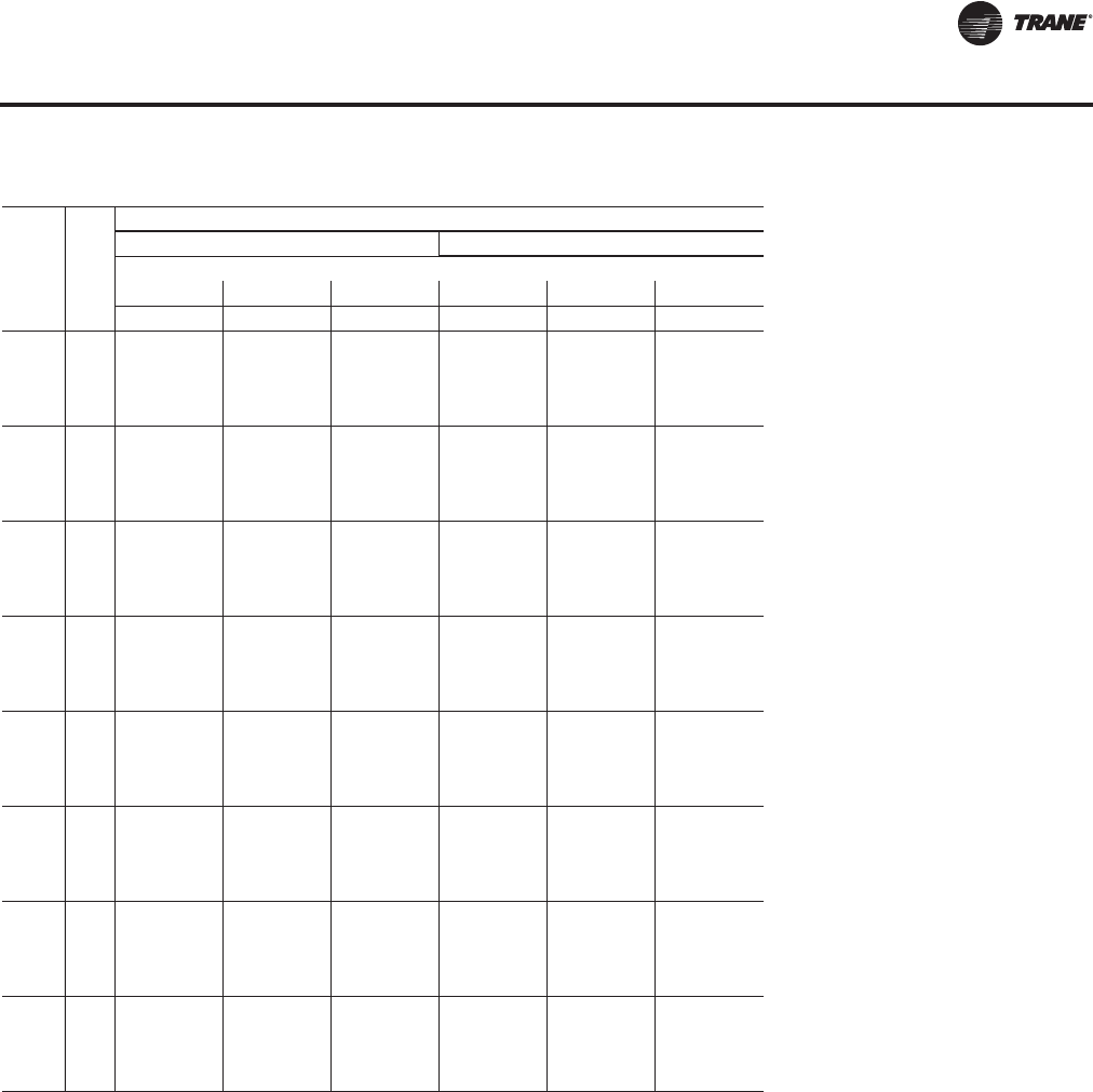
RT-PRC027T-EN 107
Performance Data
Air
Flow
CFM
Ent
DB
(°F)
Ambient Temperature WB
75 80
Entering Wet Bulb
61 67 73 61 67 73
CAP SHC CAP SHC CAP SHC CAP SHC CAP SHC CAP SHC
21000
75 1316 970 1455 829 1608 687 1298 959 1434 818 1584 676
80 1321 1092 1462 951 1614 808 1302 1081 1441 940 1591 797
85 1324 1208 1467 1072 1621 929 1306 1197 1447 1061 1598 918
90 1327 1325 1472 1193 2740 2214 1309 1309 1451 1181 1604 1038
26000
75 1397 1069 1540 892 1686 708 1376 1057 1516 879 1658 696
80 1451 1237 1549 1042 1701 861 1377 1198 1526 1030 1676 851
85 1415 1360 1556 1191 1712 1011 1395 1348 1532 1179 1686 999
90 1379 1379 1559 1332 1724 1162 1413 1413 1532 1318 2653 2135
31000
75 1449 1152 1601 949 1735 724 1427 1139 1576 936 1704 711
80 1466 1326 1612 1126 1764 910 1444 1313 1587 1114 1736 898
85 1495 1495 1615 1293 1778 1088 1475 1475 1590 1280 1750 1076
90 1524 1524 1631 1465 1786 1262 1507 1507 1606 1452 1759 1249
36000
75 1497 1232 1647 1001 1765 736 1473 1218 1620 988 1732 722
80 1519 1435 1648 1196 1796 948 1496 1421 1622 1182 1782 943
85 1576 1576 1668 1393 1827 1160 1556 1555 1641 1379 1798 1147
90 1634 1634 1689 1594 1827 1350 1638 1637 1663 1580 1798 1337
41000
75 1536 1308 1658 1040 1782 745 1511 1294 1630 1026 1748 743
80 1566 1541 1688 1264 1847 998 1542 1527 1660 1249 1816 985
85 1645 1645 1710 1489 1848 1218 1622 1622 1683 1475 1818 1204
90 1724 1724 1741 1720 1871 1439 1703 1703 1715 1706 1838 1424
46000
75 1568 1382 1687 1078 1792 753 1542 1367 1657 1063 1757 752
80 1611 1611 1720 1329 1837 1015 1588 1588 1691 1313 1922 1059
85 1703 1702 1747 1584 1881 1276 1679 1678 1718 1569 1850 1261
90 1795 1795 1794 1794 1907 1525 1769 1769 1770 1770 1876 1510
51000
75 1596 1453 1710 1113 1798 761 1569 1438 1679 1097 1879 791
80 1657 1657 1746 1391 1899 1082 1633 1632 1717 1375 1868 1066
85 1752 1752 1779 1676 1908 1331 1727 1726 1750 1661 1876 1316
90 1849 1848 1848 1848 1936 1609 1823 1823 1823 1822 1905 1594
54000
75 1611 1495 1722 1133 1925 811 1584 1480 1691 1116 1775 769
80 1681 1681 1760 1428 1912 1103 1656 1656 1731 1412 1880 1091
85 1779 1778 1796 1731 1922 1363 1753 1753 1768 1716 1890 1348
90 1877 1877 1877 1876 1952 1659 1852 1852 1851 1850 1921 1644
Table 29. Gross cooling capacities—128 tons—high capacity evaporator coil (continued)
Evaporative Condensing 60 Hz Gross Cooling Capacities—High Capacity Evaporator Coils
RT-PRC027.book Page 107 Tuesday, October 7, 2014 9:03 AM

108 RT-PRC027T-EN
Performance Data
Table 30. Gross cooling capacities—140 tons—high capacity evaporator coil
Air
Flow
CFM
Ent
DB
(°F)
Ambient Temperature WB
60 65 70
Entering Wet Bulb
61 67 73 61 67 73 61 67 73
CAP SHC CAP SHC CAP SHC CAP SHC CAP SHC CAP SHC CAP SHC CAP SHC CAP SHC
21000
75 1455 1016 1610 907 1784 764 1438 1038 1591 897 1762 754 1417 1025 1569 883 1737 741
80 1459 1172 1616 1030 1785 885 1442 1161 1597 1020 1764 875 1422 1148 1566 1002 1739 861
85 1464 1295 1620 1152 1791 1007 1443 1281 1602 1142 1770 997 1422 1267 1575 1126 1746 984
90 1468 1418 1624 1274 2820 2284 1443 1400 1606 1263 2816 2277 1423 1386 1584 1250 2807 2251
26000
75 1553 1154 1713 975 1886 794 1534 1142 1692 965 1862 782 1511 1129 1667 950 1834 769
80 1614 1334 1721 1127 1894 946 1537 1292 1700 1115 1870 935 1518 1276 1676 1102 1839 918
85 1566 1449 1727 1276 1902 1094 1547 1437 1706 1265 1879 1084 1525 1423 1682 1251 1852 1070
90 1518 1518 1734 1425 2744 2197 1557 1557 1713 1414 1886 1232 1532 1532 1688 1400 1859 1218
31000
75 1626 1249 1788 1036 1956 815 1605 1238 1733 1009 1930 803 1581 1224 1739 1009 1899 788
80 1632 1420 1798 1214 1971 995 1611 1407 1776 1202 1947 986 1587 1393 1749 1188 1917 970
85 1651 1597 1806 1391 1983 1174 1632 1585 1819 1395 1958 1162 1608 1570 1757 1365 1929 1148
90 1671 1671 1812 1559 1991 1349 1652 1652 1790 1547 1967 1337 1629 1629 1764 1532 1942 1326
36000
75 1675 1330 1845 1090 2004 831 1653 1318 1822 1078 1976 818 1628 1302 1793 1063 1942 803
80 1694 1532 1857 1295 2030 1042 1673 1520 1833 1283 2004 1032 1648 1504 1805 1269 1973 1016
85 1729 1729 1861 1491 2044 1248 1709 1709 1837 1478 2018 1236 1687 1687 1810 1463 1988 1222
90 1763 1763 1880 1691 2054 1450 1746 1746 1857 1678 2027 1437 1727 1727 1829 1662 1997 1423
41000
75 1722 1410 1890 1141 2037 843 1699 1397 1865 1129 2007 830 1672 1381 1835 1115 1972 815
80 1747 1641 1891 1366 2076 1087 1725 1628 1866 1352 2049 1075 1698 1612 1837 1337 2016 1060
85 1807 1807 1912 1590 2092 1319 1788 1788 1888 1577 2065 1307 1764 1764 1859 1561 2033 1292
90 1868 1868 1937 1818 2094 1539 1851 1851 1913 1805 2065 1525 1830 1830 1885 1789 2033 1509
46000
75 1760 1486 1925 1190 2059 853 1737 1473 1899 1178 2027 840 1709 1456 1868 1163 1991 824
80 1793 1747 1931 1434 2112 1129 1770 1734 1905 1420 2084 1117 1744 1718 1875 1404 2051 1102
85 1875 1875 1955 1687 2129 1387 1855 1854 1930 1673 2101 1375 1830 1829 1901 1657 2068 1360
90 1958 1958 1989 1945 2137 1627 1939 1939 1965 1931 2109 1614 1916 1916 1936 1915 2077 1598
51000
75 1793 1558 1932 1226 2074 862 1769 1544 1905 1211 2041 849 1741 1527 1874 1194 2003 833
80 1835 1835 1964 1499 2142 1170 1812 1811 1937 1485 2112 1158 1786 1786 1907 1468 2078 1143
85 1934 1934 1993 1781 2146 1439 1912 1912 1967 1768 2117 1425 1886 1886 1936 1751 2084 1408
90 2037 2037 2036 2036 2173 1714 2013 2013 2013 2013 2145 1700 1986 1986 1987 1986 2111 1684
54000
75 1811 1601 1947 1248 2080 868 1787 1586 1920 1234 2046 854 1758 1569 1888 1216 2008 838
80 1862 1862 1981 1537 2156 1194 1840 1840 1954 1523 2127 1182 1814 1814 1923 1506 2092 1167
85 1966 1966 2013 1838 2163 1473 1943 1943 1987 1824 2134 1459 1916 1916 1956 1807 2100 1442
90 2069 2069 2070 2070 2192 1765 2047 2047 2047 2047 2163 1751 2019 2018 2019 2019 2130 1734
58000
75 1832 1656 1965 1277 2086 874 1808 1642 1938 1262 2052 860 1778 1624 1905 1244 2013 844
80 1897 1897 2002 1587 2173 1225 1874 1874 1975 1573 2143 1213 1848 1847 1943 1555 2107 1198
85 2004 2004 2038 1912 2184 1518 1981 1981 2011 1897 2155 1503 1953 1953 1980 1880 2120 1486
90 2111 2111 2111 2111 2215 1833 2088 2088 2087 2087 2186 1819 2064 2064 2059 2058 2152 1802
Evaporative Condensing 60 Hz Gross Cooling Capacities—High Capacity Evaporator Coils
RT-PRC027.book Page 108 Tuesday, October 7, 2014 9:03 AM

RT-PRC027T-EN 109
Performance Data
Air
Flow
CFM
Ent
DB
(°F)
Ambient Temperature WB
75 80
Entering Wet Bulb
61 67 73 61 67 73
CAP SHC CAP SHC CAP SHC CAP SHC CAP SHC CAP SHC
21000
75 1397 1013 1547 872 1712 728 1378 1002 1524 859 1687 718
80 1402 1136 1553 995 1714 849 1382 1124 1531 983 1689 838
85 1403 1254 1558 1116 1722 971 1384 1242 1536 1104 1697 959
90 1404 1373 1562 1237 2793 2236 1385 1361 1540 1225 2775 2234
26000
75 1489 1116 1643 938 1806 755 1467 1104 1618 925 1777 742
80 1546 1291 1651 1089 1815 906 1475 1250 1627 1076 1788 894
85 1503 1409 1671 1244 1825 1057 1482 1396 1633 1225 1798 1045
90 1461 1461 1691 1399 1835 1207 1489 1489 1639 1374 1809 1195
31000
75 1557 1210 1712 996 1868 774 1533 1197 1686 984 1837 761
80 1629 1409 1723 1175 1888 956 1540 1364 1696 1161 1859 944
85 1586 1556 1730 1351 1900 1135 1563 1543 1770 1363 1871 1122
90 1542 1542 1738 1517 1909 1309 1586 1586 1784 1534 1884 1300
36000
75 1603 1287 1765 1050 1909 789 1577 1273 1737 1037 1876 782
80 1623 1489 1777 1255 1942 1003 1598 1475 1749 1242 1912 990
85 1665 1665 1779 1446 1957 1208 1643 1643 1755 1433 1926 1195
90 1708 1708 1802 1647 1966 1409 1689 1689 1775 1633 1937 1396
41000
75 1646 1365 1806 1100 1936 800 1619 1350 1776 1087 1901 794
80 1673 1597 1809 1321 1984 1046 1646 1582 1780 1306 1952 1033
85 1741 1741 1831 1546 2001 1278 1718 1717 1802 1531 1969 1265
90 1809 1809 1857 1774 2002 1494 1789 1789 1830 1759 1973 1480
46000
75 1682 1441 1838 1149 1954 809 1655 1425 1784 1125 1916 805
80 1717 1702 1845 1388 2018 1089 1691 1686 1816 1372 1984 1075
85 1805 1805 1871 1641 2020 1336 1781 1780 1842 1626 1986 1320
90 1893 1893 1908 1899 2045 1582 1870 1870 1880 1880 2012 1567
51000
75 1713 1514 1842 1178 1966 824 1684 1497 1811 1161 1926 815
80 1761 1761 1876 1452 2044 1129 1736 1736 1845 1436 2009 1115
85 1860 1860 1906 1735 2051 1392 1835 1834 1876 1719 2017 1376
90 1959 1959 1960 1959 2079 1668 1846 1846 1934 1933 2045 1652
54000
75 1729 1557 1856 1199 1970 823 1700 1540 1824 1183 1930 820
80 1788 1788 1892 1489 2057 1153 1763 1762 1861 1473 2021 1139
85 1890 1889 1925 1790 2067 1426 1864 1863 1895 1774 2032 1409
90 1991 1991 1993 1992 2097 1719 1966 1966 1965 1964 2062 1702
58000
75 1750 1613 1873 1227 1975 829 1721 1597 1840 1210 1934 827
80 1821 1821 1911 1538 2072 1184 1795 1794 1880 1522 2006 1147
85 1926 1925 1949 1863 2086 1469 1898 1898 1919 1847 2051 1452
90 2030 2029 2031 2031 2119 1786 2002 2001 2003 2002 2084 1769
Table 30. Gross cooling capacities—140 tons—high capacity evaporator coil (continued)
Evaporative Condensing 60 Hz Gross Cooling Capacities—High Capacity Evaporator Coils
RT-PRC027.book Page 109 Tuesday, October 7, 2014 9:03 AM

110 RT-PRC027T-EN
Performance Data
Table 31. Gross cooling capacities—162 tons—standard capacity evaporator coil
Air
Flow
CFM
Ent
DB
(°F)
Ambient Temperature WB
60 65 70
Entering Wet Bulb
61 67 73 61 67 73 61 67 73
CAP SHC CAP SHC CAP SHC CAP SHC CAP SHC CAP SHC CAP SHC CAP SHC CAP SHC
21000
75 1535 1065 1700 967 1884 827 1517 1094 1680 955 1862 817 1496 1081 1657 942 1836 802
80 1539 1229 1705 1090 1885 948 1522 1218 1679 1076 1864 938 1501 1204 1662 1065 1838 923
85 1544 1353 1709 1213 1890 1070 1526 1341 1680 1197 1869 1059 1505 1327 1667 1187 1843 1045
90 1548 1476 1707 1331 1894 1192 1530 1464 1680 1318 2920 2370 1509 1451 1671 1309 1910 1199
26000
75 1643 1215 1809 1037 1998 861 1623 1203 1790 1027 1974 849 1600 1189 1764 1012 1944 834
80 1649 1367 1820 1190 2004 1012 1629 1355 1798 1178 1980 998 1633 1356 1773 1164 1951 984
85 1654 1512 1901 1382 2011 1161 1635 1499 1804 1328 1988 1149 1612 1484 1850 1353 1959 1134
90 1659 1657 1832 1490 2018 1310 1640 1640 1811 1478 2077 1339 1590 1590 1785 1463 1967 1283
31000
75 1723 1314 1895 1101 2078 885 1702 1301 1872 1089 2051 872 1676 1286 1843 1074 2019 857
80 1727 1486 1905 1280 2089 1064 1710 1481 1882 1268 2064 1052 1681 1457 1854 1253 2033 1037
85 1746 1663 2003 1507 2101 1243 1725 1650 1977 1493 2075 1231 1700 1635 1947 1476 2045 1216
90 1764 1764 1917 1629 2211 1468 1740 1740 1894 1616 2084 1406 1719 1719 1867 1600 2150 1438
36000
75 1776 1399 1958 1158 2134 903 1753 1386 1933 1146 2105 890 1727 1369 1904 1130 2071 874
80 1795 1601 1970 1364 2155 1113 1773 1587 1945 1352 2127 1101 1746 1571 1916 1336 2095 1085
85 1825 1810 1972 1563 2169 1319 1803 1797 2048 1592 2142 1306 1779 1779 1919 1533 2109 1291
90 1908 1908 1991 1763 2178 1521 1834 1834 1966 1749 2151 1509 1811 1811 1938 1732 2119 1493
41000
75 1827 1481 2008 1211 2174 918 1804 1467 1982 1198 2144 904 1776 1450 1951 1183 2107 888
80 1852 1712 2020 1444 2206 1159 1828 1698 1995 1431 2177 1146 1801 1681 1964 1416 2144 1131
85 1904 1904 2028 1664 2221 1392 1883 1883 2003 1650 2193 1379 1859 1859 1973 1633 2160 1363
90 1956 1956 2053 1892 2231 1621 1981 1981 2028 1878 2203 1608 1917 1917 1998 1862 2170 1592
46000
75 1870 1559 2047 1261 2203 930 1845 1545 2020 1248 2170 916 1816 1528 1988 1232 2132 899
80 1901 1820 2051 1510 2247 1203 1877 1805 2024 1495 2217 1190 1849 1788 1993 1478 2182 1174
85 1977 1977 2076 1763 2264 1462 1956 1956 2049 1748 2234 1449 1930 1930 2018 1731 2199 1433
90 2054 2054 2107 2020 2265 1705 2034 2034 2081 2006 2236 1691 2011 2011 2051 1988 2202 1673
51000
75 1906 1632 2079 1309 2223 940 1881 1620 2051 1296 2189 926 1851 1600 1995 1271 2149 909
80 1946 1926 2087 1577 2280 1245 1921 1911 2060 1562 2250 1232 1893 1893 2027 1544 2213 1216
85 2041 2041 2116 1859 2282 1520 2018 2018 2089 1844 2251 1505 1991 1991 2057 1826 2216 1487
90 2136 2136 2158 2146 2308 1794 2115 2115 2132 2131 2279 1780 2089 2089 2102 2102 2244 1762
54000
75 1925 1676 2073 1328 2232 946 1899 1661 2045 1313 2197 932 1869 1643 2011 1294 2157 914
80 1970 1970 2106 1616 2297 1269 1944 1944 2078 1601 2266 1256 1917 1917 2046 1583 2229 1240
85 2075 2075 2138 1916 2301 1555 2052 2052 2110 1901 2270 1540 2024 2024 2078 1883 2234 1522
90 2185 2185 2184 2184 2329 1846 2159 2159 2160 2160 2299 1832 2131 2130 2131 2131 2264 1813
58000
75 1948 1733 2094 1358 2241 953 1922 1717 2065 1343 2206 939 1892 1699 2031 1324 2164 921
80 2005 2005 2129 1667 2316 1301 1982 1982 2101 1652 2285 1288 1954 1954 2067 1633 2247 1272
85 2117 2117 2164 1991 2324 1600 2093 2092 2137 1975 2293 1585 2064 2063 2104 1957 2256 1567
90 2228 2228 2229 2229 2355 1915 2203 2203 2204 2204 2324 1900 2174 2173 2174 2174 2288 1882
Evaporative Condensing 60 Hz Gross Cooling Capacities—Standard Capacity Evaporator Coils
RT-PRC027.book Page 110 Tuesday, October 7, 2014 9:03 AM
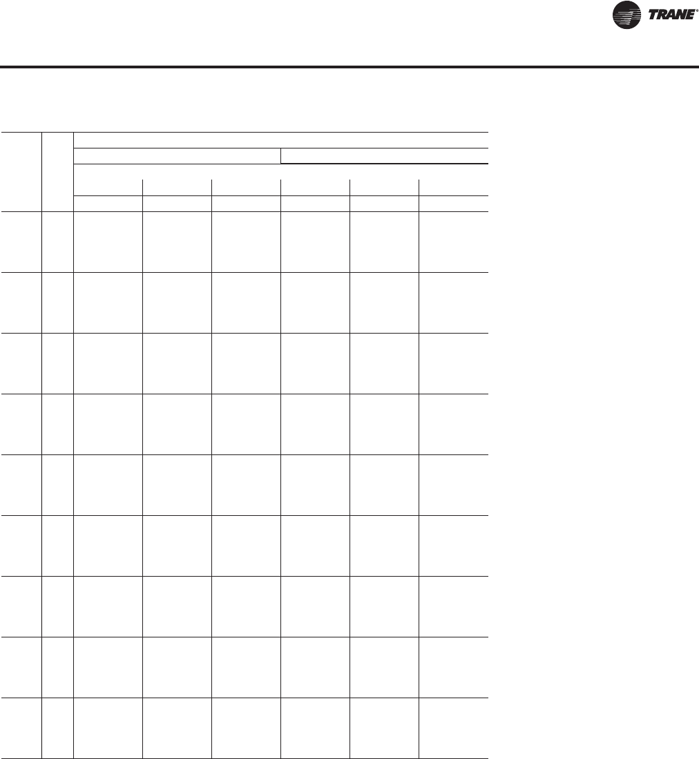
RT-PRC027T-EN 111
Performance Data
Air
Flow
CFM
Ent
DB
(°F)
Ambient Temperature WB
75 80
Entering Wet Bulb
61 67 73 61 67 73
CAP SHC CAP SHC CAP SHC CAP SHC CAP SHC CAP SHC
21000
75 1476 1068 1634 929 1810 788 1455 1056 1611 917 1785 778
80 1480 1191 1640 1052 1812 909 1460 1179 1617 1039 1787 898
85 1485 1314 1645 1174 1818 1032 1463 1301 1621 1161 1793 1020
90 1489 1437 1649 1296 2898 2329 1466 1423 1626 1283 1857 1171
26000
75 1577 1175 1739 998 1915 820 1554 1162 1713 985 1886 809
80 1610 1341 1747 1150 1923 970 1560 1309 1721 1136 1894 957
85 1589 1470 1754 1300 1931 1121 1566 1456 1728 1286 1904 1108
90 1568 1568 1760 1449 1939 1269 1573 1573 1733 1434 1987 1293
31000
75 1651 1272 1816 1059 1987 842 1626 1258 1788 1046 1955 832
80 1656 1442 1826 1239 2002 1023 1631 1427 1799 1225 1973 1009
85 1676 1619 1907 1451 2014 1201 1652 1605 1806 1401 1984 1187
90 1696 1696 1840 1584 2023 1376 1672 1672 1893 1605 2085 1408
36000
75 1700 1354 1874 1115 2037 859 1673 1338 1845 1101 2002 849
80 1720 1555 1886 1321 2064 1071 1733 1557 1857 1307 2031 1057
85 1754 1754 1887 1516 2078 1277 1730 1730 1860 1501 2045 1262
90 1789 1789 1909 1716 2088 1479 1727 1727 1881 1701 2056 1464
41000
75 1748 1434 1920 1168 2071 872 1720 1417 1889 1153 2033 864
80 1774 1665 1933 1401 2111 1117 1747 1649 1903 1386 2076 1101
85 1835 1834 1943 1617 2127 1348 1811 1810 1913 1601 2092 1333
90 1896 1896 1968 1845 2137 1577 1875 1875 1939 1829 2158 1576
46000
75 1788 1511 1956 1217 2095 883 1759 1494 1924 1202 2055 876
80 1821 1771 1961 1461 2148 1160 1793 1755 1930 1445 2112 1144
85 1904 1904 1987 1714 2165 1418 1879 1878 1956 1698 2130 1403
90 2005 2004 2021 1972 2168 1657 1964 1964 1991 1956 2137 1641
51000
75 1821 1585 1962 1254 2110 897 1792 1569 1929 1237 2069 886
80 1865 1865 1995 1527 2178 1201 1837 1837 1963 1510 2141 1186
85 1964 1964 2026 1809 2181 1471 1937 1937 1993 1792 2145 1453
90 2063 2062 2072 2072 2209 1745 2038 2037 2040 2040 2173 1728
54000
75 1839 1629 1978 1276 2117 908 1810 1612 1944 1259 2075 892
80 1890 1890 2013 1566 2193 1225 1864 1863 1980 1548 2155 1209
85 1997 1997 2046 1866 2199 1505 1969 1968 2013 1848 2162 1487
90 2104 2104 2103 2103 2229 1797 2074 2073 2075 2075 2192 1779
58000
75 1861 1687 1997 1306 2124 916 1831 1670 1962 1288 2081 900
80 1926 1926 2035 1616 2211 1256 1899 1898 2001 1598 2172 1241
85 2036 2036 2072 1940 2221 1549 2007 2006 2038 1922 2183 1531
90 2145 2145 2146 2145 2253 1865 2117 2116 2116 2116 2217 1847
Table 31. Gross cooling capacities—162 tons—standard capacity evaporator coil (continued)
Evaporative Condensing 60 Hz Gross Cooling Capacities—Standard Capacity Evaporator Coils
RT-PRC027.book Page 111 Tuesday, October 7, 2014 9:03 AM
11 2 RT-PRC027T-EN
Performance Data
Supply Fan (with or without Variable Frequency Drive)
Table 32. Supply fan performance LOW CFM—90 tons air-cooled/100 tons evap-condensing (25")
CFM Total Static Pressure
Std. 0.25 0.50 0.75 1.00 1.25 1.50 1.75 2.00
Air rpm bhp rpm bhp rpm bhp rpm bhp rpm bhp rpm bhp rpm bhp rpm bhp
16000 1030(a) 6.16 1062 6.81 1095 7.52 1126 8.14 1152 8.58 1177 9.05 1205 9.67 1234 10.38
17000 1090 7.30 1121 7.99 1152 8.74 1182 9.46 1208 9.98 1232 10.47 1256 10.99 1282 11.66
18000 1151 8.57 1180 9.31 1209 10.07 1238 10.86 1265 11.57 1288 12.05 1311 12.57 1333 13.13
19000 1211 9.99 1239 10.77 1266 11.55 1294 12.41 1321 13.20 1345 13.82 1367 14.34 1388 14.89
20000 1272 11.57 1299 12.39 1325 13.20 1351 14.08 1377 14.96 1402 15.76 1423 16.31 1444 16.87
21000 1333 13.30 1359 14.16 1383 15.02 1408 15.91 1433 16.85 1458 17.74 1480 18.48 1500 19.04
22000 1394 15.21 1419 16.11 1443 17.01 1466 17.90 1490 18.90 1513 19.85 1536 20.76 1556 21.42
23000 1455 17.28 1479 18.23 1502 19.17 1524 20.11 1547 21.12 1570 22.14 1592 23.11 1613 24.02
24000 1516 19.55 1539 20.54 1561 21.52 1583 22.49 1604 23.50 1626 24.58 1648 25.64 1669 26.63
25000 1578 22.01 1600 23.04 1621 24.07 1642 25.09 1662 26.09 1683 27.22 1705 28.33 1725 29.42
26000 1639 24.67 1660 25.74 1681 26.81 1701 27.87 1721 28.93 1741 30.04 1762 31.22 1781 32.36
27000 1701 27.54 1721 28.66 1741 29.77 1760 30.88 1780 31.97 1798 33.06 1818 34.29 1838 35.51
28000 1762 30.62 1782 31.78 1801 32.94 1820 34.09 1838 35.22 1857 36.35 1876 37.58 1895 38.83
29000 1824 33.94 1843 35.14 1861 36.34 1880 37.53 1898 38.71 1915 39.88 1933 41.08 1952 42.41
30000 1885 37.48 1904 38.73 1922 39.96 1939 41.19 1957 42.42 1974 43.64 1991 44.86 2009 46.19
31000 1947 41.27 1965 42.56 1982 43.83 2000 45.11
CFM Total Static Pressure
Std. 2.25 2.50 2.75 3.00 3.25 3.50 3.75 4.00
Air rpm bhp rpm bhp rpm bhp rpm bhp rpm bhp rpm bhp rpm bhp rpm bhp
16000 1262(a) 11.09 1289 11.80 1315 12.50 1341 13.22 1366 13.95 1391 14.67 1415 15.41 1438 16.13
17000 1309 12.40 1337 13.18 1362 13.92 1388 14.68 1412 15.45 1435 16.20 1459 17.00 1481 17.74
18000 1359 13.87 1385 14.67 1410 15.48 1435 16.28 1459 17.08 1481 17.86 1505 18.68 1527 19.49
19000 1410 15.51 1433 16.28 1458 17.13 1482 17.97 1506 18.84 1528 19.65 1551 20.50 1573 21.36
20000 1464 17.45 1484 18.09 1507 18.92 1530 19.80 1554 20.70 1577 21.62 1599 22.50 1619 23.34
21000 1519 19.63 1539 20.26 1558 20.94 1579 21.79 1602 22.73 1623 23.63 1645 24.58 1667 25.53
22000 1576 22.03 1594 22.65 1612 23.31 1631 24.00 1652 24.92 1672 25.86 1694 26.83 1714 27.80
23000 1632 24.63 1650 25.27 1668 25.93 1685 26.61 1703 27.34 1722 28.23 1742 29.23 1763 30.28
24000 1688 27.48 1706 28.13 1724 28.79 1740 29.47 1757 30.19 1775 30.97 1792 31.86 1811 32.87
25000 1745 30.41 1763 31.23 1780 31.89 1796 32.59 1813 33.31 1828 34.03 1845 34.85 1863 35.76
26000 1801 33.44 1820 34.48 1836 35.23 1853 35.94 1868 36.66 1884 37.41 1899 38.16 1916 39.02
27000 1857 36.66 1876 37.79 1893 38.83 1909 39.58 1925 40.30 1940 41.05 1956 41.84 1970 42.62
28000 1913 40.07 1931 41.26 1949 42.42 1967 43.48 1982 44.22 1996 44.95
29000 1970 43.70 1987 44.93 2005 46.18
CFM Total Static Pressure
Std. 4.25 4.50 4.75 5.00 5.25 5.50 5.75 6.00
Air rpm bhp rpm bhp rpm bhp rpm bhp rpm bhp rpm bhp rpm bhp rpm bhp
16000 1461 16.88 1484 17.60 1508 18.39 1530 19.15 1551 19.86 1575 20.69 1598 21.47 1620 22.29
17000 1504 18.52 1527 19.34 1549 20.13 1569 20.86 1591 21.67 1613 22.46 1633 23.25 1656 24.12
18000 1548 20.29 1571 21.14 1591 21.94 1613 22.78 1633 23.61 1655 24.47 1674 25.26 1694 26.08
19000 1595 22.23 1615 23.05 1636 23.91 1656 24.77 1676 25.66 1698 26.58 1717 27.44 1737 28.32
20000 1640 24.22 1661 25.15 1681 26.02 1701 26.94 1722 27.89 1741 28.77 1760 29.69 1779 30.64
21000 1687 26.43 1707 27.37 1727 28.31 1746 29.23 1766 30.18 1786 31.18 1804 32.10 1823 33.05
22000 1736 28.82 1755 29.78 1774 30.73 1793 31.71 1813 32.73 1831 33.67 1849 34.64 1867 35.65
23000 1782 31.26 1803 32.35 1822 33.35 1841 34.34 1859 35.37 1878 36.43 1895 37.40 1913 38.40
24000 1831 33.92 1851 35.02 1869 36.03 1889 37.15 1908 38.24 1926 39.31 1943 40.33 1960 41.39
25000 1880 36.77 1899 37.87 1918 38.96 1936 40.08 1954 41.17 1973 42.37 1991 43.46 2007 44.51
26000 1932 39.88 1949 40.93 1967 42.08 1985 43.21 2003 44.37
27000 1985 43.44 2000 44.30
Continued on next page
RT-PRC027.book Page 112 Tuesday, October 7, 2014 9:03 AM
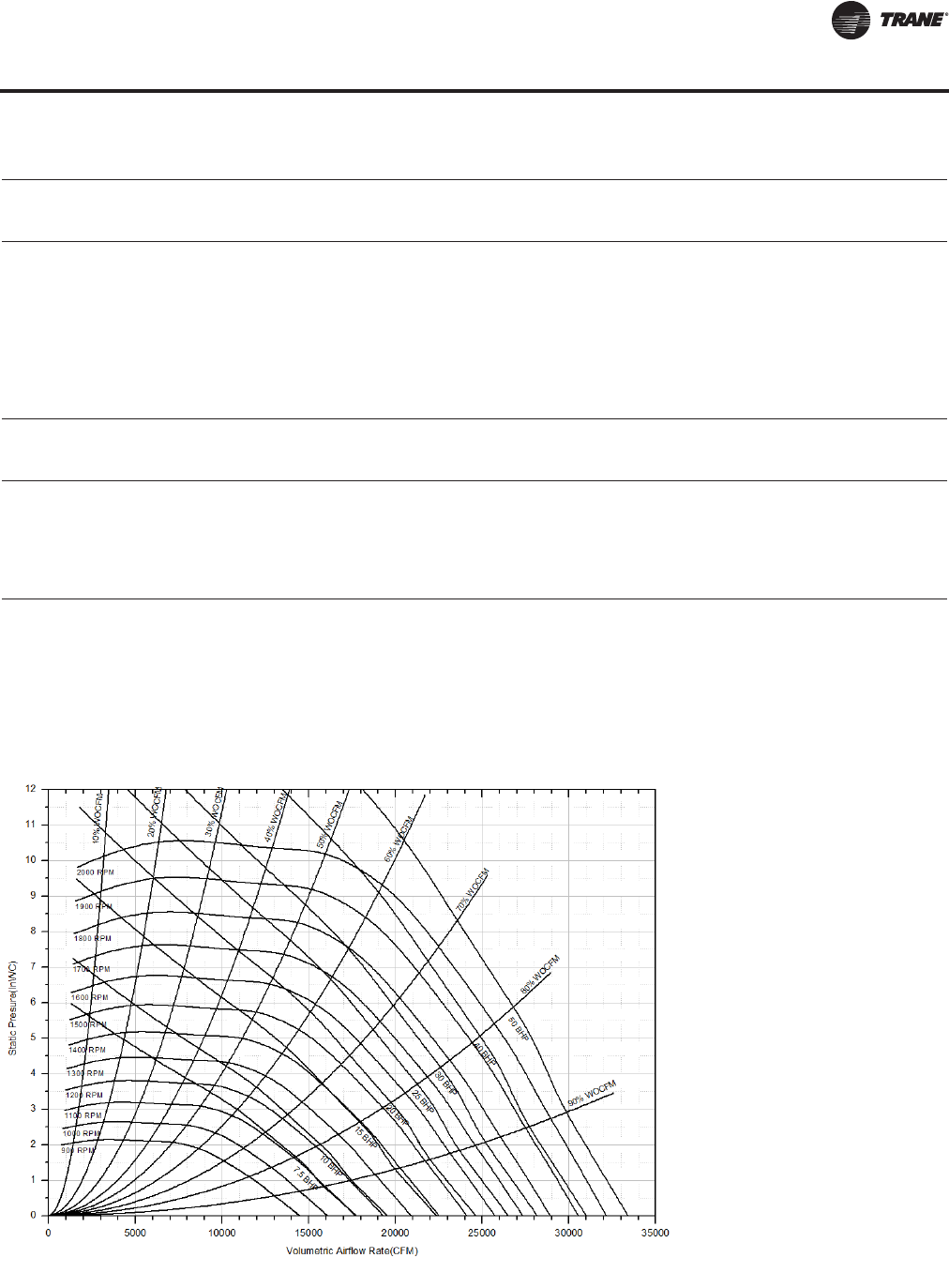
RT-PRC027T-EN 11 3
Performance Data
CFM Total Static Pressure
Std. 6.25 6.50 6.75 7.00 7.25 7.50 7.75 8.00
Air rpm bhp rpm bhp rpm bhp rpm bhp rpm bhp rpm bhp rpm bhp rpm bhp
16000 1644 23.14 1665 23.93 1687 24.77 1710 25.65 1733 26.56 1754 27.40 1776 28.28 1798 29.18
17000 1676 24.92 1697 25.75 1719 26.62 1741 27.52 1762 28.41 1784 29.33 1805 30.23 1826 31.17
18000 1714 26.94 1735 27.82 1755 28.69 1775 29.58 1794 30.44 1814 31.34 1835 32.27 1855 33.23
19000 1755 29.18 1775 30.07 1793 30.92 1812 31.81 1831 32.72 1851 33.67 1871 34.65 1888 35.51
20000 1797 31.50 1816 32.45 1836 33.43 1853 34.30 1871 35.21 1890 36.21 1907 37.10 1925 38.01
21000 1841 34.03 1859 34.98 1878 35.96 1895 36.90 1914 37.94 1930 38.85 1947 39.79 1964 40.76
22000 1886 36.69 1904 37.71 1921 38.67 1938 39.67 1956 40.70 1974 41.76 1991 42.76 2008 43.79
23000 1930 39.43 1948 40.50 1967 41.61 1983 42.58 2000 43.68
24000 1978 42.49 1995 43.54
CFM Total Static Pressure
Std. 8.25 8.50 8.75 9.00
Air rpm bhp rpm bhp rpm bhp rpm bhp
16000 1820 30.13 1843 31.11 1863 31.99 1887 33.04
17000 1846 32.07 1867 33.02 1887 33.92 1910 35.00
18000 1877 34.22 1895 35.11 1914 36.04 1935 37.08
19000 1909 36.55 1927 37.47 1946 38.43 1965 39.41
20000 1944 39.03 1962 40.00 1980 40.99 1997 41.93
21000 1982 41.75 2000 42.77
Notes:
1. Supply fan performance table includes internal resistance of rooftop. For total static pressure determination, system external static pressure must be
added to appropriate component sp drops (evap coil, filters, optional economizer, optional heating system).
2. Maximum SP leaving the rooftop is 5.5" H20 positive.
3. Max CFM allowable CFM is 31000
4. Max rpm 2000, Max hp 50
5. Min rpm 1400, Min hp 15
(a)Outlined area indicates nonstandard bhp or rpm selections. Contact a local Trane representative for more information.
Table 32. Supply fan performance LOW CFM—90 tons air-cooled/100 tons evap-condensing (25") (continued)
Figure 27. Supply fan performance LOW CFM — 90 tons air-cooled/100 tons evap-condensing (25")
Supply Fan (with or without Variable Frequency Drive)
RT-PRC027.book Page 113 Tuesday, October 7, 2014 9:03 AM
114 RT-PRC027T-EN
Performance Data
Table 33. Supply fan performance STANDARD CFM—90-105 tons air-cool/100-118 tons evap-condensing (36")
CFM Total Static Pressure
Std. 0.25 0.50 0.75 1.00 1.25 1.50 1.75 2.00
Air rpm bhp rpm bhp rpm bhp rpm bhp rpm bhp rpm bhp rpm bhp rpm bhp
20000 490(a) 3.76 520 4.39 552 5.19 583 6.08 611 6.98 638 7.91 664 8.81 690 9.77
21000 511 4.26 541 4.95 570 5.72 600 6.66 628 7.59 655 8.56 680 9.51 704 10.49
22000 532 4.80 561 5.57 588 6.30 618 7.28 645 8.26 671 9.24 696 10.24 720 11.28
23000 553 5.39 582 6.25 607 6.94 636 7.93 662 8.95 688 9.98 712 11.03 736 12.09
24000 574 6.04 603 6.99 627 7.68 654 8.63 680 9.71 705 10.76 729 11.86 752 12.94
25000 595 6.73 624 7.78 648 8.48 672 9.38 698 10.50 722 11.60 746 12.72 768 13.87
26000 617 7.47 645 8.59 668 9.35 691 10.20 716 11.32 740 12.50 763 13.63 785 14.79
27000 638 8.27 666 9.45 689 10.29 710 11.11 733 12.20 758 13.43 780 14.61 802 15.81
28000 660 9.14 686 10.36 710 11.30 730 12.12 752 13.15 776 14.41 798 15.67 819 16.90
29000 682 10.07 707 11.34 730 12.39 750 13.20 771 14.17 793 15.44 816 16.74 836 18.01
30000 704 11.07 728 12.37 752 13.56 771 14.37 790 15.29 812 16.54 834 17.89 854 19.20
31000 726 12.13 749 13.46 772 14.76 792 15.62 810 16.54 830 17.70 851 19.06 872 20.44
32000 748 13.25 771 14.63 793 15.99 812 16.95 830 17.86 849 18.95 869 20.32 890 21.74
33000 770 14.45 792 15.85 814 17.28 833 18.36 851 19.28 868 20.30 888 21.64 907 23.07
34000 791 15.72 813 17.15 835 18.63 854 19.86 872 20.79 888 21.80 906 23.04 925 24.50
35000 813 17.06 834 18.52 856 20.06 875 21.44 892 22.39 909 23.40 925 24.54 944 26.00
36000 836 18.48 856 19.97 877 21.56 896 23.05 913 24.07 929 25.08 945 26.18 962 27.58
37000 858 19.98 877 21.49 898 23.14 917 24.69 934 25.86 950 26.87 965 27.97 981 29.24
38000 880 21.56 899 23.09 919 24.79 938 26.41 955 27.73 970 28.76 986 29.87 1001 31.06
39000 902 23.22 921 24.80 940 26.52 958 28.21 976 29.69 991 30.74 1006 31.85 1021 33.04
40000 924 24.96 942 26.58 961 28.33 979 30.09 997 31.71 1012 32.83 1026 33.95 1041 35.13
41000 946 26.80 964 28.47 982 30.24 1000 32.04 1017 33.73 1033 35.02 1047 36.13 1061 37.31
42000 968 28.72 986 30.43 1003 32.22 1021 34.10 1038 35.86 1054 37.33 1068 38.44 1081 39.61
43000 991 30.74 1008 32.49 1025 34.31 1042 36.23 1059 38.05 1075 39.73 1089 40.87 1102 42.06
44000 1013 32.85 1030 34.64 1046 36.47 1063 38.44 1080 40.35 1095 42.11 1109 43.38 1123 44.59
45000 1035 35.06 1052 36.89 1068 38.74 1084 40.74 1101 42.71 1116 44.56 1130 46.02 1144 47.25
CFM Total Static Pressure
Std. 2.25 2.50 2.75 3.00 3.25 3.50 3.75 4.00
Air rpm bhp rpm bhp rpm bhp rpm bhp rpm bhp rpm bhp rpm bhp rpm bhp
20000 715 10.76 741 11.79 766 12.86 791 13.97 816 15.14 841 16.35 865 17.52 890 18.79
21000 728 11.49 753 12.55 777 13.63 802 14.76 825 15.90 849 17.14 872 18.33 896 19.64
22000 743 12.30 767 13.37 789 14.43 813 15.60 836 16.76 858 17.96 880 19.18 904 20.52
23000 758 13.15 780 14.22 803 15.34 825 16.49 847 17.68 869 18.91 891 20.17 913 21.44
24000 774 14.04 796 15.17 817 16.29 838 17.43 860 18.66 881 19.88 901 21.12 922 22.42
25000 790 15.00 811 16.18 832 17.32 852 18.48 872 19.70 893 20.92 914 22.24 934 23.57
26000 806 15.99 827 17.20 847 18.41 867 19.60 886 20.79 906 22.07 925 23.35 946 24.71
27000 823 17.04 843 18.29 863 19.53 882 20.78 902 22.03 920 23.28 939 24.61 958 25.93
28000 839 18.13 859 19.41 879 20.71 898 21.99 916 23.26 935 24.57 953 25.86 971 27.23
29000 857 19.31 876 20.61 895 21.94 914 23.28 933 24.62 951 25.94 968 27.30 985 28.62
30000 874 20.53 894 21.89 912 23.25 931 24.61 948 25.97 966 27.36 983 28.72 1000 30.10
31000 891 21.80 910 23.19 929 24.56 947 25.99 965 27.42 983 28.88 999 30.25 1016 31.69
32000 909 23.18 928 24.60 946 25.99 964 27.43 981 28.86 998 30.33 1016 31.89 1031 33.27
33000 927 24.57 945 26.02 963 27.47 980 28.92 998 30.48 1015 31.96 1031 33.46 1048 34.97
34000 945 26.04 963 27.55 981 29.03 998 30.54 1015 32.11 1031 33.59 1048 35.15 1064 36.73
35000 962 27.52 981 29.11 998 30.65 1015 32.18 1032 33.75 1049 35.35 1064 36.91 1080 38.49
36000 980 29.13 998 30.74 1016 32.36 1033 33.96 1049 35.54 1065 37.14 1081 38.76 1097 40.40
37000 999 30.82 1016 32.46 1034 34.15 1051 35.76 1067 37.41 1083 39.01 1099 40.69 1114 42.32
38000 1017 32.54 1034 34.20 1051 35.91 1069 37.65 1084 39.30 1100 40.97 1115 42.64 1130 44.33
39000 1036 34.41 1053 36.09 1070 37.81 1086 39.57 1102 41.29 1118 43.02 1133 44.77 1148 46.52
40000 1055 36.40 1071 38.02 1087 39.75 1103 41.51 1120 43.38 1135 45.10 1151 46.92 1165 48.66
41000 1075 38.58 1090 40.05 1105 41.79 1122 43.63 1138 45.49 1153 47.29 1168 49.10 1183 50.99
Continued on next page
Supply Fan (with or without Variable Frequency Drive)
RT-PRC027.book Page 114 Tuesday, October 7, 2014 9:03 AM

RT-PRC027T-EN 11 5
Performance Data
CFM Total Static Pressure
Std. 2.25 2.50 2.75 3.00 3.25 3.50 3.75 4.00
Air rpm bhp rpm bhp rpm bhp rpm bhp rpm bhp rpm bhp rpm bhp rpm bhp
42000 1095 40.91 1109 42.26 1125 44.02 1140 45.78 1155 47.64 1171 49.60 1186 51.47 1200 53.25
43000 1116 43.31 1129 44.68 1143 46.20 1158 48.05 1174 49.99 1189 51.93 1203 53.79 1218 55.73
44000 1136 45.86 1149 47.17 1162 48.59 1177 50.44 1192 52.37 1207 54.30 1221 56.23 1236 58.25
45000 1156 48.50 1169 49.81 1182 51.24 1195 52.87 1210 54.79 1225 56.80 1239 58.80 1253 60.79
CFM Total Static Pressure
Std. 4.25 4.50 4.75 5.00 5.25 5.50 5.75 6.00
Air rpm bhp rpm bhp rpm bhp rpm bhp rpm bhp rpm bhp rpm bhp rpm bhp
20000 916 20.12 944 21.56 970 22.91 995 24.26 1019 25.60 1043 26.97 1065 28.31 1088 29.66
21000 918 20.86 943 22.25 969 23.72 995 25.19 1018 26.52 1042 27.95 1067 29.49 1089 30.84
22000 925 21.76 948 23.10 969 24.43 994 25.94 1020 27.52 1043 28.96 1067 30.50 1089 31.99
23000 934 22.77 955 24.09 976 25.44 998 26.89 1019 28.31 1043 29.91 1066 31.45 1090 33.09
24000 944 23.83 964 25.13 984 26.52 1006 28.00 1026 29.45 1045 30.84 1065 32.32 1088 33.98
25000 954 24.91 974 26.24 994 27.66 1014 29.11 1033 30.52 1053 32.08 1073 33.59 1091 35.02
26000 966 26.07 984 27.43 1004 28.88 1023 30.30 1042 31.81 1061 33.26 1080 34.80 1099 36.42
27000 978 27.34 996 28.72 1015 30.13 1034 31.65 1052 33.05 1070 34.61 1088 36.10 1107 37.75
28000 990 28.63 1008 30.06 1027 31.51 1045 32.98 1062 34.40 1081 35.99 1098 37.51 1117 39.20
29000 1003 30.02 1021 31.49 1039 32.92 1057 34.43 1074 35.88 1091 37.42 1109 39.05 1126 40.60
30000 1018 31.56 1035 32.97 1052 34.45 1070 36.01 1086 37.50 1103 39.07 1119 40.56 1137 42.22
31000 1032 33.08 1049 34.55 1066 36.09 1082 37.55 1098 39.09 1115 40.71 1131 42.23 1148 43.83
32000 1048 34.79 1064 36.25 1080 37.78 1096 39.30 1112 40.81 1129 42.48 1144 44.06 1160 45.70
33000 1064 36.49 1080 38.08 1096 39.60 1111 41.10 1126 42.68 1141 44.23 1157 45.85 1173 47.54
34000 1079 38.25 1096 39.91 1110 41.41 1126 42.97 1141 44.60 1155 46.12 1171 47.80 1187 49.55
35000 1096 40.14 1111 41.72 1126 43.37 1142 44.99 1156 46.60 1170 48.18 1186 49.92 1200 51.52
36000 1112 42.04 1127 43.68 1143 45.40 1157 47.01 1172 48.68 1186 50.31 1200 52.02 1214 53.68
37000 1129 44.03 1144 45.73 1159 47.43 1173 49.10 1188 50.84 1202 52.54 1216 54.31 1230 56.03
38000 1146 46.10 1160 47.78 1175 49.54 1189 51.28 1203 52.99 1218 54.86 1232 56.59 1246 58.37
39000 1163 48.28 1177 49.93 1191 51.75 1206 53.56 1220 55.33 1234 57.17 1247 58.96 1260 60.70
40000 1180 50.47 1194 52.28 1209 54.07 1222 55.84 1236 57.67 1249 59.47 1263 61.32 1277 63.25
41000 1197 52.78 1211 54.56 1225 56.40 1239 58.23 1253 60.13 1266 61.99 1280 63.92 1293 65.79
42000 1214 55.11 1229 57.05 1242 58.86 1256 60.75 1269 62.60 1282 64.52 1296 66.51 1309 68.44
43000 1232 57.56 1246 59.46 1260 61.45 1273 63.28 1287 65.31 1299 67.18 1313 69.24 1325 71.10
44000 1250 60.14 1263 62.12 1277 64.06 1291 66.08 1304 68.05 1316 69.98 1329 71.97 1342 73.90
45000 1268 62.86 1281 64.80 1295 66.81 1308 68.78 1321 70.82 1333 72.80 1346 74.86
CFM Total Static Pressure
Std. 6.25 6.50 6.75 7.00 7.25 7.50 7.75 8.00
Air rpm bhp rpm bhp rpm bhp rpm bhp rpm bhp rpm bhp rpm bhp rpm bhp
20000 1111 31.11 1133 32.60 1153 33.99 1173 35.49 1194 37.09 1213 38.55 1233 40.10 1253 41.75
21000 1111 32.27 1133 33.71 1155 35.16 1175 36.64 1196 38.19 1217 39.84 1235 41.34 1254 42.94
22000 1112 33.49 1133 34.93 1156 36.54 1176 37.97 1197 39.48 1217 40.97 1237 42.62 1256 44.17
23000 1113 34.68 1134 36.20 1156 37.81 1177 39.32 1198 40.92 1217 42.39 1237 43.95 1257 45.59
24000 1112 35.73 1133 37.25 1156 39.04 1176 40.55 1199 42.34 1217 43.81 1239 45.57 1258 47.20
25000 1112 36.70 1134 38.41 1154 40.02 1177 41.91 1197 43.50 1217 45.18 1238 46.94 1257 48.55
26000 1118 37.96 1137 39.58 1154 41.09 1177 43.01 1198 44.81 1217 46.49 1237 48.25 1258 50.10
27000 1125 39.32 1144 40.97 1161 42.51 1179 44.22 1196 45.80 1217 47.73 1237 49.50 1256 51.35
28000 1134 40.80 1151 42.39 1169 44.06 1186 45.70 1204 47.41 1222 49.21 1238 50.84 1257 52.75
29000 1143 42.23 1161 43.94 1177 45.54 1194 47.20 1211 48.95 1229 50.77 1244 52.43 1261 54.16
30000 1153 43.79 1170 45.54 1186 47.16 1203 48.86 1220 50.64 1237 52.49 1253 54.19 1269 55.95
31000 1164 45.51 1182 47.29 1197 48.95 1213 50.69 1229 52.38 1245 54.15 1260 55.87 1276 57.66
32000 1176 47.32 1192 49.02 1208 50.70 1224 52.47 1240 54.31 1255 56.00 1270 57.75 1285 59.56
33000 1187 49.11 1204 50.95 1220 52.66 1235 54.44 1250 56.08 1265 57.91 1281 59.82 1296 61.68
34000 1201 51.16 1216 52.84 1231 54.59 1247 56.41 1261 58.07 1277 60.04 1292 61.86 1307 63.75
35000 1214 53.19 1229 54.92 1244 56.72 1258 58.47 1273 60.29 1287 62.05 1302 63.87 1317 65.78
Continued on next page
Table 33. Supply fan performance STANDARD CFM—90-105 tons air-cool/100-118 tons evap-condensing (36")
Supply Fan (with or without Variable Frequency Drive)
RT-PRC027.book Page 115 Tuesday, October 7, 2014 9:03 AM

11 6 RT-PRC027T-EN
Performance Data
CFM Total Static Pressure
Std. 6.25 6.50 6.75 7.00 7.25 7.50 7.75 8.00
Air rpm bhp rpm bhp rpm bhp rpm bhp rpm bhp rpm bhp rpm bhp rpm bhp
36000 1229 55.40 1243 57.19 1256 58.81 1272 60.73 1285 62.47 1299 64.28 1314 66.14 1328 68.08
37000 1244 57.71 1257 59.44 1270 61.11 1285 63.09 1299 64.88 1313 66.74 1326 68.52 1340 70.35
38000 1258 59.99 1273 61.90 1286 63.63 1299 65.42 1312 67.27 1326 69.17 1339 71.00
39000 1274 62.49 1287 64.35 1300 66.13 1314 67.98 1327 69.89 1339 71.57
40000 1289 64.98 1303 66.90 1316 68.75 1328 70.52 1341 72.48 1354 74.36
41000 1306 67.72 1319 69.58 1332 71.49 1344 73.32
42000 1322 70.45 1335 72.38 1347 74.22
43000 1338 73.03
CFM Total Static Pressure
Std. 8.25 8.50
Air rpm bhp rpm bhp
20000 1271 43.35 1291 45.04
21000 1274 44.63 1291 46.11
22000 1275 45.80 1294 47.53
23000 1275 47.06 1294 48.70
24000 1276 48.66 1296 50.45
25000 1276 50.25 1296 52.02
26000 1276 51.80 1296 53.57
27000 1277 53.29 1295 55.06
28000 1277 54.70 1295 56.48
29000 1278 55.96 1295 57.81
30000 1285 57.78 1302 59.68
31000 1292 59.52 1308 61.45
32000 1301 61.46 1317 63.42
33000 1311 63.47 1325 65.33
34000 1320 65.43 1335 67.46
35000 1332 67.77 1345 69.54
36000 1342 69.94
Notes:
1. Supply fan performance table includes internal resistance of rooftop. For total static pressure determination, system external static
pressure must be added to appropriate component sp drops (evap coil, filters, optional economizer, optional heating system).
2. Maximum SP leaving the rooftop is 5.5" H20 positive.
3. Max CFM for 90T is 40000 CFM, 105T 45000
4. Max rpm 1300, Max hp 60 for 90T. Max rpm 1350, Max hp 75 for 105T
5. Min rpm 750; Min hp 15 for 90T, Min hp 20 for 105T
(a)Outlined area indicates nonstandard bhp or rpm selections. Contact a local Trane representative for more information.
Table 33. Supply fan performance STANDARD CFM—90-105 tons air-cool/100-118 tons evap-condensing (36")
Supply Fan (with or without Variable Frequency Drive)
RT-PRC027.book Page 116 Tuesday, October 7, 2014 9:03 AM
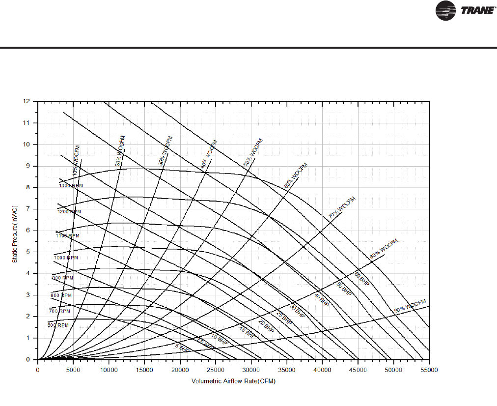
RT-PRC027T-EN 11 7
Performance Data
Figure 28. Supply fan performance STANDARD CFM —90-105 tons air-cool/100-118 tons evap-condensing (36")
Supply Fan (with or without Variable Frequency Drive)
RT-PRC027.book Page 117 Tuesday, October 7, 2014 9:03 AM
11 8 RT-PRC027T-EN
Performance Data
Table 34. Supply fan performance LOW CFM—105-150 tons air-cool/118-162 tons evap-condensing (32")
CFM Total Static Pressure
Std. 0.25 0.50 0.75 1.00 1.25 1.50 1.75 2.00
Air rpm bhp rpm bhp rpm bhp rpm bhp rpm bhp rpm bhp rpm bhp rpm bhp
19000 632(a) 4.48 667 5.30 695 5.87 723 6.53 754 7.38 782 8.22 809 9.07 835 9.93
20000 662 5.14 695 6.00 723 6.66 749 7.26 778 8.11 806 9.01 832 9.90 857 10.78
21000 692 5.86 723 6.76 752 7.53 776 8.13 802 8.93 830 9.86 856 10.78 881 11.72
22000 722 6.65 752 7.59 780 8.49 804 9.09 828 9.81 854 10.76 880 11.73 904 12.72
23000 752 7.51 781 8.48 809 9.46 832 10.14 854 10.82 879 11.73 904 12.74 928 13.77
24000 782 8.45 809 9.44 837 10.49 861 11.29 882 11.98 904 12.78 929 13.82 953 14.90
25000 813 9.46 839 10.47 865 11.59 889 12.53 910 13.22 931 13.98 953 14.95 977 16.08
26000 843 10.56 868 11.62 894 12.76 918 13.85 939 14.57 958 15.31 978 16.19 1000 17.30
27000 874 11.73 898 12.84 922 14.01 946 15.16 967 16.03 986 16.79 1005 17.61 1025 18.64
28000 904 13.00 928 14.14 951 15.34 975 16.57 996 17.60 1014 18.35 1033 19.18 1051 20.08
29000 935 14.35 957 15.54 980 16.75 1003 18.04 1024 19.23 1043 20.04 1061 20.86 1078 21.76
30000 965 15.80 987 17.03 1009 18.26 1031 19.61 1052 20.86 1072 21.86 1089 22.67 1106 23.56
31000 996 17.35 1018 18.62 1038 19.89 1060 21.27 1081 22.61 1100 23.77 1117 24.61 1134 25.48
32000 1027 19.00 1048 20.31 1068 21.62 1089 23.01 1109 24.42 1129 25.73 1146 26.66 1162 27.53
33000 1057 20.75 1078 22.11 1098 23.46 1117 24.85 1138 26.34 1157 27.72 1174 28.84 1190 29.74
34000 1088 22.61 1108 24.00 1127 25.40 1146 26.81 1166 28.35 1185 29.78 1203 31.16 1219 32.07
35000 1119 24.58 1138 26.02 1157 27.44 1176 28.86 1195 30.45 1214 31.98 1231 33.40 1248 34.54
36000 1150 26.66 1169 28.14 1187 29.60 1205 31.07 1223 32.66 1242 34.25 1259 35.76 1276 37.13
37000 1181 28.86 1199 30.38 1217 31.90 1235 33.40 1252 35.00 1271 36.66 1288 38.26 1305 39.74
38000 1212 31.17 1230 32.74 1247 34.30 1264 35.85 1281 37.42 1299 39.14 1316 40.83 1333 42.40
39000 1243 33.61 1260 35.22 1277 36.82 1294 38.40 1311 40.00 1328 41.77 1345 43.47 1361 45.13
40000 1274 36.17 1291 37.82 1308 39.48 1324 41.10 1340 42.73 1357 44.49 1373 46.27 1390 48.02
41000 1305 38.87 1321 40.56 1338 42.25 1354 43.91 1370 45.59 1386 47.37 1402 49.20 1418 50.98
42000 1336 41.70 1352 43.44 1368 45.17 1384 46.89 1399 48.58 1415 50.36 1431 52.26 1446 54.12
43000 1367 44.66 1383 46.44 1398 48.21 1414 49.97 1429 51.72 1444 53.48 1459 55.41 1475 57.34
44000 1398 47.77 1413 49.60 1429 51.40 1444 53.20 1459 55.00 1473 56.77 1488 58.70
45000 1429 51.01 1444 52.88 1459 54.73 1474 56.58 1488 58.40
CFM Total Static Pressure
Std. 2.25 2.50 2.75 3.00 3.25 3.50 3.75 4.00
Air rpm bhp rpm bhp rpm bhp rpm bhp rpm bhp rpm bhp rpm bhp rpm bhp
19000 860 10.81 885 11.68 909 12.58 933 13.47 957 14.42 981 15.38 1005 16.38 1028 17.41
20000 882 11.70 906 12.63 929 13.54 953 14.49 975 15.43 998 16.44 1021 17.42 1044 18.47
21000 905 12.68 929 13.65 951 14.59 973 15.55 995 16.54 1017 17.54 1039 18.57 1060 19.59
22000 928 13.71 951 14.69 973 15.69 995 16.71 1016 17.74 1037 18.75 1057 19.76 1078 20.83
23000 952 14.80 974 15.81 995 16.85 1017 17.93 1037 18.95 1058 20.03 1078 21.09 1097 22.13
24000 975 15.97 997 17.01 1018 18.07 1039 19.18 1060 20.29 1079 21.36 1099 22.49 1118 23.58
25000 999 17.18 1021 18.28 1042 19.41 1062 20.50 1082 21.64 1102 22.80 1121 23.95 1140 25.11
26000 1023 18.47 1045 19.65 1065 20.76 1086 21.95 1105 23.11 1124 24.29 1144 25.50 1162 26.68
27000 1047 19.82 1069 21.06 1089 22.24 1109 23.42 1128 24.63 1147 25.83 1165 27.05 1184 28.34
28000 1072 21.27 1092 22.50 1113 23.79 1133 25.03 1152 26.27 1171 27.52 1188 28.75 1207 30.05
29000 1097 22.82 1117 24.09 1137 25.36 1157 26.67 1176 27.97 1194 29.24 1212 30.52 1229 31.82
30000 1123 24.49 1142 25.75 1161 27.05 1181 28.38 1200 29.74 1218 31.08 1235 32.37 1253 33.72
31000 1150 26.42 1168 27.54 1186 28.86 1205 30.22 1224 31.60 1242 33.00 1259 34.35 1276 35.71
32000 1178 28.47 1194 29.50 1211 30.71 1229 32.08 1248 33.53 1265 34.94 1284 36.43 1301 37.85
33000 1206 30.67 1222 31.68 1237 32.77 1254 34.10 1272 35.56 1290 37.04 1307 38.53 1325 40.02
34000 1234 33.03 1249 34.00 1264 35.06 1280 36.27 1297 37.68 1314 39.17 1331 40.73 1348 42.21
35000 1263 35.48 1277 36.47 1292 37.52 1306 38.60 1322 39.98 1339 41.47 1356 43.03 1372 44.59
36000 1291 38.10 1306 39.10 1320 40.13 1334 41.25 1348 42.39 1364 43.88 1380 45.44 1396 46.99
Continued on next page
Supply Fan (with or without Variable Frequency Drive)
RT-PRC027.book Page 118 Tuesday, October 7, 2014 9:03 AM

RT-PRC027T-EN 119
Performance Data
CFM Total Static Pressure
Std. 2.25 2.50 2.75 3.00 3.25 3.50 3.75 4.00
Air rpm bhp rpm bhp rpm bhp rpm bhp rpm bhp rpm bhp rpm bhp rpm bhp
37000 1320 40.85 1334 41.87 1348 42.91 1362 44.00 1375 45.12 1390 46.42 1405 47.98 1421 49.60
38000 1348 43.78 1362 44.78 1376 45.83 1390 46.93 1403 48.02 1416 49.25 1431 50.64 1446 52.24
39000 1377 46.73 1391 47.84 1404 48.90 1418 49.98 1431 51.09 1444 52.29 1457 53.57 1472 55.12
40000 1405 49.66 1420 51.09 1433 52.13 1446 53.24 1459 54.36 1471 55.52 1484 56.75 1497 58.06
41000 1434 52.74 1449 54.38 1462 55.55 1474 56.64 1487 57.76 1500 58.95
42000 1462 55.91 1477 57.62 1490 59.11
43000 1490 59.21
CFM Total Static Pressure
Std. 4.25 4.50 4.75 5.00 5.25 5.50 5.75 6.00
Air rpm bhp rpm bhp rpm bhp rpm bhp rpm bhp rpm bhp rpm bhp rpm bhp
19000 1051 18.44 1075 19.55 1099 20.65 1121 21.72 1144 22.87 1166 23.97 1188 25.14 1214 26.48
20000 1066 19.52 1088 20.57 1111 21.70 1132 22.80 1154 23.97 1177 25.16 1199 26.36 1220 27.57
21000 1082 20.67 1103 21.75 1125 22.90 1146 24.03 1168 25.23 1189 26.39 1210 27.62 1230 28.79
22000 1098 21.88 1119 22.99 1141 24.17 1161 25.32 1181 26.44 1201 27.63 1222 28.88 1242 30.14
23000 1117 23.23 1138 24.39 1157 25.52 1177 26.71 1197 27.85 1216 29.06 1237 30.34 1255 31.57
24000 1138 24.74 1157 25.86 1175 26.99 1194 28.17 1213 29.36 1233 30.60 1251 31.78 1270 33.09
25000 1158 26.23 1177 27.41 1194 28.53 1213 29.77 1231 30.94 1250 32.24 1268 33.46 1286 34.73
26000 1180 27.86 1198 29.04 1215 30.22 1233 31.46 1250 32.69 1268 33.97 1286 35.24 1303 36.49
27000 1202 29.58 1219 30.77 1237 32.02 1254 33.31 1271 34.53 1288 35.80 1305 37.13 1321 38.35
28000 1224 31.30 1242 32.61 1259 33.92 1275 35.15 1292 36.42 1308 37.75 1325 39.05 1342 40.41
29000 1246 33.13 1263 34.43 1281 35.80 1297 37.09 1313 38.44 1330 39.83 1345 41.11 1361 42.44
30000 1270 35.09 1286 36.39 1303 37.83 1319 39.17 1336 40.58 1351 41.88 1367 43.31 1383 44.71
31000 1293 37.07 1310 38.50 1325 39.84 1341 41.25 1358 42.72 1374 44.17 1389 45.58 1404 46.95
32000 1316 39.21 1333 40.62 1348 42.02 1364 43.49 1381 45.03 1396 46.44 1411 47.92 1427 49.45
33000 1340 41.44 1357 42.92 1373 44.39 1388 45.83 1403 47.33 1418 48.81 1434 50.35 1448 51.84
34000 1365 43.77 1380 45.24 1396 46.77 1411 48.27 1427 49.84 1441 51.28 1457 52.87 1471 54.43
35000 1389 46.21 1405 47.75 1420 49.26 1435 50.83 1450 52.36 1465 53.96 1479 55.41 1494 57.12
36000 1412 48.60 1429 50.29 1444 51.86 1460 53.50 1473 55.00 1488 56.56 1503 58.28 1517 59.84
37000 1437 51.20 1452 52.86 1469 54.60 1483 56.20 1498 57.87 1512 59.38
38000 1461 53.92 1476 55.56 1492 57.26 1507 59.04
39000 1486 56.67 1501 58.39
40000 1511 59.68
CFM Total Static Pressure
Std. 6.25 6.50 6.75 7.00 7.25 7.50 7.75 8.00
Air rpm bhp rpm bhp rpm bhp rpm bhp rpm bhp rpm bhp rpm bhp rpm bhp
19000 1239 27.74 1265 29.08 1289 30.35 1314 31.70 1337 32.96 1360 34.30 1382 35.52 1404 36.82
20000 1241 28.77 1263 30.04 1289 31.46 1312 32.81 1337 34.24 1359 35.57 1383 36.97 1404 38.26
21000 1250 30.02 1271 31.32 1292 32.60 1314 33.95 1334 35.26 1358 36.76 1381 38.17 1404 39.64
22000 1263 31.47 1281 32.65 1303 34.04 1322 35.33 1342 36.69 1360 37.93 1381 39.41 1401 40.72
23000 1275 32.85 1295 34.21 1313 35.47 1332 36.79 1352 38.18 1369 39.44 1390 40.95 1408 42.32
24000 1288 34.33 1308 35.71 1326 37.00 1344 38.35 1363 39.76 1380 41.05 1400 42.58 1418 43.99
25000 1305 36.07 1322 37.32 1340 38.63 1358 40.01 1376 41.45 1393 42.76 1413 44.33 1430 45.76
26000 1321 37.79 1337 39.07 1355 40.41 1373 41.80 1391 43.26 1407 44.61 1424 46.00 1441 47.46
27000 1338 39.62 1355 41.03 1371 42.32 1389 43.76 1406 45.15 1423 46.61 1440 48.03 1456 49.52
28000 1358 41.74 1373 43.03 1389 44.37 1407 45.85 1422 47.20 1438 48.60 1454 50.04 1471 51.54
29000 1377 43.83 1394 45.26 1408 46.57 1423 47.91 1440 49.40 1456 50.84 1471 52.22 1487 53.77
30000 1398 46.06 1413 47.46 1429 48.91 1444 50.31 1459 51.76 1475 53.25 1488 54.58 1505 56.17
30000 1398 46.06 1413 47.46 1429 48.91 1444 50.31 1459 51.76 1475 53.25 1488 54.58 1505 56.17
31000 1420 48.46 1434 49.82 1449 51.23 1464 52.68 1479 54.19 1493 55.63 1508 57.11
32000 1441 50.83 1455 52.26 1470 53.72 1485 55.24 1500 56.80 1513 58.18 1528 5972
33000 1463 53.38 1478 54.87 1492 56.41 1507 57.99 1520 59.39
34000 1485 55.93 1499 57.47 1514 59.08
35000 1508 58.69
Table 34. Supply fan performance LOW CFM—105-150 tons air-cool/118-162 tons evap-condensing (32") (continued)
Supply Fan (with or without Variable Frequency Drive)
RT-PRC027.book Page 119 Tuesday, October 7, 2014 9:03 AM
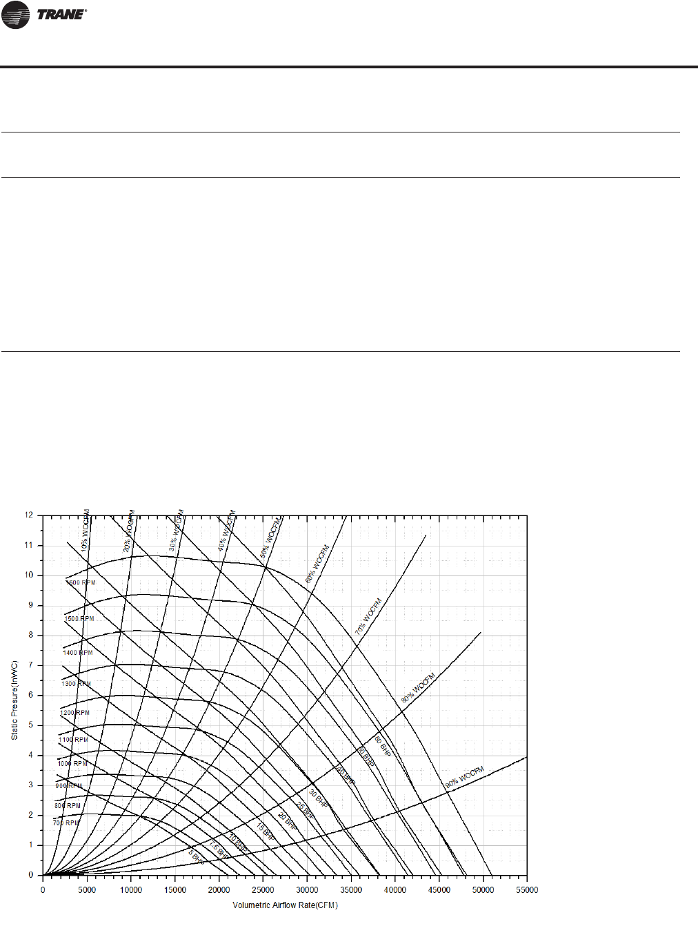
120 RT-PRC027T-EN
Performance Data
CFM Total Static Pressure
Std. 8.25 8.50 8.75 9.00
Air rpm bhp rpm bhp rpm bhp rpm bhp
19000 1427 38.17 1448 39.40 1468 40.68 1490 42.02
20000 1426 39.60 1448 41.02 1468 42.29 1490 43.72
21000 1424 40.98 1449 42.59 1468 43.86 1490 45.39
22000 1423 42.27 1446 43.88 1467 45.36 1489 46.89
23000 1428 43.75 1444 45.03 1464 46.53 1488 48.30
24000 1437 45.45 1453 46.74 1473 48.32 1490 49.71
25000 1447 47.14 1464 48.58 1482 50.06 1500 51.61
26000 1459 48.97 1477 50.55 1493 51.95 1509 53.40
27000 1473 50.95 1489 52.44 1504 53.87 1523 55.59
28000 1488 53.11 1503 54.51 1519 56.08 1536 57.71
29000 1504 55.37 1518 56.78 1533 58.25
30000 1519 57.58 1535 59.15
Notes:
1. Supply fan performance table includes internal resistance of rooftop. For total static pressure determination, system external
static pressure must be added to appropriate component sp drops (evap coil, filters, optional economizer, optional heating
system).
2. Maximum SP leaving the rooftop is 5.5" H20 positive.
3. Max CFM as follows: 105T 36000 CFM; 120T 42000 CFM, 130T and 150T 45000 CFM.
4. Max rpm 1500, Max hp 60
5. Min rpm 900, Min hp 15 for 105-120T, Min hp 20 for 130-150T
(a)Outlined area indicates nonstandard bhp or rpm selections. Contact a local Trane representative for more information.
Table 34. Supply fan performance LOW CFM—105-150 tons air-cool/118-162 tons evap-condensing (32") (continued)
Figure 29. Supply fan performance LOW CFM—105-150 tons air-cool/118-162 tons evap-condensing (32")
Supply Fan (with or without Variable Frequency Drive)
RT-PRC027.book Page 120 Tuesday, October 7, 2014 9:03 AM
RT-PRC027T-EN 121
Performance Data
Table 35. Supply fan performance STANDARD CFM—120-150 tons air-cool/128-162 tons evap-condensing (40")
CFM Total Static Pressure
Std. 0.25 0.50 0.75 1.00 1.25 1.50 1.75 2.00
Air rpm bhp rpm bhp rpm bhp rpm bhp rpm bhp rpm bhp rpm bhp rpm bhp
27000 464(a) 4.87 492 5.95 519 7.04 550 8.26 577 9.50 602 10.72 626 11.96 648 13.18
28000 479 5.34 507 6.48 531 7.58 561 8.81 589 10.11 614 11.40 637 12.65 659 13.92
29000 493 5.84 522 7.04 545 8.16 573 9.41 601 10.74 626 12.09 649 13.39 670 14.69
30000 508 6.36 537 7.63 559 8.77 585 10.04 612 11.41 637 12.79 660 14.16 682 15.52
31000 522 6.92 552 8.25 573 9.44 597 10.71 624 12.10 649 13.54 672 14.97 693 16.35
32000 537 7.52 566 8.92 587 10.14 610 11.43 635 12.81 661 14.30 684 15.78 705 17.22
33000 552 8.15 581 9.61 602 10.88 622 12.17 647 13.59 672 15.10 695 16.64 717 18.16
34000 566 8.81 596 10.34 617 11.67 636 12.97 659 14.42 684 15.94 707 17.50 729 19.11
35000 581 9.51 610 11.11 631 12.49 650 13.82 671 15.26 696 16.82 718 18.41 741 20.08
36000 596 10.26 625 11.90 646 13.34 664 14.72 684 16.16 707 17.73 730 19.36 752 21.05
37000 611 11.04 639 12.74 661 14.26 679 15.66 697 17.12 719 18.71 742 20.36 763 22.07
38000 626 11.86 654 13.62 676 15.20 694 16.65 711 18.11 732 19.73 753 21.38 775 23.14
39000 640 12.72 668 14.54 691 16.18 708 17.69 725 19.18 744 20.75 765 22.47 786 24.23
40000 655 13.62 683 15.49 706 17.22 723 18.75 739 20.29 757 21.90 777 23.60 798 25.37
41000 670 14.57 698 16.50 721 18.30 738 19.89 754 21.44 770 23.05 789 24.78 810 26.59
42000 685 15.56 712 17.55 735 19.40 753 21.06 768 22.66 784 24.29 802 26.01 821 27.83
43000 700 16.61 727 18.63 750 20.56 768 22.29 783 23.93 798 25.58 815 27.30 834 29.17
44000 715 17.69 741 19.78 764 21.76 782 23.55 798 25.23 813 26.93 828 28.64 846 30.52
45000 730 18.82 756 20.95 779 23.00 797 24.88 812 26.59 827 28.32 842 30.07 859 31.94
46000 745 20.01 771 22.20 793 24.30 812 26.24 827 28.03 842 29.80 856 31.57 872 33.42
47000 761 21.25 785 23.49 808 25.63 827 27.67 842 29.49 856 31.28 870 33.08 885 34.97
48000 776 22.53 800 24.82 822 27.03 842 29.13 857 31.01 871 32.86 884 34.68 898 36.57
49000 791 23.87 815 26.21 836 28.47 856 30.64 872 32.59 886 34.47 899 36.38 912 38.23
50000 806 25.26 829 27.65 851 29.97 870 32.19 887 34.22 901 36.18 914 38.08 927 39.98
51000 821 26.71 844 29.15 866 31.52 885 33.80 902 35.93 915 37.90 928 39.85 941 41.80
52000 836 28.22 859 30.70 880 33.14 899 35.46 916 37.68 930 39.70 943 41.69 955 43.66
53000 852 29.77 874 32.31 895 34.80 914 37.20 931 39.50 945 41.57 958 43.61 970 45.63
54000 867 31.40 889 33.97 910 36.53 929 38.98 946 41.33 960 43.50 973 45.58 985 47.63
55000 882 33.07 903 35.70 924 38.29 943 40.80 960 43.21 975 45.46 987 47.58 999 49.68
56000 897 34.82 918 37.49 939 40.15 958 42.71 975 45.18 990 47.52 1002 49.68 1014 51.81
57000 913 36.62 933 39.34 953 42.03 972 44.66 989 47.19 1005 49.63 1017 51.82 1029 54.04
58000 928 38.48 948 41.25 968 44.00 987 46.71 1004 49.29 1019 51.76 1032 54.06 1044 56.31
CFM Total Static Pressure
Std. 2.25 2.50 2.75 3.00 3.25 3.50 3.75 4.00
Air rpm bhp rpm bhp rpm bhp rpm bhp rpm bhp rpm bhp rpm bhp rpm bhp
27000 669 14.43 691 15.73 712 17.05 733 18.42 753 19.80 773 21.19 793 22.61 816 24.22
28000 680 15.23 701 16.52 721 17.85 741 19.23 761 20.64 781 22.08 800 23.53 819 24.98
29000 691 16.02 711 17.36 731 18.75 751 20.13 770 21.55 790 23.03 809 24.53 828 26.02
30000 702 16.88 722 18.27 741 19.63 761 21.07 780 22.53 799 24.02 817 25.50 835 27.03
31000 714 17.77 733 19.17 752 20.58 771 22.03 789 23.50 808 25.03 826 26.56 844 28.14
32000 725 18.69 745 20.15 764 21.62 782 23.08 799 24.55 817 26.07 836 27.71 853 29.21
33000 737 19.65 756 21.13 775 22.65 792 24.11 811 25.69 828 27.21 845 28.84 862 30.39
34000 749 20.66 768 22.19 786 23.68 804 25.24 821 26.82 838 28.39 855 29.95 872 31.68
35000 761 21.67 780 23.26 797 24.80 815 26.37 832 27.99 849 29.62 866 31.24 882 32.89
36000 772 22.69 791 24.33 809 25.97 827 27.60 844 29.23 860 30.91 876 32.51 892 34.21
37000 784 23.81 803 25.50 821 27.15 838 28.83 855 30.52 871 32.19 887 33.84 903 35.60
38000 795 24.89 815 26.68 833 28.39 850 30.12 866 31.80 883 33.54 899 35.31 914 36.97
39000 807 26.03 826 27.88 844 29.63 862 31.42 878 33.16 894 34.95 910 36.70 925 38.49
40000 818 27.24 838 29.09 856 30.94 873 32.73 890 34.58 905 36.35 921 38.17 937 40.01
41000 830 28.45 849 30.36 868 32.27 885 34.17 901 36.01 917 37.84 933 39.71 948 41.52
42000 841 29.73 860 31.64 879 33.67 897 35.62 913 37.52 929 39.40 945 41.33 960 43.20
43000 854 31.09 872 32.99 890 35.02 908 37.02 925 39.04 941 40.97 957 42.96 971 44.89
Continued on next page
Supply Fan (with or without Variable Frequency Drive)
RT-PRC027.book Page 121 Tuesday, October 7, 2014 9:03 AM

122 RT-PRC027T-EN
Performance Data
CFM Total Static Pressure
Std. 2.25 2.50 2.75 3.00 3.25 3.50 3.75 4.00
Air rpm bhp rpm bhp rpm bhp rpm bhp rpm bhp rpm bhp rpm bhp rpm bhp
44000 865 32.42 884 34.42 902 36.45 920 38.57 937 40.57 952 42.56 968 44.59 983 46.58
45000 877 33.88 895 35.87 914 37.95 931 40.07 948 42.19 964 44.23 979 46.23 994 48.27
46000 889 35.35 907 37.43 925 39.47 942 41.57 959 43.75 976 45.92 992 48.07 1007 50.16
47000 902 36.95 919 38.99 937 41.08 954 43.24 971 45.48 987 47.63 1003 49.82 1018 51.97
48000 914 38.56 931 40.57 949 42.74 966 44.93 983 47.15 999 49.34 1014 51.59 1029 53.78
49000 927 40.25 943 42.30 961 44.48 977 46.63 994 48.91 1010 51.17 1026 53.47 1041 55.71
50000 940 41.96 956 44.04 973 46.24 989 48.47 1006 50.78 1022 53.00 1037 55.36 1052 57.66
51000 954 43.78 969 45.86 985 48.09 1001 50.32 1017 52.57 1033 54.95 1049 57.27 1064 59.62
52000 968 45.69 982 47.78 997 49.96 1013 52.28 1029 54.52 1045 56.92 1060 59.30 1075 61.71
53000 982 47.67 995 49.71 1010 51.91 1025 54.25 1041 56.57 1057 58.91 1072 61.34 1087 63.81
54000 997 49.67 1009 51.77 1023 53.97 1038 56.32 1053 58.65 1069 61.05 1084 63.52 1099 66.05
55000 1011 51.81 1023 53.95 1036 56.14 1050 58.41 1065 60.83 1080 63.22 1096 65.72 1110 68.19
56000 1026 53.98 1037 56.12 1049 58.30 1063 60.61 1078 63.03 1092 65.41 1107 67.98 1122 70.46
57000 1040 56.19 1052 58.42 1063 60.59 1076 62.93 1090 65.24 1104 67.71 1119 70.26 1134 72.78
58000 1055 58.49 1066 60.70 1078 62.96 1089 65.26 1103 67.69 1117 70.15 1131 72.67 1146 75.27
CFM Total Static Pressure
Std. 4.25 4.50 4.75 5.00 5.25 5.50 5.75 6.00
Air rpm bhp rpm bhp rpm bhp rpm bhp rpm bhp rpm bhp rpm bhp rpm bhp
27000 839 25.96 863 27.73 884 29.37 906 31.14 927 32.89 948 34.59 969 36.42 989 38.17
28000 841 26.64 864 28.42 886 30.21 907 31.98 930 33.89 949 35.60 970 37.42 989 39.17
29000 846 27.50 866 29.20 888 31.00 910 32.93 930 34.69 951 36.57 971 38.40 992 40.35
30000 854 28.61 872 30.16 889 31.74 911 33.69 932 35.62 953 37.51 974 39.53 994 41.48
31000 862 29.69 880 31.35 897 32.97 914 34.53 935 36.49 955 38.48 975 40.42 994 42.38
32000 871 30.88 888 32.51 905 34.17 921 35.77 938 37.46 958 39.41 978 41.45 997 43.43
33000 879 32.04 896 33.71 913 35.34 930 37.14 947 38.87 962 40.52 978 42.24 999 44.42
34000 889 33.31 906 35.04 922 36.71 939 38.48 954 40.16 970 41.94 986 43.70 1002 45.56
35000 898 34.56 914 36.26 931 38.05 947 39.78 963 41.60 978 43.32 994 45.12 1010 47.02
36000 908 35.86 924 37.61 940 39.45 956 41.23 971 43.00 987 44.86 1002 46.71 1017 48.55
37000 919 37.30 935 39.10 949 40.83 965 42.65 981 44.56 996 46.37 1011 48.27 1025 50.03
38000 929 38.72 945 40.58 960 42.36 975 44.23 989 46.00 1004 47.85 1019 49.79 1035 51.82
39000 941 40.30 955 42.04 970 43.87 985 45.79 999 47.61 1014 49.51 1029 51.50 1043 53.35
40000 952 41.88 966 43.67 981 45.55 995 47.33 1010 49.30 1023 51.14 1038 53.18 1052 55.08
41000 963 43.44 977 45.28 992 47.22 1005 49.05 1020 50.97 1034 52.98 1048 54.96 1062 57.02
42000 974 45.09 988 46.99 1002 48.88 1017 50.87 1030 52.73 1044 54.79 1057 56.70 1071 58.69
43000 985 46.74 1000 48.69 1014 50.74 1028 52.68 1042 54.70 1055 56.59 1068 58.67 1081 60.59
44000 997 48.48 1011 50.49 1025 52.49 1039 54.59 1052 56.56 1066 58.61 1079 60.63 1092 62.73
45000 1009 50.33 1023 52.39 1037 54.45 1051 56.50 1064 58.52 1077 60.63 1090 62.70 1103 64.72
46000 1020 52.18 1035 54.30 1048 56.30 1062 58.40 1075 60.47 1088 62.64 1101 64.76 1114 66.83
47000 1033 54.14 1046 56.21 1060 58.38 1073 60.42 1086 62.55 1099 64.64 1112 66.81 1125 69.08
48000 1044 56.00 1057 58.12 1071 60.35 1084 62.44 1098 64.75 1111 66.90 1123 68.99 1135 71.17
49000 1056 57.99 1069 60.16 1083 62.44 1096 64.59 1109 66.83 1122 69.03 1135 71.32 1147 73.55
50000 1068 60.09 1081 62.33 1095 64.55 1108 66.74 1121 69.04 1133 71.29 1146 73.49 1159 75.93
51000 1079 62.11 1094 64.51 1107 66.78 1120 69.04 1133 71.39 1146 73.70 1158 75.96 1170 78.31
52000 1090 64.14 1105 66.58 1118 68.90 1132 71.34 1144 73.61 1157 75.97 1170 78.44 1181 80.68
53000 1102 66.30 1116 68.80 1130 71.30 1143 73.66 1157 76.13 1169 78.55 1181 80.76 1193 83.22
54000 1113 68.48 1128 71.04 1141 73.46 1155 75.99 1168 78.51 1180 80.83 1193 83.41
55000 1125 70.80 1139 73.29 1153 75.90 1167 78.49 1179 80.91 1192 83.44
56000 1136 73.01 1151 75.69 1165 78.36 1178 80.86 1191 83.48
57000 1148 75.50 1162 78.10 1176 80.69 1190 83.39
58000 1160 77.87 1174 80.54 1187 83.18
Continued on next page
Table 35. Supply fan performance STANDARD CFM—120-150 tons air-cool/128-162 tons evap-condensing (40")
Supply Fan (with or without Variable Frequency Drive)
RT-PRC027.book Page 122 Tuesday, October 7, 2014 9:03 AM

RT-PRC027T-EN 123
Performance Data
CFM Total Static Pressure
Std. 6.25 6.50 6.75 7.00 7.25 7.50 7.75 8.00
Air rpm bhp rpm bhp rpm bhp rpm bhp rpm bhp rpm bhp rpm bhp rpm bhp
27000 1007 39.87 1026 41.70 1045 43.52 1063 45.33 1080 47.10 1098 48.98 1116 50.97 1132 52.75
28000 1009 41.04 1028 42.80 1047 44.72 1064 46.50 1082 48.40 1101 50.40 1117 52.22 1134 54.13
29000 1011 42.21 1029 43.97 1048 45.83 1067 47.80 1084 49.68 1102 51.67 1119 53.62 1137 55.67
30000 1013 43.36 1033 45.34 1051 47.21 1069 49.18 1086 51.01 1104 52.92 1122 55.00 1137 56.88
31000 1015 44.46 1034 46.45 1051 48.31 1070 50.41 1088 52.35 1106 54.41 1122 56.28 1140 58.39
32000 1016 45.52 1035 47.51 1054 49.62 1071 51.59 1090 53.67 1108 55.86 1126 57.88 1143 60.00
33000 1018 46.53 1038 48.76 1056 50.88 1074 52.86 1091 54.95 1110 57.14 1126 59.15 1143 61.27
34000 1019 47.48 1039 49.72 1057 51.85 1076 54.08 1093 56.18 1111 58.37 1129 60.68 1146 62.80
35000 1024 48.79 1041 50.86 1059 53.00 1077 55.25 1096 57.63 1114 59.84 1129 61.87 1148 64.30
36000 1033 50.47 1048 52.36 1062 54.21 1079 56.36 1098 58.75 1115 60.97 1132 63.30 1150 65.74
37000 1041 52.11 1056 54.05 1069 55.81 1085 57.90 1099 59.81 1118 62.33 1135 64.67 1152 67.13
38000 1049 53.72 1064 55.69 1078 57.62 1092 59.63 1106 61.58 1120 63.61 1137 65.99 1153 68.30
39000 1057 55.40 1071 57.29 1086 59.39 1099 61.31 1113 63.29 1127 65.35 1141 67.50 1156 69.72
40000 1066 57.05 1080 59.11 1095 61.26 1108 63.22 1122 65.25 1135 67.36 1150 69.55 1162 71.49
41000 1076 59.05 1089 60.90 1103 63.09 1116 65.09 1130 67.17 1144 69.32 1158 71.55 1170 73.54
42000 1085 60.77 1099 62.93 1112 64.89 1126 67.08 1139 69.20 1151 71.24 1165 73.51 1178 75.53
43000 1095 62.72 1109 64.93 1121 66.94 1134 69.03 1148 71.19 1161 73.44 1173 75.43 1187 77.83
44000 1104 64.64 1118 66.90 1131 68.96 1144 71.10 1157 73.31 1170 75.60 1182 77.64 1195 79.92
45000 1116 66.82 1128 68.85 1141 71.11 1154 73.29 1166 75.39 1179 77.74 1191 79.81
46000 1126 68.98 1139 71.07 1151 73.23 1164 75.47 1177 77.78 1188 79.83
47000 1137 71.14 1149 73.27 1161 75.48 1174 77.78 1186 79.98 1198 82.25
48000 1148 73.43 1160 75.61 1173 77.88 1184 80.06 1196 82.32
49000 1159 75.71 1171 77.95 1184 80.27 1195 82.50
50000 1171 78.14 1183 80.44 1194 82.65
51000 1182 80.58 1194 82.93
52000 1193 83.00
CFM Total Static Pressure
Std. 8.25 8.50 8.75 9.00
Air rpm bhp rpm bhp rpm bhp rpm bhp
27000 1149 54.61 1166 56.58 1182 58.45 1198 60.42
28000 1151 56.15 1166 57.91 1183 59.95 1199 61.89
29000 1153 57.50 1169 59.42 1187 61.62
30000 1155 59.02 1171 60.92 1188 63.10
31000 1156 60.35 1173 62.40 1189 64.56
32000 1159 61.90 1176 64.06 1191 66.01
33000 1161 63.48 1177 65.63 1195 67.89
34000 1163 65.02 1179 67.17 1196 69.43
35000 1165 66.52 1182 68.85 1197 70.93
36000 1166 67.97 1183 70.30 1198 72.39
37000 1168 69.37 1184 71.71
38000 1170 70.71 1186 73.06
39000 1171 71.99 1189 74.69
40000 1176 73.67 1190 75.91
41000 1183 75.59 1197 77.88
42000 1191 77.80
43000 1199 79.97
Notes:
1. Supply fan performance table includes internal resistance of rooftop. For total static pressure determination, system external static pressure mustbe
added to appropriate component sp drops (evap coil, filters, optional economizer, optional heating system).
2. Maximum SP leaving the rooftop is 5.5" H20 positive.
3. Max CFM as follows: 120T & 128T 54000 CFM, 130T - 162T 58000 CFM.
4. Max rpm 1200, Max hp 100 for 130-162T; Max rpm 1100, Max hp 75 for 120T & 128T
5. Min rpm 700, Min hp 20
(a)Outlined area indicates nonstandard bhp or rpm selections. Contact a local Trane representative for more information.
Table 35. Supply fan performance STANDARD CFM—120-150 tons air-cool/128-162 tons evap-condensing (40")
Supply Fan (with or without Variable Frequency Drive)
RT-PRC027.book Page 123 Tuesday, October 7, 2014 9:03 AM
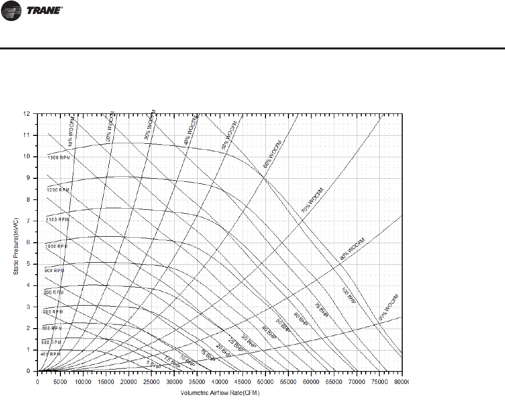
124 RT-PRC027T-EN
Performance Data
Figure 30. Supply fan performance STANDARD CFM —120-150 tons air-cool/128-162 tons evap-condensing (40")
Supply Fan (with or without Variable Frequency Drive)
RT-PRC027.book Page 124 Tuesday, October 7, 2014 9:03 AM
RT-PRC027T-EN 125
Performance Data
Exhaust Fan (with or without Energy Recovery Wheel)
Table 36. Exhaust fan performance(a) LOW CFM—90 tons air-cooled/100 tons evap-condensing (25" Fan)
CFM Negative Static Pressure
Std. 0.25 0.50 0.75 1.00 1.25 1.50 1.75 2.00
Air rpm bhp rpm bhp rpm bhp rpm bhp rpm bhp rpm bhp rpm bhp rpm bhp
10000 260(b) 1.42 319 1.91 372 2.44 423 3.03 470 3.65 515 4.27 555 4.89 594 5.52
11000 274 1.77 330 2.32 380 2.87 427 3.48 472 4.14 516 4.84 556 5.51 593 6.18
12000 288 2.19 341 2.78 389 3.38 433 4.00 476 4.69 517 5.41 558 6.18 594 6.90
13000 303 2.67 354 3.32 399 3.96 441 4.61 481 5.30 520 6.05 559 6.85 596 7.66
14000 319 3.23 366 3.92 410 4.61 450 5.31 488 6.02 525 6.78 563 7.61 598 8.46
15000 335 3.86 379 4.60 422 5.35 461 6.09 497 6.83 532 7.60 567 8.43 601 9.33
16000 352 4.58 394 5.36 434 6.16 472 6.95 507 7.73 541 8.55 574 9.39 606 10.27
17000 368 5.39 408 6.21 447 7.07 483 7.90 518 8.74 550 9.58 582 10.46 612 11.33
18000 385 6.29 423 7.16 460 8.05 495 8.95 529 9.85 560 10.72 591 11.63 620 12.55
19000 403 7.30 438 8.21 474 9.15 508 10.10 541 11.05 571 11.98 601 12.92 629 13.87
20000 420 8.41 454 9.37 488 10.34 520 11.35 552 12.34 583 13.33 611 14.31 639 15.30
21000 437 9.63 470 10.63 502 11.65 534 12.71 564 13.76 594 14.79 622 15.81 649 16.87
22000 455 10.97 487 12.02 517 13.08 548 14.17 577 15.29 606 16.37 633 17.44 661 18.55
23000 473 12.43 503 13.53 532 14.64 562 15.77 590 16.93 618 18.08 646 19.21 672 20.34
24000 491 14.02 520 15.16 548 16.32 577 17.49 604 18.69 631 19.90 657 21.08 683 22.27
25000 508 15.74 537 16.94 564 18.15 591 19.35 618 20.59 644 21.86 670 23.10 695 24.35
26000 527 17.60 554 18.86 580 20.10 606 21.35 632 22.62 658 23.95 682 25.26
27000 545 19.59 572 20.92 597 22.20 622 23.52 647 24.82
28000 563 21.74 589 23.13 614 24.46 637 25.81
CFM Negative Static Pressure
Std. 2.25 2.50
Air rpm bhp rpm bhp
10000 630 6.15 666 6.80
11000 630 6.87 664 7.55
12000 629 7.62 664 8.38
13000 631 8.47 664 9.26
14000 632 9.34 665 10.20
15000 635 10.23 667 11.17
16000 638 11.20 669 12.16
17000 642 12.28 673 13.30
18000 649 13.49 677 14.48
19000 657 14.85 684 15.84
20000 666 16.31 692 17.34
21000 676 17.91 701 18.98
22000 686 19.62 711 20.72
23000 697 21.49 721 22.61
24000 708 23.45 732 24.65
25000 719 25.57
Notes:
1. Max hp is 25.
2. Min. hp is 7.5
3. Max CFM airflow for 90/100T is 28000
4. Min CFM airflow for 90/100T is 10000.
(a) To determine exhaust fan performance for units with Energy Recovery Wheel, see Component Static Pressure Drop table for any additional static pressure
drops. For Energy Recovery Wheel selection, see Selection Procedure or contact the local Trane Sales Office to configure selection in TOPSS.
(b)Outlined area indicates nonstandard bhp or rpm selections. Contact a local Trane representative for more information.
RT-PRC027.book Page 125 Tuesday, October 7, 2014 9:03 AM
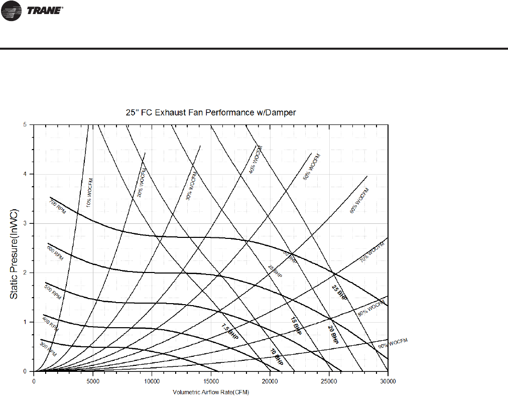
126 RT-PRC027T-EN
Performance Data
Figure 31. Exhaust fan performance LOW CFM—90 tons air-cooled/100 tons evap-condensing (25" Fan)
Exhaust Fan (with or without Energy Recovery Wheel)
RT-PRC027.book Page 126 Tuesday, October 7, 2014 9:03 AM
RT-PRC027T-EN 127
Performance Data
Table 37. Exhaust fan performance(a) STANDARD CFM—90 tons air-cooled/100 tons evap-condensing; LOW CFM—
105-150 tons air-cooled/118-162 tons evap-condensing (28")
CFM Negative Static Pressure
Std. 0.25 0.50 0.75 1.00 1.25 1.50 1.75 2.00
Air rpm bhp rpm bhp rpm bhp rpm bhp rpm bhp rpm bhp rpm bhp rpm bhp
13000 237(b) 1.90 289 2.58 335 3.29 377 4.06 417 4.86 455 5.69 490 6.56 524 7.46
14000 247 2.27 297 2.98 341 3.74 382 4.54 420 5.39 457 6.25 491 7.14 524 8.07
15000 257 2.68 305 3.44 347 4.23 387 5.08 424 5.96 459 6.86 493 7.79 525 8.74
16000 267 3.15 313 3.95 354 4.78 392 5.65 429 6.58 462 7.52 495 8.49 527 9.49
17000 278 3.67 322 4.51 362 5.39 399 6.29 434 7.25 467 8.23 498 9.25 529 10.29
18000 289 4.24 332 5.14 370 6.06 406 7.00 439 7.98 471 9.00 502 10.07 532 11.15
19000 301 4.89 342 5.82 379 6.79 413 7.77 446 8.79 477 9.85 507 10.94 536 12.06
20000 312 5.59 352 6.57 387 7.59 421 8.62 452 9.66 483 10.76 512 11.88 541 13.07
21000 324 6.37 361 7.39 397 8.46 429 9.53 460 10.63 490 11.75 518 12.90 546 14.11
22000 336 7.21 372 8.30 406 9.40 438 10.52 468 11.65 497 12.82 524 14.01 551 15.24
23000 349 8.13 382 9.27 416 10.41 446 11.58 476 12.75 504 13.96 531 15.19 557 16.45
24000 361 9.13 393 10.32 426 11.50 456 12.73 484 13.95 511 15.18 538 16.45 564 17.76
25000 374 10.21 404 11.46 436 12.68 465 13.94 493 15.22 520 16.51 545 17.80 571 19.14
26000 386 11.38 415 12.68 446 13.95 474 15.24 502 16.59 528 17.93 553 19.26 578 20.63
27000 399 12.64 427 13.99 456 15.31 484 16.65 511 18.03 537 19.43 561 20.80 585 22.20
28000 412 13.99 439 15.40 466 16.78 494 18.14 520 19.56 545 20.98 570 22.44 593 23.88
29000 424 15.43 450 16.89 477 18.33 504 19.73 530 21.19 554 22.69 578 24.18 601 25.68
30000 437 16.98 462 18.49 488 19.98 514 21.45 540 22.93 564 24.45 587 26.00 609 27.54
31000 450 18.63 474 20.19 499 21.73 524 23.25 549 24.77 573 26.34 596 27.95 618 29.53
32000 463 20.38 487 22.00 510 23.59 535 25.17 560 26.74 583 28.33 605 29.98 626 31.59
33000 476 22.25 499 23.92 522 25.56 545 27.19 569 28.79 593 30.46 615 32.12 636 33.82
34000 489 24.23 511 25.94 534 27.65 556 29.33 579 30.97 602 32.65 624 34.38 645 36.11
35000 502 26.33 524 28.09 546 29.85 567 31.58 590 33.30 612 34.99 634 36.75 654 38.52
36000 515 28.54 536 30.35 557 32.17 579 33.94 600 35.72 622 37.47 643 39.25 664 41.09
37000 528 30.89 549 32.75 569 34.62 590 36.44 611 38.29 632 40.08 653 41.89 673 43.75
38000 541 33.36 562 35.26 581 37.18 602 39.09 622 40.94 643 42.83 663 44.66 683 46.55
39000 555 35.96 574 37.92 594 39.88 613 41.83 633 43.76 653i45.67 673 47.56 693 49.50
40000 568 38.69 587 40.69 606 42.70 625 44.71 644 46.68 663 48.65
41000 581 41.57 600 43.61 618 45.68 637 47.76 655 49.78
CFM Negative Static Pressure
Std. 2.25 2.50
Air rpm bhp rpm bhp
13000 557 8.41 589 9.40
14000 557 9.06 587 10.04
15000 556 9.75 586 10.79
16000 557 10.51 586 11.57
17000 558 11.34 587 12.44
18000 561 12.23 589 13.37
19000 564 13.21 592 14.39
20000 567 14.22 595 15.44
21000 572 15.34 598 16.58
22000 577 16.49 603 17.79
23000 583 17.74 608 19.09
24000 589 19.08 614 20.47
25000 595 20.50 619 21.89
26000 602 22.03 625 23.43
27000 609 23.64 631 25.08
28000 616 25.35 639 26.86
29000 624 27.17 646 28.70
30000 632 29.10 653 30.68
31000 640 31.12 661 32.72
32000 648 33.28 669 34.90
Notes:
1. Max CFM for 90/100T is 36000, 105/118T is 33000, 120/128T is 37000, 130-162T is 41000
2. Min. CFM for 90/100T is 20000, 105T is 12000, 120/128T is 14000, 130-162T is 15000 CFM
3. Max hp for 90T and 105/118T is 25, Max hp 30 for 120/128T and 50 for 120-162T
4. Min hp for 90/100T is 10, Min hp for 105-162T is 7.5
33000 657i35.51 677 37.20
34000 666 37.89 685 39.61
35000 674 40.35 694 42.14
36000 684 42.95 703 44.79
37000 693 45.64
(a)To determine exhaust fan performance for units with Energy Recovery Wheel, see Component Static Pressure Drop tables for any additional static
pressure drops. For Energy Recovery Wheel selection, see Selection Procedure or contact the local Trane Sales Office to configure selection in TOPSS.
(b)Outlined area indicates nonstandard bhp or rpm selections. Contact a local Trane representative for more information.
Exhaust Fan (with or without Energy Recovery Wheel)
RT-PRC027.book Page 127 Tuesday, October 7, 2014 9:03 AM
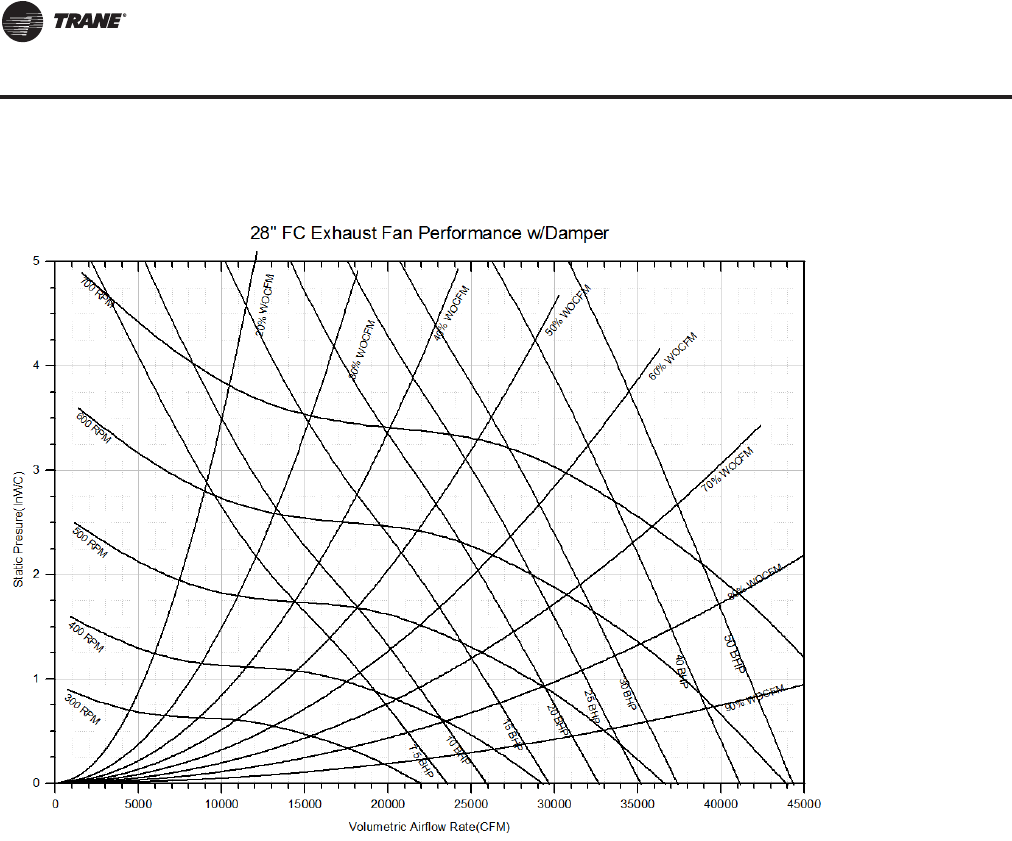
128 RT-PRC027T-EN
Performance Data
Figure 32. Exhaust fan performance STANDARD CFM—90 tons air-cooled; LOW CFM—105-150 tons air-cooled;
STANDARD CFM—100 tons evap-condenser—LOW CFM—118-162 tons evap-condensing (28")
Exhaust Fan (with or without Energy Recovery Wheel)
RT-PRC027.book Page 128 Tuesday, October 7, 2014 9:03 AM
RT-PRC027T-EN 129
Performance Data
Table 38. Exhaust fan performance(a) STANDARD CFM—105-150 tons air-cool/118-162 tons evap-condensing (32")
CFM Negative Static Pressure
Std. 0.25 0.50 0.75 1.00 1.25 1.50 1.75 2.00
Air rpm bhp rpm bhp rpm bhp rpm bhp rpm bhp rpm bhp rpm bhp rpm bhp
23000 272 6.16 307 7.39 339 8.59 370 9.96 400 11.36 429 12.87 458 14.48 484 16.02
24000 280 6.87 314 8.17 345 9.42 375 10.77 405 12.25 433 13.75 460 15.39 487 17.09
25000 288 7.63 321 8.98 352 10.31 381 11.66 410 13.21 437 14.71 464 16.37 490 18.10
26000 296 8.45 328 9.83 359 11.27 387 12.62 415 14.21 442 15.79 468 17.43 494 19.19
27000 305 9.34 336 10.76 367 12.30 394 13.69 421 15.25 447 16.90 472 18.52 497 20.31
28000 314 10.30 344 11.77 374 13.38 401 14.84 426 16.34 452 18.09 477 19.77 501 21.51
29000 323 11.35 353 12.88 382 14.54 407 16.03 432 17.55 458 19.30 482 21.10 505 22.83
30000 333 12.50 362 14.07 389 15.73 415 17.34 439 18.87 463 20.59 488 22.47 510 24.25
31000 343 13.73 371 15.35 396 16.96 422 18.69 446 20.28 469 21.97 493 23.87 516 25.78
32000 353 15.04 380 16.70 403 18.26 430 20.13 452 21.75 475 23.42 498 25.35 521 27.35
33000 363 16.44 388 18.08 411 19.68 437 21.63 460 23.35 482 25.04 504 26.88 526 28.94
34000 373 17.91 397 19.53 419 21.17 445 23.22 467 24.99 488 26.72 510 28.53 531 30.60
35000 383 19.48 405 21.04 427 22.77 452 24.80 475 26.72 495 28.52 516 30.32 537 32.38
36000 393 21.14 413 22.63 436 24.50 459 26.47 482 28.53 502 30.37 523 32.24 543 34.17
37000 403 22.89 421 24.29 445 26.33 466 28.23 490 30.42 510 32.33 529 34.23 549 36.21
38000 413 24.73 429 26.08 454 28.27 474 30.10 497 32.41 517 34.42 537 36.35 556 38.32
39000 423 26.68 438 27.96 464 30.28 481 32.06 504 34.40 525 36.55 544 38.54 562 40.58
40000 433 28.72 447 29.96 472 32.35 490 34.17 511 36.45 533 38.80 551 40.85 569 42.91
41000 444 30.87 456 32.07 481 34.48 499 36.42 518 38.62 540 41.09 558 43.24 576 45.35
42000 454 33.12 466 34.34 489 36.67 508 38.78 526 40.89 547 43.48 566 45.73 583 47.90
43000 464 35.48 476 36.74 497 38.96 517 41.23 534 43.30 554 45.86 573 48.29 591 50.56
44000 474 37.95 486 39.24 505 41.34 526 43.83 542 45.83 561 48.38 581 51.02 598 53.34
45000 484 40.53 496 41.86 513 43.83 535 46.52 550 48.48 568 50.97 589 53.78 606 56.19
46000 495 43.23 506 44.59 521 46.44 544 49.28 559 51.34 576 53.77 595 56.55 613 59.12
47000 505 46.05 516 47.44 530 49.18 552 52.11 568 54.30 583 56.60 603 59.45
48000 515 48.99 526 50.42 539 52.05 560 54.99 577 57.40 591 59.61 610 62.41
49000 525 52.05 536 53.51 548 55.06 568 57.96 586 60.60 600 62.76 617 65.51
50000 536 55.24 546 56.74 557 58.21 576 61.07 595 63.96 609 66.16
51000 546 58.55 556 60.08 566 61.56 585 64.28 604 67.41
52000 556(b) 62.00 566 63.57 576 65.07 593 67.63
CFM Negative Static Pressure
Std. 2.25 2.50
Air rpm bhp rpm bhp
23000 508 17.55 533 19.11
24000 512 18.66 536 20.29
25000 516 19.86 538 21.48
26000 518 20.99 542 22.78
27000 522 22.20 545 24.08
28000 525 23.44 548 25.34
29000 528 24.70 551 26.71
30000 533 26.15 555 28.11
31000 537 27.65 559 29.63
32000 542 29.27 563 31.19
33000 547 30.93 567 32.90
34000 553 32.72 573 34.74
35000 558 34.53 578 36.62
36000 563 36.37 583 38.64
37000 569 38.34 589 40.69
38000 574 40.38 594 42.77
39000 580 42.59 599 44.90
Continued on next page
Exhaust Fan (with or without Energy Recovery Wheel)
RT-PRC027.book Page 129 Tuesday, October 7, 2014 9:03 AM
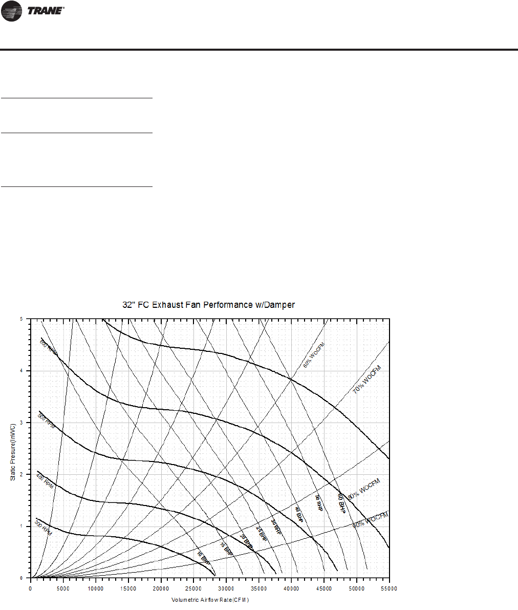
130 RT-PRC027T-EN
Performance Data
CFM Negative Static Pressure
Std. 2.25 2.50
Air rpm bhp rpm bhp
40000 587 44.97 605 47.20
41000 594 47.44 611 49.64
42000 601 50.07 618 52.23
43000 608 52.78
44000 615 55.56
Notes:
1. Max CFM for 105T is 40000; 120T is 48000, 130 and 150T is 52000.
2. Min. CFM for 105T is 23000, 120T is 27000, 130T and 150T is 29000.
3. Max hp for 105T is 50, Max hp for 120-150T is 60 hp.
4. Min. hp for 105-150T is 15.
(a)To determine exhaust fan performance for units with Energy Recovery Wheel, see Component Static Pressure Drop tables for any additional static
pressure drops. For Energy Recovery Wheel selection, see Selection Procedure or contact the local Trane Sales Office to configure selection in TOPSS.
(b)Outlined area indicates nonstandard bhp or rpm selections. Contact a local Trane representative for more information.
Table 38. Exhaust fan performance(a) STANDARD CFM—105-150 tons air-cool/118-162 tons evap-condensing (32")
Figure 33. Exhaust fan performance standard CFM —105-150 tons air-cool/118-162 tons evap-condensing (32")
Exhaust Fan (with or without Energy Recovery Wheel)
RT-PRC027.book Page 130 Tuesday, October 7, 2014 9:03 AM
RT-PRC027T-EN 131
Performance Data
Return Fan
Table 39. Return fan performance LOW CFM—90-150 tons air-cooled/100-162 tons evap-condensing (36.5")
CFM Negative Static Pressure
Std. 0.25 0.50 0.75 1.00 1.25 1.50 1.75 2.00
Air rpm bhp rpm bhp rpm bhp rpm bhp rpm bhp rpm bhp rpm bhp rpm bhp
16000 614(a) 2.65 647 3.39 678 4.15 709 5.00 739 5.83 767 6.65 797 7.53 825 8.41
17000 648 3.07 680 3.87 710 4.66 739 5.53 767 6.44 795 7.31 822 8.19 849 9.11
18000 683 3.55 713 4.39 741 5.22 769 6.10 797 7.08 823 8.01 848 8.92 875 9.89
19000 717 4.07 746 4.96 773 5.84 799 6.74 826 7.72 851 8.74 876 9.73 900 10.69
20000 752 4.65 780 5.57 806 6.51 831 7.45 855 8.44 881 9.52 904 10.56 928 11.60
21000 787 5.29 813 6.25 839 7.23 863 8.21 886 9.21 910 10.33 934 11.45 956 12.53
22000 822 5.99 847 6.99 872 8.02 895 9.04 917 10.07 940 11.17 963 12.34 985 13.54
23000 858 6.75 881 7.80 905 8.87 928 9.93 949 11.00 971 12.11 992 13.31 1014 14.55
24000 893 7.57 915 8.66 938 9.78 960 10.89 981 12.00 1002 13.13 1022 14.33 1043 15.61
25000 928 8.46 950 9.59 972 10.75 994 11.92 1014 13.07 1034 14.24 1054 15.46 1074 16.76
26000 964 9.43 984 10.60 1006 11.79 1026 13.00 1046 14.21 1066 15.42 1085 16.65 1104 17.95
27000 999 10.46 1019 11.67 1039 12.91 1060 14.17 1079 15.43 1098 16.67 1116 17.93 1135 19.24
28000 1035 11.57 1054 12.82 1073 14.11 1093 15.41 1112 16.73 1131 18.01 1148 19.31 1166 20.64
29000 1070 12.76 1089 14.06 1108 15.39 1127 16.72 1145 18.09 1163 19.43 1181 20.76 1198 22.11
30000 1106 14.04 1124 15.38 1142 16.73 1160 18.12 1179 19.53 1196 20.93 1213 22.31 1230 23.72
31000 1142 15.40 1159 16.77 1176 18.17 1194 19.61 1212 21.05 1229 22.50 1246 23.93 1262 25.35
32000 1177 16.84 1194 18.27 1211 19.70 1228 21.19 1245 22.66 1263 24.18 1279 25.65 1295 27.15
33000 1213 18.37 1230 19.84 1245 21.32 1262 22.85 1279 24.36 1296 25.93 1312 27.45 1327 28.98
34000 1249 20.01 1265 21.51 1280 23.04 1297 24.59 1313 26.17 1329 27.77 1345 29.36 1360 30.92
35000 1285 21.73 1300 23.28 1315 24.85 1331 26.45 1347 28.05 1362 29.69 1378 31.33 1394 32.99
36000 1321 23.56 1336 25.15 1350 26.76 1365 28.39 1381 30.06 1396 31.75
CFM Negative Static Pressure
Std. 2.25 2.50
Air rpm bhp rpm bhp
16000 851 9.29 876 10.20
17000 875 10.04 900 11.00
18000 901 10.86 925 11.84
19000 925 11.70 949 12.72
20000 951 12.61 974 13.68
21000 978 13.61 1000 14.69
22000 1007 14.67 1027 15.78
23000 1035 15.76 1056 16.95
24000 1064 16.89 1084 18.16
25000 1093 18.07 1113 19.41
26000 1123 19.32 1142 20.72
27000 1153 20.60 1172 22.06
28000 1183 21.99 1202 23.49
29000 1215 23.49 1232 24.97
30000 1247 25.14 1263 26.58
31000 1278 26.81 1294 28.28
32000 1310 28.61 1326 30.15
33000 1343 30.51 1358 32.03
34000 1375 32.48 1390 34.07
Notes:
1. Max. speed for plenum fan is 1400 rpm, Max. power is 40 hp
2. Max. CFM airflow are as follows: 90T 28000; 105T 33000; 120T 36000, 130-150T 36000
3. Min. CFM airflow are as follows: 90T 16000, 105T 19000; 120T 21000; 130-150T 23000
4. Performance data includes cabinet, damper, and rain hood effect
5. Return fans are not available on units with Energy Recovery Wheel.
(a)Outlined area indicates nonstandard bhp or rpm selections. Contact a local Trane representative for more information.
RT-PRC027.book Page 131 Tuesday, October 7, 2014 9:03 AM
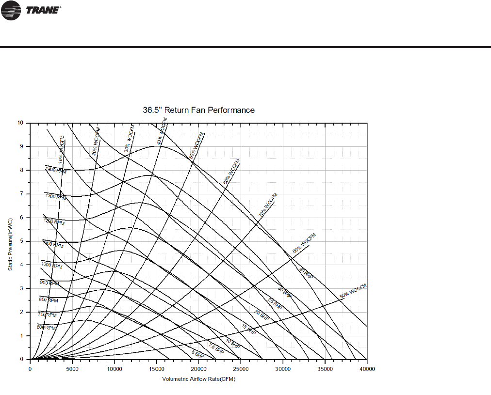
132 RT-PRC027T-EN
Performance Data
Figure 34. Return fan performance LOW CFM — 90-150 tons air-cooled/100-162 tons evap-condensing (36.5")
Return Fan
RT-PRC027.book Page 132 Tuesday, October 7, 2014 9:03 AM
RT-PRC027T-EN 133
Performance Data
Table 40. Return fan performance STD CFM—90-105 tons air-cooled/100-118 tons evap-condensing (40")
CFM Negative Static Pressure
Std. 0.25 0.50 0.75 1.00 1.25 1.50 1.75 2.00
Air rpm bhp rpm bhp rpm bhp rpm bhp rpm bhp rpm bhp rpm bhp rpm bhp
20000 571(a) 3.45 600 4.37 627 5.31 655 6.38 682 7.42 707 8.43 732 9.49 758 10.60
21000 596 3.89 625 4.87 651 5.85 677 6.92 703 8.04 727 9.10 752 10.20 776 11.32
22000 622 4.37 649 5.39 675 6.42 700 7.50 725 8.67 748 9.81 772 10.94 795 12.11
23000 648 4.90 674 5.97 699 7.04 722 8.12 747 9.33 770 10.56 792 11.72 814 12.91
24000 674 5.47 699 6.58 723 7.69 746 8.81 769 10.03 792 11.31 813 12.56 835 13.80
25000 700 6.09 724 7.24 747 8.40 770 9.56 792 10.79 813 12.10 835 13.44 856 14.72
26000 726 6.75 749 7.95 772 9.16 794 10.37 814 11.59 836 12.94 857 14.35 877 15.68
27000 752 7.46 774 8.70 797 9.96 818 11.20 838 12.49 858 13.83 878 15.25 898 16.69
28000 779 8.23 800 9.50 821 10.81 842 12.10 862 13.41 881 14.76 901 16.24 920 17.71
29000 805 9.05 825 10.37 846 11.71 867 13.07 885 14.40 904 15.77 923 17.26 942 18.80
30000 831 9.92 851 11.28 871 12.68 891 14.08 910 15.46 928 16.88 946 18.33 965 19.92
31000 858 10.85 877 12.26 896 13.69 916 15.14 934 16.57 952 18.00 969 19.50 987 21.09
32000 884 11.85 902 13.29 921 14.76 940 16.25 958 17.74 976 19.23 993 20.74 1010 22.30
33000 911 12.90 928 14.38 947 15.90 965 17.43 983 18.98 1000 20.48 1016 22.03 1033 23.64
34000 937 14.02 954 15.54 972 17.10 990 18.69 1008 20.28 1024 21.83 1040 23.41 1056 25.02
35000 964 15.20 980 16.76 998 18.37 1015 19.98 1032 21.63 1048 23.24 1064 24.86 1080 26.48
36000 990 16.44 1007 18.05 1023 19.69 1040 21.36 1057 23.05 1073 24.70 1089 26.40 1104 28.06
37000 1017 17.76 1033 19.41 1049 21.09 1065 22.81 1082 24.54 1098 26.26 1113 27.96 1128 29.65
38000 1043 19.15 1059 20.84 1075 22.56 1091 24.31 1107 26.09 1122 27.86 1137 29.63 1152 31.35
39000 1070 20.61 1085 22.35 1100 24.10 1116 25.91 1132 27.71 1147 29.53 1162 31.37 1176 33.15
40000 1097 22.14 1112 23.92 1126 25.71 1141 27.56 1157 29.41 1172 31.27 1186 33.14 1201 34.99
41000 1123 23.75 1138 25.58 1152 27.42 1167 29.30 1182 31.20 1196 33.09 1211 35.03
42000 1150 25.44 1164 27.30 1178 29.19 1193 31.11 1207 33.05 1221 35.00
43000 1177 27.21 1191 29.11 1204 31.04 1218 33.01
44000 1204 29.06 1217 31.01
CFM Negative Static Pressure
Std. 2.25 2.50
Air rpm bhp rpm bhp
20000 782 11.73 804 12.83
21000 800 12.46 822 13.64
22000 819 13.30 841 14.52
23000 837 14.13 859 15.39
24000 856 15.02 878 16.33
25000 876 16.01 897 17.31
26000 896 17.01 916 18.33
27000 918 18.09 937 19.47
28000 940 19.23 958 20.63
29000 961 20.34 979 21.86
30000 983 21.52 1001 23.11
31000 1004 22.69 1022 24.38
32000 1027 23.94 1044 25.69
33000 1050 25.31 1066 27.04
34000 1072 26.69 1088 28.44
35000 1096 28.20 1111 29.98
36000 1119 29.74 1134 31.52
37000 1143 31.44 1157 33.16
38000 1166 33.16 1181 34.98
39000 1191 34.98 1204 36.82
40000 1214 36.83
Notes:
1. Max. speed for plenum fan is 1200 rpm, Max power is 40 hp
2. Max. CFM airflow are as follows: 90T 40000; 105T 44000.
3. Min. CFM airflow are as follows: 90T 20000; 105T 24000.
4. Performance data includes cabinet, damper, and rain hood effect
5. Return fans are not available on units with Energy Recovery Wheel.
(a)Outlined area indicates nonstandard bhp or rpm selections. Contact a local Trane representative for more information.
Return Fan
RT-PRC027.book Page 133 Tuesday, October 7, 2014 9:03 AM
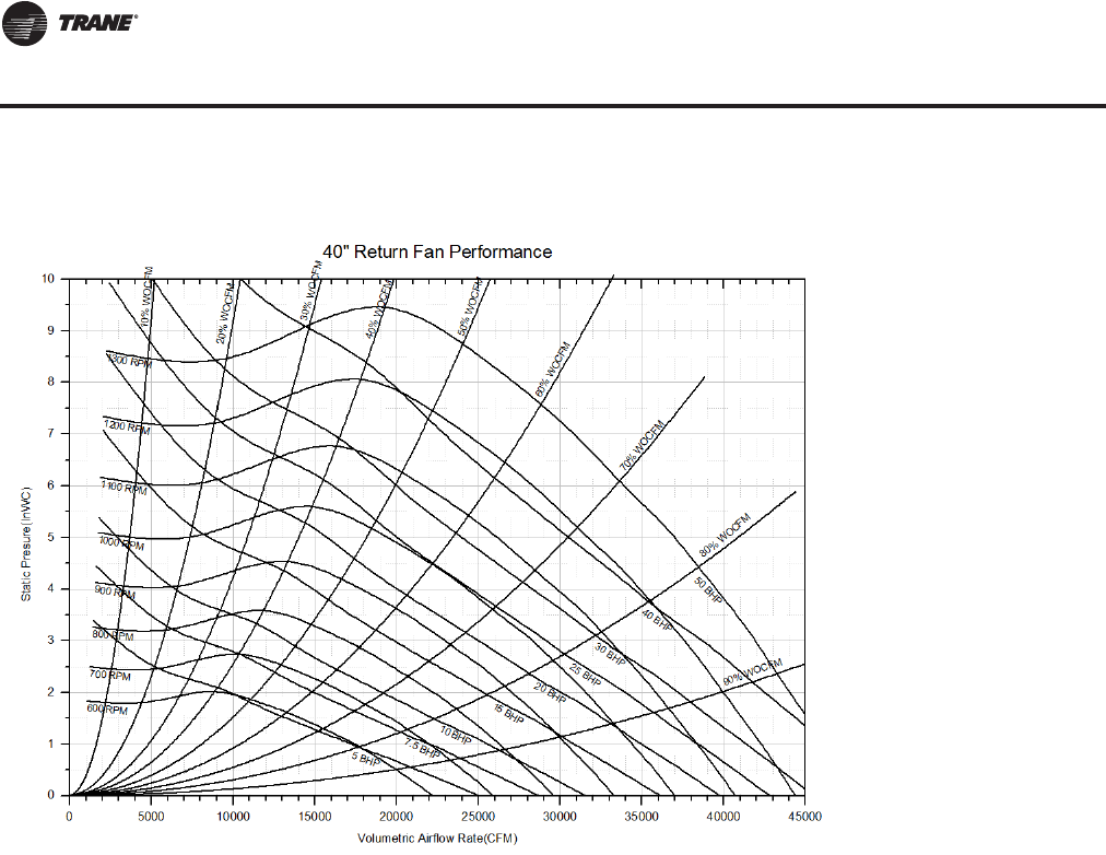
134 RT-PRC027T-EN
Performance Data
Figure 35. Return fan performance STANDARD CFM — 90-105 tons air-cool/100-118 tons evap-condensing (40")
Return Fan
RT-PRC027.book Page 134 Tuesday, October 7, 2014 9:03 AM
RT-PRC027T-EN 135
Performance Data
Table 41. Return fan performance STD CFM—120-150 tons air-cooled/128-162 tons evap-condensing (44")
CFM Negative Static Pressure
Std. 0.25 0.50 0.75 1.00 1.25 1.50 1.75 2.00
Air rpm bhp rpm bhp rpm bhp rpm bhp rpm bhp rpm bhp rpm bhp rpm bhp
27000 565(a) 5.40 589 6.66 612 7.90 635 9.23 657 10.65 679 12.08 699 13.44 720 14.85
28000 584 5.93 608 7.22 630 8.52 652 9.85 673 11.33 694 12.81 715 14.25 735 15.69
29000 603 6.49 626 7.83 648 9.17 669 10.53 690 12.02 711 13.58 731 15.10 750 16.58
30000 622 7.09 645 8.47 666 9.87 686 11.27 706 12.76 727 14.34 746 15.94 765 17.48
31000 642 7.72 663 9.15 684 10.60 704 12.03 723 13.54 743 15.15 762 16.83 781 18.45
32000 661 8.40 682 9.86 702 11.37 722 12.84 740 14.36 760 16.03 779 17.74 797 19.39
33000 680 9.12 700 10.63 721 12.17 740 13.69 758 15.26 776 16.90 794 18.63 813 20.40
34000 700 9.88 719 11.43 739 13.01 758 14.59 775 16.17 793 17.82 811 19.60 829 21.43
35000 719 10.69 738 12.28 757 13.90 776 15.53 793 17.15 810 18.83 828 20.61 845 22.50
36000 739 11.53 757 13.17 776 14.85 794 16.51 811 18.19 827 19.86 844 21.68 861 23.55
37000 758 12.43 776 14.10 794 15.82 812 17.55 829 19.25 845 20.99 861 22.79 878 24.71
38000 778 13.37 795 15.09 813 16.84 830 18.62 847 20.37 863 22.14 878 23.95 894 25.87
39000 797 14.36 814 16.12 831 17.93 848 19.74 865 21.54 880 23.36 896 25.18 911 27.09
40000 817 15.41 833 17.20 850 19.05 867 20.90 883 22.76 898 24.62 913 26.49 928 28.38
41000 837 16.50 852 18.33 869 20.23 885 22.12 901 24.06 916 25.94 931 27.84 945 29.76
42000 856 17.65 872 19.52 888 21.44 904 23.40 919 25.36 934 27.31 949 29.24 963 31.23
43000 876 18.84 891 20.76 907 22.74 922 24.73 938 26.75 952 28.73 967 30.70 980 32.71
44000 896 20.10 910 22.05 925 24.06 941 26.10 956 28.17 970 30.18 985 32.26 998 34.28
45000 915 21.41 930 23.41 944 25.46 959 27.54 974 29.65 989 31.74 1003 33.83 1016 35.88
46000 935 22.77 949 24.83 963 26.91 978 29.04 993 31.17 1007 33.32 1020 35.44 1034 37.58
47000 955 24.20 969 26.29 982 28.42 997 30.59 1011 32.75 1025 34.98 1039 37.15 1052 39.31
48000 974 25.69 988 27.83 1001 29.98 1016 32.21 1029 34.40 1043 36.66 1057 38.90 1070 41.11
49000 994 27.24 1008 29.41 1021 31.61 1034 33.87 1048 36.14 1062 38.43 1075 40.72 1088 42.99
51000 1034 30.52 1047 32.79 1059 35.08 1072 37.40 1086 39.78 1099 42.16
52000 1053 32.26 1066 34.56 1078 36.89 1091 39.28
53000 1073 34.07 1086 36.41 1098 38.79
54000 1093 35.95
CFM Negative Static Pressure
Std. 2.25 2.50
Air rpm bhp rpm bhp
27000 742 16.31 762 17.81
28000 755 17.17 776 18.71
29000 770 18.09 789 19.62
30000 784 19.01 803 20.59
31000 799 19.99 817 21.62
32000 814 21.03 832 22.67
33000 830 22.10 847 23.79
34000 846 23.26 863 24.95
35000 862 24.34 879 26.19
36000 878 25.50 895 27.42
37000 894 26.64 911 28.68
38000 911 27.90 926 29.92
39000 927 29.15 942 31.20
40000 944 30.47 959 32.62
41000 961 31.86 975 33.95
42000 977 33.26 992 35.45
Continued next page
Return Fan
RT-PRC027.book Page 135 Tuesday, October 7, 2014 9:03 AM
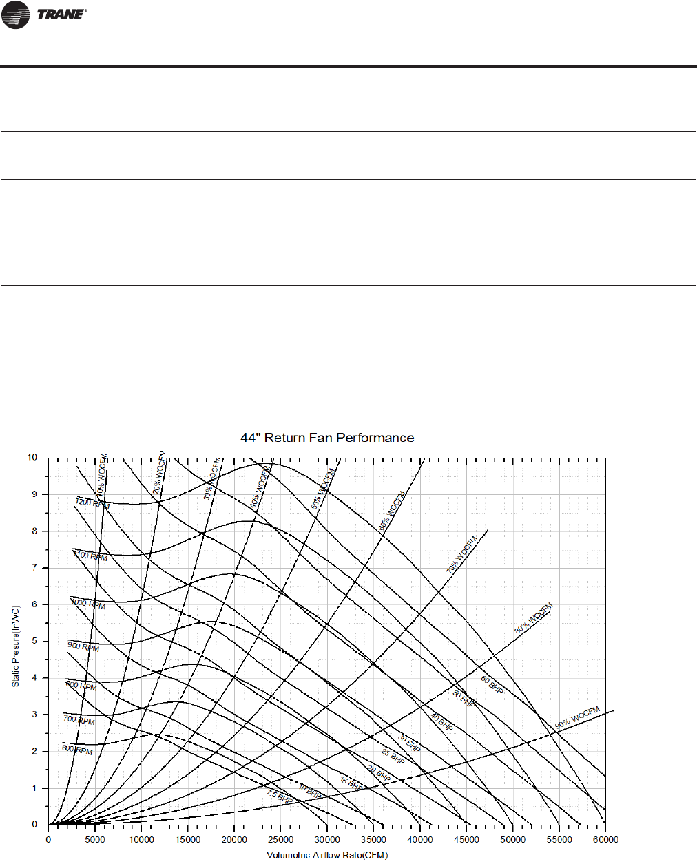
136 RT-PRC027T-EN
Performance Data
CFM Negative Static Pressure
Std. 2.25 2.50
Air rpm bhp rpm bhp
43000 994 34.75 1009 36.94
44000 1012 36.34 1026 38.52
45000 1030 38.04 1043 40.22
46000 1047 39.75 1060 41.93
47000 1065 41.48 1078 43.76
48000 1082 43.33 1095 45.61
49000 1100 45.21
Notes:
1. Max. speed for plenum fan is 1100 rpm, Max power is 50 hp
2. Max. CFM airflow is as follows: 120T 51000; 130-150T 54000
3. Min. CFM airflow is as follows: 120T 27000; 130-150T 29000
4. Performance data includes cabinet, damper, and rain hood effect
5. Return fans are not available on units with Energy Recovery Wheel.
(a)Outlined area indicates nonstandard bhp or rpm selections. Contact a local Trane representative for more information.
Table 41. Return fan performance STD CFM—120-150 tons air-cooled/128-162 tons evap-condensing (44") (continued)
Figure 36. Return fan performance STANDARD CFM—120-150 tons air-cool/128-162 tons evap-condensing (44”)
Return Fan
RT-PRC027.book Page 136 Tuesday, October 7, 2014 9:03 AM
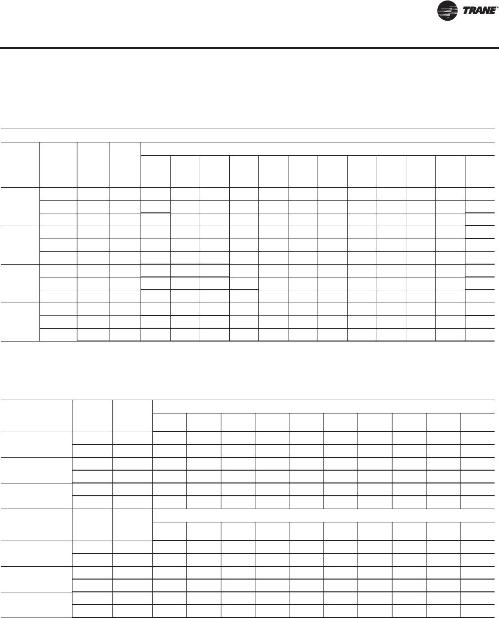
RT-PRC027T-EN 137
Performance Data
Heating Capacities
Table 42. Natural gas heating capacities — air-cooled and evaporative condensing1, 2
Air Temperature Rise vs. Unit CFM
Nominal
Tons
(AC/EC)
Gas
Heat
Modules
Heat
Input
(MBh)
Heat
Output
(MBh)
CFM
18000 20000 22000 24000 26000 30000 34000 38000 42000 46000 54000 58000
90/100
LOW 850 680 34.8 31.3 28.5 26.1 24.1 20.9 18.4 16.5 14.9 13.6 11.6 10.8
MEDIUM 1100 880 - 40.6 36.9 33.8 31.2 27.0 23.9 21.3 19.3 17.6 15.0 14.0
HIGH 1800 1440 - - - 55.3 51.0 44.2 39.0 34.9 31.6 28.9 24.6 22.9
105/118
LOW 850 680 34.8 31.3 28.5 26.1 24.1 20.9 18.4 16.5 14.9 13.6 11.6 10.8
MEDIUM 1100 880 - 40.6 36.9 33.8 31.2 27.0 23.9 21.3 19.3 17.6 15.0 14.0
HIGH 1800 1440 - - - 55.3 51.0 44.2 39.0 34.9 31.6 28.9 24.6 22.9
120/128
LOW 1100 880 - - - 33.8 31.2 27.0 23.9 21.3 19.3 17.6 15.0 14.0
MEDIUM 1800 1440 - - - - 51.0 44.2 39.0 34.9 31.6 28.9 24.6 22.9
HIGH 2500 2000 - ----61.4 54.2 48.5 43.9 40.1 34.1 31.8
130-162
LOW 1100 880 - - - 33.8 31.2 27.0 23.9 21.3 19.3 17.6 15.0 14.0
MEDIUM 1800 1440 - - - - 51.0 44.2 39.0 34.9 31.6 28.9 24.6 22.9
HIGH 2500 2000 - ----61.4 54.2 48.5 43.9 40.1 34.1 31.8
Notes:
1. Actual limits may be + or - the values shown; to accurately calculate capacities, contact the local Trane Sales Office or utilize TOPSS.
2. Follow the supply CFM ranges posted in the General Data for each case size.
Table 43. Electric heat air temperature rise (50 & 60 Hz) — air-cooled and evaporative-condensing1, 2
Nominal Tons
(AC/EC)
KW
Input
(60 Hz) Total
(MBh)
CFM
20000 22000 26000 30000 34000 38000 42000 46000 54000 58000
90/100 90 307.2 14.2 12.9 10.9 9.4 8.3 7.5 6.7
265 904.4 - 37.9 32.1 27.8 24.5 21.9 19.8 - - -
105/118 90 307.2 14.2 12.9 10.9 9.4 8.3 7.5 6.7 - - -
265 904.4 41.6 37.9 32.1 27.8 24.5 21.9 19.8 - - -
120/162 140 477.8 - 20.0 16.9 14.7 13.0 11.6 10.5 9.6 8.2 7.6
300 1023.9 - 42.9 36.3 31.5 27.8 24.8 22.5 20.5 17.5 16.3
Nominal Tons
KW
Input
(50 Hz) Total
(MBh)
CFM
20000 22000 26000 30000 34000 38000 42000 46000 54000 58000
90/100 56 191.1 8.8 8.0 6.8 5.9 5.2 4.6 4.2 - - -
166 566.6 - 23.7 20.1 17.4 15.4 13.7 12.4 - - -
105/118 56 191.1 8.8 8.0 6.8 5.9 5.2 4.6 4.2 - - -
166 566.6 26.1 23.7 20.1 17.4 15.4 13.7 12.4 - - -
120-162 88 300.3 - 12.6 10.6 9.2 8.1 7.3 6.6 6.0 5.3 4.8
188 641.6 - 26.9 22.7 19.7 17.4 15.6 14.1 12.9 11.4 10.2
Notes:
1. Actual limits may be + or - the values shown; to accurately calculate capacities, contact the local Trane Sales Office or utilize TOPSS.
2. Follow the supply CFM ranges posted in the General Data for each case size.
RT-PRC027.book Page 137 Tuesday, October 7, 2014 9:03 AM
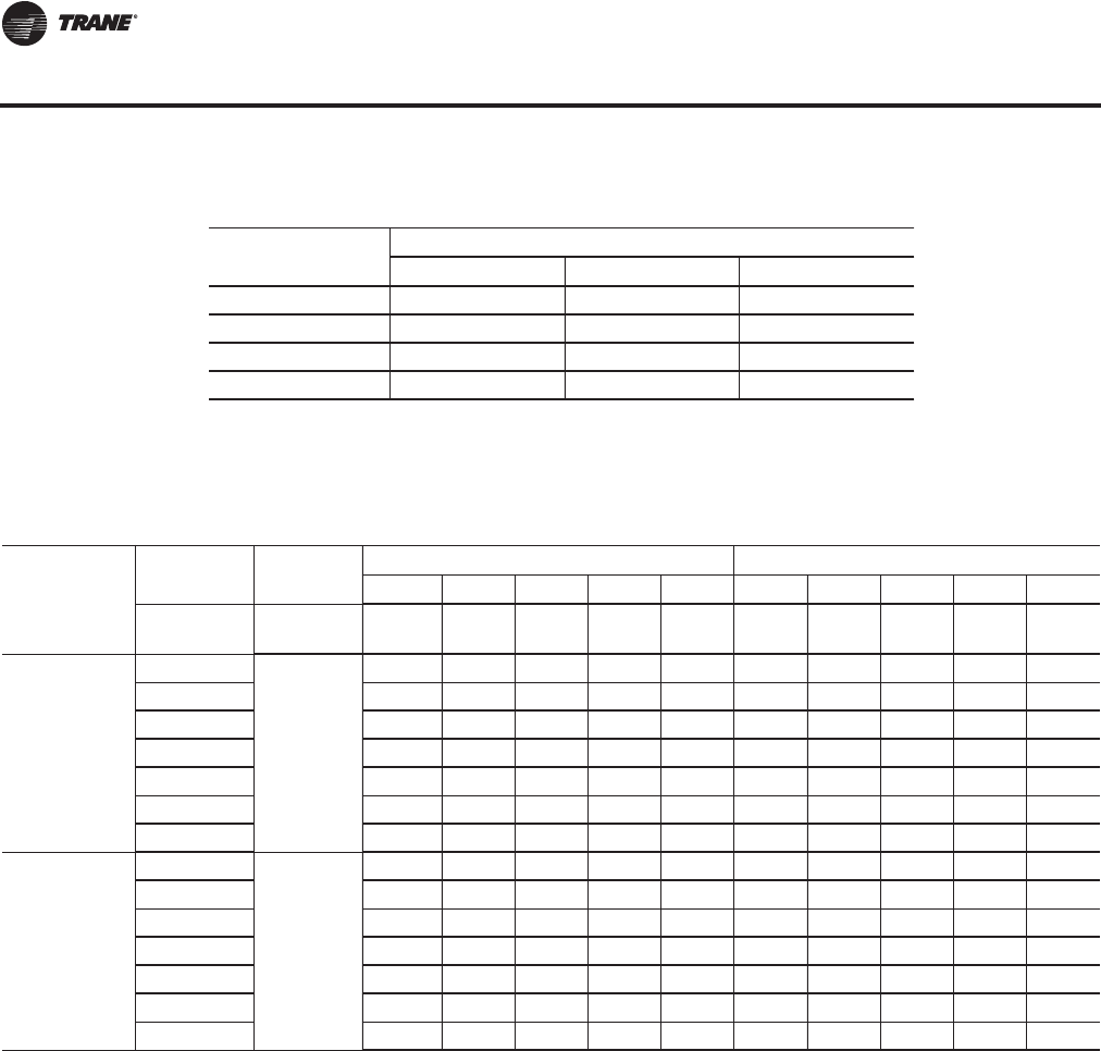
138 RT-PRC027T-EN
Performance Data
Table 44. Electric heat kW ranges — air-cooled and evaporative-condensing1, 2
Nominal Tons
(AC/EC)
Nominal Voltage
460 575 380
90/100 90-265 90-265 56-166
105/118 90-265 90-265 56-166
120/128 140-300 140-300 88-188
130-162 140-300 140-300 88-188
Notes:
1. Actual limits may be + or - the values shown; to accurately calculate capacities, contact the
local Trane Sales Office or utilize TOPSS.
2. Follow the supply CFM ranges posted in the General Data for each case size.
Table 45. Hot water coil heating capacities (Q/ITD) — air-cooled and evaporative-condensing
Nominal Tons
(AC/EC)
Water Flow High Capacity Low Capacity
(GPM) 40 80 120 160 200 30 60 100 140 175
Airflow
(CFM) WPD (ft.) 0.3 1.0 2.1 3.7 5.6 0.2 0.6 1.5 2.8 4.3
90/100
16000 7.57 9.02 9.59 9.90 10.10 5.50 6.54 7.05 7.29 7.42
20000 8.26 10.08 10.84 11.25 11.52 6.02 7.34 8.01 8.33 8.50
25000 8.90 11.15 12.12 12.66 13.01 6.52 8.15 9.00 9.42 9.65
30000 9.40 12.02 13.18 13.84 14.27 6.91 8.81 9.84 10.35 10.62
33000 9.65 12.46 13.74 14.47 14.94 7.11 9.15 10.28 10.84 11.14
36000 9.86 12.86 14.25 15.04 15.56 7.28 9.46 10.68 11.29 11.63
40000 10.12 13.35 14.86 15.73 16.31 7.48 9.83 11.16 11.84 12.21
105/118
19000 8.10 9.83 10.55 10.94 11.18 5.90 7.15 7.78 8.09 8.25
23000 8.67 10.75 11.64 12.13 12.44 6.34 7.85 8.63 9.01 9.21
28000 9.21 11.69 12.78 13.39 13.79 6.77 8.56 9.52 9.99 10.25
33000 9.65 12.46 13.74 14.47 14.94 7.11 9.15 10.28 10.84 11.14
38000 10.00 13.11 14.56 15.40 15.94 7.38 9.65 10.93 11.58 11.93
43000 10.29 13.67 15.28 16.21 16.83 7.61 10.08 11.50 12.22 12.62
45000 10.39 13.87 15.54 16.51 17.15 7.69 10.23 11.71 12.46 12.88
Continued on next page
Heating Capacities
RT-PRC027.book Page 138 Tuesday, October 7, 2014 9:03 AM
RT-PRC027T-EN 139
Performance Data
Nominal Tons
(AC/EC) Airflow
(CFM)
GPM 40 80 120 160 200 30 60 100 140 175
WPD (ft.) 0.3 1.1 2.4 4.1 6.2 0.2 0.7 1.7 3.2 4.8
120/128
21000 9.19 11.27 12.12 12.58 12.88 6.67 8.17 8.93 9.29 9.48
26000 9.89 12.46 13.55 14.16 14.55 7.21 9.07 10.04 10.51 10.76
31000 0.00 13.43 14.75 15.50 15.98 7.64 9.81 10.98 11.55 11.86
36000 0.00 14.24 15.78 16.66 17.22 0.00 10.43 11.78 12.46 12.83
41000 0.00 14.94 16.67 17.67 18.32 0.00 10.96 12.49 13.27 13.69
46000 0.00 15.54 17.45 18.57 19.30 0.00 11.42 13.12 13.99 14.46
51000 0.00 16.06 18.15 19.37 20.18 0.00 11.83 13.68 14.63 15.15
54000 0.00 16.35 18.53 19.82 20.67 0.00 12.05 13.98 14.99 15.54
130/140
23000 9.49 11.77 12.73 13.25 13.58 6.91 8.55 9.39 9.80 10.01
26000 9.89 12.46 13.55 14.16 14.55 7.21 9.07 10.04 10.51 10.76
30000 10.33 13.25 14.53 15.25 15.71 7.56 9.67 10.80 11.35 11.65
35000 0.00 14.09 15.59 16.44 16.99 0.00 10.31 11.63 12.29 12.64
40000 0.00 14.81 16.50 17.48 18.11 0.00 10.86 12.36 13.11 13.52
45000 0.00 15.42 17.30 18.40 19.11 0.00 11.34 13.00 13.85 14.31
50000 0.00 15.96 18.02 19.22 20.01 0.00 11.75 13.57 14.51 15.02
55000 0.00 16.44 18.65 19.96 20.82 0.00 12.12 14.08 15.10 15.67
58000 0.00 16.70 19.00 20.37 21.28 0.00 12.32 14.37 15.44 16.03
150/162
23000 9.49 11.77 12.73 13.25 13.58 6.91 8.55 9.39 9.80 10.01
26000 9.89 12.46 13.55 14.16 14.55 7.21 9.07 10.04 10.51 10.76
30000 10.33 13.25 14.53 15.25 15.71 7.56 9.67 10.80 11.35 11.65
35000 0.00 14.09 15.59 16.44 16.99 0.00 10.31 11.63 12.29 12.64
40000 0.00 14.81 16.50 17.48 18.11 0.00 10.86 12.36 13.11 13.52
45000 0.00 15.42 17.30 18.40 19.11 0.00 11.34 13.00 13.85 14.31
50000 0.00 15.96 18.02 19.22 20.01 0.00 11.75 13.57 14.51 15.02
55000 0.00 16.44 18.65 19.96 20.82 0.00 12.12 14.08 15.10 15.67
58000 0.00 16.70 19.00 20.37 21.28 0.00 12.32 14.37 15.44 16.03
Notes:
1. Nominal capacity is in tons
2. WPD is waterside pressure drop in feet of water
3. Hot water capacity is at 180°F entering water temperature and 65°F entering air temperature
4. Maximum entering water temperature is 200°F.
Table 45. Hot water coil heating capacities (Q/ITD) — air-cooled and evaporative-condensing (continued)
Table 46. Steam coil heating capacities (Q/ITD) — air-cooled and evaporative-condensing
Nominal
Tons
(AC/EC) Airflow High
Cap Low
Cap
90/100
16000 7.33 4.99
20000 8.17 5.67
25000 9.06 6.35
30000 9.84 6.91
33000 10.26 7.19
36000 10.66 7.44
40000 11.16 7.74
Continued on next page
Heating Capacities
RT-PRC027.book Page 139 Tuesday, October 7, 2014 9:03 AM
140 RT-PRC027T-EN
Performance Data
105/118
19000 7.97 5.51
23000 8.73 6.10
28000 9.55 6.71
33000 10.27 7.20
38000 10.92 7.61
43000 11.52 7.95
45000 11.74 8.07
120/128
21000 9.40 6.43
26000 10.41 7.24
31000 11.29 7.92
36000 12.08 8.49
41000 12.80 8.97
46000 13.45 9.39
51000 14.06 9.75
54000 14.40 9.95
130/140
23000 9.82 6.78
26000 10.41 7.24
30000 11.12 7.79
35000 11.93 8.38
40000 12.66 8.88
45000 13.32 9.31
50000 13.94 9.68
55000 14.52 10.01
58000 14.84 10.18
150/162
23000 9.82 6.78
26000 10.41 7.24
30000 11.12 7.79
35000 11.93 8.38
40000 12.66 8.88 Notes:
1. Nominal capacity is in tons.
2. Steam coil capacity is at 15 psig and 65°F entering air temperature.
3. Capacities are expressed as mbh (Q) per degree (°F) of initial
temperature difference (ITD) between the entering steam
temperature (°F) and the entering (return) air temperature (°F) to
the coil.
4. The maximum recommended steam pressure is 35 psig.
45000 13.32 9.31
50000 13.94 9.68
55000 14.52 10.01
58000 14.84 10.18
Table 46. Steam coil heating capacities (Q/ITD) — air-cooled and evaporative-condensing
Nominal
Tons
(AC/EC) Airflow High
Cap Low
Cap
Table 47. Properties of steam
Steam Pressure (psig) 2 5 10 15 20 25 30 40 50
Temperature of Steam (°F) 219 227 239 250 259 267 274 287 298
Heating Capacities
RT-PRC027.book Page 140 Tuesday, October 7, 2014 9:03 AM
RT-PRC027T-EN 141
Performance Data
Component Static Pressure Drops
Table 48. Component static pressure drops (in. H2O) — air-cooled and evaporative condensing
Nom
Tons
AC/EC CFM(a)
(a)Actual Supply Fan CFM Range:90/100 Ton 16000-40000; 105/118 Ton 19000-45000; 120/128 Ton 21000-54000; 130-150/140-162
Ton 23000-58000
Evaporator Coil
Standard High Capacity Reheat Coil (Dampers wide open)
Dry Wet Dry Wet Dry Return
Damper Econo
Damper Traq
Damper
90/100
16000 0.10 0.13 0.17 0.22 0.04 0.06 0.11 0.19
20000 0.15 0.19 0.24 0.31 0.06 0.10 0.17 0.29
25000 0.21 0.27 0.35 0.45 0.08 0.16 0.27 0.45
30000 0.28 0.36 0.47 0.60 0.11 0.23 0.39 0.65
33000 0.33 0.42 0.55 0.70 0.13 0.28 0.47 0.79
36000 0.38 0.48 0.63 0.80 0.15 0.34 0.57 0.94
40000 0.45 0.57 0.75 0.95 0.18 0.42 0.70 1.16
105/118
19000 0.18 0.23 0.27 0.32 0.05 0.09 0.15 0.26
23000 0.20 0.31 0.37 0.47 0.07 0.13 0.23 0.38
28000 0.34 0.43 0.51 0.64 0.10 0.20 0.34 0.57
33000 0.44 0.56 0.66 0.84 0.13 0.28 0.47 0.79
38000 0.55 0.70 0.83 1.05 0.16 0.38 0.63 1.05
43000 0.67 0.85 1.01 1.28 0.20 0.49 0.81 1.34
45000 0.73 0.92 1.09 1.38 0.21 0.53 0.89 1.47
120/128
21000 0.09 0.12 0.18 0.23 0.04 0.05 0.10 0.17
26000 0.13 0.16 0.25 0.32 0.06 0.09 0.15 0.26
31000 0.17 0.21 0.34 0.43 0.08 0.12 0.22 0.36
36000 0.21 0.27 0.43 0.55 0.10 0.17 0.30 0.49
41000 0.26 0.34 0.53 0.67 0.12 0.22 0.39 0.64
46000 0.32 0.40 0.64 0.81 0.15 0.28 0.49 0.80
51000 0.38 0.48 0.75 0.95 0.18 0.35 0.61 0.99
54000 0.41 0.52 0.83 1.05 0.20 0.39 0.68 1.11
130/140
23000 0.14 0.18 0.21 0.27 0.05 0.07 0.12 0.20
26000 0.17 0.22 0.25 0.32 0.06 0.09 0.15 0.26
30000 0.21 0.27 0.32 0.41 0.07 0.12 0.21 0.34
35000 0.27 0.35 0.41 0.52 0.10 0.16 0.28 0.46
40000 0.34 0.43 0.51 0.65 0.12 0.21 0.37 0.61
45000 0.41 0.52 0.61 0.78 0.15 0.27 0.47 0.77
50000 0.49 0.62 0.73 0.93 0.17 0.33 0.59 0.95
55000 0.57 0.72 0.85 1.08 0.20 0.40 0.71 1.15
58000 0.62 0.78 0.93 1.18 0.22 0.45 0.79 1.28
150/162
23000 0.21 0.27 - - 0.05 0.07 0.12 0.20
26000 0.25 0.32 - - 0.06 0.09 0.15 0.26
30000 0.32 0.41 - - 0.07 0.12 0.21 0.34
35000 0.41 0.52 - - 0.10 0.16 0.28 0.46
40000 0.51 0.65 - - 0.12 0.21 0.37 0.61
45000 0.61 0.78 - - 0.15 0.27 0.47 0.77
50000 0.73 0.93 - - 0.17 0.33 0.59 0.95
55000 0.85 1.08 - - 0.20 0.40 0.71 1.15
58000 0.93 1.18 - - 0.22 0.45 0.79 1.28
RT-PRC027.book Page 141 Tuesday, October 7, 2014 9:03 AM
142 RT-PRC027T-EN
Performance Data
Table 49. Component static pressure drops (in. H2O) — air-cooled and evaporative condensing
Nom
Tons
AC/EC CFM
Electric
Heating
(Hrztl)
All KWs(a)
Gas Heating Hydronic Heating Coil Data
Low Heat Medium Heat High Heat Hot Water Coil Steam Coil
DF Hz DF Hz DF Hz High Low High Low
90/100
16000 0.01 0.01 0.10 0.01 0.12 0.01 0.14 0.13 0.08 0.12 0.08
20000 0.02 0.01 0.16 0.01 0.19 0.01 0.22 0.19 0.12 0.17 0.12
25000 0.03 0.01 0.24 0.01 0.30 0.01 0.35 0.27 0.17 0.26 0.18
30000 0.05 0.02 0.35 0.02 0.44 0.02 0.50 0.36 0.24 0.35 0.25
33000 0.06 0.02 0.42 0.02 0.53 0.02 0.61 0.42 0.28 0.41 0.30
36000 0.07 0.03 0.51 0.03 0.63 0.03 0.72 0.49 0.33 0.48 0.35
40000 0.08 0.03 0.62 0.03 0.77 0.03 0.89 0.58 0.39 0.57 0.43
105/118
19000 0.02 0.01 0.14 0.01 0.17 0.01 0.20 0.17 0.11 0.16 0.11
23000 0.03 0.01 0.21 0.01 0.26 0.01 0.30 0.23 0.15 0.22 0.16
28000 0.04 0.02 0.31 0.02 0.38 0.02 0.44 0.32 0.21 0.31 0.22
33000 0.06 0.02 0.42 0.02 0.53 0.02 0.61 0.42 0.28 0.41 0.30
38000 0.07 0.03 0.56 0.03 0.70 0.03 0.81 0.53 0.36 0.52 0.39
43000 0.10 0.04 0.72 0.04 0.89 0.04 1.03 0.65 0.45 0.65 0.49
45000 0.10 0.04 0.79 0.04 0.98 0.04 1.13 0.71 0.49 0.70 0.53
120/128
21000 0.02 0.00 0.16 0.00 0.19 0.00 0.23 0.14 0.09 0.13 0.09
26000 0.03 0.00 0.25 0.00 0.30 0.00 0.35 0.20 0.13 0.19 0.13
31000 0.05 0.00 0.35 0.00 0.42 0.00 0.49 0.26 0.17 0.25 0.18
36000 0.07 0.00 0.48 0.00 0.57 0.00 0.67 0.33 0.22 0.33 0.24
41000 0.09 0.00 0.62 0.00 0.74 0.00 0.86 0.42 0.28 0.41 0.30
46000 0.11 0.00 0.78 0.00 0.93 0.00 1.09 0.50 0.34 0.50 0.37
51000 0.13 0.00 0.96 0.00 1.15 0.00 1.34 0.60 0.41 0.59 0.44
54000 0.15 0.00 1.07 0.00 1.28 0.01 1.50 0.66 0.45 0.65 0.49
130/140
23000 0.03 0.00 0.20 0.00 0.23 0.01 0.27 0.16 0.10 0.15 0.10
26000 0.03 0.00 0.25 0.00 0.30 0.00 0.35 0.20 0.13 0.19 0.13
30000 0.05 0.00 0.33 0.00 0.40 0.00 0.46 0.25 0.16 0.24 0.17
35000 0.06 0.00 0.45 0.00 0.54 0.00 0.63 0.32 0.21 0.31 0.22
40000 0.08 0.00 0.59 0.00 0.70 0.00 0.82 0.40 0.27 0.39 0.28
45000 0.10 0.00 0.75 0.00 0.89 0.00 1.04 0.49 0.33 0.48 0.35
50000 0.13 0.00 0.92 0.00 1.10 0.00 1.29 0.58 0.39 0.57 0.43
55000 0.16 0.00 1.12 0.01 1.33 0.01 1.56 0.68 0.47 0.67 0.51
58000 0.17 0.01 1.24 0.01 1.48 0.01 1.74 0.75 0.51 0.74 0.56
150/162
23000 0.03 0.00 0.20 0.00 0.23 0.01 0.27 0.16 0.10 0.15 0.10
26000 0.03 0.00 0.25 0.00 0.30 0.00 0.35 0.20 0.13 0.19 0.13
30000 0.05 0.00 0.33 0.00 0.40 0.00 0.46 0.25 0.16 0.24 0.17
35000 0.06 0.00 0.45 0.00 0.54 0.00 0.63 0.32 0.21 0.31 0.22
40000 0.08 0.00 0.59 0.00 0.70 0.00 0.82 0.40 0.27 0.39 0.28
45000 0.10 0.00 0.75 0.00 0.89 0.00 1.04 0.49 0.33 0.48 0.35
50000 0.13 0.00 0.92 0.00 1.10 0.00 1.29 0.58 0.39 0.57 0.43
55000 0.16 0.00 1.12 0.01 1.33 0.01 1.56 0.68 0.47 0.67 0.51
58000 0.17 0.01 1.24 0.01 1.48 0.01 1.74 0.75 0.51 0.74 0.56
(a)There is no pressure drop with electric heat DF configuration
Component Static Pressure Drops
RT-PRC027.book Page 142 Tuesday, October 7, 2014 9:03 AM
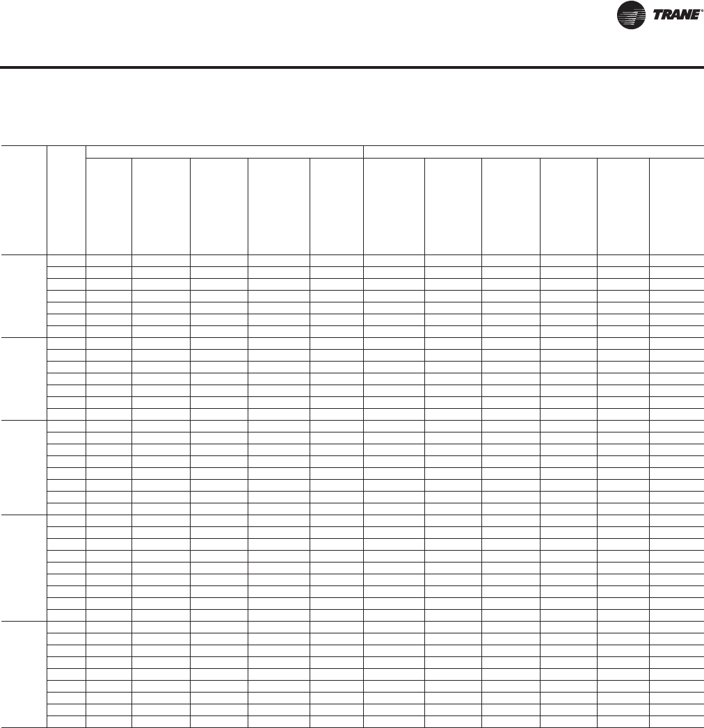
RT-PRC027T-EN 143
Performance Data
Table 50. Component static pressure drops (in. H2O) — air-cooled and evaporative condensing
Nom
Tons
AC/EC CFM
Standard Filter Section (Pre Evap) Final Filter Section (Post Evap)
Std 2"
High Eff
Throw
Away
Filters
90-95%
Low PD
Cartridge
Filters
w/ 2"
Prefilter
90-95%
Low PD
Cartridge
Filters
w/ 4"
Prefilter
90-95%
Cartridge
Filters
w/ 2"
Prefilter(a)
9
0-95%
Bag
Filters
w/ 2"
Prefilter
(a)
90-95%
Std Temp
Low PD
Cartridge
Filters
w/4”
Prefilter(b)
90-95%
Std Temp
Bag
Filters
w/ 2"
Prefilter
(c)
90-95%
Std Temp
Cartridge
Filters
w/ 2"
Prefilter
(c)
90-95%
Hi Temp
Cartridge
Filters
w/ 2" Hi
Temp
Prefilter
(c)
90-95%
Hi Temp
HEPA
w/ 2" Hi
Temp
Prefilter
(d)
90-95%
Std Temp
HEPA
Filters w/
2" Hi
Temp
Prefilter
(d)
90/
100
16000 0.08 0.24 - 0.27 0.34 0.23 0.36 0.29 0.35 0.54 0.48
20000 0.11 0.31 - 0.33 0.41 0.31 0.43 0.36 0.44 0.69 0.61
25000 0.15 0.42 - 0.42 0.50 0.43 0.54 0.47 0.58 0.89 0.78
30000 0.20 0.53 - 0.54 0.60 0.56 0.65 0.60 0.74 1.10 0.95
33000 0.23 0.61 - 0.61 0.67 0.65 0.73 0.69 0.86 1.22 1.06
36000 0.26 0.69 - 0.70 0.73 0.74 0.80 0.79 0.98 1.36 1.16
40000 0.30 0.80 - 0.82 0.83 0.88 0.91 0.93 1.15 - -
105/118
19000 0.10 0.27 - 0.30 0.37 0.27 0.40 0.32 0.40 0.62 0.55
23000 0.11 0.29 - 0.32 0.39 0.29 0.42 0.34 0.42 0.66 0.58
28000 0.18 0.49 - 0.49 0.56 0.51 0.61 0.54 0.68 1.01 0.88
33000 0.23 0.61 - 0.61 0.67 0.65 0.73 0.69 0.86 1.22 1.06
38000 0.28 0.74 - 0.76 0.78 0.81 0.86 0.86 1.06 - -
43000 0.33 0.89 - 0.92 0.91 0.98 1.00 1.05 1.30 - -
45000 0.36 0.95 - 0.99 0.96 1.05 1.06 1.13 1.40 - -
120/128
21000 0.10 - 0.30 0.35 0.42 0.34 0.45 0.38 0.47 0.73 0.64
26000 0.13 - 0.41 0.44 0.52 0.46 0.56 0.49 0.61 0.93 0.81
31000 0.17 - 0.53 0.56 0.62 0.59 0.68 0.63 0.78 1.14 0.99
36000 0.20 - 0.66 0.70 0.73 0.74 0.80 0.79 0.98 1.36 1.16
41000 0.25 - 0.81 0.85 0.86 0.91 0.94 0.97 1.20 - -
46000 0.29 - 0.96 1.03 0.99 1.09 1.09 1.17 1.45 - -
51000 0.34 - 1.14 - - 1.29 - - - - -
54000 0.37 - 1.25 - - 1.42 - - - - -
130/140
23000 0.10 - 0.32 0.37 0.44 0.36 0.47 0.40 0.49 0.77 0.68
26000 0.14 - 0.43 0.47 0.54 0.48 0.58 0.52 0.64 0.97 0.85
30000 0.17 - 0.55 0.59 0.64 0.62 0.70 0.66 0.82 1.18 1.02
35000 0.21 - 0.69 0.73 0.76 0.78 0.83 0.82 1.02 1.40 1.20
40000 0.26 - 0.84 0.89 0.88 0.94 0.97 1.01 1.25 - -
45000 0.30 - 1.00 1.07 1.02 1.13 1.12 1.22 1.51 - -
50000 0.35 - 1.17 1.27 1.16 1.33 - - - - -
55000 0.41 - 1.36 - - 1.55 - - - - -
58000 0.44 - 1.48 - - - - - - - -
150/162
23000 0.10 - 0.32 0.37 0.44 0.36 0.47 0.40 0.49 0.77 0.68
26000 0.14 - 0.43 0.47 0.54 0.48 0.58 0.52 0.64 0.97 0.85
30000 0.17 - 0.55 0.59 0.64 0.62 0.70 0.66 0.82 1.18 1.02
35000 0.21 - 0.69 0.73 0.76 0.78 0.83 0.82 1.02 1.40 1.20
40000 0.26 - 0.84 0.89 0.88 0.94 0.97 1.01 1.25 - -
45000 0.30 - 1.00 1.07 1.02 1.13 1.12 1.22 1.51 - -
50000 0.35 - 1.17 1.27 1.16 1.33 - - - - -
55000 0.41 - 1.36 - - 1.55 - - - - -
58000 0.44 - 1.48 - - - - - - - -
(a)120-150/128-162 Ton Max CFM 50000
(b)130-150/140-162 Ton Max CFM 55500
(c)120-150/128-162 Ton Max CFM 46250
(d)90-150/100-162 Ton Max CFM 37000
Component Static Pressure Drops
RT-PRC027.book Page 143 Tuesday, October 7, 2014 9:03 AM
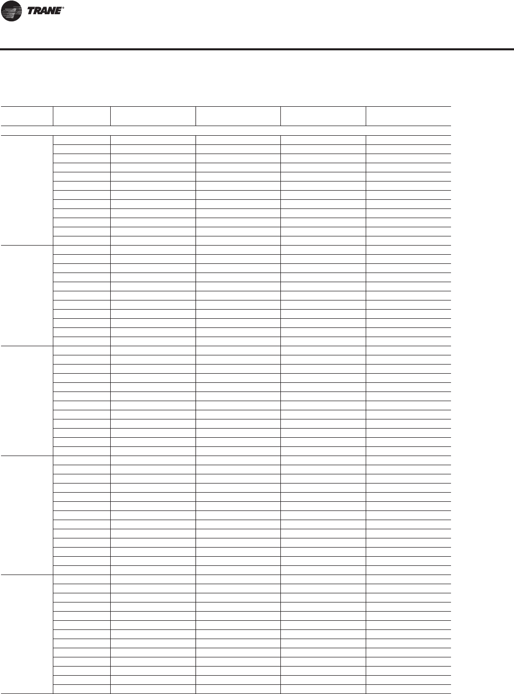
144 RT-PRC027T-EN
Performance Data
Table 51. Energy recovery wheel component static pressure drops — air-cooled and evaporative condensing
Nom Tons
AC/EC CFM Outside Air Bypass
Damper Open Outside Air Bypass
Damper Closed Exhaust Air Bypass
Damper Open Exhaust Air Bypass
Damper Closed
Low CFM Energy Recovery Wheel
90/100
8000 0.07 0.78 0.09 0.66
9000 0.09 0.88 0.11 0.79
10000 0.12 0.99 0.14 0.92
12000 0.16 1.20 0.19 1.16
14000 0.21 1.42 0.24 1.41
16000 0.27 - 0.29 -
20000 0.40 - 0.42 -
25000 0.59 - 0.60 -
30000 0.80 - 0.80 -
33000 0.94 - 0.94 -
36000 1.08 - 1.07 -
40000 1.30 - 1.27 -
105/118
9000 0.09 0.88 0.11 0.79
12000 0.16 1.20 0.19 1.16
14000 0.21 1.42 0.24 1.41
16000 0.27 - 0.29 -
19000 0.36 - 0.39
23000 0.51 - 0.52 -
28000 0.71 - 0.72 -
33000 0.94 - 0.94 -
38000 1.19 - 1.18 -
43000 1.46 - 1.41 -
45000 1.58 - 1.52 -
120/128
9000 0.09 0.78 0.11 0.69
12000 0.16 1.06 0.18 1.02
15000 0.23 1.36 0.26 1.36
18000 0.31 - 0.34 -
21000 0.41 - 0.44 -
26000 0.59 - 0.62 -
31000 0.79 - 0.82 -
36000 1.01 - 1.04 -
41000 1.25 - 1.28 -
46000 1.51 - 1.52 -
51000 1.79 - 1.79 -
54000 1.96 - 1.95 -
130/140
9000 0.09 0.71 0.10 0.62
12000 0.15 0.97 0.18 0.92
16000 0.25 1.34 0.28 1.33
20000 0.36 - 0.40 -
23000 0.46 - 0.49 -
26000 0.57 - 0.60 -
30000 0.72 - 0.75 -
35000 0.93 - 0.97 -
40000 1.16 - 1.20 -
45000 1.40 - 1.43 -
50000 1.67 - 1.69 -
55000 1.95 - 1.96 -
58000 2.12 - 2.12 -
150/162
9000 0.09 0.71 0.10 0.62
12000 0.15 0.97 0.18 0.92
16000 0.25 1.34 0.28 1.33
20000 0.36 - 0.40 -
23000 0.46 - 0.49 -
26000 0.57 - 0.60 -
30000 0.72 - 0.75 -
35000 0.93 - 0.97 -
40000 1.16 - 1.20 -
45000 1.40 - 1.43 -
50000 1.67 - 1.69 -
55000 1.95 - 1.96 -
58000 2.12 - 2.12 -
Continued on next page
Component Static Pressure Drops
RT-PRC027.book Page 144 Tuesday, October 7, 2014 9:03 AM
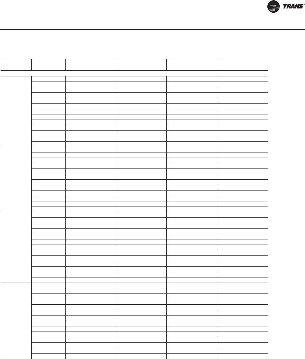
RT-PRC027T-EN 145
Performance Data
Nom Tons
AC/EC CFM Outside Air Bypass
Damper Open Outside Air Bypass
Damper Closed Exhaust Air Bypass
Damper Open Exhaust Air Bypass
Damper Closed
Standard CFM Energy Recovery Wheel
90/100
8000 0.06 0.54 0.07 0.44
9000 0.08 0.61 0.10 0.53
10000 0.10 0.68 0.12 0.62
12000 0.15 0.83 0.17 0.77
14000 0.19 0.99 0.22 0.94
16000 0.24 1.16 0.26 1.12
18000 0.30 1.32 0.31 1.29
20000 0.35 - 0.37 -
25000 0.52 - 0.54 -
30000 0.70 - 0.73 -
33000 0.82 - 0.84 -
36000 0.95 - 0.97 -
40000 1.12 - 1.14 -
105/118
9000 0.08 0.57 0.09 0.47
12000 0.14 0.77 0.16 0.65
14000 0.19 0.93 0.21 0.78
16000 0.24 1.08 0.26 0.91
19000 0.32 1.33 0.34 1.11
21000 0.37 1.49 0.40 1.25
23000 0.44 - 0.46 -
28000 0.61 - 0.64 -
33000 0.80 - 0.82 -
38000 1.00 - 1.03 -
43000 1.23 - 1.25 -
45000 1.33 - 1.34 -
120/128
10000 0.10 0.56 0.11 0.50
12000 0.14 0.69 0.16 0.63
15000 0.20 0.89 0.23 0.85
18000 0.27 1.10 0.29 1.05
21000 0.35 1.33 0.38 1.28
24000 0.43 1.57 0.47 1.51
26000 0.50 - 0.54 -
31000 0.66 - 0.72 -
36000 0.84 - 0.91 -
41000 1.04 - 1.11 -
46000 1.26 - 1.34 -
51000 1.49 - 1.56 -
54000 1.63 - 1.71 -
130-162
13000 0.16 0.59 0.17 0.53
15000 0.20 0.69 0.22 0.63
18000 0.26 0.86 0.28 0.79
21000 0.33 1.04 0.36 0.96
23000 0.38 1.16 0.42 1.06
26000 0.45 1.36 0.50 1.24
29000 0.54 1.57 0.60 1.42
30000 0.57 - 0.63 -
35000 0.72 - 0.80 -
40000 0.89 - 0.98 -
45000 1.08 - 1.17 -
50000 1.28 - 1.38 -
55000 1.50 - 1.60 -
58000 1.63 - 1.74 -
Continued on next page
Table 51. Energy recovery wheel component static pressure drops — air-cooled and evaporative condensing (continued)
Component Static Pressure Drops
RT-PRC027.book Page 145 Tuesday, October 7, 2014 9:03 AM
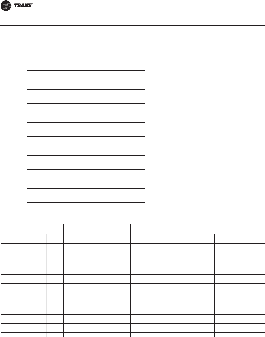
146 RT-PRC027T-EN
Performance Data
Tons
AC/EC CFM Return Damper,
ERW only Econo Damper,
ERW only
90/100
16000 0.14 0.15
20000 0.20 0.24
25000 0.29 0.39
30000 0.42 0.56
33000 0.51 0.69
36000 0.61 0.82
40000 0.75 1.01
105/118
19000 0.19 0.22
23000 0.25 0.33
28000 0.37 0.49
33000 0.51 0.69
38000 0.68 0.91
43000 0.87 1.17
45000 0.96 1.29
120/128
21000 0.22 0.18
26000 0.32 0.27
31000 0.45 0.39
36000 0.61 0.53
41000 0.79 0.69
46000 1.00 0.87
51000 1.24 1.07
54000 1.40 1.20
130/140
150/162
23000 0.25 0.21
26000 0.32 0.27
30000 0.42 0.36
35000 0.57 0.50
40000 0.75 0.65
45000 0.96 0.83
50000 1.19 1.02
55000 1.45 1.24
58000 1.63 1.38
Table 51. Energy recovery wheel component static pressure drops — air-cooled and evaporative condensing (continued)
Table 52. Energy recovery wheel pressure loss P(in. wg) and total effectiveness
Actual Air
Flow CFM
90-118 Tons
Low 120/128 Tons
Low 130-162 Tons
Low 90/100 Tons
Standard 105/118 Tons
Standard 120/128 Tons
Standard 130-162 Tons
Standard
PEff PEff PEff PEff PEff PEff PEff
8000 0.73 77.5 0.64 79.0 0.58 80.0 0.49 81.6
9000 0.82 75.9 0.72 77.6 0.65 78.7 0.55 80.6 0.51 81.3
10000 0.91 74.3 0.80 76.2 0.73 77.5 0.61 79.5 0.56 80.3 0.49 81.6
11000 1.00 72.7 0.88 74.8 0.80 76.2 0.67 78.5 0.62 79.4 0.54 80.7
12000 1.09 71.1 0.96 73.4 0.87 75.0 0.73 77.4 0.67 78.4 0.59 79.8
13000 1.18 69.5 1.04 72.0 0.94 73.7 0.79 76.4 0.73 77.4 0.64 79.0 0.48 74.7
14000 1.12 70.6 1.02 72.4 0.85 75.3 0.79 76.5 0.69 78.1 0.51 72.9
15000 1.20 69.2 1.09 71.1 0.91 74.3 0.84 75.5 0.74 77.3 0.55 71.9
16000 1.16 69.8 0.97 73.2 0.90 74.5 0.79 76.4 0.58 71.0
17000 1.24 68.5 1.03 72.1 0.95 73.5 0.83 75.6 0.61 70.0
18000 1.09 71.1 1.01 72.5 0.88 74.7 0.64 69.0
19000 1.15 70.0 1.07 71.5 0.93 73.9 0.67 68.1
20000 1.22 68.9 1.12 70.5 0.98 73.0 0.71 67.1
21000 1.18 69.5 1.03 72.1 0.74 66.1
22000 1.23 68.5 1.08 71.3 0.77 65.1
23000 1.13 70.4 0.80 64.2
24000 1.18 69.5 0.84 63.2
25000 1.23 68.7 0.87 62.2
26000 0.90 61.2
27000 0.93 60.3
28000 0.97 59.3
29000 1.00 58.3
Component Static Pressure Drops
RT-PRC027.book Page 146 Tuesday, October 7, 2014 9:03 AM
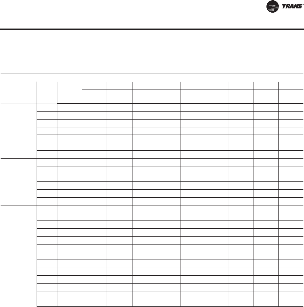
RT-PRC027T-EN 147
Performance Data
Fan Drive Selections
Table 53. Supply air fan drive selections — air-cooled (AC) and evaporative condensing (EC)
Horse Power (hp)
Nom
Tons
AC/EC Low/
Std rpm
15 hp 20 hp 25 hp 30 hp 40 hp 50 hp 60 hp 75 hp 100 hp
Drive
No. Drive
No. Drive
No. Drive
No. Drive
No. Drive
No. Drive
No. Drive
No. Drive
No.
90/100
Low 2000 L
Low 1900 K
Low 1800 J
Low 1700 H
Low 1600 G
Low 1500 F
Low 1400 E E
90-105 AC
100-118 EC
Std 1300 DD
Std 1200 CC
Std 1100 B B
Std 1000 A A
Std 900 9 9 9
Std 800 8 8 8
All
Low 1500 F
Low 1400 EE
Low 1300 D D
Low 1200 C C
Low 1100 B B
Low 1000 A A
Low 900 9 9
120-150 AC
128-162 EC
Std 1200 C
Std 1100 BBB
Std 1000 AAAA
Std 900 9 9 9 9
Std 800 8 8 8 8
Std 700 7 7 7 7
RT-PRC027.book Page 147 Tuesday, October 7, 2014 9:03 AM
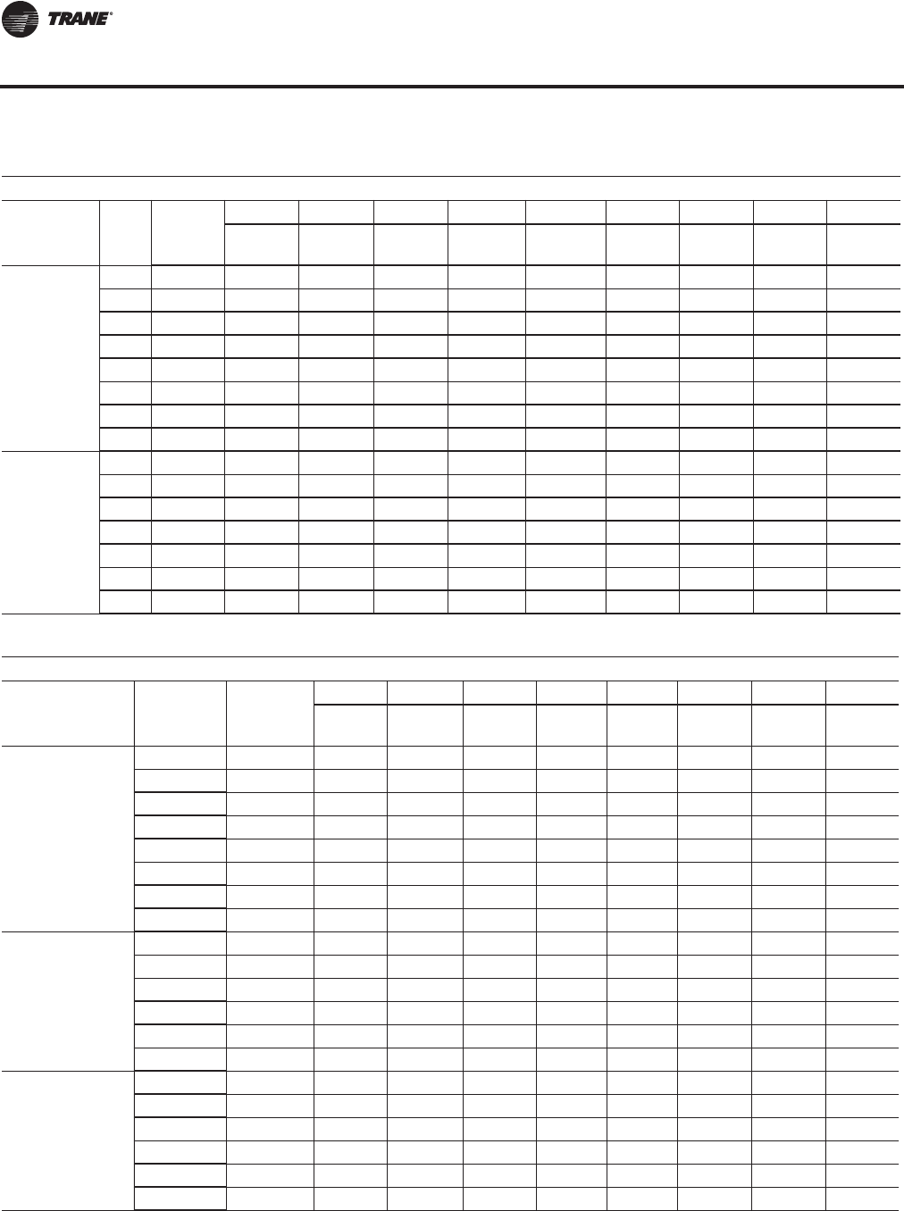
148 RT-PRC027T-EN
Performance Data
Table 54. Exhaust air fan drive selections — air-cooled (AC) and evaporative condensing (EC)
Horse Power (hp)
Nom
Tons Low/
Std rpm
7.5 hp 10 hp 15 hp 20 hp 25 hp 30 hp 40 hp 50 hp 60 hp
Drive
No. Drive
No. Drive
No. Drive No. Drive No. Drive
No. Drive
No. Drive
No. Drive
No.
90 AC
100 EC
Low 700 7 7
Low 600 6 6 6 6 6
Low 500 5 5 5 5
Low 400 4 4 4
Std 600 6 6
Std 500 5 5 5
Std 400 4 4 4 4
Std 300 3 3
105-150 AC/
118-162 EC
Low 600 6 6 6 6 6
Low 500 5 5 5 5 5 5
Low 400 4 4 4 4 4 4 4
Low 300 3 3 3
Std 600 66
Std 500 5 5 5 5 5
Std 400 4 4 4
Table 55. Return air fan drive selections air-cooled (AC) and evaporative condensing (EC)
Horse Power (hp)
Nom
Tons
AC/EC Low/ Std rpm
7.5 hp 10 hp 15 hp 20 hp 25 hp 30 hp 40 hp 50 hp
Drive
No. Drive
No. Drive
No. Drive
No. Drive
No. Drive
No. Drive
No. Drive
No.
All
Low 1400 E
Low 1300 D
Low 1200 C C
Low 1100 B
Low 1000 A A
Low 900 9
Low 800 8 8
Low 700 7
90-105 AC
100-118 EC
Std 1200 C
Std 1100 BB
Std 1000 A A
Std 900 9
Std 800 8
Std 700 7
120-150 AC/
128-162 EC
Std 1100 B
Std 1000 AA
Std 900 99
Std 800 8 8
Std 700 7
Std 600 6
Fan Drive Selections
RT-PRC027.book Page 148 Tuesday, October 7, 2014 9:03 AM

RT-PRC027T-EN 149
Electrical Data
Electrical Service Sizing
To correctly size electrical service wiring for a unit, find the appropriate calculations listed below.
Each type of unit has its own set of calculations for MCA (Minimum Circuit Ampacity), MOP
(Maximum Overcurrent Protection), and RDE (Recommended Dual Element fuse size). Read the
load definitions that follow and then find the appropriate set of calculations based on unit type.
Note: Set 1 is for cooling only and cooling with gas heat units, and set 2 is for cooling with electric
heat units.
Load Definitions: (To determine load values, see the Electrical Service Sizing DataTables on the
following page.)
LOAD1 = CURRENT OFTHE LARGEST MOTOR (COMPRESSOR OR FAN MOTOR)
LOAD2 = SUM OFTHE CURRENTS OF ALL REMAINING MOTORS
LOAD3 = CURRENT OF ELECTRIC HEATERS
LOAD4 = ANY OTHER LOAD RATED AT 1 AMP OR MORE
Set 1. Cooling Only Rooftop Units and Cooling with Gas Heat Rooftop Units
MCA = (1.25 x LOAD1) + LOAD2 + LOAD4
MOP = (2.25 x LOAD1) + LOAD2 + LOAD4
Select a fuse rating equal to the MOP value. If the MOP value does not equal a standard fuse size
as listed in NEC 240-6, select the next lower standard fuse rating.
Note: If selected MOP is less than the MCA, then select the lowest standard maximum fuse size
which is equal to or larger than the MCA, provided the selected fuse size does not exceed
800 amps.
RDE=(1.5xLOAD1)+LOAD2+LOAD4
Select a fuse rating equal to the RDE value. If the RDE value does not equal a standard fuse size as
listed in NEC 240-6, select the next higher standard fuse rating.
Note: If the selected RDE is greater than the selected MOP value, then select the RDE value to equal
the MOP value.
Set 2. Rooftop units with Electric Heat
To arrive at the correct MCA, MOP, and RDE values for these units, two sets of calculations must
be performed. First calculate the MCA, MOP, and RDE values as if the unit was in cooling mode (use
the equations given in Set 1).Then calculate the MCA, MOP, and RDE values as if the unit were in
the heating mode as follows.
(Keep in mind when determining LOADS that the compressors don't run while the unit is in the
heating mode).
MCA = 1.25 x (LOAD1 + LOAD2 + LOAD4) + LOAD3
The nameplate MCA value will be the larger of the cooling mode MCA value or the heating mode
MCA value calculated above.
MOP = (2.25 x LOAD1) + LOAD2 + LOAD3 + LOAD4
The selection MOP value will be the larger of the cooling mode MOP value or the heating mode
MOP value calculated above.
Select a fuse rating equal to the MOP value. If the MOP value does not equal a standard fuse size
as listed in NEC 240-6, select the next lower standard fuse rating.
Note: If selected MOP is less than the MCA, then select the lowest standard maximum fuse size
which is equal to or larger than the MCA, provided the selected fuse size does not exceed
800 amps.
RDE=(1.5xLOAD1)+LOAD2+LOAD3+LOAD4
RT-PRC027.book Page 149 Tuesday, October 7, 2014 9:03 AM
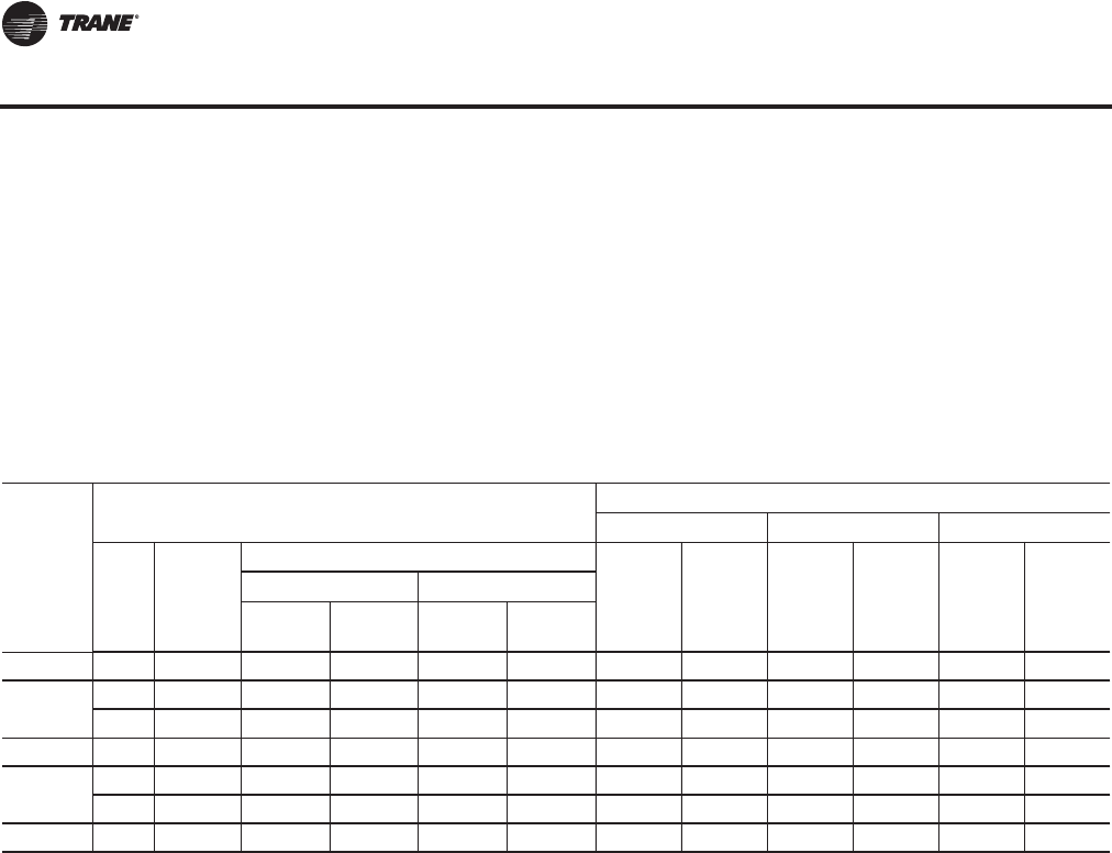
150 RT-PRC027T-EN
Electrical Data
The selection RDE value will be the larger of the cooling mode RDE value or the heating mode RDE
value calculated above.
Select a fuse rating equal to the RDE value. If the RDE value does not equal a standard fuse size as
listed in NEC 240-6, select the next higher standard fuse rating.
Notes:
•If the selected RDE is greater than the selected MOP value, then select the RDE value to equal
the MOP value.
•On 90 to 162 ton rooftops, the selected MOP value is stamped in the MOP field on the unit
nameplate.
Table 56. Electrical service sizing data — air-cooled and evaporative condensing
Nom
Tons
AC/EC
Compressor
Nominal Voltage
460 V 575 V 380 V
Size Number
per Unit
Capacity KW (ea.)
RLA
(ea.) LRA
(ea.) RLA
(ea.) LRA
(ea.) RLA
(ea.) LRA
(ea.)
60 Hz 50 Hz
Std. Coil High Cap
Coil Std. Coil High Cap
Coil
90/100 240 4 21.3 21.6 17.6 17.9 34.1 215 27.3 175 34.0 215
105/118 240 2 24.2 24.5 20.2 20.3 34.1 215 27.3 175 34.0 215
300 2 25.0 25.3 20.9 21.0 44.7 260 35.8 210 44.6 260
120/128 300 4 26.9 27.8 22.4 23.0 44.7 260 35.8 210 44.6 260
130/140 300 2 28.5 28.8 23.8 23.8 44.7 260 35.8 210 44.6 260
380 2 33.7 34.2 28.2 28.2 52.1 320 41.1 235 52.0 320
150/162 380 4 34.7 -- 28.7 -- 52.1 320 41.1 235 52.0 320
RT-PRC027.book Page 150 Tuesday, October 7, 2014 9:03 AM

RT-PRC027T-EN 151
Electrical Data
Table 57. Electrical service sizing data—motors — air-cooled and evaporative condensing
Condenser Fan Motors
Nominal Tons No. of Fans
460 V 575 V 380 V
FLA FLA FLA
Air-Cooled Condenser Fan Motors
90-105 6 16.2 13.2 15
120, 130, 150 8 21.6 17.6 20
Evaporative Condensing Condenser Motors
100 2 11.8 N/A N/A
118, 128, 140, 162 2 11.8 N/A N/A
Supply Fan Motors
Motor Horsepower
460 V 575 V 380 V
FLA FLA FLA
15 18.5 15.1 24
20 24.7 19.6 29
25 31.0 24.5 38
30 36.6 29.2 47
40 49.0 39 54
50 60.5 48 68
60 71.5 57.2 81
75 90 72 103
100 115 92 N/A
Exhaust/Return Fan Motors
Motor Horsepower
460 V 575 V 380 V
FLA FLA FLA
7.5 9.4 7.8 13.6
10 12.6 10.1 16
15 18.5 15.1 24
20 24.7 19.6 29
25 31 24.5 38
30 36.6 29.2 47
40 49.0 39 54
50 60.5 48 68
60 71.5 57.2 81
Table 58. Electrical service sizing data—electric heat module (electric heat units only)
Module KW
Voltage
460 575 380
FLA FLA FLA
90 / 56 108.3 86.6 85.1
140 / 88 168.4 134.7 133.7
265 / 166 318.8 255 252.2
300 / 188 360.8 288.7 285.6
RT-PRC027.book Page 151 Tuesday, October 7, 2014 9:03 AM
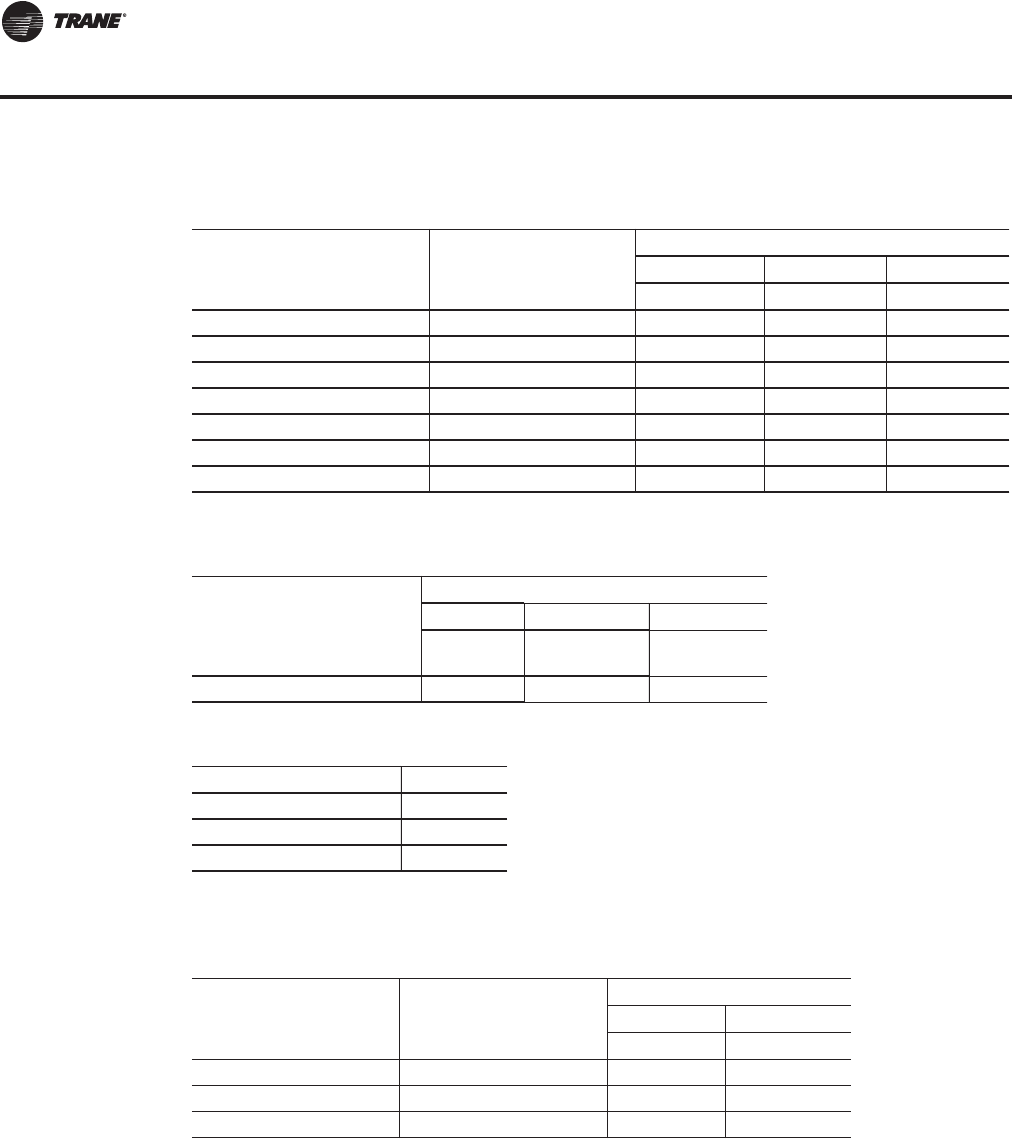
152 RT-PRC027T-EN
Electrical Data
Table 59. Electrical service sizing data—control power transformer (heating mode only)
— air-cooled and evaporative condensing
Nominal Tons
AC/EC Digit 2 Unit Function
Voltages
460 575 380
FLA FLA FLA
90-150/100-162 E, L, S, X 3 3 4
90, 105/100, 118 F (850 mbh) 4 4 5
90, 105/100, 118 F (1100 mbh) 4 4 5
90, 105/100, 118 F (1800 mbh) 4 4 5
120-150/128-162 F (1100 mbh) 4 4 5
120-150/128-162 F (1800 mbh) 4 4 5
120-150/128-162 F (2500 mbh) 4 4 5
Table 60. Electrical service sizing data—crankcase heater — air-cooled and evaporative
condensing
Nominal Tons
AC/EC
Voltage
460 575 380
FLA (add) FLA
(add) FLA
(add)
All 1 1 1
Table 61. Voltage utilization range
Unit Voltage
460/60/3 414-506
575/60/3(a)
(a)Units with air-cooled condensers only.
517-633
380/50/3(i) 342-418
Table 62. Electrical service sizing data—energy recovery wheel motor — air-cooled and
evaporative condensing
Nominal Tons
AC/EC Unit Function
Voltage
460 575
FLA FLA
90-120/100-128 1 (Low CFM ERW) 1.2 0.95
130-150/140-162 1 (Low CFM ERW) 1.7 1.4
All 2 (Std. CFM ERW) 1.7 1.4
RT-PRC027.book Page 152 Tuesday, October 7, 2014 9:03 AM
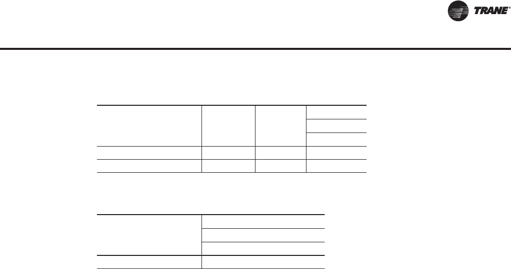
RT-PRC027T-EN 153
Electrical Data
Table 63. Electrical service sizing data—evaporative condenser
Unit Part kW hp
Voltage
460
FLA
Pump 1.5 2.7
Sump Heater 3 3.8
Table 64. Electrical service sizing data—convenience outlet transformer
air-cooled (AC) and evaporative condensing (EC)
Nominal Tons
AC/EC
Voltage
460 575
FLA (add) FLA (add)
All 3.3 2.6
RT-PRC027.book Page 153 Tuesday, October 7, 2014 9:03 AM
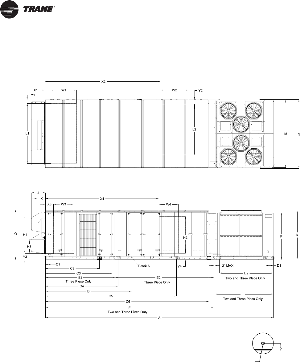
154 RT-PRC027T-EN
Dimensional Data
Figure 37. Unit top/left view(a)
(a)Representative view showing air-cooled condenser fans; for a representative view with evaporative condensing fans, see Figure 12, p. 14.
1-1/4 NPT. DRAIN
2X TYP. LEFT & RIGHT SIDES OF UNIT
Detail A
RT-PRC027.book Page 154 Tuesday, October 7, 2014 9:03 AM
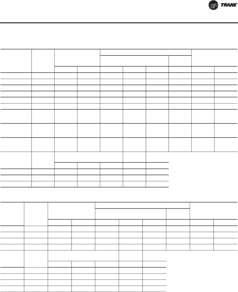
RT-PRC027T-EN 155
Dimensional Data
Table 65. Unit dimensions (in.)—ONE-PIECE unit air-cooled—WITHOUT energy recovery wheel
Tonnage Blank
Section
Unit Dimensions
Lifting Lug Locations
Unit WidthAir Handler Side Condenser
Side
A B C1 C2 C3 D1 M N
90 None 437 3/16 159 15/16 66 252 14/16 N/A 27 11/16 139 13/16 143 8/16
90 4 ft 485 6/16 159 15/16 66 252 14/16 N/A 54 2/16 139 13/16 143 8/16
90 8 ft 533 9/16 159 15/16 66 252 14/16 N/A 54 2/16 139 13/16 143 8/16
105 None 455 3/16 159 15/16 66 252 14/16 N/A 27 11/16 139 13/16 143 8/16
105 4 ft 503 6/16 159 15/16 66 252 14/16 N/A 54 2/16 139 13/16 143 8/16
105 8 ft 551 9/16 159 15/16 66 252 14/16 N/A 54 2/16 139 13/16 143 8/16
120-150 (All Units
Except High Heat
Gas Models) None 528 15/16 197 1/16 66 269 6/16 N/A 63 2/16 139 13/16 143 8/16
120-150 (All Units
Except High Heat
Gas Models) 4 ft 577 2/16 197 1/16 66 269 6/16 N/A 63 2/16 139 13/16 143 8/16
120-150 (High
Heat Gas Models
Only) None 540 15/16 197 1/16 66 269 6/16 N/A 63 2/16 139 13/16 143 8/16
Tonnage Blank
Section
Unit Height Return Fan Exhaust
Fan
OPRJK
90-150 None 103 12/16 97 9/16 103 7/16 29 3/16 17
90-150 4 ft 103 12/16 97 9/16 103 7/16 29 3/16 17
90-150 8 ft 103 12/16 97 9/16 103 7/16 29 3/16 17
Table 66. Unit dimensions (in.)—ONE-PIECE unit air-cooled—WITH energy recovery wheel
Tonnage Blank
Section
Unit Dimensions
Lifting Lug Locations
Unit WidthAir Handler Side Condenser
Side
A B C1 C2 C3 D1 M N
90 None 533 9/16 256 5/16 66 201 1/16 349 4/16 27 11/16 139 13/16 143 8/16
90 4 ft 581 13/16 256 5/16 66 201 1/16 349 4/16 54 2/16 139 13/16 143 8/16
105 None 551 9/16 256 5/16 66 201 1/16 349 4/16 27 11/16 139 13/16 143 8/16
105 4 ft 599 13/16 256 5/16 66 201 1/16 349 4/16 54 2/16 139 13/16 143 8/16
Tonnage Blank
Section
Unit Height Return Fan Exhaust
Fan
OPRJK
90 None 103 12/16 97 9/16 103 7/16 N/A 17
90 4 ft 103 12/16 97 9/16 103 7/16 N/A 17
105 None 103 12/16 97 9/16 103 7/16 N/A 17
105 4 ft 103 12/16 97 9/16 103 7/16 N/A 17
Unit Dimensions
RT-PRC027.book Page 155 Tuesday, October 7, 2014 9:03 AM
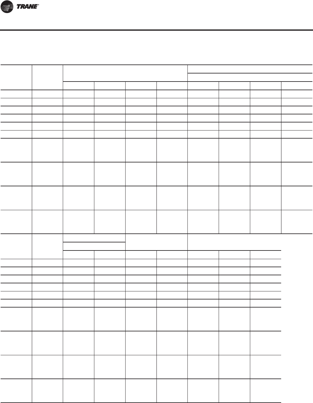
156 RT-PRC027T-EN
Dimensional Data
Table 67. Unit dimensions (in.)—TWO-PIECE unit air-cooled—WITHOUT energy recovery wheel
Tonnage Blank
Section
Unit Dimensions
Lifting Lug Locations
Air Handler Side
A B E F C1 C2 C3 C4
90 None 454 4/16 159 15/16 330 14/16 121 6/16 66 252 14/16 N/A N/A
90 4 ft 502 7/16 159 15/16 379 1/16 121 6/16 66 252 14/16 368 6/16 N/A
90 8 ft 550 11/16 159 15/16 427 4/16 121 6/16 66 252 14/16 416 10/16 N/A
105 None 472 4/16 159 15/16 330 14/16 139 6/16 66 252 14/16 N/A N/A
105 4 ft 520 7/16 159 15/16 379 1/16 139 6/16 66 252 14/16 368 6/16 N/A
105 8 ft 568 11/16 159 15/16 427 4/16 139 6/16 66 252 14/16 416 10/16 N/A
120-150 (All
Units Except
High Heat
Gas Models)
None 546 197 1/16 395 10/16 148 6/16 66 269 6/16 384 15/16 N/A
120-150 (All
Units Except
High Heat
Gas Models)
4 ft 594 4/16 197 1/16 443 13/16 148 6/16 66 269 6/16 433 2/16 N/A
120-150 (All
Units Except
High Heat
Gas Models)
8 ft 642 7/16 197 1/16 492 1/16 148 6/16 66 269 6/16 481 6/16 N/A
120-150
(High Heat
Gas Models
Only)
None 558 197 1/16 407 10/16 148 6/16 66 269 6/16 396 15/16 N/A
Tonnage Blank
Section
Lug Locations
Unit Width Unit HeightCondenser Side
D1 D2 M N O P R
90 None 16 112 7/16 139 13/16 143 8/16 103 12/16 97 9/16 103 7/16
90 4 ft 16 112 7/16 139 13/16 143 8/16 103 12/16 97 9/16 103 7/16
90 8 ft 16 112 7/16 139 13/16 143 8/16 103 12/16 97 9/16 103 7/16
105 None 16 130 7/16 139 13/16 143 8/16 103 12/16 97 9/16 103 7/16
105 4 ft 16 130 7/16 139 13/16 143 8/16 103 12/16 97 9/16 103 7/16
105 8 ft 16 130 7/16 139 13/16 143 8/16 103 12/16 97 9/16 103 7/16
120-150 (All
Units Except
High Heat
Gas Models)
None 16 139 7/16 139 13/16 143 8/16 103 12/16 97 9/16 103 7/16
120-150 (All
Units Except
High Heat
Gas Models)
4 ft 16 139 7/16 139 13/16 143 8/16 103 12/16 97 9/16 103 7/16
120-150 (All
Units Except
High Heat
Gas Models)
8 ft 16 139 7/16 139 13/16 143 8/16 103 12/16 97 9/16 103 7/16
120-150
(High Heat
Gas Models
Only)
None 16 139 7/16 139 13/16 143 8/16 103 12/16 97 9/16 103 7/16
Continued on next page
Unit Dimensions
RT-PRC027.book Page 156 Tuesday, October 7, 2014 9:03 AM
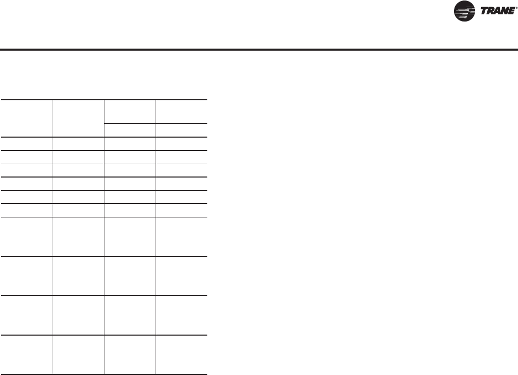
RT-PRC027T-EN 157
Dimensional Data
Tonnage Blank
Section
Return Fan Exhaust
Fan
JK
90 None 29 3/16 17
90 4 ft 29 3/16 17
90 8 ft 29 3/16 17
105 None 29 3/16 17
105 4 ft 29 3/16 17
105 8 ft 29 3/16 17
120-150 (All
Units Except
High Heat
Gas Models)
None 29 3/16 17
120-150 (All
Units Except
High Heat
Gas Models)
4 ft 29 3/16 17
120-150 (All
Units Except
High Heat
Gas Models)
8 ft 29 3/16 17
120-150
(High Heat
Gas Models
Only)
None 29 3/16 17
Table 67. Unit dimensions (in.)—TWO-PIECE unit air-cooled—WITHOUT energy recovery wheel (continued)
Unit Dimensions
RT-PRC027.book Page 157 Tuesday, October 7, 2014 9:03 AM
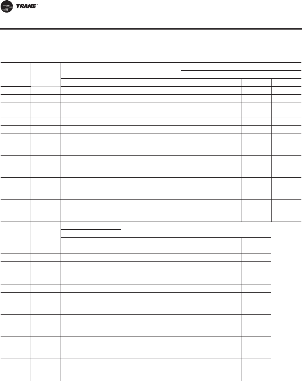
158 RT-PRC027T-EN
Dimensional Data
Table 68. Unit dimensions (in.)—TWO-PIECE unit air-cooled—WITH energy recovery wheel
Tonnage Blank
Section
Unit Dimensions
Lifting Lug Locations
Air Handler Side
A B E F C1 C2 C3 C4
90 None 550 11/16 256 5/16 427 5/16 121 6/16 66 201 1/16 349 4/16 N/A
90 4 ft 598 14/16 256 5/16 475 8/16 121 6/16 66 201 1/16 349 4/16 464 13/16
90 8 ft 647 2/16 256 5/16 523 12/16 121 6/16 66 201 1/16 349 4/16 513
105 None 568 11/16 256 5/16 427 5/16 139 6/16 66 201 1/16 349 4/16 N/A
105 4 ft 616 14/16 256 5/16 475 8/16 139 6/16 66 201 1/16 349 4/16 464 13/16
105 8 ft 665 2/16 256 5/16 523 12/16 139 6/16 66 201 1/16 349 4/16 513
120-150 (All
Units Except
High Heat
Gas Models)
None 642 7/16 293 8/16 492 1/16 148 6/16 66 238 5/16 365 5/16 480 14/16
120-150 (All
Units Except
High Heat
Gas Models)
4 ft 690 10/16 293 8/16 540 4/16 148 6/16 66 238 5/16 365 5/16 529 2/16
120-150 (All
Units Except
High Heat
Gas Models)
8 ft 738 14/16 293 8/16 588 8/16 148 6/16 66 238 5/16 365 5/16 577 5/16
120-150
(High Heat
Gas Models
Only)
None 654 7/16 293 8/16 504 1/16 148 6/16 66 238 5/16 365 5/16 492 14/16
Tonnage Blank
Section
Lug Locations
Unit Width Unit HeightCondenser Side
D1 D2 M N O P R
90 None 16 112 7/16 139 13/16 143 8/16 103 12/16 97 9/16 103 7/16
90 4 ft 16 112 7/16 139 13/16 143 8/16 103 12/16 97 9/16 103 7/16
90 8 ft 16 112 7/16 139 13/16 143 8/16 103 12/16 97 9/16 103 7/16
105 None 16 130 7/16 139 13/16 143 8/16 103 12/16 97 9/16 103 7/16
105 4 ft 16 130 7/16 139 13/16 143 8/16 103 12/16 97 9/16 103 7/16
105 8 ft 16 130 7/16 139 13/16 143 8/16 103 12/16 97 9/16 103 7/16
120-150 (All
Units Except
High Heat
Gas Models)
None 16 139 7/16 139 13/16 143 8/16 103 12/16 97 9/16 103 7/16
120-150 (All
Units Except
High Heat
Gas Models)
4 ft 16 139 7/16 139 13/16 143 8/16 103 12/16 97 9/16 103 7/16
120-150 (All
Units Except
High Heat
Gas Models)
8 ft 16 139 7/16 139 13/16 143 8/16 103 12/16 97 9/16 103 7/16
120-150
(High Heat
Gas Models
Only)
None 16 139 7/16 139 13/16 143 8/16 103 12/16 97 9/16 103 7/16
Continued on next page
Unit Dimensions
RT-PRC027.book Page 158 Tuesday, October 7, 2014 9:03 AM
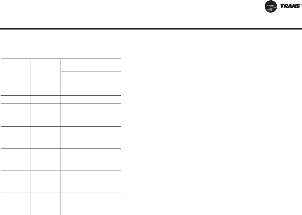
RT-PRC027T-EN 159
Dimensional Data
Tonnage Blank
Section
Return Fan Exhaust
Fan
JK
90 None N/A 17
90 4 ft N/A 17
90 8 ft N/A 17
105 None N/A 17
105 4 ft N/A 17
105 8 ft N/A 17
120-150 (All
Units Except
High Heat
Gas Models)
None N/A 17
120-150 (All
Units Except
High Heat
Gas Models)
4 ft N/A 17
120-150 (All
Units Except
High Heat
Gas Models)
8 ft N/A 17
120-150
(High Heat
Gas Models
Only)
None N/A 17
Table 68. Unit dimensions (in.)—TWO-PIECE unit air-cooled—WITH energy recovery wheel (continued)
Unit Dimensions
RT-PRC027.book Page 159 Tuesday, October 7, 2014 9:03 AM
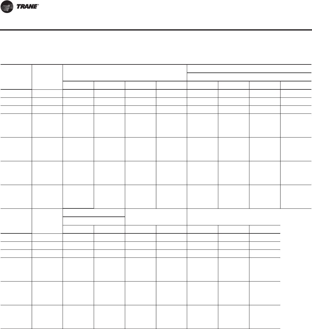
160 RT-PRC027T-EN
Dimensional Data
Table 69. Unit dimensions (in.)—TWO-PIECE unit evaporative condensing—WITHOUT energy recovery wheel
Tonnage Blank
Section
Unit Dimensions
Lifting Lug Locations
Air Handler Side
A B E F C1 C2 C3 C4
100-118 None 475 8/16 159 15/16 330 14/16 142 10/16 66 252 14/16 N/A N/A
100-118 4 ft 523 12/16 159 15/16 379 1/16 142 10/16 66 252 14/16 368 6/16 N/A
100-118 8 ft 571 15/16 159 15/16 427 5/16 142 10/16 66 252 14/16 416 10/16 N/A
128-162 (All
Units Except
High Heat
Gas Models)
None 540 5/16 197 1/16 395 10/16 142 10/16 66 269 6/16 384 15/16 N/A
128-162 (All
Units Except
High Heat
Gas Models)
4 ft 588 8/16 197 1/16 443 14/16 142 10/16 66 269 6/16 433 2/16 N/A
128-162 (All
Units Except
High Heat
Gas Models)
8 ft 636 11/16 197 1/16 492 1/16 142 10/16 66 269 6/16 481 6/16 N/A
128-162
(High Heat
Gas Models
Only)
None 552 5/16 197 1/16 407 10/16 142 10/16 66 269 6/16 396 15/16 N/A
Tonnage Blank
Section
Lug Locations
Unit Width Unit HeightCondenser Side
D1 D2 M N O P R
100-118 None 16 133 11/16 139 13/16 143 8/16 103 12/16 97 9/16 102 6/16
100-118 4 ft 16 133 11/16 139 13/16 143 8/16 103 12/16 97 9/16 102 6/16
100-118 8 ft 16 133 11/16 139 13/16 143 8/16 103 12/16 97 9/16 102 6/16
128-162 (All
Units Except
High Heat
Gas Models)
None 16 133 11/16 139 13/16 143 8/16 103 12/16 97 9/16 102 6/16
128-162 (All
Units Except
High Heat
Gas Models)
4 ft 16 133 11/16 139 13/16 143 8/16 103 12/16 97 9/16 102 6/16
128-162 (All
Units Except
High Heat
Gas Models)
8 ft 16 133 11/16 139 13/16 143 8/16 103 12/16 97 9/16 102 6/16
Continued on next page
Unit Dimensions
RT-PRC027.book Page 160 Tuesday, October 7, 2014 9:03 AM

RT-PRC027T-EN 161
Dimensional Data
Tonnage Blank
Section
Return Fan Exhaust
Fan
JK
100-118 None 29 3/16 17
100-118 4 ft 29 3/16 17
100-118 8 ft 29 3/16 17
128-162 (All
Units Except
High Heat
Gas Models)
None 29 3/16 17
128-162 (All
Units Except
High Heat
Gas Models)
4 ft 29 3/16 17
128-162 (All
Units Except
High Heat
Gas Models)
8 ft 29 3/16 17
128-162
(High Heat
Gas Models
Only)
None 29 3/16 17
Table 69. Unit dimensions (in.)—TWO-PIECE unit evaporative condensing—WITHOUT energy recovery wheel
Unit Dimensions
RT-PRC027.book Page 161 Tuesday, October 7, 2014 9:03 AM
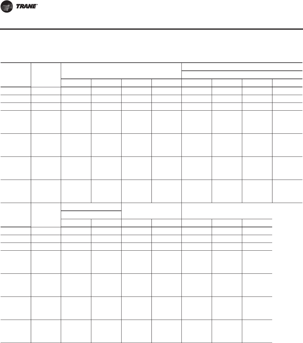
162 RT-PRC027T-EN
Dimensional Data
Table 70. Unit dimensions (in.)—TWO-PIECE unit evaporative condensing—WITH energy recovery wheel
Tonnage Blank
Section
Unit Dimensions
Lifting Lug Locations
Air Handler Side
A B E F C1 C2 C3 C4
100-118 None 571 15/16 256 5/16 427 5/16 142 10/16 66 201 1/16 349 4/16 N/A
100-118 4 ft 620 3/16 256 5/16 475 8/16 142 10/16 66 201 1/16 349 4/16 464 13/16
100-118 8 ft 668 6/16 256 5/16 523 12/16 142 10/16 66 201 1/16 349 4/16 513
128-162 (All
Units Except
High Heat
Gas Models)
None 636 11/16 293 8/16 492 1/16 142 10/16 66 238 5/16 365 5/16 480 14/16
128-162 (All
Units Except
High Heat
Gas Models)
4 ft 684 15/16 293 8/16 540 4/16 142 10/16 66 238 5/16 365 5/16 529 2/16
128-162 (All
Units Except
High Heat
Gas Models)
8 ft 733 2/16 293 8/16 588 8/16 142 10/16 66 238 5/16 365 5/16 577 5/16
128-162
(High Heat
Gas Models
Only)
None 648 11/16 293 8/16 504 1/16 142 10/16 66 238 5/16 365 5/16 492 14/16
Tonnage Blank
Section
Lug Locations
Unit Width Unit HeightCondenser Side
D1 D2 M N O P R
100-118 None 16 133 11/16 139 13/16 143 8/16 103 12/16 97 9/16 102 6/16
100-118 4 ft 16 133 11/16 139 13/16 143 8/16 103 12/16 97 9/16 102 6/16
100-118 8 ft 16 133 11/16 139 13/16 143 8/16 103 12/16 97 9/16 102 6/16
128-162 (All
Units Except
High Heat
Gas Models)
None 16 133 11/16 139 13/16 143 8/16 103 12/16 97 9/16 102 6/16
128-162 (All
Units Except
High Heat
Gas Models)
4 ft 16 133 11/16 139 13/16 143 8/16 103 12/16 97 9/16 102 6/16
128-162 (All
Units Except
High Heat
Gas Models)
8 ft 16 133 11/16 139 13/16 143 8/16 103 12/16 97 9/16 102 6/16
128-162 (All
Units Except
High Heat
Gas Models)
None 16 133 11/16 139 13/16 143 8/16 103 12/16 97 9/16 102 6/16
Continued on next page
Unit Dimensions
RT-PRC027.book Page 162 Tuesday, October 7, 2014 9:03 AM

RT-PRC027T-EN 163
Dimensional Data
Tonnage Blank
Section
Return Fan Exhaust
Fan
JK
100-118 None N/A 17
100-118 4 ft N/A 17
100-118 8 ft N/A 17
128-162 (All
Units Except
High Heat
Gas Models)
None N/A 17
128-162 (All
Units Except
High Heat
Gas Models)
4 ft N/A 17
128-162 (All
Units Except
High Heat
Gas Models)
8 ft N/A 17
128-162
(High Heat
Gas Models
Only)
None N/A 17
Table 70. Unit dimensions (in.)—TWO-PIECE unit evaporative condensing—WITH energy recovery wheel (continued)
Unit Dimensions
RT-PRC027.book Page 163 Tuesday, October 7, 2014 9:03 AM
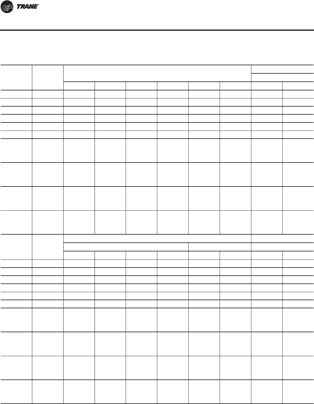
164 RT-PRC027T-EN
Dimensional Data
Table 71. Unit dimensions (in.)—THREE-PIECE unit air-cooled—WITHOUT energy recovery wheel
Tonnage Blank
Section
Unit Dimensions
Lifting Lug Locations
Air Handler Side
A B E E1 E2 F C1 C2
90 None 473 9/16 179 3/16 350 3/16 144 15/16 205 3/16 121 6/16 11 14/16 N/A
90 4 ft 521 12/16 179 3/16 398 6/16 144 15/16 253 7/16 121 6/16 11 14/16 N/A
90 8 ft 569 15/16 179 3/16 446 9/16 144 15/16 301 10/16 121 6/16 11 14/16 N/A
105 None 491 9/16 179 3/16 350 3/16 144 15/16 205 3/16 139 6/16 11 14/16 N/A
105 4 ft 539 12/16 179 3/16 398 6/16 144 15/16 253 7/16 139 6/16 11 14/16 N/A
105 8 ft 587 15/16 179 3/16 446 9/16 144 15/16 301 10/16 139 6/16 11 14/16 N/A
120-150 (All
Units Except
High Heat
Gas Models)
None 571 8/16 222 9/16 421 2/16 161 2/16 260 148 6/16 11 14/16 N/A
120-150 (All
Units Except
High Heat
Gas Models)
4 ft 619 11/16 222 9/16 469 5/16 161 2/16 308 4/16 148 6/16 11 14/16 N/A
120-150 (All
Units Except
High Heat
Gas Models)
8 ft 667 15/16 222 9/16 517 9/16 161 2/16 356 7/16 148 6/16 11 14/16 N/A
120-150
(High Heat
Gas Models
Only)
None 583 8/16 222 9/16 433 2/16 161 2/16 272 148 6/16 11 14/16 N/A
Tonnage Blank
Section
Lug Locations
Air Handler Side Condenser Side Unit Width
C3 C4 C5 C6 D1 D2 M N
90 None 138 9/16 151 6/16 272 339 11/16 16 112 7/16 139 13/16 143 8/16
90 4 ft 138 9/16 151 6/16 272 387 14/16 16 112 7/16 139 13/16 143 8/16
90 8 ft 138 9/16 151 6/16 272 436 1/16 16 112 7/16 139 13/16 143 8/16
105 None 138 9/16 151 6/16 272 339 11/16 16 130 7/16 139 13/16 143 8/16
105 4 ft 138 9/16 151 6/16 272 387 14/16 16 130 7/16 139 13/16 143 8/16
105 8 ft 138 9/16 151 6/16 272 436 1/16 16 130 7/16 139 13/16 143 8/16
120-150 (All
Units Except
High Heat
Gas Models)
None 155 2/16 167 5/16 294 14/16 410 10/16 16 139 7/16 139 13/16 143 8/16
120-150 (All
Units Except
High Heat
Gas Models)
4 ft 155 2/16 167 5/16 294 14/16 458 13/16 16 139 7/16 139 13/16 143 8/16
120-150 (All
Units Except
High Heat
Gas Models)
8 ft 155 2/16 167 5/16 294 14/16 507 1/16 16 139 7/16 139 13/16 143 8/16
120-150
(High Heat
Gas Models
Only)
None 155 2/16 167 5/16 294 14/16 422 10/16 16 139 7/16 139 13/16 143 8/16
Continued on next page
Unit Dimensions
RT-PRC027.book Page 164 Tuesday, October 7, 2014 9:03 AM
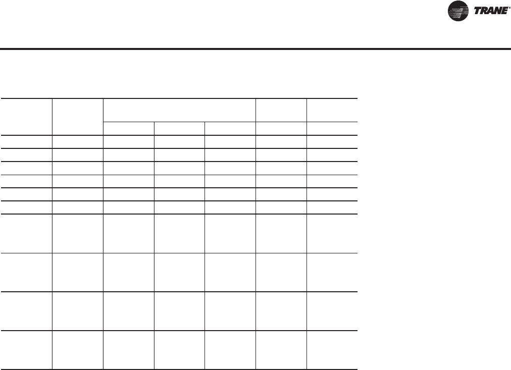
RT-PRC027T-EN 165
Dimensional Data
Tonnage Blank
Section
Unit Height Return Fan Exhaust
Fan
OPRJK
90 None 103 12/16 97 9/16 103 7/16 29 3/16 17
90 4 ft 103 12/16 97 9/16 103 7/16 29 3/16 17
90 8 ft 103 12/16 97 9/16 103 7/16 29 3/16 17
105 None 103 12/16 97 9/16 103 7/16 29 3/16 17
105 4 ft 103 12/16 97 9/16 103 7/16 29 3/16 17
105 8 ft 103 12/16 97 9/16 103 7/16 29 3/16 17
120-150 (All
Units Except
High Heat
Gas Models)
None 103 12/16 97 9/16 103 7/16 29 3/16 17
120-150 (All
Units Except
High Heat
Gas Models)
4 ft 103 12/16 97 9/16 103 7/16 29 3/16 17
120-150 (All
Units Except
High Heat
Gas Models)
8 ft 103 12/16 97 9/16 103 7/16 29 3/16 17
120-150
(High Heat
Gas Models
Only)
None 103 12/16 97 9/16 103 7/16 29 3/16 17
Table 71. Unit dimensions (in.)—THREE-PIECE unit air-cooled—WITHOUT energy recovery wheel (continued)
Unit Dimensions
RT-PRC027.book Page 165 Tuesday, October 7, 2014 9:03 AM
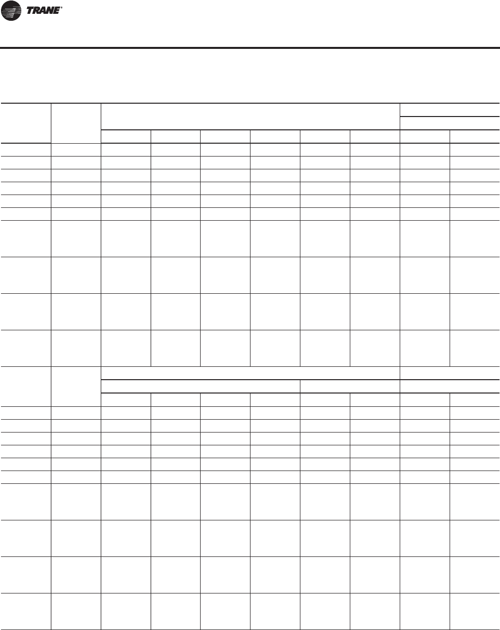
166 RT-PRC027T-EN
Dimensional Data
Table 72. Unit dimensions (in.)—THREE-PIECE unit air-cooled—WITH energy recovery wheel
Tonnage Blank
Section
Unit Dimensions
Lifting Lug Locations
Air Handler Side
A B E E1 E2 F C1 C2
90 None 569 15/16 275 10/16 446 9/16 241 6/16 205 3/16 121 6/16 17 12/16 201 1/16
90 4 ft 618 3/16 275 10/16 494 13/16 241 6/16 253 7/16 121 6/16 17 12/16 201 1/16
90 8 ft 666 6/16 275 10/16 543 241 6/16 301 10/16 121 6/16 17 12/16 201 1/16
105 None 587 15/16 275 10/16 446 9/16 241 6/16 205 3/16 139 6/16 17 12/16 201 1/16
105 4 ft 636 3/16 275 10/16 494 13/16 241 6/16 253 7/16 139 6/16 17 12/16 201 1/16
105 8 ft 684 6/16 275 10/16 543 241 6/16 301 10/16 139 6/16 17 12/16 201 1/16
120-150 (All
Units Except
High Heat
Gas Models)
None 667 15/16 318 15/16 517 9/16 257 8/16 260 148 6/16 17 12/16 204 7/16
120-150 (All
Units Except
High Heat
Gas Models)
4 ft 716 2/16 318 15/16 565 12/16 257 8/16 308 4/16 148 6/16 17 12/16 204 7/16
120-150 (All
Units Except
High Heat
Gas Models)
8 ft 764 5/16 318 15/16 613 15/16 257 8/16 356 7/16 148 6/16 17 12/16 204 7/16
120-150
(High Heat
Gas Models
Only)
None 679 15/16 318 15/16 529 9/16 257 8/16 272 148 6/16 17 12/16 204 7/16
Tonnage Blank
Section
Lug Locations
Air Handler Side Condenser Side Unit Width
C3 C4 C5 C6 D1 D2 M N
90 None 234 13/16 247 13/16 368 7/16 436 2/16 16 112 7/16 139 13/16 143 8/16
90 4 ft 234 13/16 247 13/16 368 7/16 484 5/16 16 112 7/16 139 13/16 143 8/16
90 8 ft 234 13/16 247 13/16 368 7/16 532 8/16 16 112 7/16 139 13/16 143 8/16
105 None 234 13/16 247 13/16 368 7/16 436 2/16 16 130 7/16 139 13/16 143 8/16
105 4 ft 234 13/16 247 13/16 368 7/16 484 5/16 16 130 7/16 139 13/16 143 8/16
105 8 ft 234 13/16 247 13/16 368 7/16 532 8/16 16 130 7/16 139 13/16 143 8/16
120-150 (All
Units Except
High Heat
Gas Models)
None 252 12/16 263 12/16 391 5/16 507 1/16 16 139 7/16 139 13/16 143 8/16
120-150 (All
Units Except
High Heat
Gas Models)
4 ft 252 12/16 263 12/16 391 5/16 555 4/16 16 139 7/16 139 13/16 143 8/16
120-150 (All
Units Except
High Heat
Gas Models)
8 ft 252 12/16 263 12/16 391 5/16 603 7/16 16 139 7/16 139 13/16 143 8/16
120-150
(High Heat
Gas Models
Only)
None 252 12/16 263 12/16 391 5/16 519 1/16 16 139 7/16 139 13/16 143 8/16
Continued on next page
Unit Dimensions
RT-PRC027.book Page 166 Tuesday, October 7, 2014 9:03 AM
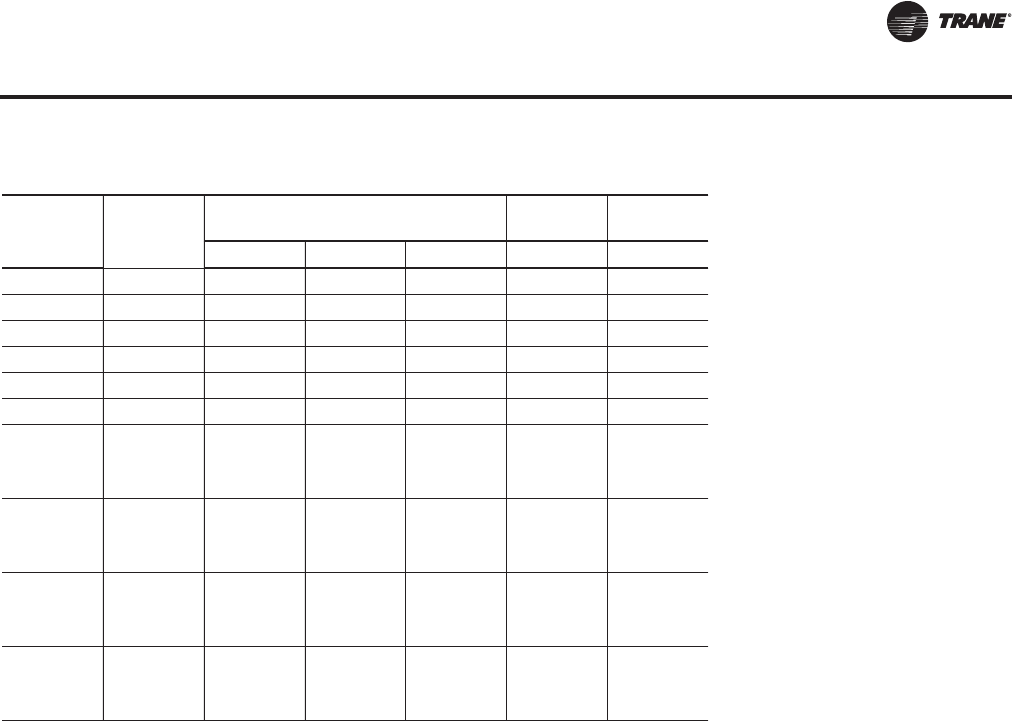
RT-PRC027T-EN 167
Dimensional Data
Tonnage Blank
Section
Unit Height Return Fan Exhaust
Fan
OPRJK
90 None 103 12/16 97 9/16 103 7/16 N/A 17
90 4 ft 103 12/16 97 9/16 103 7/16 N/A 17
90 8 ft 103 12/16 97 9/16 103 7/16 N/A 17
105 None 103 12/16 97 9/16 103 7/16 N/A 17
105 4 ft 103 12/16 97 9/16 103 7/16 N/A 17
105 8 ft 103 12/16 97 9/16 103 7/16 N/A 17
120-150 (All
Units Except
High Heat
Gas Models)
None 103 12/16 97 9/16 103 7/16 N/A 17
120-150 (All
Units Except
High Heat
Gas Models)
4 ft 103 12/16 97 9/16 103 7/16 N/A 17
120-150 (All
Units Except
High Heat
Gas Models)
8 ft 103 12/16 97 9/16 103 7/16 N/A 17
120-150
(High Heat
Gas Models
Only)
None 103 12/16 97 9/16 103 7/16 N/A 17
Table 72. Unit dimensions (in.)—THREE-PIECE unit air-cooled—WITH energy recovery wheel (continued)
Unit Dimensions
RT-PRC027.book Page 167 Tuesday, October 7, 2014 9:03 AM
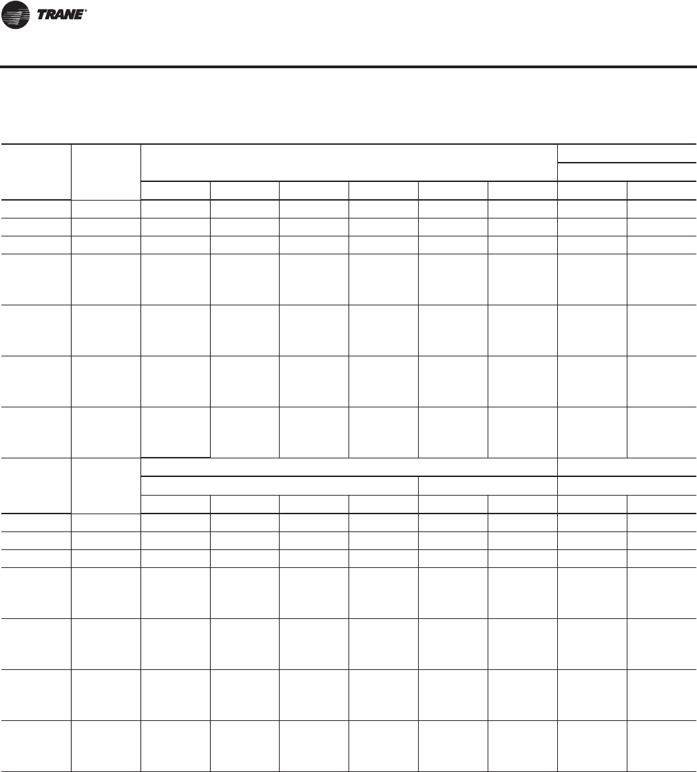
168 RT-PRC027T-EN
Dimensional Data
Table 73. Unit dimensions (in.)—THREE-PIECE unit evaporative condensing—WITHOUT energy recovery wheel
Tonnage Blank
Section
Unit Dimensions
Lifting Lug Locations
Air Handler Side
A B E E1 E2 F C1 C2
100/118 None 494 13/16 179 3/16 350 3/16 144 15/16 205 3/16 142 10/16 11 14/16 N/A
100/118 4 ft 543 179 3/16 398 6/16 144 15/16 253 7/16 142 10/16 11 14/16 N/A
100/118 8 ft 591 4/16 179 3/16 446 9/16 144 15/16 301 10/16 142 10/16 11 14/16 N/A
128-162 (All
Units Except
High Heat
Gas Models)
None 565 12/16 222 9/16 421 2/16 161 2/16 260 142 10/16 11 14/16 N/A
128-162 (All
Units Except
High Heat
Gas Models)
4 ft 613 15/16 222 9/16 469 5/16 161 2/16 308 4/16 142 10/16 11 14/16 N/A
128-162 (All
Units Except
High Heat
Gas Models)
8 ft 662 3/16 222 9/16 517 9/16 161 2/16 356 7/16 142 10/16 11 14/16 N/A
128-162
(High Heat
Gas Models
Only)
None 577 12/16 222 9/16 433 2/16 161 2/16 272 142 10/16 11 14/16 N/A
Tonnage Blank
Section
Lug Locations
Air Handler Side Condenser Side Unit Width
C3 C4 C5 C6 D1 D2 M N
100/118 None 138 9/16 151 6/16 272 339 11/16 16 133 11/16 139 13/16 143 8/16
100/118 4 ft 138 9/16 151 6/16 272 387 14/16 16 133 11/16 139 13/16 143 8/16
100/118 8 ft 138 9/16 151 6/16 272 436 1/16 16 133 11/16 139 13/16 143 8/16
128-162 (All
Units Except
High Heat
Gas Models)
None 155 2/16 167 5/16 294 14/16 410 10/16 16 133 11/16 139 13/16 143 8/16
128-162 (All
Units Except
High Heat
Gas Models)
4 ft 155 2/16 167 5/16 294 14/16 458 13/16 16 133 11/16 139 13/16 143 8/16
128-162 (All
Units Except
High Heat
Gas Models)
8 ft 155 2/16 167 5/16 294 14/16 507 1/16 16 133 11/16 139 13/16 143 8/16
128-162
(High Heat
Gas Models
Only)
None 155 2/16 167 5/16 294 14/16 422 10/16 16 133 11/16 139 13/16 143 8/16
Continued on next page
Unit Dimensions
RT-PRC027.book Page 168 Tuesday, October 7, 2014 9:03 AM
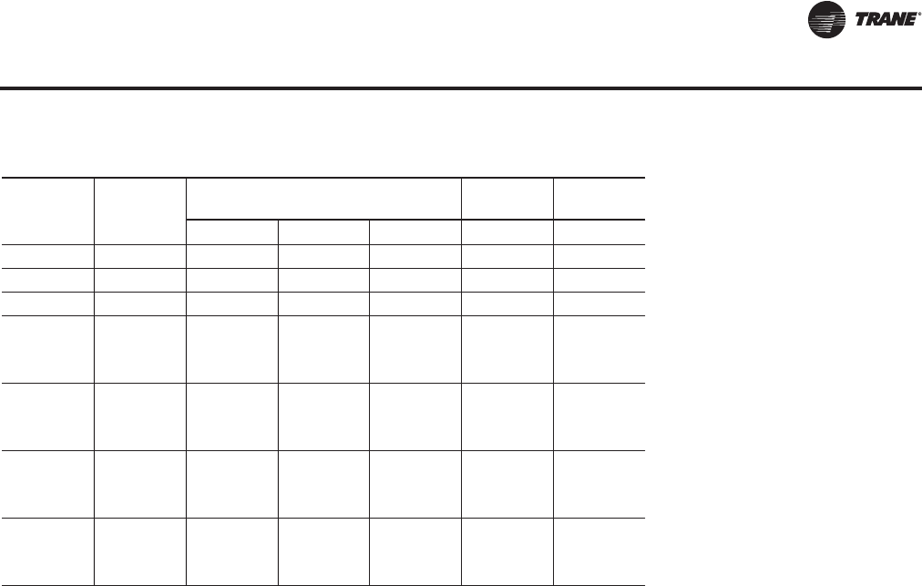
RT-PRC027T-EN 169
Dimensional Data
Tonnage Blank
Section
Unit Height Return Fan Exhaust
Fan
OPRJK
100/118 None 103 12/16 97 9/16 102 12/16 29 3/16 17
100/118 4 ft 103 12/16 97 9/16 102 12/16 29 3/16 17
100/118 8 ft 103 12/16 97 9/16 102 12/16 29 3/16 17
128-162 (All
Units Except
High Heat
Gas Models)
None 103 12/16 97 9/16 102 6/16 29 3/16 17
128-162 (All
Units Except
High Heat
Gas Models)
4 ft 103 12/16 97 9/16 102 6/16 29 3/16 17
128-162 (All
Units Except
High Heat
Gas Models)
8 ft 103 12/16 97 9/16 102 6/16 29 3/16 17
128-162
(High Heat
Gas Models
Only)
None 103 12/16 97 9/16 102 6/16 29 3/16 17
Table 73. Unit dimensions (in.)—THREE-PIECE unit evaporative condensing—WITHOUT energy recovery wheel
Unit Dimensions
RT-PRC027.book Page 169 Tuesday, October 7, 2014 9:03 AM
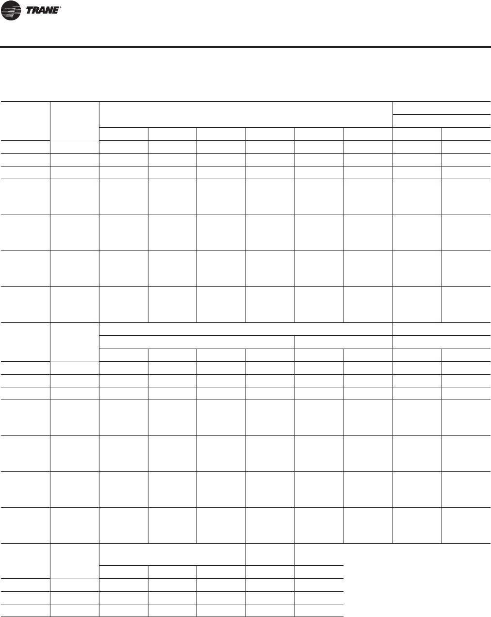
170 RT-PRC027T-EN
Dimensional Data
Table 74. Unit dimensions (in.)—THREE-PIECE unit evaporative condensing—WITH energy recovery wheel
Tonnage Blank
Section
Unit Dimensions
Lifting Lug Locations
Air Handler Side
A B E E1 E2 F C1 C2
100/118 None 591 4/16 275 10/16 446 9/16 241 6/16 205 3/16 142 10/16 17 12/16 201 1/16
100/118 4 ft 639 7/16 275 10/16 494 13/16 241 6/16 253 7/16 142 10/16 17 12/16 201 1/16
100/118 8 ft 687 10/16 275 10/16 543 241 6/16 301 10/16 142 10/16 17 12/16 201 1/16
128-162 (All
Units Except
High Heat
Gas Models)
None 662 3/16 318 15/16 517 9/16 257 8/16 260 142 10/16 17 12/16 204 7/16
128-162 (All
Units Except
High Heat
Gas Models)
4 ft 710 6/16 318 15/16 565 12/16 257 8/16 308 4/16 142 10/16 17 12/16 204 7/16
128-162 (All
Units Except
High Heat
Gas Models)
8 ft 758 10/16 318 15/16 613 15/16 257 8/16 356 7/16 142 10/16 17 12/16 204 7/16
128-162
(High Heat
Gas Models
Only)
None 674 3/16 318 15/16 529 9/16 257 8/16 272 142 10/16 17 12/16 204 7/16
Tonnage Blank
Section
Lug Locations
Air Handler Side Condenser Side Unit Width
C3 C4 C5 C6 D1 D2 M N
100/118 None 234 13/16 247 13/16 368 7/16 436 2/16 16 133 11/16 139 13/16 143 8/16
100/118 4 ft 234 13/16 247 13/16 368 7/16 484 5/16 16 133 11/16 139 13/16 143 8/16
100/118 8 ft 234 13/16 247 13/16 368 7/16 532 8/16 16 133 11/16 139 13/16 143 8/16
128-162 (All
Units Except
High Heat
Gas Models)
None 252 12/16 263 12/16 391 5/16 519 1/16 16 133 11/16 139 13/16 143 8/16
128-162 (All
Units Except
High Heat
Gas Models)
4 ft 252 12/16 263 12/16 391 5/16 507 1/16 16 133 11/16 139 13/16 143 8/16
128-162 (All
Units Except
High Heat
Gas Models)
8 ft 252 12/16 263 12/16 391 5/16 555 4/16 16 133 11/16 139 13/16 143 8/16
128-162
(High Heat
Gas Models
Only)
None 252 12/16 263 12/16 391 5/16 603 7/16 16 133 11/16 139 13/16 143 8/16
Tonnage Blank
Section
Unit Height Return Fan Exhaust
Fan
OPRJK
100-162 None 103 12/16 97 9/16 102 6/16 N/A 17
100-162 4 ft 103 12/16 97 9/16 102 6/16 N/A 17
100-162 8 ft 103 12/16 97 9/16 102 6/16 N/A 17
Unit Dimensions
RT-PRC027.book Page 170 Tuesday, October 7, 2014 9:03 AM
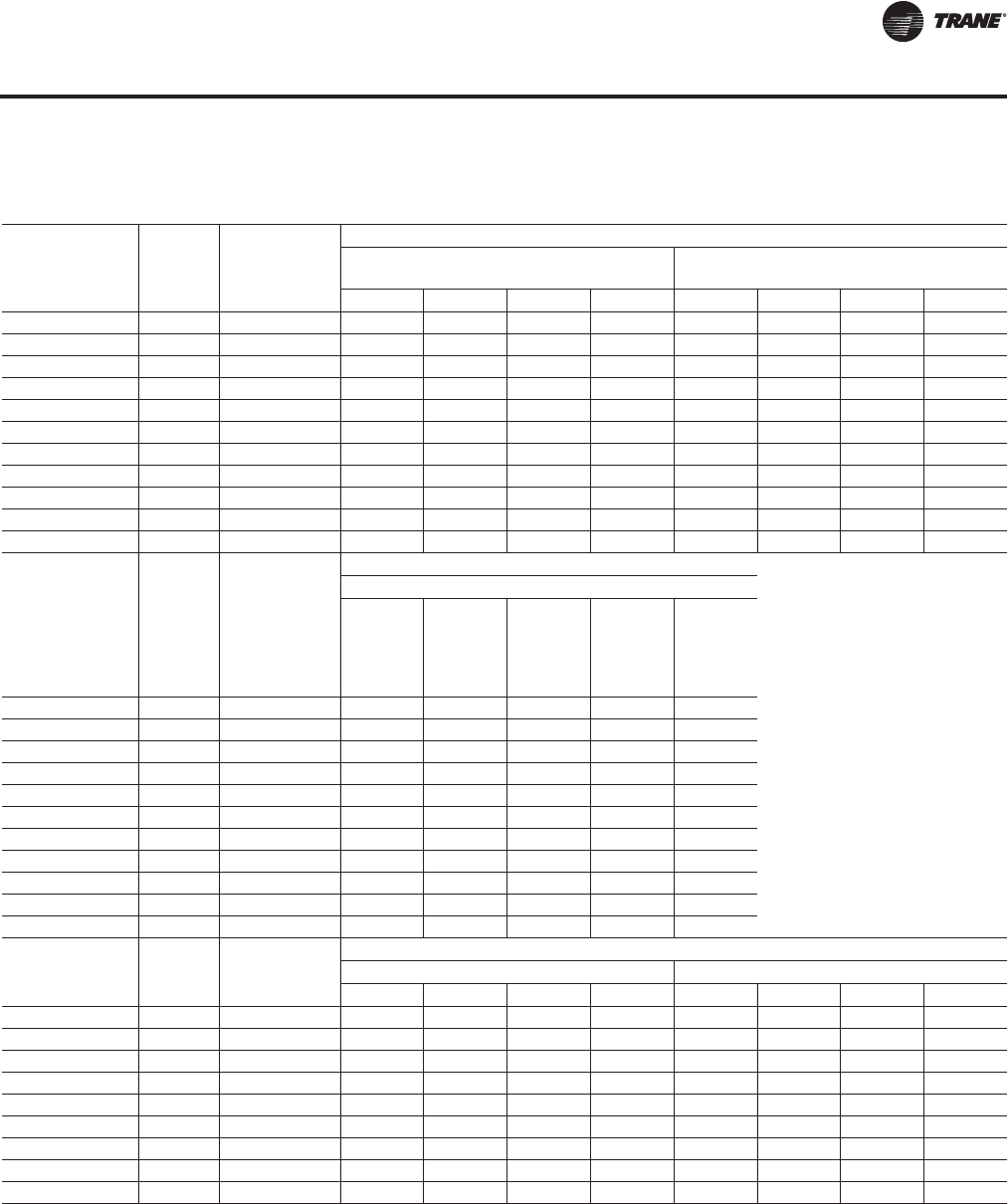
RT-PRC027T-EN 171
Dimensional Data
Table 75. Downflow/horizontal airflow configuration dimensions (in.) air-cooled (AC) and evaporative
condensing (EC) without energy recovery wheel (ERW)
Tonnage
AC/EC Blank
Section Gas Heat
DOWNFLOW Opening Dimensions
Return Opening—with or
without Exhaust Fan Return Opening—with Return Fan
X1 Y1 W1 L1 X1 Y1 W1 L1
90-105/100-118 None None 14 13/16 8 14/16 48 3/16 121 15/16 14 13/16 42 14/16 48 3/16 53 14/16
90-105/100-118 4 ft None 14 13/16 8 14/16 48 3/16 121 15/16 14 13/16 42 14/16 48 3/16 53 14/16
90-105/100-118 8 ft None 14 13/16 8 14/16 48 3/16 121 15/16 14 13/16 42 14/16 48 3/16 53 14/16
120-150/128-162 None None 14 13/16 8 14/16 48 3/16 121 15/16 14 13/16 42 14/16 48 3/16 53 14/16
120-150/128-162 4 ft None 14 13/16 8 14/16 48 3/16 121 15/16 14 13/16 42 14/16 48 3/16 53 14/16
120-150/128-162 8 ft None 14 13/16 8 14/16 48 3/16 121 15/16 14 13/16 42 14/16 48 3/16 53 14/16
90-105/100-118 None Low/Med 14 13/16 8 14/16 48 3/16 121 15/16 14 13/16 42 14/16 48 3/16 53 14/16
90-105/100-118 8 ft Low/Med 14 13/16 8 14/16 48 3/16 121 15/16 14 13/16 42 14/16 48 3/16 53 14/16
120-150/128-162 None Low/Med 14 13/16 8 14/16 48 3/16 121 15/16 14 13/16 42 14/16 48 3/16 53 14/16
120-150/128-162 8 ft Low/Med 14 13/16 8 14/16 48 3/16 121 15/16 14 13/16 42 14/16 48 3/16 53 14/16
120-150/128-162 None High 14 13/16 8 14/16 48 3/16 121 15/16 14 13/16 42 14/16 48 3/16 53 14/16
Tonnage
AC/EC Blank
Section Gas Heat
DOWNFLOW Opening Dimensions
Supply Opening
X2
(One or
Two-
Piece
Models)
X2
(Three-
Piece
Mocels) Y2 W2 L2
90-105/100-118 None None 256 1/16 275 6/16 13 47 14/16 102 8/16
90-105/100-118 4 ft None 304 4/16 323 9/16 13 47 14/16 102 8/16
90-105/100-118 8 ft None 352 8/16 371 12/16 13 47 14/16 102 8/16
120-150/128-162 None None 320 13/16 346 4/16 13 47 14/16 102 8/16
120-150/128-162 4 ft None 369 394 8/16 13 47 14/16 102 8/16
120-150/128-162 8 ft None 417 3/16 442 11/16 13 47 14/16 102 8/16
90-105/100-118 None Low/Med/High 256 1/16 275 6/16 13 47 14/16 102 8/16
90-105/100-118 8 ft Low/Med/High 352 8/16 371 12/16 13 47 14/16 102 8/16
120-150/128-162 None Low/Med 320 13/16 346 4/16 13 47 14/16 102 8/16
120-150/128-162 8 ft Low/Med 417 3/16 442 11/16 13 47 14/16 102 8/16
120-150/128-162 None High 320 13/16 346 4/16 13 59 14/16 102 8/16
Tonnage
AC/EC Blank
Section Gas Heat
HORIZONTAL Opening Dimensions
Return Side Opening Return End Opening
X3 Y3 W3 H1 Y1 Y3 H3 L1
90-105/100-118 None None 9 5/16 10 10/16 54 12/16 84 15/16 6 5/16 8 3/16 35 3/16 127 2/16
90-105/100-118 4 ft None 9 5/16 10 10/16 54 12/16 84 15/16 6 5/16 8 3/16 35 3/16 127 2/16
90-105/100-118 8 ft None 9 5/16 10 10/16 54 12/16 84 15/16 6 5/16 8 3/16 35 3/16 127 2/16
120-150/128-162 8 ft None 9 5/16 10 10/16 54 12/16 84 15/16 6 5/16 8 3/16 35 3/16 127 2/16
90-105/100-118 None Low/Med 9 5/16 10 10/16 54 12/16 84 15/16 6 5/16 8 3/16 35 3/16 127 2/16
90-105/100-118 8 ft Low/Med 9 5/16 10 10/16 54 12/16 84 15/16 6 5/16 8 3/16 35 3/16 127 2/16
120-150/128-162 None Low/Med 9 5/16 10 10/16 54 12/16 84 15/16 6 5/16 8 3/16 35 3/16 127 2/16
120-150/128-162 8 ft Low/Med 9 5/16 10 10/16 54 12/16 84 15/16 6 5/16 8 3/16 35 3/16 127 2/16
120-150/128-162 None High 9 5/16 10 10/16 54 12/16 84 15/16 6 5/16 8 3/16 35 3/16 127 2/16
Continued on next page
Configuration Dimensions
RT-PRC027.book Page 171 Tuesday, October 7, 2014 9:03 AM
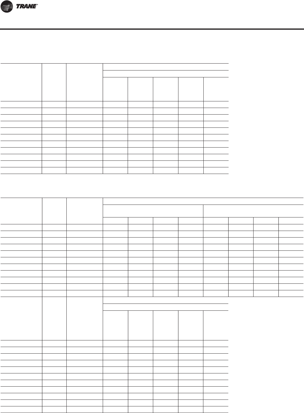
172 RT-PRC027T-EN
Dimensional Data
Tonnage
AC/EC Blank
Section Gas Heat
HORIZONTAL Opening Dimensions
Supply Opening
X4 (One
or Two-
Piece
Models)
X4
(Three-
Piece
Models) Y4 W4 H2
90-105/100-118 None None 254 12/16 274 10 10/16 54 12/16 84 15/16
90-105/100-118 4 ft None 302 15/16 322 4/16 10 10/16 54 12/16 84 15/16
90-105/100-118 8 ft None 351 2/16 370 7/16 10 10/16 54 12/16 84 15/16
120-150/128-162 None None 319 8/16 345 10 10/16 54 12/16 84 15/16
120-150/128-162 4 ft None 367 11/16 393 3/16 10 10/16 54 12/16 84 15/16
120-150/128-162 8 ft None 415 15/16 441 6/16 10 10/16 54 12/16 84 15/16
90-105/100-118 None Low/Med 254 12/16 274 10 10/16 54 12/16 66 11/16
90-105/100-118 8 ft Low/Med 351 2/16 370 7/16 10 10/16 54 12/16 84 15/16
120-150/128-162 None Low/Med 319 8/16 345 10 10/16 54 12/16 66 11/16
120-150/128-162 8 ft Low/Med 415 15/16 441 6/16 10 10/16 54 12/16 84 15/16
120-150/128-162 None High 319 8/16 345 10 10/16 66 12/16 66 11/16
Table 75. Downflow/horizontal airflow configuration dimensions (in.) air-cooled (AC) and evaporative
condensing (EC) without energy recovery wheel (ERW) (continued)
Table 76. Downflow/horizontal airflow configuration dimensions (in.) air-cooled (AC) and evaporative
condensing (EC) with energy recovery wheel
Tonnage
AC/EC Blank
Section Gas Heat
DOWNFLOW Opening Dimensions
Return Opening—with or
without Exhaust Fan Return Opening—with Return Fan
X1 Y1 W1 L1 X1 Y1 W1 L1
90-105/100-118 None None 82 3/16 8 14/16 49 10/16 121 15/16 N/A N/A N/A N/A
90-105/100-118 4 ft None 82 3/16 8 14/16 49 10/16 121 15/16 N/A N/A N/A N/A
90-105/100-118 8 ft None 82 3/16 8 14/16 49 10/16 121 15/16 N/A N/A N/A N/A
120-150/128-162 None None 82 3/16 8 14/16 49 10/16 121 15/16 N/A N/A N/A N/A
120-150/128-162 4 ft None 82 3/16 8 14/16 49 10/16 121 15/16 N/A N/A N/A N/A
120-150/128-162 8 ft None 82 3/16 8 14/16 49 10/16 121 15/16 N/A N/A N/A N/A
90-105/100-118 None Low/Med 82 3/16 8 14/16 49 10/16 121 15/16 N/A N/A N/A N/A
90-105/100-118 8 ft Low/Med 82 3/16 8 14/16 49 10/16 121 15/16 N/A N/A N/A N/A
120-150/128-162 None Low/Med 82 3/16 8 14/16 49 10/16 121 15/16 N/A N/A N/A N/A
120-150/128-162 8 ft Low/Med 82 3/16 8 14/16 49 10/16 121 15/16 N/A N/A N/A N/A
120-150/128-162 None High 82 3/16 8 14/16 49 10/16 121 15/16 N/A N/A N/A N/A
Tonnage
AC/EC Blank
Section Gas Heat
DOWNFLOW Opening Dimensions
Supply Opening
X2
(One or
Two-
Piece
Models)
X2
(Three-
Piece
Models) Y2 W2 L2
90-105/100-118 None None 352 8/16 371 12/16 13 47 14/16 102 8/16
90-105/100-118 4 ft None 400 11/16 420 13 47 14/16 102 8/16
90-105/100-118 8 ft None 448 15/16 468 3/16 13 47 14/16 102 8/16
120-150/128-162 None None 417 4/16 442 11/16 13 47 14/16 102 8/16
120-150/128-162 4 ft None 465 7/16 490 14/16 13 47 14/16 102 8/16
120-150/128-162 8 ft None 513 10/16 539 2/16 13 47 14/16 102 8/16
90-105/100-118 None Low/Med 352 8/16 371 12/16 13 47 14/16 102 8/16
90-105/100-118 8 ft Low/Med 448 15/16 468 3/16 13 47 14/16 102 8/16
120-150/128-162 None Low/Med 417 4/16 442 11/16 13 47 14/16 102 8/16
120-150/128-162 8 ft Low/Med 513 10/16 539 2/16 13 47 14/16 102 8/16
120-150/128-162 None High 417 4/16 442 11/16 13 59 14/16 102 8/16
Configuration Dimensions
RT-PRC027.book Page 172 Tuesday, October 7, 2014 9:03 AM
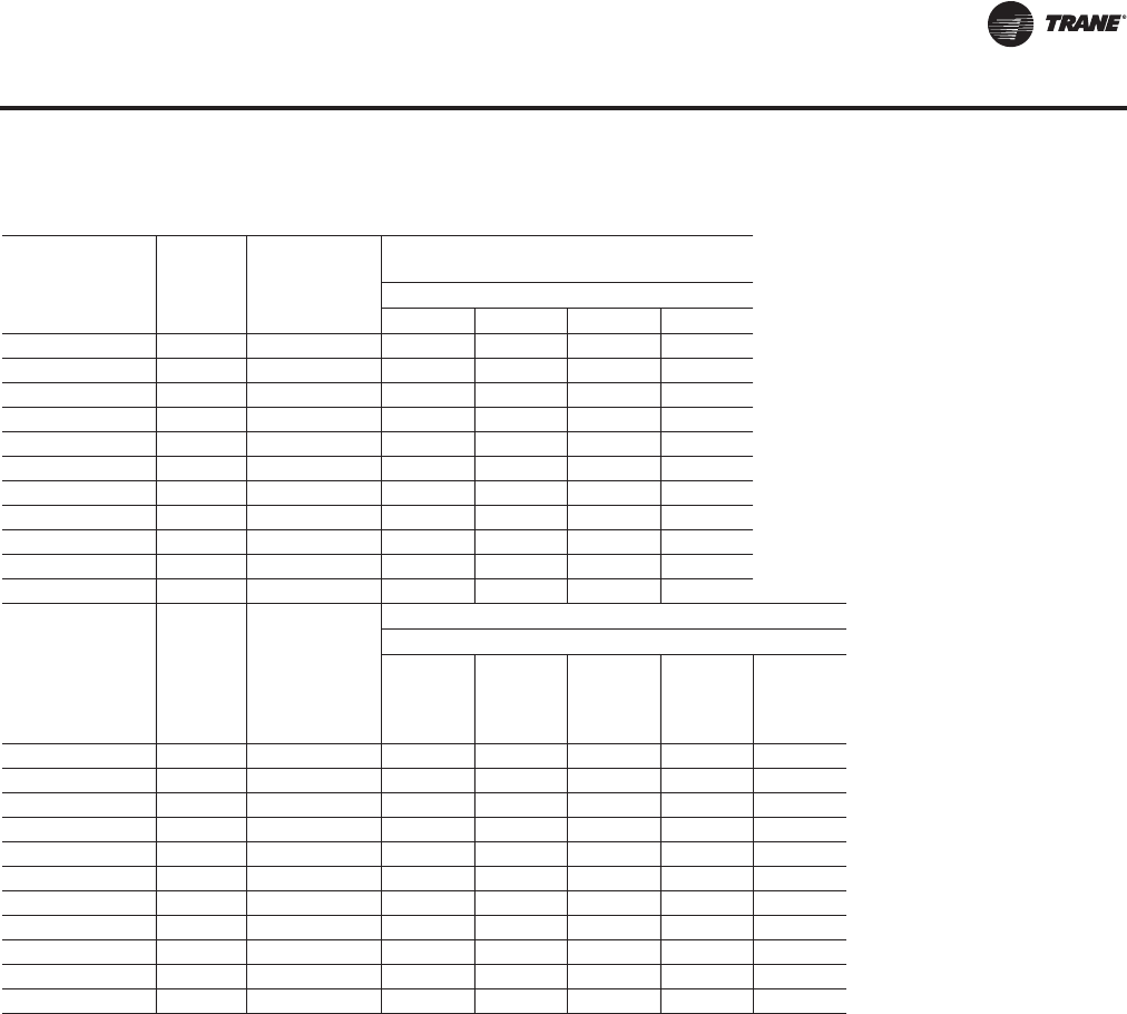
RT-PRC027T-EN 173
Dimensional Data
Tonnage Blank
Section Gas Heat
HORIZONTAL
Opening Dimensions(a)(b)
Return Side Opening
X3 Y3 W3 H1
90-105/100-118 None None 71 8/16 10 10/16 54 12/16 43 6/16
90-105/100-118 4 ft None 71 8/16 10 10/16 54 12/16 43 6/16
90-105/100-118 8 ft None 71 8/16 10 10/16 54 12/16 43 6/16
120-150/128-162 None None 71 8/16 10 10/16 54 12/16 43 6/16
120-150/128-162 4 ft None 71 8/16 10 10/16 54 12/16 43 6/16
120-150/128-162 8 ft None 71 8/16 10 10/16 54 12/16 43 6/16
90-105/100-118 None Low/Med 71 8/16 10 10/16 54 12/16 43 6/16
90-105/100-118 8 ft Low/Med 71 8/16 10 10/16 54 12/16 43 6/16
120-150/128-162 None Low/Med 71 8/16 10 10/16 54 12/16 43 6/16
120-150/128-162 8 ft Low/Med 71 8/16 10 10/16 54 12/16 43 6/16
120-150/128-162 None High 71 8/16 10 10/16 54 12/16 43 6/16
Tonnage
AC/EC Blank
Section Gas Heat
HORIZONTAL Opening Dimensions
Supply Opening
X4 (One
or Two-
Piece
Models)
X4
(Three-
Piece
Models) Y4 W4 H2
90-105/100-118 None None 351 3/16 370 7/16 10 10/16 54 12/16 84 15/16
90-105/100-118 4 ft None 399 6/16 418 11/16 10 10/16 54 12/16 84 15/16
90-105/100-118 8 ft None 447 10/16 466 14/16 10 10/16 54 12/16 84 15/16
120-150/128-162 None None 415 15/16 441 6/16 10 10/16 54 12/16 84 15/16
120-150/128-162 4 ft None 464 2/16 489 10/16 10 10/16 54 12/16 84 15/16
120-150/128-162 8 ft None 512 6/16 537 13/16 10 10/16 54 12/16 84 15/16
90-105/100-118 None Low/Med 351 3/16 370 7/16 10 10/16 54 12/16 66 11/16
90-105/100-118 8 ft Low/Med 447 10/16 466 14/16 10 10/16 54 12/16 84 15/16
120-150/128-162 None Low/Med 415 15/16 441 6/16 10 10/16 54 12/16 66 11/16
120-150/128-162 8 ft Low/Med 512 6/16 537 13/16 10 10/16 54 12/16 84 15/16
120-150/128-162 None High 415 15/16 441 6/16 10 10/16 66 12/16 66 11/16
(a)On horizontal return with ERW units, the return end opening can be on the front, rear, or both sides of the unit and must be specified.
(b)ERW is not allowed w/ end return
Table 76. Downflow/horizontal airflow configuration dimensions (in.) air-cooled (AC) and evaporative
condensing (EC) with energy recovery wheel (continued)
Configuration Dimensions
RT-PRC027.book Page 173 Tuesday, October 7, 2014 9:03 AM
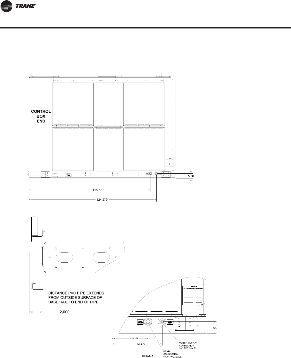
174 RT-PRC027T-EN
Dimensional Data
Figure 38. Evaporative condenser water connection locations
RIGHT SIDE VIEW
Water Connection Locations
RT-PRC027.book Page 174 Tuesday, October 7, 2014 9:03 AM
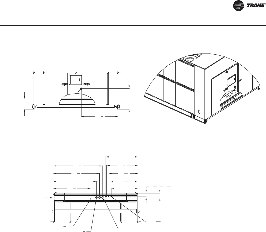
RT-PRC027T-EN 175
Dimensional Data
Figure 39. Electrical entry details/bottom view
16
603
4
711
4
761
4
811
4
46 1
16
48 1
16
613
444
Ø35
8
Ø1 1
16
Ø7
8
65
16
55
16
Marine lights
customer supplied
power service
entrance Unit power
External customer
connection points
Outside edge of
base rail
515
8
5311
16
3111
16
Ø11
2
Bottom View
Electrical Entry Details
RT-PRC027.book Page 175 Tuesday, October 7, 2014 9:03 AM
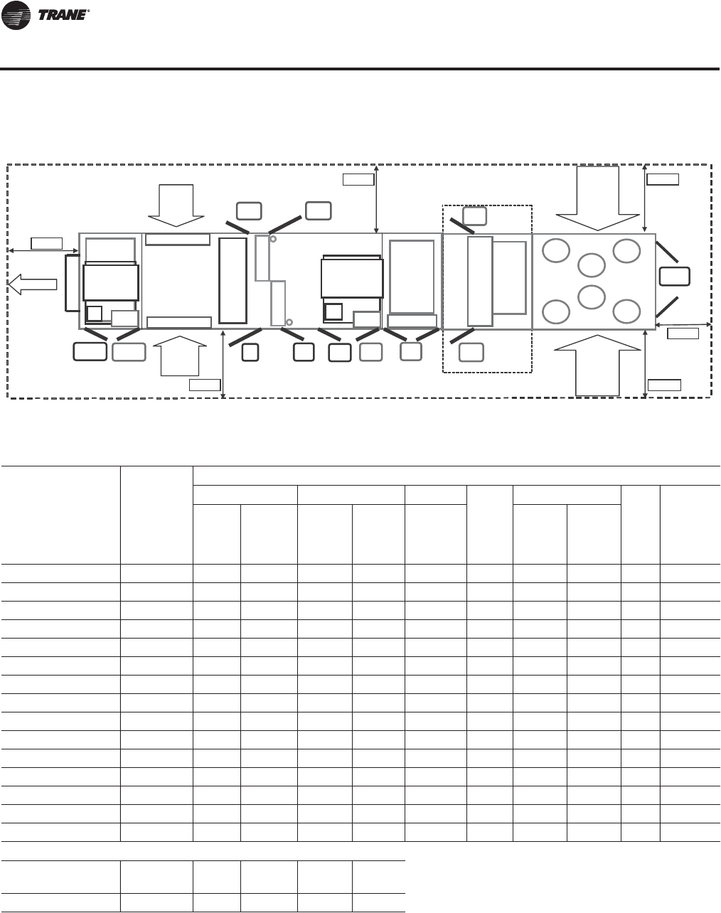
176 RT-PRC027T-EN
Dimensional Data
Figure 40. Minimum required clearance(a)
(a)Unit drawing is representative only and may not accurately depict all models.
Filters
VFD
VFD
Heat
Rtn/Exh
Mtr
Rtn/Exh
VFD
Evp
(F)
Fltr
(F)
Sup
Mtr
Sup
VFD
Fltr
(R)
Evp
(R)
Heat
(L&R
Option
Option
As Req.
As Req.
As Req.
Std
Std
Std
Std
Blank Section
Final
Filter
Fnl
Fltr
As Req.
Fnl
Fltr
As Req.
Ctrl Box
(L&R)
Std
Outside
Air
Outside
Air
Exhaust
Condenser
Condenser
Exh
AH R
CBox
AH L
Cond L
Cond R
Table 77. Minimum required clearance
Door Location Availability
Unit Option Selection (Door Swing Ft. and In.)
Standard VFD Heat
Reheat
Two-side Access
Final
Filter Energy
Recovery90-118 120-162 Return/
Exhaust Supply
Electric/
Hot
Water/
Steam 90-118 120-162
Exhaust/Ret Motor Std 2' 2" 2' 2" * * * * * * *
Exhaust/Ret VFD As Req. * * 2' 2" * * * * * *
ERW Fltr(a) (L & R) (F) Option * * * * * * * * * 2' 2"
ERW Fltr(a) (L & R) (R) Option * * * * * * * * * 2' 2"
Filter (Front) Std 2' 8" 2' 8" * * * * * * *
Filter (Rear) Option * * * * * * 2' 2" 2' 8" *
Evap (Front) Std 2' 2" 2' 2" * * * * * * *
Evap (Rear) Std 2' 8" * * * * * * * *
or Evap (Rear) Option * * * * * 2' 2 * 2' 2" *
Supply Motor Std 2' 8" 2' 8" * * * * * * *
Supply VFD As Req. * * * 2' 2" * * * * *
Heat (Left & Right) As Req. * * * * 2' 2" * * * *
Final Filter (Front) As Req. * * * * * * * * 2' 2"
Final Filter (Rear) As Req. * * * * * * * * 2' 2"
Control Box (L & R) Std 3' 2" 3' 2" * * * * * * *
Minimum Required Clearance (Ft.)
AH_L AH_R Exh Cond_L Cond_R Control
Box
8' 8' 8' 8' 8' 6'
(a)See Unit Dimensions for Energy Recovery Wheel location.
Minimum Required Clearance
RT-PRC027.book Page 176 Tuesday, October 7, 2014 9:03 AM
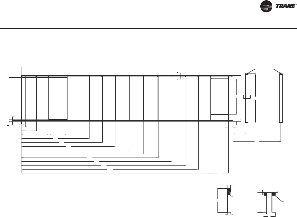
RT-PRC027T-EN 177
Dimensional Data
Figure 41. Optional roof curb (downflow)
K
U1
U2
A B
W1
W2
W3
W4
W5
W6
W7
W8
W9
E F
I
X1
X2
L
HM N
D
J
C
G
Note: All dimensions measured from top flange of roof curb
Return Air Opening
Supply Air Opening
2
1 13/16
7 1/2 1 1/2
27
11 13/16
A'
A
BB'
Section AA' Section BB'
14 1/16
2"X4"
2"X2"
Pedestals
Optional Roof Curb
RT-PRC027.book Page 177 Tuesday, October 7, 2014 9:03 AM
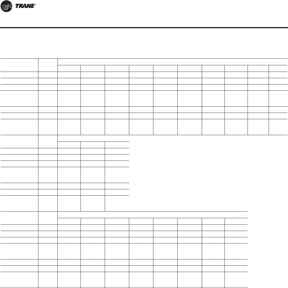
178 RT-PRC027T-EN
Dimensional Data
Table 78. Downflow roof curb dimensions ONE- or TWO-PIECE unit without energy recovery wheel (in.)
Tonnage
AC/EC Blank
Section Dimensions
ABCDE FGHIJ
90-105/100-118 None 11 15/16 49 8/16 5 15/16 123 253 2/16 49 8/16 20 15/16 104 11 15/16 1 13/16
90-105/100-118 4 ft 11 15/16 49 8/16 5 15/16 123 301 5/16 49 8/16 20 15/16 104 11 15/16 1 13/16
90-105/100-118 8 ft 11 15/16 49 8/16 5 15/16 123 349 9/16 49 8/16 20 15/16 104 11 15/16 1 13/16
120-150/128-162
(All Except High
Heat Gas Models) None 11 15/16 49 8/16 5 15/16 123 317 14/16 49 8/16 20 15/16 104 11 15/16 1 13/16
120-150/128-162 4 ft 11 15/16 49 8/16 5 15/16 123 366 2/16 49 8/16 20 15/16 104 11 15/16 1 13/16
120-150/128-162 8 ft 11 15/16 49 8/16 5 15/16 123 414 5/16 49 8/16 20 15/16 104 11 15/16 1 13/16
120-150/128-162
(High Heat Gas
Models Only) None 11 15/16 49 8/16 5 15/16 123 317 14/16 61 8/16 20 15/16 104 11 15/16 1 13/16
Tonnage
AC/EC Blank
Section Dimensions
KLM
90-105/100-118 None 1 13/16 314 9/16 134 14/16
90-105/100-118 4 ft 1 13/16 362 12/16 134 14/16
90-105/100-118 8 ft 1 13/16 411 134 14/16
120-150/128-162
(All Except High
Heat Gas Models) None 1 13/16 379 5/16 134 14/16
120-150/128-162 4 ft 1 13/16 427 8/16 134 14/16
120-150/128-16 8 ft 1 13/16 475 12/16 134 14/16
120-150/128-162
(High Heat Gas
Models Only) None 1 13/16 391 5/16 134 14/16
Tonnage
AC/EC Blank
Section Cross Member Location
W1 W2 W3 W4 W5 W6 W7 W8
90-105/100-118 None 103 6/16 145 11/16 183 6/16 218 4/16 N/A N/A N/A N/A
90-105/100-118 4 ft 103 6/16 145 11/16 187 15/16 231 10/16 266 8/16 N/A N/A N/A
90-105/100-118 8 ft 103 6/16 145 11/16 189 15/16 234 3/16 279 13/16 314 11/16 N/A N/A
120-150/128-162
(All Except High
Heat Gas Models) None 103 6/16 145 11/16 179 6/16 213 1/16 248 2/16 289 N/A N/A
120-150/128-162 4 ft 103 6/16 145 11/16 181 11/16 217 12/16 255 3/16 296 6/16 331 4/16 N/A
120-150/128-162 8 ft 103 6/16 145 11/16 185 4/16 224 13/16 265 12/16 304 7/16 344 9/16 379 7/16
120-150/128-162
(High Heat Gas
Models Only) None 103 6/16 145 11/16 179 5/16 213 1/16 248 2/16 289 N/A N/A
Roof Curb Dimensions
RT-PRC027.book Page 178 Tuesday, October 7, 2014 9:03 AM

RT-PRC027T-EN 179
Dimensional Data
Table 79. Downflow roof curb dimensions ONE or TWO-piece unit with energy recovery wheel (in.)
Tonnage
AC/EC Blank
Section Dimensions
ABCDE F GH I J
90-105/100-118 None 79 5/16 50 12/16 5 15/16 123 349 9/16 49 8/16 20 15/16 104 11 15/16 1 13/16
90-105/100-118 4 ft 79 5/16 50 12/16 5 15/16 123 397 12/16 49 8/16 20 15/16 104 11 15/16 1 13/16
90-105/100-118 8 ft 79 5/16 50 12/16 5 15/16 123 446 49 8/16 20 15/16 104 11 15/16 1 13/16
120-150/128-162
(All Except High
Heat Gas Models) None 79 5/16 50 12/16 5 15/16 123 414 5/16 49 8/16 20 15/16 104 11 15/16 1 13/16
120-150/128-162 4 ft 79 5/16 50 12/16 5 15/16 123 462 8/16 49 8/16 20 15/16 104 11 15/16 1 13/16
120-150/128-162 8 ft 79 5/16 50 12/16 5 15/16 123 510 12/16 49 8/16 20 15/16 104 11 15/16 1 13/16
120-150/128-162
(High Heat Gas
Models Only) None 79 5/16 50 12/16 5 15/16 123 414 5/16 49 8/16 20 15/16 104 11 15/16 1 13/16
Tonnage
AC/EC Blank
Section Dimensions
KLM
90-105/100-118 None 1 13/16 411 134 14/16
90-105/100-118 4 ft 1 13/16 459 3/16 134 14/16
90-105/100-118 8 ft 1 13/16 507 6/16 134 14/16
120-150/128-162
(All Except High
Heat Gas Models) None 1 13/16 476 1/16 134 14/16
120-150/128-162 4 ft 1 13/16 524 4/16 134 14/16
120-150/128-162 8 ft 1 13/16 572 8/16 134 14/16
120-150/128-162
(High Heat Gas
Models Only) None 1 13/16 488 1/16 134 14/16
Tonnage
AC/EC Blank
Section Cross Member Location
U1 U2 W1 W2 W3 W4 W5 W6 W7 W8
90-105/100-118 None 11 15/16 43 15/16 168 10/16 204 11/16 242 1/16 279 13/16 314 11/16 N/A N/A N/A
90-105/100-118 4 ft 11 15/16 43 15/16 168 10/16 204 11/16 242 1/16 284 6/16 328 362 14/16 N/A N/A
90-105/100-118 8 ft 11 15/16 43 15/16 168 10/16 204 11/16 242 1/16 286 5/16 330 9/16 376 4/16 411 2/16 N/A
120-150/128-162
(All Except High
Heat Gas Models) None 11 15/16 43 15/16 168 10/16 204 11/16 242 1/16 275 12/16 309 8/16 344 9/16 385 7/16 N/A
120-150/128-162 4 ft 11 15/16 43 15/16 168 10/16 204 11/16 242 1/16 278 2/16 314 3/16 351 9/16 392 12/16 427 10/16
120-150/128-162 8 ft 11 15/16 43 15/16 168 10/16 204 11/16 242 1/16 281 10/16 321 3/16 362 3/16 400 14/16 441
120-150/128-162
(High Heat Gas
Models Only) None 11 15/16 43 15/16 168 10/16 204 11/16 242 1/16 275 12/16 309 8/16 344 9/16 385 7/16 N/A
Tonnage
AC/EC Blank
Section W9
90-105/100-118 None N/A
90-105/100-118 4 ft N/A
90-105/100-118 8 ft N/A
120-150/128-162
(All Except High
Heat Gas Models) None N/A
120-150/128-162 4 ft N/A
120-150/128-162 8 ft 475 14/16
120-150/128-162
(High Heat Gas
Models Only) None N/A
Roof Curb Dimensions
RT-PRC027.book Page 179 Tuesday, October 7, 2014 9:03 AM
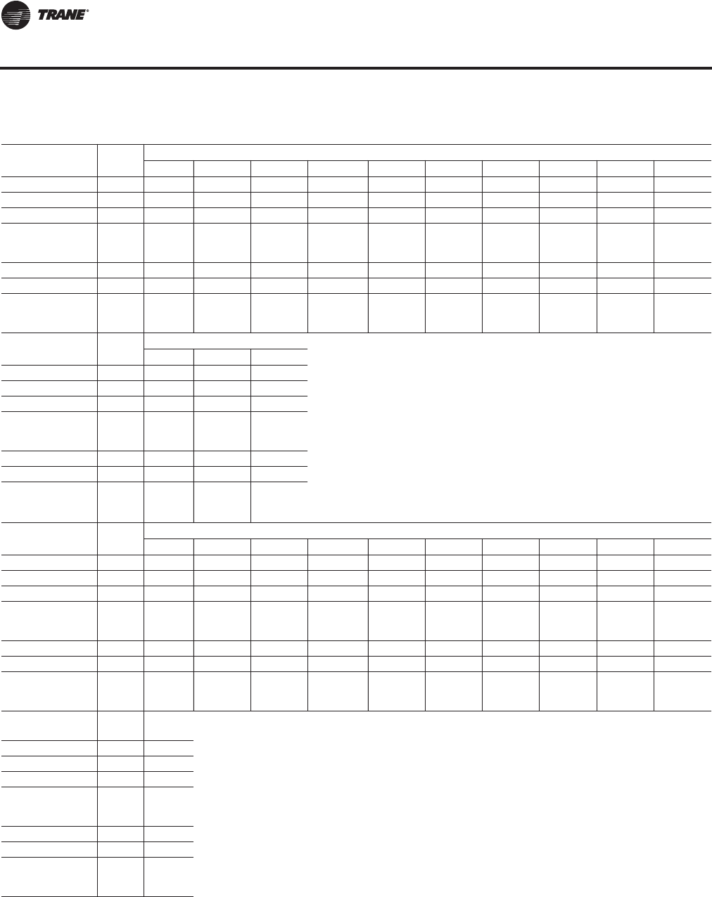
180 RT-PRC027T-EN
Dimensional Data
Table 80. Downflow roof curb dimensions THREE-piece unit without energy recovery wheel (in.)
Tonnage
AC/EC Blank
Section Dimensions
AB C D E F G H I J
90-105/100-118 None 11 15/16 49 8/16 5 15/16 123 272 7/16 49 8/16 20 15/16 104 11 15/16 1 13/16
90-105/100-118 4 ft 11 15/16 49 8/16 5 15/16 123 320 10/16 49 8/16 20 15/16 104 11 15/16 1 13/16
90-105/100-118 8 ft 11 15/16 49 8/16 5 15/16 123 368 13/16 49 8/16 20 15/16 104 11 15/16 1 13/16
120-150/128-162
(All Except High
Heat Gas Models) None 11 15/16 49 8/16 5 15/16 123 343 6/16 49 8/16 20 15/16 104 11 15/16 1 13/16
120-150/128-162 4 ft 11 15/16 49 8/16 5 15/16 123 391 9/16 49 8/16 20 15/16 104 11 15/16 1 13/16
120-150/128-162 8 ft 11 15/16 49 8/16 5 15/16 123 439 13/16 49 8/16 20 15/16 104 11 15/16 1 13/16
120-150/128-162
(High Heat Gas
Models Only) None 11 15/16 49 8/16 5 15/16 123 343 6/16 61 8/16 20 15/16 104 11 15/16 1 13/16
Tonnage
AC/EC Blank
Section Dimensions
KL M
90-105/100-118 None 1 13/16 333 13/16 134 14/16
90-105/100-118 4 ft 1 13/16 382 1/16 134 14/16
90-105/100-118 8 ft 1 13/16 430 4/16 134 14/16
120-150/128-162
(All Except High
Heat Gas Models) None 1 13/16 404 13/16 134 14/16
120-150/128-162 4 ft 1 13/16 453 134 14/16
120-150/128-162 8 ft 1 13/16 501 3/16 134 14/16
120-150/128-162
(High Heat Gas
Models Only) None 1 13/16 416 13/16 134 14/16
Tonnage
AC/EC Blank
Section Cross Member Location
U1 U2 W1 W2 W3 W4 W5 W6 W7 W8
90-105/100-118 None N/A N/A 103 6/16 145 11/16 202 11/16 237 9/16 N/A N/A N/A N/A
90-105/100-118 4 ft N/A N/A 103 6/16 145 11/16 187 15/16 250 14/16 285 12/16 N/A N/A N/A
90-105/100-118 8 ft N/A N/A 103 6/16 145 11/16 189 15/16 234 3/16 299 1/16 333 15/16 N/A N/A
120-150/128-162
(All Except High
Heat Gas Models) None N/A N/A 103 6/16 145 11/16 179 6/16 213 1/16 273 10/16 314 8/16 N/A N/A
120-150/128-162 4 ft N/A N/A 103 6/16 145 11/16 181 11/16 217 12/16 255 3/16 321 13/16 356 11/16 N/A
120-150/128-162 8 ft N/A N/A 103 6/16 145 11/16 185 4/16 224 13/16 265 12/16 304 7/16 370 1/16 404 15/16
120-150/128-162
(High Heat Gas
Models Only) None N/A N/A 103 6/16 145 11/16 179 6/16 213 1/16 273 10/16 314 8/16 N/A N/A
Tonnage
AC/EC Blank
Section W9
90-105/100-118 None N/A
90-105/100-118 4 ft N/A
90-105/100-118 8 ft N/A
120-150/128-162
(All Except High
Heat Gas Models) None N/A
120-150/128-162 4 ft N/A
120-150/128-162 8 ft N/A
120-150/128-162
(High Heat Gas
Models Only) None N/A
Roof Curb Dimensions
RT-PRC027.book Page 180 Tuesday, October 7, 2014 9:03 AM
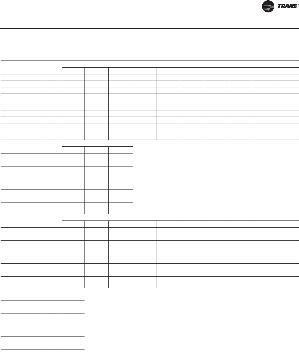
RT-PRC027T-EN 181
Dimensional Data
Table 81. Downflow roof curb dimensionsTHREE-piece unit with energy recovery wheel (in.)
Tonnage
AC/EC Blank
Section Dimensions
ABCDE F GHI J
90-105/100-118 None 79 5/16 50 12/16 5 15/16 123 368 13/16 49 8/16 20 15/16 104 11 15/16 1 13/16
90-105/100-118 4 ft 79 5/16 50 12/16 5 15/16 123 417 1/16 49 8/16 20 15/16 104 11 15/16 1 13/16
90-105/100-118 8 ft 79 5/16 50 12/16 5 15/16 123 465 4/16 49 8/16 20 15/16 104 11 15/16 1 13/16
120-150/128-162
(All Except High
Heat Gas Models) None 79 5/16 50 12/16 5 15/16 123 439 12/16 49 8/16 20 15/16 104 11 15/16 1 13/16
120-150/128-162 4 ft 79 5/16 50 12/16 5 15/16 123 488 49 8/16 20 15/16 104 11 15/16 1 13/16
120-150/128-162 8 ft 79 5/16 50 12/16 5 15/16 123 536 3/16 49 8/16 20 15/16 104 11 15/16 1 13/16
120-150/128-162
(High Heat Gas
Models Only) None 79 5/16 50 12/16 5 15/16 123 439 12/16 61 8/16 20 15/16 104 11 15/16 1 13/16
Tonnage
AC/EC Blank
Section Dimensions
KLM
90-105/100-118 None 1 13/16 430 4/16 134 14/16
90-105/100-118 4 ft 1 13/16 478 8/16 134 14/16
90-105/100-118 8 ft 1 13/16 526 11/16 134 14/16
120-150/128-162
(All Except High
Heat Gas Models) None 1 13/16 501 8/16 134 14/16
120-150/128-162 4 ft 1 13/16 549 12/16 134 14/16
120-150/128-162 8 ft 1 13/16 597 15/16 134 14/16
120-150 (High Heat
Gas Models Only) None 1 13/16 513 8/16 134 14/16
Tonnage
AC/EC Blank
Section Cross Member Location
U1 U2 W1 W2 W3 W4 W5 W6 W7 W8
90-105/100-118 None 11 15/16 43 15/16 168 10/16 204 11/16 242 1/16 299 1/16 333 15/16 N/A N/A N/A
90-105/100-118 4 ft 11 15/16 43 15/16 168 10/16 204 11/16 242 1/16 284 6/16 347 5/16 382 3/16 N/A6 N/A
90-105/100-118 8 ft 11 15/16 43 15/16 168 10/16 204 11/16 242 1/16 286 5/16 330 9/16 395 8/16 430 6/16 N/A
120-150/128-162
(All Except High
Heat Gas Models) None 11 15/16 43 15/16 168 10/16 204 11/16 242 1/16 275 12/16 309 8/16 370 1/16 410 15/16 N/A
120-150/128-162 4 ft 11 15/16 43 15/16 168 10/16 204 11/16 242 1/16 278 2/16 314 3/16 351 9/16 418 4/16 453 2/16
120-150/128-162 8 ft 11 15/16 43 15/16 168 10/16 204 11/16 242 1/16 281 10/16 321 3/16 362 3/16 400 14/16 466 7/16
120-150 (High Heat
Gas Models Only) None 11 15/16 43 15/16 168 10/16 204 11/16 242 1/16 275 12/16 309 8/16 370 1/16 410 15/16 N/A
Tonnage
AC/EC Blank
Section W9
90-105/100-118 None N/A
90-105/100-118 4 ft N/A
90-105/100-118 8 ft N/A
120-150/128-162
(All Except High
Heat Gas Models) None N/A
120-150/128-162 4 ft N/A
120-150/128-162 8 ft 501 5/16
120-150 (High Heat
Gas Models Only) None N/A
Roof Curb Dimensions
RT-PRC027.book Page 181 Tuesday, October 7, 2014 9:03 AM
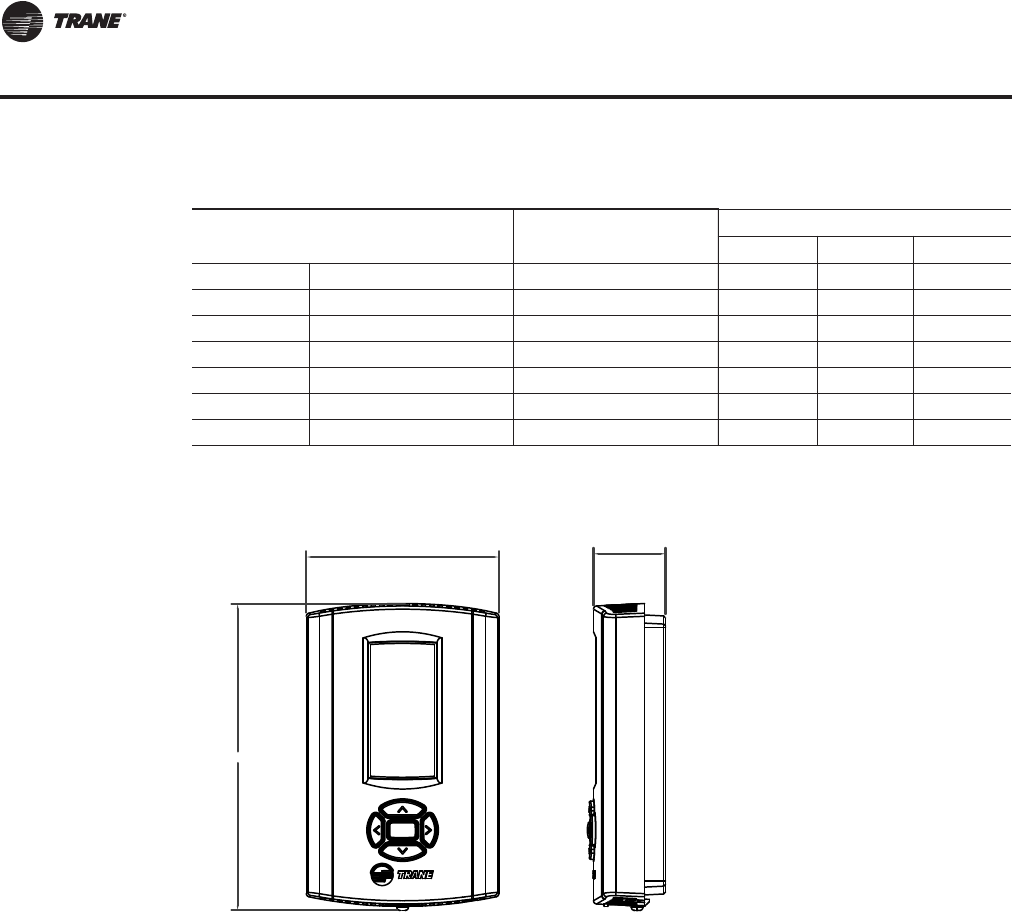
182 RT-PRC027T-EN
Dimensional Data
Table 82. Pedestal dimensions
Tonnage One-, Two-,
Three-Piece Unit Condenser Type
Pedestal Dimensions
NX1X2
90 1 Air-Cooled 145 4/16 N/A 93 1/16
90 2 or 3 Air-Cooled 145 4/16 36 3/16 111 3/16
105 1 Air-Cooled 145 4/16 N/A 111 1/16
105 2 or 3 Air-Cooled 145 4/16 36 3/16 129 3/16
120-150 1 Air-Cooled 145 4/16 N/A 117 1/16
120-150 2 or 3 Air-Cooled 145 4/16 40 3/16 136 3/16
100-162 2 or 3 Evaporative Condensing 145 4/16 36 3/16 129 3/16
Figure 42. Field installed zone sensor—programmable night setback sensor (BAYSENS119*)
(120.36 [4.74])
(27.52 [1.08])
(73.55 [2.90])
Pedestal Dimensions/Sensors
RT-PRC027.book Page 182 Tuesday, October 7, 2014 9:03 AM
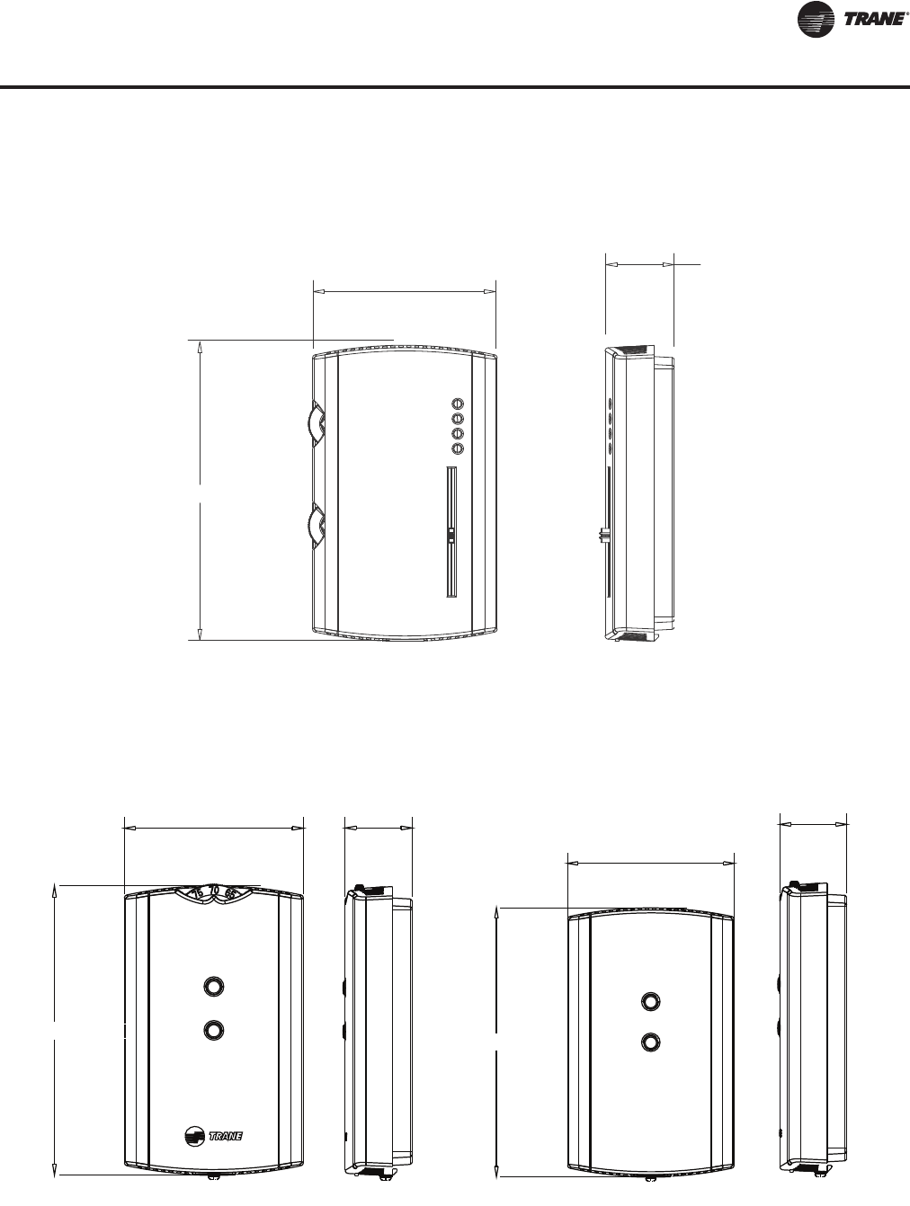
RT-PRC027T-EN 183
Dimensional Data
Figure 43. Field installed zone sensor—dual setpoint, manual/automatic changeover with
system function lights (BAYSENS110*), without LED function lights (BAYSENS108*),
single setpoint without LED function lights (BAYSENS106)
FRONT VIEW SIDE VIEW
<<4.68~ln>>
<<2.90~ln>> <<1.08~ln>>
Figure 44. Field installed zone sensor—with timed override button and local setpoint adjustment (BAYSENS074*), with
timed override only (BAYSENS073*), sensor only (BAYSENS077*)
FRONT RIGHT
2-29/32 [73,55 mm]
4-11/16 [118,75 mm]
1-3/32 [27,43 mm]
FRONT
2-29/32 [73,55 mm]
4-11/16 [118,75 mm]
RIGHT
1-3/32 [27,43 mm]
Sensors
RT-PRC027.book Page 183 Tuesday, October 7, 2014 9:03 AM
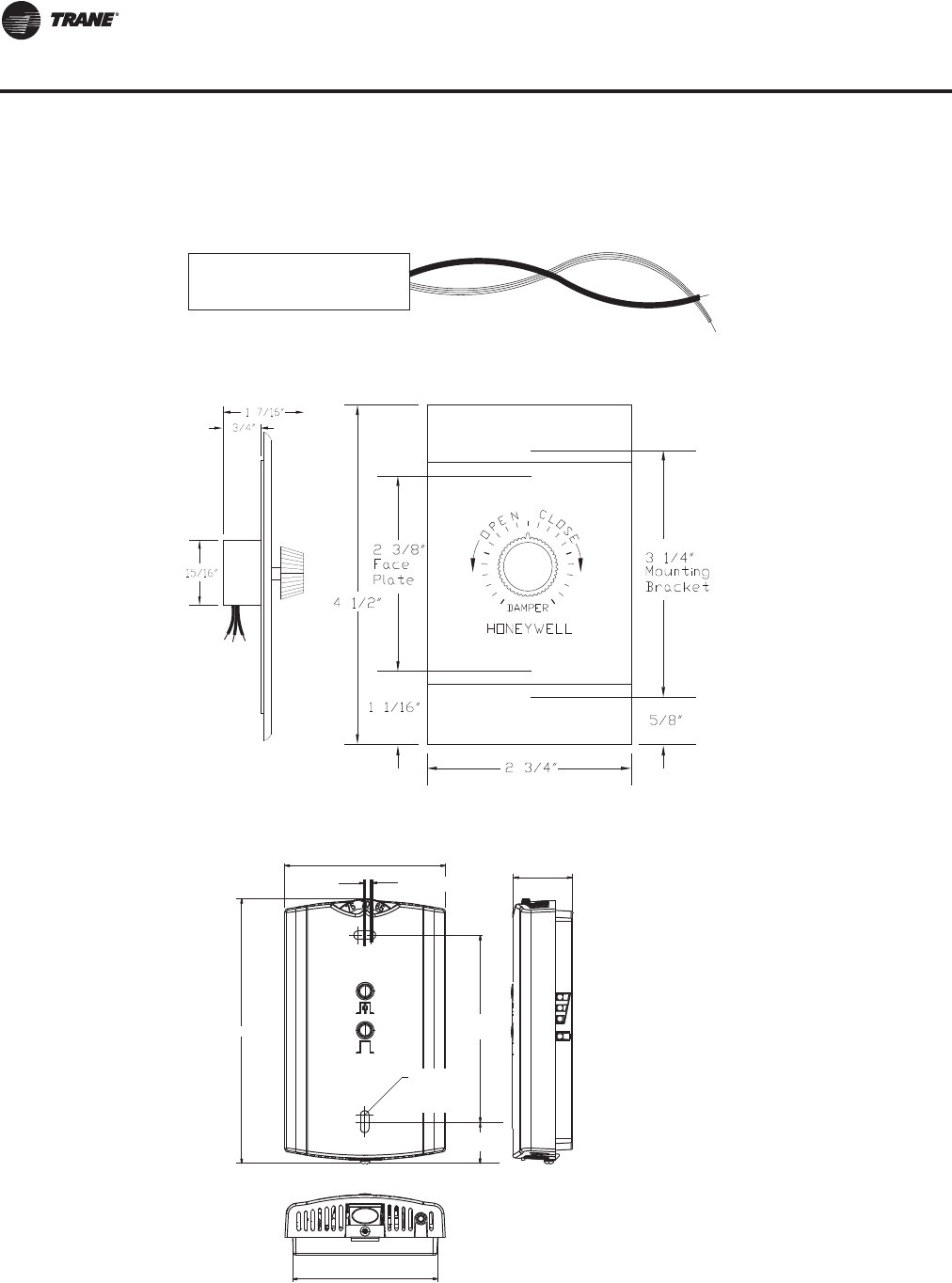
184 RT-PRC027T-EN
Dimensional Data
Note: Remote sensors are available for use with all zone sensors to provide remote sensing
capabilities.
Figure 45. Field installed temperature sensor (BAYSENS016*)
Figure 46. Field installed remote minimum position potentiometer control (BAYSTAT023*)
Figure 47. Field installed zone sensor—wireless
Note: The dimensions are the
same for both the sensor
and the receiver.
2.90 in. (73.5 mm)
1.08 in. (2.75 mm)
4.78 in. (121.4 mm)
2.62 in. (66.5 mm)
3.27 in.
(83 mm)
17.8 in.
(0.70 mm)
TYP 0.12 in. (3.0 mm)
Mounting hole
TYP R0.07 in.
(R1.9 mm)
Sensors
RT-PRC027.book Page 184 Tuesday, October 7, 2014 9:03 AM
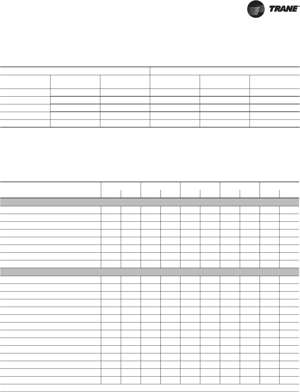
RT-PRC027T-EN 185
Weights
Notes:
1. Weights shown for air-cooled units include the following features: standard coils, 0-25% Outside Air, throwaway filters,
low CFM supply fan, minimum motor sizes, constant volume, 460 XL, No heat. Weights shown for Evaporative-condensing
units include high-capacity evaporator coil and the weight of the extra structure associated with a two piece unit. Add
1300 lbs for installed sump base water weight for evaporative condenser total operating weight.
2. Weights shown represent approximate operating weights and have a + 5% accuracy. To calculate weight for a specific
unit configuration, utilize TOPSS or contact the local Trane sales representative. ACTUAL WEIGHTS ARE STAMPED ON THE
UNIT NAMEPLATE.
Table 83. Approximate operating weights (lbs.)
Air-Cooled Units Evaporative Condensing Units
Nominal Tons Unit (Minimum) Roof Curb
(Minimum) Nominal Tons Unit (Minimum) Roof Curb
(Minimum)
90 13731 907 100 18430 1055
105 14792 907 118 18941 1055
120 16939 1040 128 21362 1194
130 17241 1040 140 21348 1194
150 17923 1040 162 21470 1194
Table 84. Component weights (lbs)
90/100 105/118 120/128 130/140 150/162
Size Weight Size Weight Size Weight Size Weight Size Weight
Refrigeration
Compressor Assy. - 1126 - 1344 - 1562 - 1616 - 1670
Air-Cooled Condensing Coil (Al) - 623 - 722 - 1049 - 1224 - 924
Evaporative Condensing Coil(a) 4566 4329 4129 4109 4029
Evap Coil - Std. Cap - 1034 - 1300 - 1664 - 1892 - 2564
Evap Coil - Hi. Cap. - 1382 - 1462 - 2564 - 2496 - N/A
Reheat Coil & Tubing - 292 - 294 - 367 - 367 - 367
Replacable Core Filter Driers - 26 - 25 - 35 - 35 - 35
HGBP - 46 - 49 - 53 - 53 - 53
Supply Fan Assembly
Supply Fan & Fan Board Assy. - Low CFM 25" 1159 32" 1361 32" 1361 32" 1361 32" 1361
Supply Fan & Fan Board Assy. - Std. CFM 36" 1490 36" 1490 40" 1653 40" 1653 40" 1653
Belt Guard - 116 - 116 - 116 - 116 - 116
Supply VFD (50 hp and below) - 233 - 233 - 233 - 233 - 233
Supply VFD (60-100 hp) - 284 - 284 - 284 - 284 - 284
Supply-Exh Fan Motor - 15 hp - 181 - 181 - 181 - 181 - 181
Supply-Exh Fan Motor - 20 hp - 206 - 206 - 206 - 206 - 206
Supply-Exh Fan Motor - 25 hp - 358 - 358 - 358 - 358 - 358
Supply-Exh Fan Motor - 30 hp - 413 - 413 - 413 - 413 - 413
Supply-Exh Fan Motor - 40 hp - 495 - 495 - 495 - 495 - 495
Supply-Exh Fan Motor - 50 hp - 604 - 604 - 604 - 604 - 604
Supply-Exh Fan Motor - 60 hp - 776 - 776 - 776 - 776 - 776
Supply-Exh Fan Motor - 75 hp - 879 - 879 - 879 - 879 - 879
Supply-Exh Fan Motor - 100 hp - 1102 - 1102 - 1102 - 1102 - 1102
continued on next page
RT-PRC027.book Page 185 Tuesday, October 7, 2014 9:03 AM
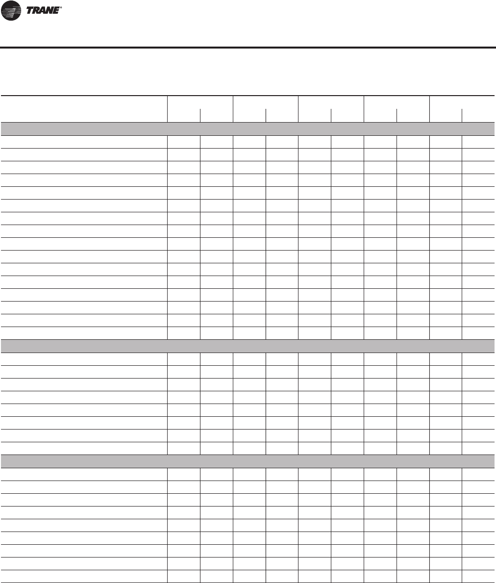
186 RT-PRC027T-EN
Weights
Return/Exhaust Fan Assembly
Return Fan & Dampers - Low CFM 36" 2294 36" 2294 36" 2294 36" 2294 36" 2294
Return Fan & Dampers - Std. CFM 40" 2343 40" 2343 44" 2445 44" 2445 44" 2445
Exhaust Fan & Dampers - Low CFM 25" 889 28" 979 28" 979 28" 979 28" 979
Exhaust Fan & Dampers - Std. CFM 28" 979 32" 1429 32" 1429 32" 1429 32" 1429
Belt Guard - 119 - 119 - 119 - 119 - 119
Exhaust VFD (50 hp and below) - 244 - 244 - 244 - 244 - 244
Exhaust VFD (60-100 hp) - 295 - 295 - 295 - 295 - 295
Exh Fan Motor - 7.5 hp - 160 160 - 160 - 160 - 160
Exh Fan Motor - 10 hp - 181 - 181 - 181 - 181 - 181
Exh Fan Motor - 15 hp - 206 - 206 - 206 - 206 - 206
Exh Fan Motor - 20 hp - 206 - 206 - 206 - 206 - 206
Exh Fan Motor - 25 hp - 358 - 358 - 358 - 358 - 358
Exh Fan Motor - 30 hp - 413 - 413 - 413 - 413 - 413
Exh Fan Motor - 40 hp - 495 - 495 - 495 - 495 - 495
Exh Fan Motor - 50 hp - 604 - 604 - 604 - 604 - 604
Exh Fan Motor - 60 hp - 776 - 776 - 776 - 776 - 776
Heat
Gas Heat Low 0.85 M 690 0.85M 690 1.1M 840 1.1M 840 1.1M 840
Gas Heat Med 1.1 M 840 1.1M 840 1.8M 1150 1.8M 1150 1.8M 1150
Gas Heat High 1.8 M 1150 1.8M 1150 2.5M 1398(b) 2.5M 1398
(2) 2.5M 1398 (2)
Electric Heat - 485 - 485 - 485 - 485 - 485
Steam Heat Low - 753 - 753 - 802 - 802 - 802
Steam Heat High - 821 - 821 - 886 - 886 - 886
Hot Water Heat Low - 773 - 773 - 841 - 841 - 841
Hot Water Heat High - 818 - 818 - 897 - 897 - 897
Filters
Filter Rack - Throwaway Filters - 181 - 181 - 191 - 191 - 191
Filter Rack - Bag Filters - 395 - 395 - 395 - 395 - 395
Filter Rack - Cartridge Filters - 662 - 662 - 662 - 662 - 662
Final Filters - Bag Filters - 392 - 392 - 392 - 392 - 392
Final Filters - Cartridge Filters w/ 2" pre-filter - 607 - 607 - 607 - 607 - 607
Final Filters - Cartridge Filters w/ 4" pre-filter - 638 - 638 - 638 - 638 - 638
Final Filters - High Temp. Cartridge - 669 - 669 - 669 - 669 - 669
Final Filters - HEPA - 1777 - 1777 - 1777 - 1777 - 1777
Final Filters - HEPA High Temp. - 1839 - 1839 - 1839 - 1839 - 1839
Continued on next page
Table 84. Component weights (lbs) (continued)
90/100 105/118 120/128 130/140 150/162
Size Weight Size Weight Size Weight Size Weight Size Weight
RT-PRC027.book Page 186 Tuesday, October 7, 2014 9:03 AM
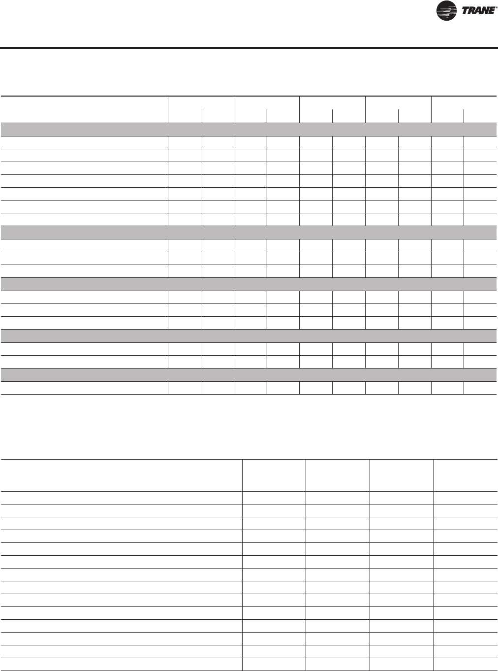
RT-PRC027T-EN 187
Weights
Outside Air
0-25% Damper - 637 - 637 - 699 - 699 - 699
Econ - 760 - 760 - 865 - 865 - 865
Econ w/ Air Measure - 724 - 724 - 807 - 807 - 807
ERW, Low CFM w/ Econ(c) - 3307 - 3307 - 3518 - 3681 - 3681
ERW, High CFM w/ Econ(3) - 3545 - 3514 - 3756 - 3756 - 3756
ERW, Low CFM w/ Econ & Air Measure(3) - 3487 - 3487 - 3727 - 3890 - 3890
ERW, High CFM w/ Econ & Air Measure(3) - 3725 - 3694 - 3965 - 3965 - 3965
Cabinet
Cabinet - 8097 - 8315 - 9473 - 9473 - 9473
Cabinet - 4' Blank Section - 935 - 935 - 901 - 901 - 901
Cabinet - 8' Blank Section - 1709 - 1709 - 1682 - 1682 - 1682
Control Box - Main
Control Box - Main - 519 - 519 - 519 - 519 - 519
Convenience Outlet - 36 - 36 - 36 - 36 - 36
Low Ambient VFD - 57 - 57 - 57 - 57 - 57
2/3 Piece Unit Adder
2 Piece Adder - 406 - 406 - 406 - 406 - 406
3 Piece Adder - 1157 - 1157 - 1236 - 1236 - 1236
Air-Cooled Condenser
Total Weight of Condenser Section - 4637 - 5201 - 6015 - 6075 - 6092
(a)Evaporative Condenser weight includes the additional weight in the cabinet structure. coil weight and additional refrigerant charge. Add 1300 lbs for
operating sump base water weight.
(b)2.5M includes weight associated with 12" of cabinet length.
(c) Energy Recovery includes weight associated w/ 96" of cabinet length.
Table 84. Component weights (lbs) (continued)
90/100 105/118 120/128 130/140 150/162
Size Weight Size Weight Size Weight Size Weight Size Weight
Table 85. Roof curb weights — air-cooled (AC) and evaporative condensing (EC)
Tonnage
AC/EC
Energy
Recovery
Wheel Blank Section One-Piece
Unit(a) Two/Three-
Piece Unit
90-105/100-118 No None 907 1055
90-105/100-118 No 4 ft 988 1136
90-105/100-118 No 8 ft 1069 1217
90-105/100-118 Yes None 1093 1240
90-105/100-118 Yes 4 ft 1174 1321
90-105/100-118 Yes 8 ft N/A 1401
120-150/128-162 (All Units Except High Heat Gas models) No None 1040 1194
120-150/128-162 (All Units Except High Heat Gas models) No 4 ft 1122 1275
120-150/128-162 (All Units Except High Heat Gas models) No 8 ft N/A 1357
120-150/128-162 (High Heat Gas Models Only) No None 1055 1209
120-150/128-162 (All Units Except High Heat Gas models) Yes None N/A 1378
120-150/128-162 (All Units Except High Heat Gas models) Yes 4 ft N/A 1459
120-150/128-162 (All Units Except High Heat Gas models) Yes 8 ft N/A 1540
120-150/128-162 (High Heat Gas Models Only) Yes None N/A 1393
(a)One-piece available with air-cooled condenser only.
RT-PRC027.book Page 187 Tuesday, October 7, 2014 9:03 AM
188 RT-PRC027T-EN
Weights
Table 86. Design Specials
Cabinet
4' or 8' blank in Pre DX or Return Position
Economizer
Title 24 Rated Ultra Low Leak Economizer w FDD
Efficiency
Hybrid High and Hybrid Ultra High Efficiency (120T)
Electrical
50Hz Exhuast/Return VFD
Dual Power
Energy Recovery
Energy recovery with Horizontal Return
Fans
Direct Drive Plenum Supply Fan
Propeller Exhaust Fan
Piezometer Rings
Heat
LP Gas heat
Seismic
OSHPD
RT-PRC027.book Page 188 Tuesday, October 7, 2014 9:03 AM

RT-PRC027T-EN 189
Mechanical Specs
General
Units shall be specifically designed for outdoor rooftop installation on a roof curb and be
completely factory assembled and tested, piped, internally wired, fully charged with compressor
oil and shipped in one, two or three-pieces for field reassembly into a single unit. Single piece units
shall be fully charged.
Units shall be available for direct expansion cooling only, or direct expansion cooling with natural
gas, electric, hot water or steam heating. Filters, outside air system, exhaust air system, optional
nonfused disconnect switches and all operating and safety controls shall be furnished factory
installed.
All units shall be cULus approved and factory run tested. Select configurations shall also be
compliant with IBC Seismic requirements. In select configurations, cooling capacity shall be rated
in accordance with ARI Standard 360. All units shall have decals and tags to aid in service and
indicate caution areas. Electrical diagrams shall be printed on long life water resistant material and
shall ship attached to control panel doors.
Casing
Exterior panels shall be zinc coated galvanized steel, phosphatized and painted with a slate grey
air-dry finish durable enough to withstand a minimum of 500 hours consecutive salt spray
application in accordance with standard ASTM B117. Screws shall be magnigard coated.
Refrigeration components and compressor shall be accessible through removable louvered panels
as standard. Unit air handling section shall be laminated double-wall construction with
polyurethane foam core injected between sheet metal panels and liners. Insulation value shall be
R8. All interior surfaces shall be suitable for cleaning per ASHRAE 62. All access doors and panels
shall have neoprene gaskets. Unit base shall be watertight with heavy gauge formed load bearing
members and curb overhang. Unit lifting lugs shall accept chains or cables for rigging. Lifting lugs
shall also serve as unit tie down points.
Access Doors
Access doors shall be hinged with a single, exterior mounted, height and tension adjustable,
handle to provide positive latching at three points. Access doors shall provide a door stop
mechanism to latch the door in the open position to prevent unsafe door closure by wind.
Doors of laminated double wall construction with a polyurethane foam core between the exterior
sheet metal pane and the interior liner, with an insulating value of R8 shall be provided on the air
handlers serviceable compartments such as return/exhaust fan, filters, evaporator coil, and blank
sections.Two single wall doors shall be provided for access to the control panel.
Blank Sections
A four or eight foot blank section of laminated double wall construction with a polyurethane foam
core between the exterior sheet metal panel and the interior liner, with an insulating value of R8
shall be provided with similarly built, hinged, access doors on either side
Two- or Three-Piece Construction
In order to facilitate lifting and rigging a two- or three-piece option is available.The condenser
section contains the refrigerant charge and associated valving to make recoupling the unit on the
roof curb easy. An electrical box is provided on the condenser to seamlessly and quickly reconnect
the electrical power and control systems.Transition panels are provided for the integrity on the
recoupled unit.
Note: Multi-piece units are shipped with nitrogen and must be field charged with R-410A.
Airflow Path
Unit shall have downflow discharge conditioned air path or horizontal discharge. Return airflow
path shall be either upflow or horizontal through the side or the end.
RT-PRC027.book Page 189 Tuesday, October 7, 2014 9:03 AM

190 RT-PRC027T-EN
Mechanical Specs
Burglar Bars
A grate system shall be installed in supply and return air duct connection areas on non-horizontal
airflow path units to minimize unwanted intrusion into duct systems.
Belt Guard
Supply and exhaust fans shall have a universal size belt guard to accommodate any applicable
drive configuration.The guard totally encloses the drive system and is provided with a two-piece
removable front panel for servicing. Return fan guards shall be individually sized with a single piece
removable panel for servicing.
Refrigeration System
Compressors
Compressors shall be direct-drive, hermetic, scroll-type compressors with centrifugal-type oil
pumps. Each compressor has a crankcase heater to minimize the amount of liquid refrigerant
present in the oil sump during off cycles. Discharge and liquid line service valves are standard on
each refrigerant circuit, as well as liquid moisture indicator/sight glass.
Supply Fan
Standard or low airflow supply fan shall have a single fan assembly with double width, double inlet,
airfoil fan, motor and fixed pitch sheave drive. All fans shall be statically and dynamically balanced
for the operating envelop. It shall be tested in the factory. Supply fans shall be test run in unit as
part of the unit test. Fan operating envelop rpm shall be below first critical speed. Fan shafts shall
be mounted on two grease lubricated ball bearings designed for 200,000 hours average life.
Extended grease lines shall allow greasing of bearings from section base rail. Fan motor and fan
assembly shall be mounted on common base to allow consistent belt tension with no relative
motion between fan and motor shafts. Entire assemblies shall be completely isolated from unit by
two-inch deflection spring isolators.
Evaporator Coil
Internally enhanced copper tubing of ½-inch O.D. shall be mechanically bonded to heavy-duty
aluminum fins of configured design. All coils shall be equipped with thermal expansion valves and
factory pressure and leak tested. A double sloped galvanized or stainless steel drain pan shall be
provided to drain condensate to both sides of the unit.
Stainless Steel Drain Pans
In order to enhance longevity and cleaning ease, optional Stainless Steel Drain Pans are available
under the evaporator coil area.
Hot Gas Bypass
The hot gas bypass option shall consist of valves, piping and controls that are all included on circuit
2 to allow operation at low airflow, avoiding coil frosting and damage to compressor.When suction
pressure falls below valve adjustable setpoint, the valves modulate hot gas to the inlet of the
evaporator.
Filter Drier
Removable core filter driers are optionally available and installed on each refrigeration circuit.
For easy access, the filter driers are conveniently located in the condenser section close to the
periphery of the unit.
Suction Service Valves
Each compressor is optionally equipped with a suction service valve in order to facilitate
compressor servicing.
RT-PRC027.book Page 190 Tuesday, October 7, 2014 9:03 AM

RT-PRC027T-EN 191
Mechanical Specs
Air-Cooled Condensing
Air-Cooled Condenser Coil
Condenser coils shall have all-aluminum, Microchannel coils. All coils shall be leak tested at the
factory to ensure pressure integrity.The condenser coil is pressure tested to 650 psig. Subcooling
circuit(s) shall be provided as standard.
Air-Cooled Condenser Fans and Motors
All condenser fans shall be vertical discharge, direct drive fans, statically balanced, with steel
blades and zinc plated steel hubs. Condenser fan motors shall be totally enclosed three-phase
motors with permanently lubricated ball bearings, built-in current and thermal overload protection
and weather tight slingers over motor bearings.
Corrosion Protected Condenser Coil
All aluminum Microchannel condenser coil protection shall consist of a corrosion resistant coating
that shall withstand ASTM B117 Salt Spray test for 6,000 hours and ASTM G85 A2 Cyclic Acidified
Salt Fog test for 2,400 hours.This coating shall be added after coil construction covering all tubes,
headers and fin edges, therefore providing optimum protection in more corrosive environments
Evaporative Condensing
Evaporative Condensing-Housing
The water basin, corner posts and roof shall be constructed with 304 Stainless Steel. Water basin
shall be lined with FRP coating to make it watertight.The side panels and sliding access doors shall
be constructed of corrosion and UV resistant, low density fiber glass. Housing shall also have 4
lifting holes, one in each corner to handle the unit with crane.
Evaporative Condensing - Condenser Coils
Durable copper 5/16" OD, 0.022 wall thickness serpentine tubing provides strength and resilience
for expansion.
Evaporative Condensing - Condenser Fan
The fan motors have variable speed capability which shall be controlled by factory-installed unit
controller.
Evaporative Condensing - Pump
Minimal maintenance sump pump is fully accessible through the evaporative-condenser access
panel. Water is pumped at min 80 GPM.The pump shall be powered by 460 V / 3 Phase.
Evaporative Condensing- Sump Float Level Switch
The minimum level float switch shall protect the pump from running dry by turning the fill valve
ON and allowing the sump to fill to a predefined minimum level.The maximum level float switch
shall prevent the overfilling of the sump and water wastage by turning the fill valve OFF when a
predefined maximum level is reached in the sump. Minimum and maximum float switched shall
be permanently affixed to the water basin and shall not need any field adjustment.
Water Treatment
To simplify field installation, unit shall have hookups for water treatment devices.Water treatment
by a water treatment expert is required for all evaporative condenser units to ensure proper
equipment life, product performance and operation. If a Dolphin WaterCare System is used water
must be maintained by a water treatment professional throughout the unit life of the Air Handling
System.
RT-PRC027.book Page 191 Tuesday, October 7, 2014 9:03 AM

192 RT-PRC027T-EN
Mechanical Specs
Dolphin WaterCare System
The Dolphin WaterCare System focuses on minimizing scale build up and managing biological
agents with no chemicals. An electronic signal is sent through a PVC pipe at a constant rate,
inducing electromagnetic fields.The electromagnetic fields interact with colloidal particles causing
precipitation, which does not adhere to the pipe, and is removed through the sump purge. Bacteria
and corrosion in the water system is controlled and kept to minimal levels by their incorporation
into the precipitate and low frequency radiation generated through the electronic pulsing.
Controls
Unit shall be completely factory wired with necessary control and contactor pressure lugs or
terminal block for power wiring. Units shall provide an internal location for a non-fused disconnect
with external handle for safety. Unit mounted microprocessor controls shall provide anti-short
cycle timing for compressors to provide a high level of machine protection.
Unit Controller
DDC microprocessor controls shall be provided to control all unit functions.The control system
shall be suitable to control CV or VAV applications.The controls shall be factory installed and
mounted in the main control panel. All factory installed controls shall be fully commissioned (run
tested) at the factory. The unit shall have a Human Interface Panel with a 16 key keypad, a 2 line
X 40 character clear English display as standard to provide the operator with full adjustment and
display of control data functions.The unit controls shall be used as a stand-alone controller, or as
part of a building management system involving multiple units.
1. The unit shall be equipped with a complete microprocessor control system.This system shall
consist of temperature and pressure (thermistor and transducer) sensors, printed circuit boards
(modules), and a unit mounted Human Interface Panel. Modules (boards) shall be individually
replaceable for ease of service. All microprocessors, boards and sensors shall be factory
mounted, wired and tested.
The microprocessor boards shall be standalone DDC controls not dependent on
communications with an on-site PC or a Building Management Network.The microprocessors
shall be equipped with onboard diagnostics, indicating that all hardware, software and
interconnected wiring are in proper operating condition.
The modules (boards) shall be protected to prevent RFI and voltage transients from affecting
the board circuits. All field wiring shall be terminated at separate, clearly marked terminal strip.
Direct field wiring to the I/O boards is not acceptable.The microprocessor's memory shall be
non-volatile EEPROM type requiring no battery or capacitive backup, while maintaining all data.
2. Zone sensors shall be available in several combinations with selectable features depending on
sensor.
3. The Human Interface Panel keypad display character format shall be 40 characters x 2 lines.The
character font shall be5x7dotmatrix plus cursor.The display shall be Supertwist Liquid
Crystal Display (LCD) with blue characters on a gray/green background which provides high
visibility and ease of interface.The display format shall be in clear English.
4. The keypad shall be equipped with 16 individual touch-sensitive membrane key switches.The
switches shall be divided into four separate sections and be password protected from change
by unauthorized personnel.The six main menus shall be STATUS, SETPOINTS, DIAGNOSTICS,
SETUP, CONFIGURATION and SERVICE MODE.
5. Microprocessor control system shall provide Loss of Refrigerant Charge diagnostics to warn of
a slightly undercharged situation followed by a warning and a lock out of an undercharged
circuit for overall unit performance and compressor protection.
6. The Human Interface Panel shall provide refrigerant superheat reading for each circuit to assist
the service technician in troubleshooting.
RT-PRC027.book Page 192 Tuesday, October 7, 2014 9:03 AM

RT-PRC027T-EN 193
Mechanical Specs
Control Options
Remote Human Interface Panel
Remote Human Interface Panel (RHI) option can perform all the same functions as unit mounted
Human Interface Panel, except for the Service Mode. Up to 4 rooftop units can be monitored and
controlled with a single RHI Panel.This panel uses the same attractive enclosure as theTracker
building control panel.With features such as a 2 line X 40 character clear English display, a red LED
light to indicate an alarm condition (alarm also shown on the two line display), a simple 16 key
keypad that is used in conjunction with the display to prompt the infrequent user when making
desired changes and an attractive hinged door makes the RHI very suitable for mounting on any
wall.The RHI can be mounted inside a building, up to 5000 feet from the unit.The RHI is wired to
the IPCB mounted in the rooftop with twisted wire pair communication wiring and 24V control
wiring.
Trane LonTalk Communication Interface Module (LCI-I)
The LCI-I provides an interface to aTracer Summit system or other control system that supports
LonTalk and shall be factory installed, allowing for control and monitoring of the unit through a
RS485, two-wire communication link.
Trane BACnet Communication Interface Module (BCI-I)
The BCI-I provides an interface toTracer SC or a 3rd party control system that supports BACnet and
shall be factory or field installed, allowing for control and monitoring of the unit through a RS485,
two-wire communication link.
Wireless Comm Interface - Field Installed
Trane Wireless Comm interface – Provides wireless communication between theTracer SC,Tracer
Unit Controllers and BACnet Communication Interface (BCI) modules.
Low Ambient Unit Operation-Variable Frequency Drives VFDs
The low ambient option allows the unit to operate down to 0°F.The VFDs will be located in an
enclosure inside the service side corner post that is adjacent to the main control box.The VFD
keypads and displays will be accessible through a standard door that will allow "touch-safe" access
to the VFDs. VFD protection fuses will be accessible through a second door below the VFD access
door.
Low Ambient Unit Operation-575 Volt Units
The low ambient option allows the unit to operate down to 0°F. Units configured with a 575V power
requirement and low ambient unit operation will require the use of step-down transformers.
Additional 3-phase transformers and transformer fuses will be required to step the voltage down
to a 460V operating voltage.The VFDs and the condenser fan motors controlled by the VFDs will
all be 460V operating devices
Generic Building Automation System Module (GBAS 0-5 VDC)
Provided for those cases where non-Tracer building management system is used. The GBAS
module option provides a binary input for Demand Limiting, four (4) analog inputs for setpoint
adjustment and five (5) relay outputs for diagnostic reporting. Inputs can use a potentiometer or
0-5 VDC signal.
Generic Building Automation System Module (GBAS 0-10 VDC)
Option used to provide broad control capabilities for building automation systems other than
Trane'sTracer system.The GBAS module provides a binary input for Demand Limiting, four (4)
analog inputs for setpoint adjustment and four (4) analog outputs as well as one (1) relay output
for diagnostic reporting. Inputs can use a potentiometer or 0-10 VDC signal.
RT-PRC027.book Page 193 Tuesday, October 7, 2014 9:03 AM

194 RT-PRC027T-EN
Mechanical Specs
Inter-Processor Communication Bridge (IPCB)
This optional module provides an amplified and filtered version of the IPC link for connection to
a Remote Human Interface Panel. Each rooftop that is tied into a Remote Human Interface Panel
must have an IPCB installed into it.
Rapid Restart
Option shall provide immediate start up upon power failure. A backup generator is required on site
before unit start up. Rapid Restart will begin immediately after recovery from a power loss and
work by restarting the compressors and supply fan quickly to provide full cooling within two to
three minutes.
System Control Options
Constant Volume (CV)
Provided with all the necessary controls to operate rooftop from a zone sensor, including CV
microprocessor unit control module, a microprocessor compressor controller and a unit mounted
Human Interface Panel.
Variable Air Volume (VAV) Supply Air Temperature control
Provided with all the necessary controls to operate a VAV rooftop from the discharge air
temperature, including discharge air microprocessor controller and discharge air sensor.The
microprocessor controller coordinates the economizer control and the stages of cooling with zone
or outdoor air reset capabilities and an adjustable control band to fine-tune the control to specific
applications.
VAV Supply AirTemperature Control with Variable Frequency Drives
w/o Bypass
Provided with all necessary controls to operate a VAV rooftop from the discharge air temperature,
including discharge air microprocessor controller and discharge air sensor.The microprocessor
controller coordinates the economizer control and the stages of cooling with discharge air
temperature reset capabilities. Includes factory installed and tested VFDs to provide supply fan
motor speed modulation.VFD receives 0-10 VDC from the unit microprocessor based upon supply
static pressure and causes the drive to accelerate or decelerate as required to maintain the supply
static pressure setpoint.
VAV Supply AirTemperature Control with Variable Frequency Drives and
Bypass
Bypass control provides full nominal airflow in the event of drive failure.
Single Zone Variable Air Volume
Single zoneVAV option shall be provided with all necessary controls to operate a rooftop unit based
on maintaining two temperature setpoints; the discharge air and zone. Option shall include factory-
installed variable frequency drive (VFD) to provide supply fan motor speed modulation. During
One Zone VAV cooling, the unit will maintain zone cooling setpoint by modulating the supply fan
speed more or less to meet zone load demand, and the unit will maintain discharge temperature
to the discharge cooling setpoint by modulating economizer if available and staging dx cooling.
Electrical System
Power Supply
Air-cooled rooftops are available with 460 or 575 voltage, 3 phase 60 hertz power supply and 380
voltage, 3 phase 50 hertz power supply (Evaporative Condenser models available in 460 voltage,
3 phase, 60 hertz power supply only).
RT-PRC027.book Page 194 Tuesday, October 7, 2014 9:03 AM

RT-PRC027T-EN 195
Mechanical Specs
Convenience Outlet
A 15A, 115V Ground Fault Interrupter convenience outlet shall be factory installed and wired and
powered from a factory mounted transformer. A unit mounted, non-fused disconnect with internal
handle is furnished with the factory powered convenience outlet.
Non-Fused Disconnect Switch
An external handle mounted on the control box door shall be provided to disconnect unit power
with the control box door closed for safety.
Phase and Voltage Monitor
Phase monitor is standard on all IntelliPak II units. Protects 3-phase equipment from phase loss,
phase reversal, phase imbalance, high operating temperatures and low voltage. Any fault
condition will produce a Failure Indicator LED, and send the unit into an emergency stop condition.
cULus approved.
Unit Interrupt Rating (Short Circuit Current Rating-SCCR)
An optional 65,000 Amp rating (480V) and 25,000 Amp rating (600V) shall be applied to the unit
enclosure using a non-fused circuit breaker for disconnect switch purposes. Fan motors,
compressors, and electric heat circuits shall be provided with series rated circuit breakers that will
provide the unit rated level of protection.The unit shall be marked with approved cULus markings
and will adhere to cULus regulations.
Marine Lights (Customer Powered)
A 120V master light switch shall be factory installed in the main unit control box for lighting control.
The master switch shall be wired into an isolated terminal block with access for customer provided
service. Marine light fixtures shall be supplied with 150W incandescent bulbs. Marine light fixtures
shall be placed in the Supply Section (2), Outside Air Section (1), Return Section (1), and Extended
Casing Section (1) for units without Heat.
Supply/Exhaust/Return Motors
Supply, exhaust/return motors are either open drip-proof or totally enclosed fan cooled (TEFC). All
60 Hz motors meet the Energy Independence and Security Act of 2007 (EISA). All 50 Hz supply,
exhaust/ return motors meet the U.S. Energy Policy Act of 1992 (EPACT).
Motors with internal Shaft grounding rings can be selected for use withVFD applications to provide
a conductive discharge path away from the motor bearings to ground.
Filters
General
Filter options shall mount integral within the unit and be accessible by a hinged access door with
a single point latching device.
Pre-evaporator Coil Filter Options
No Filters (Two-inch NominalThicknessThrowaway Filter Rack Only)
Shall provide a galvanized steel filter rack (less filter media) with filter channels to handle a
complete set of two-inch nominal thickness throwaway filters to accommodate applications which
require field supplied filters.
No Filters (Bag or Cartridge Filter Rack with Throwaway Prefilter Rack Only)
Shall provide a galvanized steel filter rack (less filter media) to handle a complete set of two-inch
or four-inch (depending on airflow) nominal thickness throwaway prefilters and 7/8" actual header
thickness bag or cartridge filters to accommodate applications which require field supplied filters.
RT-PRC027.book Page 195 Tuesday, October 7, 2014 9:03 AM

196 RT-PRC027T-EN
Mechanical Specs
MERV 8Throwaway Filters (Standard)
Shall be provided as standard-U.L. Class 2, two-inch nominal thickness, high efficiency pleated
media filters rated MERV 8 perASHRAE 52.2. Filters shall be provided mounted in a galvanized steel
filter rack.
MERV 15, 90-95 Percent Bag Filters Option
Nineteen-inch deep bag filters shall be U.L. Class 2 and have synthetic media mounted to a 7/8"
nominal thickness header frame.These bag filters shall have an efficiency rating of MERV 15 per
ASHRAE 52.2.To ensure maximum bag filter life two-inch prefilters shall be included with the bag
filters. Filters shall be mounted in a galvanized steel filter rack.
MERV 14, 90-95 Percent Cartridge Filters Option
Twelve-inch deep cartridge filters shall be U.L. Class 1 and be mounted with a 7/8" nominal
thickness header frame.These cartridge filters shall have an efficiency rating of MERV 14 per
ASHRAE 52.2.To ensure maximum cartridge filter life, two-inch (or four-inch, depending on the
application) prefilters shall be included with the cartridge filters. Filters shall be mounted in a
galvanized steel filter rack.
MERV 14, 90-95 Percent, Low Pressure Drop, Totally Incinerable, Cartridge
Twelve-inch deep cartridge filter shall be U.L. Class 2 and mounted with a rigid 7/8" nominal
thickness header frame.These low pressure drop cartridge filters shall have an efficiency rating of
MERV 14 per ASHRAE 52.2.To ensure maximum cartridge filter life two-inch or four-inch prefilters
(depending on airflow) shall be included with the high-flow, cartridge filters. Filters shall be
mounted in a galvanized steel filter rack.
Final Filters Options (Available Only on Units with Blank Section)
Final filter section filter options shall mount integral within the blank section unit casing and be
accessible by hinged access doors.
MERV 15, 90-95 Percent, Bag, Final Filter Option
Note: Available on cooling only units with four or eight-foot blank section, as well as steam and
hot water units with eight-foot blank section, unit casing only.
Nineteen-inch deep bag filters shall be U.L. Class 2 and have synthetic media mounted to a 7/8"
nominal thickness header frame.These bag filters shall have an efficiency rating of MERV 15 per
ASHRAE 52.2.To ensure maximum bag final filter life two-inch, MERV 8 prefilters shall be included
with the bag filters. Filters shall be mounted in a galvanized steel filter frame bank.
MERV 14, 90-95 Percent, Cartridge, Final Filter Option
Note: Available on cooling only units with four or eight-foot blank section, as well as steam and
hot water units with eight-foot blank section, unit casing only.
Twelve-inch deep cartridge filters shall be U.L. Class 1 and be mounted with a 7/8" nominal
thickness header frame.These cartridge filters shall have an efficiency rating of MERV 14 per
ASHRAE 52.2.To ensure maximum cartridge filter life, two-inch, MERV 8 prefilters shall be included
with the cartridge filters. Filters shall be mounted in a galvanized steel filter frame bank.
MERV 14, 90-95 Percent, Low Pressure Drop, Totally Incinerable, Cartridge,
Note: Available on cooling only units with four or eight-foot blank section, as well as steam and
hot water units with eight-foot blank section, unit casing only.
Twelve-inch deep cartridge filter shall be U.L. Class 2 and mounted with a rigid 7/8" nominal
thickness header frame.These cartridge filters shall have an efficiency rating of MERV 14 per
ASHRAE 52.2.To ensure maximum cartridge final filter life four-inch, MERV 8 prefilters shall be
included with these cartridge filters. Filters shall be mounted in a galvanized steel filter frame bank.
RT-PRC027.book Page 196 Tuesday, October 7, 2014 9:03 AM

RT-PRC027T-EN 197
Mechanical Specs
MERV 14, 90-95 Percent, HighTemperature Rated, Cartridge, Final Filter Option
Note: Available on gas and electric heat units with eight-foot blank section casing only.
Twelve-inch deep cartridge filters shall be U.L. Class 1 and be mounted in a galvanized steel casing
with a 7/8" nominal thickness header frame.These cartridge filters shall have an efficiency rating
of MERV 14 per ASHRAE 52.2.To ensure maximum cartridge final filter life high temperature rated
two-inch, MERV 8 prefilters shall be included with the cartridge filters. Filters shall be mounted in
a galvanized steel filter frame bank.
MERV 17, 99.97 Percent, Standard Temperature Rated, HEPA, Final Filter Option
Note: Available on cooling only units with four or eight-foot blank section, as well as steam and
hot water units with eight-foot blank section, unit casing only.
Twelve-inch deep HEPA filters shall be U.L. Class 1 and be mounted in a galvanized steel casing.
These filters have an efficiency rating of MERV 17 per ASHRAE 52.2 and an efficiency of 99.97% on
a 0.3 micron DOP particle size.To ensure maximum HEPA final filter life two-inch, MERV 8 prefilters
shall be included with the HEPA final filters. Filters shall be mounted in a galvanized steel filter
frame bank.
MERV 17, 99.97 Percent, HighTemperature Rated, HEPA, Final Filter Option
Note: Available on gas and electric heat units with eight-foot blank section casing only.
Twelve-inch deep HEPA filters shall be U.L. Class 1 and be mounted in a galvanized steel casing.
These filters have an efficiency rating of MERV 17 per ASHRAE 52.2 and an efficiency of 99.97% on
a 0.3 micron DOP particle size.To ensure maximum HEPA final filter life high temperature rated two-
inch, MERV 8 prefilters shall be included with the HEPA final filters. Filters shall be mounted in a
galvanized steel filter frame bank.
Exhaust Air
General
Exhaust air options shall include no relief, 100 percent modulating exhaust fan and 100 percent
modulating exhaust fan with direct space building pressurization control. Exhaust fans shall be
either standard or low airflow
No Relief (Standard)
Relief air opening shall be sealed with panel and made watertight.
100 Percent Modulating Exhaust Fan Option
Fan design shall be double width, double inlet forward-curved type. Fan shall be mounted on a
shaft with fixed sheave drive. All fans shall be dynamically balanced and tested in factory before
being installed in unit. It shall be test run in unit as part of unit test.
Fan operating envelop rpm shall be below first critical speed. Fan shaft shall be mounted on two
grease lubricated ball or roller bearings as applicable designed for 200,000-hour average life.
Extended grease lines shall be provided to allow greasing of bearings from section base rail.
Fan motor and assembly shall be mounted on common base to allow consistent belt tension with
no relative motion between fan and motor shafts.The entire assembly shall be completely isolated
from unit with 2-inch spring isolation. Discharge dampers at unit outlet shall modulate exhaust
airflow in response to OA damper position.
The fan shall operate when economizer damper is open greater than minimum position. Discharge
dampers at fan outlet shall modulate in response to economizer damper position on Constant
Volume (CV) rooftops.
RT-PRC027.book Page 197 Tuesday, October 7, 2014 9:03 AM

198 RT-PRC027T-EN
Mechanical Specs
100 Percent Modulating Exhaust Fan with Statitrac Control Option
Fan design shall be double width, double inlet forward-curved type. Fan shall be mounted on a
shaft with fixed sheave drive. All fans shall be dynamically balanced and tested in factory before
being installed in unit. Exhaust fan shall be test run as part of unit final run test.
Fan operating envelop rpm shall be below first critical speed. Fan shaft shall be mounted on two
grease lubricated ball or roller bearings designed for 200,000-hour average life. Extended grease
lines shall be provided to allow greasing of bearings from section base rail.
Fan motor and assembly shall be mounted on common base to allow consistent belt tension with
no relative motion between fan and motor shafts.The entire assembly shall be completely isolated
from unit with 2-inch spring isolators. For both CV and VAV rooftops, the 100 percent modulating
exhaust discharge damper (or VFD) shall be modulated in response to building pressure.
A differential pressure control system, (Statitrac), shall use a differential pressure transducer to
compare indoor building pressure to outdoor ambient atmospheric pressure.The FC exhaust fan
shall be turned on when required to lower building static pressure setpoint.
The (Statitrac) control system shall then modulate the discharge dampers (or VFD) to control the
building pressure to within the adjustable, specified deadband that shall be adjustable at the
Human Interface Panel. Optional bypass can be factory installed to provide full nominal airflow in
the event of a drive failure.
Return Air
General
Return air options shall include 100 percent modulating return fan and 100 percent modulating
return with direct space building pressurization control. Return fans shall be either standard or low
airflow.
100 Percent Modulating Return Fan
A single width plenum fan with airfoil blade shall be mounted on a shaft with fixed sheave drive.
The fan shall be dynamically balanced for the operating envelop and tested in factory before being
installed in unit.The plenum fan shall be test run in unit as part of unit test. Fan operating envelop
rpm shall be below first critical speed. Fan shaft shall be mounted on two grease lubricated ball or
roller bearings designed for 200,000-hour average life. Extended grease lines shall be provided to
allow greasing of bearings from section base rail.
Fan motor and assembly shall be mounted on common base to allow consistent belt tension with
no relative motion between fan and motor shafts.The entire assembly shall be completely isolated
from unit with 2-inch spring isolators. Discharge dampers at unit outlet shall modulate relief airflow
in response to OA / return air damper position.The return fanVFD shall operate in conjunction with
the supply fan.
100 Percent Modulating Return Fan with Statitrac Control Option
A single width plenum fan with airfoil blade shall be mounted on a shaft with fixed sheave drive.
The fan shall be dynamically balanced for the operating envelop and tested in factory before being
installed in unit.The plenum fan shall be test run as part of unit final run test. Fan operating envelop
rpm shall be below first critical speed. Fan shaft shall be mounted on two grease lubricated ball or
roller bearings designed for 200,000-hour average life. Extended grease lines shall be provided to
allow greasing of bearings from section base rail.
Fan motor and assembly shall be mounted on common base to allow consistent belt tension with
no relative motion between fan and motor shafts.The entire assembly shall be completely isolated
from unit with 2-inch spring isolators.The 100 percent modulating relief damper shall be
modulated in response to building pressure. A differential pressure control system, (Statitrac),
shall use a differential pressure transducer to compare indoor building pressure to outdoor
ambient atmospheric pressure.
RT-PRC027.book Page 198 Tuesday, October 7, 2014 9:03 AM

RT-PRC027T-EN 199
Mechanical Specs
The Statitrac control system shall modulate the discharge dampers to control the building pressure
to within the adjustable, specified deadband that shall be adjustable at the Human Interface Panel.
The return fan VFD shall modulate in response to return duct static pressure. Optional bypass can
be factory installed to provide full nominal airflow in the event of a drive failure.
Outside Air
General
Three outside air options: 0 to 25 percent motorized controlled outside air, 0-100 percent fully
modulating economizer, and 0-100 percent fully modulating economizer with outside air
measurement.
0-25 Percent Motorized Outside Air Damper Option
0-25 percent motorized outside air damper option shall include an outside air opening with
moisture eliminator and motorized position damper for drawing up to 25 percent outside air.The
damper position will be adjustable at the Human Interface Panel.
0-100 Percent Modulating Economizer Option
Operated through the primary temperature controls to automatically utilize OA for "free" cooling.
Automatically modulated return and OA dampers shall maintain proper temperature in the
conditioned space. Economizer shall be equipped with an automatic lockout when the outdoor high
ambient temperature is too high for proper cooling. Minimum position control shall be standard
and adjustable at the Human Interface Panel or with a remote potentiometer or through the
building management system. A spring return motor shall ensure closure of OA dampers during
unit shutdown or power interruption. Mechanical cooling shall be available to aid the economizer
mode at any ambient. Standard economizer dampers shall have a leakage rate of 20 CFM/ft^2 at
1.0 in W.C. pressure difference.
Low Leak, Standard Ultra Low Leak, and AMCA 1A Ultra Low Leak Economizer
Dampers Options
Low leak dampers shall be provided with chlorinated polyvinyl chloride gasketing added to the
damper blades and rolled stainless steel jamb seals to the sides of the damper assembly.The low
leak dampers shall have a leakage rate of 10 CFM/ft^2 (AMCA Class 2) at 1.0 in W.C. pressure
difference.
Standard ultra low leak damper will have added sealing under the jam seals and in the frame.The
ultra low leak dampers shall have a leakage rate of 4 CFM/ft^2 (AMCA Class 1) at 1.0 in W.C.
pressure difference.
Note: Based on testing completed in accordance with AMCA Standard 500D.
Ultra Low Leak, AMCA 1A Economizer
The AMCA 1A rated Ultra Low Leak Economizer option shall be provided with parallel operating,
horizontal airfoil blades and spring-return actuators (to the fresh air closed, return air open
position).The economizer, including linkages, actuators, and if ordered the optionalTraq, shall
have a 5 year limited warranty and functional life of 60,000 opening and closed cycles. Dampers
shall be AMCA 511 Class 1A certified with a maximum leakage rate of 3 CFM/sq-ft at 1.0 in WC
pressure differential.
Economizer frame and 6" wide blades shall be galvanized steel. Blade edge seals shall be
Ruskiprene (-72°F to + 275°F) and jamb seals shall be compressible, flexible metal.
The economizer fresh air damper shall include an adjustable linkage to allow for field damper
balance of pressure drop between 100% fresh and 100% return airflow paths.The adjustable
linkage is used to limit the fresh air damper maximum wide open stroke.
RT-PRC027.book Page 199 Tuesday, October 7, 2014 9:03 AM

200 RT-PRC027T-EN
Mechanical Specs
Fault Detection and Diagnostic
Fault Detection and Diagnostic (FDD) control will also be provided with Ultra Low Leak
Economizers. FDD control monitors the commanded position of the economizer compared to the
feedback position of the damper. If the damper position is outside +/- 10% of the commanded
position, a diagnostic is generated.
Intellipak units ordered with Ultra Low Leak Economizers will be listed on the California Energy
Commission Registry for factory compliance withTitle 24 Economizer and FDD requirements. A
label will be applied to the unit identifying construction with the Ultra Low Leak Economizer and
FDD controls.
Economizer Control with Comparative Enthalpy
Used with the outside air economizer, two enthalpy sensors are provided to compare total heat
content of the indoor air and outdoor air to determine the most efficient air source when
economizing.
Economizer Control with Reference Enthalpy
Used with the outside air economizer, an outdoor enthalpy sensor is provided to compare the total
heat content of outdoor air to a locally adjustable setpoint.The setpoint is programmed at the
human interface, or remote human interface, to determine if the outdoor enthalpy condition is
suitable for economizer operation.
Economizer Control with Dry Bulb
Used with the outside air economizer, an outdoor temperature sensor is included for comparing
the outdoor dry bulb temperature to a locally adjustable temperature setpoint.The setpoint is
programmed at the human interface, or remote human interface, to determine if outdoor air
temperature is suitable for economizer operation.
Outside Air Measurement (Traq)
A factory mounted airflow measurement station (Traq) shall be provided in the outside air opening
to measure airflow.The airflow measurement station shall measure from 15 to 100 percent of unit
airflow.The airflow measurement station shall adjust for temperature variations
Demand Control Ventilation
When equipped with a CO2sensor and the (VCM) module, the outside air damper position shall
modulate in response to a CO2sensor in the conditioned space, in order to minimize the unit energy
consumption, yet simultaneously meet the ventilation requirements of ASHRAE Std 62.1.TheTraq
airflow monitoring solution augments the system, allowing for measurement and control of
outside airflow.
Note: CO2sensor used with Demand ControlVentilation must be powered from an external power
source or separate 24 VAC transformer.
Ventilation Override Module
With the optional Ventilation Override Module (VOM) installed, the unit can be programmed to
transition to up to 5 different programmed sequences for Smoke Purge, Evacuation, Pressurization,
Purge, Purge with duct control sequence and Unit off.The transition occurs when a binary input
on the VOM is closed (shorted); this would typically be a hard wired relay output from a smoke
detector or fire control panel.
Heating System
Electric Heating Option
All electric heat models shall be completely assembled and have wired electric heating system
integral within the rooftop unit. Heavy duty nickel chromium elements internally wired with a
maximum density of 40 watts per square inch shall be provided. Heater circuits shall be 48 amps
RT-PRC027.book Page 200 Tuesday, October 7, 2014 9:03 AM

RT-PRC027T-EN 201
Mechanical Specs
or less, each individually fused. Automatic reset high limit control shall operate through heater
backup contactors.The 460 and 575 volt electric units shall have optional factory mounted non-
fused disconnect switch located in the main control panel to serve the entire unit.
Gas Fired Heating Option
All gas fired units shall be completely assembled and have a wired gas fired heating system integral
within unit. Units shall be cULus approved specifically for outdoor applications downstream from
refrigerant cooling coils. All gas piping shall be threaded connection with a pipe cap provided. Gas
supply connection shall be provided through the side on horizontal discharge units, and through
the bottom and side for downflow discharge units. All units shall be fire tested prior to shipment.
•Heat Exchanger shall be tubular two pass design with stainless steel primary and secondary
surfaces. Free floating design shall eliminate expansion and contraction stresses and
noises. Gasketed cleanout plate shall be provided for cleaning of tubes/ turbulators. Heat
exchanger shall be factory pressure and leak tested.
•Burner shall be a stainless steel industrial type with an air proving switch to prevent burner
operation if the burner is open for maintenance or inspection. Ceramic cone shall be
provided to shape the flame to prevent impingement on sides of heat exchanger drum.
Burner assembly shall house ignition and monitoring electrode.
•Combustion Blower shall be centrifugal type fan to provide air required for combustion. Fan
motor shall have built-in thermal overload protection.
•Gas Safety Controls shall include electronic flame safety controls to require proving of
combustion air prior to ignition sequence which shall include a 60 second pre-purge cycle.
Pilot ignition shall be provided on 850, 1100, 1800 and 2500 MBh heat exchanger units. Sixty
second delay shall be provided between first and second stage gas valve operation on two-
stage heaters. Continuous electronic flame supervision shall be provided as standard.
•Full Modulation Gas Heaters shall be made from grades of stainless steel suitable for
condensing conditions.The heater shall have a turn down ratio of at least 10 to 1 on the 850
and 20 to 1 on the 1100, 1800 and 2500 MBh
Steam Heating Option
Steam coils shall beType NS with non-freeze steam distribution circuits. Distributor tubes shall be
located concentrically within condensing tubes to assure even steam distribution. Coils shall be
pitched to provide complete drainage. Steam modulating valve with actuator shall be provided.
Hot Water Heating Option
Hot water coils shall beType 5W and factory mounted in the rooftop unit to provide complete
drainage of coil. Hot water modulating valve with actuator shall be provided
Energy Saving Options
Energy Recovery Wheel
The energy recovery option improves humidity control while using energy that is normally
exhausted from the space.The option shall incorporate a rotary wheel in an insulated cassette
frame complete with seals, drive motor, and drive belt.Two wheel size options shall be available
for each unit.The standard size option shall be capable of treating 50% of maximum unit outside
airflow, while the low CFM shall be able to treat only 30%. An exhaust fan shall be required in
conjunction with the energy recovery option. A return fan option is incompatible with the energy
recovery wheel option.
A total energy recovery wheel is required to recover both sensible and latent energy.The factory
installed wheel shall be coated with a silica gel desiccant.The desiccant shall be permanently
bonded without the use of binders or adhesives or other means which may degrade desiccant
performance.The substrate shall be lightweight polymer and shall not degrade nor require
additional coatings for application in marine or coastal environments.
RT-PRC027.book Page 201 Tuesday, October 7, 2014 9:03 AM

202 RT-PRC027T-EN
Mechanical Specs
Desiccant shall not dissolve or deliquesce in the presence of water or high humidity.The coated
wheel segments shall be washable with non-acid coil cleaner or alkaline detergent and warm water.
Wheel segments shall be removable without specialized tools or compartment modifications to
facilitate maintenance and cleaning.
Hot Gas Reheat Option
The hot gas reheat option shall be applied to circuit 1 and consist of a hot gas reheat coil located
on the leaving air side of the evaporator coil pre-piped and circuited.This option allows for
increased outdoor air ventilation. It reduces humidity levels while increasing comfort level in the
space. Cooling can operate without a demand for dehumidification.
Evaporative Condensing Option
The evaporative condenser module is located in the outdoor section of the unit.The module
consists of two serpentine copper coils enclosed in a fiber glass and stainless steel cabinet, a sump
to hold the water, and water and air movement devices.The water movement devices consist of
a sump pump for water distribution on the coils, float switches to maintain the water level in the
sump, fill and drain valves to fill and drain the sump as required.The air movement devices are
condenser fans that are modulated to control air flow through the coils.
Accessories
Roof Mounting Curb
Roof mounting curb shall be heavy gauge zinc coated steel with nominal two-inch by four-inch
nailer setup. Supply/return air opening gasketing shall be provided. Curb shall ship knocked down
for easy assembly. Channel shall be provided to allow for adjustment of return air opening location.
Curb shall be manufactured to National Roofing Contractors Association guidelines.
Electronic Zone Sensors
•Zone Sensor shall provide two temperature setpoint levers, Heat, Auto, Off, or Cool system
switch, Fan Auto or Fan On switch. Optional status indication LED lights, System On, Heat,
Cool, and Service shall be available.This sensor shall be used with CV & SZVAV units.
•Programmable Night Setback Sensor shall be electronic programmable with auto or manual
changeover with 7 day programming. Keyboard shall provide selection of Heat, Cool, Fan
Auto or On. All programmable sensors shall have System On, Heat, Cool, Service LED/
indicators as standard. Night setback sensors shall have (1) Occupied, (1) Unoccupied and
(1) Override program per day. Sensors shall be available for CV zone temperature control
and VAV Supply Air temperature control.
•VAV Zone Sensor shall be provided with supply air single temperature setpoint and AUTO/
OFF system switch. Status indication LED lights shall include: System On, Heat, Cool and
Service. Sensor shall be provided for zone temperature control withVAV units.VAV units are
not compatible with SZVAV units.
•Remote Sensor shall be available to be used for remote zone temperature sensing
capabilities when zone sensors are used as Remote panels.
•Fast Warm-Up Sensor shall be used as Morning warm-up sensor with VAV units.
•Integrated Comfort System sensors shall be available with sensor only, sensor with timed
override, and sensor with local temperature setpoint adjustment with timed override.
•Remote Minimum Position Potentiometer shall be available to remotely adjust the minimum
position setting of the unit economizer.
•Wireless Zone Sensor shall be available with a RF wireless zone temperature, setpoint and
timed override transmitter and a RF receiver that connects directly to the IntelliPak II
controller and uses spread spectrum technology. Option includes sensor, receiver wiring
harness and (2) AA lithium batteries. Sensor battery life shall provide at least 5 years life
under normal operating conditions and shall provide a readily visual indication of battery
condition.
RT-PRC027.book Page 202 Tuesday, October 7, 2014 9:03 AM

RT-PRC027T-EN 203
Mechanical Specs
CO2(Carbon Dioxide) Sensing
The CO2sensor shall have the ability to monitor space occupancy levels within the building by
measuring the parts per million of CO2in the air. As the CO2levels increase, the outside air damper
modulates to meet the CO2space ventilation requirements.
Humidity Sensor
This wall or duct-mounted humidity sensor shall be used to control activation of the hot gas reheat
dehumidification option.The humidity sensor can be set for humidity levels between 40% and 60%
relative humidity
High Duct Temperature Thermostats
Two manual reset thermostats are provided with one located in the discharge section of the unit
set at 240°F and the other in the return section set at 135°F. The rooftop will shut down if the
thermostats are tripped.
Trane Startup
ATrane technician will provide unit startup after the unit is properly installed.The installation must
include:
•Unit and all ship-with items installed
•All utilities and drain pipes connected
•All refrigerant piping reconnected and all refrigerant charge adequately distributed
throughout the system
•All ductwork attached to the unit
Prior to Trane unit startup
Prior toTrane startup, the following work should be inspected and verified:
Evaporative Condenser
Review the Multi-piece units section for refrigeration hookup. Review the water system to ensure
that the fill valve is properly set and the drain timing is set properly for the given application.Verify
the condenser fan shipping supports have been removed.
Unit inspection - cabinet
Review the overall unit for exterior damage (dents, bends, missing panels, doors working properly,
etc). Verify the unit interior is free from debris/obstructions, the panels and doors are secured
properly, the unit clearances are adequate to avoid air recirculation, and that the unit drain lines
and traps are properly installed.
Wiring
Review the unit main power to ensure that the unit is properly grounded, the main power feed wire
gauge is adequately sized, the correct voltage is supplied to the unit and electric heaters (if
applicable), and the incoming voltage is phase balanced.Verify that all wiring connections are tight,
all field installed control wiring is landed on correct terminals, and that all automation and remote
controls, along with control wiring for CV and VAV controls, are correctly installed/wired.
Refrigeration system
Review the refrigeration system to ensure the coil fins are straightened, shipping hardware and
plastic covers for compressors have been removed, compressors contain the correct oil level,
service valves are in the correct position, and the crankcase heaters have been operational for at
least 12 hours prior toTrane startup.
RT-PRC027.book Page 203 Tuesday, October 7, 2014 9:03 AM

204 RT-PRC027T-EN
Mechanical Specs
Fans
Check the unit fans to ensure the condenser fan blade set-screws to the motor shaft are tight, hold
down bolts and channels from fan sections have been removed, proper adjustment of fan section
spring isolators, proper fan belts tension, adequate fan bearings greased, alignment of fan
sheaves, adequate tightness of supply and exhaust fan pulley bolts, proper fan rotation, and proper
fan motor amperage.
Multi-piece units
Check to ensure both piping to the condenser and air handler side of the system have been
completed and interconnecting refrigerant tubing has been evacuated.Verify base rail connection
points. Inspect and verify wiring connection points related to multi-piece units.
Economizer
Check all damper linkages for proper adjustment. Verify proper damper operation and outside air
pressure sensors.
Electric Heat
On units equipped with electric heaters, check to ensure the heating system matches the unit
nameplate and verify that the correct voltage is supplied to the heaters.
Hot Water/ Steam
On units equipped with hot water heat, check and verify the following: hot water pipes are properly
routed, sized and leak free; the presence of swing joints or flexible connectors next to the hot water
coil; proper gate valve installation in the supply and return branch line; proper three way
modulating valve installation, and proper coil venting. On units equipped with steam heat, check
and verify the following: hot water pipes are properly routed, sized and leak free; proper swing
check vacuum breaker installation; proper 2-way modulating valve installation; and proper steam
trap installation.
Gas Heat
On units equipped with gas heaters, check to ensure that the flue assembly is secure and properly
installed, sufficient gas pressure exists at the unit, no leaks exist in gas supply line, the gas heat
piping includes a drip leg, and condensate line is run if required.
Trane Unit Startup
After the unit installation has been fully completed, aTrane technician will do the following:
•Verify and log supply fan operation, proper compressor operation, and condenser fan
operation, as well as correct levels of superheat and subcooling.
•Verify operation of all VAV modes per job requirements, which include: Supply Air Cooling
and Heating, Daytime Warmup, Morning Warmup, and Supply AirTempering.
Evaporative Condenser
Verify the sump fill level, set blow-down interval and duration per customer requirement.
Return Fan
Establish the return fan maximum setpoint based on the required building pressure setpoint.
Space pressure control
Verify that unit is sensing field installed building pressure input.
GBAS 0-5 &0-10 VDC
Verify that inputs are set up and functional per customer requirement.
RT-PRC027.book Page 204 Tuesday, October 7, 2014 9:03 AM

RT-PRC027T-EN 205
Mechanical Specs
Ventilation override
Verify that sequences are set up and functional per customer requirement.
Economizer
Adjust outside air travel and verify all sensor inputs.
Dehumidification
Verify that dehumidification mode operates correctly and is set up per job requirements.
Outside Air Measurement
Verify that there is correctTraq damper linkage and actuator operation, as well as matched left and
right air flow. Verify that Demand Flow Ventilation function is correct.
Gas Heat
Startup gas heat per the unit Installation, Operation, Maintenance Manual (IOM) and record CO2
and O2levels.
Energy Recovery
Check to ensure proper rotation and operation of the wheel. Use the service test guide in the unit
Installation, Operation, Maintenance Manual (IOM) to operate unit components.
All units
Verify Human Interface programming, including setpoints and sensor sources per customer
requirements. Leave the unit in a running state or off per customer requirement. Once the IntelliPak
II unit startup is complete, provide a startup activities communication and the associated operating
log.
RT-PRC027.book Page 205 Tuesday, October 7, 2014 9:03 AM

Trane optimizes the performance of homes and buildings around the world. A business of Ingersoll Rand, the leader in
creating and sustaining safe, comfortable and energy efficient environments,Trane offers a broad portfolio of advanced
controls and HVAC systems, comprehensive building services, and parts. For more information, visit www.Trane.com.
Trane has a policy of continuous product and product data improvement and reserves the right to change design and specifications without notice.
We are committed to using environmentally
conscious print practices that reduce waste.
© 2014Trane All rights reserved
RT-PRC027T-EN 07 Oct 2014
Supersedes RT-PRC027-EN (17 Jun 2013)
RT-PRC027.book Page 206 Tuesday, October 7, 2014 9:03 AM
