Trane Intellipak Ii 90 To 162 Tons Installation And Maintenance Manual Commercial Single Zone Rooftop Air Conditioners With CV, VAV, SZVAV, Or RR Controls
2015-04-02
: Trane Trane-Intellipak-Ii-90-To-162-Tons-Installation-And-Maintenance-Manual-684188 trane-intellipak-ii-90-to-162-tons-installation-and-maintenance-manual-684188 trane pdf
Open the PDF directly: View PDF ![]() .
.
Page Count: 200 [warning: Documents this large are best viewed by clicking the View PDF Link!]
- Introduction
- Table of Contents
- Model Number Descriptions
- Unit Inspection
- General Information
- Unit Clearances
- Dimensional Data
- Weights
- Installation
- Roof Curb and Ductwork
- Field Converting Horizontal Ductwork (Supply or Return) from Right to the Left Side
- Unit Rigging and Placement
- Air-Cooled and Evaporative Condensers— Three-Piece Unit Fit Up
- Air-Cooled and Evaporative Condensers— Two-Piece Unit Fit Up
- Complete Tubing and Wiring Connections as follows:
- Air-Cooled Tubing Connection
- Evaporative Condenser Tubing Connection
- Electric Heat Wiring Connection
- Power and Control Wiring Connections
- General Unit Requirements
- Rigging the Unit
- Main Electrical Power Requirements
- Field Installed Control Wiring
- Requirements for Electric Heat Units
- Requirement for Gas Heat
- Requirements for Hot Water Heat
- Requirements for Steam Heat
- O/A Pressure Sensor and Tubing Installation
- Condensate Drain Connections
- Units with Gas Furnace
- Removing Compressor Assembly Shipping Hardware
- Removing Supply and Exhaust Fan Shipping Channels
- Spring Isolators
- Remove Evaporative Condenser Fan Shipping Brackets
- O/A Sensor and Tubing Installation
- Units with Statitrac:
- Evaporative-Cooled Condenser Make-up Water and Drain Line Installation
- Gas Heat Units
- Disconnect Switch w/External Handle
- Electric Heat Units
- Main Unit Power Wiring
- Power Wire Sizing and Protection Devices
- Field Installed Control Wiring
- Controls using 24 VAC
- Controls using DC Analog Input/Outputs
- Constant Volume System Controls
- Variable Air Volume System Controls
- Constant Volume or Variable Air Volume System Controls
- Single Zone Variable Air Volume & Rapid Restart System Control
- Emergency Override
- Ventilation Override Module (VOM)
- Temperature vs. Resistance Coefficient
- Installation Checklist
- Unit Startup
- Sequence of Operation
- Cooling Sequence of Operation
- Compressor Sequence of Operation
- Units with Evaporative Condenser Sequence of Operation
- Modulating Dehumidification (Hot Gas Reheat) Sequence of Operation
- Energy Recovery Sequence of Operation
- Gas Heating Sequence of Operation Standard
- Honeywell Ignition System
- Modulating Gas Sequence of Operation
- Electric Heat Sequence of Operation
- Electric Heat—CV, VAV Daytime Warm-up
- VAV Active Occupied Discharge Heating
- SZVAV Occupied Heating
- Demand Control Ventilation Sequence of Operation
- Return Fan Sequence of Operation
- Wet Heat Sequence of Operation
- Unit Startup Check List
- Performance Data
- Pressure Curves
- Components
- Standard Unit without Energy Recovery Wheel
- Standard Unit with Energy Recovery Wheel
- Energy Recovery Wheel (ERW)
- Service and Repair
- Seal Adjustment
- Compressor Startup
- Compressor Operational Sounds
- Evaporative Condenser Startup
- Thermostatic Expansion Valves
- Measuring Superheat
- Charging by Subcooling
- Standard Ambient Units
- Electric, Steam and Hot Water Startup
- Gas Furnace Startup
- Two Stage Gas Furnace
- Full Modulating Gas Furnace
- Final Unit Checkout
- Sequence of Operation
- Service and Maintenance
- Unit Wiring Diagram Number
- Warranty and Liability Clause
SAFETY WARNING
Only qualified personnel should install and service the equipment. The installation, starting up, and servicing
of heating, ventilating, and air-conditioning equipment can be hazardous and requires specific knowledge and
training. Improperly installed, adjusted or altered equipment by an unqualified person could result in death or
serious injury. When working on the equipment, observe all precautions in the literature and on the tags,
stickers, and labels that are attached to the equipment.
IntelliPak™ II
Commercial Single-Zone Rooftop Air Conditioners
with CV, VAV, SZVAV, or RR Controls
Installation, Operation,
and Maintenance
“F0” and later design sequence
SEHJ090-162 SSHJ090-162
SFHJ090-162 SXHJ090-162
SLHJ090-162
RT-SVX24K-EN
November 2014
© 2014Trane All rights reserved RT-SVX24K-EN
Introduction
Read this manual thoroughly before operating or servicing
this unit.
Warnings, Cautions, and Notices
Safety advisories appear throughout this manual as
required.Your personal safety and the proper operation of
this machine depend upon the strict observance of these
precautions.
Important Environmental Concerns
Scientific research has shown that certain man-made
chemicals can affect the earth’s naturally occurring
stratospheric ozone layer when released to the
atmosphere. In particular, several of the identified
chemicals that may affect the ozone layer are refrigerants
that contain Chlorine, Fluorine and Carbon (CFCs) and
those containing Hydrogen, Chlorine, Fluorine and
Carbon (HCFCs). Not all refrigerants containing these
compounds have the same potential impact to the
environment.Trane advocates the responsible handling of
all refrigerants-including industry replacements for CFCs
such as HCFCs and HFCs.
Important Responsible Refrigerant
Practices
Trane believes that responsible refrigerant practices are
important to the environment, our customers, and the air
conditioning industry. All technicians who handle
refrigerants must be certified.The Federal Clean Air Act
(Section 608) sets forth the requirements for handling,
reclaiming, recovering and recycling of certain
refrigerants and the equipment that is used in these
service procedures. In addition, some states or
municipalities may have additional requirements that
must also be adhered to for responsible management of
refrigerants. Know the applicable laws and follow them.
About the Manual
Note: This document is customer property and must be
retained by the unit owner for use by maintenance
personnel.
These units are equipped with electronic Unit Control
Modules (UCM). Refer to the “Startup” and “Test Mode”
procedures within this Installation, Operation, and
The three types of advisories are defined as follows:
WARNING Indicates a potentially hazardous
situation which, if not avoided, could
result in death or serious injury.
CAUTIONsIndicates a potentially hazardous
situation which, if not avoided, could
result in minor or moderate injury. It
could also be used to alert against
unsafe practices.
NOTICE Indicates a situation that could result in
equipment or property-damage only
accidents.
WARNING
Proper Field Wiring and Grounding
Required!
Failure to follow code could result in death or serious
injury. All field wiring MUST be performed by qualified
personnel. Improperly installed and grounded field
wiring poses FIRE and ELECTROCUTION hazards.To
avoid these hazards, you MUST follow requirements for
field wiring installation and grounding as described in
NEC and your local/state electrical codes.
WARNING
Personal Protective Equipment (PPE)
Required!
Installing/servicing this unit could result in exposure to
electrical, mechanical and chemical hazards.
• Before installing/servicing this unit, technicians
MUST put on all PPE required for the work being
undertaken (Examples; cut resistant gloves/sleeves,
butyl gloves, safety glasses, hard hat/bump cap, fall
protection, electrical PPE and arc flash clothing).
ALWAYS refer to appropriate Material Safety Data
Sheets (MSDS)/Safety Data Sheets (SDS) and OSHA
guidelines for proper PPE.
• When working with or around hazardous chemicals,
ALWAYS refer to the appropriate MSDS/SDS and
OSHA/GHS (Global Harmonized System of
Classification and Labelling of Chemicals) guidelines
for information on allowable personal exposure
levels, proper respiratory protection and handling
instructions.
• If there is a risk of energized electrical contact, arc, or
flash, technicians MUST put on all PPE in accordance
with OSHA, NFPA 70E, or other country-specific
requirements for arc flash protection, PRIOR to
servicing the unit. NEVER PERFORM ANY
SWITCHING, DISCONNECTING, OR VOLTAGE
TESTING WITHOUT PROPER ELECTRICAL PPE AND
ARC FLASH CLOTHING. ENSURE ELECTRICAL
METERS AND EQUIPMENT ARE PROPERLY RATED
FOR INTENDED VOLTAGE.
Failure to follow instructions could result in death or
serious injury.

Introduction
RT-SVX24K-EN 3
Maintenance manual and the latest edition of the
appropriate programming manual for Constant Volume
(CV), Rapid Restart (RR), Variable Air Volume (VAV), or
Single Zone Variable Air Volume (SZ VAV) applications
before attempting to operate or service this equipment.
Note: The procedures discussed in this manual should
only be performed by qualified and experienced
HVAC technicians.
Overview of Manual
This booklet describes proper installation, startup,
operation, and maintenance procedures for 90 to 162 ton
rooftop air conditioners designed for CV, RR, VAV, or SZ
VAV applications. By carefully reviewing the information
within this manual and following the instructions, the risk
of improper operation and/or component damage will be
minimized.
Note: One copy of the appropriate service literature ships
inside the control panel of each unit.
It is important that periodic maintenance be performed to
help assure trouble free operation. Should equipment
failure occur, contact a qualified service organization with
qualified, experienced HVAC technicians to properly
diagnose and repair this equipment.
Note: Do Not release refrigerant to the atmosphere!
If adding or removing refrigerant is required, the service
technician must comply with all federal, state, and local
laws.
Copyright
This document and the information in it are the property of
Trane, and may not be used or reproduced in whole or in
part without written permission.Trane reserves the right
to revise this publication at any time, and to make changes
to its content without obligation to notify any person of
such revision or change.
Trademarks
All trademarks referenced in this document are the
trademarks of their respective owners.
Revision History
RT-SVX24K-EN (November 2014)
Updated the IOM with Ultra-Low Leak, AMCA 1A damper
and FDD.These features are Design Specials only.

4 RT-SVX24K-EN
Table of Contents
Introduction ............................. 2
Warnings, Cautions, and Notices ........ 2
Model Number Descriptions .............. 6
Unit Inspection .......................... 9
As soon as the unit arrives at the job site 9
Storage ............................ 9
Unit Clearances ..................... 9
Unit Dimensions and Weight Information 9
General Information .................... 10
Unit Nameplate ...................... 10
Commonly Used Acronyms ............ 10
Unit Description ...................... 10
Constant Volume (CV) and Variable Air
Volume (VAV) Units ................... 13
Constant Volume (CV) Units ........... 17
Variable Air Volume (VAV) Units ........ 17
Single Zone Variable Air Volume (SZVAV)
Only ................................ 20
Unit Clearances ......................... 23
Dimensional Data ....................... 25
Weights ................................ 44
Installation ............................. 47
Roof Curb and Ductwork ............. 47
Field Converting Horizontal Ductwork
(Supply or Return) from Right to
Left Side .......................... 49
Unit Rigging and Placement ........... 51
Air-Cooled and Evaporative Condensers—
Three-Piece Unit Fit Up .............. 54
Air-Cooled and Evaporative Condensers—
Two-Piece Unit Fit Up ............... 58
Complete Tubing and Wiring
Connections as follows: .............. 61
Air-Cooled Tubing Connection ........ 61
Evaporative Condenser Tubing
Connection ........................ 62
Electric Heat Wiring Connection ....... 63
Power and Control Wiring Connections . 63
General Unit Requirements ........... 64
Rigging the Unit .................... 65
Main Electrical Power Requirements ....65
Field Installed Control Wiring ..........65
Requirements for Electric Heat Units ....65
Requirement for Gas Heat .............65
Requirements for Hot Water Heat ......65
Requirements for Steam Heat ..........65
O/A Pressure Sensor and Tubing
Installation .........................65
Condensate Drain Connections ........65
Units with Gas Furnace ...............66
Removing Compressor Assembly
Shipping Hardware ..................66
Removing Supply and Exhaust Fan
Shipping Channels ...................66
Spring Isolators .....................66
Remove Evaporative Condenser Fan
Shipping Brackets ...................66
O/A Sensor and Tubing Installation .....68
Units with Statitrac: ..................68
Evaporative-Cooled Condenser Make-up
Water and Drain Line Installation .......69
Gas Heat Units ......................70
Disconnect Switch w/External Handle . . .78
Electric Heat Units ...................78
Main Unit Power Wiring ..............79
Power Wire Sizing and Protection Devices 81
Field Installed Control Wiring ..........83
Controls using 24 VAC ................83
Controls using DC Analog Input/Outputs .83
Constant Volume System Controls ......84
Variable Air Volume System Controls . . .84
Constant Volume or Variable Air Volume
System Controls .....................84
Single Zone Variable Air Volume & Rapid
Restart System Control ...............85
Emergency Override .................85
Ventilation Override Module (VOM) .....86
Temperature vs. Resistance Coefficient . .87
Installation Checklist .....................95
General Checklist (applies to all units) . . .95

Table of Contents
RT-SVX24K-EN 5
Unit Rigging and Placement (Two-Piece—
addition to General Checklist) ......... 95
Unit Rigging and Placement (Three-piece
unit) (in addition to Two-piece unit rigging
and placement) ..................... 95
Unit Startup ............................ 98
Sequence of Operation ................ 98
Cooling Sequence of Operation ....... 98
Compressor Sequence of Operation . . . 98
Units with Evaporative Condenser
Sequence of Operation .............. 99
Modulating Dehumidification (Hot Gas
Reheat) Sequence of Operation ...... 103
Energy Recovery Sequence of
Operation ........................ 105
Gas Heating Sequence of Operation
Standard ......................... 107
Honeywell Ignition System .......... 107
Modulating Gas Sequence of Operation 108
Electric Heat Sequence of Operation . . 108
Electric Heat—CV, VAV Daytime
Warm-up ......................... 109
VAV Active Occupied Discharge Heating 109
SZVAV Occupied Heating ........... 109
Demand Control Ventilation Sequence
of Operation ...................... 109
Return Fan Sequence of Operation .... 109
Wet Heat Sequence of Operation ..... 110
Unit Startup Check List ............... 110
Voltage Supply and Voltage Imbalance 111
Service Testing—Evaporative Condenser
Components ...................... 115
Verifying Proper Fan Rotation ........ 115
If all of the fans are rotating backwards; 116
If some of the fans are rotating
backwards; ....................... 116
System Airflow Measurements ....... 117
Exhaust Airflow Measurement
(Optional) ........................ 118
TRAQ™ Sensor Airflow Measurement . 119
Performance Data ................... 120
Supply Fan with or without Variable
Frequency Drive ................... 120
Airside Pressure Drop Standard
Evaporator Coil .....................122
Exhaust Fan Performance ............124
Return Fan Performance .............125
Component Static Pressure Drops .....127
Pressure Curves ......................136
(60 Hz) Air-Cooled Condensers ........136
Components .........................145
Standard Unit without Energy Recovery
Wheel ............................145
Standard Unit with Energy Recovery
Wheel ............................148
Energy Recovery Wheel (ERW) ........153
Service and Repair ..................158
Seal Adjustment ....................160
Compressor Startup .................161
Compressor Operational Sounds ......162
Evaporative Condenser Startup .......163
Thermostatic Expansion Valves .......165
Measuring Superheat ...............165
Charging by Subcooling .............165
Standard Ambient Units .............165
Electric, Steam and Hot Water Startup . .166
Gas Furnace Startup ................166
Two Stage Gas Furnace ..............167
Full Modulating Gas Furnace .........169
Final Unit Checkout .................171
Service and Maintenance ...............175
Scroll Compressor Replacement ......183
VFD Programming Parameters ........184
Monthly Maintenance ...............185
Filters .............................185
Air-Cooled Coil Cleaning .............187
Evaporative Condenser Coil Cleaning . .188
Final Process .......................190
Unit Wiring Diagram Number ............192
Warranty and Liability Clause ............198
Commercial Equipment ...............198
Rated 20 Tons and Larger and Related
Accessories ..........................198

6 RT-SVX24K-EN
DIGIT 1 — UNIT TYPE
S Self-Contained (Packaged
Rooftop)
DIGIT 2 — UNIT FUNCTION
E DX Cooling, Electric Heat
F DX Cooling, Natural Gas Heat
L DX Cooling, Hot Water Heat
S DX Cooling, Steam Heat
X DX Cooling, No Heat,
Extended Casing
DIGIT3—SYSTEMTYPE
H Single Zone
DIGIT 4 — DEVELOPMENT
SEQUENCE
J Ninth
DIGIT 5, 6, 7 — NOMINAL
CAPACITY
090 90Ton Air-Cooled
105 105Ton Air-Cooled
120 120Ton Air-Cooled
130 130Ton Air-Cooled
150 150Ton Air-Cooled
100 100Ton Evap Condenser
118 118 Ton Evap Condenser
128 128Ton Evap Condenser
140 140 Ton Evap Condenser
162 162Ton Evap Condenser
DIGIT 8 — VOLTAGE SELECTION
4 460/60/3 XL
5 575/60/3 XL
C 380/50/3 XL
DIGIT 9 — HEATING CAPACITY
SELECTION
0 No Heat
1 Electric heat 90/56 kW 60/50 Hz
2 Electric heat 140/88 kW 60/50 Hz
3 Electric heat 265/166 kW 60/50 Hz
4 Electric Heat 300/188 kW 60/50 Hz
A Low Gas Heat — 2-stage
B Medium Gas Heat — 2-stage
C High Gas Heat — 2-stage
D Low Gas Heat — Modulating
E Medium Gas Heat — Modulating
F High Gas Heat — Modulating
Steam or Hot Water Heat:
G Low Heat - 1.0" (25mm) Valve
H Low Heat - 1.25" (32mm) Valve
J Low Heat - 1.5" (38mm) Valve
K Low Heat - 2.0" (50mm) Valve
L Low Heat - 2.50" (64mm) Valve
M Low Heat - 3.0" (76mm) Valve
N High Heat - 1.0" (25mm) Valve
P High Heat - 1.25" (32mm) Valve
Q High Heat - 1.5" (38mm) Valve
R High Heat - 2.0" (50mm) Valve
T High Heat - 2.50" (64mm) Valve
U High Heat - 3.0" (76mm) Valve
DIGIT 10, 11 — DESIGN
SEQUENCE
A-ZZ (Factory Assigned) Sequence may
be any letter A to Z, or any digit 1 to 9.
DIGIT 12 — UNIT
CONFIGURATION SELECTION
1 One-Piece Unit w/o Blank Section
2 One-Piece Unit w/4' Blank Section
3 One-Piece Unit w/8' Blank Section
4 Two-Piece Unit w/o Blank Section
5 Two-Piece Unit w/4' Blank Section
6 Two-Piece Unit w/8' Blank Section
7 Three-Piece unit w/o Blank Section
8 Three-Piece Unit w/4' Blank Section
9 Three-Piece Unit w/8' Blank Section
DIGIT 13 — AIRFLOW DIRECTION
1 Downflow Supply /Upflow Return
2 Downflow Supply / Horiz End Return
3 Downflow Supply / Horiz Right Return
4 Right Side Horiz Supply/Upflow
Return
5 Right Side Horiz Supply / Horizontal
End Return
6 Right Side Horiz Supply / Horizontal
Right Return
DIGIT 14 — SUPPLY FAN
OPTIONS
1 Standard CFM
3 Standard CFM -TEFC Motor(s)
4 Low CFM
6 Low CFM -TEFC Motor(s)
7 = Standard CFM - w/ Motor Shaft
Grounding
9 = Standard CFM -TEFC Motor(s) w/
Shaft Grounding
A = Low CFM - w/ Motor Shaft Grounding
C = Low CFM -TEFC Motor(s) w/ Shaft
Grounding
DIGIT 15 — SUPPLY FAN MOTOR
SELECTION
F15hp
G20Hp
H25Hp
J30Hp
K40Hp
L50Hp
M60Hp
N75Hp
P100Hp
DIGIT 16 — SUPPLY FAN RPM
SELECTION
7700
8800
9900
A 1000
B1100
C 1200
D 1300
E 1400
F 1500
G 1600
H 1700
J 1800
K 1900
L2000
DIGIT 17 — EXHAUST/RETURN
FAN OPTIONS
0 None
1 Std CFM Exhaust Fan
w/o Statitrac CV Only
2 Low CFM Exhaust Fan
w/o Statitrac CV Only
3 Std CFM Exhaust w/o VFD
w/ Statitrac
4 Low CFM Exhaust w/o VFD
w/ Statitrac
5 Std CFM Exhaust w/ VFD w/
Bypass w/ Statitrac
6 Low CFM Exhaust w/ VFD w/
Bypass w/ Statitrac
7 Std CFM Exhaust w/ VFD w/o
Bypass w/ Statitrac
8 Low CFM Exhaust w/ VFD w/o
Bypass w/ Statitrac
A Std CFM Return w/o Statitrac CV
Only
B Low CFM Return w/o Statitrac CV
Only
C Std CFM Return w/ VFD w/
Bypass w/ Statitrac
D Low CFM Return w/ VFD w/
Bypass w/ Statitrac
E Std CFM Return w/ VFD w/o
Bypass w/ Statitrac
F Low CFM Return w/ VFD w/o
Bypass w/ Statitrac
Model Number Descriptions
SXHJ10540AA715MFDE81D1100A1BA1000AA1A1
1 2 3 4 567 8 9 10 11 12 13 14 15 16 17 18 19 20 21 22 23 24 25 26 27 28 29 30 31 32 33 34 35 36 37 38

RT-SVX24K-EN 7
Model Number Descriptions
DIGIT 18 — EXHAUST/RETURN
FAN MOTOR SELECTION
0 None
D 7.5 Hp
E10Hp
F15Hp
G20Hp
H25Hp
J30Hp
K40Hp
L50Hp
M60Hp
DIGIT 19 — EXHAUST/RETURN
RPM SELECTION
0 None
3300
4400
5500
6600
7700
8800
9900
A 1000
B1100
C 1200
D 1300
E 1400
DIGIT 20 — SYSTEM CONTROL
SELECTION
1 Constant Volume (CV) (Zone
Temperature Control)
2 CV w/ DischargeTemp Control
4 VAV w/ VFD Supply w/o Bypass
(DischargeTemp Control)
5 VAV w/ VFD Supply w/ Bypass
(DischargeTemp Control)
6 VAV – Single Zone VAV w/VFD w/o
Bypass (ZoneTemperature Control)
7 VAV – Single Zone VAV w/VFD w/
Bypass (ZoneTemperature Control)
DIGIT 21 — OUTSIDE AIR and
ECONOMIZER OPTION/
CONTROLS
A 0-25% Motorized Damper
B Economizer w/Dry Bulb
C Economizer w/Reference
Enthalpy
D Economizer w/Comparative
Enthalpy
E Econ w/Outside
Air Measure/Dry Bulb
F Econ w/Outside Air Measure/Ref
Enthalpy
G Econ w/Outside Air
Measure/Comp Enthalpy
H Econ w/DCV/Dry Bulb1
J Econ w/DCV/Ref Enthalpy1
K Econ w/DCV/Comp Enthalpy1
1Requires CO2 Zone Sensor(s)
DIGIT 22 — DAMPER OPTION
0 Standard
1 Low Leak
2 Ultra Low Leak
U Ultra Low Leak, AMCA 1A, w/ FDD
(Design Special)
DIGIT 23— PRE-EVAPORATOR
COIL FILTER SELECTION
0 Two Inch High Efficiency
Throwaway
1 Two InchThrowaway Rack/Less
Filters
2 90-95% Bag Filters w/Prefilters
3 Bag Filter Rack/Less Filters
4 90-95% Cartridge Filters w/
Prefilters
5 Cartridge Rack/Less Filters
6 90-95% Low Pressure Drop
Cartridge Filters w/ Prefilters
7 Low Pressure Drop Cartridge
Rack/Less Filters
DIGIT 24 — BLANK SECTION
APPLICATION OPTIONS
0 None
A 90-95% Bag w/Prefilters
B 90-95% Low Pressure Drop
Cartridge w/ Prefilters
C 90-95%, Cartridge Filters w/
Prefilters
D 90-95% HighTemp Cartridge
w/ Prefilters
E HEPA w/Prefilters
F HighTemp HEPA w/Prefilters
DIGIT 25 — ENERGY RECOVERY
WHEEL
0 None
1 Low CFM ERW w/ Bypass Defrost
2 Standard CFM ERW w/ Bypass
Defrost
DIGIT 26 — UNIT MOUNTED
POWER CONNECTION
SELECTION
A Terminal Block
B Non-Fused Disconnect
C Non-Fused Disconnect w/
Powered Convenience Outlet
D Circuit Breaker w/ high fault SCCR
E Circuit Breaker w/ high fault SCCR/
Powered Convenience Outlet
DIGIT 27 — CONDENSER COIL
SELECTION
0 Air-Cooled Aluminum
A Evap Condenser
B Evap Condenser w/ Sump Heater
C Evap Condenser w/ Dolphin
WaterCare System
D Evap Condenser w/ Dolphin
WaterCare System & Sump Heater
E Evap Condenser w/ Conductivity
Controller
F Evap Condenser w/ Conductivity
Controller and Sump Heater
J Corrosion Protected Condenser Coil
DIGIT 28 — EVAPORATOR COIL
AND DRAIN PAN
0 Standard Evap Coil w/Galvanized
Drain Pan
A Standard Evap Coil w/ Stainless
Steel Drain Pan
B High Cap Evap Coil w/Galvanized
Drain Pan
C High Cap Evap Coil w/Stainless
Steel Drain Pan
DIGIT 29 — REFRIGERATION
SYSTEM SELECTION A
0 Standard
A Suction Service Valves
B Replaceable Core Liquid Filter
Driers
C Suction Service Valves &
Replaceable Core Liquid Filter
Driers
DIGIT 30 — REFRIGERATION
SYSTEM SELECTION B
0 Standard
1 Hot Gas Reheat2
2 Hot Gas By-Pass
3 Hot Gas Reheat2/Hot Gas By-Pass
DIGIT 31 — AMBIENT CONTROL
OPTION
0 Standard Ambient
1 Low Ambient
DIGIT 32 — HIGH DUCTTEMP
THERMOSTAT
0 None
1 High DuctTempThermostat
DIGIT 33 — CONTROLS OPTION
0 None
1 Remote Human Interface (RHI) &
Inter-Processor Communication
Bridge (IPCB)
2 IPCB
3 Rapid Restart
2Humidity sensor required

8 RT-SVX24K-EN
Model Number Descriptions
DIGIT 34 — MODULE OPTIONS
0 None
A 0-5 volt Generic Building
Automation System (GBAS)
B 0-10 volt GBAS
C 0-5 volt GBAS and 0-10 volt GBAS
F LonTalk® Communication
Interface (LCI)
D Ventilation Override
G 0-5 volt GBAS volt & Ventilation
Override
H 0-10 volt GBAS & Ventilation
Override
J 0-5 volt GBAS and 0-10 volt GBAS
& Ventilation Override
L LCI & Ventilation Override
M BACnet Communication Interface
(BCI)
N BCI & Ventilation Override
DIGIT 35 — ZONE SENSOR
OPTION
0 None
A Dual Setpoint w/Man/Auto
Changeover — BAYSENS108
B Dual Setpoint w/Man/Auto
Chgovr & Sys Lights —
BAYSENS110
C Room Sensor w/timed Override &
Cancel — BAYSENS073
D Room Sensor w/TO (Timed
Override) & Cancel &
Local Stpt Adj — BAYSENS074
G VAV w/System Lights —
BAYSENS021
L Programmable
Night Setback — BAYSENS119
DIGIT 36 — AGENCY APPROVAL
OPTION
0 None
1 cULus
DIGIT 37 — SERVICE
ENHANCEMENTS
0 Single Side Access Door
A Dual Side Access Door
B Single Side Access Doors/
Marine Lights
C Dual Side Access Doors/
Marine Lights
DIGIT 38 — MISCELLANEOUS
OPTIONS
0 None
1 Belt Guards
2 Burglar Bars
3 Belt Guards/Burglar Bars
Tip: EXAMPLE
Model number
SXHJ10540AA715MFDE81D1100A
1BA1000AA1A1
describes a unit with the following
characteristics:
DX Cooling, No Heat, Extended
Casing, 105Ton nominal capacity,
with 460/3/60 power supply,
3 piece construction with
downflow supply and upflow
return, low CFM fans, a 60 hp
supply fan w/ a 1500 rpm drive, a
10 Hp return fan with VFD, bypass
and statitrac, with CV control, and
economizer w/ comparative
enthalpy, low leak dampers,
2” throwaway rack less filters,
terminal blank connection, Air
Cooled Copper Condenser coil,
high cap evap with galvanized
drain pan, suction service valves,
hot gas reheat, 0-5V GBAS, dual
setpoint with Manual/Auto
Changeover, cULus approval,
Dual side access, and belt guards.
The service digit for each model
number contains 38 digits; all 38
digits must be referenced.
RT-SVX24K-EN 9
Unit Inspection
As soon as the unit arrives at the job site
[ ] Verify that the nameplate data matches the data on
the sales order and bill of lading (including electrical
data).
[ ] Verify that the power supply complies with the unit
nameplate specifications.
[ ] Verify that the power supply complies with the
electric heater specifications on the unit nameplate.
[ ]Visually inspect the exterior of the unit, including the
roof, for signs of shipping damage.
[ ] Check for material shortages. Refer to the
Component Layout and Ship with Location illustration.
Important: If the job site inspection of the unit reveals
damage or material shortages, file a claim
with the carrier immediately. Specify the
type and extent of the damage on the“bill of
lading” before signing.
[ ] Visually inspect the internal components for
shipping damage as soon as possible after delivery
and before it is stored. Do not walk on the sheet metal
base pans.
[ ] If concealed damage is discovered, notify the
carrier's terminal of damage immediately by phone
and by mail. Concealed damage must be reported
within 15 days.
Request an immediate joint inspection of the damage
by the carrier and the consignee. Do not remove
damaged material from the receiving location.Take
photos of the damage, if possible.The owner must
provide reasonable evidence that the damage did not
occur after delivery.
[ ] Remove the protective plastic coverings that
shipped over the compressors.
Storage
Take precautions to prevent condensate from forming
inside the unit electrical compartments and motors if:
a. The unit is stored before it is installed; or,
b. The unit is set on the roof curb, and temporary heat
is provided in the building. Isolate all side panel
service entrances and base pan openings (e.g.,
conduit holes, S/A and R/A openings, and flue
openings) from the ambient air until the unit is
ready for startup.
Note: Do not use the unit heater for temporary heat
without first completing the startup procedure
detailed under “Unit Startup,” p. 98.
Trane will not assume any responsibility for equipment
damage resulting from condensate accumulation on the
unit electrical and/or mechanical components.
Unit Clearances
Figure 10, p. 23 Table 4, p. 23 illustrates the minimum
operating and service clearances for either a single or
multiple unit installation.These clearances are the
minimum distances necessary for adequate service,
cataloged unit capacity, and peak operating efficiency.
Providing less than the recommended clearances may
result in condenser coil starvation, “short-circulating” of
exhaust and economizer airflows, or recirculation of hot
condenser air.
Unit Dimensions and Weight Information
WARNING
No Step Surface!
Do not walk on the sheet metal drain pan. Walking on
the drain pan could cause the supporting metal to
collapse, resulting in the operator/technician to fall.
Failure to follow this recommendation could result in
death or serious injury.
Description Reference
Air-Cooled Condenser
One-piece unit dimensions Figure 12, p. 25, Table 5, p. 26
Two-piece unit dimensions Figure 12, p. 25, Table 6, p. 27
Three-piece unit dimensions Figure 12, p. 25, Table 8, p. 33
Typical unit and operation weights Table 12, p. 44
Evaporative Condenser
Two-piece unit dimensions Figure 12, p. 25, Table 7, p. 30
Three-piece unit dimensions Figure 12, p. 25, Table 9, p. 36
Typical unit and operation
weights(a)
(a)Weights shown represent approximate operating weights. Actual
weights are stamped on the unit nameplate.
Table 12, p. 44
10 RT-SVX24K-EN
General Information
Unit Nameplate
One Mylar unit nameplate is located on the outside upper
left corner of the control panel door. It includes the unit
model number, serial number, electrical characteristics,
weight, refrigerant charge, as well as other pertinent unit
data. A small metal nameplate with the Model Number,
Serial Number, and Unit Weight is located just above the
Mylar nameplate, and a third nameplate is located on the
inside of the control panel door.
Compressor Nameplate
The Nameplate for the Scroll Compressor is located on the
compressor lower housing. Max amps is listed on the
nameplate and is the absolute highest amp load on the
compressor at any operating condition (does not include
locked rotor amps or inrush).This value should never be
exceeded.
Commonly Used Acronyms
For convenience, a number of acronyms and
abbreviations are used throughout this manual.These
acronyms are alphabetically listed and defined below.
• AC = Air Cooled Condenser
• BAS = Building automation systems
• BCI = BACnet® Communication Interface module
• CFM = Cubic-feet-per-minute
• CKT. = Circuit
• CLV = Cooling valve (reheat only)
• CV = Constant volume
• CW = Clockwise
• CCW = Counterclockwise
• E/A = Exhaust air
• EC = Evaporative Condenser
• ECEM = Exhaust/comparative enthalpy module
• FDD = Fault Detection and Diagnostic
• RT = Rooftop unit
• O/A = Outside air
• GBAS = Generic building automation system
• HGBP = Hot gas bypass
• MCHE = Microchannel Condenser Coil
• HGRH = Hot gas reheat
• HI = Human Interface
• HVAC = Heating, ventilation and air conditioning
• I/O = Inputs/outputs
• IOM = Installation/operation/ maintenance manual
• IPC = Interprocessor communications
• IPCB = Interprocessor communications bridge
• LCI-I = LonTalk® Communication Interface for
IntelliPak
• LH = Left-hand
• MCM = Multiple compressor module
• MDM = Modulating Dehumidification Module
• MPM = Multipurpose module
• MWU = Morning warm-up
• NSB = Night setback
• O/A = Outside air
• psig = Pounds-per-square-inch, gauge pressure
• PTFE = Polytetrafluoroethylene (Teflon®)
• R/A = Return air
• RAH = Return air humidity
• RH = Right-hand
• RHV = Reheat valve
• RPM = Revolutions-per-minute
• RTM = Rooftop module
• S/A = Supply air
• SCCR = Short circuit current rating
• SCM = Single circuit module
• SZ = Single-zone (unit airflow)
• SZVAV = Single zone variable air volume
• TCI =Tracer communications module
• UCM = Unit control modules
• VAV = Variable air volume
• VCM = Ventilation control module
• VOM = Ventilation override module
• w.c. = Water column
• WCI = Wireless Communication Interface
Unit Description
EachTrane commercial, single-zone rooftop air
conditioner ships fully assembled from the factory. An
optional roof curb, specifically designed for the S_HJ units
is available fromTrane.The roof curb kit must be field
assembled and installed according to the latest edition of
the roof curb installation manual.
Trane Commercial Rooftop Units are controlled by a
microelectronic control system that consists of a network
of modules and are referred to as Unit Control Modules
(UCM).The acronym UCM is used extensively throughout
this document when referring to the control system
network.These modules through Proportional/Integral
control algorithms perform specific unit functions which
provide the best possible comfort level for the customer.
They are mounted in the control panel and are factory
wired to their respective internal components.They
receive and interpret information from other unit
Available tonnages
Air-Cooled Tonnages Evaporative Condenser
Tonnages
90 100
105 118
120 128
130 140
150 162
General Information
RT-SVX24K-EN 11
modules, sensors, remote panels, and customer binary
contacts to satisfy the applicable request for economizing,
mechanical cooling, heating, and ventilation. Refer to the
following discussion for an explanation of each module
function.
Rooftop Module (RTM - Standard on all units)
The rooftop Module (RTM) responds to cooling, heating,
and ventilation requests by energizing the proper unit
components based on information received from other
unit modules, sensors,
remote panels, and customer supplied binary inputs. It
initiates supply fan, exhaust fan, exhaust damper
positioning or variable frequency drive output, and
economizer operation based on
that information.
Compressor Module (MCM - standard on all
units)
The Compressor module, upon receiving a request for
mechanical cooling, energizes the appropriate
compressors and condenser fans. It monitors the
compressor operation through feedback information it
receives from various protection devices.
Human Interface Module (HI - standard on all
units)
The Human Interface module enables the operator to
adjust the operating parameters for the unit using a 16 key
keypad.The 2 line, 40 character LCD screen provides
status information for the various unit functions as well as
menus for the operator to set or modify the operating
parameters.
Heat Module (used on heating units)
The Heat module, upon receiving a request for Heating,
energizes the appropriate heating stages or strokes the
Modulating Heating valve as required.
Ventilation Override Module (VOM - Optional)
The Ventilation Override module initiates specified
functions such as; space pressurization, exhaust, purge,
purge with duct pressure control, and unit off when any
one of the five (5) binary inputs to the module are
activated.The compressors and condenser fans are
disabled during the ventilation operation. If more than one
ventilation sequence is activated, the one with the highest
priority is initiated.
Interprocessor Communications Board (IPCB -
Optional used with the Optional Remote
Human Interface)
The Interprocessor Communication Board expands
communications from the rooftop unit UCM network to a
Remote Human Interface Panel. DIP switch settings on the
IPCB module for this application should be; Switches 1 and
2“Off”, Switch 3 “On”.
Lontalk®/BACnet® Communication Interface
Module (LCI/BCI - Optional - used on units
with Trane ICS™ or 3rd party Building
Automation Systems)
The LonTalk/BACnet Communication Interface modules
expand communications from the unit UCM network to a
TraneTracer Summit™ or a 3rd party building automation
system and allow external setpoint and configuration
adjustment and monitoring of status and diagnostics.
Exhaust/Comparative Enthalpy Module
(ECEM - Optional used on units with Statitrac
and/or comparative enthalpy options)
The Exhaust/Comparative Enthalpy module receives
information from the return air humidity sensor, the
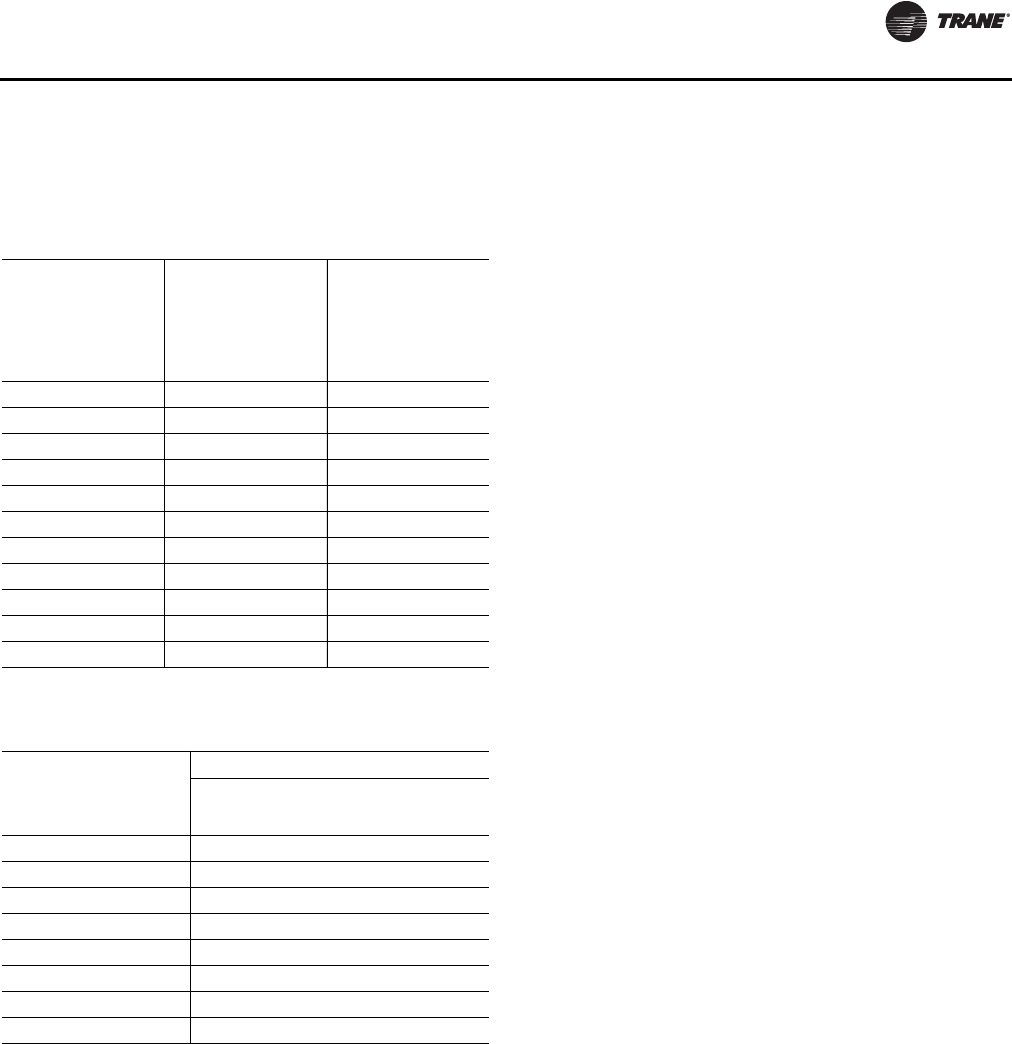
Table 1. Resistance input vs. setpoint temperature
RTM cooling or
heating setpoint
input used as the
source for a ZONE
temp setpoint (°F)
RTM cooling
setpoint input
used as the source
for SUPPLY AIR
temp setpoint
cooling (°F)
Resistance (Ohms)
Max.
Tolerance 5%
40 40 1084
45 45 992
50 50 899
55 55 796
60 60 695
65 65 597
70 70 500
75 75 403
80 80 305
n/a 85 208
n/a 90 111
Table 2. RTM resistance value vs. system operating
mode
Resistance applied to
RTM MODE input
Terminals (Ohms)
Max. Tolerance 5%
Constant Volume Units
Fan Mode System Mode
2320 Auto Off
4870 Auto Cool
7680 Auto Auto
10770 On Off
13320 On Cool
16130 On Auto
19480 Auto Heat
27930 On Heat
General Information
12 RT-SVX24K-EN
outside air humidity sensor, and the return air temperature
sensor to utilize the lowest possible humidity level when
considering economizer operation. In addition, it receives
space pressure information which is used to maintain the
space pressure to within the setpoint control band. Refer
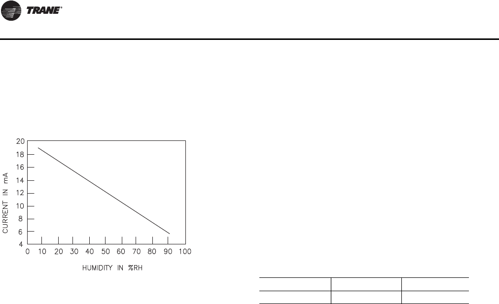
to Figure 1 for the Humidity vs. Voltage input values.
Multi Purpose Module MPM (Optional - used
with Return Fan Control, Energy Recovery, and
Evaporative Condensers)
The MPM supports three optional features.The first of
which is return plenum pressure control by receiving
analog voltage information for measuring return plenum
pressure, calibrating that reading, and providing an output
to control the return fan speed (if variable speed
configured) in response to control algorithm requests.
This module also provides inputs and outputs for control
of all Energy Recovery feature devices including the
energy wheel, exhaust and outdoor air bypass dampers,
and recovery preheat.The liquid line pressure sensor
inputs for both refrigeration circuits are received through
the MPM in support of head pressure control on water-
cooled condenser units.
Variable Speed Module (VSM - Optional -
Used with Fault Detection and Diagnostics
FDD)
The VSM is used with FDD.The VSM will accept a 0-10Vdc
actuator feedback position signal which will then be used
to determine the state of OutsideAir Damper system.
Modulating Dehumidification Module MDM
(Optional - used with Dehumidification
Control)
The MDM supports specific control inputs and outputs for
Modulating Dehumidification control including
modulating Reheat and Cooling valve control as well as
the Reheat Pumpout Coil Relay output.The Modulating
Dehumidification control algorithm provides control
requests to the MDM to accomplish proper
Dehumidification control.
Ventilation Control Module (VCM)
The Ventilation Control Module (VCM) is located in the
filter section of the unit and is linked to the unit UCM
network. Using a “velocity pressure” sensing ring located
in the outside air section allows the VCM to monitor and
control the quantity of outside air entering the unit to a
minimum airflow setpoint.
An optional temperature sensor can be connected to the
VCM which enables it to control a field installed outside air
preheater. An optional CO2sensor can be connected to the
VCM to control CO2reset.The reset function adjusts the
minimum CFM upward as the CO2concentrations
increase.
The maximum effective (reset) setpoint value for outside
air entering the unit is limited to the systems operating
CFM.The following table lists the velocity pressure vs.
Input Voltage (see also Figure 6, p. 18.).
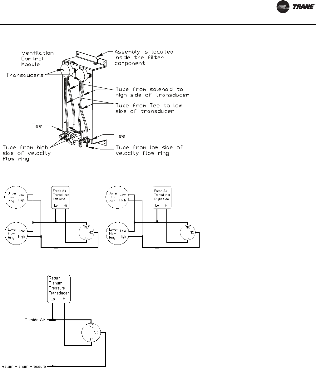
The velocity pressure transducer/solenoid assembly is
illustrated below. Refer to the “Units withTRAQ™ Sensor,”
p. 103 for VCM operation.
Figure 1. Humidity vs. current
Table 3. Minimum outside air setpoint w/VCM and
TRAQ™ sensing
Unit Input Volts CFM
90-162 Tons 0.5 - 4.5 VDC 0 - 46000
General Information
RT-SVX24K-EN 13
Generic Building Automation System Module
(GBAS - Optional used with
non-Trane building control systems)
The Generic Building Automation System (GBAS) module
allows a non-Trane building control system to
communicate with the rooftop unit and accepts external
setpoints in the form of analog inputs for cooling, heating,
supply air pressure, and a binary Input for demand limit.
Refer to the“Field Installed ControlWiring” section for the
input wiring to the GBAS module and the various desired
setpoints with the corresponding DC voltage inputs for
both VAV, SZVAV, RR and CV applications.
Input Devices and System Functions
The descriptions of the following basic Input Devices used
within the UCM network are to acquaint the operator with
their function as they interface with the various modules.
Refer to the unit electrical schematic for the specific
module connections.
Constant Volume (CV) and
Variable Air Volume (VAV) Units
Supply Air Temperature Sensor
An analog input device used with CV andVAV applications
that monitors the supply air temperature for: supply air
temperature control (VAV), supply air temperature reset
(VAV), supply air temperature low limiting (CV), supply air
tempering (CV/VAV). It is mounted in the supply air
discharge section of the unit and is connected to the RTM.
Figure 2. Velocity pressure transducer/solenoid assembly
Figure 3. Outside air tubing schematic
Figure 4. Return air pressure tubing schematic

General Information
14 RT-SVX24K-EN
Return Air Temperature Sensor
An analog input device used with a return humidity sensor
on CV and VAV applications when the comparative
enthalpy option is ordered. It monitors the return air
temperature and compares it to the outdoor temperature
to establish which temperature is best suited to maintain
the cooling requirements. It is mounted in the return air
section and is connected to the ECEM.
Leaving EvaporatorTemperature Sensor
An analog input device used with CV andVAV applications
that monitors the refrigerant temperature inside the
evaporator coil to prevent coil freezing. It is attached to the
suction line near the evaporator coil and is connected to
the MCM. It is factory set for 30°F and has an adjustable
range of 25°F to 35°F.The compressors are staged “Off” as
necessary to prevent icing.After the last compressor stage
has been turned “Off”, the compressors will be allowed to
restart once the evaporator temperature rises 10°F above
the“coil frost cutout temperature” and the minimum three
minute “Off” time has elapsed.
Entering EvaporatorTemperature Sensors
Analog input devices used with CV and VAV applications.
This device is used in conjunction with the Leaving
EvaporatorTemperature Sensor to prevent the unit from
running compressors with insufficient charge.
Filter Switch
A binary input device used on CV and VAV applications
that measures the pressure differential across the unit
filters. It is mounted in the filter section and is connected
to the RTM. A diagnostic SERVICE signal is sent to the
remote panel if the pressure differential across the filters
is at least 0.5" w.c.The contacts will automatically open
when the pressure differential across the filters decrease
to 0.4" w.c.The switch differential can be field adjusted
between 0.17" w.c. to 5.0" w.c. ± 0.05" w.c.
Leaving Recovery ExhaustTemp Sensor
Analog input device used on CV andVAV applications with
Energy Recovery option installed. It is used to monitor the
temperature of the leaving air on the Exhaust Fan side of
the energy recovery wheel.This temperature is used to
determine if the temperature of the wheel is too cold as
compared to the Recovery Frost Avoidance Setpoint.The
result is used to determine when to enable energy wheel
frost avoidance functions.
Supply, Exhaust and Return Fan Airflow
Proving Switches
Supply Airflow Proving Switch is a binary input device
used on CV and VAV applications to signal the RTM when
the supply fan is operating. It is located in the supply fan
section of the unit and is connected to the RTM. During a
request for fan operation, if the differential switch is
detected to be open for 40 consecutive seconds;
compressor operation is turned “Off”, heat operation is
turned “Off”, the request for supply fan operation is turned
“Off” and locked out, exhaust dampers (if equipped) are
“closed”, economizer dampers (if equipped) are “closed”,
and a manual reset diagnostic is initiated.
Exhaust/return Airflow Proving Switch is a binary input
device used on all rooftop units equipped with an exhaust
fan. It is located in the exhaust/return fan section of the unit
and is connected to the RTM. During a request for fan
operation, if the differential switch is detected to be open
for 40 consecutive seconds, the economizer is closed to
the minimum position setpoint, the request for exhaust
fan operation is turned “Off” and locked out, and a manual
reset diagnostic is initiated.The fan failure lockout can be
reset at the Human Interface located in the unit control
panel, byTracer, or by cycling the control power to the
RTM Off/On.
Lead-Lag
A selectable mode of operation through the Human
Interface. It alternates the starting between the first
compressor of each refrigeration circuit. Only the
compressor banks will switch, not the order of the
compressors within a bank, providing the first compressor
in each circuit had been activated during the same request
for cooling.
Charge Isolation
During the OFF cycle, most of the charge is isolated
between the compressor (internal) discharge check valves
and liquid line solenoid valve.This reduces the OFF cycle
charge migration, and liquid feedback during subsequent
startup.The liquid line solenoid is energized (opened) with
the start of the circuit compressor.
Supply, Exhaust and Return Fan Circuit
Breakers
The supply fan and exhaust fan motors are protected by
circuit breakers or fuses.They will trip and interrupt the
power supply to the motors if the current exceeds the
breaker's “must trip” value.The rooftop module (RTM)
will shut all system functions “Off” when an open fan
proving switch is detected.
Low Pressure Control
Low Pressure Control is accomplished using a binary input
device on CV andVAV applications. LP cutouts are located
on the suction lines near the scroll compressors.The LPC
contacts are designed to close when the suction pressure
exceeds 41 ± 4 psig. If the LP control is open when a
compressor is requested to start, none of the compressors
on that circuit will be allowed to operate.They are locked
out and a manual reset diagnostic is initiated.
The LP cutouts are designed to open if the suction
pressure approaches 22 ± 4 psig. If the LP cutout opens
after a compressor has started, all compressors operating
on that circuit will be turned off immediately and will

General Information
RT-SVX24K-EN 15
remain off for a minimum of three minutes. If the LP cutout
trips four consecutive times during the first three minutes
of operation, the compressors on that circuit will be locked
out and a manual reset diagnostic is initiated.
Saturated CondenserTemperature Sensors
Analog input devices used on CV and VAV applications
mounted inside a temperature well located on a
condenser tube bend.They monitor the saturated
refrigerant temperature inside the condenser coil and are
connected to the MCM. As the saturated refrigerant
temperature varies due to operating conditions, the
condenser fans are cycled “On” or “Off” as required to
maintain acceptable operating pressures.
Head Pressure Control
Accomplished using two saturated refrigerant
temperature sensors on CV and VAV applications. During
a request for compressor operation, when the condensing
temperature rises above the “lower limit” of the
controlband, the Compressor Module (MCM) starts
sequencing condenser fans “On”. If the operating fans can
not bring the condensing temperature to within the
controlband, more fans are turned on. As the saturated
condensing temperature approaches the lower limit of the
controlband, fans are sequenced “Off”.
The minimum “On/Off” time for condenser fan staging is
5.2 seconds. If the system is operating at a given fan stage
below 100% for 30 minutes and the saturated condensing
temperature is above the “efficiency check point” setting,
a fan stage will be added. If the saturated condensing
temperature falls below the “efficiency check point”
setting, the fan control will remain at the present operating
stage. If a fan stage cycles four times within a 10 minute
period, the control switches from controlling to the “lower
limit” to a temperature equal to the “lower limit” minus
the “temporary low limit suppression” setting. It will
utilize this new “low limit” temperature for one hour to
reduce condenser fan short cycling.
For evaporative condensing units, head pressure is
monitored with pressure transducers attached to the
saturated condensing line and converted to a temperature
by the MPM.This temperature is used to control the
variable speed fan and sump pump. When the
temperature rises above the upper limit (120°F) the sump
pump is energized. If the condensing temperature drops
below the lower limit (70°F) the sump pump is de-
energized.
High Pressure Limit Controls
High Pressure controls are located on the discharge lines
near the scroll compressors.They are designed to open
when the discharge pressure approaches 650 ± 10 psig.
The controls reset automatically when the discharge
pressure decreases to approximately 550 ± 10 psig.
However, the compressors on that circuit are locked out
and a manual reset diagnostic is initiated after the fourth
occurrence of a high pressure condition.
Outdoor Air Humidity Sensor
An analog input device used on CV and VAV applications
with 100% economizer. It monitors the outdoor humidity
levels for economizer operation. It is mounted in the
outside air intake section and is connected to the RTM.
Return Air Humidity Sensor
An analog input device used on CV and VAV applications
with the comparative enthalpy option. It monitors the
return air humidity level and compares it to the outdoor
humidity level to establish which conditions are best
suited to maintain the cooling requirements. It is mounted
in the return air section and is connected to the ECEM.
Space Humidity Sensor
Analog input device used on CV andVAV applications with
modulating dehumidification option and/or
humidification field installed option. It is used to monitor
the humidity level in the space and compared to
dehumidification and humidification setpoints to maintain
space humidity requirements. It is field mounted in the
space and connected to the RTM.
Status/Annunciator Output
An internal function within the RTM module on CV and
VAV applications that provides:
c. diagnostic and mode status signals to the remote
panel (LEDs) and to the Human Interface
d. control of the binary Alarm output on the RTM
e. control of the binary outputs on the GBAS module
to inform the customer of the operational status
and/or diagnostic conditions
Low Ambient Compressor Lockout
Utilizes an analog input device for CV and VAV
applications. When the system is configured for low
ambient compressor lockout, the compressors are not
allowed to operate if the temperature of the outside air
falls below the lockout setpoint. When the temperature
rises 5°F above the lockout setpoint, the compressors are
allowed to operate.The factory preset is 50°F.
These compressors come equipped with a protection
module that monitors phase loss, phase sequencing and
motor temperature.
Space Pressure Transducer
An analog input device used on CV and VAV applications
with the Statitrac option. It modulates the exhaust
dampers to keep the space pressure within the building to
a customer designated controlband. It is mounted on the
bottom support below the return damper blade assembly
and is connected to the ECEM. Field supplied pneumatic
tubing must be connected between the space being
controlled and the transducer assembly.

General Information
16 RT-SVX24K-EN
Morning Warm-Up—Zone Heat
When a system changes from an unoccupied to an
occupied mode, or switches from STOPPED to AUTO, or
power is applied to a unit with the MWU option, the heater
in the unit or external heat will be brought on if the space
temperature is below the MWU setpoint.The heat will
remain on until the temperature reaches the MWU
setpoint.
If the unit is VAV, then the VAV box/unocc relay will
continue to stay in the unoccupied position and the VFD
output will stay at 100% during the MWU mode.When the
MWU setpoint is reached and the heat mode is terminated,
then the VAV box/unocc relay will switch to the occupied
mode and the VFD output will be controlled by the duct
static pressure. During Full Capacity MWU the economizer
damper is held closed for as long as it takes to reach
setpoint. During Cycling Capacity MWU the economizer
damper is allowed to go to minimum position after one
hour of operation if setpoint has not been reached.
Compressor Motor Winding Thermostats
A thermostat is embedded in the motor windings of each
Scroll compressor. Each thermostat is designed to open if
the motor windings exceed approximately 221°F. The
thermostat will reset automatically when the winding
temperature decreases to approximately 181°F.
Rapid cycling, loss of charge, abnormally high suction
temperatures, or the compressor running backwards
could cause the thermostat to open. During a request for
compressor operation, if the Compressor Module detects
a problem outside of normal parameters, it turns any
operating compressor(s) on that circuit “Off”, locks out all
compressor operation for that circuit, and initiates a
manual reset diagnostic (compressor trip).
These compressors come equipped with a protection
module that monitors phase loss, phase sequencing and
motor temperature.
Supply Air Temperature Low Limit
Uses the supply air temperature sensor input to modulate
the economizer damper to minimum position in the event
the supply air temperature falls below the occupied
heating setpoint temperature.
Discharge LineThermostat for Evaporative
Condensers
The first compressor on each circuit is equipped with a
Discharge LineThermostat. If the temperature of the line
exceeds 210°F the thermostat interrupts the 115V circuit for
the compressors and both of the compressors on that
circuit will be de-energized. Once the temperature drops
below 170°F the thermostat will close and allow the
compressor to be energized.
Freezestat
A binary input device used on CV and VAV units with
Hydronic Heat. It is mounted in the heat section and
connected to the Heat Module. If the temperature of the air
leaving the heating coil falls to 40°F, the normally open
contacts on the freezestat closes signalling the Heat
Module and the Rooftop Module (RTM) to:
f. drive the Hydronic Heat Actuator to the full open
position
Figure 5. Transducer voltage output vs. pressure input for supply, return and building pressure
-0.75 to 9.0 Iwc Pressure Transducer Voltage Output vs. Pressure Input
0.00
0.50
1.00
1.50
2.00
2.50
3.00
3.50
4.00
4.50
-0.75
-0.25
0.25
0.75
1.25
1.75
2.25
2.75
3.25
3.75
4.25
4.75
5.25
5.75
6.25
6.75
7.25
7.75
8.25
8.75
Pressure (inches w.c.)
Volts

General Information
RT-SVX24K-EN 17
g. turn the supply fan “Off”
h. closes the outside air damper
i. turns “On” the SERVICE light at the Remote Panel
j. initiates a “LowTemp Limit” diagnostic to the
Human Interface
Compressor Circuit Breakers
The Scroll Compressors are protected by circuit breakers
which interrupt the power supply to the compressors if the
current exceeds the breakers “must trip” value. During a
request for compressor operation, if the Compressor
Module detects a problem outside normal parameters, it
turns any operating compressor(s) on that circuit “Off”,
locks out all compressor operation for that circuit, and
initiates a manual reset diagnostic (compressor trip).
Constant Volume (CV) Units
Zone Temperature—Cooling
Relies on input from a sensor located directly in the space,
while a system is in the occupied “Cooling” mode. It
modulates the economizer (if equipped) and/or stages the
mechanical cooling “On and Off” as required to maintain
the zone temperature to within the cooling setpoint
deadband.
Zone Temperature—Heating
Relies on input from a sensor located directly in the space,
while a system is in the occupied “Heating” mode or an
unoccupied period, to stage the heat “on and off” or to
modulate the heating valve (hydronic heat only) as
required to maintain the zone temperature to within the
heating setpoint deadband.The supply fan will be
requested to operate any time there is a request for heat.
On gas heat units, the fan will continue to run for 60
seconds after the furnace is turned off.
Supply Air Tempering
On CV units equipped with staged gas heat, if the supply
air temperature falls 10°F below the occupied heating
setpoint temperature while the heater is “Off”, the first
stage of heat will be turned “On”.The heater is turned “Off”
when the supply air temperature reaches 10°F above the
occupied heating setpoint temperature.
Variable Air Volume (VAV) Units
Occupied Heating—Supply Air Temperature
When a VAV unit is equipped with “Modulating Heat”, and
the system is in an occupied mode, and the field supplied
changeover relay contacts have closed or per a BAS
command, the supply air temperature will be controlled to
the customer specified supply air heating setpoint. It will
remain in the heating status until the changeover relay
contacts are opened or BAS has released the heat
command.
Occupied Cooling—Supply Air Temperature
When a VAV unit is in the occupied mode, the supply air
temperature will be controlled to the customer specified
supply air cooling setpoint by modulating the economizer
and/or staging the mechanical cooling “On and Off” as
required.The changeover relay contacts must be open, or
BAS command set to auto or cool, for the cooling to
operate.
Daytime Warm-up
On VAV units equipped with heat, if the zone temperature
falls below the daytime warm-up initiate temperature
during the occupied mode, the system will switch to full
airflow. During this mode, theVAV box/unocc relay will be
energized (this is to signal the VAV boxes to go to 100%).
After theVAV box max stroke time has elapsed (factory set
at 6 minutes), the VFD output will be set to 100%.The
airflow will be at 100% and the heat will be turned on to
control to the occupied heating setpoint.
When the zone temperature reaches the daytime warm-up
termination setpoint, the heat will be turned off, the relay
will be de-energized, releasing the VAV boxes, the VFD
output will go back to duct static pressure control and the
unit will return to discharge air control. If the occ zone
heating setpoint is less than the DWU terminate setpoint,
the heat will turn off when the occ zone heat setpoint is
reached, but it will stay in DWU mode and cycle the heat
to maintain setpoint.
Unoccupied Heating—Zone Temperature
When aVAV unit is equipped with gas, electric, or hydronic
heat and is in the unoccupied mode, the zone temperature
will be controlled to within the customer specified setpoint
deadband. During an unoccupied mode for aVAV unit, the
VAV box/unocc relay will be in the unoccupied position
and theVFD output will be at 100%.This means that if there
is a call for heat (or cool) and the supply fan comes on, it
will be at full airflow and the VAV boxes in the space will
need to be 100% open as signaled by the VAV box/unocc
relay.
Supply Air Tempering
On VAV units equipped with “Modulating Heat”,ifthe
supply air temperature falls 10°F below the supply air
temperature setpoint, the heat will modulate to maintain
the supply air temperature to within the low end of the
setpoint deadband.
Supply Duct Static Pressure Control
(Occupied)
The RTM relies on input from the duct pressure transducer
when a unit is equipped with aVariable Frequency Drive to
set the supply fan speed to maintain the supply duct static
pressure to within the static pressure setpoint deadband.
The transducer compares supply duct pressure to ambient
pressure. Refer to Figure 43, p. 67.
General Information
18 RT-SVX24K-EN
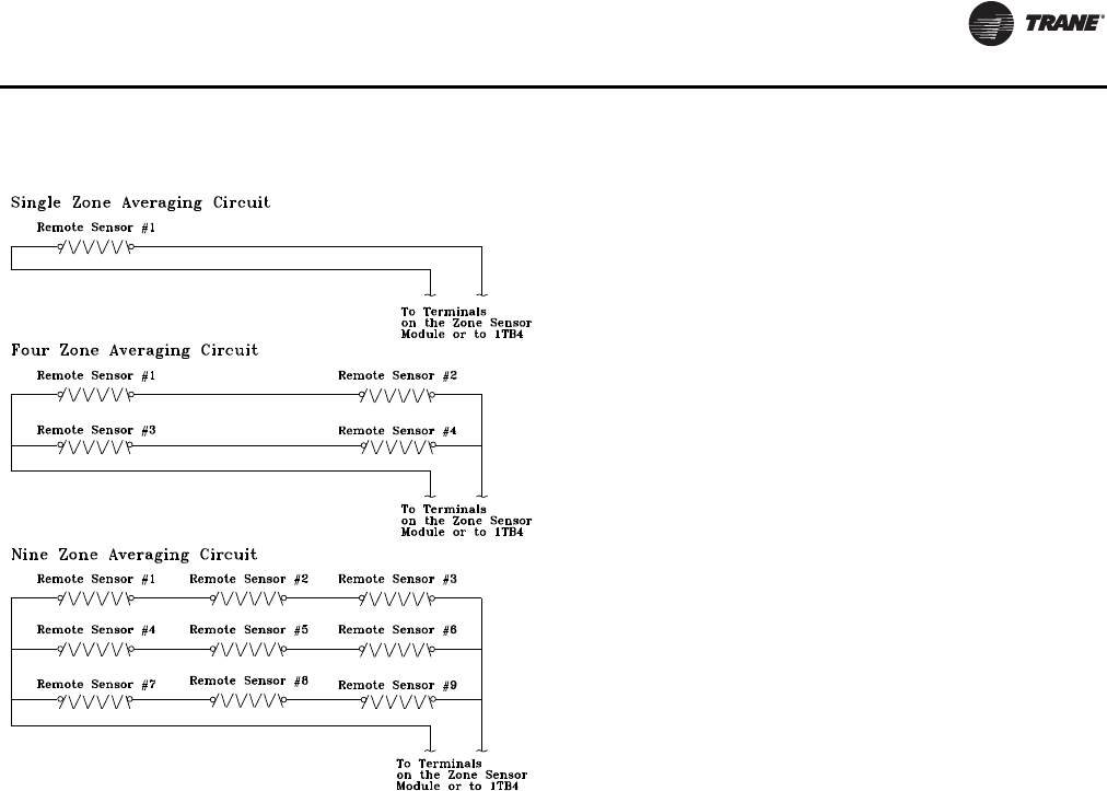
Space Temperature Averaging
Space temperature averaging for Constant Volume
applications is accomplished by wiring a number of
remote sensors in a series/parallel circuit.
The fewest number of sensors required to accomplish
space temperature averaging is four.The Space
Temperature Averaging with Multiple Sensors figure
illustrates a single sensor circuit (Single Zone), four
sensors wired in a series/parallel circuit (Four Zone), nine
sensors wired in a series/parallel circuit (Nine Zone). Any
number squared, is the number of remote sensors
required.
Wiring termination will depend on the type of remote
panel or control configuration for the system. Refer to the
wiring diagrams that shipped with the unit.
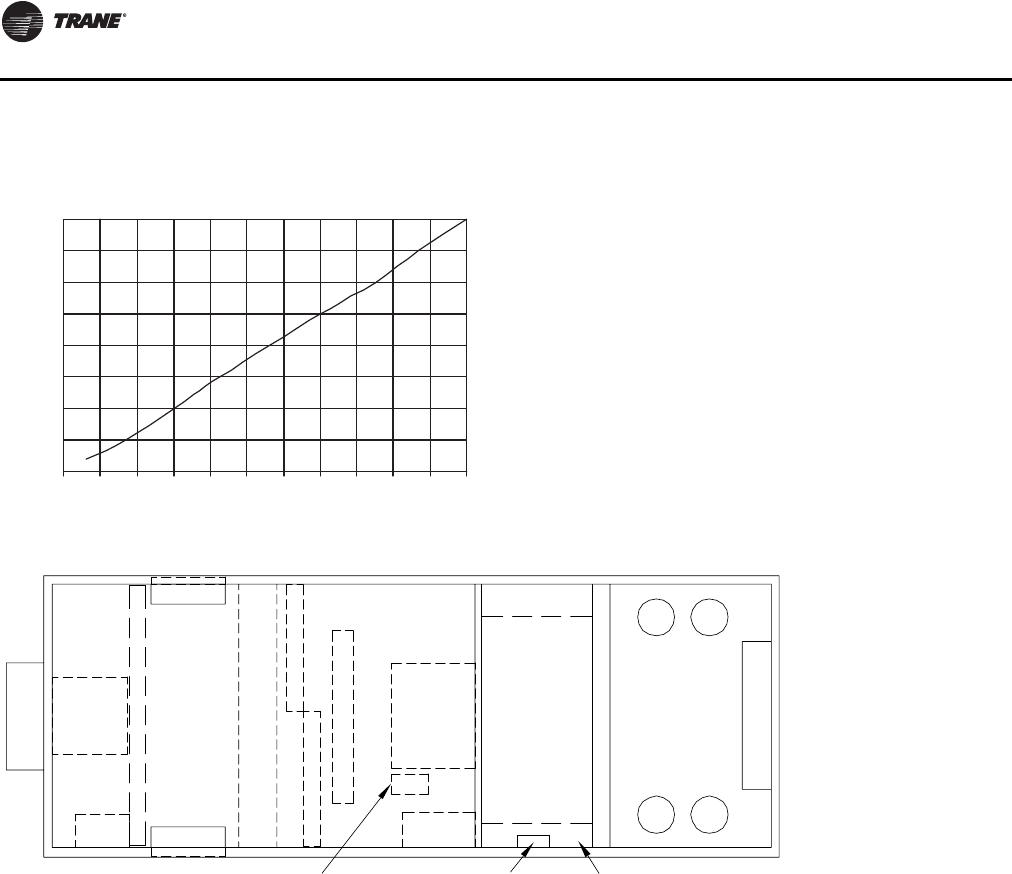
Figure 6. Transducer voltage output vs. pressure input
with VCM and TRAQ™ sensing
Transducer Voltage Output vs. Pressure Input
0.0
0.5
1.0
1.5
2.0
2.5
3.0
3.5
4.0
-0.5 0.0 0.5 1.0 1.5 2.0 2.5 3.0 3.5 4.0 4.5 5.0
Pressure (inche s w.c.)
Volts
Figure 7. Unit component layout and “ship with” locations
Return/
Exhaust
Fan
Outside Air
Dampers
Supply Fan
Condenser
Fans
Compressor
Section
Heating
Section
Exhaust Damper
Hood
Evap Coil
Evap Coil
Controls
Variable
Frquency
Drive (VFD)
Filter Section
Reheat Coil Option
Outside Air
Dampers
Return Air Dampers
Flue Vent
Access
Variable
Frquency
Drive (VFD)
Hot Water/Steam
Hydronic Connection
Outside Air
Static Kit and
sensors
General Information
RT-SVX24K-EN 19
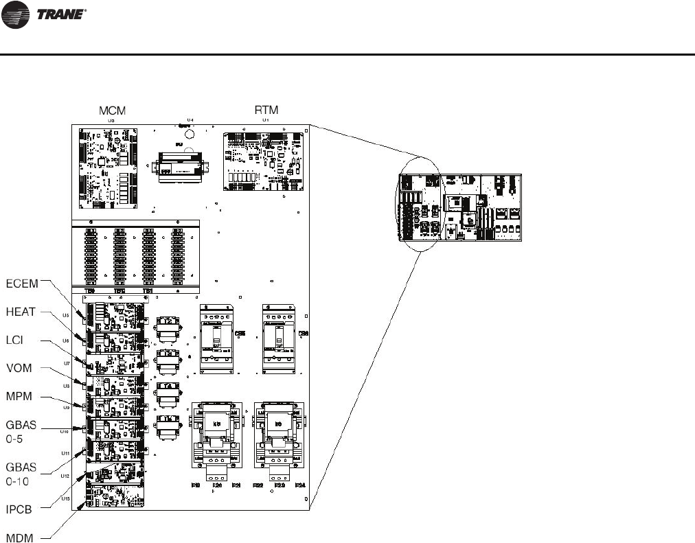
Unit Control Modules
Unit control modules are microelectronic circuit boards
designed to perform specific unit functions.The control
modules, through proportional/integral control
algorithms, provide the best possible comfort level for the
customer.They are mounted in the control panel and are
factory wired to their respective internal components.
The control modules receive and interpret information
from other unit modules, sensors, remote panels, and
customer binary contacts to satisfy the applicable request
for economizing, mechanical cooling, heating, and
ventilation. Figure 9 illustrates the typical location of each
designated module.
Figure 8. Space temperature averaging with multiple
sensors
General Information
20 RT-SVX24K-EN
Single Zone Variable Air Volume
(SZVAV) Only
The IntelliPak controls platform will support Single Zone
VAV as an optional unit control type in order to meet
ASHRAE 90.1.The basic control will be a hybrid VAV/CV
configured unit that provides discharge temperature
control to a varying discharge air temperature target
setpoint based on the space temperature and/or humidity
conditions. Concurrently, the unit will control and optimize
the supply fan speed to maintain the zone temperature to
a zone temperature setpoint.
Supply Fan Output Control
Units configured for Single Zone VAV control will utilize
the same supply fan output control scheme as on
traditional VAV units except the VFD signal will be based
on zone heating and cooling demand instead of the supply
air pressure.
VFD Control
Single Zone VAV units will be equipped with a VFD-
controlled supply fan which will be controlled via a 0-
10VDC signal from the Rooftop Module (RTM). With the
RTM supply fan output energized and the RTMVFD output
at 0VDC, the fan speed output is 37% (22Hz) from the VFD
by default; and at 10VDC the fan speed output is 100%
(60Hz).The control scales the 0-10VDC VFD output from
the RTM linearly to control between the 37-100% range.
The VFD will modulate the supply fan motor speed,
accelerating or decelerating as required to maintain the
zone temperature to the zone temperature setpoint.When
subjected to high ambient return conditions the VFD will
reduce its output frequency to maintain operation. Bypass
control is offered to provide full nominal airflow in the
event of drive failure.
Ventilation Control
Units configured for Single Zone VAV control will require
special handling of the OA Damper Minimum Position
control in order to compensate for the non-linearity of
airflow associated with the variable supply fan speed and
damper combinations. Units configured forTRAQ with or
without DCV will operate identically to traditional units
with no control changes.
Space Pressure Control
For units configured with Space Pressure Control with or
without Statitrac, the new schemes implemented for
economizer minimum position handling require changes
to the existing Space Pressure Control scheme in order to
Figure 9. Control module locations
BCI

General Information
RT-SVX24K-EN 21
prevent over/under pressurization.The overall scheme
will remain very similar to VAV units with Space Pressure
Control with the exception of the dynamic Exhaust Enable
Setpoint.
For SZVAV an Exhaust Enable Setpoint must be selected
during the 100% Fan Speed Command. Once selected, the
difference between the Exhaust Enable Setpoint and
Design OA Damper Minimum Position at 100% Fan Speed
Command will be calculated.The difference calculated will
be used as an offset and added to the Active Building
Design OA Minimum PositionTarget in order to calculate
the dynamic Exhaust EnableTarget, which will be used
throughout the Supply Fan Speed/OA Damper Position
range.
The Exhaust EnableTarget could be above or below the
Active Building Design OA Minimum PositionTarget
Setpoint, based on the Active Exhaust Enable Setpoint
being set above or below the Building Design Minimum
Position at 100% Fan Speed Command. Note that an
Exhaust Enable Setpoint of 0% will result in the same effect
on Exhaust Fan control as on VAV applications with and
without Statitrac.
Occupied Cooling Operation
For normal cooling operation, cooling capacity will be
staged or modulated in order to meet the calculated
discharge air target setpoint. If the current active cooling
capacity is controlling the discharge air within the
deadband, no additional cooling capacity change will be
requested. As the Discharge AirTemperature rises above
the deadband, the algorithm will request additional
capacity as required (additional compressors or
economizer).As the Discharge AirTemperature falls below
the deadband, the algorithm will request a reduction in
active capacity.
Default Economizer Operation
By default, the unit will be setup to optimize the minimum
supply fan speed capability during Economizer Only
operation. If the economizer is able to meet the demand
alone, due to desirable ambient conditions, the supply fan
speed will be allowed to increase above the minimum
prior to utilizing mechanical cooling if discharge air
setpoint falls below the discharge air Lower Limit
(Cooling) setpoint.
Unoccupied Mode
In Unoccupied mode the unit will utilize setback setpoints,
0% Minimum OA Damper position, and Auto Fan Mode
operation as on normal CV units.The Supply Fan speed,
and cooling and modulating types of heat, will be
controlled to the discharge air target setpoint as is done
during occupied periods.The Supply fan speed during
staged heat control will be forced to 100% as on normal CV
units.
Occupied Heating Operation
Occupied heating operation has two separate control
sequences; staged and modulated. All staged heating
types will drive the supply fan to maximum flow and stage
heating to control to the Zone Heating Setpoint. For units
with Hydronic and Gas heat, modulated SZVAV Heating.
On an initial call for heating, the supply fan will drive to the
minimum heating airflow.
On an additional call for heating, the heat will control in
order to meet the calculated discharge air target setpoint.
As the load in the zone continues to request heat
operation, the supply fan will ramp-up while the control
maintains the heating discharge air temperature. Heating
can be configured for either the energy saving SZVAV
Heating solution as described above, or the traditional,
less efficient CV Heating solution.
Compressor (DX) Cooling
Compressor control and protection schemes will function
identical to that of a traditional unit. Normal compressor
proving and disable input monitoring will remain in effect
as well as normal 3-minute minimum on, off, and inter-
stage timers. Also, all existing head pressure control
schemes will be in effect.
Cooling Sequence
If the control determines that there is a need for active
cooling capacity in order to meet the calculated discharge
air target setpoint, once supply fan proving has been
made, the unit will begin to stage compressors
accordingly. Note that the compressor staging order will
be based on unit configuration and compressor lead/lag
status.
Once the discharge air target setpoint calculation has
reached the Minimum Setpoint and compressors are
being utilized to meet the demand, as the discharge air
target setpoint value continues to calculate lower the
algorithm will begin to ramp the supply fan speed up
toward 100%. Note that the supply fan speed will remain
at the compressor stage’s associated minimum value (as
described below) until the discharge air target setpoint
value is calculated below the discharge air temperature
Minimum Setpoint (limited discharge air target setpoint).
As the cooling load in the zone decreases the zone cooling
algorithm will reduce the speed of the fan down to
minimum per compressor stage and control the
compressors accordingly. As the compressors begin to
de-energize, the supply fan speed will fall back to the
Cooling Stage’s associated minimum fan speed, but not
below. As the load in the zone continues to drop, cooling
capacity will be reduced in order to maintain the discharge
air within the ± ½ discharge air target deadband.
Fault Detection and Diagnostics
Fault Detection of the Outdoor Air Damper will be
evaluated based on the commanded position of the
damper compared to the feedback position of the damper.

General Information
22 RT-SVX24K-EN
The damper is commanded to a position based on a 2-10
VDC signal. If the Damper position is outside of ±10% of the
commanded position, a diagnostic is generated.
Unit Not Economizing when it should be:
The Unit is operating in Cooling Mode, Economizing is
enabled and/or Mechanical Cooling is enabled. If the
Commanded Economizer Position is greater than Current
Economizer Feedback Position + 10% for 5 continuous
minutes, Unit Not Economizing when it should be
diagnostic is generated.
Unit Economizing when it should not be:
The unit is operating in Cooling Mode, Economizing is
enabled and or Mechanical Cooling is enabled. If the
commanded Economizer Position is less than the current
Economizer Feedback Position - 10% for 5 continuous
minutes, Unit Economizing When it should not be
diagnostic is generated.
Outdoor Air Damper Not Modulating
The unit is operating in Ventilation Only Mode - not
attempting to Economize and the Commanded Damper
Position is greater than the Current Damper Feedback
Position + 10% for 5 continuous minutes, Outdoor Air
Damper Not Modulating diagnostic is generated.
Excessive Outdoor Air
The unit is operating in Ventilation Only Mode - not
attempting to Economize and the Commanded Damper
Position is less than the Current Damper Feedback Position
- 10% for 5 continuous minutes. Excessive Outdoor Air
diagnostic is generated.
To change the Economizer Control Function to dry bulb, go
to the Configuration Menu on the Human Interface Module
and set Comparative Enthalpy to "Not Installed".This
allows the user to select dry bulb under the Economizer
Control Function which is a Submenu of the Setup Menu.
For additional instructions please see the Programming
andTroubleshooting Guide.
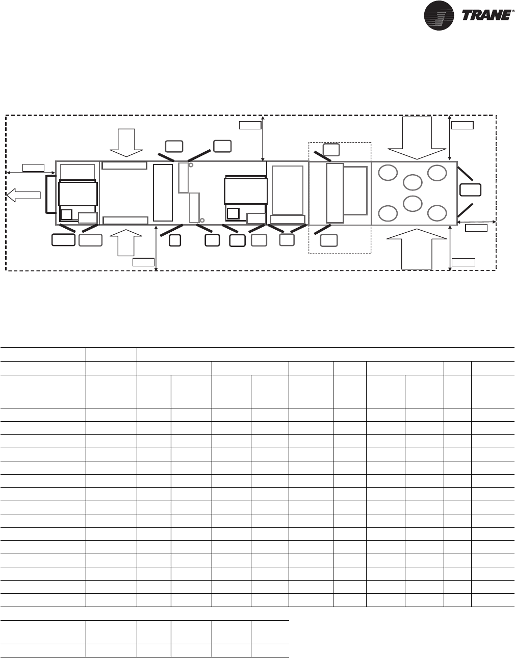
RT-SVX24K-EN 23
Unit Clearances
Figure 10. Minimum required clearance (a)
(a)Unit drawing is representative only and may not accurately depict all models.
Filters
VFD
VFD Heat
Rtn/Exh
Mtr Rtn/Exh
VFD
Evp
(
F
)
Fltr
(F)
Sup
Mtr
Sup
VFD
Fltr
(R)
Evp
(
R
)
Heat
(
L&R
OptionOption
As Req. As Req. As Req.
Std
Std StdStd
Blank Section
Final
Filter
Fnl
Fltr
As Req.
Fnl
Fltr
As Req.
Ctrl Box
(
L&R
)
Std
Outsid
e
Air
Outside
Air
Exhaust
Condenser
Condenser
Exh
AH R
CBox
AH L Cond L
Cond R
Left Side
Table 4. Minimum required clearance
Unit Option Selection (Door Swing Ft. and In.)
Standard VFD Two-side Access
Door Location Availability 90-118 120-162 Return/
Exhaust Supply Heat Reheat 90-118 120-162
Final
Filter Energy
Recovery
Exhaust/Ret Motor Std 2' 2" 2' 2" * * * * * * *
Exhaust/Ret VFD As Req. * * 2' 2" * * * * * *
ERW Fltr(a) (L & R) (F) Option * * * * * * * * * 2' 2"
ERW Fltr(a) (L & R) (R) Option * * * * * * * * * 2' 2"
Filter (Front) Std 2' 8" 2' 8" * * * * * * *
Filter (Rear) Option * * * * * * 2' 2" 2' 8" *
Evap (Front) Std 2' 2" 2' 2" * * * * * * *
Evap (Rear) Std 2' 8" * * * * * * * *
or Evap (Rear) Option * * * * * 2' 2 * 2' 2" *
Supply Motor Std 2' 8" 2' 8" * * * * * * *
Supply VFD As Req. * * * 2' 2" * * * * *
Heat (Left & Right) As Req. * * * * 2' 2" * * * *
Final Filter (Front) As Req. * * * * * * * * 2' 2"
Final Filter (Rear) As Req. * * * * * * * * 2' 2"
Control Box (L & R) Std 3' 2" 3' 2" * * * * * * *
Minimum Required Clearance (Ft.)
AH_L AH_R Exh Cond_L Cond_R Control
Box
8' 8' 8' 8' 8' 6'
(a)See Unit Dimensions for Energy Recovery Wheel location.
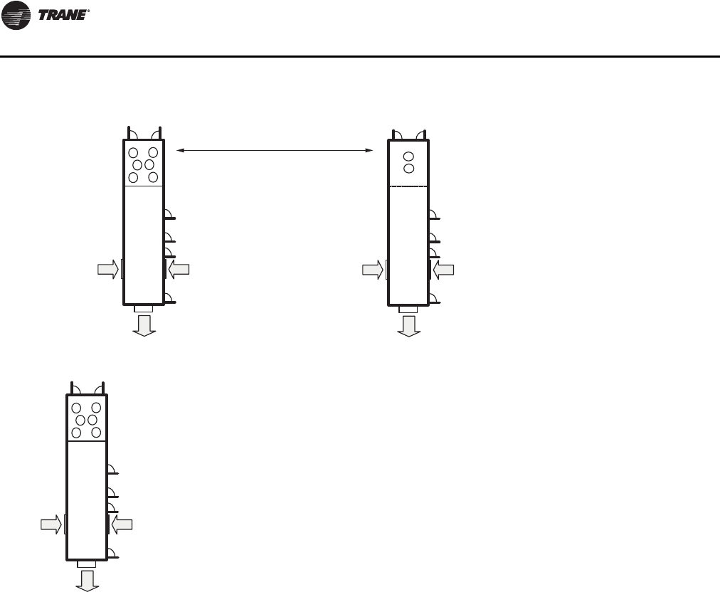
Unit Clearances
24 RT-SVX24K-EN
Notes:
1. Stagger units to minimize span deflection which deters sound
transmission and to maximize proper diffusion of the exhaust air
before it reaches the adjacent unit outside air intake.
2. Cooling tower should be 5 feet above or 20 feet away from the outside
air intake. For additional information, see 2007 ASHRAE Handbook:
HVAC Applications, page 44.4.
Figure 11. Multiple unit placement
Outdoor
Air Intake
Outdoor
Air Intake
Exhaust
Air
Outdoor
Air Intake
Outdoor
Air Intake
Exhaust
Air
Outdoor
Air Intake
Outdoor
Air Intake
Exhaust
Air
Minimum distance between units must be 16’!
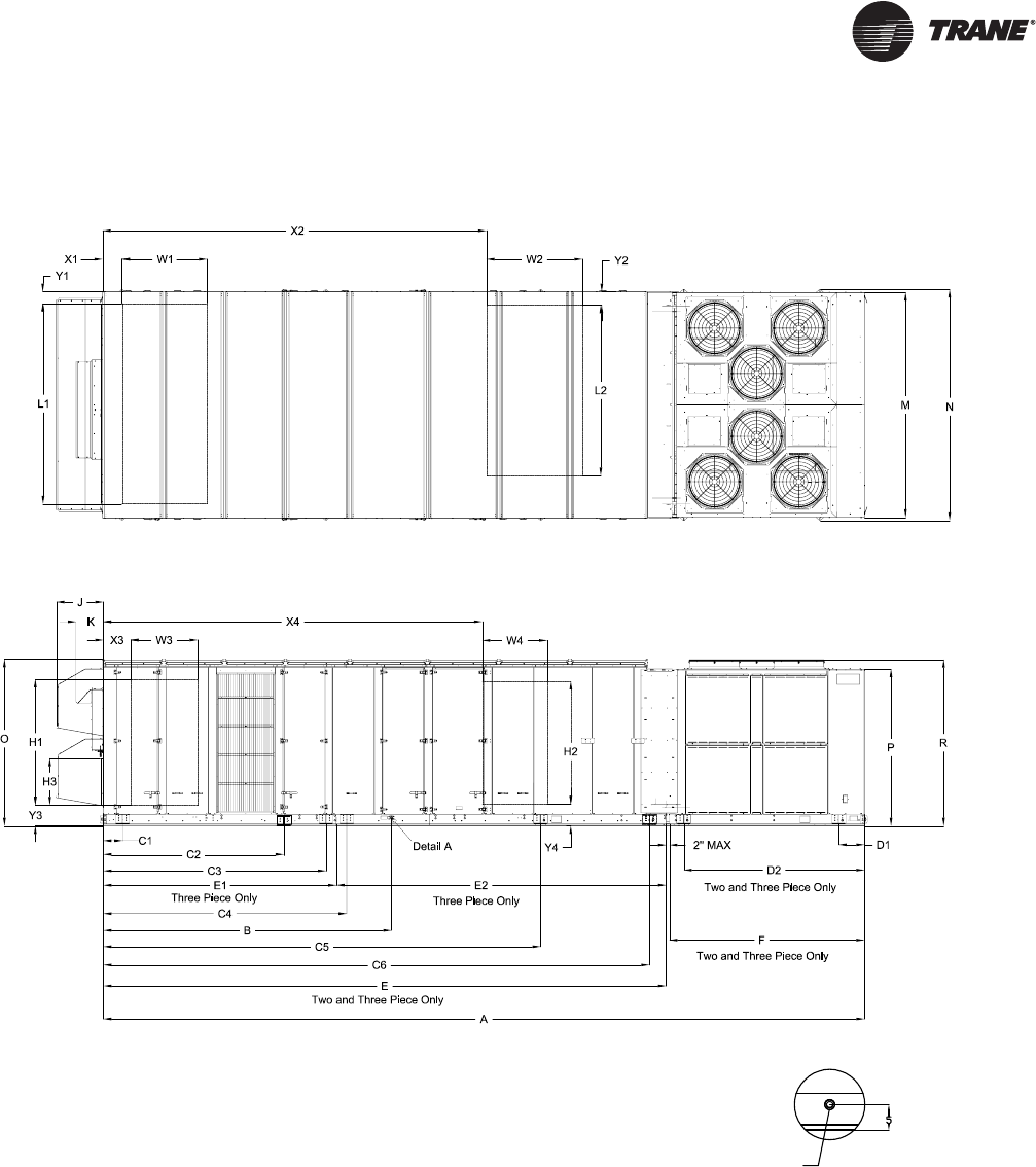
RT-SVX24K-EN 25
Dimensional Data
Figure 12. Unit Top/Front View
1-1/4 NPT. DRAIN
2X TYP. LEFT & RIGHT SIDES OF UNIT
Detail A
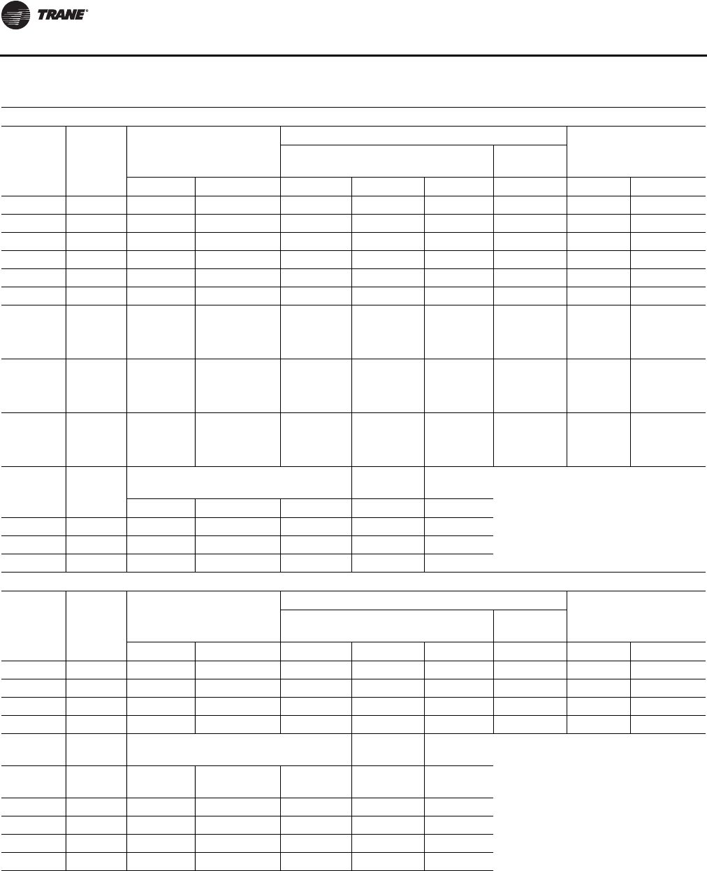
Dimensional Data
26 RT-SVX24K-EN
Table 5. Unit dimensions (in.)—one-piece unit air-cooled
ONE-PIECE Dimensions without Energy Recovery Wheel (ERW)
Tonnage Blank
Section
Unit Dimensions
Lifting Lug Locations
Unit WidthAir Handler Side Condenser
Side
A B C1 C2 C3 D1 M N
90 None 437 3/16 159 15/16 66 252 14/16 N/A 27 11/16 139 13/16 143 8/16
90 4 ft 485 6/16 159 15/16 66 252 14/16 N/A 54 2/16 139 13/16 143 8/16
90 8 ft 533 9/16 159 15/16 66 252 14/16 N/A 54 2/16 139 13/16 143 8/16
105 None 455 3/16 159 15/16 66 252 14/16 N/A 27 11/16 139 13/16 143 8/16
105 4 ft 503 6/16 159 15/16 66 252 14/16 N/A 54 2/16 139 13/16 143 8/16
105 8 ft 551 9/16 159 15/16 66 252 14/16 N/A 54 2/16 139 13/16 143 8/16
120-150 (All
Units Except
High Heat
Gas Models)
None 528 15/16 197 1/16 66 269 6/16 N/A 63 2/16 139 13/16 143 8/16
120-150 (All
Units Except
High Heat
Gas Models)
4 ft 577 2/16 197 1/16 66 269 6/16 N/A 63 2/16 139 13/16 143 8/16
120-150
(High Heat
Gas Models
Only)
None 540 15/16 197 1/16 66 269 6/16 N/A 63 2/16 139 13/16 143 8/16
Tonnage Blank
Section
Unit Height Return Fan Exhaust
Fan
OPRJK
90-150 None 103 12/16 97 9/16 103 7/16 29 3/16 17
90-150 4 ft 103 12/16 97 9/16 103 7/16 29 3/16 17
90-150 8 ft 103 12/16 97 9/16 103 7/16 29 3/16 17
ONE-PIECE Dimensions with Energy Recovery Wheel
Tonnage Blank
Section
Unit Dimensions
Lifting Lug Locations
Unit WidthAir Handler Side Condenser
Side
A B C1 C2 C3 D1 M N
90 None 533 9/16 256 5/16 66 201 1/16 349 4/16 27 11/16 139 13/16 143 8/16
90 4 ft 581 13/16 256 5/16 66 201 1/16 349 4/16 54 2/16 139 13/16 143 8/16
105 None 551 9/16 256 5/16 66 201 1/16 349 4/16 27 11/16 139 13/16 143 8/16
105 4 ft 599 13/16 256 5/16 66 201 1/16 349 4/16 54 2/16 139 13/16 143 8/16
Unit Height Return Fan Exhaust
Fan
Tonnage Blank
Section O P R J K
90 None 103 12/16 97 9/16 103 7/16 N/A 17
90 4 ft 103 12/16 97 9/16 103 7/16 N/A 17
105 None 103 12/16 97 9/16 103 7/16 N/A 17
105 4 ft 103 12/16 97 9/16 103 7/16 N/A 17
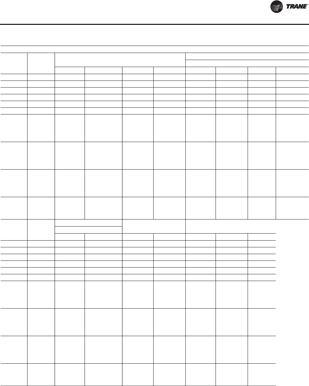
Dimensional Data
RT-SVX24K-EN 27
Table 6. Unit dimensions (In.)—two-piece unit air-cooled
TWO-PIECE Dimensions without Energy Recovery Wheel (ERW)
Tonnage Blank
Section Unit Dimensions Lifting Lug Locations
Air Handler Side
A B E F C1 C2 C3 C4
90 None 454 4/16 159 15/16 330 14/16 121 6/16 66 252 14/16 N/A N/A
90 4 ft 502 7/16 159 15/16 379 1/16 121 6/16 66 252 14/16 368 6/16 N/A
90 8 ft 550 11/16 159 15/16 427 4/16 121 6/16 66 252 14/16 416 10/16 N/A
105 None 472 4/16 159 15/16 330 14/16 139 6/16 66 252 14/16 N/A N/A
105 4 ft 520 7/16 159 15/16 379 1/16 139 6/16 66 252 14/16 368 6/16 N/A
105 8 ft 568 11/16 159 15/16 427 4/16 139 6/16 66 252 14/16 416 10/16 N/A
120-150
(All Units
Except High
Heat Gas
Models)
None 546 197 1/16 395 10/16 148 6/16 66 269 6/16 384 15/16 N/A
120-150
(All Units
Except High
Heat Gas
Models)
4 ft 594 4/16 197 1/16 443 13/16 148 6/16 66 269 6/16 433 2/16 N/A
120-150
(All Units
Except High
Heat Gas
Models)
8 ft 642 7/16 197 1/16 492 1/16 148 6/16 66 269 6/16 481 6/16 N/A
120-150
(High Heat
Gas Models
Only)
None 558 197 1/16 407 10/16 148 6/16 66 269 6/16 396 15/16 N/A
Tonnage Blank
Section
Lug Locations Unit Width Unit HeightCondenser Side
D1 D2 M N O P R
90 None 16 112 7/16 139 13/16 143 8/16 103 12/16 97 9/16 103 7/16
90 4 ft 16 112 7/16 139 13/16 143 8/16 103 12/16 97 9/16 103 7/16
90 8 ft 16 112 7/16 139 13/16 143 8/16 103 12/16 97 9/16 103 7/16
105 None 16 130 7/16 139 13/16 143 8/16 103 12/16 97 9/16 103 7/16
105 4 ft 16 130 7/16 139 13/16 143 8/16 103 12/16 97 9/16 103 7/16
105 8 ft 16 130 7/16 139 13/16 143 8/16 103 12/16 97 9/16 103 7/16
120-150
(All Units
Except High
Heat Gas
Models)
None 16 139 7/16 139 13/16 143 8/16 103 12/16 97 9/16 103 7/16
120-150
(All Units
Except High
Heat Gas
Models)
4 ft 16 139 7/16 139 13/16 143 8/16 103 12/16 97 9/16 103 7/16
120-150
(All Units
Except High
Heat Gas
Models)
8 ft 16 139 7/16 139 13/16 143 8/16 103 12/16 97 9/16 103 7/16
120-150
(High Heat
Gas Models
Only)
None 16 139 7/16 139 13/16 143 8/16 103 12/16 97 9/16 103 7/16
Continued on next page
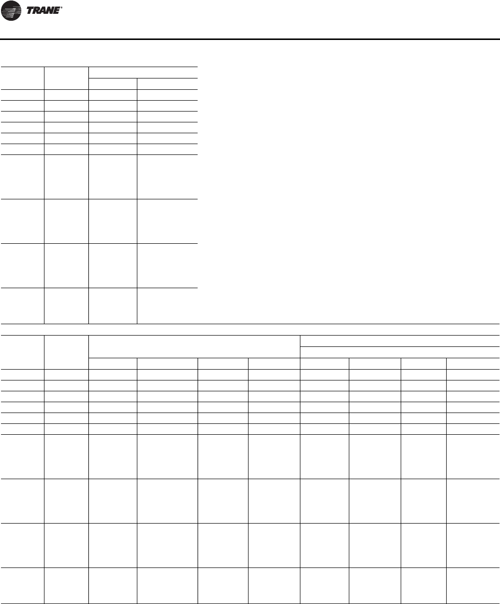
Dimensional Data
28 RT-SVX24K-EN
Tonnage Blank
Section Return Fan Exhaust Fan
JK
90 None 29 3/16 17
90 4 ft 29 3/16 17
90 8 ft 29 3/16 17
105 None 29 3/16 17
105 4 ft 29 3/16 17
105 8 ft 29 3/16 17
120-150
(All Units
Except High
Heat Gas
Models)
None 29 3/16 17
120-150
(All Units
Except High
Heat Gas
Models)
4 ft 29 3/16 17
120-150
(All Units
Except High
Heat Gas
Models)
8 ft 29 3/16 17
120-150
(High Heat
Gas Models
Only)
None 29 3/16 17
TWO-PIECE Dimensions with Energy Recovery Wheel (ERW)
Tonnage Blank
Section Unit Dimensions Lifting Lug Locations
Air Handler Side
A B E F C1 C2 C3 C4
90 None 550 11/16 256 5/16 427 5/16 121 6/16 66 201 1/16 349 4/16 N/A
90 4 ft 598 14/16 256 5/16 475 8/16 121 6/16 66 201 1/16 349 4/16 464 13/16
90 8 ft 647 2/16 256 5/16 523 12/16 121 6/16 66 201 1/16 349 4/16 513
105 None 568 11/16 256 5/16 427 5/16 139 6/16 66 201 1/16 349 4/16 N/A
105 4 ft 616 14/16 256 5/16 475 8/16 139 6/16 66 201 1/16 349 4/16 464 13/16
105 8 ft 665 2/16 256 5/16 523 12/16 139 6/16 66 201 1/16 349 4/16 513
120-150
(All Units
Except High
Heat Gas
Models)
None 642 7/16 293 8/16 492 1/16 148 6/16 66 238 5/16 365 5/16 480 14/16
120-150
(All Units
Except High
Heat Gas
Models)
4 ft 690 10/16 293 8/16 540 4/16 148 6/16 66 238 5/16 365 5/16 529 2/16
120-150
(All Units
Except High
Heat Gas
Models)
8 ft 738 14/16 293 8/16 588 8/16 148 6/16 66 238 5/16 365 5/16 577 5/16
120-150
(High Heat
Gas Models
Only)
None 654 7/16 293 8/16 504 1/16 148 6/16 66 238 5/16 365 5/16 492 14/16
Continued on next page
Table 6. Unit dimensions (In.)—two-piece unit air-cooled (continued)
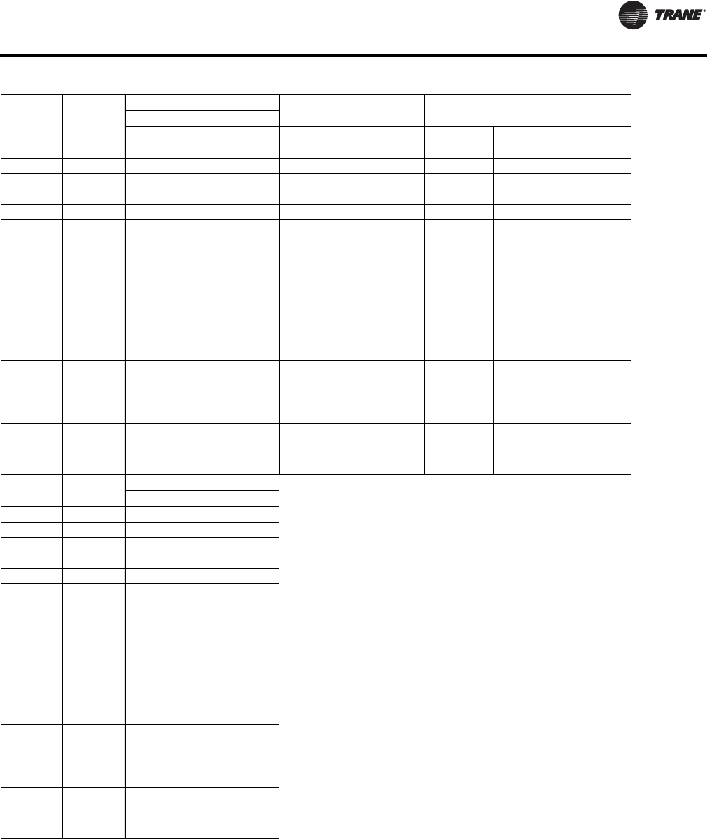
Dimensional Data
RT-SVX24K-EN 29
Tonnage Blank
Section
Lug Locations Unit WidthCondenser Side Unit Height
D1 D2 M N O P R
90 None 16 112 7/16 139 13/16 143 8/16 103 12/16 97 9/16 103 7/16
90 4 ft 16 112 7/16 139 13/16 143 8/16 103 12/16 97 9/16 103 7/16
90 8 ft 16 112 7/16 139 13/16 143 8/16 103 12/16 97 9/16 103 7/16
105 None 16 130 7/16 139 13/16 143 8/16 103 12/16 97 9/16 103 7/16
105 4 ft 16 130 7/16 139 13/16 143 8/16 103 12/16 97 9/16 103 7/16
105 8 ft 16 130 7/16 139 13/16 143 8/16 103 12/16 97 9/16 103 7/16
120-150
(All Units
Except High
Heat Gas
Models)
None 16 139 7/16 139 13/16 143 8/16 103 12/16 97 9/16 103 7/16
120-150
(All Units
Except High
Heat Gas
Models)
4 ft 16 139 7/16 139 13/16 143 8/16 103 12/16 97 9/16 103 7/16
120-150
(All Units
Except High
Heat Gas
Models)
8 ft 16 139 7/16 139 13/16 143 8/16 103 12/16 97 9/16 103 7/16
120-150
(High Heat
Gas Models
Only)
None 16 139 7/16 139 13/16 143 8/16 103 12/16 97 9/16 103 7/16
Tonnage Blank
Section Return Fan Exhaust Fan
JK
90 None N/A 17
90 4 ft N/A 17
90 8 ft N/A 17
105 None N/A 17
105 4 ft N/A 17
105 8 ft N/A 17
120-150
(All Units
Except High
Heat Gas
Models)
None N/A 17
120-150
(All Units
Except High
Heat Gas
Models)
4 ft N/A 17
120-150
(All Units
Except High
Heat Gas
Models)
8 ft N/A 17
120-150
(High Heat
Gas Models
Only)
None N/A 17
Table 6. Unit dimensions (In.)—two-piece unit air-cooled (continued)
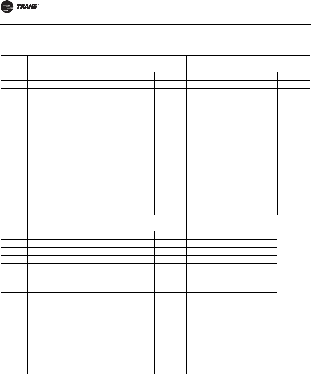
Dimensional Data
30 RT-SVX24K-EN
Table 7. Unit dimensions (in.)—two-piece unit evaporative condenser
TWO-PIECE Dimensions without Energy Recovery Wheel (ERW)
Tonnage Blank
Section
Unit Dimensions
Lifting Lug Locations
Air Handler Side
A B E F C1 C2 C3 C4
100-118 None 475 8/16 159 15/16 330 14/16 142 10/16 66 252 14/16 N/A N/A
100-118 4 ft 523 12/16 159 15/16 379 1/16 142 10/16 66 252 14/16 368 6/16 N/A
100-118 8 ft 571 15/16 159 15/16 427 5/16 142 10/16 66 252 14/16 416 10/16 N/A
128-162
(All Units
Except High
Heat Gas
Models)
None 540 5/16 197 1/16 395 10/16 142 10/16 66 269 6/16 384 15/16 N/A
128-162
(All Units
Except High
Heat Gas
Models)
4 ft 588 8/16 197 1/16 443 14/16 142 10/16 66 269 6/16 433 2/16 N/A
128-162
(All Units
Except High
Heat Gas
Models)
8 ft 636 11/16 197 1/16 492 1/16 142 10/16 66 269 6/16 481 6/16 N/A
128-162
(High Heat
Gas Models
Only)
None 552 5/16 197 1/16 407 10/16 142 10/16 66 269 6/16 396 15/16 N/A
Tonnage Blank
Section
Lug Locations
Condenser Side Unit Width Unit Height
D1 D2 M N O P R
100-118 None 16 133 11/16 139 13/16 143 8/16 103 12/16 97 9/16 102 12/16
100-118 4 ft 16 133 11/16 139 13/16 143 8/16 103 12/16 97 9/16 102 12/16
100-118 8 ft 16 133 11/16 139 13/16 143 8/16 103 12/16 97 9/16 102 12/16
128-162
(All Units
Except High
Heat Gas
Models)
None 16 133 11/16 139 13/16 143 8/16 103 12/16 97 9/16 102 12/16
128-162
(All Units
Except High
Heat Gas
Models)
4 ft 16 133 11/16 139 13/16 143 8/16 103 12/16 97 9/16 102 12/16
128-162
(All Units
Except High
Heat Gas
Models)
8 ft 16 133 11/16 139 13/16 143 8/16 103 12/16 97 9/16 102 12/16
128-162
(High Heat
Gas Models
Only)
None 16 133 11/16 139 13/16 143 8/16 103 12/16 97 9/16 102 12/16
Continued on next page
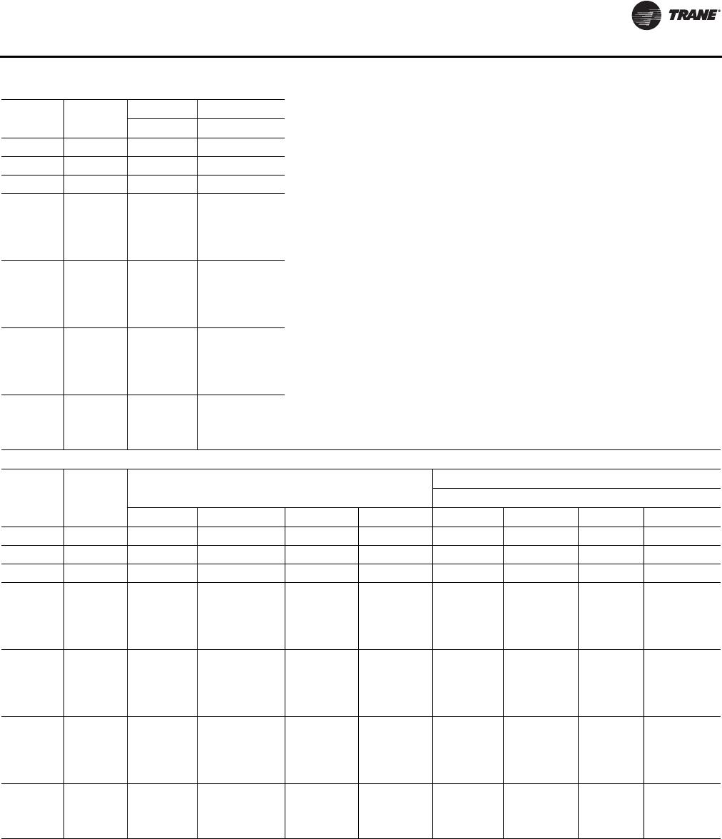
Dimensional Data
RT-SVX24K-EN 31
Tonnage Blank
Section
Return Fan Exhaust Fan
JK
100-118 None 29 3/16 17
100-118 4 ft 29 3/16 17
100-118 8 ft 29 3/16 17
128-162
(All Units
Except High
Heat Gas
Models)
None 29 3/16 17
128-162
(All Units
Except High
Heat Gas
Models)
4 ft 29 3/16 17
128-162
(All Units
Except High
Heat Gas
Models)
8 ft 29 3/16 17
128-162
(High Heat
Gas Models
Only)
None 29 3/16 17
TWO-PIECE Dimensions with Energy Recovery Wheel (ERW)
Tonnage Blank
Section
Unit Dimensions
Lifting Lug Locations
Air Handler Side
A B E F C1 C2 C3 C4
100-118 None 571 15/16 256 5/16 427 5/16 142 10/16 66 201 1/16 349 4/16 N/A
100-118 4 ft 620 3/16 256 5/16 475 8/16 142 10/16 66 201 1/16 349 4/16 464 13/16
100-118 8 ft 668 6/16 256 5/16 523 12/16 142 10/16 66 201 1/16 349 4/16 513
128-162
(All Units
Except High
Heat Gas
Models)
None 636 11/16 293 8/16 492 1/16 142 10/16 66 238 5/16 365 5/16 480 14/16
128-162
(All Units
Except High
Heat Gas
Models)
4 ft 684 15/16 293 8/16 540 4/16 142 10/16 66 238 5/16 365 5/16 529 2/16
128-162
(All Units
Except High
Heat Gas
Models)
8 ft 733 2/16 293 8/16 588 8/16 142 10/16 66 238 5/16 365 5/16 577 5/16
128-162
(High Heat
Gas Models
Only)
None 648 11/16 293 8/16 504 1/16 142 10/16 66 238 5/16 365 5/16 492 14/16
Continued on next page
Table 7. Unit dimensions (in.)—two-piece unit evaporative condenser (continued)
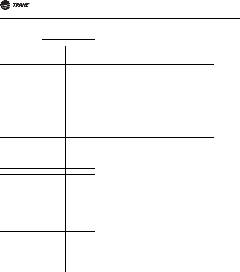
Dimensional Data
32 RT-SVX24K-EN
Tonnage Blank
Section
Lug Locations
Unit Width Unit HeightCondenser Side
D1 D2 M N O P R
100-118 None 16 133 11/16 139 13/16 143 8/16 103 12/16 97 9/16 102 12/16
100-118 4 ft 16 133 11/16 139 13/16 143 8/16 103 12/16 97 9/16 102 12/16
100-118 8 ft 16 133 11/16 139 13/16 143 8/16 103 12/16 97 9/16 102 12/16
128-162
(All Units
Except High
Heat Gas
Models)
None 16 133 11/16 139 13/16 143 8/16 103 12/16 97 9/16 102 12/16
128-162
(All Units
Except High
Heat Gas
Models)
4 ft 16 133 11/16 139 13/16 143 8/16 103 12/16 97 9/16 102 12/16
128-162
(All Units
Except High
Heat Gas
Models)
8 ft 16 133 11/16 139 13/16 143 8/16 103 12/16 97 9/16 102 12/16
128-162
(High Heat
Gas Models
Only)
None 16 133 11/16 139 13/16 143 8/16 103 12/16 97 9/16 102 12/16
Tonnage Blank
Section
Return Fan Exhaust Fan
JK
100-118 None N/A 17
100-118 4 ft N/A 17
100-118 8 ft N/A 17
128-162
(All Units
Except High
Heat Gas
Models)
None N/A 17
128-162
(All Units
Except High
Heat Gas
Models)
4 ft N/A 17
128-162
(All Units
Except High
Heat Gas
Models)
8 ft N/A 17
128-162
(High Heat
Gas Models
Only)
None N/A 17
Table 7. Unit dimensions (in.)—two-piece unit evaporative condenser (continued)
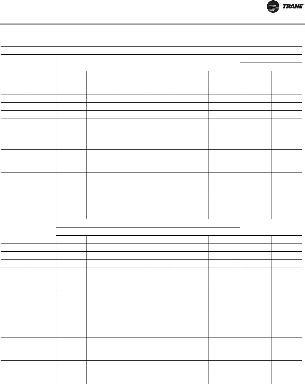
Dimensional Data
RT-SVX24K-EN 33
Table 8. Unit dimensions (in.)—three-piece unit air-cooled
THREE-PIECE Dimensions without Energy Recovery Wheel (ERW)
Tonnage Blank
Section
Unit Dimensions
Lifting Lug Locations
Air Handler Side
A B E E1 E2 F C1 C2
90 None 473 9/16 179 3/16 350 3/16 144 15/16 205 3/16 121 6/16 11 14/16 N/A
90 4 ft 521 12/16 179 3/16 398 6/16 144 15/16 253 7/16 121 6/16 11 14/16 N/A
90 8 ft 569 15/16 179 3/16 446 9/16 144 15/16 301 10/16 121 6/16 11 14/16 N/A
105 None 491 9/16 179 3/16 350 3/16 144 15/16 205 3/16 139 6/16 11 14/16 N/A
105 4 ft 539 12/16 179 3/16 398 6/16 144 15/16 253 7/16 139 6/16 11 14/16 N/A
105 8 ft 587 15/16 179 3/16 446 9/16 144 15/16 301 10/16 139 6/16 11 14/16 N/A
120-150 (All
Units Except
High Heat
Gas Models)
None 571 8/16 222 9/16 421 2/16 161 2/16 260 148 6/16 11 14/16 N/A
120-150 (All
Units Except
High Heat
Gas Models)
4 ft 619 11/16 222 9/16 469 5/16 161 2/16 308 4/16 148 6/16 11 14/16 N/A
120-150 (All
Units Except
High Heat
Gas Models)
8 ft 667 15/16 222 9/16 517 9/16 161 2/16 356 7/16 148 6/16 11 14/16 N/A
120-150
(High Heat
Gas Models
Only)
None 583 8/16 222 9/16 433 2/16 161 2/16 272 148 6/16 11 14/16 N/A
Tonnage Blank
Section
Lug Locations
Unit WidthAir Handler Side Condenser Side
C3 C4 C5 C6 D1 D2 M N
90 None 138 9/16 151 6/16 272 339 11/16 16 112 7/16 139 13/16 143 8/16
90 4 ft 138 9/16 151 6/16 272 387 14/16 16 112 7/16 139 13/16 143 8/16
90 8 ft 138 9/16 151 6/16 272 436 1/16 16 112 7/16 139 13/16 143 8/16
105 None 138 9/16 151 6/16 272 339 11/16 16 130 7/16 139 13/16 143 8/16
105 4 ft 138 9/16 151 6/16 272 387 14/16 16 130 7/16 139 13/16 143 8/16
105 8 ft 138 9/16 151 6/16 272 436 1/16 16 130 7/16 139 13/16 143 8/16
120-150 (All
Units Except
High Heat
Gas Models)
None 155 2/16 167 5/16 294 14/16 410 10/16 16 139 7/16 139 13/16 143 8/16
120-150 (All
Units Except
High Heat
Gas Models)
4 ft 155 2/16 167 5/16 294 14/16 458 13/16 16 139 7/16 139 13/16 143 8/16
120-150 (All
Units Except
High Heat
Gas Models)
8 ft 155 2/16 167 5/16 294 14/16 507 1/16 16 139 7/16 139 13/16 143 8/16
120-150
(High Heat
Gas Models
Only)
None 155 2/16 167 5/16 294 14/16 422 10/16 16 139 7/16 139 13/16 143 8/16
continued on next page
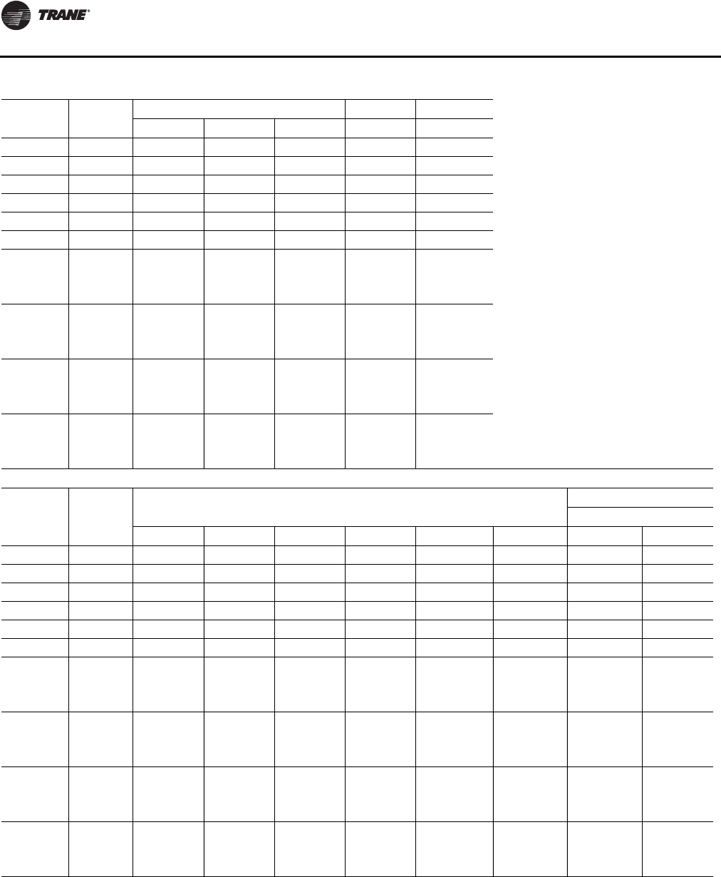
Dimensional Data
34 RT-SVX24K-EN
Tonnage Blank
Section
Unit Height Return Fan Exhaust Fan
OPRJ K
90 None 103 12/16 97 9/16 103 7/16 29 3/16 17
90 4 ft 103 12/16 97 9/16 103 7/16 29 3/16 17
90 8 ft 103 12/16 97 9/16 103 7/16 29 3/16 17
105 None 103 12/16 97 9/16 103 7/16 29 3/16 17
105 4 ft 103 12/16 97 9/16 103 7/16 29 3/16 17
105 8 ft 103 12/16 97 9/16 103 7/16 29 3/16 17
120-150 (All
Units Except
High Heat
Gas Models)
None 103 12/16 97 9/16 103 7/16 29 3/16 17
120-150 (All
Units Except
High Heat
Gas Models)
4 ft 103 12/16 97 9/16 103 7/16 29 3/16 17
120-150 (All
Units Except
High Heat
Gas Models)
8 ft 103 12/16 97 9/16 103 7/16 29 3/16 17
120-150
(High Heat
Gas Models
Only)
None 103 12/16 97 9/16 103 7/16 29 3/16 17
THREE-PIECE Dimensions with Energy Recovery Wheel (ERW)
Tonnage Blank
Section
Unit Dimensions
Lifting Lug Locations
Air Handler Side
A B E E1 E2 F C1 C2
90 None 569 15/16 275 10/16 446 9/16 241 6/16 205 3/16 121 6/16 17 12/16 201 1/16
90 4 ft 618 3/16 275 10/16 494 13/16 241 6/16 253 7/16 121 6/16 17 12/16 201 1/16
90 8 ft 666 6/16 275 10/16 543 241 6/16 301 10/16 121 6/16 17 12/16 201 1/16
105 None 587 15/16 275 10/16 446 9/16 241 6/16 205 3/16 139 6/16 17 12/16 201 1/16
105 4 ft 636 3/16 275 10/16 494 13/16 241 6/16 253 7/16 139 6/16 17 12/16 201 1/16
105 8 ft 684 6/16 275 10/16 543 241 6/16 301 10/16 139 6/16 17 12/16 201 1/16
120-150 (All
Units Except
High Heat
Gas Models)
None 667 15/16 318 15/16 517 9/16 257 8/16 260 148 6/16 17 12/16 204 7/16
120-150 (All
Units Except
High Heat
Gas Models)
4 ft 716 2/16 318 15/16 565 12/16 257 8/16 308 4/16 148 6/16 17 12/16 204 7/16
120-150 (All
Units Except
High Heat
Gas Models)
8 ft 764 5/16 318 15/16 613 15/16 257 8/16 356 7/16 148 6/16 17 12/16 204 7/16
120-150
(High Heat
Gas Models
Only)
None 679 15/16 318 15/16 529 9/16 257 8/16 272 148 6/16 17 12/16 204 7/16
continued on next page
Table 8. Unit dimensions (in.)—three-piece unit air-cooled (continued)
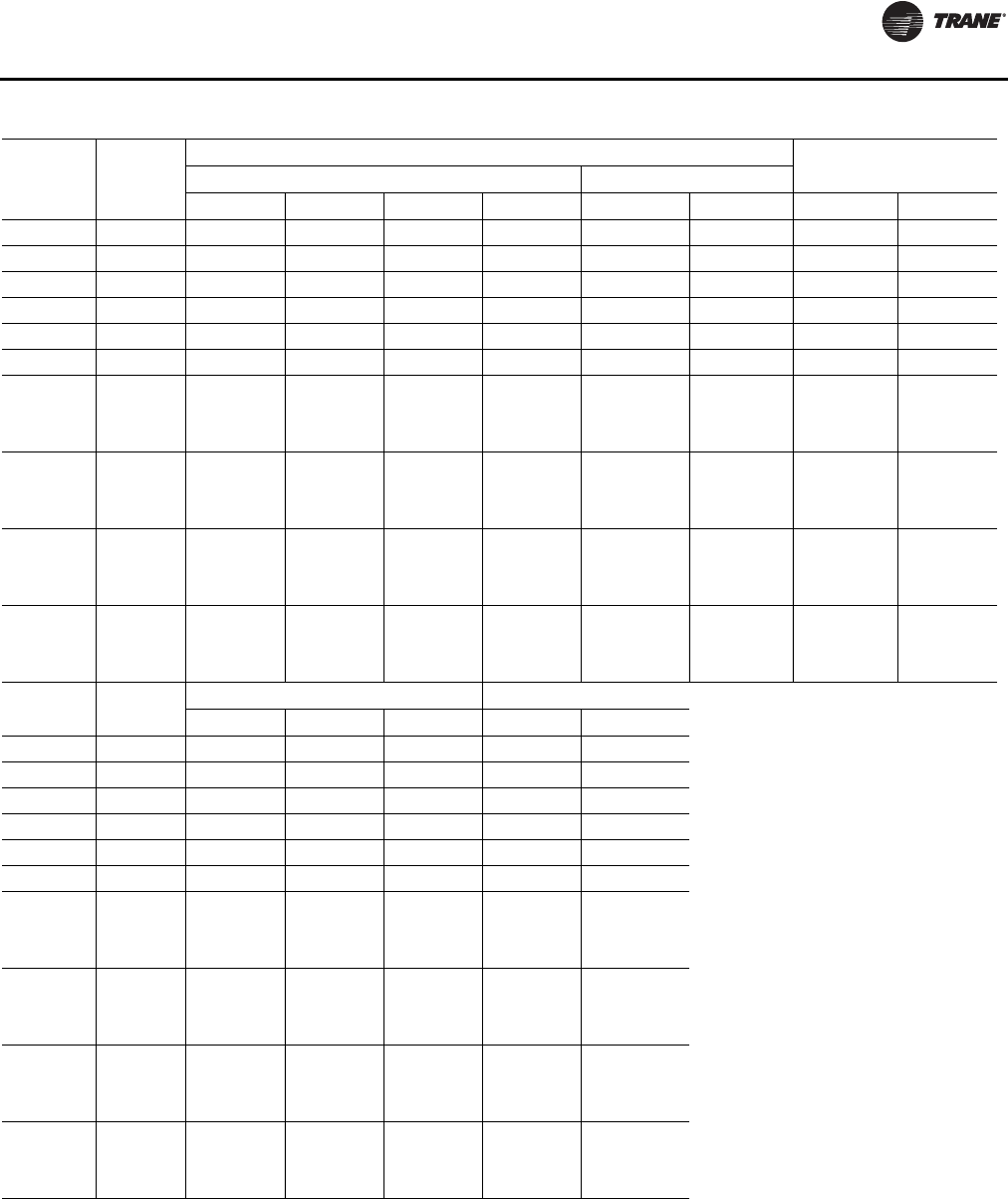
Dimensional Data
RT-SVX24K-EN 35
Tonnage Blank
Section
Lug Locations
Unit WidthAir Handler Side Condenser Side
C3 C4 C5 C6 D1 D2 M N
90 None 234 13/16 247 13/16 368 7/16 436 2/16 16 112 7/16 139 13/16 143 8/16
90 4 ft 234 13/16 247 13/16 368 7/16 484 5/16 16 112 7/16 139 13/16 143 8/16
90 8 ft 234 13/16 247 13/16 368 7/16 532 8/16 16 112 7/16 139 13/16 143 8/16
105 None 234 13/16 247 13/16 368 7/16 436 2/16 16 130 7/16 139 13/16 143 8/16
105 4 ft 234 13/16 247 13/16 368 7/16 484 5/16 16 130 7/16 139 13/16 143 8/16
105 8 ft 234 13/16 247 13/16 368 7/16 532 8/16 16 130 7/16 139 13/16 143 8/16
120-150 (All
Units Except
High Heat
Gas Models)
None 252 12/16 263 12/16 391 5/16 507 1/16 16 139 7/16 139 13/16 143 8/16
120-150 (All
Units Except
High Heat
Gas Models)
4 ft 252 12/16 263 12/16 391 5/16 555 4/16 16 139 7/16 139 13/16 143 8/16
120-150 (All
Units Except
High Heat
Gas Models)
8 ft 252 12/16 263 12/16 391 5/16 603 7/16 16 139 7/16 139 13/16 143 8/16
120-150
(High Heat
Gas Models
Only)
None 252 12/16 263 12/16 391 5/16 519 1/16 16 139 7/16 139 13/16 143 8/16
Tonnage Blank
Section
Unit Height Return Fan Exhaust Fan
OPRJ K
90 None 103 12/16 97 9/16 103 7/16 N/A 17
90 4 ft 103 12/16 97 9/16 103 7/16 N/A 17
90 8 ft 103 12/16 97 9/16 103 7/16 N/A 17
105 None 103 12/16 97 9/16 103 7/16 N/A 17
105 4 ft 103 12/16 97 9/16 103 7/16 N/A 17
105 8 ft 103 12/16 97 9/16 103 7/16 N/A 17
120-150 (All
Units Except
High Heat
Gas Models)
None 103 12/16 97 9/16 103 7/16 N/A 17
120-150 (All
Units Except
High Heat
Gas Models)
4 ft 103 12/16 97 9/16 103 7/16 N/A 17
120-150 (All
Units Except
High Heat
Gas Models)
8 ft 103 12/16 97 9/16 103 7/16 N/A 17
120-150
(High Heat
Gas Models
Only)
None 103 12/16 97 9/16 103 7/16 N/A 17
Table 8. Unit dimensions (in.)—three-piece unit air-cooled (continued)
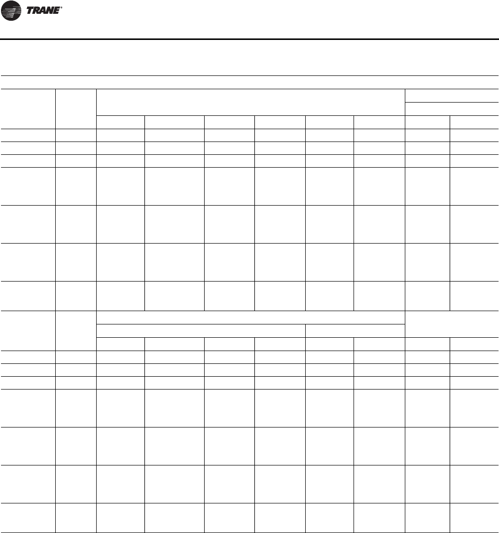
Dimensional Data
36 RT-SVX24K-EN
Table 9. Unit dimensions (in.)—three-piece unit evaporative condenser
THREE-PIECE Dimensions without Energy Recovery Wheel (ERW)
Tonnage Blank
Section
Unit Dimensions
Lifting Lug Location
Air Handler Side
A B E E1 E2 F C1 C2
100/118 None 494 13/16 179 3/16 350 3/16 144 15/16 205 3/16 142 10/16 11 14/16 N/A
100/118 4 ft 543 179 3/16 398 6/16 144 15/16 253 7/16 142 10/16 11 14/16 N/A
100/118 8 ft 591 4/16 179 3/16 446 9/16 144 15/16 301 10/16 142 10/16 11 14/16 N/A
128-162 (All
Units Except
High Heat Gas
Models)
None 565 12/16 222 9/16 421 2/16 161 2/16 260 142 10/16 11 14/16 N/A
128-162 (All
Units Except
High Heat Gas
Models)
4 ft 613 15/16 222 9/16 469 5/16 161 2/16 308 4/16 142 10/16 11 14/16 N/A
128-162 (All
Units Except
High Heat Gas
Models)
8 ft 662 3/16 222 9/16 517 9/16 161 2/16 356 7/16 142 10/16 11 14/16 N/A
128-162 (High
Heat Gas
Models Only) None 577 12/16 222 9/16 433 2/16 161 2/16 272 142 10/16 11 14/16 N/A
Tonnage Blank
Section
Lifting Lug Locations
Unit WidthAir Handler Side Condenser Side
C3 C4 C5 C6 D1 D2 M N
100/118 None 138 9/16 151 6/16 272 339 11/16 16 133 11/16 139 13/16 143 8/16
100/118 4 ft 138 9/16 151 6/16 272 387 14/16 16 133 11/16 139 13/16 143 8/16
100/118 8 ft 138 9/16 151 6/16 272 436 1/16 16 133 11/16 139 13/16 143 8/16
128-162 (All
Units Except
High Heat Gas
Models)
None 155 2/16 167 5/16 294 14/16 410 10/16 16 133 11/16 139 13/16 143 8/16
128-162 (All
Units Except
High Heat Gas
Models)
4 ft 155 2/16 167 5/16 294 14/16 458 13/16 16 133 11/16 139 13/16 143 8/16
128-162 (All
Units Except
High Heat Gas
Models)
8 ft 155 2/16 167 5/16 294 14/16 507 1/16 16 133 11/16 139 13/16 143 8/16
128-162 (High
Heat Gas
Models Only) None 155 2/16 167 5/16 294 14/16 422 10/16 16 133 11/16 139 13/16 143 8/16
continued on next page
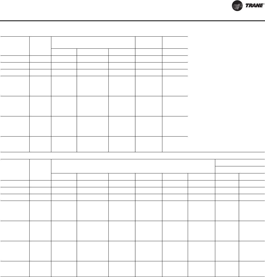
Dimensional Data
RT-SVX24K-EN 37
Tonnage Blank
Section
Unit Height Return Fan Exhaust
Fan
OPRJK
100/118 None 103 12/16 97 9/16 102 12/16 29 3/16 17
100/118 4 ft 103 12/16 97 9/16 102 12/16 29 3/16 17
100/118 8 ft 103 12/16 97 9/16 102 12/16 29 3/16 17
128-162 (All
Units Except
High Heat Gas
Models)
None 103 12/16 97 9/16 102 12/16 29 3/16 17
128-162 (All
Units Except
High Heat Gas
Models)
4 ft 103 12/16 97 9/16 102 12/16 29 3/16 17
128-162 (All
Units Except
High Heat Gas
Models)
8 ft 103 12/16 97 9/16 102 12/16 29 3/16 17
128-162 (High
Heat Gas
Models Only) None 103 12/16 97 9/16 102 12/16 29 3/16 17
THREE-PIECE Dimensions with Energy Recovery Wheel (ERW)
Tonnage Blank
Section
Unit Dimensions
Lifting Lug Locations
Air Handler Side
A B E E1 E2 F C1 C2
100/118 None 591 4/16 275 10/16 446 9/16 241 6/16 205 3/16 142 10/16 17 12/16 201 1/16
100/118 4 ft 639 7/16 275 10/16 494 13/16 241 6/16 253 7/16 142 10/16 17 12/16 201 1/16
100/118 8 ft 687 10/16 275 10/16 543 241 6/16 301 10/16 142 10/16 17 12/16 201 1/16
128-162 (All
Units Except
High Heat Gas
Models)
None 662 3/16 318 15/16 517 9/16 257 8/16 260 142 10/16 17 12/16 204 7/16
128-162 (All
Units Except
High Heat Gas
Models)
4 ft 710 6/16 318 15/16 565 12/16 257 8/16 308 4/16 142 10/16 17 12/16 204 7/16
128-162 (All
Units Except
High Heat Gas
Models)
8 ft 758 10/16 318 15/16 613 15/16 257 8/16 356 7/16 142 10/16 17 12/16 204 7/16
128-162 (High
Heat Gas
Models Only) None 674 3/16 318 15/16 529 9/16 257 8/16 272 142 10/16 17 12/16 204 7/16
continued on next page
Table 9. Unit dimensions (in.)—three-piece unit evaporative condenser (continued)
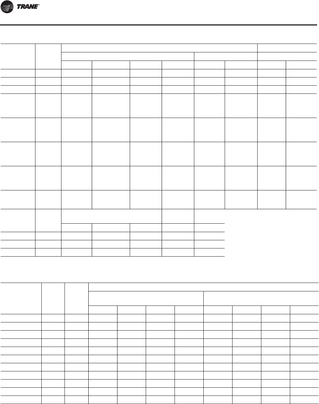
Dimensional Data
38 RT-SVX24K-EN
Tonnage Blank
Section
Lifting Lug Locations
Air Handler Side Condenser Side Unit Width
C3 C4 C5 C6 D1 D2 M N
100/118 None 234 13/16 247 13/16 368 7/16 436 2/16 16 133 11/16 139 13/16 143 8/16
100/118 4 ft 234 13/16 247 13/16 368 7/16 484 5/16 16 133 11/16 139 13/16 143 8/16
100/118 8 ft 234 13/16 247 13/16 368 7/16 532 8/16 16 133 11/16 139 13/16 143 8/16
128-162 (All
Units Except
High Heat Gas
Models)
None 252 12/16 263 12/16 391 5/16 519 1/16 16 133 11/16 139 13/16 143 8/16
128-162 (All
Units Except
High Heat Gas
Models)
4 ft 252 12/16 263 12/16 391 5/16 507 1/16 16 133 11/16 139 13/16 143 8/16
128-162 (All
Units Except
High Heat Gas
Models)
4 ft 252 12/16 263 12/16 391 5/16 507 1/16 16 133 11/16 139 13/16 143 8/16
128-162 (All
Units Except
High Heat Gas
Models)
8 ft 252 12/16 263 12/16 391 5/16 555 4/16 16 133 11/16 139 13/16 143 8/16
128-162 (High
Heat Gas
Models Only) None 252 12/16 263 12/16 391 5/16 603 7/16 16 133 11/16 139 13/16 143 8/16
Tonnage Blank
Section
Unit Height Return Fan Exhaust
Fan
OPRJK
100-162 None 103 12/16 97 9/16 102 12/16 N/A 17
100-162 4 ft 103 12/16 97 9/16 102 12/16 N/A 17
100-162 8 ft 103 12/16 97 9/16 102 12/16 N/A 17
Table 9. Unit dimensions (in.)—three-piece unit evaporative condenser (continued)
Table 10. Downflow/horizontal airflow configuration dimensions (in.) air cooled (AC) and evap condenser (EC) without
energy recovery wheel (ERW)
Tonnage Blank
Section Gas
Heat
DOWNFLOW Opening Dimensions
Return Opening—with or
without Exhaust Fan Return Opening—with Return Fan
X1 Y1 W1 L1 X1 Y1 W1 L1
90-105/100-118 None None 14 13/16 8 14/16 48 3/16 121 15/16 14 13/16 42 14/16 48 3/16 53 14/16
90-105/100-118 4 ft None 14 13/16 8 14/16 48 3/16 121 15/16 14 13/16 42 14/16 48 3/16 53 14/16
90-105/100-118 8 ft None 14 13/16 8 14/16 48 3/16 121 15/16 14 13/16 42 14/16 48 3/16 53 14/16
120-150/128-162 None None 14 13/16 8 14/16 48 3/16 121 15/16 14 13/16 42 14/16 48 3/16 53 14/16
120-150/128-162 4 ft None 14 13/16 8 14/16 48 3/16 121 15/16 14 13/16 42 14/16 48 3/16 53 14/16
120-150/128-162 8 ft None 14 13/16 8 14/16 48 3/16 121 15/16 14 13/16 42 14/16 48 3/16 53 14/16
90-105/100-118 None Low/Med 14 13/16 8 14/16 48 3/16 121 15/16 14 13/16 42 14/16 48 3/16 53 14/16
90-105/100-118 8 ft Low/Med 14 13/16 8 14/16 48 3/16 121 15/16 14 13/16 42 14/16 48 3/16 53 14/16
120-150/128-162 None Low/Med 14 13/16 8 14/16 48 3/16 121 15/16 14 13/16 42 14/16 48 3/16 53 14/16
120-150/128-162 8 ft Low/Med 14 13/16 8 14/16 48 3/16 121 15/16 14 13/16 42 14/16 48 3/16 53 14/16
120-150/128-162 None High 14 13/16 8 14/16 48 3/16 121 15/16 14 13/16 42 14/16 48 3/16 53 14/16
continued on next page
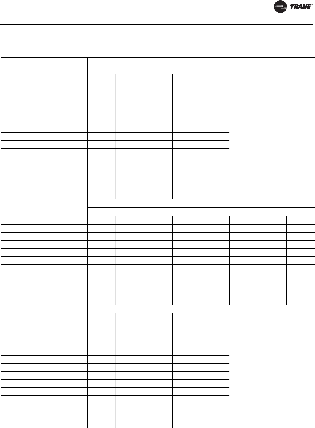
Dimensional Data
RT-SVX24K-EN 39
Tonnage Blank
Section Gas
Heat
DOWNFLOW Opening Dimensions
Supply Opening
X2
(One or
Two-Piece
Models)
X2
(Three-
Piece
Models) Y2 W2 L2
90-105/100-118 None None 256 1/16 275 6/16 13 47 14/16 102 8/16
90-105/100-118 4 ft None 304 4/16 323 9/16 13 47 14/16 102 8/16
90-105/100-118 8 ft None 352 8/16 371 12/16 13 47 14/16 102 8/16
120-150/128-162 None None 320 13/16 346 4/16 13 47 14/16 102 8/16
120-150/128-162 4 ft None 369 394 8/16 13 47 14/16 102 8/16
120-150/128-162 8 ft None 417 3/16 442 11/16 13 47 14/16 102 8/16
90-105/100-118 None Low/Med/
High 256 1/16 275 6/16 13 47 14/16 102 8/16
90-105/100-118 8 ft Low/Med/
High 352 8/16 371 12/16 13 47 14/16 102 8/16
120-150/128-162 None Low/Med 320 13/16 346 4/16 13 47 14/16 102 8/16
120-150/128-162 8 ft Low/Med 417 3/16 442 11/16 13 47 14/16 102 8/16
120-150/128-162 None High 320 13/16 346 4/16 13 59 14/16 102 8/16
Tonnage Blank
Section Gas
Heat
HORIZONTAL Opening Dimensions
Return Side Opening Return End Opening
X3 Y3 W3 H1 Y1 Y3 H3 L1
90-105/100-118 None None 9 5/16 10 10/16 54 12/16 84 15/16 6 5/16 8 3/16 35 3/16 127 2/16
90-105/100-118 4 ft None 9 5/16 10 10/16 54 12/16 84 15/16 6 5/16 8 3/16 35 3/16 127 2/16
90-105/100-118 8 ft None 9 5/16 10 10/16 54 12/16 84 15/16 6 5/16 8 3/16 35 3/16 127 2/16
120-150/128-162 8 ft None 9 5/16 10 10/16 54 12/16 84 15/16 6 5/16 8 3/16 35 3/16 127 2/16
90-105/100-118 None Low/Med 9 5/16 10 10/16 54 12/16 84 15/16 6 5/16 8 3/16 35 3/16 127 2/16
90-105/100-118 8 ft Low/Med 9 5/16 10 10/16 54 12/16 84 15/16 6 5/16 8 3/16 35 3/16 127 2/16
120-150/128-162 None Low/Med 9 5/16 10 10/16 54 12/16 84 15/16 6 5/16 8 3/16 35 3/16 127 2/16
120-150/128-162 8 ft Low/Med 9 5/16 10 10/16 54 12/16 84 15/16 6 5/16 8 3/16 35 3/16 127 2/16
120-150/128-162 None High 9 5/16 10 10/16 54 12/16 84 15/16 6 5/16 8 3/16 35 3/16 127 2/16
Tonnage Blank
Section Gas
Heat
Supply Opening
X4 (One or
Two-Piece
Models)
X4
(Three-
Piece
Models) Y4 W4 H2
90-105/100-118 None None 254 12/16 274 10 10/16 54 12/16 84 15/16
90-105/100-118 4 ft None 302 15/16 322 4/16 10 10/16 54 12/16 84 15/16
90-105/100-118 8 ft None 351 2/16 370 7/16 10 10/16 54 12/16 84 15/16
120-150/128-162 None None 319 8/16 345 10 10/16 54 12/16 84 15/16
120-150/128-162 4 ft None 367 11/16 393 3/16 10 10/16 54 12/16 84 15/16
120-150/128-162 8 ft None 415 15/16 441 6/16 10 10/16 54 12/16 84 15/16
90-105/100-118 None Low/Med 254 12/16 274 10 10/16 54 12/16 66 11/16
90-105/100-118 8 ft Low/Med 351 2/16 370 7/16 10 10/16 54 12/16 84 15/16
120-150/128-162 None Low/Med 319 8/16 345 10 10/16 54 12/16 66 11/16
120-150/128-162 8 ft Low/Med 415 15/16 441 6/16 10 10/16 54 12/16 84 15/16
120-150/128-162 None High 319 8/16 345 10 10/16 66 12/16 66 11/16
Table 10. Downflow/horizontal airflow configuration dimensions (in.) air cooled (AC) and evap condenser (EC) without
energy recovery wheel (ERW) (continued)
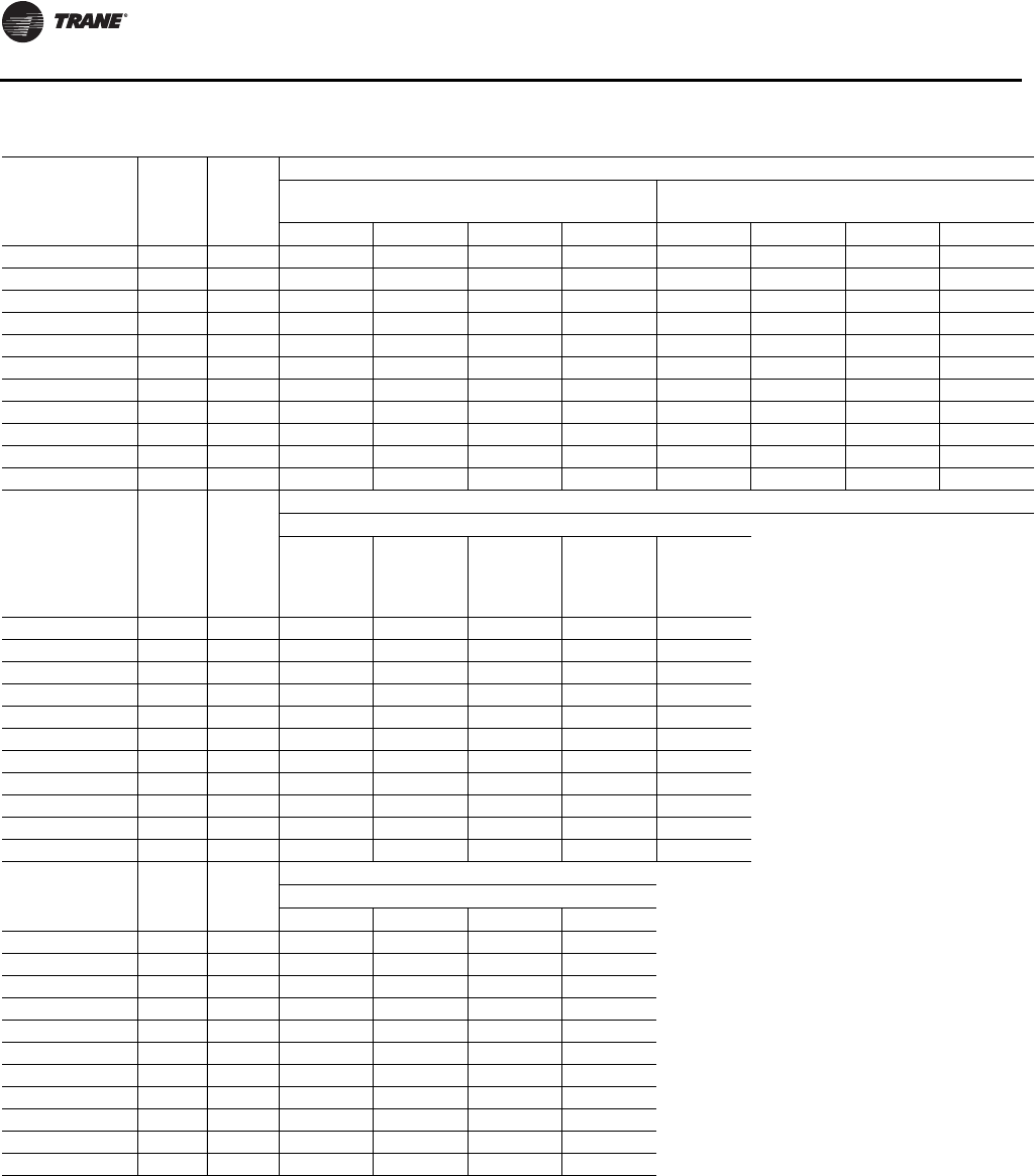
Dimensional Data
40 RT-SVX24K-EN
Table 11. Downflow/horizontal airflow configuration dimensions (in.) air-cooled (AC) and evap condenser (EC) with
energy recovery wheel
Tonnage Blank
Section Gas
Heat
DOWNFLOW Opening Dimensions
Return Opening—with or
without Exhaust Fan Return Opening—with Return Fan
X1 Y1 W1 L1 X1 Y1 W1 L1
90-105/100-118 None None 82 3/16 8 14/16 49 10/16 121 15/16 N/A N/A N/A N/A
90-105/100-118 4 ft None 82 3/16 8 14/16 49 10/16 121 15/16 N/A N/A N/A N/A
90-105/100-118 8 ft None 82 3/16 8 14/16 49 10/16 121 15/16 N/A N/A N/A N/A
120-150/128-162 None None 82 3/16 8 14/16 49 10/16 121 15/16 N/A N/A N/A N/A
120-150/128-162 4 ft None 82 3/16 8 14/16 49 10/16 121 15/16 N/A N/A N/A N/A
120-150/128-162 8 ft None 82 3/16 8 14/16 49 10/16 121 15/16 N/A N/A N/A N/A
90-105/100-118 None Low/Med 82 3/16 8 14/16 49 10/16 121 15/16 N/A N/A N/A N/A
90-105/100-118 8 ft Low/Med 82 3/16 8 14/16 49 10/16 121 15/16 N/A N/A N/A N/A
120-150/128-162 None Low/Med 82 3/16 8 14/16 49 10/16 121 15/16 N/A N/A N/A N/A
120-150/128-162 8 ft Low/Med 82 3/16 8 14/16 49 10/16 121 15/16 N/A N/A N/A N/A
120-150/128-162 None High 82 3/16 8 14/16 49 10/16 121 15/16 N/A N/A N/A N/A
Tonnage Blank
Section Gas
Heat
DOWNFLOW Opening Dimensions
Supply Opening
X2
(One or
Two-Piece
Models)
X2
(Three-
Piece
Models) Y2 W2 L2
90-105/100-118 None None 352 8/16 371 12/16 13 47 14/16 102 8/16
90-105/100-118 4 ft None 400 11/16 420 13 47 14/16 102 8/16
90-105/100-118 8 ft None 448 15/16 468 3/16 13 47 14/16 102 8/16
120-150/128-162 None None 417 4/16 442 11/16 13 47 14/16 102 8/16
120-150/128-162 4 ft None 465 7/16 490 14/16 13 47 14/16 102 8/16
120-150/128-162 8 ft None 513 10/16 539 2/16 13 47 14/16 102 8/16
90-105/100-118 None Low/Med 352 8/16 371 12/16 13 47 14/16 102 8/16
90-105/100-118 8 ft Low/Med 448 15/16 468 3/16 13 47 14/16 102 8/16
120-150/128-162 None Low/Med 417 4/16 442 11/16 13 47 14/16 102 8/16
120-150/128-162 8 ft Low/Med 513 10/16 539 2/16 13 47 14/16 102 8/16
120-150/128-162 None High 417 4/16 442 11/16 13 59 14/16 102 8/16
Tonnage Blank
Section Gas
Heat
HORIZONTAL Opening Dimensions(a)
Return Side Opening
X3 Y3 W3 H1
90-105/100-118 None None 71 8/16 10 10/16 54 12/16 43 6/16
90-105/100-118 4 ft None 71 8/16 10 10/16 54 12/16 43 6/16
90-105/100-118 8 ft None 71 8/16 10 10/16 54 12/16 43 6/16
120-150/128-162 None None 71 8/16 10 10/16 54 12/16 43 6/16
120-150/128-162 4 ft None 71 8/16 10 10/16 54 12/16 43 6/16
120-150/128-162 8 ft None 71 8/16 10 10/16 54 12/16 43 6/16
90-105/100-118 None Low/Med 71 8/16 10 10/16 54 12/16 43 6/16
90-105/100-118 8 ft Low/Med 71 8/16 10 10/16 54 12/16 43 6/16
120-150/128-162 None Low/Med 71 8/16 10 10/16 54 12/16 43 6/16
120-150/128-162 8 ft Low/Med 71 8/16 10 10/16 54 12/16 43 6/16
120-150/128-162 None High 71 8/16 10 10/16 54 12/16 43 6/16
continued on next page
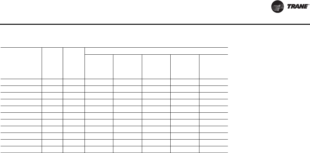
Dimensional Data
RT-SVX24K-EN 41
Tonnage Blank
Section Gas
Heat
Supply Opening
X4 (One or
Two-Piece
Models)
X4
(Three-
Piece
Models) Y4 W4 H2
90-105/100-118 None None 351 3/16 370 7/16 10 10/16 54 12/16 84 15/16
90-105/100-118 4 ft None 399 6/16 418 11/16 10 10/16 54 12/16 84 15/16
90-105/100-118 8 ft None 447 10/16 466 14/16 10 10/16 54 12/16 84 15/16
120-150/128-162 None None 415 15/16 441 6/16 10 10/16 54 12/16 84 15/16
120-150/128-162 4 ft None 464 2/16 489 10/16 10 10/16 54 12/16 84 15/16
120-150/128-162 8 ft None 512 6/16 537 13/16 10 10/16 54 12/16 84 15/16
90-105/100-118 None Low/Med 351 3/16 370 7/16 10 10/16 54 12/16 66 11/16
90-105/100-118 8 ft Low/Med 447 10/16 466 14/16 10 10/16 54 12/16 84 15/16
120-150/128-162 None Low/Med 415 15/16 441 6/16 10 10/16 54 12/16 66 11/16
120-150/128-162 8 ft Low/Med 512 6/16 537 13/16 10 10/16 54 12/16 84 15/16
120-150/128-162 None High 415 15/16 441 6/16 10 10/16 66 12/16 66 11/16
(a)On horizontal return with ERW units, the return end opening can be on the front, rear, or both sides of the unit and must be specified.
Table 11. Downflow/horizontal airflow configuration dimensions (in.) air-cooled (AC) and evap condenser (EC) with
energy recovery wheel (continued)
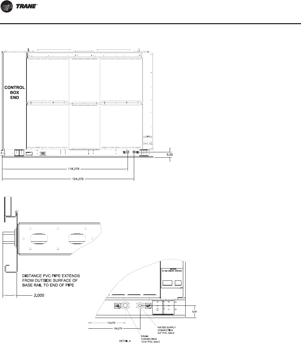
Dimensional Data
42 RT-SVX24K-EN
Figure 13. Evaporative condenser water connection locations
RIGHT SIDE VIEW
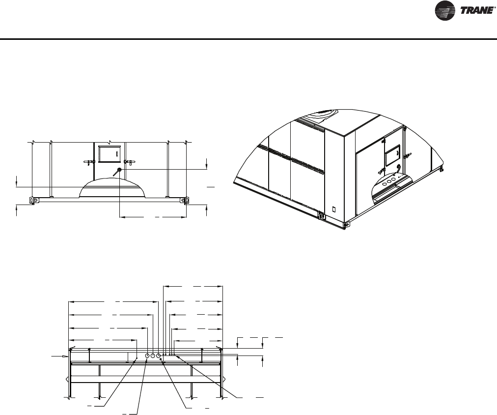
Dimensional Data
RT-SVX24K-EN 43
Figure 14. Electrical entry details (in.)
16
603
4
711
4
761
4
811
4
46 1
16
48 1
16
613
444
Ø35
8
Ø1 1
16
Ø7
8
65
16
55
16
Marine lights
customer supplied
power service
entrance Unit power
External customer
connection points
Outside edge of
base rail
515
8
5311
16
3111
16
Ø11
2
Bottom View
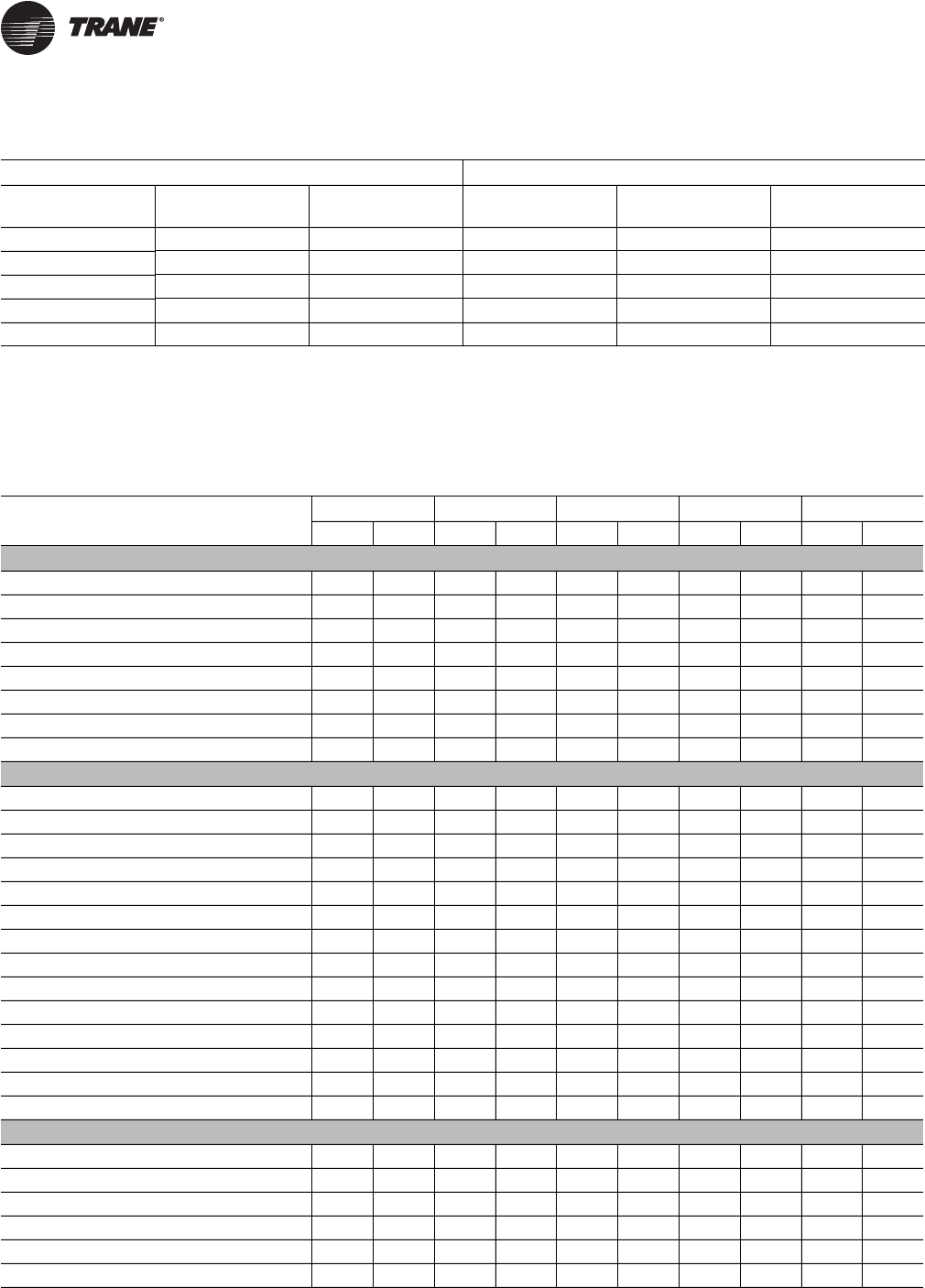
44 RT-SVX24K-EN
Weights
Notes:
1. Weights shown for air-cooled units include the following features: standard coils, 0-25% outside air, throwaway filters, low CFM supply fan, minimum
motor sizes, constant volume, 460 XL, No heat. Weights shown for Evaporative condensing units include high-capacity evaporator coil and the weight
of the extra structure associated with a two piece unit.
2. Weights shown represent approximate operating weights and have a + 5% accuracy. To calculate weight for a specific unit configuration, utilize TOPSS
or contact the local Trane sales representative. ACTUAL WEIGHTS ARE STAMPED ON THE UNIT NAMEPLATE.
Table 12. Approximate operating weights (lbs.)
Air-Cooled Condensers Evaporative Condensers
Nominal Tons Unit (Minimum) Roof Curb
(Minimum) Nominal Tons Unit (Minimum) Roof Curb
(Minimum)
90 14197 907 100 18430 1055
105 14792 907 118 18941 1055
120 16939 1040 128 21362 1194
130 17690 1040 140 21348 1194
150 17923 1040 162 21470 1194
Table 13. Component weights (lbs)
90/100 105/118 120/128 130/140 150/162
Size Weight Size Weight Size Weight Size Weight Size Weight
Refrigeration
Compressor Assembly - 1126 - 1344 - 1562 - 1616 - 1670
Air-Cooled Condensing Coil (Al) - 623 - 722 - 1049 - 1224 - 924
Evaporative Condensing Coil(a) 4566 4329 4129 4109 4029
Evap Coil - Std. Cap - 1034 - 1300 - 1664 - 1892 - 2564
Evap Coil - Hi. Cap. - 1382 - 1462 - 2564 - 2496 - N/A
Reheat Coil & Tubing - 292 - 294 - 367 - 367 - 367
Replaceable Core Filter Driers - 26 - 25 - 35 - 35 - 35
HGBP - 46 - 49 - 53 - 53 - 53
Supply Fan Assembly
Supply Fan & Fan Board Assembly - Low CFM 25" 1159 32" 1361 32" 1361 32" 1361 32" 1361
Supply Fan & Fan Board Assembly - Std. CFM 36" 1490 36" 1490 40" 1653 40" 1653 40" 1653
Belt Guard - 116 - 116 - 116 - 116 - 116
Supply VFD (50 hp and below) - 233 - 233 - 233 - 233 - 233
Supply VFD (60-100 hp) - 284 - 284 - 284 - 284 - 284
Supply-Exhaust Fan Motor - 15 hp - 181 - 181 - 181 - 181 - 181
Supply-Exhaust Fan Motor - 20 hp - 206 - 206 - 206 - 206 - 206
Supply-Exhaust Fan Motor - 25 hp - 358 - 358 - 358 - 358 - 358
Supply-Exhaust Fan Motor - 30 hp - 413 - 413 - 413 - 413 - 413
Supply-Exhaust Fan Motor - 40 hp - 495 - 495 - 495 - 495 - 495
Supply-Exhaust Fan Motor - 50 hp - 604 - 604 - 604 - 604 - 604
Supply-Exhaust Fan Motor - 60 hp - 776 - 776 - 776 - 776 - 776
Supply-Exhaust Fan Motor - 75 hp - 879 - 879 - 879 - 879 - 879
Supply-Exhaust Fan Motor - 100 hp - 1102 - 1102 - 1102 - 1102 - 1102
Return/Exhaust Fan Assembly
Return Fan & Dampers - Low CFM 36" 2294 36" 2294 36" 2294 36" 2294 36" 2294
Return Fan & Dampers - Std. CFM 40" 2343 40" 2343 44" 2445 44" 2445 44" 2445
Exhaust Fan & Dampers - Low CFM 25" 889 28" 979 28" 979 28" 979 28" 979
Exhaust Fan & Dampers - Std. CFM 28" 979 32" 1429 32" 1429 32" 1429 32" 1429
Belt Guard - 119 - 119 - 119 - 119 - 119
Exhaust VFD (50 hp and below) - 244 - 244 - 244 - 244 - 244
Weights
RT-SVX24K-EN 45
Exhaust VFD (60-100 hp) - 295 - 295 - 295 - 295 - 295
Exhaust Fan Motor - 7.5 hp - 160 160 - 160 - 160 - 160
Exhaust Fan Motor - 10 hp - 181 - 181 - 181 - 181 - 181
Exhaust Fan Motor - 15 hp - 206 - 206 - 206 - 206 - 206
Exhaust Fan Motor - 20 hp - 206 - 206 - 206 - 206 - 206
Exhaust Fan Motor - 25 hp - 358 - 358 - 358 - 358 - 358
Exhaust Fan Motor - 30 hp - 413 - 413 - 413 - 413 - 413
Exhaust Fan Motor - 40 hp - 495 - 495 - 495 - 495 - 495
Exhaust Fan Motor - 50 hp - 604 - 604 - 604 - 604 - 604
Exhaust Fan Motor - 60 hp - 776 - 776 - 776 - 776 - 776
Heat
Gas Heat Low 0.85 M 690 0.85M 690 1.1M 840 1.1M 840 1.1M 840
Gas Heat Medium 1.1 M 840 1.1M 840 1.8M 1150 1.8M 1150 1.8M 1150
Gas Heat High 1.8 M 1150 1.8M 1150 2.5M 1398(b) 2.5M 1398
(2) 2.5M 1398 (2)
Electric Heat - 485 - 485 - 485 - 485 - 485
Steam Heat Low - 753 - 753 - 802 - 802 - 802
Steam Heat High - 821 - 821 - 886 - 886 - 886
Hot Water Heat Low - 773 - 773 - 841 - 841 - 841
Hot Water Heat High - 818 - 818 - 897 - 897 - 897
Filters
Filter Rack - Throwaway Filters - 181 - 181 - 191 - 191 - 191
Filter Rack - Bag Filters - 395 - 395 - 395 - 395 - 395
Filter Rack - Cartridge Filters - 662 - 662 - 662 - 662 - 662
Final Filters - Bag Filters - 392 - 392 - 392 - 392 - 392
Final Filters - Cartridge Filters w/ 2" pre-filter - 607 - 607 - 607 - 607 - 607
Final Filters - Cartridge Filters w/ 4" pre-filter - 638 - 638 - 638 - 638 - 638
Final Filters - High Temp. Cartridge - 669 - 669 - 669 - 669 - 669
Final Filters - HEPA - 1777 - 1777 - 1777 - 1777 - 1777
Final Filters - HEPA High Temp. - 1839 - 1839 - 1839 - 1839 - 1839
Outside Air
0-25% Damper - 637 - 637 - 699 - 699 - 699
Economizer - 760 - 760 - 865 - 865 - 865
Economizer w/ TRAQ - 724 - 724 - 807 - 807 - 807
ERW, Low CFM w/ Economizer(c) - 3307 - 3307 - 3518 - 3681 - 3681
ERW, High CFM w/ Economizer(3) - 3545 - 3514 - 3756 - 3756 - 3756
ERW, Low CFM w/ Economizer & TRAQ(3) - 3487 - 3487 - 3727 - 3890 - 3890
ERW, High CFM w/ Economizer & TRAQ(3) - 3725 - 3694 - 3965 - 3965 - 3965
Table 13. Component weights (lbs) (continued)
90/100 105/118 120/128 130/140 150/162
Size Weight Size Weight Size Weight Size Weight Size Weight
Weights
46 RT-SVX24K-EN
Cabinet
Cabinet - 8097 - 8315 - 9473 - 9473 - 9473
Cabinet - 4' Blank Section - 935 - 935 - 901 - 901 - 901
Cabinet - 8' Blank Section - 1709 - 1709 - 1682 - 1682 - 1682
Control Box - Main
Control Box - Main - 519 - 519 - 519 - 519 - 519
Convenience Outlet - 36 - 36 - 36 - 36 - 36
Low Ambient VFD - 57 - 57 - 57 - 57 - 57
2/3 Piece Unit Adder
2 Piece Adder - 406 - 406 - 406 - 406 - 406
3 Piece Adder - 1157 - 1157 - 1236 - 1236 - 1236
Air-Cooled Condenser
Total Weight of Condenser Section - 4637 - 5201 - 6015 - 6075 - 6092
(a)Evaporative Condenser weight includes the additional weight in the cabinet structure. coil weight and additional refrigerant charge. Add 1300 lbs for
operating sump base water weight.
(b)2.5M includes weight associated with 12" of cabinet length.
(c) Energy Recovery includes weight associated w/ 96" of cabinet length.
Table 13. Component weights (lbs) (continued)
90/100 105/118 120/128 130/140 150/162
Size Weight Size Weight Size Weight Size Weight Size Weight
Table 14. Roof curb weights — air-cooled (AC) and evaporative condensing (EC)
Tonnage
AC/EC
Energy
Recovery
Wheel Blank Section One-Piece
Unit(a) Two/Three
Piece Unit
90-105/100-118 No None 907 1055
90-105/100-118 No 4 ft 988 1136
90-105/100-118 No 8 ft 1069 1217
90-105/100-118 Yes None 1093 1240
90-105/100-118 Yes 4 ft 1174 1321
90-105/100-118 Yes 8 ft N/A 1401
120-150/128-162 (All Units Except High Heat Gas models) No None 1040 1194
120-150/128-162 (All Units Except High Heat Gas models) No 4 ft 1122 1275
120-150/128-162 (All Units Except High Heat Gas models) No 8 ft N/A 1357
120-150/128-162 (High Heat Gas Models Only) No None 1055 1209
120-150/128-162 (All Units Except High Heat Gas models) Yes None N/A 1378
120-150/128-162 (All Units Except High Heat Gas models) Yes 4 ft N/A 1459
120-150/128-162 (All Units Except High Heat Gas models) Yes 8 ft N/A 1540
120-150/128-162 (High Heat Gas Models Only) Yes None N/A 1393
(a)One-piece available with air-cooled condenser only.
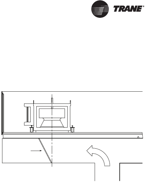
RT-SVX24K-EN 47
Installation
Roof Curb and Ductwork
The roof curbs for units consist of two main components;
a pedestal to support the unit condenser section and a“full
perimeter” enclosure to support the unit air handler
section.
Before installing any roof curb, verify;
1. That it is the correct curb for the unit,
2. That it includes the necessary gaskets and hardware
3. That the purposed installation location provides the
required clearance for proper operation.
4. ensure that the curb is level and square. The top
surface of the curb must be true to assure an adequate
curb-to-unit seal.
Step-by-step curb assembly and installation instructions
ship with eachTrane accessory roof curb kit. Follow the
instructions carefully to assure proper fit-up when the unit
is set into place.
Note: To assure proper condensate flow during
operation, the unit (and curb) must be as level as
possible.The maximum slope allowable for
rooftop unit applications, excluding Steam Heat
Units, is 4" end-to-end and 2" side-to-side. Units
with steam coils must be set level!
If the unit is elevated, a field constructed catwalk around
the unit is strongly recommended to provide easy access
for unit maintenance and service. Recommendations for
installing the Supply Air and Return Air ductwork joining
the roof curb are included in the curb instruction booklet.
Curb ductwork must be fabricated and installed by the
installing contractor before the unit is set into place.
Note: For sound consideration, cut only the holes in the
roof deck for the ductwork penetrations. Do not cut
out the entire roof deck within the curb perimeter.
Pitch Pocket Location
The location of the main supply power entry is located at
the bottom right-hand corner of the control panel.
Figure 16, p. 48 illustrates the location for the electrical
entrance through the base in order to enter the control
panel. If the power supply conduit penetrates the building
roof beneath this opening, it is recommended that a pitch
pocket be installed before the unit is placed onto the roof
curb.
The center line dimensions shown in the illustration below
indicates the center line of the electrical access hole in the
unit base when it is positioned on the curb, ±3/8 inch.The
actual diameter of the hole in the roof should be at least 1/
2 inch larger than the diameter of the conduit penetrating
the roof.This will allow for the clearance variable between
the roof curb rail and the unit base rail illustrated in
Figure 17, p. 48.
The pitch pocket dimensions listed are recommended to
enhance the application of roofing pitch after the unit is set
into place.The pitch pocket may need to be shifted as
illustrated to prevent interference with the curb pedestal.
If aTrane Curb Accessory Kit is not used:
a. The ductwork can be attached directly to the unit
bottom, around the unit supply and return air
openings. Be sure to use flexible duct connections
at the unit.
b. For “built-up” curbs supplied by others, gaskets
must be installed around the curb and the supply
and return air opening perimeters.
Notes:
•If a“built-up” curb is provided by others, it should NOT
be made of wood.
•If a “built-up” curb is provided by others, keep in mind
that these commercial rooftop units do not have base
pans in the condenser section.
•If this is a REPLACEMENT UNIT keep in mind that the
CURRENT DESIGN commercial rooftop units do not
have base pans in the condenser section.
Figure 15. Solid flow baffle wall installation for non-
Trane roof curbs
Return Fan
Roof Curb
Return Airflow
Flow Baffle
Return Airflow
Duct
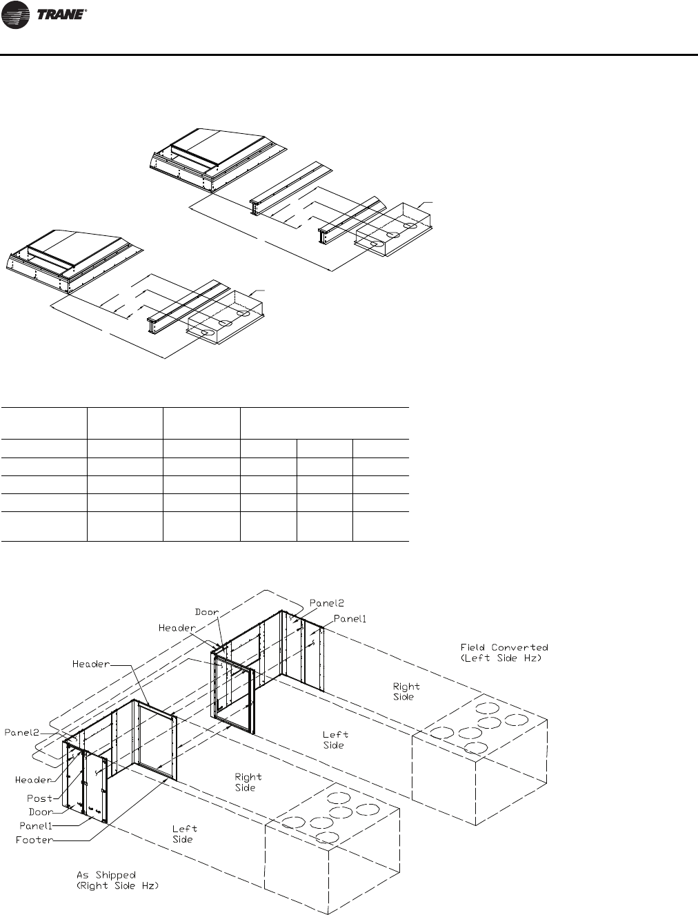
Installation
48 RT-SVX24K-EN
Figure 16. Pitch pocket location
B1
B2
B3
A2
B1
B2
B3
A1
Pitch Pocket
Pitch Pocket
Roof Curb
1Pc
Roof Curb
2Pc
Table 15. Pitch pocket dimensions (in.)
One-Piece Two/Three-
Piece One, Two, or Three-Piece
Tonnages A1 A2 B1 B2 B3
90 113.8 129.9±1 68.875 73.875 78.875
105 131.8 147.9±1 68.875 73.875 78.875
120,130,150 140.8 156.9±1 68.875 73.875 78.875
100,118,128,14
0,162 N/A 135.0±1 68.875 73.875 78.875
Figure 17. Ductwork conversion

Installation
RT-SVX24K-EN 49
Field Converting Horizontal Ductwork
(Supply or Return) from Right to the Left
Side
To field convert horizontal ductwork from right side to the
left, follow this procedure:
1. Remove Panel 2 from end of unit
2. Remove the Door and Door header from the left side.
3. Assemble Door header and Door removed from the left
side in the empty location on the end wall.
4. Remove Panel 1 and Post from the left side. Remove
gaskets from the base rail flange at the bottom.
5. Remove the top duct adapter, side duct adapters,
header, and footer in this order from the right side.
Remove gaskets from post side flanges and the base
rail flange at the bottom.
6. Assemble gaskets, header, footer, side duct adapters,
and top duct adapter in this order to the left side. See
Figure 17, p. 48 for gasket application details.
7. Finally assemble Post, gaskets, Panel 1, and Panel 2 in
this order to the right side to complete the field
conversion. See figure 14 for gasket application
details.
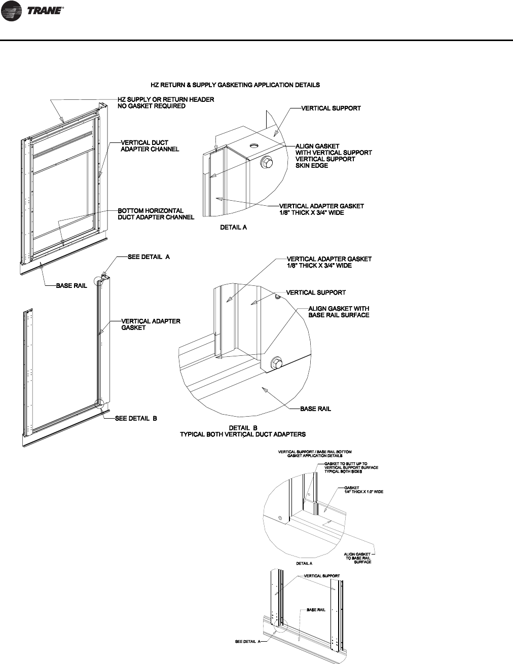
Installation
50 RT-SVX24K-EN
Figure 18. Ductwork conversion
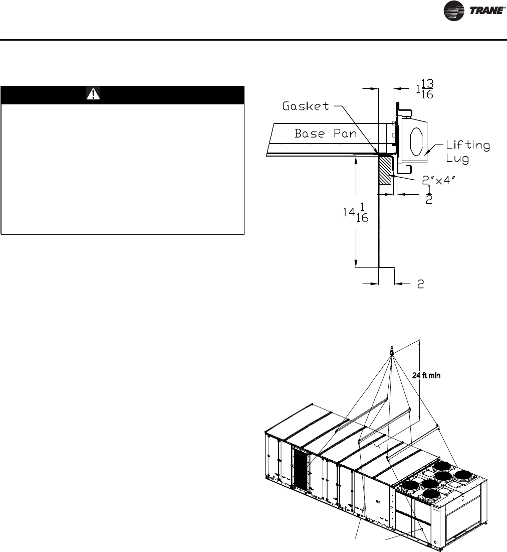
Installation
RT-SVX24K-EN 51
Unit Rigging and Placement
1. To configure the unit Center-of-Gravity, utilizeTOPSS
or contact the localTrane sales office.
2. Attach adequate strength lifting slings to all lifting lugs.
The figures beginning with Figure 20, p. 51 show the
minimum distance between the lifting hook and the
top of the unit and illustrate the installation of spreader
bars to protect the unit and to facilitate a uniform lift.
Table 12, p. 44 lists typical approximate minimal unit
operating weights.To determine additional
component weight, see Table 13, p. 44
3. Test lift the unit to ensure it is properly rigged and
balanced, make any necessary rigging adjustments.
4. Lift the unit and position it over the curb and pedestal.
(These units have a continuous base rail around the air
handler section which matches the curb.
5. Align the base rail of the unit air handler section with
the curb rail while lowering the unit onto the curb.
Make sure that the gasket on the curb is not damaged
while positioning the unit. (The pedestal simply
supports the unit condenser section)
A cross section of the juncture between the unit and the
roof curb is shown in Figure 19.
WARNING
Heavy Objects!
Ensure that all the lifting equipment used is properly
rated for the weight of the unit being lifted. Each of the
cables (chains or slings), hooks, and shackles used to
lift the unit must be capable of supporting the entire
weight of the unit. Lifting cables (chains or slings) may
not be of the same length. Adjust as necessary for even
unit lift. Other lifting arrangements could cause
equipment or property damage. Failure to follow
instructions above or properly lift unit could result in
unit dropping and possibly crushing operator/
technician which could result in death or serious injury.
Figure 19. Curb cross section
Figure 20. Typical unit rigging—one-piece unit with three
lifting lugs per side(a)
One piece unit with three
lifting lugs per side
Turnbuckle or
Chain Adjustment
for each lug
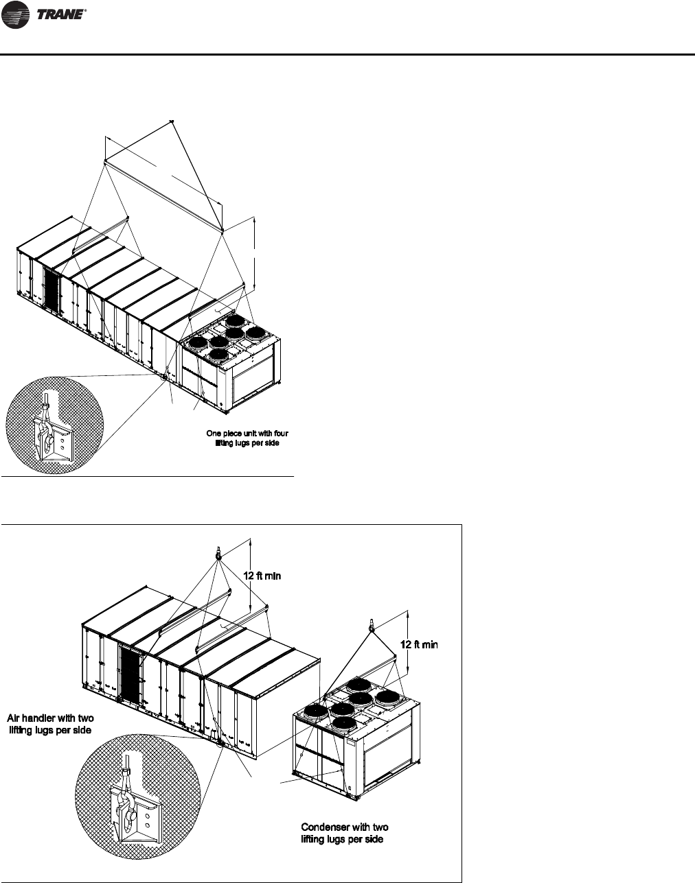
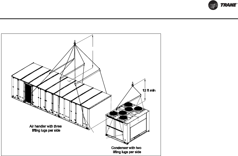
Installation
RT-SVX24K-EN 53
Figure 23. Typical unit rigging—two-piece unit with three lifting lugs per air handler side(a)
(a)Turnbuckle or Chain Adjustment required for each lifting point
24 ft min
Turnbuckle or
Chain Adjustment
for each lug
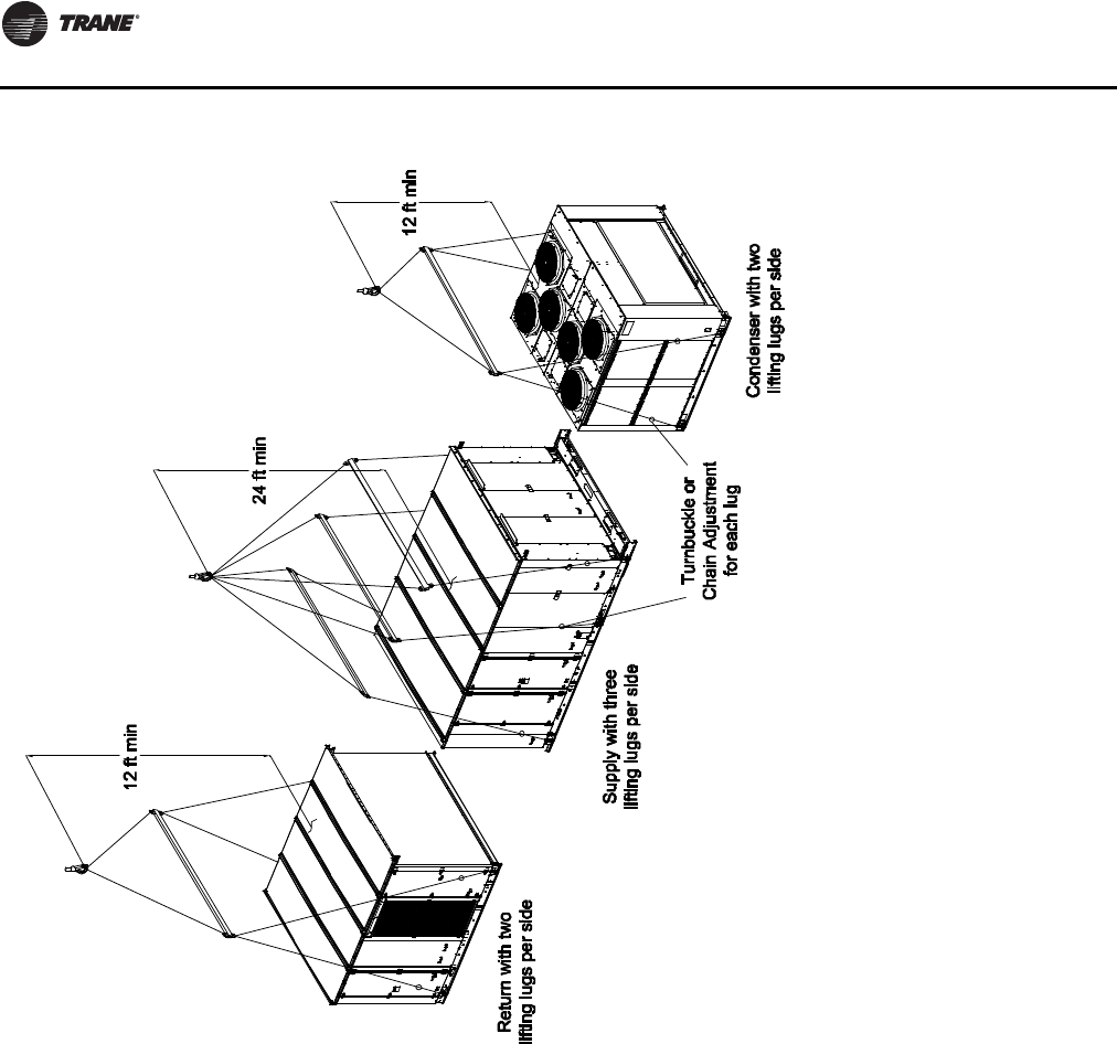
Installation
54 RT-SVX24K-EN
Figure 24. Typical unit rigging—three-piece unit
Air-Cooled and Evaporative Condensers—
Three-Piece Unit Fit Up
1. Rig and lift outside air section and evaporator section
separately.
2. Do not assemble unit on ground and attempt to lift to
roof. Unit must be assembled on roof curb.
3. Attach rail guide provided to bottom of the evaporator
base rails as shown with screws.
4. Rig and set the evaporator section onto the roof curb
(aligned with supply end).
5. Remove and discard shipping protection panels and
top block-offs from evaporator section.
6. Remove side panels and roof cap from evaporator
section and set aside to be assembled later.
7. Apply gasket to the base channel and butyl tape to the
base rail edge of the evaporator section.
8. Remove and discard shipping protection panels and
top block off from outside air section.
9. Rig and set outside air section onto roof curb using the
rail guides as an alignment aid. Outside air section
must be within 2.0" from the evaporator section.
10. Use 0.75" x 24" threaded rod, nuts, washers and
backing plate provided to pull and secure sections
together.This must be done using the lifting lugs at the
unit split as shown.
11. Use 0.375" bolts, nuts and washers provided to pull
and secure the roof rails together.This must be done
using the brackets on the roof rails as shown.
12. Attach roof splice plate to bottom side of roof panels at
the unit split with ¼" sheet metal screws.
13. Add bullwrap to electrical wiring.
14. Connect power and control wiring at the unit split.
Place power wiring connectors inside junction box.
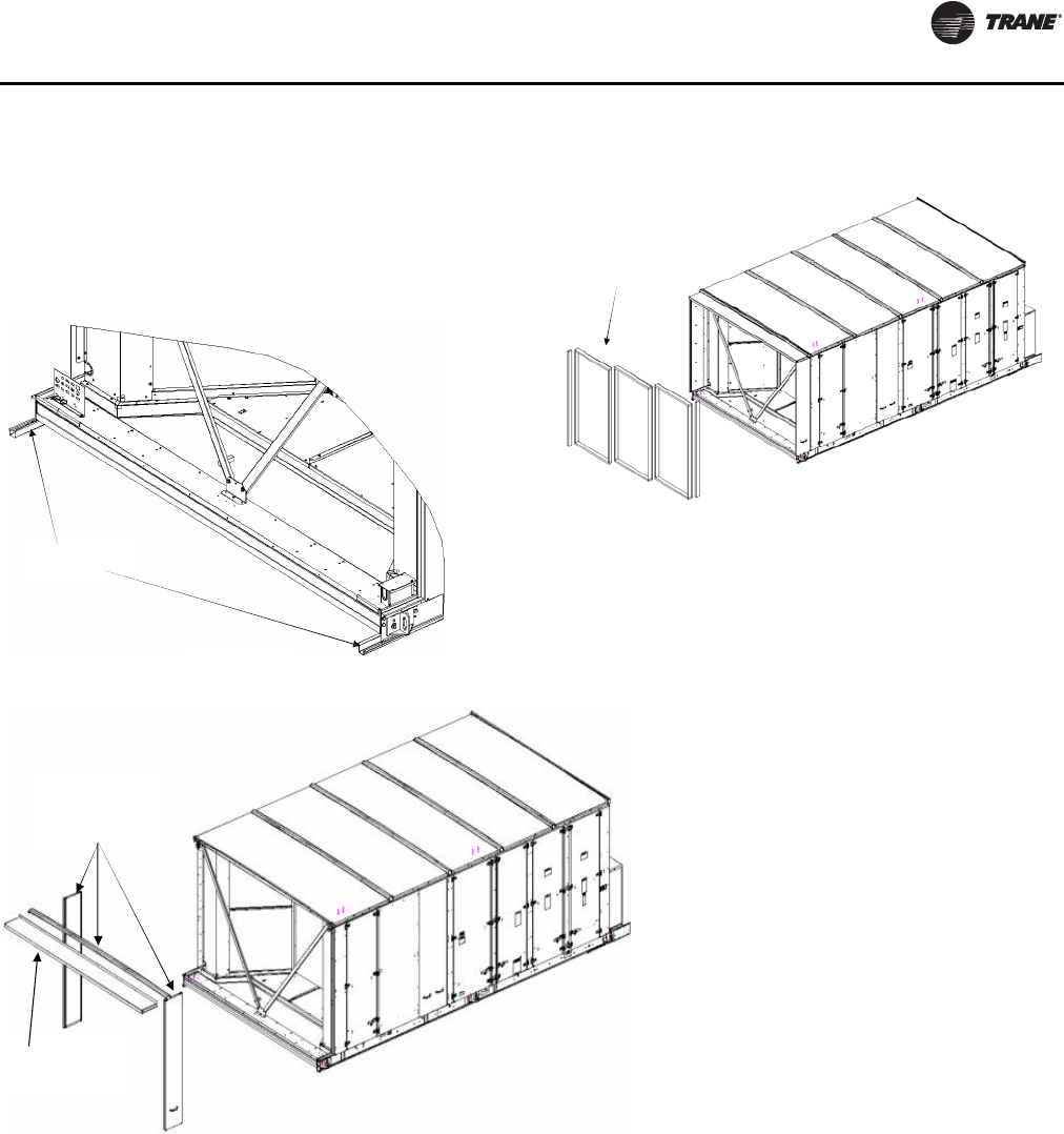
Installation
RT-SVX24K-EN 55
15. Apply gasket to side panels removed earlier. Attach
side panel to unit split.
16. Apply 1.25" butyl tape on top of unit split along the roof
seam.
17. Attach roof cap over roof seam and butyl tape with
screws
Figure 25. Rail guide locations
Attach rail guides
as shown
Figure 26. Evaporator section shipping protection
removal
Discard shipping
protection
Figure 27. Evaporator section side panel and roof cap removal
Save side panels
and roof cap for
reassembly
Discard shipping
protection
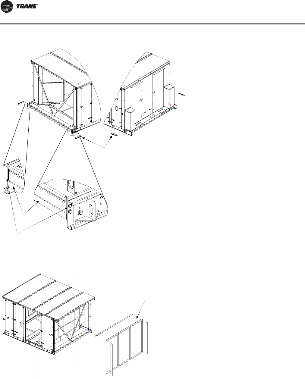
Installation
56 RT-SVX24K-EN
Figure 28. Evaporator section gasket locations
Rail guides
Gasket
Butyl Tape
Figure 29. Outside air section shipping protection removal
Discard shipping
protection
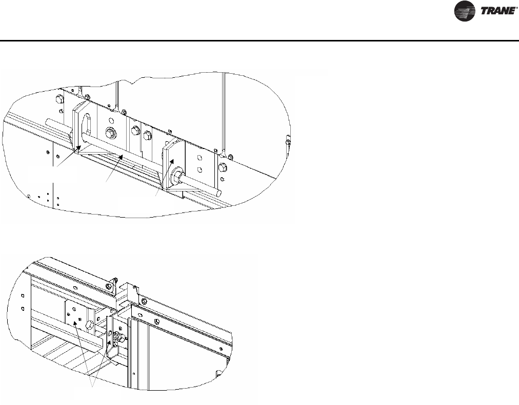
Installation
RT-SVX24K-EN 57
Figure 30. Base rail connection
Threaded rod
Lifting lug
Backing Plate
Figure 31. Roof rail connection
Brackets
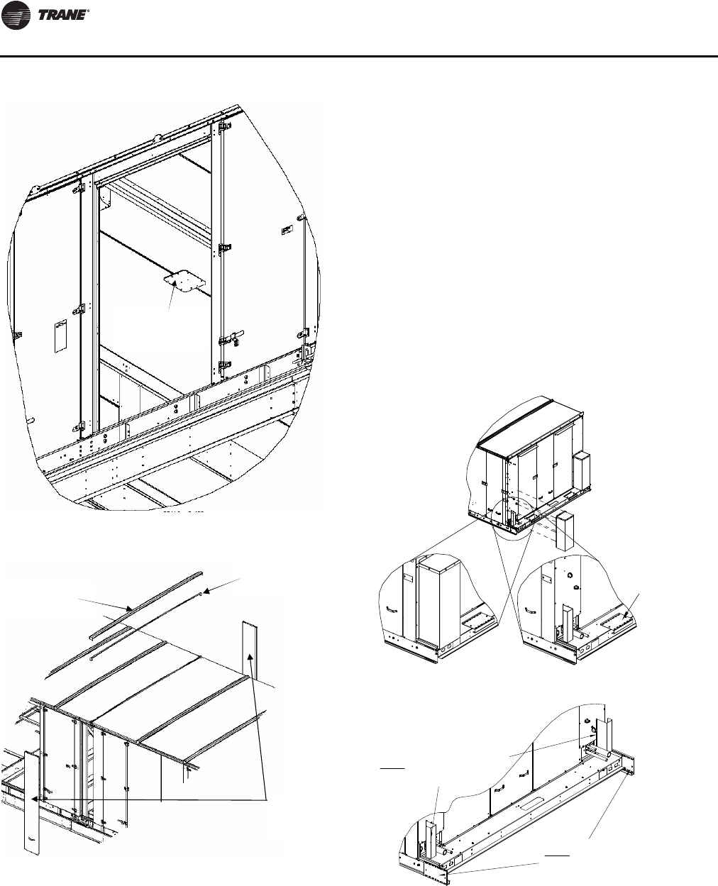
Installation
58 RT-SVX24K-EN
Air-Cooled and Evaporative Condensers—
Two-Piece Unit Fit Up
1. Rig the low side unit (Air handler) and the high side unit
(Condenser) separately.
2. First, rig and set the low side unit on the roof curb
(aligned with return end).
3. Take off and discard the protection boxes. (Do not
remove wire shields).
4. Remove the rail connector splice brackets and install
the brackets on the low side unit base rails.
5. Take off the side panels (these are labeled) and the top
cover of the high side unit and set aside to be
assembled later.
6. Rig and set the high side unit on roof curb pedestal,
using the rail splice bracket as an alignment aid to
connect the Low and high side units.The Low and high
side unit rails should be butted together with a
maximum 2" separation.
7. Remove the left upper and lower louvered panels and
the corner panels on each side to aid in tubing and
wiring connections.
Figure 32. Roof panel splice plate connection
Figure 33. Side panel and roofcap reinstallation
Apply splice plate to
bottom of roof
panels at unit split
Reinstall side
panels removed
earlier
Reinstall roof cap
removed earlier
Apply butyl tape
on unit split in roof
Figure 34. (1) Protection box removal/(2) rail connector
installation position
Note: Do not remove the
wiring shields
(2)
Note: Unscrew the rail connector
as shown in fig 1(b) and screw
back to these locations
(1)
(a) (b)
Rail connector
shipping position
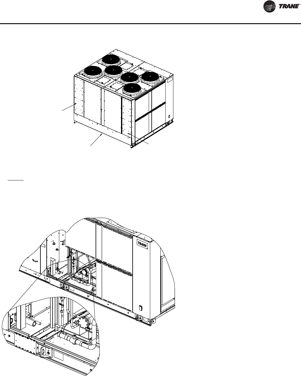
Installation
RT-SVX24K-EN 59
Figure 35. (3) Side and top filler panel removal/(4) high side installation preparation
Filler panel
shipping position
Top cover
shipping position
Filler panel
shipping position
Note: Remove the filler panels and top cover before putting the
Indoor and Outdoor sections together and screw to both Indoor
and Outdoor panels on each side as shown in fig (6). Finally the
top cover is assembled in space.
(3)
Unconnected tubes
(4)
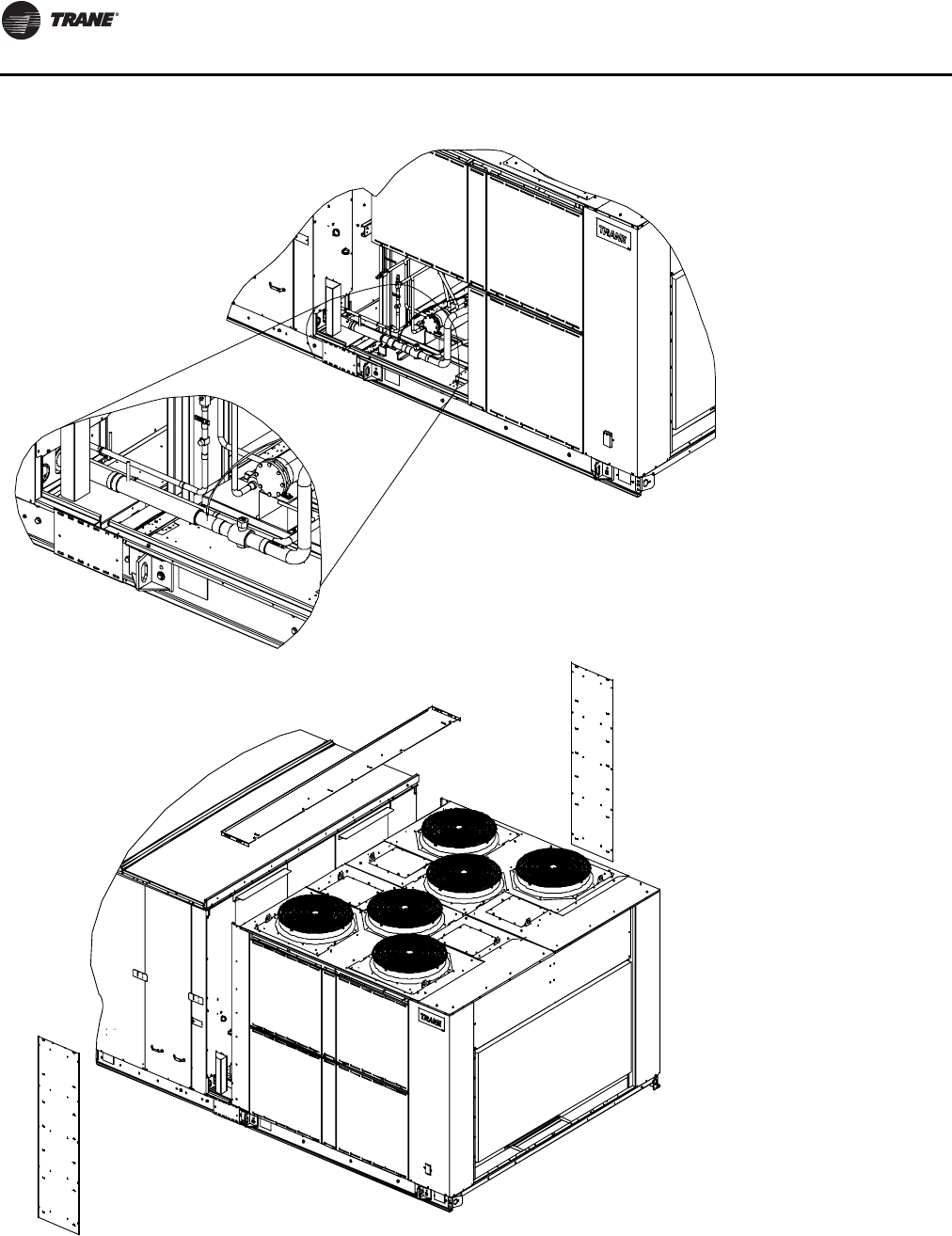
Installation
60 RT-SVX24K-EN
Figure 36. (5) Connected tubes/(6) install panels
Connected tubes
(5)
(6)
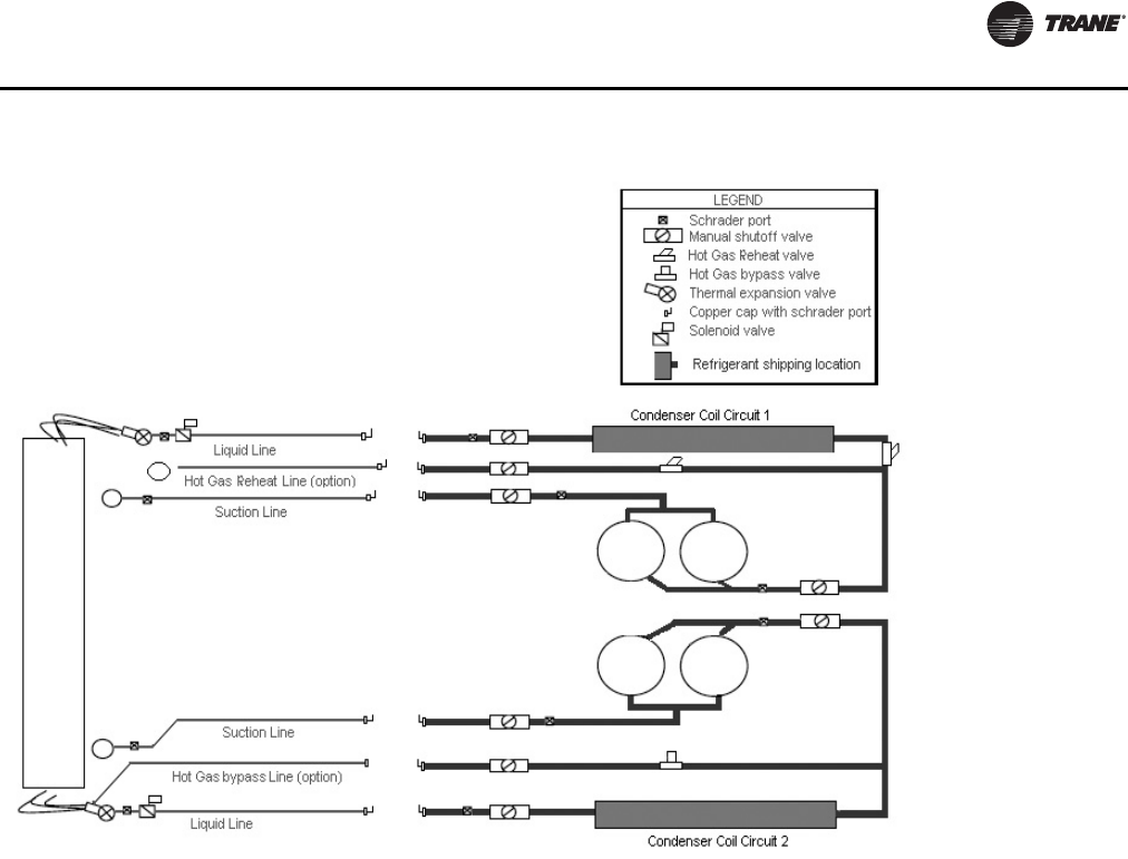
Installation
RT-SVX24K-EN 61
Complete Tubing and Wiring Connections
as follows:
Air-Cooled Tubing Connection
One piece Air Cooled units are shipped with refrigerant
throughout the entire tubing assemblies.
Two and three piece Air-Cooled low side and condenser
sections are shipped with a Nitrogen holding charge. All
service valves are shipped in an open position. Additional
interconnecting tubes (approx. 15-20” in length) will be
supplied with the unit.
Note: Field charging of 2 and 3 piece air-cooled units is
REQUIRED.
To prepare the two or three piece sections for joining
install pressure gauges to the appropriate access valve(s)
to verify nitrogen charge is present.
1. Relieve the pressure before attempting to unsweat the
“seal” caps.
2. Remove the brackets which support the suction tubes
(retain for possible use later for unit reassembly) after
the tubing connections are complete.
3. Place wet rags on the flow/ ball valve on the high side
when suction tubes are being brazed.
Note: Additional care should be taken when brazing near
the wire bundle.
4. Sweat the copper caps off both the high and low side
of the suction and liquid lines of both circuits. If present
also sweat off the copper caps from hot gas bypass or
hot gas reheat lines.
5. Clean the joints of weld puddles to avoid insertion
problems.
6. Cut the appropriate interconnecting tube to a length
approximately 0.75"- 1" more than the distance
between the two tubes.
7. Insert the appropriate tube to the complete depth of the
bell on one side of the joint and align the other
side(prying the high side may be needed). Make sure
the insertion depth is met.
8. Complete the connections by brazing the tubes in
place.
Note: Refrigeration ball valves are intended for general
service and are not a positive shutoff device.
9. Once all connections have been brazed, evacuate the
entire system.The recommended method for
evacuation and dehydration is to evacuate the system
to 500 microns or less.To establish that the unit is leak-
free, use a standing vacuum test.The maximum
allowable rise over a 15 minute period is 200 microns.
Figure 37. Charge evacuation diagram - evaporative condensers
Installation
62 RT-SVX24K-EN
If the rise exceeds this, there is either still moisture in
the system or a leak is present.
10. Charge the system per the unit nameplate field
charge.Do not add refrigerant in the suction line at this
time to prevent excessive refrigerant in the low side
prior to compressor startup.
11. At the liquid line angle valve add as much R-410A
LIQUID as possible. Depending on conditions, it could
not be possible to add more than 60% of the field
charge.This will be adequate for compressor
startup.More charge will be added after compressors
are started. Use an accurate scale to measure and
record the preliminary amount of R-410A added to
each circuit.
12. With all the circuit compressors operating, SLOWLY
meter R410-A into the suction line from the LIQUID
charging connection.
Evaporative Condenser Tubing Connection
Important: For units with electric heat, complete tubing
connections AFTER completing wiring
connections. See “Electric Heat Wiring
Connection” on page 63 section.
Important: Complete tubing connections BEFORE
Power and Control wiring connections. See
“Power and Control Wiring Connections”
on page 63 section.
There will be a N2nitrogen charge in the air handler
section.This holding charge should be relieved prior to
removing the caps.
The condenser section will ship with R-410A throughout
the entire tubing assemblies.The service valves will be
shipped in an open position. Additional interconnecting
tubes (approx. 15-20" in length) will be supplied with the
unit.
1. To prepare the condensing section for the joining of the
two sections, the discharge and liquid line service
valves should be shut and the refrigerant remaining
between the valves and the end caps should be
transferred/recovered.
2. If the unit has been purchased with hot gas bypass or
hot gas reheat options, those valves should be shut as
well and the refrigerant transferred/recovered from the
sections between the valves and the end caps.
3. Remove the brackets which support the suction tubes
(retain for possible use later for unit reassembly) after
the tubing connections are complete.
4. Relieve the pressure (charge) for the section of the
tubing being worked on.
5. Place wet rags on the flow/ ball valve on the high side
when suction tubes are being brazed.
Note: Additional care should be taken when brazing near
the wire bundle.
6. Sweat the copper caps off both the high and low side
of the suction and liquid lines of both circuits.
7. Clean the joints of weld puddles to avoid insertion
problems.
8. Cut the appropriate interconnecting tube to a length
approximately 0.75"- 1" more than the distance
between the two tubes.
9. Insert the appropriate tube to the complete depth of the
bell on one side of the joint and align the other side
(prying the high side may be needed). Make sure the
insertion depth is met.
10. Complete the connections by brazing the tubes in
place.
Note: Refrigeration ball valves are intended for general
service and are not a positive shutoff device.
11. Once all connections have been brazed, evacuate the
low side.The low side may be evacuated by the
schrader ports on the discharge line just past the
compressor and the liquid line below the sight glass.
See Figure 37, p. 61.
The recommended method for evacuation and
dehydration is to evacuate the low side to 500 microns
or less.To establish that the unit is leak-free, use a
standing vacuum test.The maximum allowable rise
over a 15 minute period is 200 microns. If the rise
exceeds this, there is either still moisture in the system
or a leak is present.
Note: Only after evacuation should the tagged valves be
opened.
WARNING
Hazard of Explosion and Deadly Gases!
Never solder, braze or weld on refrigerant lines or any
unit components that are above atmospheric pressure
or where refrigerant may be present. Always remove
refrigerant by following the guidelines established by
the EPA Federal Clean Air Act or other state or local
codes as appropriate. After refrigerant removal, use dry
nitrogen to bring system back to atmospheric pressure
before opening system for repairs. Mixtures of
refrigerants and air under pressure may become
combustible in the presence of an ignition source
leading to an explosion. Excessive heat from soldering,
brazing or welding with refrigerant vapors present can
form highly toxic gases and extremely corrosive acids.
Failure to follow all proper safe refrigerant handling
practices could result in death or serious injury.
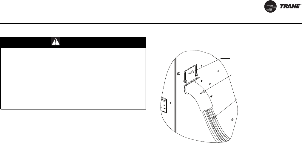
Installation
RT-SVX24K-EN 63
Electric Heat Wiring Connection
Important: For units with electric heat, complete tubing
connections AFTER completing wiring
connections. See “Tubing Connections”
section.
1. Cut and remove wire ties which hold the electric
control wires together, remove the shield bracket.
Leave the armaflex on the hole with the control wires.
2. Cut the lowest wire tie which holds the electric heat
power wires to the vertical post on the high side.
3. Route the power wires one by one in to the hole on the
low side end panel and connect them to the terminal
block inside the electric Junction Box or inside the
extended casing section.
Note: For 8' extended casing units, remove the panel (this
panel weighs approximately 60 pounds) next to the
corner post in the low side to locate the terminal
block.
4. Bundle the electric heat power and control wires with
armaflex wrap on the low side end of the unit. Screw
the shield bracket to compress the wire bundle and
create a good seal. Figure 39, p. 64
5. Route the electric heat control wires to the Junction
box located on the high side. Figure 39, p. 64
Power and Control Wiring Connections
Note: Complete Power and Control Wiring Connections
after the tubing connections are complete.
1. Discard the clamps and the wire shield which hold the
power and control wires.
2. Make the power and the control wire connections and
route the wires such that they route straight from the
hole at the bottom of the air handler, turn at right
angles and straight up through the bottom of the high
voltage junction box on the condenser side. Figure 39,
p. 64
3. Assemble the louvered panels and the corner panels in
the condenser side back in place.
4. Screw the side panels to both the air handler and
condenser side panels to act as filler panels.
5. Finally, assemble the top cover back in place.
WARNING
Proper Field Wiring and Grounding
Required!
All field wiring MUST be performed by qualified
personnel. Improperly installed and grounded field
wiring poses FIRE and ELECTROCUTION hazards.To
avoid these hazards, you MUST follow requirements for
field wiring installation and grounding as described in
NEC and your local/state electrical codes. Failure to
follow code could result in death or serious injury.
Figure 38. Wire routing at low side end wall
Rain Shield Bracket
Armaflex with
Wire Ties
Electric Heat Powe
r
and Control Wires
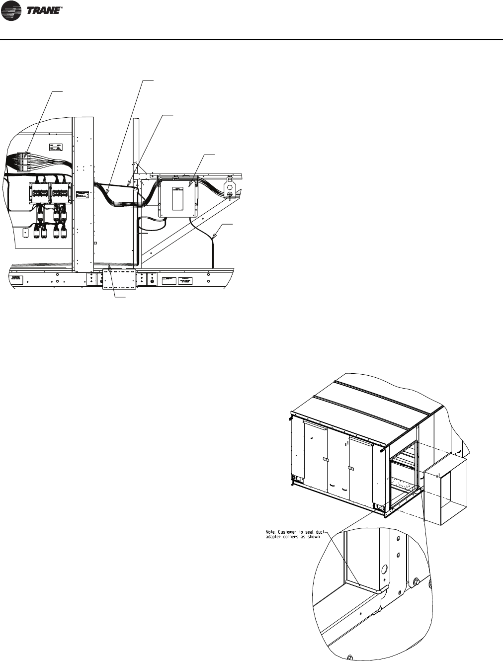
Installation
64 RT-SVX24K-EN
General Unit Requirements
The checklist below is a summary of the steps required to
successfully install a Commercial rooftop unit.This
checklist is intended to acquaint the installing personnel
with what is required in the installation process. It does not
replace the detailed instructions called out in the
applicable sections of this manual.
[ ] Check the unit for shipping damage and material
shortage; file a freight claim and notifyTrane office.
[ ] Verify that the installation location of the unit will
provide the required clearance for proper operation.
[ ] Assemble and install the roof curb. Refer to the
current edition of the roof curb installer’s guide.
[ ] Fabricate and install ductwork; secure ductwork to
curb. Seal the corners of duct adapters as shown in
Figure 41, p. 66. Ducting attached to the unit should be
self supporting. Do not use the unit to support the
weight of the ducting
[ ] Install pitch pocket for power supply through
building roof. (If applicable)
Figure 39. Wire routing and connections
Electric Heat Power Wires - Routed through the hole
at the air handler side end wall. Route wires one by one
and connect to the electric heat terminal block.
Electric Heat Control Wires - Routed through
the hole at the air handler side end wall. Remove
wire ties at hole area to improve power wire
routing. Terminate at high voltage junction box.
High Voltage Junction Box
Motor Power Wires are routed through the bottom opening and
terminated at high voltage junction box. Control wires on the right
side of unit have similar routing.
Motor Power Wires and Heater
Control Wires from the main
control box will be terminated at
the high voltage junction box by
the factory.
Electric Heat
Terminal Block
Figure 40. Sealed ductwork

Installation
RT-SVX24K-EN 65
Rigging the Unit
[ ] Set the unit onto the curb; check for levelness.
[ ] Ensure unit-to-curb seal is tight and without buckles
or cracks.
[ ] Install and connect condensate drain lines to each
evaporator drain connection.
[ ] Remove the shipping hardware from each
compressor assembly.
[ ] Remove the shipping hold-down bolts and shipping
channels from the supply and exhaust fans with spring
isolators.
[ ] Check all supply and exhaust fan spring isolators for
proper adjustment.
[ ]Verify that all plastic coverings are removed from the
compressors.
[ ] Verify all discharge and liquid line service valves
(one per circuit) are back seated.
Main Electrical Power Requirements
[ ] Verify that the power supply complies with the unit
nameplate specifications.
[ ] Inspect all control panel components; tighten any
loose connections.
[ ] Connect properly sized and protected power supply
wiring to a field-supplied/installed disconnect and unit
[ ] Properly ground the unit.
All field-installed wiring must comply with NEC and
applicable local codes.
Field Installed Control Wiring
[ ] Complete the field wiring connections for the
constant volume controls as applicable. Refer to “Field
Installed Control Wiring” for guidelines.
[ ] Complete the field wiring connections for the
variable air volume controls as applicable. Refer to
“Field Installed Control Wiring” for guidelines.
Note: All field-installed wiring must comply with NEC
and applicable local codes.
Requirements for Electric Heat Units
[ ] Verify that the power supply complies with the
electric heater specifications on the unit and heater
nameplate.
[ ] Inspect the heater junction box and control panel;
tighten any loose connections.
[ ] Check electric heat circuits for continuity.
Requirement for Gas Heat
[ ] Gas supply line properly sized and connected to the
unit gas train.
[ ] All gas piping joints properly sealed.
[ ] Drip leg Installed in the gas piping near the unit.
[ ] Gas piping leak checked with a soap solution. If
piping connections to the unit are complete, do not
pressurize piping in excess of 0.50 psig or 14 inches
w.c. to prevent component failure.
[ ] Main supply gas pressure adequate.
[ ] FlueTubes clear of any obstructions.
[ ] Factory-supplied flue assembly installed on the unit.
[ ] Connect the 3/4" CPVC furnace drain stubout to a
proper condensate drain. Provide heat tape or
insulation for condensate drain as needed.
Requirements for Hot Water Heat
[ ] Route properly sized water piping through the base
of the unit into the heating section.
[ ] Install the factory-supplied, 3-way modulating valve.
[ ] Complete the valve actuator wiring.
Requirements for Steam Heat
[ ] Route properly sized steam piping through the base
of the unit into the heating section.
[ ] Install the factory-supplied, 2-way modulating valve
[ ] Complete the valve actuator wiring.
[ ] Install 1/2", 15-degree swing-check vacuum
breaker(s) at the top of each coil section. Vent
breaker(s) to the atmosphere or merge with return
main at discharge side of steam trap.
[ ] Position the steam trap discharge at least 12" below
the outlet connection on the coil.
[ ] Use float and thermostatic traps in the system, as
required by the application.
O/A Pressure Sensor andTubing
Installation
(All VAV units and all units with Statitrac)
Figure 44, p. 68
• O/A pressure sensor mounted to the roof bracket.
• Factory supplied pneumatic tubing installed between
the O/A pressure sensor and the connector on the
vertical support.
• Field supplied pneumatic tubing connected to the
proper fitting on the space pressure transducer located
in the filter section, and the other end routed to a
suitable sensing location within the controlled space.
Condensate Drain Connections
Each unit provides two 1-1/4" evaporator drain
connections on each side of the unit.
Due to the size of these units, all condensate drain
connections must be connected to the evaporator drain
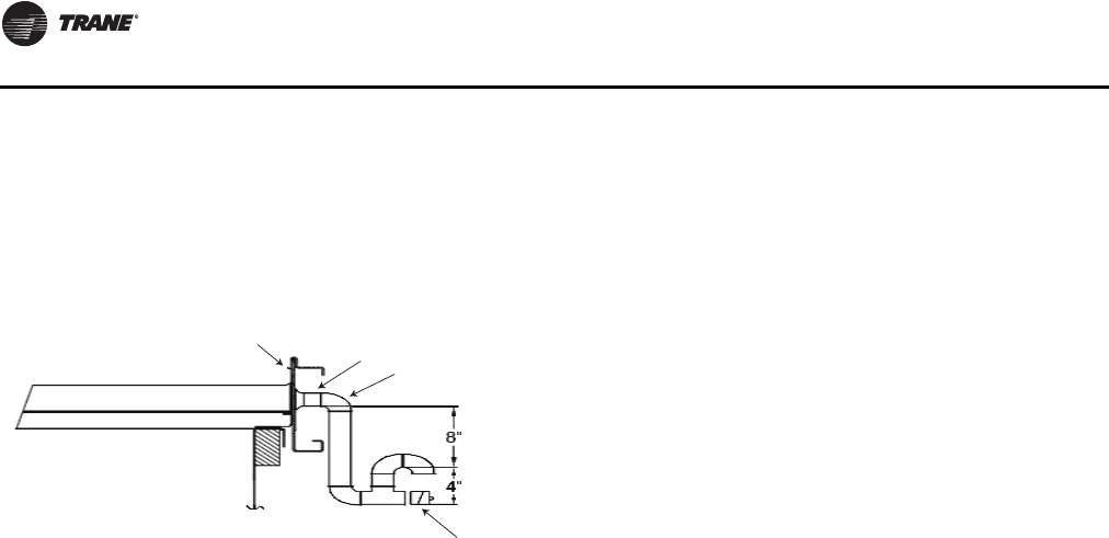
Installation
66 RT-SVX24K-EN
connections. Refer to Detail A in Figure 12, p. 25 for the
location of these drain connections.
A condensate trap must be installed due to the drain
connection being on the “negative pressure” side of the
fan. Install the P-Traps at the unit using the guidelines in
Figure 41.
Pitch the drain lines at least 1/2 inch for every 10 feet of
horizontal run to assure proper condensate flow. Do not
allow the horizontal run to sag causing a possible double-
trap condition which could result in condensate backup
due to “air lock”.
Units with Gas Furnace
Units equipped with a gas furnace have a 3/4" CPVC drain
connection stubbed out through the vertical support in the
gas heat section. It is extremely important that the
condensate be piped to a proper drain. Refer to the
appropriate illustration in Figure 49, p. 73 for the location
of the drain connection.
Note: Units equipped with an optional modulating gas
furnace will likely operate in a condensing mode
part of the time.
Ensure that all condensate drain line installations comply
with applicable building and waste disposal codes.
Note: Installation on gas heat units will require addition
of heat tape to the condensate drain.
Removing Compressor Assembly
Shipping Hardware
Each manifolded compressor assembly is rigidly bolted to
a mounting rail assembly.The rail assembly is set on six
(6) rubber isolators.The assembly is held in place by six (6)
shipping “Tiedown” bolts.To remove the shipping
hardware, follow the procedures below:
1. Remove the bolt in each rubber isolator and the slotted
shipping spacer located between the compressor rails
and the unit base rail illustrated in Figure 43, p. 67.
Reinstall the bolts at the same location by screwing
them into the base rail two to three turns only.
2. Ensure that the compressor rail assembly is free to
move on the rubber isolator.
Removing Supply and Exhaust Fan
Shipping Channels
Each supply fan assembly and exhaust fan assembly is
equipped with spring isolators. Shipping channels are
installed beneath each fan assembly and must be
removed.To locate and remove these channels, refer to
Figure 42, p. 67 and use the following procedures.
Spring Isolators
Spring isolators for the supply and/or exhaust fan are
shipped with the isolator adjusting bolt backed out. Field
adjustment is required for proper operation. Figure 42,
p. 67 shows isolator locations.To adjust the spring
isolators use the following procedure.
1. Remove and discard the shipping tie down bolts but
leave the shipping channels in place during the
adjustment procedure. See Figure 42, p. 67.
2. Tighten the leveling bolt on each isolator until the fan
assembly is approximately 1/4" above each shipping
channel.
3. Secure the lock nut on each isolator.
4. Remove the shipping channels and discard.
Remove Evaporative Condenser Fan
Shipping Brackets
To remove shipping brackets
Important: Remove fan shipping brackets before
startup. Failure to remove brackets could
result in fan damage.
Evaporative condensers are shipped with fan shipping
brackets to reduce damage caused by vibration during
shipment.The fan shipping brackets must be removed
prior to unit startup.
To remove the shipping brackets start from the side
opposite to the drain actuator
(see Figure 113, p. 164):
1. Loosen the screw for the bracket that holds the inlet
louvers below the door side.
2. Remove inlet louvers and set to the side.
Note: Service technician may need to step on the
horizontal surface of FRP coated base.
Step with care.
3. Unscrew the bolt in the middle of the door. Keep the
bolt in a safe place.
4. Lift one door with handle until it touches the top.
Swivel bottom of door to remove it from the door
opening and set it to the side.
5. Slide and remove the middle mist eliminator section
so that the shipping bracket is visible.
Figure 41. Condensate trap installation
1-1/4” NPT
female connection
Field supplied
condensate piping
Cleanout plug
Base rail
Note: Negative static pressure in coil section.
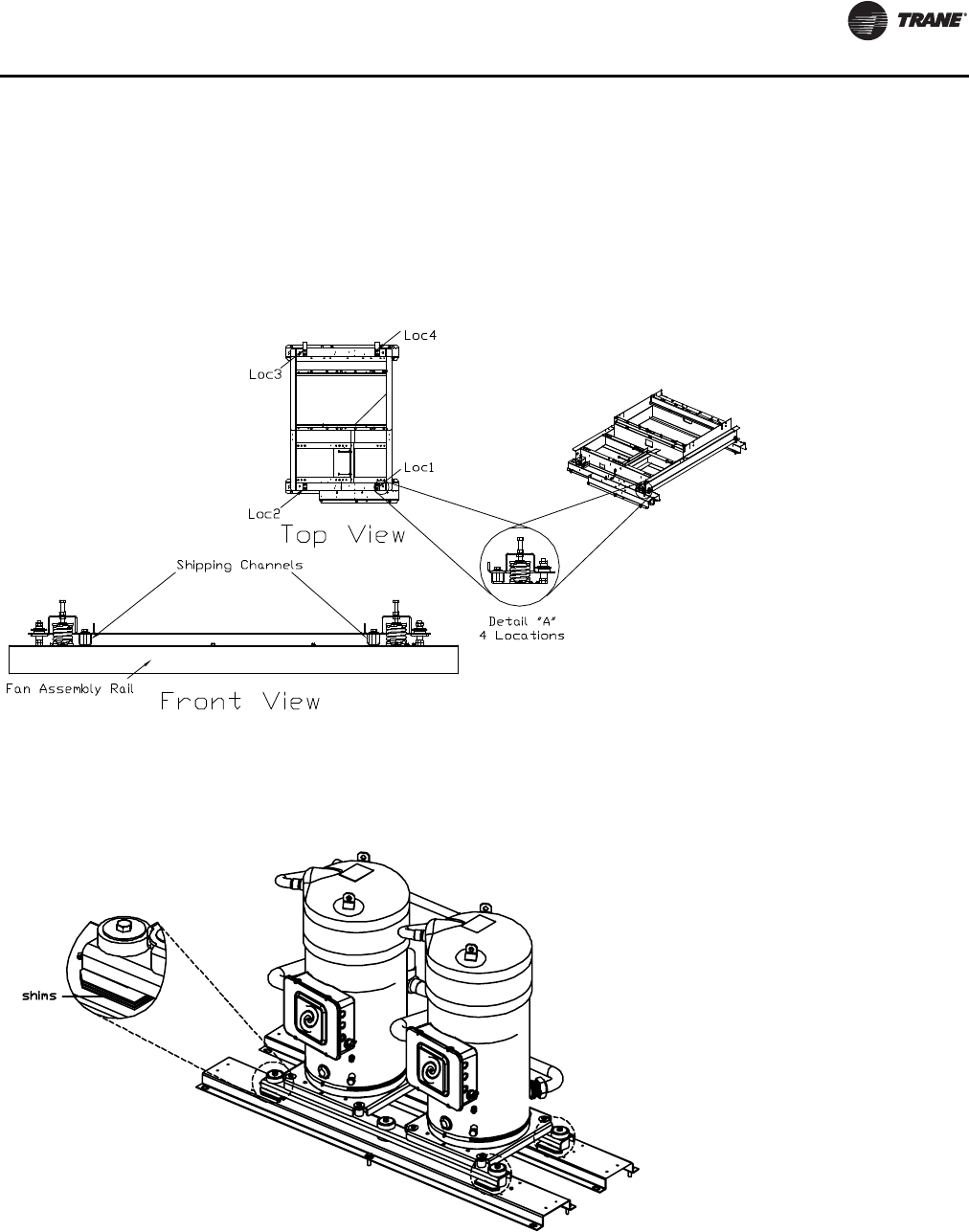
Installation
RT-SVX24K-EN 67
6. Use screw gun to unscrew the two screws that hold the
fan shipping bracket.The bracket should drop down
but still remain engaged with a hook on the bracket.
7. Go to the other side of the unit and follow the
procedure for inlet louver and door removal
(see steps1-6
).
8. Hold the bracket with one hand and remove remaining
two screws.
9. Remove the bracket and all the removed screws from
the unit.
Important: Make sure there are no screws remaining in
the coil area.
10. Reinstall inlet louvers, mist eliminators and louvers.
11. Check that the direction of arrow on the inlet louver is
correct.
Figure 42. Removing fan assembly shipping hardware
Figure 43. Removing compressor shipping hardware
Note:
Shims are located in the center, and on
the four corners, of each set of
compressors.
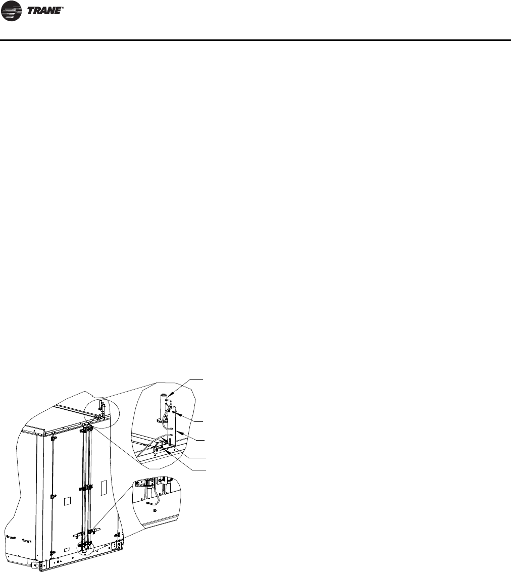
Installation
68 RT-SVX24K-EN
O/A Sensor and Tubing Installation
An Outside Air Pressure Sensor is shipped with all units
designed to operate on variable air volume applications or
constant volume units with 100% modulating exhaust w/
Statitrac.
On VAV systems, a duct pressure transducer and the
outside air sensor is used to control the discharge duct
static pressure to within a customer-specified parameter.
On CV & VAV units equipped with 100% modulating
exhaust w/Statitrac, a space pressure transducer and the
outside air sensor is used to control the exhaust fan and
dampers to relieve static pressure, to within a customer-
specified parameter, within the controlled space. Refer to
Figure 44, p. 68 and the following steps to install the
sensor and the pneumatic tubing.
1. Remove the O/A pressure sensor kit located inside the
“ship with” item container.The kit contains the
following items:
a. O/A static pressure sensor with slotted mounting
bracket
b. 50 ft. 0.188 in tubing
c. Mounting hardware
2. Remove the two roof cap screws and install the
provided L mounting bracket as shown in the figure.
3. Place the sensor mounting slotted bracket to the L
mounting bracket with the slot located to the top.
4. Install the sensor vertically to the slotted bracket and
secure it with provided bolt and nut.
5. Connect one end of factory provided tubing to the top
port of sensor and pass it through the two slots in the
mount and the other end to the port in the base.
6. Secure the tubing with the mounting hardware located
in the ship with item container.
Units with Statitrac:
1. Open the filter access door, and locate the Space
Pressure and Duct Supply Pressure control devices
illustrated in Figure 45, p. 69.There are three tube
connectors mounted on the left of the solenoid and
transducers. Connect one end of the field provided1/4"
(length 50-100 ft.) or 3/8" (length greater than 100 ft.)
O.D. pneumatic tubing for the space pressurization
control to the bottom fitting.
2. Route the opposite end of the tubing to a suitable
location inside the building.This location should be
the largest open area that will not be affected by
sudden static pressure changes.
Figure 44. Outside air sensing kit
Sensor
Sensor mounting
slotted bracket
0.188in OD tubing
L bracket
Sensor mounting
screws
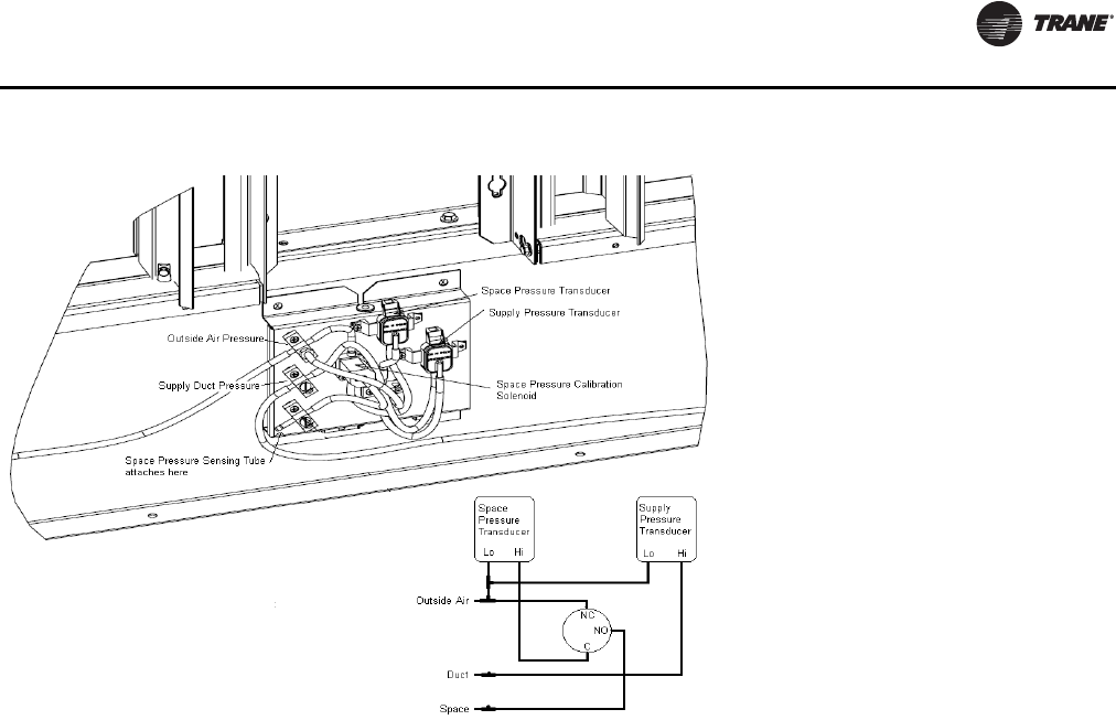
Installation
RT-SVX24K-EN 69
Evaporative-Cooled Condenser Make-up
Water and Drain Line Installation
Make-up Water and Drain Lines
Water Supply Source
The supply line should be designed to provide a minimum
supply of water within customary domestic supply
pressures, 35 to 60 psig; dynamic pressure (measured
with the valve open) which will allow approximately 30
GPM to enter the sump through the makeup water valve,
when the sump is empty.The unit uses about 2-4 GPM.
Attach a hand valve at the inlet for use during inspection
and maintenance; an inlet strainer is recommended as
well. Make-up water inlet connection is a ¾" PVC slip
connector. Care must be taken to ensure the water line
upstream of the water solenoid valve will not freeze.
Insulating the line and utilizing heat tape is recommended
if ambient temperatures below 32° F are expected.
Water Quality
Overall performance of any water-cooled device can be
affected by suspended particulates, mineral
concentration, trash and debris resulting in clogging and
heat transfer loss.The evaporative-cooled condenser is
designed to greatly minimize problems with these
impurities.
However, float valves and solenoid valves are used to
control the incoming water. If the incoming water contains
contaminants, sand or other objects, an incoming line
strainer with a 80 to 100 mesh screen is required.The inlet
line should be flushed prior to connection to the unit,
whether or not there is a strainer.
Note: Backflow preventer is field installed and should
only be installed by qualified personnel .
Water Drain Schedule 80 PVC pipe of 1¼" is normally
adequate for sump water drain. Periodically, the sump is
emptied and flushed to eliminate accumulated dirt, debris,
and minerals. Concentration of these foreign substances
will increase as the system operates.
The evaporative process releases essentially pure water
vapor into the atmosphere, leaving the impurities behind
that accumulate in the sump. Although these impurities
are present in the original make-up water, their
concentration will be higher in the sump discharge. Care
and judgment should be exercised when selecting a
discharge site.
Local Site Discharge
Rooftop or simple storm sewer discharge is generally
acceptable. Do not routinely direct the sump discharge
onto an area where these higher concentrations will
adversely affect that area, i.e. continued sump discharge
into a flower bed for example, where the input water
contains CaCO3 (lime) will eventually decrease the pH of
the soil.
Sewer Discharge
The quantities of mineral and debris flushed are actually
very small, and do not cause problems when diluted in
normal sewer flow. However, local, state or federal
standards and restrictions must be followed in any given
locality.
Figure 45. Space pressure and duct supply pressure tubing schematic
Installation
70 RT-SVX24K-EN
Make Up Water Solenoid Valve
This valve is controlled by the UCM based on water level
in the sump, as well as whether a call for mechanical
cooling exists. During low ambient temperatures, the
solenoid valve will be de-energized preventing water from
further filling sump.The sump drain valve opens to empty
sump of water. Operation can be extended to 10 deg by
providing an optional sump heater.
Drain Valve
The drain valve is shipped to “drain during power loss
conditions”. If “hold during power loss conditions” is
desired, refer to “Evaporative Condenser Drain Valve
Setup” on page 100
Gas Heat Units
All internal gas piping is factory-installed and pressure
leak-tested before shipment. Once the unit is set into
place, the gas supply line must be field-connected to the
elbow located inside the gas heat control compartments.
Access holes are provided on the unit as illustrated in
Figure 49, p. 73 to accommodate a side or bottom pipe
entry. Following the guidelines listed below will enhance
both the installation and operation of the furnace.
Note: In the absence of local codes, the installation must
conform with the American National Standard
Z223-1a of the National Fuel Gas Code, (latest
edition).
3. To assure sufficient gas pressure at the unit, use
Table 16, p. 71 as a guide to determine the appropriate
gas pipe size for the unit heating capacity listed on the
unit nameplate.
4. If a gas line already exists, verify that it is sized large
enough to handle the additional furnace capacity
before connecting to it.
5. Take all branch piping from any main gas line from the
top at 90 degrees or at 45 degrees to prevent moisture
from being drawn in with the gas.
6. Ensure that all piping connections are adequately
coated with joint sealant and properly tightened. Use a
piping compound that is resistant to liquid petroleum
gases.
7. Provide a drip leg near the unit.
8. Install a pressure regulator at the unit that is adequate
to maintain 7" w.c. for natural gas while the furnace is
operating at full capacity.
Note: Gas pressure in excess of 14" w.c. or 0.5 psig will
damage the gas train.
Failure to use a pressure regulating device will result in
incorrect gas pressure.This can cause erratic operation
due to gas pressure fluctuations as well as damage the gas
valve. Over sizing the regulator will cause irregular
pulsating flame patterns, burner rumble, potential flame
outages, and possible gas valve damage.
If a single pressure regulator serves more than one rooftop
unit, it must be sized to ensure that the inlet gas pressure
does not fall below 7" w.c. with all the furnaces operating
at full capacity.The gas pressure must not exceed 14" w.c.
when the furnaces are off.
9. Provide adequate support for all field installed gas
piping to avoid stressing the gas train and controls.
10. Leak test the gas supply line using a soap-and-water
solution or equivalent before connecting it to the gas
train.
11. Check the supply pressure before connecting it to the
unit to prevent possible gas valve damage and the
unsafe operating conditions that will result.
Note: Do not rely on the gas train shutoff valves to isolate
the unit while conducting gas pressure/leak test.
These valves are not designed to withstand
pressures in excess of 14" w.c. or 0.5 psig.
Connecting the Gas Supply Line to the
Furnace Gas Train
Follow the steps below to complete the installation
between the supply gas line and the furnace. Refer to
Figure 46, p. 71,Figure 47, p. 72 for the appropriate gas
train configuration.
1. Connect the supply gas piping using a “ground-joint”
type union to the furnace gas train and check for leaks.
2. Adjust the inlet supply pressure to the recommended
7" to 14" w.c. parameter for natural gas
3. Ensure that the piping is adequately supported to
avoid gas train stress.
4. If the through the base gas opening is used, seal off
around the pipe and the 3" water dam. If the through
the base gas opening is not used, the 3" opening
should be sealed shut to prevent indoor air leakage.
WARNING
Hazardous Gases and Flammable Vapors!
Exposure to hazardous gases from fuel substances
have been shown to cause cancer, birth defects or other
reproductive harm. Improper installation, adjustment,
alteration, service or use of this product could cause
flammable mixtures and result in a fire. To avoid
hazardous gases and flammable vapors follow proper
installation and set up of this product and all warnings
as provided in this manual. Failure to follow all
instructions could result in death or serious injury.
When using dry nitrogen cylinders for pressurizing
units for leak testing, always provide a pressure
regulator on the cylinder to prevent excessively high
unit pressures. Never pressurize unit above the
maximum recommended unit test pressure as specified
in applicable unit literature. Failure to properly regulate
pressure could result in a violent explosion, which
could result in death or serious injury or equipment or
property-only-damage.
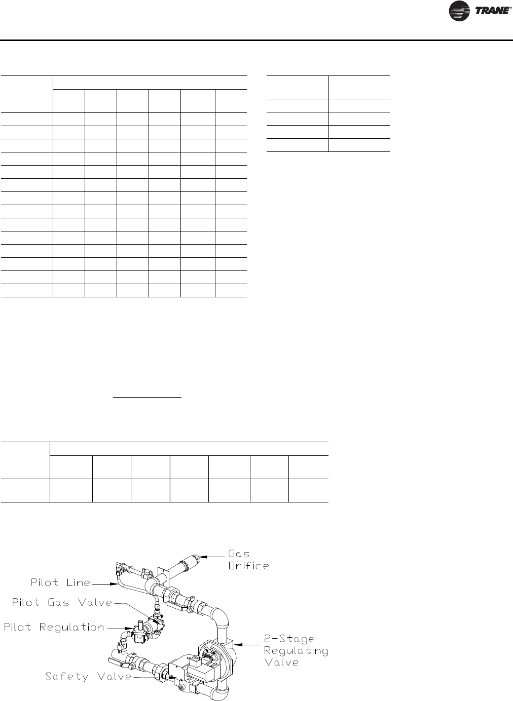
Installation
RT-SVX24K-EN 71
Table 16. Sizing natural gas pipe mains and branches
Gas Supply
Pipe Run
(ft)
Gas Input (Cubic Feet/Hour)*
1¼"
Pipe 1½"
Pipe 2"
Pipe 2½"
Pipe 3"
Pipe 4"
Pipe
10 1050 1600 3050 4800 8500 17500
20 730 1100 2100 3300 5900 12000
30 590 890 1650 2700 4700 9700
40 500 760 1450 2300 4100 8300
50 440 670 1270 2000 3600 7400
60 400 610 1150 1850 3250 6800
70 370 560 1050 1700 3000 6200
80 350 530 990 1600 2800 5800
90 320 490 930 1500 2600 5400
100 305 460 870 1400 2500 5100
125 275 410 780 1250 2200 4500
150 250 380 710 1130 2000 4100
175 225 350 650 1050 1850 3800
200 210 320 610 980 1700 3500
Notes:
1. *Table is based on a specific gravity of 0.60. Use Table 17, p. 71 for
the specific gravity of the local gas supply.
2. If more than one unit is served by the same main gas supply,
consider the total gas input (cubic feet/hr.) and the total length when
determining the appropriate gas pipe size.
3. Obtain the Specific Gravity and BTU/Cu.Ft. from the gas company.
4. The following example demonstrates the considerations necessary
when determining the actual pipe size:
Example: A 40' pipe run is needed to connect a unit with a 850 MBH
furnace to a natural gas supply having a rating of 1,000 BTU/Cu.Ft.
and a specific gravity of 0.60
Cu.Ft/Hour = Furnace MBH Input
Gas BTU/Cu.Ft. X Multiplier Table 17, p. 71
Cu.Ft/Hour = 850
Table 16, p. 71 indicates that a 2" pipe is required.
Table 17. Specific gravity multipliers
Specific
Gravity Multiplier
0.50 1.10
0.55 1.04
0.60 1.00
0.65 0.96
Table 18. Gas heating capacity altitude correction factors
Altitude (Ft.)
Sea Level
To 2000 2001 to
2500 2501 to
3500 3501 to
4500 4501 to
5500 5501 to
6500 6501 to
7500
Capacity
Multiplier 1.00 .92 .88 .84 .80 .76 .72
Note: Correction factors are per AGA Std. 221.30 - 1964, Part VI, 6.12. Local codes may supersede.
Figure 46. Two-stage natural gas train for 850, 1100 Mbh heaters
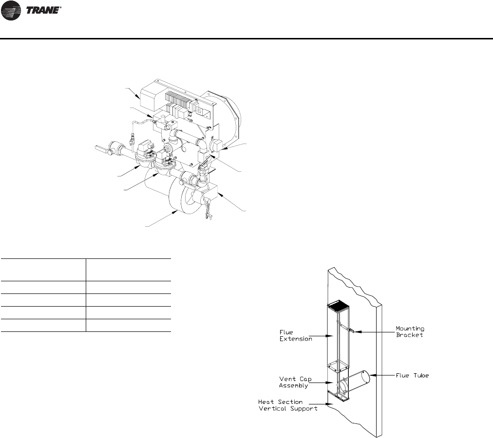
Installation
72 RT-SVX24K-EN
Flue Assembly Installation
1. Locate the collapsed flue assembly in the
compartment above the gas heat controls by removing
the panel screws.The assembly is secured by screws
up through the roof of the gas controls compartment
roof.
2. Separate the pieces of the collapsed assembly.
3. Then assemble the stack as shown in Figure 48.
4. Insert the tube on the flue assembly into the hole
located in the vertical support for the heat section.
5. Butt both tube sections together and center the pipe
clamp over joint.
6. Using the pre-punch hole in the flue assembly,
extension, and the vertical support, install the
appropriate number of mounting brackets (Refer to the
installation instructions that ship with the flue
assembly.)
Figure 47. Modulating (850-2500 Mbh heaters) and two-stage (1800-2500 Mbh heaters) natural gas train
Ignition control board
Ignition transformer
Safety valve
Single stage
regulating valve
Combustion blower
Combustion blower
pressure switch
Butterfly gas
control valve
Actuator
Gas heat inlet sizes
Standard Gas Heat
Input (MBh) Gas Heat Inlet
Sizes (in.)
850 1
1100 1 1/4
1800 1 1/2
2500 1 1/2
Figure 48. Flue assembly
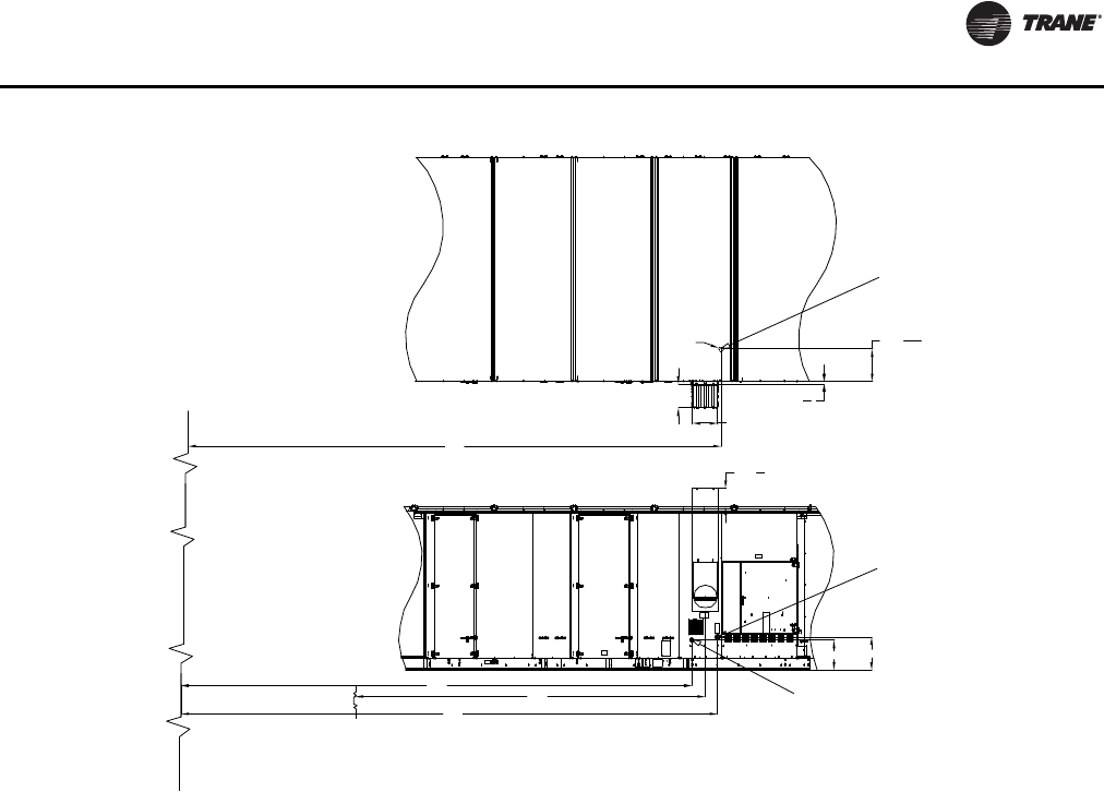
Installation
RT-SVX24K-EN 73
Figure 49. Gas heat piping penetration locations
K
17
8
115
8
W
D
2.5M & 1.8M (W=16 1/8in, D=14 11/16in)
1.1M, 0.8M (W=9 15/16in, D=9 12/16in)
H
C
21
19
20 7
16
B
Horizontal gas pipe inlet
Pipe type: Black pipe, sch 40
Condensate drain outlet
Pipe type: cpvc
Hole at the base
Ø3
Unit end plane
Edge of mist eliminator
Top View
Side View
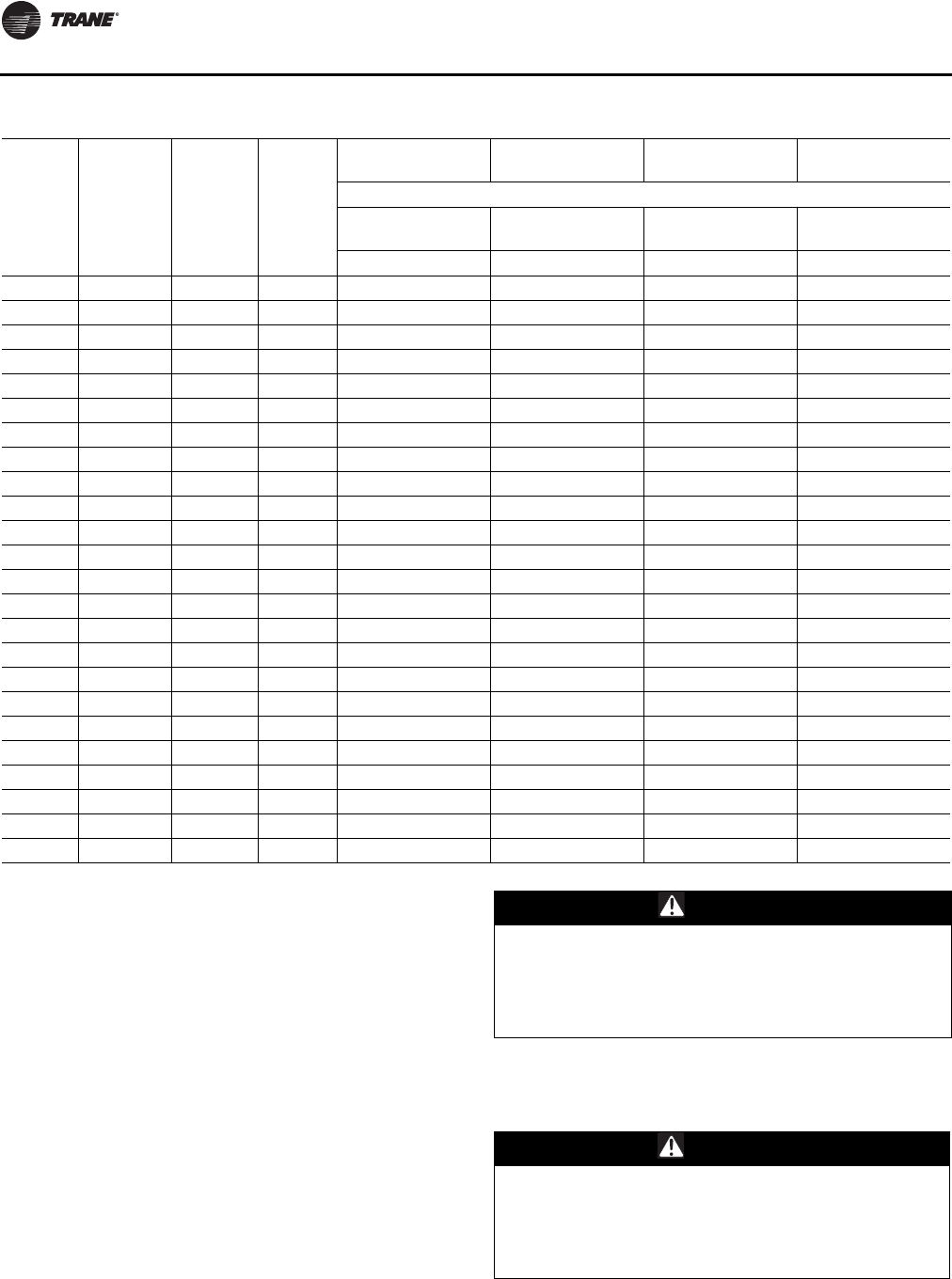
Installation
74 RT-SVX24K-EN
General Coil Piping and Connection
Recommendations
Proper installation, piping, and trapping is necessary to
ensure satisfactory coil operation and to prevent
operational damage:
• Support all piping independently of the coils.
• Provide swing joints or flexible fittings on all
connections that are adjacent to heating coils to
absorb thermal expansion and contraction strains.
• Install factory supplied control valves (valves ship
separately).
Note: The contractor is responsible for supplying the
installation hardware.
• When attaching the piping to the coil header, make the
connection only tight enough to prevent leaks.
Maximum recommended torque is 200 foot-pounds.
• Use pipe sealer on all thread connections.
Table 19. Gas heat piping penetration measurements
Tons
Energy
Recovery
Wheel
(ERW) Pieces Heat
(MBH)
Gas Flue Condensate Drain
Outlet Gas Connection,
Horizontal Gas Connection,
Base
Horizontal Distance
Mist Elim
to Flue C/L Unit End
to Hole C/L Unit End
to Hole C/L
KCHB
90-118 No ERW 1 & 2 Pc 1800 160 1/16 254 14/16 266 4/16 274 11/16
90-118 No ERW 1 & 2 Pc 1100 159 15/16 263 15/16 265 5/16 274 11/16
90-118 No ERW 1 & 2 Pc 850 159 15/16 263 15/16 265 5/16 274 11/16
120-162 No ERW 1 & 2 Pc 2500 214 11/16 321 337 7/16 339 7/16
120-162 No ERW 1 & 2 Pc 1800 214 13/16 319 11/16 331 339 7/16
120-162 No ERW 1 & 2 Pc 1100 214 11/16 327 14/16 330 1/16 339 7/16
90-118 ERW 1 & 2 Pc 1800 164 11/16 351 5/16 362 10/16 371 1/16
90-118 ERW 1 & 2 Pc 1100 164 8/16 360 6/16 361 12/16 371 1/16
90-118 ERW 1 & 2 Pc 850 164 8/16 360 6/16 361 12/16 371 1/16
120-162 ERW 1 & 2 Pc 2500 219 13/16 417 7/16 433 14/16 435 14/16
120-162 ERW 1 & 2 Pc 1800 220 416 2/16 427 7/16 435 14/16
120-162 ERW 1 & 2 Pc 1100 219 13/16 424 5/16 426 8/16 435 14/16
90-118 No ERW 3 Pc 1800 179 6/16 274 3/16 285 8/16 293 15/16
90-118 No ERW 3 Pc 1100 179 3/16 283 3/16 284 9/16 293 15/16
90-118 No ERW 3 Pc 850 179 3/16 283 3/16 284 9/16 293 15/16
120-162 No ERW 3 Pc 2500 240 2/16 346 8/16 362 15/16 364 15/16
120-162 No ERW 3 Pc 1800 240 5/16 345 3/16 356 8/16 364 15/16
120-162 No ERW 3 Pc 1100 240 2/16 353 6/16 355 9/16 364 15/16
90-118 ERW 3 Pc 1800 183 15/16 376 13/16 388 2/16 390 6/16
90-118 ERW 3 Pc 1100 183 13/16 385 13/16 387 3/16 390 6/16
90-118 ERW 3 Pc 850 183 13/16 385 13/16 387 3/16 390 6/16
120-162 ERW 3 Pc 2500 245 5/16 442 15/16 459 6/16 461 6/16
120-162 ERW 3 Pc 1800 245 8/16 441 9/16 452 15/16 461 6/16
120-162 ERW 3 Pc 1100 245 5/16 449 12/16 452 461 6/16
CAUTION
Connection Leaks!
Use a backup wrench when attaching piping to coils
with copper headers to prevent damage to the coil
header. Do not use brass connectors because they
distort easily and could cause connection leaks.
CAUTION
Over Tightening!
Do not use teflon-based products for any field
connections because their high lubricity could allow
connections to be over-tightened, resulting in damage
to the coil header.
Installation
RT-SVX24K-EN 75
• After completing the piping connections, seal around
pipe from inner panel to outer panel.
Hot Water Heat Units
Hot water heating coils are factory installed inside the
heater section of the unit. Once the unit is set into place,
the hot water piping and the factory provided three way
modulating valve must be installed.The valve can be
installed inside the heat section or near the unit. If the
valve is installed in a remote location, use field supplied
wiring to extend the control wires from the heater section
to the valve.Two access holes are provided in the unit base
as illustrated in Figure 50, p. 76.
Following the guidelines listed below will enhance both
the installation and operation of the “wet heat” system.
Figure 51, p. 77 illustrates the recommended piping
configuration for the hot water coil. Table 20 on page 76
lists the coil connection sizes.
Note: The valve actuators are not waterproof. Failure to
protect the valve from moisture may result in the
loss of heating control.
1. Support all field-installed piping independently from
the heating coil.
2. Use swing joints or flexible connectors adjacent to the
heating coil. (These devices will absorb the strains of
expansion and contraction).
3. All return lines and fittings must be equal to the
diameter of the “outlet” connection on the hot water
coil.
4. Install a “Gate” type valve in the supply branch line as
close as possible to the hot water main and upstream
of any other device or takeoff.
5. Install a “Gate” type valve in the return branch line as
close as possible to the return main and down stream
of any other device.
6. Install a strainer in the hot water supply branch as
shown in Figure 51, p. 77.
7. Install the 3-way valve in an upright position, piped for
valve seating against the flow. Ensure that the valve
location lends itself to serviceability.
8. TheType “W” hot water coil is self-venting only when
the tube water velocity exceeds 1.5 feet per second
(fps). If the tube velocity is less than 1.5 feet per second,
either:
a. install an automatic air vent at the top of the return
header, using the tapped pipe connection
or,
b. vent the coil from the top of the return header down
to the return piping. At the vent connection, size the
return piping to provide sufficient water velocity.
9. Install a “Globe” type valve in the Bypass line as shown
in Figure 51 on page 77.
Steam Heat Units
Steam heating coils are factory installed inside the heater
section of the unit.The coils are pitched, within the units,
to provide the proper condensate flow from the coil.To
maintain the designed degree of pitch for the coil, the unit
must be level.
Once the unit is set into place, the steam piping and the
factory provided two way modulating valve must be
installed.The valve can be installed inside the heater
section or near the unit. If the valve is installed in a remote
location, use field supplied wiring to extend the control
wires from the heater section to the valve.Two access
holes are provided in the unit base as illustrated in
Figure 50, p. 76.
Following the guidelines listed below will enhance both
the installation and operation of the “wet heat” system.
Figure 52, p. 77 illustrates the recommended piping
configurations for the steam coil. Table 20, p. 76 lists the
coil connection sizes.
Note: The valve actuators are not waterproof. Failure to
protect the valve from moisture may result in the
loss of heating control.
1. Support all field-installed piping independently from
the heating coil.
2. Use swing joints or flexible connectors adjacent to the
heating coil. (These devices will absorb the strains of
expansion and contraction.)
3. Install the 2-way valve in an upright position. Ensure
that the valve's location lends itself to serviceability.
4. Pitch the supply and return steam piping downward 1"
per 10' of run in the direction of flow.
5. All return lines and fittings must be equal to the
diameter of the “outlet” connection on the steam
coil(s). If the steam trap connection is smaller that the
coil “outlet” diameter, reduce the pipe size between
the strainer and the steam trap connections only.
6. Install a 1/2" 15 degree swing-check vacuum breaker at
the top of the return coil header using the tapped pipe
connection. Position the vacuum breaker as close to
the coil as possible.
Note: Vacuum breakers should have extended lines from
the vent ports to the atmosphere or connect each
vent line to the return pipe on the discharge side of
the steam traps.
CAUTION
Leakage!
Properly seal all penetrations in unit casing. Failure to
seal penetrations from inner panel to outer panel could
result in unconditioned air entering the module, and
water infiltrating the insulation, resulting in equipment
damage.
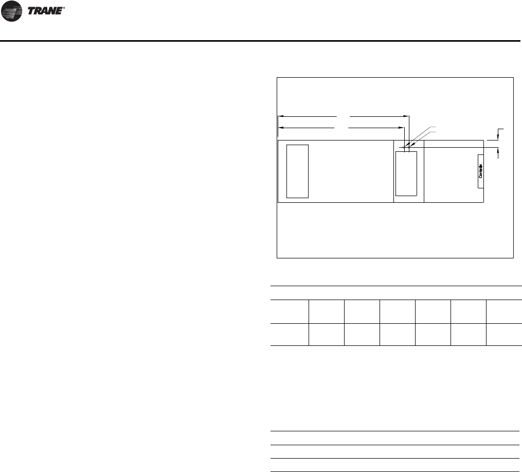
Installation
76 RT-SVX24K-EN
7. Install a “Gate” type valve in the supply branch line as
close as possible to the steam main and upstream of
any other device.
8. Install a “Gate” type valve in the return branch line as
close as possible to the condensate return main and
downstream of any other device.
9. Install a strainer as close as possible to the inlet of the
control valve and steam trap(s).
10. Steam trap selection should be based on the
maximum possible condensate flow and the
recommended load factors.
11. Install a Float-and-Thermostatic (FT) type trap to
maintain proper flow.They provide gravity drains and
continuous discharge operation. FT type traps are
required if the system includes either;
a. an atmospheric pressure/gravity condensate
return;
or,
b. a potentially low pressure steam supply.
12. Position the outlet or discharge port of the steam trap
at least 12" below the outlet connection on the coil(s).
This will provide adequate hydrostatic head pressure
to overcome the trap losses and assure complete
condensate removal.
The two steam coils are stacked together and must be
piped in a parallel arrangement.The steps listed below
should be used in addition to the previous steps.
Figure 52, p. 77 illustrates the recommended piping
configuration for the steam coils.
13. Install a strainer in each return line before the steam
trap.
14. Trap each steam coil separately as described in steps
10 and 11 to prevent condensate backup in one or both
coils.
15. In order to prevent condensate backup in the piping
header supplying both coil sections, a drain must be
installed utilizing a strainer and a steam trap as
illustrated in Figure 52, p. 77.
Figure 50. Hot water and steam heat connection location
T
able 20. Hot water and steam coil connection sizes
Hot Water Coil Steam Coil
Unit
Size Supply Return Drain/
Vent Supply Return Vent
90-162
Ton 2 ½ 2 ½ ½ 3.0 1 ¼ 1 ¼
Notes:
1. Type W coils, with center offset headers, are used in Hot Water units;
Type NS coils are used in Steam units.
2. Hot water and Steam units have multiple headers.
3. All sizes are in inches.
4. All connection threads are internal.
Table 21. Hot water and steam heat connection
dimensions
Tons A B Y Diameter
90-118 276 9/16 290 5/16 18 5
120-162 341 5/16 355 1/16 18 5
A
B
Y
Supply Air Opening
Return Air Opening
Unit bottom view
Inlet
Outlet
Recommended
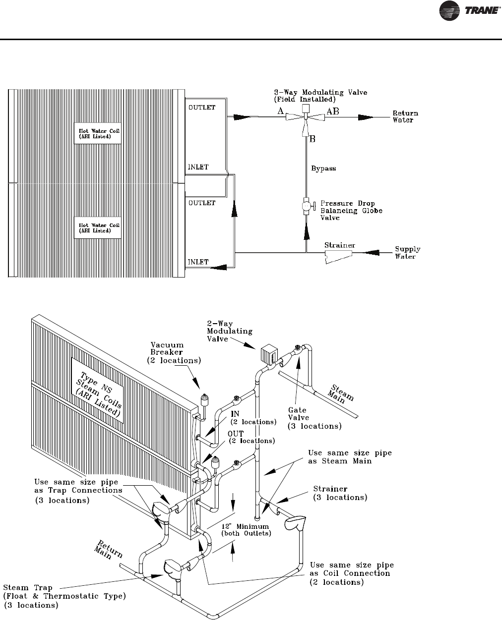
Installation
RT-SVX24K-EN 77
Figure 51. Hot water coil piping
Figure 52. Steam coil piping
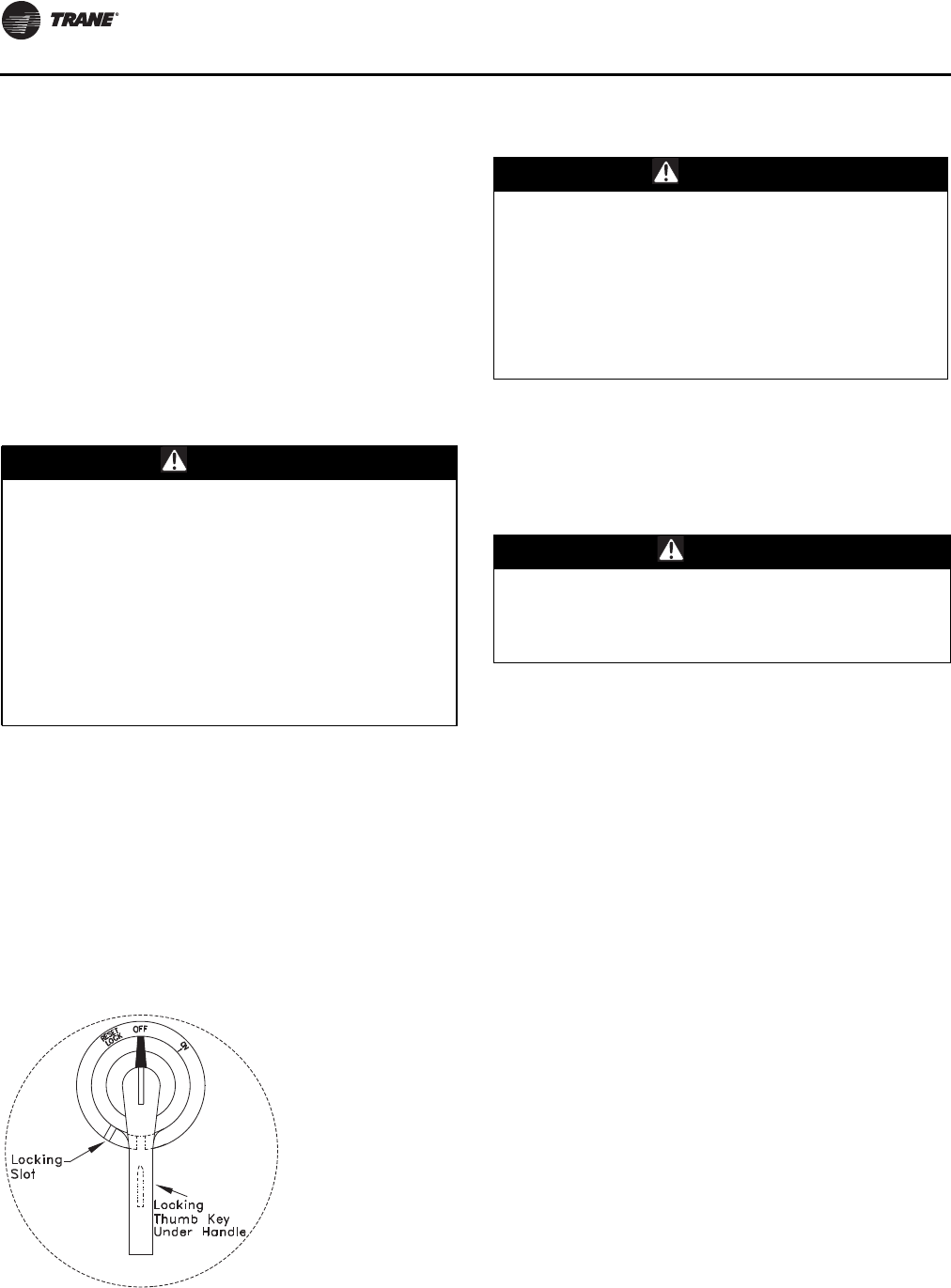
Installation
78 RT-SVX24K-EN
Disconnect Switch w/External Handle
Units come equipped with a factory mounted disconnect
switch with an externally mounted handle.This allows the
operator to disconnect power from the unit without having
to open the control panel door.The handle locations and
its three positions are shown below;
“ON” - Indicates that the disconnect switch is closed,
allowing the main power supply to be applied at the
unit.
“OFF” - Indicates that the disconnect switch is open,
interrupting the main power supply to the unit
controls.
“RESET” -Turning the handle to this position resets
the circuit breaker (if so equipped).
The handle can be locked in the “OFF” position. While
holding the handle in the “OFF” position, push the spring
loaded thumb key, attached to the handle, into the base
slot. Place the lock shackle between the handle and the
thumb key. This will prevent it from springing out of
position.
An overall layout of the field required power wiring is
illustrated beginning with Figure 54, p. 79.To ensure that
the unit supply power wiring is properly sized and
installed, follow these guidelines.
Note: All field installed wiring must conform to NEC
guidelines as well as State and Local codes.
Verify that the power supply available is compatible with
the unit nameplate rating for all components.The
available power supply must be within 10% of the rated
voltage stamped on the nameplate. Use only copper
conductors to connect the
3-phase power supply to the unit.
Electric Heat Units
Electric Heat Units require one power entry as illustrated
in Figure 54, p. 79. Use the information provided in
Table 24, p. 82 and the “Power Wire Sizing & Protection
Device Equations”, to determine the appropriate wire size
and Maximum Over current Protection for the heaters/
unit.
Note: Each power supply must be protected from short
circuit and ground fault conditions.To comply with
NEC, protection devices must be sized according to
the “Maximum Over current Protection” (MOP) or
“Recommended Dual Element” (RDE) fuse size
data on the unit nameplate.
Provide grounding for the supply power circuit in the
electric heat control box.
WARNING
Hazardous Voltage w/Capacitors!
Disconnect all electric power, including remote
disconnects and discharge all motor start/run
capacitors before servicing. Follow proper lockout/
tagout procedures to ensure the power cannot be
inadvertently energized. Verify with an appropriate
voltmeter that all capacitors have discharged. Failure to
disconnect power and discharge capacitors before
servicing could result in death or serious injury.
For additional information regarding the safe discharge
of capacitors, see PROD-SVB06A-EN
Figure 53. Disconnect switch external handle
WARNING
Live Electrical Components!
During installation, testing, servicing and
troubleshooting of this product, it may be necessary to
work with live electrical components. Have a qualified
licensed electrician or other individual who has been
properly trained in handling live electrical components
perform these tasks. Failure to follow all electrical
safety precautions when exposed to live electrical
components could result in death or serious injury.
CAUTION
Use Copper Conductors Only!
Unit terminals are not designed to accept other types
of conductors. Failure to use copper conductors may
result in equipment damage.
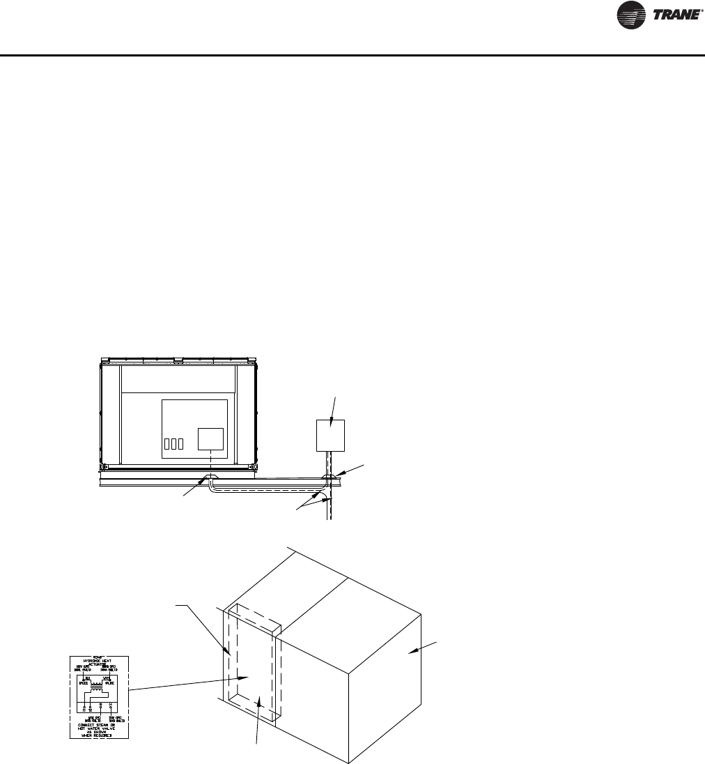
Installation
RT-SVX24K-EN 79
Main Unit Power Wiring
Figure 56, p. 80 lists the field connection wire ranges for
both the main power terminal block and the optional main
power disconnect switch.The electrical tables beginning
with Table 22, p. 81 list the component electrical data.The
electrical service must be protected from over current and
short circuit conditions in accordance with NEC
requirements. Protection devices must be sized according
to the electrical data on the nameplate. Refer to the“Power
Wire Sizing and Protection Device Equations”, for
determining;
•the appropriate electrical service wire size based on
“Minimum Circuit Ampacity” (MCA),
•the “Maximum Over current Protection” (MOP)
device,
•the “Recommended Dual Element fuse size” (RDE).
1. Location for the electrical service entrance is illustrated
in Figure 54, p. 79. Complete the unit power wiring
connections onto either the main terminal block, or the
factory mounted non-fused disconnect switch, inside
the unit control panel. Refer to the customer
connection diagram that shipped with the unit for
specific termination points.
2. Provide proper grounding for the unit in accordance
with local and national codes
Figure 54. Typical field power wiring
Field Supplied Survice
Over Current Protection
Pitch Pocket
Pitch Pocket 3-Wire Power
Supply+Ground
Front View Control Box
1TB1
or
1S1
Electric Heat Control Panel
Gas Heat Control Panel
Steam or Hot Water Control Panel
Heat Control Box
Condenser
Section
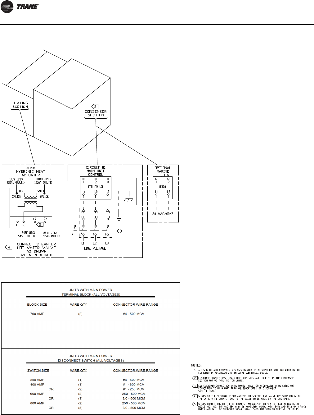
Installation
80 RT-SVX24K-EN
Figure 55. Typical field power wiring
Figure 56.Customer connection wire range
Note: Non-fused disconnect switch size is
calculated by selecting the size
greater than or equal to 1.15 X (sum of
unit loads). See unit literature for unit
load values. (See following page for
circuit breaker sizing)
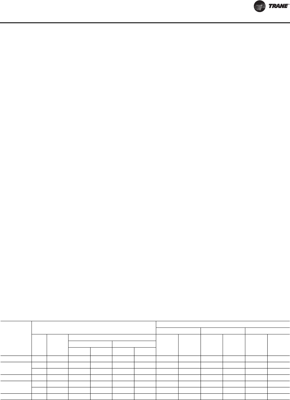
Installation
RT-SVX24K-EN 81
Power Wire Sizing and Protection Devices
To correctly size electrical service wiring for a unit, find the
appropriate calculations listed below. Each type of unit has
its own set of calculations for MCA (Minimum Circuit
Ampacity), MOP (Maximum Overcurrent Protection), and
RDE (Recommended Dual Element fuse size). Read the
load definitions that follow and then find the appropriate
set of calculations based on unit type.
Note: Set 1 is for cooling only and cooling with gas heat
units, and set 2 is for cooling with electric heat
units.
Load Definitions: (To determine load values, see the
Electrical Service Sizing DataTables on the following
page.)
LOAD1 = CURRENT OFTHE LARGEST MOTOR
(COMPRESSOR OR FAN MOTOR)
LOAD2 = SUM OFTHE CURRENTS OF ALL REMAINING
MOTORS
LOAD3 = CURRENT OF ELECTRIC HEATERS
LOAD4 = ANY OTHER LOAD RATED AT 1 AMP OR MORE
Set 1. Cooling Only Rooftop Units and Cooling
with Gas Heat Rooftop Units
MCA = (1.25 x LOAD1) + LOAD2 + LOAD4
MOP = (2.25 x LOAD1) + LOAD2 + LOAD4
Select a fuse rating equal to the MOP value. If the MOP
value does not equal a standard fuse size as listed in NEC
240-6, select the next lower standard fuse rating.
Note: If selected MOP is less than the MCA, then select
the lowest standard maximum fuse size which is
equal to or larger than the MCA, provided the
selected fuse size does not exceed 800 amps.
RDE=(1.5xLOAD1)+LOAD2+LOAD4
Select a fuse rating equal to the RDE value. If the RDE value
does not equal a standard fuse size as listed in NEC 240-6,
select the next higher standard fuse rating.
Note: If the selected RDE is greater than the selected MOP
value, then select the RDE value to equal the MOP
value.
Set 2. Rooftop units with Electric Heat
To arrive at the correct MCA, MOP, and RDE values for
these units, two sets of calculations must be performed.
First calculate the MCA, MOP, and RDE values as if the unit
was in cooling mode (use the equations given in Set 1).
Then calculate the MCA, MOP, and RDE values as if the unit
were in the heating mode as follows.
(Keep in mind when determining LOADS that the
compressors don't run while the unit is in the heating
mode).
MCA = 1.25 x (LOAD1 + LOAD2 + LOAD4) + LOAD3
The nameplate MCA value will be the larger of the cooling
mode MCA value or the heating mode MCA value
calculated above.
MOP = (2.25 x LOAD1) + LOAD2 + LOAD3 + LOAD4
The selection MOP value will be the larger of the cooling
mode MOP value or the heating mode MOP value
calculated above.
Select a fuse rating equal to the MOP value. If the MOP
value does not equal a standard fuse size as listed in NEC
240-6, select the next lower standard fuse rating.
Note: If selected MOP is less than the MCA, then select
the lowest standard maximum fuse size which is
equal to or larger than the MCA, provided the
selected fuse size does not exceed 800 amps.
RDE=(1.5xLOAD1)+LOAD2+LOAD3+LOAD4
The selection RDE value will be the larger of the cooling
mode RDE value or the heating mode RDE value calculated
above.
Select a fuse rating equal to the RDE value. If the RDE value
does not equal a standard fuse size as listed in NEC 240-6,
select the next higher standard fuse rating.
Notes:
•If the selected RDE is greater than the selected MOP
value, then select the RDE value to equal the MOP
value.
•On 90 to 162 ton rooftops, the selected MOP value is
stamped in the MOP field on the nameplate.
Table 22. Electrical service sizing data
Nom Tons
Compressor Nominal Voltage
460 V 575 V 380 V
Size Number
per Unit
Capacity kW (ea.)
RLA
(ea.) LRA
(ea.) RLA
(ea.) LRA
(ea.) RLA
(ea.) LRA
(ea.)
60 Hz 50 Hz
Std. Coil High Cap Std. Coil High Cap
90/100 240 4 21.3 21.6 17.6 17.9 34.1 215 27.3 175 34.0 215
105/118 240 2 24.2 24.5 20.2 20.3 34.1 215 27.3 175 34.0 215
300 2 25.0 25.3 20.9 21.0 44.7 260 35.8 210 44.6 260
120/128 300 4 26.9 27.8 22.4 23.0 44.7 260 35.8 210 44.6 260
130/140 300 2 28.5 28.8 23.8 23.8 44.7 260 35.8 210 44.6 260
380 2 33.7 34.2 28.2 28.2 52.1 320 41.1 235 52.0 320
150/162 380 4 34.7 -- 28.7 -- 52.1 320 41.1 235 52.0 320
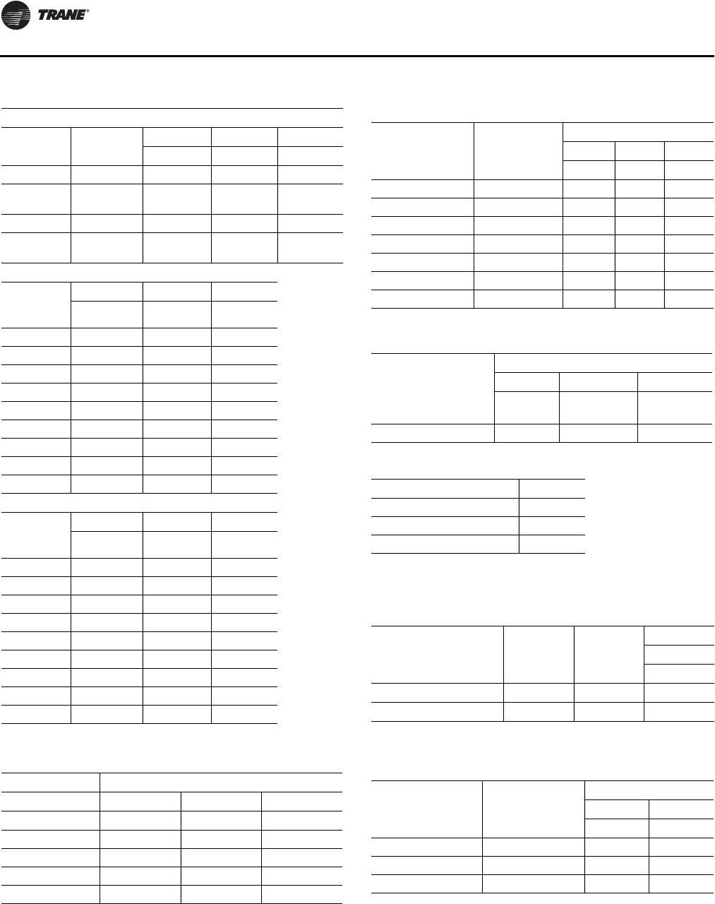
Installation
82 RT-SVX24K-EN
Table 23. Electrical service sizing data—motors
Condenser Fan Motors
Nominal
Tons No. of Fans
460 V 575 V 380 V
FLA FLA FLA
90, 105 6 16.2 13.2 15
120, 130,
150 8 21.6 17.6 20
100 2 11.8 N/A N/A
118, 128,
140, 162 2 11.8 N/A N/A
Supply Fan Motors
Motor
Horsepow
er
460 V 575 V 380 V
FLA FLA FLA
15 18.5 15.1 24
20 24.7 19.6 29
25 31 24.5 38
30 36.6 29.2 47
40 49.0 39 54
50 60.5 48 68
60 71.5 57.2 81
75 90 72 103
100 115 92 N/A
Exhaust/Return Fan Motors
Motor
Horsepow
er
460 V 575 V 380 V
FLA FLA FLA
7.5 9.4 7.8 13.6
10 12.6 10.1 16
15 18.5 15.1 24
20 24.7 19.6 29
25 31 24.5 38
30 36.6 29.2 47
40 49.0 39 54
50 60.5 48 68
60 71.5 57.2 81
Table 24. Electrical service sizing data—electric heat
module (electric heat units only)
Voltage
460 575 380
Module kW FLA FLA FLA
90 / 56 108.3 86.6 85.1
140 / 88 168.4 134.7 133.7
265 / 166 318.8 255 252.2
300 / 188 360.8 288.7 285.6
Table 25. Electrical service sizing data—control power
transformer (heating mode only)
Nominal Tons Digit 2 Unit
Function
Voltages
460 575 380
FLA FLA FLA
90-150/100-162 E, L, S, X 3 3 4
90, 105/100, 118 F (850 MBH) 4 4 5
90, 105/100, 118 F (1100 MBH) 4 4 5
90, 105/100, 118 F (1800 MBH) 4 4 5
120-150/128-162 F (1100 MBH) 4 4 5
120-150/128-162 F (1800 MBH) 4 4 5
120-150/128-162 F (2500 MBH) 4 4 5
Table 26. Electrical service sizing data—crankcase heater
Nominal Tons
Voltage
460 575 380
FLA (add) FLA
(add) FLA
(add)
90-162 1 1 1
Table 27. Voltage utilization range
Unit Voltage
460/60/3 414-506
575/60/3(a)
(a)Units with air-cooled condensers only.
517-633
380/50/3(i) 342-418
Table 28. Electrical service sizing data—evaporative
condenser
Unit Part kw HP
Voltage
460
FLA
Pump 1.5 2.7
Sump Heater 3 3.8
Table 29. Electrical service sizing data—energy recovery
wheel motor
Nominal Tons Unit Function
Voltages
460 575
FLA FLA
90-128 1 (Low CFM ERW) 1.2 0.95
130-162 1 (Low CFM ERW) 1.7 1.4
90-162 2 (Std. CFM ERW) 1.7 1.4
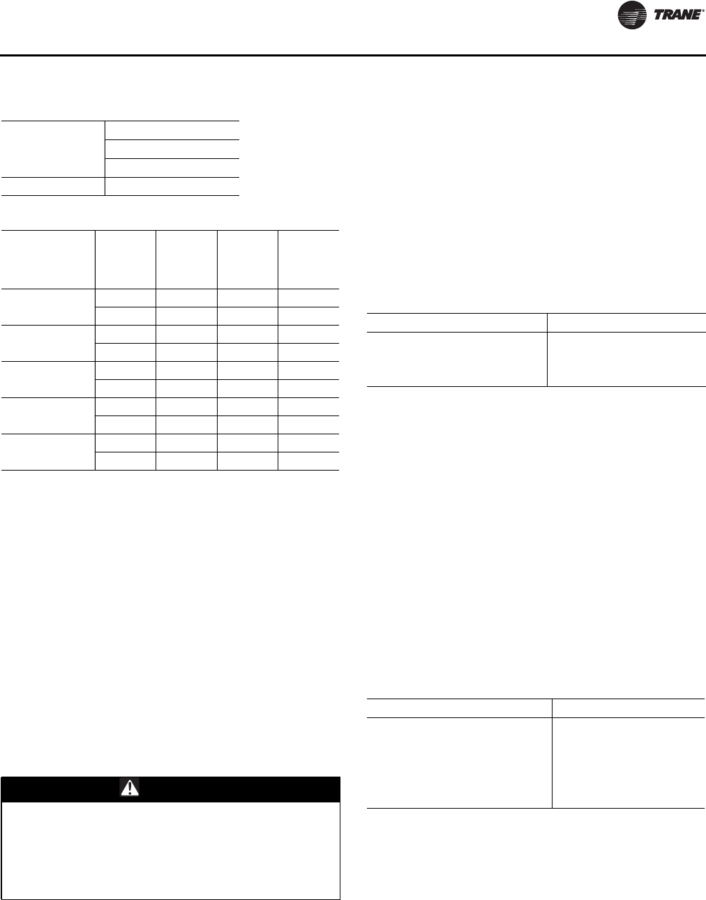
Installation
RT-SVX24K-EN 83
Field Installed Control Wiring
The Rooftop Module (RTM) must have a mode input in
order to operate the rooftop unit.The flexibility of having
several system modes depends upon the type of sensor
and/or remote panel selected to interface with the RTM. An
overall layout of the various control options available, with
the required number of conductors for each device, is
illustrated beginning with Figure 57, p. 89.
Note: All field wiring must conform to NEC guidelines as
well as state and local codes.
The various field installed control panels, sensors,
switches, and contacts discussed in this section require
both AC and DC consideration.These diagrams are
representative of standard applications and are provided
for general reference only. Always refer to the wiring
diagram that shipped with the unit for specific electrical
schematic and connection information.
Controls using 24 VAC
Before installing any connecting wiring, refer to Figure 10,
p. 23 for the electrical access locations provided on the
unit and Table 32, p. 83 forAC conductor sizing guidelines,
and;
a. Use copper conductors unless otherwise specified.
b. Ensure that the AC control wiring between the
controls and the unit's termination point does not
exceed three (3) ohms/conductor for the length of
the run.
Note: Resistance in excess of 3 ohms per conductor may
cause component failure due to insufficient AC
voltage supply.
c. Be sure to check all loads and conductors for
grounds, shorts, and miswiring.
d. Do not run the AC low voltage wiring in the same
conduit with the high voltage power wiring.
Controls using DC Analog Input/Outputs
Before installing any connecting wiring between the unit
and components utilizing a DC analog input\output signal,
refer to the appropriate illustration in Figure 10, p. 23 for
the electrical access locations provided on the unit and
Table 33, p. 83 for conductor sizing guidelines and;
e. Use standard copper conductor thermostat wire
unless otherwise specified.
f. Ensure that the wiring between the controls and the
unit termination point does not exceed two and a
half (2.5) ohms/conductor for the length of the run.
Note: Resistance in excess of 2.5 ohms per conductor can
cause deviations in the accuracy of the controls.
g. Do not run the electrical wires transporting DC
signals in or around conduit housing high voltage
wires.
Units equipped with aTrane BACnet® Communication
Interface (BCI) or LonTalk® communication Interface (LCI)
option which utilizes a serial communication link;
a. Must be 18 AWG shielded twisted pair cable
(Belden 8760 or equivalent).
b. Must not exceed 5,000 feet maximum for each link.
Table 30. Electrical service sizing data—convenience
outlet transformer
Nominal Tons
Voltage
460 575
FLA (add) FLA (add)
90-162 3.3 2.6
Table 31. Compressor data
Unit Size
Number
of
Compress
ors Compress
or Size
Compress
or
Designat
or Compress
or Type
90/100 Ton Std &
Hi-Capacity 2 CSHN250 1A, 2A Scroll
2 CSHN250 1B, 2B Scroll
105/118 Ton Std &
Hi-Capacity 2 CSHN250 1A, 2A Scroll
2 CSHN315 1B, 2B Scroll
120/128 Ton Std &
Hi-Capacity 2 CSHN315 1A, 2A Scroll
2 CSHN315 1B, 2B Scroll
130/140 Ton Std &
Hi-Capacity 2 CSHN315 1A, 2A Scroll
2 CSHN374 1B, 2B Scroll
150/162 Ton Std 2 CSHN374 1A, 2A Scroll
2 CSHN374 1B, 2B Scroll
WARNING
Hazardous Voltage!
Disconnect all electric power, including remote
disconnects before servicing. Follow proper lockout/
tagout procedures to ensure the power can not be
inadvertently energized. Failure to disconnect power
before servicing could result in death or serious injury.
Table 32. AC conductors
Distance from Unit to Control Recommended Wire Size
000-460 feet 18 gauge
461-732 feet 16 gauge
733-1000 feet 14 gauge
Table 33. DC conductors
Distance from Unit to Control Recommended Wire Size
000-150 feet 22 gauge
151- 240 feet 20 gauge
241- 385 feet 18 gauge
386- 610 feet 16 gauge
611- 970 feet 14 gauge

Installation
84 RT-SVX24K-EN
c. Must not pass between buildings.
Constant Volume System Controls
Remote Panel w/o NSB—BAYSENS110*
This electronic sensor features four system switch settings
(Heat, Cool, Auto, and Off) and two fan settings (On and
Auto) with four system status LED's. It is a manual or
automatic changeover control with dual setpoint
capability. It can be used with a remote zone sensor
BAYSENS077*. Refer to Table 34, p. 87 for the
Temperature vs. Resistance coefficient.
Constant Volume Zone Panel -BAYSENS108*
This electronic sensor features four system switch settings
(Heat, Cool, Auto, and Off) and two fan settings (On and
Auto). It is a manual or automatic changeover control with
dual setpoint capability.
Variable Air Volume System Controls
VAV Changeover Contacts
The changeover input is used with modulating gas heat,
electric heat, or hydronic heat. When the contacts are
closed, the unit will control to the discharge heating
setpoint. Refer to the unit wiring diagram for the field
connection terminals in the unit control panel.The switch
must be rated at 12 ma @ 24 VDC minimum.
Constant Volume or Variable Air Volume
System Controls
Remote Human Interface Module
The remote Human Interface module enables the operator
to set or modify the operating parameters of the unit using
a 16 key keypad and to view the operating status of the unit
on the 2 line, 40 character LCD screen without leaving the
building. However, the Remote Human Interface module
can not be used to perform any service functions.
One remote panel is designed to monitor and control up to
four units providing each of the units are equipped with an
IPCB module. Use the installation instructions that
shipped with the module to install it, and the appropriate
illustrations beginning with Figure 57, p. 89 to connect it to
the unit.
Remote Panel w/ NSB -BAYSENS119*
This 7 day programmable sensor features four periods for
Occupied\Unoccupied programming per day. Either one
or all four periods can be programmed. If the power is
interrupted, the program is retained in permanent
memory. If power is off longer than 2 hours, only the clock
and day may have to be reset.
The front panel allows selection of Occupied/Unoccupied
periods with two temperature inputs (Cooling Supply Air
Temperature and Heating Warm-up temperature) per
occupied period.
The occupied cooling setpoint ranges between 40 and
80°F.The warm-up setpoint ranges between 50 and 90°F
with a 2 degree deadband.The Unoccupied cooling
setpoint ranges between 45 and 98°F.The heating setpoint
ranges between 43 and 96°F.
The liquid crystal display (LCD) displays zone temperature,
temperature setpoints, week day, time, and operational
mode symbols.The DIP switches on the subbase are used
to enable or disable applicable functions, i.e.; Morning
warm-up, economizer minimum position override during
unoccupied status, heat installed, remote zone
temperature sensor, 12/24 hour time display, and daytime
warm-up. Refer to Table 34, p. 87 for theTemperature vs.
Resistance coefficient. During an occupied period, an
auxiliary relay rated for 1.25 amps @ 30 volts AC with one
set of single pole double throw contacts is activated.
Remote Zone Sensor (BAYSENS073*)
This electronic analog sensor features remote zone
sensing and timed override with override cancellation. It is
used when the RTM has been programmed as the source
for zone temperature control. Refer to Table 34, p. 87 for
theTemperature vs. Resistance coefficient.
Remote Zone Sensor (BAYSENS074*)
This electronic analog sensor features single setpoint
capability and timed override with override cancellation. It
is used with aTrane Integrated ComfortTM system. Refer to
Table 34, p. 87 for theTemperature vs. Resistance
coefficient.
Remote Zone Sensor (BAYSENS016*)
This bullet type analogTemperature sensor can be used
for; outside air (ambient) sensing, return air temperature
sensing, supply air temperature sensing, remote
temperature sensing (uncovered), morning warm-up
temperature sensing, and for VAV zone reset. Wiring
procedures vary according to the particular application
and equipment involved. When this sensor is wired to a
BAYSENS119* Remote Panel, wiring must be 18 AWG
ShieldedTwisted Pair (Belden 8760 or equivalent). Refer to
Table 34, p. 87 for theTemperature vs. Resistance
coefficient.
Remote Zone Sensor (BAYSENS077*)
This electronic analog sensor can be used with
BAYSENS119* or 021* Remote Panels.When this sensor is
wired to a BAYSENS119* Remote Panel, wiring must be 18
AWG ShieldedTwisted Pair (Belden 8760 or equivalent).
Refer to the specific Remote Panel for wiring details.
CO2Sensing—Space or Duct
The CO2sensor shall have the ability to monitor space
occupancy levels within the building by measuring the
parts per million of CO2in the air. As the CO2levels
increase, the outside air damper modulates to meet the
CO2space ventilation requirements.

Installation
RT-SVX24K-EN 85
Remote Minimum Position Potentiometer
(BAYSTAT023*)
The remote minimum position potentiometer is used on
units with an economizer. It allows the operator to
remotely set the economizer minimum position (which
controls the amount of outside air entering the unit). Use
the installation instructions that shipped with the
potentiometer to install it, and the appropriate illustrations
beginning with Figure 57, p. 89 to connect it to the unit.
Single Zone Variable Air Volume & Rapid
Restart System Control
Remote Zone Sensor (BAYSENS016*)
This bullet-type, analog temperature sensor can be used
for supply air and return air temperature sensing. Wiring
procedures vary according to application and equipment.
When this sensor is wired to a BAYSENS119* Remote
Panel, wiring must be 18 AWG ShieldedTwisted Pair
(Belden 8760 or equivalent). Refer to Table 34, p. 87 for the
Temperature vs. Resistance coefficient.
External Auto/Stop Switch
A field supplied single pole single throw switch may be
used to shut down the unit operation.This switch is a
binary input wired to the RTM. When opened, the unit
shuts down immediately and can be cancelled by closing
the switch. Refer to the appropriate illustrations beginning
with Figure 57, p. 89 for the proper connection terminals in
the unit control panel.The switch must be rated for 12 ma
@ 24 VDC minimum.
Emergency Override
When a Lontalk®/BACnet® communication module is
installed, the user can initiate from theTraneTracer
Summit or 3rd party BAS one of five (5) predefined, not
available to configure, Emergency Override sequences.All
compressors, condenser fans and the Humidification
output are deenergized for any Emergency Override
sequence. Each Emergency Override sequence
commands the unit operation as follows:
1. PRESSURIZE_EMERG:
– Supply Fan - On
– Supply Fan VFD Open/Max (if so equipped)
– Exhaust Fan - Off; Exhaust Dampers Closed (if so
equipped)
– OA Dampers - Open; Return Damper - Closed
– Heat - All heat stages off; Mod Heat output at 0 VDC
– Occupied/Unoccupied/VAV box output - Energized
– VOM Relay - Energized (if so equipped)
– Preheat Output - Off
– Return Fan - Off; Exhaust Dampers - Closed (if so
equipped)
– Return VFD - Min (if so equipped)
2. EMERG_DEPRESSURIZE:
– Supply Fan - Off
–Supply Fan VFD - Closed/Min (if so equipped)
– Exhaust Fan - On; Exhaust Dampers Open/Max (if
so equipped)
– OA Dampers - Closed; Return Damper - Open
– Heat - All heat stages off; Mod Heat output at 0 VDC
– Occupied/Unoccupied/VAV box output - Energized
– VOM Relay - Energized (if so equipped)
– Preheat Output - Off
– Return Fan - On; Exhaust Dampers - Open (if so
equipped)
– Return VFD - Max (if so equipped)
3. EMERG_PURGE:
– Supply Fan - On
–Supply Fan VFD - Open/Max (if so equipped)
– Exhaust Fan - On; Exhaust Dampers Open (if so
equipped)
– OA Dampers - Open; Return Damper - Closed
– Heat - All heat stages off; Mod Heat output at 0 VDC
– Occupied/Unoccupied/VAV box output - Energized
– VOM Relay - Energized (if so equipped)
– Preheat Output - Off
– Return Fan - On; Exhaust Dampers - Open (if so
equipped)
– Return VFD - Max (if so equipped)
4. EMERG_SHUTDOWN:
– Supply Fan - Off
–Supply Fan VFD - Closed/Min (if so equipped)
– Exhaust Fan - Off; Exhaust Dampers Closed (if so
equipped)
– OA Dampers - Closed; Return Damper - Open
– Heat - All heat stages off; Mod Heat output at 0 VDC
– Occupied/Unoccupied/VAV box output - Energized
– VOM Relay - Energized (if so equipped)
– Preheat Output - Off
– Return Fan - Off; Exhaust Dampers - Closed (if so
equipped)
– Return VFD - Min (if so equipped)
5. EMERG_FIRE - Input from fire pull box/system:
– Supply Fan - Off
–Supply Fan VFD - Closed/Min (if so equipped)
– Exhaust Fan - Off; Exhaust Dampers Closed (if so
equipped)

Installation
86 RT-SVX24K-EN
– OA Dampers - Closed; Return Damper - Open
– Heat - All heat stages off; Mod Heat output at 0 VDC
– Occupied/Unoccupied/VAV box output - Energized
– VOM Relay - Energized (if so equipped)
– Preheat Output - Off
– Return Fan - Off; Exhaust Dampers - Closed (if so
equipped)
– Return VFD - Min (if so equipped)
Ventilation Override Module (VOM)
Important: The ventilation override system should not
be used to signal the presence of smoke
caused by a fire, as it is not intended nor
designed to do so.
The user can customize up to five (5) different override
sequences for purposes of ventilation override control. If
more than one VOM sequence is being requested, the
sequence with the highest priority is initiated first.
Sequence hierarchy is the sequence “A” (UNIT OFF) is first,
with sequence “E” (PURGE with Duct Pressure Control)
last. A ventilation override mode can be initiated by
closing any of the five (5) corresponding binary inputs on
the VOM module. A binary output is provided on the VOM
module to provide remote indication of an active VOM
mode. All compressors, condenser fans and the
Humidification output are deenergized for any VOM
sequence.The factory default definitions for each mode
are as follows:
1. UNIT OFF sequence “A”
When complete system shutdown is required the
following sequence can be used.
– Supply Fan - Off
– Supply Fan VFD - Closed/Min (if so equipped)
– Exhaust Fan - Off; Exhaust Dampers Closed (if so
equipped)
– OA Dampers - Closed; Return Damper - Open
– Heat - All heat stages off; Mod Heat output at 0 VDC
– Occupied/Unoccupied/VAV box output -
Deenergized
– VOM Relay - Energized
– Preheat Output - Off
– Return Fan - Off; Exhaust Dampers - Closed (if so
equipped)
– Return VFD - Min (if so equipped)
– OA Bypass Dampers - Open (if so equipped)
– Exhaust Bypass Dampers - Open (if so equipped)
2. PRESSURIZE sequence “B”
Perhaps a positively pressurized space is desired instead
of a negatively pressurized space. In this case, the supply
fan should be turned on with VFD at 100% speed and
exhaust fan should be turned off.
– Supply Fan - On
– Supply Fan VFD - Max (if so equipped)
– Exhaust Fan - Off; Exhaust Dampers Closed (if so
equipped)
– OA Dampers - Open; Return Damper - Closed
– Heat - All heat stages off; Mod Heat output at 0 VDC
– Occupied/Unoccupied/VAV box output - Energized
– VOM Relay - Energized
– Preheat Output - Off
– Return Fan - Off; Exhaust Dampers - Closed (if so
equipped)
– Return VFD - Min (if so equipped)
– OA Bypass Dampers - Open (if so equipped)
– Exhaust Bypass Dampers - Open (if so equipped)
3. EXHAUST sequence “C”
With only the exhaust fans running (supply fan off), the
space that is conditioned by the rooftop would become
negatively pressurized.This is desirable for clearing the
area of smoke from the now-extinguished fire, possibly
keeping smoke out of areas that were not damaged.
– Supply Fan - Off
– Supply Fan VFD - Closed/Min (if so equipped)
– Exhaust Fan - On; Exhaust Dampers - Open (if so
equipped)
– OA Dampers - Closed; Return Damper - Open
– Heat - All heat stages off; Mod Heat output at 0 VDC
– Occupied/Unoccupied/VAV box output -
Deenergized
– VOM Relay - Energized
– Preheat Output - Off
– Return Fan - On; Exhaust Dampers - Open (if so
equipped)
– Return VFD - Max (if so equipped)
– OA Bypass Dampers - Open (if so equipped)
– Exhaust Bypass Dampers - Open (if so equipped)
4. PURGE sequence “D”
Possibly this sequence could be used for purging the air
out of a building before coming out of Unoccupied mode
of operation on VAV units or for the purging of smoke or
stale air if required after a fire.
– Supply Fan - On
– Supply Fan VFD - Max (if so equipped)
– Exhaust Fan - On; Exhaust Dampers - Open (if so
equipped)
– OA Dampers - Open; Return Damper - Closed
Installation
RT-SVX24K-EN 87
– Heat - All heat stages off; Mod Heat output at 0 VDC
– Occupied/Unoccupied/VAV box output - Energized
– VOM Relay - Energized
– Preheat Output - Off
– Return Fan - On; Exhaust Dampers - Open (if so
equipped)
– Return VFD - Max (if so equipped)
– OA Bypass Dampers - Open (if so equipped)
– Exhaust Bypass Dampers - Open (if so equipped)
5. PURGE with duct pressure control sequence “E”
This sequence can be used when supply air control is
required for smoke control.
– Supply Fan - On
– Supply Fan VFD - (If so equipped) Controlled by
Supply Air Pressure Control function; Supply Air
Pressure High Limit disabled
– Exhaust Fan - On; Exhaust Dampers Open (if so
equipped)
– OA Dampers - Open; Return Damper - Closed
– Heat - All heat stages off; Mod Heat output at 0 VDC
– Occupied/Unoccupied/VAV box output - Energized
– VOM Relay - Energized
– Preheat Output - Off
– Return Fan - On; Exhaust Dampers - Open (if so
equipped)
– Return VFD - Max (if so equipped)
– OA Bypass Dampers - Open (if so equipped)
Exhaust Bypass Dampers - Open (if so equipped)
Temperature vs. Resistance Coefficient
The UCM network relies on various sensors located
throughout the system to provide temperature
information in the form of an analog input. All of the
sensors used have the same temperature vs. resistance
co-efficient and are made from Keystone Carbon D97
material with a 1 degree Centigrade tolerance.
Emergency Stop Input
A normally closed (N.C.) switch wired to the RTM may be
used during emergency situations to shut down all unit
operations. When opened, an immediate shutdown
occurs. An emergency stop diagnostic is entered into the
Human Interface and the unit must be manually reset.
Refer to the appropriate illustrations in Figure 57, p. 89
Figure 59, p. 91 for the proper connection terminals in the
unit control panel.The switch must be rated for 12 ma @
24 VDC minimum.
External Stop Input
A normally closed (N.C.) switch wired to the RTM may be
used during emergency situations to shut down all unit
operations. When opened, an immediate shutdown
occurs.When the contacts are closed, the unit will resume
normal operation after minimum delays have occurred.
Refer to the appropriate illustrations in Figure 57, p. 89 for
the proper connection terminals in the unit control panel.
Occupied/Unoccupied Contacts
To provide Night Setback control if a remote panel with
NSB was not ordered, a field supplied contact must be
installed.This binary input provides the Occupied/
Unoccupied status information of the building to the RTM.
It can be initiated by a time clock, or a Building Automation
System control output.The relay’s contacts must be rated
for 12 ma @ 24 VDC minimum. Refer to the appropriate
illustrations in Figure 58, p. 90 Figure 59, p. 91 for the
proper connection terminals in the unit control panel.
Demand Limit Relay
If the unit is equipped with a Generic BAS Module, a
normally open (N.O.) switch may be used to limit the
electrical power usage during peak periods. When
demand limit is initiated, the mechanical cooling and
Table 34. Temp vs. resistance
Temp (F) Resistance (in.
1000 Ohms) Temp (F) Resistance (in.
1000 Ohms)
-40 346.10 71 11.60
-30 241.70 72 11.31
-20 170.10 73 11.03
-10 121.40 74 10.76
-5 103.00 75 10.50
0 87.56 76 10.25
5 74.65 77 10.00
10 63.80 78 9.76
15 54.66 79 9.53
20 46.94 80 9.30
25 40.40 85 8.25
30 34.85 90 7.33
35 30.18 100 5.82
40 26.22 105 5.21
45 22.85 110 4.66
50 19.96 120 3.76
55 17.47 130 3.05
60 15.33 140 2.50
65 13.49 150 2.05
66 13.15 160 1.69
67 12.82 170 1.40
68 12.5 180 1.17
69 12.19 190 0.98
70 11.89 200 0.83
Table 34. Temp vs. resistance (continued)
Temp (F) Resistance (in.
1000 Ohms) Temp (F) Resistance (in.
1000 Ohms)

Installation
88 RT-SVX24K-EN
heating operation is limited to either 50% or 100%.
Demand limit can be initiated by a toggle switch closure,
a time clock, or an ICSTM control output.These contacts
must be rated for 12 ma @ 24 VDC minimum.
Outside Air Sensor—BAYSENS016*
This device senses the outdoor air temperature and sends
this information in the form of an analog input to the RTM.
It's factory installed on units with an economizer, but can
be field provided/installed and used for informational
purposes on units without an economizer. Refer to the
appropriate illustrations in Figure 58, p. 90 Figure 59, p. 91
for the proper connection terminals in the unit control
panel. Refer to Table 34, p. 87 forTemperature vs.
Resistance coefficient.
Generic Building Automation System
The Generic Building Automation System (GBAS) module
allows a non-Trane building control system to
communicate with the rooftop unit and accepts external
setpoints in form of analog inputs for cooling, heating,
demand limiting, and supply air pressure parameters.
Refer to Figure 61, p. 93 &Table 35, p. 94 for the input
wiring to the GBAS module and the various desired
setpoints with the corresponding DC voltage inputs for
VAV, SZVAV and CV applications.
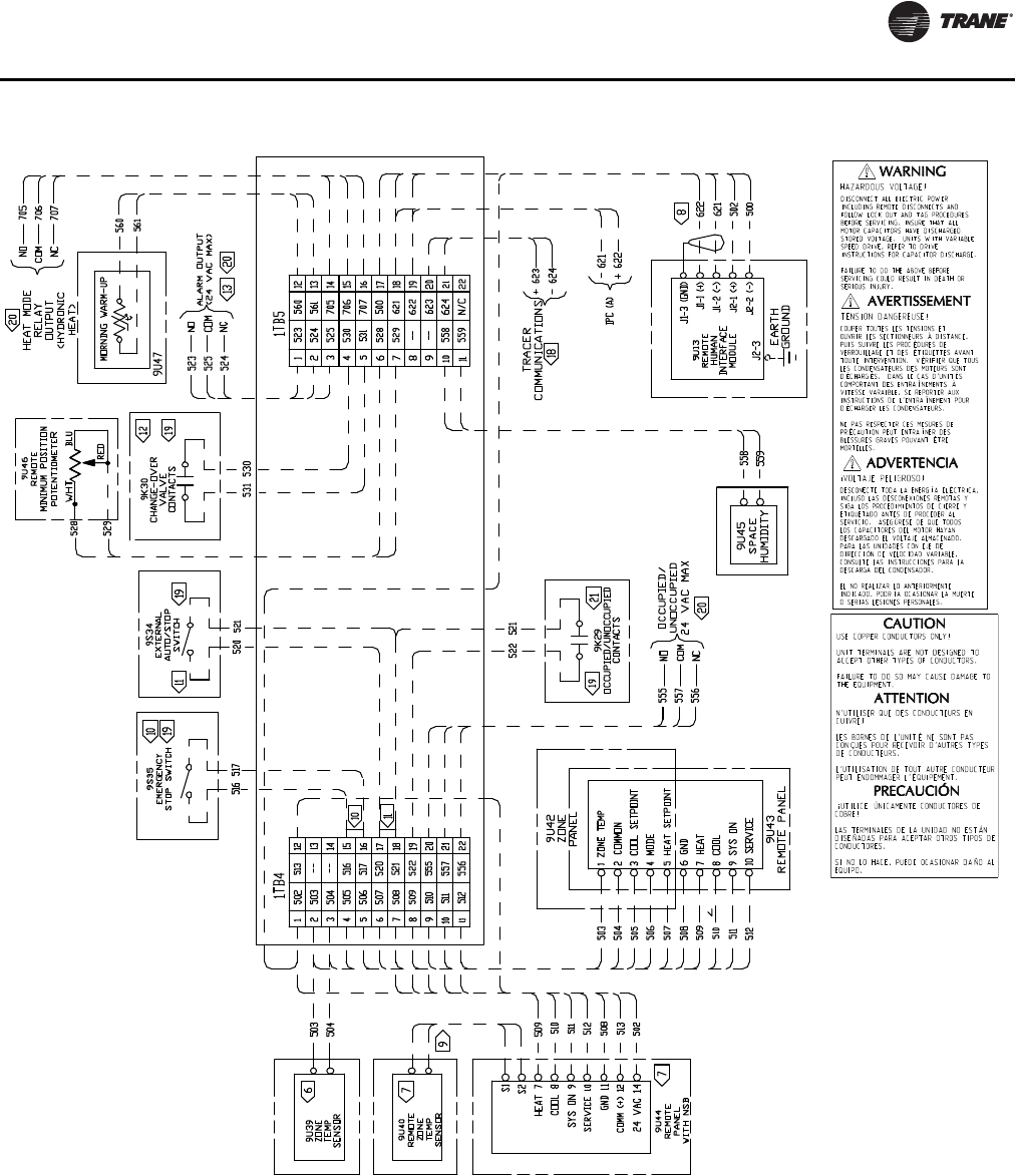
Installation
RT-SVX24K-EN 89
Figure 57. Typical field wiring diagram for 90 to 162 ton CV control options
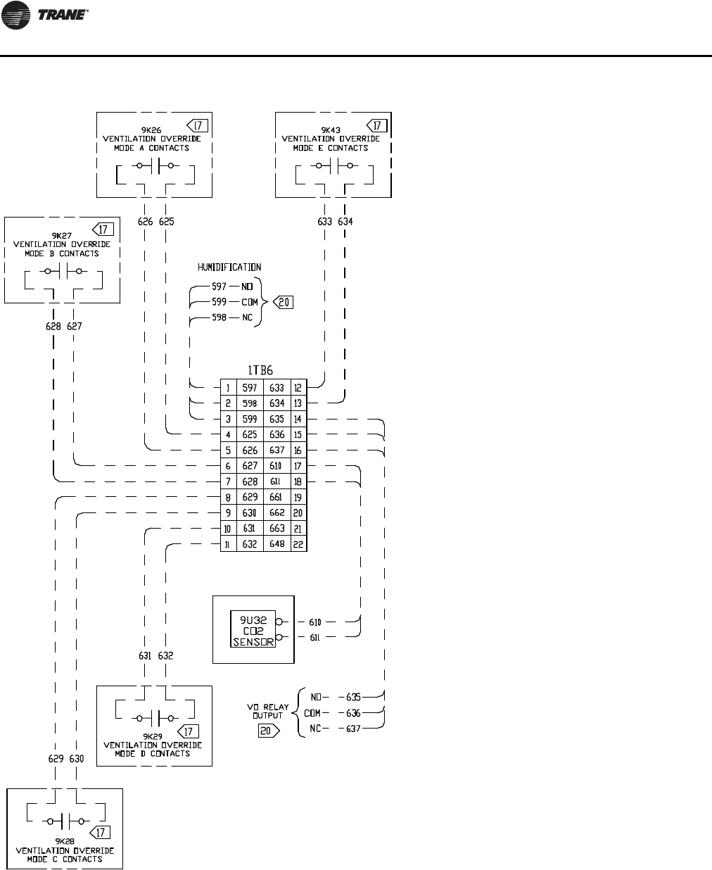
Installation
90 RT-SVX24K-EN
Figure 58. Typical ventilation override binary output for 90 to 162 ton CV control options
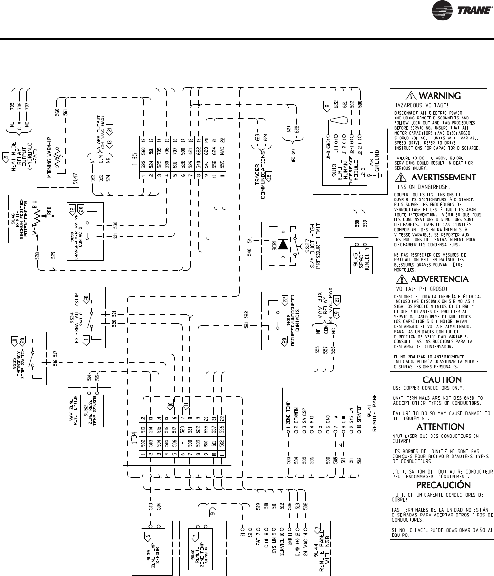
Installation
RT-SVX24K-EN 91
Figure 59. Typical field wiring diagram for 90 to 162 ton VAV control options
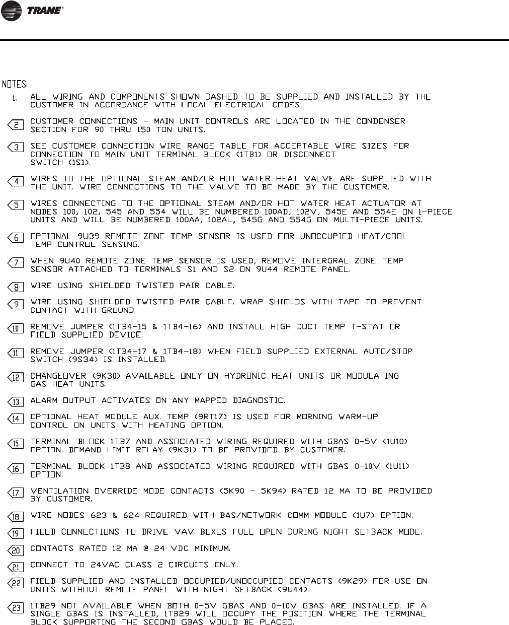
Installation
92 RT-SVX24K-EN
Figure 60. Typical field wiring diagram notes for 90 to 162 ton VAV and CV control options
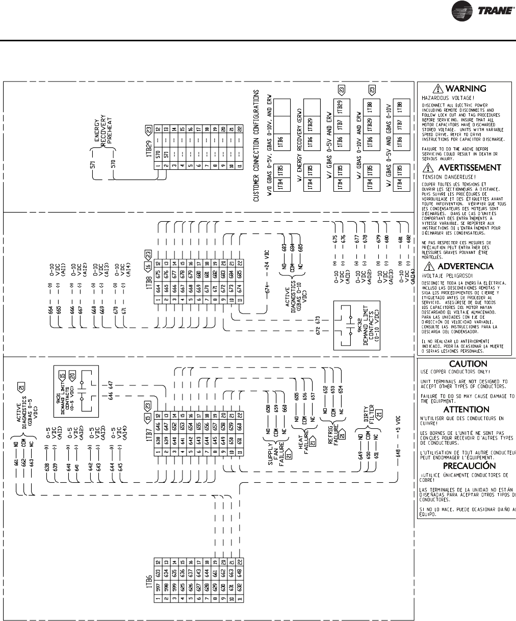
Installation
94 RT-SVX24K-EN
Table 35. GBAS voltage vs. setpoint
Setpoint GBAS 0-5 VDC GBAS 0-10 VDC Valid Range
Occ Zone Cooling Setpoint(CV only) 0.5 to 4.5 VDC 0.5 to 9.5 VDC 50 to 90°F
Unocc Zone Cooling Setpoint 0.5 to 4.5 VDC 0.5 to 9.5 VDC 50 to 90°F
Occ Zone Heating Setpoint(CV only) 0.5 to 4.5 VDC 0.5 to 9.5 VDC 50 to 90°F
Unocc Zone Heating Setpoint 0.5 to 4.5 VDC 0.5 to 9.5 VDC 50 to 90°F
SA Cooling Setpoint (VAV only) 0.5 to 4.5 VDC 0.5 to 9.5 VDC 40 to 90°F
SA Cooling Setpoint (SZVAV only) 0.5 to 4.5 VDC 0.5 to 9.5 VDC 40 to 70°F
Zone Cooling Setpoint (SZVAV only) 0.5 to 4.5 VDC 0.5 to 9.5 VDC 50 to 80°F
Zone/Return Critical Temperature Setpoint (RR only) 0.5 to 4.5 VDC 0.5 to 9.5 VDC 75 to 95°F
SA Heating Setpoint (VAV only) 0.5 to 4.5 VDC 0.5 to 9.5 VDC 40 to 180°F
SA Heating Setpoint (SZVAV only) 0.5 to 4.5 VDC 0.5 to 9.5 VDC 65 to 95°F
Space Static Pressure Setpoint 0.5 to 4.5 VDC 0.5 to 9.5 VDC -0.20 to 0.30 IWC
SA Static Pressure Setpoint 0.5 to 4.5 VDC 0.5 to 9.5 VDC 0.7 to 5.1 IWC
Min OA Flow Setpoint 1 0.5 to 4.5 VDC 0.5 to 9.5 VDC 0 to Unit Max Flow
MWU Setpoint 0.5 to 4.5 VDC 0.5 to 9.5 VDC 50 to 90°F
Econ Dry Bulb Enable Setpoint 0.5 to 4.5 VDC 0.5 to 9.5 VDC 50 to 140°F
SA_Reheat_Setpoint 0.5 to 4.5 VDC 0.5 to 9.5 VDC 60 to 90°F
Minimum Position Setpoint 3 0.5 to 4.5 VDC 0.5 to 9.5 VDC 0 to 100%
Occ Dehumidification Setpoint 0.5 to 4.5 VDC 0.5 to 9.5 VDC 40 to 65%
Unocc Dehumidification Setpoint 0.5 to 4.5 VDC 0.5 to 9.5 VDC 40 to 65%
Occ Humidification Setpoint 0.5 to 4.5 VDC 0.5 to 9.5 VDC 20 to 50%
Unocc Humidification Setpoint 0.5 to 4.5 VDC 0.5 to 9.5 VDC 20 to 50%
Notes:
1. If DCV is enabled this is used for Design Minimum OA Flow Setpoint
2. If DCV is enabled, this is used for Design Minimum OA Damper Position Setpoint
Table 36. GBAS 0-10 VDC output range
Setpoint GBAS 0-10 VDC Valid Range
Outdoor Air Temperature 0.5 to 9.5 VDC -40 to 200°F
Zone Temperature 0.5 to 9.5 VDC -40 to 200°F
Supply Air Temperature (VAV only) 0.5 to 9.5 VDC -40 to 200°F
Supply Air Pressure (VAV only) 0.5 to 9.5 VDC 0.0 to 7.91 wc
Space Pressure 0.5 to 9.5 VDC -0.67-0.67 wc
Space RH 0.5 to 9.5 VDC 0-100%
OA RH 0.5 to 9.5 VDC 0-100%
Space CO2 Level 0.5 to 9.5 VDC 50-2000 PPM
Cooling Capacity % 0.5 to 9.5 VDC 0-100%
Heating Capacity % 0.5 to 9.5 VDC 0-100%
Outdoor Air Damper Position 0.5 to 9.5 VDC 0-100%
Outdoor Airflow 0.5 to 9.5 VDC 0 to 65,000 CFM

Installation Checklist
RT-SVX24K-EN 95
Installation Checklist
General Checklist (applies to all units)
Unit checked for shipping damage and material
shortage
Verify that the installation location of the unit will
provide the required clearance for proper operation
Roof curb assembled and installed
Roof curb level and square
Ductwork secured to curb, or unit
Corners of duct adapters sealed on units with horizontal
supply or return
Horizontal supply or return ductwork is self supporting
Pitch pocket installed for units with power supply
through building roof
Unit set on curb and checked level
Unit-to-curb seal checked to ensure it is tight and
without buckles or cracks
Condensate drain lines installed to each evaporator
drain connection
Verify that all access doors open 100% and are not
obstructed by drain lines etc.
Shipping hardware removed from each compressor
assembly
Shipping hold-down bolts and shipping channels
removed from the supply and exhaust/return fans with
spring isolators
Supply and exhaust/return fans spring isolators
checked for proper adjustment
Plastic coverings (paint shields) removed from all
compressors (if present)
Verify all discharge, suction, and liquid line service
valves are back seated
Compressor crankcase heaters energized for a
minimum of 12 hours prior to unit refrigeration system
startup
Verify that unit literature (IOM, PTG) are left inside
control box for startup
Unit Rigging and Placement (Two-Piece—
addition to General Checklist)
First, rig and set the low side unit on the roof curb
(aligned with return end)
Remove the rail connector splice brackets and install
the brackets on the low side unit base rails
Take off the side panels (these are labeled) and the top
cover of the high side unit and set aside to be assembled
later
Rig and set the high side unit on roof curb pedestal
Lift the unit and position it over the pedestal
Use the rail splice bracket as an alignment aid to
connect the Low and high side units.The Low and high
side unit rails should be butted together with a maximum
2" (preferably 1") separation
Remove the left upper and lower louvered panels of the
high side unit as well as the corner panels on each side to
aid in tubing and wiring connections
Close refrigeration shut off valves as indicated in this
manual—Liquid, discharge, hot gas bypass (if present),
and hot gas reheat (if present).
For Evaporative Condensers
Recover/transfer charge from tubing between shut
valves and stub point.
For 2 and 3 piece Air-Cooled condensers add field
charge per nameplate.
Braze refrigerant piping connections and leak test
Low side and high side evacuated to 500 microns
Standing vacuum does not rise over 200 microns in 15
minutes
Open service valves to allow refrigerant flow
Refrigerant released from discharge to suction until
suction pressure is approximately 60 PSIG
Power wires connected in connection box
Control wires connected in connection box
Seal air gaps around wiring and refrigerant tubing
through bulkhead
Side panels and top cover assembled between high and
low side
Verify line dampening weights are installed on each
discharge line.
Unit Rigging and Placement (Three-piece
unit) (in addition to Two-piece unit rigging
and placement)
Rail guide attached to evaporator section base rails
Evaporator section rigged and set onto roof curb,
aligned with supply end
Removed and discarded shipping protection panels
and top blockoffs from evaporator section
Removed side panels and roof cap from evaporator
section
Applied gasket and butyl tape as indicated in the IOM
Removed and discarded shipping protection panels
and top block off from outside air section
Rigged and set outside air section onto roof curb to
within 2" of evaporator section

Installation Checklist
96 RT-SVX24K-EN
Using 0.75" x 24" threaded rod pull and secure
evaporator section and outside air section together
Using .375" bolts, nuts and washers pull and secure the
roof rails together
Installed roof splice plate
Added bullwrap to electrical wiring between
evaporator and outside air section
Connected power and control wiring between
evaporator and outside air section
Gasket applied and side panels installed on unit split
Butyl tape applied on top of unit split along roof seam
and roof cap installed
Field Installed Control Wiring—Complete the field
wiring connections for constant volume or variable air
volume controls as applicable. Refer to “Field Installed
Control Wiring” for guidelines
Electric Heat Units
Inspect the heater junction box and control panel;
tighten any loose connections
Check electric heat circuits for continuity
Two andThree piece units only) Route power wiring to
high side junction box
Gas Heat Units
Gas supply line properly sized and connected to the unit
gas train
All gas piping joints properly sealed
Drip leg Installed in the gas piping near the unit
Gas piping leak checked with a soap solution. If piping
connections to the unit are complete, do not pressurize
piping in excess of 0.50 psig or 14" W.C. to prevent
component failure
Main supply gas pressure between 7" and 14" W.C.
FlueTubes clear of any obstructions
Factory-supplied flue assembly installed on the unit
Connect the 3/4" CPVC furnace drain stub-out to a
proper condensate drain
Install field provided heat tape to furnace drain line
Hot Water Heat
Route properly sized water piping through the base of
the unit into the heating section
Install the factory-supplied, 3-way modulating valve
Complete the valve actuator wiring
Steam Heat
Route properly sized steam piping through the base of
the unit into the heating section
Install the factory-supplied, 2-way modulating valve
Complete the valve actuator wiring
Install 1/2", 15-degree swing check vacuum breaker(s)
at the top of each coil section. Vent breaker(s) to the
atmosphere or merge with return main at discharge side of
steam trap
Position the steam trap discharge at least 12" below the
outlet connection on the coil
Use float and thermostatic traps in the system, as
required by the application.
O/A Pressure Sensor andTubing Installation (All VAV
units and CV units with return fan or StatiTrac)
O/A pressure sensor mounted to the roof bracket
Factory supplied pneumatic tubing installed between
the O/A pressure sensor and the connector on the vertical
support
(Units with StatiTrac) Field supplied pneumatic tubing
connected to the proper fitting on the space pressure
transducer located in the filter section, and the other end
routed to a suitable sensing location within the controlled
space
Electrical
Verify that the power supply to the unit complies with
the unit nameplate specification
Properly ground the unit
Inspect all control panel components and tighten any
loose connections
Connect properly sized and protected power supply
wiring to a field supplied/installed disconnect and the unit
(copper wiring only to the unit)
Verify that phasing to the unit is correct (ABC)
Turn the 1S2 toggle switch off to prevent accidental unit
operation
Turn on power to the unit
Press the STOP button on the Human Interface (1U2)
Verify that all compressor crankcase heaters are
energized for at least 12 hours prior to unit startup
Evaporative Condenser
Remove fan bracket
Hookup inlet and drain piping
Install Heat tape if needed
Setup drain hold or drain on power loss
Setup Mechanical Float
Setup drain time
Setup water quality management (3rd party orTrane
factory-installed Dolphin Water Care System)
Options setup
Calibrate Conductivity Controller
Setup blowdown set points on the conductivity
sensor

Installation Checklist
RT-SVX24K-EN 97
Energy Recovery Wheel
Verify that the wheel turns freely though a full rotation
Confirm that all wheel segments are fully engaged in
the wheel frame and that the segment retainers are
completely fastened
Confirm the seal adjustment and proper belt tracking on
the wheel rim
98 RT-SVX24K-EN
Unit Startup
Sequence of Operation
Cooling Sequence of Operation
Time delays are built into the controls to increase
reliability and performance by protecting the compressors
and maximizing unit efficiency.
SZVAV Cooling Sequence of Operation
Single Zone VAV units will be equipped with a VFD
controlled supply fan which will be controlled via the 0-
10VDC RTM VFD output and the RTM Supply Fan output.
With the RTM Supply Fan output energized and the RTM
VFD output at 0Vdc the fan speed output is 37% (22Hz)
from the VFD motor, by default, and at 10VDC the Fan
Speed output is 100% (60Hz).The control scales the 0-
10Vdc VFD output from the RTM linearly to control
between the 37%-100% controllable range.
If the RTM determines that there is a need for active
cooling capacity in order to meet the calculated
Temperature Setpoint (Tset), the unit will begin to stage
compressors accordingly once supply fan proving has
been made. Note that the compressor staging order will be
based on unit configuration and compressor lead/lag
status.
Once theTset calculation has reached its bottom limit (Tset
Lower Limit Setpoint) and compressors are being utilized
to meet the demand, theTset value continues to calculate
below theTset Lower Limit Setpoint and the algorithm will
begin to ramp the Supply Fan Speed up toward 100%.
Note that the supply fan speed will remain at the
compressor stage’s associated minimum value (as
described below) until theTset value is calculated below
theTset Lower Limit Setpoint.
As the cooling load in the zone decreases the zone cooling
algorithm will reduce the speed of the fan down to
minimum per compressor stage and control the
compressor outputs accordingly. As the compressors
begin to de-energize, the Supply Fan speed will fall back to
the Cooling Stage’s associated minimum fan speed, but
not below. As the load in the zone continues to drop
cooling capacity will be reduced in order to maintain the
discharge air within the ± ½Tset deadband.
Cooling Stages Minimum Fan Speed
As the unit begins to stage compressors to meet the
cooling demand, the following minimum Supply Fan
Speeds will be utilized for each corresponding Cooling
Stage. Note that the Supply Fan Speed will be allowed to
ramp up beyond 37% as determined by the activeTset
calculation; the speeds below are only the minimum
speeds per cooling stage. Note that when transitioning
between active cooling stages, compressors may energize
prior to the supply fan reaching the minimum speed for the
associated step.
1. 2-Stage DX Cooling -The minimum fan speed for units
with 2 stages of DX Cooling will be 37% of the unit’s full
airflow capacity. At Stage 1 of DX Cooling the
minimum Fan Speed will be 37% and at Stage 2 of DX
Cooling the Fan Speed will be at a minimum of 67%.
2. 3-Stage DX Cooling - There are no IntelliPak
applications with 3 stages of DX Cooling.
3. 4-Stage DX Cooling -The minimum fan speed for units
with 4 stages of DX Cooling will be 37% of the unit’s
total airflow. At Stage 1 the minimum Supply Fan
Speed will be 37%, at Stage 2 the minimum Supply Fan
Speed will be 58%, and at Stages 3 & 4 the minimum
Supply Fan Speed will be 67%.
Rapid Restart
This feature will occur after every power cycle. Once
power is restored (e.g., via a backup generator), the RTM
will maximize cooling capacity within 3-5 minutes. Once
the space has returned to its ZoneTemperature Setpoint,
the RTM controls the load using normal capacity control
algorithms.The supply fan will be turned on immediately
after a power cycle, module initialization, or after the Unit
Start Delay has timed out.The supply fan proving switch
input must be closed prior to continuing with Rapid
Restart.
Once the supply fan proving switch input has closed, the
unit will consider the outside air temperature to determine
whether economizing or DX mechanical cooling will be
utilized to provide the necessary cooling. If the outside air
temperature is less than 50°F and economizing is enabled,
the outside air damper will be utilized. If the outside air
temperature is above 50°F, the outside air damper will
remain closed and DX mechanical cooling will occur for
the duration of Rapid Restart.
Compressor Sequence of Operation
Each compressor is equipped with a crankcase heater and
is controlled by a 600 volt auxiliary switch on the
compressor contactor.The proper operation of the
crankcase heater is important to maintain an elevated
compressor oil temperature during the “Off” cycle to
reduce oil foaming during compressor starts.
When the compressor starts, the sudden reduction in
crankcase pressure causes the liquid refrigerant to boil
rapidly causing the oil to foam.This condition could
damage compressor bearings due to reduced lubrication
and could cause compressor mechanical failures.
NOTICE:
Compressors Failure!
Unit must be powered and crankcase heaters energized
at least 8 hours BEFORE compressors are started. This
will protect the compressors from premature failure.
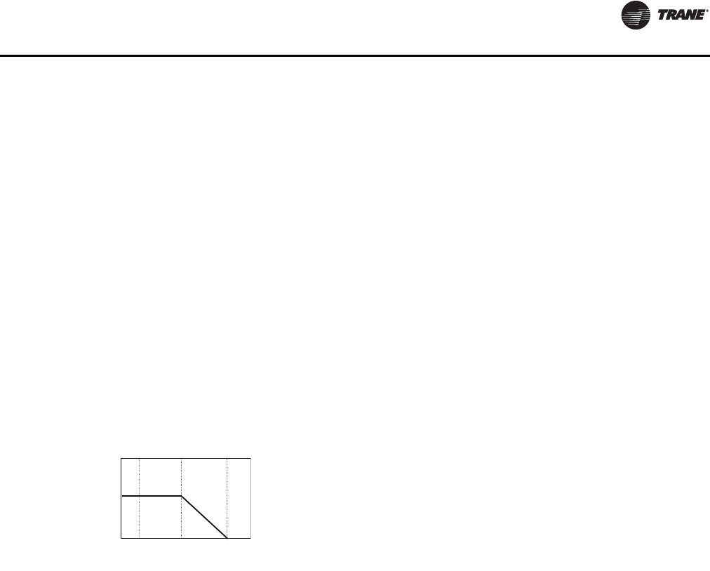
Unit Startup
RT-SVX24K-EN 99
Low Ambient Compressor Operation
Certain applications require compressor operation at
lower ambient conditions than standard units. Low
ambient compressor operation is a factory configured
option that allows units to operate down to -10°F by
extending the low ambient compressor lockout setpoint
range.
Standard configuration units are limited to a minimum
low ambient compressor lockout setpoint of 40° F. In
conditions below 40°F the low-pressure cutout (LPC)
switch can open in the first few minutes of initial
compressor operation due to refrigerant circulation
characteristics.To prevent nuisance LPC events at startup
in these conditions the unit controller will bypass LPC
processing for a varying period of time as defined below:
– For ambient temps below 20°F LPC events will be
bypassed for the first 170 seconds of compressor
operation.
For ambient temps between 20° and 40°F the bypass time
reduces linearly from 170 seconds at 20°F to 0 seconds at
40°F. LPC events are not bypassed at initial compressor
start in ambient conditions above 40°F.
– An open LPC switch detected at compressor start
will result in a manual-reset compressor lockout
condition.
– 4 consecutive LPC trip occurrences after the bypass
time expires without a minimum of 3 minutes of
compressor operation between trips will result in a
manual-reset compressor lockout.
In addition to alternate LPC event processing, the second
compressor to start on each refrigerant circuit will be
disabled for 40 minutes each time a circuit starts in
ambient conditions less than 40°F.To properly maintain
head pressure control in low ambient conditions one
condenser fan on each refrigerant circuit will be controlled
by a Variable-frequency motor drive (VFD).
This fan will always be the first fan active.The VFD will
control fan speed at all times compressors are active to the
HI-adjustable LowAmbient Control Point. If head pressure
control requires additional condenser fan stages to
maintain proper Saturated CondenserTemperature within
limits they will be activated as necessary according to the
standard head pressure control fan-staging algorithm.
Units with Evaporative Condenser
Sequence of Operation
Upon a power up without water in the sump, the
condenser sump drain will be controlled to allow the sump
to hold water.The fill relay will be energized if there is a call
for mechanical cooling and if the outdoor air temperature
is greater than 10°F on units with a sump heater installed
or greater than 40°F on units without sump heat. Once the
fill solenoid is energized, the sump will begin to fill.The
minimum water level switch will close and the fill relay will
be de-energized.The sump water temperature sensor is
invalid unless the minimum water level switch is closed.
If the sump water temperature is less than the setpoint
(default is 38°F), the sump heater will be energized until
the water temperature reaches the setpoint plus 5 degrees
(43°F for default).The fill solenoid will remain closed for 20
minutes or until the water temperature is greater than 35°F.
Once a water temperature of 35°F or greater is achieved,
the fill solenoid is energized, the sump will continue to fill,
and a five minute timer is started.
When the timer expires, the compressor lockout will be
released and mechanical cooling will be allowed. Head
pressure control will be regulated by a variable speed fan
until the liquid line pressure from either circuit reaches the
upper limit, which is set on the Human Interface under the
setup menu 120°F default.The liquid line pressure is
converted to a temperature for display at the Human
Interface. When the temperature exceeds the upper limit,
the condenser sump pump will be energized. When the
sump pump is energized, water is pumped from the sump
and sprayed over the condenser coil. If the liquid line
pressure from either circuit falls below the lower limit the
sump pump will be de-energized.
When the sump pump is energized or de-energized a
change in state is observed from an auxiliary contactor to
ensure proper sump pump operation. A change in states
must be observed by the auxiliary contactor within 6
seconds of the command to change states or mechanical
cooling will be locked out on a sump pump failure causing
a manual reset diagnostic to be set.
The fill solenoid will remain energized and the water level
will be controlled by the mechanical float valve. If the
maximum level float ever closes, an information-only
diagnostic is set and the fill solenoid is de-energized.This
is an indication that the mechanical float is not adjusted
properly or a failure of the mechanical float valve has
occurred. If the maximum level input is open for two
continuous minutes, the diagnostic will be cleared and the
fill solenoid will be energized.
If the sump water temperature ever drops below 35°F, the
drain actuator will be controlled in order to drain the water
from the sump. If there is a call for mechanical cooling and
the outdoor air temp is greater than 10°F on units with
sump heat installed or greater than 40°F on units without
sump heat, the unit will be allowed to refill the sump.
00F 20F 40F
170
Outdoor Air Tem
p(
°F
)
LPC B
yp
ass Time
(
sec
)
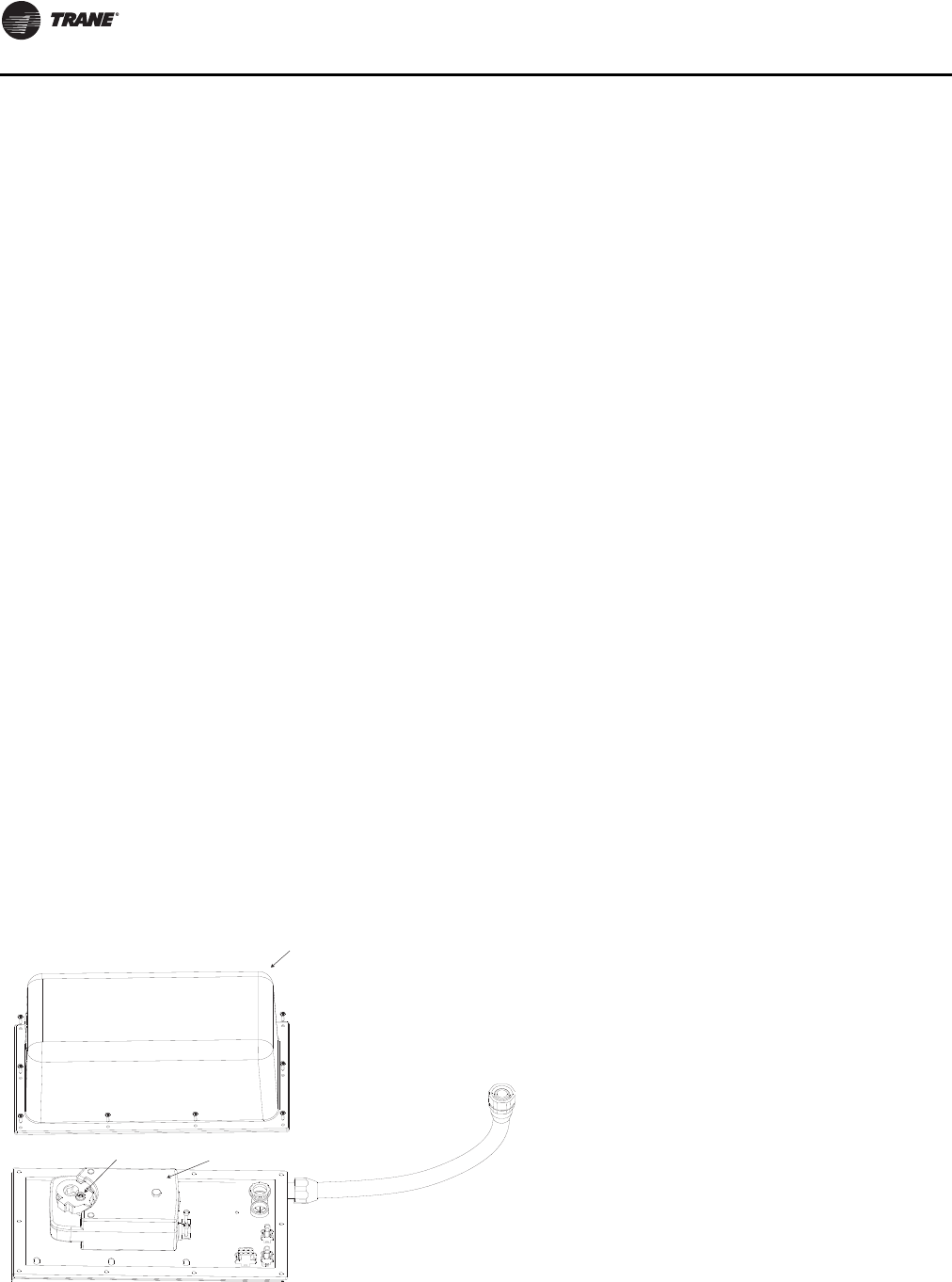
Unit Startup
100 RT-SVX24K-EN
The drain control can be configured via the Human
Interface, and by the drain actuator installation, to hold or
drain water on power loss; the default is set to drain.
Periodic purge is a cyclic opening of the drain to remove
debris and buildup from the sump and add additional
fresh water to the sump. Periodic purge has an adjustable
interval from the setup menu on the Human Interface with
a range of 1-12 hours or can be set to disabled - the default
position if periodic purge is not required.The duration of
the blowdown, or the time that the drain valve is opened,
is adjustable to a range of 5 - 255 seconds, with 120
seconds being the default.
The optional conductivity controller also uses this timer to
open the drain, when required, based on water quality.
During this purge, the fill solenoid will remain energized to
provide fresh water to the sump to replace water being
released during the blowdown. Water treatment
blowdown is provided by shorting the designated input on
the customer-supplied terminal strip.This gives the
customer more flexibility in determining water conditions
via external controls. Once the input is detected closed, the
drain valve will be opened for a time equal to the Human
Interface adjustable periodic purge duration.
Once the duration timer expires, or if the minimum level
switch opens, the drain valve will be closed and the water
treatment blowdown input will be ignored for 15 minutes.
During this blowdown the fill relay will remain open to
provide fresh water to the sump.The adjustable duration
time period should be set so that during drain operation 1
inch of water is drained from the sump with the fill
solenoid valve closed. If the minimum water level switch
opens during a blowdown cycle, the unit will de-energize
the sump pump in order to protect the compressors and
sump heater from insufficient water levels. Once the water
level reaches the minimum level input and this input
closes for 10 seconds, the compressors and sump heater
operations will be allowed to restart.
Evaporative Condenser Drain Valve Setup
The drain valve is shipped to “Drain During Unit Power
Loss Conditions.”This means that when the unit
disconnect is turned off, the 1S2 toggle switch is turned off,
or the unit loses power, the drain will open.The valve is
spring loaded and will travel from fully closed to fully open
in approximately 25 seconds.
This is desirable in cold climates where a risk of freezing
exists. In milder climates it may be desirable to keep the
water in the sump when unit power is off to avoid
unnecessarily wasting water whenever the unit
disconnect is turned off.
To convert the unit to “Hold During Unit Power Loss
Conditions”:
1. Remove power from the unit.
2. Remove the weather shield cover (Figure 62, p. 100).
3. Loosen the shaft set screw (Figure 62, p. 100), remove
the locking clip, remove the shaft adapter (Figure 63,
p. 101).
4. Lift the drain valve actuator and rotate it to the “hold
during power loss” position. (Figure 64, p. 101)
5. Reinstall the shaft adapter and locking clip and reinstall
the actuator onto the base. Make sure the arrow on the
shaft adapter is set to 0°.
6. Make sure the valve is in the fully closed position, then
tighten the shaft set screw.
7. Reinstall the weather shield cover.
8. Restore power to the unit.
9. At the Human Interface, press SETUP, NEXT until 'Head
Pressure Control Setup Submenu” is seen. Press
ENTER.
10. Change the “Sump Drain Valve Relay Control” from
Drain to Hold.
Figure 62. Drain valve actuator with weather shield
Weather Shield
Shaft Set Screw Drain Valve Actuator
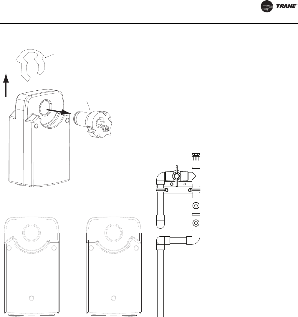
Unit Startup
RT-SVX24K-EN 101
Set Drain Duration Timer
Enter service test mode from unit Human Interface.
Navigate to the compressor condenser fan submenu.
Under head pressure control, use manual control.
Close drain valve and energize water inlet solenoid valve
until water reaches nominal level. Once level is achieved,
de-energize fill solenoid. Open drain valve and time how
long it takes for the water level to drop one inch, make sure
to take into account the closing time of the valve.
Chemical Water Treatment Tree
TheTrane evaporative condenser comes with a PVC tree to
allow easier inputs for third party water treatment.The tee
labeled A is a ¾ inch NPT threaded input, see Figure 65.
Tees B and C are 1/2 inch NPT threaded inputs.The ball
valve can be used to stop the water flow through the tree
to allow the customer to add hookup of water treatment,
or to change and update water treatment with the unit
running.
Units with DolphinWaterCare™or conductivity sensor will
have the conductivity sensor installed into the ¾ inch tee
with the other tees plugged. For all other units, A, B and C
will be plugged, see Figure 65. Ensure the ball valve is in
the open position when water treatment is being operated
in the system to make sure water flows through the tree
and transports treatment to the unit sump.
Conductivity Controller
Upon startup, the conductivity controller must be
calibrated and setup for operation. Below are the
necessary steps to accomplish those tasks.The controller
has two setpoints that control two relays. Both of these
setpoints will need to be set by Dolphin or a local water
treatment expert.
1. The first setpoint is the standard point blowdown
point.
– When the setpoint is exceeded the relay (K1) will be
energized and a blowdown request will close the
Water treatment request binary input on the MCM.
Figure 63. Actuator shaft adapter removal/assembly
Figure 64. Actuator is shipped in “Drain during power
loss” configuration
Locking clip
Shaft adapter
1
2
To drain during power loss,
set shaft adapter to 0 degrees
To hold during power loss,
set shaft adapter to 90 degrees
Figure 65. Chemical water treatment tree

Unit Startup
102 RT-SVX24K-EN
2. The second setpoint will be the emergency point
– The second setpoint will open the normally closed
K2 relay which will interrupt the sump proving
circuit which will generate a manual lockout.This
second setpoint will be used to protect the unit from
extremely high conductivity that would indicate a
failure in the system.
3. Inside the enclosure for the controller, there will be a
thermostat and strip heater that will protect LCD from
cracking at low ambient conditions.The thermostat
closes at 15°F and opens at 25°F.
Procedure to calibrate conductivity
Note: Visit this webpage for additional documentation:
<http://www.gfsignettools.com/products/pdf/
8860eng.pdf>
Use a calibrated thermometer and a known conductivity
rating.There are two different options for having a liquid
with known conductivity. Purchase a liquid with known
conductivity rating and purchase a handheld conductivity
reader.
1. Close the ball valve on the chemical treatment tree and
remove the conductivity sensor from the tree.
2. Enter service test mode on the unit and turn the pump
on, ensuring the compressors are set to Off.
3. With the conductivity controller connected to the
sensor and power, enter the CALIBRATE menu by
holding down the enter key for 2 seconds.
4. When asked for the calibration key code, hit the UP-UP-
UP
-DOWN arrow keys in sequence.
5. Using the UP and DOWN arrows go to Chan 1 Cell:
Standard. Ensure this channel is set to standard.
6. If not press the RIGHT arrow key and set to standard
then press the ENTER key to return to the
CALIBRATION menu.
7. Using the UP and DOWN arrows go to Chan 1 Cell.
Ensure that the cell constant is set to 1.0.
8. If not press the RIGHT arrow key and set the cell
constant to 1.0 then press the ENTER key to return to
the CALIBRATION menu.
9. Using the UP and DOWN arrows go to Chan 1 Set:
Temperature and press the RIGHT arrow key to enter
the edit mode.
10. Adjust the temperature on the controller to match the
actual temperature.
11. Press the ENTER key to save the input and return to the
CALIBRATE menu.
12. Using the UP and DOWN arrows, go to the Chan 1 Set:
Conductivity and press the RIGHT arrow key to enter
the edit mode.
13. Adjust the conductivity on the controller to match the
actual conductivity rating of the liquid.
14. Press the ENTER key to save the conductivity rating
and return to the CALIBRATE menu.
15. When finished calibrating the controller, press the UP
and DOWN key simultaneously to return to normal
operating mode.
Procedure to set purge setpoints on the
conductivity controller
Note: Visit this webpage for additional documentation:
<http://www.gfsignettools.com/products/pdf/
8860eng.pdf>
Work with local water treatment expert to identify nominal
purge and emergency purge conductivity value.
1. Close the ball valve on the chemical treatment tree and
remove the conductivity sensor from the tree.
2. Enter Service test mode on the unit HI and energize the
sump pump, ensuring the compressors are set to
"OFF".
3. With the conductivity controller connected to the
sensor and power, enter the CALIBRATE menu by
holding down the enter key for 2 seconds.
4. When asked for the calibration key code, hit the UP-UP-
UP
-DOWN arrow keys in sequence.
5. Using the UP and DOWN arrows, go to Relay 1
Setpoint: and press the RIGHT arrow key to enter edit
mode (K1).
6. Adjust the set point to the nominal blowdown
conductivity value.
7. Press the ENTER key to return to the CALIBRATE menu.
8. Using the UP and DOWN arrows, go to Relay 2
Setpoint: and press the RIGHT arrow key to enter edit
mode (K2).
9. Adjust the set point to the emergency conductivity
value.
10. Press the ENTER key to return to the CALIBRATE menu.
11. When finished setting the values, press the UP and
DOWN key simultaneously to return to normal
operating mode.
Units Without an Economizer
Upon entering an “occupied” mode of operation, the RTM
receives input from the remote panel to start the supply
fan. For constant volume applications, the RTM supply fan
contacts close which energizes the supply fan contactor.
When the supply fan starts, the fan proving switch closes,
signaling the RTM that airflow has been established and
the VFD will begin to ramp the fan (if equipped).
When a cooling request is sent to the RTM from a zone
temperature sensor, the RTM evaluates the operating
condition of the system using the supply air temperature
input and the outdoor temperature input before sending
the request to the MCM. Once the request is sent to the
MCM, the compressor module checks the compressor

Unit Startup
RT-SVX24K-EN 103
protection circuit before closing “Stage 1". After the first
functional stage has started, the compressor module
monitors the saturated refrigerant temperature and closes
the condenser fan output contact, when the saturated
refrigerant temperature rises above the “lower limit”
setpoint.
Units with an Economizer
Upon entering an “occupied” mode of operation, the RTM
receives input from the remote panel to start the supply
fan. For constant volume applications, the RTM supply fan
contacts close which energizes the supply fan contactor.
When the supply fan starts, the fan proving switch closes,
signaling the RTM that airflow has been established.The
RTM opens the economizer dampers to the specified
“minimum position”.
When a cooling request is sent to the RTM from the zone
temperature sensor, the RTM evaluates the operating
condition of the system using the supply air temperature
input and the outdoor temperature input before sending
the request to the MCM for mechanical cooling. If the
outdoor conditions are suitable for cooling (temperature
and humidity are within specified setpoints), the RTM will
attempt to maintain the zone temperature without using
any compressors. If the zone temperature can not be
maintained within the setpoint deadband, the RTM sends
a cooling request to the MCM.The compressor module
checks the compressor protection circuit before closing
“Stage 1". After the first functional stage has started, the
compressor module monitors the saturated refrigerant
temperature and closes the condenser fan output contact,
when the saturated refrigerant temperature rises above
the “lower limit” setpoint.
Units with TRAQ™ Sensor
The outside air enters the unit through theTRAQ Sensor
assemblies and is measured by velocity pressure flow
rings.The velocity pressure flow rings are connected to a
pressure transducer/solenoid assemblies.The solenoid is
used for calibration purposes to compensate for
temperature swings that could affect the transducer.The
Ventilation Control Module (VCM) utilizes the velocity
pressure inputs, the RTM outdoor air temperature input,
and the minimum outside air CFM setpoint to modify the
volume (CFM) of outside air entering the unit as the
measured airflow deviates from setpoint.
When the optional temperature sensor is installed and the
Preheat function is enabled, the sensor will monitor the
combined (averaged) outside air and return air
temperatures. As this mixed air temperature falls below
the Preheat ActuateTemperature Setpoint, the VCM will
activate the preheat binary output used to control a field
installed heater.The output will be deactivated when the
temperature rises 5 above the Preheat Actuate
Temperature Setpoint.
When the optional CO2sensor is installed and DCV is
enabled, the OA damper will be modulated to control CO2
concentrations. If the CO2concentration is greater than
the Design Minimum CO2Setpoint the OA damper will be
opened to the Design Minimum OA Damper Setpoint (w/
oTRAQ) or until the Design Minimum OA Flow Setpoint is
met (w/TRAQ).
If the CO2concentration is less than the DCV Minimum
CO2Setpoint the OA damper will be closed to the DCV
Minimum OA Damper Setpoint (w/oTRAQ) or until the
DCV Minimum OA Flow Setpoint is met (w/TRAQ).
If the CO2concentration is between the Design Minimum
CO2Setpoint and the DCV Minimum CO2Setpoint the OA
damper will be modulated proportionally between the
Design Minimum OA Damper Setpoint and the DCV
Minimum OA Damper Setpoint (w/TRAQ) and between
the Design Minimum OA Flow Setpoint and the DCV
Minimum OA Flow Setpoint (w/oTRAQ).
Frostat™ Control
The compressor module utilizes an evaporator
temperature sensor, mounted on the suction line of each
circuit, to protect the evaporator from freezing. If the
evaporator temperature approaches the specified
setpoint, adjustable between 25°F and 35°F, the
compressor(s) will be cycled “off”.The compressors will
not be allowed to restart until the evaporator temperature
has risen 10 F above the specified cutout temperature and
the compressor(s) have been off for a minimum of three
minutes.
Lead/Lag Operation
When Lead/Lag is enabled, each time the system cycles
after having stages 1 and 2 “On”, “Stage 2" and the
corresponding condenser fan output will start first. The
compressor module cycles the compressors “On” and
“Off” to keep the zone temperature within the cooling
setpoint deadband.The condenser fans are cycled “On”
and “Off” to maintain the saturated refrigerant
temperature within the specified controlband.
Units equipped with 100% modulating
exhaust
The exhaust dampers are controlled through an Exhaust/
Comparative Enthalpy Module (ECEM).The ECEM module
receives input from a space transducer and modulates the
exhaust dampers to maintain the space pressure to within
the specified setpoint controlband.
Modulating Dehumidification (Hot Gas
Reheat) Sequence of Operation
When the relative humidity in the controlled space (as
measured by the sensor assigned to space humidity
sensing) rises above the space humidity setpoint,
compressors and the supply fan will energize to reduce the
humidity in the space.
All compressors on both refrigerant circuits will be staged
up during active dehumidification. Circuit #1 is designated
the reheat circuit and will feature additional refrigerant

Unit Startup
104 RT-SVX24K-EN
control devices as well as a split condenser coil with one
section in the indoor air stream and the other in the
outdoor coil compartment.
During active dehumidification the discharge air will be
controlled to the Supply Air Reheat Setpoint by
modulating the amount of reheat produced by the reheat
coil.The Supply Air Reheat Setpoint, Occupied and
Unoccupied Dehumidification Setpoints are adjustable via
the human interface, BAS/Network control, or GBAS.
Active dehumidification will be terminated when the
humidity in the space is reduced to the active space
humidity setpoint - 5% or when an overriding condition
such as heating or cooling demand or a failure occurs in a
component required for dehumidification.
On VAV units, at startup, satisfying the VAV Occupied
Cooling setpoint, MWU setpoint, and DWU setpoint will
have priority over dehumidification mode. Once heating
modes are satisfied, and the unit is satisfying the SA
Cooling Setpoint, dehumidification mode will be entered if
no more than half the unit mechanical cooling capacity is
requested.
On SZVAV units, dehumidification will be similar to VAV
modulating dehumidification with the exception of a
dynamic Supply Air Reheat Setpoint. Rather than utilizing
a static Supply Air Reheat Setpoint, once the unit enters
dehumidification, the Discharge Air Setpoint will be
calculated based on the Zone temperature vs. Zone
Cooling Setpoint error and will be capped at the user
selected Supply Air Reheat setpoint.
Dehumidification is not allowed during VAV Heating
Modes (Changeover input closed). Once active,
dehumidification control will remain active for a minimum
of three minutes unless a priority unit shutdown request is
received or the High Pressure Control input opens on
either circuit.
Dehumidification control can be enabled separately for
occupied and unoccupied modes of operation via the
Human Interface and is overridden/disabled whether
active or inactive by the following methods:
– Priority unit shutdown conditions (Emergency stop,
Ventilation Override, Network Stop, etc.)
– Compressor circuit manual reset lockouts on either
circuit. Low Refrigerant Charge monitoring is active
during dehumidification mode and will lockout
compressor circuits based on the same criteria
used for cooling mode.
– Outdoor AirTemp is less then 40°F or greater the
100°F.
– Humidity Sensor Failure
– For VAV units, (in occupied) dehumidification will
be disabled if space temp is less than the Dehumid
Override Low Zone Setpoint or higher than the
Dehumid Override High Zone Setpoint. If
dehumidification is inactive it will not be allowed
until it space temp rises higher than the Dehumid
Override Low Zone Setpoint + 1.0°F or lower than
the Dehumid Override High Zone Setpoint - 2.0°F.
– For SZVAV units, dehumidification will be disabled
if space humidity levels have fallen below the
Active Occ/Unocc Dehumidification Setpoint -5%
Dehumidification Hysteresis Offset, the zone
temperature has dropped too close to the Zone
Heating Setpoint in any unit mode (ZoneTemp. is
less than ZHSP + 0.5°F), the zone temperature rises
above the Zone Cooling Setpoint +2°F in any unit
mode, Entering EvaporatorTemperature falls too
low, Froststat input becomes active, or
Dehumidification/Reheat becomes disabled.
– For CV and all units in unoccupied, if space temp is
less than the Zone Heating Setpoint (ZHSP) + 0.5° F
if dehumidification is active, or less than ZHSP + 1.0°
F if not dehumidification mode will be disabled. If
zone conditions result in a cooling request for more
than one-half the available cooling capacity of the
unit dehumidification will be disabled and will
transition to cooling control. If dehumidification is
inactive, dehumidification will not be allowed until
the active unit cooling capacity request drops to
half the available cooling capacity or less, unless
the space temp is less than the Zone Cooling
Setpoint.
– In CV units in occupied mode, if the unit is not in
“AUTO” system mode and is set to “HEAT” system
mode via the HI, BAS, or Zone Sensor device,
dehumidification control will be disabled at space
temps above Occupied ZCSP + 1.0° F. If
dehumidification is inactive it will not be allowed to
activate if space temp is greater than the OZCSP.
All units configured for modulating dehumidification will
have a reheat condenser coil purge function to ensure
proper refrigerant distribution in the reheat circuit.This
feature is always enabled and will monitor the amount of
cumulative compressor run time while the reheat
condenser coil pumpout relay is in a certain state. If
compressors accrue an amount of run time equal to the HI-
adjustable purge interval time without the pumpout relay
changing states a purge cycle will be initiated lasting for
three minutes.
During this cycle all compressors but the 2nd compressor
on circuit #1 will be energized if not already, the reheat
valve and cooling valves to will be set to 50%, and the
reheat coil pumpout relay will be toggled to its opposite
state. After the three-minute purge cycle completes the
purge interval timer will be reset and all system
components will return to the state they were in prior to
entering purge.
During dehumidification control an evaporator frost
control function designed specifically for reheat modes
will be active.This function will reduce refrigeration circuit
capacity to 50% (1st compressor on each circuit remaining
on) when the Entering EvaporatorTemp drops below a
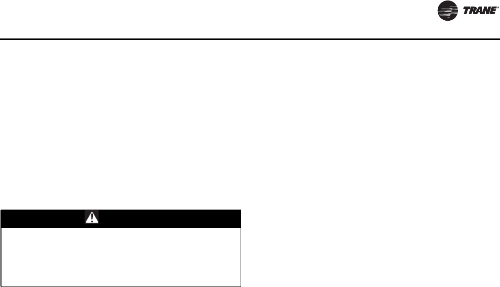
Unit Startup
RT-SVX24K-EN 105
non-adjustable limit of 35° F for 10 continuous minutes.
Once capacity is reduced, it will remain reduced until the
current cycle of dehumidification is terminated or a purge
cycle occurs.
If the Entering EvaporatorTemp remains below 35° F for an
additional 10 minutes both circuits will be de-activated and
remain off until the Entering EvaporatorTemp rises above
45°F. Even though all compressors have been de-activated
the unit will remain in dehumidification mode and re-
enable compressors up to 50% capacity when the Entering
EvaporatorTemp rises to 45°F or greater.
Energy Recovery Sequence of Operation
The primary components of the energy recovery system
are the energy recovery wheel, exhaust air bypass
damper, outdoor air bypass damper, and the energy
recovery preheat output. See Figure 67, p. 106 Figure 68,
p. 107 A filter is also placed between the wheel and the
outdoor air damper and an indicator scheme similar to that
for final filters is provided to notify the user when that filter
needs to be changed.
The energy recovery wheel will only be energized when
both the Supply Fan and Exhaust Fan are requested on by
the various functions that control them. Energy recovery is
a passive function and can not request fan operation.
Once the required airflow is present the wheel will be
commanded on if the indoor vs. outdoor conditions are
such that energy can be recovered.This is assessed
differently in cooling and heating modes.
In cooling mode, wheel activation conditions are assessed
based on indoor (return air) vs. outdoor enthalpy. Indoor
and outdoor enthalpy values are calculated using the
same sensors as used for comparative enthalpy. If the
outdoor enthalpy is 3 BTU/lb. greater than indoor enthalpy
the wheel is activated to remove energy from the
incoming outdoor air. In heating mode the wheel is
activated based on indoor vs. outdoor dry bulb
temperature. If the outdoor temperature is 5° F less than
the indoor temperature. the wheel is activated to recover
heat energy from the exhaust air.
In cooling mode the exhaust air bypass damper is held
closed, providing 100% energy recovery capacity during
cooling modes of operation. In heating modes, including
CV heating, VAV Heating, CV Supply AirTempering, VAV
Supply AirTempering, Morning Warm-up, and Daytime
Warm-up the exhaust air bypass damper is controlled to
discharge air temperature.The damper is modulated to
keep the supply air temp at the Supply Air Heating setpoint
for VAV control, or for CV control, supply air temp will be
controlled to a calculated Supply Air Heat Setpoint based
on conditions in the space.
If the wheel is active, supplemental heat (electric,
hydronic, gas) control algorithms will be disabled until the
exhaust air bypass damper is fully closed (maximum
heating capacity from the wheel). At this point,
supplemental heat algorithms are released to calculate
supplemental heat capacity requests using standard
setpoints until the setpoints are satisfied. InVAV occupied
modes the energy recovery wheel will remain active after
termination of supplemental heat above heating setpoint
until the exhaust air bypass damper is opened fully for 3
minutes (indicating minimal capacity requested from the
wheel). In CV occupied heating mode the wheel will
remain active after termination of a heating cycle until the
zone temp rises above the Occupied Zone Heating
Setpoint + 1.0°F and the exhaust air bypass damper is fully
open.The wheel will remain active if these conditions
persist continuously until the expiration of a HI-adjustable
time-out period or until the zone temp rises above the
Occupied Zone Cooling Setpoint - 0.5°F.
During active Economizing control the energy wheel will
be disabled but the outdoor air bypass damper will open
an amount that tracks the opening of the OA damper
proportionally from minimum position to fully open.
To protect the wheel from frost build-up in heating modes
a frost avoidance function is included.This feature will
energize the energy recovery preheat output (if
configured) and modulate the outdoor air bypass damper
open (to reduce incident cold outdoor air on the wheel) as
necessary when the Leaving RecoveryTemp Sensor value
is less than the Recovery Frost Avoidance Setpoint.The
Leaving RecoveryTemp Sensor is installed in the leaving
air stream on the exhaust-fan side of the energy wheel.
Figure 66 provides the exhaust air temperature setpoint
for 70ºF return air at various percents of relative humidity.
Where variable effectiveness / outside air bypass is not
enough to prevent frosting conditions, the energy
recovery wheel shuts off.Turning the wheel off during
frost conditions is a reliable method of preventing the
wheel from frosting, however, energy is not being
recovered and the extreme heating load must be handled
otherwise. Extreme winter design condition for energy
recovery units may require return air preheat.
An energy recovery wheel proving function is also
provided to indicate when the wheel is not turning after it
has been commanded on.
WARNING
Toxic Hazards!
Do not use an energy wheel in an application where the
exhaust air is contaminated with harmful toxins or
biohazards. Failure to follow this instruction could
result in death or serious injury.
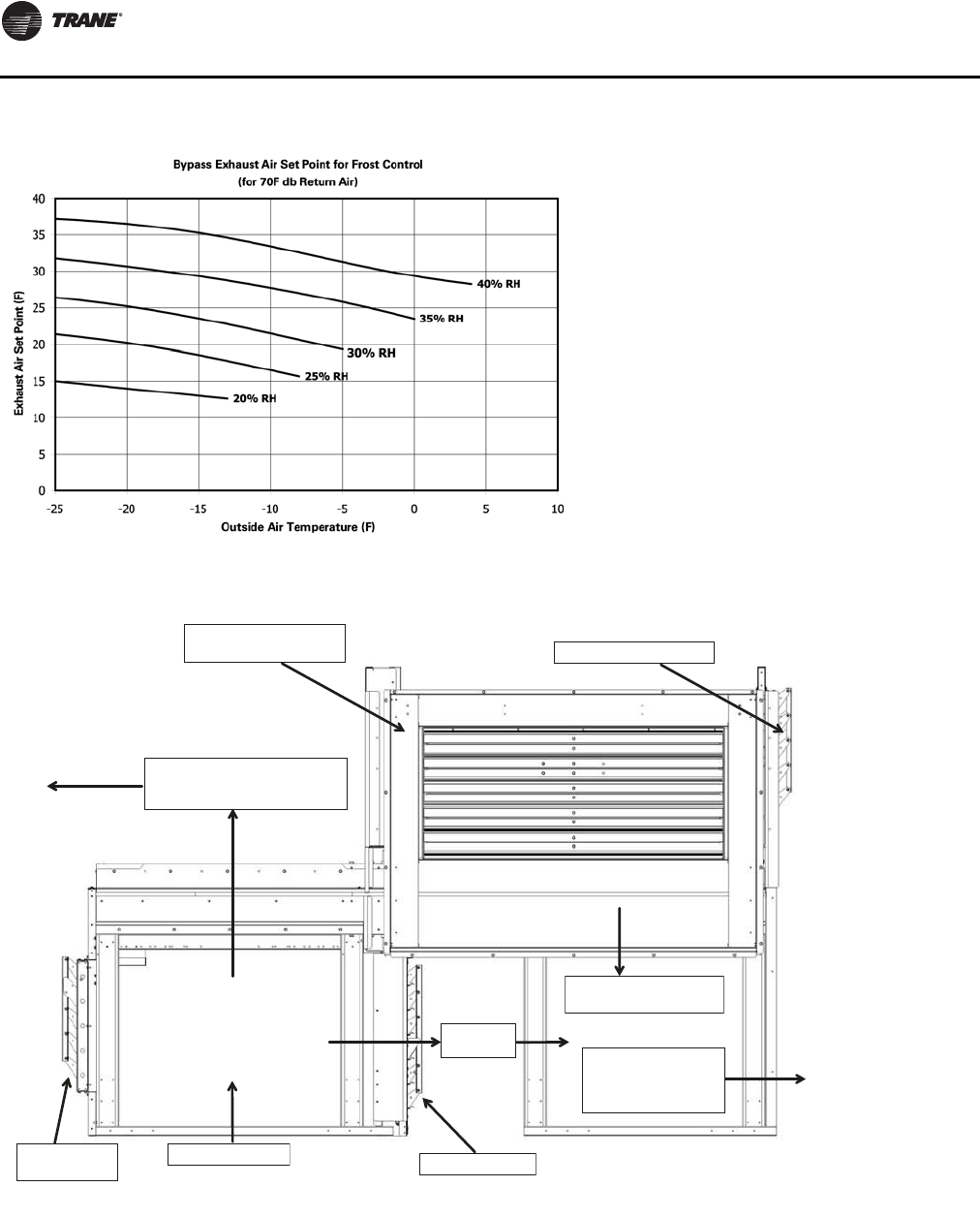
Unit Startup
106 RT-SVX24K-EN
Figure 66. Energy recovery wheel exhaust air setpoint temperatures
Figure 67. Energy recovery wheel operation
Outside Air Intake Damper
(Mist Eliminator not shown)
Exhaust Air,
Leaving Energy Recovery Wheel,
Path to Exhaust Fan
Building Return Air
Outside Air Bypass Damper
Unit Return
Airflow
Exhaust Air
Bypass Damper
Energy Recovery Wheel
Conditioned Outside Air
Return Air Damper
Path to Filters & Coil
ERW Unit Entering Air
(Mixed Return Air &
Conditioned Outside Air)
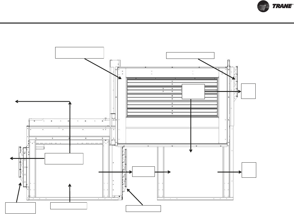
Unit Startup
RT-SVX24K-EN 107
Gas Heating Sequence of Operation
Standard
Two Stage Gas Furnace
The control system for the rooftop units are wired to
ensure that the heating and cooling do not occur
simultaneously. Refer to the wiring diagram that shipped
with the unit while reviewing the following sequence of
operation.
Honeywell Ignition System
(850 & 1100 MBH Two Stage Natural Gas)
When a heating requirement exists, the Rooftop Module
(RTM) starts the supply fan and sends a request for heat to
the Heat Module.The Heat Module closes contacts and
starts the combustion blower motor.The combustion
blower motor starts on low speed through the normally
closed combustion blower relay contacts.
The supply airflow switch and the combustion air switch
closes. Power is applied through the high limit cutout to
the Honeywell ignition control board.The ignition control
board starts a pre-purge timing cycle.At the end of the pre-
purge cycle, the ignition transformer and the pilot
solenoid valve are energized.This starts a 10 second trial
for pilot ignition. When the pilot flame is established and
sensed by the flame sensing rod, stage 1 of the main gas
valve and the 60 seconds sequencing time delay relay is
energized.
The system will operate in the low heat mode until an
additional call for heat is established by closing the
contacts on the Heat Module.The sequencing time delay
relay will energize the combustion blower motor relay
which switches the combustion blower motor to high
speed and energizes the 2nd stage solenoid on the gas
valve after approximately 60 seconds.
If the flame rod does not detect a pilot flame within the 10
second trial for ignition period, the control will lockout. If
a flame failure occurs during operation, the gas valve, the
sequencing time delay relay, and the combustion blower
relay is de-energized.The system will purge and attempt
to relight the pilot. If a flame is not detected after this
attempt, the Honeywell ignition control will lock out. The
combustion blower motor will continue to operate as long
as a heating demand exists and the system switch is “On”.
Once the heating demand has been satisfied, the
combustion blower and the Honeywell ignition control
board is de-energized.
Note: The above sequence is the same for Propane.The
orifices are smaller and the manifolds are adjusted
to different values
Figure 68. Energy recovery wheel economizer operation
Outside Air Intake Damper
(Mist Eliminator not shown)
Exhaust Air,
Path to Exhaust Fan
Building Return Air
Outside
Air Bypass Damper
Unit Return
Airflow
Exhaust Air
Bypass Damper
Un-
Conditioned
Outside
Air
Return Air Damper
Path to
Filters
& Coil
Path to
Filters
& Coil

Unit Startup
108 RT-SVX24K-EN
(1800 & 2500 MBH Two Stage Natural Gas)
When a heating requirement exists, the Rooftop Module
(RTM) starts the supply fan and sends a request for heat to
the Heat Module.The Heat Module closes contacts and
starts the combustion blower motor through the
combustion blower relay.
The supply airflow switch and the combustion air switch
closes. Power is applied through the high limit cutout to
the Honeywell ignition control board.The ignition control
board begins the pre-purge timing cycle with the damper
in the light off position and the low fire start interlock is
closed
At the end of the pre-purge cycle, the ignition transformer
and the pilot solenoid valve are energized.This starts a 10-
second trial for pilot ignition.
When the pilot flame is established and sensed by the
flame sensing rod, the stage 1 of the main gas valve will
begin.The gas butterfly control valve is in the low fire
setting by the linkage arm connection between the
combustion air actuator and the butterfly valve.
The system will operate in the low heat mode until there
is an additional call for heat established by closing the
contacts on the Heat Module.
If the flame rod does not detect a pilot flame within the 10
second trial for ignition period, the ignition control board
will lockout.The combustion blower motor will continue
to operate as long as a heating demand exists and the
system switch is “On”.
Once locked out on flame failure, the IC board will not
reactivate the ignition/combustion control circuit until it is
reset manually.To do this, press the reset button on the
front of the IC board case.
A set of relay contacts is available for external use for heat
fail (Information Only).
Once the heating demand has been satisfied, the
combustion blower and the Honeywell ignition control
board is de-energized.
Modulating Gas Sequence of Operation
The control system for the rooftop units is wired to ensure
that the heating and cooling do not occur simultaneously.
Refer to the modulating heat wiring diagram that shipped
with the unit while reviewing the following sequence of
operation. As you review the sequence of operation, keep
the following in mind:
1. The furnace will not light unless the manual gas valves
are open and the control circuit switch is closed.
2. The control systems are wired to ensure that heating
and cooling cannot occur simultaneously.
3. The unit supply fans must run continuously so airflow
switch will stay closed.
4. Modulating Gas heat is available during both occupied
and unoccupied operation.
When there is a call for heat, the heat module energizes the
combustion blower which causes the combustion air flow
switch to close.The ignition control board will energize
providing that the indoor air flow switch, high limit, and
low and high pressure gas switches are closed.
The ignition control board then causes the combustion air
actuator to drive the inlet air damper to the fully open
position for a 30 second pre-purge.The pre-purge time
does not begin until the purge interlock switches are made.
After the pre-purge, the combustion air actuator drives the
inlet air damper and the gas butterfly control valve to a
nearly closed position for light off. When the Low fire
interlock switch is closed the ignition transformer is
energized, the igniter begins to spark and the pilot valve
opens.
This begins a 10-second trial for ignition period during
which the flame rod must detect the flame. If does not
detect a flame at the end of the period, it will shut down
and lock out the ignition/ combustion circuit.
Once the pilot flame has been established, the heat
module will open the main gas valve and auxiliary gas
valve. After the main flame is established, the pilot valve
closes.The ignition sequence is completed and the heat
module will drive the combustion air actuator to a firing
rate based on a 2-10 VDC signal.The gas butterfly control
valve will respond through the connecting linkage.
The heater will continue to run until the call for heat is
removed or a limit opens.
Following the completion of the call for heat, there is a 15-
second post-purge.
Flame Failure
In the event that (IC) board loses the “proof-of-flame”
input signal during furnace operation, it will lock out and
the must be manually reset (Combustion blower motor
continues to run as long as a heating requirement exists
and control circuit switch is ON.)
Once locked out on flame failure, the (IC) board will not
reactivate the ignition/combustion control circuit until it is
reset manually.To do this, press the reset button on the
front of the (IC) board case.
A set of relay contacts is available for external use for heat
fail (Information Only).
Note: The modulating gas heaters are factory adjusted
for safe operation and to reach the nameplate rated
firing MBH for most areas of the country. The
proper air/gas ratio must be reached by the service
tech during startup..
Electric Heat Sequence of Operation
The control system for the rooftop units are wired to
ensure that heating and cooling do not occur
simultaneously. Refer to electric heat wiring diagrams that
shipped with the unit while reviewing the following

Unit Startup
RT-SVX24K-EN 109
sequence of operation. As you review the sequence of
operations, remember these points:
1. The high limit switch will trip if exposed to a
temperature greater than the trip point, and will reset
automatically once the temperature falls below the
reset point.
2. The linear high limit switch is encased in a capillary
that extends across the unit supply air opening.The
limit will trip if any 6” span of the capillary exceeds the
trip point. Refer to Table 42, p. 135.
3. Electric heat will only energize if both of the high limit
safety controls are closed.
Electric Heat—CV, VAV Daytime Warm-up
CV electric heat operation is done with discrete stages of
electric heat. Stages 2 and 3 will not energize unless Stage
1 is already operating and unable to satisfy the heating
load.The heat will be staged to control to the Heating
Setpoint.
VAV Active Occupied Discharge Heating
When the changeover input is closed (or when
commanded by BAS) the unit will control discrete stages
of electric heat to the active supply air heating setpoint.
VAV occupied electric heating operation is done with
discrete stages (steps) of electric heat.The heat staging is
dependent on unit tonnage and heater selection.The heat
will be staged to control to the Supply Air Heating
Setpoint.
SZVAV Occupied Heating
Single Zone VAV heating will only be available with
modulating types of heat - IPak II units can use hydronic
and modulating gas and will include electric heat. During
SZVAV heating, the unit will calculate a discharge heating
setpoint based on zone heating demands, and the unit will
modulate heat to maintain the discharge temperature to
this setpoint.
Demand Control Ventilation Sequence of
Operation
Note: CO2sensor used with Demand Control Ventilation
must be powered from an external power source or
separate 24 VAC transformer.
Sequence of Operation withoutTRAQ
If the space CO2level is greater than or equal to the Design
Minimum CO2Setpoint, the outdoor air damper will open
to the Design Minimum Outdoor Air Damper Setpoint. If
there is a call for economizer cooling, the damper may be
opened further to satisfy the cooling request.
If the space CO2level is less than or equal to the DCV
Minimum CO2Setpoint, the outdoor air damper will close
to the DCV Minimum Outdoor Air Damper Setpoint. If
there is a call for economizer cooling, the damper may be
opened further to satisfy the cooling request.
If the space CO2level is greater than the DCV Minimum
CO2Setpoint and less than the Design Minimum CO2
Setpoint, the outdoor air damper position is modulated
proportionally to the space CO2level relative to a target
position between the DCV Minimum CO2Setpoint and the
Design Minimum CO2Setpoint. If there is a call for
economizer cooling, the damper may be opened further to
satisfy the cooling request.
Sequence of Operation withTRAQ
If the space CO2level is greater than or equal to the Design
Minimum CO2Setpoint, the outdoor air damper will open
to the Design Minimum OutdoorAir Flow Setpoint. If there
is a call for economizer cooling, the damper may be
opened further to satisfy the cooling request.
If the space CO2level is less than or equal to the DCV
Minimum CO2Setpoint, the outdoor air damper will close
to the DCV Minimum Outdoor Air Flow Setpoint. If there is
a call for economizer cooling, the damper may be opened
further to satisfy the cooling request.
If the space CO2level is greater than the DCV Minimum
CO2Setpoint and less than the Design Minimum CO2
Setpoint, the outdoor air damper position is modulated
proportionally to the space CO2level relative to a target
position between the DCV Minimum CO2Setpoint and the
Design Minimum CO2Setpoint. If there is a call for
economizer cooling, the damper may be opened further to
satisfy the cooling request.
Return Fan Sequence of Operation
Whenever the Supply Fan is turned ON, the return fan will
be turned ON.The speed of the return fan will control to
the Return Air Plenum PressureTarget.The target is
calculated internal to the control and will be between the
Minimum Return Air Plenum Pressure Setpoint and the
Maximum Return Air Plenum Pressure Setpoint
depending on unit operation conditions. A Return Air
Pressure High Limit will be set at 3.5 IWC. If the pressure
inside the return plenum exceeds the limit the unit will
shut down.
Unit Clustering
A cluster is a master unit and one or more similarly
configured slave units operative cooperatively, as a group,
to provide higher capacity and/or redundancy at partial
capacity. Clustering is accomplished by binding variables
between unit LCI-I modules, communicating common
setpoints and allowing each unit to run independent
algorithms. A cluster will share a common supply and
return duct network.
Low Charge Protection
For each refrigeration circuit, the entering and leaving
evaporator temperatures are used to calculate superheat.
When the calculated superheat exceeds the Evaporator
Unit Startup
110 RT-SVX24K-EN
Temperature Differential Setpoint minus 5°F but not the
EvaporatorTemperature Differential Setpoint, an
information only, auto-reset, High Superheat diagnostic is
initiated. If the calculated superheat exceeds the
EvaporatorTemperature Differential Setpoint, a manual
reset, low refrigerant charge diagnostic is initiated and all
compressors on the circuit are locked out.
Wet Heat Sequence of Operation
Electrical circuitry for units with steam or hot water heat is
limited to the connections associated with the modulating
valve actuator and the freezestat.
Like the furnaces described earlier, steam and hot water
heat control systems are wired to ensure that
simultaneous heating and cooling do not occur.The
supply fan will cycle “On” and “Off” with each call for heat
during both an occupied and unoccupied period.
Whenever there is a call for heat, the relay on the heat
module energizes.This allows a modulated voltage
signal to be sent to the “Wet” heat actuator.The value of
this signal regulates the flow of steam or hot water
through the coil by positioning the valve stem at some
point between fully closed (6 VDC) and fully open (8.5
VDC).
Freeze Protection
A freezestat is mounted inside the heat section of hot water
and steam heat units to prevent the “wet” heat coil from
freezing during the “Off” cycle.
If the temperature of the air leaving the heating coils falls
to 40 F, the freezestat normally open contacts close,
completing the heat fail circuit on the UCM. When this
occurs:
a. The supply fan is turned “Off”.
b. “Wet” heat actuator fully opens to allow hot water
or steam to pass through the heating coil and
prevent freeze-up.
c. A “Low AirTemperature Unit Trip” diagnostic is
displayed on the Human Interface LCD screen.
For heating control settings and time delay specifications,
refer to Table 45, p. 158.
Unit Startup Check List
Use the following checklist, in conjunction with the
“General Unit Requirement” checklist”, to ensure that the
unit is properly installed and ready for operation. Be sure
to complete all of the procedures described in this section
before starting the unit for the first time.
[ ]Turn the field supplied disconnect switch, located
upstream of the rooftop unit, to the “Off” position.
• [ ]Turn the 115 volt control circuit switch 1S2 to the
“Off” position. It is located in the secondary of the 1T1
transformer.
• [ ]Turn the 24 volt control circuit switch 1S3 to the “Off”
position. It is located in the secondary of the 1T2 - 1T5
transformers.
• [ ]Turn the “System” selection switch (at the Remote
Panel) to the “Off” position and the “Fan” selection
switch (if Applicable) to the “Auto” or “Off” position.
• [ ] Check all electrical connections for tightness and
“point of termination” accuracy.
• [ ] Verify that the condenser airflow will be
unobstructed.
• [ ] Check the compressor crankcase oil level. Oil should
be visible in the compressor oil sight glass.The oil
level should be 1/2 to 3/4 high in the sight glass with the
compressor “Off”.
• [ ] Verify that all refrigerant service valves are back
seated on each circuit.
Do not start the unit in the cooling mode if the ambient
temperature is below the following minimum
recommended operating temperature:
Standard unit with or without HGBP-+45°F
• [ ] Check the supply fan belts for proper tension and the
fan bearings for sufficient lubrication. If the belts
require adjustment, or if the bearings need lubricating,
refer to the Service/Maintenance section of this
manual for instructions.
• [ ] Inspect the interior of the unit for tools and debris.
Install all panels in preparation for starting the unit.
Electrical Phasing
Scroll compressors are phase sensitive. Proper phasing of
the electrical supply to the unit is critical for proper
operation and reliability.The compressor motor is
WARNING
Hazardous Voltage!
Disconnect all electric power, including remote
disconnects before servicing. Follow proper lockout/
tagout procedures to ensure the power can not be
inadvertently energized. Failure to disconnect power
before servicing could result in death or serious injury.
CAUTION
Compressor Damage!
Do not allow liquid refrigerant to enter the suction line.
Excessive liquid accumulation in the liquid lines could
result in compressor damage.Compressor service
valves must be fully opened before startup (suction,
discharge, liquid line, and oil line).
Unit Startup
RT-SVX24K-EN 111
internally connected for clockwise rotation with the
incoming power supply phased as A, B, C.
Proper electrical supply phasing can be quickly
determined and corrected before starting the unit by using
an instrument such as an Associated Research Model 45
Phase Sequence Indicator and following the steps below:
• [ ]Turn the field supplied disconnect switch that
provides power to terminal block or to the unit
mounted disconnect switch to the “Off” position.
• [ ] Connect the phase sequence indicator leads to the
terminal block or unit mounted disconnect switch as
follows:
• [ ] Close the disconnect switch or circuit protector
switch that provides the supply power to the unit
terminal block or the unit mounted disconnect switch.
HIGH VOLTAGE IS PRESENT AT TERMINAL BLOCK OR
UNIT DISCONNECT SWITCH.
• [ ] Observe the ABC and CBA phase indicator lights on
the face of the sequencer.The ABC indicator light will
glow if the phase is ABC. If the CBA indicator light
glows, open the disconnect switch or circuit protection
switch and reverse any two power wires.
• [ ] Restore the main electrical power and recheck the
phasing. If the phasing is correct, open the disconnect
switch or circuit protection switch and remove the
phase sequence indicator.
Voltage Supply and Voltage Imbalance
Voltage Supply
Electrical power to the unit must meet stringent
requirements for the unit to operate properly. Measure
each leg (phase-to-phase) of the power supply. Each
reading must fall within the utilization range stamped on
the unit nameplate. If any of the readings do not fall within
the proper tolerances, notify the power company to
correct this situation before operating the unit.
Voltage Imbalance
Excessive three phase voltage imbalance between phases
will cause motors to overheat and eventually fail.The
maximum allowable voltage imbalance is 2%. Measure
and record the voltage between phases 1, 2, and 3 and
calculate the amount of imbalance as follows:
% Voltage Imbalance = where;
AV (Average Voltage) =
V1, V2, V3 = Line Voltage Readings
VD = Line Voltage reading that deviates the farthest from
the average voltage.
Example: If the voltage readings of the supply power
measured 221, 230, and 227, the average volts would be:
VD (reading farthest from average) = 221
The percentage of Imbalance equals:
The 2.2% imbalance in this example exceeds the
maximum allowable imbalance of 2.0%.This much
imbalance between phases can equal as much as a 20%
current imbalance with a resulting increase in motor
winding temperatures that will decrease motor life. If the
voltage imbalance is over 2%, notify the proper agencies
to correct the voltage problem before operating this
equipment.
Phase Sequence Leads Unit Power Terminal
Black (phase A) L1
Red (phase B) L2
Yellow (phase C) L3
WARNING
Hazardous Voltage!
Disconnect all electric power, including remote
disconnects before servicing. Follow proper lockout/
tagout procedures to ensure the power can not be
inadvertently energized. Failure to disconnect power
before servicing could result in death or serious injury.
WARNING
Live Electrical Components!
During installation, testing, servicing and
troubleshooting of this product, it may be necessary to
work with live electrical components. Have a qualified
licensed electrician or other individual who has been
properly trained in handling live electrical components
perform these tasks. Failure to follow all electrical
safety precautions when exposed to live electrical
components could result in death or serious injury.
100xAV VD–
AV
-----------------
Vo
l
t1 Vo
l
t2 Vo
l
t3++
3
-------------------------------------------------
211 230 227++
3
------------------------------------ 226 Avg=
100x226 221–
226
--------------------- 2.2 percent=
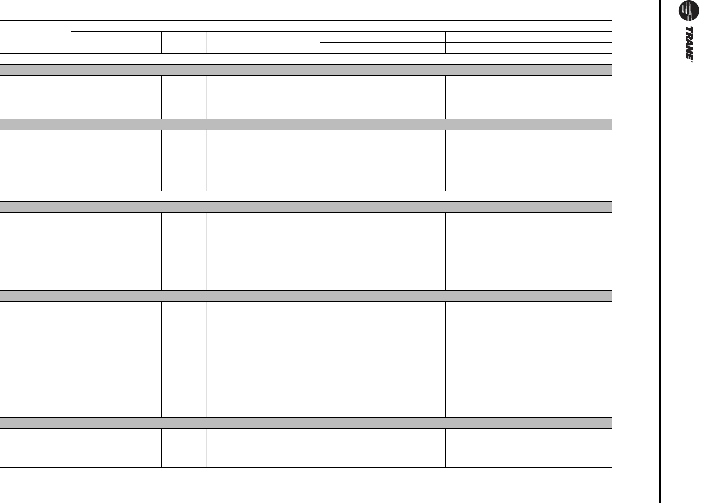
Unit Startup
11 2 RT-SVX24K-EN
Table 37. Service test guide for component operation — part I of II
Component
Being Tested
COMPONENT CONFIGURATION
Supply
Fan Return
Fan Exhaust
Fan Condenser
Fans Heat Stages Compressor Stage
1231234
COMPRESSOR
90 - 105 Ton
1A OFF OFF OFF ALL OFF OFF OFF OFF ON OFF OFF OFF
1B OFF OFF OFF ALL OFF OFF OFF OFF ON ON OFF OFF
2A OFF OFF OFF ALL OFF OFF OFF OFF OFF OFF ON OFF
2B OFF OFF OFF ALL OFF OFF OFF OFF OFF OFF ON ON
120 - 162 Ton
1A OFF OFF OFF 1A-On /1B-Off/1C-Off/1D-Off
2A-Off/2B-Off/2C-Off/2D-Off OFF OFF OFF ON OFF OFF OFF
1B OFF OFF OFF ALL OFF OFF OFF OFF ON ON OFF OFF
2A OFF OFF OFF 1A-Off/1B-Off/1C-Off/1D-Off
2A-On/2B-Off/2C-Off/2D-Off OFF OFF OFF OFF OFF ON OFF
2B OFF OFF OFF ALL OFF OFF OFF OFF OFF OFF ON ON
CONDENSER FANS
90 - 105 Ton — Air Cooled
1A OFF OFF OFF 1A-On /1B-Off/1C-Off
2A-Off/2B-Off/2C-Off OFF OFF OFF OFF OFF OFF OFF
1B & 1C OFF OFF OFF 1A-Off/1B-On /1C-On
2A-Off/2B-Off/2C-Off OFF OFF OFF OFF OFF OFF OFF
2A OFF OFF OFF 1A-Off/1B-Off/1C-Off
2A-On /2B-Off/2C-Off OFF OFF OFF OFF OFF OFF OFF
2B & 2C OFF OFF OFF 1A-On/1B-Off/1C-Off
2A-Off /2B-On /2C-On OFF OFF OFF OFF OFF OFF OFF
120 - 150 Ton — Air Cooled
1A OFF OFF OFF 1A-On /1B-Off/1C-Off/1D-Off
2A-Off/2B-Off/2C-Off/2D-Off OFF OFF OFF OFF OFF OFF OFF
1B OFF OFF OFF 1A-Off/1B-On/1C-Off/ 1D-Off
2A-Off/2B-Off/2C-Off/ 2D-Off OFF OFF OFF OFF OFF OFF OFF
1C & 1D OFF OFF OFF 1A-Off/1B-On/1C-On/ 1D-On
2A-Off/2B-Off/2C-Off/ 2D-Off OFF OFF OFF OFF OFF OFF OFF
2A OFF OFF OFF 1A-Off/1B-Off/1C-Off/ 1D-Off
2A-On /2B-Off/2C-Off & 2D-Off OFF OFF OFF OFF OFF OFF OFF
2B & 2C OFF OFF OFF 1A-Off/1B-On/1C-Off/ 1D-Off
2A-Off/2B-On/2C-On/ 2D-Off OFF OFF OFF OFF OFF OFF OFF
2D OFF OFF OFF 1A-Off/1B-On/1C-Off 1D-Off
2A-Off/2B-Off/2C-Off/ 2D-On OFF OFF OFF OFF OFF OFF OFF
100, 118, 128, 140, 162 Ton — Evaporative Condensing
1A OFF OFF OFF 1A 0 -100 %
2A OFF OFF OFF OFF OFF OFF OFF OFF
2A OFF OFF OFF 1A OFF
2A 0 - 100% OFF OFF OFF OFF OFF OFF OFF
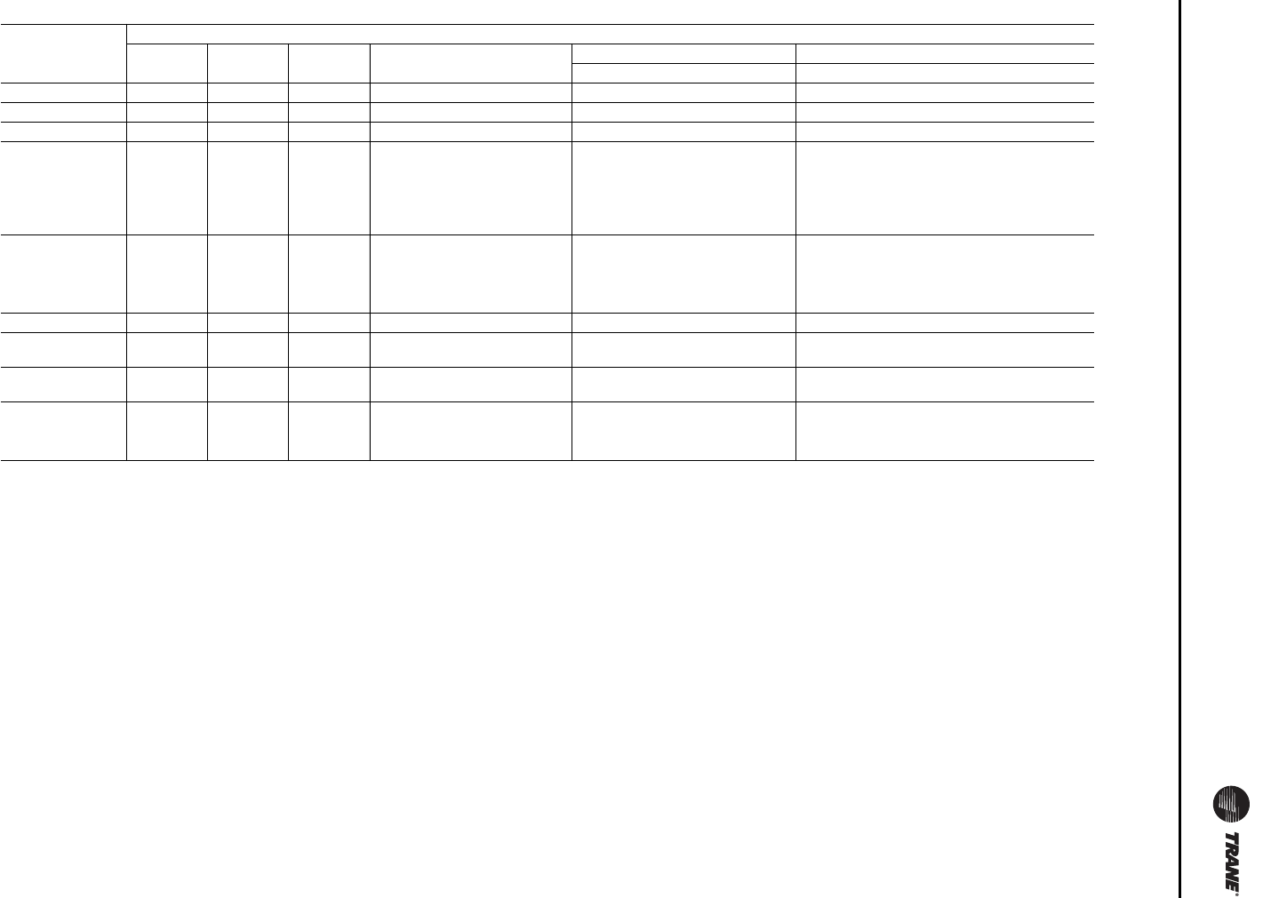
Unit Startup
RT-SVX24K-EN 11 3
SUPPLY FAN ON ON OFF ALL OFF OFF OFF OFF OFF OFF OFF OFF
RETURN FAN ON ON N/A ALL OFF OFF OFF OFF OFF OFF OFF OFF
EXHAUST FAN OFF N/A ON ALL OFF OFF OFF OFF OFF OFF OFF OFF
GAS HEAT
(Full Capacity) ON ON OFF ALL OFF ON ON ON OFF OFF OFF OFF
STAGE 1 ON ON OFF ALL OFF ON OFF ON OFF OFF OFF OFF
STAGE 2 ON ON OFF ALL OFF OFF ON N/A OFF OFF OFF OFF
Full Modulating ON ON OFF ALL OFF 10% - 90% OFF OFF OFF OFF
ELECTRIC HEAT ON ON OFF ALL OFF ON ON ON OFF OFF OFF OFF
Stage 1 ON ON OFF ALL OFF ON OFF OFF OFF OFF OFF OFF
Stage 2 ON ON OFF ALL OFF OFF ON OFF OFF OFF OFF OFF
Stage 3 ON ON OFF ALL OFF OFF OFF ON OFF OFF OFF OFF
HYDRONIC HEAT OFF OFF OFF ALL OFF 100% Select OFF OFF OFF OFF
OUTSIDE AIR
DAMPERS OFF OFF OFF ALL OFF 100% Select OFF OFF OFF OFF
EXHAUST
DAMPERS OFF OFF OFF ALL OFF 100% Select OFF OFF OFF OFF
EVAP COND
Sump Pump OFF OFF OFF ALL OFF 100% Select OFF OFF OFF OFF
Sump Heater OFF OFF OFF ALL OFF 100% Select OFF OFF OFF OFF
Table 37. Service test guide for component operation — part I of II (continued)
Component
Being Tested
COMPONENT CONFIGURATION
Supply
Fan Return
Fan Exhaust
Fan Condenser
Fans Heat Stages Compressor Stage
1231234
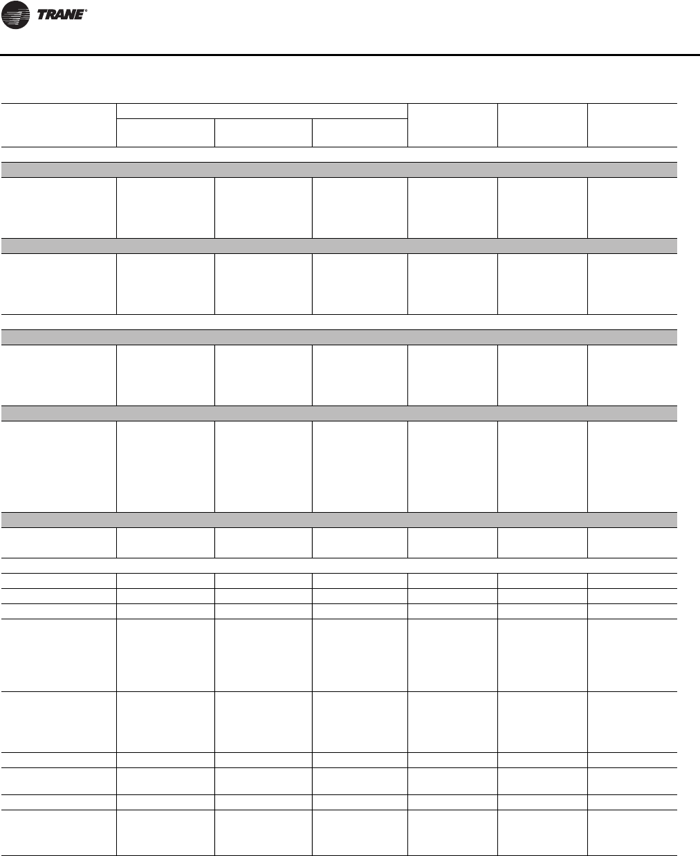
Unit Startup
114 RT-SVX24K-EN
Table 38. Service test guide for component operation — part II of II
Component
Being Tested
Component Configuration Occ
Unocc
Relay Sump Pump Sump Heater
Econo
Damper Exhaust
Damper VFD
Output
COMPRESSOR
90 - 105 Ton
1A Closed Closed 0% Default OFF OFF
1B Closed Closed 0% Default OFF OFF
2A Closed Closed 0% Default OFF OFF
2B Closed Closed 0% Default OFF OFF
120 - 162 Ton
1A Closed Closed 0% Default OFF OFF
1B Closed Closed 0% Default OFF OFF
2A Closed Closed 0% Default OFF OFF
2B Closed Closed 0% Default OFF OFF
CONDENSER FANS
90 - 105 Ton — Air Cooled
1A Closed Closed 0% Default OFF OFF
1B & 1C Closed Closed 0% Default OFF OFF
2A Closed Closed 0% Default OFF OFF
2B & 2C Closed Closed 0% Default OFF OFF
120 - 150 Ton — Air Cooled
1A Closed Closed 0% Default OFF OFF
1B Closed Closed 0% Default OFF OFF
1C & 1D Closed Closed 0% Default OFF OFF
2A Closed Closed 0% Default OFF OFF
2B & 2C Closed Closed 0% Default OFF OFF
2D Closed Closed 0% Default OFF OFF
100, 118, 128, 140, 162 Ton — Evaporative Cooled
1A Closed Closed 0% Default OFF OFF
2A Closed Closed 0% Default OFF OFF
SUPPLY FAN Closed Closed 100% Unocc OFF OFF
RETURN FAN Closed Closed 100% Default OFF OFF
EXHAUST FAN Closed Closed 100% Default OFF OFF
GAS HEAT
(Full Capacity) Closed Closed 100% Unocc OFF OFF
Stage 1 Closed Closed 100% Unocc OFF OFF
Stage 2 Closed Closed 100% Unocc OFF OFF
Full Modulating Closed Closed 100% Unocc OFF OFF
ELECTRIC HEAT Closed Closed 100% Unocc OFF OFF
Stage 1 Closed Closed 100% Unocc OFF OFF
Stage 2 Closed Closed 100% Unocc OFF OFF
Stage 3 Closed Closed 100% Unocc OFF OFF
HYDRONIC HEAT Closed Closed 100% Default OFF OFF
OUTSIDE AIR
DAMPERS Closed Closed 100% Default OFF OFF
EXHAUST DAMPERS Closed Closed 100% Default OFF OFF
EVAP COND
Sump Pump Closed Closed 100% Default ON OFF
Sump Heater Closed Closed 100% Default OFF ON
Unit Startup
RT-SVX24K-EN 11 5
Service Testing—Evaporative Condenser
Components
From the Compressor and Condenser Service Menu
screens—Head Pressure Control: AUTO or Head Pressure
Control: MANUAL
1. Select:
Head Pressure Control: MANUAL
Note: All outputs, Sump Control, Fan Stage Control and
Fan speed Control (per circuit where specified), will
be available for ON/OFF, OPEN/CLOSED, 0-100%
manual settings considering the stipulations in
Table 39:
Notes:
1. Sump Freeze Protection is active during AUTO but is inactive in service
test modes (Head Pressure Control set to MANUAL).
2. Water Treatment Drain Request will be ignored in Service Test.
Verifying Proper Fan Rotation
Note: Fans controlled by VFD will run in the correct
direction even if phasing is incorrect.
1. Ensure that the “System” selection switch at the
remote panel is in the “Off” position and the “Fan”
selection switch for constant volume units is in the
“Auto” position. (VAV and SZVAV units do not utilize a
“Fan” selection input.)
2. Close the disconnect switch or circuit protector switch
that provides the supply power to the unit terminal
block 1TB1 or the unit mounted disconnect switch
1S14.
3. Turn the 115 volt control circuit switch 1S2 and the 24
volt control circuit switch 1S3 to the “On” position.
4. Open the Human Interface access door, located in the
unit control panel, and press the SERVICE MODE key to
display the first service screen. Refer to the latest
edition of the appropriate programming manual for
applications for the SERVICETEST screens and
programming instructions.
5. Use Table 37, p. 11 2 to program the unit Fans for
operation by scrolling through the displays. All of the
Fans (Supply, Exhaust, and Condenser fans) can be
programmed to be “On”, if desired.
Refer to Figure 69, p. 11 6 for the condenser fan
locations and the Human Interface designator.
6. Once the configuration for the Fans is complete, press
the NEXT key until the LCD displays the “Start test in
__Sec.” screen. Press the + key to designate the delay
before the test is to start.This service test will begin
after theTEST START key is pressed and the delay
designated in this step has elapsed. Press the ENTER
key to confirm this choice.
7. Press theTEST START key to start the test. Remember
that the delay designated in step 6 must elapse before
the fans will begin to operate.
8. Check the supply fan and the exhaust fans (if equipped)
for proper rotation.The direction of rotation is
indicated by an arrow on the fan housings. Check the
condenser fans for clockwise rotation when viewed
from the top.
Table 39. Service test guide component operation—
evaporative condenser
COMPONENT
BEING TESTED Requirements (ON) Requirements
(OFF)
Compressors Sump minimum level
switch must be closed for
a minimum of five minutes No Requirements
Sump Pump Sump minimum level
switch must be closed for
a minimum of five minutes No Requirements
Condenser Fans No Requirements No Requirements
Fill Valve Solenoid No Requirements No Requirements
Drain Valve Actuator No Requirements No Requirements
Sump Heater No Requirements No Requirements
WARNING
Rotating Components!
During installation, testing, servicing and
troubleshooting of this product it may be necessary to
work with live and exposed rotating components. Have
a qualified or licensed service individual who has been
properly trained in handling exposed rotating
components, perform these tasks. Failure to follow all
safety precautions could result in rotating components
cutting and slashing technician which could result in
death or serious injury.
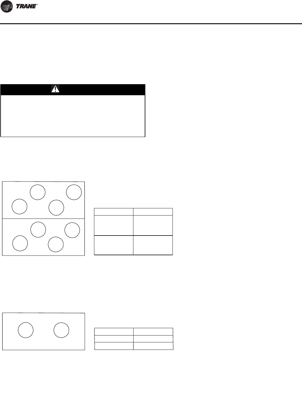
Unit Startup
11 6 RT-SVX24K-EN
If all of the fans are rotating backwards;
a. Press the STOP key at the Human Interface Module
in the unit control panel to stop the fan operation.
b. Open the field supplied disconnect switch upstream
of the rooftop unit. Lock the disconnect switch in the
open position while working at the unit.
c. Interchange any two of the field connected main
power wires at the unit terminal block or the factory
mounted disconnect switch.
Note: Interchanging “Load” side power wires at the fan
contactors will only affect the individual fan
rotation. Ensure that the voltage phase sequence at
the main terminal block or the factory mounted
disconnect switch is ABC as outlined in the
“Electrical Phasing” section.
If some of the fans are rotating backwards;
a. Press the STOP key at the Human Interface Module
in the unit control panel to stop the fan operation.
b. Open the field supplied disconnect switch upstream
of the rooftop unit. Lock the disconnect switch in the
open position while working at the unit.
c. Interchange any two of the fan motor leads at the
contactor for each fan that is rotating backwards.
WARNING
Hazardous Voltage!
Disconnect all electric power, including remote
disconnects before servicing. Follow proper lockout/
tagout procedures to ensure the power can not be
inadvertently energized. Failure to disconnect power
before servicing could result in death or serious injury.
Figure 69. Air-cooled (90-150 tons)/evaporative (100-162 tons) condenser fan locations with human interface
designator
2B9
2B11
2B10
2B12
2B14
2B15
2B13
2B16
2B9 1K9
01K101B2
2B11 1K10
4K121B2
11K131B2
21K141B2
2B15 1K12
2B16 1K1
Condenser Fan Motor Designator Condenser Fan contactor
Designator
120 TON
130 TON
150 TON
2B5 2B6
2B5 1K4*
*1K16B2
Condenser Fan Motor Designator Condenser Fan contactor
Designator
100 TON
118 TON
128 TON
140 TON
162 TON
*Note: 2B5 and 2B6 are initiated with operation of
1K4 and 1K1 compressor contactors.
Unit Startup
RT-SVX24K-EN 11 7
System Airflow Measurements
Constant Volume Systems
1. Ensure that the “System” selection switch at the
remote panel is in the “Off” position and the “Fan”
selection switch for constant volume units is in the
“Auto” position.
2. Close the disconnect switch or circuit protector switch
that provides the supply power to the unit terminal
block or the unit mounted disconnect switch.
HIGH VOLTAGE IS PRESENT AT TERMINAL BLOCK OR
UNIT DISCONNECT SWITCH.
3. Turn the 115 volt control circuit switch and the 24 volt
control circuit switch to the “On” position.
4. Open the Human Interface access door, located in the
unit control panel, and press the SERVICE MODE key to
display the first service screen. Refer to the latest
edition of the appropriate programming manual for CV
applications for the SERVICETEST screens and
programming instructions.
5. Use Table 37, p. 11 2 to program the Supply Fan for
operation by scrolling through the displays.
6. Once the configuration for the Fan is complete, press
the NEXT key until the LCD displays the “Start test in
__Sec.” screen. Press the +key to designate the delay
before the test is to start.This service test will begin
after theTEST START key is pressed and the delay
designated in this step has elapsed. Press the ENTER
key to confirm this choice.
7. Press theTEST START key to start the test. Remember
that the delay designated in step 6 must elapse before
the fans will begin to operate.
8. With the system in the SERVICE MODE and the supply
fan rotating in the proper direction, measure the
amperage at the supply fan contactors. If the
amperage exceeds the motor nameplate value, the
static pressure is less than design and the airflow is too
high. If the amperage is below the motor nameplate
value, static pressure may be too high and CFM may be
too low.To determine the actual CFM (± 5%);
a. Measure the actual fan RPM
b. Calculate theTheoretical BHP
Actual Motor Amps X Motor HP
Motor Nameplate Amps
c. Plot this data onto the appropriate Fan Performance
Curve beginning with Figure 62, p. 100. Where the
two points intersect, read straight down to the CFM
line.
Use this data to assist in calculating a new fan drive if the
CFM is not at design specifications.
An alternate method with less accuracy is to measure the
static pressure drop across the evaporator coil.This can be
accomplished by;
a. drilling a small hole through the unit casing on each
side of the coil.
Note: Coil damage can occur if care is not taken when
drilling holes in this area.
b. Measure the difference between the pressures at
both locations.
c. Plot this value onto the appropriate pressure drop
curve beginning with Figure 71, p. 120. Use the data
in Table 40, p. 127 (Component Static Pressure
Drops) to assist in calculating a new fan drive if the
CFM is not at design specifications.
d. Plug the holes after the proper CFM has been
established.
9. Press the STOP key at the Human Interface Module in
the unit control panel to stop the fan operation.
Variable Air Volume Systems
1. Ensure that the “System” selection switch at the
remote panel is in the “Off” position.
2. Close the disconnect switch or circuit protector switch
that provides the supply power to the unit terminal
block or the unit mounted disconnect switch.
WARNING
Hazardous Voltage!
Disconnect all electric power, including remote
disconnects before servicing. Follow proper lockout/
tagout procedures to ensure the power can not be
inadvertently energized. Failure to disconnect power
before servicing could result in death or serious injury.
WARNING
Live Electrical Components!
During installation, testing, servicing and
troubleshooting of this product, it may be necessary to
work with live electrical components. Have a qualified
licensed electrician or other individual who has been
properly trained in handling live electrical components
perform these tasks. Failure to follow all electrical
safety precautions when exposed to live electrical
components could result in death or serious injury.
Unit Startup
11 8 RT-SVX24K-EN
HIGH VOLTAGE IS PRESENT AT TERMINAL BLOCK OR
UNIT DISCONNECT SWITCH.
3. Turn the 115 volt control circuit switch and the 24 volt
control circuit switch to the “On” position.
4. Open the Human Interface access door, located in the
unit control panel, and press the SERVICE MODE key to
display the first service screen. Refer to the latest
edition of the appropriate Programming Manual for
VAV applications for the SERVICETEST screens and
programming instructions.
Use Table 37, p. 112 to program the following system
components for operation by scrolling through the
displays:
Supply Fan,
Variable Frequency Drive (100% Output, if applicable),
RTM Occ/Unocc Output (Unoccupied)
5. Once the configuration for the components is
complete, press the NEXT key until the LCD displays
the “Start test in __Sec.” screen. Press the +key to
designate the delay before the test is to start.This
service test will begin after theTEST START key
is pressed and the delay designated in this step has
elapsed. Press the ENTER key to confirm this choice.
6. Press theTEST START key to start the test. Remember
that the delay designated in step 6 must elapse before
the fan will begin to operate.
7. With the VFD at 100% and the supply fan operating at
full airflow capability, measure the amperage at the
supply fan contactors. If the amperage exceeds the
motor nameplate value, the static pressure is less than
design and the airflow is too high. If the amperage is
below the motor nameplate value, static pressure may
be too high and CFM may be too low.To determine the
actual CFM (± 5%);
a. Measure the actual fan RPM
b. Calculate theTheoretical BHP
Actual Motor Amps X Motor HP
Motor Nameplate Amps
c. Plot this data onto the appropriate Fan Performance
Curve beginning with Figure 62, p. 100. Where the
two points intersect, read straight down to the CFM
line.
Use this data to assist in calculating a new fan drive if the
CFM is not at design specifications.
An alternate method with less accuracy is to measure the
static pressure drop across the evaporator coil.This can be
accomplished by:
a. drilling a small hole through the unit casing on each
side of the coil.
Note: Coil damage can occur if care is not taken when
drilling holes in this area.
b. Measure the difference between the pressures at
both locations.
c. Plot this value onto the appropriate pressure drop
curve beginning with Figure 71, p. 120. Use the data
in Table 40, p. 127 (Component Static Pressure
Drops) to assist in calculating a new fan drive if the
CFM is not at design specifications.
d. Plug the holes after the proper CFM has been
established. Press the STOP key at the Human
Interface Module in the unit control panel to stop
the fan operation.
8. Press the STOP key at the Human Interface Module
in the unit control panel to stop the fan operation.
Exhaust Airflow Measurement (Optional)
1. Close the disconnect switch or circuit protector
switch that provides the supply power to the unit's
terminal block or the unit mounted disconnect
switch.
HIGH VOLTAGE IS PRESENT AT TERMINAL BLOCK OR
UNIT DISCONNECT SWITCH.
2. Turn the 115 volt control circuit switch and the 24 volt
control circuit switch to the “On” position.
3. Open the Human Interface access door, located in
the unit control panel, and press the SERVICE MODE
WARNING
Hazardous Voltage!
Disconnect all electric power, including remote
disconnects before servicing. Follow proper lockout/
tagout procedures to ensure the power can not be
inadvertently energized. Failure to disconnect power
before servicing could result in death or serious injury.
WARNING
Live Electrical Components!
During installation, testing, servicing and
troubleshooting of this product, it may be necessary to
work with live electrical components. Have a qualified
licensed electrician or other individual who has been
properly trained in handling live electrical components
perform these tasks. Failure to follow all electrical
safety precautions when exposed to live electrical
components could result in death or serious injury.
WARNING
Hazardous Voltage!
Disconnect all electric power, including remote
disconnects before servicing. Follow proper lockout/
tagout procedures to ensure the power can not be
inadvertently energized. Failure to disconnect power
before servicing could result in death or serious injury.
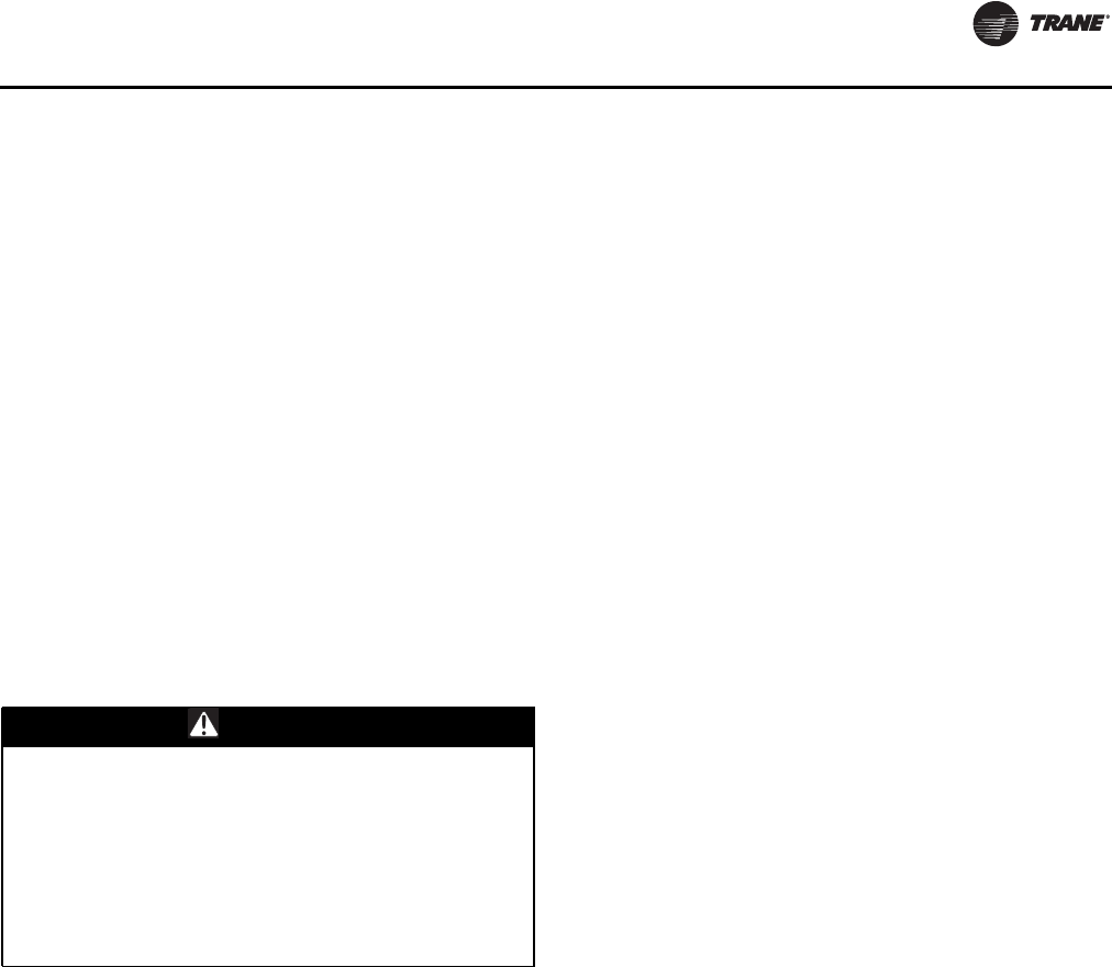
Unit Startup
RT-SVX24K-EN 119
key to display the first service screen. Refer to the
latest edition of the appropriate programming
manual for applications for the SERVICETEST
screens and programming instructions.
4. Use Table 37, p. 11 2 to program the following system
components for operation by scrolling through the
displays:
Exhaust Fan,
Exhaust Dampers (100% Open, if applicable),
Outside air dampers (100% Open),
Variable Frequency Drive (100%, if applicable),
RTM Occ/Unocc Output (Default)
5. Once the configuration for the components is
complete, press the NEXT key until the LCD displays
the “Start test in __Sec.” screen. Press the +key to
designate the delay before the test is to start.This
service test will begin after theTEST START
key is pressed and the delay designated in this step
has elapsed. Press the ENTER key to confirm this
choice.
6. Press theTEST START key to start the test. Remember
that the delay designated in step 5 must elapse before
the fans will begin to operate.
7. With the exhaust dampers open and the exhaust fan
operating at full airflow capability, measure the
amperage at the exhaust fan contactor. If the
amperage exceeds the motor nameplate value, the
static pressure is less than design and airflow is too
high. If the amperage is below the motor nameplate
value, static pressure may be too high and CFM may be
too low.To determine the actual CFM (± 5%);
a. Measure the actual fan RPM
b. Calculate theTheoretical BHP
Actual Motor Amps X
Motor HP
Motor Nameplate Amps
Use appropriate figures beginning with Figure 71, p. 120
to calculate a new fan drive if the CFM is not at design
specifications.
8. Press the STOP key at the Human Interface Module in
the unit control panel to stop the fan operation.
TRAQ™ Sensor Airflow Measurement
(Optional with all units equipped with an
economizer)
1. Open the Human Interface access door, located in the
unit control panel, and press the SERVICE MODE key to
display the first service screen. Refer to the latest
edition of the appropriate programming manual for
applications for the SERVICETEST screens and
programming instructions.
2. Use Table 37, p. 11 2 to program the following system
components for Economizer operation by scrolling
through the displays;
Supply Fan (On)
Outside air dampers (Selected % Open)
Variable Frequency Drive (100% Output, if applicable)
RTM Occ/Unocc Output (Unoccupied)
Outside Air CFM Setpoint
Outside Air Pre-Heater Operation (if applicable)
3. Once the configuration for the components is
complete, press the NEXT key until the LCD displays
the “Start test in __Sec.” screen. Press the +key to
designate the delay before the test is to start.This
service test will begin after theTEST START key
is pressed and the delay designated in this step has
elapsed. Press the ENTER key to confirm this choice.
4. Press theTEST START key to start the test. Remember
that the delay designated in step 3 must elapse before
the fans will begin to operate.
5. With the unit operating in the “TEST MODE”, the
amount of outside air flowing through theTRAQ
sensor can be viewed by switching to the “STATUS
MENU” screen “OA CFM.
6. Scroll to the “ECONOMIZER ENABLE/ECONOMIZER
POSITION” screen by pressing the “NEXT” key and
read the corresponding damper opening percentage
(%).
7. Press the STOP key at the Human Interface Module in
the unit control panel to stop the unit operation.
WARNING
Live Electrical Components!
During installation, testing, servicing and
troubleshooting of this product, it may be necessary to
work with live electrical components. Have a qualified
licensed electrician or other individual who has been
properly trained in handling live electrical components
perform these tasks. Failure to follow all electrical
safety precautions when exposed to live electrical
components could result in death or serious injury.
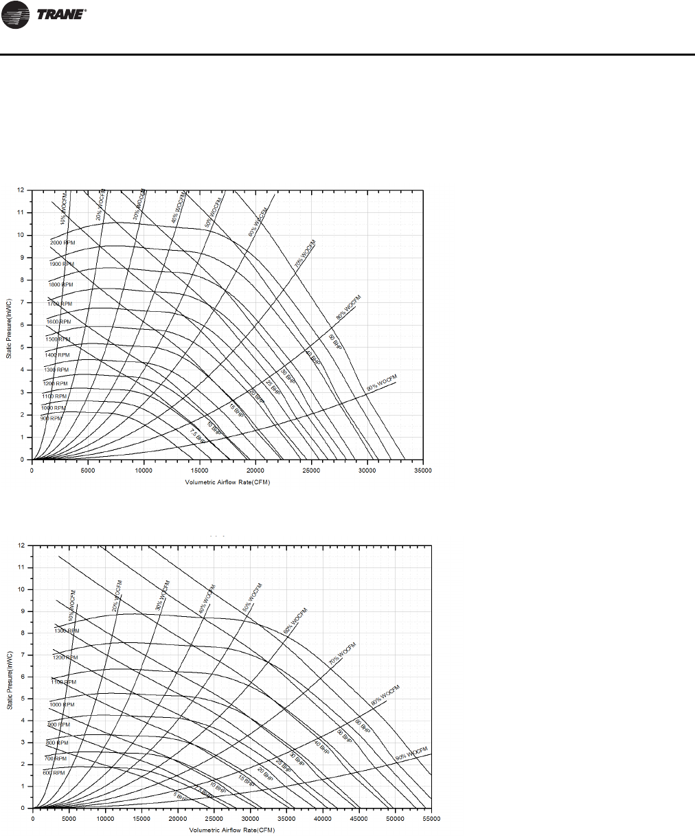
Unit Startup
120 RT-SVX24K-EN
Performance Data
Supply Fan with or without Variable
Frequency Drive
Figure 70. Supply fan performance LOW CFM — 90/100 tons, 25” supply fan
Figure 71. Supply fan performance STANDARD CFM — 90/100 and 105/118 tons, 36” supply fan
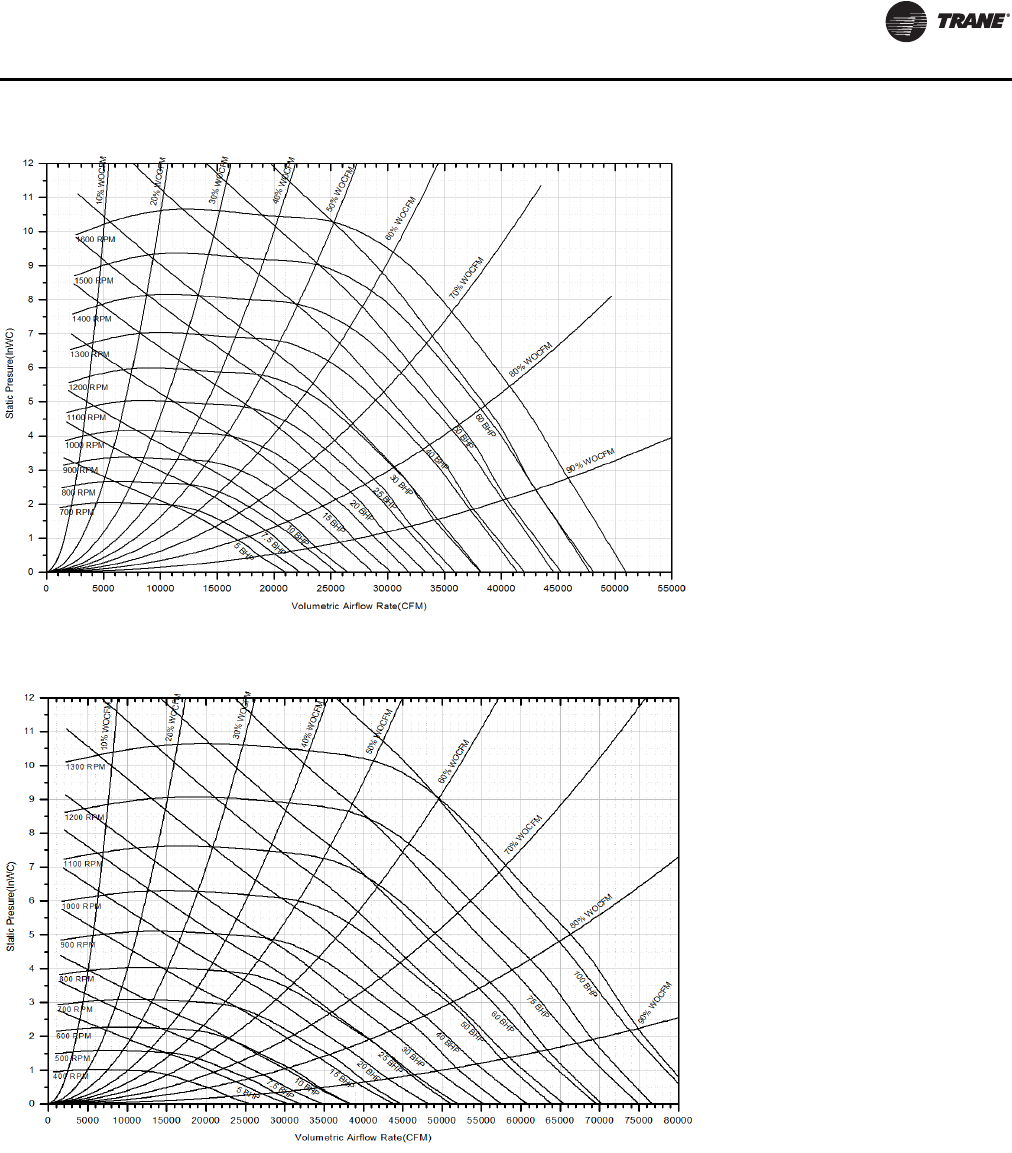
Unit Startup
RT-SVX24K-EN 121
Figure 72. Supply fan performance LOW CFM — 105-162 ton, 32” supply fan
Figure 73. Supply fan performance STANDARD CFM — 120-162 tons, 40” supply fan
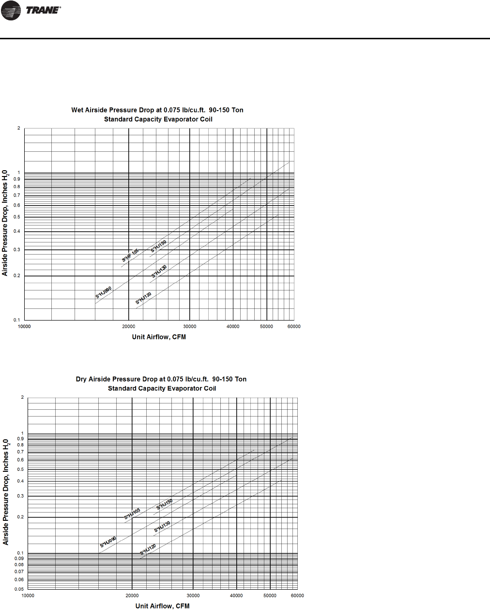
Unit Startup
122 RT-SVX24K-EN
Airside Pressure Drop Standard
Evaporator Coil
Figure 74. Wet airside pressure drop at 0.075 lb./cu. ft.—90-162 tons standard evaporator coil
Figure 75. Dry airside pressure drop at 0.075 lb./cu. ft.—90-162 tons standard capacity evaporator coil
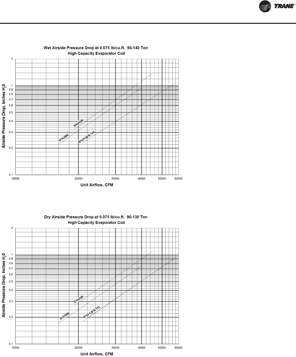
Unit Startup
RT-SVX24K-EN 123
Figure 76. Wet airside pressure drop at 0.075 lb./cu. ft.—90-140 tons high capacity evaporator coil
Figure 77. Dry airside pressure drop at 0.075 lb./cu. ft.—90-140 tons high capacity
evaporator coil
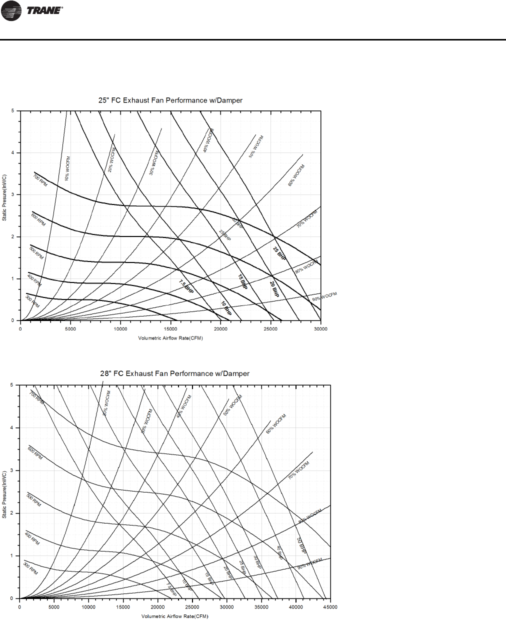
Unit Startup
124 RT-SVX24K-EN
Exhaust Fan Performance
Figure 78. Exhaust fan performance LOW CFM — 90/100 tons
Figure 79. Exhaust fan performance STANDARD CFM — 90/100 tons; LOW CFM — 105-162 tons
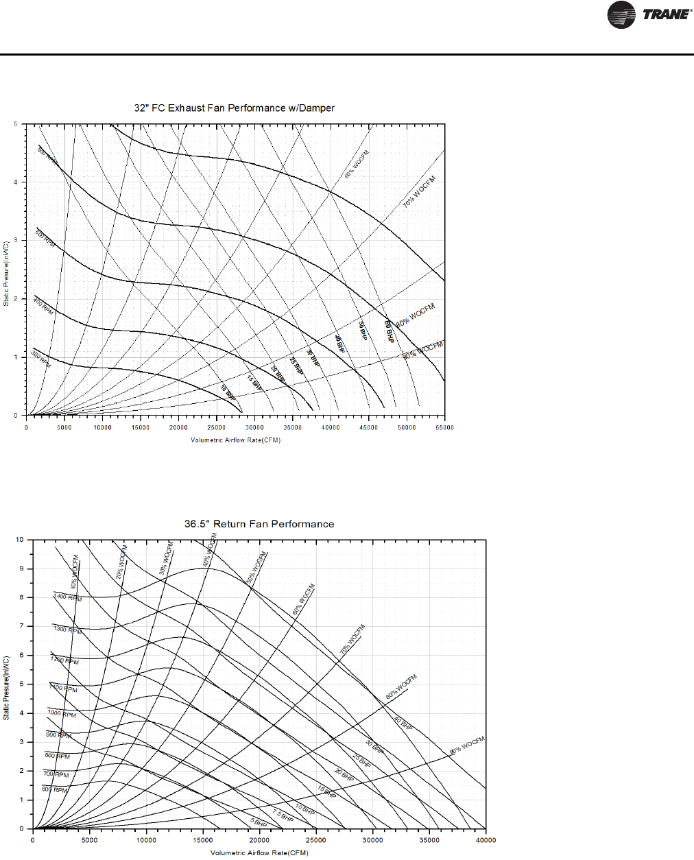
Unit Startup
RT-SVX24K-EN 125
Return Fan Performance
Figure 80. Exhaust fan performance STANDARD CFM — 105-162 tons
Figure 81. Return fan performance LOW CFM — 90-162 tons
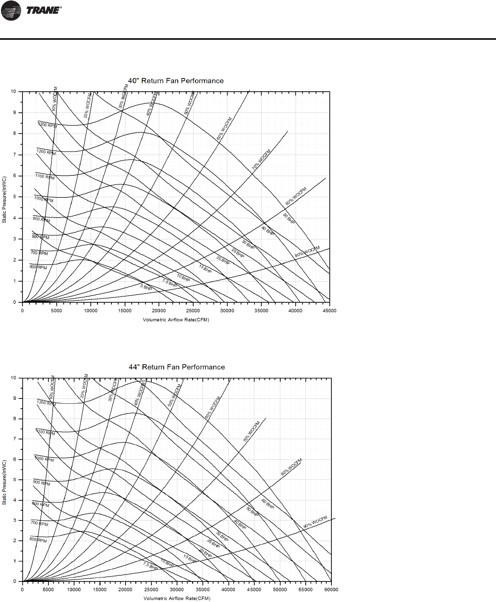
Unit Startup
126 RT-SVX24K-EN
Figure 82. Return fan performance STANDARD CFM — 90-118 tons
Figure 83. Return fan performance STANDARD CFM — 120-162 tons
Unit Startup
RT-SVX24K-EN 127
Component Static Pressure Drops
Table 40. Component static pressure drops (in. H2O)
Nom
Tons CFM
(a)
Evaporator Coil Reheat
Coil (Dampers wide open) Standard High Capacity
Dry Wet Dry Wet Dry Return
Damper Econo
Damper TRAQ
Damper
90/100
16000 0.10 0.13 0.17 0.22 0.04 0.06 0.11 0.19
20000 0.15 0.19 0.24 0.31 0.06 0.10 0.17 0.29
25000 0.21 0.27 0.35 0.45 0.08 0.16 0.27 0.45
30000 0.28 0.36 0.47 0.60 0.11 0.23 0.39 0.65
33000 0.33 0.42 0.55 0.70 0.13 0.28 0.47 0.79
36000 0.38 0.48 0.63 0.80 0.15 0.34 0.57 0.94
40000 0.45 0.57 0.75 0.95 0.18 0.42 0.70 1.16
105/118
19000 0.18 0.23 0.27 0.32 0.05 0.09 0.15 0.26
23000 0.20 0.31 0.37 0.47 0.07 0.13 0.23 0.38
28000 0.34 0.43 0.51 0.64 0.10 0.20 0.34 0.57
33000 0.44 0.56 0.66 0.84 0.13 0.28 0.47 0.79
38000 0.55 0.70 0.83 1.05 0.16 0.38 0.63 1.05
43000 0.67 0.85 1.01 1.28 0.20 0.49 0.81 1.34
45000 0.73 0.92 1.09 1.38 0.21 0.53 0.89 1.47
120/128
21000 0.09 0.12 0.18 0.23 0.04 0.05 0.10 0.17
26000 0.13 0.16 0.25 0.32 0.06 0.09 0.15 0.26
31000 0.17 0.21 0.34 0.43 0.08 0.12 0.22 0.36
36000 0.21 0.27 0.43 0.55 0.10 0.17 0.30 0.49
41000 0.26 0.34 0.53 0.67 0.12 0.22 0.39 0.64
46000 0.32 0.40 0.64 0.81 0.15 0.28 0.49 0.80
51000 0.38 0.48 0.75 0.95 0.18 0.35 0.61 0.99
54000 0.41 0.52 0.83 1.05 0.20 0.39 0.68 1.11
130/140
23000 0.14 0.18 0.21 0.27 0.05 0.07 0.12 0.20
26000 0.17 0.22 0.25 0.32 0.06 0.09 0.15 0.26
30000 0.21 0.27 0.32 0.41 0.07 0.12 0.21 0.34
35000 0.27 0.35 0.41 0.52 0.10 0.16 0.28 0.46
40000 0.34 0.43 0.51 0.65 0.12 0.21 0.37 0.61
45000 0.41 0.52 0.61 0.78 0.15 0.27 0.47 0.77
50000 0.49 0.62 0.73 0.93 0.17 0.33 0.59 0.95
55000 0.57 0.72 0.85 1.08 0.20 0.40 0.71 1.15
58000 0.62 0.78 0.93 1.18 0.22 0.45 0.79 1.28
150/162
23000 0.21 0.27 - - 0.05 0.07 0.12 0.20
26000 0.25 0.32 - - 0.06 0.09 0.15 0.26
30000 0.32 0.41 - - 0.07 0.12 0.21 0.34
35000 0.41 0.52 - - 0.10 0.16 0.28 0.46
40000 0.51 0.65 - - 0.12 0.21 0.37 0.61
45000 0.61 0.78 - - 0.15 0.27 0.47 0.77
50000 0.73 0.93 - - 0.17 0.33 0.59 0.95
55000 0.85 1.08 - - 0.20 0.40 0.71 1.15
58000 0.93 1.18 - - 0.22 0.45 0.79 1.28
Unit Startup
128 RT-SVX24K-EN
Nom
Tons CFM
Electric
Heating
(Horizontal)
Gas Heating Hydronic Heating Coil Data
Low Heat Medium Heat High Heat Hot Water Coil Steam Coil
All kW's
(b) DF Hz DF Hz DF Hz High Low High Low
90/100
16000 0.01 0.01 0.10 0.01 0.12 0.01 0.14 0.13 0.08 0.12 0.08
20000 0.02 0.01 0.16 0.01 0.19 0.01 0.22 0.19 0.12 0.17 0.12
25000 0.03 0.01 0.24 0.01 0.30 0.01 0.35 0.27 0.17 0.26 0.18
30000 0.05 0.02 0.35 0.02 0.44 0.02 0.50 0.36 0.24 0.35 0.25
33000 0.06 0.02 0.42 0.02 0.53 0.02 0.61 0.42 0.28 0.41 0.30
36000 0.07 0.03 0.51 0.03 0.63 0.03 0.72 0.49 0.33 0.48 0.35
40000 0.08 0.03 0.62 0.03 0.77 0.03 0.89 0.58 0.39 0.57 0.43
105/118
19000 0.02 0.01 0.14 0.01 0.17 0.01 0.20 0.17 0.11 0.16 0.11
23000 0.03 0.01 0.21 0.01 0.26 0.01 0.30 0.23 0.15 0.22 0.16
28000 0.04 0.02 0.31 0.02 0.38 0.02 0.44 0.32 0.21 0.31 0.22
33000 0.06 0.02 0.42 0.02 0.53 0.02 0.61 0.42 0.28 0.41 0.30
38000 0.07 0.03 0.56 0.03 0.70 0.03 0.81 0.53 0.36 0.52 0.39
43000 0.10 0.04 0.72 0.04 0.89 0.04 1.03 0.65 0.45 0.65 0.49
45000 0.10 0.04 0.79 0.04 0.98 0.04 1.13 0.71 0.49 0.70 0.53
120/128
21000 0.02 0.00 0.16 0.00 0.19 0.00 0.23 0.14 0.09 0.13 0.09
26000 0.03 0.00 0.25 0.00 0.30 0.00 0.35 0.20 0.13 0.19 0.13
31000 0.05 0.00 0.35 0.00 0.42 0.00 0.49 0.26 0.17 0.25 0.18
36000 0.07 0.00 0.48 0.00 0.57 0.00 0.67 0.33 0.22 0.33 0.24
41000 0.09 0.00 0.62 0.00 0.74 0.00 0.86 0.42 0.28 0.41 0.30
46000 0.11 0.00 0.78 0.00 0.93 0.00 1.09 0.50 0.34 0.50 0.37
51000 0.13 0.00 0.96 0.00 1.15 0.00 1.34 0.60 0.41 0.59 0.44
54000 0.15 0.00 1.07 0.00 1.28 0.01 1.50 0.66 0.45 0.65 0.49
130/140
23000 0.03 0.00 0.20 0.00 0.23 0.01 0.27 0.16 0.10 0.15 0.10
26000 0.03 0.00 0.25 0.00 0.30 0.00 0.35 0.20 0.13 0.19 0.13
30000 0.05 0.00 0.33 0.00 0.40 0.00 0.46 0.25 0.16 0.24 0.17
35000 0.06 0.00 0.45 0.00 0.54 0.00 0.63 0.32 0.21 0.31 0.22
40000 0.08 0.00 0.59 0.00 0.70 0.00 0.82 0.40 0.27 0.39 0.28
45000 0.10 0.00 0.75 0.00 0.89 0.00 1.04 0.49 0.33 0.48 0.35
50000 0.13 0.00 0.92 0.00 1.10 0.00 1.29 0.58 0.39 0.57 0.43
55000 0.16 0.00 1.12 0.01 1.33 0.01 1.56 0.68 0.47 0.67 0.51
58000 0.17 0.01 1.24 0.01 1.48 0.01 1.74 0.75 0.51 0.74 0.56
150/162
23000 0.03 0.00 0.20 0.00 0.23 0.01 0.27 0.16 0.10 0.15 0.10
26000 0.03 0.00 0.25 0.00 0.30 0.00 0.35 0.20 0.13 0.19 0.13
30000 0.05 0.00 0.33 0.00 0.40 0.00 0.46 0.25 0.16 0.24 0.17
35000 0.06 0.00 0.45 0.00 0.54 0.00 0.63 0.32 0.21 0.31 0.22
40000 0.08 0.00 0.59 0.00 0.70 0.00 0.82 0.40 0.27 0.39 0.28
45000 0.10 0.00 0.75 0.00 0.89 0.00 1.04 0.49 0.33 0.48 0.35
50000 0.13 0.00 0.92 0.00 1.10 0.00 1.29 0.58 0.39 0.57 0.43
55000 0.16 0.00 1.12 0.01 1.33 0.01 1.56 0.68 0.47 0.67 0.51
58000 0.17 0.01 1.24 0.01 1.48 0.01 1.74 0.75 0.51 0.74 0.56
Table 40. Component static pressure drops (in. H2O) (continued)
Unit Startup
RT-SVX24K-EN 129
Nom
Tons CFM
Standard Filter Section (Pre Evap) Final Filter Section (Post Evap)
Std 2"
High Eff
Throw
Away
Filters
90-95%
Low PD
Cartridg
e Filters
w/ 2"
Prefilter
90-95%
Low PD
Cartridg
e Filters
w/ 4"
Prefilter
90-95%
Cartridg
e Filters
w/ 2"
Prefilter
(c)
90-95%
Bag
Filters
w/ 2"
Prefilter
(c)
90-95%
Std Temp
Low PD
Cartridge
Filters
w/4”
Prefilter
(d)
90-95%
Std
Temp
Bag
Filters
w/ 2"
Prefilter
(e)
90-95%
Std Temp
Cartridg
e Filters
w/ 2"
Prefilter
(e)
90-95%
Hi Temp
Cartridge
Filters
w/ 2" Hi
Temp
Prefilter
(e)
90-95%
Hi Temp
HEPA w/
2" Hi
Temp
Prefilter
(f)
90-95%
Std
Temp
HEPA
Filters
w/ 2" Hi
Temp
Prefilter
(f)
90/105
16000 0.08 0.24 - 0.27 0.34 0.23 0.36 0.29 0.35 0.54 0.48
20000 0.11 0.31 - 0.33 0.41 0.31 0.43 0.36 0.44 0.69 0.61
25000 0.15 0.42 - 0.42 0.50 0.43 0.54 0.47 0.58 0.89 0.78
30000 0.20 0.53 - 0.54 0.60 0.56 0.65 0.60 0.74 1.10 0.95
33000 0.23 0.61 - 0.61 0.67 0.65 0.73 0.69 0.86 1.22 1.06
36000 0.26 0.69 - 0.70 0.73 0.74 0.80 0.79 0.98 1.36 1.16
40000 0.30 0.80 - 0.82 0.83 0.88 0.91 0.93 1.15 - -
105/118
19000 0.10 0.27 - 0.30 0.37 0.27 0.40 0.32 0.40 0.62 0.55
23000 0.11 0.29 - 0.32 0.39 0.29 0.42 0.34 0.42 0.66 0.58
28000 0.18 0.49 - 0.49 0.56 0.51 0.61 0.54 0.68 1.01 0.88
33000 0.23 0.61 - 0.61 0.67 0.65 0.73 0.69 0.86 1.22 1.06
38000 0.28 0.74 - 0.76 0.78 0.81 0.86 0.86 1.06 - -
43000 0.33 0.89 - 0.92 0.91 0.98 1.00 1.05 1.30 - -
45000 0.36 0.95 - 0.99 0.96 1.05 1.06 1.13 1.40 - -
120/128
21000 0.10 - 0.30 0.35 0.42 0.34 0.45 0.38 0.47 0.73 0.64
26000 0.13 - 0.41 0.44 0.52 0.46 0.56 0.49 0.61 0.93 0.81
31000 0.17 - 0.53 0.56 0.62 0.59 0.68 0.63 0.78 1.14 0.99
36000 0.20 - 0.66 0.70 0.73 0.74 0.80 0.79 0.98 1.36 1.16
41000 0.25 - 0.81 0.85 0.86 0.91 0.94 0.97 1.20 - -
46000 0.29 - 0.96 1.03 0.99 1.09 1.09 1.17 1.45 - -
51000 0.34 - 1.14 - - 1.29 - - - - -
54000 0.37 - 1.25 - - 1.42 - - - - -
130/140
23000 0.10 - 0.32 0.37 0.44 0.36 0.47 0.40 0.49 0.77 0.68
26000 0.14 - 0.43 0.47 0.54 0.48 0.58 0.52 0.64 0.97 0.85
30000 0.17 - 0.55 0.59 0.64 0.62 0.70 0.66 0.82 1.18 1.02
35000 0.21 - 0.69 0.73 0.76 0.78 0.83 0.82 1.02 1.40 1.20
40000 0.26 - 0.84 0.89 0.88 0.94 0.97 1.01 1.25 - -
45000 0.30 - 1.00 1.07 1.02 1.13 1.12 1.22 1.51 - -
50000 0.35 - 1.17 1.27 1.16 1.33 - - - - -
55000 0.41 - 1.36 - - 1.55 - - - - -
58000 0.44 - 1.48 - - - - - - - -
Table 40. Component static pressure drops (in. H2O) (continued)
Unit Startup
130 RT-SVX24K-EN
Nom
Tons CFM
Standard Filter Section (Pre Evap) Final Filter Section (Post Evap)
Std 2"
High Eff
Throw
Away
Filters
90-95%
Low PD
Cartridg
e Filters
w/ 2"
Prefilter
90-95%
Low PD
Cartridg
e Filters
w/ 4"
Prefilter
90-95%
Cartridg
e Filters
w/ 2"
Prefilter
(c)
90-95%
Bag
Filters
w/ 2"
Prefilter
(c)
90-95%
Std Temp
Low PD
Cartridge
Filters
w/4”
Prefilter
(d)
90-95%
Std
Temp
Bag
Filters
w/ 2"
Prefilter
(e)
90-95%
Std Temp
Cartridg
e Filters
w/ 2"
Prefilter
(e)
90-95%
Hi Temp
Cartridge
Filters
w/ 2" Hi
Temp
Prefilter
(e)
90-95%
Hi Temp
HEPA w/
2" Hi
Temp
Prefilter
(f)
90-95%
Std
Temp
HEPA
Filters
w/ 2" Hi
Temp
Prefilter
(f)
150/162
23000 0.10 - 0.32 0.37 0.44 0.36 0.47 0.40 0.49 0.77 0.68
26000 0.14 - 0.43 0.47 0.54 0.48 0.58 0.52 0.64 0.97 0.85
30000 0.17 - 0.55 0.59 0.64 0.62 0.70 0.66 0.82 1.18 1.02
35000 0.21 - 0.69 0.73 0.76 0.78 0.83 0.82 1.02 1.40 1.20
40000 0.26 - 0.84 0.89 0.88 0.94 0.97 1.01 1.25 - -
45000 0.30 - 1.00 1.07 1.02 1.13 1.12 1.22 1.51 - -
50000 0.35 - 1.17 1.27 1.16 1.33 - - - - -
55000 0.41 - 1.36 - - 1.55 - - - - -
58000 0.44 - 1.48 - - - - - - - -
(a)Actual Supply Fan CFM Range:90/100 Ton 16,000-40,000;
105/118 Ton 19,000-45,000; 120/128 Ton 21,000-54,000; 130-162 Ton 23,000-58,000
(b)There is no pressure drop with Electric Heat DF configuration
(c) 120-162 Ton Max CFM 50,000
(d)130-162 Ton Max CFM 55,500
(e) 120-162 Ton Max CFM 46,250
(f) 90-162 Ton Max CFM 37,000
Table 40. Component static pressure drops (in. H2O) (continued)
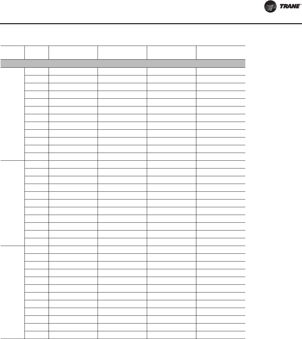
Unit Startup
RT-SVX24K-EN 131
Table 41. Energy recovery wheel component static pressure drops
Nom
Tons CFM Outside Air Bypass
Damper Open Outside Air Bypass
Damper Closed Exhaust Air Bypass
Damper Open Exhaust Air Bypass
Damper Closed
Low CFM Energy Recovery Wheel
90/100
8000 0.07 0.78 0.09 0.66
9000 0.09 0.88 0.11 0.79
10000 0.12 0.99 0.14 0.92
12000 0.16 1.20 0.19 1.16
14000 0.21 1.42 0.24 1.41
16000 0.27 - 0.29 -
20000 0.40 - 0.42 -
25000 0.59 - 0.60 -
30000 0.80 - 0.80 -
33000 0.94 - 0.94 -
36000 1.08 - 1.07 -
40000 1.30 - 1.27 -
105/118
9000 0.09 0.88 0.11 0.79
12000 0.16 1.20 0.19 1.16
14000 0.21 1.42 0.24 1.41
16000 0.27 - 0.29 -
19000 0.36 - 0.39
23000 0.51 - 0.52 -
28000 0.71 - 0.72 -
33000 0.94 - 0.94 -
38000 1.19 - 1.18 -
43000 1.46 - 1.41 -
45000 1.58 - 1.52 -
120/128
9000 0.09 0.78 0.11 0.69
12000 0.16 1.06 0.18 1.02
15000 0.23 1.36 0.26 1.36
18000 0.31 - 0.34 -
21000 0.41 - 0.44 -
26000 0.59 - 0.62 -
31000 0.79 - 0.82 -
36000 1.01 - 1.04 -
41000 1.25 - 1.28 -
46000 1.51 - 1.52 -
51000 1.79 - 1.79 -
54000 1.96 - 1.95 -
Continued on next page
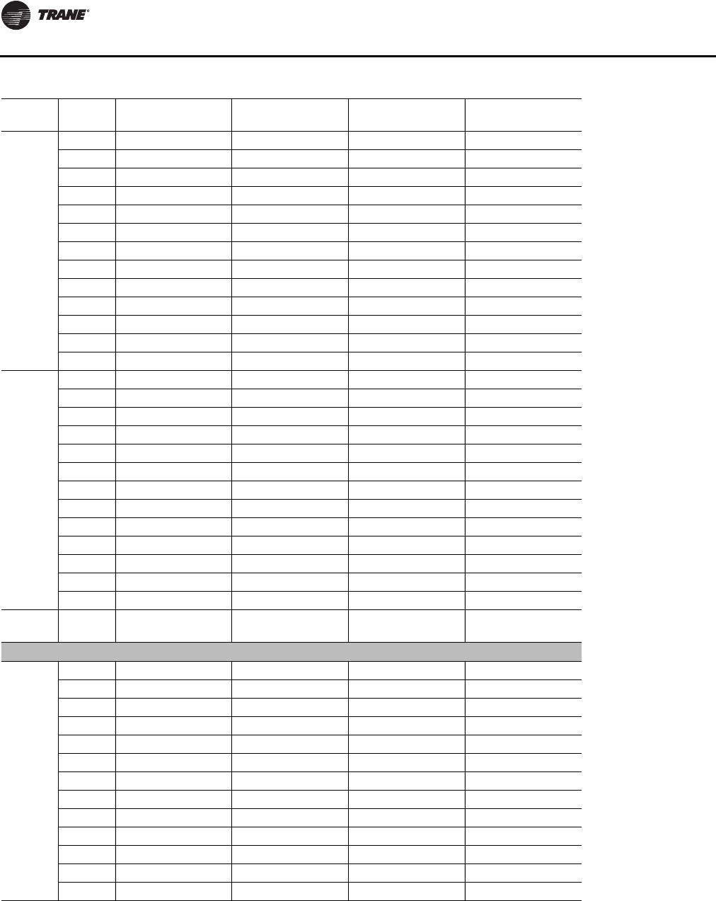
Unit Startup
132 RT-SVX24K-EN
Nom
Tons CFM Outside Air Bypass
Damper Open Outside Air Bypass
Damper Closed Exhaust Air Bypass
Damper Open Exhaust Air Bypass
Damper Closed
130/140
9000 0.09 0.71 0.10 0.62
12000 0.15 0.97 0.18 0.92
16000 0.25 1.34 0.28 1.33
20000 0.36 - 0.40 -
23000 0.46 - 0.49 -
26000 0.57 - 0.60 -
30000 0.72 - 0.75 -
35000 0.93 - 0.97 -
40000 1.16 - 1.20 -
45000 1.40 - 1.43 -
50000 1.67 - 1.69 -
55000 1.95 - 1.96 -
58000 2.12 - 2.12 -
150/162
9000 0.09 0.71 0.10 0.62
12000 0.15 0.97 0.18 0.92
16000 0.25 1.34 0.28 1.33
20000 0.36 - 0.40 -
23000 0.46 - 0.49 -
26000 0.57 - 0.60 -
30000 0.72 - 0.75 -
35000 0.93 - 0.97 -
40000 1.16 - 1.20 -
45000 1.40 - 1.43 -
50000 1.67 - 1.69 -
55000 1.95 - 1.96 -
58000 2.12 - 2.12 -
Nom
Tons CFM Outside Air Bypass
Damper Open Outside Air Bypass
Damper Closed Exhaust Air Bypass
Damper Open Exhaust Air Bypass
Damper Closed
Standard CFM Energy Recovery Wheel
90/100
8000 0.06 0.54 0.07 0.44
9000 0.08 0.61 0.10 0.53
10000 0.10 0.68 0.12 0.62
12000 0.15 0.83 0.17 0.77
14000 0.19 0.99 0.22 0.94
16000 0.24 1.16 0.26 1.12
18000 0.30 1.32 0.31 1.29
20000 0.35 - 0.37 -
25000 0.52 - 0.54 -
30000 0.70 - 0.73 -
33000 0.82 - 0.84 -
36000 0.95 - 0.97 -
40000 1.12 - 1.14 -
Continued on next page
Table 41. Energy recovery wheel component static pressure drops (continued)
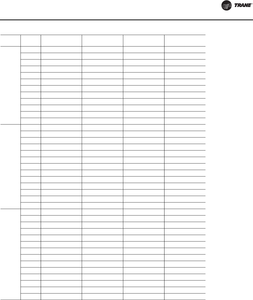
Unit Startup
RT-SVX24K-EN 133
Nom
Tons CFM Outside Air Bypass
Damper Open Outside Air Bypass
Damper Closed Exhaust Air Bypass
Damper Open Exhaust Air Bypass
Damper Closed
105/118
9000 0.08 0.57 0.09 0.47
12000 0.14 0.77 0.16 0.65
14000 0.19 0.93 0.21 0.78
16000 0.24 1.08 0.26 0.91
19000 0.32 1.33 0.34 1.11
21000 0.37 1.49 0.40 1.25
23000 0.44 - 0.46 -
28000 0.61 - 0.64 -
33000 0.80 - 0.82 -
38000 1.00 - 1.03 -
43000 1.23 - 1.25 -
45000 1.33 - 1.34 -
120/128
10000 0.10 0.56 0.11 0.50
12000 0.14 0.69 0.16 0.63
15000 0.20 0.89 0.23 0.85
18000 0.27 1.10 0.29 1.05
21000 0.35 1.33 0.38 1.28
24000 0.43 1.57 0.47 1.51
26000 0.50 - 0.54 -
31000 0.66 - 0.72 -
36000 0.84 - 0.91 -
41000 1.04 - 1.11 -
46000 1.26 - 1.34 -
51000 1.49 - 1.56 -
54000 1.63 - 1.71 -
130-162
13000 0.16 0.59 0.17 0.53
15000 0.20 0.69 0.22 0.63
18000 0.26 0.86 0.28 0.79
21000 0.33 1.04 0.36 0.96
23000 0.38 1.16 0.42 1.06
26000 0.45 1.36 0.50 1.24
29000 0.54 1.57 0.60 1.42
30000 0.57 - 0.63 -
35000 0.72 - 0.80 -
40000 0.89 - 0.98 -
45000 1.08 - 1.17 -
50000 1.28 - 1.38 -
55000 1.50 - 1.60 -
58000 1.63 - 1.74 -
Continued on next page
Table 41. Energy recovery wheel component static pressure drops (continued)
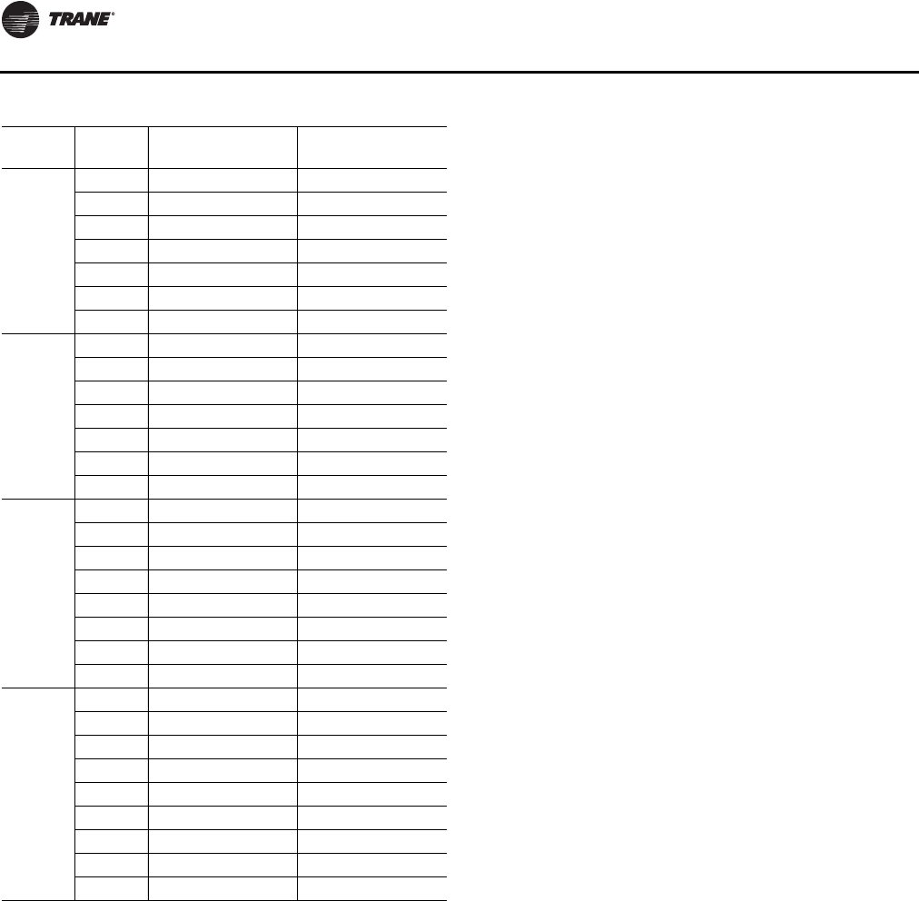
Unit Startup
134 RT-SVX24K-EN
Tons CFM Return Damper,
ERW only Econo Damper,
ERW only
90/100
16000 0.14 0.15
20000 0.20 0.24
25000 0.29 0.39
30000 0.42 0.56
33000 0.51 0.69
36000 0.61 0.82
40000 0.75 1.01
105/118
19000 0.19 0.22
23000 0.25 0.33
28000 0.37 0.49
33000 0.51 0.69
38000 0.68 0.91
43000 0.87 1.17
45000 0.96 1.29
120/128
21000 0.22 0.18
26000 0.32 0.27
31000 0.45 0.39
36000 0.61 0.53
41000 0.79 0.69
46000 1.00 0.87
51000 1.24 1.07
54000 1.40 1.20
130-162
23000 0.25 0.21
26000 0.32 0.27
30000 0.42 0.36
35000 0.57 0.50
40000 0.75 0.65
45000 0.96 0.83
50000 1.19 1.02
55000 1.45 1.24
58000 1.63 1.38
Table 41. Energy recovery wheel component static pressure drops (continued)
Unit Startup
RT-SVX24K-EN 135
Table 42. Energy recovery wheel pLoss P(in. wg), and total effectiveness
Actual Air
Flow CFM
90-118 Tons
Low 120/128 Tons
Low 130-162 Tons
Low 90/100 Tons
Standard 105/118 Tons
Standard 120/128 Tons
Standard 130-162 Tons
Standard
PEff PEff PEff PEff PEff PEff PEff
8000 0.73 77.5 0.64 79.0 0.58 80.0 0.49 81.6
9000 0.82 75.9 0.72 77.6 0.65 78.7 0.55 80.6 0.51 81.3
10000 0.91 74.3 0.80 76.2 0.73 77.5 0.61 79.5 0.56 80.3 0.49 81.6
11000 1.00 72.7 0.88 74.8 0.80 76.2 0.67 78.5 0.62 79.4 0.54 80.7
12000 1.09 71.1 0.96 73.4 0.87 75.0 0.73 77.4 0.67 78.4 0.59 79.8
13000 1.18 69.5 1.04 72.0 0.94 73.7 0.79 76.4 0.73 77.4 0.64 79.0 0.48 74.7
14000 1.12 70.6 1.02 72.4 0.85 75.3 0.79 76.5 0.69 78.1 0.51 72.9
15000 1.20 69.2 1.09 71.1 0.91 74.3 0.84 75.5 0.74 77.3 0.55 71.9
16000 1.16 69.8 0.97 73.2 0.90 74.5 0.79 76.4 0.58 71.0
17000 1.24 68.5 1.03 72.1 0.95 73.5 0.83 75.6 0.61 70.0
18000 1.09 71.1 1.01 72.5 0.88 74.7 0.64 69.0
19000 1.15 70.0 1.07 71.5 0.93 73.9 0.67 68.1
20000 1.22 68.9 1.12 70.5 0.98 73.0 0.71 67.1
21000 1.18 69.5 1.03 72.1 0.74 66.1
22000 1.23 68.5 1.08 71.3 0.77 65.1
23000 1.13 70.4 0.80 64.2
24000 1.18 69.5 0.84 63.2
25000 1.23 68.7 0.87 62.2
26000 0.90 61.2
27000 0.93 60.3
28000 0.97 59.3
29000 1.00 58.3
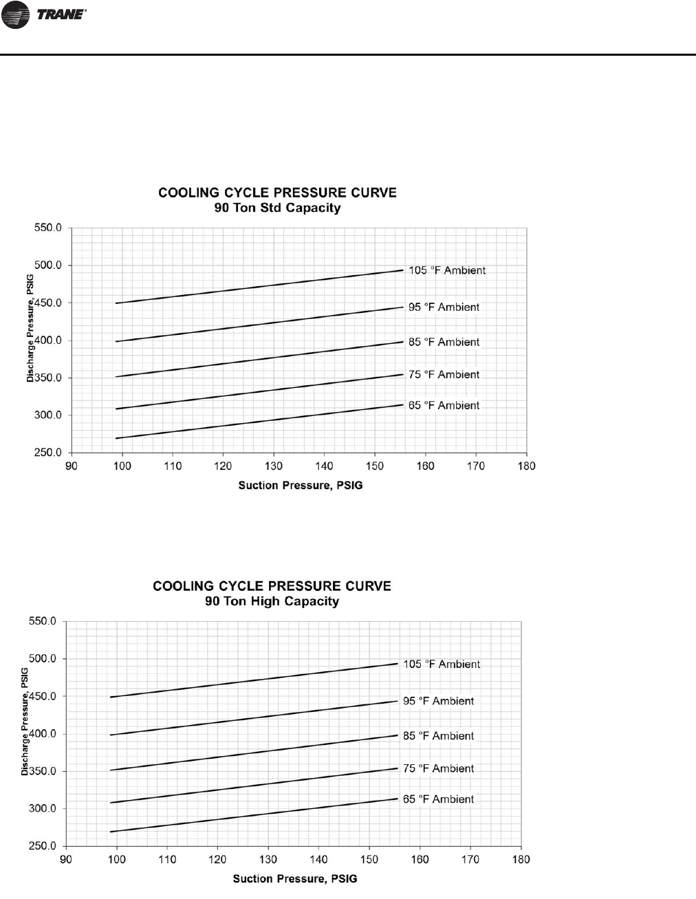
Unit Startup
136 RT-SVX24K-EN
Pressure Curves
(60 Hz) Air-Cooled Condensers
Figure 84. Operating pressure curve (all comp. and cond. fans per ckt. on)—90 tons std. capacity
Figure 85. Operating pressure curve (all comp. and cond. fans per ckt. on)—90 tons high capacity
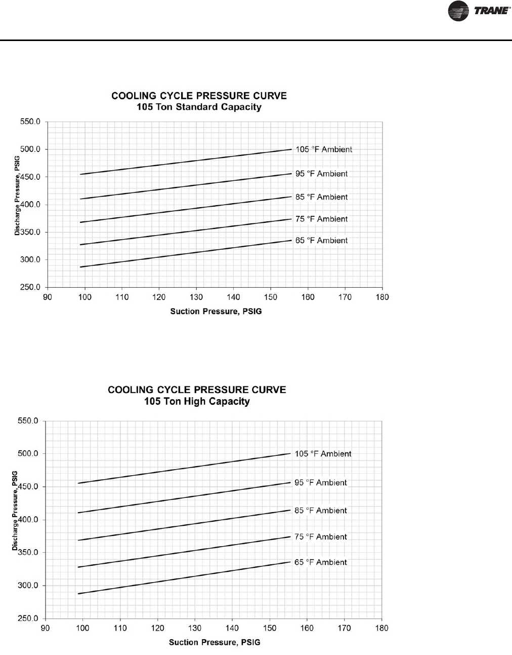
Unit Startup
RT-SVX24K-EN 137
Figure 86. Operating pressure curve (all comp. and cond. fans per ckt. on)—105 tons std. capacity
Figure 87. Operating pressure curve (all comp. and cond. fans per ckt. on)—105 tons high capacity
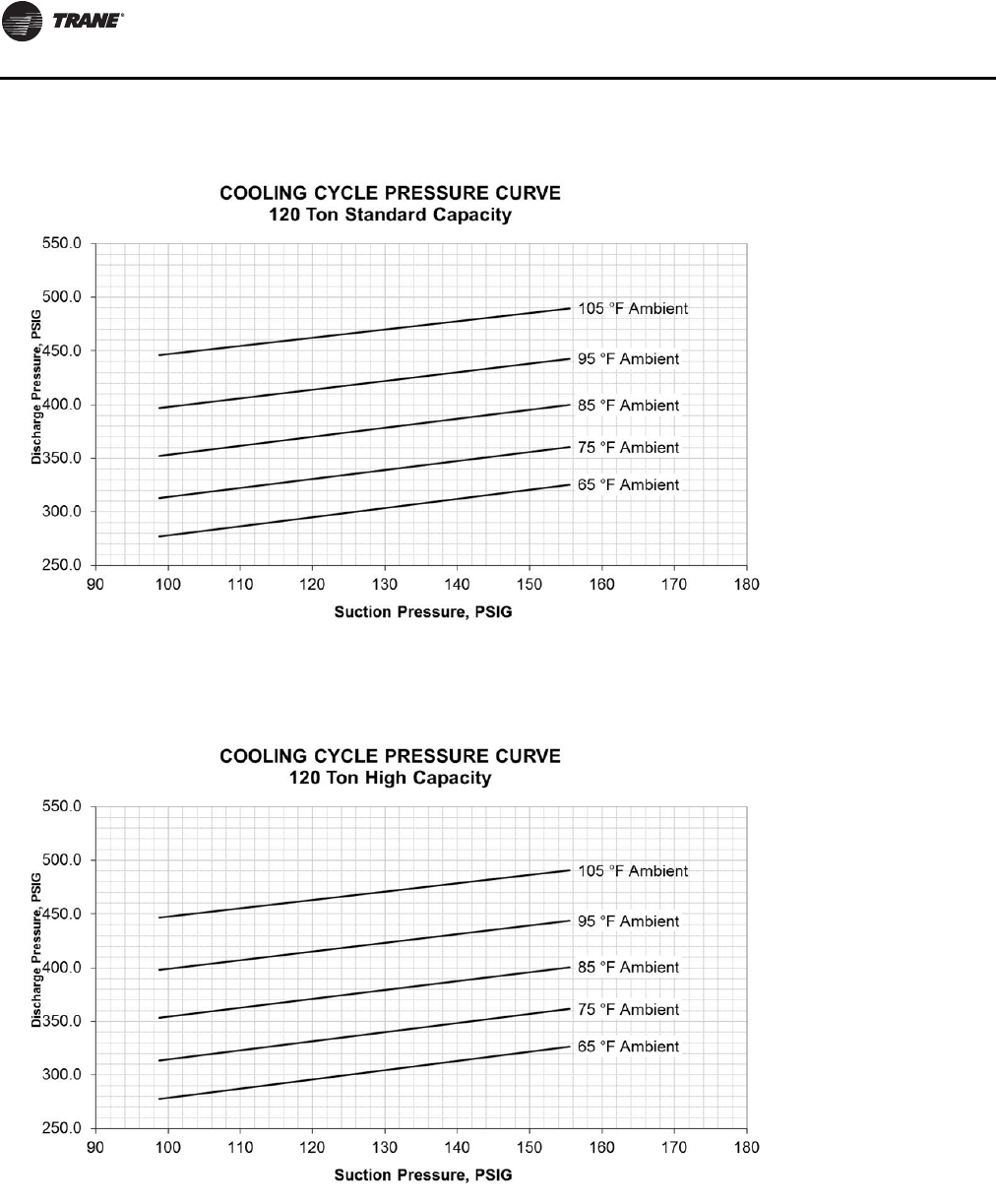
Unit Startup
138 RT-SVX24K-EN
Figure 88. Operating pressure curve (all comp. and cond. fans per ckt. on)—120 tons std. capacity
Figure 89. Operating pressure curve (all comp. and cond. fans per ckt. on)—120 tons high capacity
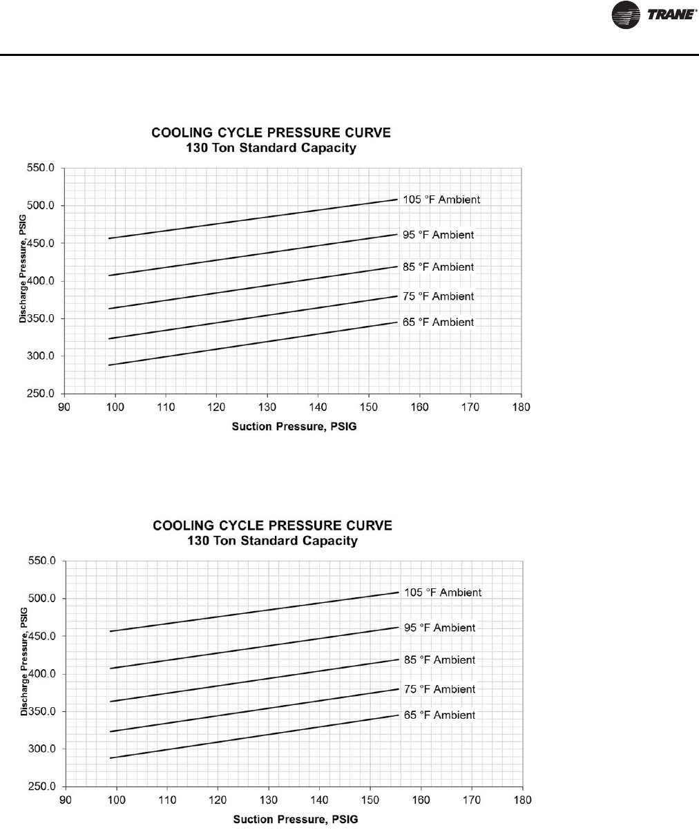
Unit Startup
RT-SVX24K-EN 139
Figure 90. Operating Pressure Curve (All Comp. and Cond. Fans per ckt. on)—130 Tons Std. Capacity
Figure 91. Operating Pressure Curve (All Comp. and Cond. Fans per ckt. on)—130 Tons High Capacity
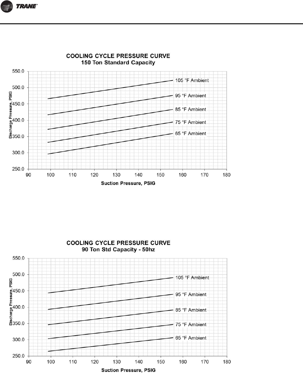
Unit Startup
140 RT-SVX24K-EN
Note: Due to the variable speed fans on Evaporative
Condenser units, typical operating pressure curves
are not relevant. If operating pressures at certain
conditions are needed, contact a localTrane sales
representative.
Figure 92. Operating pressure curve (all comp. and cond. fans per ckt. on)—150 ton std. capacity
Figure 93. Operating pressure curve (all comp. and cond. fans per ckt. on)—90 tons standard capacity

Unit Startup
RT-SVX24K-EN 141
Figure 94. Operating pressure curve (all comp. and cond. fans per ckt. on)—90 tons high capacity
Figure 95. Operating pressure curve (all comp. and cond. fans per ckt. on)—105 tons standard capacity
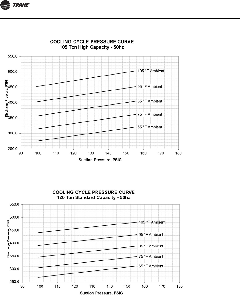
Unit Startup
142 RT-SVX24K-EN
Figure 96. Operating pressure curve (all comp. and cond. fans per ckt. on)—105 tons high capacity
Figure 97. Operating pressure curve (all comp. and cond. fans per ckt. on)—120 tons standard capacity
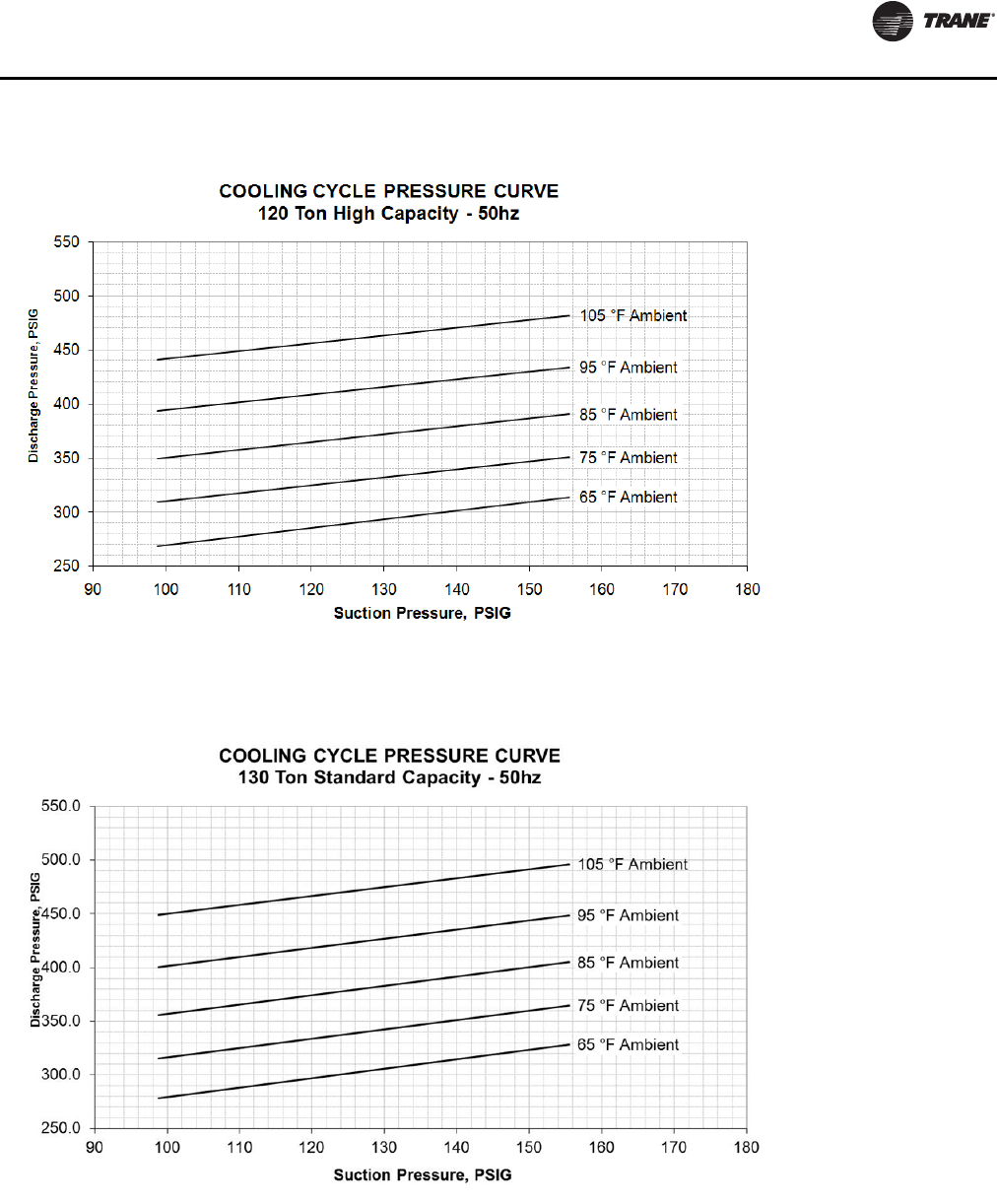
Unit Startup
RT-SVX24K-EN 143
Figure 98. Operating pressure curve (all comp. and cond. fans per ckt. on)—120 tons high capacity
Figure 99. Operating pressure curve (all comp. and cond. fans per ckt. on)—130 tons standard capacity
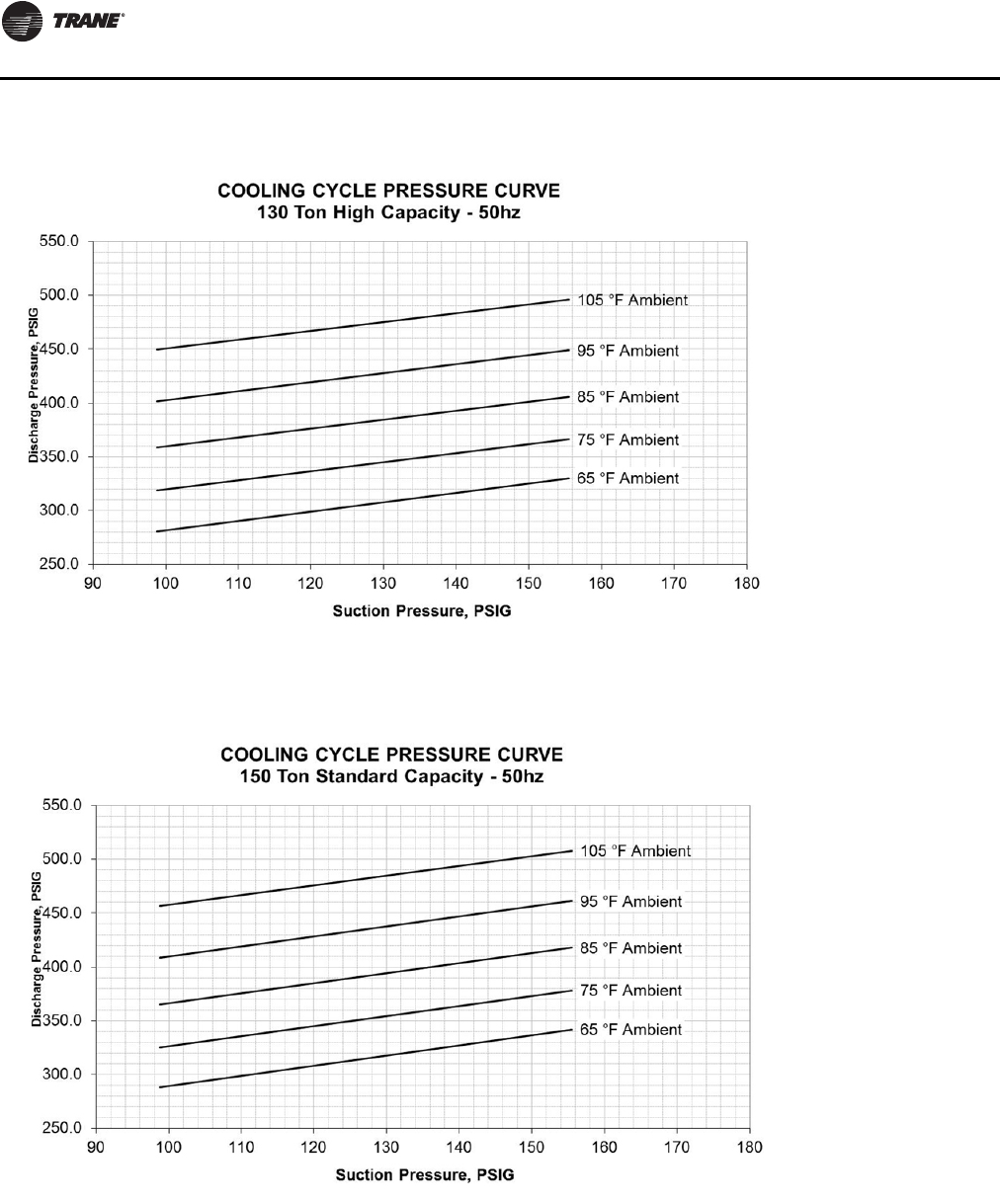
Unit Startup
144 RT-SVX24K-EN
Note: Due to the variable speed fans on evaporative
condenser units, typical operating pressure curves
are not relevant. If operating pressures at certain
conditions are needed, contact a localTrane sales
representative.
Figure 100. Operating pressure curve (all comp. and cond. fans per ckt. on)—130 tons high capacity
Figure 101. Operating pressure curve (all comp. and cond. fans per ckt. on)—150 tons standard capacity
Unit Startup
RT-SVX24K-EN 145
Components
Standard Unit without Energy Recovery
Wheel
Economizer Damper Adjustment
Exhaust Air Dampers
Verify that the exhaust dampers (if equipped) close tightly
when the unit is off. Adjust the damper linkage as
necessary to ensure proper closure. An access panel is
provided under each damper assembly.
Outside Air & Return Air Damper Operation
The outside air and return air damper linkage is accessible
from the filter section of the unit.The damper linkage
connecting the outside air dampers to the return air
dampers is preset from the factory in the number 1
position. Refer to Figure 102, p. 146 for the appropriate
linkage position for the unit and operating airflow (CFM).
Note: Bridging between the unit main supports may
consist of multiple 2 by 12 boards or sheet metal
grating.
Arbitrarily adjusting the outside air dampers to open fully
when the return air dampers are closed or; failing to
maintain the return air pressure drop with the outside air
dampers when the return air dampers are closed, can
overload the supply fan motor and cause building
pressurization control problems due to improper CFM
being delivered to the space.
The outside air/return air damper linkage is connected to
a crank arm with a series of holes that allows the installer
or operator to modify the amount of outside air damper
travel in order to match the return static pressure. Refer to
Table 43, p. 148 for the equivalent return air duct losses
that correspond to each of the holes illustrated in
Figure 102, p. 146.
To Adjust the Outside Air DamperTravel:
1. Drill a 1/4" hole through the unit casing up stream of
the return air dampers. Use a location that will produce
an accurate reading with the least amount of
turbulence. Several locations may be necessary, and
average the reading.
HIGH VOLTAGE IS PRESENT AT TERMINAL BLOCK OR
UNIT DISCONNECT SWITCH.
2. Close the disconnect switch or circuit protector switch
that provides the supply power to the unit terminal
block or the unit mounted disconnect switch.
3. Turn the 115 volt control circuit switch and the 24 volt
control circuit switch to the “On” position.
4. Open the Human Interface access door, located in the
unit control panel, and press the SERVICE MODE key to
display the first service screen. Refer to the latest
edition of the applicable programming manual for
applications for the SERVICETEST screens and
programming instructions.
5. Use Table 37, p. 11 2 to program the following system
components for operation by scrolling through the
displays;
Supply Fan (On)
Variable Frequency Drive (100% Output, if applicable)
RTM Occ/Unocc Output (Unoccupied)
Outside Air Dampers (Closed)
6. Once the configuration for the components is
complete, press the NEXT key until the LCD displays
the “Start test in __Sec.” screen. Press the + key to
designate the delay before the test is to start.This
service test will begin after theTEST START key is
pressed and the delay designated in this step has
elapsed. Press the ENTER key to confirm this choice.
7. Press theTEST START key to start the test. Remember
that the delay designated in step 6 must elapse before
the fan will begin to operate.
8. With the outside air dampers fully closed and the
supply fan operating at 100% airflow requirements,
WARNING
No Step Surface!
Do not walk on the sheet metal drain pan. Walking on
the drain pan could cause the supporting metal to
collapse, resulting in the operator/technician to fall.
Failure to follow this recommendation could result in
death or serious injury.
WARNING
Hazardous Voltage!
Disconnect all electric power, including remote
disconnects before servicing. Follow proper lockout/
tagout procedures to ensure the power can not be
inadvertently energized. Failure to disconnect power
before servicing could result in death or serious injury.
WARNING
Rotating Components!
During installation, testing, servicing and
troubleshooting of this product it may be necessary to
work with live and exposed rotating components. Have
a qualified or licensed service individual who has been
properly trained in handling exposed rotating
components, perform these tasks. Failure to follow all
safety precautions could result in rotating components
cutting and slashing technician which could result in
death or serious injury.
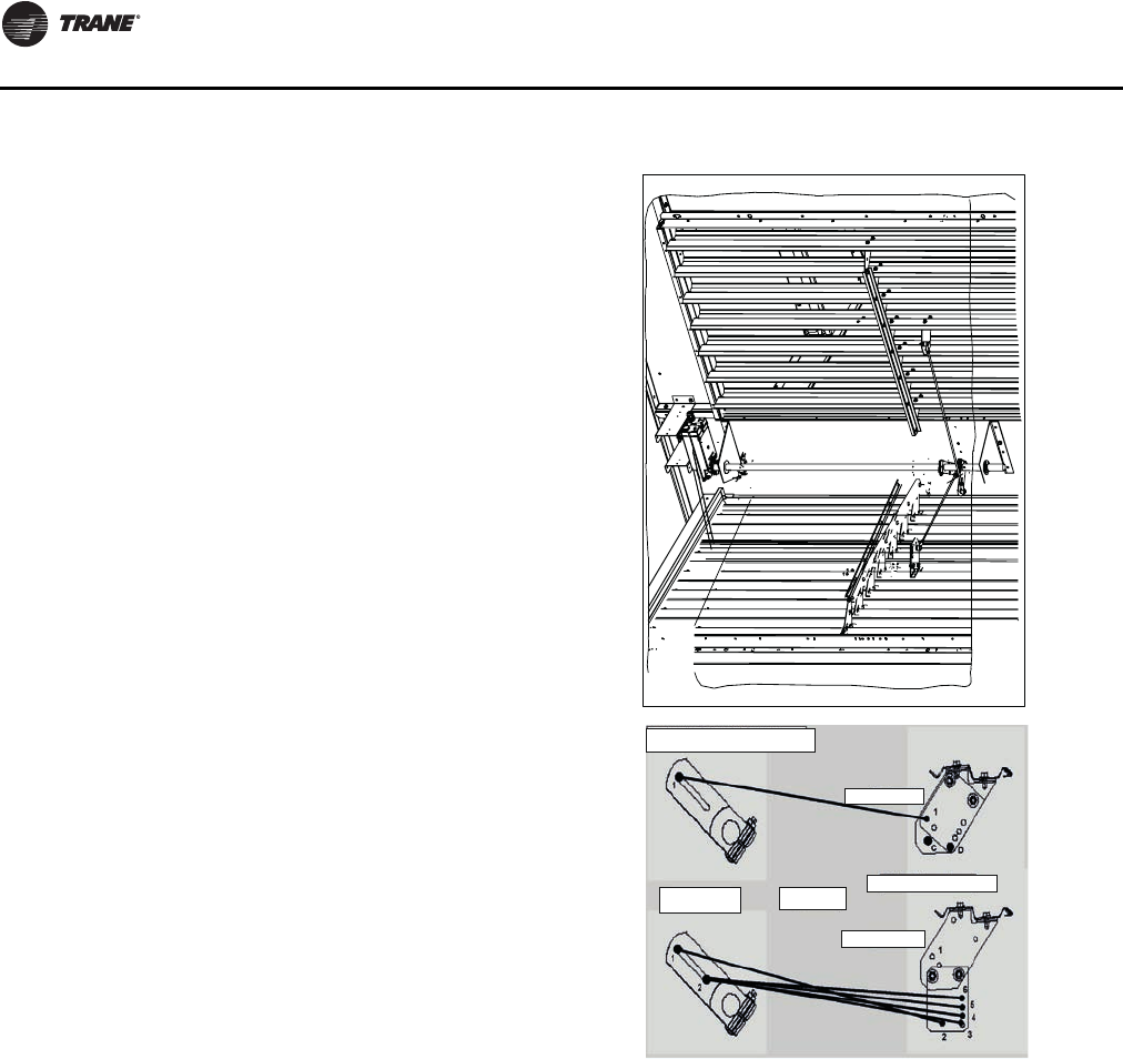
Unit Startup
146 RT-SVX24K-EN
measure the return static pressure at the location
determined in step 1.
9. Press the STOP key at the Human Interface Module in
the unit control panel to stop the fan operation.
10. Open the field supplied main power disconnect switch
upstream of the rooftop unit. Lock the disconnect
switch in the “Open” position while working on the
dampers.
Note: Gravity will cause the damper to close. Support or
secure the damper blades while removing the
actuator to prevent unexpected damper rotation.
11. Compare the static pressure reading to the static
pressure ranges and linkage positions in Table 43,
p. 148 for the unit size and operating CFM.
To relocate the outside air/return air connecting rod to
balance the outside air damper pressure drop against the
return static pressure, use the following steps. If no
adjustment is necessary, proceed to step 17.
12. Remove the drive rod and swivel from the crank
arm(s). If only one hole requires changing, loosen only
that end.
13. Manually open the return air dampers to the full open
position.
14. Manually close the outside air dampers.
15. Reattach the drive rod and swivel to the appropriate
hole(s).The length of the drive rod may need to be
adjusted to align with the new hole(s) location. If so,
loosen the lock nut on the drive rod against the swivel.
Turn the swivel “in” or “out” to shorten or lengthen the
rod as necessary. For some holes, both ends of the rod
may need to be adjusted.
16.Tighten the lock nut against the swivel(s).
17. Plug the holes after the proper CFM has been
established.
Figure 102. Outside air and return air damper assembly
Outside air damper level
Conguration B
Conguration A
All Top view
Jackshaft lever
Economizer Linkage Adjustment
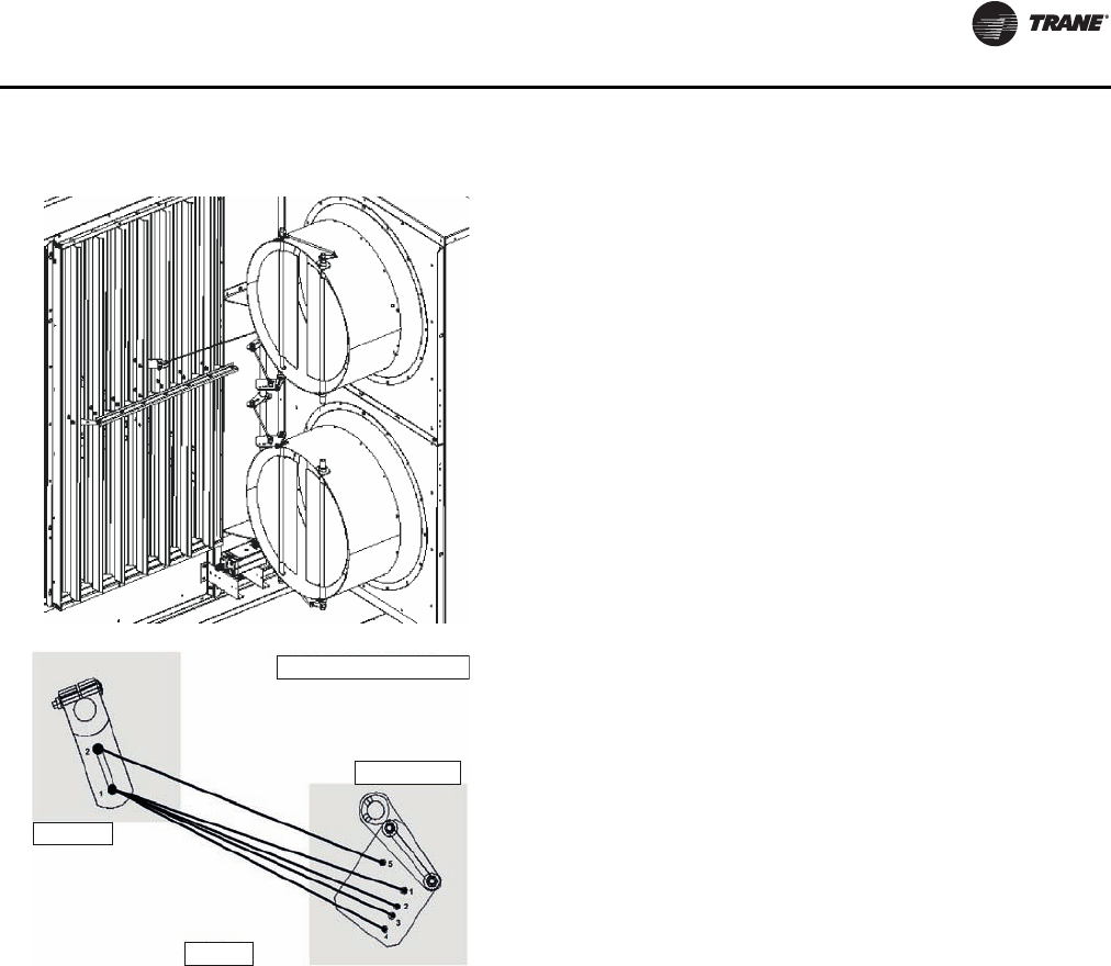
Unit Startup
RT-SVX24K-EN 147
Figure 103. Outside air and return air economizer
assembly (w/TRAQ™ dampers)
TRAQ Damper Linkage
Top view
Jackshaft
TRAQ damper
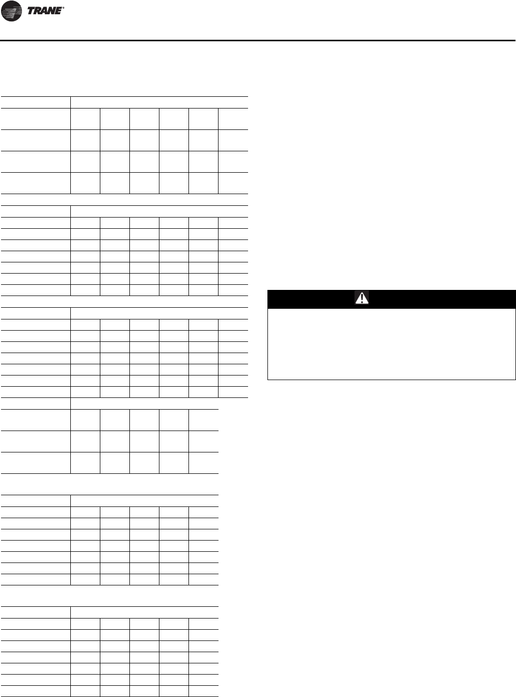
Unit Startup
148 RT-SVX24K-EN
Standard Unit with Energy Recovery
Wheel
Economizer Damper Adjustment - ERW units
Outside & Return Air Damper Operation
The outside air and return air damper actuators are
accessible through from the filter section of the unit.The
outside air and return air dampers have individual
actuators that are linked electronically.The actuators are
preset to 0 degrees from the factory. Refer to Table 44,
p. 150 for the appropriate actuator position for the unit and
operating airflow (CFM).
To Adjust Damper Travel
1. Drill a 1/4" hole through the unit casing up stream of
the return air dampers and below the energy recovery
wheel. Use a location that will produce an accurate
reading with the least amount of turbulence. Several
locations may be necessary, and average the reading.
HIGH VOLTAGE IS PRESENT AT TERMINAL BLOCK OR
UNIT DISCONNECT SWITCH.
2. Close the disconnect switch or circuit protector switch
that provides the supply power to the unit terminal
block or the unit mounted disconnect switch.
3. Turn the 115 volt control circuit switch and the 24 volt
control circuit switch to the “On” position.
4. Open the Human Interface access door, located in the
unit control panel, and press the SERVICE MODE key to
display the first service screen. Refer to the latest
edition of the applicable programming manual for
applications for the SERVICETEST screens and
programming instructions.
5. Use Table 29, p. 77 to program the following system
components for operation by scrolling through the
displays:
Supply Fan (On)
VFD Cmd (100%, if applicable)
RTM Occ/Unocc Output
(Unoccupied)
OA Damper Pos (0%)
Outside Air Bypass Damper Pos (0%)
Exhaust Air Bypass Damper Pos (0%)
Table 43. Standard unit (no ERW) (economizer) outside
air damper travel adjustment/pressure drop
(inches w.c.)
Damper Position
Economizer
Linkage Set-up 1 2 3 4 5 6
Jackshaft rod
end location 1 1 2 2 2 2
Damper lever
configuration A B B B B B
Damper lever
rod end location 1 2 3 4 5 6
120-162 Ton w/Economizer (includes mist eliminator)
CFM Pressure Drop (inches w.c.)
58500 0.80 1.64 2.96 - - -
54000 0.68 1.40 2.52 - - -
45500 0.48 0.99 1.79 2.22 2.62 -
42000 0.41 0.85 1.53 1.89 2.23 2.69
38000 0.34 0.69 1.25 1.55 1.83 2.20
34000 0.27 0.56 1.00 1.24 1.46 1.76
30000 0.21 0.43 0.78 0.97 1.14 1.37
90-118 Ton w/Economizer (includes mist eliminator)
CFM Pressure Drop (inches w.c.)
47250 0.81 1.88 - - - -
40500 0.60 1.39 2.62 - - -
36750 0.49 1.14 2.16 2.71 - -
31500 0.36 0.84 1.59 1.99 2.36 2.87
28000 0.28 0.66 1.25 1.57 1.87 2.27
25000 0.22 0.53 1.00 1.25 1.49 1.81
23000 0.19 0.45 0.85 1.06 1.26 1.53
Damper Position
Jackshaft rod
end location 1 1 1 2 1
Damper lever
rod end location 1 2 3 5 4
Jackshaft rod
end location 1 1 1 2 1
120-162 Ton w/TRAQ™ Damper (includes mist
eliminator)
CFM Pressure Drop (inches w.c.)
58500 1.10 1.52 2.16 2.73
54000 0.93 1.28 1.83 2.33
45500 0.64 0.89 1.28 1.64 2.14
42000 0.54 0.75 1.09 1.40 1.83
38000 0.44 0.60 0.88 1.14 1.50
34000 0.35 0.47 0.69 0.90 1.20
30000 0.27 0.35 0.53 0.69 0.93
90-118 Ton w/TRAQ™ Damper (includes mist
eliminator)
CFM Pressure Drop (inches w.c.)
47250 1.37 1.89 2.72
40500 0.99 1.35 1.97 2.54
36750 0.80 1.09 1.60 2.08 2.74
31500 0.58 0.77 1.15 1.51 2.01
28000 0.46 0.59 0.89 1.17 1.58
25000 0.37 0.45 0.69 0.92 1.24
23000 0.31 0.37 0.57 0.76 1.04
WARNING
Hazardous Voltage!
Disconnect all electric power, including remote
disconnects before servicing. Follow proper lockout/
tagout procedures to ensure the power can not be
inadvertently energized. Failure to disconnect power
before servicing could result in death or serious injury.
Unit Startup
RT-SVX24K-EN 149
6. Once the configuration for the components is
complete, press the NEXT key until the LCD displays
the “Start test in __Sec." screen. Press the + key to
designate the delay before the test is to start.This
service test will begin after theTEST START key is
pressed and the delay designated in this step has
elapsed. Press the ENTER key to confirm this choice.
7. Press theTEST START key to start the test. Remember
that the delay designated in step 6 must elapse before
the fan will begin to operate.
8. With the outside air dampers fully closed and the
supply fan operating at 100% airflow requirements,
measure the return static pressure at the location
determined in step 1.
9. Press the STOP key at the Human Interface Module in
the unit control panel to stop the fan operation.
10. Open the field supplied main power disconnect switch
upstream of the rooftop unit. Lock the disconnect
switch in the “Open” position while working on the
dampers.
11. Locate the static pressure reading in Table 44, p. 150
and determine which damper needs to be adjusted and
the degree reading. Proceed to the appropriate damper
actuator procedure.
To Adjust the Outside Air Damper Actuators:
12. Remove the shaft coupling from the damper shaft by
loosening the bolt and removing the retainer clip. Be
careful not to rotate the shaft.
13. Position the shaft coupling so that the indicator points
to the degree value obtained from step 11.The shaft
coupling is adjustable in 5 degree increments.
14. Replace the retainer clip and tighten the shaft coupling
on the shaft (120-180 in-lbs).
15. Close the disconnect switch or circuit protector switch
that provides the supply power to the unit terminal
block or the unit mounted disconnect switch.
16. Rotate the actuator control signal dial to Auto-Adapt.
The actuator will drive open and then closed to
determine the new open and closed positions.
17. Return the actuator control signal dial to 2-10 VDC
Modulating input signal position.
18. Plug the holes drilled in the cabinet after the proper
airfow has been established.
To Adjust the Return Damper Actuators:
19. Support or secure the damper blades in the wide open
position.
Note: Gravity will cause the damper to close. Support or
secure the damper blades while removing the
actuator to prevent unexpected damper rotation.
20. Do not remove the shaft coupling from the shaft.
Remove the retainer clip from the shaft coupling.
21. Unscrew the actuator bracket from the damper wall.
22. Slide the actuator down the damper shaft off of the
shaft coupling.
23. Rotate the actuator and reinstall the shaft coupling in
the actuator so that the indicator points to the degree
value obtained in Step 11.The shaft coupling is
adjustable in 5 degree increments.
24. Replace the retainer clip and remove the blade stops to
allow the blades to rotate.
25. Rotate the actuator to the original position and reattach
the actuator bracket to the damper wall.
26. Close the disconnect switch or circuit protector switch
that provides the supply power to the unit terminal
block or the unit mounted disconnect switch.
27. Rotate the actuator control signal dial to Auto-Adapt.
The actuator will drive open and then closed to
determine the new open and closed positions.
28. Return the actuator control signal dial to the factory set
input signal position.
29. Plug the holes drilled in the cabinet after the proper
airfow has been established.
WARNING
Rotating Components!
During installation, testing, servicing and
troubleshooting of this product it may be necessary to
work with live and exposed rotating components. Have
a qualified or licensed service individual who has been
properly trained in handling exposed rotating
components, perform these tasks. Failure to follow all
safety precautions could result in rotating components
cutting and slashing technician which could result in
death or serious injury.
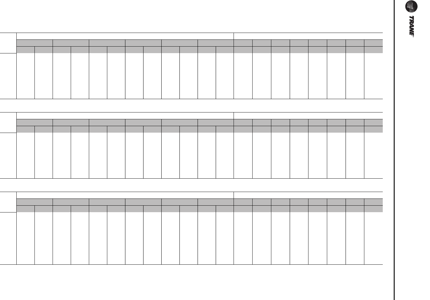
Unit Startup
150 RT-SVX24K-EN
Table 44. Standard units with ERW — field measured plenum pressure
Low CFM ERW — 90-162 Tons
90/100 Ton Low CFM ERW - Field measured plenum pressure (inches wc)
OA Actuator Reading [Degrees] RA Actuator Reading [Degrees]
60 50 40 30 20 10 0 10 20 30 35 40 45 50
CFM Econ TRAQ Econ TRAQ Econ TRAQ Econ TRAQ Econ TRAQ Econ TRAQ E/T E/T E/T E/T E/T E/T E/T E/T
16000 1.29 — 0.87 1.52 0.71 1.05 0.64 0.84 0.60 0.64 0.58 0.63 0.46 0.45 0.43 0.41 0.38 0.35 0.32 0.20
20000 1.99 — 1.34 2.34 1.09 1.62 0.98 1.28 0.92 0.97 0.89 0.96 0.69 0.68 0.65 0.62 0.57 0.52 0.48 0.29
25000 — — 2.07 — 1.68 2.49 1.50 1.97 1.41 1.49 1.36 1.47 1.04 1.02 0.99 0.93 0.86 0.78 0.71 0.42
30000 — — 2.94 — 2.39 — 2.13 2.79 1.99 2.09 1.93 2.08 1.46 1.43 1.37 1.30 1.19 1.08 0.98 0.56
33000 ————2.86 — 2.54 — 2.38 2.50 2.30 2.48 1.73 1.70 1.63 1.54 1.41 1.28 1.15 0.65
36000 ——————3.00 — 2.80 2.94 2.71 2.92 2.02 1.98 1.91 1.79 1.64 1.48 1.34 0.74
40000 ————————————2.46 2.41 2.32 2.18 1.98 1.79 1.61 0.87
105/118 Ton Low CFM ERW - Field measured plenum pressure (inches wc)
OA Actuator Reading [Degrees] RA Actuator Reading [Degrees]
60 50 40 30 20 10 0 10 20 30 35 40 45 50
CFM Econ TRAQ Econ TRAQ Econ TRAQ Econ TRAQ Econ TRAQ Econ TRAQ E/T E/T E/T E/T E/T E/T E/T E/T
19000 1.80 — 1.22 2.12 0.99 1.46 0.89 1.16 0.83 0.88 0.81 0.88 0.63 0.62 0.59 0.56 0.52 0.48 0.44 0.27
23000 2.63 — 1.76 — 1.44 2.12 1.29 1.68 1.21 1.27 1.17 1.26 0.90 0.88 0.85 0.80 0.74 0.68 0.62 0.37
28000 — — 2.57 — 2.09 — 1.86 2.45 1.74 1.84 1.69 1.82 1.28 1.25 1.21 1.14 1.05 0.95 0.86 0.50
33000 ————2.86 — 2.54 2.38 2.50 2.30 2.48 1.73 1.70 1.63 1.54 1.41 1.28 1.15 0.65
38000 ————————————2.24 2.20 2.11 1.98 1.81 1.64 1.48 0.81
43000 ————————————2.80 2.74 2.64 2.47 2.25 2.03 1.83 0.97
45000 ————————————3.04 2.98 2.86 2.68 2.44 2.20 1.97 1.04
120/128 Ton Low CFM ERW - Field measured plenum pressure (inches wc)
OA Actuator Reading [Degrees] RA Actuator Reading [Degrees]
60 50 40 30 20 10 0 10 20 30 35 40 45 50
CFM Econ TRAQ Econ TRAQ Econ TRAQ Econ TRAQ Econ TRAQ Econ TRAQ E/T E/T E/T E/T E/T E/T E/T E/T
21000 1.54 — 1.08 1.69 0.90 1.08 0.82 0.89 0.78 0.87 0.76 0.75 0.58 0.56 0.54 0.50 0.44 0.39 0.34 0.14
26000 2.33 — 1.62 2.56 1.35 1.62 1.23 1.33 1.16 1.30 1.13 1.11 0.84 0.82 0.78 0.72 0.64 0.56 0.49 —
31000 — — 2.26 — 1.88 2.25 1.70 1.85 1.61 1.80 1.56 1.53 1.15 1.12 1.07 0.98 0.87 0.75 0.65 —
36000 — — 2.99 — 2.48 2.98 2.24 2.44 2.11 2.37 2.05 2.00 1.50 1.46 1.38 1.27 1.11 0.96 0.81 —
41000 ——————2.85 — 2.68 — 2.60 2.54 1.89 1.84 1.74 1.59 1.39 1.19 1.00 —
46000 ————————————2.31 2.24 2.12 1.93 1.68 1.42 1.19 —
51000 ————————————2.77 2.69 2.54 2.31 2.00 1.69 1.40 —
54000 ————————————3.16 3.06 2.89 2.64 2.29 1.94 1.61 —
continued on next page
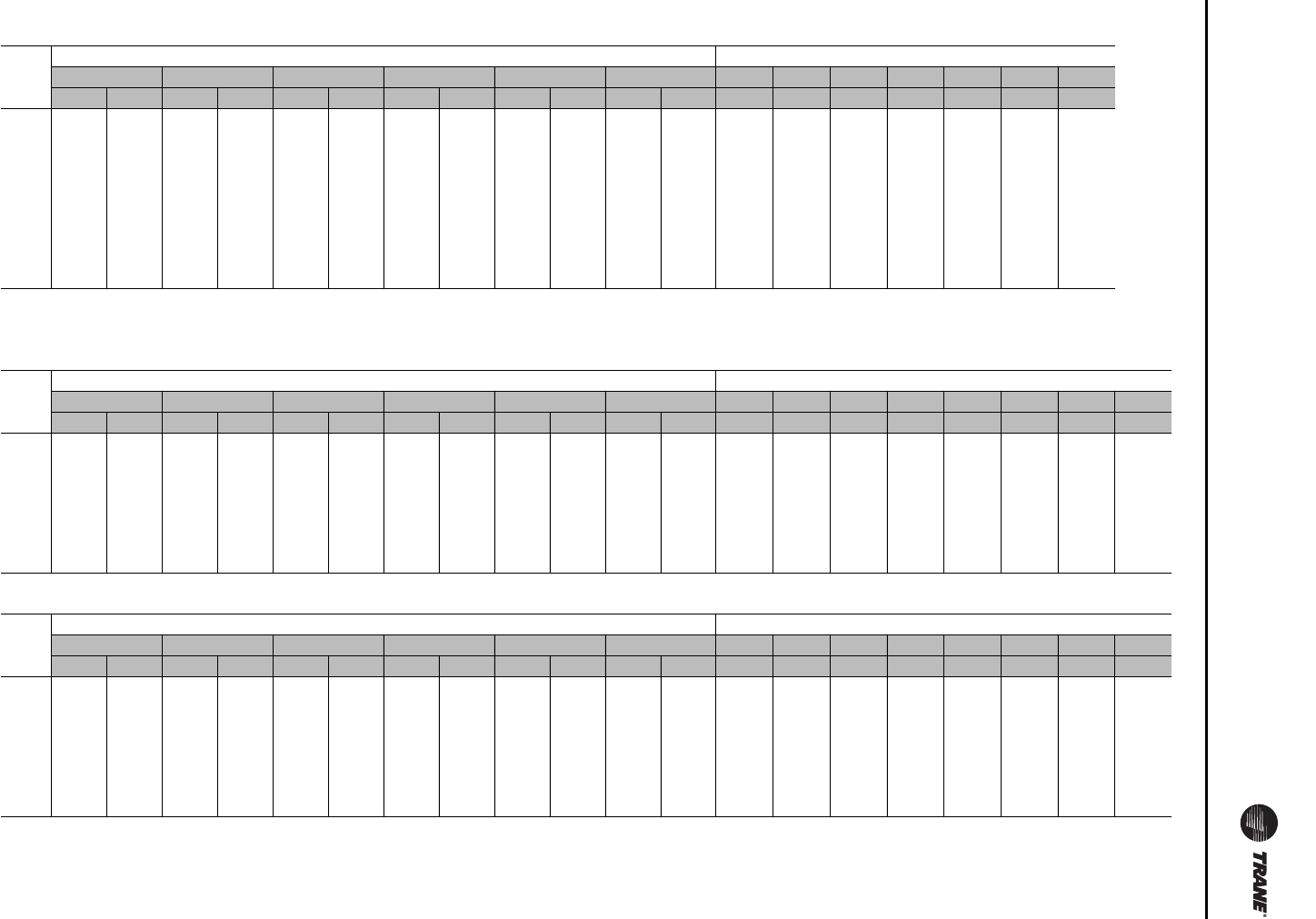
Unit Startup
RT-SVX24K-EN 151
130-162 Ton Low CFM ERW - Field measured plenum pressure (inches wc)
OA Actuator Reading [Degrees] RA Actuator Reading [Degrees]
60 50 40 30 20 10 0 10 20 30 35 40 45
CFM Econ TRAQ Econ TRAQ Econ TRAQ Econ TRAQ Econ TRAQ Econ TRAQ E/T E/T E/T E/T E/T E/T E/T
23000 1.82 — 1.27 — 1.06 1.27 0.96 1.05 0.91 1.02 0.89 0.87 0.67 0.65 0.62 0.57 0.51 0.44 0.39
26000 2.31 — 1.60 — 1.33 1.60 1.21 1.32 1.14 1.28 1.11 1.09 0.83 0.81 0.77 0.71 0.63 0.54 0.47
30000 — — 2.10 — 1.74 2.09 1.57 1.71 1.49 1.67 1.44 1.41 1.06 1.03 0.98 0.90 0.79 0.69 0.59
35000 — — 2.80 — 2.32 2.79 2.09 2.28 1.97 2.22 1.91 1.87 1.39 1.36 1.29 1.18 1.03 0.88 0.75
40000 ————2.97 — 2.68 2.92 2.52 2.84 2.45 2.39 1.77 1.72 1.62 1.48 1.29 1.10 0.92
45000 ———————————2.96 2.17 2.11 1.99 1.81 1.57 1.33 1.10
50000 ————————————2.62 2.54 2.39 2.17 1.87 1.57 1.30
55000 ————————————3.09 3.00 2.82 2.56 2.20 1.83 1.50
58000 ————————————3.40 3.29 3.10 2.80 2.40 1.99 1.62
Standard CFM ERW — 90-162 Tons
90/100 Ton Standard CFM ERW - Field measured plenum pressure (inches wc)
OA Actuator Reading [Degrees] RA Actuator Reading [Degrees]
60 50 40 30 20 10 0 10 20 30 35 40 45 50
CFM Econ TRAQ Econ TRAQ Econ TRAQ Econ TRAQ Econ TRAQ Econ TRAQ E/T E/T E/T E/T E/T E/T E/T E/T
16000 1.26 0.84 1.49 0.68 1.02 0.61 0.81 0.57 0.61 0.55 0.60 0.43 0.42 0.40 0.38 0.35 0.32 0.29 0.17
20000 1.95 1.30 2.30 1.05 1.57 0.93 1.24 0.88 0.93 0.85 0.92 0.64 0.63 0.61 0.57 0.52 0.48 0.43 0.25
25000 2.00 1.62 2.42 1.43 1.90 1.34 1.42 1.30 1.41 0.97 0.95 0.92 0.86 0.79 0.71 0.64 0.35
30000 2.84 2.28 2.02 2.69 1.89 1.99 1.82 1.97 1.35 1.32 1.27 1.19 1.08 0.97 0.87 0.46
33000 2.74 2.42 2.26 2.38 2.18 2.36 1.61 1.58 1.51 1.42 1.29 1.16 1.03 0.53
36000 2.86 2.67 2.81 2.57 2.78 1.89 1.85 1.77 1.66 1.50 1.35 1.20
40000 2.28 2.23 2.14 2.00 1.81 1.61 1.44
105/118 Ton Standard CFM ERW - Field measured plenum pressure (inches wc)
OA Actuator Reading [Degrees] RA Actuator Reading [Degrees]
60 50 40 30 20 10 0 10 20 30 35 40 45 50
CFM Econ TRAQ Econ TRAQ Econ TRAQ Econ TRAQ Econ TRAQ Econ TRAQ E/T E/T E/T E/T E/T E/T E/T E/T
19000 1.76 1.17 2.07 0.95 1.42 0.84 1.12 0.79 0.84 0.76 0.83 0.58 0.57 0.55 0.52 0.47 0.43 0.39 0.22
23000 2.55 1.69 1.36 2.05 1.21 1.61 1.13 1.20 1.09 1.19 0.82 0.80 0.77 0.73 0.66 0.60 0.54 0.30
28000 2.47 1.99 3.00 1.76 2.34 1.64 1.73 1.59 1.72 1.18 1.15 1.11 1.04 0.94 0.85 0.76 0.40
33000 2.72 2.40 2.24 2.36 2.16 2.34 1.59 1.55 1.49 1.39 1.26 1.13 1.01
38000 2.92 2.82 2.05 2.01 1.92 1.80 1.62 1.45 1.29
43000 2.57 2.51 2.41 2.24 2.02 1.80 1.59
45000 2.80 2.73 2.62 2.44 2.19 1.95 1.73
continued on next page
Table 44. Standard units with ERW — field measured plenum pressure (continued)
Unit Startup
152 RT-SVX24K-EN
120/128 Ton Standard CFM ERW - Field measured plenum pressure (inches wc)
OA Actuator Reading [Degrees] RA Actuator Reading [Degrees]
60 50 40 30 20 10 0 10 20 30 35 40 45
CFM Econ TRAQ Econ TRAQ Econ TRAQ Econ TRAQ Econ TRAQ Econ TRAQ E/T E/T E/T E/T E/T E/T E/T
21000 1.48 1.02 1.63 0.84 1.02 0.76 0.83 0.72 0.81 0.70 0.68 0.51 0.50 0.47 0.44 0.38 0.33 0.28
26000 2.23 1.53 2.47 1.26 1.52 1.13 1.24 1.07 1.21 1.04 1.01 0.75 0.73 0.69 0.63 0.55 0.47 0.40
31000 2.13 1.75 2.12 1.57 1.72 1.48 1.67 1.43 1.40 1.02 0.99 0.94 0.85 0.74 0.62 0.52
36000 2.83 2.31 2.81 2.07 2.27 1.95 2.20 1.89 1.84 1.34 1.29 1.22 1.11 0.95 0.79 0.65
41000 2.95 2.63 2.89 2.47 2.80 2.39 2.33 1.68 1.62 1.53 1.38 1.18 0.98
46000 2.96 2.88 2.06 1.99 1.87 1.68 1.43 1.17
51000 2.47 2.39 2.24 2.01 1.70 1.39
54000 2.74 2.65 2.48 2.22 1.87 1.52
130-162 Ton Standard CFM ERW - Field measured plenum pressure (inches wc)
OA Actuator Reading [Degrees] RA Actuator Reading [Degrees]
60 50 40 30 20 10 0 10 20 30 35 40 45
CFM Econ TRAQ Econ TRAQ Econ TRAQ Econ TRAQ Econ TRAQ Econ TRAQ E/T E/T E/T E/T E/T E/T E/T
23000 1.73 1.18 1.92 0.97 1.18 0.87 0.96 0.82 0.93 0.80 0.78 0.58 0.56 0.53 0.48 0.42 0.35 0.30
26000 2.19 1.49 2.43 1.22 1.48 1.09 1.20 1.03 1.16 1.00 0.97 0.71 0.69 0.65 0.59 0.51 0.43 0.35
30000 2.89 1.95 1.59 1.94 1.42 1.56 1.34 1.52 1.29 1.26 0.91 0.88 0.83 0.75 0.64 0.54 0.44
35000 2.59 2.11 2.58 1.88 2.07 1.76 2.01 1.71 1.66 1.19 1.15 1.08 0.97 0.82 0.67
40000 2.71 2.41 2.66 2.26 2.57 2.18 2.12 1.50 1.45 1.36 1.22 1.02 0.83
45000 3.00 2.80 2.71 2.63 1.84 1.78 1.66 1.49 1.24 1.00
50000 2.23 2.15 2.01 1.79 1.49 1.19
55000 2.65 2.55 2.38 2.11 1.75
58000 2.91 2.80 2.61 2.31 1.91
Table 44. Standard units with ERW — field measured plenum pressure (continued)
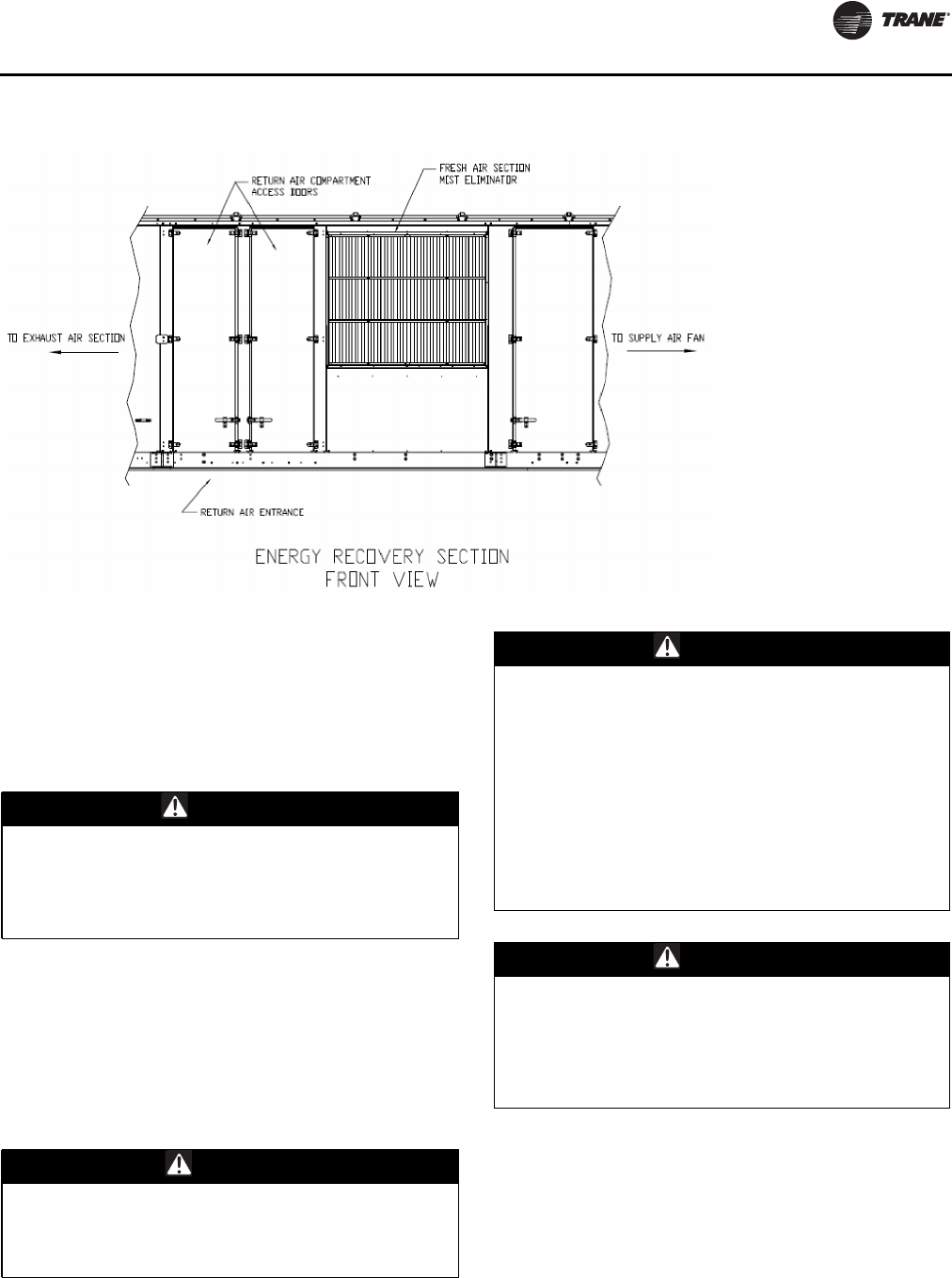
Unit Startup
RT-SVX24K-EN 153
Energy Recovery Wheel (ERW)
The IntelliPak™ II energy wheel section consists of the
energy wheel cassette assembly, return air, outside air,
and bypass dampers, and outside air mist eliminators.
Double opposing large access doors are provided on both
sides of the section for service access into the return/
exhaust air compartment, see Figure 104.
The two access doors are accessible from either side of the
rooftop.The horizontally oriented energy wheel cassette is
permanently installed in the section.The individual
segments of the energy wheel are removable for cleaning
or replacement.Two additional access doors are provided
for service access into the filter / evaporator section.
Operation
Figure 104. IntelliPak II energy wheel section
WARNING
Toxic Hazards!
Do not use an energy wheel in an application where the
exhaust air is contaminated with harmful toxins or
biohazards. Failure to follow this instruction could
result in death or serious injury.
CAUTION
Motor Failure!
Do not install a variable frequency drive (VFD) to
control the energy wheel speed.This could result in
failure of the energy wheel motor.
WARNING
Confined Space Hazards!
Do not work in confined spaces where refrigerant or
other hazardous, toxic or flammable gas may be
leaking. Refrigerant or other gases could displace
available oxygen to breathe, causing possible
asphyxiation or other serious health risks. Some gases
may be flammable and or explosive. If a leak in such
spaces is detected, evacuate the area immediately and
contact the proper rescue or response authority. Failure
to take appropriate precautions or to react properly to
such potential hazards could result in death or serious
injury.
WARNING
Hazardous Voltage!
Disconnect all electric power, including remote
disconnects before servicing. Follow proper lockout/
tagout procedures to ensure the power can not be
inadvertently energized. Failure to disconnect power
before servicing could result in death or serious injury.
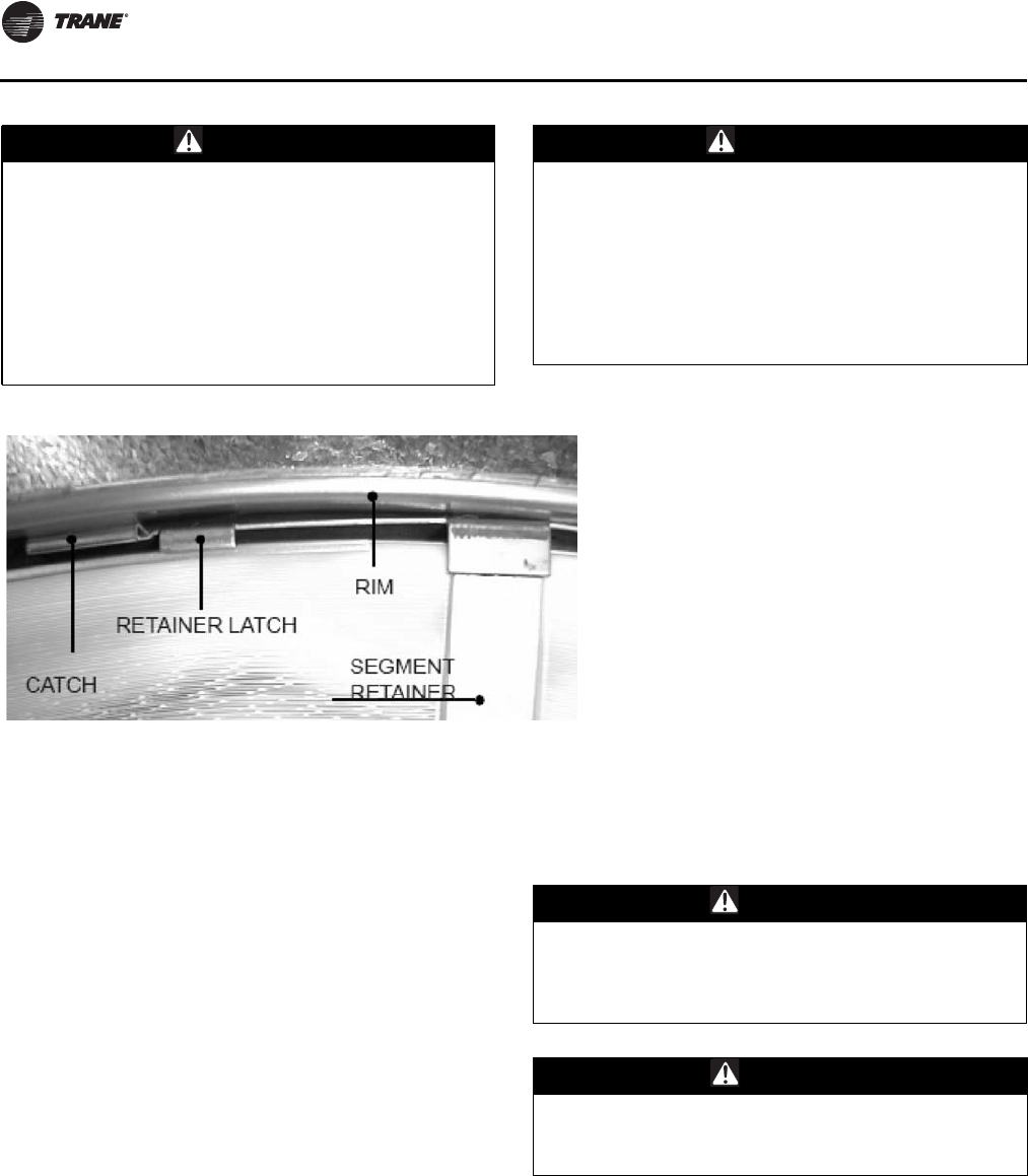
Unit Startup
154 RT-SVX24K-EN
ERW Startup
1. Turn the energy wheel clockwise (as viewed from the
pulley side) by hand to verify that the wheel turns
freely through a full rotation.
2. Confirm that all wheel segments are fully engaged in
the wheel frame and that the segment retainers are
completely fastened. See Figure 106, p. 156.
3. Manually rotate the energy wheel clockwise through
several rotations to confirm the seal adjustment and
proper belt tracking on the wheel rim. Correct belt
tracking is approximately midway between the seal
plate and the outer edge of the rim.
Note: The drive belt is a urethane stretch belt designed to
provide constant tension throughout the life of the
belt. No periodic adjustment is required. Inspect
the belt annually for proper tracking and tension. A
properly tensioned belt will turn the wheel
immediately, with no visible slippage, when power
is applied.
4. If the wheel has difficulty starting, turn off the power
and inspect the wheel for excessive interference
between the wheel surface and the four diameter
seals.To correct interference, loosen the diameter seal
adjusting screws and back the diameter seals away
from the surface of the wheel. Apply power to confirm
free wheel rotation. Re-adjust and tighten the seals
according to instructions in the “Service and Repair”
section.
Damper Actuators
Stroke the actuators to observe full open and full closure
of the dampers.
Routine Maintenance
Cleaning the Energy Wheel
Disconnect all electrical power, then use a vacuum or
brush to remove accumulated material from the face of the
wheel. Examine the energy wheel monthly for material
build-up on the wheel. If more aggressive cleaning is
needed, removed the wheel segments and follow these
steps:
1. Wash the segments or the wheel in a five-percent
solution of non-acid-base coil cleaner (part no.
WARNING
Rotating Components!
During installation, testing, servicing and
troubleshooting of this product it may be necessary to
work with live and exposed rotating components. Have
a qualified or licensed service individual who has been
properly trained in handling exposed rotating
components, perform these tasks. Failure to follow all
safety precautions could result in rotating components
cutting and slashing technician which could result in
death or serious injury.
WARNING
Rotating Components!
The following procedure involves working with rotating
components. Disconnect all electric power, including
remote disconnects before servicing. Follow proper
lockout/tagout procedures to ensure the power can not
be inadvertently energized. Failure to disconnect power
before servicing could result in rotating components
cutting and slashing technician which could result in
death or serious injury.
Figure 105. Segment retainers
CAUTION
Cleaning Damage!
Do not use acid based cleaners, aromatic solvents,
steam, or temperatures in excess of 170°F. Doing so
could cause damage to the wheel!
CAUTION
Cleaning Damage!
Do not use a pressure washer to clean energy wheel
segments. Doing so could cause damage to the wheel!
Unit Startup
RT-SVX24K-EN 155
CHM00021 at your localTrane parts center) or in an
alkaline detergent and warm water.
2. Soak the segments in the solution until grease, oil, and
tar deposits are loosened.
3. Before removing the cleaner, rapidly run your fingers
across the surface of segments to separate polymer
strips for better cleaning action.
4. Rinse the dirty solution from the segments and remove
the excess water before re-installing the segments in
the wheel.
Note: Some permanent staining of the desiccant may
remain but is not harmful to performance.
Cleaning Frequency
In reasonably clean office or school buildings, cleaning
with a coil cleaner solution may not be required for several
years. If the energy wheel is exposed to air streams
containing, for example, high levels of occupant tobacco
smoke, cooking facility exhaust air, or oil-based aerosols
found in machine shop areas, annual or more frequent
cleaning may be required to remove these contaminants
and restore performance. Periodic inspection of the wheel
should be done to determine the cleaning intervals.
High-maintenance applications may benefit from keeping
a spare set of clean segments on hand.This allows for
rapid change-out of clean segments with minimal
downtime.The dirty segments can then be cleaned at a
convenient time.
Segment Removal
Wheel segments for the low CFM energy recovery option
for the 90, 105, and 120 ton units are secured to the wheel
frame by a segment retainer that pivots on the wheel rim
and is held in place by a segment retaining catch. All other
units have larger sized wheels and have inner and satellite
segments.The satellite segments are secured to the wheel
frame by a segment retainer in the same fashion as the
outer segments for the above mentioned smaller low CFM
recovery wheels.The inner segments are secured to the
wheel center hub with a screw.
Outer and Satellite Segment Removal
Procedure:
1. Disconnect all electrical power.
2. Secure wheel from rotation.
3. Pry the segment retainer latch out from the catch. See
Figure 106. For the first or for an individual segment
removal, it will be necessary to do so on both sides of
the segment.
4. Remove the forked segment retainer(s). See
Figure 106. Again, for the first or for an individual
segment removal, it will be necessary to do so on both
sides of the segment.
5. Remove the segment from the wheel frame. It may be
necessary to gently pry the segment out of the wheel
with a screwdriver.
6. Pull the segment up and out of the wheel frame.
7. Close any open segment retainer prior to rotating the
wheel. Failure to close the retainer may damage the
retainer, seals, or segments.
8. Rotate the wheel and continue this procedure to
remove all segments. See Figure 107, p. 156.
WARNING
Hazardous Voltage!
Disconnect all electric power, including remote
disconnects before servicing. Follow proper lockout/
tagout procedures to ensure the power can not be
inadvertently energized. Do not open the service access
doors while the unit is operating. Failure to disconnect
power before servicing could result in death or serious
injury.
WARNING
Rotating Components!
During installation, testing, servicing and
troubleshooting of this product it may be necessary to
work with live and exposed rotating components. Have
a qualified or licensed service individual who has been
properly trained in handling exposed rotating
components, perform these tasks. Failure to follow all
safety precautions could result in rotating components
cutting and slashing technician which could result in
death or serious injury.
WARNING
Hazardous Voltage!
Disconnect all electric power, including remote
disconnects before servicing. Follow proper lockout/
tagout procedures to ensure the power can not be
inadvertently energized. Do not open the service access
doors while the unit is operating. Failure to disconnect
power before servicing could result in death or serious
injury.
WARNING
Hazardous Voltage!
Disconnect all electric power, including remote
disconnects before servicing. Follow proper lockout/
tagout procedures to ensure the power can not be
inadvertently energized. Do not open the service
access doors while the unit is operating. Failure to
disconnect power before servicing could result in death
or serious injury.
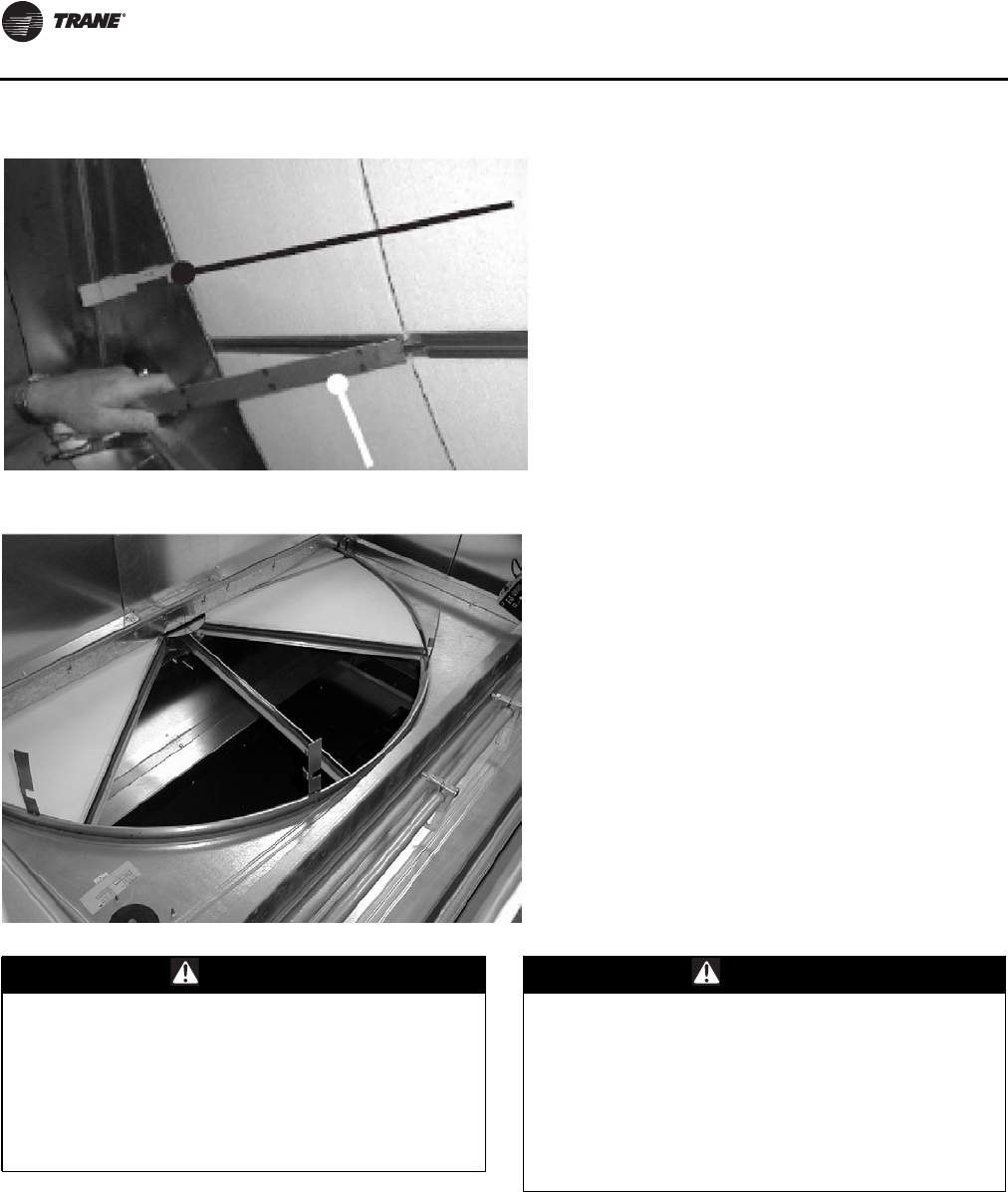
Unit Startup
156 RT-SVX24K-EN
.
Figure 106. Segment Retainers
Figure 107. Segment Removal
WARNING
Hazardous Voltage!
Disconnect all electric power, including remote
disconnects before servicing. Follow proper lockout/
tagout procedures to ensure the power can not be
inadvertently energized. Do not open the service access
doors while the unit is operating. Failure to disconnect
power before servicing could result in death or serious
injury.
WARNING
Rotating Components!
The following procedure involves working with
rotating components. Disconnect all electric power,
including remote disconnects before servicing. Follow
proper lockout/tagout procedures to ensure the power
can not be inadvertently energized. Failure to
disconnect power before servicing could result in
rotating components cutting and slashing technician
which could result in death or serious injury.
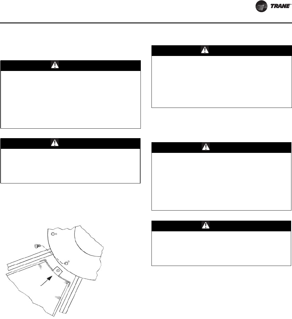
Unit Startup
RT-SVX24K-EN 157
Inner Segment Removal Procedure:
1. Disconnect all electrical power.
2. Secure wheel from rotation.
3. Support segment with one hand while removing ¼ - 20
flat head retaining screw in the wheel hub with 5/32"
Allen wrench, see Figure 108.
4. Carefully slide the segment out from between the hub
plates, and remove from the wheel.
5. Reinsert the ¼ - 20 screw in the removed segment nose
to avoid loss.
6. Rotate the wheel and continue this procedure to
remove all segments.
Segment Replacement
Inner Segment Replacement
1. Disconnect all electrical power.
2. Secure wheel from rotation.
3. Remove ¼ - 20 flat head retaining screw from the inner
segment nose with 5/32" Allen wrench.
4. Rest the edge of the segment on the support flange on
one wheel spoke and slide it until the segment nose is
fitted firmly in the wheel hub and the segment screw
hole is aligned with the hub slot.
5. Reinsert ¼ - 20 screw into the hub / inner segment and
tighten until the screw is firmly seated, see Figure 108.
CAUTION
Sharp Edges!
The service procedure described in this document
involves working around sharp edges. To avoid being
cut, technicians MUST put on all necessary Personal
Protective Equipment (PPE), including gloves and arm
guards. Protect hands and the belt from possible sharp
edges of the hole in the bearing support beam. Failure
to follow recommendations could result in minor to
moderate injury or product damage.
CAUTION
Added Support Required!
Before laying across the energy wheel, place a rigid
board across the span of the energy wheel cassette.
Failure to do so could result in personal injury and/or
damage to the energy wheel.
Figure 108. Inner Segment Removal
WARNING
Hazardous Voltage!
Disconnect all electric power, including remote
disconnects before servicing. Follow proper lockout/
tagout procedures to ensure the power can not be
inadvertently energized. Do not open the service access
doors while the unit is operating. Failure to disconnect
power before servicing could result in death or serious
injury.
CAUTION
Sharp Edges!
The service procedure described in this document
involves working around sharp edges. To avoid being
cut, technicians MUST put on all necessary Personal
Protective Equipment (PPE), including gloves and arm
guards. Protect hands and the belt from possible sharp
edges of the hole in the bearing support beam. Failure
to follow recommendations could result in minor to
moderate injury or product damage.
CAUTION
Added Support Required!
Before laying across the energy wheel, place a rigid
board across the span of the energy wheel cassette.
Failure to do so could result in personal injury and/or
damage to the energy wheel.
Unit Startup
158 RT-SVX24K-EN
Outer or Satellite Segment Replacement
1. Disconnect all electrical power.
2. Secure wheel from rotation.
3. Rotate out the two segment retainer latches, one for
each side of the selected segment opening, such that
they are 90° from the wheel rim. See Figure 108, p. 157.
4. Set the segment in the gap between the segment
retainer latches, pressing it toward the center of the
wheel and inward against the spoke flanges. See
Figure 111 , p . 160. If hand pressure does not fully seat
the segment, insert the flat tip of a screwdriver
between the wheel rim and the outer corners of the
segment and apply gentle force while guiding the
segment into place. Be careful not to bend the wheel
frame or the segment frame with the screwdriver.
5. Reinstall forked segment retainer(s)
Note: Only applies when there is an adjacent segment in
place.
6. Close each segment retainer latch under the segment
retaining catch.
7. Rotate the wheel and repeat this sequence with the
remaining segments.
Removing and replacing the segments with a spare set can
be accomplished more quickly. Remove the dirty segment,
replace it with a clean segment, then move to the next
segment.
Filtration
Galvanized steel permanent filters are provided to prevent
debris from entering the energy wheel section.The return
air filters are mounted in a filter rack underneath the
energy recovery wheel, and are accessible from either side
by means of the double access doors.The outside air filter
rack is attached to the energy recovery cassette. Use the
unit filter / evaporator coil access doors to service the
energy recovery outside air filters.
1. Disconnect all electrical power.
2. Remove all filter media from the vertical filter rack
providing air filtration for the unit evaporator coil.
3. Remove the sheet metal screws in the hinged access
panel beneath the bypass damper assembly.
4. Rotate the access panel downwards.
5. Reach in past the damper wall to access the flexible
filter puller(s). Pull them towards the evaporator coil
enough to reach the second filter in each slot of the
filter rack. Refer to Table 45, p. 158 for filter
information.
Note: Inspect these filters monthly and clean them as
necessary.
Bearing and Motor Lubrication
The wheel drive motor and wheel support shaft bearings
are permanently lubricated and no further lubrication is
necessary.
Service and Repair
Drive Belt Replacement
The drive belt is a urethane stretch belt designed to
provide constant tension throughout the life of the belt. No
WARNING
Hazardous Voltage!
Disconnect all electric power, including remote
disconnects before servicing. Follow proper lockout/
tagout procedures to ensure the power can not be
inadvertently energized. Do not open the service access
doors while the unit is operating. Failure to disconnect
power before servicing could result in death or serious
injury.
WARNING
Rotating Components!
The following procedure involves working with
rotating components. Disconnect all electric power,
including remote disconnects before servicing. Follow
proper lockout/tagout procedures to ensure the power
can not be inadvertently energized. Failure to
disconnect power before servicing could result in
rotating components cutting and slashing technician
which could result in death or serious injury.
WARNING
Hazardous Voltage!
Disconnect all electric power, including remote
disconnects before servicing. Follow proper lockout/
tagout procedures to ensure the power can not be
inadvertently energized. Do not open the service
access doors while the unit is operating. Failure to
disconnect power before servicing could result in death
or serious injury.
Table 45. ERW Filter Information
Galvanized
Steel Filter
Information
90-118T
Low CFM
ERW
Units (in.)
90-162T
Low CFM
ERW
Units (in.)
90-162T
Standard CFM
ERW
Units (in.)
RA Filters (size,
number) 24x24x1, 10 24x24x1, 10 24x24x1, 10
FA Filters (size,
number 224x24x1, 8 24x24x1, 6 24x24x1, 8
12x24x1, 2
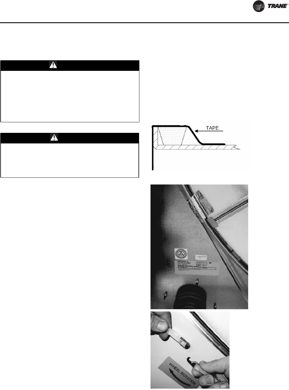
Unit Startup
RT-SVX24K-EN 159
periodic adjustment is required. Inspect the belt annually
for proper tracking and tension. A properly tensioned belt
will turn the wheel immediately, with no visible slippage,
when power is applied.
1. Disconnect all electrical power.
2. Confirm the model number on the belt replacement kit
matches the model number on the label by the motor
pulley. Remove all remnants of the old belt.
3. Uncoil the belt as necessary.The belt must not twist
when being feed around the wheel rim.
4. At a location near the motor pulley, tape the hook end
of the belt to the wheel rim, see Figure 110, p. 159 and
Figure 107, p. 156.The tape should cover the hook and
belt.
5. Manually rotate the wheel clockwise while feeding the
belt onto the wheel rim, taking care that the belt does
not twist.
Note: If for any reason the belt were to become flipped or
twisted 90° in either direction, belt failure will be
imminent.
6. Upon feeding the belt completely through, remove the
tape and join the link with the belt positioned around
the wheel rim, see Figure 110, p. 159. Keep light
tension on the belt, as a slack belt may be prone to
twist.
7. Manually rotate the wheel clockwise until the linked
belt ends are approximately 180° from the motor
pulley location.
8. Insert the right angle belt retainer from the
replacement kit at the pulley location. Place it between
the segment retainer latch pivot point and the wheel
spoke, see Figure 111 , p . 160 (left of the spoke).
Important: To avoid release of the segment latch do not
insert retainer on the other side of spoke.
9. Manually rotate the wheel counter-clockwise to
position the belt retainer clip close to the center beam
and diameter seals.
10. In a section between the retainer clip and the motor
pulley, remove the belt from the wheel rim and then
place it over the pulley.
11. Manually rotate the wheel clockwise until the belt is
fully stretched around the wheel rim and motor pulley.
12. Remove the belt retainer clip and manually rotate the
wheel clockwise at least two full rotations while
verifying the belt is not twisted on the wheel rim or as
it enters the pulley(s).
WARNING
Hazardous Voltage!
Disconnect all electric power, including remote
disconnects before servicing. Follow proper lockout/
tagout procedures to ensure the power can not be
inadvertently energized. Do not open the service access
doors while the unit is operating. Failure to disconnect
power before servicing could result in death or serious
injury.
CAUTION
Added Support Required!
Before laying across the energy wheel, place a rigid
board across the span of the energy wheel cassette.
Failure to do so could result in personal injury and/or
damage to the energy wheel.
Figure 109. Link belt installation
Figure 110. Link belt installation
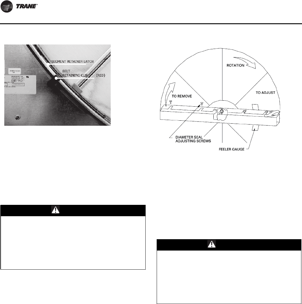
Unit Startup
160 RT-SVX24K-EN
Note: Pile seal brackets are fixed with a single screw to
the cassette frame near the ends of the wheel
bearing beam. Because the height of the belt link is
slightly higher than that of the urethane belt, a rare
interference may occur when it passes the seal
bracket. If this occurs, remove the interfering
bracket(s). No measurable change of performance
will occur.
Seal Adjustment
1. Disconnect all electrical power.
2. Loosen the diameter seal adjustment screws and back
the seals away from the wheel surface, see Figure 11 2 .
3. Rotate the wheel clockwise until two opposing spokes
are hidden behind the bearing support beam.
4. Using a folded piece of paper as a feeler gauge,
position the paper between the wheel surface and the
diameter seals.
5. Adjust the seals toward the wheel surface until slight
friction on the paper feeler gauge is felt when the
gauge is moved along the length of the spoke.
6. Check the seal adjustment through a full rotation of the
wheel. Re-tighten the adjusting screws and recheck the
clearance with the paper-feeler gauge.
Drive Motor and Pulley Replacement
1. Disconnect all electrical power.
2. Remove the belt from the pulley and position it
temporarily around the wheel rim.
3. Measure and record the distance from the inner edge
of the pulley to the mounting wall.
4. Loosen the set screw in the wheel drive pulley using an
Allen wrench and remove the pulley from the motor
drive shaft.
5. While supporting the weight of the drive motor in one
hand, loosen and remove the four mounting bolts.
6. Install a replacement motor with the hardware kit
supplied.
7. Install the pulley and adjust it to the distance recorded
earlier in this procedure.
Figure 111. Retaining clip location
WARNING
Hazardous Voltage!
Disconnect all electric power, including remote
disconnects before servicing. Follow proper lockout/
tagout procedures to ensure the power can not be
inadvertently energized. Do not open the service access
doors while the unit is operating. Failure to disconnect
power before servicing could result in death or serious
injury.
Figure 112. Wheel rotation
WARNING
Hazardous Voltage!
Disconnect all electric power, including remote
disconnects before servicing. Follow proper lockout/
tagout procedures to ensure the power can not be
inadvertently energized. Do not open the service
access doors while the unit is operating. Failure to
disconnect power before servicing could result in death
or serious injury.
Unit Startup
RT-SVX24K-EN 161
8. Tighten the set screw to the drive shaft.
9. Stretch the belt over the pulley and engage it in the
groove.
Compressor Startup
1. Ensure that the “System” selection switch at the
remote panel is in the “Off” position.
2. Before closing the disconnect switch, ensure that the
compressor discharge service valve and the liquid line
service valve for each circuit is back seated.
3. Close the disconnect switch or circuit protector switch
that provides the supply power to the unit terminal
block or the unit mounted disconnect switch to allow
the crankcase heater to operate a minimum of 8 hours
before continuing.
4. Turn the 115 volt control circuit switch and the 24 volt
control circuit switch to the “On” position.
5. Open the Human Interface access door, located in the
unit control panel, and press the SERVICE MODE key to
display the first service screen. Refer to the latest
edition of the applications programming guide for
applications for the SERVICETEST screens and
programming instructions.
6. Use Table 37, p. 11 2 to program the following system
components for operation by scrolling through the
displays;
Compressors
Compressor 1A (On)
Compressor 1B (Off)
Compressor 2A(Off)
Compressor 2B (Off)
Condenser Fans
1. Attach a set of service gauges onto the suction and
discharge gauge ports for each circuit.
See Figure 115, p. 165 for the various compressor
locations.
2. Once the configuration for the components is
complete, press the NEXT key until the LCD displays
the “Start test in __Sec.” screen. Press the + key to
designate the delay before the test is to start.This
service test will begin after theTEST START key is
pressed and the delay designated in this step has
elapsed. Press the ENTER key to confirm this choice.
3. Press theTEST START key to start the test. Remember
that the delay designated in step 8 must elapse before
the system will begin to operate.
4. Once each compressor or compressor pair has started,
verify that the rotation is correct. If a scroll compressor
is rotating backwards, it will not pump and a loud
rattling sound can be observed. Check the electrical
phasing at the load side of the compressor contactor.
If the phasing is correct, before condemning the
compressor, interchange any two leads to check the
internal motor phasing. If the compressor runs
backward for an extended period (15 to 30 minutes),
the motor winding can over heat and cause the motor
winding thermostats to open.This will cause a
“compressor trip” diagnostic and stop the
compressor.
5. Press the STOP key at the Human Interface Module in
the unit control panel to stop the compressor
operation.
6. Repeat steps 5 through 11 for each compressor stage
and the appropriate condenser fans.
Refrigerant Charging
1. Attach a set of service gauges onto the suction and
discharge gauge ports for each circuit.
See Figure 115, p. 165 for the various compressor
locations.
2. Open the Human Interface access door, located in the
unit control panel, and press the SERVICE MODE key to
display the first service screen. Refer to the latest
edition of the applications programming guide for CV
or VAV applications for the SERVICETEST screens and
programming instructions.
NOTICE:
Compressors Failure!
Unit must be powered and crankcase heaters energized
at least 8 hours BEFORE compressors are started. This
will protect the compressors from premature failure.
CAUTION
Compressor Damage!
Do not allow liquid refrigerant to enter the suction line.
Excessive liquid accumulation in the liquid lines could
result in compressor damage.
COMPRESSOR SERVICE VALVES MUST BE FULLY
OPENED BEFORE STARTUP (SUCTION, DISCHARGE,
LIQUID LINE, AND OIL LINE).
WARNING
Rotating Components!
The following procedure involves working with
rotating components. Disconnect all electric power,
including remote disconnects before servicing. Follow
proper lockout/tagout procedures to ensure the power
can not be inadvertently energized. Failure to
disconnect power before servicing could result in
rotating components cutting and slashing technician
which could result in death or serious injury.
Unit Startup
162 RT-SVX24K-EN
3. Use Table 37, p. 11 2 to program the following system
components for the number 1 refrigeration circuit by
scrolling through the displays;
Supply Fan (On)
VFD (100%, if applicable)
OCC/UNOCC Relay (Unoccupied for VAV units)
All Compressors for each circuit (On)
Condenser Fans for each circuit (On)
4. Once the configuration for the components is
complete, press the NEXT key until the LCD displays
the “Start test in __Sec.” screen. Press the + key to
designate the delay before the test is to start.This
service test will begin after theTEST START key is
pressed and the delay designated in this step has
elapsed. Press the ENTER key to confirm this choice.
5. Press theTEST START key to start the test. Remember
that the delay designated in step 4 must elapse before
the system will begin to operate.
6. After all of the compressors and condenser fans for the
number 1 circuit have been operating for
approximately 30 minutes, observe the operating
pressures. Use the appropriate pressure curve
beginning with Figure 84, p. 136 to determine the
proper operating pressures. For superheat and
subcooling guidelines, refer to “Thermostatic
ExpansionValves and Charging by Subcooling” at the
end of this section.
Note: Do Not release refrigerant to the atmosphere! If
adding or removing refrigerant is required, the
service technician must comply with all Federal,
State and local laws.
7. Verify that the oil level in each compressor is correct.
The oil level may be down to the bottom of the
sightglass but should never be above the sightglass.
8. Press the STOP key at the Human Interface Module in
the unit control panel to stop the system operation.
9. Repeat steps 1 through 8 for the number 2 refrigeration
circuit.
10. After shutting the system off, check the compressor oil
appearance. Discoloration of the oil indicates that an
abnormal condition has occurred. If the oil is dark and
smells burnt, it has overheated because: the
compressor is operating at extremely high condensing
temperatures; high superheat; a compressor
mechanical failure; or, occurrence of a motor burnout.
If the oil is black and contains metal flakes, a
mechanical failure has occurred.This symptom is
often accompanied by a high compressor amperage
draw.
If a motor burnout is suspected, use an acid test kit to
check the condition of the oil.Test results will indicate
an acid level exceeding 0.05 mg KOH/g if a burnout
occurred.
The scroll compressor uses Trane OIL00079 (one quart
container) or OIL00080 (one gallon container) without
substitution.The appropriate oil charge for CSHN250
and CSHN315 scroll compressors is 14.2 pints. For
CSHN374 scroll compressor, use 15.2 pints.
Compressor Crankcase Heaters
Each scroll compressor is equipped with a 160-watt
crankcase heater.
Compressor Operational Sounds
Because of the scroll compressor design, it emits a higher
frequency tone (sound) than a reciprocating compressor.
It is designed to accommodate liquids, both oil and
refrigerant, without causing compressor damage.The
following discussion describes some of the operational
sounds that differentiate it from those typically associated
with a reciprocating compressor.These sounds do not
affect the operation or reliability of the compressor.
At Shutdown
When a Scroll compressor shuts down, the gas within the
scroll expands and causes momentary reverse rotation
until the discharge check valve closes. This results in a
“flutter” type sound.
At Low Ambient Startup
When the compressor starts up under low ambient
conditions, the initial flow rate of the compressor is low
due to the low condensing pressure.This causes a low
differential across the thermal expansion valve that limits
its capacity. Under these conditions, it is not unusual to
hear the compressor rattle until the suction pressure
climbs and the flow rate increases.
Note: Evaporative Condensers ordered with sump
heaters will have low ambient down to 10 deg as
standard
WARNING
Rotating Components!
The following procedure involves working with rotating
components. Disconnect all electric power, including
remote disconnects before servicing. Follow proper
lockout/tagout procedures to ensure the power can not
be inadvertently energized. Failure to disconnect power
before servicing could result in rotating components
cutting and slashing technician which could result in
death or serious injury.

Unit Startup
RT-SVX24K-EN 163
Evaporative Condenser Startup
Important: Water treatment by a qualified water
treatment expert is required to ensure
proper equipment life and product
performance. Dolphin Water Care™ is an
option offered byTrane that is NOT a
subsitute for regular water treatment by a
qualified water treatment professional. If a
water treatment system is not operating on
the unit, do not proceed.
Startup for evaporative and air-cooled condensers is
initially the same. In addition, the following is required for
evaporative condensers prior to startup:
• All water and drain connections must be checked and
verified
• Evaporative condensers will ship with a fan support
channel to reduce damage caused by vibration during
shipment.The shipping support brackets must be
removed prior to unit startup. See “To remove
shipping brackets,” p. 163 and Figure 113, p. 164 for
removal instructions.
• Verify that inlet water pressure is 35-60 PSIG, dynamic
pressure (measured with the valve open)
• Verify that drain valve is set to "drain during power
loss" or "hold during power loss" per job specification
• Upon a call for cooling, the sump will fill with water.
Verify that the sump fills to a level within the slot on the
max float bracket as shown in Figure 114, p. 164.
To remove shipping brackets
Important: Remove fan shipping brackets before
startup. Failure to remove brackets could
result in fan damage.
Evaporative condensers are shipped with fan shipping
brackets to reduce damage caused by vibration during
shipment.The fan shipping brackets must be removed
prior to unit startup.
To remove the shipping brackets start from the side
opposite to the drain actuator:
1. Loosen the screw for the bracket that holds the inlet
louvers below the door side.
2. Remove inlet louvers and set to the side.
Note: Service technician may need to step on the
horizontal surface of FRP coated base.
Step with care.
3. Unscrew the bolt in the middle of the door. Keep the
bolt in a safe place.
4. Lift one door with handle until it touches the top.
Swivel bottom of door to remove it from the door
opening and set it to the side.
5. Slide and remove the middle mist eliminator section
so that the shipping bracket is visible.
6. Use screw gun to unscrew the two screws that hold the
fan shipping bracket.The bracket should drop down
but still remain engaged with a hook on the bracket.
7. Go to the other side of the unit and follow the
procedure for inlet louver and door removal
(see steps1-6
).
8. Hold the bracket with one hand and remove remaining
two screws.
9. Remove the bracket and all the removed screws from
the unit.
Important: Make sure there are no screws remaining in
the coil area.
10. Reinstall inlet louvers, mist eliminators and louvers.
11. Check that the direction of arrow on the inlet louver is
correct
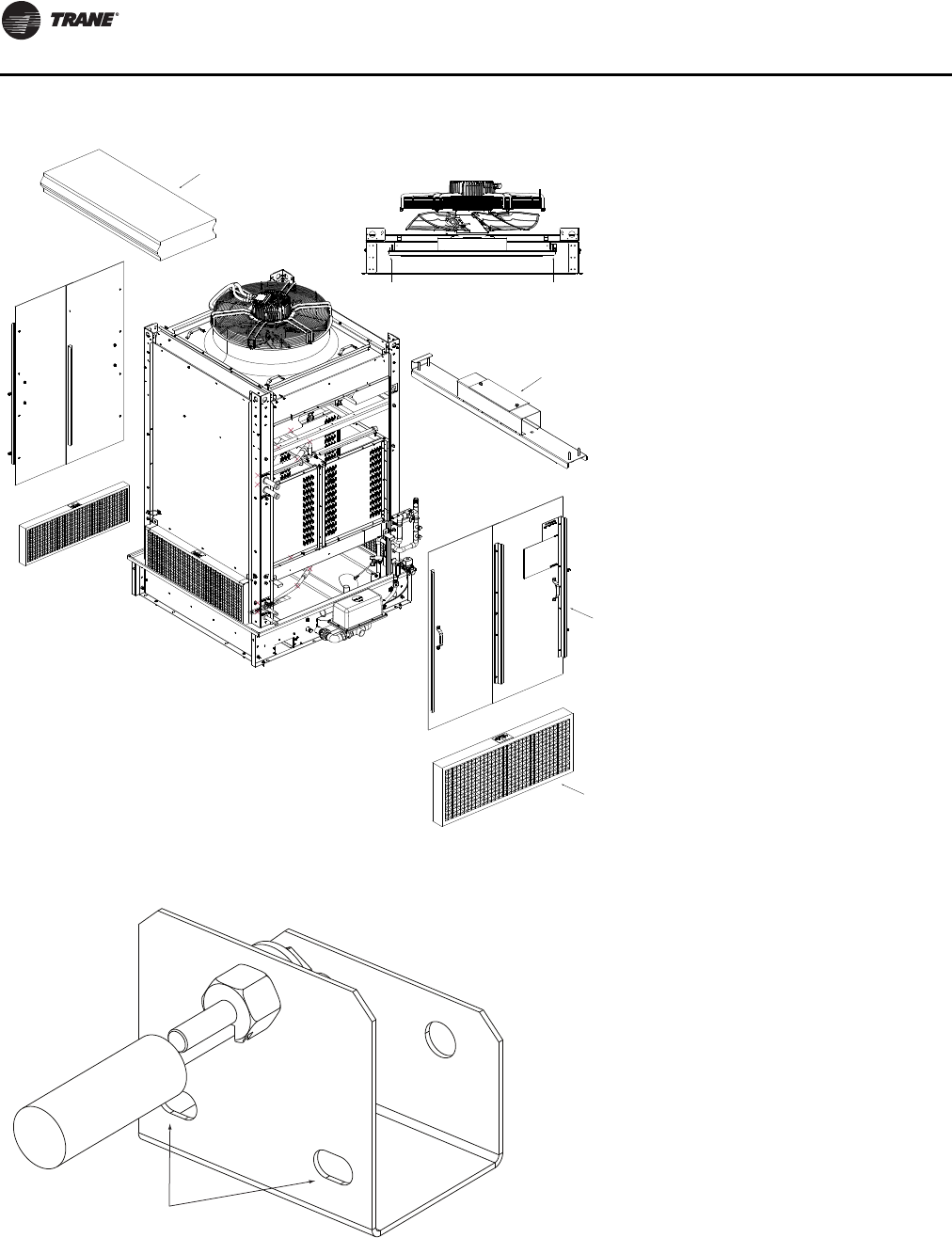
Unit Startup
164 RT-SVX24K-EN
Figure 113. Fan shipping bracket removal
Mist Eliminator
Fan Shipping Bracket Screws
Fan Shipping Bracket
Access Doors
Inlet Louvers
Actuator Side
Figure 114. Float bracket setting
Fill sump so oat shuts
o when water is within these slots
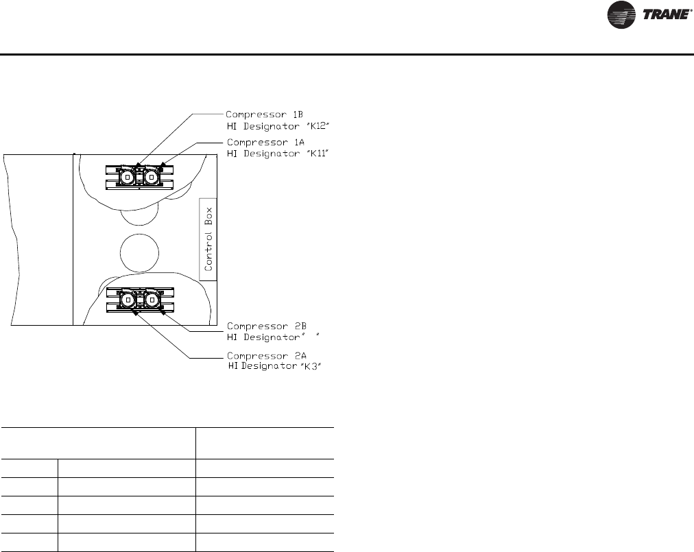
Unit Startup
RT-SVX24K-EN 165
Thermostatic Expansion Valves
The reliability and performance of the refrigeration system
is heavily dependent upon proper expansion valve
adjustment.Therefore, the importance of maintaining the
proper superheat cannot be over emphasized.
On air-cooled units, the expansion valves shipped
installed were factory set to control between 14-18°F at the
ARI full load rating conditions (approximately 45°/125°F
saturated suction/discharge). On evaporative condenser
units, the expansion valves shipped installed were factory
set to control between 18-22°F at the ARI full load rating
conditions (approximately 45°/105°F saturated suction/
discharge). At part load, expect lower superheat. Systems
operating with lower superheat could cause serious
compressor damage due to refrigerant floodback.
Pressure curves, included in the IOM, are based on
outdoor ambient between 65° & 105°F, relative humidity
above 40 percent. Measuring the operating pressures can
be meaningless outside of these ranges.
Measuring Superheat
1. Measure the suction pressure at the suction line gauge
access port located near the compressor.
2. Using a Refrigerant/Temperature chart, convert the
pressure reading to a corresponding saturated vapor
temperature.
3. Measure the suction line temperature as close to the
expansion valve bulb, as possible. Use a thermocouple
type probe for an accurate reading.
4. Subtract the saturated vapor temperature obtained in
step 2 from the actual suction line temperature
obtained in step 3.The difference between the two
temperatures is known as “superheat”.
When adjusting superheat, recheck the system subcooling
before shutting the system “Off”.
Note: If unit includes the modulating reheat
dehumidification option, adjust superheat only in
the cooling mode of operation.
Charging by Subcooling
The outdoor ambient temperature must be between 65
and 105°F and the relative humidity of the air entering the
evaporator must be above 40 percent. When the
temperatures are outside of these ranges, measuring the
operating pressures can be meaningless. Make sure hot
gas bypass (if applicable) is not flowing when taking
performance measurements. With the unit operating at
“Full Circuit Capacity”, acceptable subcooling ranges for
air-cooled units is between 14°F to 22°F.
For evaporative condenser units, acceptable subcooling
range is between 8°F to 14°F.
Measuring Subcooling
1. At the liquid line service valve, measure the liquid line
pressure. Using a Refrigerant R410A pressure/
temperature chart, convert the pressure reading into
the corresponding saturated temperature.
2. Measure the actual liquid line temperature as close to
the liquid line service valve as possible.To ensure an
accurate reading, clean the line thoroughly where the
temperature sensor will be attached. After securing the
sensor to the line, insulate the sensor and line to isolate
it from the ambient air. Use a thermocouple type probe
for an accurate reading.
Note: Glass thermometers do not have sufficient contact
area to give an accurate reading.
3. Determine the system subcooling by subtracting the
actual liquid line temperature (measured in step 2)
from the saturated liquid temperature (converted in
step 1).
Standard Ambient Units
The followingTable gives the minimum starting
temperatures for Standard Ambient Units. Do not start the
unit in the cooling mode if the ambient temperature is
below the recommended operating temperatures.
Figure 115. Compressor locations and staging sequence
Table 46. Staging sequence
Compressor Staging
(Lead) Compressor Staging
(Lag)
1A 1B 2A 2B 1A 1B 2A 2B
Stage 1 XX
Stage 2 XXXX
Stage 3 X XXXXX
Stage 4 XXXXXXXX
K
4
Unit Startup
166 RT-SVX24K-EN
Electric, Steam and Hot Water Startup
(Constant Volume & Variable Air Volume
Systems)
1. Ensure that the “System” selection switch at the
remote panel is in the “Off” position.
2. Close the disconnect switch or circuit protector switch
that provides the supply power to the unit terminal
block or the unit mounted disconnect switch.
HIGH VOLTAGE IS PRESENT AT TERMINAL BLOCK OR
UNIT DISCONNECT SWITCH.
3. Turn the 115 volt control circuit switch and the 24 volt
control circuit switch to the “On” position.
4. Open the Human Interface access door, located in the
unit control panel, and press the SERVICE MODE key to
display the first service screen. Refer to the latest
edition of the appropriate programming manual for CV
or VAV applications for the SERVICETEST screens and
programming instructions.
5. Use Table 37, p. 11 2 to program the following system
components for operation by scrolling through the
Human Interface displays;
Electric Heat
Supply Fan (On)
Variable Frequency Drive (100% Output, if applicable)
RTM Occ/Unocc Output (Unoccupied)
Heat Stages1&2(On)
Steam or Hot Water Heat
Supply Fan (On)
Variable Frequency Drive (100% Output, if applicable)
RTM Occ/Unocc Output (Unoccupied)
Hydronic Heat Actuator (100% Open)
Open the main steam or hot water valve supplying the
rooftop heater coils.
6. Once the configuration for the appropriate heating
system is complete, press the NEXT key until the LCD
displays the “Start test in __Sec.” screen. Press the +
key to designate the delay before the test is to start.
This service test will begin after theTEST START key is
pressed and the delay designated in this step has
elapsed. Press the ENTER key to confirm this choice.
7. Press theTEST START key to start the test. Remember
that the delay designated in step 6 must elapse before
the fan will begin to operate.
8. Once the system has started, verify that the electric
heat or the hydronic heat system is operating properly
by using appropriate service technics; i.e. amperage
readings, delta tees, etc.
9. Press the STOP key at the Human Interface Module in
the unit control panel to stop the system operation.
Gas Furnace Startup
(Constant Volume and Variable Air Volume
Systems)
It is important to establish and maintain the appropriate
air/fuel mixture to assure that the gas furnace operates
safely and efficiently.
Since the proper manifold gas pressure for a particular
installation will vary due to the specific BTU content of the
local gas supply, adjust the burner based on carbon
dioxide and oxygen levels.
The volume of air supplied by the combustion blower
determines the amount of oxygen available for
combustion, while the manifold gas pressure establishes
fuel input. By measuring the percentage of carbon dioxide
produced as a by-product of combustion, the operator can
estimate the amount of oxygen used and modify the air
volume or the gas pressure to obtain the proper air/fuel
ratio.
Arriving at the correct air/fuel mixture for a furnace results
in rated burner output, limited production of carbon
Table 47. Minimum ambient
Minimum Starting Ambient
Unit Size
Standard Ambient
with HGBP without HGBP
90-162 40 55
Notes:
1. Minimum starting ambients in degrees F and is based on unit
operating at min. step of unloading, and unloading and 5 mph wind
across condenser
WARNING
Hazardous Voltage!
Disconnect all electric power, including remote
disconnects before servicing. Follow proper lockout/
tagout procedures to ensure the power can not be
inadvertently energized. Do not open the service access
doors while the unit is operating. Failure to disconnect
power before servicing could result in death or serious
injury.
WARNING
Rotating Components!
During installation, testing, servicing and
troubleshooting of this product it may be necessary to
work with live and exposed rotating components. Have
a qualified or licensed service individual who has been
properly trained in handling exposed rotating
components, perform these tasks. Failure to follow all
safety precautions could result in rotating components
cutting and slashing technician which could result in
death or serious injury.
Unit Startup
RT-SVX24K-EN 167
monoxide, and a steady flame that minimizes nuisance
shutdowns.
Two Stage Gas Furnace
High-Fire Adjustment
1. Use Table 37, p. 112 to program the following system
components for operation by scrolling through the
Human Interface displays;
Gas Heat
Supply Fan (On)
Return Fan (On, if supplied)
Variable Frequency Drive (100% Output, if applicable)
RTM Occ/Unocc Output (Unoccupied)
Heat Stages1&2(On)
Turn the 115 volt control circuit switch 4S24 located in
the heater control panel to the “On” position.
Open the manual gas valve, located in the gas heat
section.
2. Once the configuration for the appropriate heating
system is complete, press the NEXT key until the LCD
displays the “Start test in __Sec.” screen. Press the +
key to designate the delay before the test is to start.
This service test will begin after theTEST START key is
pressed and the delay designated in this step has
elapsed. Press the ENTER key to confirm this choice.
3. Press theTEST START key to start the test. Remember
that the delay designated in step 2 must elapse before
the system will begin to operate.
4. Once the system has started, check the appearance of
the flame through the sight glass provided on the front
of the heat exchanger. In appearance, a normal flame
has a clearly defined shape, and is primarily (75%) blue
in color with an orange tip.
5. Check the manifold gas pressure by using the manifold
pressure port on the gas valve. Refer to Table 48, p. 168
for the required manifold pressure for high-fire
operation. If it needs adjusting, remove the cap
covering the high-fire adjustment screw on the gas
valve. Refer to Figure 118, p. 169 for the adjustment
screw location.Turn the screw clockwise to increase
the gas pressure or counterclockwise to decrease the
gas pressure.
6. Use a carbon dioxide analyzer and measure the
percentage of carbon dioxide in the flue gas. Refer to
the illustration in Figure 11 7, p . 169.Take several
samples to assure that an accurate reading is obtained.
Refer to Figure 116, p. 168 for the proper carbon
dioxide levels. A carbon dioxide level exceeding the
listed range indicates incomplete combustion due to
inadequate air or excessive gas.
Combustion Air Adjustment (O2)
7. Use an oxygen analyzer and measure the percentage
of oxygen in the flue gas.Take several samples to
assure an accurate reading. Compare the measured
oxygen level to the combustion curve in Figure 11 6 ,
p. 168.The oxygen content of the flue gas should be
4% to 5%. If the oxygen level is outside this range,
adjust the combustion air damper to increase or
decrease the amount of air entering the combustion
chamber. Refer to Figure 120, p. 171 for the location of
the combustion air damper.
8. Recheck the oxygen and carbon dioxide levels after
each adjustment. After completing the high-fire
checkout and adjustment procedure, the low-fire
setting may require adjusting.
Low-Fire Adjustment
(850 & 1100 MBH only)
1. Use theTEST initiation procedures outlined in the
previous section to operate the furnace in the low-fire
state (1st Stage).
2. Use a carbon dioxide analyzer and measure the
percentage of carbon dioxide in the flue gas. Refer to
the illustration in Figure 116, p. 168, Inset A. Take
several samples to assure that an accurate reading is
obtained. Refer to Table 48, p. 168 for the proper
carbon dioxide levels. If the measured carbon dioxide
level is within the listed values, no adjustment is
necessary. A carbon dioxide level exceeding the listed
range indicates incomplete combustion due to
inadequate air or excessive gas.
3. Check the manifold gas pressure by using the manifold
pressure port on the gas valve. Refer to Table 48, p. 168
WARNING
Hazardous Gases and Flammable Vapors!
Exposure to hazardous gases from fuel substances
have been shown to cause cancer, birth defects or other
reproductive harm. Improper installation, adjustment,
alteration, service or use of this product could cause
flammable mixtures and result in a fire. To avoid
hazardous gases and flammable vapors follow proper
installation and set up of this product and all warnings
as provided in this manual. Failure to follow all
instructions could result in death or serious injury.
WARNING
Hazardous Pressures!
When using dry nitrogen cylinders for pressurizing
units for leak testing, always provide a pressure
regulator on the cylinder to prevent excessively high
unit pressures. Never pressurize unit above the
maximum recommended unit test pressure as specified
in applicable unit literature. Failure to properly regulate
pressure could result in a violent explosion, which
could result in death or serious injury or equipment or
property-only-damage.
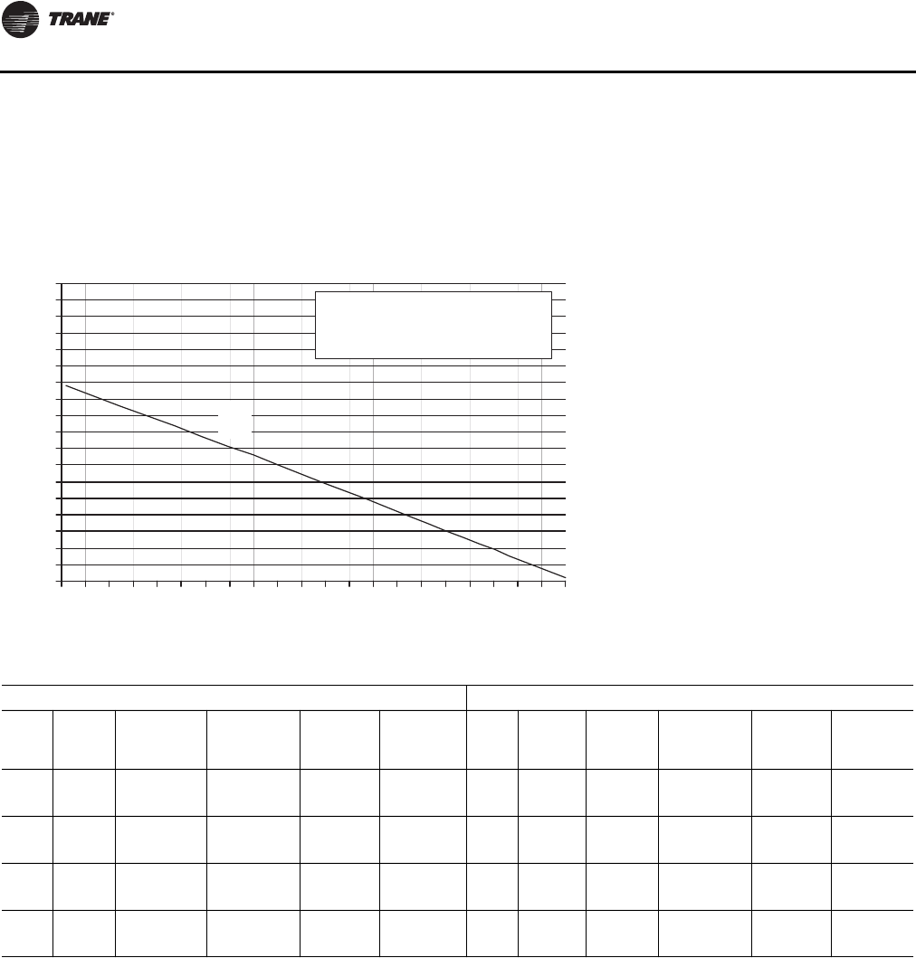
Unit Startup
168 RT-SVX24K-EN
for the required manifold pressure during low-fire
operation. If it needs adjusting, remove the cap
covering the low-fire adjustment screw on the gas
valve. Refer to Figure 118, p. 169 for the adjustment
screw location.Turn the screw clockwise to increase
the gas pressure or counterclockwise to decrease the
gas pressure.
Note: Do not adjust the combustion air damper while
the furnace is operating at low-fire.
4. Check the carbon dioxide levels after each adjustment.
5. Press the STOP key at the Human Interface Module in
the unit control panel to stop the system operation.
Figure 116. Natural gas combustion curve (ratio of oxygen to carbon dioxide in percent)
0
1
2
3
4
5
6
7
8
9
10
11
12
13
14
15
16
17
18
0123456789101112131415161718192021
Percent Oxygen
Percent Carbon Dioxide
Curve Fuel
A = 1,000 BTU per cu. ft.
of Natural Gas.
A
Table 48. Recommended manifold pressures and CO2levels during furnace operation
2-STAGE MODULATING
MBH FIRING
RATES % CO2
NAT GAS
MANIF
PRESS
“W.C. % CO2
PROPANE
MANIF
PRESS
“W.C. MBH FIRING
RATE % CO2
NAT GAS
MANIF
PRESS
“W.C. % CO2
PROPANE
MANIF
PRESS
“W.C.
850 100% 8.0-9.0 3.0-3.5 9.0-10.0 3.0-3.5 850 100% 8.0-9.0 3.0- 3.5 7.8-8.4 1.7-2.2
510 60% 5.0 -7.0 0.8-0.95 5.0-7.0 1.5-3.0 85 10% 5.0 -7.0 0.8- 0.9.5 2.0-3.0 .1-.2
1100 100% 8.0-9.0 3.0-3.3 9.0-10.0 3.0-3.3 1100 100% 7.0-9.0 .8-.9 8.5-9.5 .5-.75
550 50% 5.0 -7.0 0.8-0.95 5.0-7.0 0.8-0.95 55 5% 1.5-3.0 .05-1.0 1.5-2.5 .02-.04
1800 100% 7.0- 8.0 1.5- 1.8 N/A N/A 1800 100% 7.0-9.0 1.5- 1.8 N/A N/A
900 50% 5.0- 7.0 0.5- 0.7 N/A N/A 90 5% 1.5-3.0 .05-1.0 N/A N/A
2500 100% 7.5- 8.5 2.0- 2.5 N/A N/A 2500 100% 7.0-9.0 2.0- 2.5 N/A N/A
1250 50% 5.0- 7.0 0.5- 0.7 N/A N/A 125 5% 1.5-3.0 .05-1.0 N/A N/A
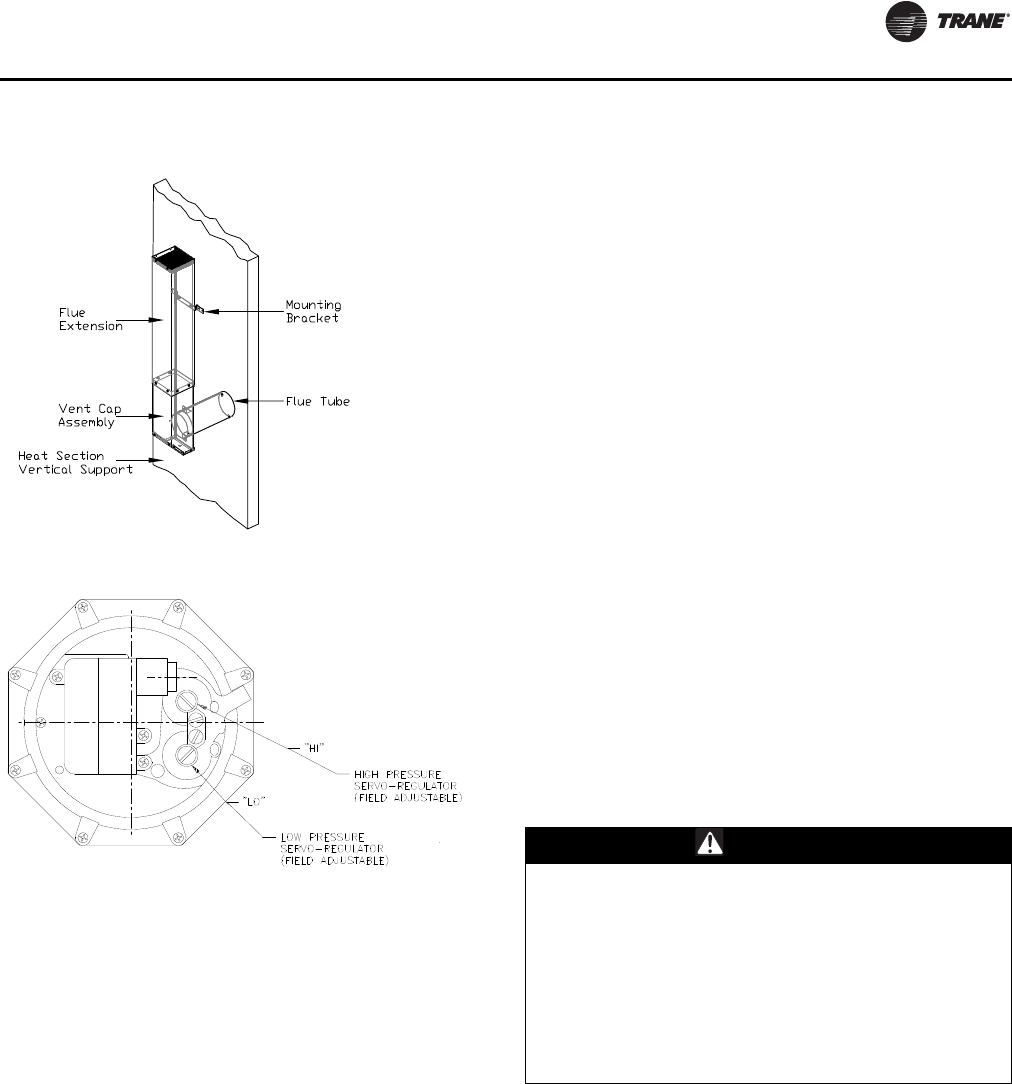
Unit Startup
RT-SVX24K-EN 169
Full Modulating Gas Furnace
Full Modulating gas heaters are available for the 850, 1100,
1800, 2500 MBH heater sizes.
– The firing rate of the 850 MBH modulating heater
can vary from 10% to 100% of the 850 MBH.
– The firing rate of the 1100, 1800 and 2500 MBH can
vary from 5% to 100% of it's nameplate value.
Heat Exchanger
The heat exchanger drum, tubes and front and rear
headers are constructed from stainless steel alloys.
Unit Control
The unit is controlled by a supply air temperature sensor
located in the supply air stream for VAV units. CV units
have two sensors, one located in the supply air stream and
the zone sensor.The temperature sensor signal is sent to
the Heat module of the IntelliPak™ II Unit Control.The
control signal from the Heat Module signal is directly
proportional 0-10 VDC.The higher the voltage signal, the
lower the call for heat.
The 0-10 VDC signal controls the air damper actuator
which is mounted on the end of the air damper shaft. As
the actuator rotates clockwise, more combustion air
passes through the combustion air blower. In turn, the gas
butterfly valve opens more through a directly connected
linkage, resulting in a higher rate of firing.
1. Use Table 37, p. 112 to program the following system
components for operation by scrolling through the
Human Interface displays;
Gas Heat
Supply Fan (On)
Variable Frequency Drive (100% Output, if applicable)
RTM Occ/Unocc Output (Unoccupied)
High Fire (90%)
Turn the 115 volt control circuit switch 4S24 located in
the heater control panel to the “On” position.
Open the manual gas valve, located in the gas heat
section.
2. Once the configuration for the appropriate heating
system is complete, press the NEXT key until the LCD
displays the “Start test in __Sec.” screen. Press the +
key to designate the delay before the test is to start.
This service test will begin after theTEST START key is
pressed and the delay designated in this step has
elapsed. Press the ENTER key to confirm this choice.
3. Press theTEST START key to start the test. Remember
that the delay designated in step 2 must elapse before
the system will begin to operate.
4. Once the system has started, check the appearance of
the flame through the sight glass provided on the front
of the heat exchanger. In appearance, a normal flame
has a clearly defined shape, and is primarily (75%) blue
in color with an orange tip.
5. Check the inlet gas pressure at the modulating gas
valve.The inlet pressure should be 6" to 8" w.c.
6. Use a carbon dioxide analyzer and measure the
percentage of carbon dioxide in the flue gas. Refer to
the illustration in Figure 11 7, p . 169.Take several
samples to assure that an accurate reading is obtained.
The C02level should fall in the ranges shown in the
guide values Table 48, p. 168
Figure 117. Flue gas carbon dioxide and oxygen
measurements
Figure 118. High/low pressure regulator
WARNING
Rotating Components!
During installation, testing, servicing and
troubleshooting of this product it may be necessary to
work with live and exposed rotating components. Have
a qualified or licensed service individual who has been
properly trained in handling exposed rotating
components, perform these tasks. Failure to follow all
safety precautions could result in rotating components
cutting and slashing technician which could result in
death or serious injury.
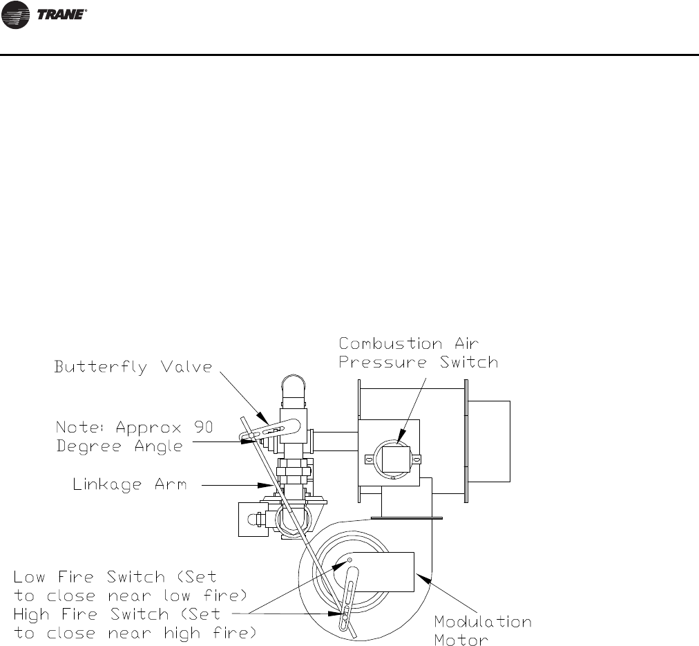
Unit Startup
170 RT-SVX24K-EN
Note: The burner capacity is controlled by the movement
of the air damper.This has been preset at the
factory and normally does not need field
adjustment.The combustion quality (air/gas) is
controlled by the setup of the air damper and
butterfly valve linkage relationship.
7. Use Table 37, p. 11 2 to program the minimum (5%)
firing rate. Allow the system to operate for
approximately 10 minutes.
8. Use a carbon dioxide analyzer and measure the
percentage of carbon dioxide in the flue gas. If the
measured carbon dioxide level is in the ranges shown
in the Guide Values Table 48, p. 168, no adjustment is
necessary.
Note: It is normal for the low fire CO2to be lower than the
high fire.
9. If the measured carbon dioxide level is below the
recommended values for low heat, return the burner to
90% fire rate and repeat step 6, to achieve optimum
combustion.
10. Program the burner for 100% operation and recheck
the CO2or O2value.
11. Check the flue gas values at several intermediate
output levels. If corrections are necessary;
– Adjust butterfly linkage
12. Press the STOP key at the Human Interface Module in
the unit control panel to stop the system operation.
Figure 119. Modulating gas regulator
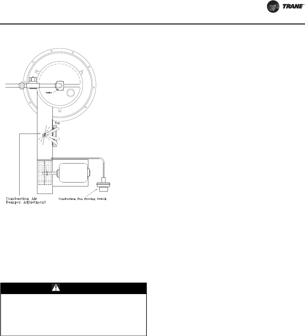
Unit Startup
RT-SVX24K-EN 171
Final Unit Checkout
After completing all of the checkout and startup
procedures outlined in the previous sections (i.e.,
operating the unit in each of its Modes through all
available stages of cooling and heating), perform these
final checks before leaving the unit:
[ ] Close the disconnect switch or circuit protector
switch that provides the supply power to the unit
terminal block or the unit mounted disconnect switch.
HIGH VOLTAGE IS PRESENT AT TERMINAL BLOCK OR
UNIT DISCONNECT SWITCH.
[ ]Turn the 115 volt control circuit switch “Off”.
[ ]Turn the 24 volt control circuit switch to the “On”
position.
[ ] At the Human Interface Module, press the “SETUP”
key. The LCD screen will display various preset
“parameters of operation” based on the unit type, size,
and the installed options. Compare the factory preset
information to the specified application requirements.
If adjustments are required, follow the step-by-step
instructions provided in the appropriate programming
manual for CV or VAV applications.
[ ] Program the Night Setback (NSB) panel (if
applicable) for proper unoccupied operation. Refer to
the programming instructions for the specific panel.
[ ] Verify that the Remote panel “System” selection
switch, “Fan” selection switch, and “Zone
Temperature” settings for constant volume systems
are correct.
[ ] Verify that the Remote panel “System” selection
switch and the “Supply AirTemperature” settings for
variable air volume systems are correct.
[ ] Inspect the unit for misplaced tools, hardware, and
debris.
[ ]Turn the 115 volt control circuit switch “On”.
[ ] Press the “AUTO” key at the Human Interface
Module to begin system operation.The system will
start automatically once the dampers modulate and a
request for either heating or cooling has been given.
[ ] Verify that all exterior panels including the control
panel doors and condenser grilles are secured in place.
Multi-piece Unit—Trane Startup
Once the IntelliPak II multi-piece unit has been installed, all
shipped with items have been installed, all utilities and
drain pipes have been connected, the refrigeration piping
has been reconnected and refrigerant charge has been
adequately distributed throughout the system, and all
ductwork has been attached to the unit,Trane will provide
unit startup.
Trane startup of multi-piece units will review the overall
unit for exterior damage (dents, bends, missing panels,
doors work properly), verify that the unit interior is free
from debris/obstructions, ensure that the panels and
doors are secured properly and verify that all wiring
connections are tight.
The overall installation will be reviewed to ensure the unit
clearances are adequate to avoid air recirculation and all
unit drain lines and traps are properly installed.
The unit main power will be reviewed to ensure the unit is
properly grounded, the main power feed wire gauge is
adequately sized, the correct voltage is supplied to unit
and electric heaters, and the incoming voltage is phase
balanced. Verification will be performed to ensure that all
field installed control wiring is applied to the correct
terminals, all automation and remote controls installed/
wired and control wiring for CV, SZVAV and VAV controls
is completed.
The refrigeration system will be reviewed to ensure the
coil fins are straightened, the removal of shipping
hardware and plastic covers for compressors, proper oil
level in the compressors, crankcase heaters have been
operational for at least 12 hours time prior toTrane startup
being performed.The proper compressor voltage and
amperage, correct position of service valves prior to
Figure 120. 850-1100 MBH
WARNING
Hazardous Voltage!
Disconnect all electric power, including remote
disconnects before servicing. Follow proper lockout/
tagout procedures to ensure the power can not be
inadvertently energized. Failure to disconnect power
before servicing could result in death or serious injury.

Unit Startup
172 RT-SVX24K-EN
startup and proper system subcooling and superheat will
be verified.
The unit fans will be checked to ensure that the condenser
fan blade set-screws to the motor shaft are tight, that the
hold down bolts and channels from fan sections have been
removed, proper adjustment of fan section spring
isolators, proper fan belts tension, adequate fan bearings
grease, alignment of fan sheaves, adequate tightness of
supply and exhaust fan pulley bolts, proper fan rotation,
and proper fan motor amperage.
A check will be made to ensure both piping to the
condenser and air handler side of the system have been
completed and interconnecting refrigerant tubing has
been evacuated by the contractor prior toTrane
performing the startup. All damper linkages will be
checked for proper adjustment, and proper damper
operation and outside air pressure sensors verified.
Units equipped with electric heaters will be checked to
ensure that the heating system matches the unit
nameplate and for correct voltage supply to the heaters.
Units equipped with gas heaters will be checked to ensure
that the flue assembly is secure and properly installed,
sufficient gas pressure exists according to pipe size, no
leaks exist in gas supply line, the gas heat piping includes
a drip leg, condensate line and the combustion air CO2 and
O2 levels are normal.
Units equipped with hot water heat will be checked to
ensure that the hot water pipes are properly routed, sized
and leak free; for the presence of swing joints or flexible
connectors next to the hot water coil; proper gate valve
installation in the supply and return branch line; proper
three way modulating valve installation, and proper coil
venting will be verified.
Units equipped with steam heat will be checked to ensure
that the hot water pipes are properly routed, sized and leak
free; proper swing check vacuum breaker installation;
proper 2-way modulating valve installation; proper steam
trap installation.
Units equipped with energy recovery wheels will be
checked to ensure proper rotation and operation of the
wheel.The service test guide will be used to check proper
component operation.
Finally, the program set points for proper unit operation
will be validated through human interface module. Once
the IntelliPak II multi-piece unit has been started, a
communication will be provided of startup activities and
the associated operating log.
Unit Startup
RT-SVX24K-EN 173
Table 49. Trane startup checklist
Important: This checklist is not intended as a substitution for the contractor’s installation instruction.
This checklist is intended to be a guide for theTrane technician just prior to unit 'startup'. Many of the recommended
checks and actions could expose the technician to electrical and mechanical hazards. Refer to the appropriate sections
in the this manual for appropriate procedures, component specifications and safety instructions.
Job Name Serial #
Job Location Model #
Sales Order # Ship Date
Unit DL # (special units) Date
Starting Sales Office Technician
Important: Except where noted, it is implied that theTrane technician is to use this checklist for inspection/verification
of prior tasks completed by the general contractor at installation. Use the line item content to also record
the associated values onto theTrane unitary packaged equipment log.
Complete
1. Crankcase heaters working for 8 hours prior to arrival of Trane technician performing startup
2. Correct voltage supplied to unit and electric heaters
3. Unit exterior inspected
4. Disconnect all power, Unit interior free from debris/obstructions etc.
5. Open all access doors to verify all open and close fully without any binding
6. All wiring connections tight
7. Unit properly grounded
8. Copper power wiring meets sizing requirement
9. All field control wiring for CV, SZVAV or VAV controls completed
10. All automation and remote controls installed/wired
11. Unit clearances adequate for service and to avoid air recirculation etc.
12. All unit drain lines and traps proper
13. All coil fins inspected and straightened
14. Shipping hardware for compressors removed
15. Hold down bolts and channels from fan sections removed
16. Fan section spring isolators checked/adjusted
17. Damper linkages tight/adjusted
18. Rail connector splice brackets installed on low side base rail
Where applicable: Evaporative condenser
19. Verify incoming water pressure is between 35-60psig, dynamic pressure (measured with valve open) for min flow rate of 30 GPM
20. Verify fan shipping brackets between fans and mist eliminators above spray distribution system have been removed
21. Verify water treatment system has been installed and approved - discontinue start-up if proof of active water treatment does not exist
Continued on next page
22. Verify conductivity controller calibration has been documented
23. Verify conductivity controller min and max setpoints have been setup
24. Verify all water and drain connections are complete
25. Verify the sump fills to within 1" of the overflow
26. Verify drain valve is set to "drain during power loss" or "hold during power loss" per job specification
Where applicable: Electric Heat
27. Electric heat circuits have continuity
Where applicable: Gas Heat
28. Gas heat piping includes drip leg previously installed by controlling contractor
29. Gas heat flue assembly fully installed
Unit Startup
174 RT-SVX24K-EN
30. Gas heat condensate line + heat tape installed where applicable
Where applicable: HW/Steam Heat
31. Modulating valve and actuator (HW and Steam) installed/wired
32. Steam heat swing check vacuum breakers installed per IOM direction
33. Steam heat condensate trap provided
34. O/A pressure sensor installed and piped
35. High side to low side piping to be completed prior to Trane technician arriving for startup
36. Space sensor and pneumatic tubing installed properly
Complete
37. Compressor discharge service valves, oil valves and liquid lines valves open/back seated (excludes Schrader valves)
38. Compressor oil levels (½ -¾ high in glass) proper
39. Verify power wires are connected in the high voltage power box
40. Verify field installed control wiring landed on correct terminals
41. All fan belts tensioned and bearings greased
42. Heat wheel rotates freely by hand
43. Reenergize power. Phase sequence (A-B-C) proper for compressor rotation
44. Incoming voltage balanced
45. All panels/doors secured prior to startup
Start unit
46. Service test guide used to operate unit components
47. Fan amperages within nameplate specs
48. Verify system airflow
49. Dampers open and close properly
50. Adjust outside air damper travel
51. On evaporative condenser models: Verify the sump fills to within 1.5” below the overflow, which is within the slot on the max float
bracket (see Figure 114, p. 164)
52. Compressor operation normal and within amperage rating
53. Superheat (14-18°F) and subcooling (14-22°F) normal for air-cooled units
54. Electric, hot water and steam heating operation checked
55. Gas heating startup sequence of operation per IOM has been followed
56. Gas heat operation has been verified with combustion analyzer
57. Incoming gas pressure does not drop below 7" water column when burner is on high fire
58. Operating log completed
Table 49. Trane startup checklist (continued)
RT-SVX24K-EN 175
Service and Maintenance
WARNING
Hazardous Voltage and Exposure to
Ultraviolet Radiation!
This product contains components that emit high-
intensity ultraviolet (UV-C) radiation which can be
harmful to unprotected eyes and skin.To avoid injury,
disconnect all electrical power, including remote
disconnects, and make sure the UV lights are off before
servicing. Follow proper lockout/tagout procedures to
ensure the power can not be inadvertently energized.
Failure to disconnect power before servicing could
result in burns or electrocution which could result in
death or serious injury.
Trane does not recommend field installation of
ultraviolet lights in its equipment for the intended
purpose of improving indoor air quality. High intensity
C-band ultraviolet light is known to severely damage
polymer (plastic) materials and poses a personal safety
risk to anyone exposed to the light without proper
personal protective equipment. Polymer materials
commonly found in HVAC equipment that could be
susceptible include insulation on electrical wiring, fan
belts, thermal insulation, various fasteners and
bushings. Degradation of these materials can result in
serious damage to the equipment.
Trane accepts no responsibility for the performance or
operation of our equipment in which ultraviolet devices
were installed outside of the Trane factory or its
approved suppliers.
Table 50. Control Settings and Time Delays
Control Description Elec. Designation Contacts Open Contacts Closed
Combustion Airflow Switch
(Gas Heat Only) 4S25 see note 1 0.1 - 0.25" wc rise in press diff
Supply Airflow Switch
(Gas Heat Only) 4S38 0.03 - 0.12" wc 0.15 + 0.05" wc rise in press diff
Freezestat
(Hydronic Heat Only) 4S12 (N.O.) Auto Reset 40 F
Gas Heat Units
Prepurge Timer: Honeywell 4U18 internal timing function 2 Stage 850/1100 MBH 60—seconds/
All other configurations—30 seconds
Sequencing Time Delay Relay 4DL6 N.C. - timed to close 60 seconds + 20%
Notes: The combustion airflow switch (4S25) differential is 0.02" - 0.08" wc.
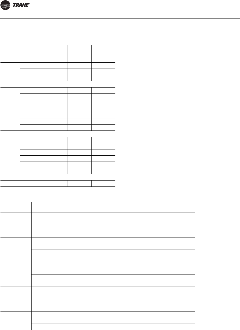
Service and Maintenance
176 RT-SVX24K-EN
Table 51. Gas Heat—High Limit
UNIT
TONS
2500 MBH HIGH LIMIT
CONTACTS CONTACTS
FAN SIZE
(IN) CONFIG. OPEN CLOSE
120-162
40 DF 195 155
40 HZ 240 200
32 DF & HORZ 220 180
1800 MBH HIGH LIMIT
120-162 32 &40 DF 240 200
32 &40 HZ 220 180
90-118
32 DF & HZ 240 200
36 DF & HZ 240 200
36 HZ 240 310
25 DF 240 200
25 HZ 220 180
1100 MBH HIGH LIMIT
120-162
32 DF 240 200
32 HZ 200 160
40 DF & HZ 240 200
90-118
32 DF 240 200
32 HZ 200 160
25 &36 DF & HZ 220 180
850 MBH HIGH LIMIT
90-118 25 &36 DF & HZ 240 200
Table 52. Electric Heat—Selection Limits
Tons Indoor Fan
Option Electric Heat Option Supply
Discharge Linear Limit -
Open Temp. Fan Fail Limit -
Open Temp.
120-162 Ton High (40") High (300 kW) Downflow 185F 185F
Hz (right) 185F 185F
Low (140 kW) Downflow 150F 185F
Hz (right) 150F 185F
Low (32") High (300 kW) Downflow 205F 185F
Hz (right) 185F 185F
Low (140 kW) Downflow 150F 185F
Hz (right) 150F 185F
105/118 Ton High (36") High (262.5 kW) Downflow 195F 155F
Hz (right) 195F 155F
Low (90 kW) Downflow 150F 175F
Hz (right) 150F 175F
Low (32") High (262.5 kW) Downflow 225F 185F
Hz (right) 205F 185F
Low (90 kW) Downflow 150F 175F
Hz (right) 150F 175F
90/105 Ton High (36") High (262.5 kW) Downflow 195F 155F
Hz (right) 195F 155F
Low (90 kW) Downflow 150F 175F
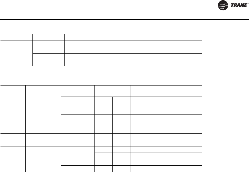
Service and Maintenance
RT-SVX24K-EN 177
Hz (right) 150F 175F
Low (25") High (262.5 kW) Downflow 215F 155F
Hz (right) 235F 155F
Low (90 kW) Downflow 150F 175F
Hz (right) 150F 175F
Table 52. Electric Heat—Selection Limits
Table 53. Compressor Circuit Breaker Electrical Characteristics
460V 575V 380V
Unit Size Compressor
Designator Compressor
Size Must
Hold Must
Trip Must
Hold Must
Trip Must
Hold Must
Trip
90/105 1A, 2A CSHN250 41.5 47.7 33.2 38.2 41.4 47.6
1B, 2B CSHN250 41.5 47.7 33.2 38.2 41.4 47.6
105/118 1A, 2A CSHN250 41.5 47.7 33.2 38.2 41.4 47.6
1B, 2B CSHN315 54.4 62.6 43.6 50.1 54.3 62.4
120/128 1A, 2A CSHN315 57.7 66.4 46.3 53.2 57.3 66
1B, 2B CSHN315 54.4 62.6 43.6 50.1 54.3 62.4
130/140 1A, 2A CSHN315 57.7 66.4 46.3 53.2 57.3 66
1B, 2B CSHN374 63.4 72.9 50.0 57.5 63.3 72.8
150/162 1A, 2A CSHN374 66.7 76.7 52.7 60.6 66.4 76.3
1B, 2B CSHN374 63.4 72.9 50.0 57.5 63.3 72.8
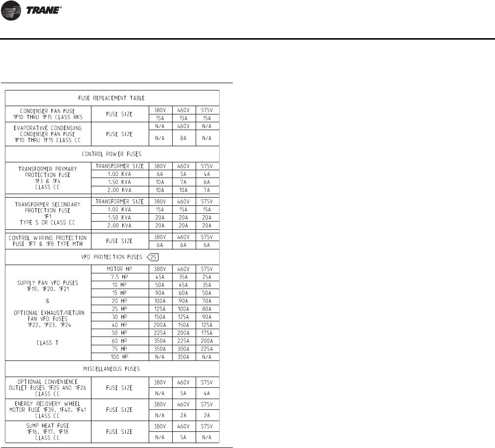
Service and Maintenance
178 RT-SVX24K-EN
Note: **See fuse replacement table onVFD panel forVFD
power fuses (F40, F41, F42).
Table 54. Unit Internal Fuse Replacement Data & VFD
Factory Settings
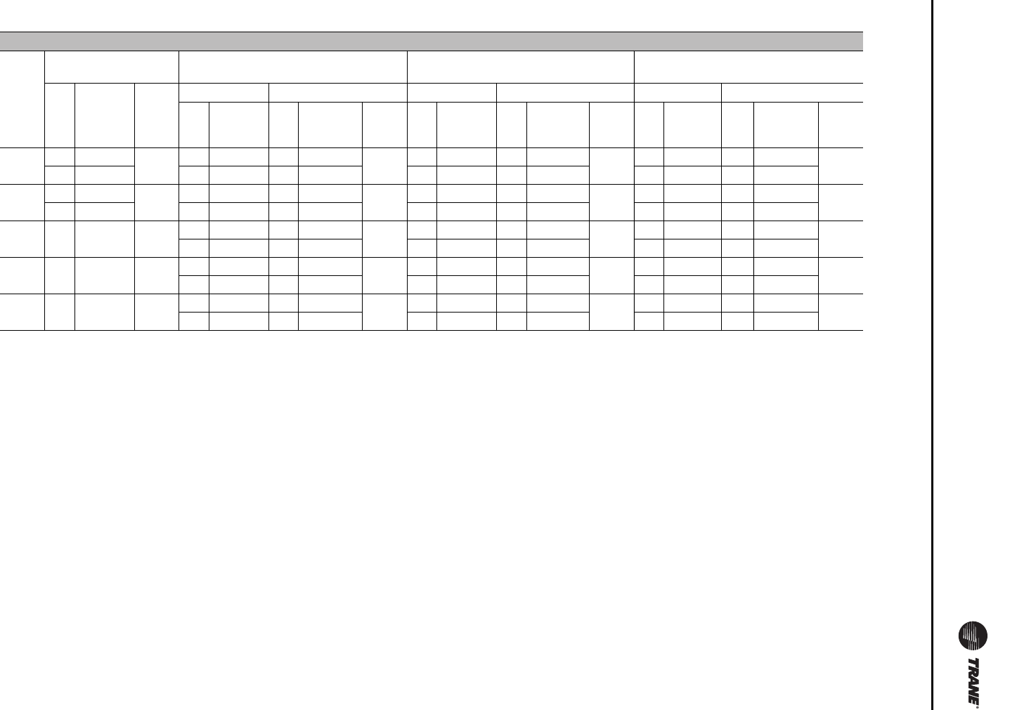
Service and Maintenance
RT-SVX24K-EN 179
Table 55. Filter Data
Filters
Unit
Model
(AC/
EC)
Standard 2" High Eff
Throwaways 90-95% Bag Filters
with Prefilters 90-95% Cartridge Filters
with Prefilters 90-95% Low Pressure Drop
Cartridge Filters
Qty Size of
Each
Face
Area
(ft2)
Pre-filters Bag Filters Prefilters Cartridge Filters Prefilters Low PD Filters
Qty Size Qty Size
Face
Area
(ft2) Qty Size Qty Size
Face
Area
(ft2) Qty Size Qty Size
Face
Area
(ft2)
90/100 21 20x24x2 80 21 20x24x2 21 20x24x19 80 21 20x24x2 21 20x24x12 80 21 20x24x2 21 20x24x12 80
5 15x24x2 5 12x24x2 5 12x24x19 5 12x24x2 5 12x24x12 5 12x24x2 5 12x24x12
105/
118 21 20x24x2 80 21 20x24x2 21 20x24x19 80 21 20x24x2 21 20x24x12 80 21 20x24x2 21 20x24x12 80
5 15x24x2 5 12x24x2 5 12x24x19 5 12x24x2 5 12x24x12 5 12x24x2 5 12x24x12
120/
128 28 20x24x2 93 21 20x24x2 21 20x24x19 80 21 20x24x2 21 20x24x12 80 21 20x24x2 21 20x24x12 80
5 12x24x2 5 12x24x19 5 12x24x2 5 12x24x12 5 12x24x2 5 12x24x12
130/
140 28 20x24x2 93 21 20x24x2 21 20x24x19 80 21 20x24x2 21 20x24x12 80 21 20x24x2 21 20x24x12 80
5 12x24x2 5 12x24x19 5 12x24x2 5 12x24x12 5 12x24x2 5 12x24x12
150/
162 28 20x24x2 93 21 20x24x2 21 20x24x19 80 21 20x24x2 21 20x24x12 80 21 20x24x2 21 20x24x12 80
5 12x24x2 5 12x24x19 5 12x24x2 5 12x24x12 5 12x24x2 5 12x24x12
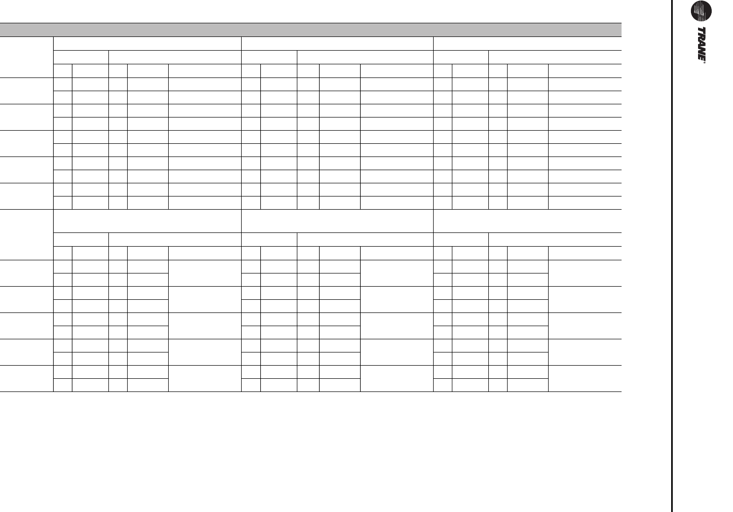
Service and Maintenance
180 RT-SVX24K-EN
Table 56. Final Filter Data
Final Filters
Unit Model
(AC/EC)
90-95% Low Pressure Drop Cartridge Filters 90-95% Bag Filters with Prefilters 90-95% Cartridge Filters with Prefilters
Pre-filters Low PD Cartridge Filters Prefilters Bag Filters Prefilters Cartridge Filters
Qty Size Qty Size Face Area (ft2) Qty Size Qty Size Face Area (ft2) Qty Size Qty Size Face Area (ft2)
90/100 15 24x24x4 15 24x24x12 74 15 24x24x2 15 24x24x19 74 15 24x24x2 15 24x24x12 74
7 12x24x4 7 12x24x12 7 12x24x2 7 12x24x19 7 12x24x2 7 12x24x12
105/118 15 24x24x4 15 24x24x12 74 15 24x24x2 15 24x24x19 74 15 24x24x2 15 24x24x12 74
7 12x24x4 7 12x24x12 7 12x24x2 7 12x24x19 7 12x24x2 7 12x24x12
120/128 15 24x24x4 15 24x24x12 74 15 24x24x2 15 24x24x19 74 15 24x24x2 15 24x24x12 74
7 12x24x4 7 12x24x12 7 12x24x2 7 12x24x19 7 12x24x2 7 12x24x12
130/140 15 24x24x4 15 24x24x12 74 15 24x24x2 15 24x24x19 74 15 24x24x2 15 24x24x12 74
7 12x24x4 7 12x24x12 7 12x24x2 7 12x24x19 7 12x24x2 7 12x24x12
150/162 15 24x24x4 15 24x24x12 74 15 24x24x2 15 24x24x19 74 15 24x24x2 15 24x24x12 74
7 12x24x4 7 12x24x12 7 12x24x2 7 12x24x19 7 12x24x2 7 12x24x12
Unit Model
(AC/EC)
90-95% High Temp Cartridge Filters
with Prefilters HEPA Filters with Prefilters High Temp HEPA Filters with Prefilters
Pre-filters High Temp Cartridge Filters Prefilters HEPA Filters Prefilters High HEPA Temp Filters
Qty Size Qty Size Face Area (ft2) Qty Size Qty Size Face Area (ft2) Qty Size Qty Size Face Area (ft2)
90/100 15 24x24x2 15 24x24x12 74 15 24x24x2 15 24x24x12 74 15 24x24x2 15 24x24x12 74
7 12x24x2 7 12x24x12 7 12x24x2 7 12x24x12 7 12x24x2 7 12x24x12
105/118 15 24x24x2 15 24x24x12 74 15 24x24x2 15 24x24x12 74 15 24x24x2 15 24x24x12 74
7 12x24x2 7 12x24x12 7 12x24x2 7 12x24x12 7 12x24x2 7 12x24x12
120/128 15 24x24x2 15 24x24x12 74 15 24x24x2 15 24x24x12 74 15 24x24x2 15 24x24x12 74
7 12x24x2 7 12x24x12 7 12x24x2 7 12x24x12 7 12x24x2 7 12x24x12
130/140 15 24x24x2 15 24x24x12 74 15 24x24x2 15 24x24x12 74 15 24x24x2 15 24x24x12 74
7 12x24x2 7 12x24x12 7 12x24x2 7 12x24x12 7 12x24x2 7 12x24x12
150/162 15 24x24x2 15 24x24x12 74 15 24x24x2 15 24x24x12 74 15 24x24x2 15 24x24x12 74
7 12x24x2 7 12x24x12 7 12x24x2 7 12x24x12 7 12x24x2 7 12x24x12
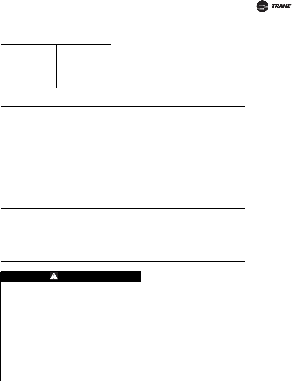
Service and Maintenance
RT-SVX24K-EN 181
Fan Belt Adjustment
The supply fan belts and optional exhaust fan belts must
be inspected periodically to assure proper unit operation.
Replacement is necessary if the belts appear frayed or
worn. Units with dual belts require a matched set of belts
to ensure equal belt length.
When removing or installing the new belts, do not stretch
them over the sheaves. Loosen the belts using the belt
tension adjustment bolts on the motor mounting base.
Once the new belts are installed, using a Browning or
Gates tension gauge (or equivalent), see Figure 121,
adjust the belt tension as follows:
1. To determine the appropriate belt deflection:
a. Measure the center-to-center shaft distance (in
inches) between the fan and motor sheaves.
b. Divide the distance measured in Step 1a by 64; the
resulting value represents the amount of belt
deflection that corresponds to the proper belt
tension.
Table 57. Grease Recommendation
Recommended Grease
for Fan Bearings Recommended
Operating Range
Exxon Unirex #2
Mobil 532 -20 F to 250 F
Mobil SHC #220
Texaco Premium RB
Table 58. Air-Cooled Condenser—Refrigerant Coil Fin Data
Tons Coil Type Coil Fin
Config. Tube Dia. Coil Rows Fins per foot Coil Face
Area (sq. ft.) Tube Type
90 Evaporator Enhanced 1/2 3 168 73.75 Internally Finned
Hi-Cap Evap Enhanced 1/2 5 168 73.75 Internally Finned
Condenser Enhanced 25 mm 1 240 134 Microchannel
105 Evaporator Internally
Finned 1/2 4 168 73.75 Internally Finned
Hi-Cap Evap Internally
Finned 1/2 6 168 73.75 Internally Finned
Condenser Enhanced 25 mm 1 240 161 Microchannel
120 Evaporator Internally
Finned 1/2 3 168 106.25 Internally Finned
Hi-Cap Evap Internally
Finned 1/2 6 168 106.25 Internally Finned
Condenser Enhanced 18 mm 2 276 161 Microchannel
130 Evaporator Internally
Finned 1/2 4 168 106.25 Internally Finned
Hi-Cap Evap Internally
Finned 1/2 6 168 106.25 Internally Finned
Condenser Enhanced 18 mm 2 276 161 Microchannel
150 Evaporator Internally
Finned 1/2 6 168 106.25 Internally Finned
Condenser Smooth 18 mm 2 276 161 Microchannel
WARNING
Hazardous Voltage w/Capacitors!
Disconnect all electric power, including remote
disconnects and discharge all motor start/run
capacitors before servicing. Follow proper lockout/
tagout procedures to ensure the power cannot be
inadvertently energized. For variable frequency drives
or other energy storing components provided by Trane
or others, refer to the appropriate manufacturer’s
literature for allowable waiting periods for discharge of
capacitors.Verify with an appropriate voltmeter that all
capacitors have discharged. Failure to disconnect
power and discharge capacitors before servicing could
result in death or serious injury.
For additional information regarding the safe discharge
of capacitors, see PROD-SVB06A-EN
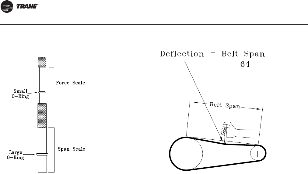
Service and Maintenance
182 RT-SVX24K-EN
2. Set the large O-ring on the belt tension gauge at the
deflection value determined in Step 1b.
3. Set the small O-ring at zero on the force scale of the
gauge plunger.
4. Place the large end of the gauge at the center of the belt
span; then depress the gauge plunger until the large O-
ring is even with the top of the next belt—-or even with
a straightedge placed across the fan and motor
sheaves. See Table 59, p. 183.
5. Remove the belt tension gauge.The small O-ring now
indicates a number other than zero on the plunger’s
force scale.This number represents the force (in
pounds) required to give the needed deflection.
6. Compare the “force” scale reading (Step 5) with the
appropriate “force” value listed in Table 59, p. 183.If
the “force”reading is outside the range, readjust the
belt tension.
Note: Actual belt deflection “force” must not exceed the
maximum “force” value shown in Table 59, p. 183.
7. Recheck the belt tension at least twice during the first
2to 3 days of operation. Belt tension will decrease
rapidly until the new belts are “run in”.
Figure 121.Tension Gauge Figure 122.Belt Tension
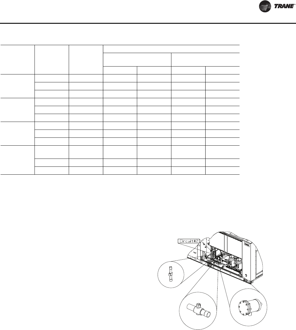
Service and Maintenance
RT-SVX24K-EN 183
Scroll Compressor Replacement
The compressor manifold system was purposely designed
to provide proper oil return to each compressors.The
refrigerant manifold system must not be modified in any
way.
Note: Altering the compressor manifold piping may
cause oil return problems and compressor failure.
Should a compressor replacement become necessary and
a suction line filter drier is to be installed, install it a
minimum of 18 inches upstream of the oil separator tee.
See Figure 123, p. 183.
Anytime a compressor is replaced, the oil for each
compressor within the manifolded set must be replaced.
The scroll compressor uses Trane OIL00079 (one quart
container) or OIL00080 (one gallon container) without
substitution.The appropriate oil charge for CSHN250 and
CSHN315 scroll compressors is 14.2 pints. For CSHN374
scroll compressor, use 15.2 pints.
The recommended method for evacuation and
dehydration is to evacuate both the high side and the low
side to 500 microns or less.To establish that the unit is
leak-free, use a standing vacuum test.The maximum
allowable rise over a 15 minute period is 200 microns. If
the rise exceeds this, there is either still moisture in the
system or a leak is present.
Note: Do Not release refrigerant to the atmosphere! If
adding or removing refrigerant is required, the
service technician must comply with all Federal,
State and local laws.
Table 59. Belt Tension Measurement and Deflection Ranges
Belt
Cross
Section
Smallest
Sheave
Diameter
Range (In.) RPM Range
Belt Deflection Force (Lbs.)
Super Gripbelts and
Unnotched Gripbands Gripnotch Belts and
Notched Gripbands
Min. Max. Min. Max.
A, AX 3.0-3.6 1000-2500 3.7 5.5 4.1 6.1
3.8-4.8 1000-2500 4.5 6.8 5.0 7.4
5.0-7.0 1000-2500 5.4 8.0 5.7 8.4
B, BX 3.4 – 4.2 860-2500 -- -- 4.9 7.2
4.4 – 5.6 860-2500 5.3 7.9 7.1 10.5
5.8 – 8.6 860-2500 6.3 9.4 8.5 12.6
3V, 3VX 2.2 - 2.4 1000-2500 -- -- 3.3 4.9
2.65 - 3.65 1000-2500 3.6 5.1 4.2 6.2
4.12 - 6.90 1000-2500 4.9 7.3 5.3 7.9
5V, 5VX 4.4 – 6.7 500-1749
1750-3000 -- -- 10.2
8.8 15.2
13.2
7.1 –10.9 500-1740 12.7 18.9 14.8 22.1
11.8-16.0 500-1740 15.5 23.4 17.1 25.5
Figure 123.Suction Line Filter/Drier Installation
Sight glass
Suction service
valve
Replaceable core
drier
Note: These components are also located at circuit #1 side
Service and Maintenance
184 RT-SVX24K-EN
VFD Programming Parameters
Units shipped with an optional variable frequency drive
(VFD) are preset and run tested at the factory. If a problem
with a VFD occurs, ensure that the programmed
parameters listed in Table 60, p. 185 have been set before
replacing the drive.
Note: Check to make sure that parameter 1-23 is set to 60
Hz.To check parameter 1-23 press the [Main Menu]
button (press [Back] button if the main menu does
not display), use the [▼] button to scroll down to
Load & Motor, press OK, use the [▼] button to
select 1-2, press OK, and finally use the [▼] button
until parameter 1-23 is displayed. Parameter 1-23
can then be modified by pressing OK button and
using [▲] and [▼] buttons. When the desired
selection has been made, press the OK button.
Should replacing the VFD become necessary, the
replacement is not configured with all ofTrane's operating
parameters.The VFD must be programmed before
attempting to operate the unit.
To verify and/or program a VFD, use the following steps:
1. At the unit, turn the 115 volt control circuit switch to the
“Off” position.
2. Turn the 24 volt control circuit switch to the “Off'
position.
HIGH VOLTAGE IS PRESENT AT TERMINAL BLOCK OR
UNIT DISCONNECT SWITCH.
3. To modify parameters:
a. Press Main Menu button (press [Back] button if the
main menu does not display)
b. Use the [▲] and [▼] buttons to find the parameter
menu group (first part of parameter number)
c. Press [OK]
d. Use the [▲] and [▼] buttons to select the correct
parameter sub-group (first digit of second part of
parameter number)
e. Press [OK]
f. Use the [▲] and [▼] buttons to select the specific
parameter
g. Press [OK]
h. To move to a different digit within a parameter
setting, use the [►◄] buttons (Highlighted area
indicates digit selected for change)
i. Use the [▲] and [▼] buttons to adjust the digit
j. Press [Cancel] button to disregard change, or press
[OK] to accept change and enter the new setting
4. Repeat step (3) for each menu selection setting in
Table 60, p. 185.
5. To reset all programming parameters back to the
factory defaults:
a. Go to parameter 14-22 Operation Mode
b. Press [OK]
c. Select “Initialization”
d. Press [OK]
e. Cut off the mains supply and wait until the display
turns off.
f. Reconnect the mains supply - the frequency
converter is now reset.
WARNING
Hazardous Voltage w/Capacitors!
Disconnect all electric power, including remote
disconnects and discharge all motor start/run
capacitors before servicing. Follow proper lockout/
tagout procedures to ensure the power cannot be
inadvertently energized. For variable frequency drives
or other energy storing components provided by Trane
or others, refer to the appropriate manufacturer’s
literature for allowable waiting periods for discharge of
capacitors. Verify with an appropriate voltmeter that all
capacitors have discharged. Failure to disconnect power
and discharge capacitors before servicing could result
in death or serious injury.
For additional information regarding the safe discharge
of capacitors, see PROD-SVB06A-EN
WARNING
Hazardous Voltage w/Capacitors!
Disconnect all electric power, including remote
disconnects and discharge all motor start/run
capacitors before servicing. Follow proper lockout/
tagout procedures to ensure the power cannot be
inadvertently energized. For variable frequency drives
or other energy storing components provided by Trane
or others, refer to the appropriate manufacturer’s
literature for allowable waiting periods for discharge of
capacitors.Verify with an appropriate voltmeter that all
capacitors have discharged. Failure to disconnect
power and discharge capacitors before servicing could
result in death or serious injury.
For additional information regarding the safe discharge
of capacitors, see PROD-SVB06A-EN
Service and Maintenance
RT-SVX24K-EN 185
g. Ensure parameter 14-22 Operation Mode has
reverted back to “Normal Operation”.
Notes:
•Item 5 resets the drive to the default factory settings.
The program parameters listed in Table 60, p. 185 will
need to be verified or changed as described in Item 3
and 4.
•Some of the parameters listed in theTable are motor
specific. Due to various motors and efficiencies
available, use only the values stamped on the specific
motor nameplate. Do not use the Unit nameplate
values.
•A backup copy of the current setup may be saved to the
LCP before changing parameters or resetting the drive.
See LCP Copy in the VFD Operating Instructions for
details.
6. Follow the startup procedures for supply fan in the
“Variable Air Volume System” section or the
“Exhaust Airflow Measurement” startup procedures
for the exhaust fan.
7. After verifying that the VFD(s) are operating
properly, press the STOP key at the Human Interface
Module to stop the unit operation.
8. Follow the applicable steps in the “Final Unit
Checkout” section to return the unit to its normal
operating mode.
Note: If a problem with a VFD occurs, ensure that the
programmed parameters listed for supply and
exhaust VFD Table 60, p. 185 and Table 61, p. 190
have been set before replacing the drive.
Monthly Maintenance
Before completing the following checks, turn the unit OFF
and lock the main power disconnect switch open.
Filters
Inspect the return air filters. Clean or replace them if
necessary. Refer to Table 55, p. 179 and Table 56, p. 180 for
filter information.
Cooling Season
• [ ] Check the unit drain pans and condensate piping to
ensure that there are no blockages.
• [ ] Inspect the evaporator and condenser coils for dirt,
bent fins, etc. If the coils appear dirty, clean them
according to the instructions described in “Coil
Cleaning” later in this section.
• [ ] Manually rotate the condenser fans to ensure free
movement and check motor bearings for wear. Verify
that all of the fan mounting hardware is tight.
• [ ] Inspect the F/A-R/A damper hinges and pins to
ensure that all moving parts are securely mounted.
Keep the blades clean as necessary.
Table 60. Supply and Exhaust VFD Programming Parameters
Menu Parameter Description Setting Description
Load & Motor 1-21 Motor Power Set Based on Motor Nameplate Set only for application using 3hp motors.
Set to 2.2 kW/3 hp
1-22 Motor Voltage Set Based on Motor Nameplate Set only for 380/415 50 Hz applications
1-24 Motor Current Set Based on Motor Nameplate Sets the motor FLA
1-25 Motor Speed Set Based on Motor Nameplate Sets the motor RPM
Limits & Warnings 4-18 Current Limit Rated Current 100% Limits the maximum current to motor
Notes:
1. These parameters are motor specific and the actual motor nameplate rating must be used. Do not use the unit nameplate.
WARNING
Hazardous Voltage w/Capacitors!
Disconnect all electric power, including remote
disconnects and discharge all motor start/run
capacitors before servicing. Follow proper lockout/
tagout procedures to ensure the power cannot be
inadvertently energized. For variable frequency drives
or other energy storing components provided by Trane
or others, refer to the appropriate manufacturer’s
literature for allowable waiting periods for discharge of
capacitors.Verify with an appropriate voltmeter that all
capacitors have discharged. Failure to disconnect
power and discharge capacitors before servicing could
result in death or serious injury.
For additional information regarding the safe discharge
of capacitors, see PROD-SVB06A-EN
WARNING
Rotating Components!
During installation, testing, servicing and
troubleshooting of this product it may be necessary to
work with live and exposed rotating components. Have
a qualified or licensed service individual who has been
properly trained in handling exposed rotating
components, perform these tasks. Failure to follow all
safety precautions could result in rotating components
cutting and slashing technician which could result in
death or serious injury.
Service and Maintenance
186 RT-SVX24K-EN
• [ ]Verify that all damper linkages move freely; lubricate
with white grease, if necessary.
• [ ] Check supply fan motor bearings; repair or replace
the motor as necessary.
• [ ] Check the fan shaft bearings for wear. Replace the
bearings as necessary.
• [ ] Lubricate the supply fan shaft bearings with a lithium
based grease. Refer to Table 57, p. 181 for
recommended greases.
Note: The bearings are manufactured using a special
synthetic lithium based grease designed for long
life and minimum lube intervals. Over lubrication
can be just as harmful as not enough.
Use a hand grease gun to lubricate these bearings; add
grease until a light bead appears all around the seal. Do
not over lubricate!
After greasing the bearings, check the setscrews to ensure
that the shaft is held securely to the bearings and fan
wheels. Make sure that all bearing supports are tight.
• [ ] Check the supply fan belt(s). If the belts are frayed or
worn, replace them. Refer to the “Fan Belt
Adjustment” section for belt replacement and
adjustments.
• [ ] Check the condition of the gasket around the control
panel doors.These gaskets must fit correctly and be in
good condition to prevent water leakage.
• [ ] Verify that all wire terminal connections are tight.
• [ ] Remove any corrosion present on the exterior
surfaces of the unit and repaint these areas.
• [ ] Generally inspect the unit for unusual conditions
(e.g., loose access panels, leaking piping connections,
etc.)
• [ ] Make sure that all retaining screws are reinstalled in
the unit access panels once these checks are complete.
• [ ] With the unit running, check and record the:
ambient temperature;
compressor oil level (each circuit);
compressor suction and discharge pressures (each
circuit);
superheat and subcooling (each circuit);
Record this data on an “operator’s maintenance log” like
the one shown in Table 63, p. 191. If the operating
pressures indicate a refrigerant shortage, measure the
system superheat and system subcooling. For guidelines,
refer to “Charging by Subcooling”.
Note: Do Not release refrigerant to the atmosphere! If
adding or removing refrigerant is required, the
service technician must comply with all federal,
state and local laws.
Heating Season
Before completing the following checks, turn the unit OFF
and lock the main power disconnect switch open.
• Inspect the unit air filters. If necessary, clean or replace
them.
• Check supply fan motor bearings; repair or replace the
motor as necessary.
• Lubricate the supply fan shaft bearings with a lithium
based grease. Refer to Table 57, p. 181 for
recommended greases.
Note: The bearings are manufactured using a special
synthetic lithium based grease designed for long
life and minimum lube intervals.Too much
lubrication in a bearing can be just as harmful as
not enough.
Use a hand grease gun to lubricate the bearings; add
grease until a light bead appears all around the seal. Do
not over lubricate!
After greasing the bearings, check the setscrews to ensure
that the shaft is held securely. Make sure that all bearing
braces are tight.
• [ ] Inspect both the main unit control panel and heat
section control box for loose electrical components
and terminal connections, as well as damaged wire
insulation. Make any necessary repairs.
• [ ] Gas Heat Units only - Check the heat exchanger for
any corrosion, cracks, or holes.
• [ ] Check the combustion air blower for dirt. Clean as
necessary.
Note: Typically, it is not necessary to clean the gas
furnace. However, if cleaning does become
necessary, remove the burner inspection plate
from the rear of the heat exchanger to access the
drum. Be sure to replace the existing gaskets with
new ones before reinstalling the inspection plate.
WARNING
Hazardous Voltage w/Capacitors!
Disconnect all electric power, including remote
disconnects and discharge all motor start/run
capacitors before servicing. Follow proper lockout/
tagout procedures to ensure the power cannot be
inadvertently energized. For variable frequency drives
or other energy storing components provided by Trane
or others, refer to the appropriate manufacturer’s
literature for allowable waiting periods for discharge of
capacitors.Verify with an appropriate voltmeter that all
capacitors have discharged. Failure to disconnect
power and discharge capacitors before servicing could
result in death or serious injury.
For additional information regarding the safe discharge
of capacitors, see PROD-SVB06A-EN
Service and Maintenance
RT-SVX24K-EN 187
• [ ] Open the main gas valve and apply power to the unit
heating section; then initiate a “Heat” test using the
startup procedure described in “Gas Furnace Startup”.
• [ ] Verify that the ignition system operates properly.
Air-Cooled Coil Cleaning
Regular coil maintenance, including annual cleaning
enhances the unit operating efficiency by minimizing:
– compressor head pressure and amperage draw;
– water carryover;
– fan brake horsepower; and,
– static pressure losses
At least once each year—or more often if the unit is located
in a “dirty” environment—clean the evaporator and
Microchannel Condenser Coil and Hot Gas Reheat Coil
using the instructions outlined below. Follow these
instructions as closely as possible to avoid damaging the
coils.
Refrigerant Coils
To clean refrigerant coils, use a soft brush and a sprayer.
Important: DO NOT use any detergents with
microchannel condenser coils. Pressurized
water or air ONLY.
For evaporator and reheat coil cleaners, contact the local
Trane Parts Center for appropriate detergents.
1. Remove enough panels from the unit to gain safe
access to coils.
Important: Bridging between the main supports
required before attempting to enter into the
unit. Bridging may consist of multiple 2 by
12 boards or sheet metal grating.
2. Straighten any bent coil fins with a fin comb.
3. For accessible areas, remove loose dirt and debris
from both sides of the coil. For dual row microchannel
condenser coil applications, seek pressure coil wand
extension through the localTrane Parts Center.
4. When cleaning evaporator and reheat coils, mix the
detergent with water according to the manufacturer’s
instructions. If desired, heat the solution to 150° F
maximum to improve its cleansing capability.
Important: DO NOT use any detergents with
microchannel coils. Pressurized water or air
ONLY.
5. Pour the cleaning solution into the sprayer. If a high-
pressure sprayer is used:
a. The minimum nozzle spray angle is 15 degrees.
b. Do not allow sprayer pressure to exceed 600 psi.
WARNING
Hazardous Gases and Flammable Vapors!
Exposure to hazardous gases from fuel substances
have been shown to cause cancer, birth defects or other
reproductive harm. Improper installation, adjustment,
alteration, service or use of this product could cause
flammable mixtures or lead to excessive carbon
monoxide. To avoid hazardous gases and flammable
vapors follow proper installation and set up of this
product and all warnings as provided in this manual.
Failure to follow all instructions could result in death or
serious injury.
WARNING
Hazardous Pressures!
When using dry nitrogen cylinders for pressurizing
units for leak testing, always provide a pressure
regulator on the cylinder to prevent excessively high
unit pressures. Never pressurize unit above the
maximum recommended unit test pressure as specified
in applicable unit literature. Failure to properly regulate
pressure could result in a violent explosion, which
could result in death or serious injury or equipment or
property-only-damage.
WARNING
Hazardous Chemicals!
Coil cleaning agents can be either acidic or highly
alkaline and can burn severely if contact with skin
occurs. Handle chemical carefully and avoid contact
with skin. ALWAYS wear Personal Protective
Equipment (PPE) including goggles or face shield,
chemical resistant gloves, boots, apron or suit as
required. For personal safety refer to the cleaning agent
manufacturer’s Materials Safety Data Sheet and follow
all recommended safe handling practices. Failure to
follow all safety instructions could result in death or
serious injury.
WARNING
No Step Surface!
Do not walk on the sheet metal base. Walking on the
base could cause the supporting metal to collapse,
resulting in the operator/technician to fall. Failure to
follow this recommendation could result in death or
serious injury.
Service and Maintenance
188 RT-SVX24K-EN
c. Spray the solution perpendicular (at 90 degrees) to
the coil face.
d. For evaporator and reheat coils, maintain a
minimum clearance of 6" between the sprayer
nozzle and the coil. For microchannel condenser
coils, optimum clearance between the sprayer
nozzle and the microchannel coil is 1"-3”.
6. Spray the leaving-airflow side of the coil first; then
spray the opposite side of the coil. For evaporator and
reheat coils, allow the cleaning solution to stand on the
coil for five minutes.
7. Rinse both sides of the coil with cool, clean water.
8. Inspect both sides of the coil; if it still appears to be
dirty, repeat Steps 6 and 7.
9. Reinstall all of the components and panels removed in
Step 1; then restore power to the unit.
10. For evaporator and reheat coils, use a fin comb to
straighten any coil fins which were inadvertently bent
during the cleaning process.
Steam or Hot Water Coils
To clean a steam or hot water coil, use a soft brush, a
steam-cleaning machine, and water.
1. Verify that switches 1S1 and 1S70 are turned “OFF”, and
that the main unit disconnect is locked open.
2. Remove enough panels and components from the unit
to gain sufficient access to the coil.
3. Straighten any bent coil fins with a fin comb. (Use the
data in Table 58, p. 181 to determine the appropriate fin
comb size.)
4. Remove loose dirt and debris from both sides of the
coil with a soft brush.
5. Use the steam-cleaning machine to clean the leaving-
air side of the coil first; start at the top of the coil and
work downward; then clean the entering-air side of the
coil, starting at the top of the coil and working
downward.
6. Check both sides of the coil; if it still appears dirty,
repeat Step 5.
7. Reinstall all of the components and panels removed in
Step 2; then restore power to the unit.
Evaporative Condenser Coil Cleaning
Sump Water Management
Water Supply
Overall performance of any water- cooled device can be
affected by suspended particulates, mineral
concentration, trash and debris resulting in clogging and
heat transfer loss.The unit is designed to greatly minimize
problems with these impurities, however, float valves and
solenoid valves are used to control the incoming water.
If the incoming water contains contaminants, sand or
other objects, it is best to insert an incoming line strainer
having a mesh of 80 to 100.The inlet line should be flushed
prior to connection to the unit, whether or not there is a
strainer.
There is an air gap between the water inlet float valve and
sump water level to prevent back flow; however, if local
code dictates, a backflow prevention valve may be
required (field-provided and installed by a qualified
technician).
Water Drain
Local Site Discharge: Rooftop or simple storm sewer
discharge is generally acceptable. Do not routinely direct
the sump discharge onto an area that will be adversely
affected. For example, continued sump discharge into a
flower bed where the input water contains CaCO3 (lime)
will eventually decrease the pH of the soil.
Sewer Discharge:The quantities of mineral and debris
flushed are actually very small and do not cause problems
when diluted in normal sewer flow. However, local, state
or federal standards and restrictions must be followed in
any given locality.
Traditional Bleed Method
ASHRAE recommendation for continuous bleed rates:
With good, quality makeup water, the bleed rates (0.8 - 2
GPH/ton) may be as low as one-half the evaporation rate
(1.6 -2 GPH), and the total water consumption would range
from 2.4 GPH/ton for air conditioning to 3 GPH/ton for
refrigeration (Chapter 36.17 of ASHRAE's “Systems and
Equipment Handbook”)
Operation and Care
The sump should be inspected at least every 6 months for
possible build up of scale pieces that has been shed from
the coils.The sump flush frequency or bleed rate should
be increased if large amounts of scale are present.
If the water has a “milky or cloudy” appearance, then
minerals are concentrating in the sump and the number of
flushes should be increased.
If the water remains clear between flushes, then the
number of flushes can be decreased.Through field trials,
the optimum flush frequency can be determined. Please
note that in some areas, water quality can vary during
WARNING
No Step Surface!
Do not walk on the sheet metal drain pan. Walking on
the drain pan could cause the supporting metal to
collapse, resulting in the operator/technician to fall.
Failure to follow this recommendation could result in
death or serious injury.

Service and Maintenance
RT-SVX24K-EN 189
different times of the year.The sump water clarity should
be checked periodically.
The evaporative condenser has several design features to
reduce the possibility of biological growth in the sump.
These features include:
• air inlets constructed to eliminate direct sunlight in the
sump
• The sump flush sequence replenishes the sump with
fresh water 1 to 12 times per day depending on the
flush setting
• The copper tubing in the coils is a natural biocide
Important: Do not use chlorine tablets directly on
stainless steel surface as it can adversely
affect its corrosion resistance.
Always consult local codes for water treatment and waste
water removal requirements. Consult a water treatment
expert for water analysis and chemical treatment methods
and recommendations for specific applications.
If deemed necessary after consultation with local water
experts, there are various means of water treatment
available which can be field installed.
Microchannel Condenser Coil Repair and
Replacement
If microchannel condenser coil repair or replacement is
required, seek HVAC Knowledge Center information or
Service Guide document RT-SVB83*-EN for further details.
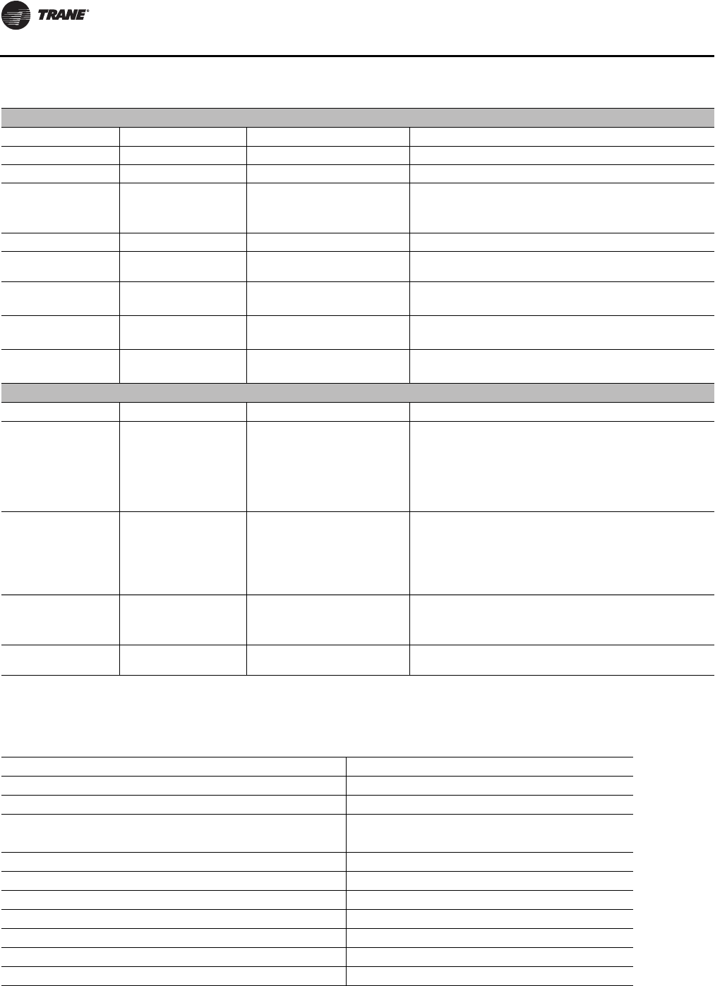
Service and Maintenance
190 RT-SVX24K-EN
Final Process
Record the unit data in the blanks provided.
Table 61. Evaporative Condenser Models—Maintenance and Troubleshooting
Maintenance Schedule
Component Action Frequency Comments
Fan Motor None Required Non-grease bearings
Sump Pump Inspect / Clean 1 – 2 times per year Clean inlet openings to pump
Sump Inspect / Clean 1 – 2 times per year depending
on water hardness and unit run
time
Sump can be drained and hosed out using hose bib
provided at water fill solenoid valve. Vacuuming scale out
is an alternate method
Sump Float Switch Inspect 1 – 2 times per year Float should be free for full float travel
Sump Float Make Up
Valve Inspect for proper water
level 1 – 2 times per year
Spray Nozzles Inspect / Clean 1 – 2 times per year Inspection through access panel
Conductivity Sensor Inspect / Clean 1 – 2 times per year Clean sensor to ensure accurate readings
Conductivity Controller Inspect / Recalibrate 1 – 2 times per year Recalibrate controller
Troubleshooting
Component Problem Check Fix
Fan Motor Does not run
Condenser Fan Relay closure and
control voltage indicating a call
from compressor control panel
for the condenser fan to operate.
Sump Pump Overload Trip. Fan
Motor Overload Trip. Fan fuse
trip.
Check each motor overload and reset if necessary.
Check amp draw for each leg.
Sump Pump Does not run
Sump Pump Overload Trip Low
Water Level or faulty float
switch. Unit in ‘Dry Mode’
Operation
Reset – check amps on each leg to determine if faulty motor.
Check and clean debris around float switch. Check Ambient
thermostat setting and mode of operation (close on rise).
See section 2 for T’stat setup instructions.
Sump Pump Low Flow Pump may be operating
backwards or impeller inlet may
be slightly blocked.
Change pumping direction by changing any two legs to the
pump motor. Disconnect Power and remove pump to inspect
for possible impeller obstruction.
Spray Nozzle Dry area on coil Check for proper spray pattern
over each quadrant. Remove debris from clogged nozzle.
Table 62. Unit Data Log
Complete Unit Model Number:
Unit Serial Number:
Unit “DL” Number (“design special” units only):
Wiring Diagram Numbers (from unit control panel):
-schematic(s)
-connections
Network ID (LCI/BCI):
Service and Maintenance
RT-SVX24K-EN 191
Table 63. Sample maintenance log
Date
Current
Ambient
Temp F/C
Refrigerant Circuit #1 Refrigerant Circuit #2
Compr.
Oil Level
Suct.
Press.
Psig/kPa
Disch.
Press
Psig/kPa
Liquid
Press
Psig/kPa Super-
heat F/C Sub-cool
F/C Compr.
Oil Level
Suct.
Press.
Psig/kPa
Disch.
Press
Psig/kPa
Liquid
Press
Psig/kPa Super-
heat F/C Sub-cool
F/C
- ok
- low - ok
- low
- ok
- low - ok
- low
- ok
- low - ok
- low
- ok
- low - ok
- low
- ok
- low - ok
- low
- ok
- low - ok
- low
- ok
- low - ok
- low
- ok
- low - ok
- low
- ok
- low - ok
- low
- ok
- low - ok
- low
- ok
- low - ok
- low
- ok
- low - ok
- low
- ok
- low - ok
- low
- ok
- low - ok
- low
192 RT-SVX24K-EN
Unit Wiring Diagram Number
Note: Wiring diagrams can be accessed via e-Library by entering the diagram number in the literature order number
search field or by calling technical support.
Table 64. Wiring diagram matrix
Air Cooled Water
Cooled Tonnnage Description
VAV / SZ VAV
Power
1-Piece 2313-0820 90-150T Schematic, Power - w/Supply VFD
2313-0821 90-150T Schematic, Power - w/Exhaust/Return VFD
2313-0822 90-150T Schematic, Power - w/Sup & Exh/Rtn VFD
2313-0832 90T, 105T Schematic, Power - w/Supply VFD w/Low Ambient
2313-0833 90T, 105T Schematic, Power - w/Exhaust/Return VFD w/Low Ambient
2313-0834 90T, 105T Schematic, Power - w/Sup & Exh/Rtn VFD w/Low Ambient
2313-0844 120T,130T,150T Schematic, Power - w/Supply VFD w/Low Ambient
2313-0845 120T,130T,150T Schematic, Power - w/Exhaust/Return VFD w/Low Ambient
2313-0846 120T,130T,150T Schematic, Power - w/Sup & Exh/Rtn VFD w/Low Ambient
2313-0848 120T,130T,150T Schematic, Power 2-Pc - w/Supply VFD w/Low Ambient
2313-0864 Air Handler Schematic, Power - w/Supply VFD Air Handler
2313-0865 Air Handler Schematic, Power - w/Exhaust/Return VFD Air Handler
2313-0866 Air Handler Schematic, Power - w/Sup & Exh/Rtn VFD Air Handler
Multi-Piece 2313-0824 90-150T Schematic, Power - w/Supply VFD 2-Pc
2313-0825 90-150T Schematic, Power - w/Exhaust/Return VFD 2-Pc
2313-0826 90-150T Schematic, Power - w/Sup & Exh/Rtn VFD 2-Pc
2313-0828 90-150T Schematic, Power 3-Pc - w/Supply VFD
2313-0829 90-150T Schematic, Power 3-Pc - w/Exhaust/Return VFD
2313-0830 90-150T Schematic, Power 3-Pc - w/Sup & Exh/Rtn VFD
2313-0836 90T, 105T Schematic, Power 2-Pc - w/Supply VFD w/Low Ambient
2313-0837 90T, 105T Schematic, Power 2-Pc - w/Exhaust/Return VFD w/Low Ambient
2313-0838 90T, 105T Schematic, Power 2-Pc - w/Sup & Exh/Rtn VFD w/Low Ambient
2313-0840 90T, 105T Schematic, Power 3-Pc - w/Supply VFD w/Low Ambient
2313-0841 90T, 105T Schematic, Power 3-Pc - w/Exhaust/Return VFD w/Low Ambient
2313-0842 90T, 105T Schematic, Power 3-Pc - w/Sup & Exh/Rtn VFD w/Low Ambient
2313-0849 120T,130T,150T Schematic, Power 2-Pc - w/Exhaust/Return VFD w/Low Ambient
2313-0850 120T,130T,150T Schematic, Power 2-Pc - w/Sup & Exh/Rtn VFD w/Low Ambient
2313-0852 120T,130T,150T Schematic, Power 3-Pc - w/Supply VFD w/Low Ambient
2313-0853 120T,130T,150T Schematic, Power 3-Pc - w/Exhaust/Return VFD w/Low Ambient
2313-0854 120T,130T,150T Schematic, Power 3-Pc - w/Sup & Exh/Rtn VFD w/Low Ambient
2313-0856 100-162T Schematic, Power 2-Pc - w/Supply VFD
2313-0857 100-162T Schematic, Power 2-Pc - w/Exhaust/Return VFD
2313-0858 100-162T Schematic, Power 2-Pc - w/Sup & Exh/Rtn VFD
2313-0860 100-162T Schematic, Power 3-Pc - w/Supply VFD
2313-0861 100-162T Schematic, Power 3-Pc - w/Exhaust/Return VFD
2313-0862 100-162T Schematic, Power 3-Pc - w/Sup & Exh/Rtn VFD
Controls
1-Piece 2309-3652 All Tonnages + Air Handler Notes and Specs
2309-3901 All Tonnages + Air Handler Schematic/Connection Sup VFD w/o Bypass

Unit Wiring Diagram Number
RT-SVX24K-EN 193
2309-3902 All Tonnages + Air Handler Schematic/Connection Sup VFD w/Bypass
2309-3905 All Tonnages + Air Handler Schematic/Connection Exh/Rtn VFD w/o Bypass
2309-3906 All Tonnages + Air Handler Schematic/Connection Exh/Rtn VFD w/Bypass
2313-0818 All Tonnages + Air Handler Field Connection VAV
2313-0869 90-150T Connection, Control Box - w/Supply VFD
2313-0870 90-150T Connection, Control Box - w/Exh/Rtn VFD
2313-0871 90-150T Connection, Control Box - w/Sup & Exh/Rtn VFD
2313-0873 90-150T Connection, Control Box - w/Supply VFD 2/3-Pc
2313-0874 90-150T Connection, Control Box - w/Exh/Rtn VFD 2/3-Pc
2313-0875 90-150T Connection, Control Box - w/Sup & Exh/Rtn VFD 2/3-Pc
2313-0877 90-105T Connection, Control Box - w/Supply VFD w/Low Ambient
2313-0878 90-105T Connection, Control Box - w/Exh/Rtn VFD w/Low Ambient
2313-0879 90-105T Connection, Control Box - w/Sup & Exh/Rtn VFD w/Low Ambient
2313-0881 90-105T Connection, Control Box - w/Supply VFD w/Low Ambient 2/3-Pc
2313-0882 90-105T Connection, Control Box - w/Exh/Rtn VFD w/Low Ambient 2/3-Pc
2313-0883 90-105T Connection, Control Box - w/Sup & Exh/Rtn VFD w/Low Ambient 2/
3-Pc
2313-0885 120-150T Connection, Control Box - w/Supply VFD w/Low Ambient
2313-0886 120-150T Connection, Control Box - w/Exh/Rtn VFD w/Low Ambient
2313-0887 120-150T Connection, Control Box - w/Sup & Exh/Rtn VFD w/Low Ambient
2313-0897 Air Handler Connection, Control Box - w/Supply VFD Air Handler
2313-0898 Air Handler Connection, Control Box - w/Exh/Rtn VFD Air Handler
2313-0899 Air Handler Connection, Control Box - w/Sup & Exh/Rtn VFD Air Handler
2313-0902 90-150T & Air Handler Connection, Common Control Modules - w/Return VFD
2313-0903 100-162T Connection, Common Control Modules - w/Return VFD
2309-3787 90-150T Connection, Raceway Devices - Condenser Zone (Air Cooled)
2313-0816 100-162T Connection, Raceway Devices - Condenser Zone (Evap Cooled)
2309-3789 Air Handler Connection, Raceway Devices - Condenser Zone (Air Handler)
2309-3741 Air Handler Connection, Raceway Devices - Air Handler w/Supply VFD
2309-3742 Air Handler Connection, Raceway Devices - Air Handler w/Exh/Rtn VFD
2309-3743 Air Handler Connection, Raceway Devices - Air Handler w/Sup & Exh/Rtn VFD
2309-3757 90-162 Ton Connection, Raceway Devices - Evap Module w/Supply VFD
2309-3758 90-162 Ton Connection, Raceway Devices - Evap Module w/Exh/Rtn VFD
2309-3759 90-162 Ton Connection, Raceway Devices - Evap Module w/Sup & Exh/Rtn VFD
Multi-Piece 2309-3652 All Tonnages + Air Handler Notes and Specs
2309-3903 All Tonnages Schematic/Connection Sup VFD w/o Bypass 2/3-Pc
2309-3904 All Tonnages Schematic/Connection Sup VFD w/Bypass 2/3-Pc
2309-3907 All Tonnages Schematic/Connection Exh/Rtn VFD w/o Bypass 2-Pc
2309-3908 All Tonnages Schematic/Connection Exh/Rtn VFD w/Bypass 2-Pc
2309-3909 All Tonnages Schematic/Connection Exh/Rtn VFD w/o Bypass 3-Pc
2309-3910 All Tonnages Schematic/Connection Exh/Rtn VFD w/Bypass 3-Pc
2313-0818 All Tonnages + Air Handler Field Connection VAV
2313-0889 120-150T Connection, Control Box - w/Supply VFD w/Low Ambient 2/3-Pc
2313-0890 120-150T Connection, Control Box - w/Exh/Rtn VFD w/Low Ambient 2/3-Pc
2313-0891 120-150T Connection, Control Box - w/Sup & Exh/Rtn VFD w/Low Ambient 2/
3-Pc
Table 64. Wiring diagram matrix (continued)
Air Cooled Water
Cooled Tonnnage Description
Unit Wiring Diagram Number
194 RT-SVX24K-EN
2313-0900 90-150T & AH Connection, Common Control Modules - w/o Return VFD
2313-0901 100-162T Connection, Common Control Modules - w/o Return VFD
2309-3787 90-150T Connection, Raceway Devices - Condenser Zone (Air Cooled)
2313-0816 100-162T Connection, Raceway Devices - Condenser Zone (Evap Cooled)
2309-3789 Air Handler Connection, Raceway Devices - Condenser Zone (Air Handler)
2313-0893 100-162T Connection, Control Box - w/Supply VFD 2/3-Pc
2313-0894 100-162T Connection, Control Box - w/Exh/Rtn VFD 2/3-Pc
2313-0895 100-162T Connection, Control Box - w/Sup & Exh/Rtn VFD 2/3-Pc
2313-0900 90-150T & Air Handler Connection, Common Control Modules - w/o Return VFD
2313-0902 90-150T & Air Handler Connection, Common Control Modules - w/Return VFD
2309-3787 90-150T Connection, Raceway Devices - Condenser Zone (Air Cooled)
2313-0816 100-162T Connection, Raceway Devices - Condenser Zone (Evap Cooled)
2309-3789 Air Handler Connection, Raceway Devices - Condenser Zone (Air Handler)
2309-3725 90-162 Ton Connection, Raceway Devices - Evap Module w/Supply VFD 3-Pc
2309-3726 90-162 Ton Connection, Raceway Devices - Evap Module w/Exh/Rtn VFD 3-Pc
2309-3727 90-162 Ton Connection, Raceway Devices - Evap Module w/Sup & Exh/Rtn VFD
3-Pc
2309-3741 Air Handler Connection, Raceway Devices - Air Handler w/Supply VFD
2309-3742 Air Handler Connection, Raceway Devices - Air Handler w/Exh/Rtn VFD
2309-3743 Air Handler Connection, Raceway Devices - Air Handler w/Sup & Exh/Rtn VFD
2309-3761 90-162 Ton Connection, Raceway Devices - Evap Module w/Supply VFD 2-Pc
2309-3762 90-162 Ton Connection, Raceway Devices - Evap Module w/Exh/Rtn VFD 2-Pc
2309-3763 90-162 Ton Connection, Raceway Devices - Evap Module w/Sup & Exh/Rtn VFD
2-Pc
Option
Modules
1-Piece 2313-0314 All Tonnages + Air Handler Schematic, Controls - RTM w/Supply VFD
2309-3627 All Tonnages + Air Handler Schematic, Controls - RTM w/Exh/Rtn VFD
2309-3628 All Tonnages + Air Handler Schematic, Controls - RTM w/Sup & Exh/Rtn VFD
2309-3633 90-150T Schematic, Controls - MCM
2313-0102 All Tonnages + Air Handler Schematic, Controls - HEAT - Elec/ Hydronic Heat
2309-3638 All Tonnages + Air Handler Schematic, Controls - HEAT - 2-stg / Modulating Gas Heat
2309-3685 All Tonnages + Air Handler Schematic, Controls - Cooling Only
2309-3645 All Tonnages + Air Handler Schematic, LHI, ECEM, VCM, MPM w/o Exh or Rtn VFD
2309-3646 All Tonnages + Air Handler Schematic, LHI, ECEM, VCM, MPM w/Return VFD
2309-3647 All Tonnages + Air Handler Schematic, LHI, ECEM, VCM, MPM w/Exhaust VFD
2309-3648 All Tonnages Schematic, LHI, ECEM, VCM, MPM 2-Pc, w/o Exh or Rtn VFD
2313-0867 All Tonnages + Air Handler Schematic, VOM, LCI, IPCB, GBAS 0-5V,GBAS 0-10V, BCI, WCI
Multi-Piece 2313-0316 All Tonnages Schematic, Controls - RTM 2-Pc w/Supply VFD
2309-3631 All Tonnages Schematic, Controls - RTM 2-Pc w/Exh/Rtn VFD
2309-3632 All Tonnages Schematic, Controls - RTM 2-Pc w/Sup & Exh/Rtn VFD
2313-0318 All Tonnages Schematic, Controls - RTM 3-Pc w/Supply VFD
2309-3770 All Tonnages Schematic, Controls - RTM 3-Pc w/Exh/Rtn VFD
2309-3771 All Tonnages Schematic, Controls - RTM 3-Pc w/Sup & Exh/Rtn VFD
2309-3635 90-150T Schematic, Controls - MCM 2/3-Pc
Table 64. Wiring diagram matrix (continued)
Air Cooled Water
Cooled Tonnnage Description
Unit Wiring Diagram Number
RT-SVX24K-EN 195
2313-0809 100-162T Schematic, Controls - MCM 2/3-Pc
2309-3641 All Tonnages Schematic, Controls - HEAT - Elec/ Hydronic Heat 2/3-Pc
2309-3642 All Tonnages Schematic, Controls - HEAT - 2-stg / Modulating Gas Heat 2/3-Pc
2309-3645 All Tonnages + Air Handler Schematic, LHI, ECEM, VCM, MPM w/o Exh or Rtn VFD
2309-3648 All Tonnages Schematic, LHI, ECEM, VCM, MPM 2-Pc, w/o Exh or Rtn VFD
2309-3649 All Tonnages Schematic, LHI, ECEM, VCM, MPM 2-Pc w/Return VFD
2309-3650 All Tonnages Schematic, LHI, ECEM, VCM, MPM 2-Pc w/Exhaust VFD
2309-3772 All Tonnages Schematic, LHI, ECEM, VCM, MPM 3-Pc, w/o Exh or Rtn VFD
2309-3773 All Tonnages Schematic, LHI, ECEM, VCM, MPM 3-Pc w/Return VFD
2309-3774 All Tonnages Schematic, LHI, ECEM, VCM, MPM 3-Pc w/Exhaust VFD
2313-0867 All Tonnages + Air Handler Schematic, VOM, LCI, IPCB, GBAS 0-5V,GBAS 0-10V, BCI, WCI
CV
Power
1-Piece 2313-0819 90-150T Schematic, Power - Standard
2313-0831 90T, 105T Schematic, Power - Standard w/Low Ambient
2313-0843 120T,130T,150T Schematic, Power - Standard w/Low Ambient
2313-0855 100-162T Evap Cooled Schematic, Power 2-Pc - Standard
2313-0863 Air Handler Schematic, Power - Standard Air Handler
Multi-Piece 2313-0823 90-150T Schematic, Power - Standard 2-Pc
2313-0827 90-150T Schematic, Power 3-Pc - Standard
2313-0835 90T, 105T Schematic, Power 2-Pc - Standard w/Low Ambient
2313-0839 90T, 105T Schematic, Power 3-Pc - Standard w/Low Ambient
2313-0847 120T,130T,150T Schematic, Power 2-Pc - Standard w/Low Ambient
2313-0851 120T,130T,150T Schematic, Power 3-Pc - Standard w/Low Ambient
2313-0859 100-162T Schematic, Power 3-Pc - Standard
Controls
1-Piece 2309-3652 All Tonnages + Air Handler Notes and Specs
2313-0817 All Tonnages + Air Handler Field Connection CV
2313-0868 90-150T Connection, Control Box - Standard
2313-0876 90-105T Connection, Control Box - Standard w/Low Ambient
2313-0884 120-150T Connection, Control Box - Standard w/Low Ambient
2313-0896 Air Handler Connection, Control Box - Standard Air Handler
2313-0900 90-150T & Air Handler Connection, Common Control Modules - w/o Return VFD
2313-0901 100-162T Connection, Common Control Modules - w/o Return VFD
2309-3787 90-150T Connection, Raceway Devices - Condenser Zone (Air Cooled)
2313-0816 100-162T Connection, Raceway Devices - Condenser Zone (Evap Cooled)
2309-3789 Air Handler Connection, Raceway Devices - Condenser Zone (Air Handler)
2309-3740 Air Handler Connection, Raceway Devices - Air Handler Standard
Multi-Piece 2309-3756 90-162 Ton Connection, Raceway Devices - Standard Evap Module
2309-3685 All Tonnages + Air Handler Schematic, Controls - Cooling Only
2309-3652 All Tonnages + Air Handler Notes and Specs
2313-0900 90-150T & Air Handler Connection, Common Control Modules - w/o Return VFD
2313-0817 All Tonnages + Air Handler Field Connection CV
Table 64. Wiring diagram matrix (continued)
Air Cooled Water
Cooled Tonnnage Description
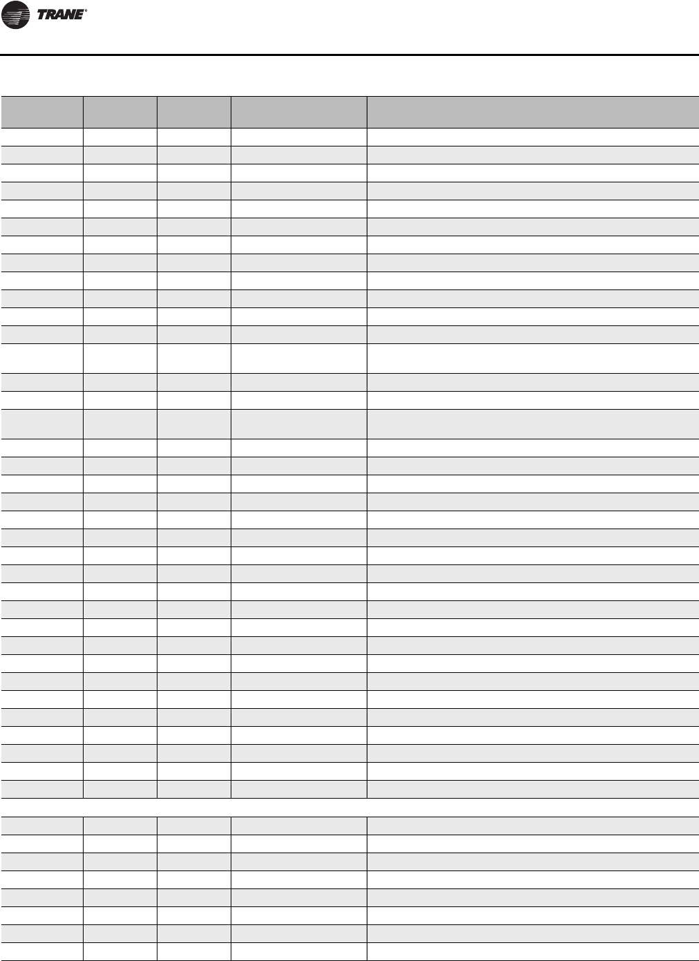
Unit Wiring Diagram Number
196 RT-SVX24K-EN
2313-0872 90-150T Connection, Control Box - Standard 2/3-Pc
2313-0880 90-105T Connection, Control Box - Standard w/Low Ambient 2/3-Pc
2313-0888 120-150T Connection, Control Box - Standard w/Low Ambient 2/3-Pc
2313-0892 100-162T Connection, Control Box - Standard 2/3-Pc
2313-0900 90-150T & AH Connection, Common Control Modules - w/o Return VFD
2313-0901 100-162T Connection, Common Control Modules - w/o Return VFD
2309-3787 90-150T Connection, Raceway Devices - Condenser Zone (Air Cooled)
2313-0816 100-162T Connection, Raceway Devices - Condenser Zone (Evap Cooled)
2309-3789 Air Handler Connection, Raceway Devices - Condenser Zone (Air Handler)
2309-3724 90-162 Ton Connection, Raceway Devices - Evap Module Standard 3-Pc
2309-3725 90-162 Ton Connection, Raceway Devices - Evap Module w/Supply VFD 3-Pc
2309-3726 90-162 Ton Connection, Raceway Devices - Evap Module w/Exh/Rtn VFD 3-Pc
2309-3727 90-162 Ton Connection, Raceway Devices - Evap Module w/Sup & Exh/Rtn VFD
3-Pc
2309-3760 90-162 Ton Connection, Raceway Devices - Evap Module Standard 2-Pc
Option
Modules
1-Piece 2313-0313 All Tonnages + Air Handler Schematic, Controls - RTM Std
2309-3633 90-150T Schematic, Controls - MCM
2313-0102 All Tonnages + Air Handler Schematic, Controls - HEAT - Elec/ Hydronic Heat
2309-3638 All Tonnages + Air Handler Schematic, Controls - HEAT - 2-stg / Modulating Gas Heat
2309-3685 All Tonnages + Air Handler Schematic, Controls - Cooling Only
2309-3645 All Tonnages + Air Handler Schematic, LHI, ECEM, VCM, MPM w/o Exh or Rtn VFD
2309-3648 All Tonnages Schematic, LHI, ECEM, VCM, MPM 2-Pc, w/o Exh or Rtn VFD
2309-3772 All Tonnages Schematic, LHI, ECEM, VCM, MPM 3-Pc, w/o Exh or Rtn VFD
2313-0867 All Tonnages + Air Handler Schematic, VOM, LCI, IPCB, GBAS 0-5V,GBAS 0-10V, BCI, WCI
Multi-Piece 2313-0315 All Tonnages Schematic, Controls - RTM 2-Pc Std
2313-0317 All Tonnages Schematic, Controls - RTM 3-Pc Std
2309-3635 90-150T Schematic, Controls - MCM 2/3-Pc
2313-0809 100-162T Schematic, Controls - MCM 2/3-Pc
2309-3641 All Tonnages Schematic, Controls - HEAT - Elec/ Hydronic Heat 2/3-Pc
2309-3642 All Tonnages Schematic, Controls - HEAT - 2-stg / Modulating Gas Heat 2/3-Pc
2309-3645 All Tonnages + Air Handler Schematic, LHI, ECEM, VCM, MPM w/o Exh or Rtn VFD
2309-3648 All Tonnages Schematic, LHI, ECEM, VCM, MPM 2-Pc, w/o Exh or Rtn VFD
2309-3772 All Tonnages Schematic, LHI, ECEM, VCM, MPM 3-Pc, w/o Exh or Rtn VFD
2313-0867 All Tonnages + Air Handler Schematic, VOM, LCI, IPCB, GBAS 0-5V,GBAS 0-10V, BCI, WCI
Heat
Electric 2313-0912 All Tonnages + Air Handler Schematic Electric Heat 90kw (SCCR)
2313-0913 All Tonnages + Air Handler Schematic Electric Heat 140kw (SCCR)
2313-0914 All Tonnages + Air Handler Schematic Electric Heat 265kw (SCCR)
2313-0915 All Tonnages + Air Handler Schematic Electric Heat 300kw (SCCR)
2313-0916 All Tonnages Schematic Electric Heat 90kw 2/3-Pc (SCCR)
2313-0917 All Tonnages Schematic Electric Heat 140kw 2/3-Pc (SCCR)
2313-0918 All Tonnages Schematic Electric Heat 265kw 2/3-Pc (SCCR)
2313-0919 All Tonnages Schematic Electric Heat 300kw 2/3-Pc (SCCR)
Table 64. Wiring diagram matrix (continued)
Air Cooled Water
Cooled Tonnnage Description
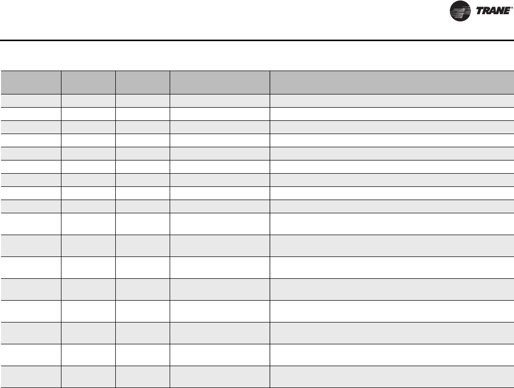
Unit Wiring Diagram Number
RT-SVX24K-EN 197
2313-0920 All Tonnages + Air Handler Connection Electric Heat 90kw (SCCR)
2313-0921 All Tonnages + Air Handler Connection Electric Heat 140kw (SCCR)
2313-0922 All Tonnages + Air Handler Connection Electric Heat 265kw (SCCR)
2313-0923 All Tonnages + Air Handler Connection Electric Heat 300kw (SCCR)
2313-0924 All Tonnages Connection Electric Heat 90kw 2/3-Pc (SCCR)
2313-0925 All Tonnages Connection Electric Heat 140kw 2/3-Pc (SCCR)
2313-0926 All Tonnages Connection Electric Heat 265kw 2/3-Pc (SCCR)
2313-0927 All Tonnages Connection Electric Heat 300kw 2/3-Pc (SCCR)
Gas 2309-3669 90-118T LOW-MED, 120-
162T LOW Schematic/Connection - 2-Stage Natural Gas Heat <1800 mbh
2309-3670 90-118T HIGH, 120-162T
MED-HIGH Schematic/Connection 2-Stage Natural Gas Heat 1800/2500mbh
2309-3671 All Tonnages + Air Handler Schematic/Connection Modulating Natural Gas Heat 1800/2500
MBH
2309-3672 "90-118T LOW-MED, 120-
162T LOW "Schematic/Connection - 2-Stage Natural Gas Heat <1800 mbh 2/
3-Pc
2309-3673 90-118T HIGH, 120-162T
MED-HIGH Schematic/Connection 2-Stage Natural Gas Heat 1800/2500mbh 2/
3-Pc
2309-3674 All Tonnages Schematic/Connection Modulating Natural Gas Heat1800/2500MBH
2/3-Pc
2309-3730 90-118T LOW-MED, 120-
162T LOW Schematic/Connection Modulating Natural Gas Heat 850/1100 MBH
2309-3731 90-118T LOW-MED, 120-
162T LOW Schematic/Connection Modulating Natural Gas Heat 850/1100MBH
2/3-Pc
Table 64. Wiring diagram matrix (continued)
Air Cooled Water
Cooled Tonnnage Description

198 RT-SVX24K-EN
Warranty and Liability Clause
Commercial Equipment
Rated 20 Tons and Larger and
Related Accessories
PRODUCTS COVERED -This warranty* is extended by
Trane Inc. and applies only to commercial equipment rated
20Tons and larger and related accessories.
The Company warrants for a period of 12 months from
initial startup or 18 months from date of shipment,
whichever is less, that the Company products covered by
this order (1) are free from defects in material and
workmanship and (2) have the capacities and ratings set
forth in the Company’s catalogs and bulletins, provided
that no warranty is made against corrosion, erosion or
deterioration.The Company’s obligations and liabilities
under this warranty are limited to furnishing f.o.b. factory
or warehouse at Company designated shipping point,
freight allowed to Buyer’s city (or port of export for
shipment outside the conterminous United States)
replacement equipment (or at the option of the Company
parts therefore) for all Company products not conforming
to this warranty and which have been returned to the
manufacturer.The Company shall not be obligated to pay
for the cost of lost refrigerant. No liability whatever shall
attach to the Company until said products have been paid
for and then said liability shall be limited to the purchase
price of the equipment shown to be defective.
The Company makes certain further warranty protection
available on an optional extra-cost basis. Any further
warranty must be in writing, signed by an officer of the
Company.
The warranty and liability set forth herein are in lieu of all
other warranties and liabilities, whether in contract or in
negligence, express or implied, in law or in fact, including
implied warranties of merchantability and fitness for
particular use. In no event shall the Company be liable for
any incidental or consequential damages.
THEWARRANTY AND LIABILITY SET FORTH HEREIN ARE
IN LIEU OF ALL OTHER WARRANTIES AND LIABILITIES,
WHETHER IN CONTRACT OR IN NEGLIGENCE, EXPRESS
OR IMPLIED, IN LAW OR IN FACT, INCLUDING IMPLIED
WARRANTIES OF MERCHANTABILITY AND FITNESS FOR
PARTICULAR USE, IN NO EVENT SHALLWARRANTOR BE
LIABLE FOR ANY INCIDENTAL OR CONSEQUENTIAL
DAMAGES.
Manager - Product Service
Trane
Clarksville,Tn 37040-1008
PW-215-2688
*A 10 year limited warranty is provided on optional Full
Modulation Gas Heat Exchanger.
*Optional Extended Warranties are available for
compressors and heat exchangers of Combination Gas-
Electric Air Conditioning Units.
* A 5 year limited warranty is provided for optional “AMCA
1A Ultra Low Leak” airfoil blade economizer assemblies
and the “AMCA 1A Ultra Low Leak” economizer actuator.
Trane optimizes the performance of homes and buildings around the world. A business of Ingersoll Rand, the leader in
creating and sustaining safe, comfortable and energy efficient environments,Trane offers a broad portfolio of advanced
controls and HVAC systems, comprehensive building services, and parts. For more information, visit www.Trane.com.
Trane has a policy of continuous product and product data improvement and reserves the right to change design and specifications without notice.
We are committed to using environmentally
conscious print practices that reduce waste.
© 2014Trane All rights reserved
RT-SVX24K-EN 01 Nov 2014
Supersedes RT-SVX24J-EN (20 Aug 2013)
