Trane Intellipak Ii 90 To 162 Tons Installation And Maintenance Manual Installation, Operation,
2015-04-02
: Trane Trane-Intellipak-Ii-90-To-162-Tons-Installation-And-Maintenance-Manual-684189 trane-intellipak-ii-90-to-162-tons-installation-and-maintenance-manual-684189 trane pdf
Open the PDF directly: View PDF ![]() .
.
Page Count: 130 [warning: Documents this large are best viewed by clicking the View PDF Link!]
- Overview of Manual
- Table of Contents
- Model Number Descriptions
- General Information
- Dimensional Data
- Pre-Installation
- Installation
- Unit Weights
- Roof Curb and Ductwork
- Pitch Pocket Location
- Field Converting Horizontal Ductwork from Right to the Left Side
- Unit Rigging and Placement
- Lifting the External Piping Enclosure
- Gas Heat Units
- Hot Water Heat Units
- Steam Heat Units
- General Coil Piping and Connection Recommendations
- Chilled Water Units
- Electrical Data
- Controls
- Sequence of Operation
- Performance Data
- Unit Start-up
- Maintenance
- Wiring Diagrams
- Index
- Warranty and Liability Clause
SAFETY WARNING
Only qualified personnel should install and service the equipment. The installation, starting up, and
servicing of heating, ventilating, and air-conditioning equipment can be hazardous and requires specific
knowledge and training. Improperly installed, adjusted or altered equipment by an unqualified person could
result in death or serious injury. When working on the equipment, observe all precautions in the literature
and on the tags, stickers, and labels that are attached to the equipment.
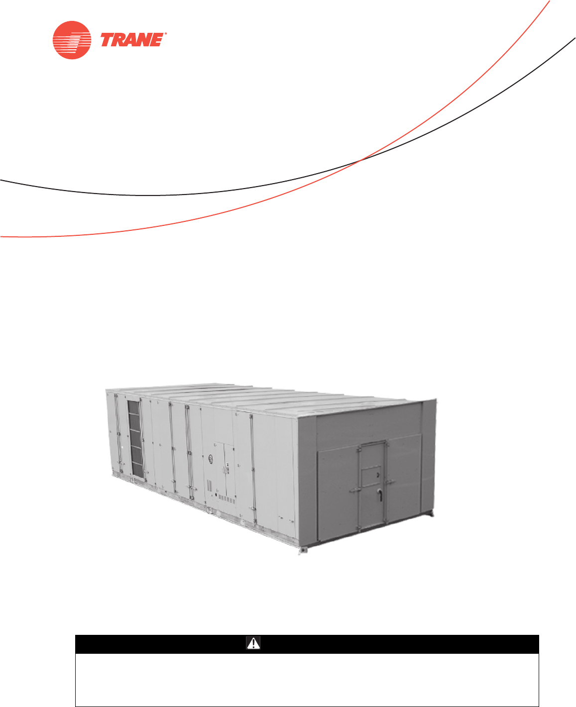
IntelliPak™ II
Commercial Rooftop Air Handlers with
CV, VAV, or SZVAV Controls
October 2011 RT-SVX28E-EN
Installation, Operation,
and Maintenance
‘F0’ and later design sequence WEHC WSHC
WFHC WXHC
WLHC
© 2011 Trane All rights reserved RT-SVX28E-EN
Warnings, Cautions and Notices
Warnings, Cautions and Notices. Note that warnings, cautions and notices appear at
appropriate intervals throughout this manual. Warnings are provide to alert installing contractors
to potential hazards that could result in death or personal injury. Cautions are designed to alert
personnel to hazardous situations that could result in personal injury, while notices indicate a
situation that could result in equipment or property-damage-only accidents.
Your personal safety and the proper operation of this machine depend upon the strict observance
of these precautions.
Read this manual thoroughly before operating or servicing this unit.
Important
Environmental Concerns!
Scientific research has shown that certain man-made chemicals can affect the earth’s naturally
occurring stratospheric ozone layer when released to the atmosphere. In particular, several of the
identified chemicals that may affect the ozone layer are refrigerants that contain Chlorine, Fluorine
and Carbon (CFCs) and those containing Hydrogen, Chlorine, Fluorine and Carbon (HCFCs). Not all
refrigerants containing these compounds have the same potential impact to the environment.
Trane advocates the responsible handling of all refrigerants-including industry replacements for
CFCs such as HCFCs and HFCs.
Responsible Refrigerant Practices!
Trane believes that responsible refrigerant practices are important to the environment, our
customers, and the air conditioning industry. All technicians who handle refrigerants must be
certified. The Federal Clean Air Act (Section 608) sets forth the requirements for handling,
reclaiming, recovering and recycling of certain refrigerants and the equipment that is used in these
service procedures. In addition, some states or municipalities may have additional requirements
that must also be adhered to for responsible management of refrigerants. Know the applicable
laws and follow them.
ATTENTION: Warnings, Cautions and Notices appear at appropriate sections throughout this
literature. Read these carefully:
WARNING Indicates a potentially hazardous situation which, if not avoided, could result in
death or serious injury.
CAUTIONsIndicates a potentially hazardous situation which, if not avoided, could result in
minor or moderate injury. It could also be used to alert against unsafe practices.
NOTICE: Indicates a situation that could result in equipment or property-damage only
accidents.
WARNING
Proper Field Wiring and Grounding Required!
All field wiring MUST be performed by qualified personnel. Improperly installed and grounded
field wiring poses FIRE and ELECTROCUTION hazards. To avoid these hazards, you MUST
follow requirements for field wiring installation and grounding as described in NEC and your
local/state electrical codes. Failure to follow code could result in death or serious injury.
RT-SVX28E-EN 3
Warnings, Cautions and Notices
Overview of Manual
Notes:
•This document is the customer property and must be retained by the unit owner for use by
maintenance personnel.
•The procedures discussed in this manual should only be performed by qualified, experienced
HVAC technicians.
This booklet describes proper installation, start-up, operation, and maintenance procedures for
Casings A-C rooftop air handlers designed for Constant Volume (CV), Single Zone Variable Air
Volume (SZVAV) and Variable Air Volume (VAV) applications. By carefully reviewing the
information within this manual and following the instructions, the risk of improper operation and/
or component damage will be minimized.
Note: One copy of the appropriate service literature ships inside the control panel of each unit.
It is important that periodic maintenance be performed to help assure trouble free operation.
Should equipment failure occur, contact a qualified service organization with qualified,
experienced HVAC technicians to properly diagnose and repair this equipment.
WARNING
Personal Protective Equipment (PPE) Required!
Installing/servicing this unit could result in exposure to electrical, mechanical and chemical
hazards.
• Before installing/servicing this unit, technicians MUST put on all Personal Protective
Equipment (PPE) recommended for the work being undertaken. ALWAYS refer to appropriate
MSDS sheets and OSHA guidelines for proper PPE.
• When working with or around hazardous chemicals, ALWAYS refer to the appropriate MSDS
sheets and OSHA guidelines for information on allowable personal exposure levels, proper
respiratory protection and handling recommendations.
• If there is a risk of arc or flash, technicians MUST put on all Personal Protective Equipment
(PPE) in accordance with NFPA 70E or other country-specific requirements for arc flash
protection, PRIOR to servicing the unit.
Failure to follow recommendations could result in death or serious injury.

4 RT-SVX28E-EN
Table of Contents
Overview of Manual . . . . . . . . . . . . . . . . . . . . . . . . . . . . . . . . . . . . . . . . . . . 3
Model Number Descriptions . . . . . . . . . . . . . . . . . . . . . . . . . . . . . . . . . . . . . . . . . . . . . 7
General Information . . . . . . . . . . . . . . . . . . . . . . . . . . . . . . . . . . . . . . . . . . . . . . . . . . . . 9
Commonly used Acronyms . . . . . . . . . . . . . . . . . . . . . . . . . . . . . . . . . . . . . . . . . 9
Unit Description . . . . . . . . . . . . . . . . . . . . . . . . . . . . . . . . . . . . . . . . . . . . . . . . . . . 9
Input Devices and System Functions . . . . . . . . . . . . . . . . . . . . . . . . . . . . . . . . 13
Constant Volume (CV) and Variable Air Volume (VAV) Units . . . . . . . . . 13
Constant Volume (CV) Units . . . . . . . . . . . . . . . . . . . . . . . . . . . . . . . . . . . . 15
Variable Air Volume (VAV) Units . . . . . . . . . . . . . . . . . . . . . . . . . . . . . . . . 16
Single Zone Variable Air Volume (SZVAV) Only . . . . . . . . . . . . . . . . . . . 17
Space Temperature Averaging . . . . . . . . . . . . . . . . . . . . . . . . . . . . . . . . . 19
Unit Control Modules . . . . . . . . . . . . . . . . . . . . . . . . . . . . . . . . . . . . . . . . . 20
Dimensional Data . . . . . . . . . . . . . . . . . . . . . . . . . . . . . . . . . . . . . . . . . . . . . . . . . . . . . . 22
Unit Clearance . . . . . . . . . . . . . . . . . . . . . . . . . . . . . . . . . . . . . . . . . . . . . . . . . . . . 22
Unit Dimensions . . . . . . . . . . . . . . . . . . . . . . . . . . . . . . . . . . . . . . . . . . . . . . . . . . 24
Pre-Installation . . . . . . . . . . . . . . . . . . . . . . . . . . . . . . . . . . . . . . . . . . . . . . . . . . . . . . . . 28
General Unit Requirements . . . . . . . . . . . . . . . . . . . . . . . . . . . . . . . . . . . . 28
Rigging the Unit . . . . . . . . . . . . . . . . . . . . . . . . . . . . . . . . . . . . . . . . . . . . . 29
Main Electrical Power Requirements . . . . . . . . . . . . . . . . . . . . . . . . . . . . . 29
Field Installed Control Wiring . . . . . . . . . . . . . . . . . . . . . . . . . . . . . . . . . . . 29
Requirements for Electric Heat Units . . . . . . . . . . . . . . . . . . . . . . . . . . . . . 29
Requirement for Gas Heat . . . . . . . . . . . . . . . . . . . . . . . . . . . . . . . . . . . . . 29
Requirements for Hot Water Heat . . . . . . . . . . . . . . . . . . . . . . . . . . . . . . . 29
Requirements for Steam Heat . . . . . . . . . . . . . . . . . . . . . . . . . . . . . . . . . . 30
Requirements for Chilled Water Cooling . . . . . . . . . . . . . . . . . . . . . . . . . . 30
O/A Pressure Sensor and Tubing Installation (all units with Statitrac) . . 30
Condensate Drain Connections . . . . . . . . . . . . . . . . . . . . . . . . . . . . . . . . . 30
Units with Gas Furnace . . . . . . . . . . . . . . . . . . . . . . . . . . . . . . . . . . . . . . . . 31
Removing Supply and Exhaust Fan Shipping Channels . . . . . . . . . . . . . 31
Spring Isolators . . . . . . . . . . . . . . . . . . . . . . . . . . . . . . . . . . . . . . . . . . . . . . 31
O/A Sensor and Tubing Installation . . . . . . . . . . . . . . . . . . . . . . . . . . . . . . 32
Units with Statitrac . . . . . . . . . . . . . . . . . . . . . . . . . . . . . . . . . . . . . . . . . . . 33
Installation . . . . . . . . . . . . . . . . . . . . . . . . . . . . . . . . . . . . . . . . . . . . . . . . . . . . . . . . . . . . 34
Unit Weights . . . . . . . . . . . . . . . . . . . . . . . . . . . . . . . . . . . . . . . . . . . . . . . . . . . . . 34
Roof Curb and Ductwork . . . . . . . . . . . . . . . . . . . . . . . . . . . . . . . . . . . . . . . . . . . 36
Pitch Pocket Location . . . . . . . . . . . . . . . . . . . . . . . . . . . . . . . . . . . . . . . . . 37
If a Trane Curb Accessory Kit is not used . . . . . . . . . . . . . . . . . . . . . . . . . 37
Field Converting Horizontal Ductwork from Right to the Left Side . . . . . 38
Unit Rigging and Placement . . . . . . . . . . . . . . . . . . . . . . . . . . . . . . . . . . . . . . . . 38
Lifting the External Piping Enclosure . . . . . . . . . . . . . . . . . . . . . . . . . . . . . 41
Gas Heat Units . . . . . . . . . . . . . . . . . . . . . . . . . . . . . . . . . . . . . . . . . . . . . . . . . . . 42

RT-SVX28E-EN 5
Connecting the Gas Supply Line to the Furnace Gas train . . . . . . . . . . . 43
Hot Water Heat Units . . . . . . . . . . . . . . . . . . . . . . . . . . . . . . . . . . . . . . . . . . . . . . 47
Steam Heat Units . . . . . . . . . . . . . . . . . . . . . . . . . . . . . . . . . . . . . . . . . . . . . . . . . 48
General Coil Piping and Connection Recommendations . . . . . . . . . . . . . . . . 49
Chilled Water Units . . . . . . . . . . . . . . . . . . . . . . . . . . . . . . . . . . . . . . . . . . . . . . . 52
General Coil Piping Recommendations . . . . . . . . . . . . . . . . . . . . . . . . . . . 52
Coil Winterization . . . . . . . . . . . . . . . . . . . . . . . . . . . . . . . . . . . . . . . . . . . . 55
External Piping Enclosure Installation . . . . . . . . . . . . . . . . . . . . . . . . . . . . 56
Electrical Data . . . . . . . . . . . . . . . . . . . . . . . . . . . . . . . . . . . . . . . . . . . . . . . . . . . . 58
Disconnect Switch w/External Handle . . . . . . . . . . . . . . . . . . . . . . . . . . . . 58
Electric Heat Units . . . . . . . . . . . . . . . . . . . . . . . . . . . . . . . . . . . . . . . . . . . . 58
Main Unit Power Wiring . . . . . . . . . . . . . . . . . . . . . . . . . . . . . . . . . . . . . . . 59
Power Wire Sizing and Protection Devices . . . . . . . . . . . . . . . . . . . . . . . . 61
Controls . . . . . . . . . . . . . . . . . . . . . . . . . . . . . . . . . . . . . . . . . . . . . . . . . . . . . . . . . . . . . . 64
Field Installed Control Wiring . . . . . . . . . . . . . . . . . . . . . . . . . . . . . . . . . . . 64
Controls using 24 VAC . . . . . . . . . . . . . . . . . . . . . . . . . . . . . . . . . . . . . . . . 64
Controls using DC Analog Input/Outputs . . . . . . . . . . . . . . . . . . . . . . . . . 65
Constant Volume System Controls . . . . . . . . . . . . . . . . . . . . . . . . . . . . . . 65
Variable Air Volume System Controls . . . . . . . . . . . . . . . . . . . . . . . . . . . . 65
Constant Volume or Variable Air volume System Controls . . . . . . . . . . 66
Emergency Override . . . . . . . . . . . . . . . . . . . . . . . . . . . . . . . . . . . . . . . . . . 67
Ventilation Override Module (VOM) . . . . . . . . . . . . . . . . . . . . . . . . . . . . . 68
Temperature vs. Resistance Coefficient . . . . . . . . . . . . . . . . . . . . . . . . . . 71
Sequence of Operation . . . . . . . . . . . . . . . . . . . . . . . . . . . . . . . . . . . . . . . . . . . . . . . . . 80
Cooling Sequence of Operation . . . . . . . . . . . . . . . . . . . . . . . . . . . . . . . . . 80
Gas Heating Sequence of Operation . . . . . . . . . . . . . . . . . . . . . . . . . . . . . 81
Electric Heat Sequence of Operation . . . . . . . . . . . . . . . . . . . . . . . . . . . . . 83
CV Electric Heat . . . . . . . . . . . . . . . . . . . . . . . . . . . . . . . . . . . . . . . . . . . . . . 84
VAV Occupied Electric Heat . . . . . . . . . . . . . . . . . . . . . . . . . . . . . . . . . . . . 84
Demand Control Ventilation Sequence of Operation . . . . . . . . . . . . . . . . 84
Return Fan Sequence of Operation . . . . . . . . . . . . . . . . . . . . . . . . . . . . . . 84
Wet Heat Sequence of Operation . . . . . . . . . . . . . . . . . . . . . . . . . . . . . . . . 84
Verifying Proper Fan Rotation . . . . . . . . . . . . . . . . . . . . . . . . . . . . . . . . . . 87
System Airflow Measurements . . . . . . . . . . . . . . . . . . . . . . . . . . . . . . . . . 88
Exhaust Airflow Measurement (Optional) . . . . . . . . . . . . . . . . . . . . . . . . . 91
Traq™ Sensor Airflow Measurement (Optional with all units equipped with
an economizer) . . . . . . . . . . . . . . . . . . . . . . . . . . . . . . . . . . . . . . . . . . . . . . 92
Performance Data . . . . . . . . . . . . . . . . . . . . . . . . . . . . . . . . . . . . . . . . . . . . . . . . . . . . . 93
Supply Fan (with or without Variable Frequency Drive) . . . . . . . . . . . . . . . . 93
Exhaust Fan . . . . . . . . . . . . . . . . . . . . . . . . . . . . . . . . . . . . . . . . . . . . . . . . . . . . . . 94
Return Fan . . . . . . . . . . . . . . . . . . . . . . . . . . . . . . . . . . . . . . . . . . . . . . . . . . . . . . . 96
Component Static Pressure Drops . . . . . . . . . . . . . . . . . . . . . . . . . . . . . . . . . . . 97

6 RT-SVX28E-EN
Unit Start-up . . . . . . . . . . . . . . . . . . . . . . . . . . . . . . . . . . . . . . . . . . . . . . . . . . . . . . . . . . 99
Economizer Damper Adjustment . . . . . . . . . . . . . . . . . . . . . . . . . . . . . . . . . . . . 99
To Adjust the Fresh Air Damper Travel . . . . . . . . . . . . . . . . . . . . . . . . . . . 99
Chilled Water Cooling Startup (Constant Volume & Variable Air
Volume Systems) . . . . . . . . . . . . . . . . . . . . . . . . . . . . . . . . . . . . . . . . . . . . . . . . 103
Electric, Steam and Hot Water Start-Up (Constant Volume & Variable Air Vol-
ume Systems) . . . . . . . . . . . . . . . . . . . . . . . . . . . . . . . . . . . . . . . . . . . . . . . . . . . 104
Gas Furnace Start-Up
(Constant Volume and Variable Air Volume Systems) . . . . . . . . . . . . . . . . . 105
Two Stage Gas Furnace . . . . . . . . . . . . . . . . . . . . . . . . . . . . . . . . . . . . . . 106
Full Modulating Gas Furnace . . . . . . . . . . . . . . . . . . . . . . . . . . . . . . . . . . 109
Final Unit Checkout . . . . . . . . . . . . . . . . . . . . . . . . . . . . . . . . . . . . . . . . . . . . . . 112
Maintenance . . . . . . . . . . . . . . . . . . . . . . . . . . . . . . . . . . . . . . . . . . . . . . . . . . . . . . . . . 113
Fan Belt Adjustment . . . . . . . . . . . . . . . . . . . . . . . . . . . . . . . . . . . . . . . . . 116
VFD Programming Parameters . . . . . . . . . . . . . . . . . . . . . . . . . . . . . . . . 119
Monthly Maintenance . . . . . . . . . . . . . . . . . . . . . . . . . . . . . . . . . . . . . . . . 120
Cooling Season . . . . . . . . . . . . . . . . . . . . . . . . . . . . . . . . . . . . . . . . . . . . . 120
Heating Season . . . . . . . . . . . . . . . . . . . . . . . . . . . . . . . . . . . . . . . . . . . . . 121
Coil Cleaning . . . . . . . . . . . . . . . . . . . . . . . . . . . . . . . . . . . . . . . . . . . . . . . 122
Final Process . . . . . . . . . . . . . . . . . . . . . . . . . . . . . . . . . . . . . . . . . . . . . . . 124
Wiring Diagrams . . . . . . . . . . . . . . . . . . . . . . . . . . . . . . . . . . . . . . . . . . . . . . . . . . . . . 125
Index . . . . . . . . . . . . . . . . . . . . . . . . . . . . . . . . . . . . . . . . . . . . . . . . . . . . . . . . . . . . . . . . 127
Warranty and Liability Clause . . . . . . . . . . . . . . . . . . . . . . . . . . . . . . . . . . . . . . . . . . 129

RT-SVX28E-EN 7
DIGIT 1 — UNIT TYPE
W Self-Contained (Packaged
Air Handler)
DIGIT 2 — UNIT FUNCTION
E Electric Heat
F Natural Gas Heat
L Hot Water Heat
S Steam Heat
X No Heat
DIGIT3—SYSTEMTYPE
H Single Zone
DIGIT 4 — DEVELOPMENT
SEQUENCE
C Third
DIGIT 5 — UNIT SIZE
A 16,000 - 31,000 CFM
B 20,000 - 38,000 CFM
C 20,000 - 45,000 CFM
DIGIT6—COOLING COIL
0 No Cooling Coil
2 2 Row Chilled Water
4 4 Row Chilled Water
6 6 Row Chilled Water
8 8 Row Chilled Water
DIGIT 7 — CHILLED WATER COIL
FIN SERIES
0 No Chilled Water Coil
A Series 80 without Turbulators
B Series 80 with Turbulators
C Series 108 without Turbulators
D Series 108 with Turbulators
E Series 144 without Turbulators
F Series 144 with Turbulators
G Series 168 without Turbulators
H Series 168 with Turbulators
DIGIT 8 — VOLTAGE SELECTION
4 460/60/3 XL
5 575/60/3 XL
DIGIT 9 — HEAT CAPACITY
SELECTION
0 No Heat
1 Electric Heat 90 kW
2 Electric Heat 140 kW
3 Electric Heat 265 kW
4 Electric Heat 300 kW
A Low Gas Heat - 2 stage
B Medium Gas Heat - 2 stage
C High Gas Heat - 2 stage
D Low Gas Heat - Modulating
E Medium Gas Heat - Modulating
F High Gas Heat - Modulating
Low Heat Options
H Low Heat - 1.25 in. (32mm) Valve
J Low Heat - 1.5 in. (38mm) Valve
K Low Heat - 2.0 in. (50mm) Valve
L Low Heat - 2.50 in. (64mm) Valve
M Low Heat - 3.0 in. (76mm) Valve
High Heat Options
P High Heat - 1.25 in.(32mm) Valve
Q High Heat - 1.5 in. (38mm) Valve
R High Heat - 2.0 in. (50mm) Valve
T High Heat - 2.50 in. (64mm) Valve
U High Heat - 3.0 in. (76mm) Valve
DIGIT 10 & 11— DESIGN
SEQUENCE
AO
DIGIT 12 — UNIT
CONFIGURATION SELECTION
4 1 Piece Unit - without Blank
Section
5 1 Piece Unit with 4 ft. Blank
Section
6 1 Piece Unit with 8 ft. Blank
Section
DIGIT 13 — AIRFLOW DIRECTION
1 Downflow Supply/Upflow Return
2 Downflow Supply/Horizontal End
Return
3 Downflow Supply/Horizontal
Right Return
4 Right Side Horizontal Supply/
Upflow Return
5 Right Side Horizontal Supply/
Horizontal End Return
6 Right Side Horizontal Supply/
Horizontal Right Return
DIGIT 14 — FAN MOTOR
SELECTION
1 Standard Fan
3 Standard Fan w/ TEFC Motor
DIGIT 15 — SUPPLY FAN MOTOR
SELECTION
F15Hp
G20Hp
H25Hp
J30Hp
K40Hp
L50Hp
M60Hp
N75Hp
DIGIT 16 — SUPPLY FAN RPM
SELECTION
7700
8800
9900
A1000
B1100
C 1200
D 1300
E 1400
F 1500
G 1600
H 1700
J 1800
K 1900
L2000
DIGIT 17 — EXHAUST/RETURN
FAN OPTIONS
0 None
1 High CFM Exhaust w/o Statitrac
CV Only
2 Low CFM Exhaust w/o Statitrac
CV Only
3 High CFM Exhaust w/o VFD w/
Statitrac
4 Low CFM Exhaust w/o VFD w/
Statitrac
5 High CFM Exhaust w/ VFD w/
Bypass w/ Statitrac
6 Low CFM Exhaust w/ VFD w/
Bypass w/ Statitrac
7 High CFM Exhaust w/ VFD w/o
Bypass w/ Statitrac
8 Low CFM Exhaust w/ VFD w/o
Bypass w/ Statitrac
A Return w/o Statitrac CV Only
C Return w/ VFD w/ Bypass w/
Statitrac
E Return w/ VFD w/o Bypass w/
Statitrac
DIGIT 18 — EXHAUST/RETURN
FAN MOTOR SELECTION
0 None
D 7.5 Hp
E10Hp
F15Hp
G20Hp
H25Hp
J30Hp
K40Hp
L50Hp
M60Hp
Model Number Descriptions
WEHCA0040A0411F70001A0000A0D0A00000000
1 2 3 4 567 8 9 10 11 12 13 14 15 16 17 18 19 20 21 22 23 24 25 26 27 28 29 30 31 32 33 34 35 36 37 38

8RT-SVX28E-EN
Model Number Descriptions
DIGIT 19 — EXHAUST/RETURN
RPM SELECTION
0 None
3300
4400
5500
6600
7700
8800
9900
A1000
B1100
C 1200
D 1300
E 1400
DIGIT 20 — SYSTEM CONTROL
SELECTION
1 Constant Volume (Zone
Temperature Control)
2 VAV (Discharge Air Control)
4 VFD Supply w/o Bypass
(Discharge Air Control)
5 VFD Supply w/Bypass (Discharge
Air Control)
6 Single Zone VAV w/VFD w/o Bypass
(Zone Temperature Control)
7 Single Zone VAV w/VFD w/Bypass
(Zone Temperature Control)
DIGIT 21 — FRESH AIR AND
ECONOMIZER OPTIONS/
CONTROLS
A 0 - 25% Motorized Damper
B Econ w/Dry Bulb
C Econ w/Reference Enthalpy
D Econ w/Comparative Enthalpy
E Econ w/Fresh Air Measure /Dry
Bulb
F Econ w/ Fresh Air Measure /Ref
Enth
G Econ w/Fresh Air Measure /Comp
Enth
H Econ w/DCV /Dry Bulb
J Econ w/DCV /Ref Enth
K Econ w/DCV /Comp Enth
DIGIT 22 — DAMPER OPTION
0 Standard
1 Low Leak
2 Ultra Low Leak
DIGIT 23 — PRE COOLING COIL
FILTER SELECTION
0 2" High Efficiency Throw Away
1 2" Throw Away Rack / Less Filters
2 90 - 95%, Bag Filters w/ Pre Filters
3 Bag Filter Rack / Less Filters
4 90 - 95%, Cartridge Filters w/
Pre Filters
5 Cartridge Rack / Less Filters
6 90 - 95% Low PD Cartridge w/
Pre Filters
7 Low PD Cartridge Rack / Less
Filters
DIGIT 24 — BLANK SECTION
APPLICATION OPTIONS
0 None
A 90 - 95% Bag w/Pre Filters
B 90 - 95% Low PD Cartridge w/
Pre Filters
C 90 - 95%, Cartridge Filters w/
Pre Filters
D 90 - 95% Hi Temp Cartridge w/
Pre Filters
E HEPA w/Pre Filters
F Hi Temp HEPA w/Pre Filters
DIGIT 25 — FUTURE
DEVELOPMENT
0
DIGIT 26 — UNIT MOUNTED POWER
CONNECTION SELECTION
A Terminal Block
B Non Fused Disconnect
C Non Fused Disconnect w/
Pwrd conv outlet
D Circuit Breaker w/ SCWR
E Ckt Brkr w/ SCWR/ Pwrd conv
outlet
DIGIT 27 — (FUTURE
DEVELOPMENT)
0 None
DIGIT 28 — COIL/DRAIN PAN
D No Drain Pan
E Galvanized Drain Pan
DIGIT 29 — CHILLED WATER
COIL VALVE
0 None
A 1.5" Cooling Valve
B 2" Cooling Valve
C 2.5" Cooling Valve
D 3" Cooling Valve
DIGIT 30 — (FUTURE
DEVELOPMENT)
0 None
DIGIT 31 — (FUTURE
DEVELOPMENT)
0 None
DIGIT 32 — HIGH DUCT
TEMPERATURE THERMOSTAT
0 None
1 High Duct Temp Thermostat
DIGIT 33 — REMOTE HUMAN
INTERFACE
0 None
1 RHI & IPCB
2 IPCB
DIGIT 34 — MODULE OPTIONS
0 None
A 0-5 Volt GBAS
B 0-10 Volt GBAS
C 0-5 / 0-10 Volt GBAS
F LonTalk Communication Interface
(LCI)
D Ventilation Override
G 0-5 Volt GBAS / Ventilation
Override
H 0-10 Volt GBAS / Ventilation
Override
J 0-5 / 0-10 V GBAS / Ventilation
Override
L LCI & Ventilation Override
M BACnet Communication
Interface (BCI)
N BCI & Ventilation Override
DIGIT 35 — ZONE SENSOR
OPTION
0 None
A Dual Setpoint w/Man/Auto
Changeover
B Dual Stpt w/Man/Auto Chgovr &
Sys Lights
C Room Sensor w/Timed Override
& Cancel
D Room Snsr w/TO & Cancel &
Local Stpt Adj
G VAV w/System Lights
L Programmable Night Setback
DIGIT 36 — AGENCY APPROVAL
OPTION
0 None
1 cULus
DIGIT 37 — SERVICE
ENHANCEMENTS
0 Single Side Access Doors
A Dual Side Access Doors
B Single Side Access Doors /
Marine Lights
C Dual Side Access Doors / Marine
Lights
DIGIT 38 — BELT GUARDS/
BURGLAR BARS/MARINE LIGHTS
0 None
1 Belt Guards
2 Burglar Bars
3 Belt Guards / Burglar Bars

RT-SVX28E-EN 9
General Information
Unit Nameplate
One Mylar unit nameplate is located on the outside upper left corner of the control panel door. It
includes the unit model number, serial number, electrical characteristics, weight, refrigerant
charge, as well as other pertinent unit data. A small metal nameplate with the Model Number, Serial
Number, and Unit Weight is located just above the Mylar nameplate, and a third nameplate is
located on the inside of the control panel door.
Precautionary Measures
• Avoid breathing fiberglass dust
• Use a NIOSH approved dust/mist respirator
• Avoid contact with the skin or eyes. Wear long-sleeved, loose-fitting clothing, gloves, and
eye protection
• Wash clothes separately from other clothing: rinse washer thoroughly
• Operations such as sawing, blowing, tear-out, and spraying may generate fiber concentrations
requiring additional respiratory protection. Use the appropriate NIOSH approved respiration in
these situations.
First Aid Measures
Eye Contact
– Flush eyes with water to remove dust. If symptoms persist, seek medical attention.
Skin Contact
– Wash affected areas gently with soap and warm water after handling.
Commonly used Acronyms
For convenience, a number of acronyms and abbreviations are used throughout this manual.
These acronyms are alphabetically listed and defined below.
• AHU = Air Handler Unit • LCI-I = LonTalk Communication Interface for IntelliPak
• BAS = Building automation systems • LH = Left-hand
• BCI = BACnet Communication Interface module • MWU = Morning warm-up
• CFM = Cubic-feet-per-minute • NSB = Night setback
• CV = Constant volume • O/A = Outside air
• CW = Clockwise • psig = Pounds-per-square-inch, gauge pressure
• CCW = Counterclockwise • R/A = Return air
• E/A = Exhaust air • RH = Right-hand
• ECEM = Exhaust/comparative enthalpy module • RPM = Revolutions-per-minute
• F/A = Fresh air • RTM = Rooftop module
• GBAS = Generic building automation system • S/A = Supply air
• HGBP = Hot gas bypass • SZ = Single-zone (unit airflow)
• HI = Human Interface • SZVAV = Single zone variable air volume
• HVAC = Heating, ventilation and air conditioning • UCM = Unit control modules
• I/O = Inputs/outputs • VAV = Variable air volume
• IOM = Installation/operation/ maintenance manual • VCM = Ventilation control module
• IPC = Interprocessor communications • VOM = Ventilation override module
• IPCB = Interprocessor communications bridge • w.c. = Water column
10 RT-SVX28E-EN
General Information
Unit Description
Each Trane commercial, single-zone rooftop air handler ships fully assembled from the factory.
An optional roof curb, specifically designed for the W_HC units is available from Trane. The roof
curb kit must be field assembled and installed according to the latest edition of the roof curb
installation manual.
Trane Commercial Rooftop Air Handlers are controlled by a microelectronic control system that
consists of a network of modules and are referred to as Unit Control Modules (UCM). The acronym
UCM is used extensively throughout this document when referring to the control system network.
These modules through Proportional/Integral control algorithms perform specific unit functions
which provide the best possible comfort level for the customer.
They are mounted in the control panel and are factory wired to their respective internal
components. They receive and interpret information from other unit modules, sensors, remote
panels, and customer binary contacts to satisfy the applicable request for economizing, mechanical
cooling, heating, and ventilation. Refer to the following discussion for an explanation of each
module function.
Rooftop Module (RTM - Standard on all units)
The rooftop Module (RTM) responds to cooling, heating, and ventilation requests by energizing the
proper unit components based on information received from other unit modules, sensors, remote
panels, and customer supplied binary inputs. It initiates supply fan, exhaust fan, exhaust damper,
or variable frequency drive output, and economizer operation based on that information.
Human Interface Module (HI - standard on all units)
The Human Interface module enables the operator to adjust the operating parameters for the unit
using a 16 key keypad. The 2 line, 40 character LCD screen provides status information for the
various unit functions as well as menus for the operator to set or modify the operating parameters.
Heat Module (used on heating units)
The Heat module, upon receiving a request for Heating, energizes the appropriate heating stages
or strokes the Modulating Heating valve as required.
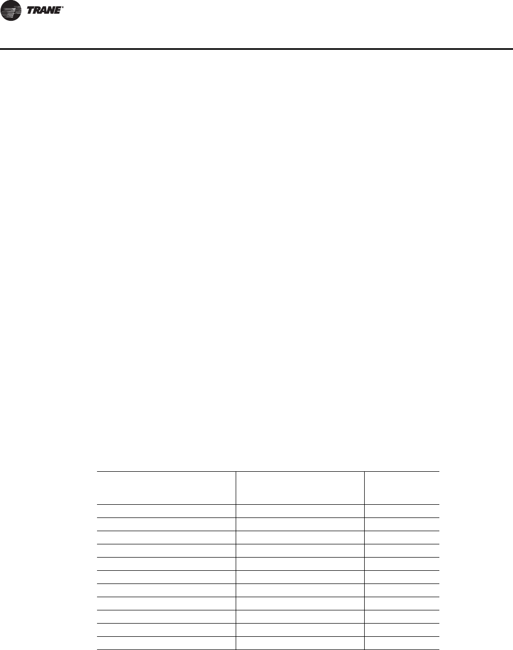
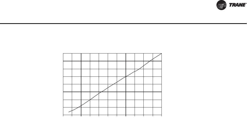
Table 1. Resistance input vs. setpoint temperature
RTM cooling or heating setpoint
input used as the source for a
ZONE temp setpoint (F)
RTM cooling setpoint input
used as the source for SUPPLY
AIR temp setpoint cooling (F)
Resistance
(Ohms) Max.
Tolerance 5%
40 40 1084
45 45 992
50 50 899
55 55 796
60 60 695
65 65 597
70 70 500
75 75 403
80 80 305
n/a 85 208
n/a 90 111
RT-SVX28E-EN 11
General Information
Ventilation Override Module (VOM - Optional)
Important: The ventilation override system should not be used to signal the presence of smoke
caused by a fire as it is not intended nor designed to do so.
The Ventilation Override module initiates specified functions such as; space pressurization,
exhaust, purge, purge with duct pressure control, and unit off when any one of the five (5) binary
inputs to the module are activated. If more than one ventilation sequence is activated, the one with
the highest priority is initiated.
Interprocessor Communications Board (IPCB - Optional used with the Optional
Remote Human Interface)
The Interprocessor Communication Board expands communications from the unit UCM network
to a Remote Human Interface Panel. DIP switch settings on the IPCB module for this application
should be; Switches 1 and 2 "Off", Switch 3 "On".
Lontalk/BACnet Communication Interface Module (LCI/BCI - Optional - used
on units with Trane ICS™ or 3rd party Building Automation Systems)
The LonTalk/BACnet Communication Interface modules expand communications from the unit
UCM network to a Trane Tracer Summit™ or a 3rd party building automation system and allow
external setpoint and configuration adjustment and monitoring of status and diagnostics.
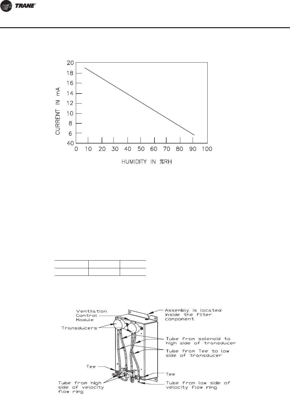
Exhaust/Comparative Enthalpy Module (ECEM - Optional used on units with
Statitrac and/or comparative enthalpy options)
The Exhaust/Comparative Enthalpy module receives information from the return air humidity
sensor, the outside air humidity sensor, and the return air temperature sensor to utilize the lowest
possible humidity level when considering economizer operation. In addition, it receives space
pressure information which is used to maintain the space pressure to within the setpoint
controlband. Refer to Figure 1, p. 12 for the Humidity vs. Voltage input values.
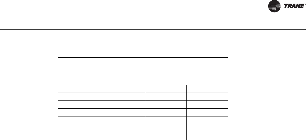
Table 2. Resistance value vs. system operating mode
Resistance applied to RTM MODE
input Terminals (Ohms) Max.
Tolerance 5% Constant Volume Units
2320 Auto Off
4870 Auto Cool
7680 Auto Auto
10770 On Off
13320 On Cool
16130 On Auto
19480 Auto Heat
12 RT-SVX28E-EN
General Information
Ventilation Control Module (VCM)
The Ventilation Control Module (VCM) is located in the filter section of the unit and is linked to the
unit UCM network. Using a "velocity pressure" sensing ring located in the fresh air section allows
the VCM to monitor and control the quantity of fresh air entering the unit to a minimum airflow
setpoint.
An optional temperature sensor can be connected to the VCM which enables it to control a field
installed fresh air preheater.
An optional CO2 sensor can be connected to the VCM to control CO2 reset. The reset function
adjusts the minimum CFM upward as the CO2 concentrations increase. The maximum effective
(reset) setpoint value for fresh air entering the unit is limited to the systems operating CFM. The
following table lists the Minimum Outside Air CFM vs. Input Voltage.
The velocity pressure transducer/solenoid assembly is illustrated below. Refer to the “Units with
Traq™ Sensor,” p. 81 section for VCM operation.
Figure 1. Humidity vs. current
Table 3. Minimum outside air setpoint w/VCM and Traq™ sensing
Unit Input Volts CFM
Casings A-Cs 0.5 - 4.5 VDC 0 - 45000
Table 4. Velocity pressure transducer/solenoid assembly

RT-SVX28E-EN 13
General Information
Generic Building Automation System Module (GBAS - Optional used with
non-Trane building control systems)
The Generic Building Automation System (GBAS) module allows a non-Trane building control
system to communicate with the air handler unit and accepts external setpoints in the form of
analog inputs for cooling, heating, supply air pressure, and a binary Input for demand limit. Refer
to the "Field Installed Control Wiring" section for the input wiring to the GBAS module and the
various desired setpoints with the corresponding DC voltage inputs for CV, VAV, and SZ VAV
applications.
Input Devices and System Functions
The descriptions of the following basic Input Devices used within the UCM network are to acquaint
the operator with their function as they interface with the various modules. Refer to the unit
electrical schematic for the specific module connections.
Constant Volume (CV) and Variable Air Volume (VAV) Units
Chilled Water Valve Control
The 0 to 10 VDC output from the heat module doubles as the chilled water controller. The unit has
isolating relays to switch between heat and cool.
Supply Air Temperature Sensor
An analog input device used with CV and VAV applications that monitors the supply air
temperature for: supply air temperature control (VAV), supply air temperature reset (VAV), supply
air temperature low limiting (CV), supply air tempering (CV/VAV). It is mounted in the supply air
discharge section of the unit and is connected to the RTM.
Return Air Temperature Sensor
An analog input device used with a return humidity sensor on CV and VAV applications when the
comparative enthalpy option is ordered. It monitors the return air temperature and compares it to
the outdoor temperature to establish which temperature is best suited to maintain the cooling
requirements. It is mounted in the return air section and is connected to the ECEM.
Filter Switch
A binary input device used on CV and VAV applications that measures the pressure differential
across the unit filters. It is mounted in the filter section and is connected to the RTM. A diagnostic
SERVICE signal is sent to the remote panel if the pressure differential across the filters is at least 0.5"
w.c. The contacts will automatically open when the pressure differential across the filters decrease
to 0.4" w.c. The switch differential can be field adjusted between 0.17" w.c. to 5.0" w.c. ± 0.05" w.c.
Supply and Exhaust Airflow Proving Switches
Supply Airflow Proving Switch is a binary input device used on CV and VAV applications to signal
the RTM when the supply fan is operating. It is located in the supply fan section of the unit and is
connected to the RTM. During a request for fan operation, if the differential switch is detected to
be open for 40 consecutive seconds; heat operation is turned "Off", the request for supply fan
operation is turned "Off" and locked out, exhaust dampers (if equipped) are "closed", economizer
dampers (if equipped) are "closed", and a manual reset diagnostic is initiated.
Exhaust Airflow Proving Switch is a binary input device used on all air handler units equipped with
an exhaust fan. It is located in the exhaust fan section of the unit and is connected to the RTM.
During a request for fan operation, if the differential switch is detected to be open for 40 consecutive
seconds, the economizer is closed to the minimum position setpoint, the request for exhaust fan
operation is turned "Off" and locked out, and a manual reset diagnostic is initiated. The fan failure
lockout can be reset at the Human Interface located in the unit control panel, by Tracer, or by cycling
the control power to the RTM Off/On).
14 RT-SVX28E-EN
General Information
Supply and Exhaust Fan Circuit Breakers
The supply fan and exhaust fan motors are protected by circuit breakers. They will trip and interrupt
the power supply to the motors if the current exceeds the breaker's "must trip" value. The rooftop
module (RTM) will shut all system functions "Off" when an open fan proving switch is detected.
Outdoor Air Humidity Sensor
An analog input device used on CV and VAV applications with 100% economizer. It monitors the
outdoor humidity levels for economizer operation. It is mounted in the fresh air intake section and
is connected to the RTM.
Return Air Humidity Sensor
An analog input device used on CV and VAV applications with the comparative enthalpy option.
It monitors the return air humidity level and compares it to the outdoor humidity level to establish
which conditions are best suited to maintain the cooling requirements. It is mounted in the return
air section and is connected to the ECEM.
Space Humidity Sensor
Analog input device used on CV and VAV applications with modulating dehumidification option
and/or humidification field installed option. It is used to monitor the humidity level in the space and
compared to dehumidification and humidification setpoints to maintain space humidity
requirements. It is field mounted in the space and connected to the RTM.
Status/Annunciator Output
An internal function within the RTM module on CV and VAV applications that provides:
1. diagnostic and mode status signals to the remote panel (LEDs) and to the Human Interface
2. control of the binary Alarm output on the RTM
3. control of the binary outputs on the GBAS module to inform the customer of the operational
status and/or diagnostic conditions
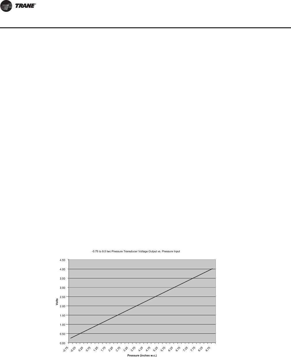
Space Pressure Transducer
An analog input device used on CV and VAV applications with the Statitrac option. It modulates the
exhaust dampers to keep the space pressure within the building to a customer designated
controlband. It is mounted in the filter section just above the exhaust damper actuator and is
Table 5. Transducer voltage output vs. pressure input w/ multiple sensors

RT-SVX28E-EN 15
General Information
connected to the ECEM. Field supplied pneumatic tubing must be connected between the space
being controlled and the transducer assembly.
Morning Warm-Up—Zone Heat
When a system changes from an unoccupied to an occupied mode, or switches from STOPPED to
AUTO, or power is applied to a unit with the MWU option, the heater in the unit or external heat
will be brought on if the space temperature is below the MWU setpoint. The heat will remain on
until the temperature reaches the MWU setpoint. If the unit is VAV, then the VAV box/unocc relay
will continue to stay in the unoccupied position and the VFD output will stay at 100% during the
MWU mode. When the MWU setpoint is reached and the heat mode is terminated, then the VAV
box/unocc relay will switch to the occupied mode and the VFD output will be controlled by the duct
static pressure. During Full Capacity MWU the economizer damper is held closed for as long as it
takes to reach setpoint. During Cycling Capacity MWU the economizer damper is allowed to go to
minimum position after one hour of operation if setpoint has not been reached.
Supply Air Temperature Low Limit
Uses the supply air temperature sensor input to modulate the economizer damper to minimum
position in the event the supply air temperature falls below the occupied heating setpoint
temperature.
Freezestat - Heating
A binary input device used on CV and VAV units with Hydronic Heat. It is mounted in the heat
section and connected to the Heat Module. If the temperature of the air entering the heating coil
falls to 40 F, the normally open contacts on the freezestat closes signalling the Heat Module and the
Rooftop Module (RTM) to:
1. drive the Hydronic Heat Actuator to the full open position
2. turn the supply fan "Off"
3. closes the outside air damper
4. turns "On" the SERVICE light at the Remote Panel
5. initiates a "Freezestat" diagnostic to the Human Interface
Freezestat - Cooling
A binary input device used on CV and VAV units with Chilled Water. The freezestat is mounted on
the upstream side of the cooling coil. If the temperature of the air entering the cooling coil falls to
40 F, the normally closed contacts on the freezestat open signalling the Rooftop Module (RTM) to:
1. drive the Chilled Water Actuator to the full open position
2. turn the supply fan "Off"
3. closes the outside air damper
4. turns "On" the SERVICE light at the Remote Panel
5. initiates a "Freezestat" diagnostic to the Human Interface
Chilled Water Valve Control
The 0 to 10 VDC output from the heat module doubles as the chilled water controller. The unit has
isolating relays to switch between heat and cool.
Constant Volume (CV) Units
Zone Temperature—Cooling
Relies on input from a sensor located directly in the space, while a system is in the occupied
"Cooling" mode. It modulates the economizer (if equipped) and/or stages the mechanical cooling
"On and Off" as required to maintain the zone temperature to within the cooling setpoint deadband.

16 RT-SVX28E-EN
General Information
Zone Temperature—Heating
Relies on input from a sensor located directly in the space, while a system is in the occupied
"Heating" mode or an unoccupied period, to stage the heat "on and off" or to modulate the heating
valve (hydronic heat only) as required to maintain the zone temperature to within the heating
setpoint deadband. The supply fan will be requested to operate any time there is a requested for
heat. On gas heat units, the fan will continue to run for 60 seconds after the furnace is turned off.
Supply Air Tempering
On CV units equipped with staged heat, if the supply air temperature falls 10 F below the occupied
heating setpoint temperature while the heater is "Off", the first stage of heat will be turned "On".
The heater is turned "Off" when the supply air temperature reaches 10º F above the occupied
heating setpoint temperature.
Variable Air Volume (VAV) Units
Occupied Heating—Supply Air Temperature
When a VAV unit is equipped with "Modulating Heat", and the system is in an occupied mode, and
the field supplied changeover relay contacts have closed, the supply air temperature will be
controlled to the customer specified supply air heating setpoint. It will remain in the heating status
until the changeover relay contacts are opened.
Occupied Cooling—Supply Air Temperature
When a VAV unit is in the occupied mode, the supply air temperature will be controlled to the
customer specified supply air cooling setpoint by modulating the economizer and/or staging the
mechanical cooling "On and Off" as required. The changeover relay contacts must be open on units
with "Modulating Heat" for the cooling to operate.
Daytime Warm-up
On VAV units equipped with heat, if the zone temperature falls below the daytime warm-up initiate
temperature during the occupied mode, the system will switch to full airflow. During this mode, the
VAV box/unocc relay will be energized (this is to signal the VAV boxes to go to 100%). After the VAV
box max stroke time has elapsed (factory set at 6 minutes), the VFD output will be set to 100%. The
airflow will be at 100% and the heat will be turned on to control to the occupied heating setpoint.
When the zone temperature reaches the daytime warm-up termination setpoint, the heat will be
turned off, the relay will be de-energized, releasing the VAV boxes, the VFD output will go back to
duct static pressure control and the unit will return to discharge air control. If the occ zone heating
setpoint is less than the DWU terminate setpoint, the heat will turn off when the occ zone heat
setpoint is reached, but it will stay in DWU mode and cycle the heat to maintain setpoint.
Unoccupied Heating—Zone Temperature
When a VAV unit is equipped with gas, electric, or hydronic heat and is in the unoccupied mode,
the zone temperature will be controlled to within the customer specified setpoint deadband. During
an unoccupied mode for a VAV unit, the VAV box/unocc relay will be in the unoccupied position and
the VFD output will be at 100%. This means that if there is a call for heat (or cool) and the supply
fan comes on, it will be at full airflow and the VAV boxes in the space will need to be 100% open
as signaled by the VAV box/unocc relay.Supply Air Tempering
On VAV units equipped with "Modulating Heat", if the supply air temperature falls 10 F below the
supply air temperature setpoint, the hydronic heat valve will modulate to maintain the supply air
temperature to within the low end of the setpoint deadband.
Supply Duct Static Pressure Control (Occupied)
The RTM relies on input from the duct pressure transducer when a unit is equipped with a Variable
Frequency Drive to position the supply fan speed to maintain the supply duct static pressure to
within the static pressure setpoint deadband. Refer to Figure 2, p. 17.
RT-SVX28E-EN 17
General Information
Single Zone Variable Air Volume (SZVAV) Only
The IntelliPak controls platform will support Single Zone VAV as an optional unit control type in
order to meet ASHRAE 90.1. The basic control will be a hybrid VAV/CV configured unit that provides
discharge temperature control to a varying discharge air temperature target setpoint based on the
space temperature and/or humidity conditions. Concurrently, the unit will control and optimize the
supply fan speed to maintain the zone temperature to a zone temperature setpoint.
Supply Fan Output Control
Units configured for Single Zone VAV control will utilize the same supply fan output control scheme
as on traditional VAV units except the VFD signal will be based on zone heating and cooling demand
instead of the supply air pressure.
VFD Control
Single Zone VAV units will be equipped with a VFD-controlled supply fan which will be controlled
via a 0-10VDC signal from the Rooftop Module (RTM). With the RTM supply fan output energized
and the RTM VFD output at 0VDC, the fan speed output is 37% (22Hz) from the VFD by default; and
at 10VDC the fan speed output is 100% (60Hz). The control scales the 0-10VDC VFD output from the
RTM linearly to control between the 37-100% range. The VFD will modulate the supply fan motor
speed, accelerating or decelerating as required to maintain the zone temperature to the zone
temperature setpoint. When subjected to high ambient return conditions the VFD will reduce its
output frequency to maintain operation. Bypass control is offered to provide full nominal airflow
in the event of drive failure.
Ventilation Control
Units configured for Single Zone VAV control will require special handling of the OA Damper
Minimum Position control in order to compensate for the non-linearity of airflow associated with
the variable supply fan speed and damper combinations. Units configured for TRAQ with or
without DCV will operate identically to traditional units with no control changes.
Space Pressure Control
For units configured with Space Pressure Control with or without Statitrac, the new schemes
implemented for economizer minimum position handling require changes to the existing Space
Pressure Control scheme in order to prevent over/under pressurization. The overall scheme will
remain very similar to VAV units with Space Pressure Control with the exception of the dynamic
Exhaust Enable Setpoint.
For SZVAV an Exhaust Enable Setpoint must be selected during the 100% Fan Speed Command.
Once selected, the difference between the Exhaust Enable Setpoint and Design OA Damper
Figure 2. Transducer voltage output vs. pressure input with multiple sensors
0.0
0.5
1.0
1.5
2.0
2.5
3.0
3.5
4.0
-0.5 0.0 0.5 1.0 1.5 2.0 2.5 3.0 3.5 4.0 4.5 5.0
Pressure (inches w.c.)
Volts

18 RT-SVX28E-EN
General Information
Minimum Position at 100% Fan Speed Command will be calculated. The difference calculated will
be used as an offset and added to the Active Building Design OA Minimum Position Target in order
to calculate the dynamic Exhaust Enable Target, which will be used throughout the Supply Fan
Speed/OA Damper Position range.
The Exhaust Enable Target could be above or below the Active Building Design OA Minimum
Position Target Setpoint, based on the Active Exhaust Enable Setpoint being set above or below
the Building Design Minimum Position at 100% Fan Speed Command. Note that an Exhaust Enable
Setpoint of 0% will result in the same effect on Exhaust Fan control as on VAV applications with and
without Statitrac.
Occupied Cooling Operation
For normal cooling operation, cooling capacity will be staged or modulated in order to meet the
calculated discharge air target setpoint. If the current active cooling capacity is controlling the
discharge air within the deadband, no additional cooling capacity change will be requested. As the
Discharge Air Temperature rises above the deadband, the algorithm will request additional
capacity as required (additional compressors or economizer). As the Discharge Air Temperature
falls below the deadband, the algorithm will request a reduction in active capacity.
Default Economizer Operation
By default, the unit will be setup to optimize the minimum supply fan speed capability during
Economizer Only operation. If the economizer is able to meet the demand alone, due to desirable
ambient conditions, the supply fan speed will be allowed to increase above the minimum prior to
utilizing mechanical cooling if discharge air setpoint falls below the discharge air Lower Limit
(Cooling) setpoint.
Unoccupied Mode
In Unoccupied mode the unit will utilize setback setpoints, 0% Minimum OA Damper position, and
Auto Fan Mode operation as on normal CV units. The Supply Fan speed, and cooling and
modulating types of heat, will be controlled to the discharge air target setpoint as is done during
occupied periods. The Supply fan speed during staged heat control will be forced to 100% as on
normal CV units.
Occupied Heating Operation
Occupied heating operation has two separate control sequences; staged and modulated. All staged
heating types will drive the supply fan to maximum flow and stage heating to control to the Zone
Heating Setpoint. For units with Hydronic and Gas heat, modulated SZVAV Heating. On an initial
call for heating, the supply fan will drive to the minimum heating airflow. On an additional call for
heating, the heat will control in order to meet the calculated discharge air target setpoint. As the
load in the zone continues to request heat operation, the supply fan will ramp-up while the control
maintains the heating discharge air temperature. Heating can be configured for either the energy
saving SZVAV Heating solution as described above, or the traditional, less efficient CV Heating
solution.
Compressor (DX) Cooling
Compressor control and protection schemes will function identical to that of a traditional unit.
Normal compressor proving and disable input monitoring will remain in effect as well as normal
3-minute minimum on, off, and inter-stage timers. Also, all existing head pressure control schemes
will be in effect.
Cooling Sequence
If the control determines that there is a need for active cooling capacity in order to meet the
calculated discharge air target setpoint, once supply fan proving has been made, the unit will begin
to stage compressors accordingly. Note that the compressor staging order will be based on unit
configuration and compressor lead/lag status.
RT-SVX28E-EN 19
General Information
Once the discharge air target setpoint calculation has reached the Minimum Setpoint and
compressors are being utilized to meet the demand, as the discharge air target setpoint value
continues to calculate lower the algorithm will begin to ramp the supply fan speed up toward 100%.
Note that the supply fan speed will remain at the compressor stage’s associated minimum value
(as described below) until the discharge air target setpoint value is calculated below the discharge
air temperature Minimum Setpoint (limited discharge air target setpoint).
As the cooling load in the zone decreases the zone cooling algorithm will reduce the speed of the
fan down to minimum per compressor stage and control the compressors accordingly. As the
compressors begin to de-energize, the supply fan speed will fall back to the Cooling Stage’s
associated minimum fan speed, but not below. As the load in the zone continues to drop, cooling
capacity will be reduced in order to maintain the discharge air within the ± ½ discharge air target
deadband.
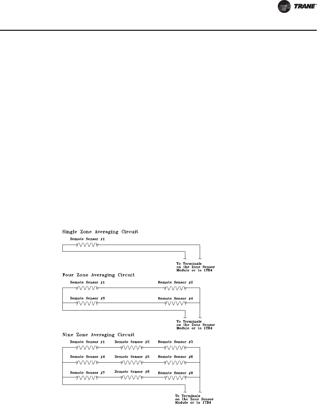
Space Temperature Averaging
Space temperature averaging for Constant Volume applications is accomplished by wiring a
number of remote sensors in a series/parallel circuit.
The fewest number of sensors required to accomplish space temperature averaging is four. The
Space Temperature Averaging with Multiple Sensors figure illustrates a single sensor circuit
(Single Zone), four sensors wired in a series/parallel circuit (Four Zone), nine sensors wired in a
series/parallel circuit (Nine Zone). Any number squared, is the number of remote sensors required.
Wiring termination will depend on the type of remote panel or control configuration for the system.
Refer to the wiring diagrams that shipped with the unit.
Table 6. Space temperature averaging with multiple sensors
20 RT-SVX28E-EN
General Information
Unit Control Modules
Unit control modules are microelectronic circuit boards designed to perform specific unit
functions. These modules, through proportional/integral control algorithms, provide the best
possible comfort level for the customer. They are mounted in the control panel and are factory
wired to their respective internal components. They receive and interpret information from other
unit modules, sensors, remote panels, and customer binary contacts to satisfy the applicable
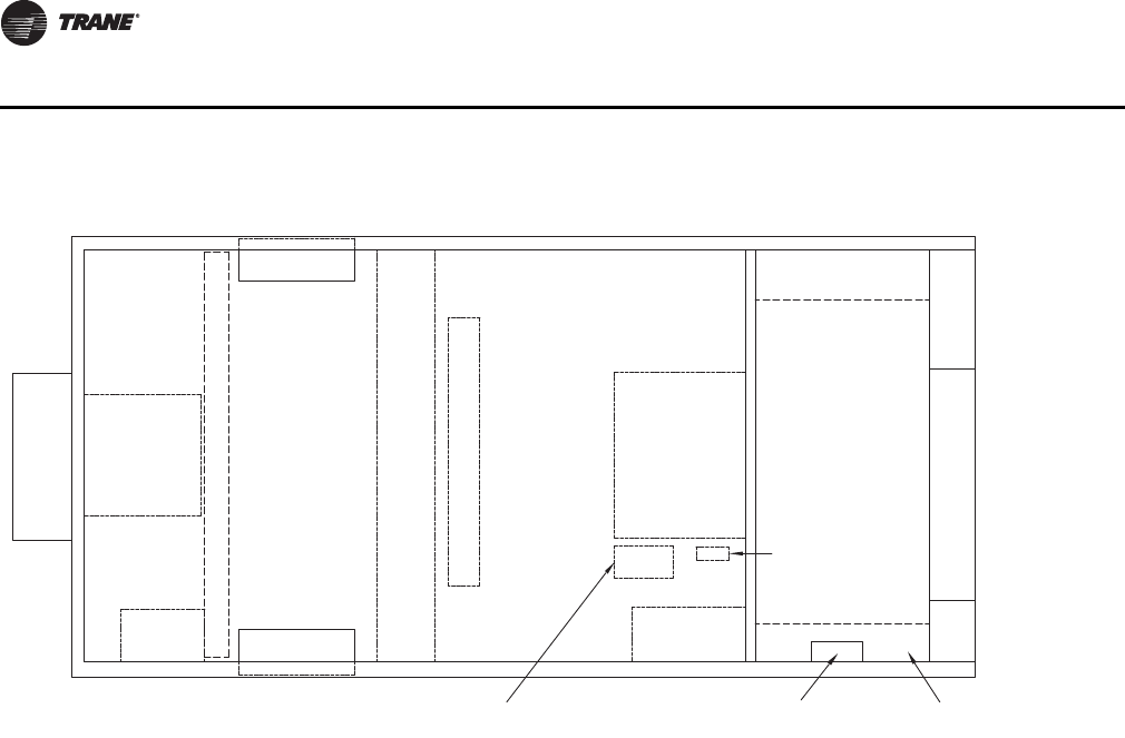
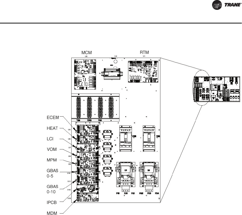
request for economizing, mechanical cooling, heating, and ventilation. Figure 3, p. 21 illustrates
the typical location of each designated module.
Table 7. Unit component layout and "ship with" locations
Return/
Exhaust
Fan
Fresh Air
Dampers
Supply Fan Heating
Section
Exhaust Damper
Hood
Variable
Frequency
Drive (VFD)
Filter Section
Chilled Water Coil
Fresh Air
Dampers
Return Air Dampers
Flue Vent
Access
Variable
Frquency
Drive (VFD)
Hot Water/Steam
Hydronic Connection
valves and actuator
Outside Air
Static Kit and
sensors
Baysens set
Controls
RT-SVX28E-EN 21
General Information
Figure 3. Control module locations
BCI
22 RT-SVX28E-EN
Dimensional Data
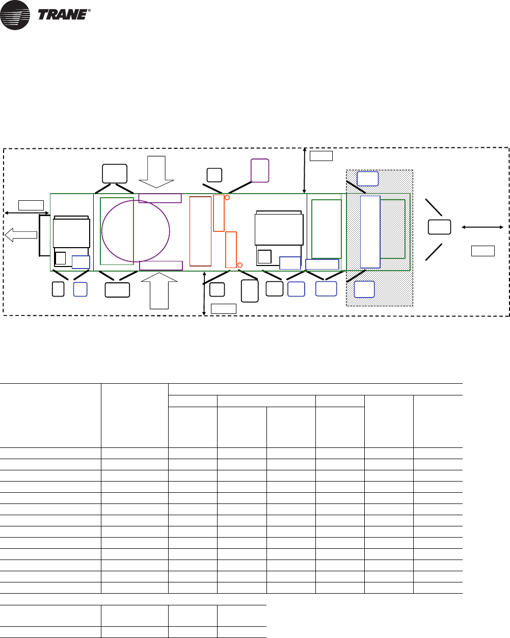
Unit Clearance
Figure 4. Minimum required clearance (i)
(i) Unit drawing is representative only and may not accurately depict all models.
Blank Section
Cool
Coil
(F)
Fltr
(F)
Sup
Mtr
Sup
VFD
Fltr
(R)
Cool
Coil
(R)
Heat
(L&R)
OptionStd
As Req. As Req.StdStd
Std
Rtn
Mtr
Rtn
VFD
As Req.
Std
ER Fltr
(L&R) (F)
Std
ER Fltr
(L&R) (R)
Std
Final
Filter
Fnl
Fltr (F)
As Req.
Fnl
Fltr (R)
As Req.
Filters
VFD Heat
VFD
Ctrl Box
(L&R)
Std
Exhaust
Fresh
Air
Fresh
Air
Exh
AH R
AH L
C Box
Table 8. Minimum required clearance
Unit Option Selection (Door Swing Ft. and In.)
Standard VFD Heat
Door Location Availability A,B,C
Return/
Exhaust Supply
Electric/
Hot
Water/
Steam
Two-side
Access Final Filter
Exhaust Motor Std 2' 2" * * * * *
Exhaust VFD As Req. * 2' 2" * * * *
Filter (Front) Std2' 8"*****
Filter (Rear) Option * * * * 2’ 2" *
Cooling Coil (Front) Std 2' 2" * * * * *
Cooling Coil (Rear) Std 2' 8" * * * * *
or Cooling Coil (Rear)Option******
Supply Motor Std2' 8"*****
Supply VFD As Req. * * 2' 2" * * *
Heat (Left & Right) As Req. * * * 2' 2" * *
Final Filter (Front) As Req. * * * * * 2' 2"
Final Filter (Rear) As Req. * * * * * 2' 2"
Control Box (L & R)Std3' 2"*****
Minimum Required Clearance (Ft.)
AH_L AH_R Exh
Control
Box
8’ 8’ 8’ 6’
RT-SVX28E-EN 23
Dimensional Data
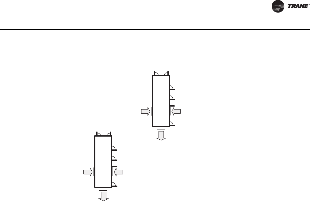
Important: Stagger units to minimize span deflection which deters sound transmission and to
maximize proper diffusion of the exhaust air before it reaches the adjacent unit fresh
air intake.
Figure 5. Multiple units placement
Outdoor
Air Intake
Outdoor
Air Intake
Exhaust
Air
Outdoor
Air Intake
Outdoor
Air Intake
Exhaust
Air
24 RT-SVX28E-EN
Dimensional Data
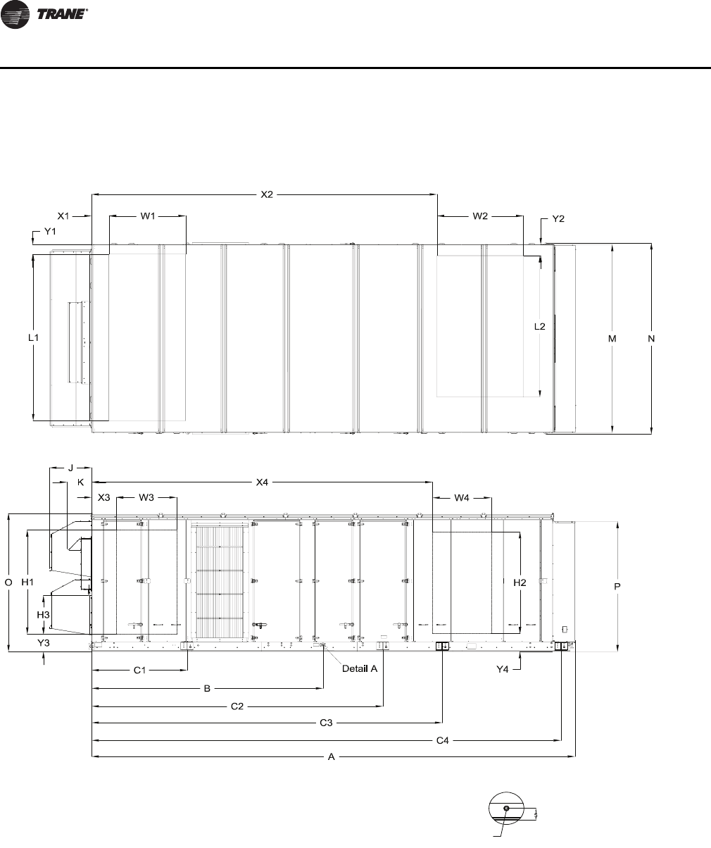
Unit Dimensions
Figure 6. Unit top/front view
1-1/4 NPT. DRAIN
2X TYP. LEFT & RIGHT SIDES OF UNIT
Detail A
RT-SVX28E-EN 25
Dimensional Data
Table 9. Unit dimensions (In.)
ONE-PIECE Dimensions
Lifting Lug Locations
Unit Dimensions Air Handler Side Unit Width
Casing
Blank
Section A B C1C2C3C4 M N
A, B, C
None 334 2/16 159 15/16 66 252 14/16 n/a n/a 139 13/16 143 8/16
4Ft 382 5/16 159 15/16 66 252 14/16 368 6/16 n/a 139 13/16 143 8/16
8Ft 430 9/16 159 15/16 66 252 14/16 416 10/16 n/a 139 13/16 143 8/16
Unit Height
Return
Fan
Exhaust
Fan
Casing O P J K
A, B, C
103 12/16 97 9/16 29 3/16 17
103 12/16 97 9/16 29 3/16 17
103 12/16 97 9/16 29 3/16 17
Table 10. Downflow/horizontal airflow configuration dimensions (in.)
DOWNFLOW Opening Dimensions
Return Opening—with or
without Exhaust Fan Return Opening—with Return Fan
Casing Gas Heat
Blank
SectionX1Y1W1L1X1Y1W1L1
A, B, C
No Gas None 14 13/16 8 14/16 48 3/16 121 15/16 14 13/16 42 14/16 48 3/16 53 14/16
No Gas 4Ft 14 13/16 8 14/16 48 3/16 121 15/16 14 13/16 42 14/16 48 3/16 53 14/16
No Gas 8Ft 14 13/16 8 14/16 48 3/16 121 15/16 14 13/16 42 14/16 48 3/16 53 14/16
Gas None 14 13/16 8 14/16 48 3/16 121 15/16 14 13/16 42 14/16 48 3/16 53 14/16
Gas 8Ft 14 13/16 8 14/16 48 3/16 121 15/16 14 13/16 42 14/16 48 3/16 53 14/16
DOWNFLOW Opening Dimensions
Supply Opening
Casing Gas Heat
Blank
Section X2 Y2 W2 L2
A, B, C
No Gas None 256 1/16 13 47 14/16 102 8/16
No Gas 4Ft 304 4/16 13 47 14/16 102 8/16
No Gas 8Ft 352 8/16 13 47 14/16 102 8/16
Gas None 256 1/16 13 47 14/16 102 8/16
Gas 8Ft 352 8/16 13 47 14/16 102 8/16
HORIZONTAL Opening Dimensions
Return Side Opening Return End Opening
Casing Gas Heat
Blank
SectionX3Y3W3H1X1Y3H3H1
A, B, C
No Gas None 9 5/16 10 10/16 54 12/16 84 15/16 6 5/16 8 3/16 35 3/16 127 2/16
No Gas 4Ft 9 5/16 10 10/16 54 12/16 84 15/16 6 5/16 8 3/16 35 3/16 127 2/16
No Gas 8Ft 9 5/16 10 10/16 54 12/16 84 15/16 6 5/16 8 3/16 35 3/16 127 2/16
Gas None 9 5/16 10 10/16 54 12/16 84 15/16 6 5/16 8 3/16 35 3/16 127 2/16
Gas 8Ft 9 5/16 10 10/16 54 12/16 84 15/16 6 5/16 8 3/16 35 3/16 127 2/16
26 RT-SVX28E-EN
Dimensional Data
HORIZONTAL Opening Dimensions
Supply Opening
Casing Gas Heat
Blank
Section X4 Y4 W4 H2
A, B, C
No Gas None 254 12/16 10 10/16 54 12/16 84 15/16
No Gas 4Ft 302 15/16 10 10/16 54 12/16 84 15/16
No Gas 8Ft 351 3/16 10 10/16 54 12/16 84 15/16
Gas None 254 12/16 10 10/16 54 12/16 66 11/16
Gas 8Ft 351 3/16 10 10/16 54 12/16 84 15/16
Table 10. Downflow/horizontal airflow configuration dimensions (in.)
Figure 7. Electrical entry details/bottom view
16
603
4
711
4
761
4
811
4
46 1
16
48 1
16
613
444
Ø35
8
Ø1 1
16
Ø7
8
65
16
55
16
Marine lights
customer supplied
power service
entrance Unit power
External customer
connection points
Outside edge of
base rail
515
8
5311
16
3111
16
Ø11
2
RT-SVX28E-EN 27
Dimensional Data
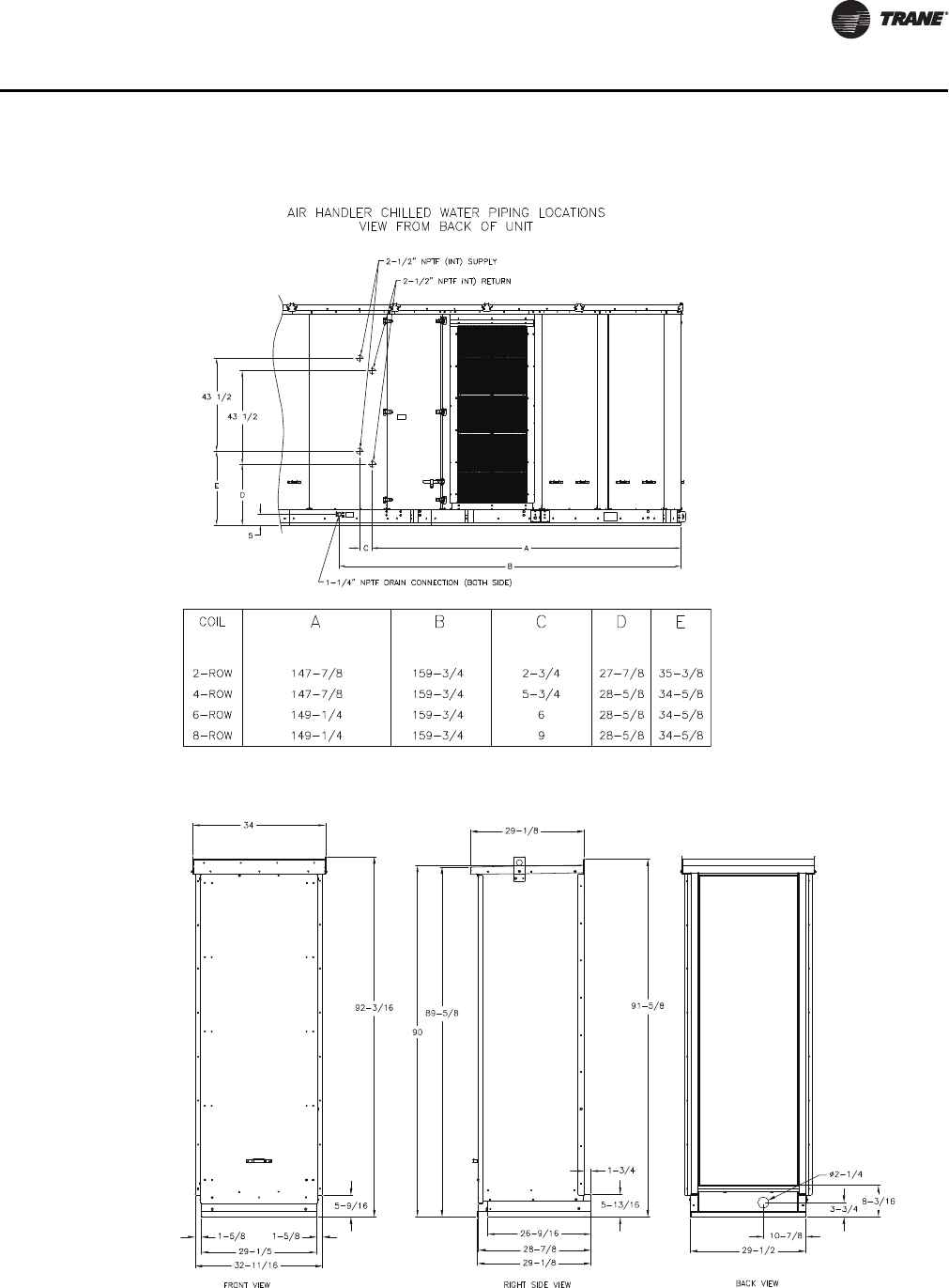
Figure 8. Chilled water piping locations
Figure 9. Piping enclosure
28 RT-SVX28E-EN
Pre-Installation
General Unit Requirements
The checklist below is a summary of the steps required to successfully install a commercial rooftop
air handler. This checklist is intended to acquaint the installing personnel with what is required in
the installation process. It does not replace the detailed instructions called out in the applicable
sections of this manual.
• Check the unit for shipping damage and material shortage; file a freight claim and notify Trane
office.
• Verify that the installation location of the unit will provide the required clearance for proper
operation.
• Assemble and install the roof curb. Refer to the current edition of the roof curb installer’s guide.
• Install and connect condensate drain lines to each cooling coil drain connection.
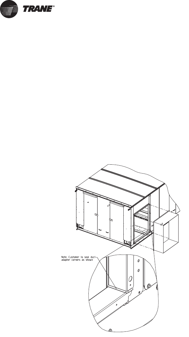
• Fabricate and install ductwork; secure ductwork to curb. Seal the corners of duct adapters as
shown in Figure 10. Ducting attached to the unit should be self supporting. Do not use the unit
to support the weight of the ducting
• Install pitch pocket for power supply through building roof. (If applicable)
Figure 10. Sealed ductwork

RT-SVX28E-EN 29
Pre-Installation
Rigging the Unit
• Set the unit onto the curb; check for levelness.
• Ensure unit-to-curb seal is tight and without buckles or cracks.
• Remove the shipping hold-down bolts and shipping channels from the supply and exhaust fans
with spring isolators.
• Check all supply and exhaust fan spring isolators for proper adjustment.
Main Electrical Power Requirements
• Verify that the power supply complies with the unit nameplate specifications.
• Inspect all control panel components; tighten any loose connections.
• Connect properly sized and protected power supply wiring to a field-supplied/installed
disconnect and unit
• Properly ground the unit.
• All field-installed wiring must comply with NEC and applicable local codes.
Field Installed Control Wiring
• Complete the field wiring connections for the constant volume controls as applicable. Refer to
"Field Installed Control Wiring" for guidelines.
• Complete the field wiring connections for the variable air volume controls as applicable. Refer
to "Field Installed Control Wiring" for guidelines.
Note: All field-installed wiring must comply with NEC and applicable local codes.
Requirements for Electric Heat Units
• Verify that the power supply complies with the electric heater specifications on the unit and
heater nameplate.
• Inspect the heater junction box and control panel; tighten any loose connections.
• Check electric heat circuits for continuity.
Requirement for Gas Heat
• Gas supply line properly sized and connected to the unit gas train.
• All gas piping joints properly sealed.
• Drip leg Installed in the gas piping near the unit.
• Gas piping leak checked with a soap solution. If piping connections to the unit are complete,
do not pressurize piping in excess of 0.50 psig or 14 inches w.c. to prevent component failure.
• Main supply gas pressure adequate.
• Flue Tubes clear of any obstructions.
• Factory-supplied flue assembly installed on the unit.
• Connect the 3/4" CPVC furnace drain stubout to a proper condensate drain.
Requirements for Hot Water Heat
• Route properly sized water piping through the base of the unit into the heating section.
• Install the factory-supplied, 3-way modulating valve.
• Complete the valve actuator wiring.
30 RT-SVX28E-EN
Pre-Installation
Requirements for Steam Heat
• Route properly sized steam piping through the base of the unit into the heating section.
• Install the factory-supplied, 2-way modulating valve
• Complete the valve actuator wiring.
• Install 1/2", 15-degree swing-check vacuum breaker(s) at the top of each coil section. Vent
breaker(s) to the atmosphere or merge with return main at discharge side of steam trap.
• Position the steam trap discharge at least 12" below the outlet connection on the coil.
• Use float and thermostatic traps in the system, as required by the application.
Requirements for Chilled Water Cooling
• Install and connect condensate drain lines to each cooling coil drain connection.
• Route properly sized water piping through the back of the unit.
• Install external piping enclosure.
• Install the factory-supplied, 3-way modulating valve.
• Complete the valve actuator wiring.
O/A Pressure Sensor and Tubing Installation (all units with Statitrac)
• O/A pressure sensor mounted to the roof bracket.
• Factory supplied pneumatic tubing installed between the O/A pressure sensor and the
connector on the vertical support.
• Field supplied pneumatic tubing connected to the proper fitting on the space pressure
transducer located in the filter section, and the other end routed to a suitable sensing location
within the controlled space.
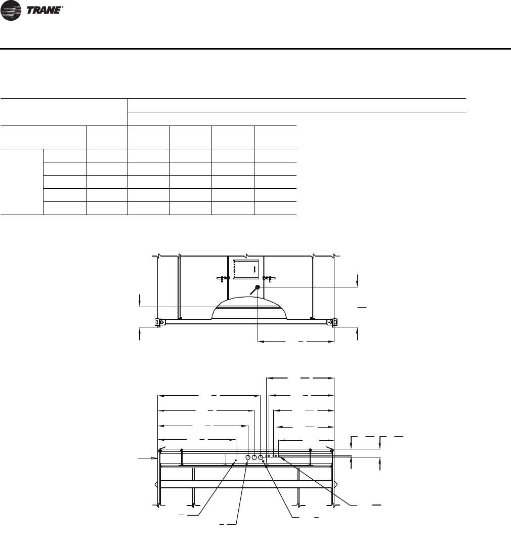
Condensate Drain Connections
Each unit provides two 1-1/4" cooling coil condensate drain connections on each side of the unit.
Due to the size of these units, all condensate drain connections must be connected to the cooling
coil drain connections. Refer to Detail A in Figure 6, p. 24 for the location of these drain connections.
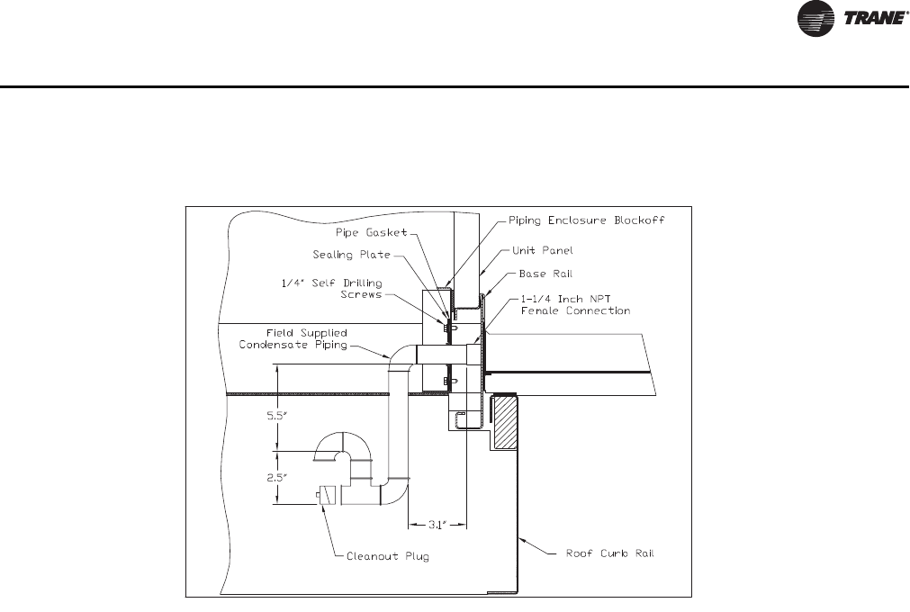
A condensate trap must be installed due to the drain connection being on the "negative pressure"
side of the fan. Install the P-Traps at the unit using the guidelines in Figure 11.
Figure 11. Condensate trap installation
Base rail
Cleanout Plug
1-1
4 Inch NPT
Female Connection
Field supplied
condensate piping
5.5"
2.5"
RT-SVX28E-EN 31
Pre-Installation
Pitch the drain lines at least 1/2 inch for every 10 feet of horizontal run to assure proper condensate
flow. Do not allow the horizontal run to sag causing a possible double-trap condition which could
result in condensate backup due to "air lock".
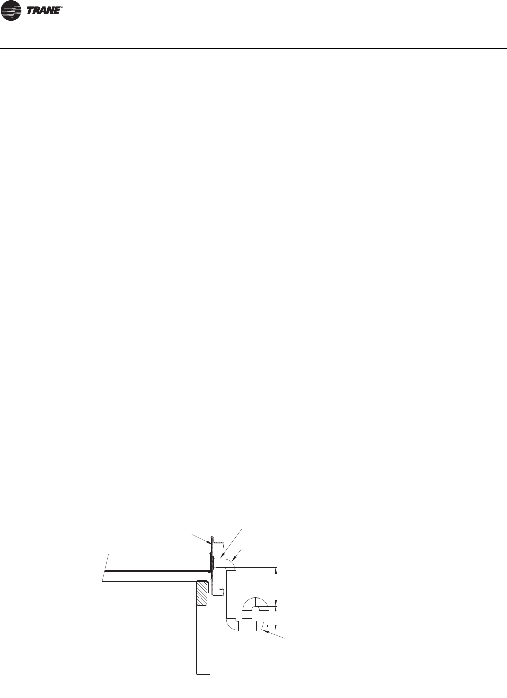
For units with an external piping enclosure, the condensate trap must be run through the external
piping enclosure on the rear side of the unit. Use Figure 12 as a guideline to install a P-Trap at the
back of the unit when an external piping enclosure is mounted around the condensate drain
connection.
Units with Gas Furnace
Units equipped with a gas furnace have a 3/4" CPVC drain connection stubbed out through the
vertical support in the gas heat section. It is extremely important that the condensate be piped to
a proper drain. Refer to the appropriate illustration in Figure 6, p. 24 for the location of the drain
connection.
Note: Units equipped with an optional modulating gas furnace will likely operate in a condensing
mode part of the time.
Ensure that all condensate drain line installations comply with applicable building and waste
disposal codes.
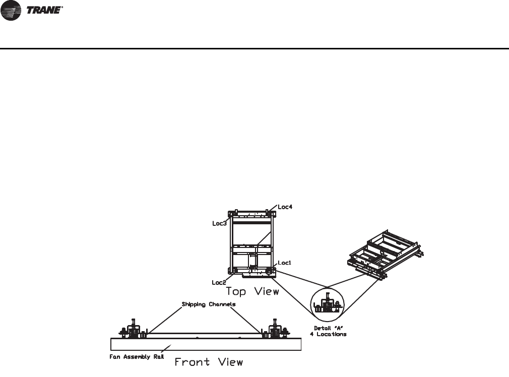
Removing Supply and Exhaust Fan Shipping Channels
Each supply fan assembly and exhaust fan assembly is equipped with spring isolators. Shipping
channels are installed beneath each fan assembly and must be removed. To locate and remove
these channels, refer to Figure 13, p. 32 and use the following procedures.
Spring Isolators
Spring isolators for the supply and/or exhaust fan are shipped with the isolator adjusting bolt
backed out. Field adjustment is required for proper operation. Figure 13, p. 32 shows isolator
locations. To adjust the spring isolators use the following procedure.
1. Remove and discard the shipping tie down bolts but leave the shipping channels in place during
the adjustment procedure. See Figure 13, p. 32.
Figure 12. Trap installation inside external piping enclosure
32 RT-SVX28E-EN
Pre-Installation
2. Tighten the leveling bolt on each isolator until the fan assembly is approximately 1/4" above
each shipping channel.
3. Secure the lock nut on each isolator.
4. Remove the shipping channels and discard.
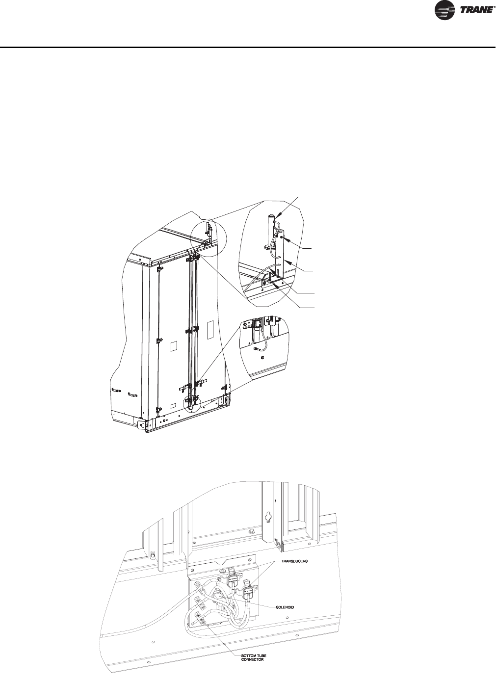
O/A Sensor and Tubing Installation
An Outside Air Pressure Sensor is shipped with all units designed to operate on variable air volume
applications or constant volume units with 100% modulating exhaust w/Stratitrac.
On VAV systems, a duct pressure transducer and the outside air sensor is used to control the
discharge duct static pressure to within a customer-specified parameter.
On CV & VAV units equipped with 100% modulating exhaust w/Stratitrac, a space pressure
transducer and the outside air sensor is used to control the exhaust fan and dampers to relieve
static pressure, to within a customer-specified parameter, within the controlled space. Refer to
Figure 14, p. 33 and the following steps to install the sensor and the pneumatic tubing.
1. Remove the O/A pressure sensor kit located inside the "ship with" item container. The kit
contains the following items:
a. O/A static pressure sensor with slotted mounting bracket
b. 50 ft. 0.188 in tubing
c. Mounting hardware
2. Remove the two roof cap screws and install the provided L mounting bracket as shown in the
figure.
3. Place the sensor mounting slotted bracket to the L mounting bracket with the slot located to the
top.
4. Install the sensor vertically to the slotted bracket and secure it with provided bolt and nut.
5. Connect one end of factory provided tubing to the top port of sensor and pass it through the
two slots in the mount and the other end to the port in the base.
6. Secure the tubing with the mounting hardware located in the ship with item container.
Figure 13. Removing fan assembly shipping hardware
RT-SVX28E-EN 33
Pre-Installation
Units with Statitrac
1. Open the filter access door, and locate the DSP control devices illustrated in Figure 15. There
are three tube connectors mounted on the left of the solenoid and transducers. Connect one
end of the field provided1/4" (length 50-100 ft.) or 3/8" (length greater than 100 ft.) O.D.
pneumatic tubing for the space pressurization control to the bottom fitting. Route the opposite
end of the tubing to a suitable location inside the building. This location should be the largest
open area that will not be affected by sudden static pressure changes.
Figure 14. Outside air sensing kit
Figure 15. DSP control device
Sensor
Sensor mounting
slotted bracket
0.188in OD tubing
L bracket
Sensor mounting
screws
34 RT-SVX28E-EN
Installation
Unit Weights
Notes:
1. Weights shown include the following features: standard coils, 0-25% Fresh Air, throwaway filters, low cfm supply fan,
minimum motor sizes, constant volume, 460 XL, No heat.
2. Weights shown represent approximate operating weights and have a + 5% accuracy. To calculate weight for a specific
unit configuration, utilize TOPSS or contact the local Trane sales representative. ACTUAL WEIGHTS ARE STAMPED ON THE
UNIT NAMEPLATE.
Table 11. Approximate operating weights (lbs.)
Nominal Tons Unit (Minimum)
Roof Curb
(Minimum)
A 8580 1066
B 8782 1066
C 8910 1066
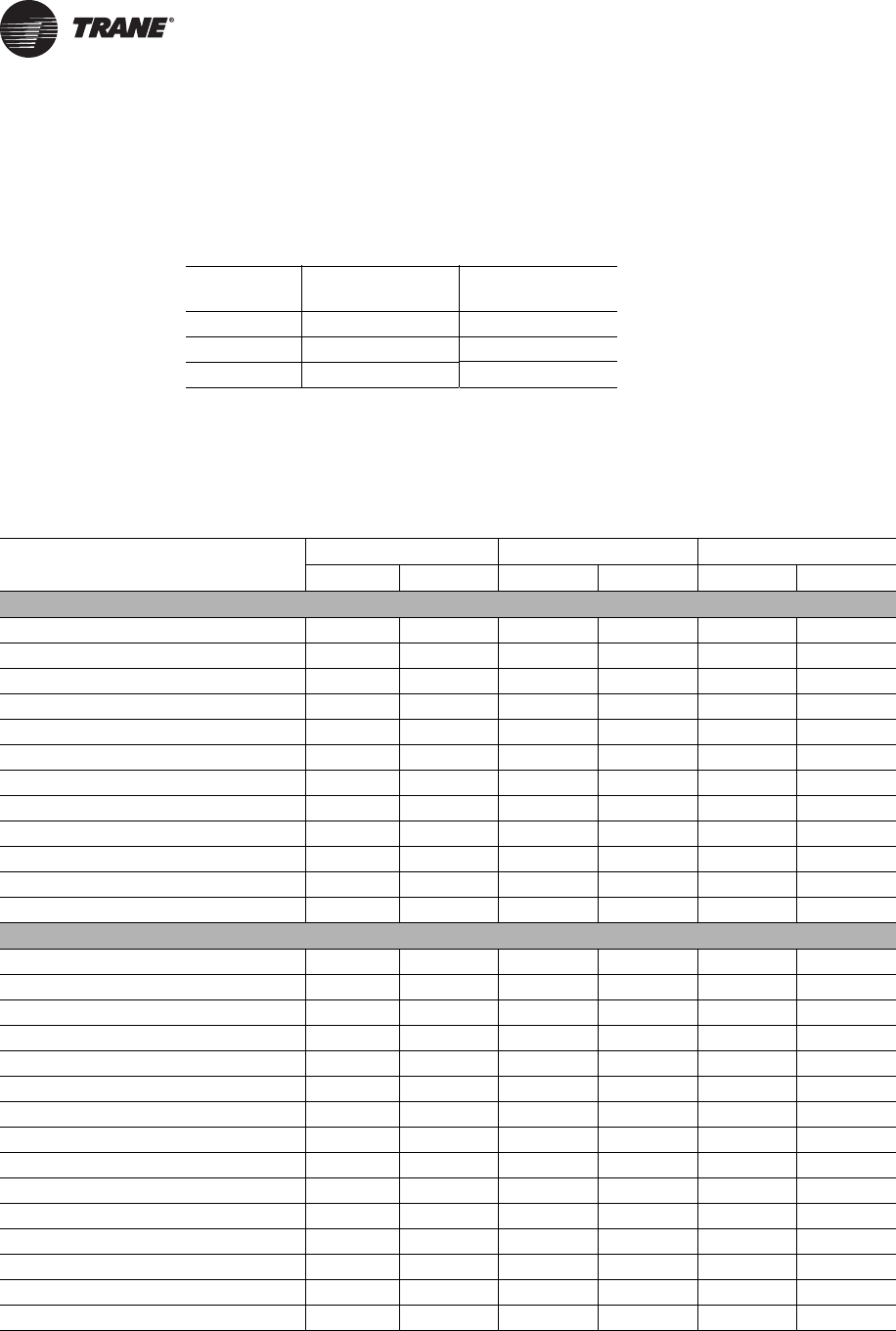
Table 12. Component weights (lbs.)
AB C
Size Wt (lbs.) Size Wt (lbs.) Size Wt (lbs.)
Supply Fan Assembly
Supply Fan & FanBoard Assy. 25" 1226 32" 1419 36" 1530
Belt Guard 116 116 116
Supply VFD (50 HP and below) 233 233 233
Supply VFD (60 thru 75 HP) 284 284 284
Supply-Exh Fan Motor - 15 HP 181 181 181
Supply-Exh Fan Motor - 20 HP 206 206 206
Supply-Exh Fan Motor - 25 HP 358 358 358
Supply-Exh Fan Motor - 30 HP 413 413 413
Supply-Exh Fan Motor - 40 HP 495 495 495
Supply-Exh Fan Motor - 50 HP 604 604 604
Supply-Exh Fan Motor - 60 HP - 776 776
Supply-Exh Fan Motor - 75 HP - - 879
Return/Exhaust Fan Assembly
Return Fan & Dampers 36" 2284 40" 2333 40" 2333
Exhaust Fan & Dampers - Low CFM 25" 879 25" 879 28" 963
Exhaust Fan & Dampers - Std CFM - - 28" 963 32" 1417
Belt Guard 119 119 119
Exhaust VFD (50 HP and below) 244 244 244
Exhaust VFD (60 HP) 295 295 295
Exh Fan Motor - 7.5 HP 160 160 -
Exh Fan Motor - 10 HP 181 181 181
Exh Fan Motor - 15 HP 206 206 206
Exh Fan Motor - 20 HP 206 206 206
Exh Fan Motor - 25 HP 358 358 358
Exh Fan Motor - 30 HP - 413 413
Exh Fan Motor - 40 HP - 495 495
Exh Fan Motor - 50 HP - 604 604
Exh Fan Motor - 60 HP - - 776
RT-SVX28E-EN 35
Installation
AB C
Size Wt (lbs.) Size Wt (lbs.) Size Wt (lbs.)
Chilled Water Assy.
2 Row 5W Chilled Water Coil - 80 FPF 992 992 992
2 Row 5W Chilled Water Coil - 108 FPF 1042 1042 1042
2 Row 5W Chilled Water Coil - 144 FPF 1106 1106 1106
2 Row 5W Chilled Water Coil - 168 FPF 1148 1148 1148
4 Row W Chilled Water Coil - 80 FPF 1523 1523 1523
4 Row W Chilled Water Coil - 108 FPF 1622 1622 1622
4 Row W Chilled Water Coil - 144 FPF 1750 1750 1750
4 Row W Chilled Water Coil - 168 FPF 1835 1835 1835
6 Row WD Chilled Water Coil - 80 FPF 2046 2046 2046
6 Row WD Chilled Water Coil - 108 FPF 2195 2195 2195
6 Row WD Chilled Water Coil - 144 FPF 2387 2387 2387
6 Row WD Chilled Water Coil - 168 FPF 2515 2515 2515
8 Row WD Chilled Water Coil - 80 FPF 2643 2643 2643
8 Row WD Chilled Water Coil - 108 FPF 2842 2842 2842
8 Row WD Chilled Water Coil - 144 FPF 3098 3098 3098
8 Row WD Chilled Water Coil - 168 FPF 3268 3268 3268
External Piping Cabinet
External Piping Cabinet - Shipping 353 353 353
External Piping Cabinet - Operation 268 268 268
Gas/Electric Heat
Gas Heat Low 0.85M 690 0.85M 690 0.85M 690
Gas Heat Med 1.1M 840 1.1M 840 1.1M 840
Gas Heat High 1.8M 1150 1.8M 1150 1.8M 1150
Electric Heat 485 485 485
Hydronic Heat
Steam Heat Low 946 946 946
Steam Heat High 1014 1014 1014
Hot Water Heat Low 1080 1080 1080
Hot Water Heat High 1125 1125 1125
Filters
Filter Rack - Throwaway Filters 181 181 181
Filter Rack - Bag Filters 395 395 395
Filter Rack - Cartridge Filters 662 662 662
Final Filters - Bag Filters 392 392 392
Final Filters - Cartridge Filters w/ 2" pre-filter 607 607 607
Final Filters - Cartridge Filters w/ 4" pre-filter 638 638 638
Final Filters - High Temp. Cartridge 669 669 669
Final Filters - HEPA 1777 1777 1777
Final Filters - HEPA High Temp. 1839 1839 1839
Table 12. Component weights (lbs.) (continued)
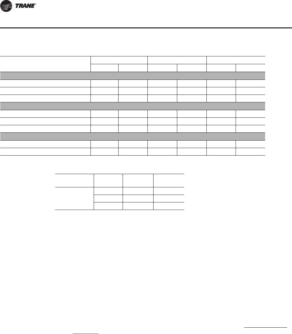
36 RT-SVX28E-EN
Installation
Roof Curb and Ductwork
The roof curb for air handler units consist of two main components; a "full perimeter" enclosure
to support the unit air handler section and an add on substructure to support the external piping
enclosure when the chilled water option is selected.
Before installing any roof curb, verify;
1. That it is the correct curb for the unit,
2. That it includes the necessary gaskets and hardware
3. That the purposed installation location provides the required clearance for proper operation.
Insure that the curb is level and square. The top surface of the curb must be true to assure an
adequate curb-to-unit seal.
Step-by-step curb assembly and installation instructions ship with each Trane accessory roof curb
kit. Follow the instructions carefully to assure proper fit-up when the unit is set into place.
Note: To assure proper condensate flow during operation, the unit (and curb) must be as level as
possible. The maximum slope allowable for rooftop unit applications, excluding Steam
Heat Units, is 4" end-to-end and 2" side-to-side. Units with steam coils must be set level!
If the unit is elevated, a field constructed catwalk around the unit is strongly recommended to
provide easy access for unit maintenance and service.
Recommendations for installing the Supply Air and Return Air ductwork joining the roof curb are
included in the curb instruction booklet. Curb ductwork must be fabricated and installed by the
installing contractor before the unit is set into place.
Note: For sound consideration, cut only the holes in the roof deck for the ductwork penetrations.
Do not cut out the entire roof deck within the curb perimeter.
AB C
Size Wt (lbs.) Size Wt (lbs.) Size Wt (lbs.)
Fresh Air
0-25% Damper 611 611 611
Econ 759 759 759
Econ w/ Air Measure 715 715 715
Cabinet
Cabinet 5971 5971 5971
Cabinet - 4' Blank Section 846 846 846
Cabinet - 8' Blank Section 1650 1650 1650
Control Box - Main
Control Box - Main 454 454 454
Convenience Outlet 36 36 36
Table 12. Component weights (lbs.) (continued)
Table 13. Roof curb weights
Casing Blank
Installed
Weight
Shipping
Weight
A, B, C
None 1066 1334
4 Ft 1147 1415
8 Ft 1228 1497
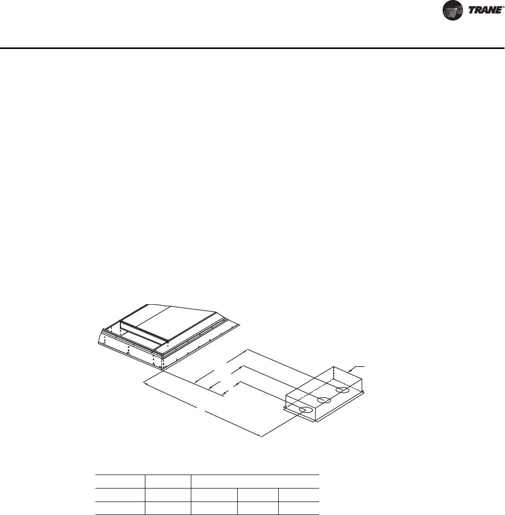
RT-SVX28E-EN 37
Installation
Pitch Pocket Location
The location of the main supply power entry is located at the bottom right-hand corner of the
control panel. Figure 16 illustrates the location for the electrical entrance through the base in
order to enter the control panel. If the power supply conduit penetrates the building roof beneath
this opening, it is recommended that a pitch pocket be installed before the unit is placed onto the
roof curb.
The center line dimensions shown in the illustration below indicates the center line of the electrical
access hole in the unit base when it is positioned on the curb, ±3/8 inch. The actual diameter of the
hole in the roof should be at least 1/2 inch larger than the diameter of the conduit penetrating the
roof. This will allow for the clearance variable between the roof curb rail and the unit base rail
illustrated in Figure 16.
The pitch pocket dimensions listed are recommended to enhance the application of roofing pitch
after the unit is set into place. The pitch pocket may need to be shifted as illustrated to prevent
interference with the curb pedestal.
If a Trane Curb Accessory Kit is not used
If a Trane Curb Accessory Kit is not used:
1. The ductwork can be attached directly to the unit bottom, around the unit supply and return air
openings. Be sure to use flexible duct connections at the unit. The customer is responsible for
sealing the bottom of the external piping enclosure when the unit contains the chilled water
option.
2. For "built-up" curbs supplied by others, gaskets must be installed around the unit, external
piping enclosure curb, and the supply and return air opening perimeters. The customer is
responsible for sealing the bottom of the external piping enclosure when the unit contains the
chilled water option.
3. Units that come with external piping enclosures must be mounted on a roof curb.
Figure 16. Pitch pocket location
Table 14. Pitch pocket dimensions (in.)
Tonnages A1 B1 B2 B3
Casings A-C 9.52 68.875 73.875 78.875
B1
B2
B3
A1
Pitch Pocket
Roof Curb
1Pc
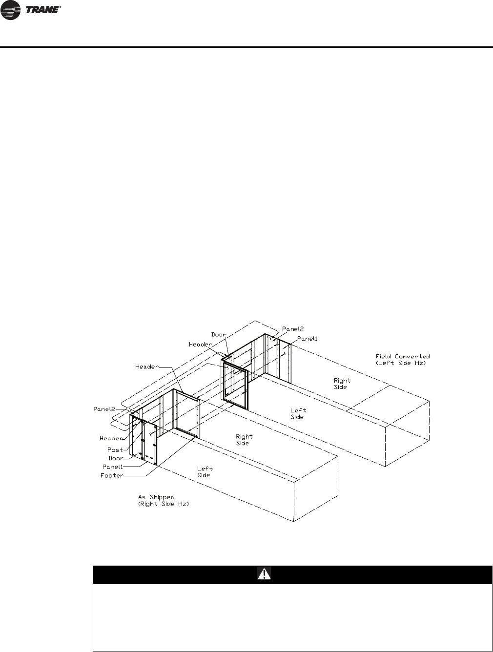
38 RT-SVX28E-EN
Installation
Notes:
•If a "built-up" curb is provided by others, keep in mind that external piping enclosure roof curbs
must have a notch for the air handler unit base rail.
•If a "built-up" curb is provided by others, it should NOT be made of wood.
•If this is a REPLACEMENT UNIT keep in mind that the CURRENT DESIGN rooftop air handler
units with chilled water require an add-on roof curb for the external piping enclosure.
Field Converting Horizontal Ductwork from Right to the Left Side
To field convert horizontal ductwork from one side to the other, follow this procedure:
1. Remove the door and door header from the left side.
2. Remove Panel 2.
3. Remove Post and Panel 1.
4. Place door and door header removed from the left side in the empty location on the end wall.
5. Remove the horizontal duct header, footer, and side flange kits and install them at the empty
left side.
6. Finally place Panel 2, Post, and Panel 1 at the empty spot on the right horizontal side to complete
the field conversion.
Unit Rigging and Placement
1. To configure the unit center-of-gravity, utilize TOPPS or contact the local Trane sales office.
Figure 17. Ductwork conversion
WARNING
Heavy Objects!
Do not use cables (chains or slings) except as shown. Each of the cables (chains or slings) used
to lift the unit must be capable of supporting the entire weight of the unit. Lifting cables
(chains or slings) may not be of the same length. Adjust as necessary for even unit lift. Other
lifting arrangements may cause equipment or property-only damage. Failure to properly lift
unit could result in death or serious injury. See details below.
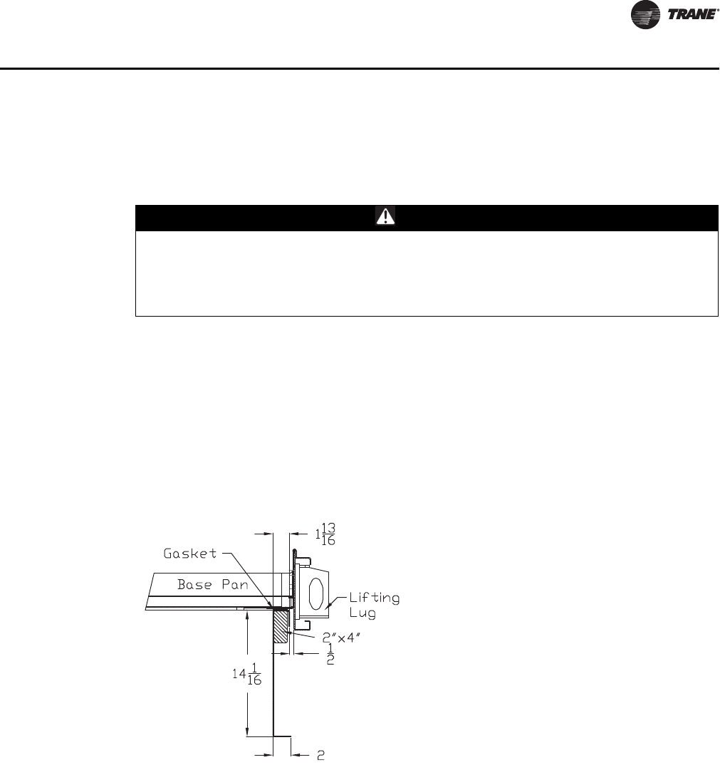
RT-SVX28E-EN 39
Installation
2. Attach adequate strength lifting slings to all lifting lugs. The minimum distance between the
lifting hook and the top of the unit should be 12 feet. Figure 19, p. 40, Figure 20, p. 40, and
Figure 21, p. 41 illustrate the installation of spreader bars to protect the unit and to facilitate a
uniform lift. Tab le 1, p. 10 lists typical approximate minimal unit operating weights. To
determine additional component weight, see Table 2, p. 10
3. Test lift the unit to ensure it is properly rigged and balanced, make any necessary rigging
adjustments.
4. Lift the unit and position it over the curb and pedestal. (These units have a continuous base rail
around the air handler section which matches the curb.
5. Align the base rail of the unit air handler section with the curb rail while lowering the unit onto
the curb. Make sure that the gasket on the curb is not damaged while positioning the unit. (The
pedestal simply supports the unit condenser section)
A cross section of the juncture between the unit and the roof curb is shown in Figure 18, p. 39.
WARNING
Improper Unit Lift!
Test lift unit approximately 24 inches to verify proper center of gravity lift point. To avoid
dropping of unit, reposition lifting point if unit is not level. Failure to properly lift unit could
result in unit dropping and possibly crushing operator/technician which could result in death
or serious injury and possible equipment or property-only damage.
Figure 18. Curb cross section
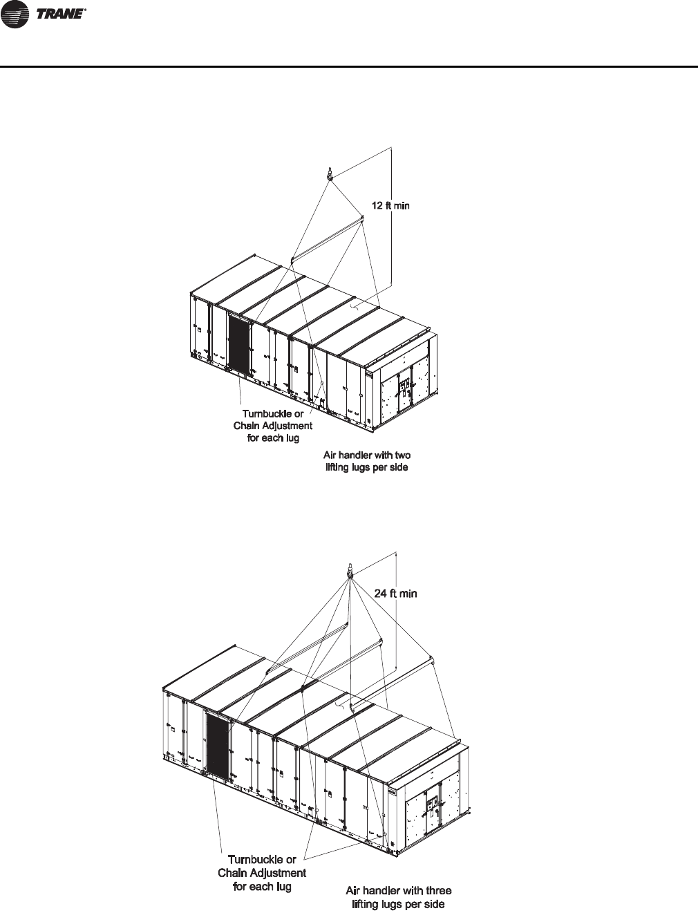
40 RT-SVX28E-EN
Installation
Note: Turnbuckle or Chain Adjustment required for each lifting point.
Note: Turnbuckle or Chain Adjustment required for each lifting point.
Figure 19. Typical unit rigging—air handler with two lifting lugs per side
Figure 20. Typical unit rigging—air handler with three lifting lugs per side
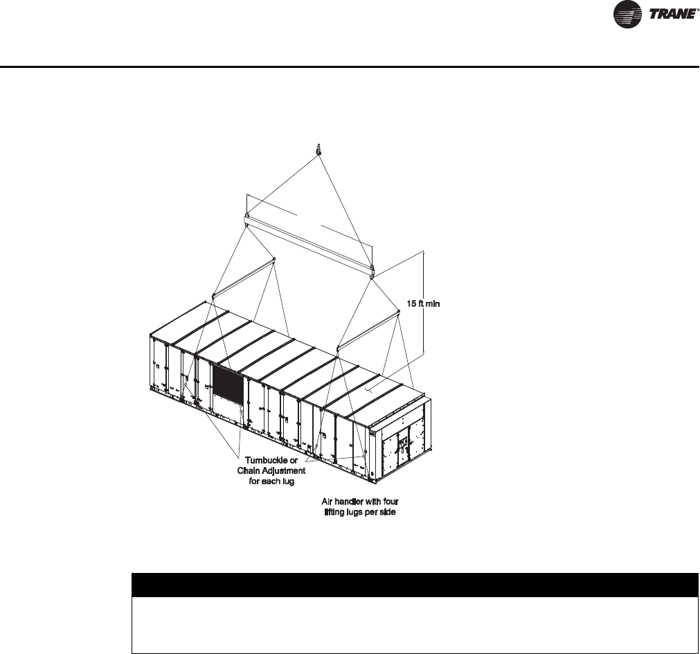
RT-SVX28E-EN 41
Installation
Lifting the External Piping Enclosure
1. Detach external piping enclosure from shipping skid as shown in Figure 22.
2. Attach the cables, chains or straps to lifting lugs Figure 23, p. 45.
Note: Rigging and spreader bars not furnished by Trane.
Figure 21. Typical unit rigging—air handler with four lifting lugs per side
20 ft min
NOTICE:
Lifting Damage!
Do not attach the external piping enclosure to the unit prior to lifting the unit. Doing so could
damage the air handler or piping enclosure.
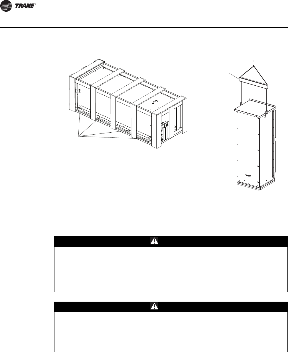
42 RT-SVX28E-EN
Installation
Gas Heat Units
All internal gas piping is factory-installed and pressure leak-tested before shipment. Once the unit
is set into place, the gas supply line must be field-connected to the elbow located inside the gas
heat control compartments.
Access holes are provided on the unit as illustrated in Figure 25, p. 47 to accommodate a side or
bottom pipe entry. Following the guidelines listed below will enhance both the installation and
operation of the furnace.
Note: In the absence of local codes, the installation must conform with the American National
Standard Z223-1a of the National Fuel Gas Code, (latest edition).
Figure 22. External piping enclosure crate
Crate Attachment
Points
Rigging and spreader
bar not furnished by
Trane
WARNING
Hazardous Gases and Flammable Vapors!
Exposure to hazardous gases from fuel substances have been shown to cause cancer, birth
defects or other reproductive harm. Improper installation, adjustment, alteration, service or
use of this product could cause flammable mixtures or lead to excessive carbon monoxide. To
avoid hazardous gases and flammable vapors follow proper installation and set up of this
product and all warnings as provided in this manual. Failure to follow all instructions could
result in death or serious injury.
WARNING
Hazardous Pressures!
When using dry nitrogen cylinders for pressurizing units for leak testing, always provide a
pressure regulator on the cylinder to prevent excessively high unit pressures. Never pressurize
unit above the maximum recommended unit test pressure as specified in applicable unit
literature. Failure to properly regulate pressure could result in a violent explosion, which could
result in death or serious injury or equipment or property-only-damage.
RT-SVX28E-EN 43
Installation
1. To assure sufficient gas pressure at the unit, use Table 15, p. 44 as a guide to determine the
appropriate gas pipe size for the unit heating capacity listed on the unit nameplate.
2. If a gas line already exists, verify that it is sized large enough to handle the additional furnace
capacity before connecting to it.
3. Take all branch piping from any main gas line from the top at 90 degrees or at 45 degrees to
prevent moisture from being drawn in with the gas.
4. Ensure that all piping connections are adequately coated with joint sealant and properly
tightened. Use a piping compound that is resistant to liquid petroleum gases.
5. Provide a drip leg near the unit.
6. Install a pressure regulator at the unit that is adequate to maintain 7" w.c. for natural gas while
the furnace is operating at full capacity.
If a single pressure regulator serves more than one air handler unit, it must be sized to ensure that
the inlet gas pressure does not fall below 7" w.c. with all the furnaces operating at full capacity. The
gas pressure must not exceed 14" w.c. when the furnaces are off.
7. Provide adequate support for all field installed gas piping to avoid stressing the gas train and
controls.
8. Leak test the gas supply line using a soap-and-water solution or equivalent before connecting
it to the gas train.
9. Check the supply pressure before connecting it to the unit to prevent possible gas valve damage
and the unsafe operating conditions that will result.
Important: Do not rely on the gas train shutoff valves to isolate the unit while conducting gas
pressure/leak test. These valves are not designed to withstand pressures in excess
of 14" w.c. or 0.5 psig.
Connecting the Gas Supply Line to the Furnace Gas train
Follow the steps below to complete the installation between the supply gas line and the furnace.
Refer to Figure 23, p. 45, and Figure 24, p. 45 for the appropriate gas train configuration.
1. Connect the supply gas piping using a "ground-joint" type union to the furnace gas train and
check for leaks.
2. Adjust the inlet supply pressure to the recommended 7" to 14" w.c. parameter for natural gas
3. Ensure that the piping is adequately supported to avoid gas train stress.
4. If the through the base gas opening is used, seal off around the pipe and the 3" water dam. If
the through the base gas opening is not used, the 3" opening should be sealed shut to prevent
indoor air leakage.
NOTICE:
Gas Valve and Gas Train Damage!
• Gas pressure in excess of 14" w.c. or 0.5 psig will damage the gas train.
• Failure to use a pressure regulating device will result in incorrect gas pressure. This can cause
erratic operation due to gas pressure fluctuations as well as damage the gas valve.
• Over sizing the regulator will cause irregular pulsating flame patterns, burner rumble,
potential flame outages, and possible gas valve damage.
44 RT-SVX28E-EN
Installation
Table 15. Sizing natural gas pipe mains and branches
Gas Supply
Pipe Run (ft)
Gas Input (Cubic Feet/Hour)*
1-1/4"
Pipe
1-1/2"
Pipe
2"
Pipe
2-1/2"
Pipe
3"
Pipe
4"
Pipe
10 1050 1600 3050 4800 8500 17500
20 730 1100 2100 3300 5900 12000
30 590 890 1650 2700 4700 9700
40 500 760 1450 2300 4100 8300
50 440 670 1270 2000 3600 7400
60 400 610 1150 1850 3250 6800
70 370 560 1050 1700 3000 6200
80 350 530 990 1600 2800 5800
90 320 490 930 1500 2600 5400
100 305 460 870 1400 2500 5100
125 275 410 780 1250 2200 4500
150 250 380 710 1130 2000 4100
175 225 350 650 1050 1850 3800
200 210 320 610 980 1700 3500
*Table is based on a specific gravity of 0.60. Use Ta b l e 1 6 for the specific gravity of the local gas supply.
Notes:
1. If more than one unit is served by the same main gas supply, consider the total gas input (cubic feet/hr.) and the total
length when determining the appropriate gas pipe size.
2. Obtain the Specific Gravity and BTU/Cu.Ft. from the gas company.
3. The following example demonstrates the considerations necessary when determining the actual pipe size:
Example: A 40' pipe run is needed to connect a unit with a 850 MBH furnace to a natural gas supply having a rating of
1,000 BTU/Cu.Ft. and a specific gravity of 0.60
Cu.Ft/Hour = Furnace MBH Input
Gas BTU/Cu.Ft. X Multiplier Ta bl e 1 6
Cu.Ft/Hour = 850
This table indicates that a 2" pipe is required.
Table 16. Specific gravity multipliers
Specific Gravity Multiplier
0.50 1.10
0.55 1.04
0.60 1.00
0.65 0.96
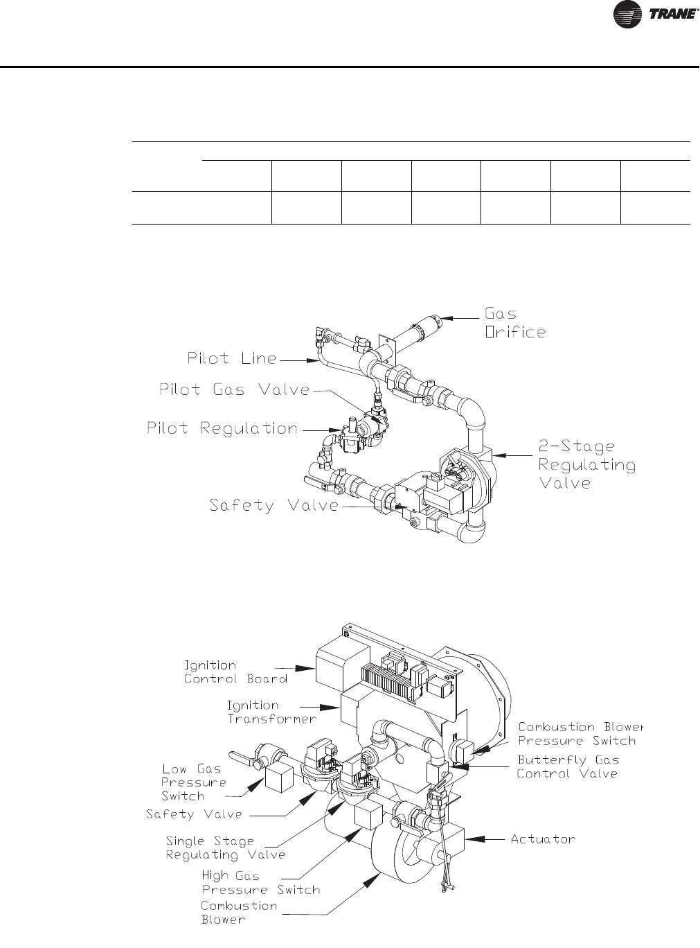
RT-SVX28E-EN 45
Installation
Table 17. Gas heating capacity altitude correction factors
Altitude (Ft.)
Sea Level
To 2000
2001 to
2500
2501 to
3500
3501 to
4500
4501 to
5500
5501 to
6500
6501 to
7500
Capacity
Multiplier 1.00 .92 .88 .84 .80 .76 .72
Note: Correction factors are per AGA Std. 221.30 - 1964, Part VI, 6.12. Local codes may supersede.
Figure 23. Two-Stage natural gas train
Figure 24. Modulating natural gas train
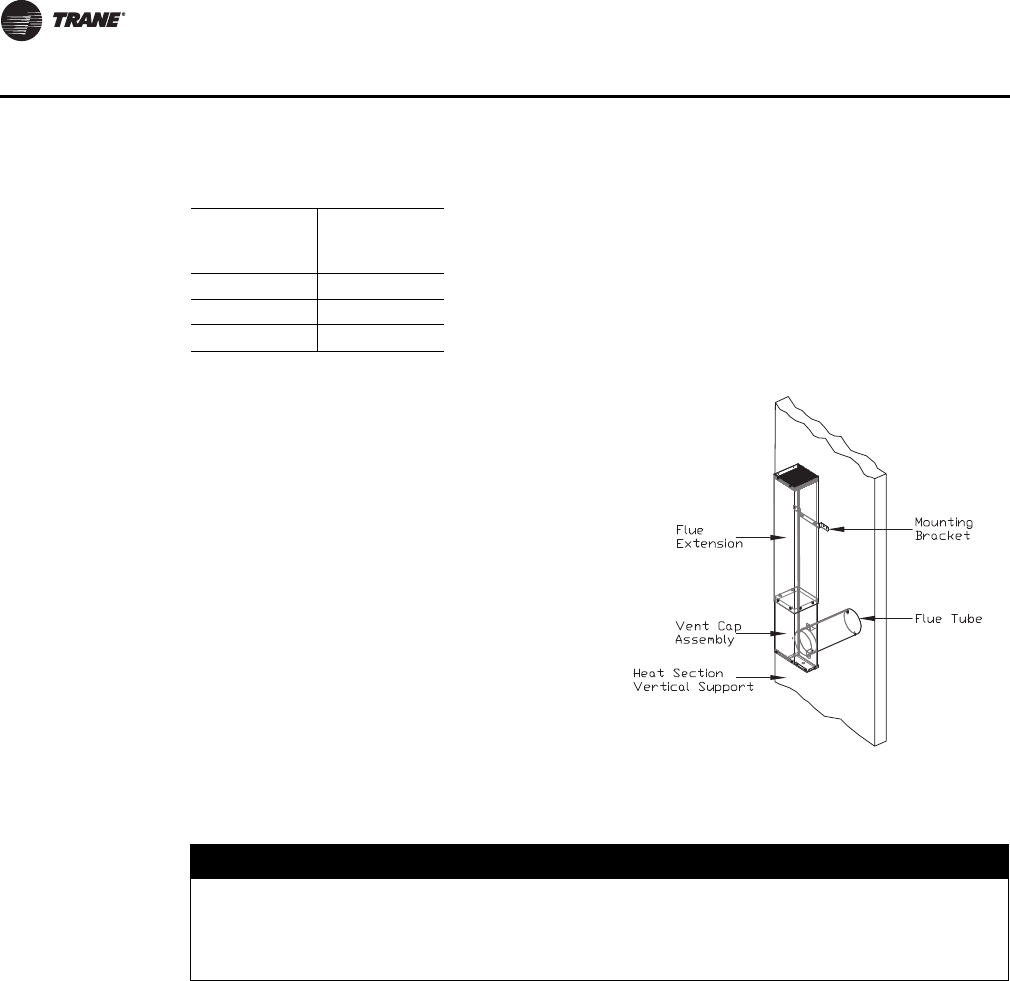
46 RT-SVX28E-EN
Installation
6. Using the pre-punch hole in the flue assembly, extension, and the vertical support, install the
appropriate number of mounting brackets (Refer to the installation instructions that ship with
the flue assembly.)
Table 18. Gas heat inlet sizes
Standard Gas
Heat Input
(MBh)
Gas Heat Inlet
Sizes (in.)
850 1
1100 1 1/4
1800 1 1/2
Flue Assembly Installation
1. Locate the collapsed flue assembly in the
compartment above the gas heat controls by
removing the panel screws. The assembly is
secured by screws up through the roof of the
gas controls compartment roof.
2. Separate the pieces of the collapsed
assembly.
3. Then assemble the stack as shown in
Figure 26.
4. Insert the tube on the flue assembly into the
hole located in the vertical support for the
heat section.
5. Butt both tube sections together and center
the pipe clamp over joint.
NOTICE:
Equipment Damage!
Properly seal all penetrations in unit casing. Failure to seal penetrations from inner panel to
outer panel may result in unconditioned air entering the module, and water infiltrating the
insulation, resulting in equipment damage.
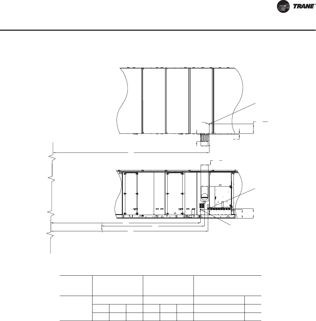
RT-SVX28E-EN 47
Installation
Hot Water Heat Units
Hot water heating coils are factory installed inside the heater section of the unit. Once the unit is
set into place, the hot water piping and the factory provided three way modulating valve must be
installed. The valve can be installed inside the heat section or near the unit. If the valve is installed
in a remote location, use field supplied wiring to extend the control wires from the heater section
to the valve. Two access holes are provided in the unit base as illustrated in Figure 26, p. 51.
Following the guidelines listed below will enhance both the installation and operation of the "wet
heat" system.
Figure 27, p. 51 illustrates the recommended piping configuration for the hot water coil. Table 20
on page 50 lists the coil connection sizes.
Important: The valve actuators are not waterproof. Failure to protect the valve from moisture
may result in the loss of heating control.
Figure 25. Gas heat piping penetration locations
K
17
8
115
8
W
D
1.8M (W=16 1/8in, D=14 11/16in)
1.1M, 0.8M (W=9 15/16in, D=9 12/16in)
H
C
21
19
20 7
16
B
Horizontal gas pipe inlet
Pipe type: Black pipe, sch 40
Condensate drain outlet
Pipe type: cpvc
Hole at the base
Ø3
Unit end plane
Edge of mist eliminator
Top View
Side View
Table 19. Gas heat piping connection locations
Casings
Distance from Mist
Eliminator to the
Center of Flu
Distance of
Condensate Drain
Outlet
Distance of Horizontal
Gas Pipe Inlet
A-C
KCHB
1.8M 1.1M 0.8M 1.8M 1.1M 0.8M 1.8M 1.1M 0.8M
160.1 159.9 159.9 254.9 263.6 263.6 266.2 265.3 265.3 274.8

48 RT-SVX28E-EN
Installation
1. Support all field-installed piping independently from the heating coil.
2. Use swing joints or flexible connectors adjacent to the heating coil. (These devices will absorb
the strains of expansion and contraction).
3. All return lines and fittings must be equal to the diameter of the "outlet" connection on the hot
water coil.
4. Install a "Gate" type valve in the supply branch line as close as possible to the hot water main
and upstream of any other device or takeoff.
5. Install a "Gate" type valve in the return branch line as close as possible to the return main and
down stream of any other device.
6. Install a strainer in the hot water supply branch as shown in Figure 27, p. 51.
7. Install the 3-way valve in an upright position, piped for valve seating against the flow. Ensure
that the valve location lends itself to serviceability.
8. The Type "W" hot water coil is self-venting only when the tube water velocity exceeds 1.5 feet
per second (fps). If the tube velocity is less than 1.5 feet per second, either:
a. install an automatic air vent at the top of the return header, using the tapped pipe connection
or,
b. vent the coil from the top of the return header down to the return piping. At the vent
connection, size the return piping to provide sufficient water velocity.
9. Install a "Globe" type valve in the Bypass line as shown in Figure 27, p. 51.
Steam Heat Units
Steam heating coils are factory installed inside the heater section of the unit. The coils are pitched,
within the units, to provide the proper condensate flow from the coil. To maintain the designed
degree of pitch for the coil, the unit must be level.
Once the unit is set into place, the steam piping and the factory provided two way modulating valve
must be installed. The valve can be installed inside the heater section or near the unit. If the valve
is installed in a remote location, use field supplied wiring to extend the control wires from the
heater section to the valve. Two access holes are provided in the unit base as illustrated in
Figure 26, p. 51.
Following the guidelines listed below will enhance both the installation and operation of the "wet
heat" system.
Figure 28, p. 52 illustrates the recommended piping configurations for the steam coil. Table 20,
p. 50 lists the coil connection sizes.
Important: The valve actuators are not waterproof. Failure to protect the valve from moisture
may result in the loss of heating control.
1. Support all field-installed piping independently from the heating coil.
2. Use swing joints or flexible connectors adjacent to the heating coil. (These devices will absorb
the strains of expansion and contraction.)
3. Install the 2-way valve in an upright position. Ensure that the valve's location lends itself to
serviceability.
4. Pitch the supply and return steam piping downward 1" per 10' of run in the direction of flow.
5. All return lines and fittings must be equal to the diameter of the "outlet" connection on the
steam coil(s). If the steam trap connection is smaller that the coil "outlet" diameter, reduce the
pipe size between the strainer and the steam trap connections only.
6. Install a 1/2" 15 degree swing-check vacuum breaker at the top of the return coil header using
the tapped pipe connection. Position the vacuum breaker as close to the coil as possible.
RT-SVX28E-EN 49
Installation
Note: Vacuum breakers should have extended lines from the vent ports to the atmosphere or
connect each vent line to the return pipe on the discharge side of the steam traps.
7. Install a "Gate" type valve in the supply branch line as close as possible to the steam main and
upstream of any other device.
8. Install a "Gate" type valve in the return branch line as close as possible to the condensate return
main and downstream of any other device.
9. Install a strainer as close as possible to the inlet of the control valve and steam trap(s).
10. Steam trap selection should be based on the maximum possible condensate flow and the
recommended load factors.
11. Install a Float-and-Thermostatic (FT) type trap to maintain proper flow. They provide gravity
drains and continuous discharge operation. FT type traps are required if the system includes
either;
a. an atmospheric pressure/gravity condensate return;
or,
b. a potentially low pressure steam supply.
12. Position the outlet or discharge port of the steam trap at least 12" below the outlet connection
on the coil(s). This will provide adequate hydrostatic head pressure to overcome the trap losses
and assure complete condensate removal.
The two steam coils are stacked together and must be piped in a parallel arrangement. The
steps listed below should be used in addition to the previous steps. Figure 28, p. 52 illustrates
the recommended piping configuration for the steam coils.
13. Install a strainer in each return line before the steam trap.
14. Trap each steam coil separately as described in steps 10 and 11 to prevent condensate backup
in one or both coils.
15. In order to prevent condensate backup in the piping header supplying both coil sections, a drain
must be installed utilizing a strainer and a steam trap as illustrated in Figure 28, p. 52.
General Coil Piping and Connection Recommendations
Important: Proper installation, piping, and trapping is necessary to ensure satisfactory coil
operation and to prevent operational damage:
• Support all piping independently of the coils.
• Provide swing joints or flexible fittings on all connections that are adjacent to heating coils to
absorb thermal expansion and contraction strains.
• Install factory supplied control valves (valves ship separately).
Note: The contractor is responsible for supplying the installation hardware.
• When attaching the piping to the coil header, make the connection only tight enough to prevent
leaks. Maximum recommended torque is 200 foot-pounds.
NOTICE:
Coil Header Damage!
Use a backup wrench when attaching piping to coils with copper headers to prevent damage
to the coil header. Do not use brass connectors because they distort easily and could cause
connection leaks.
50 RT-SVX28E-EN
Installation
• After completing the piping connections, seal around pipe from inner panel to outer panel.
Note: If glycol is used in the hot water system, be sure to use a glycol approved for use with
commercial heating systems and copper tube coils. Follow the manufacturer's
recommendations for water treatment and mix. Failure to do so could affect coil
performance or damage the tubes or braze joints.
NOTICE:
Over Tightening!
Do not use Teflon-based products for any field connections because their high lubricity could
allow connections to be over-tightened, resulting in damage to the coil header.
NOTICE:
Equipment Damage!
Properly seal all penetrations in unit casing. Failure to seal penetrations from inner panel to
outer panel may result in unconditioned air entering the module, which could result in
equipment damage.
NOTICE:
Coil Damage!
Failure to properly protect coils not in use during freezing temperatures could result in coil
freeze-up damage.
Table 20. Hot water and steam coil connection sizes
Hot Water Coil Steam Coil
Casings Supply Return
Drain/
Vent Supply Return Vent
A-C 2 ½2 ½ ½ 3.0 1 ¼1 ¼
Notes:
1. Type W coils, with center offset headers, are used in Hot Water units; Type NS
coils are used in Steam units.
2. Hot water and Steam units have multiple headers.
3. All sizes are in inches.
4. All connection threads are internal.
Table 21. Hot water and steam heat connection dimensions
Casings A B Y Diameter
A-C 276 9/16 290 5/16 18 5
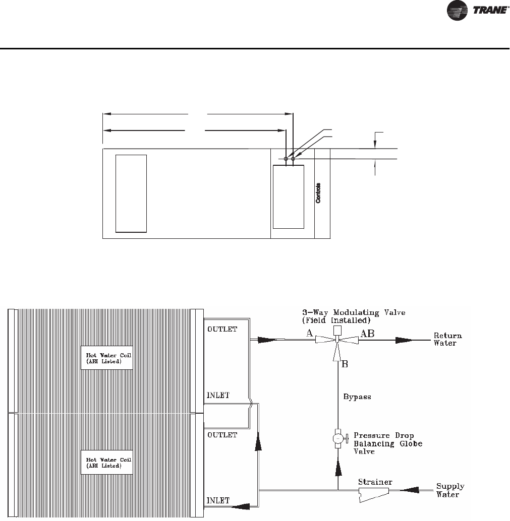
RT-SVX28E-EN 51
Installation
Figure 26. Hot water and steam heat connection locations
A
B
Y
Supply Air Opening
Return Air Opening
Unit bottom view
Inlet
Outlet
Recommended
Figure 27. Hot water coil piping
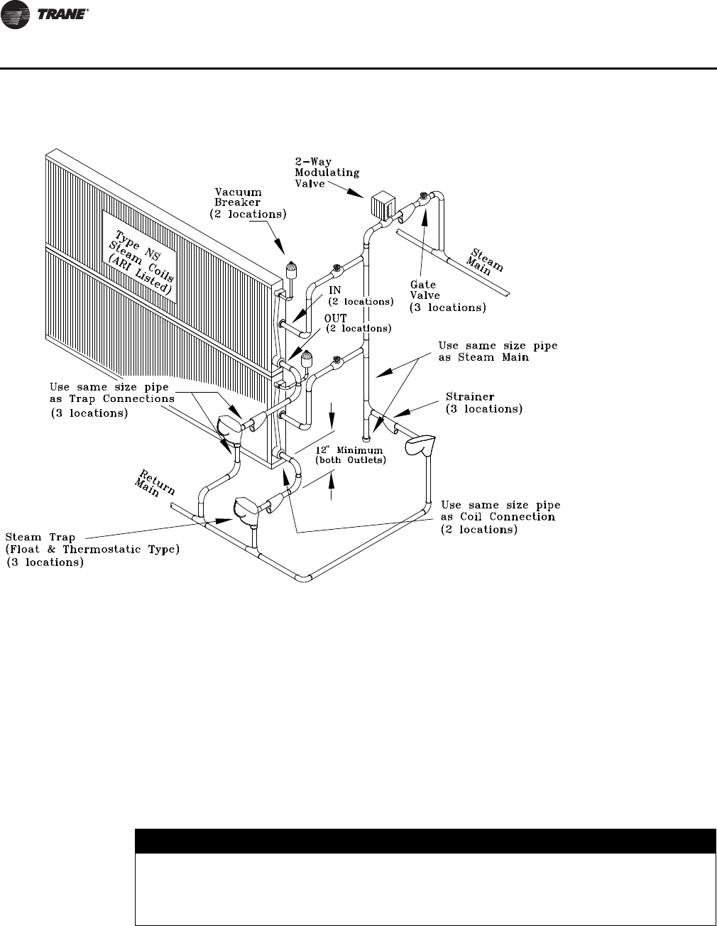
52 RT-SVX28E-EN
Installation
Chilled Water Units
Chilled water coils are factory installed inside the cooling section of the unit. Once the unit is set
into place, the chilled water piping, external piping enclosure, and appropriate modulating valve
(factory provided) must be installed.
Important: Supply, return, and vent connections, control valve, and actuator must be field
installed.
General Coil Piping Recommendations
1. Support all field-installed piping independently from the cooling coil.
2. When attaching the piping to the coil header, make the connection only tight enough to prevent
leaks. Maximum recommended torque is 200 pound-feet.
Figure 28. Steam coil piping
NOTICE:
Coil Header Damage!
Use a backup wrench when attaching piping to coils with copper headers to prevent damage
to the coil header. Do not use brass connectors because they distort easily and could cause
connection leaks.
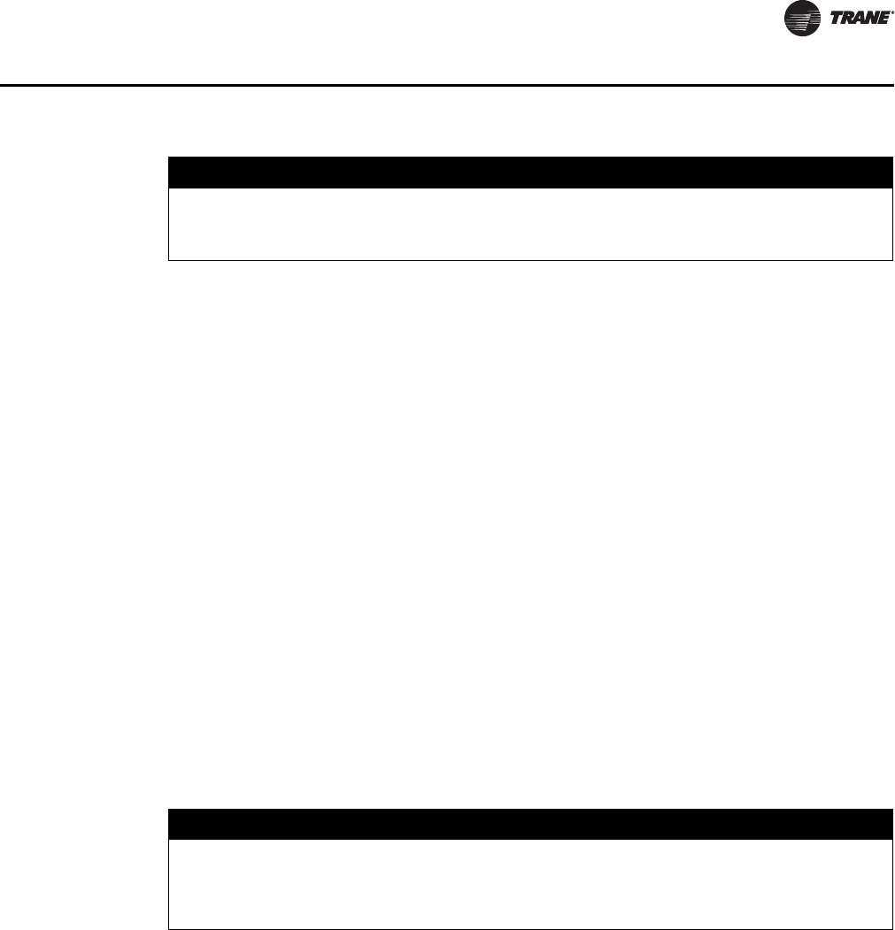
RT-SVX28E-EN 53
Installation
3. Use a short nipple on the coil headers prior to making any welded flange or welded elbow type
connections.
4. Use swing joints or flexible connectors adjacent to the cooling coil. (These devices will absorb
the strains of expansion and contraction).
5. All return lines and fittings must be equal to the diameter of the "outlet" connection on the
chilled water coil. Table 22, p. 54
6. Coils should be installed with field fitted drains and vents to permit winterization of coils not
in use and to assist in evacuating air from the chilled water system during start-up. See coil
winterization for more details.
7. The Types 5W and W cold water coils are self-venting only when the tube water velocity exceeds
1.5 feet per second (fps). If the tube velocity is less than 1.5 feet per second, either:
a. install an automatic air vent at the top of the return header, using the tapped pipe connection
or,
b. vent the coil from the top of the return header down to the return piping. At the vent
connection, size the return piping to provide sufficient water velocity.
8. The Types WD cold water coils are self-venting only when the tube water velocity exceeds 2.5
feet per second (fps). If the tube velocity is less than 2.5 feet per second, either:
a. install an automatic air vent at the top of the return header, using the tapped pipe connection
or,
b. vent the coil from the top of the return header down to the return piping. At the vent
connection, size the return piping to provide sufficient water velocity.
9. Use the provided piping gasket and sealing ring on the sections of pipe penetrating the unit
cabinet. See Figure 29, p. 54 and Figure 30, p. 55.
10. Seal the piping penetration on both sides of the cabinet wall before piping insulation.
11. Install the 3-way valve in an upright position. Ensure that the valve location lends itself to
serviceability and is protected from freezing temperatures.
12. Install the actuator in a location protected from moisture and freezing temperatures. Actuator
control wiring is located in the chilled water section of the unit.
Note: Space inside the piping enclosure limits the ability to house control valves and actuators
along with coil supply and return piping.
Important: Valve actuators are not waterproof. Failure to protect the valve from moisture may
result in the loss of cooling control.
NOTICE:
Over Tightening!
Teflon tape or piping compound should not be used for any field connections because its high
lubricity may allow connections to be overtightened, resulting in damage to the coil header.
NOTICE:
Equipment Damage!
Properly seal all penetrations in unit casing. Failure to seal penetrations from inner panel to
outer panel may result in unconditioned air entering the module which could result in
equipment damage.
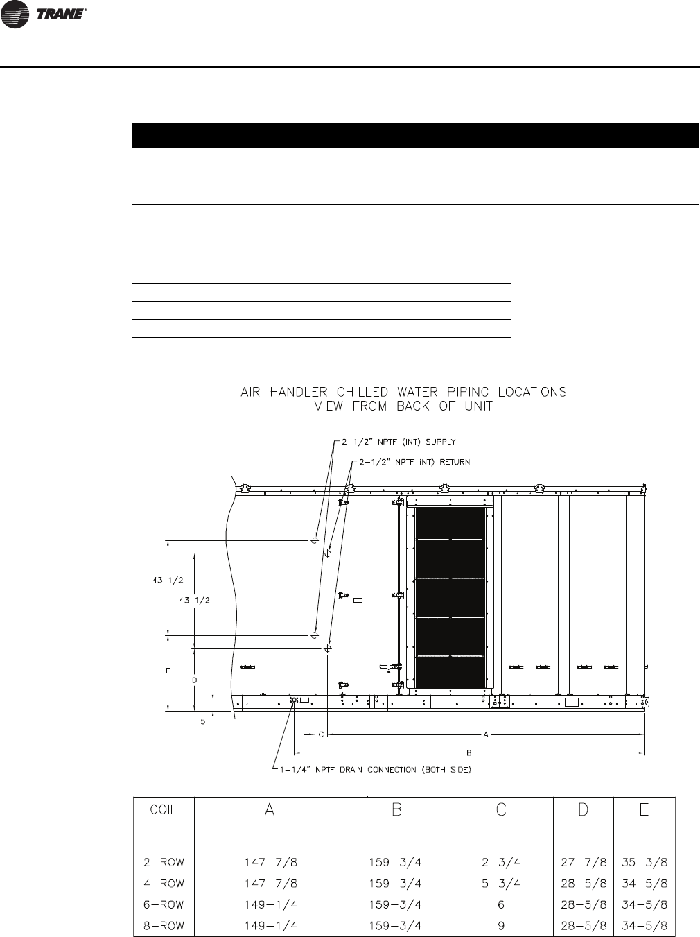
54 RT-SVX28E-EN
Installation
NOTICE:
Coil Damage!
Failure to properly protect coils not in use during freezing temperatures could result in coil
freeze-up damage.
Table 22. Chilled water connection sizes (in.)
Chilled Water Coil Connection Sizes
Coil Type Supply Return Drain/Vent
5W 2 1/2 2 1/2 1/2
W 2 1/2 2 1/2 1/2
WD 2 1/2 2 1/2 1/2
Figure 29. Chilled water piping locations
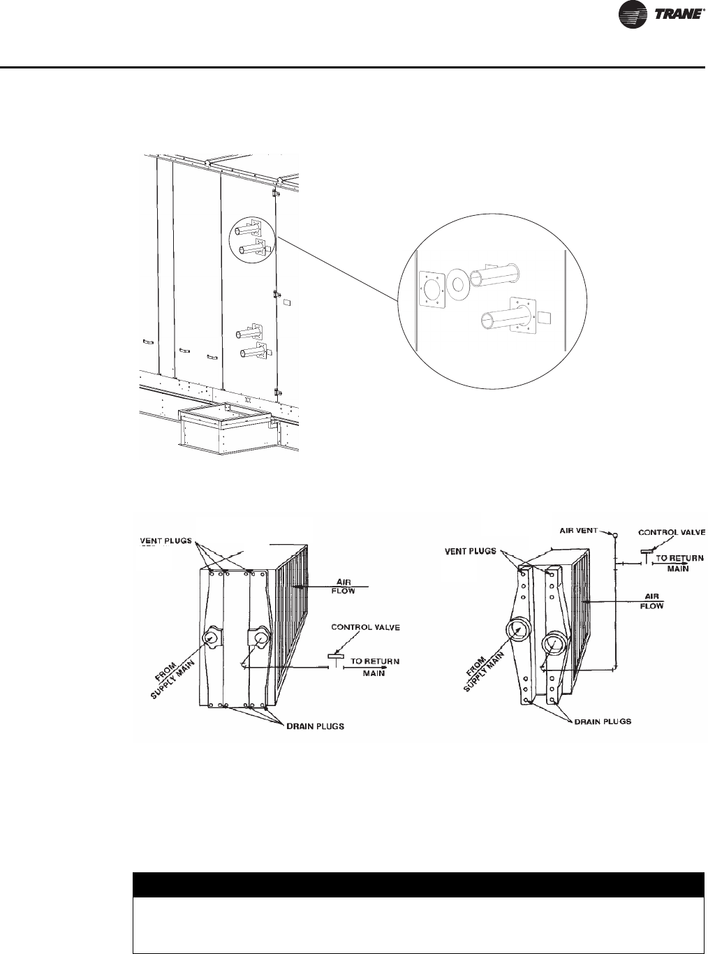
RT-SVX28E-EN 55
Installation
Coil Winterization
When applying air handlers with a chiller water coil and an economizer, the coil should be
completely drained for winter operation. If the coil can not be completely drained, the coil should
be filled with a glycol mixture that will protect the solution from freezing due to winter ambient
temperatures.
Figure 30. Chilled water piping penetration seal
Figure 31. Chilled water piping schematic
Type WD Coils Type 5W & W Coils
NOTICE:
Coil Damage!
Failure to properly protect coils not in use during freezing temperatures could result in coil
freeze-up damage.

56 RT-SVX28E-EN
Installation
Important: If glycol is used in the chilled water system, be sure to use a glycol approved for use
with commercial cooling systems and copper tube coils. Follow the manufacturer's
recommendations for water treatment and mix. Failure to do so could affect coil
performance or damage the tubes or braze joints.
External Piping Enclosure Installation
Installation of the external piping enclosure requires assembly of the curb and installing the
enclosure to both the unit baserail and unit cabinet as described below.
The pipe cabinet should be supported by chains, spreader bar, or other means when installing (see
lifting instructions section). Mounting hardware, caulk, piping boot and sealing rings are located
inside the piping enclosure skid.
1. Verify that the piping enclosure roof curb was properly installed. See roof curb installation
manual for more information.
2. Remove paper backing on butyl tape from back and bottom of external piping enclosure.
Figure 32, p. 57
3. Set external piping enclosure on curb. Figure 33, p. 57
4. Ensure enclosure-to-curb seal is tight and without buckles or cracks.
5. Attach external piping enclosure top and side flanges to air handler cabinet panel with #14 drill
screws. Figure 33, p. 57
Notes:
•Use force to compress the gasket between piping enclosure and the main unit cabinet while
drilling screws.
•Use all holes in the attachment flanges.
6. Attach the external piping enclosure baserail flanges to air handler unit base rail with #14 drill
screws. Figure 33, p. 57
7. Remove external piping enclosure access panel. Figure 34, p. 57
Note: Only remove outside perimeter bolts to remove access panel.
8. Attach condensate drain hole blockoff to air handler cabinet panel with #14 drill screws.
Figure 35, p. 58
9. Apply caulk around the inside and outside perimeter of the external piping enclosure.
10. Seal condensate drain hole extension with pipe gasket and sealing plate using #14 drill screws.
Figure 12, p. 31
11. Re attach access panel to external piping enclosure.
Notes:
•When locating the access panel, first slide the panel into the roof slot. Next grab the handle and
use force to compress roof gasket. Then slide bottom into place over baserail gasket.
•Use all access panel bolt holes for reattachment to prevent water leakage.
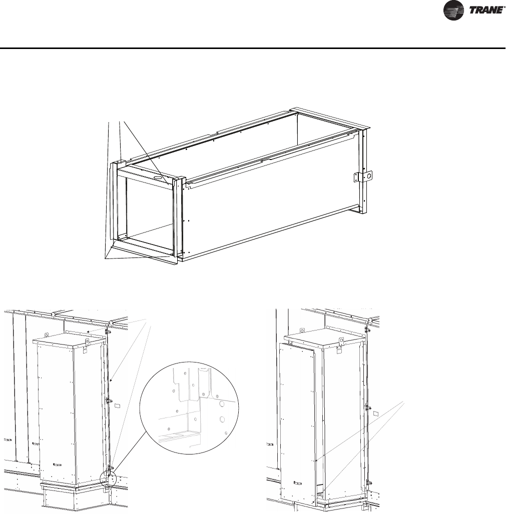
RT-SVX28E-EN 57
Installation
Figure 32. External piping enclosure butyl tape backing
Butyl Tape Backing
Figure 33. External Piping enclosure installation Figure 34. External piping enclosure access panel
Unit Attachment
Flanges
Only Remove Outside
Perimeter Bolts for
Access Panel
Removal
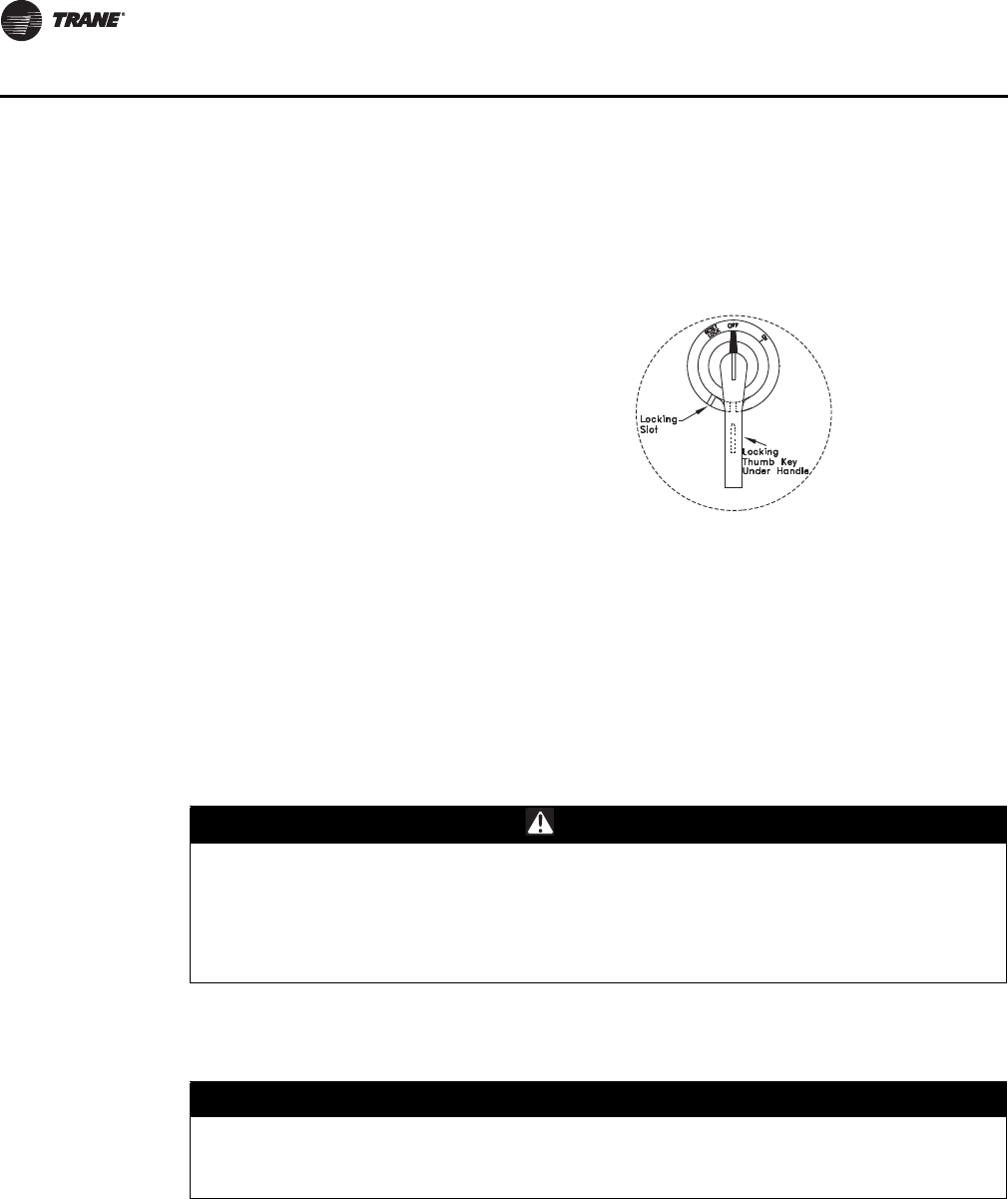
58 RT-SVX28E-EN
Installation
Electrical Data
Disconnect Switch w/External Handle
"OPEN COVER/RESET" - Turning the handle to this position releases the handle from the
disconnect switch, allowing the control panel door to be opened.
Once the door has been opened, it can be closed with the handle in any one of the three positions
outlined above, provided it matches the disconnect switch position. The handle can be locked in
the "OFF" position. While holding the handle in the "OFF" position, push the spring loaded thumb
key, attached to the handle, into the base slot. Place the lock shackle between the handle and the
thumb key. This will prevent it from springing out of position.
An overall layout of the field required power wiring is illustrated beginning with Figure 36, p. 59.
To insure that the unit supply power wiring is properly sized and installed, follow these guidelines.
Note: All field installed wiring must conform to NEC guidelines as well as State and Local codes.
Verify that the power supply available is compatible with the unit nameplate rating for all
components. The available power supply must be within 10% of the rated voltage stamped on the
nameplate. Use only copper conductors to connect the 3-phase power supply to the unit.
Electric Heat Units
Electric Heat Units require one power entry as illustrated in Figure 36, p. 59. Use the information
provided in Table 23, p. 62 and the "Power Wire Sizing & Protection Device Equations", to
determine the appropriate wire size and Maximum Over current Protection for the heaters/unit.
Important: Each power supply must be protected from short circuit and ground fault conditions.
To comply with NEC, protection devices must be sized according to the "Maximum
Units come equipped with a factory mounted
disconnect switch with an externally mounted
handle. This allows the operator to disconnect
power from the unit without having to open the
control panel door. The handle locations and its
three positions are shown below;
"ON" - Indicates that the disconnect switch is
closed, allowing the main power supply to be
applied at the unit.
"OFF" - Indicates that the disconnect switch is
open, interrupting the main power supply to
the unit controls.
Figure 35. Disconnect switch external
handle
WARNING
Live Electrical Components!
During installation, testing, servicing and troubleshooting of this product, it may be necessary
to work with live electrical components. Have a qualified licensed electrician or other
individual who has been properly trained in handling live electrical components perform these
tasks. Failure to follow all electrical safety precautions when exposed to live electrical
components could result in death or serious injury.
NOTICE:
Use Copper Conductors Only!
Unit terminals are not designed to accept other types of conductors. Failure to use copper
conductors could result in equipment damage.
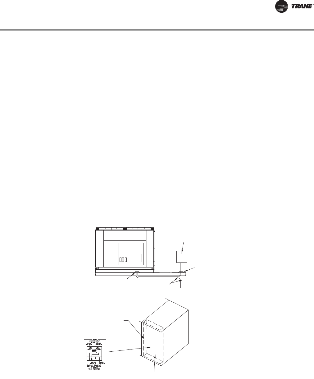
RT-SVX28E-EN 59
Installation
Over current Protection" (MOP) or "Recommended Dual Element" (RDE) fuse size
data on the unit nameplate.
Provide grounding for the supply power circuit in the electric heat control box.
Main Unit Power Wiring
Figure 38, p. 60 lists the field connection wire ranges for both the main power terminal block and
the optional main power disconnect switch. The electrical tables beginning with Table 23, p. 62 list
the component electrical data. The electrical service must be protected from over current and short
circuit conditions in accordance with NEC requirements. Protection devices must be sized
according to the electrical data on the nameplate. Refer to the "Power Wire Sizing and Protection
Device Equations", for determining;
a. the appropriate electrical service wire size based on "Minimum Circuit Ampacity" (MCA),
b. the "Maximum Over current Protection" (MOP) device,
c. the "Recommended Dual Element fuse size" (RDE).
1. Location for the electrical service entrance is illustrated in Figure 6, p. 24. Complete the unit
power wiring connections onto either the main terminal block, or the factory mounted non-
fused disconnect switch, inside the unit control panel. Refer to the customer connection
diagram that shipped with the unit for specific termination points.
2. Provide proper grounding for the unit in accordance with local and national codes.
Figure 36. Typical field power wiring
Field Supplied Survice
Over Current Protection
Pitch Pocket
Pitch Pocket 3-Wire Power
Supply+Ground
Front View Control Box
1TB1
or
1S1
Electric Heat Control Panel
Gas Heat Control Panel
Steam or Hot Water Control Panel
Heat Control Box
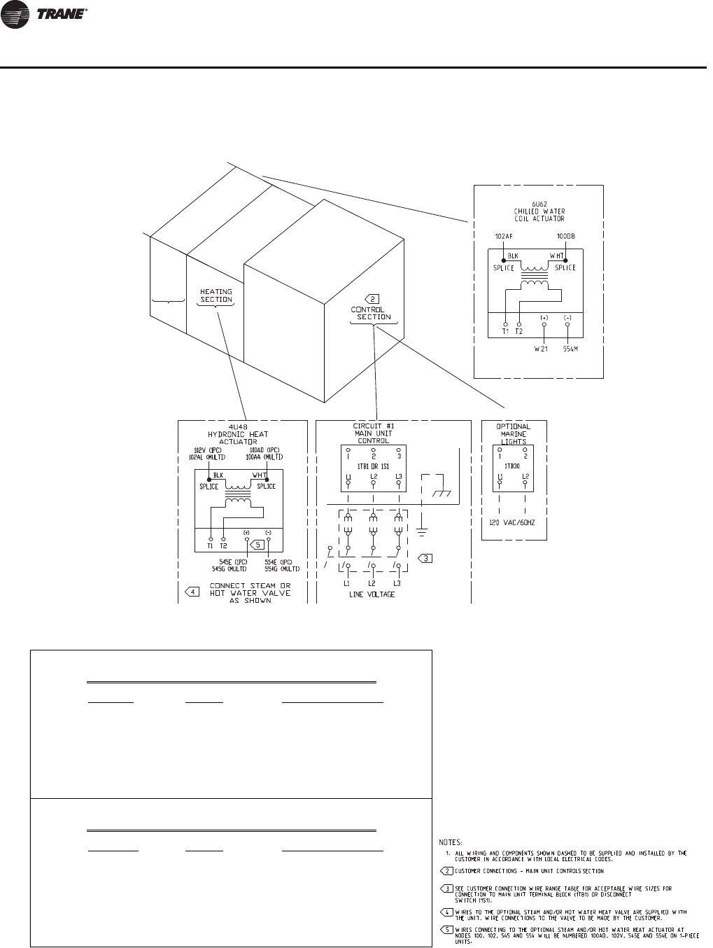
60 RT-SVX28E-EN
Installation
Figure 37. Typical field power wiring
COOLING
SECTION
Figure 38. Customer connection wire range
Note: DISCONNECT SWITCH SIZE IS
CALCULATED BY SELECTING THE
SIZE GREATER THAN OR EQUAL
TO 1.15 X (SUM OF UNIT LOADS).
SEE UNIT LITERATURE FOR UNIT
LOAD VALUES.
BLOCK SIZE WIRE QTY CONNECTOR WIRE RANGE
760 AMP (2)
SW ITCH SIZE WIRE QTY CONNECTOR WIRE RANGE
250 AMP (1)
400 AMP (1)
OR (2)
600 AMP (2)
OR (3)
800 AMP (2)
OR (3)
250 - 500 MCM
3/0 - 500 MCM
250 - 500 MCM
3/0 - 500 MCM
DISCONNECT SWITCH (ALL VOLTAGES)
#4 - 500 MCM
#1 - 600 MCM
#1 - 250 MCM
UNITS W ITH MAIN POW ER
TERMINAL BLOCK (ALL VOLTAGES)
#4 - 500 MCM
UNITS W ITH MAIN POW ER

RT-SVX28E-EN 61
Installation
Power Wire Sizing and Protection Devices
To correctly size electrical service wiring for a unit, find the appropriate calculations listed below.
Each type of unit has its own set of calculations for MCA (Minimum Circuit Ampacity), MOP
(Maximum Overcurrent Protection), and RDE (Recommended Dual Element fuse size). Read the
load definitions that follow and then find the appropriate set of calculations based on unit type.
Note: Set 1 is for cooling only and cooling with gas heat units, and set 2 is for cooling with electric
heat units.
Load Definitions: (To determine load values, see the Electrical Service Sizing Data Tables on the
following page.)
LOAD1 = CURRENT OF THE LARGEST MOTOR (COMPRESSOR OR FAN MOTOR)
LOAD2 = SUM OF THE CURRENTS OF ALL REMAINING MOTORS
LOAD3 = CURRENT OF ELECTRIC HEATERS
LOAD4 = ANY OTHER LOAD RATED AT 1 AMP OR MORE
Set 1. Cooling Only Air Handler Units and Cooling with Gas Heat Air Handler
Units
MCA = (1.25 x LOAD1) + LOAD2 + LOAD4
MOP = (2.25 x LOAD1) + LOAD2 + LOAD4
Select a fuse rating equal to the MOP value. If the MOP value does not equal a standard fuse size
as listed in NEC 240-6, select the next lower standard fuse rating.
Note: If selected MOP is less than the MCA, then select the lowest standard maximum fuse size
which is equal to or larger than the MCA, provided the selected fuse size does not exceed
800 amps.
RDE = (1.5 x LOAD1) + LOAD2 + LOAD4
Select a fuse rating equal to the RDE value. If the RDE value does not equal a standard fuse size as
listed in NEC 240-6, select the next higher standard fuse rating.
Note: If the selected RDE is greater than the selected MOP value, then select the RDE value to equal
the MOP value.
Set 2. Air Handler Units with Electric Heat
To arrive at the correct MCA, MOP, and RDE values for these units, two sets of calculations must
be performed. First calculate the MCA, MOP, and RDE values as if the unit was in cooling mode (use
the equations given in Set 1). Then calculate the MCA, MOP, and RDE values as if the unit were in
the heating mode as follows.
(Keep in mind when determining LOADS that the compressors don't run while the unit is in the
heating mode).
MCA = 1.25 x (LOAD1 + LOAD2 + LOAD4) + LOAD3
The nameplate MCA value will be the larger of the cooling mode MCA value or the heating mode
MCA value calculated above.
MOP = (2.25 x LOAD1) + LOAD2 + LOAD3 + LOAD4
The selection MOP value will be the larger of the cooling mode MOP value or the heating mode
MOP value calculated above.
Select a fuse rating equal to the MOP value. If the MOP value does not equal a standard fuse size
as listed in NEC 240-6, select the next lower standard fuse rating.
Note: If selected MOP is less than the MCA, then select the lowest standard maximum fuse size
which is equal to or larger than the MCA, provided the selected fuse size does not exceed
800 amps.
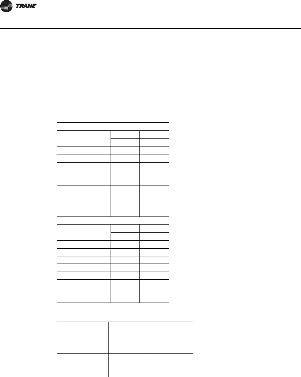
62 RT-SVX28E-EN
Installation
RDE = (1.5 x LOAD1) + LOAD2 + LOAD3 + LOAD4
The selection RDE value will be the larger of the cooling mode RDE value or the heating mode RDE
value calculated above. Select a fuse rating equal to the RDE value. If the RDE value does not equal
a standard fuse size as listed in NEC 240-6, select the next higher standard fuse rating.
Notes:
•If the selected RDE is greater than the selected MOP value, then select the RDE value to equal
the MOP value.
•On air handler units, the selected MOP value is stamped in the MOP field on the nameplate.
Table 23. Electrical service sizing data—motors
Supply Fan Motors
Motor Horsepower
460 V 575 V
FLA FLA
15 18.9 15.1
20 24.7 19.6
25 31.0 24.5
30 36.6 29.2
40 47.6 39
50 60.5 48
60 71.5 57.2
75 90 72
100 115 92
Exhaust/Return Fan Motors
Motor Horsepower
460 V 575 V
FLA FLA
7.5 9.4 8.2
10 12.6 10.1
15 18.9 15.1
20 24.7 19.6
25 31 24.5
30 36.6 29.2
40 47.6 39
50 60.5 48
Table 24. Electrical service sizing data—electric heat module (electric heat units only)
Module kW
Voltage
460 575
FLA FLA
90 108.3 86.6
140 168.4 134.7
265 318.8 255
300 360.8 288.7
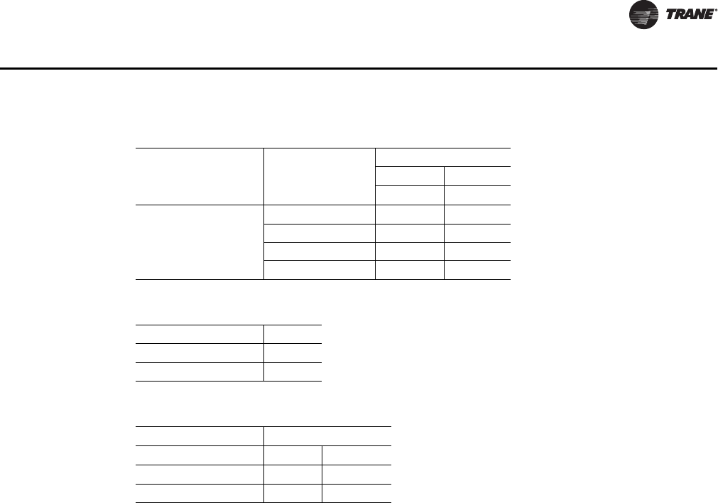
RT-SVX28E-EN 63
Installation
Table 25. Electrical service sizing data—control power transformer (heating mode only)
Unit Size
Digit 2 Unit
Function
Voltages
460 575
FLA FLA
A, B, C
E, L, S, X 3 3
F (850 MBH) 4 4
F (1100 MBH) 4 4
F (1800 MBH) 4 4
Table 26. Voltage utilization range
Unit Voltage
460/60/3 414-506
575/60/3 517-633
Table 27. Electrical service sizing data - convenience outlet transformer
Nominal Tons Voltage
460 575
FLA Add FLA Add
Casings A-C 3.3 2.6
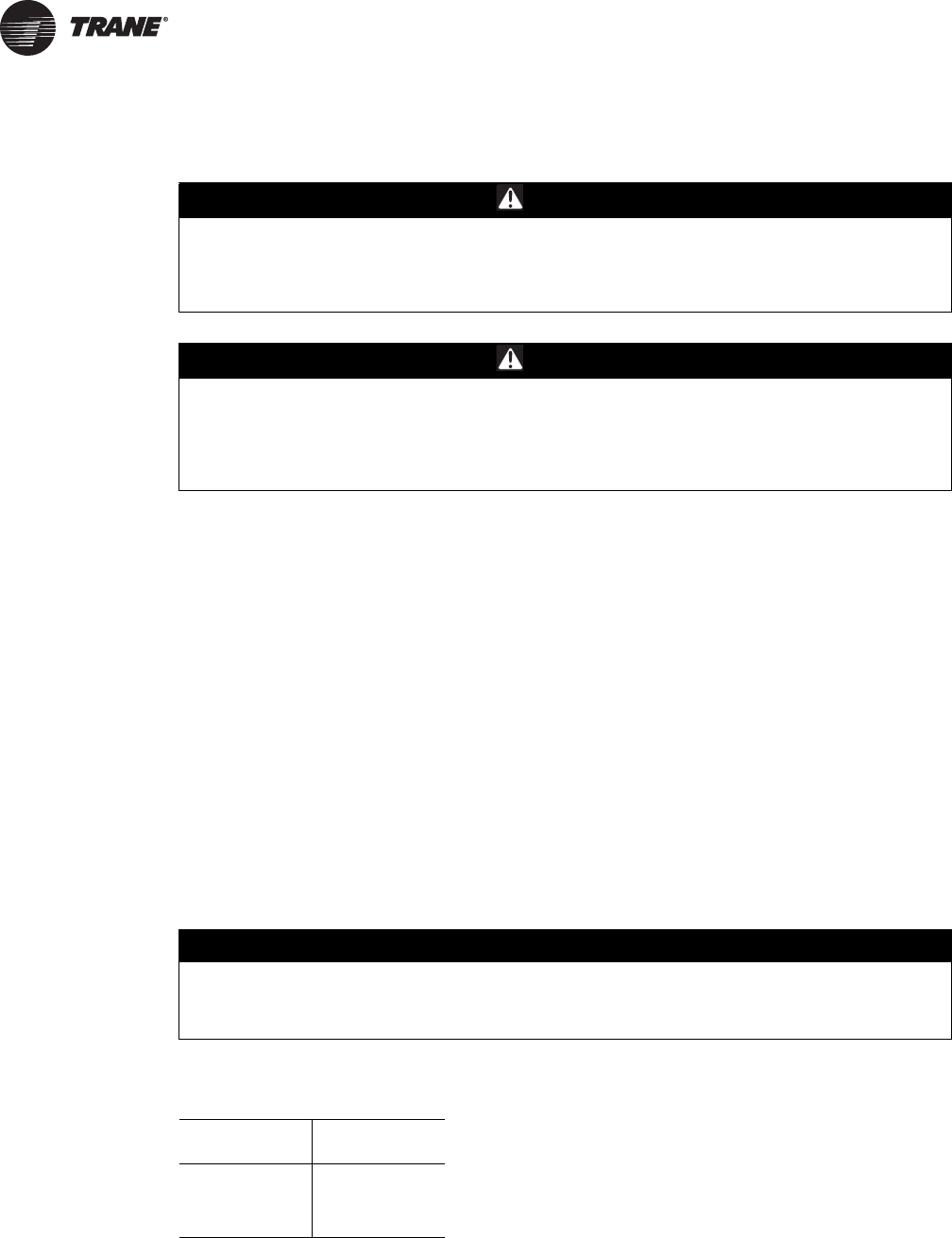
64 RT-SVX28E-EN
Controls
Field Installed Control Wiring
The Rooftop Module (RTM) must have a mode input in order to operate the air handler. The
flexibility of having several system modes depends upon the type of sensor and/or remote panel
selected to interface with the RTM. An overall layout of the various control options available, with
the required number of conductors for each device, is illustrated beginning with Figure 39, p. 73.
Note: All field wiring must conform to NEC guidelines as well as state and local codes.
The various field installed control panels, sensors, switches, and contacts discussed in this section
require both AC and DC consideration. These diagrams are representative of standard applications
and are provided for general reference only. Always refer to the wiring diagram that shipped with
the unit for specific electrical schematic and connection information.
Controls using 24 VAC
Before installing any connecting wiring, refer to Figure 7, p. 26 for the electrical access locations
provided on the unit and Tabl e 28 , p. 64 for AC conductor sizing guidelines, and;
1. Use copper conductors unless otherwise specified.
2. Ensure that the AC control wiring between the controls and the unit's termination point does
not exceed three (3) ohms/conductor for the length of the run.
Important: Be sure to check all loads and conductors for grounds, shorts, and miswiring.
3. Do not run the AC low voltage wiring in the same conduit with the high voltage power wiring.
WARNING
Hazardous Voltage!
Disconnect all electric power, including remote disconnects before servicing. Follow proper
lockout/tagout procedures to ensure the power can not be inadvertently energized. Failure to
disconnect power before servicing could result in death or serious injury.
WARNING
Proper Field Wiring and Grounding Required!
All field wiring MUST be performed by qualified personnel. Improperly installed and grounded
field wiring poses FIRE and ELECTROCUTION hazards. To avoid these hazards, you MUST
follow requirements for field wiring installation and grounding as described in NEC and your
local/state electrical codes. Failure to follow code could result in death or serious injury.
NOTICE:
Equipment Damage!
Resistance in excess of 3 ohms per conductor could cause component failure due to
insufficient AC voltage supply.
Table 28. AC conductors
Distance from
Unit to Control
Recommended
Wire Size
000-460 feet 18 gauge
461-732 feet 16 gauge
733-1000 feet 14 gauge
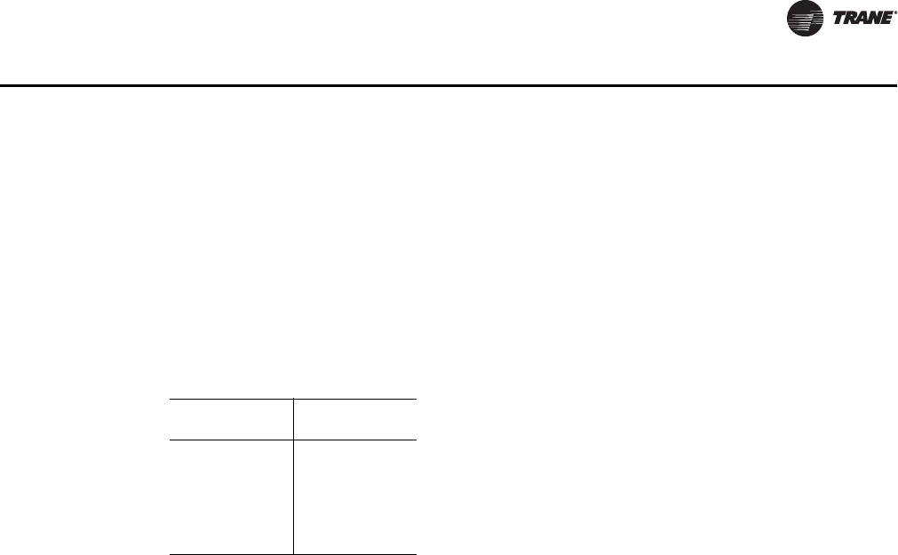
RT-SVX28E-EN 65
Controls
Controls using DC Analog Input/Outputs
Before installing any connecting wiring between the unit and components utilizing a DC analog
input\output signal, refer to the appropriate illustration in Figure 7, p. 26 for the electrical access
locations provided on the unit and Table 28, p. 64 for conductor sizing guidelines and;
1. Use standard copper conductor thermostat wire unless otherwise specified.
2. Ensure that the wiring between the controls and the unit termination point does not exceed two
and a half (2.5) ohms/conductor for the length of the run.
Important: Resistance in excess of 2.5 ohms per conductor can cause deviations in the accuracy
of the controls.
3. Do not run the electrical wires transporting DC signals in or around conduit housing high
voltage wires.
Units equipped with a Trane BACnet Communication Interface (BCI) or LonTalk
communication Interface (LCI) option which utilizes a serial communication
link;
1. Must be 18 AWG shielded twisted pair cable (Belden 8760 or equivalent).
2. Must not exceed 5,000 feet maximum for each link.
3. Must not pass between buildings.
Constant Volume System Controls
Remote Panel w/o NSB—BAYSENS110*
This electronic sensor features four system switch settings (Heat, Cool, Auto, and Off) and two fan
settings (On and Auto) with four system status LED's. It is a manual or automatic changeover
control with dual setpoint capability. It can be used with a remote zone sensor BAYSENS077*. Refer
to Table 30, p. 71 for the Temperature vs. Resistance coefficient.
Constant Volume Zone Panel -BAYSENS108*
This electronic sensor features four system switch settings (Heat, Cool, Auto, and Off) and two fan
settings (On and Auto). It is a manual or automatic changeover control with dual setpoint capability.
Variable Air Volume System Controls
Remote Panel w/o NSB -BAYSENS021*
The remote panel w/o Night setback has a system switch as well as a S/A temperature setpoint
indicator, a local sensor, and four LED's. These features allow the operator to control system
operation, and monitor unit operating status from a remote location. Use the installation
instructions that shipped with the panel to install it, and the unit field wiring diagram to connect
it to the unit.
Table 29. DC conductors
Distance from
Unit to Control
Recommended
Wire Size
000-150 feet 22 gauge
151- 240 feet 20 gauge
241- 385 feet 18 gauge
386- 610 feet 16 gauge
611- 970 feet 14 gauge

66 RT-SVX28E-EN
Controls
VAV Changeover Contacts
These contacts are connected to the RTM when daytime heating on VAV units with internal or
external hydronic heat is required. Daytime (occupied) heating switches the system to a CV type
mode of operation. Refer to the unit wiring diagram for the field connection terminals in the unit
control panel. The switch must be rated at 12 ma @ 24 VDC minimum.
Constant Volume or Variable Air Volume System Controls
Remote Panel w/ NSB -BAYSENS119*
This 7 day programmable sensor features four periods for Occupied\Unoccupied programming per
day. Either one or all four periods can be programmed. If the power is interrupted, the program is
retained in permanent memory. If power is off longer than 2 hours, only the clock and day may have
to be reset.
The front panel allows selection of Occupied/Unoccupied periods with two temperature inputs
(Cooling Supply Air Temperature and Heating Warm-up temperature) per occupied period. The
occupied cooling setpoint ranges between 40 and 80 Fahrenheit. The warm-up setpoint ranges
between 50 and 90 degrees Fahrenheit with a 2 degrees deadband. The Unoccupied cooling
setpoint ranges between 45 and 98 degrees Fahrenheit. The heating setpoint ranges between 43
and 96 degrees Fahrenheit.
The liquid crystal display (LCD) displays zone temperature, temperature setpoints, week day, time,
and operational mode symbols.
The DIP switches on the subbase are used to enable or disable applicable functions, i.e.; Morning
warm-up, economizer minimum position override during unoccupied status, heat installed, remote
zone temperature sensor, 12/24 hour time display, and daytime warm-up. Refer to Table 30, p. 71
for the Temperature vs. Resistance coefficient.
During an occupied period, an auxiliary relay rated for 1.25 amps @ 30 volts AC with one set of
single pole double throw contacts is activated.
Remote Human Interface Module
The remote Human Interface module enables the operator to set of modify the operating
parameters of the unit using it's 16 key keypad and view the operating status of the unit on the 2
line, 40 character LCD screen without leaving the building. However, the Remote Human Interface
module can not be used to perform any service functions.
One remote panel is designed to monitor and control up to four units providing each of the units
are equipped with an IPCB module. Use the installation instructions that shipped with the module
to install it, and the appropriate illustrations beginning with Figure 39, p. 73 to connect it to the unit.
Remote Zone Sensor (BAYSENS073*)
This electronic analog sensor features remote zone sensing and timed override with override
cancellation. It is used when the RTM has been programmed as the source for zone temperature
control. Refer to Table 30, p. 71 for the Temperature vs. Resistance coefficient.
Remote Zone Sensor (BAYSENS074*)
This electronic analog sensor features single setpoint capability and timed override with override
cancellation. It is used with a Trane Integrated ComfortTM system. Refer to Table 30, p. 71 for the
Temperature vs. Resistance coefficient.
Remote Zone Sensor (BAYSENS016*)
This bullet type analog Temperature sensor can be used for; outside air (ambient) sensing, return
air temperature sensing, supply air temperature sensing, remote temperature sensing
(uncovered), morning warm-up temperature sensing, and for VAV zone reset. Wiring procedures
vary according to the particular application and equipment involved. When this sensor is wired to

RT-SVX28E-EN 67
Controls
a BAYSENS119* Remote Panel, wiring must be 18 AWG Shielded Twisted Pair (Belden 8760 or
equivalent). Refer to Table 30, p. 71 for the Temperature vs. Resistance coefficient.
Remote Zone Sensor (BAYSENS077*)
This electronic analog sensor can be used with BAYSENS019*, 020*, or 021* Remote Panels. When
this sensor is wired to a BAYSENS019* or BAYSENS020* Remote Panel, wiring must be 18 AWG
Shielded Twisted Pair (Belden 8760 or equivalent). Refer to the specific Remote Panel for wiring
details.
CO2 Sensing—Space or Duct
The CO2 sensor shall have the ability to monitor space occupancy levels within the building by
measuring the parts per million of CO2 (Carbon Dioxide) in the air. As the CO2 levels increase, the
outside air damper modulates to meet the CO2 space ventilation requirements
Remote Minimum Position Potentiometer (BAYSTAT023*)
The remote minimum position potentiometer is used on units with an economizer. It allows the
operator to remotely set the economizer minimum position (which controls the amount of outside
air entering the unit). Use the installation instructions that shipped with the potentiometer to install
it, and the appropriate illustrations beginning with Figure 39, p. 73 to connect it to the unit.
External Auto/Stop Switch
A field supplied single pole single throw switch may be used to shut down the unit operation. This
switch is a binary input wired to the RTM. When opened, the unit shuts down immediately and can
be cancelled by closing the switch.
Refer to the appropriate illustrations beginning with Figure 39, p. 73 for the proper connection
terminals in the unit control panel. The switch must be rated for 12 ma @ 24 VDC minimum.
Emergency Override
When a LonTalk/BACnet communication module is installed, the user can initiate from the Trane
Tracer Summit or 3rd party BAS one of five (5) predefined, not available to configure, Emergency
Override sequences. The Humidification output is deenergized for any Emergency Override
sequence. Each Emergency Override sequence commands the unit operation as follows:
1. PRESSURIZE_EMERG:
– Supply Fan - On
– Supply Fan VFD Open/Max (if so equipped)
– Exhaust Fan - Off; Exhaust Dampers Closed (if so equipped)
– OA Dampers - Open; Return Damper - Closed
– Heat - All heat stages off; Mod Heat output at 0 VDC
– Occupied/Unoccupied/VAV box output - Energized
– VOM Relay - Energized (if so equipped)
– Preheat Output - Off
– Return Fan - Off; Exhaust Dampers - Closed (if so equipped)
– Return VFD - Min (if so equipped)
2. EMERG_DEPRESSURIZE:
– Supply Fan - Off
– Supply Fan VFD - Closed/Min (if so equipped)
– Exhaust Fan - On; Exhaust Dampers Open/Max (if so equipped)
– OA Dampers - Closed; Return Damper - Open

68 RT-SVX28E-EN
Controls
– Heat - All heat stages off; Mod Heat output at 0 VDC
– Occupied/Unoccupied/VAV box output - Energized
– VOM Relay - Energized (if so equipped)
– Preheat Output - Off
– Return Fan - On; Exhaust Dampers - Open (if so equipped)
– Return VFD - Max (if so equipped)
3. EMERG_PURGE:
– Supply Fan - On
– Supply Fan VFD - Open/Max (if so equipped)
– Exhaust Fan - On; Exhaust Dampers Open (if so equipped)
– OA Dampers - Open; Return Damper - Closed
– Heat - All heat stages off; Mod Heat output at 0 VDC
– Occupied/Unoccupied/VAV box output - Energized
– VOM Relay - Energized (if so equipped)
– Preheat Output - Off
– Return Fan - On; Exhaust Dampers - Open (if so equipped)
– Return VFD - Max (if so equipped)
4. EMERG_SHUTDOWN:
– Supply Fan - Off
– Supply Fan VFD - Closed/Min (if so equipped)
– Exhaust Fan - Off; Exhaust Dampers Closed (if so equipped)
– OA Dampers - Closed; Return Damper - Open
– Heat - All heat stages off; Mod Heat output at 0 VDC
– Occupied/Unoccupied/VAV box output - Energized
– VOM Relay - Energized (if so equipped)
– Preheat Output - Off
– Return Fan - Off; Exhaust Dampers - Closed (if so equipped)
– Return VFD - Min (if so equipped)
5. EMERG_FIRE - Input from fire pull box/system:
– Supply Fan - Off
– Supply Fan VFD - Closed/Min (if so equipped)
– Exhaust Fan - Off; Exhaust Dampers Closed (if so equipped)
– OA Dampers - Closed; Return Damper - Open
– Heat - All heat stages off; Mod Heat output at 0 VDC
– Occupied/Unoccupied/VAV box output - Energized
– VOM Relay - Energized (if so equipped)
– Preheat Output - Off
– Return Fan - Off; Exhaust Dampers - Closed (if so equipped)
– Return VFD - Min (if so equipped)

RT-SVX28E-EN 69
Controls
Ventilation Override Module (VOM)
Important: The ventilation override system should not be used to signal the presence of smoke
caused by a fire as it is not intended nor designed to do so.
The user can customize up to five (5) different override sequences for purposes of ventilation
override control. If more than one VOM sequence is being requested, the sequence with the highest
priority is initiated first. Sequence hierarchy is the sequence “A” (UNIT OFF) is first, with sequence
“E” (PURGE with Duct Pressure Control) last.
A ventilation override mode can be initiated by closing any of the five (5) corresponding binary
input on the VOM module. A binary output is provided on the VOM module to provide remote
indication of an active VOM mode. The Humidification output is deenergized for any VOM
sequence. The factory default definitions for each mode are as follows:
1. UNIT OFF sequence “A”
When complete system shutdown is required the following sequence can be used.
– Supply Fan - Off
– Supply Fan VFD - Closed/Min (if so equipped)
– Exhaust Fan - Off; Exhaust Dampers Closed (if so equipped)
– OA Dampers - Closed; Return Damper - Open
– Heat - All heat stages off; Mod Heat output at 0 VDC
– Occupied/Unoccupied/VAV box output - Deenergized
– VOM Relay - Energized
– Preheat Output - Off
– Return Fan - Off; Exhaust Dampers - Closed (if so equipped)
– Return VFD - Min (if so equipped)
– OA Bypass Dampers - Open (if so equipped)
– Exhaust Bypass Dampers - Open (if so equipped)
2. PRESSURIZE sequence “B”
Perhaps a positively pressurized space is desired instead of a negatively pressurized space. In this
case, the supply fan should be turned on with the VFD at 100% speed and exhaust fan should be
turned off.
– Supply Fan - On
– Supply Fan VFD - Max (if so equipped)
– Exhaust Fan - Off; Exhaust Dampers Closed (if so equipped)
– OA Dampers - Open; Return Damper - Closed
– Heat - All heat stages off; Mod Heat output at 0 VDC
– Occupied/Unoccupied/VAV box output - Energized
– VOM Relay - Energized
– Preheat Output - Off
– Return Fan - Off; Exhaust Dampers - Closed (if so equipped)
– Return VFD - Min (if so equipped)
– OA Bypass Dampers - Open (if so equipped)
– Exhaust Bypass Dampers - Open (if so equipped)
3. EXHAUST sequence “C”

70 RT-SVX28E-EN
Controls
With only the exhaust fans running (supply fan off), the space that is conditioned by the air handler
would become negatively pressurized. This is desirable for clearing the area of smoke from the
now-extinguished fire, possibly keeping smoke out of areas that were not damaged.
– Supply Fan - Off
– Supply Fan VFD - Closed/Min (if so equipped)
– Exhaust Fan - On; Exhaust Dampers Open (if so equipped)
– OA Dampers - Closed; Return Damper - Open
– Heat - All heat stages off; Mod Heat output at 0 VDC
– Occupied/Unoccupied/VAV box output - Deenergized
– VOM Relay - Energized
– Preheat Output - Off
– Return Fan - On; Exhaust Dampers - Open (if so equipped)
– Return VFD - Max (if so equipped)
– OA Bypass Dampers - Open (if so equipped)
– Exhaust Bypass Dampers - Open (if so equipped)
4. PURGE sequence “D”
Possibly this sequence could be used for purging the air out of a building before coming out of
Unoccupied mode of operation on VAV units or for the purging of smoke or stale air if required after
a fire.
– Supply Fan - On
– Supply Fan VFD - Max (if so equipped)
– Exhaust Fan - On; Exhaust Dampers Open (if so equipped)
– OA Dampers - Open; Return Damper - Closed
– Heat - All heat stages off; Mod Heat output at 0 VDC
– Occupied/Unoccupied/VAV box output - Energized
– VOM Relay - Energized
– Preheat Output - Off
– Return Fan - On; Exhaust Dampers - Open (if so equipped)
– Return VFD - Max (if so equipped)
– OA Bypass Dampers - Open (if so equipped)
– Exhaust Bypass Dampers - Open (if so equipped)
5. PURGE with duct pressure control sequence “E”
This sequence can be used when supply air control is required for smoke control.
– Supply Fan - On
– Supply Fan VFD - (If so equipped) Controlled by Supply Air Pressure Control function;
Supply Air Pressure High Limit disabled
– Exhaust Fan - On; Exhaust Dampers Open (if so equipped)
– OA Dampers - Open; Return Damper - Closed
– Heat - All heat stages off; Mod Heat output at 0 VDC
– Occupied/Unoccupied/VAV box output - Energized
– VOM Relay - Energized
– Preheat Output - Off
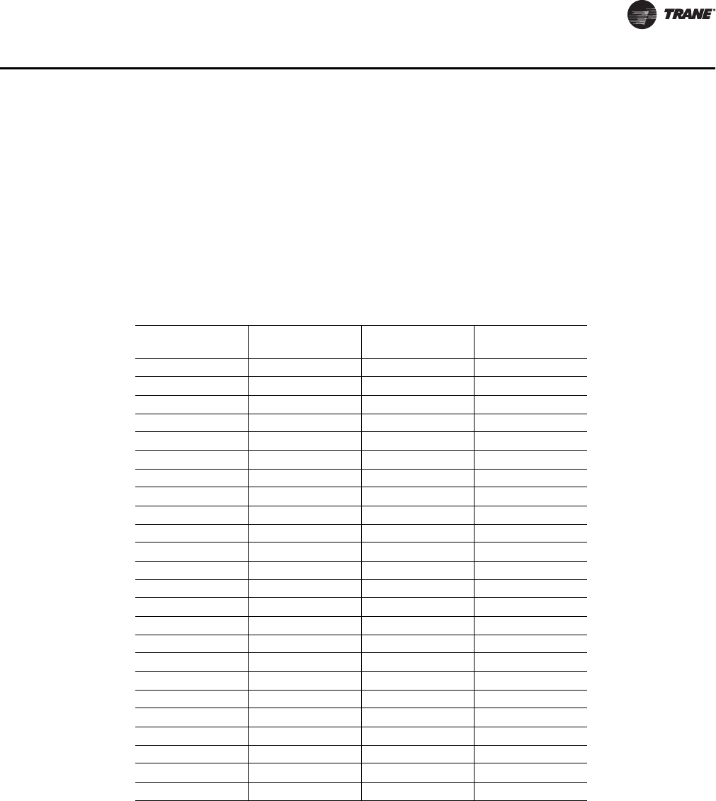
RT-SVX28E-EN 71
Controls
– Return Fan - On; Exhaust Dampers - Open (if so equipped)
– Return VFD - Max (if so equipped)
– OA Bypass Dampers - Open (if so equipped)
– Exhaust Bypass Dampers - Open (if so equipped)
Temperature vs. Resistance Coefficient
The UCM network relies on various sensors located throughout the system to provide temperature
information in the form of an analog input. All of the sensors used have the same temperature vs.
resistance co-efficient and are made from Keystone Carbon D97 material with a 1 degree
Centigrade tolerance.
Emergency Stop Switch
A normally closed (N.C.) switch wired to the RTM may be used during emergency situations to shut
down all unit operations. When opened, an immediate shutdown occurs. An emergency stop
diagnostic is entered into the Human Interface and the unit must be manually reset. Refer to the
appropriate illustrations in Figure 40, p. 74 and Figure 41, p. 75 for the proper connection terminals
in the unit control panel. The switch must be rated for 12 ma @ 24 VDC minimum.
Table 30. Temperature vs. resistance
Temperature (°F)
Resistance
(in. 1000 Ohms) Temperature (°F)
Resistance
(in. 1000 Ohms)
-40 346.1 71 11.6
-30 241.7 72 11.31
-20 170.1 73 11.03
-10 121.4 74 10.76
-5 103 75 10.5
0 87.56 76 10.25
5 74.65 77 10
10 63.8 78 9.76
15 54.66 79 9.53
20 46.94 80 9.3
25 40.4 85 8.25
30 34.85 90 7.33
35 30.18 100 5.82
40 26.22 105 5.21
45 22.85 110 4.66
50 19.96 120 3.76
55 17.47 130 3.05
60 15.33 140 2.5
65 13.49 150 2.05
66 13.15 160 1.69
67 12.82 170 1.4
68 12.5 180 1.17
69 12.19 190 0.985
70 11.89 200 0.83
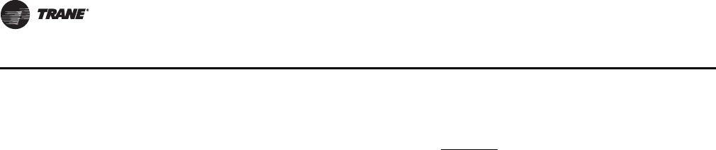
72 RT-SVX28E-EN
Controls
Occupied/Unoccupied Contacts
To provide Night Setback control if a remote panel with NSB was not ordered, a field supplied
contact must be installed. This binary input provides the Occupied/Unoccupied status information
of the building to the RTM. It can be initiated by a time clock, or a Building Automation System
control output. The relay’s contacts must be rated for 12 ma @ 24 VDC minimum. Refer to the
appropriate illustrations in Figure 40, p. 74 and Figure 41, p. 75 for the proper connection terminals
in the unit control panel.
Demand Limit Relay
If the unit is equipped with a Generic BAS Module, a normally open (N.O.) switch may be used to
limit the electrical power usage during peak periods. When demand limit is initiated, the
mechanical cooling and heating operation is limited to either 50% or 100%. Demand limit can be
initiated by a toggle switch closure, a time clock, or an ICSTM control output. These contacts must
be rated for 12 ma @ 24 VDC minimum.
Outside Air Sensor (BAYSENS016*)
This device senses the outdoor air temperature and sends this information in the form of an analog
input to the RTM. It's factory installed on units with an economizer, but can be field provided/
installed and used for informational purposes on units without an economizer. Refer to the
appropriate illustrations in Figure 40, p. 74 and Figure 41, p. 75 for the proper connection terminals
in the unit control panel. Refer to Table 30, p. 71 for Temperature vs. Resistance coefficient.
Generic Building Automation System
The Generic Building Automation System (GBAS) module allows a non-Trane building control
system to communicate with the air handler unit and accepts external setpoints in form of analog
inputs for cooling, heating, demand limiting, and supply air pressure parameters. Refer to
Figure 44, p. 78 & Table 31, p. 79 for the input wiring to the GBAS module and the various desired
setpoints with the corresponding DC voltage inputs for both VAV and CV applications.
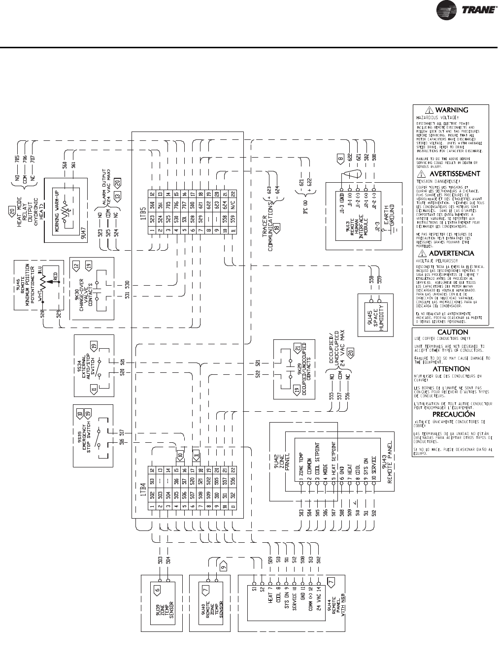
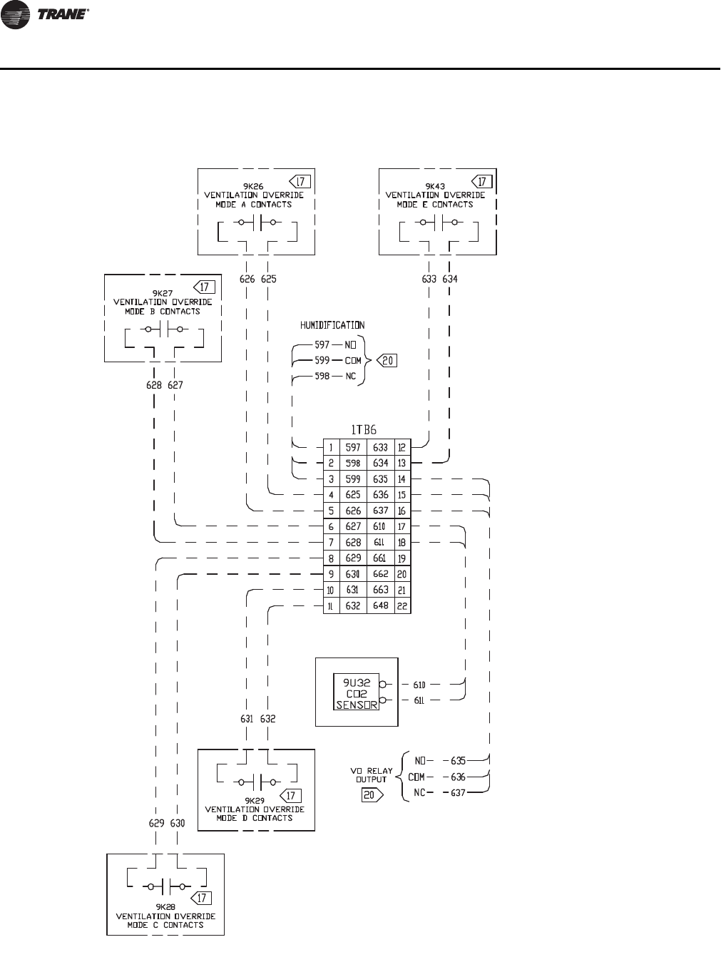
74 RT-SVX28E-EN
Controls
Figure 40. Typical ventilation override binary output for casings A-C CV control options
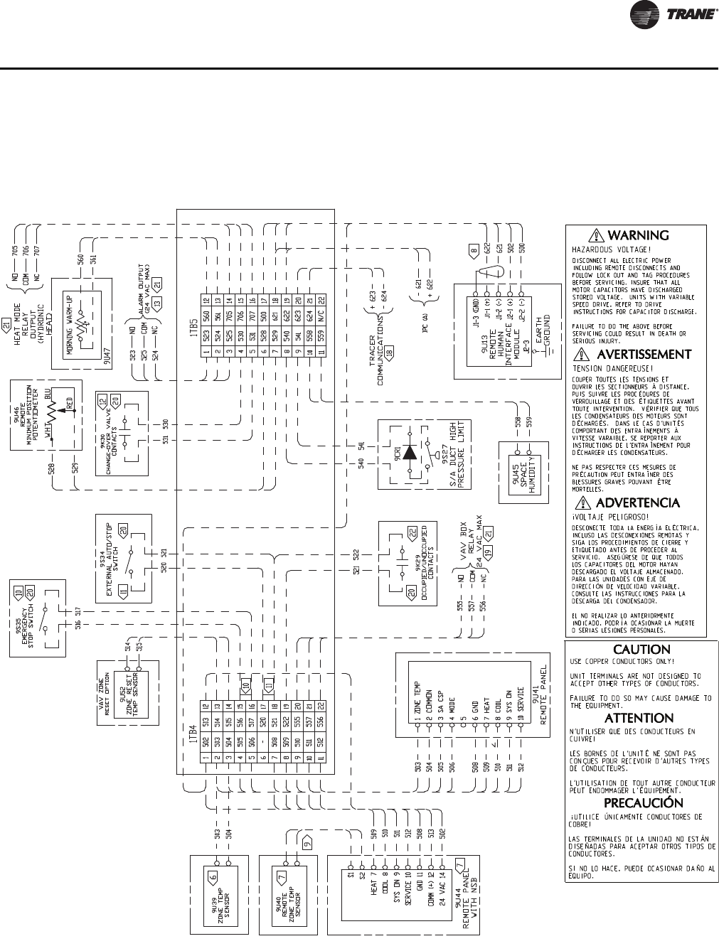
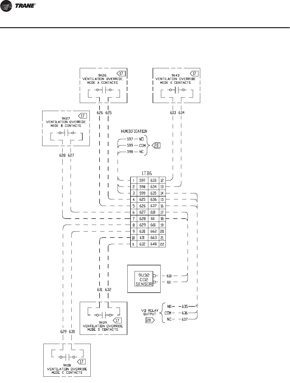
76 RT-SVX28E-EN
Controls
Figure 42. Typical ventilation override binary output for casings A-C CV control options
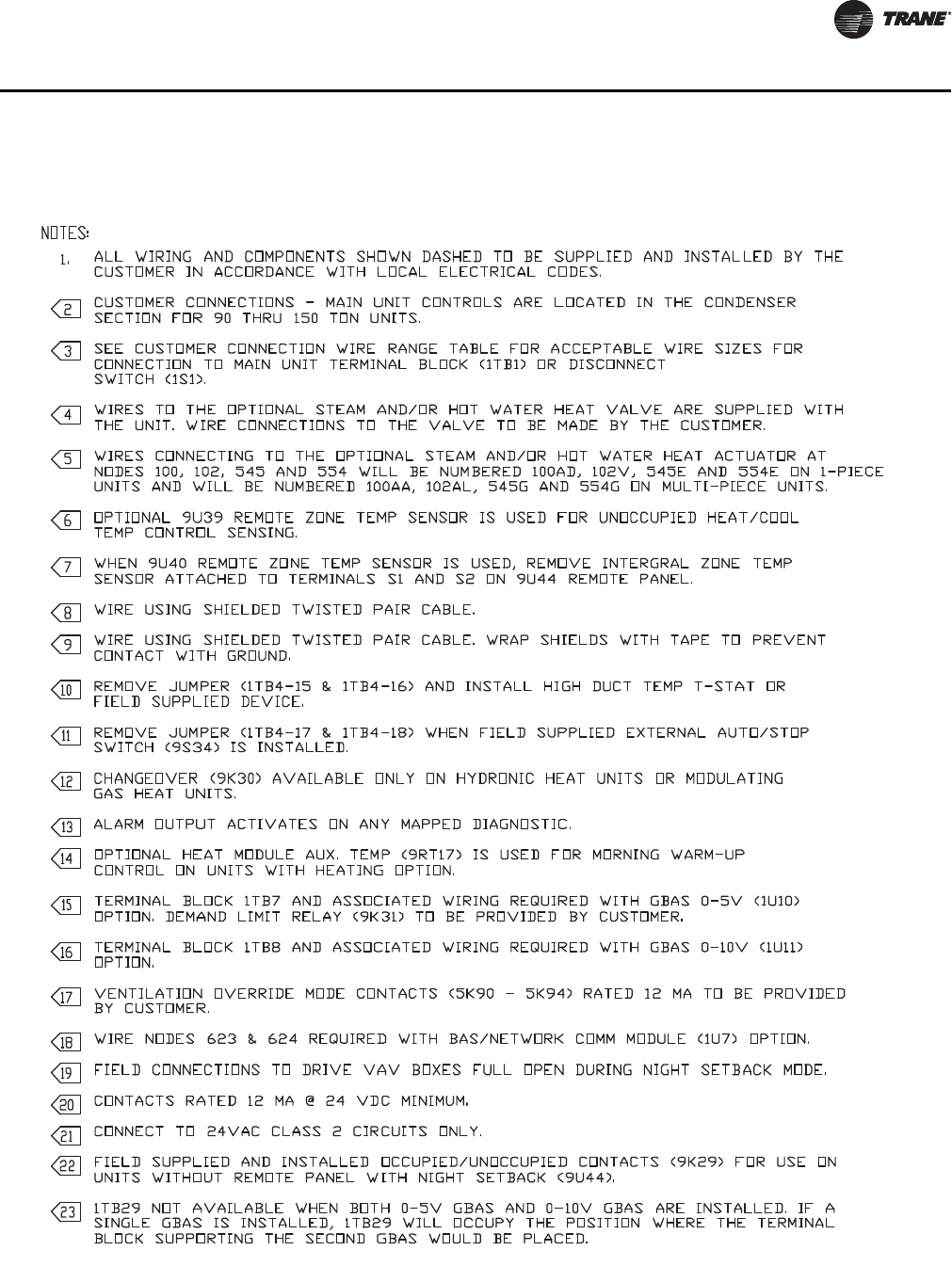
RT-SVX28E-EN 77
Controls
Figure 43. Typical field wiring diagram notes for VAV and CV control options
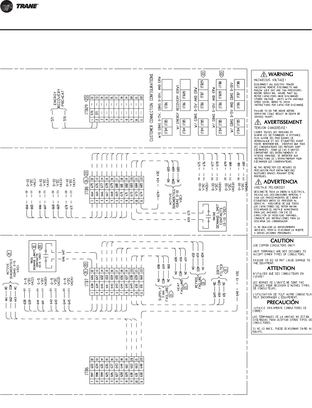
RT-SVX28E-EN 79
Controls
Table 31. GBAS voltage vs. setpoint
Setpoint GBAS 0-5vdc GBAS 0-10vdc Valid Range
Occ Zone Cooling Setpoint(CV only) 0.5 to 4.5vdc 0.5 to 9.5vdc 50 to 90°F
Unocc Zone Cooling Setpoint 0.5 to 4.5vdc 0.5 to 9.5vdc 50 to 90°F
Occ Zone Heating Setpoint(CV only) 0.5 to 4.5vdc 0.5 to 9.5vdc 50 to 90°F
Unocc Zone Heating Setpoint 0.5 to 4.5vdc 0.5 to 9.5vdc 50 to 90°F
SA Cooling Setpoint (VAV only) 0.5 to 4.5vdc 0.5 to 9.5vdc 40 to 180°F
SA Heating Setpoint (VAV only) 0.5 to 4.5vdc 0.5 to 9.5vdc 40 to 180°F
Space Static Pressure Setpoint 0.5 to 4.5vdc 0.5 to 9.5vdc -0.20 to 0.30 IWC
SA Static Pressure Setpoint 0.5 to 4.5vdc 0.5 to 9.5vdc 0.7 to 5.1 IWC
Min OA Flow Setpoint 10.5 to 4.5vdc 0.5 to 9.5vdc 0 to Unit Max Flow
MWU Setpoint 0.5 to 4.5vdc 0.5 to 9.5vdc 50 to 90°F
Econ Dry Bulb Enable Setpoint 0.5 to 4.5vdc 0.5 to 9.5vdc 50 to 140°F
SA_Reheat_Setpoint 0.5 to 4.5vdc 0.5 to 9.5vdc 40 to 180°F
Minimum Position Setpoint 20.5 to 4.5vdc 0.5 to 9.5vdc 0 to 100%
Occ Dehumidification Setpoint 0.5 to 4.5vdc 0.5 to 9.5vdc 40 to 65%
Unocc Dehumidification Setpoint 0.5 to 4.5vdc 0.5 to 9.5vdc 40 to 65%
Occ Humidification Setpoint 0.5 to 4.5vdc 0.5 to 9.5vdc 40 to 65%
Unocc Humidification Setpoint 0.5 to 4.5vdc 0.5 to 9.5vdc 40 to 65%
Notes:
1. If DCV is enabled this is used for Design Minimum OA Flow Setpoint
2. If DCV is enabled, this is used for Design Minimum OA Damper Position Setpoint

80 RT-SVX28E-EN
Sequence of Operation
Cooling Sequence of Operation
Time delays are built into the controls to increase reliability and performance.
SZVAV Cooling Sequence of Operation
Single Zone VAV units will be equipped with a VFD controlled supply fan which will be controlled
via the 0-10VDC RTM VFD output and the RTM Supply Fan output. With the RTM Supply Fan output
energized and the RTM VFD output at 0Vdc the fan speed output is 37% (22Hz) from the VFD motor,
by default, and at 10VDC the Fan Speed output is 100% (60Hz). The control scales the 0-10Vdc VFD
output from the RTM linearly to control between the 37%-100% controllable range.
If the RTM determines that there is a need for active cooling capacity in order to meet the calculated
Temperature Setpoint (Tset), the unit will begin to stage compressors accordingly once supply fan
proving has been made. Note that the compressor staging order will be based on unit configuration
and compressor lead/lag status.
Once the Tset calculation has reached its bottom limit (Tset Lower Limit Setpoint) and compressors
are being utilized to meet the demand, the Tset value continues to calculate below the Tset Lower
Limit Setpoint and the algorithm will begin to ramp the Supply Fan Speed up toward 100%. Note
that the supply fan speed will remain at the compressor stage’s associated minimum value (as
described below) until the Tset value is calculated below the Tset Lower Limit Setpoint.
As the cooling load in the zone decreases the zone cooling algorithm will reduce the speed of the
fan down to minimum per compressor stage and control the compressor outputs accordingly. As
the compressors begin to de-energize, the Supply Fan speed will fall back to the Cooling Stage’s
associated minimum fan speed, but not below. As the load in the zone continues to drop cooling
capacity will be reduced in order to maintain the discharge air within the ± ½ Tset deadband.
Cooling Stages Minimum Fan Speed
As the unit begins to stage compressors to meet the cooling demand, the following minimum
Supply Fan Speeds will be utilized for each corresponding Cooling Stage. Note that the Supply Fan
Speed will be allowed to ramp up beyond 37% as determined by the active Tset calculation; the
speeds below are only the minimum speeds per cooling stage. Note that when transitioning
between active cooling stages, compressors may energize prior to the supply fan reaching the
minimum speed for the associated step.
1. 2-Stage DX Cooling - The minimum fan speed for units with 2 stages of DX Cooling will be 37%
of the unit’s full airflow capacity. At Stage 1 of DX Cooling the minimum Fan Speed will be 37%
and at Stage 2 of DX Cooling the Fan Speed will be at a minimum of 67%.
2. 3-Stage DX Cooling - There are no IntelliPak applications with 3 stages of DX Cooling.
3. 4-Stage DX Cooling - The minimum fan speed for units with 4 stages of DX Cooling will be 37%
of the unit’s total airflow. At Stage 1 the minimum Supply Fan Speed will be 37%, at Stage 2
the minimum Supply Fan Speed will be 58%, and at Stages 3 & 4 the minimum Supply Fan
Speed will be 67%.
Units without an Economizer
Upon entering an "occupied" mode of operation, the RTM receives input from the remote panel to
start the supply fan. For constant volume applications, the RTM supply fan contacts close which
energizes the supply fan contactor. When the supply fan starts, the fan proving switch closes,
signaling the RTM that airflow has been established. The VFD will begin to ramp the fan (if
equipped).
When a cooling request is sent to the RTM from a zone temperature sensor, the RTM evaluates the
operating condition of the system using the supply air temperature input and the outdoor
temperature input. before sending the request to the MCM.

RT-SVX28E-EN 81
Sequence of Operation
Units with an Economizer
Upon entering an "occupied" mode of operation, the RTM receives input from the remote panel to
start the supply fan. For constant volume applications, the RTM supply fan contacts close which
energizes the supply fan contactor. When the supply fan starts, the fan proving switch closes,
signaling the RTM that airflow has been established. The RTM opens the economizer dampers to
the specified "minimum position".
When a cooling request is sent to the RTM from the zone temperature sensor, the RTM evaluates
the operating condition of the system using the supply air temperature input and the outdoor
temperature input before sending the request to the MCM for mechanical cooling.
Units with Traq™ Sensor
The fresh air enters the unit through the Traq Sensor assemblies and is measured by velocity
pressure flow rings. The velocity pressure flow rings are connected to a pressure transducer/
solenoid assemblies. The solenoid is used for calibration purposes to compensate for temperature
swings that could affect the transducer. The Ventilation Control Module (VCM) utilizes the velocity
pressure inputs, the RTM outdoor air temperature input, and the minimum outside air CFM
setpoint to modify the volume (CFM) of fresh air entering the unit as the measured airflow deviates
from setpoint.
When the optional temperature sensor is installed and the Preheat function is enabled, the sensor
will monitor the combined (averaged) fresh air and return air temperatures. As this mixed air
temperature falls below the Preheat Actuate Temperature Setpoint, the VCM will activate the
preheat binary output used to control a field installed heater. The output will be deactivated when
the temperature rises 5 above the Preheat Actuate Temperature Setpoint.
When the optional CO2 sensor is installed and DCV is enabled, the OA damper will be modulated
to control CO2 concentrations. If the CO2 concentration is greater than the Design Minimum CO2
Setpoint the OA damper will be opened to the Design Minimum OA Damper Setpoint (w/o Traq)
or until the Design Minimum OA Flow Setpoint is met (w/ Traq).
If the CO2 concentration is less than the DCV Minimum CO2 Setpoint the OA damper will be closed
to the DCV Minimum OA Damper Setpoint (w/o Traqs) or until the DCV Minimum OA Flow Setpoint
is met (w/ Traqs). If the CO2 concentration is between the Design Minimum CO2 Setpoint and the
DCV Minimum CO2 Setpoint the OA damper will be modulated proportionally between the Design
Minimum OA Damper Setpoint and the DCV Minimum OA Damper Setpoint (w/ Traqs) and between
the Design Minimum OA Flow Setpoint and the DCV Minimum OA Flow Setpoint (w/o Traqs).
Units Equipped with 100% Modulating Exhaust
The exhaust dampers are controlled through an Exhaust/Comparative Enthalpy Module (ECEM).
The ECEM module receives input from a space transducer and modulates the exhaust dampers to
maintain the space pressure to within the specified setpoint controlband.
Gas Heating Sequence of Operation
Standard Two Stage Gas Furnace
The control system for air handler units is wired to ensure that the heating and cooling do not occur
simultaneously. Refer to the wiring diagram that shipped with the unit while reviewing the
following sequence of operation.
Honeywell Ignition System
(850 & 1100 MBH Two Stage Natural Gas)
When a heating requirement exists, the Rooftop Module (RTM) starts the supply fan and sends a
request for heat to the Heat Module. The Heat Module closes contacts and starts the combustion
blower motor. The combustion blower motor starts on low speed through the normally closed
combustion blower relay contacts.

82 RT-SVX28E-EN
Sequence of Operation
The supply airflow switch and the combustion air switch closes. Power is applied through the high
limit cutout to the Honeywell ignition control board. The ignition control board starts a pre-purge
timing cycle. At the end of the pre-purge cycle, the ignition transformer and the pilot solenoid valve
are energized. This starts a 10 second trial for pilot ignition. When the pilot flame is established and
sensed by the flame sensing rod, stage 1 of the main gas valve and the 60 seconds sequencing time
delay relay is energized.
The system will operate in the low heat mode until an additional call for heat is established by
closing the contacts on the Heat Module.
The sequencing time delay relay will energize the combustion blower motor relay which switches
the combustion blower motor to high speed and energizes the 2nd stage solenoid on the gas valve
after approximately 60 seconds.
If the flame rod does not detect a pilot flame within the 10 second trial for ignition period, the control
will lockout. If a flame failure occurs during operation, the gas valve, the sequencing time delay
relay, and the combustion blower relay is de-energized. The system will purge and attempt to
relight the pilot. If a flame is not detected after this attempt, the Honeywell ignition control will lock
out. The combustion blower motor will continue to operate as long as a heating demand exists and
the system switch is "On".
Once the heating demand has been satisfied, the combustion blower and the Honeywell ignition
control board is de-energized.
Note: The above sequence is the same for Propane. The orifices are smaller and the manifolds are
adjusted to different values
(1800 MBH Two Stage Natural Gas)
When a heating requirement exists, the Rooftop Module (RTM) starts the supply fan and sends a
request for heat to the Heat Module. The Heat Module closes contacts and starts the combustion
blower motor through the combustion blower relay.
The supply airflow switch and the combustion air switch closes. Power is applied through the high
limit cutout to the Honeywell ignition control board. The ignition control board begins the pre-
purge timing cycle with the damper in the light off position and the low fire start interlock is closed
At the end of the pre-purge cycle, the ignition transformer and the pilot solenoid valve are
energized. This starts a 10-second trial for pilot ignition.
When the pilot flame is established and sensed by the flame sensing rod, the stage 1 of the main
gas valve will begin. The gas butterfly control valve is in the low fire setting by the linkage arm
connection between the combustion air actuator and the butterfly valve.
The system will operate in the low heat mode until there is an additional call for heat established
by closing the contacts on the Heat Module.
If the flame rod does not detect a pilot flame within the 10 second trial for ignition period, the
ignition control board will lockout. The combustion blower motor will continue to operate as long
as a heating demand exists and the system switch is "On".
Once locked out on flame failure, the IC board will not reactivate the ignition/combustion control
circuit until it is reset manually. To do this, press the reset button on the front of the IC board case.
A set of relay contacts is available for external use for heat fail (Information Only).
Once the heating demand has been satisfied, the combustion blower and the Honeywell ignition
control board is de-energized.
Modulating Gas Sequence of Operation
The control system for air handler units is wired to ensure that the heating and cooling do not occur
simultaneously. Refer to the modulating heat wiring diagram that shipped with the unit while
reviewing the following sequence of operation. As you review the sequence of operation, keep the
following in mind:

RT-SVX28E-EN 83
Sequence of Operation
1. The furnace will not light unless the manual gas valves are open and the control circuit switch
is closed.
2. The control systems are wired to ensure that heating and cooling cannot occur simultaneously.
3. The unit supply fans must run continuously so airflow switch will stay closed.
4. Modulating Gas heat is available during both occupied and unoccupied operation.
When there is a call for heat, the heat module energizes the combustion blower which causes the
combustion air flow switch to close. The ignition control board will energize providing that the
indoor air flow switch, high limit, and low and high pressure gas switches are closed.
The Low Pressure Gas Switch must be closed, indicating the required minimum gas pressure is
present. The High Pressure Gas Switch must be closed, indicating the manifold pressure is not set
too high. The ignition control board then causes the combustion air actuator to drive the inlet air
damper to the fully open position for a 30 second pre-purge. The pre-purge time does not begin
until the purge interlock switches are made.
After the pre-purge, the combustion air actuator drives the inlet air damper and the gas butterfly
control valve to a nearly closed position for light off. When the Low fire interlock switch on is closed
the ignition transformer is energized, the igniter begins to spark and the main valve and auxiliary
gas valve open.
This begins a 10-second trial for ignition period during which the flame rod must detect the flame.
If does not detect a flame at the end of the period, it will shut down and lock out the ignition/
combustion circuit.
Once the light off flame has been established, the heat module will drive the combustion air
actuator to a firing rate based on a 2-10 VDC signal. The gas butterfly control valve will respond
through the connecting linkage.
The heater will continue to run until the call for heat is removed or a limit opens. Following the
completion of the call for heat, there is a 15-second post-purge.
Flame Failure
In the event that (IC) board loses the "proof-of-flame" input signal during furnace operation, it will
lock out and the must be manually reset (Combustion blower motor continues to run as long as a
heating requirement exists and control circuit switch is ON.)
Once locked out on flame failure, the (IC) board will not reactivate the ignition/combustion control
circuit until it is reset manually. To do this, press the reset button on the front of the (IC) board case.
A set of relay contacts is available for external use for heat fail (Information Only).
Note: The modulating gas heaters are factory adjusted for the proper air/gas ratio at minimum and
nameplate rated firing MBH for most areas in the country.
Electric Heat Sequence of Operation
The control system for air handler units is wired to ensure that heating and cooling do not occur
simultaneously. Refer to electric heat wiring diagrams that shipped with the unit while reviewing
the following sequence of operation. As you review the sequence of operations, remember these
points:
1. The high limit switch will trip if exposed to a temperature greater than the trip point, and will
reset automatically once the temperature falls below the reset point.
2. The linear high limit switch is encased in a capillary that extends across the unit supply air
opening. The limit will trip if any 6” span of the capillary exceeds the trip point.
3. Electric heat will only energize if both of the high limit safety controls are closed.

84 RT-SVX28E-EN
Sequence of Operation
CV Electric Heat
CV electric heat operation is done with discrete stages of electric heat. Stages 2 and 3 will not
energize unless Stage 1 is already operating and unable to satisfy the heating load. The heat will
be staged to control to the Zone Temperature Heating Setpoint.
VAV Occupied Electric Heat
VAV occupied electric heating operation is done with discrete stages (steps) of electric heat. The
heat staging is dependent on unit tonnage and heater selection. The heat will be staged to control
to the Supply Air Heating Setpoint.
Demand Control Ventilation Sequence of Operation
Sequence of Operation without TRAQs
If the space CO2 level is greater than or equal to the Design Minimum CO2 Setpoint, the outdoor
air damper will open to the Design Minimum Outdoor Air Damper Setpoint. If there is a call for
economizer cooling, the damper may be opened further to satisfy the cooling request.
If the space CO2 level is less than or equal to the DCV Minimum CO2 Setpoint, the outdoor air
damper will close to the DCV Minimum Outdoor Air Damper Setpoint. If there is a call for
economizer cooling, the damper may be opened further to satisfy the cooling request.
If the space CO2 level is greater than the DCV Minimum CO2 Setpoint and less than the Design
Minimum CO2 Setpoint, the outdoor air damper position is modulated proportionally to the space
CO2 level relative to a target position between the DCV Minimum CO2 Setpoint and the Design
Minimum CO2 Setpoint. If there is a call for economizer cooling, the damper may be opened further
to satisfy the cooling request.
Sequence of Operation with TRAQs
If the space CO2 level is greater than or equal to the Design Minimum CO2 Setpoint, the outdoor
air damper will open to the Design Minimum Outdoor Air Flow Setpoint. If there is a call for
economizer cooling, the damper may be opened further to satisfy the cooling request.
If the space CO2 level is less than or equal to the DCV Minimum CO2 Setpoint, the outdoor air
damper will close to the DCV Minimum Outdoor Air Flow Setpoint. If there is a call for economizer
cooling, the damper may be opened further to satisfy the cooling request.
If the space CO2 level is greater than the DCV Minimum CO2 Setpoint and less than the Design
Minimum CO2 Setpoint, the outdoor air damper position is modulated proportionally to the space
CO2 level relative to a target position between the DCV Minimum CO2 Setpoint and the Design
Minimum CO2 Setpoint. If there is a call for economizer cooling, the damper may be opened further
to satisfy the cooling request.
Return Fan Sequence of Operation
Whenever the Supply Fan is turned ON, the return fan will be turned ON. The speed of the return
fan will control to the Return Air Plenum Pressure Target. The target is calculated internal to the
control and will be between the Minimum Return Air Plenum Pressure Setpoint and the Maximum
Return Air Plenum Pressure Setpoint depending on unit operation conditions. A Return Air
Pressure High Limit will be set at 3.5 IWC. If the pressure inside the return plenum exceeds the limit
the unit will shut down.
Wet Heat Sequence of Operation
Electrical circuitry for units with steam or hot water heat is limited to the connections associated
with the modulating valve actuator and the freezestat. Like the furnaces described earlier, steam
and hot water heat control systems are wired to ensure that simultaneous heating and cooling do
not occur. The supply fan will cycle "On" and "Off" with each call for heat during both an occupied
and unoccupied period.
RT-SVX28E-EN 85
Sequence of Operation
Whenever there is a call for heat, the relay on the heat module energizes. This allows a
modulated voltage signal to be sent to the "Wet” heat actuator. The value of this signal regulates
the flow of steam or hot water through the coil by positioning the valve stem at some point between
fully closed (6 VDC) and fully open (8.5 VDC).
Freeze Protection
A freezestat is mounted inside the heat section of hot water and steam heat units to prevent the
“wet” heat coil from freezing during the "Off" cycle.
If the temperature of the air leaving the heating coils falls to 40 F, the freezestat normally open
contacts close, completing the heat fail circuit on the UCM. When this occurs:
1. The supply fan is turned "Off".
2. "Wet” heat actuator fully opens to allow hot water or steam to pass through the heating coil and
prevent freeze-up.
3. A "Heat Fail" diagnostic is displayed on the Human Interface LCD screen.
For heating control settings and time delay specifications, refer to Table 38, p. 113. Use the
following checklist, in conjunction with the “General Unit Requirement" checklist”, to ensure that
the unit is properly installed and ready for operation. Be sure to complete all of the procedures
described in this section before starting the unit for the first time.
– Turn the field supplied disconnect switch, located upstream of the air handler unit, to the
"Off" position.
– Turn the 115 volt control circuit switch 1S1 to the "Off" position. It is located in the secondary
of the 1T1 transformer.
– Turn the 24 volt control circuit switch 1S70 to the "Off" position. It is located in the secondary
of the 1T2 & 1T3 transformers.
– Turn the "System" selection switch (at the Remote Panel) to the "Off" position and the "Fan"
selection switch (if Applicable) to the "Auto" or "Off" position.
– Check all electrical connections for tightness and "point of termination" accuracy.
Do not start the unit in the cooling mode if the ambient temperature is below the following
minimum recommended operating temperature:
Standard unit with or without HGBP-+45 F
– Check the supply fan belts for proper tension and the fan bearings for sufficient lubrication.
If the belts require adjustment, or if the bearings need lubricating, refer to the Service/
Maintenance section of this manual for instructions.
– Inspect the interior of the unit for tools and debris. Install all panels in preparation for starting
the unit.
WARNING
Hazardous Voltage!
Disconnect all electric power, including remote disconnects before servicing. Follow proper
lockout/tagout procedures to ensure the power can not be inadvertently energized. Failure to
disconnect power before servicing could result in death or serious injury.
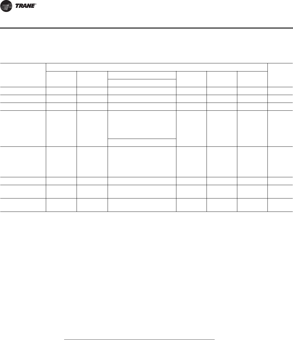
86 RT-SVX28E-EN
Sequence of Operation
Verifying Proper Fan Rotation
1. Ensure that the "System" selection switch at the remote panel is in the "Off" position and the
"Fan" selection switch for constant volume units is in the "Auto" position. (VAV units do not
utilize a "Fan" selection input.)
2. Close the disconnect switch or circuit protector switch that provides the supply power to the unit
terminal block 1TB1 or the unit mounted disconnect switch 1S14.
3. Turn the 115 volt control circuit switch 1S1 and the 24 volt control circuit switch 1S70 to the "On"
position.
4. Open the Human Interface access door, located in the unit control panel, and press the SERVICE
MODE key to display the first service screen. Refer to the latest edition of the appropriate
programming manual for CV or VAV applications for the SERVICE TEST screens and
programming instructions.
5. Use Table 32, p. 86 to program the unit Fans for operation by scrolling through the displays. All
Fans can be programmed to be "On", if desired. Verify proper fan rotation for VFDs with bypass.
6. Once the configuration for the Fans is complete, press the NEXT key until the LCD displays the
“Start test in __Sec.” screen. Press the + key to designate the delay before the test is to start.
This service test will begin after the TEST START key is pressed and the delay designated in this
step has elapsed. Press the ENTER key to confirm this choice.
Table 32. Service test guide component operation
COMPONENT
BEING TESTED
COMPONENT CONFIGURATION
Occ
Unocc
Relay
Supply
Fan
Exhaust
Fan
Heat Stages Econo
Damper
Exhaust
Damper
VFD
Output123
SUPPLY FAN ON OFF OFF OFF OFF Closed Closed 100% Unocc
EXHAUST FAN OFF ON OFF OFF OFF Closed Closed 100% Default
CHILLED WATER OFF OFF 100% Select Closed Closed 0% Default
GAS HEAT (Full
Capacity) ON OFF ON ON N/A Closed Closed 100% Unocc
STAGE 1 ON OFF ON OFF N/A Closed Closed 100% Unocc
STAGE 2 ON OFF OFF ON N/A Closed Closed 100% Unocc
FULL MODULATING ON OFF 10% - 90% Closed Closed 100% Unocc
ELECTRIC HEAT ON OFF ON ON ON Closed Closed 100% Unocc
Stage 1 ON OFF ON OFF OFF Closed Closed 100% Unocc
Stage 2 ON OFF OFF ON OFF Closed Closed 100% Unocc
Stage 3 ON OFF OFF OFF ON Closed Closed 100% Unocc
HYDRONIC HEAT OFF OFF 100% Select Closed Closed 0% Default
FRESH AIR
DAMPERS OFF OFF 100% Select 100% Open Closed 0% Default
EXHAUST
DAMPERS OFF OFF 100% Select 100% 100% Open 0% Default
RT-SVX28E-EN 87
Sequence of Operation
7. Press the TEST START key to start the test. Remember that the delay designated in step 6 must
elapse before the fans will begin to operate.
8. Check the supply fan and the exhaust fans (if equipped) for proper rotation. The direction of
rotation is indicated by an arrow on the fan housings.
If all of the fans are rotating backwards
1. Press the STOP key at the Human Interface Module in the unit control panel to stop the fan
operation.
2. Open the field supplied disconnect switch upstream of the air handler unit. Lock the disconnect
switch in the open position while working at the unit.
3. Interchange any two of the field connected main power wires at the unit terminal block or the
factory mounted disconnect switch.
Note: Interchanging "Load" side power wires at the fan contactors will only affect the individual
fan rotation. Ensure that the voltage phase sequence at the main terminal block or the
factory mounted disconnect switch is ABC as outlined in the "Electrical Phasing" section.
If some of the fans are rotating backwards
1. Press the STOP key at the Human Interface Module in the unit control panel to stop the fan
operation.
2. Open the field supplied disconnect switch upstream of the air handler unit. Lock the disconnect
switch in the open position while working at the unit.
3. Interchange any two of the fan motor leads at the contactor for each fan that is rotating
backwards.
System Airflow Measurements
Constant Volume Systems
1. Ensure that the "System" selection switch at the remote panel is in the "Off" position and the
"Fan" selection switch for constant volume units is in the "Auto" position. (VAV units do not
utilize a "Fan" selection input.)
2. Close the disconnect switch or circuit protector switch that provides the supply power to the unit
terminal block or the unit mounted disconnect switch.
WARNING
Rotating Components!
During installation, testing, servicing and troubleshooting of this product it may be necessary
to work with live and exposed rotating components. Have a qualified or licensed service
individual who has been properly trained in handling exposed rotating components, perform
these tasks. Failure to follow all safety precautions could result in rotating components cutting
and slashing technician which could result in death or serious injury.
WARNING
Hazardous Voltage!
Disconnect all electric power, including remote disconnects before servicing. Follow proper
lockout/tagout procedures to ensure the power can not be inadvertently energized. Failure to
disconnect power before servicing could result in death or serious injury.
88 RT-SVX28E-EN
Sequence of Operation
3. Turn the 115 volt control circuit switch and the 24 volt control circuit switch to the "On" position.
4. Open the Human Interface access door, located in the unit control panel, and press the SERVICE
MODE key to display the first service screen. Refer to the latest edition of the appropriate
programming manual for CV applications for the SERVICE TEST screens and programming
instructions.
5. Use Tab le 32 , p. 8 6 to program the Supply Fan for operation by scrolling through the displays.
6. Once the configuration for the Fan is complete, press the NEXT key until the LCD displays the
“Start test in __Sec.” screen. Press the + key to designate the delay before the test is to start.
This service test will begin after the TEST START key is pressed and the delay designated in this
step has elapsed. Press the ENTER key to confirm this choice.
7. Press the TEST START key to start the test. Remember that the delay designated in step 6 must
elapse before the fans will begin to operate.
8. With the system in the SERVICE MODE and the supply fan rotating in the proper direction,
measure the amperage at the supply fan contactors. If the amperage exceeds the motor
nameplate value, the static pressure is less than design and the airflow is too high. If the
amperage is below the motor nameplate value, static pressure may be too high and CFM may
be too low. To determine the actual CFM (± 5%);
a. Measure the actual fan RPM
b. Calculate the Theoretical BHP
Actual Motor Amps X Motor HP
Motor Nameplate Amps
c. Plot this data onto the appropriate Fan Performance Curve beginning with Figure 12, p. 31.
Where the two points intersect, read straight down to the CFM line.
Use this data to assist in calculating a new fan drive if the CFM is not at design specifications.
An alternate method with less accuracy is to measure the static pressure drop across the chilled
water coil. This can be accomplished by;
d. drilling a small hole through the unit casing on each side of the coil.
Note: Coil damage can occur if care is not taken when drilling holes in this area.
e. Measure the difference between the pressures at both locations.
WARNING
Hazardous Voltage!
Disconnect all electric power, including remote disconnects before servicing. Follow proper
lockout/tagout procedures to ensure the power can not be inadvertently energized. Failure to
disconnect power before servicing could result in death or serious injury.
HIGH VOLTAGE IS PRESENT AT TERMINAL BLOCK OR UNIT DISCONNECT SWITCH.
WARNING
Live Electrical Components!
During installation, testing, servicing and troubleshooting of this product, it may be necessary
to work with live electrical components. Have a qualified licensed electrician or other
individual who has been properly trained in handling live electrical components perform these
tasks. Failure to follow all electrical safety precautions when exposed to live electrical
components could result in death or serious injury.
RT-SVX28E-EN 89
Sequence of Operation
f. Plot this value onto the appropriate pressure drop curve beginning with Figure 39, p. 73. Use
the data in Table 22, p. 54
(Component Static Pressure Drops) to assist in calculating a new fan drive if the CFM is not
at design specifications.
g. Plug the holes after the proper CFM has been established.
9. Press the STOP key at the Human Interface Module in the unit control panel to stop the fan
operation.
Variable Air Volume Systems
1. Ensure that the "System" selection switch at the remote panel is in the "Off" position.
2. Close the disconnect switch or circuit protector switch that provides the supply power to the unit
terminal block or the unit mounted disconnect switch.
3. Turn the 115 volt control circuit switch and the 24 volt control circuit switch to the "On" position.
4. Open the Human Interface access door, located in the unit control panel, and press the SERVICE
MODE key to display the first service screen. Refer to the latest edition of the appropriate
Programming Manual for VAV applications for the SERVICE TEST screens and programming
instructions.
Use Table 32, p. 86 to program the following system components for operation by scrolling
through the displays:
Supply Fan,
Variable Frequency Drive (100% Output, if applicable),
RTM Occ/Unocc Output (Unoccupied)
5. Once the configuration for the components is complete, press the NEXT key until the LCD
displays the “Start test in __Sec.” screen. Press the + key to designate the delay before the test
is to start. This service test will begin after the TEST START key is pressed and the delay
designated in this step has elapsed. Press the ENTER key to confirm this choice.
6. Press the TEST START key to start the test. Remember that the delay designated in step 6 must
elapse before the fan will begin to operate.
7. With the VFD at 100% and the supply fan operating at full airflow capability, measure the
amperage at the supply fan contactors. If the amperage exceeds the motor nameplate value,
WARNING
Hazardous Voltage!
Disconnect all electric power, including remote disconnects before servicing. Follow proper
lockout/tagout procedures to ensure the power can not be inadvertently energized. Failure to
disconnect power before servicing could result in death or serious injury.
HIGH VOLTAGE IS PRESENT AT TERMINAL BLOCK OR UNIT DISCONNECT SWITCH.
WARNING
Live Electrical Components!
During installation, testing, servicing and troubleshooting of this product, it may be necessary
to work with live electrical components. Have a qualified licensed electrician or other
individual who has been properly trained in handling live electrical components perform these
tasks. Failure to follow all electrical safety precautions when exposed to live electrical
components could result in death or serious injury.
90 RT-SVX28E-EN
Sequence of Operation
the static pressure is less than design and the airflow is too high. If the amperage is below the
motor nameplate value, static pressure may be too high and CFM may be too low. To determine
the actual CFM (± 5%);
a. Measure the actual fan RPM
b. Calculate the Theoretical BHP
Actual Motor Amps X Motor HP
Motor Nameplate Amps
c. Plot this data onto the appropriate Fan Performance Curve beginning with Figure 39, p. 73.
Where the two points intersect, read straight down to the CFM line.
Use this data to assist in calculating a new fan drive if the CFM is not at design specifications.
An alternate method with less accuracy is to measure the static pressure drop across the chilled
water coil. This can be accomplished by:
d. drilling a small hole through the unit casing on each side of the coil.
Note: Coil damage can occur if care is not taken when drilling holes in this area.
e. Measure the difference between the pressures at both locations.
f. Plot this value onto the appropriate pressure drop curve beginning with Figure 39, p. 73. Use
the data in Tabl e 23, p. 62 (Component Static Pressure Drops) to assist in calculating a new
fan drive if the CFM is not at design specifications.
g. Plug the holes after the proper CFM has been established. Press the STOP key at the Human
Interface Module in the unit control panel to stop the fan operation.
8. Press the STOP key at the Human Interface Module in the unit control panel to stop the fan
operation.
Exhaust Airflow Measurement (Optional)
1. Close the disconnect switch or circuit protector switch that provides the supply power to the
unit's terminal block or the unit mounted disconnect switch.
2. Turn the 115 volt control circuit switch and the 24 volt control circuit switch to the "On" position.
3. Open the Human Interface access door, located in the unit control panel, and press the SERVICE
MODE key to display the first service screen. Refer to the latest edition of the appropriate
programming manual for CV or VAV applications for the SERVICE TEST screens and
programming instructions.
4. Use Table 32, p. 86 to program the following system components for operation by scrolling
through the displays:
Exhaust Fan,
Exhaust Dampers (100% Open, if applicable),
Fresh Air dampers (100% Open),
WARNING
Hazardous Voltage!
Disconnect all electric power, including remote disconnects before servicing. Follow proper
lockout/tagout procedures to ensure the power can not be inadvertently energized. Failure to
disconnect power before servicing could result in death or serious injury.
HIGH VOLTAGE IS PRESENT AT TERMINAL BLOCK OR UNIT DISCONNECT SWITCH.
RT-SVX28E-EN 91
Sequence of Operation
Variable Frequency Drive (100%, if applicable),
RTM Occ/Unocc Output (Default)
5. Once the configuration for the components is complete, press the NEXT key until the LCD
displays the “Start test in __Sec.” screen. Press the + key to designate the delay before the test
is to start. This service test will begin after the TEST START key is pressed and the delay
designated in this step has elapsed. Press the ENTER key to confirm this choice.
6. Press the TEST START key to start the test. Remember that the delay designated in step 5 must
elapse before the fans will begin to operate.
7. With the exhaust dampers open and the exhaust fan operating at full airflow capability,
measure the amperage at the exhaust fan contactor. If the amperage exceeds the motor
nameplate value, the static pressure is less than design and airflow is too high. If the amperage
is below the motor nameplate value, static pressure may be too high and CFM may be too low.
To determine the actual CFM (± 5%);
a. Measure the actual fan RPM
b. Calculate the Theoretical BHP
Actual Motor Amps X Motor HP
Motor Nameplate Amps
Use appropriate figures beginning with Figure 45, p. 93 to calculate a new fan drive if the CFM is
not at design specifications.
8. Press the STOP key at the Human Interface Module in the unit control panel to stop the fan
operation.
Traq™ Sensor Airflow Measurement (Optional with all units equipped with an
economizer)
1. Open the Human Interface access door, located in the unit control panel, and press the SERVICE
MODE key to display the first service screen. Refer to the latest edition of the appropriate
programming manual for CV or VAV applications for the SERVICE TEST screens and
programming instructions.
2. Use Table 32, p. 86 to program the following system components for Economizer operation by
scrolling through the displays;
Supply Fan (On)
Fresh Air dampers (Selected% Open)
Variable Frequency Drive (100% Output, if applicable)
RTM Occ/Unocc Output (Unoccupied)
Outside Air CFM Setpoint
Outside Air Pre-Heater Operation (if applicable)
3. Once the configuration for the components is complete, press the NEXT key until the LCD
displays the “Start test in __Sec.” screen. Press the + key to designate the delay before the test
WARNING
Live Electrical Components!
During installation, testing, servicing and troubleshooting of this product, it may be necessary
to work with live electrical components. Have a qualified licensed electrician or other
individual who has been properly trained in handling live electrical components perform these
tasks. Failure to follow all electrical safety precautions when exposed to live electrical
components could result in death or serious injury.
92 RT-SVX28E-EN
Sequence of Operation
is to start. This service test will begin after the TEST START key is pressed and the delay
designated in this step has elapsed. Press the ENTER key to confirm this choice.
4. Press the TEST START key to start the test. Remember that the delay designated in step 3 must
elapse before the fans will begin to operate.
5. With the unit operating in the "TEST MODE", the amount of outside air flowing through the traq
sensor can be viewed by switching to the "STATUS MENU" screen "OA CFM.
6. Scroll to the "ECONOMIZER ENABLE/ECONOMIZER POSITION" screen by pressing the "NEXT"
key and read the corresponding damper opening percentage (%).
7. Press the STOP key at the Human Interface Module in the unit control panel to stop the unit
operation.
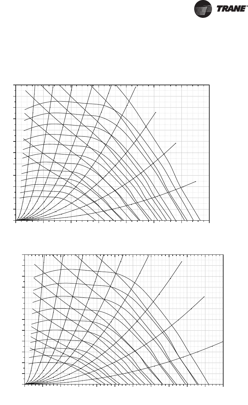
RT-SVX28E-EN 93
Performance Data
Supply Fan (with or without Variable Frequency Drive)
Figure 45. Supply fan performance STANDARD CFM — casing A, 25”
Figure 46. Supply fan performance STANDARD CFM — casing B, 32”
0 5000 10000 15000 20000 25000 30000 35000
0
1
2
3
4
5
6
7
8
9
10
11
12
10% WOCFM
20% WOCFM
30% WOCFM
40% WOCFM
50% WOCFM
90% WOCFM
80% WOCFM
70% WOCFM
50 BHP
2000 RPM
1900 RPM
1800 RPM
1700 RPM
60% WOCFM
40 BHP
30 BHP
25 BHP
20 BHP
15 BHP
10 BHP
7.5 BHP
1600 RPM
1500 RPM
1400 RPM
1300 RPM
1200 RPM
1100 RPM
1000 RPM
900 RPM
Static Presure(InWC)
0 5000 10000 15000 20000 25000 30000 35000 40000 45000 50000 55000
0
1
2
3
4
5
6
7
8
9
10
11
12
10% WOCFM
20% WOCFM
30% WOCFM
40% WOCFM
50% WOCFM
60% WOCFM
90% WOCFM
80% WOCFM
70% WOCFM
60 BHP
50 BHP
40 BHP
1600 RPM
1500 RPM
30 BHP
25 BHP
20 BHP
15 BHP
10 BHP
7.5 BHP
5 BHP
1400 RPM
1300 RPM
1200 RPM
1100 RPM
1000 RPM
900 RPM
800 RPM
700 RPM
Volumetric Airflow Rate(CFM)
Static Presure(InWC)
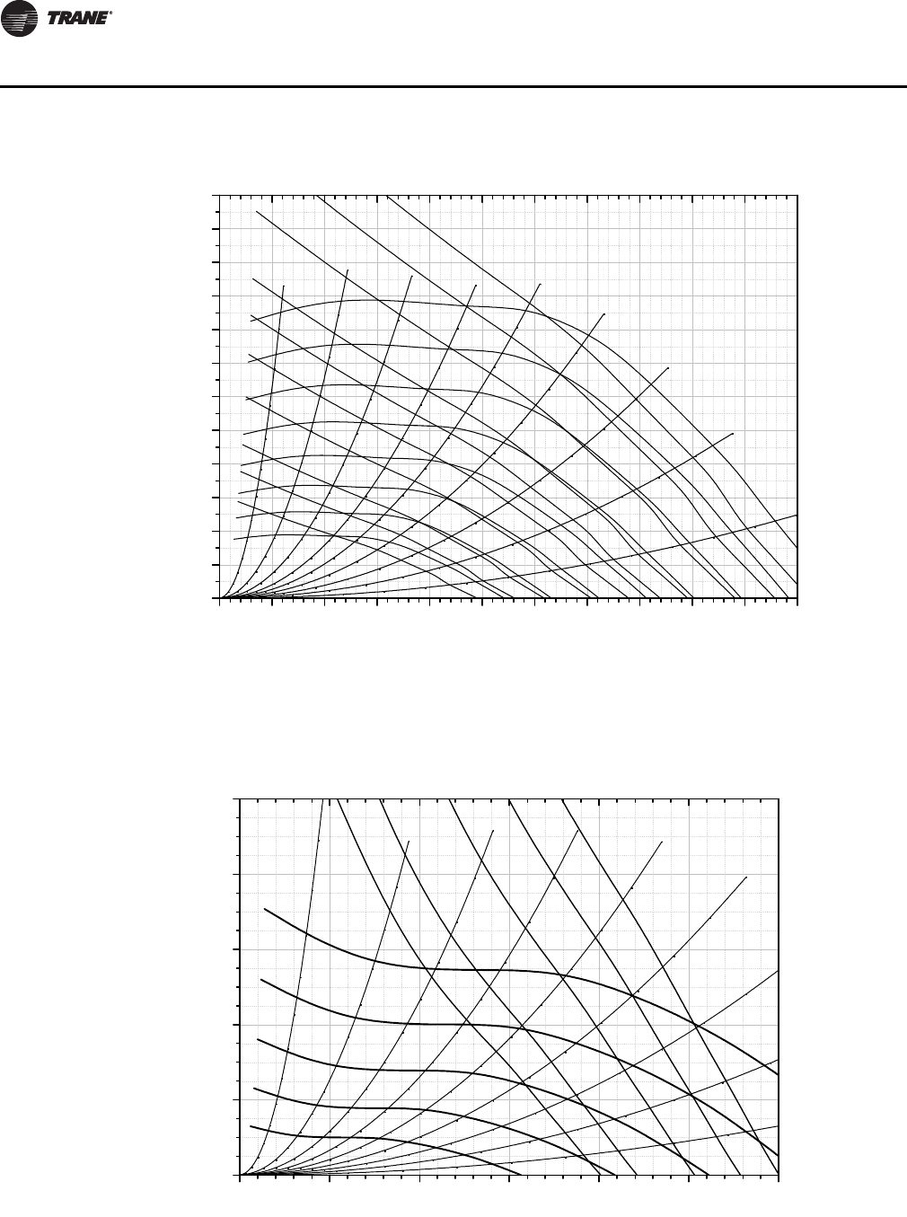
94 RT-SVX28E-EN
Performance Data
Exhaust Fan
Figure 47. Supply fan performance STANDARD CFM — casing C, 36”
0 5000 10000 15000 20000 25000 30000 35000 40000 45000 50000 55000
0
1
2
3
4
5
6
7
8
9
10
11
12
90% WOCFM
80% WOCFM
70% WOCFM
60 BHP
50 BHP
40 BHP
60% WOCFM
50% WOCFM
40% WOCFM
30% WOCFM
20% WOCFM
10% WOCFM
30 BHP
25 BHP
20 BHP
15 BHP
10 BHP
7.5 BHP
5 BHP
1300 RPM
1200 RPM
1100 RPM
1000 RPM
900 RPM
800 RPM
700 RPM
600 RPM
Volumetric Airflow Rate(CFM)
Static Presure(InWC)
Figure 48. Exhaust fan performance STANDARD CFM—casing A; LOW CFM—casing B
0 5000 10000 15000 20000 25000 30000
0
1
2
3
4
5
90% WOCFM
80% WOCFM
70% WOCFM
60% WOCFM
50% WOCFM
40% WOCFM
30% WOCFM
20% WOCFM
10% WOCFM
30 BHP
25 BHP
25 BHP
20 BHP
15 BHP
10 BHP
7.5 BHP
700 RPM
600 RPM
500 RPM
400 RPM
300 RPM
Volumetric Airflow Rate(CFM)
25" FC Exhaust Fan Performance w/Damper
Static Presure(InWC)
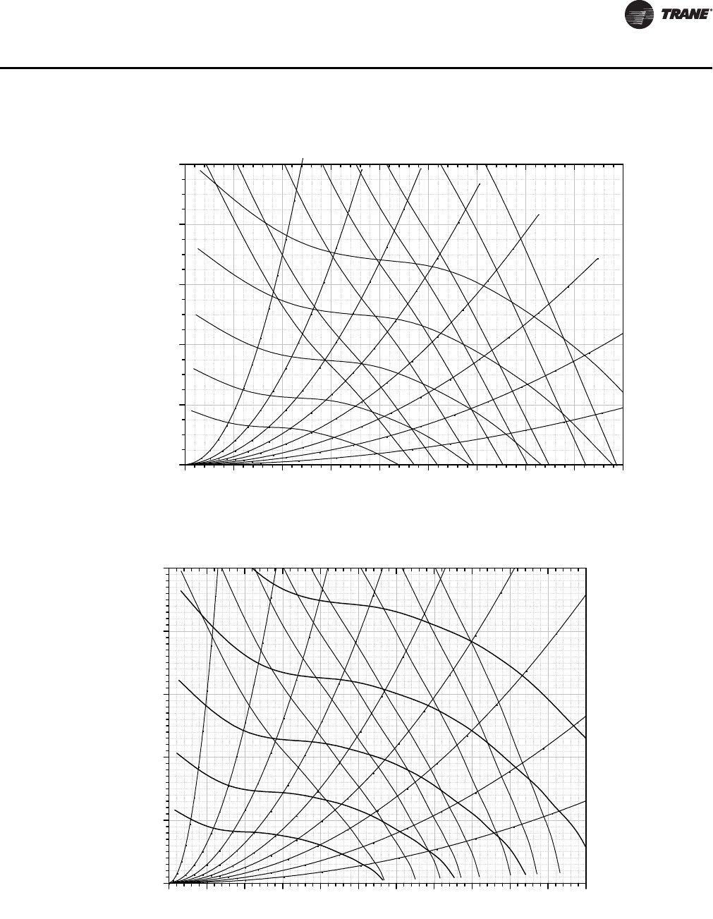
RT-SVX28E-EN 95
Performance Data
Figure 49. Exhaust fan performance STANDARD CFM—casing B; LOW CFM—casing C
Figure 50. Exhaust fan performance standard CFM—casing C
0 5000 10000 15000 20000 25000 30000 35000 40000 45000
0
1
2
3
4
5
90% WOCFM
80% WOCFM
50 BHP
70% WOCFM
60% WOCFM
50% WOCFM
40% WOCFM
30% WOCFM
20% WOCFM
40 BHP
30 BHP
25 BHP
20 BHP
15 BHP
10 BHP
7.5 BHP
700 RPM
600 RPM
500 RPM
400 RPM
300 RPM
Volumetric Airflow Rate(CFM)
28" FC Exhaust Fan Performance w/Damper
Static Presure(InWC)
0 5000 10000 15000 20000 25000 30000 35000 40000 45000 50000 55000
0
1
2
3
4
5
90% WOCFM
80% WOCFM
70% WOCFM
60 BHP
60% WOCFM
50 BHP
40 BHP
30 BHP
25 BHP
20 BHP
15 BHP
10 BHP
600 RPM
500 RPM
400 RPM
300 RPM
Volumetric Airflow Rate(CFM)
32" FC Exhaust Fan Performance w/Damper
Static Presure(InWC)
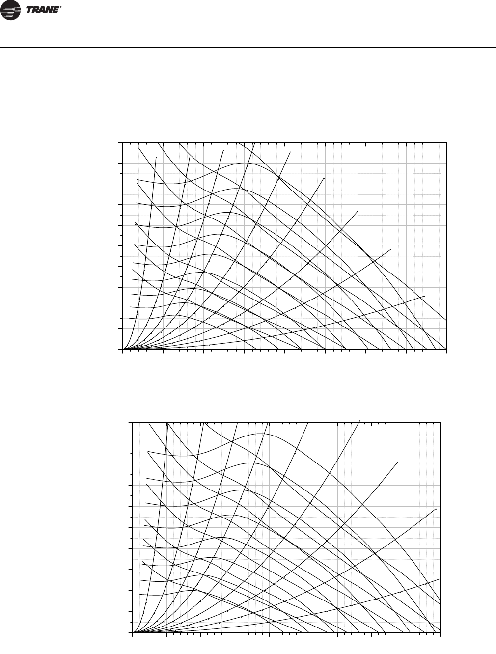
96 RT-SVX28E-EN
Performance Data
Return Fan
Figure 51. Return fan performance STANDARD CFM—casing A
Figure 52. Return fan performance standard CFM—casing B and C
0 5000 10000 15000 20000 25000 30000 35000 40000
0
1
2
3
4
5
6
7
8
9
10
90% WOCFM
80% WOCFM
70% WOCFM
40 BHP
1400 RPM
60% WOCFM
50% WOCFM
40% WOCFM
30% WOCFM
20% WOCFM
10% WOCFM
30 BHP
25 BHP
20 BHP
15 BHP
10 BHP
7.5 BHP
5 BHP
1300 RPM
1200 RPM
1100 RPM
1000 RPM
900 RPM
800 RPM
700 RPM
600 RPM
Volumetric Airflow Rate(CFM)
36.5" Return Fan Performance
Static Presure(InWC)
0 5000 10000 15000 20000 25000 30000 35000 40000 45000
0
1
2
3
4
5
6
7
8
9
10
10% WOCFM
20% WOCFM
30% WOCFM
40% WOCFM
50% WOCFM
60% WOCFM
90% WOCFM
80% WOCFM
70% WOCFM
50 BHP
40 BHP
30 BHP
25 BHP
20 BHP
15 BHP
10 BHP
7.5 BHP
5 BHP
1300 RPM
1200 RPM
1100 RPM
1000 RPM
900 RPM
800 RPM
700 RPM
600 RPM
Volumetric Airflow Rate(CFM)
40" Return Fan Performance
Static Presure(InWC)
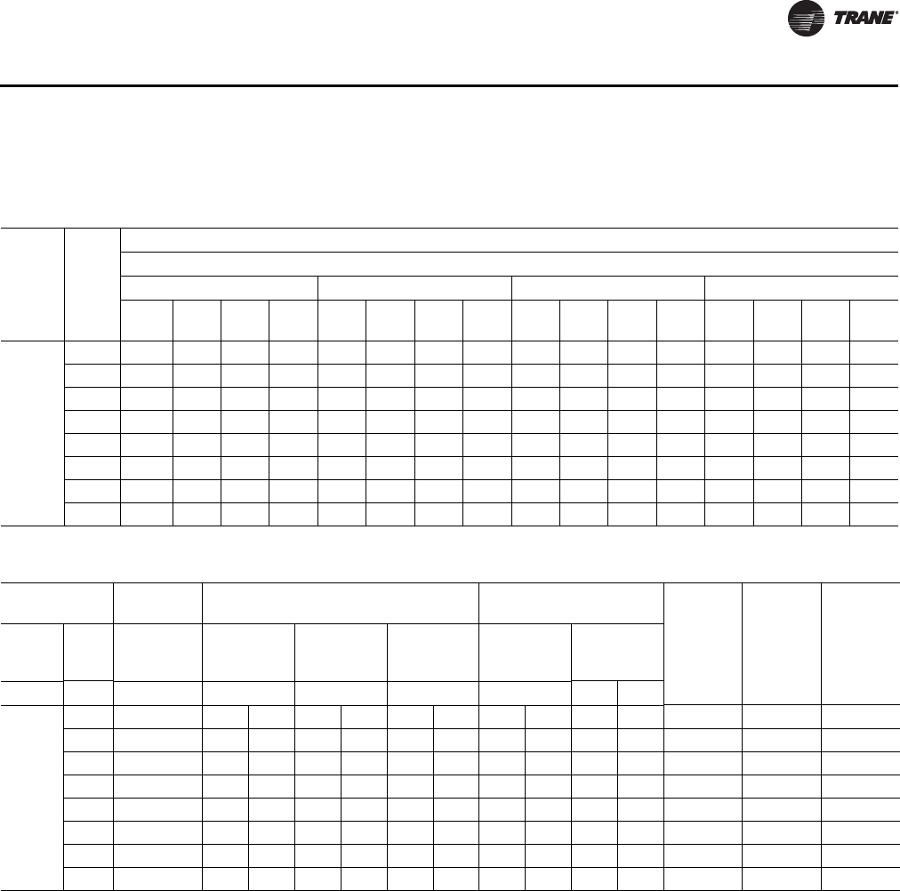
RT-SVX28E-EN 97
Performance Data
Component Static Pressure Drops
Table 33. Chilled water coil airside pressure drop (in H20)
Casing CFM
Chilled Water Coil
Airside Pressure Drop (in H2O)
2 row 4 row 6 row 8 row
80 fpf
108
fpf
144
fpf
168
fpf 80 fpf
108
fpf
144
fpf
168
fpf 80 fpf
108
fpf
144
fpf
168
fpf 80 fpf
108
fpf
144
fpf
168
fpf
A, B, C
16000 0.03 0.06 0.09 0.12 0.09 0.13 0.19 0.25 0.13 0.19 0.29 0.36 0.18 0.27 0.39 0.49
20000 0.06 0.09 0.13 0.16 0.13 0.19 0.27 0.34 0.20 0.28 0.40 0.50 0.27 0.38 0.54 0.68
23000 0.07 0.11 0.16 0.19 0.17 0.24 0.33 0.41 0.25 0.35 0.49 0.61 0.34 0.48 0.67 0.83
28000 0.10 0.15 0.21 0.26 0.24 0.33 0.44 0.54 0.35 0.49 0.66 0.81 0.48 0.67 0.89 1.10
33000 0.14 0.19 0.26 0.32 0.31 0.43 0.57 0.69 0.46 0.64 0.85 1.03 0.63 0.87 1.14 1.39
38000 0.18 0.24 0.33 - 0.40 0.54 0.70 - 0.59 0.80 1.04 - 0.81 1.09 1.41 -
43000 0.22 0.29 - - 0.49 0.65 - - 0.73 0.98 - - 0.99 1.34 - -
45000 0.23 0.31 - - 0.53 0.70 - - 0.78 1.05 - - 1.07 1.44 - -
Table 34. Component static pressure drops (in. H2O)
Gas Heating
Hydronic Heating Coil
Data
Return
Damper
Econo
Damper
(wide
open
in H20)
Traq
Damper
(wide
open
in H20)
Electric
Heating
(Horiz.) Low Heat
Medium
Heat High Heat
Hot Water
Coil Steam Coil
Casing CFM All kW's (i) DF Hz DF Hz DF Hz High Low High Low
A, B, C
16000 0.01 0.01 0.10 0.01 0.12 0.01 0.14 0.13 0.08 0.12 0.08 0.06 0.11 0.19
20000 0.02 0.01 0.16 0.01 0.19 0.01 0.22 0.17 0.11 0.16 0.11 0.09 0.15 0.26
23000 0.03 0.01 0.21 0.01 0.26 0.01 0.30 0.23 0.15 0.22 0.16 0.13 0.23 0.38
28000 0.04 0.02 0.31 0.02 0.38 0.02 0.44 0.32 0.21 0.31 0.22 0.20 0.34 0.57
33000 0.06 0.02 0.42 0.02 0.53 0.02 0.61 0.42 0.28 0.41 0.30 0.28 0.47 0.79
38000 0.07 0.03 0.56 0.03 0.70 0.03 0.81 0.53 0.36 0.52 0.39 0.38 0.63 1.05
43000 0.10 0.04 0.72 0.04 0.89 0.04 1.03 0.65 0.45 0.65 0.49 0.49 0.81 1.34
45000 0.10 0.04 0.79 0.04 0.98 0.04 1.13 0.71 0.49 0.70 0.53 0.53 0.89 1.47
(i) There is no pressure drop with Electric Heat DF configuration
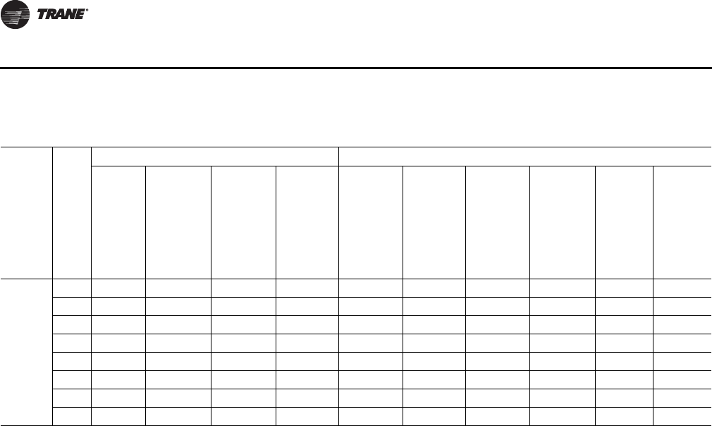
98 RT-SVX28E-EN
Performance Data
Table 35. Component static pressure drops (in. H2O)
Casing CFM
Standard Filter Section (Cooling Coil) Final Filter Section (Cooling Coil)
Std 2"
High Eff
Throw
Away
Filters
90-95%
Low PD
Cartridge
Filters w/
2"
Prefilter
90-95%
Cartridge
Filters w/
2"
Prefilter(i)
90-95%
Bag
Filters w/
2"
Prefilter
(i)
90-95%
Std Temp
Low PD
Cartridge
Filters w/
4”
Prefilter
(i)
90-95%
Std Temp
Bag
Filters w/
2"
Prefilter
(i)
90-95%
Std Temp
Cartridge
Filters w/
2"
Prefilter
(i)
90-95%
Hi Temp
Cartridge
Filters w/
2" Hi
Temp
Prefilter
(i)
90-95%
Hi Temp
HEPA w/
2" Hi
Temp
Prefilter
(ii)
90-95%
Std Temp
HEPA
Filters
w/ 2" Hi
Temp
Prefilter
(ii)
A, B, C
16000 0.08 0.24 0.27 0.34 0.23 0.36 0.29 0.35 0.54 0.48
20000 0.11 0.29 0.32 0.39 0.29 0.42 0.34 0.42 0.66 0.58
23000 0.11 0.29 0.32 0.39 0.29 0.42 0.34 0.42 0.66 0.58
28000 0.18 0.49 0.49 0.56 0.51 0.61 0.54 0.68 1.01 0.88
33000 0.23 0.61 0.61 0.67 0.65 0.73 0.69 0.86 1.22 1.06
38000 0.28 0.74 0.76 0.78 0.81 0.86 0.86 1.06 - -
43000 0.33 0.89 0.92 0.91 0.98 1.00 1.05 1.30 - -
45000 0.36 0.95 0.99 0.96 1.05 1.06 1.13 1.40 - -
(i) Case A, B, C Max CFM 45,000
(ii) Case A, B, C Max CFM 37,000
RT-SVX28E-EN 99
Unit Start-up
Storage and Operating Temperature Limits
Storage: -40ºF to 150ºF
Operation: -40ºF to 125ºF
Economizer Damper Adjustment
Exhaust Air Dampers
Verify that the exhaust dampers (if equipped) close tightly when the unit is off. Adjust the damper
linkage as necessary to ensure proper closure. An access panel is provided under each damper
assembly.
Fresh Air & Return Air Damper Operation
The fresh air and return air damper linkage is accessible from the filter section of the unit. The
damper linkage connecting the fresh air dampers to the return air dampers is preset from the
factory in the number 1 position. Refer to Figure 53, p. 101 for the appropriate linkage position for
the unit and operating airflow (CFM).
Note: Bridging between the unit main supports may consist of multiple 2 by 12 boards or sheet
metal grating.
Arbitrarily adjusting the fresh air dampers to open fully when the return air dampers are closed or;
failing to maintain the return air pressure drop with the fresh air dampers when the return air
dampers are closed, can overload the supply fan motor and cause building pressurization control
problems due to improper CFM being delivered to the space.
The fresh air/return air damper linkage is connected to a crank arm with a series of holes that allows
the installer or operator to modify the amount of fresh air damper travel in order to match the return
static pressure. Refer to Tab l e 3 6, p. 10 3 for the equivalent return air duct losses that correspond
to each of the holes illustrated in Figure 53, p. 101.
To Adjust the Fresh Air Damper Travel
1. Drill a 1/4" hole through the unit casing up stream of the return air dampers. Use a location that
will produce an accurate reading with the least amount of turbulence. Several locations may
be necessary, and average the reading.
2. Close the disconnect switch or circuit protector switch that provides the supply power to the unit
terminal block or the unit mounted disconnect switch.
3. Turn the 115 volt control circuit switch and the 24 volt control circuit switch to the "On" position.
WARNING
No Step Surface!
Do not walk on the sheet metal drain pan. Walking on the drain pan could cause the
supporting metal to collapse, resulting in the operator/technician to fall. Failure to follow this
recommendation could result in death or serious injury.
WARNING
Hazardous Voltage!
Disconnect all electric power, including remote disconnects before servicing. Follow proper
lockout/tagout procedures to ensure the power can not be inadvertently energized. Failure to
disconnect power before servicing could result in death or serious injury.
HIGH VOLTAGE IS PRESENT AT TERMINAL BLOCK OR UNIT DISCONNECT SWITCH.
100 RT-SVX28E-EN
Unit Start-up
4. Open the Human Interface access door, located in the unit control panel, and press the SERVICE
MODE key to display the first service screen. Refer to the latest edition of the applicable
programming manual for CV or VAV applications for the SERVICE TEST screens and
programming instructions.
5. Use Table 32, p. 86 to program the following system components for operation by scrolling
through the displays;
Supply Fan (On)
Variable Frequency Drive (100% Output, if applicable)
RTM Occ/Unocc Output (Unoccupied)
Fresh Air Dampers (Closed)
6. Once the configuration for the components is complete, press the NEXT key until the LCD
displays the “Start test in __Sec.” screen. Press the + key to designate the delay before the test
is to start. This service test will begin after the TEST START key is pressed and the delay
designated in this step has elapsed. Press the ENTER key to confirm this choice.
7. Press the TEST START key to start the test. Remember that the delay designated in step 6 must
elapse before the fan will begin to operate.
8. With the fresh air dampers fully closed and the supply fan operating at 100% airflow
requirements, measure the return static pressure at the location determined in step 1.
9. Press the STOP key at the Human Interface Module in the unit control panel to stop the fan
operation.
10. Open the field supplied main power disconnect switch upstream of the air handler unit. Lock
the disconnect switch in the "Open" position while working on the dampers.
11. Compare the static pressure reading to the static pressure ranges and linkage positions in
Table 36, p. 103 for the unit size and operating CFM.
To relocate the fresh air/return air connecting rod to balance the fresh air damper pressure drop
against the return static pressure, use the following steps. If no adjustment is necessary, proceed
to step 17.
12. Remove the drive rod and swivel from the crank arm(s). If only one hole requires changing,
loosen only that end.
13. Manually open the return air dampers to the full open position.
14. Manually close the fresh air dampers.
15. Reattach the drive rod and swivel to the appropriate hole(s). The length of the drive rod may
need to be adjusted to align with the new hole(s) location. If so, loosen the lock nut on the drive
rod against the swivel. Turn the swivel "in" or "out" to shorten or lengthen the rod as necessary.
For some holes, both ends of the rod may need to be adjusted.
16. Tighten the lock nut against the swivel(s).
17. Plug the holes after the proper CFM has been established.
WARNING
Rotating Components!
The following procedure involves working with rotating components. Disconnect all electric
power, including remote disconnects before servicing. Follow proper lockout/tagout
procedures to ensure the power can not be inadvertently energized. Failure to disconnect
power before servicing could result in rotating components cutting and slashing technician
which could result in death or serious injury.
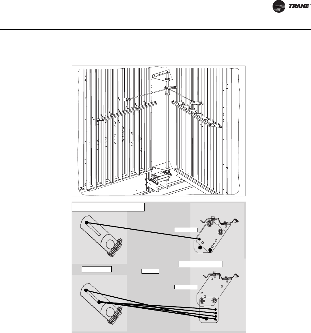
RT-SVX28E-EN 101
Unit Start-up
Figure 53. Fresh air and return air damper assembly
Economizer Linkage Adjustment
Jackshaft lever
Fresh air damper lever
1
1
2
1
CD
All top view
Configuration A
Configuration B
1
5
2
6
4
3
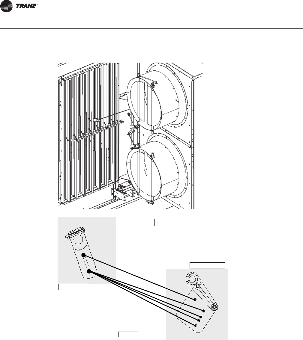
102 RT-SVX28E-EN
Unit Start-up
Figure 54. Fresh air and return air economizer assembly (w/Traq™ dampers)
Traq Damper Linkage Adjustment
Top view
Traq damper lever
Jackshaft lever
2
1
5
4
3
2
1
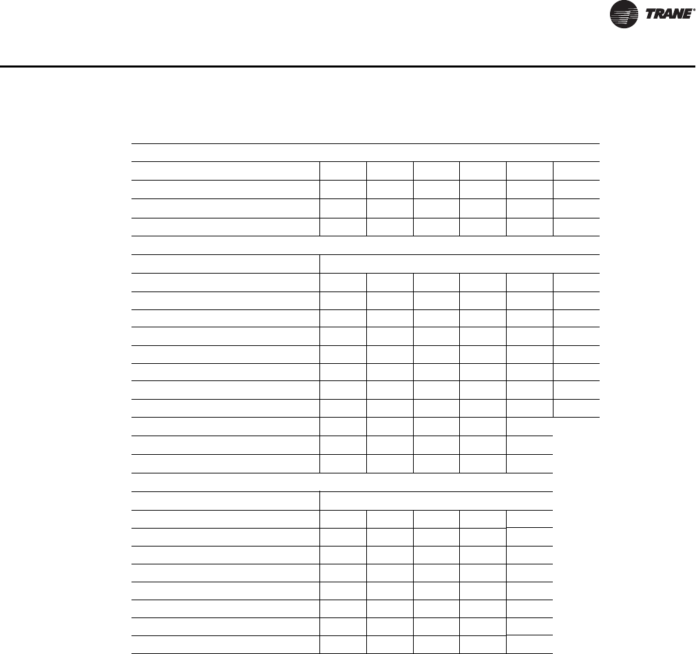
RT-SVX28E-EN 103
Unit Start-up
Chilled Water Cooling Startup (Constant Volume & Variable Air
Volume Systems)
1. Ensure that the "System" selection switch at the remote panel is in the "Off" position.
2. Close the disconnect switch or circuit protector switch that provides the supply power to the unit
terminal block or the unit mounted disconnect switch.
3. Check piping and valve for leaks. Open or close the valves to check operation. Drain lines should
be open.
4. Remove all foreign material from the drain pan and check drain pan opening and condensate
line for obstructions.
Table 36. (Economizer) Fresh air damper travel adjustment/pressure drop (inches H2O).
Damper Position
Linkage Set-up 123456
Jackshaft rod end location112222
Damper lever configurationABBBBB
Damper lever rod end location123456
w/Economizer (includes mist eliminator)
CFM Pressure Drop (inches h2O)
45000 0.74 1.71 ————
43000 0.67 1.56 2.95 — — —
38000 0.52 1.22 2.31 2.89 — —
33000 0.39 0.92 1.74 2.18 2.59 —
28000 0.28 0.66 1.25 1.57 1.87 2.27
23000 0.19 0.45 0.85 1.06 1.26 1.53
20000 0.14 0.34 0.64 0.80 0.95 1.16
16000 0.09 0.22 0.41 0.52 0.61 0.74
Linkage Set-up 12345
Jackshaft rod end location11121
Damper lever rod end location12354
w/Traq™ Damper (includes mist eliminator)
CFM Pressure Drop (inches h2O)
45000 1.23 1.70 2.46 — —
43000 1.12 1.54 2.24 2.87 —
38000 0.86 1.18 1.72 2.23 2.93
33000 0.64 0.86 1.27 1.66 2.21
28000 0.46 0.59 0.89 1.17 1.58
23000 0.31 0.37 0.57 0.76 1.04
20000 0.25 0.26 0.40 0.55 0.76
16000 0.18 0.15 0.22 0.31 0.45
104 RT-SVX28E-EN
Unit Start-up
5. Turn the 115 volt control circuit switch and the 24 volt control circuit switch to the "On" position.
6. Open the Human Interface access door, located in the unit control panel, and press the SERVICE
MODE key to display the first service screen. Refer to the latest edition of the appropriate
programming manual for CV or VAV applications for the SERVICE TEST screens and
programming instructions.
7. U s e Table 32, p. 86 to program the following system components for operation by scrolling
through the Human Interface displays;
8. Chilled Water Cooling
9. Supply Fan (On)
10. Variable Frequency Drive (100%Output, if applicable)
11. RTM Occ/Unocc Output (Unoccupied)
12. Chilled Water Actuator (100%Open)
13. Open the main chilled water valve supplying the coils.
14. Once the configuration for the appropriate cooling system is complete, press the NEXT key until
the LCD displays the "Start test in __Sec." screen. Press the + key to designate the delay before
the test is to start. This service test will begin after the TEST START key is pressed and the delay
designated in this step has elapsed. Press the ENTER key to confirm this choice.
15. Press the TEST START key to start the test. Remember that the delay designated in step 6 must
elapse before the fan will begin to operate.
16. Once the system has started, verify that the cooling system is operating properly by using
appropriate service technics; i.e. amperage readings, delta tees, etc.
17. Press the STOP key at the Human Interface Module in the unit control panel to stop the system
operation.
Electric, Steam and Hot Water Start-Up (Constant Volume & Variable
Air Volume Systems)
1. Ensure that the "System" selection switch at the remote panel is in the "Off" position.
2. Close the disconnect switch or circuit protector switch that provides the supply power to the unit
terminal block or the unit mounted disconnect switch.
3. Turn the 115 volt control circuit switch and the 24 volt control circuit switch to the "On" position.
WARNING
Hazardous Voltage!
Disconnect all electric power, including remote disconnects before servicing. Follow proper
lockout/tagout procedures to ensure the power can not be inadvertently energized. Failure to
disconnect power before servicing could result in death or serious injury.
HIGH VOLTAGE IS PRESENT AT TERMINAL BLOCK OR UNIT DISCONNECT SWITCH.
RT-SVX28E-EN 105
Unit Start-up
4. Open the Human Interface access door, located in the unit control panel, and press the SERVICE
MODE key to display the first service screen. Refer to the latest edition of the appropriate
programming manual for CV or VAV applications for the SERVICE TEST screens and
programming instructions.
5. Use Table 32, p. 86 to program the following system components for operation by scrolling
through the Human Interface displays;
Electric Heat
Supply Fan (On)
Variable Frequency Drive (100% Output, if applicable)
RTM Occ/Unocc Output (Unoccupied)
Heat Stages 1 & 2 (On)
Steam or Hot Water Heat
Supply Fan (On)
Variable Frequency Drive (100% Output, if applicable)
RTM Occ/Unocc Output (Unoccupied)
Hydronic Heat Actuator (100% Open)
Open the main steam or hot water valve supplying the air handler heating coils.
6. Once the configuration for the appropriate heating system is complete, press the NEXT key
until the LCD displays the “Start test in __Sec.” screen. Press the + key to designate the delay
before the test is to start. This service test will begin after the TEST START key is pressed and
the delay designated in this step has elapsed. Press the ENTER key to confirm this choice.
7. Press the TEST START key to start the test. Remember that the delay designated in step 6 must
elapse before the fan will begin to operate.
8. Once the system has started, verify that the electric heat or the hydronic heat system is
operating properly by using appropriate service technics; i.e. amperage readings, delta tees,
etc.
9. Press the STOP key at the Human Interface Module in the unit control panel to stop the system
operation.
Gas Furnace Start-Up
(Constant Volume and Variable Air Volume Systems)
It is important to establish and maintain the appropriate air/fuel mixture to assure that the gas
furnace operates safely and efficiently.
Since the proper manifold gas pressure for a particular installation will vary due to the specific BTU
content of the local gas supply, adjust the burner based on carbon dioxide and oxygen levels.
The volume of air supplied by the combustion blower determines the amount of oxygen available
for combustion, while the manifold gas pressure establishes fuel input. By measuring the
WARNING
Rotating Components!
During installation, testing, servicing and troubleshooting of this product it may be necessary
to work with live and exposed rotating components. Have a qualified or licensed service
individual who has been properly trained in handling exposed rotating components, perform
these tasks. Failure to follow all safety precautions could result in rotating components cutting
and slashing technician which could result in death or serious injury.
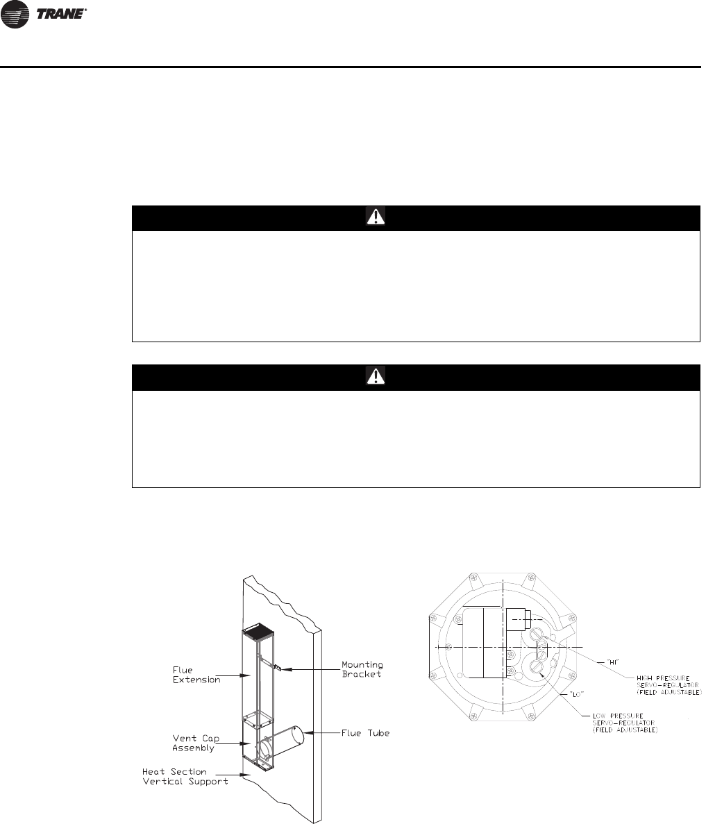
106 RT-SVX28E-EN
Unit Start-up
percentage of carbon dioxide produced as a by-product of combustion, the operator can estimate
the amount of oxygen used and modify the air volume or the gas pressure to obtain the proper air/
fuel ratio.
Arriving at the correct air/fuel mixture for a furnace results in rated burner output, limited
production of carbon monoxide, and a steady flame that minimizes nuisance shutdowns.
Two Stage Gas Furnace
WARNING
Hazardous Gases and Flammable Vapors!
Exposure to hazardous gases from fuel substances have been shown to cause cancer, birth
defects or other reproductive harm. Improper installation, adjustment, alteration, service or
use of this product could cause flammable mixtures and result in a fire. To avoid hazardous
gases and flammable vapors follow proper installation and set up of this product and all
warnings as provided in this manual. Failure to follow all instructions could result in death or
serious injury.
WARNING
Hazardous Pressures!
When using dry nitrogen cylinders for pressurizing units for leak testing, always provide a
pressure regulator on the cylinder to prevent excessively high unit pressures. Never pressurize
unit above the maximum recommended unit test pressure as specified in applicable unit
literature. Failure to properly regulate pressure could result in a violent explosion, which could
result in death or serious injury or equipment or property-only-damage.
Figure 55. Flue gas carbon dioxide and oxygen
measurements
Figure 56. High/low pressure regulator
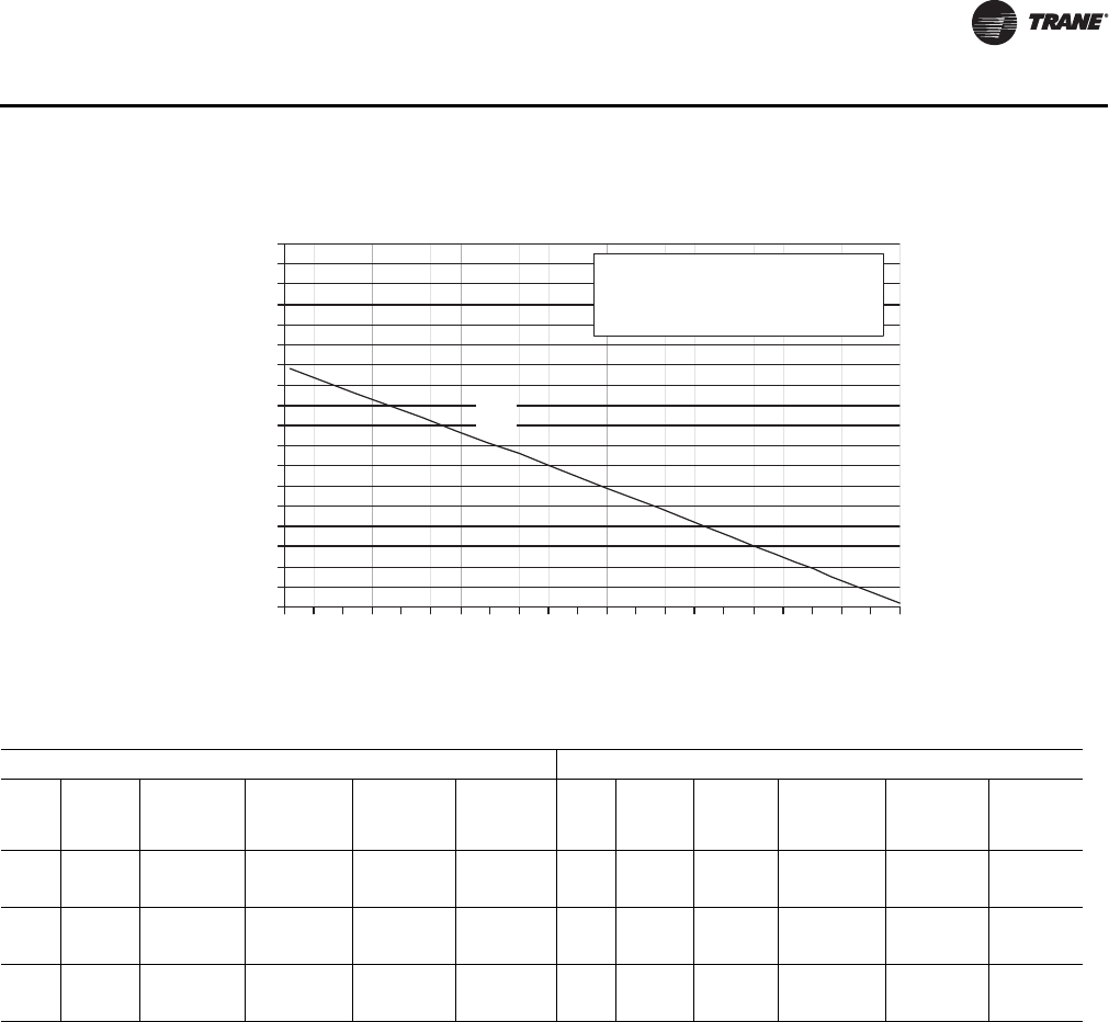
RT-SVX28E-EN 107
Unit Start-up
High-Fire Adjustment
1. Us e Table 32, p. 86 to program the following system components for operation by scrolling
through the Human Interface displays;
Gas Heat
Supply Fan (On)
Return Fan (On, if supplied)
Variable Frequency Drive (100% Output, if applicable)
RTM Occ/Unocc Output (Unoccupied)
Heat Stages 1 & 2 (On)
Turn the 115 volt control circuit switch 4S24 located in the heater control panel to the "On"
position.
Open the manual gas valve, located in the gas heat section.
2. Once the configuration for the appropriate heating system is complete, press the NEXT key
until the LCD displays the “Start test in __Sec.” screen. Press the + key to designate the delay
before the test is to start. This service test will begin after the TEST START key is pressed and
the delay designated in this step has elapsed. Press the ENTER key to confirm this choice.
Figure 57. Natural gas combustion curve (ratio of oxygen to carbon dioxide in percent)
0
1
2
3
4
5
6
7
8
9
10
11
12
13
14
15
16
17
18
0123456789101112131415161718192021
Percent Oxygen
Percent Carbon Dioxide
Curve Fuel
A = 1,000 BTU per cu. ft.
of Natural Gas.
A
Table 37. Recommended manifold pressures and CO2 levels during furnace operation
2-STAGE MODULATING
MBH
FIRING
RATES
% CO2
NAT GAS
MANIF
PRESS
"W.C.
% CO2
PROPANE
MANIF
PRESS "
W.C. MBH
FIRING
RATE
% CO2
NAT GAS
MANIF
PRESS
" W.C.
% CO2
PROPANE
MANIF
PRESS
"W.C.
850 100% 8.0-9.0 3.0-3.5 9.0-10.0 3.0-3.5 850 100% 8.0-9.0 3.0- 3.5 7.8-8.4 1.7-2.2
510 60% 5.0 -7.0 0.8-0.95 5.0-7.0 1.5-3.0 85 10% 5.0 -7.0 0.8- 0.9.5 2.0-3.0 .1-.2
1100 100% 8.0-9.0 3.0-3.3 9.0-10.0 3.0-3.3 1100 100% 7.0-9.0 .8-.9 8.5-9.5 .5-.75
550 50% 5.0 -7.0 0.8-0.95 5.0-7.0 0.8-0.95 55 5% 1.5-3.0 .05-1.0 1.5-2.5 .02-.04
1800 100% 7.0- 8.0 1.5- 1.8 N/A N/A 1800 100% 7.0-9.0 1.5- 1.8 N/A N/A
900 50% 5.0- 7.0 0.5- 0.7 N/A N/A 90 5% 1.5-3.0 .05-1.0 N/A N/A

108 RT-SVX28E-EN
Unit Start-up
3. Press the TEST START key to start the test. Remember that the delay designated in step 2 must
elapse before the system will begin to operate.
4. Once the system has started, check the appearance of the flame through the sight glass
provided on the front of the heat exchanger. In appearance, a normal flame has a clearly defined
shape, and is primarily (75%) blue in color with an orange tip.
5. Check the manifold gas pressure by using the manifold pressure port on the gas valve. Refer
to Tabl e 37, p. 107 for the required manifold pressure for high-fire operation. If it needs
adjusting, remove the cap covering the high-fire adjustment screw on the gas valve. Refer to
Figure 56, p. 106 for the adjustment screw location. Turn the screw clockwise to increase the gas
pressure or counterclockwise to decrease the gas pressure.
6. Use a carbon dioxide analyzer and measure the percentage of carbon dioxide in the flue gas.
Refer to the illustration in Figure 55, p. 106. Take several samples to assure that an accurate
reading is obtained. Refer to Figure 57, p. 107 for the proper carbon dioxide levels. A carbon
dioxide level exceeding the listed range indicates incomplete combustion due to inadequate air
or excessive gas.
Combustion Air Adjustment (O2)
1. Use an oxygen analyzer and measure the percentage of oxygen in the flue gas. Take several
samples to assure an accurate reading. Compare the measured oxygen level to the combustion
curve in Figure 57, p. 107. The oxygen content of the flue gas should be 4% to 5%. If the oxygen
level is outside this range, adjust the combustion air damper to increase or decrease the
amount of air entering the combustion chamber. Refer to Figure 59, p. 109 for the location of
the combustion air damper.
2. Recheck the oxygen and carbon dioxide levels after each adjustment. After completing the high-
fire checkout and adjustment procedure, the low-fire setting may require adjusting.
Low-Fire Adjustment (850 & 1100 MBH only)
1. Use the TEST initiation procedures outlined in the previous section to operate the furnace in
the low-fire state (1st Stage).
2. Use a carbon dioxide analyzer and measure the percentage of carbon dioxide in the flue gas.
Refer to the illustration in Figure 57, p. 107, Inset A. Take several samples to assure that an
accurate reading is obtained. Refer to Ta b le 37, p. 10 7 for the proper carbon dioxide levels. If the
measured carbon dioxide level is within the listed values, no adjustment is necessary. A carbon
dioxide level exceeding the listed range indicates incomplete combustion due to inadequate air
or excessive gas.
3. Check the manifold gas pressure by using the manifold pressure port on the gas valve. Refer
to Tabl e 37, p. 107 for the required manifold pressure during low-fire operation. If it needs
adjusting, remove the cap covering the low-fire adjustment screw on the gas valve. Refer to
Figure 56, p. 106 for the adjustment screw location. Turn the screw clockwise to increase the gas
pressure or counterclockwise to decrease the gas pressure.
Note: Do not adjust the combustion air damper while the furnace is operating at low-fire.
4. Check the carbon dioxide levels after each adjustment.
5. Press the STOP key at the Human Interface Module in the unit control panel to stop the system
operation.
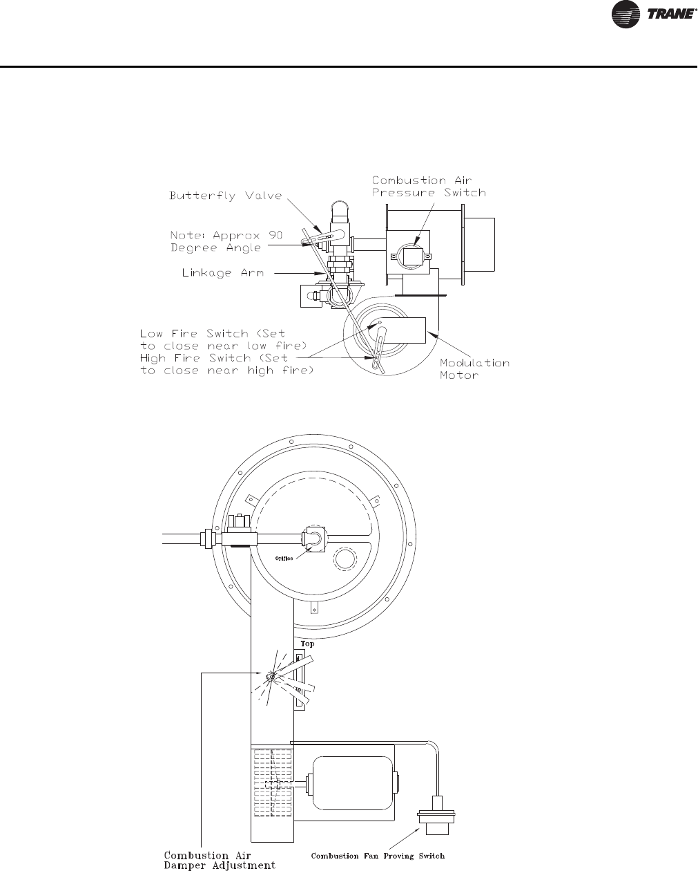
RT-SVX28E-EN 109
Unit Start-up
Full Modulating Gas Furnace
Full Modulating gas heaters are available for the 850, 1100 and 1800 MBH heater sizes.
– The firing rate of the 850 MBH modulating heater can vary from 10% to 100% of the 850 MBH.
– The firing rate of the 1100 and 1800 MBH can vary from 5% to 100% of it's nameplate value.
Figure 58. Modulating gas regulator
Figure 59. 850-1100 MBH

110 RT-SVX28E-EN
Unit Start-up
Heat Exchanger
The heat exchanger drum, tubes and front and rear headers are constructed from stainless steel
alloys.
Unit Control
The unit is controlled by a supply air temperature sensor located in the supply air stream for VAV
units. CV units have two sensors, one located in the supply air stream and the zone sensor. The
temperature sensor signal is sent to the Heat module of the IntelliPak II Unit Control. The control
signal from the Heat Module signal is directly proportional 0-10 VDC. The higher the voltage signal,
the lower the call for heat.
The 0-10 VDC signal controls the air damper actuator which is mounted on the end of the air damper
shaft. As the actuator rotates clockwise, more combustion air passes through the combustion air
blower. In turn, the gas butterfly valve opens more through a directly connected linkage, resulting
in a higher rate of firing.
1. Us e Table 32, p. 86 to program the following system components for operation by scrolling
through the Human Interface displays;
Gas Heat
Supply Fan (On)
Variable Frequency Drive (100% Output, if applicable)
RTM Occ/Unocc Output (Unoccupied)
High Fire (90%)
Turn the 115 volt control circuit switch 4S24 located in the heater control panel to the "On"
position.
Open the manual gas valve, located in the gas heat section.
2. Once the configuration for the appropriate heating system is complete, press the NEXT key
until the LCD displays the “Start test in __Sec.” screen. Press the + key to designate the delay
before the test is to start. This service test will begin after the TEST START key is pressed and
the delay designated in this step has elapsed. Press the ENTER key to confirm this choice.
3. Press the TEST START key to start the test. Remember that the delay designated in step 2 must
elapse before the system will begin to operate.
4. Once the system has started, check the appearance of the flame through the sight glass
provided on the front of the heat exchanger. In appearance, a normal flame has a clearly defined
shape, and is primarily (75%) blue in color with an orange tip.
5. Check the inlet gas pressure at the modulating gas valve. The inlet pressure should be 6" to 8"
w.c.
6. Use a carbon dioxide analyzer and measure the percentage of carbon dioxide in the flue gas.
Refer to the illustration in Figure 55, p. 106. Take several samples to assure that an accurate
reading is obtained. The C02 level should fall in the ranges shown in the Guide Values Ta bl e 37,
p. 107
WARNING
Rotating Components!
During installation, testing, servicing and troubleshooting of this product it may be necessary
to work with live and exposed rotating components. Have a qualified or licensed service
individual who has been properly trained in handling exposed rotating components, perform
these tasks. Failure to follow all safety precautions could result in rotating components cutting
and slashing technician which could result in death or serious injury.

RT-SVX28E-EN 111
Unit Start-up
Note: The burner capacity is controlled by the movement of the air damper. This has been preset
at the factory and normally does not need field adjustment. The combustion quality (air/gas)
is controlled by the setup of the air damper and butterfly valve linkage relationship.
7. U s e Table 32, p. 86 to program the minimum (5%) firing rate. Allow the system to operate for
approximately 10 minutes.
8. Use a carbon dioxide analyzer and measure the percentage of carbon dioxide in the flue gas.
If the measured carbon dioxide level is in the ranges shown in the Guide Values Tab le 3 7, p . 10 7 ,
no adjustment is necessary.
Note: It is normal for the low fire CO2 to be lower than the high fire.
9. If the measured carbon dioxide level is below the recommended values for low heat, return the
burner to 90% fire rate and repeat step 6, to achieve optimum combustion.
10. Program the burner for 100% operation and recheck the CO2 or O2 value.
11. Check the flue gas values at several intermediate output levels. If corrections are necessary;
– Adjust butterfly linkage
12. Press the STOP key at the Human Interface Module in the unit control panel to stop the system
operation.
11 2 RT-SVX28E-EN
Unit Start-up
Final Unit Checkout
After completing all of the checkout and start-up procedures outlined in the previous sections (i.e.,
operating the unit in each of its Modes through all available stages of cooling and heating), perform
these final checks before leaving the unit:
• Close the disconnect switch or circuit protector switch that provides the supply power to the
unit's terminal block or the unit mounted disconnect switch.
• Turn the 115 volt control circuit switch "Off".
• Turn the 24 volt control circuit switch to the "On" position.
• At the Human Interface Module, press the "SETUP" key. The LCD screen will display various
preset "parameters of operation" based on the unit type, size, and the installed options.
Compare the factory preset information to the specified application requirements. If
adjustments are required, follow the step-by-step instructions provided in the appropriate
programming manual for CV or VAV applications.
• Program the Night Setback (NSB) panel (if applicable) for proper unoccupied operation. Refer
to the programming instructions for the specific panel.
• Verify that the Remote panel "System" selection switch, "Fan" selection switch, and "Zone
Temperature" settings for constant volume systems are correct.
• Verify that the Remote panel "System" selection switch and the "Supply Air Temperature"
settings for variable air volume systems are correct.
• Inspect the unit for misplaced tools, hardware, and debris.
• Turn the 115 volt control circuit switch "On".
• Press the "AUTO" key at the Human Interface Module to begin system operation. The system
will start automatically once the dampers modulate and a request for either heating or cooling
has been given.
• Verify that all exterior panels including the control panel doors are secured in place.
WARNING
Hazardous Voltage!
Disconnect all electric power, including remote disconnects before servicing. Follow proper
lockout/tagout procedures to ensure the power can not be inadvertently energized. Failure to
disconnect power before servicing could result in death or serious injury.
HIGH VOLTAGE IS PRESENT AT TERMINAL BLOCK OR UNIT DISCONNECT SWITCH.
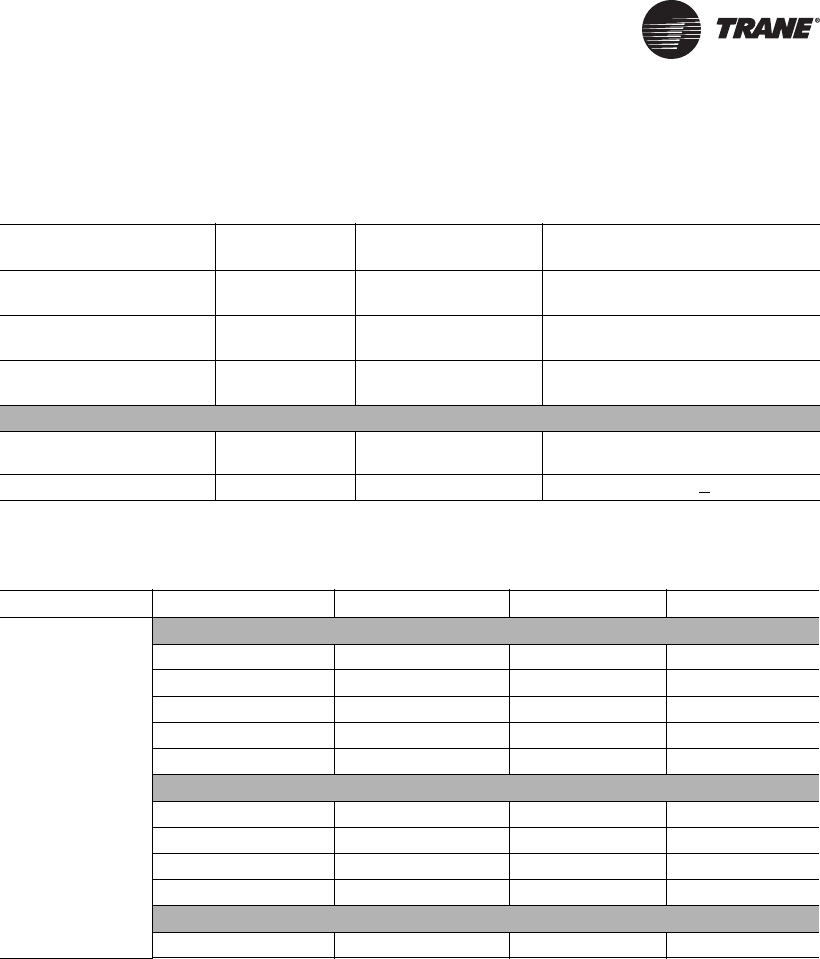
RT-SVX28E-EN 11 3
Maintenance
Table 38. Control settings and time delays
Control Description
Elec.
Designation Contacts Open Contacts Closed
Combustion Airflow Switch
(Gas Heat Only) 4S25 see note 1 0.1 - 0.25" wc rise in press diff
Supply Airflow Switch
(Gas Heat Only) 4S38 0.03 - 0.12" wc 0.15 + 0.05" wc rise in press diff
Freezestat
(Hydronic Heat Only) 4S12 (N.O.) Auto Reset 40°F
Gas Heat Units
Prepurge Timer: Honeywell 4U18 internal timing function 2 Stage 850/1100 MBH 60—seconds/
All other configurations—30 seconds
Sequencing Time Delay Relay 4DL6 N.C. - timed to close 60 seconds + 20%
Note: The combustion airflow switch (4S25) differential is 0.02" - 0.08" wc.
Table 39. Gas heat—high limit
Unit Size Fan Size (in) Config. Contacts Open Contacts Closed
Casings A-C
1800 MBH High Limit
25 DF 240 200
25 HZ 220 180
32 DF & HZ 240 200
36 DF & HZ 240 200
36 HZ 240 310
1100 MBH High Limit
25 DF & HZ 220 180
32 DF 240 200
32 HZ 200 160
36 DF & HZ 220 180
850 MBH High Limit
25 &36 DF & HZ 240 200
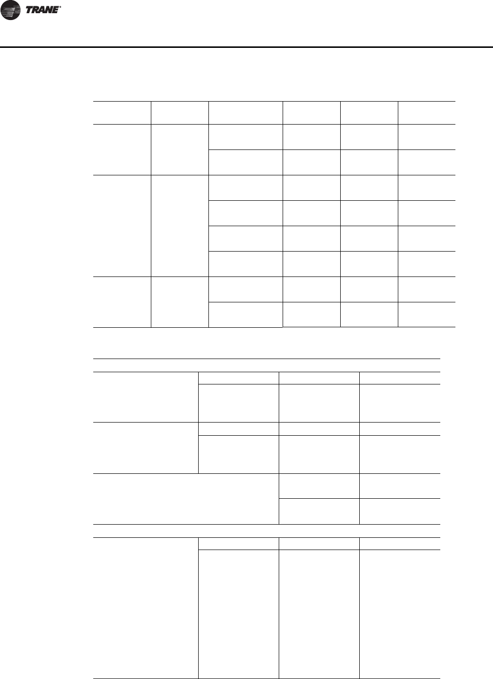
114 RT-SVX28E-EN
Maintenance
Table 40. Electric heat—selection limits
Size
Indoor Fan
Option
Electric Heat
Option
Supply
Discharge
Linear Limit
Open Temp.
Fan Fail Limit
Open Temp.
A25
262.5 kW Downflow 215°F 155°F
Hz (right) 235°F 155°F
90 kW Downflow 150°F 175°F
Hz (right) 150°F 175°F
B32
300 kW Downflow 205°F 185°F
Hz (right) 185°F 185°F
262.5 kW Downflow 225°F 185°F
Hz (right) 205°F 185°F
140 kW Downflow 150°F 185°F
Hz (right) 150°F 185°F
90 kW Downflow 150°F 175°F
Hz (right) 150°F 175°F
C36
262.5 kW Downflow 195°F 155°F
Hz (right) 195°F 155°F
90 kW Downflow 150°F 175°F
Hz (right) 150°F 175°F
Table 41. Unit internal & VFD fuse replacement
CONTROL POWER FUSES
TRANSFORMER PRIMARY TRANSFORMER SIZE 460V 575V
PROTECTION FUSE 1.00 kVA 3.5A 2.5A
1F3 & 1F4 1.50 kVA 5A 4A
TYPE FLQ 2.00 kVA 6A 5A
TRANSFORMER SECONDARY TRANSFORMER SIZE 460V 575V
PROTECTION FUSE 1.00 kVA 15A 15A
1F1 1.50 kVA 20A 20A
TYPE S 2.00 kVA 20A 20A
CONTROL WIRING
FUSE SIZE
460V 575V
PROTECTION FUSE
1F7 & 1F8 6A 6A
TYPE MTH
VFD PROTECTION FUSES*
MOTOR HP 460V 575V
SUPPLY FAN VFD FUSES
1F19, 1F20, 1F21
7.5 35A 25A
10 45A 35A
15 60A 50A
& 20 90A 70A
25 100A 80A
OPTIONAL EXHAUST /
RETURN FAN VFD FUSES
1F22, 1F23, 1F24
CLASS T
30 125A 90A
40 150A 125A
50 200A 175A
60 225A 200A
75 300A 225A
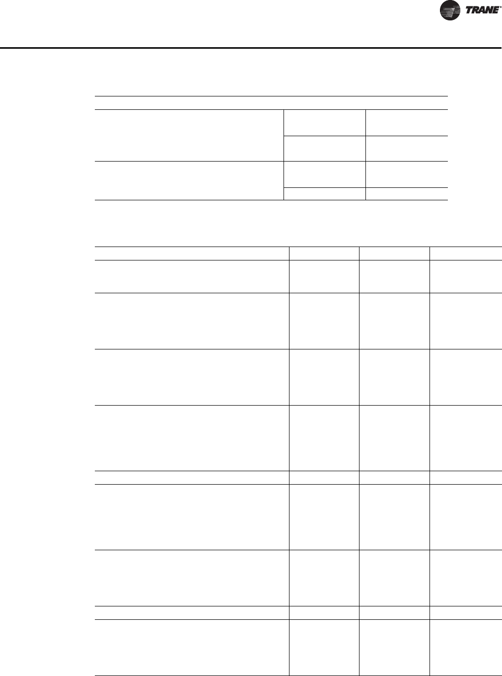
RT-SVX28E-EN 11 5
Maintenance
MISCELLANEOUS FUSES
OPTIONAL CONVENIENCE 460V 575V
OUTLET FUSES
1F25 & 1F26 FUSE SIZE 5A 4A
TIME DELAY TYPE FUSE
OPTIONAL MARINE 460V 575V
LIGHTS FUSES
1F27 & 1F28 FUSE SIZE 15A 15A
*SEE FUSE REPLACEMENT TABLE ON VFD PANEL FOR VFD POWER FUSES (F40, F41, F42).
Table 42. Filter data (all dimensions in inches)
Casing A Casing B Casing C
Standard 2" High Efficiency Throwaway Filters
Number/Size
Face area (Ft2)
21 - 20X24X2
5 - 12X24X2
80
21 - 20X24X2
5 - 12X24X2
80
21 - 20X24X2
5 - 12X24X2
80
90-95% Bag Filters w/Prefilters
Number/Size
Face area (Ft2)
21 - 20X24X19
5 - 12X24X19
80
21 - 20X24X19
5 - 12X24X19
80
21 - 20X24X19
5 - 12X24X19
80
Prefilters
Number/Size
21 - 20X24X2
5 - 12X24X2
21 - 20X24X2
5 - 12X24X2
21 - 20X24X2
5 - 12X24X2
90-95% Cartridge Filters w/Prefilters
Number/Size
Face area (Ft2)
21 - 20X24X2
5 - 12X24X2
80
21 - 20X24X2
5 - 12X24X2
80
21 - 20X24X2
5 - 12X24X2
80
Prefilters
Number/Size
21 - 20X24X2
5 - 12X24X2
21 - 20X24X2
5 - 12X24X2
21 - 20X24X2
5 - 12X24X2
90-95% Low Pressure Drop Cartridge Filters
w/Prefilters
Number/Size
Face area (Ft2)
21 - 20X24X2
5 - 12X24X2
80
21 - 20X24X2
5 - 12X24X2
80
21 - 20X24X2
5 - 12X24X2
80
Prefilters
Number/Size
21 - 20X24X2
5 - 12X24X2
21 - 20X24X2
5 - 12X24X2
21 - 20X24X2
5 - 12X24X2
Final Filters
90-95% Low Pressure Drop Cartridge Filters
w/Prefilters(1)
Number/Size
Face area (Ft2)
15 - 24X24X12
7 - 12X24X12
74
15 - 24X24X12
7 - 12X24X12
74
15 - 24X24X12
7 - 12X24X12
74
Prefilters
Number/Size
15 - 24X24X4
7 - 12X24X4
15 - 24X24X4
7 - 12X24X4
15 - 24X24X4
7 - 12X24X4
90-95% Bag Filters w/Prefilters(2)
Number/Size
Face area (Ft2)
15 - 24X24X19
7 - 12X24X19
74
15 - 24X24X19
7 - 12X24X19
74
15 - 24X24X19
7 - 12X24X19
74
Prefilters
Number/Size
15 - 24X24X2
7 - 12X24X2
15 - 24X24X2
7 - 12X24X2
15 - 24X24X2
7 - 12X24X2
Final Filters
90-95% Cartridge Filters(2)
Number/Size
Face area (Ft2)
15 - 24X24X12
7 - 12X24X12
74
15 - 24X24X12
7 - 12X24X12
74
15 - 24X24X12
7 - 12X24X12
74
Prefilters
Number/Size
15 - 24X24X2
7 - 12X24X2
15 - 24X24X2
7 - 12X24X2
15 - 24X24X2
7 - 12X24X2
Table 41. Unit internal & VFD fuse replacement (continued)
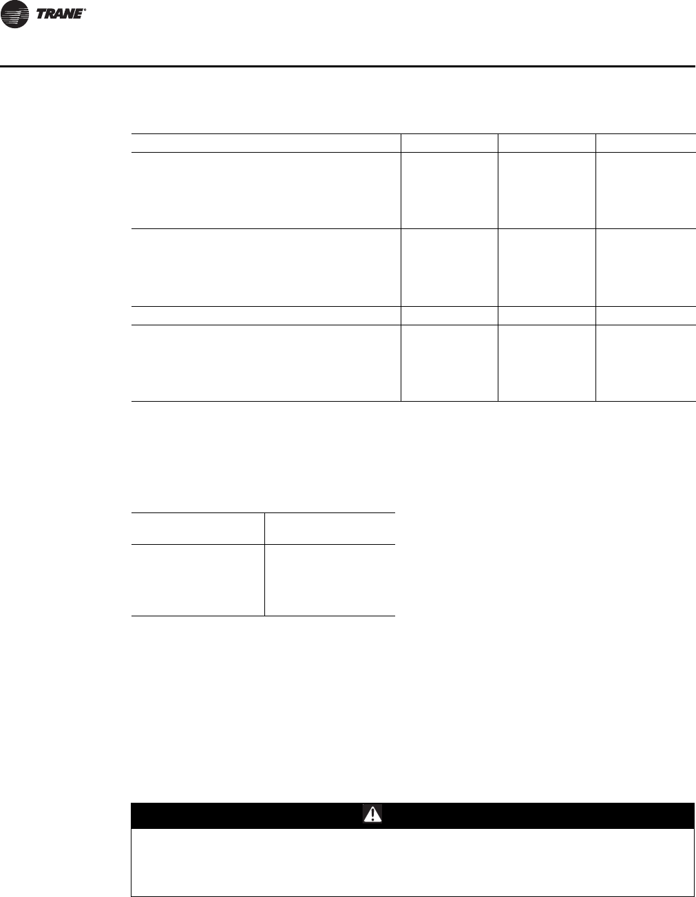
11 6 RT-SVX28E-EN
Maintenance
Fan Belt Adjustment
The supply fan belts and optional exhaust fan belts must be inspected periodically to assure proper
unit operation.
Replacement is necessary if the belts appear frayed or worn. Units with dual belts require a
matched set of belts to ensure equal belt length.
When removing or installing the new belts, do not stretch them over the sheaves. Loosen the belts
using the belt tension adjustment bolts on the motor mounting base.
Once the new belts are installed, using a Browning or Gates tension gauge (or equivalent), see
Figure 61, p. 117, adjust the belt tension as follows:
90-95% High Temp Cartridge Filters(3)
Number/Size
Face area (Ft2)
15 - 24X24X12
7 - 12X24X12
74
15 - 24X24X12
7 - 12X24X12
74
15 - 24X24X12
7 - 12X24X12
74
Prefilters
Number/Size
15 - 24X24X2
7 - 12X24X2
15 - 24X24X2
7 - 12X24X2
15 - 24X24X2
7 - 12X24X2
HEPA Filters(2) w/Prefilters
Number/Size
Face area (Ft2)
15 - 24X24X12
7 - 12X24X12
74
15 - 24X24X12
7 - 12X24X12
74
15 - 24X24X12
7 - 12X24X12
74
Prefilters
Number/Size
15 - 24X24X2
7 - 12X24X2
15 - 24X24X2
7 - 12X24X2
15 - 24X24X2
7 - 12X24X2
Final Filters
High Temp HEPA Cartridge Filters w/Prefilters(3)
Number/Size
Face area (Ft2)
15 - 24X24X12
7 - 12X24X12
74
15 - 24X24X12
7 - 12X24X12
74
15 - 24X24X12
7 - 12X24X12
74
Prefilters
Number/Size
15 - 24X24X2
7 - 12X24X2
15 - 24X24X2
7 - 12X24X2
15 - 24X24X2
7 - 12X24X2
(1) High Airflow Applications of Cooling only/Steam and Hot Water Units require 4" High Efficiency Throw Away Prefilters with
the 90-95% Low PD Cartridge Filter Option.
(2) Standard Airflow Applications of Cooling only/Steam and Hot Water Units include 2" High Efficiency Throw Away Prefilters
with the 90-95% Bag and HEPA Filter Options.
(3) Gas/Electric Units require 2" High Efficiency High Temperature Rated Throwaway Prefilters with High Temperature Rated
90-95% Cartridge and HEPA filter options.
Table 43. Grease recommendation
Recommended Grease
for Fan Bearings
Recommended
Operating Range
Exxon Unirex #2
Mobil 532 -20°F to 250°F
Mobil SHC #220
Texaco Premium RB
Table 42. Filter data (all dimensions in inches) (continued)
Casing A Casing B Casing C
WARNING
Hazardous Voltage!
Disconnect all electric power, including remote disconnects before servicing. Follow proper
lockout/tagout procedures to ensure the power can not be inadvertently energized. Failure to
disconnect power before servicing could result in death or serious injury.
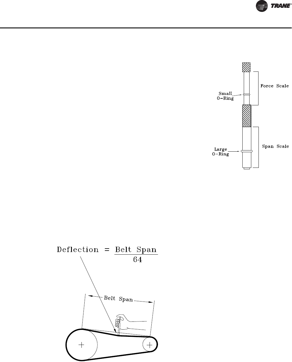
RT-SVX28E-EN 11 7
Maintenance
6. Compare the "force" scale reading (Step 5) with the appropriate “force” value listed in Table 44,
p. 118. If the "force" reading is outside the range, readjust the belt tension.
Note: Actual belt deflection "force" must not exceed the maximum “force” value shown in
Table 44, p. 118.
7. Recheck the belt tension at least twice during the first 2 to 3 days of operation. Belt tension will
decrease rapidly until the new belts are “run in”.
1. To determine the appropriate belt deflection:
a. Measure the center-to-center shaft distance (in inches)
between the fan and motor sheaves.
b. Divide the distance measured in Step 1a by 64; the
resulting value represents the amount of belt deflection
that corresponds to the proper belt tension.
2. Set the large O-ring on the belt tension gauge at the
deflection value determined in Step 1b.
3. Set the small O-ring at zero on the force scale of the gauge
plunger.
4. Place the large end of the gauge at the center of the belt
span; then depress the gauge plunger until the large O-ring
is even with the top of the next belt—-or even with a
straightedge placed across the fan and motor sheaves.
Refer to Figure 61, p. 117.
5. Remove the belt tension gauge. The small O-ring now
indicates a number other than zero on the plunger’s force
scale. This number represents the force (in pounds)
required to give the needed deflection.
Figure 60. Tension gauge
Figure 61. Belt tension
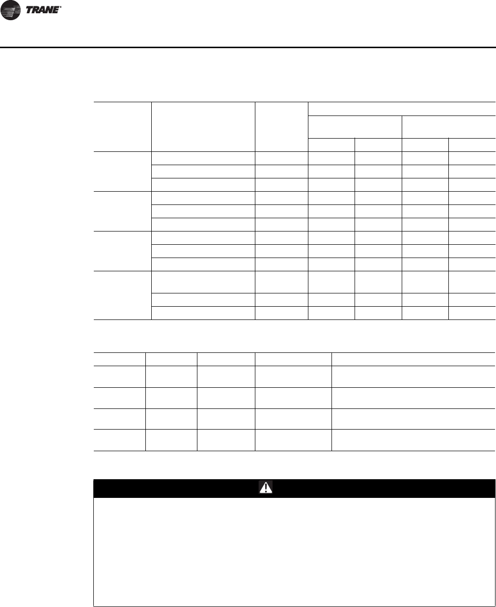
11 8 RT-SVX28E-EN
Maintenance
Table 44. Belt tension measurement and deflection ranges
Belt
Cross
Section
Smallest Sheave
Diameter Range (In.) RPM Range
Belt Deflection Force (Lbs.)
Super Gripbelts and
Unnotched Gripbands
Gripnotch Belts and
Notched Gripbands
Min. Max. Min. Max.
A, AX 3.0-3.6 1000-2500 3.7 5.5 4.1 6.1
3.8-4.8 1000-2500 4.5 6.8 5.0 7.4
5.0-7.0 1000-2500 5.4 8.0 5.7 8.4
B, BX 3.4 – 4.2 860-2500 -- -- 4.9 7.2
4.4 – 5.6 860-2500 5.3 7.9 7.1 10.5
5.8 – 8.6 860-2500 6.3 9.4 8.5 12.6
3V, 3VX 2.2 - 2.4 1000-2500 -- -- 3.3 4.9
2.65 - 3.65 1000-2500 3.6 5.1 4.2 6.2
4.12 - 6.90 1000-2500 4.9 7.3 5.3 7.9
5V, 5VX 4.4 – 6.7
500-1749
1750-3000 -- -- 10.2
8.8
15.2
13.2
7.1 –10.9 500-1740 12.7 18.9 14.8 22.1
11.8-16.0 500-1740 15.5 23.4 17.1 25.5
Table 45. Supply and exhaust fan VFD programming
Menu Parameter Description Setting Description
Load & Motor 1-21 Motor Power Set Based on Motor
Nameplate
Set only for application using 3hp hi- Efficiency
motors. Set to 2.2 kW/3 hp
1-22 Motor Voltage Set Based on Motor
Nameplate Set only for 380/415 50 Hz applications
1-24 Motor Current Set Based on Motor
Nameplate Sets the motor FLA
1-25 Motor Speed Set Based on Motor
Nameplate Sets the motor RPM
Note: These parameters are motor specific and the actual motor nameplate rating must be used. Do not use the unit name.
WARNING
Hazardous Voltage w/Capacitors!
Disconnect all electric power, including remote disconnects and discharge all motor start/run
capacitors before servicing. Follow proper lockout/tagout procedures to ensure the power
cannot be inadvertently energized. For variable frequency drives or other energy storing
components provided by Trane or others, refer to the appropriate manufacturer’s literature for
allowable waiting periods for discharge of capacitors. Verify with an appropriate voltmeter that
all capacitors have discharged. Failure to disconnect power and discharge capacitors before
servicing could result in death or serious injury.
For additional information regarding the safe discharge of capacitors, see PROD-SVB06A-EN
RT-SVX28E-EN 119
Maintenance
VFD Programming Parameters
Units shipped with an optional variable frequency drive (VFD) are preset and run tested at the
factory. If a problem with a VFD occurs, ensure that the programmed parameters listed in Tab l e 45,
p. 118 have been set before replacing the drive.
Note: Check to make sure that parameter 1-23 is set to 60 Hz. To check parameter 1-23 press the
[Main Menu] button (press [Back] button if the main menu does not display), use the [▼]
button to scroll down to Load & Motor, press OK, use the [▼] button to select 1-2, press OK,
and finally use the [▼] button until parameter 1-23 is displayed. Parameter 1-23 can then be
modified by pressing OK button and using [▲] and [▼] buttons. When the desired selection
has been made, press the OK button.
Should replacing the VFD become necessary, the replacement is not configured with all of Trane's
operating parameters. The VFD must be programmed before attempting to operate the unit.
To verify and/or program a VFD, use the following steps:
1. At the unit, turn the 115 volt control circuit switch to the "Off" position.
2. Turn the 24 volt control circuit switch to the "Off' position.
3. To modify parameters:
a. Press Main Menu button (press [Back] button if the main menu does not display)
b. Use the [▲] and [▼] buttons to find the parameter menu group (first part of parameter
number)
c. Press [OK]
d. Use the [▲] and [▼] buttons to select the correct parameter sub-group (first digit of second
part of parameter number)
e. Press [OK]
f. Use the [▲] and [▼] buttons to select the specific parameter
g. Press [OK]
h. To move to a different digit within a parameter setting, use the [►◄] buttons (Highlighted
area indicates digit selected for change)
i. Use the [▲] and [▼] buttons to adjust the digit
j. Press [Cancel] button to disregard change, or press [OK] to accept change and enter the new
setting
4. Repeat step (3) for each menu selection setting in Tab le 45 , p. 118 .
5. To reset all programming parameters back to the factory defaults:
a. Go to parameter 14-22 Operation Mode
b. Press [OK]
c. Select "Initialization”
d. Press [OK]
e. Cut off the mains supply and wait until the display turns off.
WARNING
Hazardous Voltage!
Disconnect all electric power, including remote disconnects before servicing. Follow proper
lockout/tagout procedures to ensure the power can not be inadvertently energized. Failure to
disconnect power before servicing could result in death or serious injury.
HIGH VOLTAGE IS PRESENT AT TERMINAL BLOCK OR UNIT DISCONNECT SWITCH.
120 RT-SVX28E-EN
Maintenance
f. Reconnect the mains supply - the frequency converter is now reset.
g. Ensure parameter 14-22 Operation Mode has reverted back to "Normal Operation".
Notes:
•Item 5 resets the drive to the default factory settings. The program parameters listed in Ta b le 45 ,
p. 118 will need to be verified or changed as described in Item 3 and 4.
•Some of the parameters listed in the Table are motor specific. Due to various motors and
efficiencies available, use only the values stamped on the specific motor nameplate. Do not use
the Unit nameplate values.
•A backup copy of the current setup may be saved to the LCP before changing parameters or
resetting the drive. See LCP Copy in the VFD Operating Instructions for details.
6. Follow the startup procedures for supply fan in the "Variable Air Volume System" section or the
"Exhaust Airflow Measurement" startup procedures for the exhaust fan.
7. After verifying that the VFD(s) are operating properly, press the STOP key at the Human
Interface Module to stop the unit operation.
8. Follow the applicable steps in the "Final Unit Checkout" section to return the unit to its normal
operating mode.
If a problem with a VFD occurs, ensure that the programmed parameters listed for supply and
exhaust VFD Table 45, p. 118 have been set before replacing the drive.
Monthly Maintenance
Before completing the following checks, turn the unit OFF and lock the main power disconnect
switch open.
Filters
Inspect the return air filters. Clean or replace them if necessary. Refer to the Table 42, p. 115 for filter
information.
Cooling Season
• Check the unit drain pans and condensate piping to ensure that there are no blockages.
• Inspect the chilled water coils for dirt, bent fins, etc. If the coils appear dirty, clean them
according to the instructions described in “Coil Cleaning” later in this section.
• Manually rotate the condenser fans to ensure free movement and check motor bearings for
wear. Verify that all of the fan mounting hardware is tight.
• Inspect the F/A-R/A damper hinges and pins to ensure that all moving parts are securely
mounted. Keep the blades clean as necessary.
WARNING
Hazardous Voltage!
Disconnect all electric power, including remote disconnects before servicing. Follow proper
lockout/tagout procedures to ensure the power can not be inadvertently energized. Failure to
disconnect power before servicing could result in death or serious injury.
WARNING
Hazardous Voltage!
Disconnect all electric power, including remote disconnects before servicing. Follow proper
lockout/tagout procedures to ensure the power can not be inadvertently energized. Failure to
disconnect power before servicing could result in death or serious injury.
RT-SVX28E-EN 121
Maintenance
• Verify that all damper linkages move freely; lubricate with white grease, if necessary.
• Check supply fan motor bearings; repair or replace the motor as necessary.
• Check the fan shaft bearings for wear. Replace the bearings as necessary.
• Lubricate the supply fan shaft bearings with a lithium based grease. Refer to Table 43, p. 116 for
recommended greases.
Important: The bearings are manufactured using a special synthetic lithium based grease
designed for long life and minimum lube intervals. Over lubrication can be just as
harmful as not enough.
Use a hand grease gun to lubricate these bearings; add grease until a light bead appears all around
the seal. Do not over lubricate!
After greasing the bearings, check the setscrews to ensure that the shaft is held securely to the
bearings and fan wheels. Make sure that all bearing supports are tight.
• Check the supply fan belt(s). If the belts are frayed or worn, replace them. Refer to the "Fan Belt
Adjustment" section for belt replacement and adjustments.
• Check the condition of the gasket around the control panel doors. These gaskets must fit
correctly and be in good condition to prevent water leakage.
• Verify that all wire terminal connections are tight.
• Remove any corrosion present on the exterior surfaces of the unit and repaint these areas.
• Generally inspect the unit for unusual conditions (e.g., loose access panels, leaking piping
connections, etc.)
• Make sure that all retaining screws are reinstalled in the unit access panels once these checks
are complete.
• With the unit running, check and record the:
– ambient temperature;
– compressor oil level (each circuit);
– compressor suction and discharge pressures (each circuit);
– superheat and subcooling (each circuit);
Record this data on an “operator’s maintenance log” like the one shown in Table 46, p. 124.
Heating Season
Before completing the following checks, turn the unit OFF and lock the main power disconnect
switch open.
• Inspect the unit air filters. If necessary, clean or replace them.
• Check supply fan motor bearings; repair or replace the motor as necessary.
• Lubricate the supply fan shaft bearings with a lithium based grease. Refer to Table 43, p. 116 for
recommended greases.
Important: The bearings are manufactured using a special synthetic lithium based grease
designed for long life and minimum lube intervals. Too much lubrication in a bearing
can be just as harmful as not enough.
WARNING
Hazardous Voltage!
Disconnect all electric power, including remote disconnects before servicing. Follow proper
lockout/tagout procedures to ensure the power can not be inadvertently energized. Failure to
disconnect power before servicing could result in death or serious injury.
122 RT-SVX28E-EN
Maintenance
Use a hand grease gun to lubricate the bearings; add grease until a light bead appears all around
the seal. Do not over lubricate! After greasing the bearings, check the setscrews to ensure that the
shaft is held securely. Make sure that all bearing braces are tight.
• Inspect both the main unit control panel and heat section control box for loose electrical
components and terminal connections, as well as damaged wire insulation. Make any
necessary repairs.
• Gas Heat Units only - Check the heat exchanger for any corrosion, cracks, or holes.
• Check the combustion air blower for dirt. Clean as necessary.
Note: Typically, it is not necessary to clean the gas furnace. However, if cleaning does become
necessary, remove the burner inspection plate from the rear of the heat exchanger to access
the drum. Be sure to replace the existing gaskets with new ones before reinstalling the
inspection plate.
• Open the main gas valve and apply power to the unit heating section; then initiate a "Heat" test
using the start-up procedure described in "Gas Furnace Start-Up".
• Verify that the ignition system operates properly.
Coil Cleaning
Regular coil maintenance, including annual cleaning enhances the unit operating efficiency by
minimizing:
– water carryover;
– fan brake horsepower; and,
– static pressure losses
At least once each year—or more often if the unit is located in a “dirty” environment—clean the
chilled water coils using the instructions outlined below. Follow these instructions as closely as
possible to avoid damaging the coils.
WARNING
Hazardous Gases and Flammable Vapors!
Exposure to hazardous gases from fuel substances have been shown to cause cancer, birth
defects or other reproductive harm. Improper installation, adjustment, alteration, service or
use of this product could cause flammable mixtures or lead to excessive carbon monoxide. To
avoid hazardous gases and flammable vapors follow proper installation and set up of this
product and all warnings as provided in this manual. Failure to follow all instructions could
result in death or serious injury.
WARNING
Hazardous Pressures!
When using dry nitrogen cylinders for pressurizing units for leak testing, always provide a
pressure regulator on the cylinder to prevent excessively high unit pressures. Never pressurize
unit above the maximum recommended unit test pressure as specified in applicable unit
literature. Failure to properly regulate pressure could result in a violent explosion, which could
result in death or serious injury or equipment or property-only-damage.
NOTICE:
Damaging Coil Cleaners!
Coil cleaners can damage roofs, surrounding buildings, vehicles, etc. Cleaning substances
should be checked to ensure that they will not cause damage to surroundings. Coils and roof (if
applicable) should be rinsed thoroughly. Do not spray coil cleaners in windy conditions.
RT-SVX28E-EN 123
Maintenance
Chilled Water Coils
To clean coils, use a soft brush and a sprayer (either a garden pump-up type or a high-pressure
sprayer). A high-quality detergent is also required; suggested brands include “SPREX A.C.”,
“OAKITE 161”, “OAKITE 166” and “COILOX”. If the detergent selected is strongly alkaline (pH value
exceeds 8.5), add an inhibitor.
1. Remove the access panels on both sides of the unit and the filters.
Note: Bridging between the unit's main supports may consist of multiple 2 by 12 boards or sheet
metal grating.
2. Straighten any bent coil fins with a fin comb.
3. Mix the detergent with water according to the manufacturer’s instructions. If desired, heat the
solution to 150 F maximum to improve its cleansing capability.
4. Pour the cleaning solution into the sprayer. If a high-pressure sprayer is used:
a. Do not allow the sprayer pressure to exceed 600 psi. The minimum spray nozzle angle is 15
degrees.
b. Spray the solution perpendicular (at 90 degrees) to the coil face.
c. Maintain a minimum clearance of 6" between the sprayer nozzle and the coil.
5. Spray the leaving-airflow side of the coil first; then spray the opposite side of the coil. Allow the
cleaning solution to stand on the coil for five minutes.
6. Rinse both sides of the coil with cool, clean water.
7. Inspect both sides of the coil; if it still appears to be dirty, repeat Steps 7 and 8.
8. Reinstall all of the components and panels removed in Step 2; then restore power to the unit.
Steam or Hot Water Coils
To clean a steam or hot water coil, use a soft brush, a steam-cleaning machine, and water.
1. Verify that switches 1S1 and 1S70 are turned "OFF", and that the main unit disconnect is locked
open.
2. Remove enough panels and components from the unit to gain sufficient access to the coil.
3. Straighten any bent coil fins with a fin comb.
4. Remove loose dirt and debris from both sides of the coil with a soft brush.
5. Use the steam-cleaning machine to clean the leaving-air side of the coil first; start at the top of
the coil and work downward; then clean the entering-air side of the coil, starting at the top of
the coil and working downward.
6. Check both sides of the coil; if it still appears dirty, repeat Step 5.
7. Reinstall all of the components and panels removed in Step 2; then restore power to the unit.
WARNING
No Step Surface!
Do not walk on the sheet metal drain pan. Walking on the drain pan could cause the
supporting metal to collapse, resulting in the operator/technician to fall. Failure to follow this
recommendation could result in death or serious injury.
124 RT-SVX28E-EN
Maintenance
Final Process
For future reference, it may be helpful to record the unit data in the blanks provided.
Table 46. Unit data log
Complete Unit Model Number:
Unit Serial Number:
Unit “DL” Number (“design special” units only):
Wiring Diagram Numbers (from unit control panel):
-schematic(s)
-connections
Network ID (LCI/BCI):
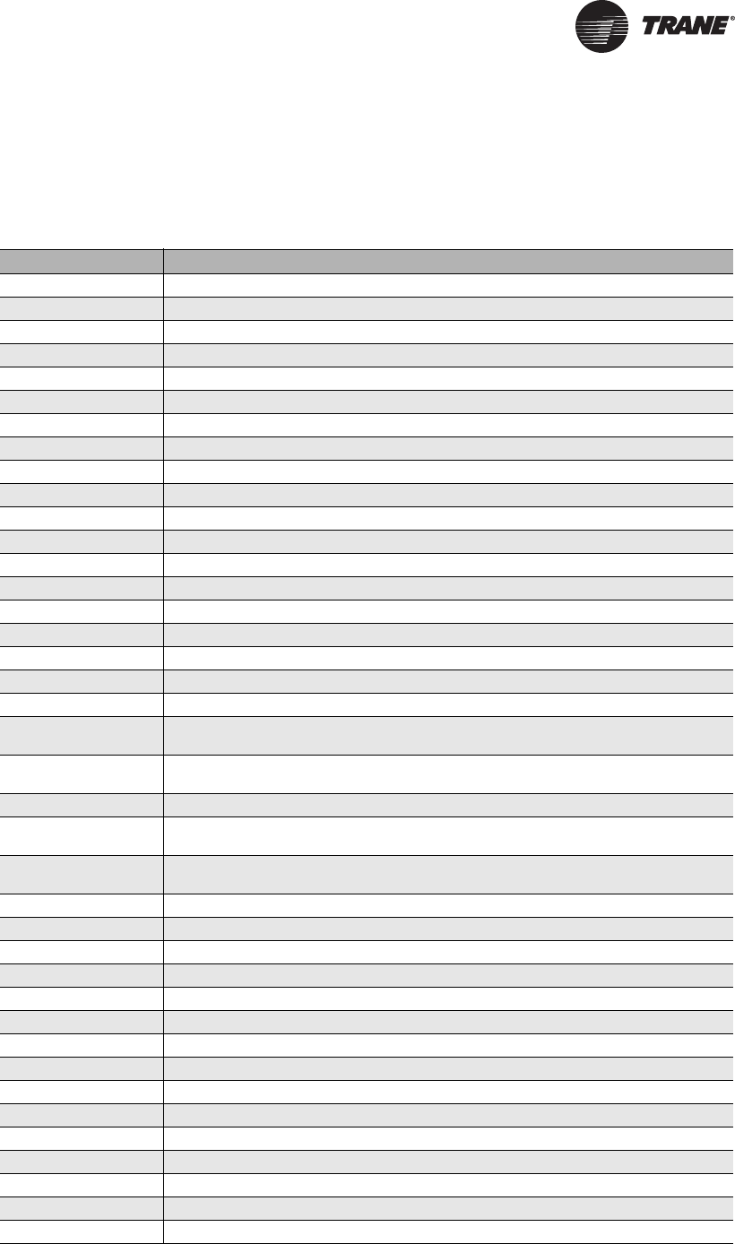
RT-SVX28E-EN 125
Wiring Diagrams
Note: Trane Wiring Diagrams are available via Trane e-Library or through the local Trane Sales
Office.
Table 47. Unit wiring diagrams
Diagram No. Description
2309-3625 SCHEMATIC-CONTROLS-RTM-STD 90-150 TON
2309-3626 SCHEMATIC-CONTROLS-RTM-W/SUP 90-150 TON
2309-3627 SCHEMATIC-CONTROLS-RTM-W/EXH/RTN 90-150 TON
2309-3628 SCHEMATIC-CONTROLS-RTM-W/SUP & EXH/RTN 90-150 TON
2309-3637 SCHEMATIC-CONTROLS-HEAT-ELEC/HYDRONIC HEAT- 90-150 TON
2309-3638 SCHEMATIC-CONTROLS-HEAT-2-STG-MOD GAS HEAT- 90-150 TON
2309-3645 SCHEMATIC-LHI-ECEM-VCM-MPM-W/O EXH OR RTN VFD
2309-3646 SCHEMATIC-LHI-ECEM-VCM-MPM-W/ RTN VFD
2309-3647 SCHEMATIC-LHI-ECEM-VCM-MPM-W/ EXH VFD
2309-3651 SCHEMATIC-VOM-LCI/BCI-IPCB-GBAS 0-5V-GBAS 0-10V- 90-150 TON
2309-3652 NOTES AND SPECS
2309-3653 SCHEMATIC-ELEC-HEAT-90KW
2309-3654 SCHEMATIC-ELEC-HEAT-140KW
2309-3655 SCHEMATIC-ELEC-HEAT-265KW
2309-3656 SCHEMATIC-ELEC-HEAT-300KW
2309-3661 CONNECTION-ELEC-HEAT-90KW
2309-3662 CONNECTION-ELEC-HEAT-140KW
2309-3663 CONNECTION-ELEC-HEAT-265KW
2309-3664 CONNECTION-ELEC-HEAT-300KW
2309-3669 SCHEMATIC/CONNECTION-2 STG-NATURAL-GAS-HEAT < 1800 MBH - 90-118 TON
LOW-MED - 120-162 TON LOW
2309-3670 SCHEMATIC/CONNECTION-2 STG-NATURAL-GAS-HEAT-1800/2500 MBH- 90-118 TON
HIGH - 120-162 TON MED-HIGH
2309-3671 PRINT SCHEMATIC/CONNECTION-MODULATING-NATURAL-GAS-HEAT
2309-3672 SCHEMATIC/CONNECTION-2 STG-NATURAL-GAS-HEAT < 1800 MBH-2 PC- 90-118 TON
LOW-MED - 120-162 TON LOW
2309-3673 SCHEMATIC/CONNECTION-2 STG-NATURAL-GAS-HEAT-1800/2500 MBH-2 PC-
90-118 TON HIGH - 120-162 TON MED-HIGH
2309-3674 PRINT SCHEMATIC/CONNECTION-MODULATING-NATURAL-GAS-HEAT-2 PC
2309-3685 SCHEMATIC-CONTROLS-COOLING-ONLY- 90-150 TON
2309-3708 CONNECTION, COMMON CONTROL MODULES - W/O RETURN VFD
2309-3709 CONNECTION, COMMON CONTROL MODULES - W/ RETURN VFD
2309-3730 SCHEMATIC/CONNECTION-MODULATING-NATURAL-GAS-HEAT
2313-0863 Schematic, Power - Standard Air Handler
2309-0864 Schematic, Power - w/Supply VFD Air Handler
2309-0865 Schematic, Power - w/ Exhaust/Return VFD Air Handler
2309-0866 Schematic, Power - w/Sup & Exh/Rtn VFD Air Handler
2309-3736 Connection, Control Box - Standard Air Handler
2309-3737 Connection, Control Box - w/Supply VFD Air Handler
2309-3738 Connection, Control Box - w/Exh/Rtn VFD Air Handler
2309-3739 Connection, Control Box - w/Sup & Exh/Rtn VFD Air Handler
2309-3740 Connection, Raceway Devices - Air Handler Standard
2309-3741 Connection, Raceway Devices - Air Handler w/Supply VFD
126 RT-SVX28E-EN
Wiring Diagrams
2309-3742 Connection, Raceway Devices - Air Handler w/ Exh/Rtn VFD
2309-3743 Connection, Raceway Devices - Air Handler w/Sup & Exh/Rtn VFD
2309-3789 Connection, Raceway Devices - Condenser Zone (Air Handler)
2309-3901 SCHEMATIC/CONNECTION-SUP-VFD-W/O-BYPASS
2309-3902 SCHEMATIC/CONNECTION-SUP-VFD-W/ BYPASS
2309-3905 SCHEMATIC/CONNECTION-EXH-RTN-VFD-W/O-BYPASS
2309-3906 SCHEMATIC/CONNECTION-EXH-RTN-VFD-W/ BYPASS
Table 47. Unit wiring diagrams
Diagram No. Description

RT-SVX28E-EN 127
A
Adjusting the Fresh Air Damper 99
Airflow Measurements 88
B
BACnet 9, 11, 65
BAYSENS008B
See figure 40 65
BAYSENS010B
See figure 40, Remote Panel w/o
NSB 65
BAYSENS013C
See figure 40
figure 41 66
BAYSENS014C
See figure 40
figure 41 66
BAYSENS016 66
BAYSENS016A
See figure 40
figure 41 66
BAYSENS017B
See figure 40
figure 41 67
BAYSENS019*
See figure 40 66
BAYSENS020*
See figure 40 66
BAYSENS021 65
BAYSENS021A
See Figure 41 65
BAYSENS073 66
BAYSENS074 66
BAYSENS108 65
BAYSENS119 66
BCI 65, 124
Belt Tension Measurement and
Deflection Ranges 118
C
Chilled 13
Chilled Water Units 52
Chilled Water Valve Control 13
Coil Cleaning 120, 122
Coil Winterization 55
Combustion Air Adjustment (O2
) 108
Commonly used Acronyms 9
Component Static Pressure
Drops 90
Compressor Module 10
Compressor Motor Winding
Thermostats 15
Constant Volume Systems 88
Constant Volume Zone Panel 65
Control Settings and Time Delays
See Table 30 113
Control Wiring 64
Cooling Sequence of Operation 80
Curb Accessory Kit 37
CV Electric Heat 84
D
Daytime Warm-up 16, 66
Demand Control Ventilation
Sequence of Operation 84
DSP control devices
See Figure 26 33
E
Economizer 81
Economizer Damper Adjustment 99
Electric Heat 83
Electric Heat—Selection Limits 114
Electric, Steam and Hot Water Start-
Up 104
Emergency Stop Switch 71
Exhaust Air Dampers 99
Exhaust Airflow Measurement 91
Exhaust/Comparative Enthalpy
Module 11
External Auto/Stop Switch (5S67)
See Figures 40, 41, 42, 43 67
F
factory mounted disconnect
switch 58
Fan Belt Adjustment 115
Fan Rotation 87
Fans are rotating backwards 87, 88
Filter Data (All dimensions in
inches) 115
Filter Switch 13
Final Unit Checkout 112
Flame Failure 83
Flue Assembly
See Figure 31 46
Freeze Protection 85
Fresh Air & Return Air Damper
See Tables 26, 27 & Figure 64 99
Fresh Air & Return Air Damper
Operation 99
Full Modulating Gas Furnace 109
Fuse Replacement 114
G
Gas Furnace Start-Up 105
Gas Heat Inlet Sizes 46
Gas Heat Piping Connection
Locations 47
Generic Building Automation
System 72
Generic Building Automation System
Module 13
Grease Recommendations
See Table 35 115
H
Heat Exchanger 110
Heat Module 10
High Duct Temp Thermostats
(Optional 3S16, 3S17) 15
Honeywell Ignition System 81
Hot Water Heat Units 47
Human Interface Module
See also appropriate SAHF-PTG
manual 10
I
Input Devices 13
Interprocessor Communications
Board 11
L
Lontalk Communication Interface 11
Low Ambient Compressor
Lockout 14
Low-Fire Adjustment 108
M
Main Unit Power Wiring 59
Minimum Position
Potentiometer 67
Modulating Gas Sequence of
Operation 82
Modules 20
Morning Warm-Up 15
N
nameplate location 9
O
Occupied Cooling 16
Occupied Heating 16
Occupied/Unoccupied Contacts 71
Outdoor Air Humidity Sensor 14
Outside Air Sensor (3RT3) 66, 72
Index

128 RT-SVX28E-EN
Index
P
Pitch Pocket Location 37
P-Traps at the unit
See Figure 20 30
R
Remote Human Interface Module 66
Remote Panel w/o NSB
See BAYSENS010B
BAYSENS021A 65
Remote Zone Sensor 66
request for exhaust fan operation 13
request for supply fan operation 13
Return Air Humidity Sensor
(3U64) 14
Return Air Temperature Sensor 13
Return Fan Performance 96
Return Fan Sequence of
Operation 84
Roof Curb and Ductwork 36
Rooftop Module 10
RTM Resistance Value vs System
Operating Mode 10
S
Sequence of Operation with
TRAQs 84
Some Fans are rotating backwards
See Fan Rotation 88
Space Humidity Sensor 14
Space Pressure Transducer
See Figure 3 14
Space Temperature Averaging 19
Standard Ambient Dampers 103
Status/Annunciator Output 14
Steam Heat Units 48
Steam or Hot Water Coils 123
supply air temperature falls 10 F
below 16
Supply Air Temperature Low
Limit 15
supply air temperature reaches 10 F
above 16
Supply Air Tempering 16
Supply and Exhaust Airflow Proving
Switches 13
Supply and Exhaust Fan Shipping
Channels
See Figures 24 & 25 31
Supply Duct Static Pressure
Control 16
SZVAV 17, 18, 19, 80
T
Thermostatic Expansion Valves 103
Traq Sensor 81
Traq™ Sensor 81
TraqTM Sensor Airflow
Measurement 92
Two Stage Gas Furnace 81, 106
U
Unit Control 110
Unit Control Modules 20
Unit Description 9
Unit Rigging and Placement 38
Units with an Economizer 81
Units without an economizer 80
Unoccupied Heating 16
unoccupied to an occupied mode
with the MWU option 15
V
Variable 65
Variable Air Volume Systems 89
VAV Changeover Contacts 66
VAV Occupied Electric Heat 84
VCM optional CO2 sensor 12
VCM optional temperature
sensor 12
Ventilation Control Module 12
Ventilation Override Module 11
W
Wet Heat 84
Z
Zone Temperature - Cooling 15
Zone Temperature - Heating 16

RT-SVX28E-EN 129
Warranty and Liability Clause
Commercial Equipment Rated 20 Tons and Larger and Related
Accessories
PRODUCTS COVERED - This warranty* is extended by Trane Inc. and applies only to commercial
equipment rated 20 Tons and larger and related accessories.
The Company warrants for a period of 12 months from initial start-up or 18 months from date of
shipment, whichever is less, that the Company products covered by this order (1) are free from
defects in material and workmanship and (2) have the capacities and ratings set forth in the
Company’s catalogs and bulletins, provided that no warranty is made against corrosion, erosion
or deterioration. The Company’s obligations and liabilities under this warranty are limited to
furnishing f.o.b. factory or warehouse at Company designated shipping point, freight allowed to
Buyer’s city (or port of export for shipment outside the conterminous United States) replacement
equipment (or at the option of the Company parts therefore) for all Company products not
conforming to this warranty and which have been returned to the manufacturer. The Company shall
not be obligated to pay for the cost of lost refrigerant. No liability whatever shall attach to the
Company until said products have been paid for and then said liability shall be limited to the
purchase price of the equipment shown to be defective.
The Company makes certain further warranty protection available on an optional extra-cost basis.
Any further warranty must be in writing, signed by an officer of the Company.
The warranty and liability set forth herein are in lieu of all other warranties and liabilities, whether
in contract or in negligence, express or implied, in law or in fact, including implied warranties of
merchantability and fitness for particular use. In no event shall the Company be liable for any
incidental or consequential damages.
THE WARRANTY AND LIABILITY SET FORTH HEREIN ARE IN LIEU OF ALL OTHER WARRANTIES
AND LIABILITIES, WHETHER IN CONTRACT OR IN NEGLIGENCE, EXPRESS OR IMPLIED, IN LAW
OR IN FACT, INCLUDING IMPLIED WARRANTIES OF MERCHANTABILITY AND FITNESS FOR
PARTICULAR USE, IN NO EVENT SHALL WARRANTOR BE LIABLE FOR ANY INCIDENTAL OR
CONSEQUENTIAL DAMAGES.
Manager - Product Service
Trane
Clarksville, Tn 37040-1008
PW-215-2688
*A 10 year limited warranty is provided on optional Full Modulation Gas Heat Exchanger.
*Optional Extended Warranties are available for compressors and heat exchangers of Combination
Gas-Electric Air Conditioning Units.

Trane optimizes the performance of homes and buildings around the world. A business of Ingersoll Rand, the
leader in creating and sustaining safe, comfortable and energy efficient environments, Trane offers a broad
portfolio of advanced controls and HVAC systems, comprehensive building services, and parts. For more
information, visit www.Trane.com.
Trane has a policy of continuous product and product data improvement and reserves the right to change design and specifications without notice.
We are committed to using environmentally
conscious print practices that reduce waste.
© 2011 Trane All rights reserved
RT-SVX28E-EN 24 Oct 2011
Supersedes RT-SVX28D-EN (26 Jan 2011)
