Trane Oa1D Oa2D Oa3D Indirect Gas Fired Electric Heat Installation And Maintenance Manual OAU SVX01E EN (17 Apr 2014)
2015-04-02
: Trane Trane-Oa1D-Oa2D-Oa3D-Indirect-Gas-Fired-Electric-Heat-Installation-And-Maintenance-Manual-684416 trane-oa1d-oa2d-oa3d-indirect-gas-fired-electric-heat-installation-and-maintenance-manual-684416 trane pdf
Open the PDF directly: View PDF ![]() .
.
Page Count: 56
- Introduction
- Model Number Descriptions
- General Information
- Overview of Manual
- Model Number Description
- Unit Nameplate
- Compressor Nameplate
- Unit Description
- Indoor Fan Failure Input
- Low Pressure Control ReliaTel Control
- Refrigerant Circuits
- High Pressure Control ReliaTel Control
- Space Temperature / RH Sensor (Optional)
- High Temperature Sensor
- Outdoor Air Temperature and Relative Humidity Sensor
- Control Input (Occupied / Unoccupied)
- Hot Gas Reheat
- 100 Percent Outdoor Air Hood with Damper and Filters
- Modulating Indirect Gas-Fired Burner
- Through the Base Electrical with Disconnect Switch
- Through the Base Gas Piping
- Hinged Access Doors
- Modulating Electric Heat
- Unit Inspection
- Unit Clearances, Curb Dimensions, and Dimensional Data
- Unit Weight and Rigging
- Sequence of Operation
- Installation
- System Configuration and Pre-Start
- Start-Up
- Maintenance
- Performance Data
- Alarms and Troubleshooting
- Appendix
SAFETY WARNING
Only qualified personnel should install and service the equipment. The installation, starting up, and servicing of heating, ventilating, and air-
conditioning equipment can be hazardous and requires specific knowledge and training. Improperly installed, adjusted or altered equipment
by an unqualified person could result in death or serious injury. When working on the equipment, observe all precautions in the literature and
on the tags, stickers, and labels that are attached to the equipment.
Installation, Operation,
and Maintenance
Important: Proper execution of the tasks outlined in this Installation, Operation, and Maintenance manual
require and assume the technician has been certified as a start up technician for the Horizon Outdoor
Air unit. This includes working knowledge of the Tracer TU program.
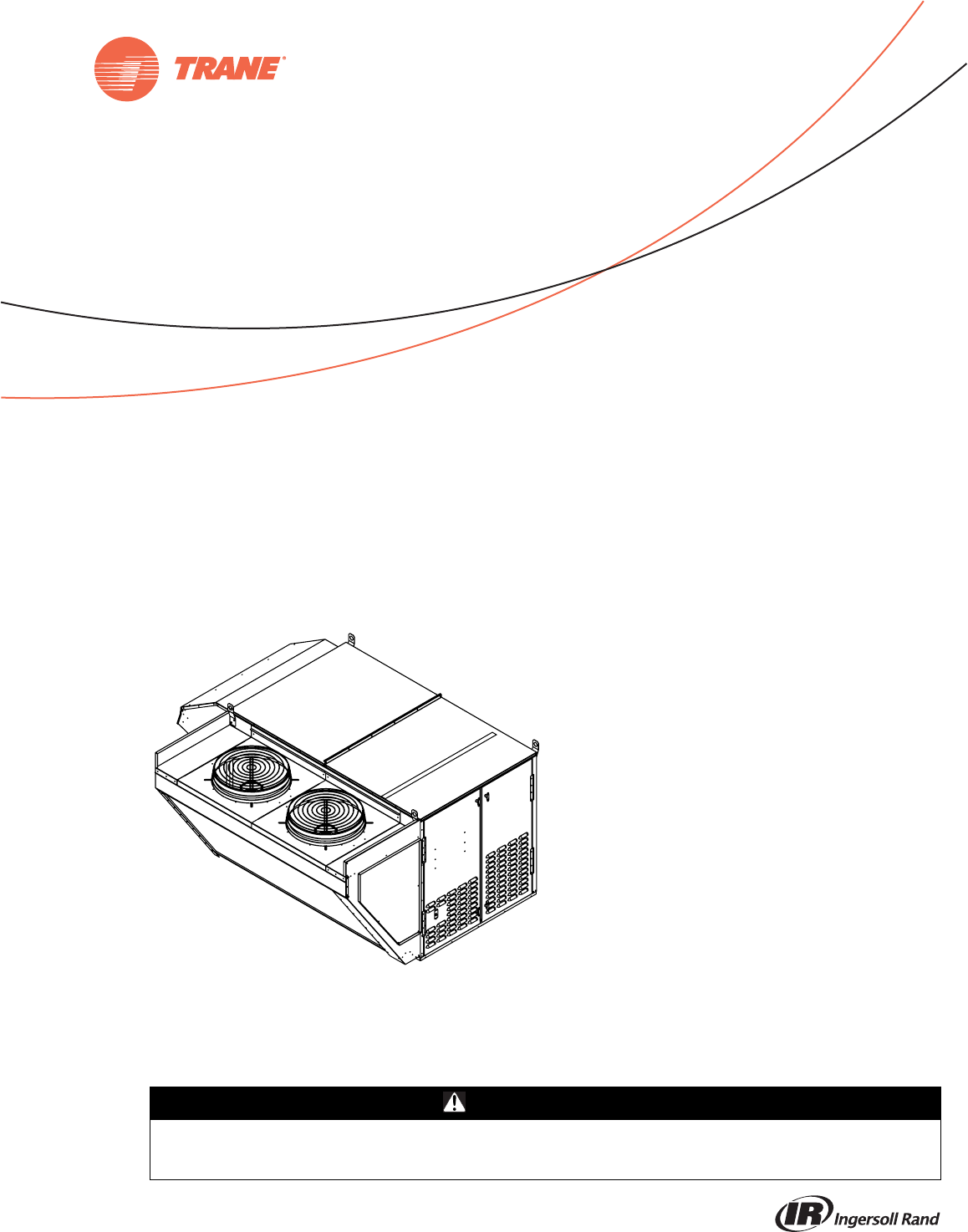
Horizon™ Outdoor Air Unit
Indirect Gas-Fired/Electric Heat
Models: OA1D, OA2D, OA3D
OAU-SVX01E-EN
April 2014
© 2014 Trane All rights reserved OAU-SVX01E-EN
Introduction
Read this manual thoroughly before operating or servicing
this unit.
Warnings, Cautions, and Notices
Safety advisories appear throughout this manual as
required. Your personal safety and the proper operation of
this machine depend upon the strict observance of these
precautions.
Important Environmental Concerns
Scientific research has shown that certain man-made
chemicals can affect the earth’s naturally occurring
stratospheric ozone layer when released to the
atmosphere. In particular, several of the identified
chemicals that may affect the ozone layer are refrigerants
that contain Chlorine, Fluorine and Carbon (CFCs) and
those containing Hydrogen, Chlorine, Fluorine and
Carbon (HCFCs). Not all refrigerants containing these
compounds have the same potential impact to the
environment. Trane advocates the responsible handling of
all refrigerants-including industry replacements for CFCs
such as HCFCs and HFCs.
Important Responsible Refrigerant Practices
Trane believes that responsible refrigerant practices are
important to the environment, our customers, and the air
conditioning industry. All technicians who handle
refrigerants must be certified. The Federal Clean Air Act
(Section 608) sets forth the requirements for handling,
reclaiming, recovering and recycling of certain
refrigerants and the equipment that is used in these
service procedures. In addition, some states or
municipalities may have additional requirements that
must also be adhered to for responsible management of
refrigerants. Know the applicable laws and follow them.
The three types of advisories are defined as follows:
WARNING Indicates a potentially hazardous
situation which, if not avoided, could
result in death or serious injury.
CAUTIONsIndicates a potentially hazardous
situation which, if not avoided, could
result in minor or moderate injury. It
could also be used to alert against
unsafe practices.
NOTICE: Indicates a situation that could result in
equipment or property-damage only
accidents.
WARNING
Proper Field Wiring and Grounding
Required!
Failure to follow code could result in death or serious
injury. All field wiring MUST be performed by qualified
personnel. Improperly installed and grounded field
wiring poses FIRE and ELECTROCUTION hazards. To
avoid these hazards, you MUST follow requirements for
field wiring installation and grounding as described in
NEC and your local/state electrical codes.
WARNING
Personal Protective Equipment (PPE)
Required!
Installing/servicing this unit could result in exposure to
electrical, mechanical and chemical hazards.
• Before installing/servicing this unit, technicians
MUST put on all PPE required for the work being
undertaken (Examples; cut resistant gloves/sleeves,
butyl gloves, safety glasses, hard hat/bump cap, fall
protection, electrical PPE and arc flash clothing).
ALWAYS refer to appropriate Material Safety Data
Sheets (MSDS)/Safety Data Sheets (SDS) and OSHA
guidelines for proper PPE.
• When working with or around hazardous chemicals,
ALWAYS refer to the appropriate MSDS/SDS and
OSHA/GHS (Global Harmonized System of
Classification and Labelling of Chemicals) guidelines
for information on allowable personal exposure
levels, proper respiratory protection and handling
instructions.
• If there is a risk of energized electrical contact, arc, or
flash, technicians MUST put on all PPE in accordance
with OSHA, NFPA 70E, or other country-specific
requirements for arc flash protection, PRIOR to
servicing the unit. NEVER PERFORM ANY
SWITCHING, DISCONNECTING, OR VOLTAGE
TESTING WITHOUT PROPER ELECTRICAL PPE AND
ARC FLASH CLOTHING. ENSURE ELECTRICAL
METERS AND EQUIPMENT ARE PROPERLY RATED
FOR INTENDED VOLTAGE.
Failure to follow instructions could result in death or
serious injury.
Introduction
OAU-SVX01E-EN 3
Copyright
This document and the information in it are the property of
Trane, and may not be used or reproduced in whole or in
part without written permission. Trane reserves the right
to revise this publication at any time, and to make changes
to its content without obligation to notify any person of
such revision or change.
Trademarks
All trademarks referenced in this document are the
trademarks of their respective owners.
Revision History
OAU-SVX01E-EN (17 Apr 2014)
• Model number updates
WARNING
Contains Refrigerant!
System contains oil and refrigerant under high
pressure. Recover refrigerant to relieve pressure before
opening the system. See unit nameplate for refrigerant
type. Do not use non-approved refrigerants, refrigerant
substitutes, or refrigerant additives.
Failure to follow proper procedures or the use of non-
approved refrigerants, refrigerant substitutes, or
refrigerant additives could result in death or serious
injury or equipment damage.
WARNING
Hazard of Explosion and Deadly Gases!
Never solder, braze or weld on refrigerant lines or any
unit components that are above atmospheric pressure
or where refrigerant may be present. Always remove
refrigerant by following the guidelines established by
the EPA Federal Clean Air Act or other state or local
codes as appropriate. After refrigerant removal, use dry
nitrogen to bring system back to atmospheric pressure
before opening system for repairs. Mixtures of
refrigerants and air under pressure may become
combustible in the presence of an ignition source
leading to an explosion. Excessive heat from soldering,
brazing or welding with refrigerant vapors present can
form highly toxic gases and extremely corrosive acids.
Failure to follow all proper safe refrigerant handling
practices could result in death or serious injury.

4 OAU-SVX01E-EN
Table of Contents
Introduction . . . . . . . . . . . . . . . . . . . . . . . . . . . . . 2
Warnings, Cautions, and Notices . . . . . . . . 2
Important Environmental Concerns . . . . . 2
Important Responsible Refrigerant Practices
. . . . . . . . . . . . . . . . . . . . . . . . . . . . . . . . . . . 2
Model Number Descriptions . . . . . . . . . . . . . . 6
Horizon Outdoor Air Unit . . . . . . . . . . . . . . . 6
General Information . . . . . . . . . . . . . . . . . . . . . 9
Overview of Manual . . . . . . . . . . . . . . . . . . 9
Model Number Description . . . . . . . . . . . . 9
Unit Nameplate . . . . . . . . . . . . . . . . . . . . . 9
Compressor Nameplate . . . . . . . . . . . . . . . 9
Unit Description . . . . . . . . . . . . . . . . . . . . . 9
Indoor Fan Failure Input . . . . . . . . . . . . . . 9
Low Pressure Control ReliaTel Control . . 9
Refrigerant Circuits . . . . . . . . . . . . . . . . . . 9
High Pressure Control ReliaTel Control . . 9
Space Temperature / RH Sensor (Optional)
. . . . . . . . . . . . . . . . . . . . . . . . . . . . . . . . . . 10
High Temperature Sensor . . . . . . . . . . . . 10
Outdoor Air Temperature and Relative Hu-
midity Sensor . . . . . . . . . . . . . . . . . . . . . . 10
Control Input (Occupied / Unoccupied) . 10
Hot Gas Reheat . . . . . . . . . . . . . . . . . . . . . 10
100 Percent Outdoor Air Hood with Damper
and Filters . . . . . . . . . . . . . . . . . . . . . . . . . 10
Modulating Indirect Gas-Fired Burner . . 10
Through the Base Electrical with Disconnect
Switch . . . . . . . . . . . . . . . . . . . . . . . . . . . . 10
Through the Base Gas Piping . . . . . . . . . 10
Hinged Access Doors . . . . . . . . . . . . . . . . 10
Modulating Electric Heat . . . . . . . . . . . . . 10
Unit Inspection . . . . . . . . . . . . . . . . . . . . . . . 11
First Aid Measures . . . . . . . . . . . . . . . . . . 11
Storage . . . . . . . . . . . . . . . . . . . . . . . . . . . 11
Unit Clearances . . . . . . . . . . . . . . . . . . . . 11
Unit Clearances, Curb Dimensions, and Dimen-
sional Data . . . . . . . . . . . . . . . . . . . . . . . . . . . . . 12
OA1 Units . . . . . . . . . . . . . . . . . . . . . . . . . . . 12
Unit Clearances . . . . . . . . . . . . . . . . . . . . 12
Curb Dimensions . . . . . . . . . . . . . . . . . . . .12
Dimensional Data . . . . . . . . . . . . . . . . . . . .13
OA2 Units . . . . . . . . . . . . . . . . . . . . . . . . . . . .14
Unit Clearances . . . . . . . . . . . . . . . . . . . . .14
Curb Dimensions . . . . . . . . . . . . . . . . . . . .15
Dimensional Data . . . . . . . . . . . . . . . . . . . .15
OA3 Units . . . . . . . . . . . . . . . . . . . . . . . . . . . .16
Unit Clearances . . . . . . . . . . . . . . . . . . . . .16
Curb Dimensions . . . . . . . . . . . . . . . . . . . .17
Dimensional Data . . . . . . . . . . . . . . . . . . . .17
Unit Weight and Rigging . . . . . . . . . . . . . . . . .18
Unit Weight . . . . . . . . . . . . . . . . . . . . . . . . .18
Corner Weight . . . . . . . . . . . . . . . . . . . . . .19
Rigging . . . . . . . . . . . . . . . . . . . . . . . . . . . .20
Sequence of Operation . . . . . . . . . . . . . . . . . . .21
Space Control with Indirect Gas-Fired or Elec-
tric Heat and Modulating HGRH, ERV, and
Powered Ex. . . . . . . . . . . . . . . . . . . . . . . . . . .21
Sequence of Operation—”Occupied” . . .21
Sequence of Operation—”Unoccupied” .22
Discharge Air Control with Indirect Gas-Fired
or Electric Heat and Modulating HGRH, ERV,
and Powered Ex. . . . . . . . . . . . . . . . . . . . . . .23
Sequence of Operation—”Occupied” . . .23
Sequence of Operation—”Unoccupied” .24
Installation . . . . . . . . . . . . . . . . . . . . . . . . . . . . . .25
Ductwork . . . . . . . . . . . . . . . . . . . . . . . . . . .25
General Unit Requirements . . . . . . . . . . . .25
Main Electrical Power Requirements . . . .26
Condensate Drain Configuration . . . . . . .26
Filter Installation . . . . . . . . . . . . . . . . . . . . .26
Field Installed Power Wiring . . . . . . . . . . .26
Main Unit Power . . . . . . . . . . . . . . . . . . . . . .28
Standard Wiring . . . . . . . . . . . . . . . . . . . . .28
Voltage Imbalance . . . . . . . . . . . . . . . . . . .28
Electrical Phasing (Three-Phase Motors) .29
Compressor Crankcase Heaters . . . . . . . .29
Main Unit Display and ReliaTel Controls .30
Field-Installed Control Wiring . . . . . . . . . .30
Control Power Transformer . . . . . . . . . . .30

OAU-SVX01E-EN 5
Controls Using 24 Vac . . . . . . . . . . . . . . . 30
Controls Using DC Analog Input/Output
(Standard Low Voltage Multiconductor Wire)
. . . . . . . . . . . . . . . . . . . . . . . . . . . . . . . . . . 31
DC Conductors . . . . . . . . . . . . . . . . . . . . . . . 31
System Configuration and Pre-Start . . . . . . 33
Start-Up . . . . . . . . . . . . . . . . . . . . . . . . . . . . . . . 36
Indirect Gas-Fired Heating Start-Up . . . . . 36
Start-Up Procedure . . . . . . . . . . . . . . . . . 36
Safety Controls . . . . . . . . . . . . . . . . . . . . . 39
Maintenance . . . . . . . . . . . . . . . . . . . . . . . . . . . 40
Monthly Maintenance . . . . . . . . . . . . . . . . . 40
Filters . . . . . . . . . . . . . . . . . . . . . . . . . . . . . 40
Supply/Return Air Smoke Detector Mainte-
nance . . . . . . . . . . . . . . . . . . . . . . . . . . . . . 40
Cooling Season . . . . . . . . . . . . . . . . . . . . 40
Heating Season . . . . . . . . . . . . . . . . . . . . 40
Condenser Coil Cleaning . . . . . . . . . . . . . 40
Final Process . . . . . . . . . . . . . . . . . . . . . . . . . 41
Performance Data . . . . . . . . . . . . . . . . . . . . . . 42
Superheat and Refrigeration Circuit Data 48
Alarms and Troubleshooting . . . . . . . . . . . . 52
Microprocessor Control . . . . . . . . . . . . . . 52
System Alarms . . . . . . . . . . . . . . . . . . . . . 52
Sensor Failure Alarm Display . . . . . . . . . 52
RTRM Failure Modes . . . . . . . . . . . . . . . . 54
Appendix . . . . . . . . . . . . . . . . . . . . . . . . . . . . . . 55
OAU Filter Guide . . . . . . . . . . . . . . . . . . . . . 55
6 OAU-SVX01E-EN
Model Number Descriptions
Horizon Outdoor Air
Unit
Digit 1, 2 — Unit Type
OA = Outdoor Air
Digit 3 — Cabinet Size
1 = 625 cfm–4,000 cfm
2 = 1,500 cfm–9,000 cfm
3 = 3,750 cfm–13,500 cfm
Digit 4 — Major Design
Sequence
C = Revision 4
D = Revision 5
E = Heat Pump
Digit 5, 6, 7 — Normal Gross
Cooling Capacity (MBh)
000= No Cooling
060= 5 Tons High Efficiency
072= 6 Tons High Efficiency
084= 7 Tons High Efficiency
096= 8 Tons High Efficiency
120 = 10 Tons High Efficiency
144 = 12 Tons High Efficiency
180 = 15 Tons High Efficiency
210 = 17 Tons High Efficiency
240= 20 Tons High Efficiency
264= 22 Tons High Efficiency
300= 25 Tons High Efficiency
360= 30 Tons High Efficiency
420= 35 Tons High Efficiency
480= 40 Tons High Efficiency
540= 45 Tons High Efficiency
600= 50 Tons High Efficiency
648= 54 Tons High Efficiency
Digit 8 — Minor Design
Sequence
A
B
Digit 9 — Voltage Selection
1 = 115/60/1
2 = 208-230/60/1
3 = 208-230/60/3
4 = 460/60/3
5 = 575/60/3
Digit 10 — Reserved for Future
Use
Digit 11 — Evaporator Type
0 = No Cooling
A = DX 3-Row
B = DX 4-Row
C = DX 4-Row Interlaced
D = DX 6-Row Interlaced
E = DX 8-Row
F = Glycol/Chilled Water Coil
G = DX 4-Row with
MSP® Technology
Digit 12 — Hot Gas Reheat
0= No HGRH
1 = Fin and Tube Modulating
2 = Fin and Tube On/Off
3 = Microchannel Modulating
4 = Microchannel On/Off
Digit 13 — Compressor
0= No Compressors
A = Scroll Compressors
B = Digital Scroll (1st Circuit Only)
C = Digital Scroll (1st and 2nd Circuit)
D = Variable Speed Scroll (1st
Circuit Only)
E = Variable Speed Scroll (1st and
2nd Circuit)
Digit 14 — Condenser
0 = No Condenser
1 = Air-Cooled Fin and Tube
2 = Air-Cooled Fin and Tube
w/Head Pressure On/Off Control
3 = Water-Cooled DX Condenser
Copper/Steel
4 = Air-Cooled Fin and Tube
w/Head Pressure Variable Speed
5 = Air-Cooled Microchannel
6 = Air-Cooled Microchannel
w/Head Pressure On/Off Control
7 = Air-Cooled Microchannel
Variable Speed
8 = Water-Cooled DX Condenser
Copper/Nickel
Digit 15 — Refrigerant Capacity
Control
0 = No RCC Valve
A = RCC Valve on 1st Circuit
B = RCC Valve on 1st and 2nd Circuit
C = ERCC Valve on 1st Circuit
D = ERCC Valve on 1st and 2nd Circuit
E = HGBP Valve on 1st Circuit
F = HGBP Valve on 1st and
2nd Circuit
Digit 16 — Indoor Fan Motor
(IFM)
0 = Direct Drive w/VFD
1 = Direct Drive (VFD by Others)
2 = Belt Drive
3 = Belt Drive w/VFD
4 = Direct Drive w/Shaft Grounding
Ring w/VFD
5 = Special Motor Option
Digit 17 — Indoor Fan Wheel
A=122
B = 122.6
C=150
D = 150.6
E=165
F = 165.6
G=182
H = 182.6
J=200
K = 200.6
L = 182 X 2
M = 182.6 X 2
Digit 18 — Indoor Fan Motor
Power (hp)
A = 1/2 hp—1800 rpm
B = 1/2 hp—3600 rpm
C = 3/4 hp—1800 rpm
D = 3/4 hp—3600 rpm
E = 1 hp—1800 rpm
F = 1 hp—3600 rpm
G = 1.5 hp—1800 rpm
H = 1.5 hp—3600 rpm
J = 2 hp—1800 rpm
K = 2 hp—3600 rpm
L = 3 hp—1800 rpm
M = 3 hp—3600 rpm
N = 5 hp—1800 rpm
P = 5 hp—3600 rpm
R = 7.5 hp—1800 rpm
S = 7.5 hp—3600 rpm
T = 10 hp—1800 rpm
U = 10 hp—3600 rpm
V = 15 hp—1800 rpm
W = 15 hp—3600 rpm
Digit 19 — Reserved for Future
Use
Digit 20 — Heat Type (PRI/SEC)
0 = No Heat
A = Indirect-Fired (IF)
B = Direct-Fired (DF)
C = Electric—4-Stage
D = Electric—SCR Modulating
E = Dual Fuel (PRI-IF/SEC-DF)
F = Dual Fuel (PRI-ELEC/SEC-DF)
G = Dual Fuel (PRI-IF/SEC-ELEC)
H = Dual Fuel (PRI-ELEC/SEC-ELEC)
J= Hot Water
K = Steam
Digit 21 — Primary Fuel Type
0 = No Heat
1= Natural Gas
2= Propane
3 = Electric—Open Coil
4 = Electric—Sheathed Coil
5=Hot Water
6 = Steam
OA2D300A4-D1A1A0GM-G1KB0AC3CJ -A41B102A0
1 2 3 4 5 6 7 8 9 101112131415161718192021222324252627282930313233343536373839
Model Number Descriptions
OAU-SVX01E-EN 7
Digit 22 — Heat Capacity
(Primary Heat Source)
Digit 23 — Heat Capacity
(Secondary Heat Source)
Digit 24 — Corrosive
Environment Package
0 = No Corrosive Package
1 = S/S Cabinet, Basepan,
Eco-Coated Coils
2 = S/S Cabinet, Basepan
3 = S/S Basepan, Eco-Coated Coils
4 = S/S Coil Casing
5 = S/S Interior Casing
6 = Eco-Coated Coils
7 = S/S Coil Casing with
Eco-Coated Coils
8 = Copper/Copper Condenser,
Evap, HGRH Coils
Digit 25, 26 — Unit Controls
00 = Non-DDC—Electromechanical
AA = Trane—Discharge Air Control
w/LON Read-Write w/Display
AB = Trane—Space Control w/LON
Read-Write w/Display
AC = Trane—Discharge Air Control
w/BACnet® (No Display)
AD = Trane—Space Control
w/BACnet (No Display)
AF = Trane—Discharge Air Control
w/BACnet w/Display
AG = Trane—Space Control
w/BACnet w/Display
AH = Trane—Discharge Air Control
w/BACnet w/Display
AI = Trane—Discharge Air Control
w/LON Read-Write (No Display)
AJ = Trane—Space Control
w/LON Read-Write (No Display)
AK = Trane—Multi-Zone VAV Control
w/LON Read-Write w/Display
AL = Trane—Multi-Zone VAV Control
w/BACnet w/Display
AM= Trane—Multi-Zone VAV Control
w/LON Read-Write (No Display)
AN = Trane—Multi-Zone VAV Control
w/BACnet (No Display)
AO = Trane—Single-Zone VAV Control
w/LON Read-Write w/Display
AP = Trane—Single-Zone VAV Control
w/BACnet w/Display
AQ = Trane—Single-Zone VAV Control
w/LON Read-Write (No Display)
AR = Trane—Single-Zone VAV Control
w/BACnet (No Display)
Digit 27 — Powered Exhaust Fan
Motor (PFM) and Exhaust
Dampers
0 = No Powered Exhaust
1 = Direct Drive w/VFD and Gravity
Dampers
2 = Direct Drive (VFD by Others)
3 = Belt Drive
4 = Belt Drive w/VFD
5 = Special Motor Option
6 = Direct Drive w/VFD and
Barometric Relief Damper
7 = Direct Drive w/VFD and Isolation
Dampers w/End Switch
8 = Barometric Relief Dampers
(NO PFM)
Digit 28 — Powered Exhaust Fan
Wheel
0 = No Powered Exhaust
A= 122
B = 122.6
C= 150
D = 150.6
E= 165
F = 165.6
G= 182
H = 182.6
J= 200
K = 200.6
L = 182 X 2
M = 182.6 X 2
Digit 29 — Powered Exhaust Fan
Motor Power
0 = No Powered Exhaust
A = 1/2 hp—1800 rpm
B = 1/2 hp—3600 rpm
C = 3/4 hp—1800 rpm
D = 3/4 hp—3600 rpm
E = 1 hp—1800 rpm
F = 1 hp—3600 rpm
G = 1.5 hp—1800 rpm
H = 1.5 hp—3600 rpm
J = 2 hp—1800 rpm
K = 2 hp—3600 rpm
L = 3 hp—1800 rpm
M = 3 hp—3600 rpm
N = 5 hp—1800 rpm
P = 5 hp—3600 rpm
R = 7.5 hp—1800 rpm
S = 7.5 hp—3600 rpm
T = 10 hp—1800 rpm
U = 10 hp—3600 rpm
V = 15 hp—1800 rpm
W = 15 hp—3600 rpm
Digit 30 — Reserved for Future
Use
Digit 31 — ERV (Requires
Powered Exhaust)
0= No ERV
A = ERV-Composite Construction
B = ERV—Composite Construction
with Frost Protection w/VFD
C = ERV—Composite Construction
with Bypass
D = ERV—Composite Construction
with Frost Protection and Bypass
E = ERV—Aluminum Construction
F = ERV—Aluminum Construction
with Frost Protection w/VFD
G = ERV—Aluminum Construction
with Bypass
H = ERV—Aluminum Construction
with Frost Protection and Bypass
Digit 32 — ERV Size
0= No ERV
1= 3014
2 = 3622
3 = 4136
4 = 4634
5 = 5856
6 = 6488
7 = 6876
8= 74122
Digit 33 — Damper Options
0 = 100% OA 2-Position Damper
1 = 100% OA 2-Position Damper
w/RA 2-Position Damper
2 = Modulating OA and RA Dampers
w/Economizer
Digit IF ELEC
0 No Heat No Heat
A50 MBh10 kW
B75 MBh20 kW
C100 MBh24 kW
D125 MBh28 kW
E150 MBh32 kW
F200 MBh40 kW
G250 MBh48 kW
H300 MBh60 kW
J350 MBh68 kW
K400 MBh79 kW
L500 MBh99 kW
M 600 MBh 111 kW
N 700 MBh 119 kW
P 800 MBh 139 kW
R 1000 MBh 159 kW
S179 kW
T199 kW
U215 kW
X Special Heater Option
Digit IF ELEC DF
0 No Heat/No Secondary Heat
A 50 MBh 10 kW 300 MBh
B 75 MBh 20 kW 600 MBh
C 100 MBh 24 kW 900 MBh
D 125 MBh 28 kW 1200 MBh
E150 MBh32 kW
F200 MBh40 kW
G250 MBh48 kW
H300 MBh60 kW
J350 MBh68 kW
K400 MBh79 kW
L500 MBh99 kW
M 600 MBh 111 kW
N 700 MBh 119 kW
P 800 MBh 139 kW
R 1000 MBh 159 kW
S179 kW
T199 kW
U215 kW

Model Number Descriptions
8 OAU-SVX01E-EN
Digit 34 — Filtration Options
A = Aluminum Mesh Intake Filters
(ALM)
B = MERV-8,30%, and ALM
C = MERV-13, 80%, and ALM
D = MERV-14, 95%, and ALM
E = MERV-8 30%, MERV-13 80%, and
ALM
F = MERV-8 30%, MERV-14 95%, and
ALM
G = MERV-8, 30%, and ALM, with
UVC
H = MERV-13, 80%, and ALM, with
UVC
J = MERV-14, 95%, and ALM, with
UVC
K = MERV-8 30%, MERV-13 80%,
ALM, and UVC
L = MERV-8 30%, MERV-14 95%,
ALM, and UVC
M = MERV-8 30%, ALM, and TCACS
N = MERV-13 80%, ALM, and TCACS
P = MERV-14 95%, ALM, and TCACS
Q = MERV-8 30%, MERV-13 80%,
ALM, and TCACS
R = MERV-8 30%, MERV-14 95%,
ALM, and TCACS
X = Special Filter Options
Digit 35 — Smoke Detector
(Factory-Installed)
0= No Smoke Detector
1 = Supply Smoke Detector
2 = Return Smoke Detector
3 = Supply and Return Smoke
Detector
Digit 36 — Electrical Options
0 = Non-Fused Disconnect
A = Fused Disconnect Switch
B = Non-Fused Disconnect
w/Convenience Outlet
C = Fused Disconnect Switch
w/Convenience Outlet
D=Dual Point Power
w/Convenience Outlet
F = 65 SCCR Electrical Rating
w/Non-Fused Disconnect
G = 65 SCCR Electrical Rating
w/Fused Disconnect
H = 65 KAIC Electrical Rating
w/Non-Fused Disconnect
J = 65 KAIC Electrical Rating
w/Fused Disconnect
Digit 37 — Air Flow Monitoring
0 = No Airflow Monitoring
1 = Airflow Monitoring—IFM
Piezo Ring
2 = Airflow Monitoring—PE
Piezo Ring
3 = Airflow Monitoring—Outdoor Air
with Display and IFM
w/Piezo Ring
4 = Airflow Monitoring—IFM
Piezo Ring and PE Piezo Ring
5 = Airflow Monitoring—Outdoor Air
Monitoring w/Display Supply
Air and Exhaust Air
w/Piezo Rings
Digit 38 — Accessories
0 = No Options
A = Hailguards
B = LED Service Light and
C = Hailguards and LED Service
Light
Digit 39 — Altitude
0 = Sea Level to 1,000 Feet
1 = 1,001 to 2,000 Feet
2 = 2,001 to 3,000 Feet
3 = 3,001 to 4,000 Feet
4 = 4,001 to 5,000 Feet
5 = 5,001 to 6,000 Feet
6 = 6,001 to 7,000 Feet
7 = Above 7,000 Feet

OAU-SVX01E-EN 9
General Information
Overview of Manual
Note: One copy of this document ships inside the control
panel of each unit and is customer property. It must
be retained by the unit’s maintenance personnel.
This booklet describes proper installation, operation, and
maintenance procedures for air cooled systems. By
carefully reviewing the information within this manual
and following the instructions, the risk of improper
operation and/or component damage will be minimized.
It is important that periodic maintenance be performed to
help assure trouble free operation. A maintenance
schedule is provided at the end of this manual. Should
equipment failure occur, contact a qualified service
organization with qualified, experienced HVAC technicians
to properly diagnose and repair this equipment.
Model Number Description
All products are identified by a multiple-character model
number that precisely identifies a particular type of unit.
An explanation of the alphanumeric identification code is
provided (see “Model Number Descriptions,” p. 6). Its use
will enable the owner/operator, installing contractors, and
service engineers to define the operation, specific
components, and other options for any specific unit.
When ordering replacement parts or requesting service,
be sure to refer to the specific model number and serial
number printed on the unit nameplate.
Unit Nameplate
A Mylar® unit nameplate is located on the unit’s corner
support next to the control box. It includes the unit model
number, serial number, electrical characteristics,
refrigerant charge, as well as other pertinent unit data.
Compressor Nameplate
The nameplate for the compressors are located on the side
of the compressor.
Unit Description
Before shipment, each unit is leak tested, dehydrated,
charged with refrigerant and compressor oil, and run
tested for proper control operation.
The condenser coils are aluminum fin, mechanically
bonded to copper tubing.
Direct-drive, vertical discharge condenser fans are
provided with built-in thermal overload protection.
The Outdoor Air Unit Main Unit Display and ReliaTel™
Control Module (RTRM) are microelectronic control
systems. The acronym RTRM is extensively throughout
this document when referring to the control system
network.
The Main Unit Display and the RTRM are mounted in the
Main Control Panel. The Main Unit Display and RTRM
receive information from sensors and customer binary
contacts to satisfy the applicable request for ventilation,
cooling, dehumidification and heating.
Indoor Fan Failure Input
The Indoor Fan Failure Switch (IFFS) is connected to verify
indoor fan operation.
When there is a call for the indoor fan to be energized, the
differential pressure switch, connected to the Main Unit
Display, must prove airflow within 30 seconds or the Main
Unit Display will shut off all mechanical operations, lock
the system out and send a diagnostic alarm to the Unit
Display. The system will remain locked out until a reset is
initiated through the MCM via the Alarm Reset Function on
the Unit Display.
Low Pressure Control ReliaTel Control
This input incorporates the compressor low pressure
control (CLP 1/2) of each refrigeration circuit and can be
activated by opening a field supplied contact installed on
the OAUTS.
If this circuit is open before the compressor is started, the
ReliaTel™ control will not allow the affected compressor to
operate. Anytime this circuit is opened for 1 continuous
second during compressor operation, the compressor for
that circuit is immediately turned “Off.” The compressor
will not be allowed to restart for a minimum of 3 minutes
should the contacts close.
If four consecutive open conditions occur during the first
three minutes of operation, the compressor for that circuit
will be locked out, and a manual reset will be required to
restart the compressor.
Refrigerant Circuits
For 5–7 ton units, one refrigerant circuit shall incorporate
a standard 6-row coil. For 8–54 ton units, two independent
refrigerant circuits shall incorporate an interlaced coil. All
circuits shall have thermal expansion valves (TXVs),
service pressure ports and refrigerant line filter driers as
standard. An area will be provided for replacement suction
line driers. Refrigerant circuit one (1st Stage) is equipped
with a factory installed and preset refrigerant capacity
control (RCC) to prevent evaporator coil temperatures
below approximately 38°F (114 lb suction). The refrigerant
capacity device is not installed when the unit is equipped
with a digital scroll.
High Pressure Control ReliaTel Control
The compressor high pressure controls (CHP 1/2/3/4) are
wired in series between the compressor outputs on
RTRM1 (CHP 1/2) and RTRM2 (CHP 3/4) and the
compressor contactor coils. If one of the high pressure
control switches opens, the respective RTRM senses a lack
of current while calling for cooling and locks the
compressor out.

General Information
10 OAU-SVX01E-EN
On dual circuit units, if the high pressure control opens,
the compressor on the affected circuit is locked out. A
manual reset for the affected circuit is required.
Space Temperature / RH Sensor (Optional)
Field installed, wall mounted temperature sensor
(BAYSENS036A) and humidity to control space cooling,
heating and dew point. Refer to “Space Control with
Indirect Gas-Fired or Electric Heat and Modulating HGRH,
ERV, and Powered Ex.,” p. 21 for specific details.
High Temperature Sensor
The Discharge Air Temperature Sensor (DTC) supplies a
continuous signal to the MCM. Factory setting for
Discharge Air Temperature (DTC) Discharge Air
Temperature Setpoint (MDTS) is 90°F (adj 70–100°F), the
unit will be shut down, and require a manual restart if
Discharge Air Temperature exceeds MDTS for 10 minutes
(adj 10–25 minutes). If DAT exceeds Discharge Air High
Temperature Cutoff (DHCS) of 125°F for 10 minutes, the
unit will shut down and require manual restart.
Outdoor Air Temperature and Relative
Humidity Sensor
This factory installed combination outdoor air sensor
located in the outdoor air hood is designed to sense both
outdoor air temperature and relative humidity for use by
the microprocessor controller to make required
ventilation, cooling, dehumidification and heating
decisions. Refer to “Sequence of Operation,” p. 21 for
detailed unit control and operational modes.
Control Input (Occupied / Unoccupied)
Terminals are provided on the terminal strip labeled
OAUTS for a field installed dry contact or switch closure to
put the unit in the Occupied or Unoccupied modes.
Hot Gas Reheat
This option shall consist of a hot-gas reheat coil located on
the leaving air side of the evaporator. Refer to the
“Sequence of Operation,” p. 21 for detailed unit control
and operational modes.
100 Percent Outdoor Air Hood with
Damper and Filters
Factory-installed and -integrated 100 percent outdoor air
hood with damper controlled by a direct coupled actuator
and 2 in. (50.80 mm) permanent and washable aluminum
mesh filters (mist eliminators) removable through a
hinged access panel. The unit is factory equipped with
provisions to accept an optional field installed 100 percent
return air damper controlled by a direct coupled actuator
that is electrically interlocked with the outdoor air damper.
Modulating Indirect Gas-Fired Burner
The unit will have fully modulating, high turndown,
indirect gas-fired heat. The heating section will include
high turn-down burners and a stainless steel tubular heat
exchanger. The heat exchanger will be constructed of
type 439 stainless steel and be a tubular design capable of
draining internal condensate. External flue to be
constructed of type 430 stainless steel.
Units will be suitable for use with natural gas or Liquid
Propane (LP) gas.
Through the Base Electrical with
Disconnect Switch
Factory installed 3-pole, molded case disconnect switch
with provisions for through the base electrical connections
will be included. The disconnect switch, with integral
overcurrent circuit breaker, will be installed in the unit in a
water tight enclosure with access through a hinged door.
Factory wiring will be provided from the switch to the unit
high voltage terminal block. The switch will be UL/CSA
agency recognized.
Through the Base Gas Piping
The unit will include provisions for installing through the
base gas piping. The factory installed option will have all
piping necessary including an external shutoff piping yoke
with pre-assembled, manual gas shut-off valve, elbows,
and union. The manual shut-off valve will include an 1/8 in.
(3.17 mm) NPT pressure tap. This assembly will require
minor field labor to install.
Hinged Access Doors
Hinged access doors with hold open brackets will be
factory-installed.
Modulating Electric Heat
The unit may have fully modulating, SCR, or Vernier-
controlled, electric heat. The primary heating section will
include open coil heating elements, automatic and manual
cut-outs, low voltage controls, air proving switch,
maximum 48 amps per circuit and fusing for heaters over
48 amps. For ductwork installation, refer to “Ductwork,”
p. 25.
General Information
OAU-SVX01E-EN 11
Unit Inspection
As soon as the unit arrives at the job site:
• Avoid breathing fiberglass dust.
• Use a NIOSH approved dust/mist respirator.
• Avoid contact with the skin or eyes. Wear long-sleeved,
loose-fitting clothing, gloves, and eye protection.
• Wash clothes separately from other clothing: rinse
washer thoroughly.
• Operations such as sawing, blowing, tear-out, and
spraying may generate fiber concentrations requiring
additional respiratory protection. Use the appropriate
NIOSH approved respiration in these situations.
First Aid Measures
Eye Contact
Flush eyes with water to remove dust. If symptoms persist,
seek medical attention.
Skin Contact
Wash affected areas gently with soap and warm water
after handling.
Storage
Take precautions to prevent condensate from forming
inside the unit’s electrical compartments and motors if:
• the unit is stored before it is installed; or,
• the unit is set on the roof curb, and temporary heat is
provided in the building. Isolate all side panel service
entrances and base pan openings (e.g., conduit holes,
S/A and R/A openings, and flue openings) from the
ambient air until the unit is ready for start-up.
Note: Do not use the unit’s heater for temporary heat
without first completing the start-up procedure
detailed in “Start-Up,” p. 36.
The manufacturer will not assume any responsibility for
equipment damage resulting from condensate
accumulation on the unit’s electrical and/or mechanical
components.
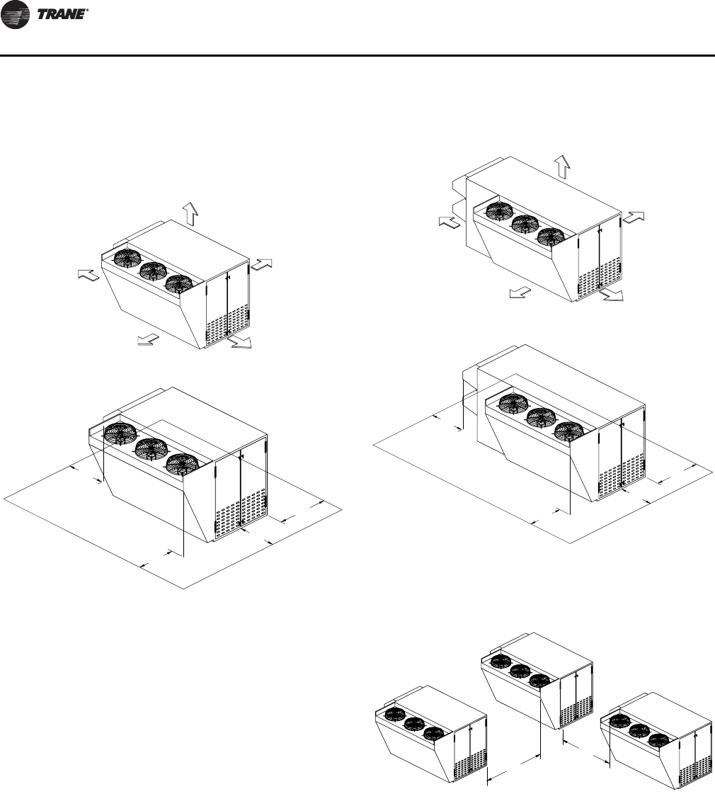
Unit Clearances
“Unit Clearances, Curb Dimensions, and Dimensional
Data,” p. 12 contains figures that illustrate the minimum
operating and service clearances for either a single or
multiple unit installation: Figure 1, p. 12 and Figure 2, p. 12
for OA1 units,Figure 7, p. 14 through Figure 10, p. 15 for
OA2 units, and Figure 15, p. 16 through Figure 18, p. 17 for
OA3 units. These clearances are the minimum distances
necessary to assure adequate serviceability, cataloged
unit capacity, and peak operating efficiency.
Providing less than the recommended clearances may
result in condenser coil starvation, “short-circuiting” of
exhaust or recirculation of hot condenser air.
WARNING
Fiberglass Wool!
Product may contain fiberglass wool. Disturbing the
insulation in this product during installation,
maintenance or repair will expose you to airborne
particles of glass wool fibers and ceramic fibers known
to the state of California to cause cancer through
inhalation. Glass wool fibers may also cause
respiratory, skin or eye irritation.
Verify that the nameplate data matches the data on
the sales order and bill of lading (including electrical
data).
Verify that the power supply complies with the unit
nameplate specifications.
Visually inspect the exterior of the unit, including the
roof, for signs of shipping damage.
Visually inspect the internal components for shipping
damage as soon as possible after delivery and before
it is stored. Do not walk on the sheet metal base pans.
If concealed damage is discovered, notify the carrier’s
terminal of damage immediately by phone and by
mail. Concealed damage must be reported within
15 days.
Request an immediate joint inspection of the damage
by the carrier and the consignee. Do not remove
damaged material from the receiving location. Take
photos of the damage, if possible. The owner must
provide reasonable evidence that the damage did not
occur after delivery.
Notify the appropriate sales representative before
installing or repairing a damaged unit.
12 OAU-SVX01E-EN
Unit Clearances, Curb Dimensions, and Dimensional
Data
OA1 Units
Unit Clearances
Note: Certain options require auxiliary cabinet. Refer to
project-specific unit submittals.
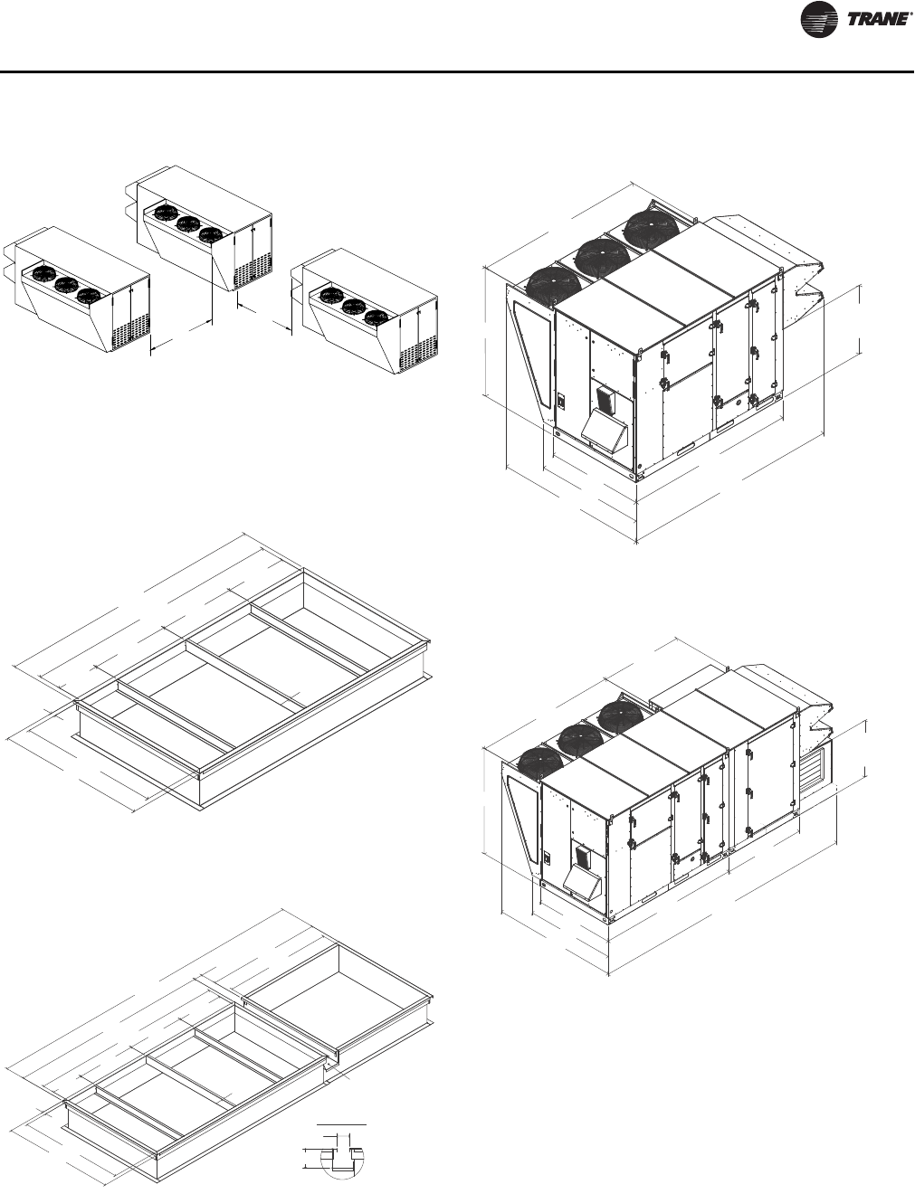
Curb Dimensions
WARNING
Combustible Materials!
Maintain proper clearance between the unit heat
exchanger, vent surfaces and combustible materials.
Refer to unit nameplate and installation instructions for
proper clearances. Improper clearances could result in a
fire hazard. Failure to maintain proper clearances could
result in death or serious injury or property damage.
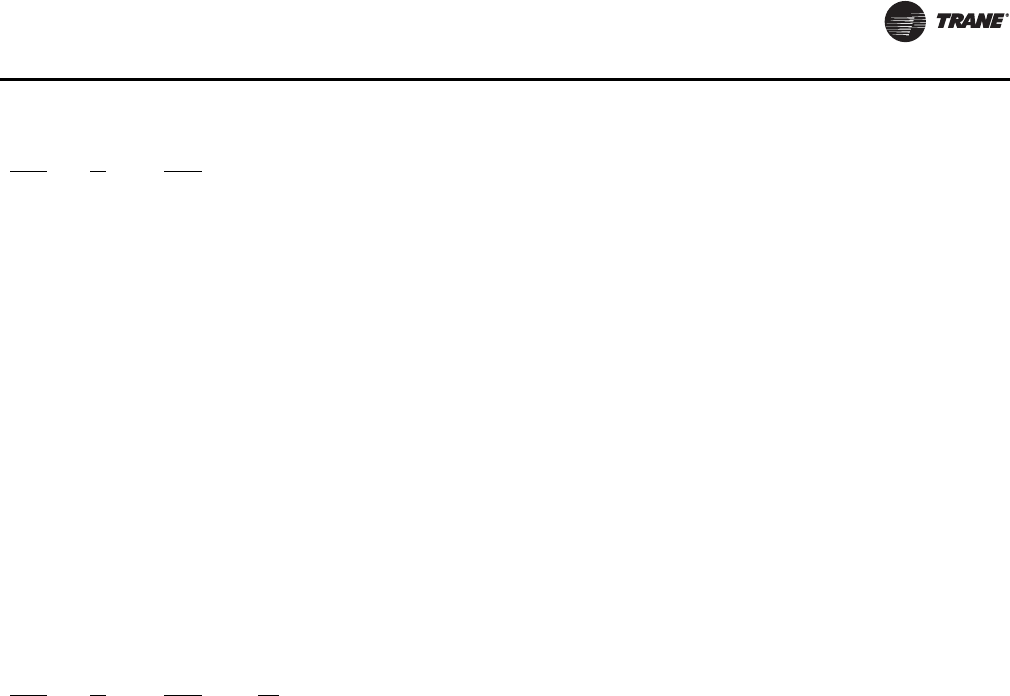
Figure 1. Typical installation clearances for OA1 unit
CLEARANCE 36"
TOP OF UNIT 72"
CLEARANCE 60"
CLEARANCE 36"
CLEARANCE FROM
CLEARANCE 48"
3'-0"
3'-0"
3'-0" 4'-0"
Figure 2. Typical installation clearances for OA1 unit
with auxiliary cabinet
Figure 3. Unit curb data for OA1 5–15 tons
7'0"
6'0"
3'0"
3'0"
4'0"
3'0"
SUPPLY
RETURN
2öļ
8õļ
7öļ
19ļ
õļ
1ôļ
4ôļ
49ļ
1õļ
öļ
1.00
TYP.
Unit Clearances, Curb Dimensions, and Dimensional Data
OAU-SVX01E-EN 13
Note: Certain options require auxiliary cabinet. Refer to
project-specific unit submittals.
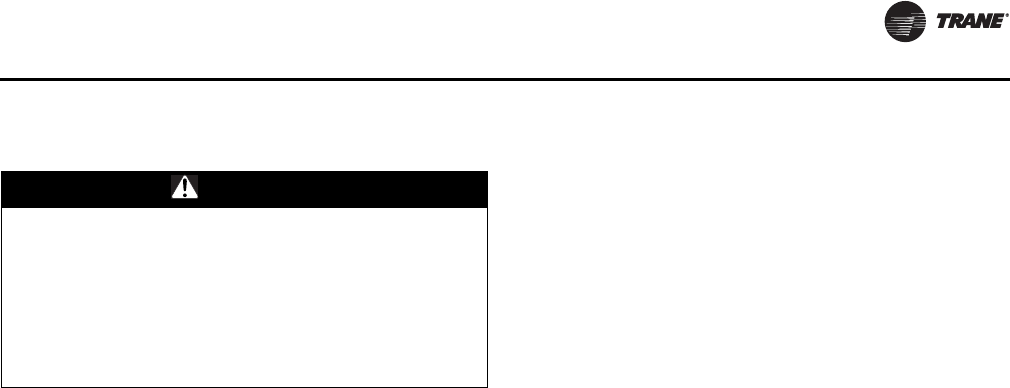
Dimensional Data Note: Certain options require auxiliary cabinet. Refer to
project-specific unit submittals.
Figure 4. Unit curb data for OA1 5–15 tons with
auxiliary cabinet
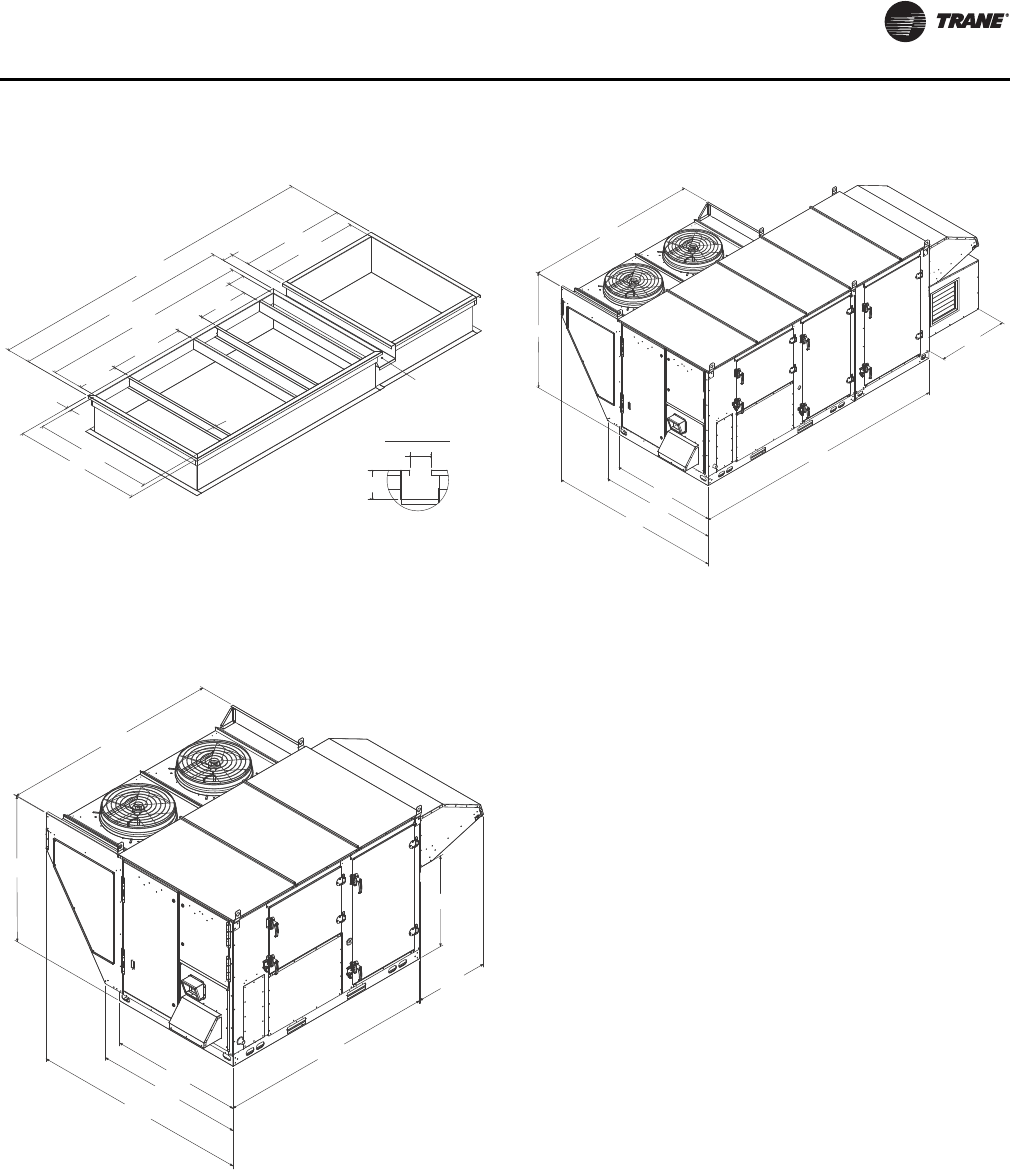
Figure 5. Unit dimensional data for OA1 5–15 tons (in.)
GUTTER DETAIL
Ɍļ
ôļ
SUPPLY
GUTTER
RETURN
õļ
19"
8õļ
40"
12ɍļ
3ôļ
Ɍļ
1ôļ
7öļ
4ôļ
49"
1õļ
öļ
1.00
TYP.
28öļ
53.00
59.45
87.12
36.71
87.33
59.23
87.18
29.63
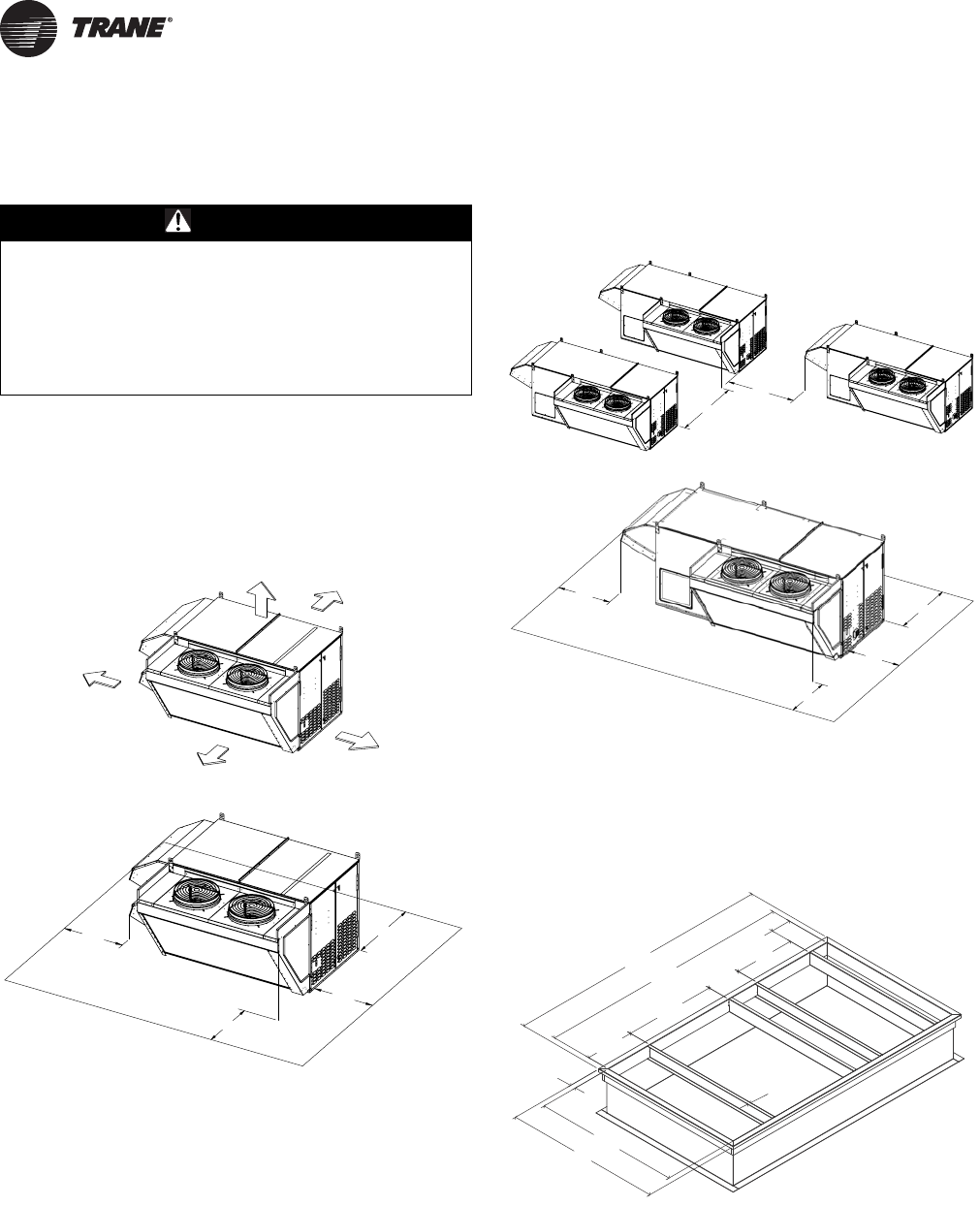
Figure 6. Unit dimensional data for OA1 5–15 tons
with auxiliary cabinet (in.)
87.33
59.23
53.00
131.26
87.12
59.45
35.24
Unit Clearances, Curb Dimensions, and Dimensional Data
14 OAU-SVX01E-EN
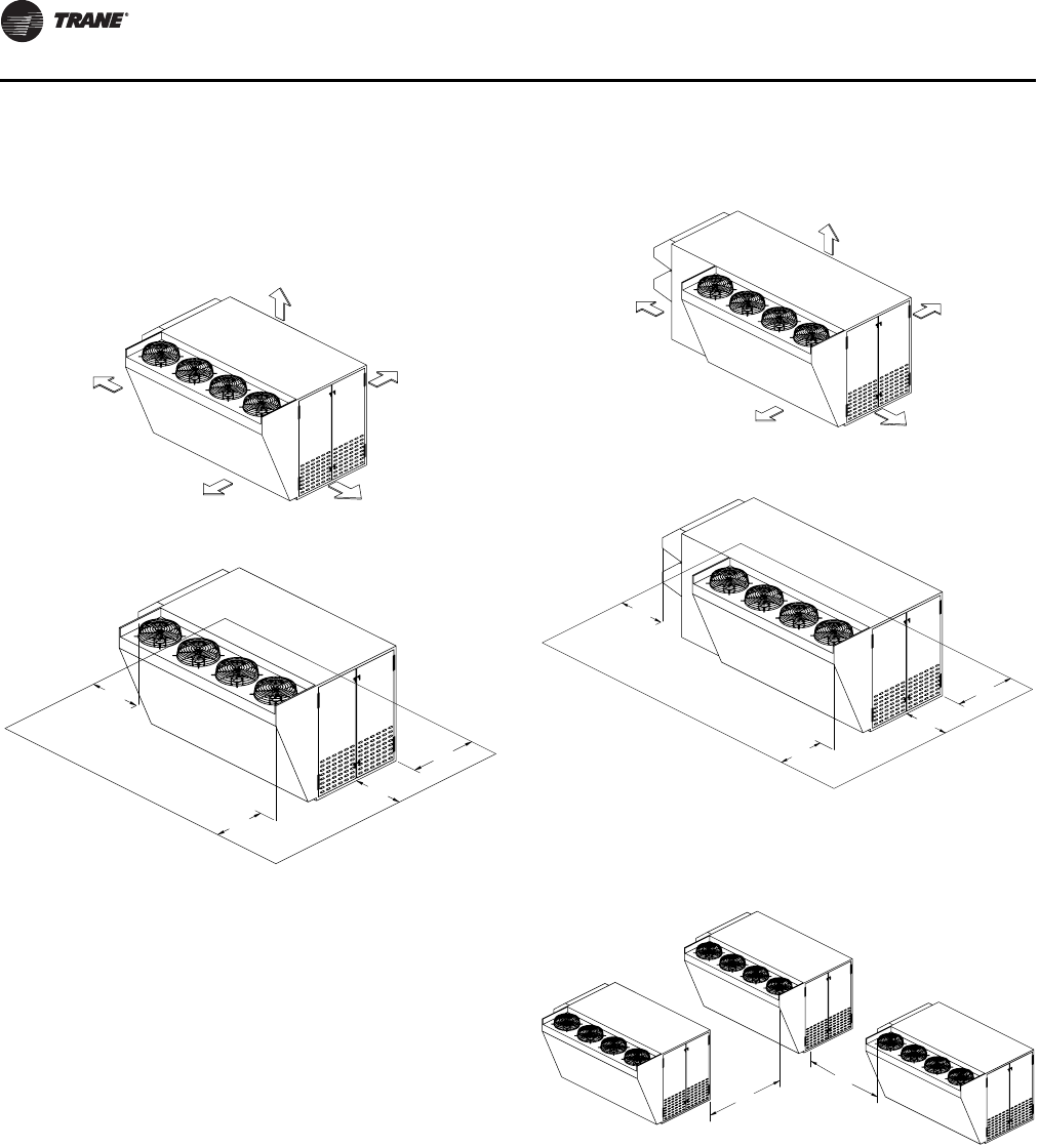
OA2 Units
Unit Clearances
Note: Certain options require auxiliary cabinet. Refer to
project-specific unit submittals.
Figure 7. Typical installation clearances for OA2 unit
CLEARANCE 36"CLEARANCE 60"
TOP OF UNIT 72"
CLEARANCE 36"
CLEARANCE FROM
CLEARANCE 48"
3'0"
3'0"
4'0"
3'0"
Figure 8. Typical installation clearances for OA2 unit
with auxiliary cabinet
Figure 9. Typical installation clearances for OA2 unit
TOP OF UNIT 72"
"63 ECNARAELC"06 ECNARAELC
CLEARANCE 36"
CLEARANCE FROM
CLEARANCE 48"
3'0"
3'0"
4'0"
3'0"
7'0"
6'0"
Unit Clearances, Curb Dimensions, and Dimensional Data
OAU-SVX01E-EN 15
Note: Certain options require auxiliary cabinet. Refer to
project-specific unit submittals.
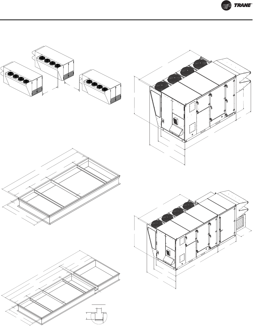
Curb Dimensions
Note: Certain options require auxiliary cabinet. Refer to
project-specific unit submittals.
Dimensional Data
Note: Certain options require auxiliary cabinet. Refer to
project-specific unit submittals.
Figure 10. Typical installation clearances for OA2 unit
with auxiliary cabinet
Figure 11. Unit curb data for OA2 12–30 tons (in.)
Figure 12. Unit curb data for OA2 12–30 tons with
auxiliary cabinet (in.)
7'0"
6'0"
SUPPLY
RETURN
öļ
1ļ
TYP.
30ļ
29ļ
56ļ
2õļ
5ôļ
9ôļ
ļ
1õļ
SUPPLY
RETURN
GUTTER
1õļ
ļ
16Ɍļ
29ļ
9Ɏļ
56ļ
5ôļ
öļ
õļ
30ļ
58ļ
5ôļ
Ɍļ
1ļ
TYP.
GUTTER DETAIL
Ɍļ
ôļ
Figure 13. Unit dimensional data for OA2 12–30 tons
Figure 14. Unit dimensional data for OA2 12–30 tons
with auxiliary cabinet
80.57 OF AIR INLET
106.45
66.83
106.00
135.52
94.21
43.02
BASE TO BOTTOM
60.00
80.57
106.00
94.21
62.11
66.83
60.00
106.10
200.99
OF AIR INLET
43.02
BASE TO BOTTOM
62.51
Unit Clearances, Curb Dimensions, and Dimensional Data
16 OAU-SVX01E-EN
OA3 Units
Unit Clearances
Note: Certain options require auxiliary cabinet. Refer to
project-specific unit submittals.
Figure 15. Typical installation clearances for OA3 unit
TOP OF UNIT 72"
"63 ECNARAELC"06 ECNARAELC
CLEARANCE 36"
CLEARANCE FROM
CLEARANCE 48"
3'0"
3'0"
4'0"
3'0"
Figure 16. Typical installation clearances for OA3 unit
with auxiliary cabinet
Figure 17. Typical installation clearances for OA3 unit
CLEARANCE 36"
TOP OF UNIT 72"
CLEARANCE 36"CLEARANCE 60"
CLEARANCE FROM
CLEARANCE 48"
3'0"
3'0"
4'0"
3'0"
7'0"
6'0"
Unit Clearances, Curb Dimensions, and Dimensional Data
OAU-SVX01E-EN 17
Note: Certain options require auxiliary cabinet. Refer to
project-specific unit submittals.
Curb Dimensions
Note: Certain options require auxiliary cabinet. Refer to
project-specific unit submittals.
Dimensional Data
Note: Certain options require auxiliary cabinet. Refer to
project-specific unit submittals.
Figure 18. Typical installation clearances for OA3 unit
with auxiliary cabinet
Figure 19. Unit curb data for OA3 30–54 tons
Figure 20. Unit curb data for OA3 30–54 tons with
auxiliary cabinet
7'0"
6'0"
SUPPLY
RETURN
öļ
33ļ
63ļ
5ôļ
140ļ
13ôļ
1ļ
TYP.
5ɏļ
2õļ
2ɍļ
SUPPLY
RETURN
GUTTER
1ļ
TYP.
63ļ
202ļ
5ɏļ
5ôļ
140ļ
33ļ
öļ
5ɏļ
2õļ
13ôļ
Ɍļ 5ɍļ
2ɍļ
GUTTER DETAIL
Ɍļ
ôļ
Figure 21. Unit dimensional data for OA3 30–54 tons
Figure 22. Unit dimensional data for OA3 30–54 tons
with auxiliary cabinet
144.00
67.00
74.63
144.17
42.00
92.07
98.49
48.62
62.00
67.00
74.63
98.49
144.00
92.07
144.17
35.84
18 OAU-SVX01E-EN
Unit Weight and Rigging
Unit Weight
WARNING
Heavy Objects!
Do not use cables (chains or slings) except as shown.
Each of the cables (chains or slings) used to lift the unit
must be capable of supporting the entire weight of the
unit. Lifting cables (chains or slings) may not be of the
same length. Adjust as necessary for even unit lift.
Other lifting arrangements may cause equipment or
property-only damage. Failure to properly lift unit could
result in death or serious injury. See details below.
WARNING
Improper Unit Lift!
Test lift unit approximately 24 inches to verify proper
center of gravity lift point. To avoid dropping of unit,
reposition lifting point if unit is not level. Failure to
properly lift unit could result in death or serious injury
or possible equipment or property-only damage.
Table 1. Typical unit weight and center-of-gravity
(CG)—units without auxiliary cabinet
Model
Number
Operating
Weight (lb) Shipping
Weight (lb) Center-of-
gravity (in.)
Min Max Min Max Length Width
OA1D060* 1811 2275 1898 2362 40 30
OA1D072* 1811 2330 1898 2417 40 30
OA1D084* 1811 2330 1933 2452 40 30
OA1D096* 1901 2596 2059 2754 40 30
OA1D120* 1901 2596 2089 2784 40 30
OA1D144* 1901 2596 2112 2807 40 30
OA1D180* 1901 2734 2192 3025 40 30
OA2D144* 3125 3790 3335 4000 49 34
OA2D180* 3289 3954 3580 3871 49 34
OA2D210* 3344 4161 3687 4030 49 34
OA2D240* 3372 4189 3764 4156 49 34
OA2D264* 3372 4189 3764 4156 49 34
OA2D300* 3530 4390 4012 4494 49 34
OA2D360* 3338 4198 3820 4302 49 34
OA3D360* 4931 5914 5576 6221 67 38
OA3D420* 5246 6229 5892 6538 67 38
OA3D480* 5339 6351 6014 6689 67 38
OA3D540* 5406 6363 6026 6646 67 38
OA3D600* 5570 6652 6343 7116 67 38
OA3D648* 5582 6664 6355 7128 67 38
Note: Minimum and maximum weights vary widely due to the highly
configurable nature of the product.
Unit Weight and Rigging
OAU-SVX01E-EN 19
Corner Weight
Table 2. Typical unit weight and center-of-gravity
(CG)—units with auxiliary cabinet
Model
Number
Operating
Weight (lb) Shipping
Weight (lb) Center-of-
gravity (in.)
Min Max Min Max Length Width
OA1D060* 2798 3262 2885 3349 56 29
OA1D072* 2743 3262 2830 3349 56 29
OA1D084* 2775 3294 2897 3416 56 29
OA1D096* 2927 3622 3085 3780 56 29
OA1D120* 2927 3622 3115 3810 56 29
OA1D144* 2927 3622 3138 3833 56 29
OA1D180* 2927 3760 3218 4051 56 29
OA2D144* 4508 5173 4718 5383 72 33
OA2D180* 4715 5380 4632 5297 72 33
OA2D210* 5028 5845 4897 5714 72 33
OA2D240* 5056 5873 5023 5840 72 33
OA2D264* 5056 5873 5023 5840 72 33
OA2D300* 5194 6054 5298 6158 72 33
OA2D360* 4936 5796 5040 5900 72 33
OA3D360* 6907 7890 7214 8197 81 37
OA3D420* 7222 8205 7531 8514 81 37
OA3D480* 7315 8327 7653 8665 81 37
OA3D540* 7382 8339 7665 8622 81 37
OA3D600* 7527 8609 7991 9073 81 37
OA3D648* 7539 8621 8003 9085 81 37
Note: Minimum and maximum weights vary widely due to the highly
configurable nature of the product.
Table 3. Corner weights (percent of total weight)
Cabinet Size
Percentage (%)
Corner A Corner B Corner C Corner D
OA1* without
auxiliary cabinet 16.3 20.7 33.3 29.7
OA1* with
auxiliary cabinet 18.2 23.2 27.5 31.1
OA2* without
auxiliary cabinet 20.1 17.2 34.0 28.7
OA2* with
auxiliary cabinet 18.3 24.0 32.5 25.2
OA3* without
auxiliary cabinet 14.9 24.2 29.9 31.0
OA3* with
auxiliary cabinet 16.8 23.6 28.5 31.1
Note: Actual corner weights will vary depending on components selected.
Figure 23. Cabinet corners
OALCabinet
AB
INTAKE
HOOD
DC
OA1,OA2,andOA3Cabinets
AB
INTAKE
HOOD
DC
CONDENSERSECTION
Unit Weight and Rigging
20 OAU-SVX01E-EN
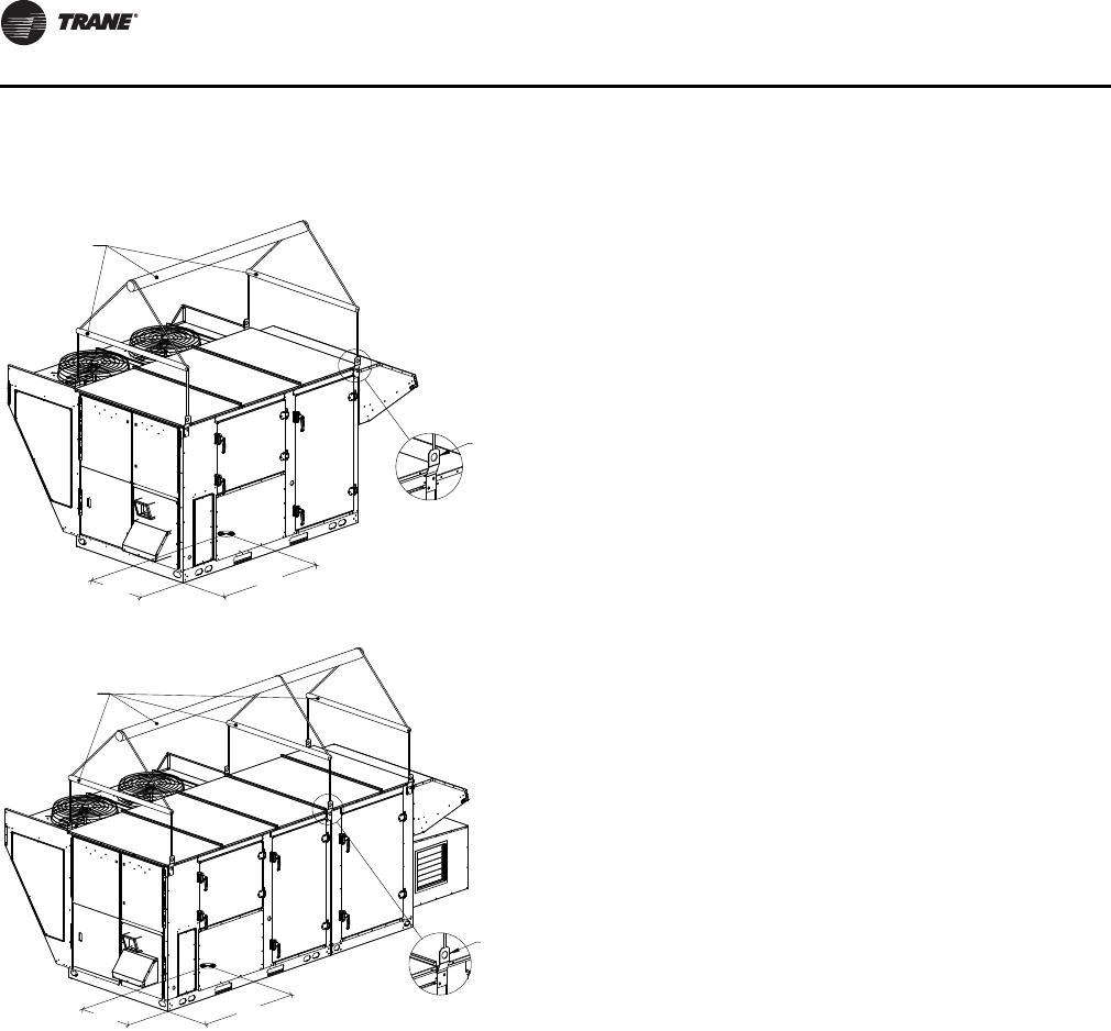
Rigging
Refer to Table 1, p. 18, Table 2, p. 19, and Figure 24, p. 20
for typical unit operating weights rigging before
proceeding.
1. Remove the shipping crate from around the unit.
2. Rig the unit as shown in Figure 24, p. 20. Attach
adequate strength lifting slings to all four lifting
brackets in the unit base rail. Do not use cables, chains,
or slings except as shown.
3. Install a lifting bar, as shown in Figure 24, p. 20, to
protect the unit and to facilitate a uniform lift. The
minimum distance between the lifting hook and the
top of the unit should be 7 feet.
4. Test-lift the unit to ensure it is properly rigged and
balanced, make any necessary rigging adjustments.
5. Lift the unit and position it into place. Remove fork
pockets prior to setting on the curb.
6. Downflow units; align the base rail of the unit with the
curb rail while lowering the unit onto the curb. Make
sure that the gasket on the curb is not damaged while
positioning the unit.
Figure 24. Rigging and center-of-gravity data
SPREADER BARS
LENGTH
WIDTH
LIFTING POINTS
(4 LOCATIONS)
4-point lift
SPREADER BARS
LENGTH
WIDTH
LIFTING POINTS
(6 LOCATIONS)
DETAIL A
SCALE 1 : 12
6-point lift

OAU-SVX01E-EN 21
Sequence of Operation
Space Control with Indirect Gas-
Fired or Electric Heat and
Modulating HGRH, ERV, and
Powered Ex.
Sequence of Operation—”Occupied”
Optional space temperature and/or humidity sensors
must be installed and wired to unit and configured as
“installed” at the main unit controller.
Emergency Stop. When the contacts at Terminal
OAUTS 9 and 10 are open, the unit’s operation will be in
Alarm Status. The Alarm must be reset from either the BAS
or the optional on-board unit display.
Alarms must be reset from the optional on-board unit
display or remote BAS to restart the control sequence. If
optional display is not installed; Tracer TU must be used to
diagnose and clear alarm. If Tracer TU is not available,
cycle main power to unit to clear alarm.
Important: Cycling power to unit to clear alarm may not
resolve alarm condition.
Starting Sequence
When 3-phase is powered to unit the main unit controller
and the RTRM will initialize. Initialization process requires
approximately 3 minutes.
The unit is placed in occupied operation via either the BAS
or by closing connection between unit terminals OAUTS 7
and 8. The unit must not be in lockout.
Starting Sequence with No Return Air Damper
Installed
The outdoor air damper will be commanded to open. The
damper end switch will make causing the main unit
controller to initialize the indoor fan starting sequence by
sending a preset run signal (field adjustable between
50 percent and 100 percent) to the indoor fan VFD. If after
30 seconds the indoor fan proving switch does not prove
the indoor fan on, the main unit controller will command
the indoor fan off and signal an alarm.
Starting Sequence with Optional Return Air
Damper Installed
Identical to sequence with no return air damper except the
outdoor air and return air dampers will be commanded to
move to their preset occupied positions. Outdoor air
damper end switch is disabled when the return air damper
is installed.
Operating Modes
A. Economizer (Ventilation)
B. Heating
C. Dehumidification
D. Cooling
All modes are enabled by the main unit control module.
The control module calculates dewpoint based on sensed
air temperature and humidity.
A. Economizer Mode. Economizer mode is enabled
based on outdoor air dewpoint. Operation in economizer
mode is enabled when the outdoor air dewpoint remains
below the outdoor air economizer enable dewpoint
setpoint. Operation in economizer mode continues until
outdoor air conditions call for either dehumidification,
cooling or heating mode. Space call for heating,
dehumidification or cooling will cancel call for economizer
operation.
B. Heating Mode. Heating mode is enabled on space
heating setpoint. The main unit controller will modulate
the heating output to maintain the space heating setpoint.
Maximum discharge air heating temperature is
adjustable—default maximum is 90ºF. Hot gas reheat is
disabled when heating is enabled.
C. Dehumidification Mode. Dehumidification mode is
enabled on space dewpoint setpoint if no call for heating
is enabled. The unit’s controller will activate the
dehumidification mode when space dewpoint is higher
than or equal to space dewpoint setpoint. Compressor
control is based on evaporator leaving air temperature
setpoint. With dehumidification enabled, if evaporator
leaving air temperature is above setpoint first stage
dehumidification (Compressor 1) will start. If after a
3-minute minimum delay the evaporator leaving air
temperature is still above the setpoint, the second, third,
and fourth stages of dehumidification (Compressor 2, 3,
and 4) will be staged on sequentially following individual
3-minute minimum delays between each call.
Dehumidification mode will remain active if outdoor air is
above outdoor air dehumidification setpoint. Space call
for heating will cancel outdoor air dehumidification.
During operation in dehumidification mode, the main unit
controller will enable hot gas reheat. Hot gas reheat will
modulate to maintain the space cooling setpoint.
D. Cooling Mode . Cooling mode is enabled on space
cooling setpoint if no call for heating or dehumidification
is present. Compressor staging is identical to
dehumidification however control temperature is space
cooling setpoint.
During operation in cooling mode hot gas reheat is
enabled. Hot gas reheat is controlled to maintain space
cooling setpoint.

Sequence of Operation
22 OAU-SVX01E-EN
Optional Features
Digital Compressors
Main unit controller will modulate digital compressor to
maintain either evaporator leaving or space temperature
setpoints depending on mode of operation. Remaining
compressors will be staged as described in mode.
ERV and Powered Exhaust
ERV and powered exhaust are interlocked with indoor fan
operation in occupied heating, dehumidification or
cooling modes. Outdoor air sensors sending temperature
and Rh signals to the main unit controller to make mode
calls are relocated downstream of the ERV. Outdoor air
heating and dehumidification override setpoints will be
based on ERV leaving conditions. Additional sensors will
be installed in the non-ERV outdoor air position for
information purposes and those outdoor air readings may
be viewed at the main unit controller or via the BAS. When
operating in economizer mode the ERV is disabled and the
ERV by-pass damper(s) open, powered exhaust remains
on and is adjusted to 100 percent capacity by the main unit
controller. The main unit controller will end ERV operation
and open ERV bypass dampers if outdoor air/return air
conditions could cause ERV frosting, powered exhaust
remains on.
Note: For units with optional ERV defrost heater, the
control sequence will engage heater at frost
condition rather than stop ERV.
The powered exhaust fan speed is factory set to run
between 50 percent and 100 percent (field adjustable).
Hot Gas Reheat
Following continuous 30-minute hot gas reheat operation
at less than 100 percent reheat capacity a purge cycle will
be initiated. During the purge cycle the, hot gas reheat
signal is set and held at 100 percent for a period of
3 minutes. Following the purge cycle, normal operation
resumes.
Sequence of Operation—”Unoccupied”
Emergency Stop. When the contacts at Terminal
OAUTS 9 and 10 are open, the unit’s operation will be in
Alarm Status. The Alarm must be reset from either the BAS
or the optional on-board unit display.
Starting Sequence
Indoor fan proving sequence is identical to occupied
operation.
Starting Sequence with Optional Return Air
Damper Installed
The outdoor air damper will be commanded to close and
the return air damper will open. Outdoor air damper end
switch is disabled when the return air damper is installed.
Starting Sequence with No Return Air Damper
Installed. Identical to occupied sequence no return air
damper installed.
Operating Modes
A. Unoccupied Heating
B. Unoccupied Dehumidification
C. Unoccupied Cooling
A. Heating Mode. Unoccupied heating is enabled
based on unoccupied space heating setpoint. Unoccupied
heating is enabled when space temperature reaches
unoccupied space heating setpoint - 2°. The modulating
gas heat or SCR electric heat will continue to raise the
discharge air temperature to a maximum of 90°F and
continue to supply heated 90° air to the space until the
space temperature reaches setpoint + 2°. Unit operation is
discontinued when unoccupied space heating is satisfied.
B. Dehumidification Mode. When no call for
unoccupied heating exists, unoccupied dehumidification
is enabled based on unoccupied space dewpoint setpoint.
During unoccupied dehumidification operation
dehumidification capacity is restricted to 50 percent (only
half of the compressors are allowed to come on).
Unoccupied dehumidification is enabled when space
temperature reaches unoccupied space dehumidification
setpoint + 1°. Dehumidification stops at setpoint - 1°. Unit
operation is discontinued when unoccupied space
dehumidification is satisfied.
C. Cooling Mode. When no call for unoccupied heating
or unoccupied dehumidification exists, unoccupied
cooling is enabled based on unoccupied space cooling
setpoint. During unoccupied space cooling operation
cooling capacity is restricted to 50 percent (only half of the
compressors are allowed to come on). Unoccupied
cooling is enabled when space temperature reaches
unoccupied space cooling setpoint + 2°. Cooling stops at
setpoint - 2°. Unit operation is discontinued when
unoccupied space cooling is satisfied.
Powered Exhaust/ERV Sequence of Operation
Powered Exhaust/ERV operation is disabled during unit
“Unoccupied” operating modes.

Sequence of Operation
OAU-SVX01E-EN 23
Discharge Air Control with
Indirect Gas-Fired or Electric Heat
and Modulating HGRH, ERV, and
Powered Ex.
Sequence of Operation—”Occupied”
Emergency Stop. When the contacts at Terminal
OAUTS 9 and 10 are open, the unit’s operation will be in
Alarm Status. The Alarm must be reset from either the BAS
or the optional on-board unit display.
Alarms must be reset from the optional on-board unit
display or remote BAS to restart the control sequence. If
optional display is not installed; Tracer TU must be used to
diagnose and clear alarm. If Tracer TU is not available,
cycle main power to unit to clear alarm.
Important: Cycling power to unit to clear alarm may not
resolve alarm condition.
Starting Sequence
When 3-phase is powered to unit the main unit controller
and the RTRM will initialize. Initialization process requires
approximately 3 minutes.
The unit is placed in occupied operation via either the BAS
or by closing connection between unit terminals OAUTS 7
and 8. The unit must not be in lockout.
Starting Sequence with No Return Air Damper
Installed
The outdoor air damper will be commanded to open. The
damper end switch will make causing the main unit
controller to initialize the indoor fan starting sequence by
sending a preset run signal (field adjustable between
50 percent and 100 percent) to the indoor fan VFD. If after
30 seconds the indoor fan proving switch does not prove
the indoor fan on, the main unit controller will command
the indoor fan off and signal an alarm.Starting Sequence
with Optional Return Air Damper Installed
Identical to sequence with no return air damper except the
outdoor air and return air dampers will be commanded to
move to their preset occupied positions. Outdoor air
damper end switch is disabled when the return air damper
is installed.
Operating Modes
A. Economizer (Ventilation)
B. Heating
C. Dehumidification
D. Cooling
All modes are enabled by the main unit control module.
The control module calculates dewpoint based on sensed
outdoor air temperature and humidity.
A. Economizer Mode. Operation in economizer mode
is enabled when the outdoor air temperature is between
the Outdoor Air Cooling Setpoint and the Outdoor Air
Heating setpoint and no call for dehumidification exists.
Operation in economizer mode continues until outdoor air
conditions call for either dehumidification, cooling or
heating mode.
B. Heating Mode. Heating mode is enabled on outdoor
air heating setpoint. The main unit controller will
modulate the heating capacity to maintain the discharge
air heating setpoint. Hot gas reheat is disabled when
heating is enabled. Heating will be disabled at outdoor air
heating setpoint + 2°.
C. Dehumidification Mode. Dehumidification mode is
enabled on outdoor air dewpoint enable setpoint if no call
for heating is enabled. The unit’s controller will activate the
dehumidification mode when outdoor air dewpoint is
higher than or equal to outdoor air dewpoint setpoint.
Compressor control is based on evaporator leaving air
temperature setpoint. With dehumidification enabled, if
evaporator leaving air temperature is above setpoint first
stage dehumidification (Compressor 1) will start. If after a
3-minute minimum delay the evaporator leaving air
temperature is still above the evaporator leaving air
temperature setpoint, the second, third, and fourth stages
of dehumidification (Compressor 2, 3, and 4) will be
staged on sequentially following individual 3-minute
minimum delays between each call. Dehumidification
mode will be disabled at outdoor air dewpoint setpoint
- 2°.
During operation in dehumidification mode, the main unit
controller will enable hot gas reheat. Hot gas reheat will
modulate to maintain the discharge air cooling setpoint.
C. Cooling Mode. Cooling mode is enabled on outdoor
air cooling setpoint if no call for heating or
dehumidification is present. Compressor staging is
identical to dehumidification; however, control
temperature is discharge air cooling setpoint. Cooling will
be disabled at outdoor air cooling setpoint - 2°.
During operation in cooling mode hot gas reheat is
enabled. Hot gas reheat is controlled to maintain discharge
air cooling setpoint.
Optional Features
Digital Compressors
Main unit controller will modulate digital compressor to
maintain either evaporator leaving or discharge air
temperature setpoints depending on mode of operation.
Remaining compressors will be staged as described in
mode.
ERV and Powered Exhaust
ERV and powered exhaust are interlocked with indoor fan
operation in occupied heating, dehumidification or
cooling modes. Outdoor air sensors sending temperature
and Rh signals to the main unit controller to make mode

Sequence of Operation
24 OAU-SVX01E-EN
calls are relocated downstream of the ERV. Mode calls will
be based on ERV leaving conditions. Additional sensors
will be installed in the non-ERV outdoor air position for
information purposes and those outdoor air readings may
be viewed at the main unit controller or via the BAS. When
operating in economizer mode the ERV is disabled and the
ERV by-pass damper(s) open, powered exhaust remains
on and is adjusted to 100 percent capacity by the main unit
controller. The main unit controller will end ERV operation
and open ERV bypass dampers if outdoor air/return air
conditions could cause ERV frosting, powered exhaust
remains on.
Note: For units with optional ERV defrost heater, the
control sequence will engage heater at frost
condition rather than stop ERV.
The powered exhaust fan speed is factory set to run
between 50 percent and 100 percent (field adjustable).
Hot Gas Reheat
Following continuous 30-minute hot gas reheat operation
at less than 100 percent reheat capacity a purge cycle will
be initiated. During the purge cycle the, hot gas reheat
signal is set and held at 100 percent for a period of
3 minutes. Following purge cycle normal operation
resumes.
Sequence of Operation—”Unoccupied”
Optional space temperature and/or humidity sensors
must be installed and wired to unit and configured as
“installed” at the main unit controller to enable
unoccupied sequences.
Emergency Stop. When the contacts at Terminal
OAUTS 9 and 10 are open, the unit’s operation will be in
Alarm Status. The Alarm must be reset from either the BAS
or the optional on-board unit display.
Starting Sequence
Indoor fan proving sequence is identical to occupied
operation.
Starting Sequence with Optional Return Air
Damper Installed
The outdoor air damper will be commanded to close and
the return air damper will open. Outdoor air damper end
switch is disabled when the return air damper is installed.
Starting Sequence with No Return Air Damper
Installed
Identical to occupied sequence no return air damper
installed.
Operating Modes
A. Unoccupied Heating
B. Unoccupied Dehumidification
C. Unoccupied Cooling
A. Heating Mode. Unoccupied heating is enabled
based on unoccupied space heating setpoint. Unoccupied
heating is enabled when space temperature reaches
unoccupied space heating setpoint - 2°. The modulating
gas heat or SCR electric heat will continue to raise the
discharge air temperature to a maximum of 90°F and
continue to supply heated 90° air to the space until the
space temperature reaches setpoint + 2°. Unit operation is
discontinued when unoccupied space heating is satisfied.
B. Dehumidification Mode. When no call for
unoccupied heating exists, unoccupied dehumidification
is enabled based on unoccupied space dewpoint setpoint.
During unoccupied dehumidification operation
dehumidification capacity is restricted to 50 percent (only
half of the compressors are allowed to come on).
Unoccupied dehumidification is enabled when space
temperature reaches unoccupied space dehumidification
setpoint + 1°. Dehumidification stops at setpoint - 1°. Unit
operation is discontinued when unoccupied space
dehumidification is satisfied.
C. Cooling Mode. When no call for unoccupied heating
or unoccupied dehumidification exists, unoccupied
cooling is enabled based on unoccupied space cooling
setpoint. During unoccupied space cooling operation
cooling capacity is restricted to 50 percent (only half of the
compressors are allowed to come on). Unoccupied
cooling is enabled when space temperature reaches
unoccupied space cooling setpoint + 2°. Cooling stops at
setpoint - 2°. Unit operation is discontinued when
unoccupied space cooling is satisfied.
Powered Exhaust/ERV Sequence of Operation
Powered Exhaust/ERV operation is disabled during unit
“Unoccupied” operating modes.
OAU-SVX01E-EN 25
Installation
Ductwork
Elbows with turning vanes or splitters are recommended
to minimize air noise due to turbulence and to reduce static
pressure.
When attaching the ductwork to the unit, provide a water-
tight flexible connector at the unit to prevent operating
sounds from transmitting through the ductwork.
All outdoor ductwork between the unit and the structure
should be weather proofed after installation is completed.
Note: For sound consideration, cut holes in the roof deck
only for the ductwork penetrations. Do not cut out
the roof deck within the entire curb perimeter. All
duct work must be installed and connected to top of
roof curb before the unit is set on curb.
If a Curb Accessory Kit is not used:
1. Be sure to use flexible duct connections at the unit.
2. Gaskets must be installed around the curb perimeter
flange and the supply and return air opening flanges.
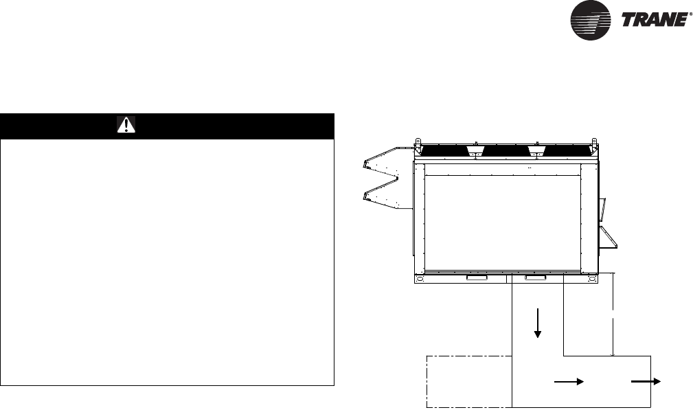
Note: For units will electric heat in the primary heating
position, refer to Figure 25.
General Unit Requirements
The checklist listed below is a summary of the steps
required to successfully install a commercial unit. This
checklist is intended to acquaint the installing personnel
with what is required in the installation process. It does
not replace the detailed instructions called out in
the applicable sections of this manual.
WARNING
Hazardous Service Procedures!
The maintenance and troubleshooting procedures
recommended in this section of the manual could result
in exposure to electrical, mechanical or other potential
safety hazards. Always refer to the safety warnings
provided throughout this manual concerning these
procedures. When possible, disconnect all electrical
power including remote disconnect and discharge all
energy storing devices such as capacitors before
servicing. Follow proper lockout/tagout procedures to
ensure the power can not be inadvertently energized.
When necessary to work with live electrical
components, have a qualified licensed electrician or
other individual who has been trained in handling live
electrical components perform these tasks. Failure to
follow all of the safety warnings provided could result
in death or serious injury.
Figure 25.
Important: Bottom discharge units with open coil
electric heater in primary heat location
require discharge duct with 90° elbow. This
is a MANDATORY installation requirement.
Check the unit for shipping damage and material
shortage. File a freight claim and notify appropriate
sales representative if damage or shortage is
discovered.
Verify that the unit nameplate model, options, and
voltage are correct.
Verify that the installation location of the unit will
provide the required clearance for proper operation.
Assemble and install the roof curb (if applicable).
Refer to the latest edition of the curb installers guide
that ships with each curb kit. Check curb for level
installation; if not level, shim as required.
Rigging unit (refer to “Unit Weight and Rigging,”
p. 18).
Set the unit onto the curb; check for level.
Ensure unit-to-curb seal is tight and without buckles
or cracks.
Install and connect proper condensate drain line to
the evaporator condensate pan drain connection (see
Figure 26, p. 26).
48" Minimum
Airflow
Installation
26 OAU-SVX01E-EN
Main Electrical Power Requirements
Note: All field-installed wiring must comply with NEC
and applicable local codes.
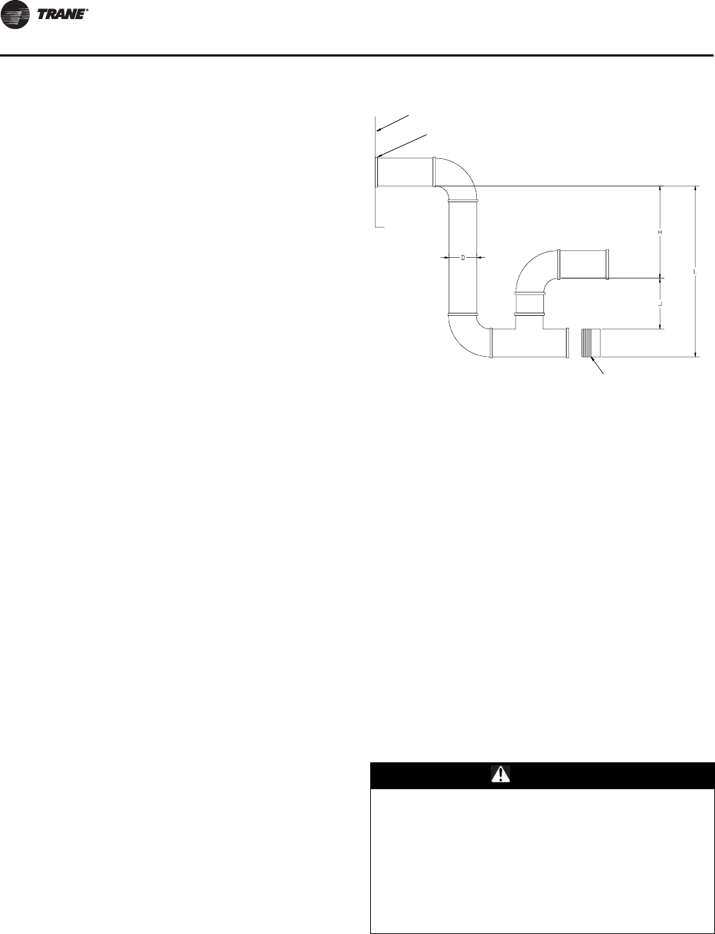
Condensate Drain Configuration
OAU units are selected based on dehumidification
capability. As such, condensate can form at a high rate.
Therefore, the OAU drain pan and condensate line are
sized and designed accordingly. However, an often-
overlooked element of proper condensate drainage is
proper P-Trap and drain line sizing and installation. An
incorrectly-designed and -installed P-Trap can restrict
condensate flow or cause water in the condensate drain
pan to “spit” or “geyser” which may cause condensate
overflow. Carefully install and trap the drain pan to ensure
adequate condensate removal under all conditions.
An evaporator condensate drain connection is provided
on each unit. Refer to Figure 28, p. 27, Figure 29, p. 27, and
Figure 30, p. 27 for the appropriate drain location.
A condensate trap must be installed at the unit due to the
drain connection being on the “negative pressure” side of
the fan. Install the P-Trap using the guidelines in Figure 26.
Pitch drain lines connected to P-Trap at least 1/2 inch for
every 10 feet of horizontal run to assure proper
condensate flow. Do not allow the horizontal run to sag
causing a possible double-trap condition which could
result in condensate backup due to “air lock”.
Filter Installation
Each unit ships with 2-inch permanent filters (mist
eliminators) installed in the air inlet hood. The quantity of
filters is determined by unit size. Access to the filters is
through the hinged filter access panel on the air intake
hood. In addition to the filters in the intake hood, there is
a separate bank of filters accessible through the
evaporator coil compartment door. Filter type, size, and
quantity are determined by selected filter option and unit
size.
Note: Do not operate the unit without filters.
Field Installed Power Wiring
An overall dimensional layout for the standard field
installed wiring entrance into the unit is illustrated in
Figure 28, p. 27, Figure 29, p. 27, and Figure 30, p. 27. To
Verify that the power supply complies with the unit
nameplate specifications.
Inspect all control panel components; tighten any
loose connections.
Connect properly sized and protected power supply
wiring to a field-supplied/-installed disconnect switch
and to the main power terminal block (HTB1) in the
unit control panel.
Connect properly-sized earth ground.
Figure 26. Condensate trap installation
D = Pipe diameter; see Figure 28, p. 27, Figure 29, p. 27, and
Figure 30, p. 27 for correct pipe diameter
H = Internal static pressure (in wg) +1 in.
J = H + 0.5
L = H + J +D
Notes:
1. Pitch drain at least 1/2 in. per 10 ft horizontal run.
2. Condensate drain pan will not drain properly if P-trap is not primed
and of adequate height to allow for cabinet operating negative
pressure.
WARNING
Proper Field Wiring and Grounding
Required!
All field wiring MUST be performed by qualified
personnel. Improperly installed and grounded field
wiring poses FIRE and ELECTROCUTION hazards. To
avoid these hazards, you MUST follow requirements for
field wiring installation and grounding as described in
NEC and your local/state electrical codes. Failure to
follow code could result in death or serious injury.
PANEL ENCLOSURE
D" NPT FEMALE
CONNECTOR
CLEANOUT PLUG
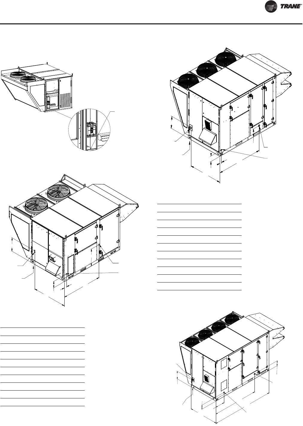
Installation
OAU-SVX01E-EN 27
ensure that the unit’s supply power wiring is properly sized
and installed, refer to the following guidelines.
Figure 27. Main power entrance
Figure 28. OA1D utility connections
Table 4. OA1D Unit
MBh Pipe Connection (in.)
50 1/2
75 1/2
100 1/2
125 1/2
150 3/4
200 3/4
250 3/4
300 3/4
350 1
MAIN POWER ENTRANCE
FOR UNIT
3/4" NPT
CONDENSATE DRAINELECTRICAL
DISCONNECT
THROUGH BASE
ELECTRIC
18.13
54.26
23.37
8.74
3.21
46.58
GAS INLET
NPT SIZE VARIES
Figure 29. OA2 utility connections
Table 5. OA2D Unit
MBh Pipe Connection (in.)
150 3/4
200 3/4
250 3/4
300 3/4
350 1
400 1
500 1
600 1-1/4
700 1-1/4
800 1-1/4
Figure 30. OA3 utility connections
ELECTRIC
THROUGH BASE
DISCONNECT
ELECTRICAL
1" NPT
CONDENSATE DRAIN
GAS INLET
NPT SIZE VARIES
74.04
13.33
54.49
9.09
2.50
18.95
THROUGH
THE BASE
ELECTRIC
GAS INLET
NPT SIZE VARIES
1-1/4" NPT
CONDENSATE DRAIN
ELECTRICAL
DISCONNECT
9.76
21.56
104.33
144.00
67.00
17.74
11.78
Installation
28 OAU-SVX01E-EN
Note: All field installed wiring must conform to NEC
guidelines as well as State and Local codes.
Verify that the power supply available is compatible with
the unit’s nameplate ratings. The available supply power
must be within 10 percent of the rated voltage stamped on
the nameplate. Use only copper conductors to connect the
power supply to the unit.
Main Unit Power
Standard Wiring
The electrical service must be protected from over current
and short circuit conditions in accordance with NEC
requirements. Protection devices must be sized according
to the electrical data on the nameplate.
1. Location of the applicable electrical service entrance is
illustrated in Figure 28, p. 27, Figure 29, p. 27, and
Figure 30, p. 27. Complete the unit’s power wiring
connections onto either; the main terminal block HTB1
inside the unit control panel, the factory mounted non-
fused disconnect switch (UCD) or circuit breaker (UCB),
or the electric heat non-fused disconnect switch. Refer
to the customer connection diagram that shipped with
the unit for specific termination points.
2. Provide proper grounding for the unit in accordance
with local and national codes.
Use the following checklist in conjunction with the
checklist in “General Unit Requirements,” p. 25 to ensure
that the unit is properly installed and ready for operation.
Voltage Imbalance
Three phase electrical power to the unit must meet
stringent requirements for the unit to operate properly.
Measure each leg (phase-to-phase) of the power supply.
Each reading must fall within the utilization range stamped
on the unit nameplate. If any of the readings do not fall
Table 6. OA3D Unit
MBh Pipe Connection (in.)
300 3/4
350 1
400 1
500 1
600 1-1/4
700 1-1/4
800 1-1/4
1000 1-1/4
WARNING
Hazardous Voltage!
Disconnect all electric power, including remote
disconnects before servicing. Follow proper lockout/
tagout procedures to ensure the power can not be
inadvertently energized. Failure to disconnect power
before servicing could result in death or serious injury.
NOTICE:
Use Copper Conductors Only!
Unit terminals are not designed to accept other types
of conductors. Failure to use copper conductors could
result in equipment damage.
WARNING
Proper Field Wiring and Grounding
Required!
All field wiring MUST be performed by qualified
personnel. Improperly installed and grounded field
wiring poses FIRE and ELECTROCUTION hazards. To
avoid these hazards, you MUST follow requirements for
field wiring installation and grounding as described in
NEC and your local/state electrical codes. Failure to
follow code could result in death or serious injury.
Verify that the correct size and number of filters are in
place.
Inspect the interior of the unit for tools and debris and
install all panels in preparation for starting the unit.
Check all electrical connections for tightness and
“point of termination” accuracy.
Verify condenser airflow is unobstructed.
Verify that the condenser and indoor fans turn freely
without rubbing and are properly tightened on the
shafts.
Check motor mounting bolts and inlet cone for
tightness. Free spin wheel by hand to check for proper
alignment of motor, wheel, and inlet cone. Record
motor nameplate amps at unit-rated voltage.
Check proper indoor fan wheel rotation. Wheel
housing will be marked to indicate direction of proper
rotation.
With access doors closed and secured, operate
blower at 100 percent speed. Check amp readout of
amps output to indoor fan at VFD display to confirm
operation within motor amp capacity.
WARNING
Live Electrical Components!
During installation, testing, servicing and
troubleshooting of this product, it may be necessary to
work with live electrical components. Have a qualified
licensed electrician or other individual who has been
properly trained in handling live electrical components
perform these tasks. Failure to follow all electrical
safety precautions when exposed to live electrical
components could result in death or serious injury.
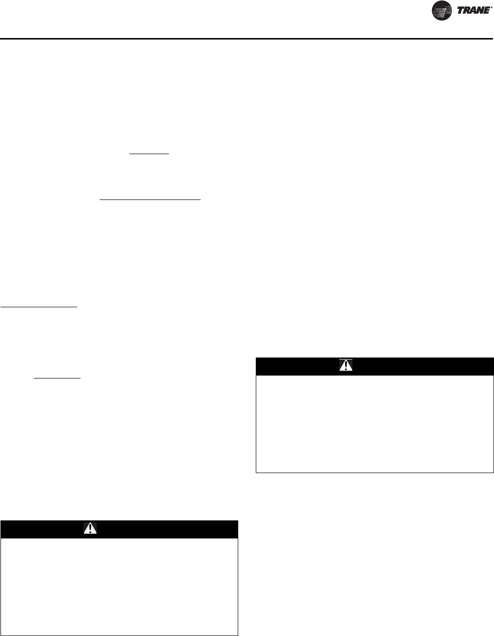
Installation
OAU-SVX01E-EN 29
within the proper tolerances, notify the power company to
correct this situation before operating the unit.
Excessive three phase voltage imbalance between phases
will cause motors to overheat and eventually fail. The
maximum allowable voltage imbalance is 2.0 percent.
Measure and record the voltage between phases 1, 2, and
3 and calculate the amount of imbalance as follows:
V1, V2, V3 = Line Voltage Readings
VD = Line Voltage reading that deviates the farthest from
the average voltage.
Example: If the voltage readings of the supply power
measured 221, 230, and 227, the average volts would be:
VD (reading farthest from average) = 221
The percentage of Imbalance equals:
The 2.2 percent imbalance in this example exceeds the
maximum allowable imbalance of 2.0 percent. This much
imbalance between phases can equal as much as a
20 percent current imbalance with a resulting increase in
motor winding temperatures that will decrease motor life.
If the voltage imbalance is over 2.0 percent, notify the
proper agencies to correct the voltage problem before
operating this equipment.
Electrical Phasing (Three-Phase Motors)
The compressor motor(s) and the supply fan motor are
internally connected for the proper rotation when the
incoming power supply is phased as A to L1, B to L2, and
C to L3.
Proper electrical supply phasing can be quickly
determined and corrected before starting the unit by using
an instrument such as an Associated Research Model 45
Phase Sequence Indicator and following these steps:
Compressor Crankcase Heaters
To prevent injury or death from electrocution, it is the
responsibility of the technician to recognize this hazard
and use extreme care when performing service
procedures with the electrical power energized.
Each compressor shall be equipped with a crankcase
heater. The proper operation of the crankcase heater is
important to maintain an elevated compressor oil
temperature during the “Off” cycle to reduce oil foaming
during compressor starts. Oil foaming occurs when
refrigerant condenses in the compressor and mixes with
the oil. In lower ambient conditions, refrigerant migration
to the compressor could increase.
When the compressor starts, the sudden reduction in
crankcase pressure causes the liquid refrigerant to boil
rapidly causing the oil to foam. This condition could
damage compressor bearings due to reduced lubrication
and could cause compressor mechanical failures.
% Voltage Imbalance = 100 X AV - VD where;
AV
AV (Average Voltage) = Volt 1 + Volt 2 + Volt 3
3
221 + 230 + 227 = 226 Avg.
3
100 X 226 - 221 = 2.2%
226
WARNING
Live Electrical Components!
During installation, testing, servicing and
troubleshooting of this product, it may be necessary to
work with live electrical components. Have a qualified
licensed electrician or other individual who has been
properly trained in handling live electrical components
perform these tasks. Failure to follow all electrical
safety precautions when exposed to live electrical
components could result in death or serious injury.
Turn off the main source feeding power to the unit
field-supplied or factory-installed main disconnect
device (switch or circuit breaker).
Close the unit disconnect device cover, leaving
disconnect switch in the off position, and turn main
source power on.
Observe the ABC and CBA phase indicator lights on
the face of the sequencer. The ABC indicator light will
glow if the phase is ABC. If the CBA indicator light
glows, turn main source power off and then open the
unit main disconnect device cover and reverse any
two power wires.
Restore the main source power and recheck the
phasing. If the phasing is correct, turn main source
power off then open the unit main disconnect device
cover, remove the phase sequence indicator, reinstall
disconnect device cover and, leaving disconnect
device in the off position, turn main power source to
unit on.
WARNING
Live Electrical Components!
During installation, testing, servicing and
troubleshooting of this product, it may be necessary to
work with live electrical components. Have a qualified
licensed electrician or other individual who has been
properly trained in handling live electrical components
perform these tasks. Failure to follow all electrical
safety precautions when exposed to live electrical
components could result in death or serious injury.
Installation
30 OAU-SVX01E-EN
Before initial start up, or if main power has been off for an
extended period of time, compressor crankcase heater(s)
should be operated for a minimum of 8 hours prior to
compressor operation. With main power OFF, remove
jumper between OAUTS terminals 9 and 10 (E-Stop). Turn
main power to energize crankcase heater(s). At end of
warm up period turn main power off, install 9-10 jumper,
turn main power on, and resume normal operation.
Following crankcase heater warm-up, turn main power
disconnect off, and install jumper on E-Stop terminals 9
and 10.
Turn Main disconnect “On”.
Main Unit Display and ReliaTel Controls
When first powered “On”, the controls perform self-
diagnostic initialization to check that all internal controls
are functional. The Status LED located on the Main Unit
Display and the Liteport LED located on the RTRM module
is turned “On” within one second of power-up if internal
operation is okay.
Field-Installed Control Wiring
An overall layout of the various control options available
with the required number of conductors for each control
device is illustrated in Figure 31, p. 31 and Figure 32, p. 32.
Note: All field wiring must conform to NEC guidelines as
well as state and local codes.
Control Power Transformer
The 24-volt control power transformers are to be used only
with the accessories called out in this manual.
Transformers rated greater than 50 VA are equipped with
internal circuit breakers. If a circuit breaker trips, turn “Off”
all power to the unit before attempting to reset it.
The transformers are located in the control panel. The
circuit breaker is located on the left side of the
transformers and can be reset by pressing in on the black
reset button.
Controls Using 24 Vac
Before installing any connecting wiring, refer to Figure 28,
p. 27, Figure 29, p. 27, and Figure 30, p. 27 for the electrical
access locations provided on the unit and Table 7 for AC
conductor sizing guidelines, and:
1. Use copper conductors unless otherwise specified.
2. Ensure that the AC control wiring between the controls
and the unit’s termination point does not exceed three
(3) ohms/ conductor for the length of the run.
Note: Resistance in excess of 3 ohms per conductor
may cause component failure due to
insufficient AC voltage supply.
3. Be sure to check all loads and conductors for grounds,
shorts, and mis-wiring.
4. Do not run the AC low-voltage wiring in the same
conduit with the high-voltage power wiring.
WARNING
Proper Field Wiring and Grounding
Required!
All field wiring MUST be performed by qualified
personnel. Improperly installed and grounded field
wiring poses FIRE and ELECTROCUTION hazards. To
avoid these hazards, you MUST follow requirements for
field wiring installation and grounding as described in
NEC and your local/state electrical codes. Failure to
follow code could result in death or serious injury.
WARNING
Hazardous Voltage!
Disconnect all electric power, including remote
disconnects before servicing. Follow proper lockout/
tagout procedures to ensure the power can not be
inadvertently energized. Failure to disconnect power
before servicing could result in death or serious injury.
WARNING
Hazardous Voltage!
Disconnect all electric power, including remote
disconnects before servicing. Follow proper lockout/
tagout procedures to ensure the power can not be
inadvertently energized. Failure to disconnect power
before servicing could result in death or serious injury.
NOTICE:
Use Copper Conductors Only!
Unit terminals are not designed to accept other types
of conductors. Failure to use copper conductors could
result in equipment damage.
Table 7. 24 Vac conductors
Distance from Unit to Control Recommended Wire Size
000–460 feet
000–140 m 18 gauge
0.75 mm2
461–732 feet
104–223 m 16 gauge
1 mm2
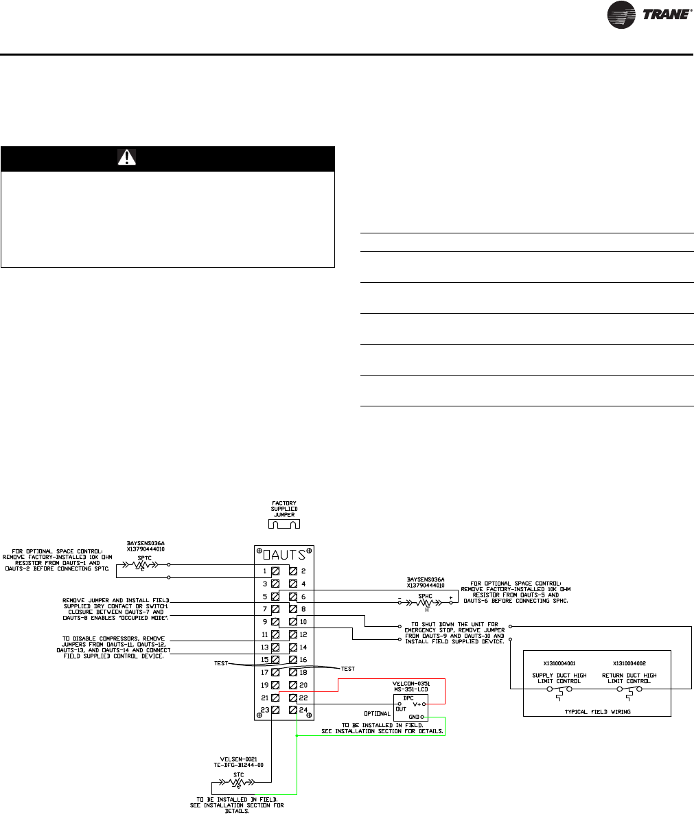
Installation
OAU-SVX01E-EN 31
Controls Using DC Analog Input/Output
(Standard Low Voltage Multiconductor
Wire)
Before installing any connecting wiring between the unit
and components utilizing a DC analog input\output signal,
refer to Figure 28, p. 27, Figure 29, p. 27, and Figure 30,
p. 27 for the electrical access locations provided on the
unit.
1. Table 8, p. 31 lists the conductor sizing guidelines that
must be followed when interconnecting the DC binary
output devices and the system components utilizing a
DC analog input\output signal to the unit.
Note: Resistance in excess of 2.5 ohms per conductor
can cause deviations in the accuracy of the
controls.
2. Ensure that the wiring between controls and the unit’s
termination point does not exceed 2.5 ohms/
conductor for the length of the run.
3. Do not run the electrical wires transporting DC signals
in or around conduit housing high voltage wires.
DC Conductors
WARNING
Hazardous Voltage!
Disconnect all electric power, including remote
disconnects before servicing. Follow proper lockout/
tagout procedures to ensure the power can not be
inadvertently energized. Failure to disconnect power
before servicing could result in death or serious injury.
Table 8. Zone sensor module wiring
Distance from Unit to Control Recommended Wire Size
000–150 feet
0–45.7 m 22 gauge
0.33 mm2
151–240 feet
46–73.1 m 20 gauge
0.50 mm2
241–385 feet
73.5–117.3 m 18 gauge
0.75 mm2
386–610 feet
117.7–185.9 m 16 gauge
1.3 mm2
611–970 feet
186.2–295.7 m 14 gauge
2.0 mm2
Figure 31. OAUTS Connection B
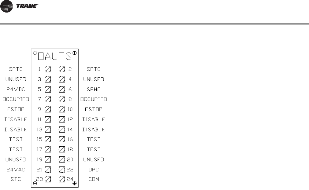
Installation
32 OAU-SVX01E-EN
Figure 32. OAUTS Connection C
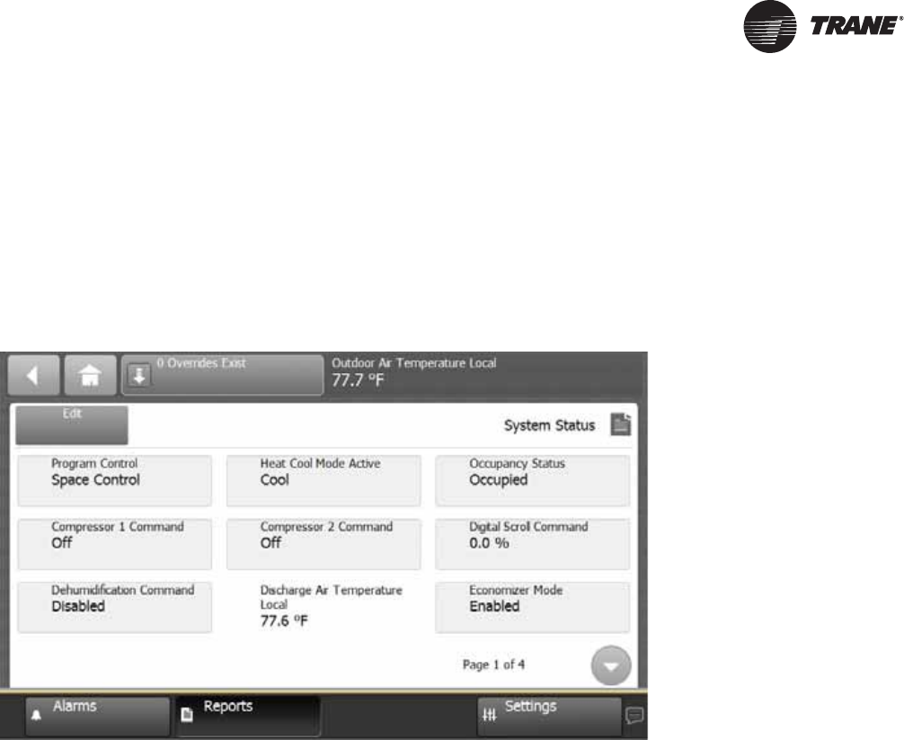
OAU-SVX01E-EN 33
System Configuration and Pre-Start
The following procedure must be completed prior to
performing the start-up procedure in the system Start-Up
section in this document. This section describes
procedures to navigate the various displays on the Unit
Display and configure the Outdoor Air Unit Main Unit
Display system setpoints and operating parameters.
Important: This section is intended to provide
guidelines for navigation through the
remote operator display screens. For
additional control system information, refer
to Integration Guide: Tracer™ UC600
Programmable Controller for Packaged
Outdoor Air Unit (BAS-SVP18A-EN, or the
most recent revision). The unit is configured
at the factory with the default settings as
described in “Sequence of Operation—
”Unoccupied”,” p . 2 4 ; also refer to
“Sequence of Operation,” p. 21 for details
concerning setup and operating setpoints.
System Configuration and Pre-Start
34 OAU-SVX01E-EN
Table 9. Menu descriptions
Screen Menu Point List Min/Inactive Default Max/Active BAS
Point?
Alarms Active Alarms List of all active alarms
All Alarms List of all previous alarms
Reports
(continued
on next
page)
Custom Graphics *NOT USED*
System Status
Program Control Discharge Air Control Space ControlSpace ControlY
Heat Cool Mode Active Heat --- Cool N
Occupancy Status Occupied|Unoccupied|Occupied Bypass|Occupied Standby|Unknown Y
Compressor 1 Command Off --- On N
Compressor 2 Command Off --- On N
Compressor 3 Command Off --- On N
Compressor 4 Command Off --- On N
Digital Scroll Command 0% --- 100% N
Dehumidification Command Disabled Enabled N
Discharge Air Temperature Local Analog Input
Economizer Mode Disabled Enabled N
Evap Leaving Temp Local Analog Input
Heat Capacity 0% --- 100% N
Heating Output Command 0% --- 100% N
Heat 1 Command Off --- On N
Heat 2 Command Off --- On N
Heat 3 Command Off --- On N
Inducer Command Off --- On N
Gas Valve Status Binary Input
HGRH Command 0% --- 100% N
OA Damper End Switch Binary Input
Outdoor Air Damper Command Closed --- Open N
OAD Position Local Binary Input
Outdoor Air Relative Humidity Local Analog Input
Outdoor Air Temperature Local Analog Input
Space Dewpoint Active Analog Input
Space Temperature Local Analog Input
Supply Fan Start Stop Command Off --- Off N
Filter Status Clean --- Dirty N
System Lockout Normal Normal Lockout N
UNOCC Cooling Mode Off --- On N
UNOCC Dehumid Mode Off --- On N
UNOCC Heating Mode Off --- On N
ERV Command Disable --- Enable N
ERV Leaving Air Temperature Local Analog Input
PEVFD Command 0% 80% 100% Y
Discharge Airflow Local Analog Input
ERV Leaving Air Humidity Local Analog Input
System Configuration and Pre-Start
OAU-SVX01E-EN 35
Reports
(continued
from
previous
page)
System Setpoints
DAT High Temp Cutout 100°F 125°F 150°F Y
DAT Low Temp Cutout 35°F 35°F 50°F Y
DAT Temp Cutout Time 10 min. 10 min. 25 min. Y
Discharge Air Cooling Setpoint 55°F 55°F 75°F Y
Discharge Air Heating Setpoint 65°F 85°F 90°F Y
ERV Wheel Frost Cutout Setpoint 32°F 34°F 40°F Y
EVAP Leaving Temp Setpoint 45°F 53°F 70°F Y
IVFD Signal 50% 100% 100% Y
Maximum Discharge Air Temperature 70°F 90°F 100°F Y
Minimum Discharge Air Cooling Setpoint 40°F 50°F 65°F Y
Minimum Discharge Air Heating Setpoint 50°F 55°F 60°F Y
Maximum OA Damper Position 0% 100% 100% Y
Minimum OA Damper Position 0% 100% 100% Y
Occupied Space Cooling Setpoint 65°F 74°F 90°F Y
Occupied Space Heating Setpoint 60°F 70°F 75°F Y
Outdoor Air Cooling Setpoint (OACS) 70°F 75°F 85°F Y
Outdoor Air Dewpoint Setpoint (OADS) 49°F 58°F 65°F Y
Outdoor Air Heating Setpoint (OAHS) 40°F 70°F 70°F Y
PEVFD Setpoint 0% 80% 100% Y
Space Dewpoint Setpoint (SPDS) 50°F 59°F 68°F Y
UNOCC Space Cooling Setpoint 60°F 80°F 90°F Y
UNOCC Space Dewpoint Setpoint 49°F 65°F 68°F Y
UNOCC Space Heating Setpoint 50°F 60°F 70°F Y
System Setup
Program Control Discharge Air Control Space ControlSpace ControlY
Compressor Count 004N
Heater Count 002N
Split Manifold Burner Not Installed Installed Installed N
ERV Option Not Installed Installed Installed N
Powered Exhaust Option Not Installed Installed Installed N
Return Air Damper Option Not Installed Installed Installed N
Space Temp/Humidity Sensor Installed Not Installed Installed Installed N
Heat Type No Heat|Gas Heat|Electric Heat|Other N
Alarm Reset Off Off On Y
Supply Fan Failure Reset Off Off On Y
Override Summary List of active overrides - same as selecting Override button at top of screen
All Point Report List of all points (AO/AI/BO/BI/MS/etc …) in the configuration file
About Controller Name listed is the version of the program installed in the UC600
Expansion Modules Provides status of expansion modules
TGP2 Programs List of all TGP2 programs loaded on the UC600
Data Graphs *NOT USED*
Settings
Schedules - Refer to UC600 IOM for scheduling functions
Display Preferences
Language
Date and Time
Clean Touchscreen
Table 9. Menu descriptions (continued)
Screen Menu Point List Min/Inactive Default Max/Active BAS
Point?
36 OAU-SVX01E-EN
Start-Up
Indirect Gas-Fired Heating
Start-Up
Notes:
1. This furnace module does not have a pilot. It is
equipped with a direct spark ignition device that
automatically lights the gas burner. DO NOT try to light
burners by hand.
2. BEFORE OPERATING, leak test all gas piping up to
heater gas valve. Smell around the unit area for gas. If
gas is smelled, do NOT attempt to place heater in
operation until source of gas leak is identified and
corrected.
3. Use only hand force to operate the gas control lever to
the “ON” position. NEVER use tools. If lever does not
operate by hand, replace gas valve prior to staring the
unit. Forcing or attempting to repair the gas valve may
result in fire or explosion.
4. Do not attempt to operate unit, if there is indication that
any part or control has been under water. Any control
or component that has been under water must be
replaced prior to trying to start the unit.
Refer to “Sequence of Operation,” p. 21 for additional
information.
Tools Required
• Voltage Meter (μA)
•Amp Meter
• Gas Manometer (2)
• Temperature Probe
• Small Refrigeration Screwdriver
• 5/16-in. Nut Driver
• 3/16-in. Allen Wrench
• 3/32-in. Allen Wrench
• 1/8-in. NPT barbed pressure taps (3)
• 1/2-in. Open End Wrench
Start-Up Procedure
1. Check Inlet Gas Pressure
Check to insure the gas pressure supplied to the unit is
within the pressure requirement listed on the
nameplate. DO NOT expose gas controls to pressures
above 1/2 psi (14 in. wc). The gas supply line should be
installed with an external manual shutoff and pressure
tap.
2. Verify Indoor Fan Failure Switch Operation
Indoor Fan Failure Switch (IFFS) is located in the unit
electrical control compartment above the heater.
Indoor fan failure switch will fail if not proven within
30 seconds of call for indoor fan—ON.
All unit air filters must be clean before proceeding to
properly complete this verification.
Important: If the unit air filters are not clean, unit
performance could be affected. Remove
and clean or replace air filters as required
prior to proceeding with the burner
pressure testing.
In the event that the pressure switch fails to operate,
check the pick-up tubes to be certain that the tubes are
not obstructed and confirm that the tube connections
to IFFS are tight and secure.
WARNING
Hazardous Service Procedures!
The maintenance and troubleshooting procedures
recommended in this section of the manual could result
in exposure to electrical, mechanical or other potential
safety hazards. Always refer to the safety warnings
provided throughout this manual concerning these
procedures. When possible, disconnect all electrical
power including remote disconnect and discharge all
energy storing devices such as capacitors before
servicing. Follow proper lockout/tagout procedures to
ensure the power can not be inadvertently energized.
When necessary to work with live electrical
components, have a qualified licensed electrician or
other individual who has been trained in handling live
electrical components perform these tasks.
Do not attempt the following procedures until all
electrical and gas connections to the unit have been
completed and the outdoor air damper and evaporator
fan operation have been verified and are operating
correctly.
Failure to follow all of the safety warnings provided
could result in death or serious injury.
WARNING
Hazard of Explosion!
Never use an open flame to detect gas leaks. It could
result in an explosion. Use a leak test solution for leak
testing. Failure to follow recommended safe leak test
procedures could result in death or serious injury or
equipment or property-only-damage.
Start-Up
OAU-SVX01E-EN 37
3. Confirm Gas Flow at Unit
Open door to unit vestibule housing the gas heater.
Move gas control lever to “OFF” position. Remove
1/8-in. pressure taps (see Figure 34, p. 39) from both
modulating and on-off sections of the split heater
manifold. Install a barbed fitting in both 1/8-in. tapped
holes for connection to individual gas manometers.
Note: There is a third 1/8-in. gas pressure tap located in
the pipe connecting the main valve/regulator and
modulating valve. Maximum pressure into
modulating valve is 5-in. The On-Off gas valve
includes a regulator adjustment device that is
located on the top of the valve. Use this device to
regulate valve output to modulating valve as
required.
Wait 5 minutes for any gas to clear. If you smell gas, see
Step 2 and correct leak. If you don’t smell gas or have
corrected any leaks, go to Step 4.
4. Burner Starting Sequence and Burner Ignition
Figure 34, p. 39 illustrates indirect gas-fired furnace
components.
5. Main Gas Supply
Turn manual gas cock “ON”.
6. Split Manifold High Fire and Burner Test
Open all manual gas valves. Turn power on at unit’s
main disconnect switch. Open gas supply manual shut-
off valve. Using unit display (or computer with Trane
Tracer TU), proceed to System Status Display and
Override all Compressor stages OFF, Disable
Dehumidification, Disable Economizer Mode, Disable
ERV. If two heaters are installed, test heating with split
manifold first by overriding burner 2 OFF. Override
heating Output Command to 100.0 percent if one
heater is installed and to 49 percent if two heaters are
installed. Override Heat Cool Mode Active to Heat. This
will enable call for heat to split manifold heater.
Depending on outdoor air temperature, at time of
startup, heater high limit temperature may be
exceeded causing limit switch to trip. Limit switch is
auto-reset. Limit switch must be jumpered out of the
circuit if OA temperature dictates.
With limit switch closed, the draft inducer will run on
high speed for 10 seconds for proof of high and low
airflow switch closure, then begin a 30-second pre-
purge period. At the end of the pre-purge the direct
spark will be energized and On-Off gas valve will open
for a 5-second ignition trial. Following successful
ignition, the inducer remains on high for 10-second
flame stabilization, followed by 30-second warm up.
Should the flame go out or the burner fail to light, an
ignition retry will initiate following a 15-second inter-
purge period.
Following successful ignition, manifold pressure
should be 1.2 in. wc during the warm-up period. The
manifold pressure will rise to 3.5 in. wc at 100 percent
firing rate. Following these sequences to check low fire
gas pressure for modulating section, reduce Heating
Output Command to 0 percent. Inducer speed will
reduce to low speed. Correct gas pressure for
modulating manifold section of heater at 0 percent
output signal or low fire will be 0.17 in. For modulating
sections, the outlet gas pressure from main/regulator
valve into the modulating valve is 5-in. wc.
Main On-Off valves in 1/2-in. gas line require 3/32-in.
Allen wrench to adjust outlet gas pressure. Valves in
3/4-in. gas line require flat blade screwdriver to adjust
outlet gas pressure. Following these sequences,
inducer speed will reduce to low speed and will now be
speed-controlled by the heater controller based on gas
input to burners.
With heating command at 100 percent and with a
single split manifold heater installed, the On-Off
section of the heater will require the modulating
section to prove ON before the On-Off section will
enable. Inducer speed high at all times the On-Off
section is in ignition sequence or firing. On-Off section
sequence includes a 1-second ignition pre-purge
followed by 4-second ignition trial. Ignition or flame
failure will be followed by 30-second inter-purge for
two ignition retry then 5-minute lockout period if both
retry attempts fail. Correct manifold gas pressure for
On-Off heater section is 3.5 in. wc.
For units including an additional separate On-Off
heater, set heat command output to 49 percent to run
modulating heater start-up. When complete with
modulating heater start-up, increase heat output
command to 100 percent to start up the second heater.
Failure to Ignite
•On the initial start-up, or after unit has been off long
periods of time, the first ignition trial may be
unsuccessful due to need to purge air from
manifold at start-up.
•If ignition does not occur on the first trial, the gas
and spark are shut-off by the ignition control and
the control enters an inter-purge period of
15 seconds, during which the draft inducer
continues to run.
•At the end of the inter-purge period, another trial for
ignition will be initiated.
•Control will initiate up to three ignition trials on a
call for heat before lockout of control occurs.
WARNING
Hazardous Voltage and Gas!
Turn off the gas supply and disconnect all electric
power, including remote disconnects before servicing
unit. Follow proper lockout/tagout procedures to
ensure the power can not be inadvertently energized
and the gas can not be inadvertently turned on. Failure
to turn off gas or disconnect power before servicing
could result in death or serious injury.
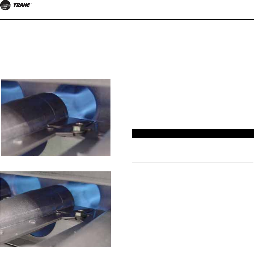
Start-Up
38 OAU-SVX01E-EN
•Control can be brought out of lockout by cycling call
for heat at the Main Unit Display.
Prior to completing the start-up, check the appearance
of the main burner flame. Refer to Figure 33, p. 38 for
flame characteristics of properly adjusted natural gas
systems.
Main burner flame
•The burner flame should be predominately blue in
color and well defined and centered at the tube
entry as shown in Figure 33 above. Distorted flame
or yellow tipping of natural gas flame, or a long
yellow flame on propane, may be caused by lint and
dirt accumulation inside burner or at burner ports,
at air inlet between burner and manifold pipe, or
debris in the main burner orifice. Soft brush or
vacuum clean affected areas.
•Poorly defined, substantially yellow flames, or
flames that appear lazy, indicate poor air supply to
burners or excessive burner input. Verify gas
supply type and manifold pressure with rating
plate.
•Poor air supply can be caused by obstructions or
blockage in heat exchanger tubes or vent discharge
pipe. Inspect and clean as necessary to eliminate
blockage. Vacuum any dirt or loose debris. Clean
heat exchanger tubes with stiff brush. Poor flame
characteristics can also be caused by flue gas
recirculation into combustion air supply. If
surrounding buildings or prevailing winds cause
recirculation, a flue extension may be required to
prevent recirculation. Contact manufacturer prior
to making any flue adjustments.
•Reduced air delivery can also be the result of
inducer fan blade slippage, dirt accumulation in the
fan blade or low voltage to draft inducer motor.
Inspect draft fan assembly and be sure fan blade is
secure to motor shaft. Check line voltage to heater.
7. Flame Sensor Current Check
Flame current is the current which passes through the
flame from the sensor to ground. A flame signal of 0.5
to 1.0 microamp (μA) is marginal. For dependable
operation, a flame signal of greater than 1.0 μA is
required. To measure flame current, connect a meter
capable of reading micro-amp current so the flame
signal will be read thru the meter’s COM and μA
connections. The meter should read greater than
1.0 μA.
Note: If the meter reads below “0” on scale, meter
leads are reversed; disconnect power and
reconnect meter leads for proper polarity.
Figure 33. Flame characteristics of properly-adjusted
natural gas systems
Burner flame at start-up: 1.2 in. wc manifold pressure
draft inducer—high speed
Burner flame at high fire: 3.5 in. wc manifold pressure
draft inducer—high speed
NOTICE:
Meter Damage!
Do NOT measure voltage with meter connected to a
circuit. Failure to follow these instructions could result
in meter damage.
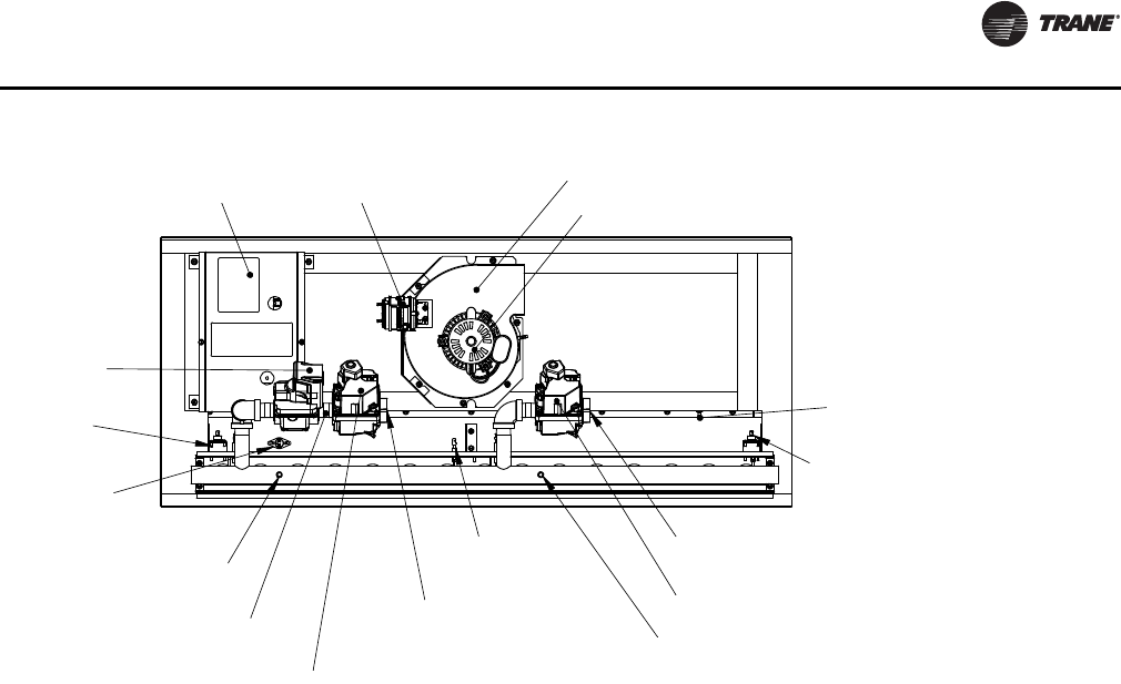
Start-Up
OAU-SVX01E-EN 39
Safety Controls
Air Pressure Switch. An air pressure switch is provided
as part of the control system to verify airflow through draft
inducer by monitoring the difference in pressure between
the draft inducer and the atmosphere. If sufficient negative
pressure is not present, indicating lack of proper air
movement through heat exchanger, the switch opens
shutting off gas supply though the ignition control
module. On units with two speed draft inducer operation,
a dual air pressure switch is used, monitoring high and low
speed pressures. The air pressure switches have fixed
settings and are not adjustable.
Rollout Switch (Manual Reset). The furnace module
is equipped with manual reset rollout switch(es) in the
event of burner flame rollout. The switch will open on
temperature rise and shut-off gas supply through the
ignition control module. Flame rollout can be caused by
insufficient airflow for the burner firing rate (high gas
pressure), blockage of the vent system or in the heat
exchanger. The furnace module should not be placed back
in operation until the cause of rollout condition is
identified and corrected. The rollout switch can be reset by
pressing the button on top of the switch.
High Limit Switch. The furnace module is equipped
with a fixed temperature high limit switch mounted on the
vestibule panel that shuts off gas to the heater through the
ignition control module in the event of reduced airflow
over the heat exchanger tubes. Reduced airflow can be
caused by indoor fan failure, dirty or blocked filters, or
restriction of the air inlet or outlet to the unit. The high limit
switch will automatically reset when the air temperature
drops to approximately 30°F below the limit setpoint.
Determine the cause of the reduced air flow and correct.
Figure 34. OA1/OA2/OA3 indirect gas-fired furnace components
INDUCER MOTOR
INLET PRESSURE TAP
IGNITION
ON/OFF GAS VALVE
ON/OFF GAS VALVE
MANIFOLD GAS
PRESSURE = 14" W.C.
AIR-PROVING
PRESSURE TAP
SWITCH
MAXIMUM INLET
PRESSURE TAP
MANIFOLD GAS
ROLLOUT SWITCH
CONTROLLERS
MAXIMUM INLET
PRESSURE = 14" W.C.
CONDENSATE DRAIN
(TYP. 2)
INDUCER BLOWER
MODULATING VALVE
FLAME
SENSOR
HIGH LIMIT
SWITCH
ROLLOUT
SWITCH
MODULATING
GAS VALVE
40 OAU-SVX01E-EN
Maintenance
Make sure all personnel are standing clear of the unit
before proceeding. The system components will start
when the power is applied.
Monthly Maintenance
Before completing the following checks, turn the unit OFF
and lock the main power disconnect switch open.
Filters
• Inspect the return air filters. Clean or replace them if
necessary. Refer to the unit Service Facts for filter
information and refer to “OAU Filter Guide” in
“Appendix,” p. 55 for exact replacement dimensions.
Supply/Return Air Smoke Detector
Maintenance
Airflow through the unit is affected by the amount of dirt
and debris accumulated on the indoor coil and filters.
To insure that airflow through the unit is adequate for
proper sampling by the return air smoke detector,
complete adherence to the maintenance procedures,
including recommended intervals between filter changes,
and coil cleaning is required.
Periodic checks and maintenance procedures must be
performed on the smoke detector to insure that it will
function properly.
For detailed instructions concerning these checks and
procedures, refer to the appropriate section(s) of the
smoke detector Installation and Maintenance Instructions
provided with the literature package for this unit.
Cooling Season
• Check the unit’s drain pans and condensate piping to
ensure that there are no blockages.
• Inspect the evaporator and condenser coils for dirt,
bent fins, etc. If the coils appear dirty, clean them
according to the instructions described in “Condenser
Coil Cleaning,” p. 40.
• Manually rotate the condenser fan(s) to ensure free
movement and check motor bearings for wear. Verify
that all of the fan mounting hardware is tight.
• Inspect the F/A-R/A damper hinges and pins to ensure
that all moving parts are securely mounted. Keep the
blades clean as necessary.
• Verify that all damper linkages move freely; lubricate
with white grease, if necessary.
• Check supply fan motor bearings; repair or replace the
motor as necessary.
• Check the fan shaft bearings for wear. Replace the
bearings as necessary.
• Verify that all wire terminal connections are tight.
• Remove any corrosion present on the exterior surfaces
of the unit and repaint these areas.
• Generally inspect the unit for unusual conditions (e.g.,
loose access panels, leaking piping connections, etc.).
• Make sure that all retaining screws are reinstalled in
the unit access panels once these checks are complete.
• With the unit running, check and record the: ambient
temperature; compressor suction and discharge
pressures (each circuit); superheat (each circuit);
Record this data on an “operator’s maintenance log”
like the one shown in Table 10, p. 41. If the operating
pressures indicate a refrigerant shortage, measure the
system superheat.
Note: Do NOT release refrigerant to the atmosphere! If
adding or removing refrigerant is required, the
service technician must comply with all federal,
state and local laws.
Heating Season
• Inspect the unit’s air filters. If necessary, clean or
replace them.
• Check supply fan motor bearings; repair or replace the
motor as necessary.
• Inspect both the main unit control panel and heat
section control box for loose electrical components
and terminal connections, as well as damaged wire
insulation. Make any necessary repairs.
• Verify that the electric heat system operates properly.
Condenser Coil Cleaning
Regular coil maintenance, including annual cleaning,
enhances the unit’s operating efficiency by minimizing:
compressor head pressure and amperage draw;
evaporator water carryover; fan brake horsepower, due to
increase static pressure losses; airflow reduction.
At least once each year, or more often if the unit is located
in a “dirty” environment, clean the condenser coils using
the instructions outlined below. Be sure to follow these
instructions as closely as possible to avoid damaging the
coils.
WARNING
Hazardous Voltage!
Disconnect all electric power, including remote
disconnects before servicing. Follow proper lockout/
tagout procedures to ensure the power can not be
inadvertently energized. Failure to disconnect power
before servicing could result in death or serious injury.
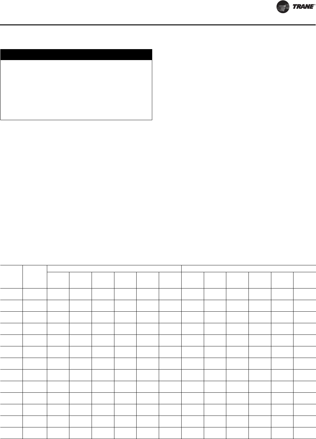
Maintenance
OAU-SVX01E-EN 41
Microchannel (MCHE) Coils
Due to the soft material and thin walls of the MCHE coils,
the traditional field maintenance method recommended
for Round Tube Plate Fin (RTPF) coils does not apply to
microchannel coils.
Moreover, chemical cleaners are a risk factor to MCHE due
to the material of the coil. The manufacturer does not
recommend the use of chemical cleaners to clean
microchannel coils. Using chemical cleaners could lead to
warranty claims being further evaluated for validity and
failure analysis.
The recommended cleaning method for microchannel
condenser coils is pressurized water or air with a non-
pinpoint nozzle and an ECU of at least 180 with pressure no
greater than 600 psi. To minimize the risk of coil damage,
approach the cleaning of the coil with the pressure washer
aimed perpendicular to the face of the coil during cleaning.
Optimum clearance between the sprayer nozzle and the
microchannel coil is 1 in.–3 in.
Final Process
For future reference, you may find it helpful to record the
unit data requested below in the blanks provided.
(1) Complete Unit Model Number:
_____________________________________________________
_____________________________________________________
_____________________________________________________
(2) Unit Serial Number:
_____________________________________________________
_____________________________________________________
_____________________________________________________
(3) Wiring Diagram Numbers (from unit control panel)
— schematic(s)
_____________________________________________________
_____________________________________________________
_____________________________________________________
_____________________________________________________
_____________________________________________________
— connection(s)
_____________________________________________________
_____________________________________________________
_____________________________________________________
NOTICE:
Coil Damage!
DO NOT use any detergents with microchannel
condenser coils. Use pressurized water or air ONLY,
with pressure no greater than 600psi. Failure to do so
could result in coil damage.
For additional information regarding the proper
microchannel coil cleaning procedure, refer to
RT-SVB83*-EN.
Table 10. Sample maintenance log
Date
Current
Ambient
Temp F/C
Refrigerant Circuit #1 Refrigerant Circuit #2
Compr.
Oil Level
Suct.
Press.
Psig/kPa
Disch.
Press
Psig/kPa
Liquid
Press
Psig/kPa Super-
heat F/C Sub-cool
F/C Compr.
Oil Level
Suct.
Press.
Psig/kPa
Disch.
Press
Psig/kPa
Liquid
Press
Psig/kPa Super-
heat F/C Sub-cool
F/C
- ok
- low - ok
- low
- ok
- low - ok
- low
- ok
- low - ok
- low
- ok
- low - ok
- low
- ok
- low - ok
- low
- ok
- low - ok
- low
- ok
- low - ok
- low
- ok
- low - ok
- low
- ok
- low - ok
- low
- ok
- low - ok
- low
- ok
- low - ok
- low
- ok
- low - ok
- low
- ok
- low - ok
- low
42 OAU-SVX01E-EN
Performance Data
Table 11. OA1 General Data—Cooling 5–8 Tons High Efficiency
5 Tons Downflow 6 Tons Downflow 7 Tons Downflow 8 Tons Downflow
OA1D060A OA1D072A OA1D084 OA1D096
Cooling Performance
Gross Cooling Capacity, Btu (kW) 61,464 (18.01) 73,757 (21.62) 86,050 (25.22) 98,342 (28.82)
Nominal cfm (m3/h) 625–1250 (1062–2124) 750–1500 (1274–2549) 875–1750 (1487–2973) 1000–2000 (1699–3398)
Compressor
Number 1112
Type Scroll Scroll Scroll Scroll
Outdoor Coil
Type High Performance High Performance High Performance High Performance
Tube Size—OD, in. (mm) 3/8 (9.5) 3/8 (9.5) 3/8 (9.5) 3/8 (9.5)
Face Area, ft2 (m2) 13 (1.21) 13 (1.21) 13 (1.21) 24 (2.23)
Rows 2222
FPI 12121212
Indoor Coil
Type High Performance High Performance High Performance High Performance
Tube Size—OD, in. (mm) 1/2 (12.7) 1/2 (12.7) 1/2 (12.7) 1/2 (12.7)
Face Area, ft2 (m2) 6 (0.56) 6 (0.56) 6 (0.56) 9 (0.84)
Rows 6666
FPI 12121212
Refrigerant Control TXV TXV TXV TXV
Drain Connection Size, in. (mm) 3/4 (20) 3/4 (20) 3/4 (20) 3/4 (20)
Outdoor Fan
Type Propeller Propeller Propeller Propeller
Number Used 1112
Diameter, in. (mm) 24 (609.6) 24 (609.6) 24 (609.6) 24 (609.6)
Drive Type Direct Direct Direct Direct
No. Speeds 1111
CFM (m3/h) 6,500 (11,044) 6,500 (11,044) 6,500 (11,044) 13,000 (22,087)
Number Motors 1112
Motor HP (kW), per motor 1.0 (0.75) 1.0 (0.75) 1.0 (0.75) 1.0 (0.75)
Motor RPM 1140 1140 1140 1140
Indoor Fan
Type Backward Inclined Backward Inclined Backward Inclined Backward Inclined
Number Used 1111
Diameter Varies Varies Varies Varies
Drive Type Direct Drive Direct Drive Direct Drive Direct Drive
Number Motors 1111
Motor HP (kW), Standard–Oversized 1.0–3.0 (0.75–2.24) 1.0–3.0 (0.75–2.24) 1.0–3.0 (0.75–2.24) 1.0–5.0 (0.75–3.73)
Motor RPM, Standard–Oversized 1750–3500 1750–3500 1750–3500 1750–3500
Motor Frame Size, Standard–Oversized Varies Varies Varies Varies
Filters
Type Furnished Refer to “OAU Filter
Guide” in “Appendix,”
p. 55
Refer to “OAU Filter
Guide” in “Appendix,”
p. 55
Refer to “OAU Filter
Guide” in “Appendix,”
p. 55
Refer to “OAU Filter
Guide” in “Appendix,”
p. 55
Number Size Recommended
Refrigerant Charge, lb of R-410A
Downflow See Nameplate See Nameplate See Nameplate See Nameplate
Performance Data
OAU-SVX01E-EN 43
Table 12. OA1 General Data—Cooling 10–15 Tons High Efficiency
10 Tons Downflow 12 Tons Downflow 15 Tons Downflow
OA1D120A OA1D144A OA1D144A
Cooling Performance
Gross Cooling Capacity, Btu (kW) 121,904 (35.73) 147,514 (43.23) 184,392 (54.04)
Nominal cfm (m3/h) 1250–2500 (2124–4248) 1500–3000 (2549–5097) 1875–3750 (3186–6371)
Compressor
Number 2 2 2
Type Scroll Scroll Scroll
Outdoor Coil
Type High Performance High Performance High Performance
Tube Size—OD, in. (mm) 3/8 (9.5) 3/8 (9.5) 3/8 (9.5)
Face Area, ft2 (m2) 24 (2.23) 24 (2.23) 24 (2.23)
Rows 2 2 2
FPI 121212
Indoor Coil
Type High Performance High Performance High Performance
Tube Size—OD, in. (mm) 1/2 (12.7) 1/2 (12.7) 1/2 (12.7)
Face Area, ft2 (m2) 9 (0.84) 9 (0.84) 9 (0.84)
Rows 6 6 6
FPI 121212
Refrigerant Control TXV TXV TXV
Drain Connection Size, in. (mm) 3/4 (20) 3/4 (20) 3/4 (20)
Outdoor Fan
Type Propeller Propeller Propeller
Number Used 2 2 2
Diameter, in. (mm) 24 24 24
Drive Type Direct Direct Direct
No. Speeds 1 1 1
CFM (m3/h) 13,500 (22,937) 13,500 (22,937) 13,500 (22,937)
Number Motors 2 2 2
Motor HP (kW), per motor 1.0 (0.75) 1.0 (0.75) 1.0 (0.75)
Motor RPM 1140 1140 1140
Indoor Fan
Type Backward Inclined Backward Inclined Backward Inclined
Number Used 1 1 1
Diameter Varies Varies Varies
Drive Type Direct Drive Direct Drive Direct Drive
Number Motors 1 1 1
Motor HP (kW), Standard–Oversized 1.0–5.0 (0.75–3.73) 1.0–5.0 (0.75–3.73) 1.0–5.0 (0.75–3.73)
Motor RPM, Standard–Oversized 1750–3500 1750–3500 1750–3500
Motor Frame Size, Standard–Oversized Varies Varies Varies
Filters
Type Furnished Refer to “OAU Filter
Guide” in “Appendix,”
p. 55
Refer to “OAU Filter
Guide” in “Appendix,”
p. 55
Refer to “OAU Filter
Guide” in “Appendix,”
p. 55
Number Size Recommended
Refrigerant Charge, lb of R-410A
Downflow See Nameplate See Nameplate See Nameplate
Performance Data
44 OAU-SVX01E-EN
Table 13. OA2 General Data—Cooling 12–20 Tons High Efficiency
12 Tons Downflow 15 Tons Downflow 17 Tons Downflow 20 Tons Downflow
OA2D144A OA2D180A OA2D210A OA2D240A
Cooling Performance
Gross Cooling Capacity, Btu (kW) 147,514 (43.23) 184,392 (54.04) 208,973 (61.24) 245,856 (72.05)
Nominal cfm (m3/h) 1500–3000 (2549–5097) 1875–3750 (3186–6371) 2125–4250 (3610–7221) 2500–5000 (4248–8495)
Compressor
Number 2222
Type Scroll Scroll Scroll Scroll
Outdoor Coil
Type High Performance High Performance High Performance High Performance
Tube Size—OD, in. (mm) 3/8 (9.5) 3/8 (9.5) 3/8 (9.5) 3/8 (9.5)
Face Area, ft2 (m2) 24 (2.23) 30 (2.79) 38 (3.53) 38 (3.53)
Rows 2333
FPI 12121212
Indoor Coil
Type High Performance High Performance High Performance High Performance
Tube Size—OD, in. (mm) 1/2 (12.7) 1/2 (12.7) 1/2 (12.7) 1/2 (12.7)
Face Area, ft2 (m2) 9 (0.84) 10 (0.93) 15 (1.39) 15 (1.39)
Rows 6666
FPI 12121212
Refrigerant Control TXV TXV TXV TXV
Drain Connection Size, in. (mm) 1 (25) 1 (25) 1 (25) 1 (25)
Outdoor Fan
Type Propeller Propeller Propeller Propeller
Number Used 2333
Diameter, in. (mm) 24 (609.6) 24 (609.6) 24 (609.6) 24 (609.6)
Drive Type Direct Direct Direct Direct
No. Speeds 1111
CFM (m3/h) 19,500 (33,131) 19,500 (33,131) 19,500 (33,131) 19,500 (33,131)
Number Motors 3333
Motor HP (kW), per motor 1.0 (0.75) 1.0 (0.75) 1.0 (0.75) 1.0 (0.75)
Motor RPM 1140 1140 1140 1140
Indoor Fan
Type Backward Inclined Backward Inclined Backward Inclined Backward Inclined
Number Used 1111
Diameter Varies Varies Varies Varies
Drive Type Direct Drive Direct Drive Direct Drive Direct Drive
Number Motors 1111
Motor HP (kW), Standard–Oversized 1.0–5.0 (0.75–3.73) 1.0–5.0 (0.75–3.73) 1.0–7.5 (0.75–5.6) 1.0–7.5 (0.75–5.6)
Motor RPM, Standard–Oversized 1750–3500 1750–3500 1750–3500 1750–3500
Motor Frame Size, Standard–Oversized Varies Varies Varies Varies
Filters
Type Furnished Refer to “OAU Filter
Guide” in “Appendix,”
p. 55
Refer to “OAU Filter
Guide” in “Appendix,”
p. 55
Refer to “OAU Filter
Guide” in “Appendix,”
p. 55
Refer to “OAU Filter
Guide” in “Appendix,”
p. 55
Number Size Recommended
Refrigerant Charge, lb of R-410A
Downflow See Nameplate See Nameplate See Nameplate See Nameplate

Performance Data
OAU-SVX01E-EN 45
Table 14. OA2 General Data—Cooling 22–30 Tons High Efficiency
22 Tons Downflow 25 Tons Downflow 30 Tons Downflow
OA2D264A OA2D300A OA2D360A
Cooling Performance
Gross Cooling Capacity, Btu (kW) 270,442 (79.26) 307,320 (90.07) 368,784 (108.08)
Nominal cfm (m3/h) 2750–5500
(4692–9345) 3125–6250
(5309–10619) 3750–7500
(6371–12743)
Compressor
Number 2 2 2
Type Scroll Scroll Scroll
Outdoor Coil
Type High Performance High Performance High Performance
Tube Size—OD, in. (mm) 3/8 (9.5) 3/8 (9.5) 3/8 (9.5)
Face Area, ft2 (m2) 38 (3.53) 38 (3.53) 38 (3.53)
Rows 3 3 3
FPI 12 12 12
Indoor Coil
Type High Performance High Performance High Performance
Tube Size—OD, in. (mm) 1/2 (12.7) 1/2 (12.7) 1/2 (12.7)
Face Area, ft2 (m2) 15 (1.39) 20 (1.86) 20 (1.86)
Rows 6 6 6
FPI 12 12 12
Refrigerant Control TXV TXV TXV
Drain Connection Size, in. (mm) 1 (25) 1 (25) 1 (25)
Outdoor Fan
Type Propeller Propeller Propeller
Number Used 3 3 3
Diameter, in. (mm) 24 (609.6) 24 (609.6) 24 (609.6)
Drive Type Direct Direct Direct
No. Speeds 1 1 1
CFM (m3/h) 19,500 (33,131) 19,500 (33,131) 19,500 (33,131)
Number Motors 3
Motor HP (kW), per motor 1.0 (0.75) 1.0 (0.75) 1.0 (0.75)
Motor RPM 1140 1140 1140
Indoor Fan
Type Backward Inclined Backward Inclined Backward Inclined
Number Used 1 1 1
Diameter Varies Varies Varies
Drive Type Direct Drive Direct Drive Direct Drive
Number Motors 1 1 1
Motor HP (kW), Standard–Oversized 1.0–7.5 (0.75–5.6) 1.0–15.0 (0.75–11.19) 1.0–15.0 (0.75–11.19)
Motor RPM, Standard–Oversized 1750–3500 1750–3500 1750–3500
Motor Frame Size, Standard–Oversized Varies Varies Varies
Filters
Type Furnished Refer to “OAU Filter Guide”
in “Appendix,” p. 55 Refer to “OAU Filter Guide”
in “Appendix,” p. 55 Refer to “OAU Filter Guide”
in “Appendix,” p. 55
Number Size Recommended
Refrigerant Charge, lb of R-410A
Downflow See Nameplate See Nameplate See Nameplate
Performance Data
46 OAU-SVX01E-EN
Table 15. OA3 General Data—Cooling 30–40 Tons High Efficiency
30 Tons Downflow 35 Tons Downflow 40 Tons Downflow
OA3D360A OA3D420A OA3D480A
Cooling Performance
Gross Cooling Capacity, Btu (kW) 368,784 (108.08) 430,248 (126.09) 491,712 (144.11)
Nominal cfm (m3/h) 3750–7500
(6371–12743) 4375–8750
(7433–14866) 5000–10000
(8495–16990)
Compressor
Number 233
Type Scroll Scroll Scroll
Outdoor Coil
Type High Performance High Performance High Performance
Tube Size—OD, in. (mm) 3/8 (9.5) 3/8 (9.5) 3/8 (9.5)
Face Area, ft2 (m2) 48 (4.46) 53 (4.92) 63 (5.85)
Rows 233
FPI 121212
Indoor Coil
Type High Performance High Performance High Performance
Tube Size—OD, in. (mm) 1/2 (12.7) 1/2 (12.7) 1/2 (12.7)
Face Area, ft2 (m2) 23 (2.14) 23 (2.14) 29 (2.69)
Rows 666
FPI 121212
Refrigerant Control TXV TXV TXV
Drain Connection Size, in. (mm) 1-1/4 (32) 1-1/4 (32) 1-1/4 (32)
Outdoor Fan
Type Propeller Propeller Propeller
Number Used 4 4 4
Diameter, in. (mm) 24 24 24
Drive Type Direct Drive Direct Drive Direct Drive
No. Speeds 111
CFM (m3/h) 26,000 (44,174) 26,000 (44,174) 26,000 (44,174)
Number Motors 444
Motor HP (kW), per motor 1.0 (0.75) 1.0 (0.75) 1.0 (0.75)
Motor RPM 1140 1140 1140
Indoor Fan
Type Backward Inclined Backward Inclined Backward Inclined
Number Used 1 1 1 or 2
Diameter Varies Varies Varies
Drive Type Direct Drive Direct Drive Direct Drive
Number Motors 1 1 1 or 2
Motor HP (kW), Standard–Oversized 1.5–15 (1.12–11.19) 1.5–15 (1.12–11.19) 2.0–15 (1.49–11.19)
Motor RPM, Standard–Oversized 1750–3500 1750–3500 1750–3500
Motor Frame Size, Standard–Oversized Varies Varies Varies
Filters
Type Furnished Refer to “OAU Filter Guide”
in “Appendix,” p. 55 Refer to “OAU Filter Guide”
in “Appendix,” p. 55 Refer to “OAU Filter Guide”
in “Appendix,” p. 55
Number Size Recommended
Refrigerant Charge, lb of R-410A
Downflow See Nameplate See Nameplate See Nameplate
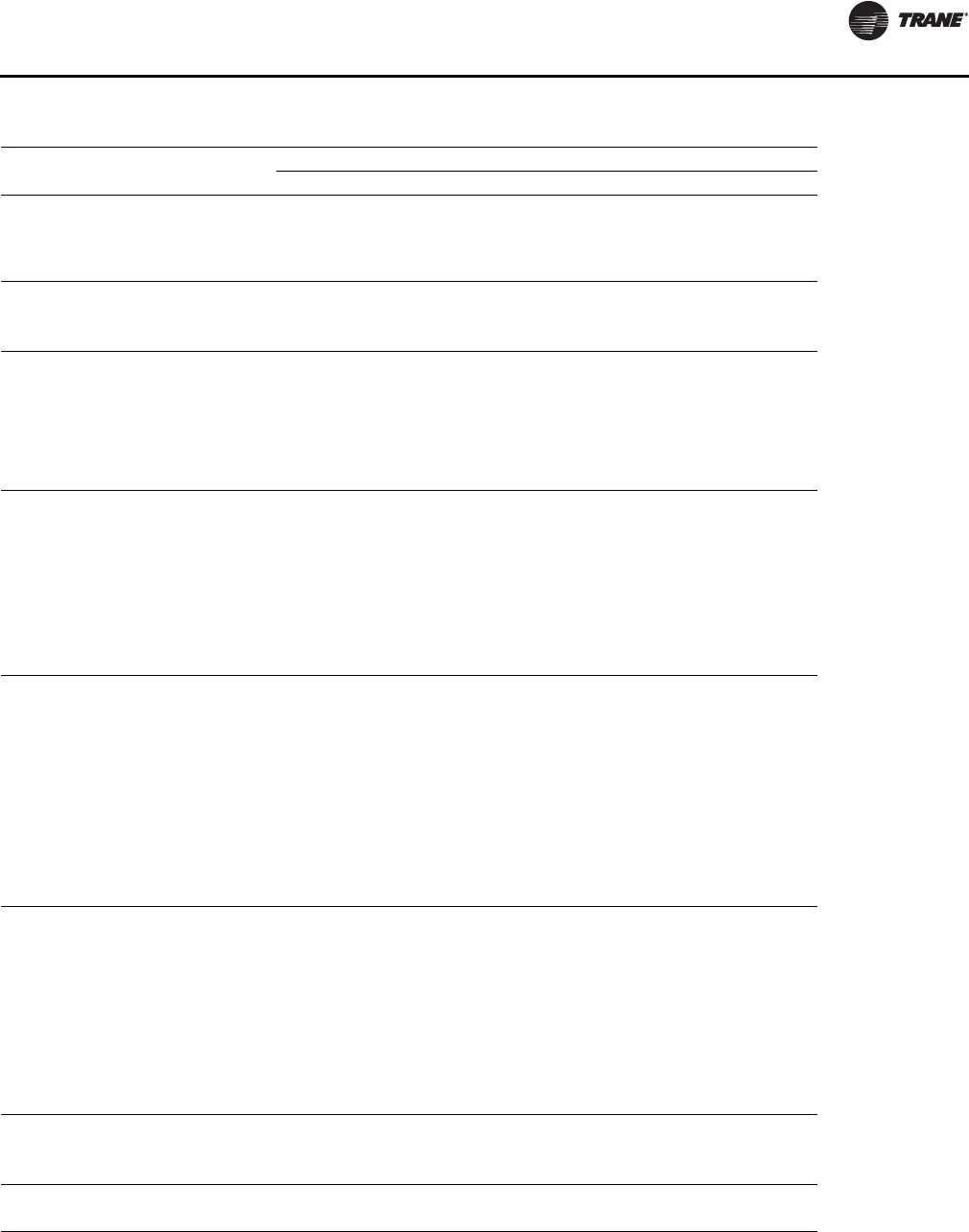
Performance Data
OAU-SVX01E-EN 47
Table 16. OA3 General Data—Cooling 45–54 Tons High Efficiency
45 Tons Downflow 50 Tons Downflow 54 Tons Downflow
OA3D540A OA3D600A OA3D648A
Cooling Performance
Gross Cooling Capacity, Btu (kW) 553,176 (162.12) 614,640 (180.13) 663,811 (194.54)
Nominal cfm (m3/h) 5625–11250
(9557–19114) 6250–12500
(10619–21238) 6750–13500
(11468–22937)
Compressor
Number 344
Type Scroll Scroll Scroll
Outdoor Coil
Type High Performance High Performance High Performance
Tube Size—OD, in. (mm) 3/8 (9.5) 3/8 (9.5) 3/8 (9.5)
Face Area, ft2 (m2) 63 (5.85 63 (5.85 63 (5.85
Rows 444
FPI 121212
Indoor Coil
Type High Performance High Performance High Performance
Tube Size—OD, in. (mm) 1/2 (12.7) 1/2 (12.7) 1/2 (12.7)
Face Area, ft2 (m2) 29 (2.69) 29 (2.69) 29 (2.69)
Rows 666
FPI 121212
Refrigerant Control TXV TXV TXV
Drain Connection Size, in. (mm) 1-1/4 (32) 1-1/4 (32) 1-1/4 (32)
Outdoor Fan
Type Propeller Propeller Propeller
Number Used 4 4 4
Diameter, in. (mm) 24 (609.6) 24 (609.6) 24 (609.6)
Drive Type Direct Direct Direct
No. Speeds 111
CFM (m3/h) 26,000 (44,174) 26,000 (44,174) 26,000 (44,174)
Number Motors 444
Motor HP (kW), per motor 1.0 (0.75) 1.0 (0.75) 1.0 (0.75)
Motor RPM 1140 1140 1140
Indoor Fan
Type Backward Inclined Backward Inclined Backward Inclined
Number Used 1 or 2 1 or 2 1 or 2
Diameter Varies Varies Varies
Drive Type Direct Drive Direct Drive Direct Drive
Number Motors 1 or 2 1 or 2 1 or 2
Motor HP (kW), Standard–Oversized 2.0–15 (1.49–11.19) 3.0–15 (2.24–11.19) 3.0–15 (2.24–11.19)
Motor RPM, Standard–Oversized 1750–3500 1750–3500 1750–3500
Motor Frame Size, Standard–Oversized Varies Varies Varies
Filters
Type Furnished Refer to “OAU Filter Guide”
in “Appendix,” p. 55 Refer to “OAU Filter Guide”
in “Appendix,” p. 55 Refer to “OAU Filter Guide”
in “Appendix,” p. 55
Number Size Recommended
Refrigerant Charge, lb of R-410A
Downflow See Nameplate See Nameplate See Nameplate
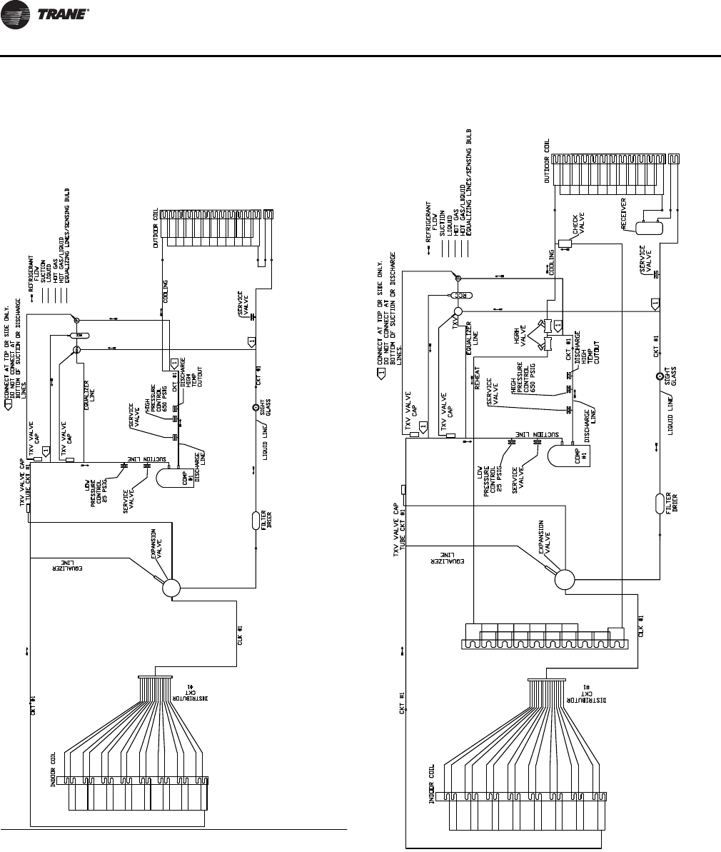
Performance Data
48 OAU-SVX01E-EN
Superheat and Refrigeration
Circuit Data
Figure 35. Refrigeration diagram: Single compressor
without reheat
Figure 36. Refrigeration diagram: Single compressor
with reheat
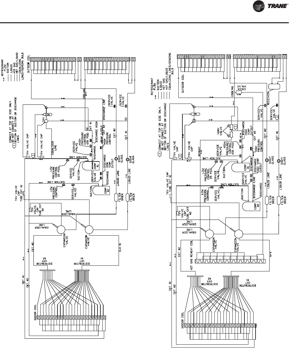
Performance Data
OAU-SVX01E-EN 49
Figure 37. Refrigeration diagram: dual compressor no
reheat Figure 38. Refrigeration diagram: dual compressor with
reheat
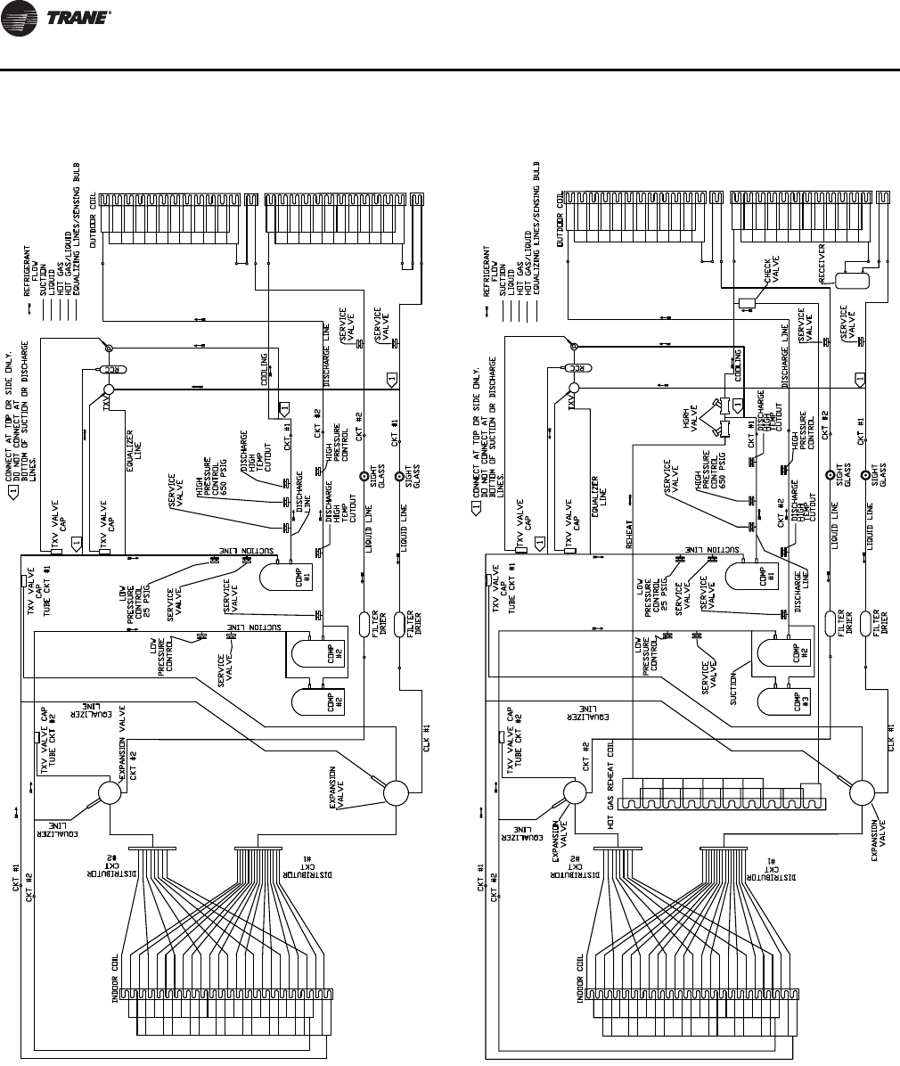
Performance Data
50 OAU-SVX01E-EN
Figure 39. Refrigeration diagram: triple compressor
with no reheat Figure 40. Refrigeration diagram: triple compressor
with reheat
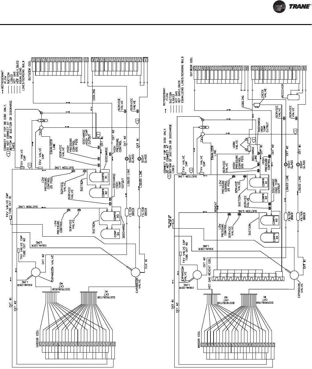
Performance Data
OAU-SVX01E-EN 51
Figure 41. Refrigeration diagram: quad compressor
with no reheat Figure 42. Refrigeration diagram: quad compressor
with reheat

52 OAU-SVX01E-EN
Alarms and Troubleshooting
Microprocessor Control
The Main Unit Display and RTRM have the ability to
provide the service personnel with some unit diagnostics
and system status information.
1. Verify that the Liteport LED on the RTRM is burning
continuously. If the LED is lit, go to Step 3.
2. If the LED is not lit, verify that 24 Vac is presence
between J1-1 and J1-2. If 24 Vac is present, proceed to
Step 3. If 24 Vac is not present, check the unit main
power supply, check transformer (TNS1). Proceed to
Step 3 if necessary.
3. Utilizing “Method 1” in the RTRM “System Status
Checkout Procedure”, check the following:
•System status
•Cooling status
If a System failure is indicated, proceed to Step 4. If no
failures are indicated, proceed to Step 5.
4. If a System failure is indicated, recheck Step 1 and Step
2. If the LED is not lit in Step 1, and 24 Vac is present in
Step 2, the RTRM has failed. Replace the RTRM.
5. If no failures are indicated, use one of the override
options to start the unit. Following the Override
procedure will allow you to check all of the operating
modes, and all of the external controls (relays,
contactors, etc.) for each respective mode.
6. Refer to the sequence of operations for each mode, to
assist in verifying proper operation. Make the
necessary repairs and proceed to Step 7.
7. If no abnormal operating conditions appear in the
Override mode, release the override and turn the
power “Off” at the main power disconnect switch.
System Alarms
The Main Unit Display has built in alarms to help the
operator troubleshoot system failures. This section will
describe these alarms and provide a guide to
troubleshooting the all unit operating modes.
Comprehensive system alarms and diagnostics are
accessed through the Alarms icon at the unit display
discussed later in the section, or through Tracer TU
programming on connected computer. Sensor failures
may be viewed through the Alarms icon.
If an alarm is present, the main indicator light on the
UC600 will blink red. If the optional unit display is installed,
the Alarm icon on the display will register ALARM,
illuminate red and flash.
Important: The space temperature sensor (SPTC) and
space relative humidity sensor (SPHC) will
read failed if they are not connected; they
will Alarm as “In Fault.”
Sensor Failure Alarm Display
Press the Alarm button on the Home display of the Unit
Display to display system sensor status as described in
Table 17 and Table 18, p. 53.
WARNING
Hazardous Service Procedures!
The maintenance and troubleshooting procedures
recommended in this section of the manual could result
in exposure to electrical, mechanical or other potential
safety hazards. Always refer to the safety warnings
provided throughout this manual concerning these
procedures. When possible, disconnect all electrical
power including remote disconnects before servicing.
Follow proper lockout/tagout procedures to ensure the
power can not be inadvertently energized. When
necessary to work with live electrical components, have
a qualified licensed electrician or other individual who
has been trained in handling live electrical components
perform these tasks. Failure to follow all of the safety
warnings provided could result in death or serious
injury.
Table 17. TOAU UC600 alarms
Point Diagnostic Possible Cause
1Indoor Fan
Failure
VFD not operating
Outdoor and/or Return Air Dampers not
Operating Properly
Indoor Fan Motor Failure
Indoor Fan Failure Switch IFFS (pressure)
Failure
IFFS Tubing damaged or not properly
connected
Refer to startup procedure
3OAD Proving
Switch
No voltage at actuator
Failed OAD power transformer
No continuity thru end switch (check at UC)
Note: If unit optional RA damper is
installed, send switch on OAD is always
proven
6Discharge Air
Temp Source
Failure
BAS communication down
Failed sensor or improper sensor
installation
8 Fire Shutdown BAS ONLY
10 Low Temp
Lockout
Heat Overridden OFF
Compressor(s) Overridden ON
Setpoint Failures Incorrect
DAT sensor malfunction
Reference Table 18, p. 53 for heat failure
issues
Alarms and Troubleshooting
OAU-SVX01E-EN 53
11 Space Temp
Source Failure
BAS communication down
Failed sensor or improper sensor
installation
13 OA Temp Source
Failure
BAS communication down
Failed sensor or improper sensor
installation
14 OA Humidity
Source Failure
BAS communication down
Failed sensor or improper sensor
installation
Humidity Wiring is polarity sensitive
15 High Temp
Lockout
Heat Overridden ON
Low discharge air volume
Dirty air filters
High gas heater manifold pressure
OA/RA damper position incorrect
High temp limit not properly installed or
wired
DAT sensor malfunction
17 System Lockout Check all Alarms
External safety device failed open
19 Space RH Source
Failure
BAS communication down
Failed sensor or improper sensor
installation
Humidity Wiring is polarity sensitive
32 ERV Leaving Air
Condition Failure
Failed RH or temperature sensor
Incorrectly installed or connect RH or Temp
sensor
42 Heat Failure
Applies to 5:1 and 10:1 Gas Heaters Only
Trips after heat command “ON” and no GV
status offer 1 minute
Refer to unit “Service Facts” heat control
LED status legend
No gas, low gas pressure or high gas
pressure to unit
Unit Manual shutoffs closed
Heater inducer failure
Heat relay failure
Loose or incorrect wiring
Table 18. TOAU UC60 troubleshooting
Trouble Possible Cause
Unit Not Running
No power supply to unit disconnect switch
Power disconnect tripped
Lockout alarm mode
Emergency Stop condition exists
Unit in Unoccupied mode
Discharge air sensor failed or not installed and
connected to unit
Table 17. TOAU UC600 alarms (continued)
Point Diagnostic Possible Cause
No Heat
No gas supply to unit
Unit manual gas valve(s) closed
Heater high limit tripped
Heat relay not energized
Conditions do not warrant call for heat
Heater control module malfunction
Roll out switch trip
Main gas on-off switch OFF
Inducer fan failure
Heater air proving switch not making or failed
No Compressor
Compressor limit switch(es) open
Compressor relay not energized or failed
Conditions do not warrant call for cooling or
dehumidification
Wide Discharge
Temp Swings
Discharge air sensor position must be at least
4 ft.-0 in. away from unit outlet
Min and Max gas heater manifold pressures not set
correctly
Space too Hot,
Cold or Humid
Setpoints no adjusted properly
Space sensors not correctly located or wired
Malfunctioning space sensor
IFM or PEX VFD OC
Trip
Overcurrent alarm requires max Hz setting on VFD
be checked and set to not exceed motor
nameplate amps
EX VFD only run to
Min HZ Setting
If supplied with RA pressure transducer and
modulating damper setup is not installed or
properly wired.
ERV Will Not Run ERV leaving air temp below 34°F low temp cutout
Interlocked with Exhaust fan if exhaust is not
running ERV will be OFF
Unit Trips Heater
High Limit
High fire gas manifold pressure too high
Supply fan speed too low
Dirty or clogged filters
Restricted discharge air duct
Temperature of air entering heater too high
Defective high limit
Protonode Not
Communicating Change Baud rate on UC600 to 38,400
Table 18. TOAU UC60 troubleshooting (continued)
Trouble Possible Cause
Alarms and Troubleshooting
54 OAU-SVX01E-EN
RTRM Failure Modes
Following is the listing of RTRM failure indication causes.
System Failure
Check the voltage between RTRM terminals 6 and 9 on J6,
it should read approximately 32 Vdc. If no voltage is
present, a System failure has occurred. Refer to Step 4 in
“Microprocessor Control,” p. 52 for the recommended
troubleshooting procedure.
Cooling Failure
• CLP1 has opened during the 3 minute minimum “on
time” during four consecutive compressor starts,
check CLP1 or CLP2 by testing voltage between the
J1-8 and J3-2 terminals on the RTRM and ground. If
24 Vac is present, the CLPs have not tripped. If no
voltage is present, CLPs have tripped.
System Failure
Measure the voltage between terminals J6-9 & J6-6.
Normal Operation = approximately 32 Vdc
System Failure = less than 1 Vdc, approximately 0.75 Vdc
Cool Failure
Measure the voltage between terminals J6-8 and J6-6.
Cool Operating = approximately 32 Vdc
Cool Off = less than 1 Vdc, approximately 0.75 Vdc
Cooling Failure = voltage alternates between 32 Vdc and
0.75 Vdc
WARNING
Live Electrical Components!
During installation, testing, servicing and
troubleshooting of this product, it may be necessary to
work with live electrical components. Have a qualified
licensed electrician or other individual who has been
properly trained in handling live electrical components
perform these tasks. Failure to follow all electrical
safety precautions when exposed to live electrical
components could result in death or serious injury.
OAU-SVX01E-EN 55
Appendix
OAU Filter Guide
Table 19. OA1D Units
Evaporator
Thickness MERV Qty Height Width
2 in. 8, 13 216 20
216 25
4 in. 14 216 20
216 25
Auxiliary Module
Return Air
Thickness MERV Qty Height Width
2 in. 8 2 20 24
Outside Air
Thickness MERV Qty Height Width
2 in. 8 2 20 24
Inlet
Thickness Material Qty Height Width
2 in. Aluminum Mesh 3 16 25
Table 20. OA2D Units
Evaporator
Thickness MERV Qty Height Width
2 in. 8, 13 9 20 18
4 in. 14 6 20 25
Auxiliary Module (46XX ERV)
Return Air
Thickness MERV Qty Height Width
2 in. 8 225 20
125 16
Outside Air
Thickness MERV Qty Height Width
2 in. 8 225 20
125 16
Auxiliary Module (58XX/ 64XX ERV)
Return Air
Thickness MERV Qty Height Width
2 in. 8 8 20 18
Outside Air
Thickness MERV Qty Height Width
2 in. 8 8 20 18
Inlet
Thickness Material Qty Height Width
2 in. Aluminum Mesh 6 20 20
Table 21. OA3D Units
Evaporator
Thickness MERV Qty Height Width
2 in. 8, 13 9 24 20
4 in. 14 9 24 20
Auxiliary Module (58XX ERV)
Return Air
Thickness MERV Qty Height Width
2 in. 8 6 18 20
Outside Air
Thickness MERV Qty Height Width
2 in. 8 6 18 20
Auxiliary Module (68XX / 74XX ERV)
Return Air
Thickness MERV Qty Height Width
2 in. 8 8 25 20
Outside Air
Thickness MERV Qty Height Width
2 in. 8 8 25 20
Inlet
Thickness Material Qty Height Width
2 in. Aluminum Mesh 10 16 25
Trane optimizes the performance of homes and buildings around the world. A business of Ingersoll Rand, the leader in
creating and sustaining safe, comfortable and energy efficient environments, Trane offers a broad portfolio of advanced
controls and HVAC systems, comprehensive building services, and parts. For more information, visit www.Trane.com.
Trane has a policy of continuous product and product data improvement and reserves the right to change design and specifications without notice.
We are committed to using environmentally
conscious print practices that reduce waste.
© 2014 Trane All rights reserved
OAU-SVX01E-EN 17 Apr 2014
Supersedes OAU-SVX01D-EN (05 Feb 2014)
