Trane Odyssey 6 To 25 Tons Catalogue R 22 Dry Charge Product Catalog For Heat Pump Condenser — 7.5, 10, 15 And 20 60 Hz
2015-04-02
: Trane Trane-Odyssey-6-To-25-Tons-Catalogue-684220 trane-odyssey-6-to-25-tons-catalogue-684220 trane pdf
Open the PDF directly: View PDF ![]() .
.
Page Count: 20
May 2014 SSP-PRC027B-EN
Split System Air Conditioners
Odyssey™™
R-22 Dry Charge
Heat Pump Condenser — 7.5, 10, 15 and 20 Tons — 60 Hz
Product Catalog
©2014 Trane All rights reserved SSP-PRC027B-EN
Introduction
Trane’s reputation for providing quality comfort solutions continues with the development of the
next generation Light Commercial Odyssey Split Systems.
With wide network availability, flexible applications, installation ease, built-in reliability and easy
servicing, Odyssey will meet any number of customer applications. Add to that Trane’s
outstanding customer service and you have the formula to make Odyssey the clear choice for
continued customer satisfaction.
Wide network availability
A broad distribution network provides owners, maintenance personnel, contractors, etc., the
means to get their hands on equipment when they need it. Whether it’s an emergency
replacement or a new construction project in its infancy stages, Odyssey products meet an array
of needs at the right time and right price.
Flexible applications
No matter what the application, Odyssey provides the solution. A broad array of models and
tonnages are available with single or dual compressors, single or dual circuits and numerous
accessories. Condensing units can be installed on the ground or on a rooftop along with
extended piping runs, while air handlers can be free discharge on the ground or horizontally
suspended with long duct runs from a ceiling. Should application challenges arise, Odyssey
delivers.
Easy to install
Small footprints and low weights combined with factory installed components like TXVs, filter
driers, etc., reduce installation time and cost. Colored and numbered wiring and factory tested
units make Odyssey the right choice.
Built-in reliability
Keeping in mind that productivity only occurs when equipment is operational,Trane has taken
the steps to ensure that Odyssey is up and running. Early indicators such as phase/reversal
monitors and loss of charge protection provide diagnostics which prevent failure and provide
years of worry-free service and operation.
SSP-PRC027B-EN 3
Easy to service
When preventive maintenance or service is required, technicians will find efficient access to both
air handlers and condensers. Panels provide complete, easy access coupled with standardized
cabinets in which all components are located in proximity. Odyssey’s improved design results in
minimum service times and costs.
With these capabilities, Odyssey provides customers high efficiency and superior performance
for the best all-around value in the market today.
Copyright
This document and the information in it are the property of Trane, and may not be used or
reproduced in whole or in part without written permission. Trane reserves the right to revise this
publication at any time, and to make changes to its content without obligation to notify any
person of such revision or change.
Trademarks
All trademarks referenced in this document are the trademarks of their respective owners.
IInnttrroodduuccttiioonn

4SSP-PRC027B-EN
Accessories.................................................................... 5
HeatPumpCondenser ....................................................... 5
ModelNumberDescription.................................................... 6
HeatPumpCondenser....................................................... 6
GeneralData................................................................... 7
PerformanceData ............................................................. 8
ElectricalData ................................................................12
DimensionalData.............................................................13
HeatPumpCondenser ...................................................... 13
Weights.......................................................................16
HeatPumpCondenser ...................................................... 16
Table of Contents
SSP-PRC027B-EN 5
Accessories
Heat Pump Condenser
Table 1. TWA Accessories
Model Used With
Coil (Hail/Vandal) Guard
BAYGARD058A TWA090A
BAYGARD060A TWA120A
BAYGARD061A TWA180B, TWA240B
BAYHGBP010B All models
Rubber Isolators
BAYISLT005A (black) TWA090A, TWA120A
BAYISLT009A (red) TWA180B
BAYISLT010A (green) TWA240B
Steel Spring Isolators
BAYISLT023A (red) TWA090A, TWA120A
BAYISLT024A (black) TWA180B
BAYISLT025A (yellow) TWA240B
Low Ambient — On/Off Fan Control (External mount, small cabinets)(a) (b) (c)
BAYLOAMU01B (External Mount, small cabinets)(d) (all voltages) TWA090A
BAYLOAMU02B (Internal mount, large cabinets) (all voltages) TWA120A, TWA180B, TWA240B
(a) Cycles fan on/off, (no modulating).
(b) Quantity of 1 required for each fan (2 total for ).
(c) ReliaTel™ requires onboard EDC function to be disabled when BAYLOAM is used, remove OA sensor from terminal J8-1&2
(d) Kit mounts external to the outdoor unit and operates by sensing ambient and liquid line temperatures.

6SSP-PRC027B-EN
Model Number Description
Heat Pump Condenser
T W A 120 A 3 0 0 * *
1 2 3 4 5 6 7 8 9 10 11 12
All products are identified by a multiple-character model number that precisely identifies a
particular type of unit. An explanation of the alphanumeric identification code is provided. Its use
will enable the owner/operator, installing contractors, and service engineers to define the
operation, specific components, and other options for any specific unit. When ordering
replacement parts or requesting service, be sure to refer to the specific model number, serial
number, and DL number (if applicable) stamped on the unit nameplate.
DDIIGGIITTSS 11 -- 33:: PPrroodduucctt TTyyppee
TWA = Split System Heat Pump
DDIIGGIITTSS 44 -- 66:: NNoommiinnaall GGrroossss CCoooolliinngg CCaappaacciittyy ((MMBBhh))
090 = 7.5 Tons (60Hz)
120 = 10 Tons (60Hz)
180 = 15 Tons (60Hz)
240 = 20 Tons (60Hz)
DDIIGGIITT 77:: MMaajjoorr DDeevveellooppmmeenntt SSeeqquueennccee
A = Single Compressor, Single Circuit, R-22
B = Dual Compressor, Dual Circuit, R-22
DDIIGGIITT 88:: EElleeccttrriiccaall CChhaarraacctteerriissttiiccss
3 = 208–230/60/3
4 = 460/60/3
DDIIGGIITTSS 99 -- 1100:: FFaaccttoorryy IInnssttaalllleedd OOppttiioonnss
00 = Packed Stock
DDIIGGIITTSS 1111:: MMiinnoorr DDeessiiggnn SSeeqquueennccee
* = Current Design Sequence1
DDIIGGIITTSS 1122:: SSeerrvviiccee DDiiggiitt
* = Current Design Sequence1
1. * = sequential alpha character
SSP-PRC027B-EN 7
General Data
Table 2. General data for 7.5 - 20 ton heat pump, 60 Hz
7.5 Tons 10 Tons 15 Tons 20 Tons
Single Compressor
TTA090A3, A4
Single Compressor
TTA120A3, A4
Dual Compressor
TTA180B3, B4
Dual Compressor
TTA240B3, B4
Compressor
Type Scroll Scroll Scroll Scroll
No./Tons 1/6.9 1/8.6 2/6.9 2/8.6
System Data
No. Refrigerant Circuits 1 1 2 2
Suction Line (in.) OD 1.38 1.38 1.38 1.38
Liquid Line (in.) OD 5/8 1/2 1/2 1/2
Outdoor Coil
Type Lanced Lanced Lanced Lanced
Tube Size (in.) OD 0.38 0.38 0.38 0.38
Face Area (sq ft) 19.2 24.0 24.0 24.0
Rows/FPI (Fins per inch) 2/18 2/18 2/18 2/18
Outdoor Fan
Type Propeller Propeller Propeller Propeller
No. Used/Diameter (in.) 1/26 1/28 2/28 2/28
Drive Type/No. Speeds Direct/1 Direct/1 Direct/1 Direct/1
CFM 6530 9600 19500 19500
No. Motor/HP 1/0.5 1/1 2/1 2/1
Motor RPM 1100 1100 1100 1100
Refrigerant Charge (Field
Supplied)
lbs of R-22 17.6 22.5 39.0 43.8
Shipping Dimensions
HxWxD (in.) 43.54” x 43” x 36.5” 43.5” x 53” x 40.5” 49.5" x 94.8" x 47" 49.5" x 94.8" x 47"
8SSP-PRC027B-EN
Performance Data
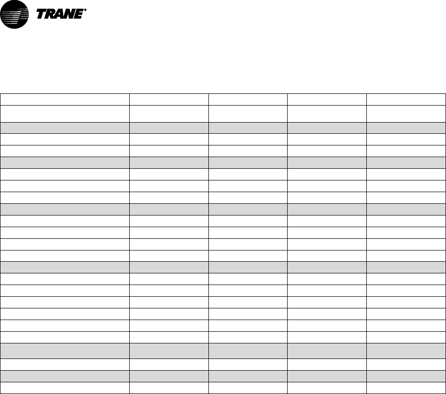
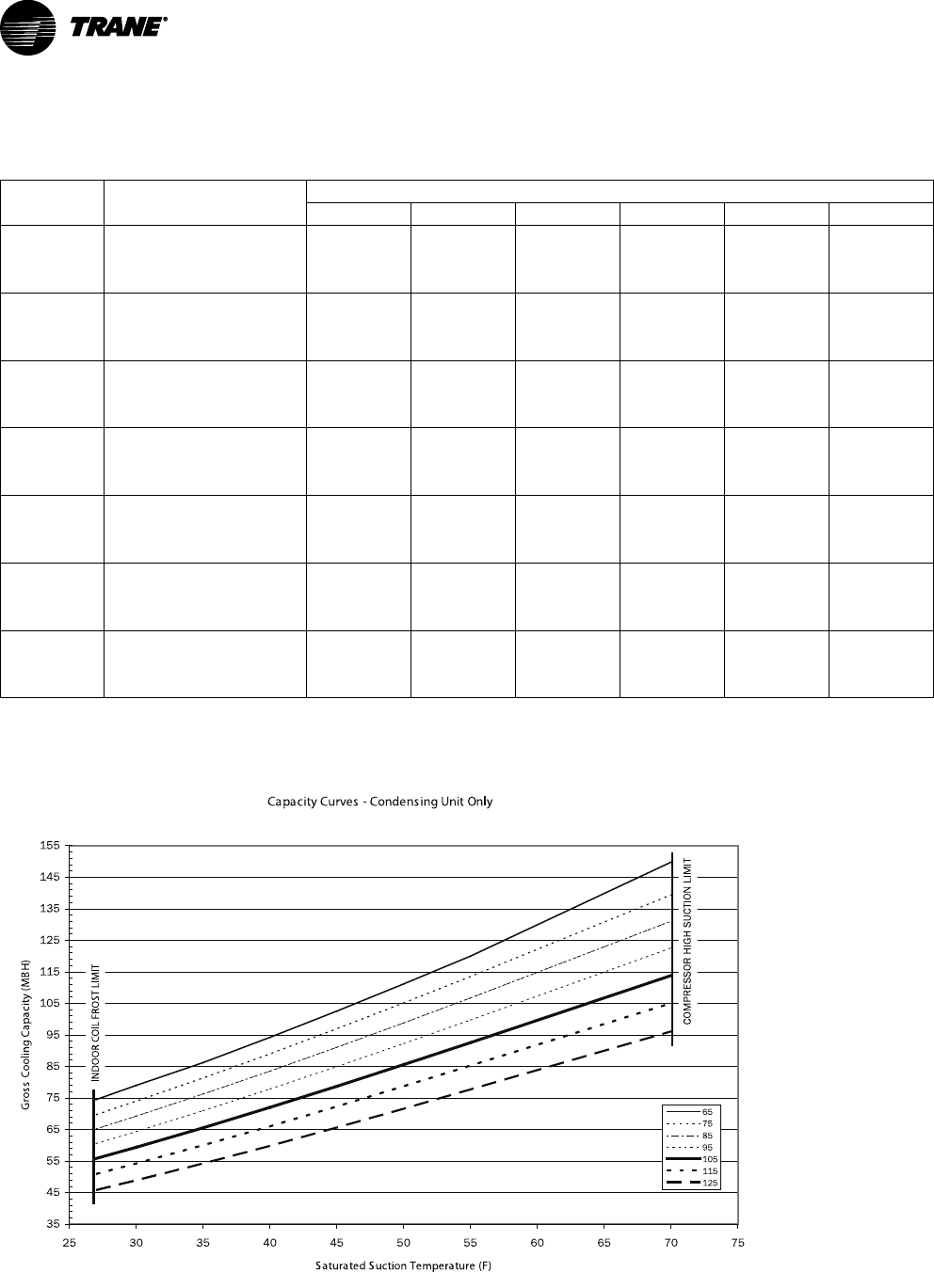
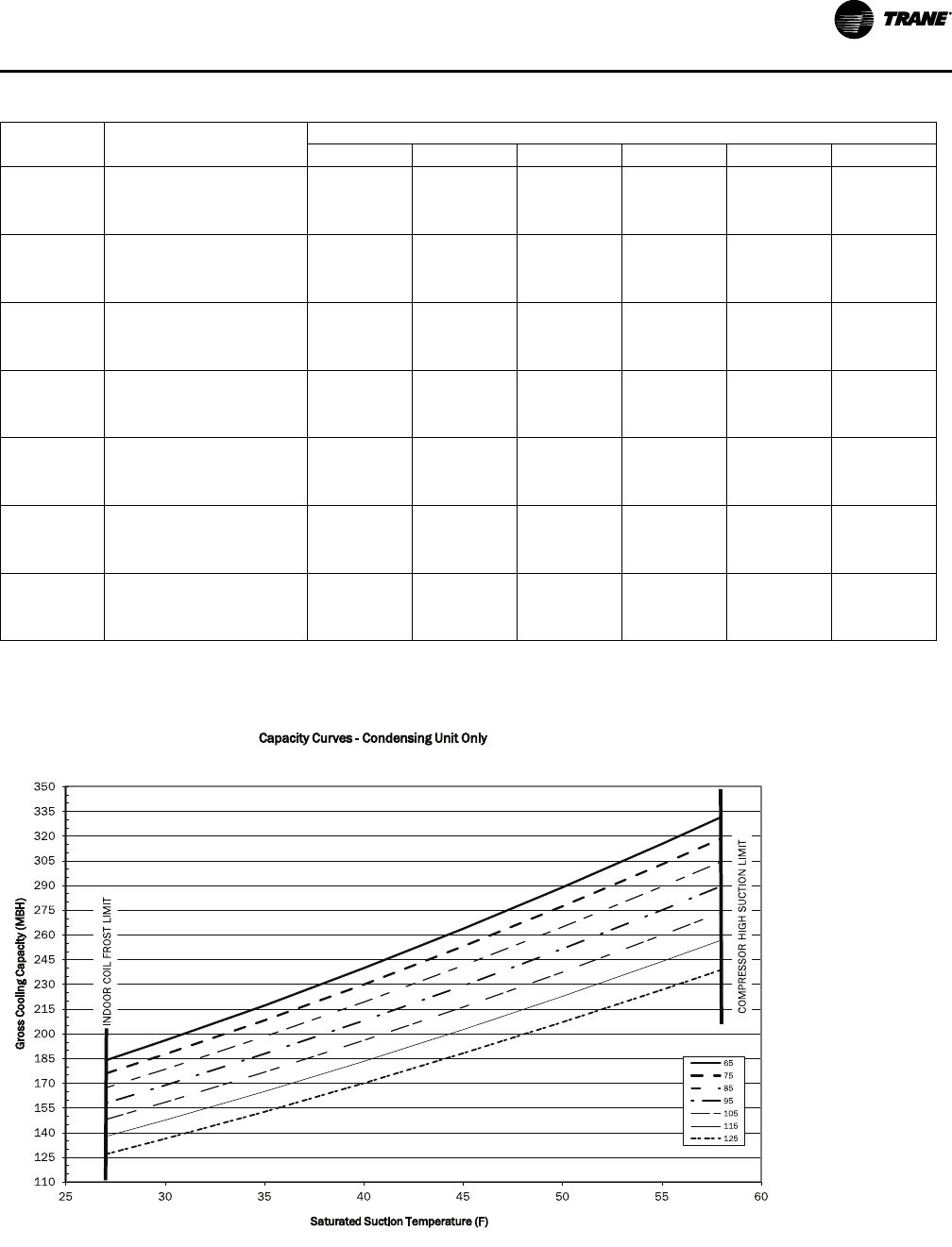
Table 3. Gross cooling capacities (MBH) 7.5 tons TWA090A condensing unit only (IP)
Outdoor
Temp (°F)
Suction Temperature (°F)
30 35 40 45 50 55
65
Head Press (psig) 161.6 172.5 178.6 185.2 192.0 199.2
Capacity (Btuh/1000) 75.4 83.5 92.3 101.5 111.1 121.0
Unit Power (kW) 4.8 5.0 5.1 5.3 5.5 5.6
75
Head Press (psig) 190.7 196.7 203.0 209.7 216.7 224.1
Capacity (Btuh/1000) 71.3 79.2 87.7 96.4 105.5 114.8
Unit Power (kW) 5.3 5.5 5.6 5.8 6.0 6.2
85
Head Press (psig) 217.1 223.3 230.0 237.0 244.3 252.0
Capacity (Btuh/1000) 67.5 75.0 83.0 91.3 99.9 108.8
Unit Power (kW) 5.8 6.0 6.1 6.3 6.5 6.7
95
Head Press (psig) 246.4 252.9 259.7 266.9 274.5 282.3
Capacity (Btuh/1000) 63.6 70.8 78.3 86.2 94.4 102.8
Unit Power (kW) 6.4 6.6 6.7 6.9 7.1 7.3
105
Head Press (psig) 278.2 285.0 292.0 299.4 307.2 315.2
Capacity (Btuh/1000) 59.7 66.5 73.6 81.0 88.7 96.7
Unit Power (kW) 7.0 7.2 7.4 7.6 7.8 8.0
115
Head Press (psig) 312.8 319.8 327.1 334.6 342.5 350.7
Capacity (Btuh/1000) 55.7 62.1 68.9 75.8 83.1 90.5
Unit Power (kW) 7.7 7.8 8.0 8.2 8.4 8.6
125
Head Press (psig) 350.1 357.3 364.7 372.5 380.5 388.8
Capacity (Btuh/1000) 51.6 57.7 64.1 70.6 77.3 84.3
Unit Power (kW) 8.4 8.6 8.7 8.9 9.1 9.3
Note: Performance data calculated at 15°F subcooling and 15°F superheat and does not include capacity loss due to refrigerant lines.
Figure 1. TWA090A capacity curve
C
apacity Curves - Condensing Unit Only
3
5
45
55
65
75
85
95
105
115
125
135
145
155
25 30 35 40 45 50 55 60 65 70 75
S
aturated Suction Temperature (F)
G
ross Cooling Capacity (MBH)
65
75
85
95
105
115
125
L
IMIT
C
OMPRESSOR HIGH SUCTION LIMIT
I
NDOOR COIL FROST LIMIT
SSP-PRC027B-EN 9
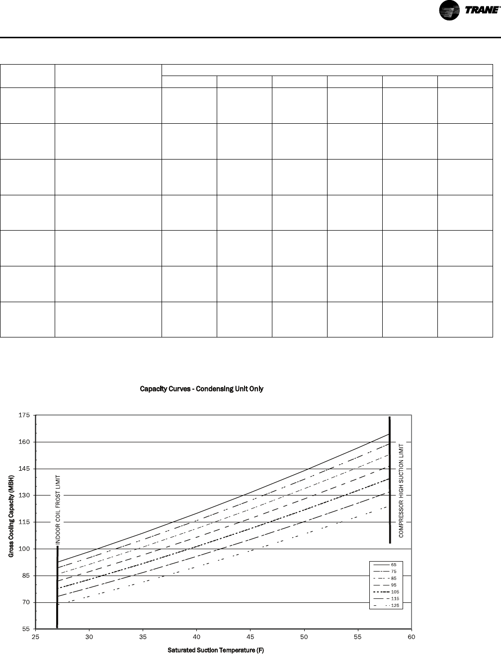
Table 4. Gross cooling capacities (MBH) 10 tons TWA120A condensing unit only (IP)
Outdoor
Temp (°F)
Suction Temperature (°F)
30 35 40 45 50 55
65
Head Press (psig) 166.3 172.1 178.4 185.1 192.3 199.9
Capacity (Btuh/1000) 98.4 108.8 119.9 131.5 143.8 156.6
Unit Power (kW) 7.1 7.3 7.5 7.8 8.0 8.3
75
Head Press (psig) 189.0 194.9 201.2 207.9 215.1 222.7
Capacity (Btuh/1000) 95.0 105.1 115.8 127.1 138.9 151.3
Unit Power (kW) 7.6 7.8 8.0 8.3 8.5 8.8
85
Head Press (psig) 213.9 219.9 226.3 233.1 240.4 248.1
Capacity (Btuh/1000) 91.2 101.0 111.3 122.2 133.6 145.6
Unit Power (kW) 8.1 8.4 8.6 8.8 9.1 9.3
95
Head Press (psig) 241.6 247.7 254.3 261.2 268.5 276.2
Capacity (Btuh/1000) 87.2 96.5 106.5 117.0 127.9 139.4
Unit Power (kW) 8.8 9.0 9.2 9.5 9.7 10.0
105
Head Press (psig) 272.0 278.2 284.8 291.7 299.1 306.9
Capacity (Btuh/1000) 82.8 91.8 101.2 111.3 121.8 132.7
Unit Power (kW) 9.6 9.8 10.0 10.2 10.5 10.7
115
Head Press (psig) 305.1 311.3 317.9 324.9 332.3 340.1
Capacity (Btuh/1000) 78.1 86.7 95.7 105.2 115.2 125.6
Unit Power (kW) 10.4 10.6 10.8 11.0 11.3 11.5
125
Head Press (psig) 340.8 347.1 353.8 360.8 368.2 375.9
Capacity (Btuh/1000) 73.2 81.3 89.9 98.8 108.2 118.0
Unit Power (kW) 11.3 11.5 11.7 12.0 12.2 12.4
Note: Performance data calculated at 15°F subcooling and 15°F superheat and does not include capacity loss due to refrigerant lines.
Figure 2. TWA120A capacity curves
5
5
70
85
100
115
130
145
160
175
25 30 35 40 45 50 55 60
Gross Cooling Capacity (MBH)
Saturated Suction Temperature (F)
Capacity Curves -Condensing Unit Only
65
75
85
95
105
115
125
I
NDOOR COIL FROST LIMIT
C
OMPRESSOR HIGH SUCTION LIMIT
PPeerrffoorrmmaannccee DDaattaa
10 SSP-PRC027B-EN
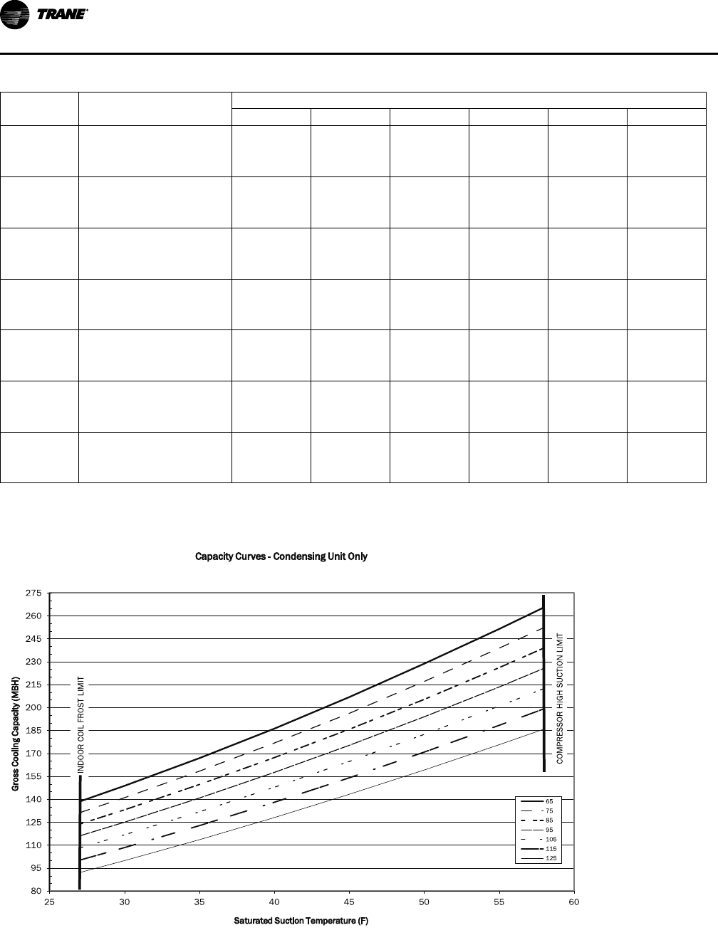
Table 5. Gross cooling capacities (MBH) 15 tons TWA180B condensing unit only (IP)
Outdoor
Temp (°F)
Suction Temperature (°F)
30 35 40 45 50 55
65
Head Press (psig) 149.9 154.2 158.9 164.0 169.3 175.0
Capacity (Btuh/1000) 148.9 167.0 186.2 206.9 228.7 251.4
Unit Power (kW) 10.4 10.6 10.9 11.1 11.4 11.6
75
Head Press (psig) 172.4 176.8 181.5 186.6 192.0 197.6
Capacity (Btuh/1000) 141.1 158.4 176.8 196.3 217.1 238.9
Unit Power (kW) 11.3 11.5 11.7 12.0 12.3 12.6
85
Head Press (psig) 197.3 201.8 206.6 211.6 217.0 222.7
Capacity (Btuh/1000) 133.2 149.7 167.3 185.8 205.4 226.2
Unit Power (kW) 12.2 12.4 12.7 13.0 13.3 13.6
95
Head Press (psig) 224.8 229.4 234.3 239.5 245.0 250.8
Capacity (Btuh/1000) 125.1 140.9 157.6 175.4 194.0 213.5
Unit Power (kW) 13.2 13.5 13.8 14.1 14.4 14.7
105
Head Press (psig) 255.2 259.9 264.9 270.2 275.8 281.6
Capacity (Btuh/1000) 116.8 131.9 147.9 164.8 182.5 201.0
Unit Power (kW) 14.4 14.7 15.0 15.3 15.6 15.9
115
Head Press (psig) 288.4 293.2 298.3 303.7 309.3 315.2
Capacity (Btuh/1000) 108.4 122.8 138.1 154.1 170.9 188.4
Unit Power (kW) 15.7 15.9 16.2 16.5 16.9 17.2
125
Head Press (psig) 324.5 329.5 334.7 340.1 345.8 351.7
Capacity (Btuh/1000) 99.9 113.6 128.1 143.3 159.2 175.7
Unit Power (kW) 17.1 17.3 17.6 17.9 18.2 18.6
Note: Performance data calculated at 15°F subcooling and 15°F superheat and does not include capacity loss due to refrigerant lines.
Figure 3. TWA180B capacity curves
8
0
95
110
125
140
155
170
185
200
215
230
245
260
275
25 30 35 40 45 50 55 60
Gross Cooling Capacity (MBH)
Saturated Suction Temperature (F)
Capacity Curves - Condensing Unit Only
65
75
85
95
105
115
125
I
NDOOR COIL FROST LIMIT
C
OMPRESSOR HIGH SUCTION LIMIT
PPeerrffoorrmmaannccee DDaattaa
SSP-PRC027B-EN 11
Table 6. Gross cooling capacities (MBH) 20 tons TWA240B condensing unit only (IP)
Outdoor
Temp (°F)
Suction Temperature (°F)
30 35 40 45 50 55
65
Head Press (psig) 164.1 169.9 176.1 182.8 189.9 197.5
Capacity (Btuh/1000) 196.0 217.1 239.8 263.8 288.9 315.2
Unit Power (kW) 14.3 14.8 15.2 15.7 16.2 16.8
75
Head Press (psig) 186.5 192.3 198.6 205.3 212.4 219.9
Capacity (Btuh/1000) 187.6 208.1 229.8 253.0 277.4 302.8
Unit Power (kW) 15.3 15.7 16.2 16.7 17.2 17.7
85
Head Press (psig) 211.3 217.1 223.4 230.1 237.3 245.0
Capacity (Btuh/1000) 178.5 198.3 219.2 241.4 264.8 289.3
Unit Power (kW) 16.4 16.8 17.3 17.8 18.3 18.8
95
Head Press (psig) 238.7 244.7 251.1 257.8 265.1 272.7
Capacity (Btuh/1000) 168.8 187.8 208.0 229.1 251.6 275.1
Unit Power (kW) 17.7 18.2 18.6 19.1 19.5 20.0
105
Head Press (psig) 268.9 275.0 281.4 288.2 295.4 303.1
Capacity (Btuh/1000) 158.4 176.7 195.9 216.2 237.4 259.9
Unit Power (kW) 19.2 19.6 20.1 20.5 21.0 21.5
115
Head Press (psig) 301.8 307.9 314.4 321.3 328.5 336.2
Capacity (Btuh/1000) 147.6 164.9 183.3 202.5 222.7 243.8
Unit Power (kW) 20.9 21.3 21.7 22.2 22.6 23.1
125
Head Press (psig) 337.5 343.7 350.2 357.1 364.1 371.6
Capacity (Btuh/1000) 136.2 152.7 170.0 188.2 207.1 226.7
Unit Power (kW) 22.7 23.1 23.5 24.0 24.4 24.8
Note: Performance data calculated at 15°F subcooling and 15°F superheat and does not include capacity loss due to refrigerant lines.
Figure 4. TWA240B capacity curves
1
10
125
140
155
170
185
200
215
230
245
260
275
290
305
320
335
350
25 30 35 40 45 50 55 60
Gross Cooling Capacity (MBH)
Saturated Suction Temperature (F)
Capacity Curves - Condensing Unit Only
65
75
85
95
105
115
125
I
NDOOR COIL FROST LIMIT
C
OMPRESSOR HIGH SUCTION LIMIT
PPeerrffoorrmmaannccee DDaattaa
12 SSP-PRC027B-EN
Electrical Data
Table 7. Electrical characteristics — compressor and condenser fan motors — heat pumps — 60Hz
Tons Unit Model
Number
Compressor Motor Condenser Fan Motor
No. Volts Phase
Amps
No. Volts Phase
Amps
RLA LRA FLA LRA
(Ea.) (Ea.) (Ea.) (Ea.)
7.5 TWA090A3 1 208-230 3 22.4 164 1 208-230 1 3.1 8.1
TWA090A4 1 460 3 10.9 100 1 460 1 1.6 3.8
10 TWA120A3 1 208-230 3 30.1 225 1 208-230 1 5.0 14.4
TWA120A4 1 460 3 15.5 114 1 460 1 2.5 5.8
15 TWA180B3 1 208-230 3 22.4 164 2 208-230 2 5.0 14.4
TWA180B4 1 460 3 10.9 100 2 460 2 2.5 5.8
20 TWA240B3 1 208-230 3 30.1 225 2 208-230 2 5.0 14.4
TWA240B4 1 460 3 15.5 114 2 460 2 2.5 5.8
Note: Electrical characteristics reflect nameplate values and are calculated in accordance with cULus and ARI
specifications.
Table 8. Unit wiring — heat pumps —60Hz
Tons Unit Model
Number
Unit Operating
Voltage Range
Minimum Circuit
Ampacity
Maximum Fuse or HACR
Circuit Breaker Size
7.5 TWA090A3 187-253 31.1 45
TWA090A4 414-506 15.2 25
10 TWA120A3 187-253 42.6 60
TWA120A4 414-506 21.9 30
15 TWA180B3 187-253 60.4 80
TWA180B4 414-506 29.5 40
20 TWA240B3 187-253 77.7 100
TWA240B4 414-506 39.9 50
Note: HACR type circuit breaker per NEC.
SSP-PRC027B-EN 13
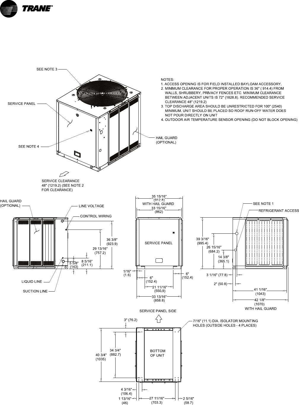
Dimensional Data
Heat Pump Condenser
Figure 5. 7.5 ton heat pump, single compressor
BOTTOM
OF UNIT
14 3/8"
(365.1)
26 15/16"
(684.2)
39 3/16"
(995.4)
3 1/16" (77.8)
2" (50.8)
33 13/1 6"
(858 .8)
1/16"
(1.6)
6"
(152 .4)
21 11 /16"
(550.9)
34 3/4"
(882.7)
40 3/4"
(1035)
3" (76. 2)
1 13/16"
(46)
27 11/ 16"
(703.3 )
2 5/16"
(58.7)
4 3/16"
(106.4)
33 15 /16"
(862)
36 3/8"
(923.9)
29 13/16"
(757.2)
8 5/16"
(211.1)
5 5/8"
(143)
35 15 /16"
(912.8 )
41 1/16"
(1043)
42 1/8"
(1070)
NOTES:
1. ACCESS OPENING IS FOR FIELD INSTALLED BAYLOAM ACCESSORY.
2. MINIMUM CLEARANCE FOR PROPER OPERATION IS 36" ( 914.4) FROM
WALLS, SHRUBBERY, PRIVACY FENCES ETC. MINIMUM CLEARANCE
BETWEEN ADJACENT UNITS IS 72" (1828.8). RECOMMENDED SERVICE
C LEARANCE 48" (1219.2)
3. TOP DISCHARGE AREA SHOULD BE UNRESTRICTED FOR 100" (2540)
MINIMUM. UNIT SHOULD BE PLACED SO ROOF RUN-OFF WATER DOES
NOT POUR DIRECTLY ON UNIT
4. OUTDOOR AIR TEMPERATURE SENS OR OPENING (DO NOT BLOCK OPENING)
SERVICE CLEARANCE
48" (1219.2) (SEE NOTE 2
FOR CLEARANCE)
SEE NOTE 1
REFRIGERANT ACCESS
HAIL GUARD
(OPTIONAL)
SUCTION LINE
LIQUID LINE
CONTROL WIRING
LINE VOLTAGE
SER VICE PANEL
HAIL GUARD
(OP TIONAL)
SERVICE PANEL
SEE NOTE 3
SERVIC E PANEL SIDE
SEE NOTE 4
WITH HAIL GUARD
7/16" (11.1) DIA. ISOLATOR MOUNTING
HOLES (OUTSIDE HOLES - 4 PLACES)
WITH HAIL GUARD
6"
(152 .4)
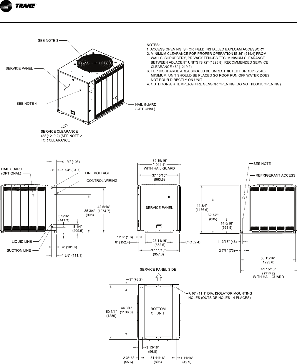
14 SSP-PRC027B-EN
Figure 6. 10 ton heat pump, single compressor
BOTTOM
OF UNIT
51 15/16"
(1319.2)
50 15/16"
(1293.8)
1/16" (1.6)
2 7/8" (73)
32 7/8"
(835)
44 3/4"
(1136.6)
25 11 /16"
(652.5)
6" (152. 4)
1 13/16" (46)
14 5/16"
(363.5)
37 11 /16"
(957.3)
44 3/4"
(1136.6)
50 3/4"
(1289)
3" (76. 2)
31 11 /16"
(805)
3 13/16 "
(96.8)
2 3/16"
(55.6)
1 11/16"
(42.9)
37 15 /16"
(963.6)
42 5/16"
(1074.7)
35 3/4"
(908)
1 1/4" ( 31.7)
8 1/4"
(209.5)
5 9/16"
(141.3)
4 3/8" (111.1)
4" (101. 6)
4 1/4" (108)
39 15/16"
(1014.4)
7/16" (11.1) DIA. ISOLATOR MOUNTING
HOLES (OUTSIDE HOLES - 4 PLACES)
NOTES:
1. ACCESS OPENING IS FOR FIELD INSTALLED BAYLOAM ACCESSORY.
2. MINIMUM CLEARANCE FOR P ROPER OPERATION IS 36" (914.4) FROM
WALLS, SHRUBBERY, PRIVACY FENCES ETC. MINIMUM CLEARANCE
BETWEEN ADJACENT UNITS IS 72" (1828.8). RECOMMENDED SERVICE
CLEARANCE 48" (1219.2)
3. TOP DIS CHARGE AREA SHOULD BE UNRESTRICTED FOR 100" (2540)
MINIMUM. UNIT SHOULD BE PLACED SO ROOF RUN-OFF WATER DOES
NOT POUR DIRECTLY ON UNIT
4. OUTDOOR AIR TEMPERATURE SENSOR OPENING (DO NOT BLOCK OPENING)
LIQUID LINE
SUCTION LINE
SERVICE PANEL SIDE
SERVICE CLEARANCE
48" (1219.2) (SEE NOTE 2
FOR CLEARANCE
HAIL GUARD
(OP TIONAL)
SERVICE PANEL
SEE NOTE 3
HAIL GUARD
(OP TIONAL)
SERVICE PANEL
CONTROL WIRING
LINE VOLTAGE
REFRIGERANT ACCESS
SEE NOTE 1
SEE NOTE 4
WITH HAIL GUARD
WITH HAIL GUARD
6" (152. 4)
DDiimmeennssiioonnaall DDaattaa
SSP-PRC027B-EN 15
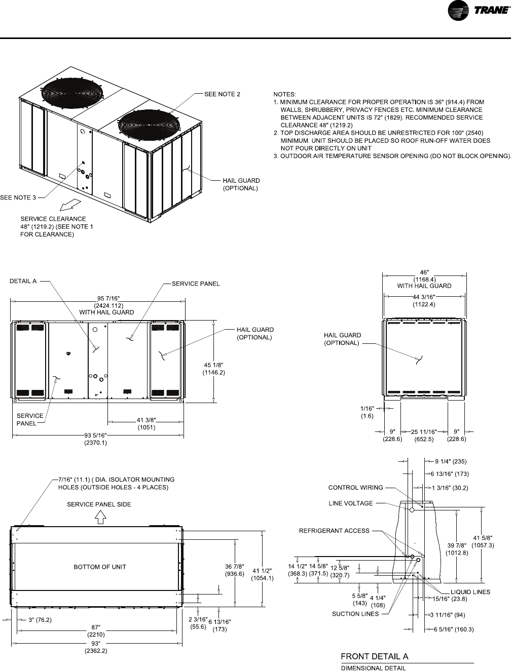
Figure 7. 15-20 ton heat pump, dual compressor
BOTTOM OF UNIT
1/16"
(1.6)
9"
(228.6)
9"
(228.6)
25 11/16"
(652.5)
46"
(1168. 4)
93"
(2362.2)
87"
(2210)
41 1/ 2"
(1054 .1)
2 3/16"
(55.6)
3" (76. 2)
6 13/16"
(173)
36 7/8"
(936.6)
6 5/16" (160.3)
3 11/16" (94)
15/16" (23.8)
1 3/16" (30.2)
39 7/8"
(1012.8)
41 5/8"
(1057.3)
9 1/4" (235)
41 3/8"
(1051)
93 5/16"
(2370.1)
45 1/8"
(1146.2)
14 1/2"
(368.3)
14 5/8"
(371.5) 12 5/8"
(320.7)
5 5/8"
(143) 4 1/4"
(108)
6 13/16" (173)
95 7/16"
(2424.112)
44 3/16"
(1122.4)
LINE VOLTAGE
SUCTION LINES
REFRIGERANT ACCESS
LIQUID LINES
NOTES:
1. MINIMUM CLEARANCE FOR PROPER OPERATION IS 36" (914.4) FROM
WALLS, SHRUBBERY, PRIVACY FENCES ETC. MINIMUM CLEARANCE
BETWEEN ADJACENT UNITS IS 72" (1829). RECOMMENDED SERVICE
C LEARANCE 48" (1219.2)
2. TOP DISCHARGE AREA SHOULD BE UNRESTRICTED FOR 100" (2540)
MINIMUM. UNIT SHOULD BE PLACED SO ROOF RUN-OFF WATER DOES
NOT POUR DIRECTLY ON UNIT
3. OUTDOOR AIR TEMPERATURE SENSOR OPENING (DO NOT BLOCK OPENING).
7/16" (11.1) ( DIA. ISOLATOR MOUNTING
HOLES (OUTSIDE HOLES - 4 PLACES)
SERVICE PANEL SIDE
SERVICE CLEARANCE
48" (1219.2) (S EE NOTE 1
FOR CLEARANCE)
HAIL GUARD
(OPTIONAL)
HAIL GUARD
(OP TIONAL)
SER VICE
PANEL
DIMENSIONAL DETAIL
FRO NT DETAIL A
SEE NOTE 2
HAIL GUARD
(OP TIONAL)
DETAIL A
SERVICE PANEL
CONTROL WIRING
WITH HAIL GUARD
SEE NOTE 3
WITH HAIL GUARD
DDiimmeennssiioonnaall DDaattaa
16 SSP-PRC027B-EN
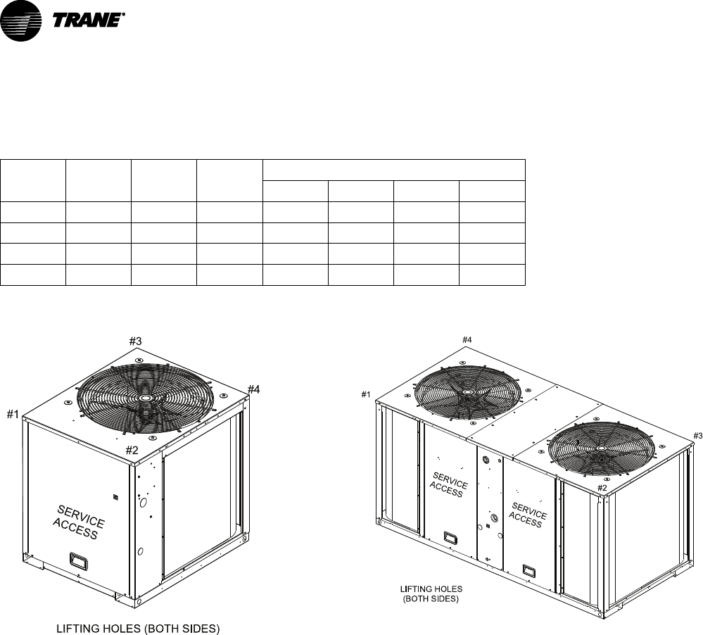
Weights
Heat Pump Condenser
Table 9. TWA unit and corner weights — lbs (60 Hz)
Tons Model No. Shipping
Max (lbs)
Net Max
(lbs)
Corner Weights
1 2 3 4
7.5 TWA090A 394 340 117 86 58 79
10 TWA120A 509 438 127 121 72 118
15 TWA180B 898 765 202 192 181 190
20 TWA240B 981 848 254 266 147 181
Figure 8. TWA090, 120
#1
#2
#3
#4
LIFTING HOLES (BOTH SIDES)
SERVICE
ACCESS
Figure 9. TWA180, 240
SERVICE
ACCESS SERVICE
ACCESS
#1
#2
#3
#4
LIFTING HOLES
(BOTH SIDES)

SSP-PRC027B-EN 17
NNootteess

18 SSP-PRC027B-EN
NNootteess

SSP-PRC027B-EN 19
NNootteess
NNootteess
Trane optimizes the performance of homes and buildings around the world. A business of Ingersoll Rand, the leader in
creating and sustaining safe, comfortable and energy efficient environments, Trane offers a broad portfolio of advanced
controls and HVAC systems, comprehensive building services, and parts. For more information, visit www.Trane.com.
Trane has a policy of continuous product and product data improvements and reserves the right to change design and specifications without notice.
©2014 Trane All rights reserved
SSP-PRC027B-EN 19 May 2014
Supersedes SSP-PRC027-EN (June 2012)
We are committed to using environmentally
conscious print practices that reduce waste.
