Trane Odyssey 6 To 25 Tons Installation And Maintenance Manual Split System Air Conditioners, Odyssey™, Cooling Condenser —
2015-04-02
: Trane Trane-Odyssey-6-To-25-Tons-Installation-And-Maintenance-Manual-684223 trane-odyssey-6-to-25-tons-installation-and-maintenance-manual-684223 trane pdf
Open the PDF directly: View PDF ![]() .
.
Page Count: 56
- Model Number Description
- General Information
- Pre-Installation
- Dimensional Data
- Weights
- Installation
- Electrical Data
- Charging Charts and Superheat
- Installation Checklist
- Pre-Start
- Start-Up
- Service Test Modes for ReliaTel™ Controls
- Troubleshooting
- Maintenance
- Wiring Diagram Matrix
SSAAFFEETTYY WWAARRNNIINNGG
Only qualified personnel should install and service the equipment. The installation, starting up, and servicing of heating, ventilating, and
air-conditioning equipment can be hazardous and requires specific knowledge and training. Improperly installed, adjusted or altered
equipment by an unqualified person could result in death or serious injury. When working on the equipment, observe all precautions in the
literature and on the tags, stickers, and labels that are attached to the equipment.
March 2015 SS-SVX10E-EN
Split System Air Conditioners
Odyssey™™
Cooling Condenser — 6 to 25 Tons
((6600 HHzz))
TTA073G***A
TTA090G/H***A
TTA120G/H/F***A
TTA150E***A
TTA180E/F***A
TTA240E/F***A
TTA300F***A
((5500 HHzz))
TTA061G***A
TTA076G/H***A
TTA101G/H/F***A
TTA126E***A
TTA156E/F***A
TTA201E/F***A
TTA251F***A
Installation, Operation,
and Maintenance
©2015 Trane All rights reserved SS-SVX10E-EN
Introduction
Read this manual thoroughly before operating or
servicing this unit.
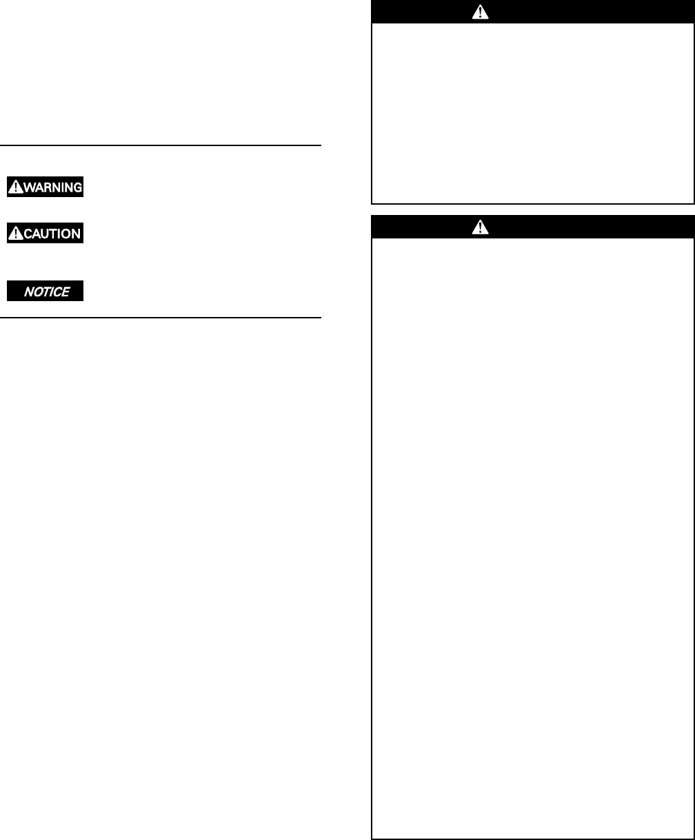
Warnings, Cautions, and Notices
Safety advisories appear throughout this manual as
required. Your personal safety and the proper
operation of this machine depend upon the strict
observance of these precautions.
The three types of advisories are defined as follows:
Indicates a potentially hazardous situation
which, if not avoided, could result in death or
serious injury.
Indicates a potentially hazardous situation
which, if not avoided, could result in minor or
moderate injury. It could also be used to alert
against unsafe practices.
Indicates a situation that could result in
equipment or property-damage only
accidents.
Important Environmental Concerns
Scientific research has shown that certain man-made
chemicals can affect the earth’s naturally occurring
stratospheric ozone layer when released to the
atmosphere. In particular, several of the identified
chemicals that may affect the ozone layer are
refrigerants that contain Chlorine, Fluorine and Carbon
(CFCs) and those containing Hydrogen, Chlorine,
Fluorine and Carbon (HCFCs). Not all refrigerants
containing these compounds have the same potential
impact to the environment. Trane advocates the
responsible handling of all refrigerants-including
industry replacements for CFCs such as HCFCs and
HFCs.
Important Responsible Refrigerant
Practices
Trane believes that responsible refrigerant practices are
important to the environment, our customers, and the
air conditioning industry. All technicians who handle
refrigerants must be certified. The Federal Clean Air Act
(Section 608) sets forth the requirements for handling,
reclaiming, recovering and recycling of certain
refrigerants and the equipment that is used in these
service procedures. In addition, some states or
municipalities may have additional requirements that
must also be adhered to for responsible management
of refrigerants. Know the applicable laws and follow
them.
WWAARRNNIINNGG
PPrrooppeerr FFiieelldd WWiirriinngg aanndd GGrroouunnddiinngg
RReeqquuiirreedd!!
FFaaiilluurree ttoo ffoollllooww ccooddee ccoouulldd rreessuulltt iinn ddeeaatthh oorr
sseerriioouuss iinnjjuurryy..
AAllll ffiieelldd wwiirriinngg MMUUSSTT bbee ppeerrffoorrmmeedd bbyy qquuaalliiffiieedd
ppeerrssoonnnneell.. IImmpprrooppeerrllyy iinnssttaalllleedd aanndd ggrroouunnddeedd
ffiieelldd wwiirriinngg ppoosseess FFIIRREE aanndd EELLEECCTTRROOCCUUTTIIOONN
hhaazzaarrddss.. TToo aavvooiidd tthheessee hhaazzaarrddss,, yyoouu MMUUSSTT ffoollllooww
rreeqquuiirreemmeennttss ffoorr ffiieelldd wwiirriinngg iinnssttaallllaattiioonn aanndd
ggrroouunnddiinngg aass ddeessccrriibbeedd iinn NNEECC aanndd yyoouurr llooccaall//
ssttaattee eelleeccttrriiccaall ccooddeess..
WWAARRNNIINNGG
PPeerrssoonnaall PPrrootteeccttiivvee EEqquuiippmmeenntt ((PPPPEE))
RReeqquuiirreedd!!
FFaaiilluurree ttoo wweeaarr pprrooppeerr PPPPEE ffoorr tthhee jjoobb bbeeiinngg
uunnddeerrttaakkeenn ccoouulldd rreessuulltt iinn ddeeaatthh oorr sseerriioouuss iinnjjuurryy..
TTeecchhnniicciiaannss,, iinn oorrddeerr ttoo pprrootteecctt tthheemmsseellvveess ffrroomm
ppootteennttiiaall eelleeccttrriiccaall,, mmeecchhaanniiccaall,, aanndd cchheemmiiccaall
hhaazzaarrddss,, MMUUSSTT ffoollllooww pprreeccaauuttiioonnss iinn tthhiiss mmaannuuaall
aanndd oonn tthhee ttaaggss,, ssttiicckkeerrss,, aanndd llaabbeellss,, aass wweellll aass tthhee
iinnssttrruuccttiioonnss bbeellooww::
•• BBeeffoorree iinnssttaalllliinngg//sseerrvviicciinngg tthhiiss uunniitt,,
tteecchhnniicciiaannss MMUUSSTT ppuutt oonn aallll PPPPEE rreeqquuiirreedd ffoorr
tthhee wwoorrkk bbeeiinngg uunnddeerrttaakkeenn ((EExxaammpplleess;; ccuutt
rreessiissttaanntt gglloovveess//sslleeeevveess,, bbuuttyyll gglloovveess,, ssaaffeettyy
ggllaasssseess,, hhaarrdd hhaatt//bbuummpp ccaapp,, ffaallll pprrootteeccttiioonn,,
eelleeccttrriiccaall PPPPEE aanndd aarrcc ffllaasshh ccllootthhiinngg))..
AALLWWAAYYSS rreeffeerr ttoo aapppprroopprriiaattee MMaatteerriiaall SSaaffeettyy
DDaattaa SShheeeettss ((MMSSDDSS))//SSaaffeettyy DDaattaa SShheeeettss
((SSDDSS)) aanndd OOSSHHAA gguuiiddeelliinneess ffoorr pprrooppeerr PPPPEE..
•• WWhheenn wwoorrkkiinngg wwiitthh oorr aarroouunndd hhaazzaarrddoouuss
cchheemmiiccaallss,, AALLWWAAYYSS rreeffeerr ttoo tthhee aapppprroopprriiaattee
MMSSDDSS//SSDDSS aanndd OOSSHHAA//GGHHSS ((GGlloobbaall
HHaarrmmoonniizzeedd SSyysstteemm ooff CCllaassssiiffiiccaattiioonn aanndd
LLaabbeelllliinngg ooff CChheemmiiccaallss)) gguuiiddeelliinneess ffoorr
iinnffoorrmmaattiioonn oonn aalllloowwaabbllee ppeerrssoonnaall eexxppoossuurree
lleevveellss,, pprrooppeerr rreessppiirraattoorryy pprrootteeccttiioonn aanndd
hhaannddlliinngg iinnssttrruuccttiioonnss..
•• IIff tthheerree iiss aa rriisskk ooff eenneerrggiizzeedd eelleeccttrriiccaall
ccoonnttaacctt,, aarrcc,, oorr ffllaasshh,, tteecchhnniicciiaannss MMUUSSTT ppuutt
oonn aallll PPPPEE iinn aaccccoorrddaannccee wwiitthh OOSSHHAA,, NNFFPPAA
7700EE,, oorr ootthheerr ccoouunnttrryy--ssppeecciiffiicc rreeqquuiirreemmeennttss
ffoorr aarrcc ffllaasshh pprrootteeccttiioonn,, PPRRIIOORR ttoo sseerrvviicciinngg
tthhee uunniitt.. NNEEVVEERR PPEERRFFOORRMM AANNYY SSWWIITTCCHHIINNGG,,
DDIISSCCOONNNNEECCTTIINNGG,, OORR VVOOLLTTAAGGEE TTEESSTTIINNGG
WWIITTHHOOUUTT PPRROOPPEERR EELLEECCTTRRIICCAALL PPPPEE AANNDD
AARRCC FFLLAASSHH CCLLOOTTHHIINNGG.. EENNSSUURREE
EELLEECCTTRRIICCAALL MMEETTEERRSS AANNDD EEQQUUIIPPMMEENNTT AARREE
PPRROOPPEERRLLYY RRAATTEEDD FFOORR IINNTTEENNDDEEDD VVOOLLTTAAGGEE..
SS-SVX10E-EN 3
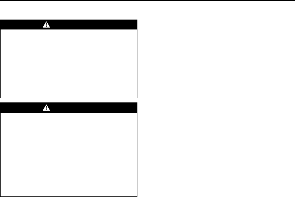
WWAARRNNIINNGG
RReeffrriiggeerraanntt uunnddeerr HHiigghh PPrreessssuurree!!
FFaaiilluurree ttoo ffoollllooww iinnssttrruuccttiioonnss bbeellooww ccoouulldd rreessuulltt iinn
aann eexxpplloossiioonn wwhhiicchh ccoouulldd rreessuulltt iinn ddeeaatthh oorr sseerriioouuss
iinnjjuurryy oorr eeqquuiippmmeenntt ddaammaaggee..
SSyysstteemm ccoonnttaaiinnss ooiill aanndd rreeffrriiggeerraanntt uunnddeerr hhiigghh
pprreessssuurree.. RReeccoovveerr rreeffrriiggeerraanntt ttoo rreelliieevvee pprreessssuurree
bbeeffoorree ooppeenniinngg tthhee ssyysstteemm.. SSeeee uunniitt nnaammeeppllaattee ffoorr
rreeffrriiggeerraanntt ttyyppee.. DDoo nnoott uussee nnoonn--aapppprroovveedd
rreeffrriiggeerraannttss,, rreeffrriiggeerraanntt ssuubbssttiittuutteess,, oorr rreeffrriiggeerraanntt
aaddddiittiivveess..
WWAARRNNIINNGG
RR--441100AA RReeffrriiggeerraanntt uunnddeerr HHiigghheerr
PPrreessssuurree tthhaann RR--2222!!
FFaaiilluurree ttoo uussee pprrooppeerr eeqquuiippmmeenntt oorr ccoommppoonneennttss aass
ddeessccrriibbeedd bbeellooww,, ccoouulldd rreessuulltt iinn eeqquuiippmmeenntt ffaaiilliinngg
aanndd ppoossssiibbllyy eexxppllooddiinngg,, wwhhiicchh ccoouulldd rreessuulltt iinn
ddeeaatthh,, sseerriioouuss iinnjjuurryy,, oorr eeqquuiippmmeenntt ddaammaaggee..
TThhee uunniittss ddeessccrriibbeedd iinn tthhiiss mmaannuuaall uussee RR--441100AA
rreeffrriiggeerraanntt wwhhiicchh ooppeerraatteess aatt hhiigghheerr pprreessssuurreess
tthhaann RR--2222.. UUssee OONNLLYY RR--441100AA rraatteedd sseerrvviiccee
eeqquuiippmmeenntt oorr ccoommppoonneennttss wwiitthh tthheessee uunniittss.. FFoorr
ssppeecciiffiicc hhaannddlliinngg ccoonncceerrnnss wwiitthh RR--441100AA,, pplleeaassee
ccoonnttaacctt yyoouurr llooccaall TTrraannee rreepprreesseennttaattiivvee..
Copyright
This document and the information in it are the
property of Trane, and may not be used or reproduced
in whole or in part without written permission. Trane
reserves the right to revise this publication at any time,
and to make changes to its content without obligation
to notify any person of such revision or change.
Trademarks
All trademarks referenced in this document are the
trademarks of their respective owners.
Revision History
• Microchannel is now standard on 5–10 ton single
and dual compressor units. All data has been
updated to reflect this change.
• With the change to Microchannel, the Odyssey split
system now offers a new 60Hz, 7.5 ton dual
compressor model that can be matched with a new
60Hz, 7.5 ton Single Zone VAV and 2–Speed air
handler. A new 50Hz, 6.25 ton dual compressor
model is now also available and can be matched
with a new 50Hz, 6.25 ton standard air handler.
• The 50Hz, 7 ton model has been discontinued.
IInnttrroodduuccttiioonn
4SS-SVX10E-EN
Model Number Description. . . . . . . . . . . . . . . . . 6
Cooling Condenser . . . . . . . . . . . . . . . . . . . . . . . 6
General Information . . . . . . . . . . . . . . . . . . . . . . . . 7
Unit Description . . . . . . . . . . . . . . . . . . . . . . . . . . 7
Pre-Installation . . . . . . . . . . . . . . . . . . . . . . . . . . . . . 8
Unit Inspection . . . . . . . . . . . . . . . . . . . . . . . . . . . 8
Inspection Checklist . . . . . . . . . . . . . . . . . . . 8
Testing for Leaks. . . . . . . . . . . . . . . . . . . . . . . . . . 8
Lifting Recommendations . . . . . . . . . . . . . . . . . 8
Clearances . . . . . . . . . . . . . . . . . . . . . . . . . . . . . . . 8
Unit Mounting. . . . . . . . . . . . . . . . . . . . . . . . . . . . 9
Structural Preparation . . . . . . . . . . . . . . . . . 9
Rooftop Mounting . . . . . . . . . . . . . . . . . . . . 9
Ground Level Mounting . . . . . . . . . . . . . . . 9
Dimensional Data . . . . . . . . . . . . . . . . . . . . . . . . . 10
Weights . . . . . . . . . . . . . . . . . . . . . . . . . . . . . . . . . . . 20
Cooling Condenser . . . . . . . . . . . . . . . . . . . . . . 20
Installation . . . . . . . . . . . . . . . . . . . . . . . . . . . . . . . . 22
Refrigerant Piping Guidelines. . . . . . . . . . . . . 22
Refrigerant Piping Procedures (Outdoor
Units). . . . . . . . . . . . . . . . . . . . . . . . . . . . . . . . . . . 23
Refrigerant Piping Procedures (Indoor
Unit). . . . . . . . . . . . . . . . . . . . . . . . . . . . . . . . . . . . 24
Leak Check . . . . . . . . . . . . . . . . . . . . . . . . . . . . . . 24
System Evacuation. . . . . . . . . . . . . . . . . . . 24
Insulating and Isolating Refrigerant
Lines . . . . . . . . . . . . . . . . . . . . . . . . . . . . . . . . . . . 25
Refrigerant Charging Procedure . . . . . . . . . . 25
Charging Levels. . . . . . . . . . . . . . . . . . . . . . 26
Liquid Charging . . . . . . . . . . . . . . . . . . . . . . . . . 27
Electrical Wiring . . . . . . . . . . . . . . . . . . . . . . . . . 28
Unit Power Supply . . . . . . . . . . . . . . . . . . . 28
Low Voltage Wiring . . . . . . . . . . . . . . . . . . 29
Electromechanical Controls . . . . . . . . . . . 29
ReliaTel Controls . . . . . . . . . . . . . . . . . . . . . 29
Field Wiring . . . . . . . . . . . . . . . . . . . . . . . . . 30
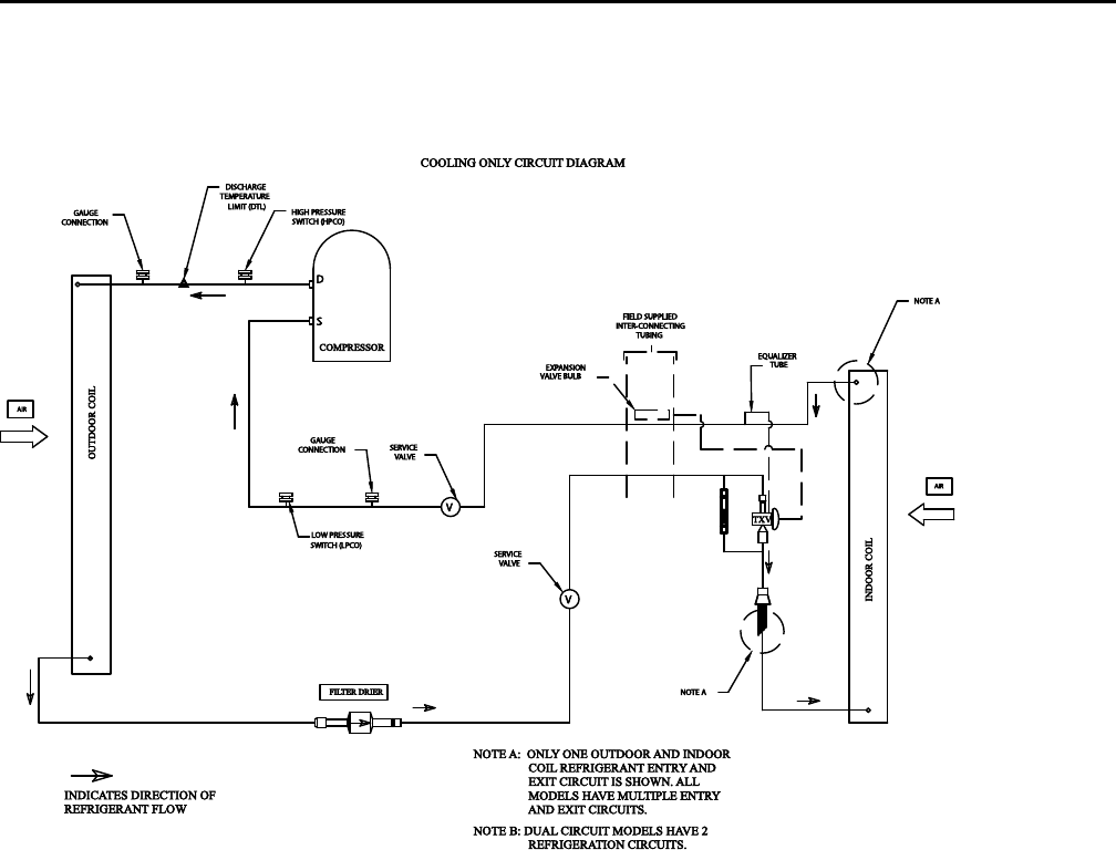
Refrigerant Circuit. . . . . . . . . . . . . . . . . . . . 32
Electrical Data . . . . . . . . . . . . . . . . . . . . . . . . . . . . . 34
Charging Charts and Superheat . . . . . . . . . . . 38
Installation Checklist. . . . . . . . . . . . . . . . . . . . . . . 43
Refrigerant Piping . . . . . . . . . . . . . . . . . . . . . . . 43
Electrical Wiring . . . . . . . . . . . . . . . . . . . . . . . . . 43
Pre-Start . . . . . . . . . . . . . . . . . . . . . . . . . . . . . . . . . . . 44
Control Circuit Features . . . . . . . . . . . . . . . . . . 44
Discharge Temperature Limit
(DTL). . . . . . . . . . . . . . . . . . . . . . . . . . . . . . . . 44
Low Outdoor Ambient Cooling . . . . . . . . 44
Evaporator Defrost Control
(EDC) . . . . . . . . . . . . . . . . . . . . . . . . . . . . . . . 44
Low Pressure Cut-Out (LPCO) . . . . . . . . . 44
High Pressure Cut-Out (HPCO) . . . . . . . . 44
Internal Overload Protector
(IOL) . . . . . . . . . . . . . . . . . . . . . . . . . . . . . . . . 44
Start-Up . . . . . . . . . . . . . . . . . . . . . . . . . . . . . . . . . . . 45
Electromechanical Controls. . . . . . . . . . . . . . . 45
General . . . . . . . . . . . . . . . . . . . . . . . . . . . . . 45
Evaporator Fan (Indoor Supply
Air) . . . . . . . . . . . . . . . . . . . . . . . . . . . . . . . . . 45
Cooling Mode . . . . . . . . . . . . . . . . . . . . . . . 45
ReliaTel Controls . . . . . . . . . . . . . . . . . . . . . . . . 45
Control Cooling Mode . . . . . . . . . . . . . . . . 45
Control Evaporator Fan
Operation . . . . . . . . . . . . . . . . . . . . . . . . . . . 46
Control Heating Operation . . . . . . . . . . . . 46
Service Test Modes for ReliaTel™
Controls . . . . . . . . . . . . . . . . . . . . . . . . . . . . . . . . . . . 47
Test Modes. . . . . . . . . . . . . . . . . . . . . . . . . . . . . . 47
Step Test Mode . . . . . . . . . . . . . . . . . . . . . . 47
Resistance Test Mode . . . . . . . . . . . . . . . . 47
Auto Test Mode . . . . . . . . . . . . . . . . . . . . . . 47
Troubleshooting . . . . . . . . . . . . . . . . . . . . . . . . . . . 48
Troubleshooting ReliaTel™ Controls. . . . . . . 48
System Status Checkout Procedure . . . . . . . 48
Method 1 . . . . . . . . . . . . . . . . . . . . . . . . . . . . 48
Method 2 . . . . . . . . . . . . . . . . . . . . . . . . . . . . 49
Temperature Tests . . . . . . . . . . . . . . . . . . . . . . . 49
Test 1 - Zone Temperature
Thermistor (ZTEMP). . . . . . . . . . . . . . . . . . 49
Test 2 - Cooling Set Point (CSP) and
Heating Set Point (HSP). . . . . . . . . . . . . . . 49
Test 3 - System Mode and Fan
Selection . . . . . . . . . . . . . . . . . . . . . . . . . . . . 50
Test 4 - LED Indicator Test (SYS ON,
HEAT, & COOL). . . . . . . . . . . . . . . . . . . . . . . 50
Programmable & Digital Zone Sensor
Test. . . . . . . . . . . . . . . . . . . . . . . . . . . . . . . . . . . . . 50
Testing Serial Communication
Voltage. . . . . . . . . . . . . . . . . . . . . . . . . . . . . . 50
RLCI Loss of Communications. . . . . . . . . 51
Resetting Cooling and Heating
Lockouts . . . . . . . . . . . . . . . . . . . . . . . . . . . . . . . . 51
Table of Contents

SS-SVX10E-EN 5
Method 1 . . . . . . . . . . . . . . . . . . . . . . . . . . . . 51
Method 2 . . . . . . . . . . . . . . . . . . . . . . . . . . . . 51
Zone Temperature Sensor (ZTS) Service
Indicator . . . . . . . . . . . . . . . . . . . . . . . . . . . . . . . . 51
Maintenance . . . . . . . . . . . . . . . . . . . . . . . . . . . . . . 52
Monthly . . . . . . . . . . . . . . . . . . . . . . . . . . . . . . . . 52
Annually (Cooling Season) . . . . . . . . . . . . . . . 52
Coil Cleaning . . . . . . . . . . . . . . . . . . . . . . . . . . . . 52
Tube and Fin. . . . . . . . . . . . . . . . . . . . . . . . . 52
Microchannel (MCHE) Coils . . . . . . . . . . . 53
Maintenance Log . . . . . . . . . . . . . . . . . . . . . . . . 54
Wiring Diagram Matrix . . . . . . . . . . . . . . . . . . . . 55
TTaabbllee ooff CCoonntteennttss

6SS-SVX10E-EN
Model Number Description
Cooling Condenser
T T A 2 40 F 3 0 0 * *
1 2 3 4 5 6 7 8 9 10 11 12
T T A 2 0 1 F D 0 0 * *
1 2 3 4 5 6 7 8 9 10 11 12
NNoottee:: When ordering replacement parts or requesting
service, be sure to refer to the specific model
number, serial number, and DL number (if
applicable) stamped on the unit nameplate.
DDIIGGIITTSS 11 -- 33:: PPrroodduucctt TTyyppee
TTA = Split System Cooling
DDIIGGIITTSS 44 -- 66:: NNoommiinnaall GGrroossss CCoooolliinngg CCaappaacciittyy
((MMBBhh))
061 = 5 Tons (50Hz)
076 = 6.25 Tons (50Hz)
101 = 8.33 Tons (50Hz)
126 = 10.4 Tons (50Hz)
156 = 13.0 Tons (50Hz)
201 = 16.7 Tons (50Hz)
251 = 20.9 Tons (50Hz)
073 = 6 Tons (60Hz)
090 = 7.5 Tons (60Hz)
120 = 10 Tons (60Hz)
150 = 12.5 Tons (60Hz)
180 = 15 Tons (60Hz)
240 = 20 Tons (60Hz)
300 = 25 Tons (60Hz)
DDIIGGIITT 77:: MMaajjoorr DDeevveellooppmmeenntt SSeeqquueennccee
E = Dual Compressor, Dual Circuit, Tube and Fin
F = Dual Compressor, Single Circuit (Manifold Scroll
Compressors), Tube and Fin
G = Single Compressor, Single Circuit, Microchannel
H = Dual Compressor, Dual Circuit, Microchannel
DDIIGGIITT 88:: EElleeccttrriiccaall CChhaarraacctteerriissttiiccss
3 = 208–230/60/3
4 = 460/60/3
W = 575/60/3
D = 380-415/50/3
K = 380/60/3
DDIIGGIITTSS 99 -- 1100:: FFaaccttoorryy IInnssttaalllleedd OOppttiioonnss
00 = Packed Stock
0S = Coated Coil
0R = ReliaTel, no LCI Board
0T = ReliaTel, no LCI Board with Coated Coil
0U = ReliaTel, with LCI Board
0W = ReliaTel, with LCI Board and Coated Coil
H0 = Hail Guard with Packed Stock
HS = Hail Guard with Coated Coil
HR = Hail Guard with ReliaTel, no LCI Board
HT = Hail Guard with ReliaTel, no LCI Board with
Coated Coil
HU = Hail Guard with ReliaTel, with LCI Board
HW = Hail Guard with ReliaTel, with LCI Board and
Coated Coil
DDIIGGIITTSS 1111:: MMiinnoorr DDeessiiggnn SSeeqquueennccee
* = Current Design Sequence1
DDIIGGIITTSS 1122:: SSeerrvviiccee DDiiggiitt
* = Current Design Sequence1
1. * = sequential alpha character
SS-SVX10E-EN 7
General Information
This manual describes proper installation, operation,
and maintenance procedures for air-cooled systems. By
carefully reviewing the information within this manual
and following the instructions, the risk of improper
operation and/or component damage will be
minimized. It is important that periodic maintenance be
performed to help assure trouble free operation.
Should equipment failure occur, contact a qualified
service organization with qualified, experienced HVAC
technicians to properly diagnose and repair this
equipment.
IImmppoorrttaanntt:: All phases of this installation must comply
with the NATIONAL, STATE & LOCAL
CODES. In addition to local codes, the
installation must conform with National
Electric Code -ANSI/NFPA NO. 70 LATEST
REVISION.
Any individual installing, maintaining, or servicing this
equipment must be properly trained, licensed and
qualified.
IImmppoorrttaanntt:: Do not remove the VFD without first
contacting technical support! For
performance-related questions and
diagnostic support in North America call 1-
877-872-6363. Any return requires a claim
number FIRST. Removal of the VFD prior to
this step will void the unit’s warranties.
Installation procedures should be performed in the
sequence that they appear in this manual. Do not
destroy or remove the manual from the unit. The
manual should remain weather-protected with the unit
until all installation procedures are complete.
NNoottee:: It is not the intention of this manual to cover all
possible variations in systems that may occur or
to provide comprehensive information
concerning every possible contingency that may
be encountered during an installation. If
additional information is required or if specific
problems arise that are not fully discussed in this
manual, contact your local sales office.
Use the “Installation Checklist,” p. 43 provided In this
manual to verify that all necessary installation
procedures have been completed. Do not use the
checklist as a substitute for reading the information
contained in the manual. Read the entire manual
before beginning installation procedures.
Unit Description
These condensers come with single, dual and
manifolded compressor options. Single compressor
outdoor units feature a single refrigeration circuitry,
requiring only one set of refrigerant lines. Dual
compressor/dual circuit models give true stand-by
protection; if one compressor fails, the second will
automatically start-up. Also, the first compressor can
be serviced without shutting down the unit since the
refrigerant circuits are independent. During light load
conditions, only one compressor will operate to save
energy.The dual manifolded scroll compressors come
with two stages of capacity modulation and a single
refrigeration circuit.
8SS-SVX10E-EN
Pre-Installation
Unit Inspection
Inspect material carefully for any shipping damage. If
damaged, it must be reported to, and claims made
against the transportation company. Compare the
information that appears on the unit nameplate with
ordering and submittal data to ensure the proper unit
was shipped. Available power supply must be
compatible with electrical characteristics specified on
component nameplates. Replace damaged parts with
authorized parts only.
Inspection Checklist
To protect against loss due to damage incurred in
transit, complete the following checklist upon receipt of
the unit.
Inspect individual pieces of the shipment before
accepting the unit. Check for obvious damage to the
unit or packing material.
Inspect the unit for concealed damage before it is
stored and as soon as possible after delivery.
Concealed damage must be reported within 15
days. If concealed damage is discovered, stop
unpacking the shipment. Do not remove damaged
material from the receiving location. Take photos of
the damage if possible. The owner must provide
reasonable evidence that the damage did not occur
after delivery.
Notify the carrier’s terminal of damage immediately
by phone and by mail. Request an immediate joint
inspection of the damage by the carrier and the
consignee.
Notify the sales representative and arrange for
repair. Do not repair the unit until the damage is
inspected by the carrier’s representative.
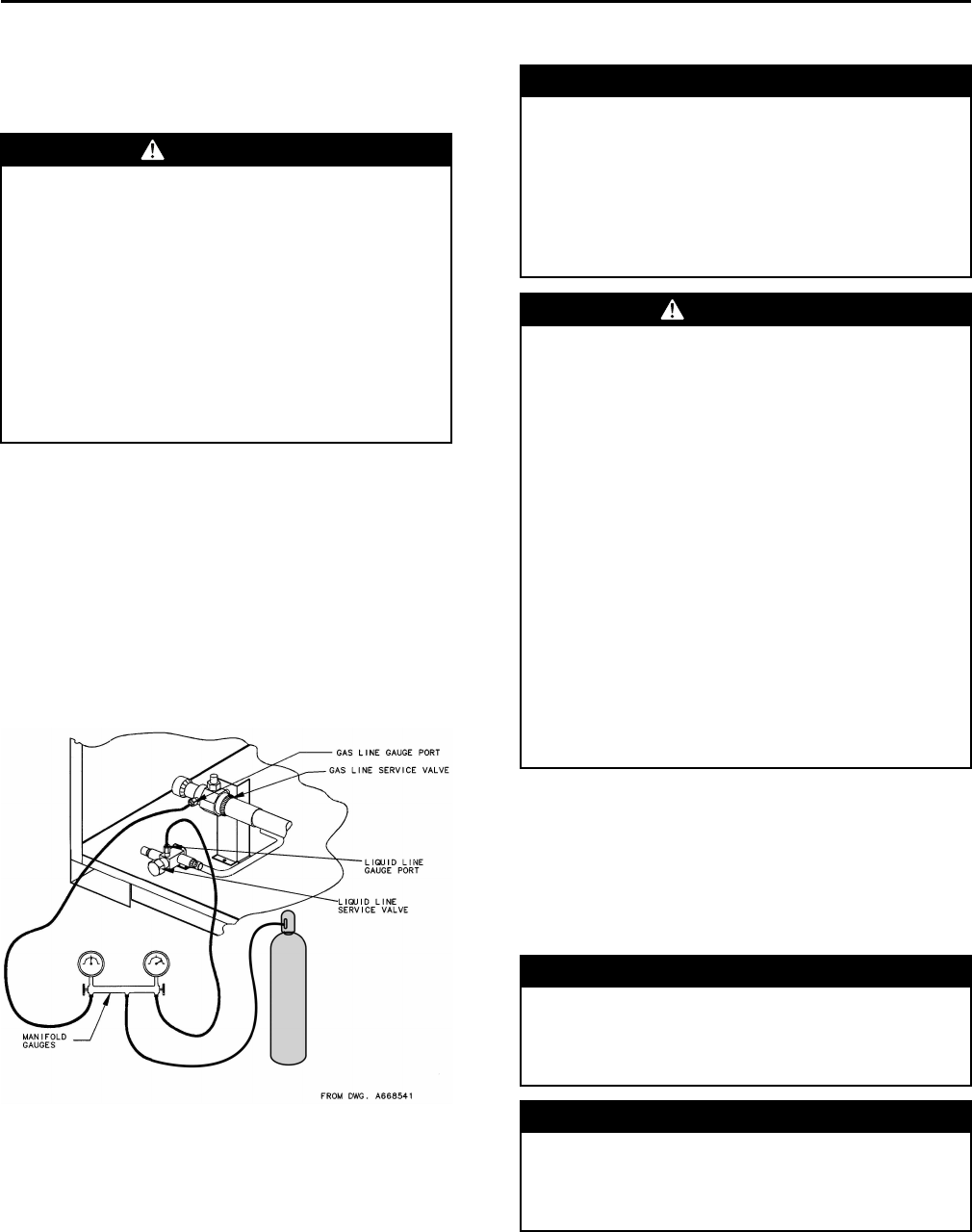
Testing for Leaks
All units are shipped with a holding charge of nitrogen
in each circuit and should be leak tested before
installation.
1. Remove the access panel.
2. Locate the liquid line or suction line access valve for
each circuit.
3. Install gauges to determine if the circuits are still
pressurized. If not, the charge has escaped and
should be repaired as required to obtain a leak-free
circuit.
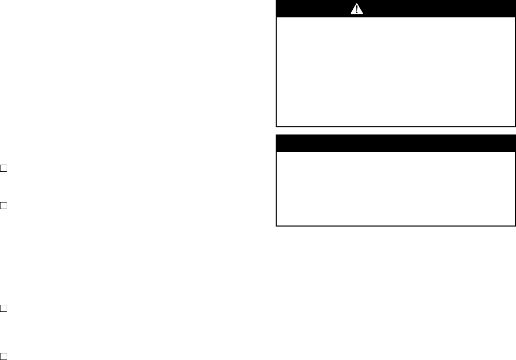
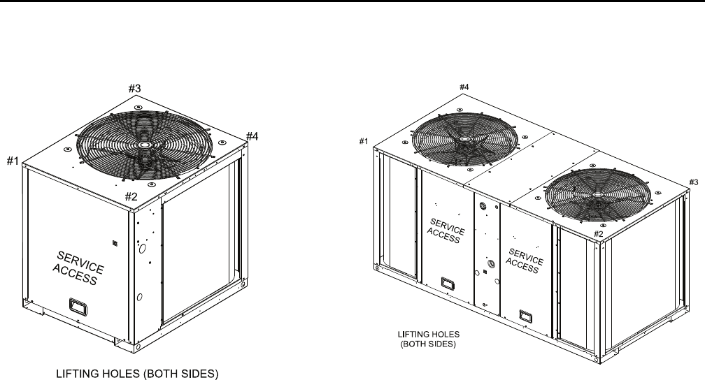
Lifting Recommendations
WWAARRNNIINNGG
IImmpprrooppeerr UUnniitt LLiifftt!!
FFaaiilluurree ttoo pprrooppeerrllyy lliifftt uunniitt ccoouulldd rreessuulltt iinn uunniitt
ddrrooppppiinngg aanndd ppoossssiibbllyy ccrruusshhiinngg ooppeerraattoorr//
tteecchhnniicciiaann wwhhiicchh ccoouulldd rreessuulltt iinn ddeeaatthh oorr sseerriioouuss
iinnjjuurryy,, aanndd eeqquuiippmmeenntt oorr pprrooppeerrttyy--oonnllyy ddaammaaggee..
TTeesstt lliifftt uunniitt aapppprrooxxiimmaatteellyy 2244 iinncchheess ttoo vveerriiffyy
pprrooppeerr cceenntteerr ooff ggrraavviittyy lliifftt ppooiinntt.. TToo aavvooiidd
ddrrooppppiinngg ooff uunniitt,, rreeppoossiittiioonn lliiffttiinngg ppooiinntt iiff uunniitt iiss
nnoott lleevveell..
NNOOTTIICCEE
EEqquuiippmmeenntt DDaammaaggee!!
UUssee sspprreeaaddeerr bbaarrss ttoo pprreevveenntt ssttrraappss ffrroomm
ddaammaaggiinngg tthhee uunniitt.. IInnssttaallll tthhee bbaarrss bbeettwweeeenn lliiffttiinngg
ssttrraappss,, bbootthh uunnddeerrnneeaatthh tthhee uunniitt aanndd aabboovvee tthhee
uunniitt ttoo pprreevveenntt tthhee ssttrraappss ffrroomm ccrruusshhiinngg tthhee uunniitt
ccaabbiinneett oorr ddaammaaggiinngg tthhee ffiinniisshh..
Before preparing the unit for lifting, estimate the
approximate center of gravity for lifting safety. Because
of placement of internal components, the unit weight
may be unevenly distributed. See “Weights,” p. 20 for
approximate unit weights.
The crated unit can be moved using a forklift of suitable
capacity. For lifting the unit, attach lifting straps or
slings securely to the lifting holes at each corner (see
unit drawings in “Weights,” p. 20). Use spreader bars
to protect the unit casing from damage. Test lift the unit
to determine proper balance and stability.
Clearances
Provide enough space around the unit to allow
unrestricted access to all service points. Refer to the
“Dimensional Data,” p. 10 for unit dimensions and
minimum required service and free air clearances.
Observe the following points to ensure proper unit
operation.
1. Do not install the unit under a low overhang.
Condenser discharge must not be restricted—refer
to notes in “Dimensional Data drawings,” p. 10.
IImmppoorrttaanntt:: Do not obstruct condenser discharge
air. This can result in warm air
recirculation through the coil.
2. Do not locate the unit in a position where runoff
water can fall into the fan discharge openings.
3. Condenser intake air is supplied from three or four
sides of the unit. Adhere to the minimum required
clearances given in unit dimensional drawings (see
“Dimensional Data,” p. 10).
SS-SVX10E-EN 9
Unit Mounting
WWAARRNNIINNGG
MMoouunnttiinngg IInntteeggrriittyy!!
FFaaiilluurree ttoo ffoollllooww iinnssttrruuccttiioonn bbeellooww ccoouulldd rreessuulltt iinn
ddeeaatthh oorr sseerriioouuss iinnjjuurryy oorr ppoossssiibbllee eeqquuiippmmeenntt oorr
pprrooppeerrttyy--oonnllyy ddaammaaggee..
EEnnssuurree tthhee rrooooff ssttrruuccttuurree ssuuppppoorrttss aarree ssttrroonngg
eennoouugghh ttoo ssuuppppoorrtt tthhee wweeiigghhtt ooff tthhee uunniitt aanndd aannyy
aacccceessssoorriieess..
Structural Preparation
NNOOTTIICCEE
RRooooff DDaammaaggee!!
SSyysstteemm ccoonnttaaiinnss ooiill aanndd rreeffrriiggeerraanntt uunnddeerr hhiigghh
pprreessssuurree.. RRooooffss sshhoouulldd bbee pprrootteecctteedd ffrroomm
eexxppoossuurree ttoo ooiillss aanndd rreeffrriiggeerraanntt iinn tthhee ssyysstteemm.. IIff
rrooooffttoopp iiss nnoott pprrootteecctteedd,, ddaammaaggee ttoo tthhee rrooooff mmaayy
ooccccuurr..
IImmppoorrttaanntt:: Refer to local building codes for proper
installation. All installation must comply
with local building codes.
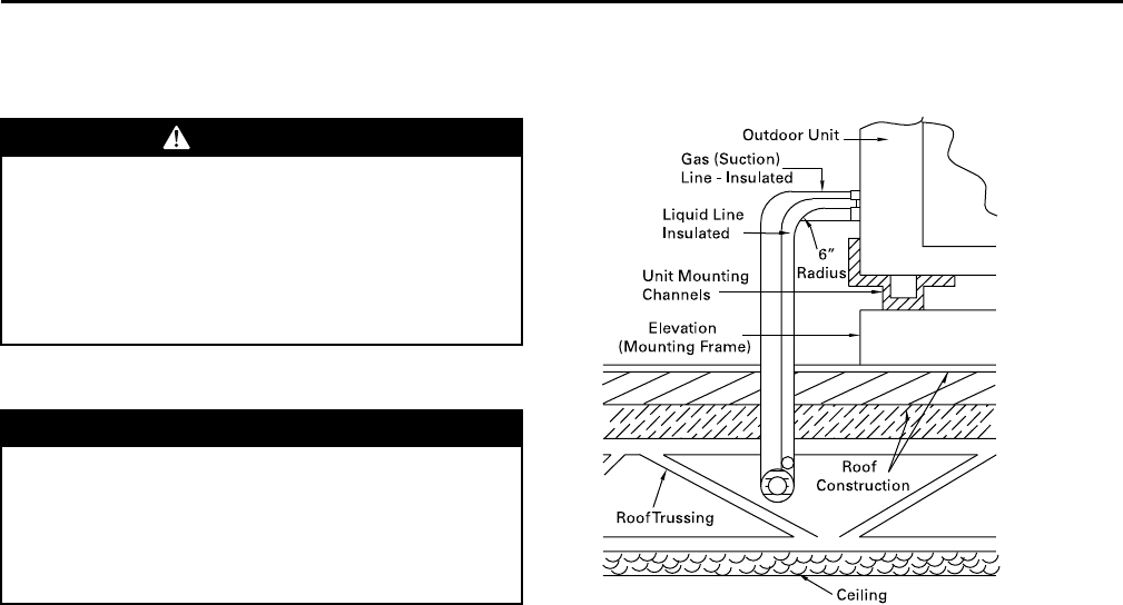
Rooftop Mounting
If the unit will be roof mounted, determine for certain
that the structure is strong enough to support the unit
and any required accessories, see “Weights,” p. 20. The
unit should be elevated on a level, field fabricated four-
inch steel or wood 4" x 4" mounting frame. Complete
the frame and secure it into position before lifting the
unit to the roof. The mounting frame must support a
minimum of three of the unit’s four sides and should
span roof supports to distribute the load on the roof.
Figure 1. Roof mounted unit
Ground Level Mounting
For ground level installation, the unit base should be
adequately supported and hold the unit near level. The
installation must meet the guidelines set forth in local
codes. The support should extend two inches beyond
the unit base channels at all points. The unit and
support must be isolated from any adjacent structure to
prevent possible noise or vibration problems. Any
ground level location must comply with required
clearances given in the unit dimensional drawings (see
“Dimensional Data,” p. 10).
PPrree--IInnssttaallllaattiioonn
10 SS-SVX10E-EN
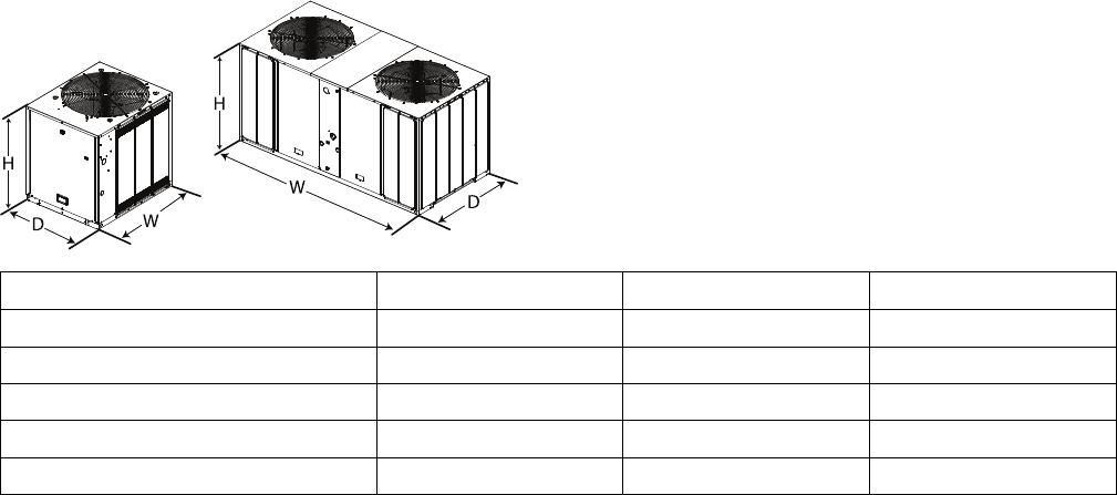
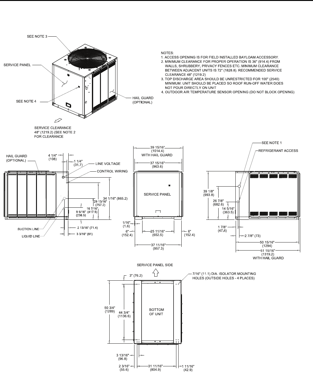
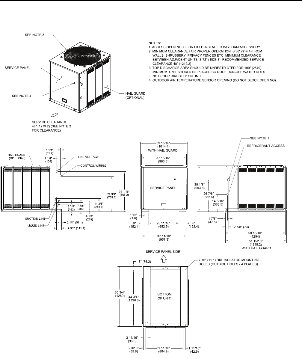
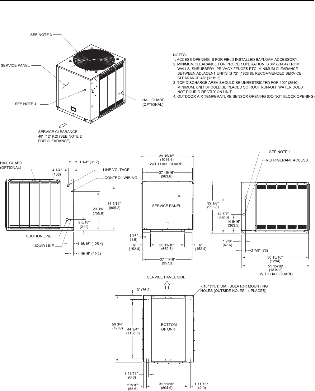
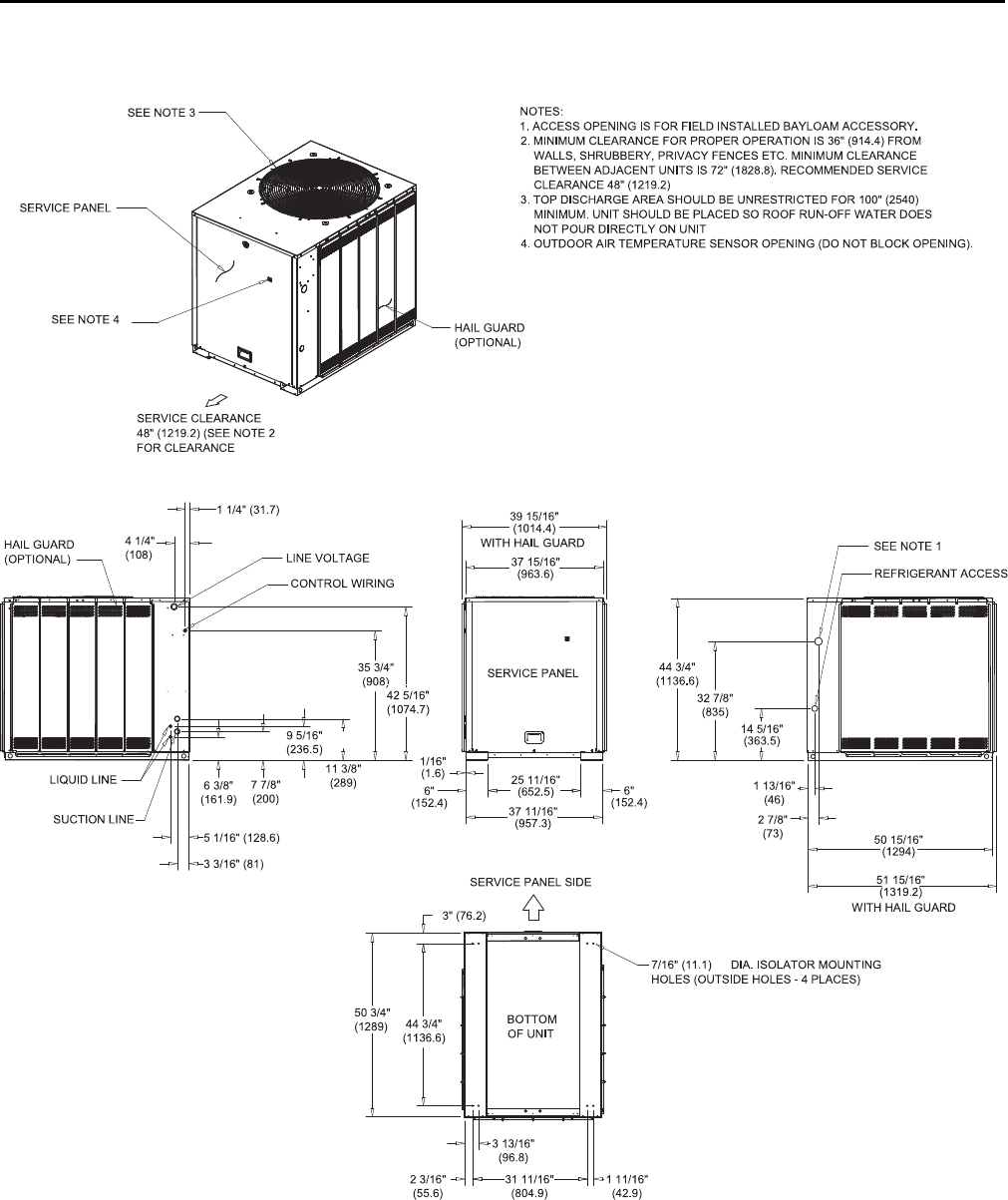
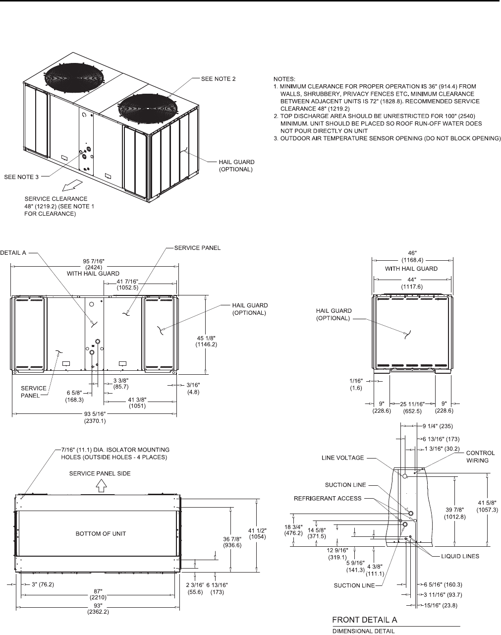
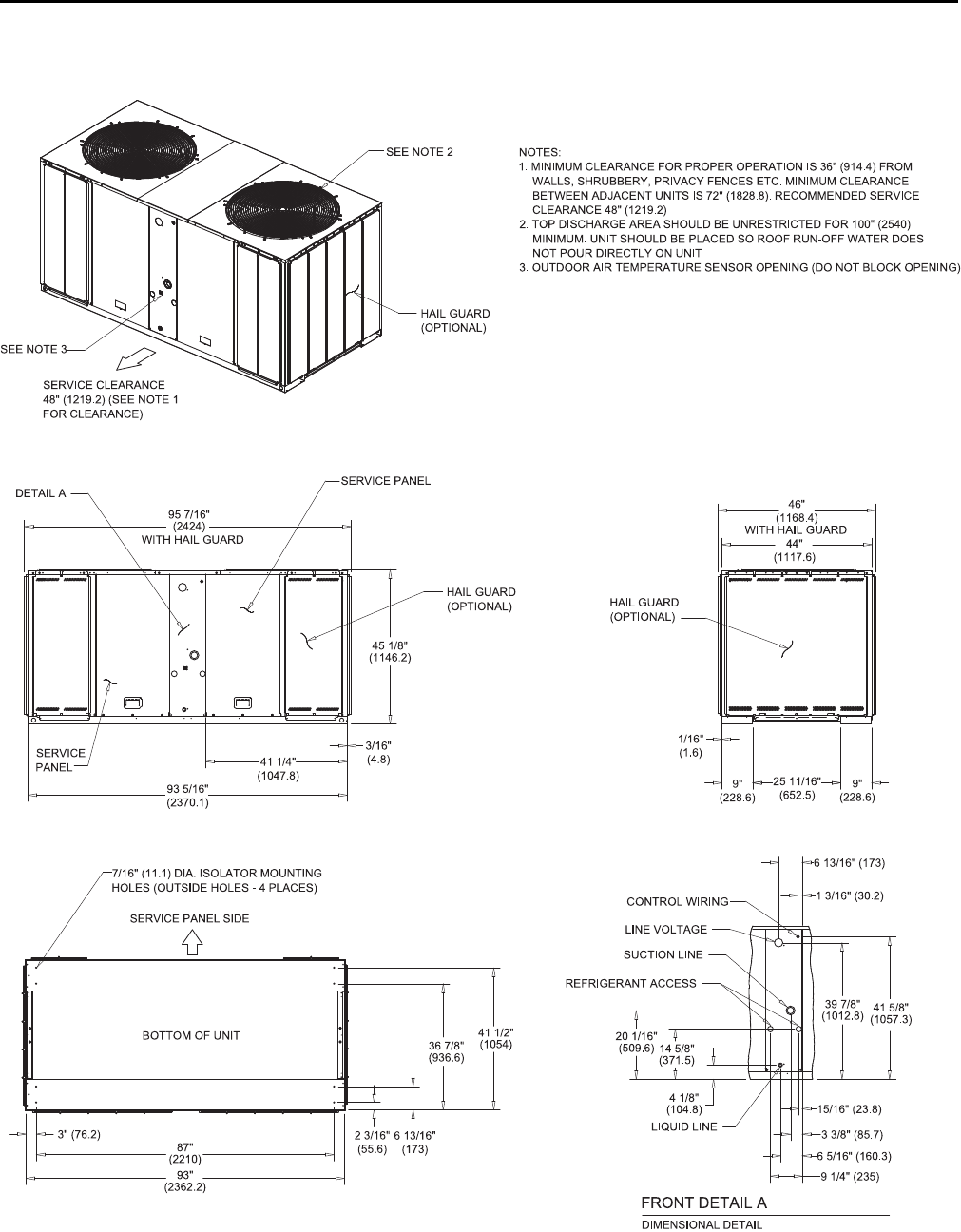
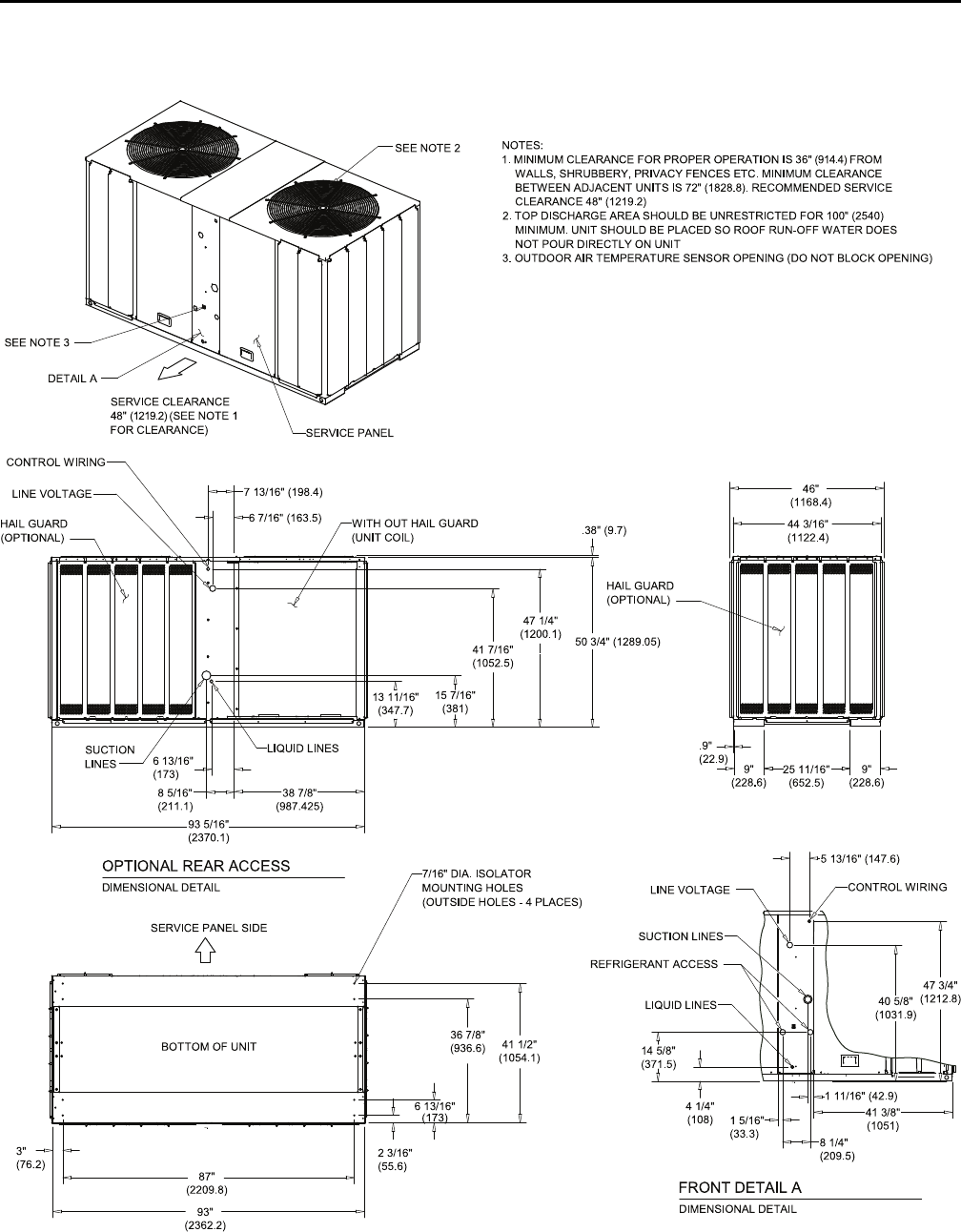
Dimensional Data
Figure 2. Height, width and depth measurements
H - in. (mm) W - in. (mm) D - in. (mm)
TTA061, 073, 076, 090 39.125 (993.8) 42.125 (1070) 36 (914.4)
TTA101, 120 39.125 (993.8) 52.125 (1324) 40 (1016)
TTA126, 150 45.125 (1146.1) 52.125 (1324) 40 (1016)
TTA156, 180, 201, 240 45.125 (1146.1) 95.5 (2425.7) 45.875 (1165.2)
TTA251, 300 51.125 (1298.6) 95.5 (2425.7) 45.875 (1165.2)
NNoottee:: Full dimensional data available on next pages.
20 SS-SVX10E-EN
Weights
Cooling Condenser
Table 1. TTA unit and corner weights — lbs (60 Hz)
Tons Model No. Shipping
Max (lbs)
Net Max
(lbs)
Corner Weights
1 2 3 4
6 TTA073G 306 241 68 72 35 65
7.5
TTA090G 316 251 71 75 37 68
TTA090H 380 315 99 91 63 62
10
TTA120G 412 340 114 89 60 77
TTA120H 424 352 110 102 71 69
TTA120F 509 438 129 140 83 86
12.5 TTA150E 543 468 130 151 79 108
15
TTA180E 850 723 207 204 151 161
TTA180F 852 725 196 208 153 168
20
TTA240E 970 837 262 240 164 171
TTA240F 966 835 257 249 153 176
25 TTA300F 1168 1037 338 266 241 194
Table 2. TTA unit and corner weights — lbs (50 Hz)
Tons Model No. Shipping
Max (kg)
Net Max
(kg)
Corner Weights
1 2 3 4
5 TTA061G 140 110 31 33 16 30
6.25 TTA076G 144 115 32 34 17 31
TTA076H 173 144 45 42 29 28
8.33
TTA101G 188 155 52 40 27 35
TTA101H 193 160 50 46 32 31
TTA101F 229 197 58 63 37 39
10.4 TTA126E 244 211 59 68 36 49
13 TTA156E 383 325 93 92 68 72
TTA156F 383 326 88 94 69 76
16.7 TTA201E 437 377 118 108 74 77
TTA201F 435 376 116 112 69 79
20.9 TTA251F 530 470 153 121 109 88
22 SS-SVX10E-EN
Installation
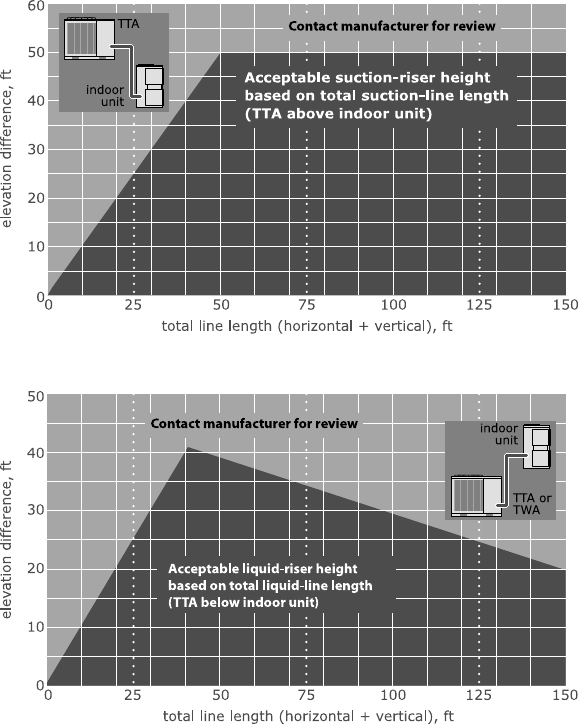
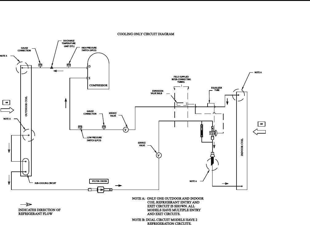
Refrigerant Piping Guidelines
Figure 14. Allowable elevation difference: Cooling only TTA above indoor unit
Figure 15. Allowable elevation difference: TTA below indoor unit
NNoottee:: Route refrigerant piping for minimum linear length, minimum number of bends and fittings (no reducers) and
minimum amount of line exposed to outdoor ambients.
SS-SVX10E-EN 23
Refrigerant Piping Procedures
(Outdoor Units)
WWAARRNNIINNGG
RR--441100AA RReeffrriiggeerraanntt uunnddeerr HHiigghheerr
PPrreessssuurree tthhaann RR--2222!!
FFaaiilluurree ttoo uussee pprrooppeerr eeqquuiippmmeenntt oorr ccoommppoonneennttss aass
ddeessccrriibbeedd bbeellooww,, ccoouulldd rreessuulltt iinn eeqquuiippmmeenntt ffaaiilliinngg
aanndd ppoossssiibbllyy eexxppllooddiinngg,, wwhhiicchh ccoouulldd rreessuulltt iinn
ddeeaatthh,, sseerriioouuss iinnjjuurryy,, oorr eeqquuiippmmeenntt ddaammaaggee..
TThhee uunniittss ddeessccrriibbeedd iinn tthhiiss mmaannuuaall uussee RR--441100AA
rreeffrriiggeerraanntt wwhhiicchh ooppeerraatteess aatt hhiigghheerr pprreessssuurreess
tthhaann RR--2222.. UUssee OONNLLYY RR--441100AA rraatteedd sseerrvviiccee
eeqquuiippmmeenntt oorr ccoommppoonneennttss wwiitthh tthheessee uunniittss.. FFoorr
ssppeecciiffiicc hhaannddlliinngg ccoonncceerrnnss wwiitthh RR--441100AA,, pplleeaassee
ccoonnttaacctt yyoouurr llooccaall TTrraannee rreepprreesseennttaattiivvee..
Each TTA unit ships with a holding charge of dry
nitrogen. The nitrogen should be removed and the
entire system evacuated (at the proper time) to avoid
possible contamination.
1. Remove the compressor service access panel.
2. Locate the liquid and suction line service valves.
Check that the piping connection stubs on the
valves (Figure 16, p. 23) line up properly with the
holes in the unit cabinet.
Figure 16. Outdoor units - refrigerant piping (with dry
nitrogen)
3. Remove the refrigerant connection seal caps and
open the service valve slowly to release the
nitrogen from the unit.
NNOOTTIICCEE
SSyysstteemm CCoommppoonneenntt DDaammaaggee!!
DDoo nnoott rreemmoovvee tthhee sseeaall ccaappss ffrroomm rreeffrriiggeerraanntt
ccoonnnneeccttiioonnss,, oorr ooppeenn tthhee sseerrvviiccee vvaallvveess uunnttiill
pprreeppaarreedd ttoo bbrraazzee rreeffrriiggeerraanntt lliinneess ttoo tthhee
ccoonnnneeccttiioonnss.. EExxcceessssiivvee eexxppoossuurree ttoo aattmmoosspphheerree ((>>
55 mmiinn..)) mmaayy aallllooww mmooiissttuurree oorr ddiirrtt ttoo ccoonnttaammiinnaattee
tthhee ssyysstteemm,, ddaammaaggiinngg vvaallvvee sseeaallss aanndd ccaauussiinngg iiccee
ffoorrmmaattiioonn iinn ssyysstteemm ccoommppoonneennttss..
WWAARRNNIINNGG
HHaazzaarrdd ooff EExxpplloossiioonn aanndd DDeeaaddllyy
GGaasseess!!
FFaaiilluurree ttoo ffoollllooww aallll pprrooppeerr ssaaffee rreeffrriiggeerraanntt
hhaannddlliinngg pprraaccttiicceess ccoouulldd rreessuulltt iinn ddeeaatthh oorr sseerriioouuss
iinnjjuurryy..
NNeevveerr ssoollddeerr,, bbrraazzee oorr wweelldd oonn rreeffrriiggeerraanntt lliinneess oorr
aannyy uunniitt ccoommppoonneennttss tthhaatt aarree aabboovvee aattmmoosspphheerriicc
pprreessssuurree oorr wwhheerree rreeffrriiggeerraanntt mmaayy bbee pprreesseenntt..
AAllwwaayyss rreemmoovvee rreeffrriiggeerraanntt bbyy ffoolllloowwiinngg tthhee
gguuiiddeelliinneess eessttaabblliisshheedd bbyy tthhee EEPPAA FFeeddeerraall CClleeaann
AAiirr AAcctt oorr ootthheerr ssttaattee oorr llooccaall ccooddeess aass aapppprroopprriiaattee..
AAfftteerr rreeffrriiggeerraanntt rreemmoovvaall,, uussee ddrryy nniittrrooggeenn ttoo
bbrriinngg ssyysstteemm bbaacckk ttoo aattmmoosspphheerriicc pprreessssuurree bbeeffoorree
ooppeenniinngg ssyysstteemm ffoorr rreeppaaiirrss.. MMiixxttuurreess ooff
rreeffrriiggeerraannttss aanndd aaiirr uunnddeerr pprreessssuurree mmaayy bbeeccoommee
ccoommbbuussttiibbllee iinn tthhee pprreesseennccee ooff aann iiggnniittiioonn ssoouurrccee
lleeaaddiinngg ttoo aann eexxpplloossiioonn.. EExxcceessssiivvee hheeaatt ffrroomm
ssoollddeerriinngg,, bbrraazziinngg oorr wweellddiinngg wwiitthh rreeffrriiggeerraanntt
vvaappoorrss pprreesseenntt ccaann ffoorrmm hhiigghhllyy ttooxxiicc ggaasseess aanndd
eexxttrreemmeellyy ccoorrrroossiivvee aacciiddss..
4. Cut, fit and braze tubing, starting at the outdoor unit
and work toward the indoor unit. See
recommended tube sizes, .
NNoottee:: Use long radius ells for all 90° bends.
All brazing should be done using a 2 to 3 psig dry
nitrogen purge flowing through the pipe being
brazed, see Figure 16, p. 23.
NNOOTTIICCEE
SSyysstteemm CCoommppoonneenntt DDaammaaggee!!
IInnssttaallll aa rreegguullaattiinngg vvaallvvee bbeettwweeeenn tthhee nniittrrooggeenn
ssoouurrccee aanndd tthhee ggaauuggee mmaanniiffoolldd.. UUnnrreegguullaatteedd
pprreessssuurree ccaann ddaammaaggee ssyysstteemm ccoommppoonneennttss..
NNOOTTIICCEE
SSyysstteemm CCoommppoonneenntt DDaammaaggee!!
WWeett--wwrraapp aallll vvaallvveess aanndd pprrootteecctt ppaaiinntteedd ssuurrffaacceess
ffrroomm eexxcceessssiivvee hheeaatt.. HHeeaatt ccaann ddaammaaggee ssyysstteemm
ccoommppoonneennttss aanndd tthhee uunniitt ffiinniisshh..
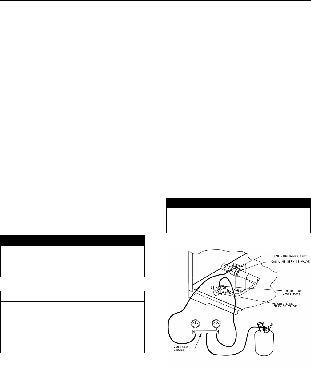
5. Shut off nitrogen supply. Shut off the manifold
valve for the line that is connected to the suction
line service valve. Disconnect the line from the
gauge port on the valve.
IInnssttaallllaattiioonn
24 SS-SVX10E-EN
Refrigerant Piping Procedures
(Indoor Unit)
Once liquid and suction lines are complete to the
refrigerant connections on the indoor unit, remove the
gauge port core(s) on the indoor unit connection stubs
to release the dry nitrogen charge.
NNOOTTIICCEE
UUnniitt DDaammaaggee!!
DDoo nnoott aappppllyy hheeaatt ttoo rreemmoovvee sseeaall ccaappss uunnttiill tthhee
ggaauuggee ppoorrtt ccoorreess hhaavvee bbeeeenn rreemmoovveedd.. IIff sseeaall ccaappss
aarree iinnttaacctt,, aapppplliiccaattiioonn ooff hheeaatt mmaayy ggeenneerraattee
eexxcceessssiivvee pprreessssuurree iinn tthhee uunniitt aanndd rreessuulltt iinn
ddaammaaggee ttoo tthhee ccooiill oorr eexxppaannssiioonn vvaallvvee..
1. Remove both seal caps from the indoor unit
connection stubs.
NNOOTTIICCEE
UUnniitt DDaammaaggee!!
DDoo nnoott rreemmoovvee tthhee sseeaall ccaappss ffrroomm rreeffrriiggeerraanntt
ccoonnnneeccttiioonnss,, oorr ooppeenn tthhee sseerrvviiccee vvaallvveess uunnttiill
pprreeppaarreedd ttoo bbrraazzee rreeffrriiggeerraanntt lliinneess ttoo tthhee
ccoonnnneeccttiioonnss.. DDuuee ttoo tthhee hhiigghh hhyyggrroossccooppiicc
pprrooppeerrttiieess ooff tthhee RR--441100AA ooiill,, eexxcceessssiivvee eexxppoossuurree ttoo
aattmmoosspphheerree wwiillll aallllooww mmooiissttuurree ttoo ccoonnttaammiinnaattee
tthhee ssyysstteemm,, ddaammaaggiinngg tthhee ccoommpprreessssoorr..
2. Turn on nitrogen supply. Nitrogen enters through
the liquid line gauge port.
3. Braze the liquid line connections.
4. Open the gauge port on the suction line and then
braze the suction line to the connection stub.
Nitrogen will bleed out the open gauge port on the
suction line.
5. Shut off nitrogen supply.
Leak Check
WWAARRNNIINNGG
HHaazzaarrdd ooff EExxpplloossiioonn!!
FFaaiilluurree ttoo ffoollllooww tthheessee rreeccoommmmeennddaattiioonnss ccoouulldd
rreessuulltt iinn ddeeaatthh oorr sseerriioouuss iinnjjuurryy oorr eeqquuiippmmeenntt oorr
pprrooppeerrttyy--oonnllyy ddaammaaggee..
UUssee oonnllyy ddrryy nniittrrooggeenn wwiitthh aa pprreessssuurree rreegguullaattoorr ffoorr
pprreessssuurriizziinngg uunniitt.. DDoo nnoott uussee aacceettyylleennee,, ooxxyyggeenn oorr
ccoommpprreesssseedd aaiirr oorr mmiixxttuurreess ccoonnttaaiinniinngg tthheemm ffoorr
pprreessssuurree tteessttiinngg.. DDoo nnoott uussee mmiixxttuurreess ooff aa
hhyyddrrooggeenn ccoonnttaaiinniinngg rreeffrriiggeerraanntt aanndd aaiirr aabboovvee
aattmmoosspphheerriicc pprreessssuurree ffoorr pprreessssuurree tteessttiinngg aass tthheeyy
mmaayy bbeeccoommee ffllaammmmaabbllee aanndd ccoouulldd rreessuulltt iinn aann
eexxpplloossiioonn.. RReeffrriiggeerraanntt,, wwhheenn uusseedd aass aa ttrraaccee ggaass
sshhoouulldd oonnllyy bbee mmiixxeedd wwiitthh ddrryy nniittrrooggeenn ffoorr
pprreessssuurriizziinngg uunniittss..
WWAARRNNIINNGG
HHaazzaarrdd ooff EExxpplloossiioonn!!
FFaaiilluurree ttoo ffoollllooww rreeccoommmmeennddeedd ssaaffee lleeaakk tteesstt
pprroocceedduurreess ccoouulldd rreessuulltt iinn ddeeaatthh oorr sseerriioouuss iinnjjuurryy
oorr eeqquuiippmmeenntt oorr pprrooppeerrttyy--oonnllyy--ddaammaaggee..
NNeevveerr uussee aann ooppeenn ffllaammee ttoo ddeetteecctt ggaass lleeaakkss.. UUssee aa
lleeaakk tteesstt ssoolluuttiioonn ffoorr lleeaakk tteessttiinngg..
After the brazing operation of refrigerant lines to both
the outdoor and indoor unit is completed, the field
brazed connections must be checked for leaks.
Pressurize the system through the service valve with
dry nitrogen to 200 psi. Use soap bubbles or other leak-
checking methods to ensure that all field joints are leak
free. If not, release pressure, repair and repeat leak test.
System Evacuation
1. After completion of leak check, evacuate the
system.
2. Attach appropriate hoses from manifold gauge to
gas and liquid line pressure taps.
NNoottee:: Unnecessary switching of hoses can be
avoided and complete evacuation of all lines
leading to sealed system can be
accomplished with manifold center hose and
connecting branch hose to a cylinder of R-
410A and vacuum pump.
3. Attach center hose of manifold gauges to vacuum
pump.
NNOOTTIICCEE
OOppeerraattiinngg UUnnddeerr VVaaccuuuumm!!
FFaaiilluurree ttoo ffoollllooww tthheessee iinnssttrruuccttiioonnss wwiillll rreessuulltt iinn
ccoommpprreessssoorr ffaaiilluurree..
DDoo nnoott ooppeerraattee oorr aappppllyy ppoowweerr ttoo tthhee ccoommpprreessssoorr
wwhhiillee uunnddeerr aa vvaaccuuuumm..
4. Evacuate the system to hold a 500 micron vacuum.
5. Close off valve to vacuum pump and observe the
micron gauge. If gauge pressure rises above 500
microns in one minute, then evacuation is
incomplete or the system has a leak.
6. If vacuum gauge does not rise above 500 microns in
10 minutes, the evacuation should be complete.
NNOOTTIICCEE
EEqquuiippmmeenntt DDaammaaggee!!
CChhaarrggee wwiitthh aacccceessss ppoorrtt oonn tthhee lliiqquuiidd lliinnee sseerrvviiccee
vvaallvvee oonnllyy..
7. With vacuum pump and micron gauge blanked off,
open valve on R-410A cylinder and allow refrigerant
pressure to build up to about 80 psig.
8. Close valve on the R-410A supply cylinder. Close
valves on manifold gauge set and remove
IInnssttaallllaattiioonn
SS-SVX10E-EN 25
refrigerant charging hoses from liquid and gas
gauge ports.
9. Leak test the entire system. Using proper
procedures and caution, as described in the
previous section, repair any leaks found and repeat
the leak test.
Insulating and Isolating
Refrigerant Lines
Insulate the entire suction line with refrigerant piping
insulation. Also insulate any portion of the liquid line
exposed to temperature extremes. Insulate and isolate
liquid and suction lines from each other. Isolate
refrigerant lines from the structure and any duct work.
IImmppoorrttaanntt::
1. To prevent possible noise or vibration
problems, be certain to isolate
refrigerant lines from the building.
2. All suction and hot gas bypass piping (if
installed) should be insulated from the
termination in the air handler to the
condensing unit cabinet entry. Failure to
do so can cause condensate drip off and
performance degradation.
3. Prior to starting a unit, it is advisable to
have the approved oils available in the
event oil needs to be added to the
system.
NNOOTTIICCEE
EEqquuiippmmeenntt DDaammaaggee!!
TThhiiss iiss PPOOEE ooiill,, wwhhiicchh rreeaaddiillyy aabbssoorrbbss mmooiissttuurree..
AAllwwaayyss uussee nneeww ooiill aanndd nneevveerr lleeaavvee ccoonnttaaiinneerrss
ooppeenn ttoo aattmmoosspphheerree wwhhiillee nnoott iinn uussee..
Table 3. TTA approved oils
Unit Model Number Approved Oils
TTA061, TTA073, TTA076,
TTA090, TTA101, TTA120,
TTA126, TTA150, TTA156,
TTA180, TTA251, TTA300
Trane Oil Part Number
OIL00094 (1 quart container)
TTA201, TTA240
Trane Oil Part Number
OIL00079 (1 quart container)
or OIL00080 (1 gallon
container).
For units equipped with compressors containing site
glasses, the oil level must be visible through the sight
glass when the compressor is running under stabilized
conditions and a few minutes after the compressor has
stopped.
Refrigerant Charging Procedure
If charging by weight, refer to for starting change. If
refrigerant adjustments are needed because of length
of line, refer to “Charging Charts and Superheat,” p. 38.
Charge by weight through the gauge port on the liquid
line. Once the charge enters the system, backseat
(open) the liquid line service valve and disconnect the
charging line and replace the cap on the gauge port.
NNootteess::
• R-410A should only be charged in the liquid
state.
• When possible, always charge the
refrigerant into the liquid line of the unit.
• If the entire charge can’t be charged into the
liquid line, the balance of the unit charge can
be metered through a charging manifold set
as liquid — preferably through a schrader
valve into the suction line to the compressor
— only while the compressor is running.
• Check and adjust superheat using Table 9, p.
41, then re-check charging charts to
determine if charge corrections are
necessary.
NNOOTTIICCEE
EEqquuiippmmeenntt DDaammaaggee!!
NNeevveerr cchhaarrggee lliiqquuiidd rreeffrriiggeerraanntt iinnttoo tthhee ssuuccttiioonn
lliinnee ooff tthhee uunniitt wwiitthh tthhee ccoommpprreessssoorr ooffff..
Figure 17. Outdoor units - refrigerant piping
IInnssttaallllaattiioonn
26 SS-SVX10E-EN
Charging Levels
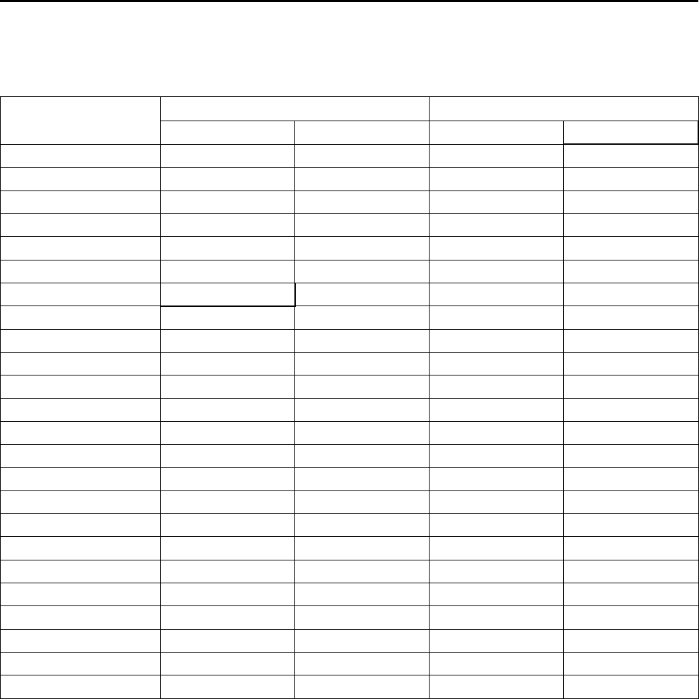
Table 4. Estimated charge levels at ARI rated line lengths (25 feet) - 50 & 60 Hz
Matched Set
Refrigerant Charge Per Circuit
Circuit 1 Circuit 2 Liquid Line Diameter Vapor Line Diameter
TTA061G w/TWE076D(a) 10 N/A 0.5 (1/2”) 1.125 (1 1/8”)
TTA073G w/TWE090D 10 N/A 0.5 (1/2”) 1.125 (1 1/8”)
TTA076G w/TWE076D 9.7 N/A 0.5 (1/2”) 1.375 (1 3/8”)
TTA076H w/TWE076E 7.25 7.3125 0.5 (1/2”) 1.125 (1 1/8”)
TTA090G w/TWE090D 9.7 N/A 0.5 (1/2”) 1.375 (1 3/8”)
TTA090H w/TWE090E 7.25 7.3125 0.5 (1/2”) 1.125 (1 1/8”)
TTA101G w/TWE101D 13.6 N/A 0.5 (1/2”) 1.375 (1 3/8”)
TTA101H w/TWE101E 7.7 7.6 0.5 (1/2”) 1.125 (1 1/8”)
TTA101F w/TWE101D 21.2 N/A 0.5 (1/2”) 1.375 (1 3/8”)
TTA120G w/TWE120D 13.6 N/A 0.5 (1/2”) 1.375 (1 3/8”)
TTA120H w/TWE120E 7.7 7.6 0.5 (1/2”) 1.125 (1 1/8”)
TTA120F w/TWE120D 21.2 N/A 0.5 (1/2”) 1.375 (1 3/8”)
TTA126E w/TWE126E 15.2 15.5 0.5 (1/2”) 1.125 (1 1/8”)
TTA150E w/TWE150E 15.2 15.5 0.5 (1/2”) 1.125 (1 1/8”)
TTA156E w/TWE156E 19.5 19.5 0.5 (1/2”) 1.375 (1 3/8”)
TTA156F w/TWE156E 37.6 N/A 0.625 (5/8”) 1.625 (1 5/8”)
TTA180E w/TWE180E 19.5 19.5 0.5 (1/2”) 1.375 (1 3/8”)
TTA180F w/TWE180E 37.6 N/A 0.625 (5/8”) 1.625 (1 5/8”)
TTA201E w/TWE201E 21.9 21.9 0.5 (1/2”) 1.375 (1 3/8”)
TTA201F w/TWE201E 41.3 N/A 0.625 (5/8”) 1.625 (1 5/8”)
TTA240E w/TWE240E 21.9 21.9 0.5 (1/2”) 1.375 (1 3/8”)
TTA240F w/TWE240E 41.3 N/A 0.625 (5/8”) 1.625 (1 5/8”)
TTA251F w/TWE251E(b) 62.5 N/A 0.625 (5/8”) 2.125 (2 1/8”)
TTA300F w/TWE300E 62.5 N/A 0.625 (5/8”) 2.125 (2 1/8”)
Notes:
1. For line lengths other than 25', please refer to the Application Guide (SS-APG008-EN) for charge levels and line sizes.
2. See and for transition tube location and electrical connections.
(a) TTA061D and TTA073D need a reducer for vapor line. (1.375 to 1.125 inch) (1 3/8” to 1 1/8”)
(b) TTA251F and TTA300F are provided with a transition tube to be installed outside of the unit for front or rear access, (1.625 to 2.125 inch) (1 5/8" to 2 1/
8").
IInnssttaallllaattiioonn
SS-SVX10E-EN 27
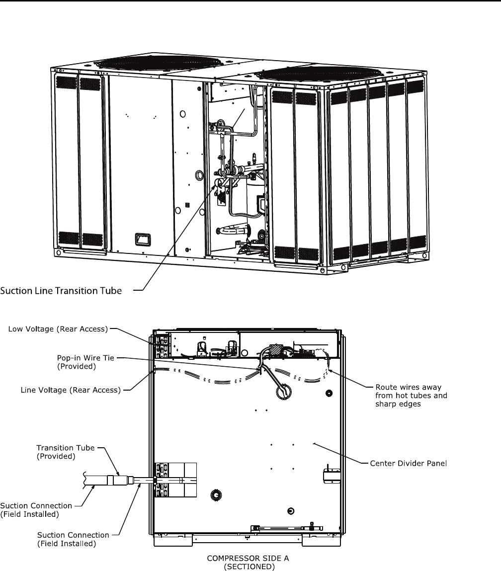
Figure 18. TTA 251, 300 transition tube location
Figure 19. TTA251, 300 rear refrigerant and electrical connections
Liquid Charging
This procedure is accomplished with the unit
operating. Electrical connections must be complete. Do
not proceed until the system is ready to operate.
NNoottee:: The compressor access panel must be installed
when the unit is running and being charged.
Manifold hoses must be routed through
refrigerant gauge access hole(s). See
“Dimensional Data,” p. 10 for specific locations.
IInnssttaallllaattiioonn
28 SS-SVX10E-EN
WWAARRNNIINNGG
LLiivvee EElleeccttrriiccaall CCoommppoonneennttss!!
FFaaiilluurree ttoo ffoollllooww aallll eelleeccttrriiccaall ssaaffeettyy pprreeccaauuttiioonnss
wwhheenn eexxppoosseedd ttoo lliivvee eelleeccttrriiccaall ccoommppoonneennttss ccoouulldd
rreessuulltt iinn ddeeaatthh oorr sseerriioouuss iinnjjuurryy..
WWhheenn iitt iiss nneecceessssaarryy ttoo wwoorrkk wwiitthh lliivvee eelleeccttrriiccaall
ccoommppoonneennttss,, hhaavvee aa qquuaalliiffiieedd lliicceennsseedd eelleeccttrriicciiaann
oorr ootthheerr iinnddiivviidduuaall wwhhoo hhaass bbeeeenn pprrooppeerrllyy ttrraaiinneedd
iinn hhaannddlliinngg lliivvee eelleeccttrriiccaall ccoommppoonneennttss ppeerrffoorrmm
tthheessee ttaasskkss..
1. Turn on power to the unit. Allow the system to run
for 15 minutes to stabilize operating conditions.
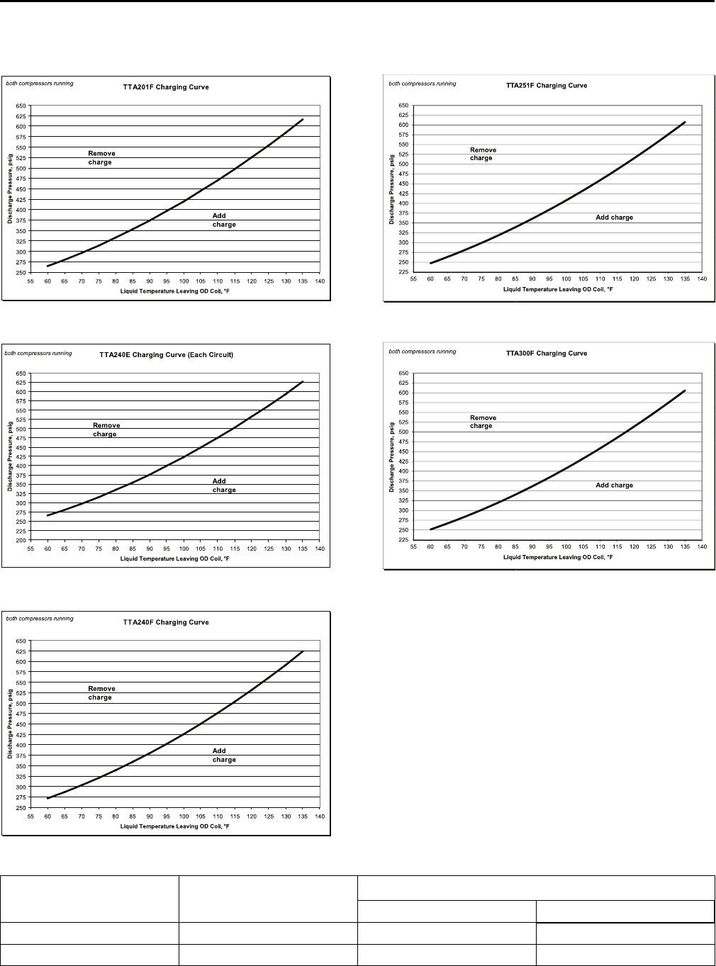
2. Measure airflow across the indoor coil. Compare
the measurements with the fan performance data in
the Data/Submittal or Service Facts. Once proper
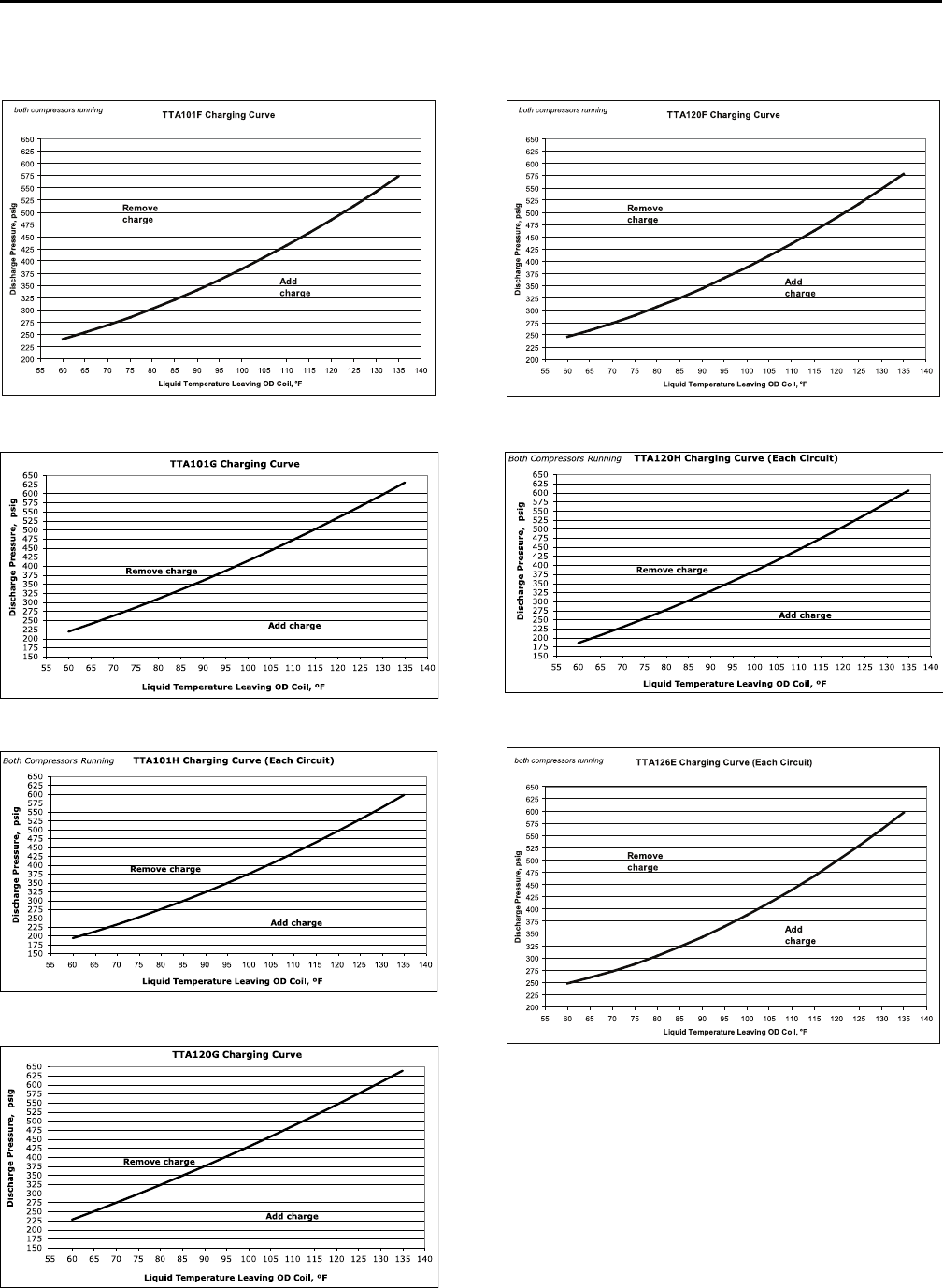
airflow is established, compare discharge pressure
and liquid temperature to the “Charging Charts,” p.
38. Add or remove refrigerant (liquid only) as
required to obtain correct discharge pressure and
liquid temperature.
3. Check suction line superheat and condenser sub-
cooling to ensure the unit is operating properly.
4. Disconnect all power to the unit.
IImmppoorrttaanntt:: If the unit is charged and left without
power until a later date, the crankcase
heater should be energized for a
minimum of 8 hours prior to powering
the compressor(s).
WWAARRNNIINNGG
HHaazzaarrddoouuss VVoollttaaggee ww//CCaappaacciittoorrss!!
FFaaiilluurree ttoo ddiissccoonnnneecctt ppoowweerr aanndd ddiisscchhaarrggee
ccaappaacciittoorrss bbeeffoorree sseerrvviicciinngg ccoouulldd rreessuulltt iinn ddeeaatthh oorr
sseerriioouuss iinnjjuurryy..
DDiissccoonnnneecctt aallll eelleeccttrriicc ppoowweerr,, iinncclluuddiinngg rreemmoottee
ddiissccoonnnneeccttss aanndd ddiisscchhaarrggee aallll mmoottoorr ssttaarrtt//rruunn
ccaappaacciittoorrss bbeeffoorree sseerrvviicciinngg.. FFoollllooww pprrooppeerr lloocckkoouutt//
ttaaggoouutt pprroocceedduurreess ttoo eennssuurree tthhee ppoowweerr ccaannnnoott bbee
iinnaaddvveerrtteennttllyy eenneerrggiizzeedd.. FFoorr vvaarriiaabbllee ffrreeqquueennccyy
ddrriivveess oorr ootthheerr eenneerrggyy ssttoorriinngg ccoommppoonneennttss
pprroovviiddeedd bbyy TTrraannee oorr ootthheerrss,, rreeffeerr ttoo tthhee
aapppprroopprriiaattee mmaannuuffaaccttuurreerr’’ss lliitteerraattuurree ffoorr
aalllloowwaabbllee wwaaiittiinngg ppeerriiooddss ffoorr ddiisscchhaarrggee ooff
ccaappaacciittoorrss.. VVeerriiffyy wwiitthh aann aapppprroopprriiaattee vvoollttmmeetteerr
tthhaatt aallll ccaappaacciittoorrss hhaavvee ddiisscchhaarrggeedd..
FFoorr aaddddiittiioonnaall iinnffoorrmmaattiioonn rreeggaarrddiinngg tthhee ssaaffee
ddiisscchhaarrggee ooff ccaappaacciittoorrss,, sseeee PPRROODD--SSVVBB0066AA--EENN..
5. Remove the charging system from the unit.
6. Replace all panels.
Electrical Wiring
WWAARRNNIINNGG
PPrrooppeerr FFiieelldd WWiirriinngg aanndd GGrroouunnddiinngg
RReeqquuiirreedd!!
FFaaiilluurree ttoo ffoollllooww ccooddee ccoouulldd rreessuulltt iinn ddeeaatthh oorr
sseerriioouuss iinnjjuurryy..
AAllll ffiieelldd wwiirriinngg MMUUSSTT bbee ppeerrffoorrmmeedd bbyy qquuaalliiffiieedd
ppeerrssoonnnneell.. IImmpprrooppeerrllyy iinnssttaalllleedd aanndd ggrroouunnddeedd
ffiieelldd wwiirriinngg ppoosseess FFIIRREE aanndd EELLEECCTTRROOCCUUTTIIOONN
hhaazzaarrddss.. TToo aavvooiidd tthheessee hhaazzaarrddss,, yyoouu MMUUSSTT ffoollllooww
rreeqquuiirreemmeennttss ffoorr ffiieelldd wwiirriinngg iinnssttaallllaattiioonn aanndd
ggrroouunnddiinngg aass ddeessccrriibbeedd iinn NNEECC aanndd yyoouurr llooccaall//
ssttaattee eelleeccttrriiccaall ccooddeess..
Field wiring consists of providing power supply to the
unit, installing the system indoor thermostat and
providing low voltage system interconnecting wiring.
Access to electrical connection locations is shown in
“Dimensional Data,” p. 10. Determine proper wire sizes
and unit protective fusing requirements by referring to
the unit nameplate and/or the unit Service Facts. Field
wiring diagrams for accessories are shipped with the
accessory.
Unit Power Supply
The installer must provide line voltage circuit(s) to the
unit main power terminals as shown by the unit wiring
diagrams (available through e-Library or by contacting
a local sales office) or field wiring. Power supply must
include a disconnect switch in a location convenient to
the unit. Ground the unit according to local codes and
provide flexible conduit if codes require and/or if
vibration transmission may cause noise problems.
IImmppoorrttaanntt:: All wiring must comply with applicable
local and national (NEC) codes. Type and
location of disconnect switches must
comply with all applicable codes.
WWAARRNNIINNGG
PPrrooppeerr FFiieelldd WWiirriinngg aanndd GGrroouunnddiinngg
RReeqquuiirreedd!!
FFaaiilluurree ttoo ffoollllooww ccooddee ccoouulldd rreessuulltt iinn ddeeaatthh oorr
sseerriioouuss iinnjjuurryy..
AAllll ffiieelldd wwiirriinngg MMUUSSTT bbee ppeerrffoorrmmeedd bbyy qquuaalliiffiieedd
ppeerrssoonnnneell.. IImmpprrooppeerrllyy iinnssttaalllleedd aanndd ggrroouunnddeedd
ffiieelldd wwiirriinngg ppoosseess FFIIRREE aanndd EELLEECCTTRROOCCUUTTIIOONN
hhaazzaarrddss.. TToo aavvooiidd tthheessee hhaazzaarrddss,, yyoouu MMUUSSTT ffoollllooww
rreeqquuiirreemmeennttss ffoorr ffiieelldd wwiirriinngg iinnssttaallllaattiioonn aanndd
ggrroouunnddiinngg aass ddeessccrriibbeedd iinn NNEECC aanndd yyoouurr llooccaall//
ssttaattee eelleeccttrriiccaall ccooddeess..
IInnssttaallllaattiioonn
SS-SVX10E-EN 29
NNOOTTIICCEE
UUssee CCooppppeerr CCoonndduuccttoorrss OOnnllyy!!
FFaaiilluurree ttoo uussee ccooppppeerr ccoonndduuccttoorrss ccoouulldd rreessuulltt iinn
eeqquuiippmmeenntt ddaammaaggee aass uunniitt tteerrmmiinnaallss aarree nnoott
ddeessiiggnneedd ttoo aacccceepptt ootthheerr ttyyppeess ooff ccoonndduuccttoorrss..
Low Voltage Wiring
Mount the indoor thermostat, zone sensor, or Night
Setback Panel (NSB) in accordance with the
corresponding thermostat installation instructions.
Install color-coded, weather-proof, multi-wire cable
according to the field wiring schematics (see “Field
Wiring,” p. 30).
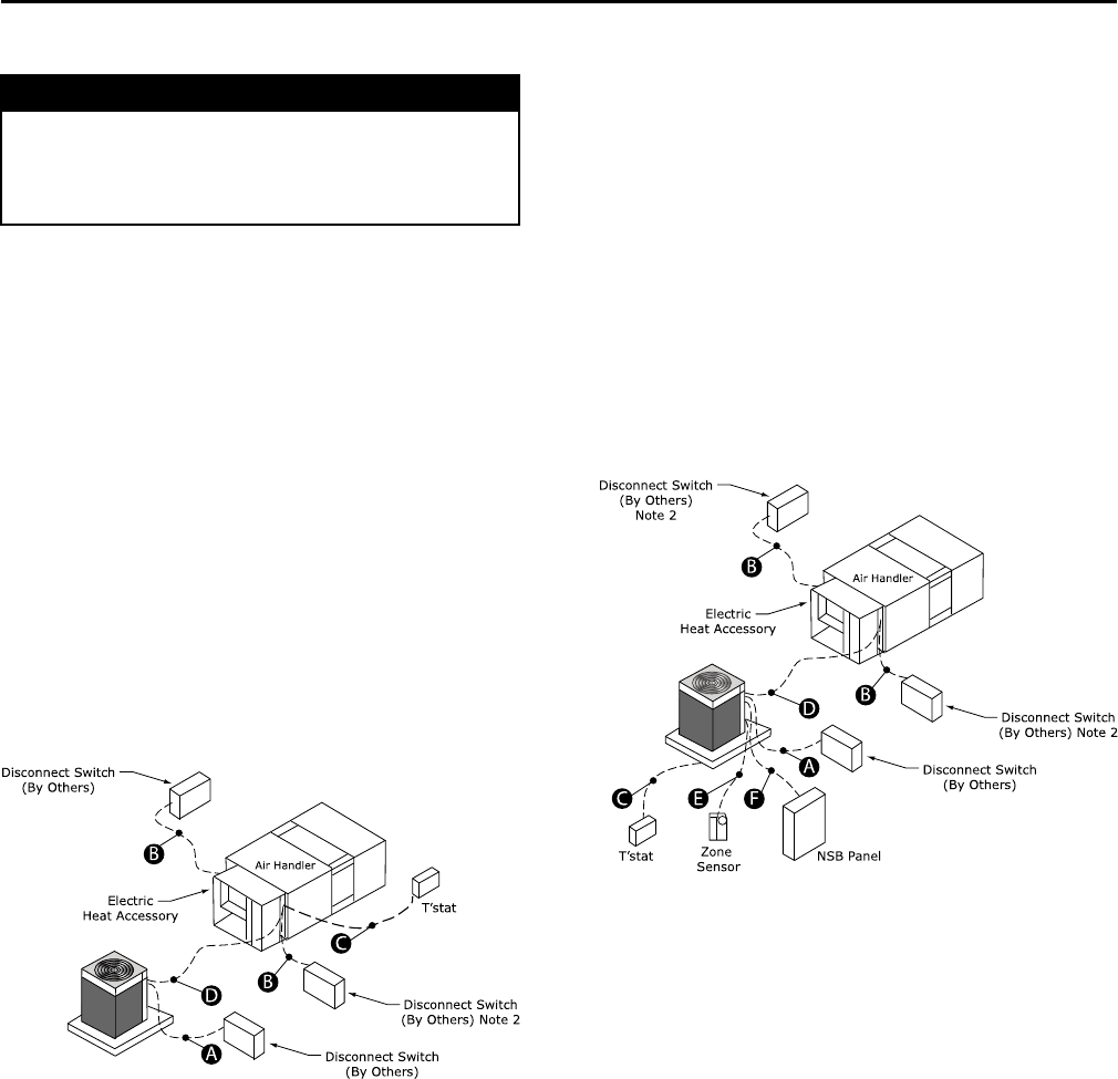
Electromechanical Controls
Wiring shown with dashed lines is to be furnished and
installed by the customer. All customer supplied wiring
must be copper only and must conform to NEC and
local electrical codes. Codes may require line of sight
between disconnect switch and unit.
NNoottee:: When electric heater accessory is used, single
point power entry or dual point power entry is
field optional. Single point power entry option is
through electric heater only.
Figure 20. Electromechanical jobsite connections
A. 3 power wires, line voltage for 3 phase, (2 power wires for
single phase)
B. 3 power wires, line voltage for 3 phase, (2 power wires for
single phase)
C. Cooling only thermostat: 3 to 7 wires depending on stages of
electric heat
D. 3 to 7 wires depending on type of outdoor unit(s)
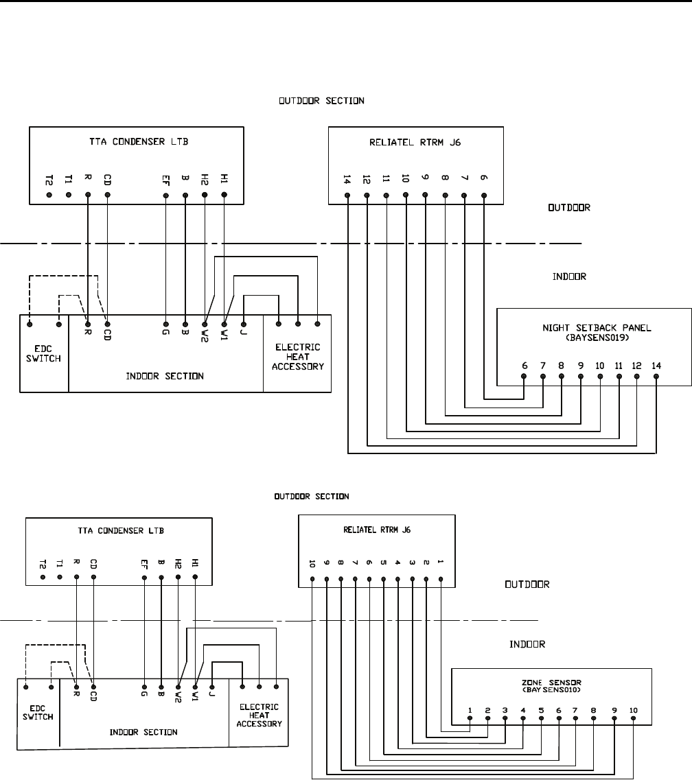
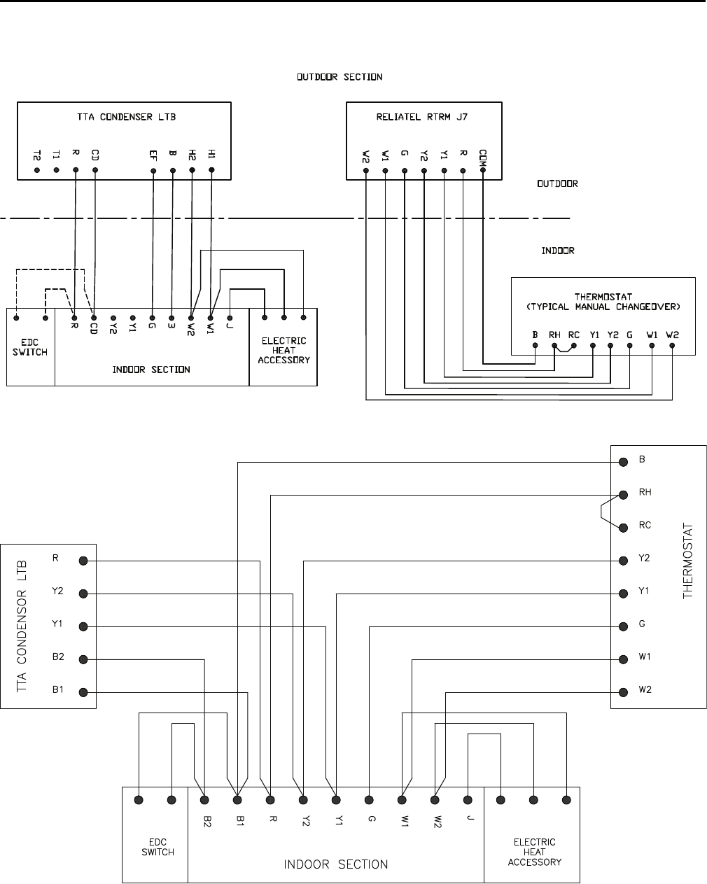
ReliaTel Controls
Wiring shown with dashed lines is to be furnished and
installed by the customer. All customer supplied wiring
must be copper only and must conform to NEC and
local electrical codes. Codes may require line of sight
between disconnect switch and unit.
NNootteess::
1. When electric heater accessory is used,
single point power entry or dual point power
entry is field optional. Single point power
entry option is through electric heater only.
2. ***Choose only one of the following;
Thermostat, Zone Sensor, or NSB Panel.
Figure 21. ReliaTel jobsite connections
A. 3 power wires, line voltage for 3 phase, (2 power wires for
single phase)
B. 3 power wires, line voltage for 3 phase, (2 power wires for
single phase)
C. Cooling only thermostat: 3 to 7 wires depending on stages of
electric heat
D. 3 to 7 wires depending on type of outdoor unit(s)
E. Zone Sensor: 4 to 10 wires depending on zone sensor model(a)
F. Night Setback Panel: 7 wires
(a) For SZVAV air handlers: 4 additional wires are required (2 of which
require twisted pair or shielded wire) in order to make connections
between ReliaTel boards in the condenser and air handler.
IInnssttaallllaattiioonn
34 SS-SVX10E-EN
Electrical Data
Table 5. Electrical characteristics — compressor and condenser fan motors — 60 Hz
Tons
Unit
Model
Number
Compressor Motor Condenser Fan Motor
No. Volts Phase
Amps
No. Volts Phase
Amps
RLA LRA FLA LRA
(Ea.) (Ea.) (Ea.) (Ea.)
6
TTA073G3 1 208-230 3 21.9 136 1 208-230 1 3.1 8.1
TTA073G4 1 460 3 9.1 66.1 1 460 1 1.6 3.8
TTA073GK 1 380 3 11.4 83 1 380 1 2.7 7
TTA073GW 1 575 3 7.4 55.3 1 575 1 1.2 3
7.5
TTA090G3 1 208-230 3 25 164 1 208-230 1 3.1 8.1
TTA090G4 1 460 3 12.9 100 1 460 1 1.6 3.8
TTA090GK 1 380 3 14.3 94.3 1 380 1 2.7 7
TTA090GW 1 575 3 10.6 78 1 575 1 1.2 3
7.5
TTA090H3 2 208-230 3 14.6 83.1 1 208-230 1 3.1 8.1
TTA090H4 2 460 3 6.8 41 1 460 1 1.6 3.8
TTA090HK 2 380 3 8.5 51.8 1 380 1 2.7 7
TTA090HW 2 575 3 4.9 33 1 575 1 1.2 3
10
TTA120G3 1 208-230 3 36 267 1 208-230 1 5 14.4
TTA120G4 1 460 3 19 142 1 460 1 2.5 5.8
TTA120GK 1 380 3 27 160 1 380 1 3.4 7.8
TTA120GW 1 575 3 17 103 1 575 1 2 5.1
10
TTA120H3 2 208-230 3 16 110 1 208-230 1 5 14.4
TTA120H4 2 460 3 7.8 52 1 460 1 2.5 5.8
TTA120HK 2 380 3 10.4 65.6 1 380 1 3.4 7.8
TTA120HW 2 575 3 6 38.9 1 575 1 2 5.1
10
TTA120F3 2 208-230 3 17.6 123 1 208-230 1 5 14.4
TTA120F4 2 460 3 9.6 62 1 460 1 2.5 5.8
TTA120FW 2 575 3 6.1 40 1 575 1 2 5.1
12.5
TTA150E3 2 208-230 3 22.4 149 1 208-230 1 5 14.4
TTA150E4 2 460 3 10.6 75 1 460 1 2.5 5.8
TTA150EK 2 380 3 11.3 88 1 380 1 3.4 7.8
TTA150EW 2 575 3 8.6 54 1 575 1 2 5.1
15
TTA180E3 2 208-230 3 25 164 2 208-230 1 5 14.4
TTA180E4 2 460 3 12.2 100 2 460 1 2.5 5.8
TTA180EK 2 380 3 14.3 94.3 2 380 1 3.4 7.8
TTA180EW 2 575 3 9.6 78 2 575 1 2 5.1
15
TTA180F3 2 208-230 3 25 164 2 208-230 1 5 14.4
TTA180F4 2 460 3 12.2 100 2 460 1 2.5 5.8
TTA180FK 2 380 3 14.3 94.3 2 380 1 3.4 7.8
TTA180FW 2 575 3 9.9 78 2 575 1 2 5.1
20
TTA240E3 2 208-230 3 39.1 267 2 208-230 1 5 14.4
TTA240E4 2 460 3 18.6 142 2 460 1 2.5 5.8
TTA240EK 2 380 3 23.1 160 2 380 1 3.4 7.8
TTA240EW 2 575 3 15.4 103 2 575 1 2 5.1
20
TTA240F3 2 208-230 3 39.1 267 2 208-230 1 5 14.4
TTA240F4 2 460 3 19.8 142 2 460 1 2.5 5.8
TTA240FK 2 380 3 23.1 160 2 380 1 3.4 7.8
TTA240FW 2 575 3 15.8 103 2 575 1 2 5.1
SS-SVX10E-EN 35
Table 5. Electrical characteristics — compressor and condenser fan motors — 60 Hz (continued)
Tons
Unit
Model
Number
Compressor Motor Condenser Fan Motor
No. Volts Phase
Amps
No. Volts Phase
Amps
RLA LRA FLA LRA
(Ea.) (Ea.) (Ea.) (Ea.)
25
TTA300F3 2 208-230 3 53.6 245 2 208-230 1 5 14.4
TTA300F4 2 460 3 20.7 125 2 460 1 2.5 5.8
TTA300FK 2 380 3 26.4 145 2 380 1 3.4 7.8
TTA300FW 2 575 3 16.4 100 2 575 1 2 5.1
Note: Electrical characteristics reflect nameplate values and are calculated in accordance with cULus and ARI specifications.
Table 6. Unit wiring — condensing units — 60 Hz
Tons Unit Model Number Unit Operating
Voltage Range Minimum Circuit Ampacity Maximum Fuse or HACR
Circuit Breaker Size
6
TTA073G3 187-253 30.5 50
TTA073G4 414-506 13 20
TTA073GK 342-418 17 25
TTA073GW 518-632 10.5 15
7.5
TTA090G3 187-253 34.4 45
TTA090G4 414-506 17.7 25
TTA090GK 342-418 20.6 25
TTA090GW 518-632 14.5 20
7.5
TTA090H3 187-253 36 50
TTA090H4 414-506 16.9 20
TTA090HK 342-418 21.8 30
TTA090HW 518-632 12.2 15
10
TTA120G3 187-253 42.6 60
TTA120G4 414-506 23.4 30
TTA120GK 342-418 28.2 35
TTA120GW 518-632 17.5 25
10
TTA120H3 187-253 41 45
TTA120H4 414-506 20.1 25
TTA120HK 342-418 26.9 30
TTA120HW 518-632 15.5 20
10
TTA120F3 187-253 44.6 50
TTA120F4 414-506 24.1 30
TTA120FW 518-632 15.7 20
12.5
TTA150E3 187-253 55.4 70
TTA150E4 414-506 26.4 30
TTA150EK 342-418 28.8 35
TTA150EW 518-632 21.4 25
15
TTA180E3 187-253 66.3 80
TTA180E4 414-506 32.5 40
TTA180EK 342-418 39 45
TTA180EW 518-632 25.6 30
15
TTA180F3 187-253 66.3 80
TTA180F4 414-506 32.5 40
TTA180FK 342-418 39 45
TTA180FW 518-632 26.3 30
EElleeccttrriiccaall DDaattaa
36 SS-SVX10E-EN
Table 6. Unit wiring — condensing units — 60 Hz (continued)
Tons Unit Model Number Unit Operating
Voltage Range Minimum Circuit Ampacity Maximum Fuse or HACR
Circuit Breaker Size
20
TTA240E3 187-253 98 110
TTA240E4 414-506 46.9 60
TTA240EK 342-418 58.8 70
TTA240EW 518-632 38.7 45
20
TTA240F3 187-253 98 110
TTA240F4 414-506 49.6 60
TTA240FK 342-418 58.8 70
TTA240FW 518-632 39.6 45
25
TTA300F3 187-253 130.6 150
TTA300F4 414-506 51.6 60
TTA300FK 342-418 66.2 70
TTA300FW 518-632 40.9 45
Notes:
1. Electrical characteristics reflect nameplate values and are calculated in accordance with cULus and ARI specifications. 7.5 and 10 ton
values are system rated; 12.5 - 25 ton values are condensing unit only rated.
2. HACR type circuit breaker per NEC.
Table 7. Electrical characteristics — compressor and condenser fan motors — 50 Hz
Tons Unit Model
Number
Compressor Motor Condenser Fan Motor
No. Volts Phase
Amps
No. Volts Phase
Amps
RLA
(Ea.)
LRA
(Ea.)
RLA
(Ea.)
LRA
(Ea.)
5 TTA061GD 1 380-415-50 3 8.9 67.1 1 380-415-50 1 1.6 3.8
6.25 TTA076GD 1 380-415-50 3 12.5 101 1 380-415-50 1 1.6 3.8
TTA076HD 2 380-415-50 3 6.7 43 1 380-415-50 1 1.6 3.8
8.33
TTA101GD 1 380-415-50 3 19 142 1 380-415-50 1 1.9 5.8
TTA101HD 2 380-415-50 3 8 51.5 1 380-415-50 1 1.9 5.8
TTA101FD 2 380-415-50 3 9.9 64 1 380-415-50 1 1.9 5.8
10.4 TTA126ED 2 380-415-50 3 10.9 75 1 380-415-50 1 1.9 5.8
13 TTA156ED 2 380-415-50 3 12.5 101 2 380-415-50 1 1.9 5.8
TTA156FD 2 380-415-50 3 12.5 101 2 380-415-50 1 1.9 5.8
16.7 TTA201ED 2 380-415-50 3 19.1 142 2 380-415-50 1 1.9 5.8
TTA201FD 2 380-415-50 3 19.1 142 2 380-415-50 1 1.9 5.8
20.9 TTA251FD 2 380-415-50 3 20.7 118 2 380-415-50 1 1.9 5.8
Note: Electrical characteristics reflect nameplate values and are calculated in accordance with UL and ARI
specifications.
Table 8. Unit wiring — condensing units — 50 Hz
Tons
Unit Model
Number
Unit Operating
Voltage
Maximum
Circuit
Ampacity
Maximum Fuse
Size or Maximum
Circuit Breaker
5 TTA061GD 380/415 12.7 20
6.25 TTA076GD 380/415 17.3 25
TTA076HD 380/415 16.7 20
8.33
TTA101GD 380/415 25.7 40
TTA101HD 380/415 19.9 25
TTA101FD 380/415 24.2 30
10.4 TTA126ED 380/415 26.4 30
13 TTA156ED 380/415 32 40
TTA156FD 380/415 32 40
EElleeccttrriiccaall DDaattaa
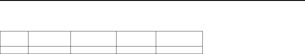
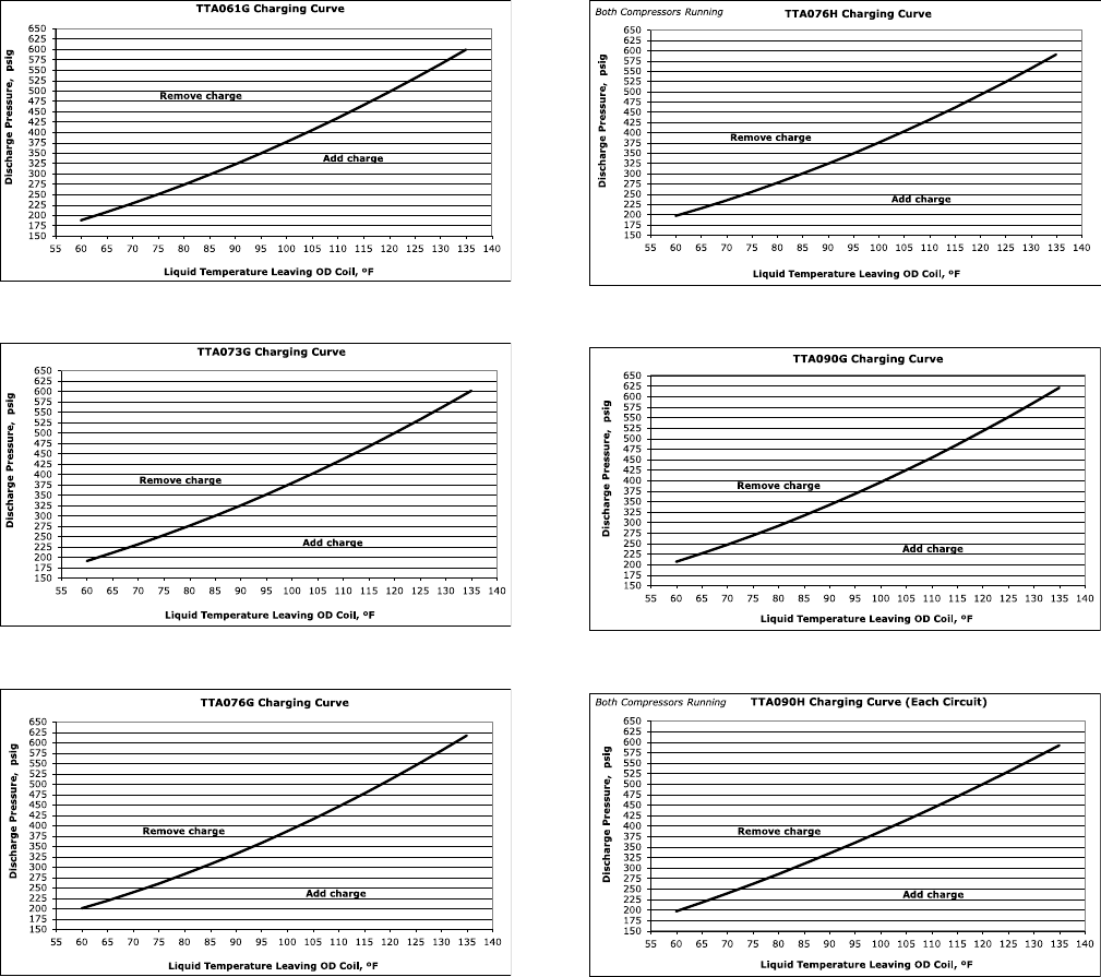
38 SS-SVX10E-EN
Charging Charts and Superheat
Figure 28. TTA061G
Figure 29. TTA073G
Figure 30. TTA076G
Figure 31. TTA076H
Figure 32. TTA090G
Figure 33. TTA090H
SS-SVX10E-EN 41
Figure 47. TTA201F
Figure 48. TTA240E
Figure 49. TTA240F
Figure 50. TTA251F
Figure 51. TTA300F
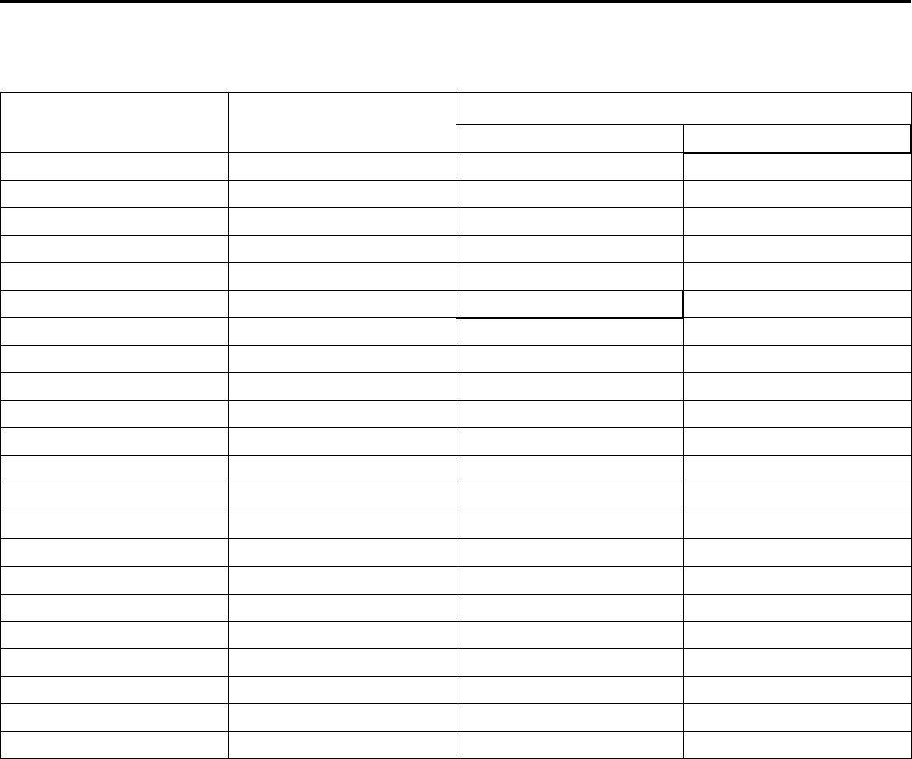
Table 9. TTA superheat with matched TWE air handler
Condenser Air Handler
Cooling Superheat
Circuit 1 Circuit 2
TTA061G TWE076D 13.23 —
TTA073G TWE090D 13.23 —
CChhaarrggiinngg CChhaarrttss aanndd SSuuppeerrhheeaatt
42 SS-SVX10E-EN
Table 9. TTA superheat with matched TWE air handler (continued)
Condenser Air Handler
Cooling Superheat
Circuit 1 Circuit 2
TTA076G TWE076D 15.51 —
TTA076H TWE076E 10.44 10.58
TTA090G TWE090D 15.51 —
TTA090H TWE090E 10.44 10.58
TTA101G TWE101D 13.68 —
TTA101H TWE101E 15.19 16.72
TTA101F TWE101D 11.4 —
TTA120G TWE120D 13.68 —
TTA120H TWE120E 15.19 16.72
TTA120F TWE120D 11.4 —
TTA126E TWE126E 13.6 13.6
TTA150E TWE150E 13.6 13.6
TTA156E TWE156E 18.4 18.4
TTA156F TWE156E 19.1 —
TTA180E TWE180E 18.4 18.4
TTA180F TWE180E 19.1 —
TTA201E TWE201E 15.2 15.2
TTA201F TWE201E 12.9 —
TTA240E TWE240E 15.2 15.2
TTA240F TWE240E 12.9 —
TTA251F TWE251E 16.2 —
TTA300F TWE251E 16.2 —
Notes:
1. An adjustable TXV is provided for each circuit in the TWE and TWA models. If the application causes the superheat to deviate from the values
shown above by more than 1 degree - after the system has achieved steady state - the TXV should be adjusted to provide the values shown as
measured at the compressor.
2. The values given above have been tested and are approved for the matched sets shown. If an alternate combination is used, an expansion device
should be used that provides 16-20°F degrees of superheat measured at the compressor.
3. Check and adjust superheat using this table, then compare with charging chart to determine if charge corrections are necessary.
CChhaarrggiinngg CChhaarrttss aanndd SSuuppeerrhheeaatt
SS-SVX10E-EN 43
Installation Checklist
Complete this checklist once the unit is installed to
verify that all recommended procedures have been
accomplished before starting the system. Do not
operate the system until all items covered by this
checklist are complete.
Inspect unit location for proper required service
clearances.
Inspect unit location for proper free air clearances.
Inspect unit location for secure, level mounting
position.
Remove coil protection boards on microchannel
units.
Refrigerant Piping
Properly sized/constructed liquid and suction lines
connected to stubs at both the indoor and outdoor
units?
Insulated the entire suction line?
Insulated portions of liquid line exposed to
extremes in temperature?
Performed initial leak test?
Evacuated each refrigerant circuit to 500 microns?
Charged each circuit with proper amount of R-
410A?
Electrical Wiring
Provided unit power wiring (with disconnect) to
proper terminals in the unit control section?
Installed system indoor thermostat?
Installed system low voltage interconnecting wiring
to proper terminals of outdoor unit, indoor unit and
system thermostat?
44 SS-SVX10E-EN
Pre-Start
Control Circuit Features
NNoottee:: Not all of these features may be required for your
unit, check electrical schematic.
Discharge Temperature Limit (DTL)
The control’s sensor is located on the discharge line.
This device will shut off the compressor and the
outdoor fan(s) if the discharge temperature exceeds the
DTL setting. Once the discharge temperature has
returned to normal, the compressor will cycle back on.
Low Outdoor Ambient Cooling
The Evaporator Defrost Control is standard equipment
on Air Handlers and will permit low ambient cooling
down to 50°F. For cooling operation down to 0°F, use an
Accessory Head Pressure Control on the outdoor unit.
Evaporator Defrost Control (EDC)
This control is located in the Air Handler. The control’s
sensing tube is embedded vertically in the evaporator
coil, near the center. This device will stop the
compressor if the indoor coil temperature drops below
its setting. The indoor air will still circulate across the
coil bringing the temperature of the coil back up to the
cut-in temperature of the evaporator defrost control.
Low Pressure Cut-Out (LPCO)
This control’s sensor is located in the suction (gas) line,
near the compressor. This control will stop the
compressor and the outdoor fans if suction pressure
drops below the Low Pressure Cut-Out setting. Once
the suction pressure has returned to normal, the
compressor and outdoor fans will cycle back on.
High Pressure Cut-Out (HPCO)
This control’s sensor is located in the discharge line.
This device will shut off the compressor and the
outdoor fan(s) if the discharge pressure exceeds the
High Pressure Cut-Out’s setting. Once the discharge
pressure has returned to normal, the compressor will
cycle back on.
WWAARRNNIINNGG
PPrreevveenntt IInnjjuurryy!!
DDuuee ttoo aaggeennccyy ssaaffeettyy rreeqquuiirreemmeennttss,, nnoo sscchhrraaddeerr
ccoorree iiss ttoo bbee iinnssttaalllleedd bbeenneeaatthh tthhee HHPPCCOO.. RReemmoovvaall
ooff tthhee HHPPCCOO wwiitthhoouutt eevvaaccuuaattiinngg tthhee ssyysstteemm cchhaarrggee
ccoouulldd ccaauussee iinnjjuurryy aanndd rreelleeaassee ooff rreeffrriiggeerraanntt..
Internal Overload Protector (IOL)
This device is embedded in the compressor. It will shut
off the compressor if the discharge temperature of the
compressor exceeds its design trip temperature.
NNoottee:: The IOL will put the compressor back in
operation once the compressor motor heat has
dropped below the trip setting; however, a check
of the refrigerant and electrical systems should
be made to determine the cause and be
corrected.
SS-SVX10E-EN 45
Start-Up
Electromechanical Controls
The 24–volt, electromechanical controls feature a
control transformer and contactor pressure lugs for
power wiring. Once the unit is properly installed and
pre-start procedures are complete, start the unit by
turning the System Switch on the indoor thermostat to
either HHEEAATT,CCOOOOLL or AAUUTTOO. The system should
operate normally.
NNOOTTIICCEE
EEqquuiippmmeenntt DDaammaaggee!!
EEnnssuurree tthhee ddiissccoonnnneecctt ffoorr tthhee iinnddoooorr aaiirr hhaannddlleerr iiss
cclloosseedd bbeeffoorree ooppeerraattiinngg tthhee ssyysstteemm.. OOppeerraattiinngg tthhee
oouuttddoooorr uunniitt wwiitthhoouutt tthhee iinnddoooorr ffaann eenneerrggiizzeedd ccaann
ccaauussee uunniitt ttrriipp--oouutt oonn hhiigghh pprreessssuurree ccoonnttrrooll aanndd//oorr
lliiqquuiidd fflloooodd bbaacckk ttoo tthhee ccoommpprreessssoorr..
General
Operation of the system cooling (and optional heating)
cycles is controlled by the position of the system switch
on the room thermostat. Once the system switch is
placed in either the HHEEAATT or CCOOOOLL position, unit
operation is automatic. The optional automatic
changeover thermostat, when in the AAUUTTOO position,
automatically changes to heat or cool with sufficient
room temperature change.
Evaporator Fan (Indoor Supply Air)
The evaporator fan is controlled by an OONN//AAUUTTOO
switch on the room thermostat. With the switch
positioned at AAUUTTOO and the system operating in the
cooling mode, fan operation coincides with the cooling
run cycles. If the system is equipped with heat and is
operating in the heating mode while the fan switch is at
AAUUTTOO, fan operation coincides with the heating run
cycles. When the fan switch is positioned at OONN, fan
operation is continuous.
Cooling Mode
With the disconnect switch in the OONN position, current
is supplied to the compressor sump heater(s), phase
monitor and control transformer. The sump heater(s)
supplies heat to the compressor(s) during the ““OOffff””
cycle. The phase monitor looks at the incoming power
to verify that there is no reversed phase, no phase
imbalance, and no loss of phase. If the phase monitor
detects any of these three conditions, it will shut off
control voltage. The transformer steps down the line
voltage to 24V for the low voltage control circuit. When
the room thermostat system switch is positioned at
CCOOOOLL and the fan switch is at AAUUTTOO, the compressor
contactor energizes on a call for cooling. When the
contacts of the compressor contactor close, operation
of the compressor and condenser fan begins. The
evaporator fan contactor also energizes on a call for
cooling and initiates evaporator fan operation.
On units with dual circuits, the second stage of cooling
is initiated as a result of the 2-stage thermostat calling
for additional cooling.
ReliaTel Controls
The ReliaTel™ Control is a microelectronic control
feature, which provides operating functions that are
significantly different than conventional
Electromechanical units. The ReliaTel™ Refrigeration
Module (RTRM) uses Proportional/Integral control
algorithms to perform specific unit functions that
govern the unit operation in response to application
conditions.
The RTRM provides compressor anti-short cycle timing
functions through minimum ““OOffff”” and ““OOnn”” timing to
increase reliability, performance and to maximize unit
efficiency. Upon power initialization, the RTRM
performs self-diagnostic checks to ensure that all
internal controls are functioning. It checks the
configuration parameters against the components
connected to the system. The system LED located on
the RTRM module is turned ““OOnn”” within one second
after power-up if all internal operations are okay.
Once the unit is properly installed and pre-start
procedures are complete, start the unit by turning the
System Switch on the indoor thermostat to either
HHEEAATT,CCOOOOLL or AAUUTTOO. The system should operate
normally.
NNOOTTIICCEE
EEqquuiippmmeenntt DDaammaaggee!!
EEnnssuurree tthhee ddiissccoonnnneecctt ffoorr tthhee iinnddoooorr aaiirr hhaannddlleerr iiss
cclloosseedd bbeeffoorree ooppeerraattiinngg tthhee ssyysstteemm.. OOppeerraattiinngg tthhee
oouuttddoooorr uunniitt wwiitthhoouutt tthhee iinnddoooorr ffaann eenneerrggiizzeedd ccaann
ccaauussee uunniitt ttrriipp--oouutt oonn hhiigghh pprreessssuurree ccoonnttrrooll aanndd//oorr
lliiqquuiidd fflloooodd bbaacckk ttoo tthhee ccoommpprreessssoorr..
Control Cooling Mode
For Zone Sensor Control
When the system switch is set to the CCOOOOLL position
and the zone temperature rises above the cooling
setpoint, the RTRM energizes the compressor
contactor, provided the high and low pressure and the
discharge temperature limit controls are closed. When
the compressor contacts close, the compressor and the
outdoor fan motor start to maintain the zone
temperature to within ± 2°F of the sensor setpoint at
the sensed location. On units with dual circuits, the
second stage of cooling is initiated as a result of the
Proportional/Integral control algorithms calling for
additional cooling.

46 SS-SVX10E-EN
For Thermostat Control
When the room thermostat system switch is positioned
at CCOOOOLL and the fan switch is at AAUUTTOO, the RTRM
energizes the compressor contactor, provided the high
and low pressure and the discharge temperature limit
controls are closed. When the contacts of the
compressor contactor close, operation of the
compressor and condenser fan begins. The evaporator
fan contactor also energizes on a call for cooling and
initiates evaporator fan operation. On units with dual
circuits, the second stage of cooling is initiated as a
result of the 2-stage thermostat calling for additional
cooling.
NNoottee:: Irregular unit operation may occur when the unit
is controlled with a triac-switching thermostat.
Please review the approved thermostat vendor
list for all recommended relay-switching
thermostats.
Control Evaporator Fan Operation
When the fan selection switch is set to the AAUUTTOO
position, the RTRM energizes the evaporator fan relay
coil approximately 1 second after energizing the
compressor contactor coil in the cooling mode. In the
heating mode, the RTRM energizes the evaporator fan
relay coil approximately 1 second before energizing the
electric heat contactors.
The RTRM de-energizes the evaporator fan relay coil
approximately 60 seconds on dual compressor units
and 80 seconds on single compressor units after the
cooling requirement has been satisfied to enhance unit
efficiency. When the heating cycle is terminated, the
evaporator fan relay coil is de-energized at the same
time as the heater contactors. When the fan selection
switch is set to the OONN position, the RTRM keeps the
evaporator fan relay coil energized for continuous fan
motor operation.
Control Heating Operation
Electric heat is factory disabled on all split system units
with ReliaTel control (jumper placed between J2-1 and
J2-2 RTRM inputs). To configure the unit for electric
heat, cut or remove the jumper wire between J2-1 and
J2-2 on the RTRM. All split system units with ReliaTel
control are also configured from the factory for only 1-
stage of electric heat (jumper placed between J1-3 and
J1-6 RTRM inputs). To configure the unit for 2-stages of
electric heat, cut or remove the jumper placed between
J1-3 and J1-6 RTRM inputs.
When the system switch is set to the HHEEAATT position
and heating is required, the RTRM energizes the Heat 1
relay coil on the RTRM. When the Heat 1 relay contacts
close, the first stage electric heat contactor is
energized. If the first stage of electric heat cannot
satisfy the heating requirement, the RTRM energizes
the Heat 2 relay coil on the RTRM. When the Heat 2
relay contacts close, the second stage electric heat
contactor is energized. The first and second stages of
heat are cycled ““OOnn”” and ““OOffff”” as required to maintain
the zone.
SSttaarrtt--UUpp
SS-SVX10E-EN 47
Service Test Modes for ReliaTel™™ Controls
Test Modes
Upon power initialization, the RTRM performs self-
diagnostic checks to ensure that all internal controls are
functional. It also checks the configuration parameters
against the components connected to the system. The
system LED located on the RTRM module is turned
““OOnn”” within one second of power-up if internal
operation is okay.
Use one of the following ““TTeesstt”” procedures to bypass
some time delays and to start the unit at the control
panel. Each step of unit operation can be activated
individually by temporarily shorting across the ““TTeesstt””
terminals for 2 to 3 seconds. The system LED located
on the RTRM module will blink when the test mode has
been initiated. The unit can be left in any ““TTeesstt”” step
for up to one hour before it will automatically
terminate, or it can be terminated by opening the main
power disconnect switch. Once the test mode has been
terminated, the system LED will glow continuously and
the unit will revert to the ““SSyysstteemm”” control.
There are three methods in which the ““SSeerrvviiccee TTeesstt””
can be cycled at LTB-Test 1(T1) and LTB-Test 2 (T2).
Step Test Mode
This method initiates the different components of the
unit, one at a time, by temporarily shorting across the
two test terminals for 2 to 3 seconds.
For the initial start-up of the unit, this method allows
the technician to cycle a component ““OOnn”” and have up
to one hour to complete the check. Service Test Mode
will be ignored if a short is present across Test 1 and
Test 2 at start-up.
Resistance Test Mode
This method can be used for start-up when a decade
box for variable resistance outputs is available. This
method initiates the different components of the unit,
one at a time, when a specific resistance value is placed
across the two test terminals. The unit will remain in
the specific test mode for approximately one hour even
though the resistance is left on the test terminals.
Table 10. Service test guide for component operation
TEST STEP MODE FAN COMP 1 COMP 2 HEAT 1 HEAT 2 OHMS
1 Fan On Off Off Off Off 2.2K
2 Cool 1 On On(a) Off Off Off 4.7K
3(b) Cool 2 On On(a) On(a) Off Off 6.8K
4(b) Heat 1 On Off Off On Off 10K
5(b) Heat 2 On Off Off On On 15K
(a) The condenser fans will operate any time a compressor is ON.
(b) Steps for optional accessories and non-applicable modes in unit will be skipped.
Auto Test Mode
This method is not recommended for start-up due to
the short timing between individual component steps.
This method initiates the different components of the
unit, one at a time, when a fixed jumper is installed
across the test terminals.
The unit will start the first test step and change to the
next step every 30 seconds. At the end of the test
mode, control of the unit will automatically revert to the
applied ““SSyysstteemm”” control method. For unit test steps,
test modes, and step resistance values to cycle the
various components, refer to Table 10, p. 47.
48 SS-SVX10E-EN
Troubleshooting
Troubleshooting ReliaTel™
Controls
WWAARRNNIINNGG
LLiivvee EElleeccttrriiccaall CCoommppoonneennttss!!
FFaaiilluurree ttoo ffoollllooww aallll eelleeccttrriiccaall ssaaffeettyy pprreeccaauuttiioonnss
wwhheenn eexxppoosseedd ttoo lliivvee eelleeccttrriiccaall ccoommppoonneennttss ccoouulldd
rreessuulltt iinn ddeeaatthh oorr sseerriioouuss iinnjjuurryy..
WWhheenn iitt iiss nneecceessssaarryy ttoo wwoorrkk wwiitthh lliivvee eelleeccttrriiccaall
ccoommppoonneennttss,, hhaavvee aa qquuaalliiffiieedd lliicceennsseedd eelleeccttrriicciiaann
oorr ootthheerr iinnddiivviidduuaall wwhhoo hhaass bbeeeenn pprrooppeerrllyy ttrraaiinneedd
iinn hhaannddlliinngg lliivvee eelleeccttrriiccaall ccoommppoonneennttss ppeerrffoorrmm
tthheessee ttaasskkss..
The RTRM has the ability to provide the service
personnel with some unit diagnostics and system
status information.
Before turning the main power disconnect switch ““OOffff,,””
follow the steps below to check the ReliaTel™
Refrigeration Module (RTRM). All diagnostics & system
status information stored in the RTRM will be lost when
the main power is turned ““OOffff””.
To prevent injury or death from electrocution, it is the
responsibility of the technician to recognize this hazard
and use extreme care when performing service
procedures with the electrical power energized.
NNoottee:: The J6 & J7 screw terminals must be tightened
in order to accurately measure voltage in the
required steps.
1. Verify that the system LED on the RTRM is burning
continuously. If the LED is lit, go to Step 3.
2. If the LED is not lit, verify that 24 VAC is present
between J1-1 and J1-2. If 24 VAC is present,
proceed to Step 3. If 24 VAC is not present, check
the unit main power supply, check transformer
(TNS1). Proceed to Step 3 if necessary.
3. Utilizing “Method 1,” p. 48 or “Method 2,” p. 49 in
the System Status Checkout Procedure section,
check the following:
• System status
• Heating status
• Cooling status
NNoottee:: If a System failure is indicated, proceed to
Step 4. If no failures are indicated, proceed to
Step 5.
4. If a System failure is indicated, recheck Step 1 and
Step 2. If the LED is not lit in Step 1, and 24 VAC is
present in Step 2, then the RTRM has failed.
Replace the RTRM.
5. If no failures are indicated, use one of the TEST
mode procedures described in the “Service Test
Modes chapter,” p. 47 to start the unit. This
procedure will allow you to check all of the RTRM
outputs, and all of the external controls (relays,
contactors, etc.) that the RTRM outputs energize, for
each respective mode. Proceed to Step 6.
6. Step the system through all of the available modes,
and verify operation of all outputs, controls, and
modes. If a problem in operation is noted in any
mode, you may leave the system in that mode for
up to one hour while troubleshooting. Refer to the
sequence of operations for each mode, to assist in
verifying proper operation. Make the necessary
repairs and proceed to Step 7 and Step 8.
7. If no abnormal operating conditions appear in the
test mode, exit the test mode by turning the power
““OOffff”” at the main power disconnect switch.
8. Refer to the individual component test procedures if
other microelectronic components are suspect.
System Status Checkout
Procedure
““SSyysstteemm SSttaattuuss”” is checked by using one of the
following two methods:
Method 1
If the Zone Sensor Module (ZSM) is equipped with a
remote panel with LED status indication, you can check
the unit within the space. If the ZSM does not have
LED’s, use “Method 2,” p. 49. BAYSENS010B,
BAYSENS011B, BAYSENS119A, BAYSENS020A,
BAYSENS021A, BAYSENS023A, BAYSENS109 and
BAYSENS110 all have the remote panel indication
feature. The LED descriptions are listed below.
•LLEEDD 11 ((SSyysstteemm))
–““OOnn”” during normal operation.
–““OOffff”” if a system failure occurs or the LED fails.
–““FFllaasshhiinngg”” indicates test mode
•LLEEDD 22 ((HHeeaatt))
–““OOnn”” when the heat cycle is operating.
–““OOffff”” when the heat cycle terminates or the LED
fails.
–““FFllaasshhiinngg”” indicates a heating failure.
•LLEEDD 33 ((CCooooll))
–““OOnn”” when the cooling cycle is operating.
–““OOffff”” when the cooling cycle terminates or the
LED fails.
–““FFllaasshhiinngg”” indicates a cooling failure.
The following information describes the complete
listing of failure indication causes.
SS-SVX10E-EN 49
System Failure
Check the voltage between terminals 6 and 9 on J6, it
should read approximately 32 VDC. If no voltage is
present, a System failure has occurred. Refer to Step 4
in the previous section for the recommended
troubleshooting procedure.
Cooling Failure
1. Cooling and heating set point (slide pot) on the
zone sensor has failed. Refer to the “Programmable
& Digital Zone Sensor Test,” p. 50.
2. Zone temperature thermistor ZTEMP on ZTS failed.
Refer to the “Programmable & Digital Zone Sensor
Test,” p. 50.
3. CC1 or CC2 24 VAC control circuit has opened,
check CC1 & CC2 coils, and any of the controls
below that apply to the unit (HPC1, HPC2, DTL1,
DTL2).
4. LPC1 has opened during the 3 minute minimum “on
time” during 4 consecutive compressor starts,
check LPC1 or LPC2 by testing voltage between the
J1-8 & J3-2 terminals on the RTRM and ground. If
24 VAC is present, the LPCs have not tripped. If no
voltage is present, LPCs have tripped.
Simultaneous Heat and Cool Failure
WWAARRNNIINNGG
LLiivvee EElleeccttrriiccaall CCoommppoonneennttss!!
FFaaiilluurree ttoo ffoollllooww aallll eelleeccttrriiccaall ssaaffeettyy pprreeccaauuttiioonnss
wwhheenn eexxppoosseedd ttoo lliivvee eelleeccttrriiccaall ccoommppoonneennttss ccoouulldd
rreessuulltt iinn ddeeaatthh oorr sseerriioouuss iinnjjuurryy..
WWhheenn iitt iiss nneecceessssaarryy ttoo wwoorrkk wwiitthh lliivvee eelleeccttrriiccaall
ccoommppoonneennttss,, hhaavvee aa qquuaalliiffiieedd lliicceennsseedd eelleeccttrriicciiaann
oorr ootthheerr iinnddiivviidduuaall wwhhoo hhaass bbeeeenn pprrooppeerrllyy ttrraaiinneedd
iinn hhaannddlliinngg lliivvee eelleeccttrriiccaall ccoommppoonneennttss ppeerrffoorrmm
tthheessee ttaasskkss..
• Emergency Stop is activated.
Method 2
The second method for determining system status is
done by checking voltage readings at the RTRM (J6).
The system indication descriptions and the
approximate voltages are listed below.
System Failure
Measure the voltage between terminals J6-9 & J6-6.
•NNoorrmmaall OOppeerraattiioonn = approximately 32 VDC
•SSyysstteemm FFaaiilluurree = less than 1 VDC, approximately
0.75 VDC
•TTeesstt MMooddee = voltage alternates between 32 VDC &
0.75 VDC
Heat Failure
Measure the voltage between terminals J6-7 & J6-6.
•HHeeaatt OOppeerraattiinngg = approximately 32 VDC
•HHeeaatt OOffff = less than 1 VDC, approximately 0.75 VDC
•HHeeaattiinngg FFaaiilluurree = voltage alternates between 32
VDC & 0.75 VDC
Cool Failure
Measure the voltage between terminals J6-8 & J6-6.
•CCooooll OOppeerraattiinngg = approximately 32 VDC
•CCooooll OOffff = less than 1 VDC, approximately 0.75 VDC
•CCoooolliinngg FFaaiilluurree = voltage alternates between 32
VDC & 0.75 VDC
To use LED’s for quick status information at the unit,
purchase a BAYSENS010B ZSM and connect wires with
alligator clamps to terminals 6 through 10. Connected
each respective terminal wire (6 through 10) from the
Zone Sensor to the unit J6 terminals 6 through 10.
NNoottee:: If the system is equipped with a programmable
zone sensor, (BAYSENS119A, or BAYSENS023A),
the LED indicators will not function while the
BAYSENS010A is connected.
Temperature Tests
NNoottee:: These procedures are not for programmable or
digital models and are conducted with the Zone
Sensor Module electrically removed from the
system.
Test 1 - Zone Temperature Thermistor
(ZTEMP)
This component can be tested by measuring the
resistance between terminals 1 and 2 on the Zone
Temperature Sensor. See Table 11, p. 49 for typical
indoor temperatures, and corresponding resistive
values.
Table 11. Typical indoor temperatures and values
Zone Temperature Nominal Resistance
50°F or 10.0°C 19.9 Kohms
55°F or 12.8°C 17.47 Kohms
60°F or 15.6°C 15.3 Kohms
65°F or 18.3°C 13.49 Kohms
70°F or 21.1°C 11.9 Kohms
75°F or 23.9°C 10.50 Kohms
80°F or 26.7°C 9.3 Kohms
85°F or 29.4°C 8.25 Kohms
90°F or 32.2°C 7.3 Kohms
Test 2 - Cooling Set Point (CSP) and
Heating Set Point (HSP)
CCooooll SSPP = Terminals 2 and 3
TTrroouubblleesshhoooottiinngg
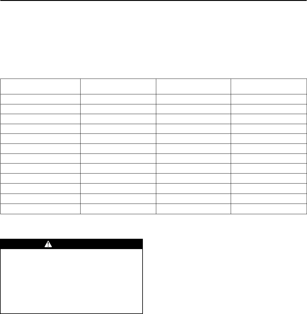
50 SS-SVX10E-EN
Range = 100 to 900 Ohms approximate
HHeeaatt SSPP = Terminals 2 and 5
Range = 100 to 900 Ohms approximate
Test 3 - System Mode and Fan Selection
The combined resistance of the MMOODDEE selection switch
and the FFAANN selection switch can be measured
between terminals 2 and 4 on the Zone Sensor. The
possible switch combinations are listed in Table 12, p.
50 with their corresponding resistance values.
Table 12. Test 3 - system mode and fan selection
Resistance Valves(Ohms)
Zone Sensor Unit/Fan
Mode Local Unit Mode Local Fan Mode
2.32K Off/Auto Off Auto
4.87K Cool/Auto Cool Auto
7.68K Auto/Auto Auto Auto
10.77K Off/On Off On
13.32K Cool/On Cool On
16.13K Auto/On Auto On
19.48K Heat/Auto Heat Auto
27.93K Heat/On Heat On
35.0K Emergency Heat/Auto Emergency Heat Auto
43.45K Emergency Heat/On Emergency Heat On
Out of Range (Short) INVALID/Short Invalid (CV), Auto (VAV) Invalid
Out of Range (Open) INVALID/Open Invalid (CV), Off (VAV) Invalid
Test 4 - LED Indicator Test (SYS ON,
HEAT, & COOL)
WWAARRNNIINNGG
LLiivvee EElleeccttrriiccaall CCoommppoonneennttss!!
FFaaiilluurree ttoo ffoollllooww aallll eelleeccttrriiccaall ssaaffeettyy pprreeccaauuttiioonnss
wwhheenn eexxppoosseedd ttoo lliivvee eelleeccttrriiccaall ccoommppoonneennttss ccoouulldd
rreessuulltt iinn ddeeaatthh oorr sseerriioouuss iinnjjuurryy..
WWhheenn iitt iiss nneecceessssaarryy ttoo wwoorrkk wwiitthh lliivvee eelleeccttrriiccaall
ccoommppoonneennttss,, hhaavvee aa qquuaalliiffiieedd lliicceennsseedd eelleeccttrriicciiaann
oorr ootthheerr iinnddiivviidduuaall wwhhoo hhaass bbeeeenn pprrooppeerrllyy ttrraaiinneedd
iinn hhaannddlliinngg lliivvee eelleeccttrriiccaall ccoommppoonneennttss ppeerrffoorrmm
tthheessee ttaasskkss..
Method 1
Testing the LED using a meter with diode test function.
Test both forward and reverse bias. Forward bias
should measure a voltage drop of 1.5 to 2.5 volts,
depending on your meter. Reverse bias will show an
Over Load, or open circuit indication if LED is
functional.
Method 2
Testing the LED with an analog Ohmmeter. Connect
Ohmmeter across LED in one direction, then reverse
the leads for the opposite direction. The LED should
have at least 100 times more resistance in reverse
direction, as compared with the forward direction. If
high resistance in both directions, LED is open. If low in
both directions, LED is shorted.
Method 3
To test LED’s with ZSM connected to unit, test voltages
at LED terminals on ZSM. A measurement of 32 VDC,
across an unlit LED, means the LED has failed.
IImmppoorrttaanntt:: Measurements should be made from LED
common (ZSM terminal 6 to respective LED
terminal).
Programmable & Digital Zone
Sensor Test
Testing Serial Communication Voltage
1. Verify 24 VAC is present between terminals J6-14 &
J6-11.
TTrroouubblleesshhoooottiinngg
SS-SVX10E-EN 51
WWAARRNNIINNGG
LLiivvee EElleeccttrriiccaall CCoommppoonneennttss!!
FFaaiilluurree ttoo ffoollllooww aallll eelleeccttrriiccaall ssaaffeettyy pprreeccaauuttiioonnss
wwhheenn eexxppoosseedd ttoo lliivvee eelleeccttrriiccaall ccoommppoonneennttss ccoouulldd
rreessuulltt iinn ddeeaatthh oorr sseerriioouuss iinnjjuurryy..
WWhheenn iitt iiss nneecceessssaarryy ttoo wwoorrkk wwiitthh lliivvee eelleeccttrriiccaall
ccoommppoonneennttss,, hhaavvee aa qquuaalliiffiieedd lliicceennsseedd eelleeccttrriicciiaann
oorr ootthheerr iinnddiivviidduuaall wwhhoo hhaass bbeeeenn pprrooppeerrllyy ttrraaiinneedd
iinn hhaannddlliinngg lliivvee eelleeccttrriiccaall ccoommppoonneennttss ppeerrffoorrmm
tthheessee ttaasskkss..
2. Disconnect wires from J6-11 and J6-12. Measure
the voltage between J6-11 and J6-12, should be
about 32 VDC.
3. Reconnect wires to terminals J6-11 and J6-12.
Measure voltage again between J6-11 and J6-12,
voltage should flash high and low every 0.5
seconds. The voltage on the low end will measure
about 19 VDC, while the voltage on the high end
will measure from approximately 24 to 38 VDC.
4. Verify all modes of operation, by running the unit
through all of the steps in “Service Test Modes for
ReliaTel Controls,” p. 47.
5. After verifying proper unit operation, exit the test
mode. Turn the fan on continuously at the ZSM, by
pressing the button with the fan symbol. If the fan
comes on and runs continuously, the ZSM is good.
If you are not able to turn the fan on, the ZSM is
defective.
RLCI Loss of Communications
If the RLCI loses input from the building management
system, the RTRM will control in the default mode after
approximately 15 minutes. If the RTRM loses the
Heating and Cooling setpoint input, the RTRM will
control in the default mode instantaneously. The
temperature sensing thermistor in the Zone Sensor
Module is the only component required for the
““DDeeffaauulltt MMooddee”” to operate.
Resetting Cooling and Heating
Lockouts
Cooling Failures and Heating Lockouts are reset in an
identical manner.“Method 1,” p. 51 explains resetting
the system from the space; “Method 2,” p. 51 explains
resetting the system at the unit.
NNoottee:: Before resetting Cooling Failures and Heating
Lockouts check the Failure Status Diagnostics by
the methods previously explained. Diagnostics
will be lost when the power to the unit is
disconnected.
Method 1
To reset the system from the space, turn the MMOODDEE
selection switch at the zone sensor to the OOFFFF position.
After approximately 30 seconds, turn the MMOODDEE
selection switch to the desired mode, i.e. HHEEAATT,CCOOOOLL,
or AAUUTTOO.
Method 2
To reset the system at the unit, cycle the unit power by
turning the disconnect switch OOFFFF and then OONN
Lockouts can be cleared through the building
management system. Refer to the building
management system instructions for more
information.
Zone Temperature Sensor (ZTS)
Service Indicator
The ZSM SERVICE LED is a generic indicator that will
signal the closing of a Normally Open switch at any
time, providing the Indoor Motor (IDM) is operating.
This indicator is usually used to indicate an airside fan
failure.
The RTRM will ignore the closing of this Normally
Open switch for 2 (±1) minutes. This helps prevent
nuisance SERVICE LED indications.
TTrroouubblleesshhoooottiinngg
52 SS-SVX10E-EN
Maintenance
WWAARRNNIINNGG
HHaazzaarrddoouuss VVoollttaaggee ww//CCaappaacciittoorrss!!
FFaaiilluurree ttoo ddiissccoonnnneecctt ppoowweerr aanndd ddiisscchhaarrggee
ccaappaacciittoorrss bbeeffoorree sseerrvviicciinngg ccoouulldd rreessuulltt iinn ddeeaatthh oorr
sseerriioouuss iinnjjuurryy..
DDiissccoonnnneecctt aallll eelleeccttrriicc ppoowweerr,, iinncclluuddiinngg rreemmoottee
ddiissccoonnnneeccttss aanndd ddiisscchhaarrggee aallll mmoottoorr ssttaarrtt//rruunn
ccaappaacciittoorrss bbeeffoorree sseerrvviicciinngg.. FFoollllooww pprrooppeerr lloocckkoouutt//
ttaaggoouutt pprroocceedduurreess ttoo eennssuurree tthhee ppoowweerr ccaannnnoott bbee
iinnaaddvveerrtteennttllyy eenneerrggiizzeedd.. FFoorr vvaarriiaabbllee ffrreeqquueennccyy
ddrriivveess oorr ootthheerr eenneerrggyy ssttoorriinngg ccoommppoonneennttss
pprroovviiddeedd bbyy TTrraannee oorr ootthheerrss,, rreeffeerr ttoo tthhee
aapppprroopprriiaattee mmaannuuffaaccttuurreerr’’ss lliitteerraattuurree ffoorr
aalllloowwaabbllee wwaaiittiinngg ppeerriiooddss ffoorr ddiisscchhaarrggee ooff
ccaappaacciittoorrss.. VVeerriiffyy wwiitthh aann aapppprroopprriiaattee vvoollttmmeetteerr
tthhaatt aallll ccaappaacciittoorrss hhaavvee ddiisscchhaarrggeedd..
FFoorr aaddddiittiioonnaall iinnffoorrmmaattiioonn rreeggaarrddiinngg tthhee ssaaffee
ddiisscchhaarrggee ooff ccaappaacciittoorrss,, sseeee PPRROODD--SSVVBB0066AA--EENN..
NNOOTTIICCEE
OOppeerraattiinngg UUnnddeerr VVaaccuuuumm!!
FFaaiilluurree ttoo ffoollllooww tthheessee iinnssttrruuccttiioonnss wwiillll rreessuulltt iinn
ccoommpprreessssoorr ffaaiilluurree..
DDoo nnoott ooppeerraattee oorr aappppllyy ppoowweerr ttoo tthhee ccoommpprreessssoorr
wwhhiillee uunnddeerr aa vvaaccuuuumm..
Perform all of the indicated maintenance procedures at
the intervals scheduled. This will prolong the life of the
unit and reduce the possibility of costly equipment
failure.
Monthly
Conduct the following maintenance inspections once
per month.
Check unit wiring to ensure all connections are tight
and that the wiring insulation is intact.
Inspect the condenser coils for dirt and debris. If the
coils appear dirty, clean them.
With the unit operating in the cooling mode, check
the suction and discharge pressures and compare
them with Pressure Curve values in unit Service
Facts. Record these readings on the “Maintenance
Log,” p. 54.
Annually (Cooling Season)
The following maintenance procedures must be
performed at the beginning of each cooling season to
ensure efficient unit operation.
Perform all of the monthly maintenance
inspections.
With the unit operating, check unit superheat and
record the reading in the “Maintenance Log,” p. 54.
Remove any accumulation of dust and/or dirt from
the unit casing.
Remove corrosion from any surface and repaint.
Check the gasket around the control panel door to
ensure it fits correctly and is in good condition to
prevent water leakage.
Inspect the control panel wiring to ensure that all
connections are tight and that the insulation is
intact.
NNoottee:: Condenser fan motors are permanently
lubricated.
Check refrigerant piping and fittings for leaks
Inspect the condenser coils for dirt and debris. If the
coils appear dirty, clean them.
Coil Cleaning
Regular coil maintenance, including annual cleaning-
enhances the unit's operating efficiency by minimizing:
• compressor head pressure and amperage draw
• water carryover
• fan brake horsepower
• static pressure losses
At least once each year — or more often if the unit is
located in a “dirty” environment — clean the coil using
the instructions outlined below. Be sure to follow these
instructions as closely as possible to avoid damaging
the coils.
Tube and Fin
NNoottee:: To clean refrigerant coils, use a soft brush and a
sprayer. Contact your local Parts Center for
appropriate detergents.
1. Remove enough panels from the unit to gain safe
access to coil.
2. Straighten any bent coil fins with a fin comb.
3. Remove loose dirt and debris from both sides of the
coil with a soft brush.
4. Mix the detergent with water according to the
manufacturer's instructions. If desired, heat the
solution to 150° F maximum to improve its
cleansing capability.
5. Pour the cleaning solution into the sprayer.
6. Spray the leaving-airflow side of the coil first; then
spray the opposite side of the coil. Allow the
cleaning solution to stand on the coil for five
minutes.
7. Rinse both sides of the coil with cool, clean water.
8. Inspect both sides of the coil; if it still appears to be
dirty, repeat Step 7 and 8.
9. Reinstall all of the components and panels removed

SS-SVX10E-EN 53
in Step 1; then restore power to the unit.
10. Using a fin comb, straighten any coil fins that were
inadvertently bent during the cleaning process.
Microchannel (MCHE) Coils
NNOOTTIICCEE
CCooiill DDaammaaggee!!
FFaaiilluurree ttoo ffoollllooww iinnssttrruuccttiioonnss bbeellooww ccoouulldd rreessuulltt iinn
ccooiill ddaammaaggee..
DDOO NNOOTT uussee aannyy ddeetteerrggeennttss wwiitthh mmiiccrroocchhaannnneell
ccoonnddeennsseerr ccooiillss..
UUssee pprreessssuurriizzeedd wwaatteerr oorr aaiirr OONNLLYY,, wwiitthh pprreessssuurree
nnoo ggrreeaatteerr tthhaann 660000ppssii..
FFoorr aaddddiittiioonnaall iinnffoorrmmaattiioonn rreeggaarrddiinngg tthhee pprrooppeerr
mmiiccrroocchhaannnneell ccooiill cclleeaanniinngg pprroocceedduurree,, rreeffeerr ttoo RRTT--
SSVVBB8833**--EENN
Due to the soft material and thin walls of the MCHE
coils, the traditional field maintenance method
recommended for Round Tube Plate Fin (RTPF) coils
does not apply to microchannel coils. Moreover,
chemical cleaners are a risk factor to MCHE due to the
material of the coil. The manufacturer does not
recommend the use of chemical cleaners to clean
microchannel coils. Using chemical cleaners could lead
to warranty claims being further evaluated for validity
and failure analysis.
The recommended cleaning method for microchannel
condenser coils is pressurized water or air with a non-
pinpoint nozzle and an ECU of at least 180 with
pressure no greater than 600 psi. To minimize the risk
of coil damage, approach the cleaning of the coil with
the pressure washer aimed perpendicular to the face of
the coil during cleaning. Optimum clearance between
the sprayer nozzle and the microchannel coil is 1”–3”.
MMaaiinntteennaannccee
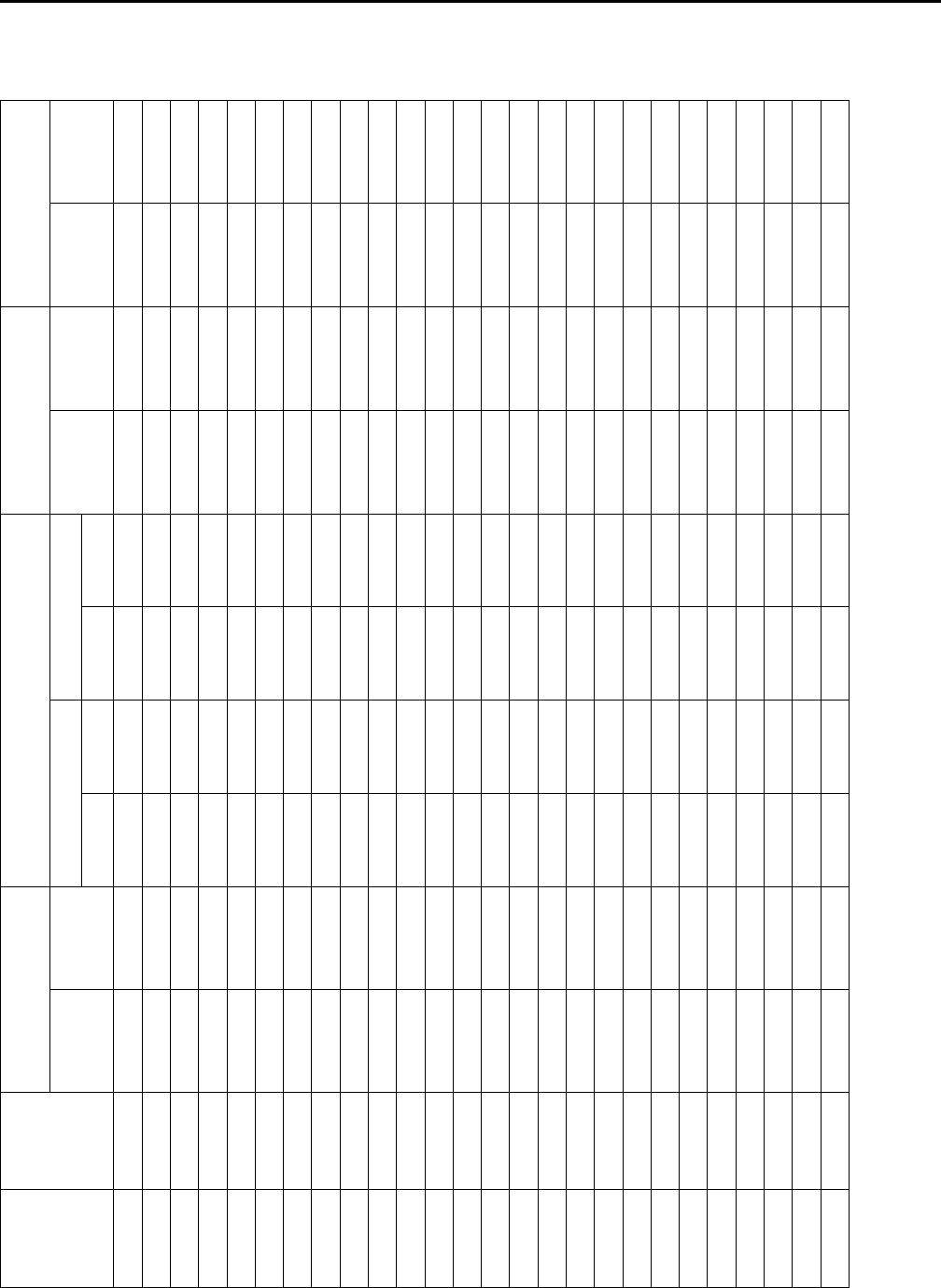
54 SS-SVX10E-EN
Maintenance Log
Date
Ambient
Temp.
(°F)
Evaporator Entering Air Compressor
Superheat (°F)
(at compressor)
Subcooling (°F)
(at service valve)
Dry
Bulb
Wet
Bulb
Suction Pressure Discharge Pressure
Circuit #1 Circuit #2 Circuit #1 Circuit #2
(C1) (C2) (C1) (C2)
Note: Perform each inspection once per month (during cooling season) while unit is operating
MMaaiinntteennaannccee

SS-SVX10E-EN 55
Wiring Diagram Matrix
Table 13. Wiring schematics R-410A cooling
Model
Number Ton Refrigerant
Circuit Voltage Hz Ph Schematics Connection Diagrams
ReliaTel Electromechanical ReliaTel Electromechanical
TTA061GD 5 Single 380-415 50 3 2313-0403 2313-0404 2313-0416 2313-0413
TTA073G3 6 Single 208-230 60 3 2313-0403 2313-0404 2313-0416 2313-0413
TTA073G4 6 Single 460 60 3 2313-0403 2313-0404 2313-0416 2313-0413
TTA073GW 6 Single 575 60 3 2313-0403 2313-0404 2313-0416 2313-0413
TTA073GK 6 Single 380 60 3 2313-0403 2313-0404 2313-0416 2313-0413
TTA073H3 6 Dual 208-230 60 3 1213-1507 1213-1503 2313-0416 2313-0413
TTA073H4 6 Dual 460 60 3 1213-1507 1213-1503 1213-1517 1213-1512
TTA073HW 6 Dual 575 60 3 1213-1507 1213-1503 1213-1517 1213-1512
TTA073HK 6 Dual 380 60 3 1213-1507 1213-1503 1213-1517 1213-1512
TTA076GD 6.25 Single 380-415 50 3 2313-0403 2313-0404 2313-0416 2313-0413
TTA090G3 7.5 Single 208-230 60 3 12131506 12131502 1213-1516 1213-1511
TTA090G4 7.5 Single 460 60 3 12131506 12131502 1213-1516 1213-1511
TTA090GW 7.5 Single 575 60 3 12131506 12131502 1213-1516 1213-1511
TTA090GK 7.5 Single 380 60 3 12131506 12131502 1213-1516 1213-1511
TTA090H3 7.5 Dual 208-230 60 3 1213-1507 1213-1503 1213-1517 1213-1512
TTA090H4 7.5 Dual 460 60 3 1213-1507 1213-1503 1213-1517 1213-1512
TTA090HW 7.5 Dual 575 60 3 1213-1507 1213-1503 1213-1517 1213-1512
TTA090HK 7.5 Dual 380 60 3 1213-1507 1213-1503 1213-1517 1213-1512
TTA101GD 10 Single 380-415 50 3 2313-0403 2313-0404 2313-0416 2313-0413
TTA101HD 10 Dual 380-415 50 3 2313-0435 2313-0433 2313-0436 2313-0434
TTA101FD 10 Manif 380-415 50 3 2313-0411 2313-0412 2313-0418 2313-0415
TTA120G3 10 Single 208-230 60 3 12131506 12131502 1213-1516 1213-1511
TTA120G4 10 Single 460 60 3 12131506 12131502 1213-1516 1213-1511
TTA120GW 10 Single 575 60 3 12131506 12131502 1213-1516 1213-1511
TTA120GK 10 Single 380 60 3 1213-1507 1213-1503 1213-1517 1213-1512
TTA120H3 10 Dual 208-230 60 3 1213-1507 1213-1503 1213-1517 1213-1512
TTA120H4 10 Dual 460 60 3 1213-1507 1213-1503 1213-1517 1213-1512
TTA120HW 10 Dual 575 60 3 1213-1507 1213-1503 1213-1517 1213-1512
TTA120HK 10 Dual 380 60 3 1213-1507 1213-1503 1213-1517 1213-1512
TTA120F3 10 Manif 208-230 60 3 2313-0411 2313-0412 2313-0418 2313-0415
TTA120F4 10 Manif 460 60 3 2313-0411 2313-0412 2313-0418 2313-0415
TTA120FW 10 Manif 575 60 3 2313-0411 2313-0412 2313-0418 2313-0415
TTA120FK 10 Manif 380 60 3 2313-0411 2313-0412 2313-0418 2313-0415
TTA126ED 10.4 Dual 380-415 50 3 2313-0435 2313-0433 2313-0436 2313-0434
TTA150E3 12.5 Dual 208-230 60 3 2313-0435 2313-0433 2313-0436 2313-0434
TTA150E4 12.5 Dual 460 60 3 2313-0435 2313-0433 2313-0436 2313-0434
TTA150EW 12.5 Dual 575 60 3 2313-0435 2313-0433 2313-0436 2313-0434
TTA150EK 12.5 Dual 380 60 3 2313-0435 2313-0433 2313-0436 2313-0434
TTA156ED 13 Dual 380-415 50 3 2313-0403 2313-0404 2313-0425 2313-0421
TTA156FD 15 Manif 380-415 50 3 2313-0411 2313-0412 2313-0427 2313-0423
TTA180E3 15 Dual 208-230 60 3 2313-0403 2313-0404 2313-0425 2313-0421
TTA180E4 15 Dual 460 60 3 2313-0403 2313-0404 2313-0425 2313-0421
TTA180EW 15 Dual 575 60 3 2313-0403 2313-0404 2313-0425 2313-0421
TTA180EK 15 Dual 380 60 3 2313-0403 2313-0404 2313-0425 2313-0421
TTA180F3 15 Manif 208-230 60 3 2313-0411 2313-0412 2313-0427 2313-0423
TTA180F4 15 Manif 460 60 3 2313-0411 2313-0412 2313-0427 2313-0423
TTA180FW 15 Manif 575 60 3 2313-0411 2313-0412 2313-0427 2313-0423
TTA180FK 15 Manif 380 60 3 2313-0411 2313-0412 2313-0427 2313-0423
Table 13. Wiring schematics R-410A cooling (continued)
Model
Number Ton Refrigerant
Circuit Voltage Hz Ph Schematics Connection Diagrams
ReliaTel Electromechanical ReliaTel Electromechanical
TTA201ED 16.7 Dual 380-415 50 3 2313-0403 2313-0404 2313-0425 2313-0421
TTA201FD 16.7 Manif 380-415 50 3 2313-0411 2313-0412 2313-0427 2313-0423
TTA240E3 20 Dual 208-230 60 3 2313-0407 2313-0408 2313-0426 2313-0422
TTA240E4 20 Dual 460 60 3 2313-0403 2313-0404 2313-0425 2313-0421
TTA240EW 20 Dual 575 60 3 2313-0403 2313-0404 2313-0425 2313-0421
TTA240EK 20 Dual 380 60 3 2313-0403 2313-0404 2313-0425 2313-0421
TTA240F3 20 Manif 208-230 60 3 2313-0410 2313-0409 2313-0428 2313-0424
TTA240F4 20 Manif 460 60 3 2313-0411 2313-0412 2313-0427 2313-0423
TTA240FW 20 Manif 575 60 3 2313-0411 2313-0412 2313-0427 2313-0423
TTA240FK 20 Manif 380 60 3 2313-0411 2313-0412 2313-0427 2313-0423
TTA251FD 25 Manif 380-415 50 3 2313-0445 2313-0444 2313-0449 2313-0447
TTA300F3 25 Manif 208-230 60 3 2313-0443 2313-0442 2313-0448 2313-0446
TTA300F4 25 Manif 460 60 3 2313-0445 2313-0444 2313-0449 2313-0447
TTA300FW 25 Manif 575 60 3 2313-0445 2313-0444 2313-0449 2313-0447
TTA300FK 25 Manif 380 60 3 2313-0445 2313-0444 2313-0449 2313-0447
Note: Wiring diagrams are available through e-Library or by contacting your local sales office.
WWiirriinngg DDiiaaggrraamm MMaattrriixx
The manufacturer optimizes the performance of homes and buildings around the world. A business of Ingersoll Rand,
the leader in creating and sustaining safe, comfortable and energy efficient environments, the manufacturer offers a
broad portfolio of advanced controls and HVAC systems, comprehensive building services, and parts. For more
information, visit www.IRCO.com.
The manufacturer has a policy of continuous product and product data improvements and reserves the right to change design and specifications without notice.
©2015 Trane All rights reserved
SS-SVX10E-EN 02 Mar 2015
Supersedes SS-SVX10D-EN (January 2014)
We are committed to using environmentally
conscious print practices that reduce waste.
