Trane Performance Air Handlers Installation And Maintenance Manual
2015-04-02
: Trane Trane-Performance-Air-Handlers-Installation-And-Maintenance-Manual-684267 trane-performance-air-handlers-installation-and-maintenance-manual-684267 trane pdf
Open the PDF directly: View PDF ![]() .
.
Page Count: 132 [warning: Documents this large are best viewed by clicking the View PDF Link!]
SAFETY WARNING
Only qualified personnel should install and service the equipment. The installation, starting up, and
servicing of heating, ventilating, and air-conditioning equipment can be hazardous and requires specific
knowledge and training. Improperly installed, adjusted or altered equipment by an unqualified person could
result in death or serious injury. When working on the equipment, observe all precautions in the literature
and on the tags, stickers, and labels that are attached to the equipment.
Installation, Operation
and Maintenance
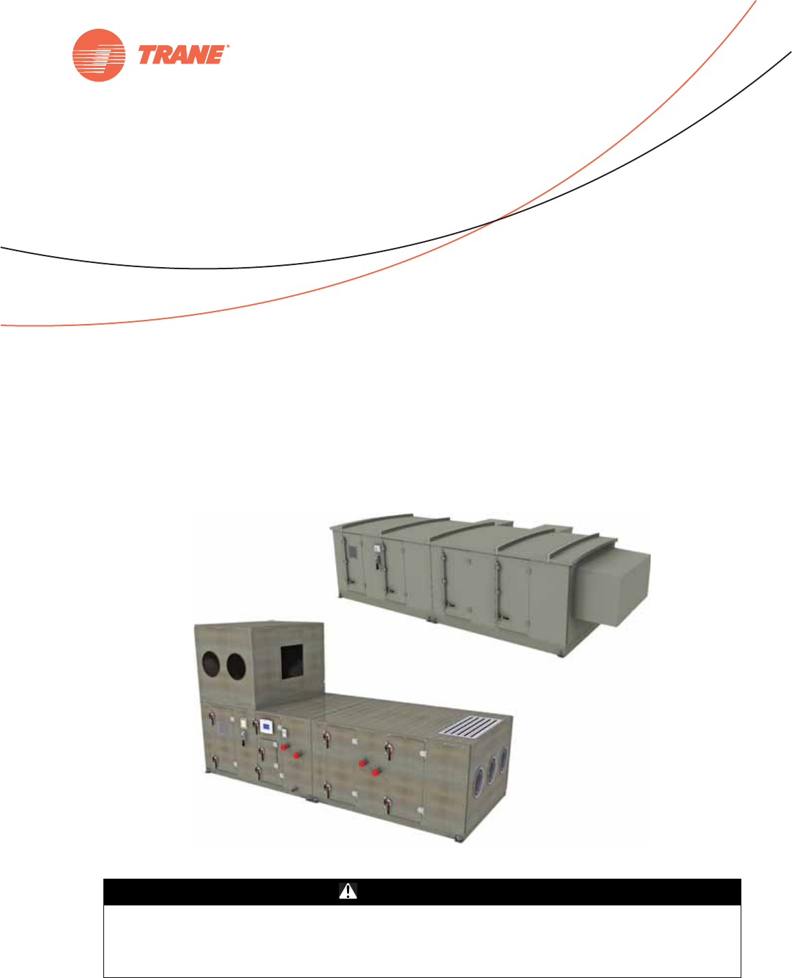
Performance Climate Changer™ Air Handlers
Indoor and Outdoor Units
Sizes 3-120
October 2012 CLCH-SVX07C-EN
X-39641152010
© 2012 Trane All rights reserved CLCH-SVX07C-EN
Warnings, Cautions and Notices
Warnings, Cautions and Notices.
Note that warnings,
cautions and notices appear at appropriate intervals
throughout this manual. Warnings are provide to alert
installing contractors to potential hazards that could result
in death or personal injury. Cautions are designed to alert
personnel to hazardous situations that could result in
personal injury, while notices indicate a situation that
could result in equipment or property-damage-only
accidents.
Your personal safety and the proper operation of this
machine depend upon the strict observance of these
precautions.
Read this manual thoroughly before operating or servicing
this unit.
Important
Environmental Concerns!
Scientific research has shown that certain man-made
chemicals can affect the earth’s naturally occurring
stratospheric ozone layer when released to the
atmosphere. In particular, several of the identified
chemicals that may affect the ozone layer are refrigerants
that contain Chlorine, Fluorine and Carbon (CFCs) and
those containing Hydrogen, Chlorine, Fluorine and
Carbon (HCFCs). Not all refrigerants containing these
compounds have the same potential impact to the
environment. Trane advocates the responsible handling of
all refrigerants-including industry replacements for CFCs
such as HCFCs and HFCs.
Responsible Refrigerant Practices!
Trane believes that responsible refrigerant practices are
important to the environment, our customers, and the air
conditioning industry. All technicians who handle
refrigerants must be certified. The Federal Clean Air Act
(Section 608) sets forth the requirements for handling,
reclaiming, recovering and recycling of certain
refrigerants and the equipment that is used in these
service procedures. In addition, some states or
municipalities may have additional requirements that
must also be adhered to for responsible management of
refrigerants. Know the applicable laws and follow them.
ATTENTION:
Warnings, Cautions and Notices appear at
appropriate sections throughout this literature. Read
these carefully:
WARNING
Indicates a potentially hazardous
situation which, if not avoided, could
result in death or serious injury.
CAUTION
sIndicates a potentially hazardous
situation which, if not avoided, could
result in minor or moderate injury. It
could also be used to alert against
unsafe practices.
NOTICE:
Indicates a situation that could result in
equipment or property-damage only
WARNING
Proper Field Wiring and Grounding
Required!
All field wiring MUST be performed by qualified
personnel. Improperly installed and grounded field
wiring poses FIRE and ELECTROCUTION hazards. To
avoid these hazards, you MUST follow requirements for
field wiring installation and grounding as described in
NEC and your local/state electrical codes. Failure to
follow code could result in death or serious injury.
WARNING
Personal Protective Equipment (PPE)
Required!
Installing/servicing this unit could result in exposure to
electrical, mechanical and chemical hazards.
• Before installing/servicing this unit, technicians
MUST put on all Personal Protective Equipment (PPE)
recommended for the work being undertaken.
ALWAYS refer to appropriate MSDS sheets and OSHA
guidelines for proper PPE.
• When working with or around hazardous chemicals,
ALWAYS refer to the appropriate MSDS sheets and
OSHA guidelines for information on allowable
personal exposure levels, proper respiratory
protection and handling recommendations.
• If there is a risk of arc or flash, technicians MUST put
on all Personal Protective Equipment (PPE) in
accordance with NFPA 70E or other country-specific
requirements for arc flash protection, PRIOR to
servicing the unit.
Failure to follow recommendations could result in death
or serious injury.
Warnings, Cautions and Notices
CLCH-SVX07C-EN 3
Ultraviolet (UV) Germicidal Irradiation Lights!
The United States Environmental Protection Agency (EPA)
believes that molds and bacteria inside buildings have the
potential to cause health problems in sensitive
individuals. If specified, Trane provides ultraviolet lights
(UV-C) as a factory-engineered and installed option in
select commercial air handling products for the purpose of
reducing microbiological growth (mold and bacteria)
within the equipment. When factory provided, polymer
materials that are susceptible to deterioration by the UV-C
light will be substituted or shielded from direct exposure
to the light. In addition, UV-C radiation can damage human
tissue, namely eyes and skin. To reduce the potential for
inadvertent exposure to the lights by operating and
maintenance personnel, electrical interlocks that
automatically disconnect power to the lights are provided
at all unit entry points to equipment where lights are
located.
WARNING
Equipment Damage From Ultraviolet (UV)
Lights!
Trane does not recommend field installation of
ultraviolet lights in its air handling equipment for the
intended purpose of improving indoor air quality. High
intensity C-band ultraviolet light is known to severely
damage polymer (plastic) materials and poses a
personal safety risk to anyone exposed to the light
without proper personal protective equipment (could
cause damage to eyes and skin). Polymer materials
commonly found in HVAC equipment that may be
susceptible include insulation on electrical wiring, fan
belts, thermal insulation, various fasteners and
bushings. Degradation of these materials can result in
serious damage to the equipment.
Trane accepts no responsibility for the performance or
operation of our air handling equipment in which
ultraviolet devices were installed outside of the Trane
factory.

4 CLCH-SVX07C-EN
Table of Contents
Warnings, Cautions and Notices . . . . . . . . . . 2
Introduction . . . . . . . . . . . . . . . . . . . . . . . . . . . . . 6
Overview of Manual . . . . . . . . . . . . . . . . . . . 6
Nameplate . . . . . . . . . . . . . . . . . . . . . . . . . . . . 6
General Information . . . . . . . . . . . . . . . . . . . . . 7
Operating Environment . . . . . . . . . . . . . . . . 7
Unit Description . . . . . . . . . . . . . . . . . . . . . . . 7
Factory-Mounted Controls . . . . . . . . . . . . . 7
Pre-Packaged Solutions for Controls . . . . 7
Wiring . . . . . . . . . . . . . . . . . . . . . . . . . . . . . 8
Pre-Installation Requirements . . . . . . . . . . . . . 9
Receiving Checklist . . . . . . . . . . . . . . . . . . . . 9
Assembly Hardware . . . . . . . . . . . . . . . . . . 9
Resolving Shipping Damage . . . . . . . . . . . . 9
Storage Recommendations . . . . . . . . . . . . 10
General Storage . . . . . . . . . . . . . . . . . . . . 10
Long-Term Storage . . . . . . . . . . . . . . . . . 10
Outdoor Storage Considerations . . . . . . 10
Preparing the Unit Site . . . . . . . . . . . . . . . . 10
Roof Curb Installation Checklist . . . . . . . . . 11
Unit Dimensions and Weights . . . . . . . . . . . 12
Service Clearances . . . . . . . . . . . . . . . . . . . . 12
Fans/Motors . . . . . . . . . . . . . . . . . . . . . . . . . 20
Starter/VFD Weights . . . . . . . . . . . . . . . . . 20
Motor Weights . . . . . . . . . . . . . . . . . . . . . 20
Installation - Mechanical . . . . . . . . . . . . . . . . 21
Lifting and Rigging . . . . . . . . . . . . . . . . . . . 21
Remove Shipping Tie-Downs . . . . . . . . . 21
General Lifting Considerations . . . . . . . . 22
Lifting Hoods and Pipe Cabinets . . . . . . . 24
Forklifting Considerations . . . . . . . . . . . . 24
Unit Placement and Assembly . . . . . . . . . . 25
Unit Placement . . . . . . . . . . . . . . . . . . . . . 25
Unit Assembly . . . . . . . . . . . . . . . . . . . . . 26
Ceiling Suspension . . . . . . . . . . . . . . . . . 26
Shipping Gussets . . . . . . . . . . . . . . . . . . . 27
Section-to-Section Assembly . . . . . . . . . 27
Pipe Cabinet Installation . . . . . . . . . . . . . . . 32
Outdoor Unit Weather Hoods . . . . . . . . . . .34
Stacked Outdoor Units . . . . . . . . . . . . . . . . .34
Assembly hardware . . . . . . . . . . . . . . . . . .34
Unit assembly . . . . . . . . . . . . . . . . . . . . . . .35
Vertical Seam Cap Installation . . . . . . . . .36
Flashing Installation . . . . . . . . . . . . . . . . . .37
Indoor Dual-Path SDU/Winterizer Assembly
. . . . . . . . . . . . . . . . . . . . . . . . . . . . . . . . . . . . .42
Horizontal SDU/Winterizer Air Handler
Assembly . . . . . . . . . . . . . . . . . . . . . . . . . .42
Vertical SDU/Winterizer Air Handler
Assembly . . . . . . . . . . . . . . . . . . . . . . . . . .43
External Raceway Assembly . . . . . . . . . . . .44
Component Installation Requirements . . . . .45
Diffuser Section . . . . . . . . . . . . . . . . . . . . . . .45
Filter Section . . . . . . . . . . . . . . . . . . . . . . . . . .45
Filter Installation . . . . . . . . . . . . . . . . . . . . .45
Filter Placement . . . . . . . . . . . . . . . . . . . . .46
Fan Section . . . . . . . . . . . . . . . . . . . . . . . . . . .62
Fan Isolation . . . . . . . . . . . . . . . . . . . . . . . .62
Adjusting the Isolators . . . . . . . . . . . . . . . .62
Seismic Application Requirements . . . . . . .63
Anchor Requirements . . . . . . . . . . . . . . . .63
Anchor Pattern . . . . . . . . . . . . . . . . . . . . . .63
Hurricane Application Requirements . . . . .64
Miami/Dade County Hurricane-Certified Air
Handlers . . . . . . . . . . . . . . . . . . . . . . . . . . .64
Approved Method for Anchoring Unit . . .64
Hurricane Unit Anchorage . . . . . . . . . . . . .65
Gas Heat Installation . . . . . . . . . . . . . . . . .66
Pipe Cabinet Installation . . . . . . . . . . . . . .67
Pipe Cabinet Hurricane Anchorage . . . . .69
Damper Section . . . . . . . . . . . . . . . . . . . . . . .69
Damper Torque Requirements . . . . . . . . .70
Opposed-Blade and Parallel-Blade Damper
. . . . . . . . . . . . . . . . . . . . . . . . . . . . . . . . . . .78
Multizone Modules . . . . . . . . . . . . . . . . . . . .79
Duct Connections . . . . . . . . . . . . . . . . . . . . . .79
Fan Discharge Connections . . . . . . . . . . . .79
Damper Connections . . . . . . . . . . . . . . . . .80

CLCH-SVX07C-EN 5
Table of Contents
Bottom Opening Duct Installation . . . . . . 81
Discharge Plenum Connections . . . . . . . 82
Bell Mouth Discharge Connections . . . . 82
Traq Damper Connections . . . . . . . . . . . . 83
External Face-and-Bypass Connections . 84
Other Connections . . . . . . . . . . . . . . . . . . 85
Coil Piping and Connections . . . . . . . . . . . . . 86
General Recommendations . . . . . . . . . . . . 86
Drain Pan Trapping . . . . . . . . . . . . . . . . . . . 86
Steam Coil Piping . . . . . . . . . . . . . . . . . . . . 87
Water Coil Piping . . . . . . . . . . . . . . . . . . . . . 89
Refrigerant Coil Piping . . . . . . . . . . . . . . . . 90
Liquid Lines . . . . . . . . . . . . . . . . . . . . . . . . 91
Suction Lines . . . . . . . . . . . . . . . . . . . . . . 92
Installation - Electrical . . . . . . . . . . . . . . . . . . . 99
Quick Connects . . . . . . . . . . . . . . . . . . . . 101
Controls Interface . . . . . . . . . . . . . . . . . . . . . . 104
Connecting the operator display . . . . . . . 104
Setting up the operator display . . . . . . . . 104
Calibrating the operator display . . . . . . . 104
Adjusting brightness and contrast . . . . . 104
External communications port . . . . . . . . 105
Start-Up . . . . . . . . . . . . . . . . . . . . . . . . . . . . . . 106
Pre-Startup Checklist . . . . . . . . . . . . . . . . . 106
General Checks . . . . . . . . . . . . . . . . . . . . 106
Fan-Related Checks . . . . . . . . . . . . . . . . 106
Coil-Related Checks . . . . . . . . . . . . . . . . 106
Motor-Related Checks . . . . . . . . . . . . . . 107
Unit Operation . . . . . . . . . . . . . . . . . . . . . . 107
Calculate Motor Voltage Imbalance . . . 107
VFD Programming Parameters . . . . . . . 107
Tension the Fan Belt . . . . . . . . . . . . . . . 109
Determine Fan Speed . . . . . . . . . . . . . . 110
Align Fan and Motor Sheaves . . . . . . . . 111
Check Multiple Belts . . . . . . . . . . . . . . . . 111
Airflow Measuring Systems . . . . . . . . . . . 111
Traq™ Dampers . . . . . . . . . . . . . . . . . . . 111
Fan Inlet Airflow Measuring System . . 117
Wiring . . . . . . . . . . . . . . . . . . . . . . . . . . . .117
Transmitter Sizing . . . . . . . . . . . . . . . . . .117
Transmitter Calibration . . . . . . . . . . . . . .117
Constant Factor K . . . . . . . . . . . . . . . . . . .118
Maintenance . . . . . . . . . . . . . . . . . . . . . . .120
External Insulating Requirements . . . . . . .120
Routine Maintenance . . . . . . . . . . . . . . . . . . .121
Maintenance Checklist . . . . . . . . . . . . . . . .121
Air Filters . . . . . . . . . . . . . . . . . . . . . . . . . . . .122
Throwaway Filters . . . . . . . . . . . . . . . . . .122
Permanent Filters . . . . . . . . . . . . . . . . . . .122
Cartridge or Bag Filters . . . . . . . . . . . . . .122
Drain Pans . . . . . . . . . . . . . . . . . . . . . . . . . . .122
Fans . . . . . . . . . . . . . . . . . . . . . . . . . . . . . . . .123
Inspecting and Cleaning Fans . . . . . . . . .123
Bearing Set Screw Alignment . . . . . . . . .123
Torque Requirements . . . . . . . . . . . . . . .124
Fan Bearing Lubrication . . . . . . . . . . . . .124
Motor Bearing Lubrication . . . . . . . . . . .124
Fan Motor Inspection . . . . . . . . . . . . . . . .124
Coils . . . . . . . . . . . . . . . . . . . . . . . . . . . . . . . .125
Steam and Water Coils . . . . . . . . . . . . . .125
Refrigerant Coils . . . . . . . . . . . . . . . . . . . .125
Coil Winterization . . . . . . . . . . . . . . . . . . .126
Moisture Purge Cycle . . . . . . . . . . . . . . . .126
Cleaning Non-Porous Surfaces . . . . . . . .127
Cleaning Porous Surfaces . . . . . . . . . . . .127
Ultraviolet (UV) Light Maintenance . . . . .128
Cleaning the Bulbs . . . . . . . . . . . . . . . . . .128
Replacing the Bulbs . . . . . . . . . . . . . . . . .128
Disposal of Bulbs . . . . . . . . . . . . . . . . . . .128
Troubleshooting . . . . . . . . . . . . . . . . . . . . . . . .129
6 CLCH-SVX07C-EN
Introduction
Overview of Manual
Use this manual to install, startup, operate, and maintain
the Performance Climate Changer™ air handler. Carefully
review the procedures discussed in this manual to
minimize installation and startup difficulties.
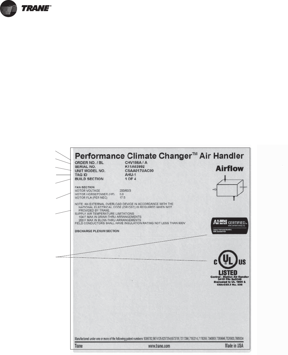
Nameplate
Each Performance air handler section includes one or
more nameplate/label (see Figure 1), which identifies the
type of section and functional components, customer
tagging information, the unit serial number, the unit order
number, the build-section position for installation, and the
unit model number.
Note: The unit serial number and order number is
required when ordering parts or requesting service
for a Trane air handler.
Figure 1. Performance air handler section nameplate
Agency listings and/or
agency certifications
Trane order number
Unit level serial number
Service model number
Unit tagging
Section location
Functional section type
Notes and additional
section information

General Information
CLCH-SVX07C-EN 7
General Information
Operating Environment
The Performance Climate Changer™ air handler is a
central station air handler for indoor and outdoor
applications. When considering the placement of the air
handler, it is important to consider the operating
environment. The acceptable ambient temperature range
for unit operation is -40ºF to 140ºF (-40ºC to 60ºC).
For heating applications, a special motor may be required
to withstand the higher temperatures. Motors with Class B
insulation are acceptable for ambient temperatures up to
104º F, while motors with Class F insulation can withstand
ambient temperatures to +140º F (60º C).
Note: Units with UL approval have a maximum ambient
temperature requirement of 104ºF. The customer
should provide adequate freeze protection for the
coils. See “Routine Maintenance” on page 121 for
more information.
Unit Description
The Performance Climate Changer air handler is designed
for a variety of controlled-air applications. The basic unit
consists of a fan, heating and/or cooling coils, filters, and
dampers.
Trane air handlers ship as complete assemblies or in sub-
assemblies if shipping splits are required. Some assembly
is required when the unit ships in subassemblies.
A wide variety of components is available for Trane air
handlers, including numerous fan, coil, and filter options,
access sections, diffusers, discharge plenums, face-and-
bypass sections, UL-approved electric heat sections,
humidifiers, mixing boxes, moisture eliminator sections,
exhaust dampers, controls, blenders and airflow
monitoring stations.
For more information, refer to the following documents,
available from your local Trane sales engineer:
• CLCH-PRC015-EN, Performance Climate Changer™ Air
Handler catalog
• CLCH-PRC016-EN, Performance Climate Changer™ Air
Handler quick select
• CLCH-SVN05A-EN, Roof Curbs for Performance
Climate Changer™ Air Handlers installation
instructions
• CLCH-PRG003-EN, Performance Climate Changer™
Air handler guide specifications
• CLCH-SLB017-EN, Performance Climate Changer™ Air
Handler sales brochure
• CLCH-SVX08A-EN, Gas Heat in Performance Climate
Changer™ Air Handlers installation, operation, and
maintenance guide
Factory-Mounted Controls
Trane air handlers are available with a wide selection of
factory-mounted controls, including controllers, motor
starters, and variable frequency drives (VFD).
Most control components are mounted inside the unit.
Depending on the system configuration, this may include
damper actuators, dirty filter switches, averaging
temperature sensors, and low limit switches. VFDs,
starters, controllers, control transformers, static pressure
transducers, DC power supplies, and customer interface
relays will be in enclosures mounted on the inside of the
unit.
Small items that cannot be factory-mounted, such as
space temperature sensors, outside air temperature
sensors, and humidity sensors, will ship inside the control
enclosures, or packaged and shipped inside the fan or
mixing box section. Larger items are shipped inside the
fan section.
Note: All control valves ship directly to the “ship-to
address” from the vendor unless another address
is given on the Trane sales order.
All factory-mounted control systems (controls that are
factory-wired to a unit controller or termination strip)
ordered without starters or variable-frequency drives
(VFDs) are provided with 120 to 24 Vac control
transformers mounted and wired in the auxiliary control
panel. The customer must provide 120 Vac control power,
50/60 Hz, typically 3 amps for unit sizes 3 to 57 and 5 amps
for unit sizes 66 to 100. A dedicated 15-amp circuit is
recommended.
Factory-mounted control systems ordered with factory-
mounted starters or VFDs are supplied with line to 24 Vac
control transformers. No additional power wiring is
required.
Pre-Packaged Solutions for Controls
If the air handler has been selected using one of Trane’s
pre-packaged solutions options for controls, there are a
number of resources available to aid in commissioning
and start-up of the unit. These resources include
commissioning sheets, graphics and technical application
notes. The technical application notes include the control
sequencing, Trane Graphic Programming (TGP) and Rover
set-up files for the specific unit selected. These resources
are available through your local Trane sales office.
General Information
8 CLCH-SVX07C-EN
For a more in-depth understanding of controls, refer to the
following manuals:
• For programmable MP580 controllers
–CNT-SVP01A-EN
• For hardware installation
–CNT-SVN01A-EN
• For Trane TR200 Drives
–BAS-SVX19A-EN
Wiring
Entrances are generally provided for field-installation of
high and low voltage wiring through a pipe/nipple
connection in the unit depending on unit configuration
with or without factory-mounted controls. Before
installation, consider overall unit serviceability and
accessibility before mounting, running wires (power),
making penetrations, or mounting any components to the
cabinet.
Wiring to the air handler must be provided by the installer
and must comply with all national and local codes. The fan
motor nameplate includes a wiring diagram. If there are
any questions concerning the wiring of the motor, write
down the information on the motor nameplate and contact
your local Trane sales office.
WARNING
Proper Field Wiring and Grounding
Required!
All field wiring MUST be performed by qualified
personnel. Improperly installed and grounded field
wiring poses FIRE and ELECTROCUTION hazards. To
avoid these hazards, you MUST follow requirements for
field wiring installation and grounding as described in
NEC and your local/state electrical codes. Failure to
follow code could result in death or serious injury.

CLCH-SVX07C-EN 9
Pre-Installation Requirements
Based on customer requirements, Trane air handlers can
ship as complete units or as individual sections to be field
assembled. Unit sizes 3-120 have an integral base frame
designed with the necessary number of lift points for safe
installation. Indoor air handlers sizes 3-30 are also shipped
with a shipping skid designed for forklift transport.
Unless otherwise specified, Performance indoor air
handlers ship in subassemblies if the total length of the
units exceeds 98 inches or if the total weight exceeds the
limits shown in Table 1. If either the maximum weight or
maximum length is exceeded, the unit will ship in multiple
pieces. See Table 2 for limits for outdoor air handlers.
Note: These limits are based on a four-point lift.
Receiving Checklist
Upon receipt of the air handler(s), a thorough inspection
should be performed to note any shipping damage that
may have occurred and that the shipment is complete. All
factory shipping protection should be removed
immediately to allow complete access for the inspection.
The shipping protection provided by the factory is for
transit protection only and should not be used as a jobsite
storage cover.
Note: Delivery cannot be refused. Trane is not
responsible for shipping damage.
• Check all access doors to confirm that the latches and
hinges are not damaged.
• Inspect the interior of each section for any internal
damage.
Note: Concealed damage must be reported within
15 days of receipt.
• Inspect the coils for damage to the fin surface and/or
coil connections.
• If the unit was ordered with factory-mounted controls,
locate all sensors.
Note: Items that cannot be factory-mounted should ship
inside the control enclosures or should be
packaged inside the fan or mixing box section.
• Check all control devices attached to the unit exterior
and confirm that they are not damaged.
• Manually rotate the fan wheel to ensure free
movement of the shaft, bearings, and drive.
• Inspect the fan housing for any foreign objects.
• If the unit is shipped in subassemblies, locate the
assembly hardware, which should be packaged and
shipped inside the fan or mixing box section.
• Inspect and test all piping for possible shipping
damage. Nipples may be installed on coils at the
factory but should always be tightened and tested
before any connections are made. Rough handling
during shipping, in addition to other factors can cause
pipe connections to become loose.
Note: Trane will not be responsible for any leak at the field
connections. Coils have been factory pressure
tested before shipping.
Assembly Hardware
Trane air handlers ship with all necessary assembly
hardware and gasket material. This hardware is packaged
in either a clear plastic envelope or cardboard box and can
be found inside the fan, mixing box, or access section. If
there is not enough space inside the section, a crate or
pallet will be loaded onto the bed of the truck. Check the
Parts List on the Field Assembly drawing against the
contents of the crate. Do not proceed with unit assembly
until verification that all materials are present. Sometimes
it is necessary to use more than one section to ship
hardware. Please check all sections thoroughly before
contacting your local Trane sales engineer to report
missing hardware.
Resolving Shipping Damage
Trane air handlers ship freight-on-board (FOB), meaning
that the unit belongs to the customer the moment the
delivery truck leaves the factory. If damage has occurred to
the unit during shipment, follow these instructions:
Note: Trane is not responsible for shipping damage.
1. Make specific notation, describing the damage, on the
freight bill. Take photos of the damaged material if
possible.
2. Report all claims of shipping damage to the delivering
carrier immediately and coordinate carrier inspection
if necessary.
Note: Do not attempt to repair the unit without consulting
the delivering carrier.
Table 1. Shipping length and weight limitations for
indoor air handlers
Unit Size Maximum Unit
Weight (lb.) Maximum Unit
Length (in)
3–31 <2,500 98
35, 36 <3,900 98
40, 41 <4,300 98
50–58 <5,100 98
66-120 <8000 98
Table 2. Shipping length and weight limitations for
outdoor air handlers
Unit Size Minimum
Length (in.) Maximum
Length (in.) Maximum
Weight (lb.)
3–31 24.50 360.00 8,000
35-58 24.50 96.00
1
12,000
66-120 24.50 96.00
1
12,000
Notes:
1
Some specialty sections can be attached to the adjacent section
even if this causes length to be greater than 96 inches, up to
118.44 inches.
Pre-Installation Requirements
10 CLCH-SVX07C-EN
3. Notify your Trane sales representative of the damage
and arrange for repair.
Note: Do not attempt to repair the unit without consulting
the Trane sales representative.
4. Keep the damaged material in the same location as it
was received.
Note: It is the receiver's responsibility to provide
reasonable evidence that concealed damage was
not incurred after delivery.
Storage Recommendations
Note: All factory shipping protection should be removed.
This wrapping is for transit protection only and
should not be used for jobsite storage.
Indoor air handlers and/or field-installed accessories that
must be stored for a period of time before installation must
be protected from the elements. A controlled indoor
environment is recommended for proper storage.
Outdoor air handlers require no special protection for
storage before installation. Keep the equipment in the
original container for protection and ease of handling.
Note: The warranty does not cover damage to the unit or
controls due to negligence during storage.
General Storage
The unit controller and all other electrical/electronic
components should be stored in conditions of
-20ºF to 120°F and 5 to 95 percent relative humidity, non-
condensing. Electrical components are not moisture-
tolerant. Factory protective coverings should be removed
prior to storage.
Long-Term Storage
For longer periods of storage, allow proper clearance
around the unit to perform periodic inspection and
maintenance of the equipment.
While the unit is in storage:
• Every two weeks, rotate the fan and motor shaft 30
revolutions by hand. Check for free rotation.
• Every six months, check fan shaft bearings and grease
lines. Add grease using a manual grease gun following
the lubrications recommendations in “Fan Bearing
Lubrication” on page 124.
• Check the motor lubrication; remove and clean grease
plugs and check for the presence of moisture in the
grease. If moisture is present, remove the motor and
send it to an authorized repair shop for bearing
inspection/replacement. If no moisture if present, refer
to the motor manufacturer’s lubrication
recommendation for proper lubrication.
Outdoor Storage Considerations
Outdoor storage is not recommended for units that will be
installed indoors. However, when outdoor storage is
necessary, several things must be done to prevent
damage:
Note: Keep the equipment on the original wooden blocks/
skid for protection and ease of handling.
• Select a well-drained area, preferably a concrete pad or
blacktop surface.
• Place the unit on a dry surface or raised off the ground
to assure adequate air circulation beneath the unit and
to assure no portion of the unit will contact standing
water at any time.
• Loosen the belt tension on the drive belts.
• Cover the unit securely with a canvas tarp.
• Do not stack units.
• Do not pile other material on the unit.
Preparing the Unit Site
• Ensure the installation site can support the total weight
of the unit (see “Unit Dimensions and Weights” on
page 12 for approximate section weights; refer to the
unit submittals for actual weights).
• Allow sufficient space for adequate free air and
necessary service access (see “Service Clearances”
on page 12). Refer to submittals for specific
minimums.
• Allow room for supply and return piping, ductwork,
electrical connections, and coil removal.
• Ensure there is adequate height for condensate drain
requirements. See “Drain Pan Trapping” on page 86.
Note: If unit is installed in a mechanical room on a pad,
inadequate height may necessitate core-drilling
the floor to attain proper trap height. Insufficient
height could inhibit condensate drainage and
result in flooding the unit and/or equipment room.
NOTICE:
Corrosion!
Use only canvas tarps to cover air handlers. Plastic
tarps can cause condensation to form in and on the
equipment, which could result in corrosion damage or
wet storage stains.
Pre-Installation Requirements
CLCH-SVX07C-EN 11
• Confirm the roof curb or foundation of the mounting
platform is level and large enough to accommodate
the unit. Refer to the unit submittals for specific
dimensions.
• Provide adequate lighting for maintenance personnel
to perform maintenance duties.
• Provide permanent power outlets in close proximity to
the unit for installation and maintenance.
• Depending upon job requirements, the customer may
need to provide 120 Vac power to the unit controller.
Refer to submittals for more information. A dedicated
15-amp circuit is recommended.
• Wiring for the air handler must be provided by the
installer and must comply with all national and local
electrical codes.
• If the unit integral base frame ceiling suspension
provisions are not used, the installer/contractor must
provide a ceiling-suspended mounting frame
designed to support the length, width, and weight of
the entire air-handling unit. See “Ceiling Suspension”
on page 26 for more information.
• Rooftop curb-mounted units must be sealed tightly to
the curb. Use proper sealants and roof-to-curb sealing
techniques to prevent water and air leakage. Refer to
CLCH-SVN05A-EN Roof Curbs for Performance
Climate Changer™ Air Handlers Installation
Instructions.
Note: Preparation of the roof curb or pier mount and roof
openings should be completed prior to lifting the
unit to the roof.
Roof Curb Installation Checklist
See CLCH-SVN05A-EN Roof Curbs for Performance
Climate Changer™ Air Handlers Installation Instructions
for information on installing roof curbs.
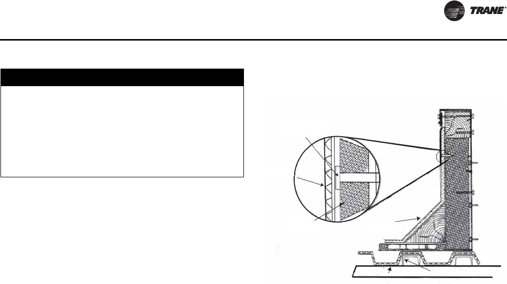
It is recommended that the curb be installed directly on the
support members and fastened to the supports using tack
welds or other equivalent methods. Properly supported
decking should be installed inside the air handler section
of the curb when this method is used. See Figure 2.
1. Verify that the roof structure can adequately support
the combined weight of the unit and curb assembly.
2. Ensure that the selected installation location provides
sufficient service and operational clearances.
3. Remove any twist within the curb due to roof supports
and square the curb.
4. Level the curb.
5. Secure the curb to the roof support members.
6. Install 2-inch thick boards or rigid insulation around the
curb.
7. Install cant strips around the curb.
8. Bring field supplied roofing felt up to the top of the curb
nailing strips. Nail felt into place.
9. Install field supplied flashing under the lip of the curb
flanges and over the felt.
10. Apply sealant to the four corners.
11. Caulk all joints between the curb and the roof.
Attach the gasket material to the curb’s top flanges (entire
perimeter) and to the supply and return air duct opening
panel flanges.
NOTICE:
Microbial Growth!
The floor or foundation must be level and the
condensate drain at the proper height for proper coil
drainage and condensate flow. Standing water and wet
surfaces inside the equipment can become an
amplification site for microbial growth (mold), which
could cause odors and damage to the equipment and
building materials.
Figure 2. Cross section of typical curb installation on
new construction
Screw securing roof
felt to rigid insulation
or 2 x 10
Flashing
(field-supplied)
Roofing felt
(field-supplied)
4 x 4 cant
(field-supplied)
Roof deck Support channels
12 CLCH-SVX07C-EN
Unit Dimensions and Weights
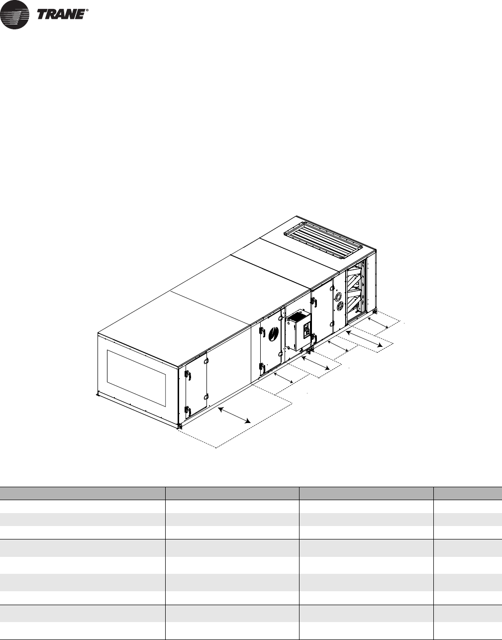
Service Clearances
A minimum clearance of the section width plus 12 inches
on the access door side of the gas heat section is
recommended for routine maintenance. This clearance
provides enough room to replace the heat exchanger in
the event of failure. The section side panels must be
removed to access the heat exchanger. Refer to Table 3 for
service clearance recommendations for the air handler.
Note: For specific dimensional and weight information, refer to the unit submittals. The dimensions and weights in this
manual are approximate. Trane has a policy of continuous product and product data improvement and reserves
the right to change design and specifications without notice.
Figure 3. Service Clearance
Filter mixing box
Coil
Fan
Gas heat
Access
door
UV
lights
VFD
F
E
D
C
B
A
Table 3. Service clearance dimensions (inches)
Component 3 4 6 8 10 12 14 17 21 22 25 26 30 31 35 36 40 41 50 51 57 58 66 80 100 120
A (filter) 4848484848484848484848484848484848484848484852565858
B (coil) 48 59 59 66 77 82 87 87 95 77 95 77 109 87 115 96 128 96 141 110 141 110 156 156 170 197
C (UV Lights) 4848484848484848484848484848484848484848484852565858
C (Catalytic Air
Cleaner) 43 59 59 63 75 81 83 83 58 75 58 75 83 83 75 59 83 83 83 83 83 83 83 83 75 83
D (external starter
or VFD) 61 61 61 61 61 61 61 61 64 64 64 64 64 64 64 64 64 64 64 64 64 64 64 64 64 64
D (internal starter
or VFD) 48 48 48 48 48 48 48 48 48 48 48 48 48 48 48 48 48 48 48 48 48 48 48 48 48 48
E (fan) 484848485154586160516651665866607060776677669393101101
F (gas heat - Ext
Vestibule) n/a n/a 89 90 108 100 100 105 115 n/a 115 n/a 118 n/a 136 n/a 140 n/a 156 n/a 156 n/a 170 179 180 n/a
F (gas heat - Int
Vestibule) n/a n/a 56 63 74 79 84 84 92 n/a 92 n/a 106 n/a 112 n/a 125 n/a 138 n/a 138 n/a 153 153 167 194
Note: At a minimum, the above clearance dimensions are recommended on one side of the unit for regular service and maintenance. Refer to as-built
submittal for locations of items such as filter access doors, coil, piping connections, motor locations, hoods, pipe cabinets, etc. Sufficient clearance
must be provided on all sides of unit for removal of access panels, plug panels, or section-to-section attachment brackets. Clearance for starters, VFDs,
or other high-voltage devices must be provided per NEC requirements.
Note: For specific dimensional and weight information, refer to the unit submittals. The dimensions and weights in this manual are approximate. Trane has
a policy of continuous product and product data improvement and reserves the right to change design and specifications without notice.

Unit Dimensions and Weights
CLCH-SVX07C-EN 13
Table 4. Section dimensions (inches) and weights (pounds) - unit sizes 3-30
Nominal airflow 1500 2000 3000 4000 5000 6000 7000 8500 10,500 11,000 12,500 13,000 15,000
Airflow at 625 fpm 2169 3475 4338 4581 6075 8331 9025 11,806 13,456 13,194 16,944 18,231 19,025
Unit size 3 4 6 8 10 12 14 17 21 22 25 26 30
Height - indoor unit 29.00 29.00 35.25 37.75 37.75 41.50 41.50 49.00 52.75 67.25 61.50 85.50 61.50
Width 31.50 44.00 44.00 50.50 61.50 66.50 72.00 72.00 80.00 61.50 80.00 61.50 93.50
Height for outdoor unit
includes base drip lip 36.25 36.38 42.63 45.13 45.13 49.25 49.25 56.75 60.50 n/a 69.25 n/a 69.25
Weight add for outdoor unit
(lbs/in. of unit length) 1.66 1.91 1.91 2.04 2.27 2.40 2.51 2.51 2.68 n/a 2.68 n/a 2.94
Access or blank
-Small horizontal 10.00 10.00 10.00 10.00 10.00 10.00 10.00 10.00 10.00 10.00 10.00 10.00 10.00
48.05 57.43 60.55 66.67 74.92 80.55 84.67 88.41 96.28 89.63 100.65 98.73 110.78
-Medium horizontal 14.00 14.00 14.00 14.00 14.00 14.00 14.00 14.00 14.00 14.00 14.00 14.00 14.00
59.91 71.18 75.25 82.74 92.66 99.61 104.57 109.45 119.10 111.84 124.79 123.71 136.97
-Extended-medium horizontal 19.00 19.00 19.00 19.00 19.00 19.00 19.00 19.00 19.00 19.00 19.00 19.00 19.00
74.73 88.37 93.62 102.82 114.83 123.43 129.44 135.74 147.62 139.60 154.97 154.93 169.71
-Medium-large horizontal 24.50 24.50 24.50 26.50 26.50 26.50 26.50 24.50 24.50 26.50 24.50 26.50 24.50
121.60 107.28 113.84 132.94 148.08 159.18 166.74 164.66 178.99 170.14 188.17 189.27 205.72
-Large horizontal or turning 34.00 34.00 34.00 36.00 36.00 36.00 36.00 36.00 34.00 36.00 46.00 46.00 46.00
137.75 164.85 179.46 208.50 235.01 257.70 271.35 293.42 314.60 315.97 413.45 428.50 457.18
-Extra-large horizontal or
turning
36.00 41.00 41.00 44.00 42.50 42.50 42.50 44.00 50.25 50.25 56.50 56.50 56.50
143.68 188.92 205.18 240.63 263.83 288.68 303.68 335.49 407.29 395.09 476.83 494.06 525.93
-Ducted inlet or ducted
outlet section 10.00 10.00 10.00 10.00 10.00 10.00 10.00 10.00 10.00 10.00 10.00 10.00 10.00
48.10 57.40 60.50 66.70 74.90 80.50 84.70 88.40 96.30 89.60 100.60 98.70 110.80
Blender 19.00 24.50 24.50 26.50 36.00 36.00 36.00 36.00 34.00 30.500 46.00 36.00 46.00
94.86 132.71 146.30 173.34 238.64 264.12 276.73 303.71 323.59 300.15 427.13 385.06 470.25
Cool Dry Quiet (CDQ)
Desiccant Dehumidification 52.00 52.00 52.00 52.00 55.00 58.00 58.00 58.00 56.00 n/a 56.00 n/a 58.00
495.00 651.00 694.00 792.00 1011.00 1165.00 1326.00 1390.00 1793.00 1876.00 2029.00
Coils
-Small horizontal (with 4-row
UW) 10.00 10.00 10.00 10.00 10.00 10.00 10.00 10.00 10.00 10.00 10.00 10.00 10.00
116.10 148.55 174.35 205.79 244.49 285.13 307.44 352.47 433.37 433.22 502.46 523.01 572.50
-Medium horizontal (with 8-
row UW) 14.00 14.00 14.00 14.00 14.00 14.00 14.00 14.00 14.00 14.00 14.00 14.00 14.00
168.65 220.23 265.58 318.97 382.53 450.07 488.32 569.79 700.27 690.67 817.63 840.58 941.48
-Extended-medium horizontal
(with 8-row UW) 19.00 19.00 19.00 19.00 19.00 19.00 19.00 19.00 19.00 19.00 19.00 19.00 19.00
185.58 239.53 286.06 341.16 406.80 476.00 516.35 599.24 737.96 721.58 858.03 878.74 985.30
-Medium-large horizontal
(with 10-row W) 24.50 24.50 24.50 26.50 26.50 26.50 26.50 24.50 24.50 26.50 24.50 26.50 24.50
270.61 359.79 433.08 554.88 656.63 777.26 884.93 1013.57 1262.10 1175.58 1478.66 1503.93 1503.93
-Large horizontal or vertical
(with 10-row W) 34.00 34.00 34.00 36.00 36.00 36.00 36.00 36.00 34.00 36.00 46.00 46.00 46.00
302.77 396.45 471.99 597.03 702.74 826.53 938.18 1081.30 1333.70 1234.32 1652.36 1652.73 1652.73
-Electric Heat Coil 36.00 41.00 41.00 44.00 42.50 42.50 42.50 44.00 50.25 n/a 46.00 n/a 56.50
295.00 364.00 413.00 480.00 563.00 622.00 666.00 731.00 876.00 1012.00 1244.00
Integral-face-and-bypass coil
-Less than 4 rows n/a 26.50 26.50 26.50 26.50 26.50 26.50 26.50 26.50 26.50 26.50 26.50 26.50
n/a 355.20 367.21 470.21 541.93 585.86 619.66 733.14 792.88 858.31 805.52 1047.84 940.46
-4 rows n/a 43.00 43.00 43.00 43.00 43.00 43.00 43.00 43.00 43.00 43.00 43.00 43.00
n/a 543.54 560.74 725.48 835.34 901.70 950.23 1131.90 1216.48 1313.83 1399.66 1613.03 1439.40
Controls section (includes
largest available VFD) 28.50 28.50 28.50 28.50 28.50 28.50 28.50 28.50 28.50 28.50 28.50 28.50 28.50
184.00 208.00 253.00 272.00 295.00 315.00 327.00 350.00 428.00 419.00 453.00 464.00 487.00

Unit Dimensions and Weights
14 CLCH-SVX07C-EN
Unit size 3 4 6 8 10 12 14 17 21 22 25 26 30
Diffuser 10.00 10.00 10.00 14.00 14.00 14.00 14.00 14.00 14.00 14.00 19.00 19.00 19.00
45.70 55.08 58.20 80.39 90.31 97.26 102.22 107.10 116.75 109.49 152.62 152.58 167.36
Discharge plenum
-Horizontal 34.00 34.00 34.00 36.00 36.00 36.00 36.00 36.00 34.00 36.00 46.00 46.00 46.00
135.40 162.50 177.11 206.15 232.66 255.35 269.00 291.07 312.25 313.62 411.10 426.15 454.83
-Vertical 36.00 41.00 41.00 44.00 42.50 42.50 42.50 44.00 50.25 n/a 56.50 n/a 56.50
159.90 211.48 233.54 275.69 306.29 339.58 358.68 401.43 486.37 570.00 634.27
Energy Wheel n/a 52.00 52.00 52.00 55.00 58.00 58.00 58.00 56.00 n/a 56.00 n/a 58.00
609.00 663.00 765.00 911.00 1085.00 1208.00 1269.00 1484.00 1595.00 1868.00
Face-and-Bypass Dampers
-Face-and-bypass 19.00 19.00 19.00 19.00 19.00 19.00 19.00 19.00 19.00 19.00 19.00 19.00 19.00
105.60 129.06 141.70 157.63 178.68 199.15 209.53 224.50 248.05 137.25 265.62 152.58 291.36
-External face-and-bypass 19.00 19.00 19.00 19.00 19.00 19.00 19.00 19.00 19.00 22.00 19.00 27.75 19.00
122.68 155.15 167.79 190.70 219.68 241.45 255.80 270.77 300.08 153.91 317.53 207.22 353.22
-Internal face-and-bypass or
face damper only 19.00 19.00 19.00 19.00 19.00 19.00 19.00 19.00 19.00 19.00 19.00 19.00 19.00
107.95 140.46 149.91 174.82 203.43 227.60 241.91 255.18 291.55 137.25 306.62 152.58 341.36
Fan
-Belt-drive plenum fan with
motor 36.00 41.00 41.00 44.00 42.50 42.50 42.50 44.00 50.25 n/a 56.50 n/a 56.50
397.87 538.34 631.36 682.55 875.00 951.91 1069.39 1239.89 1443.56 1494.52 1751.34
-Housed FC fan with motor 36.00 41.00 41.00 44.00 42.50 42.50 42.50 44.00 50.25 50.25 56.50 56.50 56.50
368.77 449.75 544.28 589.00 721.69 882.15 904.21 1054.64 1329.38 1295.80 1487.55 1511.37 1710.85
-Housed AF/BC fan with motor 36.00 41.00 41.00 44.00 42.50 42.50 42.50 44.00 50.25 50.25 56.50 56.50 56.50
378.87 467.35 574.68 649.40 849.71 920.08 942.14 1098.21 1432.10 1444.53 1572.28 1609.10 1797.21
-Direct-drive plenum fan with
motor 36.00 41.00 41.00 44.00 42.50 42.50 42.50 44.00 50.25 50.25 56.50 56.50 56.50
373.16 516.35 535.05 692.86 795.54 912.52 936.26 991.99 1380.92 1237.09 1541.05 1600.04 1652.91
Filters
-Side load 2-in. angled 24.50 24.50 24.50 26.50 26.50 26.50 26.50 24.50 24.50 24.50 24.50 24.50 24.50
134.55 163.83 175.66 202.44 225.96 251.82 265.94 314.12 347.50 348.70 403.70 418.53 454.19
-Side load 4-in. angled 24.50 24.50 24.50 26.50 26.50 26.50 26.50 24.50 24.50 24.50 24.50 24.50 24.50
141.89 176.87 192.86 209.64 247.16 254.22 273.54 352.07 379.13 361.27 409.37 470.37 465.65
-Side load cartridge 12-in. or
short bag 18-in. 24.50 24.50 24.50 26.50 26.50 26.50 26.50 24.50 24.50 24.50 24.50 24.50 24.50
125.03 159.79 176.46 220.46 234.88 284.12 303.60 335.02 365.40 342.50 439.69 440.65 479.36
-Side load 2-in. flat 14.00 14.00 14.00 14.00 14.00 14.00 14.00 14.00 14.00 14.00 14.00 14.00 14.00
70.27 86.53 91.98 103.59 117.74 133.81 141.07 148.02 165.52 160.19 182.07 177.12 198.93
-Side load 4-in. flat 14.00 14.00 14.00 14.00 14.00 14.00 14.00 14.00 14.00 14.00 14.00 14.00 14.00
81.56 104.62 114.08 117.09 143.40 142.66 154.67 202.82 213.64 189.17 217.75 254.10 249.73
-Side load 2-in. and 4-in.
combination flat 19.00 19.00 19.00 19.00 19.00 19.00 19.00 19.00 19.00 19.00 19.00 19.00 19.00
100.62 128.19 139.09 144.56 174.73 185.69 201.37 252.57 268.17 252.01 288.98 326.16 326.58
-Long bag 30-in. 36.00 41.00 41.00 44.00 42.50 42.50 42.50 44.00 50.25 50.25 46.00 40.00 46.00
159.54 203.31 223.70 269.26 289.43 330.97 349.19 382.94 461.96 395.90 488.89 462.06 523.37
-Front-load HEPA 40.00 40.00 40.00 40.00 40.00 40.00 40.00 40.00 40.00 40.00 40.00 40.00 40.00
240.36 262.50 346.16 368.01 407.75 439.62 452.92 569.28 692.30 595.47 750.47 837.36 822.10
-Front-load cartridge 40.00 40.00 40.00 40.00 40.00 40.00 40.00 40.00 40.00 40.00 40.00 40.00 40.00
215.15 237.79 285.59 310.12 341.11 386.04 399.01 470.25 525.86 468.47 580.13 552.53 651.47
-Front-load short bag 45.00 45.00 45.00 45.00 45.00 45.00 45.00 45.00 45.00 45.00 45.00 45.00 45.00
222.35 246.75 279.75 306.39 335.16 369.65 383.67 432.15 473.60 487.79 518.05 573.98 566.55
Table 4. Section dimensions (inches) and weights (pounds) - unit sizes 3-30

Unit Dimensions and Weights
CLCH-SVX07C-EN 15
Unit size 3 4 6 8 10 12 14 17 21 22 25 26 30
Gas heat
- 200 MBH n/a n/a 57.00 57.00 59.00 57.00 57.00 60.00 60.00 n/a n/a n/a n/a
752.92 797.85 852.48 912.57 937.05 1011.83 1074.91
- 300 MBH n/a n/a 73.00 73.00 n/a n/a n/a n/a n/a n/a n/a n/a n/a
901.27 953.49
- 360 MBH n/a n/a n/a n/a 77.00 73.00 68.00 71.00 69.00 n/a 69.00 n/a 66.00
1093.23 1131.38 1127.89 1211.08 1264.50 1348.04 1298.88
- 560 MBH n/a n/a n/a n/a n/a n/a n/a 71.00 69.00 n/a 65.00 n/a 66.00
1191.99 1246.59 1307.47 1441.79
- 700 MBH n/a n/a n/a n/a n/a n/a n/a 83.00 75.00 n/a 75.00 n/a 76.00
1479.92 1503.43 1599.35 1745.65
- 860 MBH n/a n/a n/a n/a n/a n/a n/a n/a 81.00 n/a 81.00 n/a 76.00
1606.36 1711.24 1804.77
- 1000 MBH n/a n/a n/a n/a n/a n/a n/a n/a 87.00 n/a 90.00 n/a 85.00
1364.25 1497.35 1560.01
Humidifier
-Building Steam 14.00 14.00 14.00 14.00 14.00 14.00 14.00 14.00 14.00 14.00 14.00 14.00 14.00
125.00 146.00 165.00 184.00 226.00 269.00 286.00 324.00 354.00 368.00 398.00 500.00 452.00
-Atmospheric Steam 14.00 14.00 14.00 14.00 14.00 14.00 14.00 14.00 14.00 14.00 14.00 14.00 19.00
127.00 168.00 178.00 203.00 252.00 276.00 312.00 339.00 396.00 344.00 432.00 396.00 528.00
Mixing box
-with angled filters 34.00 34.00 34.00 36.00 36.00 36.00 36.00 36.00 34.00 36.00 46.00 46.00 46.00
137.75 164.85 179.46 208.50 235.01 257070 271.35 293.42 314.60 315.97 413.45 428.50 457.18
-with front/back Traq and top
Traq dampers 36.00 41.00 41.00 44.00 42.50 42.50 42.50 44.00 50.25 51.00 56.50 n/a 56.50
191.06 247.07 272.06 321.58 356.08 396.49 418.78 463.57 555.65 549.18 646.61 715.15
-reduced length with side/top/
back/bottom airfoil damper 23.40 23.40 23.40 23.40 23.40 23.40 28.40 28.40 28.40 n/a 28.40 n/a 32.50
131.80 158.30 177.90 202.80 231.60 257.60 298.40 328.40 370.10 408.10 485.80
Multizone
- 3-deck vertical discharge n/a n/a 61.00 61.00 66.00 71.00 71.00 71.00 82.00 n/a 82.00 n/a 82.00
1125.00 1313.00 1671.00 1899.00 2063.00 2211.00 2757.00 2991.00 3425.00
- 2-deck vertical discharge n/a n/a 61.00 61.00 66.00 71.00 71.00 71.00 82.00 n/a 82.00 n/a 82.00
763.00 899.00 1099.00 1266.00 1380.00 1526.00 1882.00 2108.00 2413.00
-3-deck horizontal discharge n/a n/a 52.00 52.00 52.00 57.00 57.00 57.00 72.00 n/a 72.00 n/a 72.00
1031.00 1219.00 1511.00 1729.00 1892.00 2034.00 2603.00 2829.00 3267.00
-2-deck horizontal discharge n/a n/a 52.00 52.00 52.00 57.00 57.00 57.00 72.00 n/a 72.00 n/a 72.00
701.00 832.00 982.00 1145.00 1253.00 1396.00 1755.00 1975.00 2264.00
Silencer
-3 ft 38.00 38.00 38.00 38.00 38.00 38.00 38.00 38.00 38.00 38.00 38.00 38.00 38.00
198.00 256.00 286.00 319.00 359.00 442.00 461.00 512.00 573.00 562.00 699.00 659.00 800.00
-5 ft 62.00 62.00 62.00 62.00 62.00 62.00 62.00 62.00 62.00 62.00 62.00 62.00 62.00
308.00 391.00 436.00 483.00 541.00 678.00 704.00 780.00 873.00 858.00 1073.00 1005.00 1215.00
Trane Catalytic Air Cleaning
System (TCACS) 36.00 36.00 36.00 36.00 36.00 36.00 36.00 36.00 36.00 36.00 36.00 36.00 36.00
334.73 367.14 389.21 434.66 470.05 497.59 514.12 544.30 599.38 690.80 665.11 777.83 711.12
UV light 14.00 14.00 14.00 14.00 14.00 14.00 14.00 14.00 14.00 n/a 14.00 n/a 14.00
76.02 93.64 98.69 120.26 135.22 146.68 155.07 162.95 179.84 188.71 218.33
Table 4. Section dimensions (inches) and weights (pounds) - unit sizes 3-30

Unit Dimensions and Weights
16 CLCH-SVX07C-EN
Sections below are for outdoor units only
Unit size 3 4 6 8 10 12 14 17 21 22 25 26 30
Diagonal economizer
-with airfoil dampers 46.00 49.00 50.00 48.00 53.00 53.00 57.00 52.00 63.00 n/a 57.00 n/a 63.00
187.00 231.00 256.00 276.00 334.00 365.00 407.00 414.00 534.00 548.00 649.00
-with airfoil damper and one
side Traq damper 46.00 49.00 50.00 48.00 53.00 53.00 57.00 52.00 63.00 n/a 57.00 n/a 63.00
204.00 247.00 271.00 290.00 349.00 378.00 426.00 431.00 555.00 565.00 689.00
Exhaust damper section for
outdoor unit 19.00 19.00 19.00 19.00 19.00 19.00 19.00 19.00 19.00 n/a 19.00 n/a 19.00
93.30 113.30 124.30 140.20 159.60 176.70 186.80 204.00 229.10 250.50 280.40
Hoods
-Back inlet hood with airfoil and
Traq dampers 22.25 44.00 44.00 50.38 61.50 66.38 71.88 72.00 79.88 n/a 79.88 n/a 93.38
22.00 45.00 47.00 47.00 52.00 69.00 74.00 74.00 74.00 128.00 166.00
-Side inlet hood with airfoil and
Traq dampers 20.00 20.00 20.00 20.00 22.88 22.88 31.38 25.75 29.13 n/a 25.75 n/a 27.88
17.00 17.00 22.00 22.00 31.00 42.00 50.00 50.00 50.00 84.00 96.00
-Exhaust hood with airfoil
damper 20.00 20.00 20.00 20.00 22.88 22.88 31.38 25.75 29.13 n/a 25.75 n/a 27.88
12.00 12.00 16.00 16.00 21.00 29.00 30.00 30.00 30.00 59.00 67.00
-Economizer inlet hood 45.50 49.00 49.50 48.00 53.00 53.00 56.50 52.00 62.50 n/a 57.00 n/a 62.50
41.00 37.00 45.00 61.00 68.00 76.00 137.00 174.00 179.00 214.00 224.00
Pipe cabinet weight
15 inches long, 36 inches deep 104.00 104.00 116.00 120.00 120.00 127.00 127.00 141.00 148.00 n/a 164.00 n/a 164.00
24 inches long, 36 inches deep 122.00 122.00 135.00 140.00 140.00 147.00 147.00 162.00 170.00 n/a 187.00 n/a 187.00
48 inches long, 36 inches deep 169.00 169.00 184.00 191.00 191.00 200.00 200.00 218.00 228.00 n/a 249.00 n/a 249.00
96 inches long, 36 inches deep 263.00 263.00 284.00 293.00 293.00 305.00 305.00 331.00 343.00 n/a 373.00 n/a 373.00
Note:
1
Nominal airflow is based on 500 fpm through a nominal coil (i.e. 500xunit size 8=4000 cfm).
2
Airflow@625 fpm through the flat filter (maximum filter velocity).
3
Height includes standard 2.5-inch base frame for sizes 3-57 and 6-inch base frame for sizes 66-120.
4
Height includes 6-inch base frame for sizes 3-120.
5
Variable
lengths available from 14-96 inches.
6
Fan section weights include the heaviest fan with the largest ODP motor available.
7
Nominal length and height shown for
discharge plenums. Variable plenum height and length is available from 0.5 to 1.5 of nominal.
8
Access section required with humidifiers for dispersion distance.
Table 4. Section dimensions (inches) and weights (pounds) - unit sizes 3-30
Table 5. Section dimensions (inches) and weights (pounds) - unit sizes 31-120
Nominal airflow 15,500 17,500 18,000 20,000 20,500 25,000 25,500 28,500 29,000 33,000 40,000 50,000 60,000
Airflow at 625 fpm 22,138 23,263 25,000 25,519 30,138 34,375 34,306 39,581 39,722 47,225 53,475 65,106 76,388
Unit size 31 35 36 40 41 50 51 57 58 66 80 100 120
Height - indoor unit 85.50 67.25 89.00 67.25 104.00 75.75 104.00 85.50 116.25 92.50 107.50 119.75 119.75
Width 72.00 100.00 80.00 112.50 80.00 125.50 93.50 125.50 93.50 140.50 140.50 154.50 182.00
Height for outdoor unit
includes base drip lip n/a 75.00 n/a 75.00 n/a 84.38 n/a 94.13 n/a 97.63 112.63 124.88 124.88
Weight add for outdoor unit
(lbs/in. of unit length) n/a 3.02 n/a 3.28 n/a 3.73 n/a 6.12 n/a 2.57 2.57 2.80 3.25
Access or blank
-Small horizontal 10.00 10.00 10.00 10.00 10.00 10.00 10.00 10.00 10.00 n/a n/a n/a n/a
106.61 211.11 207.98 227.92 224.38 254.69 242.54 265.35 255.92
-Medium horizontal 14.00 14.00 14.00 14.00 14.00 14.00 14.00 14.00 14.00 15.00 15.00 15.00 15.00
133.18241.53238.68260.24257.35290.28277.55302.41292.80430.36449.60493.59549.13
-Extended-medium horizontal 19.00 19.00 19.00 19.00 19.00 19.00 19.00 19.00 19.00 19.00 19.00 19.00 19.00
166.39 279.57 277.04 300.64 298.56 334.76 321.32 348.74 338.89 476.36 497.88 545.85 605.56
-Medium-large horizontal 26.50 24.50 29.50 24.50 29.50 24.50 29.50 24.50 29.50 24.50 24.50 24.50 24.50
202.93321.40319.24345.09343.89410.37369.46427.50389.59574.11600.46656.89725.47
-Large horizontal or turning 46.00 48.00 46.00 48.00 46.00 48.00 46.00 48.00 46.00 49.00 54.00 60.00 60.00
467.28 514.42 509.00 557.22 561.11 639.24 615.72 682.26 661.42 907.93 1036.33 1242.40 1387.96
-Extra-large horizontal or
turning n/a 63.75 n/a 63.75 n/a 68.50 n/a n/a n/a n/a n/a n/a n/a
624.86 675.12 809.42
Unit Dimensions and Weights
CLCH-SVX07C-EN 17
Unit size 31 35 36 40 41 50 51 57 58 66 80 100 120
-Ducted inlet or ducted
outlet section 10.00 10.00 10.00 10.00 10.00 10.00 10.00 10.00 10.00 10.00 10.00 10.00 10.00
106.60 211.10 208.00 227.90 224.40 254.70 242.50 265.30 255.90 372.90 389.30 428.30 478.60
Blender 40.00 48.00 48.00 48.00 48.00 48.00 54.00 48.00 48.00 49.00 54.00 60.00 60.00
449.80 540.76 495.07 593.46 616.31 675.51 656.33 731.75 718.81 970.30 1112.23 1345.03 1567.62
Cool Dry Quiet (CDQ)
Desiccant Dehumidification n/a 56.00 n/a 56.00 n/a 59.00 n/a n/a n/a n/a n/a n/a n/a
2914.00 3122.00 4224.00
Coils
-Small horizontal (with 4-row
UW) 10.00 10.00 10.00 10.00 10.00 10.00 10.00 10.00 10.00 n/a n/a n/a n/a
594.43 690.59 675.23 754.61 792.51 934.27 922.65 1044.33 1014.74
-Medium horizontal (with 8-
row UW) 14.00 14.00 14.00 14.00 14.00 14.00 14.00 14.00 14.00 15.00 15.00 15.00 15.00
968.56 1094.27 1095.29 1219.78 1290.73 1561.92 1523.08 1759.58 1686.19 2220.94 2558.94 3094.04 3638.44
-Extended-medium horizontal
(with 8-row UW) 19.00 19.00 19.00 19.00 19.00 19.00 19.00 19.00 19.00 19.00 19.00 19.00 19.00
1009.31 1148.70 1138.74 1279.06 1337.01 1613.56 1572.75 1813.06 1738.19 2275.46 2615.73 3163.21 3712.02
-Medium-large horizontal
(with 10-row W) 26.50 24.50 29.50 24.50 29.50 24.50 29.50 24.50 29.50 24.50 24.50 24.50 24.50
1737.73 1955.08 2017.86 2216.68 2355.51 2754.49 2791.28 3215.01 3116.00 3876.05 4488.82 5499.42 6713.50
-Large horizontal or vertical
(with 10-row W) 46.00 48.00 46.00 48.00 46.00 48.00 46.00 48.00 46.00 n/a n/a n/a n/a
1896.66 2131.70 2161.23 2401.84 2508.26 2985.19 2955.21 3454.40 3287.59
-Electric Heat Coil n/a 63.75 n/a 63.75 n/a 68.50 n/a 48.00 n/a 49.00 n/a n/a n/a
1666.00 1825.00 2267.00 2297.00 2857.00
Integral-face-and-bypass coil
-Less than 4 rows 26.50 29.50 29.50 29.50 29.50 29.50 29.50 29.50 29.50 29.50 29.50 29.50 29.50
1190.19 1129.66 1407.86 1168.40 1449.00 1793.80 1640.15 1956.80 1817.25 2322.61 2378.60 2865.77 2936.42
-4 rows 43.00 43.00 43.00 43.00 43.00 n/a n/a n/a n/a n/a n/a n/a n/a
1836.97 1677.52 2148.28 1720.20 2196.84
Controls section (includes
largest available VFD) 28.50 28.50 28.50 28.50 28.50 28.50 28.50 28.50 28.50 28.50 28.50 28.50 28.50
496.00 637.00 649.00 674.00 698.00 745.00 747.00 787.00 790.00 964.00 1031.00 1146.00 1266.00
Diffuser 19.00 24.50 24.50 24.50 24.50 24.50 24.50 24.50 24.50 27.50 37.25 37.25 37.25
164.04319.05316.89342.74341.54381.33367.11397.35387.24571.76715.78781.92860.66
Discharge plenum
-Horizontal 46.00 48.00 46.00 48.00 46.00 48.00 46.00 48.00 46.00 49.00 54.00 60.00 60.00
464.93 627.24 621.68 677.47 682.71 772.27 745.34 821.10 798.32 1058.35 1198.64 1423.88 1585.80
-Vertical n/a 63.75 n/a 63.75 n/a 68.50 n/a n/a n/a n/a n/a n/a n/a
876.48 949.58 1136.53
Energy Wheel n/a 61.00 n/a 65.00 n/a 65.00 n/a n/a n/a n/a n/a n/a n/a
2403.00 2742.00 3111.00
Face-and-Bypass Dampers
-Face-and-bypass 19.00 19.00 19.00 19.00 19.00 19.00 19.00 19.00 19.00 19.00 19.00 19.00 19.00
164.04 473.39 274.69 556.23 296.21 630.10 318.97 714.61 336.54 888.33 973.60 1093.88 1205.53
-External face-and-bypass 27.75 22.00 27.75 22.00 27.75 22.00 27.75 22.00 27.75 39.00 39.00 39.00 39.00
222.16 566.46 341.83 660.36 368.32 740.29 395.56 831.66 417.20 1256.07 1348.84 1498.11 1643.69
-Internal face-and-bypass or
face damper only 19.00 19.00 19.00 19.00 19.00 19.00 19.00 19.00 19.00 19.00 19.00 19.00 19.00
164.04 502.53 274.69 575.62 296.21 678.20 318.97 714.61 336.54 888.33 954.26 1082.84 1194.50
Fan
-Belt-drive plenum fan with
motor n/a 53.50 n/a 53.50 n/a 57.50 n/a 59.50 n/a 61.00 63.00 73.75 82.25
2368.54 2740.37 3263.68 3599.82 4062.62 4745.62 6223.51 7341.11
-Housed FC fan with motor 73.25 63.75 80.50 63.75 80.50 68.50 88.00 68.50 88.00 84.00 92.00 96.00 96.00
1832.18 2400.18 2423.46 2603.08 2771.01 3151.89 3312.75 3235.63 3414.05 4201.67 4922.58 5297.62 5600.08
-Housed AF/BC fan with motor 73.25 63.75 80.50 63.75 80.50 68.50 88.00 68.50 88.00 84.00 92.00 96.00 96.00
1979.55 2429.71 2568.99 2695.61 2863.54 3221.42 3382.28 3305.16 3483.58 4311.38 5101.29 6025.44 6891.90
Table 5. Section dimensions (inches) and weights (pounds) - unit sizes 31-120

Unit Dimensions and Weights
18 CLCH-SVX07C-EN
Unit size 31 35 36 40 41 50 51 57 58 66 80 100 120
-Direct-drive plenum fan with
motor 73.25 63.75 80.50 63.75 80.50 68.50 88.00 68.50 88.00 84.00 92.00 96.00 96.00
1673.71 2057.87 2804.47 2406.73 3039.54 3469.95 4268.88 3545.86 4349.06 4903.24 5456.86 7176.65 7382.51
Filters
-Side load 2-in. angled 24.50 24.50 24.50 24.50 24.50 27.50 24.50 27.50 24.50 27.50 27.50 27.50 27.50
469.97 593.86 562.37 649.06 652.32 770.02 688.86 797.89 777.14 989.00 1088.02 1157.16 1282.20
-Side load 4-in. angled 24.50 24.50 24.50 24.50 24.50 27.50 24.50 27.50 24.50 27.50 27.50 27.50 27.50
477.66 594.02 567.56 631.64 663.25 768.20 747.25 805.97 778.73 999.89 1105.14 1201.91 1338.65
-Side load cartridge 12-in. or
short bag 18-in. 24.50 24.50 24.50 24.50 24.50 27.50 24.50 27.50 24.50 27.50 27.50 27.50 27.50
487.55 681.24 637.25 668.25 762.69 878.57 874.81 934.14 980.36 1239.99 1364.91 1746.31 1903.54
-Side load 2-in. flat 14.00 14.00 14.00 14.00 14.00 14.00 14.00 14.00 14.00 15.00 15.00 15.00 15.00
198.17319.66322.85358.18358.29408.69392.33438.52426.12598.12637.02716.56817.63
-Side load 4-in. flat 14.00 14.00 14.00 14.00 14.00 14.00 14.00 14.00 14.00 15.00 15.00 15.00 15.00
241.97 359.20 350.39 375.13 404.69 451.33 461.82 498.71 476.21 657.87 729.15 803.46 913.90
-Side load 2-in. and 4-in.
combination flat 19.00 19.00 19.00 19.00 19.00 19.00 19.00 19.00 19.00 19.00 19.00 19.00 19.00
322.00 476.00 484.13 504.37 570.61 600.40 646.20 671.64 667.97 853.08 981.02 1078.09 1165.92
-Long bag 30-in. 37.25 37.25 37.25 37.25 37.25 37.25 37.25 37.25 37.25 37.25 37.25 37.25 37.25
505.93 657.41 700.77 716.04 802.78 826.72 883.10 906.56 944.63 1094.61 1270.51 1393.17 1549.80
-Front-load HEPA 40.00 40.00 40.00 40.00 40.00 40.00 40.00 40.00 40.00 40.00 40.00 40.00 40.00
874.09 985.62 1176.01 1128.46 1267.90 1397.21 1449.89 1520.35 1561.45 1845.81 2141.38 2553.97 2924.72
-Front-load cartridge 40.00 40.00 40.00 40.00 40.00 40.00 40.00 40.00 40.00 40.00 40.00 40.00 40.00
637.18 867.68 796.62 922.78 931.37 1093.06 1061.94 1173.89 1168.54 1449.48 1671.46 1923.09 2155.95
-Front-load short bag 45.00 45.00 45.00 45.00 45.00 45.00 45.00 45.00 45.00 45.00 45.00 45.00 45.00
622.53 750.89 778.04 799.75 885.35 917.08 968.65 979.84 1048.59 1231.49 1365.35 1538.95 1696.33
Gas heat
- 200 MBH n/a n/a n/a n/a n/a n/a n/a n/a n/a n/a n/a n/a n/a
- 300 MBH n/a n/a n/a n/a n/a n/a n/a n/a n/a n/a n/a n/a n/a
- 360 MBH n/a 66.00 n/a n/a n/a n/a n/a n/a n/a n/a n/a n/a n/a
1402.11
- 560 MBH n/a 66.00 n/a 64.00 n/a 64.00 n/a 64.00 n/a n/a n/a n/a n/a
1594.61 1468.07 1853.53 1900.53 n/a n/a n/a n/a
- 700 MBH n/a 73.00 n/a 75.00 n/a 74.00 n/a 74.00 n/a 74.00 n/a n/a n/a
1895.19 1804.11 2190.52 2241.91 2490.63
- 860 MBH n/a 80.00 n/a 75.00 n/a 74.00 n/a 74.00 n/a 74.00 74.00 n/a n/a
2046.29 2098.72 2280.52 2331.91 2580.63 2198.81 n/a n/a
- 1000 MBH n/a 80.00 n/a 81.00 n/a 77.00 n/a 77.00 n/a 74.00 74.00 84.00 92.00
1723.73 1844.68 2325.57 2082.86 2300.63 1918.81 3156.04 3125.34
- 1250-1750 MBH n/a 101.00 n/a 105.00 n/a 106.00 n/a 106.00 n/a 109.00 109.00 92.00 102.00
2540.84 2717.94 3264.84 2942.76 3309.39 2949.68 3878.54 3886.60
- 2000 MBH n/a n/a n/a n/a 114.00 n/a 114.00 n/a 112.00 112.00 109.00 109.00
3758.71 3430.29 3688.33 3320.33 4503.52 4391.21
-2400 MBH n/a n/a n/a n/a n/a n/a n/a 118.00 112.00 121.00 119.00
3890.31 3455.33 4715.85 4668.51
Humidifier
-Building Steam 14.00 14.00 14.00 14.00 14.00 14.00 14.00 14.00 14.00 15.00 15.00 15.00 15.00
561.00 544.00 622.00 599.00 684.00 782.00 773.00 897.00 807.00 1123.00 1215.00 1363.00 1551.00
-Atmospheric Steam 19.00 19.00 19.00 19.00 19.00 19.00 19.00 19.00 19.00 19.00 19.00 19.00 19.00
471.00 581.00 508.00 665.00 570.00 724.00 683.00 803.00 742.00 977.00 1078.00 1265.00 1492.00
Table 5. Section dimensions (inches) and weights (pounds) - unit sizes 31-120

Unit Dimensions and Weights
CLCH-SVX07C-EN 19
Unit size 31 35 36 40 41 50 51 57 58 66 80 100 120
Mixing box
-with angled filters 46.00 48.00 46.00 48.00 46.00 48.00 46.00 48.00 46.00 49.00 54.00 60.00 60.00
467.28 519.12 513.70 561.92 565.81 653.36 629.45 653.36 675.14 946.02 1077.83 1287.99 1433.55
-with front/back Traq and top
Traq dampers n/a 63.75 n/a 63.75 n/a 68.50 n/a 68.50 n/a 84.00 92.00 96.00 96.00
966.49 1073.80 1261.78 1365.59 1907.28 2151.42 2473.12 2790.48
-reduced length with side/top/
back/bottom airfoil damper n/a 35.50 n/a 38.50 n/a 41.50 n/a 41.50 n/a 41.50 41.50 47.00 53.00
708.50 795.10 947.60 1022.70 1328.50 1453.60 1731.30 2025.40
Multizone
- 3-deck vertical discharge n/a 92.00 n/a 92.00 n/a 96.00 n/a n/a n/a n/a n/a n/a n/a
4263.00 4732.00 5739.00
- 2-deck vertical discharge n/a 92.00 n/a 92.00 n/a 96.00 n/a n/a n/a n/a n/a n/a n/a
2965.00 3267.00 3986.00
-3-deck horizontal discharge n/a 78.00 n/a 78.00 n/a 78.00 n/a n/a n/a n/a n/a n/a n/a
4020.00 4471.00 5276.00
-2-deck horizontal discharge n/a 78.00 n/a 78.00 n/a 78.00 n/a n/a n/a n/a n/a n/a n/a
2725.00 3006.00 3633.00
Silencer
-3 ft 38.00 38.00 38.00 38.00 38.00 38.00 38.00 38.00 38.00 38.00 38.00 38.00 38.00
826.00 918.00 951.00 974.00 1013.00 1226.00 1142.00 1332.00 1312.00 1573.00 1741.00 2196.00 2555.00
-5 ft 62.00 62.00 62.00 62.00 62.00 62.00 62.00 62.00 62.00 62.00 62.00 62.00 62.00
1272.00 1335.00 1478.00 1439.00 1558.00 1795.00 1759.00 1945.00 2030.00 2313.00 2555.00 3230.00 3786.00
Trane Catalytic Air Cleaning
System (TCACS) 36.00 36.00 36.00 36.00 36.00 36.00 36.00 36.00 36.00 36.00 36.00 36.00 36.00
825.55 881.59 916.32 935.35 945.79 1044.28 1043.64 1148.17 1132.38 1362.38 1451.30 1707.27 1881.13
UV light 14.00 14.00 14.00 14.00 14.00 14.00 14.00 14.00 14.00 15.00 15.00 15.00 15.00
n/a 325.48 n/a 352.71 n/a 394.34 n/a 419.43 n/a 574.52 604.11 667.60 758.72
Sections below are for outdoor units only
Diagonal economizer
-with airfoil dampers n/a 75.00 n/a 83.00 n/a 72.00 n/a 76.00 n/a 83.00 86.00 93.00 93.00
931.00 1062.00 1120.00 1223.00 1680.00 1851.00 2173.00 2396.00
-with airfoil damper and one
side Traq damper n/a 75.00 n/a 83.00 n/a 72.00 n/a 76.00 n/a 83.00 86.00 93.00 93.00
973.00 1101.00 1169.00 1266.00 1722.00 1920.00 2290.00 2494.00
Unit size 31 35 36 40 41 50 51 57 58 66 80 100 120
Exhaust damper section for
outdoor unit n/a 24.50 n/a 24.50 n/a 24.50 n/a 22.40 n/a 22.40 22.40 22.40 22.40
450.80 489.90 565.60 586.60 755.30 820.10 935.50 1058.30
Hoods
-Back inlet hood with airfoil
and Traq dampers n/a 99.88 112.38 n/a 125.38 n/a 125.38 n/a 126.00 140.00 140.00 167.25
176.00 n/a 195.00 230.00 270.00 317.00 344.00 491.00 566.00
-Side inlet hood with airfoil and
Traq dampers n/a 40.88 40.88 n/a 44.75 n/a 37.25 n/a 37.25 37.25 43.00 48.75
122.00 n/a 128.00 161.00 174.00 189.00 258.00 412.00 415.00
-Exhaust hood with airfoil
damper n/a 40.88 40.88 n/a 39.63 n/a 37.25 n/a 37.25 37.25 43.00 48.75
73.00 n/a 77.00 93.00 114.00 129.00 174.00 206.00 221.00
-Economizer inlet hood n/a 75.00 83.00 n/a 72.00 n/a 75.50 n/a 83.00 86.00 93.00 93.00
195.00 n/a 275.00 358.00 345.00 418.00 522.00 629.00 778.00
Pipe cabinet weight
15 inches long, 36 inches deep n/a 175.00 n/a 175.00 n/a 191.00 n/a 209.00 n/a 215.00 243.00 265.00 265.00
24 inches long, 36 inches deep n/a 199.00 n/a 199.00 n/a 216.00 n/a 236.00 n/a 243.00 273.00 298.00 298.00
48 inches long, 36 inches deep n/a 263.00 n/a 263.00 n/a 284.00 n/a 309.00 n/a 317.00 354.00 385.00 385.00
96 inches long, 36 inches deep n/a 392.00 n/a 392.00 n/a 421.00 n/a 454.00 n/a 466.00 517.00 558.00 558.00
Table 5. Section dimensions (inches) and weights (pounds) - unit sizes 31-120
Unit Dimensions and Weights
20 CLCH-SVX07C-EN
Fans/Motors
Starter/VFD Weights
Fan weights do not include starter/VFD weights. Table 6
gives approximate starter/VFD weights.
Motor Weights
Fan weights provided in this manual include the heaviest
ODP (open drip-proof) motor. Approximate motor weights
are shown in Table 7.
Table 6. Approximate starter and VFD weights per horsepower (lbs.)
Horsepower 11.5 2 3 5 7.5 10 15 20 25 30 40 50 60 75 100 125
Starter
1
65 65 65 65 65 65 65 65 65 97 97 97 97 97 97 97 97
VFD
2
123 123 132 124 125 136 151 162 177 197 241 325 332 243 258 294 314
Note:
1
These weights represent the largest available starter.
2
VFD weights include transformer, distribution block, and enclosure.
Table 7. Approximate motor weights (pounds)
Motor Type Motor
RPM
Horsepower
3/4 11-1/2 2 3 5 7-1/2 10 15 20 25 30 40 50 60 75 100 125
Energy efficient ODP (EEOP) 1800 24 29
NEMA Premium ODP (HEOP) 1200 39 77 91 147 126 249 300 375 443 594 667
NEMA Premium TEFC (HETC) 1200 56 96 109 148 185 310 341 423 481 614 655
NEMA Premium ODP (HEOP) 1800 36 42 47 76 82 118 148 234 263 330 379 488 521 698 808 1114 1238
NEMA Premium TEFC (HETC) 1800 47 54 56 91 108 159 185 285 315 452 481 578 670 808 889 1239 1466
NEMA Premium ODP (HEOP) 3600 36 36 37 89 104 173 203 267 243 261 407
NEMA Premium TEFC (HETC) 3600 36 53 62 85 103 154 176 287 322 448 496
CLCH-SVX07C-EN 21
Installation - Mechanical
Lifting and Rigging
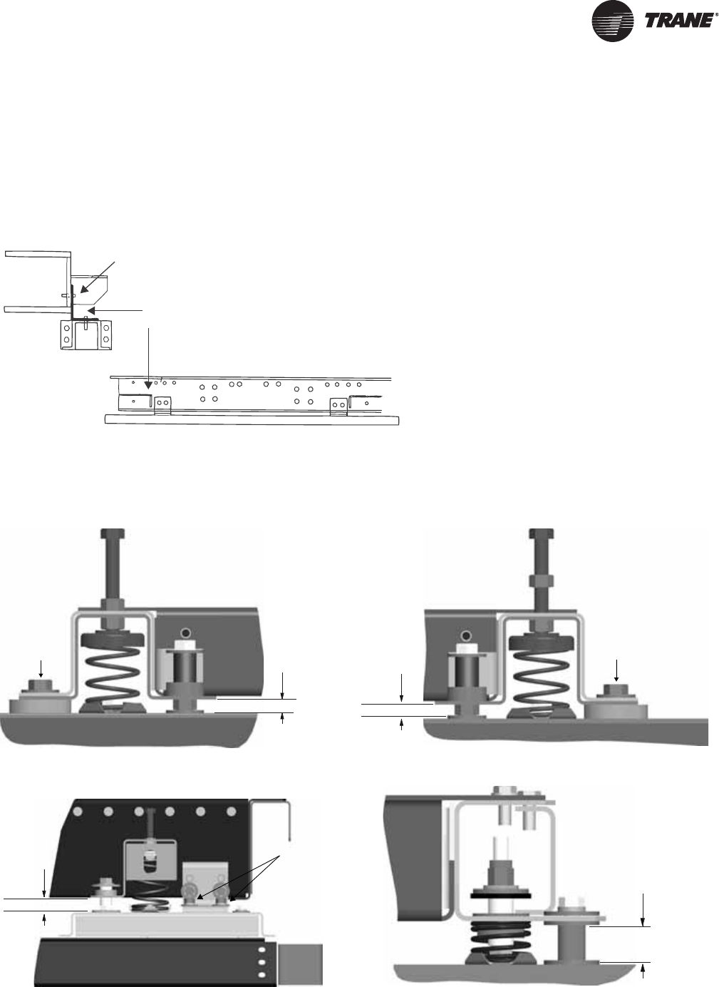
Remove Shipping Tie-Downs
Prior to unit placement, remove the shipping tie-
downs. See Figure 4.
• Shipping tie-downs are located at each corner of the
isolation base. See Figure 5, Figure 6, Figure 7, and
Figure 8.
Figure 4. Isolator tie-down removal
Angle, isolator
tie-down (4 required)
Screw (4 per angle)
lockwasher and hex nut
Figure 5. Isolator tie-down for unit sizes 3-8 Figure 6. Isolator tie-down for unit sizes 10-30
Figure 7. Isolator tie-down removal for unit sizes 66-120 Figure 8. Belt-drive plenum fan tie down
Required
clearance
Tiedown
Required
clearance
Tiedown
Required
clearance
Tiedown
Required
clearance
Installation - Mechanical
22 CLCH-SVX07C-EN
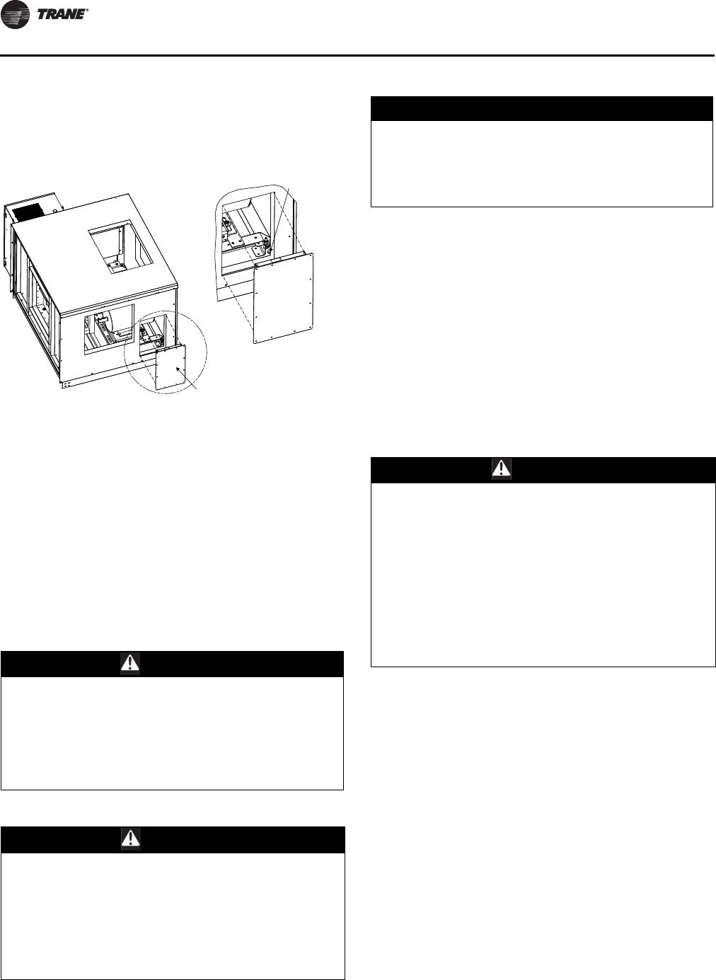
• Access for removal of shipping tie-downs for unit sizes
3-30 is available through the fan section access door or
opposite drive-side plug panel. See Figure 9.
• Access for removal of shipping tie-downs for unit sizes
3-30 is available through the fan section access door or
opposite drive-side plug panel. See Figure 9.
• Remove the bolt. This will release the isolator and
make it possible to remove the pipe or spacer.
• Replace plug panel if applicable.
Note: For outdoor air handlers, after isolator tie-down is
removed, remove the paper backing from the butyl
tape around plug panel perimeter prior to replacing
plug panel.
General Lifting Considerations
:
Before preparing the unit for lifting, estimate the
approximate center of gravity for lifting safety. Because of
placement of internal components, the unit weight may be
unevenly distributed, with more weight in the coil and fan
areas. Approximate unit weights are provided in “Unit
Dimensions and Weights” on page 12. Refer to the unit
submittals for actual section weights. Test the unit for
proper balance before lifting.
For outdoor air handlers, preparation of the roof curb or
pier mount and roof openings must be completed before
lifting to the roof. See CLCH-SVN04A-EN Roof Curbs for
Performance Climate Changer Air Handlers installation
instructions for details.
Always rig subassemblies or sections as they ship from
the factory. Never bolt sections together before rigging.
• Make the loop of the sling parallel to the direction of
airflow, if possible.
• When hoisting the unit into position, use the proper
rigging method, such as straps, slings, spreader bars,
or lifting lugs for protection and safety.
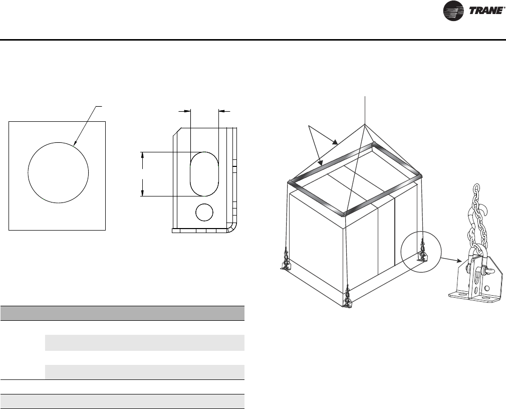
•Use all lifting lugs provided. See Figure 10 and Table 8
for lug hole sizes and location.
Figure 9. Plug panel plate
WARNING
Risk of Unit Dropping!
Always place, assemble, and suspend modules/
subassemblies one at a time. Placing, assembling, and/
or suspending more than one module/subassembly at
a time could result in module/subassemblies dropping
and crushing technicians which could result in death,
serious injury, or equipment damage.
WARNING
Improper Unit Lift!
Test lift unit approximately 24 inches to verify proper
center of gravity lift point. To avoid dropping of unit,
reposition lifting point if unit is not level. Failure to
properly lift unit could result in unit dropping and
possibly crushing operator/technician which could
result in death or serious injury and possible equipment
or property-only damage.
Remove plug panel plate
Remove
tie-down
NOTICE:
Equipment Damage!
Keep skid in place until unit is ready to set. Do not
move the unit or subassembly without the skid in
place as shipped from the factory. Premature skid
removal could result in equipment damage.
WARNING
Heavy Objects!
Ensure that all the lifting equipment used is properly
rated for the weight of the unit being lifted. Each of the
cables (chains or slings), hooks, and shackles used to
lift the unit must be capable of supporting the entire
weight of the unit. Lifting cables (chains or slings) may
not be of the same length. Adjust as necessary for even
unit lift. Other lifting arrangements could cause
equipment or property damage. Failure to follow
instructions above or properly lift unit could result in
unit dropping and possibly crushing operator/
technician which could result in death or serious injury.
Installation - Mechanical
CLCH-SVX07C-EN 23
• For unit sizes 3 to 120 with integral base frame, use
field-provided spreader bars and slings to rig units and
subassemblies as shown in Figure 11. The air handler
is not designed to be lifted or rigged from the top of the
unit.
• For outdoor units, never stack the pipe cabinet or inlet
hood on the unit as it is being lifted.
• Do not attach the intake/exhaust hood or pipe cabinet
to the unit prior to lifting the unit. Doing so may
damage the equipment. Attach the hoods to the unit
only after all sections are in place.
• For outdoor air handlers, all shipping supports and
crating on the face of the sections must be removed to
permit proper fit-up and sealing of the surfaces.
Dispose of properly.
Figure 10. Lug holes
Table 8. Lug hole sizes
Section Location Unit Size Width Height
Unit Lug
Hole Size
Indoor 3-21, 25, 30 0.88 1.38
Indoor 22, 26, 31,
35-58 1.38 1.25
Indoor 66-120 1.25 2.75
Outdoor 3-30 1.25 2.75
Pipe Cabinet Outdoor 3-120 2.5-in. diameter
Hood Outdoor 3-120 1-in. diameter
Unit lug
Pipe cabinet
or hood lug
Diameter Width
Height
Figure 11. Lifting detail for unit sizes 3 to 120
Rigging and spreader
bars furnished
by others
Installation - Mechanical
24 CLCH-SVX07C-EN
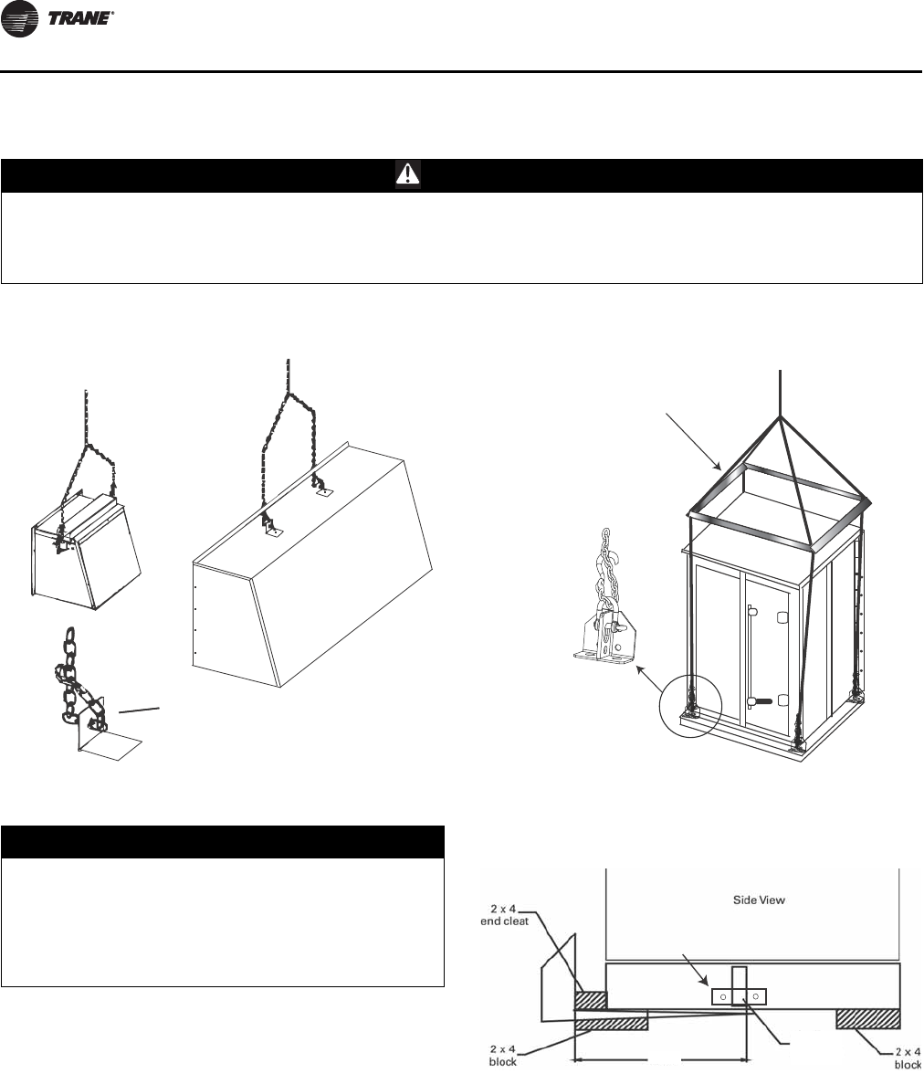
Lifting Hoods and Pipe Cabinets
Forklifting Considerations
Note: Do not use a forklift on outdoor air handlers or
indoor air handlers/subassemblies larger than size
30.
For unit sizes 3-30, a forklift may be used to lift a single
section or small subassembly, provided the forks extend
under both ends of the base frame, or as indicated in
Figure 14. The forks should not contact the bottom of the
air handler. Units should only be lifted from the proper end
identified by the lifting label on the unit. A lifting crane or
other means should be used for larger units where forks
cannot extend under both base rails.
WARNING
Risk of Unit Dropping!
Always place, assemble, and suspend modules/subassemblies one at a time. Placing, assembling, and/or suspending
more than one module/subassembly at a time could result in module/subassemblies dropping and crushing
technicians which could result in death, serious injury, or equipment damage.
Figure 12. Lifting inlet and exhaust hoods Figure 13. Lifting pipe cabinets
Recommended
attachment to
lift lugs
Rigging and spreader
bar provided by
contractor
Recommended
attachment to
lifting lugs
NOTICE:
Equipment Damage!
Do not use a fork lift on air handlers or subassemblies
larger than size 30. Improper use of fork lifts on units
larger than size 30 could result in equipment damage.
Trane is not responsible for equipment damage
resulting from improper fork lifting practices.
Figure 14. Fork lift points with base rail
48 in.
Wooden toe
cleat or metal
cross beam
Unfasten external bracket
to remove wooden toe cleat.
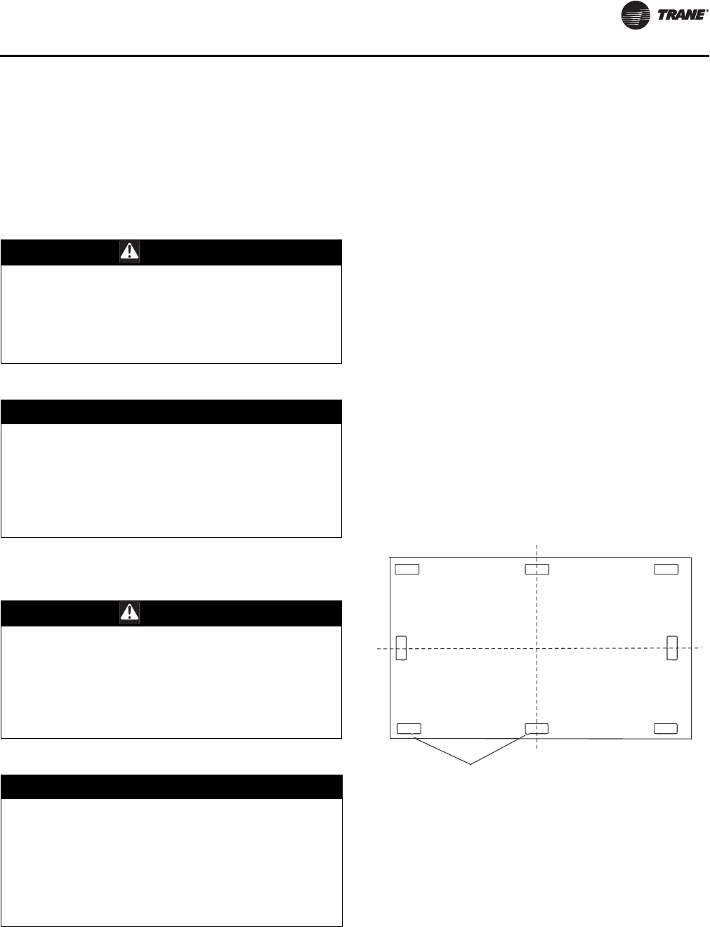
Installation - Mechanical
CLCH-SVX07C-EN 25
Unit Placement and Assembly
If the air handler ships in subassemblies or in individual
sections, some assembly is required, including:
• Ceiling-suspended indoor unit assembly; see See
“Ceiling Suspension” on page 26.
• Section-to-section assembly; see “Section-to-Section
Assembly” on page 27.
:
Unit Placement
If a unit arrives in sections, then each section must be
individually hoisted, set on the housekeeping pad, roof
curb, or pier mount and then assembled.
Refer to the unit submittals and unit tagging for correct
placement of all sections. If there are any discrepancies
between the submittals and the unit tagging, contact your
local Trane representative before proceeding.
Following the order of the sections on the unit submittals
and tagging, individually place each unassembled section
or subassembly in the appropriate installation location.
Note: Prior to placing fan section in the appropriate
installation location, verify shipping tie-downs
have been removed.
For outdoor units, the pipe cabinet must also be mounted
as an individual section. Refer to “Pipe Cabinet
Installation” on page 32 for specific instructions.
When mounting the unit on a roof curb, make sure the
gasketing between the roof curb and unit base provides an
airtight seal.
When mounting the unit on a pier mount, locate one pier
at each corner as a minimum, directly underneath any
shipping split (ensure full support under each side) and
then every four feet at equally spaced intervals around the
perimeter of the unit. Both the unit and the pipe cabinet
should be supported by their base around the entire
perimeter. See Figure 15 and Figure 16.
WARNING
Toxic Fumes!
Keep open flame away from unit exterior or interior. Do
not weld or use cutting torch on the exterior or interior
of the unit. The unit contains polyurethane insulation.
Flame could produce toxic gas which could result in
death or serious injury.
NOTICE:
Equipment Damage!
The internal sections of this unit containing electrical
components must not exceed 104o F operating
temperature. Internal sections of the unit which do not
contain electrical components must not exceed 200o F
temperature. Failure to comply with temperature
requirements could result in equipment damage.
WARNING
Risk of Unit Dropping!
Always place, assemble, and suspend modules/
subassemblies one at a time. Placing, assembling, and/
or suspending more than one module/subassembly at
a time could result in module/subassemblies dropping
and crushing technicians which could result in death,
serious injury, or equipment damage.
NOTICE:
Microbial Growth!
The floor or foundation must be level and the
condensate drain at the proper height for proper coil
drainage and condensate flow. Standing water and wet
surfaces inside the equipment can become an
amplification site for microbial growth (mold), which
could cause odors and damage to the equipment and
building materials.
Figure 15. Piers located in each corner and spaced evenly
every four feet
Note: Piers beneath shipping splits must be structurally
sound to support the weight of the unit.
Piers
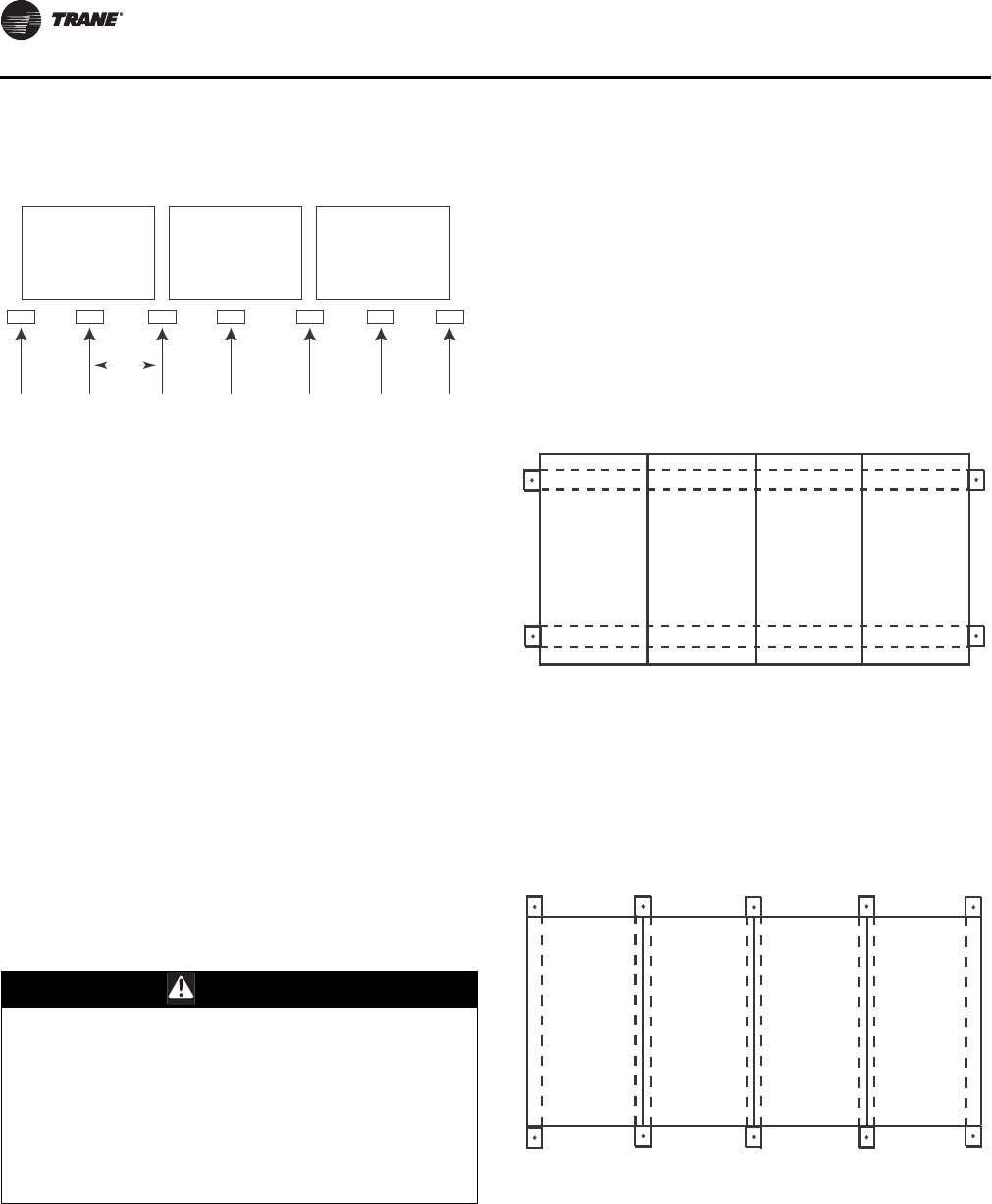
Installation - Mechanical
26 CLCH-SVX07C-EN
For proper operation, the unit must be installed level (zero
tolerance) in both horizontal axes. For vertical discharge
units, allow space under the unit for supply air ductwork
connections.
Unit Assembly
Note: Air handlers often include optional factory-
provided casing penetration entry points for field-
provided wiring. Consider overall unit
serviceability and accessibility before mounting,
running wires (power), making cabinet
penetrations, or mounting any components to the
cabinet.
See “Component Installation Requirements” on page 45
for special assembly/installation considerations.
Removing the Shipping Skid
Remove the wooden shipping blocks, wooden toe cleat if
there is one, and end cleats prior to lowering unit into final
position or installing the unit to the roof curb.
Ceiling Suspension
Note: Ceiling suspension is not recommended for units
larger than size 57 unless using a field-provided
mounting frame.
Using a Field-Provided Mounting Frame
If a field-provided mounting frame is used for ceiling
suspension, the installer/contractor must provide a
ceiling-suspended mounting frame designed to support
the length, width, and weight of the entire air-handling
unit. See “Unit Dimensions and Weights” on page 12 for
approximate weights.
Note: It is the building engineer’s responsibility to size the
structural channels and to provide the appropriate
hangers.
Structural channels in a field-provided frame can be
mounted parallel to airflow or perpendicular to airflow:
• For parallel-to-airflow channels, size channels based
on a four-point load distribution (see Figure 17.
• For perpendicular-to-airflow channels, size channels
based on the load distribution of the individual
sections and install the channels so that both ends of
every section are supported (see Figure 18).
Figure 16. Side view with two shipping splits - locate
one pier directly under each shipping split
Note: Piers beneath shipping splits must be structurally
sound to support the weight of the unit.
WARNING
Risk of Unit Dropping!
Do not use mounting legs for ceiling suspension,
external isolation, or unit support during module
placement. Mounting legs are designed only to secure
the unit to the floor, housekeeping pad, or platform.
Improper use of the mounting legs as described above
could result in unit dropping and crushing technicians
which could result in death or serious injury, and
equipment damage.
4 ft
Figure 17. Typical suspension method-parallel channels
Figure 18. Typical ceiling suspension-perpendicular
channels
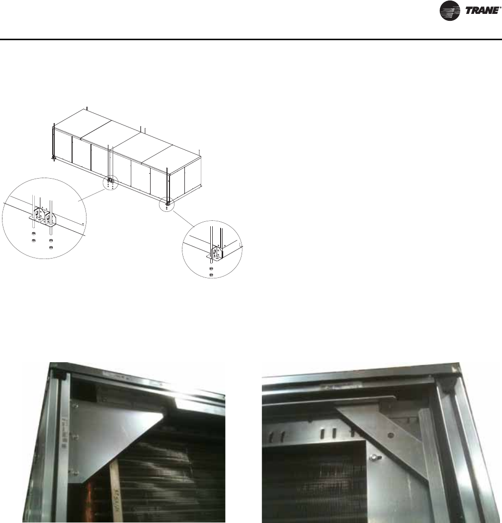
Installation - Mechanical
CLCH-SVX07C-EN 27
Using Integral Base Frame
If using the factory-provided integral base frame for ceiling
suspension, individual sections and/or subassemblies will
have base frame shipping splits and base frame lifting
lugs. When using the base frame for ceiling suspension:
• Suspend the unit (on both sides of the unit) at each
shipping split lug as well as the four corners of the unit
(see Figure 19). See Figure 10 and Table 8 on page 23
for lug hole sizes.
• Bolt shipping splits together.
The hanger rods must extend through the bottom of the
base lug. It is the building engineer’s responsibility to
provide the appropriate hangers.
Shipping Gussets
Prior to pulling the shipping splits together, the shipping
gussets (see Figure 20) should be removed to simplify
panel removal (except for units required OSHPD
certification). If there is enough access after joining the
shipping splits, the gussets can be removed after they are
joined. The exception to this rule is for size 35-50 stacked
units. For these sizes, the gusset should be left in place for
the lower level unit unless they are installed in a shipping
split that contains a coil.
Do not mistake the coil structural gusset (see Figure 21)
used on unit sizes 66-120 with the shipping gussets.
Section-to-Section Assembly
Air handlers ship with all necessary assembly hardware
and gasket material. The hardware should be packaged in
either a clear plastic envelope or cardboard box inside the
fan section, access section, or mixing box.
The number of sections to be assembled often makes it
necessary to use more than one section to ship the
assembly material; therefore, check all sections
thoroughly before contacting your Trane sales
representative to report missing items.
Sections are joined with gasketing applied to one of the
mating surfaces and hardware to bolt the sections
together. The gasketing for section-to-section joints is a
closed cell foam with adhesive backing.
To assemble the unit:
1. Locate the mounting hardware and gasket material.
2. All shipping supports and crating on the face of the
sections must be removed and discarded to permit
proper fit-up and sealing of the surfaces. Remove any
shipping bolts located on the mounting surfaces of the
sections (see Figure 22).
3. Apply the gasketing to one of the mating surfaces; see
Figure 22, Figure 23, and Figure 24.
Figure 19. Ceiling suspension for unit sizes 3-57
Hole diameter
is 0.625 inches
Figure 20. Shipping gusset Figure 21. Coil structural gusset
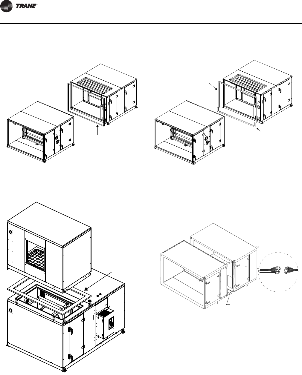
Installation - Mechanical
28 CLCH-SVX07C-EN
4. If the unit is equipped with factory-mounted controls,
move adjacent subassembly within six inches and
fasten quick connects where the sections bolt together
(see Figure 25).
Note: Reference the appropriate controller manual for
more details on the installation of units with
factory-mounted controls.
5. Use a bar clamp to pull adjacent shipping section lifting
lugs together.
6. For indoor units sizes 66-120 and for outdoor units size
10-120, a wedge block is provided to aid in pulling and
aligning the units together. Attach the wedge blocks to
both sides of the units being pulled together, matching
the correct wedge block with the correct hole pattern.
See Figure 29, p. 30.
7. Verify that the subassembly with the overhang profile
on the roof is higher than the mating subassembly. If it
is not, raise one end of the subassembly and bring the
unit together. See Figure 26.
8. Due to unlevel floor and platforms, the roof may be
misaligned as shown in Figure 26. A common solution
Figure 22. Section-to-section installation Figure 23. Coil-section-to-downstream-section bolt up
with splash guard
Indoor units - Gasket
0.375 in. T x 0.750 in. W (3-30)
1.0 in. T x 1.0 in. W (35-120)
Outdoor units - Butyl tape
0.375 in. T x 0.375 in W (3-120)
Butyl Tape
0.375 in. T x 0.375 in. W
Gasket
0.375 in. T x 0.750 in. W
Figure 24. Stacked unit assembly (shown for sizes 3-50)
Gasket
X23010544010
1.00 inches T
x
4.00 inches W
Figure 25. Horizontal section-to-section quick connects
Use 2 x 4 inch wood to protect
hands from accidental pinching
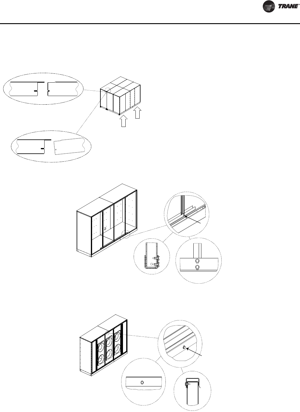
Installation - Mechanical
CLCH-SVX07C-EN 29
is to raise one end of the shipping section to clear the
hemming before pulling the units together. 9. In addition, an adjustment can also be made to the
height of the roof of either subassembly.
At the center
(width-wise) of the unit, measure the height of each
adjacent subassembly and verify that the
subassembly with the overlap sheet metal is higher
than the mating subassembly roof. If it is not, adjust
the height of either subassembly by loosening the
screws in the vertical channels or component
structure and adjust the height of the roof. See
Figure 27
and Figure 28).
Figure 26. Roof alignment (indoor unit only)
Figure 27. Adjust height of roof by adjusting vertical channels
Loosen screws along
width of unit for roof
height adjustment.
Figure 28. Adjust height of roof by loosening screws
Loosen screws along
width of unit for roof
height adjustment.
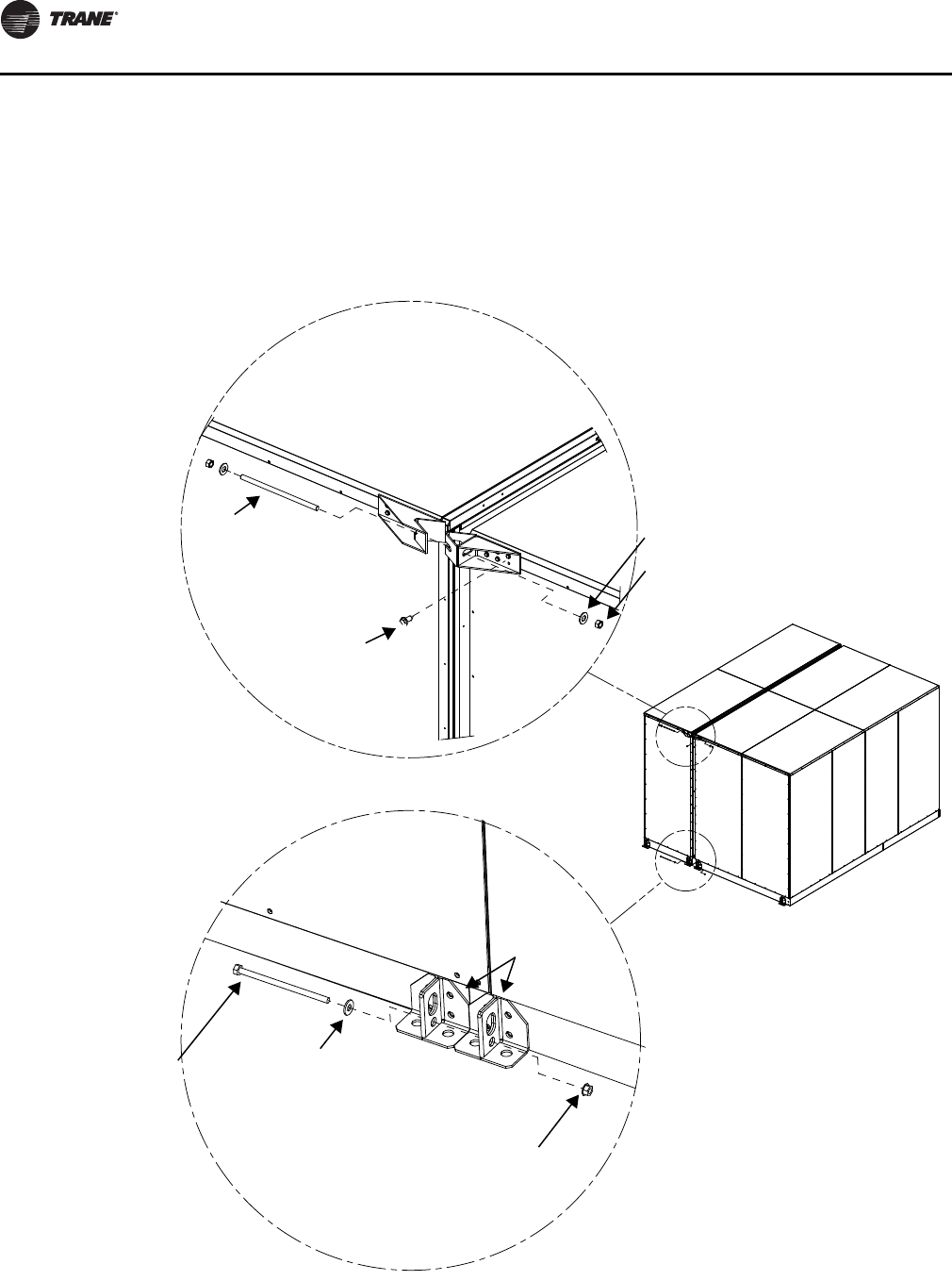
Installation - Mechanical
30 CLCH-SVX07C-EN
10. For unit sizes 3-30, bolt the unit base frames together
using 5/16-inch bolts (see Figure 29).
11. For unit sizes 35-120, bolt the unit base frames together
using ½-threaded rod (see Figure 29).
12. For sizes 66-120 only, bolt through the wedge blocks
using a ½-threaded rod (see Figure 29). Alternate
between tightening on the lifting lug bolts and wedge
block bolts until the shipping section comes together.
13. Use straps and come-alongs to compress the
gasketing and pull the sections together along the
height of the unit.
Figure 29. Base frame split assembly
Nut hex flange (HW)
Size 3-30 - 0.313-18
Size 66-120 - 0.500-13
Hex machine bolt fully
threaded zinc plated
Size 3-30 - 5/16 x 6 in.
Size 66-120 - 0.500-13 x 10 in.
Washer
Size 3-30 - 0.375 ID x 0.875 OD
Size 66-120 - 0.656 ID x 0.312 OD
Lifting lugs
Threaded rod
0.500-13 x 10.50
Nut
0.500-13 hex machine
Washer
0.656 ID x 1.312 OD
Wedge block for
indoor unit size 66-120
outdorr unit size 10-120
Leached self-driller screw
0.250-14 x 0.75
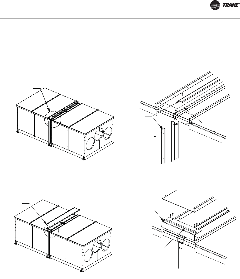
Installation - Mechanical
CLCH-SVX07C-EN 31
14. Install the section-to-section screws inserting the
appropriate screws through the overlapping flanges
using a powered impact gun and taking care not to
strip the screws. Outdoor air handlers will ship with a
seam cap that is to be installed over the section-to-
section seams. Factory-supplied butyl tape must be
applied over the seam prior to seam cap being applied.
See Figure 30.
15. For outdoor air handlers, attach roof overhang angle
with number 10 screws. Join outdoor roof panels
together at the seams in the direction perpendicular to
airflow and secure them in place with 5/16-inch x 3/4-
inch bolts and 5/16 lock nuts. Install the roof joint strip
to cover the seam between two outdoor roof panels in
the perpendicular to airflow direction of. Use 3/8-inch
butyl tape to cover the seam between two outdoor roof
panels overhang at the side the unit. Bend joint strip
over roof panel and use two number 10 sheet metal
screws (one in each roof panel) to secure joint strip.
Trim the roof joint strip to insure that it does not
protrude more than 1/16-inch beyond outdoor roof
overhang (see Figure 31).
Figure 30. Section-to-section seam cap installation
Seam cap
Butyl tape
Detail A
See
Detail A
See
Detail B
Detail B
Roof overhang
Butyl tape
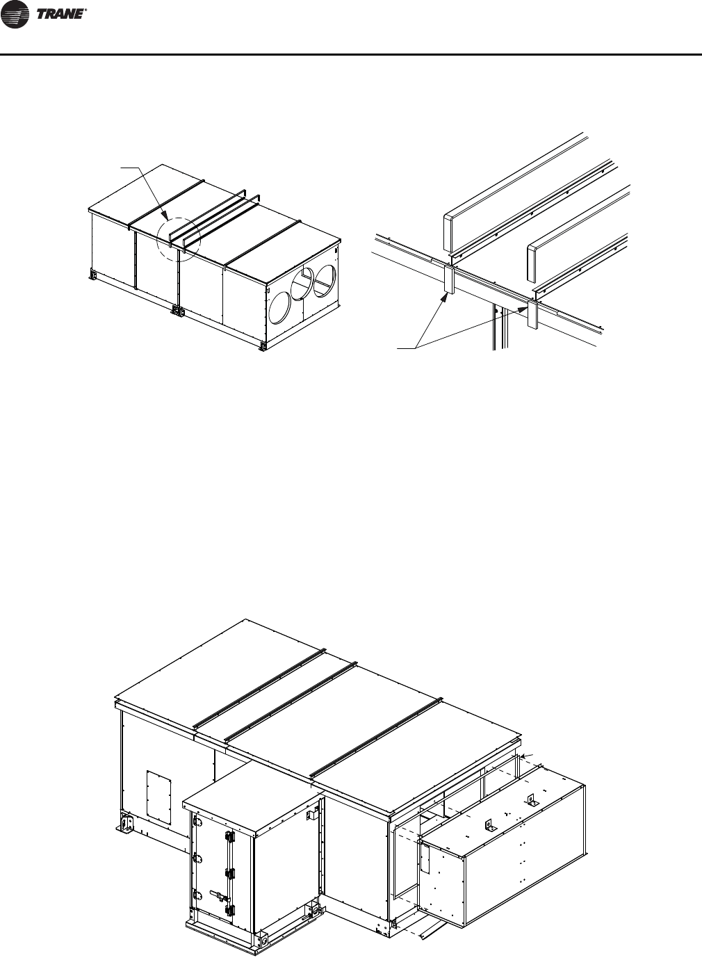
Installation - Mechanical
32 CLCH-SVX07C-EN
Pipe Cabinet Installation
1. After air handler is completely installed and checked
for accuracy of level and square, pipe cabinet install
can begin.
2. Remove pipe cabinet base cross member by removing
the four bolts and nuts.
3. Check to ensure that the structure the pipe cabinet is to
be installed on is square and level.
4. Install 3/8-inch x 3/8-inch white butyl tape to flanged
side of pipe cabinet wall and remove paper backing
from tape. See Figure 32.
5. Lift cabinet into place on to pipe cabinet curb.
6. Slide pipe cabinet tight up against the sidewall of the
air handler.
7. Check pipe cabinet side walls to ensure they are plumb.
8. Apply a bead of caulk along the corner between the
pipe cabinet and air handler wall prior to installing
connecting angle.
Figure 31. Join outdoor roof panels at the seams
See
Detail A
Detail A
Butyl tape
Figure 32. Pipe cabinet installation
Butyl tape
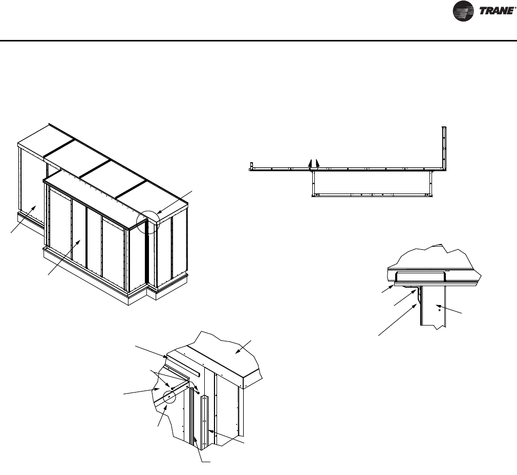
Installation - Mechanical
CLCH-SVX07C-EN 33
9. Install inside corner cap. See Figure 33 Detail A and B.
10. Install 3/8-inch x 3/8-inch white butyl tape to unit wall
where pipe cabinet roof connects.
11. Lift pipe cabinet roof into place and attach to unit wall
with screws. See Figure 33.
Figure 33. Pipe cabinet installation details
A
See Detail B
AHU
Pipe cabinet
Ribbed
Butyl tape
Screw:
10-16 x .750
self-driller
Pipe cabinet
outer roof
Slots provided to allow
final adjustment
of outer roof
AHU
outdoor roof
Inside corner cap
Ribbed Butyl tape
Ribbed Butyl tape
(see note)
Inside
corner cap
Pipe cabinet
wall
Detail B
Detail A
Top view
Roof and base parts
rmoved for clarity
Note: Seam to be sealed prior to
attaching inside corner cap with
10-16 x .750 self-driller screws
Ribbed Butyl tape
(see note)
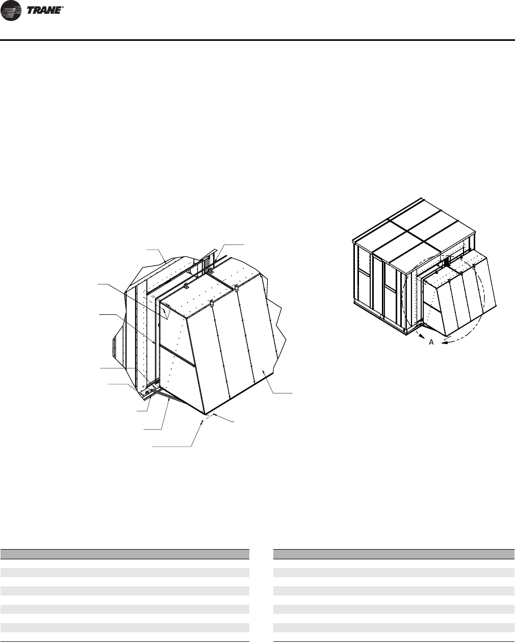
Installation - Mechanical
34 CLCH-SVX07C-EN
Outdoor Unit Weather Hoods
1. Per the unit drawing determine mounting location of
the unit weather hoods.
2. Using the factory provided screws mount the weather
hoods to the unit.
3. On larger units, weather hoods may be large enough to
require angled down supports. In those cases, the
angles are shipped attached to the hood but will need
to be connected to the air handler by the installing
contractor. See Figure 34.
Note: It is required that the hoods be sealed to the unit
using factory-provided butyl/caulk tape.
Stacked Outdoor Units
Assembly hardware
Figure 34. Hood installation
AHU outdoor roof Butyl caulk tape
1.00 W x .125T.
Hood
Nut-Hex .31-18
Detail A
Screw self-driller
10-16 x .750
Butyl caulk tape
1.00 W x .125T.
Nut-Hex .31-18
Bolt .313-18 x .750 Hex
Bracket Support
Angle Hood Support
(when required)
Bolt .313-18 x .750 Hex
Table 9. Parts list for outdoor stacked units
Item Description Item Description
1 Gasket: 1.00T x 4.00W
2Bracket: Stacked unit 10 Guard: Energy recovery end cover
3 Screw: 0.313-18 x 0.875 sheet metal 11 Guard: Energy recovery end cover
4Screw: 10-16 x 0.750 self driller 12 Guard: Direction of airflow flashing
5 Tape: Butyl 0.38T 13 Guard: Flashing seam cover
6Tape: Ribbed Butyl 14 Adhesive/sealant: Flex polyurethane
7 Plate: Vertical seam cap 15 Bracket: Hood support
8Tape: 0.12T x 1.00W, gray Butyl 16 Angle: Hood support
9 Guard: perpendicular to airflow flashing 17 Screw: 0.250-14 x 0.750 self driller
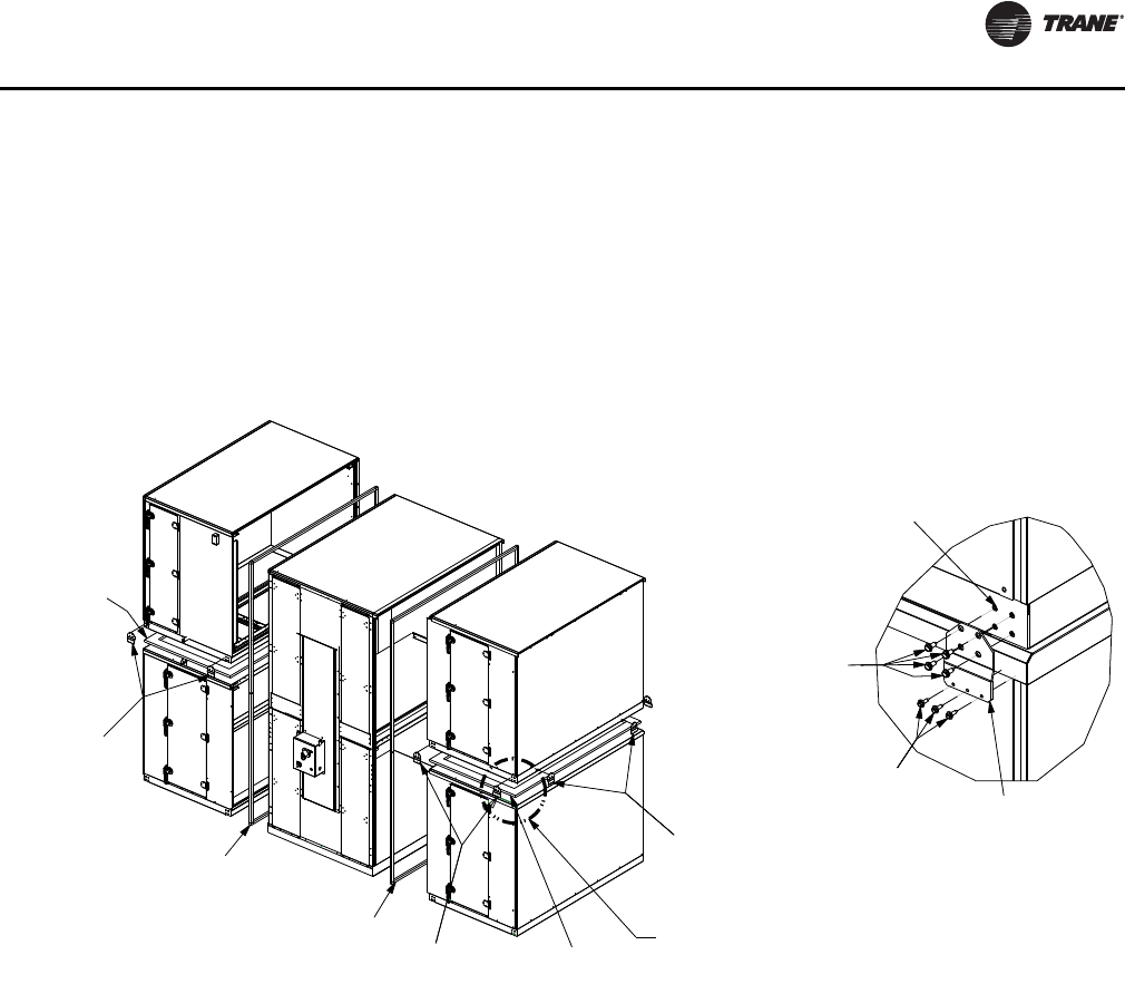
Installation - Mechanical
CLCH-SVX07C-EN 35
Unit assembly
1. See Figure 35. Apply gasket (Item 1) on top of lower
unit. Compress gasketing to ensure a good air seal
between upper and lower sections.
2. Place upper unit on lower unit.
3. Remove lifting lugs from top unit and attach stacking
brackets (Item 2) to top and bottom units using screws
(Item 3 and Item 4). See Detail A in Figure 35. Stacking
brackets (Item 2) are to be used on the right and left
sides at each shipping split section end and also on
front and back of the unit.
4. Apply Butyl tape (Item 5) to one side of the shipping
split section.
5. Slide shipping split sections together, pulling tight
using lifting lugs and threaded rod on bottom and
straps or pipe clamps on top.
Figure 35. Stacked unit assembly
(1) Gasket:
1.00T x 4.00W
(2) Bracket:
stacked unit
(5) Tape:
Butyl 0.38T
(5) Tape:
Butyl 0.38T
(3) Screw:
0.313-18 x 0.875
sheetmetal
Part# X25240049010
(4) Screw:
10-16 x 0.750
self-driller
Part# X25020634020
(1) Gasket:
1.00T x 4.00W
See Detail A
Detail A
Remove lugs from upper
baserail prior to installing
stacked unit bracket
(2) Bracket:
stacked unit
(2) Bracket:
stacked unit
(2)Bracket:
stacked unit
Part# 4953-0203
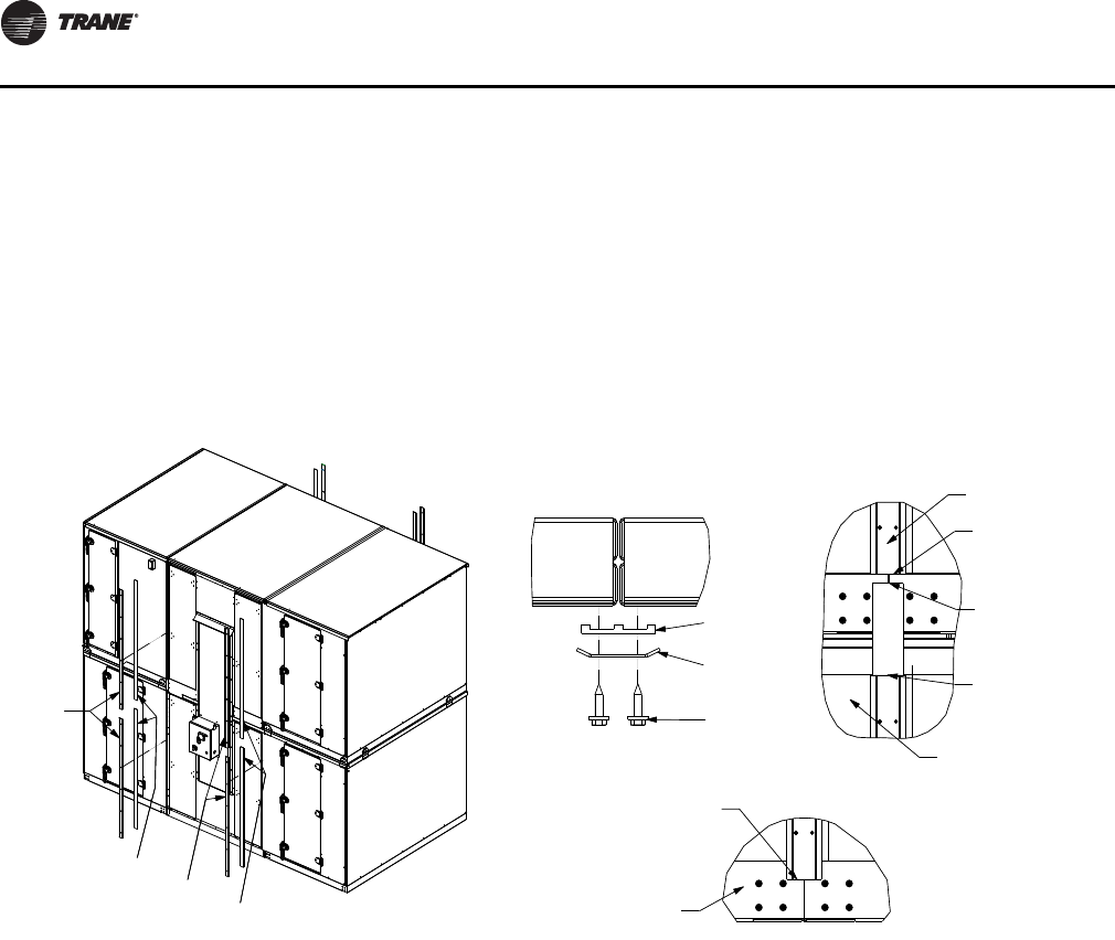
Installation - Mechanical
36 CLCH-SVX07C-EN
Vertical Seam Cap Installation
1. See Figure 36. Apply ribbed Butyl tape (Item 6) over all
vertical shipping split seams (see Detail A). First level
ribbed Butyl tape (Item 6) starts 1/2 inch below second
level wall panel (see Detail B), and extends down
beyond the bottom of the first level wall panel onto the
base rail at least one inch (see Detail C). Second level
ribbed Butyl tape (Item 6) starts at bottom of wall panel
on second level (see Detail B) and runs up to the top of
the second level wall panel.
2. Secure vertical seam cap (Item 7) over ribbed Butyl
tape (Item 6) with screws (Item 4) (see Detail A). First
level vertical seam cap (Item 7) starts at bottom of hem
on roof panels (see Detail B) and extends down onto
the base rail at least one inch (see Detail D in Figure 41).
Vertical seam cap (Item 7) on second level starts at
bottom of wall panel and extends up (see Detail B).
Second level vertical seam cap (Item 7) may extend
onto the roof panel.
Figure 36. Vertical seam cap installation
(7) Plate:
Vertical
seam cap
(6) Tape:
Ribbed Butyl
(7) Plate:
Vertical
seam cap
(4) Screw:
10-16 x 0.750
self driller
(6) Tape:
Ribbed Butyl
(7) Plate: Vertical
seam cap
(6) Tape:
Ribbed Butyl
Detail A
Shipping split seams
Detail B
Ribbed Butyl tape and
seam cap flush with
bottom of wall panel
First level ribbed
Butyl tape 1/2 inch
below second level
wall panel
First level seam cap
starts at bottom of
hem on roof panel
First level
Ribbed Butyl tape and seam
cap extend beyond the bottom
of wall panel onto base rail at
least one inch
First level
Second level
Detail C
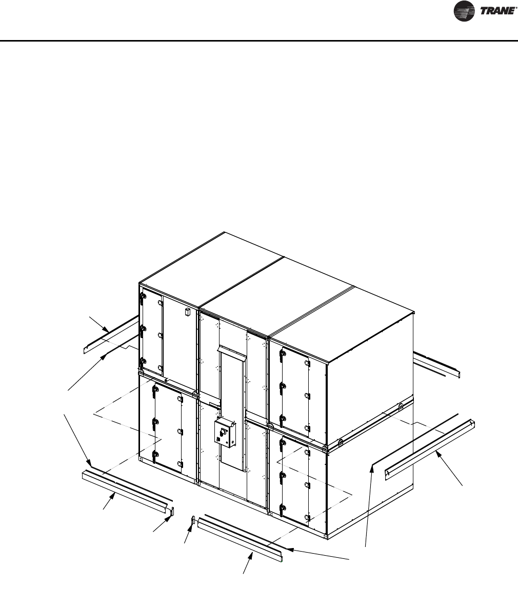
Installation - Mechanical
CLCH-SVX07C-EN 37
Flashing Installation
For additional information, see “Flashing Installation
Notes” on page 40.
For hood installations, see “Install flashing and hood” on
page 41.
1. See Figure 37. Apply Butyl tape (Item 8) to
perpendicular-to-airflow flashing (Item 9) and secure
to base rail with screws (Item 4) on front and back of
unit (see Detail A in Figure 41).
2. For energy wheel/CDQ wheel, preassemble end covers
(Item 10 and Item 11) to direction-of-airflow flashing
(Item 12) with screws (Item 4). Apply caulk (Item 14) to
create water tight seal (see Detail B in Figure 39).
3. Apply Butyl tape (Item 8) to direction-of-airflow
flashing (Item 12) and secure to base rails with screws
(Item 4). Start at corners to ensure tight corner seams.
Apply caulk (Item 14) to create water-tight seal (see
Detail A and Detail C in Figure 40).
4. Install seam covers (Item 13) to all flashing seams (see
Detail D in Figure 41).
Figure 37. Flashing installation
(9) Guard:
Perpendicular-to-
airflow flashing
(8) Tape:
0.12T x 1.00W
gray Butyl
(12) Guard:
Direction-of-
airflow flashing
(10) Guard:
Energy recovery
end cover (11) Guard:
Energy recovery
end cover (12) Guard:
Direction-of-
airflow flashing
(8) Tape:
0.12T x 1.00W
gray Butyl
(9) Guard:
Perpendicular-to-
airflow flashing
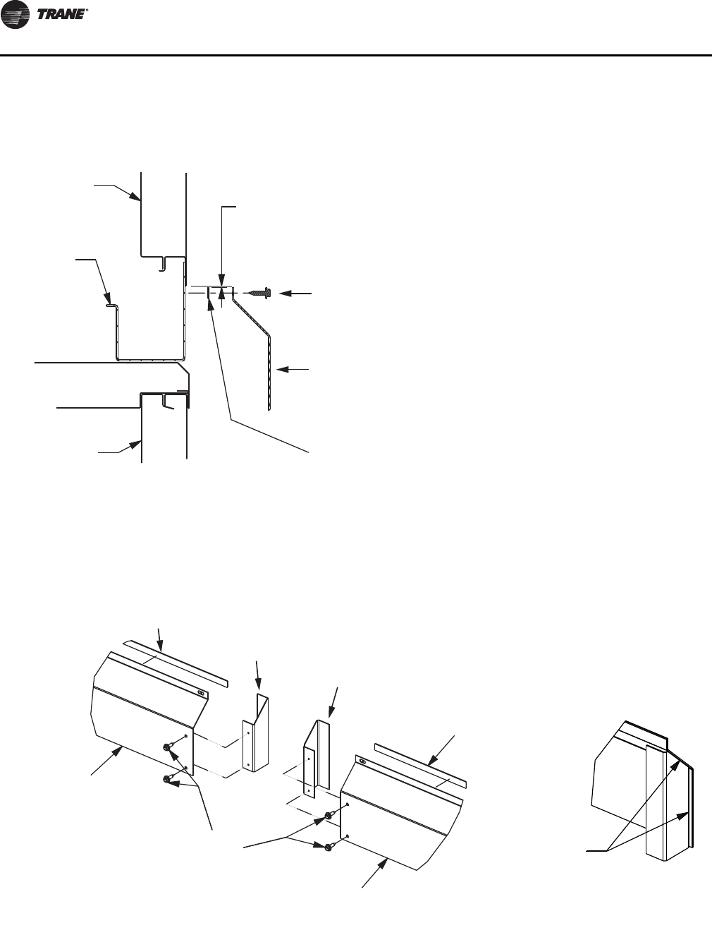
Installation - Mechanical
38 CLCH-SVX07C-EN
Figure 38. Flashing installation location
Detail A
Base rail
.060 gap between
bottom of panel and
top of flashing
Lower panel
Upper panel
(4) Screw:
10-16 x 0.750
self-driller
(9) Guard: Perpendicular-
to-airflow flashing
or
(12) Guard: Direction-
of-airflow flashing
(8) Tape:
0.12T x 1.00W
gray Butyl
Figure 39. Flashing end cover installation applied to energy wheels and CDQ sections
Detail B
(8) Tape:
0.12T x 1.00W
gray Butyl (10) Guard:
Energy recovery
end cover (11) Guard:
Energy recovery
end cover
(8) Tape:
0.12T x 1.00W
gray Butyl
(12) Guard:
Direction-of-
airflow flashing
(4) Screw:
10-16 x 0.750
self-driller (12) Guard:
Direction-of-
airflow flashing
Apply caulk
(14) Adhesive/sealant:
Flex polyurethane
Assembled view
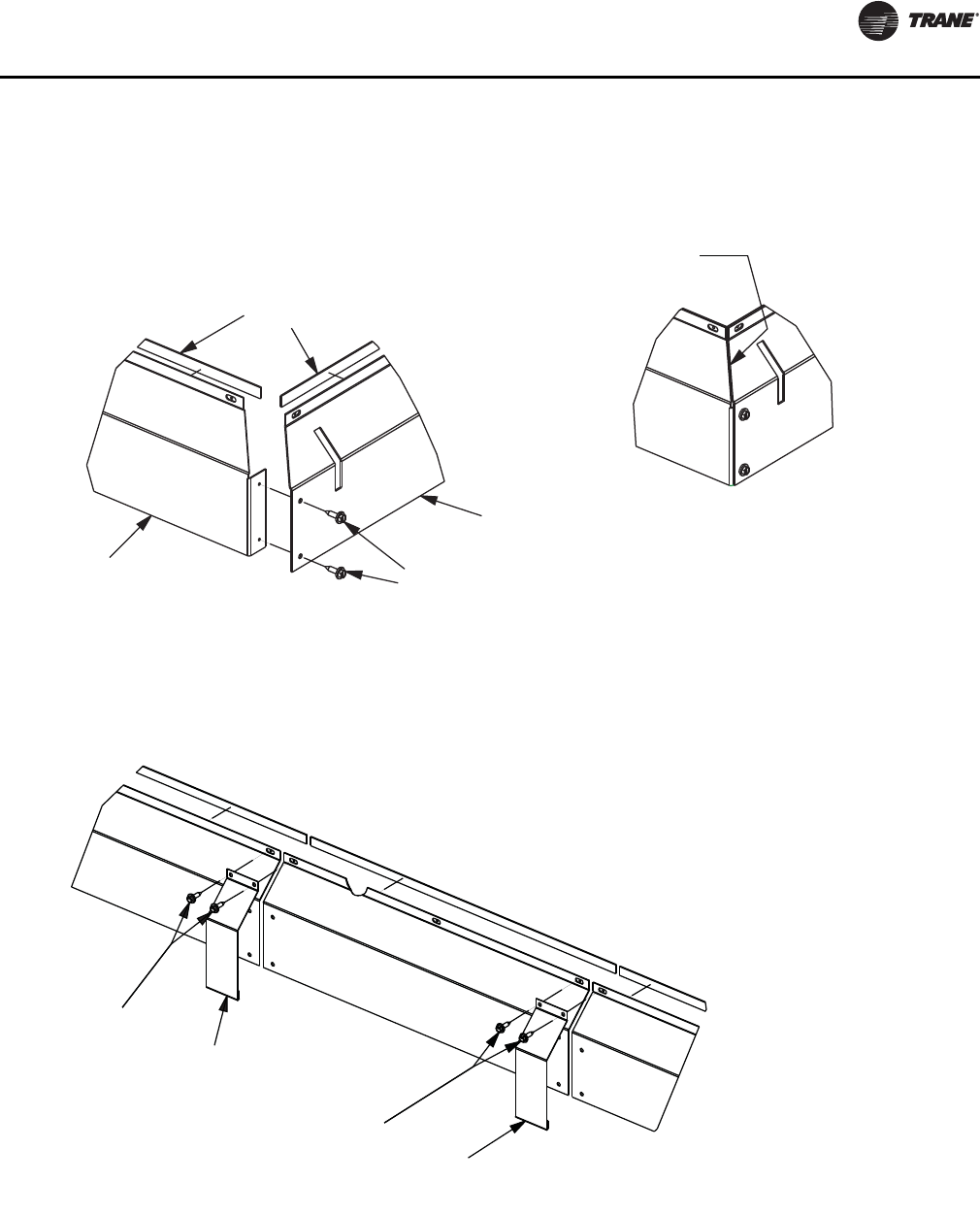
Installation - Mechanical
CLCH-SVX07C-EN 39
Figure 40. Flashing for corner seams
Assembled view
Detail C
Apply caulk
(14) Adhesive/sealant:
Flex polyurethane
(12) Guard:
Direction-of-
airflow flashing
(4) Screw:
10-16 x 0.750
self-driller
(9) Guard:
Perpendicular-to-
airflow flashing
(8) Tape:
0.12T x 1.00W
gray Butyl
Figure 41. Flashing seam cover installation
Detail D
(4) Screw:
10-16 x 0.750
self-driller
(13) Guard:
Flashing seam cover
Note: Install flashing seam
cover on all flashing seams
(4) Screw:
10-16 x 0.750
self-driller
(13) Guard:
Flashing seam cover
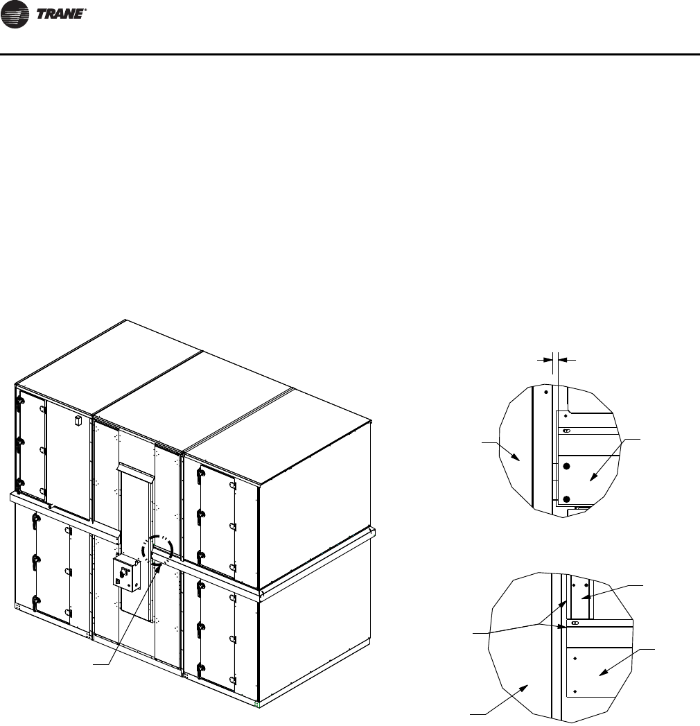
Installation - Mechanical
40 CLCH-SVX07C-EN
Flashing Installation Notes
• Side flashing will have locating features:
– Right side front and back pieces will have two
diamonds and a tab. Intermediate right side pieces
(if present) will have two diamonds and length of
part will match the ship group length and mounting
holes will match hole pattern on the unit.
– Left side front and back pieces will have one
diamond and a tab. Intermediate left side pieces (if
present) will have one diamond and length of part
will match the ship group length and mounting
holes will match hole pattern on the unit.
• Flashing runs full length on right/left sides of unit
except on access side when an energy recovery
section is present. For energy recovery section without
full height doors, flashing will extend to removable
plug panel. For energy recovery section with full height
doors, flashing will be flush with edge of vertical seam
caps (see Detail A in Figure 42).
• Flashing runs full length on front/back of unit. Front/
back flashing will not have any locating features and
will always have mitre (one piece will have two mitres,
two pieces will have one mitre).
Figure 42. Side flashing installation
Flashing
Plug panel
Detail A
without full height doors
.406 from plug
panel flange
Vertical
seam cap
Flashing
Door
Flashing flush
with vertical
seam cap
Detail A
with full height doors
Assembled view
See Detail A
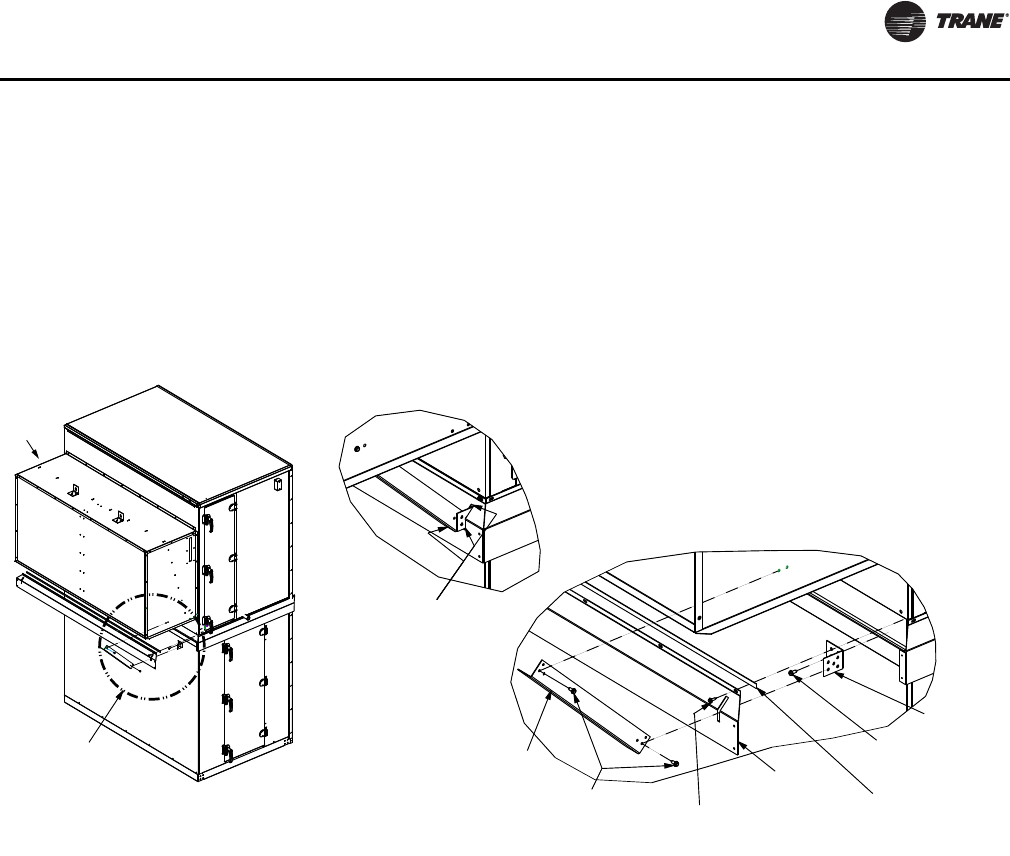
Installation - Mechanical
CLCH-SVX07C-EN 41
Install flashing and hood
1. See Figure 43. Secure two hood support brackets (Item
15) to base rail with screws (Item 17).
2. Apply Butyl tape (Item 8) to flashing (Item 9) and place
over hood support brackets (Item 15) using cut in
flashing and secure to base rails with screws (Item 4).
3. See “Outdoor Unit Weather Hoods” on page 34 for
hood installation instructions.
4. Secure hood support angles (Item 16) to hood support
brackets (Item 15) and to the hood side panels with
screws (Item 17).
5. Apply caulk (Item 14) around hood support bracket
(Item 15), hood support angle (Item 16), and cutout in
perpendicular-to-airflow flashing (Item 9) to ensure
water-tight seal.
Figure 43. Stacked unit assembly
(4) Screw:
10-16 x 0.750
self driller
(8) Tape:
0.12T x 1.00W
gray Butyl
(9) Guard:
perpendicular
to airflow flashing
Apply caulk
(14) Adhesive/sealant:
flex polyurethane
(15) Bracket:
hood support
(16) Angle:
hood support
(17) Screw:
0.250-14 x 0.750
self driller
Hood
See Detail A
Detail A
Detail A
Assembled View
(17) Screw:
0.250-14 x 0.750
self driller
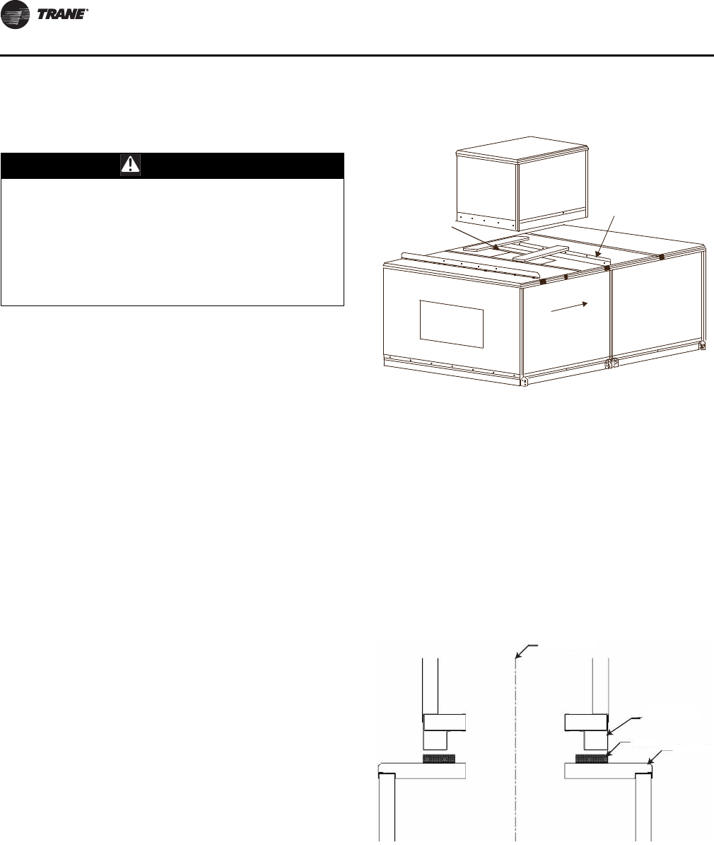
Installation - Mechanical
42 CLCH-SVX07C-EN
Indoor Dual-Path SDU/Winterizer
Assembly
A dual-path, Split Dehumidification Unit (SDU)/winterizer
air handler consists of two units that are stacked together
in a draw-thru arrangement that share one supply fan. The
unit on the first level (primary unit) is designed to handle
the return air and is larger than the unit on the second level
(secondary unit), which is designed to handle outside air.
Factory-designed unit support brackets are provided with
all factory-approved, dual-path SDUs or winterizer air
handlers.
• A horizontal SDU/winterizer dual-path air handler
incorporates a horizontal supply fan on the first level
with a top opening in the primary unit that aligns with
a bottom opening in the secondary unit.
• A vertical SDU/winterizer dual-path air handler
incorporates a vertical supply fan on the second level
with a back opening that aligns with a front opening in
the secondary unit.
To assemble air handlers utilizing factory-approved and
factory-provided dissimilar unit sizes for horizontal SDU or
winterizer applications, join all similar size shipping
sections per “Section-to-Section Assembly” on page 27.
Horizontal SDU/Winterizer Air Handler
Assembly
To assemble dissimilar unit sizes for an indoor horizontal
SDU/winterizer configuration:
1. Locate the mounting hardware and gasket material.
Note: Black unit support brackets ship pre-installed on
the primary (larger) unit section.
2. Apply gasket in direction of airflow between the black
unit support brackets to the roof of the primary unit.
See Figure 44. The gasket needs to be placed such that
it will be directly under the integral base frame of the
secondary (smaller) unit to be stacked on top. The
secondary unit will be centered along the width on the
primary unit.
3. If there is an opening in the roof of the primary unit,
apply gasket perpendicular to airflow on the roof next
to the opening (air entering side only).
4. Lift the secondary unit, following instructions in
“General Lifting Considerations” on page 22 (see
Figure 11), and place on the black unit support brackets
(see Figure 45). The secondary unit must be centered
on the primary unit between the black unit support
brackets.
WARNING
Heavy Objects!
Do not stack air handlers unless factory-designed and
factory-approved. When stacking units, factory-
designed unit support brackets must be used. Stacking
units without factory-approval and without factory-
provided support brackets could result in the base unit
collapsing under the weight of the top unit which could
result in death or serious injury and property damage.
Figure 44. Apply gasket in direction of airflow
Figure 45. Place secondary unit on black unit support
brackets.
Gasket
X23010544010
1.0 inches T x
4.0 inches W
Airflow
Unit support
brackets
Center of units
Secondary
unit
Gasket Primary
unit
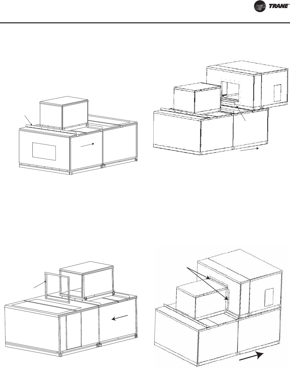
Installation - Mechanical
CLCH-SVX07C-EN 43
5. Install screws as shown in Figure 46 inserting the
appropriate screws using a powered impact gun and
taking care not to strip the screws.
6. Remove the secondary unit lifting lugs one at a time
and reinstall screws after sections are set in final
position.
Vertical SDU/Winterizer Air Handler
Assembly
To assemble dissimilar unit sizes for an indoor vertical
SDU/winterizer configuration:
1. Apply gasketing to the mating surface of the secondary
unit (see Figure 47).
2. Apply gasketing to the mating surface of the primary
unit at the bottom of the opening (see Figure 48.
3. Lift the secondary unit, follow instructions in “General
Lifting Considerations” on page 22 (see Figure 11), and
place on the black unit support brackets (see Figure 45,
p. 42. The secondary unit must be centered on the
primary unit between the black unit support brackets.
4. Install trim angles as shown in Figure 49 inserting the
10-16 x 3/4-inch self-drilling screws using a powered
impact gun and taking care not to strip the screws.
Figure 46. Install screws using powered impact gun.
Figure 47. Apply gasketing to mating surface of
secondary unit
Airflow
X25240049010
Screw: 0.313-18 x 0.875 in.
Sheet metal hex head
Airflow
Gasket
1.0 inches T x 1.0 inches W
Figure 48. Apply gasketing to the mating surface of the
primary unit.
Figure 49. Install trim angles
Gasket
1-inch T x
2 1/2 inch W
Airflow
Vertical and horizontal
trim angles
Airflow
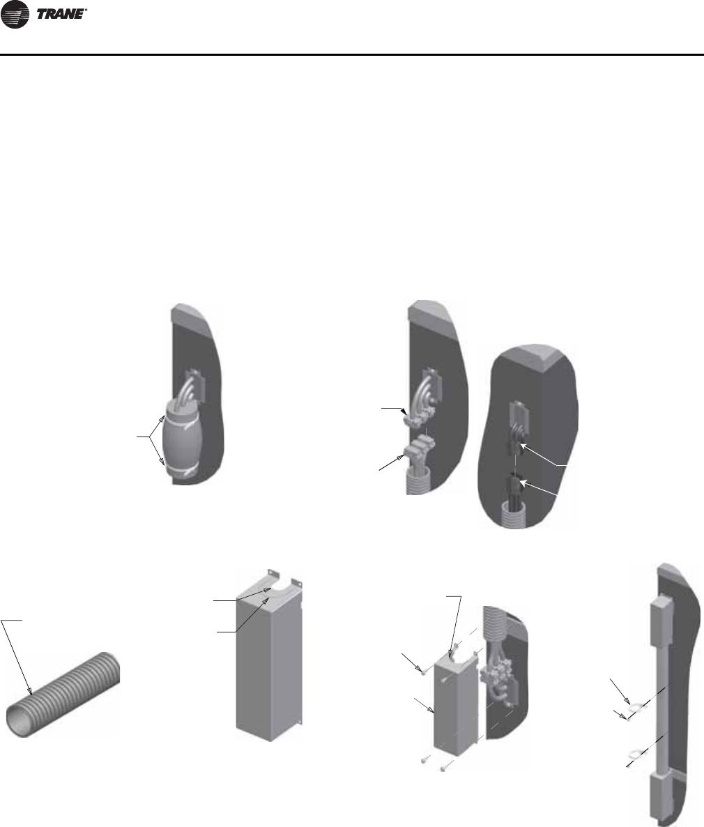
Installation - Mechanical
44 CLCH-SVX07C-EN
External Raceway Assembly
For air handling units with factory-installed power wiring
extending from the first level to the second level, wiring
must be connected and assembled in a raceway.
1. Remove protective foam cover from connectors.
2. Attach stacked raceway harness connectors, matching
connector colors on the high voltage side and
connector numbers on the low voltage side.
3. Verify conduit size.
4. Attach covers.
5. Secure conduit.
Part numbers:
• Indoor
– External Raceway Kit: KIT09713
• Outdoor
– External Raceway Kit - Top: KIT16191
– External Raceway Kit - Bottom: KIT16192
Figure 50. External raceway
Cut zip-ties
Step 1
Match connector
numbers (LV side)
Match connector
colors (HV side)
High-voltage (HV)
stacked harness
Low-voltage (LV)
stacked harness
Step 2
Verify if conduit is
1-inch or 2-inch for
stacked harness
Use for 1-inch stacked
raceway conduit
Use for 2-inch stacked
raceway conduit (requires
removal of knockout)
Cover
Conduit
Step 3
Wrap around
conduit when
attaching cover
Screw; 10-16 x 0.75
self-driller
Enclosure;
stacked raceway
Step 4
Tie; 0.25 wire -
screw type
Screw;
.250-14 x 0.75
self-driller
Space tie downs
no greater than
10 inches. Also
locate cut-screw
behind conduit
Step 5
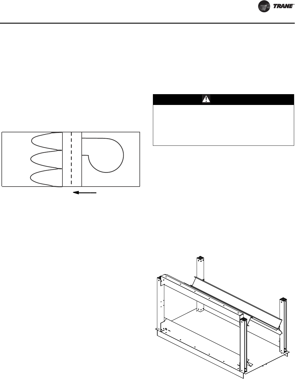
Component Installation Requirements
CLCH-SVX07C-EN 45
Component Installation Requirements
The components in the air handler may have installation
requirements that could affect the unit’s performance.
Diffuser Section
Diffuser sections are usually placed between a fan and a
downstream coil or filter. Because placement is critical to
unit performance, verify the correct placement of the
diffuser section before assembling the unit (see Figure 51).
Filter Section
Bag and cartridge filter sections can be used as a pre-filter
section, a final filter section, or both. This use is
determined by the filter’s placement in relation to the fan.
• A final filter is placed after the fan.
• A pre-filter is placed before the fan.
Note: Cartridge and bag filters provided by Trane are
fitted with a 7/8-inch header that fits in the filter
track. If using filters supplied by another
manufacturer, filters should be purchased with a 7/
8-inch header. In some cases it may be necessary to
gasket other manufacturers’ filters to ensure a
good air seal.
Filters should be installed when the unit is set. This will
protect internal components, such as the heating and
cooling coils.
Final Filter Section
A final filter section should not be bolted directly to the
face of a fan section. One or more intermediate sections
must be placed between the fan discharge and the filter
section.
Pre-Filter Section
A pre-filter section has no special installation
requirements unless placed directly upstream of a plenum
fan. In these configurations, ensure a blank section is
placed between the fan inlet and the filter section.
Trane recommends the use of disposable pre-filters with
high-efficiency filters. Disposable pre-filters slide into the
mounting tracks just ahead of the bag/cartridge filters.
Filter Installation
To install filters:
1. Disconnect the power to the unit.
2. Open the filter section access door.
3. Slide the filters into the tracks.
Note: Bag filters must be installed with the pleats in the
vertical plane.
4. The block-off is permanently installed and will create a
seal when the access door is closed.
5. Close the access door slowly to allow any gasketing to
compress.
Figure 51. Diffuser placement sizes 3 to 120
Airflow
WARNING
Hazardous Voltage!
Disconnect all electric power, including remote
disconnects before servicing. Follow proper lockout/
tagout procedures to ensure the power can not be
inadvertently energized. Failure to disconnect power
before servicing could result in death or serious injury.
Figure 52. Filter block-off placement
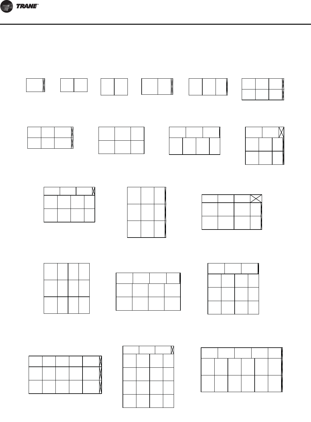
Component Installation Requirements
46 CLCH-SVX07C-EN
Filter Placement
Figure 53. 2-inch and 4-inch flat filter placement for unit sizes 3-50 - side loading
Size 3
20
25 2.5
Size 4
20
20 20 20 20
Size 6
25
24 20
Size 8
24
2.5
Size 10
20 20 1.25
25
16
Size 12
16
16
20 20 20 2.5
Size 14
20 3
16
16
20 25
Size 17
20
20
24 24 20
16
25
25 25 25 1
16
202020
Size 21
25 25 7.5
Size 22
16
20
20
20
20 16 1.5
24
20
20
12
16
24 24 4
202020
Size 25 Size 26
1.5
20
25
25
25
20 16
12
24
17.5
20
20
24 24 16 1.5
Size 30
25
20
Size 31
25
25
16 16 16
Size 35
24
20
25 25 25 20 1
20
16
24 24 24
Size 36
20
25
20
25 25 1
16
20
20
20 20 16
Size 40
20
16
20
20
20 20 25 3.520
Size 41
20
20
24 24 24 4
12
20
20
20
20 20 16
Size 50
16
25
20
25
25
25 25 25 20
20 20 20 20 20 1.5
3.47 ft ² 5.56 ft ² 6.94 ft ² 7.33 ft ² 9.72 ft ²
13.33 ft ²
14.44 ft ²
18.89 ft ² 21.53 ft ²
21.11 ft ²
27.11 ft ²
29.17 ft ²
30.44 ft ²
35.42 ft ² 37.22 ft ² 40.00 ft ²
40.83 ft ²
48.22 ft ²
55.00 ft ²
Component Installation Requirements
CLCH-SVX07C-EN 47
Figure 54. 2-inch and 4-inch flat filter placement for unit sizes 51-120 - side loading
Size 51
12
24
17.5
20
24 24 16 1.5
20
20
20
Size 57
20
25
16
20
20
25 25 25 20 1.5
Size 58
20
24
20
20
20
20
24 24 16 1.5
Size 66
20
24
20
20
20
24 24 24 24 16 .5
Size 80
20
16.5
24 24 24 24 24 16 .5
12
20
20
20
Size 100
20
25
20
20
20
20
25 25 25 25 25 .5
Size 120
25
20
25
25
25
20 20 20 20 20 20 20 16 2
54.89 ft²
63.33 ft²
61.11 ft²
75.56 ft²
85.56 ft²
104.17 ft² 122.22 ft²

Component Installation Requirements
48 CLCH-SVX07C-EN
Figure 55. 2-inch/4-inch combination flat filter placement for unit sizes 3-50 - side loading
Size 3
20
25 2.5
Size 4
20
20 20 20 20
Size 6
25
24 20
Size 8
24
2.5
Size 10
20 20 1.25
25
16
Size 12
16
16
20 20 20 2.5
Size 14
20 3
16
16
20 25
Size 17
20
20
24 24 20
16
25
25 25 25 1
16
202020
Size 21
25 25 7.5
Size 22
16
20
20
20
20 16 1.5
24
20
20
12
16
24 24 4
202020
Size 25 Size 26
1.5
20
25
25
25
20 16
12
24
17.5
20
20
24 24 16 1.5
Size 30
25
20
Size 31
25
25
16 16 16
Size 35
24
20
25 25 25 20 1
20
16
24 24 24
Size 36
20
25
20
25 25 1
16
20
20
20 20 16
Size 40
20
16
20
20
20 20 25 3.520
Size 41
20
20
24 24 24 4
12
20
20
20
20 20 16
Size 50
16
25
20
25
25
25 25 25 20
20 20 20 20 20 1.5
3.47 ft ² 5.56 ft ² 6.94 ft ² 7.33 ft ² 9.72 ft ²
13.33 ft ²
14.44 ft ²
18.89 ft ² 21.53 ft ²
21.11 ft ²
27.11 ft ²
29.17 ft ²
30.44 ft ²
35.42 ft ² 37.22 ft ² 40.00 ft ²
40.83 ft ²
48.22 ft ²
55.00 ft ²
Component Installation Requirements
CLCH-SVX07C-EN 49
Figure 56. 2-inch/4-inch combination flat filter placement for unit sizes 51-120 - side loading
Size 51
12
24
17.5
20
24 24 16 1.5
20
20
20
Size 57
20
25
16
20
20
25 25 25 20 1.5
Size 58
20
24
20
20
20
20
24 24 16 1.5
Size 66
20
24
20
20
20
24 24 24 24 16 .5
Size 80
20
16.5
24 24 24 24 24 16 .5
12
20
20
20
Size 100
20
25
20
20
20
20
25 25 25 25 25 .5
Size 120
25
20
25
25
25
20 20 20 20 20 20 20 16 2
54.89 ft²
63.33 ft²
61.11 ft²
75.56 ft²
85.56 ft²
104.17 ft² 122.22 ft²
Component Installation Requirements
50 CLCH-SVX07C-EN
Figure 57. 2-inch and 4-inch angled filter placement for unit sizes 3-50 - side loading
Size 3
16
25 2.5
Size 4
16
20 20
Size 6
20 20
Size 8
20
6.5
Size 10
25 25 7.25
20
Size 12
20
20
20 20 20 2.5
16 16
16
20 20
16
20 20
Size 14
20 3
20
20
20 25
Size 17
16
16
20 20 25
16
25 25 25 1
Size 21
25 25 7.5
Size 22
16
16
16
3
16
16
16
16
16
16
16
16
25
16
25 25 1
Size 25 Size 26
7.5
25
16
25
16
20
Size 30
16
16
16
16
16
16
16
16
16
16
16
16
16
16
16
16
16
20 20 25 4.5
16
20
Size 31
Size 35
25 25 25 20 1
16
Size 36
25 25 25 1
20
16
16
16
16
16
16
16
16
20 25 3
16
16
16
16
16
20
20
20
20
20
Size 40
20
16
20 20 25 3.520
Size 41
16
Size 50
20
20 20 20 20 20 20 1.5
16
16
16
16
16
16
16
16
16
16
16
16
25 25 25 1
20
20
20
20
20
5.56 ft ² 8.89 ft ² 8.89 ft ²
18.06 ft ²
28.89 ft ²
11.11 ft ² 13.89 ft ² 16.67 ft ²
33.33 ft ²
33.33 ft ²
50.00 ft ²
44.44 ft ²
57.78 ft ² 63.33 ft ²
56.67 ft ²
62.50 ft ²
70.00 ft ² 66.67 ft ² 100.00 ft ²
Component Installation Requirements
CLCH-SVX07C-EN 51
Figure 58. 2-inch and 4-inch angled filter placement for unit sizes 51-120 - side loading
Size 51
20 Size 57
20
20 1.5
Size 58
20
25 1
Size 66
20
16 .5
Size 80
16 .5
20
Size 100
20
25 25 25 25 25 25 .5
Size 120
20
25 3
20
20
20
20
20
20
20
20 20 20 25 4.5
20
20
20
20
20
2020202020
20
20
20
20
20
20
20
16161616
20
20
20
20
20
202020202020
20
20
20
20
20
20
20
202020202020
20
20
20
20
20
20
20
20
20
20
20
20
20
20
252525252525
94.44 ft ²
100.00 ft ²
98.89 ft ²
113.33 ft ²
151.11 ft ²
166.67 ft ² 194.44 ft ²
Component Installation Requirements
52 CLCH-SVX07C-EN
Figure 59. Long bag filter placement for unit sizes 3-50 - side loading
Size 3
20
24 3.9
Size 4
20
20 .8 20 20
Size 6
24
12 12
Size 8
24
.1
Size 10
20 20 6.45
24
12
Size 12
12
20
20 20 20 3.7
Size 14
24 1.2
12
20
24 20
Size 17
20
20
24 24 20
20
24
5.2
242424
Size 21 Size 22
20
24
20 12 6.7
24
20
20
12
24 24 5.2
Size 25 Size 26
6.7
20
24
24
24
20 12
12
20
18.7
20
20
11.1
Size 30
24
24
Size 31
24
24
24 20 1.2
Size 35
24
20
20
12
24 24 24
Size 36
24
24
5.2
Size 40
24
24
24
2.5
Size 41
24 24 24 5.2
24 Size 50
12
24
24
24
3.5
.8
2424 15.3
20.82424
20 12 12
1.2
24
24 24 24
20 20 20
1.6
24
24
24 24
24 24 24 12
24
24
24
24 24 24 24
3.33 ft ² 5.56 ft ² 6.67 ft ² 8.00 ft ² 8.67 ft ²
12.33 ft ²
13.44 ft ²
18.89 ft ² 22.00 ft ² 17.33 ft ²
26.00 ft ²
26.00 ft ²
28.22 ft ²
34.00 ft ²
34.67 ft ² 36.00 ft ²
36.00 ft ²
48.00 ft ²
50.00 ft ²
Component Installation Requirements
CLCH-SVX07C-EN 53
Figure 60. Long bag filter placement for unit sizes 57-120 - side loading
Size 51
24
24
24 24 12 7.1
24
24
24
Size 57
24
24
24
24
3.5
Size 58
12
24
24
24
24
24
24 24 12 7.1
Size 66
20
24
20
20
20
24 24 24 24 18.5
Size 80
24
24 6.9
Size 100
12
20
24
1.7
Size 120
24
24 1.2
24 24 24 24
18.7
24
24
24
24 24 24 24 12
24
24
24
24 24 24 24 24 24 8.9
20 20 20 20 20 20 12
12
24
24
24
24 24 24 24 24 24 12
12.8
56.00 ft ²
60.00 ft ²
62.00 ft ²
66.67 ft ²
88.00 ft ²
111.33 ft ² 134.00 ft ²
Component Installation Requirements
54 CLCH-SVX07C-EN
Figure 61. Short bag filter placement for unit sizes 3-50 - side loading
Size 3
20
24 3.9
Size 4
20
20 .8 20 20
Size 6
24
12 12
Size 8
24
.1
Size 10
20 20 6.45
24
12
Size 12
12
20
20 20 20 3.7
Size 14
24 1.2
12
20
24 20
Size 17
20
20
24 24 20
20
24
5.2
242424
Size 21 Size 22
20
24
20 12 6.7
24
20
20
12
24 24 5.2
Size 25 Size 26
6.7
20
24
24
24
20 12
12
20
18.7
20
20
11.1
Size 30
24
24
Size 31
24
24
24 20 1.2
Size 35
24
20
20
12
24 24 24
Size 36
24
24
5.2
Size 40
24
24
24
2.5
Size 41
24 24 24 5.2
24 Size 50
12
24
24
24
3.5
.8
2424 15.3
20.82424
20 12 12
1.2
24
24 24 24
20 20 20
1.6
24
24
24 24
24 24 24 12
24
24
24
24 24 24 24
3.33 ft ² 5.56 ft ² 6.67 ft ² 8.00 ft ² 8.67 ft ²
12.33 ft ²
13.44 ft ²
18.89 ft ² 22.00 ft ² 17.33 ft ²
26.00 ft ²
26.00 ft ²
28.22 ft ²
34.00 ft ²
34.67 ft ² 36.00 ft ²
36.00 ft ²
48.00 ft ²
50.00 ft ²
Component Installation Requirements
CLCH-SVX07C-EN 55
Figure 62. Short bag filter placement for unit sizes 57-120 - side loading
Size 51
24
24
24 24 12 7.1
24
24
24
Size 57
24
24
24
24
3.5
Size 58
12
24
24
24
24
24
24 24 12 7.1
Size 66
20
24
20
20
20
24 24 24 24 18.5
Size 80
24
24 6.9
Size 100
12
20
24
1.7
Size 120
24
24 1.2
24 24 24 24
18.7
24
24
24
24 24 24 24 12
24
24
24
24 24 24 24 24 24 8.9
20 20 20 20 20 20 12
12
24
24
24
24 24 24 24 24 24 12
12.8
56.00 ft ²
60.00 ft ²
62.00 ft ²
66.67 ft ²
88.00 ft ²
111.33 ft ² 134.00 ft ²
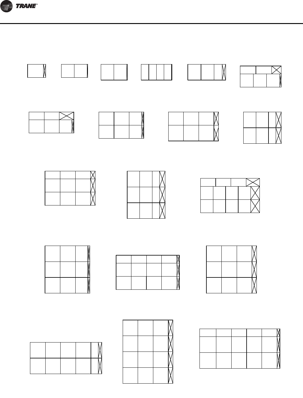
Component Installation Requirements
56 CLCH-SVX07C-EN
Figure 63. Cartridge filter placement for unit sizes 3-50 - side loading
Size 3
20
24 3.9
Size 4
20
20 .8 20 20
Size 6
24
12 12
Size 8
24
.1
Size 10
20 20 6.45
24
12
Size 12
12
20
20 20 20 3.7
Size 14
24 1.2
12
20
24 20
Size 17
20
20
24 24 20
20
24
5.2
242424
Size 21 Size 22
20
24
20 12 6.7
24
20
20
12
24 24 5.2
Size 25 Size 26
6.7
20
24
24
24
20 12
12
20
18.7
20
20
11.1
Size 30
24
24
Size 31
24
24
24 20 1.2
Size 35
24
20
20
12
24 24 24
Size 36
24
24
5.2
Size 40
24
24
24
2.5
Size 41
24 24 24 5.2
24 Size 50
12
24
24
24
3.5
.8
2424 15.3
20.82424
20 12 12
1.2
24
24 24 24
20 20 20
1.6
24
24
24 24
24 24 24 12
24
24
24
24 24 24 24
3.33 ft ² 5.56 ft ² 6.67 ft ² 8.00 ft ² 8.67 ft ²
12.33 ft ²
13.44 ft ²
18.89 ft ² 22.00 ft ² 17.33 ft ²
26.00 ft ²
26.00 ft ²
28.22 ft ²
34.00 ft ²
34.67 ft ² 36.00 ft ²
36.00 ft ²
48.00 ft ²
50.00 ft ²
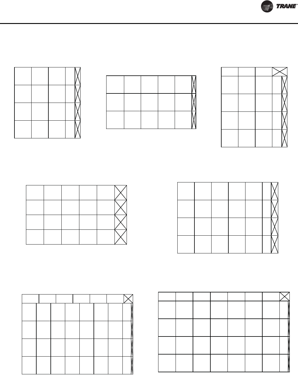
Component Installation Requirements
CLCH-SVX07C-EN 57
Figure 64. Cartridge filter placement for unit sizes 57-120 - side loading
Size 51
24
24
24 24 12 7.1
24
24
24
Size 57
24
24
24
24
3.5
Size 58
12
24
24
24
24
24
24 24 12 7.1
Size 66
20
24
20
20
20
24 24 24 24 18.5
Size 80
24
24 6.9
Size 100
12
20
24
1.7
Size 120
24
24 1.2
24 24 24 24
18.7
24
24
24
24 24 24 24 12
24
24
24
24 24 24 24 24 24 8.9
20 20 20 20 20 20 12
12
24
24
24
24 24 24 24 24 24 12
12.8
56.00 ft ²
60.00 ft ²
62.00 ft ²
66.67 ft ²
88.00 ft ²
111.33 ft ² 134.00 ft ²
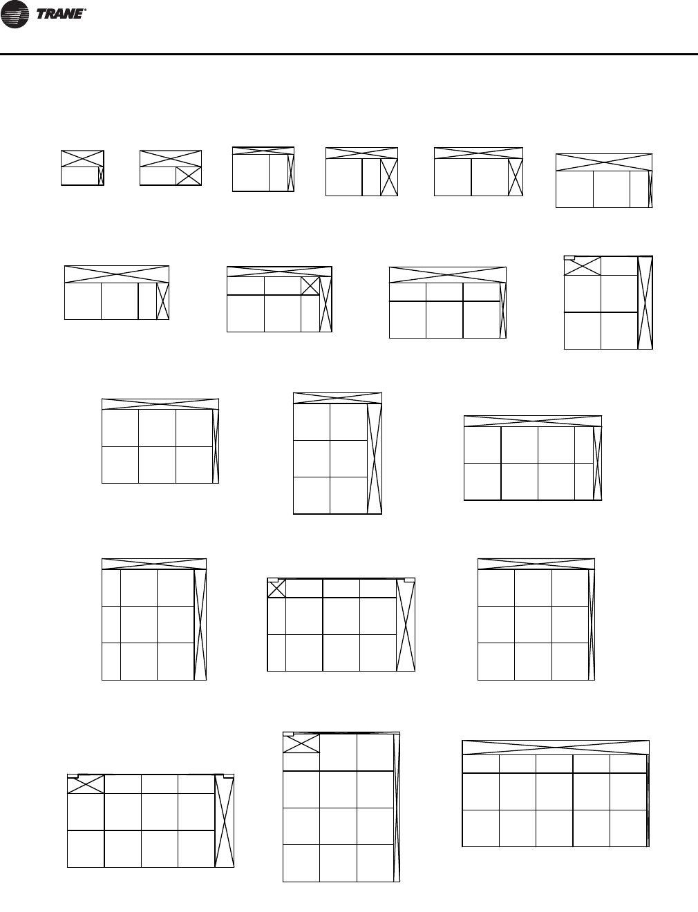
Component Installation Requirements
58 CLCH-SVX07C-EN
Figure 65. Front-load bag and cartridge filter placement for unit size 3-50
Size 3
12
24 3.38
Size 4
12
24 15.88 24 12
Size 6
24
24
Size 8
24
10.25
Size 10
24 24 9.25
24
Size 12
10.88
24
24 24 12 2.13
Size 14
24 7.63
24
24 12
Size 17
12
24
24 24 12
12
24
3.625
242424
Size 21 Size 22
24
24
24
12
9.25
24
24
24
6.75
24 24 3.63
Size 25 Size 26
9.25
24
24
24
24
24
6.75
24
24
24
5
Size 30
24
24
Size 31
24
24
24
12 7.63
Size 35
24
24
24
12
24 2412
Size 36
24
24
3.63
Size 40
24
24
Size 41
24 24 24 3.63
24
Size 50
12
24
24
24
.88
3.75
7.63
24
24 24 12
11.5
24
24
24 24
24
24
24
24 24 24 24
12
12
24 24 2424 12
2.00 ft ² 2.00 ft ² 6.00 ft ² 6.00 ft ² 8.00 ft ²
10.00 ft ²
10.00 ft ²
14.00 ft ² 18.00 ft ²
18.00 ft ²
24.00 ft ²
24.00 ft ²
28.00 ft ²
30.00 ft ²
34.00 ft ² 36.00 ft ²
46.00 ft ²
50.00 ft ²
10.38 10.38 4.63 7.13 7.13
10.88 6.25 10
.38
6.63
6.63
.38
6.63
.38
1
8.88
38.00 ft ²
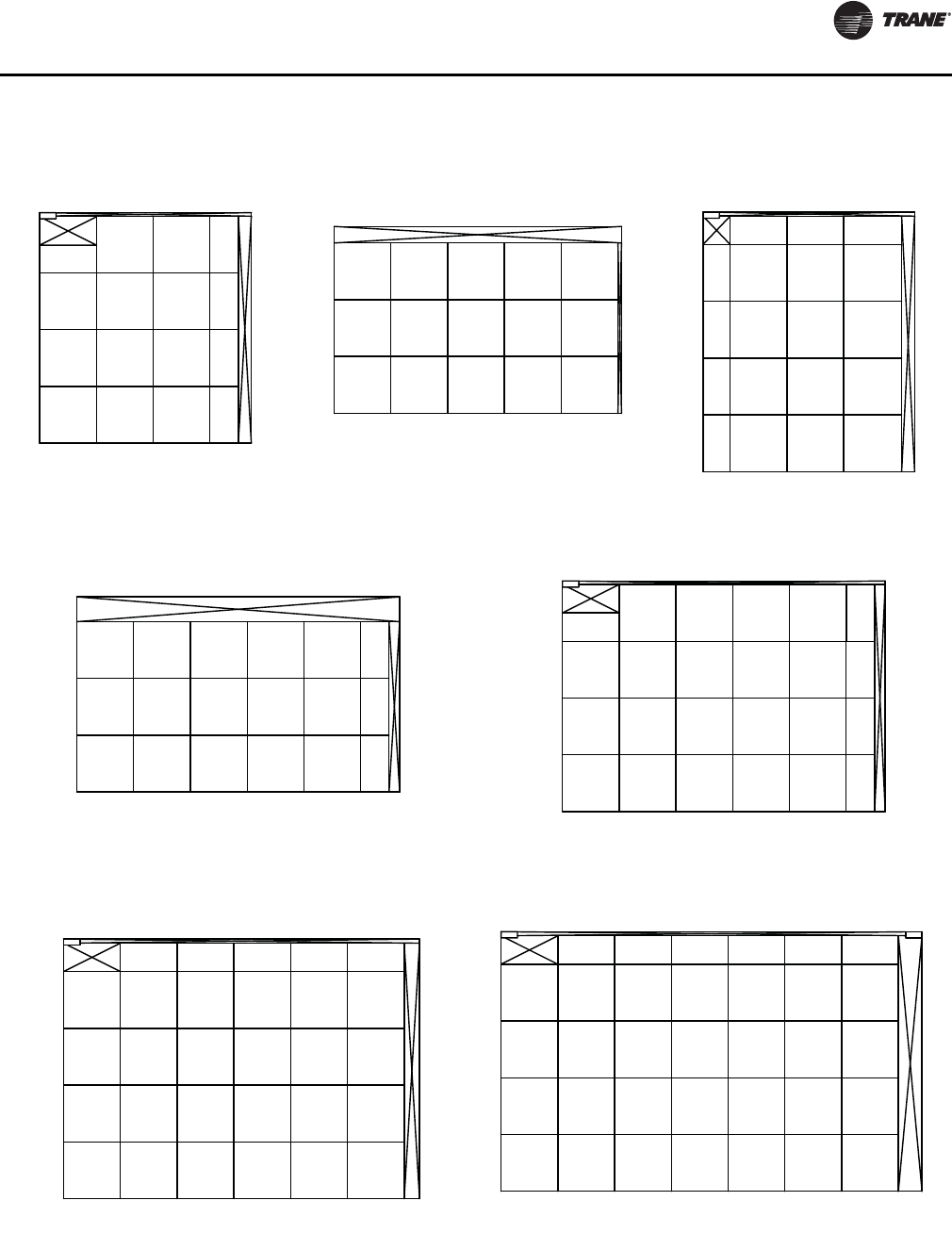
Component Installation Requirements
CLCH-SVX07C-EN 59
Figure 66. Front-loading bag and cartridge filter placement for unit size 57-120
Size 51
24
24 24 12 5
24
24
24
Size 57
24
24
24
24
.88
Size 58
12
12
24
24
24
24
24 24 24 5
Size 66
10.13
24
24
24
24
24 24 24 3.75
Size 80
24
24 3.75
Size 100
12
24
Size 120
24
24 9.13
24 24 24 24
24
24
24
24 24 24 24 12
24
24
24
24 5.75
12
24
24
24
24 12
24 24 24 24 24 24 24 24 24 24 24
54.00 ft ²
60.00 ft ²
62.00 ft ²
66.00 ft ²
24
1
6.63
1.13
1
1.13 1.13
106.00 ft ² 124.00 ft ²
86.00 ft ²
Component Installation Requirements
60 CLCH-SVX07C-EN
Figure 67. HEPA filter placement for unit size 3-50 - front loading
Size 3
12
24 2.88
Size 4
12
24 15.38
24 12
Size 6
24
30
Size 8
24
3.25
Size 10
24 24 8.25
30
Size 12
30
24 24 13.25
Size 14
24 18.75
30
24
Size 17
12
24
30
12
30
2.13
242424
Size 21
Size 22
30
30
24 2.25
30
24
24
30 12 2.13
Size 25 Size 26
2.25
30
24
24
24
24
30
24
24
3.63
Size 30
24
30
Size 31
24
24
30 6.75
Size 35
30
30
24
30 30
Size 36
24
24
2.13
Size 40
24
30
24
6
Size 41
24 24 24 2.13
Size 50
12
30
24
24
5.0
2.75
6.75 24
30 24
4.13
24
24
24 24
30
30
30 30 30 24
12
9
30 30 12
24 24 24
30 4.0
2.00 ft ² 2.00 ft ²
6.00 ft ² 7.00 ft ²
10.00 ft ² 10.00 ft ²
10.00 ft ²
14.00 ft ² 21.00 ft ²
19.00 ft ²
24.00 ft ²
27.00 ft ²
28.00 ft ²
30.00 ft ²
30.00 ft ² 36.00 ft ²
37.00 ft ²
45.00 ft ²
46.00 ft ²
24 624 24 24 6
24 24 24
24 24 24 24 9
30
6
9
9
Component Installation Requirements
CLCH-SVX07C-EN 61
Figure 68. HEPA filter placement for unit size 57-120 - front loading
Size 51
30
12
30 24 3.625
24
24
24
Size 57
24
30
24
24
5.0
Size 58
30
24
24
24
24
30 24 3.625
Size 66
30
24
24
24
30 30 1.375
Size 80
12
30 1.375
Size 100
12
Size 120
24 5.625
30 30 24
24
24
24
30 30 30 12
30
30
30
24 2.75
12
30
30
30
30 12
24 24 24 24 24
48.00 ft ² 57.00 ft ²
56.00 ft ²
66.00 ft ²
76.00 ft ²
102.00 ft ² 119.00 ft ²
24 24 24 6
24 24 24 24 24 6
24 24 24 24 24 24
6
6
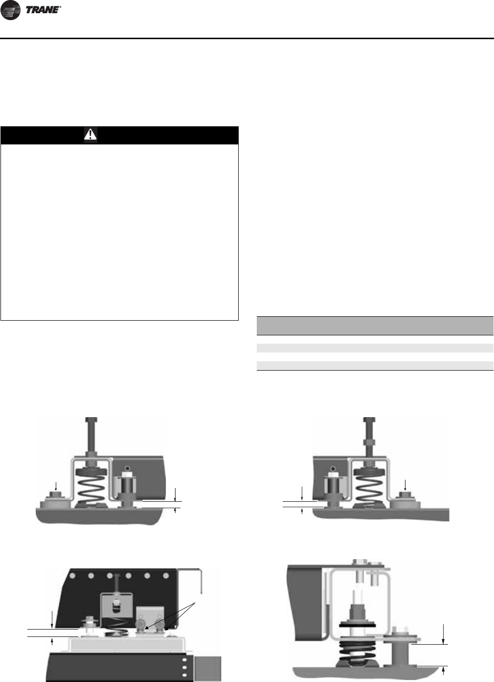
Component Installation Requirements
62 CLCH-SVX07C-EN
Fan Section
The fan section can be configured as either draw-thru or
blow-thru. Review the submittals and unit tagging
information prior to assembly to determine placement.
Fan Isolation
The fan-and-motor assembly is internally isolated. The fan
and motor bases are bolted to a minimum of four spring
isolators. The isolators are secured to the fan section
support base.
Shipping tie-down bolts are bolted adjacent to the
isolators between the fan isolation base and the isolator
support frame. The shipping tie-downs secure the
isolation base to the support assembly to prevent any
damage to the fan section during shipment.
Note: Remove the tie-downs only if the factory-provided
isolation is to be used.
Adjusting the Isolators
Once the shipping tie-downs are removed and the internal
isolation is released, it may be necessary to adjust the
isolators to achieve the proper operation height of the fan
and motor isolation base.
Minimum required clearances are listed in Table 10. To
determine the isolator clearances on all unit sizes,
measure between the top of the cabinet channel and the
bottom of the isolation base channel. See Figure 69,
Figure 70, Figure 71, and Figure 72.
WARNING
Hazardous Service Procedures!
The maintenance and troubleshooting procedures
recommended in this manual could result in exposure
to electrical, mechanical or other potential safety
hazards. Always refer to the safety warnings provided
throughout this manual concerning these procedures.
Unless specified otherwise, disconnect all electrical
power including remote disconnect and discharge all
energy storing devices such as capacitors before
servicing. Follow proper lockout/tagout procedures to
ensure the power can not be inadvertently energized.
When necessary to work with live electrical
components, have a qualified licensed electrician or
other individual who has been trained in handling live
electrical components perform these tasks. Failure to
follow all of the recommended safety warnings
provided, could result in death or serious injury. Table 10. Minimum isolator clearances (inches)
Unit Size Fan Type Required
Clearance
3–8 FC, BC, Plenum 1.0
10–31 FC, AF, Plenum 0.5
35-58 FC, AF, Plenum 0.5
66-120 FC, AF, Plenum 1.0
Figure 69. Isolator adjustment for unit sizes 10-30 Figure 70. Isolator adjustment for unit sizes 10-30
Figure 71. Isolator adjustment for unit sizes 66-120 Figure 72. Belt-drive plenum fan isolator adjustment size
3-8
Required
clearance
Tiedown
Required
clearance
Tiedown
Required
clearance
Tiedown
Required
clearance
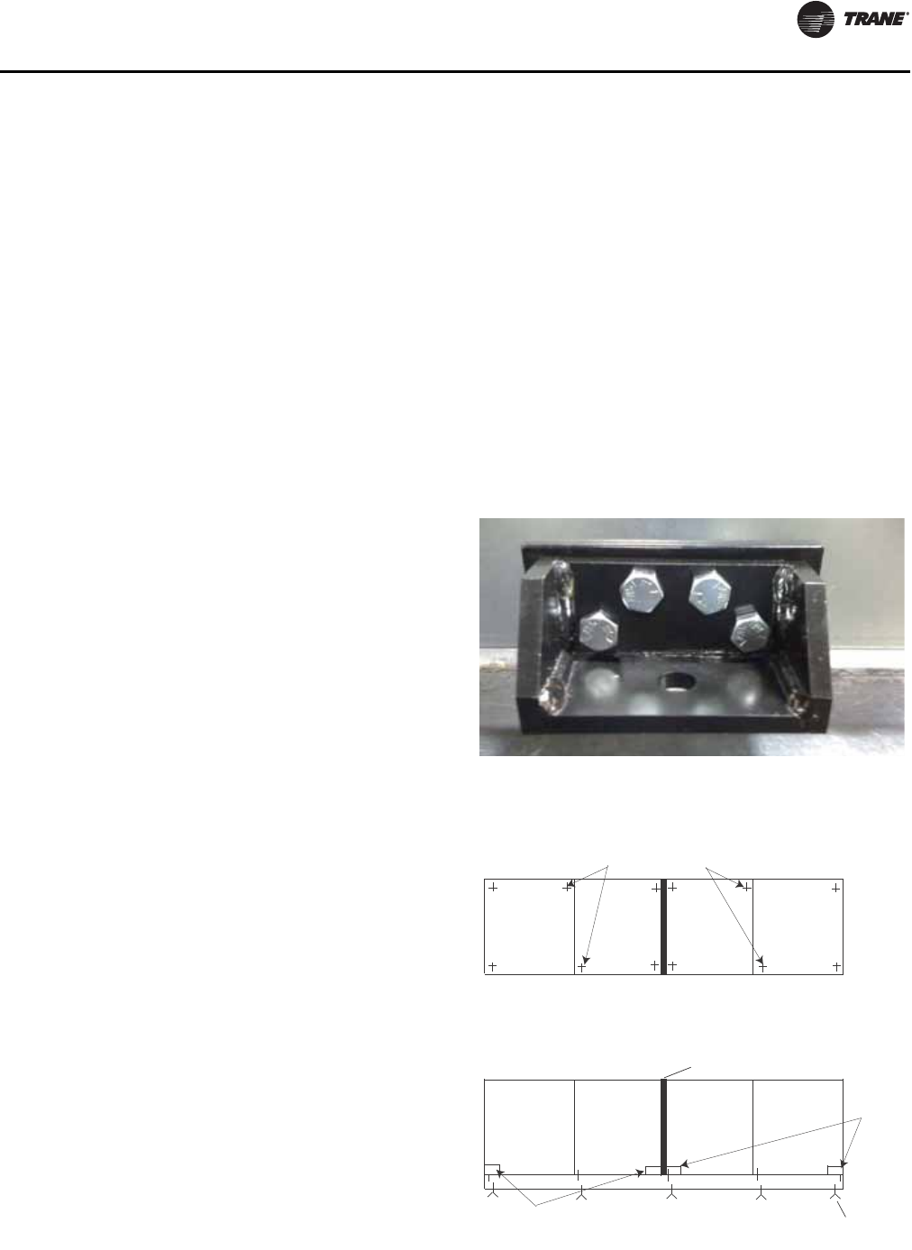
Component Installation Requirements
CLCH-SVX07C-EN 63
Seismic Application
Requirements
Air handling equipment manufactured by Trane is capable
of structurally and operationally withstanding the seismic
response criteria as required by the International Building
Codes (IBC) 2000,2003, 2006, 2009. Trane has third-party
certification for IBC compliance for seismic applications
for unit sizes 3-30. Certification for larger sizes is in
process.
Note: If seismic isolation has been specified, the
following requirements must be adhered to for
installation. Failure to follow these instruction
would void the warranty.
Anchor Requirements
Single Level Design Break - Size 3-120
Grade to Roof Mounted (0<=Sds<=1.85) Non-
Isolated
4000 psi concrete
• 3/8-inch diameter Hilti Kwik Bolt TZ carbon steel
concrete anchors attached to unit base rails.
• Install clips at shipping split corners
• Install clips at shipping splits containing fans or coils at
48 inches maximum on-center spacing.
• 2-inch minimum anchor embedment
• 4-3/8-inch minimum distance to the nearest edge
• 4-inch minimum concrete slab thickness
Steel dunnage/steel curb
3/8-inch diameter ASTM A325 or SAE grade 5 bolts
attached to unit base located as noted above or 1-inch long
3/16-inch welds at unit base located as noted above.
Stacked Design Break - Size 3-50
Grade to Roof Mounted (0<=Sds<=1.85) Non-
Isolated
4000 psi concrete
• 1/2-inch diameter Hilti Kwik Bolt TZ carbon steel
concrete anchors attached to unit base rails
• Install clips at all ship split corners.
• Install clips at ship splits with a stacked section at 36
inches maximum on-center spacing.
• Install clips at single level ship splits containing fans or
coils at 48 inches maximum on-center spacing.
• 3 1/4-inch minimum anchor embedment
• 7 1/2-inch minimum distance to the nearest edge
• 6-inch minimum concrete slab thickness
Steel dunnage/steel curb
1/2-inch diameter ASTM A325 or SAE Grade 5 bolts
attached to unit base located as noted above or 1-inch long
3/16-inch welds at unit bases located as noted above.
Anchor Pattern
Lifting lugs should be used to anchor the unit at the ends
of each shipping split. Per the anchor requirements,
additional anchoring may be needed. If so, anchors will be
provided and installed on the unit. An example of a seismic
anchor is shown in Figure 73.
Anchor selection meets or exceeds IBC 2000, 2003, 2006
and 2009 compliance requirements.
Special Inspection per IBC Section 1704 is required on all
installations. All anchors listed above must be installed to
meet compliance.
Figure 73. Seismic anchor
Figure 74. Seismic anchor pattern
Section
Base rail
Staggered anchor bolt patterns
Shipping split joint
Lifting
lugs
Anchor bolt
to floor curb
AHU Plan View
AHU Elevation View
Shipping split 1 Shipping split 2
Lifting lugs
Shipping split 1 Shipping split 2
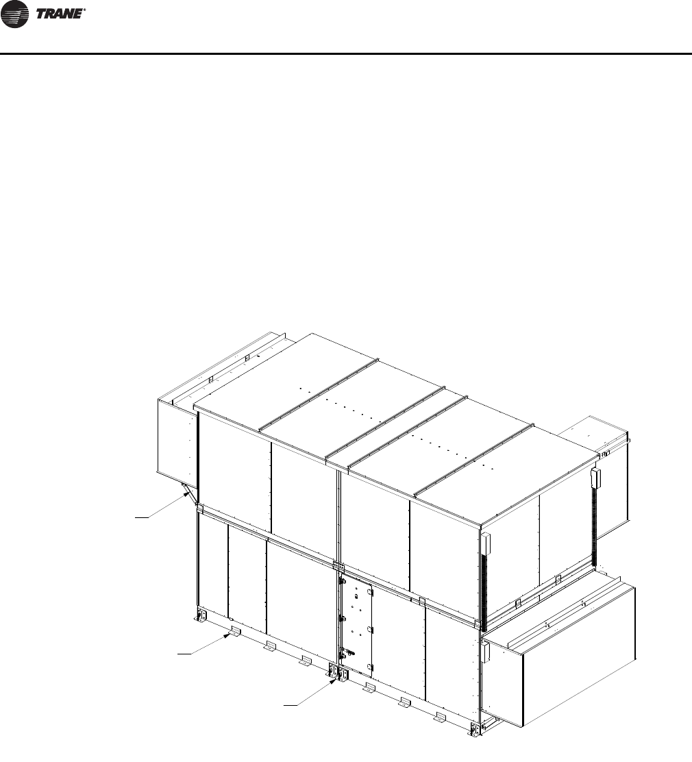
Component Installation Requirements
64 CLCH-SVX07C-EN
Hurricane Application
Requirements
Miami/Dade County Hurricane-Certified
Air Handlers
Performance Climate Changer air handlers size 3-30 are
approved and have has been designed to comply with the
High Velocity Hurricane Zone of the Florida Building Code.
Notice of compliance and additional product construction
details can be found at the Miami-Dade County, Building
Code Compliance Office Web site.
The Florida licensed engineer or architect-of-record for the
project shall be responsible for the design, sizing, and
structural adequacy of the product framework as well as
curbing and attachment to the roof, or as accepted by the
corresponding building departments.
Approved Method for Anchoring Unit
The method shown in Figure 75 through Figure 85 is what
is approved and recommended for anchoring the unit to
substrate and roof curb. Any deviation to this may require
the approval of the local building code enforcement
agency.
Figure 75. Method for anchoring unit to substrate and roof curb
See Detail C
for hood support
installation
See Detail B
Install fastener to
substrate through only one
lug at this location
See Detail A
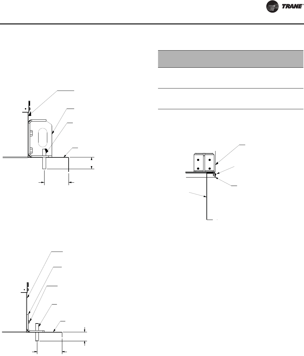
Component Installation Requirements
CLCH-SVX07C-EN 65
Hurricane Unit Anchorage
Figure 76. Typical direct anchorage to substrate at
lifting lugs (also see Table 11)
Figure 77. Typical direct anchorage to substrate using
L-clip in addition to lifting lugs (also see
Table 11)
Note: Anchor spacing to be 24 inches maximum typical long side of unit.
Detail A
First level base rail
First level lifting lug
Install fastener
one per lug, either hole
Substrate
Min embedment
Min edge
distance
Detail B
First level base rails
3-in.x3-in.x6-in. long
x 1/4-in. thick min. L-angle
clip, galv steel 36 ksi min.
Qty 5 screws per angle
Installation fastener
one per angle, centered
Substrate
Min embedment
Min edge
distance
Table 11. Installation anchor information
Anchor/substrate Minimum
embedment
Minimum
edge
distance
1/2-inch powers chem-standard
threaded rod installed with chem-
standard adhesive capsule in 3.2 ksi
minimum concrete substrate
1 1/2 inches 6 inches
1/4-inch Elco dril-flex hex head schre
installed in 36 ksi minimum steel 1/8-
inch think minimum Ufull thread
engagement)
1/8 inch 1/2 inch
Figure 78. Typical installation of unit baserail to curb
Unit base panel
1/4-in. sheet
metal fasteners
Factory-supplied
drip lip
6-in. max O.C. for 0.119-in.
min roof curb thickness.
2-in. max O.C. for 0.047-in.
min roof curb thickness
Roof curb
by others
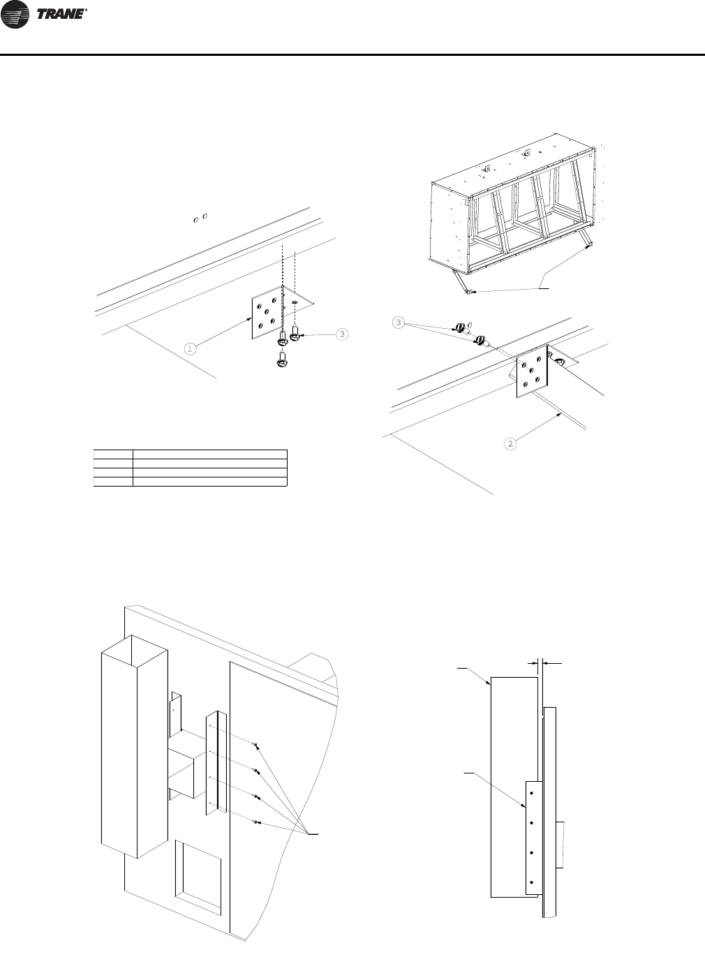
Component Installation Requirements
66 CLCH-SVX07C-EN
Gas Heat Installation
Figure 79. Installation of front and back hoods
Item Description
1
2
3
Support bracket
L angle
1/4-14 x .75 sheet metal screw
3
1
2
3
Fasten bracket to bottom of
hood L angle (for hoods that
are lower to ground, may need
to flip the bracket (1) so the
short flange is pointing down
to the ground.
Detail C
Front and Back Hoods Only
Fasten ship-with angle
to support bracket
These brackets
are attached to
the unit baserail.
Figure 80. Attach the gas heat flue duct to the L angles on both sides
Attach the gas heat flue duct
to the L angles on both sides
Gas heat flue See note
L bracket
Right side view
Note: When installing flue, leave enough clearance to avoid roof’s edge and anything above the roof.
#10 x 3/4-in. self-drilling
sheet metal screws
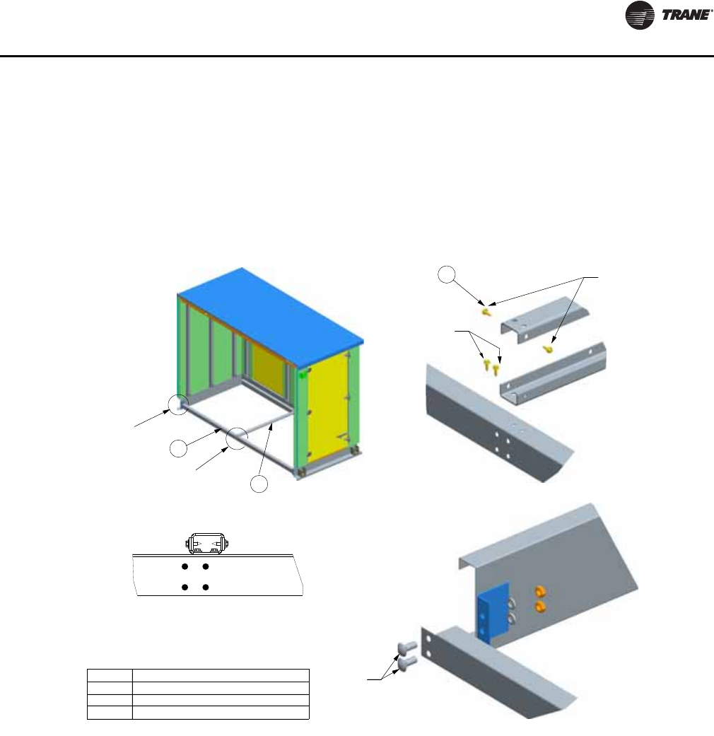
Component Installation Requirements
CLCH-SVX07C-EN 67
Pipe Cabinet Installation
Nested U Channels and L angle have to be removed to
install the pipe cabinet to the unit and reinstall per
hurricane certification guidelines. See Figure 81.
1. Remove the fasteners from the top of the nested U
channel.
2. Remove the U channel from the unit base L angle and
the pipe cabinet base L angle.
3. Remove the corner fasteners from the pipe cabinet
base and the unit base L angle. These fasteners are not
required to be put back.
Figure 81. Instructions for pipe cabinet with nested U channels
Item Description
1
2
3
Nested U Channel
L angle
5/16-18 x .875 screw
3
1
2
Detail B
See Detail B
See Detail A
Step 1
Step 2
Step 3
Detail A
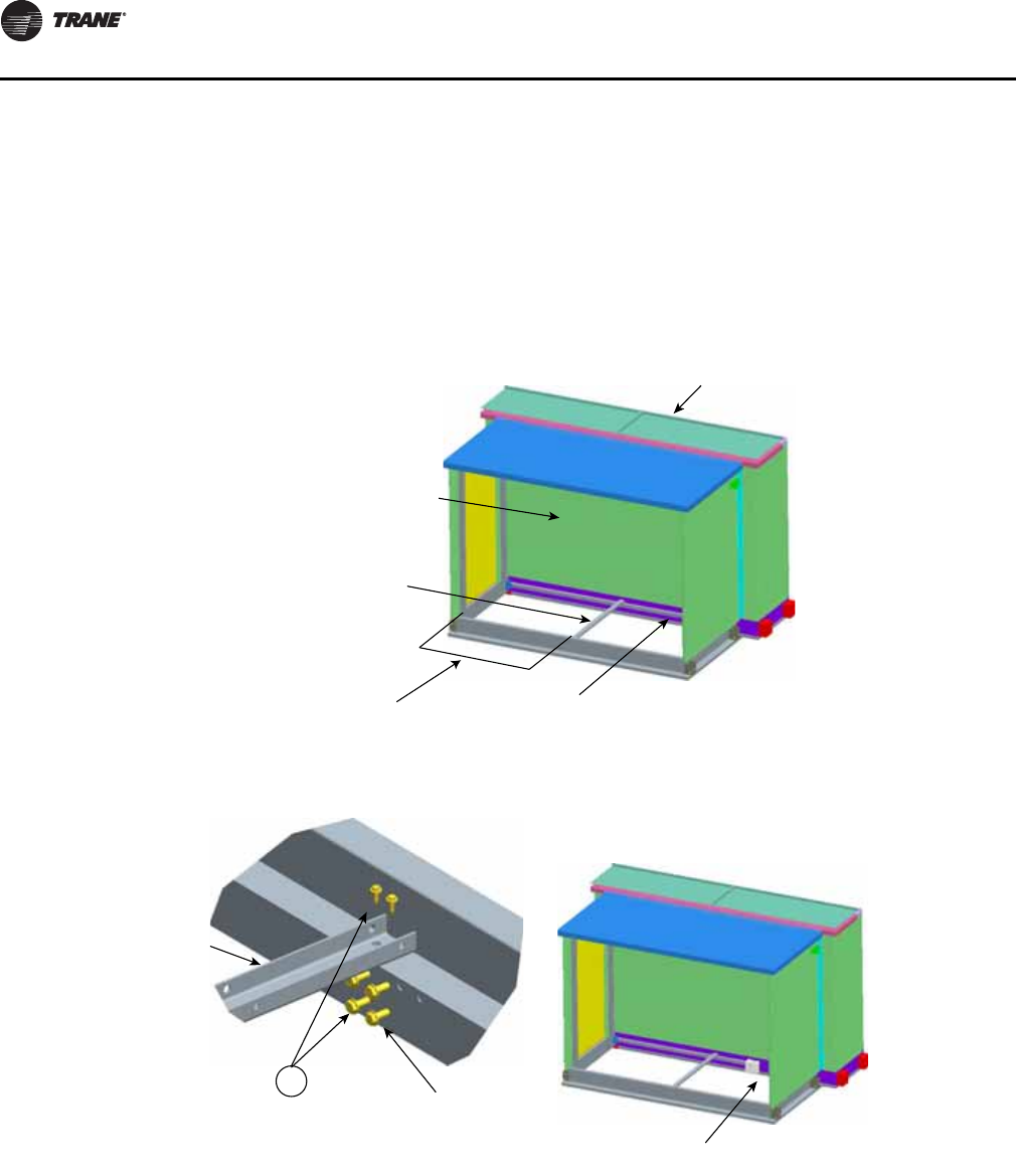
Component Installation Requirements
68 CLCH-SVX07C-EN
4. Attach the unit base L angle from the pipe cabinet to the
unit base rail. See Step 4 in Figure 82
5. Attach a U channel to the unit base L angle. Make sure
to clear any coil piping. Make sure to attach enough
nested U channels to comply to the unsupported span.
See Step 5 in Figure 82.
6. Locate the pipe cabinet in place, and reinstall the U
channel to the pipe base L angle and reinstall the top U
channel to the nest (see Step 1, Figure 81).
7. When the L angle interferes with the unit base rail
lifting lugs or splice plate, mark and cut L angle section
to clear the component. If excess L angle is not needed
for nested U channel, leave it off. See Figure 82.
Figure 82. Attaching L angles in pipe cabinet
Pipe cabinet wall
removed for clarity
Step 5
Step 4
Step 6
L angle attached
to unit baserail
Nested U channel
attached to L angle
Unsupported span
Size 3-50 - 52 in. max
Size 57-120 - 34 in. max
Air handler
Step 7
3
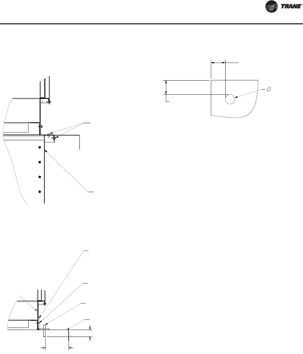
Component Installation Requirements
CLCH-SVX07C-EN 69
Pipe Cabinet Hurricane Anchorage
Damper Section
Dampers are factory-installed and adjusted and can be
found in mixing box/economizer sections. There are two
damper blade configurations available: parallel-blade and
opposed-blade.
Traq™ dampers are another type of damper available in
mixing box sections. Traq dampers have only one blade
configuration - opposed. They have two control
applications available - standard Traq dampers and low-
flow Traq dampers. Low-flow Traq dampers are always not
linked and consist of two damper sets - one set for
minimum outside air measurement and one set for
economizing. Each will have its own VCM.
The air handler is available with factory-mounted controls
or end devices. If the unit is not ordered with controls or
end devices, it is the installer’s responsibility to provide
and install the damper actuators. Size the actuators
according to Table 12.
Mixing section and economizer dampers are designed for
the damper actuators to be direct coupled and installed in
the air stream. If other provisions are required,
modifications to the section will be the responsibility of
the installing contractor.
Figure 83. Typical installation of pipe cabinet baserail to
curb
Figure 84. Typical direct anchorage pipe cabinet
baserail to substrate with L clip
6-in. max O.C. for 0.119-in.
min roof curb thickness.
2-in. max O.C. for 0.047-in.
min roof curb thickness
Roof curb
by others
1/4-in. sheet
metal screws
3-in.x3-in.x6-in. long
x 1/4-in. thick min.
L-angle clip, galv steel
36 ksi min.
Qty 5 screws per angle
Installation fastener
one per angle, centered
Substrate
Min embedment
Min edge
distance
Baserail
Figure 85. Pipe-cabinet approved field penetrations
3-in. min
panel left
or right
2-in. max
3-in. min
panel top
or bottom
Field-drilled hole detail

Component Installation Requirements
70 CLCH-SVX07C-EN
Damper Torque Requirements
Table 12. Mixing box damper torque requirements (inch pound) at 1-inch w.g. air pressure drop
Unit
Size
Parallel
airfoil
damper
only
Opposed
airfoil
damper
only
Standard
Traq
damper
only
Low-flow
minimum
OA Traq
damper only
Low-flow
econ Traq
damper
only
Parallel airfoil
damper linked
to parallel
airfoil damper
Opposed airfoil
damper linked
to opposed
airfoil damper
Standard
Traq linked
to airfoil
damper
Standard
Traq linked
to standard
Traq damper
3 9.00 6.40 18.00 n/a n/a 10.30 7.70 19.30 36.00
413.10 9.30 36.00 18.00 18.00 14.90 11.20 37.90 72.00
6 17.10 12.20 36.00 18.00 18.00 19.60 14.70 38.40 72.00
823.30 16.60 54.00 18.00 36.00 26.60 19.90 57.30 108.00
10 29.00 20.70 54.00 18.00 36.00 33.20 24.90 58.10 108.00
12 35.70 25.50 67.50 22.50 45.00 40.70 30.60 72.60 135.00
14 39.50 28.20 67.50 22.50 45.00 45.20 33.90 73.10 135.00
17 48.90 34.90 67.50 22.50 45.00 55.90 41.90 74.50 135.00
21 60.40 43.10 99.00 33.00 66.00 69.00 51.80 107.60 198.00
25 72.40 51.70 99.00 33.00 66.00 82.80 62.10 109.30 198.00
30 84.20 60.10 108.00 36.00 72.00 96.20 72.20 120.00 216.00
35 100.20 71.50 108.00 36.00 72.00 114.50 85.90 122.30 198.00
40 110.20 78.70 108.00 36.00 72.00 125.90 94.50 119.60 198.00
50 126.30 90.20 112.50 37.50 75.00 144.30 108.20 135.70 216.00
57 154.80 110.60 112.50 37.50 75.00 176.90 132.70 164.20 198.00
66 177.60 126.80 150.00 37.50 75.00 202.90 152.20 187.00 264.00
80 210.30 150.20 187.50 37.50 112.50 240.30 180.20 223.10 360.00
100 272.00 194.30 225.00 37.50 150.00 310.90 233.20 284.90 396.00
120 322.40 230.30 225.00 37.50 150.00 368.50 276.30 335.20 432.00
Table 13. Air-to-Air Plate Heat Exchanger Bypass Damper
Unit size
Damper dia (in)
Damper qty Damper
torque (in-lb)Actuator torque
(max) (in-lb) Actuator qty LinkageA B
3 25.00 24.03 1 20.90 42.00 1 No
437.50 24.03 131.30 42.00 1No
6 37.50 29.78 1 38.80 160.00 1 No
844.00 29.78 145.50 160.00 1No
10 55.00 35.53 1 67.90 160.00 1 No
12 60.00 35.53 174.00 160.00 1No
14 65.50 35.53 1 80.80 160.00 1 No
17 65.50 24.03 2109.30 160.00 1Yes
21 73.50 24.03 2 122.70 160.00 1 Yes
25 73.50 29.78 2152.00 160.00 1Yes
30 87.00 29.78 2 179.90 160.00 2 Yes
35 93.50 29.78 2193.40 160.00 2Yes
40 106.00 29.78 2 219.20 160.00 2 Yes

Component Installation Requirements
CLCH-SVX07C-EN 71
Table 14. Air-to-Air Plate Heat Exchanger Frost Damper
Unit size A B Damper qty Damper
torque (in-lb)Actuator torque
(max) (in-lb) Actuator qty Linkage
3 25.00 13.97 1 12.10 42.00 1 No
437.50 13.97 118.20 42.00 1No
6 37.50 13.97 1 18.20 42.00 1 No
844.00 13.97 121.30 42.00 1No
10 55.00 13.97 1 26.70 42.00 1 No
12 60.00 13.97 129.10 42.00 1No
14 65.50 13.97 1 31.80 160.00 1 No
17 65.50 13.97 263.50 160.00 1Yes
21 73.50 13.97 2 71.30 160.00 1 Yes
25 73.50 13.97 271.30 160.00 1Yes
30 87.00 13.97 2 84.40 160.00 1 Yes
35 93.50 13.97 290.70 160.00 1Yes
40 106.00 13.97 2 102.80 160.00 1 Yes
50 119.00 13.97 2115.40 160.00 1Yes
Table 15. Side Traq damper - standard flow mixing box
Unit size Damper dia
(in) Damper
qty Damper torque
(in-lb) Total torque
(in-lb)
Actuator
torque (max)
(in-lb) Actuator
qty Face-to-face
linkage Linkage on
face
3, 4, 6, 8 13.00 1 18.00 18.00 42.00 1 No No
10, 12 16.00 122.50 22.50 42.00 1No No
14, 17 13.00 2 18.00 36.00 42.00 1 No Yes
21, 22, 25, 26 16.00 222.50 45.00 160.00 1No Yes
30, 31, 35, 40 20.00 2 33.00 66.00 160.00 1 No Yes
36, 41, 50, 57, 66 24.00 236.00 72.00 160.00 1No Yes
51, 58, 80 28.00 2 37.50 75.00 160.00 1 No Yes
100 28.00 337.50 112.50 160.00 1No Yes
120 24.00 4 36.00 144.00 160.00 1 No Yes
Table 16. Side Traq damper - standard flow diagonal economizer
Unit
sizes Damper
dia (in) D am p e r
qty Damper
torque (in-lb.) Total torque
(in-lb.) Actuator torque
(max) (in-lb.) Actuator
qty Face-to-face
linkage Linkage on
face
3 13.00 1 18.00 18.0 42.00 1 No No
413.00 218.00 36.0 42.00 2No No
6, 8 13.00 2 18.00 36.0 42.00 1 No Yes
10, 12, 14 16.00 222.50 45.0 160.00 1No Yes
17 13.00 4 18.00 72.0 160.00 1 No Yes
21 20.00 233.00 66.0 160.00 1No Yes
25 16.00 4 22.50 90.0 160.00 1 No Yes
30 20.00 333.00 99.0 160.00 1No Yes
35 28.00 2 37.50 75.0 160.00 2 No No
40 28.00 237.50 75.0 160.00 1No Yes
50 24.00 3 36.00 108.0 160.00 1 No Yes
57 24.00 436.00 144.0 160.00 1No Yes
66 28.00 3 37.50 112.5 160.00 1 No Yes
80 28.00 437.50 150.0 160.00 1No Yes
100, 120 28.00 5 37.50 187.5 160.00 2 No Yes

Component Installation Requirements
72 CLCH-SVX07C-EN
Table 17. Single -Side Traq low flow mixing box
Unit size Damper
Dia (in) Damper
Qty
Damper
Torque
(in-lb.)
Low flow
Traq
Torque (in-
lb.)
Remained
Traq Torque
(in-lb.)
Actuator
qty for low
flow Traq
Actuator qty
for
remained
damper Actuator
total Qty
Face-to-
face
Linkage Linkage
on Face
14, 17 13.00 2 18.00 18.00 18.00 1 1 2 No No
21, 22, 25, 26 16.00 222.50 22.50 22.50 1 1 2 No No
30, 31, 35, 40 20.00 2 33.00 33.00 33.00 1 1 2 No No
36, 41, 50, 57, 66 24.00 236.00 36.00 36.00 1 1 2 No No
51, 58, 80 28.00 2 37.50 37.50 37.50 1 1 2 No No
100 28.00 337.50 37.50 75.00 1 1 2 No Yes
120 24.00 4 36.00 36.00 108.00 1 1 2 No Yes
Table 18. Dual-side Traq low flow mixing box
Unit size Damper
dia (in) Damper
qty
Damper
torque
(in-lb)
Low-flow
Traq
torque
(in-lb)
Remained
Traq
torque
(in-lb)
Actuator
qty for
std Traq
damper
Actuator qty
for low-flow
Traq
damper
Actuator
qty for
single low-
flow Traq Actuator
total qty
Face-
to-face
linkage Linkage
on face
3, 4, 6, 8 13.00 2 18.00 18.00 18.00 1 - 1 2 No No
10, 12 16.00 222.50 22.50 22.50 1 - 1 2 No No
14, 17 13.00 4 18.00 18.00 54.00 1 1 1 3 No No
21, 22, 25, 26 16.00 422.50 22.50 67.50 1 1 1 3 No No
30, 31, 35, 40 20.00 4 33.00 33.00 99.00 1 1 1 3 No No
36, 41, 50, 57,
66 24.00 436.00 36.00 108.00 1 1 1 3 No No
51, 58, 80 28.00 4 37.50 37.50 112.50 1 1 1 3 No No
100 28.00 637.50 37.50 187.50 1 1 1 3 No Yes
120 24.00 8 36.00 36.00 252.00 1 1 1 3 No Yes
Table 19. Side Traq low-flow diagonal economizer
Unit
size D a m p e r
dia (in) Damper
qty
D a m p e r
torque
(in-lb.)
Low flow
Traq torque
(in-lb.)
Remainder
Traq torque
(in-lb.)
Actuator
qty for low
flow Traq
Actuator qty
for remainder
damper Actuator
total qty
Face-to-
face
linkage Linkage
on face
4 13.00 2 18.00 18.00 18.00 1 1 2 No No
613.00 218.00 18.00 18.00 1 1 2 No No
8 13.00 2 18.00 18.00 18.00 1 1 2 No No
10 16.00 222.50 22.50 22.50 1 1 2 No No
12 16.00 2 22.50 22.50 22.50 1 1 2 No No
14 16.00 222.50 22.50 22.50 1 1 2 No No
17 13.00 4 18.00 18.00 54.00 1 1 2 No Yes
21 20.00 233.00 33.00 33.00 1 1 2 No No
25 16.00 4 22.50 22.50 67.50 1 1 2 No Yes
30 20.00 333.00 33.00 66.00 1 1 2 No Yes
35 28.00 2 37.50 37.50 37.50 1 1 2 No No
40 28.00 237.50 37.50 37.50 1 1 2 No No
50 24.00 3 36.00 36.00 72.00 1 1 2 No Yes
57 24.00 436.00 36.00 108.00 1 1 2 No Yes
66 28.00 3 37.50 37.50 75.00 1 1 2 No Yes
80 28.00 437.50 37.50 112.50 1 1 2 No Yes
100 28.00 5 37.50 37.50 150.00 1 1 2 No Yes
120 28.00 537.50 37.50 150.00 1 1 2 No Yes

Component Installation Requirements
CLCH-SVX07C-EN 73
Table 20. Side rectangle angle damper - 2000 fpm
Unit size A (in) B (in) Damper
qty Torque
(in-lb.) Actuator torque
(max) (in-lb.) Actuator
qty Linkage
3 11.25 13.97 1 13.10 42.00 1 No
411.25 13.97 113.10 42.00 1No
6 15.75 13.97 1 18.30 42.00 1 No
820.25 13.97 123.60 42.00 1No
10 20.25 16.30 1 27.50 42.00 1 No
12 27.00 16.30 136.70 42.00 1No
14 23.25 19.72 1 38.20 42.00 1 No
17 30.50 19.72 150.10 160.00 1No
21 36.75 19.72 1 60.40 160.00 1 No
25 45.75 19.72 175.20 160.00 1No
30 48.50 20.22 1 81.70 160.00 1 No
35 45.50 25.47 196.60 160.00 1No
40 48.00 28.35 1 113.40 160.00 1 No
50 56.75 31.22 1147.60 160.00 1No
57 65.75 31.22 1 171.10 160.00 2 No
66 70.50 31.22 1183.40 160.00 2No
80 85.00 31.22 1 221.10 160.00 2 No
100 95.00 36.97 1292.70 160.00 2No
120 96.00 42.72 1 341.80 160.00 3 No
Table 21. Side rectangle damper per 1200 fpm - diagonal economizer with OA rectangular dampers
Unit size A (in) B (in) Damper qty T o r q u e
(in-lb.)
Actuator
torque (max)
(in-lb.) Actuator qty Linkage
3 12.50 13.97 1 14.60 42.00 1 No
413.75 19.72 122.60 42.00 1No
6 18.75 19.72 1 30.80 42.00 1 No
824.25 19.72 139.90 42.00 1No
10 23.50 25.47 1 49.90 160.00 1 No
12 29.00 25.47 161.60 160.00 1No
14 26.00 31.22 1 67.60 160.00 1 No
17 32.00 31.22 183.30 160.00 1No
21 40.00 31.22 1 104.10 160.00 1 No
25 48.00 31.22 1124.90 160.00 1No
30 47.00 36.97 1 144.80 160.00 1 No
35 48.00 42.72 1170.90 160.00 2No
40 48.00 48.47 1 193.90 160.00 2 No
50 57.75 48.47 1233.30 160.00 2No
57 67.50 48.47 1 272.60 160.00 2 No
66 69.50 28.35 2277.10 160.00 2Yes
80 83.00 28.35 2 330.90 160.00 3 Yes
100 95.25 31.22 2418.20 160.00 3Yes
120 95.00 36.97 2 493.90 160.00 4 Yes

Component Installation Requirements
74 CLCH-SVX07C-EN
Table 22. Short mixing box rectangle damper - top, back or bottom only
Unit size A (in) B (in) Damper Qty Torque (in-
lb.) Actuator Torque
(max) (in-lb.) Actuator qty Linkage
3 13.00 8.22 1 5.20 42.00 1 No
419.75 8.22 17.90 42.00 1No
6 27.00 8.22 1 10.80 42.00 1 No
835.00 8.22 114.00 42.00 1No
10 43.75 8.22 1 17.50 160.00 1 No
12 32.00 13.97 121.70 160.00 1No
14 60.00 8.22 1 24.00 160.00 1 No
17 43.50 13.97 129.50 160.00 1No
21 53.75 13.97 1 36.50 160.00 1 No
25 64.50 13.97 143.80 160.00 1No
30 55.00 19.72 1 52.70 160.00 1 No
35 64.00 19.72 161.40 160.00 1No
40 56.50 25.47 1 70.00 160.00 1 No
50 68.00 25.47 184.20 160.00 1No
57 66.00 31.22 1 100.20 160.00 1 No
66 58.50 19.72 2112.20 160.00 1No
80 54.25 25.47 2 134.30 160.00 1 No
100 65.25 25.47 2161.60 160.00 2No
120 66.00 31.22 2 200.30 160.00 2 No
Table 23. Damper torque per blade (inch-pounds)
Unit size 2 Deck
Horizontal 2 Deck
Vertical
3 Deck
dual-actuator
Horizontal
3 Deck
dual-actuator
Vertical
3 Deck
single-actuator
Horizontal
3 Deck
single-actuator
Vertical
6 7.10 5.50 7.50 5.80 32.50 25.00
87.10 5.50 7.50 5.80 32.50 25.00
10 8.00 6.20 8.60 6.60 32.50 25.00
12 8.00 6.20 8.60 6.60 32.50 25.00
14 8.00 6.20 8.60 6.60 32.50 25.00
17 8.00 6.20 8.60 6.60 32.50 25.00
21 9.90 7.50 11.50 8.70 32.50 25.00
25 9.90 7.50 11.50 8.70 32.50 25.00
30 9.90 7.50 11.50 8.70 32.50 25.00
35 19.80 15.20 31.50 24.40 32.50 25.00
40 19.80 15.20 31.50 24.40 32.50 25.00
50 19.80 15.20 31.50 24.40 32.50 25.00

Component Installation Requirements
CLCH-SVX07C-EN 75
Table 24. Energy recovery bypass opposed-blade damper
Unit size A (in) B (in) Damper
qty Torque
(in-lb.) Actuator Torque
(max) (in-lb.) Actuator
qty Linkage
3 - 8 18.00 8.22 1 5.10 42.00 1 No
8 - 14 32.00 8.22 19.10 42.00 1No
10 - 17 41.75 8.22 1 11.90 42.00 1 No
12 - 21 53.50 8.22 115.30 42.00 1No
21 - 50 52.50 13.97 1 25.50 160.00 1 No
17, 21 61.50 8.22 117.60 42.00 1No
21 - 30 66.00 8.22 1 18.80 42.00 1 No
25 - 50 65.00 13.97 131.50 160.00 1No
21 70.00 8.22 1 20.00 42.00 1 No
35 - 50 84.50 13.97 141.00 160.00 1No
35 - 50 75.00 13.97 1 36.40 160.00 1 No
40 - 50 102.00 13.97 149.50 160.00 1No
50 113.00 13.97 1 54.80 160.00 1 No
Table 25. Exhaust fan damper torque
Unit size A (in) B (in) Damper
Qty Torque
(in-lb.) Actuator Torque
(max) (in-lb.) Actuator
qty Linkage
3 19.83 13.97 1 13.50 42 1 No
432.33 13.97 122.00 42 1No
6 32.33 13.97 1 22.00 42 1 No
838.83 13.97 126.40 160 1No
10 49.83 13.97 1 33.80 160 1 No
12 54.83 13.97 137.20 160 1No
14 60.33 13.97 1 41.00 160 1 No
17 60.33 13.97 141.00 160 1No
21 68.33 13.97 1 46.40 160 1 No
25 68.33 13.97 146.40 160 1No
30 81.83 13.97 1 55.60 160 1 No
35 40.88 19.72 278.40 160 2No
40 30.42 19.72 3 87.50 160 3 No
50 34.75 19.72 399.90 160 3No
57 34.75 19.72 3 99.90 160 3 No
66 39.75 31.22 3181.00 160 3No
80 38.42 31.22 3 174.90 160 3 No
100 43.09 31.22 3196.20 160 3No
120 52.25 31.22 3 237.90 160 3 No

Component Installation Requirements
76 CLCH-SVX07C-EN
Table 26. Energy recovery recirculation parallel-blade damper
Unit size A (in) B (in) Damper
qty Torque
(in-lb.) Actuator torque
(max) (in-lb.) Actuator
qty Linkage
3 16.00 13.97 1 10.90 42.00 1 No
428.50 13.97 119.40 42.00 1No
6 28.50 13.97 1 19.40 42.00 1 No
835.00 13.97 123.80 42.00 1No
10 46.00 13.97 1 31.20 42.00 1 No
12 51.00 13.97 134.60 42.00 1No
14 56.50 13.97 1 38.40 160.00 1 No
17 56.50 13.97 138.40 160.00 1No
21 64.50 13.97 1 43.80 160.00 1 No
25 64.50 13.97 143.80 160.00 1No
30 78.00 13.97 1 53.00 160.00 1 No
35 84.50 13.97 157.40 160.00 1No
40 97.00 13.97 1 65.90 160.00 1 No
50 110.00 13.97 174.70 160.00 1No
Table 27. Face damper torque requirements
Unit size A (in) B (in) Damper Qty Torque (in-lb) Actuator torque
(max) (in-lb.) Actuator Qty
3 23.20 19.72 1 13.80 42.00 1
435.70 19.72 121.30 42.00 1
6 35.70 25.47 1 27.50 42.00 1
842.20 25.47 132.50 42.00 1
10 53.20 25.47 1 40.90 42.00 1
12 58.20 31.22 154.90 160.00 1
14 63.70 31.22 1 60.10 160.00 1
17 63.70 36.97 171.10 160.00 1
21 71.70 42.72 1 92.50 160.00 1
22 50.94 54.82 1 84.36 160.00 1
25 71.70 48.47 1 105.00 160.00 1
26 50.94 68.19 1 104.93 160.00 1
30 85.20 48.47 1 124.70 160.00 1
31 29.19 68.19 2 120.25 160.00 1
35 43.44 50.94 2 133.70 160.00 1
36 33.19 73.94 2 148.26 160.00 1
40 32.19 50.94 3 148.60 160.00 1
41 33.19 91.19 2 182.85 160.00 2
50 36.52 62.44 3 206.70 160.00 2
51 39.94 91.19 2 220.03 160.00 2
57 36.52 68.19 3 225.70 160.00 2
58 39.94 102.69 2 247.78 160.00 2
66 41.52 73.94 3 278.20 160.00 2
80 41.52 85.44 3321.50 160.00 3
100 46.19 99.41 3 416.10 160.00 3
120 55.35 99.41 3498.70 160.00 4

Component Installation Requirements
CLCH-SVX07C-EN 77
Table 28. Internal face-and-bypass damper torque requirements
Unit size A (in) B (in) Damper Qty Torque (in-lb) Actuator torque
(max) (in-lb.) Actuator Qty
3 23.20 18.31 1 12.80 42.00 1
435.70 18.31 119.70 42.00 1
6 35.70 19.37 1 20.90 42.00 1
842.20 24.39 131.10 42.00 1
10 53.20 24.39 1 39.20 42.00 1
12 58.20 31.14 154.80 160.00 1
14 63.70 31.14 1 59.90 160.00 1
17 63.70 36.61 170.50 160.00 1
21 71.70 42.17 1 91.30 160.00 1
22 50.94 50.94 178.38 160.00 1
25 71.70 47.80 1 103.50 160.00 1
26 50.94 68.19 1104.93 160.00 1
30 85.20 47.80 1 123.00 160.00 1
31 29.19 68.19 2120.25 160.00 1
35 43.44 50.94 2 133.70 160.00 1
36 33.19 73.94 2148.26 160.00 1
40 32.19 50.94 3 148.60 160.00 1
41 33.19 85.44 2171.32 160.00 2
50 36.52 62.44 3 206.70 160.00 2
51 39.94 85.44 2206.16 160.00 2
57 36.52 68.19 3 225.70 160.00 2
58 39.94 101.62 2245.19 160.00 2
66 41.52 73.94 3 278.20 160.00 2
80 41.52 85.44 3321.50 160.00 3
100 46.19 99.41 3 416.10 160.00 3
120 55.35 99.41 3498.70 160.00 4
External face-and-bypass damper torque requirements
Unit size A (in) B (in) Damper
Qty Bypass Torque
(in-lb) Face Torque
(in-lb.) Torque
(in-lb) Actuator torque
(max) (in-lb.) Actuator
Qty
3 19.83 13.97 1 8.40 13.80 22.20 42.00 1
432.33 13.97 113.60 21.30 34.90 42.00 1
6 32.33 13.97 1 13.60 27.50 41.10 42.00 1
838.83 13.97 116.40 32.50 48.90 160.00 1
10 49.83 13.97 1 21.00 40.90 62.00 160.00 1
12 54.83 13.97 123.10 54.90 78.00 160.00 1
14 60.33 13.97 1 25.50 60.10 85.50 160.00 1
17 60.33 13.97 125.50 71.10 96.60 160.00 1
21 68.33 13.97 1 28.80 92.50 121.40 160.00 1
22 49.83 13.97 121.03 84.36 105.39 160.00 1
25 68.33 13.97 1 28.80 105.00 133.80 160.00 1
26 49.83 19.72 129.69 104.93 134.61 160.00 1
30 81.83 13.97 1 34.50 124.70 159.30 160.00 1
31 60.33 19.72 135.94 120.25 156.19 160.00 1
35 41.17 13.97 2 34.70 133.70 168.40 160.00 2
36 68.33 19.72 140.71 148.26 188.96 160.00 2
40 27.61 13.97 3 35.00 148.6 183.50 160.00 2
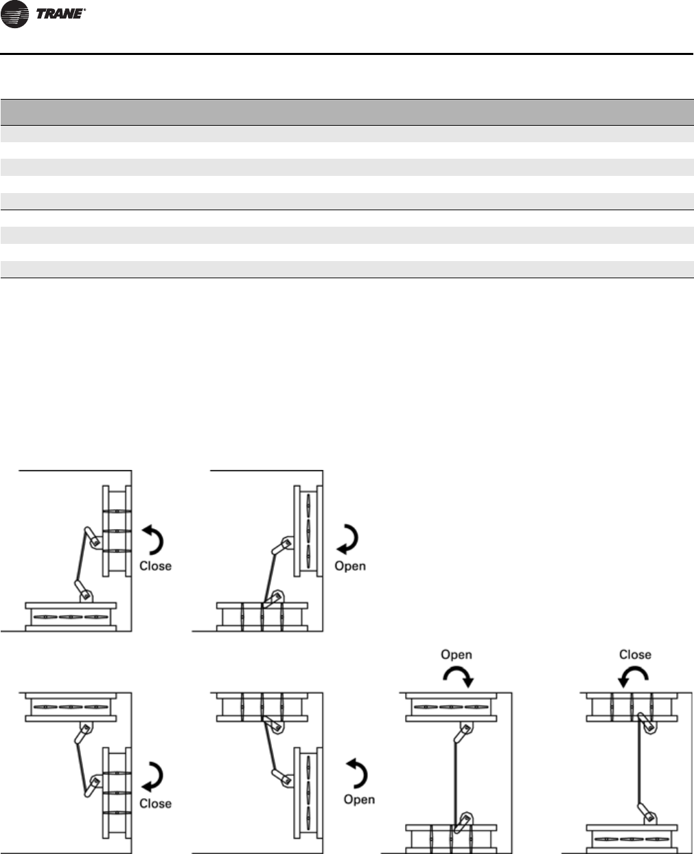
Component Installation Requirements
78 CLCH-SVX07C-EN
Unit size A (in) B (in) Damper
Qty Bypass Torque
(in-lb) Face Torque
(in-lb.) Torque
(in-lb) Actuator torque
(max) (in-lb.) Actuator
Qty
41 68.33 19.72 140.71 182.85 223.55 160.00 2
50 31.94 13.97 3 40.40 206.70 247.10 160.00 2
51 81.83 19.72 148.75 220.03 268.78 160.00 2
57 31.94 13.97 3 40.40 225.70 266.10 160.00 2
58 81.83 19.72 148.75 247.78 296.53 160.00 2
66 36.94 25.47 3 85.30 278.20 363.50 160.00 3
80 36.94 25.47 385.30 321.50 406.80 160.00 3
100 41.61 25.47 3 96.00 416.10 512.20 160.00 4
120 50.78 25.47 3117.20 498.70 615.90 160.00 4
External face-and-bypass damper torque requirements
Opposed-Blade and Parallel-Blade Damper
Opposed-blade and parallel-blade airfoil dampers in unit
sizes 3-120, as well as internal and external face-and-
bypass sections, have centered dampers with an internal
jack-shaft (see Figure 86, Figure 87 and Figure 88). A 95-
degree actuator rotation gives a 90-degree blade travel.
Note: Damper blades should be checked for proper
operation from full open to full closed position
before unit start up. Damper blade positioning may
have changed due to shipping and handling
vibrations.
Figure 86. Typical mixing box configurations for unit sizes 3 to 120
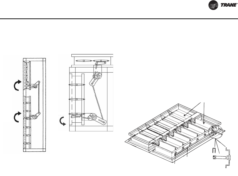
Component Installation Requirements
CLCH-SVX07C-EN 79
Multizone Modules
Under certain operating conditions, condensation may
form on the cold deck portion of the multizone damper
section. To prevent this, insulate around the damper rods.
Be sure the insulation does not affect damper operation.
Zone Damper Operators
Zone damper operators are available factory-mounted
with factory-mounted controls or as a stand-alone end
device. If not factory-provided, the contractor is
responsible for providing these operators. In all cases, the
damper operator should be connected to the drive rod.
Adjusting Zone Dampers
Zone dampers should be installed and adjusted prior to
making duct connections, assuring proper setup of the
damper zones:
1. Check the damper blades to confirm they are not
binding. The blade should rotate 90 degrees.
2. Determine the number of zones required. The zone
damper is fitted with a linkage bar that connects all
damper zones.
3. Select the number of damper segments required for
the first zone.
4. Cut a section out of the damper linkage bar just after
the last lever in that zone.
Note: It may be necessary to remove the damper linkage
bar to cut it. To remove the linkage bar pry the “e”
rings from the blade axles and remove the bar.
5. Repeat steps 3 and 4 for the remaining zones.
6. Attach the damper operator drive rod to one blade axle
in each zone with the two-deck damper.
7. Use the self-drilling screws provided to mount the
bearing bracket assembly (see Figure 89).
Note: The drive rod kits ship in a separate box, found in
the fan module or the cold deck of the multizone
module.
Duct Connections
All duct connections to the air handlers should be installed
in accordance with the standards of the National Fire
Protection Association (NFPA):
• NFPA 90A for installing air conditioning and ventilating
systems other than residence type.
• NFPA 90B for residence-type warm air heating and air-
conditioning systems.
See unit submittal documentation for additional duct
mounting information.
Fan Discharge Connections
To ensure the highest fan efficiency, duct turns and
transitions must be made carefully, minimizing air friction
losses and turbulence. Proper ductwork installation, as
outlined by such organizations as Sheet Metal and Air
Conditioning Contractors National Association, Inc.
(SMACNA), should be followed closely.
Fan sections with rectangular and round openings have a
one-inch flange on the discharge that can be used to attach
the duct. When using lined ducts, the insulation should not
obstruct the discharge opening. For plenum fan sections
with bell mouth fittings, see “Bell Mouth Discharge
Connections” on page 82.
Figure 87. Typical internal
face-and-bypass
configuration
Figure 88. Typical external
face-and-bypass
configuration
Open
Close
Close
Figure 89. Setting the zone damper rods and damper
linkage
Damper blades
Damper
linkage bar
Damper
lever Bearing
bracket assembly
BRK1756
Drive rod
SHF1709
Clip
CL0312
Complete Kit DMP0670
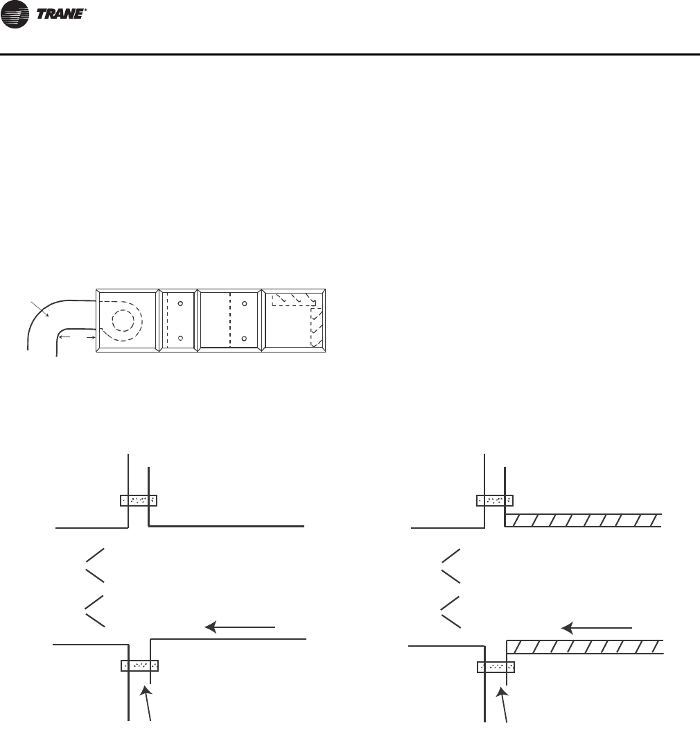
Component Installation Requirements
80 CLCH-SVX07C-EN
Connections made directly to the discharge opening of a
housed fan should have a minimum of three fan diameters
of straight duct before any turns or transitions. The
ductwork should be the same size as the fan discharge
opening. The first turn of the connection should be in the
same direction as the fan rotation as shown in Figure 90.
The air that the fan discharges into the duct is extremely
turbulent and requires some length of duct to stabilize.
Abrupt changes in ductwork directly off the fan discharge
may adversely affect fan performance and acoustics.
Damper Connections
Standard damper sections include mixing sections, filter
mixing sections, face dampers sections, internal face-and-
bypass sections, and economizer sections. There are two
damper blade configurations available - parallel-blade and
opposed-blade. Traq™ dampers are another type of
damper available in mixing box sections.
Ductwork attached to the standard damper sections
should be sized to fit the opening of the damper. Duct
opening dimensions are provided in the submittals. When
using lined duct, ensure that the insulation does not
obstruct the damper opening (see Figure 91 and
Figure 92).
Note: Damper blades should be checked for proper
operation from full-open to full-closed position
before unit start up. Damper blade positioning may
have changed due to shipping and handling
vibrations.
Figure 90. Typical discharge ductwork
recommendations
Splitters or
turning vanes
Vane turns in same
direction as fan rotation
3 fan
diameter
minimum
Figure 91. Typical section with duct flat/flange
connection- uninsulated or externally
insulated
Figure 92. Typical section with duct flat/flange
connection- internally insulated
Unit
Section
Flat Connection
Uninsulated Duct
Airflow
Unit
Section
Flat Connection
Insulated Duct
Airflow
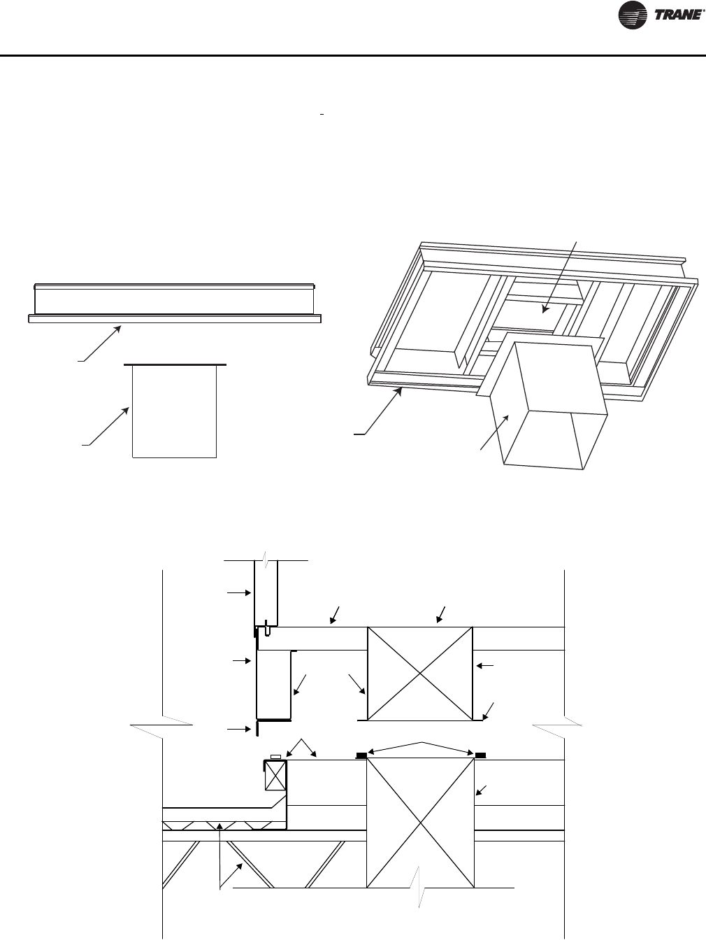
Component Installation Requirements
CLCH-SVX07C-EN 81
Bottom Opening Duct Installation
1. Install gasket to duct flange to ensure air tight seal.
2. Install duct into place underneath framed opening in
unit base per Figure 93. Refer to factory curb layout
provided with unit submittals for duct size and
location.
3. Bottom of unit base elevation is flush with duct
opening in bottom of unit (see Figure 94 and
Figure 95).
Figure 93. Field-supplied duct connection to AHU bottom supply/return air opening
Bottom supply/
return airflow
Trane AHU
base (typical)
Field-supplied
rigid duct
Trane AHU
base (typical)
Field-supplied
rigid duct
Figure 94. Field-supplied duct connection details - curb mount
Field-supplied
duct
Gasket
Supply opening
in floor
Roof Curb
Unit
wall Unit floor
Building roofing
and structure
may vary per job
Unit base
3-50-14 ga
57-120-10 ga
3-120-10 ga
6 inches
1 in. flange
3-120-16 ga
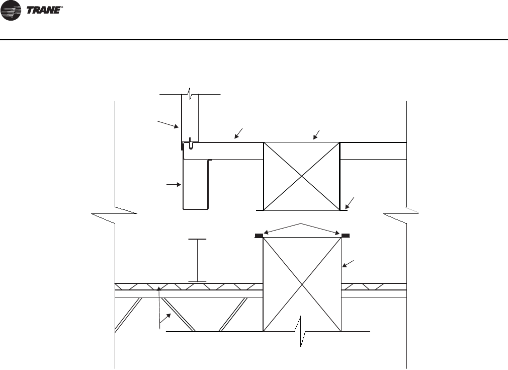
Component Installation Requirements
82 CLCH-SVX07C-EN
Discharge Plenum Connections
Discharge plenum sections are available with or without
openings. Sections with rectangular and round openings
have a framed opening that can be used to secure the duct
to the frames. If the duct is lined, it is important the
insulation does not obstruct the opening of the section.
For a discharge plenum with field-cut openings, attach the
duct to the side panel.
Bell Mouth Discharge Connections
Round duct connections to be fastened to plenum fan and
discharge plenum sections with bell mouth discharge
openings should be sized to attach to the casing or directly
to the bell mouth fitting. Attachment to the casing requires
the round duct diameter to be sized two inches larger than
the nominal bell mouth outlet. An angle ring with a flat
flange should be affixed to the round duct to secure the
duct to the casing (see Figure 96). Attachment to the bell
mouth fitting requires the duct and fitting to be insulated
by the installing contractor up to the bell mouth radius to
prevent condensation (see Figure 97). The bell mouth
fitting extends through the casing by one inch.
Figure 95. Field-supplied duct connection details - pier mount
Gasket
Supply opening
in floor
Unit
wall Unit
floor
Building roofing
and structure
may vary per job
Unit base
3-57-3 inches
66-120-4 inches 1 in. flange
Field-supplied
duct
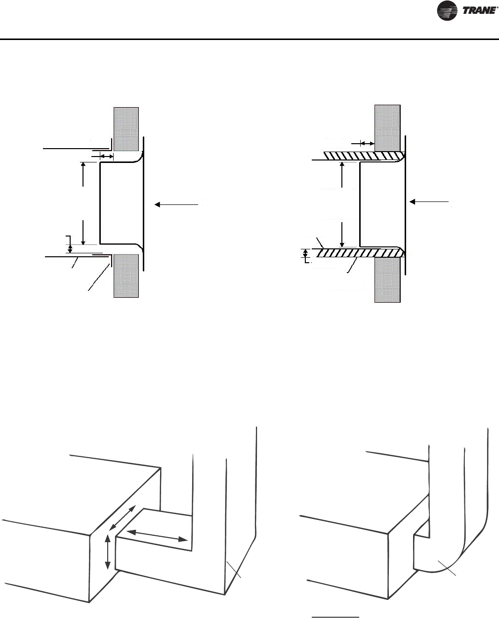
Component Installation Requirements
CLCH-SVX07C-EN 83
Traq Damper Connections
Size the duct connections to attach to the specified portion
on the face of the mixing box that the duct connection
completely covers all of the Traq damper.
For a mitered corner, provide one hydraulic duct diameter
between the entering face of the Traq dampers and the
duct turn. For a radius elbow, or sweep, place the elbow
directly against the face of the Traq dampers (see
Figure 98).
Figure 96. Securing round duct to casing over bell
mouth outlet Figure 97. Securing round duct to bell mouth outlet
1 inch
Bell mouth
outlet -
nominal
diameter
1 inch
Round duct
Angle ring
Airflow
1 inch
Bell mouth
outlet -
nominal
diameter
Round
duct
1 inch
External
insulation
Airflow
Figure 98. Traq damper duct connections
Traq damper
mixing box
Inlet duct
Traq damper
mixing box
Radius elbow
(sweep)
Mitered
corner
W
d
H
d = 1 hydraulic duct diameter = 2 x W x H
W + H
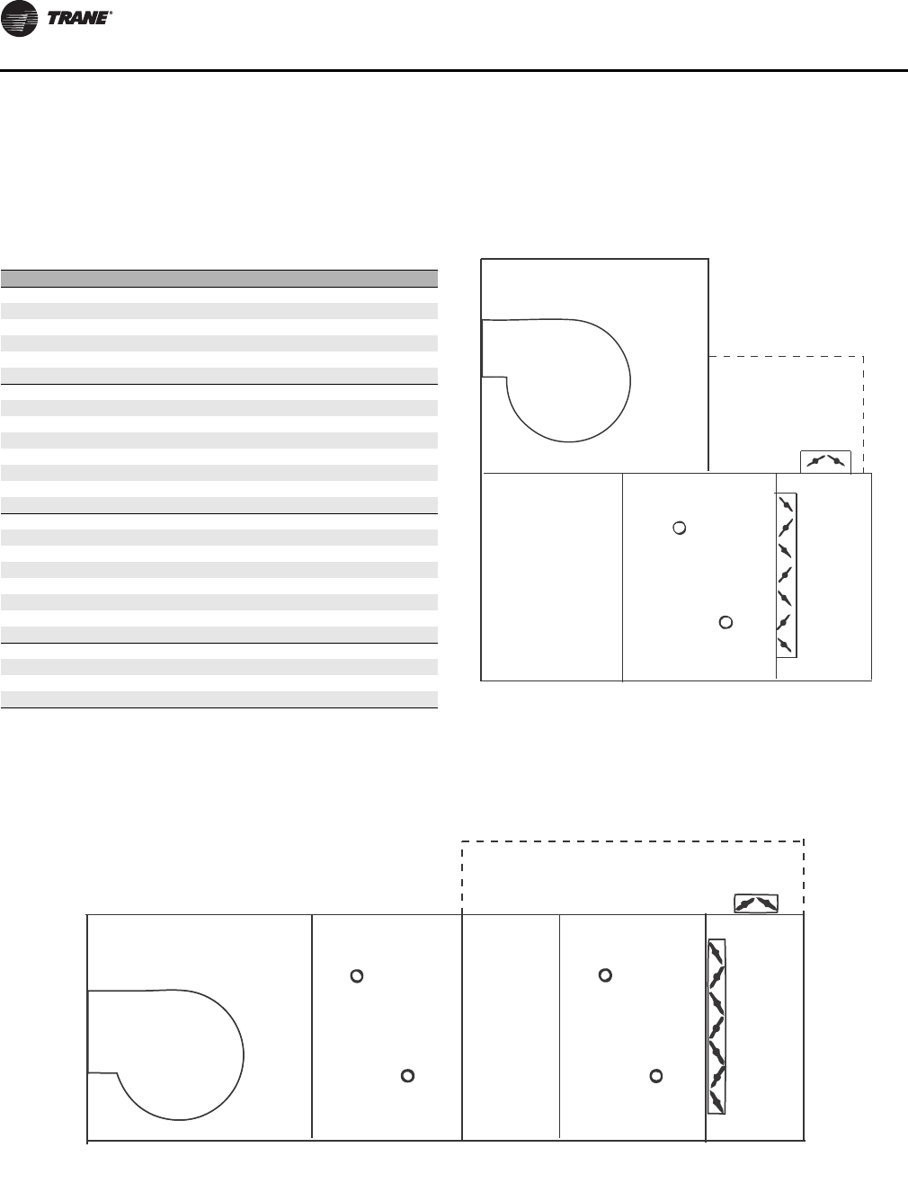
Component Installation Requirements
84 CLCH-SVX07C-EN
External Face-and-Bypass Connections
The external face-and-bypass damper sections will
require a field-fabricated duct to direct the bypass air into
the appropriate section. Duct sizing recommendations are
listed in Table 29.
When attaching a bypass duct to a downstream fan section
or access section, the section will have a factory-provided
opening. (see Figure 99, Figure 100, and Figure 101.)
When bypassing into an access section, remove a panel. It
is not necessary to cut an opening.
Table 29. Recommended bypass duct sizes (inches)
Unit size H W L
3 16.00 20.00 14.00
418.00 33.00 16.00
6 18.00 33.00 16.00
818.00 39.00 16.00
10 18.00 50.00 16.00
12 22.00 55.00 20.00
14 22.00 61.00 20.00
17 22.00 61.00 20.00
21 28.00 69.00 26.00
22 45.00 50.50 31.13
25 28.00 69.00 26.00
26 47.00 50.50 33.13
30 28.00 82.00 26.00
31 47.00 61.00 33.13
35 45.00 80.00 36.00
36 47.50 69.00 40.13
40 45.00 93.00 36.00
41 55.50 69.00 40.13
50 45.00 106.00 36.00
51 55.50 82.00 40.13
57 47.00 106.00 40.00
58 55.50 82.00 52.13
66 48.00 121.00 40.00
80 56.00 121.00 48.00
100 56.00 135.00 48.00
120 56.00 162.00 48.00
Figure 99. External face-and-bypass with duct
configuration designed to bypass air into a
vertical fan section
Duct
Fan
External
face-and-bypass
Coil
Figure 100. External face-and-bypass with duct configuration designed to bypass air around one coil
Fan
Coil Coil External
face-and-bypass
Duct
Access
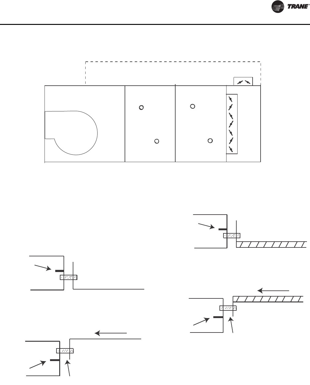
Component Installation Requirements
CLCH-SVX07C-EN 85
Other Connections
Access, filter, and other sections may have open inlets
with a 2-inch (sizes 3-120) panel frame for connecting the
ductwork. If the duct is lined, it is important the insulation
does not obstruct the opening of the section.
Figure 101. External face-and-bypass with duct configuration designed to bypass air into a horizontal fan section
Fan
Coil Coil External
face-and-bypass
Duct
Figure 102. Typical duct flat/flange end of unit
connection - uninsulated
Unit Section
End of unit
2-inch panel
Thermal
break
Uninsulated Duct
2-inch panel
Thermal
break
Airflow
Figure 103. Typical duct flat/flange end of unit
connection - insulated
Unit Section
End of unit
2-inch panel
Thermal
break
Internally insulated Duct
2-inch panel
Thermal
break
Airflow
86 CLCH-SVX07C-EN
Coil Piping and Connections
General Recommendations
Proper installation, piping, and trapping is necessary to
ensure satisfactory coil operation and to prevent
operational damage:
• Support all piping independently of the coils.
• Provide swing joints or flexible fittings on all
connections that are adjacent to heating coils to
absorb thermal expansion and contraction strains.
• If the coil was ordered with factory-mounted controls,
install the control valves. The valves ship separately.
Note: The contractor is responsible for supplying the
installation hardware.
• For best results, use a short pipe nipple on the coil
headers prior to making any welded flange or welded
elbow type connections.
• Extended drain and vent connections are provided as
standard on D1 and D2 coils only. If extended drains
and vents are required on other water coils, they must
be field-installed or ordered as specials from the
factory.
• Pipe coils counterflow to airflow.
• When attaching the piping to the coil header, make the
connection only tight enough to prevent leaks.
Maximum recommended torque is 200 foot-pounds.
• Use pipe sealer on all thread connections.
• After completing the piping connections, seal around
pipe from inner panel to outer panel.
Drain Pan Trapping
Threaded condensate drain connections are provided on
only one side of the coil section. Pitch the connection lines
horizontal or downward toward an open drain. Trane
recommends installing a plug to facilitate cleaning of the
trap. The drain connection sizes are:
Figure 30 illustrates the proper trapping, piping, and
operation of the trap. Use the formula under the figure to
determine the correct minimum depth for the condensate
trap. If a section has a drain pan for cleaning purposes
only, it does not need a trap; however, a cap or shutoff
valve should be installed on the drain connection. Only
sections handling condensate, such as a cooling coil
section or moisture eliminator section, require a trap.
NOTICE:
Connection Leaks!
Use a backup wrench when attaching piping to coils
with copper headers to prevent damage to the coil
header. Do not use brass connectors because they
distort easily and could cause connection leaks.
NOTICE:
Over Tightening!
Do not use Teflon-based products for any field
connections because their high lubricity could allow
connections to be over-tightened, resulting in damage
to the coil header.
NOTICE:
Leakage!
Properly seal all penetrations in unit casing. Failure to
seal penetrations from inner panel to outer panel could
result in unconditioned air entering the module, and
water infiltrating the insulation, resulting in equipment
damage.
WARNING
No Step Surface!
Do not walk on the sheet metal drain pan. Walking on
the drain pan could cause the supporting metal to
collapse, resulting in the operator/technician to fall.
Failure to follow this recommendation could result in
death or serious injury.
NOTICE:
Water Damage!
When more than one module has a drain pain, trap
each module individually. Connecting all drains to a
common line with only one trap can result in
condensate retention and possible water damage to
the air handler or adjoining space.
Unit size NPT (national pipe thread) external
connection
3-31 1-inch
35-58 1 1/4 inch
66-120 1 1/2 inch
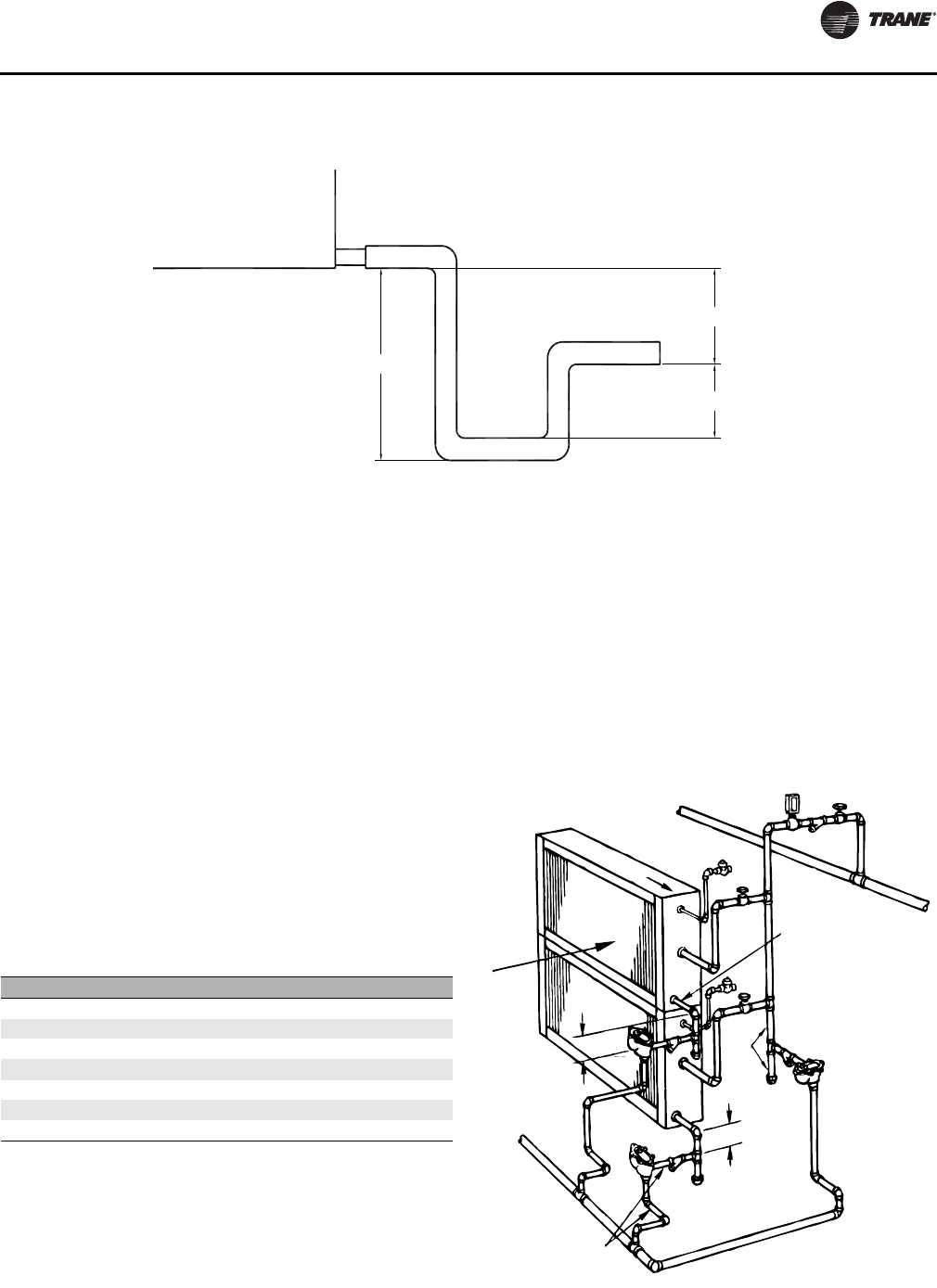
Coil Piping and Connections
CLCH-SVX07C-EN 87
Steam Coil Piping
Air handlers fitted with steam coils have labeled holes for
piping penetrations. Figure 104 illustrates a typical steam
coil piping configuration. See Table 31 for the codes of
system components in these figures.
The coil condensate return line must be piped full size of
the condensate trap connection, except for a short nipple
screwed directly into the coil header’s condensate return
tapping. Do not bush or reduce the coil return trapping
size.
Table 30. Drain pan trapping for negative and positive pressure applications
H
J
L
Drain pan trapping for section
under negative pressure
L = H + J + pipe diameter where:
H = 1 inch for each inch of negative
pressure plus 1 inch
J = 1/2 H
Drain pan trapping for section
under positive pressure
L = H + J + pipe diameter where:
H = 1/2 inch (minimum)
J = 1/2 inch plus the unit positive static
pressure at coil discharge
(loaded filters)
Table 31. Code of system components for piping figures
Code System component
FT Float and thermostatic steam trap
GV Gate valve
OV Automatic two-position (ON-OFF) control valve
VB Vacuum breaker
ST Strainer
AV Automatic or manual air vent
MV Modulating control valve
Figure 104. Typical piping for Type NS steam coils and
horizontal tubes for horizontal airflow
Full size of
coil connection
ST
GV
MV
Steam main
Pitch down
VB
GV
Airflow
12 in. min.
FT
ST
12 in. min.
Full
size
of
main
VB
GV
ST
FT
Return main
Full size of
steam trap
connection
ST
FT

Coil Piping and Connections
88 CLCH-SVX07C-EN
To prevent coil damage, complete the following
recommendations:
• Install a 1/2-inch NPT, 15 degree swing check valve
vacuum breaker with cracking pressure of 0.25 inches
Hg (3.4 inches water) or lower at the top of the coil. This
vacuum breaker should be installed as close to the coil
as possible.
• For coil type NS, install the vacuum breaker in the
unused condensate return tapping at the top of the
coil.
• Vent the vacuum breaker line to atmosphere or
connect it into the return main at the discharge side of
the steam trap
Note: Vacuum breaker relief is mandatory when the coil
is controlled by a modulating steam supply or
automatic two position (ON-OFF) steam supply
valve. Vacuum breaker relief is also recommended
when face-and-bypass control is used.
Proper steam trap installation is necessary for satisfactory
coil performance and service life. For steam trap
installation:
1. Install the steam trap discharge 12 inches below the
condensate return connection. Twelve inches provides
sufficient hydrostatic head pressure to overcome trap
losses and ensures complete condensate removal.
a. Use float and thermostatic traps with atmospheric
pressure gravity condensate return, with automatic
controls, or where the possibility of low-pressure
supply steam exists. (Float and thermostatic traps
are recommended because of gravity drain and
continuous discharge operation.)
b. Use bucket traps only when the supply steam is not
modulated and is 25 psig or higher.
Note: Trane steam coils require a minimum of 2 psi of
pressure to assure even heat distribution.
2. Trap each coil separately to prevent holding up
condensate in one or more of the coils.
3. Install strainers as close as possible to the inlet side of
the trap.
4. If installing coils in series airflow, control each coil
bank independently with an automatic steam-control
valve. Size the traps for each coil using the capacity of
the first coil in direction of airflow.
5. Use a modulating valve that has linear flow
characteristics to obtain gradual modulation of the coil
steam supply.
Note: Do not modulate systems with overhead or
pressurized returns unless the condensate is
drained by gravity into a receiver, vented to
atmosphere, and returned to the condensate
pump.
6. Pitch all supply and return steam piping down 1 inch
for every 10 feet in the direction of the steam or
condensate flow.
Note: Do not drain the steam mains or take-offs through
the coils. Drain the mains ahead of the coils
through a steam trap to the return line.
7. Ensure overhead returns have 1 psig of pressure at the
steam trap discharge for every 2 feet of elevation for
continuous condensate removal.
NOTICE:
Breaker Cracking Pressure!
The 1/2-inch NPT, 15 degree swing check valve vacuum
breaker is recommended because other vacuum
breakers, such as spring-loaded ball-check breakers,
have cracking pressures as high as 1.25 inches Hg (17
inches of water). Vacuum breakers with fitting sizes
smaller than 1/2 inch NPT are too small to relieve
vacuum quick enough to ensure complete condensate
drainage. Other types of swing check valve vacuum
breakers are acceptable if the fittings size is not smaller
than 1/2-inch NPT and the cracking pressure is not
larger than 0.25 inches HG (3.5 inches of water). Failure
to follow these instructions could result in equipment
damage.
NOTICE:
Coil Condensate!
Condensate must flow freely from the coil at all times
to prevent coil damage from water hammer, unequal
thermal stresses, freeze-up and/or corrosion. In all
steam coil installations, the condensate return
connections must be at the low point of the coil. Failure
to follow these instructions could result in equipment
damage.
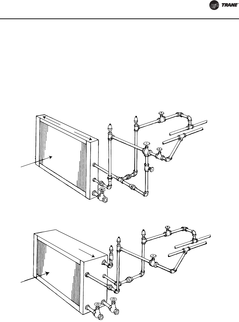
Coil Piping and Connections
CLCH-SVX07C-EN 89
Water Coil Piping
Figure 105, and Figure 106 illustrate typical water coil
piping configurations.
Type 5A, 5W, D1, W, UW, TT, P,2, P4, and P8 water coils are
self-venting only if the water velocity exceeds 1.5 feet per
second (fps) in the coil tubes. Type D2, UA, UU, and WD
water coils are self-venting only if the water velocity
exceeds 2.5 fps in the coil tubes. See the unit submittals for
coil water velocity. If the water velocity is below these
minimums, vent the coil by one of the following methods:
1. Install an air vent in the top pipe plug tapping of the
return header.
2. When the return line rises above the top of the coil,
vent from the top of the return header horizontally to
the return piping.
Note: TT coils are designed with larger than normal end
tube sheet holes to allow for maximum expansion.
Air leakage around tubes should be expected and
handled by capping over coil ends or by sealing
around tubes with a pliable sealant such as
silicone.
Figure 105. Typical piping for type 5W one-row water coil
Figure 106. Typical piping for type 5A, 5W two-row, W 3- to 12-row, WD, D1, and D2 water coils
GV
GV
GV
AV
AV
Water supply
main
Water
return main
Drain
Level
Air flow
AV
AV
AV
GV
Water supply
main
Water
return main
Drain
Air flow
Pitch down
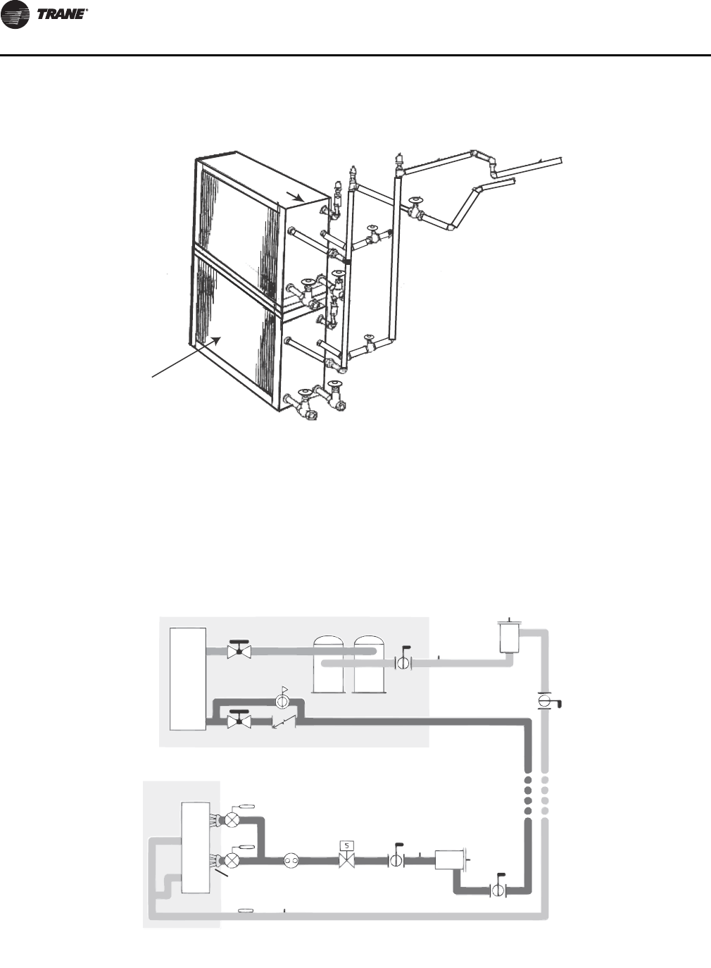
Coil Piping and Connections
90 CLCH-SVX07C-EN
Refrigerant Coil Piping
Note: Refer to for information on handling refrigerants.
Use Figure 108 to determine the proper, relative sequence
of the components in the refrigerant lines that connect the
condensing unit to an evaporator coil. Refer to “,” p . 9 3 for
more detailed schematics of evaporator piping.
Figure 107. Typical piping for stacked water coils
Pitch down
AV
AV
AV
Water
supply main
Water
return main
GV
Drain
Airflow
GV
MV
Figure 108. Example of placement for split-system components
Discharge
line
Manual
ball valve Access
port Filter
Access
port
Access
port
Filter drier
with access
port
Manual
angle valves
Check/relief
valve
Condensing unit
Condenser and
sbucooler coil
Compressors
Liquid line
Access
port
Manual
ball valve
Solenoid
valve
Moisture-
indicating
sight glass
Expansion
valves
Evaporator coil
Distriburtor
Manual ball valve
Suction lineFrostat™ control
Manual
ball valve
Kit with sensor - X13790452010 SEN-01212
Kit with switch - X13100429010 THT 02442
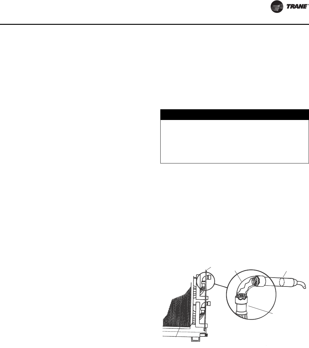
Coil Piping and Connections
CLCH-SVX07C-EN 91
Liquid Lines
Line Sizing
Properly sizing the liquid line is critical to a successful split-
system application. The selected tube diameter must
provide at least 5°F [2.7°C] of subcooling at the expansion
valve throughout the operating envelope. Increasing the
size of the liquid line will not increase the available
subcooling.
Routing. Install the liquid line with a slight slope in the
direction of flow so that it can be routed with the suction
line. Minimize tube bends and reducers because these
items tend to increase pressure drop and to reduce
subcooling at the expansion valve. Liquid line receivers,
other than those that are factory-installed, are not
recommended.
Insulation
The liquid line is generally warmer than the surrounding
air, so it does not require insulation. In fact, heat loss from
the liquid line improves system capacity because it
provides additional subcooling.
Components
Liquid-line refrigerant components necessary for a
successful job include a filter drier, access port, solenoid
valve, moisture-indicating sight glass, expansion valve(s),
and ball shutoff valves. Figure 108 illustrates the proper
sequence for positioning them in the liquid line. Position
the components as close to the evaporator as possible.
•Filter drier. There is no substitute for cleanliness during
system installation. The filter drier prevents residual
contaminants, introduced during installation, from
entering the expansion valve and solenoid valve.
•Access port. The access port allows the unit to be
charged with liquid refrigerant and is used to
determine subcooling. This port is usually a
Schraeder® valve with a core.
•Solenoid valve. In split systems, solenoid valves
isolate the refrigerant from the evaporator during off
cycles; under certain conditions, they may also trim the
amount of active evaporator as compressors unload.
Generally, the “trim” solenoid valve is unnecessary for
variable-air-volume comfort-cooling applications, and
is only required for constant-volume applications
when dehumidification is a concern.
•Moisture-indicating sight glass. Be sure to install one
moisture-indicating sight glass in the main liquid line.
The only value of the sight glass is its moisture
indication ability. Use actual measurements of
temperature and pressure—not the sight glass—to
determine subcooling and whether the system is
properly charged. The moisture indicator/sight glass
must be sized to match the size of the liquid line at the
thermal expansion valve.
•Thermal expansion valve. The expansion valve is the
throttling device that meters the refrigerant into the
evaporator coil. Metering too much refrigerant floods
the compressor; metering too little elevates the
compressor temperature. Choosing the correct size
and type of expansion valve is critical to assure it will
correctly meter refrigerant into the evaporator coil
throughout the entire operating envelope of the
system. Correct refrigerant distribution into the coil
requires an expansion valve for each distributor.
The thermal expansion valve must be selected for proper
size and capacity. The size of the expansion valve should
cover the full range of loadings. Check that the valve will
successfully operate at the lightest load condition. For
improved modulation, choose expansion valves with
balanced port construction and external equalization.
Cut the process tube and cap assembly from the liquid
connection as shown in Figure 109 and install the
expansion valve directly to the liquid connections.
NOTICE:
Valve Damage!
Disassemble the thermal expansion valve before
completing the brazing connections. If necessary, wrap
the valve in a cool, wet cloth while brazing. Failure to
protect the valve from high temperatures could result
in damage to internal components.
Figure 109. Type F refrigerant coil with packed elbow
Cut here
for piping
Perforated plate
(packed elbow)
Panel
Venturi type
distributor
Coil

Coil Piping and Connections
92 CLCH-SVX07C-EN
Suction Lines
Line sizing
Proper suction-line sizing is required to guarantee the oil
returns to the compressor throughout the system’s
operating envelope. At the same time, the line must be
sized so that the pressure drop does not excessively affect
capacity or efficiency. To accomplish both objectives, it
may be necessary to use two different line diameters: one
for the horizontal run and for vertical drops, and another
for the vertical lifts.
Routing
To prevent residual or condensed refrigerant from “free-
flowing” toward the compressor, install the suction line so
it slopes slightly—that is, by ¼ inch to 1 inch per 10 feet of
run—toward the evaporator. When the application
includes a suction riser, oil must be forced to travel the
height of the riser. Riser traps and double risers are
unnecessary in the suction line when the refrigerant coil is
used with Trane condensing units.
Avoid putting refrigerant lines underground. Refrigerant
condensation or installation debris inside the line, service
access, and abrasion/corrosion can quickly impair
reliability.
Insulation
Any heat that transfers from the surrounding air to the
cooler suction lines increases the load on the condenser
(reducing the system’s air-conditioning capacity) and
promotes condensate formation (adversely affecting
indoor air quality). After operating the system and testing
all fittings and joints to verify the system is leak-free,
insulate the suction lines all the way to inner side panel to
prevent heat gain and unwanted condensation.
Components
Installing the suction line requires field installation of
these components: a filter, access port, and a Frostat™
control when the refrigerant coil is used with Trane
condensing units. Position them as close to the
compressor as possible.
Note: Placement of the Frostat control is illustrated in
Figure 108 on page 90.
•Filter. The suction filter prevents contaminants,
introduced during installation, from entering the
compressor. For this reason, the suction filter should
be the replaceable-core type, and a clean core should
be installed after the system is cleaned up.
•Access port. The access port is used to determine
suction pressure. This port is usually a Schraeder valve
with a core.
•Frostat™ coil frost protection. The Frostat control is the
preferred method for protecting evaporator coils from
freezing when the refrigerant coil is used with Trane
condensing units. It senses the suction-line
temperature and temporarily disables mechanical
cooling if it detects frost conditions. The control is
mechanically attached to the outside of the refrigerant
line, near the evaporator, and wired to the unit control
panel.
•Ball shutoff valve. Adding manual, ball-type shutoff
valves upstream and downstream of the filter
simplifies replacement of the filter core.
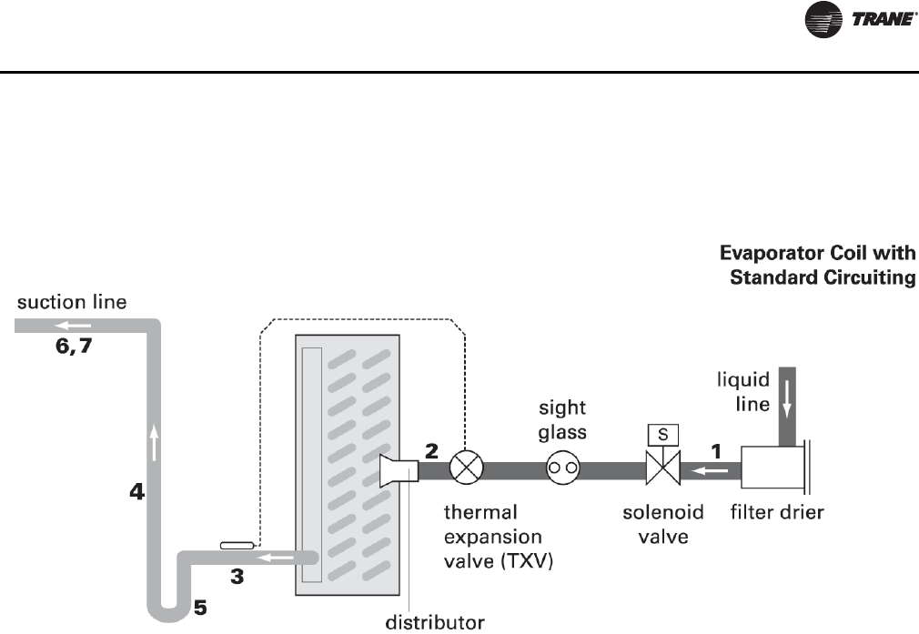
Coil Piping and Connections
CLCH-SVX07C-EN 93
1. Pitch the liquid line slightly—1 inch/10 feet —so that
the refrigerant drains toward the evaporator.
2. Provide one expansion valve per distributor.
3. Slightly pitch the outlet line from the suction header
toward the suction riser—that is, 1 inch/10 feet in the
direction of flow. Use the tube diameter that matches
the suction-header connection.
4. For the vertical riser, use the tube diameter
recommended by the condensing unit manufacturer.
Assure the top of the riser is higher than the evaporator
coil.
5. Arrange the suction line so the refrigerant gas leaving
the coil flows downward, past the lowest suction-
header outlet, before turning upward.
6. Pitch the suction line slightly—1 inch/10 feet —so the
refrigerant drains toward the evaporator.
7. Insulate the suction line.
Field-Installed Evaporator Piping Examples
Figure 110. Single-circuit condensing unit: evaporator coil with one distributor
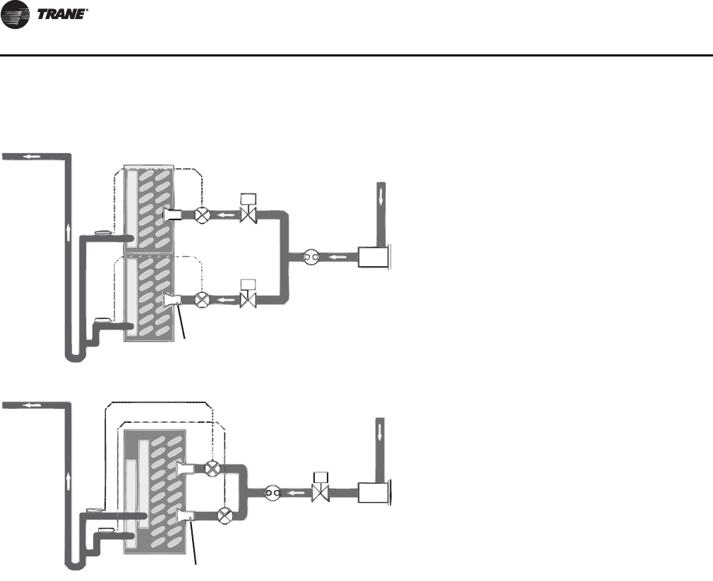
Coil Piping and Connections
94 CLCH-SVX07C-EN
Figure 111. Single-circuit condensing unit: evaporator coil with two distributors
1. Pitch the liquid line slightly—1 inch/10 feet —so
the refrigerant drains toward the evaporator.
2. Provide one expansion valve per distributor.
3. Slightly pitch the outlet line from the suction
header toward the suction riser—that is, 1 inch/
10 feet in the direction of flow. Use the tube
diameter that matches the suction-header
connection.
4. Arrange the suction line so the refrigerant gas
leaving the coil flows downward, past the lowest
suction-header outlet, before turning upward.
Use a double-elbow configuration to isolate the
thermal expansion valve bulb from other
suction headers.
5. For horizontal tubing, use the tube diameter
recommended by the condensing unit
manufacturer.
6. For the vertical riser, use the tube diameter
recommended by the condensing unit
manufacturer. Assure the top of the riser is
higher than the evaporator coil.
7. Pitch the suction line slightly—1 inch/10 feet —
so the refrigerant drains toward the evaporator.
8. Insulate the suction line.
9. Only use a “trim” solenoid valve for constant-
volume, humidity-sensitive applications. For all
other applications, install a single solenoid valve
(the “pumpdown” solenoid valve) between the
liquid-line filter drier and the sight glass.
Suction line
7, 8
Liquid
line
Evaporator coil
with horizontal-split
(standard) circuiting
Evaporator coil with
intertwined circuiting
Liquid
line
‘Trim’
solenoid valve
‘Pump-down’
solenoid valve
Sight
glass 1
Filter drier
Filter drier
Solenoid
valve
Thermal
expansion
valve (TXV)
9
2
2
1
9
7, 8
3
4
4
5
5
6
6
3
3
Distributor
Thermal
expansion
valve (TXV)
Sight
glass
Distributor
S
S
S
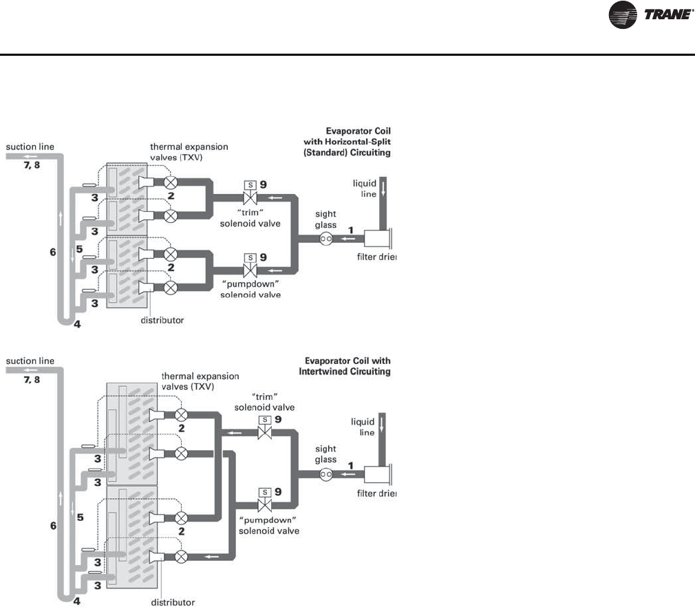
Coil Piping and Connections
CLCH-SVX07C-EN 95
Figure 112. Single-Circuit Condensing Unit: Evaporator Coil with Four Distributors
1. Pitch the liquid line slightly—1 inch/10 feet —so
the refrigerant drains toward the evaporator.
2. Provide one expansion valve per distributor.
3. Slightly pitch the outlet line from the suction
header toward the suction riser—that is, 1 inch/
10 feet in the direction of flow. Use the tube
diameter that matches the suction-header
connection.
4. Arrange the suction line so the refrigerant gas
leaving the coil flows downward, past the lowest
suction-header outlet, before turning upward.
Use a double-elbow configuration to isolate the
thermal expansion valve bulb from other
suction headers.
5. For horizontal tubing, use the tube diameter
recommended by the condensing unit
manufacturer.
6. For the vertical riser, use the tube diameter
recommended by the condensing unit
manufacturer. Assure the top of the riser is
higher than the evaporator coil.
7. Pitch the suction line slightly—1 inch/10 feet —
so the refrigerant drains toward the evaporator.
8. Insulate the suction line.
Only use a “trim” solenoid valve for constant-
volume, humidity-sensitive applications. For all
other applications, install a single solenoid valve
(the “pumpdown” solenoid valve) between the
liquid-line filter drier and the sight glass.
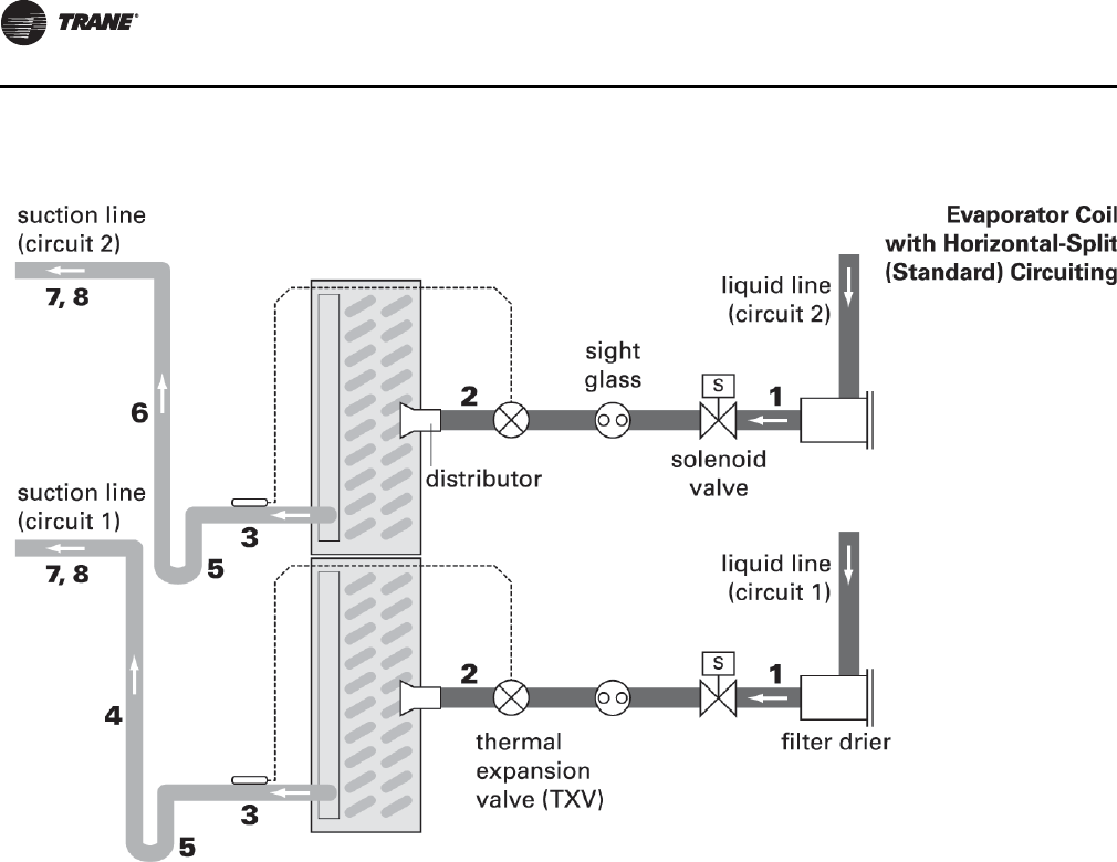
Coil Piping and Connections
96 CLCH-SVX07C-EN
1. Pitch the liquid lines slightly—1 inch/10 feet —so the
refrigerant drains toward the evaporator.
2. Provide one expansion valve per distributor.
3. Slightly pitch the outlet line from the suction header
toward the suction riser—that is, 1 inch/10 feet in the
direction of flow. Use the tube diameter that matches
the suction-header connection.
4. The top of the Circuit 1 suction riser must be higher
than the bottom evaporator coil. Use the tube diameter
recommended by the condensing unit manufacturer
for the riser.
5. Arrange the suction line so the refrigerant gas leaving
the coil flows downward, past the lowest suction-
header outlet, before turning upward.
6. The top of the Circuit 2 suction riser must be higher
than the top evaporator coil. Use the tube diameter
recommended by the condensing unit manufacturer
for the riser.
7. Pitch the suction lines slightly—1 inch/10 feet —so the
refrigerant drains toward the evaporator.
8. Insulate the suction lines.
Figure 113. Dual-circuit condensing unit: evaporator coil with two distributors
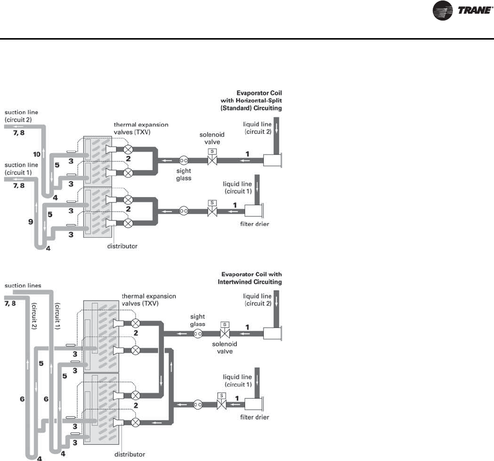
Coil Piping and Connections
CLCH-SVX07C-EN 97
Figure 114. Dual-circuit condensing unit: evaporator coil with four distributors
1. Pitch the liquid line slightly—1 inch/10 feet —so
the refrigerant drains toward the evaporator.
2. Provide one expansion valve per distributor.
3. Slightly pitch the outlet line from the suction
header toward the suction riser—that is, 1 inch/
10 feet in the direction of flow. Use the tube
diameter that matches the suction-header
connection.
4. Arrange the suction line so the refrigerant gas
leaving the coil flows downward, past the lowest
suction-header outlet, before turning upward.
Use a double-elbow configuration to isolate the
thermal expansion valve bulb from other
suction headers.
5. For horizontal tubing, use the tube diameter
recommended by the condensing unit
manufacturer.
6. For the vertical riser, use the tube diameter
recommended by the condensing unit
manufacturer. Assure the top of the riser is
higher than the evaporator coil.
7. Pitch the suction line slightly—1 inch/10 feet —
so the refrigerant drains toward the evaporator.
8. Insulate the suction line.
9. The top of the Circuit 1 suction riser must be
higher than the bottom evaporator coil. Use the
tube diameter recommended by the condensing
unit manufacturer for the riser.
10. The top of the Circuit 2 suction riser must be
higher than the top evaporator coil. Use the tube
diameter recommended by the condensing unit
manufacturer for the riser.
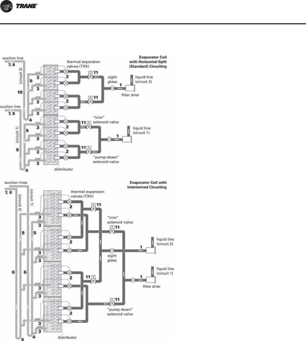
Coil Piping and Connections
98 CLCH-SVX07C-EN
Figure 115.Dual-circuit condensing unit: evaporator coil with eight distributors
1. Pitch the liquid line slightly—1 inch/10 feet —so
the refrigerant drains toward the evaporator.
2. Provide one expansion valve per distributor.
3. Slightly pitch the outlet line from the suction
header toward the suction riser—that is, 1 inch/
10 feet in the direction of flow. Use the tube
diameter that matches the suction-header
connection.
4. Arrange the suction line so the refrigerant gas
leaving the coil flows downward, past the
lowest suction-header outlet, before turning
upward. Use a double-elbow configuration to
isolate the TXV bulb from other suction headers.
5. For horizontal tubing, use the tube diameter
recommended by the condensing unit
manufacturer.
6. For the vertical riser, use the tube diameter
recommended by the condensing unit
manufacturer. Assure the top of the riser is
higher than the evaporator coil.
7. Pitch the suction line slightly—1 inch/10 feet —
so the refrigerant drains toward the evaporator.
8. Insulate the suction line.
9. The top of the Circuit 1 suction riser must be
higher than the bottom evaporator coil. Use the
tube diameter recommended by the
condensing unit manufacturer for the riser.
10. The top of the Circuit 2 suction riser must be
higher than the top evaporator coil. Use the tube
diameter recommended by the condensing unit
manufacturer for the riser.
11. Only use a “trim” solenoid valve for constant-
volume, humidity-sensitive applications. For all
other applications, install a single solenoid
valve (the “pumpdown” solenoid valve)
between the liquid-line filter drier and the sight
glass.
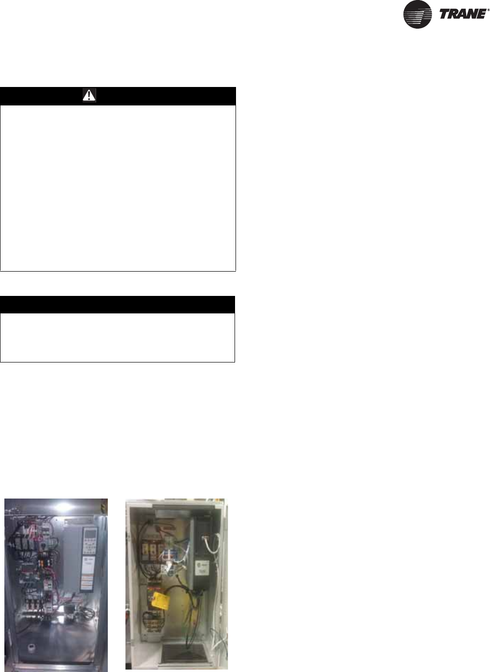
CLCH-SVX07C-EN 99
Installation - Electrical
.
Units intended for indoor use are available with starters or
variable-frequency drives (VFDs) that are externally
mounted in an enclosure or internally mounted in a
recessed cabinet. Units intended for outdoor use are only
available with internally mounted starters or VFDs. A
typical internally mounted VFD is shown in Figure 116. A
typical externally mounted VFD is shown in Figure 117.
Typical wiring schematics for VFDs and starters are shown
in Figure 123 and Figure 124, respectively. Unit specific
wiring schematics are shipped with each unit.
All units with starters or VFDs that have direct-digital
controllers (DDCs) are provided with line voltage to 24 Vac
power transformers as shown in Figure 118. When
provided, the line voltage to 24 Vac transformers are
factory wired to the supply fan power feed. All units with
factory-mounted controllers, and no starters or VFDs, are
provided with 120 Vac to 24 Vac control transformers, as
shown in Figure 120, and require a separate 120V field
connection. As with starters or VFDs, units intended for
indoor use are available with DDCs mounted internally
(see Figure 118) or externally (see Figure 119 and
Figure 120), while units intended for outdoor use are only
available with internally mounted DDCs.
In units with 24Vac LED marine lights, the lights are wired
together to a single switch located in the controls interface
module. Figure 119 shows a typical mounting of the
controls interface module with an externally mounted
controller. When DDCs are provided, the lighting circuit is
powered from the DDC power feed and does not require a
separate power source. When marine lights are provided
without DDCs, the lighting circuit requires a separate 120V
field connection that powers the lights through a 120V to
24Vac power transformer.
A mounted GFCI receptacle is provided for all units that
have DDCs or marine lights. The receptacle is mounted in
the controls interface module (see Figure 119) with the unit
light switch. The receptacle requires a separate 120V
power feed.
WARNING
Hazardous Voltage w/Capacitors!
Disconnect all electric power, including remote
disconnects and discharge all motor start/run
capacitors before servicing. Follow proper lockout/
tagout procedures to ensure the power cannot be
inadvertently energized. For variable frequency drives
or other energy storing components provided by Trane
or others, refer to the appropriate manufacturer’s
literature for allowable waiting periods for discharge of
capacitors. Verify with an appropriate voltmeter that all
capacitors have discharged. Failure to disconnect
power and discharge capacitors before servicing could
result in death or serious injury.
For additional information regarding the safe discharge
of capacitors, see PROD-SVB06A-EN
NOTICE:
Use Copper Conductors Only!
Unit terminals are not designed to accept other types
of conductors. Failure to use copper conductors could
result in equipment damage.
Figure 116. Internally
mounted VFD Figure 117. Externally
mounted VFD
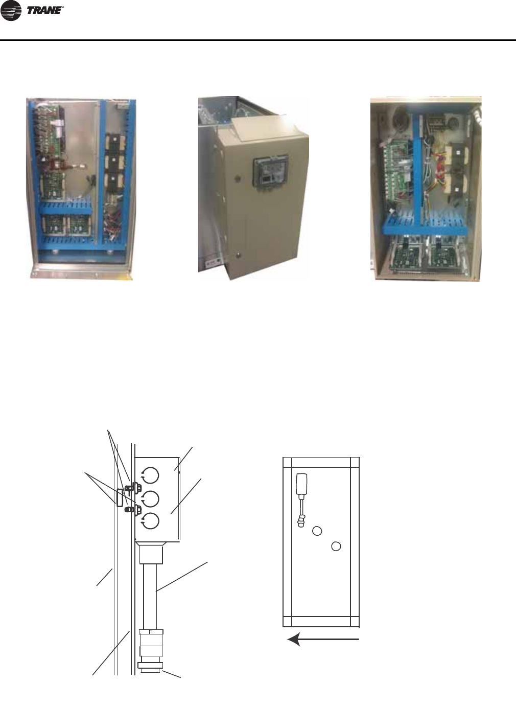
Installation - Electrical
100 CLCH-SVX07C-EN
Field installed DDC control devices:
• Install outside-air sensor and space sensor, if ordered.
• Connect control valves, if ordered, to the valve jack
provided as part of the unit wiring harness. The valve
jack is typically located at the air-leaving side of the coil
connection inside the casing panel. For valve junction
box mounting and wiring detail, see Figure 121.
Figure 118. Internal controller Figure 119. External mounted
controller Figure 120. External controller
Figure 121.
Junction box for valve wiring
#10 self-drilling
screws (2) 2 x 4 junction box
Cover
Conduit
assembly
Valve
connection
End panel
Double-
wall panel
Bushing
(2 required
for units with
double-wall)
Airflow
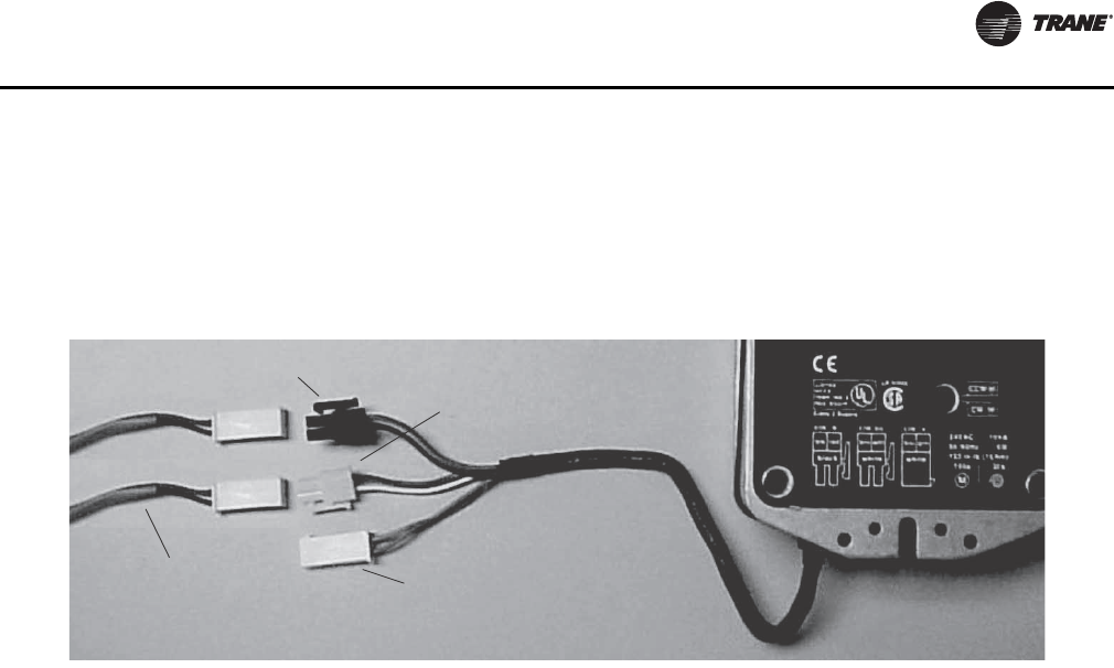
Installation - Electrical
CLCH-SVX07C-EN 101
Quick Connects
The actuators, factory-mounted or field-supplied, are
separately wired and controlled by a direct-digital
controller or other building logic. Figure 122 illustrates the
typical quick connect scheme.
If the unit does not include a factory-mounted starter,
wiring to the unit fan motor must be provided by the
installer and must comply with all national and local
electrical codes. The installer must also furnish a service
disconnect switch in compliance with national and local
electrical codes.
Fan motors require motor overload protective devices that
are rated or selected in compliance with the National
Electric Code (NEC) or Canadian Electric Code. Specific
unit and motor connection diagrams are provided on the
starter/VFD if Trane-provided, or refer to the motor
nameplate.
If wiring directly to the motor, a flexible connection at the
motor to permit fan belt adjustment should be provided.
Fractional horsepower motors may be factory connected
to a terminal box on the unit. If this construction is
provided, the installer should complete field wiring to this
connection box. For a typical high voltage wiring
schematic, see Figure 123.
Note: Properly seal all penetrations in unit casing. Failure
to seal penetrations from inner panel to outer panel
could result in unconditioned air entering the unit.
Figure 122. Typical quick connects with wiring identification
Actuator
Power 24 Vac Control signal
(2-10 Vdc)
Feedback signal
Wiring harness
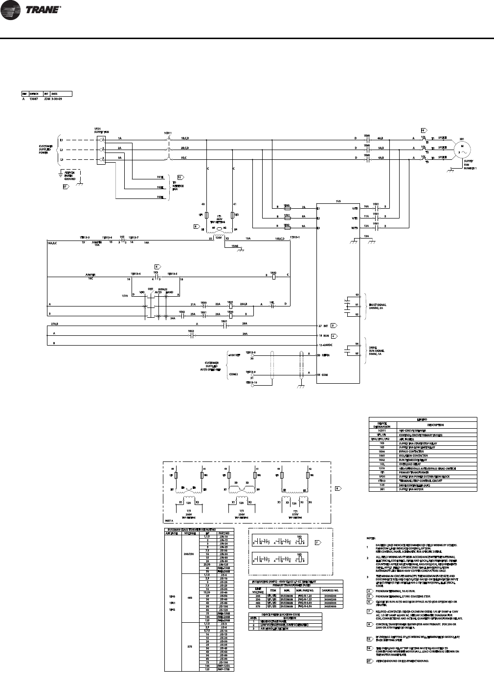
Installation - Electrical
102 CLCH-SVX07C-EN
Figure 123. Typical VFD wiring schematic
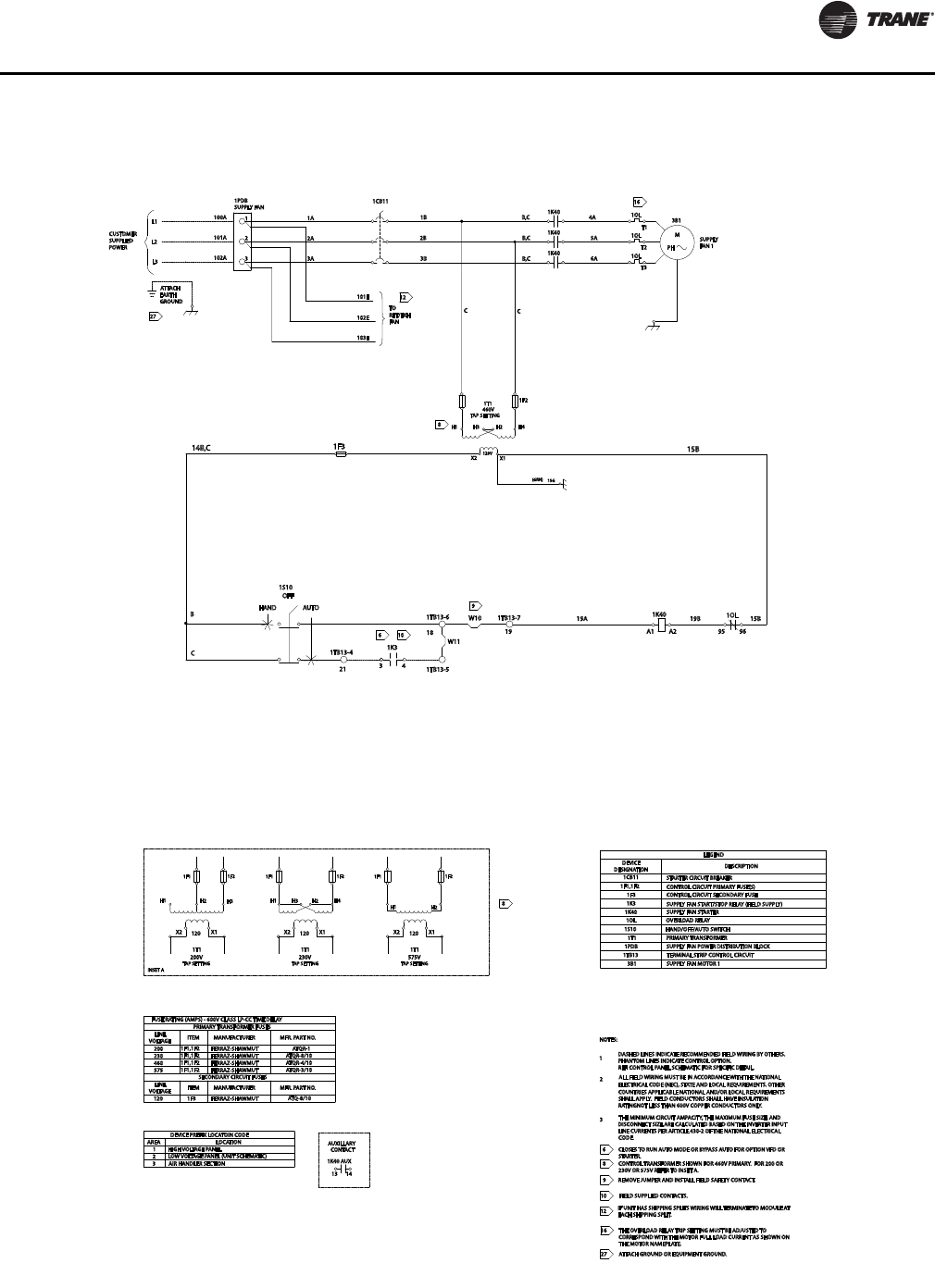
Installation - Electrical
CLCH-SVX07C-EN 103
Figure 124. Typical starter wiring schematic
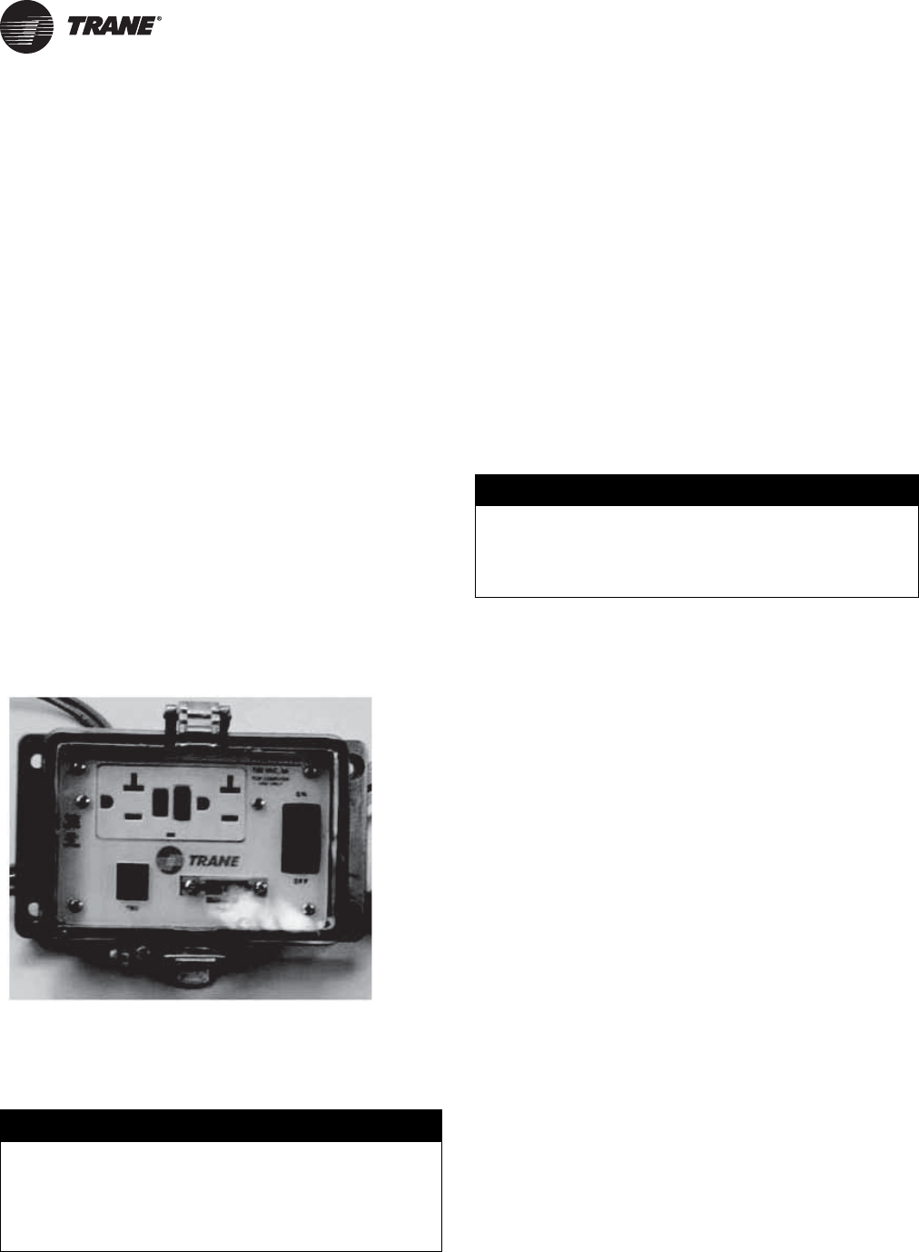
104 CLCH-SVX07C-EN
Controls Interface
The portable operator display is used for temporary
connection to and operation of Tracer MP580/581
controllers. With the portable operator display, you can
monitor data, change setpoints, monitor alarms, and
override points. The portable operator display includes a
10 ft (3 m) cable with connector that is stored in the storage
compartment of the carrying bag. The cable cannot be
disconnected from the operator display. Keep this
document with the portable operator display for access to
calibration and cleaning instructions.
Note: The portable operator display is not used for
timeclock scheduling. To provide scheduling you
must use a Tracer Summit system.
Connecting the operator display
To connect the portable operator display:
1. Locate the factory-provided service module (see
Figure 125).
2. Attach the operator-display cable to the operator-
display connector on the service module. The operator
display receives power from the controller and turns
on automatically when it is connected.
Setting up the operator display
This section shows how to calibrate the operator display
touch screen and how to adjust the brightness and
contrast. To set up the operator display screens and
security, see the Tracer MP580/ 581 Programmable
Controller Programming guide (CNT-SVP01B-EN).
Calibrating the operator display
To calibrate the operator display:
1. On the home screen, press Setup. The Setup menu
appears.
2. Page down to view the next screen.
3. Press Calibrate Touch Screen. A calibration screen
appears.
4. Touch the target using a small, pliable, blunt object,
such as a pencil eraser or your finger. Hold until the
beeping stops. A second calibration screen appears.
5. Again, touch the target with the object. Hold until the
beeping stops. The Advanced Selection screen
appears.
6. Press Home. The home screen appears.
Adjusting brightness and contrast
To adjust the brightness and contrast of the operator
display:
1. On the home screen, press Setup. The Setup menu
appears.
2. Page down to view the next screen.
3. Press the Adjust Brightness and Contrast buttons. The
Brightness and Contrast screen appears.
4. To increase the brightness, press the buttons along the
top row, in sequence, from left to right. To decrease the
brightness, press the buttons from right to left.
Note: Contrast adjustment is not available on all
computer display models.
5. To increase the contrast, press the buttons along the
bottom row, in sequence, from left to right. To decrease
the contrast, press the buttons from right to left.
6. Press Home. The home screen appears.
Figure 125. Service module
NOTICE:
Water Damage!
To clean the operator display, use a cloth dampened
with commercial liquid glass cleaner. Spraying water or
cleaner directly on the screen could result in equipment
damage.
NOTICE:
Equipment Damage!
Do not allow the operator display to come in contact
with sharp objects. This could result in equipment
damage.

Controls Interface
CLCH-SVX07C-EN 105
External communications port
Units with a factory-provided DDC controller can include a
service module (see Figure 125) with an external
communications port when purchased. Both the operator
display and Rover service tool can be connected without
shutting off the unit through the external communications
port. Open the cover plate on the service module and plug
into the RJ-11 port for the operator display or the RS 485
port for the Rover service tool. This enables continuous
operation of the air handler without disruption to the
operating conditions of the unit. When servicing of the unit
is complete, close the cover plate on the service module to
eliminate any air leakage path.
106 CLCH-SVX07C-EN
Start-Up
Pre-Startup Checklist
Once the air handler has been assembled and installed,
attention must be directed to individual components for
proper operation. Before operating the unit, complete the
pre-startup checklist.
General Checks
• Ensure the unit has been installed level.
• Ensure supply-air and return-air ducts have been
connected.
• Ensure damper operator motors and connecting
linkage have been installed.
• Verify damper operation and linkage alignment.
• Check that air filters are in place and positioned
properly.
• Remove any debris from the unit interior.
• Remove all foreign material from the drain pan and
check drain pan opening and condensate line for
obstructions.
• Close and secure all unit access doors.
• If differential pressure switch is provided on filter rack,
adjust per system requirements.
• Inspect electrical connections to the unit and unit
controllers.
– Connections should be clean and secure.
– Compare the actual wiring with the unit diagrams.
– Reference the appropriate controller manual for
more details about starting units with factory-
mounted controls.
• Check piping and valves for leaks. Open or close the
valves to check for proper operation. Drain lines should
be open.
• Leave this manual with the unit.
Fan-Related Checks
• If the unit is not externally isolated, ensure that the fan
isolator tie-down bolts have been removed. See “Fan
Isolation” section on page 62 for more information.
• Rotate all fan wheels manually to confirm they turn
freely in the proper direction.
• Check fan shaft bearings, fan wheel, and drive sheave
set screws for proper torque settings (see Table 35 on
page 111.
– Fan sheaves should be tight and aligned.
– Bearing set screws should be torqued. See Tab le 4 8
on page 124 for torque values.
• Check fan drive belt tension. See “Tension the Fan
Belt” section on page 109.
• Inspect fan motor and bearings for proper lubrication,
if necessary. See “Fan Bearing Lubrication,” on
page 124.
Coil-Related Checks
:
• Ensure coil and condensate drain piping connections
are complete.
• Check the piping and valves for leaks.
– Open or close the valves to check operation.
– The drain lines should be open.
• If unit has a refrigerant coil, ensure that it has been
charged and leak-tested according to the instructions
provided with the condenser equipment. Adjust the
superheat setting.
• Remove all foreign material from the drain pan and
check the pan opening and condensate line for
obstructions.
• For steam coils, slowly turn the steam on full for at least
10 minutes before opening the fresh air intake on units
with fresh air dampers.
WARNING
Hazardous Voltage w/Capacitors!
Disconnect all electric power, including remote
disconnects and discharge all motor start/run
capacitors before servicing. Follow proper lockout/
tagout procedures to ensure the power cannot be
inadvertently energized. For variable frequency drives
or other energy storing components provided by Trane
or others, refer to the appropriate manufacturer’s
literature for allowable waiting periods for discharge of
capacitors. Verify with an appropriate voltmeter that all
capacitors have discharged. Failure to disconnect
power and discharge capacitors before servicing could
result in death or serious injury.
For additional information regarding the safe discharge
of capacitors, see PROD-SVB06A-EN
NOTICE:
Proper Water Treatment!
The use of untreated or improperly treated water in
coils could result in scaling, erosion, corrosion, algae or
slime. It is recommended that the services of a qualified
water treatment specialist be engaged to determine
what water treatment, if any, is required. Trane
assumes no responsibility for equipment failures which
result from untreated or improperly treated water, or
saline or brackish water.
Start-Up
CLCH-SVX07C-EN 107
Motor-Related Checks
• Locate installation manual from the motor
manufacturer for the specific motor installed. This can
be found by contacting the motor manufacturer’s
representative. The motor manufacturer’s
recommendations take precedence for all matters
related to the start-up and routine maintenance of the
motor.
• Check the motor lubrication for moisture and rust.
– Remove and clean grease plugs to inspect.
– If moisture is present, consult an authorized repair
shop for bearing inspection/replacement. This may
require removal and transport of motor.
– If no moisture is present, refer to the motor
manufacturer’s lubrication recommendations for
proper lubrication.
– The motor manufacturer may recommend
lubricating the motor as part of their routine start-
up instructions.
• Check motor winding. An acceptable winding
resistance reading is from 6 meg-ohms to infinity. If
reading is less than 5 mega-ohms, the winding should
be dried out in an oven or by a blower.
• Inspect the entire motor for rust and corrosion.
• Bump-start the unit and confirm the fan wheel rotates
properly, as indicated by the rotation arrow located on
the fan housing.
Note: For motor warranty needs, contact your local Trane
sales office.
Unit Operation
Before complete start-up, bump-start the unit and confirm
the fan wheel rotates properly, as indicated by the rotation
arrow located on the fan housing.
After initial startup:
• Calculate the motor voltage imbalance, notifying the
power company to correct unacceptable imbalances.
• Periodically check the fan belt tension.
Calculate Motor Voltage Imbalance
After startup, measure the motor voltage and amperage
on all phases to ensure proper operation. The readings
should fall within the range given on the motor nameplate.
The maximum allowable voltage imbalance is 2 percent.
Voltage imbalance is defined as 100 times the sum of the
deviation of the three voltages from the average, divided
by twice the average voltage. For example, if the three
measured voltages are 221, 230 and 227, the average
voltage would be 226 volts. The percent of voltage
imbalance is then calculated.
In the example, 2.2 percent imbalance is not acceptable
and the power company should be notified to correct it.
VFD Programming Parameters
Units shipped with an optional variable frequency drive
(VFD) are preset and run-tested at the Trane factory. If a
problem with a VFD occurs, ensure that the programmed
parameters listed in Table 33 have been set. If trouble still
persist after verifying factory parameters are correct, call
Trane Drive Technical Support at 1-877-872-6363. Have the
unit serial number from the drive available for the
technical support representative. The technician will
determine if drive can be repaired or needs to be replaced.
WARNING
Rotating Components!
During installation, testing, servicing and
troubleshooting of this product it may be necessary to
work with live and exposed rotating components. Have
a qualified or licensed service individual who has been
properly trained in handling exposed rotating
components, perform these tasks. Failure to follow all
safety precautions could result in rotating components
cutting and slashing technician which could result in
death or serious injury.
WARNING
Live Electrical Components!
During installation, testing, servicing and
troubleshooting of this product, it may be necessary to
work with live electrical components. Have a qualified
licensed electrician or other individual who has been
properly trained in handling live electrical components
perform these tasks. Failure to follow all electrical
safety precautions when exposed to live electrical
components could result in death or serious injury.
Voltage imbalance =
where:
A = (226-221) + (230-226) + (227-226)
Voltage imbalance = 2.2% (not acceptable)
100A
2
AvgVoltage×
--------------------------------------------------
Start-Up
108 CLCH-SVX07C-EN
.
Table 32. Trane TR200 Switching Frequency
Horsepower Voltage Max KHz Trane Setting
0.5 - 15 208/230 16 16
20 - 25 208/230 14 14
30 - 40 208/230 12 12
50 230 12 12
0.5 - 25 460 16 16
30 - 50 460 14 14
60 - 125 460 12 12
0.5 - 10 575 16 16
15 - 50 575 10 10
60 - 125 575 8 8
WARNING
Hazardous Voltage w/Capacitors!
Disconnect all electric power, including remote
disconnects and discharge all motor start/run
capacitors before servicing. Follow proper lockout/
tagout procedures to ensure the power cannot be
inadvertently energized. For variable frequency drives
or other energy storing components provided by Trane
or others, refer to the appropriate manufacturer’s
literature for allowable waiting periods for discharge of
capacitors. Verify with an appropriate voltmeter that all
capacitors have discharged. Failure to disconnect
power and discharge capacitors before servicing could
result in death or serious injury.
For additional information regarding the safe discharge
of capacitors, see PROD-SVB06A-EN
Table 33. Trane TR200 VFD Programming Parameters
Parameter #
TR200 Description Factory Default Trane Setting
3 Region International North American
103 Torque Characteristics (Fan Array only) Auto Energy Optim. VT Variable Torque (Fan Array only)
512 Terminal 27 Digital Input Safety Interlock Coast Inverse
121 Motor Power Depends on unit Set Based on Motor Nameplate
122 Motor Voltage Depends on unit Set Based on Motor Nameplate
124 Motor Current Depends on unit Set Based on Motor Nameplate
125 Rated Motor Speed Depends on Parameter 102 Set Based on Motor Nameplate
173 Flying Start Depends on application Enable
302 Minimum Reference 6 Hz 0 Hz
303 Maximum Reference 60 Hz 60 or the Value of Maximum Inverter
Frequency (Hz) on Nameplate if fan is
direct drive.
315 Terminal 53 Analog Input No Operation Analog Input 53
341 Ramp-up Time 60 sec 30 sec
342 Ramp-down Time 60 sec 30 sec
412 Output Freq Low Limit 6 Hz 20 Hz
414 Output Freq High Limit 60 Hz 60 or the Value of Maximum Inverter
Frequency (Hz) on Nameplate if fan is
direct drive.
418 Current Limit Depends on unit 110 percent
614 Terminal 53 Low Ref Feedback 0 Hz 20 Hz
615 Terminal 53 High Ref Feedback Expression Limit 60 or the Value of Maximum Inverter
Frequency (Hz) on Nameplate if fan is
direct drive.
1401 Switching Frequency Depends on application See Table 32.
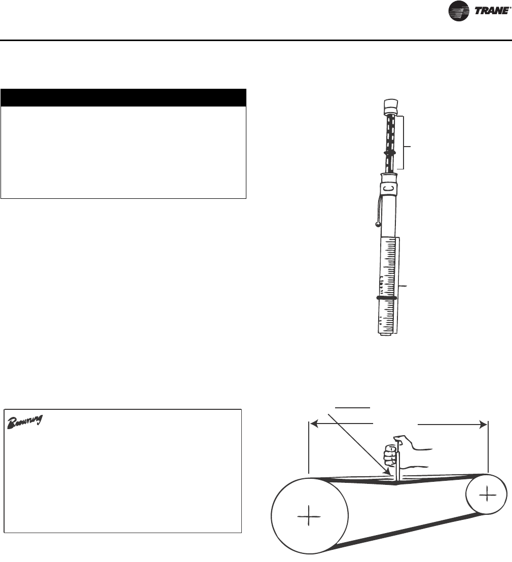
Start-Up
CLCH-SVX07C-EN 109
Tension the Fan Belt
Proper belt tension is required to ensure maximum
bearing and drive component life and is based on motor
horsepower requirement. A label located on the bearing
support on the drive side of the unit lists all drive parts, the
proper belt tension, and deflection for that tension for the
specific drive (Figure 126).
If the drive is changed from the original, proper belt
tension can be estimated using Table 34.
The correct operation tension for a V-belt drive is the
lowest tension at which the belts will not slip under the
peak load conditions. It may be necessary, however, to
increase the tension of some drives to reduce excessive
belt flopping or to reduce excessive startup squealing.
Check the fan belt tension at least three times during the
first days of operation because there is a rapid decrease in
tension until the belt settles in. To measure belt tension,
use a belt tensiometer (see Figure 127). Determine actual
deflection by depressing one belt with the belt
tensiometer and measuring the deflection relative to the
other belts or to belt line (see Figure 128). Adjust the belt
tension to the correct pounds force and tighten all set
screws to the proper torque.
NOTICE:
Belt Tension! (2 of 2)
Do not over-tension belts. Excessive belt tension will
reduce fan and motor bearing life, accelerate belt wear
and possibly cause shaft failure. Under tensioning belts
is the primary cause of premature belt failure. Belts
should not squeal at startup. Recheck belt tension after
8 hours, 24 hours, and 100 hours of operation and
monthly thereafter.
Figure 126. Tension drive belt label
V-BELT DRIVE KIT 1627373
MODULE 0400
PURCHASE ORD. NUMBER B24597-061 H5D073B A
CUSTOMER’S KIT # H5D073B A-012-0400
MTR HP.= 10.0
FAN RPM = 1458 CD = 9.4 AT 3.00 TRN OPN
TENSION INFO - 3.86 LB., 0.14 IN.
DRIVE’S BELTS - B40
MOTOR SHEAVE - 2VP75X 1 3/8
MOTOR BUSHING - NONE REQUIRED
FAN SHEAVE - 2B5V80
FAN BUSHING - B 1 7/16
Figure 127. Belt tensioner
Figure 128. Belt tension measurement
Small O-Ring
Force Scale
Large O-Ring
Span Scale
Belt Span
Belt Span
64
Deflection =
Start-Up
110 CLCH-SVX07C-EN
Determine Fan Speed
Fan speed can be determined using a strobe-type
tachometer, or revolution counter.
Check unit vibration if the fan speed is changed more than
five percent from the original designed speed, or if parts
such as shafts, fan wheels, bearings, or other drive
components are replaced. Do not exceed the maximum
fan speed.
Pay particular attention to any vibration, noise, or
overheating of the motor and fan bearings; however, note
that bearings may run warm during break in.
Table 34. Typical sheave diameter and deflection force
Cross
section
Smallest sheave
diameter range
(in.) Speed (rpm)
range
Belt Deflection Force (lbs)
Super gripbelts and
unnotched gripbands Gripnotch belts and
notched gripbands
Used belt New belt Used belt New belt
A, AX
3.0–3.6 1,000–2,500 3.7 5.5 4.1 6.4
2,501–4,000 2.8 4.2 3.4 5.0
3.8–4.8 1,000–2,500 4.5 6.8 5.0 7.4
2,501–4,000 3.8 5.7 4.3 6.4
5.0–7.0 1,000–2,500 5.4 8.0 5.7 9.4
2,501–4,000 4.7 7.0 5.1 7.6
B, BX
3.4–4.2 860–2,500 n/a n/a 4.9 7.2
2,501–4,000 n/a n/a 4.2 6.2
4.4–5.6 860–2,500 5.3 7.9 7.1 10.5
2,501–4,000 4.5 6.7 7.1 9.1
5.8–8.6 860–2,500 6.3 9.4 8.5 12.6
2,501–4,000 6.0 8.9 7.3 10.9
C, CX 7.0–9.0 500–1,740 11.5 17.0 14.7 21.8
1,741–3,000 9.4 13.8 11.9 17.5
9.5–16.0 500–1,740 14.1 21.0 15.9 23.5
1,741–3,000 12.5 18.5 14.6 21.6
D12.0–16.0 200–850 24.9 37.0 n/a n/a
851–1,500 21.2 31.3 n/a n/a
18.0–20.0 200–850 30.4 45.2 n/a n/a
851–1,500 25.6 38.0 n/a n/a
3V, 3VX
2.2–2.4 1,000–2,500 n/a n/a 3.3 4.9
2,501–4,000 n/a n/a 2.9 4.3
2.65–3.65 1,000–2,500 3.6 5.1 4.2 6.2
2,501–4,000 3.0 4.4 3.8 5.6
4.12–6.90 1,000–2,500 4.9 7.3 5.3 7.9
2,501–4,000 4.4 6.6 4.9 7.3
5V, 5VX
4.4–6.7 500–1,749 n/a n/a 10.2 15.2
1,750–3,000 n/a n/a 8.8 13.2
3,001–4,000 n/a n/a 5.6 8.5
7.1–10.9 500–1,749 12.7 18.9 14.8 22.1
1,750–3,000 11.2 16.7 13.7 20.1
11.8–16.0 500–1,749 15.5 23.4 17.1 25.5
1,750–3,000 14.6 21.8 16.8 25.0
8V 12.5–17.0 200–850 33.0 49.3 n/a n/a
851–1,500 26.8 39.9 n/a n/a
18.0–22.4 200–850 39.6 59.2 n/a n/a
851–1,500 35.3 52.7 n/a n/a
WARNING
Live Electrical Components!
During installation, testing, servicing and
troubleshooting of this product, it may be necessary to
measure the speed of rotating components. Have a
qualified licensed service individual who has been
properly trained in handling exposed rotating
components perform these tasks. Failure to follow all
safety precautions when exposed to rotating
components could result in death or serious injury.
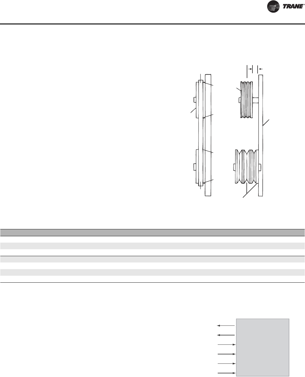
Start-Up
CLCH-SVX07C-EN 111
Align Fan and Motor Sheaves
Align the fan and motor sheaves using a straightedge. The
straightedge must be long enough to span the distance
between the outside edges of the sheaves. When the
sheaves are aligned, the straightedge will touch both
sheaves at points A through D (see Figure 129) to confirm
the shaft is parallel. For uneven width sheaves, place a
string in the center groove of both sheaves and pull tight.
Adjust the sheaves and tighten the sheave set screws to
the proper torque given in Table 35.
Check Multiple Belts
Tighten the belts slightly and rotate the drive several
times.
On multiple belt drives, ensure the force of deflection is
approximately the same on each belt by pushing each belt
in an equal distance at a point halfway from each sheave
(see Figure 129). If this force is not the same for each belt,
the motor and fan shaft are not parallel. Realign as
required. After realignment, tighten the belts again to the
standard belt tensioning specifications. If the force is still
not the same for all belts, the belts or sheaves are worn
and must be replaced.
Airflow Measuring Systems
Traq™ Dampers
Traq dampers are low-leak dampers that modulate and
measure airflow. Each Traq damper section is supplied
with a factory-mounted ventilation control module (VCM)
on the interior of the mixing box section. The VCM has an
input terminal for power and an output terminal for air
velocity (see Figure 130). A direct-digital controller
controls the factory-mounted and wired actuators.
Figure 129. Proper drive alignment
D
Fixed
Sheave C
B
A
Adjustable
Sheave
Straight
Edge
Lines must
be parallel
Center line
must coincide
Fixed
Sheave
Table 35. Fan and drive compound torque settings (inches)
Screw Size Hex Key Square Head Hex Head Torque (in.-lb.) Torque (ft.-lb.)
1/4 1/8 3/8 7/16 66-90 5.5-7.5
5/16 5/32 1/2 1/2 126-164 10.5-13.7
3/8 3/16 9/16 9/16 228-300 19.0-25.0
7/15 7/32 5/8 5/8 348-450 29.0-37.5
1/2 1/4 3/4 3/4 504-650 42.0-54.2
5/8 5/16 15/16 15/16 1290-1390 107.0-116.0
#10 3/32 - - 28-40 2.3-3.3
Figure 130. Traq damper terminal connections
Ventilation Control Module
Velocity (2-10 Vdc)
GND
24 Vac
GND
J4 (Red)
J4 (White)
J2 (Black)
J2 (Green)
J5 (Yellow)
J5 (White)
Thermistor
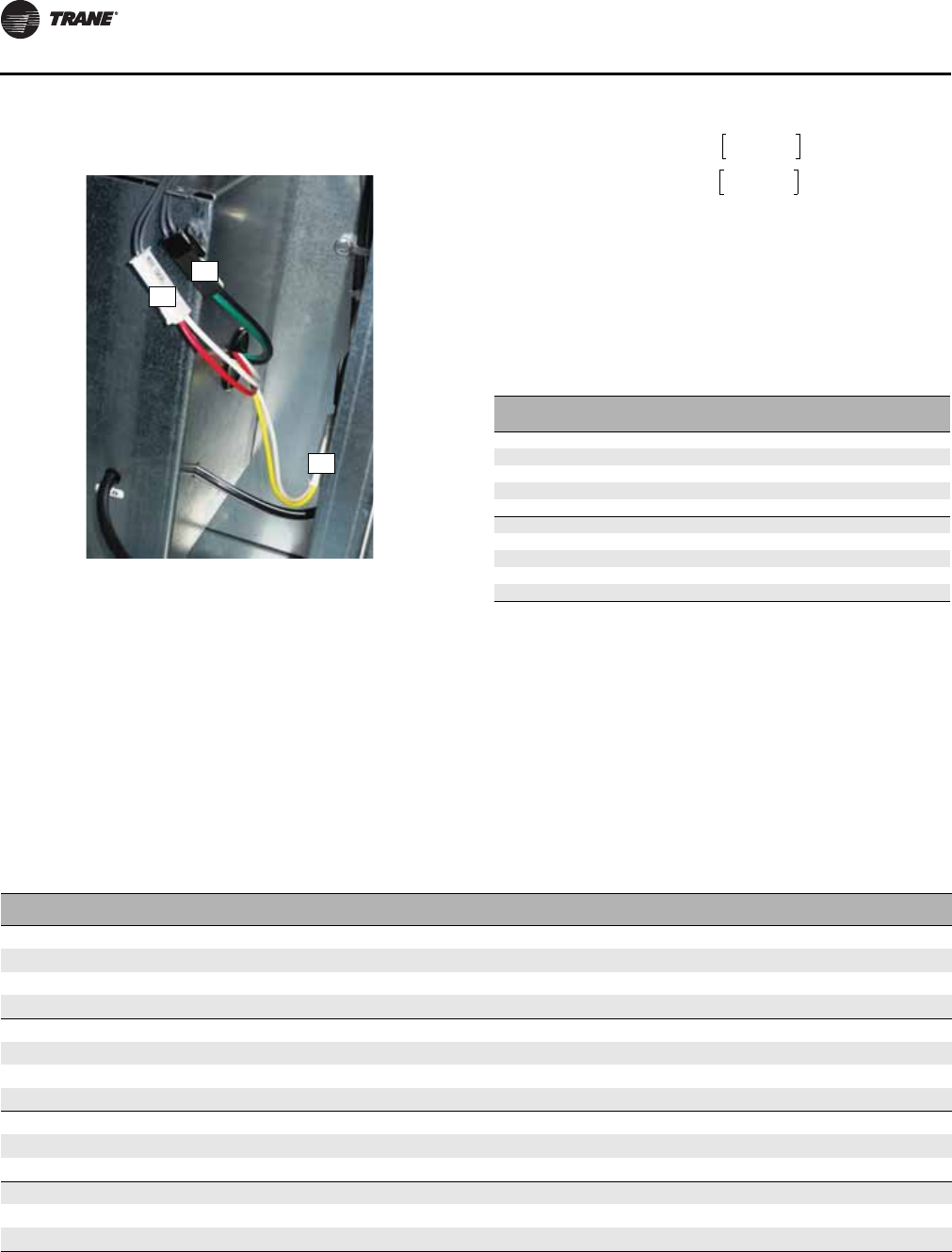
Start-Up
112 CLCH-SVX07C-EN
VCM (Transducer) Calibration.
The VCM has an auto-
zero function that recalibrates the transducer once every
minute. When troubleshooting, allow for the recalibration
time before making any measurements.
Input Power.
The only input the VCM needs is the 24 Vac
power connected to terminals 1TB1–5 and 1TB1–6.
Output Velocity Signal.
The 2 to 10 Vdc linear output
signal from the VCM represents air velocity. This voltage
can be converted to represent airflow (cfm or L/s) using the
formula below and Table 36.
Table 37. In Table 38 through Figure 45, the cfm at 10Vdc
is a calculated value based on area and peak
velocity. In certain situations, it can be
advantageous to raise the velocity of air
through the remaining Traq dampers by
closing off one or more dampers in the unit. The
cfm at 10Vdc can be recalculated based on the
proportion of remaining Traq dampers or by
multiplying the remaining area of dampers by
peak velocity. Calculations are based on VCM
voltage versus airflow at sea level.
Figure 131. Traq damper terminal connections
J5
J4
J2
Airflow = k (cfm @ 10V)
or
Airflow = k (L/s @ 10V)
For example, if the VCM on a size 30 air handler at sea
level (k=1) has a 10-volt signal, it would represent
24,492 cfm (11,559 L/s) through the Traq damper. If
the voltage were 6 volts, airflow through the Traq
damper would be 12,246 cfm (5779 L/s).
Table 36. Altitude adjustment factors
Sea level = 1.0
Elevation (feet) k
1000 0.982
2000 0.964
3000 0.949
4000 0.930
5000 0.914
6000 0.897
7000 0.876
8000 0.860
9000 0.846
10,000 0.825
volts 2–()
8
------------------------------
volts 2–()
8
------------------------------
Table 38. Back or top inlet standard Traq damper-air mixing and indoor economizer section
Unit Size Part Number Traq Damper
Size (inches) Quantity Peak Velocity
(fpm) Total Area
(ft
2
)CFM @ 10VDC
Peak Velocity L/s @ 10VDC
Peak Velocity
3 495100860001 13 1 2475 0.92 2279 1076
4, 6 495100860001 13 22475 1.84 4559 2151
8, 10 495100860001 13 3 2475 2.76 6838 3227
12, 14, 17 495100870001 16 32475 4.19 10,365 4891
21, 25 495100890001 20 3 2600 6.54 17,012 8028
22, 26 495100870001 16 42475 5.58 13,820 6525
30, 35, 40 495100880001 24 3 2600 9.42 24,492 11,558
31 495100890001 20 42600 8.72 22,682 10,708
36, 41 495100880001 24 3 2600 9.42 24,492 11,563
50, 57 495100900001 28 32600 12.83 33,358 15,742
51, 58 495100900001 28 3 2600 12.82 33,337 15,738
66 495100900001 28 42600 17.10 44,460 20,981
80 495100900001 28 5 2600 21.38 55,588 26,232
100, 120 495100900001 28 62600 25.66 66,716 31,483

Start-Up
CLCH-SVX07C-EN 113
Table 39. Back or top inlet low-flow Traq damper-air mixing and indoor economizer sections
Unit Size Part Number Traq Damper
Size (in) Damper
Type Qty Peak Velocity
(fpm) Total Area
(ft
2
)CFM @ 10VDC
Peak Velocity L/s @ 10VDC
Peak Velocity
4 495100860001 13 Min. Outside Air 1 2475 0.92 2279 1076
Economizing 1
6495100860001 13 Min. Outside Air 12475 0.92 2279 1076
Economizing 1
8, 10 495100860001 13 Min. Outside Air 1 2475 0.92 2279 1076
Economizing 2 1.84 4554 2149
12, 14, 17 495100870001 16 Min. Outside Air 12475 1.40 3455 1630
Economizing 22.79 6910 3261
21, 25 495100890001 20 Min. Outside Air 1 2600 2.18 5671 2676
Economizing 2 4.36 11341 5352
22, 26 495100870001 16 Min. Outside Air 12475 1.40 3455 1631
Economizing 34.19 10365 4893
30, 35, 40 495100880001 24 Min. Outside Air 1 2600 3.14 8164 3853
Economizing 2 6.28 16,328 7705
31 495100890001 20 Min. Outside Air 12600 2.18 5671 2677
Economizing 36.54 17,012 8031
36, 41 495100880001 24 Min. Outside Air 1 2600 3.14 8164 3854
Economizing 2 6.28 16,328 7708
50, 57 495100900001 28 Min. Outside Air 12600 4.27 11,112 5244
Economizing 28.55 22,224 10,488
51, 58 495100900001 28 Min. Outside Air 1 2600 4.27 11,112 5246
Economizing 2 8.55 22,225 10,492
66 495100900001 28 Min. Outside Air 12600 4.27 11,112 5244
Economizing 312.82 33,336 15,731
80 495100900001 28 Min. Outside Air 2 2600 4.27 11,112 5244
Economizing 3 17.10 44,448 20,975
100 495100900001 28 Min. Outside Air 22600 4.27 11,112 5244
Economizing 48.55 22,224 10,488
120 495100900001 28 Min. Outside Air 2 2600 4.27 11,112 5244
Economizing 4 21.37 55,561 26,219
Table 40. Mixing box Traq damper inlet - single-side standard flow
Unit size Part number Traq damper
size (in) Qty Peak velocity
(fpm) Total area
(ft
2
)CFM@10VDC peak
velocity L/s@ 10VDC peak
velocity
3, 4, 6, 8 495100860001 13 1 2475 0.92 2279 1076
10, 12 495100870001 16 12475 1.40 3455 1631
14, 17 495100860001 13 2 2475 1.84 4559 2152
21, 22, 25, 26 495100870001 16 22475 2.79 6910 3262
30, 31, 35, 40 495100890001 20 2 2600 4.36 11,341 5354
36, 41, 50, 57, 66 495100880001 24 22600 6.28 16,328 7708
51, 58, 80 495100900001 28 2 2600 8.59 22,225 10,492
100 495100900001 28 32600 12.82 33,337 15,738
120 495100880001 24 4 2600 12.56 32,656 15,417
Start-Up
114 CLCH-SVX07C-EN
Table 41. Mixing box Traq damper inlet - single-side low flow
Unit size Part number Traq damper
size (in) Damper type Qty Peak velocity
(fpm) Total area
(ft
2
)CFM@10VDC
peak velocity L/s@ 10VDC
peak velocity
14, 17 495100860001 13 Min. Outside Air 1 2475 0.92 2279 1076
Economizing 1
21, 22, 25,
26 495100870001 16 Min. Outside Air 12475 1.40 3455 1631
Economizing 1
30, 31, 35,
40 495100890001 20 Min. Outside Air 1 2600 2.18 5671 2677
Economizing 1
36, 41, 50,
57, 66 495100880001 24 Min. Outside Air 12600 3.14 8164 3854
Economizing 1
51, 58, 80 495100900001 28 Min. Outside Air 1 2600 4.27 11,112 5246
Economizing 1
100 495100900001 28 Min. Outside Air 12600 4.27 11,112 5246
Economizing 28.55 22,225 10,492
120 495100880001 24 Min. Outside Air 1 2600 3.14 8164 3854
Economizing 3 9.42 24,492 11,563
Table 42. Mixing box Traq damper inlet - dual-side standard flow
Unit size Part number Traq damper
size (in) Qty Peak velocity
(fpm) Total area
(ft
2
)CFM@10VDC peak
velocity L/s@ 10VDC peak
velocity
3, 4, 6, 8 495100860001 13 2 2475 1.84 4559 2152
10, 12 495100870001 16 22475 2.79 6910 3262
14, 17 495100860001 13 4 2475 3.68 9118 4305
21, 22, 25, 26 495100870001 16 42475 5.58 13,820 6525
30, 31, 35, 40 495100890001 20 4 2600 8.72 22,682 10,708
36, 41, 50, 57,
66 495100880001 24 42600 12.56 32,656 15,417
51, 58, 80 495100900001 28 4 2600 17.10 44,450 20,985
100 495100900001 28 62600 25.64 66,674 31,477
120 495100880001 24 8 2600 25.12 65,312 30,834

Start-Up
CLCH-SVX07C-EN 115
Table 43. Mixing box Traq damper inlet - dual-side low-flow
Unit size Part number Traq damper
size (in) Damper type Qty Peak velocity
(fpm) Total area
(ft
2
)CFM@10VDC
peak velocity L/s@ 10VDC
peak velocity
3, 4, 6, 8 495100860001 13 Min. Outside Air 1 2475 0.92 2279 1076
Economizing 1
10, 12 495100870001 16 Min. Outside Air 12475 1.40 3455 1631
Economizing 1
14, 17 495100860001 13 Min. Outside Air 1 2475 0.92 2279 1076
Economizing 3 2.76 6838 3228
21, 22, 25,
26 495100870001 16 Min. Outside Air 12475 1.40 3455 1631
Economizing 34.19 10365 4893
30, 31, 35,
40 495100890001 20 Min. Outside Air 1 2600 2.18 5671 2677
Economizing 3 6.54 17,012 8031
36, 41, 50,
57, 66 495100880001 24 Min. Outside Air 12600 3.14 8164 3854
Economizing 39.42 24,492 11,563
51, 58, 80 495100900001 28 Min. Outside Air 1 2600 4.27 11,112 5246
Economizing 3 12.82 33,337 15,738
100 495100900001 28 Min. Outside Air 12600 4.27 11,112 5246
Economizing 521.37 55,562 26,231
120 495100880001 24 Min. Outside Air 1 2600 3.14 8164 3854
Economizing 7 21.98 57,148 26,980
Table 44. Side inlet standard Traq dampers - diagonal economizer section
Unit size Part number Traq damper
size (in) Quantity Peak velocity
(fpm) Total area
(ft2) CFM@10VDC
peak velocity L/s@10VDC peak
velocity
3 495100860001 13 1 2475 0.92 2279 1076
4, 6, 8 495100860001 13 22475 1.84 4559 2151
10, 12, 14 495100870001 16 2 2475 2.79 6905 3259
17 495100860001 13 42475 3.68 9118 4303
21 495100890001 20 2 2600 4.36 11,341 5352
25 495100870001 16 42475 5.58 13,820 6522
30 495100890001 20 3 2600 6.54 17,012 8028
35, 40 495100900001 28 22600 8.55 22,224 10,488
50 495100880001 24 3 2600 9.42 24,492 11,558
57 495100880001 24 42600 12.56 32,656 15,410
66 495100900001 28 3 2600 12.82 33,336 15,731
80 495100900001 28 42600 17.10 44,448 20,975
100, 120 495100900001 28 5 2600 21.37 55,561 26,219

Start-Up
116 CLCH-SVX07C-EN
Table 45. Side inlet low-flow Traq dampers - diagonal economizer section
Unit size Part number Traq damper
size (in) Damper type Qty Peak velocity
(fpm) Total area
(ft
2
)CFM@10VDC
peak velocity L/s@ 10VDC
peak velocity
4 495100860001 13 Min. Outside Air 1 2475 0.92 2279 1076
Economizing
6495100860001 13 Min. Outside Air 12475 0.92 2279 1076
Economizing
8 495100860001 13 Min. Outside Air 1 2475 0.92 2279 1076
Economizing
10 495100870001 16 Min. Outside Air 12475 1.40 3455 1630
Economizing
12 495100870001 16 Min. Outside Air 1 2475 1.40 3455 1630
Economizing
14 495100870001 16 Min. Outside Air 12475 1.40 3455 1630
Economizing
17 495100860001 13 Min. Outside Air 1 2475 0.92 2279 1076
Economizing 3 2.76 6838 3227
21 495100890001 20 Min. Outside Air 12600 2.18 5671 2676
Economizing
25 495100870001 16 Min. Outside Air 1 2600 1.40 3630 1713
Economizing 3 4.19 10,889 5138
30 495100890001 20 Min. Outside Air 12600 2.18 5671 2676
Economizing 24.36 11,341 5352
35, 40 495100900001 28 Min. Outside Air 1 2600 4.27 11,112 5244
Economizing
50 495100880001 24 Min. Outside Air 12600 3.14 8164 3853
Economizing 26.28 16,328 7705
57 495100880001 24 Min. Outside Air 1 2600 3.14 8164 3853
Economizing 3 9.42 24,492 11,558
66 495100900001 28 Min. Outside Air 12600 4.27 11,112 5244
Economizing 28.55 22,224 10,488
80 495100900001 28 Min. Outside Air 1 2600 4.27 11,112 5244
Economizing 3 12.82 33,336 15,731
100, 120 495100900001 28 Min. Outside Air 12600 4.27 11,112 5244
Economizing 417.10 44,448 20,975
Trane utilizes AMCA certification for airflow measuring stations. Trane certifies that the Traq damper
herein is licensed to bear the AMCA seal. The ratings shown are based on tests and procedures performed
in accordance with AMCA Publication 611 and comply with the requirements of the AMCA Certified
Ratings Program.
The certification program provides the engineer and owner assurance that manufacturer-published
performance ratings for airflow measurement stations are accurate and repeatable. Trane Traq dampers
are certified with the integral ventilation control module which converts differential pressure to an
electronic signal for control.
Refer to Performance Climate Changer Air Handler catalog CLCH-PRC015-EN for Traq damper testing and
rating information.
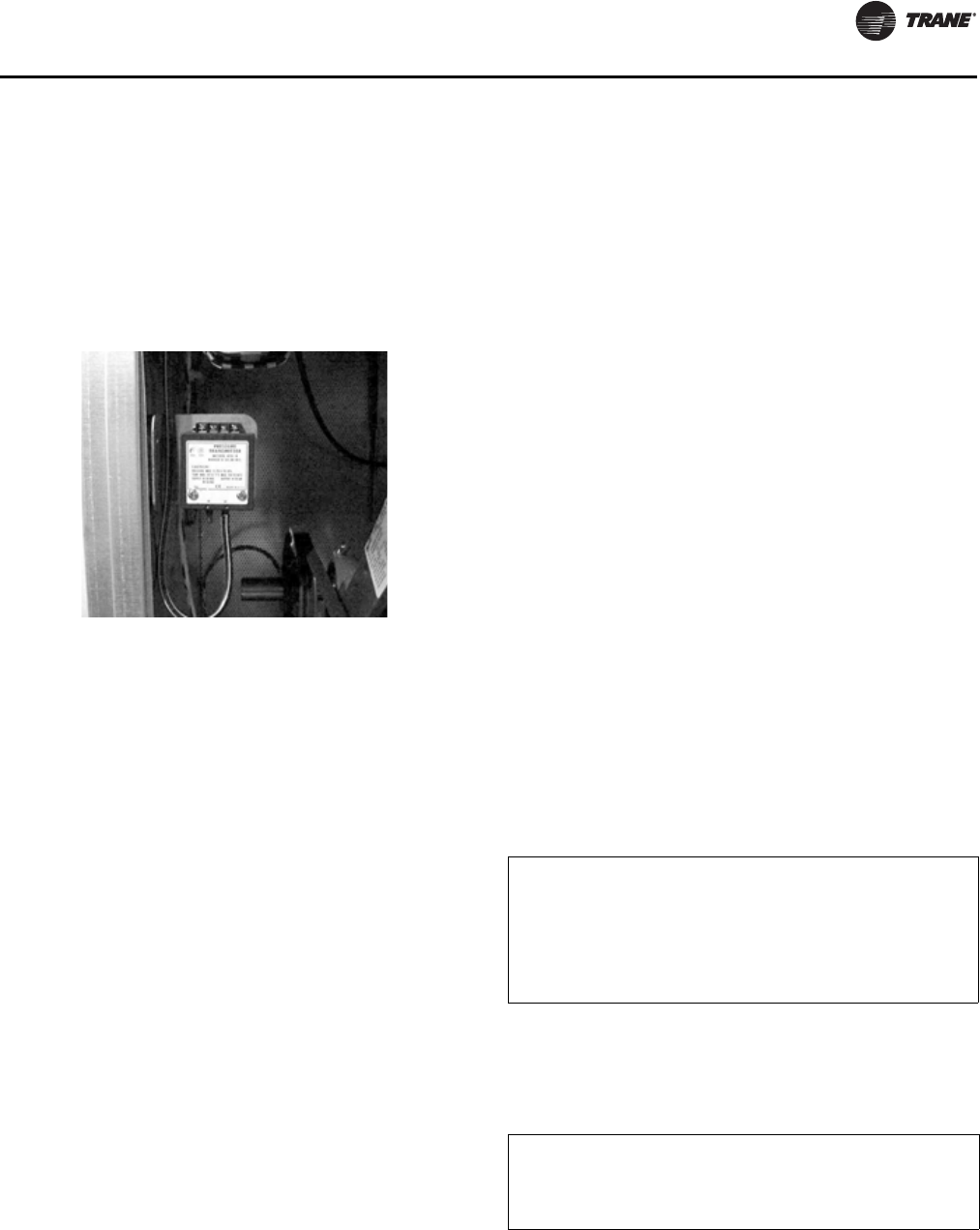
Start-Up
CLCH-SVX07C-EN 117
Fan Inlet Airflow Measuring System
A fan inlet airflow measuring system is available on many
centrifugal and plenum fans. Each system comes with a
differential pressure transmitter. The minimum diameter
is connected to the LO port of the transmitter and the
reference pressure point is connected to (or actually is) the
HI port of the transmitter.
Wiring
The transmitter requires 24VDC power on terminals 1 (+)
and 2 (ground) of the transmitter. When the airflow
measurement system is ordered with a factory-mounted
MP580 controller, the 24 VDC power will be supplied.
In the absence of a factory-provided MP580 controller, the
installing contractor must ensure the transmitter has
24VDC power.
Note: Ensure that the transmitter has a separate power
source.
Transmitter Sizing
The Trane specification requires that the flow meter option
have a total accuracy of 5 percent. The total accuracy is a
combination of:
• how accurately the flow meter itself is in sensing
airflow
• how accurately the transmitter senses the differential
pressure
• how accurately the controller translates the signal
from the transmitter to a differential pressure.
Selecting the proper transmitter is critical in order to get
accurate airflow measurements. How accurately the
transmitter senses the differential pressure is dependent
on:
• the pressure range selected
• accuracy of the selected transmitter
Trane air handlers use either a 0-20 inch or a 0-40 inch
range transmitter as standard. To sufficiently cover VAV
turndown on the smallest fans with the above range, a
transmitter with an accuracy of 0.25 percent (full scale) is
used as standard. If a field-provided transmitter with a
lower accuracy is selected, the range should be chosen
closer to the actual, maximum pressure differential
expected for the application.
The transmitter outputs a signal that represents the
differential pressure which is used to calculate airflow. To
adequately calculate and display the airflow for the
smaller fans, ensure that the analog input is programmed
with enough decimal places to sufficiently represent the
pressure differential being measured. For instance, Rover
should be used to increase the number of decimal places
being used (to a maximum of 4) on an MP-580/581
controller in lieu of the default zero.
Note that the adjustment of the “Zero” and “Span”
controls on the transmitter itself are not required at time of
installation. The transmitter is factory-calibrated to the
range selected and cannot be significantly adjusted to
“tighten” the range closer to the pressure being read for
the given application. The adjustments are primarily
provided to account for any drift that may occur over time.
Transmitter Calibration
The transmitter is factory-calibrated to a specific pressure
range with either a 0-20 inch or 0-40 inch w.g. range being
used in most cases. To check calibration and to adjust if
necessary, consult the transmitter manufacturer or the
factory for specific procedures.
The transmitter outputs a linear, 2-10 VDC signal
representing a differential pressure measurement. With
this measurement, the airflow through the fan can be
calculated using the following equation:
Significant differences in elevation and/or temperature
will affect the density of air. For air at a constant, non-
standard density, a field-obtained K factor can be used.
Alternatively, the following equation can be used to
continuously correct the equation above:
Note: Alternative units, including SI, can be used in place
of the IP units above although the K-factor must be
converted appropriately.
Figure 132. Fan inlet airflow measuring system
CFM = K * SQRT(DP)
Where:
CFM = Airflow (ft
3
/min.) assuming a standard air density of 0.075
lbm/ft
3
.
K = A constant factor that is unique for each fan. See “Constant
Factor K” section on page 118 for more information.
DP = Differential pressure (inches w.g.) being measured by the
transmitter.
ACFM = CFM * SQRT(0.075/ρ)
Where:
ACFM = Actual airflow (ft
3
/min.) corrected for non-standard air
density.
ρ = Density (lbm/ft
3
) of the air at the inlet to the fan.

Start-Up
118 CLCH-SVX07C-EN
Constant Factor K
The constant factor K is unique for each fan and is
primarily a function of the area and other geometric
properties of the fan inlet. Pre-engineered factors are
available from the factory for fan types where the airflow
measurement system is available. See Table 46 for single-
fan K factors. For a multiple-fan system, the constant
factor K may need to be adjusted depending on how many
transmitters are supplied.
Table 46. Constant K Factors
Fan Size (inches)/Type Fan Class Fan Name K-Factor
9 BC Class I 9 BA 935.00
9 BC Class II 9 BB 868.20
10 BC Class I 10 BA 1072.50
10 BC Class II 10 BB 1072.50
12 AF Class I 12 AA 2337.50
12 AF Class II 12 AB 2237.30
15 AF Class I 15 AA 3873.60
15 AF Class II 15 AB 3873.60
18 AF Class I 18 AA 4675.00
18 AF Class II 18 AB 4675.00
20 AF Class I 20 AA 5843.70
20 AF Class II 20 AB 5119.90
22 AF Class I 22 AA 7513.40
22 AF Class II 22 AB 6624.10
25 AF Class I 25 AA 9683.90
25 AF Class II 25 AB 8891.10
28 AF Class I 28 AA 12,856.20
28 AF Class II 28 AB 11,795.00
32 AF Class I 32 AA 16,295.60
32 AF Class II 32 AB 16,295.60
36 AF Class I 36 AA 19,701.70
36 AF Class II 36 AB 19,367.80
40 AF
1
Class I 40 AA 23,374.90
40 AF
2
Class II 40 AA 25,378.40
40 AF
1
Class I 40 AB 22,974.20
40 AF
2
Class II 40 AB 25,044.50
44 AF Class I 44 AA 30,113.00
44 AF Class II 44 AA 30,113.00
49 AF Class I 49 AB 37,470.00
49 AF Class II 49 AB 37,470.00
20 FC Class I 20 FA 7300.00
20 FC Class II 20 FB 7203.90
22 FC Class I 22 FA 9081.90
22 FC Class II 22 FB 8793.10
25 FC Class I 25 FA 12,030.00
25 FC Class II 25 FB 11,700.00
28 FC Class I 28 FA 14,450.00
28 FC Class II 28 FB 14,036.00
Note:
1
To be used for fan rpm < 700 or cfm < 25,500.
2
To be used for fan rpm > 700 or cfm > 25,500.
Start-Up
CLCH-SVX07C-EN 119
When a single transmitter is supplied in a multiple fan
system, one or more fans will be brought back to the
transmitter as a manifold and the airflow will represent the
total airflow for the system. As a result, the factor should
be adjusted as follows:
*If a fan fails in a multiple fan system where only one
transmitter is being supplied, and if the remaining fans will
continue to be used, the factor should be reduced
accordingly. Additionally, if the inactive fan was included
in the manifold back to the transmitter, the tubes from the
inactive fan should be temporarily removed and replaced
with tubes from an active fan (or simply plugged).
When a transmitter is supplied for each fan, the factor does
not need to be adjusted. The resulting airflow will
represent single-fan airflow. At the controller level, the
individual airflows should be summed to get the total
airflow. If a field-provided K-factor is to be used (see
below), the measured airflow for the system should be
divided by the number of active fans to get a single-fan
K-factor.
Fan Size (inches)/Type Fan Class Fan Name K-Factor
32 FC Class I 32 FA 20,400.00
32 FC Class II 32 FB 20,150.00
36 FC Class I 36 FA 28,049.90
36 FC Class II 36 FB 27,549.00
40 FC Class I 40 FA 39,236.40
40 FC Class II 40 FB 38,067.70
10 BC belt-drive plenum Class I or II 10 PA or 10 PB 563.00
11 BC belt-drive plenum Class I or II 11PA or 11 PB 703.00
12 AF belt-drive plenum Class I or II 12PA or 12 PB 1168.70
14 AF belt-drive plenum Class I or II 14PA or 14 PB 1536.10
16 AF belt-drive plenum Class I or II 16PA or 16 PB 1870.00
18 AF belt-drive plenum Class I or II 18PA or 18 PB 2270.70
20 AF belt-drive plenum Class I or II 20PA or 20 PB 2905.20
22 AF belt-drive plenum Class I or II 22PA or 22 PB 3673.20
25 AF belt-drive plenum Class I or II 25PA or 25 PB 4608.20
28 AF belt-drive plenum Class I or II 28 PA or 28 PB 6277.80
32 AF belt-drive plenum Class I or II 32 PA or 32 PB 7847.30
36 AF belt-drive plenum Class I or II 36 PA or 36 PB 10017.80
40 AF belt-drive plenum Class I or II 40 PA or 40 PB 13,023.10
44 AF belt-drive plenum Class I or II 44 PA or 44 PB 14,692.80
49 AF belt-drive plenum Class I or II 49 PA or 49 PB 18,299.20
55 AF belt-drive plenum Class I or II 55 PA or 55 PB 23,901.00
63 AF belt-drive plenum Class I or II 63 PA or 63 PB 31,135.00
10.50 AF direct-drive plenum Class II 10 NF or 10 NW 630.00
13.50 AF direct-drive plenum Class II 13 NR or 13 NF 952.00
15 AF direct-drive plenum Class II 15 NR or 15 NF 1139.00
18 AF direct-drive plenum Class II 18 NR or 18 NF 1673.00
20 AF direct-drive plenum Class II 20 NR or 20 NF 1942.00
22 AF direct-drive plenum Class II 22 NR, 22 NF, or 22 NW 2454.00
24 AF direct-drive plenum Class II 24 NR, 24 NF, or 24 NW 3010.00
27 AF direct-drive plenum Class II 27 NR or 27 NF 3701.00
30 AF direct-drive plenum Class II 30 NR or 30 NF 4620.00
22 AF stacked direct-drive plenum Class II 22 SF or 22 SW 2849.00
24.50 AF stacked direct-drive plenum Class II 24 SF or 24 SW 4765.00
Note: (1) to be used for fan rpm < 700 or cfm < 25,500. (2) to be used for fan rpm > 700 or cfm > 25,500
Table 46. Constant K Factors
K = N * K-Factor from Table 46
Where:
K = The final factor to be used for controller
programming.
N = The number of active* fans in the system.

Start-Up
120 CLCH-SVX07C-EN
Field-obtained factors can provide maximum accuracy. To
obtain the factor in the field, measure the differential
pressure output from the transmitter while measuring the
airflow through the system. Once these two values have
been measured, simply solve for K using the following
equation:
Maintenance
For a typical HVAC environment - especially with upstream
filtration - there should be little to no required
maintenance. In extreme cases or for mishaps (bearing
grease in the taps for example), the flow meter is easily
cleanable. The fan inlet airflow measuring system is
extremely simple: a few pressure taps, a few fittings, and
some tubing. Although unlikely, if any tap were to get
clogged, simply disconnect each side of the transmitter
and blast air in a reverse direction through the system.
External Insulating Requirements
The following areas should be specifically addressed, as
applicable:
• Supply and return water piping connections
• Supply and return refrigerant piping connections
• Condensate drain lines and connections
• Outdoor-air-intake duct connections
• Discharge duct connections
• Special requirements for low-temperature-air systems
K = ACFM/SQRT(DP)
Where:
K = Field-provided constant factor.
ACFM = Actual airflow (ft
3
/min.) being measured at the air density
being measured.
DP = Differential pressure (inches w.g.) being measured by the
transmitter.
CLCH-SVX07C-EN 121
Routine Maintenance
WARNING
Hazardous Service Procedures!
The maintenance and troubleshooting procedures
recommended in this manual could result in exposure
to electrical, mechanical or other potential safety
hazards. Always refer to the safety warnings provided
throughout this manual concerning these procedures.
Unless specified otherwise, disconnect all electrical
power including remote disconnect and discharge all
energy storing devices such as capacitors before
servicing. Follow proper lockout/tagout procedures to
ensure the power can not be inadvertently energized.
When necessary to work with live electrical
components, have a qualified licensed electrician or
other individual who has been trained in handling live
electrical components perform these tasks. Failure to
follow all of the recommended safety warnings
provided, could result in death or serious injury.
WARNING
Rotating Components!
The following procedure involves working with
rotating components. Disconnect all electric power,
including remote disconnects before servicing. Follow
proper lockout/ tagout procedures to ensure the power
can not be inadvertently energized. Secure rotor to
ensure rotor cannot freewheel. Failure to secure rotor
or disconnect power before servicing could result in
rotating components cutting and slashing technician
which could result in death or serious injury.
Maintenance Checklist
Table 47. Maintenance Checklist
Frequency Maintenance
After 48 hours
of operation
For belt-drive fans, the belts have acquired their permanent set. Readjust but do not overtighten. See “Tension the Fan Belt”
on page 109 for more information.
Every week
Observe unit weekly for any change in running condition and unusual noise.
Every month
• Clean or replace air filters if clogged or dirty; coat permanent filters with oil after cleaning; change bag filters when pressure
drop is 1 in. wg. See “Air Filters” on page 122 for more information.
• Belt-drive fans - relubricate fan bearings if necessary. See “Fan Bearing Lubrication” on page 124 for more information.
Belt-drive fans - check and adjust fan belt tension.See “Tension the Fan Belt” on page 109 for more information.
Every three to
six months
• Belt-drive fans - check fan bearing grease line connections. Lines should be tight to the bearings.
• Check motor bracket torque. See Table 48 on page 124 for torque requirements.
• Belt-drive fans - check bearing bolt torque and bearing setscrew torque. See Table 48 on page 124 for torque requirements.
• Belt-drive fans - align fan and motor sheaves. Tighten sheave set screws to the proper torque. See “Align Fan and Motor
Sheaves” on page 111 for more information.
• Inspect and clean drain pans. See “Drain Pans” on page 122 for more information.
• Tighten electrical connections.
• Inspect coils for dirt build-up. See “Coils” on page 125 for more information.
Every year
• Inspect the unit casing for corrosion. If damage is found, clean and repaint.
• Clean the fan wheels and shaft. See “Fans” on page 123 for more information.
• Inspect and clean drain pans.
• Check damper linkages, set screws, and blade adjustment. Clean, but do not lubricate, the nylon damper rod bushings.
• Clean damper operators.
•Inspect electrical components and insulation.
• Inspect wiring for damage.
• Rotate the fan wheel and check for obstructions. The wheel should not rub. Adjust the center if necessary.
• Lubricate motor bearings in accordance with motor manufacturer’s recommendations (see “Motor Bearing Lubrication” on
page 124 for more information).
• Check condition of gasketing and insulation around unit, door and dampers.
• Examine flex connections for cracks or leaks. Repair or replace damaged material.
Routine Maintenance
122 CLCH-SVX07C-EN
Air Filters
Throwaway Filters
To replace throwaway filters, install new filters with the
directional arrows pointing in the direction of airflow.
Note: Bag and cartridge filters must have an airtight seal
to prevent air bypass. If using filters not supplied by
Trane, apply foam gasketing to the vertical edges of
the filter.
Permanent Filters
To clean permanent filters:
1. Disconnect all electrical power to the unit.
2. Wash the filter under a stream of water to remove dirt
and lint.
3. Remove oil from the filter with a wash of mild alkali
solution.
4. Rinse the filter in clean, hot water and allow to dry.
5. Coat both sides of the filter by immersing or spraying
it with Air Maze Filter Kote W or an equivalent.
6. Allow to drain and dry for about 12 hours.
7. Reinstall the filter.
Note: It may be preferable to keep extra, clean filters to
replace the dirty filters to minimize unit downtime
for filter maintenance.
Cartridge or Bag Filters
To replace cartridge or bag filters:
1. Disconnect all electrical power to the unit.
2. Remove the dirty filters from their installed position.
3. Keeping the new bag filters folded, slide each filter into
the filter rack, pushing them tightly against the unit.
Note: The pleats should be in the vertical position.
4. If using the optional pre-filters, replace them on the
appropriate filter rack.
5. Close and secure the access door.
Drain Pans
The condensate drain pan and drain line must be checked
to assure the condensate drains as designed. This
inspection should occur a minimum of every six months or
more often as dictated by operating experience.
If evidence of standing water or condensate overflow
exists, identify and remedy the cause immediately. Refer
to “Troubleshooting” on page 129 for possible causes and
solutions.
To clean drain pans:
1. Disconnect all electrical power to the unit.
2. Wearing the appropriate personal protective
equipment, remove any standing water.
3. Scrape solid matter off of the drain pan.
4. Vacuum the drain pan with a vacuum device that uses
high-efficiency particulate arrestance (HEPA) filters
with a minimum efficiency of 99.97 percent at
0.3 micron particle size.
5. Thoroughly clean any contaminated area(s) with a
mild bleach and water solution or an EPA-approved
sanitizer specifically designed for HVAC use.
6. Immediately rinse the affected surfaces thoroughly
with fresh water and a fresh sponge to prevent
potential corrosion of metal surfaces.
7. Allow the unit to dry completely before putting it back
into service.
WARNING
Rotating Components!
The following procedure involves working with rotating
components. Disconnect all electric power, including
remote disconnects before servicing. Follow proper
lockout/ tagout procedures to ensure the power can
not be inadvertently energized. Secure rotor to ensure
rotor cannot freewheel. Failure to secure rotor or
disconnect power before servicing could result in
rotating components cutting and slashing technician
which could result in death or serious injury.
WARNING
Hazardous Chemicals!
Coil cleaning agents can be either acidic or highly
alkaline and can burn severely if contact with skin
occurs. Handle chemical carefully and avoid contact
with skin. ALWAYS wear Personal Protective Equipment
(PPE) including goggles or face shield, chemical
resistant gloves, boots, apron or suit as required. For
personal safety refer to the cleaning agent
manufacturer’s Materials Safety Data Sheet and follow
all recommended safe handling practices. Failure to
follow all safety instructions could result in death or
serious injury.
WARNING
No Step Surface!
Do not walk on the sheet metal drain pan. Walking on
the drain pan could cause the supporting metal to
collapse, resulting in the operator/technician to fall.
Failure to follow this recommendation could result in
death or serious injury.
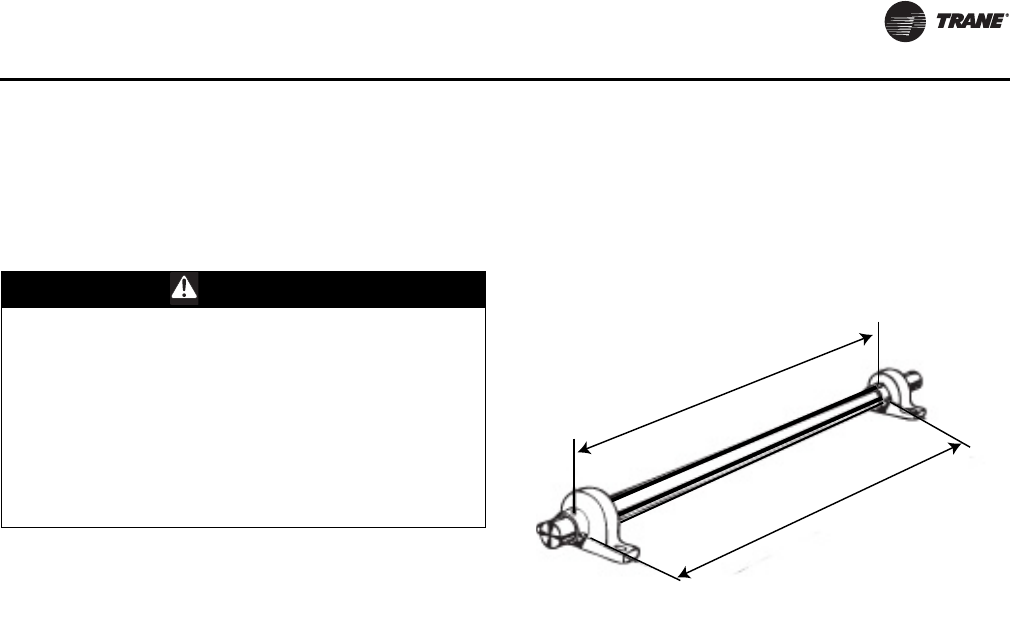
Routine Maintenance
CLCH-SVX07C-EN 123
8. Be careful any contaminated material does not contact
other areas of the unit or building. Properly dispose of
all contaminated materials and cleaning solution.
Fans
Inspecting and Cleaning Fans
Fan sections of air handlers should be inspected every six
months at a minimum or more frequently if operating
experience dictates. If evidence of microbial growth
(mold) is found, identify and remedy the cause
immediately. Refer to “Troubleshooting” on page 129 for
possible causes and solutions. To clean the fan section:
1. Disconnect all electrical power to the unit.
2. Wearing the appropriate personal protective
equipment, remove any contamination.
3. Vacuum the section with a vacuum device that uses
high-efficiency particulate arrestance (HEPA) filters
with a minimum efficiency of 99.97 percent at
0.3 micron particle size.
4. Thoroughly clean any contaminated area(s) with a
mild bleach and water solution or an EPA-approved
sanitizer specifically designed for HVAC use.
5. Immediately rinse the affected surfaces thoroughly
with fresh water and a fresh sponge to prevent
potential corrosion of metal surfaces.
6. Allow the unit to dry completely before putting it back
into service.
7. Be careful any contaminated material does not contact
other areas of the unit or building. Properly dispose of
all contaminated materials and cleaning solution.
Bearing Set Screw Alignment
Align bearing set screws for belt-drive fans as illustrated in
Figure 133. Table 48 provides bearing set screw torque
measurements.
WARNING
Rotating Components!
The following procedure involves working with rotating
components. Disconnect all electric power, including
remote disconnects before servicing. Follow proper
lockout/ tagout procedures to ensure the power can
not be inadvertently energized. Secure rotor to ensure
rotor cannot freewheel. Failure to secure rotor or
disconnect power before servicing could result in
rotating components cutting and slashing technician
which could result in death or serious injury.
Figure 133. Alignment
Align set screws
Align set screws
Routine Maintenance
124 CLCH-SVX07C-EN
Torque Requirements
Refer to Table 48 for minimum torque of motor mounting
and bearings bolts. Refer to Table 35 on page 111 for
minimum setscrew torque.
Fan Bearing Lubrication
For belt-drive fans, the grease used in electric motor
bearings is usually not compatible with the grease used in
fan bearings. Never mix the two grease types! See
Table 49 for compatible greases and Table 50 for
maximum grease capacity.
Note: Lubricate the motor bearing according to the motor
manufacturer’s recommendations and use the
manufacturer-recommended grease. See “Motor
Bearing Lubrication” on page 124.
• Fan bearings without lubrication lines are sealed
bearings. Re-lubrication is not required.
• Fan bearings equipped with lubrication lines should be
lubricated with a lithium-based grease that conforms
to NLGI No. 2 for consistency.
Motor Bearing Lubrication
Obtain an operation and maintenance manual from the
motor manufacturer for the specific motor installed. The
motor manufacturer’s recommendations take precedence
for all matters related to the start-up and routine
maintenance of the motor.
Motor grease fittings have been removed from factory-
installed motors in compliance with UL regulations. Motor
bearings require periodic maintenance throughout their
life. Many different styles of motors come as standard
selections, so please obtain the motor IOM and use the
manufacturer-recommended grease.
Fan Motor Inspection
Inspect fan motors periodically for excessive vibration or
temperature.
Table 48. Minimum hex head bolt torque in lb.-ft.
(Grade 5 bolts)
Size (inches) Thread Designation Minimum Torque
1/4-20 UNC 6
1/4-28 UNF 7
65/16-18 UNC 14
5/16-24 UNF 16
3/8-16 UNC 24
3/8-24 UNF 28
7/16-14 UNC 42
7/16-20 UNF 45
1/2-13 UNC 69
1/2-20 UNF 83
9/16-12 UNC 99
9/16-18 UNF 118
5/8-11 UNC 150
5/8-18 UNF 176
3/4-10 UNC 254
3/4-16 UNF 301
7/8-9 UNC 358
7/8-14 UNF 422
1-8 UNC 500
1-14 UNF 602
Note: Soft metric conversions are not acceptable for screw and hex sizes.
NOTICE:
Bearing Failure!
Do not mix greases with different bases within the
bearing. Mixing grease within the bearing could result
in premature bearing failure.
Table 49. Compatible Greases
Type
Texaco Multi Fak 2
Shell Alvania 2
Mobil 532
Chevron Dura-Lith 2
Exxon Beacon
Keystone 84H
Table 50. Fan bearing maximum grease capacity
Shaft size (inches) Capacity (fluid ounce)
1/2 - 3/4 1/7
7/8 - 1 3/16 3/8
1 1/4 - 1 1/2 5/8
1 11/16 - 1 15/16 7/8
2 - 2 7/16 1 1/4
2 1/2 - 2 15/16 2
Routine Maintenance
CLCH-SVX07C-EN 125
Coils
All coils should be kept clean to maintain maximum
performance.
Steam and Water Coils
To clean steam and water coils:
1. Disconnect all electrical power to the unit.
2. Wearing the appropriate personal protective
equipment, use a soft brush to remove loose debris
from both sides of the coil.
3. Install a block-off to prevent spray from going through
the coil and into a dry section of the unit and/or system
ductwork.
4. Mix a high-quality coil cleaning detergent with water
according to the manufacturer’s instructions.
Note: If the detergent is strongly alkaline after mixing (PH
8.5 or higher), it must contain an inhibitor. Follow
the cleaning solution manufacturer’s instructions
regarding the use of the product.
5. Place the mixed solution in a garden pump-up sprayer
or high-pressure sprayer. If a high pressure sprayer is
to be used:
– Maintain minimum nozzle spray angle of
15 degrees.
– Spray perpendicular to the coil face.
– Keep the nozzle at least 6 inches from the coil.
–Do not exceed 600 psi.
6. Spray the leaving air side of the coil first, then the
entering air side.
7. Thoroughly rinse both sides of the coil and the drain
pan with cool, clean water.
8. Repeat steps 6 and 7 as necessary.
9. Straighten any coil fins that may have been damaged
during the cleaning process.
10. Confirm the drain line is open following the cleaning
process.
11. Allow the unit to dry thoroughly before putting it back
into service.
12. Replace all panels and parts and restore electrical
power to the unit.
13. Be careful any contaminated material does not contact
other areas of the unit or building. Properly dispose of
all contaminated materials.
Refrigerant Coils
WARNING
Hazardous Voltage!
Disconnect all electric power, including remote
disconnects before servicing. Follow proper lockout/
tagout procedures to ensure the power can not be
inadvertently energized. Failure to disconnect power
before servicing could result in death or serious injury.
WARNING
Hazardous Chemicals!
Coil cleaning agents can be either acidic or highly
alkaline and can burn severely if contact with skin
occurs. Handle chemical carefully and avoid contact
with skin. ALWAYS wear Personal Protective Equipment
(PPE) including goggles or face shield, chemical
resistant gloves, boots, apron or suit as required. For
personal safety refer to the cleaning agent
manufacturer’s Materials Safety Data Sheet and follow
all recommended safe handling practices. Failure to
follow all safety instructions could result in death or
serious injury.
WARNING
Hazardous Pressures!
Coils contain refrigerant under pressure. When cleaning
coils, maintain coil cleaning solution temperature
under 150°F to avoid excessive pressure in the coil.
Failure to follow these safety precautions could result in
coil bursting, which could result in death or serious
injury.
WARNING
Hazardous Voltage!
Disconnect all electric power, including remote
disconnects before servicing. Follow proper lockout/
tagout procedures to ensure the power can not be
inadvertently energized. Failure to disconnect power
before servicing could result in death or serious injury.
WARNING
Hazardous Chemicals!
Coil cleaning agents can be either acidic or highly
alkaline and can burn severely if contact with skin
occurs. Handle chemical carefully and avoid contact
with skin. ALWAYS wear Personal Protective Equipment
(PPE) including goggles or face shield, chemical
resistant gloves, boots, apron or suit as required. For
personal safety refer to the cleaning agent
manufacturer’s Materials Safety Data Sheet and follow
all recommended safe handling practices. Failure to
follow all safety instructions could result in death or
serious injury.

Routine Maintenance
126 CLCH-SVX07C-EN
To clean refrigerant coils:
1. Disconnect all electrical power to the unit.
2. Wearing the appropriate personal protective
equipment, use a soft brush to remove loose debris
from both sides of the coil.
3. Install a block-off to prevent spray from going through
the coil and into a dry section of the unit and/or system
ductwork.
4. Mix a high-quality coil cleaning detergent with water
according to the manufacturer’s instructions.
Note: If the detergent is strongly alkaline after mixing (PH
8.5 or higher), it must contain an inhibitor. Follow
the cleaning solution manufacturer’s instructions
regarding the use of the product.
5. Place the mixed solution in a garden pump-up sprayer
or high-pressure sprayer. If a high pressure sprayer is
to be used:
– Maintain minimum nozzle spray angle of
15 degrees.
– Spray perpendicular to the coil face.
– Keep the nozzle at least 6 inches from the coil.
–Do not exceed 600 psi.
6. Spray the leaving air side of the coil first, then the
entering air side.
7. Thoroughly rinse both sides of the coil and the drain
pan with cool, clean water.
8. Repeat steps 6 and 7 as necessary.
9. Straighten any coil fins damaged during the cleaning
process.
10. Confirm the drain line is open following the cleaning
process.
11. Allow the unit to dry thoroughly before putting it back
into service.
12. Replace all panels and parts and restore electrical
power to the unit.
13. Be careful any contaminated material does not contact
other areas of the unit or building. Properly dispose of
all contaminated materials and cleaning solution.
Coil Winterization
Water coil winterization procedures consist primarily of
draining water from the coil before the heating season.
Trane recommends flushing the coil with glycol if coils will
be exposed to temperatures below 35 degrees.
Install field-fitted drains and vents to permit winterization
of coils not in use and to assist in evacuating air from the
water system during startup. If draining is questionable
because of dirt or scale deposits inside the coil, fill the coil
with glycol before the heating season begins.
Individual coil types determine how to properly winterize
the coil. To determine the coil type find the “Service Model
No of Coil” on the coil section nameplate. The coil type is
designated by the second and third digits on that model
number. For example, if the model number begins with
“DUWB,” the coil type is UW; if the model number begins
with “DW0B,” the coil type is W.
Note: On many unit sizes, there are multiple coils in the
coil section. Be sure to winterize all coils in a given
coil section.
To winterize type D1, D2, WL, LL, UA, UW, UU, W, P2, P4,
P8, WD, 5D, and 5W coils:
1. Remove the vent and drain plugs.
2. Blow the coil out as completely as possible with
compressed air.
3. Fill and drain the coil several times with full strength
glycol so that it mixes thoroughly with the water
retained in the coil.
4. Drain the coil out as completely as possible.
5. To ensure no water remains in the coil, do not replace
the vent and drain plugs until the coils are put back into
service.
Note: Use care in removing header plugs from Type P2,
P4, and P8 coils. Over-torquing may result in
twisted tubes.
Moisture Purge Cycle
By it’s very nature, any HVAC unit with a cooling coil serves
as a dehumidifier, reducing the surrounding air’s ability to
hold water vapor as its temperature falls. This normally
doesn’t present a problem when the unit is running.
However, when the fan stops, water vapor condenses on
the cold metal surfaces inside the air handler and remains
there until the air warms sufficiently to re-evaporate it.
This damp, dark environment—though temporary—can
encourage the growth of mold, mildew, and other
microbial contaminants.
NOTICE:
Coil Freeze-up!
Drain and vent coils when not in use. Trane
recommends glycol protection in all possible freezing
applications. Use a glycol approved for use with
commercial cooling and heating systems and copper
tube coils. Failure to do so could result in equipment
damage.
Routine Maintenance
CLCH-SVX07C-EN 127
Providing a moisture purge cycle 15 to 30 minutes after
shutdown disperses the cold, humid air inside the air-
handling system more evenly throughout the building.
This four-step cycle:
• Closes the outdoor air dampers.
• Turns off the cooling coil.
• Opens any variable-air-volume terminals connected to
the air handler.
• Operates the supply fan for 10 to 15 minutes.
Air movement discourages water condensation and
hastens re-evaporation of any condensate that does
happen to form. This simple preventative measure
effectively combats microbial growth and curbs moisture-
related deterioration of air-handling components.
Cleaning Non-Porous Surfaces
If microbial growth on a non-porous insulating surface
(closed cell insulation or sheet metal surface) is observed:
1. Disconnect all electrical power to the unit.
2. Wearing the appropriate personal protective
equipment, use a brush for sheet metal surfaces or a
soft sponge on a foil face or closed cell foam surface to
mechanically remove the microbial growth.
Note: Be careful not to damage the non-porous surface of
the insulation.
3. Install a block-off to prevent spray from going into a dry
section of the unit and/or system ductwork.
4. Thoroughly clean the contaminated area(s) with an
EPA-approved sanitizer specifically designed for HVAC
use.
5. Rinse the affected surfaces thoroughly with fresh
water and a fresh sponge to prevent potential
corrosion of the drain pan and drain line
6. Repeat steps 4 and 5 as necessary.
7. Confirm the drain line is open following the cleaning
process.
8. Allow the unit to dry thoroughly before putting it back
into service.
9. Replace all panels and parts and restore electrical
power to the unit.
10. Be careful any contaminated material does not contact
other areas of the unit or building. Properly dispose of
all contaminated materials and cleaning solution.
Cleaning Porous Surfaces
To clean a porous insulating surface (fiberglass
insulation):
1. Disconnect all electrical power to the unit.
2. Wearing the appropriate personal protective
equipment, use a vacuum device with a HEPA filter
(99.97 percent efficient at 0.3 micron particles) to
remove the accumulated dirt and organic matter.
Note: Be careful not to tear the insulation surface or
edges.
3. Confirm the drain line is open following the cleaning
process.
4. Allow the unit to dry thoroughly before putting it back
into service.
5. Replace all panels and parts and restore electrical
power to the unit.
6. Be careful any contaminated material does not contact
other areas of the unit or building. Properly dispose of
all contaminated materials and cleaning solution.
WARNING
Hazardous Voltage!
Disconnect all electric power, including remote
disconnects before servicing. Follow proper lockout/
tagout procedures to ensure the power can not be
inadvertently energized. Failure to disconnect power
before servicing could result in death or serious injury.
WARNING
Hazardous Voltage!
Disconnect all electric power, including remote
disconnects before servicing. Follow proper lockout/
tagout procedures to ensure the power can not be
inadvertently energized. Failure to disconnect power
before servicing could result in death or serious injury.
Routine Maintenance
128 CLCH-SVX07C-EN
Ultraviolet (UV) Light
Maintenance
The intensity of the ultraviolet energy emitted from the
ultraviolet bulbs is dependent on the cleanliness and age
of the bulb. The surface of the bulb should be kept as clean
as possible for optimum intensity. Depending on the
filtration level of the HVAC system and the general hygiene
of the building, periodic cleaning may be necessary.
Before attempting any maintenance procedures, always
follow all warnings and cautions as detailed in this
maintenance section.
Cleaning the Bulbs
Note: If bulbs are found to be broken, see the proper
warning and cautions below regarding broken
bulbs and hazardous vapors.
1. Disconnect all electrical power to the unit and the
ultraviolet bulbs.
2. Wearing soft cloth gloves and safety glasses, use two
hands and firmly grasp the bulb at each end.
3. Rotate the bulb 90 degrees in either direction and move
bulb away from the fixture and out of unit.
4. Wipe down each bulb with a clean cloth and alcohol.
Avoid touching the bulb with bare hands as skin oils
can accelerate future glass soiling and degrade the
bulb performance.
5. Carefully return the bulb to the fixture and rotate it 90
degrees in either direction until it is firmly secured.
6. Close and latch all unit panels and reenergize power to
the lights.
Replacing the Bulbs
Ultraviolet bulbs should be replaced annually if operated
continuously or after 9,000 hours of use if operated
intermittently. Replacement bulbs must be the specific size
and wattage as originally supplied from the factory.
Note: Although the lights may continue to generate a
characteristic blue glow beyond 9,000 operating
hours, the ultraviolet radiation emitted by the bulbs
degrades over time and will no longer provide the
intended benefit.
1. Disconnect power to the HVAC unit and the ultraviolet
bulbs. SEE WARNING ABOVE.
2. Wearing soft cloth gloves and safety glasses, use two
hands and firmly grasp the bulb at each end.
3. Rotate the bulb 90 degrees in either direction and move
bulb away from the fixture and out of unit.
4. Carefully install a new replacement bulb in the fixture
and rotate it 90 degrees in either direction until it is
firmly secured.
5. If broken bulbs are found or if you are required to
dispose of used bulbs, the proper warning and
cautions must be followed.
6. Always use cloth gloves and suitable eye protection
when cleaning or replacing these bulbs. Bulbs may
break if dropped or handled improperly.
Disposal of Bulbs
UV bulbs, like fluorescent bulbs, contain mercury, which is
a regulated hazardous waste. The disposal requirements
for hazardous wastes are determined by local, state and
federal guidelines. Check all regulations before disposing
of bulbs to assure you have met all requirements.
Refer to the MSDS sheet from the bulb manufacturer for
additional disposal, handling and safety information.
After replacing bulbs, close and latch all unit panels and
reenergize power to the lights.
WARNING
Hazardous Voltage and Exposure to
Ultraviolet Radiation!
This product contains components that emit high-
intensity ultraviolet (UV-C) radiation which can be
harmful to unprotected eyes and skin. To avoid injury,
disconnect all electrical power, including remote
disconnects, and make sure the UV lights are off before
servicing. Follow proper lockout/tagout procedures to
ensure the power can not be inadvertently energized.
Failure to disconnect power before servicing could
result in burns or electrocution which could result in
death or serious injury.
WARNING
Hazardous Mercury Vapors!
If large numbers of UV bulbs are broken, an appropriate
respirator, as described in OSHA 1910.134, MUST be
worn to prevent inhalation of mercury vapors. Mercury
vapors are toxic and inhaling them could result in
poisoning and suffocation. Failure to follow this
recommendation could result in death or serious injury.
CAUTION
Broken Glass!
Bulbs are fragile and can be easily broken. To avoid
getting cut, always use cloth gloves and eye protection
when handling, cleaning or replacing these bulbs.
Bulbs may break if dropped or handled improperly.
Refer to the MSDS sheet from the bulb manufacturer
for additional safety information. Failure to handle
bulbs properly could result in minor to moderate injury.
CLCH-SVX07C-EN 129
Troubleshooting
This section is intended to be used as a diagnostic aid only.
For detailed repair procedures, contact your local Trane
service representative.
WARNING
Hazardous Service Procedures!
The maintenance and troubleshooting procedures recommended in this manual could result in exposure to electrical,
mechanical or other potential safety hazards. Always refer to the safety warnings provided throughout this manual
concerning these procedures. Unless specified otherwise, disconnect all electrical power including remote disconnect
and discharge all energy storing devices such as capacitors before servicing. Follow proper lockout/tagout procedures
to ensure the power can not be inadvertently energized. When necessary to work with live electrical components,
have a qualified licensed electrician or other individual who has been trained in handling live electrical components
perform these tasks. Failure to follow all of the recommended safety warnings provided, could result in death or
serious injury.
Table 51. Air handler troubleshooting recommendations
Symptom Probable Cause Recommended Action
Bearing is
excessively hot
First start after relubrication (Grease distribution) Allow machine to cool down and restart.
Over-lubrication Clean surface of grease and purge.
Over tensioned belts Adjust belt tension.
No lubricant Apply lubricant. Check bearings for damage.
Misaligned bearing Correct alignment. Check shaft level.
Motor fails to
start
Blown fuse or open circuit breaker Replace fuse or reset circuit breaker.
Overload trip Check and reset overload.
Improper wiring or connections Check wiring with diagram supplied on unit.
Improper current supply Compare actual supply power with motor nameplate recommendations.
Contact power company for adjustments.
Mechanical failure Check that motor and drive rotate freely. Check bearing lubricant.
Motor stalls Open phase Check line for an open phase.
Overloaded motor Reduce load or replace with larger motor.
Low line voltage Check across AC line. Correct voltage if possible.
Excessive
vibration
Poor alignment Align bearing set screws (see Table 35 on page 111). Loosen and
retighten bearing set screws.
Shipping spacers not removed Remove shipping spacers and/or bolts (see “Fan Isolation” on page 62).
Over tensioned belts Adjust belt tension.
Misaligned drive Align drive.
Motor runs and
then dies down Partial loss of line voltage Check for loose connections. Determine adequacy of main power supply.
Starter shorts when motor warms up Replace starter.
Motor does not
come up to
speed
Low voltage at motor terminals Check across AC line and correct voltage loss if possible.
Line wiring to motor too small Replace with larger sized wiring.
Motor overheats Overloaded motor Reduce load or replace with a larger motor.
Motor fan is clogged with dirt preventing proper
ventilation Remove fan cover, clean fan and replace cover.
Excessive motor
noise
Motor mounting bolts loose Tighten motor mounting bolts.
Rigid coupling connections Replace with flexible connections.
Worn motor bearings Replace bearings and seals.
Fan rubbing on fan cover Remove interference in motor fan housing.
Rapid motor
bearing wear
Excessive overhung load due to overtensioned drive Check belt tension and overhung load.
Excessive overhung load due to a small diameter motor
sheave Replace sheave with larger one.
Loose fan belt Motor is poorly positioned Adjust belt tension.
Worn or damaged belt Replace belt or belt set. Check sheave alignment.
Worn sheaves Replace sheaves.

Troubleshooting
130 CLCH-SVX07C-EN
Short belt life
Worn sheaves Replace sheaves.
Misaligned belt Realign drive with MVP sheave set at mean pitch diameter.
Grease or oil on belts Check for leaky bearings. Clean belts and sheaves.
Belt slipping Improper belt tension. Adjust tension.
Belts rubbing Remove obstruction or realign drive for clearance.
Bearing noise Poor alignment Loosen bearing set screws and realign (see “Align Fan and Motor
Sheaves” on page 111)
Failed bearing Replace bearing.
Inadequate lubrication Replace bearing.
Low water coil
capacity
Incorrect airflow Check fan operating condition.
Incorrect water flow Inspect the water pumps and valves for proper operation and check the
lines for obstructions.
Incorrect water temperature Adjust the chiller or boiler to provide the proper water temperature.
Coil is piped incorrectly Verify coil piping (see “Coil Piping and Connections” on page 86).
Dirty fin surface Clean the fin surface (see the “Coils” section on page 125).
Incorrect glycol mixture Verify glycol mixture and adjust if necessary.
Low refrigerant
coil capacity
Incorrect airflow Check fan operating condition.
Expansion valve is not operating properly or is sized
incorrectly
Check sensing bulb temperature.
Verify valve operation.
Verify proper valve size.
Incorrect refrigerant charge Verify refrigerant charge and adjust if necessary.
Condensing unit failure Verify condensing unit operation.
Coil is piped incorrectly Verify coil piping (see “Coil Piping and Connections” on page 86.)
Clogged refrigerant line filter Change filter core.
Failure of suction/liquid line components Verify component operation
Dirty fin surface Clean the fin surface (see the “Coils” section on page 125).
Do not use steam to clean refrigerant coils.
Fin frosting Verify defrost cycle operation.
Verify frostat operation.
Verify refrigerant charge.
Low steam coil
capacity
Incorrect airflow Check fan operating condition.
Coil is piped incorrectly Verify coil piping (see “Coil Piping and Connections” on page 86).
Incorrect steam pressure Verify steam pressure and adjust if necessary.
Excessive steam superheat Check steam superheat.
Steam superheat should not exceed 50ºF.
Failure of steam line/condensate return components Verify component operation
Boiler failure Verify boiler operation
Dirty fin surface Clean the fin surface (see the “Coils” section on page 125).
Drain pan is
overflowing
Plugged Drain Line Clean drain line
Unit not level Level unit
Improper trap design Design trap per unit installation instructions
Standing water
in drain pan
Improper trap design Design trap per unit installation instructions
Unit not level Level unit
Plugged drain line Clean drain line
Wet interior
Coil face velocity too high Reduce fan speed
Improper trap design Design trap per unit installation instructions
Drain pan leaks/overflows Repair leaks
Condensation on surfaces Insulate surfaces
Excess dirt in
unit Missing filters Replace filters
Filter bypass Reduce filter bypass by ensuring all blockoffs are in place.
Microbial growth
(mold) inside air
handler Standing water in drain pan See “Standing water in drain pan” above
Table 51. Air handler troubleshooting recommendations
Symptom Probable Cause Recommended Action

Troubleshooting
CLCH-SVX07C-EN 131

Trane optimizes the performance of homes and buildings around the world. A business of Ingersoll Rand, the
leader in creating and sustaining safe, comfortable and energy efficient environments, Trane offers a broad
portfolio of advanced controls and HVAC systems, comprehensive building services, and parts.
For more information, visit www.Trane.com.
Trane has a policy of continuous product and product data improvement and reserves the right to change design and specifications without notice.
We are committed to using environmentally
conscious print practices that reduce waste.
© 2012 Trane All rights reserved
CLCH-SVX07C-EN 15 Oct 2012
Supersedes CLCH-SVX07C-EN (29 Feb 2012)
