Trane Performance Air Handlers Installation And Maintenance Manual
2015-04-02
: Trane Trane-Performance-Air-Handlers-Installation-And-Maintenance-Manual-684268 trane-performance-air-handlers-installation-and-maintenance-manual-684268 trane pdf
Open the PDF directly: View PDF ![]() .
.
Page Count: 28
- Warnings, Cautions and Notices
- Model Number Description
- General Information
- Pre-Installation
- Installation
- Piping
- Wiring
- Operation
- Routine Maintenance
- Troubleshooting
- Notes
SAFETY WARNING
Only qualified personnel should install and service the equipment. The installation, starting up, and
servicing of heating, ventilating, and air-conditioning equipment can be hazardous and requires specific
knowledge and training. Improperly installed, adjusted or altered equipment by an unqualified person could
result in death or serious injury. When working on the equipment, observe all precautions in the literature
and on the tags, stickers, and labels that are attached to the equipment.
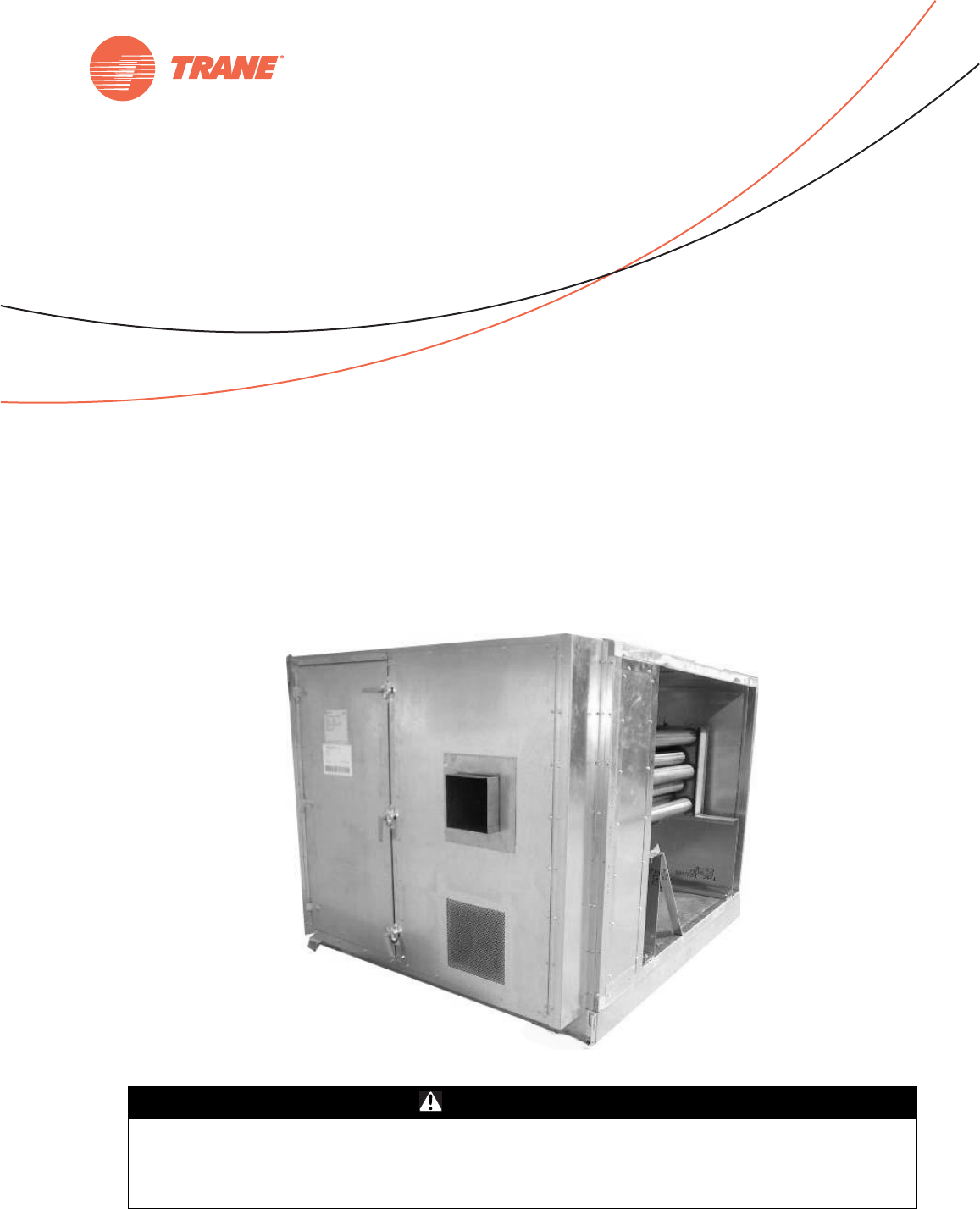
Gas Heat Sections
for Performance Climate Changer™ Air Handlers
Sizes 6-120 for Indoor and Outdoor Units
November 2012
CLCH-SVX08A-EN
Installation, Operation
and Maintenance
© 2012 Trane All rights reserved CLCH-SVX08A-EN
Warnings, Cautions and Notices
Warnings, Cautions and Notices.
Note that warnings,
cautions and notices appear at appropriate intervals
throughout this manual. Warnings are provide to alert
installing contractors to potential hazards that could result
in death or personal injury. Cautions are designed to alert
personnel to hazardous situations that could result in
personal injury, while notices indicate a situation that
could result in equipment or property-damage-only
accidents.
Your personal safety and the proper operation of this
machine depend upon the strict observance of these
precautions.
Read this manual thoroughly before operating or servicing
this unit.
Important
Environmental Concerns!
Scientific research has shown that certain man-made
chemicals can affect the earth’s naturally occurring
stratospheric ozone layer when released to the
atmosphere. In particular, several of the identified
chemicals that may affect the ozone layer are refrigerants
that contain Chlorine, Fluorine and Carbon (CFCs) and
those containing Hydrogen, Chlorine, Fluorine and
Carbon (HCFCs). Not all refrigerants containing these
compounds have the same potential impact to the
environment. Trane advocates the responsible handling of
all refrigerants-including industry replacements for CFCs
such as HCFCs and HFCs.
Responsible Refrigerant Practices!
Trane believes that responsible refrigerant practices are
important to the environment, our customers, and the air
conditioning industry. All technicians who handle
refrigerants must be certified. The Federal Clean Air Act
(Section 608) sets forth the requirements for handling,
reclaiming, recovering and recycling of certain
refrigerants and the equipment that is used in these
service procedures. In addition, some states or
municipalities may have additional requirements that
must also be adhered to for responsible management of
refrigerants. Know the applicable laws and follow them.
ATTENTION:
Warnings, Cautions and Notices appear at
appropriate sections throughout this literature. Read
these carefully:
WARNING
Indicates a potentially hazardous
situation which, if not avoided, could
result in death or serious injury.
CAUTION
sIndicates a potentially hazardous
situation which, if not avoided, could
result in minor or moderate injury. It
could also be used to alert against
unsafe practices.
NOTICE:
Indicates a situation that could result in
equipment or property-damage only
WARNING
Proper Field Wiring and Grounding
Required!
All field wiring MUST be performed by qualified
personnel. Improperly installed and grounded field
wiring poses FIRE and ELECTROCUTION hazards. To
avoid these hazards, you MUST follow requirements for
field wiring installation and grounding as described in
NEC and your local/state electrical codes. Failure to
follow code could result in death or serious injury.
WARNING
Personal Protective Equipment (PPE)
Required!
Installing/servicing this unit could result in exposure to
electrical, mechanical and chemical hazards.
• Before installing/servicing this unit, technicians
MUST put on all Personal Protective Equipment (PPE)
recommended for the work being undertaken.
ALWAYS refer to appropriate MSDS sheets and OSHA
guidelines for proper PPE.
• When working with or around hazardous chemicals,
ALWAYS refer to the appropriate MSDS sheets and
OSHA guidelines for information on allowable
personal exposure levels, proper respiratory
protection and handling recommendations.
• If there is a risk of arc or flash, technicians MUST put
on all Personal Protective Equipment (PPE) in
accordance with NFPA 70E or other country-specific
requirements for arc flash protection, PRIOR to
servicing the unit.
Failure to follow recommendations could result in death
or serious injury.

CLCH-SVX07C-EN 3
Table of Contents
Warnings, Cautions and Notices . . . . . . . . . . 2
Model Number Description . . . . . . . . . . . . . . . 4
Overview of Manual
. . . . . . . . . . . . . . . . . . . 4
Nameplate
. . . . . . . . . . . . . . . . . . . . . . . . . . . . 4
General Information
. . . . . . . . . . . . . . . . . . . . . 5
Product Information
. . . . . . . . . . . . . . . . . . . . 5
Burner Specifications . . . . . . . . . . . . . . . . . 5
Description
. . . . . . . . . . . . . . . . . . . . . . . . . . . 6
Pre-Installation
. . . . . . . . . . . . . . . . . . . . . . . . . . 8
Arrival at Jobsite
. . . . . . . . . . . . . . . . . . . . . . 8
Flue Stack for Indoor Air Handler . . . . . . . 8
Protective Covering . . . . . . . . . . . . . . . . . . 8
Hardware Kits . . . . . . . . . . . . . . . . . . . . . . . 8
Rain Hood . . . . . . . . . . . . . . . . . . . . . . . . . . 8
Instruction Manuals . . . . . . . . . . . . . . . . . . 8
Receiving Inspection
. . . . . . . . . . . . . . . . . . . 8
Storage
. . . . . . . . . . . . . . . . . . . . . . . . . . . . . . 8
Outdoor Units . . . . . . . . . . . . . . . . . . . . . . . 8
Indoor Units . . . . . . . . . . . . . . . . . . . . . . . . 9
Installation
. . . . . . . . . . . . . . . . . . . . . . . . . . . . . . 9
Contractors’ Responsibilities
. . . . . . . . . . . . 9
Installing Contractor . . . . . . . . . . . . . . . . . . 9
Electrical and/or Controls Contractor . . . 10
Service Clearance Recommendations
. . . 10
Installations at High Altitude
. . . . . . . . . . . 11
Rigging/Lifting
. . . . . . . . . . . . . . . . . . . . . . . 11
Assembly . . . . . . . . . . . . . . . . . . . . . . . . . 11
Duct Connections
. . . . . . . . . . . . . . . . . . . . . 11
Combustion Air Duct . . . . . . . . . . . . . . . . 11
Duct Transitions . . . . . . . . . . . . . . . . . . . . 11
Airflow Direction . . . . . . . . . . . . . . . . . . . 11
Rain Hood - Combustion Air Inlet . . . . . . 12
Flue Stack Installation
. . . . . . . . . . . . . . . . . 13
Outdoor Gas Heat Section . . . . . . . . . . . . 13
Indoor Gas Heat Section . . . . . . . . . . . . . 13
Piping
. . . . . . . . . . . . . . . . . . . . . . . . . . . . . . . . . 14
Gas Piping
. . . . . . . . . . . . . . . . . . . . . . . . . . . 14
Proper Gas Pressure . . . . . . . . . . . . . . . . 14
Heat Exchanger Condensate Piping . . . . .14
Wiring
. . . . . . . . . . . . . . . . . . . . . . . . . . . . . . . . . .15
High-Voltage Wiring
. . . . . . . . . . . . . . . . . . .15
Wiring Entrance Locations . . . . . . . . . . . .15
Wiring . . . . . . . . . . . . . . . . . . . . . . . . . . . . .15
Low-Voltage Wiring
. . . . . . . . . . . . . . . . . . . .16
Operation
. . . . . . . . . . . . . . . . . . . . . . . . . . . . . . .20
Initial Startup
. . . . . . . . . . . . . . . . . . . . . . . . .20
Pre-Startup . . . . . . . . . . . . . . . . . . . . . . . . .20
Startup . . . . . . . . . . . . . . . . . . . . . . . . . . . .21
Pre-Purge and Pilot Ignition . . . . . . . . . . .21
Main Burner Ignition . . . . . . . . . . . . . . . . .21
Pre-Purge and Main Flame Ignition . . . . .22
Final Check Out
. . . . . . . . . . . . . . . . . . . . . . .22
Normal Shutdown
. . . . . . . . . . . . . . . . . . . . .23
Seasonal Startup/Shutdown
. . . . . . . . . . . .23
Seasonal Shutdown . . . . . . . . . . . . . . . . . .23
Seasonal Startup . . . . . . . . . . . . . . . . . . . .23
Routine Maintenance
. . . . . . . . . . . . . . . . . . . .24
Heating Mode Maintenance
. . . . . . . . . . . . .24
Service Personnel Maintenance
. . . . . . . . .24
Troubleshooting
. . . . . . . . . . . . . . . . . . . . . . . . .25
4 CLCH-SVX08A-EN
Model Number Description
Overview of Manual
Use this manual to install, startup, operate, and maintain
the Performance Climate Changer™ air handler gas heat section. Carefully review the procedures discussed in this
manual to minimize installation and startup difficulties.
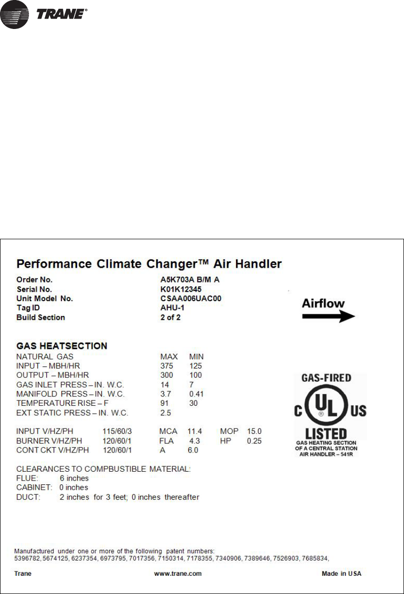
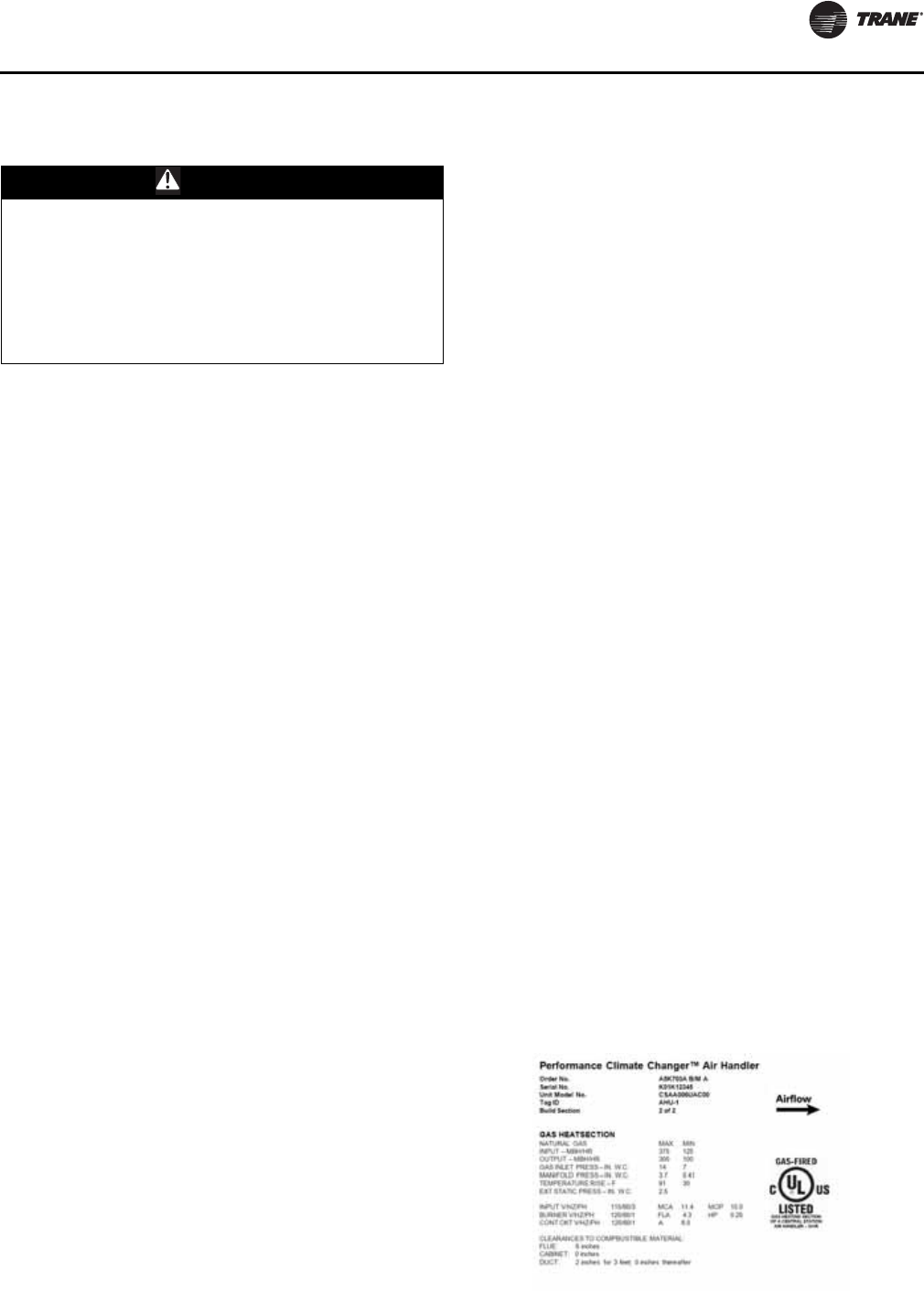
Nameplate
Each air handler section includes a nameplate/label (see
Figure 1), which identifies the type of section, customer
tagging information, the unit serial number, the unit order
number, the build-section position for installation, and the
unit model number.
Note: The unit serial number and order number is
required when ordering parts or requesting service
for a Trane air handler.
Figure 1. Performance air handler section nameplate

CLCH-SVX08A-EN 5
General Information
Product Information
Model and serial numbers for the gas heat section are
designated on the nameplate located on the piping-side
access door inside the section. Record the information
below for a permanent record of the equipment installed
on your job site. The nameplate also contains the range of
settings for which the gas heat unit is capable. Record and
retain these settings in case the unit should ever need
adjustment after service repairs.
Note: This information is required when ordering repair
parts.
Burner Specifications
Model Number____________________________________________________________________________
Serial Number_____________________________________________________________________________
Air Handler Sales Order Number____________________________________________________________
Air Handler Serial Number_________________________________________________________________
Startup Date_______________________________________________________________________________
Altitude Above Sea Level___________________________________________________________________
Calorific Value_____________________________________________________________________________
Maximum Firing MBh______________________________________________________________________
Minimum Firing MBh______________________________________________________________________
Type of Gas________________________________________________________________________________
Maximum Inlet Gas Pressure_______________________________________________________________
Minimum Inlet Gas Pressure________________________________________________________________
Temperature Rise (ºF)_______________________________________________________________________
Manifold Pressure at Maximum MBh________________________________________________________
Table 1. Motor and Electrical Specifications
Specifications Gas Heater Input Power Burner Motor
1
Control Power
1
Exhaust Motor
Volts 115 115
Hertz 60 60 60 60
Phase 1 1
HP n/a n/a
FLA/Amps n/a 6
MCA n/a n/a n/a
MOP n/a n/a n/a
Note:
1
Powered by a "line to 115 volt" transformer for all gas heaters except 115/60/1 rated units.
General Information
6 CLCH-SVX08A-EN
Description
The gas heat section consists of a drum-and-tube heat
exchanger, burner, gas train components, and a control
panel for electrical connections. It is an integral part of the
entire air-handling system.
An access door is provided for service and maintenance of
the burner and gas train components.
The gas heat section must be in a blow-thru position
downstream from the supply fan. Downstream sections
must be separated by a blank access section and discharge
temperatures must be controlled so as not to exceed the
temperature limits of components in the downstream
sections.
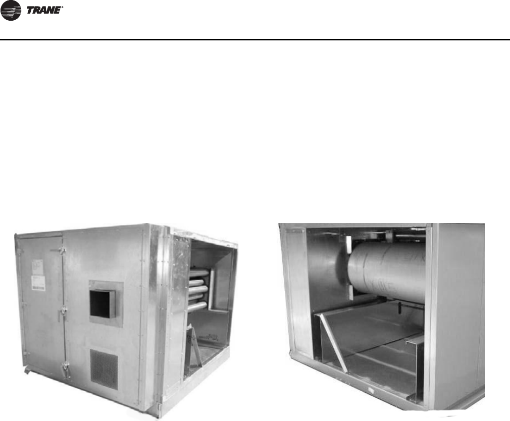
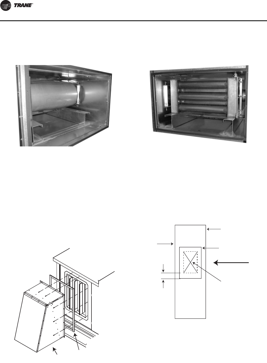
Depending on the heater size, an external vestibule that
extends the width of the gas heat section may be used to
house the burner and gas train components (see Figure 2).
The external vestibule, if required, ships attached to the
gas heat section. Some heaters have gas train
components in an internal vestibule (see Figure 3). Refer
to Table 2 for vestibule locations.
Figure 2. Gas heat section with external vestibule Figure 3. Gas heat section with internal vestibule
General Information
CLCH-SVX08A-EN 7
Table 2. Vestibule locations
Unit Size Gas Output
(MBH) Vestibule
Type Unit Size Gas Output
(MBH) Vestibule
Type Unit Size Gas Output
(MBH) Vestibule
Type
6 200 Ext 35 360 Int 66 700 Int
6300 Ext 35 560 Int 66 860 Int
8 200 Ext 35 700 Int 66 1000 Int
8300 Ext 35 860 Int 66 1250 Int
10 200 Ext 35 1000 Ext 66 1500 Int
10 360 Ext 35 1250 Ext 66 1750 Int
12 200 Int 35 1500 Ext 66 2000 Ext
12 360 Ext 35 1750 Ext 66 2400 Ext
14 200 Int 40 560 Int 80 860 Int
14 360 Ext 40 700 Int 80 1000 Int
17 200 Int 40 860 Int 80 1250 Int
17 360 Ext 40 1000 Ext 80 1500 Int
17 560 Ext 40 1250 Ext 80 1750 Int
17 700 Ext 40 1500 Ext 80 2000 Ext
21 200 Int 40 1750 Ext 80 2400 Ext
21 360 Ext 50 560 Int 100 1000 Int
21 560 Ext 50 700 Int 100 1250 Int
21 700 Ext 50 860 Int 100 1500 Int
21 860 Ext 50 1000 Int 100 1750 Int
21 1000 Ext 50 1250 Ext 100 2000 Int
25 360 Ext 50 1500 Ext 100 2400 Ext
25 560 Ext 50 1750 Ext 120 1000 Int
25 700 Ext 50 2000 Ext 120 1250 Int
25 860 Ext 57 560 Int 120 1500 Int
25 1000 Ext 57 700 Int 120 1750 Int
30 360 Int 57 860 Int 120 2000 Int
30 560 Int 57 1000 Int 120 2400 Int
30 700 Int 57 1250 Ext
30 860 Int 57 1500 Ext
30 1000 Ext 57 1750 Ext
57 2000 Ext
8 CLCH-SVX08A-EN
Pre-Installation
Arrival at Jobsite
Gas heat sections arrive at the jobsite with an integral base
frame for the purpose of mounting units to a
housekeeping pad or roof curb. The base frame variables
in height from the standard 2.5- inches to 8 inches.
The gas heat section is designed with the necessary
number of lift points for safe installation. The lift points are
designed to accept standard rigging devices and are
removable after installation. Indoor sections size 3-30 will
also be shipped with a shipping skid designed for forklift
transport.
Outdoor gas heat sections ship with wooden blocks
fastened under the base channel. The blocks elevate the
section for shipping protection and ease of handling.
Leave the wooden blocks attached until the section is
placed in its final position to avoid bending the base
channel during rigging and handling.
Flue Stack for Outdoor Air Handler
A stainless-steel flue stack is provided with outdoor air
handlers. It ships inside the gas heat section and must be
mounted on the flue opening on the side of the unit. The
flue stack must be installed on the gas heat section before
assembling the gas heat section to the air handler.
It is very difficult to remove the flue from inside the unit
once the unit is assembled.
Flue Stack for Indoor Air Handler
Indoor air handlers require a field-engineered and field-
installed flue stack. Local codes and practices vary
throughout the country. The engineer should size the flue
based on MBh output, horizontal and vertical run lengths,
type of flue material, NFPA 54 Fuel Gas Code, and local
codes. The flue should be designed for 800 degrees F (430
degrees C). If horizontal runs over 20 feet or other static-
increasing transitions are necessary, a flue booster fan will
be required.
Protective Covering
The large openings of the gas heat section are protected by
an Oriented Strand Board (OSB) panel covering. The OSB
panel is held in place by sheet metal screws. Leave the
covering attached to the section until it is ready to install to
prevent debris from entering the section.
Hardware Kits
Hardware kids ship inside the air handler fan section in a
plastic bag or cardboard box. This kit contains gasketing
and screws. For outdoor units, roof joint connection strips
and wall panel seam caps are included. These are used
when fastening the gas heat section to the air handler.
Keep the hardware with the gas heat section until it is
ready to install.
Rain Hood
A rain hood is provided for outdoor units with internal
vestibules. The rain hood is shipped on a separate wood
skid. A kit containing mounting hardware ships inside the
gas heat section and must be removed before assembly to
the air handler.
Instruction Manuals
Individual instruction manuals for all of the gas train
components (such as flame-control relay valves, pressure
switches, and actuators) ship inside the piping vestibule.
Retain these manual for future repair or troubleshooting.
Receiving Inspection
Upon receipt of the gas heat section, inspect it for damage
that may have occurred during shipment. Report damage
immediately to the freight company. Trane is not
responsible for shipping damage.
• Inspect the access door latches and hinges for damage.
• Open the access door and check for internal, hidden
damage. Concealed damage must be reported within
15 days of receipt.
• Locate the hardware kit.
• Locate the flue stack if it is an outdoor unit.
• If shipped on a skid, do not remove the gas heat section
from the skid at this time.
Storage
Outdoor Units
A gas heat section designed for outdoor use requires no
special protection during storage. Select a solid, well-
drained area. Concrete or black top surfaces are
recommended. If concrete or black top is not available, set
the section on wood timbers to prevent dirt, mud, snow,
etc. from getting into the unit. Keep access doors closed to
prevent damage to gas train components.
If needed, cover with a canvas tarp. Covering the unit with
clear or black plastic sheets is not recommended because
this material traps condensed moisture, which can cause
equipment damage resulting from rust and corrosion.
NOTICE:
Equipment Damage!
Do not use type B flue stacks with this product as they
are not suitable for the flue gas temperatures. Failure to
follow this recommendation could result in equipment
damage.
Installation
CLCH-SVX08A-EN 9
Trane warranty does not cover equipment damage due to
negligence during storage.
Indoor Units
For a gas heat section designed for indoor use, Trane
recommends indoor storage. If outdoor storage is
necessary, select a solid, well-drained area. Concrete or
black top surfaces are recommended. If concrete or black
top is not available, set the unit on wood timbers to
prevent dirt, mud, snow, etc. from getting into the module.
Keep access doors closed to prevent damage to gas train
components.
Cover the unit with a canvas tarp. Covering the unit with
clear or black plastic sheets is not recommended because
this material traps condensed moisture, which can cause
equipment damage resulting from rust and corrosion.
Trane warranty does not cover equipment damage due to
negligence during storage.
Installation
:
Contractors’ Responsibilities
Installing Contractor
• Unpack the gas heat section and remove the skid.
• Remove protective coverings.
• Rig and/or move the section to the air handler location.
The contractor must provide slings, spreader bars,
clevis hooks, pins, etc. for rigging.
• For outdoor gas heat sections, a level roof curb or
structural steel support system is required. If the gas
heat section is provided with an external piping
vestibule, no support is required for the vestibule.
• For outdoor sections, install the flue stack. The flue
must be removed from the airstream before assembly.
Install the flue stack on the gas heat section before
assembling the gas heat section to the air handler.
• Clear debris from combustion air inlets located on the
side or bottom of the gas heat section. Remove any
debris obstructing combustion air inlets.
• In areas where snow drifts are higher than the bottom
of the vestibule, a hood or louver may have to be
installed for combustion air.
• Assemble the gas heat section to the air-handling
system. Refer to the Performance Climate Changer air
handler Installation, Operation, and Maintenance
manual, CLCH-SVX07B-EN for specific assembly
instructions. This manual ships inside the supply fan
section of the air handler.
WARNING
Improper Unit Lift!
Do not lift unit from top! Lift unit from lifting lugs only
located at bottom of unit. Test lift unit approximately 24
inches to verify proper center of gravity lift point. To
avoid dropping of unit, reposition lifting point if unit is
not level. Failure to properly lift unit could result in unit
dropping and possibly crushing operator/technician
which could result in death or serious injury and
possible equipment or property-only damage.
WARNING
Heavy Objects!
Ensure that all the lifting equipment used is properly
rated for the weight of the unit being lifted. Each of the
cables (chains or slings), hooks, and shackles used to
lift the unit must be capable of supporting the entire
weight of the unit. Lifting cables (chains or slings) may
not be of the same length. Adjust as necessary for even
unit lift. Other lifting arrangements could cause
equipment or property damage. Failure to follow
instructions above or properly lift unit could result in
unit dropping and possibly crushing operator/
technician which could result in death or serious injury.
WARNING
Hazardous Gases and Flammable Vapors!
Exposure to hazardous gases from fuel substances
have been shown to cause cancer, birth defects or other
reproductive harm. Improper installation, adjustment,
alteration, service or use of this product could cause
flammable mixtures or lead to excessive carbon
monoxide. To avoid hazardous gases and flammable
vapors follow proper installation and set up of this
product and all warnings as provided in this manual.
Failure to follow all instructions could result in death or
serious injury.
WARNING
Combustible Materials!
Maintain proper clearance between the unit heat
exchanger, vent surfaces and combustible materials.
Refer to unit nameplate and installation instructions for
proper clearances. Improper clearances could result in
combustible materials catching on fire. Failure to
maintain proper clearances could result in death or
serious injury or property damage.
Installation
10 CLCH-SVX08A-EN
• Penetrate the unit casing and connect the supply gas
line to the gas train. Gas supply line connection sizes
are shown in Table 3.
• For indoor gas heat sections, install a field-engineered
flue stack according to local codes. See Table 4 for flue
connection sizes.
Electrical and/or Controls Contractor
• Provide power to the gas heat section. See “Wiring” on
page 15 for power requirements.
• Provide a binary start–stop signal.
• Provide an analog 0 to 10 Vdc modulating signal. A 0 to
10 Vdc interface module is installed as standard
equipment. A 4 to 20 mA interface module is available
and may have been installed on the unit for the control
signal in lieu of the 0 to 10 Vdc signal.
• Provide an interlock in the start-stop signal circuit with
the air handler supply fan. This interlock must insure
the start-stop signal is interrupted to the gas heat
system if the supply fan is shut off. The gas heat system
must not operate without the supply fan providing
airflow.
• All wiring must comply with applicable local and
National Electric Code (NEC) specifications.
• For VAV units, provide temperature sensors for
entering and leaving air in gas heat section.
All power and control wiring for the gas heat section must
be field provided. All power and control wiring for any
section downstream of the gas heat must be field
provided.
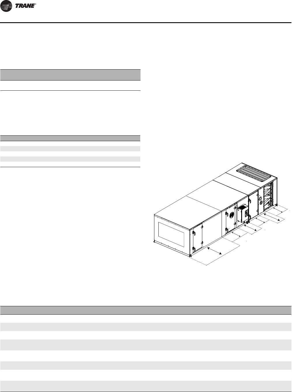
Service Clearance
Recommendations
A minimum clearance of the section width plus 12 inches
on the access door side of the gas heat section is
recommended for routine maintenance. This clearance
provides enough room to replace the heat exchanger in
the event of failure. The section side panels must be
removed to access the heat exchanger. Refer to Figure 4
for service clearance recommendations for the air handler.
Table 3. Gas supply line connection sizes
Gas Output
(MBh) 200-560 700-1000 1250-
1750 2000-
2400
Connection Size
(NPT) 1 in. 1 1/4 in. 1 1/2 in. 2 in.
Table 4. Flue connection sizes for gas heat sections
Gas Output (MBh) Flue Size (inches)
200, 360, 560 8 × 8
300, 360 9 × 9
700, 860, 1000 12 × 12
1750 10 × 10
2000, 2400 14 x 14
Figure 4. Service Clearance
Filter mixing box
Coil
Fan
Gas heat
Access
door
UV
lights
VFD
F
E
D
C
B
A
Table 5. Service clearances (inches)
Component 346810 12 14 17 21 25 30 35 40 50 57 66 80 100 120
A (filter)
48 48 48 48 48 48 48 48 48 48 48 48 48 48 48 52 56 58 58
B (coil)
48 59 59 66 77 82 87 87 95 95 109 115 128 141 141 156 156 170 197
C (UV Lights)
48 48 48 48 48 48 48 48 48 48 48 48 48 48 48 52 56 58 58
D (external
starter or VFD)
61 61 61 61 61 61 61 61 64 64 64 64 64 64 64 64 64 64 64
D (internal
starter or VFD)
48 48 48 48 48 48 48 48 48 48 48 48 48 48 48 48 48 48 48
E (fan)
48 48 48 48 51 54 58 61 60 66 66 66 70 77 77 93 93 101 101
F (gas heat -
Ext Vestibule)
N/A N/A 89 90 108 100 100 105 115 115 118 136 140 156 156 170 179 180 N/A
F (gas heat -
Int Vestibule)
N/A N/A 56 63 74 79 84 84 92 92 106 112 125 138 138 153 153 167 194
Note: At a minimum, the above clearance dimensions are recommended on one side of the unit for regular service and maintenance. Refer to as-built
submittal for locations of items such as filter access doors, coil, piping connections, motor locations, etc. Sufficient clearance must be provided on
all sides of unit for removal of access panels, plug panels, or section-to-section attachment brackets. Clearance for starters, VFDs, or other high-voltage
devices must be provided per NEC requirements.
Installation
CLCH-SVX08A-EN 11
Installations at High Altitude
Adjustment of gas train linkages is not normally required.
However, for high altitude installations, adjustment to the
air-fuel linkages may be necessary for proper combustion.
Heater outputs must be derated four percent for every
1000 feet over 2000 feet above sea level. When specifying
gas heaters, the engineer should provide the MBh and
airflow required at altitude. All Trane literature is based on
nominal outputs at sea level.
It is recommended that the services of an experienced,
qualified gas heat technician be employed to adjust air-fuel
linkages for proper combustion.
Rigging/Lifting
Refer to the Performance Climate Changer™ air handler
Installation, Operation, and Maintenance manual, CLCH-
SVX07B-EN, for instructions on equipment rigging and
lifting. This manual ships inside the unit fan section.
Assembly
Refer to the design engineer’s plans and submittals for the
location of the gas heat section in the air handler. The gas
heat section will arrive at the job site as an individual
section. It is not shipped with the air handler. Hardware for
fastening the gas heat section to the air handler can be
found in the fan section. Final assembly of the air handler
should be done at the unit installation site. Refer to the
Performance Climate Changer™ air handler Installation,
Operation, and Maintenance manual, CLCH-SVX07B-EN,
for further instructions on equipment assembly.
Duct Connections
All duct connections to the gas heat section should be
installed in accordance with the standards of the National
Fire Protection Association (NFPA) and the Sheet Metal
and Air Conditioning Contractors National Association,
Inc. (SMACNA).
Combustion Air Duct
• Outdoor units with internal vestibules have a rain hood
that requires field mounting.
• Outdoor units with external vestibules do not have a
rain hood. Combustion air enters through openings in
the bottom of the vestibule.
• All indoor units ship with a screened opening on the
combustion air inlet.
If combustion air is to be ducted to the gas heat vestibule,
the unit’s capacity must be derated to account for the
resistance in the air duct. For every 0.14 inches wg of duct
resistance, unit capacity (MBh output) will reduce by five
percent.
If combustion air is ducted to the vestibule, it is strongly
recommended that an experienced gas heat technician
check the system and emission levels in the exhaust flue at
start up. Carbon dioxide should be between 8.2 and 9.4
percent. This corresponds to the allowable range of excess
air needed for combustion. The additional static pressure
of the inlet air duct may change the fuel-air ratio slightly
necessitating system adjustment.
Separated combustion can be a desirable option, but will
require more field-installation time and material. The
burner fans are not sized to handle any static in the
combustion air stream. A booster fan will likely be
required to overcome combustion air duct static.
Combustion air cannot be ducted directly to the
combustion air fan. The airflow through the vestibule is
needed to keep the temperatures in the vestibule down.
Duct Transitions
When the gas heat section is the last section of the air
handler, and duct transitions should be smooth and
uniform from all sides. Follow recommendations for duct
transitions from SMACNA.
Fasten the ductwork directly to the ductwork opening.
When using lined ductwork, the insulation should not
obstruct the discharge opening.
Airflow Direction
The airflow direction through the gas heater is important
because it prevents localized “hot spots” on the heat
exchanger. Airflow direction labels denoting correct
airflow direction through the gas heat section are provided
on the burner side of the heating section. See Figure 5.
WARNING
Hazard of Explosion!
Installations at altitudes of 3,000 feet above sea level or
higher may require adjustment of the air-fuel linkage
for proper combustion. Linkage and air-fuel adjustment
should only be done by an experienced, qualified gas
heat technician. Failure to follow these
recommendations could result in death or serious
injury or equipment or property-only damage.
Figure 5. Airflow direction label
Installation
12 CLCH-SVX08A-EN
Airflow from the supply fan should enter on the drum (or
primary) side of the heat exchanger (Figure 6) and exit on
the tube (or secondary) side (Figure 7).
Rain Hood - Combustion Air Inlet
Rain hoods are only required on an outdoor unit with an
internal vestibule. Depending on unit size, the combustion
air opening will be in the access door or in the side panel.
A unit with an external vestibule has the combustion air
opening in the floor of the vestibule and does not require
a rain hood, unless excessive snowdrifts are expected.
Rain hoods for the combustion air opening ship loose and
must be installed at the job site. The assembly consists of
the hood, butyl tape and number 10 screws.
• Install butyl tape between the hood and the side panel
or door panel (see Figure 8).
• Locate the bottom edge of the hood 2 3/8 inches below
the bottom edge of the inlet air opening and center the
hood left-to-right over the inlet air opening (see
Figure 9).
• Install the hood to the unit with number 10 screws.
Figure 6. Entering airside (drum or primary) of gas heat
section Figure 7. Leaving air side (tube or secondary) of gas heat
section
Figure 8. Installation of rain hood for combustion air
opening
Hood Butyl tape
Figure 9. Center inlet air opening
Hinge
side
2 3/8 in.
Center hood left-to-right
over opening
Combustion
air opening
Rain hood
Access door
Airflow
Installation
CLCH-SVX08A-EN 13
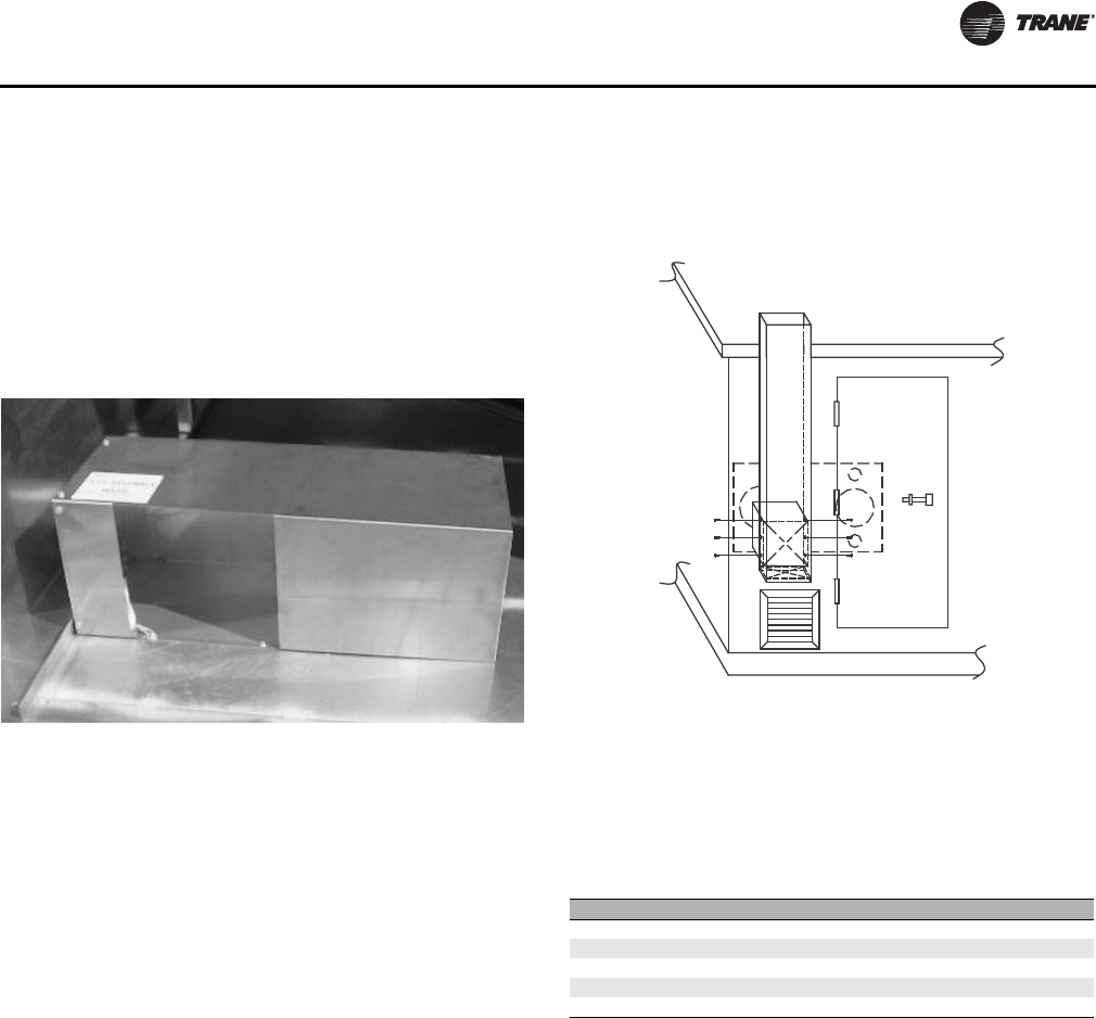
Flue Stack Installation
Outdoor Gas Heat Section
The flue stack for outdoor gas heat sections ships inside
the gas heat section (see Figure 10). Attach the flue stack to
the flue collar and secure it with screws as indicated in
Figure 11. See Table 6 for flue connection sizes.
A rain hood or screen is recommended on the flue to
prevent possible blockage from bird nests and beehives.
The rain hood or screen must be field provided.
It is very difficult to remove flue from inside the unit once
the unit is assembled.
Indoor Gas Heat Section
For indoor gas heat sections, a field-engineered flue stack
is required. Install according to local codes. See
connection sizes in Table 6.
Figure 10. Outdoor air handler flue stack
Figure 11. Outdoor air handler flue stack installation
Table 6. Flue connection sizes for gas heat sections
Gas Output (MBh) Flue Size (inches)
200, 360, 560 8 × 8
300, 360 9 × 9
700, 860, 1000 12 × 12
1750 10 × 10
2000, 2400 14 x 14
Piping
14 CLCH-SVX08A-EN
Piping
Gas Piping
Note: Installation must conform with the American
National Standard Z223.1 (NFPA 54), the National
Fuel Gas Code, latest edition, in the absence of local
codes.
• Gas piping should always be done in accordance with
local codes.
• Tighten all joints securely.
• Pipe unions should be a “ground joint” type to prevent
leakage.
• Provide adequate support for field-installed piping to
avoid placing stress on the gas train and controls.
• Run takeoff lines from the side or top of the main gas
line to prevent moisture from being drawn into the gas
train of the unit.
• Provide a drip leg in the field-installed piping, installing
it near the unit.
Proper Gas Pressure
• To assure sufficient gas pressure at the unit, use
appropriately sized gas pipe for unit capacity. Refer to
the National Fuel Gas Code for pipe sizing information.
• Select an appropriately sized gas pressure regulator to
assure the required gas supply pressure is maintained
at the unit.
• Required gas pressure to the gas train is 7 to 14 inches
wc (0.25 to 0.5 psig) for units through 2400 MBh. Note
that a minimum of 9 inches wc (0.32 psig) is required
for 1250-2000 MBh heaters with 10:1 turndown
capability. For all size units, do not exceed 14 inches wc
(0.5 psig) inlet gas pressure.
• Gas pressure and volume must be maintained and
stable at high fire.
• If the gas pressure regulator serves more than one
heating unit, it must be sized appropriately to ensure
that the inlet gas pressure at each unit is 7 to 14 inches
wc while all burners are firing. Nine inches wc is
required for 1250 to 2000 10:1 turndown heaters. Gas
pressure must not exceed 14 inches wc when all units
are off.
• Check the gas supply pressure before making the final
connection to the unit. If the gas pressure is too high,
damage to the gas valve could occur.
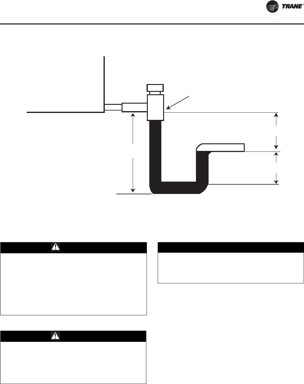
Heat Exchanger Condensate Piping
Condensate usually does not form in the heat exchanger
during normal heating operation. However, if the unit
operates for extended periods of time at very low fire, or
if the air handler serves as a cooling unit also, condensate
can form in the heat exchanger and should be removed.
All units are equipped with a condensate drain and drain
valve. The condensate drain is on the same side as the gas
train located inside the piping vestibule.
Since the drain line is equipped with a shut-off valve, a
condensate p-trap is not required, but may be installed for
convenience to avoid periodic manual draining. If a p-trap
and drain is to be connected to the condensate drain line,
consult local plumbing codes for disposal of the
condensate may be a slightly acidic solution.
Use Figure 12 as a guideline for p-trap construction.
The use of a tee-fitting at the connection to the condensate
outlet is recommended. This allows for priming and
cleaning the trap. If a tee-fitting is used, be sure to furnish
a plug or cap for the clean out opening. Be sure to replace
the plug after priming or cleaning the trap.
WARNING
Hazard of Explosion and Deadly Gases!
Never solder, braze or weld on refrigerant lines or any
unit components that are above atmospheric pressure
or where refrigerant may be present. Always remove
refrigerant by following the guidelines established by
the EPA Federal Clean Air Act or other state or local
codes as appropriate. After refrigerant removal, use dry
nitrogen to bring system back to atmospheric pressure
before opening system for repairs. Mixtures of
refrigerants and air under pressure may become
combustible in the presence of an ignition source
leading to an explosion. Excessive heat from soldering,
brazing or welding with refrigerant vapors present can
form highly toxic gases and extremely corrosive acids.
Failure to follow all proper safe refrigerant handling
practices could result in death or serious injury.
NOTICE:
Excessive Gas Pressure!
The gas pressure at the inlet to the gas train must not
exceed 14 in. wc. A properly sized gas regulator that
provides a maximum of 14 in wc. of gas pressure, must
be supplied in the gas inlet line to unit. Failure to
maintain proper gas pressure could result in damage to
the gas train components.
Table 7. Gas supply line connection sizes
Gas Output
(MBh) 200-560 700-1000 1250-1750 2000-2400
Connection Size
(NPT) 1 in. 1 1/4 in. 1 1/2 in. 2 in.
Wiring
CLCH-SVX08A-EN 15
Wiring
High-Voltage Wiring
Wiring Entrance Locations
Indoor air handlers can accept conduit penetrations on
any side of the piping vestibule. For outdoor air handlers,
the recommended conduit entrance into the gas heat
section is through the floor of the piping vestibule.
Terminate conduits on the power junction box or gas
heater control panel as appropriate.
Wiring
• All field wiring must be in accordance with the National
Electric Code and state and local requirements.
• All wiring (including low-voltage wiring) must be
copper conductors only with the insulation rated for
600 volts.
• Refer to the nameplate located on the gas heater
section for the proper Input Voltage, Minimum Circuit
Figure 12. Heat exchanger condensate piping
J
H
L
Normal operation
Tee with cap
L=H+J+diameter where:
H = 5 inches
J = 2.5 inches
WARNING
Proper Field Wiring and Grounding
Required!
All field wiring MUST be performed by qualified
personnel. Improperly installed and grounded field
wiring poses FIRE and ELECTROCUTION hazards. To
avoid these hazards, you MUST follow requirements for
field wiring installation and grounding as described in
NEC and your local/state electrical codes. Failure to
follow code could result in death or serious injury.
WARNING
Hazardous Voltage!
Disconnect all electric power, including remote
disconnects before servicing. Follow proper lockout/
tagout procedures to ensure the power can not be
inadvertently energized. Failure to disconnect power
before servicing could result in death or serious injury.
NOTICE:
Use Copper Conductors Only!
Unit terminals are not designed to accept other types
of conductors. Failure to use copper conductors could
result in equipment damage.
Wiring
16 CLCH-SVX08A-EN
Ampacity (MCA) and Maximum Overcurrent
Protection (MOP) requirements for proper electrical
installation.
• Input voltage must be within +/- 10 percent of specified
value.
• Ground the supply power in the junction box to the
ground lead provided.
• Do not route any wires through the heat exchanger
section unless the insulation is rated for 600˚F or
higher. Radiant heat from the heat exchanger will
damage wire insulation that is unsuitable for high
temperatures.
•See Table 8 for power supply requirements.
Note: Factory wiring routed through the heated part of
the cabinet has insulation rated for 600˚F.
Gas Heaters with 200–1000 MBh Output
Single-phase 120, 208, 230, 460 or 575 volt power is
required to operate the heater controls or power the
transformer (TRANS1), if provided.
Single-phase power for 208, 230 460 and 575 voltage is
provided for the gas heat off two legs of the three-phase
supply to the air-handling unit. A transformer in the piping
vestibule is provided to step down the voltage required for
gas heat.
Gas Heaters with 1250–2400 MBh Output
Three-phase 208, 230, 460 or 575 volt power is required to
operate the exhaust fan and power the transformer
(TRANS1).
Low-Voltage Wiring
The gas heat control system requires a binary signal for
on/off control. Provide an interlock in the start-stop signal
circuit with the air handler supply fan. This interlock must
insure the start-stop signal is interrupted to the gas heat
system if the supply fan is shut off. The gas heat system
must not operate without the supply fan providing airflow.
The control system also requires a 0 to 10 Vdc analog
signal for modulation where 10 Vdc is a signal for full heat.
A 4 to 20 mA interface module is available.
Table 8. Power supply requirements
3:1 and 10:1 Burner Turndown Units
Gas Output (MBh) 200-1000 1250-2000 2000
3
Voltage/Ph 115-575/1 208-575/3 208/230/460/575/3
Minimum Circuit Ampacity (MCA) less than 15 less than 15
1
19.71/17.9/9.0/7.2
Maximum Overcurrent Protection (MOP) 15 15
2
25/25/15/15
Note:
1
All except the 2000 MBh output, 208 volt, 3 phase unit. This unit will have a marked MCA of 16.1
2
All except the 2000 MBh output, 208 and 230 volt, 3 phase units. These units have a marked MOP of 20
3
2000 MBh with optional 3 hp exhaust motor required for long horizontal flue vents
20:1 Burner Turndown Units
Gas Output (MBh) 1250-1750 2000 2400
Voltage/Ph 208-575/3 208/230/460/575/3 208/230/460/575/3
Minimum Circuit Ampacity (MCA) less than 15 17.3/16.0/8.0/6.4 20.9/19.0/9.5/7.6
Maximum Overcurrent Protection (MOP) 15 20/20/15/15 25/25/15/15
Note: The MCA and MOP for the 2000 MBh with optional 3 hp exhaust motor will be the same as 2400 MBh.
NOTICE:
Equipment Damage!
The gas heat system will not operate without a supply
fan providing airflow. Operating the gas heat system
without a supply fan could result in damage to
equipment or property.
Wiring
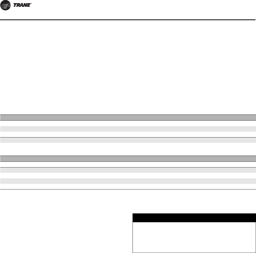
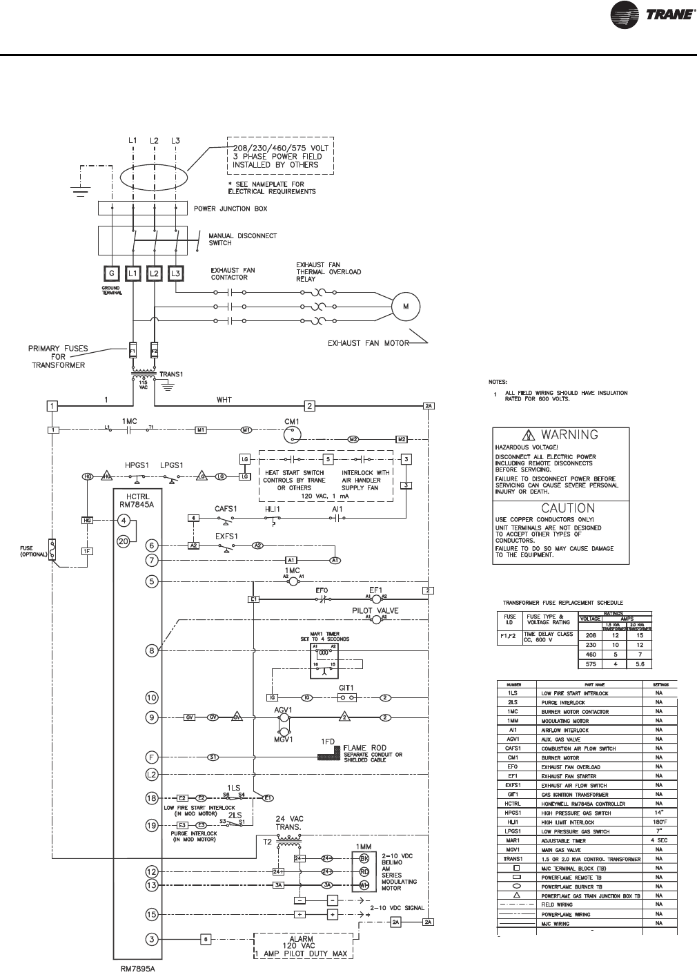
CLCH-SVX08A-EN 17
Figure 13. 200-1000 MBh 3:1 or 10:1 turndown wiring diagram
Wiring
18 CLCH-SVX08A-EN
Figure 14. 1250-2000 MBh 3:1 or 10:1 turndown wiring diagram
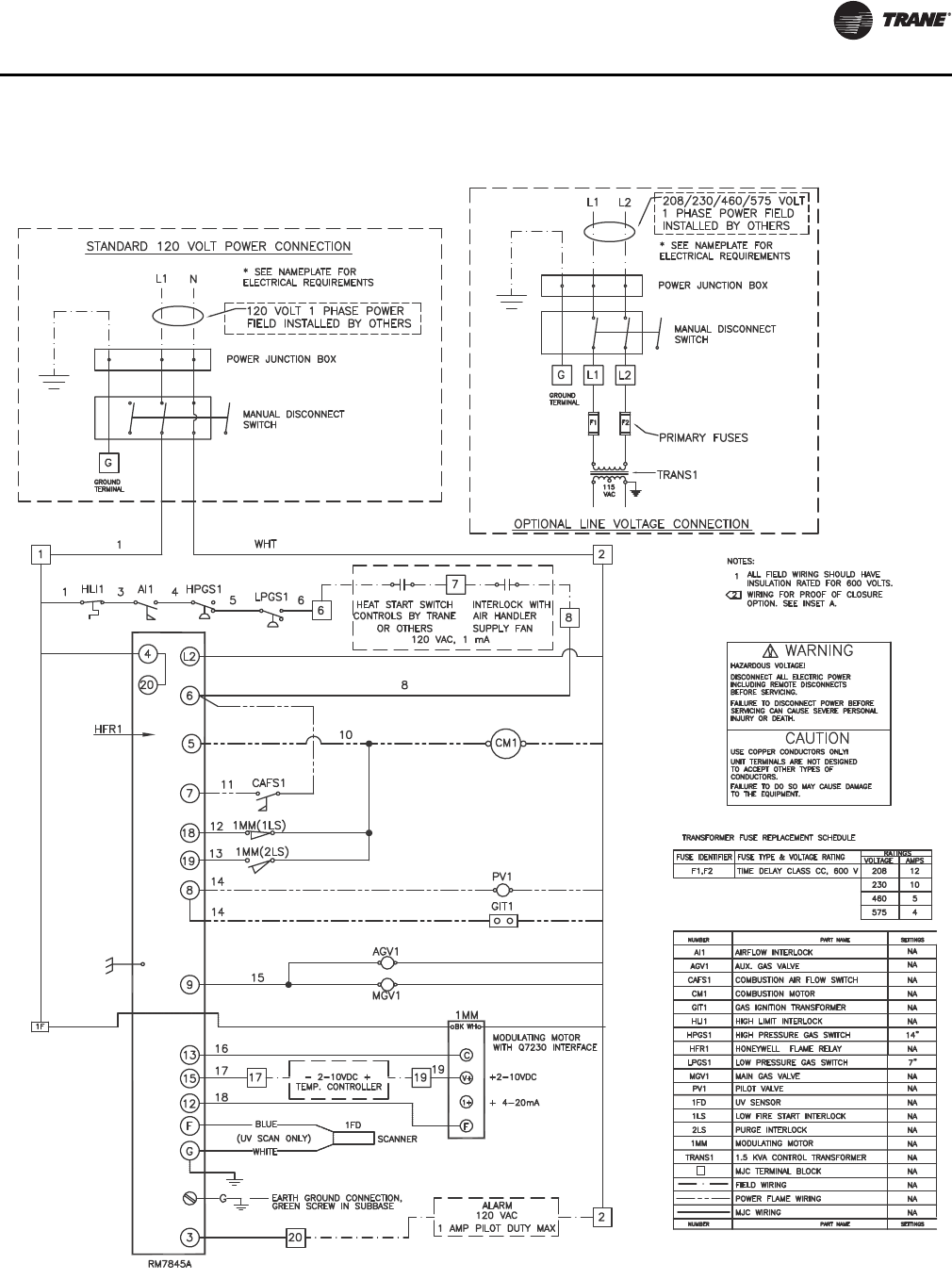
Wiring
CLCH-SVX08A-EN 19
Figure 15. 1250-2400 MBh 20:1 turndown wiring diagram
20 CLCH-SVX08A-EN
Operation
Gas heat sections have been run-tested in the factory to
assure proper operation and ease of startup. The actuator
linkages controlling the air–fuel mixture are preset for
optimum efficiency and performance.
Thoroughly review all service literature before startup and
servicing. The sequence of operation and all details of the
flame-safeguard control system can be found in the
burner equipment literature. The technical bulletins cover
the individual components of the heating system. This
literature ships inside the piping vestibule of the gas heat
section.
Initial Startup
Note: The procedures discussed in this section should be
done by qualified technicians who are experienced
with gas heating equipment.
Pre-Startup
1. Close all manual gas valves.
2. Move the manual disconnect switch in the vestibule to
the OFF position.
3. Check the air shutter and modulating gas valve
linkages for tightness.
4. Attach a manometer to the bleed port on the side of the
first manual gas valve in the burner vestibule at the
inlet end of the gas train, upstream of the automatic
gas valve/regulator. This manometer checks incoming
gas pressure and should measure 7 to 14 inches wc.
(Exception: 1250 through 2000 Mbh with 10:1
turndown require 9 to 14 inches wc.)
5. Attach another manometer to the burner manifold to
check the burner manifold pressure while the unit is
firing.
6. Attach a third manometer to the pilot gas line to check
the pilot gas pressure while the unit is firing.
7. Remove any debris from combustion air inlets and/or
hoods. Note that some combustion air inlets are
located on the floor panel of the piping vestibule.
Insure the openings are not blocked.
8. For units with burners size 1250 and larger, ensure
exhaust fan rotation is correct.
WARNING
Hazardous Gases and Flammable Vapors!
Exposure to hazardous gases from fuel substances have
been shown to cause cancer, birth defects or other
reproductive harm. Improper installation, adjustment,
alteration, service or use of this product could cause
flammable mixtures or lead to excessive carbon
monoxide. To avoid hazardous gases and flammable
vapors follow proper installation and set up of this
product and all warnings as provided in this manual.
Failure to follow all instructions could result in death or
serious injury.
WARNING
Hazardous Voltage!
Disconnect all electric power, including remote
disconnects before servicing. Follow proper lockout/
tagout procedures to ensure the power can not be
inadvertently energized. Failure to disconnect power
before servicing could result in death or serious injury.
WARNING
Hazard of Explosion!
Installations at altitudes of 3,000 feet above sea level or
higher may require adjustment of the air-fuel linkage
for proper combustion. Linkage and air-fuel adjustment
should only be done by an experienced, qualified gas
heat technician. Failure to follow these
recommendations could result in death or serious
injury or equipment or property-only damage.
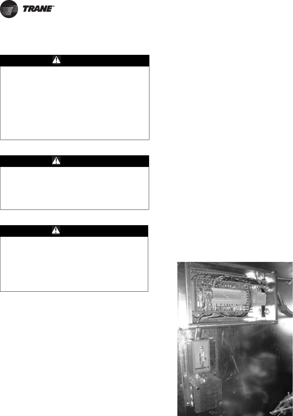
Figure 16. Control panel for the JR burner on 200-1000
mbh (3:1 & 10:1 turndown) units
Operation
CLCH-SVX08A-EN 21
Startup
1. Start the air-handling unit fan. The field-installed
supply fan interlock and primary airflow switch
contacts (AI1) should close.
2. The high-temperature-limit switch contacts (HL1), the
modulating gas valve actuator, and its end switch
contacts (AES) should be closed.
3. The building control system should call for heat,
closing a contact between terminals four and five.
4. Open the manual gas valve outside the unit next to the
gas pressure regulator and bleed air from the piping.
5. Measure the gas pressure at the manual gas valve. The
inlet gas pressure should not exceed 14 inches wg.
Adjust the gas pressure, if necessary.
6. Open the first manual gas valve in the burner vestibule.
7. Open the manual gas valve in the pilot gas line and
bleed the air from the line.
8. Remove any debris from combustion air inlets and/or
hoods. Note that some combustion air inlets are
located on the floor panel of the piping vestibule.
Insure the openings are not blocked.
Pre-Purge and Pilot Ignition
(3:1, 10:1 Turndown, 200-2000 MBh)
Move the manual disconnect switch in the heater vestibule
to the ON position. The system should energize, and the
combustion blower motor should start, indicating that all
of the safety/limit contacts are closed:
• HLI1: high-temperature limit
• AI1: airflow interlock
• HPGS1: high-pressure gas switch
• LPGS1: low-pressure gas switch
The combustion airflow switch (CAFS1) should close,
starting the purge timer, the green power light should
illuminate on the flame-relay panel, the combustion air
dampers should open and the prepurge cycle should
begin. The combustion air blower should run for
approximately 90 seconds to evacuate the heat exchanger
of any combustible gases before the ignition sequence.
This prepurge cycle is initiated before every startup.
With the prepurge cycle complete, the ignition
transformer and pilot solenoid should be energized,
allowing gas to flow to the pilot burner. The pilot should
light immediately. The pilot flame gas pressure should be
2.5 to 3 inches wg.
If the pilot does not light within 10 seconds, the flame relay
should shut down the system, and the red Flame Failure
light should illuminate on the flame relay panel. If the pilot
does not light, press the Reset button to clear the fault and
repeat the procedure outlined in “Startup” on page 21.
The pilot flame can be viewed through the small sight
glass on the burner.
Cycle the pilot on and off several times to ensure its
reliability. Turn the manual disconnect switch in the
control panel to the Off position.
Main Burner Ignition
(3:1, 10:1 Turndown, 200-2000 MBh)
1. With the manual disconnect switch in the Off position,
open the second manual gas valve located
downstream of the automatic gas valve/regulator in
the piping vestibule. Note that this valve is just
upstream of the modulating gas valve.
2. Turn the manual disconnect switch to the On position.
After the pre-purge and pilot cycle, the main gas valve
will energize and the main burner will light.
3. The amber Main Flame light should illuminate on the
flame-relay panel after the ultra-violet flame sensor
has detected the main flame. The flame can be
observed through the larger sight glass under the
burner. Normal flame color is blue; abnormal color is
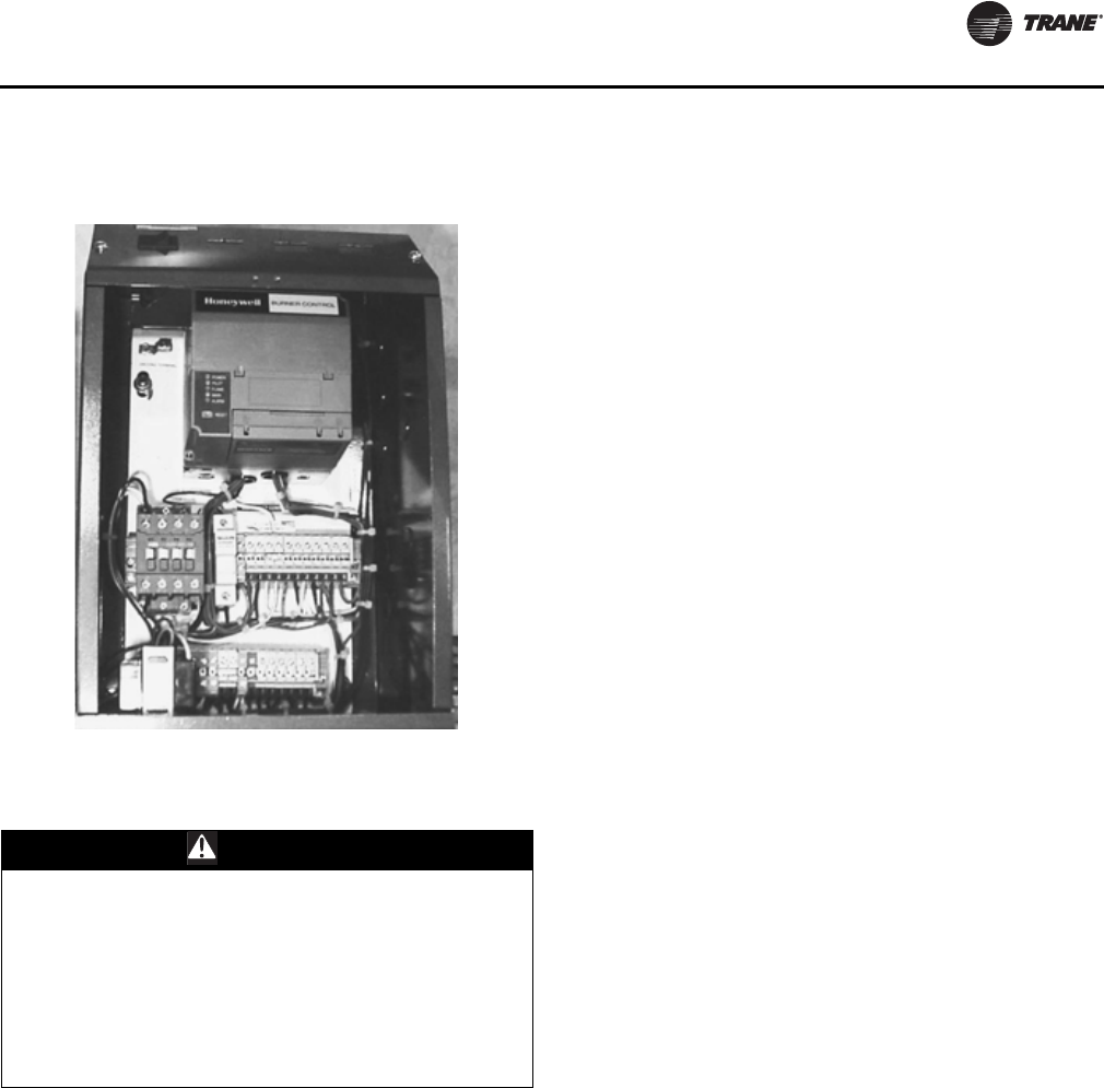
Figure 17. Control panel for the FDM burner on 1250-
2400 (20:1 turndown) units
WARNING
Live Electrical Components!
During installation, testing, servicing and
troubleshooting of this product, it may be necessary to
work with live electrical components. Have a qualified
licensed electrician or other individual who has been
properly trained in handling live electrical components
perform these tasks. Failure to follow all electrical
safety precautions when exposed to live electrical
components could result in death or serious injury.
Operation
22 CLCH-SVX08A-EN
yellow, indicating a need for adjustments by a qualified
technician. Note that smaller sized heaters have the
sight glass on the side opposite the piping connection
side.
4. Check the flame-signal strength from the ultra-violet
sensor. A 0 to 15 Vdc, 10K ohm (minimum) voltmeter
is required.
5. Insert the positive probe of the voltmeter into the
positive (+) flame-signal test point on the flame relay
cover.
6. Connect the negative probe to the negative (-) test
point on the flame relay cover. Table 9 shows the
desired signal strengths.
7. Allow the burner to ramp up to full fire.
.
Pre-Purge and Main Flame Ignition
(20:1 Turndown, 1250-2400 MBh)
With the manual gas cocks closed move the manual
disconnect switch in the heater vestibule to the ON
position. The system should energize, and the combustion
blower motor should start, indicating that all of the safety/
limit contacts are closed:
• HLI1: high-temperature limit
• AI1: airflow interlock
• HPGS1: high-pressure gas switch
• LPGS1: low-pressure gas switch
The combustion airflow switch (CAFS1) should close,
starting the purge timer, the green power light should
illuminate on the flame-relay panel, and the prepurge
cycle should begin. The combustion air blower should run
for approximately 90 seconds to evacuate the heat
exchanger of any combustible gases before the ignition
sequence. This prepurge cycle is initiated before every
startup.
At the end of the purge cycle, the ignition transformer and
automatic gas valves will energize. With the manual gas
cocks closed, the burner should go into a safety lockout
condition. The flame safeguard will have to be reset
manually. Turn the manual disconnect switch in the
control panel to the OFF position.
Note: Prior to opening the manual gas cock make certain
the modulating gas linkage is set to operate in all
positions without binding.
1. Turn the manual disconnect switch in the control panel
to the ON position. After the prepurge sequence is
complete the ignition transformer will energize
providing ignition spark and the main automatic gas
valves will open. With the ignition spark energized and the
automatic gas valve open, slowly open the manual gas
shut off cocks. Flame should be established. (Make sure
the modulating gas valve is adequately open).
2. At initial start up, air may be trapped in the gas lines so
more than one attempt to light off may be required. Do
not allow unburned gas to accumulate in the
combustion chamber.
3. Once flame is established run the mod motor to
position the modulating gas valve wide open.
4. The amber Main Flame light should illuminate on the
flame relay panel after the ultra-violet flame sensor has
detected the main flame. The flame can be observed
through the larger sight glass under the burner.
Normal flame color is blue; abnormal color is yellow,
indicating a need for adjustments by a qualified
technician. Note that smaller sized heaters have the
sight glass on the side opposite the piping connection
side.
5. Check the flame-signal strength from the flame rod. A
0 to 15 Vdc, 1 megohm/volt (minimum) meter is
required.
6. Insert the positive probe of the voltmeter into the
positive (+) flame-signal test point on the flame relay
cover.
7. Connect the negative probe to the negative (-) test
point on the flame relay cover. Flame signal strength
should be a steady dc voltage between 1.25 and 5.0
volts.
8. Allow the burner to ramp up to full fire.
Final Check Out
1. Check the gas pressure at the burner manifold. It
should be the same pressure that is indicated on the
Manifold Pressure at Max. Input nameplate at full fire.
Refer to the Power Flame burner nameplate for this
value.
2. Adjust the gas pressure at the automatic gas valve/
regulator by removing the dust cap on the main gas
valve/regulator and turning the adjusting screw. Turn
the adjusting screw clockwise to increase the gas
pressure; turn the adjusting screw counter-clockwise
to decrease the gas pressure. If the pressure cannot be
maintained at full fire at the setting shown on the
nameplate and the regulator is adjusted fully open,
contact your local gas utility.
3. Using a gas analyzer, check the emissions in the
exhaust gas. Acceptable values are:
a. Carbon monoxide (CO)—400 ppm or less corrected
to 12 percent carbon dioxide.
b. Efficiency—75 percent or higher
c. Oxygen—8 to12 percent
d. Carbon dioxide - 8.2 to 9.4 percent
Table 9. Signal strengths
Signal Strength Ultra-Violet Sensor
Good 5.0–11.0 Vdc
Marginal 1.7–5.0 Vdc
Inadequate 0.0–1.7 Vdc
Operation
CLCH-SVX08A-EN 23
:
The gas heat module/section goes through the following
routine every time it is started. The air handler fan must be
running, and the Power light on the flame-relay module
should be illuminated.
1. A contact closure command (the signal to start) comes
from a thermostat or building automation system.
2. The combustion air blower starts and runs for
approximately 90 seconds. This 90-second run is a pre-
purge cycle to clear the heat exchanger of combustible
gases before ignition.
3. 3:1 and 10:1 turndown, 200-2000 Mbh: The pilot
light ignites, and the pilot light on the flame-relay
module should illuminate. (The pilot flame can be
viewed through the small sight glass on the burner.)
The pilot flame will burn for 10 seconds, then the flame
light on the flame-relay module should illuminate.
4. 3:1 and 10:1 turndown, 200-2000 Mbh: The main
burner ignites, the modulating gas-valve actuator
starts to open, and the main light on the flame-relay
module should illuminate. Note that it could take as
long as 30 seconds for the actuator to fully open.
5. 20:1 turndown, 1250 thru 2400 Mbh: The main
burner lights and the main burner light on the flame-
relay should illuminate. The modulating gas-valve
actuator starts to open, and the main light on the flame-
relay module should illuminate. Note that it could take
as long as 30 seconds for the actuator to fully open.
6. The gas-valve actuator slowly modulates open or
closed in response to the heat load required in the
building.
7. Complete the start-up checklist and send a copy as
directed to Trane to validate the warranty.
Normal Shutdown
When the system no longer requires heat, the temperature
control system opens the heat start contacts. The pilot
valve (3:1, 10:1 turndown burners), modulating gas valve
(20:1 turndown burners), automatic gas valve/regulator,
redundant automatic gas valve, and combustion blower
motor immediately de-energize, shutting down the
heating system.
The air-handling unit fan should run for a minimum of
three to ten minutes after heater shutdown to cool the heat
exchanger.
Seasonal Startup/Shutdown
Note: This procedure should be performed by a qualified
technician who is experienced in the servicing of
gas heating equipment.
The following recommended procedures for seasonal
shutdown and startup are important to maintaining your
equipment in proper working order.
Seasonal Shutdown
When heating system is to be shut down for extended
period of time:
• Disconnect the main power to the heating module/
section.
• Open the manual disconnect switch in the control
panel.
• Close all manual valves in the gas line.
Seasonal Startup
When heating system is to be started for first time in the
season:
• Disconnect electrical power.
• If the heat exchanger does not have a p-trap and
condensate drain line, connect a hose to the drain
valve and drain any accumulated condensate.
• Check all electrical terminals for tight connections.
• Open all manual gas valves and ensure that these
valves operate freely.
• Check the air shutter and modulating gas valve
linkages for tightness.
• Clean dust, dirt, and debris from the air shutters on the
combustion fan and the air inlet louver.
• Check the exhaust flue for debris and clean as
necessary.
• Re-connect the power and initiate the startup
sequence.
NOTICE:
Over Firing Burners!
If fuel and air adjustment linkages were adjusted in the
start-up process, insure that the burner is not allowed
to over fire. The gas pressure on the manifold must not
exceed the gas pressure stated on the Powerflame
burner name plate. Over firing operation could result in
equipment and property damage.
WARNING
Hazardous Gases and Flammable Vapors!
Exposure to hazardous gases from fuel substances
have been shown to cause cancer, birth defects or other
reproductive harm. Improper installation, adjustment,
alteration, service or use of this product could cause
flammable mixtures or lead to excessive carbon
monoxide. To avoid hazardous gases and flammable
vapors follow proper installation and set up of this
product and all warnings as provided in this manual.
Failure to follow all instructions could result in death or
serious injury.
24 CLCH-SVX08A-EN
Routine Maintenance
:
Heating Mode Maintenance
Service Personnel Maintenance
WARNING
Hazardous Gases and Flammable Vapors!
Exposure to hazardous gases from fuel substances have
been shown to cause cancer, birth defects or other
reproductive harm. Improper installation, adjustment,
alteration, service or use of this product could cause
flammable mixtures or lead to excessive carbon
monoxide. To avoid hazardous gases and flammable
vapors follow proper installation and set up of this
product and all warnings as provided in this manual.
Failure to follow all instructions could result in death or
serious injury.
Table 10. Routine maintenance in heating mode
Task Frequency Remarks
Unit startup Weekly Listen to and visually inspect the unit during normal startup.
Unit shutdown Weekly Listen to and visually inspect the unit during normal shutdown.
Check fuel valves, pilot and main Weekly Open limit switches and listen to and visually inspect.
Check combustion safety controls:
• Flame failure Weekly • Close manual fuel supply for the pilot and the main fuel valves; check safety shutdown
timing and record.
• Flame signal strength Weekly • Follow procedure to check flame signal strength outlined in “Main Burner Ignition” on
page 21.
Drain condensate from heat exchanger Weekly This task only needs to be done if the unit runs for extended hours at low fire.
Clean air inlet louver Monthly Use brush and vacuum cleaner
Clean combustion air blower and motor Monthly Use brush and vacuum cleaner
Clean exhaust flue Monthly Use brush and vacuum cleaner
Clean combustion air dampers Monthly Use brush and vacuum cleaner
Check combustion air inlets for
obstruction. Remove debris. Monthly Use brush or vacuum cleaner.
Check gas piping for leaks Yearly Use soap bubble solution or equivalent leak tester.
WARNING: Do not use an open flame to perform a leak test as personal injury or death
could occur.
Table 11. Routine maintenance for trained service personnel
Task Frequency Remarks
Inspect burner components Semiannually Refer to burner and component manufacturer’s manuals
Visually inspect safety switches Semiannually
Inspect airflow sensor lines for obstructions.
Inspect terminal connections for tightness.
Inspect switches for fused contacts.
Check that settings haven’t changed or been tampered with.
Check flue emissions Annually Use a combustion analyzer
Check fuel valves, main Annually Perform valve leak test per valve manufacturer’s instructions
Check safety controls:
• High limit
•Airflow
• Low gas pressure
• High gas pressure
• Exhaust fan switch (where
applicable)
Annually Refer to control manufacturer’s instructions
Inspect gas pilot assembly Annually Remove and clean if applicable
CLCH-SVX08A-EN 25
Troubleshooting
:
WARNING
Hazardous Service Procedures!
The maintenance and troubleshooting procedures
recommended in this manual could result in exposure
to electrical, mechanical or other potential safety
hazards. Always refer to the safety warnings provided
throughout this manual concerning these procedures.
Unless specified otherwise, disconnect all electrical
power including remote disconnect and discharge all
energy storing devices such as capacitors before
servicing. Follow proper lockout/tagout procedures to
ensure the power can not be inadvertently energized.
When necessary to work with live electrical
components, have a qualified licensed electrician or
other individual who has been trained in handling live
electrical components perform these tasks. Failure to
follow all of the recommended safety warnings
provided, could result in death or serious injury.
WARNING
Hazardous Gases and Flammable Vapors!
Exposure to hazardous gases from fuel substances have
been shown to cause cancer, birth defects or other
reproductive harm. Improper installation, adjustment,
alteration, service or use of this product could cause
flammable mixtures or lead to excessive carbon
monoxide. To avoid hazardous gases and flammable
vapors follow proper installation and set up of this
product and all warnings as provided in this manual.
Failure to follow all instructions could result in death or
serious injury.
Table 12. Troubleshooting gas heat sections
Symptom Probable Cause Recommended Action
Unit not running, no
heat in building.
Loss of power, fuse blown, or
circuit breaker tripped • Check the fuse/breaker panel and reset or replace the device.
• Check the fuses if provided, in gas heat control panel and replace as needed.
Manual gas valve closed Open the gas valve. There may be more than one manual gas valve in the piping system.
Be sure to check all valves.
Thermostat not calling for heat • Repair or replace the thermostat, if defective.
• Set thermostat to heating mode.
Safety switch tripped
Verify that one of the following safety switches has tripped:
•High Limit. This switch trips due to a high temperature condition in the gas heat
section. Allow the air handler fan to run and cool heat exchanger. The switch must be
manually reset when the heat exchanger cools.
•Airflow Interlock. This switch trips when there is no or very low airflow over the heat
exchanger. Repair the air handler fan, if necessary. Also, check to see if the unit is
running with a variable-frequency drive. The minimum speed may be set too low.
•High Pressure Gas. This switch trips if there is excessive gas pressure in the gas piping.
Adjust the gas pressure regulator or contact the local gas utility.
•Low Pressure Gas. This switch trips when there is very low gas pressure in the gas
piping. Adjust the gas pressure regulator or contact the local gas utility.
Unit locked out on flame failure;
“Alarm” LED illuminated on flame-
relay panel.
Press the Reset button to reset the flame relay and attempt to restart the gas heat
module/section. If the unit continues to trip-out, see the troubleshooting symptom
below.
Combustion airflow switch
contacts may be open
• The combustion air motor may be overloaded. Press the Reset button on back side
of the combustion air blower motor.
• The combustion air blower motor may be defective. Replace the motor.
• The modulating gas valve end switch contacts may be open, indicating that the gas
valve is not fully closed. Look for jammed linkages and repair as necessary.
• Replace the modulating gas valve and actuator.
• Check airflow switch sensor tubes for clogging or obstruction. Remove debris to clear
tubes.
• Check exhaust flue for obstructions. Clear obstructions.
• Check inlet air damper for obstructions. Clear obstructions.
Induced draft exhauster fan, if so
equipped, airflow switch contacts
may be open.
• Check airflow switch sensor tubes for clogging or obstruction. Remove debris to clear
tubes.
• Check exhaust flue for obstructions. Clear obstructions.
• Check if air balancing damper is closed. Open damper.
• Check 3-phase wiring to unit for correct phasing. Motor may be running backwards.
Unit only runs when
service access door on
piping vestibule is open
Combustion airflow switch
contacts may be open. Check combustion air inlet (into piping vestibule) for obstructions blocking entrance of
combustion air. Remove obstructions or debris.
Troubleshooting
26 CLCH-SVX08A-EN
Unit will not run, locks
out on flame failure;
“Alarm” LED
illuminated on flame
relay panel.
Flame sensor not sensing pilot
flame
• The manual gas valve may be closed; open it.
• (3:1 and 10:1 turndown burners) UV flame sensor may be dirty; check the lens for
dirt, soot, and so on, and clean the lens, if necessary.
• Check the ignition cable and wiring for loose, frayed connections or broken wiring.
Repair as necessary.
• Pilot solenoid valve may not be opening.
• Check for voltage at the pilot solenoid valve.
• Check for sufficient gas pressure in the pilot line and adjust the pilot pressure
regulator.
• (20:1 Turndown Burners) Check flame rod for cleanliness, adequate grounding and
that it is properly located in the flame. Also ensure that temperature at flame rod
insulator is no greater than 500 F (260 C).
• Perform Ignition Interference Test per component manufacturers manual.
Low flame signal voltage
• Check flame signal voltage per procedure in Start-Up section.
• (3:1 and 10:1 turndown burners) UV flame sensor may be dirty; check lens for dirt,
soot, and so on and clean the lens, if necessary.
• The flame sensor may be defective; replace it.
• (20:1 turndown burners) Check flame rod for cleanliness, adequate grounding and
that it is properly located in the flame. Also ensure that temperature at flame rod
insulator is no greater than 500 F (260 C).
CO is above 400 ppm. Gas pressure not adjust properly.Adjust gas pressure. See “Proper Gas Pressure” on page 14.
Table 12. Troubleshooting gas heat sections

Notes
CLCH-SVX08A-EN 27
Notes
Trane optimizes the performance of homes and buildings around the world. A business of Ingersoll Rand, the
leader in creating and sustaining safe, comfortable and energy efficient environments, Trane offers a broad
portfolio of advanced controls and HVAC systems, comprehensive building services, and parts.
For more information, visit www.Trane.com.
Trane has a policy of continuous product and product data improvement and reserves the right to change design and specifications without notice.
We are committed to using environmentally
conscious print practices that reduce waste.
© 2012 Trane All rights reserved
CLCH-SVX08A-EN 10 Nov 2012
Supersedes CLCH-SVX08A-EN (02 Feb 2012)
