Trane Rauj Cauj 20 To 120 Tons Catalogue SS PRC030 EN (03/2012)
2015-04-02
: Trane Trane-Rauj-Cauj-20-To-120-Tons-Catalogue-684211 trane-rauj-cauj-20-to-120-tons-catalogue-684211 trane pdf
Open the PDF directly: View PDF ![]() .
.
Page Count: 52
Split System Condensing Units —RAUJ
Remote Chiller Evaporators
20 - 120 Tons — 50/60 Hz — R-410A
March 2012 SS-PRC030-EN
Product Catalog
© 2012 Trane All rights reserved SS-PRC030-EN
Introduction
Trane 20 to 120-ton air-cooled condensing units are the leaders in the split system marketplace.
Designed for efficiency, reliability and flexibility, the Trane units have the most advanced design
in the industry.
All 20 to 120-ton units feature the Trane 3-D™ Scroll compressor, solid-state controls and Trane’s
exclusive Packed Stock Plus availability 20 to 60 tons for quick shipment. These innovations make
an already proven product even better!
Trademarks
Trane and the Trane logo are trademarks of Trane in the United States and other countries. All
trademarks referenced in this document are the trademarks of their respective owners.

Table of Contents
SS-PRC030-EN 3
Introduction . . . . . . . . . . . . . . . . . . . . . . . . . . . . . . . . . . . . . . . . . . . . . . . . . . . . . . . . . . . . 2
Features and Benefits . . . . . . . . . . . . . . . . . . . . . . . . . . . . . . . . . . . . . . . . . . . . . . . . . . . 4
Application Considerations . . . . . . . . . . . . . . . . . . . . . . . . . . . . . . . . . . . . . . . . . . . . . . 6
Selection Procedure . . . . . . . . . . . . . . . . . . . . . . . . . . . . . . . . . . . . . . . . . . . . . . . . . . . . 9
20 to 60-Ton Units . . . . . . . . . . . . . . . . . . . . . . . . . . . . . . . . . . . . . . . . . . . . . . . . 10
80 to 120-Ton Units2 . . . . . . . . . . . . . . . . . . . . . . . . . . . . . . . . . . . . . . . . . . . . . . . . . . . . . . . . . . . 10
Model Number Descriptions . . . . . . . . . . . . . . . . . . . . . . . . . . . . . . . . . . . . . . . . . . . . 10
General Data . . . . . . . . . . . . . . . . . . . . . . . . . . . . . . . . . . . . . . . . . . . . . . . . . . . . . . . . . . 11
Performance Data . . . . . . . . . . . . . . . . . . . . . . . . . . . . . . . . . . . . . . . . . . . . . . . . . . . . . 13
60 Hz Data . . . . . . . . . . . . . . . . . . . . . . . . . . . . . . . . . . . . . . . . . . . . . . . . . . . . . . . 13
50 Hz Data . . . . . . . . . . . . . . . . . . . . . . . . . . . . . . . . . . . . . . . . . . . . . . . . . . . . . . . 17
Controls . . . . . . . . . . . . . . . . . . . . . . . . . . . . . . . . . . . . . . . . . . . . . . . . . . . . . . . . . . . . . . 25
Standard Options 20 to 120-Ton Condensing Units . . . . . . . . . . . . . . . . . . . . 25
Electrical Data . . . . . . . . . . . . . . . . . . . . . . . . . . . . . . . . . . . . . . . . . . . . . . . . . . . . . . . . . 26
Dimensional Data . . . . . . . . . . . . . . . . . . . . . . . . . . . . . . . . . . . . . . . . . . . . . . . . . . . . . . 29
Weights . . . . . . . . . . . . . . . . . . . . . . . . . . . . . . . . . . . . . . . . . . . . . . . . . . . . . . . . . . . . . . 48
Mechanical Specifications . . . . . . . . . . . . . . . . . . . . . . . . . . . . . . . . . . . . . . . . . . . . . . 50
20 to 120-ton Condensing Units . . . . . . . . . . . . . . . . . . . . . . . . . . . . . . . . . . . . . 50
Remote Evaporator Chillers . . . . . . . . . . . . . . . . . . . . . . . . . . . . . . . . . . . . . . . . 51
4 SS-PRC030-EN
Features and Benefits
Trane 3-D Scroll Compressor
Simple Design with 70% Fewer Parts
Fewer parts than an equal capacity reciprocating compressor means significant reliability and
efficiency benefits. The single orbiting scroll eliminates the need for pistons, connecting rods, wrist
pins and valves. Fewer parts lead to increased reliability. Fewer moving parts, less rotating mass
and less internal friction means greater efficiency than reciprocating compressors.
The Trane 3-D Scroll provides important reliability and efficiency benefits. The 3-D Scroll allows the
orbiting scrolls to touch in all three dimensions, forming a completely enclosed compression
chamber which leads to increased efficiency. In addition, the orbiting scrolls only touch with
enough force to create a seal; there is no wear between the scroll plates. The fixed and orbiting
scrolls are made of high strength cast iron which results in less thermal distortion, less leakage, and
higher efficiencies. The most outstanding feature of the 3-D Scroll compressor is the greater
tolerance to slugging tha reciprocating compressors.
Proven Design Through Testing and Research
With over twenty years of development and testing, Trane 3-D Scroll compressors have undergone
more than 400,000 hours of laboratory testing and field operation. This work combined with over
25 patents makes Trane the worldwide leader in air conditioning scroll compressor technology.
Voltage Power Supply
20 to 120-ton units have four voltage options in 200, 230, 460 and 575.
Passive Manifolding
Trane offers a parallel manifolding scheme that uses no moving mechanical parts. This feature
assures continuous oil return, again providing greater system reliability. And greater reliability
means optimal performance over the life of the unit.
Additional Features
System Control Options
In addition to “no system control” option, Trane offers three system control options on 20-60 ton
units and two system control options on the 80-120 ton units, each using solid- state electronics.
These options allow the unit to be ordered with the controls needed, saving field installation costs.
Low Torque Variation
The 3-D Scroll compressor has a very smooth
compression cycle; torque variations are only 30
percent of that produced by a reciprocating
compressor. This means that the scroll compressor
imposes very little stress on the motor resulting in
greater reliability. Low torque variation reduces
noise and vibration
Suction Gas Cooled Motor
Compressor motor efficiency and reliability is
further optimized with the latest scroll design. Cool
suction gas keeps the motor cooler for longer life
and better efficiency.

SS-PRC030-EN 5
Features and Benefits
Coil Frost Protection
Trane offers Frostat™ with the VAV system control option on the 20 to 120-ton units. FROSTAT is
the industry’s most reliable method of coil frost protection and assures that your system will
provide energy efficient comfort at part load conditions.
Remote Chiller Evaporator Option with Field Installation Kit
Allows chilled water to be generated remotely from the condensing section.
The EVP option is controls only and includes unit controller, discharge water temperature sensor
and water freezestat.
Accessory kit includes evaporator, with mounting hardware and insulation, water strainer,
minimum water flow limit switch and evaporator pipe stubs with couplings. Control option must
be selected with accessory kit.
20 to 120-Ton Units
Standard Features
• Trane 3-D™ Scroll compressors
• Phase Loss/Reversal/Low Voltage Monitor
• Factory-installed Discharge and Liquid Line Service Valves
• Passive manifolding for 3-D Scroll compressors
• Standard ambient operating range 40°F to 125°F (115°F max ambient for EVP chiller)
• Heavy gauge galvanized steel frame
• Louvered panels for coil protection
• Slate gray air-dry paint finish
Optional Features
• Remote chiller evaporator with field installation kit
• Non-fused disconnect (20 to 60-Ton Models)
• Low ambient option
• Hot gas bypass to the evaporator inlet
• Suction service valve
• Pressure gauges
• Return air sensor
• Unit spring isolators
• Neoprene-in-shear isolators
• cULus approval (not available for 50 Hz)
• Packed Stock Plus program (20 to 60-Ton Models)
• Extended Compressor Warranty
• Corrosion protected condenser coil
• Constant volume, VAV, and no controls options on 20 to 60-Ton models, VAV and no controls
options on 80 to 120-Ton Models
Packed Stock Plus
Trane 20 to 60-ton air-cooled condensing units are available through the most flexible packed stock
program in the industry. Trane knows that you want your units on the job site, on time, with the
options you need. Packed Stock Plus provides you with the controls and options you need —
options like hot gas bypass, isolators and refrigerant gauges. You no longer have to settle for a
basic unit requiring many field installed options to meet your job schedule. Now, you can get a
customized unit from the factory in record time. The Packed Stock Plus program provides more
control over unit selection and scheduling than ever before. Trane wants to make it easy for you
to do business with them.

6 SS-PRC030-EN
Application Considerations
Certain application constraints should be considered when sizing, selecting and installing Trane air-
cooled condensing units. Unit reliability is dependent upon these considerations. Where your
application varies from the guidelines presented, it should be reviewed with the local Trane sales
engineer.
Unit Sizing
Unit capacities are listed in the performance data section. Intentionally oversizing a unit to assure
adequate capacity is not recommended. Erratic system operation and excessive compressor
cycling are often a direct result of an oversized condensing unit. In addition, an oversized unit is
usually more expensive to purchase, install and operate. If oversizing is desired, consider using two
units.
Unit Placement
A base or foundation is not required if the selected unit location is level and strong enough to
support the unit’s operating weight.
Isolation and Sound Emission
The most effective form of isolation is to locate the unit away from any sound sensitive area.
Structurally transmitted sound can be reduced by using spring or rubber isolators. The isolators
are effective in reducing the low frequency sound generated by compressors and, therefore, are
recommended for sound sensitive installations. An acoustical engineer should always be
consulted on critical applications.
For maximum isolation effect, the refrigeration lines and electrical conduit should also be isolated.
Use flexible electrical conduit. State and local codes on sound emissions should always be
considered. Since the environment in which a sound source is located affects sound pressure, unit
placement must be carefully evaluated.
Servicing
Adequate clearance for compressor servicing should be provided. Recommended minimum space
envelopes for servicing are located in the dimensional data section of this catalog and can serve
as guidelines for providing adequate clearance. The minimum space envelopes also allow for
control panel door swing and routine maintenance requirements. Local code requirements may
take precedence.
Unit Location
Unobstructed flow of condenser air is essential for maintaining condensing unit capacity and
operating efficiency. When determining unit placement, careful consideration must be given to
assure proper air flow across the condenser heat transfer surface. Failure to heed these
considerations will result in warm air recirculation and coil air flow starvation.
Warm air recirculation occurs when discharge air from the condenser fans is recycled back at the
condenser coil inlet. Coil starvation occurs when free air flow to the condenser is restricted.
Both warm air recirculation and coil starvation cause reductions in unit efficiency and capacity. In
addition, in more severe cases, nuisance unit shutdowns will result from excessive head pressures.
Accurate estimates of the degree of efficiency and capacity reduction are not possible due to the
unpredictable effect of varying winds.
When hot gas bypass is used, reduced head pressure increases the minimum ambient condition
for proper operation. In addition, wind tends to further reduce head pressure. Therefore, it is
advisable to protect the air-cooled condensing unit from continuous direct winds exceeding 10
miles per hour.
Debris, trash, supplies, etc., should not be allowed to accumulate in the vicinity of the air-cooled
condensing unit. Supply air movement may draw debris between coil fins and cause coil
starvation. Special consideration should be given to units operating in low ambient temperatures.

SS-PRC030-EN 7
Application Considerations
Condenser coils and fan discharge must be kept free of snow and other obstructions to permit
adequate air flow for satisfactory unit operation.
Effect of Altitude on Capacity
Condensing unit capacities given in the performance data tables are at sea level. At elevations
substantially above sea level, the decreased air density will decrease condenser capacity and,
therefore, unit capacity and efficiency. The adjustment factors in Table 4, p. 12 can be applied
directly to the catalog performance data to determine the unit’s adjusted performance.
Ambient Considerations
Start-up and operation at lower ambients requires sufficient head pressure be maintained for
proper expansion valve operation. At higher ambients, excessive head pressure may result.
Standard operating conditions are 40°F to 125°F (115°F max ambient for EVP chiller). With a low
ambient damper, operation down to 0°F is possible. Minimum ambient temperatures are based on
still conditions (winds not exceeding five mph). Greater wind velocities will result in increased
minimum operating ambients. Units with hot gas bypass have a minimum operating ambient
temperature of 10°F. For proper operation outside these recommendations, contact the local Trane
sales office.
Coil Frost Protection
Frostat™ is standard on condensing units when the VAV option is ordered. Frostat™ consists of a
ship-with thermostat for field installation on the suction line. A timer is also factory-installed to
avoid short cycling. Frostat™ cycles the compressor off when the suction line is below 30°F. Refer
to S/S-EB-43 for more detail.
When hot gas valves must be used on 20 to 120-ton units, they can be ordered as a miscellaneous
option. The 20 to 30-ton units require one valve; 40 to 60-ton units also require one valve except
when no system control option is selected; this option requires two valves. The 80 to 120-ton units
require one valve when Supply Air VAV control is selected. Two valves are required on all other 80
to 120-ton control options.
Refrigerant Piping
Special consideration must always be given to oil return. Minimum suction gas velocities must
always be maintained for proper oil return. Utilize Tube Size and Component Selectionapplication
guide SS-APG012-EN for proper system design. For special applications, call Clarksville Product
Support.
Note: Under certain conditions, R-410A refrigerant can present special challenges with piping and
system design. Whenever refrigerant line set lengths approach 150 equivalent feet and/or
design ambient temperature exceeds 115°F, contact your Trane Account Executive to review
application requirements.
Remote Chiller Evaporator
Water Treatment
Using untreated or improperly treated water may result in scaling, erosion, corrosion, and algae
or slime buildup in the heat exchanger that will adversely affect system capacity. Proper water
treatment must be determined locally and depends on the type of system and local water
characteristics. Neither salt nor brackish water is recommended, either will lead to a shortened heat
exchanger life. Trane encourages employment of a qualified water treatment specialist, familiar
with local water conditions, to assist in the establishment of a proper water treatment program.
Water Flow Limits
The minimum and maximum water flow rates are given in Table 2, p. 12. Water flow rates below
the tabulated values will result in laminar flow causing freeze-up problems, scaling, stratification
and poor system control. Flow rates exceeding the maximum listed may result in very high
pressure drop, erosion of the heat exchanger and damage to the water flow switch.

8 SS-PRC030-EN
Application Considerations
Water Temperature Limits
RAUJ with remote EVP chiller performance data is based on a water temperature drop of 10°F. Full
load chilled water temperature drops from 8 to 14°F may be used as long as minimum and
maximum water temperature and minimum and maximum flow rates are not violated. Leaving
water temperatures below 42°F require freeze protection down to 15°F. The maximum water
temperature that can be circulated through the chiller when the unit is not operating is 125°F.
Evaporator damage may result above this temperature.
Short Water Loops
Adequate chilled water system water volume is an important system design parameter because it
provides for stable chilled water temperature control and helps limit unacceptable short cycling of
chiller compressors. Typically, a five-minute water loop circulation time is sufficient to prevent
short water loop issues. Therefore, as a guideline, ensure the volume of water in the chilled water
loop equals or exceeds five times the evaporator flow rate. For systems with a rapidly changing
load profile the amount of volume should be increased.
Note: Water volumes should be calculated as close as possible to maintain constant water flow
through the water loop.
Water Piping
Foreign matter in the chilled water system will increase pressure drop and reduce water flow.
Installation of a properly selected strainer is also necessary to prevent debris larger than 0.039”
from entering the heat exchanger. All building water piping must be thoroughly flushed before
making the final piping connections to the heat exchanger. To reduce heat loss and prevent
condensation, insulation should be applied to piping. Expansion tanks are also generally required
to accommodate chilled water volume changes.
SS-PRC030-EN 9
Selection Procedure
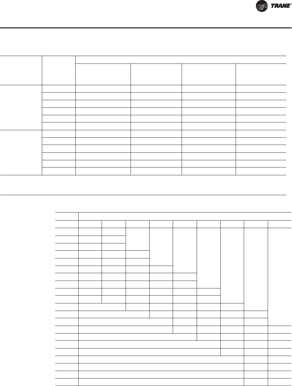
Net capacity curves for the RAUJ condensing units are given in the performance data section.
When matched with a coil curve, the resultant point of intersection will be the system design
balance point. The design operating suction temperature and capacity can then be read directly
from the graph.
Note: It is usually necessary to account for suction and liquid line losses in the performance . The
actual losses are determined by the interconnecting piping.
To plot the DX evaporator performance curve it is only necessary to obtain gross evaporator
capacities for the given entering air conditions and cfm at two different saturated suction
temperatures. The Trane Refrigeration Coil Computer Selection Program can be used to
conveniently provide the necessary evaporator capacity values at the selected suction
temperatures.
Selection Example
The RAUJ 20 to 120-Ton TOPSS™ selection program provides the ability to generate performance
output for pre-selected Trane Modular Climate Changer evaporator coils with the RAUJ
condensing units. To select a condensing unit and evaporator coil not available in the RAUJ
TOPSS™ program, the example below can be used to cross-plot an evaporator coil with known
performance with the RAUJ condensing unit
From the Trane Refrigeration Coil Computer Selection Program:
DX Evap Coil = Model Number DFDB42 - 42" X 60" / 4 Row / 144 FPF - FD/Delta-flo E
Entering Coil Conditions = 80/67 DB/WB and 95°F Ambient - 8500 CFM
Coil Performance @ 38F SST - 406.49 MBh Total
Coil Performance @ 45F SST - 293.09 MBh Total
Balance Point at 95°F Ambient = 370 MBh @ 40.2 SST
Coils are identical fin series and circuiting on both simulations.
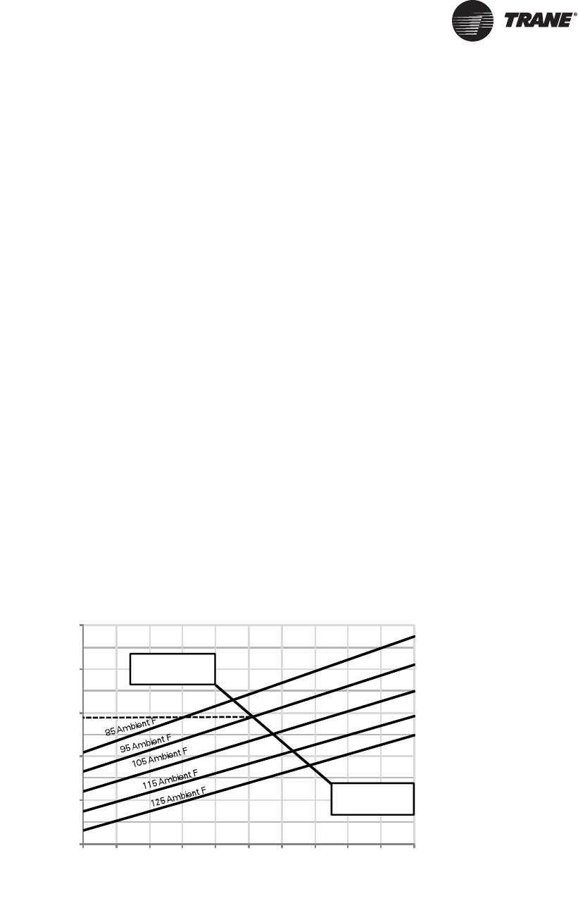
By plotting the two coil performance outputs across the RAUJC30 Net Capacity curve at their
respective total MBH at the defined saturated suction temperatures and ignoring line losses,, we
can see that the condenser/evaporator coil combination, at 95 F ambient, provides 370 MBH Net
Capacity at 40.2 SST.
Figure 1. 30 Ton condensing unit performance - RAUJ-C30 (60 Hz)
225
275
325
375
425
475
30 32 34 36 38 40 42 44 46 48
50
406.49MBH
@ 38F SST
293.09MBH
@ 45F SST
Net Capacity(MBH)
Saturated Suction(F)
Evaporator coil line
10 SS-PRC030-EN
20 to 60-Ton Units1
Digit 1 — Unit Type
R = Condensing Unit
Digit 2 — Condenser
A = Air Cooled
Digit 3 — Airflow
U = Upflow
Digit 4 — Development
Sequence
J= Third
Digits 5,6,7 — Nominal Capacity
C20 = 20 Tons
C25 = 25 Tons
C30 = 30 Tons
C40 = 40 Tons
C50 = 50 Tons
C60 = 60 Tons
Digit 8 — Voltage and Start
Characteristics
E = 200/60/3 XL
D = 415/50/3 XL
F = 230/60/3 XL
4 = 460/60/3 XL
5 = 575/60/3 XL
9 = 380/50/3 XL
Digit 9 — System Control
B = No System Control
C = Constant Volume Control
E = Supply Air VAV Control
P = EVP Control
Digit 10 —Design Sequence
(Factory Assigned)
A = First
B = Second
Etc.
DIGIT 11 — Ambient Control
0 = Standard
1 = 0°F (Low Ambient Dampers)
DIGIT 12 — Agency Approval
0 = None
3 = cULus (not available for 50 Hz)
DIGIT 13
A = Non Fused Unit Disconnect Switch
DIGIT 14
B = Hot Gas Bypass Valve
DIGIT 15
D = Suction Service Valves
DIGIT 16
F = Pressure Gauges and Piping
1The service digit for each model number contains
21 digits; all 21 digits must be referenced.
Digit 17
G = Return Air Sensor
Digit 18
J = Corrosion Protected Condenser Coil
Digit 19
C = Remote Chiller Evaporator & Install
Kit
T = Flow Switch (EVP Control Only)
Digit 20
1 = Spring Isolators
2 = Neoprene Isolators
80 to 120-Ton Units2
Digit 1 — Unit Type
R = Remote Condensing Unit
Digit 2 — Condenser
A = Air-Cooled
Digit 3 — Airflow
U = Upflow
Digit 4 — Development
Sequence
J = Third
Digits 5,6,7 — Nominal Capacity
C80 = 80 Tons
D10 = 100 Tons
D12 = 120 Tons
Digit 8 — Voltage and Start
Characteristics
E = 200/60/3 XL
F = 230/60/3 XL
4 = 460/60/3 XL
5 = 575/60/3 XL
* = 380/50/3 XL2
* = 415/50/3 XL2
Digit 9 — System Control
B = No System Control
E = Supply Air VAV Control
P = EVP Control
Digit 10 — Design Sequence
(Factory Assigned)
A = First
B = Second
Etc.
Digit 11 — Ambient Control
0 = Standard
1 = 0°F (Low Ambient Dampers)
Digit 12 — Agency Approval
0 = None
3 = cULus (not available for 50 Hz)
2Contact the local Trane Sales Office for ordering
information regarding 80-120 50Hz models.
Digit 13 — Number of Circuits
2 = Dual (All 80-120 Ton)
Digit 14
B = Hot Gas Bypass Valve
Digit 15
D = Suction Service Valves
Digit 16
F = Pressure Gauges and Piping
Digit 17
J = Corrosion Protected Condenser Coil
Digit 18
1 = Spring Isolators
Digit 19
C = Remote Chiller Evap & Install Kit
3 = Flow Switch ( EVP Control only)
Model Number Descriptions
SS-PRC030-EN 11
General Data
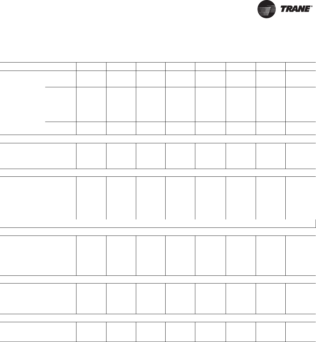
Table 1. General data - 20-120 ton condensing units
Model Number RAUJ-C20 RAUJ-C25 RAUJ-C30 RAUJ-C40 RAUJ-C50 RAUJ-C60 RAUJ-C80 RAUJ-D10 RAUJ-D12
Compressor Data
Type Scroll Scroll Scroll Scroll Scroll Scroll Scroll Scroll Scroll
Manifolded Sets
Circuit 1 10T + 10T 10T +13.5T 15T + 15T 10T + 10T 11.5T +
13.5T 15T + 15T 15T + 15T +
15T
15T + 15T +
20T
20T + 20T +
20T
Circuit 2 10T + 10T 11.5T +
13.5T 15T + 15T 15T + 15T +
15T
15T + 15T +
20T
20T + 20T +
20T
Unit Capacity Steps
(%) 100-50 100-42 100-50 100-75-50-
25
100-73-46-
23
100-75-50-
25
100-83-66-
50-33-17
100-80-60-
45-30-15
100-83-66-
50-33-17
Condenser Fan Data
Qty/Fan Dia. Type
Fan Drive Type
No. of Motors/HP Ea.
Nominal Total CFM
2/26"/Prop
Direct
2/1.0
14600
3/26"/Prop
Direct
3/1.0
20700
3/26:/Prop
Direct
3/1.0
20700
4/26"/Prop
Direct
4/1.0
26790
6/26"/Prop
Direct
6/1.0
36890
6/26"/Prop
Direct
6/1.0
40490
8/26"/Prop
Direct
8/1.0
56490
12/26"/Prop
Direct
12/1.0
73890
12/26"/Prop
Direct
12/1.0
76280
Condenser Coil Data
Number of Coils/
Size (Inches) 2/42x71 2/42x71 2/42x71 2/59x71 2/51x96 2/51x96 4/59x71 4/51x96 4/64x96
Face Area (Sq. Ft.) 41.4 41.4 41.4 58.2 68.0 68.0 116.4 136.0 170.7
Rows/Fin Per Ft. 1/240 1/240 1/240 1/240 1/240 1/240 1/240 1/240 1/240
Condenser Storage
Capacity (Lbs)(a)
(a) Condenser storage capacity is given at conditions of 95°F outdoor temperature, and 95% full.
18.7 18.7 18.7 23.5 25.0 25.0 47.1 50.0 62.9
Type Microchannel
Refrigerant Data(b)
(b) Refer to Refrigerant Piping in the Application Considerations section.
No. Refrigerant
Circuits 111222222
Refrigerant Type R-410A R-410A R-410A R-410A R-410A R-410A R-410A R-410A R-410A
Refrigerant
Operating Charge
(Lbs.)/Unit(c) (d)
(c) Operating charge is approximate for condensing unit only, and does not include charge for low side or interconnecting lines.
(d) Condensing units are shipped with a nitrogen holding charge only.
11.9 11.8 11.8 22.7 23.4 23.8 57.1 59.1 65.3
Outdoor Air Temperature for Mechanical Cooling
Standard Ambient
Operating Range
(F)(e)
(e) Maximum operating ambient for EVP remote chillers is 115°F.
40-125 40-125 40-125 40-125 40-125 40-125 40-125 40-125 40-120
Low Ambient Option
(F) 000000000
Cabinet Dimensions
Length (Inches)
Width (Inches)
Height (Inches)
88.25
60.12
68
88.25
61.12
68
88.25
60.12
68
88.25
88.25
73
113.82
88.25
73
113.82
88.25
73
176.25 in,
88.25
73
227.25 in
88.25
73
227.25 in
88.25
73
12 SS-PRC030-EN
General Data
Table 2. General data - 20 - 120 ton remote chillers
Model Number
RAUJ-
C20
RAUJ-
C25
RAUJ-
C30
RAUJ-
C40
RAUJ-
C50
RAUJ-
C60
RAUJ-
C80
RAUJ-
D10
RAUJ-
D12
Shipping weight, lbs 44 84 113 90 135 157 208 292 320
Operating weight, lbs 56 104 142 131 206 244 330 473 520
No. of refrigerant circuits 1 1 1 2 2 2 2 2 2
Water volume, Gal 1.4 2.2 3.3 4.6 7.9 9.7 13.6 20.1 22.2
Chiller refrig charge @ AHRI condition, lbs 0.9 1.5 2.2 3.1 5.3 6.4 9.0 13.3 14.7
Minimum water flow rate, GPM 24 30 36 48 60 72 96 120 144
Maximum water flow rate, GPM 69 89 100 136 176 201 275 346 407
Chiller Water Supply/Return Pipe Size, in 2.0 2.0 2.0 3.0 3.0 3.0 4.0 4.0 4.0
Notes:
1. All heat exchangers are brazed plate.
2. All heat exchangers are single circuit on the water side.
3. Shipping and operating weights are approximate.
4. Refrigerant charge is approximate and for chiller only.
5. Applications with leaving water temperature below 42°F require freeze protection down to 15°F.
6. Maximum chiller operating ambient is 115°F.
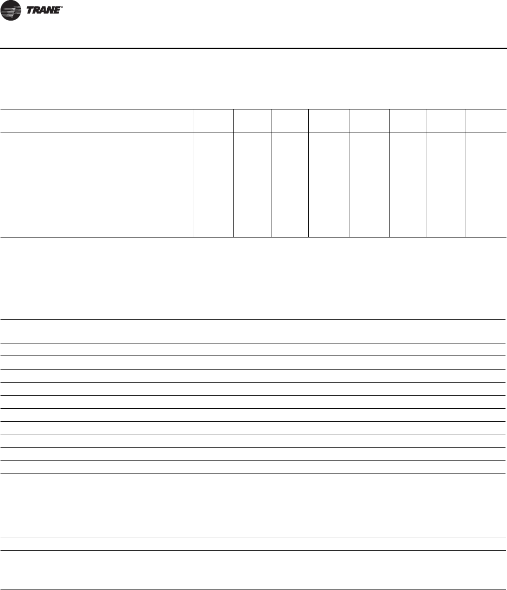
Table 3. EER data - condensing unit only(a)
Net Cap (MBH)
Total Compressor
kW
Condenser Fan kW
Each/Total Control kW Total Power kW EER IEER
RAUJ-C20 266.9 20.6 0.9/1.8 0.4 22.9 11.7 15.1
RAUJ-C25 324.9 23.9 0.9/2.7 0.4 26.9 12.1 15.1
RAUJ-C30 399.4 32.1 0.9/2.7 0.4 35.2 11.4 15.5
RAUJ-C40 545.5 42.4 0.9/3.6 0.7 46.7 11.7 15.4
RAUJ-C50 690.5 53.5 0.9/5.4 0.7 59.6 11.6 15.1
RAUJ-C60 786.6 64.4 0.9/5.4 0.7 70.5 11.2 15.3
RAUJ-C80 1121.0 94.3 0.9/7.2 0.7 102.1 11.0 15.4
RAUJ-D10 1374.0 109.3 0.9/10.8 0.7 120.7 11.4 15.6
RAUJ-D12 1661.0 134.3 0.9/10.8 0.7 145.6 11.3 15.7
Note: Capacity is rated in accordance with AHRI 365 - 95F Ambient, 45F Saturated Suction Temperature
(a) Condensing unit only ratings are in accordance with AHRI standard 365. Full load ratings are at 95°F entering air temperature, and refrigerant conditions
entering the condensing unit of 45°F saturated and 60°F actual temperature. Part load ratings are at 80°F entering air temperature and refrigerant
conditions entering the condensing unit of 50°F saturated suction and 65°F actual temperature.
Ta b l e 4. Altitude correction multiplier for capacity
Altitude (ft.) 2,000 4,000 6,000 8,000 10,000
Condensing Unit Only 0.982 0.960 0.933 0.902 0.866
Condensing Unit / Air Handling Unit Combination 0.983 0.963 0.939 0.911 0.881
Condensing Unit With Evap. 0.986 0.968 0.947 0.921 0.891
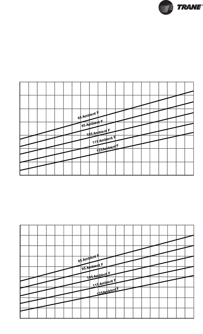
SS-PRC030-EN 13
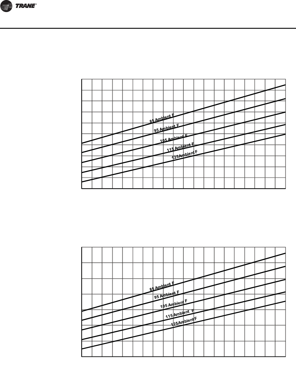
Performance Data
60 Hz Data
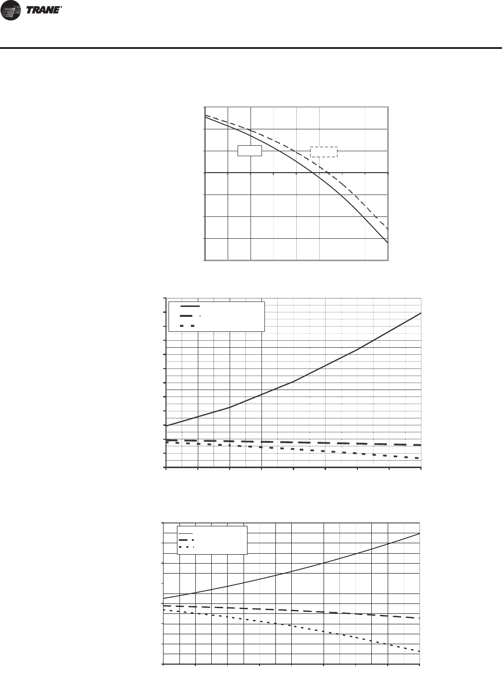
Figure 2. 20 Ton condensing unit performance — RAUJ-C20 (60 HZ)
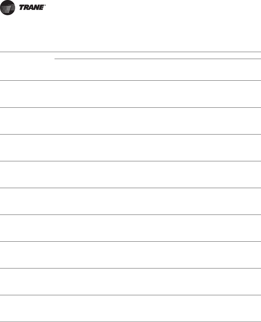
Figure 3. 25 Ton condensing unit performance — RAUJ-C25 (60 HZ)
150
175
200
225
250
275
300
325
30 32 34 36 38 40 42 44 46 48 50
Net Capacity MBH
Saturated Suction Temperature (F)
175
200
225
250
275
300
325
350
375
400
30 32 34 36 38 40 42 44 46 48 50
Net Capacity MBH
Saturated Suction Temperature (F)
14 SS-PRC030-EN
Performance Data
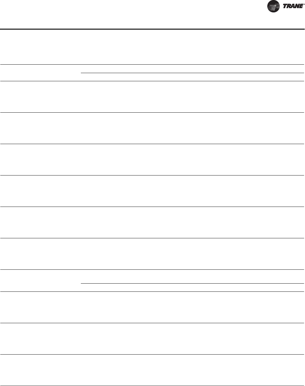
Figure 4. 30 Ton condensing unit performance — RAUJ-C30 (60 HZ)
Figure 5. 40 Ton condensing unit performance — RAUJ-C40 (60 HZ)
225
250
275
300
325
350
375
400
425
450
475
30 32 34 36 38 40 42 44 46 48 50
Net Capacity MBH
Saturated Suction Temperature (F)
300
350
400
450
500
550
600
650
30 32 34 36 38 40 42 44 46 48 50
Net Capacity MBH
Saturated Suction Temperature (F)
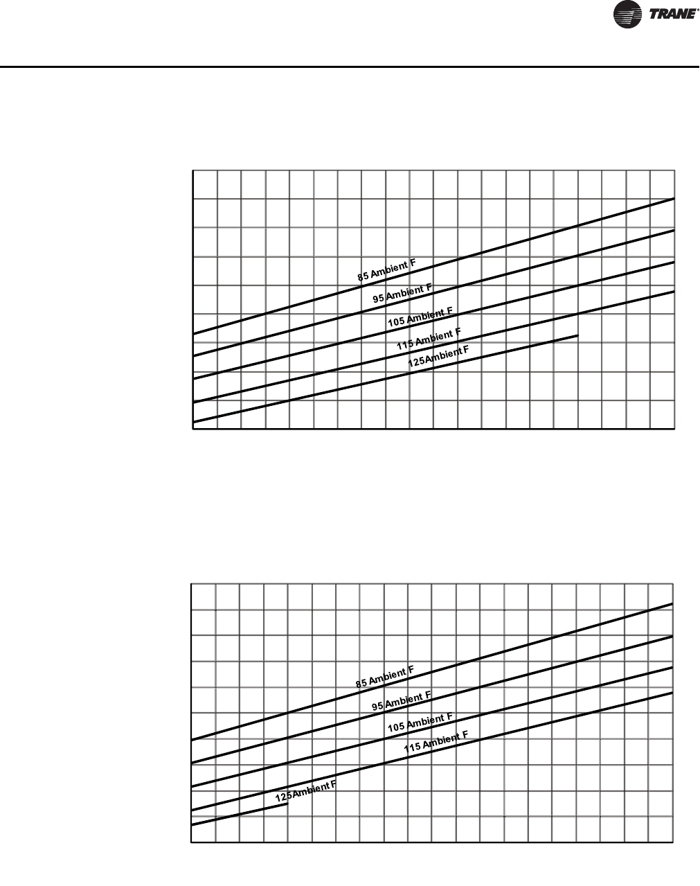
SS-PRC030-EN 15
Performance Data
Figure 6. 50 Ton condensing unit performance — RAUJ-C50 (60 HZ)
Figure 7. 60 Ton condensing unit performance — RAUJ-C60 (60 HZ)
400
450
500
550
600
650
700
750
800
850
30 32 34 36 38 40 42 44 46 48 50
Net Capacity MBH
Saturated Suction Temperature (F)
450
500
550
600
650
700
750
800
850
900
950
30 32 34 36 38 40 42 44 46 48 50
Net Capacity MBH
Saturated Suction Temperature (F)
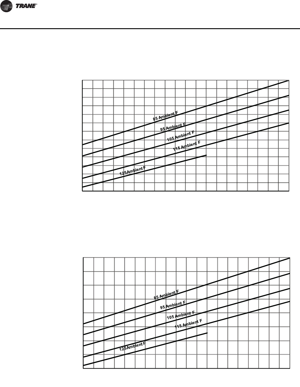
16 SS-PRC030-EN
Performance Data
Figure 8.80 Ton condensing unit performance — RAUJ-C80 (60 HZ)
Figure 9. 100 Ton condensing unit performance — RAUJ-D10 (60 HZ)
650
700
750
800
850
900
950
1000
1050
1100
1150
1200
1250
1300
30 32 34 36 38 40 42 44 46 48 50
Net Capacity MBH
Saturated Suction Temperature (F)
800
900
1000
1100
1200
1300
1400
1500
1600
30 32 34 36 38 40 42 44 46 48 50
Net Capacity MBH
Saturated Suction Temperature (F)
SS-PRC030-EN 17
Performance Data
50 Hz Data
Figure 10. 120 Ton condensing unit performance — RAUJ-D12 (60 HZ)
1000
1100
1200
1300
1400
1500
1600
1700
1800
1900
2000
30 32 34 36 38 40 42 44 46 48 50
Net Capacity MBH
Saturated Suction Temperature (F)
Figure 11. 20 Ton condensing unit performance — RAUJ-C20 (50 HZ)
125
150
175
200
225
250
275
30 32 34 36 38 40 42 44 46 48 50
Net Capacity MBH
Saturated Suction Temperature (F)

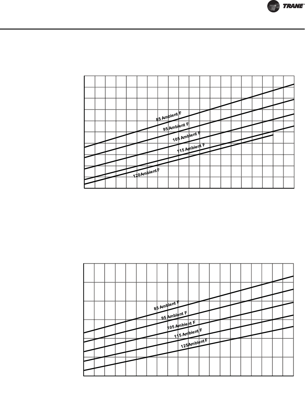
18 SS-PRC030-EN
Performance Data
Figure 12. 25 Ton condensing unit performance — RAUJ-C25 (50 HZ)
Figure 13. 30 Ton condensing unit performance — RAUJ-C30 (50 HZ)
150
175
200
225
250
275
300
325
30 32 34 36 38 40 42 44 46 48 50
Net Capacity MBH
Saturated Suction Temperature (F)
175
200
225
250
275
300
325
350
375
400
30 32 34 36 38 40 42 44 46 48 50
Net Capacity MBH
Saturated Suction Temperature (F)
SS-PRC030-EN 19
Performance Data
Figure 14.40 Ton condensing unit performance — RAUJ-C40 (50 HZ)
Figure 15. 50 Ton condensing unit performance — RAUJ-C50 (50 HZ)
250
275
300
325
350
375
400
425
450
475
500
525
30 32 34 36 38 40 42 44 46 48 50
Net Capacity MBH
Saturated Suction Temperature (F)
325
375
425
475
525
575
625
675
30 32 34 36 38 40 42 44 46 48 50
Net Capacity MBH
Saturated Suction Temperature (F)
20 SS-PRC030-EN
Performance Data
Figure 16. 60 Ton condensing unit performance — RAUJ-C60 (50 HZ)
Figure 17. 80 Ton condensing unit performance — RAUJ-C80 (50 HZ)
375
425
475
525
575
625
675
725
775
30 32 34 36 38 40 42 44 46 48 50
Net Capacity MBH
Saturated Suction Temperature (F)
525
575
625
675
725
775
825
875
925
975
1025
1075
30 32 34 36 38 40 42 44 46 48 50
Net Capacity MBH
Saturated Suction Temperature (F)
SS-PRC030-EN 21
Performance Data
Figure 18. 100 Ton condensing unit performance — RAUJ-D10 (50 HZ)
Figure 19. 120 Ton condensing unit performance — RAUJ-D12 (50 HZ)
650
750
850
950
1050
1150
1250
1350
30 32 34 36 38 40 42 44 46 48 50
Net Capacity MBH
Saturated Suction Temperature (F)
750
850
950
1050
1150
1250
1350
1450
1550
1650
30 32 34 36 38 40 42 44 46 48 50
Net Capacity MBH
Saturated Suction Temperature (F)
22 SS-PRC030-EN
Performance Data
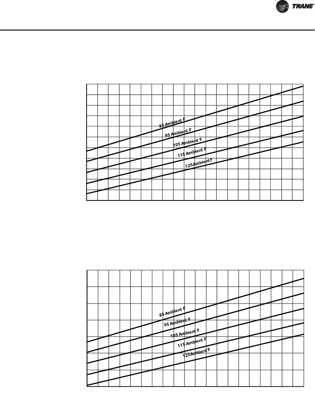
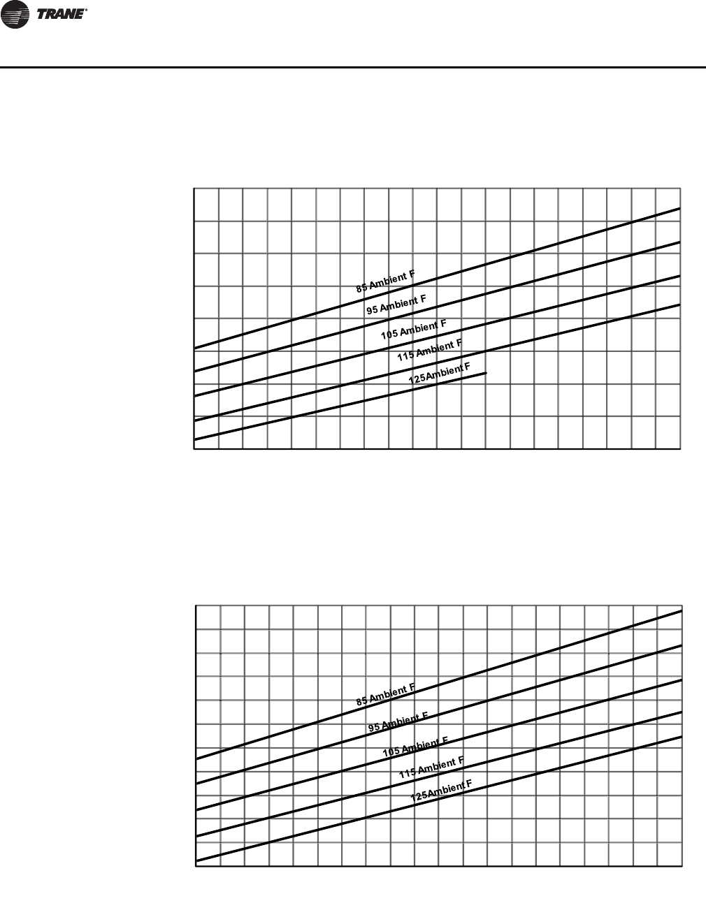
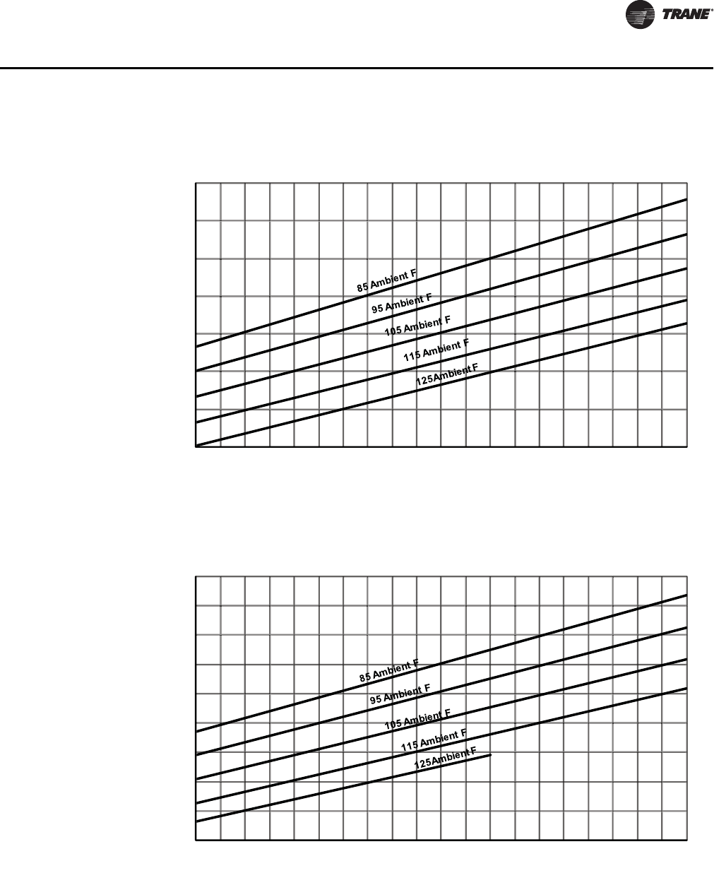
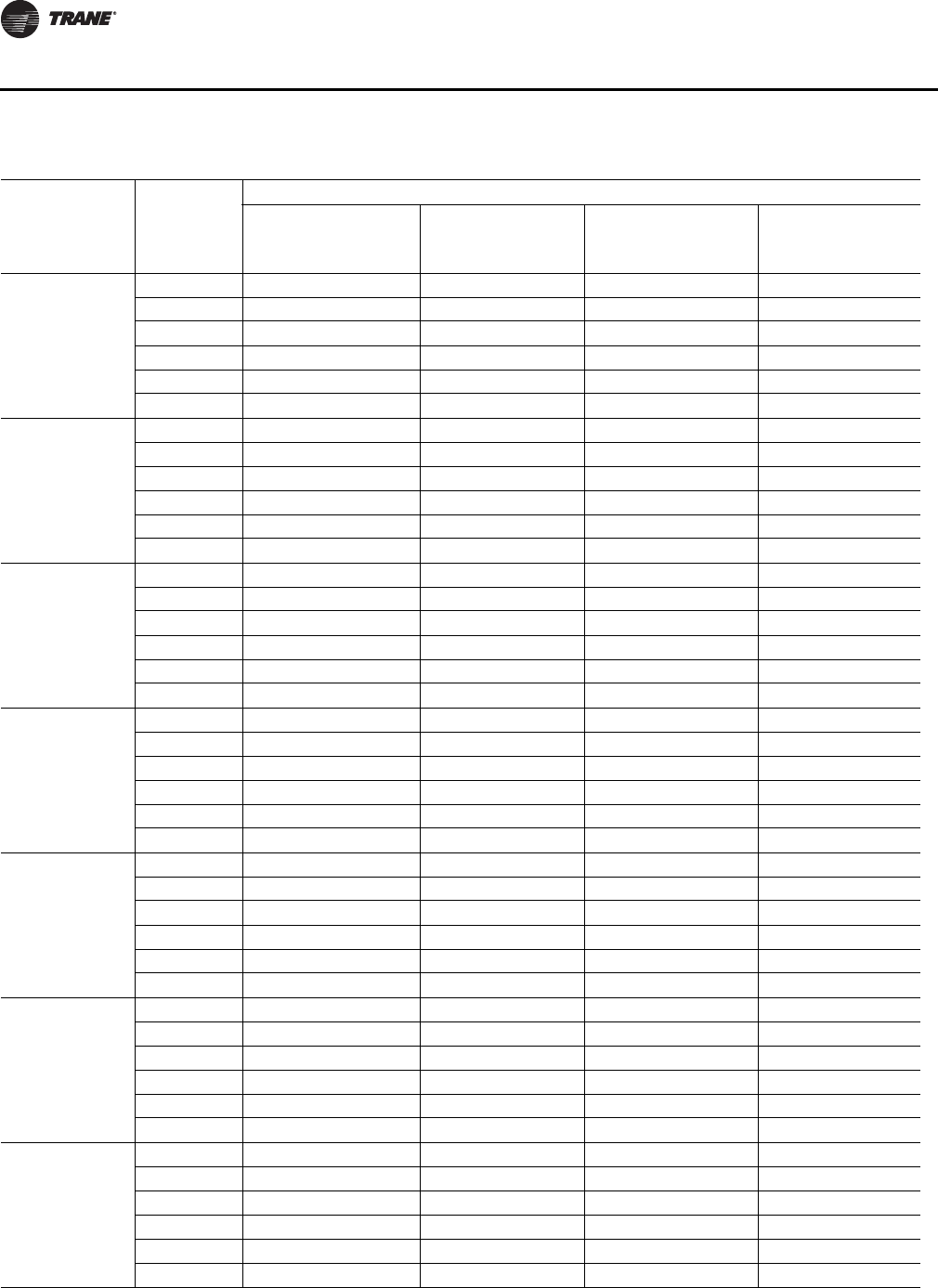
Table 5. System performance data — 20-120 Ton RAUJ with remote EVP chiller
Model LWFT(F)
Entering Condenser Air Temperature (F)
85 95 105 115
Capacity
Tons
Compr
kW
Capacity
Tons
Compr
kW
Capacity
Tons
Compr
kW
Capacity
Tons
Compr
kW
RAUJ C20
40 18.8 17.5 17.7 19.4 16.6 21.4 15.4 23.7
42 19.4 17.8 18.3 19.6 17.2 21.7 16.0 23.9
44 20.1 18.0 19.0 19.8 17.8 21.9 16.6 24.1
46 20.8 18.2 19.6 20.0 18.4 22.1 17.1 24.3
48 21.5 18.4 20.2 20.3 19.0 22.3 17.7 24.5
50 22.1 18.6 20.9 20.5 19.6 22.5 18.3 24.7
RAUJ C25
40 23.3 20.5 21.9 22.7 20.5 25.1 19.0 27.7
42 24.1 20.7 22.7 22.9 21.2 25.3 19.7 28.0
44 24.9 21.0 23.5 23.1 22.0 25.5 20.4 28.2
46 25.8 21.2 24.3 23.4 22.7 25.8 21.1 28.4
48 26.6 21.5 25.1 23.6 23.5 26.0 21.8 28.7
50 27.5 21.7 25.9 23.9 24.2 26.3 22.5 28.9
RAUJ C30
40 28.4 27.2 26.8 29.8 25.0 32.7 23.3 35.8
42 29.4 27.6 27.7 30.2 25.9 33.1 24.1 36.1
44 30.4 27.9 28.6 30.5 26.8 33.4 25.0 36.5
46 31.4 28.3 29.6 30.9 27.7 33.8 25.8 36.8
48 32.4 28.7 30.5 31.3 28.6 34.2 26.7 37.2
50 33.5 29.0 31.5 31.7 29.5 34.5 27.5 37.6
RAUJ C40
40 34.0 38.9 33.9 38.9 33.9 39.0 33.8 39.2
42 35.3 39.3 35.2 39.3 35.2 39.4 35.1 39.6
44 36.6 39.7 36.5 39.8 36.5 39.9 36.4 40.0
46 37.9 40.1 37.9 40.2 37.8 40.3 37.7 40.4
48 39.3 40.6 39.2 40.6 39.2 40.8 39.1 40.9
50 40.7 41.0 40.6 41.1 40.5 41.2 40.5 41.4
RAUJ C50
40 45.6 50.1 45.6 50.2 45.5 50.3 45.4 50.5
42 47.2 50.6 47.2 50.7 47.1 50.9 47.0 51.1
44 48.9 51.2 48.8 51.3 48.7 51.5 48.6 51.7
46 50.6 51.8 50.5 51.9 50.4 52.1 50.3 52.3
48 52.2 52.4 52.2 52.5 52.1 52.7 51.9 52.9
50 54.0 53.0 53.9 53.2 53.8 53.3 53.6 53.5
RAUJ C60
40 52.1 59.6 52.0 59.7 51.9 59.9 51.8 60.1
42 53.9 60.3 53.8 60.4 53.7 60.6 53.6 60.8
44 55.7 61.1 55.7 61.2 55.5 61.4 55.4 61.6
46 57.6 61.8 57.5 62.0 57.4 62.2 57.3 62.4
48 59.5 62.6 59.4 62.8 59.3 63.0 59.1 63.2
50 61.5 63.4 61.3 63.6 61.2 63.8 61.0 64.0
RAUJ C80
40 72.2 87.7 72.1 87.8 72.0 88.1 71.8 88.4
42 74.8 88.4 74.7 88.7 74.5 89.0 74.4 89.3
44 77.4 89.3 77.3 89.6 77.1 89.8 76.9 90.2
46 80.0 90.2 79.9 90.4 79.8 90.7 79.6 91.1
48 82.7 91.1 82.6 91.4 82.4 91.7 82.2 92.0
50 85.4 92.0 85.3 92.3 85.1 92.6 84.9 93.0
SS-PRC030-EN 23
Performance Data
RAUJ D10
40 89.9 102.6 89.8 102.8 89.6 103.2 89.4 103.5
42 93.1 103.7 93.0 103.9 92.8 104.2 92.6 104.6
44 96.3 104.8 96.2 105.0 96.0 105.4 95.8 105.8
46 99.6 105.9 99.5 106.1 99.3 106.5 99.1 106.9
48 103.0 107.0 102.8 107.3 102.6 107.6 102.4 108.1
50 106.4 108.2 106.2 108.5 106.0 108.9 105.7 109.3
RAUJ D12
40 107.8 124.9 107.6 125.2 107.5 125.5 107.3 126.0
42 111.5 126.1 111.4 126.4 111.2 126.8 111.0 127.3
44 115.4 127.4 115.2 127.7 115.0 128.1 114.7 128.7
46 119.2 128.8 119.0 129.1 118.8 129.5 118.5 130.0
48 123.1 130.1 122.9 130.4 122.7 130.9 122.4 131.4
50 127.1 131.5 126.9 131.9 126.6 132.3 126.3 132.8
Note:
1. Performance data at 10°F water temperature drop and 60 Hz.
2. Leaving water temperature (LWT) below 42°F requires freeze protection to 15°F.
3. 40F LWT performance includes 20% glycol.
Table 5. System performance data — 20-120 Ton RAUJ with remote EVP chiller (continued)
Model LWFT(F)
Entering Condenser Air Temperature (F)
85 95 105 115
Capacity
Tons
Compr
kW
Capacity
Tons
Compr
kW
Capacity
Tons
Compr
kW
Capacity
Tons
Compr
kW
Table 6. Chiller water pressure drop, ft H2O
Flow Size, tons
GPM20253040506080100120
25 3.7
30 5.2 3.2
35 6.9 4.2
40 8.8 5.4 3.1
45 10.9 6.7 3.9
50 13.3 8.2 4.8 5.3
60 18.5 11.4 6.7 7.5 4.1
70 24.6 15.2 8.9 10.1 5.5
80 19.4 11.4 13.0 7.1 5.0
90 24.1 14.2 16.3 8.9 6.3
100 17.3 19.9 10.9 7.7 4.3
120 28.3 15.4 10.9 6.1 3.2
140 20.7 14.6 8.2 4.4
160 26.7 18.9 10.6 5.6 4.8
180 23.6 13.2 7.1 6.1
200 16.2 8.7 7.4
240 22.9 12.3 10.6
280 16.5 14.2
320 21.3 18.3
360 26.7 23.0
400 28.2
24 SS-PRC030-EN
Performance Data
Figure 20. Remote EVP glycol freeze protection
Figure 21. Remote EVP ethylene glycol GPM, capacity, and compressor power adjustment
Figure 22. Remote EVP propylene glycol GPM, capacity, and compressor power adjustment
Ethylene Propylene
-40
-30
-20
-10
0
10
20
30
10 15 20 25 30 35 40 45 50
% Glycol by Weight
Solution Freeze Point Temperature, F
0.96
0.98
1.00
1.02
1.04
1.06
1.08
1.10
1.12
1.14
1.16
1.18
1.20
10 15 20 25 30 35 40 45 50
% Ethylene Glycol by Weight
Multiplier
GPM
Compressor power
Capacity
0.94
0.96
0.98
1.00
1.02
1.04
1.06
1.08
10 15 20 25 30 35 40 45 50
% Propylene Glycol by Weight
Multiplier
Compressor power
Capacity
GPM

SS-PRC030-EN 25
Controls
Standard Options 20 to 120-Ton Condensing Units
System Control Options
Select one of the following control options to meet your application requirements.
•No System Control provides the compressors wired to a terminal strip inside the control
panel. The temperature controller must be field provided and installed. The 20, 25 and 30-ton
have two capacity steps. The 40, 50 and 60-ton sizes have four steps available. The 80, 100, and
120-ton sizes have six steps available.
•Constant Volume Control (20 to 60-Ton Models) includes a W973 controller with two cool,
four heat steps on the 20, 25 and 30-ton sizes. Four cool, four heat steps are provided on the
40, 50 and 60-ton sizes. The heating contacts are wired to terminals in the condensing unit
control panel for easy interface with a field supplied electric duct heater or gas duct furnace.
An optional return air sensor is available with this controller which provides the zone
temperature input to the thermostat, thus generating the loading demand signal to the
Honeywell W973 constant volume controller.
•EVP Chiller Control consists of an interface panel in the main unit control box and a remote
mounted control box that is customer installed. The remote mounted box contains the
Honeywell W7100G controller. The water chiller controller has an adjustable 0-10°F control
band using integrating logic, built-in fixed-off timers and field installed discharge water
temperature sensors for control and chiller freeze protection. Pumpdown is provided. Lead-lag
and multiple chiller control are not provided. There are two capacity steps on 20, 25 and 30-ton
sizes, four capacity steps on 40, 50 and 60 ton sizes and six capacity steps on 80, 100 and 120-
ton sizes.
•Supply Air VAV Control provides a Honeywell W7100A control system. This option is for use
with shut-off VAV or other applications requiring control of supply air temperature. The control
provides a voltage output for interface with field supplied components to provide simultaneous
economizer operation. The discharge air sensor ships with the unit for field mounting. The
standard VAV unit is provided with reliable coil frost protection in the form of Trane’s proven
and patented Frostat™. Frostat™ is used in place of hot gas bypass.
Low Ambient Control Option
•Standard — Unit start-up and operation down to approximately 40°F at minimum compressor
load.
•Low Ambient — Factory-installed head pressure control damper assembly permits operation
down to 0°F by maintaining proper head pressure. Ten minute timer is standard for protection
against nuisance trips.
Miscellaneous Options
Select the miscellaneous options to meet your project requirements.
•Non-Fused Unit Disconnect Switch (20 to 60-Ton Models) is mounted in the control box
and provides for interruption of power for servicing the unit. Lugs are suitable for copper wires
only. No overcurrent or short circuit protection is provided for the unit by this switch.
•Hot Gas Bypass Valves are stocked and shipped with the unit for field installation. When
suction pressure falls below the valve adjustable set point, the valve modulates hot gas to the
inlet of the evaporator.
Note: Frostat™ is standard on VAV units and is recommended in place of hot gas bypass.
26 SS-PRC030-EN
Electrical Data
Table 7. Condensing units — 60 Hz
Nominal
Tons
Model
Number
Unit Characteristics
Voltage/Start
Characteristics
Allowable
Voltage
Utilization
Range
Minimum Circuit
Ampacity(a),(b)
(a) Minimum circuit ampacity (MCA) is 125 percent of the RLA of one compressor motor plus the total RLA of the remaining motors.
(b) Local codes may take precedence.
Max.
Overcurrent
Protection
Device(c),(b)
(c) Maximum Overcurrent Protection Device permitted by NEC 440-22 is 225 percent of the RLA of one compressor motor plus the total RLA of the remaining
motors.
Recommended
Dual Element
Fuse Size(d),(b)
(d) Recommended dual element fuse size is 150 percent of the RLA of one compressor motor plus the total RLA of the remaining motors.
Number Of
Compressors
20
RAUJ-C20E 200/60/3/XL 180-220 102 125 125 2
RAUJ-C20F 230/60/3/XL 207-253 89 110 100 2
RAUJ-C204 460/60/3/XL 414-506 46 60 60 2
RAUJ-C205 575/60/3/XL 517-633 39 50 45 2
25
RAUJ-C25E 200/60/3/XL 180-220 119 150 150 2
RAUJ-C25F 230/60/3/XL 207-253 107 150 125 2
RAUJ-C254 460/60/3/XL 414-506 52 70 60 2
RAUJ-C255 575/60/3/XL 517-633 44 60 50 2
30
RAUJ-C30E 200/60/3/XL 180-220 141 175 175 2
RAUJ-C30F 230/60/3/XL 207-253 123 150 150 2
RAUJ-C304 460/60/3/XL 414-506 63 80 70 2
RAUJ-C305 575/60/3/XL 517-633 57 70 70 2
40
RAUJ-C40E 200/60/3/XL 180-220 193 225 225 4
RAUJ-C40F 230/60/3/XL 207-253 168 200 200 4
RAUJ-C404 460/60/3/XL 414-506 87 100 100 4
RAUJ-C405 575/60/3/XL 517-633 73 80 80 4
50
RAUJ-C50E 200/60/3/XL 180-220 236 250 250 4
RAUJ-C50F 230/60/3/XL 207-253 215 250 250 4
RAUJ-C504 460/60/3/XL 414-506 102 110 110 4
RAUJ-C505 575/60/3/XL 517-633 86 100 100 4
60
RAUJ-C60E 200/60/3/XL 180-220 267 300 300 4
RAUJ-C60F 230/60/3/XL 207-253 232 250 250 4
RAUJ-C604 460/60/3/XL 414-506 120 125 125 4
RAUJ-C605 575/60/3/XL 517-633 107 125 125 4
80
RAUJ-C80E 200/60/3/XL 180-220 411 450 450 6
RAUJ-C80F 230/60/3/XL 207-253 358 400 400 6
RAUJ-C804 460/60/3/XL 414-506 174 200 175 6
RAUJ-C805 575/60/3/XL 517-633 139 150 150 6
100
RAUJ-D10E 200/60/3/XL 180-220 480 500 500 6
RAUJ-D10F 230/60/3/XL 207-253 425 450 450 6
RAUJ-D104 460/60/3/XL 414-506 207 225 225 6
RAUJ-D105 575/60/3/XL 517-633 166 175 175 6
120
RAUJ-D12E 200/60/3/XL 180-220 574 600 600 6
RAUJ-D12F 230/60/3/XL 207-253 515 600 600 6
RAUJ-D124 460/60/3/XL 414-506 255 300 300 6
RAUJ-D125 575/60/3/XL 517-633 204 225 225 6
SS-PRC030-EN 27
Electrical Data
Ta b l e 8. Compressor motor and condenser fan data — 60 Hz
Nominal
Tons Model Voltage
Compressor 1A(a) Compressor 1B Compressor 2A Compressor 2B Condenser Fans
RLA LRA RLA LRA RLA LRA RLA LRA Qty. FLA
20 RAUJ-C20
200 XL 41.4 267.0 41.4 267.0 - - - - 2 4.1
230 XL 35.5 267.0 35.5 267.0 - - - - 2 4.1
460 XL 18.6 142.0 18.6 142.0 - - - - 2 1.8
575 XL 15.8 103.0 15.8 103.0 - - - - 2 1.4
25 RAUJ-C25
200 XL 41.4 267.0 52.0 315.0 - - - - 3 4.1
230 XL 35.5 267.0 46.9 315.0 - - - - 3 4.1
460 XL 18.6 142.0 22.2 158.0 - - - - 3 1.8
575 XL 15.8 103.0 19.2 136.0 - - - - 3 1.4
30 RAUJ-C30
200 XL 56.9 351.0 56.9 351.0 - - - - 3 4.1
230 XL 48.8 351.0 48.8 351.0 - - - - 3 4.1
460 XL 25.5 197.0 25.5 197.0 - - - - 3 1.8
575 XL 23.1 146.0 23.1 146.0 - - - - 3 1.4
40 RAUJ-C40
200 XL 41.4 267.0 41.4 267.0 41.4 267.0 41.4 267.0 4 4.1
230 XL 35.5 267.0 35.5 267.0 35.5 267.0 35.5 267.0 4 4.1
460 XL 18.6 142.0 18.6 142.0 18.6 142.0 18.6 142.0 4 1.8
575 XL 15.8 103.0 15.8 103.0 15.8 103.0 15.8 103.0 4 1.4
50 RAUJ-C50
200 XL 47.0 304.0 52.0 315.0 47.0 304.0 52.0 315.0 6 4.1
230 XL 42.3 304.0 46.9 315.0 42.3 304.0 46.9 315.0 6 4.1
460 XL 20.2 158.0 22.2 158.0 20.2 158.0 22.2 158.0 6 1.8
575 XL 17.1 136.0 19.2 136.0 17.1 136.0 19.2 136.0 6 1.4
60 RAUJ-C60
200 XL 56.9 351.0 56.9 351.0 56.9 351.0 56.9 351.0 6 4.1
230 XL 48.8 351.0 48.8 351.0 48.8 351.0 48.8 351.0 6 4.1
460 XL 25.5 197.0 25.5 197.0 25.5 197.0 25.5 197.0 6 1.8
575 XL 23.1 146.0 23.1 146.0 23.1 146.0 23.1 146.0 6 1.4
Nominal
Tons Model Voltage
Compressors
1A/2A(b)
Compressors
1B/2B
Compressors
1C/2C Condenser Fans
RLA LRA RLA LRA RLA LRA Qty. FLA
80 RAUJ-C80
200 XL 60.5 320.0 60.5 320.0 60.5 320.0 - - 8 4.1
230 XL 52.0 320.0 52.0 320.0 52.0 320.0 - - 8 4.1
460 XL 25.4 160.0 25.4 160.0 25.4 160.0 - - 8 1.8
575 XL 20.3 135.0 20.3 135.0 20.3 135.0 - - 8 1.4
100 RAUJ-D10
200 XL 60.5 320.0 60.5 320.0 83.9 485.0 - - 12 4.1
230 XL 52.0 320.0 52.0 320.0 74.5 485.0 - - 12 4.1
460 XL 25.4 160.0 25.4 160.0 37.2 215.0 - - 12 1.8
575 XL 20.3 135.0 20.3 135.0 29.8 175.0 - - 12 1.4
120 RAUJ-D12
200 XL 83.9 485 83.9 485 83.9 485.0 - - 12 4.1
230 XL 74.5 485 74.5 485 74.5 485.0 - - 12 4.1
460 XL 37.2 215 37.2 215 37.2 215.0 - - 12 1.8
575 XL 29.8 175 29.8 175 29.8 175.0 - - 12 1.4
(a) Value given is per compressor on 20-60 ton units.
(b) For 80 to 120-ton units, electrical values shown are for each compressor.
28 SS-PRC030-EN
Electrical Data
Table 9. Condensing units — 50 Hz
Unit Characteristics
Nominal
Tons
Model
Number
Voltage/Start
Characteristics
Allowable
Voltage
Utilization
Range
Minimum
Circuit
Ampacity(a)
,(b)
Max.
Overcurrent
Protection
Device(c),(b)
Recommended
Dual Element
Fuse Size(d),(b)
Number Of
Compressors
20 RAUJ-C209/D 380/415/50/3/XL 360-440 46 60 60 2
25 RAUJ-C259/D 380/415/50/3/XL 360-440 52 70 60 2
30 RAUJ-C309/D 380/415/50/3/XL 360-440 63 80 70 2
40 RAUJ-C409/D 380/415/50/3/XL 360-440 86 100 100 4
50 RAUJ-C509/D 380/415/50/3/XL 360-440 101 110 110 4
60 RAUJ-C609/D 380/415/50/3/XL 360-440 119 125 125 4
80 RAUJ-C809/D 380/415/50/3/XL 360-440 173 175 175 6
100 RAUJ-D109/D 380/415/50/3/XL 360-440 206 225 225 6
120 RAUJ-D129/D 380/415/50/3/XL 360-440 253 300 300 6
(a) Minimum circuit ampacity (MCA) is 125 percent of the RLA of one compressor motor plus the total RLA of the remaining motors.
(b) Local codes may take precedence.
(c) Maximum Overcurrent Protection Device permitted by NEC 440-22 is 225 percent of the RLA of one compressor motor plus the total RLA of the remaining
motors.
(d) Recommended dual element fuse size is 150 percent of the RLA of one compressor motor plus the total RLA of the remaining motors.
Table 10. Compressor motor and condenser fan data — 50 Hz
Nominal
Tons Model Voltage
Compressor 1A(a) Compressor 1B Compressor 2A Compressor 2B Condenser Fans
RLA LRA RLA LRA RLA LRA RLA LRA Qty. FLA
20 RAUJ-C20 380/415 XL 18.6 142 18.6 142 - - - - 2 1.7
25 RAUJ-C25 380/415 XL 18.6 142 22.2 158 - - - - 3 1.7
30 RAUJ-C30 380/415 XL 25.5 146 25.5 146 - - - - 3 1.7
40 RAUJ-C40 380/415 XL 18.6 142 18.6 142 18.6 142 18.6 142 4 1.7
50 RAUJ-C50 380/415 XL 20.2 158 22.2 158 20.2 158 22.2 158 6 1.7
60 RAUJ-C60 380/415 XL 25.5 146 25.5 146 25.5 146 25.5 146 6 1.7
Nominal
Tons Model Voltage
Compressors
1A/2A(b)
Compressors
1B/2B
Compressors
1C/2C Condenser Fans
FLA RLA FLA RLA FLA RLA Qty. FLA
80 RAUJ-C80 380/415 XL 25.4 160 25.4 160 25.4 160 - - 8 1.7
100 RAUJ-D10 380/415 XL 25.4 160 25.4 160 37.2 215 - - 12 1.7
120 RAUJ-D12 380/415 XL 37.2 215 37.2 215 37.2 215 - - 12 1.7
(a) Value given is per compressor on 20-60 ton units.
(b) For 80 to 120-ton units, electrical values shown are for each compressor.
SS-PRC030-EN 29
Dimensional Data
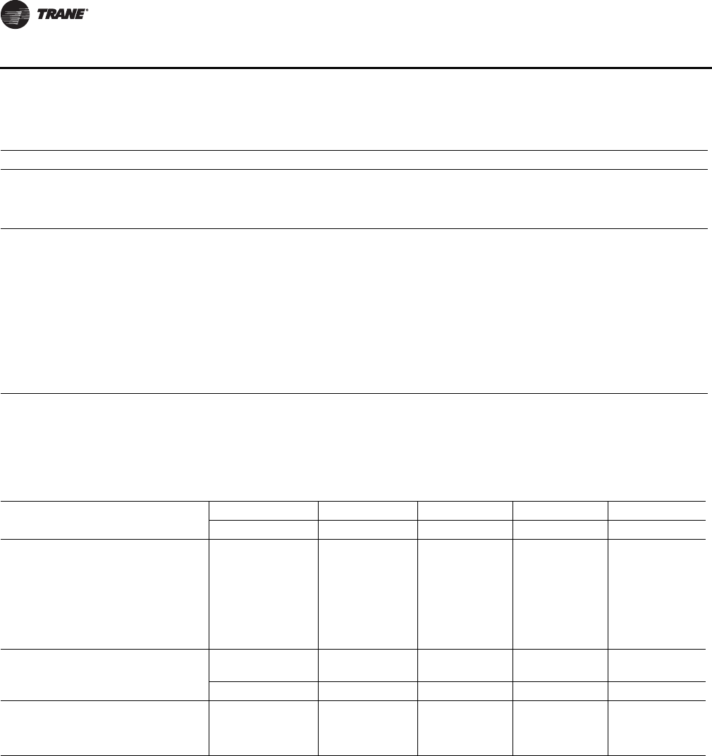
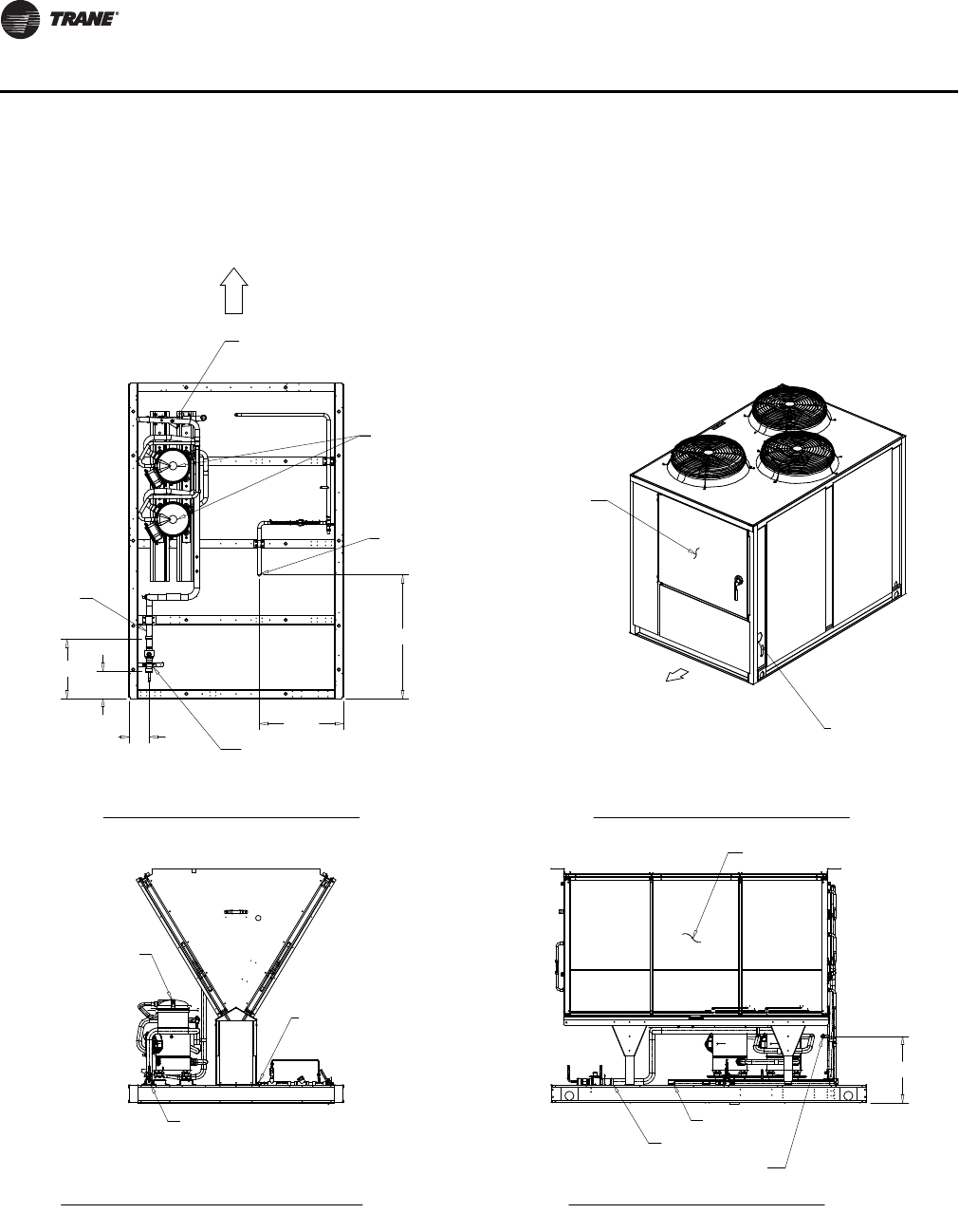
Figure 23. 20-ton Air-cooled condensing unit
4" CONDUIT
MAIN POWER
1 3/4" KO LOW
VOLTAGE (30V MAX.)
37 11/16"
3 3/8"
CONTROL PANEL
35 13/16"
31 1/4"
29 1/4"
4 1/2"
2 5/8"
5 5/16"
5 3/8"
3 3/8"
1/2" X 4 KO (115V)
1/2" X 2 KO (115V)
4 3/8"
6 1/8"
88 5/16"
74 1/4"
60"
11 1/2"
18"
1 1/4" x 4 1/2"
SLOT FOR 115
VOLT CONTROL
4" LINE
VOLTAGE
ACCESS
78"
5 3/16"
1 13/16"
LOW AMBIENT
DAMPER (SEE NOTE 2)
FAN GRILLE
FAN GRILLE
CONTROL PANEL
(SEE DETAIL A)
26 13/16"
CONTROL BOX BOTTOM
(SEE DETAIL A)
13"
6 1/4"
57 5/8"
1 1/4"
8"
72 1/2"
3/4" X 4 MTG HOLES
DOOR 43 1/4" W/
180 DEG SWING
2 1
4 3
FRONT (SEE
NOTE 3 FOR
ALL MIN.
CLEARANCE)
NOTES:
1. SEE CONNECTION DRAWING FOR CONNECTION LOCATION AND SIZES.
2. LOW AMBIENT DAMPER ONLY COMES WITH SELECTED UNIT .
3. FRONT OF UNIT CLEARANCE 72" . BACK OF UNIT CLEARANCE 72" .
LEFT AND RIGHT SIDE OF UNIT CLEARANCE 42".
DETAIL A
CONTROL BOX BOTTOM
30 SS-PRC030-EN
Dimensional Data
Figure 24. 20-ton Air-cooled condensing unit (connections)
VOLTAGE ACCESS
CONTROL PANEL
7/8" O.D.
LIQUID LINE
8 1/16"
13"
42"
SCALE 1,000
34 1/2"
57/16"
53/4"
LIQUID LINE
DISCHARGE LINE
COIL
1 3/8" O.D.
DISCHARGE LINE
CONTROL PANEL SIDE
CONTROL
PANEL SIDE
20 TON UNIT
PLAN VIEW OF UNIT
CONNECTION DRAWING
CONNECTION DRAWING
CONTROL PANEL SIDE VIEW OF UNIT
ISOMETRIC DRAWING
ORIENTATION VIEW OF UNIT
NOTES:
1. VERIFY WEIGHT, CONNECTION, AND ALL DIMENSION WITH
INSTALLER DOCUMENTS BEFORE INSTALLATION
SS-PRC030-EN 31
Dimensional Data
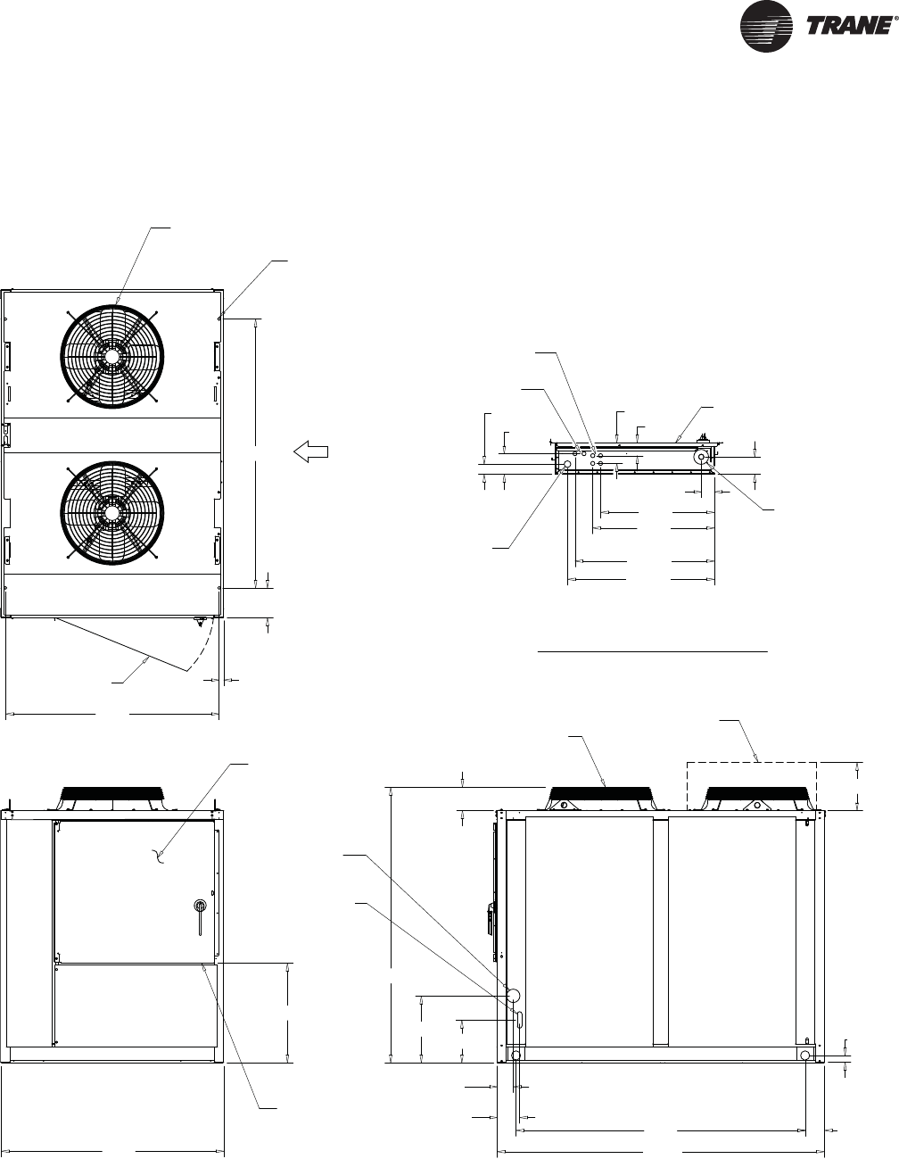
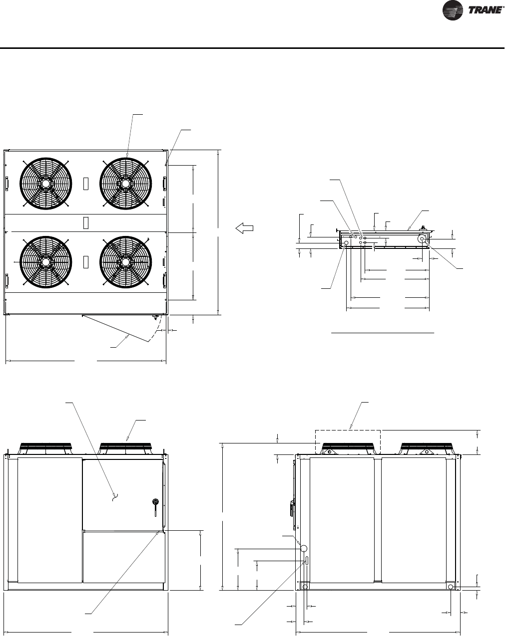
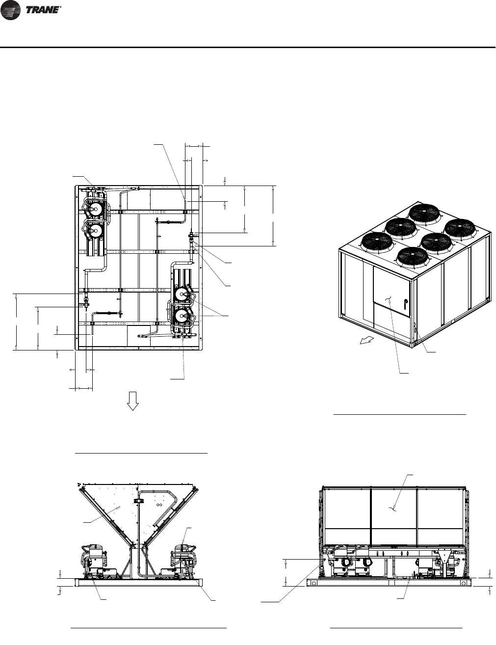
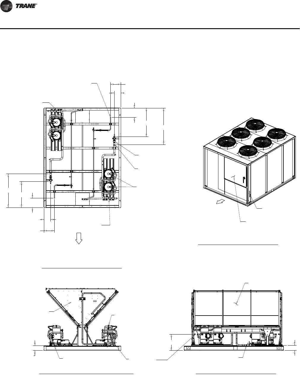
Figure 25. 25- and 30-ton Air-cooled condensing unit
1/2" X 4 KO (115V)
1 3/4" KO LOW
VOLTAGE (30V MAX.)
1/2" X 2 KO (115V)
CONTROL PANEL
4 1/2"
3 3/8"
5 3/8"
2 5/8"
37 11/16"
35 13/16"
5 5/16"
3 3/8"
31 1/4"
29 1/4"
4" CONDUIT
MAIN POWER
1.6
CONTROL BOX BOTTOM
(SEE DETAIL A)
FAN GRILLE
LOW AMBIENT
DAMPER (SEE NOTE 2)
FAN GRILLE
4" LINE
VOLTAGE ACCESS
1 1/4" x 4 1/2"
SLOT FOR 115
VOLT CONTROL
88 1/2"
60 1/8"
74 1/4"
18"
11 1/2"
88 5/16"
78"
4 3/8"
6 1/8"
5 3/16"
1 13/16"
13"
6 1/4"
CONTROL PANEL
(SEE DETAIL A)
27 1/4"
57 5/8"
1 1/4"
8"
72 1/2"
DOOR 43 1/4" W/
180 DEG SWING
2 1
3
4
3/4" X 4 MTG HOLES
FRONT (SEE
NOTE 3 FOR
ALL MIN.
CLEARANCE)
CONTROL BOX BOTTOM
DETAIL A
NOTES:
1. SEE CONNECTION DRAWING FOR CONNECTION LOCATION AND SIZES.
2. LOW AMBIENT DAMPER ONLY COMES WITH SELECTED UNIT .
3. FRONT OF 20 AND 30 UNIT CLEARANCE 72" . BACK OF UNIT CLEARANCE 72”.
LEFT AND RIGHT SIDE OF 20 AND 30 UNIT CLEARANCE 42”.
32 SS-PRC030-EN
Dimensional Data
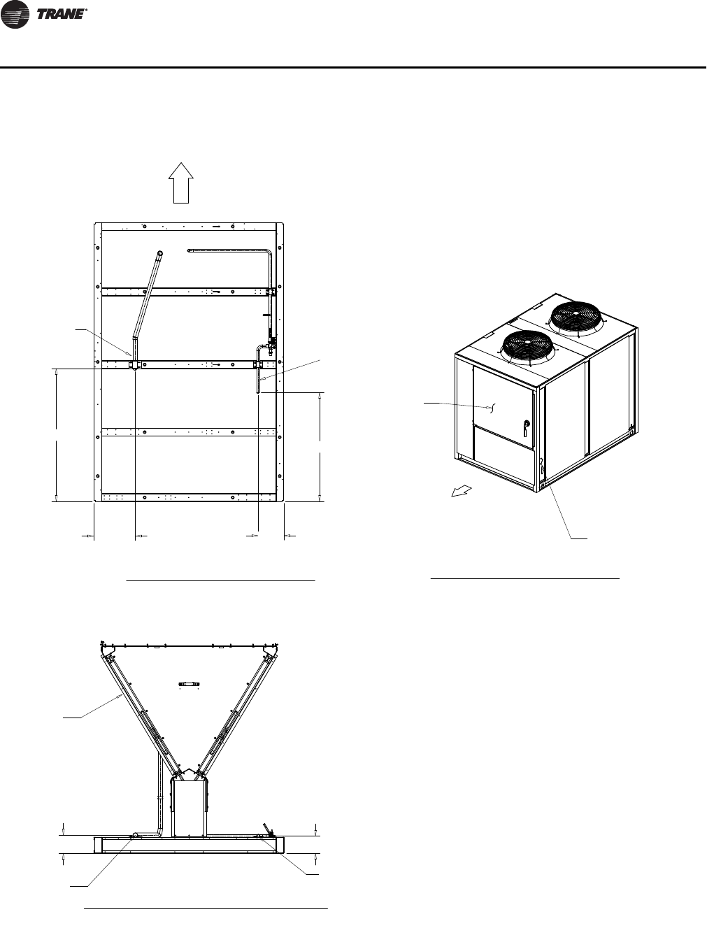
Figure 26. 25- and 30-ton Air-cooled condensing unit (connections)
HOT GAS BYPASS (OPTIONAL)
LIQUID LINE
7/8" O.D. HOT GAS
BYPASS (OPTIONAL)
7/8" O.D.
LIQUID LINE
SERVICE VALVE (OPTIONAL)
COIL
COMPRESSORS
16 9/16"
5 11/16"
79/16"
34 1/2"
23 1/2"
1 5/8" O.D.
SUCTION LINE
A
B
A
CONTROL PANEL
VOLTAGE ACCESS
SCALE1 .00 0
CONTROL PANEL SIDE
AA
C
FRONT
AA
A
C
AA
C
FRONT
AA
A
C
AA
C
FRONT
A A
A
C
AA
C
FRONT
A A
A
C
1 5/8" O.D.
SUCTION LINE
SUCTION LINE
18 9/16"
SUCTION LINE
LIQUID LINE
COIL
PLAN VIEW OF UNIT
CONNECTION DRAWING
CONNECTION DRAWING
CONTROL PANEL SIDE VIEW OF UNIT
ISOMETRIC DRAWING
ORIENTATION VIEW OF UNIT
BACK VIEW OF UNIT
CONNECTION DRAWING
1. VERIFY WEIGHT, CONNECTION, AND ALL DIMENSION WITH
INSTALLER DOCUMENTS BEFORE INSTALLATION
SS-PRC030-EN 33
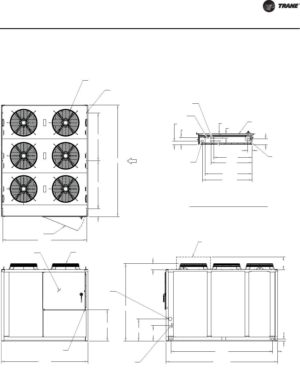
Dimensional Data
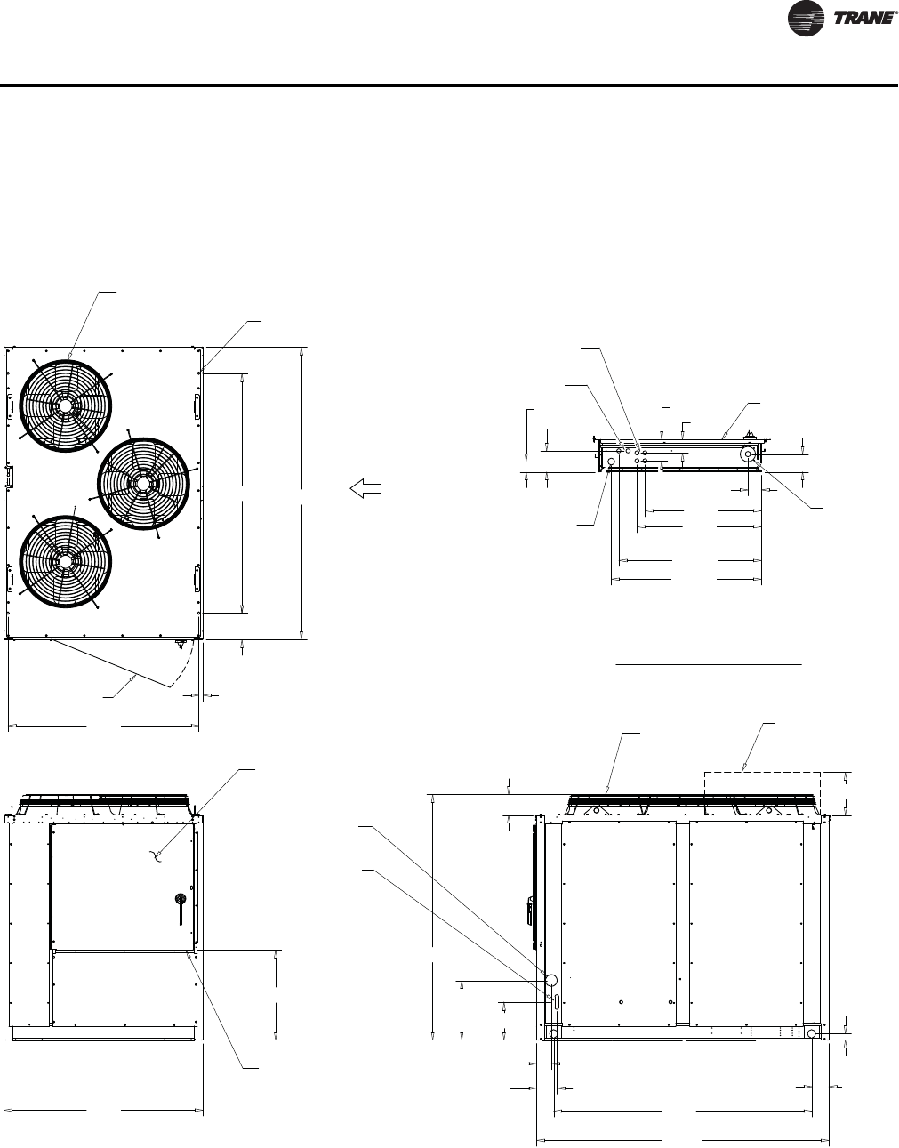
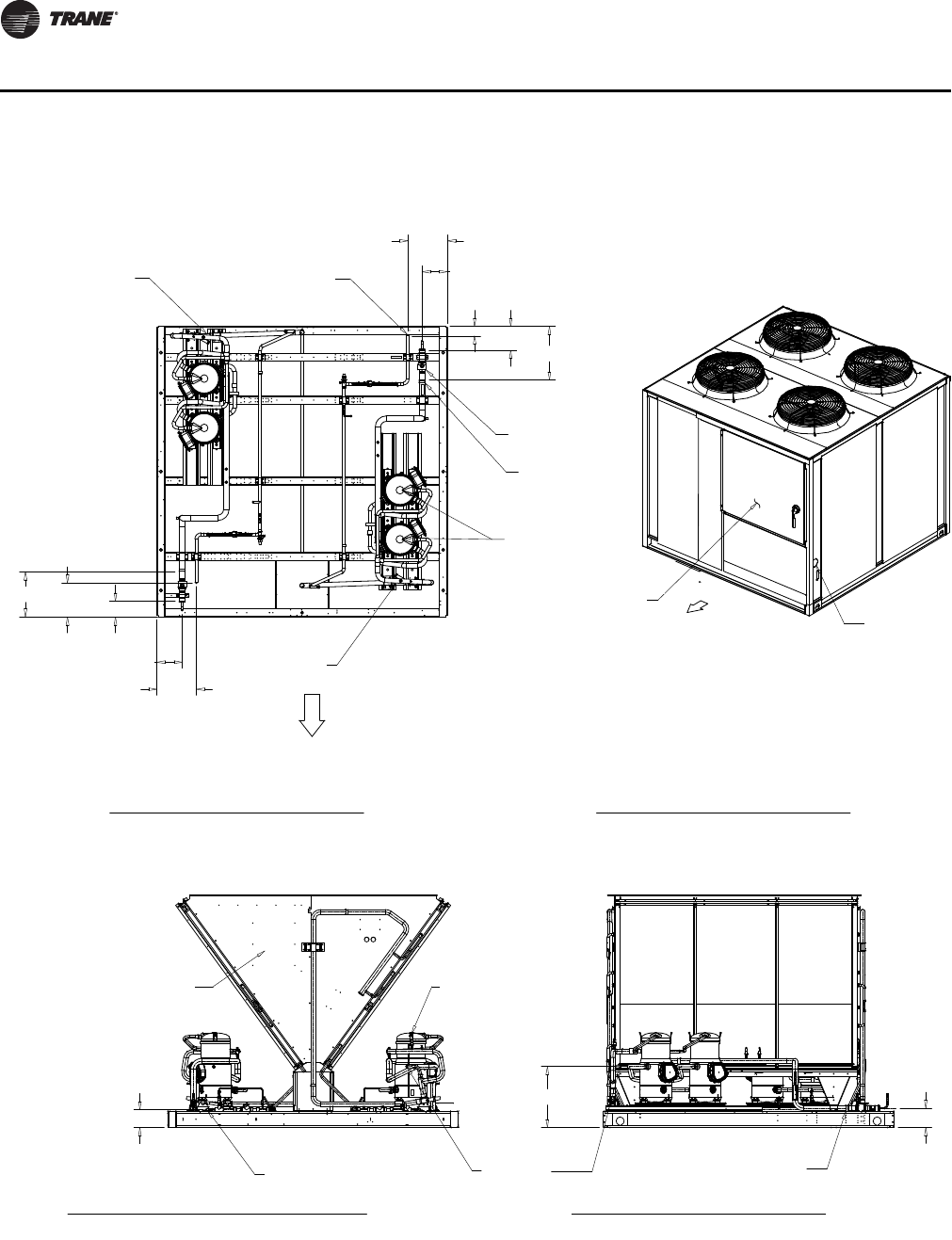
Figure 27. 40-ton Air-cooled condensing unit
29 1/4"
31 1/4"
35 13/16"
37 11/16"
3 3/8"
3 3/8"
5 5/16"
2 5/8" 5 3/8"
1 3/4" KO LOW
VOLTAGE (30V MAX.)
1/2" X 2 KO (115V)
1/2" X 4 KO (115V)
4 1/2"
4" CONDUIT
MAIN POWER
CONTROL PANEL
88 9/16"
88 5/16"
22 1/2"
16"
4 3/8"
6 1/8"
5 3/16"
1 15/16"
88 5/16"
79 1/4"
13"
LOW AMBIENT
DAMPER (SEE NOTE 2)
FAN GRILLE
FAN GRILLE
1 1/4" x 4 1/2"
SLOT FOR 115
VOLT CONTROL
4" LINE
VOLTAGE ACCESS
CONTROL PANEL
(SEE DETAIL A)
6 1/4"
32 3/16"
BOTTOM OF CONTROL
BOX (SEE DETAIL A)
DOOR 43 1/4" W/
180 DEG SWING
2
3
6
8"
36 1/8"
36 1/8"
1 1/4"
1
4
5
3/4" X 6
MTG HOLES
85 5/8"
FRONT (SEE
NOTE 3 FOR
ALL MIN.
CLEARANCE)
DETAIL A
BOTTOM OF CONTROL BOX
NOTES:
1. SEE CONNECTION DRAWING FOR CONNECTION LOCATION AND SIZES.
2. LOW AMBIENT DAMPER ONLY COMES WITH SELECTED UNIT .
3. FRONT AND BACK OF UNIT CLEARANCE 72" . LEFT AND RIGHT
SIDE OF UNIT CLEARANCE 42".
34 SS-PRC030-EN
Dimensional Data
Figure 28.40-ton Air-cooled condensing unit (connections)
1 5/8" O.D.
SUCTION LINE
COMPRESSORS
COMPRESSOR
COIL
7/8" O.D. HOT GAS
BYPASS (OPTIONAL)
7/8" O.D. HOT GAS
BYPASS (OPTIONAL)
7/8" O.D.
LIQUID LINE
12"
7 11/16"
13 3/4"
43/4"
10 1/4"
711/16"
12"
71/4"
16 1/4"
SERVICE VALVE
(OPTIONAL)
27/8"
AA
C
AA
C
SCALE1,000
57/16"
18 1/2"
513/16"
LIQUID LINE
HOT GAS BYPASS
(OPTIONAL) SUCTION LINE
VOLTAGE
ACCESS
CONTROL
PANEL
CONTROL PANEL SIDE
CONTROL
PANEL SIDE
PLAN VIEW OF UNIT
CONNECTION DRAWING
CONNECTION DRAWING
CONTROL PANEL SIDE VIEW OF UNIT
ISOMETRIC DRAWING
ORIENTATION VIEW OF UNIT
BACK VIEW OF UNIT
CONNECTION DRAWING
NOTES:
1. VERIFY WEIGHT, CONNECTION, AND ALL DIMENSION WITH
INSTALLER DOCUMENTS BEFORE INSTALLATION
SS-PRC030-EN 35
Dimensional Data
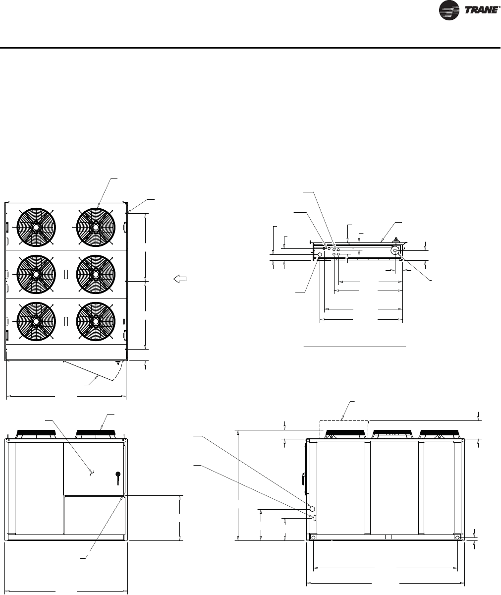
Figure 29. 50-ton Air-cooled condensing unit
29 1/4"
31 1/4"
35 13/16"
37 11/16"
3 3/8"
3 3/8"
5 5/16"
2 5/8"
5 3/8"
1 3/4" KO LOW
VOLTAGE (30V MAX.)
1/2" X 2 KO (115V)
1/2" X 4 KO (115V)
4 1/2"
4" CONDUIT
MAIN POWER
CONTROL PANEL
88 5/16"
113 13/16"
103 1/2"
16"
22 1/2"
79 1/4"
1 15/16"
FAN GRILLE
LOW AMBIENT
DAMPER (SEE NOTE 2)
FAN GRILLE
1 1/4" x 4 1/2"
SLOT FOR 115
VOLT CONTROL
4" LINE
VOLTAGE
ACCESS
BOTTOM OF CONTROL
BOX (SEE DETAIL A)
13"
6 1/4"
32 1/4"
CONTROL PANEL
(SEE DETAIL A)
DOOR 43 1/4" W/
180 DEG SWING
8 1/8"
48 7/8"
48 7/8"
85 5/8"
3/4" X 6
MTG HOLES
12
34
56
FRONT (SEE
NOTE 3 FOR
ALL MIN.
CLEARANCE)
DETAIL A
BOTTOM OF CONTROL BOX
NOTES:
1. SEE CONNECTION DRAWING FOR CONNECTION LOCATION AND SIZES.
2. LOW AMBIENT DAMPER ONLY COMES WITH SELECTED UNIT .
3. FRONT AND BACK OF UNIT CLEARANCE 72" . LEFT AND RIGHT
SIDE OF UNIT CLEARANCE 42".
36 SS-PRC030-EN
Dimensional Data
Figure 30. 50-ton Air-cooled condensing unit (connections)
COMPRESSORS
COIL
COMPRESSOR
COIL
1 5/8" O.D. SUCTION LINE
SUCTION LINE
LIQUID LINE
7/8" O.D. HOT GAS
BYPASS (OPTIONAL)
HOT GAS BYPASS
(OPTIONAL)
7/8" O.D, HOT GAS
BYPASS (OPTIONAL)
12"
10 13/16"
41 3/4"
32 3/4"
7 11/16"
7/8" O.D. LIQUID LINE
SERVICE VALVE (OPTIONAL)
12"
711/16"
10 13/16"
29 3/4"
38 3/4"
CONTROL
PANEL
VOLTAGE
ACCESS
CONTROL PANEL SIDE
CONTROL
PANEL SIDE
AA
A
AA
A
57/16"
513/16
18 1/2"
PLAN VIEW OF UNIT
CONNECTION DRAWING
CONNECTION DRAWING
CONTROL PANEL SIDE VIEW OF UNIT
ISOMETRIC DRAWING
ORIENTATION VIEW OF UNIT
BACK VIEW OF UNIT
CONNECTION DRAWING
NOTES:
1. VERIFY WEIGHT, CONNECTION, AND ALL DIMENSION WITH
INSTALLER DOCUMENTS BEFORE INSTALLATION
SS-PRC030-EN 37
Dimensional Data
Figure 31. 60-ton Air-cooled condensing unit
29 1/4"
31 1/4"
35 13/16"
37 11/16"
3 3/8"
3 3/8"
5 5/16"
2 5/8"
5 3/8"
1 3/4" KO LOW
VOLTAGE (30V MAX.)
1/2" X 2 KO (115V)
1/2" X 4 KO (115V)
4 1/2"
4" CONDUIT
MAIN POWER
CONTROL PANEL
FAN GRILLE
4" LINE
VOLTAGE
ACCESS
1 1/4" x 4 1/2"
SLOT FOR 115
VOLT CONTROL
FAN GRILLE
CONTROL PANEL
(SEE DETAIL A)
1 15/16"
103 1/2"
5 3/16"
113 13/16"
22 1/2"
16"
79 1/4"
114"
88 5/16"
13"
LOW AMBIENT
DAMPER (SEE NOTE 2)
32 3/16"
BOTTOM OF CONTROL
BOX (SEE DETAIL A)
6 1/4"
3/4" X 6
MTG HOLES
DOOR 43 1/4" W/
180 DEG SWING
8 1/8"
48 7/8"
48 7/8"
85 5/8"
2 1
3
4
65
FRONT (SEE
NOTE 3 FOR
ALL MIN.
CLEARANCE)
NOTES:
1. SEE CONNECTION DRAWING FOR CONNECTION LOCATION AND SIZES.
2. LOW AMBIENT DAMPER ONLY COMES WITH SELECTED UNIT .
BOTTOM OF CONTROL BOX
DETAIL A
3. FRONT AND BACK OF UNIT CLEARANCE 72" . LEFT AND RIGHT
SIDE OF UNIT CLEARANCE 42".
38 SS-PRC030-EN
Dimensional Data
Figure 32. 60-ton Air-cooled condensing unit (connections)
COMPRESSORS
COIL
COMPRESSOR
COIL
1 5/8" O.D. SUCTION LINE
SUCTION LINE
LIQUID LINE
7/8" O.D. HOT GAS
BYPASS (OPTIONAL)
HOT GAS BYPASS
(OPTIONAL)
7/8" O.D, HOT GAS
BYPASS (OPTIONAL)
12"
10 13/16"
41 3/4"
32 3/4"
711/16"
7/8" O.D. LIQUID LINE
SERVICE VALVE (OPTIONAL)
12"
7 11/16"
10 13/16"
29 3/4"
38 3/4"
CONTROL
PANEL
VOLTAGE
ACCESS
CONTROL PANEL SIDE
CONTROL
PANEL SIDE
AA
A
AA
A
57/16"
5 13/16"
18 1/2"
NOTES:
1. VERIFY WEIGHT, CONNECTION, AND ALL DIMENSION WITH
INSTALLER DOCUMENTS BEFORE INSTALLATION
PLAN VIEW OF UNIT
CONNECTION DRAWING
CONNECTION DRAWING
CONTROL PANEL SIDE VIEW OF UNIT
ISOMETRIC DRAWING
ORIENTATION VIEW OF UNIT
BACK VIEW OF UNIT
CONNECTION DRAWING
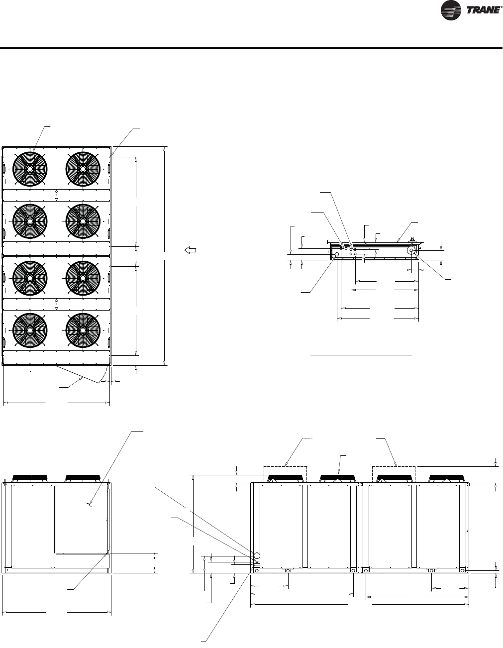
SS-PRC030-EN 39
Dimensional Data
Figure 33. 80-ton Air-cooled condensing unit
29 1/4"
31 1/4"
35 13/16"
37 11/16"
3 3/8"
3 3/8"
5 5/16"
2 5/8" 5 3/8"
1 3/4" KO LOW
VOLTAGE (30V MAX.)
1/2" X 2 KO (115V)
1/2" X 4 KO (115V)
4 1/2"
4" CONDUIT
MAIN POWER
CONTROL PANEL
1.6
1 13/16"
176 7/16"
83 1/8"
30 1/4" 30 1/8"
83 1/4"
88 5/16"
176 11/16"
FAN GRILLE
1 1/4" x 4 1/2"
SLOT FOR 115
VOLT CONTROL
4" LINE
VOLTAGE
ACCESS
FAN GRILLE
79 1/4"
7"
9"
14"
LOW AMBIENT
DAMPER (SEE NOTE 2)
6 1/4"
13"
16 5/16"
BOTTOM OF CONTROL
BOX (SEE DETAIL A)
CONTROL PANEL
(SEE DETAIL A)
2 1/4" x 1 1/4" 24 VOLTAGE
CONTROL WIRING
3/4" X 8
MTG HOLES
DOOR 43 1/4" W/
180 DEG SWING
1 1/4"
8"
72 1/8"
16"
72 1/8"
85 5/8"
12
4 3
65
87
FRONT (SEE
NOTE 3 FOR
ALL MIN.
CLEARANCE)
DIMENSIONAL DETAIL
DETAIL A
NOTES:
1. SEE CONNECTION DRAWING FOR CONNECTION LOCATION AND SIZES.
2. LOW AMBIENT DAMPER ONLY COMES WITH SELECTED UNIT .
3. FRONT AND BACK OF UNIT CLEARANCE 96" . LEFT AND RIGHT
SIDE OF UNIT CLEARANCE 48".
40 SS-PRC030-EN
Dimensional Data
Figure 34.80-ton Air-cooled condensing unit (connections)
1 1/8" O.D.
LIQUID LINE
2 5/8" O.D .SUCTION LINE
COIL
2 5/8" O.D. SUCTION LINE
3/8" O.D. HOT GAS
YPASS (OPTIONAL)
COMPRESSOR (6)
1 3/8" HOT GAS
BYPASS (OPTIONAL)
COMPRESSOR (6)
HOT GAS BYPASS
(OPTIONAL)
14 13/16"
25 1/8"
46 3/16"
SERVICE VALUE
(OPTIONAL SEE DETAIL A) 42 9/16"
25 1/8"
14 1/16" 19 1/16"
73 3/8"
45 9/16"
CONTROL
ANEL SIDE
18 5/16"
SUCTION LINE
LIQUID LINE
DETAIL A
VOLTAGE
ACCESS
CONTROL
PANEL
CONTROL
PANEL SIDE
5 9/16"
93/8"
LIQUID LINE
COIL
COMPRESSOR (6)
SERVICE VALUE
(OPTIONAL SEE DETAIL A)
DETAIL A
DETAIL DRAWING
NOTES:
1
. VERIFY WEIGHT, CONNECTION, AND ALL DIMENSION WITH
INSTALLER DOCUMENTS BEFORE INSTALLATION
PLAN VIEW OF UNIT
CONNECTION DRAWING
CONNECTION DRAWING
CONTROL PANEL SIDE VIEW OF UNIT
LEFT VIEW OF UNIT
CONNECTION DRAWING
ISOMETRIC DRAWING
ORIENTATION VIEW OF UNIT
SS-PRC030-EN 41
Dimensional Data
Figure 35. 100- and 120-ton Air-cooled condensing unit
29 1/4"
31 1/4"
35 13/16"
37 11/16"
3 3/8"
3 3/8"
5 5/16"
2 5/8" 5 3/8"
1 3/4" KO LOW
VOLTAGE (30V MAX.)
1/2" X 2 KO (115V)
1/2" X 4 KO (115V)
4 1/2"
4" CONDUIT
MAIN POWER
CONTROL PANEL
1 15/16"
108 11/16"
20 1/16"
5 3/16"
108 5/8"
5 1/8"
20 1/16"
79 1/4"
7"
14"
9"
88 5/16"
FAN GRILLE
CONTROL PANEL
(SEE DETAIL A)
4" LINE
VOLTAGE ACCESS
1 1/4" x 4 1/2"
SLOT FOR 115
VOLT CONTROL
FAN GRILLE
LOW AMBIENT
DAMPER (SEE NOTE 2)
BOTTOM OF CONTROL
BOX (SEE DETAIL A)
16 3/16"
2 1/4" x 1 1/4" 24 VOLTAGE
CONTROL WIRING
6 1/4"
13"
3/4" X 8
MTG HOLES
DOOR 43 1/4" W/
180 DEG SWING
8"
1 1/4"
97 5/8"
16"
97 5/8"
85 13/16"
FRONT (SEE
NOTE 3 FOR
ALL MIN.
CLEARANCE)
DIMENSIONAL DETAIL
DETAIL A
NOTES:
1. SEE CONNECTION DRAWING FOR CONNECTION LOCATION AND SIZES.
2. LOW AMBIENT DAMPER ONLY COMES WITH SELECTED UNIT .
3. FRONT AND BACK OF UNIT CLEARANCE 96" . LEFT AND RIGHT
SIDE OF UNIT CLEARANCE 48".
227 1/4”
42 SS-PRC030-EN
Dimensional Data
Figure 36. 100- and 120-ton Air-cooled condensing unit (connections)
25/8"O.D.
SUCTION LINE
1 3/8"HOT GAS
BYPASS (OPTIONAL)
1 1/8" O.D.
LIQUID LINE
COMPRESSOR (6)
SUCTION LINE
COIL
COMPRESSOR (6)
LIQUID LINE
2 5/8" O.D.
SUCTION LINE
HOT GAS BYPASS
(OPTIONAL)
1 3/8"HOT GAS
BYPASS (OPTIONAL)
25 1/8"
39 5/8"
67 7/16"45 7/8"
18 1/16" 13 1/16"
1 1/8" O.D.
LIQUID LINE
2 5/8" O.D. SUCTION LINE
46 1/4"
74"
25 1/8"
SCALE1,000
18 5/16"
59/16"
93/8"
VOLTAGE
ACCESS
CONTROL
PANEL
CONTROL
PANEL SIDE
CONTROL
PANEL SIDE
SERVICE VALUE (OPTIONAL SEE DETAIL A)
SERVICE VALUE
(OPTIONAL SEE DETAIL A)
DETAIL A
DETAIL DRAWING
NOTES:
1. VERIFY WEIGHT, CONNECTION, AND ALL DIMENSION WITH
INSTALLER DOCUMENTS BEFORE INSTALLATION
PLAN VIEW OF UNIT
CONNECTION DRAWING
CONNECTION DRAWING
CONTROL PANEL SIDE VIEW OF UNIT LEFT VIEW OF UNIT
CONNECTION DRAWING
ISOMETRIC DRAWING
ORIENTATION VIEW OF UNIT
SS-PRC030-EN 43
Dimensional Data
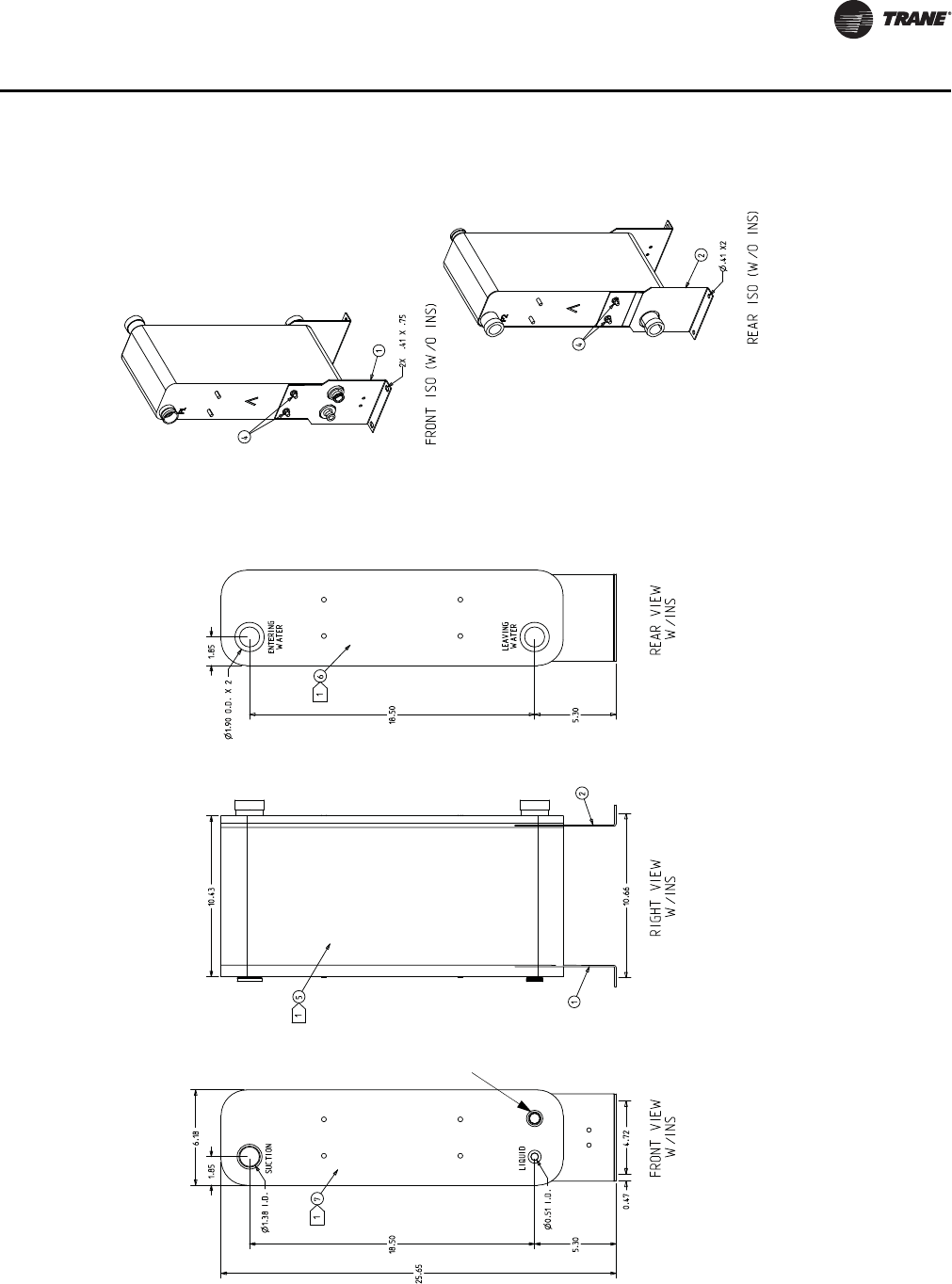
Figure 37. 20-ton Evaporator chiller
Notes:Notes:
THIS HEAT EXCHANGER IS INTENDED FOR INDOOR INSTALLATION ONLYTHIS HEAT EXCHANGER IS INTENDED FOR INDOOR INSTALLATION ONLY
HEAT EXCHANGER MOUNTING LEGS ARE INSTALLED AT JOB SITE WITH SUPPLIED FASTENERS (ITEM 4)HEAT EXCHANGER MOUNTING LEGS ARE INSTALLED AT JOB SITE WITH SUPPLIED FASTENERS (ITEM 4)
INSULATION (ITEMS 5, 6, & 7) SHOULD BE INSTALLED AFTER INSTALLING LEGS & REFRIGERANT INSULATION (ITEMS 5, 6, & 7) SHOULD BE INSTALLED AFTER INSTALLING LEGS & REFRIGERANT
TUBING, OR MUST BE ADEQUATELY SHIELDED AGAINST HEAT WHEN BRAZING REFRIGERANT LINESTUBING, OR MUST BE ADEQUATELY SHIELDED AGAINST HEAT WHEN BRAZING REFRIGERANT LINES
INSTALL INSULATION SIDE PIECES FIRST (ITEMS 6 & 7), THEN WRAPPER (ITEM 5), ITEM 5 MAY INSTALL INSULATION SIDE PIECES FIRST (ITEMS 6 & 7), THEN WRAPPER (ITEM 5), ITEM 5 MAY
REQUIRE TRIMMING REQUIRE TRIMMING
USE VINYL TAPE (FIELD SUPPLIED) TO SEAL INSULATION AFTER INSTALLATIONUSE VINYL TAPE (FIELD SUPPLIED) TO SEAL INSULATION AFTER INSTALLATION
WATER CONNECTIONS ARE GROOVED (VICTAULIC)WATER CONNECTIONS ARE GROOVED (VICTAULIC)
REFRIGERANT CONNECTIONS ARE STAINLESS STEEL AND REQUIRE SPECIAL BRAZE MATERIALS.REFRIGERANT CONNECTIONS ARE STAINLESS STEEL AND REQUIRE SPECIAL BRAZE MATERIALS.
SEE IOM BRAZE PROCEDURES.SEE IOM BRAZE PROCEDURES.
REQUIRES FIELD
PROVIDED
1/2”X14NPTE
STAINLESS STEEL
OR PVC PLUG
44 SS-PRC030-EN
Dimensional Data
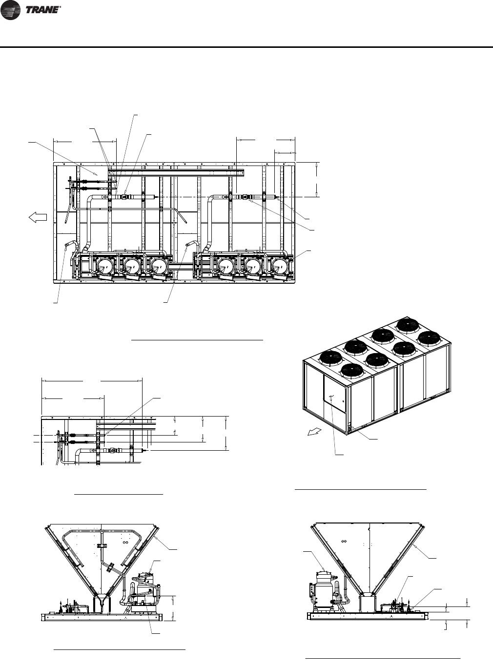
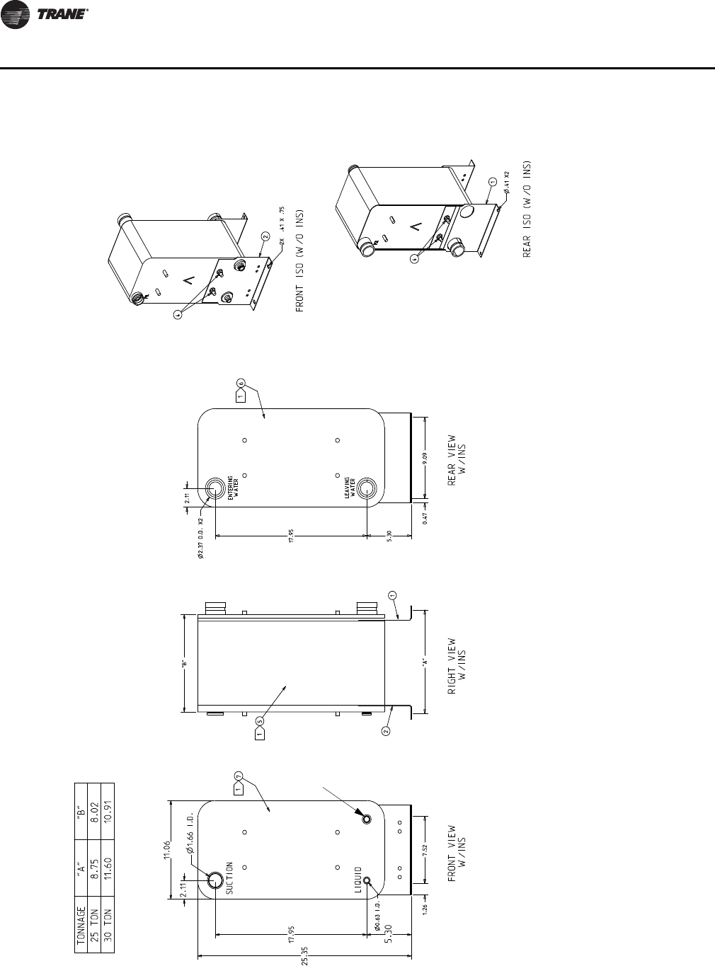
Figure 38. 25 and 30-ton Evaporator chiller
Notes:
THIS HEAT EXCHANGER IS INTENDED FOR INDOOR INSTALLATION ONLY
HEAT EXCHANGER MOUNTING LEGS ARE INSTALLED AT JOB SITE WITH SUPPLIED FASTENERS (ITEM 4)
INSULATION (ITEMS 5, 6, & 7) SHOULD BE INSTALLED AFTER INSTALLING LEGS & REFRIGERANT TUBING, OR
MUST BE ADEQUATELY SHIELDED AGAINST HEAT WHEN BRAZING REFRIGERANT LINES
Install INSULATION SIDE PIECES FIRST (ITEMS 6 & 7), THEN WRAPPER (ITEM 5), ITEM 5 MAY REQUIRE
TRIMMING
USE VINYL TAPE (FIELD SUPPLIED) TO SEAL INSULATION AFTER INSTALLATION
WATER CONNECTIONS ARE GROOVED (VICTAULIC)
REFRIGERANT CONNECTIONS ARE STAINLESS STEEL AND REQUIRE SPECIAL BRAZE MATERIALS.
SEE IOM BRAZE PROCEDURE.
REQUIRES FIELD
PROVIDED
1/2”X14NPTE
STAINLESS STEEL
OR PVC PLUG
SS-PRC030-EN 45
Dimensional Data
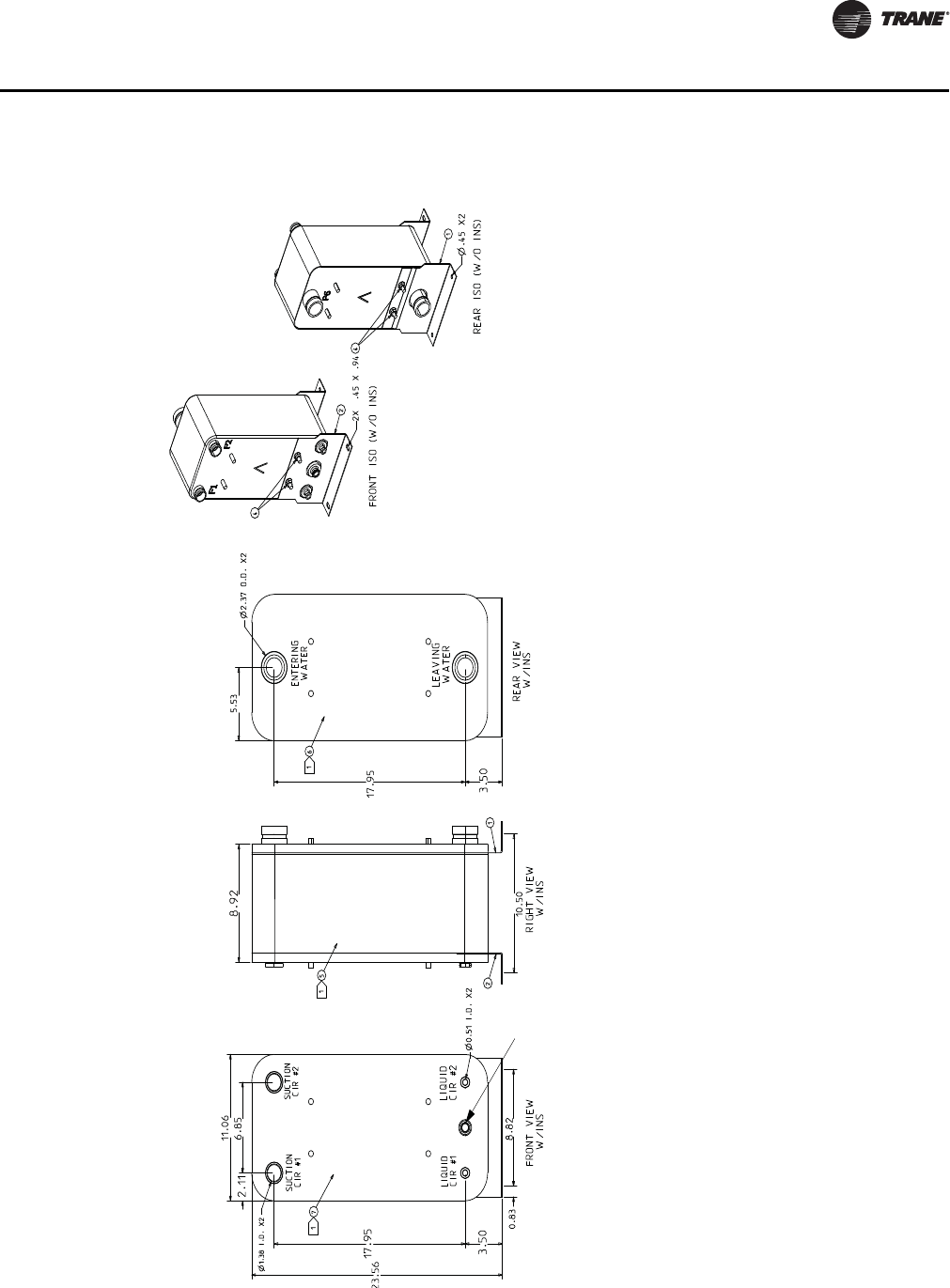
Figure 39. 40-ton Evaporator chiller
Notes:Notes:
THIS HEAT EXCHANGER IS INTENDED FOR INDOOR INSTALLATION ONLYTHIS HEAT EXCHANGER IS INTENDED FOR INDOOR INSTALLATION ONLY
HEAT EXCHANGER MOUNTING LEGS ARE INSTALLED AT JOB SITE WITH SUPPLIED FASTENERS (ITEM 4)HEAT EXCHANGER MOUNTING LEGS ARE INSTALLED AT JOB SITE WITH SUPPLIED FASTENERS (ITEM 4)
INSULATION (ITEMS 5, 6, & 7) SHOULD BE INSTALLED AFTER INSTALLING LEGS & REFRIGERANT INSULATION (ITEMS 5, 6, & 7) SHOULD BE INSTALLED AFTER INSTALLING LEGS & REFRIGERANT
TUBING, OR MUST BE ADEQUATELY SHIELDED AGAINST HEAT WHEN BRAZING REFRIGERANT LINESTUBING, OR MUST BE ADEQUATELY SHIELDED AGAINST HEAT WHEN BRAZING REFRIGERANT LINES
Install INSULATION SIDE PIECES FIRST (ITEMS 6 & 7), THEN WRAPPER (ITEM 5), ITEM 5 MAY Install INSULATION SIDE PIECES FIRST (ITEMS 6 & 7), THEN WRAPPER (ITEM 5), ITEM 5 MAY
REQUIRE TRIMMING REQUIRE TRIMMING
USE VINYL TAPE (FIELD SUPPLIED) TO SEAL INSULATION AFTER INSTALLATIONUSE VINYL TAPE (FIELD SUPPLIED) TO SEAL INSULATION AFTER INSTALLATION
WATER CONNECTIONS ARE GROOVED (VICTAULIC)WATER CONNECTIONS ARE GROOVED (VICTAULIC)
REFRIGERANT CONNECTIONS ARE STAINLESS STEEL AND REQUIRE SPECIAL BRAZE MATERIALS.REFRIGERANT CONNECTIONS ARE STAINLESS STEEL AND REQUIRE SPECIAL BRAZE MATERIALS.
SEE IOM BRAZE PROCEDURE.SEE IOM BRAZE PROCEDURE.
REQUIRES FIELD
PROVIDED
1/2”X14NPTE
STAINLESS STEEL
OR PVC PLUG
46 SS-PRC030-EN
Dimensional Data
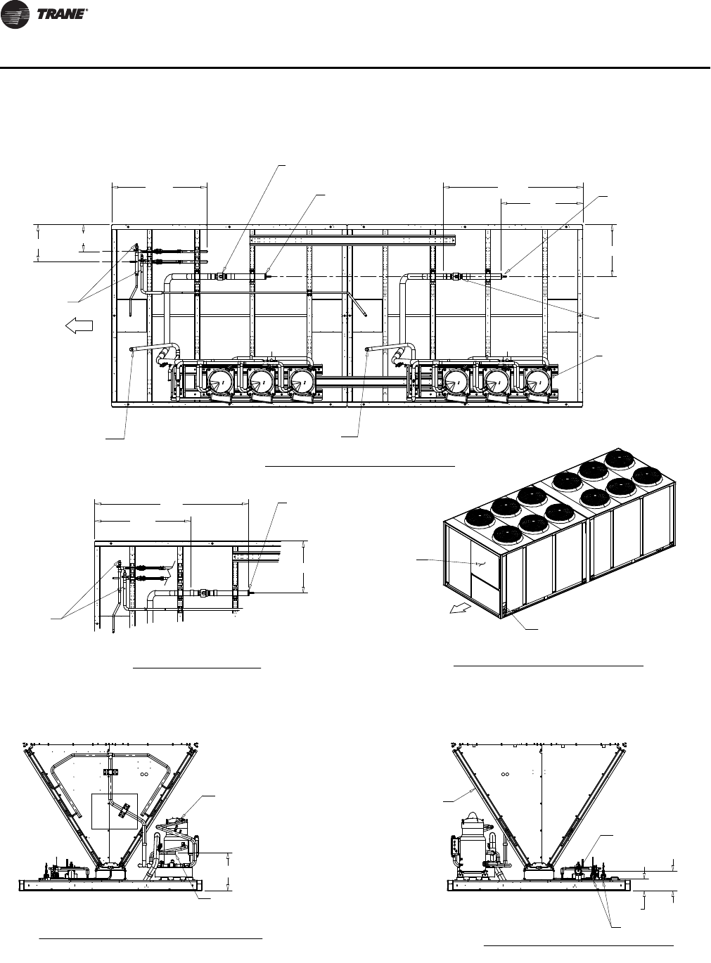
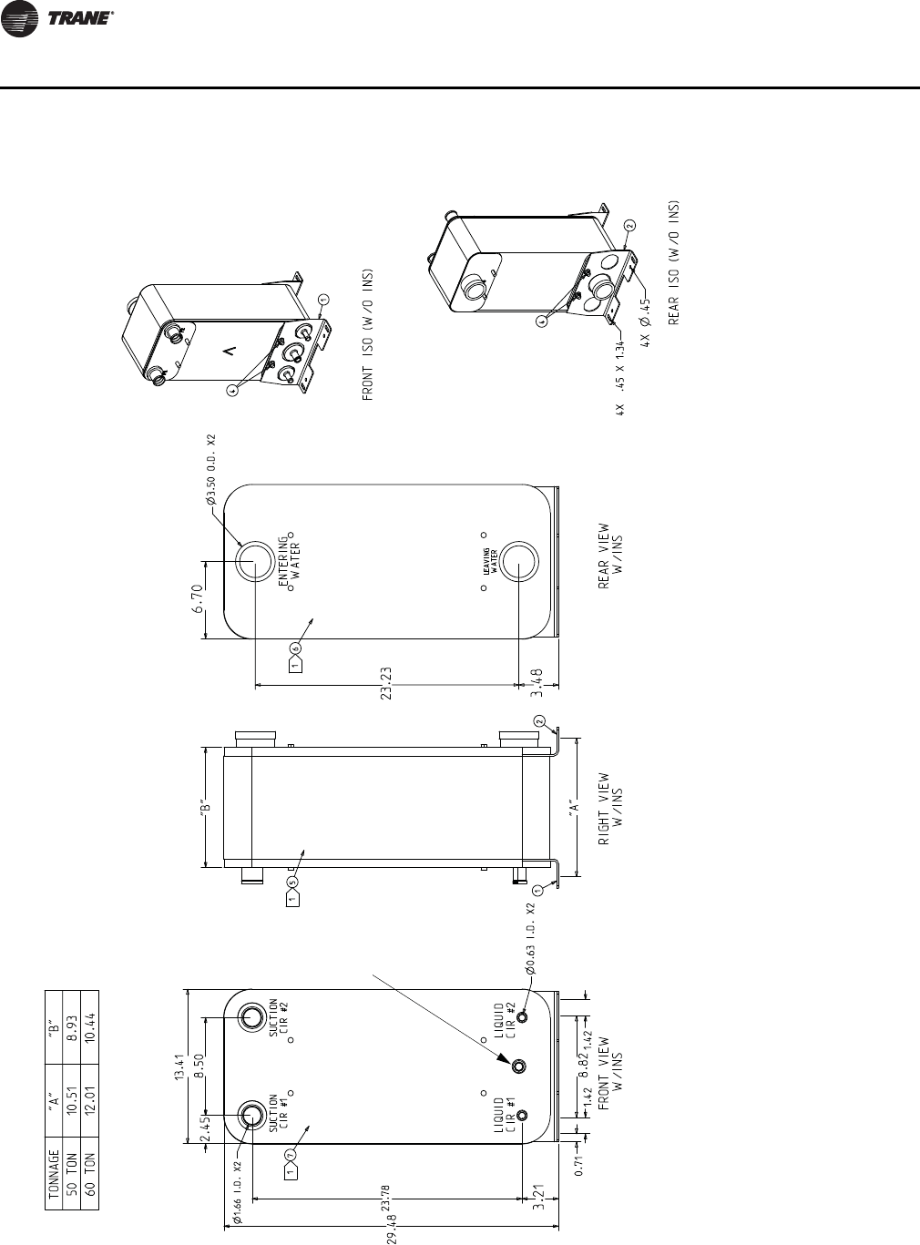
Figure 40. 50 and 60-ton Evaporator chiller
Notes:Notes:
THIS HEAT EXCHANGER IS INTENDED FOR INDOOR INSTALLATION ONLYTHIS HEAT EXCHANGER IS INTENDED FOR INDOOR INSTALLATION ONLY
HEAT EXCHANGER MOUNTING LEGS ARE INSTALLED AT JOB SITE WITH SUPPLIED FASTENERS (ITEM 4). HEAT EXCHANGER MOUNTING LEGS ARE INSTALLED AT JOB SITE WITH SUPPLIED FASTENERS (ITEM 4).
ATTACH MOUNTING LEGS BEFORE PIPING AND INSULATINGATTACH MOUNTING LEGS BEFORE PIPING AND INSULATING
INSULATION (ITEMS 5, 6, & 7) SHOULD BE INSTALLED AFTER INSTALLING LEGS & REFRIGERANT INSULATION (ITEMS 5, 6, & 7) SHOULD BE INSTALLED AFTER INSTALLING LEGS & REFRIGERANT
TUBING, OR MUST BE ADEQUATELY SHIELDED AGAINST HEAT WHEN BRAZING REFRIGERANT LINESTUBING, OR MUST BE ADEQUATELY SHIELDED AGAINST HEAT WHEN BRAZING REFRIGERANT LINES
INSTALL FACE INSULATION FIRST (ITEMS 6 & 7), THEN WRAPPER INSULATION (ITEM 5), ITEM 5 MAY INSTALL FACE INSULATION FIRST (ITEMS 6 & 7), THEN WRAPPER INSULATION (ITEM 5), ITEM 5 MAY
REQUIRE TRIMMING REQUIRE TRIMMING
USE VINYL TAPE (FIELD SUPPLIED) TO SEAL INSULATION AFTER INSTALLATIONUSE VINYL TAPE (FIELD SUPPLIED) TO SEAL INSULATION AFTER INSTALLATION
WATER CONNECTIONS ARE GROOVED (VICTAULIC)WATER CONNECTIONS ARE GROOVED (VICTAULIC)
REFRIGERANT CONNECTIONS ARE STAINLESS STEEL AND REQUIRE SPECIAL BRAZE MATERIALS.REFRIGERANT CONNECTIONS ARE STAINLESS STEEL AND REQUIRE SPECIAL BRAZE MATERIALS.
SEE IOM BRAZE PROCEDURES.SEE IOM BRAZE PROCEDURES.
REQUIRES FIELD
PROVIDED
1/2”X14NPTE
STAINLESS STEEL
OR PVC PLUG
SS-PRC030-EN 47
Dimensional Data
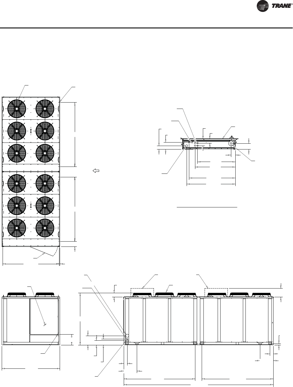
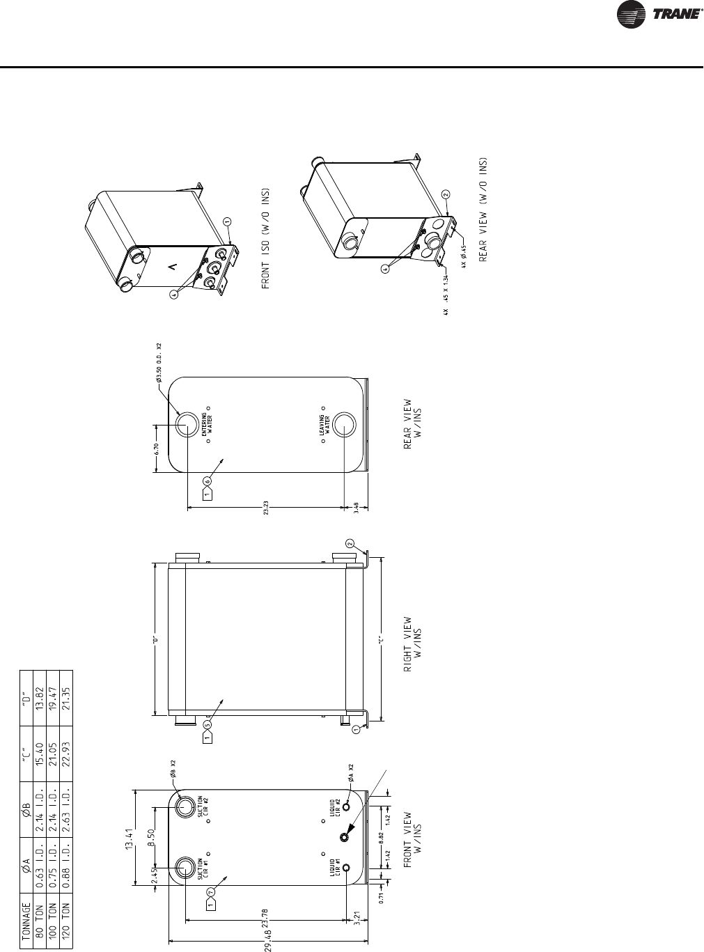
Figure 41. 80, 100, and 120-ton Evaporator chiller
Notes:Notes:
THIS HEAT EXCHANGER IS INTENDED FOR INDOOR INSTALLATION ONLYTHIS HEAT EXCHANGER IS INTENDED FOR INDOOR INSTALLATION ONLY
HEAT EXCHANGER MOUNTING LEGS ARE INSTALLED AT JOB SITE WITH SUPPLIED FASTENERS HEAT EXCHANGER MOUNTING LEGS ARE INSTALLED AT JOB SITE WITH SUPPLIED FASTENERS
(ITEM 4)(ITEM 4)
INSULATION (ITEMS 5, 6, & 7) SHOULD BE INSTALLED AFTER INSTALLING LEGS & INSULATION (ITEMS 5, 6, & 7) SHOULD BE INSTALLED AFTER INSTALLING LEGS &
REFRIGERANT TUBING, OR MUST BE ADEQUATELY SHIELDED AGAINST HEAT WHEN BRAZING REFRIGERANT TUBING, OR MUST BE ADEQUATELY SHIELDED AGAINST HEAT WHEN BRAZING
REFRIGERANT LINESREFRIGERANT LINES
Install INSULATION SIDE PIECES FIRST (ITEMS 6 & 7), THEN WRAPPER (ITEM 5), ITEM 5 MAY Install INSULATION SIDE PIECES FIRST (ITEMS 6 & 7), THEN WRAPPER (ITEM 5), ITEM 5 MAY
REQUIRE TRIMMING REQUIRE TRIMMING
USE VINYL TAPE (FIELD SUPPLIED) TO SEAL INSULATION AFTER INSTALLATIONUSE VINYL TAPE (FIELD SUPPLIED) TO SEAL INSULATION AFTER INSTALLATION
WATER CONNECTIONS ARE GROOVED (VICTAULIC)WATER CONNECTIONS ARE GROOVED (VICTAULIC)
REFRIGERANT CONNECTIONS ARE STAINLESS STEEL AND REQUIRE SPECIAL BRAZE MATERIALS.REFRIGERANT CONNECTIONS ARE STAINLESS STEEL AND REQUIRE SPECIAL BRAZE MATERIALS.
SEE IOM BRAZE PROCEDURES.SEE IOM BRAZE PROCEDURES.
REQUIRES FIELD
PROVIDED
1/2”X14NPTE
STAINLESS STEEL
OR PVC PLUG
48 SS-PRC030-EN
Weights
Table 11. 20- to 120- Ton air-cooled condensing units
Tons
Operating
Weight
Weight on isolator mounting location (lbs.)
Model Loc. 1 Loc. 2 Loc 3. Loc 4. Loc. 5 Loc. 6 Loc. 7 Loc. 8
20 RAUJC20 1573 475.5 383.3 403.2 311.0 --- --- --- ---
25 RAUJC25 1623 491.2 399.3 412.2 320.3 --- --- --- ---
30 RAUJC30 1623 491.2 399.3 412.2 320.3 --- --- --- ---
40 RAUJC40 2532 452.3 415.7 440.3 403.7 428.3 391.8 --- ---
50 RAUJC50 2868 365.5 331.0 427.8 393.3 700.1 650.3 --- ---
60 RAUJC60 2853 367.2 332.8 426.0 391.6 692.5 642.9 --- ---
80 RAUJC80 4940 798.3 462.1 786.7 450.5 785.1 448.9 772.4 436.1
100 RAUJC100 5622 871.1 609.5 881.0 616.2 882.6 432.1 892.5 436.8
120 RAUJC120 6121 988.2 614.7 948.3 587.4 941.8 583.0 901.8 555.8
Table 12. Evaporator chiller weight
Nominal Tons Operating Weight (Lbs.) Ship Weight (Lbs.)
20 55 44
25 102 84
30 140 113
40 128 90
50 201 135
60 238 157
80 321 208
100 459 292
120 505 320
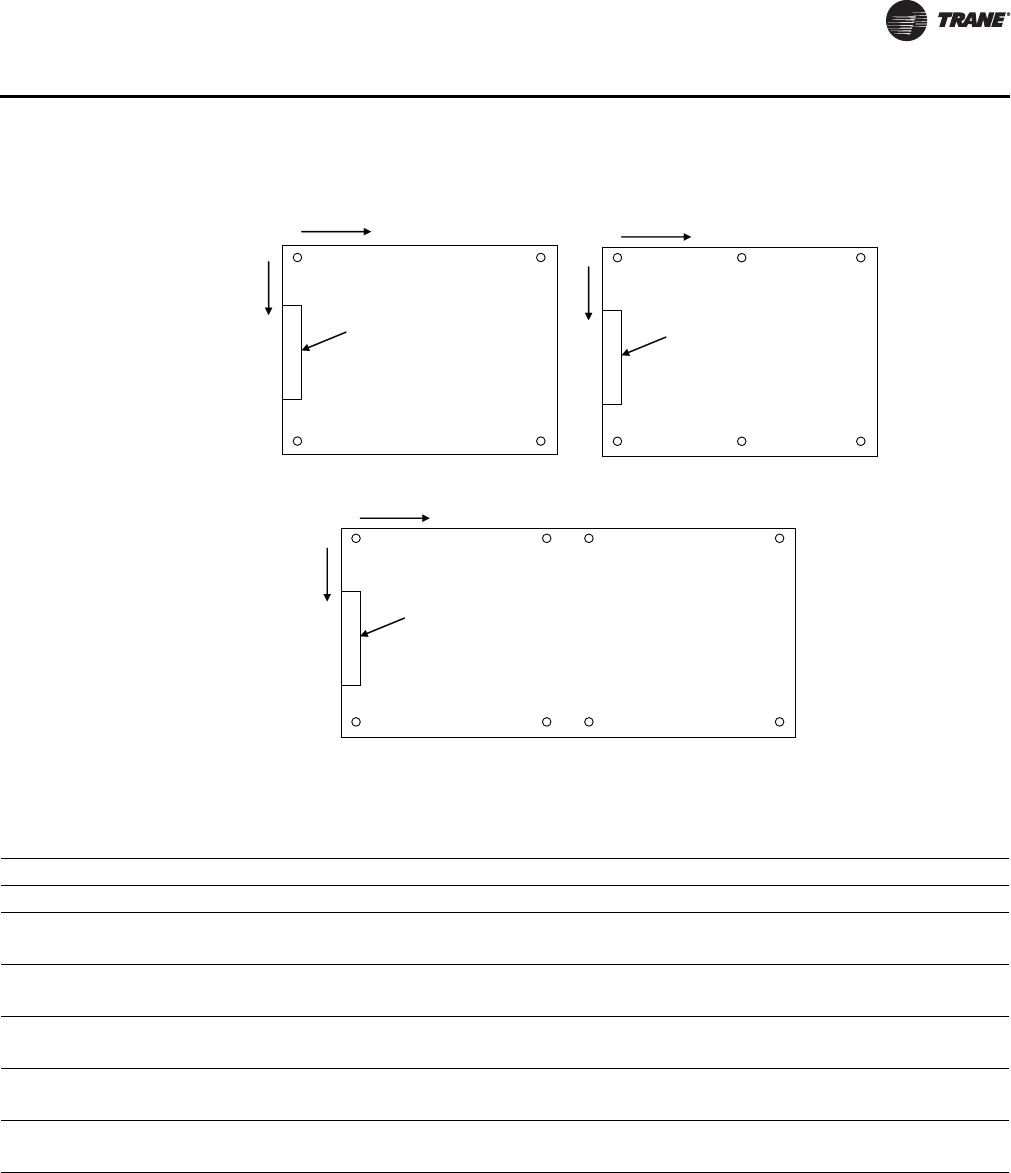
SS-PRC030-EN 49
Weights
Figure 42. Air-cooled condensing units
1
2
3
4
5
6
7
8
Control
Panel
X
Y
1
2
3
4
5
6
Control
Panel
X
Y
Control
Panel
1
2
3
4
X
Y
20-30 Ton 40-60 Ton
80-120 Ton
Table 13. Isolator mounting locations
Mounting Location
Unit Size 12345678
20/25/30 X 8” 8” 6' 8 1/8” 6' 8 1/8”
Y 4' 10 3/4” 1 1/4” 4' 10 3/4 1 1/4”
40 X 8” 8” 3' 8 1/8” 3' 8 1/8” 6' 8 1/4” 6' 8 1/4”
Y 7' 3 1/8” 1 1/4” 7' 3 1/8” 1 1/4” 7' 3 1/8” 1 1/4”
50/60 X 8” 8” 4' 8 7/8” 4' 8 7/8” 8' 9 3/4” 8' 9 3/4”
Y 7' 3 1/8” 1 1/4” 7' 3 1/8” 1 1/4” 7' 3 1/8 1 1/4”
80 X 8” 8” 6' 8 1/8” 6' 8 1/8” 9' 1/8 9' 1/8” 14' 1/4” 14' 1/4"
Y 7' 3 1/8” 1 1/4” 7' 3 1/8” 1 1/4” 7' 3 1/8 1 1/4” 7' 3 1/8” 1 1/4"
100/120 X 8” 8” 8' 9 5/8” 8' 9 5/8” 10' 1 5/8 10' 1 5/8” 18' 3 1/4” 18' 3 1/4”
Y 7' 3 1/8” 1 1/4” 7' 3 1/8” 1 1/4” 7' 3 1/8 1 1/4” 7' 3 1/8” 1 1/4"

50 SS-PRC030-EN
Mechanical Specifications
20 to 120-ton Condensing Units
General
All air-cooled condensing units have scroll compressors and are factory assembled and wired. Each
unit is shipped from the factory with a nitrogen holding charge. Units are constructed of 14-gauge
welded galvanized steel frame with 14 and 16-gauge galvanized steel panels and access doors. Unit
surface is phosphatized and finished with an air-dry paint. This air-dry paint finish is durable
enough to withstand a minimum of 500-consecutive-hour salt spray application in accordance with
standard ASTM B117.
Compressor
Trane 3-D Scroll compressors have a simple mechanical design with only three major moving parts.
Scroll type compression provides inherently low vibration. The 3-D Scroll provides a completely
enclosed compression chamber which leads to increased efficiency. Exhaustive testing on 3-D
Scroll, including start up with the shell full of liquid, has proven that slugging does not fail involutes.
Direct-drive, 3600 rpm, suction gas-cooled hermetic motor. Trane 3-D Scroll compressor includes
centrifugal oil pump, oil level sightglass and oil charging valve.
Split systems can have significantly more refrigerant than packaged systems and thus require
controls to reliably manage this excess refrigerant. Each compressor shall have crankcase heaters
installed, properly sized to minimize the amount of liquid refrigerant present in the oil sump during
off cycles. Additionally, the condensing unit shall have controls to initiate a refrigerant pump down
cycle at system shut down on each refrigerant circuit. To be operational, the refrigerant pump down
cycle requires a field provided and installed isolation solenoid valve on the liquid line near the
evaporator.
Condenser
Condenser coils are single or dual circuit having an all aluminum Microchannel design. The coils
are burst tested and leak tested. Factory installed liquid line service valves are standard. Direct
drive vertical discharge fans are statically and dynamically balanced. Three-phase motors have
permanently lubricated ball bearings and thermal overload protection. Optional low ambient
allows operating down to 0°F with external damper assembly for head pressure control.
Refrigerant Circuits and Capacity Modulation
20 to 30-ton sizes are single circuit and have two steps of capacity. The 40 to 60-ton sizes are two
circuits with four capacity steps. Each circuit has two compressors piped in parallel. Discharge and
liquid line service valves are standard on each circuit. 80, 100, and 120-ton sizes are two circuits with
six capacity steps. Each circuit has three compressors piped in parallel.
Unit Control
Factory-provided 115-volt control circuit includes fusing and control power transformer. The unit
is wired with magnetic contactors for compressor and condenser motors, three-leg, solid-state
compressor overload protection, and high-low pressure cutouts. Charge isolation, reset relay and
anti-recycle compressor timer are provided.
Corrosion Protected Condenser Coil
All Aluminum Microchannel condenser coil protection shall consist of a corrosion resistant coating
that shall withstand ASTM B117 Salt Spray test for 1000 hours and ASTM G85 A2 Cyclic Acidified
Salt Fog test for 2400 hours. This coating shall be added after coil construction, covering all tubes,
headers and fin edges, therefore providing optimal protection in more corrosive environments.

SS-PRC030-EN 51
Mechanical Specifications
Remote Evaporator Chillers
The remote chiller control option includes an interface panel in the main unit control box and a
remote mounted control box that is customer installed. The remote mounted box contains the
Honeywell W7100G controller. The chiller controller has an adjustable 0-10°F control band with
integrating logic, built in fixed-off timers and field installed discharge water temperature sensors
for control and chiller freeze protection. There are two capacity steps on 20, 25 and 30-ton sizes,
four capacity steps on 40, 50 and 60 ton sizes and six capacity steps on 80, 100 and 120 ton sizes.
The remote chiller accessory kit includes the evaporator with mounting hardware and insulation,
water strainer, minimum water flow limit switch and water side pipe stubs with couplings. The
chiller is a stainless steel brazed plate heat exchanger designed for up to 150 psig water side
working pressure and 430 psig refrigerant working pressure. Chiller mounting is intended for non-
freezing locations only. The strainer will prevent system debris larger than 0.039” from entering the
evaporator.
Trane optimizes the performance of homes and buildings around the world. A business of Ingersoll Rand, the
leader in creating and sustaining safe, comfortable and energy efficient environments, Trane offers a broad
portfolio of advanced controls and HVAC systems, comprehensive building services, and parts. For more
information, visit www.Trane.com.
Trane has a policy of continuous product and product data improvement and reserves the right to change design and specifications without notice.
We are committed to using environmentally
conscious print practices that reduce waste.
© 2012 Trane All rights reserved
SS-PRC030-EN 01 Mar 2012
Supersedes SS-PRC030-EN (24 Aug 2011)
