Trane Rauj Cauj 20 To 120 Tons Installation And Maintenance Manual SS SVX11H EN (10/2012)
2015-04-02
: Trane Trane-Rauj-Cauj-20-To-120-Tons-Installation-And-Maintenance-Manual-684213 trane-rauj-cauj-20-to-120-tons-installation-and-maintenance-manual-684213 trane pdf
Open the PDF directly: View PDF ![]() .
.
Page Count: 106 [warning: Documents this large are best viewed by clicking the View PDF Link!]
- Warnings, Cautions and Notices
- Introduction
- Model Number Descriptions
- General Information
- Unit Dimensions & Weights
- Installation
- Foundation
- Unit Isolation
- Leveling the Unit
- General Unit Requirements
- Refrigerant Piping Requirements
- EVP Chilled Water Piping Requirements
- Main Electrical Power Requirements
- Field Installed Control Wiring Requirements
- Low Voltage Wiring (AC & DC)
- Refrigerant Line Components
- Refrigerant Piping
- Typical Field-Installed Evaporator Piping: Dual-Circuit Examples
- Typical Field-Installed EVP Chiller Evaporator Piping
- Hot Gas Bypass for Commercial Comfort- Cooling Applications
- Optional Pressure Gauges
- Final Refrigerant Pipe Connections
- Brazing Procedures
- Leak Testing Procedure
- Remote EVP Chiller
- Field Installed Power Wiring
- Disconnect Switch External Handle (20- 120 Ton Factory Mounted Option)
- Main Unit Power Wiring
- Power Wire Sizing and Protection Device
- Field Installed Control Wiring
- Controls Using 115 VAC
- Controls using 24 VAC
- Controls using DC Analog Input/Outputs
- Economizer Actuator Circuit
- No System Control
- Variable Air Volume Control (Honeywell W7100A)
- Discharge Air Sensor (Honeywell 6RT3 or Honeywell 8RT3) Discharge Air Sensor
- Suction Line Thermostat
- Night Setback
- EVP Chiller Control
- Outside Air Thermostat (5S57 Field Provided)
- Constant Volume Control (Honeywell W973) — 20 - 60TUnits Only
- System Pre-Start Procedures
- EVP Chiller Applications
- System Evacuation Procedures
- Discharge Air Controller Checkout (Honeywell W7100A)
- Discharge Air Sensor Checkout (Honeywell Sensor)
- Economizer Actuator Checkout
- EVP Chiller Control Checkout (Honeywell W7100G)
- Chilled Water Sensor Checkout (Honeywell Sensor)
- Master Energy Control Checkout
- Operating Principals
- Start-Up
- Maintenance
- Warranty and Liability Clause
- Wiring Diagrams
SAFETY WARNING
Only qualified personnel should install and service the equipment. The installation, starting up, and
servicing of heating, ventilating, and air-conditioning equipment can be hazardous and requires specific
knowledge and training. Improperly installed, adjusted or altered equipment by an unqualified person could
result in death or serious injury. When working on the equipment, observe all precautions in the literature
and on the tags, stickers, and labels that are attached to the equipment.
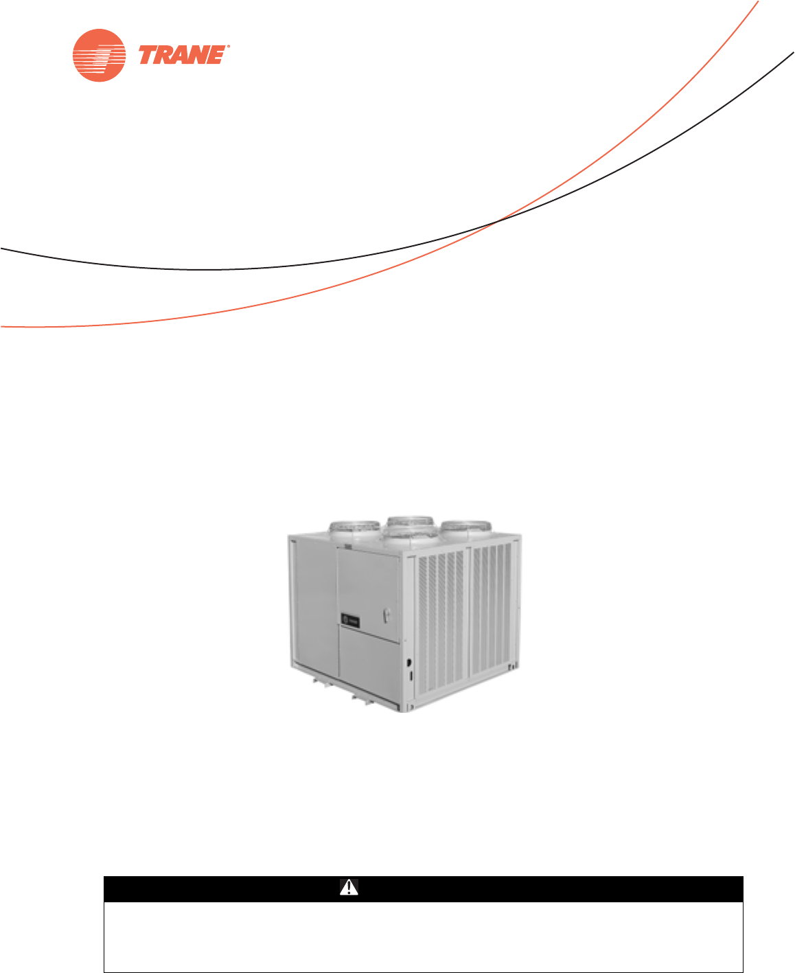
Remote Split System Units
and Remote Chillers
Air Cooled Condensing Units
October 2012 SS-SVX11H-EN
Installation, Operation,
and Maintenance
Models
RAUJ-C20 RAUJ-C40 RAUJ-C80
RAUJ-C25 RAUJ-C50 RAUJ-D10
RAUJ-C30 RAUJ-C60 RAUJ-D12
© 2012 Trane All rights reserved SS-SVX11H-EN
Warnings, Cautions and Notices
Warnings, Cautions and Notices. Note that warnings,
cautions and notices appear at appropriate intervals
throughout this manual. Warnings are provide to alert
installing contractors to potential hazards that could result
in death or personal injury. Cautions are designed to alert
personnel to hazardous situations that could result in
personal injury, while notices indicate a situation that
could result in equipment or property-damage-only
accidents.
Your personal safety and the proper operation of this
machine depend upon the strict observance of these
precautions.
Read this manual thoroughly before operating or servicing
this unit.
Important
Environmental Concerns!
Scientific research has shown that certain man-made
chemicals can affect the earth’s naturally occurring
stratospheric ozone layer when released to the
atmosphere. In particular, several of the identified
chemicals that may affect the ozone layer are refrigerants
that contain Chlorine, Fluorine and Carbon (CFCs) and
those containing Hydrogen, Chlorine, Fluorine and
Carbon (HCFCs). Not all refrigerants containing these
compounds have the same potential impact to the
environment. Trane advocates the responsible handling of
all refrigerants-including industry replacements for CFCs
such as HCFCs and HFCs.
Responsible Refrigerant Practices!
Trane believes that responsible refrigerant practices are
important to the environment, our customers, and the air
conditioning industry. All technicians who handle
refrigerants must be certified. The Federal Clean Air Act
(Section 608) sets forth the requirements for handling,
reclaiming, recovering and recycling of certain
refrigerants and the equipment that is used in these
service procedures. In addition, some states or
municipalities may have additional requirements that
must also be adhered to for responsible management of
refrigerants. Know the applicable laws and follow them.
ATTE NT ION : Warnings, Cautions and Notices appear at
appropriate sections throughout this literature. Read
these carefully:
WARNING Indicates a potentially hazardous
situation which, if not avoided, could
result in death or serious injury.
CAUTIONsIndicates a potentially hazardous
situation which, if not avoided, could
result in minor or moderate injury. It
could also be used to alert against
unsafe practices.
NOTICE: Indicates a situation that could result in
equipment or property-damage only
WARNING
R-410A Refrigerant under Higher Pressure
than R-22!
The units described in this manual use R-410A
refrigerant which operates at higher pressures than R-22
refrigerant. Use ONLY R-410A rated service equipment
or components with these units. For specific handling
concerns with R-410A, please contact your local Trane
representative.
Failure to use R-410A rated service equipment or
components could result in equipment exploding under
R-410A high pressures which could result in death,
serious injury, or equipment damage.
WARNING
Proper Field Wiring and Grounding
Required!
All field wiring MUST be performed by qualified
personnel. Improperly installed and grounded field
wiring poses FIRE and ELECTROCUTION hazards. To
avoid these hazards, you MUST follow requirements for
field wiring installation and grounding as described in
NEC and your local/state electrical codes. Failure to
follow code could result in death or serious injury.
WARNING
Personal Protective Equipment (PPE)
Required!
Installing/servicing this unit could result in exposure to
electrical, mechanical and chemical hazards.
• Before installing/servicing this unit, technicians
MUST put on all Personal Protective Equipment (PPE)
recommended for the work being undertaken.
ALWAYS refer to appropriate MSDS sheets and OSHA
guidelines for proper PPE.
• When working with or around hazardous chemicals,
ALWAYS refer to the appropriate MSDS sheets and
OSHA guidelines for information on allowable
personal exposure levels, proper respiratory
protection and handling recommendations.
• If there is a risk of arc or flash, technicians MUST put
on all Personal Protective Equipment (PPE) in
accordance with NFPA 70E or other country-specific
requirements for arc flash protection, PRIOR to
servicing the unit.
Failure to follow recommendations could result in death
or serious injury.

Introduction
SS-SVX11H-EN 3
Introduction
Overview of Manual
Note: One copy of this document ships inside the control
panel of each unit and is customer property. It must
be retained by the unit's maintenance personnel.
This booklet describes proper installation, operation, and
maintenance procedures for air cooled systems. By
carefully reviewing the information within this manual
and following the instructions, the risk of improper
operation and/or component damage will be minimized. It
is important that periodic maintenance be performed to
help assure trouble free operation. A maintenance
schedule is provided at the end of this manual. Should
equipment failure occur, contact a qualified service
organization with qualified, experienced HVAC technicians
to properly diagnose and repair this equipment.
Revision Summary
SS-SVX11H-EN
Update valve selection part numbers and wiring diagram
drawing numbers.
Trademarks
Trane, Frostat and the Trane logo are trademarks of Trane
in the United States and other countries. All trademarks
referenced in this document are the trademarks of their
respective owners.

4 SS-SVX11H-EN
Table of Contents
Model Number Descriptions . . . . . . . . . . . . . . 6
General Information . . . . . . . . . . . . . . . . . . . . . 7
Unit Inspection . . . . . . . . . . . . . . . . . . . . . . 7
Unit Dimensions & Weights . . . . . . . . . . . . . 10
Unit Clearances . . . . . . . . . . . . . . . . . . . . . . 10
Dimensions . . . . . . . . . . . . . . . . . . . . . . . . . . 11
Unit Isolation . . . . . . . . . . . . . . . . . . . . . . . . 32
Neoprene Isolators (20 - 60 Ton units) . . 32
Spring Isolators (20 - 120 Ton units) . . . . 32
Installation . . . . . . . . . . . . . . . . . . . . . . . . . . . . . 34
Foundation . . . . . . . . . . . . . . . . . . . . . . . . 34
Unit Isolation . . . . . . . . . . . . . . . . . . . . . . 34
Leveling the Unit . . . . . . . . . . . . . . . . . . . 34
General Unit Requirements . . . . . . . . . . . 34
Refrigerant Piping Requirements . . . . . . 34
EVP Chilled Water Piping Requirements 34
Main Electrical Power Requirements . . . 35
Field Installed Control Wiring
Requirements . . . . . . . . . . . . . . . . . . . . . . 35
Low Voltage Wiring (AC & DC) . . . . . . . . 36
Refrigerant Line Components . . . . . . . . . 36
Refrigerant Piping . . . . . . . . . . . . . . . . . . 38
Typical Field-Installed Evaporator Piping:
Dual-Circuit Examples . . . . . . . . . . . . . . . 40
Typical Field-Installed EVP Chiller
Evaporator Piping . . . . . . . . . . . . . . . . . . . 41
Hot Gas Bypass for Commercial
Comfort-Cooling Applications . . . . . . . . . 41
Optional Pressure Gauges . . . . . . . . . . . . 42
Final Refrigerant Pipe Connections . . . . 43
Brazing Procedures . . . . . . . . . . . . . . . . . 43
Leak Testing Procedure . . . . . . . . . . . . . . 44
Remote EVP Chiller . . . . . . . . . . . . . . . . . 44
Field Installed Power Wiring . . . . . . . . . . 48
Disconnect Switch External Handle
(20-120 Ton Factory Mounted Option) . . 48
Main Unit Power Wiring . . . . . . . . . . . . . 49
Power Wire Sizing and Protection Device 49
Field Installed Control Wiring . . . . . . . . . 52
Controls Using 115 VAC . . . . . . . . . . . . . 52
Controls using 24 VAC . . . . . . . . . . . . . . . .53
Controls using DC Analog Input/Outputs .54
Economizer Actuator Circuit . . . . . . . . . . .54
No System Control . . . . . . . . . . . . . . . . . . .55
Variable Air Volume Control (Honeywell
W7100A) . . . . . . . . . . . . . . . . . . . . . . . . . . .60
Discharge Air Sensor (Honeywell 6RT3 or
Honeywell 8RT3) Discharge Air Sensor . .62
Suction Line Thermostat . . . . . . . . . . . . . .62
Night Setback . . . . . . . . . . . . . . . . . . . . . . .63
EVP Chiller Control . . . . . . . . . . . . . . . . . . .63
Outside Air Thermostat
(5S57 Field Provided) . . . . . . . . . . . . . . . . .66
Constant Volume Control
(Honeywell W973) — 20 - 60TUnits Only .66
System Pre-Start Procedures . . . . . . . . . . . . .70
EVP Chiller Applications . . . . . . . . . . . . . .70
System Evacuation Procedures . . . . . . . .70
Discharge Air Controller Checkout
(Honeywell W7100A) . . . . . . . . . . . . . . . . .72
Discharge Air Sensor Checkout
(Honeywell Sensor) . . . . . . . . . . . . . . . . . .73
Economizer Actuator Checkout . . . . . . . . .73
EVP Chiller Control Checkout
(Honeywell W7100G) . . . . . . . . . . . . . . . . .74
Chilled Water Sensor Checkout
(Honeywell Sensor) . . . . . . . . . . . . . . . . . .75
Master Energy Control Checkout . . . . . . . .75
Zone Thermostat Checkout
(Honeywell T7067) . . . . . . . . . . . . . . . . . . .76
Discharge Air Sensor Checkout
(Honeywell 6RT1) . . . . . . . . . . . . . . . . . . . .77
Voltage Imbalance . . . . . . . . . . . . . . . . . . .77
Electrical Phasing . . . . . . . . . . . . . . . . . . .78
Operating Principals . . . . . . . . . . . . . . . . . . . . .79
Start-Up . . . . . . . . . . . . . . . . . . . . . . . . . . . . . . . .83
Low Ambient Damper Adjustment
(Factory or Field Installed) . . . . . . . . . . . . .83
EVP Chiller Applications . . . . . . . . . . . . . .83
“Air Over” Evaporator Application . . . . . .83
System Airflow Measurement . . . . . . . . .84
Preliminary Expansion Valve Adjustment 84

SS-SVX11H-EN 5
Adding Preliminary Charge . . . . . . . . . . . 86
Compressor Start-Up (All Systems) . . . . 86
Pressure Curves . . . . . . . . . . . . . . . . . . . . 92
Final System Setup . . . . . . . . . . . . . . . . . 95
Maintenance . . . . . . . . . . . . . . . . . . . . . . . . . . . 97
Compressor Operational Sounds . . . . . . 97
Scroll Compressor Failure Diagnosis
and Replacement . . . . . . . . . . . . . . . . . . . 97
Fuse Replacement Data . . . . . . . . . . . . . 101
Fall Restraint - Condenser Section Roof 101
Monthly Maintenance . . . . . . . . . . . . . . 102
Coil Cleaning . . . . . . . . . . . . . . . . . . . . . . 102
Warranty and Liability Clause . . . . . . . . . . . 104
Wiring Diagrams . . . . . . . . . . . . . . . . . . . . . . 105
6 SS-SVX11H-EN
Model Number Descriptions
20 to 60-Ton Units1
DIGIT 1 — UNIT TYPE
R = Condensing Unit
DIGIT 2 — CONDENSER
A = Air Cooled
DIGIT 3 — AIRFLOW
U = Upflow
DIGIT 4 — DEVELOPMENT
SEQUENCE
J= Third
DIGITS 5,6,7 — NOMINAL
CAPACITY
C20 = 20 Tons
C25 = 25 Tons
C30 = 30 Tons
C40 = 40 Tons
C50 = 50 Tons
C60 = 60 Tons
DIGIT 8 — VOLTAGE AND START
CHARACTERISTICS
E = 200/60/3 XL
D = 415/50/3 XL
F = 230/60/3 XL
4 = 460/60/3 XL
5 = 575/60/3 XL
9 = 380/50/3 XL
DIGIT 9 — SYSTEM CONTROL
B = No System Control
C = Constant Volume Control
E = Supply Air VAV Control
P = EVP Control
DIGIT 10 — DESIGN SEQUENCE
X = Factory Assigned
DIGIT 11 — AMBIENT CONTROL
0 = Standard
1 = 0°F (Low Ambient Dampers)
DIGIT 12 — AGENCY APPROVAL
0 = None
3 = cULus (not available for 50 Hz)
DIGIT 13
A = Non Fused Unit Disconnect Switch
DIGIT 14
B = Hot Gas Bypass Valve
DIGIT 15
D = Suction Service Valves
DIGIT 16
F = Pressure Gauges and Piping
DIGIT 17
G = Return Air Sensor
DIGIT 18
J = Corrosion Protected Condenser Coil
DIGIT 19
C = Remote Chiller Evaporator & Install
Kit
T = Flow Switch (EVP Control Only)
DIGIT 20
1 = Spring Isolators
2 = Neoprene Isolators
80 to 120-Ton Units1
DIGIT 1 — UNIT TYPE
R = Remote Condensing Unit
DIGIT 2 — CONDENSER
A = Air-Cooled
DIGIT 3 — AIRFLOW
U = Upflow
DIGIT 4 — DEVELOPMENT
SEQUENCE
J = Third
DIGITS 5,6,7 — NOMINAL
CAPACITY
C80 = 80 Tons
D10 = 100 Tons
D12 = 120 Tons
DIGIT 8 — VOLTAGE AND START
CHARACTERISTICS
E = 200/60/3 XL
F = 230/60/3 XL
4 = 460/60/3 XL
5 = 575/60/3 XL
* = 380/50/3 XL2
* = 415/50/3 XL2
DIGIT 9 — SYSTEM CONTROL
B = No System Control
E = Supply Air VAV Control
P = EVP Control
DIGIT 10 — DESIGN SEQUENCE
X = Factory Assigned
DIGIT 11 — AMBIENT CONTROL
0 = Standard
1 = 0°F (Low Ambient Dampers)
DIGIT 12 — AGENCY APPROVAL
0 = None
3 = cULus (not available for 50 Hz)
DIGIT 13 — NUMBER OF
CIRCUITS
2 = Dual (All 80-120 Ton)
DIGIT 14
B = Hot Gas Bypass Valve
DIGIT 15
D = Suction Service Valves
DIGIT 16
F = Pressure Gauges and Piping
DIGIT 17
H = Corrosion Protected Condenser Coil
DIGIT 18
1 = Spring Isolators
DIGIT 19
C = Remote Chiller Evap & Install Kit
3 = Flow Switch ( EVP Control only)
1The service digit for each model number contains 21 digits; all 21 digits must be referenced.
2Contact the local Trane Sales Office for ordering information regarding 80-120 50Hz models.
SS-SVX11H-EN 7
General Information
Unit Inspection
As soon as the unit arrives at the job site
• Verify that the nameplate data matches the data on the
sales order and bill of lading (including electrical data).
• Verify that the power supply complies with the unit
nameplate specifications.
• Visually inspect the exterior of the unit, including the
roof, for signs of shipping damage.
• Check for material shortages. Refer to the Component
Layout and Ship with Location illustration.
Important: If the job site inspection of the unit reveals
damage or material shortages, file a claim
with the carrier immediately. Specify
the type and extent of the damage on
the ‘bill of lading” before signing.
• Visually inspect the internal components for shipping
damage as soon as possible after delivery and before
it is stored. Do not walk on the sheet metal base pans.
Bridging between the unit's main supports may consist of
multiple 2 by 12 boards or sheet metal grating.
• If concealed damage is discovered, notify the carrier's
terminal of damage immediately by phone and by
mail. Concealed damage must be reported within 15
days.
• Request an immediate joint inspection of the damage
by the carrier and the consignee. Do not remove
damaged material from the receiving location. Take
photos of the damage, if possible. The owner must
provide reasonable evidence that the damage did not
occur after delivery.
• Notify the appropriate Trane office before installing or
repairing a damaged unit.
Unit Nameplate
One Mylar unit nameplate is located on the outside upper
right corner of the control panel door. It includes the unit
model number, serial number, electrical characteristics,
weight, refrigerant charge, as well as other pertinent unit
data. A small metal nameplate with the Model Number,
Serial Number, and Unit Weight is located just above the
Mylar nameplate, and a third nameplate is located on the
inside of the control panel door.
When ordering replacement parts or requesting service,
be sure to refer to the specific model number, serial
number, and DL number (if applicable) stamped on the
unit nameplate.
Compressor Nameplate
The nameplate for the “Scroll” compressors is located on
the compressor lower housing.
EVP Chiller - Applications Only
If ordered with remote EVP chiller kit, piping components
ship in condenser section. The heat exchanger ships
separately. The 20-30 chiller nameplate is located on same
side as water connections near center left. The 40-120 Ton
chiller nameplate is located on same side as water
connections near bottom. To view, raise insulation flap
over nameplate. Replace and retape insulation flap after
viewing.
Phase Monitor (1U3)
The unit is equipped with a phase monitor in the control
box. The phase monitor will protect against phase loss,
imbalance and reversal of the line voltage. If a fault occurs,
the red LED will energize. While the fault condition is
present the phase monitor interrupts the 115V control
circuit. If no faults are observed, a green LED will be
energized.
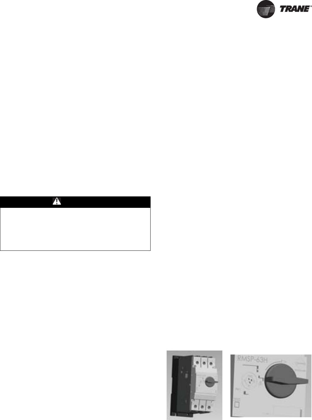
Manual Motor Protectors (380V through 575V
Only): Manual motor protectors will be used as branch
circuit protection for compressors. These devices are
capable of providing both overload and short-circuit
protection.
Before operating, the manual motor protector must be
switched with the rotary on/off switch to the “ON” position
and the overload setpoint dial must be set to the
appropriate rating of the motor.
Important: In order to avoid nuisance trips, the
overload setpoint dial must be adjusted to
the following calculated value:
•Overload Setting = (Compressor RLA) x 1.12
WARNING
No Step Surface!
Do not walk on the sheet metal drain pan. Walking on
the drain pan could cause the supporting metal to
collapse, resulting in the operator/technician to fall.
Failure to follow this recommendation could result in
death or serious injury.
Figure 1. Compressor protection module
General Information
8 SS-SVX11H-EN
On 80-120 Ton units, the CSHN*** compressors come
equipped with a compressor protection device capable of
detecting phase reversal, phase loss, and phase
unbalance. The compressor protection device uses a
Green and Red LED to indicate the compressor status. A
solid Green LED denotes a fault free condition; a blinking
Red LED indicates an identifiable fault condition. Once a
problem has been detected, the power will have to be
cycled to clear the reset circuit.
Note: If the compressor has tripped, the resistance will be
4500 ohms or greater; when reset, they will be less
than 2750 ohms.
Blink Code: The blink code consists of different on / off time
of the Red LED which is repeated continuously until either
the fault is cleared or until power is cycled.
Discharge Line Thermostat
The first compressor on each circuit is equipped with a
Discharge Line Thermostat. If the temperature of the line
exceeds 230F the thermostat interrupts the 115V control
circuit for the compressors and all the compressors on the
circuit will de-energize. Once the temperature drops below
180F the thermostat will close and allow the compressor to
be energized.
Unit Description
All air cooled condensing units are designed for outdoor
installations with vertical air discharge. These units may
be installed on a flat roof or placed on a concrete slab at
ground level.
Before shipment, each unit is leak-tested, evacuated, a
nitrogen holding charge is added, and the controls are
tested for proper operation.
The condenser coils an all Aluminum Microchannel
design. Corrosion protected condenser coils are a
standard option. Louvered condenser grilles for coil
protection are standard. Direct-drive, vertical discharge
condenser fans are provided with built-in current and
overload protection.
For “Ship with” items, see Figure 2, p. 9 and Figure 3, p. 9.
If low ambient operation is required, low ambient
dampers are available as a field or factory installed option.
Units may be ordered with one of the following options:
• No System Controls (Field provided controls required)
• Constant Volume Controls
• Supply Air Temperature Control (VAV applications)
• EVP Chiller Controls
Basic unit components include:
• Manifolded Scroll Compressors
• Condenser coils
• Condenser fans (number based on unit size)
• Discharge service valve (one per circuit)
• Liquid line service valve (one per circuit)
Table 1. Blink codes
Fault LED on LED off LED on LED off
PTC(a) overheat or PTC
reset delay active
(a) PTC = Positive Temperature Coefficient
short long short long
Phase loss long long long long
Incorrect phase
sequence short short short long
Table 2. General data - 20 - 120 Ton remote chillers
Model Number
RAUJ-
C20
RAUJ-
C25
RAUJ-
C30
RAUJ-
C40
RAUJ-
C50
RAUJ-
C60
RAUJ-
C80
RAUJ-
D10
RAUJ-
D12
Shipping weight, lbs 44 84 113 90 135 157 208 292 320
Operating weight, lbs 56 104 142 131 206 244 330 473 520
No. of refrigerant circuits 1 1 1 2 2 2 2 2 2
Water volume, Gal 1.4 2.2 3.3 4.6 7.9 9.7 13.6 20.1 22.2
Chiller refrig charge @ AHRI condition, lbs 0.9 1.5 2.2 3.1 5.3 6.4 9.0 13.3 14.7
Minimum water flow rate, GPM 24 30 36 48 60 72 96 120 144
Maximum water flow rate, GPM 69 89 100 136 176 201 275 346 407
Chiller Water Supply/Return Pipe Size, in 2.0 2.0 2.0 3.0 3.0 3.0 4.0 4.0 4.0
Notes:
1. All heat exchangers are brazed plate.
2. All heat exchangers are single circuit on the water side.
3. Shipping and operating weights are approximate.
4. Refrigerant charge is approximate and for chiller only.
5. Applications with leaving water temperature below 42°F require freeze protection down to 15°F.
6. Maximum chiller operating ambient is 115°F.
General Information
SS-SVX11H-EN 9
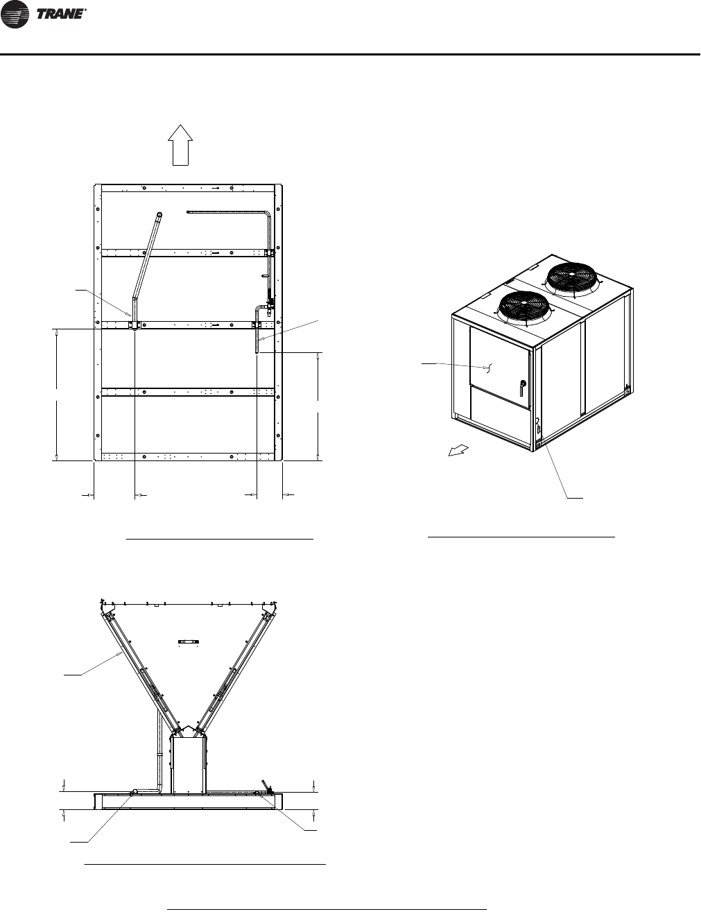
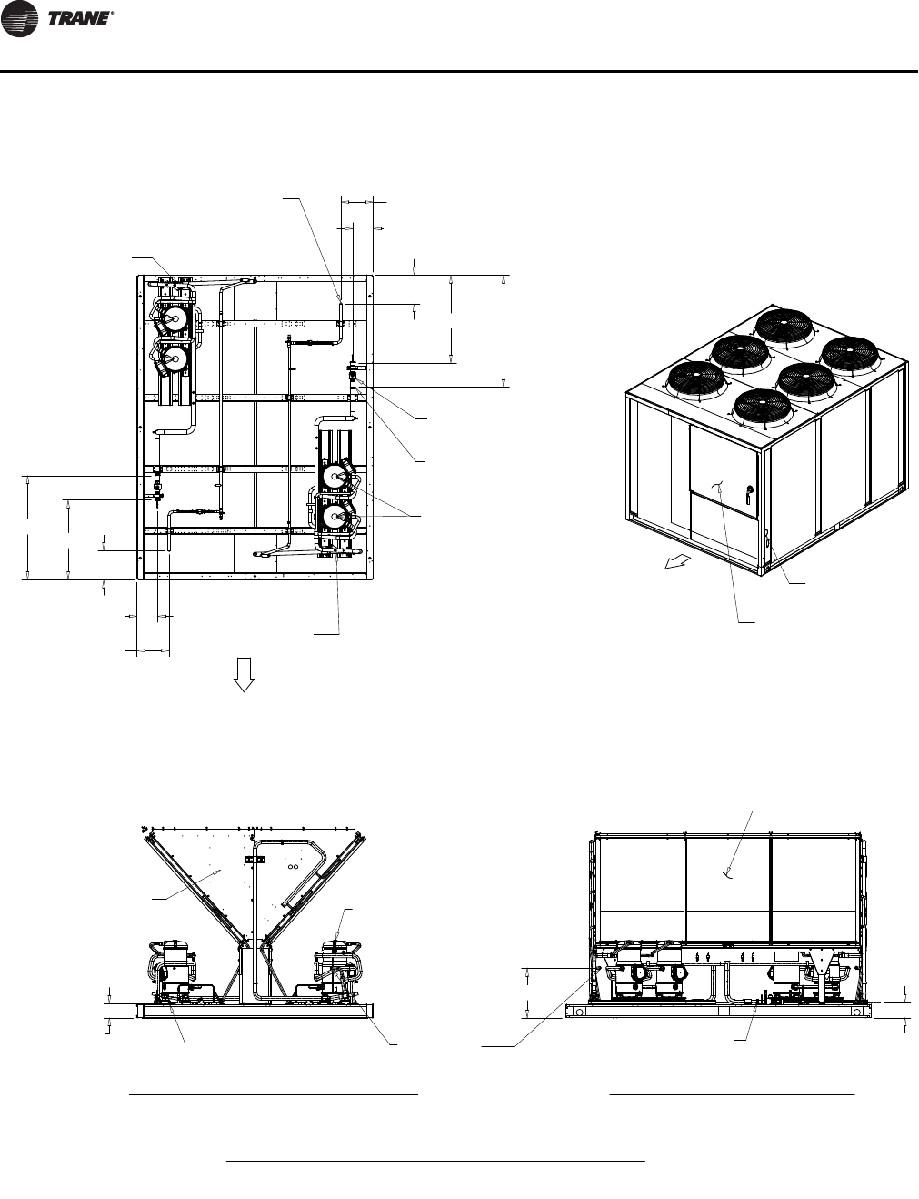
Figure 2. Component layout and ‘ship-with’ locations 20 - 60T units(a)
(a) 60T unit shown
Condenser
Coil
Access
Panels
Lifting
Bracket
(2/side)
Condenser
Air Intake
Grills
“Shipwith”
Area
Control
Panel
Compressors
Condenser
Fans
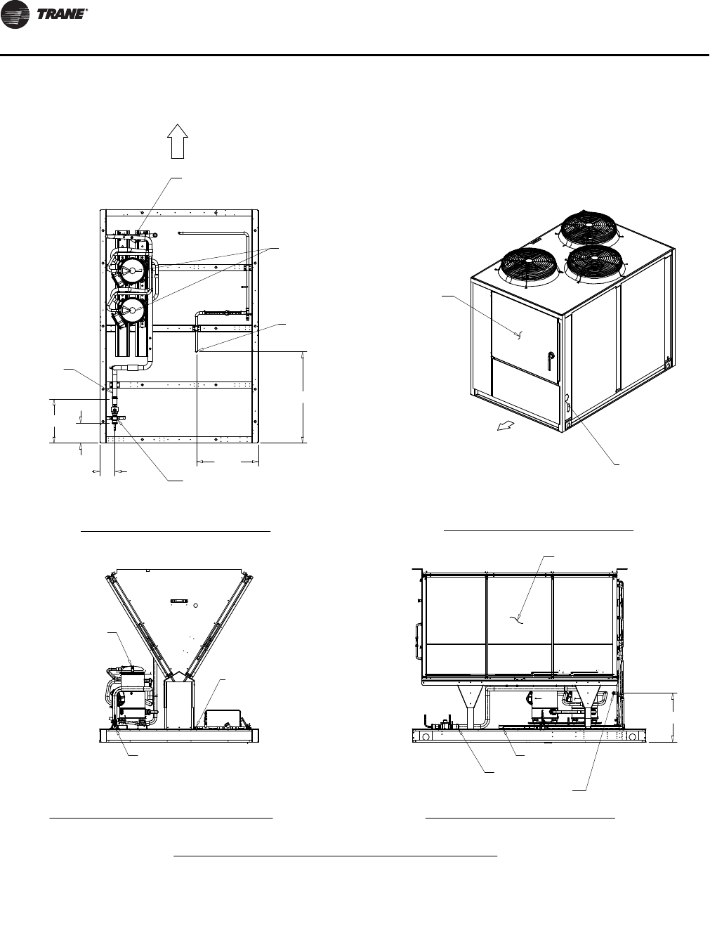
Figure 3. Component layout and ‘ship-with’ locations 80 - 120T units(a)
(a) 120T unit shown
Condenser
Coil
Access
Panels Lifting
Bracket
(2/side)
Condenser
Air Intake
Grills
Control
Panel
Compressors
Condenser
Fans
“Shipwith”
Area
10 SS-SVX11H-EN
Unit Dimensions & Weights
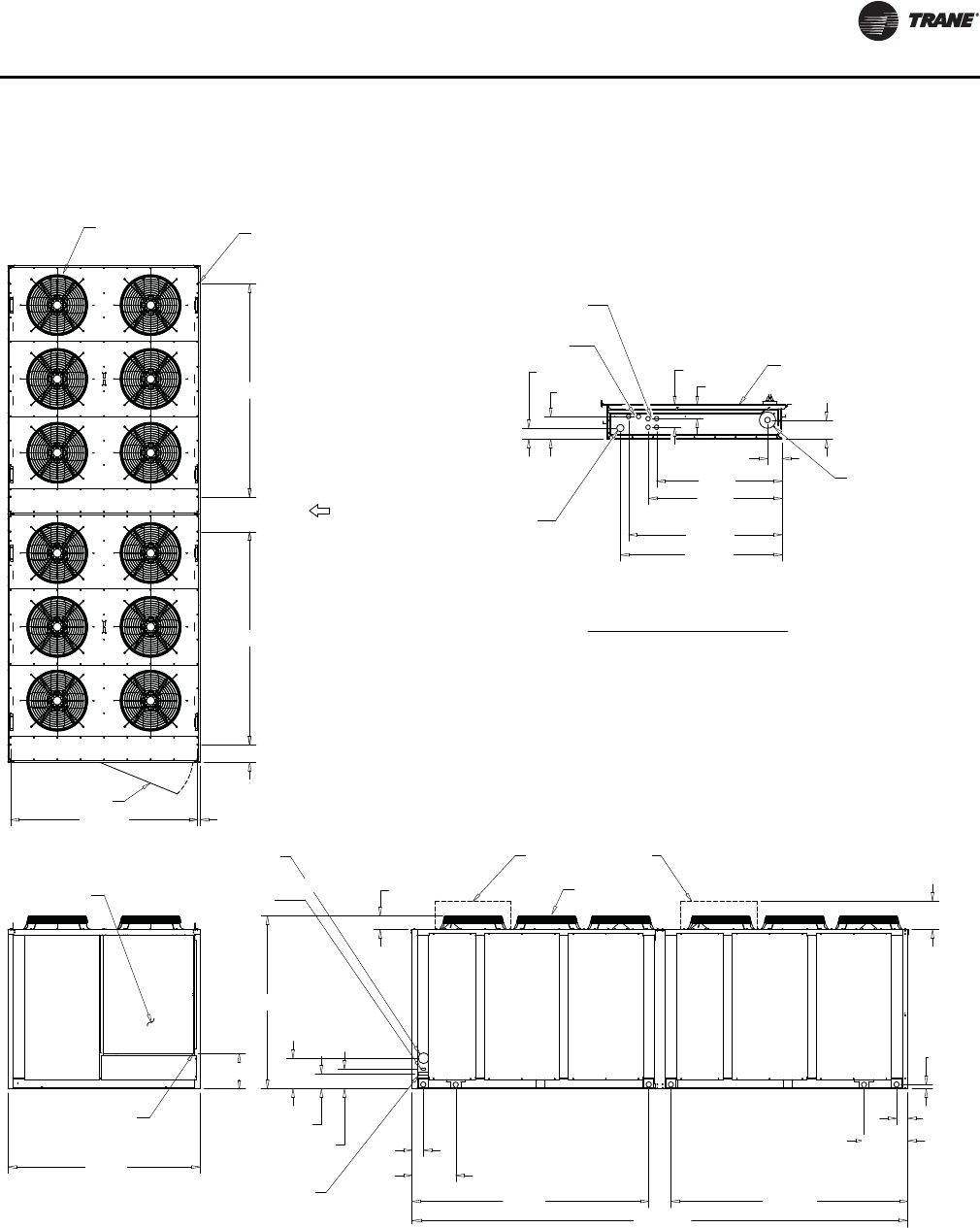
Unit Clearances
Figure 4, p. 10 illustrates the minimum operating and
service clearances for either a single, multiple, or pit
application. These clearances are the minimum distances
necessary to assure adequate serviceability, cataloged
unit capacity, and peak operating efficiency.
Locate the unit as close to the applicable system support
equipment as possible to minimize refrigerant piping
lengths.
Allow adequate clearance for water and refrigerant piping
connections, space to perform service procedures, i.e.
read gauges, thermometers, and operate water system
valves.
EVP Chiller Considerations
Allow adequate clearance for water and refrigerant piping
connections, space to perform service procedures, (i.e.
read gauges, thermometers, and operate water system
valves.
Note: The braze plate chiller is intended for indoor
application. If a sub-freezing location is required,
contact Trane for installation precautions required
to prevent damage.
NOTICE:
Equipment Damage!
Providing less than the recommended clearances could
result in condenser coil starvation or recirculation of
hot condenser air.
Figure 4. Typical installation clearances for single, multiple or pit applications (20-60 Ton units only)
Unit Dimensions & Weights
SS-SVX11H-EN 11
Dimensions
Figure 5. 20-Ton air-cooled condensing unit
4" CONDUIT
MAIN POWER
1 3/4" KO LOW
VOLTAGE (30V MAX.)
37 11/16"
3 3/8"
CONTROL PANEL
35 13/16"
31 1/4"
29 1/4"
4 1/2"
2 5/8"
5 5/16"
5 3/8"
3 3/8"
1/2" X 4 KO (115V)
1/2" X 2 KO (115V)
4 3/8"
6 1/8"
88 5/16"
74 1/4"
60"
11 1/2"
18"
1 1/4" x 4 1/2"
SLOT FOR 115
VOLT CONTROL
4" LINE
VOLTAGE
ACCESS
78"
5 3/16"
1 13/16"
LOW AMBIENT
DAMPER (SEE NOTE 2)
FAN GRILLE
FAN GRILLE
CONTROL PANEL
(SEE DETAIL A)
26 13/16"
CONTROL BOX BOTTOM
(SEE DETAIL A)
13"
6 1/4"
57 5/8"
1 1/4"
8"
72 1/2"
3/4" X 4 MTG HOLES
DOOR 43 1/4" W/
180 DEG SWING
2 1
4 3
FRONT (SEE
NOTE 3 FOR
ALL MIN.
CLEARANCE)
NOTES:
1. SEE CONNECTION DRAWING FOR CONNECTION LOCATION AND SIZES.
2. LOW AMBIENT DAMPER ONLY COMES WITH SELECTED UNIT .
3. FRONT OF UNIT CLEARANCE 72" . BACK OF UNIT CLEARANCE 72" .
LEFT AND RIGHT SIDE OF UNIT CLEARANCE 42".
DETAIL A
CONTROL BOX BOTTOM
Unit Dimensions & Weights
12 SS-SVX11H-EN
Figure 6. 20-Ton air-cooled condensing unit (connections)
VOLTAGE ACCESS
CONTROL PANEL
5/8" O.D.
LIQUID LINE
8 1/16"
13"
42"
SCALE1,00
0
34 1/2"
5 7/16"
5 3/4"
LIQUID LINE
SUCTION LINE
COIL
1 5/8" O.D.
SUCTION LINE
CONTROL PANEL SIDE
CONTROL
PANEL SIDE
20 TON UNIT
PLAN VIEW OF UNIT
CONNECTION DRAWING
CONNECTION DRAWING
CONTROL PANEL SIDE VIEW OF UNIT
ISOMETRIC DRAWING
ORIENTATION VIEW OF UNIT
NOTES:
1. VERIFY WEIGHT, CONNECTION, AND ALL DIMENSION WITH
INSTALLER DOCUMENTS BEFORE INSTALLATION

Unit Dimensions & Weights
SS-SVX11H-EN 13
Figure 7. 25- and 30-Ton air-cooled condensing unit
1/2" X 4 KO (115V)
1 3/4" KO LOW
VOLTAGE (30V MAX.)
1/2" X 2 KO (115V)
CONTROL PANEL
4 1/2"
3 3/8"
5 3/8"
2 5/8"
37 11/16"
35 13/16"
5 5/16"
3 3/8"
31 1/4"
29 1/4"
4" CONDUIT
MAIN POWER
1.6
CONTROL BOX BOTTOM
(SEE DETAIL A)
FAN GRILLE
LOW AMBIENT
DAMPER (SEE NOTE 2)
FAN GRILLE
4" LINE
VOLTAGE ACCESS
1 1/4" x 4 1/2"
SLOT FOR 115
VOLT CONTROL
88 1/2"
60 1/8"
74 1/4"
18"
11 1/2"
88 5/16"
78"
4 3/8"
6 1/8"
5 3/16"
1 13/16"
13"
6 1/4"
CONTROL PANEL
(SEE DETAIL A)
27 1/4"
57 5/8"
1 1/4"
8"
72 1/2"
DOOR 43 1/4" W/
180 DEG SWING
2 1
3
4
3/4" X 4 MTG HOLES
FRONT (SEE
NOTE 3 FOR
ALL MIN.
CLEARANCE)
CONTROL BOX BOTTOM
DETAIL A
NOTES:
1. SEE CONNECTION DRAWING FOR CONNECTION LOCATION AND SIZES.
2. LOW AMBIENT DAMPER ONLY COMES WITH SELECTED UNIT .
3. FRONT OF 20 AND 30 UNIT CLEARANCE 72" . BACK OF UNIT CLEARANCE 72”.
LEFT AND RIGHT SIDE OF 20 AND 30 UNIT CLEARANCE 42”.
Unit Dimensions & Weights
14 SS-SVX11H-EN
Figure 8. 25- and 30-Ton air-cooled condensing unit (connections)
HOT GAS BYPASS (OPTIONAL)
LIQUID LINE
7/8" O.D. HOT GAS
BYPASS (OPTIONAL)
7/8" O.D.
LIQUID LINE
SERVICE VALVE (OPTIONAL)
COIL
COMPRESSORS
16 9/16"
5 11/16"
7 9/16"
34 1/2"
23 1/2"
A
B
A
CONTROL PANEL
VOLTAGE ACCESS
SCALE1 .00 0
CONTROL PANEL SIDE
AA
C
FRONT
AA
A
C
AA
C
FRONT
AA
A
C
AA
C
FRONT
A A
A
C
AA
C
FRONT
A A
A
C
SUCTION LINE
18 9/16"
SUCTION LINE
LIQUID LINE
COIL
25 - 30 TON UNIT
DIMENSIONAL CONNECTION DRAWING
PLAN VIEW OF UNIT
CONNECTION DRAWING
CONNECTION DRAWING
CONTROL PANEL SIDE VIEW OF UNIT
ISOMETRIC DRAWING
ORIENTATION VIEW OF UNIT
BACK VIEW OF UNIT
CONNECTION DRAWING
SUCTION LINE
Horizontal
25T: 2 1/8” O.D.
30T: 2 1/8” O.D.
Vertical
25T: 1 5/8” O.D.
30T: 2 1/8” O.D.
Unit Dimensions & Weights
SS-SVX11H-EN 15
Figure 9. 40-Ton air-cooled condensing unit
29 1/4"
31 1/4"
35 13/16"
37 11/16"
3 3/8"
3 3/8"
5 5/16"
2 5/8" 5 3/8"
1 3/4" KO LOW
VOLTAGE (30V MAX.)
1/2" X 2 KO (115V)
1/2" X 4 KO (115V)
4 1/2"
4" CONDUIT
MAIN POWER
CONTROL PANEL
88 9/16"
88 5/16"
22 1/2"
16"
4 3/8"
6 1/8"
5 3/16"
1 15/16"
88 5/16"
79 1/4"
13"
LOW AMBIENT
DAMPER (SEE NOTE 2)
FAN GRILLE
FAN GRILLE
1 1/4" x 4 1/2"
SLOT FOR 115
VOLT CONTROL
4" LINE
VOLTAGE ACCESS
CONTROL PANEL
(SEE DETAIL A)
6 1/4"
32 3/16"
BOTTOM OF CONTROL
BOX (SEE DETAIL A)
DOOR 43 1/4" W/
180 DEG SWING
2
3
6
8"
36 1/8"
36 1/8"
1 1/4"
1
4
5
3/4" X 6
MTG HOLES
85 5/8"
FRONT (SEE
NOTE 3 FOR
ALL MIN.
CLEARANCE)
DETAIL A
BOTTOM OF CONTROL BOX
NOTES:
1. SEE CONNECTION DRAWING FOR CONNECTION LOCATION AND SIZES.
2. LOW AMBIENT DAMPER ONLY COMES WITH SELECTED UNIT .
3. FRONT AND BACK OF UNIT CLEARANCE 72" . LEFT AND RIGHT
SIDE OF UNIT CLEARANCE 42".
Unit Dimensions & Weights
16 SS-SVX11H-EN
Figure 10. 40-Ton air-cooled condensing unit (connections)
1 5/8" O.D.
SUCTION LINE
COMPRESSORS
COMPRESSOR
COIL
7/8" O.D. HOT GAS
BYPASS (OPTIONAL)
7/8" O.D. HOT GAS
BYPASS (OPTIONAL)
5/8" O.D.
LIQUID LINE
12"
7 11/16"
13 3/4"
4 3/4"
10 1/4"
711/16"
12"
71/4"
16 1/4"
SERVICE VALVE
(OPTIONAL)
2 7/8"
AA
C
AA
C
SCALE1,000
5 7/16"
18 1/2"
513/16"
LIQUID LINE
HOT GAS BYPASS
(OPTIONAL) SUCTION LINE
VOLTAGE
ACCESS
CONTROL
PANEL
CONTROL PANEL SIDE
CONTROL
PANEL SIDE
40 TON UNIT
DIMENSIONAL CONNECTION DRAWING
PLAN VIEW OF UNIT
CONNECTION DRAWING
CONNECTION DRAWING
CONTROL PANEL SIDE VIEW OF UNIT
ISOMETRIC DRAWING
ORIENTATION VIEW OF UNIT
BACK VIEW OF UNIT
CONNECTION DRAWING
NOTES:
1. VERIFY WEIGHT, CONNECTION, AND ALL DIMENSION WITH
INSTALLER DOCUMENTS BEFORE INSTALLATION

Unit Dimensions & Weights
SS-SVX11H-EN 17
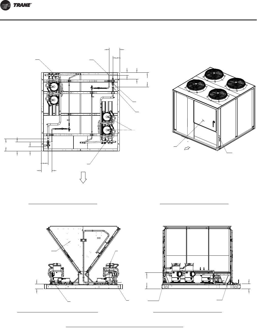
Figure 11. 50-Ton air-cooled condensing unit
29 1/4"
31 1/4"
35 13/16"
37 11/16"
3 3/8"
3 3/8"
5 5/16"
2 5/8"
5 3/8"
1 3/4" KO LOW
VOLTAGE (30V MAX.)
1/2" X 2 KO (115V)
1/2" X 4 KO (115V)
4 1/2"
4" CONDUIT
MAIN POWER
CONTROL PANEL
88 5/16"
113 13/16"
103 1/2"
16"
22 1/2"
79 1/4"
1 15/16"
FAN GRILLE
LOW AMBIENT
DAMPER (SEE NOTE 2)
FAN GRILLE
1 1/4" x 4 1/2"
SLOT FOR 115
VOLT CONTROL
4" LINE
VOLTAGE
ACCESS
BOTTOM OF CONTROL
BOX (SEE DETAIL A)
13"
6 1/4"
32 1/4"
CONTROL PANEL
(SEE DETAIL A)
DOOR 43 1/4" W/
180 DEG SWING
8 1/8"
48 7/8"
48 7/8"
85 5/8"
3/4" X 6
MTG HOLES
12
34
56
FRONT (SEE
NOTE 3 FOR
ALL MIN.
CLEARANCE)
DETAIL A
BOTTOM OF CONTROL BOX
NOTES:
1. SEE CONNECTION DRAWING FOR CONNECTION LOCATION AND SIZES.
2. LOW AMBIENT DAMPER ONLY COMES WITH SELECTED UNIT .
3. FRONT AND BACK OF UNIT CLEARANCE 72" . LEFT AND RIGHT
SIDE OF UNIT CLEARANCE 42".
Unit Dimensions & Weights
18 SS-SVX11H-EN
Figure 12. 50-Ton air-cooled condensing unit (connections)
COMPRESSORS
COIL
COMPRESSOR
COIL
15/8" O.D. SUCTION LINE
for vertical
2 1/8” O.D. SUCTION LINE
for horizontal
SUCTION LINE
LIQUID LINE
7/8" O.D. HOT GAS
BYPASS (OPTIONAL)
HOT GAS BYPASS
(OPTIONAL)
7/8" O.D, HOT GAS
BYPASS (OPTIONAL)
12"
10 13/16"
41 3/4"
32 3/4"
7 11/16"
7/8" O.D. LIQUID LINE
SERVICE VALVE (OPTIONAL)
12"
7 11/16"
10 13/16"
29 3/4"
38 3/4"
CONTROL
PANEL
VOLTAGE
ACCESS
CONTROL PANEL SIDE
CONTROL
PANEL SIDE
AA
A
AA
A
5 7/16"
5 13/16
18 1/2"
DIMENSIONAL CONNECTION DRAWING
50 TON UNIT
PLAN VIEW OF UNIT
CONNECTION DRAWING
CONNECTION DRAWING
CONTROL PANEL SIDE VIEW OF UNIT
ISOMETRIC DRAWING
ORIENTATION VIEW OF UNIT
BACK VIEW OF UNIT
CONNECTION DRAWING
NOTES:
1. VERIFY WEIGHT, CONNECTION, AND ALL DIMENSION WITH
INSTALLER DOCUMENTS BEFORE INSTALLATION
Unit Dimensions & Weights
SS-SVX11H-EN 19
Figure 13. 60-Ton air-cooled condensing unit
29 1/4"
31 1/4"
35 13/16"
37 11/16"
3 3/8"
3 3/8"
5 5/16"
2 5/8"
5 3/8"
1 3/4" KO LOW
VOLTAGE (30V MAX.)
1/2" X 2 KO (115V)
1/2" X 4 KO (115V)
4 1/2"
4" CONDUIT
MAIN POWER
CONTROL PANEL
FAN GRILLE
4" LINE
VOLTAGE
ACCESS
1 1/4" x 4 1/2"
SLOT FOR 115
VOLT CONTROL
FAN GRILLE
CONTROL PANEL
(SEE DETAIL A)
1 15/16"
103 1/2"
5 3/16"
113 13/16"
22 1/2"
16"
79 1/4"
114"
88 5/16"
13"
LOW AMBIENT
DAMPER (SEE NOTE 2)
32 3/16"
BOTTOM OF CONTROL
BOX (SEE DETAIL A)
6 1/4"
3/4" X 6
MTG HOLES
DOOR 43 1/4" W/
180 DEG SWING
8 1/8"
48 7/8"
48 7/8"
85 5/8"
2 1
3
4
65
FRONT (SEE
NOTE 3 FOR
ALL MIN.
CLEARANCE)
NOTES:
1. SEE CONNECTION DRAWING FOR CONNECTION LOCATION AND SIZES.
2. LOW AMBIENT DAMPER ONLY COMES WITH SELECTED UNIT .
BOTTOM OF CONTROL BOX
DETAIL A
3. FRONT AND BACK OF UNIT CLEARANCE 72" . LEFT AND RIGHT
SIDE OF UNIT CLEARANCE 42".

Unit Dimensions & Weights
20 SS-SVX11H-EN
Figure 14. 60-Ton air-cooled condensing unit (connections)
COMPRESSORS
COIL
COMPRESSOR
COIL
2 1/8" O.D. SUCTION LINE
SUCTION LINE
LIQUID LINE
7/8" O.D. HOT GAS
BYPASS (OPTIONAL)
HOT GAS BYPASS
(OPTIONAL)
7/8" O.D, HOT GAS
BYPASS (OPTIONAL)
12"
10 13/16"
41 3/4"
32 3/4"
711/16"
7/8" O.D. LIQUID LINE
SERVICE VALVE (OPTIONAL)
12"
7 11/16"
10 13/16"
29 3/4"
38 3/4"
CONTROL
PANEL
VOLTAGE
ACCESS
CONTROL PANEL SIDE
CONTROL
PANEL SIDE
AA
A
AA
A
5 7/16"
5 13/16"
18 1/2"
60 TON UNIT
DIMENSIONAL CONNECTION DRAWING
NOTES:
1. VERIFY WEIGHT, CONNECTION, AND ALL DIMENSION WITH
INSTALLER DOCUMENTS BEFORE INSTALLATION
PLAN VIEW OF UNIT
CONNECTION DRAWING
CONNECTION DRAWING
CONTROL PANEL SIDE VIEW OF UNIT
ISOMETRIC DRAWING
ORIENTATION VIEW OF UNIT
BACK VIEW OF UNIT
CONNECTION DRAWING
Unit Dimensions & Weights
SS-SVX11H-EN 21
Figure 15. 80-Ton air-cooled condensing unit
29 1/4"
31 1/4"
35 13/16"
37 11/16"
3 3/8"
3 3/8"
5 5/16"
2 5/8" 5 3/8"
1 3/4" KO LOW
VOLTAGE (30V MAX.)
1/2" X 2 KO (115V)
1/2" X 4 KO (115V)
4 1/2"
4" CONDUIT
MAIN POWER
CONTROL PANEL
1.6
1 13/16"
176 7/16"
83 1/8"
30 1/4" 30 1/8"
83 1/4"
88 5/16"
176 11/16"
FAN GRILLE
1 1/4" x 4 1/2"
SLOT FOR 115
VOLT CONTROL
4" LINE
VOLTAGE
ACCESS
FAN GRILLE
79 1/4"
7"
9"
14"
LOW AMBIENT
DAMPER (SEE NOTE 2)
6 1/4"
1
16 5/16"
BOTTOM OF CONTROL
BOX (SEE DETAIL A)
CONTROL PANEL
(SEE DETAIL A)
2 1/4" x 1 1/4" 24 VOLTAGE
CONTROL WIRING
3/4" X 8
MTG HOLES
DOOR 43 1/4" W/
180 DEG SWING
1 1/4"
8"
72 1/8"
16"
72 1/8"
85 5/8"
12
4 3
65
87
FRONT (SEE
NOTE 3 FOR
ALL MIN.
CLEARANCE)
DIMENSIONAL DETAIL
DETAIL A
NOTES:
1. SEE CONNECTION DRAWING FOR CONNECTION LOCATION AND SIZES.
2. LOW AMBIENT DAMPER ONLY COMES WITH SELECTED UNIT .
3. FRONT AND BACK OF UNIT CLEARANCE 96" . LEFT AND RIGHT
SIDE OF UNIT CLEARANCE 48".
Unit Dimensions & Weights
22 SS-SVX11H-EN
Figure 16. 80-Ton air-cooled condensing unit (connections)
1 1/8" O.D.
LIQUID LINE
2 1/8" O.D .SUCTION LINE
COIL
21/8"O.D.SUCTIONLINE
1 3/8" O.D. HOT GAS
BYPASS (OPTIONAL)
COMPRESSOR (6)
13/8"HOTGAS
BYPASS (OPTIONAL)
COMPRESSOR (6)
HOT GAS BYPASS
(OPTIONAL)
14 13/16"
25 1/8"
46 3/16"
SERVICE VALUE
(OPTIONAL SEE DETAIL A) 42 9/16"
25 1/8"
14 1/16" 19 1/16"
73 3/8"
45 9/16"
CONTROL
PANEL SIDE
18 5/16"
SUCTION LINE
LIQUID LINE
DETAIL A
VOLTAGE
ACCESS
CONTROL
PANEL
CONTROL
PANEL SIDE
5 9/16"
93/8"
LIQUID LINE
COIL
COMPRESSOR (6)
SERVICE VALUE
(OPTIONAL SEE DETAIL A)
DETAIL A
DETAIL DRAWING
NOTES:
1
. VERIFY WEIGHT, CONNECTION, AND ALL DIMENSION WITH
INSTALLER DOCUMENTS BEFORE INSTALLATION
PLAN VIEW OF UNIT
CONNECTION DRAWING
CONNECTION DRAWING
CONTROL PANEL SIDE VIEW OF UNIT
LEFT VIEW OF UNIT
CONNECTION DRAWING
ISOMETRIC DRAWING
ORIENTATION VIEW OF UNIT
Unit Dimensions & Weights
SS-SVX11H-EN 23
Figure 17. 100- and 120-Ton air-cooled condensing unit
29 1/4"
31 1/4"
35 13/16"
37 11/16"
3 3/8"
3 3/8"
5 5/16"
2 5/8" 5 3/8"
1 3/4" KO LOW
VOLTAGE (30V MAX.)
1/2" X 2 KO (115V)
1/2" X 4 KO (115V)
4 1/2"
4" CONDUIT
MAIN POWER
CONTROL PANEL
1 15/16"
108 11/16"
20 1/16"
5 3/16"
108 5/8"
5 1/8"
20 1/16"
79 1/4"
7"
14"
9"
88 5/16"
FAN GRILLE
CONTROL PANEL
(SEE DETAIL A)
4" LINE
VOLTAGE ACCESS
1 1/4" x 4 1/2"
SLOT FOR 115
VOLT CONTROL
FAN GRILLE
LOW AMBIENT
DAMPER (SEE NOTE 2)
BOTTOM OF CONTROL
BOX (SEE DETAIL A)
16 3/16"
2 1/4" x 1 1/4" 24 VOLTAGE
CONTROL WIRING
6 1/4"
13"
3/4" X 8
MTG HOLES
DOOR 43 1/4" W/
180 DEG SWING
8"
1 1/4"
97 5/8"
16"
97 5/8"
85 13/16"
FRONT (SEE
NOTE 3 FOR
ALL MIN.
CLEARANCE)
DIMENSIONAL DETAIL
DETAIL A
NOTES:
1. SEE CONNECTION DRAWING FOR CONNECTION LOCATION AND SIZES.
2. LOW AMBIENT DAMPER ONLY COMES WITH SELECTED UNIT .
3. FRONT AND BACK OF UNIT CLEARANCE 96" . LEFT AND RIGHT
SIDE OF UNIT CLEARANCE 48".
227 1/4”
Unit Dimensions & Weights
24 SS-SVX11H-EN
Figure 18. 100- and 120-Ton air-cooled condensing unit (connections)
1 3/8"HOT GAS
BYPASS (OPTIONAL)
1 1/8" O.D.
LIQUID LINE
COMPRESSOR (6)
SUCTION LINE
COIL
COMPRESSOR (6)
LIQUID LINE
SUCTION LINE
HOT GAS BYPASS
(OPTIONAL)
1 3/8"HOT GAS
BYPASS (OPTIONAL)
25 1/8"
39 5/8"
67 7/16"45 7/8"
18 1/16" 13 1/16"
/8" O.D.
QUID LINE
2 5/8" O.D. SUCTION LINE
46 1/4"
74"
25 1/8"
SCALE1,000
18 5/16"
59/16"
93/8"
VOLTAGE
ACCESS
CONTROL
PANEL
CONTROL
PANEL SIDE
CONTROL
PANEL SIDE
SERVICE VALUE (OPTIONAL SEE DETAIL A)
SERVICE VALUE
(OPTIONAL SEE DETAIL A)
DETAIL A
DETAIL DRAWING
NOTES:
1. VERIFY WEIGHT, CONNECTION, AND ALL DIMENSION WITH
INSTALLER DOCUMENTS BEFORE INSTALLATION
PLAN VIEW OF UNIT
CONNECTION DRAWING
CONNECTION DRAWING
CONTROL PANEL SIDE VIEW OF UNIT LEFT VIEW OF UNIT
CONNECTION DRAWING
ISOMETRIC DRAWING
ORIENTATION VIEW OF UNIT
2 5/8” O.D. for horizontal
2 1/8” O.D. for vertical
SUCTION LINE
2 5/8” O.D. for horizontal
2 1/8” O.D. for vertical
Unit Dimensions & Weights
SS-SVX11H-EN 25
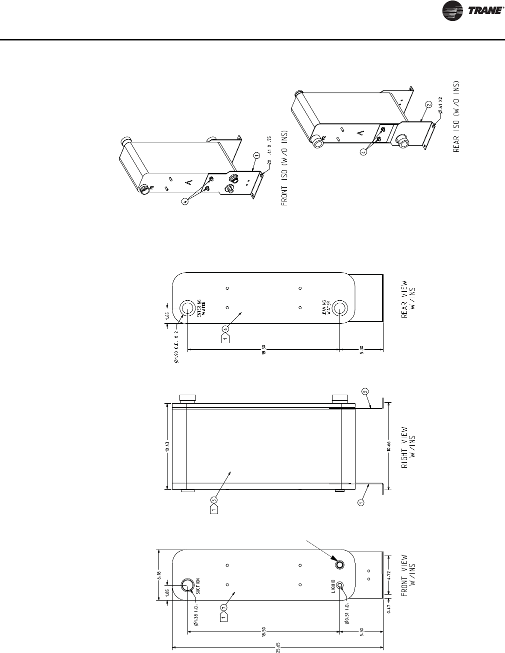
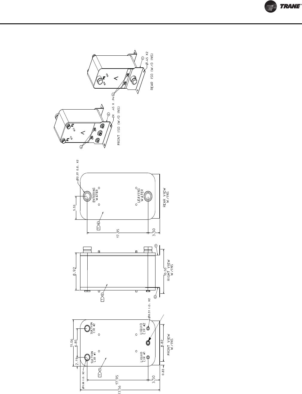
Figure 19. 20-Ton evaporator chiller
Notes:Notes:
THIS HEAT EXCHANGER IS INTENDED FOR INDOOR INSTALLATION ONLYTHIS HEAT EXCHANGER IS INTENDED FOR INDOOR INSTALLATION ONLY
HEAT EXCHANGER MOUNTING LEGS ARE INSTALLED AT JOB SITE WITH SUPPLIED FASTENERS (ITEM 4)HEAT EXCHANGER MOUNTING LEGS ARE INSTALLED AT JOB SITE WITH SUPPLIED FASTENERS (ITEM 4)
INSULATION (ITEMS 5, 6, & 7) SHOULD BE INSTALLED AFTER INSTALLING LEGS & REFRIGERANT INSULATION (ITEMS 5, 6, & 7) SHOULD BE INSTALLED AFTER INSTALLING LEGS & REFRIGERANT
TUBING, OR MUST BE ADEQUATELY SHIELDED AGAINST HEAT WHEN BRAZING REFRIGERANT LINESTUBING, OR MUST BE ADEQUATELY SHIELDED AGAINST HEAT WHEN BRAZING REFRIGERANT LINES
INSTALL INSULATION SIDE PIECES FIRST (ITEMS 6 & 7), THEN WRAPPER (ITEM 5), ITEM 5 MAY INSTALL INSULATION SIDE PIECES FIRST (ITEMS 6 & 7), THEN WRAPPER (ITEM 5), ITEM 5 MAY
REQUIRE TRIMMING REQUIRE TRIMMING
USE VINYL TAPE (FIELD SUPPLIED) TO SEAL INSULATION AFTER INSTALLATIONUSE VINYL TAPE (FIELD SUPPLIED) TO SEAL INSULATION AFTER INSTALLATION
WATER CONNECTIONS ARE GROOVED (VICTAULIC)WATER CONNECTIONS ARE GROOVED (VICTAULIC)
REFRIGERANT CONNECTIONS ARE STAINLESS STEEL AND REQUIRE SPECIAL BRAZE MATERIALS.REFRIGERANT CONNECTIONS ARE STAINLESS STEEL AND REQUIRE SPECIAL BRAZE MATERIALS.
SEE IOM BRAZE PROCEDURES.SEE IOM BRAZE PROCEDURES.
REQUIRES FIELD
PROVIDED
1/2”X14NPTE
STAINLESS STEEL
OR PVC PLUG
Unit Dimensions & Weights
26 SS-SVX11H-EN
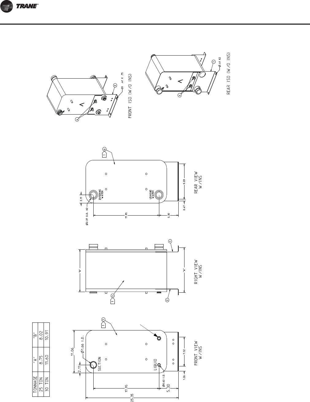
Figure 20. 25 and 30-Ton evaporator chiller
Notes:
THIS HEAT EXCHANGER IS INTENDED FOR INDOOR INSTALLATION ONLY
HEAT EXCHANGER MOUNTING LEGS ARE INSTALLED AT JOB SITE WITH SUPPLIED FASTENERS (ITEM 4)
INSULATION (ITEMS 5, 6, & 7) SHOULD BE INSTALLED AFTER INSTALLING LEGS & REFRIGERANT TUBING, OR
MUST BE ADEQUATELY SHIELDED AGAINST HEAT WHEN BRAZING REFRIGERANT LINES
Install INSULATION SIDE PIECES FIRST (ITEMS 6 & 7), THEN WRAPPER (ITEM 5), ITEM 5 MAY REQUIRE
TRIMMING
USE VINYL TAPE (FIELD SUPPLIED) TO SEAL INSULATION AFTER INSTALLATION
WATER CONNECTIONS ARE GROOVED (VICTAULIC)
REFRIGERANT CONNECTIONS ARE STAINLESS STEEL AND REQUIRE SPECIAL BRAZE MATERIALS.
SEE IOM BRAZE PROCEDURE.
REQUIRES FIELD
PROVIDED
1/2”X14NPTE
STAINLESS STEEL
OR PVC PLUG
Unit Dimensions & Weights
SS-SVX11H-EN 27
Figure 21. 40-Ton evaporator chiller
Notes:Notes:
THIS HEAT EXCHANGER IS INTENDED FOR INDOOR INSTALLATION ONLYTHIS HEAT EXCHANGER IS INTENDED FOR INDOOR INSTALLATION ONLY
HEAT EXCHANGER MOUNTING LEGS ARE INSTALLED AT JOB SITE WITH SUPPLIED FASTENERS (ITEM 4)HEAT EXCHANGER MOUNTING LEGS ARE INSTALLED AT JOB SITE WITH SUPPLIED FASTENERS (ITEM 4)
INSULATION (ITEMS 5, 6, & 7) SHOULD BE INSTALLED AFTER INSTALLING LEGS & REFRIGERANT INSULATION (ITEMS 5, 6, & 7) SHOULD BE INSTALLED AFTER INSTALLING LEGS & REFRIGERANT
TUBING, OR MUST BE ADEQUATELY SHIELDED AGAINST HEAT WHEN BRAZING REFRIGERANT LINESTUBING, OR MUST BE ADEQUATELY SHIELDED AGAINST HEAT WHEN BRAZING REFRIGERANT LINES
Install INSULATION SIDE PIECES FIRST (ITEMS 6 & 7), THEN WRAPPER (ITEM 5), ITEM 5 MAY Install INSULATION SIDE PIECES FIRST (ITEMS 6 & 7), THEN WRAPPER (ITEM 5), ITEM 5 MAY
REQUIRE TRIMMING REQUIRE TRIMMING
USE VINYL TAPE (FIELD SUPPLIED) TO SEAL INSULATION AFTER INSTALLATIONUSE VINYL TAPE (FIELD SUPPLIED) TO SEAL INSULATION AFTER INSTALLATION
WATER CONNECTIONS ARE GROOVED (VICTAULIC)WATER CONNECTIONS ARE GROOVED (VICTAULIC)
REFRIGERANT CONNECTIONS ARE STAINLESS STEEL AND REQUIRE SPECIAL BRAZE MATERIALS.REFRIGERANT CONNECTIONS ARE STAINLESS STEEL AND REQUIRE SPECIAL BRAZE MATERIALS.
SEE IOM BRAZE PROCEDURE.SEE IOM BRAZE PROCEDURE.
REQUIRES FIELD
PROVIDED
1/2”X14NPTE
STAINLESS STEEL
OR PVC PLUG
Unit Dimensions & Weights
28 SS-SVX11H-EN
Figure 22. 50 and 60-Ton evaporator chiller
Notes:Notes:
THIS HEAT EXCHANGER IS INTENDED FOR INDOOR INSTALLATION ONLYTHIS HEAT EXCHANGER IS INTENDED FOR INDOOR INSTALLATION ONLY
HEAT EXCHANGER MOUNTING LEGS ARE INSTALLED AT JOB SITE WITH SUPPLIED FASTENERS (ITEM 4). HEAT EXCHANGER MOUNTING LEGS ARE INSTALLED AT JOB SITE WITH SUPPLIED FASTENERS (ITEM 4).
ATTACH MOUNTING LEGS BEFORE PIPING AND INSULATINGATTACH MOUNTING LEGS BEFORE PIPING AND INSULATING
INSULATION (ITEMS 5, 6, & 7) SHOULD BE INSTALLED AFTER INSTALLING LEGS & REFRIGERANT INSULATION (ITEMS 5, 6, & 7) SHOULD BE INSTALLED AFTER INSTALLING LEGS & REFRIGERANT
TUBING, OR MUST BE ADEQUATELY SHIELDED AGAINST HEAT WHEN BRAZING REFRIGERANT LINESTUBING, OR MUST BE ADEQUATELY SHIELDED AGAINST HEAT WHEN BRAZING REFRIGERANT LINES
INSTALL FACE INSULATION FIRST (ITEMS 6 & 7), THEN WRAPPER INSULATION (ITEM 5), ITEM 5 MAY INSTALL FACE INSULATION FIRST (ITEMS 6 & 7), THEN WRAPPER INSULATION (ITEM 5), ITEM 5 MAY
REQUIRE TRIMMING REQUIRE TRIMMING
USE VINYL TAPE (FIELD SUPPLIED) TO SEAL INSULATION AFTER INSTALLATIONUSE VINYL TAPE (FIELD SUPPLIED) TO SEAL INSULATION AFTER INSTALLATION
WATER CONNECTIONS ARE GROOVED (VICTAULIC)WATER CONNECTIONS ARE GROOVED (VICTAULIC)
REFRIGERANT CONNECTIONS ARE STAINLESS STEEL AND REQUIRE SPECIAL BRAZE MATERIALS.REFRIGERANT CONNECTIONS ARE STAINLESS STEEL AND REQUIRE SPECIAL BRAZE MATERIALS.
SEE IOM BRAZE PROCEDURES.SEE IOM BRAZE PROCEDURES.
REQUIRES FIELD
PROVIDED
1/2”X14NPTE
STAINLESS STEEL
OR PVC PLUG

Unit Dimensions & Weights
SS-SVX11H-EN 29
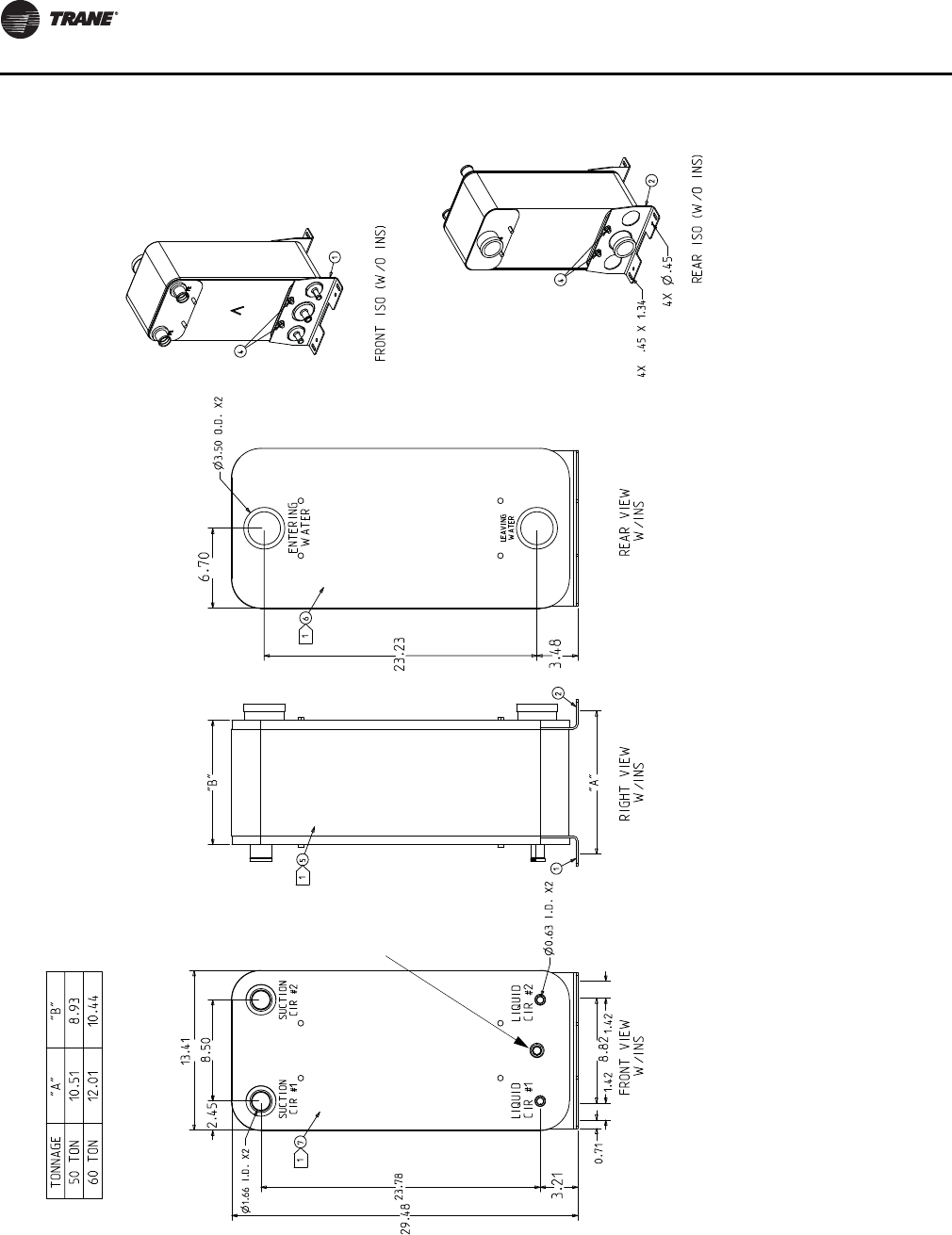
Figure 23. 80 and 120-Ton evaporator chiller
Notes:Notes:
THIS HEAT EXCHANGER IS INTENDED FOR INDOOR INSTALLATION ONLYTHIS HEAT EXCHANGER IS INTENDED FOR INDOOR INSTALLATION ONLY
HEAT EXCHANGER MOUNTING LEGS ARE INSTALLED AT JOB SITE WITH SUPPLIED FASTENERS HEAT EXCHANGER MOUNTING LEGS ARE INSTALLED AT JOB SITE WITH SUPPLIED FASTENERS
(ITEM 4)(ITEM 4)
INSULATION (ITEMS 5, 6, & 7) SHOULD BE INSTALLED AFTER INSTALLING LEGS & INSULATION (ITEMS 5, 6, & 7) SHOULD BE INSTALLED AFTER INSTALLING LEGS &
REFRIGERANT TUBING, OR MUST BE ADEQUATELY SHIELDED AGAINST HEAT WHEN BRAZING REFRIGERANT TUBING, OR MUST BE ADEQUATELY SHIELDED AGAINST HEAT WHEN BRAZING
REFRIGERANT LINESREFRIGERANT LINES
Install INSULATION SIDE PIECES FIRST (ITEMS 6 & 7), THEN WRAPPER (ITEM 5), ITEM 5 MAY Install INSULATION SIDE PIECES FIRST (ITEMS 6 & 7), THEN WRAPPER (ITEM 5), ITEM 5 MAY
REQUIRE TRIMMING REQUIRE TRIMMING
USE VINYL TAPE (FIELD SUPPLIED) TO SEAL INSULATION AFTER INSTALLATIONUSE VINYL TAPE (FIELD SUPPLIED) TO SEAL INSULATION AFTER INSTALLATION
WATER CONNECTIONS ARE GROOVED (VICTAULIC)WATER CONNECTIONS ARE GROOVED (VICTAULIC)
REFRIGERANT CONNECTIONS ARE STAINLESS STEEL AND REQUIRE SPECIAL BRAZE MATERIALS.REFRIGERANT CONNECTIONS ARE STAINLESS STEEL AND REQUIRE SPECIAL BRAZE MATERIALS.
SEE IOM BRAZE PROCEDURES.SEE IOM BRAZE PROCEDURES.
REQUIRES FIELD
PROVIDED
1/2”X14NPTE
STAINLESS STEEL
OR PVC PLUG
Unit Dimensions & Weights
30 SS-SVX11H-EN
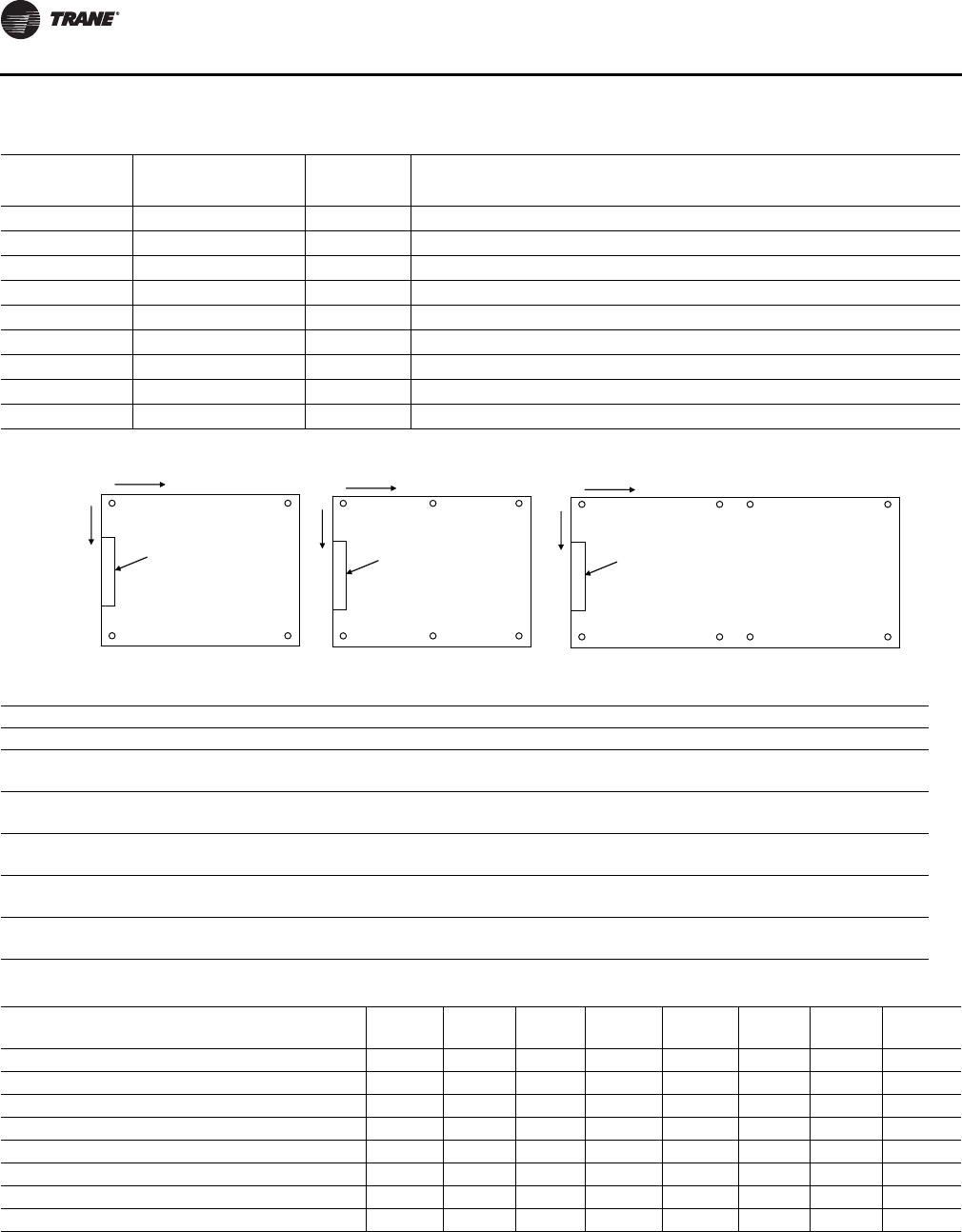
Table 3. Typical unit weights and point loading data 20 - 120 Ton units
Weight CG Locations Weight on isolator mounting location (lbs.)
Tons Model Shipping Operating X Y Loc. 1 Loc. 2 Loc 3. Loc 4. Loc. 5 Loc. 6 Loc. 7 Loc. 8
20 RAUJC20 1548 1573 40.8 33.0 475.5 383.3 403.2 311.0 --- --- --- ---
25 RAUJC25 1598 1623 40.6 32.8 491.2 399.3 412.2 320.3 --- --- --- ---
30 RAUJC30 1598 1623 40.6 32.8 491.2 399.3 412.2 320.3 --- --- --- ---
40 RAUJC40 2482 2532 43.4 46.0 452.3 415.7 440.3 403.7 428.3 391.8 --- ---
50 RAUJC50 2826 2868 52.3 45.9 365.5 331.0 427.8 393.3 700.1 650.3 --- ---
60 RAUJC60 2803 2853 52.1 45.9 367.2 332.8 426.0 391.6 692.5 642.9 --- ---
80 RAUJC80 4870 4940 86.0 55.8 798.3 462.1 786.7 450.5 785.1 448.9 772.4 436.1
100 RAUJC100 5539 5622 110.9 55.0 871.1 609.5 881.0 616.2 882.6 432.1 892.5 436.8
120 RAUJC120 5995 6121 111.5 54.2 988.2 614.7 948.3 587.4 941.8 583.0 901.8 555.8
Figure 24. Air-cooled condensing units
Table 4. Isolator mounting locations
Mounting Location
Unit Size 12345678
20/25/30 X8”8”6' 8 1/8”6' 8 1/8”----
Y4' 10 3/4”1 1/4”4' 10 3/4”1 1/4”----
40 X 8” 8” 3' 8 1/8” 3' 8 1/8” 6' 8 1/4” 6' 8 1/4” - -
Y 7' 3 1/8” 1 1/4” 7' 3 1/8” 1 1/4” 7' 3 1/8” 1 1/4” - -
50/60 X 8” 8” 4' 8 7/8” 4' 8 7/8” 8' 9 3/4” 8' 9 3/4” - -
Y 7' 3 1/8” 1 1/4” 7' 3 1/8” 1 1/4” 7' 3 1/8” 1 1/4” - -
80 X 8” 8” 6' 8 1/8” 6' 8 1/8” 9' 1/8” 9' 1/8” 14' 1/4” 14' 1/4"
Y 7' 3 1/8” 1 1/4” 7' 3 1/8” 1 1/4” 7' 3 1/8” 1 1/4” 7' 3 1/8” 1 1/4"
100/120 X 8” 8” 8' 9 5/8” 8' 9 5/8” 10' 1 5/8” 10' 1 5/8” 18' 3 1/4 18' 3 1/4”
Y 7' 3 1/8” 1 1/4” 7' 3 1/8” 1 1/4” 7' 3 1/8” 1 1/4” 7' 3 1/8” 1 1/4"
Table 5. General data - 20 - 120 Ton remote chillers
Model Number
RAUJ-
C20
RAUJ-
C25
RAUJ-
C30
RAUJ-
C40
RAUJ-
C50
RAUJ-
C60
RAUJ-
C80
RAUJ-
D10
RAUJ-
D12
Shipping weight, lbs 44 84 113 90 135 157 208 292 320
Operating weight, lbs 56 104 142 131 206 244 330 473 520
No. of refrigerant circuits 1 1 1 2 2 2 2 2 2
Water volume, Gal 1.4 2.2 3.3 4.6 7.9 9.7 13.6 20.1 22.2
Chiller refrig charge @ ARI condition, lbs 0.9 1.5 2.2 3.1 5.3 6.4 9.0 13.3 14.7
Minimum water flow rate, GPM 24 30 36 48 60 72 96 120 144
Maximum water flow rate, GPM 69 89 100 136 176 201 275 346 407
Chiller Water Supply/Return Pipe Size, in 2.0 2.0 2.0 3.0 3.0 3.0 4.0 4.0 4.0
Notes:
1. All heat exchangers are brazed plate.
2. All heat exchangers are single circuit on the water side.
3. Shipping and operating weights are approximate.
4. Refrigerant charge is approximate and for chiller only.
5. Applications with leaving water temperature below 42°F require freeze protection down to 15°F.
6. Maximum chiller operating ambient is 115°F.
Control
Panel
80-120 Ton
1
2
3
4
5
6
7
8
Y
X
Control
Panel
Control
Panel
20-30 Ton 40-60 Ton
11
22
33
44
5
6
YY
XX
Unit Dimensions & Weights
SS-SVX11H-EN 31
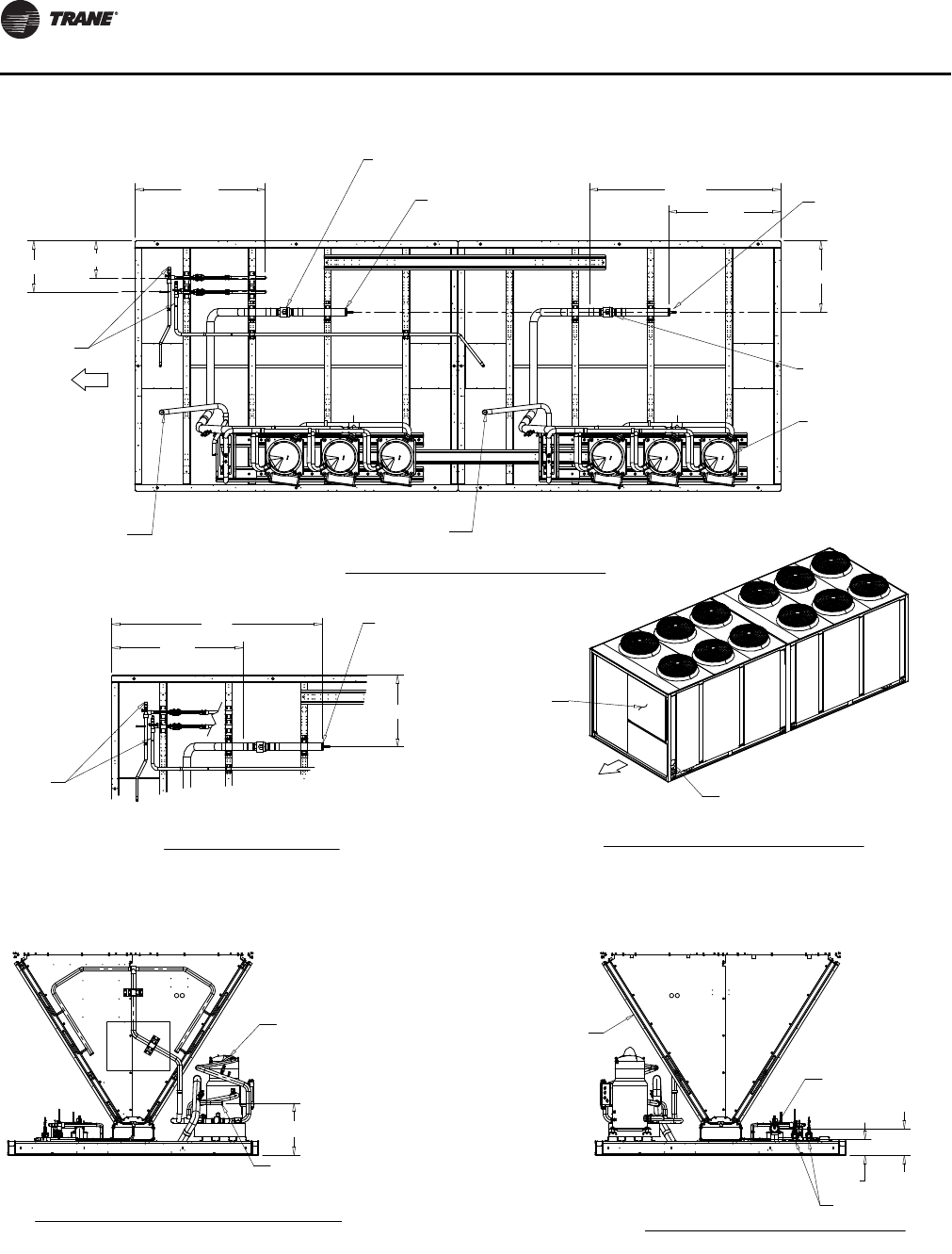
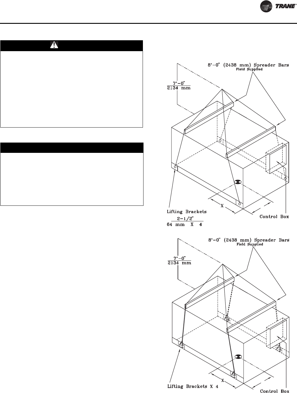
Use spreader bars as shown in Figure 25. See installation
manual or nameplate for unit weight. See installation
instructions located inside the central panel for further
rigging information.
A Rigging illustration and Center-of-Gravity dimensional
data table is shown in Figure 25. Refer to the typical unit
operating weights table before proceeding.
1. Rig the condensing unit as shown in Figure 25. Attach
adequate strength lifting slings to all four lifting
brackets in the unit base rail. Do not use cables, chains,
or slings except as shown.
2. Install spreader bars, as shown in Figure 25, to protect
the unit and to facilitate a uniform lift. The minimum
distance between the lifting hook and the top of the
unit should be 7 feet.
3. Test-lift the unit to ensure it is properly rigged and
balanced, make any necessary rigging adjustments.
4. Lift the unit and position it into place.
WARNING
Heavy Objects!
Ensure that all the lifting equipment used is properly
rated for the weight of the unit being lifted. Each of the
cables (chains or slings), hooks, and shackles used to
lift the unit must be capable of supporting the entire
weight of the unit. Lifting cables (chains or slings) may
not be of the same length. Adjust as necessary for even
unit lift. Other lifting arrangements could cause
equipment or property damage. Failure to follow
instructions above or properly lift unit could result in
unit dropping and possibly crushing operator/
technician which could result in death or serious injury.
NOTICE:
Heat Exchanger or Compressor Damage!
Do not operate system below minimum specified water
flow rate or below 42°F leaving water temperature
without glycol. If water freezes inside the brazed plate
heat exchanger, separation between refrigerant and
water could be damaged and the heat exchanger must
be replaced. Compressor damage could also occur
requiring replacement and system cleanup.
Figure 25. Rigging and center-of-gravity data 20 - 60
Ton units (L) and rigging and center-of-
gravity data 80 - 120 Ton units (R)
Y
Y
Unit Dimensions & Weights
32 SS-SVX11H-EN
Unit Isolation
To minimize unit sound and vibration transmission, one of
the following installation methods should be used:
1. Install the unit directly on an isolated (detached)
concrete pad or on isolated concrete footings located
at each unit load point.
2. Install the optional neoprene or spring isolators at each
. Refer to the “Neoprene isolators” or “Spring isolator”
section below.
Neoprene Isolators (20 - 60 Ton units)
Install the neoprene isolators at each unit mounting (load)
point, using the following procedure:
1. Elevate the unit (one side at a time) to allow access to
the base rail mounting holes.
2. Align the mounting holes in the base rail of the unit
with the holes in the top of the appropriate isolator. See
Ta b l e 6, p. 33 and/or Ta b l e 7, p . 33 for the appropriate
isolator for each load point.
3. Install a 1/2" NC bolt (field supplied) through the base
rail of the unit into the threaded bolt hole of the
isolator. Position the isolator to allow access to the
mounting holes in the base of the isolator, then tighten
securely.
4. Lower the unit and isolator onto the mounting surface.
The maximum isolator deflection should be
approximately 1/4 inch.
5. Secure the isolator to the mounting surface using the
base holes in the isolator.
6. Level the unit carefully. Refer to the “Leveling the Unit”
section.
7. After the unit is level, tighten the isolator base
mounting bolts to secure them to the mounting
surface.
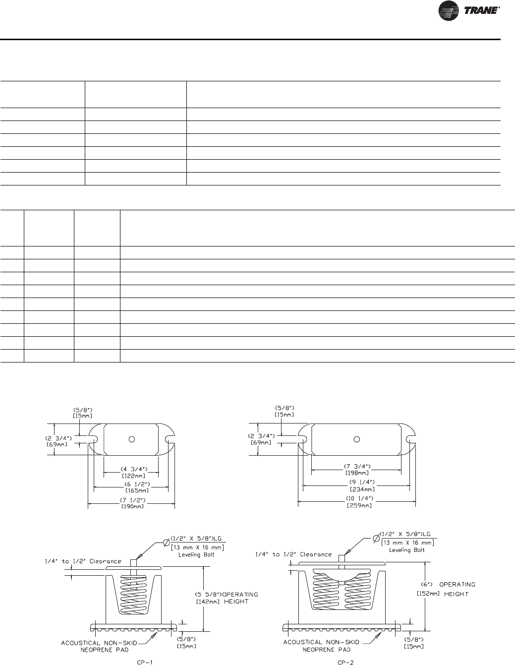
Spring Isolators (20 - 120 Ton units)
Install the spring isolators at each unit mounting (load)
point, using the following procedure:
1. Elevate the unit (one side at a time) to allow access to
the base rail mounting holes.
2. Align the mounting holes in the base rail of the unit
with the positioning pin in the top of the appropriate
isolator. Refer to Figure 26, p. 33 for the appropriate
isolator for each load point.
3. Position the isolator to allow access to the mounting
holes in the base of the isolator.
4. Lower the unit onto the isolator. The positioning pin on
the isolator must engage into the hole of the base rail.
The clearance between the upper and lower isolator
housings should be approximately 1/4 to 1/2 inch.
Refer to Figure 26, p. 33 A clearance greater than 1/2
inch indicates that shims are required to level the unit.
Refer to the “Leveling the Unit” section.
5. Make minor clearance adjustments by turning the
isolator leveling bolt (Figure 26, p. 33) clockwise to
increase the clearance and counterclockwise to
decrease the clearance. If proper isolator clearance
cannot be obtained by turning the leveling bolt, level
the isolators themselves. A 1/4 inch variance in
elevation is acceptable.
6. Secure the isolator to the mounting surface using the
base holes in the isolator.
7. After unit is level, tighten isolator base mounting bolts
to secure them to the mounting surface.
WARNING
Heavy Objects!
Use solid type blocks, i.e. 4" X 4" wood blocks or
similar material to prevent collapsing. Keep hands and
other body limbs clear of elevated base rail while
installing isolators. Failure to do so could result in
death or serious injury.
WARNING
Heavy Objects!
Use solid type blocks, i.e. 4" X 4" wood blocks or
similar material to prevent collapsing. Keep hands and
other body limbs clear of elevated base rail while
installing isolators. Failure to do so could result in
death or serious injury.
Unit Dimensions & Weights
SS-SVX11H-EN 33
Table 6. Typical neoprene isolator selection & location
Shipping
Weight
Operating
Weight
Isolator Part No. On Mounting Location
Tons Model Loc. 1 Loc. 2 Loc 3. Loc 4. Loc. 5 Loc. 6
20 RAUJC20 1548 1573 R-3-RED R-3-RED R-3-RED R-3-RED --- ---
25 RAUJC25 1598 1623 R-3-RED R-3-RED R-3-RED R-3-RED --- ---
30 RAUJC30 1598 1623 R-3-RED R-3-RED R-3-RED R-3-RED --- ---
40 RAUJC40 2482 2532 R-3-RED R-3-RED R-3-RED R-3-RED R-3-RED R-3-RED
50 RAUJC50 2826 2868 R-3-RED R-3-RED R-3-RED R-3-RED R-3-GREEN R-3-GREEN
60 RAUJC60 2803 2853 R-3-RED R-3-RED R-3-RED R-3-RED R-3-GREEN R-3-GREEN
Table 7. Typical spring isolator selection and location 20-120 Ton units
Mdl
RA Weights
CG
Locations Isolator Part No. On Mounting Location
Tons Ship Oper X Y Loc. 1 Loc. 2 Loc 3. Loc 4. Loc. 5 Loc. 6 Loc. 7 Loc. 8
20 1548 1573 40.8 33.0 CP-1D-510 CP-1D-510 CP-1D-510 CP-1D-340 --- --- --- ---
25 1598 1623 40.6 32.8 CP-1D-510 CP-1D-510 CP-1D-510 CP-1D-340 --- --- --- ---
30 1598 1623 40.6 32.8 CP-1D-510 CP-1D-510 CP-1D-510 CP-1D-340 --- --- --- ---
40 2482 2532 43.4 46.0 CP-1D-510 CP-1D-510 CP-1D-510 CP-1D-510 CP-1D-510 CP-1D-510 --- ---
50 2826 2868 52.3 45.9 CP-1D-510 CP-1D-340 CP-1D-510 CP-1D-510 CP-1D-900 CP-1D-675 --- ---
60 2803 2853 52.1 45.9 CP-1D-510 CP-1D-340 CP-1D-510 CP-1D-510 CP-1D-900 CP-1D-675 --- ---
80 4870 4940 86.0 55.8 CP-1D-900 CP-1D-510 CP-1D-900 CP-1D-510 CP-1D-900 CP-1D-510 CP-1D-900 CP-1D-510
100 5539 5622 110.9 55.0 CP-1D-900 CP-1D-675 CP-1D-900 CP-1D-675 CP-1D-900 CP-1D-510 CP-1D-900 CP-1D-510
120 5995 6121 111.5 54.2 C2P-1D-1020 CP-1D-675 C2P-1D-1020 CP-1D-675 C2P-1D-1020 CP-1D-675 C2P-1D-1020 CP-1D-675
Figure 26. Spring isolators 20-120 Ton data

34 SS-SVX11H-EN
Installation
Foundation
If the unit is installed at ground level, elevate it above the
snow line. Provide concrete footings at each support
location or a slab foundation for support. See Table 3, p. 30
for the unit operating and point loading weights when
constructing the footing foundation.
Anchor the unit to the footings or slab using hold down
bolts or isolators. Isolators should be installed to minimize
the transmission of vibrations into the building. See
section “Unit Isolation,” p. 32 for spring or rubber isolator
installation instructions.
For rooftop applications, ensure the roof is strong enough
to support the unit. See Table 3, p. 30 for the unit operating
weights.
Anchor the unit to the roof with hold-down bolts or
isolators. Follow the instructions in section “Unit
Isolation,” p. 32 “for proper isolator placement and
installation.
Check with a roofing contractor for proper waterproofing
procedures.
Unit Isolation
To minimize unit sound and vibration transmission, one of
the following installation methods should be used:
1. Install the unit directly on an isolated (detached)
concrete pad or on isolated concrete footings located
at each unit load point.
2. Install the optional neoprene or spring isolators at each
mounting location. See “Neoprene Isolators (20 - 60
Ton units),” p. 32 or “Spring Isolators (20 - 120 Ton
units),” p. 32.
Leveling the Unit
Before tightening the mounting bolts, level the unit
carefully. Use the unit base rail as a reference. Level the
unit to within 1/4 inch over its entire length. Use shims if
non-adjustable isolators (neoprene) are used.
If adjustable isolators (spring) are used, ensure that the
proper isolator housing clearance is maintained while
leveling the unit. Isolators are identified by color and/or an
isolator part number. Shims under the isolators may be
required if the unit cannot be leveled using the isolator
leveling bolt.
General Unit Requirements
The checklist listed below is a summary of the steps
required to successfully install a commercial air cooled
condenser. This checklist is intended to acquaint the
installing personnel with what is required in the
installation process. It does not replace the detailed
instruction called out in the applicable sections of this
manual.
• Verify that the power supply complies with the unit
nameplate specifications.
• Check the unit for shipping damage and material
shortage; file a freight claim and notify Trane office.
• Verify that the installation location of the unit will
provide the required clearance for proper operation.
• Install appropriate isolators, if required.
Refrigerant Piping Requirements
• Install properly sized liquid line(s) between the liquid
line connections on the unit and the evaporator. See
section “Refrigerant Piping,” p. 38 for recommended
line components and guidelines.
• Install a properly sized liquid line isolation solenoid
valve in each liquid line.
• Install refrigerant rated shutoff valves in the liquid
line(s) to isolate the filter drier(s) for service.
• Install a properly sized filter drier in each liquid line.
• Install a properly sized filter in each suction line.
• Install properly sized suction line(s) between the
suction line connections on the unit and the
evaporator. See “Refrigerant Piping,” p. 38 for
recommended line components and guidelines.
• Install properly sized hot gas bypass line(s) between
the hot gas bypass connections on the unit and the
evaporator.
• Insulate the suction line.
• Leak test the system. See “Leak Testing Procedure,”
p. 44 for recommended procedures.
EVP Chilled Water Piping Requirements
• Install properly sized chilled water pipe between the
EVP chiller and the supporting equipment. See
“Chilled Water Piping,” p. 45 for recommended system
components and guidelines.
• Install supply and return water side pressure gauges
(with isolation valves.)
• Install thermometers in water supply and return
piping.
• Install isolation (shutoff) valves in water supply and
return piping.
• Install a properly sized strainer in the supply piping.
• Install blowdown (recommended) valve or plug in
strainer cleanout.
• Install a balancing valve in the return piping.
• Install a water flow switch in the return piping.
• Install chilled solution sensor well and sensor in the
water outlet piping.
• Install freezestat well and freezestat bulb in the water outlet piping.
Installation
SS-SVX11H-EN 35
• Install chiller piping drain with shutoff valve.
• Install 1/2” x 14 NPT stainless steel or PVC plug in braze
plate chiller body.
• Flush the chilled solution piping system, if applicable.
• Connect the chilled solution piping to the chiller.
Note: The braze plate chiller is intended for indoor
application. If a subfreezing location is required,
contact Trane for installation precautions required
to prevent damage.
Note: If using an acidic, commercial flushing solution, to
prevent damage to the internal evaporator
components, flush all chilled solution piping before
making the final connection to the EVP chiller.
Main Electrical Power Requirements
• Verify the power supply meets the required power
requirements of the system.
• Install power wiring in accordance with all applicable
codes.
• Install and connect properly sized power supply
wiring, with over current protection, to the main power
terminal block (1TB1) or to an optional factory
mounted non-fused disconnect switch (1S1) in the
control panel.
• Install and connect properly sized power supply
wiring, with over current protection, to the proper
termination point in the air handling unit (If
applicable).
• Install proper grounding wires to an earth ground.
• Install and connect properly sized power supply
wiring, with overcurrent protection, to the proper
termination point for the chilled solution pump (EVP
units only).
Field Installed Control Wiring
Requirements
115 Volt Control Wiring (All Units)
• Verify that the Control transformer (1T1) is wired for
the proper operating voltage.
• Connect properly sized wiring to the liquid line
solenoid valve(s).
• The phase monitor (1U3) when powered with line
voltage properly phased and balanced has a green LED
energized.
• Connect properly sized wiring to the hot gas bypass
solenoid valve(s), if applicable, to operate with the
unit. Refer to the unit wiring diagram that shipped with
the unit.
• Install the interlock circuitry wiring for the air handling
unit to permit compressor operation after the fan has
started, i.e., proof of fan operation device, fan starter
auxiliary contacts or pump starter station, pump
starter auxiliary contacts, proof of flow device, etc.
Refer to the field connection diagram that shipped with
the unit for interlocking information.
• Install properly sized power supply wiring, with over
current protection, to the proper termination point for
the field provided economizer actuator(s), if
applicable. Refer to the “Economizer Actuator Circuit”
illustrated in the “Field Installed Control Wiring”
section.
”No Controls” Units
• A field provided “step” controller must be installed
and properly wired. (Controller will have 2, 4 or 6 steps,
depending on unit configuration.) Refer to the field
connection diagram for connection information.
• Install proper grounding wires to an earth ground.
WARNING
Hazardous Voltage!
Disconnect all electric power, including remote
disconnects before servicing. Follow proper lockout/
tagout procedures to ensure the power cannot be
inadvertently energized. Failure to disconnect power
before servicing could result in death or serious injury.
WARNING
Proper Field Wiring and Grounding
Required!
All field wiring MUST be performed by qualified
personnel. Improperly installed and grounded field
wiring poses FIRE and ELECTROCUTION hazards. To
avoid these hazards, you MUST follow requirements for
field wiring installation and grounding as described in
NEC and your local/state electrical codes. Failure to
follow code could result in death or serious injury.
WARNING
Hazardous Voltage!
Disconnect all electric power, including remote
disconnects before servicing. Follow proper lockout/
tagout procedures to ensure the power cannot be
inadvertently energized. Failure to disconnect power
before servicing could result in death or serious injury.
WARNING
Proper Field Wiring and Grounding
Required!
All field wiring MUST be performed by qualified
personnel. Improperly installed and grounded field
wiring poses FIRE and ELECTROCUTION hazards. To
avoid these hazards, you MUST follow requirements for
field wiring installation and grounding as described in
NEC and your local/state electrical codes. Failure to
follow code could result in death or serious injury.
Installation
36 SS-SVX11H-EN
• Install an outside air thermostat in series with the flow
switch to stop or prevent the unit from operating below
the recommended ambient temperatures.
EVP Chiller Units
• Install proper grounding wires to an earth ground.
• Install an outside air thermostat in series with the flow
switch to stop or prevent the unit from operating below
the recommended ambient temperatures.
Low Voltage Wiring (AC & DC)
Variable Air Volume (VAV) Units
• Install a field provided remote system control switch to
activate the system.
• Connect properly sized wiring from the field provided
economizer, if applicable, to the discharge air
controller in the unit control panel.
• Install and connect properly sized wiring from the night
setback relay contacts to the proper termination points
inside the unit control panel. Verify the appropriate
jumpers have been removed.
• Install the suction line thermostat onto the suction line.
Connect properly sized wiring between the thermostat
and terminal strip 7TB7 in the unit control panel.
• Install the discharge air sensor and wire it to the
discharge air controller with shielded cable.
Constant Volume Units
• Install the zone thermostat, with or without switching
subbase.
• Connect properly sized control wiring to the proper
termination points between the zone thermostat and
the unit control panel.
• Install the discharge air sensor and connect it to the
master energy controller (MEC) with shielded cable.
• Connect properly sized wiring from the field provided
economizer, if applicable, to the master energy
controller (MEC) in the unit control panel.
EVP Chillers
• Install the appropriate jumpers on the chilled water
temperature controller for hot gas bypass operation (if
applicable). Refer to the control wiring diagram that
shipped with the unit for jumper details.
• Install and connect the chilled water temperature
sensor to the chilled solution temperature controller
with shielded cable.
• Install the proper staging resistor on to the chilled
water temperature controller.
Refrigerant Line Components
Suction line refrigerant components necessary for field
installation in the suction line are a filter (Core Type),
access valves (ports), FrostatTM control for coil frost
protection, and ball shutoff valves. They are placed in the
suction line as illustrated in Figure 27, p. 38.
The required liquid line refrigerant components include a
filter drier (Core Type), access valve(s) or (ports), solenoid
valve(s), moisture indicating sight glass, expansion
valve(s), and ball shutoff valve(s). They are placed in the
liquid line as shown in Figure 27.
Suction And Liquid Line Filter/Filter Drier
(Field Supplied)
Install the filter in the suction line upstream of the
compressors. To prevent oil accumulation, suction filters
should be installed vertical with the outlet at the bottom as
shown in Figure 27 or no more than 45° from vertical.
Install the filter drier in the liquid line as close as possible
to the expansion valves. Locate them upstream of the
moisture indicator and solenoid valve.
For recommended components, refer to the latest edition
of the Applications Guide SS-APG012-EN.
Liquid Line Moisture Indicator Sight Glass
To aid in troubleshooting, install a moisture indicator sight
glass in the liquid line near the evaporator, downstream of
the solenoid valve prior to any branch takeoffs to the
expansion valve. The sight glass should not be used to
determine adequate refrigerant charge. Liquid
temperature and discharge pressure measurements are
required to determine the proper charge. Note that under
some conditions, charging until the sight glass is solid
liquid will overcharge the system and reduce compressor
reliability. Refer to "Compressor Startup" for proper
system charging.
For recommended components, refer to the latest edition
of Applications Guide SS-APG012-EN.
WARNING
Hazardous Voltage!
Disconnect all electric power, including remote
disconnects before servicing. Follow proper lockout/
tagout procedures to ensure the power cannot be
inadvertently energized. Failure to disconnect power
before servicing could result in death or serious injury.
WARNING
Proper Field Wiring and Grounding
Required!
All field wiring MUST be performed by qualified
personnel. Improperly installed and grounded field
wiring poses FIRE and ELECTROCUTION hazards. To
avoid these hazards, you MUST follow requirements for
field wiring installation and grounding as described in
NEC and your local/state electrical codes. Failure to
follow code could result in death or serious injury.
Installation
SS-SVX11H-EN 37
Liquid Line Solenoid Valves
Liquid line isolation solenoid valves (one per refrigeration
circuit) are required for refrigerant migration control into
evaporator during “Off” cycle and should be connected as
illustrated in applicable field connection diagram.
For recommended components, see latest edition of
application guide, SS-APG012-EN.
Thermostatic Expansion Valve (TXV)
Trane recommends a balance-ported externally equalized
valve in order to maintain satisfactory superheat control
down to lower valve loading conditions and to
compensate for pressure drops between the expansion
valve and superheat control point (evaporator refrigerant
outlet). For fin and tube evaporator applications, a 30%
bleed port TXV is required for 20-60T units and a 15% bleed
port is required for 80-120T units.
In order to get proper refrigerant distribution into the coil,
an expansion valve is required for each coil distributor.
TXV for Remote Chiller
Piping between TXV and Chiller, a braze plate heat
exchanger (BPHE), must be 8-12” long and same size as
BPHE inlet ID. Field supplied reducer(s) may be required at
TXV. A bleed port valve is not required with brazed plate
heat exchanger applications.
Note: Install reducers at the TXV outlet only.
See Figure 19, p. 25 through Figure 23, p. 29 for BPHE inlet
dimensions.
Table 8. Valve selection
Capacity
Bleed Applicable Units Min Max Selection(a) Alternate(a)
0Any BPHE ALL Fin and Tube
OD Coils
1.5 2 BBIZE-1-1/2-GA ERZE-1-1/2-GA
2 3 BBIZE-2-GA ERZE-2-GA
2.5 4 BBIZE-3-GA ERZE-3-GA
3.5 5.5 BBIZE-4-GA ERZE-4-GA
4.5 6.5 BBIZE-5-GA ERZE-5-GA
5.5 7.5 BBIZE-6-GA ERZE-6-GA
6.5 10.5 BBIZE-8-GA ERZE-8-GA
8.5 13.5 BBIZE-12-1/2-GA ERZE-12-1/2-GA
11 16.5 BBIZE-15-GA ERZE-15-GA
13 22 OZE-20-GA
17 26 OZE-25-GA
20.5 39 OZE-35-GA
30.5 59 OZE-50-GA
45.5 70 OZE-60-GA
15 80-120 MCHE
2 2.5 BBIZE-1-1/2-GA-B15 EBQE Body + BQC-A-B15 + KT-45-ZGA
2.5 3 BBIZE-2-GA-B15 EBQE Body + BQC-B-B15 + KT-45-ZGA
3 4.5 BBIZE-3-GA-B15 EBQE Body + BQC-B-B15 + KT-45-ZGA
4 6 BBIZE-4-GA-B15 EBQE Body + BQC-C-B15 + KT-45-ZGA
5 7.5 BBIZE-5-GA-B15 EBQE Body + BQC-C-B15 + KT-45-ZGA
6 9 BBIZE-6-GA-B15 ERZE-8-GA-B15
7 12 BBIZE-8-GA-B15 ERZE-8-GA-B15
9.5 15.5 BBIZE-12-1/2-GA-B15 ERZE-12-1/2-GA-B15
12.5 19 BBIZE-15-GA-B15 ERZE-15-GA-B15
15 25 OZE-20-GA-B15
19.5 30 OZE-25-GA-B15
23.5 45 OZE-35-GA-B15
35 68 OZE-50-GA-B15
52.5 70 OZE-60-GA-B15
69.5 70 OZE--GA-B15
30 20-60T MCHE
2 3 BBIZE-1-1/2-GA-B30
2.5 3.5 BBIZE-2-GA-B30
3.5 5 BBIZE-3-GA-B30
4.5 7 BBIZE-4-GA-B30
6 8.5 BBIZE-5-GA-B30
7 10 BBIZE-6-GA-B30
8 13.5 BBIZE-8-GA-B30
11 17.5 BBIZE-12-1/2-GA-B30
14 21.5 BBIZE-15-GA-B30
17 28.5 OZE-20-GA-B30
22 30 OZE-25-GA-B40
(a) Valve part numbers with “-ZGA” in place of “-GA”, may be used interchangeably.
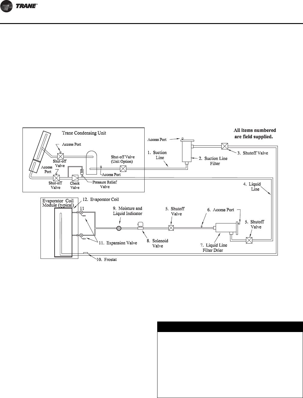
Installation
38 SS-SVX11H-EN
Access Valves (Ports)
The access ports in the liquid line allows the unit to be
charged with liquid refrigerant and is used to determine
sub-cooling.
The access ports in the suction line allow the operating
suction pressure to be checked across the suction line
filter. These ports are usually a Schrader valve with core.
Ball Shutoff Valves
The ball shutoff valve allows for isolation of the Filter/Filter
Drier for easier core replacement.
Two ball shutoff valves equal to the OD Tubing size for both
the liquid line and suction line are required.
Frostat™ Coil Frost Protection
The Frostat control is the preferred method of coil frost
protection. The Frostat control bulb is mechanically
attached to the suction line near the evaporator and wired
to the unit control panel. Refer to the proper field
connection diagram for details.
Split System Component Number Definitions
1. Interconnecting Suction Line Tubing
2. Suction Line Filter
3. Shutoff Valves - Manual ball valves
4. Interconnecting Liquid Line Tubing. If risers exceed 10
feet, Trane must review the application
5. Shutoff valves - Manual ball valves
6. Access Ports
7. Liquid Line Filter Drier
8. Liquid Line Solenoid Valve
9. Moisture and Liquid Indicator
10. Frostat™ (Required for coil freeze protection)
11. Expansion Valve (One Expansion Valve for each Coil
Distributor)
12. Evaporator Coil
Refrigerant Piping
Refrigerant piping must be properly sized and applied.
These two factors have a very significant effect on both
system performance and reliability.
Note: Use Type “L” refrigerant grade copper tubing only.
Refrigerant Piping should be sized and laid out according
to the job plans and specifications. This should be done
when the system components are selected.
Figure 27. Typical placement of split system piping components
NOTICE:
Equipment Damage!
Compressors contain POE oil which readily absorbs
moisture directly from the air. Moisture absorbed by
POE oil is very difficult to remove by evacuation and
can cause compressor failure. To prevent
contamination, this unit shipped sealed containing dry
nitrogen. Minimize the amount of time the system is
open to the atmosphere. When open, flow dry nitrogen
through the piping to prevent atmospheric moisture
from contacting compressor POE oil.
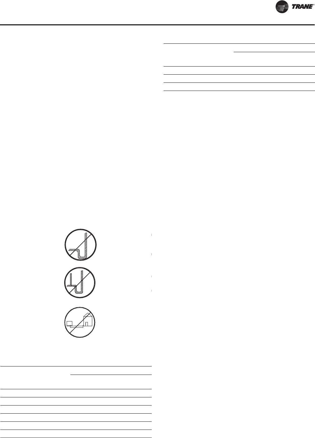
Installation
SS-SVX11H-EN 39
Suction Line Piping
Proper suction line sizing is required to guarantee that oil
is returned to the compressor throughout the operating
system. Furthermore, the line must be sized so that the
pressure drop does not excessively affect capacity or
efficiency. To accomplish both, it may be necessary to have
two sizes, one for horizontal run and vertical drops, and
another for the vertical lifts. The suction line size pre-
selected in Table 9, p. 39 are independent of the line length
for a properly charged RAUJ unit operating in a normal air
conditioning application.
For more information, refer to the latest edition of
Application Guide SS-APG012-EN.
1. Do not use suction line traps.
2. Do not use double risers.
3. Avoid putting liquid lines underground.
4. Route suction lines as short and direct as possible.
5. Slope suction lines toward the evaporator ¼-inch to 1-
inch for every 10 feet.
6. Insulate the suction lines.
7. The suction line filter should be as close to the
compressor as possible.
Note: If Suction Riser Exceeds 50 Feet, Trane Must
Review The Application.
Liquid Line Piping
Oversized liquid lines reduce compressor reliability due to
excess refrigerant in the system, and system operation
becomes more charge critical due to liquid thermal
expansion into the condenser at higher ambients.
Conversely, liquid line OD needs to be big enough to allow
for adequate subcooling entering the expansion valve at
high load conditions. The preselected lines in Tab l e 10 ,
p. 40 are independent of line length or rise within the
limitations of the latest edition of the Application Guide
SS-APG012-EN.
The liquid line should have a slight slope in the direction
of flow so that it can be routed with the suction line.
The unit has a liquid line check valve that prevents liquid
refrigerant from flowing backward through the liquid line,
filling the condenser, and overflowing to the compressor
during the “Off” cycle. A relief valve is also installed to
prevent the buildup of high pressure in the liquid line
when the unit is off. For proper operation of the relief valve,
the liquid line service valve should not be in the back
seated position but cracked open so the relief valve (and
the fan pressure switch) is open to the condenser. The line
that connects the outlet of the 235 psig relief valve to the
liquid line service valve must not be removed.
For more information, refer to the latest edition of
Application Guide SS-APG012-EN.
1. Avoid putting liquid lines underground.
2. Route liquid lines as short and direct as possible.
3. Slope liquid lines away from the condensing unit 1-
inch for every 10 feet.
4. Only insulate liquid lines that pass through heated
areas.
5. Wire solenoid valves according to the field connection
diagram for proper operation.
6. The liquid line filter drier should be as close to the
solenoid valve as possible.
Table 9. Suction line interconnecting tubing
Capacity
OD unit
connection
(Per circuit)
Recommended field piping
OD Horizontal
(Per Circuit)
OD Vertical
(Per Circuit)
20 Ton 1-5/8" 1-5/8" 1-5/8"
25 Ton 1-5/8" 2-1/8" 1-5/8"
30 Ton 1-5/8" 2-1/8" 2-1/8"
40 Ton 1-5/8" 1-5/8" 1-5/8"
50 Ton 1-5/8" 2-1/8" 1-5/8"
60 Ton 1-5/8" 2-1/8" 2-1/8"
80 Ton 2-5/8" 2-1/8" 2-1/8"
100 Ton 2-5/8" 2-5/8" 2-1/8"
120 Ton 2-5/8" 2-5/8" 2-1/8"
Note: If risers exceed 50 feet, the application must be reviewed by Trane.
Table 9. Suction line interconnecting tubing
Capacity
OD unit
connection
(Per circuit)
Recommended field piping
OD Horizontal
(Per Circuit)
OD Vertical
(Per Circuit)
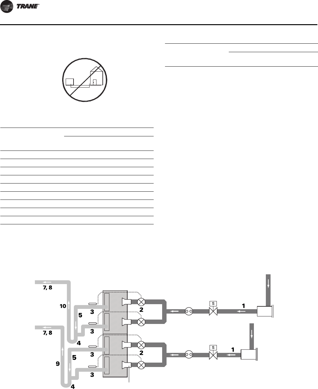
Installation
40 SS-SVX11H-EN
Note: If the liquid line riser exceeds 10 feet, refer to Tube
Size and Component Selection, publication
number SS-APG012-EN
Typical Field-Installed Evaporator Piping:
Dual-Circuit Examples
1. Install the TXV directly to the unit liquid connection.
2. Locate the TXV bulb midway between the 90 degrees
bends on top of the suction line as illustrated in
Figure 28, p. 40 and Figure 29, p. 41.
3. Secure bulb to suction line with two clamps provided
by manufacturer and insulate bulb.
4. Install the Frostat™ according to instructions enclosed
in the kit as close to evaporator as possible. Although
it may look like a trap, it is the result of going down past
the last outlet and turning to go up.
Note: All 20-60T units will require 30% bleed TXVs. All 80-
120T units will require 15% bleed TXVs. This does
not apply if they are connected to remote chiller
evaporators (see next section).
Table 10. Liquid line interconnecting tubing
Capacity
OD unit
connection
(Per Circuit)
Recommended field piping
OD Horizontal
(Per Circuit)
OD Vertical
(Per Circuit)
20 Ton 7/8" 5/8" 5/8"
25 Ton 7/8" 7/8" 7/8"
30 Ton 7/8" 7/8" 7/8"
40 Ton 7/8" 5/8" 5/8"
50 Ton 7/8" 7/8" 7/8"
60 Ton 7/8" 7/8" 7/8"
80 Ton 1-1/8" 1-1/8" 1-1/8"
100 Ton 1-1/8" 1-1/8" 1-1/8"
120 Ton 1-1/8" 1-1/8" 1-1/8"
Note: If risers exceed 10 feet, refer to Tube S ize an d Component Selection,
publication SS-APG012-EN.
Table 10. Liquid line interconnecting tubing
Capacity
OD unit
connection
(Per Circuit)
Recommended field piping
OD Horizontal
(Per Circuit)
OD Vertical
(Per Circuit)
Figure 28. Face-split
liquid line
(circuit 1)
filter drier
thermal expansion
valves (TXV)
liquid line
(circuit 2)
distributor
solenoid
valve
sight
glass
Evaporator Coil
with Horizontal-Split
(Standard) Circuiting
suction line
(circuit 2)
suction line
(circuit 1)
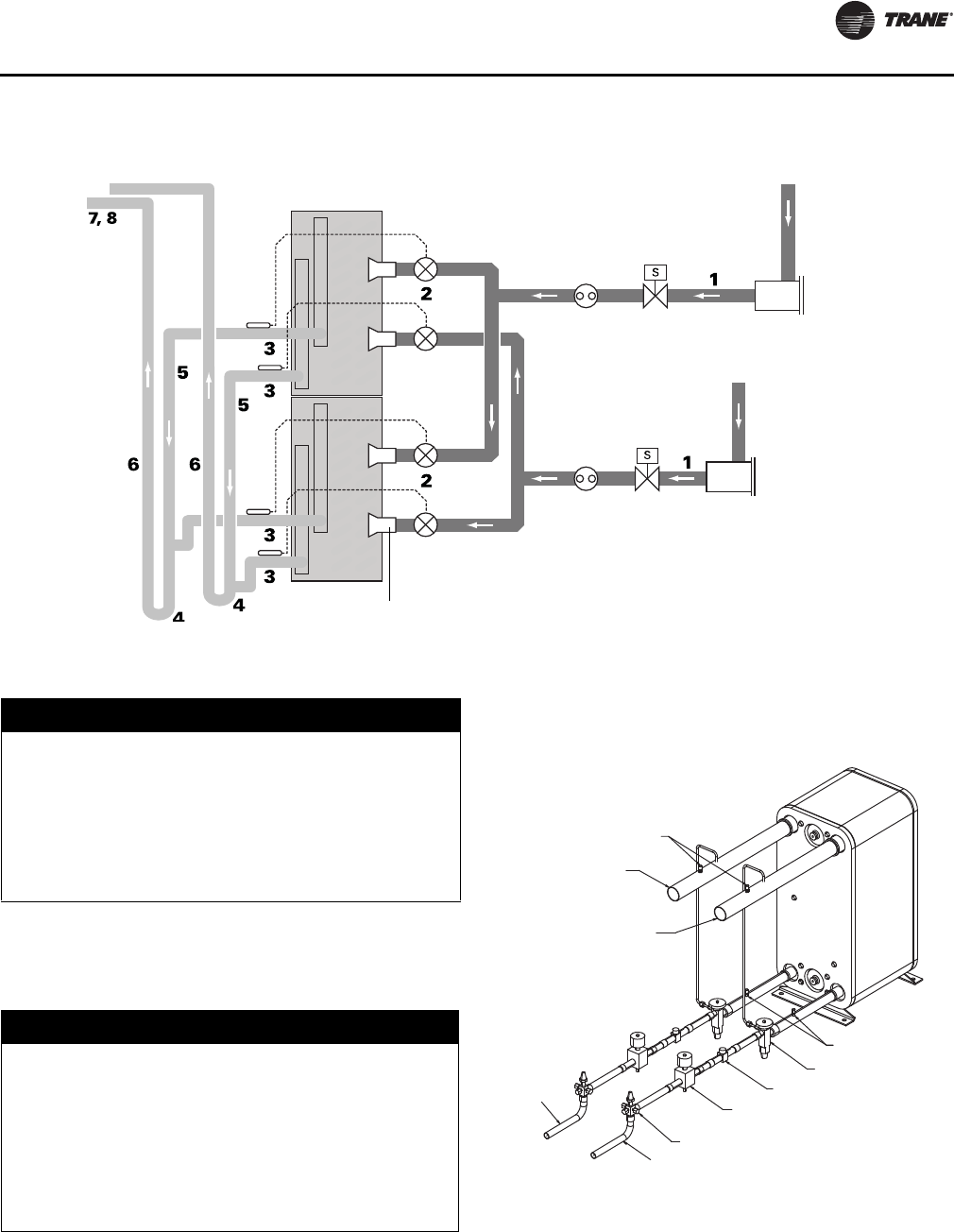
Installation
SS-SVX11H-EN 41
Typical Field-Installed EVP Chiller
Evaporator Piping
1. Install the TEV(s) directly to the unit liquid connection.
See TEV recommendations in the Tube Size and
Component Selection Application Guide, publication
number SS-APG012-EN.
2. Locate TEV bulb on top of the suction line 12” from the
heat exchanger outlet.
3. Secure the bulb to the suction line with two clamps
provided by the manufacturer and insulate the bulb.
4. Locate liquid line solenoid valve(s) near TEV.
5. Install the Frostat™ according to instructions enclosed
in the kit as close to the evaporator as possible.
Hot Gas Bypass for Commercial Comfort-
Cooling Applications
Hot gas bypass is not recommended for use on RAUJ
units. Frostat™ is the preferred method of protecting the
evaporator from freeze-up. It turns off compressors when
Figure 29. Intertwined
thermal expansion
valves (TXV)
distributor
suction lines
Evaporator Coil with
Intertwined Circuiting
liquid line
(circuit 1)
filter drier
liquid line
(circuit 2)
solenoid
valve
sight
glass
(circuit 1)
(circuit 2)
NOTICE:
Equipment Damage!
The braze connections at the heat exchanger are
stainless steel. Use 40-45% silver brazing alloy BAg-7 or
BAg-29 for copper to steel refrigerant connections at
the chiller. Use flux sparingly to prevent plugging heat
exchanger flow passages. Improper methods could
result in refrigerant leaks or damage to the heat
exchanger. See “Brazing Procedures,” p. 43.
NOTICE:
Evaporator Damage!
To prevent evaporator damage and for proper
refrigerant distribution, an 8-12” stub tube must be
brazed between the expansion valve and the chiller
entering refrigerant connection. This tube must be the
same diameter as the heat exchanger connection ID.
Use reducers only at the expansion valve. See
Figure 19, p. 25 through Figure 23, p. 29 for Chiller inlet
dimensions.
Figure 30. EVP Chiller, Typical Refrigerant Piping (2
circuit system)
GAUGE PORTS &
SUPERHEAT
ADJUSTMENT PORT
#1 SUCTION LINE
#2 SUCTION LINE
CHARGING PORT
EXPANSION VALVE
MOISTURE INDICATOR
SOLENOID VALVE
(MIGRATION ONLY)
REFRIGERANT “SHUT OFF” VALVE
#2 LIQUID LINE
#1 LIQUID
LINE
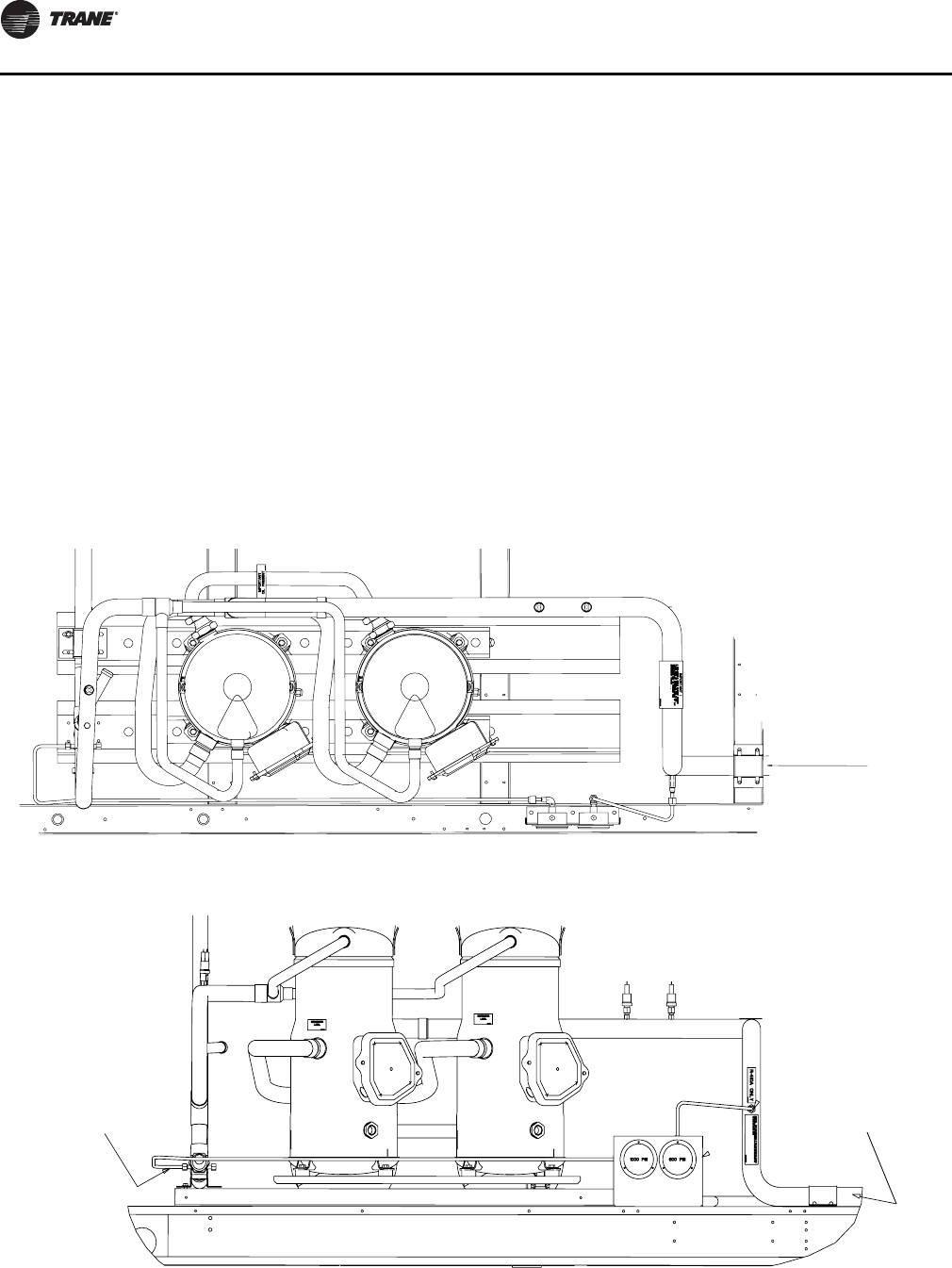
Installation
42 SS-SVX11H-EN
the coil frosting is sensed. The compressor is allowed to
operate when the coil temperature rises a few degrees
above the frosting condition. This action reduces the
overall energy consumption of the system while reliably
maintaining system control.
For more information, refer to the Hot Gas Bypass
Engineers Newsletter, ADM-APN007-EN.
Optional Pressure Gauges
When a unit is ordered with optional pressure gauges, (“F”
in the miscellaneous digit of the model number), a set of
gauges and the necessary mounting hardware ship in the
location illustrated in the Unit Component “Layout” and
“Shipwith” Location. The mounting location and tubing
configuration for the optional pressure gauges after field
installation is shown below.
1. Assemble the valve depressor, flare nuts, 1/4" copper
tubing, 90 degree flare elbows, gauge & gauge bracket
together as shown in Detail “A” & “B”.
Note: Wrap all appropriate pipe threads with Teflon tape
before assembly.
2. Remove the valve stem cap and place the valve
depressor (with tubing connected) onto the valve stem
and tighten.
Note: Do not install the valve depressor without the
tubing being connected. If gauges need to be
replaced, remove valve depressor from valve stem,
first, to prevent loss of refrigerant charge.
3. Using the gauge bracket as a template for the self
tapping screws, mount the gauge bracket
approximately 1/2" to 3/4" from the outer edge of the
base rail, relative to the compressors for that circuit, as
illustrated.
4. Apply 6" strips of edge protector to both side flanges of
the gauge bracket, to prevent the bracket from cutting
into the power wires.
Figure 31. Pressure gauges 20 - 60 Ton units: plan view
Suction Connection
Figure 32. Pressure gauges 20 - 60 Ton units: front view
Suction Connection
Discharge Connection
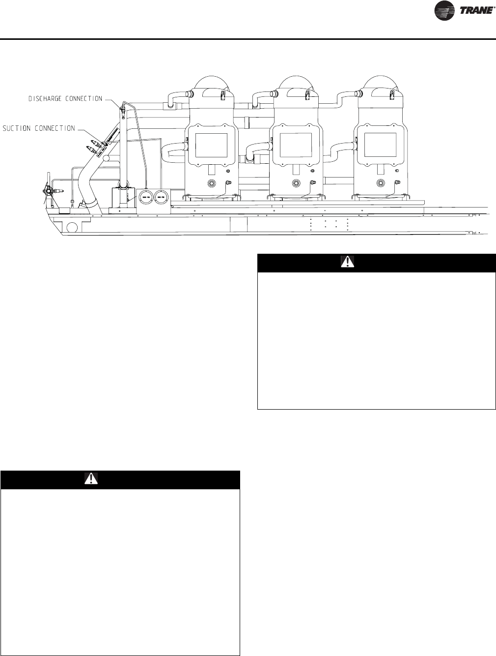
Installation
SS-SVX11H-EN 43
Final Refrigerant Pipe Connections
To access the refrigerant pipe connections, remove the
louvered side grills.
These condensing units are shipped with a Nitrogen
holding charge. Install pressure gauges to the appropriate
access valve(s) and take a reading. If no pressure is
present, refer to the “Leak Testing Procedure” section. If
pressure is present, relieve the pressure before attempting
to unsweat the “seal” caps. If refrigerant connections are
not capped, but are “spun-end” tubes, use a tubing cutter
to remove the end from the pipe.
Note: To prevent damage to the system, do not drill a hole
in the seal caps or saw the ends off pipe stubs. This
could introduce copper chips into the system
piping.
Brazing Procedures
Proper brazing techniques are essential when installing
refrigerant piping. The following factors should be kept in
mind when forming sweat connections.
1. When copper is heated in the presence of air, Copper
oxide forms. To prevent copper oxide from forming
inside the tubing during brazing, sweep an inert gas,
such as dry nitrogen, through the tubing. Nitrogen
displaces air in the tubing and prevents oxidation of
the interior surfaces. A nitrogen flow of one to three
cubic feet per minute is sufficient to displace the air.
Use a pressure regulating valve or flow meter to
control the flow.
2. Ensure that the tubing surfaces to be brazed are clean,
and that the ends of the tubes have been carefully
reamed to remove any burrs.
3. Make sure the inner and outer tubes of the joint are
symmetrical and have a close clearance, providing an
easy slip fit. If the joint is too loose, the tensile strength
of the connection will be significantly reduced. The
overlap distance should be equal to the diameter of the
inner tube.
4. Wrap the body of each refrigerant line component with
a wet cloth to keep it cool during brazing. Move any
tube entrance grommets away for the brazing area.
Figure 33. Pressure gauges 80 - 120 Ton units: front view
WARNING
Hazard of Explosion and Deadly Gases!
Never solder, braze or weld on refrigerant lines or any
unit components that are above atmospheric pressure
or where refrigerant may be present. Always remove
refrigerant by following the guidelines established by
the EPA Federal Clean Air Act or other state or local
codes as appropriate. After refrigerant removal, use dry
nitrogen to bring system back to atmospheric pressure
before opening system for repairs. Mixtures of
refrigerants and air under pressure may become
combustible in the presence of an ignition source
leading to an explosion. Excessive heat from soldering,
brazing or welding with refrigerant vapors present can
form highly toxic gases and extremely corrosive acids.
Failure to follow all proper safe refrigerant handling
practices could result in death or serious injury.
WARNING
Hazard of Explosion!
Use only dry nitrogen with a pressure regulator for
pressurizing unit. Do not use acetylene, oxygen or
compressed air or mixtures containing them for
pressure testing. Do not use mixtures of a hydrogen
containing refrigerant and air above atmospheric
pressure for pressure testing as they may become
flammable and could result in an explosion.
Refrigerant, when used as a trace gas should only be
mixed with dry nitrogen for pressurizing units. Failure
to follow these recommendations could result in death
or serious injury or equipment or property-only
damage.
Installation
44 SS-SVX11H-EN
Note: Use 40 to 45% silver brazing alloy (BAg-7 or BAg-
28) on dissimilar metals. Use BCup-6 brazing alloy
on copper to copper joints.
5. If flux is used, apply it sparingly to the joint. Excessive
flux can enter the system which will contaminate the
refrigerant system.
6. Apply heat evenly over the length and circumference
of the joint to draw the brazing material into the joint
by capillary action. Remove the brazing rod and flame
from the joint as soon as a complete fillet is formed to
avoid possible restriction in the line.
7. Visually inspect the connection after brazing to locate
any pin holes or crevices in the joint. The use of a
mirror may be required, depending on the joint
location.
Leak Testing Procedure
When Leak-testing a refrigerant system, observe all safety
precautions.
Trane condensing units are shipped with a Nitrogen
holding charge. If there is no pressure, the unit must be
leak tested to determine the location of leak as follows:
Note: These service procedures require working with
refrigerant, Do NOT release refrigerant to the
atmosphere! The service technician must comply
with all federal, state, and local laws.
Use refrigerant gas as a tracer for leak detection and use
oil-pumped dry nitrogen to develop the required test
pressure. Test the high and low side of the system at
pressures dictated by local codes.
1. Close the field supplied liquid line service valve(s)
installed near the evaporator and the compressor
discharge service valve to isolate the system's high
side from the low side. Pressure test the liquid line,
discharge line, and condenser coils at pressures
dictated by local codes. Do not exceed 10# above the
pressure control settings.
2. Connect a refrigerant cylinder to the charging port of
the liquid line service valve. Use the refrigerant to raise
the high side pressure to 12 to 15 psig.
3. Disconnect the refrigerant cylinder. Connect a dry
nitrogen cylinder to the charging port and increase the
high side pressure. Do not exceed the condenser
maximum working pressure listed on the unit
nameplate.
4. Use a leak detector or soap bubbles to check for leaks.
Check all piping joints, valves, etc...
5. If a leak is located, use proper procedures to remove
the refrigerant/nitrogen mixture, break the connection
and remake as a new joint. Retest for leaks after making
repairs.
6. Repeat the test procedure for the low side of the
system, charging through the suction pressure gauge
port or through an access provided on the suction line
by the installer. Increase the system pressure to 100
psig.
7. If a leak is located, use proper procedures to remove
the refrigerant/nitrogen mixture, break the connection
and remake as a new joint. Retest for leaks after making
repairs.
8. Open the liquid line service valve and the compressor
discharge service valve.
Remote EVP Chiller
Water Treatment
The use of untreated or improperly treated water could
result in scaling, erosion, corrosion, and algae or slime
buildup in the heat exchanger. This will adversely affect
WARNING
Hazard of Explosion!
Use only dry nitrogen with a pressure regulator for
pressurizing unit. Do not use acetylene, oxygen or
compressed air or mixtures containing them for
pressure testing. Do not use mixtures of a hydrogen
containing refrigerant and air above atmospheric
pressure for pressure testing as they may become
flammable and could result in an explosion. Refrigerant,
when used as a trace gas should only be mixed with
dry nitrogen for pressurizing units. Failure to follow
these recommendations could result in death or serious
injury or equipment or property-only damage.
WARNING
Hazard of Explosion!
Never use an open flame to detect gas leaks. It could
result in an explosion. Use a leak test solution for leak
testing. Failure to follow recommended safe leak test
procedures could result in death or serious injury or
equipment or property-only-damage.
NOTICE:
Proper Water Treatment!
The use of untreated or improperly treated could result
in scaling, erosion, corrosion, algae or slime. It is
recommended that the services of a qualified water
treatment specialist be engaged to determine what
water treatment, if any, is required. Trane assumes no
responsibility for equipment failures which result from
untreated or improperly treated water, or saline or
brackish water.
NOTICE:
Heat Exchanger Damage!
The use of untreated or improperly treated water could
result in heat exchanger fouling and permanent
damage to the heat exchanger.
Installation
SS-SVX11H-EN 45
system capacity. Proper water treatment must be
determined locally and depends on the type of system and
local water characteristics. Neither salt nor brackish water
is recommend, use of either will lead to a shortened heat
exchanger life. Trane encourages employment of a
qualified water treatment specialist, familiar with local
water conditions, to assist in the establishment of a proper
water treatment program.
Water Flow Limits
The minimum and maximum water flow rates are given in
the General Data section. Water flow rates below the
tabulated values will result in laminar flow causing freeze-
up problems, scaling, stratification and poor system
control. Flow rates exceeding the maximum listed could
result in very high pressure drop, erosion of the heat
exchanger and damage to the water flow switch.
Water Temperature Limits
Catalog chiller performance data is based on a water
temperature drop of 10°F . Full load chilled water
temperature drops from 8 to 14°F may be used as long as
minimum and maximum water temperature and
minimum and maximum flow rates are not violated.
Leaving water temperatures below 42°F require freeze
protection down to 15°F. The maximum water temperature
that can be circulated through the chiller when the unit is
not operating is 125°F. Evaporator damage could result
above this temperature.
Short Water Loops
Adequate chilled water system water volume is an
important system design parameter because it provides
for stable chilled water temperature control and helps limit
unacceptable short cycling of chiller compressors.
Typically, a five-minute water loop circulation time is
sufficient to prevent short water loop issues. Therefore, as
a guideline, ensure the volume of water in the chilled water
loop equals or exceeds five times the evaporator flow rate.
For systems with a rapidly changing load profile the
amount of volume should be increased.
Note: Water volumes should be calculated as close as
possible to maintain constant water flow through
the water loop.
Chilled Water Piping
Typical Water Piping. Figure 36, p. 48 illustrates typical
water piping components for remote chiller applications.
(Remote Chiller accessory kit includes strainer, water flow
switch, pipe stubs, couplings, evaporator insulation and
mounting legs, and a ship separate braze plate heat
exchanger.)
Foreign matter in the chilled water system will increase
pressure drop and reduce water flow. Installation of a
properly selected strainer is also necessary to prevent
debris larger than 0.039” from entering the heat
exchanger. All building piping must be thoroughly flushed
before making the final piping connections to the heat
exchanger. The strainer must also be cleaned prior to
initial start-up.
Important: Start up without flushing building piping
risks plugging chiller with debris and
reducing capacity.
To reduce heat loss and prevent condensation, insulation
should be applied to piping. Expansion tanks are also
usually required to accommodate chilled water volume
changes.
Braze Plate (BPHE) Chiller. Evaporator water inlet and
outlet types, sizes and locations are shown in Figure 19,
p. 25 to Figure 23, p. 29. Installation of a field provided 1/
2” x 14NPTE stainless steel or PVC plug is required.
Strainer. Install a strainer in the water supply line to
protect the chiller from plugging with system piping
debris. Strainers should be installed as close as practical to
the heat exchanger water inlet (the remote chiller
accessory kit includes strainer and piping to connect with
NOTICE:
Heat Exchanger Damage!
Water flow rates beyond the heat exchanger limits
could result in permanent damage to the heat
exchanger.
NOTICE:
Heat Exchanger and Compressor
Damage!
Leaving water temperatures below 42°F require glycol
protection down to 15°F. Otherwise, water freezing in
brazed plate chiller could rupture separation between
refrigerant and water flow channels necessitating heat
exchanger/compressor replacement and system
cleanup.
NOTICE:
Heat Exchanger Damage!
The brazed plate heat exchanger could be damaged by
excessive refrigerant pressures if circulating water
temperatures exceed 125°F when the unit is not
operating..
NOTICE:
Compressor Damage!
Water loops with less than five minute circulation time
could result in poor superheat control and compressor
damage.
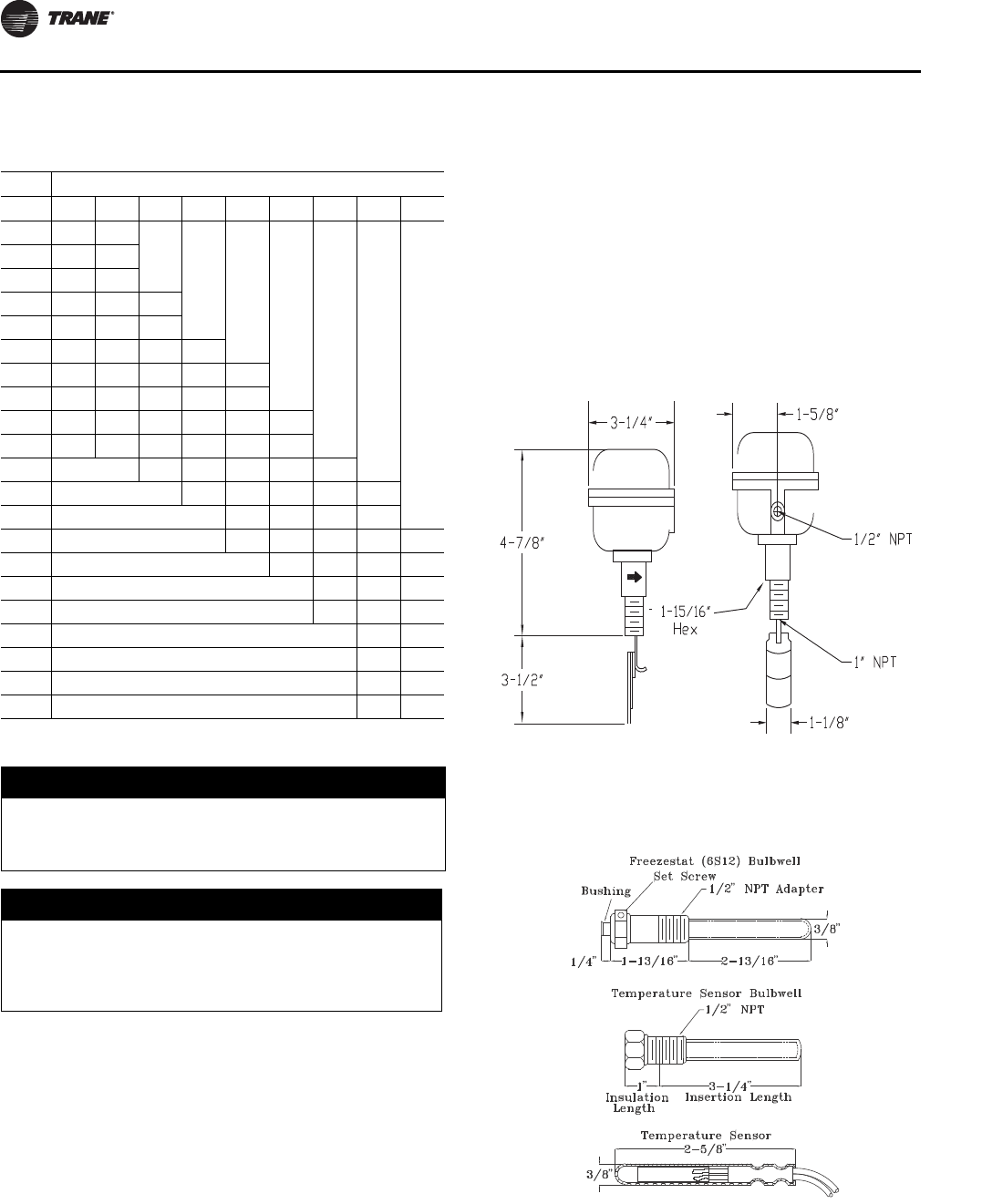
Installation
46 SS-SVX11H-EN
BPHE). A field provided blow down valve (recommended)
or plug must be installed in strainer cleanout if not present.
Chiller Water Flow Switch.
Install a flow switch or other flow sensing device,
illustrated in Figure 34, to prevent or stop the compressor
operation if the water flow drops below minimum limits.
Locate the device in the chilled water return line as shown
in Figure 36, p. 48. Install per switch manufacturer’s
instructions and refer to the field wiring and unit
schematics for the flow switch electrical interlock
connections. Adjust switch trip point to prevent operation
below minimum limits.
The water flow switch included in the EVP chiller accessory
kit must be adjusted to prevent flow below the minimum
limit. To set the flow limit:
1. Establish minimum water flow.
2. Rotate the flow switch adjustment screw until the
switch opens. This gets close to the correct setting but
final adjustment must be done without water flow.
3. Beginning from water off, start flow and adjust GPM
until the switch trips. If flow rate is below minimum,
stop water flow and rotate adjusting screw
accordingly.
4. Repeat until the switch trips at or above minimum flow.
Note: Use pressure gauge(s) and Water Pressure Drop
table to determine water flow rate. See General
Data for minimum flow limits.
Air Vents. Vents must be installed at high points in the
piping system to facilitate air purging during the filling
process. Air vents between the system shut off valve and
Table 11. Chiller water pressure drop, Ft H2O
Flow Size, Tons
GPM20253040506080100120
25 3.7
30 5.2 3.2
35 6.9 4.2
40 8.8 5.4 3.1
45 10.9 6.7 3.9
50 13.3 8.2 4.8 5.3
60 18.5 11.4 6.7 7.5 4.1
70 24.6 15.2 8.9 10.1 5.5
80 19.4 11.4 13.0 7.1 5.0
90 24.1 14.2 16.3 8.9 6.3
100 17.3 19.9 10.9 7.7 4.3
120 28.3 15.4 10.9 6.1 3.2
140 20.7 14.6 8.2 4.4
160 26.7 18.9 10.6 5.6 4.8
180 23.6 13.2 7.1 6.1
200 16.2 8.7 7.4
240 22.9 12.3 10.6
280 16.5 14.2
320 21.3 18.3
360 26.7 23.0
400 28.2
NOTICE:
Evaporator Damage!
To prevent evaporator damage, do not use water flow
switch to cycle the system.
NOTICE:
Evaporator Damage!
Operation at water flow rates below the minimum
limits could result in permanent damage to the heat
exchanger and compressors.
Figure 34. Optional flow switch
Figure 35. Freezestat Bulb-well, Temperature Sensor
and Well

Installation
SS-SVX11H-EN 47
heat exchanger are also useful for EVP chiller service and
shutdown.
Water Pressure Gauges.
Install pressure gauge(s) to monitor the entering and
leaving chilled water pressure, and strainer condition.
Water Shutoff Valves. Provide shutoff valves in the
"Supply" and "Return" pipe near the chiller so the gauge(s),
thermostats, sensors, strainer, etc., can be isolated during
service.
Pipe Unions. Use pipe unions to simplify disassembly
for system service. Use vibration eliminators to prevent
transmitting vibrations through the water lines.
Thermometers. Install thermometers in the lines to
monitor the evaporator entering and leaving water
temperatures.
Balancing Valves. Install a balancing cock (valve) in the
leaving water line. It will be used to establish a balanced
flow.
Note: Both the entering and leaving water lines should
have shutoff valves installed to isolate the
evaporator for service.
Chiller Drain. Drain piping, with shut off valve, must be
installed at the lowest point between the chiller and
system piping valves to allow water removal for service
and shut down procedures. The drain must be piped to a
suitable facility.
Note: Insure that the drain is closed before filling system
with water.
Water Temperature Sensor. The Temperature Sensor
and Sensor-well must be installed in the leaving water
piping as close to the chiller as possible. Both devices are
located inside the remote panel. Thermal paste is also
provided inside the remote panel and must be used when
installing the sensor into the sensor-well. Figure 35, p. 46
illustrates the Sensor-well dimensions.
Freezestat. A Bulb-well (located inside the remote panel)
must be installed in the leaving water piping as close to the
chiller as possible. It should be located upstream of the
Temperature Sensor location. The Freezestat, located
within the remote panel, is equipped with a remote
Sensing Bulb and 20 feet of capillary tube. The Remote
Sensing Bulb must be installed by the installing personnel.
Thermal paste is also provided inside the remote panel
and must be used when installing the bulb into the bulb-
well. Figure 35, p. 46 illustrates the Bulb-well dimensions.
Important: Isolate the water pumps from the system
piping to avoid vibration transmission.
Insulate all water piping. Use appropriate
pipe sealant on all threaded connections.
Final Water Piping Connections
1. All water piping in the system must be flushed
thoroughly before making the final connections.
2. Clean strainer.
3. Connect the water pipe to the EVP chiller.
4. Make sure the 1/2” x 14NPTE plug is installed.
5. Close the drain shutoff valve.
6. While filling the chiller system with solution, vent the
air from the system at the highest points.
NOTICE:
Evaporator Damage!
To prevent evaporator damage do not exceed 150 psig
evaporator pressure.
NOTICE:
Equipment Damage!
Failure to use thermal paste could result in erratic
temperature sensing resulting in equipment damage.
NOTICE:
Equipment Damage!
If an acidic commercial flushing solution is used,
bypass the EVP chiller to prevent damage to the heat
exchanger.
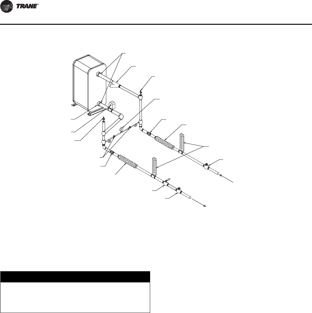
Installation
48 SS-SVX11H-EN
Notes:
1. Shutoff valves are required for evaporator servicing.
2. Evaporator is shown for illustration purposes only.
3. Water inlet, outlet diameter dimensional locations depend on unit size.
4. Water connections at the evaporator are grooved.
5. Field supplied 1/2” x 14 NPTE stainless steel or PVC plug required.
6. Locate freezestat and discharge temperature sensors close to the water outlet.
7. Install drain with shutoff valve at low point in leaving piping before system valve.
Field Installed Power Wiring
An overall dimensional layout for the field installed wiring
entrance into the unit is illustrated in Figure 5, p. 11 to
Figure 18, p. 24. To insure that the unit’s supply power
wiring is properly sized and installed, follow the guidelines
outlined below.
Verify that the power supply available is compatible with
the unit’s nameplate ratings. The available supply power
must be within 10% of the rated voltage stamped on the
nameplate.
Disconnect Switch External Handle (20-
120 Ton Factory Mounted Option)
Units ordered with the factory mounted nonfused
disconnect switch comes equipped with an externally
mounted handle. This allows the operator to disconnect
power from the unit without having to open the control
panel door. Handle locations and its three positions are
shown below;
“ON” - Indicates disconnect switch is closed, allowing
main power supply to be applied at unit.
“OFF” - Indicates disconnect switch is open, interrupting
main power supply to unit controls.
“OPEN COVER/RESET” - Turning the handle to this
position releases the handle form the disconnect switch,
allowing the control panel door to be opened.
Once the door has been opened, it can be closed with the
handle in any one of the three positions outlined above,
provided it matches the disconnect switch position.
The handle can be locked in the “OFF” position. While
holding the handle in the “OFF” position, push the spring
loaded thumb key, attached to the handle, into the base
slot. Place the lock shackle between the handle and the
thumb key. This will prevent it from springing out of
position.
Figure 36. EVP Chiller, Typical Water Piping
PIPE CONNECTIONS
WATER STRAINER
AIR VENTS
PRESSURE GAUGE
UNIONS
VIBRATION ELIMINATORS
THERMOMETERS
GATE VALVES
RETURN LINE (INLET)
(SEE NOTE 1)
SUPPLY LINE OUTLET
FLOW SWITCH
AIR VENTS
SHUTOFF VALVES
UNIONS
VIBRATION ELIMINATORS
BALANCING VALVE
GATE VALVES
SUPPLY LINE OUTLET
NOTICE:
Use Copper Conductors Only!
Unit terminals are not designed to accept other types
of conductors. Failure to use copper conductors could
result in equipment damage.
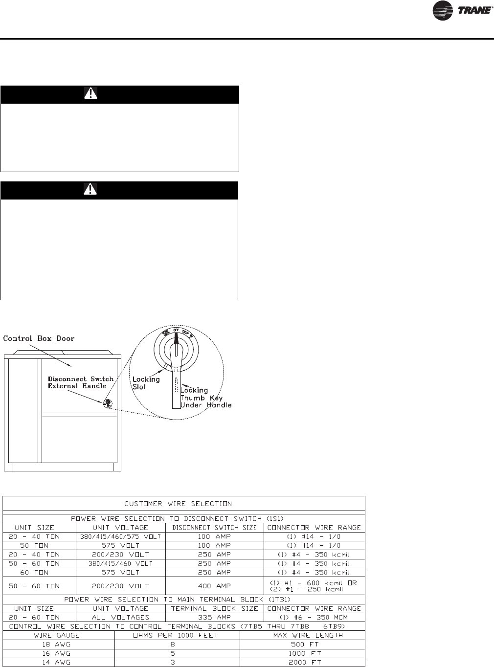
Installation
SS-SVX11H-EN 49
Main Unit Power Wiring Table 12, p. 49 lists the field connection wire ranges for
both the main power terminal block 1TB1 and the optional
main power disconnect switch 1S1. The unit electrical data
is listed in Table 14, p. 51 and Table 15, p. 52. The electrical
service must be protected from over current and short
circuit conditions in accordance with NEC requirements.
Protection devices must be sized according to the
electrical data on the nameplate. Refer to the “Power Wire
Sizing & Protection Device Equations”, for determining:
a. the appropriate electrical service wire size based on
“Minimum Circuit Ampacity” (MCA),
b. the “Maximum Over current Protection” (MOP)
device.
c. the “Recommended Dual Element fuse size” (RDE).
1. If the unit is not equipped with an optional factory
installed non-fused disconnect switch, a field supplied
disconnect switch must be installed at or near the unit
in accordance with the National Electrical Code (NEC
latest edition). Refer to the “Power Wire Sizing &
Protection Device Equations” (DSS calculation), for
determining the correct size.
2. Complete the unit’s power wiring connections onto
either the main terminal block 1TB1, or the factory
mounted non-fused disconnect switch 1S1, inside the
unit control panel. Refer to the customer connection
diagram that shipped with the unit for specific
termination points.
3. Provide proper grounding for the unit in accordance
with local and national codes.
Power Wire Sizing and Protection Device
Equations
WARNING
Hazardous Voltage!
Disconnect all electric power, including remote
disconnects before servicing. Follow proper lockout/
tagout procedures to ensure the power cannot be
inadvertently energized. Failure to disconnect power
before servicing could result in death or serious injury.
WARNING
Proper Field Wiring and Grounding
Required!
All field wiring MUST be performed by qualified
personnel. Improperly installed and grounded field
wiring poses FIRE and ELECTROCUTION hazards. To
avoid these hazards, you MUST follow requirements for
field wiring installation and grounding as described in
NEC and your local/state electrical codes. Failure to
follow code could result in death or serious injury.
Figure 37. Disconnect switch details
Table 12. Customer connection wire range 20 - 60 Ton units
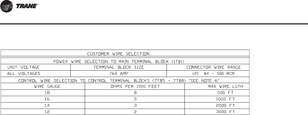
Installation
50 SS-SVX11H-EN
To correctly size the main power wiring for the unit, use the
appropriate calculation(s) listed below. Read the load
definitions that follow and use Calculation #1 for
determining the MCA (Minimum Circuit Ampacity), MOP
(Maximum Over current Protection), and RDE
(Recommended Dual Element fuse size) for each unit. Use
Calculation #2 to determine the DSS (Disconnect Switch
Size) for each unit.
Load Definitions:
LOAD 1 = CURRENT OF THE LARGEST MOTOR
(COMPRESSOR OR FAN MOTOR)
LOAD 2 = SUM OF THE CURRENTS OF ALL
REMAINING MOTORS
LOAD 4 = CONTROL POWER TRANSFORMER
= AND ANY OTHER LOAD RATED AT 1 AMP OR
MORE
Calculation #1
(MCA, MOP, and RDE)
MCA = (1. 2 5 x LOAD 1) + LOA D 2 + LOA D 4 MOP
= (2.25 x LOAD 1) + LOAD 2 + LOAD 4
Select a fuse rating equal to the MOP value. If the MOP
value does not equal a standard fuse size as listed in NEC
240 - 6, select the next lower standard fuse rating.
Note: If selected MOP is less than the MCA, then select
the lowest standard maximum fuse size which is
equal to or larger than the MCA, provided the
selected fuse size does not exceed 800 amps.
RDE = (1.5 x LOAD 1) + LOAD 2 + LOAD 4
Select a fuse rating equal to the RDE value. If the RDE value
does not equal a standard fuse size as listed in NEC 240 -
6 select the next higher standard fuse rating.
Note: If the selected RDE is greater than the selected MOP
value, then select the RDE value to equal the MOP
value.
Calculation #2
Disconnect Switch Sizing (DSS)
DSS = 1.15 X (LOAD 1 + LOAD 2 + LOAD 4)
Table 13. Customer connection wire range 80 - 120 Ton units
Installation
SS-SVX11H-EN 51
Table 14. Electrical service sizing data (20-60 Ton units)
Unit Characteristics Condenser Fan Motor Compressor Motor
Model
Electrical
Characteristics
Allowable
Voltage
Range
Min.
Circuit
Amp
Max.
Overcurrent
Protection
Rec.
Dual
Element
Fuse
Size KW NO HP FLA LRA NO
1A/ 2A
RLA
1B/2B
RLA
1A/2A
LRA
1B/2B
LRA
20 Ton
200/60/3XL 180-220 102 125 125 0.9 2 1 4.1 20.7 2 41.4 41.4 267 267
230/60/3XL 208-254 89 110 100 0.9 2 1 4.1 20.7 2 35.5 35.5 267 267
460/60/3XL 416-508 46 60 60 0.9 2 1 1.8 9.0 2 18.6 18.6 142 142
575/60/3XL 520-635 39 50 45 0.9 2 1 1.4 7.2 2 15.8 15.8 103 103
380/415/50/3XL 342-418
373-456 46 60 50 0.75 2 1 1.7 9.2 2 18.6 18.6 142 142
25 Ton
200/60/3XL 180-220 119 150 150 0.9 3 1 4.1 20.7 2 41.4 52 267 315
230/60/3XL 208-254 107 150 125 0.9 3 1 4.1 20.7 2 35.5 47 267 315
460/60/3XL 416-508 52 70 60 0.9 3 1 1.8 9.0 2 18.6 22.2 142 158
575/60/3XL 520-635 44 60 50 0.9 3 1 1.4 7.2 2 15.8 19.2 103 136
380/415/50/3XL 342-418
373-456 52 70 60 0.75 3 1 1.7 9.2 2 18.6 22.2 142 158
30 Ton
200/60/3XL 180-220 141 175 175 0.9 3 1 4.1 20.7 2 56.9 56.9 351 351
230/60/3XL 208-254 123 150 150 0.9 3 1 4.1 20.7 2 48.8 48.8 351 351
460/60/3XL 416-508 63 80 70 0.9 3 1 1.8 9.0 2 25.5 25.5 197 197
575/60/3XL 520-635 57 70 70 0.9 3 1 1.4 7.2 2 23.1 23.1 146 146
380/415/50/3XL 342-418
373-456 63 80 70 0.75 3 1 1.7 9.2 2 25.5 25.5 197 197
40 Ton
200/60/3XL 180-220 193 225 225 0.9 6 1 4.1 20.7 4 41.4 41.4 267 267
230/60/3XL 208-254 168 200 200 0.9 6 1 4.1 20.7 4 35.5 35.5 267 267
460/60/3XL 416-508 87 100 100 0.9 6 1 1.8 9.0 4 18.6 18.6 142 142
575/60/3XL 520-635 73 80 80 0.9 6 1 1.4 7.2 4 15.8 15.8 103 103
380/415/50/3XL 342-418
373-456 86 100 100 0.75 6 1 1.7 9.2 4 18.6 18.6 142 142
50 Ton
200/60/3XL 180-220 236 250 250 0.9 6 1 4.1 20.7 4 47 52 304 315
230/60/3XL 208-254 215 250 250 0.9 6 1 4.1 20.7 4 42.3 47 304 315
460/60/3XL 416-508 102 110 110 0.9 6 1 1.8 9.0 4 20.2 22.2 147 158
575/60/3XL 520-635 86 100 100 0.9 6 1 1.4 7.2 4 17.1 19.2 122 136
380/415/50/3XL 342-418
373-456 101 110 110 0.75 6 1 1.7 9.2 4 20.2 22.2 147 158
60 Ton
200/60/3XL 180-220 267 300 300 0.9 6 1 4.1 20.7 4 56.9 56.9 351 351
230/60/3XL 208-254 232 250 250 0.9 6 1 4.1 20.7 4 48.8 48.8 351 351
460/60/3XL 416-508 120 125 150 0.9 6 1 1.8 9.0 4 25.5 25.5 197 197
575/60/3XL 520-635 107 125 125 0.9 6 1 1.4 7.2 4 20.3 20.3 146 146
380/415/50/3XL 342-418
373-456 119 125 125 0.75 6 1 1.7 9.2 4 25.4 25.4 197 197
Notes:
1. LOAD 1= Current of the largest motor (Compressor or Fan Motor); LOAD 2=Sum of the currents of all remaining motors. LOAD 3= FLA(Full Load
Amps) of the electric heater; LOAD 4= Any other load rated at 1 amp or more.
2. For Electric Heat MCA, MOP, RDE values, calculate for both cooling and heating modes.
3. If selected Max Over Cur is less than the Minimum Circuit Ampacity, then select the lowest maximum fuse size which is equal to or larger than the Min
Circuit Ampacity, provided the selected fuse size does not exceed 800 amps.
Installation
52 SS-SVX11H-EN
Field Installed Control Wiring
Before installing any connecting wiring, refer to Figure 5,
p. 11 to Figure 18, p. 24 for the electrical access locations
provided on the unit. Install appropriately sized control
wiring for the 115 volt electrical components as required
by the application.
Since the unit-mounted 115V control power transformer
(1T1) is provided on all units, it is not necessary to run a
separate 115 volt control power source to the unit.
Note: 200/230 Volt units are shipped with transformer
1T1 wired for 200 volt operation. If the unit is to be
operated on a 230 volt power supply, rewire the
transformer as shown on the unit schematic.
Controls Using 115 VAC
Install appropriately sized 115 volt control wiring for the
electrical components as required by the application.
These components may include:
• Hot gas bypass solenoid wiring;
• Supply fan interlock and control circuit;
• System control switch wiring (“No Control” units);
• Step controller wiring (“No Control” units);
• Chilled water pump interlock wiring (EVP units);
Table 15. Electrical service sizing data (80-120 Ton units)
Unit Characteristics
Condenser Fan
Motor Compressor Motor
Model
Electrical
Characteristics
Allowable
Voltage
Range
Min.
Circuit
Amp
Max.
Overcurrent
Protection
Rec.
Dual
Element
Fuse
Size KW NO HP FLA LRA NO
1A/
2A
RLA
1B/
2B
RLA
1C/
2C
RLA
1A/
2A
LRA
1B/
2B
LRA
1C/
2C
LRA
80 Ton
200/60/3XL 200/60/3XL 411 450 450 0.9 8 1 4.1 20.7 6 60.5 60.5 60.5 320 320 320
230/60/3XL 230/60/3XL 358 400 400 0.9 8 1 4.1 20.7 6 52 52 52 320 320 320
460/60/3XL 460/60/3XL 174 200 175 0.9 8 1 1.8 9 6 25.4 25.4 25.4 160 160 160
575/60/3XL 575/60/3XL 139 150 150 0.9 8 1 1.4 7.2 6 20.3 20.3 20.3 135 135 135
100 Ton
200/60/3XL 200/60/3XL 480 500 500 0.9 12 1 4.1 20.7 6 60.5 60.5 83.9 320 320 485
230/60/3XL 230/60/3XL 425 450 450 0.9 12 1 4.1 20.7 6 52 52 74.5 320 320 485
460/60/3XL 460/60/3XL 207 225 225 0.9 12 1 1.8 9 6 25.4 25.4 37.2 160 160 215
575/60/3XL 575/60/3XL 166 175 175 0.9 12 1 1.4 7.2 6 20.3 20.3 29.8 135 135 175
120 Ton
200/60/3XL 200/60/3XL 574 600 600 0.9 12 1 4.1 20.7 6 83.9 83.9 83.9 485 485 485
230/60/3XL 230/60/3XL 515 600 600 0.9 12 1 4.1 20.7 6 74.5 74.5 74.5 485 485 485
460/60/3XL 460/60/3XL 255 300 300 0.9 12 1 1.8 9 6 37.2 37.2 37.2 215 215 215
575/60/3XL 575/60/3XL 204 225 225 0.9 12 1 1.4 7.2 6 29.8 29.8 29.8 175 175 175
Notes:
1. LOAD 1= Current of the largest motor (Compressor or Fan Motor); LOAD 2=Sum of the currents of all remaining motors. LOAD 3= FLA(Full Load
Amps) of the electric heater; LOAD 4= Any other load rated at 1 amp or more.
2. For Electric Heat MCA, MOP, RDE values, calculate for both cooling and heating modes.
3. If selected Max Over Cur is less than the Minimum Circuit Ampacity, then select the lowest maximum fuse size which is equal to or larger than the Min
Circuit Ampacity, provided the selected fuse size does not exceed 800 amps.
WARNING
Hazardous Voltage!
Disconnect all electric power, including remote
disconnects before servicing. Follow proper lockout/
tagout procedures to ensure the power cannot be
inadvertently energized. Failure to disconnect power
before servicing could result in death or serious injury.
WARNING
Proper Field Wiring and Grounding
Required!
All field wiring MUST be performed by qualified
personnel. Improperly installed and grounded field
wiring poses FIRE and ELECTROCUTION hazards. To
avoid these hazards, you MUST follow requirements for
field wiring installation and grounding as described in
NEC and your local/state electrical codes. Failure to
follow code could result in death or serious injury.
WARNING
Hazardous Voltage!
Disconnect all electric power, including remote
disconnects before servicing. Follow proper lockout/
tagout procedures to ensure the power cannot be
inadvertently energized. Failure to disconnect power
before servicing could result in death or serious injury.
Installation
SS-SVX11H-EN 53
• Chilled water flow switch wiring (EVP units);
• Outside air thermostat wiring (EVP units);
• Liquid line solenoid valve(s).
Supply Fan Interlock
Control options utilizing an Air Handler. The
normally open evaporator fan interlock auxiliary contacts
and the evaporator fan controls; system On/Off switch, fan
starter/contactor, and overloads, must be wired as
illustrated in the appropriate interlock connection wiring
diagram for the specified application.
EVP Flow control (6S58). The flow switch is a binary
output device and must be wired within the interlock
circuit. Before installing the control wiring, refer to the
remote panel illustration for the electrical access into the
panel. Refer to the field connection diagram for the specific
connection points inside the remote panel.
Provide a proper ground for all control circuitry at the
ground connection screws provided within both the
remote panel and the unit’s control panel.
EVP Circulating Pump Interlock. Pump operation and
sequence is the responsibility of the installer. During
compressor operation, the fluid flow through the chiller
must be maintained. The field provided; ON/OFF switch,
pump starter/contactor, auxiliary contacts and overloads
(OL’s) must be installed as part of the system’s interlock
circuit to disable the compressors in the event the
circulating pump shuts down or is turned off.
Note: Due to the location of the 5S1 switch within the
circulating pump control circuit, it can be used as a
system ON/OFF switch.
Outside Air Thermostat (5S57). A field provided
outside air thermostat must be installed within the
interlock circuit to prevent the system from operating
below its workable temperature range. Before installing
the control wiring, refer to the remote panel illustration for
the electrical access into the panel. Refer to the field
connection diagram for the specific connection points
inside the remote panel. Refer to the “EVP Chiller
Controls” section for temperature requirements.
Hot Gas Bypass (All control options). If hot gas
bypass is required, refer to the “Refrigerant Piping”
illustration for supporting equipment tubing connections.
Refer to the specific control option field connection
diagram terminal connections for the hot gas bypass
solenoid coils.
Controls using 24 VAC
Before installing any connecting wiring, refer to Figure 5,
p. 11 to Figure 18, p. 24. for the electrical access locations
provided on the unit and Table 16, p. 53 for AC conductor
sizing guidelines, and;
1. Use copper conductors unless otherwise specified.
2. Ensure that the AC control wiring between the controls
and the unit’s termination point does not exceed three
(3) ohms/conductor for the length of the run.
3. Be sure to check all loads and conductors for grounds,
shorts, and miswiring.
4. Do not run the AC low voltage wiring in the same
conduit with the high voltage power wiring.
Typical Low voltage components may include:
• zone thermostat wiring (AC & DC wiring);
• system control switch wiring (VAV units);
• night setback relay wiring (VAV units);
• economizer actuator circuit wiring (VAV units);
• discharge air sensor wiring (VAV units);
• jumpers for hot gas bypass operation;
• chilled water temperature sensor (EVP units).
WARNING
Hazardous Voltage!
Disconnect all electric power, including remote
disconnects before servicing. Follow proper lockout/
tagout procedures to ensure the power cannot be
inadvertently energized. Failure to disconnect power
before servicing could result in death or serious injury.
NOTICE:
Equipment Damage!
Resistance in excess of 3 ohms per conductor could
cause component failure due to insufficient AC voltage
supply.
Table 16. AC conductors
Distance from Unit to Control
Recommended
Wire Size
000 - 460 feet 18 gauge
461 - 732 feet 16 gauge
733 - 1000 feet 14 gauge
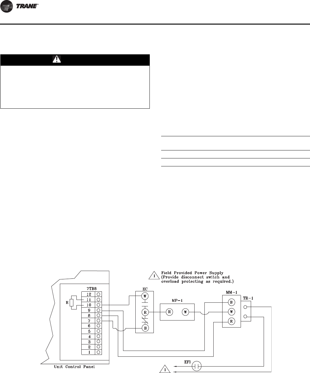
Installation
54 SS-SVX11H-EN
Controls using DC Analog Input/Outputs
Before installing any connecting wiring between the unit
and components utilizing a DC analog input/output signal,
refer to Figure 5, p. 11 to Figure 18, p. 24 for the electrical
access locations provided on the unit.
These components for 20 - 60 Ton units may include:
• Field installed Discharge Duct Sensor (6RT1 CV units);
• Field installed Return Duct Sensor (6RT6 CV units);
• Field installed Discharge Air Sensor (6RT3 VAV units);
• Field installed Chilled Water Sensor (6RT2 EVP units);
These components for 80 - 120 Ton units may include:
• Field installed Discharge Air Sensor (8RT3 VAV units);
• Field installed Chilled Water Sensor (8RT2 EVP units).
1. Wiring for the components utilizing a DC analog input/
output signal must be shielded cable (Belden 8760 or
equivalent). Ground the shield at one end only.
2. Tabl e 17, p. 54 lists the conductor sizing guidelines that
must be followed when interconnecting a DC binary
output device to the unit.
Note: Resistance in excess of 2.5 ohms per conductor can
cause deviations in the accuracy of the controls.
3. Ensure that the wiring between the binary controls and
the unit’s termination point does not exceed two and a
half (2.5) ohms/conductor for the length of the run.
4. Do not run the electrical wires transporting DC signals
in or around conduit housing high voltage wires.
Economizer Actuator Circuit
Each unit ordered with the Constant Volume or Variable Air
Volume control option has the capability of controlling a
field installed economizer. The diagram below illustrates a
typical economizer actuator circuit.
When connecting the economizer actuator control circuit
to the terminal board inside the unit control panel, refer to
the actual unit wiring diagram for terminal designation,
i.e. W, B, R, & Y. A separate power supply for the actuator(s)
must be field provided.
WARNING
Hazardous Voltage!
Disconnect all electric power, including remote
disconnects before servicing. Follow proper lockout/
tagout procedures to ensure the power cannot be
inadvertently energized. Failure to disconnect power
before servicing could result in death or serious injury.
Table 17. DC conductors
Distance from Unit to Control
Recommended
Wire Size
000 - 499 feet 16 gauge
500 - 1000 feet 14 gauge
Figure 38. 20 - 60 Ton unit control panel
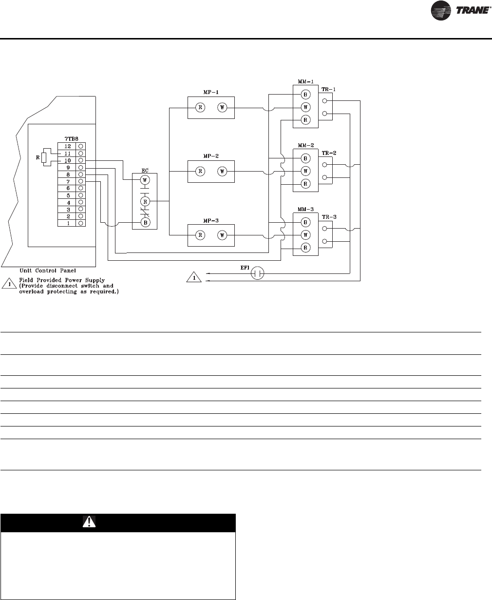
Installation
SS-SVX11H-EN 55
No System Control
Temperature Control Parameters
Each unit ordered with the “No Controls” option, requires
a field provided and field wired temperature controller.
Single refrigerant circuit units require a 2-step control
device, and dual refrigerant circuit units require a 4-step
(20-60T units) or 6-step (80-120T units) control device.
Each unit is shipped from the factory with internal “Fixed-
On” & “Fixed-Off” time delays wired into each step of
cooling. The “Fixed-Off” timers are 5 minutes each and
they begin timing when the circuit for that step of cooling
is deactivated. The “Fixed-On” timers are 3 minutes each
and they begin timing when the circuit for that step is
activated.
Note: Units ordered with the “No Controls” option
cannot be used with EVP Chiller applications.
Table 18. 80 - 120 Ton unit control panel
Table 19. Economizer actuator circuit legend
Device
Designation Device Designation Parts And Notes
MM Modutral Motor M.H. M955, (Up to 3 motors may be controlled as shown. Additional motors must be
slaved.)
TR Transformer M.H. 13081B; cover mounted
EC Enthalpy Control M.H. H2051046
MP Minimum Position Potentiometer M.H. S96A1012
EFI Evaporator Fan Interlock Field Provided
7TB88 Low Voltage Terminal Strip Located in Temperature Controller Panel
R 1/4 Watt - 5% Carbon
1 Motor/Circuit = None Req.
2 Motors/ circuit = 1300 Ohms
3 Motors/Circuit = 910 Ohms
WARNING
Hazardous Voltage!
Disconnect all electric power, including remote
disconnects before servicing. Follow proper lockout/
tagout procedures to ensure the power cannot be
inadvertently energized. Failure to disconnect power
before servicing could result in death or serious injury.
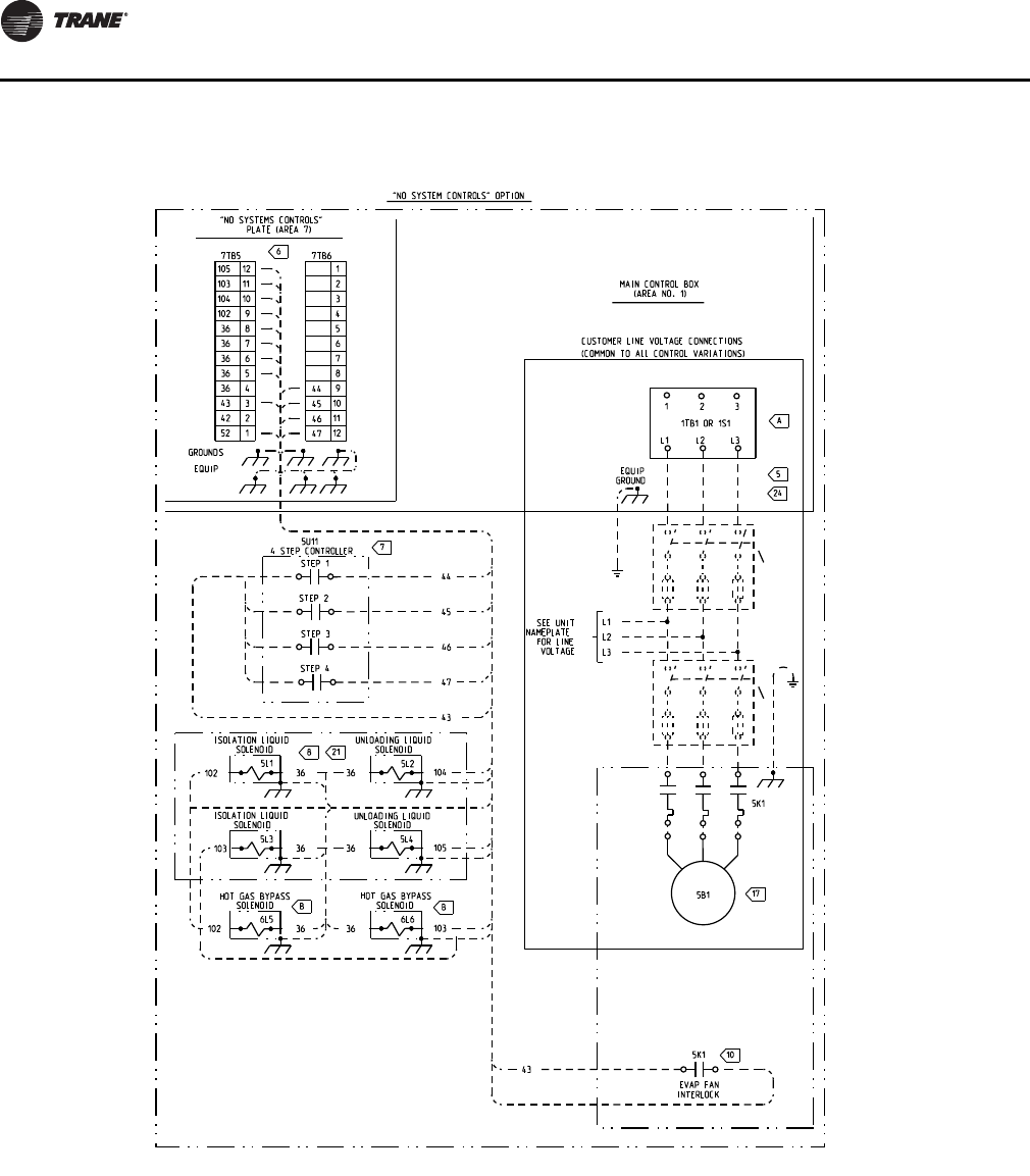
Installation
56 SS-SVX11H-EN
Figure 39. Field connection diagram RAUJ20-60 - no system control
2307-9122
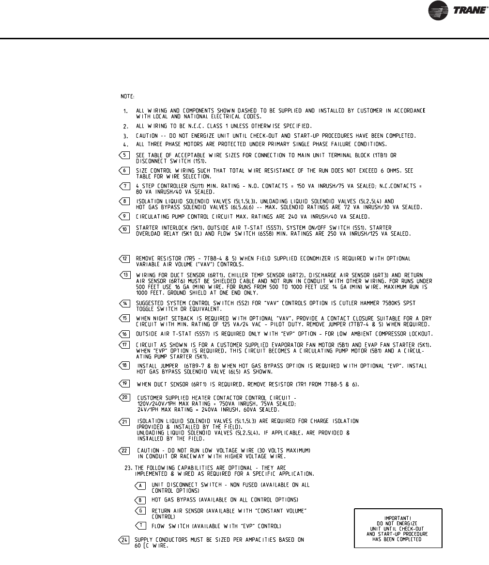
Installation
SS-SVX11H-EN 57
Figure 40. Field connection diagram notes - RAUJ 20-60 - all system controls
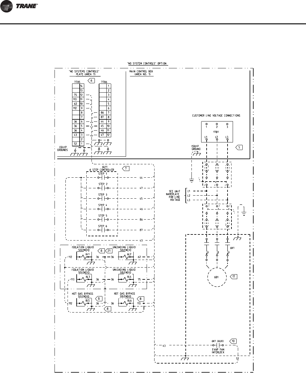
Installation
58 SS-SVX11H-EN
Figure 41. Field connection diagram RAUJ80-120 - no system control
2307-9144
Installation
SS-SVX11H-EN 59
Figure 42. Field connection diagram notes - RAUJ 80-120 - all system controls
21 ISOLATION LIQUID SOLENOID VALVES (6L1, 6L3) ARE REQUIRED FOR CHARGE ISOLATION (PROVIDED
& INSTALLED BY THE FIELD). UNLOADING LIQUID SOLENOID VALVES (6L2, 6L4), IF APPLICABLE,
ARE PROVIDED & INSTALLED BY THE FIELD.
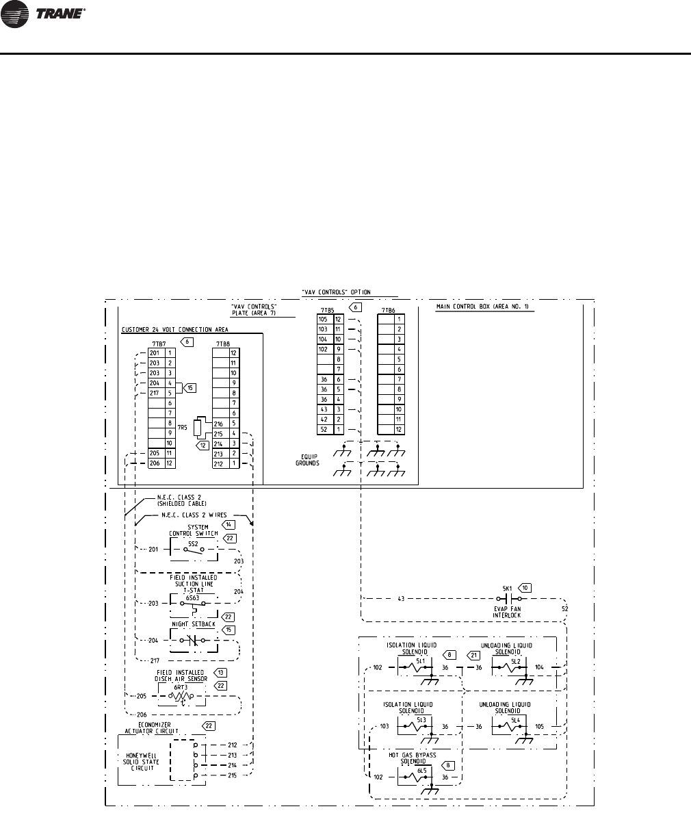
Installation
60 SS-SVX11H-EN
Variable Air Volume Control (Honeywell
W7100A)
In a variable air volume system, the desired space
temperature is maintained by varying the amount of
conditioned air being delivered to the space. As the
cooling requirements of the space decreases, less air is
delivered to the zone; conversely, as the cooling
requirements of the space increases, a greater volume of
air is delivered to the zone.
The descriptions of the following basic input devices used
with the Honeywell W7100A discharge air controller are to
acquaint the operator with their function as they interface
with the controller. Refer to field connection diagram
numbers 2307-9122 (for 20-60) and 2307-9144 (for 80-120)
for the specific component connections at the unit control
panel.
For discussion of evaporator fan interlock, hot gas bypass,
and economizer connections, refer to the section
“Controls Using 115 VAC,” p. 52.
Refer to wiring notes on Figure 40, p. 57.
Figure 43. Field connection diagram RAUJ20-60 - variable air volume control
2307-9122
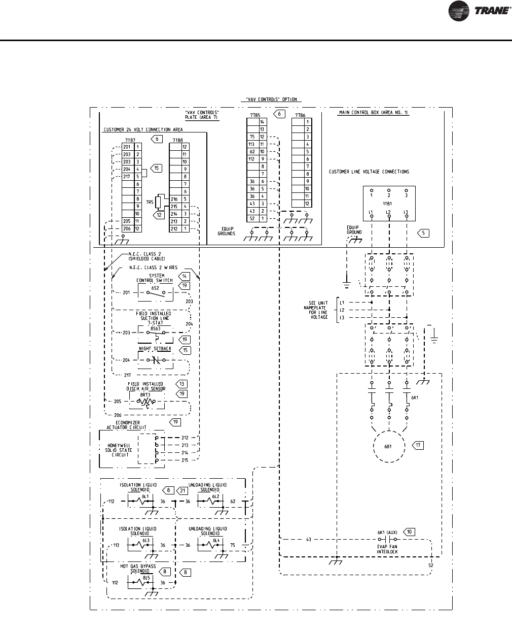
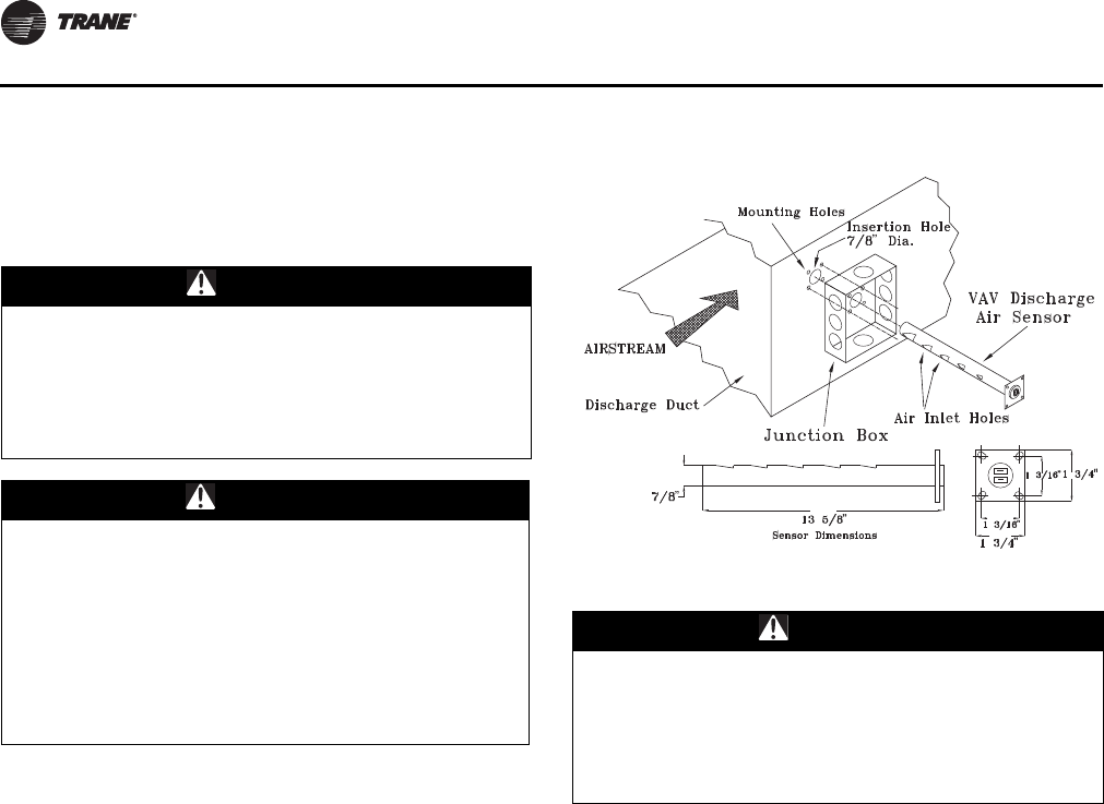
Installation
62 SS-SVX11H-EN
Discharge Air Sensor (Honeywell 6RT3 or
Honeywell 8RT3) Discharge Air Sensor
Each unit ordered with variable air volume controls (digit
9 in the model number) is shipped with a Honeywell 6RT3
or 8RT3 discharge air sensor.
Install sensor in a turbulent free area of discharge air duct
where it will provide accurate supply air sensing. See
Figure 45, p. 62 for installation and sensor dimensions.
The sensor serves two functions:
1. Sends supply air temperature data to Discharge Air
Controller as an analog input, to control the
economizer (if applicable) and cycling of compressors.
2. Low limit sensor for system when supply air
temperature reaches too high a delta T between actual
supply air temperature and supply air temperature
setpoint.
Before installing any connecting wiring, see Figure 5, p. 11
to Figure 18, p. 24 for electrical access locations. Wire
sensor per field connection diagram, numbers 2307-9122
(for 20-60) and 2307-9144 (for 80-120). Shielded cable
(Belden 8760 or equivalent) must be used when wiring
sensor to the terminal board inside unit control panel.
Connect shielded cable to appropriate terminals on
terminal board (7TB7), in control panel.
Ground shield (at unit only) using ground screw in
customer 24 volt connection area as shown in field
connection diagram.
Suction Line Thermostat
Each unit ordered with variable air volume controls (digit
9 in the model number) is shipped with a suction line
thermostat (6S63) that must be field installed.
Locate the thermostat close to the expansion valve bulb on
a slightly flattened portion of the suction line. The
thermostat must be securely fastened to the suction line
and a field provided thermoconductive grease must be
applied to the area to ensure good heat transfer.
Before installing any connecting wiring, see Figure 5, p. 11
to Figure 18, p. 24 for electrical access locations. Wire
suction line thermostat per field connection diagram,
numbers 2307-9122 (for 20-60) and 2307-9144 (for 80-120).
See Table 16, p. 53 (AC Conductors) for wiring
specifications.
Insulate the suction line, where the thermostat is
mounted, to isolate it from the surrounding air.
WARNING
Hazardous Voltage!
Disconnect all electric power, including remote
disconnects before servicing. Follow proper lockout/
tagout procedures to ensure the power cannot be
inadvertently energized. Failure to disconnect power
before servicing could result in death or serious injury.
WARNING
Proper Field Wiring and Grounding
Required!
All field wiring MUST be performed by qualified
personnel. Improperly installed and grounded field
wiring poses FIRE and ELECTROCUTION hazards. To
avoid these hazards, you MUST follow requirements for
field wiring installation and grounding as described in
NEC and your local/state electrical codes. Failure to
follow code could result in death or serious injury.
Figure 45. Discharge air sensor assembly
WARNING
Hazardous Voltage!
Disconnect all electric power, including remote
disconnects before servicing. Follow proper lockout/
tagout procedures to ensure the power cannot be
inadvertently energized. Failure to disconnect power
before servicing could result in death or serious injury.
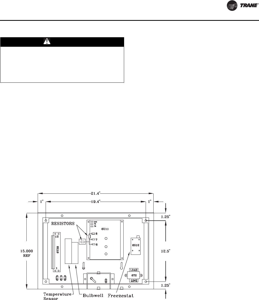
Installation
SS-SVX11H-EN 63
Night Setback
If night setback operation is desired, connect a set of
normally open contacts (field provided) to the appropriate
terminals on the terminal board (7TB7), in the unit’s
control panel. Remove the factory installed jumper at the
terminal board when making the final wiring termination.
Refer to the field connection diagram, numbers 2307-9122
(for 20-60) and 2307-9144 (for 80-120) for details.
EVP Chiller Control
Each unit ordered for EVP Chiller applications (digit 9 in the
model number), is shipped with the following controls:
• EVP Remote Panel w/ W7100G Controller
• Freezestat (6S12)
• Chiller Water Temperature Sensor (6RT2)
• Freezestat Bulb well
• Chilled Water Temperature Sensor Well
The installation of the freezestat bulb well, freezestat bulb,
and the chilled water temperature sensor was discussed in
the “Chilled Water Piping” section. Refer to that section for
their installation locations and dimensional data.
The chiller control (located in the remote panel) controls
the system operation by responding to the leaving water
temperature. The remote panel must be mounted indoors
and within 20 feet of the chiller. Figure 46, p. 63 illustrates
the remote panel dimensional data, the component
locations, the locations for the shipwith items, grounding
lugs, and the field connection terminal board 6TB9. Refer
to the field connection diagram illustrated in Figure 47,
p. 64 (20-60T) and Figure 48, p. 65 (80-120T) for the
interconnecting points between the remote panel and the
unit’s control panel.
WARNING
Hazardous Voltage!
Disconnect all electric power, including remote
disconnects before servicing. Follow proper lockout/
tagout procedures to ensure the power cannot be
inadvertently energized. Failure to disconnect power
before servicing could result in death or serious injury.
Figure 46. EVP Chiller Remote Panel
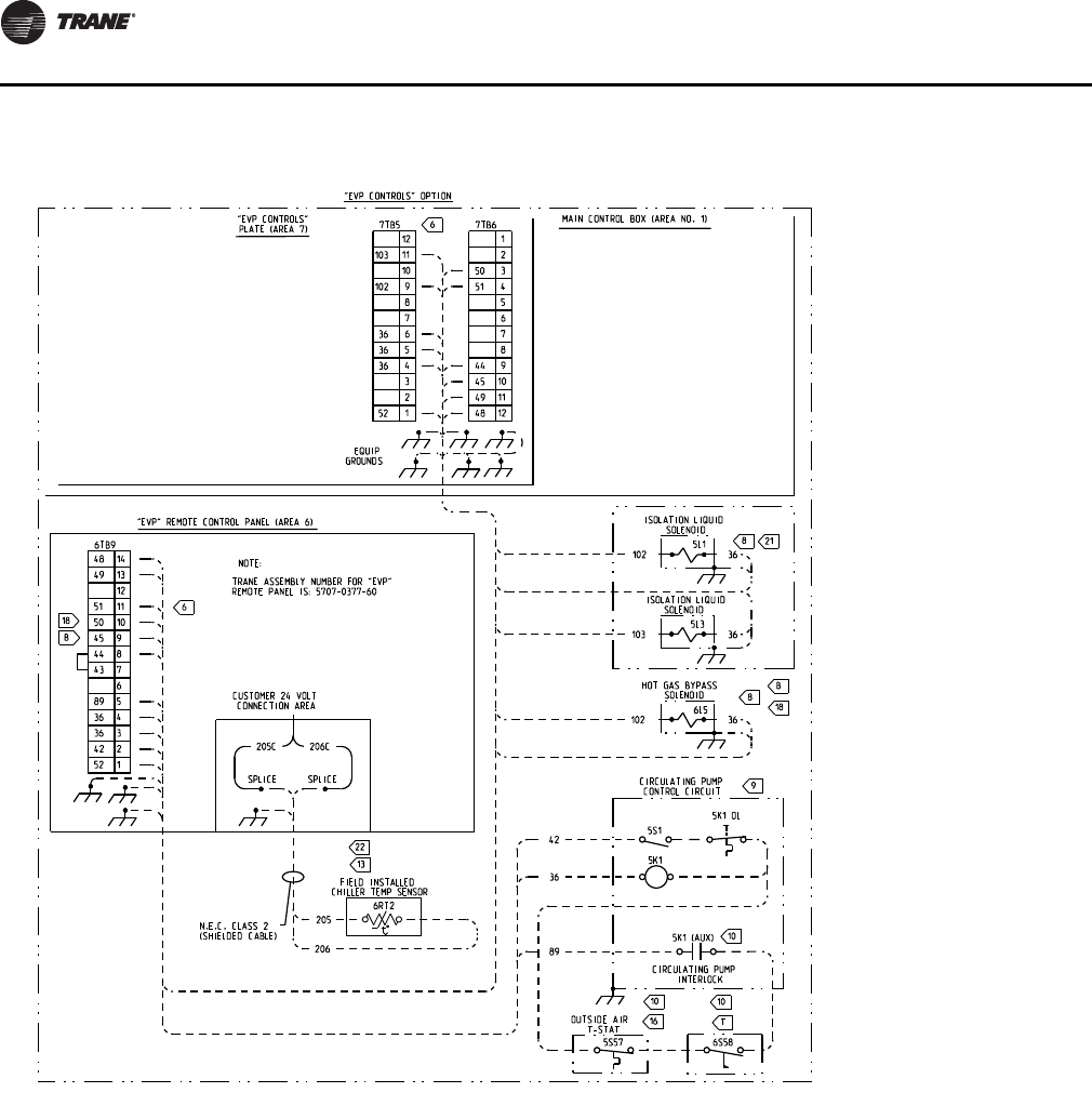
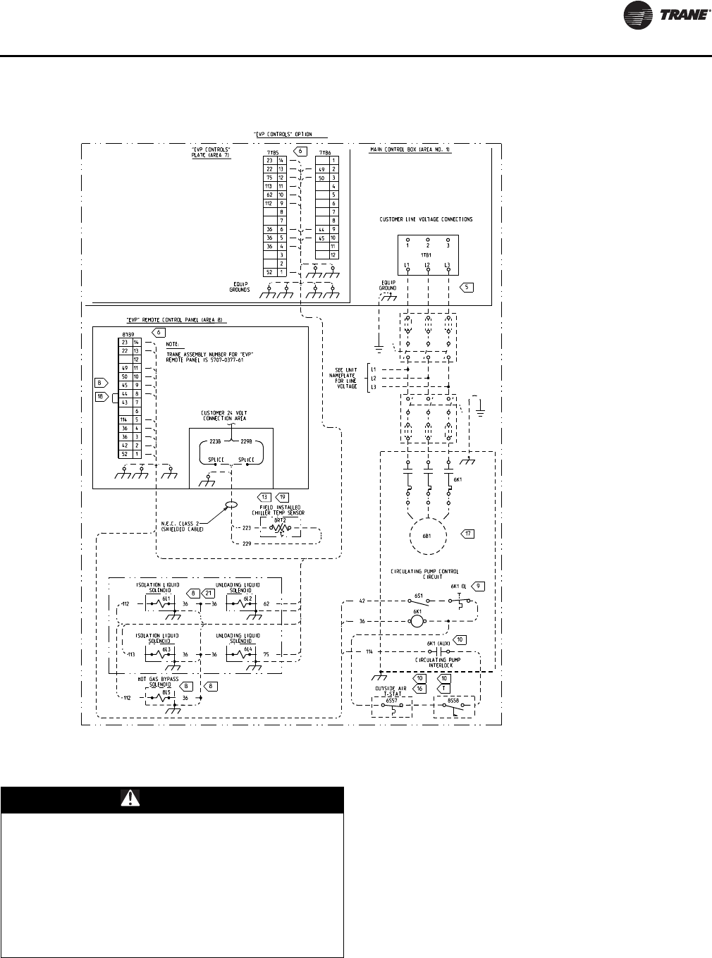
Installation
SS-SVX11H-EN 65
See wiring notes on Figure 42, p. 59..
A ground wire must be installed between the EVP remote
panel and the unit control panel.
W7100G Discharge Chilled Water Controller
The discharge chilled water controller (6U11) is shipped
from the factory with a combination wire/ resistor type
jumper installed across Terminals 6, 7, & 8. The resistive
portion of the jumper is across Terminals 7 & 8, which set
the number of operating stages, of the control. As shipped,
a 200 ohm resistive jumper is installed across Terminals 7
& 8 on the controller. The 200 ohm resistive jumper is
required for two (2) stage operation on 20 through 30 Ton
units. If the unit is a 20, 25, or 30 Ton unit, locate the bag
that is secured to the controller, and discard it.
Figure 48. Field connection diagram - RAUJ-C80-120 EVP chiller applications
2307-9144
WARNING
Proper Field Wiring and Grounding
Required!
All field wiring MUST be performed by qualified
personnel. Improperly installed and grounded field
wiring poses FIRE and ELECTROCUTION hazards. To
avoid these hazards, you MUST follow requirements for
field wiring installation and grounding as described in
NEC and your local/state electrical codes. Failure to
follow code could result in death or serious injury.
Installation
66 SS-SVX11H-EN
For 40 through 60 Ton units, requiring four (4) stages
of operation, a 402 ohm resistive jumper must be installed
across Terminals 7 & 8 on the controller. Remove the
combination wire/resistor jumper containing the 200 ohm
resistor from Terminals 6, 7, & 8. Locate the bag that is
secured to the controller, and install the 402 ohm
combination jumper across Terminals 6, 7, & 8 on the
controller. Refer to the remote panel illustration for the
terminal identification.
Note: The resistor portion of the combination jumper
must be installed across Terminals 7 & 8 on the
controller.
For 80-120 Ton units, requiring six (6) stages of
operation, a 604 ohm resistive jumper is needed across
Terminals 7 & 8 on the controller. This jumper is factory
installed.
The descriptions of the following input devices are to
acquaint the operator with their function as they interface
with the Honeywell W7100G controller.
Note: All wiring must comply with local and national
electrical codes (NEC).
Outside Air Thermostat
(5S57 Field Provided)
The setpoint for the outside air thermostat is based upon
the working ambient selected when the unit was ordered.
A Zero (“0”) in the 11th digit of the model number indicates
the system is designed for standard ambient operation of
40ºF and above. A One (“1”) in the 11th digit of the model
number indicates the system is designed for low ambient
operation of 0ºF and above. Therefore, select a thermostat
with the appropriate operating range based on the unit
specifications. See field connection diagram for the
specific connection points inside the remote panel.
Constant Volume Control
(Honeywell W973) — 20 - 60TUnits Only
The descriptions of the following basic input devices used
with the Honeywell W973 Master Energy Controller (MEC)
are to acquaint the operator with their function as they
interface with the controller. Refer to field connection
diagram, number 2307-9122, for the specific component
connections at the unit’s control panel.
WARNING
Hazardous Voltage!
Disconnect all electric power, including remote
disconnects before servicing. Follow proper lockout/
tagout procedures to ensure the power cannot be
inadvertently energized. Failure to disconnect power
before servicing could result in death or serious injury.
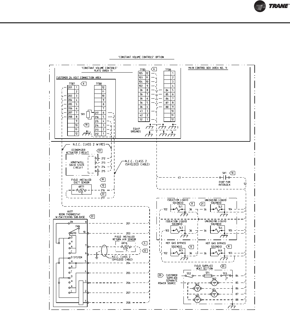
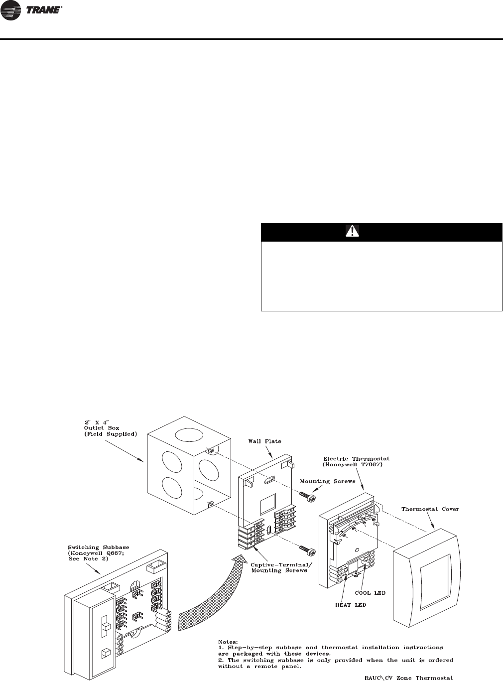
Installation
68 SS-SVX11H-EN
Electronic Zone Thermostat (Honeywell
T7067)
Each unit ordered with constant volume controls (in the
model number) is shipped with a Honeywell T7067
electronic zone thermostat. A Honeywell switching
subbase (Q667) is also included. The switching subbase
allows the operator to select the “System Mode” of
operation, i.e., Cool, Heat, Auto, or Off and the “Fan Mode”
of operation, i.e., On or Auto.
Note: As long as the status of the system is in an occupied
mode, the supply fan will operate continuously.
The fan will only cycle in the “Auto” mode during
unoccupied periods.
The zone thermostat should be located in an area with
good air circulation to enhance zone temperature
averaging. Position the thermostat about 54" above the
floor in a frequently occupied area.
Do not mount the thermostat where its sensing element
may be affected by:
a. Drafts or “dead” spots behind doors or in corners;
b. Hot or cold air from ducts;
c. Radiant heat from the sun, or from appliances;
d. Concealed pipes and chimneys;
e. Vibrating surfaces; or
f. Unconditioned areas behind the thermostat (e.g.,
outside walls).
Mount the thermostat subbase on either a standard 2" X 4"
handy box, a comparable European outlet box, or on any
nonconductive flat surface. Refer to the illustration in
Figure 50, p. 68 for mounting details.
Note: Specific installation instructions are packaged with
each thermostat and subbase. For subbase and
thermostat terminal identification, refer to
Figure 51, p. 69.
Thermostat Checkout
Once the subbase is mounted, before connecting any
wiring, use an ohm meter and complete the continuity
checks listed in Table 20, p. 69.
Thermostat Wiring
Before installing any connecting wiring, refer to Figure 5,
p. 11 to Figure 18, p. 24 for the electrical access locations
provided on the unit. Wire the thermostat in accordance
with field connection diagram, numbers 2307-9122 (for 20-
60) and 2307-9144 (for 80-120).
WARNING
Hazardous Voltage!
Disconnect all electric power, including remote
disconnects before servicing. Follow proper lockout/
tagout procedures to ensure the power cannot be
inadvertently energized. Failure to disconnect power
before servicing could result in death or serious injury.
Figure 50. T7067 electronic zone thermostat & Q667 switching subbase
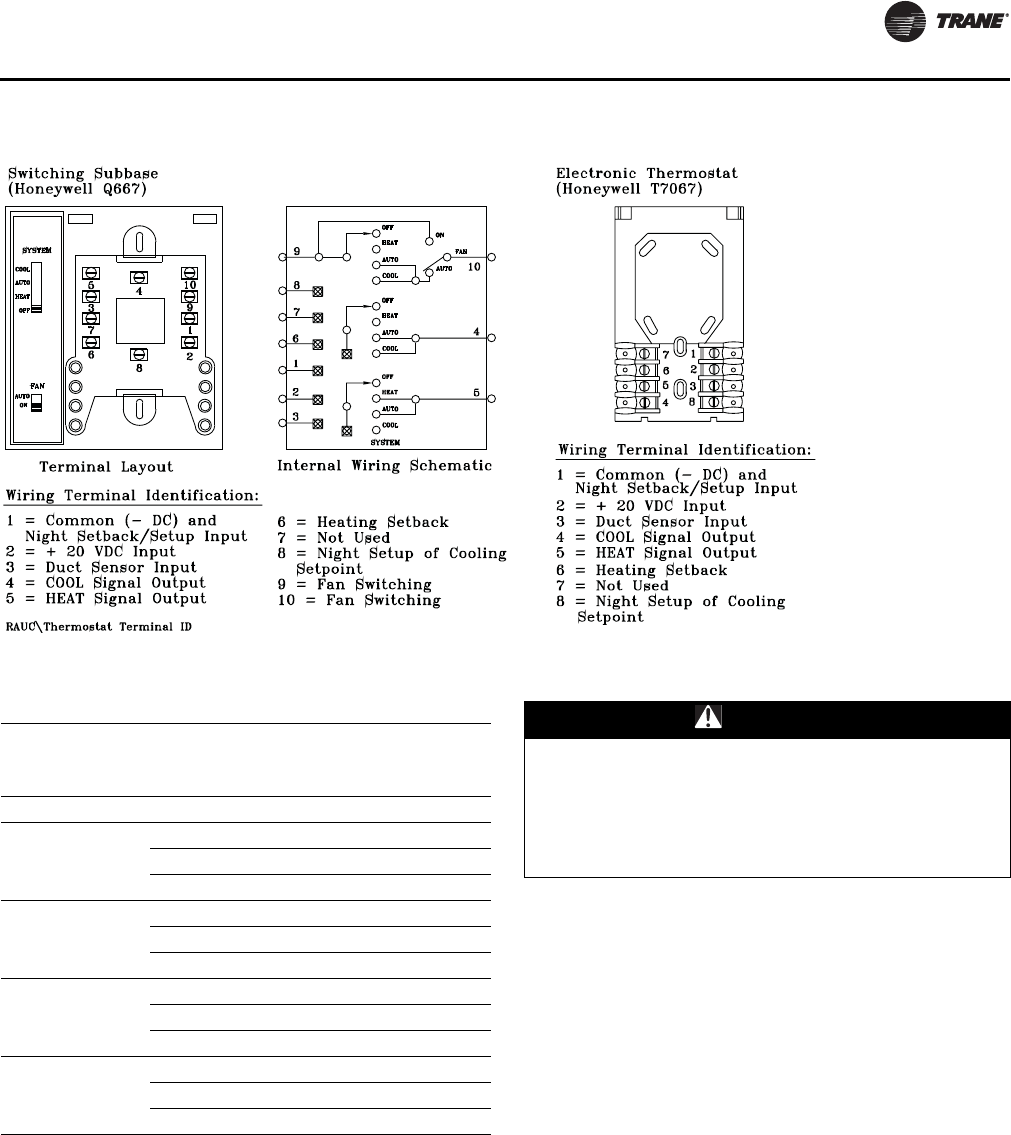
Installation
SS-SVX11H-EN 69
Discharge Air Sensor (Honeywell 6RT1)
A discharge air sensor ships with each unit when the
constant volume control option is ordered. The sensor
should be installed in a turbulent free area of the discharge
air duct at a location that will provide accurate supply air
sensing. Refer to the illustration in Figure 45, p. 62 for
installation and sensor dimensional information.
Wire the sensor in accordance with field connection
diagram, numbers 2307-9122 (for 20-60) and 2307-9144
(for 80-120). As shipped from the factory, a resistor (7R1)
is installed on terminal board 1TB8 terminals 5 & 6).
Remove this resistor when the sensor is installed.
Shielded cable (Belden 8760 or equivalent) must be used
when wiring the sensor to the terminal board inside the
unit’s control panel.
When the sensor is installed, it serves two functions;
1. It sends the supply air temperature to the master
energy controller (MEC), in the form of an analog input,
to assist in the rate at which the system changes the
space temperature. By offsetting the actual zone
thermostat setpoint, up or down, the MEC can closer
control the zone comfort level.
2. It serves as a low limit for the system when the supply
air temperature reaches too high a delta tee between
the actual supply air temperature and the zone
temperature to help prevent overshooting of the zone
thermostat setpoint.
Figure 51. Q667 switching subbase & T7067 thermostat terminal identification
Table 20. (Q667) switching subbase
Subbase Switch
Positions Check Continuity between
These Terminal Pairs
Circuit
should beFan System
ON N/A 9 (Subbase) & 10 (Subbase) Closed
AUTO OFF
9 (Subbase) & 10 (Subbase) Open
5 (Subbase) & 5 (T’stat) Open
4 (Subbase) & 4(T’Stat) Open
AUTO HEAT
9 (Subbase) & 10 (Subbase) Open
5 (Subbase) & 5 (T’stat) Closed
4 (Subbase) & 4(T’Stat) Open
AUTO AUTO
9 (Subbase) & 10 (Subbase) Closed
5 (Subbase) & 5 (T’stat) Closed
4 (Subbase) & 4(T’Stat) Closed
AUTO COOL
9 (Subbase) & 10 (Subbase) Closed
5 (Subbase) & 5 (T’stat) Open
4 (Subbase) & 4(T’Stat) Closed
WARNING
Hazardous Voltage!
Disconnect all electric power, including remote
disconnects before servicing. Follow proper lockout/
tagout procedures to ensure the power cannot be
inadvertently energized. Failure to disconnect power
before servicing could result in death or serious injury.
70 SS-SVX11H-EN
System Pre-Start Procedures
Use the checklist provided below in conjunction with the
“General Unit Requirement” checklist” to ensure that the
unit is properly installed and ready for operation. Be sure
to complete all of the procedures described in this section
before starting the unit for the first time.
• Turn the field supplied disconnect switch, located
upstream of the unit, to the “Off” position.
Note: Verify that the 115 volt control switch (1S2) in
the unit control box is in the "Off" position.
• Turn the “System” selection switch (at the Remote
Panel) to the “Off” position and the “Fan” selection
switch (if applicable) to the “Auto” or “Off” position.
• Check all electrical connections for tightness and
“point of termination” accuracy.
• Verify that the condenser airflow will be unobstructed.
• Check the condenser fan blades. Ensure they rotate
freely within the fan orifices and are securely fastened
to the fan motor shaft.
• Disable the compressor (s) by unplugging the reset
relay for each circuit. Refer to the unit-wiring diagram
that shipped with the unit.
• Verify that all compressor service valves, discharge
service valves, and liquid line service valves are back
seated on each circuit.
Important: COMPRESSOR SERVICE VALVES MUST BE
FULLY OPENED BEFORE START-UP
(SUCTION, DISCHARGE, AND LIQUID
LINE).
Important: After liquid line service valves are fully
opened (back seated), close just 1/4 turn to
allow for fan pressure control (4S7, 4S8)
operation.
• Check the compressor oil levels. Oil levels must be
near or above the top of all compressor sight glasses.
• Pack Stock Units;
Two low pressure switches are installed at the factory.
However, only one is wired into the control circuit. This
is to facilitate an EVP chiller or air over evaporator
application. Before starting the system, verify that the
correct pressure switch is connected to the control
circuit. See Table 23, p. 91 for the pressure control
settings, and the unit wiring diagram that shipped with
the unit, for the appropriate connections.
• Check the condenser coils. They should be clean and
the fins should be straight. Straighten any bent coil fins
with an appropriate sized fin comb.
• Inspect the interior of the unit for tools and debris.
• Inspect the interior of the unit for tools and debris in
preparation for starting the unit and complete the
remainder of the “Pre-start” procedures before
starting the unit.
EVP Chiller Applications
1. Flush building piping.
2. Clean strainer. Make sure strainer blow down valve or
plug is in place.
3. Connect chiller. Make sure chiller 1/2”x14NPTE plug is
in place.
4. Close drain valve
5. Fill system with water.
6. Vent system piping at the highest points.
7. Inspect water piping for leaks and repair.
System Evacuation Procedures
Each refrigeration circuit for split system applications
must be evacuated before the unit can be started. Use a
rotary type vacuum pump capable of pulling a vacuum of
100 microns or less. Verify that the unit disconnect switch
and the system control circuit switches are “OFF”.
The oil in the vacuum pump should be changed each time
the pump is used with a high quality vacuum pump oil.
Before using any oil, check the oil container for
discoloration which usually indicates moisture in the oil
and/or water droplets. Moisture in the oil adds to what the
pump has to remove from the system, making the pump
inefficient.
When connecting the vacuum pump to a refrigeration
system, it is important to manifold the vacuum pump to
both the high and low side of the system (liquid line access
valve and suction line access valve). Follow pump
manufacturer’s directions for proper methods of using
vacuum pump.
WARNING
Hazardous Voltage!
Disconnect all electric power, including remote
disconnects before servicing. Follow proper lockout/
tagout procedures to ensure the power cannot be
inadvertently energized. Failure to disconnect power
before servicing could result in death or serious injury.
NOTICE:
Compressor Damage!
Do not allow liquid refrigerant to enter the suction line.
Excessive liquid accumulation in the suction lines could
result in compressor damage.
NOTICE:
Evaporator Damage!
If acidic commercial flushing solution is used, bypass
the EVP chiller to prevent damage to the heat
exchanger.
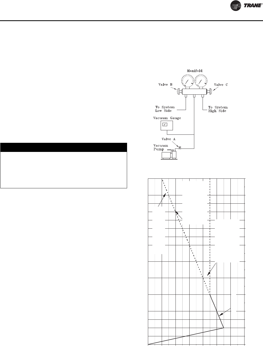
System Pre-Start Procedures
SS-SVX11H-EN 71
The lines used to connect pump to the system should be
copper and the largest diameter that can practically be
used. Using larger line sizes with minimum flow resistance
can significantly reduce evacuation time. Rubber or
synthetic hoses are not recommended for system
evacuation. They have moisture absorbing characteristics
which result in excessive rates of evaporation, causing
pressure rise during standing vacuum test. This makes it
impossible to determine if system has a leak, excessive
residual moisture, or a continual or high rate of pressure
increase due to hoses.
An electronic micron vacuum gauge should be installed in
the common line ahead of the vacuum pump shutoff valve,
as shown in Figure 52, p. 71. Close Valves B and C, and
open Valve A.
Start vacuum pump. After several minutes, the gauge
reading will indicate the maximum vacuum the pump is
capable of pulling. Rotary pumps should produce
vacuums of 100 microns or less.
Open Valves B and C. Evacuate the system to a pressure of
300 microns or less. As vacuum is being pulled on the
system, it may appear that no further vacuum is being
obtained, yet the pressure is high. To facilitate the
evacuation process, it is recommended that the vacuum
be “Broken”.
To break the vacuum, shutoff valves A, B, & C and connect
a refrigerant cylinder to the charging port on the manifold.
Purge the air from the hose. Raise the standing vacuum
pressure in the system to “zero” (0 psig) gauge pressure.
Repeat this process two or three times during evacuation.
Note: It is unlawful to release refrigerant into the
atmosphere. When service procedures require
working with refrigerants, the service technician
must comply with all Federal, State, and local laws.
Standing Vacuum Test
Once 300 microns or less is obtained, close Valve A and
leave valves B and C open. This will allow the vacuum
gauge to read the actual system pressure. Let the system
equalize for approximately 15 minutes. This is referred to
as a “standing vacuum test” where, time versus pressure
rise. The maximum allowable rise over a 15 minute period
is 200 microns. If the pressure rise is greater than 200
microns but levels off to a constant value, excessive
moisture is present. If the pressure steadily continues to
rise, a leak is indicated. Figure 53, p. 71 illustrates three
possible results of the “standing vacuum test”.
If a leak is encounter, repair the system and repeat the
evacuation process until the recommended vacuum is
obtained. Once the system has been evacuated, break the
vacuum with refrigerant, and complete the remaining
“Pre-Start Procedures” before starting the unit.
NOTICE:
Equipment Damage!
Do not, under any circumstances, use a megohm meter
or apply power to the windings of a compressor while
it is under a vacuum. Electrical shorting between motor
windings and/or housing can occur while in a vacuum,
causing motor burnout.
Figure 52. Typical vacuum pump hookup
Figure 53. Evacuation time vs. pressure rise
200
400
600
800
1000
1200
1400
1600
-10 0 10 20 30 40 50 60 70 80 90
TIME IN MINUTES
PRESSURE IN MICRON
S
Continuously increasing pressure
indicates the presence of leaks,
moisture or both.
State of equilibrium indicates the
true amount of moisture left in
the system. It indicates that no
leaks are present, but further
evacuation is required.
State of equilibrium indicates the
true amount of moisture left in
the system. It indicates that no
leaks are present and the
system is properly evacuated.
Initial evacuation pressure
System Pre-Start Procedures
72 SS-SVX11H-EN
Discharge Air Controller Checkout
(Honeywell W7100A)
Note: The following checkout procedure must be
performed in its entirety and in the sequence
given.
The W7100A (7U11) discharge air controller can be
checked out using a highly accurate digital volt-ohmmeter
and the W7100A accessory tool kit (Trane part # TOL-0101
or Honeywell part # 4074EDJ).
1. Turn all control switches to the “OFF” position to
deactivate the Evaporator Fan and the Mechanical
Cooling.
2. Turn the main power disconnect switch for the
evaporator fan and condensing unit “OFF”.
3. Disable the mechanical cooling by removing the field
installed evaporator fan auxiliary interlock wire from
terminal board 7TB5 terminal 3 inside the unit control
panel.
4. At the Discharge Air Controller, in the unit control
panel, remove the red dust cover from the test plug
socket at the bottom of the W7100A. Insert the “Test
Plug”, from the kit, into the test plug socket. The test
plug overrides most of the built-in time delays for
staging the compressors “On” and “Off”. Refer to the
illustration in Figure 54, p. 73 for terminal and control
dial identification.
5. Install a jumper across the P and P1 terminals (remote
setpoint input), and another jumper across terminals 6
and 7 (reset input) if reset is enabled.
6. Disconnect the wires from terminals T and T1
(discharge air sensor).
7. Remove the 3,400 ohm resistor (blue leads) from the
test kit and connect it across terminals T and T1 to
simulate a discharge air temperature of 60ºF.
8. Set the “Setpoint F” dial at 56ºF or below; then set the
“Control Band F” dial at 2 to minimize the control
response time.
9. At the Discharge Air controller, verify that the
controller ground wire is connected to the chassis
ground. Refer to the unit wiring diagram that shipped
on the unit.
Note: It is not necessary to set the “Reset F” dial since the
factory installed jumper across Terminals 6 and 7
disables this dial.
10. Turn the control circuit switch 1S2, in the unit control
panel, and the main power disconnect switch for the
condensing unit to the “ON” position.
After approximately 2 minutes (time required to drive the
economizer fully open), the LEDs on the W7100 should
begin to illuminate as the cooling outputs stage “On”.
11. At the Discharge Air Controller, use a digital voltmeter
to verify there is 24 volts AC across terminals TR & TR.
12. Set the “Setpoint F” dial at 64ºF; within 10 seconds, the
LEDs should turn “Off” as the cooling outputs stage
“Off”.
13. Immediately readjust the “Setpoint F” dial to 56°F; the
LEDs should begin to illuminate again as the cooling
outputs stage “On”.
If the unit includes the zone reset option, proceed to the
next step; if not, proceed to step 18.
14. Set the “Reset F” dial at 15°F and the “Setpoint F” dial
at 41ºF; then remove the jumper across terminals 6 & 7.
To simulate a call for maximum reset, install the 1780 ohm
resistor (red leads), from the test kit, across terminals 6
and 7. The cooling LEDs should remain lit.
15. Turn the “Setpoint F” dial to 49ºF; within 1 to 2 minutes,
the LEDs should turn “Off” as the cooling outputs stage
“Off”.
16. As soon as all of the cooling LEDs are “Off”, remove the
1780 ohm resistor from terminals 6 and 7 and re-install
the jumper across these terminals.
17. Adjust the “Setpoint F” dial to 56ºF; within 1 minute,
the LEDs should illuminate as the cooling outputs
stage “On”.
If the system includes an economizer, complete steps 18
through 23 to verify proper economizer control operation;
if not, proceed to step 24.
18. With all of the cooling LEDs “On”, measure the DC
voltage across terminals R (-) and W (+). The measured
voltage should be 1.7 VDC to 2.1 VDC.
19. Set the “Setpoint F” dial at 64ºF to drive the
economizer output to the minimum position.
Within 2 minutes, the LEDs should turn “Off” as the
cooling outputs stage “Off”.
In approximately 5 minutes; measure the voltage
across terminals R (-) & W (+). The measured voltage
should drop to approximately 0.2 VDC.
WARNING
Hazardous Voltage!
Disconnect all electric power, including remote
disconnects before servicing. Follow proper lockout/
tagout procedures to ensure the power cannot be
inadvertently energized. Failure to disconnect power
before servicing could result in death or serious injury.
WARNING
High Voltage is Present at Terminal Block
1TB1 or Unit Disconnect Switch 1S1!
To prevent injury or death form electrocution, it is the
responsibility of the technician to recognize this hazard
and use extreme care when performing service
procedures with the electrical power energized.
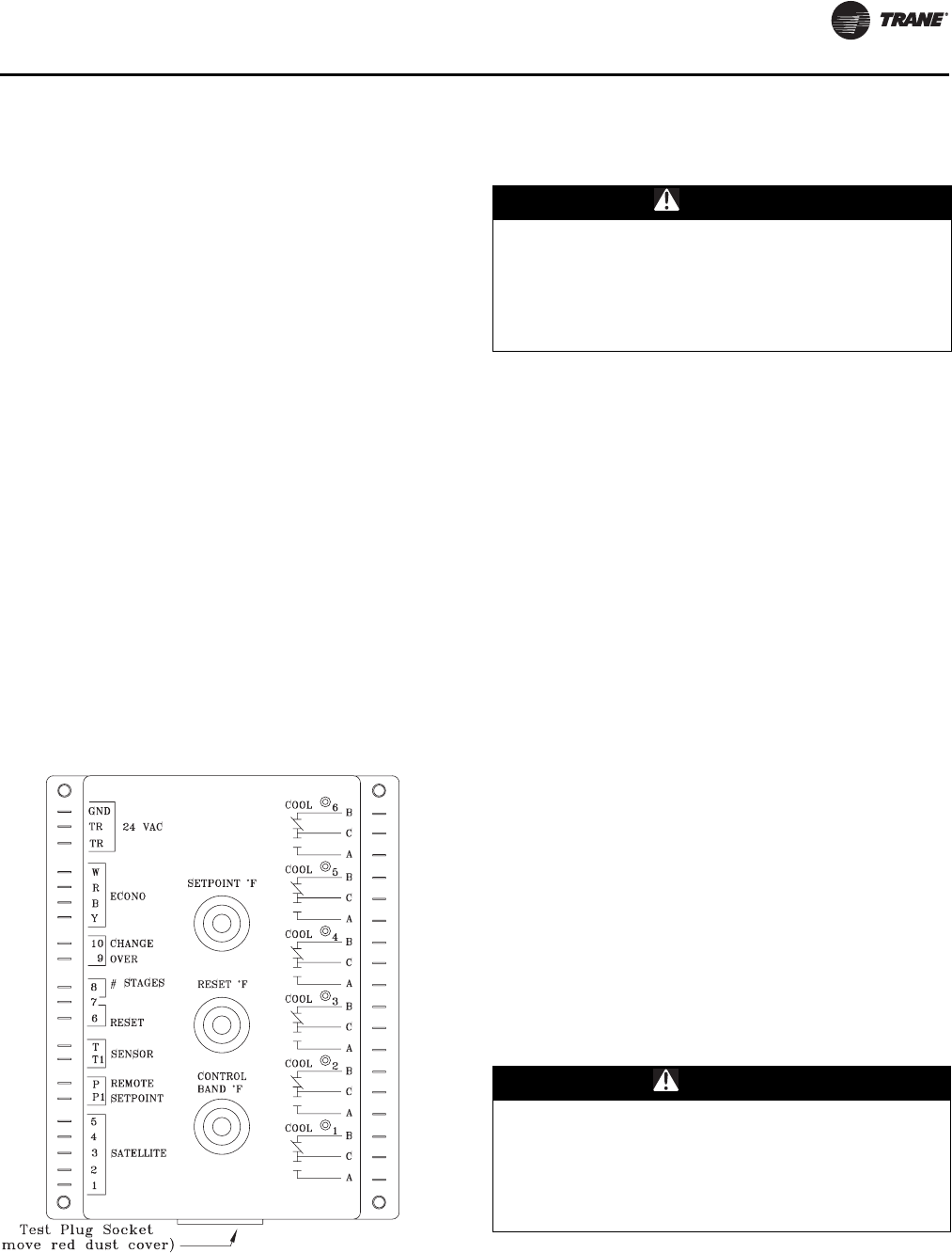
System Pre-Start Procedures
SS-SVX11H-EN 73
20. Turn the control circuit switch 1S2, in the unit control
panel, and the main power disconnect switch to the
“OFF” position.
21. Remove the wires from terminals R, B, W, & Y.
22. Measure the resistance across the following pairs of
terminals, and compare the actual resistance readings
with the values shown below.
W7100 Terminals R-to-W = 226 ohms
W7100 Terminals R-to-B = 432 ohms
W7100 Terminals R-to-Y = 226 ohms
23. Reconnect the economizer leads R, B, W, & Y to the
appropriate terminals on the controller.
24. Turn the control circuit switch 1S2, in the unit control
panel, and the main power disconnect switch to the
“OFF” position.
25. Remove the jumper, installed in step 5, from terminals
6 & 7.
26. Remove the 3,400 ohm resistor from terminals T & T1
and reconnect the discharge air sensor leads to
terminals T & T1.
27. Remove the “Test Plug” from the W7100 test socket
and reinstall the red dust cover.
28. Reconnect the field installed evaporator fan auxiliary
interlock wire to terminal board 7TB5 terminal 3.
29. Turn all control switches to the “On” position and
restore main power to the system.
Discharge Air Sensor Checkout (Honeywell
Sensor)
1. Verify that the main power disconnect switch and the
control circuit switch 1S2, in the unit control panel, is
“OFF”.
2. At the Discharge Air Controller, in the unit control
panel, disconnect the wire connected to Terminal T1.
Use a digital ohmmeter to measure the resistance
across Terminal T and the wire removed from Terminal
T1.
3. Use the conversion chart in Figure 55, p. 74 to convert
the measured resistance to an equivalent temperature.
4. Measure the actual temperature at the sensor location.
If the measured resistance in step 2 is not within ± 10.0
ohms of the actual temperature, the sensor is out of
range; replace it.
Note: Before condemning the sensor, verify that the
connecting cable resistance is not excessive. Refer
to the “Field Installed Control Wiring” section.
5. Make all necessary repairs and reconnect the duct
sensor lead to terminal T1 on the controller.
6. Restore power to the system and turn all control
switches to the “ON” position.
Economizer Actuator Checkout
(Used with “Zone” or “Discharge Air” Temp
Controller)
The following procedures should be used to verify that the
field provided economizer actuator(s) function properly.
These procedures are based on using a typical Honeywell
actuator. If another type actuator is used, refer to the
specific checkout procedures for that actuator.
1. Turn all control switches to the “Off” position to
deactivate the Evaporator Fan and the Mechanical
Cooling. Verify that the main power disconnect switch
Figure 54. W7100A discharge air controller
WARNING
Hazardous Voltage!
Disconnect all electric power, including remote
disconnects before servicing. Follow proper lockout/
tagout procedures to ensure the power cannot be
inadvertently energized. Failure to disconnect power
before servicing could result in death or serious injury.
WARNING
Hazardous Voltage!
Disconnect all electric power, including remote
disconnects before servicing. Follow proper lockout/
tagout procedures to ensure the power cannot be
inadvertently energized. Failure to disconnect power
before servicing could result in death or serious injury.
System Pre-Start Procedures
74 SS-SVX11H-EN
for the condensing unit and the control circuit switch
1S2, in the unit control panel, is “OFF”.
2. Verify that the field provided disconnect switch and/or
the control circuit switch for the economizer actuator(s)
is “OFF”.
3. At the actuator, disconnect the control wires connected
to Terminals W, R, B, and Y.
4. Install a jumper across the actuator terminals R-to-W-
to-B.
5. Close the field provided disconnect switch and/or the
control circuit switch for the economizer actuator(s). If
the economizer actuator is working properly, it should
drive to mid-position.
6. Open the field provided disconnect switch and/or the
control circuit switch for the economizer actuator(s)
and remove the jumpers installed in step 4.
7. Reconnect the control wires to the actuator terminals
W, R, B, and Y.
8. Restore power to the actuator circuit and turn all
control switches to the “ON” position and restore
power to the system.
EVP Chiller Control Checkout (Honeywell
W7100G)
Note: The following checkout procedure must be
performed in its entirety and in the sequence given.
The W7100G (6U11) chilled water controller can be checked
out using a highly accurate digital voltohmmeter, the
W7100 accessory tool kit (Trane part # TOL-0101 or
Honeywell part # 4074EDJ), and the Honeywell 4074EFV
resistor bag assembly.
1. Verify that the main power disconnect switch and the
control circuit switch 1S2, in the unit control panel, is
“OFF”.
2. At the unit control panel, unplug the reset relay 1K11
and 1K12, (1K12 used on 40 through 60 Ton units only).
Refer to the connection diagram that shipped with the
unit for the location of the relay(s).
3. At the Chilled Water controller (6U11) inside the remote
panel, disconnect the sensor (6RT2) leads form
Terminals T & T1.
4. Remove the 3,400 ohm resistor (blue leads) from the
test kit and connect it across Terminals T and T1 to
simulate a discharge air temperature of 60ºF.
5. Remove the factory-installed jumper (wire 209A) from
the “fast response” Terminals 9 & 10.
6. To simulate a call for maximum reset, remove the
jumper from Terminals 6 & 7 and install the 1780 ohm
resistor (red leads), from the test kit, across Terminals
6 and 7.
7. Install a jumper across the P1 and P2 Terminals
(remote setpoint input).
8. Remove the red dust cover from the test plug socket at
the bottom of the W7100G. Insert the “Test Plug”, from
the kit, into the test plug socket. The test plug overrides
most of the built-in time delays for staging the
compressors “On” and “Off”. Refer to the illustration in
Figure 56, p. 75 for terminal and control dial
identification.
9. Set the “Reset F” dial at 20ºF and the “Setpoint F” dial
at 10ºF
10. “Close” the main power disconnect switch and turn the
control circuit switch 1S2, in the unit control panel,
“ON”.
Figure 55. Discharge duct sensor 6RT2 & 6RT3
“temperature vs resistance” curve
3000
3200
3400
3600
3800
4000
4200
20 40 60 80 100 120 140 160 180 200 220
Temperature - OF (OC)
Resistance (Ohms)
(-6.7oC) (4.4oC) (15.6oC) (26.7oC) (37.8oC) (48.9oC) (60.0oC) (71.1oC) (82.2oC) (93.3oC) (104.4oC)
3483 ± 10 Ohms @
77O F (25O C)
WARNING
Hazardous Voltage!
Disconnect all electric power, including remote
disconnects before servicing. Follow proper lockout/
tagout procedures to ensure the power cannot be
inadvertently energized. Failure to disconnect power
before servicing could result in death or serious injury.
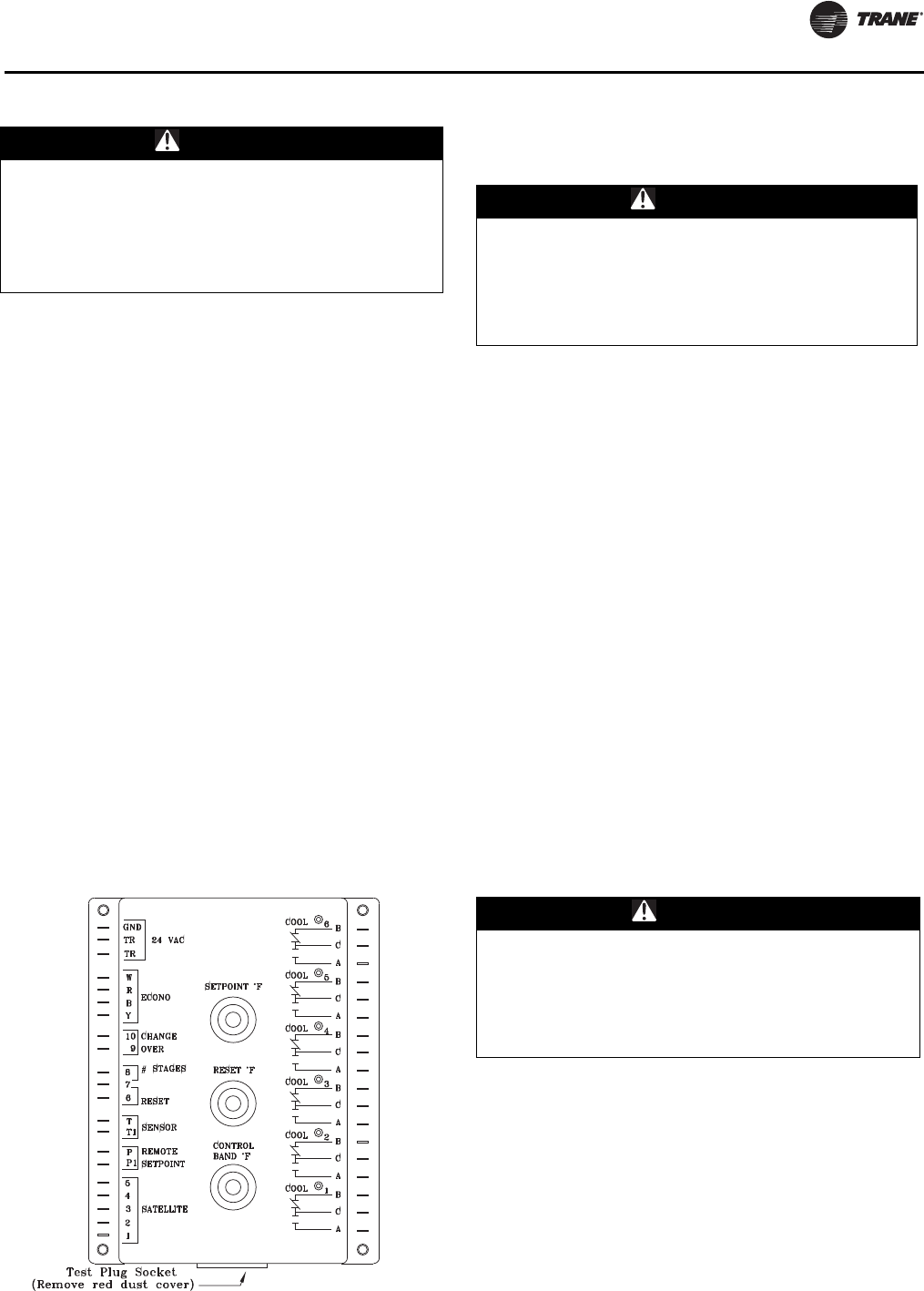
System Pre-Start Procedures
SS-SVX11H-EN 75
11. At the Chilled Water Controller, use a digital voltmeter
to verify there is 24 volts AC across terminals TR & TR.
12. After approximately 15 seconds, the LEDs on the
W7100G should begin to illuminate as the cooling
outputs stage “On”.
13. Set the “Setpoint F” dial at 60ºF; within 15 seconds, the
LEDs should turn “Off” as the cooling outputs stage
“Off”.
14. Remove the 1780 ohm resistor from Terminals 6 & 7
and reinstall the wire jumper removed in step 6.
15. Set the “Setpoint F” dial at 50ºF; within 15 seconds, the
LEDs should turn “On” as the cooling outputs stage
“On”.
16. Turn the control circuit switch 1S2, in the unit control
panel, to the “OFF” position.
17. Remove the 3,400 ohm resistor from Terminals T & T1
and reconnect the chilled water temperature sensor
leads to Terminals T & T1.
18. Remove the “Test Plug” from the W7100G test socket
and reinstall the red dust cover.
19. Plug the reset relay(s) 1K11 and 1k12 (if applicable)
back into their receptacle.
20. Turn the control switch 1S2 to the “On” position to
restore power to the control system.
Chilled Water Sensor Checkout
(Honeywell Sensor)
1. Verify that the main power disconnect switch and the
control circuit switch 1S2, in the unit control panel, is
“OFF”.
2. At the temperature controller, disconnect the wire
connected to terminal T1. Use a digital ohmmeter to
measure the resistance across terminal T and the wire
removed from terminal T1.
3. Use the conversion chart in Figure 37 to convert the
measured resistance to an equivalent temperature.
4. Measure the actual temperature at the sensor location.
If the measured resistance in step 2 is not within ± 10.0
ohms of the actual temperature, the sensor is out of
range; replace it.
Note: Before condemning the sensor, verify that the
connecting cable resistance is not excessive. Refer
to the “Field Installed Control Wiring” section.
5. Make all necessary repairs and reconnect the duct
sensor lead to terminal T1 on the controller.
6. Turn all control switches to the “ON” position and
restore power to the system.
Master Energy Control Checkout
Available Only For 20 - 60 Ton Units
1. Open the system control switches 5S1 and 5S2 to
disable the Evaporator Fan and Heating system.
2. Verify that the main power disconnect switch and the
control circuit switch 1S2, in the unit control panel, is
“OFF”.
3. At the Master Energy Controller (7U11), in the unit
control panel, remove at least one wire from each of
the “Heat Relay” normally open contacts and one from
each of the “Cool Relay” normally open contacts.
WARNING
High Voltage is Present at Terminal Block
1TB1 or Unit Disconnect Switch 1S1!
To prevent injury or death form electrocution, it is the
responsibility of the technician to recognize this hazard
and use extreme care when performing service
procedures with the electrical power energized.
Figure 56. W7100G chilled water controller
WARNING
Hazardous Voltage!
Disconnect all electric power, including remote
disconnects before servicing. Follow proper lockout/
tagout procedures to ensure the power cannot be
inadvertently energized. Failure to disconnect power
before servicing could result in death or serious injury.
WARNING
Hazardous Voltage!
Disconnect all electric power, including remote
disconnects before servicing. Follow proper lockout/
tagout procedures to ensure the power cannot be
inadvertently energized. Failure to disconnect power
before servicing could result in death or serious injury.
System Pre-Start Procedures
76 SS-SVX11H-EN
Insulate the wires with tape to prevent shorting or
grounding during control checkout.
4. Close the main power disconnect switch and turn the
control circuit switch 1S2, in the unit control panel,
“ON”.
5. At the Master Energy Controller, use a digital voltmeter
to verify that there is 20 volts DC power between
terminals 1 (N) & 2 (+20). Refer to the illustration in
Figure 54, p. 73 for terminal identification.
Note: The wires that are still connected to one side of the
“Cool Relay” contacts, are active with 115 volts
applied. Ohming the contacts when only one wire
is connected will not cause any damage to the
ohmmeter. However, do not try to ohm any set of
contacts with wires connected to both terminals of
that contact.
6. To verify the “Heating” output relays are operating;
a. place a jumper between Terminals 2 (+20) & 5 (H).
b. place the ohmmeter leads across each set of
normally open “Heat Relay” contacts. The
ohmmeter should read “Resistance” which
indicates that the heating output relays have
“pulled in”.
7. To verify the “Cooling” output relays are operating;
a. Remove the jumper from Terminals 2 (+20) & 5 (H)
and reinstall it between Terminals 2 (+20) & 4 (C).
b. place the ohmmeter leads across each set of
normally open “Cool Relay” contacts. The
ohmmeter should read “Resistance” which
indicates that the cooling output relays have
“pulled in”.
8. With all of the “Cooling Output” relays pulled in (step
7), measure the DC voltage across Terminals R (-) and
W (+). The measured voltage should be approximately
1.7 to 2.1 VDC.
9. Remove the jumper installed between Terminals 2
(+20) & 4 (C).
10. Measure the voltage again across Terminals R (-) and
W (+). The measured voltage should now be
approximately 0.2 VDC.
11. Turn the control circuit switch 1S2, in the unit control
panel, to the “OFF” position.
12. Remove the wires from Terminals R, B, W, & Y.
13. Measure the resistance across the following pairs of
terminals and compare the actual resistance readings
with the values shown below:
(1) MEC Terminals R-to-W = 226 ohms
(2) MEC Terminals R-to-B = 432 ohms
(3) MEC Terminals R-to-Y = 226 ohms
14. Reconnect the economizer leads W, R, B and Y to the
appropriate terminals on the controller.
15. Turn switches 1S2, 5S1, & 5S2 to the “ON” position to
restore power to the control system.
Zone Thermostat Checkout (Honeywell
T7067)
Available Only For 20 - 60 Ton Units
1. Open the system control switches 5S1 and 5S2 to
disable the Evaporator Fan and Heating system.
2. Close the main power disconnect switch and turn
control circuit switch 1S2, in unit control panel, “ON”.
3. At the Zone Thermostat (6U37), use a digital voltmeter
to verify that there is 20 volts DC power between
thermostat Terminals 1 & 2. See illustration in
Figure 29, p. 41 for terminal identification. Refer to
Tabl e 21, p. 77 for the thermostat “voltage output”
ramps.
4. To check the “Cooling” output signal, place the
voltmeter leads between thermostat Terminals 1 & 4.
Refer to Figure 29, p. 41 and;
a. move the cooling (blue) setpoint lever from right to
left. As the cooling setpoint is lowered, the voltage
signal should increase and the “Cooling” LED
brighten.
b. move the cooling (blue) setpoint lever from left to
right. As the cooling setpoint rises, the voltage
signal should decrease and the “Cooling” LED dim.
5. To check the “Heating” output signal, place the
voltmeter leads between thermostat Terminals 1 & 5.
Refer to Figure 29, p. 41 and;
a. move the heating (red) setpoint lever from left to
right. As the heating setpoint rises, the voltage
signal should increase and the “Heating” LED
brighten.
b. move the heating (red) setpoint lever form right to
left. As the heating setpoint lowers, the voltage
signal should decrease and the “Heating” LED dim.
WARNING
High Voltage is Present at Terminal Block
1TB1 or Unit Disconnect Switch 1S1!
To prevent injury or death form electrocution, it is the
responsibility of the technician to recognize this hazard
and use extreme care when performing service
procedures with the electrical power energized.
WARNING
High Voltage is Present at Terminal Block
1TB1 or Unit Disconnect Switch 1S1!
To prevent injury or death form electrocution, it is the
responsibility of the technician to recognize this hazard
and use extreme care when performing service
procedures with the electrical power energized.
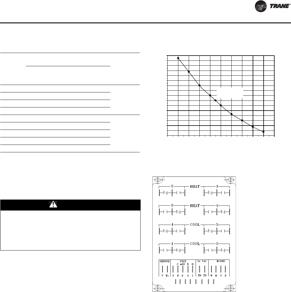
System Pre-Start Procedures
SS-SVX11H-EN 77
Discharge Air Sensor Checkout (Honeywell
6RT1)
Available Only For 20 - 60 Ton Units
1. Turn the control circuit switch 1S2, in the unit control
panel, to the “OFF” position.
2. At the Master Energy Controller, disconnect wire
connected to Terminal T1. Use a digital ohmmeter to
measure resistance between Terminal T and the wire
removed from Terminal T1.
3. Use chart in Figure 55, p. 74 to convert the measured
resistance to an equivalent temperature.
4. Measure the actual temperature at the sensor location.
If the measured resistance in step 2 is not within ± 10.0
ohms of the actual temperature, the 6RT1 is out of
range; replace it.
Note: Before condemning the sensor, verify that the
connecting cable resistance is not excessive. Refer
to the “Field Installed Control Wiring” section.
5. Make all necessary repairs and reconnect the duct
sensor lead to terminal T1 on the controller.
6. Turn switches 1S2, 5S1, & 5S2 to the “ON” position to
restore power to the control system.
\
Voltage Imbalance
Excessive three phase voltage imbalance between phases
will cause motors to overheat and eventually fail. The
maximum allowable voltage imbalance is 2%. Measure
and record the voltage between phases 1, 2, and 3 and
calculate the amount of imbalance as follows:
% Voltage Imbalance = 100 x [(AV - VD)/(AV)] where:
•AV (Average Voltage) = (Volt 1 + Volt 2 + Volt 3)/3
•V1, V2, V3 = Line Voltage Readings
•VD = Line Voltage reading that deviates the farthest
from the average voltage.
Example: If voltage readings of supply power measured
221, 230, and 227, average volts would be:
•(221 + 230 + 227)/3 = 226 Avg.
Table 21. Zone thermostat (6U37) “voltage output”
ramps
1U11
Function
Nominal Operating Points and
Throttling Ranges Measured
between
these 1U11
Terminals
Pull-In
Voltage1
(VDC)
Drop-Out
Voltage(a)
(VDC)
(a) "Pull-In" and "Drop-Out" values are ± 0.25 VDC
Throttling
Range
HEAT 1(a) 4.63 4.0 Terminal 5
(heating) &
Terminal 1
(common)
HEAT 2(a) 5.88 5.25
HEAT 3(a) 7.13 6.50
HEAT 4(a) 8.38 7.75
COOL 1 4.58 - 5.42 3.44 - 4.56
Terminal 4
(cooling) &
Terminal 1
(common)
COOL 2 5.43 - 6.34 4.69 - 5.81
COOL 3 6.63 - 7.63 5.90 - 7.10
COOL 4 7.84 - 8.92 7.11 - 8.39
Economizer 2.75 - 4.00
WARNING
Hazardous Voltage!
Disconnect all electric power, including remote
disconnects before servicing. Follow proper lockout/
tagout procedures to ensure the power cannot be
inadvertently energized. Failure to disconnect power
before servicing could result in death or serious injury.
Figure 57. 6RT1 discharge duct sensor “temperature vs
resistance” curve
Figure 58. W973 master energy controller (MEC)
1600
1800
2000
2200
2400
2600
2800
3000
3200
3400
3600
3800
4000
4200
4400
4600
4800
55 60 65 70 75 80 85 90 95 100 105
Temperature - Degree F (C)
Resistance (Ohms)
(16oC) (18oC) (21oC) (24oC) (27oC) (29oC) (32oC) (35oC)
3000 Ohms @
77O F (25O C)
System Pre-Start Procedures
78 SS-SVX11H-EN
•VD (reading farthest from average) = 221
The percentage of Imbalance equals:
•100 x[(226 - 221)/226)] = 2.2%
The 2.2% imbalance in this example exceeds the
maximum allowable imbalance of 2.0%. This much
imbalance between phases can equal as much as a 20%
current imbalance with a resulting increase in motor
winding temperatures that will decrease motor life. If the
voltage imbalance is over 2%, notify the proper agencies
to correct the voltage problem before operating this
equipment.
Electrical Phasing
Proper electrical phasing can be quickly determined and
corrected before starting unit by using an instrument such
as Associated Research Model 45 Phase Sequence
Indicator, following steps below
• Turn field supplied disconnect switch that provides
power to terminal block 1TB1 to “Off” position
• Verify that the 115 volt control switch (1S2) in the unit
control box is in the "Off" position.
• Connect the phase sequence indicator leads to the
terminal block or to the “Line” side of the optional
factory mounted disconnect switch as follows:
•Black (phase A) to L1
•Red (phase B) to L2
•Yellow (phase C) to L3
• Close the main power disconnect switch or circuit
protector switch that provides the supply power to the
condensing unit.
• Observe the ABC and CBA phase indicator lights on the
face of the sequencer. The ABC indicator light will glow
if the phase is ABC. If the CBA indicator light glows,
open the disconnect switch or circuit protection switch
and reverse any two power wires.
• Restore the main electrical power and recheck the
phasing. If the phasing is correct.
• Open the main power disconnect switch or circuit
protection switch and remove the phase sequence
indicator.
WARNING
Hazardous Voltage!
Disconnect all electric power, including remote
disconnects before servicing. Follow proper lockout/
tagout procedures to ensure the power cannot be
inadvertently energized. Failure to disconnect power
before servicing could result in death or serious injury.
WARNING
High Voltage is Present at Terminal Block
1TB1 or Unit Disconnect Switch 1S1!
To prevent injury or death form electrocution, it is the
responsibility of the technician to recognize this hazard
and use extreme care when performing service
procedures with the electrical power energized.
SS-SVX11H-EN 79
Operating Principals
VAV W7100A Discharge Air Controller (7U11)
The discharge air controller used in Variable Air Volume
applications is a Honeywell W7100A. This microprocessor
controller is designed to maintain an average discharge air
(D/A) temperature by:
1. monitoring the discharge air temperature sensor; and
2. modulating economizer dampers and sequencing
stages of mechanical cooling “On” or “Off”, as
required.
The W7100A receives analog input from the discharge air
sensor mounted in the supply duct every 2 to 3 seconds by
pulsing DC current across the sensor, then “reading” the
voltage potential across this thermistor.
If the comparison between the setpoint and the actual
discharge air temperature indicates that cooling is
required, the W7100A attempts to satisfy the load by
modulating the economizer open (if applicable).
Economizer Cycle
The economizer is only allowed to function if the ambient
conditions are below the setpoint of the enthalpy switch.
If the ambient air conditions are above the enthalpy
setpoint, the W7100A will open the Fresh Air dampers to
the minimum setpoint position.
To take full advantage of the “free cooling” provided by
the economizer, the W7100A “resets” the discharge air
setpoint. The amount of “reset” between the actual
discharge air setpoint and the economizer control point is
equal to 1/2 of the W7100’s control band setpoint.
Example: With a typical control band setting of 6°F, the
amount of discharge air “reset” is 3ºF (1/2 of the control
band setpoint). Therefore, if the discharge air setpoint is
55°F, the economizer control point is 52°F (i.e., 55°F - 3°F).
A second economizer “algorithm” within the W7100A is
the response time of the controller. The greater the
amount of deviation between the discharge air
temperature and the economizer control point, i.e., as the
temperature strays further from the control point, the
response time becomes faster; and, as the discharge air
temperature approaches the control point, the response
time becomes slower.
When the discharge air temperature is within the
“Deadband” (± 1.5°F of the economizer control point); the
W7100A maintains the economizer’s present position.
When the economizer cannot handle the cooling
requirement or when the outdoor ambient conditions are
unsuitable for “economizing”, the W7100A activates the
unit’s mechanical cooling section.
Note: As long as ambient conditions are suitable for
economizing, the economizer works in conjunction
with the mechanical cooling operation.
The control algorithm used by the W7100A to add stages
of cooling is illustrated in Figure 59, p. 79. When the
discharge air temperature drifts above the setpoint,
“Region 1”, a stage of mechanical cooling is added based
on time and the amount of deviation from setpoint. If the
discharge air temperature remains above the setpoint, the
W7100A energizes additional stages of mechanical
cooling.
If the operating cooling stage is capable of satisfying the
cooling requirement, as the discharge air temperature falls
below the setpoint for a sufficient period of time, the
W7100A turns the stages of mechanical cooling “Off”,
“Region 3”.
The W7100A determines the length of the time before
stages of mechanical cooling are turned “On” and “Off”.
When the system is operating within the control band, the
delay is longest at setpoint, and decreases to a minimum
of 4 minutes when the discharge air temperature exceeds
the upper or lower limit of the control band. Refer to the
illustration in Figure 59.
Figure 59. W7100A staging sequence
Operating Principals
80 SS-SVX11H-EN
Chilled Water Temperature Controller (6U11)
The chilled water temperature controller used with EVP
chiller applications is a Honeywell W7100G. This
microprocessor controller is designed to maintain an
average leaving water temperature using an integrating
control band concept that matches the required operating
capacity to the chiller load. The integral action, unlike
“proportional only” type controllers, minimizes the
amount of offset from the control setpoint.
The control band setting is centered on the leaving water
setpoint. It is adjustable from 0ºF to 10ºF [0ºC to 6ºC] and
is used to stabilize system operation. The control
algorithm used by the W7100G to add stages of cooling is
illustrated in Figure 74. As the water temperature rises
above the upper control band limit, a stage of mechanical
cooling is added, provided the minimum “Off” time has
been satisfied (Point A). The minimum “fast response”
time and the time delay between staging for the W7100G
is set for 60 seconds.
If the water temperature remains above the upper control
band limit (Point B), the next available stage of cooling will
be energized when the minimum time delay between
stages has elapsed. As the water temperature decreases
below the lower control band, the last stage that was
turned “On” will be cycled “Off” (Point C) when the
minimum “On” time for that stage has elapsed. As the load
on the water increases due to cooling stages being cycled
“Off”, the controller will maintain its current position, i.e.,
no staging of cooling “On” or “Off”, as long as the
temperature remains inside the control band. When the
temperature increases above the upper control band limit
(Point D), mechanical cooling stages will be sequenced
“On” in the same manner as before. As a rule, any time the
water temperature is above the upper control band limit,
a stage of cooling will be “added” and anytime the water
temperature decreases below the lower control band limit,
a stage of cooling will be “Subtracted”
Thermostatic Expansion Valve
The reliability and performance of the refrigeration system
is heavily dependent upon proper expansion valve
adjustment. Therefore, the importance of maintaining the
proper superheat cannot be over emphasized. See
Table 22, p. 85 for proper superheat adjustment. Accurate
measurements of superheat will provide the following
information.
1. Effectiveness of expansion valve control of refrigerant
flow.
2. Efficiency of the evaporator coil.
3. Amount of protection compressor is receiving against
flooding or overheating.
The expected range for superheat is 14-18°F at full load
conditions. At part load, expect a properly adjusted
expansion valve to control to 8-12°F superheat. Systems
operating with lower superheat could cause serious
compressor damage due to refrigerant floodback.
The outdoor ambient temperature must be between 65ºF
and 105ºF and the relative humidity of the air entering the
evaporator must be above 40 percent. When the
temperatures are outside of these ranges, measuring the
operating pressures can be meaningless.
Figure 60. W7100G staging sequence
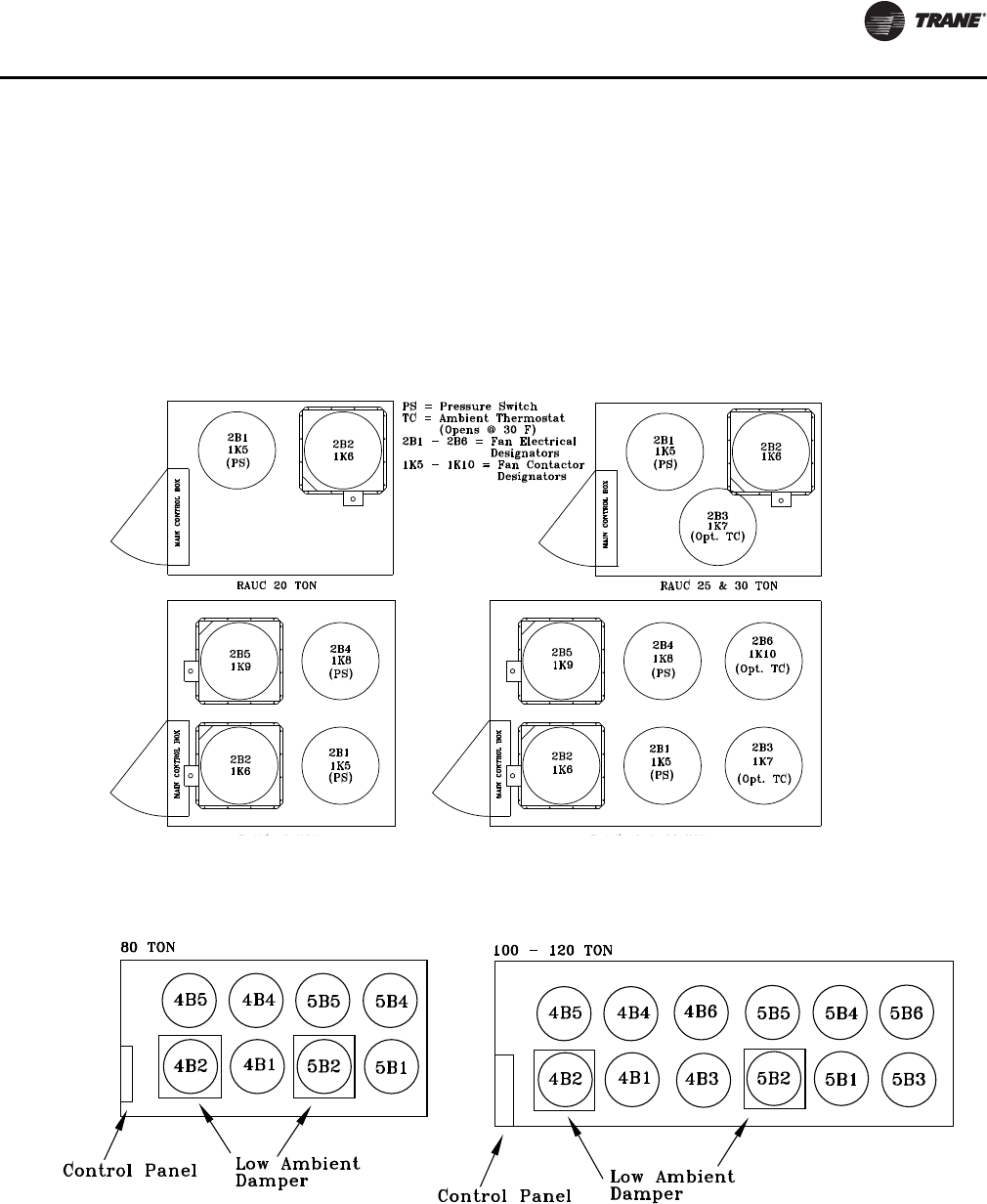
Operating Principals
SS-SVX11H-EN 81
Condenser Fans
Condenser fan cycling is accomplished through
interlocking fan contactors with a combination of
compressor contactors and pressure switches (4S7 &
4S8). When the low ambient damper option is applied,
ambient thermostats (1S36 & 1S37) are used to provide
additional fan cycling control. Figure 61 and Figure 62
illustrate the condenser fan locations with their respective
fan and relay designation.
When a cooling command has been initiated (first step),
the first compressor for circuit one is energized, an
auxiliary contactor on the compressor contactor is closed
energizing contactor 1K6 for fan 2B2 or 1K9 4B2 (80 - 120
Ton). When the liquid line pressure exceeds 255 psig the
fan pressure switch (4S7 & 4S8) will close and energize
contactor 1K5 (20 -60 Ton units) or 1K7 (80 - 120 Ton units).
When the next cooling step is added, an additional fan
contactor will be energized by the compressor contactor
on 25 - 120 Ton units.
Figure 61. Condenser fan locations: 20-60
Figure 62. Condenser fan locations: 80-120

Operating Principals
82 SS-SVX11H-EN
Low Ambient Dampers
Low Ambient Dampers are available as a factory installed
option or can be field-installed. Dampers are used to
extend the operation of these units from the standard
operational temperatures to a minimum of 0ºF without hot
gas bypass or 10ºF with hot gas bypass. (These values
apply when wind speed across the condenser coil is less
than 5 m.p.h.). If typical wind speeds are higher than 5
m.p.h., a wind screen around the unit may be required. By
restricting the airflow across the condenser coils,
saturated condensing temperatures can be maintained as
the ambient temperatures change.
The low ambient damper actuator controls damper
modulation for each refrigerant circuit in response to
saturated condensing temperature.
Compressor Crankcase Heaters
Each compressor is equipped with a crankcase heater and
is controlled by a 600 volt auxiliary switch on the
compressor contactor. The proper operation of the
crankcase heater is important to maintain an elevated
compressor oil temperature during the “Off” cycle to
prevent low oil viscosity and foaming during compressor
starts.
When the compressor starts, the sudden reduction in
crankcase pressure causes the liquid refrigerant to boil
rapidly causing the oil to foam. This condition could
damage compressor bearings due to reduced lubrication
and could cause compressor mechanical failures.
When power has been “Off” for an extended period, allow
the crankcase heater to operate a minimum of 24 hours
before starting the unit.
Low Ambient Thermostats
In addition to the low ambient dampers on 25, 30, 50 & 60
Ton units, a low ambient thermostat is installed to further
restrict the airflow across the condenser by cycling the 2B3
condenser fan on 25 & 30 Ton units plus 2B6 on 50 & 60 Ton
units. The thermostat opens when the ambient
temperature reaches 30ºF and closes at approximately
33ºF.
Hot Gas Bypass Operation
The HGBP valve regulates evaporator pressure by
opening as suction pressure decreases, to maintain a
desired minimum evaporating pressure regardless of a
decrease in evaporator external loading.
When the evaporator (suction) pressure is above the
valve’s setpoint, it remains closed. As suction pressure
falls below the valve’s setpoint, the valve begins to open.
The valve will continue to open at a rate proportional to the
suction pressure drop, thus maintaining evaporator
pressure.
Hot gas bypass valves are adjustable and should be set to
begin opening at approximately 100 psig suction pressure
and reach the full open position at 98 psig for DX coil
applications.
SS-SVX11H-EN 83
Start-Up
Low Ambient Damper Adjustment
(Factory or Field Installed)
When a unit is ordered with the low ambient option (i.e.,
Digit 11 is a “1” in the model number), a damper is factory
installed over the lead condenser fan for each refrigeration
circuit. See Figure 61, p. 81 or Figure 62, p. 81 for damper
location illustrations for the appropriate unit.
For field installation, mount the dampers over the
condenser fans at the locations shown in Figure 61, p. 81
or Figure 62, p. 81 and connect the actuator, controller,
and sensor for each circuit. (Refer to the Installation
Instructions provided with each low ambient damper kit.)
The controller has a factory default setpoint of 80º F. This
setpoint can be adjusted by installing a field supplied
resistor on 2TB34 in the low ambient control panel located
in the back of the main control panel. (See the low ambient
wiring diagram that shipped with the unit or with the field
kit, for resistance values and installation location.)
Inspect the damper blades for proper alignment and
operation. Dampers should be in the closed position
during the “Off” cycle.
If adjustment is required:
1. Remove the sensor leads from the input terminals 6
and 7 for circuit #1 and/or 11 and 12 for circuit #2.
(Controller output signal will go to 0.0 VDC and the
damper will drive to the closed position.)
2. Loosen the actuator clamp.
3. Firmly hold the damper blades in the closed position
4. Retighten the actuator clamp.
To check damper operation, jumper between the sensor
input terminals 6 and 7 and/or 11 and 12 (if applicable).
Controller output signal will go to 10 VDC and damper will
drive to full open position.
EVP Chiller Applications
Start the chilled water circulating pump by closing the field
provided pump disconnect switch and turn the pump
control circuit switch 5S1 “On”.
Check the flow device to ensure it opens at minimum flow
and closes properly.
With water circulating through the system, check the EVP
chiller pressure drop and adjust the flow (if necessary).
Refer to the appropriate EVP chiller size in for the operating
pressure drop.
Freezestat Setting
At the remote panel, set the freezestat at a minimum of 5°F
above the chilled water freezing temperature.
“Air Over” Evaporator Application
Verifying Proper Supply Fan Rotation
1. Verify the main power disconnect switch is off.
2. Unplug 1K21 & 1K22 reset relays from sockets in the
unit main control box to prevent inadvertent
compressor starts.
3. Ensure that the “System” selection switch at the
remote panel is in the “Off” position and the “Fan”
selection switch for the appropriate controls
application is in the “Auto” position. (VAV units do not
utilize a “Fan” selection input.)
4. Turn the 115 volt control circuit switch 1S2 to the “On”
position.
WARNING
Live Electrical Components!
During installation, testing, servicing and
troubleshooting of this product, it may be necessary to
work with live electrical components. Have a qualified
licensed electrician or other individual who has been
properly trained in handling live electrical components
perform these tasks. Failure to follow all electrical
safety precautions when exposed to live electrical
components could result in death or serious injury.
NOTICE:
Actuator Damage!
To prevent damage, do not depress actuator clutch
while actuator is energized.
WARNING
Hazardous Voltage!
Disconnect all electric power, including remote
disconnects before servicing. Follow proper lockout/
tagout procedures to ensure the power cannot be
inadvertently energized. Failure to disconnect power
before servicing could result in death or serious injury.
WARNING
Live Electrical Components!
During installation, testing, servicing and
troubleshooting of this product, it may be necessary to
work with live electrical components. Have a qualified
licensed electrician or other individual who has been
properly trained in handling live electrical components
perform these tasks. Failure to follow all electrical
safety precautions when exposed to live electrical
components could result in death or serious injury.

Start-Up
84 SS-SVX11H-EN
5. Turn the main power disconnect switch or circuit
protector switch for the unit to the “On” position.
6. Turn the field provided disconnect switch for the
supply fan to the “On” position and “bump” the field
supplied control circuit switch “On”, (i.e., “On” then
immediately “Off”).
7. If the fan does not start in applications where the fan
control circuit is energized via terminal 7TB5-1 in the
RAUJ 115V control circuit, the field power wiring to the
RAUJ unit could be improperly phased. Phase
protection module (1U3) located in the RAUJ control
box interrupts control circuit power when improperly
phased field power is detected.
8. While the fan is coasting down, check the rotation. If
the fan is rotating backwards, turn the field provided
disconnect switch for the air handler to the “Off”
position and interchange any two of the main power
wires at the fan motor starter or contactor.
9. After all adjustments have been made, restart the
supply fan and proceed through the following
procedures.
System Airflow Measurement
Much of the systems performance and reliability is closely
associated with, and dependent upon having the proper
airflow supplied both to the space that is being
conditioned and across the evaporator coil.
With the supply fan rotating in the proper direction,
measure the amperage at the supply fan contactor. If the
amperage exceeds the motor nameplate value, the static
pressure is less than design and the airflow is too high. If
the amperage is below the motor nameplate value, static
pressure could be too high and CFM could be too low. To
determine the actual CFM (± 5%);
a. Measure the actual fan RPM
b. Calculate the Theoretical BHP
i. (Actual Motor Amps X Motor HP)/Motor
Nameplate Amps
c. Plot this data onto the appropriate Fan Performance
Curve or Performance Table that shipped with the
Air Handling equipment. Where the two points
intersect, read the CFM line.
Use this data to assist in calculating a new fan drive if the
CFM is not at design specifications.
An alternate method with less accuracy is to measure the
static pressure drop across the evaporator coil. This can be
accomplished by;
1. Drilling a small hole through the unit casing on each
side of the coil.
2. Measure the difference between the pressures at both
locations.
3. Plot this value onto the appropriate component
pressure drop curve that shipped with the Air Handling
equipment. Use the data to assist in calculating a new
fan drive if the CFM is not at design specifications.
4. Plug the holes after the proper CFM has been
established.
After all adjustments have been made, proceed through
the following procedures.
Preliminary Expansion Valve Adjustment
No bleed thermal expansion valves are set by
manufacturers to control between 12-14.4°F superheat
leaving the evaporator at nominal design conditions.
Thermal expansion valves with bleeds are set to their
highest superheat setting. Actual superheat depends on
many factors (valve vs. system relative sizing, operating
conditions, system load step, system charge, piping, and
condenser fan control). The thermal expansion valves
must be adjusted as part of the unit start-up procedure. Do
not adjust valves beyond manufacturer's available
nominal adjustment range.
WARNING
Rotating Components!
During installation, testing, servicing and
troubleshooting of this product it may be necessary to
work with live and exposed rotating components. Have
a qualified or licensed service individual who has been
properly trained in handling exposed rotating
components, perform these tasks. Failure to follow all
safety precautions could result in rotating components
cutting and slashing technician which could result in
death or serious injury.
NOTICE:
Coil Damage!
Coil damage can occur if care is not taken when drilling
holes in this area.
NOTICE:
Compressor Damage!
Increase thermal expansion valve superheat settings
before starting compressors to minimize compressor
operation with low oil viscosity. Failure to follow the
above could result in compressor failure or reduced
compressor life.
Start-Up
SS-SVX11H-EN 85
Information in Table 22, p. 85 is approximate and intended
to simplify field adjustment by presetting valves to
approximately 18°F superheat for DX evap coils and 15°F
superheat for EVP chillers. Actual operating superheat will
typically be less than 18°/15°F and varies depending on
many factors including those listed above. Superheat
gradient (superheat change per turn) is also approximate
and will not be constant throughout the valve adjustment
range. Check superheat after startup to confirm proper
control.
Tag or mark valve to keep a record of any field
adjustments.
Table 22. Thermal expansion valve manufacturer settings - no bleed(a)
Sporlan
Standard off the shelf nominal valve settings (90 PSIG air test setting)
Valve
Superheat,
°F
CW turns
available
CCW turns
available
Superheat
change per
turn
Field adjust
for 18°F (DX
evap coil)
Field adjust for
15°F (EVP only)
BBIZE-1-GA
12
4.5
4.5
2.4°F 2.5 CW —
BBIZE-1-1/2-GA
BBIZE-2-GA
BBIZE-3-GA
BBIZE-4-GA
BBIZE-5-GA
BBIZE-6-GA
BBIZE-8-GA
BBIZE-12.5-GA
BBIZE-15-GA
OZE-20-GA
3.4°F .25 CW .25 CWOZE-25-GA
OZE-35-GA
OZE-50-GA 7.5 1.8°F 3.25 CW 1.75 CW
OZE-60-GA
Emerson
Standard off the shelf nominal valve settings
Valve Nom Tons
Superheat,
°F
CW turns
available
CCW turns
available
Superheat
change per
turn
Field adjust for
18°F (DX evap
coil)
Field adjust
for 15°F (EVP
only)
C 1-1/2 to 7 13 6 6 4 1.25 CW
TF 12 to 20 5 5 2 2.5 CW 1.0 CW
Danfoss
Standard off the shelf nominal valve settings
Valve Body size SHT, °F
CW turns
available
CCW turns
available
Superheat
change per
turn
Field adjust for
18°F (DX evap
coil)
Field adjust
for 15°F (EVP
only)
TGEL 3.5 TR
TGE 10
14.4
4
3
4.5°F .75 CW —
TGEL 4.5 TR
TGEL 6.5 TR
TGEL 9 TR
TGEL 13 TR
TGEL 15 TR
TGE 20
7 3 1.25 CW .25 CW
TGEL 19 TR
TGEL 23 TR
TGEL 31 TR
TGE 40 4TGEL 35 TR
TGEL 46 TR
(a) Valve part numbers with “-ZGA” in place of “-GA”, may be used interchangeably. “ERZE-” part number valves are an acceptable alternate to “BBIZE”
valves.
Start-Up
86 SS-SVX11H-EN
Adding Preliminary Charge
1. Leak check must be completed and system evacuated.
2. Verify that oil levels are near or above the top of all
compressor sight glasses.
3. Insure field supplied unit disconnect is "OFF". Then
verify that the unit 1S2 115 volt control circuit switch is
"OFF" and that reset relays 1K21 & 1K22 have been
unplugged to prevent inadvertent compressor starts.
4. Turn field supplied unit disconnect "ON" to energize
crankcase heaters. Verify crankcase heaters are
operating.
5. Verify that discharge, suction, and liquid line service
valves are open. Liquid line service valve must be
closed 1/4" turn from full open to allow for fan pressure
switch operation.
6. If system is equipped with hot gas bypass, insure hot
gas bypass is closed and remains closed during
charging.
7. Refer to Ta b l e 24, p. 91 for the charge estimate for the
condensing unit circuit and piping at the appropriate
piping length.
8. At the liquid line angle valve add as much R-410A
LIQUID as possible up to, but not exceeding, that listed
in Ta b l e 24, p. 91. Depending on conditions, it could
not be possible to add more than 60% of the charge
listed in Ta b l e 24, p. 91. This will be adequate for
compressor startup. More charge will be added after
compressors are started. Use an accurate scale to
measure and record the preliminary amount of R-410A
added to each circuit.
9. Do not add refrigerant in the suction line at this time to
prevent excessive refrigerant in the low side prior to
compressor startup.
Compressor Start-Up (All Systems)
1. Review the proceeding "Adding Preliminary Charge"
section and confirm all steps were completed.
2. Initial compressor start-up is best done above 70°F
outdoor temperature with ample evaporator load (at
least 70°F return air and 350 CFM/Ton).
Table 25, p. 91 gives the minimum starting
temperatures for both "Standard" & "Low" Ambient
units.
Do not attempt to charge the system with the low
ambient dampers and/or hot gas bypass operating (if
applicable). Disable low ambient dampers in the
"Open" position (refer to the "Low Ambient Damper
Adjustment" section) and verify hot gas bypass is not
operating before proceeding.
3. On units with dual circuits, work on only one circuit at
a time. Refer to Ta b l e 26, p. 91 for the compressor
sequencing and Figure 64, p. 92 or Figure 65, p. 92 for
their location.
4. Compare the amount of preliminary charge added in
the proceeding section to the Ta b l e 24, p. 91 estimates
for condensing unit and piping only. Up to 20% more
charge than listed in Tab l e 24, p. 91 may be required to
fully charge the circuit, depending on the evaporator
design. Have adequate R-410A available to complete
charging as described in the following steps.
5. Attach a thermocouple type temperature sensor on the
liquid line close to the liquid line service valve. To
insure an accurate liquid temperature reading, clean
the line where the sensor is attached. After securing the
sensor to the line, insulate the sensor and line to isolate
it from the ambient air.
6. Attach a set of service gauges onto the suction and
discharge gauge ports.
7. Check the low side pressure. The low pressure cutout
(4S3, 4S4) opens below 58 Psig and closes above 78
Psig. If the low side pressure is less than 78 Psig,
refrigerant may need to be added to the suction line
before starting the compressor(s). Slowly meter into
the suction line only as much R410A as needed to make
the low pressure cutout from the VAPOR charging
connection. If possible, plan to use this entire
refrigerant bottle on the same unit in order to minimize
fractionalization. Use an accurate scale to measure and
record the amount of R-410A added.
WARNING
Hazardous Voltage!
Disconnect all electric power, including remote
disconnects before servicing. Follow proper lockout/
tagout procedures to ensure the power cannot be
inadvertently energized. Failure to disconnect power
before servicing could result in death or serious injury.
NOTICE:
Compressor Damage!
Do not allow liquid refrigerant to enter the suction line.
Excessive liquid accumulation in the suction line could
result in compressor bearing damage. Keep crankcase
heaters on whenever refrigerant is in the system. If
crankcase heaters have not been on with refrigerant in
the system, turn the crankcase heaters on for a
minimum of 24 hours before starting compressors.
Failure to follow the above could result in compressor
failure or reduced compressor life.
Start-Up
SS-SVX11H-EN 87
8. Switch the field supplied unit disconnect "OFF". Open
the unit control box and plug in the reset relay (1K21 or
1K22) for the circuit being started only.
9. This charging procedure is more accurate at higher
outdoor temperatures. If the outdoor temperature is
less than 80°F, temporarily disable the fan pressure
control switches (4S11, 4S12) or (4S7, 4S8) on 80 - 120
Ton units. To do this, refer to unit wiring diagrams and
disconnect the wires between the switches and the
terminal strip.
10. Then switch the RAUJ 115 volt (1S2) control circuit
switch "ON". Close the control box and then switch the
field supplied unit disconnect "ON". Unit power should
be off no longer than 30 minutes to prevent refrigerant
migration to compressor sumps. If power is off for
longer than 30 minutes, allow time for crankcase
heaters to drive refrigerant from compressor sumps
before starting compressors.
11. Verify that oil levels are near or above the top of all
compressor sight glasses.
12. Start the first step compressor only.
a. If the compressor and condenser fans do not start,
the field power wiring to the RAUJ unit could be
improperly phased. A main unit power phase
protection module (1U3) is located in the RAUJ
control box and interrupts control circuit power
when improperly phased field power is detected.
i. CSHD compressors (used in 20-60T units) are
not equipped with electronic modules and do
not have individual compressor phase
protection.
ii. CSHN compressors (used in 80-120T units) are
individually equipped with compressor
protection modules (381U1, 382U2, 383U3,
384U4, 385U5, 386U6) located in the compressor
junction boxes. These modules include phase,
voltage, overcurrent, and over temperature
protection. If CSHN compressors are started
with reversed phasing, the module output relay
will open in about 6 seconds. Module output
relays are wired in series with the unit 115 volt
control circuit reset relays (1K21, 1K22). When
any module output relay opens, the circuit reset
relay latches closed and circuit operation is
locked out. Note: Refer to the Service &
Maintenance section of this manual or COM-
SVN01A-EN for further discussion regarding
other potential compressor protection module
faults.
b. As soon as a compressor starts, verify correct
rotation. If a scroll compressor is allowed to run
backwards for even a very short period of time,
internal compressor damage could occur and
compressor life could be reduced. When rotating
backwards scroll compressors make a loud noise,
do not pump, draw about 1/2 expected amps, and
the low side shell gets hot. Immediately shut off a
compressor rotating backwards.
c. Check condenser fans for proper rotation. As
viewed from the top of the unit, the correct rotation
direction is clockwise. All Motors are Rotating
Backwards.
WARNING
Hazardous Voltage!
Disconnect all electric power, including remote
disconnects before servicing. Follow proper lockout/
tagout procedures to ensure the power cannot be
inadvertently energized. Failure to disconnect power
before servicing could result in death or serious injury.
NOTICE:
Compressor Damage!
Keep crankcase heaters on whenever refrigerant is in
the system. If crankcase heaters have not been on with
refrigerant in the system, turn the crankcase heaters on
for a minimum of 24 hours before starting
compressors. Failure to follow the above could result in
compressor failure or reduced compressor life.
WARNING
Live Electrical Components!
During installation, testing, servicing and
troubleshooting of this product, it may be necessary to
work with live electrical components. Have a qualified
licensed electrician or other individual who has been
properly trained in handling live electrical components
perform these tasks. Failure to follow all electrical safety
precautions when exposed to live electrical
components could result in death or serious injury.
NOTICE:
Compressor Damage!
Improper power phasing will cause compressor to run
backwards. Compressor could be running backwards if
it is noisy, low side shell gets hot, suction pressure
does not drop within 5 seconds after startup, and
compressor only draws ½ expected amps. Stop the
compressor immediately and have a qualified
electrician or technician properly trained in 3 phase
power correct the wiring. Failure to do the above could
result in compressor damage.
Start-Up
88 SS-SVX11H-EN
i. Turn the field supplied disconnect switch or
circuit protector switch that provides power to
the condensing unit to the “Off” position. Lock
the disconnect switch in the open position while
working at the unit.
ii. Verify that field connected main power phase
sequence matches that specified on the unit
wiring diagrams. Rotation will be incorrect if any
two power wires are interchanged at the unit
terminal block 1TB1 or the optional factory
mounted non-fused disconnect switch (1S1) in
the unit control panel.
iii. Check the unit phase module (1U1) for correct
operation and unit wiring.
Note: Interchanging "Load" side power wires at
the contactors only affects the individual
fan rotation. Ensure that the voltage phase
sequence at the main terminal block 1TB1
is ABC as outlined in the "Electrical
Phasing" section.
Some Motors are Rotating Backwards
iv. Turn the field supplied disconnect switch or
circuit protector switch that provides power to
the condensing unit to the "Off" position. Lock
the disconnect switch in the open position while
working at the unit.
v. If the unit main power phase sequence is correct,
rotation of an individual motor will be
backwards if any two leads are interchanged
between the unit main power and the motor.
Verify that wiring from the unit main power to
the motor is per the unit wiring diagram. Refer to
the illustration in Figure 63 for the compressor
terminal/phase identification. Compressor
damage could occur if a compressor runs
backwards for a very short period of time.
d. Start the remaining circuit compressor(s). Verify
correct rotation. Incorrect rotation is noisy,
compressor draws about ½ expected amps, and the
low side shell gets hot. Immediately shut off any
compressors rotating backwards.
e. After allowing 10 minutes for circuit operation to
stabilize at full load, check the liquid temperature
and discharge pressure. Plot on Figure 63, p. 89.
Expect the operating point to be in the "Add charge"
portion of Figure 63, p. 89. The remainder of the
circuit charge will be added in the following steps.
WARNING
Rotating Components!
During installation, testing, servicing and
troubleshooting of this product it may be necessary to
work with live and exposed rotating components. Have
a qualified or licensed service individual who has been
properly trained in handling exposed rotating
components, perform these tasks. Failure to follow all
safety precautions could result in rotating components
cutting and slashing technician which could result in
death or serious injury.
WARNING
Hazardous Voltage!
Disconnect all electric power, including remote
disconnects before servicing. Follow proper lockout/
tagout procedures to ensure the power cannot be
inadvertently energized. Failure to disconnect power
before servicing could result in death or serious injury.
WARNING
Hazardous Voltage!
Disconnect all electric power, including remote
disconnects before servicing. Follow proper lockout/
tagout procedures to ensure the power cannot be
inadvertently energized. Failure to disconnect power
before servicing could result in death or serious injury.
WARNING
Rotating Components!
During installation, testing, servicing and
troubleshooting of this product it may be necessary to
work with live and exposed rotating components. Have
a qualified or licensed service individual who has been
properly trained in handling exposed rotating
components, perform these tasks. Failure to follow all
safety precautions could result in rotating components
cutting and slashing technician which could result in
death or serious injury.
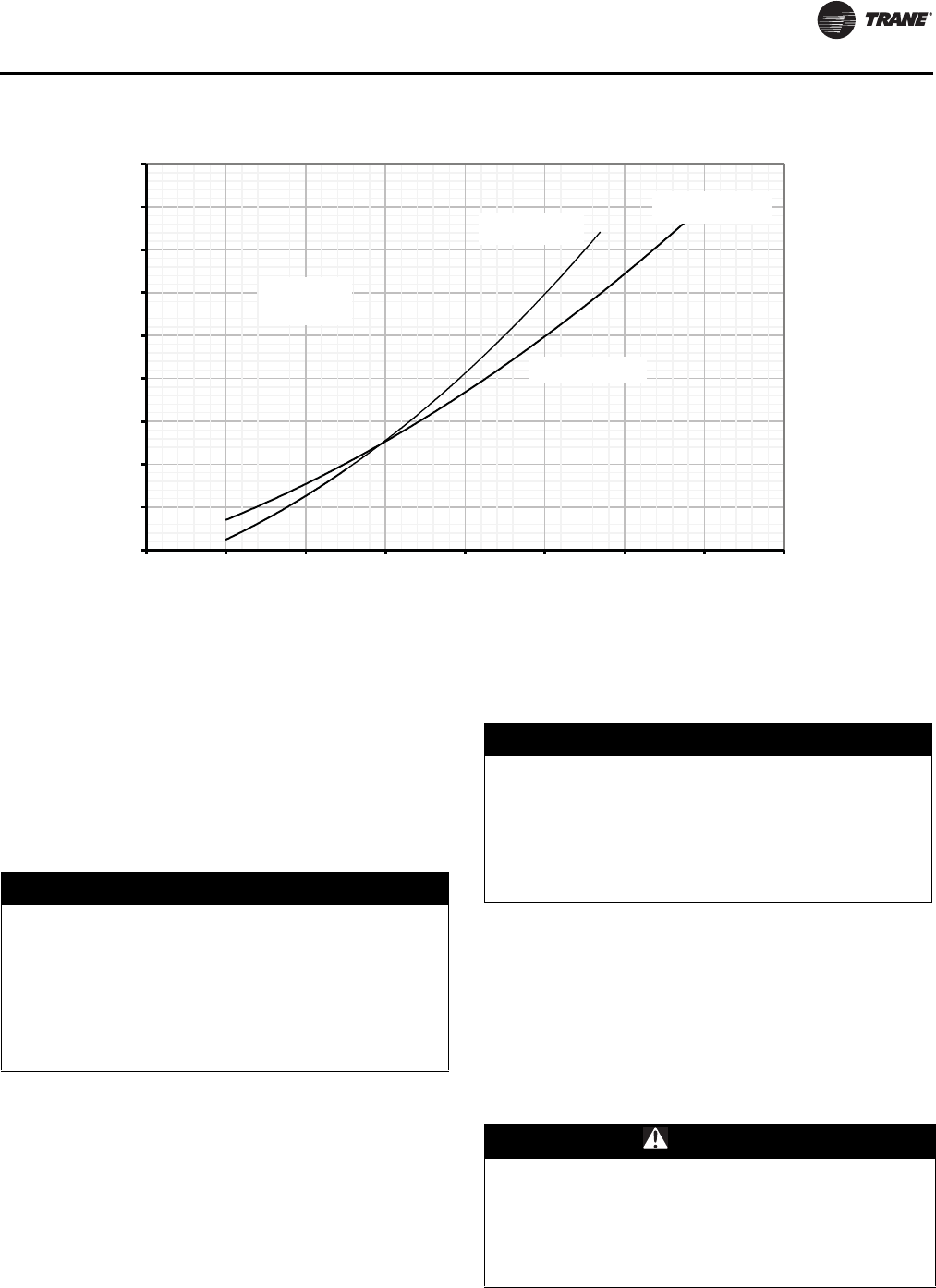
Start-Up
SS-SVX11H-EN 89
f. Subtract the total charge already added from the
Table 24, p. 91 charge estimate for condensing unit
at the appropriate piping length. Add no more R-
410A than 1/2 of this difference at a time.
g. With all the circuit compressors operating, SLOWLY
meter R-410A into the suction line from the LIQUID
charging connection. Add no more than 1/2 of the
difference from step f. above. Then allow the unit to
run for 10 minutes, and plot the new operating point
on Figure 63. Use an accurate scale to measure and
record the amount of R-410A added.
h. Repeat step g., adding smaller increments of
refrigerant until circuit operation is approximately
on the appropriate line of Figure 63, p. 89. As the
charging line is approached, smaller increments of
refrigerant will move the operating point more.
i. This procedure results in less subcooling than
previous split system charging methods. Note that
using this charging method will at times result in
bubbles at sight glasses installed just upstream of
expansion valves; especially during lower ambient
operation, part load, and for systems with
evaporators located above condensing units. This
charging procedure will maximize the usable
operating envelope of the R-410A RAUJ units.
Important: Do not release refrigerant to the
atmosphere! If adding or removing
refrigerant is required, the service
technician must comply with all Federal,
State, and local laws. Refer to general
service bulletin MSCU-SB-1 (latest edition).
j. Record the total charge added to the circuit.
k. If applicable, repeat steps a. through j. on the 2nd
refrigeration circuit.
Figure 63. System charging chart (all units)
250
300
350
400
450
500
550
600
650
700
70 80 90 100 110 120 130 140 150
Discharge Pressure, psig
Liquid Line Temp at Outdoor Unit, F
Remove
Charge
Add Charge
150" lines
150" lines
Add Charge
50" lines
Add Charge
Add Charge
NOTICE:
Compressor Damage!
To prevent compressor liquid slugging, only add liquid
in the suction line when the compressor is running. Use
extreme caution to meter liquid refrigerant into the
suction line slowly. If liquid is added too rapidly,
compressor oil dilution and oil pumpout could occur.
Failure to follow the above could result in compressor
failure or reduced compressor life.
NOTICE:
Compressor Damage!
Do not overcharge system. Excessive refrigerant
charging of the RAUJ unit can cause compressor liquid
slugging at startup, and conditions where compressors
and/or condenser fans short cycle. Failure to do the
above could result in compressor failure and/or
reduced compressor life.
WARNING
Hazardous Voltage!
Disconnect all electric power, including remote
disconnects before servicing. Follow proper lockout/
tagout procedures to ensure the power cannot be
inadvertently energized. Failure to disconnect power
before servicing could result in death or serious injury.
Start-Up
90 SS-SVX11H-EN
l. If in step 9. the fan pressure control switches were
disabled to allow for charging below 80°F outdoor
temperature, disconnect unit power and reconnect
the control wiring for these fans at this time. Follow
the procedures discussed earlier to confirm proper
rotation of these condenser fans.
13. After the unit has been operating for approximately 30
minutes at full load with all condenser fans running,
record the operating pressures. Operating pressures
should be within +/- 10 Psig of the appropriate pressure
curve in Figure 63, p. 89. Measure and record the
system subcooling and superheat as described in the
following sections.
Subcooling
The outdoor ambient temperature must be between 65ºF
and 105ºF and the relative humidity of the air entering the
evaporator must be above 40 percent. When the
temperatures are outside of these ranges, measuring the
operating pressures can be meaningless.
With the unit operating at “Full Circuit Capacity”,
acceptable subcooling ranges between 8ºF to 16ºF.
Measuring Subcooling
Note: System charging is done by using the charging
chart on fig. 38 page 76. Do not attempt to charge
the system based on subcooling.
•At the liquid line service valve, measure the liquid
line pressure. Using a Refrigerant 410A pressure/
temperature chart, convert the pressure reading
into the corresponding saturated temperature.
•Measure the actual liquid line temperature as close
to the liquid line service valve as possible. To ensure
an accurate reading, clean the line thoroughly
where the temperature sensor will be attached.
After securing the sensor to the line, insulate the
sensor and line to isolate it from the ambient air.
Note: Glass thermometers do not have sufficient contact
area to give an accurate reading.
•Determine the system subcooling by subtracting
the actual liquid line temperature from the
saturated liquid temperature.
Measuring Superheat
•Measure the suction pressure at the outlet of the
evaporator as close to the expansion valve bulb
location as possible.
•Measured the suction line temperature as close to
the expansion valve bulb, as possible.
•Using a Refrigerant/Temperature chart, convert the
pressure reading to a corresponding saturated
vapor temperature.
Note: On many Trane fan/coil units, an access valve is
provided close to the expansion valve bulb
location. This valve must be added on climate
changers and other evaporators.
•Subtract the saturated vapor temperature, from the
actual suction line temperature. The difference
between the two temperatures is known as
“superheat”.
14. Verify that the oil level in each compressor is correct.
As a minimum, oil must be visible in the sight glass.
15. Once the checks and adjustments for the operating
circuit has been completed, check and record the:
– ambient temperature;
– compressor oil level (each circuit);
– compressor suction and discharge pressures and
liquid line temperatures (each circuit);
– superheat and subcooling (each circuit);
Record this data on an “operator’s maintenance log”
shown in Table 28, p. 96. Repeat these procedures for
the second refrigeration circuit, if applicable.
16. Turn the 115-volt control circuit switch 1S2 to the “OFF”
position and open the field provided or optional factory
mounted disconnect switch.
17. After shutting the system off, check the compressor oil
appearance. Discoloration of the oil indicates that an
abnormal condition has occurred. If the oil is dark and
smells burnt, it has overheated because of:
compressor is operating at extremely high condensing
temperatures; high superheat; a compressor
mechanical failure; or, occurrence of a motor burnout.
If the oil is black and contains metal flakes, a
mechanical failure has occurred. This symptom is
often accompanied by a high compressor amperage
draw.
If a motor burnout is suspected, use an acid test kit to
check the condition of the oil. Test results will indicate
an acid level exceeding 0.05 mg KOH/g if a burnout
occurred.
Compressor Oil
RAUJ unit and replacement compressors ship fully
charged with POE oil from the factory. The scroll
compressor uses POE oil (OIL00079 for a quart container
or OIL00080 for a gallon container) without substitution.
The appropriate oil charge for a 7.5 Ton scroll compressor
is 6.3 pints. For 9 through 15 Ton light commercial scroll
compressors is 7 pints. For a 15 and 20 Ton large
commercial scroll compressors (80-120T units), use 14.2
pints.
NOTICE:
Compressor Damage!
POE oil absorbs atmospheric moisture quickly which
can lead to compressor damage. Always use the
smallest container size required for the job
requirements. Always leave the oil container tightly
sealed until time of use. Do not reuse oil that has been
opened.
Start-Up
SS-SVX11H-EN 91
Compressor Crankcase Heaters
7.5 thru 15 Ton CSHD compressors use one 90-watt heater
per compressor. 15 and 20 Ton CSHN compressors use
one 160-watt heater per compressor.
Table 23. Pressure control switch settings
Pressure Switch Make Break
Hi Pressure 550 psi 650 psi
Lo Pressure 78 psi 58 psi
Condenser Fan Cycling switch 444 psi 255 psi
EVP Lo Pressure 105 psi 82 psi
Table 24. Approximate charge per circuit for condensing
unit and lines only (does not include
evaporator)
Total Interconnecting Line Length
Capacity 50 100 150
20 19 25 32
25 25 37 50
30 25 38 50
40 25 37 50
50 25 38 50
60 24 36 48
80 49 69 88
100 52 73 94
120 55 76 98
Table 25. Minimum starting ambient temperature
Unit
Size
Minimum Starting Ambient(a)
(a) Minimum starting ambients in degrees F and is based on the unit op-
erating at minimum step of unloading and 5 mph wind across con-
denser.
Standard Units Low Ambient Units
With
HGBP
No
HGBP
With
HGBP
No
HGBP
20-60 45° 40° 10° 0°
80-120 45° 40° 10° 0°
Table 26. Compressor sequence: 20-120 Ton units
Unit
Size
Control
Step Circuit 1 Circuit 2 % Loaded Unit
20 1
2
1A
1A,1B
50
100
25 1
2
1A
1A,1B
42
100
30 1
2
1A
1A,1B
50
100
40
1
2
3
4
1A
1A
1A,1B
1A,1B
2A
2A
2A,2B
25
50
75
100
50
1
2
3
4
1A
1A
1A,1B
1A,1B
2A
2A
2A,2B
23
46
73
100
60
1
2
3
4
1A
1A
1A,1B
1A,1B
2A
2A
2A,2B
25
50
75
100
80
1
2
3
4
5
6
1A
1A
1A,1B
1A,1B
1A,1B,1C
1A,1B,1C
2A
2A
2A,2B
2A,2B
2A,2B,2C
17
33
50
66
83
100
100
1
2
3
4
5
6
1A
1A
1A,1B
1A,1B
1A,1B,1C
1A,1B,1C
2A
2A
2A,2B
2A,2B
2A,2B,2C
15
30
45
60
80
100
120
1
2
3
4
5
6
1A
1A
1A,1B
1A,1B
1A,1B,1C
1A,1B,1C
2A
2A
2A,2B
2A,2B
2A,2B,2C
17
33
50
66
83
100
Table 26. Compressor sequence: 20-120 Ton units
Unit
Size
Control
Step Circuit 1 Circuit 2 % Loaded Unit
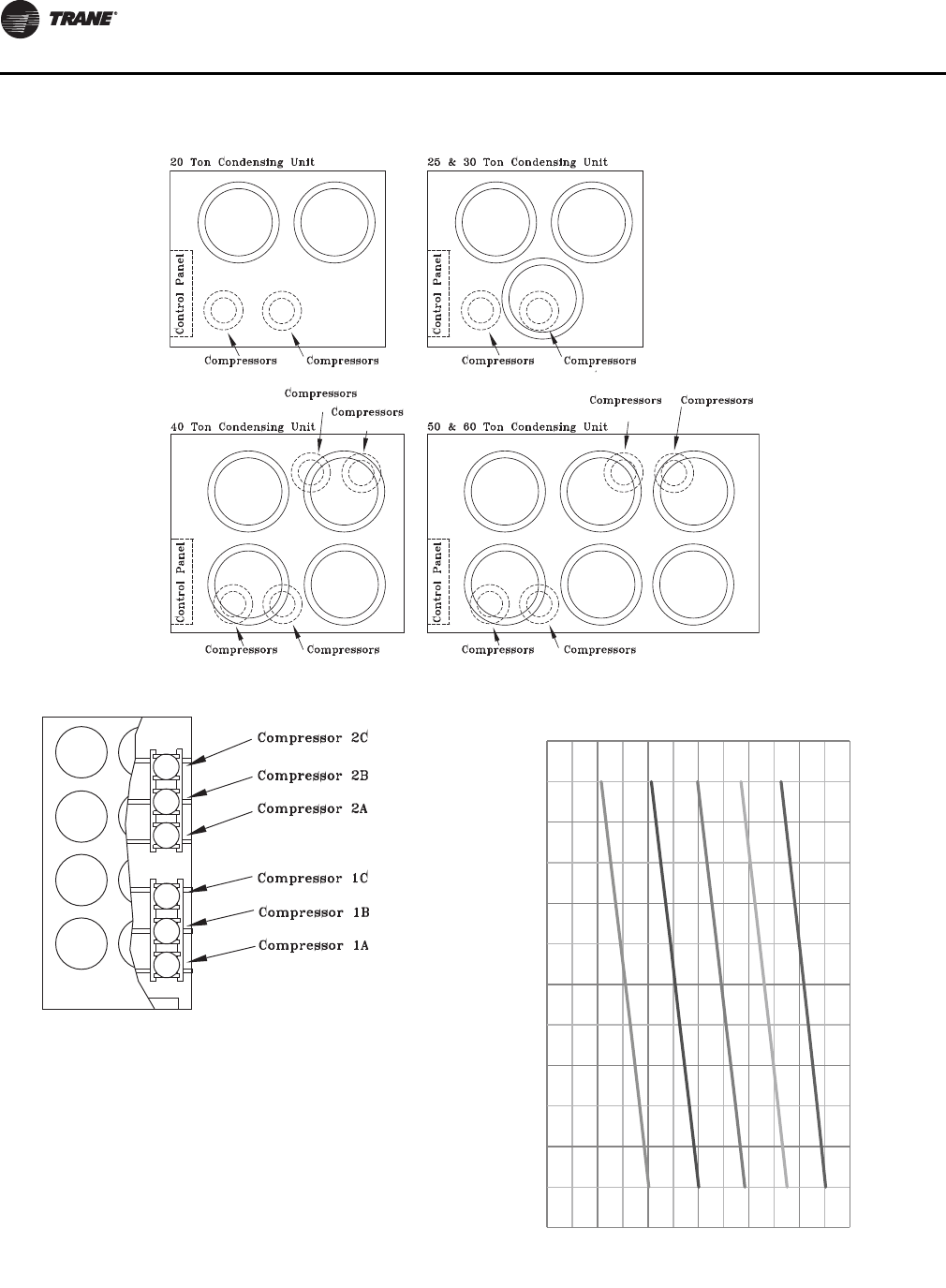
Start-Up
92 SS-SVX11H-EN
Pressure Curves
To Check Operating Pressures
1. Start the unit and allow the pressures to stabilize.
2. Measure the outdoor air dry bulb temperature (F)
entering the condenser coil.
3. Measure the discharge and suction pressure (psig)
next to the compressor.
4. Plot the outdoor dry bulb temperature and the
operating suction pressure (psig) onto the chart.
5. At point of intersection, read to the left for discharge
pressure. Measured discharge pressure should be
within +/- 10 psig of graph.
.
Figure 64. Typical compressor locations 20 - 60 Ton units
“2B” “2B” “2A”
“2A”
“1A” “1A”
“1A”
“1A” “1B” “1B”
“1B”
“1B”
Figure 65. Typical compressor locations 80 - 120T units
Figure 66. 20 Ton cooling cycle pressure curve(a)
(a) All compressors and condenser fans running
65F OD
75F OD
85F OD
95F OD
105F OD
250
300
350
400
450
500
550
95 105 115 125 135 145
Discharge pressure, PSIG
20T Cooling Cycle Pressure Curve
All compressors and condenser fans running
Sucon pressure, PSIGSucon pressure, PSIGSucon pressure, PSIGSucon pressure, PSIG
Start-Up
SS-SVX11H-EN 93
Figure 67. 25 Ton cooling cycle pressure curve(a)
(a) All compressors and condenser fans running
Figure 68. 30 Ton cooling cycle pressure curve(a)
(a) All compressors and condenser fans running
65F OD
75F OD
85F OD
95F OD
105F OD
250
300
350
400
450
500
550
95 105 115 125 135 145
Discharge pressure, PSIG
25T Cooling Cycle Pressure Curve
All compressors and condenser fans running
Sucon pressure, PSIGSucon pressure, PSIGSucon pressure, PSIGSucon pressure, PSIGSucon pressure, PSIGSucon pressure, PSIGSucon pressure, PSIGSucon pressure, PSIG
65F OD
75F OD
85F OD
95F OD
105F OD
250
300
350
400
450
500
550
95 105 115 125 135 145
Discharge pressure, PSIG
30T Cooling Cycle Pressure Curve
All compressors and condenser fans running
Sucon pressure, PSIGSucon pressure, PSIGSucon pressure, PSIGSucon pressure, PSIGSucon pressure, PSIGSucon pressure, PSIGSucon pressure, PSIGSucon pressure, PSIG
Figure 69. 40 Ton cooling cycle pressure curve(a)
(a) All compressors and condenser fans running
Figure 70. 50 Ton cooling cycle pressure curve(a)
(a) All compressors and condenser fans running
65F OD
75F OD
85F OD
95F OD
105F OD
250
300
350
400
450
500
550
95 105 115 125 135 145
Discharge pressure, PSIG
40T Cooling Cycle Pressure Curve
All compressors and condenser fans running
Sucon pressure, PSIGSucon pressure, PSIGSucon pressure, PSIGSucon pressure, PSIGSucon pressure, PSIGSucon pressure, PSIGSucon pressure, PSIGSucon pressure, PSIG
65F OD
75F OD
85F OD
95F OD
105F OD
250
300
350
400
450
500
550
95 105 115 125 135 145
Discharge pressure, PSIG
50T Cooling Cycle Pressure Curve
All compressors and condenser fans running
Sucon pressure, PSIGSucon pressure, PSIGSucon pressure, PSIGSucon pressure, PSIGSucon pressure, PSIGSucon pressure, PSIGSucon pressure, PSIGSucon pressure, PSIG
Start-Up
94 SS-SVX11H-EN
Figure 71. 60 Ton cooling cycle pressure curve(a)
(a) All compressors and condenser fans running
Figure 72. 80 Ton cooling cycle pressure curve(a)
(a) All compressors and condenser fans running
65F OD
75F OD
85F OD
95F OD
105F OD
250
300
350
400
450
500
550
95 105 115 125 135 145
Discharge pressure, PSIG
60T Cooling Cycle Pressure Curve
All compressors and condenser fans running
Sucon pressure, PSIGSucon pressure, PSIGSucon pressure, PSIGSucon pressure, PSIGSucon pressure, PSIGSucon pressure, PSIGSucon pressure, PSIGSucon pressure, PSIG
65F OD
75F OD
85F OD
95F OD
105F OD
250
300
350
400
450
500
550
95 105 115 125 135 145
Discharge pressure, PSIG
80T Cooling Cycle Pressure Curve
All compressors and condenser fans running
Sucon pressure, PSIGSucon pressure, PSIGSucon pressure, PSIGSucon pressure, PSIGSucon pressure, PSIGSucon pressure, PSIGSucon pressure, PSIGSucon pressure, PSIG
Figure 73. 100 Ton cooling cycle pressure curve(a)
(a) All compressors and condenser fans running
Figure 74. 120 Ton cooling cycle pressure curve(a)
(a) All compressors and condenser fans running
65F OD
75F OD
85F OD
95F OD
105F OD
250
300
350
400
450
500
550
95 105 115 125 135 145
Discharge pressure, PSIG
100T Cooling Cycle Pressure Curve
All compressors and condenser fans running
Sucon pressure, PSIGSucon pressure, PSIGSucon pressure, PSIGSucon pressure, PSIGSucon pressure, PSIGSucon pressure, PSIGSucon pressure, PSIGSucon pressure, PSIG
65F OD
75F OD
85F OD
95F OD
105F OD
250
300
350
400
450
500
550
95 105 115 125 135 145
Discharge pressure, PSIG
120T Cooling Cycle Pressure Curve
All compressors and condenser fans running
Sucon pressure, PSIGSucon pressure, PSIGSucon pressure, PSIGSucon pressure, PSIGSucon pressure, PSIGSucon pressure, PSIGSucon pressure, PSIGSucon pressure, PSIG
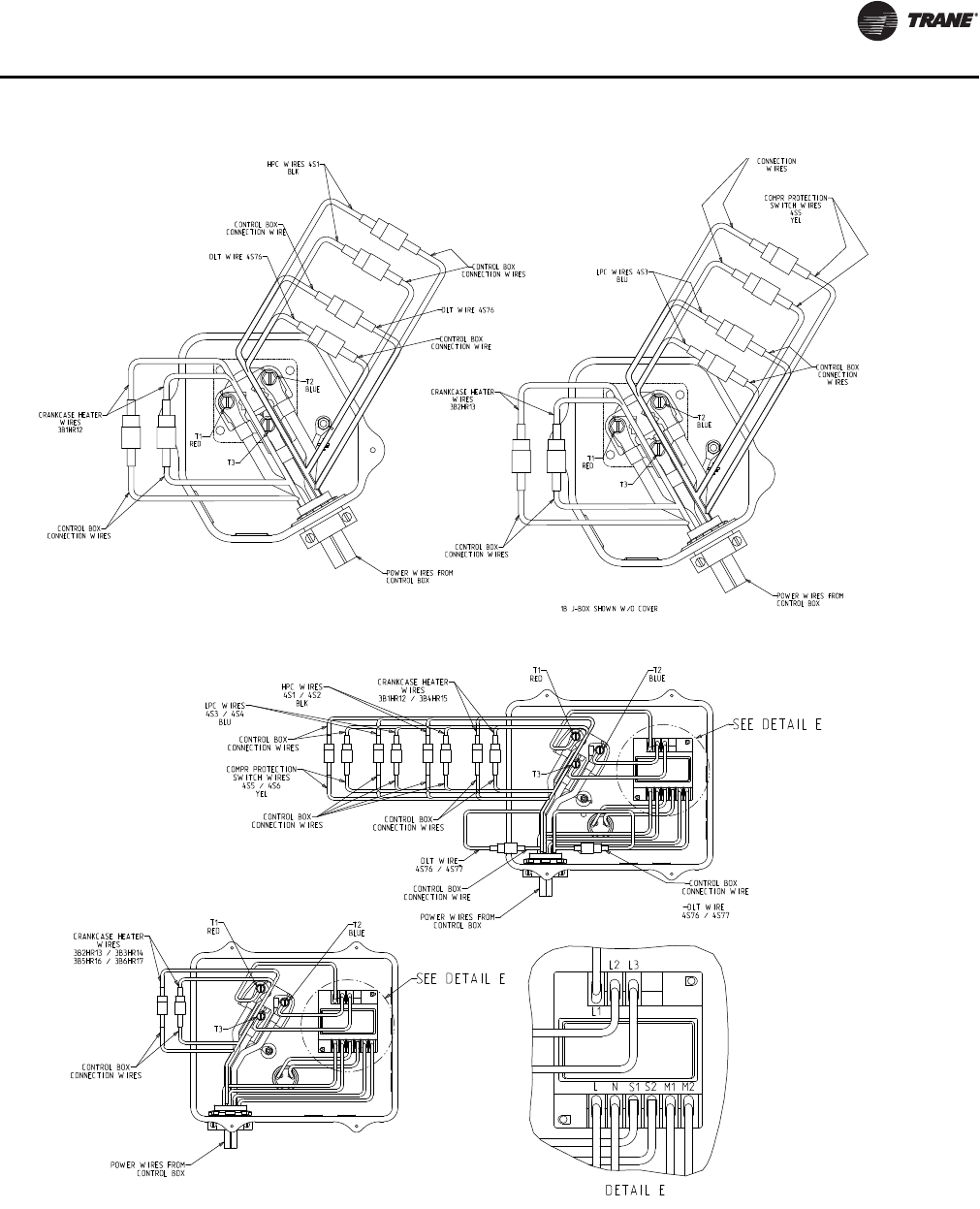
Start-Up
SS-SVX11H-EN 95
Final System Setup
After completing the Pre-start and Start-up procedures
outlined in the previous sections, perform these final
checks before leaving the unit:
Figure 75. Junction box: 20-60 Ton units
Figure 76. Junction box: 80-120 Ton units
CRANKCASE HEATER
WIRES
3B1HR12
CONTROL BOX
CONNECTION WIRES
T1
RED
T3
T2
BLUE
DLT WIRE 4S76
DLT WIRE 4S76
CONTROL BOX
CONNECTION WIRE
CONTROL BOX
CONNECTION WIRE
POWER WIRES FROM
CONTROL BOX
HPC WIRES 4S1
BLK
CONTROL BOX
CONNECTION WIRES
1B J-BOX SHOWN W/O COVER
POWER WIRES FROM
CONTROL BOX
CONTROL BOX
CONNECTION WIRES
CRANKCASE HEATER
WIRES
3B2HR13
T1
RED
T3
T2
BLUE
LPC WIRES 4S3
BLU
CONTROL BOX
CONNECTION
WIRES
COMPR PROTECTION
SWITCH WIRES
4S5
YEL
CONNECTION
WIRES
SEE DETAIL E
CONTROL BOX
CONNECTION WIRES
CRANKCASE HEATER
WIRES
3B1HR12 / 3B4HR15
DLT WIRE
4S76 / 4S77
CONTROL BOX
CONNECTION WIRE
CONTROL BOX
CONNECTION WIRE
POWER WIRES FROM
CONTROL BOX
T1
RED
T3
T2
BLUE
SCALE 0.500
HPC WIRES
4S1 / 4S2
BLK
CONTROL BOX
CONNECTION WIRES
LPC WIRES
4S3 / 4S4
BLU
COMPR PROTECTION
SWITCH WIRES
4S5 / 4S6
YEL
CONTROL BOX
CONNECTION WIRES
DETAIL E
LNS1 S2 M1 M2
L1
L3
L2
SEE DETAIL E
POWER WIRES FROM
CONTROL BOX
CONTROL BOX
CONNECTION WIRES
CRANKCASE HEATER
WIRES
3B2HR13 / 3B3HR14
3B5HR16 / 3B6HR17
T1
RED
T3
T2
BLUE
Start-Up
96 SS-SVX11H-EN
• Turn the 115 volt control circuit switch 1S2 “Off” and
program the Night Setback (NSB) panel (if applicable)
for proper unoccupied operation. Refer to the
programming instructions for the specific panel.
• Verify “System” selection switch and the “Fan Mode”
selection switch at the Remote panel is set correctly.
• Verify that the “System” control switch for the supply
fan is “On”.
• Verify that the “System” control switch for the supply
fan or the chilled water pump is “On.”
• Set the correct “Operating Temperature” for the
system at the system controller. Refer to Ta b l e 25, p. 91
for the recommended control set points for the
appropriate control option.
• Turn the 115 volt control circuit switch 1S2 “On”. The
system will start automatically once a request for
cooling has been given.
• Verify that all exterior panels and the control panel
doors are secured in place.
WARNING
Hazardous Voltage!
Disconnect all electric power, including remote
disconnects before servicing. Follow proper lockout/
tagout procedures to ensure the power cannot be
inadvertently energized. Failure to disconnect power
before servicing could result in death or serious injury.
Table 27. Recommended operating setpoints 20 - 120 Ton units
Control Control Setting Recommended Setting
Discharge Air Controller (VAV
units only)
Supply Air Setpoint Set at design discharge (supply) air temperature; minimum setting = 55° F
Reset Setpoint Set at maximum amount of allowable reset for supply air setpoint.
Control Band Set at 6° F Minimum Setpoint
Chiller Control (EVP units only)
Freezestat
Leaving Fluid Setpoint Set at design leaving chilled water temperature (typically) 44° F
Reset Setpoint Set at maximum amount of allowable reset for leaving fluid setpoint.
Control Band Set at 6° F Minimum Setpoint (minimum control temperature cannot be lower
than freezestat setting)
Freezestat Low Limit Solution Temperature Set at 5° F Minimum above the Chilled Solution Freeze Temperature
Zone Thermostat (CV units only) Zone Setpoint Set at desired space temperature.
Note: "No Controls" Units See System Engineer
Table 28. Sample maintenance log
Date
Current
Ambient
Temp.
(°F)
Refrigerant Circuit #1 Refrigerant Circuit #2
Compr
Oil
level
Suct.
Press.
(Psig)
Disch.
Press.
(Psig)
Liquid
Press.
(Psig)
Liq
Line
Temp
(°F)
Super-
heat
(°F)
Sub-
cool
(°F)
Compr
Oil
level
Suct.
Press.
(Psig)
Disch.
Press.
(Psig)
Liquid
Press.
(Psig)
Liq
Line
Temp
(°F)
Super-
heat
(°F)
Sub-
cool
(°F)
- ok
- Low
- ok
- Low
- ok
- Low
- ok
- Low
- ok
- Low
- ok
- Low
- ok
- Low
- ok
- Low
- ok
- Low
- ok
- Low
- ok
- Low
- ok
- Low
- ok
- Low
- ok
- Low
- ok
- Low
- ok
- Low
- ok
- Low
- ok
- Low
- ok
- Low
ok
- Low
Note: Check and record the data requested above each month during the cooling season with the unit running
SS-SVX11H-EN 97
Maintenance
Compressor Operational Sounds
The following discussion describes some of the
operational sounds of Trane R-410A scroll compressors.
These sounds do not affect the operation or reliability of
the compressor.
At Shutdown:
When a Scroll compressor shuts down, the gas within the
scroll expands and causes momentary reverse rotation
until the discharge check valve closes. This results in a
“flutter” type sound.
At Low Ambient Start-Up:
When the compressor starts up under low ambient
conditions, the initial flow rate of the compressor is low
due to the low condensing pressure. This causes a low
differential across the thermal expansion valve that limits
its capacity. Under these conditions, it is not unusual to
hear the compressor rattle until the suction pressure
climbs and the flow rate increases.
Scroll Compressor Failure Diagnosis and
Replacement
The RAUJ product does not have microelectronics that
provide compressor failure diagnostic capability at the
unit level. CSHN compressors (used in 80-120T RAUJ
units) do include a module in each compressor junction
box that recognizes certain fault conditions. Refer to Unit
Description section of this manual for protection features
included with RAUJ units. For more detailed information
regarding compressor failure diagnosis and replacement
of scroll compressors, refer to COM-SVN01A-EN.
Table 35 lists the specific compressor electrical and the
circuit breaker trip information. A tripped circuit breaker
does not necessarily mean a compressor has failed, but if
the circuit breaker has not tripped the compressor is
probably good. Verify first that simpler problems don't
exist including: low pressure, high pressure, discharge
temperature, or power supply phasing and voltage issues.
Refrigerant Evacuation and Charging
The compressor manifold system was designed to provide
proper oil return to each compressor. The refrigerant
manifold must not be modified in any way. Should a
compressor replacement become necessary and a suction
line filter drier is to be installed, install it at least the
minimum distance upstream of the suction manifold Tee
as shown in Figure 81, p. 100 and Figure 82, p. 100. Refer
to SS-APG012-EN for recommended suction filter
selections.
WARNING
R-410A Refrigerant under Higher Pressure
than R-22!
The units described in this manual use R-410A
refrigerant which operates at higher pressures than R-
22 refrigerant. Use ONLY R-410A rated service
equipment or components with these units. For specific
handling concerns with R-410A, please contact your
local Trane representative.
Failure to use R-410A rated service equipment or
components could result in equipment exploding under
R-410A high pressures which could result in death,
serious injury, or equipment damage.
WARNING
Refrigerant under High Pressure!
System contains oil and refrigerant under high
pressure. Recover refrigerant to relieve pressure before
opening the system. See unit nameplate for refrigerant
type. Do not use non-approved refrigerants, refrigerant
substitutes, or refrigerant additives. Failure to recover
refrigerant to relieve pressure or the use of non-
approved refrigerants, refrigerant substitutes, or
refrigerant additives could result in an explosion which
could result in death or serious injury or equipment
damage.
NOTICE:
Compressor Damage!
Do not alter compressor manifold piping. Altering the
manifold piping could cause oil return problems and
compressor failure.
NOTICE:
Compressor Damage!
If it becomes necessary to remove or recharge the
system with refrigerant, it is important that the
following actions are taken. Failure to do so could cause
permanent damage to the compressor.
• To prevent cross contamination of refrigerants and
oils, use only dedicated R410A service equipment.
• Disconnect unit power before evacuation and do not
apply voltage to compressor while under vacuum.
• Due to presence of POE oil, minimize system open
time. Do not exceed 1 hour.
• When recharging R-410A refrigerant, follow
procedures outlined in the Start-Up section of this
IOM.
• Allow the crankcase heater to operate a minimum of
24 hours before starting the unit.
Failure to follow these instructions could result in
compressor failure.
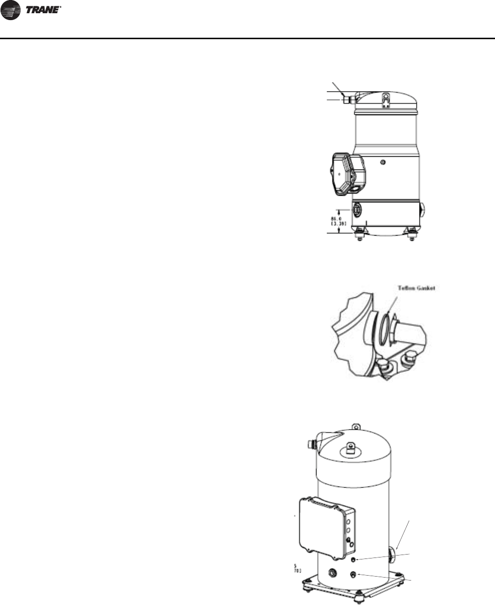
Maintenance
98 SS-SVX11H-EN
Important: Do not spill compressor oil. Refrigerant oil
is detrimental to some roofing materials.
Care must be taken to protect the roof from
oil leaks or spills.
Important: Do not release refrigerant to the
atmosphere! If adding or removing
refrigerant is required, the service
technician must comply with all federal,
state, and local laws.
Compressor Start-up
Discoloration of the oil indicates that an abnormal
condition has occurred. If the oil is dark and smells burnt,
it has overheated because of: compressor operating at
extremely high condensing temperatures; high superheat;
a compressor mechanical failure; or, occurrence of a motor
burnout.
If a motor burnout is suspected, use an acid test kit
(KIT15496) to check the condition of the oil. Test results will
indicate an acid level has exceeded the limit if a burnout
occurred. Oil test kits must be used for POE oil (OIL00079
for a quart container or OIL00080 for a gallon container) to
determine whether the oil is acidic. If a motor burnout has
occurred, change the oil in all compressors in a tandem or
trio set.
CSHD Compressors (20-60T)
For CSHD compressors this will require that the oil be
removed using a suction or pump device through the oil
equalizer Rotolock fitting, see Figure 77. Use a dedicated
device for removing oil. It is good practice to flush the
suction device with clean oil prior to use. Place a catch pan
under the oil equalizer Rotolock connection fitting on the
compressor to catch the oil that will come out of the
compressor when the oil equalizer tube is removed from
the compressor.
Prior to reinstalling the oil equalizer line to each
compressor, replace the Teflon gasket on the oil equalizer
Rotolock fitting on each compressor. See Figure 78. Torque
Rotolock nut to the values listed in Table 30, p. 99
Charge the new oil into the Schrader valve on the shell of
the compressor. Due to the moisture absorption
properties of POE oil, do not use POE oil from a previously
opened container. Also discard any excess oil from the
container that is not used.
CSHN Compressors (80-120T)
CSHN compressors have an oil drain valve, See Figure 79,
which allows the oil to be drained out of the compressor.
After the refrigerant has been recovered, pressurize the
system with nitrogen to help remove the oil from the
compressor. .
Charge the new oil into the Schrader valve or oil drain
valve on the shell of the compressor. Due to the moisture
absorption properties of POE oil, do not use POE oil from
a previously opened container. Also discard any excess oil
from the container that is not used.
Figure 77. CSHD
Figure 78. Teflon gasket
Figure 79. CSHN
Oil equalizer Rotolock
connection tting
¼ Schrader port
Oil drain valve
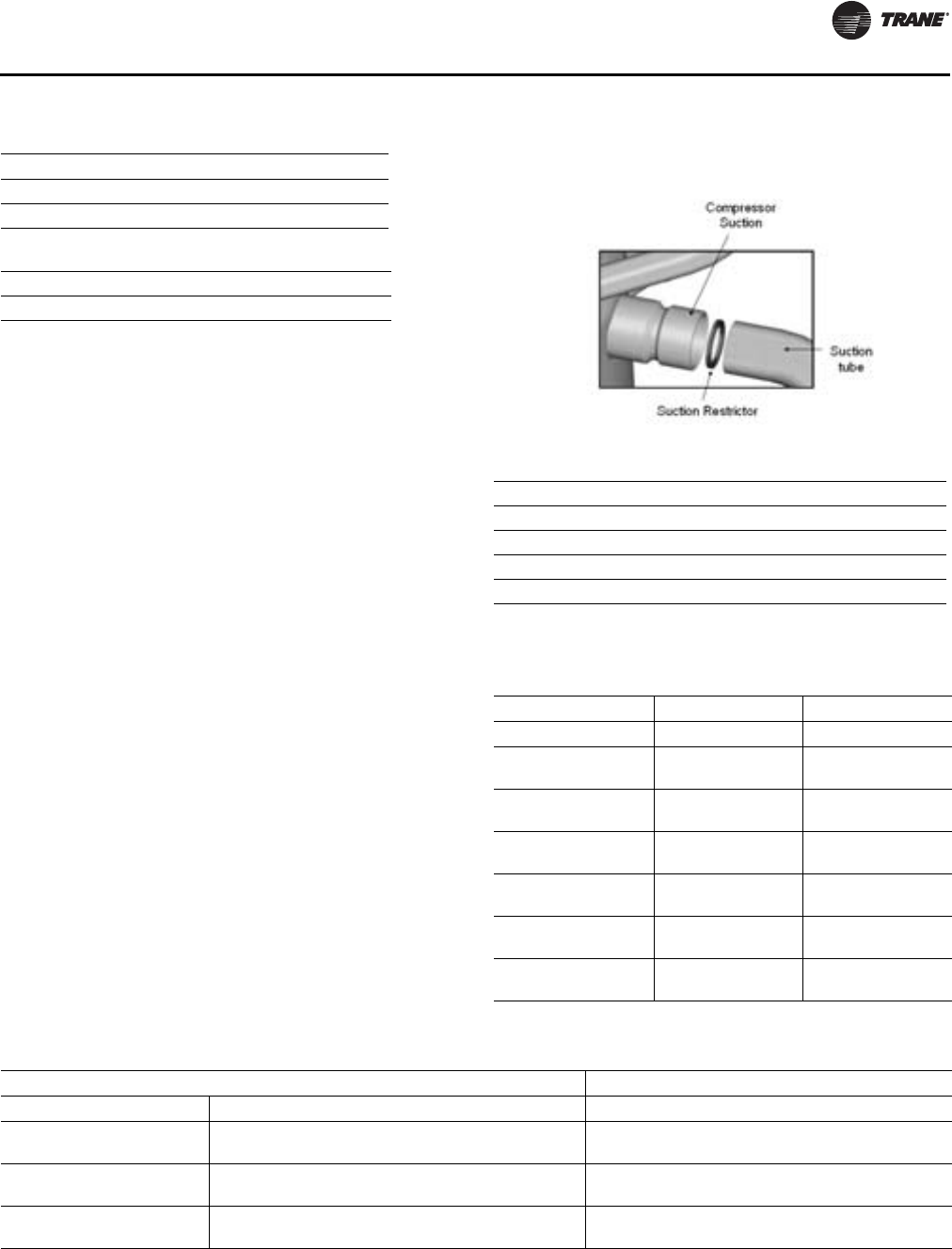
Maintenance
SS-SVX11H-EN 99
Note: Always replace gasket when reassembling oil
equalizer lines.
Electrical Phasing: It is very important to review and
follow the Electrical Phasing procedure described in the
startup procedure of this IOM.
If the compressors are allowed to run backward for even a
very short period of time, internal compressor damage
could occur and compressor life could be reduced.
If a scroll compressor is rotating backwards, it will not
pump, make a loud rattling sound, low side shell gets hot,
and draw ½ expected amps. Immediately shut off the unit.
Ensure that unit phasing is correct. If the incorrect phasing
is determined to be at one compressor, interchange any
two compressor leads to correct the motor phasing.
Precision Suction Restrictor: RAUJ tandems with
unequal compressors and all RAUJ trios use precision
suction restrictors to balance the oil levels in the
compressors. For manifolded compressors in RA units,
this restrictor is placed in the compressor indicated in
Table 31, p. 99. When replacing this compressor, it is
imperative that the proper restrictor is selected from those
provided with the replacement compressor.
When the compressors are restarted verify that correct oil
levels are obtained when all compressors are running in a
manifold set.
Table 29. Oil charge per compressor
Compressor Pints
CSHD 110 thru 183 7.0
CSHN 176 thru 250 14.2
Table 30. Torque requirements for rotolock fittings
CSHD* 64 +/- 12 ft-lbs
CSHN* 100 +/- 10 ft-lbs
Figure 80. Precision suction restrictor
Table 31. Suction restrictor location
25 Ton 1A CSHD125
50 Ton 1A, 2A CSHD142
80 Ton 1C, 2C CSHN176
100 Ton 1A, 1B, 2A, 2B CSHN184
120 Ton 1C, 2C CSHN250
Table 32. 20-60 Ton unit compressor circuit breakers
(200-230 volts)
1A/ 2A 1B / 2B 1A/ 2A 1B / 2B
Unit Voltage Must Hold Must Trip
20 Ton 200
230
50.4
43.2
50.4
43.2
58
49.7
58
49.7
25 Ton 200
230
50.4
43.2
63.1
57.1
58
49.7
72.5
65.7
30 Ton 200
230
69.3
59.4
69.3
59.4
79.7
68.3
79.7
68.3
40 Ton 200
230
50.4
43.2
50.4
43.2
58
49.7
58
49.7
50 Ton 200
230
57.1
51.4
63.1
57.1
65.7
59.2
72.5
65.7
60 Ton 200
230
69.3
59.4
69.3
59.4
79.7
68.3
79.7
68.3
Table 33. 80-120 Ton unit compressor circuit breakers (200-230 volts)
1A / 2A 1B / 2B 1C / 2C 1A / 2A 1B / 2B 1C / 2C
Unit Voltage Must Hold Must Trip
80 Ton 200
230
73.7
63.1
73.7
63.1
73.7
63.1
84.7
72.5
84.7
72.5
84.7
72.5
100 Ton 200
230
73.7
63.1
73.7
63.1
105.2
90.7
84.7
72.5
84.7
72.5
121
104.3
120 Ton 200
230
105
90.7
105.2
90.7
105.2
90.7
121
104.3
121
104.3
121
104.3
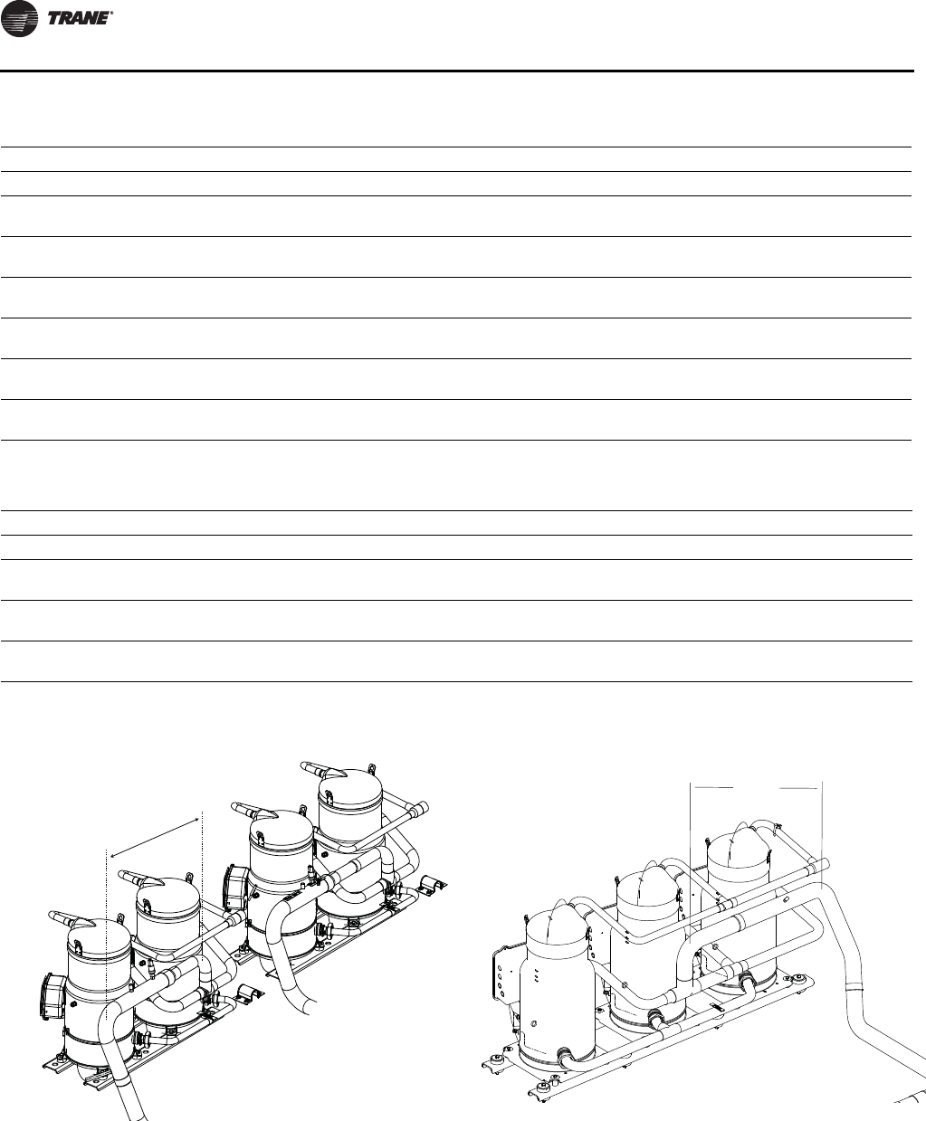
Maintenance
100 SS-SVX11H-EN
Table 34. 20-60 Ton unit compressor circuit breakers (460-575 volts)
1A/ 2A 1B / 2B
Unit Voltage Dial Setting
20 Ton 460
575
20.8
17.7
20.8
17.7
25 Ton 460
575
20.8
17.7
24.9
21.4
30 Ton 460
575
28.5
25.9
28.5
25.9
40 Ton 460
575
20.8
17.7
20.8
17.7
50 Ton 460
575
22.6
19.1
24.9
21.4
60 Ton 460
575
28.5
25.9
28.5
25.9
Table 35. 80-120 Ton unit compressor circuit breakers (460-575 volts)
1A / 2A 1B / 2B 1C / 2C
Unit Voltage Dial Setting
80 Ton 460
575
28.4
22.7
28.4
22.7
28.4
22.7
100 Ton 460
575
28.4
22.7
28.4
22.7
41.6
33.3
120 Ton 460
575
41.6
33.3
41.6
33.3
41.6
33.3
Figure 81. Suction line filter installation: 20-60 Ton units
16 “ min
Minimum 16" for CSHD straight
unobstructed piping between the
Suction Filter/Drier and the Tee
Figure 82. Suction line filter installation: 80-120 Ton units
25” min
Minimum 25” for CSHN straight
unobstructed piping between the
Suction Filter/Drier and the Tee
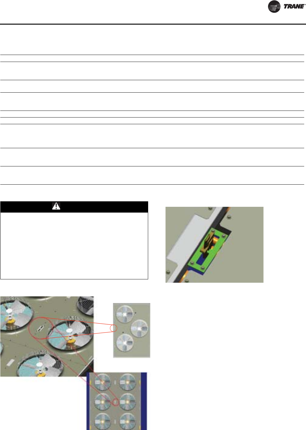
Maintenance
SS-SVX11H-EN 101
Fuse Replacement Data
Fall Restraint - Condenser Section Roof
This unit is built with fall restraint slots located on unit top
that must be used during servicing. See Figure 83 and
Figure 84.
Table 36. Fuse replacement selection
Fuse Description Unit Size Unit Voltage Fuse Type Fuse Size
Condenser Fan Fuse
(1F1-1F3 on 20 - 30 Ton)
(1F1-1F6 on 40 - 60 Ton)
20-60 Ton
200/230
460/575
380/415
Class RK5 25 Amp
15 Amp
Control CKT Fuse 1F7 20 - 30
40 - 60 All Class CC FNQ
R
3.2
6.25
Compressor Protector Fuse
1F8 20 - 60
1F9 40 - 60
20 -60 Ton All ABC - 6 6 Amp
Control Circuit Fuse 1F1 80 - 120 All Class CC FNQ-R 10 Amp
Compressor Protector Fuse 1F2 - 1F3 80 - 120 All ABC - 6 6 AMP
Condenser Fan Fuse
1F4-1F9 80
200 V
230 V
460 V
575 V
Class RK5
30 Amp
25 Amp
20 Amp
15 Amp
Condenser Fan Fuse
1F4-1F9 100 - 120
200 / 230 V
460 V
575 V
Class RK5
35 Amp
25 Amp
20 Amp
Transformer Fuse
1F12 - 1F13 All
200 V
230 V
460 V
FNQ-R
6 Amp
5 Amp
4 Amp
WARNING
Falling Off Equipment!
This unit is built with fall restraint slots located on unit
top that MUST be used during servicing. These slots are
to be used with fall restraint equipment that will not
allow an individual to reach the unit edge. However
such equipment will NOT prevent falling to the ground,
for they are NOT designed to withstand the force of a
falling individual. Failure to use fall restraint slots and
equipment could result in individual falling off the unit
which could result in death or serious injury.
Figure 83. Fall restraint slot location
20-30 Ton Sizes
40-120 Ton Sizes
Figure 84. Fall restraint slot location (inset)
Maintenance
102 SS-SVX11H-EN
Monthly Maintenance
Air Handling Equipment
Before completing the following checks, turn the system
control circuit switch 1S2 and 5S1 to the "Off" position.
Open the main power disconnect switch for the
Condensing Unit and Air Handling Unit and "lock it" in the
"Off" position before removing any access panels.
• Inspect the return air filters. Clean or replace them if
necessary.
• Check the evaporator drain pan and condensate piping
to ensure that there are no blockages.
• Inspect the evaporator coils for dirt. If the coils appear
dirty, clean them according to the instructions
described in the “Coil Cleaning” section.
• Inspect the economizer damper hinges and pins (if
applicable) to ensure that all moving parts are securely
mounted. Clean the blades as necessary.
• Verify that all damper linkages move freely; lubricate
with white grease, if necessary.
• Check Supply Fan motor bearings; repair or replace the
motor as necessary.
• Check the fan shaft bearings for wear. Replace the
bearings as necessary.
• Lubricate supply fan bearings. Contact equipment
manufacturer for recommended greases.
Important: Use a hand grease gun to lubricate
bearings. Add grease until a light bead
appears all around the seal.
Note: After greasing the bearings, check the setscrews to
ensure that the shaft is held securely to the
bearings and fan wheels. Make sure that all bearing
supports are tight.
• Check the supply fan belt(s). If the belts are frayed or
worn, replace them.
• Verify that all wire terminal connections are tight.
• Inspect unit for unusual conditions (e.g., loose access
panels, leaking piping connections, etc.)
• When checks are complete, verify all retaining screws
are reinstalled in unit access panels.
Condensing Unit
• Manually rotate the condenser fans to ensure free
movement and check motor bearings for wear. Verify
that all of the fan mounting hardware is tight.
• Verify that all wire terminal connections are tight.
• Inspect the condenser coils for dirt and foreign debris.
If the coils appear dirty, clean them according to the
instructions described in the “Coil Cleaning” section.
• Inspect the compressor and condenser fan motor
contactors. If the contacts appear severely burned or
pitted, replace the contactor. Do not clean the contacts.
• Check the compressor oil level. (Compressors "Off")
Coil Cleaning
Regular coil maintenance, including annual cleaning,
enhances unit’s operating efficiency by minimizing:
•compressor head pressure and amperage draw;
•water carryover;
•fan brake horsepower; and,
•static pressure losses.
At least once each year—or more often if the unit is located
in a “dirty” environment—clean the microchannel
condenser using the instructions outlined below. Be sure
to follow these instructions as closely as possible to avoid
damaging the coils.
To clean refrigerant coils, use a soft brush and a sprayer.
Note: DO NOT use any detergents with microchannel
condenser coils. Pressurized water or air ONLY.
WARNING
Hazardous Voltage!
Disconnect all electric power, including remote
disconnects before servicing. Follow proper lockout/
tagout procedures to ensure the power cannot be
inadvertently energized. Failure to disconnect power
before servicing could result in death or serious injury.
NOTICE:
Bearing Damage!
To prevent damage to fan bearings, do not over
lubricate. Over lubrication can be just as harmful as not
enough grease.
WARNING
Rotating Components!
The following procedure involves working with rotating
components. Disconnect all electric power, including
remote disconnects before servicing. Follow proper
lockout/tagout procedures to ensure the power cannot
be inadvertently energized. Failure to disconnect power
before servicing could result in rotating components
cutting and slashing technician which could result in
death or serious injury.
NOTICE:
Coil Cleaners!
Coil cleaners can damage roofs, surrounding buildings,
vehicles, etc. Cleaning substances should be checked to
ensure that they will not cause damage to
surroundings. Coils and roof (if applicable) should be
rinsed thoroughly. Do not spray coil cleaners in windy
conditions.
Maintenance
SS-SVX11H-EN 103
1. Remove enough panels from the unit to gain safe
access to coils..
Important: Bridging between the main supports
required before attempting to enter into the
unit. Bridging may consist of multiple 2 by
12 boards or sheet metal grating.
2. Straighten any bent coil fins with a fin comb.
3. For accessible areas, remove loose dirt and debris
from both sides of the coil. For dual row microchannel
condenser coil applications, seek pressure coil wand
extension through the local Trane Parts Center..
Note: DO NOT use any detergents with microchannel
coils. Pressurized water or air ONLY.
4. Pour the cleaning solution into the sprayer. If a high-
pressure sprayer is used:
a. The minimum nozzle spray angle is 15 degrees.
b. Do not allow sprayer pressure to exceed 600 psi.
c. Spray the solution perpendicular (at 90 degrees) to
the coil face.
5. Spray the leaving-airflow side of the coil first; then
spray the opposite side of the coil. For evaporator and
reheat coils, allow the cleaning solution to stand on the
coil for five minutes.
6. Rinse both sides of the coil with cool, clean water.
7. Inspect both sides of the coil; if it still appears to be
dirty, repeat Steps 6 and 7.
8. Reinstall all of the components and panels removed in
Step 1; then restore power to the unit.
9. For evaporator and reheat coils, use a fin comb to
straighten any coil fins which were inadvertently bent
during the cleaning process.
Microchannel Condenser Coil Repair and
Replacement
If microchannel condenser coil repair or replacement is
required, seek HVAC Knowledge Center information or
Service Guide document RT-SVB83*-EN for further details.
EVP Remote Evaporator Chiller
The brazed plate evaporator is difficult to clean should it
become plugged with debris so proper installation and
maintenance of the inlet water strainer is important.
Particles larger than 0.039” entering the heat exchanger
could block flow passages causing a failure. Indications of
a plugged BPHE evaporator include “wet” suction due to
lack of heat exchange, loss of superheat control,
depressed discharge superheat (superheat less than 63°F),
compressor oil dilution and/or starvation and premature
compressor failure.
Minimum water flow rate must be maintained to avoid
laminar flow, potential evaporator freezing, scaling and
poor temperature control.
Maximum water flow rate must not be exceeded to avoid
possible erosion.
Water Strainer Maintenance
To protect the evaporator and for maximum efficiency, the
strainer must be cleaned. A differential pressure gauge
installed across the inlet and outlet will indicate pressure
loss due to clogging and may be used as a guide to
determine when cleaning is required. Normally when
differential pressure reaches 5-10psi, the screen must be
cleaned. To clean, open and flush out until any sediment is
removed.
EVP Evaporator Replacement
If the evaporator requires replacement, it is very important
that the new evaporator be replaced correctly and with the
correct refrigerant and water piping connections. The
refrigerant inlet/liquid connection is at the bottom of the
evaporator and the refrigerant outlet/suction connection is
at the top of the evaporator and both are on the same side.
Pay particular attention to evaporators with dual circuits.
Avoid cross-circuiting when installing the new evaporator.
Proper brazing techniques for dissimilar materials must be
followed, see “Brazing Procedures” section.
Water Loop
If the water loop is drained for an extended period, pipe
sections between the strainer and the heat exchanger
should be cleaned or replaced, to prevent rust buildup
from entering the chiller.
WARNING
No Step Surface!
Do not walk on the sheet metal drain pan. Walking on
the drain pan could cause the supporting metal to
collapse, resulting in the operator/technician to fall.
Failure to follow this recommendation could result in
death or serious injury.
NOTICE:
Heat Exchanger Damage!
Do not stop water flow with the refrigeration system
running. Freezing and heat exchanger damage could
occur.

104 SS-SVX11H-EN
Warranty and Liability Clause
COMMERCIAL EQUIPMENT RATED 20 TONS AND LARGER AND RELATED ACCESSORIES
PRODUCTS COVERED
This warranty* is extended by Trane Inc. and applies only to commercial equipment rated 20 Tons and larger and related
accessories.
The Company warrants for a period of 12 months from initial start-up or 18 months from date of shipment, whichever is
less, that the Company products covered by this order (1) are free from defects in material and workmanship and (2) have
the capacities and ratings set forth in the Company’s catalogs and bulletins, provided that no warranty is made against
corrosion, erosion or deterioration. The Company’s obligations and liabilities under this warranty are limited to furnishing
f.o.b. factory or warehouse at Company designated shipping point, freight allowed to Buyer’s city (or port of export for
shipment outside the conterminous United States) replacement equipment (or at the option of the Company parts
therefore) for all Company products not conforming to this warranty and which have been returned to the manufacturer.
The Company shall not be obligated to pay for the cost of lost refrigerant. No liability whatever shall attach to the Company
until said products have been paid for and then said liability shall be limited to the purchase price of the equipment shown
to be defective.
The Company makes certain further warranty protection available on an optional extra-cost basis. Any further warranty
must be in writing, signed by an officer of the Company.
The warranty and liability set forth herein are in lieu of all other warranties and liabilities, whether in contract or in
negligence, express or implied, in law or in fact, including implied warranties of merchantability and fitness for particular
use. In no event shall the Company be liable for any incidental or consequential damages.
THE WARRANTY AND LIABILITY SET FORTH HEREIN ARE IN LIEU OF ALL OTHER WARRANTIES AND LIABILITIES,
WHETHER IN CONTRACT OR IN NEGLIGENCE, EXPRESS OR IMPLIED, IN LAW OR IN FACT, INCLUDING IMPLIED
WARRANTIES OF MERCHANTABILITY AND FITNESS FOR PARTICULAR USE, IN NO EVENT SHALL WARRANTOR BE
LIABLE FOR ANY INCIDENTAL OR CONSEQUENTIAL DAMAGES.
Manager - Product Service
Trane In c.
Clarksville, Tn 37040-1008
PW-215-2688
*Optional Extended Warranties are available for compressors and heat exchangers of Combination Gas-Electric Air
Conditioning Units.
SS-SVX11H-EN 105
Wiring Diagrams
Note: Published unit wiring diagrams (individual, separate diagrams for unitary product lines) are available via e-Library.
Drawing
Number Description
2307-4483 Unit Connection Wiring Split - System Condensing Unit Air Cooled RAUJ 20-60 Ton units
2307-4495 Connection-Adder Plates Split System Condensing Unit RAUJ 80-120 Ton units
2307-9116 Power Schematic - Split System Condensing Unit RAUJ 20-60 Ton units
2307-9208 Schematic w/No System Controls - Split System Condensing Unit RAUJ 20-60 Ton units
2307-9209 Schematic w/Constant Volume Controls - Split System Condensing Unit RAUJ 20-60 Ton units
2307-9210 Schematic w/Variable Air Volume Controls - Split System Condensing Unit RAUJ 20-60 Ton units
2307-9211 Schematic w/EVP Controls - Split System condensing Unit RAUJ 20-60 Ton units
2307-9212 Connection - Main Control Box & Raceway Devices - Split System Condensing Unit RAUJ 20-60 Ton units
2307-9122 Field Connection Diagram - Split System Condensing Unit RAUJ 20-60 Ton units
2307-9218 Power Schematic - Split System Condensing Unit RAUJ 80-120 Ton units
2307-9214 Schematic - Air Cooled Diagram - Split System Condensing Unit RAUJ 80-120 Ton units w/No Controls
2307-9215 Schematic - Air Cooled Diagram - Split System Condensing Unit RAUJ 80-120 Ton units w/Variable Air Volume Controls
2307-9216 Schematic - Air Cooled Diagram - Split System Condensing Unit RAUJ 80-120 Ton units w/EVP Controls
2307-9217 Connection - Air Cooled Control Box Diagram - Split System Condensing Unit RAUJ 80-120 Ton units
2307-9144 Field Connection Air Cooled Diagram - Split System Condensing Unit RAUJ 80-120 Ton units
2307-9219 Connection Raceway Diagram - Split System Condensing Unit RAUJ 80-120 Ton units
2307-3900 Connection - Low Ambient Damper Option 20-120 Ton units
Trane optimizes the performance of homes and buildings around the world. A business of Ingersoll Rand, the
leader in creating and sustaining safe, comfortable and energy efficient environments, Trane offers a broad
portfolio of advanced controls and HVAC systems, comprehensive building services, and parts. For more
information, visit www.Trane.com.
Trane has a policy of continuous product and product data improvement and reserves the right to change design and specifications without notice.
We are committed to using environmentally
conscious print practices that reduce waste.
© 2012 Trane All rights reserved
SS-SVX11H-EN 30 Oct 2012
Supersedes SS-SVX11G-EN (05 Mar 2012)
