Trane Round In Out Catalogue VAV PRC012 EN (072013)
Trane-Fan-Powered-Low-Height-Series-Catalogue-684365 trane-fan-powered-low-height-series-catalogue-684365
Trane-Fan-Powered-Series-Terminal-Catalogue-684343 trane-fan-powered-series-terminal-catalogue-684343
Trane-Fan-Powered-Parallel-Terminal-Catalogue-684354 trane-fan-powered-parallel-terminal-catalogue-684354
Trane-Fan-Powered-Low-Height-Parallel-Catalogue-684376 trane-fan-powered-low-height-parallel-catalogue-684376
2015-04-02
: Trane Trane-Round-In-Round-Out-Catalogue-684311 trane-round-in-round-out-catalogue-684311 trane pdf
Open the PDF directly: View PDF ![]() .
.
Page Count: 234 [warning: Documents this large are best viewed by clicking the View PDF Link!]
- Features and Benefits
- Agency Certifications
- Model Number Descriptions
- Selection Procedure
- Performance Data
- Electrical Data
- Acoustics Data
- Dimensional Data
- Mechanical Specifications: Fan-Powered
- DDC Controls
- Control Logic
- DDC Remote Heat Control Options
- Tracer™ UC400 and UC210 Programmable BACnet Controllers
- Trane DDC VAV Controller Logic
- Flow Tracking Control
- Tracer™ Programmable BACnet Controller — Unit Control Module
- Trane LonMark DDC VAV Controller
- Trane DDC VAV Controller Logic
- Flow Tracking Control
- LonMark™ Direct Digital Controller—Unit Control Module
- Direct Digital Controller—Unit Control Module
- Wireless Comm Interface (WCI)
- Wireless Receiver/Wireless Zone Sensor
- DDC Zone Sensor
- CO2 Wall Sensor and Duct CO2 Sensor
- DDC Zone Sensor with LCD
- Zone Occupancy Sensor
- Factory or Field Wired Auxiliary Temperature Sensor
- Control Relay
- Two-Position Water Valve
- Proportional Water Valve
- Differential Pressure Transducer
- Transformers
- Trane Actuator – 90 Second at 60 Hz Drive Time
- Belimo Actuator – 95 Second Drive Time
- Trane Spring Return Actuator
- VariTrane DDC Retrofit Kit
- Retrofit Kit Actuator
- Silicon-Controlled Rectifier (SCR)
- Pneumatic Controls
- Controls Specifications
- Application Considerations
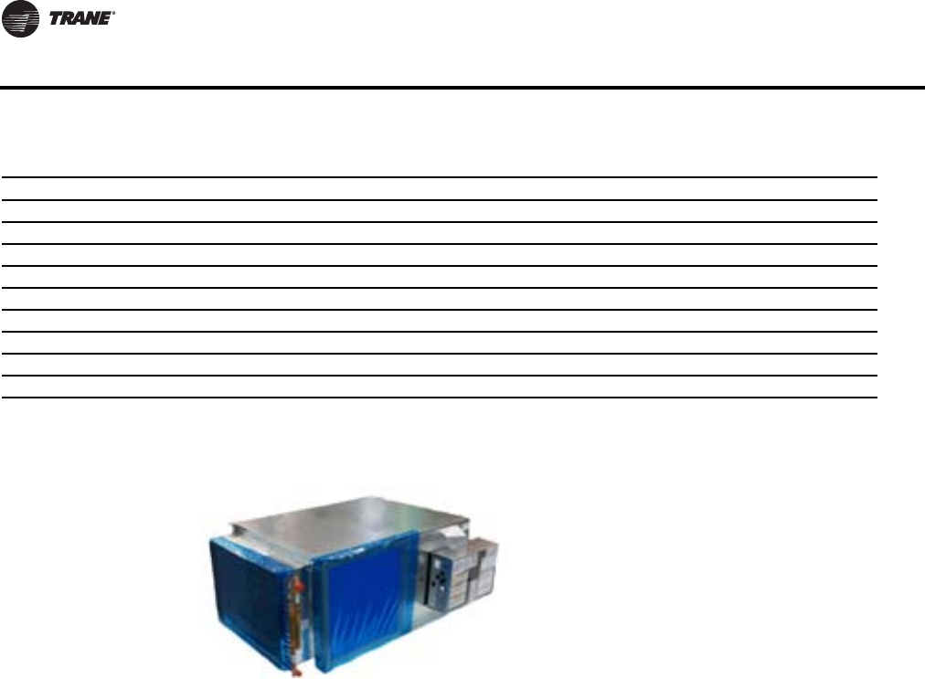
VariTrane™ Products
Parallel and Series Fan-Powered
VPCF, VPWF, VPEF, VSCF, VSWF, VSEF,
LPCF, LPWF, LPEF, LSCF, LSWF, LSEF
July 2013 VAV-PRC012-EN
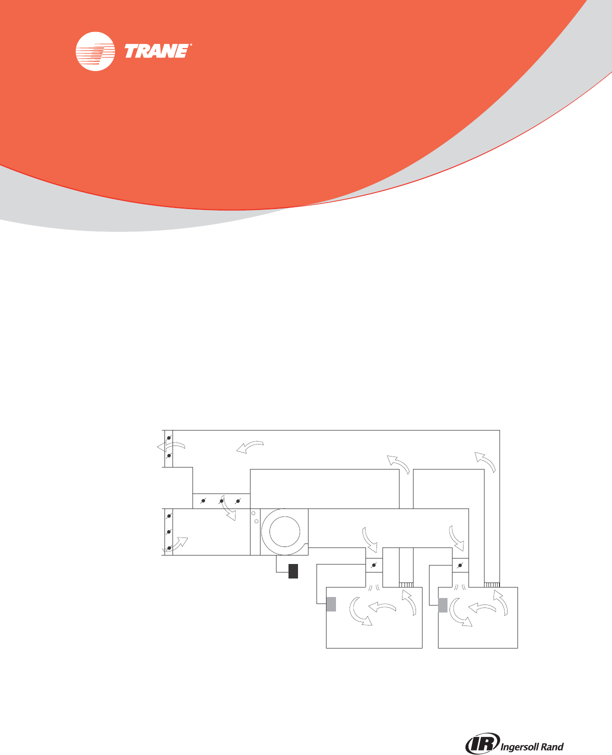
Variable-Air-Volume (VAV) System
RA
EA
OA PA
supply
fan
cooling
coil
variable-
speed drive
thermostat
VAV
box
SA
Product Catalog
© 2013Trane All rights reserved VAV-PRC012-EN
Introduction
Fan-powered units offer energy savings due to intermittent fan control.The fan energizes only in
heating mode when the space needs heat. Additional energy savings are obtained by using warm
plenum air for free reheat. Motor heat is never wasted in parallel units.They are an excellent choice
when minimal zone heating is needed.
Revision Summary
VAV-PRC012-EN (16 Jul 2013). Updated proportional water valve design.
VAV-PRC012-EN (27 June 2013). Updated controls information. Updated dimensions for units
with attenuators.
Trademarks
Earthwise, VariTrane, VariTrac,Trane and theTrane logo are trademarks ofTrane in the United
States and other countries. All trademarks referenced in this document are the trademarks of their
respective owners.
BACnet is a registered trademark of American Society of Heating, Refrigerating and Air-
Conditioning Engineers (ASHRAE); LONMARK and LonTalk are registered trademarks of Echelon
Corporation.
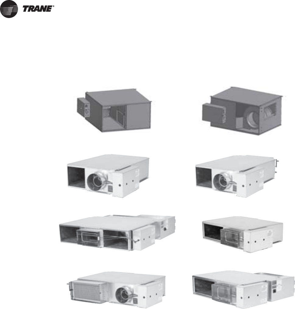
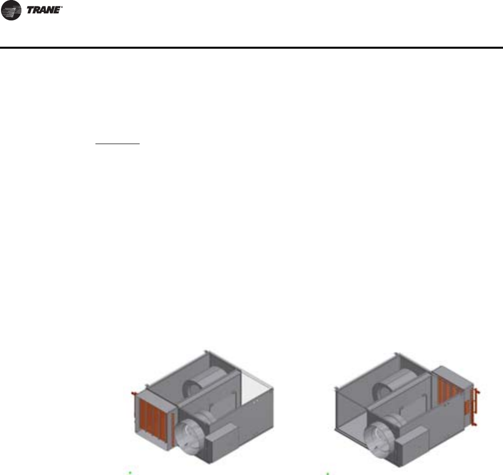
Figure 1. Parallel fan-powered terminal unit (L) & series fan-powered terminal units (R)
Figure 2. Low height series: LSCF (L) & low height series: LSWF (R)
Figure 3. Low height series: LSEF (L) & low height parallel: LPCF (R)
Figure 4. Low height parallel: LPWF (L) & low height parallel: LPEF (R)

Table of Contents
VAV-PRC012-EN 3
Features and Benefits ..............................................5
Agency Certifications ..............................................13
Model Number Descriptions ........................................15
Selection Procedure ...............................................17
Performance Data ................................................24
Parallel Fan-Powered Terminal Units .............................. 24
Series Fan-Powered Terminal Units ............................... 35
Low Height Parallel Fan-Powered Terminal Units .................... 47
Low Height Series Fan-Powered Terminal Units ..................... 53
Electrical Data ....................................................59
Parallel Fan-Powered Terminal Units .............................. 59
Series Fan-Powered Terminal Units ............................... 63
Low Height Parallel Fan-Powered Terminal Units .................... 68
Low Height Series Fan-Powered Terminal Units ..................... 70
Acoustics Data ...................................................76
Parallel Fan-Powered Terminal Units .............................. 76
Series Fan-Powered Terminal Units ............................... 85
Low Height Parallel Fan-Powered Terminal Units .................... 92
Low Height Series Fan-Powered Terminal Units ..................... 98
Dimensional Data ................................................103
Parallel Fan-Powered Terminal Units ............................. 103
Series Fan-Powered Terminal Units .............................. 109
Low Height Parallel Fan-Powered Terminal Units ................... 123
Low Height Series Fan-Powered Terminal Units .................... 134
Mechanical Specifications: Fan-Powered ............................142
DDC Controls ...................................................147
Control Logic ................................................. 147
DDC Remote Heat Control Options ............................... 148
Tracer™ UC400 and UC210 Programmable BACnet Controllers ....... 152
Trane DDC VAV Controller Logic ................................. 154
Flow Tracking Control .......................................... 157
Tracer™ Programmable BACnet Controller — Unit Control Module .... 158
Trane LonMark DDC VAV Controller .............................. 160
Trane DDC VAV Controller Logic ................................. 162

4 VAV-PRC012-EN
Flow Tracking Control .......................................... 165
LonMark™ Direct Digital Controller—Unit Control Module ........... 166
Direct Digital Controller—Unit Control Module ..................... 169
Wireless Comm Interface (WCI) .................................. 170
Wireless Receiver/Wireless Zone Sensor .......................... 172
DDC Zone Sensor ............................................. 173
CO2Wall Sensor and Duct CO2Sensor ............................ 174
DDC Zone Sensor with LCD ..................................... 176
Zone Occupancy Sensor ........................................ 177
Factory or Field Wired Auxiliary Temperature Sensor ............... 178
Control Relay ................................................. 178
Two-Position Water Valve ...................................... 179
Proportional Water Valve ....................................... 180
Differential Pressure Transducer ................................. 181
Transformers ................................................. 182
Trane Actuator – 90 Second at 60 Hz Drive Time .................... 183
Belimo Actuator – 95 Second Drive Time .......................... 184
Trane Spring Return Actuator ................................... 185
VariTrane DDC Retrofit Kit ...................................... 186
Retrofit Kit Actuator ........................................... 186
Silicon-Controlled Rectifier (SCR) ................................ 187
Pneumatic Controls ............................................ 188
Controls Specifications ......................................... 203
Application Considerations ........................................208
VAV System .................................................. 208
Parallel vs. Series ............................................. 211
Low-Temperature Air .......................................... 213
Energy Savings & System Controls ............................... 216
Control Types ................................................ 218
Flow Measurement and Control ................................. 221
Reheat Options ............................................... 224
Insulation .................................................... 226
Acoustics .................................................... 226
Duct Design .................................................. 230
Best Practices ................................................. 231
Unit Conversions .............................................. 232
Additional VAV System and Product References .................... 233
VAV-PRC012-EN 5
Features and Benefits
VariTrane™– VAV Leadership
VariTrane variable-air-volume (VAV) units lead the industry in quality and reliability and are
designed to meet the specific needs of today’s applications.This generation of VariTrane units
builds upon the history of quality and reliability and expands the products into the most complete
VAV offering in the industry.
Parallel Fan-powered units offer energy savings due to intermittent fan control.The fan
energizes only in heating mode when the space needs heat.Additional energy savings are obtained
by using warm plenum air for free reheat. Motor heat is never wasted in parallel units.They are
an excellent choice when minimal zone heating is needed.
Series fan-powered units have fans which are always energized in occupied mode.They are
common in applications such as conference rooms, cafeterias, etc., that desire constant airflow
rates at all conditions.
Low-height parallel units provide the energy savings of an intermittent fan with the flexibility
of an 11"–11.5” casing height.This is a good choice for tight plenum spaces.
Low-height series units have been used for years in projects with strict plenum height
requirements. Units
are available in 11.0" height.
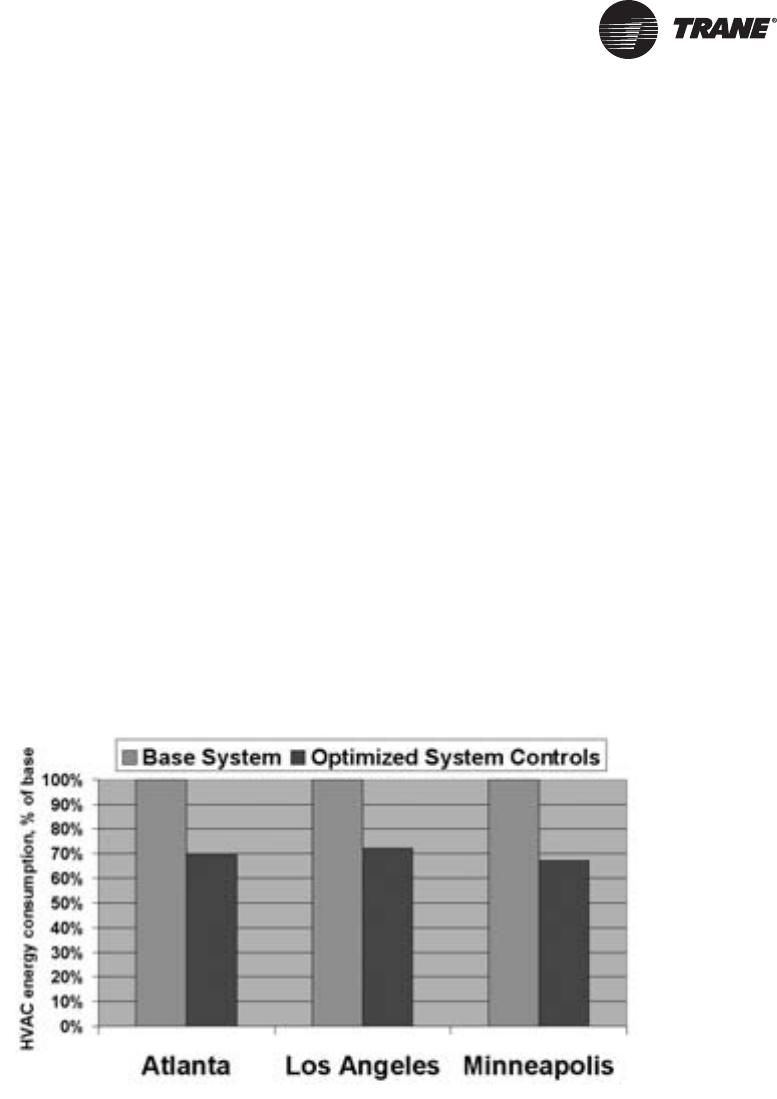
Energy Efficient Earthwise™ Systems
A significant consumer of energy in commercial buildings is heating and air conditioning. One of
the most energy-efficient HVAC solutions is theVAV system.This inherent system efficiency, along
with high-quality, affordable DDC controls, has steadily increased demand for VAV systems over
the years. VAV systems save significant energy, are able to deliver the required amount of
ventilation air, and provide reliable occupant comfort.
Energy saving features must go beyond a simpleVAV unit to incorporateVAV unit level and system
level control strategies like:
• Ventilation Optimization-Combines demand-controlled ventilation (using either a time-of-day
schedule, an occupancy sensor, or a carbon dioxide sensor) at the zone level with ventilation
reset at the system level to deliver the required amount of outdoor air to each zone, while
minimizing costly over-ventilation.
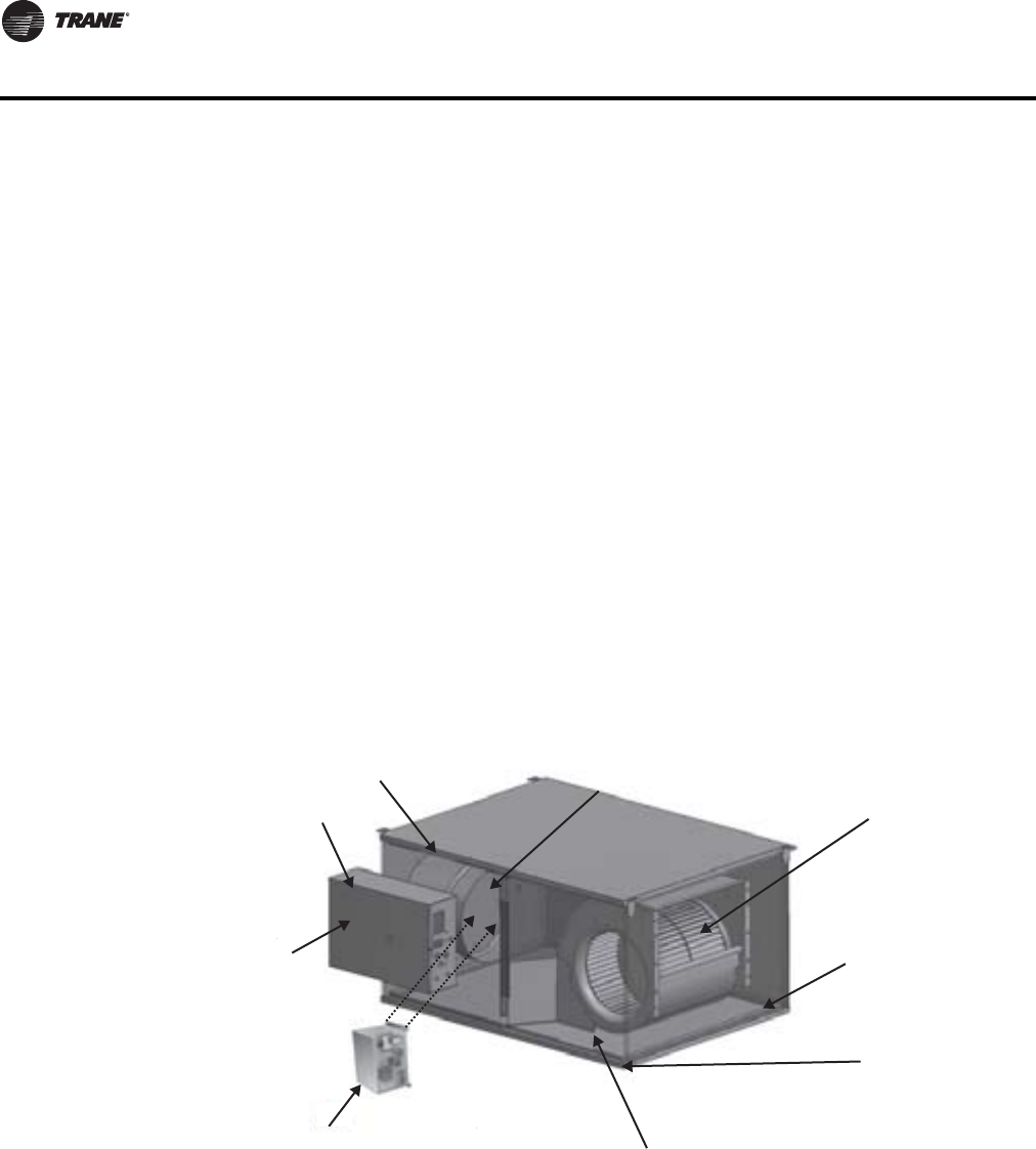
Figure 5. Rooftop VAV (office building)
6 VAV-PRC012-EN
Features and Benefits
• Fan Pressure Optimization- reduces supply fan energy by as much as 40% by intelligently
reducing the pressure in the air distribution system to the lowest possible level without
impacting occupant comfort.
• Night setback reduces energy consumption during unoccupied periods by raising or lowering
space temperature setpoints.
• Supply AirTemperature Reset-reduces overall system energy use (balancing reduced cooling
and reheat energy with increased fan energy) by raising the supply air temperature at part load,
while avoiding elevated space humidity levels.
• Electrically Commutated Motors (ECM) improve the efficiency of fan-powered VAV units.
• LowTemperature Air Distribution can decrease overall system energy use by reducing airflows
and the fan energy needed to move that air through the system.
To determine the potential energy savings a VAV system can bring to your applications,Trane
offers energy-modeling software like System Analyzer™ andTRACE 700®. WhenTRACE™ was
introduced into the HVAC industry in 1972, the HVAC design and analysis program was the first of
its kind and quickly became a defacto industry standard. It continues to grow with the industry
meeting requirements for ASHRAE Standard 140, ASHRAE 90.1, and the LEED® Green Building
Rating System and has now been approved by the IRS to certify energy savings for building
owners. Contact your localTrane Sales Engineer for additional information.
Control Flexibility—Trane
factory installs more VAV
controllers than any other
manufacturer in the
industry. In addition to
Trane DDC controls and
simple factory-mounting
of non-Trane VAV controllers,
Trane now offers a LonMark™
controller that is completely
factory-commissioned to
maximize installation quality
and system reliability. Labor
savings are maximized with
Trane factory-commissioned
controllers.
Accurate Flow Ring—Housed
and recessed within the air
valve to provide flow ring
handling/shipping protection.
The patented flow ring provides
unmatched airflow measurement
accuracy.
Rugged Air Valve—Trane air
valves are heavy gage steel
with a continuously welded
seam to limit inlet deformation.
This provides consistent and
repeatable airflow across
the flow ring with performance you
can count on.
Technologically Advanced "
S
Units— New super-quiet (S
Q
fan/motor/wheel assemblie
s
engineered as an air delive
r
system to provide the most
efficient design available in
industry. For quiet comfort
y
can trust, rely on Trane SQ
u
Tough Interlocking Panels— Ru
g
and rigidity are assured with Tra
patent-pending interlocking pan
Superior Metal Encapsulated
VariTrane Units are complete
encapsulated edges to arrest
fibers and prevent erosion in
Full Range of Insulation—Whether seeking optimal acoustical perf
or cleanability, Trane has a complete line of insulation options, inc
l
double-wall, matte-faced, foil-faced, closed cell, etc.
Optional Narrow Corridor unit
configuration — designed to minimize building
material expenses by squeezing more into less space.
Meets all NEC jumpback clearance requirements
for these extra-tight areas. Narrow Corridor
Configuration not pictured here. Refer to Series
Fan-Powered dimensional data for reference drawings.
Service Friendly:
* Internal shaft visible
through control box
cover sight hole for
blade orientation
verification.
* Same-side NEC jumpback clearance—
provides all high- and low-voltage
components on the same side
to minimize field labor.
* SQ fan-powered units have
improved accessability to
internal components. Sliding
panels are standard which
improve safety and allow
servicing with a single
technician.

VAV-PRC012-EN 7
Features and Benefits
Construction
UL-listed products—
Safety and reliability are vital in commercial construction. AllVariTrane units are completely listed
in accordance with UL -1995 as terminal units.This listing includes the VAV terminal with electric
heaters. Additionally, all insulation materials pass UL 25/50 smoke and flame safety standards.
AHRI Certified Performance—
All VariTrane units are AHRI certified. AHRI 880 guarantees the pressure drop, flow performance,
and acoustical performance provided is reliable and has been tested in accordance with industry
accepted standards. AHRI 885 uses AHRI 880 performance and applies accepted industry methods
to estimate expected “NC” sound levels within the occupied space.
Casing Design—
Interlocking Panels—VariTrane products are manufactured in the most state-of-the-artVAV facility
in the world.The patent-pending interlocking panels are designed using integral I-beam
construction technology.This limits deformation and creates tremendous product rigidity. An
additional benefit is a smooth unit exterior with few exposed screws—ideal for exposed ceiling
applications. VariTrane units are designed for use in systems that operate up to 5" w.c. of inlet
pressure.
Metal Encapsulated Edges—AllVariTrane units are complete
with encapsulated edges to arrest cut fibers and prevent
insulation erosion into the airstream.This is the standard of
care in applications concerned with fiberglass erosion or
projects with either double-wall or externally wrapped duct
work.
TheTrane Air Valve—is at the heart of VariTrane terminal
units.This is where airflow is measured and controlled.
Repeatability and ruggedness is vital.VariTrane products are
the most rugged and reliable available.
18-gage Cylinder—limits deformation or damage during shipment and job site handling, and
provides even airflow distribution across the flow ring for unmatched airflow measurement
accuracy.
Continuously Welded Seam — an automated weld process creates the highest quality continuous
seam, which is “right” every time.The welded seam improves air valve rigidity and creates
consistent and repeatable airflow across the flow measurement device.The result is a truly round
cylinder every time, with no flat spots caused by lower quality crimping and riviting technologies.
Flow Ring—TheTrane flow ring is time tested to perform under the
most demanding conditions. Additionally,Trane’s patented flow ring
is recessed within the air valve cylinder to reduce the potential for
damage during job site handling and installation.
8 VAV-PRC012-EN
Features and Benefits
External Shaft—The simple design provides controller flexibility and is designed to facilitate
actuator field replacement.
Position Indicator—The position indicator shows current air valve position to aid in system
commissioning. Many times this can be seen from the floor without climbing a ladder.
ExternalActuator—This feature increases serviceability, control system compatibility, and actuator
clutch access for simplified commissioning.
Indoor Air Quality (IAQ) Features
The oil embargo of the early 1970s created an energy crisis, which resulted in tighter buildings, and
reduced ventilation rates. A fallout issue of tighter building construction was poor indoor air
quality.This heightened IAQ awareness. IAQ issues have been featured in publications from the
smallest towns to the largest cities. System design should consider applicable ventilation and IAQ
standards.(See your localTrane Sales Engineer or visit www.trane.com for additional information).
Good indoor air quality results from units and systems which:
• Provide the required amount of ventilation air to each zone during all operating conditions
• Limit particulates from entering occupied spaces
• Allow proper access for periodic cleaning.
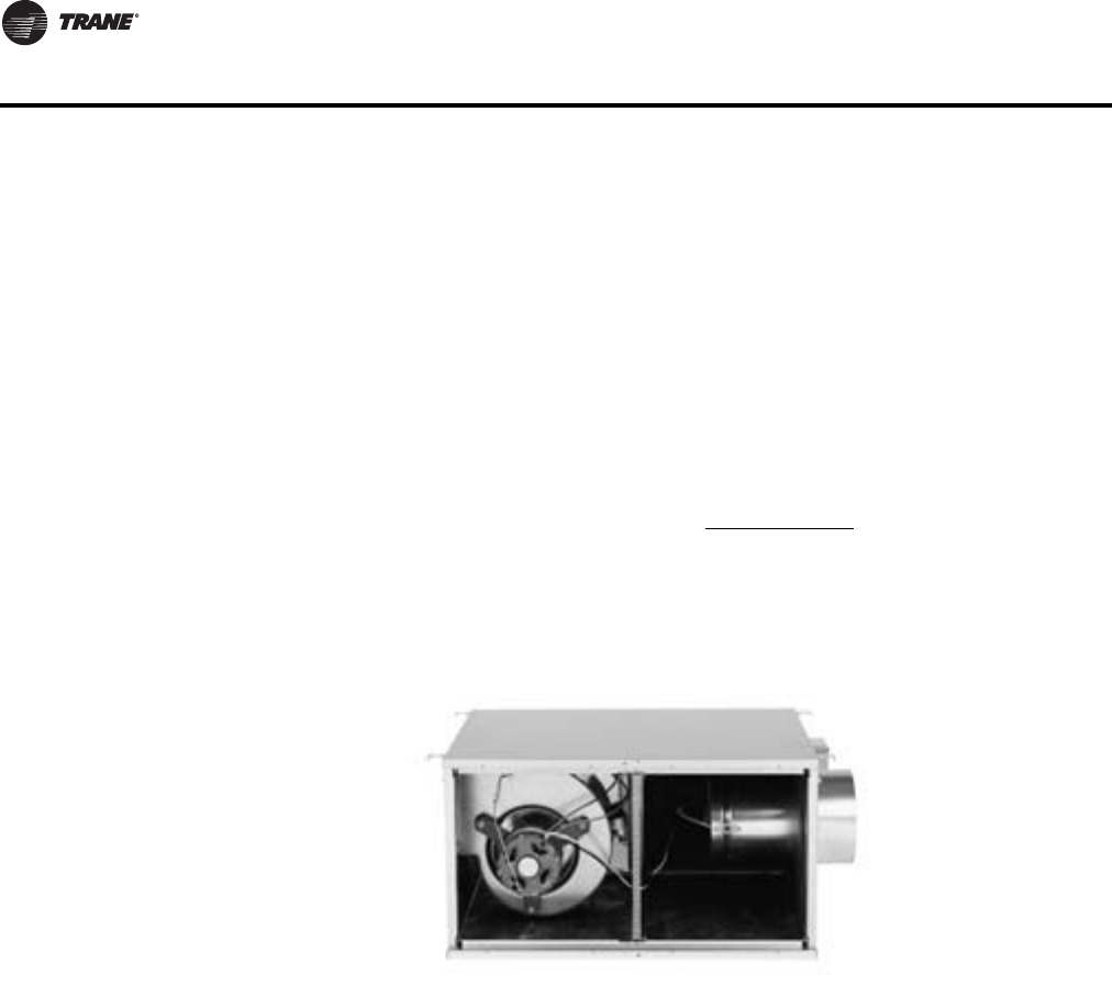
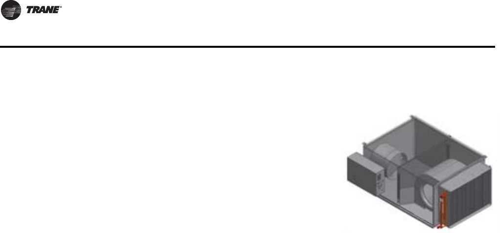
Note: Access made easy on new VariTrane units, as shown on this Series Fan-Powered unit.
VariTrane units are designed with simplified access and a full line of insulation options including:
Matte-faced—Typical industry standard with reduced first cost.
Closed-cell—This insulation has an R-value and performance equivalent to matte-faced insulation.
The main difference is the reduction of water vapor transmission. Closed-cell is designed for use
in installations with a high chance of water formation. (It has been used to coat the exterior of chiller
evaporator barrels for many years.)
Foil-faced—A fiberglass insulation with a thin aluminum coating on the air stream side to prevent
fibers from becoming airborne.The aluminum lining is acceptable for many applications, however
it is not as rugged as double-wall
Double-wall—Premium insulation often used in many health care applications with insulation
locked between metal liners.This eliminates the possibility for insulation entering the airstream
and allows for unit interior wipe-down as needed.
VariTrane VAV units are the most prepared IAQ units in the industry.
The end result is a reliable product designed for peak performance, regardless of job site conditions
or handling.
VAV-PRC012-EN 9
Features and Benefits
Tracer™ Building Automation System
Tracer Building Automation System assures comfort within your building. Building controls have
a bigger job description than they did a few years ago. It’s no longer enough to control heating and
cooling systems and equipment. Sophisticated buildings require smarter technology that will
carry into the future. Tracer™ controls provide the technology platform – mobile, easy-to-use,
cloud-based, scalable and open - for the next generation of data-driven, technology-enabled
services that are creating high performance buildings. With aTraneTracer Building Automation
System, you’ll:
• Reduce operating costs through energy management strategies
• Consistently provide occupant comfort
• Enjoy reliable operation with standard, pre-engineered and pretested applications
• Easily troubleshoot and monitor either on site or from a remote location
• Reduce installation time and simplify troubleshooting
Whether factory-mounted or field-installed,Trane offers a wide range of controllers to suit virtually
any application.These units are compatible with a variety of building types and can be used for new
construction or renovation.Through extensive usability testing internally and with building
operators, we’ve designed our controls for real world ease of use.
(Additional control options and sequence-of-operations are located in the “Controls” section.)
Note: One of many Trane DDC Control Options which are factory-installed, wired, calibrated, and fully tested before shipment.
Trane DDC controllers provideTrane-designed solid-state electronics intended specifically for VAV
temperature control in space comfort applications. DDC control capabilities include:
• Pressure-independent (PI) operation—Provides airflow required by the room thermostat to
maintain occupant comfort.The controller automatically adjusts valve position to maintain
required airflow. Minimum and maximum airflow is factory-set and field-adjustable.
• Factory-set airflow and temperature setpoints
• Most advanced system integration in the industry.
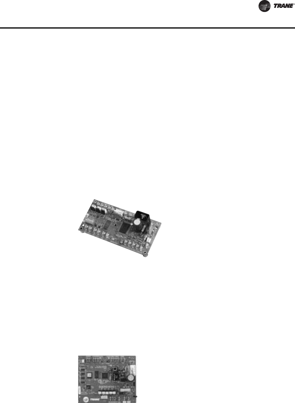
Tracer VV550 LonTalk™ Controllers
Trane VAV UCM DDC Controller
DDC (communicating electronic)—DDC
controllers are today’s industry standard. DDC
controllers provide system-level data used to
optimize overall SYSTEM performance.
Variables such as occupied/unoccupied,
minimum and maximum cfm and
temperature, valve position, ventilation
fraction, etc. are available on a simple twisted-
shielded wire pair. For additional information,
see “Industry Issues: Energy Efficiency”.
LonTalk™ Controller
Trane now offers a full line of LonTalk™
controllers designed for simple integration
into ANY system which can communicate via
the LonMark Space Comfort Control (SCC)
protocol.These controllers are also
completely factory-commissioned.
10 VAV-PRC012-EN
Features and Benefits
Tracer BACnet™ Controllers
Trane now offers a full line of BACnet controllers designed for simple integration into any system
which can communicate via the BACnet protocol.These controllers are factory-commissioned and
shipped ready to be installed.
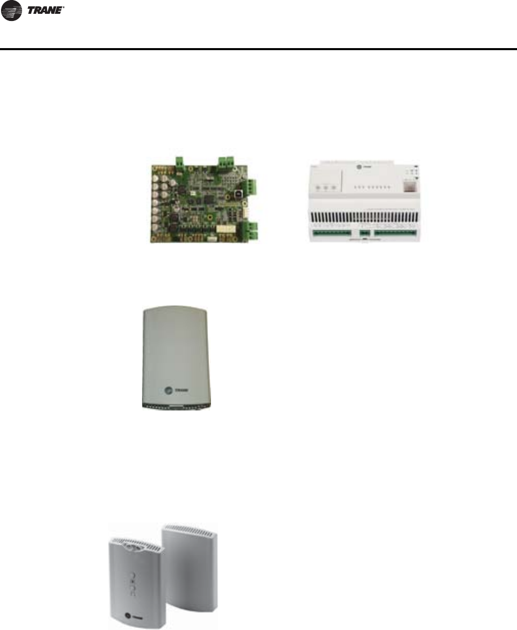
Trane Wireless Comm Interface (WCI)
Trane Wireless Zone Sensor
WCI controller
Provides wireless communication between theTracer SC,
Tracer Unit Controllers, and BACnet™ Communication
Interface (BCI) modules.
TheTrane WCI is the perfect alternative toTrane’s BACnet
wired communication links (for example – Comm links
between aTracer SC andTracer UC400).
Eliminating communication wire used between terminal
products, zone sensors, and system controllers has substantial
benefits.
• Installation time and associated risks are reduced.
• Projects are completed with fewer disruptions.
• Future re-configurations, expansions, and upgrades are
easier and more cost effective.
Wireless Zone Sensor
Provides wireless communication between the Unit Controller
and the zone sensor.This is an alterntive to the wired zone
sensor when access and routing of communicaiton cable is an
issue. It also allows very flexible mounting and relocation of
zone sensors
UC210 BACnet Controller UC400 BACnet Controller
VAV-PRC012-EN 11
Features and Benefits
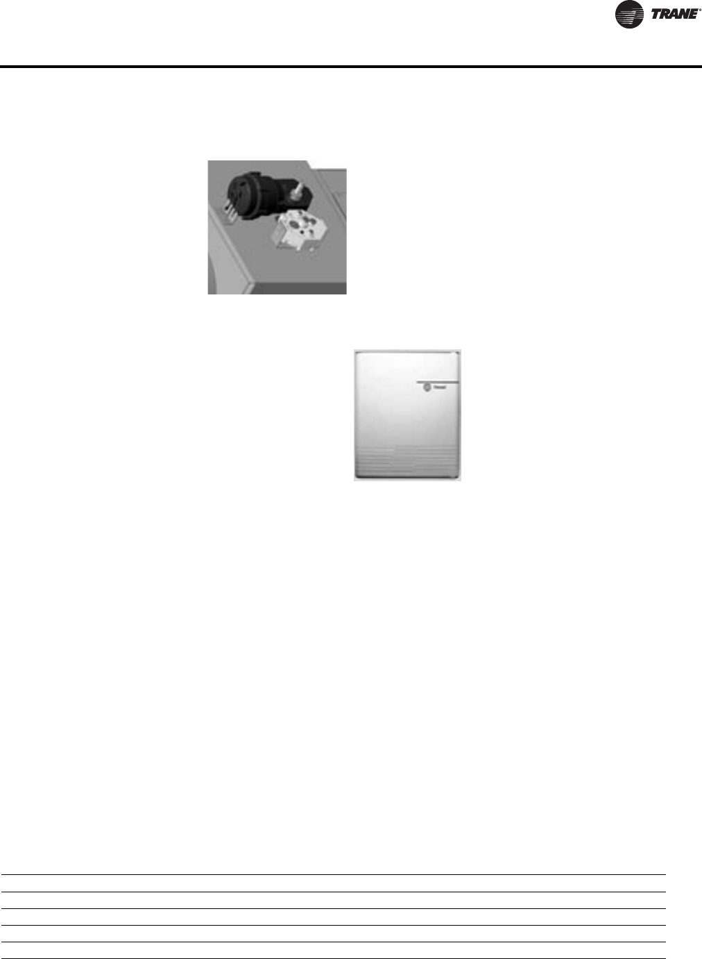
Pneumatic Controller
Integration Options (Interfacing with other control systems) - Trane offers three ways to
interface with other control systems.
1. UseTrane LonMark, factory-commissioned VAV controllers
2. UseTrane Binary Input Controller (BIC). BIC allows system control through binary logic.This
means that a control system on an existing campus, or those seeking “Analog non-
communicating control” can control aTrane DDCVAV unit via basic binary contact closures, like
relays, etc.This can be a cost effective interface option where a fullTrane DDC VAV System is
not available.
3. UseTrane BACnet™ factory-commissioned VAV controllers.
Factory-installed vs. Factory-commissioned:
The terms factory-installed and factory-commissioned are often used interchangeably.Trane takes
great pride in being the industry leader in factory-commissioned DDC controllers. Table
differentiates these concepts.
Factory-commissioned controllers provide the highest quality and most reliable units for yourVAV
system. Additional testing verifies proper unit operation including occupied/unoccupied airflow,
temperature setpoints, communication link functionality, and output device functionality.The
benefits of factory-commissioning are standard on VariTrane terminal units withTrane DDC
controls.This means that factory-commissioned quality on VariTrane VAV units is now available
on ANY manufacturer’s control system that can communicate using the LonMark Space Comfort
Control (SCC) protocol. (See Controls section for complete listing of variables which are
communicated.
Pneumatic Controller
Pneumatic—Pneumatic controllers provide
proven reliability and performance. A full line
of options provide:
• Highest quality PVR available, which
maximizes zone temperature control.
Pressure-independent operation
• AllVariTrane pneumatic controllers use the
patented flow sensor input to provide the
most accurate performance available.
Binary Input Controller
Table 1. Factory-installed vs. factory-commissioned
Factory-installed Factory-commissioned
Transformer installed (option) X X
Wires terminated in reliable/consistent setting X X
Controller mounted XX
Electric heat contactors and fan relay wired X X
12 VAV-PRC012-EN
Features and Benefits
Indoor Air Quality Management During Construction
Trane VAV Systems - Proven Performance
Trane is the industry leader in VAV systems, including factory-commissioned controls and
integration with other control systems.This leadership began with customers seeking the most
reliable VAV products in the industry.The solution was factory-commissioned controls (see
Factory-installed vs. Factory-commissioned). Since then, it has blossomed to include optimized
system control strategies.
Control strategies are often made more complicated than necessary. VariTrane DDC controls
simplify control strategies by pre-engineering control logic and sequencing into the controller.This
information is available via a twisted-shielded wire pair, and accessible via aTraneTracer™ SC
building automation system. Data is easily accessed via a computer workstation.
Optimized system control strategies, such as ventilation optimization, fan-pressure optimization,
and optimal start/stop, are pre-engineered inVariTrane™ unit-level DDC controllers and theTracer
SC building automation system.
This allows aTrane VAV system to meet or exceed the latest ASHRAE 90.1 Energy Efficiency
standards. Pre-engineered controls allow consistent, high quality installations which are very
repeatable.The end result is PROVEN control strategies you can rely on to perform. For more
information on these and other control strategies, contact your localTrane Sales Office, or visit
www.trane.com.
Purchasing VAV controllers and VAV hardware from a single manufacturer provides a single
contact for all HVAC system related questions.
Testing of electric heat contactors and fan relay X
Controller addressing and associated testing X
Minimum & Maximum airflows settings (occupied/unoccupied) X
Minimum & Maximum temperature setpoints (occupied/unoccupied) X
Minimum ventilation requirements X
Thumbwheel enable/disable X
Heating offset X
Wireless communications modules (WCI) X X
Wireless zone sensor X
Table 1. Factory-installed vs. factory-commissioned
Factory-installed Factory-commissioned
LEED wrap option is a pressure sensitive
covering that prevents contamination of the
VAV box during the construction phase. It is
utilized to seal all openings without
constraining the installation process.

VAV-PRC012-EN 13
Agency Certifications
There are numerous regulations and standards in the industry that determine the construction and
performance parameters for VAV terminal units. Some of the more important of those standards
and regulations are listed below, along with a brief description of what each one addresses.
American Society of Heating, Refrigerating and Air-conditioning Engineers
(ASHRAE) - 41.1
ASHRAE - 41.2
ASHRAE - 41.3
These standards specify methods for temperature measurement (41.1), laboratory airflow
measurement (41.2), and pressure measurement (41.3).While none of these standards specifically
discusses VAV air terminals, they discuss topics that are aspects of terminal box systems.
Therefore, some engineers will include these standards in their specifications as a primer on
accepted measurement techniques.
ASHRAE - 62
This standard specifies the minimum ventilation rates and indoor air quality that are acceptable for
occupied spaces.
ASHRAE - 111
This standard calls out procedures to be followed for testing and balancing HVAC systems. It
includes descriptions of the equipment used, procedures followed, and field changes that must be
made when a system is balanced.
Air-Conditioning, Heating and Refrigeration Institute (AHRI)
AHRI 880
This standard sets forth classifications, performance testing requirements, and test results
reporting requirements for air terminal units.The standard contains very detailed procedures that
are to be followed for the testing and certification program associated with this standard.This is
one of the most commonly referenced standards in the VAV terminal unit industry.The AHRI-880
certification program is designed to police the accuracy of documented performance for terminal
units.The certification program requires a sampling of at least four units be tested annually.The
tested units are chosen at random by AHRI and sent to an independent laboratory for the testing.
The performance is tested at one specific operating condition.The operating characteristics tested
include discharge and radiated sound power (for the damper and, in the case of fan-powered
boxes, the fan), wide-open damper pressure drop, and fan motor amp draw. VariTrane terminal
units are certified according to AHRI-880.
AHRI 885
This document provides a procedure to estimate sound pressure levels in an occupied space.The
standard accounts for the amount of sound pressure in the space due to the VAV air terminal,
diffusers and their connecting low pressure ductwork. While sound generated from the central
system fan and ductwork may be a significant factor in determining the sound pressure level in the
room, this standard does not address those factors. It focuses solely on theVAV terminal and items
downstream of it.This standard is related to AHRI-880 by using sound power determined using
AHRI-880 methodology as a starting point for the AHRI-885 procedure.
Underwriter’s Laboratory (UL) 1995
Underwriter’s Laboratory is an independent testing agency that examines products and
determines if those products meet safety requirements. Equipment manufacturers strive to meet
UL guidelines and obtain listing and classifications for their products because customers recognize
UL approval as a measure of a safely designed product.VariTrane VAV air terminals are listed
per UL-1995, Heating and Cooling Equipment.The terminals are listed as an entire assembly.

14 VAV-PRC012-EN
Agency Certifications
National Fire Protection Association
NFPA 70
This standard is also known as the National Electrical Code (NEC).The Code gives standards for
installation of wiring and electrical equipment for most types of commercial and residential
buildings. It is often referred to inVAV air terminal specifications when fan-powered boxes, electric
heat or electric controls are included.
NFPA 90A
This standard does not speak directly to VAV air terminals but does discuss central system
considerations pertaining to a fire and/or smoke condition.The standard discusses safety
requirements in design and construction that should be followed to keep the air-handling system
from spreading a fire or smoke.The standard specifies practices that are intended to stop fire and
smoke from spreading through a duct system, keep the fire-resistive properties of certain building
structures (fire walls, etc.) intact, and minimize fire ignition sources and combustible materials.

VAV-PRC012-EN 15
Digit 1, 2—Unit Type
VP = VariTrane™ Fan-Powered Parallel
VS = VariTrane Fan-Powered Series
LP = VariTrane Fan-Powered
Low-Height Parallel
LS = VariTrane Fan-Powered
Low-Height Series
Digit 3—Reheat
C = Cooling Only
E = Electric Heat
W = Hot Water Heat
Digit 4—Development Sequence
F = Sixth
Digit 5, 6—Primary Air Valve
05 = 5" inlet (350 max cfm)
06 = 6" inlet (500 max cfm)
08 = 8" inlet (900 max cfm)
10 = 10" inlet (1400 max cfm)
12 = 12" inlet (2000 max cfm)
14 = 14" inlet (3000 max cfm)
16 = 16" inlet (4000 max cfm)
RT = 8" x 14" inlet (1800 max CFM)
Note: 10, 12, 14, 16 NotAvailable on Low-
Height
Digit 7, 8—Secondary Air Valve
00 = N/A
Digit 9—Fan
P = 02SQ fan (500 nominal cfm)
Q = 03SQ fan (1100 nominal cfm)
R = 04SQ fan (1350 nominal cfm)
S = 05SQ fan (1550 nominal cfm)
T = 06SQ fan (1850 nominal cfm)
U = 07SQ fan (2000 nominal cfm)
V = 08SQ Fan (500 nominal cfm)
W = 09SQ Fan (900 nominal cfm)
X = 10SQ Fan (1800 nominal cfm)
Digit 10, 11—Design Sequence
** = Factory assigned
Digit 12, 13, 14, 15—Controls
DD01= Cooling Only Control
DD02= N.C. On/Off Hot Water
DD03= Prop. Hot Water
DD04= Staged On/Off E-Heat
DD05= Pulse Width Mod of E-Heat
DD07= N.O. On/Off Hot Water
DD11= VV550 DDC Controller - Cooling
Only
DD12= VV550 DDC Ctrl w/N.C. On/Off
HW Valve
DD13= VV550 DDC Ctrl w/Prop. HW
Valve
DD14= VV550 DDC Ctrl - On/Off
Electric Heat
DD15= VV550 DDC Ctrl w/Pulse Width
Modulation
DD17= VV550 DDC Ctrl w/N.O. On/Off
HW Valve
DD23= VV550 DDC- Basic plus- Local
(Electric heat- PWM) Remote
(Staged EH)
DD28= VV550 DDC-Basic plus- Local
(Water heat- N.O. 2-position)
Remote (Water- N.O. 2-position)
DD29= VV550 DDC-Basic plus- Local
(Water heat- N.C. 2-position)
Remote (Water- N.C. 2-position)
DD30= VV550 DDC-Basic plus- Local
(Water heat- N.O. 2-position)
Remote (Water- N.C. 2-position)
DD31= VV550 DDC-Basic plus- Local
(Water heat- N.C. 2-position)
Remote (Water- N.O. 2-position)
DD32= VV550 DDC-Basic plus- Local
(Electric heat- Staged) Remote
(Staged EH)
DD41= UC400 DDC-Basic (No water or
electric heat)
DD42= UC400 DDC-Basic (Water heat-
Normally Closed- 2 position)
DD43= UC400 DDC-Basic (Water heat-
Modulating)
DD44= UC400 DDC-Basic (Electric heat-
staged)
DD45= UC400 DDC-Basic (Electric heat-
PWM)
DD47= UC400 DDC-Basic (Water heat-
Normally Opened- 2 position)
DD53= UC400 DDC-Basic plus- Local
(Electric heat- PWM) Remote
(Staged EH)
DD58= UC400 DDC-Basic plus- Local
(Water heat- N.O. 2-position)
Remote (Water- N.O. 2-position)
DD59= UC400 DDC-Basic plus- Local
(Water heat- N.C. 2-position)
Remote (Water- N.C. 2-position)
DD60= UC400 DDC-Basic plus- Local
(Water heat- N.O. 2-position)
Remote (Water- N.C. 2-position)
DD61= UC400 DDC-Basic plus- Local
(Water heat- N.C. 2-position)
Remote (Water- N.O. 2-position)
DD62= UC400 DDC-Basic plus- Local
(Electric heat- Staged) Remote
(Staged EH)
DD65= Basic (Electric Heat- Modulating
SCR)
DD66= Basic plus – Local (Electric heat –
Modulating SCR) Remote
(Staged EH)
DD71= UC210 DDC-Basic
(Cooling only)
DD72= UC210 DDC-Basic
(Water heat-nc 2pos)
DD73= UC210 DDC-Basic
(Water heat-Modulating)
DD74= UC210 DDC-Basic
(Electric heat-staged)
DD75= UC210 DDC-Basic
(Electric heat-pwm)
DD77= UC210 DDC-Basic
(Water heat-NO 2pos)
DD83= UC210 DDC-Basic+ Local
(Electric heat-pwm)
Remote (Staged)
DD84= UC210 DDC-Basic+ Local
(Water heat Modulating)
Remote (Water-NC 2pos)
DD85= UC210 DDC-Basic+ Local
(Water heat Modulating)
Remote (Water-NO 2pos)
DD86= UC210 DDC-Basic+ Local
(Water heat NO 2pos)
Remote (Water-Modulating)
DD87= UC210 DDC-Basic+ Local
(Water heat NC 2pos)
Remote (Water-Modulating)
DD88= UC210 DDC-Basic+ Local
(Water heat NO 2pos)
Remote (Water-NO 2pos)
DD89= UC210 DDC-Basic+ Local
(Water heat NC 2pos)
Remote (Water-NC 2pos)
DD90= UC210 DDC-Basic+ Local
(Water heat NO 2pos)
Remote (Water-NC 2pos)
DD91= UC210 DDC-Basic+ Local
(Water heat NC 2pos)
Remote (Water-NO 2pos)
DD92= UC210 DDC-Basic+ Local
(Electric heat-staged)
Remote (Staged)
DD95= UC210 DDC-Ctrl w/Modulating
SCR
DD96= UC210 DDC-SpaceTemp Ctrl w/
Local SCR & Remote Stge Elec
Heat
DD00= Trane Actuator Only
ENCL= Shaft Only in Enclosure
ENON= Shaft Out Side for Electric Units
FM00= Other Actuator and Control
FM01= Trane supplied actuator,
other control
PN00= N.O. Actuator and Linkage Only
PN05= N.O. 3000 Series, RA Stat
PN51= Pneumatic normally open
w/3011,DPS fan
PN52= Pneumatic normally open
w/3011, DPM fan
PNON= Shaft Out Side for Pneumatic
Units
N.C. = Normally-closed
N.O. = Normally-opened
DA Stat = Direct-acting pneumatic t-stat
(by others)
RA Stat = Reverse-acting pneumatic
t-stat (by others)
PN = Pneumatic
FM = Factory installation of customer-
supplied controller
PVR = Pneumatic Volume Regulator
Digit 16—Insulation
A = 1/2” Matte-faced
B = 1" Matte-faced
D = 1" Foil-faced
F = 1" Double-wall
G = 3/8” Closed-cell
Digit 17—Motor Type
D = PSC Motor
E = High-efficiency motor (ECM)
Model Number Descriptions

16 VAV-PRC012-EN
Model Number Descriptions
Digit 18—Motor Voltage
1 = 115/60/1
2 = 277/60/1
3 = 347/60/1
4 = 208/60/1
5 = 230/50/1
Digit 19—Outlet Connection
1 = Flanged
2 = Slip & Drive
Digit 20—Attenuator
0 = No Attenuator
W = With Attenuator
Digit 21—Water Coil
0 = None
1 = 1-Row–Plenum inlet installed RH
2 = 2-Row–Plenum inlet installed RH
3 = 1-Row–Discharge installed, LH
4 = 1-Row–Discharge installed, RH
5 = 2-Row–Discharge installed, LH
6 = 2-Row–Discharge installed, RH1
A = 1-Row–Premium water coil inlet
B = 2-Row–Premium water coil inlet
C = 1-Row–Premium hot coil
on discharge, LH
D = 1-Row–Premium hot coil
on discharge, RH
E = 2-Row–Premium hot coil
on discharge, LH
F = 2-Row–Premium hot coil
on discharge, RH
Note: 1- and 2-row not available with
Low-Height
Digit 22—Electrical Connections
L = Left (Airflow hitting you in the
face)
R = Right (Airflow hitting you in the
face)
W = Narrow Corridor LH, Hi-Volt Inlet
Facing
X = Narrow Corridor RH, Hi-Volt Inlet
Facing
Note: (W & X) Fan Powered Series Only
Digit 23—Transformer
0 = N/A (provided as standard)
Digit 24—Disconnect Switch
0 = None
W = With
Electric Reheat w/ door interlocking
power disconnect, Cooling Only and
Water Reheat w/ toggle disconnect
Digit 25—Power Fuse
0 = None
W = With
Digit 26—Electric Heat Voltage
0 = None
A = 208/60/1
B = 208/60/3
C = 240/60/1
D = 277/60/1
E = 480/60/1
F = 480/60/3
G = 347/60/1
H = 575/60/3
J = 380/50/3
K = 120/60/1
Note: K not available with Low Height
Digit 27, 28, 29—Electric Heat
kW
000 = None
050 = 0.5 kW
010 = 1.0 kW
015 = 1.5 kW
260 = 26.0 kW
Note: Electric Heat Voltage -
0.5 to 8.0 kW–½ kW increments
8.0 to 18.0 kW –1 kW increments
18.0 to 46.0 kW–2 kW increments
Digit 30—Electric Heat Stages
0 = None
1 = 1 Stage
2 = 2 Stages Equal
3 = 3 Stages Equal
Note: 3 not available with Low Height
Digit 31—Contactors
0 = None
1 = 24-volt magnetic
2 = 24-volt mercury
3 = PE with magnetic
4 = PE with mercury
5 = SCR heat UC400
6 = SCR heat FMTD/ENCL/DD00
Note: SCR cannot be selected with the
following configuration:
•KW > 10, 208 volt 3 phase, Low
Height
•KW > 22, 480 volt 3 phase, Low
Height
•Voltage = 575 volt
Digit 32—Airflow Switch
0 = None
W = With
Digit 33—Not Used
0 = N/A
Digit 34—Actuator
0 = Standard
A = Belimo actuator
Digit 35—Wireless Sensors
0 = None
1 = Factory Mounted Wireless
Receiver (Sensor Assembly)
2 = Wireless Comm Interface
Modular FM
Note: All sensors selected in accessories
Digit 36—Pre-Wired Factory
Solutions
0 = None
1 = Factory Mounted DTS
2 = HW Valve Harness
3 = Both DTS & HW Valve Harness

VAV-PRC012-EN 17
Selection Procedure
This section describes elements and process required to properly select fan-powered VAV
terminals, and includes a specific examples. Selection procedure is iterative in nature which makes
computer selection desirable. Selection of fan-powered VAV terminals involves four elements:
• Air valve selection
• Heating coil selection
• Fan size and selection
• Acoustics
Note: Use the same procedures for selecting Low-Height Fan-Powered Units.
Air Valve Selection
Provided in the Performance Data—Air Pressure Requirements section of the catalog is the unit air
pressure drop at varying airflows.To select an air valve, determine the airflow required at design
cooling. Next, select an air valve diameter that will allow proper airflow modulation, (a velocity of
1600 – 2000 FPM is recommended). Keep in mind that modulation below 300 FPM is not
recommended. Proper selection requires defining the minimum valve airflow (in either heating
or cooling) and maintaining at least 300 FPM through the air valve.The minimum is typically set
based on ventilation requirements. If zone ventilation does not come through the VAV unit, a
minimum valve position can also be zero.
Heating Coil Selection
Supply Air Temperature
The first step required when selecting a heating coil is to determine the heating supply air
temperature to the space, calculated using the heat transfer equation. A recommended value is
90°F, although values between 85°F and 95°F are common. Discharge air temperatures that exceed
20 degrees above space temperature are not recommended for proper diffuser operation. Air
temperature difference is defined as the heating supply air temperature to the space minus the
winter room design temperature.The zone design heat loss rate is denoted by the letter Q. Supply
air temperature to the space equals the leaving air temperature (LAT) for the terminal unit.
Coil Leaving Air Temperature
Once the terminal unit LAT is determined, the heating requirements for the coil can be calculated.
The leaving air temperature for the coil of a parallel fan-powered terminal unit varies based on the
type of unit installed heat being selected. Series unit leaving air temperatures do not vary because
in each case the coil is located on the unit discharge.
Electric coil LAT equals terminal unit LAT because the coil is located on the unit discharge. Hot water
coils can be located on either the discharge or, for maximum system efficiency, the plenum inlet
when located on the entering air side of the fan. Coil LAT is calculated using a mixing equation.
Given the unit heating airflow and LAT, minimum primary airflow at its supply air temperature, and
the volume of heated plenum air, the leaving air temperature for the hot water coil can be
determined (see the unit selection example that follows for more details).
Coil Entering Air Temperature
The entering air temperature (EAT) to the coil also varies based on the coil position on the unit for
parallel units.The unit heat is mounted on the discharge of a series unit.Therefore the EAT equals
the temperature of blended primary and plenum air.
Parallel electric coils are mounted on the unit discharge. Hot water coils can be mounted on the
discharge or on the plenum inlet. Plenum inlet mounting creates a more efficientVAV system.This
is because the parallel fan is energized only when in heating mode, and thus, when in cooling
mode, the water coil is not in the airstream.
The EAT for discharge mounted coils equals the temperature of blended primary air and plenum
air. For plenum inlet mounted water coils, the EAT equals the plenum air temperature.

18 VAV-PRC012-EN
Selection Procedure
Capacity Requirement
Once both coil EAT and LAT are determined, the heat transfer (Q) for the coil must be calculated
using the heat transfer equation. For electric heat units, the Q value must be converted from Btu
to kW for heater selection.The required kW should be compared to availability charts in the
performance data section for the unit selected. For hot water heat units, reference the capacity
charts in the performance data section for the required heat transfer Q and airflow to pick the
appropriate coil.
Fan Size and Selection
Fan Airflow
Fan airflow is determined by calculating the difference between the unit design heating airflow and
minimum primary airflow.
Fan External Static Pressure
Fan external static pressure is the total resistance experienced by the fan, which may include
downstream ductwork and diffusers, heating coils, and sound attenuators. As total airflow varies
so will static pressure, making calculation of external static pressure dependent on unit type.
In many applications of parallel terminals, a minimum primary airflow must be maintained to meet
ventilation requirements.This primary airflow contributes to the total resistance experienced by
the fan and should be accounted for in all components downstream of the fan itself, including
electric coils. Hot water coils positioned on the fan inlet are not affected by the additional primary
airflow.The static pressure resistance experienced by the fan due to the hot water coil is based on
fan airflow only, not the total heating airflow.
With series fan-powered terminal units, all airflow passes through the fan. External static pressure
requirements are the sum of the individual component pressure retirements at the design airflow
of the unit.
Fan Motor Type
The fan motor type that will be used for the unit will need to be known before fan selection can
begin.The ECM motor offers more efficient operation than the standard single-speed PSC motor
and will use different fan curves. Because series fans operate in both heating and cooling mode,
payback is typically 2–3 years for the premium ECM option. Refer to the Features and Benefits
section to determine which motor is more appropriate for the unit
Selection
Once fan airflow and external static pressure are determined, reference the fan curves in the
performance data section. Cross plot both airflow and external static pressure on each applicable
graph. A selection between the minimum and maximum airflow ranges for the fan is required.
It is common to identify more than one fan that can meet the design requirements.Typically,
selection begins with the smallest fan available to meet capacity. If this selection does not meet
acoustical requirements, upsizing the fan and operating it at a slower speed can be done for quieter
operation.
Acoustics
Air Valve Generated Noise
To determine the noise generated by the air valve, two pieces of information are required; design
airflow and design air pressure drop.The design air pressure drop is determined by taking the
difference between design inlet and static pressure (the valve’s most over-pressurized condition)
and external static pressure at design cooling flow.This represents a worst-case operating
condition for the valve.

VAV-PRC012-EN 19
Selection Procedure
Fan Generated Noise
To determine fan noise levels, fan airflow, external static pressure and speed information is
required.
Evaluation Elements
For parallel fan-powered terminal units, the air valve and fan operation must be evaluated
separately because these operations are not simultaneous. For Series fan-powered units, the air
valve and fan are evaluated together because they have simultaneous operation. Access the
appropriate acoustics table(s) of the catalog and determine the sound power and NC prediction for
both the discharge and radiated paths. It is important to understand that discharge air noise is
generally not a concern with fan-powered terminals. Radiated noise from the unit casing typically
dictates the noise level of the space. If the entire unit or any element of it is generating noise in
excess of the Noise Criteria requirements, the size of the appropriate portion of the terminal should
be increased. Because the selection procedure is iterative, care should be taken by the designer to
confirm that the change in selection does not affect other elements of the unit or system design.
Selection Example—Parallel With Hot Water Heat
Air Valve Selection
Design Cooling Airflow:1000 cfm
Minimum Ventilation Airflow: 200 cfm
Maximum Unit APD: 0.25 in. wg
Choose 10" air valve
Check – Is minimum airflow above 300 FPM? Guidelines, FPP 8)
A 10" air valve is selected with unit pressure drop = 0.01 in. wg
Heating Coil Selection
Required Information:
Zone design heat loss: 20000 Btu
Unit heating airflow: 600 cfm
Winter room design temp.: 68ºF
Coil entering water temp.: 180ºF
Minimum primary airflow: 200 cfm
Fan Airflow: 400 cfm
Plenum temperature: 70ºF
Coil flow rate: 2 gpm
Primary air temperature: 55ºF
Heat Transfer Equation (Btu)
Q = 1.085 x Cfm x DTemperature
For the heating zone, the temperature difference is the zone supply air temperature (SAT) minus
the winter room design temperature.
18000 Btu = 1.085 x 600 x (SAT - 68ºF)
SAT = 95.6ºF
Because the designer chose to maximize system efficiency by having the hot water coil on the
plenum inlet, the unit supply air temperature is equal to the mix of the heated plenum air from the
fan and the minimum primary airflow.
600 cfm x 95.6ºF =
200 cfm x 55ºF +
(600 cfm - 200 cfm) x Coil LAT
Coil LAT = 116ºF
20 VAV-PRC012-EN
Selection Procedure
For the heating coil, the temperature difference is the calculated coil LAT minus the coil EAT
(Plenum AirTemperature).
CoilQ=1.085 x 400 x (116-70) = 19,964 Btu = 19.96 Mbh
Coil Performance Table
Selection:
Size 02SQ fan, 1-row coil with 2 gpm =20.53 Mbh (at 400 cfm)
1-row coil with 2 gpm = 2.57 ft WPD
Fan Selection
Required Information:
Design airflow: 400 cfm
Downstream static pressure at design airflow: 0.25 in. wg
Fan external static pressure equals downstream static pressure (ductwork and diffusers) plus coil
static pressure.The coil static pressure that the fan experiences is at the fan airflow (400 cfm).The
downstream static pressure the fan experiences is at fan airflow plus minimum primary airflow.
The sum of fan airflow and minimum primary airflow (600 cfm) is less than design airflow (1000
cfm) and therefore the 0.25 in. wg downstream static pressure at design airflow must be adjusted
for the lower heating airflow.
Parallel Fan-Powered Unit with Water Coil (2 Options)
Using Fan LawTwo:
Heating Downstream Static Pressure = (600/1000)2 x 0.25 = .09 in. wg
A size 02SQ fan has the capability to deliver approximately 650 cfm at 0.09 downstream static
pressure. If an attenuator is required, use the attenuator air pressure drop tables to define
additional fan static pressure.
Acoustics
Required Information:
Design inlet static press.: 1.0 in. wg
NC criteria: NC-35
The selection is a VPWF Parallel Fan-poweredTerminal Unit, 10" primary, parallel fan size 02SQ,
with a 1-row hot water coil.
Determine the casing radiated noise level because it typically dictates the sound level (NC) of the
space. With a parallel unit, two operating conditions must be considered, design cooling and
design heating.
Plenum Inlet Mounted Discharge Mounted
VAV-PRC012-EN 21
Selection Procedure
Design Cooling (1000 cfm). Radiated valve typically sets the NC for parallel units in cooling mode.
The closest tabulated condition (1100 cfm at 1.0 in. wg ISP) has an NC=31. (A more accurate
selection can be done viaTOPSS electronic selection program.):
Design Heating (200 cfm valve, 400 cfm fan, 0.25 in. wg DSP). Radiated fan typically sets the NC
for parallel units in heating mode.The closest cataloged condition (430 fan cfm , 0.25 in. wg DSP)
has an NC=32. (A more accurate selection can be done viaTOPSS electronic selection program.)
The predicted NC level for design cooling is NC-30 and for design heating is NC-31. If the catalog
path attenuation assumptions are acceptable, this unit meets all of the design requirements and
the selection process is complete.
Computer Selection
The advent of personal computers has served to automate many processes that were previously
repetitive and time-consuming. One of those tasks is the proper scheduling, sizing, and selection
of VAV terminal units.Trane has developed a computer program to perform these tasks.The
software is called theTrane Official Product Selection System (TOPSS).
TheTOPSS program will take the input specifications and output the properly sizedVariTrane VAV
terminal unit along with the specific performance for that size unit.
The program has several required fields, denoted by red shading in theTOPSS screen, and many
other optional fields to meet the criteria you have. Required values include maximum and
minimum airflows, control type, and model. If selecting models with reheat, you will be required
to enter information to make that selection also.The user is given the option to look at all the
information for one selection on one screen or as a schedule with the other VAV units on the job.
The user can select single-duct, dual-duct, and fan-powered VAV boxes with the program, as well
as most otherTrane products, allowing you to select all yourTrane equipment with one software
program.
The program will also calculate sound power data for the selected terminal unit.The user can enter
a maximum individual sound level for each octave band or a maximum NC value.The program will
calculate acoustical data subject to default or user supplied sound attenuation data.
Schedule View
The program has many time-saving features such as:
• Copy/Paste from spreadsheets like Microsoft® Excel
• Easily arranged fields to match your schedule
• Time-saving templates to store default settings
The user can also export the Schedule View to Excel to modify and put into a CAD drawing as a
schedule.
Specific details regarding the program, its operation, and how to obtain a copy of it are available
from your localTrane sales office.
Table 2. Selection Program Output (Radiated Valve):
Octave Band 2 3 4 5 6 7 NC
Sound Power 65 60 53 48 41 32 30
Table 3. Selection Program Output (Radiated Fan):
Octave Band 2 3 4 5 6 7 NC
Sound Power 66 58 56 52 48 41 31
22 VAV-PRC012-EN
Selection Procedure
Selection Example—Series With Hot Water Heat and ECM
Air Valve Selection
Heating Coil Selection
Required Information: Zone design heat loss: 30000 Btu
Design heating airflow: 1000 cfm
Winter room design temp.: 68ºF
Coil entering water temp.: 180ºF
Minimum primary airflow: 200 cfm
Plenum temperature: 70ºF
Primary air temperature: 55ºF
Coil flow rate: 2 gpm
HeatTransfer Equation (Btu)Q=1.085 x Cfm x Temperature
For the heating zone, the temperature difference is the zone supply air temperature (SAT) minus
the winter room design temperature.
30000 Btu = 1.085 x 1000 x (SAT-68°F)
SAT = 96ºF
Because the hot water coil is on the unit discharge of a series fan-powered unit, the unit supply air
temperature is equal to the coil LAT. Coil entering air temperature (EAT) is a mix of plenum air and
the minimum primary airflow.
1000 cfm x Coil EAT = 200 cfm x 55ºF + (1000 cfm - 200 cfm) x 70ºF
Coil EAT = 67ºF
For the heating coil, the temperature difference is the calculated coil LAT minus the coil EAT
(Plenum AirTemperature).
Coil Q =1.085 x 1000 x (96-70) = 31,465 Btu
On a series unit the hot water coil is located on the discharge, so the total heating airflow, 1000 cfm,
passes through the coil.
Coil Performance Table
Selection:
Performance:
Size 03SQ fan, 1-row coil at 2 gpm = 32.23 MBh
1-row Coil at 2 gpm= 0.83 ft WPD
Fan Selection
Required Information. Fan airflow: 1000 cfm
Downstream static pressure at design airflow: 0.25 in. wg
A size 03SQ fan can operate at up to 1150 cfm (1-row coil) or 1100 (2-row coil) and 0.25" downstream
static pressure. Inlet and coil selections should be verified withTOPSS electronic selections.
Required Information: Design cooling airflow: 1000 cfm
Minimum ventilation airflow: 200 cfm
Maximum unit APD: 0.40 in. wg
A 10" air valve is selected.
Check–is minimum airflow above 300 FPM?
Answer–Yes. Minimum cfm allowable = 165 cfm. (See
General Data—Valve/Controller Guidelines pp FPS 8).
The 03SQ fan will be used in this instance. By interpolating,
you can choose a 10" air valve with wide-open air pressure
drop of 0.32 in. wg.
VAV-PRC012-EN 23
Selection Procedure
If an attenuator is required, use attenuator air pressure drop tables to define additional fan static
pressure.
Acoustics
Required Information. Design inlet static press: 0.75 in. wg
NC criteria (general office space): NC-40
The selection is a VSWF Series Fan-PoweredTerminal Unit, 10" primary, series fan size 03SQ, with
a 1-row hot water coil.
Determine the casing radiated noise level because it typically dictates the sound level
(NC) of the space. With a series unit, the air valve and fan operate simultaneously, so the chart
for air valve and fan sound data must be consulted.
The results in the below table are for the acoustics value of a size 10" air valve with a size 03SQ fan.
The predicted NC level for design conditions is NC-38.
Note: Ensure water coil acoustical impact is considered. For this example, the appurtenance effect
adds one (1) NC to fan-only radiated sound. Because this does not set NC for this selection,
it can be overlooked.The addition of an attenuator (see same appurtenance effect tables
reduces the NC four (4) points, resulting in a final selection NC = 30 (if required).
Note: Do not overlook the water coil impact on acoustics. A good rule of thumb is that it will add
1 to 2 NC to “fan only” radiated sound for most applications.
Computer Selection
The advent of personal computers has served to automate many processes that were previously
repetitive and time-consuming. One of those tasks is the proper scheduling, sizing, and selection
of VAV terminal units.Trane has developed a computer program to perform these tasks.The
software is called theTrane Official Product Selection System (TOPSS).
TheTOPSS program will take the input specifications and output the properly sizedVariTrane VAV
terminal unit along with the specific performance for that size unit.
The program has several required fields, denoted by red shading in theTOPSS screen, and many
other optional fields to meet the criteria you have. Required values include maximum and
minimum airflows, control type, and model. If selecting models with reheat, you will be required
to enter information to make that selection also.The user is given the option to look at all the
information for one selection on one screen or as a schedule with the other VAV units on the job.
User can select single-duct, dual-duct, and fan-powered VAV boxes with the program, as well as
most otherTrane products, allowing selection of allTrane equipment with one software program.
The program will also calculate sound power data for the selected terminal unit.The user can enter
a maximum individual sound level for each octave band or a maximum NC value.The program will
calculate acoustical data subject to default or user supplied sound attenuation data.
Schedule View
The program has many time-saving features such as:
• Copy/Paste from spreadsheets like Microsoft® Excel
• Easily arranged fields to match your schedule
• Time-saving templates to store default settings
User can also export Schedule View to Excel to modify and put into a CAD drawing as a schedule.
Specific details regarding program, its operation, and how to obtain a copy of it are available from
your localTrane sales office.
Octave Band 2 3 4 5 6 7 NC
Sound Power 70 65 63 61 59 59 38

24 VAV-PRC012-EN
Performance Data
Parallel Fan-Powered Terminal Units
Table 4. Primary airflow control factory setting-I-P
Control Type
Air Valve
Size (in.)
Maximum
Valve Cfm
Maximum
Controller Cfm
Minimum
Controller Cfm
Constant Volume
Cfm
Direct Digital
Control/ UCM
5
6
8
350
500
900
40-350
60-500
105-900
0, 40-350
0, 60-500
0, 105-900
40-350
60-500
105-900
10
12
14
16
1400
2000
3000
4000
165-1400
240-2000
320-3000
420-4000
0, 165-1400
0, 240-2000
0, 320-3000
0, 420-4000
165-1400
240-2000
320-3000
420-4000
Pneumatic with
Volume
Regulator
5
6
8
350
500
900
63-350
73-500
134-900
0, 63-350
0, 73-500
0, 134-900
63-350
73-500
134-900
10
12
14
16
1400
2000
2885
3785
215-1400
300-2000
408-2887
536-3789
0, 215-1400
0, 300-2000
0, 408-2887
0, 536-3789
215-1400
300-2000
408-2887
536-3789
Note: Maximum airflow must be greater than or equal to minimum airflow.
Table 5. Primary airflow control factory settings – SI
Control Type
Air Valve
Size (in.)
Maximum
Valve L/s
Maximum
Controller L/s
Minimum
Controller L/s
Constant
Volume L/s
Direct Digital
Control/ UCM
5
6
8
165
236
425
19-165
28-236
50-425
0, 19-350
0, 28-236
0, 50-425
19-350
28-236
50-425
10
12
14
16
661
944
1416
1888
77-661
111-944
151-1416
198-1888
0, 77-661
0, 111-944
0, 151-1416
0, 198-1888
77-661
111-944
151-1416
198-1888
Pneumatic with
Volume
Regulator
5
6
8
165
236
425
30-165
35-236
63-425
0, 30-165
0, 35-236
0, 63-425
30-165
35-236
63-425
10
12
14
16
661
944
1362
1787
102-661
141-944
193-1363
253-1788
0, 102-661
0, 141-944
0, 193-1363
0, 253-1788
102-661
141-944
193-1363
253-1788
Note: Maximum airflow must be greater than or equal to minimum airflow.
Table 6. Unit air pressure drop – in. wg (I-P)
Fan/Inlet Size Airflow Cfm Cooling Only Fan/Inlet Size Airflow Cfm Cooling Only
02SQ-05 40
150
250
350
0.01
0.03
0.08
0.17
04SQ-14 320
1200
2100
3000
0.01
0.01
0.01
0.01
02SQ-06 60
200
350
500
0.01
0.05
0.17
0.35
05SQ-10 165
550
950
1400
0.01
0.01
0.02
0.05
Note: Unit pressure drops do not include hot water coil or attenuator pressure drops.
02SQ-08 105
350
600
900
0.01
0.03
0.09
0.21
05SQ-12 240
750
1350
2000
0.01
0.01
0.01
0.01
VAV-PRC012-EN 25
Performance Data
02SQ-10 165
550
950
1400
0.01
0.01
0.01
0.01
05SQ-14 320
1200
2100
3000
0.01
0.01
0.01
0.01
03SQ-06 60
200
350
500
0.01
0.06
0.19
0.40
06SQ-10 165
550
950
1400
0.01
0.01
0.01
0.01
03SQ-08 105
350
600
900
0.01
0.03
0.08
0.20
06SQ-12 240
750
1350
2000
0.01
0.01
0.01
0.01
03SQ-10 165
550
950
1400
0.01
0.01
0.02
0.05
06SQ-14 320
1200
2100
3000
0.01
0.01
0.01
0.01
03SQ-12 240
750
1350
2000
0.01
0.01
0.01
0.01
06SQ-16 420
1600
2800
4000
0.01
0.01
0.01
0.01
04SQ-08 105
350
600
900
0.01
0.03
0.08
0.20
07SQ-10 165
550
950
1400
0.01
0.01
0.01
0.01
04SQ-10 165
550
950
1400
0.01
0.01
0.02
0.05
07SQ-12 240
750
1350
2000
0.01
0.01
0.01
0.01
04SQ-12 240
750
1350
2000
0.01
0.01
0.01
0.01
07SQ-14 320
1200
2100
3000
0.01
0.01
0.01
0.01
07SQ-16 420
1600
2800
4000
0.01
0.01
0.01
0.01
Note: Unit pressure drops do not include hot water coil or attenuator pressure drops.
Table 7. Coil air pressure drop – in. wg (I-P)
Fan Size Airflow Cfm 1-Row HW (in. wg) 2-Row HW (in. wg)
02SQ 100
200
300
400
500
0.00
0.01
0.01
0.02
0.02
0.00
0.01
0.02
0.03
0.05
03SQ
04SQ
05SQ
250
500
750
1000
1250
1400
0.01
0.02
0.04
0.07
0.10
0.12
0.02
0.04
0.08
0.13
0.19
0.23
06SQ
07SQ
600
900
1200
1500
1800
2000
0.02
0.04
0.06
0.09
0.12
0.15
0.04
0.07
0.11
0.16
0.22
0.27
Note: HW Coil Only pressure drops do not include unit pressure drop.
Table 6. Unit air pressure drop – in. wg (I-P) (continued)
Fan/Inlet Size Airflow Cfm Cooling Only Fan/Inlet Size Airflow Cfm Cooling Only

26 VAV-PRC012-EN
Performance Data
Table 8. Attenuator air pressure drop (I-P)
Fan Size Plenum Cfm Attenuator Fan Size Plenum Cfm Attenuator
02SQ 50
200
350
500
650
750
0.00
0.00
0.01
0.02
0.04
0.06
05SQ 50
300
600
900
1200
1550
0.00
0.00
0.02
0.06
0.13
0.24
03SQ 50
250
500
750
1000
1200
0.00
0.00
0.00
0.00
0.01
0.06
06SQ 50
500
900
1300
1650
1900
0.00
0.01
0.03
0.06
0.10
0.14
04SQ 50
300
600
900
1200
1450
0.00
0.01
0.02
0.03
0.05
0.06
07SQ 50
500
1000
1500
2000
2500
0.00
0.01
0.04
0.08
0.15
0.25
Note: Plenum cfm = (Fan cfm)
Table 9. Attenuator air pressure drop (SI)
Fan Size Plenum L/s Attenuator Fan Size Plenum L/s Attenuator
02SQ 24
94
165
236
307
354
0
0
2
5
10
14
05SQ 24
142
283
425
566
731
0
1
5
15
32
61
03SQ 24
118
236
354
472
566
0
0
0
0
2
14
06SQ 24
236
425
613
779
897
0
2
7
15
26
35
04SQ
24
142
283
425
566
684
0
3
5
8
11
14
07SQ
24
236
472
708
944
1180
0
2
9
21
38
62
Note: Plenum cfm = (Fan cfm)
Table 10. Coil air pressure drop – Pa (SI)
Fan Size Airflow L/s 1-Row HW (Pa) 2-Row HW (Pa)
02SQ 200
300
400
500
600
0
1
2
4
6
1
3
5
8
12
03SQ
04SQ
05SQ
118
236
354
472
590
661
2
5
10
17
25
31
4
11
21
33
47
57

VAV-PRC012-EN 27
Performance Data
06SQ
07SQ
900
1200
1500
1800
2150
2500
5
9
15
22
30
36
10
18
28
41
56
67
Note: HW Coil Only pressure drops do not include unit pressure drop.
Table 10. Coil air pressure drop – Pa (SI)
Table 11. Unit air pressure drop-Pa (SI)
Fan/Inlet Size Airflow L/s Cooling Only Fan/Inlet Size Airflow L/s Cooling Only
02SQ-05
19
71
118
165
2
7
20
41
04SQ-14
151
566
991
1416
2
2
2
2
02SQ-06
28
94
165
236
2
13
41
86
05SQ-10
78
260
448
661
2
2
6
13
02SQ-08
50
165
283
425
2
8
23
51
05SQ-12
113
354
637
944
2
2
2
2
02SQ-10
78
260
448
661
2
2
2
3
05SQ-14
151
566
991
1416
2
2
2
2
03SQ-06
28
94
165
236
2
15
48
99
06SQ-10
78
260
448
661
2
2
2
2
03SQ-08
50
165
283
425
2
6
21
49
06SQ-12
113
354
637
944
2
2
2
2
03SQ-10
78
260
448
661
2
2
6
13
06SQ-14
151
566
991
1416
2
2
2
2
03SQ-12
113
354
637
944
2
2
2
2
06SQ-16
198
755
1321
1888
2
2
2
2
04SQ-08
50
165
283
425
2
6
21
49
07SQ-10
78
260
448
661
2
2
2
2
04SQ-10
78
260
448
661
2
2
6
13
07SQ-12
113
354
637
944
2
2
2
2
04SQ-12
113
354
637
944
2
2
2
2
07SQ-14
151
566
991
1416
2
2
2
2
07SQ-16
198
755
1321
1888
2
2
2
2
Note: Unit pressure drops do not include hot water coil or attenuator pressure drops.
28 VAV-PRC012-EN
Performance Data
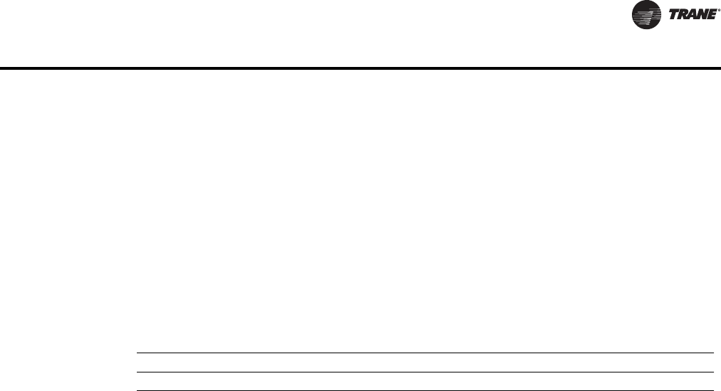
0.20
200 300 400 500
Airflow
Discharge Static Pressure
25
50
75
94 142 189 236
Cfm
L/s
Pa In. wg
700600
330283
0.10
0.60
0.30
0.50
0.40
100
125
150
Parallel 02SQ—PSC
100
47
120 cfm min
(57 L/s)
Note: When attenuator is required, add inlet
attenuator pressure to discharge static
pressure for final fan performance.
VPCF and VPEF maximum
Minimum
1-row coil maximum
2-row coil maximum
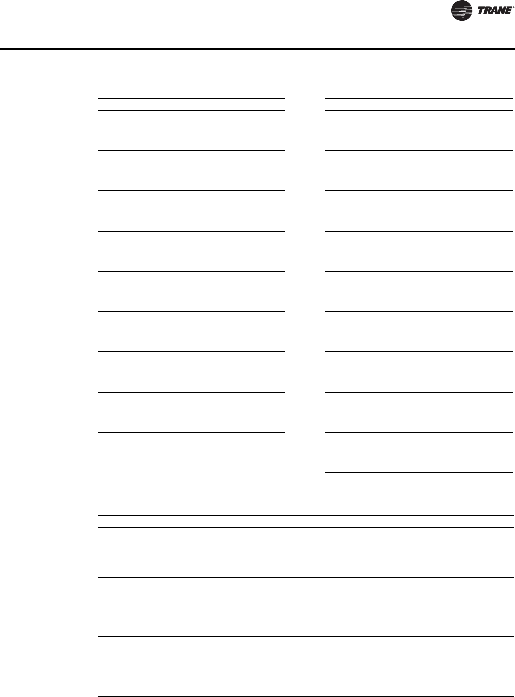
Parallel Fan Size 03SQ—PSC
0.10
0.20
0.30
200 300 400 500
Airflow
Discharge Static Pressure
25
50
75
94 142 189 236
Cfm
L/s
Pa In. wg
0.80
199
0.70
174
0.60
150
0.50
125
0.40
100
1300
614
1200
566
1100
519
1000
472
900
425
800
378
700
330
600
283
250 cfm min
(118 L/s)
Parallel 04SQ—PSC
0.20
0.40
0.60
0.80
200 400 600 800 1000 1200 1400 1600
Airflow
Discharge Static Pressure
0.30
0.50
0.10
0.70
199
174
150
125
100
75
50
25
94 189 283 378 472 566 661 755
Pa In. wg
Cfm
L/s
300 cfm min
(142 L/s)

VAV-PRC012-EN 29
Performance Data
Parallel 05SQ—PSC
0.10
0.20
0.30
0.40
0.50
0.60
0.70
0.80
300 500 700 900 1100 1300 1500 1700
Airflow
Discharge Static Pressure
Pa In. wg
Cfm
L/s
199
174
150
125
100
75
50
25
142 236 330 425 519 614 708 802
350 cfm min
(165 L/s)
Note: When attenuator is required, add inlet
attenuator pressure to discharge static
pressure for final fan performance.
VPCF and VPEF maximum
Minimum
1-row coil maximum
2-row coil maximum
0.10
0.20
0.30
400
Airflow
Discharge Static Pressure
25
50
100
189 378 566 850 1038
Cfm
L/s
Pa In. wg
Parallel 06SQ—PSC
600 800 1000 1200 1400 1600 1800 2000 2200
0.40
0.50
0.60
0.70
0.80
199
174
150
125
75
755661472
283 944
530 cfm min
(250 L/s)
Airflow
Discharge Static Pressure
25
50
75
236 519 708 897 1086
Cfm
L/s
Pa In. wg
Parallel 07SQ—PSC
0.10
0.20
0.30
0.50
0.60
0.70
0.80
500 700 900 1100 1300 1500 1700 1900 2100
0.40
2300
425330 991802614
199
174
150
125
100
585 cfm min
(276 L/s)
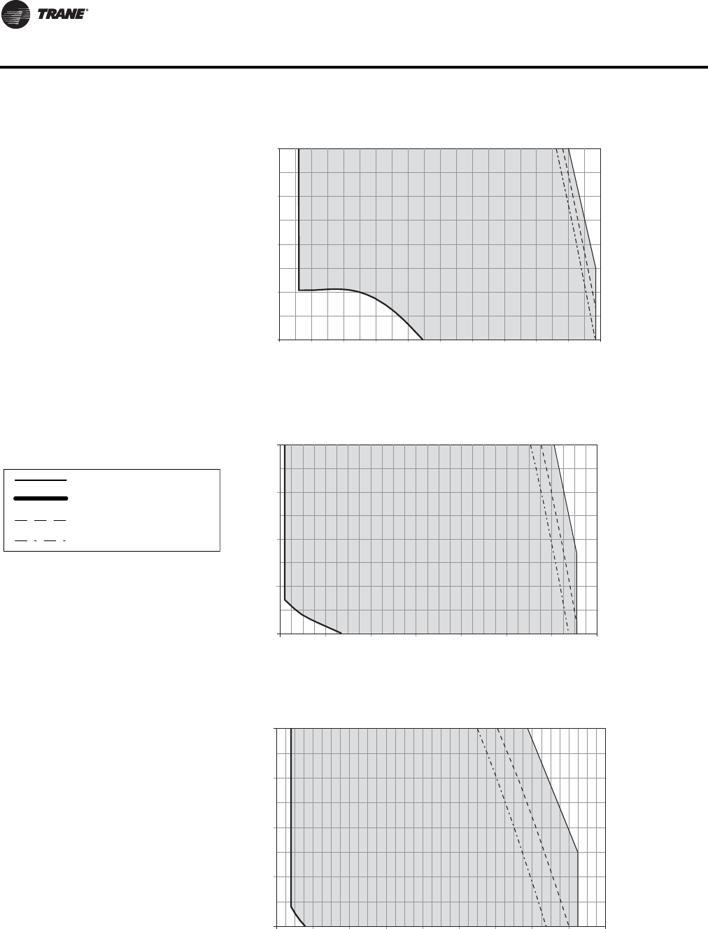
30 VAV-PRC012-EN
Performance Data
Airflow
Discharge Static Pressure
25
50
75
47 142 283 378 519
Cfm
L/s
Pa In. wg
VPxF 03SQ—ECM
0.10
0.20
0.30
0.40
0.50
100 200 300 400 500 600 700 800 900 1000 1100
125
100
236 330 425 47294 189
160 cfm min
(76 L/s)
Notes:
1. ECMs (Electrically Commutated Motors) are
ideal for systems seeking maximum motor
efficiency.
2. When attenuator is required, add inlet
attenuator pressure to discharge static
pressure for final fan performance.
VPCF and VPEF maximum
Minimum
1-row coil maximum
2-row coil maximum
Airflow
Discharge Static Pressure
25
50
75
94 189 283 755
Cfm
L/s
Pa In. wg
VPxF 04SQ—ECM
0.10
0.20
0.30
0.40
0.50
200 400 600 800 1000 1200 1400 1600
100
125
661566472378
220 cfm min
(104 L/s)
Airflow
Discharge Static Pressure
25
50
75
94 189 944
Cfm
L/s
Pa In. wg
VPxF 05SQ—ECM
0.10
0.20
0.30
0.40
0.50
200 400 600 800 1000 1200 1400 1800 2000
125
100
661566472378
283 850
1600
755
280 cfm min
(132 L/s)
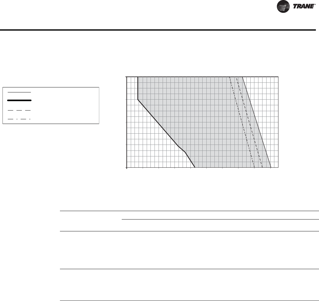
VAV-PRC012-EN 31
Performance Data
Notes:
1. ECMs (Electrically Commutated Motors) are
ideal for systems seeking maximum motor
efficiency.
2. When attenuator is required, add inlet
attenuator pressure to discharge static
pressure for final fan performance.
VPCF and VPEF maximum
Minimum
1-row coil maximum
2-row coil maximum
Airflow
Discharge Static Pressure
25
50
100
189
Cfm
L/s
Pa In. wg
VPxF 06SQ—ECM
0.10
0.20
0.30
0.40
0.50
400 600 800 1000 1200 1400 1600 1800 2000 2200
75
125
850755661566472378283
189 944 1038
530 cfm min
(250 L/s)
Table 12. Heating capacity (MBh) - fan size 02SQ (I-P)
Rows Gpm
Water
Pressure
Drop (ft)
Airflow (Cfm)
100 150 200 250 300 350 400 450 500 550 600
1-Row
Capacity
MBH
0.5
1.0
2.0
3.0
4.0
5.0
0.22
0.76
2.65
5.54
9.39
14.17
-
9.20
9.79
10.01
10.12
10.19
-
11.49
12.50
12.87
13.07
13.19
-
13.14
14.52
15.04
15.32
15.49
-
14.45
16.17
16.84
17.19
17.41
-
15.56
17.60
18.39
18.82
19.09
-
16.52
18.87
19.79
20.29
20.60
-
17.38
20.02
21.07
21.64
22.00
-
18.16
21.09
22.26
22.90
23.30
-
18.93
22.08
23.38
24.09
24.54
-
19.64
23.02
24.44
25.22
25.71
-
20.30
23.90
25.44
26.29
26.83
2-Row
Capacity
MBH
1.0
2.0
3.0
4.0
5.0
1.30
4.41
9.08
15.18
22.66
9.97
10.29
10.40
10.45
10.48
13.83
14.58
14.83
14.95
15.03
17.07
18.39
18.83
19.05
19.18
19.81
21.78
22.46
22.80
23.00
22.13
24.82
25.76
26.23
26.52
24.13
27.56
28.77
29.40
29.78
25.85
30.03
31.54
32.32
32.80
27.35
32.27
34.09
35.04
35.62
28.67
34.31
36.45
37.56
38.25
29.83
36.18
38.63
39.92
40.72
30.86
37.90
40.67
42.13
43.03
Notes:
1. Fouling Factor = 0.0005 °F ft² h/Btu.
2. Capacity based on 70°F entering air temperature and 180°F entering water temperature.

32 VAV-PRC012-EN
Performance Data
Water Coil Performance Notes (I-P)
1. Fouling Factor = 0.0005.
2. The off-coil temperature of the hot water coil on parallel fan-powered units must not exceed
140°F when mounted on plenum inlet.
3. The following equations may be used in calculating Leaving AirTemperature (LAT) and Water
Temperature Difference (WTD).
Table 13. Heating capacity (MBh) - fan sizes 03SQ–05SQ (I-P)
Rows Gpm
Water
Pressure
Drop (ft)
Airflow (Cfm)
150 300 450 600 750 900 1050 1200 1350 1500 1650
1-Row
Capacity
MBH
1.0
2.0
3.0
4.0
5.0
6.0
7.0
8.0
9.0
10.0
0.28
1.02
2.22
3.85
5.92
8.41
11.32
14.65
18.40
22.57
-
13.14
13.62
13.88
14.04
14.14
14.22
14.28
14.33
14.37
-
18.63
19.69
20.27
20.64
20.89
21.08
21.22
21.33
21.42
-
22.21
23.78
24.65
25.21
25.59
25.88
26.10
26.28
26.42
-
25.01
27.05
28.20
28.95
29.46
29.85
30.15
30.38
30.57
-
27.36
29.86
31.28
32.21
32.85
33.34
33.71
34.01
34.25
-
29.41
32.34
34.03
35.14
35.92
36.50
36.95
37.31
37.60
-
31.30
34.58
36.54
37.82
38.73
39.41
39.94
40.36
40.71
-
33.00
36.63
38.84
40.31
41.35
42.13
42.73
43.22
43.62
-
34.54
38.52
40.98
42.62
43.80
44.67
45.36
45.91
46.36
-
35.94
40.31
42.99
44.80
46.10
47.08
47.85
48.46
48.97
-
37.23
41.99
44.86
46.85
48.28
49.36
50.21
50.89
51.45
2-Row
Capacity
MBH
1.0
2.0
3.0
4.0
5.0
6.0
7.0
8.0
9.0
10.0
0.35
1.28
2.74
4.72
7.20
10.18
13.64
17.59
22.03
26.94
-
15.08
15.36
15.50
15.59
15.64
15.68
15.71
15.74
15.76
-
25.87
27.00
27.57
27.92
28.15
28.31
28.44
28.54
28.62
-
33.70
35.94
37.11
37.83
38.31
38.66
38.93
39.13
39.30
-
39.58
42.99
44.82
45.97
46.74
47.31
47.74
48.08
48.35
-
44.13
48.69
51.20
52.78
53.87
54.67
55.28
55.76
56.15
-
47.77
53.40
56.57
58.59
59.99
61.02
61.81
62.44
62.95
-
50.73
57.36
61.15
63.60
65.32
66.58
67.55
68.32
68.95
-
53.20
60.74
65.13
67.99
70.00
71.49
72.64
73.55
74.30
-
55.29
63.66
68.60
71.85
74.15
75.86
77.19
78.24
79.10
-
57.08
66.21
71.68
75.30
77.87
79.80
81.29
82.48
83.45
-
58.63
68.46
74.42
78.39
81.23
83.36
85.01
86.33
87.42
Table 14. Heating capacity (MBh) - fan sizes 06SQ & 07SQ (I-P)
Rows Gpm
Water
Pressure
Drop (ft)
Airflow (Cfm)
900 1000 1100 1200 1300 1400 1500 1600 1700 1800 1900
1-Row
Capacity
MBH
0.5
1.0
2.0
3.0
4.0
5.0
6.0
7.0
0.11
0.36
1.24
2.57
4.32
6.49
9.04
11.99
-
-
32.17
35.12
36.78
37.86
38.61
39.17
-
-
33.60
36.76
38.60
39.79
40.63
41.25
-
-
34.93
38.31
40.32
41.63
42.55
43.23
-
-
36.17
39.77
41.95
43.38
44.38
45.13
-
-
37.34
41.16
43.51
45.05
46.14
46.95
-
-
38.43
42.50
45.01
46.66
47.83
48.70
-
-
39.47
43.81
46.44
48.21
49.46
50.40
-
-
40.45
45.07
47.82
49.70
51.04
52.04
-
-
41.38
46.27
49.14
51.14
52.56
53.62
-
-
42.27
47.42
50.42
52.53
54.04
55.16
-
-
43.12
48.53
51.68
53.88
55.47
56.66
2-Row
Capacity
MBH
1.0
2.0
3.0
4.0
5.0
6.0
7.0
0.68
2.24
4.57
7.59
11.29
15.64
20.61
-
51.03
56.65
59.73
61.67
63.00
63.97
-
53.38
59.74
63.27
65.51
67.05
68.18
-
55.46
62.53
66.50
69.04
70.79
72.07
-
57.32
65.06
69.46
72.28
74.24
75.69
-
58.98
67.37
72.18
75.29
77.45
79.05
-
60.47
69.48
74.69
78.08
80.44
82.19
-
61.83
71.42
77.02
80.67
83.24
85.14
-
63.07
73.20
79.18
83.09
85.86
87.90
-
64.20
74.86
81.19
85.36
88.31
90.51
-
65.24
76.40
83.08
87.50
90.63
92.96
-
66.20
77.83
84.84
89.50
92.81
95.28
L
AT EAT MBH 921.7
Cfm
--------------------------------------
+=
WTD EWT LWT 2MBH
Gpm
------------------------
=–=
VAV-PRC012-EN 33
Performance Data
4. Capacity based on 70°F entering air temperature and 180°F entering water temperature. Refer
to correction factors for different entering conditions.
5. For premium coils (.020” wall), water side pressure drop increases 17% and water velocity
increases 7% for fixed GPM.
Table 15. Temperature correction factors for water pressure drop (ft)
Average Water Temperature
Correction Factor
200
0.970
190
0.985
180
1.000
170
1.020
160
1.030
150
1.050
140
1.080
130
1.100
120
1.130
110
1.150
Table 16. Temperature correction factors for coil capacity (MBH)
Entering Water Minus Entering Air
Correction Factor
40
0.355
50
0.446
60
0.537
70
0.629
80
0.722
90
0.814
100
0.907
110
1.000
120
1.093
130
1.187
Table 17. Heating capacity (kW) - fan size 02SQ (SI)
Rows L/s
Water
Pressure
Drop
(kPa)
Airflow (L/s)
47 71 94 118 142 165 189 212 236 260 283
1-Row
Capacity
kW
0.03
0.06
0.13
0.19
0.25
0.32
0.66
2.26
7.91
16.57
28.08
42.34
-
2.69
2.87
2.93
2.97
2.99
-
3.37
3.66
3.77
3.83
3.87
-
3.85
4.26
4.41
4.49
4.54
-
4.24
4.74
4.93
5.04
5.10
-
4.56
5.16
5.39
5.52
5.59
-
4.84
5.53
5.80
5.95
6.04
-
5.09
5.87
6.18
6.34
6.45
-
5.32
6.18
6.52
6.71
6.83
-
5.55
6.47
6.85
7.06
7.19
-
5.76
6.75
7.16
7.39
7.53
-
5.76
6.75
7.16
7.39
7.53
2-Row
Capacity
kW
0.06
0.13
0.19
0.25
0.32
3.89
13.19
27.13
45.38
67.73
2.92
3.02
3.05
3.06
3.07
4.05
4.27
4.35
4.38
4.40
5.00
5.39
5.52
5.58
5.62
5.80
6.38
6.58
6.68
6.74
6.49
7.27
7.55
7.69
7.77
7.07
8.08
8.43
8.62
8.73
7.58
8.80
9.24
9.47
9.61
8.02
9.46
9.99
10.27
10.44
8.40
10.06
10.68
11.01
11.21
8.74
10.60
11.32
11.70
11.93
8.74
10.60
11.32
11.70
11.93
Table 18. Heating capacity (kW) - fan sizes 03SQ–05SQ (SI)
Rows L/s
Water
Pressure
Drop (kPa)
Airflow (L/s)
71 142 212 283 354 425 495 566 637 708 779
1-Row
Capacity
kW
0.06
0.13
0.19
0.25
0.32
0.38
0.44
0.50
0.57
0.63
0.82
3.06
6.63
11.51
17.68
25.13
33.83
43.79
55.00
67.45
-
3.85
3.99
4.07
4.11
4.15
4.17
4.19
4.20
4.21
-
5.46
5.77
5.94
6.05
6.12
6.18
6.22
6.25
6.28
-
6.51
6.97
7.22
7.39
7.50
7.58
7.65
7.70
7.74
-
7.33
7.93
8.27
8.48
8.64
8.75
8.83
8.90
8.96
-
8.02
8.75
9.17
9.44
9.63
9.77
9.88
9.97
10.04
-
8.62
9.48
9.97
10.30
10.53
10.70
10.83
10.93
11.02
-
9.17
10.14
10.71
11.08
11.35
11.55
11.71
11.83
11.93
-
9.67
10.74
11.38
11.81
12.12
12.35
12.52
12.67
12.78
-
10.12
11.29
12.01
12.49
12.84
13.09
13.29
13.46
13.59
-
10.53
11.81
12.60
13.13
13.51
13.80
14.02
14.20
14.35
-
10.53
11.81
12.60
13.13
13.51
13.80
14.02
14.20
14.35
2-Row
Capacity
kW
0.06
0.13
0.19
0.25
0.32
0.38
0.44
0.50
0.57
0.63
1.06
3.83
8.20
14.11
21.52
30.42
40.78
52.59
65.84
80.52
-
4.42
4.50
4.54
4.57
4.58
4.60
4.61
4.61
4.62
-
7.58
7.91
8.08
8.18
8.25
8.30
8.33
8.36
8.39
-
9.88
10.53
10.88
11.09
11.23
11.33
11.41
11.47
11.52
-
11.60
12.60
13.14
13.47
13.70
13.87
13.99
14.09
14.17
-
12.93
14.27
15.01
15.47
15.79
16.02
16.20
16.34
16.45
-
14.00
15.65
16.58
17.17
17.58
17.88
18.12
18.30
18.45
-
14.87
16.81
17.92
18.64
19.14
19.51
19.80
20.02
20.21
-
15.59
17.80
19.09
19.92
20.51
20.95
21.29
21.56
21.77
-
16.20
18.66
20.11
21.06
21.73
22.23
22.62
22.93
23.18
-
16.73
19.40
21.01
22.07
22.82
23.39
23.82
24.17
24.46
-
16.73
19.40
21.01
22.07
22.82
23.39
23.82
24.17
24.46

34 VAV-PRC012-EN
Performance Data
Water Coil Performance Notes (SI)
1. Fouling Factor = 0.0005.
2. The off-coil temperature of the hot water coil on parallel fan-powered units must not exceed
60°C when mounted on plenum inlet.
3. The following equations may be used in calculating Leaving AirTemperature (LAT) and Water
Temperature Difference (WTD).
WTD=EWT-LWT=kW/(4.19) L/s
4. Capacity based on 21°C entering air temperature and 82°C entering water temperature. Refer
to correction factors for different entering conditions.
5. For premium coils (.020” wall), water side pressure drop increases 17% and water velocity
increases 7% for fixed GPM.
Table 19. Heating capacity (kW) - fan sizes 06SQ & 07SQ (SI)
Rows L/s
Water
Pressure
Drop
(kPa)
Airflow (L/s)
425 472 519 566 613 661 708 755 802 849 897
1-Row
Capacity
kW
0.03
0.06
0.13
0.19
0.25
0.32
0.38
0.44
0.33
1.09
3.71
7.68
12.92
19.39
27.04
35.84
-
-
9.43
10.29
10.78
11.10
11.32
11.48
-
-
9.85
10.77
11.31
11.66
11.91
12.09
-
-
10.24
11.23
11.82
12.20
12.47
12.67
-
-
10.60
11.66
12.30
12.71
13.01
13.23
-
-
10.94
12.06
12.75
13.20
13.52
13.76
-
-
11.26
12.46
13.19
13.67
14.02
14.27
-
-
11.57
12.84
13.61
14.13
14.50
14.77
-
-
11.86
13.21
14.01
14.57
14.96
15.25
-
-
12.13
13.56
14.40
14.99
15.40
15.72
-
-
12.39
13.90
14.78
15.40
15.84
16.17
-
-
12.39
13.90
14.78
15.40
15.84
16.17
2-Row
Capacity
kW
0.06
0.13
0.19
0.25
0.32
0.38
0.44
2.02
6.70
13.65
22.70
33.76
46.74
61.61
-
14.96
16.60
17.51
18.07
18.46
18.75
-
15.64
17.51
18.54
19.20
19.65
19.98
-
16.25
18.33
19.49
20.23
20.75
21.12
-
16.80
19.07
20.36
21.18
21.76
22.18
-
17.28
19.74
21.15
22.06
22.70
23.17
-
17.72
20.36
21.89
22.88
23.58
24.09
-
18.12
20.93
22.57
23.64
24.39
24.95
-
18.48
21.45
23.20
24.35
25.16
25.76
-
18.82
21.94
23.80
25.02
25.88
26.52
-
19.12
22.39
24.35
25.64
26.56
27.24
-
19.12
22.39
24.35
25.64
26.56
27.24
Table 20. Temperature correction factors for water pressure drop (kPa)
Average Water Temperature
Correction Factor
93
0.970
88
0.985
82
1.000
77
1.020
71
1.030
66
1.050
60
1.080
54
1.100
49
1.130
43
1.150
Table 21. Temperature correction factors for coil capacity (kW)
Entering Water Minus Entering Air
Correction Factor
22
0.355
27
0.446
33
0.537
38
0.629
44
0.722
50
0.814
55
0.907
61
1.000
67
1.093
72
1.187
L
AT EAT kW 0.83
Ls
-----------------------------
+=
VAV-PRC012-EN 35
Performance Data
Series Fan-Powered Terminal Units
Table 22. Primary airflow control factory settings – I-P
Control Type
Air Valve Size
(in.)
Maximum
Valve Cfm
Maximum
Controller Cfm
Minimum
Controller Cfm
Constant
Volume Cfm
Direct Digital
Control/UCM
4
5
6
8
225
350
500
900
25-225
40-350
60-500
105-900
0, 25-225
0, 40-350
0, 60-500
0, 105-900
25-225
40-350
60-500
105-900
10
12
14
16
1400
2000
3000
4000
165-1400
240-2000
320-3000
420-4000
0, 165-1400
0, 240-2000
0, 320-3000
0, 420-4000
165-1400
240-2000
320-3000
420-4000
Pneumatic with
Volume Regulator
4
5
6
8
225
350
500
900
38-225
63-350
73-500
134-900
0, 38-225
0, 63-350
0, 73-500
0, 134-900
38-225
63-350
73-500
134-900
10
12
14
16
1400
2000
2885
3785
215-1400
300-2000
408-2887
536-3789
0, 215-1400
0, 300-2000
0, 408-2887
0, 536-3789
215-1400
300-2000
408-2887
536-3789
Note: Maximum airflow must be greater than or equal to minimum airflow.
Table 23. Primary airflow control factory settings – SI
Control Type
Air Valve Size
(in.)
Maximum
Valve L/s
Maximum
Controller L/s
Minimum
Controller L/s
Constant
Volume L/s
Direct Digital
Control/UCM
4
5
6
8
106
165
236
425
12-106
19-165
28-236
50-425
0, 12-106
0, 19-165
0, 28-236
0, 50-425
12-106
19-165
28-236
50-425
10
12
14
16
661
944
1416
1888
77-661
111-944
151-1416
198-1888
0, 77-661
0, 111-944
0, 151-1416
0, 198-1888
77-661
111-944
151-1416
198-1888
Pneumatic with
Volume
Regulator
4
5
6
8
106
165
236
425
18-106
30-165
35-236
63-425
0, 18-106
0, 30-165
0, 35-236
0, 63-425
18-106
30-165
35-236
63-425
10
12
14
16
661
944
1362
1787
102-661
141-944
193-1363
253-1788
0, 102-661
0, 141-944
0, 193-1363
0, 253-1788
102-661
141-944
193-1363
253-1788
Note: Maximum airflow must be greater than or equal to minimum airflow.

36 VAV-PRC012-EN
Performance Data
Table 24. Unit air pressure drop – in. wg (I-P)
Fan/Inlet Size Airflow Cfm Unit Fan/Inlet Size Airflow Cfm Unit
2SQ-04 200
225
0.03
0.03 04SQ-12
330
750
1150
1550
0.02
0.11
0.28
0.51
2SQ-05
200
250
300
350
0.03
0.04
0.06
0.09
04SQ-14
330
750
1150
1550
0.02
0.11
0.26
0.48
2SQ-06
200
300
400
500
0.03
0.06
0.12
0.19
05SQ-10
400
750
1100
1400
0.01
0.08
0.22
0.39
2SQ-08
200
400
550
700
0.01
0.05
0.10
0.16
05SQ-12
400
900
1400
1900
0.01
0.09
0.28
0.58
2SQ-10
200
400
550
700
0.01
0.02
0.06
0.11
05SQ-14
400
900
1400
1900
0.01
0.09
0.26
0.53
03SQ-06
250
300
400
500
0.10
0.15
0.34
0.45
6SQ-10
700
950
1200
1400
0.01
0.03
0.12
0.22
03SQ-08
250
500
700
900
0.05
0.16
0.31
0.49
6SQ-12
700
1150
1600
2000
0.01
0.01
0.12
0.27
03SQ-10
250
550
850
1200
0.03
0.11
0.24
0.44
6SQ-14
700
1350
2000
2600
0.01
0.04
0.19
0.41
03SQ-12
250
550
850
1200
0.01
0.07
0.16
0.32
6SQ-16
700
1350
2000
2600
0.01
0.04
0.19
0.41
04SQ-06
330
400
450
500
0.16
0.29
0.35
0.48
7SQ-10
850
1000
1200
1400
0.01
0.05
0.12
0.22
Note: Unit pressure drops do not include hot water coil or attenuator pressure drops.
VAV-PRC012-EN 37
Performance Data
04SQ-08
330
500
700
900
0.04
0.12
0.25
0.44
7SQ-12
850
1200
1600
2000
0.01
0.02
0.12
0.27
04SQ-10
330
700
1050
1400
0.02
0.12
0.29
0.54
7SQ-14
850
1550
2250
3000
0.01
0.07
0.27
0.59
7SQ-16
850
1550
2250
3000
0.01
0.07
0.27
0.59
Note: Unit pressure drops do not include hot water coil or attenuator pressure drops.
Table 24. Unit air pressure drop – in. wg (I-P) (continued)
Fan/Inlet Size Airflow Cfm Unit Fan/Inlet Size Airflow Cfm Unit
Table 25. Coil air pressure drop – in. wg (I-P)
Fan
Size
Airflow
Cfm
1-Row HW
(in. wg)
2-Row HW
(in. wg) Fan Size Airflow Cfm
1-Row HW
(in. wg)
2-Row HW
(in. wg)
02SQ
200
300
400
500
600
0.01
0.02
0.04
0.06
0.08
0.03
0.05
0.08
0.11
0.15
05SQ
400
700
1000
1250
1500
1750
0.01
0.04
0.07
0.10
0.14
0.19
0.03
0.08
0.13
0.19
0.26
0.34
03SQ
04SQ
250
500
750
1000
1250
1500
0.01
0.02
0.05
0.08
0.12
0.16
0.02
0.05
0.10
0.15
0.22
0.30
06SQ
07SQ
600
1000
1500
2000
2500
3000
0.02
0.04
0.08
0.13
0.19
0.27
0.04
0.08
0.15
0.23
0.34
0.47
Note: HW Coil Only pressure drops do not include unit pressure drop.
Table 26. Attenuator air pressure drop (I-P)
Fan Size Plenum Cfm Attenuator Fan Size Plenum Cfm Attenuator
02SQ
50
150
350
550
750
950
0.00
0.00
0.02
0.05
0.10
0.16
05SQ
50
300
650
1000
1300
1650
0.00
0.01
0.05
0.14
0.28
0.52
03SQ
50
250
500
750
1000
1200
0.00
0.00
0.02
0.06
0.13
0.21
06SQ
50
500
900
1300
1700
2100
0.00
0.00
0.02
0.07
0.17
0.36
04SQ
50
300
600
900
1200
1500
0.00
0.02
0.07
0.14
0.24
0.35
07SQ
50
800
1200
1600
2000
2400
0.00
0.01
0.05
0.14
0.30
0.58
Note: Plenum cfm = (Fan cfm) – (Min. valve cfm)
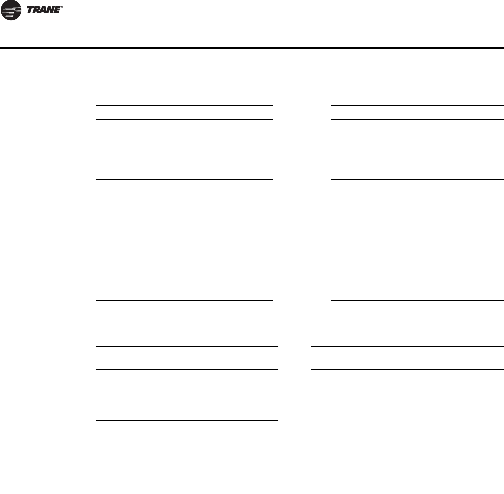
38 VAV-PRC012-EN
Performance Data
Table 27. Attenuator air pressure drop (SI)
Fan Size Plenum L/s Attenuator Fan Size Plenum L/s Attenuator
02SQ
24
71
165
260
354
448
0
1
4
12
24
40
05SQ
24
142
307
472
613
779
0
2
12
36
70
129
03SQ
24
118
236
354
472
566
0
1
5
15
32
52
06SQ
24
236
425
613
802
991
0
1
4
16
42
90
04SQ
24
142
283
425
566
708
0
5
18
36
59
88
07SQ
24
378
566
755
944
1133
0
3
12
34
75
144
Note: Plenum cfm = (Fan cfm) – (Min. valve cfm)
Table 28. Coil air pressure drop – Pa (SI)
Fan
Size
Airflow
L/s
1-Row HW
(Pa)
2-Row HW
(Pa) Fan Size
Airflow L/
s
1-Row HW
(Pa)
2-Row HW
(Pa)
02SQ
250
400
500
600
700
3
6
10
14
20
7
12
19
28
38
05SQ
189
330
472
590
708
826
4
9
17
25
35
47
8
19
33
48
65
85
03SQ
04SQ
118
236
354
472
590
708
2
6
12
19
29
40
5
13
24
38
55
75
06SQ
07SQ
850
1300
1700
2150
2550
3000
4
9
19
31
47
66
9
19
36
58
85
117
Note: HW coil only pressure drops do not include unit pressure drop.
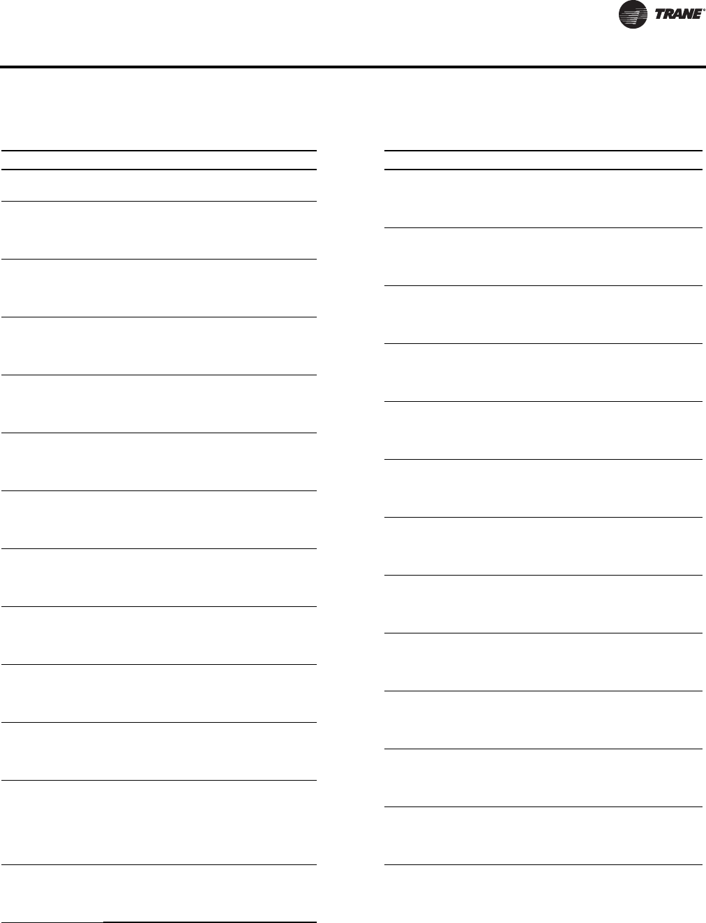
VAV-PRC012-EN 39
Performance Data
Table 29. Unit air pressure drop-Pa (SI)
Fan/Inlet Size Airflow Cfm Unit Fan/Inlet Size Airflow Cfm Unit
2SQ-04 94
106
7
904SQ-14
156
354
543
731
5
27
65
120
2SQ-05
94
118
142
165
7
11
16
22 05SQ-10
189
354
519
661
1
20
55
98
2SQ-06
94
142
189
236
7
16
29
46 05SQ-12
189
425
661
897
2
23
71
144
2SQ-08
94
189
260
330
2
12
24
39 05SQ-14
189
425
661
897
2
21
65
131
2SQ-10
94
189
260
330
2
5
14
39 6SQ-10
330
448
566
661
2
8
31
55
03SQ-06
118
142
189
236
25
38
85
112 6SQ-12
330
543
755
944
2
3
31
68
03SQ-08
118
236
330
425
12
41
76
123 6SQ-14
330
637
944
1227
2
9
47
101
03SQ-10
118
260
401
566
8
28
59
110 6SQ-16
330
637
944
1227
2
9
47
101
03SQ-12
118
260
401
566
4
17
40
79 7SQ-10
401
472
566
661
2
12
55
04SQ-06
156
189
212
236
40
73
88
119 7SQ-12
401
566
755
944
2
5
31
68
04SQ-08
156
236
330
425
10
29
63
109 7SQ-14
401
731
1062
1416
2
18
67
147
04SQ-10
156
330
495
661
5
30
73
135 7SQ-16
401
731
1062
1416
2
18
67
147
04SQ-12
156
354
543
731
5
28
69
127
Note: Unit pressure drops do not include hot water coil or attenuator pressure drops.
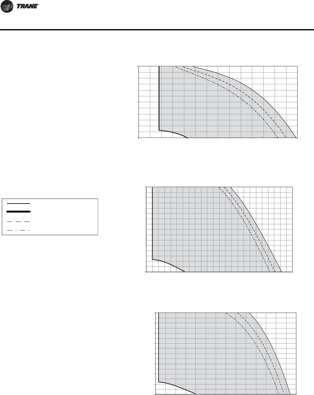
40 VAV-PRC012-EN
Performance Data
Airflow
Discharge Static Pressure
0
25
50
75
47 94 142 189 236
Cfm
L/s
Pa In. wg
Series 02SQ—PSC
0.00
0.10
0.20
0.30
0.40
0.50
0.60
100 200 300 400 500 600 700 800
378
330283
150
125
100
190 cfm min
(90 L/s)
Note: When attenuator is required, add inlet
attenuator pressure to discharge static
pressure for final fan performance.
VSCF and VSEF maximum
Minimum
1-row coil maximum
2-row coil maximum
Series 03SQ—PSC
0.00
0.20
0.40
0.60
0.80
200 300 400 500 600 700 800 900 1000 1100 1200 1300 1400
Airflow
Discharge Static Pressure
0.10
0.30
0.50
0.70
199
174
150
125
100
75
50
25
0
94 142 189 236 283 330 378 425 472 519 566 614 661
Pa In. wg
Cfm
L/s
250 cfm min
(118 L/s)
Series 04SQ—PSC
0.00
0.20
0.40
0.60
0.80
300 400 500 600 700 800 900 1000 1100 1200 1300 1400 1500 1600 1700
Airflow
Discharge Static Pressure
0.10
0.30
0.50
0.70
Pa In. wg
Cfm
L/s
199
174
150
125
100
75
50
25
0
142 189 236 283
330 378 425 472 519 566 614 661 708 755 802
330 cfm min
(156 L/s)
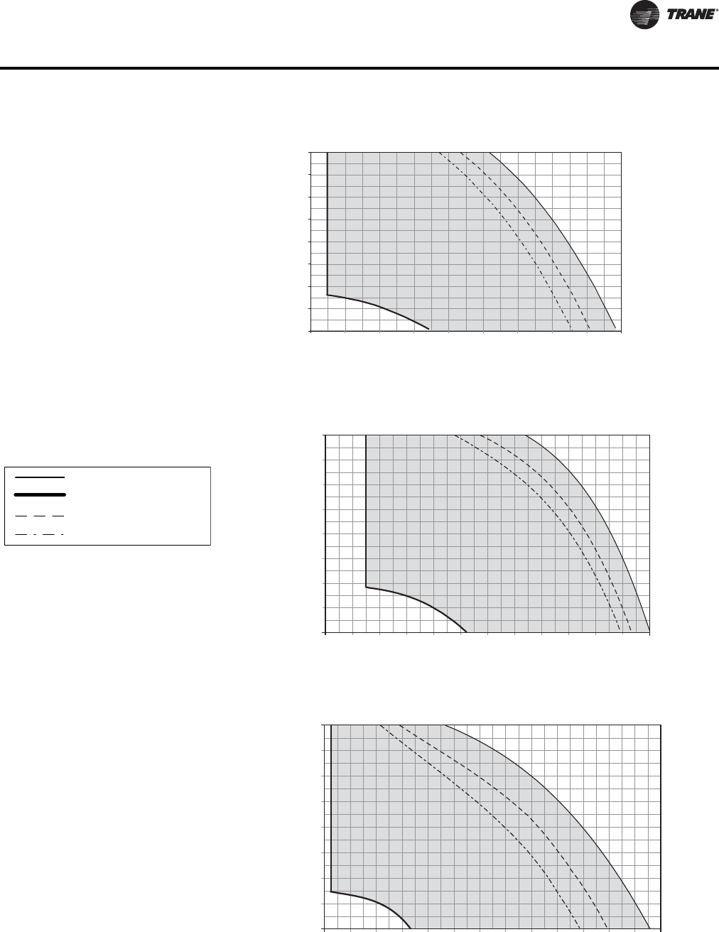
VAV-PRC012-EN 41
Performance Data
Series 05SQ—PSC
0.00
0.20
0.40
0.60
0.80
300 500 700 900 1100 1300 1500 1700 1900 2100
Airflow
Discharge Static Pressure
0.10
0.30
0.50
0.70
Pa In. wg
Cfm
L/s
199
174
150
125
100
75
50
25
0
142 236 330 425 519 614 708 802 897 991
400 cfm min
(189 L/s)
Note: When attenuator is required, add inlet
attenuator pressure to discharge static
pressure for final fan performance.
VSCF and VSEF maximum
Minimum
1-row coil maximum
2-row coil maximum
Airflow
Discharge Static Pressure
0
25
50
75
189 283 378 850 1322
Cfm
L/s
Pa In. wg
Series 06SQ—PSC
0.00
0.10
0.20
0.30
0.40
0.50
0.60
0.70
0.80
400 600 800 1000 1200 1400 1600 1800 2000 2200 2400 2600 2800
199
174
150
125
100
944755661566472 122711331038
700 cfm min
(330 L/s)
Airflow
Discharge Static Pressure
0
25
50
75
378 1322 1605
Cfm
L/s
Pa In. wg
Series 07SQ—PSC
0.00
0.10
0.20
0.30
0.40
0.50
0.60
0.70
0.80
800 1000 1200 1400 1600 1800 2000 2200 2400 2600 2800 3000 3200 3400
199
174
150
125
100
15101416
1227
11331038944850755661566472
850 cfm min
(401 L/s)
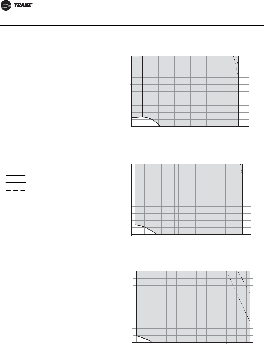
42 VAV-PRC012-EN
Performance Data
Airflow
Discharge Static Pressure
25
50
75
47 94 142 189 236
Cfm
L/s
Pa In. wg
VSxF Size 03SQ—ECM
0.00
0.10
0.20
0.30
0.40
0.50
100 200 300 400 500 600 700 800 900 1000 1100 1200
125
100
0
566519472425378330283
200 cfm min
(94 L/s)
Notes:
1. ECMs (Electrically Commutated Motors) are
ideal for systems seeking maximum motor
efficiency.
2. When attenuator is required, add inlet
attenuator pressure to discharge static
pressure for final fan performance.
VSCF and VSEF maximum
Minimum
1-row coil maximum
2-row coil maximum
Airflow
Discharge Static Pressure
0
25
50
75
94 189
Cfm
L/s
Pa In. wg
125
100
755
566472378283
VSxF 04SQ—ECM
0.00
0.10
0.20
0.30
0.40
0.50
200 400 600 800 1000 1200 1400 1600
661
240 cfm min
(113 L/s)
Airflow
Discharge Static Pressure
0
25
50
75
142 236
Cfm
L/s
Pa In. wg
125
100
708
614519425330
VSxF 05SQ—ECM
0.00
0.10
0.20
0.30
0.40
0.50
300 500 700 900 1100 1300 1500 1700 1900 2100
991897
802
350 cfm min
(165 L/s)
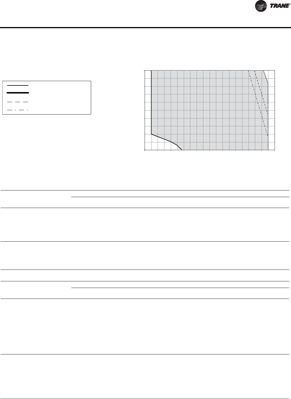
VAV-PRC012-EN 43
Performance Data
Notes:
1. ECMs (Electrically Commutated Motors) are
ideal for systems seeking maximum motor
efficiency.
2. When attenuator is required, add inlet
attenuator pressure to discharge static
pressure for final fan performance.
VSCF and VSEF maximum
Minimum
1-row coil maximum
2-row coil maximum
Airflow
Discharge Static Pressure
0
25
50
75
283 472 661 944
Cfm
L/s
Pa In. wg
VSxF 06SQ—ECM
0.00
0.10
0.20
0.30
0.40
0.50
600 800 1,000 1,200 1,400 1,800 2,000 2,200 2,400 2,600
1,600
125
100
566 1038850755 12271133378
700 cfm min
(330 L/s)
Table 30. Heating capacity (MBh) - fan size 02SQ (I-P)
Rows Gpm
Water
Pressure
Drop (ft)
Airflow (Cfm)
150 200 250 300 350 400 450 500 550 600 700
1-Row
Capacity
MBH
0.50
1.0
2.0
3.0
4.0
5.0
0.16
0.53
1.85
3.85
6.51
9.79
-
9.14
9.94
10.25
10.41
10.51
-
10.34
11.40
11.80
12.02
12.15
-
11.34
12.63
13.14
13.41
13.58
-
12.20
13.73
14.34
14.66
14.87
-
12.97
14.73
15.43
15.81
16.05
-
13.67
15.66
16.45
16.89
17.17
-
14.32
16.52
17.41
17.90
18.21
-
14.93
17.33
18.32
18.87
19.21
-
15.51
18.10
19.18
19.78
20.17
-
16.05
18.82
20.01
20.66
21.08
-
17.02
20.18
21.56
22.32
22.81
2-Row
Capacity
MBH
1.0
2.0
3.0
4.0
5.0
1.00
3.42
7.05
11.82
17.68
12.59
13.42
13.71
13.86
13.94
15.23
16.60
17.08
17.33
17.48
17.40
19.34
20.04
20.40
20.62
19.21
21.73
22.66
23.14
23.44
20.74
23.84
25.00
25.62
25.99
22.06
25.71
27.12
27.86
28.32
23.19
27.39
29.03
29.90
30.44
24.19
28.90
30.77
31.77
32.40
25.07
30.27
32.37
33.50
34.21
25.85
31.52
33.84
35.10
35.89
27.19
33.72
36.46
37.96
38.92
Table 31. Heating capacity (MBh) - fan sizes 03SQ 04SQ (I-P)
Rows Gpm
Water
Pressure
Drop (ft)
Airflow (Cfm)
200 300 400 550 700 850 1000 1150 1300 1450 1600
1-Row
Capacity
MBH
1.0
2.0
3.0
4.0
5.0
6.0
7.0
8.0
9.0
10.0
0.27
1.01
2.19
3.81
5.85
8.32
11.20
14.50
18.22
22.35
-
15.03
15.70
16.06
16.29
16.45
16.56
16.65
16.72
16.78
-
18.19
19.23
19.80
20.16
20.41
20.59
20.73
20.84
20.93
-
20.63
22.00
22.76
23.24
23.58
23.82
24.01
24.17
24.29
-
23.57
25.41
26.44
27.11
27.57
27.91
28.18
28.39
28.56
-
26.00
28.29
29.59
30.43
31.02
31.46
31.80
32.08
32.30
-
28.09
30.81
32.38
33.40
34.12
34.66
35.07
35.41
35.68
-
29.99
33.08
34.91
36.11
36.96
37.59
38.08
38.48
38.80
-
31.71
35.15
37.23
38.60
39.58
40.31
40.88
41.34
41.71
-
33.27
37.05
39.38
40.93
42.03
42.86
43.51
44.03
44.46
-
34.68
38.83
41.38
43.10
44.34
45.26
45.99
46.57
47.05
-
35.97
40.51
43.26
45.15
46.51
47.54
48.34
48.99
49.52
2-Row
Capacity
MBH
1.0
2.0
3.0
4.0
5.0
6.0
7.0
8.0
0.39
1.41
3.01
5.16
7.84
11.06
14.81
19.07
-
18.93
19.46
19.72
19.88
19.98
20.06
20.12
-
25.58
26.72
27.30
27.65
27.88
28.05
28.18
-
30.93
32.79
33.75
34.34
34.74
35.02
35.24
-
37.20
40.20
41.80
42.79
43.47
43.96
44.34
-
41.99
46.12
48.38
49.81
50.79
51.50
52.05
-
45.78
50.97
53.88
55.73
57.01
57.96
58.68
-
48.85
55.02
58.54
60.81
62.40
63.57
64.46
-
51.38
58.45
62.56
65.23
67.10
68.49
69.57
-
53.52
61.41
66.05
69.11
71.26
72.87
74.11
-
55.34
63.98
69.14
72.55
74.98
76.79
78.19
-
56.92
66.24
71.88
75.63
78.31
80.32
81.88

44 VAV-PRC012-EN
Performance Data
Water Coil Notes (I-P)
1. Fouling Factor = 0.0005.
2. The following equations may be used in calculating Leaving AirTemperature (LAT) and Water
Temperature Difference (WTD):
3. Capacity based on 70°F entering air temperature and 180°F entering water temperature. Refer
to correction factors for different entering conditions.
Table 32. Heating capacity (MBh) - fan size 05SQ (I-P)
Rows Gpm
Water
Pressure
Drop (ft)
Airflow (Cfm)
350 500 650 800 1000 1200 1400 1600 1800 2000 2150
1-Row
Capacity
MBH
1.0
2.0
3.0
4.0
5.0
6.0
7.0
8.0
0.29
1.08
2.33
4.03
6.18
8.76
11.79
15.24
-
21.67
23.02
23.76
24.23
24.55
24.79
24.97
-
25.25
27.14
28.20
28.87
29.34
29.69
29.95
-
28.09
30.49
31.85
32.72
33.34
33.79
34.14
-
30.49
33.38
35.03
36.10
36.86
37.42
37.85
-
33.30
36.75
38.78
40.11
41.05
41.75
42.29
-
35.79
39.71
42.12
43.71
44.83
45.67
46.33
-
37.96
42.39
45.14
46.98
48.29
49.28
50.05
-
39.88
44.89
47.92
50.01
51.50
52.63
53.51
-
41.61
47.17
50.48
52.81
54.50
55.76
56.76
-
43.17
49.26
52.91
55.44
57.30
58.71
59.82
-
44.25
50.73
54.64
57.30
59.30
60.82
62.01
2-Row
Capacity
MBH
1.0
2.0
3.0
4.0
5.0
6.0
7.0
8.0
0.39
1.39
2.96
5.08
7.72
10.90
14.59
18.79
-
29.95
31.40
32.14
32.58
32.87
33.08
33.24
-
37.69
40.36
41.74
42.59
43.16
43.57
43.88
-
43.62
47.58
49.69
51.00
51.88
52.53
53.02
-
48.30
53.51
56.37
58.16
59.39
60.28
60.96
-
53.17
59.95
63.77
66.21
67.90
69.14
70.09
-
56.95
65.16
69.90
72.97
75.11
76.69
77.91
-
59.97
69.45
75.05
78.72
81.30
83.22
84.70
-
62.43
73.07
79.45
83.68
86.69
88.93
90.66
-
64.49
76.15
83.26
88.02
91.42
93.97
95.95
-
66.24
78.82
86.60
91.85
95.63
98.47
100.69
-
67.38
80.59
88.84
94.45
98.49
101.54
103.93
Table 33. Heating capacity (MBh) - fan size 06SQ & 07SQ (I-P)
Rows Gpm
Water
Pressure
Drop (ft)
Airflow (Cfm)
700 900 1100 1300 1500 1700 1900 2100 2300 2500 2700
1-Row
Capacity
MBH
0.5
1.0
2.0
3.0
4.0
5.0
6.0
0.12
0.40
1.37
2.83
4.76
7.13
9.93
-
-
31.21
33.81
35.27
36.20
36.85
-
-
34.50
37.76
39.61
40.80
41.64
-
-
37.47
41.19
43.42
44.87
45.90
-
-
40.06
44.25
46.86
48.57
49.78
-
-
42.33
47.10
50.00
51.97
53.36
-
-
44.37
49.74
52.91
55.12
56.70
-
-
46.21
52.17
55.63
58.07
59.83
-
-
47.89
54.40
58.24
60.84
62.79
-
-
49.43
56.49
60.68
63.46
65.59
-
-
50.85
58.43
62.97
66.00
68.24
-
-
52.16
60.24
65.14
68.41
70.77
2-Row
Capacity
MBH
1.0
2.0
3.0
4.0
5.0
6.0
0.77
2.58
5.27
8.78
13.07
18.13
-
47.79
52.10
54.37
55.77
56.71
-
54.01
60.08
63.38
65.44
66.85
-
58.79
66.51
70.82
73.55
75.43
-
62.56
71.79
77.06
80.45
82.80
-
65.61
76.21
82.39
86.40
89.22
-
68.13
79.96
86.98
91.60
94.86
-
70.25
83.19
91.00
96.18
99.86
-
72.05
86.00
94.54
100.26
104.34
-
73.60
88.47
97.69
103.91
108.37
-
74.95
90.65
100.51
107.20
112.03
-
76.14
92.61
103.06
110.19
115.36
Table 34. Temperature correction factors for water pressure drop (ft)
Average Water Temperature
Correction Factor
200
0.970
190
0.985
180
1.000
170
1.020
160
1.030
150
1.050
140
1.080
130
1.100
120
1.130
110
1.150
L
AT EAT MBHx921.7
Cfm
------------------------------------
+=
WTD EWT LWT 2MBH
Gpm
------------------------
=–=
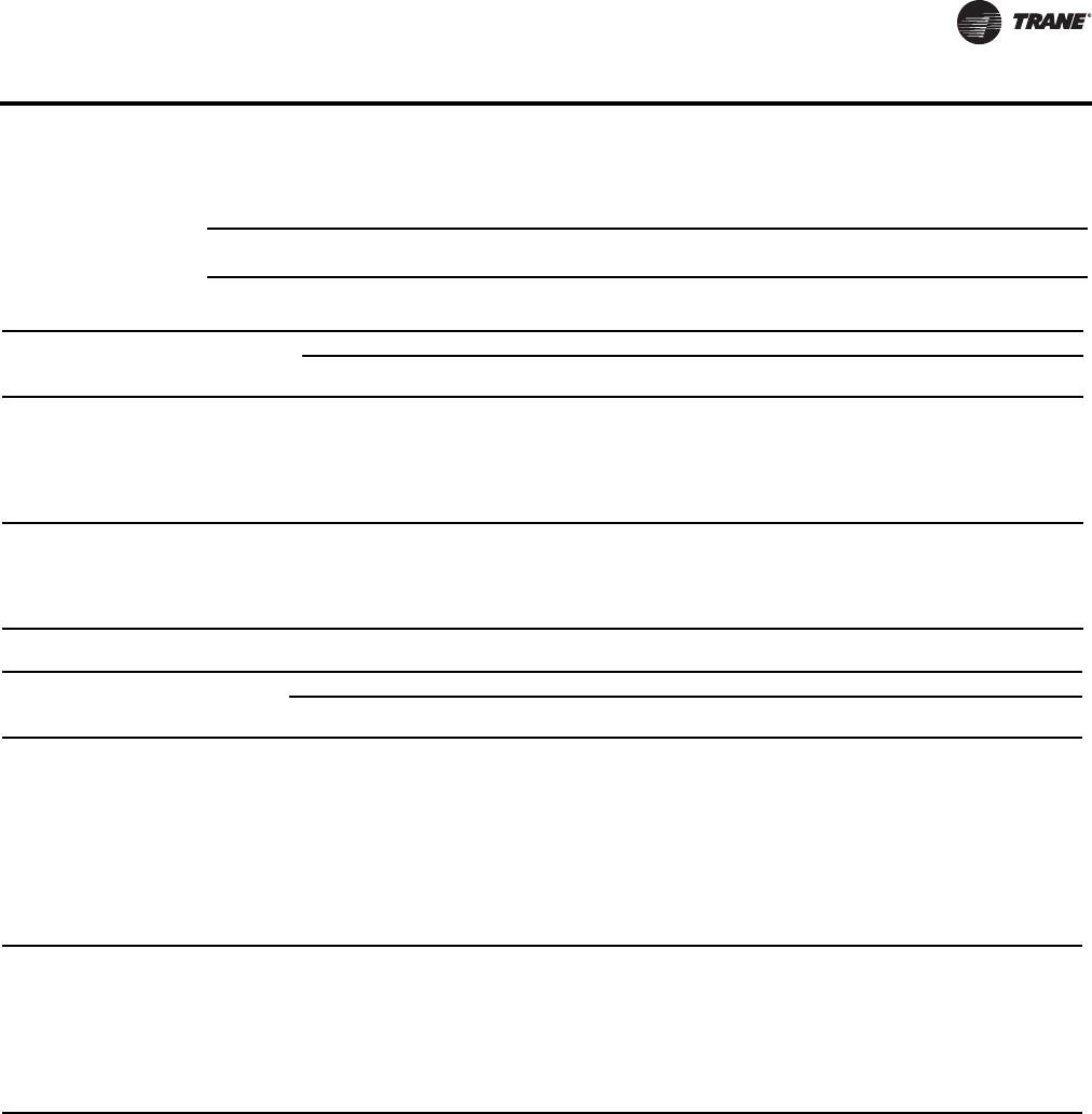
VAV-PRC012-EN 45
Performance Data
Table 35. Temperature correction factors for coil capacity (MBH)
Entering Water Minus Entering Air
Correction Factor
40
0.355
50
0.446
60
0.537
70
0.629
80
0.722
90
0.814
100
0.907
110
1.000
120
1.093
130
1.187
Table 36. Heating capacity (kW) - fan size 02SQ (SI)
Rows L/s
Water
Pressure
Drop (kPa)
Airflow (L/s)
71 94 118 142 165 189 212 236 260 283 330
1-Row
Capacity kW
0.03
0.06
0.13
0.19
0.25
0.32
0.47
1.59
5.52
11.51
19.45
29.27
-
2.68
2.91
3.00
3.05
3.08
-
3.03
3.34
3.46
3.52
3.56
-
3.32
3.70
3.85
3.93
3.98
-
3.58
4.02
4.20
4.30
4.36
-
3.80
4.32
4.52
4.63
4.71
-
4.01
4.59
4.82
4.95
5.03
-
4.20
4.84
5.10
5.25
5.34
-
4.38
5.08
5.37
5.53
5.63
-
4.55
5.30
5.62
5.80
5.91
-
4.70
5.52
5.86
6.06
6.18
-
4.70
5.52
5.86
6.06
6.18
2-Row
Capacity kW
0.06
0.13
0.19
0.25
0.32
3.00
10.21
21.07
35.33
52.84
3.69
3.93
4.02
4.06
4.09
4.46
4.86
5.01
5.08
5.12
5.10
5.67
5.87
5.98
6.04
5.63
6.37
6.64
6.78
6.87
6.08
6.99
7.33
7.51
7.62
6.46
7.54
7.95
8.16
8.30
6.80
8.03
8.51
8.76
8.92
7.09
8.47
9.02
9.31
9.50
7.35
8.87
9.49
9.82
10.03
7.58
9.24
9.92
10.29
10.52
7.58
9.24
9.92
10.29
10.52
Table 37. Heating capacity (kW) - fan sizes 03SQ 04SQ(SI)
Rows L/s
Water
Pressure
Drop (kPa)
Airflow (L/s)
94 142 189 260 330 401 472 543 613 684 755
1-Row
Capacity kW
0.06
0.13
0.19
0.25
0.32
0.38
0.44
0.50
0.57
0.63
0.81
3.02
6.56
11.39
17.49
24.86
33.49
43.36
54.46
66.80
-
4.40
4.60
4.71
4.77
4.82
4.85
4.88
4.90
4.92
-
5.33
5.64
5.80
5.91
5.98
6.03
6.08
6.11
6.13
-
6.04
6.45
6.67
6.81
6.91
6.98
7.04
7.08
7.12
-
6.91
7.45
7.75
7.94
8.08
8.18
8.26
8.32
8.37
-
7.62
8.29
8.67
8.92
9.09
9.22
9.32
9.40
9.47
-
8.23
9.03
9.49
9.79
10.00
10.16
10.28
10.38
10.46
-
8.79
9.70
10.23
10.58
10.83
11.02
11.16
11.28
11.37
-
9.29
10.30
10.91
11.31
11.60
11.81
11.98
12.12
12.22
-
9.75
10.86
11.54
11.99
12.32
12.56
12.75
12.90
13.03
-
10.16
11.38
12.13
12.63
12.99
13.27
13.48
13.65
13.79
-
10.16
11.38
12.13
12.63
12.99
13.27
13.48
13.65
13.79
2-Row
Capacity kW
0.06
0.13
0.19
0.25
0.32
0.38
0.44
0.50
1.18
4.22
8.99
15.41
23.45
33.07
44.26
57.00
-
5.55
5.70
5.78
5.83
5.86
5.88
5.90
-
7.50
7.83
8.00
8.10
8.17
8.22
8.26
-
9.07
9.61
9.89
10.06
10.18
10.26
10.33
-
10.90
11.78
12.25
12.54
12.74
12.88
12.99
-
12.31
13.52
14.18
14.60
14.88
15.09
15.25
-
13.42
14.94
15.79
16.33
16.71
16.99
17.20
-
14.32
16.12
17.16
17.82
18.29
18.63
18.89
-
15.06
17.13
18.33
19.12
19.67
20.07
20.39
-
15.68
18.00
19.36
20.25
20.89
21.36
21.72
-
16.22
18.75
20.26
21.26
21.97
22.50
22.92
-
16.22
18.75
20.26
21.26
21.97
22.50
22.92

46 VAV-PRC012-EN
Performance Data
Water Coil Notes (SI)
1. Fouling Factor = 0.0005.
2. The following equations may be used in calculating Leaving AirTemperature (LAT) and Water
Temperature Difference (WTD).
3. Capacity based on 21°C entering air temperature and 82°Centering water temperature. Refer to
correction factors for different entering conditions.
Average Water Temperature
Correction Factor
93
0.970
88
0.985
82
1.000
77
1.020
71
1.030
66
1.050
60
1.080
54
1.100
49
1.130
43
1.150
Entering Water Minus Entering Air
Correction Factor
22
0.355
27
0.446
33
0.537
38
0.629
44
0.722
50
0.814
55
0.907
61
1.000
67
1.093
72
1.187
Table 38. Heating capacity (kW) - fan size 05SQ(SI)
Rows L/s
Water
Pressure
Drop (kPa)
Airflow (L/s)
165 236 307 378 472 566 661 755 849 944 1015
1-Row
Capacity kW
0.06
0.13
0.19
0.25
0.32
0.38
0.44
0.50
0.87
3.22
6.95
12.04
18.46
26.20
35.23
45.57
-
6.35
6.75
6.96
7.10
7.19
7.26
7.32
-
7.40
7.95
8.26
8.46
8.60
8.70
8.78
-
8.23
8.94
9.33
9.59
9.77
9.90
10.01
-
8.94
9.78
10.27
10.58
10.80
10.97
11.09
-
9.76
10.77
11.37
11.76
12.03
12.24
12.40
-
10.49
11.64
12.34
12.81
13.14
13.39
13.58
-
11.12
12.42
13.23
13.77
14.15
14.44
14.67
-
11.69
13.16
14.04
14.66
15.09
15.42
15.68
-
12.19
13.82
14.79
15.48
15.97
16.34
16.63
-
12.65
14.44
15.51
16.25
16.79
17.21
17.53
-
12.65
14.44
15.51
16.25
16.79
17.21
17.53
2-Row
Capacity kW
0.06
0.13
0.19
0.25
0.32
0.38
0.44
0.50
1.16
4.16
8.85
15.17
23.09
32.57
43.60
56.16
-
8.78
9.20
9.42
9.55
9.63
9.70
9.74
-
11.05
11.83
12.23
12.48
12.65
12.77
12.86
-
12.78
13.94
14.56
14.95
15.21
15.39
15.54
-
14.16
15.68
16.52
17.04
17.40
17.67
17.87
-
15.58
17.57
18.69
19.41
19.90
20.26
20.54
-
16.69
19.10
20.48
21.38
22.01
22.48
22.83
-
17.57
20.35
21.99
23.07
23.83
24.39
24.82
-
18.30
21.41
23.28
24.52
25.41
26.06
26.57
-
18.90
22.32
24.40
25.80
26.79
27.54
28.12
-
19.41
23.10
25.38
26.92
28.03
28.86
29.51
-
19.41
23.10
25.38
26.92
28.03
28.86
29.51
Table 39. Heating capacity (kW) - fan sizes 06SQ & 07SQ (SI)
Rows L/s
Water
Pressure
Drop (kPa)
Airflow (L/s)
330 425 519 613 708 802 897 991 1085 1180 1274
1-Row
Capacity kW
0.03
0.06
0.13
0.19
0.25
0.32
0.38
0.36
1.20
4.10
8.46
14.22
21.30
29.68
-
-
9.15
9.91
10.34
10.61
10.80
-
-
10.11
11.07
11.61
11.96
12.20
-
-
10.98
12.07
12.73
13.15
13.45
-
-
11.74
12.97
13.73
14.23
14.59
-
-
12.41
13.80
14.66
15.23
15.64
-
-
13.00
14.58
15.51
16.15
16.62
-
-
13.54
15.29
16.30
17.02
17.54
-
-
14.03
15.94
17.07
17.83
18.40
-
-
14.49
16.55
17.78
18.60
19.22
-
-
14.90
17.12
18.46
19.34
20.00
-
-
14.90
17.12
18.46
19.34
20.00
2-Row
Capacity kW
0.06
0.13
0.19
0.25
0.32
0.38
2.31
7.71
15.74
26.24
39.08
54.19
-
14.01
15.27
15.94
16.34
16.62
-
15.83
17.61
18.58
19.18
19.59
-
17.23
19.49
20.75
21.55
22.11
-
18.33
21.04
22.58
23.58
24.27
-
19.23
22.33
24.14
25.32
26.15
-
19.97
23.43
25.49
26.85
27.80
-
20.59
24.38
26.67
28.19
29.27
-
21.11
25.20
27.71
29.38
30.58
-
21.57
25.93
28.63
30.45
31.76
-
21.97
26.57
29.46
31.42
32.83
-
21.97
26.57
29.46
31.42
32.83
Table 40. Temperature correction factors for water pressure drop (kPa)
Table 41. Temperature correction factors for coil capacity (kW)
L
AT EAT kW 0.83
Ls
-----------------------------
+=
W
TD EWT LWT kW
4.19 L s
-----------------------------
=–=

VAV-PRC012-EN 47
Performance Data
Low Height Parallel Fan-PoweredTerminal Units
Table 42. Primary airflow control factory settings – I-P
Control Type
Air Valve Size
(in.)
Maximum Valve
Cfm
Maximum
Controller Cfm
Minimum Controller
Cfm
Constant Volume
Cfm
Direct Digital Control/
UCM
5
6
8
8x14
350
500
900
2200
40-350
60-500
105-900
200-2200
0, 40-350
0, 60-500
0, 105-900
0, 220-2200
40-350
60-500
105-900
220-2200
Pneumatic with
Volume Regulator
5
6
8
8x14
350
500
900
2100
63-350
73-500
134-900
297-2100
0, 63-350
0, 73-500
0, 134-900
0, 297-2100
63-350
73-500
134-900
297-2100
Analog Electronic
5
6
8
8x14
350
500
900
2200
82-350
120-500
210-900
440-2200
0, 82-310
0, 120-360
0, 210-660
0, 440-1475
82-310
120-360
210-660
440-1475
Table 43. Primary airflow control factory settings – SI
Control Type
Air Valve Size
(in.)
Maximum Valve
L/s
Maximum
Controller L/s
Minimum Controller
L/s
Constant Volume
L/s
Direct Digital Control/
UCM
5
6
8
8x14
165
236
425
1038
19-165
28-236
50-425
104-1038
0, 19-165
0, 28-236
0, 50-425
0, 104-1038
19-165
28-236
50-425
104-1038
Pneumatic with Volume
Regulator
5
6
8
8x14
165
236
425
991
30-165
35-236
63-425
140-991
0, 30-165
0, 35-236
0, 63-425
0, 140-991
30-165
35-236
63-425
140-991
Analog Electronic
5
6
8
8x14
165
236
425
1038
39-165
57-236
100-425
208-1038
0, 39-146
0, 57-170
0, 100-311
0, 208-696
39-146
57-170
100-311
208-696
Note: Maximum airflow must be greater than or equal to minimum airflow.
Table 44. Unit air pressure drop – in. wg (I-P)
Fan/Inlet Size Airflow Cfm Cooling Only Unit
(in. wg)
Fan/Inlet Size Airflow Cfm Cooling Only Unit
(in. wg)
08SQ-05
150
200
250
350
0.01
0.02
0.03
0.05
09SQ-08
400
600
800
900
0.01
0.09
0.16
0.20
08SQ-06
200
300
400
500
0.01
0.04
0.06
0.09
09SQ-8x14
700
1100
1500
1900
0.10
0.25
0.47
0.75
08SQ-08
400
600
800
900
0.01
0.09
0.16
0.20
10SQ-08
400
600
800
900
0.01
0.09
0.18
0.24
09SQ-06
200
300
400
500
0.01
0.04
0.06
0.09
10SQ-8x14
725
1000
1200
1450
0.18
0.36
0.53
0.78
Notes:
1. Units with Electric Coils per fan size add 0.01" (3 Pa) to cooling only value.
2. HW Coil only pressure drops are just for the heating coil.

48 VAV-PRC012-EN
Performance Data
Table 45. Unit air pressure drop – Pa (SI)
Inlet/Fan Size Airflow L/s
Cooling Only
Unit (Pa) Inlet/Fan Size Airflow L/s
Cooling Only
Unit (Pa)
08SQ-05
71
94
118
165
2
5
7
13
09SQ-08
189
283
378
425
2
21
40
51
08SQ-06
200
142
189
236
0.01
10
16
24
09SQ-8x14
330
519
708
897
26
63
116
185
08SQ-08
189
283
378
425
2
21
40
51
10SQ-08
189
283
378
425
2
23
45
59
09SQ-06
94
142
189
236
2
10
16
24
10SQ-8x14
345
475
565
685
47
91
131
195
Notes:
1. Units with Electric Coils per fan size add 0.01" (3 Pa) to cooling only value.
2. HW Coil only pressure drops are just for the heating coil.
Table 46. Coil air pressure drop
in. wg (I-P) Pa (SI)
Fan Size Airflow Cfm 1-Row HW
(in. wg)
2-Row HW
(in. wg)
Fan Size Airflow L/s 1-Row HW
(Pa)
2-Row HW (Pa)
08SQ
100
200
300
400
450
0.00
0.01
0.02
0.03
0.04
0.01
0.02
0.04
0.06
0.07
08SQ
47
94
142
189
212
1
2
4
7
9
2
5
10
15
18
09SQ
250
400
550
700
850
0.01
0.03
0.05
0.08
0.11
0.03
0.06
0.10
0.15
0.20
09SQ
118
189
260
330
401
3
7
12
19
27
7
15
25
36
51
10SQ
725
800
900
1000
1100
1150
0.09
0.11
0.13
0.16
0.19
0.20
0.17
0.20
0.24
0.29
0.33
0.35
10SQ
342
375
425
475
520
543
22
26
33
40
46
49
43
49
60
72
82
87
Note: HW Coil Only pressure drops do not include unit pressure drop.
Table 47. Attenuator air pressure drop
(I-P) (SI)
Fan Size Plenum Cfm Attenuator Fan Size Plenum L/s Attenuator
08SQ
150
250
350
450
0.01
0.03
0.05
0.07
08SQ
71
118
165
212
0.01
0.01
0.02
0.02
09SQ
350
500
650
800
0.05
0.08
0.13
0.18
09SQ
165
236
307
378
0.02
0.03
0.04
0.05
10SQ not available 10SQ not available
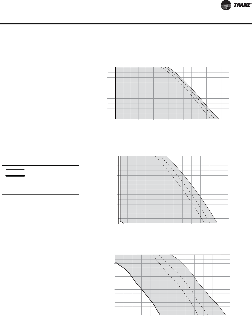
VAV-PRC012-EN 49
Performance Data
Performance Data Fan Curves
Airflow
Discharge Static Pressure
25
50
75
11894 142 212 260
Cfm
L/s
Pa In. wg
Low-Height Parallel 08SQ—PSC
0.10
0.20
0.30
0.40
0.50
0.60
150 200 250 300 350 400 450 500 550
125
150
100
165 189 23671
175 cfm min
(83 L/s)
Notes:
1. When attenuator is required, add inlet
attenuator pressure to discharge static
pressure for final fan performance.
2. When attenuator is required, add inlet
attenuator pressure to discharge static
pressure for final fan performance.
LPCF and LPEF maximum
Minimum
1-row coil maximum
2-row coil maximum
Airflow
Discharge Static Pressure
25
50
75
189 236 273 330 378
Cfm
L/s
Pa In. wg
Low-Height Parallel 09SQ—PSC
0.10
0.20
0.30
0.40
0.50
0.60
0.70
0.80
400 500 600 700 800 900 1000
174
199
150
125
100
472
425
410 cfm min
(193 L/s)
Low-Height Parallel 10SQ—PSC
0.10
0.20
0.30
300 500 700 900 1100
Airflow
Discharge Static Pressure
25
50
75
142 236 330 425 519
Cfm
L/s
Pa In. wg
0.80
199
0.70
174
0.60
150
0.50
125
0.40
100
1500
708
1300
614
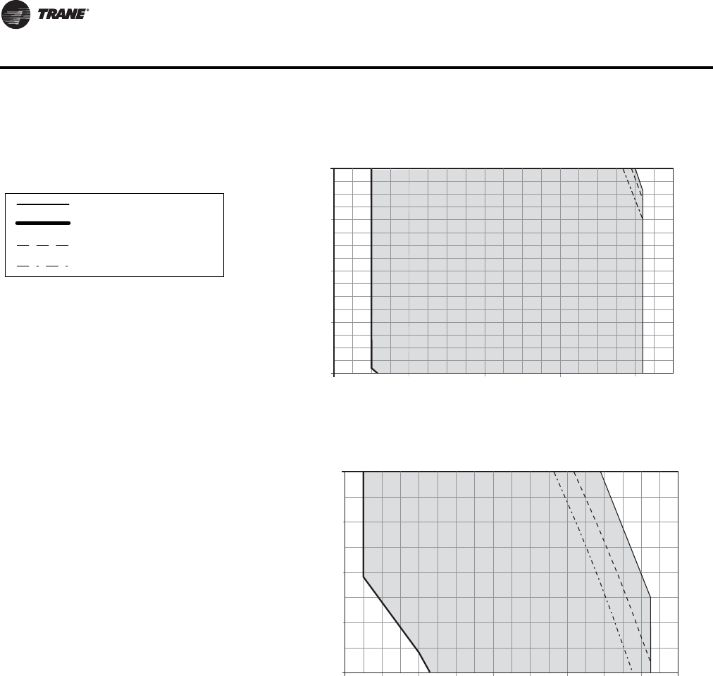
50 VAV-PRC012-EN
Performance Data
Notes:
1. ECMs (Electrically Commutated Motors) are
ideal for systems seeking maximum motor
efficiency.
2. When attenuator is required, add inlet
attenuator pressure to discharge static
pressure for final fan performance.
LPCF and LPEF maximum
Minimum
1-row coil maximum
2-row coil maximum
Airflow
Discharge Static Pressure
25
50
75
24 71 118 165 212
Cfm
L/s
Pa In. wg
LPxF 08SQ—ECM
0.10
0.20
0.30
0.40
0.50
50 150 250 350 450
125
100
100 cfm min
(47 L/s)
Airflow
Discharge Static Pressure
25
50
75
94 142 189 236
Cfm
L/s
Pa In. wg
LPxF 09SQ—ECM
0.10
0.20
0.30
0.40
0.50
200 300 400 500 600 700 800 900 1000 1100
125
100
283 519472
425378
330
250 cfm min
(118 L/s)

VAV-PRC012-EN 51
Performance Data
Water Coil Notes (I-P)
Note: Fouling Factor = 0.0005.
Note: The off-coil temperature of the hot water coil on parallel fan-powered units must not exceed
140°F when mounted on plenum inlet.
Note: The following equations may be used in calculating Leaving AirTemperature (LAT) and
Water Temperature Difference (WTD).
Note: Capacity based on 70°F entering air temperature and 180°F entering water temperature.
Refer to correction factors for different entering conditions.
Table 48. Heating capacity (MBh) - fan sizes 08SQ & 09SQ (I-P)
Rows Gpm
Water
Pressure
Drop (ft)
Airflow (Cfm)
100 200 300 400 500 600 700 800 900
1-Row
Capacity MBH
0.5
1.0
1.5
2.0
2.5
0.80
2.67
5.43
9.02
13.39
7.73
8.58
8.90
9.06
9.17
10.43
12.15
12.83
13.20
13.43
12.20
14.51
15.52
16.07
16.43
13.50
16.37
17.69
18.42
18.89
14.51
17.98
19.56
20.47
21.06
15.33
19.42
21.21
22.30
23.00
16.03
20.69
22.72
23.97
24.79
16.63
21.82
24.15
25.51
26.45
17.15
22.85
25.46
26.95
28.00
2-Row
Capacity MBH
1.0
2.0
3.0
4.0
5.0
0.89
3.02
6.24
10.47
15.66
9.36
9.74
9.86
9.92
9.96
15.49
16.83
17.29
17.53
17.67
19.69
22.20
23.11
23.59
23.88
22.72
26.42
27.82
28.56
29.01
25.00
29.83
31.72
32.73
33.36
26.79
32.65
35.02
36.29
37.10
28.23
35.03
37.85
39.39
40.36
29.41
37.06
40.32
42.11
43.24
30.41
38.83
42.49
44.52
45.81
Table 49. Heating capacity (MBh) - fan size 10SQ (I-P)
Rows Gpm
Water
Pressure
Drop (ft)
Airflow (Cfm)
700 800 900 1000 1100 1200 1240
1-Row Capacity
MBH
0.7
1.0
1.5
2.0
2.5
1.51
2.80
5.69
9.45
14.03
18.46
20.69
22.72
23.97
24.79
19.31
21.82
24.15
25.51
26.45
20.07
22.85
25.46
26.95
28.00
20.75
23.78
26.67
28.32
29.46
21.37
24.64
27.79
29.62
30.83
21.93
25.43
28.84
30.84
32.14
22.14
25.72
29.24
31.30
32.66
2-Row Capacity
MBH
1.5
2.0
3.0
4.0
5.0
1.85
3.07
6.32
10.58
15.80
32.51
35.03
37.85
39.39
40.36
34.20
37.06
40.32
42.11
43.24
35.65
38.83
42.49
44.52
45.81
36.90
40.38
44.42
46.68
48.13
38.01
41.76
46.15
48.62
50.22
38.98
42.99
47.71
50.39
52.13
39.34
43.44
48.29
51.06
52.84
Table 50.
Temperature correction factors for water pressure drop (WPD)
Average Water Temperature 200 190 180 170 160 150 140 130 120 110
Correction Factor 0.970 0.985 1.000 1.020 1.030 1.050 1.080 1.100 1.130 1.150
Temperature correction factors for coil capacity (MBH)
Entering Water Minus Entering Air 40 50 60 70 80 90 100 110 120 130
Correction Factor 0.355 0.446 0.537 0.629 0.722 0.814 0.907 1.000 1.093 1.187
L
AT EAT MBH 921.7
Cfm
--------------------------------------
+=
WTD EWT LWT–2MBH
Gpm
------------------------
==

52 VAV-PRC012-EN
Performance Data
Water Coil Notes (SI)
1. Fouling Factor = 0.0005.
2. The off-coil temperature of the hot water coil on parallel fan-powered units must not exceed
60°C when mounted on plenum inlet.
3. The following equations may be used in calculating Leaving AirTemperature (LAT) and Water
Temperature Difference (WTD).
4. Capacity based on 21°C entering air temperature and 82°C entering water temperature. Refer
to correction factors for different entering conditions.
Average Water Temperature 93 88 82 77 71 66 60 54 49 43
Correction Factor 0.970 0.985 1.000 1.020 1.030 1.050 1.080 1.100 1.130 1.150
Entering Water Minus Entering Air 22 27 33 38 44 50 55 61 67 72
Correction Factor 0.355 0.446 0.537 0.629 0.722 0.814 0.907 1.000 1.093 1.187
Table 51. Heating capacity (kW) - fan sizes 08SQ & 09SQ (SI)
Rows L/s Water Pressure
Drop (kPa)
Airflow (L/s)
47 94 142 189 236 283 330 378 425
1-Row Capacity
kW
0.03
0.06
0.09
0.13
0.16
2.39
7.98
16.24
26.97
40.04
2.27
2.51
2.61
2.66
2.69
3.06
3.56
3.76
3.87
3.94
3.58
4.25
4.55
4.71
4.81
3.96
4.80
5.18
5.40
5.54
4.25
5.27
5.73
6.00
6.17
4.49
5.69
6.22
6.54
6.74
4.70
6.06
6.66
7.03
7.27
4.87
6.40
7.08
7.48
7.75
5.03
6.70
7.46
7.90
8.21
2-Row Capacity
kW
0.06
0.13
0.19
0.25
0.32
2.65
9.03
18.65
31.29
46.82
2.74
2.85
2.89
2.91
2.92
4.54
4.93
5.07
5.14
5.18
5.77
6.51
6.77
6.91
7.00
6.66
7.74
8.15
8.37
8.50
7.33
8.74
9.30
9.59
9.78
7.85
9.57
10.26
10.64
10.87
8.27
10.27
11.09
11.54
11.83
8.62
10.86
11.82
12.34
12.67
8.91
11.38
12.45
13.05
13.43
Table 52. Heating capacity (kW) - fan size 10SQ (SI)
Rows L/s
Water Pressure
Drop (kPa)
Airflow (L/s)
330 378 425 472 519 566 585
1-Row Capacity
kW
0.04
0.06
0.09
0.13
0.16
4.51
8.37
17.02
28.25
41.94
5.41
6.06
6.66
7.03
7.27
5.66
6.40
7.08
7.48
7.75
5.88
6.70
7.46
7.90
8.21
6.08
6.97
7.81
8.30
8.63
6.26
7.22
8.14
8.68
9.03
6.43
7.45
8.45
9.04
9.42
6.49
7.54
8.57
9.17
9.57
2-Row Capacity
kW
0.09
0.13
0.19
0.25
0.32
5.53
9.19
18.89
31.61
47.22
9.53
10.27
11.09
11.54
11.83
10.02
10.86
11.82
12.34
12.67
10.45
11.38
12.45
13.05
13.43
10.82
11.84
13.02
13.68
14.10
11.14
12.24
13.52
14.25
14.72
11.42
12.60
13.98
14.77
15.28
11.53
12.73
14.15
14.96
15.49
Table 53.
Temperature correction factors for water pressure drop (kPa)
Temperature correction factors for coil capacity (kW)
L
AT EAT kW 0.83
Ls
-----------------------------
+=
W
TD EWT LWT kW
4.19Ls
----------------------------------
=–=

VAV-PRC012-EN 53
Performance Data
Low Height Series Fan-Powered Terminal Units
Table 54. Primary airflow control factory settings-I-P
Control Type Air Valve Size
(in.)
Maximum Valve
Cfm
Maximum Controller
Cfm
Minimum Controller
Cfm
Constant Volume
Cfm
Direct Digital Control/UCM
5
6
8
8x14
350
500
900
2200
40-350
60-500
105-900
200-2200
0, 40-350
0, 60-500
0, 105-900
0, 220-2200
40-350
60-500
105-900
220-2200
Pneumatic with Volume
Regulator
5
6
8
8x14
350
500
900
2100
63-350
73-500
134-900
297-2100
0, 63-350
0, 73-500
0, 134-900
0, 297-2100
63-350
73-500
134-900
297-2100
Analog Electronic
5
6
8
8x14
350
500
900
2200
82-350
120-500
210-900
440-2200
0, 82-310
0, 120-360
0, 210-660
0, 440-1475
82-310
120-360
210-660
440-1475
Table 55. Primary airflow control factory settings-SI
Control Type
Air Valve Size
(in.)
Maximum
Valve L/s
Maximum Controller
L/s
Minimum Controller L/
s
Direct Digital Control/ UCM
5
6
8
8x14
165
236
425
1038
19-165
28-236
50-425
104-1038
0, 19-165
0, 28-236
0, 50-425
0, 104-1038
19-165
28-236
50-425
104-1038
Pneumatic with Volume Regulator
5
6
8
8x14
165
236
425
991
30-165
35-236
63-425
140-991
0, 30-165
0, 35-236
0, 63-425
0, 140-991
30-165
35-236
63-425
140-991
Analog Electronic
5
6
8
8x14
165
236
425
1038
39-165
57-236
100-425
208-1038
0, 39-146
0, 57-170
0, 100-311
0, 208-696
39-146
57-170
100-311
208-696
Note: Maximum airflow must be greater than or equal to minimum airflow.
Table 56. Unit air pressure drop
in. wg (I-P) Pa (SI
Fan/Inlet Size Airflow Cfm Cooling Only Fan/Inlet Size Airflow L/s Cooling Only
08SQ-05
150
250
350
0.01
0.03
0.11
08SQ-05
71
118
165
2
9
28
08SQ-06
150
275
400
500
0.02
0.14
0.35
0.58
08SQ-06
71
130
189
236
5
34
86
143
08SQ-08
150
275
400
500
0.01
0.05
0.13
0.21
08SQ-08
71
130
189
236
3
14
32
52
09SQ-06
350
400
450
500
0.17
0.26
0.37
0.50
09SQ-06
165
189
212
236
43
66
93
124

54 VAV-PRC012-EN
Performance Data
09SQ-08
400
600
750
900
0.08
0.24
0.40
0.61
09SQ-08
189
283
354
425
21
59
100
151
09SQ-8x14
600
700
900
1050
0.18
0.27
0.51
0.73
8x14-09SQ
283
330
425
495
44
66
126
182
10SQ-08
400
600
800
0.08
0.38
0.84
10SQ-08
189
283
378
20
94
209
10SQ-8x14
600
900
1100
1500
0.21
0.50
0.77
1.47
10SQ-8x14
283
425
519
708
51
124
191
367
Table 56. Unit air pressure drop (continued)
in. wg (I-P) Pa (SI
Table 57. Coil air pressure drop
in.wg (I-P) Pa (SI)
Fan
Size Airflow Cfm
1-Row HW (in.
wg)
2-Row HW (in.
wg) Fan Size Airflow L/s 1-Row HW (Pa) 2-Row HW (Pa)
08SQ
100
200
300
400
500
0.00
0.01
0.02
0.03
0.05
0.01
0.03
0.05
0.07
0.10
08SQ
47
94
142
189
236
1
3
5
9
13
3
6
11
18
25
09SQ
400
550
700
850
1000
0.03
0.06
0.09
0.13
0.18
0.07
0.12
0.17
0.24
0.32
09SQ
189
260
330
401
472
9
15
23
33
44
18
29
43
0
80
10SQ
400
800
1200
1600
2000
0.01
0.03
0.06
0.11
0.16
0.02
0.07
0.12
0.20
0.29
10SQ
189
378
566
755
944
3
8
16
27
40
6
16
31
50
72
Note: HW Coil Only pressure drops do not include unit pressure drop.
Table 58. Attenuator air pressure drop
(I-P) (SI)
Fan Size Plenum Cfm Attenuator Fan Size Plenum L/s Attenuator
08SQ
150
250
350
450
0.02
0.04
0.06
0.09
08SQ
71
118
165
212
0.01
0.01
0.02
0.03
09SQ
350
500
650
800
0.06
0.10
0.15
0.22
09SQ
165
236
307
378
0.02
0.03
0.05
0.06
10SQ
400
700
1000
1300
1600
0.02
0.05
0.09
0.14
0.20
10SQ
189
330
472
614
755
0.01
0.02
0.03
0.04
0.06
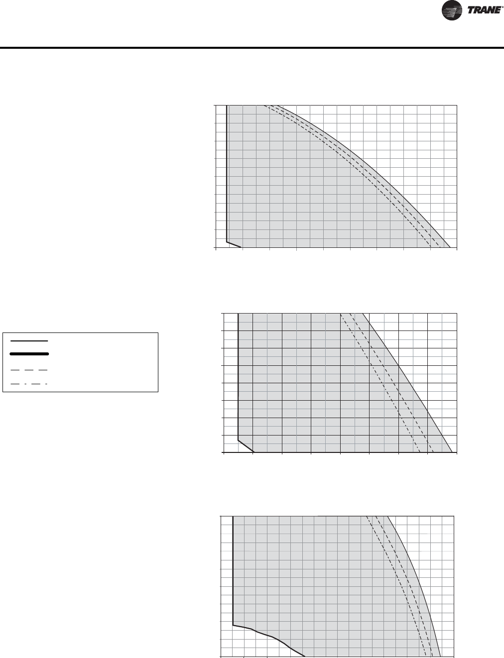
VAV-PRC012-EN 55
Performance Data
0.00
0.10
0.20
0.30
Airflow
Discharge Static Pressure
0
25
50
75
94 142 189 236
Cfm
L/s
Pa In. wg
0.80
199
0.70
174
0.60
150
0.50
125
0.40
100
212 260165118 283
Low-Height Series 08SQ—PSC
150 200 250 300 350 400 450 500 550 600
71
170 cfm min
(80 L/s)
Note: When attenuator is required, add inlet
attenuator pressure to discharge static
pressure for final fan performance.
LSCF and LSEF maximum
Minimum
1-row coil maximum
2-row coil maximum
0.00
0.10
0.20
0.30
Airflow
Discharge Static Pressure
0
25
50
75
142 189 236
Cfm
L/s
Pa In. wg
0.80
199
0.70
174
0.60
150
0.50
125
0.40
100
519
472425378330283
Low-Height Series 09SQ—PSC
300 400 500 600 700 800 900 1000 1100
350 cfm min
(165 L/s)
0.00
0.10
0.20
0.30
Airflow
Discharge Static Pressure
0
25
50
75
142 236
Cfm
L/s
Pa In. wg
0.80
199
0.70
174
0.60
150
0.50
125
0.40
100
614
519425330
Low-Height Series 10SQ—PSC
300 500 700 900 1100 1300 1500 1700 1900 2100 2300
1086991897802708
405 cfm min
(191 L/s)
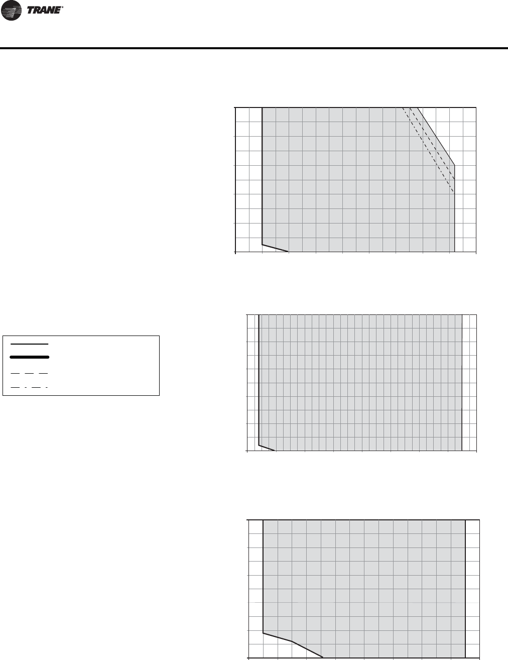
56 VAV-PRC012-EN
Performance Data
Airflow
Discharge Static Pressure
0
25
50
75
24 94 118 189 236
Cfm
L/s
Pa In. wg
LSxF 08SQ—ECM
0.00
0.10
0.20
0.30
0.40
0.50
50 100 150 200 250 300 350 400 450 500
125
100
2121651427147
100 cfm min
(47 L/s)
Notes:
1. ECMs (Electrically Commutated Motors) are
ideal for systems seeking maximum motor
efficiency.
2. When attenuator is required, add inlet
attenuator pressure to discharge static
pressure for final fan performance.
LSCF and LSEF maximum
Minimum
1-row coil maximum
2-row coil maximum
Airflow
Discharge Static Pressure
0
25
50
75
94 142 189 236
Cfm
L/s
Pa In. wg
LSxF 09SQ—ECM
0.00
0.10
0.20
0.30
0.40
0.50
200 300 400 500 600 700 800 900 1000
425378
330
283 472
100
125
240 cfm min
(113 L/s)
Airflow
Discharge Static Pressure
0
25
50
75
142 330236 425 897
Cfm
L/s
Pa In. wg
LSxF 10SQ—ECM
0.00
0.10
0.20
0.30
0.40
0.50
300 500 700 900 1100 1300 1500 1700 1900
125
100
519 614 708 802
400 cfm min
(189 L/s)

VAV-PRC012-EN 57
Performance Data
Water Coil Notes
1. Fouling Factor = 0.0005.
2. The following equations may be used in calculating Leaving AirTemperature (LAT) and Water
Temperature Difference (WTD).
3. Capacity based on 70°F entering air temperature and 180°F entering water temperature. Refer
to correction factors for different entering conditions.
Average Water Temperature 200 190 180 170 160 150 140 130 120 110
Correction Factor 0.970 0.985 1.000 1.020 1.030 1.050 1.080 1.100 1.130 1.150
Entering Water Minus Entering Air 40 50 60 70 80 90 100 110 120 130
Correction Factor 0.355 0.446 0.537 0.629 0.722 0.814 0.907 1.000 1.093 1.187
Table 59. Heating capacity (MBh) - fan sizes 08SQ & 09SQ (I-P)
Rows Gpm
Water
Pressure
Drop (ft)
Airflow (Cfm)
100 200 300 400 500 600 700 800 900 1000
1-Row Capacity
MBH
1.0
2.0
3.0
4.0
5.0
6.0
0.15
0.58
1.27
2.24
3.48
4.98
-
-
7.92
8.08
8.17
8.24
-
-
11.16
11.48
11.69
11.83
-
-
13.45
13.94
14.25
14.47
-
-
15.34
15.98
16.39
16.69
-
-
16.97
17.76
18.28
18.65
-
-
18.42
19.36
19.99
20.43
-
-
19.73
20.82
21.54
22.06
-
-
20.92
22.16
22.98
23.58
-
-
22.01
23.39
24.32
24.99
-
-
23.02
24.54
25.57
26.31
2-Row Capacity
MBH
1.0
2.0
3.0
4.0
5.0
0.76
2.60
5.39
9.06
13.57
9.04
9.45
9.59
9.66
9.70
14.59
15.95
16.43
16.68
16.83
18.26
20.70
21.60
22.08
22.37
20.87
24.34
25.68
26.40
26.85
22.83
27.24
29.01
29.96
30.56
24.35
29.61
31.78
32.96
33.71
25.57
31.59
34.14
35.54
36.43
26.58
33.28
36.17
37.78
38.80
27.42
34.74
37.95
39.75
40.90
28.14
36.02
39.53
41.51
42.78
Table 60. Heating capacity (MBh) - fan size 10SQ (I-P)
Rows Gpm
Water
Pressure
Drop (ft)
Airflow (Cfm)
450 600 750 900 1050 1200 1350 1500 1650 1800 1950
1-Row Capacity
MBH
1.0
2.0
4.0
6.0
8.0
10.0
0.16
0.61
2.32
5.09
8.91
13.77
-
-
25.05
26.10
26.66
27.02
-
-
28.61
30.00
30.76
31.23
-
-
31.67
33.40
34.34
34.95
-
-
34.39
36.45
37.59
38.32
-
-
36.86
39.26
40.59
41.44
-
-
39.12
41.85
43.38
44.36
-
-
41.23
44.28
46.00
47.11
-
-
43.18
46.57
48.48
49.72
-
-
45.02
48.73
50.83
52.20
-
-
46.75
50.77
53.07
54.56
-
-
48.41
52.71
55.20
56.83
2-Row Capacity
MBH
1.0
2.0
3.0
4.0
5.0
1.29
4.31
8.84
14.77
22.03
28.40
33.46
35.30
36.25
36.83
32.18
39.56
42.41
43.91
44.83
34.87
44.37
48.23
50.30
51.58
36.88
48.27
53.10
55.72
57.37
38.43
51.49
57.23
60.40
62.41
39.66
54.19
60.78
64.48
66.84
40.66
56.50
63.88
68.08
70.78
41.49
58.49
66.61
71.28
74.30
42.19
60.23
69.03
74.15
77.48
42.79
61.76
71.20
76.74
80.36
43.30
63.13
73.16
79.09
82.99
Table 61. Temperature correction factors for water pressure drop (ft)
Table 62. Temperature correction factors for coil capacity (MBH)
LAT EAT MBH 921.7
Cfm
--------------------------------------
+=
WTD EWT LWT 2MBH
Gpm
------------------------
=–=

58 VAV-PRC012-EN
Performance Data
Water Coil Notes
1. Fouling Factor = 0.0005.|
2. The following equations may be used in calculating Leaving AirTemperature (LAT) and Water
Temperature Difference (WTD).
3. Capacity based on 21°C entering air temperature and 82°C entering water temperature. Refer
to correction factors for different entering conditions.
Average Water Temperature 93 88 82 77 71 66 60 54 49 43
Correction Factor 0.970 0.985 1.000 1.020 1.030 1.050 1.080 1.100 1.130 1.150
Entering Water Minus Entering Air 22 27 33 38 44 50 55 61 67 72
Correction Factor 0.355 0.446 0.537 0.629 0.722 0.814 0.907 1.000 1.093 1.187
Table 63. Heating capacity (kW) - fan size 08SQ & 09SQ (SI)
Rows L/s
Water Pressure
Drop (kPa)
Airflow (L/s)
47 94 142 189 236 283 330 378 425 472
1-Row Capacity
kW
0.06
0.13
0.19
0.25
0.32
0.38
0.44
1.72
3.81
6.71
10.40
14.90
-
-
2.32
2.37
2.39
2.41
-
-
3.27
3.36
3.42
3.47
-
-
3.94
4.08
4.18
4.24
-
-
4.50
4.68
4.80
4.89
-
-
4.97
5.21
5.36
5.47
-
-
5.40
5.67
5.86
5.99
-
-
5.78
6.10
6.31
6.47
-
-
6.13
6.49
6.74
6.91
-
-
6.45
6.86
7.13
7.32
-
-
6.75
7.19
7.49
7.71
2-Row Capacity
kW
0.06
0.13
0.19
0.25
0.32
2.27
7.78
16.11
27.08
40.58
2.65
2.77
2.81
2.83
2.84
4.28
4.67
4.82
4.89
4.93
5.35
6.07
6.33
6.47
6.56
6.12
7.13
7.53
7.74
7.87
6.69
7.98
8.50
8.78
8.96
7.14
8.68
9.31
9.66
9.88
7.49
9.26
10.00
10.41
10.68
7.79
9.75
10.60
11.07
11.37
8.04
10.18
11.12
11.65
11.99
8.25
10.56
11.58
12.16
12.54
Table 64. Heating capacity (kW) - fan size 10SQ (SI)
Rows L/s
Water
Pressure Drop
(kPa)
Airflow (L/s)
212 283 354 425 495 566 637 708 779 849 920
1-Row Capacity kW
0.06
0.13
0.25
0.38
0.50
0.63
0.48
1.82
6.93
15.22
26.64
41.16
-
-
7.34
7.65
7.81
7.92
-
-
8.38
8.79
9.01
9.15
-
-
9.28
9.79
10.07
10.24
-
-
10.08
10.68
11.02
11.23
-
-
10.80
11.50
11.90
12.15
-
-
11.47
12.27
12.71
13.00
-
-
12.08
12.98
13.48
13.81
-
-
12.66
13.65
14.21
14.57
-
-
13.19
14.28
14.90
15.30
-
-
13.70
14.88
15.55
15.99
-
-
13.70
14.88
15.55
15.99
2-Row Capacity kW
0.06
0.13
0.19
0.25
0.32
3.84
12.90
26.43
44.15
65.84
8.32
9.81
10.35
10.62
10.79
9.43
11.59
12.43
12.87
13.14
10.22
13.00
14.14
14.74
15.12
10.81
14.15
15.56
16.33
16.81
11.26
15.09
16.77
17.70
18.29
11.62
15.88
17.81
18.90
19.59
11.92
16.56
18.72
19.95
20.74
12.16
17.14
19.52
20.89
21.78
12.36
17.65
20.23
21.73
22.71
12.54
18.10
20.87
22.49
23.55
12.54
18.10
20.87
22.49
23.55
Table 65. Temperature correction factors for water pressure drop (kPa)
Table 66. Temperature correction factors for coil capacity (kW)
LAT EAT kW 0.83
Lls
-----------------------------
+=
WTD EWT LWT kW
4.19Lls
----------------------------
=–=
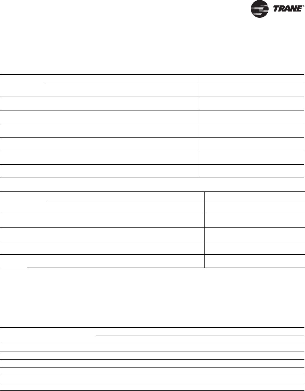
VAV-PRC012-EN 59
Electrical Data
Parallel Fan-Powered Terminal Units
Table 67. PSC motor units—electric coil kW guidelines – minimum to maximum (VPEF)
Fan Size Stages
Single-Phase Voltage Three-Phase Voltage
120V 208V 240V 277V 347V 480V 208V 480V 600V
380V/
50Hz
02SQ 1
2
0.5-5.0
0.5-5.0
0.5-6.0
0.5-6.0
0.5-6.0
0.5-6.0
0.5-6.0
1.0-6.0
0.5-6.0
1.0-6.0
0.5-6.0
1.0-6.0
0.5-6.0
1.0-6.0
1.0-6.0
2.0-6.0
1.5-6.0
3.0-6.0
1.0-6.0
1.5-6.0
03SQ 1
2
0.5-5.0
0.5-5.0
0.5-9.0
0.5-9.0
0.5-10.0
0.5-10.0
0.5-11.0
1.0-11.0
0.5-11.0
1.0-11.0
0.5-11.0
1.0-11.0
0.5-11.0
1.0-11.0
1.0-11.0
2.0-11.0
1.5-11.0
3.0-11.0
1.0-11.0
1.5-11.0
04SQ 1
2
0.5-4.5
0.5-4.5
0.5-8.0
0.5-8.0
0.5-10.0
0.5-10.0
0.5-12.0
1.0-12.0
0.5-14.0
1.0-14.0
0.5-14.0
1.0-14.0
0.5-14.0
1.0-14.0
1.0-14.0
2.0-14.0
1.5-14.0
3.0-14.0
1.0-14.0
1.5-14.0
05SQ 1
2
0.5-4.5
0.5-4.5
0.5-8.0
0.5-8.0
0.5-9.0
0.5-9.0
0.5-12.0
1.0-12.
0.5-15.0
1.0-15.0
0.5-18.0
1.0-18.0
0.5-14.0
1.0-14.0
1.0-18.0
2.0-18.0
1.5-18.0
3.0-18.0
1.0-18.0
1.5-18.0
06SQ 1
2
-
-
0.5-9.0
0.5-9.0
-
-
0.5-12.0
1.0-12.0
0.5-15.0
1.0-15.0
0.5-16.0
1.0-16.0
0.5-15.0
1.0-15.0
1.0-16.0
2.0-16.0
1.5-16.0
3.0-16.0
1.0-16.0
1.5-16.0
07SQ 1
2
-
-
0.5-8.0
0.5-8.0
-
-
0.5-11.0
1.0-11.0
0.5-15.0
1.0-15.0
0.5-20.0
1.0-20.0
0.5-14.0
1.0-14.0
1.0-20.0
2.0-20.0
1.5-20.0
3.0-20.0
1.0-20.0
1.5-20.0
Table 68. ECM units—electric coil kW guidelines – minimum to maximum (VPEF)
Fan Size Stages
Single-Phase Voltage Three-Phase Voltage
120V 208V 240V 277V 347V 480V 208V 480V 600V
380V/
50Hz
03SQ 1
2
0.5-4.5
0.5-4.5
0.5-8.0
0.5-8.0
0.5-10.0
0.5-10.0
0.5-11.0
1.0-11.0
-
-
0.5-11.0
1.0-11.0
0.5-11.0
1.0-11.0
1.0-11.0
2.0-11.0
-
-
-
-
04SQ 1
2
0.5-4.5
0.5-4.5
0.5-8.0
0.5-8.0
0.5-9.0
0.5-9.0
0.5-12.0
1.0-12.0
-
-
0.5-14.0
1.0-14.0
0.5-14.0
1.0-14.0
1.0-14.0
2.0-14.0
-
-
-
-
05SQ 1
2
0.5-4.0
0.5-4.0
0.5-7.0
0.5-7.0
0.5-8.0
0.5-8.0
0.5-11.0
1.0-11.0
-
-
0.5-18.0
1.0-18.0
0.5-12.0
1.0-12.0
1.0-18.0
2.0-18.0
-
-
-
-
06SQ 1
2
0.5-4.0
0.5-4.0
0.5-7.0
0.5-7.0
0.5-8.0
0.5-8.0
0.5-11.0
1.0-11.0
-
-
0.5-16.0
1.0-16.0
0.5-12.0
1.0-12.0
1.0-16.0
2.0-16.0
-
-
-
-
Notes:
1. Coils available with 24-VAC magnetic or mercury contactors, load carrying P.E. switches, and P.E. switch with magnetic or mercury contactors.
2. Available kW increments are by 0.5 from 0.5 kW to 8.0 kW, by 1.0 kW from 9.0 to 18.0 kW, and by 2.0 kW from 18.0 to 20.0 kW.
3. Each stage will be equal in kW output.
4. All heaters contain an auto reset thermal cutout and a manual reset cutout.
5. See section “Formulas,” p. 73 for formulas used to calculate the current amp draw for the heater elements.
6. Recommended coil temperature rise = 20° to 30°F (-7° to -1°C). Maximum temperature rise = 55°F (12°C).
7. Heaters should not operate at cfms below the nameplate minimum.
Table 69. Fan electrical performance (PSC)
Fan Size HP
Maximum Fan Motor Amperage (FLA)
115 VAC 208 VAC 277 VAC
02SQ 1/8 1.6 - 0.7
03SQ 1/3 4.3 - 1.6
04SQ 1/3 5.5 - 2.0
05SQ 1/2 6.7 - 2.4
06SQ 1/2 - 4.6 3.8
07SQ 1 - 6.6 4.7

60 VAV-PRC012-EN
Electrical Data
Notes:
1. Electric Heat Units - Units with fan sizes 02SQ to 05SQ and a primary voltage of 208/60/1, 208/60/3, or 240/60/1 have 115/60/1 VAC fan motors. Fan
sizes 06SQ and 07SQ with the same voltages, have 208/60/1 VAC motors.
2. Electric Heat Units - Units with primary voltage of 277/60/1, 480/60/1 or 480/60/3 use 277 VAC fan motors.
3. Electric Heat Units - Units with primary voltage of 347/60/1 or 575/60/3 use 347 VAC fan motors.
4. With 380/50/3 and 230/50/1, use 230/50 motors.
Table 69. Fan electrical performance (PSC)
Table 70. Fan electrical performance (ECM)
Fan Size HP
Maximum Fan Motor Amperage (FLA)
115 VAC 277 VAC
03SQ 1/3 4.5 2.4
04SQ 1/2 6.5 3.5
05SQ 1 10.1 5.4
06SQ 1 9.5 5.1
Notes:
1. Electric heat units—units with primary voltages of 208/60/1, 208/60/3, or 240/60/1 have 115-VAC fan motors.
2. Electric heat units—units with primary voltages of 277/60/1, 480/60/1, or 480/60/3 have 277-VAC fan motors.
3. 347/60/1 and 230/50/1 voltage motors not available with ECMs.
Table 71. Minimum unit electric heat Cfm guidelines (PSC)
Unit kW
Cfm
02SQ 03SQ 04SQ 05SQ 06SQ 07SQ
0.5
1
1.5
118
118
118
200
200
200
315
315
315
350
350
350
533
533
533
585
585
585
2
2.5
3
118
146
174
200
200
200
315
315
315
350
350
350
533
533
533
585
585
585
3.5
4
4.5
201
229
257
200
230
260
315
315
315
350
350
350
533
533
533
585
585
585
5
5.5
6
285
312
340
290
315
350
315
315
350
350
350
350
533
533
533
585
585
585
6.5
7
7.5
-
-
-
375
400
430
375
400
430
375
400
430
533
533
533
585
585
585
8
9
10
-
-
-
460
515
575
460
515
575
460
515
575
533
589
645
585
633
682
11
12
13
-
-
-
630
-
-
630
690
745
630
690
745
701
758
814
730
779
827
14
15
16
-
-
-
-
-
-
810
-
-
810
860
920
870
926
982
876
924
972
17
18
20
-
-
-
-
-
-
-
-
-
973
1030
-
-
-
-
1021
1069
1166

VAV-PRC012-EN 61
Electrical Data
Table 72. Minimum unit electric heat L/s guidelines (PSC)
Unit kW
L/s
02SQ 03SQ 04SQ 05SQ 06SQ 07SQ
0.5
1
1.5
56
56
56
94
94
94
149
149
149
165
165
165
252
252
252
276
276
276
2
2.5
3
56
69
82
94
94
94
149
149
149
165
165
165
252
252
252
276
276
276
3.5
4
4.5
95
108
121
94
109
123
149
149
149
165
165
165
252
252
252
276
276
276
5
5.5
6
134
147
160
137
149
165
149
149
165
165
165
165
252
252
252
276
276
276
6.5
7
7.5
-
-
-
177
189
203
177
189
203
177
189
203
252
252
252
276
276
276
8
9
10
-
-
-
217
243
271
217
243
271
217
243
271
252
278
305
276
299
322
11
12
13
-
-
-
297
-
-
297
326
352
297
326
352
331
358
384
345
367
390
14
15
16
-
-
-
-
-
-
382
-
-
382
406
434
410
437
463
413
436
459
17
18
20
-
-
-
-
-
-
-
-
-
459
486
-
-
-
-
482
505
550
Table 73. Minimum unit electric heat Cfm guidelines (ECM)
Unit kW
Cfm
03SQ 04SQ 05SQ 06SQ
0.5
1
1.5
200
200
200
315
315
315
350
350
350
560
560
560
2
2.5
3
200
200
200
315
315
315
350
350
350
560
560
560
3.5
4
4.5
200
230
260
315
315
315
350
350
350
560
560
560
5
5.5
6
290
315
350
315
315
350
350
350
350
560
560
560
6.5
7
7.5
375
400
430
375
400
430
375
400
430
560
560
560
8
9
10
460
515
575
460
515
575
460
515
575
560
604
649
62 VAV-PRC012-EN
Electrical Data
11
12
13
630
-
-
630
690
745
630
690
745
693
738
782
14
15
16
-
-
-
810
-
-
810
860
920
826
871
915
17
18
-
-
-
-
973
1030
-
-
Table 73. Minimum unit electric heat Cfm guidelines (ECM) (continued)
Unit kW
Cfm
03SQ 04SQ 05SQ 06SQ
Table 74. Minimum unit electric heat L/s guidelines (ECM)
L/s
Unit kW 03SQ 04SQ 05SQ 06SQ
0.5
1
1.5
94
94
94
149
149
149
165
165
165
264
264
264
2
2.5
3
94
94
94
149
149
149
165
165
165
264
264
264
3.5
4
4.5
94
109
123
149
149
149
165
165
165
264
264
264
5
5.5
6
137
149
165
149
149
165
165
165
165
264
264
264
6.5
7
7.5
177
189
203
177
189
203
177
189
203
264
264
264
8
9
10
217
243
271
217
243
271
217
243
271
264
285
306
11
12
13
297
-
-
297
326
352
297
326
352
327
348
369
14
15
16
-
-
-
382
-
-
382
406
434
390
411
432
17
18
-
-
-
-
459
486
-
-
VAV-PRC012-EN 63
Electrical Data
Series Fan-Powered Terminal Units
Table 75. VSEF—electric coil kW guidelines – minimum to maximum (PSC motor units)
Fan
Size Stages
Single-Phase Voltage Three-Phase Voltage
120V 208V 240V 277V 347V 480V 208V 480V 600V 380V/50Hz
02SQ 1
2
0.5-5.0
0.5-5.0
0.5-7.0
0.5-7.0
0.5-7.0
0.5-7.0
0.5-7.0
1.0-7.0
0.5-7.0
1.0-7.0
1.0-7.0
1.5-7.0
0.5-7.0
1.0-7.0
1.0-7.0
3.5-7.0(a)
(a) 4.5, 5.5, 6.5, 9, 11, 13 kW not available
1.5-7.0
-
1.5-7.0
2.5-7.0
03SQ 1
2
0.5-5.0
0.5-5.0
0.5-9.0
0.5-9.0
0.5-10.0
0.5-10.0
0.5-12.0
1.0-12.0
0.5-14.0
1.0-14.0
1.0-13.0(b)
1.5-13.0(b)
(b) 12 kW not available
0.5-14.0
1.0-14.0
1.0-12.0
3.5-12.0(a)
1.5-13.0
-
1.0-14(c)
2.5-13(c)
(c) 10, 13 kW not available
04SQ 1
2
0.5-4.5
0.5-4.5
0.5-8.0
0.5-8.0
0.5-10.0
0.5-10.0
0.5-12.0
1.0-12.0
0.5-16.0
1.0-16.0
0.5-18.0
1.0-18.0
0.5-15.0
1.0-15.0
1.0-18.0
2.5-18.0
1.5-18.0(d)
4.0-15.0
(d) 16, 17 kW not available
1.0-18
1.5-18
05SQ 1
2
0.5-4.5
0.5-4.5
0.5-8.0
0.5-8.0
0.5-9.0
0.5-9.0
0.5-12.0
1.0-12.0
0.5-15.0
1.0-15.0
0.5-20.0
1.0-20.0
0.5-14.0
1.0-14.0
1.0-20.0
2.5-20.0
1.5-22.0
4.0-20.0(e)
(e) 18 kW not available
1.0-22.0
1.5-22.0
06SQ 1
2
-
-
0.5-9.0
0.5-9.0
-
-
0.5-12.0
1.0-12.0
0.5-15.0
1.0-15.0
0.5-22.0
1.0-22.0
0.5-15.0
1.0-15.0
1.0-22.0
2.0-22.0
1.5-22.0
3.0-22.0
1.0-22
1.5-22
07SQ 1
2
-
-
0.5-8.0
0.5-8.0
-
-
0.5-11.0
1.0-11.0
0.5-15.0
1.0-15.0
0.5-20.0
1.0-20.0
0.5-14.0
1.0-14.0
1.0-24.0
2.0-24.0
1.5-24.0
3.0-24.0
-
-
Table 76. VSEF—electric coil kW guidelines – minimum to maximum (ECM units)
Fan
Size Stages
Single-Phase Voltage Three-Phase Voltage
120V 208V 240V 277V 347V 480V 208V 480V 600V
380V/
50Hz
03SQ 1
2
0.5-4.5
0.5-4.5
0.5-8.0
0.5-8.0
0.5-10.0
0.5-10.0
0.5-12.0
1.0-12.0
-
-
1.0-13.0(a)
1.5-13.0(a)
(a) 12 kW not available
0.5-14.0
1.0-14.0
1.0-12.0
3.5-12.0(b)
(b) 4.5, 5,5, 6.5, 9, 11 kW not available
-
-
-
-
04SQ 1
2
0.5-4.5
0.5-4.5
0.5-8.0
0.5-8.0
0.5-9.0
0.5-9.0
0.5-12.0
1.0-12.0
-
-
0.5-18.0
1.0-18.0
0.5-14.0
1.0-14.0
1.0-18.0(c)
2.5-15.0
(c) 16, 17 kW not available
-
-
-
-
05SQ 1
2
0.5-4.0
0.5-4.0
0.5-7.0
0.5-7.0
0.5-8.0
0.5-8.0
0.5-11.0
1.0-11.0
-
-
0.5-18.0
1.0-18.0
0.5-12.0
1.0-12.0
1.0-22.0
2.5-20.0
-
-
-
-
06SQ 1
2
0.5-4.0
0.5-4.0
0.5-7.0
0.5-7.0
0.5-8.0
0.5-8.0
0.5-11.0
1.0-11.0
-
-
0.5-22.0
1.0-22.0
0.5-12.0
1.0-12.0
1.0-22.0
2.0-22.0
-
-
-
-
Notes:
1. Coils available with electric, 24 VAC magnetic or contactors, load carrying P.E. switches, and P.E. switches with magnetic or mercury contactors.
2. Available kW increments are by 0.5 from 0.5 to 8.0 kW, by 1.0 kW from 9.0 to 17.0 kW, and by 2.0 kW from 18.0 to 24.0 kW.
3. Each stage will be equal in kW output.
4. All heaters contain an auto reset thermal cutout and a manual reset cutout.
5. See section “Formulas,” p. 73 for formulas used to calculate the current amp draw for the heater elements.
6. Recommended coil temperature rise = 20°-30°F (-7° to -1°C). Maximum temperature rise = 55°F (12°C).
7. Heaters should not operate at cfms below the nameplate minimum.
Table 77. Fan electrical performance (PSC)
Fan Size HP
Maximum Fan Motor Amperage (FLA)
115 VAC 208 VAC 277 VAC
02SQ 1/8 1.6 - 0.7
03SQ 1/3 4.3 - 1.6
04SQ 1/3 5.5 - 2.0
05SQ 1/2 6.7 - 2.4
06SQ 1/2 - 4.6 3.8

64 VAV-PRC012-EN
Electrical Data
07SQ 1 - 6.6 4.7
Notes:
1. Electric Heat Units—Units with fan sizes 02SQ to 05SQ and a primary voltage of 208/60/1, 208/60/3 or 0/60/1 use 115/60/1 VAC fan motors. Fan
sizes 06SQ and 07SQ in these same voltages, have 208/60/1 VAC fan motors.
2. Electric Heat Units—Units with primary voltage of 277/60/1, 480/60/1 or 480/60/3 use 277 VAC fan motors.
3. Electric Heat Units—Units with primary voltage of 347/60/1 or 575/60/3 use 347 VAC fan motors.
4. With 380/50/3 and 230/50/1 use 230/50 motors.
Table 77. Fan electrical performance (PSC)
Table 78. Fan electrical performance (ECM)
Fan Size HP
Maximum Fan Motor Amperage (FLA)
120 VAC 277 VAC
03SQ 1/3 4.5 2.4
04SQ ½ 6.5 3.5
05SQ 1 10.1 5.4
06SQ 1 9.5 5.1
Notes:
1. Acceptable selections are any point within the shaded area. The ECM will operate on a vertical performance line using the solid state speed controller
provided.
2. The ECM motor provides constant volume with changing static pressure conditions. Therefore, the fan curves for the ECM are different compared to
fan curves with PSC motors.
3. By using an ECM motor, less fan sizes are used because of the wider turn-down ratios.
Table 79. Minimum unit electric
Unit kW
Heat Cfm Guidelines (PSC)
02SQ 03SQ 04SQ 05SQ 06SQ 07SQ
0.5
1
1.5
191
191
191
260
260
260
315
315
315
400
400
400
700
700
700
850
850
850
2
2.5
3
191
191
214
260
260
260
315
315
315
400
400
400
700
700
700
850
850
850
3.5
4
4.5
236
259
282
260
260
260
315
315
315
400
400
400
700
700
700
850
850
850
5
5.5
6
304
327
350
290
315
350
315
315
350
400
400
400
700
700
700
850
850
850
6.5
7
7.5
372
395
-
375
400
430
375
400
430
400
400
430
700
700
700
850
850
850
8
9
10
-
-
-
460
515
575
460
515
575
460
515
575
700
700
700
850
850
850
11
12
13
-
-
-
630
690
745
630
690
745
630
690
745
713
792
872
850
902
954
14
15
16
-
-
-
810
-
-
810
860
920
810
860
920
951
1031
1110
1006
1057
1109
17
18
20
-
-
-
-
-
-
973
1030
-
973
1030
1150
1190
1269
1428
1161
1213
1317
22
24
-
-
-
-
-
-
1260
-
1587
-
1420
1524
VAV-PRC012-EN 65
Electrical Data
Table 80. Minimum unit electric
Unit kW
Heat L/s Guidelines (PSC)
02SQ 03SQ 04SQ 05SQ 06SQ 07SQ
0.5
1
1.5
90
90
90
123
123
123
149
149
149
189
189
189
330
330
330
401
401
401
2
2.5
3
90
90
101
123
123
123
149
149
149
189
189
189
330
330
330
401
401
401
3.5
4
4.5
112
122
133
123
123
123
149
149
149
189
189
189
330
330
330
401
401
401
5
5.5
6
144
154
165
137
149
165
149
149
165
189
189
189
330
330
330
401
401
401
6.5
7
7.5
176
186
-
177
189
203
177
189
203
189
189
203
330
330
330
401
401
401
8
9
10
-
-
-
217
243
271
217
243
271
217
243
271
330
330
330
401
401
401
11
12
13
-
-
-
297
326
352
297
326
352
297
326
352
336
374
411
401
426
450
14
15
16
-
-
-
382
-
-
382
406
434
382
406
434
449
486
524
475
499
524
17
18
20
-
-
-
-
-
-
459
486
-
459
486
543
562
599
674
548
572
621
22
24
-
-
-
-
-
-
595
-
749
-
670
719
66 VAV-PRC012-EN
Electrical Data
Table 81. Minimum unit electric
Unit kW
Heat Cfm Guidelines (ECM)
03SQ 04SQ 05SQ 06SQ
0.5
1
1.5
260
260
260
315
315
315
400
400
400
943
943
943
2
2.5
3
260
260
260
315
315
315
400
400
400
943
943
943
3.5
4
4.5
260
260
260
315
315
315
400
400
400
943
943
943
5
5.5
6
290
315
350
315
315
350
400
400
400
943
943
943
6.5
7
7.5
375
400
430
375
400
430
400
400
430
943
943
943
8
9
10
460
515
575
460
515
575
460
515
575
943
943
975
11
12
13
630
690
745
630
690
745
630
690
745
1006
1038
1069
14
15
16
810
-
-
810
860
920
810
860
920
1101
1133
1164
17
18
20
22
-
-
-
-
973
1030
-
-
973
1030
1150
1260
1196
1228
1291
1354
VAV-PRC012-EN 67
Electrical Data
Table 82. Minimum unit electric
Unit kW
Heat L/s Guidelines (ECM)
03SQ 04SQ 05SQ 06SQ
0.5
1
1.5
123
123
123
149
149
149
189
189
189
445
445
445
2
2.5
3
123
123
123
149
149
149
189
189
189
445
445
445
3.5
4
4.5
123
123
123
149
149
149
189
189
189
445
445
445
5
5.5
6
137
149
165
149
149
165
189
189
189
445
445
445
6.5
7
7.5
177
189
203
177
189
203
189
189
203
445
445
445
8
9
10
217
243
271
217
243
271
217
243
271
445
445
460
11
12
13
297
326
352
297
326
352
297
326
352
475
490
505
14
15
16
382
-
-
382
406
434
382
406
434
520
535
549
17
18
20
22
-
-
-
-
459
486
-
-
459
486
543
595
564
579
609
639
68 VAV-PRC012-EN
Electrical Data
Low Height Parallel Fan-PoweredTerminal Units
Table 83. LPEF—electric coil kW guidelines – minimum to maximum (PSC motor units)
Fan Size Stages
Single-Phase Voltage Three-Phase Voltage
120V 208V 240V 277V 347V 480V 208V 480V 600V
380V/
50Hz
08SQ 1
2
0.5-4.5
0.5-4.5
0.5-7.0
0.5-7.0
0.5-7.0
0.5-7.0
0.5-7.0
1.0-7.0
0.5-7.0
1.0-7.0
0.5-7.0
1.0-7.0
0.5-7.0
1.0-7.0
1.0-7.0
2.0-7.0
1.5-7.0
3.0-7.0
-
-
09SQ 1
2
0.5-4.5
0.5-4.5
0.5-8.0
0.5-8.0
0.5-10.0
0.5-10.0
0.5-12.0
1.0-12.0
0.5-14.0
1.0-14.0
0.5-14.0
1.0-14.0
0.5-14.0
1.0-14.0
1.0-14.0
2.0-14.0
1.5-14.0
3.0-14.0
-
-
10SQ 1
2
0.5-4.0
0.5-4.0
0.5-8.0
0.5-8.0
0.5-9.0
0.5-9.0
0.5-12.0
1.0-12.0
0.5-14.0
1.0-14.0
0.5-14.0
1.0-14.0
1.0-13.0
1.0-13.0
1.0-14.0
2.0-14.0
1.5-12.0
3.0-12.0
-
-
Table 84. LPEF–electric coil kW guidelines – minimum to maximum (ECM units)
Fan Size Stages
Single-Phase Voltage Three-Phase Voltage
120V 208V 240V 277V 347V 480V 208V 480V 600V
380V/
50Hz
08SQ 1
2
0.5-5.0
0.5-5.0
0.5-7.0
0.5-7.0
0.5-7.0
0.5-7.0
0.5-7.0
1.0-7.0
-
-
0.5-7.0
1.0-7.0
0.5-7.0
1.0-7.0
1.0-7.0
2.0-7.0
-
-
-
-
09SQ 1
2
0.5-4.5
0.5-4.5
0.5-8.0
0.5-8.0
0.5-9.0
0.5-9.0
0.5-12.0
1.0-12.0
-
-
0.5-14.0
1.0-14.0
0.5-14.0
1.0-14.0
1.0-14.0
2.0-14.0
-
-
-
-
Notes:
1. Coils available with 24 VAC magnetic or mercury contactors, load carrying P.E. switches, and P.E. switch with magnetic or mercury
contractors.
2. Available kW increments are by 0.5 from 0.5 kW to 8.0 kW and by 1.0 kW from 9.0 to 14.0 kW.
3. Each stage will be equal in kW output.
4. All heaters contain an auto thermal cutout and a manual reset cutout.
5. The current amp draw for the heater elements is calculated by the formula below.
Table 85. Fan electrical performance (PSC)
Fan Size HP
Maximum Fan Motor Amperage (FLA)
115 VAC 277 VAC 347 VAC
08SQ 1/3 5.5 2.5 1.8
09SQ 1/3 5.5 2.5 1.8
10SQ* 2 x 1/8 9.4 3.5 3.0
Notes:
1. Electric Heat Units - Units with Primary Voltage of 208/60/1, 208/60/3 or 240/60/1 use 115 VAC fan motors.
2. Electric Heat Units - Units with Primary Voltage of 277/60/1, 480/60/1 or 480/60/3 use 277 VAC fan motors.
3. Electric Heat Units - Units with Primary Voltage of 347/60/1 or 575/60/3 use 347 VAC fan motors.
4. Values are for standard, single-speed, permanent split capacitor type motors. Consult factory for non-standard motor performance.
5. Motor amps for 10SQ are total amps for two motors.
Table 86. Fan electrical performance (ECM)
Fan Size HP
Maximum Fan Motor Amperage (FLA)
115 VAC 277 VAC
08SQ 1/2 2.0 1.1
09SQ 1/2 6.7 3.6

VAV-PRC012-EN 69
Electrical Data
Table 87. Minimum unit electric heat guidelines
Unit kW
Cfm (PSC)
Unit kW
L/s (PSC)
08SQ 09SQ 10SQ 08SQ 09SQ 10SQ
0.5
1
1.5
173
173
173
440
440
440
720
720
720
0.5
1
1.5
82
82
82
208
208
208
340
340
340
2
2.5
3
173
173
173
440
440
440
720
720
720
2
2.5
3
82
82
82
208
208
208
340
340
340
3.5
4
4.5
202
232
261
440
440
440
720
720
720
3.5
4
4.5
95
109
123
208
208
208
340
340
340
5
5.5
6
290
319
349
440
440
440
720
720
720
5
5.5
6
137
151
164
208
208
208
340
340
340
6.5
7
7.5
378
407
-
440
440
468
720
720
720
6.5
7
7.5
178
192
-
208
208
221
340
340
340
8
9
10
-
-
-
496
552
608
720
720
720
8
9
10
-
-
-
234
261
287
340
340
340
11
12
13
14
-
-
-
-
664
720
776
832
720
720
720
-
11
12
13
14
-
-
-
-
313
340
366
393
340
340
340
-
Table 88. Minimum unit electric heat Cfm guidelines (ECM)
Unit kW
Cfm (ECM)
Unit kW
L/s (ECM)
08SQ 09SQ 08SQ 09SQ
0.5
1
1.5
188
188
188
490
490
490
0.5
1
1.5
89
89
89
231
231
231
2
2.5
3
188
188
188
490
490
490
2
2.5
3
89
89
89
231
231
231
3.5
4
4.5
220
251
283
490
490
490
3.5
4
4.5
104
118
133
231
231
231
5
5.5
6
314
346
377
490
490
490
5
5.5
6
148
163
178
231
231
231
6.5
7
7.5
409
440
-
490
490
514
6.5
7
7.5
193
208
-
231
231
243
8
9
10
-
-
-
539
588
637
8
9
10
-
-
-
254
277
300
11
12
13
14
-
-
-
-
685
734
783
832
11
12
13
14
-
-
-
-
323
347
370
393
70 VAV-PRC012-EN
Electrical Data
Low Height Series Fan-Powered Terminal Units
Table 89. LSEF-electric coil kW guidelines-minimum to maximum (PSC motor units)
Fan Size Stages
Single-Phase Voltage Three-Phase Voltage
120V 208V 240V 277V 347V 480V 208V 480V 600V
380V/
50Hz
08SQ 1
2
0.5-4.5
0.5-4.5
0.5-6.0
0.5-6.0
-
-
0.5-6.0
0.5-6.0
0.5-6.0
1.0-6.0
0.5-6.0
1.0-6.0
0.5-6.0
1.0-6.0
1.0-6.0
3.0-6.0
1.5-6.0
5.0-5.0
-
-
09SQ 1
2
0.5-4.5
0.5-4.5
0.5-8.0
0.5-8.0
0.5-10.0
0.5-10.0
0.5-12.0
1.0-12.0
0.5-12.0
1.0-12.0
0.5-12.0
1.0-12.0
0.5-12.0
1.0-12.0
1.0-12.0
3.0-12.0
1.5-12.0
4.5, 5, 9, 10
-
-
10SQ 1
2
0.5-4.0
0.5-4.0
0.5-7.5
0.5-7.5
0.5-8.0
0.5-8.0
0.5-11.0
1.0-11.0
0.5-15.0
1.0-15.0
0.5-18.0
1.0-18.0
0.5-13.0
1.0-13.0
1.0-18.0
2.0-18.0
1.5-18.0
3.0-18.0
-
-
Table 90. LSEF-electric coil kW guidelines-minimum to maximum (ECM units)
Fan Size Stages
Single-Phase Voltage Three-Phase Voltage
120V 208V 240V 277V 347V 480V 208V 480V 600V
380V/
50Hz
08SQ 1
2
0.5-5.0
0.5-5.0
0.5-6.0
0.5-6.0
0.5-6.0
0.5-6.0
0.5-6.0
1.0-6.0
-
-
0.5-6.0
1.0-6.0
0.5-6.0
1.0-6.0
1.0-6.0
3.0-6.0
-
-
-
-
09SQ 1
2
0.5-4.5
0.5-4.5
0.5-8.0
0.5-8.0
0.5-10.0
0.5-10.0
0.5-12.0
1.0-12.0
-
-
0.5-12.0
1.0-12.0
0.5-12.0
1.0-12.0
1.0-12.0
3.0-12.0
-
-
-
-
10SQ 1
2
0.5-4.5
0.5-4.5
0.5-8.0
0.5-8.0
0.5-9.0
0.5-9.0
0.5-12.0
1.0-12.0
-
-
0.5-18.0
1.0-18.0
0.5-14.0
1.0-14.0
1.0-18.0
2.0-18.0
-
-
-
-
Notes:
1. Coils available with 24 VAC magnetic or mercury contactors, load carrying P.E. switches, and P.E. switch with magnetic or mercury
contactors.
2. Available kW increments are by 0.5 from 0.5 kW to 8.0 kW and by 1.0 kW from 9.0 to 18.0 kW.
3. Each stage will be equal in kW output.
4. All heaters contain an auto thermal cutout and a manual reset cutout.
5. The current amp draw for the heater elements is calculated by the formula below.
Table 91. Fan electrical performance (PSC)
Fan Size HP
Maximum Fan Motor Amperage (FLA)
115 VAC 277 VAC 347 VAC
08SQ 1/3 5.5 2.5 1.8
09SQ 1/3 5.5 2.5 1.8
10SQ* 2 x 1/3 11.0 5.0 3.5
Notes:
1. Electric Heat Units - Units with Primary Voltage of 208/60/1, 208/60/3 or 240/60/1 use 115 VAC fan motors.
2. Electric Heat Units - Units with Primary Voltage of 277/60/1, 480/60/1 or 480/60/3 use 277 VAC fan motors.
3. Electric Heat Units - Units with Primary Voltage of 347/60/1 or 575/60/3 use 347 VAC fan motors.
4. Values are for standard, single-speed, permanent split capacitor type motors. Consult factory for non-standard motor performance.
5. Motor amps for 10SQ are total amps for two motors.
Table 92. Fan electrical performance (ECM)
Fan Size HP
Maximum Fan Motor Amperage (FLA)
115 VAC 277 VAC
08SQ 1/2 1.3 .7
09SQ 1/2 5.0 2.7
10SQ 2 x 1/2 7.5 4.0
VAV-PRC012-EN 71
Electrical Data
Table 93. Minimum unit electric heat guidelines (PSC)
Unit kW
Cfm
Unit kW
L/s
08SQ 09SQ 10SQ 08SQ 09SQ 10SQ
0.5
1
1.5
228
228
228
377
377
377
440
440
440
0.5
1
1.5
108
108
108
178
178
178
208
208
208
2
2.5
3
228
244
260
377
377
377
440
440
440
2
2.5
3
108
115
123
178
178
178
208
208
208
3.5
4
4.5
276
293
309
377
377
377
440
440
440
3.5
4
4.5
130
138
146
178
178
178
208
208
208
5
5.5
6
325
341
357
377
377
377
440
440
440
5
5.5
6
153
161
168
178
178
178
208
208
208
6.5
7
7.5
-
-
-
403
429
455
440
440
467
6.5
7
7.5
-
-
-
190
202
215
208
208
220
8
9
10
-
-
-
480
532
584
494
547
601
8
9
10
-
-
-
227
251
275
233
258
284
11
12
13
-
-
-
635
687
-
655
708
762
11
12
13
-
-
-
300
324
-
309
334
360
14
15
16
-
-
-
-
-
-
815
869
923
14
15
16
-
-
-
-
-
-
385
410
435
17
18
-
-
-
-
976
1030
17
18
-
-
-
-
461
486
72 VAV-PRC012-EN
Electrical Data
Table 94. Minimum unit electric heat guidelines (ECM)
Unit kW
Cfm
Unit kW
L/s
08SQ 09SQ 10SQ 08SQ 09SQ 10SQ
0.5
1
1.5
128
128
128
377
377
377
480
480
480
0.5
1
1.5
60
60
60
178
178
178
227
227
227
2
2.5
3
128
159
190
377
377
377
480
480
480
2
2.5
3
60
75
90
178
178
178
227
227
227
3.5
4
4.5
221
253
284
377
377
377
480
480
480
3.5
4
4.5
104
119
134
178
178
178
227
227
227
5
5.5
6
315
346
377
377
377
377
480
480
480
5
5.5
6
149
163
178
178
178
178
227
227
227
6.5
7
7.5
-
-
-
403
429
455
480
480
505
6.5
7
7.5
-
-
-
190
202
215
227
227
238
8
9
10
-
-
-
480
532
584
530
580
630
8
9
10
-
-
-
227
251
276
250
274
297
11
12
13
-
-
-
635
687
-
680
730
779
11
12
13
-
-
-
300
324
-
321
345
368
14
15
16
-
-
-
-
-
-
829
879
929
14
15
16
-
-
-
-
-
-
391
415
438
17
18
-
-
-
-
979
1029
17
18
-
-
-
-
462
486
VAV-PRC012-EN 73
Electrical Data
Formulas
Fan-Powered Parallel
Minimum Circuit Ampacity (MCA) Equation
MCA=1.25x(
motor amps + heater amps)
Motor amps is the sum of all motor current draws if more than one is used in the unit.
Maximum Overcurrent Protection (MOP) Equation
MOP = (2.25 x motor1 amps) + motor2 amps + heater amps
motor1 amps = current draw of largest motor
motor2 amps = sum of current of all other motors used in unit
General Sizing Rules:
• If MOP = 15, then fuse size = 15
• If MOP = 19, then fuse size = 15 with one exception. If heater amps x 1.25 > 15, then fuse size = 20.
• If MOP is equal to or less than MCA, then choose next fuse size greater than MCA.
• Control fusing not applicable.
• Standard Fuse Sizes: 15, 20, 25, 30, 35, 40, 45, 50, and 60.
Example:
A modelVPEF, electric reheat unit size 10-05SQ has 480/3 phase, 12 kW electric reheat with 2 stages
and 277-Volt motor.
For MOP of fan-powered unit:
12 kW-480/3 heater:12x1000/480x1.73=14.45 amps
MCA = (2.4 + 14.45) x 1.25 = 21.06, MOP = (2.25 x 2.4) + 14.45 = 19.9.
Since MOP is less than or equal to MCA, then MOP = 25.
For total current draw of unit:
12kW-480/3 heater:12x1000/480x1.73=14.45
Two heat outputs (2 stages) @0.5 amps max each=1.00
Motor amps: 277 V (Fan size 0517) =2.4
Amps Max: 18.35
Useful Formulas:
|
kW = 1214 x L/s x ATD
kW Cfm ATD
3145
--------------------------------=
A
TD kW 3145
Cfm
------------------------------
-
=
A
TD kW
1214 L s
--------------------------------=
amps kW 1000
PrimaryVoltage
------------------------------------------------------------
--
=
amps kW 1000
PrimaryVoltag
-----------------------------------------------
-
=
74 VAV-PRC012-EN
Electrical Data
Fan-Powered Series
Minimum Circuit Ampacity (MCA) Equation
• MCA = 1.25 x (Smotor amps + heater amps)
Here motor amps is the sum of all motor current draws if more than one is used in the unit.
Maximum Overcurrent Protection (MOP) Equation
• MOP = (2.25 x motor 1amps) + motor2 amps + heater amps motor1 amps = current draw of
largest motor
motor2 amps = sum of current draw of all other motors used in units
General Sizing Rules:
• If MOP = 15, then fuse size = 15
• If MOP = 19, then fuse size = 15 with one exception. If heater amps x 1.25 > 15, then fuse size = 20.
• If MOP is less than/equal to MCA, then choose next fuse size greater than MCA.
• Control fusing not applicable.
• Standard Fuse Sizes: 15, 20, 25, 30, 35, 40, 45, 50, and 60.
Example:
A modelVSEF, electric reheat unit size 10-0517 has 480/3 phase, 12 kW electric reheat with 2 stages
and 277-Volt motor.
For MOP of fan-powered unit:
12 kW - 480/3 heater:12x1000/480x1.73=14.45 amps.
MCA=(2.4 + 14.45) x 1.25 = 21.06, MOP = (2.25 x 2.4) + 14.45 = 19.9.
Since MOP is less than/equal to MCA, then MOP = 25.
For total current draw of unit:
12 kW—480/3 heater:12x1000/480x1.73=14.45
Two heat outputs (2 stages)@0.5 amps max each=1.00
Motor amps: 277 V (Fan size 0517)=2.4
Total amps max: 18.35
Used Formulas:
kW=1214 x L/s x ATD
amps kW 1000
PrimaryVoltage
------------------------------------------------------------
--
=
kW Cfm ATD
3145
--------------------------------=
A
TD kW 3145
Cfm
------------------------------
-
=
A
TD kW
1214 L s
--------------------------------=
amps kW 1000
PrimaryVoltag
-----------------------------------------------
-
=

VAV-PRC012-EN 75
Electrical Data
Low Height Parallel Fan-Powered
Minimum Circuit Ampacity (MCA) = (motor amps + heater amps) x 1.25
Maximum Overcurrent Protection (MOP) = (2.25 x motor amps) + heater amps
General Sizing Rules:
• If MOP = 15, then fuse size = 15
• If MOP = 19, then fuse size = 15 with one exception. If heater amps x 1.25 > 15, then fuse size = 20.
• If MOP £ MCA, then choose next fuse size greater than MCA.
• Control fusing not applicable.
• Standard Fuse Sizes: 15, 20, 25, 30, 35, 40, 45, 50, and 60.
Useful Formulas:
Low-Height Series Fan-Powered
Minimum Circuit Ampacity (MCA) = (motor amps + heater amps) x 1.25
Maximum Overcurrent Protection (MOP) = (2.25 x motor amps) + heater amps
General Sizing Rules:
• If MOP = 15, then fuse size = 15
• If MOP = 19, then fuse size = 15 with one exception. If heater amps x 1.25 > 15, then fuse size = 20.
• If MOP is less than/equal to MCA, then choose next fuse size greater than MCA.
• Control fusing not applicable.
• Standard Fuse Sizes: 15, 20, 25, 30, 35, 40, 45, 50, and 60.
Useful Formulas
kW Cfm ATD
3145
--------------------------------=
A
TD kW 3145
Cfm
------------------------------
-
=
A
TD kW
1214 L s
--------------------------------=
k
W 1214 L s AT
D
=
amps kW 1000
PrimaryVoltage
------------------------------------------------------------
--
=
amps kW 1000
PrimaryVoltag
-----------------------------------------------
-
=
kW Cfm ATD
3145
--------------------------------=
3amps kW 1000
PrimaryVoltage 3
------------------------------------------------------------------=
ATD kW 3145
Cfm
-------------------------------=
kW 1214 Lls ATD=
1amps kW 1000
PrimaryVoltage
----------------------------------------------------=
ATD kW
1214 Lls
------------------------------=

76 VAV-PRC012-EN
Acoustics Data
Parallel Fan-Powered Terminal Units
Table 95. Discharge sound power (dB)1, 2, 4- valve only
Fan
Size
Inlet
Size
(in)
0.5" Inlet Pressure
Ps5
1.0" Inlet Pressure
Ps5
1.5" Inlet Pressure
Ps3
2.0" Inlet Pressure
Ps5
3.0" Inlet Pressure
Ps5
Cfml/s 234567234567234567234567234567
02SQ 5 250 118 65 57 54 53 50 47
02SQ 6
200 94 55 51 44 43 38 30 57 52 48 47 43 39 60 54 54 53 51 50 63 56 57 57 56 56
300 142 60 53 49 48 44 35 62 56 54 53 50 43 64 58 57 56 54 50 66 60 61 59 57 55
400 189 62 54 49 47 42 36 67 60 58 57 54 46 67 61 59 60 57 49 68 62 60 61 58 52 69 64 63 63 60 56
500 236 64 57 53 51 47 41 70 63 60 59 55 47 71 65 64 65 62 55 73 68 66 68 65 58
02SQ 8
350 165 56 49 46 45 40 33 60 54 51 48 46 45 63 58 56 53 52 51 65 60 59 56 55 55
520 245 61 54 50 49 44 37 64 58 55 52 50 47 66 62 60 57 55 52 68 64 63 60 58 56
700 330 66 60 55 53 49 42 68 63 60 57 54 49 69 65 63 60 57 52 70 67 65 62 59 54 72 69 67 65 62 57
900 425 70 64 59 57 52 45 73 67 64 61 57 52 74 70 69 66 62 57 76 72 71 68 65 60
02SQ 10
550 260 63 55 52 52 49 39 67 60 57 57 55 47 71 65 62 62 59 54 73 67 65 65 62 58
820 387 66 58 56 56 54 44 71 64 61 61 59 51 76 70 67 67 65 58 78 72 70 70 67 61
1100 519 69 61 59 59 58 48 73 67 64 65 63 55 77 70 68 68 66 58 79 72 70 70 68 60 82 75 73 74 71 64
1400 661 71 65 62 62 60 51 76 70 67 67 65 57 82 75 72 73 71 63 85 78 76 76 74 67
03SQ 6
100 47 48 45 41 37 33 30 49 46 44 39 37 39 50 48 47 43 45 47 51 48 47 45 49 53
200 94 52 48 43 40 35 29 55 51 47 44 41 40 57 53 52 48 47 48 58 55 54 50 51 54
300 142 57 51 46 43 36 32 60 56 51 47 44 40 62 59 56 52 50 49 63 60 59 55 54 54
400 189 59 53 48 44 38 34 64 59 54 50 46 42 65 61 57 53 50 46 66 63 59 55 52 49 68 64 62 58 56 54
600 283 63 59 56 50 46 44 65 61 57 53 48 46 73 68 64 61 56 52 75 70 68 64 60 56
03SQ
04SQ 8
175 83 48 45 42 39 34 30 50 47 44 41 41 42 53 49 47 45 47 49 55 50 49 48 51 53
350 165 52 48 44 41 35 31 56 52 49 46 43 41 60 57 55 52 51 51 62 58 58 54 54 55
525 248 57 53 49 47 42 34 61 57 54 51 47 42 65 61 59 56 53 51 66 63 62 58 56 56
700 330 62 57 53 51 47 40 64 60 57 55 51 45 66 63 60 57 54 49 68 65 63 60 56 52 70 67 66 62 59 57
1050 496 68 64 60 59 51 46 72 68 65 63 59 53 73 70 68 67 63 57 75 72 71 69 65 60
03SQ
04SQ
05SQ
10
275 130 52 48 46 44 38 32 54 51 49 47 46 47 56 54 53 51 50 49 58 56 56 54 54 53
550 260 57 52 50 47 42 35 60 57 54 51 48 43 63 62 60 57 55 54 65 64 63 60 58 56
825 389 61 56 53 50 46 39 64 61 58 56 52 46 67 66 64 60 58 53 70 69 68 64 62 59
1100 519 64 60 57 54 50 43 67 64 62 59 55 49 70 67 65 62 59 53 72 69 67 64 61 56 74 71 70 67 64 60
1640 774 69 66 63 59 54 48 73 70 68 64 61 55 76 74 72 69 66 60 79 77 75 73 70 64
03SQ
04SQ
05SQ
12
385 182 52 48 47 41 38 34 56 52 51 46 43 41 59 57 57 52 50 48 59 59 60 55 54 53
775 366 58 53 52 49 43 37 63 59 57 54 50 47 67 65 63 59 55 52 69 67 66 61 58 55
1160 547 62 57 55 51 47 41 67 62 60 57 54 49 73 68 67 64 61 55 76 71 70 67 64 59
1550 732 65 60 58 54 50 44 70 65 63 60 57 51 77 71 69 67 64 58 80 75 73 71 68 62
1600 755 74 68 66 64 61 55
2350 1109 70 66 65 60 56 50 75 71 69 65 61 55 81 75 73 71 68 62 84 79 77 75 72 66
04SQ
05SQ 14
525 248 55 50 48 45 41 35 59 54 53 50 48 44 63 59 59 55 53 52 64 62 62 58 56 55
1050 496 61 56 54 51 51 40 67 62 60 57 54 49 70 68 66 62 59 56 72 70 69 65 62 58
1575 743 64 59 57 54 52 44 71 65 63 60 57 52 75 72 70 67 63 59 77 75 73 70 67 62
2100 991 67 62 60 57 53 47 72 68 66 62 59 56 76 72 69 66 63 59 79 74 72 70 66 61 82 78 76 73 70 65
3200 1510 72 68 67 63 59 55 77 72 71 67 64 59 83 78 76 73 70 65 87 82 79 77 74 69
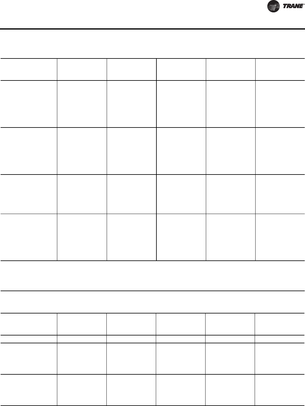
VAV-PRC012-EN 77
Acoustics Data
06SQ
07SQ 10
550 260 53 49 46 43 38 31 56 54 51 49 45 41 60 60 58 54 52 54 62 63 62 58 56 54
800 378 57 53 50 46 41 34 60 58 55 52 48 42 64 63 61 57 54 53 66 66 65 61 59 56
1000 472 60 56 53 49 44 36 63 61 58 54 50 43 67 65 63 60 56 52 69 68 67 64 61 57
1100 519 66 65 62 58 54 49
1200 566 62 59 56 52 46 39 66 64 61 57 52 46 70 68 66 62 58 53 72 70 69 66 62 58
1350 637 64 61 58 54 48 42 68 66 63 59 54 48 72 70 68 64 60 54 74 72 71 67 63 59
06SQ
07SQ 12
800 378 63 56 55 54 51 42 68 62 61 61 59 51 71 67 65 66 64 57 73 70 68 69 67 60
1100 519 65 57 56 54 52 43 72 65 63 63 60 53 75 71 69 70 67 60 77 74 72 73 71 64
1400 661 66 59 58 54 52 44 74 67 64 64 62 54 79 73 71 72 70 62 81 77 74 76 74 66
1600 755 78 72 69 69 67 60
1700 802 67 61 60 55 52 44 75 69 66 65 62 55 82 75 72 73 71 63 84 79 76 77 76 68
2000 944 69 63 61 55 52 46 76 70 67 65 63 55 84 77 74 74 71 64 86 81 78 78 77 69
06SQ
07SQ 14
1100 519 60 54 53 51 48 41 65 60 58 57 54 48 69 66 64 61 60 55 73 71 69 64 62 59
1600 755 64 58 56 55 52 45 69 64 62 61 58 52 74 70 68 66 64 59 77 73 71 69 67 62
2100 991 67 61 60 57 55 47 72 67 66 64 61 55 75 70 68 67 64 58 77 72 71 69 67 61 80 76 74 72 70 65
2500 1180 70 64 63 60 57 50 74 69 67 66 63 56 80 74 72 71 69 63 83 77 76 74 72 66
3000 1416 73 67 66 63 60 53 77 71 69 68 65 58 83 76 74 73 71 65 87 79 78 76 74 68
06SQ
07SQ 16
1400 661 62 57 54 54 51 43 67 63 61 60 57 52 72 70 67 65 62 57 75 75 72 67 65 61
2100 991 64 60 58 56 54 46 71 66 63 62 60 55 76 73 71 69 67 62 78 76 74 72 70 65
2700 1274 67 63 61 59 56 49 73 68 66 65 62 57 79 74 72 71 69 64 82 78 76 75 73 68
2800 1321 77 71 69 68 66 61
3400 1605 70 65 64 62 58 52 75 70 68 66 64 58 82 75 74 72 70 65 86 79 77 76 74 69
4000 1888 73 68 67 64 61 55 77 72 70 68 65 60 84 77 75 74 71 66 89 80 78 77 75 70
Notes:
1. All data are measured in accordance with Industry Standard AHRI 880-2011.
2. All sound power levels, dB re: 10-12 Watts.
3. Data in this column constitute AHRI 880-2011 Standard Rating Conditions
4. Where Ps is the inlet static pressure minus discharge static.
5. Application ratings are outside the scope of the certification program.
Table 95. Discharge sound power (dB)1, 2, 4- valve only (continued)
Fan
Size
Inlet
Size
(in)
0.5" Inlet Pressure
Ps5
1.0" Inlet Pressure
Ps5
1.5" Inlet Pressure
Ps3
2.0" Inlet Pressure
Ps5
3.0" Inlet Pressure
Ps5
Cfml/s 234567234567234567234567234567
Table 96. Radiated sound power (dB)1, 2, 4- valve only
Fan
Size
Inlet
Size
(in)
0.5" Inlet Pressure
Ps5
1.0" Inlet Pressure
Ps5
1.5" Inlet Pressure
Ps3
2.0" Inlet Pressure
Ps5
3.0" Inlet Pressure
Ps5
Cfml/s234567234567234567234567234567
02SQ 5 250 118 50 48 46 42 38 30
02SQ 6
200 94 48 40 38 35 31 25 48 44 42 37 33 26 53 48 47 43 38 33 54 50 47 44 41 37
300 142 51 45 42 35 29 24 54 49 46 39 33 26 57 51 50 44 38 32 60 55 53 48 42 37
400 189 54 48 46 38 32 25 58 53 49 42 35 26 60 54 51 44 37 29 61 55 52 47 40 33 63 57 55 49 43 37
500 236 52 50 48 40 33 27 62 56 52 45 37 29 65 59 56 50 42 34 65 60 57 52 45 38
02SQ 8
350 165 53 45 40 37 31 23 55 49 44 39 35 30 60 53 50 45 41 36 62 55 52 48 45 40
520 245 57 49 44 40 34 26 59 53 48 42 37 31 64 57 53 47 43 38 66 59 56 51 46 41
700 330 61 53 48 43 37 29 63 57 52 46 40 33 66 59 55 48 43 39 68 61 57 50 45 40 70 63 60 54 48 42
900 425 66 58 53 47 41 33 68 62 56 50 44 37 72 65 61 53 48 42 73 67 63 56 50 44

78 VAV-PRC012-EN
Acoustics Data
02SQ 10
550 260 57 50 44 39 32 25 61 54 48 42 36 28 65 58 52 46 40 34 67 60 56 50 43 38
"820 387 59 52 46 41 34 25 64 58 52 46 40 31 69 63 56 51 44 37 71 66 60 54 47 40
1100 519 62 56 50 44 41 26 66 61 54 49 42 33 70 64 58 52 45 36 72 66 60 54 48 39 75 68 63 57 51 42
1400 661 65 60 53 47 44 30 68 64 57 52 45 36 74 69 63 57 50 41 77 71 66 60 53 44
03SQ 6
100 47 49 44 38 37 31 24 50 46 41 41 35 29 52 47 44 46 41 36 53 48 45 48 45 40
200 94 50 44 39 37 31 24 53 48 43 41 36 29 56 51 47 46 42 36 59 53 49 49 45 40
300 142 52 45 40 38 31 25 54 50 45 42 36 30 59 53 50 47 42 37 60 55 53 49 45 40
400 189 54 47 42 39 33 26 57 53 48 44 38 31 59 55 51 46 41 35 61 55 52 48 43 38 62 57 55 50 46 41
600 283 58 53 50 45 40 34 58 56 54 48 42 35 64 61 58 51 45 39 67 62 60 53 48 42
03SQ
04SQ 8
175 83 52 45 39 36 33 26 54 47 42 41 36 30 57 50 45 46 42 36 59 52 46 49 45 39
350 165 57 50 43 38 33 26 59 52 46 42 37 30 61 54 50 47 43 37 63 55 52 50 46 40
525 248 58 51 45 39 34 27 61 55 48 43 38 31 64 57 53 48 44 37 66 58 56 51 47 41
700 330 60 53 47 42 36 30 63 56 51 45 39 33 64 58 53 47 42 35 66 60 55 49 44 37 68 62 58 52 48 41
1050 496 63 59 55 49 42 35 68 62 57 51 45 38 72 65 60 54 48 41 74 67 63 56 50 43
03SQ
04SQ
05SQ
10
275 130 55 49 43 38 34 27 57 51 45 42 37 30 58 53 48 47 43 36 59 54 50 50 46 40
550 260 59 54 47 40 34 28 61 56 50 45 39 34 63 58 53 51 45 41 64 60 56 54 51 44
825 389 61 55 49 42 36 29 63 58 53 46 40 35 66 61 57 51 46 41 69 64 60 54 50 44
1100 519 62 56 50 44 38 32 66 60 54 49 43 37 68 62 57 51 46 40 70 64 59 53 48 43 72 66 62 56 51 46
1640 774 65 61 55 50 43 37 70 65 58 53 46 40 76 69 64 58 51 45 79 72 67 61 55 49
03SQ
04SQ
05SQ
12
385 182 52 47 42 40 36 30 55 50 45 43 40 35 59 53 48 47 44 39 61 55 50 50 47 42
775 366 59 51 45 40 35 28 63 55 48 43 38 33 66 59 52 48 44 39 69 62 56 52 48 42
1160 547 63 54 47 41 35 30 67 58 51 46 39 35 72 63 56 51 45 40 75 67 60 54 49 43
1550 732 66 58 50 43 37 31 71 62 54 48 42 36 75 66 59 53 46 41 78 70 63 56 50 44
1600 755 73 64 57 51 44 39
2350 1109 69 64 55 49 42 36 74 68 59 52 45 40 79 72 64 57 50 44 82 75 67 60 54 47
04SQ
05SQ 14
525 248 58 51 45 40 34 27 61 53 48 44 38 31 64 56 51 49 44 37 66 59 54 51 47 40
1050 496 62 56 49 42 37 30 66 59 52 46 42 34 71 63 57 51 46 39 74 66 60 54 49 42
1575 743 65 59 52 44 37 31 70 62 55 48 42 35 75 67 61 54 48 40 78 70 64 57 51 43
2100 991 67 60 54 45 38 33 72 64 58 50 43 36 75 66 60 53 46 40 78 69 63 56 49 43 83 74 68 61 54 46
3200 1510 72 66 59 51 44 38 77 70 63 55 48 42 83 75 68 60 53 47 86 78 71 63 56 50
06SQ
07SQ 10
550 260 51 44 42 40 37 32 54 49 45 44 42 38 58 55 49 49 48 45 61 58 52 52 52 49
800 378 53 48 43 41 37 32 57 52 47 45 42 38 62 58 52 50 48 45 65 61 55 53 52 49
1000 472 55 51 44 42 38 33 59 55 48 46 42 38 65 61 54 51 48 45 68 63 57 54 52 49
1100 519 63 59 53 49 46 42
1200 566 58 53 47 43 38 33 62 58 51 47 42 38 67 63 56 52 48 45 70 65 59 56 52 49
1350 637 60 55 49 44 39 34 64 60 53 48 43 39 69 65 58 53 49 45 72 67 61 57 53 49
06SQ
07SQ 12
800 378 58 50 44 40 33 26 62 55 49 45 38 31 66 60 54 50 43 36 68 63 56 52 46 39
1100 519 60 52 46 40 33 27 65 58 51 47 40 33 70 64 58 53 46 39 72 66 60 56 50 42
1400 661 62 54 46 40 34 27 67 60 53 48 41 34 73 66 60 55 48 41 75 69 64 58 52 44
1600 755 73 65 58 53 46 40
1700 802 64 56 48 42 34 28 68 62 54 48 41 35 76 68 61 56 49 42 78 72 66 60 54 46
2000 944 65 58 49 47 36 31 70 63 55 50 42 35 77 70 62 57 50 43 79 73 67 61 55 48
Table 96. Radiated sound power (dB)1, 2, 4- valve only (continued)
Fan
Size
Inlet
Size
(in)
0.5" Inlet Pressure
Ps5
1.0" Inlet Pressure
Ps5
1.5" Inlet Pressure
Ps3
2.0" Inlet Pressure
Ps5
3.0" Inlet Pressure
Ps5
Cfml/s234567234567234567234567234567
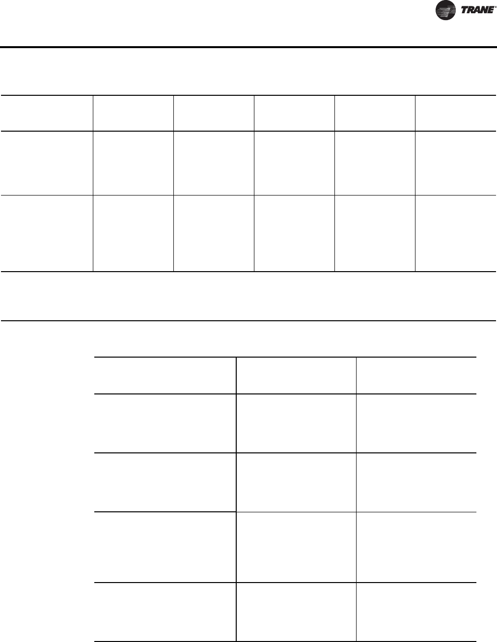
VAV-PRC012-EN 79
Acoustics Data
06SQ
07SQ 14
1100 519 56 49 44 40 32 25 61 55 48 44 38 30 66 61 54 49 43 36 69 66 57 51 45 40
1600 755 59 53 47 42 35 27 65 59 52 48 41 33 70 64 58 53 46 39 74 68 61 55 49 42
2100 991 64 57 51 46 38 29 68 61 55 50 43 35 72 64 58 53 46 38 74 67 61 55 49 41 77 70 64 59 52 45
2500 1180 67 59 53 48 40 31 71 63 57 52 44 36 76 68 62 56 50 42 79 72 66 60 54 46
3000 1416 71 62 56 50 42 33 74 66 59 54 46 38 78 70 64 58 51 44 82 74 68 62 56 48
06SQ
07SQ 16
1400 661 63 54 48 41 36 29 67 59 53 46 42 35 70 66 58 52 48 40 72 70 61 54 50 43
2100 991 66 57 51 44 39 32 71 63 56 49 45 38 75 69 63 56 52 44 77 72 66 59 55 47
2700 1274 68 60 54 46 41 34 73 65 59 51 47 40 78 72 66 59 54 47 80 75 69 62 58 50
2800 1321 76 69 62 55 51 44
3400 1605 70 63 57 51 46 42 76 68 61 54 48 42 81 74 68 60 56 48 83 76 70 64 59 52
4000 1888 73 66 60 56 52 50 78 70 63 56 50 45 83 75 70 62 57 50 85 78 72 65 60 53
Notes:
1. All data are measured in accordance with Industry Standard AHRI 880-2011.
2. All sound power levels, dB re: 10-12 Watts.
3. Data in this column constitute AHRI 880-2011 Standard Rating Conditions
4. Where Ps is the inlet static pressure minus discharge static.
5. Application ratings are outside the scope of the certification program.
Table 96. Radiated sound power (dB)1, 2, 4- valve only (continued)
Fan
Size
Inlet
Size
(in)
0.5" Inlet Pressure
Ps5
1.0" Inlet Pressure
Ps5
1.5" Inlet Pressure
Ps3
2.0" Inlet Pressure
Ps5
3.0" Inlet Pressure
Ps5
Cfml/s234567234567234567234567234567
Table 97. Fan only sound power
Discharge Lw (dB) Radiated Lw (dB)
Outlet
SP
Octave Bands Octave Bands
Fan CFMl/s234567234567
02SQ 0.25
200 94 59 51 50 46 42 35 63 55 53 50 44 37
280 132 61 53 51 48 44 38 65 57 54 52 46 40
350 165 62 54 52 50 46 40 66 58 55 52 48 42
430 203 65 56 54 52 49 43 68 60 57 54 50 45
500(a) 236 66 57 55 53 50 46 69 61 58 56 52 48
03SQ 0.25
250 118 57 50 51 45 40 39 61 55 53 49 42 35
400 189 60 52 53 46 42 41 64 56 55 51 45 40
610 288 67 59 57 53 48 47 70 62 60 56 51 48
850 401 69 60 60 56 52 51 72 63 62 59 55 53
1090(a) 514 74 65 65 63 58 58 77 68 66 64 60 59
04SQ 0.25
300 142 59 52 52 47 41 38 61 56 54 49 43 34
530 250 60 54 55 50 45 42 63 57 56 51 47 41
790 373 66 59 59 55 50 48 69 62 60 56 52 49
1100 519 69 63 64 60 56 55 72 66 64 60 57 55
1300(a) 614 71 65 66 64 59 58 74 68 66 63 60 59
1350 637 72 66 66 65 60 59 75 69 67 64 61 60
05SQ 0.25
350 165 60 53 54 46 40 37 63 57 54 48 42 35
650 307 62 56 57 50 45 42 65 60 57 51 47 43
970 458 65 61 62 57 51 50 68 63 62 57 53 51
1300 614 68 64 66 63 58 57 71 67 65 62 59 57
1550(a) 732 70 66 67 66 61 60 74 69 68 65 62 61
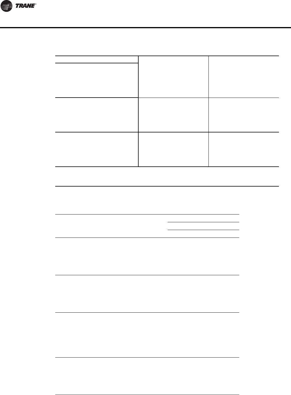
80 VAV-PRC012-EN
Acoustics Data
06SQ 0.25
920 434 66 61 60 56 51 48 71 64 62 56 51 47
1200 566 69 64 61 59 54 51 73 65 63 59 53 51
1400 661 71 65 63 61 56 54 75 67 64 60 55 53
1700 802 73 68 65 63 58 57 77 69 66 63 58 56
1960(a) 925 75 70 68 66 62 60 79 71 67 64 61 59
07SQ 0.25
1050 496 62 61 61 55 49 46 67 61 62 56 50 46
1300 614 65 65 62 58 53 50 69 64 66 58 54 50
1500 708 67 67 64 61 56 53 70 65 68 60 56 52
1800 850 69 68 68 65 60 57 73 68 68 63 59 56
2020(a) 953 70 69 69 66 62 59 74 69 69 65 61 58
06SQ ECM 0.25
800 378 68 61 60 57 51 49 71 65 63 57 52 49
1100 519 71 64 62 59 54 52 73 66 64 58 54 51
1500 708 74 67 65 63 58 56 76 70 66 62 57 55
1800 850 76 69 67 66 60 58 78 72 67 64 60 58
2100 991 78 71 69 68 63 62 80 74 69 66 63 61
Notes:
1. All data are measured in accordance with Industry Standard AHRI 880-2011.
2. all sound power levels, dB re: 10-12 Watts
3. application ratings are outside the scope of the certification program
(a) AHRI 880-2011 section 7.2 Standard Rating Conditions
Table 98. Sound noise criteria (NC) - fan only
Fan-Only
0.25" Disch. Pres.
Fan Outlet SP CFM l/s Discharge Radiated
02SQ 0.25
200 94 -- 27
280 132 -- 29
350 165 -- 30
430 203 17 33
500(a) 236 19 34
03SQ 0.25
250 118 -- 27
400 189 -- 30
610 288 17 35
850 401 20 38
1090(a) 514 26 44
04SQ 0.25
300 142 -- 28
530 250 -- 31
790 373 16 35
1100 519 21 39
1300(a) 614 23 41
1350 637 24 43
05SQ 0.25
350 165 -- 28
650 307 -- 32
970 458 18 37
1300 614 22 40
1550(a) 732 24 44
Table 97. Fan only sound power (continued)
Discharge Lw (dB) Radiated Lw (dB)

VAV-PRC012-EN 81
Acoustics Data
06SQ 0.25
920 434 18 37
1200 566 21 39
1400 661 23 42
1700 802 26 44
1960(a) 925 29 47
07SQ 0.25
1050 496 18 37
1300 614 23 41
1500 708 25 44
1800 850 26 44
2020(a) 953 27 45
06SQ
ECM 0.25
800 378 18 38
1100 519 22 39
1500 708 26 43
1800 850 29 45
2100 991 31 48
Notes:
1. “--” represents NC levels below NC 15.
2. NC values are calculated using modeling assumptions based on AHRI 885-2008 Appendix E.
3. application ratings are outside the scope of the certification program.
(a) AHRI 880-2011 section 7.2 Standard Rating Conditions
Table 98. Sound noise criteria (NC) - fan only (continued)
Fan-Only
Table 99. AHRI 885-2008 discharge transfer function assumptions:
Octave Band
23 4 5 6 7
Small Box (<300 Cfm) -24 -28 -39 -53 -59 -40
Medium Box (300-700 Cfm) -27 -29 -40 -51 -53 -39
Large Box (>700 Cfm) -29 -30 -41 -51 -52 -39
Notes: Subtract from terminal unit sound power to determine discharge sound pressure in the space.
1. NC Values are calculated using current Industry Standard AHRI 885-2008. Radiated Transfer Function obtained from Appendix E, Type 2 Mineral Fiber
Insulation.
2. Application ratings are outside the scope of the Certification Program.
Table 100.AHRI 885-2008 radiated transfer function assumptions:
Octave Band
23 4 5 6 7
Type 2- Mineral Fiber Insulation -18 -19 -20 -26 -31 -36
Total dB reduction -18 -19 -20 -26 -31 -36
Notes: Subtract from terminal unit sound power to determine discharge sound pressure in the space.
1. NC Values are calculated using current Industry Standard AHRI 885-2008. Radiated Transfer Function obtained from Appendix E, Type 2 Mineral Fiber
Insulation.
2. Application ratings are outside the scope of the Certification Program.
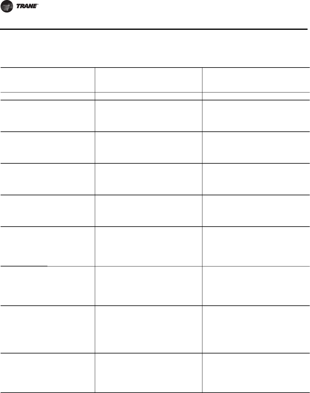
82 VAV-PRC012-EN
Acoustics Data
Table 101. Sound noise criteria (NC) - valve only
Discharge1,2,4 Radiated1,2,4
Fan Size
Inlet
Size (in)
Inlet Pressure (Ps)3,5 Inlet Pressure (Ps)3,5
CFM l/s 0.5” 1.0” 1.5” 2.0” 3.0” 0.5” 1.0” 1.5” 2.0” 3.0”
02SQ 5 250 118 21 20
02SQ 6
200 94 -- -- -- 20 -- 15 21 21
300 142 -- -- 16 19 15 20 24 27
400 189 -- 20 20 21 23 20 23 25 26 30
500 236 16 23 25 28 22 26 31 32
02SQ 8
350 165 -- -- 16 19 -- 18 24 26
520 245 -- 16 21 23 19 22 27 31
700 330 18 22 24 26 29 24 26 30 33 35
900 425 23 27 30 32 30 33 38 39
02SQ 10
550 260 -- 17 23 25 19 24 29 31
820 387 16 22 29 31 21 27 34 37
1100 519 20 25 30 32 36 25 31 35 38 42
1400 661 23 29 36 40 30 34 40 44
03SQ 6
100 47 -- -- -- 17 -- -- 18 20
200 94 -- -- -- 18 -- 16 21 23
300 142 -- -- 17 18 -- 19 24 27
400 189 -- 17 19 22 23 15 22 25 26 30
03SQ
04SQ 8
175 83 -- -- -- 17 -- 15 19 21
350 165 -- -- -- 19 19 21 24 26
525 248 -- -- 19 22 20 24 27 31
700 330 -- 18 22 24 26 22 26 27 30 33
1050 496 23 28 30 32 30 33 38 40
03SQ
04SQ 10
275 130 -- -- -- 17 17 19 22 24
550 260 -- -- 19 22 23 25 27 31
825 389 -- 18 24 28 24 27 32 35
1100 519 17 22 25 28 30 25 30 33 35 38
1640 774 24 29 34 37 31 36 43 47
03SQ
04SQ
05SQ
12
385 182 -- -- -- 17 15 19 22 24
775 366 -- 16 23 25 21 26 30 34
1160 547 -- 19 26 30 26 31 38 42
1550 732 17 23 30 35 30 36 42 45
1600 755 26 39
2350 1109 24 30 35 40 34 40 47 51
04SQ
05SQ 14
525 248 -- -- 16 19 20 24 27 30
1050 496 -- 19 26 29 25 30 36 40
1575 743 16 23 31 35 29 35 42 45
2100 991 19 26 31 34 38 31 38 42 45 52
3200 1510 26 31 38 43 38 44 52 56
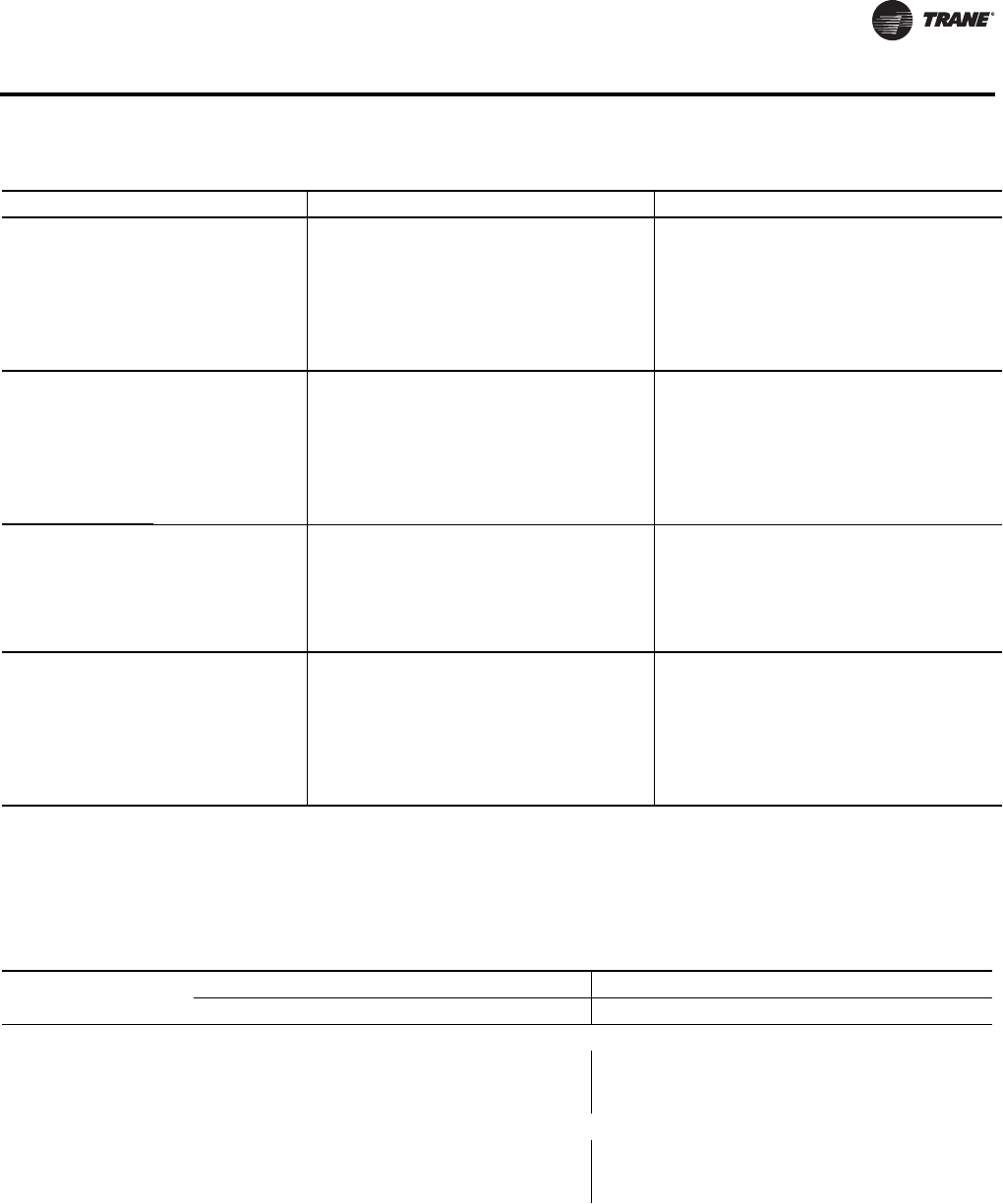
VAV-PRC012-EN 83
Acoustics Data
06SQ
07SQ 10
550 260 -- -- 18 20 15 19 24 27
800 378 -- -- 20 24 16 21 27 31
1000 472 -- 18 23 26 19 24 31 33
1100 519 23 28
1200 566 16 21 26 29 21 27 33 36
1350 637 18 24 29 31 24 30 36 38
06SQ
07SQ 12
800 378 -- 19 25 29 20 25 30 33
1100 519 15 24 30 33 22 29 35 38
1400 661 16 27 33 37 25 31 39 42
1600 755 32 39
1700 802 18 28 37 39 27 33 43 45
2000 944 20 29 39 42 29 35 44 47
06SQ
07SQ 14
1100 519 -- 17 24 30 18 24 31 37
1600 755 -- 21 29 32 21 29 35 40
2100 991 18 25 29 31 36 27 33 38 40 44
2500 1180 21 27 34 38 31 36 43 47
3000 1416 25 30 38 43 36 40 45 51
06SQ
07SQ 16
1400 661 -- 20 29 35 26 31 37 42
2100 991 17 24 32 36 30 36 42 44
2700 1274 20 26 33 38 33 39 45 48
2800 1321 30 43
3400 1605 23 29 37 42 35 43 49 52
4000 1888 26 31 39 46 39 45 52 54
Notes:
1. “--” represents NC levels below NC 15.
2. NC Values are calculated using modeling assumptions based on AHRI 885-98-02 Addendum
3. Data at 1.5” inlet pressure constitute AHRI 880-2011 Standard Rating Conditions.
4. Where Ps is the inlet static pressure minus discharge static.
5. Data at 0.5”, 1.0”, 2.0” and 3.0” are application ratings. These ratings are outside the scope of the certification program.
Table 101. Sound noise criteria (NC) - valve only (continued)
Discharge1,2,4 Radiated1,2,4
Table 102. Parallel inlet attenuator appurtenance effects (fan noise only)
Fan
Discharge Sound Effect* (dB) Radiated Sound Effect* (dB)
234567234567
Matte-faced and foil-faced insulation, solid double-wall**
02SQ
03SQ, 04SQ, 05SQ
06SQ, 07SQ
2
2
2
1
1
1
1
1
1
2
2
2
1
1
1
2
2
2
1
0
1
-2
-1
0
-8
-8
-8
-13
-12
-12
-15
-16
-15
-16
-17
-18
Closed-cell insulation
02SQ
03SQ, 04SQ, 05SQ
06SQ, 07SQ
1
1
1
1
1
1
1
1
1
1
1
1
1
1
1
1
1
1
1
0
1
-1
-1
-1
-3
-3
-3
-2
-2
-2
-4
-4
-4
-4
-4
-4
Notes:
* Add to sound power, a negative effect represents a sound reduction, a positive effect represents a sound increase.
** Note- Attenuators on double-wall units contain foil-faced insulation.
1. All data are measured in accordance with Industry Standard AHRI 880-2011.
2. All sound power levels, dB re: 10-12 Watts.
3. Application ratings are outside the scope of the Certification Program.
84 VAV-PRC012-EN
Acoustics Data
Table 103. Parallel cabinet lining appurtenance effects (fan noise and valve noise)
Fan
Discharge Sound Effect* (dB) Radiated Sound Effect* (dB)
2345672 3 4567
Solid double-wall
02SQ
03SQ, 04SQ, 05SQ
06SQ, 07SQ
3
1
3
1
-1
1
1
1
1
-1
3
1
1
4
3
3
5
5
1
1
-1
0
0
-1
0
2
-1
1
5
2
4
8
4
7
8
5
Closed-cell insulation
02SQ
03SQ, 04SQ, 05SQ
06SQ, 07SQ
1
1
1
1
1
1
1
2
2
0
2
1
1
2
2
4
3
4
0
1
1
0
2
0
2
4
3
2
4
4
5
4
5
7
5
6
Note:
* Add to sound power, a negative effect represents a sound reduction, a positive effect represents a sound increase
1. All data are measured in accordance with Industry Standard AHRI 880-2011.
2. All sound power levels, dB re: 10-12 Watts.
3. Application ratings are outside the scope of the Certification Program.
Table 104. Parallel heating coil appurtenance effects
Fan
Discharge Sound Effect* (dB) Radiated Sound Effect* (dB)
2345 6 7 2 345 6 7
Hot Water Coil**
02SQ
03SQ, 04SQ, 05SQ
06SQ, 07SQ
-1
2
2
0
2
1
-1
2
0
-1
2
-1
0
2
0
-1
1
0
-1
1
0
-1
1
0
0
1
0
-1
1
-1
-1
0
0
-3
0
-1
Electric Heat***
02SQ
03SQ, 04SQ, 05SQ
06SQ, 07SQ
0
0
3
0
0
4
0
0
3
-1
0
2
-2
0
4
-1
1
4
0
0
1
0
0
0
0
0
0
0
0
0
0
0
0
0
0
0
Notes:
* Add to sound power, a negative effect represents a sound reduction, a positive effect represents a sound increase.
** Add to fan sound only, not valve sound.
***Add to both fan sound and valve sound.
Apply fan only data, not valve sound.
1. All data are measured in accordance with Industry Standard AHRI 880-2011.
2. All sound power levels, dB re: 10-12 Watts.
3. Application ratings are outside the scope of the Certification Program.

VAV-PRC012-EN 85
Acoustics Data
Series Fan-Powered Terminal Units
Table 105. Discharge sound power (dB)- fan and 100% primary
Fan
Size
Inlet
Size (in)
0.5” Inlet Pressure Ps 1.0” Inlet Pressure Ps 2.0” Inlet Pressure Ps 3.0” Inlet Pressure Ps
Cfm l/s 234567234567234567234567
02SQ 10
200 94 71 55 54 52 49 45 72 61 56 54 52 51 74 70 66 62 59 55 74 64 63 61 59 59
300 142 71 56 55 52 49 46 72 61 57 54 52 52 74 69 65 61 58 56 75 67 66 63 60 60
500 236 71 57 56 52 49 47 72 61 58 54 52 53 74 68 64 60 57 59 76 74 73 67 63 63
600 283 72 60 59 55 52 50 74 63 60 56 54 55 75 67 64 60 58 59 76 72 69 64 61 62
700 330 73 62 61 57 55 53 75 64 61 58 56 56 75 66 63 59 58 58 76 69 64 61 59 60
03SQ 10
250 118 57 49 47 43 38 34 57 50 48 43 39 34 58 52 48 44 40 36 59 53 48 45 41 39
480 227 61 53 52 49 45 43 62 55 53 49 46 43 63 57 53 49 46 44 64 59 53 50 47 45
720 340 66 58 58 55 53 52 68 60 59 56 54 52 68 63 58 55 53 52 70 65 59 55 53 52
960 453 71 63 63 61 59 59 72 64 63 62 59 59 74 67 64 62 60 60 74 68 64 62 60 59
1200 566 76 67 67 66 64 65 77 68 67 66 64 64 79 71 68 67 65 65 79 72 68 68 65 65
04SQ 12
330 156 58 52 49 45 39 34 59 53 49 45 40 35 62 57 50 46 40 38 63 59 51 46 42 40
620 293 62 55 54 51 46 43 63 57 54 51 47 44 67 62 55 52 47 46 68 64 55 52 48 47
930 439 66 59 59 57 54 53 68 61 59 57 55 53 72 67 60 58 55 54 73 69 60 58 55 54
1250 590 72 64 64 63 60 60 74 66 65 64 61 61 76 69 65 65 62 62 78 72 66 65 63 62
1550 732 77 69 68 68 66 66 77 70 68 69 66 66 80 72 69 70 67 67 81 75 70 70 68 67
05SQ 12
400 189 56 52 52 46 40 38 57 53 52 47 41 39 59 54 52 47 42 40 60 56 53 48 43 41
760 359 61 58 58 54 49 48 62 58 57 54 49 48 65 60 57 53 49 48 66 62 58 54 50 48
1140 538 67 64 64 62 59 58 67 63 63 61 58 57 71 66 63 60 57 56 73 69 64 61 58 56
1500 708 73 69 69 68 65 64 73 69 69 67 65 64 75 70 69 68 65 64 77 72 69 68 65 64
1900 897 77 74 73 74 71 71 78 74 73 74 71 70 79 74 73 73 70 70 79 75 73 73 70 70
06SQ 16
700 330 57 53 53 49 46 41 70 59 55 52 51 50 75 71 65 62 56 56 78 71 69 65 60 58
1200 566 63 59 58 55 52 48 72 63 60 57 55 54 77 72 67 64 60 60 80 75 71 67 64 62
1600 755 69 63 62 59 56 54 74 67 64 61 59 58 79 74 69 66 62 62 82 77 73 69 66 64
2100 991 75 69 67 65 62 61 77 71 69 66 63 62 81 76 72 69 66 66 84 80 75 72 70 68
2500 1180 77 72 69 67 65 64 79 74 71 69 66 65 83 78 74 71 69 68 86 82 77 74 72 70
07SQ 16
850 401 62 58 51 53 47 51 66 60 53 54 47 52 69 63 56 56 52 58 75 69 62 59 54 63
1400 661 65 61 59 56 52 53 69 63 61 57 55 57 74 68 64 59 57 61 77 72 67 62 59 63
1900 897 69 66 65 61 58 57 73 67 66 61 59 60 77 71 68 63 61 63 80 75 70 65 63 64
2250 1062 72 69 68 64 62 61 75 70 69 64 62 62 79 73 71 65 64 65 82 77 72 67 65 66
2500 1180 74 71 71 67 65 63 76 72 71 67 65 65 79 74 73 67 66 67 83 77 73 69 67 67
3000 1416 77 75 75 71 69 68 79 75 75 71 69 69 81 77 76 71 70 70 85 79 76 72 70 70
04SQ
ECM 12
275 130 56 51 49 44 38 37 57 52 49 44 38 38 58 53 49 44 39 39 59 55 50 45 41 40
620 293 61 55 54 51 46 45 63 57 54 51 47 46 65 60 55 51 47 47 66 62 55 52 48 47
930 439 66 59 59 57 54 53 68 61 59 57 55 53 72 67 60 58 55 54 73 69 60 58 55 54
1250 590 72 64 64 63 60 60 74 66 65 64 61 61 76 69 65 65 62 62 78 72 66 65 63 62
1550 732 77 69 68 68 66 66 77 70 68 69 66 66 80 72 69 70 67 67 81 75 70 70 68 67
1660 783 79 71 69 70 68 68 78 71 69 71 68 68 81 73 70 72 69 69 82 76 71 72 70 69

86 VAV-PRC012-EN
Acoustics Data
05SQ
ECM 14
350 165 57 51 50 45 39 39 57 52 50 45 40 39 57 53 49 46 40 40 59 54 50 47 42 41
760 359 62 58 57 54 49 49 62 58 57 53 49 48 64 60 56 53 49 48 66 62 57 54 50 49
1140 538 67 64 64 62 59 58 67 63 63 61 58 57 71 66 63 60 57 56 73 69 64 61 58 56
1500 708 73 69 69 68 65 64 73 69 69 67 65 64 75 70 69 68 65 64 77 72 69 68 65 64
1900 897 77 74 73 74 71 71 78 74 73 74 71 70 79 74 73 73 70 70 79 75 73 73 70 70
2350 1109 81 78 77 78 76 76 82 78 77 78 76 76 83 79 77 78 76 76 83 79 77 78 76 76
06SQ
ECM 16
700 330 57 53 53 49 46 41 70 59 55 52 51 50 75 71 65 62 56 56 78 71 69 65 60 58
1200 566 63 59 58 55 52 48 72 63 60 57 55 54 77 72 67 64 60 60 80 75 71 67 64 62
1600 755 69 63 62 59 56 54 74 67 64 61 59 58 79 74 69 66 62 62 82 77 73 69 66 64
2100 991 75 69 67 65 62 61 77 71 69 66 63 62 81 76 72 69 66 66 84 80 75 72 70 68
2500 1180 77 72 69 67 65 64 79 74 71 69 66 65 83 78 74 71 69 68 86 82 77 74 72 70
1500 708 75 74 70 68 64 63 76 74 70 69 64 63
Notes:
1. All data are measured in accordance with Industry Standard AHRI 880-2011.
2. All sound power levels, dB re: 10-12 Watts.
3. Where Ps is the inlet static pressure minus discharge static.
4. Application ratings are outside the scope of the certification program.
Table 105. Discharge sound power (dB)- fan and 100% primary (continued)
Fan
Size
Inlet
Size (in)
0.5” Inlet Pressure Ps 1.0” Inlet Pressure Ps 2.0” Inlet Pressure Ps 3.0” Inlet Pressure Ps
Cfm l/s 234567234567234567234567
Table 106. Radiated sound power (dB)1,2,4- fan and 100% primary
Fan
Size
Inlet
Size
(in)
0.5” Inlet Pressure
Ps5
1.0” Inlet Pressure
Ps5
1.5” Inlet Pressure
Ps3
2.0” Inlet Pressure
Ps5
3.0” Inlet Pressure
Ps5
Cfml/s234567234567234567234567234567
02SQ 10
200 94 65 53 53 52 49 45 66 59 55 54 52 51 68 68 65 62 59 55 68 62 62 61 59 59
300 142 65 54 54 52 49 46 66 59 56 54 52 52 68 67 64 61 58 56 69 65 65 63 60 60
500 236 65 55 55 52 49 47 66 59 57 54 52 53 68 66 63 60 57 59 70 72 72 67 63 63
600 283 66 58 58 54 52 50 68 60 58 56 54 54 69 66 63 60 58 60 71 72 70 66 62 63
700 330 67 60 60 57 55 53 69 62 60 58 56 56 69 64 61 59 57 58 70 67 63 61 59 60 72 71 68 66 62 63
03SQ 10
250 118 53 49 47 44 40 35 56 51 49 47 44 42 58 54 53 52 49 48 59 56 56 55 52 52
480 227 58 54 52 49 45 42 61 56 53 51 48 48 63 59 57 55 52 53 65 62 60 58 55 56
720 340 63 59 57 54 51 50 66 61 58 55 53 54 69 65 61 58 56 59 71 68 64 61 58 61
960 453 68 63 61 59 57 57 71 65 63 60 58 59 73 69 65 62 59 62 74 71 68 64 61 63
1100 519 74 69 66 63 61 63
1200 566 72 67 65 63 61 62 75 69 66 64 62 63 77 72 68 66 63 65 78 74 70 67 64 66
04SQ 12
330 156 56 51 49 44 41 37 58 54 52 47 46 47 62 58 56 53 51 53 64 60 59 57 54 56
620 293 60 55 54 49 46 44 62 58 55 51 50 51 67 63 60 56 54 57 69 65 63 60 57 60
930 439 64 60 59 54 52 51 67 62 59 55 54 56 73 68 64 59 58 62 74 71 67 63 60 65
1250 590 69 65 63 59 58 57 72 66 64 60 59 60 76 71 66 62 61 65 78 74 69 65 63 67
1500 708 77 71 68 65 64 65
1550 732 74 69 67 65 63 63 76 71 68 65 64 64 79 73 69 66 65 67 80 76 72 68 66 68
05SQ 12
400 189 57 54 50 45 44 40 60 56 53 49 50 50 63 60 57 53 52 55 65 62 60 57 54 57
760 359 61 58 55 51 50 47 64 60 57 53 54 54 68 64 60 56 55 59 70 67 64 60 57 61
1140 538 65 63 60 57 56 54 68 65 61 58 58 58 73 69 64 60 59 63 75 73 68 63 61 65
1500 708 69 67 65 63 62 60 72 69 65 63 62 62 76 72 68 64 63 65 78 75 70 66 65 67
1900 897 74 72 69 68 67 66 76 73 70 69 67 67 76 73 70 68 67 67 79 75 71 68 67 68 81 77 72 69 68 69

VAV-PRC012-EN 87
Acoustics Data
06SQ 16
700 330 54 52 53 49 46 41 67 58 55 52 51 50 72 70 65 62 56 56 75 70 69 65 60 58
1200 566 60 58 58 55 52 48 69 62 60 57 55 54 74 71 67 64 60 60 77 74 71 67 64 62
1600 755 66 62 62 59 56 54 71 66 64 61 59 58 76 73 69 66 62 62 79 76 73 69 66 64
2100 991 72 68 67 65 62 61 74 70 68 66 63 62 78 74 72 69 66 66 81 79 75 72 70 68
2500 1180 74 71 69 67 65 64 76 73 70 69 66 65 78 75 72 70 68 67 80 76 74 71 69 68 83 81 77 74 72 70
07SQ 16
850 401 59 57 51 53 47 51 63 59 53 54 47 52 66 62 56 56 52 58 72 68 62 59 54 63
1400 661 62 60 59 56 52 53 66 62 61 57 55 57 71 67 64 59 57 61 74 71 67 62 59 63
1900 897 66 65 65 61 58 57 70 66 66 61 59 60 74 70 68 63 61 63 77 74 70 65 63 64
2250 1062 69 68 68 64 62 60 72 69 69 64 62 62 75 72 71 65 64 65 79 75 72 67 65 66
2500 1180 71 70 71 67 65 63 73 71 71 67 65 65 76 73 73 67 66 67 80 76 73 69 67 67
2800 1321 76 74 74 69 68 68
3000 1416 74 74 75 71 69 68 76 74 75 71 69 69 78 76 76 71 70 70 82 78 76 72 70 70
04SQ
ECM 12
275 130 56 52 49 44 41 38 59 54 52 47 46 47 62 58 56 53 51 52 64 60 59 56 54 56
620 293 60 56 54 49 47 45 63 58 56 51 50 52 68 63 60 56 55 57 69 66 63 60 57 61
930 439 64 60 59 54 52 51 67 62 59 55 54 56 73 68 64 59 58 62 74 71 67 63 60 65
1250 590 69 65 63 59 58 57 72 66 64 60 59 60 76 71 66 62 61 65 78 74 69 65 63 67
1550 732 74 69 67 65 63 63 76 71 68 65 64 64 79 73 69 66 65 67 80 76 72 68 66 68
1660 783 76 70 68 67 65 65 77 73 69 67 66 65 80 74 70 67 66 68 81 77 73 69 67 68
05SQ
ECM 14
350 165 53 50 48 46 42 38 55 52 50 48 46 47 57 55 54 53 51 51 60 58 57 56 54 55
760 359 58 56 54 51 49 46 61 58 56 53 51 52 64 61 59 57 55 57 66 64 62 59 58 60
1140 538 63 62 60 56 55 53 66 63 61 57 56 57 71 67 63 60 59 62 72 70 66 62 61 64
1500 708 69 67 65 62 61 60 70 67 65 62 62 61 72 68 66 63 62 63 73 70 66 64 63 65
1900 897 73 71 69 68 66 66 74 71 69 67 66 66 76 73 69 68 67 68 77 75 71 68 67 69
2350 1109 75 74 72 72 71 71 77 75 72 72 71 71 79 77 73 72 72 72 81 78 74 73 72 73
06SQ
ECM 16
700 330 54 52 53 49 46 41 67 58 55 52 51 50 72 70 65 62 56 56 75 70 69 65 60 58
1200 566 60 58 58 55 52 48 69 62 60 57 55 54 74 71 67 64 60 60 77 74 71 67 64 62
1600 755 66 62 62 59 56 54 71 66 64 61 59 58 76 73 69 66 62 62 79 76 73 69 66 64
2100 991 72 68 67 65 62 61 74 70 68 66 63 62 78 74 72 69 66 66 81 79 75 72 70 68
2500 1180 74 71 69 67 65 64 76 73 70 69 66 65 80 76 74 71 69 68 83 81 77 74 72 70
Notes:
1. All data are measured in accordance with Industry Standard AHRI 880-2011.
2. All sound power levels, dB re: 10-12 Watts.
3. Data in this column constitute AHRI 880-2011 Standard Rating Conditions.
4. Where Ps is the inlet static pressure minus discharge static.
5. Application ratings are outside the scope of the certification program.
Table 106. Radiated sound power (dB)1,2,4- fan and 100% primary (continued)
Fan
Size
Inlet
Size
(in)
0.5” Inlet Pressure
Ps5
1.0” Inlet Pressure
Ps5
1.5” Inlet Pressure
Ps3
2.0” Inlet Pressure
Ps5
3.0” Inlet Pressure
Ps5
Cfml/s234567234567234567234567234567

88 VAV-PRC012-EN
Acoustics Data
Table 107. Fan only sound power (dB)
Fan
Outlet
SP
Discharge Lw (dB) Radiated Lw (dB)
Octave Bands Octave Bands
CFMl/s234567234567
02SQ 0.25
200 94 64 53 52 46 41 33 56 49 47 43 36 28
300 142 65 52 51 47 42 34 57 48 48 44 39 32
500 236 70 58 56 54 50 47 61 56 54 50 47 43
600 283 73 61 59 57 53 52 64 59 57 53 50 48
690(a) 326 76 64 61 59 56 55 66 61 59 56 53 51
700 330 76 64 61 60 56 55 66 62 60 56 53 51
03SQ 0.25
250 118 57 50 48 45 40 34 52 49 47 43 37 28
480 227 60 52 54 49 45 41 55 52 51 47 42 39
720 340 64 56 58 54 52 51 60 57 56 53 50 49
960 453 71 62 63 61 59 58 67 63 61 59 56 56
1100(a) 519 74 65 65 64 62 62 70 65 64 61 59 60
1200 566 76 67 67 67 64 64 73 67 65 63 61 62
04SQ 0.25
330 156 58 51 48 45 40 34 56 51 48 42 37 30
620 293 61 54 53 51 47 44 59 54 53 47 44 40
930 439 66 59 59 58 54 53 63 58 58 53 51 49
1250 590 74 66 65 65 62 61 69 64 63 59 58 56
1500(a) 708 77 70 68 68 65 65 74 68 66 63 62 61
1550 732 78 71 68 69 66 66 75 69 66 64 63 62
05SQ 0.25
400 189 58 54 52 48 42 39 54 52 51 44 40 33
760 359 62 57 56 54 50 48 58 56 53 49 47 43
1140 538 68 63 64 62 59 58 63 62 60 57 55 52
1500 708 73 69 69 68 65 65 69 67 64 62 60 59
1900 897 78 73 73 73 70 70 73 71 68 67 66 65
06SQ 0.25
700 330 57 56 52 50 44 39 58 55 52 47 41 34
1200 566 59 58 57 55 51 49 60 58 58 51 47 44
1600 755 64 62 62 61 57 56 63 62 62 57 53 51
2100 991 69 67 67 67 64 64 68 67 66 62 60 59
2500(a) 1180 73 71 71 71 69 69 72 71 69 66 64 63
07SQ 0.25
850 401 57 61 53 50 45 41 55 56 52 48 41 36
1400 661 63 67 59 56 54 54 59 62 58 54 50 48
1900 897 68 69 65 62 60 61 63 64 64 60 56 55
2250 1062 71 72 69 66 64 65 66 67 68 64 61 59
2500 1180 73 74 72 69 67 68 69 69 70 66 64 62
2800(a) 1321 75 75 74 72 69 70 70 71 71 68 66 65
3000 1416 76 76 76 73 71 72 71 72 72 70 68 67
03SQ
ECM 0.25
200 94 56 49 47 44 38 37 51 48 48 42 35 34
480 227 58 51 53 48 45 43 53 50 51 46 42 40
720 340 64 56 57 54 52 51 57 55 55 51 49 47
960 453 71 63 63 62 59 59 67 62 61 59 56 56
1175 555 76 67 67 66 63 63 70 66 64 62 60 60
VAV-PRC012-EN 89
Acoustics Data
04SQ
ECM 0.25
275 130 56 51 48 45 39 37 52 49 48 42 37 35
620 293 60 54 55 51 48 47 55 52 52 48 45 43
930 439 63 59 59 57 55 55 59 58 58 54 53 52
1250 590 70 65 65 65 63 63 65 64 64 61 60 59
1550 732 76 71 69 69 67 68 68 67 67 65 64 63
1660 783 78 73 70 70 68 70 69 68 68 66 65 64
05SQ
ECM 0.25
350 165 57 52 50 46 40 39 52 49 47 43 38 34
760 359 60 55 55 52 49 48 56 52 51 48 46 43
1140 538 65 61 62 60 57 57 61 59 58 55 54 52
1500 708 72 67 68 66 64 64 67 65 63 61 61 60
1900(a) 897 77 72 72 72 70 70 72 70 68 67 66 66
2350 1109 82 77 76 77 75 76 76 75 72 71 71 71
06SQ
ECM 0.25
700 330 56 52 53 51 45 44 56 50 50 46 43 36
1200 566 60 57 57 55 50 49 57 54 55 51 48 45
1600 755 63 61 61 59 55 55 60 57 60 56 52 51
2100 991 69 67 67 66 62 63 66 63 64 62 59 58
2500(a) 1180 73 71 70 70 66 67 70 67 68 66 63 62
Notes:
1. All data are measured in accordance with Industry Standard AHRI 880-2011.
2. all sound power levels, dB re: 10-12 Watts
3. application ratings are outside the scope of the certification program
(a) xAHRI 880-2011 section 7.2 Standard Rating Conditions
Table 108. Sound noise criteria (NC) fan and 100% primary
Fan
Size
Inlet
Size
(in)
Discharge Radiated
Inlet Pressure (Ps) Inlet Pressure (Ps)
CFM l/s 0.5” 1.0” 2.0” 3.0” 0.5” 1.0” 1.5” 2.0” 3.0”
10
200 94 25 26 30 28 29 30 40 37
300 142 25 26 29 30 29 31 39 40
02SQ 500 236 25 26 28 35 30 32 38 48
600 283 26 28 30 32 33 33 38 46
700 330 27 30 30 31 35 35 36 38 44
03SQ 10
250 118 -- -- -- -- 21 23 27 31
480 227 -- -- -- 16 26 27 32 35
720 340 16 18 21 23 32 33 36 39
960 453 23 24 26 27 36 38 40 44
1100 519 41
1200 566 29 30 33 33 40 42 44 46
04SQ 12
330 156 -- -- -- 16 23 26 31 34
620 293 -- -- 19 22 28 30 35 38
930 439 17 18 25 28 34 34 39 43
1250 590 24 26 29 31 38 39 43 46
1500 708 44
1550 732 30 30 34 35 43 44 47 49
Table 107. Fan only sound power (dB)
Fan
Outlet
SP
Discharge Lw (dB) Radiated Lw (dB)
Octave Bands Octave Bands
CFMl/s234567234567
90 VAV-PRC012-EN
Acoustics Data
05SQ 12
400 189 -- -- -- -- 24 27 32 35
760 359 -- -- 17 19 30 32 35 39
1140 538 22 21 24 27 35 36 40 45
1500 708 28 28 29 31 40 40 44 47
1900 897 34 33 33 35 45 46 46 47 50
06SQ 16
700 330 -- 21 30 32 27 31 42 45
1200 566 15 24 31 34 33 35 43 47
1600 755 20 26 33 37 37 39 45 49
2100 991 28 30 36 40 43 44 48 52
2500 1180 31 33 38 43 45 46 48 50 55
07SQ 16
850 401 -- 17 22 28 26 28 32 39
1400 661 18 21 26 31 34 36 39 43
1900 897 24 25 30 34 40 41 44 46
2250 1062 27 28 33 37 44 45 47 48
2500 1180 30 31 33 38 47 47 49 49
2800 1321 50
3000 1416 34 34 37 41 51 51 52 52
04SQ
ECM 12
275 130 -- -- -- -- 23 26 31 34
620 293 -- -- 17 19 28 31 35 38
930 439 17 18 25 28 34 34 39 43
1250 590 24 26 29 31 38 39 43 46
1550 732 30 30 34 35 43 44 47 49
1660 783 33 31 35 36 44 45 48 50
05SQ
ECM 14
350 165 -- -- -- -- 22 24 28 32
760 359 -- -- 17 19 28 31 34 37
1140 538 22 21 24 27 35 36 38 42
1500 708 28 28 29 31 40 40 41 42
1900 897 34 33 33 35 45 45 45 47
2350 1109 39 39 39 39 48 48 50 51
06SQ
ECM 16
700 330 -- 21 30 32 27 31 42 45
1200 566 15 24 31 34 33 35 43 47
1600 755 20 26 33 37 37 39 45 49
2100 991 28 30 36 40 43 44 48 52
2500 1180 31 33 38 43 45 46 50 55
Notes:
1. “--” represents NC levels below NC 15.
2. NC Values are calculated using modeling assumptions based on AHRI 885-98-02 Addendum
3. Data at 1.5” inlet pressure constitute AHRI 880-2011 Standard Rating Conditions.
4. Where Ps is the inlet static pressure minus discharge static.
5. Data at 0.5”, 1.0”, 2.0” and 3.0” are application ratings. These ratings are outside the scope of the certification program.
Table 108. Sound noise criteria (NC) fan and 100% primary (continued)
Fan
Size
Inlet
Size
(in)
Discharge Radiated
Inlet Pressure (Ps) Inlet Pressure (Ps)
CFM l/s 0.5” 1.0” 2.0” 3.0” 0.5” 1.0” 1.5” 2.0” 3.0”
Table 109.AHRI 885-2008 discharge transfer function assumptions:
Octave Band
2 3 456 7
Small Box (<300 Cfm)
Medium Box (300-700 Cfm)
Large Box (>700 Cfm)
-24
-27
-29
-28
-29
-30
-39
-40
-41
-53
-51
-51
-59
-53
-52
-40
-39
-39
Notes: Subtract from terminal unit sound power to determine discharge sound pressure in the space.
1. NC Values are calculated using modeling assumptions based on AHRI 885-2008.
2. Where DPs is inlet static pressure minus discharge static pressure.
3. Application ratings are outside the scope of the Certification Program.
VAV-PRC012-EN 91
Acoustics Data
Table 110. AHRI 885-2008 radiated transfer function assumptions:
Octave Band
234567
Type 2- Mineral Fiber Insulation
Total dB reduction
-18
-18
-19
-19
-20
-20
-26
-26
-31
-31
-36
-36
Notes: Subtract from terminal unit sound power to determine radiated sound pressure in the space.
1. NC Values are calculated using modeling assumptions based on AHRI 885-2008.
2. Where DPs is inlet static pressure minus discharge static pressure.
3. Application ratings are outside the scope of the Certification Program.
Table 111. Series inlet attenuator appurtenance effects
Fan
Discharge Sound Effect* (dB) Radiated Sound Effect* (dB)
23456723 4 5 6 7
Matte-faced and foil-faced insulation, solid double-wall**
02SQ
03SQ, 04SQ, 05SQ
06SQ, 07SQ
2
2
2
2
2
2
2
2
2
3
3
3
3
3
3
2
2
2
-3
-1
1
-3
-3
-3
-9
-10
-8
-10
-14
-9
-12
-17
-8
-17
-20
-10
Closed-cell insulation
02SQ
03SQ, 04SQ, 05SQ
06SQ, 07SQ
2
2
2
2
2
2
2
2
2
3
3
3
3
3
3
2
2
2
1
1
1
-2
-2
-2
-5
-5
-5
-4
-4
-4
-6
-6
-6
-6
-6
-6
Notes:
* Add to sound power, a negative effect represents a sound reduction, a positive effect represents a sound increase.
** Note – Attenuators on double-wall units contain foil-faced insulation.
1. All data are measured in accordance with Industry Standard AHRI 880-2011.
2. All sound power levels, dB re: 10-12 watts.
3. Application ratings are outside the scope of the Certification Program.
Table 112. Series cabinet lining appurtenance effects
Fan
Discharge Sound Effect* (dB) Radiated Sound Effect* (dB)
234567 2 3 4567
Solid double-wall
02SQ
03SQ, 04SQ, 05SQ
06SQ, 07SQ
0
0
0
0
0
0
0
0
0
0
0
0
0
0
0
0
0
0
0
0
1
0
0
3
0
1
2
2
2
5
3
3
8
3
4
8
Closed-cell insulation
02SQ
03SQ, 04SQ, 05SQ
06SQ, 07SQ
0
0
0
0
0
0
0
0
0
0
0
0
0
0
0
0
0
0
-1
1
1
-1
1
5
0
2
3
1
2
4
1
2
6
2
2
6
Note:
* Add to sound power, a negative effect represents a sound reduction, a positive effect represents a sound increase.
1. All data are measured in accordance with Industry Standard AHRI 880-2011.
2. All sound power levels, dB re: 10-12 watts.
3. Application ratings are outside the scope of the Certification Program.
Table 113. Series heating coil appurtenance effects
Fan
Discharge Sound Effect* (dB) Radiated Sound Effect* (dB)**
2345672 3 4 567
Hot Water Coil
02SQ
03SQ, 04SQ, 05SQ
06SQ, 07SQ
1
1
2
2
3
6
2
1
4
1
2
4
2
2
4
2
1
3
2
0
6
2
2
5
2
1
2
2
2
2
2
2
2
2
2
3
Electric Heat
02SQ
03SQ, 04SQ, 05SQ
06SQ, 07SQ
-4
2
4
-1
1
4
0
2
2
0
1
2
1
-1
3
0
-1
1
-1
0
2
0
1
3
-1
1
3
0
1
4
0
1
3
0
1
2
Notes:
* Add to sound power, a negative effect represents a sound reduction, a positive effect represents a sound increase.
** Radiated effect applies to “fan only” sound only. Do not apply to fan + valve sound.
1. All data are measured in accordance with Industry Standard AHRI 880-2011.
2. All sound power levels, dB re: 10-12 Watts.
3. Application ratings are outside the scope of the Certification Program.

92 VAV-PRC012-EN
Acoustics Data
Low Height Parallel Fan-PoweredTerminal Units
Table 114. Discharge sound power (dB)1,2,4
Fan
Size
Inlet
Size
(in)
0.5” Inlet Pressure
Ps5
1.0” Inlet Pressure
Ps5
1.5” Inlet Pressure
Ps3
2.0” Inlet Pressure
Ps5
3.0” Inlet Pressure
Ps5
Cfml/s234567234567234567234567234567
08SQ 5
150 71 55 48 44 39 32 29 58 51 49 45 38 38 58 52 50 47 44 46 60 54 52 49 47 50
200 94 58 51 47 42 36 31 61 54 51 47 40 39 62 56 53 50 46 47 63 57 55 52 49 51
250 118 62 54 49 45 40 33 63 57 53 48 42 40 65 59 56 51 45 44 65 60 56 53 48 48 66 61 58 54 51 52
300 142 65 56 51 48 43 37 66 60 55 50 45 42 69 62 59 55 50 48 69 64 61 57 54 54
350 165 67 59 54 50 46 41 69 62 57 53 49 44 71 65 61 57 51 49 73 68 64 61 58 55
08SQ
09SQ 6
200 94 56 49 45 40 34 29 58 52 50 44 38 37 61 55 52 50 47 48 63 57 54 51 49 52
280 132 60 53 49 44 40 33 62 56 54 48 44 40 65 59 56 53 50 48 67 61 58 55 52 52
350 165 63 57 53 48 44 37 65 60 57 52 48 42 68 62 59 56 53 49 70 64 61 58 55 53
400 189 69 64 60 56 54 47
430 203 67 62 57 52 50 42 68 64 60 56 54 46 71 66 63 59 56 50 73 68 65 61 58 54
500 236 71 65 61 56 53 45 71 67 63 59 57 49 73 69 66 62 60 53 75 71 68 64 62 56
08SQ
09SQ 8
350 165 58 51 48 44 39 31 61 55 53 48 44 40 65 60 57 53 50 49 67 62 60 55 53 52
500 236 61 55 52 48 44 36 65 59 56 52 48 43 69 64 61 57 54 51 71 66 64 59 57 54
600 283 64 58 54 50 47 39 67 61 59 54 51 45 71 67 64 60 57 53 73 69 66 62 59 56
700 330 72 67 64 60 57 51
800 378 68 63 59 56 52 44 71 66 63 59 56 49 75 71 68 64 62 56 78 74 71 68 64 59
900 425 70 65 61 58 55 47 73 68 64 61 58 51 77 72 69 66 63 57 80 75 73 70 67 61
09SQ
8
x
14
780 368 64 63 58 52 48 45 69 69 62 56 52 54 73 70 72 61 56 55 77 74 78 66 59 56
1100 519 66 64 61 54 52 48 70 69 66 59 56 55 76 72 75 64 61 58 79 76 80 68 63 59
1500 708 69 67 65 58 56 51 73 69 71 62 61 57 79 75 79 69 66 62 83 78 82 72 68 63
1560 736 75 73 74 66 63 60
1800 850 71 69 68 61 59 53 75 71 74 65 63 58 81 76 80 71 68 63 83 78 82 73 70 65
2200 103
878 73 76 68 65 61 82 77 81 73 70 65 84 79 83 75 72 67
10SQ
8
x
14
780 368 65 60 52 48 41 34 68 66 60 57 45 42 70 68 66 65 51 50 72 69 69 69 56 54
1170 552 72 69 62 58 51 46 75 74 70 68 56 52 76 76 75 73 59 56
1560 736 76 74 70 65 59 53 78 76 72 68 60 55 79 79 76 74 63 59
1800 850 79 77 75 70 63 57 81 80 77 74 65 60
2000 944 80 78 78 71 65 59 82 80 78 74 67 61
Notes:
1. All data are measured in accordance with Industry Standard AHRI 880-2011.
2. All sound power levels, dB re: 10-12 Watts.
3. Data in this column constitute AHRI 880-2011 Standard Rating Conditions.
4. Where Ps is the inlet static pressure minus discharge static.
5. Application ratings are outside the scope of the certification program.

VAV-PRC012-EN 93
Acoustics Data
Table 115. Radiated sound power (dB)1,2,4
Fan
Size
Inlet
Size
(in)
0.5” Inlet Pressure
Ps5
1.0” Inlet Pressure
Ps5
1.5” Inlet Pressure
Ps3
2.0” Inlet Pressure
Ps5
3.0” Inlet Pressure
Ps5
Cfml/s234567234567234567234567234567
08SQ 5
150 71 53 44 38 33 28 21 54 45 40 36 31 25 54 47 42 40 38 34 56 49 45 46 42 38
200 94 55 46 41 35 29 21 56 48 42 37 32 25 57 50 45 42 38 34 58 51 47 46 42 38
250 118 56 49 44 36 30 22 59 50 44 38 33 26 59 50 46 41 36 32 60 52 48 43 39 34 61 53 48 47 43 38
300 142 59 50 45 38 31 24 62 52 47 40 34 28 62 54 50 45 40 34 63 55 50 48 44 38
350 165 62 51 46 39 33 26 65 55 50 43 36 30 65 56 51 47 41 35 65 57 53 50 45 39
08SQ
09SQ 6
200 94 53 45 40 33 27 21 56 48 43 35 29 22 57 48 44 40 37 32 58 50 45 45 42 37
280 132 54 46 40 33 27 22 57 50 45 37 30 24 59 51 47 42 37 33 61 53 48 46 42 37
350 165 54 46 41 34 28 22 58 51 46 38 31 25 62 54 49 44 38 34 63 55 50 47 43 38
400 189 62 55 50 42 36 31
430 203 56 49 43 36 30 25 60 53 48 40 33 27 64 57 52 46 39 35 66 58 53 49 43 38
500 236 59 53 47 40 34 29 62 55 50 42 35 30 66 58 53 47 41 36 68 60 55 51 44 39
08SQ
09SQ 8
350 165 57 50 45 38 34 23 59 54 46 40 34 26 61 55 48 43 39 35 63 56 50 47 44 37
500 236 60 53 47 40 34 24 62 56 49 42 36 28 65 58 51 46 41 35 67 60 54 50 45 38
600 283 62 54 49 41 34 24 65 58 51 44 37 29 68 60 54 47 42 35 70 62 56 51 46 38
700 330 69 61 55 47 40 33
800 378 65 57 52 44 36 26 69 61 54 46 40 32 73 64 58 50 44 36 74 66 60 54 48 40
900 425 66 58 53 45 37 28 71 63 56 48 41 33 75 66 60 52 45 37 76 67 62 55 48 40
09SQ
8
x
14
780 368 62 59 55 48 40 31 66 61 57 51 44 38 70 63 61 53 48 43 72 66 63 55 51 46
1100 519 64 60 56 47 40 32 68 63 60 52 45 38 72 66 65 57 52 45 74 68 66 59 54 48
1500 708 68 62 58 47 39 32 71 65 64 53 46 39 75 69 70 62 56 47 77 72 70 63 58 50
1560 736 73 68 67 58 51 43
1800 850 71 63 59 47 39 32 73 67 68 54 47 39 77 71 72 62 56 47 79 73 73 64 59 50
2200 103
876 70 73 55 48 40 80 74 75 62 55 47 82 75 76 65 58 49
10SQ
8
x
14
780 368 60 55 47 41 32 28 63 61 55 48 38 34 66 63 60 55 45 41 69 66 64 59 50 45
1170 552 68 65 57 50 41 39 71 69 66 59 48 45 74 74 69 64 53 48
1560 736 73 71 64 56 47 46 74 72 66 59 49 47 76 74 71 65 54 50
1800 850 75 74 68 61 51 49 77 76 72 65 55 51
2000 944 76 75 70 62 52 50 78 77 72 65 55 52
Notes:
1. All data are measured in accordance with Industry Standard AHRI 880-2011.
2. All sound power levels, dB re: 10-12 Watts.
3. Data in this column constitute AHRI 880-2011 Standard Rating Conditions.
4. Where Ps is the inlet static pressure minus discharge static.
5. Application ratings are outside the scope of the certification program.
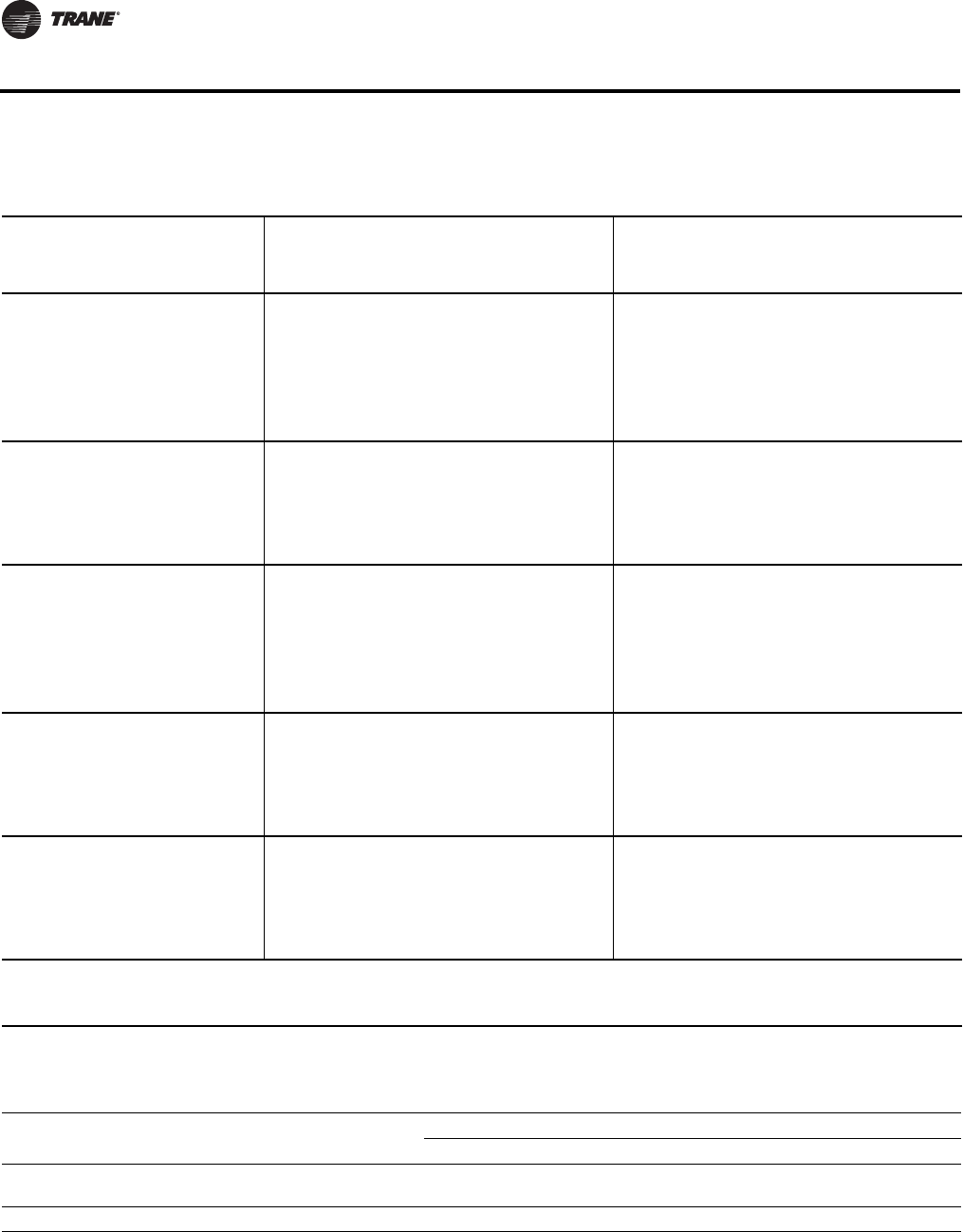
94 VAV-PRC012-EN
Acoustics Data
Table 116. Fan only sound power (dB)
Fan
Outlet
SP
Discharge Lw (dB) Radiated Lw (dB)
Octave Bands Octave Bands
CFMl/s234567234567
08SQ 0.25
175 83 61 53 51 47 41 34 65 56 57 50 41 35
250 118 64 56 55 50 44 40 68 58 60 53 44 38
320 151 67 58 58 53 48 45 72 61 63 56 48 42
400 189 71 62 61 58 54 51 75 64 65 61 52 47
460(a) 217 73 64 64 62 58 56 76 66 69 63 55 50
470 222 74 65 65 62 58 56 77 67 69 64 56 50
09SQ 0.25
400 189 70 61 58 54 48 44 69 65 62 56 46 38
500 236 71 62 59 56 49 46 70 66 64 58 48 40
700 330 74 65 63 61 54 53 72 69 68 64 54 46
800 378 76 67 65 64 57 56 74 71 70 67 57 49
900(a) 425 78 70 69 67 61 61 77 74 72 69 60 53
10SQ 0.25
700 330 67 59 56 51 45 40 67 61 57 54 49 44
840 396 69 60 58 53 48 43 68 63 58 55 50 46
980 463 70 63 59 56 51 47 70 65 60 57 53 50
1200 566 74 67 64 61 56 54 73 69 64 61 57 55
1400 661 77 71 67 65 60 57 76 72 67 64 60 58
1420(a) 670 77 71 67 65 60 57 76 72 67 64 60 58
08SQ
ECM 0.25
150 71 61 55 51 46 40 34 66 58 56 50 42 36
230 109 64 57 54 49 44 39 69 60 58 52 44 40
310 146 67 59 57 53 48 45 71 62 62 56 47 44
380 179 70 61 61 57 51 50 74 64 64 59 50 47
460(a) 217 72 65 64 61 55 54 76 67 66 63 54 51
09SQ
ECM 0.25
400 189 71 61 58 54 47 45 69 64 61 56 47 41
600 283 75 64 62 59 52 51 72 67 65 61 51 45
700 330 77 66 64 63 56 56 75 71 68 64 55 49
900(a) 425 81 71 70 68 62 62 79 75 72 69 61 55
1020 481 83 73 72 70 65 64 81 78 74 72 64 58
Notes:
1. All data are measured in accordance with Industry Standard AHRI 880-2011.
2. all sound power levels, dB re: 10-12 Watts
3. application ratings are outside the scope of the certification program
(a) AHRI 880-2011 section 7.2 Standard Rating Conditions
Table 117. AHRI 885-2008 add discharge transfer function assumptions:
Octave Band
23456 7
Small Box (< 300 CFM)
Medium Box (300-700 CFM)
-24
-27
-28
-29
-39
-40
-53
-51
-59
-53
-40
-39
Large Box (> 700 CFM) -29 -30 -41 -51 -52 -39
Notes: Subtract from terminal unit sound power to determine discharge sound pressure in the space.
1. NC Values are calculated using modeling assumptions based on AHRI 885-2008.
2. Where DPs is inlet static pressure minus discharge static pressure.
3. Application ratings are outside the scope of the Certification Program.
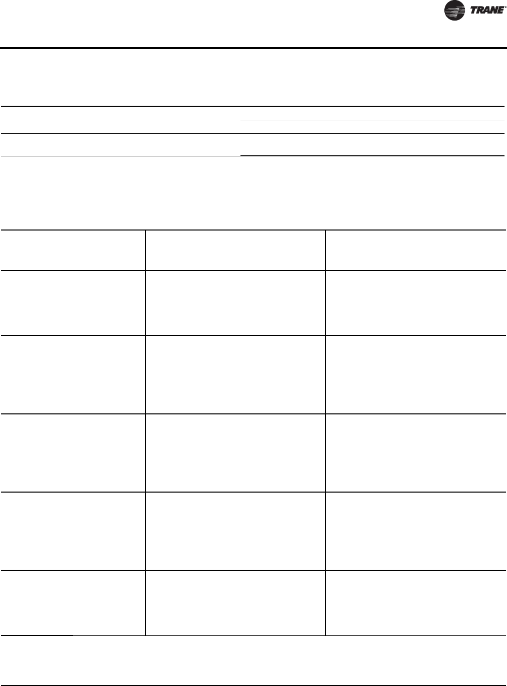
VAV-PRC012-EN 95
Acoustics Data
Table 118. AHRI 885-2008 radiated transfer function assumptions:
Octave Band
23 4 5 6 7
Type 2- Mineral Fiber Insulation
Total dB reduction
-18
-18
-19
-19
-20
-20
-26
-26
-31
-31
-36
-36
Notes: Subtract from terminal unit sound power to determine radiated sound pressure in the space.
1. NC Values are calculated using modeling assumptions based on AHRI 885-2008.
2. Where DPs is inlet static pressure minus discharge static pressure.
3. Application ratings are outside the scope of the Certification Program.
Table 119. Sound noise criteria (NC) - valve only
Fan
Size
Inlet
Size
(in)
Discharge1,2,4 Radiated1,2,4
Inlet Pressure (Ps)3,5 Inlet Pressure (Ps)3,5
CFM l/s 0.5” 1.0” 1.5” 2.0” 3.0” 0.5” 1.0” 1.5” 2.0” 3.0”
08SQ 5
150 71 -- -- -- -- -- -- 15 19
200 94 -- 16 17 19 16 17 19 21
250 118 17 19 21 21 23 18 21 21 22 24
300 142 21 23 26 26 21 25 25 26
350 165 24 26 29 32 25 29 29 29
08SQ
09SQ 6
200 94 -- -- -- 16 -- 17 19 20
280 132 -- -- 17 20 -- 19 21 24
350 165 -- 18 21 24 -- 20 25 26
400 189 23 25
430 203 20 22 25 28 17 22 27 30
500 236 25 26 28 31 21 25 30 33
08SQ
09SQ 8
350 165 -- -- 18 20 19 23 24 26
500 236 -- 17 23 25 22 25 29 31
600 283 16 20 26 28 25 29 33 35
700 330 26 34
800 378 21 25 31 34 29 34 39 40
900 425 24 28 33 37 30 36 42 43
09SQ 8x14
780 368 20 27 28 33 30 32 36 38
1100 519 21 27 31 36 31 35 40 41
1500 708 25 27 34 38 33 39 46 46
1560 736 32 43
1800 850 27 30 36 38 36 44 48 49
2200 1038 32 37 39 49 51 52
10SQ 8x14
780 368 17 24 26 27 24 31 35 39
1170 552 27 33 36 36 41 46
1560 736 33 36 39 43 44 47
1800 850 37 40 46 49
2000 944 38 40 47 50
Notes:
1. “--” represents NC levels below NC 15.
2. NC Values are calculated using modeling assumptions based on AHRI 885-98-02 Addendum
3. Data at 1.5” inlet pressure constitute AHRI 880-2011 Standard Rating Conditions.
4. Where Ps is the inlet static pressure minus discharge static.
5. Data at 0.5”, 1.0”, 2.0” and 3.0” are application ratings. These ratings are outside the scope of the certification program.

96 VAV-PRC012-EN
Acoustics Data
Table 120. Sound noise criteria (NC) - fan only
Fan-Only
0.25” Disch. Pres.
Fan Outlet SP CFM l/s Discharge Radiated
08SQ 0.25
175 83 -- 32
250 118 16 35
320 151 20 38
400 189 25 42
460(a) 217 28 45
470 222 29 45
09SQ 0.25
400 189 21 37
500 236 23 39
700 330 26 44
800 378 29 46
900(a) 425 32 48
10SQ 0.25
700 330 17 32
840 396 20 33
980 463 21 36
1200 566 26 40
1400 661 30 44
1420(a) 670 30 44
08SQ
ECM 0.25
150 71 -- 31
230 109 -- 34
310 146 17 37
380 179 21 40
460(a) 217 24 43
09SQ
ECM 0.25
400 189 23 36
600 283 28 40
700 330 30 44
900(a) 425 35 48
1020 481 38 51
Notes:
1. “--” represents NC levels below NC 15.
2. NC values are calculated using modeling assumptions based on AHRI 885-2008 Appendix E.
3. Application ratings are outside the scope of the certification program.
(a) AHRI 880-2011 section 7.2 Standard Rating Conditions.
Table 121. Discharge sound power (dB)-fan only (AHRI conditions)
Fan Size Inlet Size Cfm L/s 2 3 4 5 6 7
08SQ 5, 6, 8 460 217 68 62 63 62 58 56
09SQ 6, 8, 8x14 900 425 73 68 68 67 61 61
10SQ 8, 8x14 1420 670 72 69 66 65 60 57
Notes:
1. All sound data rated in accordance with current Industry Standard AHRI 880-2011.
2. All sound power levels, dB re: 10-12 Watts.
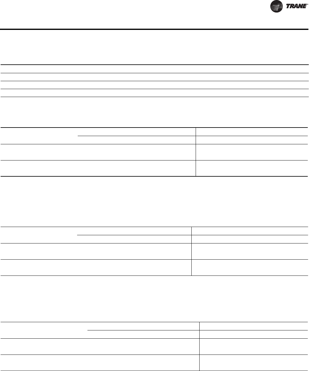
VAV-PRC012-EN 97
Acoustics Data
Table 122. Radiated sound power (dB)-fan only (AHRI conditions)
Fan Size Inlet Size Cfm L/s 2 3 4 5 6 7
08SQ 5, 6, 8 460 217 76 66 69 63 55 50
09SQ 6, 8, 8x14 900 425 77 74 72 69 60 53
10SQ 8, 8x14 1420 670 76 72 67 64 60 58
Notes:
1. All sound data rated in accordance with current Industry Standard AHRI 880-2011.
2. All sound power levels, dB re: 10-12 Watts.
Table 123. Inlet attenuator appurtenance effects (fan noise only)
Fan
Discharge Sound Effect(a)(dB) Radiated Sound Effect(a) (dB)
2 3 4567234 5 6 7
Matte-faced and foil-faced insulation(b)
08SQ, 09SQ 2 3 455620-4-8-7-7
Closed-cell insulation
08SQ, 09SQ 2 3 4545212-3-4-4
(a) Add to sound power, a negative effect represents a sound reduction, a positive effect represents a sound increase.
(b) Attenuators on double-wall units contain foil-faced insulation.
All data are measured in accordance with Industry Standard AHRI 880-2011.
All sound power levels, dB re: 10-12 Watts.
Application ratings are outside the scope of the Certification Program.
Table 124. Cabinet lining appurtenance effects (fan noise and valve noise)
Fan
Discharge Sound Effect(a) (dB) Radiated Sound Effect(a) (dB)
2 3 4 5 6 7 2 3 4 5 6 7
Solid double-wall
08SQ, 09SQ 1 0 2 3 4 6 2 1 2 5 9 13
Closed-cell insulation
08SQ, 09SQ 2 1 3 2 2 2 2 2 4 5 5 8
(a) Add to sound power, a negative effect represents a sound reduction, a positive effect represents a sound increase.
All data are measured in accordance with Industry Standard AHRI 880-2011.
All sound power levels, dB re: 10-12 Watts.
Application ratings are outside the scope of the Certification Program.
Table 125. Heating coil appurtenance effects
Fan
Discharge Sound Effect(a) (dB) Radiated Sound Effect(a) (dB)
2 3 4 5672 3456 7
Hot Water Coil (Fan Noise)
08SQ, 09SQ 3 3 4 5 4 5 2 2 3 3 3 4
Electric Heat
08SQ, 09SQ 0 -1 0 1 1 3 1 1 1 2 2 3
(a) Add to sound power, a negative effect represents a sound reduction, a positive effect represents a sound increase.
All data are measured in accordance with Industry Standard AHRI 880-2011.
All sound power levels, dB re: 10-12 Watts.
Application ratings are outside the scope of the Certification Program.

98 VAV-PRC012-EN
Acoustics Data
Low Height Series Fan-Powered Terminal Units
Table 126. Discharge sound power (dB)
Fan
Size
Inlet
Size
(in)
0.5” Inlet Pressure Ps 1.0” Inlet Pressure Ps 2.0” Inlet Pressure Ps 3.0” Inlet Pressure Ps
Cfm l/s 234567234567234567234567
08SQ 8
170 80 61 53 54 47 44 42 60 52 49 42 38 33 61 58 50 43 39 34 61 60 52 45 41 35
250 118 64 56 57 52 49 47 63 55 54 48 44 40 64 60 55 49 45 41 64 62 55 50 46 42
330 156 68 60 61 56 53 52 67 59 58 53 49 47 68 63 59 54 50 48 68 65 59 55 51 49
410 193 71 63 64 61 57 57 71 63 63 59 55 55 72 65 63 60 56 55 72 67 63 60 56 56
500 227 74 67 67 65 61 62 75 67 67 65 61 62 76 68 67 65 61 62 76 69 67 65 61 63
09SQ 8x14
350 165 63 59 55 51 45 41 64 60 59 52 45 41 65 62 59 53 47 42 66 63 59 54 48 44
500 236 67 64 60 57 51 49 67 65 63 57 51 49 69 67 63 58 53 49 71 68 63 59 54 51
700 330 71 70 66 64 59 59 72 71 67 64 59 59 75 73 67 65 60 59 77 75 69 66 61 61
800 378 75 73 68 67 62 62 75 73 69 67 62 62 76 74 69 67 63 62 78 76 71 68 64 64
890 420 77 75 70 69 65 64 77 75 71 69 65 64 78 76 71 69 65 64 79 77 72 70 66 66
10SQ 8x14
440 208 60 58 54 50 43 37 62 59 54 51 44 39 64 60 57 51 46 40 66 63 58 53 47 41
700 330 63 60 57 53 47 43 64 61 57 54 48 44 66 63 59 55 49 45 69 64 65 56 51 46
900 425 65 64 60 56 50 47 67 65 61 58 53 50 69 66 62 59 53 51 71 67 66 60 55 51
1100 519 69 68 64 62 57 55 71 69 65 62 57 56 72 70 66 63 58 56
1300 614 73 72 68 65 61 60 74 72 68 66 61 60
1500 708 75 74 70 68 64 63 76 74 70 69 64 63
08SQ
ECM 8
170 80 61 53 54 47 44 42 60 52 49 42 38 33 61 58 50 43 39 34 61 60 52 45 41 35
250 118 64 56 57 52 49 47 63 55 54 48 44 40 64 60 55 49 45 41 64 62 55 50 46 42
330 156 68 60 61 56 53 52 67 59 58 53 49 47 68 63 59 54 50 48 68 65 59 55 51 49
410 193 71 63 64 61 57 57 71 63 63 59 55 55 72 65 63 60 56 55 72 67 63 60 56 56
500 227 74 67 67 65 61 62 75 67 67 65 61 62 76 68 67 65 61 62 76 69 67 65 61 63
09SQ
ECM 8x14
350 165 63 59 55 51 45 41 64 60 59 52 45 41 65 62 59 53 47 42 66 63 59 54 48 44
500 236 67 64 60 57 51 49 67 65 63 57 51 49 69 67 63 58 53 49 71 68 63 59 54 51
700 330 71 70 66 64 59 59 72 71 67 64 59 59 75 73 67 65 60 59 77 75 69 66 61 61
800 378 75 73 68 67 62 62 75 73 69 67 62 62 76 74 69 67 63 62 78 76 71 68 64 64
890 420 77 75 70 69 65 64 77 75 71 69 65 64 78 76 71 69 65 64 79 77 72 70 66 66
10SQ
ECM 8x14
440 208 60 58 54 50 43 37 62 59 54 51 44 39 64 60 57 51 46 40 66 63 58 53 47 41
700 330 63 60 57 53 47 43 64 61 57 54 48 44 66 63 59 55 49 45 69 64 65 56 51 46
900 425 65 64 60 56 50 47 67 65 61 58 53 50 69 66 62 59 53 51 71 67 66 60 55 51
1100 519 69 68 64 62 57 55 71 69 65 62 57 56 72 70 66 63 58 56
1300 614 73 72 68 65 61 60 74 72 68 66 61 60
1500 708 75 74 70 68 64 63 76 74 70 69 64 63
Notes:
1. All data are measured in accordance with Industry Standard AHRI 880-2011.
2. All sound power levels, dB re: 10-12 Watts.
3. Where Ps is the inlet static pressure minus discharge static.
4. Application ratings are outside the scope of the certification program.

VAV-PRC012-EN 99
Acoustics Data
Table 127. Radiated sound power (dB)1,2,4
Fan
Size
Inlet
Size
(in)
0.5” Inlet Pressure
Ps5
1.0” Inlet Pressure
Ps5
1.5” Inlet Pressure
Ps5
2.0” Inlet Pressure
Ps5
3.0” Inlet Pressure
Ps5
Cfml/s234567234567234567234567234567
08SQ 8
170 80 54 49 45 37 28 22 55 53 47 40 33 31 58 62 55 45 41 37 58 63 58 49 46 40
250 118 57 52 48 42 33 27 58 56 50 43 36 33 60 63 56 47 42 38 60 64 59 50 46 41
330 156 60 56 52 46 37 31 61 59 54 47 39 36 63 64 58 50 43 39 63 65 60 52 46 42
410 193 63 60 56 50 41 36 64 62 57 50 42 38 65 65 59 52 44 41 65 67 62 53 46 43
500 227 66 64 60 53 44 40 67 65 60 54 45 41 68 66 61 54 46 42 68 66 61 54 45 42 68 68 63 55 46 44
09SQ 8
x
14
350 165 58 53 47 39 32 27 59 56 56 43 37 34 62 63 61 52 45 42 64 65 62 54 49 45
500 236 62 57 51 44 36 30 63 59 57 46 39 36 65 64 62 53 46 44 67 66 63 55 50 47
700 330 68 63 56 50 40 33 68 64 58 50 42 39 69 65 62 53 47 46 71 67 64 56 51 50
800 378 70 66 58 52 44 38 70 66 59 52 44 41 70 66 61 53 46 44 71 67 63 55 48 47 72 69 65 57 52 51
890 420 72 67 59 54 46 40 72 67 60 54 46 42 73 69 64 56 49 48 74 71 67 59 53 51
10SQ
8
x
14
440 208 61 56 49 42 33 27 62 59 52 45 40 38 65 60 60 50 46 46 66 63 61 58 50 49
700 330 62 58 51 45 37 31 64 61 55 48 43 41 68 64 62 53 48 48 70 66 67 57 52 51
900 425 66 62 55 48 41 34 68 63 56 50 44 42 70 66 64 55 50 50 72 68 68 58 54 52
1100 519 71 65 58 53 46 42 72 68 65 57 52 52 73 70 69 60 55 54
1300 614 74 69 65 58 53 52 76 72 69 61 56 55
76 70 63 59 52 48
1500 708 76 71 64 60 54 52 78 74 70 63 58 57
08SQ
ECM 8
170 80 54 49 44 36 29 22 57 54 48 39 36 30 57 60 54 44 41 36 58 61 56 48 45 40
250 118 57 52 47 40 32 27 59 56 50 42 37 32 59 62 56 46 42 38 60 63 58 50 46 41
330 156 60 56 51 44 36 31 62 58 53 46 39 35 62 64 58 49 44 40 63 66 61 52 47 42
410 193 63 59 55 48 40 36 64 60 56 49 41 38 65 66 60 52 45 42 66 68 63 54 48 44
500 227 66 62 58 52 43 40 66 62 58 52 43 40 67 67 61 54 46 43 68 70 65 56 49 45
09SQ
ECM
8
x
14
350 165 60 53 47 40 32 25 60 56 55 43 37 34 63 63 62 52 45 42 64 63 62 54 49 47
500 236 64 57 51 44 36 29 64 59 56 46 39 36 67 64 63 53 46 44 68 65 63 55 50 48
700 330 71 63 56 51 41 33 71 64 58 51 42 39 71 65 63 53 47 46 73 68 64 57 51 49
800 378 73 66 58 53 44 38 73 66 59 53 44 40 73 67 63 55 48 46 75 69 64 58 52 49
890 420 75 67 59 55 46 40 75 67 60 55 46 41 75 69 63 56 49 47 77 70 65 59 53 50
10SQ
ECM
8
x
14
440 208 61 54 47 42 37 32 62 57 49 44 38 38 64 59 60 48 44 44 68 63 68 56 48 51
700 330 64 57 50 45 37 32 66 60 54 49 43 43 69 64 60 53 47 49 71 66 68 56 51 51
900 425 65 62 55 48 40 35 69 63 56 52 44 43 72 67 61 55 50 51 73 68 68 58 52 52
1100 519 72 66 58 54 46 43 74 70 62 57 52 53 75 71 67 60 54 54
1300 614 76 71 63 59 53 53 77 72 67 61 56 55
1500 708 78 72 65 61 54 52 79 74 68 63 58 57
Notes:
1. All data are measured in accordance with Industry Standard AHRI 880-2011.
2. All sound power levels, dB re: 10-12 Watts.
3. Data in this column constitute AHRI 880-2011 Standard Rating Conditions.
4. Where Ps is the inlet static pressure minus discharge static.
5. Application ratings are outside the scope of the certification program.

100 VAV-PRC012-EN
Acoustics Data
Table 128. Fan only sound power (dB)
Fan
Outlet
SP
Discharge Lw (dB) Radiated Lw (dB)
Octave Bands Octave Bands
CFMl/s234567234567
08SQ 0.25
170 80 61 51 52 46 42 38 53 47 44 36 26 21
250 118 63 54 55 50 46 43 56 51 48 41 30 23
330 156 67 58 59 54 50 49 59 56 52 46 36 27
410 193 70 61 64 58 56 56 60 59 55 49 40 34
480 227 73 64 66 62 60 59 63 62 58 53 44 37
500(a) 236 73 65 67 63 60 60 64 62 59 54 45 38
09SQ 0.25
350 165 65 58 55 51 46 41 57 51 44 38 24 20
500 236 69 62 60 57 52 49 61 55 48 42 30 23
700 330 74 68 66 64 59 58 66 61 55 49 38 29
800(a) 378 77 70 69 67 62 61 68 64 58 52 42 32
890 420 79 73 71 70 65 64 70 67 60 55 45 36
10SQ 0.25
440 208 61 58 54 51 44 38 62 57 48 41 29 22
700 330 63 61 58 56 49 45 64 60 51 45 33 24
900 425 65 64 61 59 53 51 66 62 54 48 36 26
1100 519 68 67 64 62 57 55 68 64 57 52 40 30
1300 614 71 70 66 66 61 59 71 66 60 55 44 33
1400(a) 661 72 71 68 68 62 61 72 68 61 56 46 35
1500 708 73 73 69 69 64 63 74 69 62 58 48 36
08SQ
ECM 0.25
170 80 60 48 47 42 36 30 53 46 41 36 25 23
250 118 63 52 53 48 44 38 55 50 45 40 28 25
330 156 67 57 59 53 50 47 58 54 50 44 33 28
410 193 71 62 63 59 56 54 61 58 54 49 38 33
480 227 74 65 67 64 61 59 66 61 57 53 43 37
09SQ
ECM 0.25
350 165 64 60 57 53 48 46 60 53 45 39 28 23
500 236 69 65 62 60 55 54 64 58 50 44 34 28
700 330 73 71 67 67 62 61 69 63 56 51 40 33
800 378 77 74 71 70 66 65 72 66 59 54 44 36
890 420 80 78 74 74 70 69 76 70 62 57 48 40
10SQ
ECM 0.25
440 208 62 59 58 55 49 48 62 55 48 41 30 23
700 330 65 62 61 58 52 51 65 59 52 46 35 27
900 425 67 64 63 61 55 54 67 62 55 50 39 30
1100 519 69 67 66 64 58 58 70 66 58 54 42 33
1300 614 72 70 68 67 62 62 73 69 61 57 46 36
1500 708 75 73 70 70 65 65 75 71 63 59 49 40
Notes:
1. All data are measured in accordance with Industry Standard AHRI 880-2011.
2. All sound power levels, dB re: 10-12 Watts
3. Application ratings are outside the scope of the certification program
(a) AHRI 880-2011 section 7.2 Standard Rating Conditions
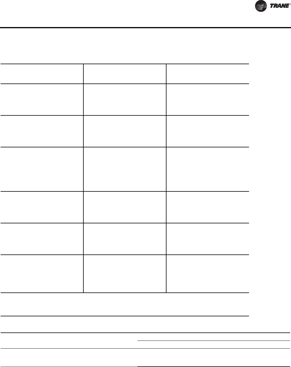
VAV-PRC012-EN 101
Acoustics Data
Table 129. Sound noise criteria (NC) - fan and 100% primary
Fan
Size
Inlet
Size
(in)
Discharge Radiated
Inlet Pressure (Ps) Inlet Pressure (Ps)
CFM l/s 0.5” 1.0” 2.0” 3.0” 0.5” 1.0” 2.0” 3.0”
08SQ 8
170 80 -- -- 15.6 18.0 18.7 21.4 32.0 33.2
250 118 17 15 18 20 22 25 33 34
330 156 22 20 22 24 26 28 34 36
410 193 26 26 27 27 31 32 36 38
480 227 29 31 32 32 35 36 37 39
09SQ 8x14
350 165 16 17 19 20 21 31 36 37
500 236 22 23 25 26 26 32 37 38
700 330 29 30 32 35 33 34 37 39
800 378 32 32 33 36 37 37 38 40
890 420 35 35 36 37 38 38 40 43
10SQ 8x14
440 208 -- 16 17 20 25 28 35 36
700 330 17 18 20 22 27 31 37 43
900 425 22 23 24 25 32 33 39 44
1100 519 26 27 29 36 40 45
1300 614 31 31 40 45
1500 708 33 33 43 46
08SQ
ECM 8
170 80 -- -- 16 18 18 23 30 31
250 118 17 15 18 20 21 25 32 33
330 156 22 20 22 24 25 27 34 37
410 193 26 26 27 27 30 31 37 39
480 227 29 31 32 32 33 33 38 42
09SQ
ECM 8x14
350 165 16 17 19 20 22 30 37 37
500 236 22 23 25 26 27 31 38 38
700 330 29 30 32 35 36 36 38 39
800 378 32 32 33 36 39 39 39 42
890 420 35 35 36 37 42 42 42 44
10SQ
ECM 8x14
440 208 -- 16 17 20 24 26 35 44
700 330 17 18 20 22 27 30 35 44
900 425 22 23 24 25 32 34 38 44
1100 519 26 27 29 38 42 43
1300 614 31 31 43 44
1500 708 33 33 45 47
Notes:
1. “--” represents NC levels below NC 15.
2. NC Values are calculated using modeling assumptions based on AHRI 885-98-02 Addendum
3. Where Ps is the inlet static pressure minus discharge static.
4. Data at 0.5”, 1.0”, 2.0” and 3.0” are application ratings. These ratings are outside the scope of the certification program.
Table 130.AHRI 885-2008 add discharge transfer function assumptions:
Octave Band
23456 7
Small Box (< 300 CFM)
Medium Box (300-700 CFM)
Large Box (> 700 CFM)
-24
-27
-29
-28
-29
-30
-39
-40
-41
-53
-51
-51
-59
-53
-52
-40
-39
-39
Notes: Subtract from terminal unit sound power to determine discharge sound pressure in the space.
1. NC Values are calculated using current Industry Standard AHRI 885-2008. Radiated Transfer Function obtained from Appendix E, Type 2Mineral Fiber
Insulation.
2. Application ratings are outside the scope of the Certification Program.
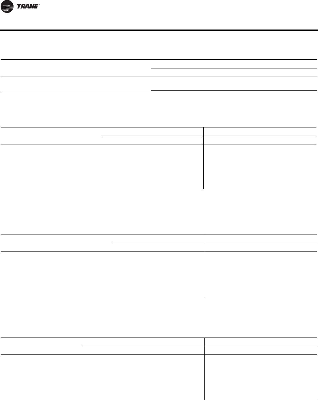
102 VAV-PRC012-EN
Acoustics Data
Table 131.AHRI 885-2008 radiated transfer function assumptions:
Octave Band
234 567
Type 2- Mineral Fiber Insulation
Total dB reduction
-18
-18
-19
-19
-20
-20
-26
-26
-31
-31
-36
-36
Notes: Subtract from terminal unit sound power to determine radiated sound pressure in the space.
1. NC Values are calculated using current Industry Standard AHRI 885-2008. Radiated Transfer Function obtained from Appendix E, Type 2Mineral Fiber
Insulation.
2. Application ratings are outside the scope of the Certification Program.
Table 132. Inlet attenuator appurtenance effects
Fan
Discharge Sound Effect(a) (dB) Radiated Sound Effect(a) (dB)
2 3 4567 2 3 4 5 6 7
Matte-faced and foil-faced insulation, solid double-wall(b)
08SQ, 09SQ
10SQ
0
2
0
2
0
2
1
2
0
2
0
2
-1
-2
-3
-3
-3
-5
-7
-10
-7
-12
-6
-12
Closed-cell insulation
08SQ, 09SQ
10SQ
0
2
1
2
0
2
0
2
0
2
0
2
-1
-1
-1
-1
-1
-2
-4
-5
-6
-9
-4
-9
(a) Add to sound power, a negative effect represents a sound reduction, a positive effect represents a sound increase.
(b) Attenuators on double-wall units have 1" foil-faced insulation. All edges are encapsulated with metal.
All data are measured in accordance with Industry Standard AHRI 880-2011.
All sound power levels, dB re: 10-12 Watts.
Application ratings are outside the scope of the Certification Program.
Table 133. Cabinet lining appurtenance effects
Fan
Discharge Sound Effect(a) (dB) Radiated Sound Effect(a) (dB)
2345672 3 4 5 6 7
Solid double-wall
08SQ, 09SQ
10SQ
0
0
0
0
0
0
0
0
0
0
0
0
-1
1
-2
0
2
2
11
9
17
14
19
16
Closed-cell insulation
08SQ, 09SQ
10SQ
0
0
0
0
0
0
0
0
0
0
0
0
2
2
3
3
6
4
7
7
8
6
12
11
(a) Add to sound power, a negative effect represents a sound reduction, a positive effect represents a sound increase.
All data are measured in accordance with Industry Standard AHRI 880-2011.
All sound power levels, dB re: 10-12 Watts.
Application ratings are outside the scope of the Certification Program.
Table 134. Heating coil appurtenance effects
Fan
Discharge Sound Effect(a) (dB) Radiated Sound Effect(a) (dB)
234567234567
Hot Water Coil(b)
08SQ, 09SQ
10SQ
1
1
1
2
1
2
1
1
2
2
1
1
1
1
2
1
2
1
3
2
7
4
12
8
Electric Heat(b)
08SQ, 09SQ
10SQ
-1
1
-2
0
-1
-1
-1
-1
-1
-1
-1
0
-3
2
-1
4
1
3
1
4
7
6
7
9
(a) Add to sound power, a negative effect represents a sound reduction, a positive effect represents a sound increase.
(b) Radiated effect applies to “fan only” sound only. Do not apply to fan + valve sound.
All data are measured in accordance with Industry Standard AHRI 880-2011.
All sound power levels, dB re: 10-12 Watts.
Application ratings are outside the scope of the Certification Program.
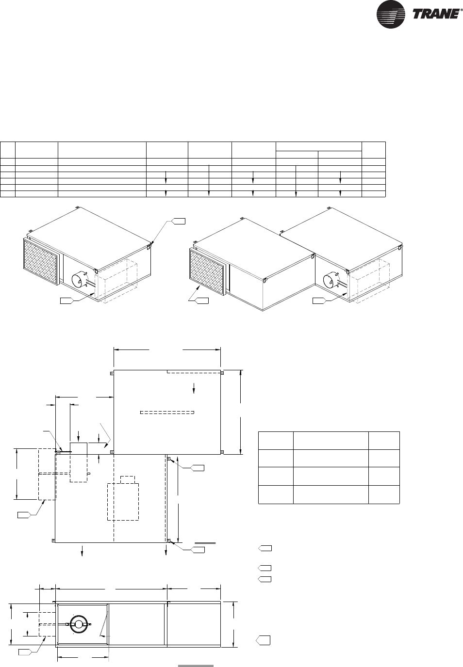
VAV-PRC012-EN 103
Dimensional Data
Parallel Fan-Powered Terminal Units
(508 mm)
Plenum Inlet
TOP VIEW
DISCHARGE VIEW
Discharge Outlet
B
tubing
Flow Ring
Panel slides
A
Airflow
W
for Motor access
20.00"
(102 mm)
Airflow
Valve
Air 4.00"
Primary
(508 mm)
20.00"
5.
L
Field Installed
Optional Attenuator
5.
PARALLEL COOLING ONLY (VPCF)
(1016 mm)
40.00"
Airflow
2.
4.
4. See Installation Documents for exact hanger bracket location.
1. Allow a minimum 6" (152 mm) plenum inlet
clearance for unducted installations.
2. Filter location with optional Attenuator.
3. Attenuator-factory assembled, field installed.
7. Air valve centered between top and bottom panel.
6. When Attenuator option selected, water coil ships mounted
to attenuator.
5. For Motor access, remove bottom screw on hanger brackets
to slide panel as shown in drawing.
H
NOTES:
(762 mm)
30.00"
Actuator, Controller and
Fan Controls located in this area
9.
Actuator, Controller and
Fan Controls located in this area
9.
(287 mm)
11.30" Max.
(140 mm)
5.50" Max.
9.
9.
(406 mm x 508 mm x 25 mm)
16" x 20" x 1"
20" x 20" x 1"
(508 mm x 508 mm x 25 mm)
(356 mm x 508 mm x 25 mm)
14" x 20" x 1"
Filter Size
06SQ
07SQ
04SQ
05SQ
Fan Size
03SQ
02SQ
40.00" (1016 mm)
30.00" (762 mm)
32.50" (826 mm)
254 mm, 305 mm, 356 mm, 406 mm
254 mm, 305 mm, 356 mm, 406 mm
127 mm, 152 mm, 203 mm, 254 mm
203 mm, 254 mm, 305 mm, 356 mm
152 mm, 203 mm, 254 mm, 305 mm
INLET SIZE
07SQ
03SQ
06SQ
05SQ
04SQ
02SQ
FAN
SIZE
10", 12", 14", 16"
10", 12", 14", 16"
5", 6", 8", 10"
AVAILABILITY
(NOMINAL Ø")
8", 10", 12", 14"
10", 12", 14"
6", 8", 10", 12"
21.50" (546 mm)
15.50" (394 mm)
17.50" (445 mm)
INLET SIZE
AVAILABILITY
(NOMINAL Ømm)
254 mm, 305 mm, 356 mm
40.00" (1016 mm)
HW
20.00" (508 mm)
14.00" (356 mm)
16.00" (406 mm)
19.25" (489 mm)
A
DISCHARGE DIMENSIONS
LB
UNIT WT
Attn. Weight
Wt Lbs
(kg)
125 (57)
96 (43)
117 (53)
111 (50)
97 (44)
78 (35)
WT LBS
(kg)
48 (22)
54 (25)
46 (21)
9. Maximum dimensions for controls area shown. Configurations
and types of control boxes vary according to control type
selected. See "Enclosure Details" for specific layout.
8. All high & low voltage controls have same-side NEC
jumpback clearance. (Left-hand shown, right-hand/mirror
image optional.)
Optional Attenuator
Field Installed
(Valve 16")
(Valves 5"-14") (102 mm)
4.00"
2.00"
(51 mm)
(479 mm)
18.875" Max.
back draft damper
10. Graphic shown is for left-hand electrical. Right-hand electrical
is a mirror image.
Valve 5"
6.50"
(165 mm)
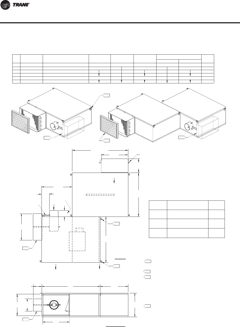
104 VAV-PRC012-EN
Dimensional Data
(508 mm)
(508 mm)
TOP VIEW
DISCHARGE VIEW
(287 mm)
B11.30" Max.
(140 mm)
5.50" Max.
A
W20.00"
(102 mm)
4.00"
(508 mm)
20.00"
5.
L
5.
152 mm, 203 mm, 254 mm, 305 mm
203 mm, 254 mm, 305 mm, 356 mm
254 mm, 305 mm, 356 mm
PARALLEL HOT WATER (VPWF)
Fan Controls located in this area
Actuator, Controller and
SIZE
03SQ
04SQ
05SQ
FAN
6", 8", 10", 12"
10", 12", 14"
8", 10", 12", 14"
(NOMINAL Ø")
AVAILABILITY
INLET SIZE
(1016 mm)
40.00"
Coil
Water
2.
20.00"
4.
(NOMINAL Ømm)
AVAILABILITY
INLET SIZE
17.50" (445 mm)
H
4. See Installation Documents for exact hanger bracket location.
1. Allow a minimum 6" (152 mm) plenum inlet clearance
for unducted installations.
2. Filter location with optional Attenuator.
3. Attenuator-factory assembled, field installed.
7. Air valve centered between top and bottom panel.
6. When Attenuator option selected, water coil ships
mounted to attenuator.
5. For Motor access, remove bottom screw on hanger
brackets to slide panel as shown in drawing.
H
NOTES:
(762 mm)
30.00"
16.00" (406 mm)
DISCHARGE DIMENSIONS
(160 mm)
6.30"
Connection
Coil
32.50" (826 mm)
WL
A
48 (22)
Wt Lbs
Attn. Weight
UNIT WT
96 (43)
97 (44)
(kg)
WT LBS
111 (50)
B
(kg)
40.00" (1016 mm) 19.25" (489 mm)
8. All high & low voltage controls have same-side NEC
jumpback clearance. (Left-hand shown, right-hand/mirror
image optional.)
30.00" (762 mm)
127 mm, 152 mm, 203 mm, 254 mm
02SQ 5", 6", 8", 10" 15.50" (394 mm) 14.00" (356 mm) 78 (35)
46 (21)
10", 12", 14", 16"
10", 12", 14", 16"
06SQ
07SQ
254 mm, 305 mm, 356 mm, 406 mm
254 mm, 305 mm, 356 mm, 406 mm
21.50" (546 mm) 40.00" (1016 mm) 20.00" (508 mm) 117 (53)
125 (57)
54 (25)
(Valves 6"-14")
(Valve 16") (51 mm)
(102 mm)
2.00"
4.00"
Filter Size
14" x 20" x 1"
(356 mm x 508 mm x 25 mm)
(508 mm x 508 mm x 25 mm)
20" x 20" x 1"
02SQ
06SQ
07SQ
Fan Size
16" x 20" x 1"
(406 mm x 508 mm x 25 mm)
03SQ
05SQ
04SQ
9.
Actuator, Controller and
Fan Controls located in this area
9.
9.
9.
Field Installed
Optional Attenuator
Airflow
Plenum Inlet
for Motor access
Panel slides
Airflow
Discharge Outlet
Air
Valve
Airflow
Primary
tubing
Flow Ring Field Installed
Optional Attenuator
18.875" Max.
(479 mm)
Valve 5"
6.50"
(165 mm)
back draft damper
9. Maximum dimensions for controls area shown.
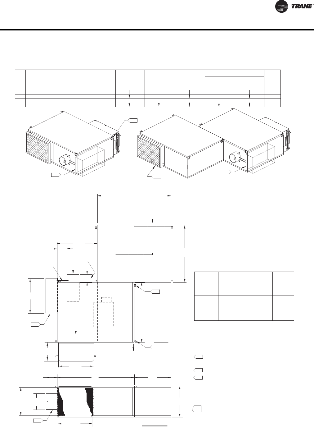
VAV-PRC012-EN 105
Dimensional Data
(508 mm)
TOP VIEW
DISCHARGE VIEW
B
A
W20.00"
(102 mm)
4.00"
(508 mm)
20.00"
5.
L
5.
PARALLEL WITH HOT WATER ON DISCHARGE (VPWF)
(1016 mm)
40.00"
2.
4. See Installation Documents for exact hanger bracket location.
1. Allow a minimum 6" (152 mm) plenum inlet
clearance for unducted installations.
2. Filter location with optional Attenuator.
3. Attenuator-factory assembled, field installed.
6. Air valve centered between top and bottom panel.
5. For Motor access, remove bottom screw on hanger brackets
to slide panel as shown in drawing.
H
NOTES:
(762 mm)
30.00"
20.00" (508 mm)
(508 mm)
Water
Coil
20.00"
(160 mm)
6.30"
4.
40.00" (1016 mm)
30.00" (762 mm)
32.50" (826 mm)
254 mm, 305 mm, 356 mm, 406 mm
254 mm, 305 mm, 356 mm, 406 mm
127 mm, 152 mm, 203 mm, 254 mm
203 mm, 254 mm, 305 mm, 356 mm
152 mm, 203 mm, 254 mm, 305 mm
INLET SIZE
07SQ
03SQ
06SQ
05SQ
04SQ
02SQ
FAN
SIZE
10", 12", 14", 16"
10", 12", 14", 16"
5", 6", 8", 10"
AVAILABILITY
(NOMINAL Ø")
8", 10", 12", 14"
10", 12", 14"
6", 8", 10", 12"
21.50" (546 mm)
15.50" (394 mm)
17.50" (445 mm)
INLET SIZE
AVAILABILITY
(NOMINAL Ømm)
254 mm, 305 mm, 356 mm
40.00" (1016 mm)
HW
20.00" (508 mm)
14.00" (356 mm)
16.00" (406 mm)
A
DISCHARGE DIMENSIONS
LB
UNIT WT
Attn. Weight
Wt. Lbs.
(kg)
125 (57)
96 (43)
117 (53)
111 (50)
97 (44)
78 (35)
WT LBS
(kg)
48 (22)
54 (25)
46 (21)
Actuator, Controller and
Fan Controls located in this area
8. Actuator, Controller and
Fan Controls located in this area
8.
(406 mm x 508 mm x 25 mm)
16" x 20" x 1"
20" x 20" x 1"
(508 mm x 508 mm x 25 mm)
(356 mm x 508 mm x 25 mm)
14" x 20" x 1"
Filter Size
06SQ
07SQ
04SQ
05SQ
Fan Size
03SQ
02SQ
8.
(287 mm)
11.30" Max.
5.50" Max.
(140 mm)
8.
7. All high & low voltage controls have same-side NEC
jumpback clearance. (Left-hand shown, right-hand/mirror
image optional.)
Airflow
Plenum Inlet
for Motor access
Panel slides
Airflow
Discharge Outlet
Air
Valve
Airflow
Primary
tubing
Flow Ring
Optional Attenuator
Field Installed
Optional Attenuator
Field Installed
(Valve 16")
(Valves 5"-14")
(51 mm)
2.00"
(102 mm)
4.00"
18.875" Max.
(479 mm)
8. Maximum dimensions for controls area shown.
Valve 5"
6.50"
(165 mm)
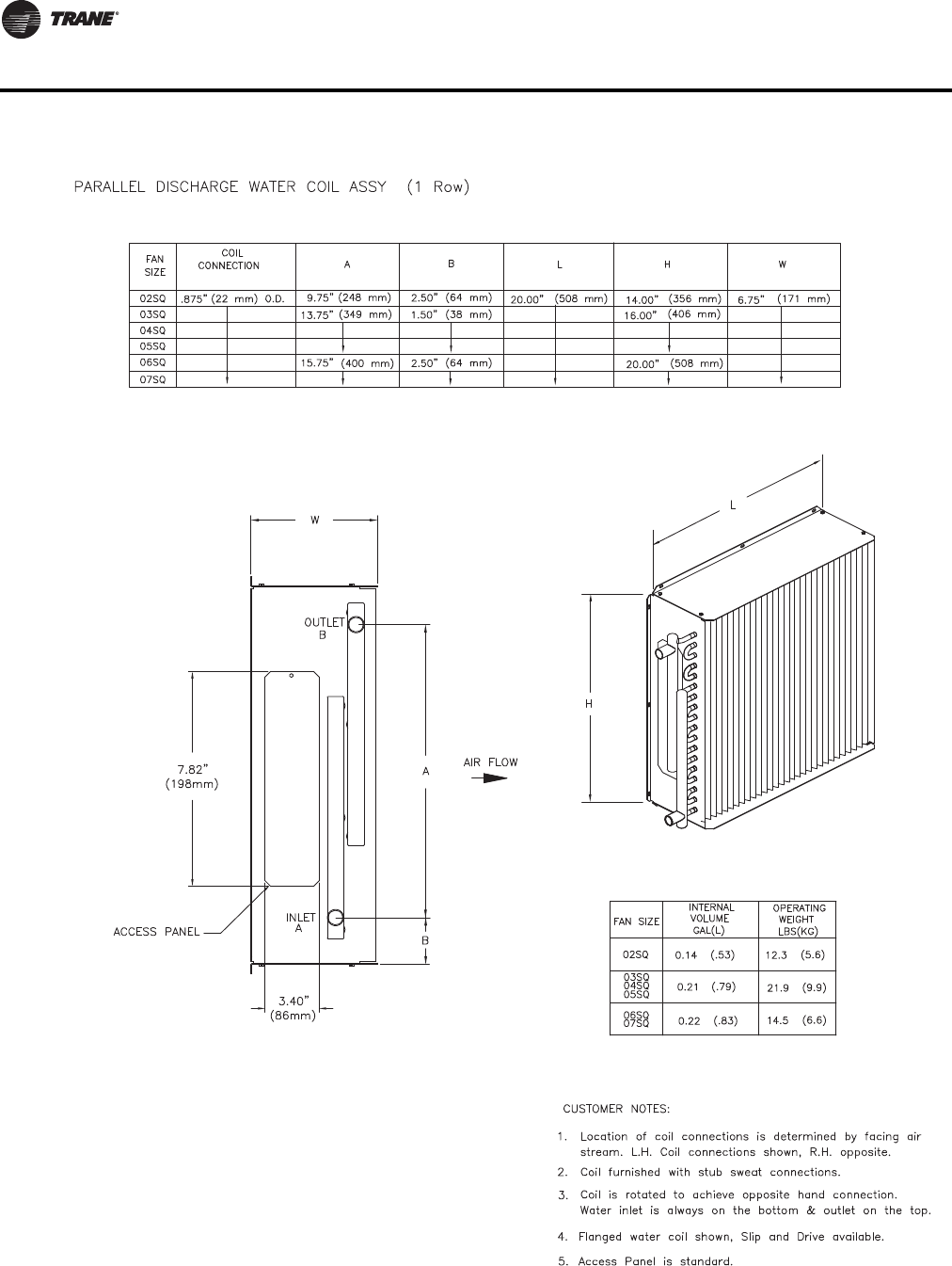
106 VAV-PRC012-EN
Dimensional Data
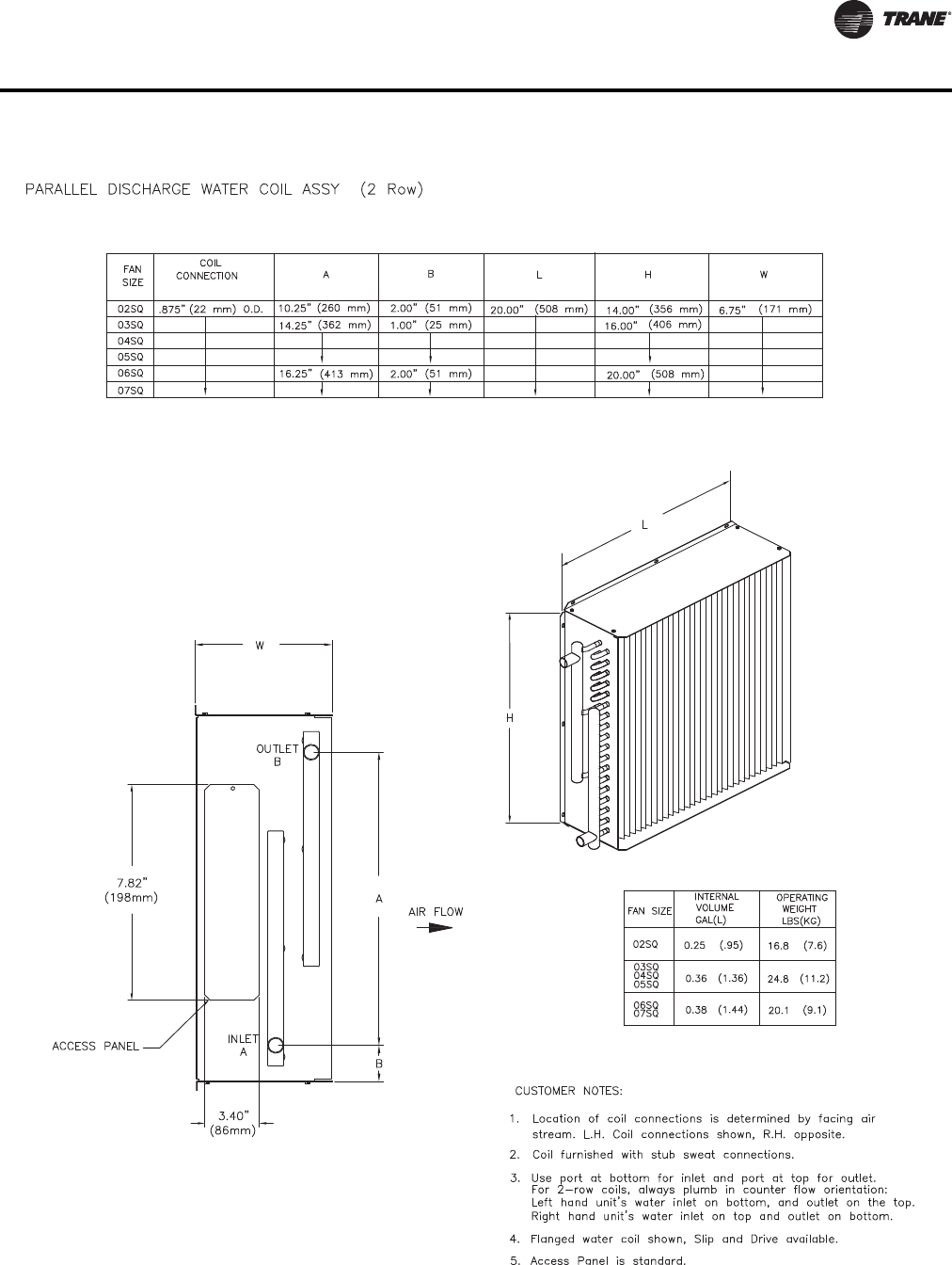
VAV-PRC012-EN 107
Dimensional Data
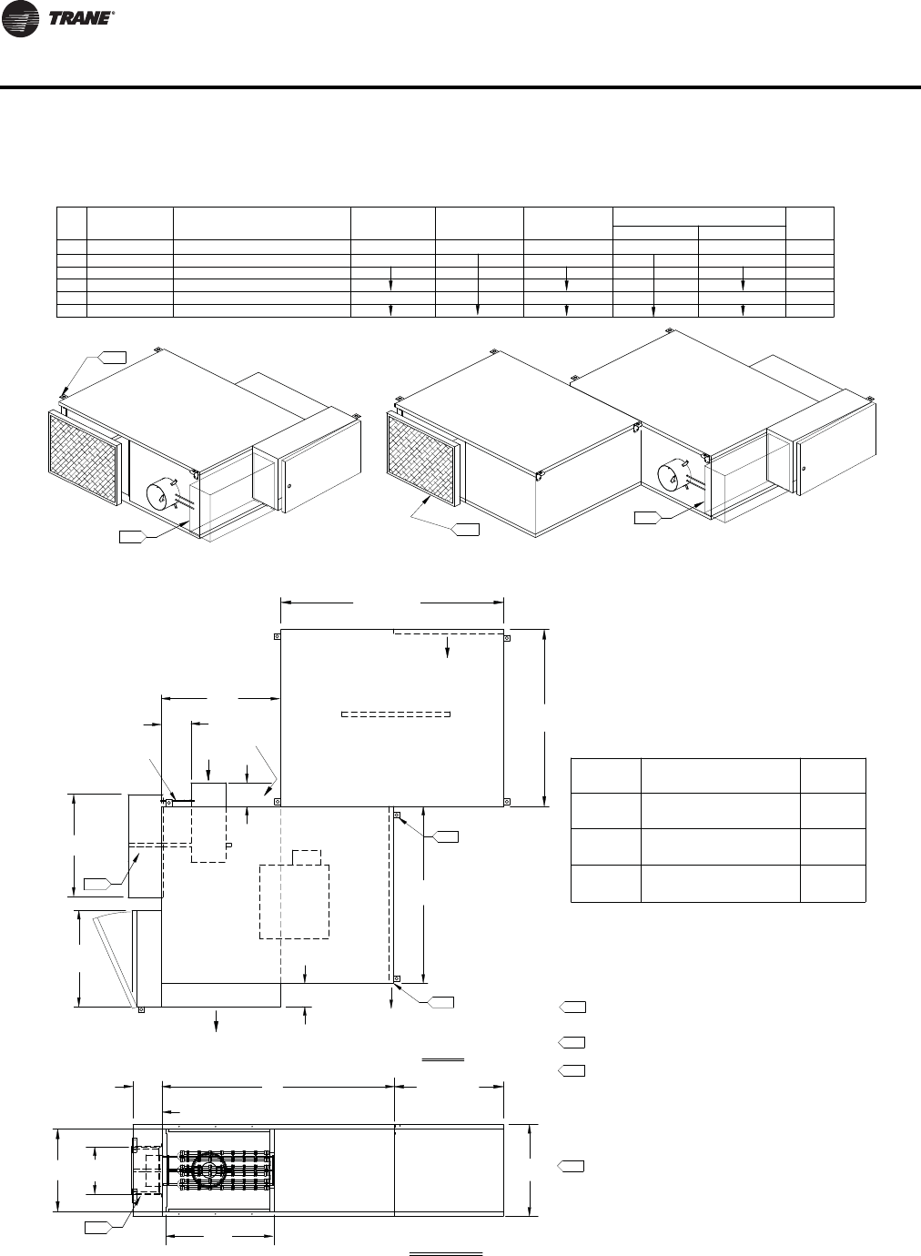
108 VAV-PRC012-EN
Dimensional Data
4.
(102 mm)
4.00" (762 mm)
30.00"
(1016 mm)
40.00"
(102 mm)
4.00"
(152 mm)
6.00"
Heater
Terminal Box
(559 mm)
22.00"
(508 mm)
20.00"
NOTES:
1. Allow a minimum 6" (152 mm) plenum inlet clearance for
unducted installations.
2. Filter location with optional Attenuator.
3. Attenuatory factory assembled, field installed.
4. For motor access, remove bottom screws on hanger brackets
to slide panel as shown in drawing.
5. See Installation Documents for exact hanger bracket location.
6. Air valve centered between top and bottom panel.
7. Heating coil uninsulated. External insulation may be field
supplied and installed as required.
8. All high & low voltage controls have same side NEC jumpback
clearance. (Left-hand shown, right-hand/mirror image optional.)
9. Maximum dimensions for controls area shown. Configurations
and types of control boxes vary according to control type
selected. See "Enclosure Details" for specific layout.
4.
(508 mm)
20.00"
5.
2.
TOP VIEW
B
L
A
H
W
DISCHARGE VIEW
PARALLEL ELECTRIC HEAT (VPEF)
32.50" (826 mm)
30.00" (762 mm)
40.00" (1016 mm)
152 mm, 203 mm, 254 mm, 305 mm
203 mm, 254 mm, 305 mm, 356 mm
127 mm, 152 mm, 203 mm, 254 mm
254 mm, 305 mm, 356 mm, 406 mm
254 mm, 305 mm, 356 mm, 406 mm
FAN INLET SIZE
07SQ
03SQ
04SQ
05SQ
06SQ
SIZE
02SQ
10", 12", 14", 16"
6", 8", 10", 12"
10", 12", 14"
8", 10", 12", 14"
(NOMINAL Ø")
AVAILABILITY
5", 6", 8", 10"
10", 12", 14", 16"
17.50" (445 mm)
15.50" (394 mm)
21.50" (546 mm)
INLET SIZE
254 mm, 305 mm, 356 mm
(NOMINAL Ømm)
AVAILABILITY
40.00" (1016 mm)
HW
16.00" (406 mm)
14.00" (356 mm)
20.00" (508 mm)
DISCHARGE DIMENSIONS
A
20.00" (508 mm)
LB
Attn. Weight
Wt. Lbs.
(kg)
UNIT WT
186 (84)
WT LBS
120 (54)
96 (43)
(kg)
48 (22)
54 (25)
46 (21)
138 (63)
141 (64)
178 (80)
Filter Size
14" x 20" x 1"
(356 mm x 508 mm x 25 mm)
(508 mm x 508 mm x 25 mm)
20" x 20" x 1"
16" x 20" x 1"
(406 mm x 508 mm x 25 mm)
02SQ
03SQ
05SQ
04SQ
06SQ
07SQ
Fan Size
Fan Controls located in this area
Actuator, Controller and
9. Fan Controls located in this area
Actuator, Controller and
9.
11.30" Max.
(287 mm)
5.50" Max.
(140 mm)
9.
9.
Airflow
Plenum Inlet
for Motor access
Panel slides
Airflow
Discharge Outlet
Air
Valve
Airflow
Primary
tubing
Flow Ring
Optional Attenuator
Field Installed
Field Installed
Optional Attenuator
18.875" Max.
(479 mm)
Valve 5"
6.50"
(165 mm)
Maximum dimensions for controls area shown.
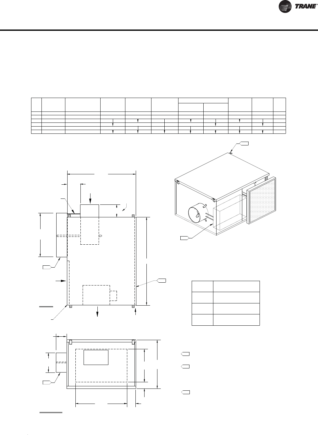
VAV-PRC012-EN 109
Dimensional Data
Series Fan-Powered Terminal Units
W
Airflow
Primary
Valve
Air
Tubing
Flow Ring
H
B
Discharge Outlet
Airflow
D
C
A
Plenum Inlet
Airflow
L
4.
2.
NOTES:
1. Allow a minimum 6" (152 mm) plenum inlet clearance for
unducted installations.
2. See Installation Documents for exact hanger bracket location.
3. Air valve centered between top and bottom panel.
4. For motor access, remove bottom screw on hanger brackets
to slide panel as shown in drawing.
5. Attenuator option not available with this unit layout.
6. All high & low voltage controls have same-side NEC jumpback
clearance. (Left-hand shown, right-hand/mirror image optional.)
7. Maximum dimensions for controls area shown. Configurations and
types of control boxes vary according to control types selected.
Filter
4.00"
(102 mm)
TOP VIEW
SERIES COOLING ONLY (VSCF) WITHOUT ATTENUATOR
DISCHARGE VIEW
DISCHARGE DIMENSIONS
14.00" (356 mm)
18.00" (457 mm)
16.00" (406 mm)
254, 305, 356
104, 127, 152, 203, 254
FAN
SIZE
07SQ
06SQ
05SQ
04SQ
03SQ
02SQ
INLET SIZE
AVAILABILITY
NOMINAL Ø
INCHES
6, 8, 10, 12, 14
10, 12, 14
6, 8, 10, 12
4, 5, 6, 8, 10
INLET SIZE
AVAILABILITY
NOMINAL Ø
(mm)
22.00" (559 mm)
30.00" (762 mm)
24.00" (610 mm)
15.50" (394 mm)
21.50" (546 mm)
17.50" (445 mm)
H W
34.00" (864 mm)
40.00" (1016 mm)
L
12.00" (305 mm)
24.00" (610 mm)
19.00" (483 mm)
A
5.00" (127 mm)
3.00" (76 mm)
2.50" (64 mm)
BC
1.66" (42 mm)
.65" (17 mm)
.75" (19 mm)
D
117 (53)
125 (57)
78 (35)
86 (39)
100 (45)
85 (39)
Unit Wt
Lbs
(kg)
14" x 14" x 1"
(356 mm x 356 mm x 25 mm)
16" x 20" x 1"
(406 mm x 508 mm x 25 mm)
(508 mm x 508 mm x 25 mm)
20" x 20" x 1"
Fan Size
03SQ
04SQ
05SQ
02SQ
Filter Size
Fan Controls located in this area
Actuator, Controller and
7.
7.
7.
11.30" Max.
(287 mm)
5.50" Max.
(140 mm)
(479 mm)
18.875" Max.
(Valves 4"-14")
(Valve 16") (51 mm)
2.00"
4.00"
(102 mm)
06SQ
07SQ
10, 12, 14, 16
10, 12, 14, 16
254, 305, 356, 406
254, 305, 356, 406
152, 203, 254, 305
152, 203, 254, 305, 356
Panel slides
for Motor access
Valves 4" & 5"
6.50"
(165 mm)
Maximum dimensions for controls area shown.
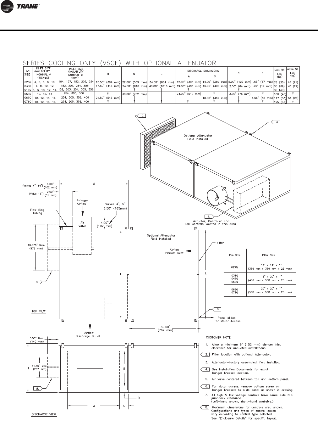
110 VAV-PRC012-EN
Dimensional Data
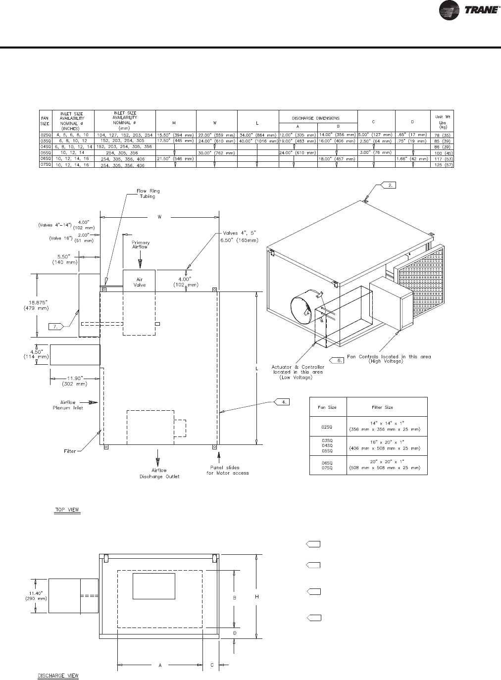
VAV-PRC012-EN 111
Dimensional Data
NARROW CORRIDOR DESIGN SERIES COOLING (VSCF) WITHOUT ATTENUATOR
NOTES:
1. Allow a minimum 6" (152 mm) plenum inlet
clearance for unducted installations.
2. See installation Documents for exact hanger bracket location.
3. Air valve centered between top and bottom panel.
4. For Motor access, remove bottom screw on hanger
brackets to slide panel as shown in drawing.
5. Attenuator option not available with this unit layout.
6. All high & low voltage controls have same-side NEC
jumpback clearance. (unit shown w/left hand high &
low voltage box connections [high voltage inlet facing].
Right hand connections available.)
7. Maximum dimensions for controls are shown.
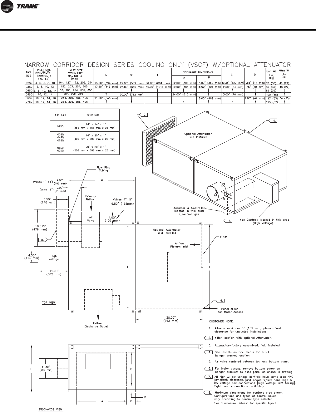
112 VAV-PRC012-EN
Dimensional Data
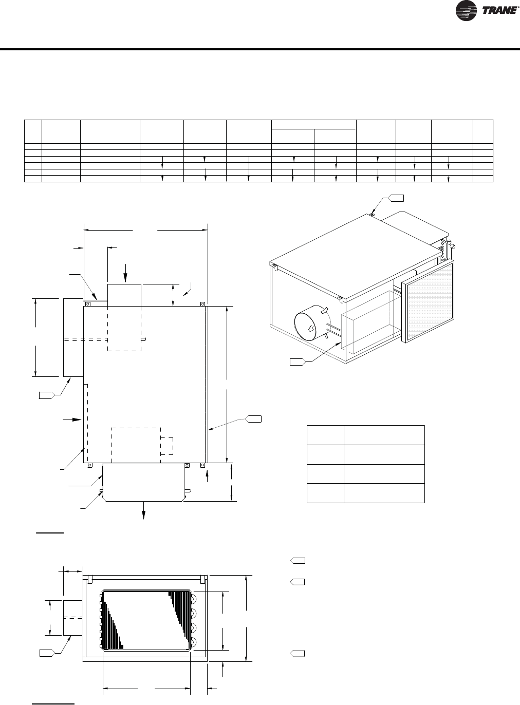
VAV-PRC012-EN 113
Dimensional Data
SERIES HOT WATER (VSWF) WITHOUT ATTENUATOR
Coil Connection
W
Airflow
Primary
Valve
Air
Tubing
Flow Ring
Discharge Outlet
Airflow
Water Coil
H
B
D
C
A
Plenum Inlet
Airflow
L
3.00" x 7.00"
Coil Access
(76 mm x 178 mm)
4.
2.
Filter
TOP VIEW
DISCHARGE VIEW
Actuator, Controller and
Fan Controls located in this area
9.
9.
9.
5.50" Max.
(287 mm)
11.30" Max.
(140 mm)
(Valves 4"-14")
(Valve 16") (51 mm)
2.00"
4.00"
(102 mm)
for Motor access
Panel slides
(479 mm)
18.875" Max.
DISCHARGE DIMENSIONS
14.00" (356 mm)
18.00" (457 mm)
16.00" (406 mm)
254, 305, 356
104, 127, 152, 203, 254
FAN
SIZE
07SQ
06SQ
05SQ
04SQ
03SQ
02SQ
INLET SIZE
AVAILABILITY
NOMINAL Ø
INCHES
6, 8, 10, 12, 14
10, 12, 14
6, 8, 10, 12
4, 5, 6, 8, 10
INLET SIZE
AVAILABILITY
NOMINAL Ø
(mm)
22.00" (559 mm)
30.00" (762 mm)
24.00" (610 mm)
15.50" (394 mm)
21.50" (546 mm)
17.50" (445 mm)
H W
34.00" (864 mm)
40.00" (1016 mm)
L
12.00" (305 mm)
24.00" (610 mm)
19.00" (483 mm)
A
5.00" (127 mm)
3.00" (76 mm)
2.50" (64 mm)
BC
1.66" (42 mm)
.65" (17 mm)
.75" (19 mm)
D
117 (53)
125 (57)
78 (35)
86 (39)
100 (45)
85 (39)
Unit Wt
Lbs
(kg)
10, 12, 14, 16
10, 12, 14, 16
254, 305, 356, 406
254, 305, 356, 406
152, 203, 254, 305
152, 203, 254, 305, 356
14" x 14" x 1"
(356 mm x 356 mm x 25 mm)
16" x 20" x 1"
(406 mm x 508 mm x 25 mm)
(508 mm x 508 mm x 25 mm)
20" x 20" x 1"
Fan Size
03SQ
04SQ
05SQ
02SQ
Filter Size
06SQ
07SQ
NOTES:
1. Allow a minimum 6" (152 mm) plenum inlet clearance for
unducted installations.
2. See Installation Documents for exact hanger bracket location.
3. Air valve centered between top and bottom panel.
4. For motor access, remove bottom screw on hanger brackets
to slide panel as shown in drawing.
5. Attenuator option not available with this unit layout.
6. Heating coil uninsulated. External insulation may be field-
supplied and installed as required.
7. Rotate coil 180 for right-hand coil connection.
8. All high & low voltage controls have same-side NEC jumpback
clearance. (Left-hand shown, right-hand/mirror image optional.)
9. Maximum dimensions for controls area shown. Configurations and
types of control boxes vary according to control types selected. See
"Enclosure Details" for specific layout.
E
E
6.75" (171 mm)
6.75" (171 mm)
10.75" (273 mm)
4.00"
(102 mm)
Valves 4" & 5"
6.50"
(165 mm)
Maximum dimensions for controls area shown.
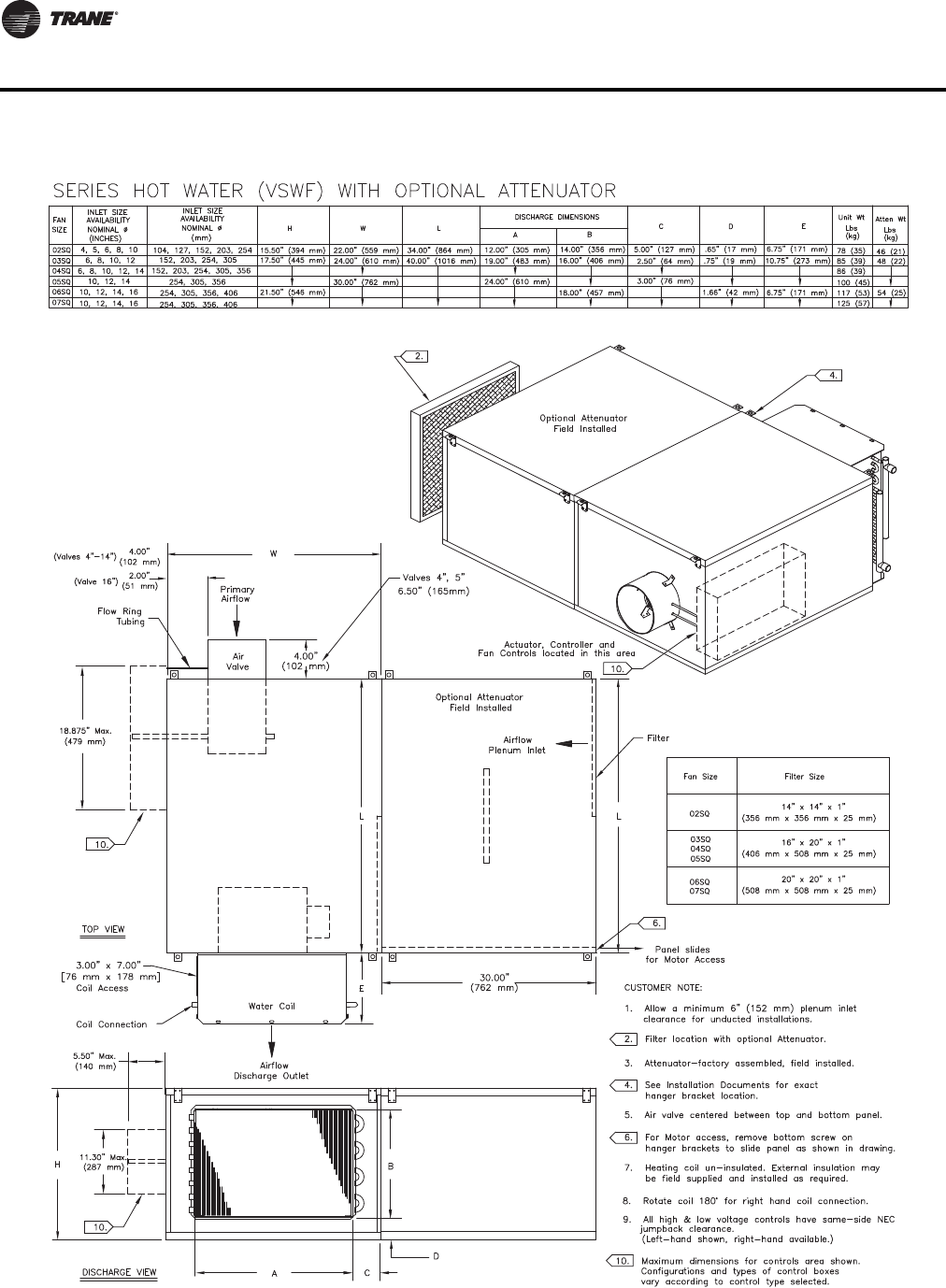
114 VAV-PRC012-EN
Dimensional Data
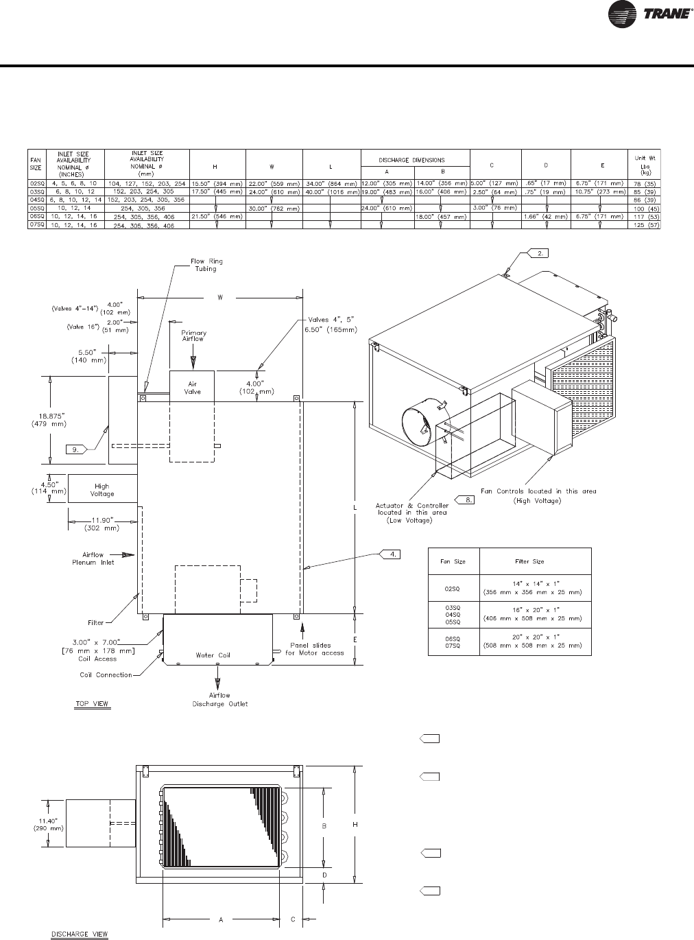
VAV-PRC012-EN 115
Dimensional Data
NARROW CORRIDOR DESIGN SERIES HOT WATER (VSWF) WITHOUT ATTENUATOR
NOTES:
1. Allow a minimum 6" (152 mm) plenum inlet
clearance for unducted installations.
2. See Installation Documents for exact hanger
bracket location.
3. Air valve centered between top and bottom panel.
4. For motor access, remove bottom screw on
hanger brackets to slide panel as shown in drawing.
5. Attenuator option not available with this unit layout.
6. Heating coil un-insulated. External insulation may be
field supplied and installed as required.
7. Rotate coil 180° for right hand coil connection.
8. All high & low voltage controls have same-side NEC
jumpback clearance. (unit shown w/left hand high &
low voltage box connections [high voltage inlet facing].
Right hand connections available.)
9. Maximum dimensions for controls area shown.
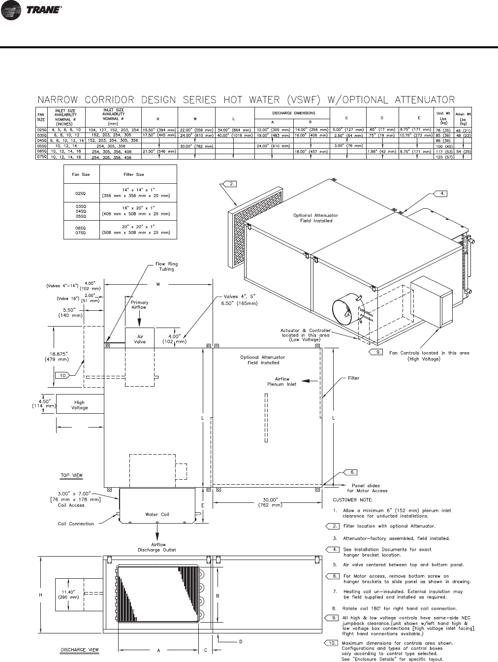
116 VAV-PRC012-EN
Dimensional Data
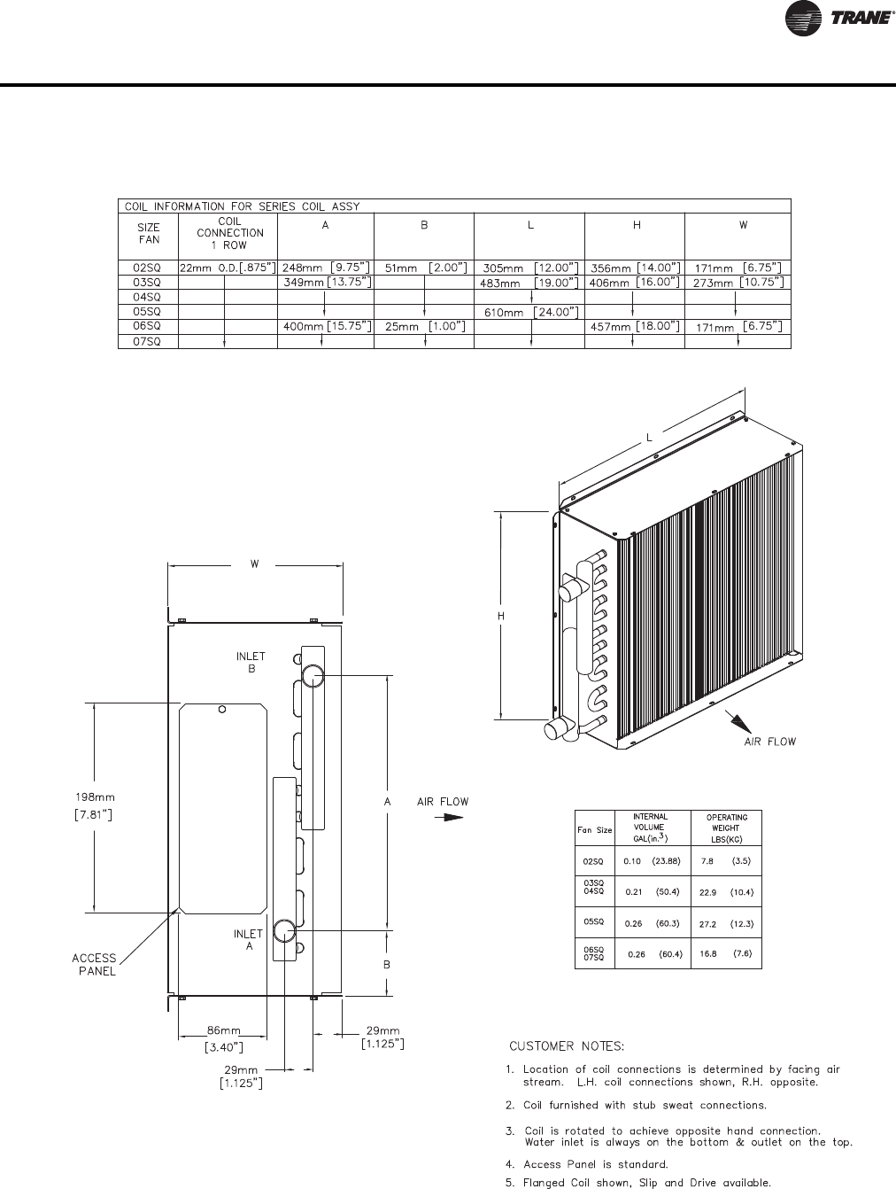
VAV-PRC012-EN 117
Dimensional Data
COIL INFORMATION FOR SERIES 1-ROW COIL
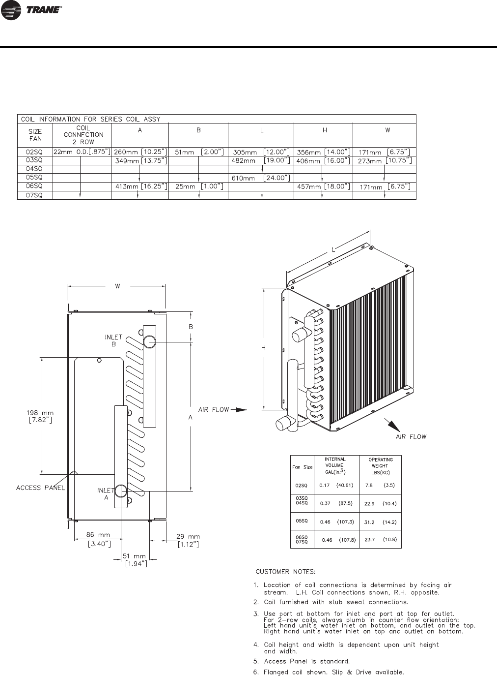
118 VAV-PRC012-EN
Dimensional Data
COIL INFORMATION FOR SERIES 2-ROW COILS
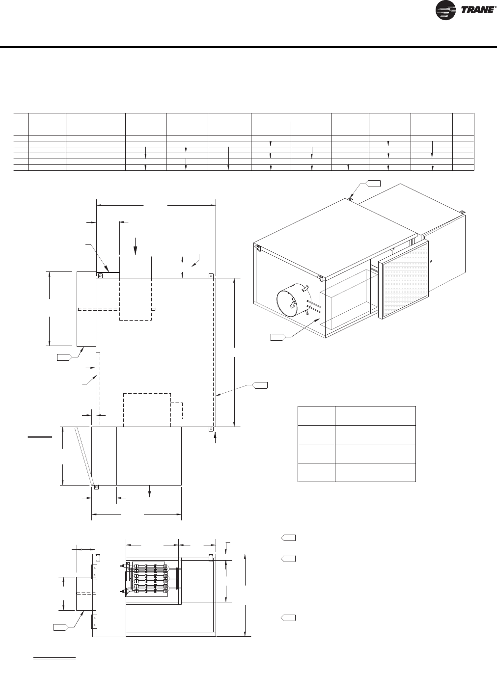
VAV-PRC012-EN 119
Dimensional Data
4.
W
L
Primary
Air
Valve
Airflow
Tubing
Flow Ring
Airflow
C
A
B
TOP VIEW
DISCHARGE VIEW
Plenum Inlet
SERIES ELECTRIC (VSEF) WITHOUT ATTENUATOR
H
(157 mm)
6.20"
Discharge Outlet
Airflow
Electric
D
Heater
Filter
02SQ
Fan Size
20" x 20" x 1"
(508 mm x 508 mm x 25 mm)
(406 mm x 508 mm x 25 mm)
16" x 20" x 1"
(356 mm x 356 mm x 25 mm)
14" x 14" x 1"
Filter Size
2.
Actuator, Controller and
Fan Controls located in this area
8.
8.
8.
(287 mm)
11.30" Max.
(140 mm)
5.50" Max.
(479 mm)
18.875" Max.
(Valves 4"-14")
(Valve 16") (51 mm)
2.00"
4.00"
(102 mm)
B
DISCHARGE DIMENSIONS
104, 127, 152, 203, 254
152, 203, 254, 305, 356
254, 305, 356, 406
05SQ
04SQ
03SQ
02SQ
07SQ
06SQ 10, 12, 14, 16
10, 12, 14, 16
4, 5, 6, 8, 10
6, 8, 10, 12
10, 12, 14
6, 8, 10, 12, 14
254, 305, 356, 406
254, 305, 356
152, 203, 254, 305 40.00" (1016 mm)
34.00" (864 mm)
21.50" (546 mm)
17.50" (445 mm)
15.50" (394 mm)
H
24.00" (610 mm)
30.00" (762 mm)
22.00" (559 mm)
W L ACD
12.00" (305 mm) 10.00" (254 mm)
14.00" (356 mm)
18.00" (457 mm)
25.00" (635 mm)
85 (39)
86 (39)
78 (35)
100 (45)
117 (53)
125 (57)
for Motor access
Panel slides
16.00" (406 mm)
19.00" (483 mm)
12.00" (305 mm)
18.50" (470 mm)
17.00" (432 mm)
E
E
5.50" (140 mm)
4.00" (102 mm)
5.00" (127 mm)
10.00" (254 mm)
06SQ
07SQ
03SQ
04SQ
05SQ
NOTES:
1. Allow a minimum 6" (152 mm) plenum inlet clearance for
unducted installations.
2. See Installation Documents for exact hanger bracket location.
3. Air valve centered between top and bottom panel.
4. For motor access, remove bottom screw on hanger brackets
to slide panel as shown in drawing.
5. Attenuator option not available with this unit layout.
6. Heating coil uninsulated. External insulation may be field-
supplied and installed as required.
7. All high & low voltage controls have same-side NEC jumpback
clearance. (Left-hand shown, right-hand/mirror image optional.)
8. Maximum dimensions for controls area shown. Configurations and
types of control boxes vary according to control types selected. See
"Enclosure Details" for specific layout.
FAN
SIZE
INLET SIZE
AVAILABILITY
NOMINAL Ø
INCHES
INLET SIZE
AVAILABILITY
NOMINAL Ø
(mm)
Unit Wt
Lbs
(kg)
4.00" (102 mm) 22.00" (559 mm)
Fans
02SQ
Fans
03SQ–05SQ
Fans
06SQ–07SQ
1.50"
(38 mm)
1.50"
(38 mm)
3.00"
(76 mm)
Fans
02SQ
Fans
03SQ–05SQ
Fans
06SQ–07SQ
1.00"
(25 mm)
2.00"
(51 mm)
0.60"
(15 mm)
4.00"
(102 mm)
Valves 4" & 5"
6.50"
(165 mm)
Maximum dimensions for controls area shown.
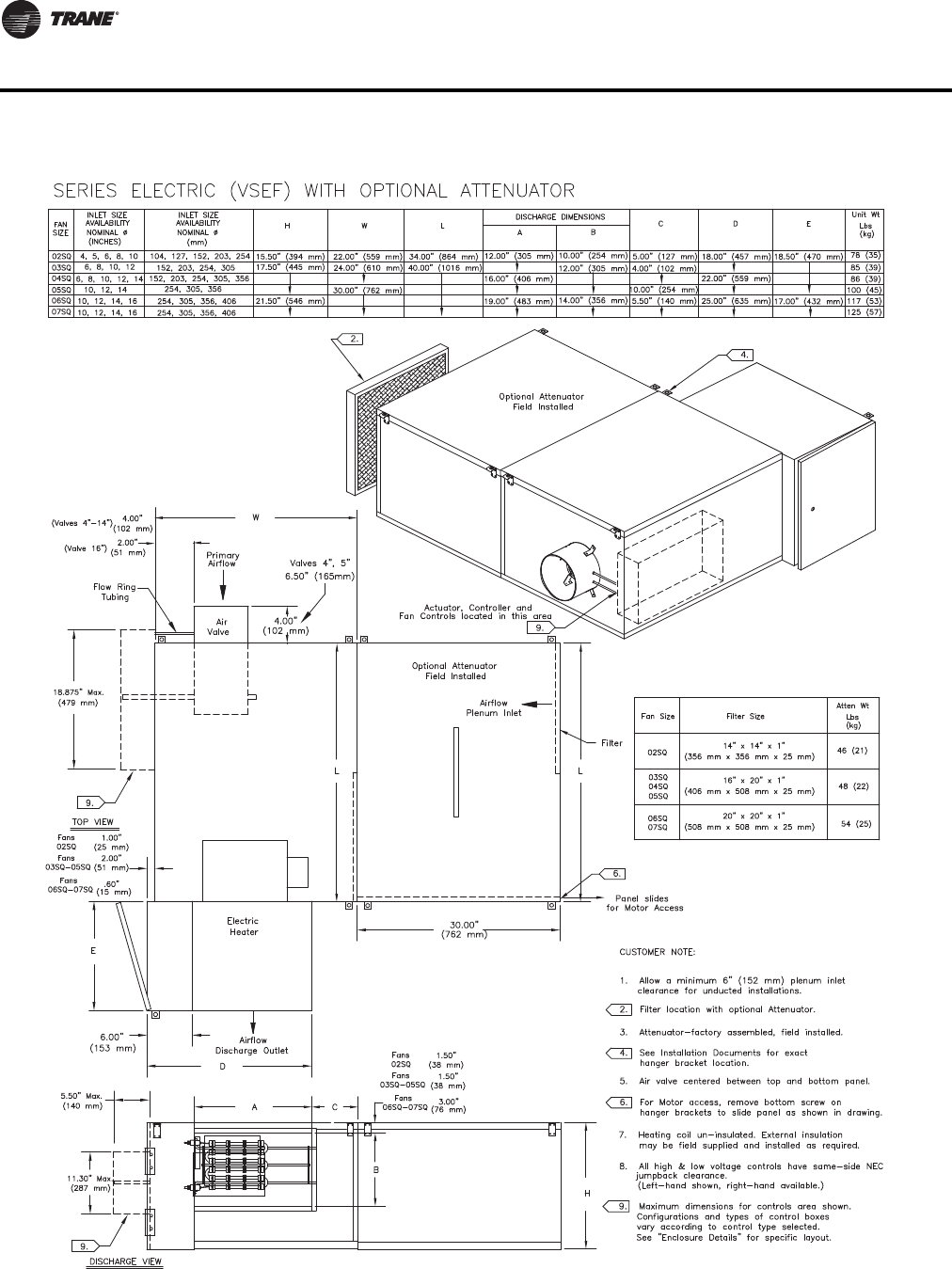
120 VAV-PRC012-EN
Dimensional Data
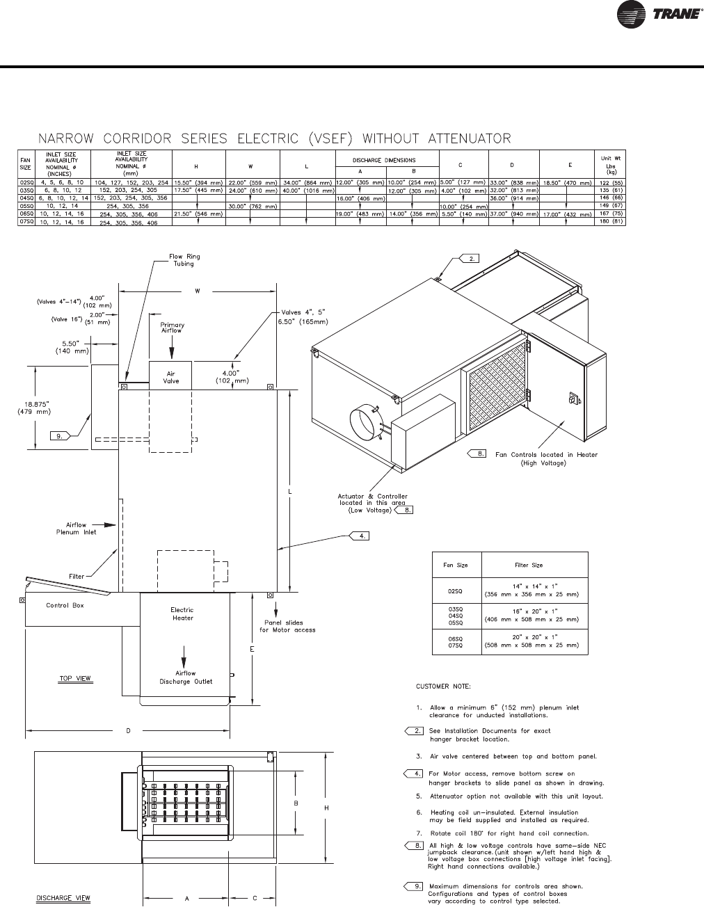
VAV-PRC012-EN 121
Dimensional Data
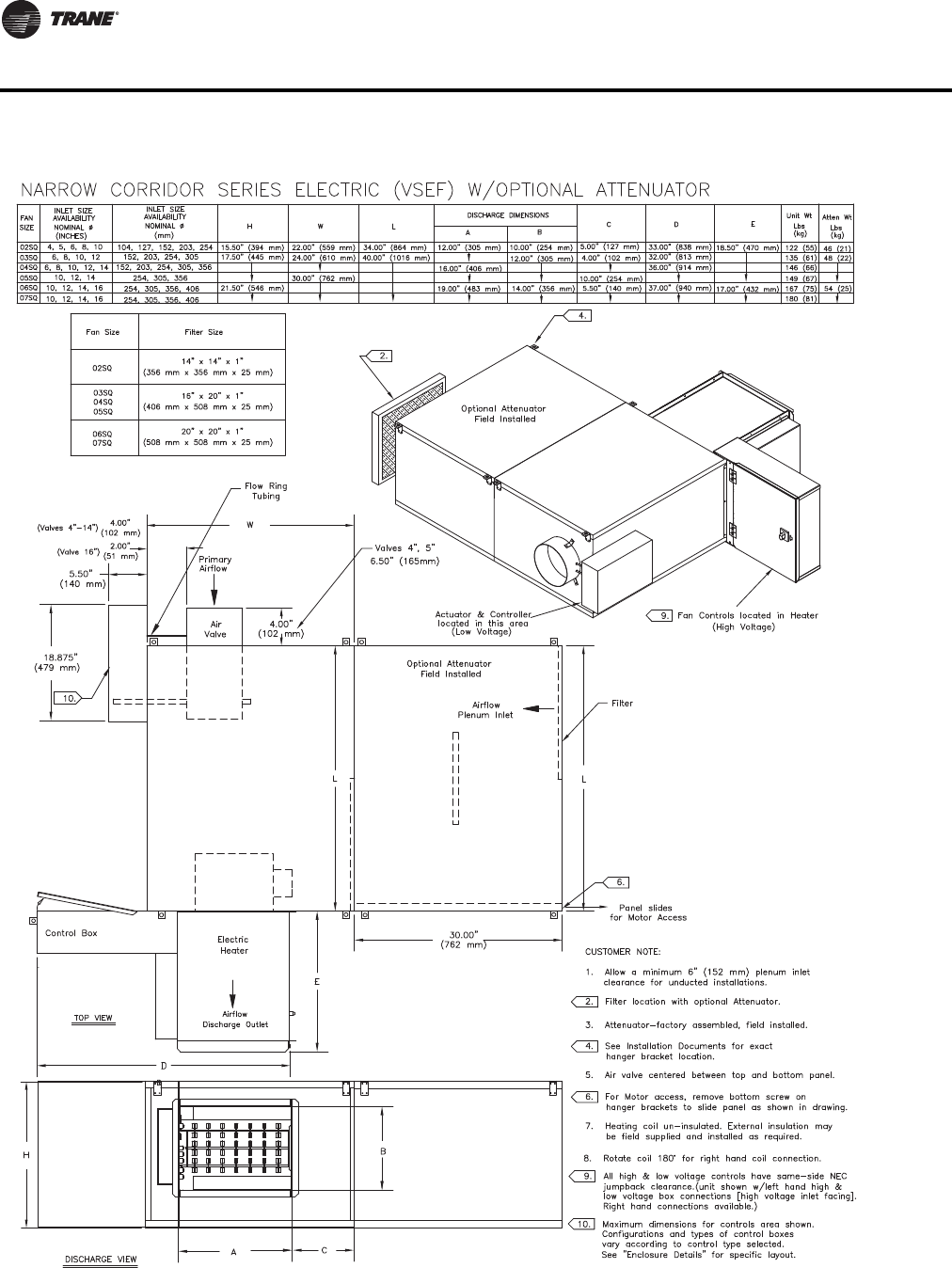
122 VAV-PRC012-EN
Dimensional Data
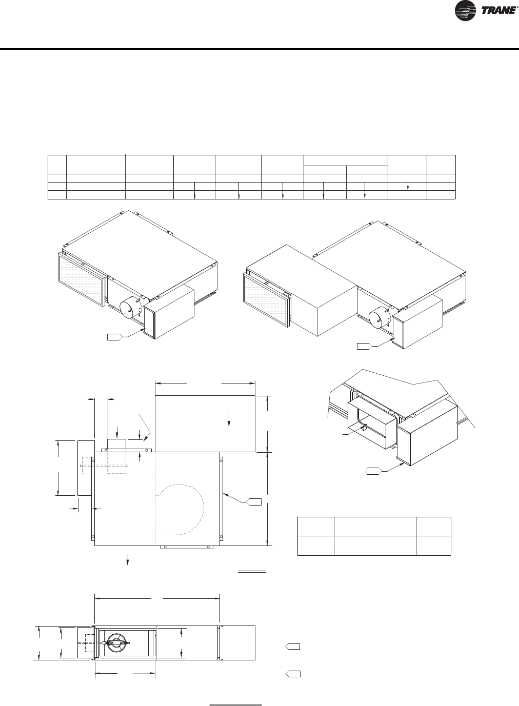
VAV-PRC012-EN 123
Dimensional Data
Low Height Parallel Fan-PoweredTerminal Units
DISCHARGE VIEW
TOP VIEW
LOW-HEIGHT PARALLEL COOLING (LPCF) FAN SIZES 08SQ & 09SQ
5.
Actuator, Controller and
Fan Controls located in this area
H
Airflow
Discharge Outlet
Primary
Airflow
Fan Controls located in this area
Actuator, Controller and
5.
L
W
A
B
(457 mm)
18.00"
(813 mm)
32.00"
Plenum Inlet
Airflow
B
9.5" (241 mm)
DISCHARGE DIMENSIONS
203 x 356
152, 203
127, 152, 203
INLET SIZE
AVAILABILITY
NOMINAL Ø (mm)
09SQ
FAN
08SQ
SIZE NOMINAL Ø (INCHES)
AVAILABILITY
5, 6, 8
6, 8
8 x 14
INLET SIZE
11.00" (279 mm)
H
40.00" (1016 mm)
W
19.25" (489 mm)
30.00" (762 mm)
LA
WT LBS
UNIT WT
4.00" (102 mm)
3.25" (83 mm)
D(kg)
(203 mm X 356 mm)
Fan Controls located in Enclosure
Rectangular Damper Detail
Rectangular Damper
8" x 14"
Actuator, Controller and
5.
NOTES:
1. Allow a minimum 6" (152 mm) plenum inlet clearance for unducted
installations.
2. Flanged discharge outlet accepts up to 1" (25 mm) duct flange.
3. Bottom Access panel standard.
4. Air valve centered between top and bottom panel.
5. Control box enclosure provided with all control types.
6. All high & low voltage controls have same-side NEC jumpback
clearance. (Left-hand shown, right-hand/mirror image optional.)
7. Flange adds 2" to width and length of unit.
Fan Size
09SQ
08SQ
Attn Wt
Wt. Lbs.
(kg)
(254 mm x 508 mm x 25 mm)
10" x 20" x 1"
Filter Size
(445 mm)
17.50"
(127 mm)
5.00"
(267 mm)
10.50"
10 (4.5)
69 (31.3)
74 (33.6)
83 (37.7)
Optional Attenuator
Field Installed
Optional Attenuator
Field Installed
09SQ
D
4.00
(102 mm)
7.
Valve 5"
6.50"
(165 mm)
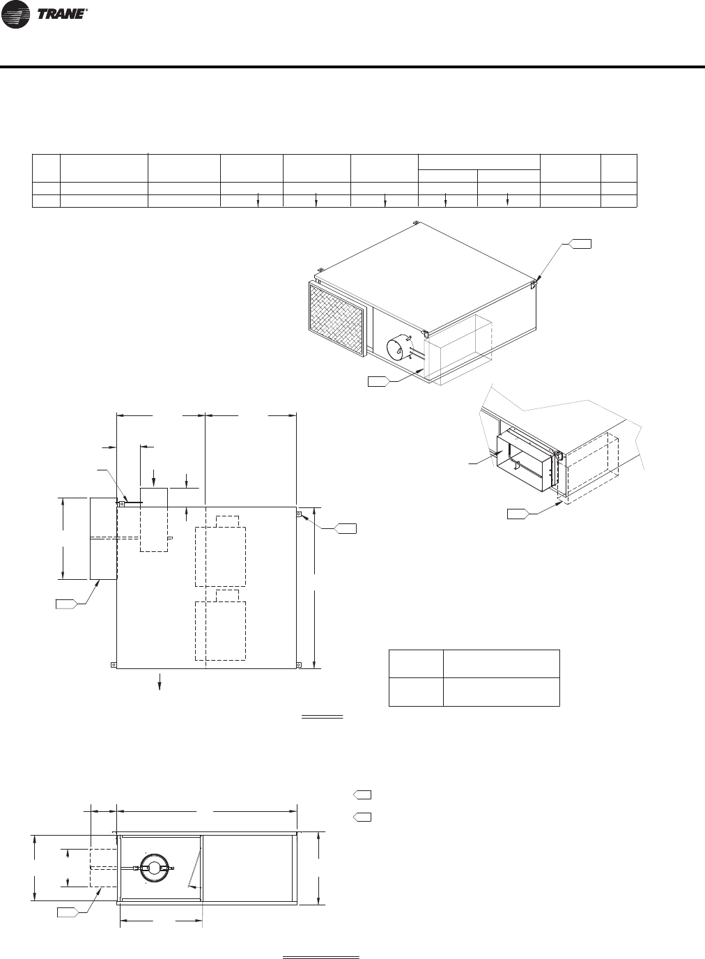
124 VAV-PRC012-EN
Dimensional Data
DISCHARGE VIEW
TOP VIEW
LOW-HEIGHT PARALLEL COOLING (LPCF) FAN SIZE 10SQ
NOTES:
1. Allow a minimum 6" (152 mm) plenum inlet clearance for unducted installations.
2. Flanged discharge outlet accepts up to a 1" (25 mm) duct flange.
5. Air valve centered between top and bottom panel.
4. See Installation Documents for exact hanger bracket location.
Rectangular Damper Detail
Fan Controls located in this area
Actuator, Controller and
6.
4.
B
6.
11.30" Max.
(287 mm)
6.
5.50" Max.
(140 mm)
18.875" Max.
(479 mm)
Flow Ring
tubing
A
Airflow
Discharge Outlet
W
Primary
Airflow
Air
Valve
4.
L
20.00"
(508 mm) (508 mm)
20.00"
H
(254 mm x 508 mm x 25 mm)
10" x 20" x 1"
10SQ
Fan Size Filter Size
Fan Controls located in this area
Actuator, Controller and
6.
90 (41)
92 (42)
(203 mm X 356 mm)
8" x 14"
Rectangular Damper
D
10.00" (254 mm)
INLET SIZE
AVAILABILITY
203 x 356
NOMINAL Ø (mm)
SIZE
FAN
10SQ
10SQ
INLET SIZE
AVAILABILITY
NOMINAL Ø (INCHES)
8
8 x 14
203 50.00" (1270 mm)
11.50" (292 mm)
H
40.00" (1016 mm)
W
A
DISCHARGE DIMENSIONS
19.25" (489 mm)
LB
4.00" (102 mm)
3.25" (83 mm)
DWT LBS
UNIT WT
(kg)
3. Bottom Access panel standard.
6. Maximum dimensions for controls area shown.
4.00
(102 mm)
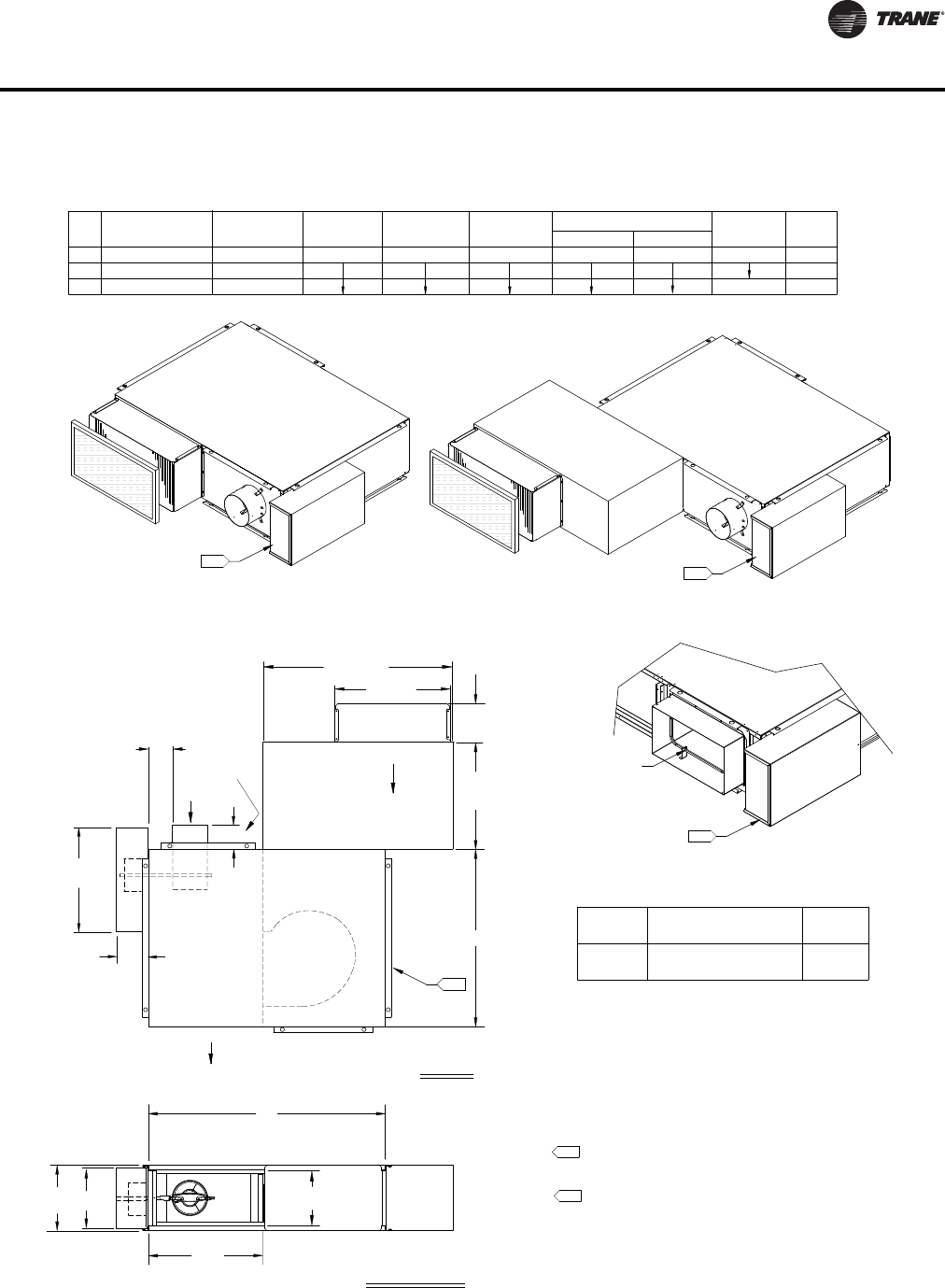
VAV-PRC012-EN 125
Dimensional Data
DISCHARGE VIEW
TOP VIEW
LOW-HEIGHT PARALLEL HOT WATER (LPWF) FAN SIZES 08SQ & 09SQ
NOTES:
(254 mm x 508 mm x 25 mm)
10" x 20" x 1"
08SQ
Fan Size Filter Size
SIZE
08SQ
FAN INLET SIZE
AVAILABILITY
8 x 14
09SQ
5.
Actuator, Controller and
Fan Controls located in this area
H
Airflow
Discharge Outlet
Primary
Airflow
Fan Controls located in this area
Actuator, Controller and
5.
L
W
A
B
(457 mm)
18.00"
(813 mm)
32.00"
09SQ
5, 6, 8
NOMINAL Ø (INCHES) NOMINAL Ø (mm)
AVAILABILITY
INLET SIZE
127, 152, 203
6, 8 152, 203
203 x 356
30.00" (762 mm)
40.00" (1016 mm)
11.00" (279 mm)
HW
DISCHARGE DIMENSIONS
19.25" (483 mm)
LA
9.50" (241 mm)
B
UNIT WT
D
3.25" (83 mm)
4.00" (102 mm)
WT LBS
(kg)
Attn Wt
Wt Lbs
(kg)
Plenum Inlet
Airflow
20.00"
(508 mm)
(173 mm)
6.80"
5. Control box enclosure provided with all control types.
4. Air valve centered between top and bottom panel.
1. Allow a minimum 6" (152 mm) plenum inlet clearance for
unducted installations.
2. Flanged discharge outlet accepts up to a 1" (25 mm) duct flange.
3. Bottom Access panel standard.
(203 mm x 356 mm)
Fan Controls located in Enclosure
Rectangular Damper Detail
Rectangular Damper
8" x 14"
Actuator, Controller and
5.
6. All high & low voltage controls have same-side NEC jumpback
clearance. (Left-hand shown, right-hand/mirror image optional.)
7. Flange adds 2" to width and length of unit.
10 (4.5)
(127 mm)
5.00"
(445 mm)
17.50"
(267 mm)
10.50"
98 (44.5)
103 (46.7)
112 (50.8)
Optional Attenuator
Field Installed
Optional Attenuator
Field Installed
09SQ
D
4.00
(102 mm)
Valve 5"
6.50"
(165 mm)
7.
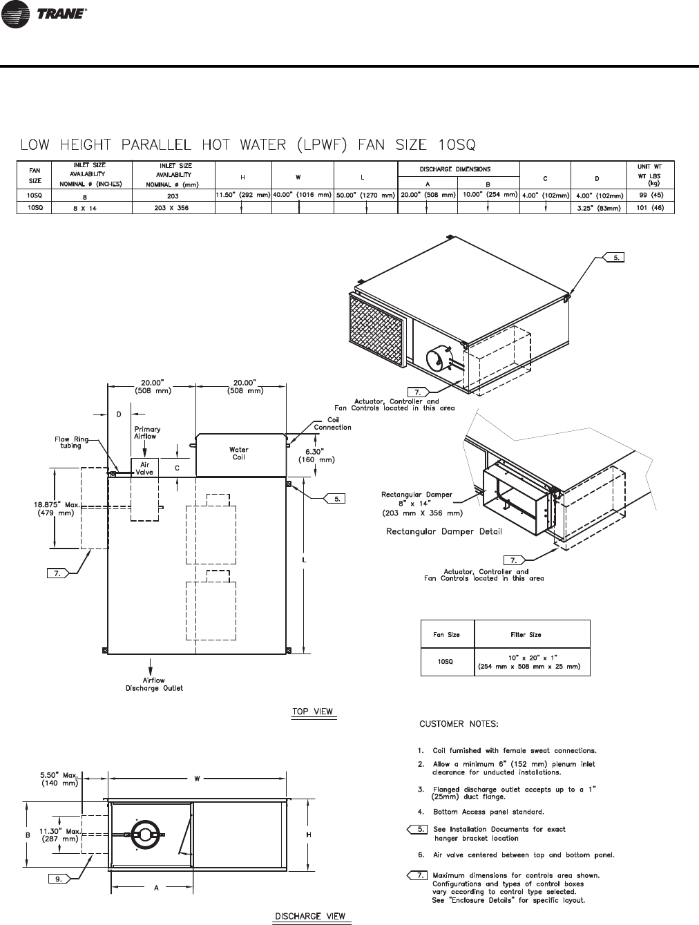
126 VAV-PRC012-EN
Dimensional Data
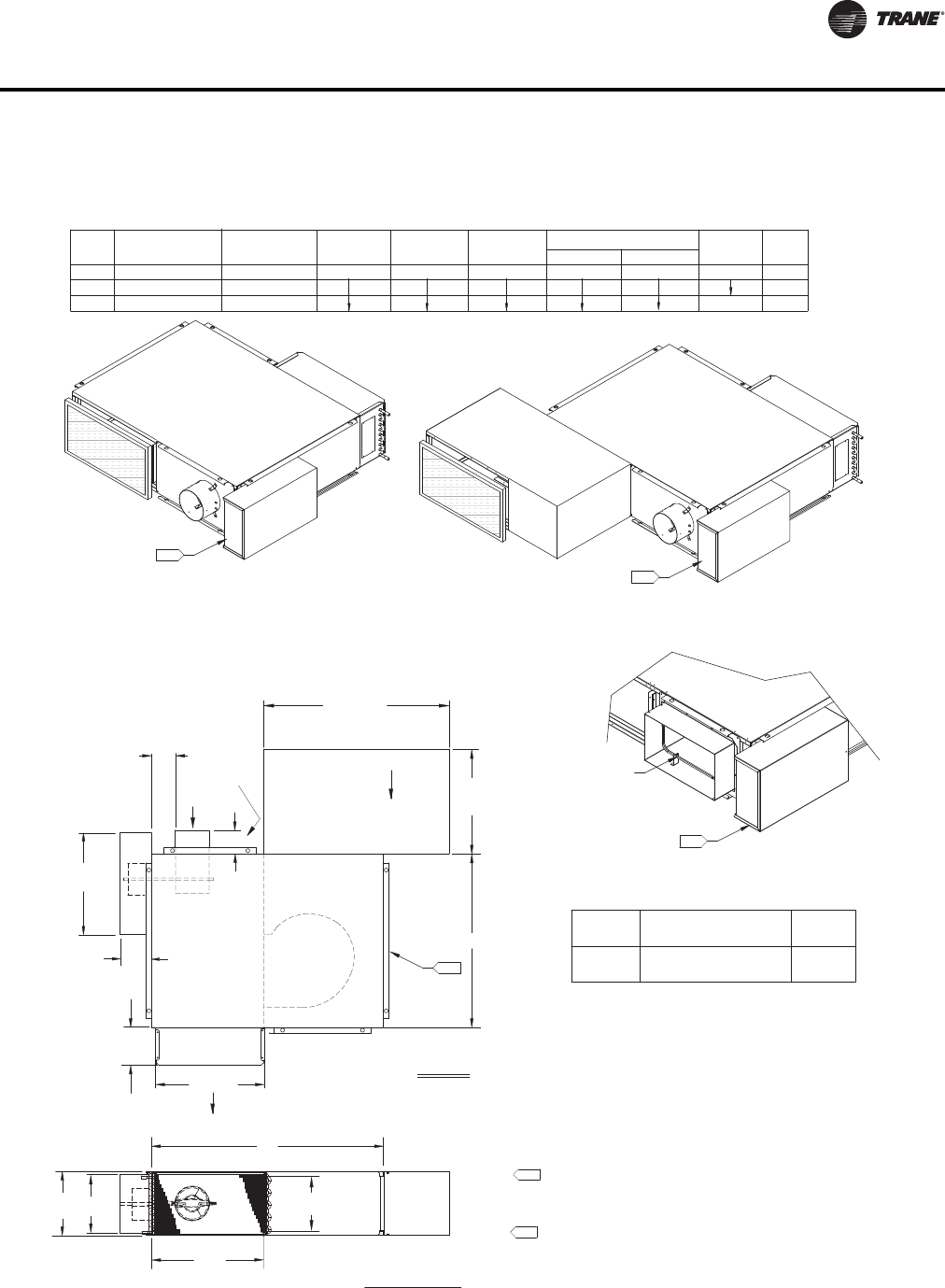
VAV-PRC012-EN 127
Dimensional Data
DISCHARGE VIEW
TOP VIEW
PARALLEL LOW-HEIGHT HOT WATER (LPWF) COIL ON DISCHARGE
FAN SIZES 08SQ & 09SQ
NOTES:
1. Allow a minimum 6" (152 mm) plenum inlet clearance for
unducted installations.
2. Flanged discharge outlet accepts up to a 1" (25 mm) duct flange.
3. Bottom Access panel standard.
4. Air valve centered between top and bottom panel.
5. Control box enclosure provided with all control types.
6. All high & low voltage controls have same-side NEC jumpback clearance.
(Left-hand shown, right-hand/mirror image optional.)
7. Flange adds 2" to width and length of unit.
(254 mm x 508 mm x 25 mm)
10" x 20" x 1"
08SQ
Fan Size Filter Size
SIZE
08SQ
FAN INLET SIZE
AVAILABILITY
8 X 14
09SQ
H
Airflow
Discharge Outlet
Primary
Airflow
L
W
A
B
(457 mm)
18.00"
(813 mm)
32.00"
09SQ
5, 6, 8
NOMINAL Ø (INCHES) NOMINAL Ø (mm)
AVAILABILITY
INLET SIZE
127, 152, 203
6, 8 152, 203
203 X 356
30.00" (762 mm)
40.00" (1016 mm)
11.00" (279 mm)
HW
DISCHARGE DIMENSIONS
20.00" (508 mm)
L
A
10.00" (254 mm)
B
UNIT WT
D
3.25" (83 mm)
4.00" (102 mm)
WT LBS
(kg)
Attn Wt
Wt Lbs
(kg)
Plenum Inlet
Airflow
(203 mm X 356 mm)
Fan Controls located in Enclosure
Rectangular Damper Detail
Rectangular Damper
8" x 14"
Actuator, Controller and
5.
10 (4.5)
(127 mm)
5.00"
(445 mm)
17.50"
(267 mm)
10.50"
98 (44.5)
103 (46.7)
112 (50.8)
Optional Attenuator
Field Installed
09SQ
D
Actuator, Controller and
Fan Controls located in this area
Fan Controls located in this area
Actuator, Controller and
5.
Field Installed
Optional Attenuator
5.
(508 mm)
20.00"
(173 mm)
6.80"
4.00
(102 mm)
Valve 5"
6.50"
(165 mm)
7.
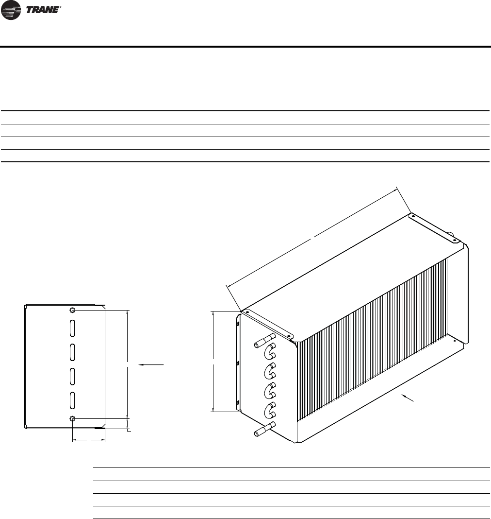
128 VAV-PRC012-EN
Dimensional Data
Coil Information For Low Height Parallel Inlet-1 Row
Notes:
1. Location of coil connections is determined by facing air steam. R.H. Coil connections shown, L.H. not available.
2. Coil furnished with stub sweet connections.
Size Inlet/Fan Coil Connection 1-Row A B L H
08SQ 3/8" (10 mm) O.D. 9" (229 mm) 2 7/8" (71 mm) 20" (508 mm) 10" (254 mm)
09SQ 3/8" (10 mm) O.D. 9" (229 mm) 2 7/8" (71 mm) 20" (508 mm) 10" (254 mm)
10SQ .375" (10 mm) O.D. 9.00" (229 mm) 2.80" (71 mm) 20.00" (508 mm) 10.00" (254 mm)
H
L
AIR FLOW
A
B
INLET
OUTLET
7/8"
[22mm]
AIR FLOW
Fan Size Internal Volume Gal (L) Operating Weight Lbs (Kg)
08SQ 0.07 (16.7) 9.7 (4.4)
09SQ 0.07 (16.7) 9.7 (4.4)
10SQ 0.07 (.27) 9.7 (4.4)
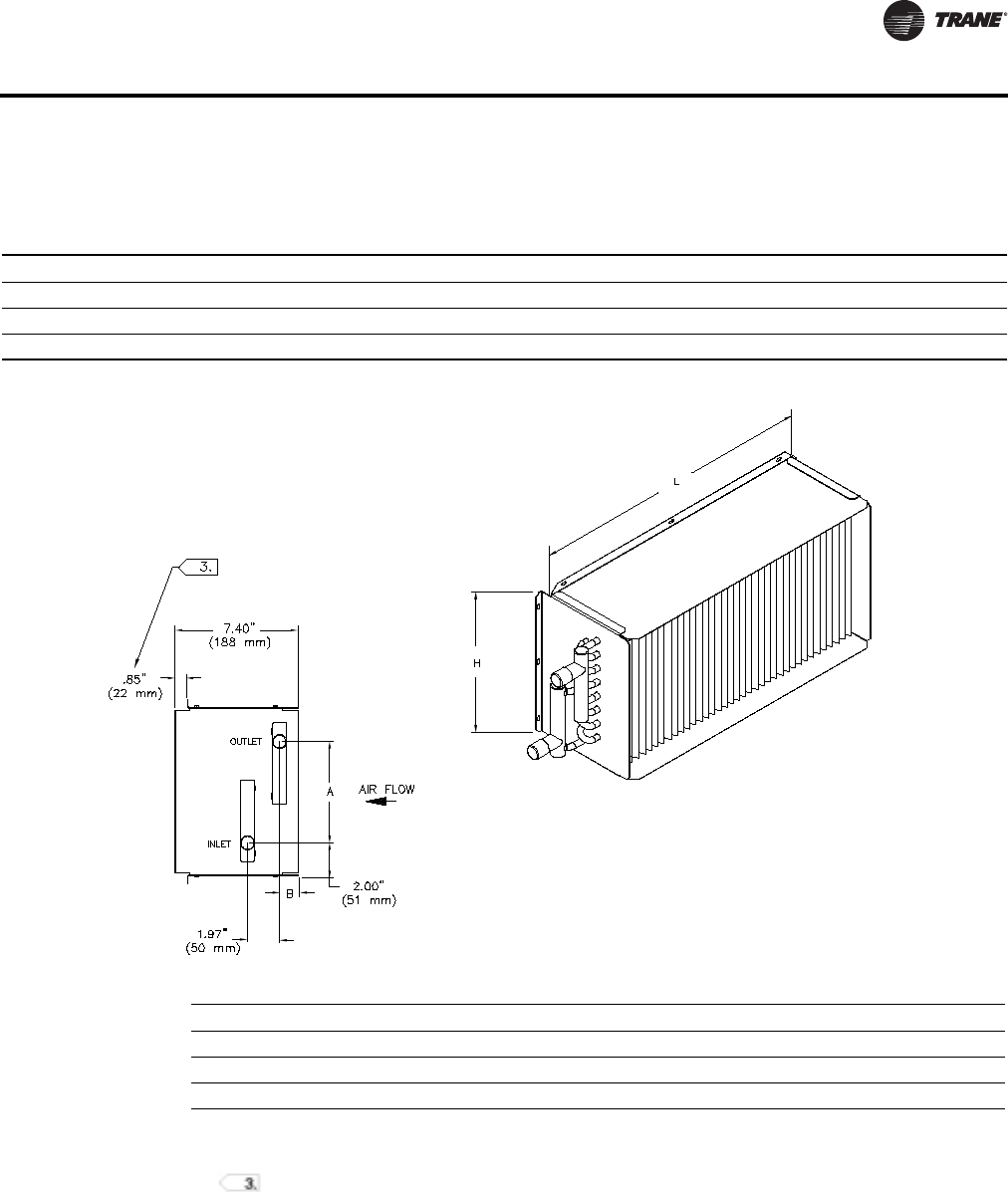
VAV-PRC012-EN 129
Dimensional Data
Coil Information For Low Height Parallel Plenum Inlet 2-Row Coil
Notes:
1. Location of coil connections is determined by facing air steam. R.H. Coil connections shown, L.H. not available.
2. Coil furnished with female sweat connections.
3. 0.85" lip NOT on 08SQ or 09SQ units.
Fan Size Coil Connection 2 Row A B L H
08SQ 7/8" (22 mm) O.D. 6 1/4" (157 mm) 2 1/8" (55 mm) 20" (508 mm) 10" (254 mm)
09SQ 7/8" (22 mm) O.D. 6 1/4" (157 mm) 2 1/8" (55 mm) 20" (508 mm) 10" (254 mm)
10SQ .875" (22 mm) O.D. 6.20" (157 mm) 2.18" (55 mm) 20.00" (508 mm) 10.00" (254 mm)
Fan Size Internal Volume Gal (L) Operating Weight Lbs (Kg)
08SQ 0.16 (39.0) 13.7 (6.2)
09SQ 0.16 (39.0) 13.7 (6.2)
10SQ 0.16 (.61) 13.7 (6.2)
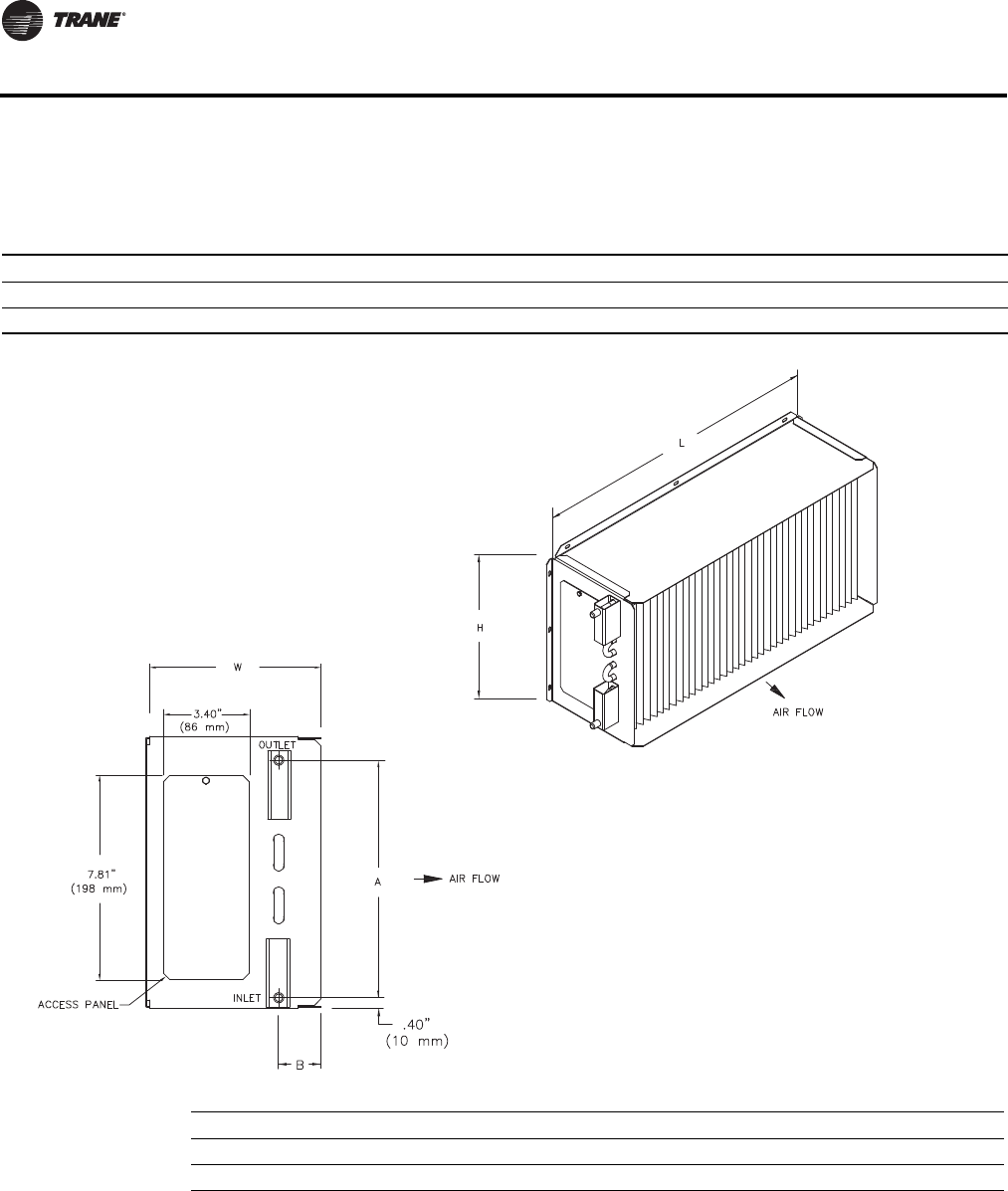
130 VAV-PRC012-EN
Dimensional Data
Coil Information For Low Height Parallel Discharge 1-Row Coil
Notes:
1. Location of coil connections is determined by facing air stream. L.H. Coil connections shown, R.H. opposit.
2. Coil furnished with stub sweat connections.
3. Coil is rotated to achieve opposite hand connection. Note: Water inlet is always on the bottom and outlet on the top.
4. Access Panel is standard.
Fan Size Coil Connection A B L H W
08SQ 3/8" (10 mm) O.D. 9.00" (229 mm) 1.65" (42 mm) 20.00" (508 mm) 10.00" (254 mm) 6.75" (171 mm)
09SQ 3/8" (10 mm) O.D. 9.00" (229 mm) 1.65" (42 mm) 20.00" (508 mm) 10.00" (254 mm) 6.75" (171 mm)
Fan Size Internal Volume Gal (L) Operating Weight Lbs (Kg)
08SQ 0.07 (.28) 9.7 (4.4)
09SQ 0.07 (.28) 9.7 (4.4)
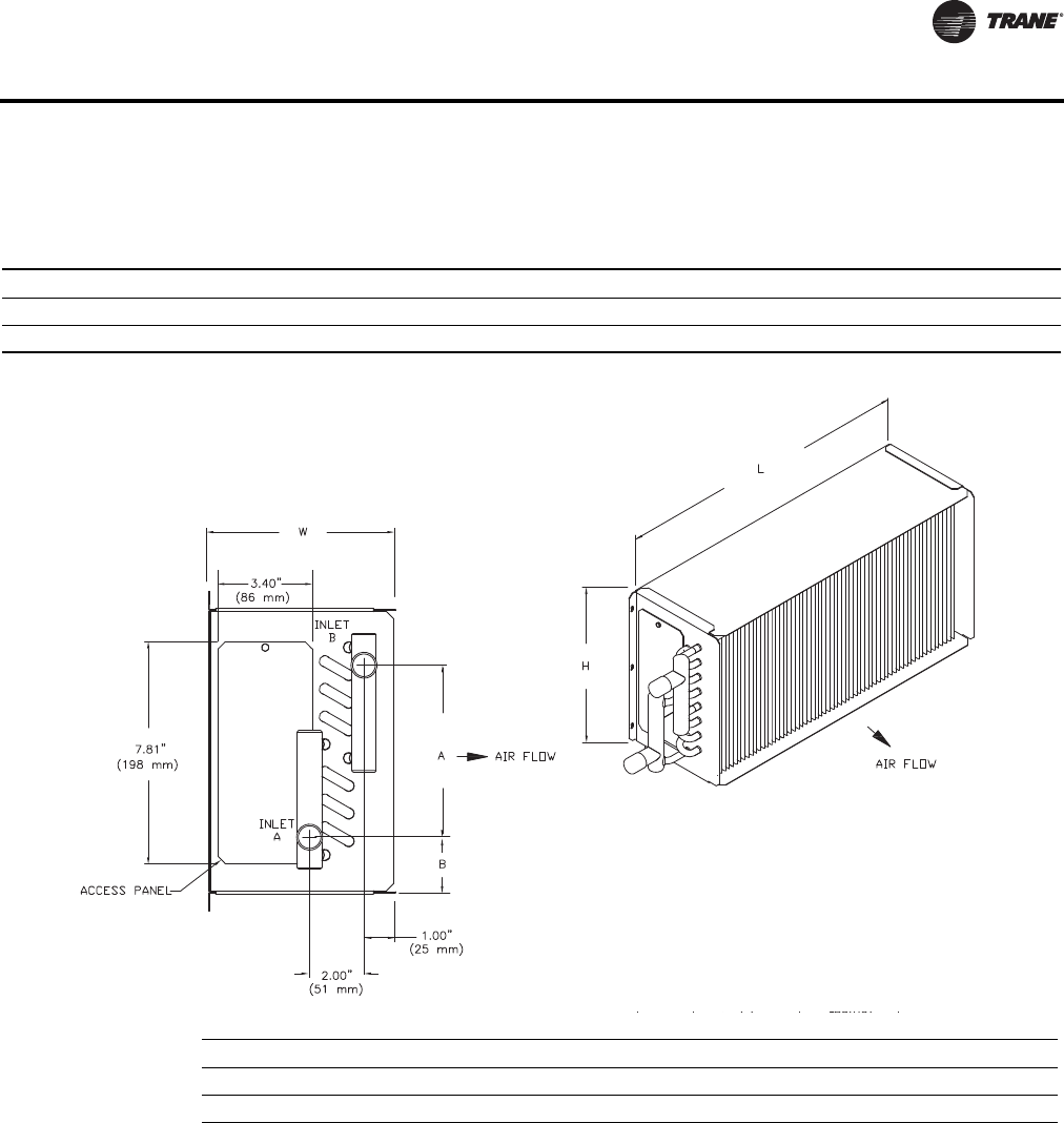
VAV-PRC012-EN 131
Dimensional Data
Coil Information For Low Height Parallel Discharge 2 Row Coil
Notes:
1. Location of coil connections is determined by facing air stream. L.H. Coil connections shown, R.H. opposite.
2. Coil furnished with stub sweat connections.
3. Use port at bottom for inlet and port at top for outlet. For 2-row coils, always plumb in counter flow orientation: Left hand
unit's water inlet on bottom, and outlet on the top. Right hand unit’s water inlet on top and outlet on bottom.
4. Access Panel is standard.
Fan Size Coil Connection A B L H W
08SQ 7/8" (22 mm) O.D. 6.25" (159 mm) 2.00 (51 mm) 20.00" (508 mm) 10.00" (254 mm) 6.75" (171 mm)
09SQ 7/8" (22 mm) O.D. 6.25" (159 mm) 2.00 (51 mm) 20.00" (508 mm) 10.00" (254 mm) 6.75" (171 mm)
Fan Size Internal Volume Gal (L) Operating Weight Lbs (Kg)
08SQ 0.17 (.64) 13.7 (6.2)
09SQ 0.17 (.64) 13.7 (6.2)
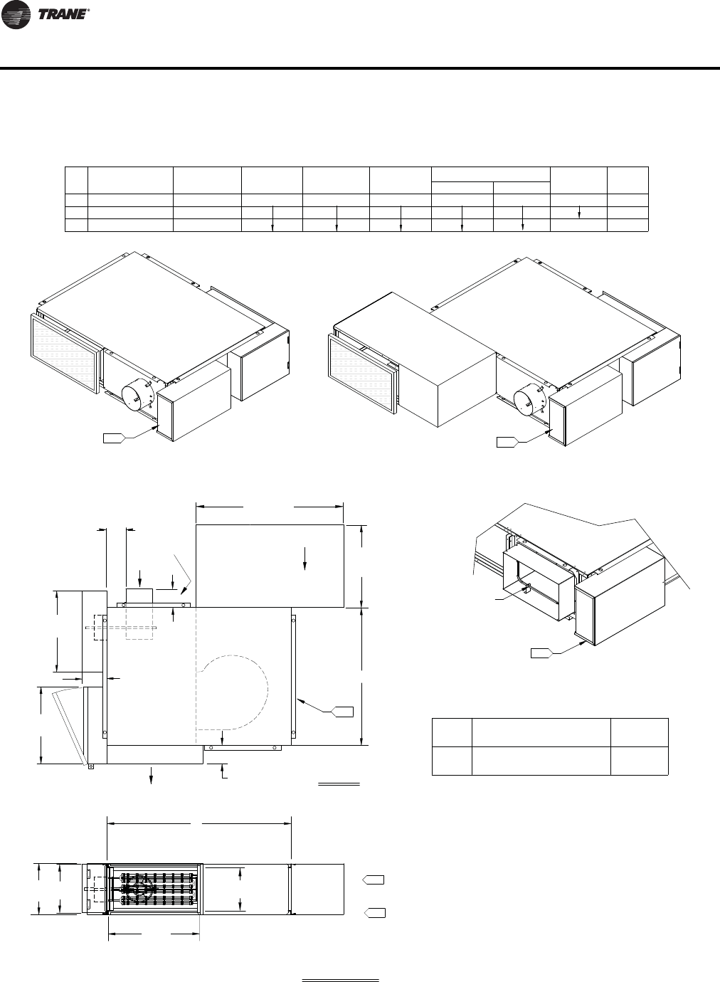
132 VAV-PRC012-EN
Dimensional Data
DISCHARGE VIEW
TOP VIEW
LOW-HEIGHT PARALLEL ELECTRIC HEAT (LPEF) FAN SIZES 08SQ & 09SQ
5.
H
Primary
Airflow
5.
L
W
A
B
(457 mm)
18.00"
(813 mm)
32.00"
Plenum Inlet
Airflow
B
9.50" (241 mm)
DISCHARGE DIMENSIONS
203 x 356
152, 203
127, 152, 203
INLET SIZE
AVAILABILITY
NOMINAL Ø (mm)
09SQ
FAN
08SQ
SIZE NOMINAL Ø (INCHES)
AVAILABILITY
5, 6, 8
6, 8
8 x 14
INLET SIZE
11.00" (279 mm)
H
40.00" (1016 mm)
W
19.00" (483 mm)
30.00" (762 mm)
LA
WT LBS
UNIT WT
4.00" (102 mm)
3.25" (83 mm)
D(kg)
Rectangular Damper Detail
(203 mm X 356 mm)
8" x 14"
Rectangular Damper
5.
Filter Size
10" x 20 " x 1"
(254 mm x 508 mm x 25 mm)
08SQ
09SQ
Fan Size (kg)
Lbs
Atten Wt
Fan Controls located in Enclosure
Actuator, Controller and
Fan Controls located in Enclosure
Actuator, Controller and
Fan Controls located in Enclosure
Actuator, Controller and
20.00"
(508 mm)
Terminal Box
Discharge Outlet
Airflow
Heater
6.00"
(152 mm)
NOTES:
1. Allow a minimum 6" (152 mm) plenum inlet clearance for unducted installations.
2. Flanged discharge outlet accepts up to a 1" (25 mm) duct flange.
5. Control box enclosure provided with all control types.
4. Air valve centered between top and bottom panel.
3. Bottom Access panel standard.
6. All high & low voltage controls have same-side NEC jumpback clearance. (Left-hand
shown, right-hand/mirror image optional.)
7. Flange adds 2" to width and length of unit.
10 (4.5)
(127 mm)
5.00"
(445 mm)
17.50"
(267 mm)
10.50"
104 (47.2)
109 (49.4)
118 (53.5)
Optional Attenuator
Field Installed
Optional Attenuator
Field Installed
09SQ
D
4.00
(102 mm)
Valve 5"
6.50"
(165 mm)
7.
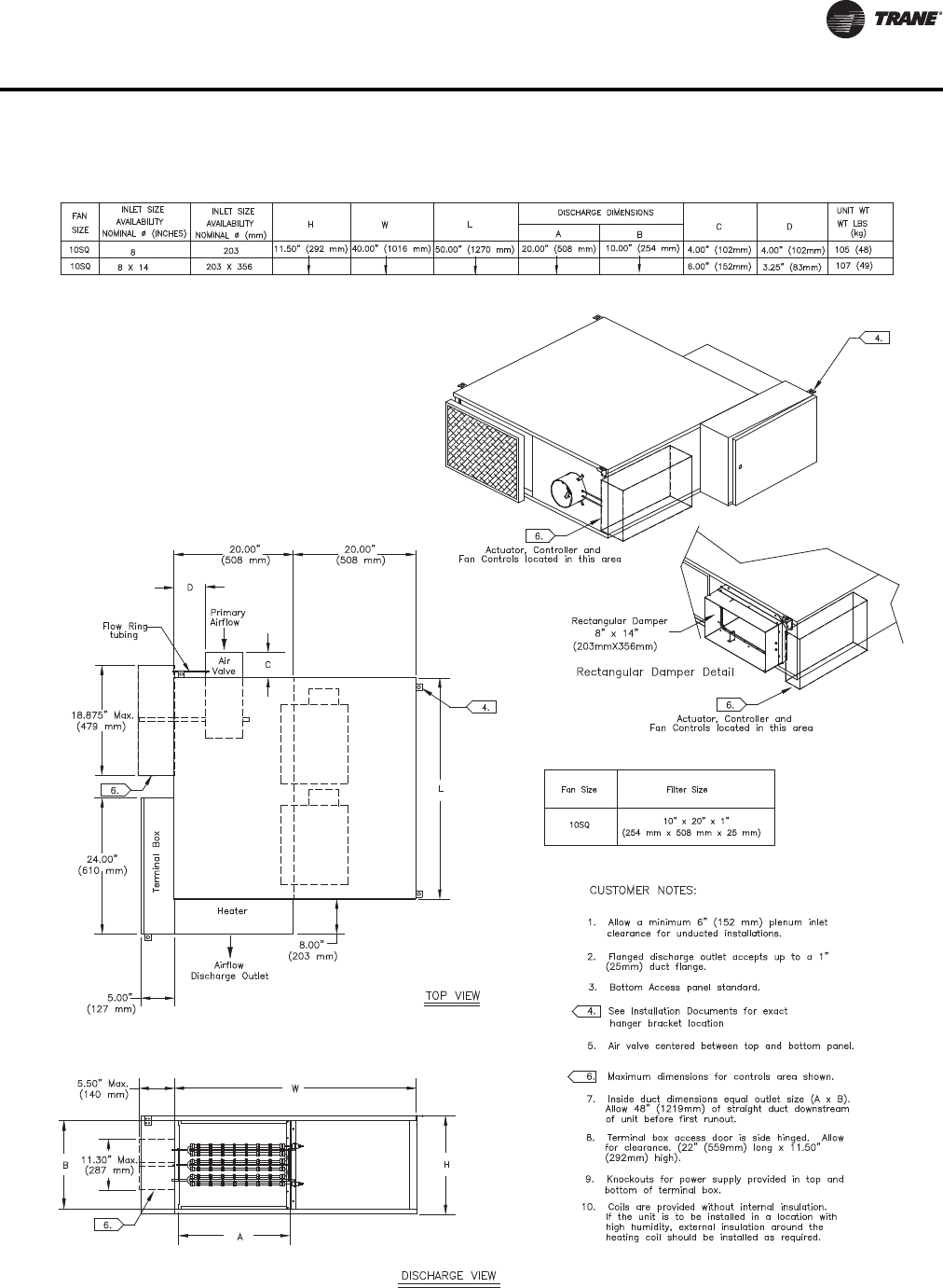
VAV-PRC012-EN 133
Dimensional Data
L
O
W-HEI
G
HT PARALLEL ELE
C
TRI
C
(LPEF) FAN
S
IZE 10
SQ
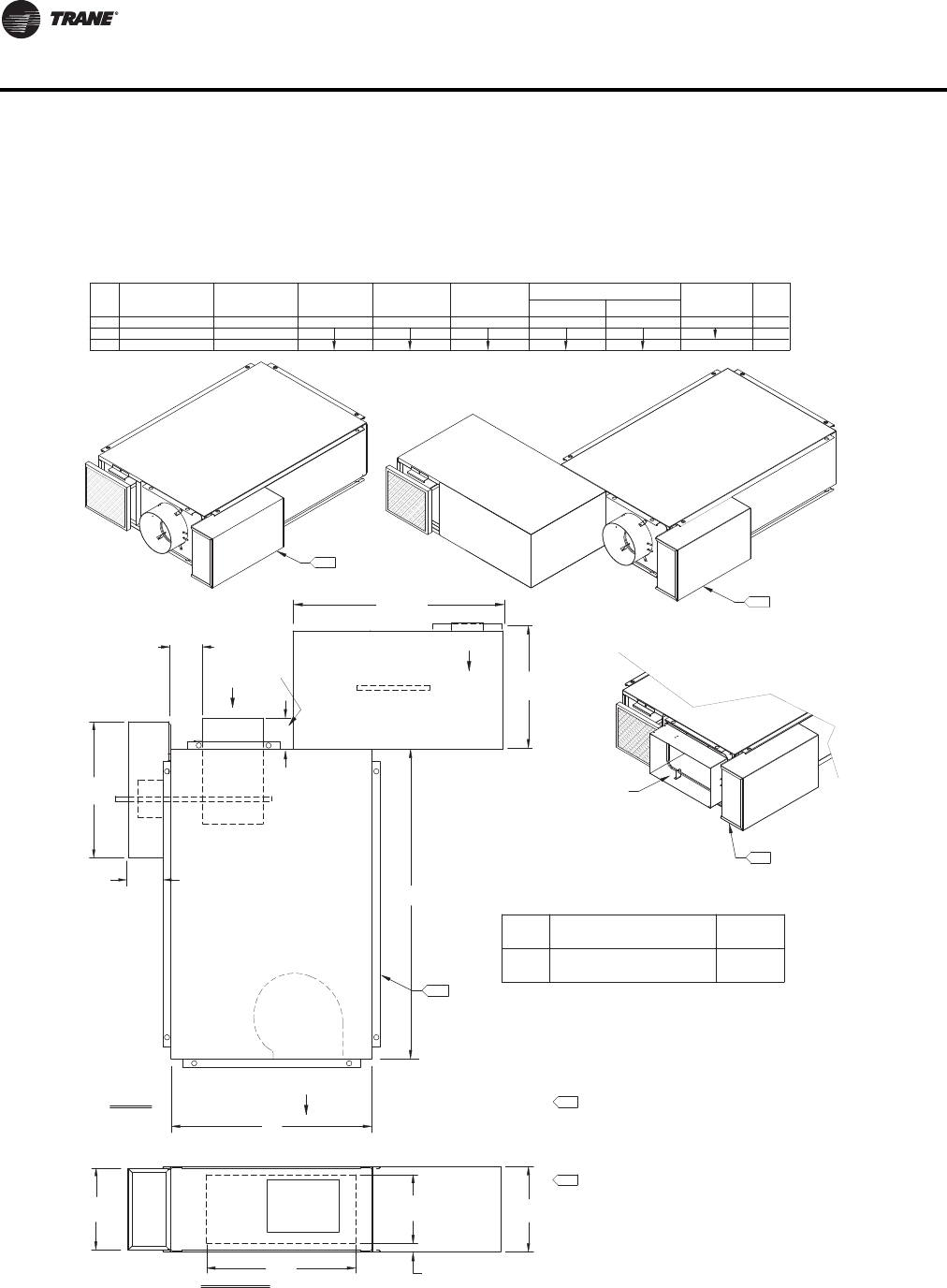
134 VAV-PRC012-EN
Dimensional Data
Low Height Series Fan-Powered Terminal Units
Airflow
Primary
Plenum Inlet
Airflow
LOW-HEIGHT SERIES COOLING ONLY (LSCF) FAN SIZES 08SQ & 09SQ
DISCHARGE VIEW
DISCHARGE DIMENSIONS
SIZE
FAN
09SQ
08SQ 26.00" (660 mm)
11.00" (279 mm)
HW
40.00" (1016 mm)
LABD
Unit Wt
Lbs
(kg)
Discharge Outlet
Airflow
TOP VIEW
09SQ
Air
Valve
Field Installed
Optional Attenuator
Rectangular Damper Detail
W
H
L
Field Installed
Optional Attenuator
A
B
Fan Controls located in Enclosure
Actuator, Controller and
Rectangular Damper
(203 mm x 356 mm)
8" x 14"
D
4.00" (102 mm)
4.50" (114 mm)
1.00"
(25 mm)
6, 8
8 x 14
5, 6, 8
INLET SIZE
NOMINAL Ø (inches)
AVAILABILITY
127, 152, 203
152, 203
203 x 355
INLET SIZE
AVAILABILITY
NOMINAL Ø (mm)
(813 mm)
32.00"
18.00"
(457 mm)
4.
4.
Actuator, Controller and
Fan Controls located in Enclosure
Actuator, Controller and
Fan Controls located in Enclosure
4.
10.50"
(267 mm)
(127 mm)
5.00"
(445 mm)
17.50"
18.00" (457 mm) 10.00" (254 mm)
NOTES:
1. Allow a minimum 6" (152 mm) plenum inlet clearance for
unducted installations.
2. Flanged discharge outlet accepts up to a 1" (25 mm) duct flange.
3. Bottom Access panel standard.
4. Control box enclosure provided with all control types.
5. Air valve centered between top and bottom panel.
6. All high & low voltage controls have same-side NEC jumpback
clearance. (Left-hand shown, right-hand/mirror image optional.)
7. Flange adds 2" to width and length of unit.
(254 mm x 254 mm x 25 mm)
09SQ
08SQ 10" x 10" x 1"
Fan Size Filter Size
Atten Wt
Lbs
(kg)
10 (4.5)
105 (47)
96 (44)
86 (39)
4.00
(102 mm)
Valve 5"
6.50"
(165 mm)
7.
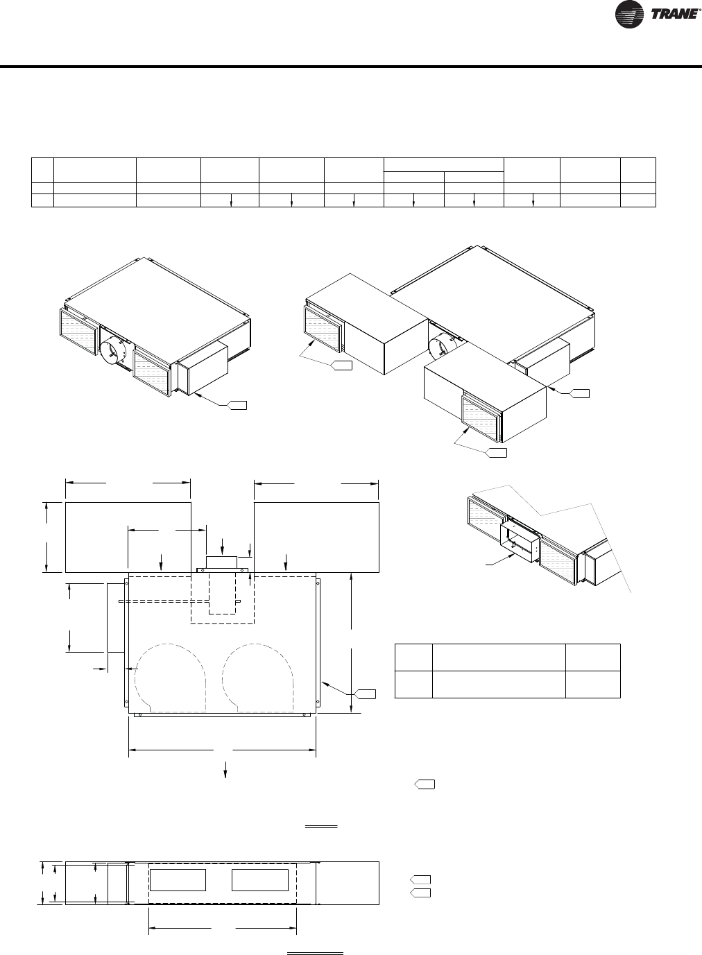
VAV-PRC012-EN 135
Dimensional Data
5. Heating coil uninsulated. External insulation may be field
supplied and installed as required.
NOTES:
1. Allow a minimum 6" (152 mm) plenum inlet clearance for
unducted installations.
2. Filter location with optional Attenuator.
3. Attenuator-factory assembled, field installed.
4. Air valve centered between top and bottom panel.
LOW-HEIGHT SERIES COOLING (LSCF) FAN SIZE 10SQ
36.00" (914 mm)
11.00" (279 mm) 48.00" (1219 mm) 10.00" (254 mm)
38.00" (965 mm)
6. All high & low voltage controls have same-side NEC jumback
clearance. (Left-hand shown, right-hand/mirror image optional.)
Airflow
Plenum Inlet
Field Installed
Optional Attenuator
Field Installed
Optional Attenuator
Field Installed
Optional Attenuator
Field Installed
Optional Attenuator
L
H
2.
2.
A
TOP VIEW
DISCHARGE VIEW
32.00"
(813 mm) (813 mm)
32.00"
B
Rectangular Damper Detail
Rectangular Damper
(203 mm x 356 mm)
8" x 14"
(457 mm)
18.00"
DISCHARGE DIMENSIONS
10SQ
10SQ
SIZE
FAN HW L
A
4.00" (102 mm)
BC
20.00" (508 mm)
17.50" (445 mm)
D
UNIT WT
(kg)
WT LBS
Primary
Airflow
C
D
Plenum Inlet
Airflow
Airflow
Discharge Outlet
W
NOMINAL Ø (INCHES)
8 x 14
8
INLET SIZE
AVAILABILITY NOMINAL Ø (mm)
203
203 x 356
AVAILABILITY
INLET SIZE
(254 mm x 406 mm x 25 mm)
Fan Size
10SQ
Atten Wt
Filter Size
10" x 16" x 1"
(kg)
Lbs
8. Control box enclosure provided with all control types.
9. Flange adds 2" to width and length of unit.
7. Bottom Access panel standard.
Fan Controls located in Enclosure
Actuator, Controller and
8.
Fan Controls located in Enclosure
Actuator, Controller and
8.
(127 mm)
5.00"
17.50"
(445 mm)
(267 mm)
10.50"
120 (54)
20 (9)
130 (59)
9.
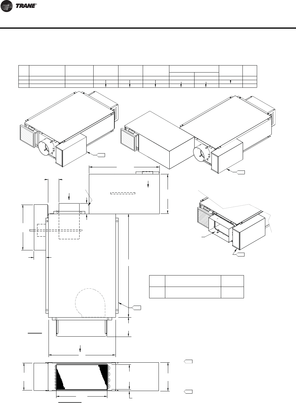
136 VAV-PRC012-EN
Dimensional Data
Airflow
Primary
Plenum Inlet
Airflow
DISCHARGE VIEW
DISCHARGE DIMENSIONS
18.00" (457 mm)
127, 152, 203
SIZE
FAN
09SQ
08SQ 5, 6, 8 26.00" (660 mm)
11.00" (279 mm)
HW
40.00" (1016 mm)
L
10.00" (254 mm)
ABD
Unit Wt
Lbs
(kg)
Discharge Outlet
Airflow
TOP VIEW
09SQ
6, 8 152, 203
8 x 14 203 x 355
Air
Valve
Field Installed
Optional Attenuator
Rectangular Damper Detail
W
H
L
Field Installed
Optional Attenuator
A
B
Rectangular Damper
(203 mm x 356 mm)
8" x 14"
D
4.00" (102 mm)
4.50" (114 mm)
1.00"
(25 mm)
LOW-HEIGHT SERIES HOT WATER (LSWF) FAN SIZES 08SQ & 09SQ
Water
Coil
INLET SIZEINLET SIZE
AVAILABILITY
NOMINAL Ø (INCHES)
AVAILABILITY NOMINAL Ø (mm)
32.00"
(813 mm)
(457 mm)
18.00"
(254 mm x 254 mm x 25 mm)
08SQ
09SQ
Fan Size
Atten Wt
10" x 10" x 1"
Filter Size (kg)
Lbs
NOTES:
1. Allow a minimum 6" (152 mm) plenum inlet clearance for
unducted installations.
2. Flanged discharge outlet accepts up to a 1" (25 mm)
duct flange.
3. Bottom Access panel standard.
4. Control box enclosure provided with all control types.
5. Air valve centered between top and bottom panel.
6. Heating coil uninsulated. External insulation may be field
supplied and installed as required.
7. All high & low voltage controls have same-side NEC
jumpback clearance. (Left-hand shown, right-hand/mirror
image optional.)
8. Flange adds 2" to width and length of unit.
Fan Controls located in Enclosure
Actuator, Controller and
4.
Fan Controls located in Enclosure
Actuator, Controller and
4.
Fan Controls located in Enclosure
Actuator, Controller and
4.
(445 mm)
17.50"
(127 mm)
5.00"
10.50"
(267 mm)
6.80"
(173 mm)
10 (4.5)
114 (52)
105 (48)
95 (43)
4.00
(102 mm)
Valve 5"
6.50"
(165 mm)
8.
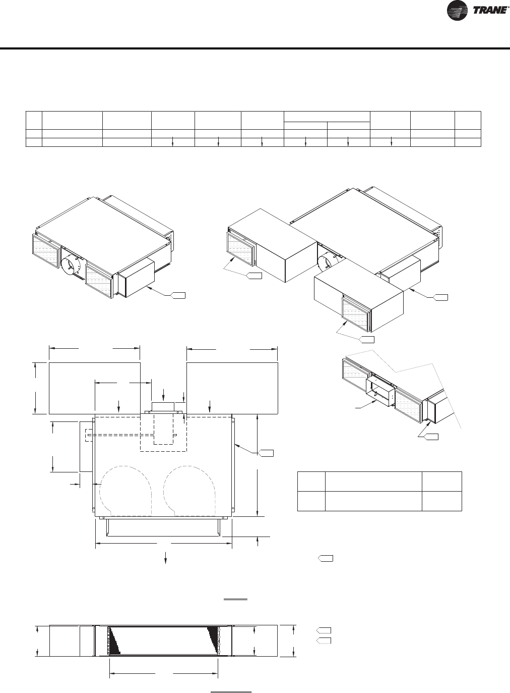
VAV-PRC012-EN 137
Dimensional Data
5. Heating coil uninsulated. External insulation may be field
supplied and installed as required.
NOTES:
1. Allow a minimum 6" (152 mm) plenum inlet clearance for
unducted installations.
2. Filter location with optional Attenuator.
3. Attenuator-factory assembled, field installed.
4. Air valve centered between top and bottom panel.
LOW-HEIGHT SERIES HOT WATER (LSWF) FAN SIZE 10SQ
6. All high & low voltage controls have same-side NEC
jumpback clearance. (Left-hand shown, right-hand/mirror
image optional.)
Field Installed
Optional Attenuator
Field Installed
Optional Attenuator
Field Installed
Optional Attenuator
Field Installed
Optional Attenuator
L
2.
2.
A
(173 mm)
6.80"
TOP VIEW
DISCHARGE VIEW
32.00"
(813 mm) (813 mm)
32.00"
Rectangular Damper Detail
Rectangular Damper
(203 mm x 356 mm)
8" x 14"
(457 mm)
18.00"
W
Discharge Outlet
Airflow
Plenum Inlet
Airflow
DAirflow
Primary
Plenum Inlet
Airflow
FAN
10SQ
10SQ
SIZE
36.00" (914 mm)
11.00" (279 mm)
H
48.00" (1219 mm)
WDISCHARGE DIMENSIONS
LABD
4.00" (102 mm)
C
UNIT WT
(kg)
WT LBS
38.00" (965 mm) 10.00" (254 mm)
NOMINAL Ø (INCHES)
8 x 14
8
INLET SIZE
AVAILABILITY NOMINAL Ø (mm)
AVAILABILITY
203 x 356
203
INLET SIZE
(445 mm)
(127 mm)
5.00"
17.50"
BH
C
Actuator, Controller and
Fan Controls located in Enclosure
8.
Actuator, Controller and
Fan Controls located in Enclosure
8.
Actuator, Controller and
Fan Controls located in Enclosure
8.
(267 mm)
10.50"
8. Control box enclosure provided with all control types.
9. Flange adds 2" to width and length of unit.
7. Bottom Access panel standard.
20.00" (508 mm)
17.50" (445 mm) 146 (66)
136 (62)
10" x 16" x 1"
(254 mm x 406 mm x 25 mm)
10SQ
Fan Size
20 (9)
Filter Size Lbs
(kg)
Atten Wt
9.
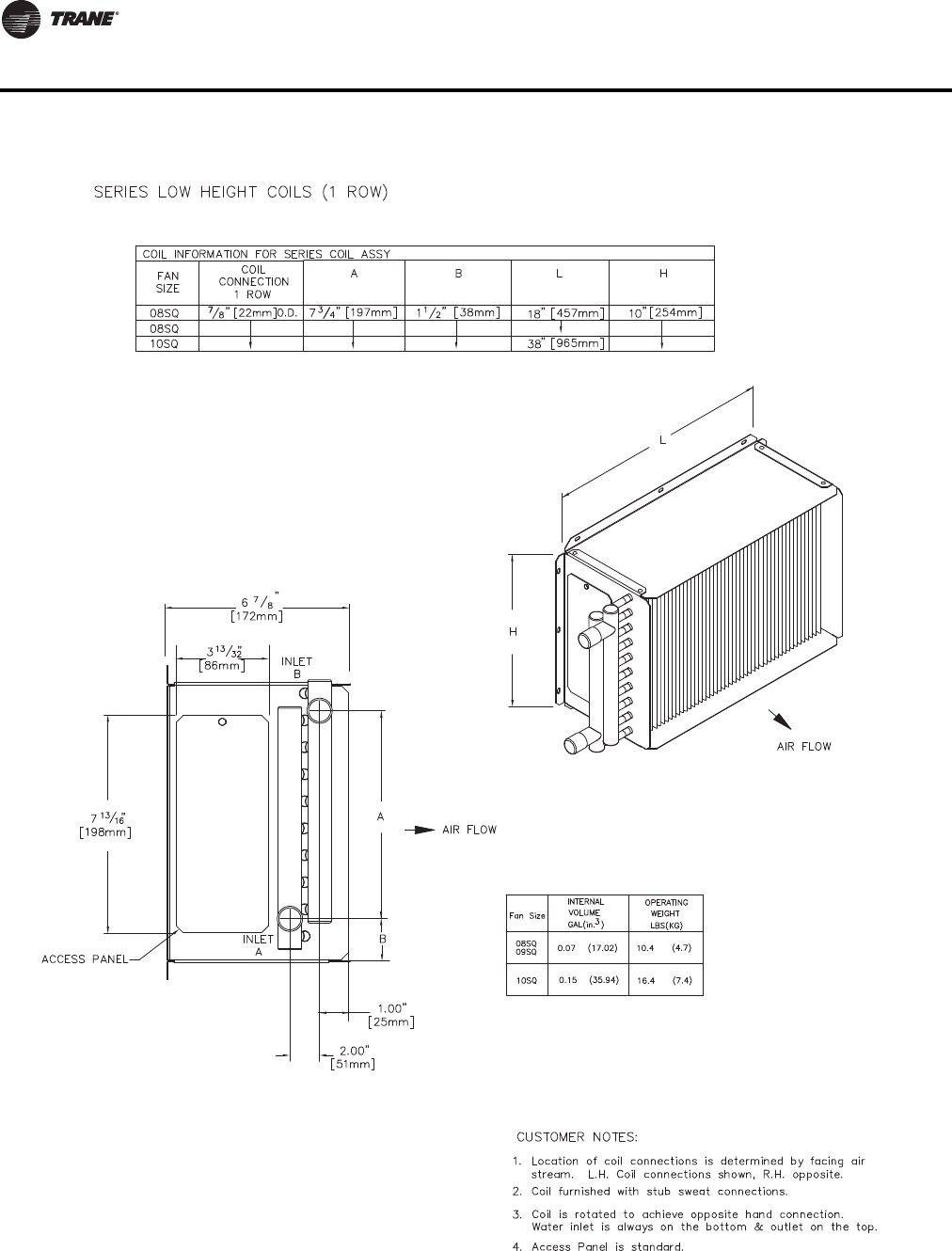
138 VAV-PRC012-EN
Dimensional Data
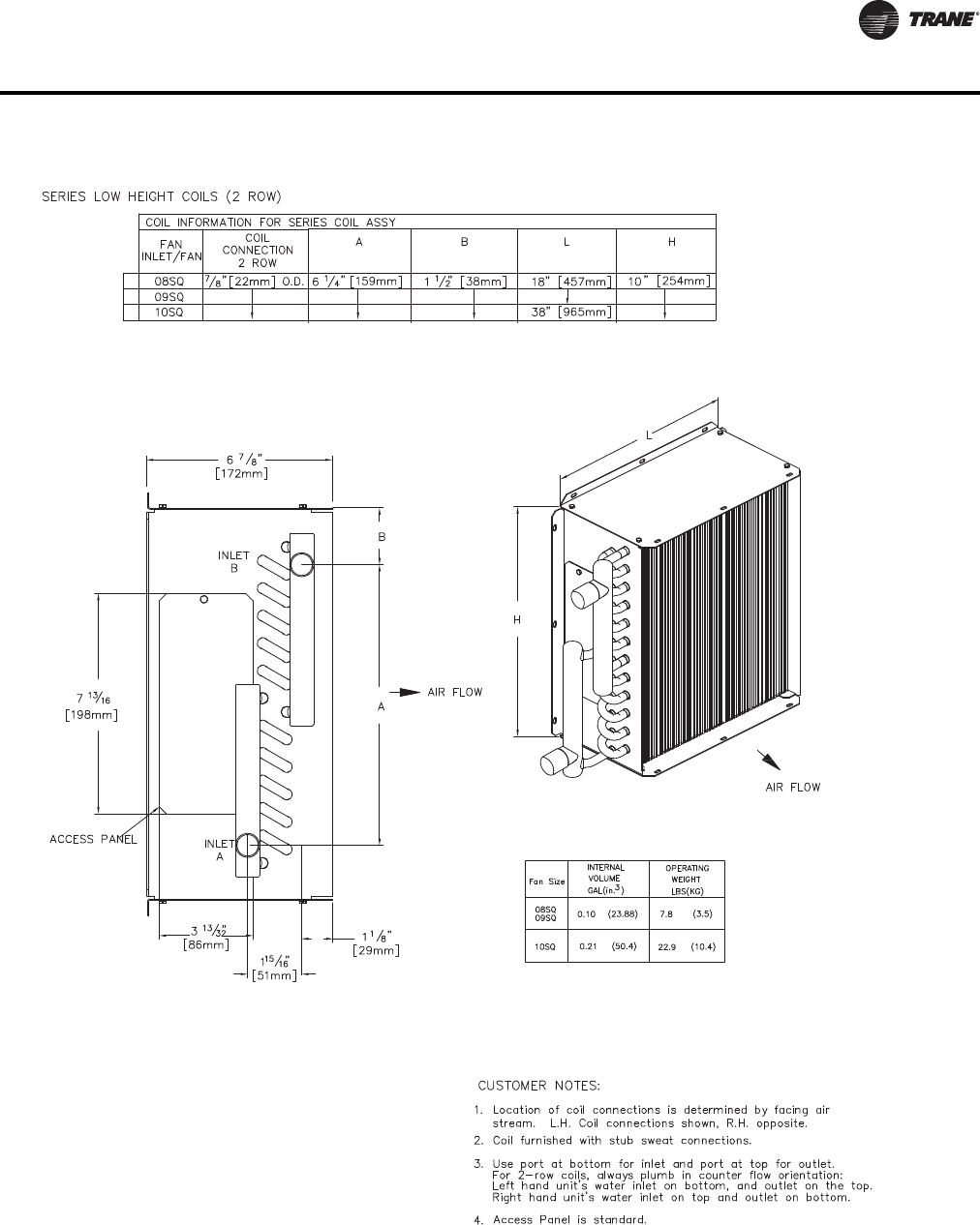
VAV-PRC012-EN 139
Dimensional Data
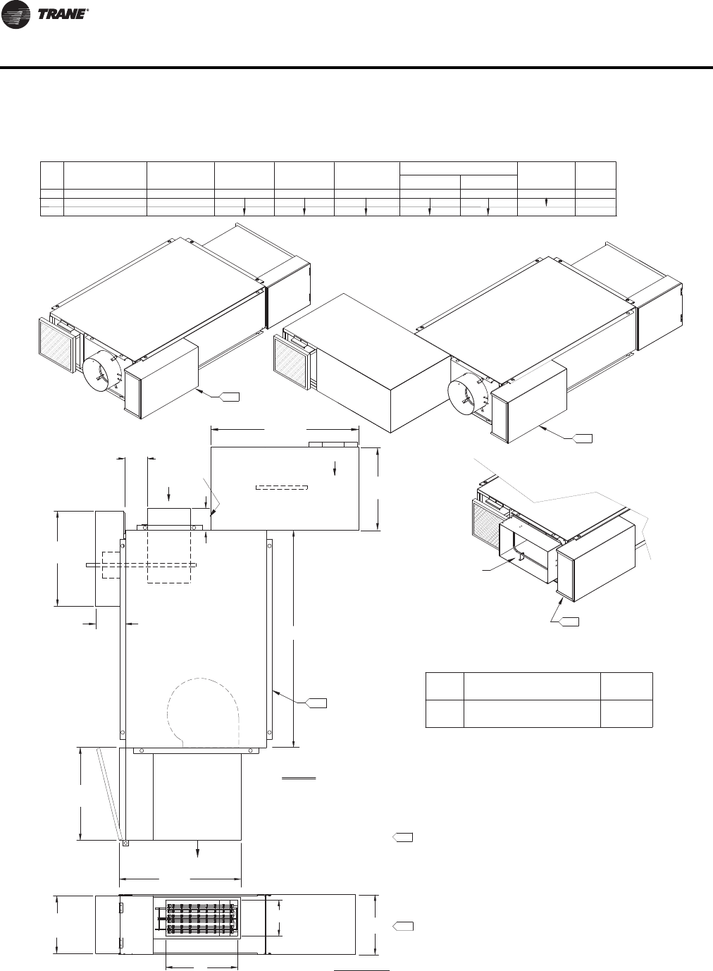
140 VAV-PRC012-EN
Dimensional Data
Airflow
Primary
Plenum Inlet
Airflow
LOW-HEIGHT SERIES ELECTRIC HEAT (LSEF) FAN SIZES 08SQ & 09SQ
DISCHARGE VIEW
DISCHARGE DIMENSIONS
14.00" (356 mm)
127, 152, 203
SIZE
FAN
09SQ
08SQ 5, 6, 8 26.00" (660 mm)11.00" (279 mm)
HW
40.00" (1016 mm)
L
9.00" (229 mm)
ABD
Unit Wt
Lbs
(kg)
10" x 10" x 1"
(254 mm x 254 mm x 25 mm)
Fan Size
08SQ
Filter Size
TOP VIEW
09SQ
6, 8 152, 203
8 x 14 203 x 355
Air
Valve
Field Installed
Optional Attenuator
Rectangular Damper Detail
H
L
Field Installed
Optional Attenuator
B
09SQ
Rectangular Damper
(203 mm x 356 mm)
8" x 14"
D
4.00" (102 mm)
4.50" (114 mm)
Discharge Outlet
Airflow
Electric
Heater
A
NOMINAL Ø (INCHES)
AVAILABILITY
INLET SIZE
NOMINAL Ø (mm)
AVAILABILITY
INLET SIZE
Atten Wt
(kg)
Lbs
(813 mm)
32.00"
(457 mm)
18.00"
Actuator, Controller and
Fan Controls located in Enclosure
4.
Actuator, Controller and
Fan Controls located in Enclosure
4.
Actuator, Controller and
Fan Controls located in Enclosure
4.
NOTES:
1. Allow a minimum 6" (152 mm) plenum inlet clearance for unducted installations.
2. Flanged discharge outlet accepts up to 1" (25 mm) duct flange.
3. Bottom Access panel standard.
4. Control box enclosure provided with all control types.
5. Air valve centered between top and bottom panel.
6. Heating coil uninsulated. External insulation may be field supplied and
installed as required.
7. All hight & low voltage controls have same-side NEC jumpback clearance.
(Left-hand shown, right-hand/mirror image optional.)
8. Flange adds 2" to width and length of unit.
20.00"
(508 mm)
(508 mm)
20.00"
17.50"
(445 mm)
(127 mm)
5.00"
(267 mm)
10.50"
101 (45.8)
111 (50.3)
120 (54.4)
10 (4.5)
4.00
(102 mm)
Valve 5"
6.50"
(165 mm)
8.
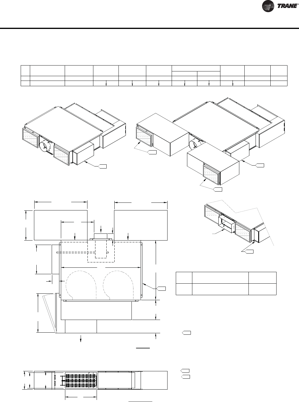
VAV-PRC012-EN 141
Dimensional Data
5. Heating coil uninsulated. External insulation may be field supplied
and installed as required.
NOTES:
1. Allow a minimum 6" (152 mm) plenum inlet clearance for
unducted installations.
2. Filter location with optional Attenuator.
3. Attenuator-factory assembled, field installed.
4. Air valve centered between top and bottom panel.
LOW-HEIGHT SERIES ELECTRIC (LSEF) FAN SIZE 10SQ
6. All high & low voltage controls have same-side NEC jumpback
clearance. (Left-hand shown, right-hand/mirror image optional.)
Airflow
Plenum Inlet
Field Installed
Optional Attenuator
Field Installed
Optional Attenuator
Field Installed
Optional Attenuator
Field Installed
Optional Attenuator
L
W
H
(279 mm)
11.00"
Discharge Outlet
Airflow
Heater
Terminal Box
2.
2.
24.00"
(610 mm)
A
(203 mm)
8.00"
TOP VIEW
DISCHARGE VIEW
32.00"
(813 mm) (813 mm)
32.00"
B
Plenum Area
18.00"
(457 mm)
Rectangular Damper Detail
(203 mm x 356 mm)
Rectangular Damper
8" x 14"
SIZE
10SQ
10SQ
FAN DISCHARGE DIMENSIONS
LWH
36.00" (914 mm)
48.00" (1219 mm)
11.00" (279 mm)
ACD
WT LBS
4.00" (102 mm)
B(kg)
UNIT WT
19.00" (483 mm) 9.50" (241 mm)
C
Airflow
Primary
D
Airflow
Plenum Inlet
NOMINAL Ø (mm)
INLET SIZE
NOMINAL Ø (INCHES)
8 x14
AVAILABILITY
8
AVAILABILITY
203 x 356
203
INLET SIZE
8. Control box enclosure provided with all control types.
9. Flange adds 2" to width and length of unit.
7. Bottom Access panel standard.
Fan Controls located in Enclosure
Actuator, Controller and
8.
Fan Controls located in Enclosure
Actuator, Controller and
8.
Fan Controls located in Enclosure
Actuator, Controller and
8.
(254 mm x 406 mm x 25 mm)
Fan Size
10SQ
Atten Wt (Qty 2)
Filter Size
10" x 16" x 1"
(kg)
Lbs
20.00" (508 mm)
17.50" (445 mm)
(127 mm)
5.00"
17.50"
(445 mm)
(267 mm)
10.50"
145 (65.8)
155 (70.3)
20 (9.1)
9.

142 VAV-PRC012-EN
Mechanical Specifications: Fan-Powered
MODELS: VPCF, VPWF, VPEF, VSCF, VSWF, VSEF, LPCF, LPWF, LPEF,
LSCF, LSWF, & LSEF
VP, LP = Parallel Fan Powered Units
VS, LS = Series Fan Powered Units
Note: L = Low Height
Model Break Downs
• VPCF, VSCF, LPCF, & LSCF = Cooling Only
• VPWF, VSWF, LPWF, & LSWF = With Hot Water Coil
• VPEF, VSEF, LPEF, & LSEF = With Electric Coil
CASING
22-gage galvanized steel. Hanger brackets, side access (standard height - V model numbers) or
bottom access (low height - L model numbers), and plenum filter are provided as standard.
AGENCY LISTING
The unit is UL and Canadian UL Listed as a room air terminal unit. Control # 9N65.
AHRI 880 Certified.
INSULATION
1/2" (12.7 mm) Matte-faced Insulation—. The interior surface of the unit casing is
acoustically and thermally lined with ½-inch, 1.5 lb/ft3 (12.7 mm, 24.0 kg/m3) composite density
glass fiber with a high-density facing.The insulation R-Value is 1.9.The insulation is UL listed and
meets NFPA-90A and UL 181 standards.There are no exposed edges of insulation (complete metal
encapsulation).
1" (25.4 mm) Matte-faced Insulation—. The interior surface of the unit casing is acoustically
and thermally lined with 1 inch, 1.0 lb/ft3 (25.4 mm, 16.0 kg/m3) composite density glass fiber with
a high-density facing.The insulation R-Value is 3.85.The insulation is UL listed and meets NFPA-
90A and UL 181 standards.There are no exposed edges of insulation (complete metal
encapsulation).
1" (25.4 mm) Foil-faced Insulation—. The interior surface of the unit casing is acoustically and
thermally lined with 1-inch, 1.5 lb/ft3 (25.4 mm, 24.0 kg/m3) density glass fiber with foil facing.The
insulation R-Value is 4.1.The insulation is UL listed and meets NFPA-90A and UL 181 standards as
well as bacteriological standard ASTM C 665.There are no exposed edges of insulation (complete
metal encapsulation).
1" (25.4 mm) Double-wall Insulation—. The interior surface of the unit casing is acoustically
and thermally lined with a 1-inch, 1.0 lb./ft3 (25.4 mm, 16.0 kg/m3) composite density glass fiber
with high-density facing.The insulation R-value is 3.8.The insulation is UL listed and meets NFPA-
90A and UL 181 standards.The insulation is covered by an interior liner made of 26-gage galvanized
steel. All wire penetrations are covered by grommets.There are no exposed edges of insulation
(complete metal encapsulation).
3/8" (9.5 mm) Closed-cell Insulation—. The interior surface of the unit casing is acoustically
and thermally lined with 3/8-inch, 4.4 lb/ft3 (9.5 mm, 70.0 kg/m3) closed-cell insulation.The
insulation is UL listed and meets NFPA-90A and UL 181 standards.The insulation has an R-Value
of 1.4.There are no exposed edges of insulation (complete metal encapsulation).
PRIMARY AIR VALVE
Air Valve Round—. The primary air inlet connection is an 18-gage galvanized steel cylinder sized
to fit standard round duct.A multiple-point, averaging flow sensing ring is provided with balancing
VAV-PRC012-EN 143
Mechanical Specifications: Fan-Powered
taps for measuring +/-5% of unit cataloged airflow. An airflow-versus-pressure differential
calibration chart is provided.The damper blade is constructed of a closed-cell foam seal that is
mechanically locked between two 22-gage galvanized steel disks.The damper blade assembly is
connected to a cast zinc shaft supported by self-lubricating bearings.The shaft is cast with a
damper position indicator.The valve assembly includes a mechanical stop to prevent over-
stroking. At 4 in. wg, air valve leakage does not exceed 1% of cataloged airflow.
Air Valve Rectangular. —Inlet collar is constructed of 22-gage galvanized steel sized to fit
standard rectangular duct. An integral multiple-point, averaging flow-sensing ring provides
primary airflow measurement within +/-5% of unit cataloged airflow. Damper is 22-gage galvanized
steel.The damper blade assembly is connected to a solid metal shaft supported by self-lubricating
bearings.The shaft is cast with a damper position indicator.The valve assembly includes a
mechanical stop to prevent over-stroking. At 3.0 in. wg, air valve leakage does not exceed 44 cfm
(21 L/s).
Attenuators
The attenuator is 22-gage galvanized steel with an internal acoustical liner. Attenuators have been
tested in accordance with AHRI 880 standards.
Fan Motor
PSC—. Single-speed, direct-drive, permanent split capacitor type.Thermal overload protection
provided. Motors will be designed specifically for use with an open SCR. Motors will accommodate
anti-backward rotation at start up. Motor and fan assembly are isolated from terminal unit.
ECM—. Electrically Commutated Motor is designed for high-efficient operation with over 70%
efficiency throughout the operating range.
FAN SPEED CONTROL
Variable Speed Control Switch (SCR)—. The SCR speed control device is provided as
standard and allows the operator infinite fan speed adjustment.
Transformer
The 50-VA transformer is factory-installed in the fan control box to provide 24 VAC for controls.
Disconnect Switch
A toggle disconnect is provided as standard and allows the operator to turn the unit on or off by
toggling to the appropriate setting.This switch breaks both legs of power to the fan and the
electronic controls (if applicable)
Note: Not provided on Low Height units with pneumatic controls.
Table 135. Fan-inlet combinations
Inlet
VPXF LSXF
02SQ 03SQ 04SQ 05SQ 06SQ 07SQ 08SQ 09SQ 10SQ
5" X X
6" X X XX
8" X X X X X
10" X X X X X X
12" X X X X X
14" X X X X
16" XX
8 x 14" XX

144 VAV-PRC012-EN
Mechanical Specifications: Fan-Powered
Outlet Connection
Flanged Connection—Rectangular opening on unit discharge to accept 90° flanged ductwork
connection.
Filter
A 1" (25 mm) filter is provided on the plenum inlet and attaches to the unit with a filter frame.
Hot Water Coil
Parallel Water Coils—. factory- installed on the plenum inlet.The coil has 1-row with 144
aluminum-plated fins per foot (.305 m), and if needed 2-row with 144 aluminum-plated fins per foot
(.305 m). Full fin collars provided for accurate fin spacing and maximum fin-tube contact.The 3/
8" (9.5 mm) OD seamless copper tubes are mechanically expanded into the fin collars. Coils are
proof tested at 450 psig (3102 kPa) and leak tested at 300 psig (2068 kPa) air pressure under water.
Coil connections are brazed.
Series Water Coils. —factory-installed on the fan discharge.The coil has 1-row with 144
aluminum-plated fins per foot (.305 m) and, if needed, 2-row with 144 aluminum-plated fins per foot
(.305 m). Full fin collars provided for accurate fin spacing and maximum fin-tube contact.The 3/
8" (9.5 mm) OD seamless copper tubes are mechanically expanded into the fin collars. Coils are
proof tested at 450 psig (3102 kPa) and leak tested at 300 psig (2068 kPa) air pressure under water.
Coil connections are brazed. Gasketed access panels, which are standard, are attached with screws.
Electric Heat Coil
The electric heater is a factory-provided and installed, UL recognized resistance open-type heater.
It also contains a disc-type automatic pilot duty thermal primary cutout, and manual reset load
carrying thermal secondary device. Heater element material is nickel-chromium.The heater
terminal box is provided with 7/8" (22 mm) knockouts for customer power supply.Terminal
connections are plated steel with ceramic insulators. All fan-powered units with electric reheat are
single-point power connections.
Electric Heat Options
Silicon-Controlled Rectifier (SCR). Optional electric heat control that provides modulation.
Magnetic Contactor. Optional electric heater 24V contactor for use with direct digital controls.
Mercury Contactor. Optional electric heater 24V contactor for use with direct digital controls.
P.E. Switch with Magnetic Contactor. This optional switch and magnetic contactor is for use
with pneumatic controls.
P.E. Switch with Mercury Contactor. This optional switch and mercury contactor is for use
with pneumatic controls.
Airflow Switch. Optional air pressure device designed to disable heater when system fan is off.
Power Fuse. If a power fuse is chosen with a unit containing electric heat, then a safety fuse is
located in the electric heater’s line of power to prevent power surge damage to the electric heater.
Any electric heat unit with a calculated MCA greater than or equal to 30 will have a fuse provided.
Disconnect Switch. A standard factory-provided door interlocking disconnect switch on the
heater control panel disengages primary voltage to the terminal.
Unit Controls Sequence Of Operation
Parallel
The unit controller continuously monitors the zone temperature against its setpoint and varies the
primary airflow as required to meet zone setpoints. Airflow is limited by minimum and maximum

VAV-PRC012-EN 145
Mechanical Specifications: Fan-Powered
position set points. For a parallel unit, the controller will intermittently start the fan upon a call for
heat. Upon a further call for heat, reheat is enabled.
1. Primary Airflow—The fan energizes when primary airflow drops below the fan setpoint airflow.
The fan automatically starts when the zone temperature drops to the heating temperature
setpoint.
2. ZoneTemperature—The fan energizes when the zone temperature drops to a selectable
number of degrees above the heating temperature setpoint.
Series
The controller will start and run the fan continuously during the occupied mode and intermittently
during the unoccupied mode. Upon a further call for heat, any hot water or electric heat associated
with the unit is enabled.
Direct Digital Controls
DDC Actuator—. Trane 3-wire, 24-VAC, floating-point quarter turn control actuator with linkage
release button. Actuator has a constant drive rate independent of load, a rated torque of 35 in-lb,
a 90-second drive time, and is non-spring return.Travel is terminated by end stops at fully-opened
and -closed positions. An integral magnetic clutch eliminates motor stall.
DDC Actuator - Belimo — LMB24-3-TTN 3-wire, 24VAC/DC, floating-point, quarter turn actuator
with linkage release button. Actuator has a constant drive rate independent of load, a rated torque
of 45 in-lb, a 95 second drive time, and is non-spring return.Travel is terminated by end stops at
fully-opened and -closed positions. Internal electronic control prevents motor stall when motor
reaches end stops.
Direct Digital Controller—. The microprocessor-based terminal unit controller provides
accurate, pressure-independent control through the use of a proportional integral control
algorithm and direct digital control technology.The controller, named the Unit Control Module
(UCM), monitors zone temperature setpoints, zone temperature and its rate of change, and valve
airflow using a differential pressure signal from the pressure transducer. Additionally, the
controller can monitor either supply duct air temperature or CO2 concentration via appropriate
sensors.The controller is provided in an enclosure with 7/8" (22 mm) knockouts for remote control
wiring. ATrane UCM zone sensor is required.
DDC Zone Sensor—. The UCM controller senses zone temperature through a sensing element
located in the zone sensor. In addition to the sensing element, zone sensor options may include an
externally-adjustable setpoint, communications jack for use with a portable edit device, and an
override button to change the individual controller from unoccupied to occupied mode.The
override button has a cancel feature that will return the system to unoccupied.Wired zone sensors
utilize a thermistor to vary the voltage output in response to changes in the zone temperature.
Wiring to the UCM controller must be 18- to 22-awg. twisted pair wiring.The setpoint adjustment
range is 50–88ºF (10–31°C). Depending upon the features available in the model of sensor selected,
the zone sensor may require from a 2-wire to a 5-wire connection.Wireless zone sensors report the
same zone information as wired zone sensors, but do so using radio transmitter technology.
Therefore with wireless, wiring from the zone sensor to the UCM is unnecessary.
Digital Display Zone Sensor with Liquid Crystal Display (LCD)—. The digital display zone
sensor contains a sensing element, which sends a signal to the UCM.A Liquid Crystal Display (LCD)
displays setpoint or space temperature. Sensor buttons allow the user to adjust setpoints, and
allow space temperature readings to be turned on or off.The digital display zone sensor also
includes a communication jack for use with a portable edit device, and an override button to change
the UCM from unoccupied to occupied.The override button has a cancel feature, which returns the
system to unoccupied mode.
Trane LonTalk/BACnet—. The controller is designed to send and receive data using LonTalk or
BACnet. Current unit status conditions and setpoints may be monitored and/or edited from any of
several LonTalk or BACnet compatible system-level controllers.

146 VAV-PRC012-EN
Mechanical Specifications: Fan-Powered
Pneumatic Controls
Normally Open Actuator—. Pneumatic 3 - 8 psig (20 - 55 kPa) spring-range pneumatic actuator.
3011 Pneumatic Volume Regulator (PVR)—. The regulator is a thermostat reset velocity
controller, which provides consistent air delivery within 5% of cataloged flow down to 18% of unit
cataloged cfm, independent of changes in system static pressure. Factory-calibrated, field-
adjustable setpoints for minimum and maximum flows. Average total unit bleed rate, excluding
thermostat, is 28.8 scim at 20 psig (7.87 ml/min at 138 kPa) supply.
UNIT OPTIONS
Power Fuse (VPCF, VPWF)—. Optional fuse is factory-installed in the primary voltage hot leg.
HOT WATER VALVES
Two-Position Valve—. The valve is a field-adaptable, 2-way or 3-way configuration and ships
with a cap to be field-installed when configured as a 2-way valve.All connections are National Pipe
Thread (NPT).The valve body is forged brass with a hard chrome-plated brass stem. Upon demand,
the motor strokes the valve.When the actuator drive stops, a spring returns the valve to its fail-safe
position.The valves come with a manual operating lever that allows for the valve to be opened for
system flushing. It will reset to normal position the first time the valve is cycled.
Flow Capacity – 4.0 Cv
Overall Diameter – ½" NPT
Close-off Pressure – 30 psi (207 kPa)
Flow Capacity – 5.0 Cv
Overall Diameter – 3/4" NPT
Close-off Pressure – 14.5 psi (100 kPa)
Flow Capacity – 8.0 Cv
Overall Diameter – 1" NPT
Close-off Pressure – 9 psi (62 kPa)
Maximum Operating FluidTemperature – 200 deg F (95ºC)
Maximum system pressure – 300 psi (2067 kPa)
Maximum static pressure – 300 psi (2067 kPa)
Electrical Rating – 7 VA at 24 VAC, 6.5 Watts, 50/60 Hz
18" wire leads are provided on each valve.
Proportional Water Valve—The valve is a field-adaptable, 2-way or 3-way configuration and
ships with a plug in B port.This configures the valve for 2-way operation. For 3-way operation,
remove the plug.The intended fluid is water or water and glycol (50% maximum glycol).The
actuator is a synchronous motor drive.The valve is driven to a predetermined position by the UCM
controller using a proportional plus integral control algorithm. If power is removed, the valve stays
in its last position.The actuator is rated for plenum applications under UL 2043 and UL 873
standards.
Pressure andTemperature Ratings –The valve is designed and tested in full compliance with ANSI
B16.15 Class 250 pressure/temperature ratings, ANSI B16.104 Class IV control shutoff leakage, and
ISA S75.11 flow characteristic standards.
Flow Capacity – 0.70 Cv, 2.7 Cv, 6.60 Cv, 8.00 Cv
Overall Diameter – ½" NPT
Maximum Allowable Pressure – 300 psi (2068 kPa)
Maximum Operating FluidTemperature – 201ºF (94°C)
Maximum Close-off Pressure – 60 psi (0.4 MPa)
Electrical Rating – 3VAat24VAC
8” plenum rated cable with AMP Mate-N-Lok connector

VAV-PRC012-EN 147
DDC Controls
Control Logic
DDC controllers are today’s industry standard. DDC controllers provide system-level data used to
optimize system performance. Variables such as occupied/unoccupied status, minimum and
maximum airflow setpoints, temperature and temperature setpoints, valve position, fan status (on
or off, and mode of operation: series or parallel), reheat status (on or off), box type and air valve
size, temperature correction offsets, flow correction values, ventilation fraction, etc. are available
on a simple twisted-shielded wire pair.
Trane DDC controllers provideTrane-designed, solid-state electronics intended specifically forVAV
temperature control in space comfort applications. DDC control capabilities include:
• Proportional plus integral control loop algorithm for determining required airflow needed to
control room temperature. Airflow is limited by active minimum and maximum airflow
setpoints.
• Pressure-independent (PI) operation, which automatically adjusts valve position to maintain
required airflow. In certain low-flow situations or in cases where the flow measurement has
failed, the DDC controller will operate in a pressure-dependent (PD) mode of operation.
• Cooling and heating control action of air valve. In cooling control action, the DDC controller
matches cooling airflow to cooling load. In heating control action, the DDC controller matches
the heating airflow to control heating load.The DDC controller will automatically change over
to cooling control action if the supply air temperature is below the room temperature and will
automatically change over to heating control action if the supply air temperature is 10°F or more
above the room temperature. If the supply air temperature is between the room temperature
and the room temperature plus 10°F, then the DDC controller will provide the active minimum
airflow.The DDC controller first chooses theTracer™ SC -supplied supply air temperature value
to use for auto changeover. If this is not available, it uses the temperature provided by the
optional auxiliary temperature sensor. If this is also not available, it uses the heating/cooling
mode assigned byTracer SC or the DDC controller’s service tool (Everyware™or Rover™ V4).
• Multiple reheat control options including staged electric, staged hot-water (normally on or
normally off), proportional hot-water, and slow pulsed width modulation. Modulating reheat
options utilize a separate reheat proportional-plus-integral control loop from that controlling
airflow into the room. Staged reheat options utilize a control algorithm based on heating
setpoint and room temperature.
• 24VAC binary input that can be configured as a generic input or as occupancy input.When the
DDC controller is operation withTracer SC, the status of the input is provided toTracer for its
action. In stand-alone operation and when configured for an occupancy input, the input will
control occupancy status of the DDC controller.
• Auxiliary temperature analog input that can be configured for an auxiliary temperature sensor
or a 2-to-10 VDC CO2sensor. When sensor is mounted in the supply air duct and configured for
temperature, the value of the input is used as status-only byTracer SC ifTracer SC is providing
a supply air temperature to the DDC controller. Otherwise, the input will be used for
determining control action of the DDC controller. When configured for a CO2sensor, the value
of the input is used as a status-only input byTracer SC.
• Dual-duct support with two DDC controllers. One DDC controller controls the cooling air valve
and the other controller controls the heating air valve. With constant-volume sequences, the
discharge air volume is held constant by controlling discharge air volume with the heating
UCM.

148 VAV-PRC012-EN
DDC Controls
Note: Flow sensor DP (in. wg) is measured at the flow ring to aid in system balancing and commissioning. See “Valve/Controller
Airflow Guidelines” in each section for unit performance.
DDC Remote Heat Control Options
When heat is added to the primary air atVAV unit before it enters zone, the air is said to be reheated.
Operating characteristics of four basic types of VariTrane DDC terminal reheat are discussed.
Fan-Powered Terminal Units: On/Off Hot Water Reheat
Two stages of on/off hot water reheat are available.The water valves used are 2-position and are
either fully-opened or fully-closed.The heating minimum airflow setpoint is enabled during reheat.
On parallel-configured fan-powered units, the fan is energized when the space temperature falls
below the active fan on/off point (active heating setpoint plus fan offset).The parallel fan is turned
off when the space temperature rises above the active fan on/off point (active heating setpoint plus
fan offset) plus 0.5°F (0.28°C).
Series configured fan-powered terminal units utilize continuous fan operation during all occupied
settings and while unoccupied when minimum airflows are being enforced.
When the zone temperature falls below the active heating setpoint, the UCM modulates the
primary airflow to the minimum heating airflow setpoint.
Stage 1 energizes when the space temperature is below the active heating setpoint, and is de-
energized when the space temperature is 0.5°F (0.28°C) above the active heating setpoint. Stage
2 energizes when the zone temperature is 1°F (0.56°C) or more below the active heating setpoint,
and de-energizes when the space temperature is 0.5°F (0.28°C) below the active heating setpoint.
When reheat is de-energized, the cooling minimum airflow setpoint is activated.
Fan-Powered Terminal Units: Proportional Hot Water Reheat
Proportional hot water reheat uses 3-wire floating-point-actuator technology.The heating
minimum airflow setpoint is enabled during reheat.
On parallel-configured fan-powered units, the fan is energized when the space temperature falls
below the active fan on/off point (active heating setpoint plus fan offset).The parallel fan is turned
off when the space temperature rises above the active fan on/off point (active heating setpoint plus
fan offset) plus 0.5°F (0.28°C).
Figure 6. Flow sensor signal vs. airflow delivery
0.01
0.1
1
5
10 100 1,000 10,000
Cfm
Flow Sensor DP (In. wg)
4" 12"10"8"6"
5" 14" 16"

VAV-PRC012-EN 149
DDC Controls
Series-configured fan-powered terminal units utilize continuous fan operation during all occupied
settings and while unoccupied when minimum airflows are being enforced.
When the zone temperature falls below the active heating setpoint, the UCM modulates the
primary airflow to the minimum heating airflow setpoint.
The water valve opens as space temperature drops below the heating setpoint.The degree to which
the hot water valve opens is dependent on both the degree that space temperature is below the
active heating setpoint and the time that the space temperature has been below the active heating
setpoint. If not already closed, the water valve fully closes when the zone temperature rises above
the active heating setpoint by 0.5 °F (0.28 °C). When reheat is de-energized, the cooling minimum
airflow setpoint is activated.
Fan-poweredTerminal Units: On/Off Electric Reheat
Two stages of staged electric reheat are available.The heating minimum airflow setpoint is enabled
during reheat.
On parallel-configured fan-powered units, the fan is energized when the space temperature falls
below the active fan on/off point (active heating setpoint plus fan offset).The parallel fan is turned
off when the space temperature rises above the active fan on/off point (active heating setpoint plus
fan offset).
Series-configured fan-powered terminal units utilize the continuous fan operation during all
occupied settings and while unoccupied when minimum airflows are being enforced.
When the zone temperature falls below the active heating setpoint, the UCM modulates the
primary airflow to the minimum heating airflow setpoint.
Stage 1 energizes when the space temperature is below the active heating setpoint, and is de-
energized when the space temperature rises 0.5°F (0.28°C) above the active heating setpoint. Stage
2 energizes when the space temperature is 1.0°F (0.56°C) or more below the active heating setpoint,
and is de-energized when the space temperature is 0.5°F (0.28°C) below the active heating setpoint.
When reheat is de-energized, the cooling minimum airflow setpoint is activated.
Fan-poweredTerminal Units: Pulse-Width Modulation of Electric Heat
Electric heat is modulated by energizing for a portion of a three-minute time period.The heating
minimum airflow setpoint is enabled during reheat.This allows exact load matching for energy
efficient operation, and optimum zone temperature control. One or two stages can be used.
On parallel-configured fan-powered units, the fan is energized when the space temperature falls
below the active fan on/off point (active heating setpoint plus fan offset).The parallel fan is turned
off when the space temperature rises above the active fan on/off point (active heating setpoint plus
fan offset) plus 0.5°F (0.28°C).
Series-configured fan-powered terminal units utilize the continuous fan operation during all
occupied settings and while unoccupied when minimum airflows are being enforced. When the
zone temperature falls below the active heating setpoint, the UCM modulates the primary airflow
to the minimum heating airflow setpoint.
The amount of reheat supplied is dependent on both the degree that space temperature is below
the active heating setpoint and the time that the space temperature has been below the active
heating setpoint. If not already off, reheat de-energizes when the space temperature rises 0.5°F
(0.28°C) above the active heating setpoint.The Stage 1 “on” time is proportional to the amount of
reheat required. For example, when 50% of stage 1 capacity is required, reheat is on for 90 seconds
and off for 90 seconds.When 75% of stage 1 capacity is required, reheat is on for 135 seconds and
off for 45 seconds. When 100% of stage 1 capacity is required, reheat is on continuously.
Stage 2 uses the same “on” time logic as stage 1 listed above, except stage 1 is always energized.
For example, when 75% of unit capacity is required, stage 1 is energized continuously, and stage
2 is on for 90 seconds and off for 90 seconds. When reheat is de-energized, the cooling minimum
airflow setpoint is activated. When reheat is de-energized, the cooling minimum airflow setpoint
it activated.
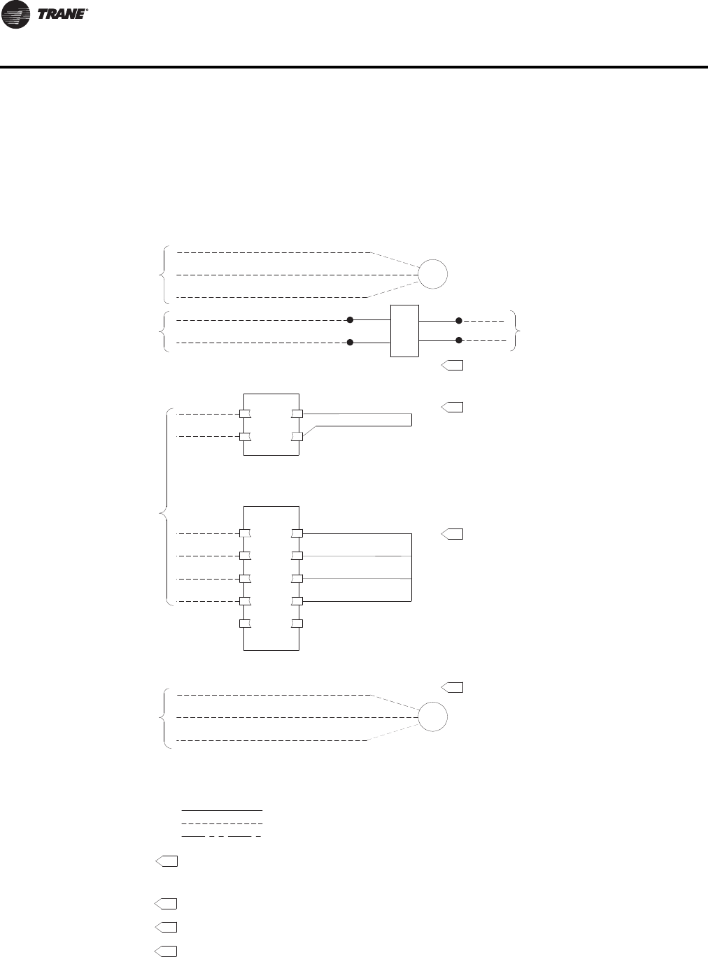
150 VAV-PRC012-EN
DDC Controls
Heat Controls
24-VAC Fan/Staged
2nd
1st
C
Fan
Load: 10 VA (MAGN)
Load: 12 VA (MERC)
Load: 6.5 VA
FAN RELAY
2
1
3
5
4
2
1
HEATER CONTROL BOX
3rd
2
3
4
5.
Damper
Actuator
Line Voltage
CW
COM
CCW
24 VAC, 50 VA
Transformer
Load: 4 VA
24-VAC to
Customer
Controls
By Others
Damper Controls
24-VAC
M
Load: 4 VA
Actuator
Damper
24-VAC
Damper Controls
By Others
COM
CW
CCW
M
Y
BL
NOTES:
1. Factory-installed
Field Wiring
Optional or installed by others
2.
Only available with fan-powered units.
3.
4. Located in HeaterTerminal box.
Only available with dual-duct units.
5.
DD00—Available for all VariTrane Units
(Trane actuator for field-installed DDC controls)
A unit controller is not provided.The air damper actuator is provided with an integral screw terminal block.
The fan contactor (fan-powered units), 24-VAC control power transformer (optional for single- and dual-duct
units), and factory-installed electric heater contactor wires are attached to the outside of the unit for field
connection of controls. A second actuator is provided with an integral screw terminal for dual-duct units.
Located in HeaterTerminal Box for electric heat on single-duct units.
Located in Control Box for cooling only and hot water heat on single-duct units.
Located in Control Box on all fan-powered units.
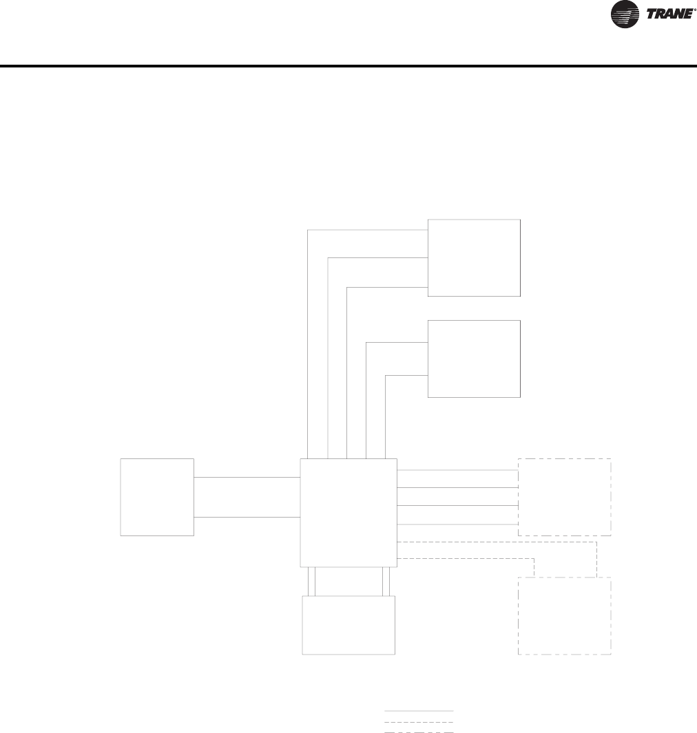
VAV-PRC012-EN 151
DDC Controls
L
O
1st stage
2nd stage
3rd stage
24VAC (hot) common
CCW
COM
CW
24 VAC
Y
BL
24 VAC, 50va
Standard – (Fan-powered)
Optional – (Single-duct and Dual-duct)
Transformer
Customer-furnished
Controller
Electric
Reheat
Contactors
Hot Water
Reheat
Fan
Relay
Actuator Customer-furnished
orTrane-supplied
Trane-supplied
(Fan-powered only)
Trane-supplied
Available on all VariTrane Units
FM00 – Customer-supplied actuator and DDC controller factory-installed.
FM01 –Trane actuator and customer-supplied DDC controller factory-installed
Optional or installed by others
NOTES:
1. Factory-installed
Field Wiring
Optional
Trane-supplied
water valve
field-wired
to controller.
Airflow
Sensor
LO HI Trane-supplied
All customer furnished controllers and actuators are installed and wired per control manufacturer's specifications.
Metal control enclosure is standard.
2. NEMA-1 Enclosure provided.

152 VAV-PRC012-EN
DDC Controls
Tracer™ UC400 and UC210 Programmable BACnet Controllers
Introduction
TheTracer UC400 and UC210 controllers are programmable general purpose BACnet,
microprocessor-based, Direct Digital Controllers (DDC). When factory installed onTrane (Variable
Air Volume) VAV terminal units, it is factory downloaded with appropriate VAV programs and
configuration settings.TraneVAV units have been made with either pneumatic, analog electronic,
or microprocessor controls (DDC VAV).
TheTracer UC400 or UC210 controller can be configured from the factory with three different
application programs: SpaceTemperature Control (STC), Ventilation Flow Control (VFC), and Flow
Tracking Control (FTC).
TheTracer UC400 or UC210 controller programmed for STC modulates a VAV's damper blade
based on a zone temperature, measured airflow, and setpoints to continuously control conditioned
air delivery to the space.The volume of incoming air is monitored and the damper adjusts to
provide accurate control independent of the duct pressure.The damper modulates between
operator setpoints depending on space conditions. Additionally, fan and heat outputs may be
energized depending on the application.
TheTracer UC400 or UC210 controller configured forVFC can be applied to aVAV terminal and used
to temper cold outdoor air (OA) that is brought into a building for ventilation purposes.The
tempered air is intended to supply an air-handling unit (AHU), which provides comfort control to
the zones it is serving.The VAV terminal supplies the correct amount of ventilation air, and when
reheat is added, tempers the ventilation air to reduce the load on the air handler by sensing the
discharge air temperature of the VAV unit and controlling its long-term average to the discharge
air temperature setpoint.
TheTracer UC400 or UC210 controller can be configured for FTC and has twoVAV units withTracer
UC400 controllers working together to provide flow tracking control. OneTracer UC400 or UC210
controller is configured from the factory with the Space temperature program and the other is
downloaded with the FTC program.The STC airflow output is bound to the flow tracking controller
airflow setpoint input.The flow tracking controller adds the configured airflow tracking offset
(positive or negative) to the airflow setpoint (communicated airflow setpoint) and controls the
airflow to this setpoint.
TheTracer UC400 or UC210 controller is BTL compliant with BACnet, an open standard building
automation protocol. It meets the Application Specific Controller (ASC) profile per ASHRAE 135-
2004.This allows theTracer UC400 or UC210 controller to integrate with other BACnet systems.
Available Inputs
Inputs include a twisted/shielded communication link, zone sensor, duct temperature sensors
(optional), Occupancy Sensor (optional), Discharge AirTemperature (DAT) and/or Supply Air
Temperature (SAT), CO2 sensor, and 24 VAC power. In addition to the points used for the VAV
application, the spare inputs and outputs on theTracer UC400 or UC210 controller may be used for
ancillary control, which can be programmed usingTracerTUTracer Graphical Programming 2
(TGP2).
Note: For more information on using spare points, see BAS-SVX20*-ENTracer UC400
Programmable Controller Installation, Operation, and Maintenance.
General Features and Benefits
Assured Accuracy
• Proportional-plus-integral control loop algorithm for determining required airflow needed to
control room temperature. Airflow is limited by active minimum and maximum airflow
setpoints.

VAV-PRC012-EN 153
DDC Controls
• Pressure-independent (PI) operation that automatically adjusts valve position to maintain
required airflow. In certain low-flow situations or in cases where the flow measurement has
failed, the DDC controller will operate in a pressure-dependent (PD) mode of operation.
• When combined with the patentedTrane Flow ring and pressure transducer, flow is repeatable
to +/- 5% accuracy across the Pressure Independent (PI) flow range. (See Valve/Controller
Airflow Guidelines section).
• Improved 2-Point Air Balancing is available – Assures optimized flow-sensing accuracy across
the operating range.This provides a more accurate airflow balancing method when compared
to typical single-point flow correction air balancing.
• Analog input resolution of +/- 1/8°F within the comfort range maximizes zone temperature
control yielding excellent comfort control.
Reliable Operation
• Built for life –Trane products are designed to stand the test of time, with a proven design life
that exceeds 20 years.
• Fully factory tested – fully screened and configured at the factory. All features are tested
including fan and reheat stage energization, air valve modulation, and controller inputs and
outputs.
Safe Operation
• All components, including the controller, pressure transducer, transformer, etc. are mounted
in a NEMA 1 sheet metal enclosure and are tested as an assembly to UL1995 standards.The
result is a rugged and safe VAV, controller, and thus, overall unit.
• When in PI-mode, EH is disabled when the sensed flow is below the minimum required.
• HW coilVAV units in ventilation flow control (VFC) have a Freeze protection algorithm to protect
the water coil and the internal space from water damage.This is accomplished by driving the
water valve to maximum position on alarm conditions.
System-Level Optimization
Trane controllers are designed to integrate intoTracer™ SC and leverage clear and clean unit-
controller related data for system level control decisions. Integrating aTraneVV550 controller into
aTracer SC Control system provides the next step in building system control.
Specifically, system-level decisions on how to operate all components can be made. Energy
efficient optimization strategies like Static Pressure Optimization, Ventilation Reset, and CO2
Demand-controlled Ventilation can be employed with the simple press of a button.The end-result
is the most efficient and reliable building control system available.
Simplified Installation
Factory Commissioned Quality – AllTrane DDC VAV controllers are factory-commissioned.This
means that the DDC boards are powered and run-tested with your specific sequence parameters.
They are connected to a communication link to make sure that information and diagnostic data
function properly. Before any VariTrane VAV unit ships they must pass a rigorous quality control
procedure.You can be assured that aTrane VAV unit withTrane DDC VAV controls will work right
out of the crate.
Zone sensor air balance – When applied to aTrane zone sensor with thumbwheel and on/cancel
buttons, a balancing contractor can drive the primary air valve to maximum or minimum airflow
from the sensor to determine the point of calibration to be used (maximum will result in optimum
performance).The flow reading can then be calibrated from the sensor, without the use of
additional service tools. (Non-LCD versions)
Tenant-Finish Heat Mode – In some office projects, the building is being constructed as tenants are
being identified.Tenant-finish heat mode is designed for applications when a given floor has not
been occupied.The main AHU system is used for heat and because the internal furnishings are not

154 VAV-PRC012-EN
DDC Controls
complete, the sensors have not been installed. In this case, the primary valve drives open using
the heat of the main AHU to keep plumbing lines from freezing. When available, the operation of
the VAV unit fan (series or parallel) remains unaffected.
Controller Flexibility
• 24VAC binary input that can be configured as a generic input or as occupancy input.When the
DDC controller is operating withTracer™ SC, the status of the input is provided toTracer SC
for its action. In stand-alone operation and when configured for an occupancy input, the input
will control occupancy status of the DDC controller.
• Auxiliary temperature analog input configured for an auxiliary temperature sensor.The value
of the input is used as status-only byTracer SC ifTracer SC is providing a supply air temperature
to the DDC controller. Otherwise, the input will be used for determining heating/cooling control
action of theVAV unit.When the auxiliary temperature sensor is located in the discharge of the
unit, and attached to aTraneTracer™ SC BAS, additional test sequencing and reporting is
available to maximize VAV system capabilities and simplify system commissioning.
• Dual-duct support with two DDC controllers. One DDC controller controls the cooling air valve
and the other controller controls the heating air valve. With constant-volume sequences, the
discharge air volume is held constant by controlling discharge air volume with the heating
Controller.
• Tracer™ UC400 Programmable BACnet Controller certified performance ensures that aTrane
VAV with controller will provide state-of-the-art, consistent open communication protocol for
integration with the industry’s latest (Non-Trane) building automation control systems,
including Johnson Control, Andover, Siemans, Honeywell, etc.
•CO
2demand controlled ventilation enables a HVAC system to adjust ventilation flow based on
critical zone, average CO2of specified zones, etc.Trane demand controlled ventilation
strategies are pre-defined for simplified application and can be easily customized to meet the
needs of a specific system.
Trane DDC VAV Controller Logic
Control Logic
Direct Digital Control (DDC) controllers are today’s industry standard. DDC controllers share
system-level data to optimize system performance (including changing ventilation requirements,
system static pressures, supply air temperatures, etc.). Variables available via a simple twisted-
shielded wire pair include occupied/unoccupied status, minimum and maximum airflow setpoints,
zone temperature and temperature setpoints, air valve position, airflow cfm, fan status (on or off),
fan operation mode (parallel or series), reheat status (on or off), VAV unit type, air valve size,
temperature correction offsets, flow correction values, ventilation fraction, etc.
With the advent ofTracer UC400 open protocol, the most reliable VAV controller is now available
for ANY system. Gone are the days of being locked into a single supplier.Trane DDC controllers
provideTrane-designed solid-state electronics intended specifically forVAV applications including:
3. SpaceTemperature Control
4. Ventilation Flow Control (100% outside air applications)
5. FlowTracking Space Pressurization Control (New feature)
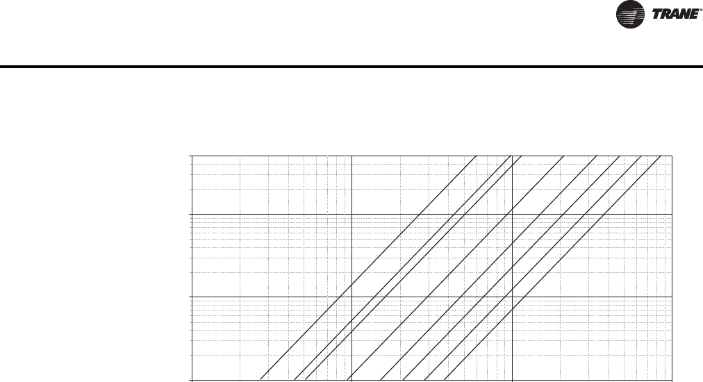
VAV-PRC012-EN 155
DDC Controls
Note: Flow sensor DP (in. wg) is measured at the flow ring to aid in system balancing and commissioning. See “Valve/Controller
Airflow Guidelines” in each section for unit performance.
Space Temperature Control
Space temperature control applications are whereTrane emerged as an industry leader in quality
and reliability.This did not occur overnight and has continued to improve as our controller and
control logic has improved over time. STC employs controller logic designed to modulate the
supply airstream and associated reheat (either local or remote) to exactly match the load
requirements of the space.
Additionally, minimum and maximum airflow and specific controller sequence requirements are
pre-programmed to ensure that appropriate ventilation standards are consistently maintained.
When connected to aTraneTracer™ SC, trend logging, remote alarming, etc. are available to fully
utilize the power and capabilities of your systems.
General Operation-Cooling
In cooling control action, the DDC controller matches primary airflow to cooling load.The DDC
controller will automatically change over to heating control action if the supply air temperature is
above a configured/editable setpoint. When the supply air temperature is less than 10 degrees
below this setpoint, the controller will automatically switch to cooling control action.The DDC
controller first chooses theTracer SC -provided supply air temperature value to use for auto
changeover. If this is not available, it uses the temperature provided by the optional auxiliary
temperature sensor (must be installed for inlet temperature monitoring). If this is also not available,
it uses the heating/cooling mode assigned byTracer Building Automation System or the DDC
controller’s service tool.
General Operation-Reheat
In heating control action, the DDC controller matches primary airflow to heating load.The DDC
controller will automatically change over to heating control action if the supply air temperature is
above a configured/editable setpoint. When the supply air temperature is less than 10 degrees
below this setpoint, the controller will automatically switch to cooling control action.The DDC
controller first chooses theTracer SC -provided supply air temperature value to use for auto
changeover. If this is not available, it uses the temperature provided by the optional auxiliary
temperature sensor (must be installed for inlet temperature monitoring). If this is also not available,
it uses the heating/cooling mode assigned byTracer SC or the DDC controller’s service tool.
Figure 7. Flow sensor single vs. airflow delivery
0.01
0.1
1
5
10 100 1,000 10,000
Cfm
Flow Sensor DP (In. wg)
4" 12"10"8"6"
5" 14" 16"

156 VAV-PRC012-EN
DDC Controls
When heat is added to the primary air, the air is considered reheated. Reheat can be either local
(integral to theVAV unit in the form of an electric coil or hot water coil) or remote (typically existing
wall fin radiation, convector, etc.) or any combination of local and remote.The operating
characteristics of the four basic types of VariTrane DDC terminal reheat are discussed.
Fan-Powered Terminal Units: On/Off Hot Water Reheat
One or two stages of on/off hot water reheat are available.Two position water valves complete the
HW reheat system and are either fully opened or fully closed.The heating minimum airflow
setpoint is enforced during reheat.
On parallel fan-powered units, the fan is energized upon a call for heating.The parallel fan is turned
off when the space temperature rises above the fan on/off point (active heating setpoint plus fan
offset) plus 0.5°F (0.28°C).
Series fan-powered terminal unit fans are continuously energized during occupied mode. When
unoccupied, the fan is energized upon a call for heating or cooling and de-energized when
unoccupied zone set point is satisfied.
When the zone temperature falls below the active heating setpoint, the UCM modulates the
primary airflow to the minimum heating airflow setpoint.
Stage 1 energizes when the space temperature is below the active heating setpoint, and is de-
energized when the space temperature is 0.5°F (0.28°C) above the active heating setpoint. Stage
2 energizes when the zone temperature is 1°F (0.56°C) or more below the active heating setpoint,
and de-energizes when the space temperature is 0.5°F (0.28°C) below the active heating setpoint.
When reheat is de-energized, the cooling minimum airflow setpoint is activated.
Fan-Powered Terminal Units: Proportional Hot Water Reheat
Proportional hot water reheat uses 3-wire floating-point-actuator technology.The heating
minimum airflow setpoint is enforced during reheat.
On parallel fan-powered units, the fan is energized upon a call for heating.The parallel fan is turned
off when the space temperature rises above the fan on/off point (active heating setpoint plus fan
offset) plus 0.5ºF (0.28ºC).
Series fan-powered terminal unit fans are continuously energized during occupied mode. When
unoccupied, the fan is energized upon a call for heating or cooling and de-energized when
unoccupied zone setpoint is satisfied.
The water valve opens as space temperature drops below the heating setpoint. A separate reheat
proportional-plus-integral control loop from that controlling airflow into the room is enforced.The
degree to which the hot water valve opens is dependent on both the degree that the space
temperature is below the active heating setpoint and the time that the space temperature has been
below the active heating setpoint. If not already closed, the water valve fully closes when the zone
temperature rises above the active heating setpoint by 0.5 °F (0.28 °C). When reheat is de-
energized, the cooling minimum airflow setpoint is activated.
Fan-poweredTerminal Units: On/Off Electric Reheat
One or two stages of staged electric reheat are available.The heating minimum airflow setpoint
is enforced during reheat.
On parallel fan-powered units, the fan is energized upon a call for heating.The parallel fan is turned
off when the space temperature rises above the fan on/off point (active heating setpoint plus fan
offset) plus 0.5°F (0.28°C).
Series fan-powered terminal unit fans are continuously energized during occupied mode. When
unoccupied, the fan is energized upon a call for heating or cooling and de-energized when
unoccupied zone set point is satisfied.
Stage 1 energizes when the space temperature is below the active heating setpoint, and is de-
energized when the space temperature rises 0.5°F (0.28°C) above the active heating setpoint. Stage
2 energizes when the space temperature is 1.0°F (0.56°C) or more below the active heating setpoint,

VAV-PRC012-EN 157
DDC Controls
and is de-energized when the space temperature is 0.5°F (0.28°C) below the active heating setpoint.
When reheat is de-energized, the cooling minimum airflow setpoint is activated.
Fan-poweredTerminal Units: Pulse-Width Modulation of Electric Heat
One or two stages of pulse-width modulation of electric heat are available. Energizing for a portion
of a three-minute time period modulates the electric heater.This allows exact load matching for
energy efficient operation and optimum zone temperature control.The heating minimum airflow
setpoint is enforced during reheat.
On parallel fan-powered units, the fan is energized upon a call for heating.The parallel fan is turned
off when the space temperature rises above the fan on/off point (active heating setpoint plus fan
offset) plus 0.5°F (0.28°C).
Series fan-powered terminal unit fans are continuously energized during occupied mode. When
unoccupied, fan is energized upon a call for heating or cooling and de-energized when unoccupied
zone set point is satisfied.
The amount of reheat supplied is dependent on both the degree that the space temperature is
below the active heating setpoint and the time that the space temperature has been below the
active heating setpoint. If not already off, reheat de-energizes when the space temperature rises
0.5°F (0.28°C) above the active heating setpoint.The Stage 1 “on” time is proportional to the
amount of reheat required. For example, when 50% of stage 1 capacity is required, reheat is on for
90 seconds and off for 90 seconds. When 75% of stage 1 capacity is required, reheat is on for 135
seconds and off for 45 seconds. When 100% of stage 1 capacity is required, reheat is on
continuously.
Stage 2 uses the same “on” time logic as stage 1 listed above, except stage 1 is always energized.
For example, when 75% of unit capacity is required, stage 1 is energized continuously, and stage
2 is on for 90 seconds and off for 90 seconds. When reheat is de-energized, the cooling minimum
airflow setpoint is activated. When reheat is de-energized, the cooling minimum airflow setpoint
it activated.
Ventilation Control
Ventilation control enhances the usability ofTrane DDC controllers in more select applications that
require measurement of outside air (ventilation). Ventilation control is designed for use with
constant volume single-ductVAV units which modulate the primary damper and associated reheat
to maintain an average constant discharge air temperature.The reheat is modulated to provide
discharge air temperature consistent with AHU supply air temperature (typically 50º–60ºF).This is
critical to ensure that ASHRAE Standard 62 Ventilation standards are attained, consistently
maintained, and monitored. When connected to aTrane Building Automation System, trend
logging, remote alarming, etc. is available. In fact, theTraneTracer SC control system can provide
unmatched “peace of mind” by calling/paging the appropriate person(s) when specific alarms
occur.
Flow Tracking Control
This enhanced VAV DDC controller feature allows twoTrane VV550 controllers to coordinate
modulation simultaneously.This allows a specific CFM offset to be maintained.The CFM offset
provides pressurization control of an occupied space, while maintaining the comfort and energy
savings of a VAV system. A flow tracking system in a given zone consists of a standard Space
Comfort ControlVAV (see B)unit plus a single-duct, cooling-only, exhaust VAV unit (see C). As the
supplyVAV unit modulates the supply airflow through the air valve to maintain space comfort, the
exhaust box modulates a similar amount to maintain the required CFM differential.This is a simple,
reliable means of pressurization control, which meets the requirements of the majority of zone
pressurization control applications.Typical applications include:
• School and University laboratories
• Industrial laboratories
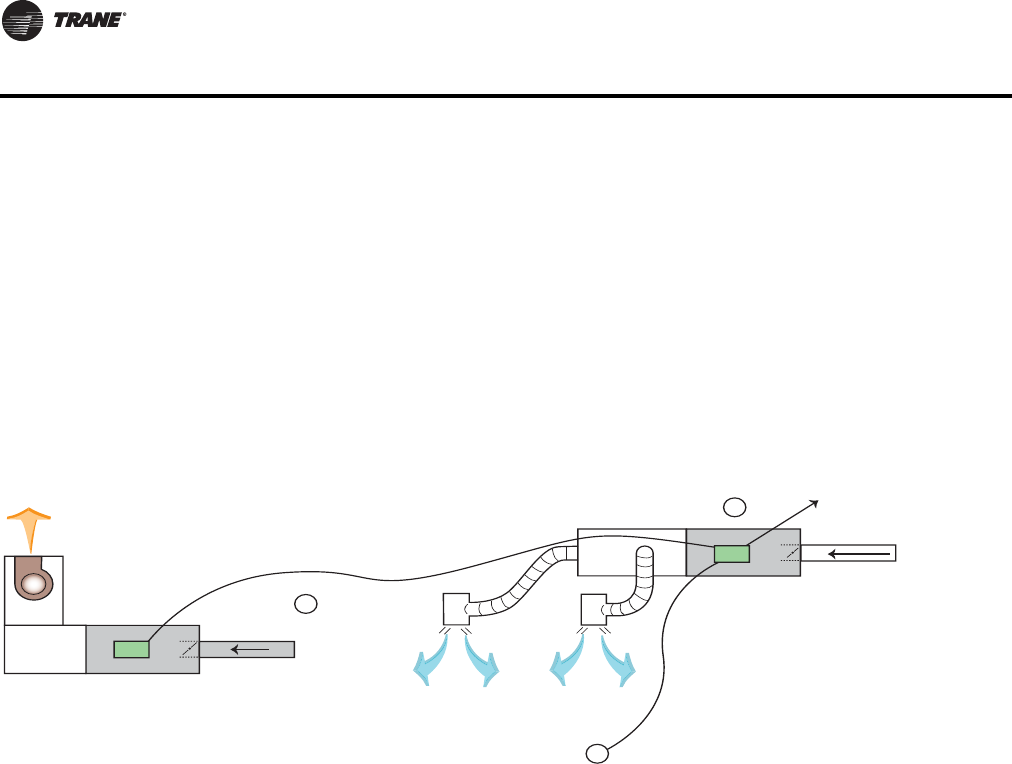
158 VAV-PRC012-EN
DDC Controls
• Hospital operating rooms
• Hospital patient rooms
• Research and Development facilities
• And many more…
The CFM offset is assured and can be monitored and documented when connected to aTrane
Tracer™ SC Building Automation System. FlowTracking Control is designed to meet most
pressurization control projects. If an application calls for pressure control other than flow tracking,
contact your localTrane Sales Office for technical support.
Tracer™ Programmable BACnet Controller — Unit Control Module
TheTracer UC400 direct digital controller Unit Control Module (DDC-UCM) is a microprocessor-
based terminal unit with non-volatile memory which provides accurate airflow and room
temperature control ofTrane and non-TraneVAV air terminal units.Tracer UC400 provides a simple
open protocol to allow integration ofTrane VAV units and controls into other existing control
systems.The UCM can operate in pressure-independent or pressure-dependent mode and uses a
proportional plus integral control algorithm.
The controller monitors zone temperature setpoints, zone temperature and its rate of change and
valve airflow (via flow ring differential pressure).The controller also accepts an auxiliary duct
temperature sensor input or a supply air temperature value fromTracer SC. Staged electric heat,
pulse width modulated electric heat, proportional hot water heat or on/off hot water heat control
are provided when required.The control board operates using 24-VAC power.TheTracer UC400
is also a member of theTrane Integrated Comfort™ systems (ICS) family of products. When used
with aTraneTracer™ SC or otherTrane controllers, zone grouping and unit diagnostic information
can be obtained. Also part of ICS is the factory-commissioning of parameters specified by the
engineer (see "Factory-Installed vs. Factory-Commissioned" in the Features and Benefits section
for more details).
Figure 8. How does it operate?
B
A
C
Exhaust
Communication link
Supply VAV
To other VAVs or
Main Control Panel
How Does It Operate?
T
Primary Air
from Main
AHU
Occupied Space
VAV-PRC012-EN 159
DDC Controls
Specifications
Supply Voltage
24 VAC, 50/60 Hz
Maximum VA Load
No Heat or Fan
8 VA (Board,Transducer, Zone Sensor, and Actuator)
Note: If using field-installed heat, 24 VAC transformer should be sized for additional load.
Output Ratings
Actuator Output:24 VAC at 12 VA
1st Stage Reheat:24 VAC at 12 VA
2nd Stage Reheat:24 VAC at 12 VA
3rd Stage Reheat:24 VAC at 12 VA
Binary Input
24 VAC, occupancy or generic.
Auxiliary Input
Can be configured for discharge or primary air temperature sensor.
Operating Environment
32 to 140°F, (0 to 60°C)
5% to 95% RH, Non-condensing
Storage Environment
-40 to 180°F (-40 to 82.2°C),
5% to 95%RH, Non-Condensing
Physical Dimensions
Width: 5.5" (139.7 mm)
Length: 4.5" (69.85 mm)
Height: 2.0" (44.45 mm)
Connections
1/4" (6.35 mm) Stab Connections
Communications
Tracer UC400– Space Comfort Control (SCC) profile with FTT-10 transceiver.
22 awg. unshielded level 4 communication wire.
Fan Control
Series fan: On unless unoccupied and min. flow has been released.
Parallel fan: On when zone temperature is less than heating setpoint plus fan offset. Off when zone
temperature is more than heating setpoint plus fan offset plus 0.5°F (0.28°C).
Heat Staging
Staged electric or hot water proportional or pulse-width modulation

160 VAV-PRC012-EN
DDC Controls
Trane LonMark DDC VAV Controller
Introduction
This LonMark™ certified controller uses the Space Comfort Controller (SCC) profile to exchange
information over a LonTalk™ network. Networks with LonMark certified controllers provide the
latest open protocol technology. Being LonMark certified guarantees that owners and end-users
have the capability of addingTrane products to other “open” systems and relieves owners of the
pressure and expense of being locked into a single DDC supplier.TheTrane VV550 VAV controller
with VariTrane VAV units can be applied to more than justTrane systems. When a customer buys
aTrane VAV unit withTrane DDC controller, they take advantage of:
• Factory-commissioned quality
• Knowing they have selected the most reliable VAV controllers in the industry
• Trane as a single source to solve any VAV equipment, or system-related issues
• The most educated and thorough factory service technicians in the controls industry
• Over 150 local parts centers throughout North America that can provide what you need, when
you need it.
Don’t let your existing controls supplier lock you out of the most recognized name inVAV system
control in the industry. SpecifyTrane open-protocol systems.
What are the new features of this controller? Read on to find out more.
General Features and Benefits
Assured Accuracy
• Proportional-plus-integral control loop algorithm for determining required airflow needed to
control room temperature. Airflow is limited by active minimum and maximum airflow
setpoints.
• Pressure-independent (PI) operation that automatically adjusts valve position to maintain
required airflow. In certain low-flow situations or in cases where the flow measurement has
failed, the DDC controller will operate in a pressure-dependent (PD) mode of operation.
• When combined with the patentedTrane Flow ring and pressure transducer, flow is repeatable
to +/- 5% accuracy across the Pressure Independent (PI) flow range. (See Valve/Controller
Airflow Guidelines section).
• Improved 2-Point Air Balancing is available – Assures optimized flow-sensing accuracy across
the operating range.This provides a more accurate airflow balancing method when compared
to typical single-point flow correction air balancing.
• Analog input resolution of +/- 1/8°F within the comfort range maximizes zone temperature
control yielding excellent comfort control.
Reliable Operation
• Built for life –Trane products are designed to stand the test of time, with a proven design life
that exceeds 20 years.
• Fully factory tested – fully screened and configured at the factory. All features are tested
including fan and reheat stage energization, air valve modulation, and controller inputs and
outputs.
Safe Operation
• All components, including the controller, pressure transducer, transformer, etc. are mounted
in a NEMA 1 sheet metal enclosure and are tested as an assembly to UL1995 standards.The
result is a rugged and safe VAV, controller, and thus, overall unit.
VAV-PRC012-EN 161
DDC Controls
• When in PI-mode, EH is disabled when the sensed flow is below the minimum required.
• HW coilVAV units in ventilation flow control (VFC) have a Freeze protection algorithm to protect
the water coil and the internal space from water damage.This is accomplished by driving the
water valve to maximum position on alarm conditions.
System-Level Optimization
Trane controllers are designed to integrate intoTraneTracer Building Automation Systems and
leverage clear and clean unit-controller related data for system level control decisions. Integrating
aTrane VV550 controller into aTracer Control System provides the next step in building system
control.
Specifically, system-level decisions on how to operate all components can be made. Energy
efficient optimization strategies like Static Pressure Optimization, Ventilation Reset, and CO2
Demand-controlled Ventilation can be employed with the simple press of a button.The end-result
is the most efficient and reliable building control system available.
Simplified Installation
Factory Commissioned Quality – AllTrane DDC VAV controllers are factory-commissioned.This
means that the DDC boards are powered and run-tested with your specific sequence parameters.
They are connected to a communication link to make sure that information and diagnostic data
function properly. Before any VariTrane VAV unit ships they must pass a rigorous quality control
procedure.You can be assured that aTrane VAV unit withTrane DDC VAV controls will work right
out of the crate.
Zone sensor air balance – When applied to aTrane zone sensor with thumbwheel and on/cancel
buttons, a balancing contractor can drive the primary air valve to maximum or minimum airflow
from the sensor to determine the point of calibration to be used (maximum will result in optimum
performance).The flow reading can then be calibrated from the sensor, without the use of
additional service tools. (Non-LCD versions)
Tenant-Finish Heat Mode – In some office projects, the building is being constructed as tenants are
being identified.Tenant-finish heat mode is designed for applications when a given floor has not
been occupied.The main AHU system is used for heat and because the internal furnishings are not
complete, the sensors have not been installed. In this case, the primary valve drives open using
the heat of the main AHU to keep plumbing lines from freezing. When available, the operation of
the VAV unit fan (series or parallel) remains unaffected.
Controller Flexibility
• 24VAC binary input that can be configured as a generic input or as occupancy input.When the
DDC controller is operating withTracer SC, the status of the input is provided toTracer for its
action. In stand-alone operation and when configured for an occupancy input, the input will
control occupancy status of the DDC controller.
• Auxiliary temperature analog input configured for an auxiliary temperature sensor.The value
of the input is used as status-only byTracer SC ifTracer SC is providing a supply air temperature
to the DDC controller. Otherwise, the input will be used for determining heating/cooling control
action of theVAV unit.When the auxiliary temperature sensor is located in the discharge of the
unit, and attached to aTraneTracer Building Automation System, additional test sequencing
and reporting is available to maximize VAV system capabilities and simplify system
commissioning.
• Dual-duct support with two DDC controllers. One DDC controller controls the cooling air valve
and the other controller controls the heating air valve. With constant-volume sequences, the
discharge air volume is held constant by controlling discharge air volume with the heating
Controller.
• LonMark certified performance ensures that aTrane VAV with controller will provide state-of-
the-art, consistent open communication protocol for integration with the industry’s latest (Non-
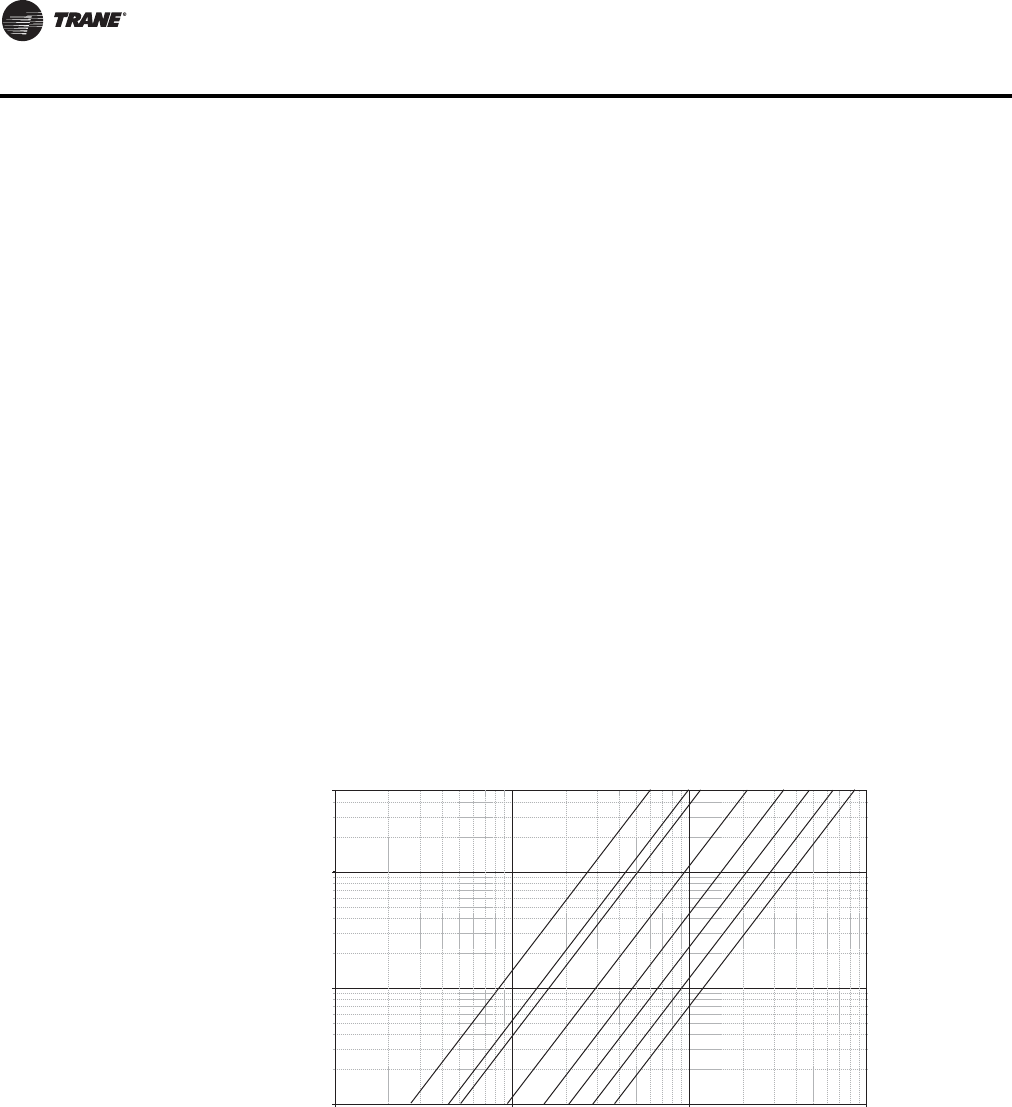
162 VAV-PRC012-EN
DDC Controls
Trane) building automation control systems, including Johnson Control, Andover, Siemans,
Honeywell, etc.
•CO
2demand controlled ventilation enables a HVAC system to adjust ventilation flow based on
critical zone, average CO2of specified zones, etc.Trane demand controlled ventilation
strategies are pre-defined for simplified application and can be easily customized to meet the
needs of a specific system.
Trane DDC VAV Controller Logic
Control Logic
Direct Digital Control (DDC) controllers are today’s industry standard. DDC controllers share
system-level data to optimize system performance (including changing ventilation requirements,
system static pressures, supply air temperatures, etc.). Variables available via a simple twisted-
shielded wire pair include occupied/unoccupied status, minimum and maximum airflow setpoints,
zone temperature and temperature setpoints, air valve position, airflow cfm, fan status (on or off),
fan operation mode (parallel or series), reheat status (on or off), VAV unit type, air valve size,
temperature correction offsets, flow correction values, ventilation fraction, etc.
With the advent of LonMark open protocol, the most reliable VAV controller is now available for
ANY system. Gone are the days of being locked into a single supplier.Trane DDC controllers
provideTrane-designed solid-state electronics intended specifically forVAV applications including:
1. SpaceTemperature Control
2. Ventilation Flow Control (100% outside air applications)
6. FlowTracking Space Pressurization Control (New feature)
Note: Flow sensor DP (in. wg) is measured at the flow ring to aid in system balancing and commissioning. See “Valve/Controller
Airflow Guidelines” in each section for unit performance.
Space Temperature Control
Space temperature control applications are whereTrane emerged as an industry leader in quality
and reliability.This did not occur overnight and has continued to improve as our controller and
control logic has improved over time. STC employs controller logic designed to modulate the
supply airstream and associated reheat (either local or remote) to exactly match the load
requirements of the space.
Additionally, minimum and maximum airflow and specific controller sequence requirements are
pre-programmed to ensure that appropriate ventilation standards are consistently maintained.
Figure 9. Flow sensor single vs. airflow delivery
0.01
0.1
1
5
10 100 1,000 10,000
Cfm
Flow Sensor DP (In. wg)
4" 12"10"8"6"
5" 14" 16"

VAV-PRC012-EN 163
DDC Controls
When connected to aTraneTracer Building Automation System, trend logging, remote alarming,
etc. are available to fully utilize the power and capabilities of your systems.
General Operation-Cooling
In cooling control action, the DDC controller matches primary airflow to cooling load.The DDC
controller will automatically change over to heating control action if the supply air temperature is
above a configured/editable setpoint. When the supply air temperature is less than 10 degrees
below this setpoint, the controller will automatically switch to cooling control action.The DDC
controller first chooses theTracer™ SC -provided supply air temperature value to use for auto
changeover. If this is not available, it uses the temperature provided by the optional auxiliary
temperature sensor (must be installed for inlet temperature monitoring). If this is also not available,
it uses the heating/cooling mode assigned byTracer SC or the DDC controller’s service tool.
General Operation-Reheat
In heating control action, the DDC controller matches primary airflow to heating load.The DDC
controller will automatically change over to heating control action if the supply air temperature is
above a configured/editable setpoint. When the supply air temperature is less than 10 degrees
below this setpoint, the controller will automatically switch to cooling control action.The DDC
controller first chooses theTracer-provided supply air temperature value to use for auto
changeover. If this is not available, it uses the temperature provided by the optional auxiliary
temperature sensor (must be installed for inlet temperature monitoring). If this is also not available,
it uses the heating/cooling mode assigned byTracer SC or the DDC controller’s service tool.
When heat is added to the primary air, the air is considered reheated. Reheat can be either local
(integral to theVAV unit in the form of an electric coil or hot water coil) or remote (typically existing
wall fin radiation, convector, etc.) or any combination of local and remote.The operating
characteristics of the four basic types of VariTrane™ DDC terminal reheat are discussed.
Fan-Powered Terminal Units: On/Off Hot Water Reheat
One or two stages of on/off hot water reheat are available.Two position water valves complete the
HW reheat system and are either fully opened or fully closed.The heating minimum airflow
setpoint is enforced during reheat.
On parallel fan-powered units, the fan is energized upon a call for heating.The parallel fan is turned
off when the space temperature rises above the fan on/off point (active heating setpoint plus fan
offset) plus 0.5°F (0.28°C).
Series fan-powered terminal unit fans are continuously energized during occupied mode. When
unoccupied, the fan is energized upon a call for heating or cooling and de-energized when
unoccupied zone set point is satisfied.
When the zone temperature falls below the active heating setpoint, the UCM modulates the
primary airflow to the minimum heating airflow setpoint.
Stage 1 energizes when the space temperature is below the active heating setpoint, and is de-
energized when the space temperature is 0.5°F (0.28°C) above the active heating setpoint. Stage
2 energizes when the zone temperature is 1°F (0.56°C) or more below the active heating setpoint,
and de-energizes when the space temperature is 0.5°F (0.28°C) below the active heating setpoint.
When reheat is de-energized, the cooling minimum airflow setpoint is activated.
Fan-Powered Terminal Units: Proportional Hot Water Reheat
Proportional hot water reheat uses 3-wire floating-point-actuator technology.The heating
minimum airflow setpoint is enforced during reheat.
On parallel fan-powered units, the fan is energized upon a call for heating.The parallel fan is turned
off when the space temperature rises above the fan on/off point (active heating setpoint plus fan
offset) plus 0.5ºF (0.28ºC).

164 VAV-PRC012-EN
DDC Controls
Series fan-powered terminal unit fans are continuously energized during occupied mode. When
unoccupied, the fan is energized upon a call for heating or cooling and de-energized when
unoccupied zone setpoint is satisfied.
The water valve opens as space temperature drops below the heating setpoint. A separate reheat
proportional-plus-integral control loop from that controlling airflow into the room is enforced.The
degree to which the hot water valve opens is dependent on both the degree that the space
temperature is below the active heating setpoint and the time that the space temperature has been
below the active heating setpoint. If not already closed, the water valve fully closes when the zone
temperature rises above the active heating setpoint by 0.5 °F (0.28 °C). When reheat is de-
energized, the cooling minimum airflow setpoint is activated.
Fan-poweredTerminal Units: On/Off Electric Reheat
One or two stages of staged electric reheat are available.The heating minimum airflow setpoint
is enforced during reheat.
On parallel fan-powered units, the fan is energized upon a call for heating.The parallel fan is turned
off when the space temperature rises above the fan on/off point (active heating setpoint plus fan
offset) plus 0.5°F (0.28°C).
Series fan-powered terminal unit fans are continuously energized during occupied mode. When
unoccupied, the fan is energized upon a call for heating or cooling and de-energized when
unoccupied zone set point is satisfied.
Stage 1 energizes when the space temperature is below the active heating setpoint, and is de-
energized when the space temperature rises 0.5°F (0.28°C) above the active heating setpoint. Stage
2 energizes when the space temperature is 1.0°F (0.56°C) or more below the active heating setpoint,
and is de-energized when the space temperature is 0.5°F (0.28°C) below the active heating setpoint.
When reheat is de-energized, the cooling minimum airflow setpoint is activated.
Fan-poweredTerminal Units: Pulse-Width Modulation of Electric Heat
One or two stages of pulse-width modulation of electric heat are available. Energizing for a portion
of a three-minute time period modulates the electric heater.This allows exact load matching for
energy efficient operation and optimum zone temperature control.The heating minimum airflow
setpoint is enforced during reheat.
On parallel fan-powered units, the fan is energized upon a call for heating.The parallel fan is turned
off when the space temperature rises above the fan on/off point (active heating setpoint plus fan
offset) plus 0.5°F (0.28°C).
Series fan-powered terminal unit fans are continuously energized during occupied mode. When
unoccupied, fan is energized upon a call for heating or cooling and de-energized when unoccupied
zone set point is satisfied.
The amount of reheat supplied is dependent on both the degree that the space temperature is
below the active heating setpoint and the time that the space temperature has been below the
active heating setpoint. If not already off, reheat de-energizes when the space temperature rises
0.5°F (0.28°C) above the active heating setpoint.The Stage 1 “on” time is proportional to the
amount of reheat required. For example, when 50% of stage 1 capacity is required, reheat is on for
90 seconds and off for 90 seconds. When 75% of stage 1 capacity is required, reheat is on for 135
seconds and off for 45 seconds. When 100% of stage 1 capacity is required, reheat is on
continuously.
Stage 2 uses the same “on” time logic as stage 1 listed above, except stage 1 is always energized.
For example, when 75% of unit capacity is required, stage 1 is energized continuously, and stage
2 is on for 90 seconds and off for 90 seconds. When reheat is de-energized, the cooling minimum
airflow setpoint is activated. When reheat is de-energized, the cooling minimum airflow setpoint
it activated.
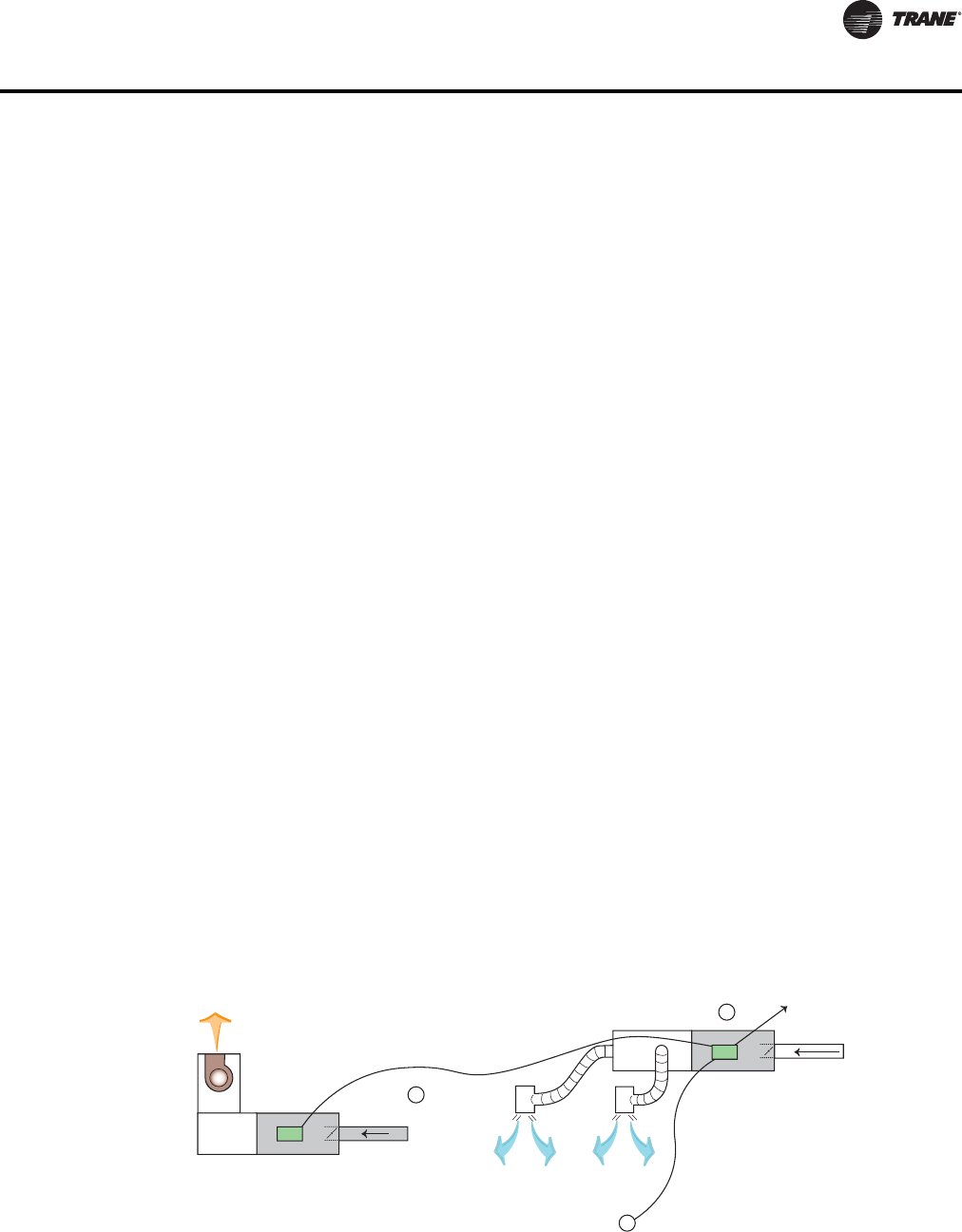
VAV-PRC012-EN 165
DDC Controls
Ventilation Control
Ventilation control enhances the usability ofTrane DDC controllers in more select applications that
require measurement of outside air (ventilation). Ventilation control is designed for use with
constant volume single-ductVAV units which modulate the primary damper and associated reheat
to maintain an average constant discharge air temperature.The reheat is modulated to provide
discharge air temperature consistent with AHU supply air temperature (typically 50º–60ºF).This is
critical to ensure that ASHRAE Standard 62 Ventilation standards are attained, consistently
maintained, and monitored. When connected to aTrane Building Automation System, trend
logging, remote alarming, etc. is available. In fact, theTraneTracer Control System can provide
unmatched “peace of mind” by calling/paging the appropriate person(s) when specific alarms
occur.
Flow Tracking Control
This enhanced VAV DDC controller feature allows twoTrane VV550 controllers to coordinate
modulation simultaneously.This allows a specific CFM offset to be maintained.The CFM offset
provides pressurization control of an occupied space, while maintaining the comfort and energy
savings of a VAV system. A flow tracking system in a given zone consists of a standard Space
Comfort ControlVAV (see B)unit plus a single-duct, cooling-only, exhaust VAV unit (see C). As the
supplyVAV unit modulates the supply airflow through the air valve to maintain space comfort, the
exhaust box modulates a similar amount to maintain the required CFM differential.This is a simple,
reliable means of pressurization control, which meets the requirements of the majority of zone
pressurization control applications.Typical applications include:
• School and University laboratories
• Industrial laboratories
• Hospital operating rooms
• Hospital patient rooms
• Research and Development facilities
• And many more…
The CFM offset is assured and can be monitored and documented when connected to aTrane
Tracer BuildingAutomation System. FlowTracking Control is designed to meet most pressurization
control projects. If an application calls for pressure control other than flow tracking, contact your
localTrane Sales Office for technical support.
Figure 10. How does it operate?
B
A
C
Exhaust
Communication link
Supply VAV
To other VAVs or
Main Control Panel
T
Primary Air
from Main
AHU
Occupied Space
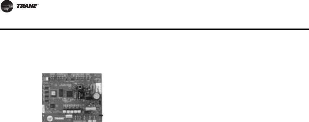
166 VAV-PRC012-EN
DDC Controls
LonMark™ Direct Digital Controller—Unit Control Module
The controller monitors zone temperature setpoints, zone temperature and its rate of change and
valve airflow (via flow ring differential pressure).The controller also accepts an auxiliary duct
temperature sensor input or a supply air temperature value fromTracer™ SC. Staged electric heat,
pulse width modulated electric heat, proportional hot water heat or on/off hot water heat control
are provided when required.The control board operates using 24-VAC power.TheTrane LonMark
DDC-UCM is also a member of theTrane Integrated Comfort™ systems (ICS) family of products.
When used with aTraneTracer™ SC or otherTrane controllers, zone grouping and unit diagnostic
information can be obtained.Also part of ICS is the factory-commissioning of parameters specified
by the engineer (see "Factory-Installed vs. Factory-Commissioned" in the Features and Benefits
section for more details).
Note: Trane LonMark DDC-UCM controllers can also take advantage of factory-commissioned
quality on non-Trane systems through LonMark open protocol.
Specifications
Supply Voltage
24 VAC, 50/60 Hz
Maximum VA Load
No Heat or Fan
8 VA (Board,Transducer, Zone Sensor, and Actuator)
Note: If using field-installed heat, 24 VAC transformer should be sized for additional load.
Output Ratings
Actuator Output:24 VAC at 12 VA
1st Stage Reheat:24 VAC at 12 VA
2nd Stage Reheat:24 VAC at 12 VA
3rd Stage Reheat:24 VAC at 12 VA
Binary Input
24 VAC, occupancy or generic.
Auxiliary Input
Can be configured for discharge or primary air temperature sensor.
Operating Environment
32 to 140°F, (0 to 60°C)
5% to 95% RH, Non-condensing
TheTrane LonMark direct digital controller Unit Control Module (DDC-UCM)
is a microprocessor-based terminal unit with non-volatile memory which
provides accurate airflow and room temperature control ofTrane and non-
Trane VAV air terminal units. LonMark provides a simple open protocol to
allow integration ofTrane VAV units and controls into other existing control
systems.The UCM can operate in pressure-independent or pressure-
dependent mode and uses a proportional plus integral control algorithm.

VAV-PRC012-EN 167
DDC Controls
Storage Environment
-40 to 180°F (-40 to 82.2°C),
5% to 95%RH, Non-Condensing
Physical Dimensions
Width: 5.5" (139.7 mm)
Length: 4.5" (69.85 mm)
Height: 2.0" (44.45 mm)
Connections
1/4" (6.35 mm) Stab Connections
Communications
LonMark – Space Comfort Control (SCC) profile with FTT-10 transceiver.
22 awg. unshielded level 4 communication wire.
Fan Control
Series fan: On unless unoccupied and min. flow has been released.
Parallel fan: On when zone temperature is less than heating setpoint plus fan offset. Off when zone
temperature is more than heating setpoint plus fan offset plus 0.5°F (0.28°C).
Heat Staging
Staged electric or hot water proportional or pulse-width modulation
Table 136. Input listing
Input description Input SNVT type
Space temperature nviSpaceTemp SNVT_temp_p
Setpoint nviSetpoint SNVT_temp_p
Occupancy, schedule nviOccSchedule SNVT_tod_event
Occupancy, manual command nviOccManCmd SNVT_occupancy
Occupancy sensor nviOccSensor SNVT_occupancy
Application mode nviApplicMode SNVT_hvac_mode
Heat/cool mode input nviHeatCool SNVT_hvac_mode
Fan speed command nviFanSpeedCmd SNVT_switch
Auxiliary heat enable nviAuxHeatEnable SNVT_switch
Valve override nviValveOverride SNVT_hvac_overid
Flow override nviFlowOverride SNVT_hvac_overid
Emergency override nviEmergOverride SNVT_hvac_emerg
Source temperature nviSourceTemp SNVT_temp_p
Space CO2 nviSpaceCO2 SNVT_ppm
Clear alarms/diagnostics nviRequest(a) SNVT_obj_request
Air flow setpoint input nviAirFlowSetpt SNVT_flow
(a) Part of the node object

168 VAV-PRC012-EN
DDC Controls
Table 136, p. 167 provides an input listing forTracer VV550/551 VAV controllers, and Table 137,
p. 168 provides an output listing forTracer VV550/551 VAV controllers. Table 138, p. 168 provides
the configuration properties for the controller.The content of the lists conforms to both the
LonMark SCC functional profile 8500 and the LonMark node object.
Table 137. Output listing
Output description Output SNVT type
Space temperature nvoSpaceTemp SNVT_temp_p
Unit status, mode nvoUnitStatus SNVT_hvac_status
Effective setpoint nvoEffectSetpt SNVT_temp_p
Effective occupancy nvoEffectOccup SNVT_occupancy
Heat cool mode nvoHeatCool SNVT_hvac_mode
Setpoint nvoSetpoint SNVT_temp_p
Discharge air temperature nvoDischAirTemp SNVT_temp_p
Space CO2 nvoSpaceCO2 SNVT_ppm
Effective air flow setpoint nvoEffectFlowSP SNVT_flow
Air flow nvoAirFlow SNVT_flow
File table address nvoFileDirectory(a) SNVT_address
Object status nvoStatus(a) SNVT_obj_status
Alarm message nvoAlarmMessage SNVT_str_asc
(a) Part of the node object.
Table 138. Configuration properties
Configuration property
description Configuration property SNVT type SCPT reference
Send heartbeat nciSndHrtBt SNVT_time_sec SCPTmaxSendTime (49)
Occ temperature setpoints nciSetpoints SNVT_temp_setpt SCPTsetPnts (60)
Minimum send time nciMinOutTm SNVT_time_sec SCPTminSendTime (52)
Receive heartbeat nciRecHrtBt SNVT_time_sec SCPTmaxRcvTime (48)
Location label nciLocation SNVT_str_asc SCPTlocation (17)
Local bypass time nciBypassTime SNVT_time_min SCPTbypassTime (34)
Manual override time nciManualTime SNVT_time_min SCPTmanOverTime (35)
Space CO2 limit nciSpaceCO2Lim SNVT_ppm SCPTlimitCO2 (42)
Nominal air flow nciNomFlow SNVT_flow SCPTnomAirFlow (57)
Air flow measurement gain nciFlowGain SNVT_multiplier SCPTsensConstVAV (67)
Minimum air flow nciMinFlow SNVT_flow SCPTminFlow (54)
Maximum air flow nciMaxFlow SNVT_flow SCPTmaxFlow (51)
Minimum air flow for heat nciMinFlowHeat SNVT_flow SCPTminFlowHeat (55)
Maximum air flow for heat nciMaxFlowHeat SNVT_flow SCPTmaxFlowHeat (37)
Minimum flow for standby nciMinFlowStdby SNVT_flow SCPTminFlowStby (56)
Firmware major version nciDevMajVer(a) n/a SCPTdevMajVer (165)
Firmware minor version nciDevMinVer(a) n/a SCPTdevMinVer (166)
Flow offset for tracking applications nciFlowOffset SNVT_flow_f SCPToffsetFlow (265)
Local heating minimum air flow nciMinFlowUnitHt SNVT_flow SCPTminFlowUnitHeat (270)
Minimum flow for standby heat nciMnFlowStbyHt SVNT_flow SCPTminFlowStbyHeat(263)
(a) Part of the node object.
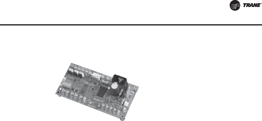
VAV-PRC012-EN 169
DDC Controls
Direct Digital Controller—Unit Control Module
The controller also accepts an auxiliary duct temperature sensor input or a supply air temperature
value fromTracer™ SC. Staged electric heat, pulse width modulated electric heat, proportional hot
water heat or on/off hot water heat control are provided when required.The control board operates
using 24-VAC power.TheTrane DDC-UCM is a member of theTrane Integrated Comfort™ systems
(ICS) family of products. When used with aTraneTracer Building Automation System or other
Trane controllers, zone grouping and unit diagnostic information can be obtained. Also part of ICS
is the factory-commissioning of parameters specified by the engineer (see "Factory-Installed vs.
Factory-Commissioned" in the Features and Benefits section for more details).
Specifications
Supply Voltage
24 VAC, 50/60 Hz
Maximum VA Load
No Heat or Fan
12 VA (Board,Transducer, Zone Sensor, and Actuator)
Note: If using field-installed heat, 24 VAC transformer should be sized for additional load.
Output Ratings
Actuator Output: 24 VAC at 12 VA
1st Stage Reheat: 24 VAC at 12 VA
2nd Stage Reheat: 24 VAC at 12 VA
3rd Stage Reheat: 24 VAC at 12 VA
Binary Input
24 VAC
Auxiliary Input
Can be configured for an optional 2–10 VDC CO2sensor, or auxiliary temperature sensor.
Operating Environment:
32 to 140°F, (0 to 60°C)
5% to 95% RH, Non-condensing
Storage Environment
-40 to 180°F (-40 to 82.2°C),
5% to 95%RH, Non-Condensing
TheTrane direct digital controller Unit Control
Module (DDC-UCM) is a microprocessor-based
terminal unit with non-volatile memory which
provides accurate airflow and room temperature
control ofTrane VAV air terminal units.The UCM can
operate in a pressure-independent or a pressure-
dependent mode and uses a proportional plus
integral control algorithm.The controller monitors
zone temperature setpoints, zone temperature and its
rate of change and valve airflow (via flow ring
differential pressure).
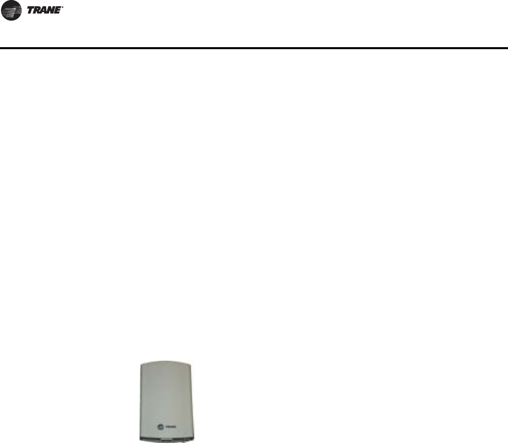
170 VAV-PRC012-EN
DDC Controls
Physical Dimensions
Width: 5.5" (139.7 mm)
Length: 2.8" (69.85 mm)
Height: 1.8" (44.45 mm)
Connections
1/4" (6.35 mm) Stab Connections
Communications
RS-485; Stranded wire, twisted pair, shielded, copper conductor only, 18–20 awg
Fan Control
• Series fan: On unless unoccupied and min. flow has been released.
• Parallel fan: On when zone temperature is less than heating setpoint plus fan offset. Off when
zone temperature is more than heating setpoint plus fan offset plus 0.5°F (0.28°C).
Heat Staging
Staged electric or hot water proportional or pulse-width modulation
Wireless Comm Interface (WCI)
Quantity of WCIs per Network. EachTrane wireless network can have a total of 31 WCIs (30
member WCIs plus 1 coordinator WCI). Each network requires one WCI to function as network
coordinator.
Quantity of Networks per Tracer SC. ATracer SC can support up to 8 wireless networks.
Automatic Network Formation. When aWCI is connected to aTracer SC, it is auto-assigned as
the coordinator.To enable the coordinator,Tracer SC must be configured for wireless
communication.The coordinator WCI opens the network to allow all WCIs having matching
addresses to automatically join the network.
If noTracer SC is present, a centrally locatedWCI must be designated to act as the coordinator.You
can manually set the coordinator WCI so all WCIs having matching addresses automatically join
the network.
Wireless Zone Sensors. The WCI also communicates withTrane wireless zone sensors,
eliminating the need for analog receivers.
Wired Zone Sensors.
Systems using Wireless Comm can also use wired zone sensors.
WCI controller
TheTrane® Wireless Comm Interface (WCI) enables wireless
communication between system controls, unit controls, and
wireless sensors for the new generation ofTrane control
products.The WCI replaces the need for communication wire
in all system applications.
Note: See BAS-SVX40A-EN, Installation, Operation and
Maintenance, Wireless Comm for more information.
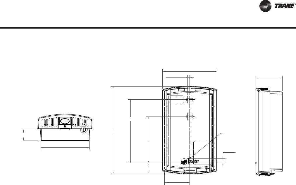
VAV-PRC012-EN 171
DDC Controls
Dimensions
Specifications
Operating Temperature
-40 to 158ºF (-40 to 70ºC)
Storage temperature
-40 to 185ºF (-40 to 85°C)
Storage and operating humidity range
5% to 95% relative humidity (RH), non-condensing
Voltage
24 Vac/Vdc nominal ± 10%. If using 24 Vac, polarity must be maintained.
Receiver power consumption
<2.5 VA
Housing material
Polycarbonate/ABS (suitable for plenum mounting), UV protected, UL 94: 5 VA flammability rating
Mounting
3.2 in (83 mm) with 2 supplied mounting screws
Range
Open range: 2,500 ft (762 m) with packet error rate of 2%
Indoor:Typical range is 200 ft (61 mm); actual range is dependent on the environment. See BAS-
SVX55 for more detail.
Note: Range values are estimated transmission distances for satisfactory operation. Actual
distance is job specific and must be determined during site evaluation. Placement of WCI
is critical to proper system operation. In most general office space installations, distance is
2.896 in (73.55 mm)
0.118 in
(3.00 mm)
4.677 in (118.8 mm)
3.385 in (86.0 mm)
2.480 in (63.0 mm)
R0.71 in
(R1.80 mm) TYP
0.236 in
(6.0 mm)
1.344 in (34.14 mm)
1.419 in (36.03 mm)
0.650 in (16.50 mm)
2.62 in (66.55 mm)
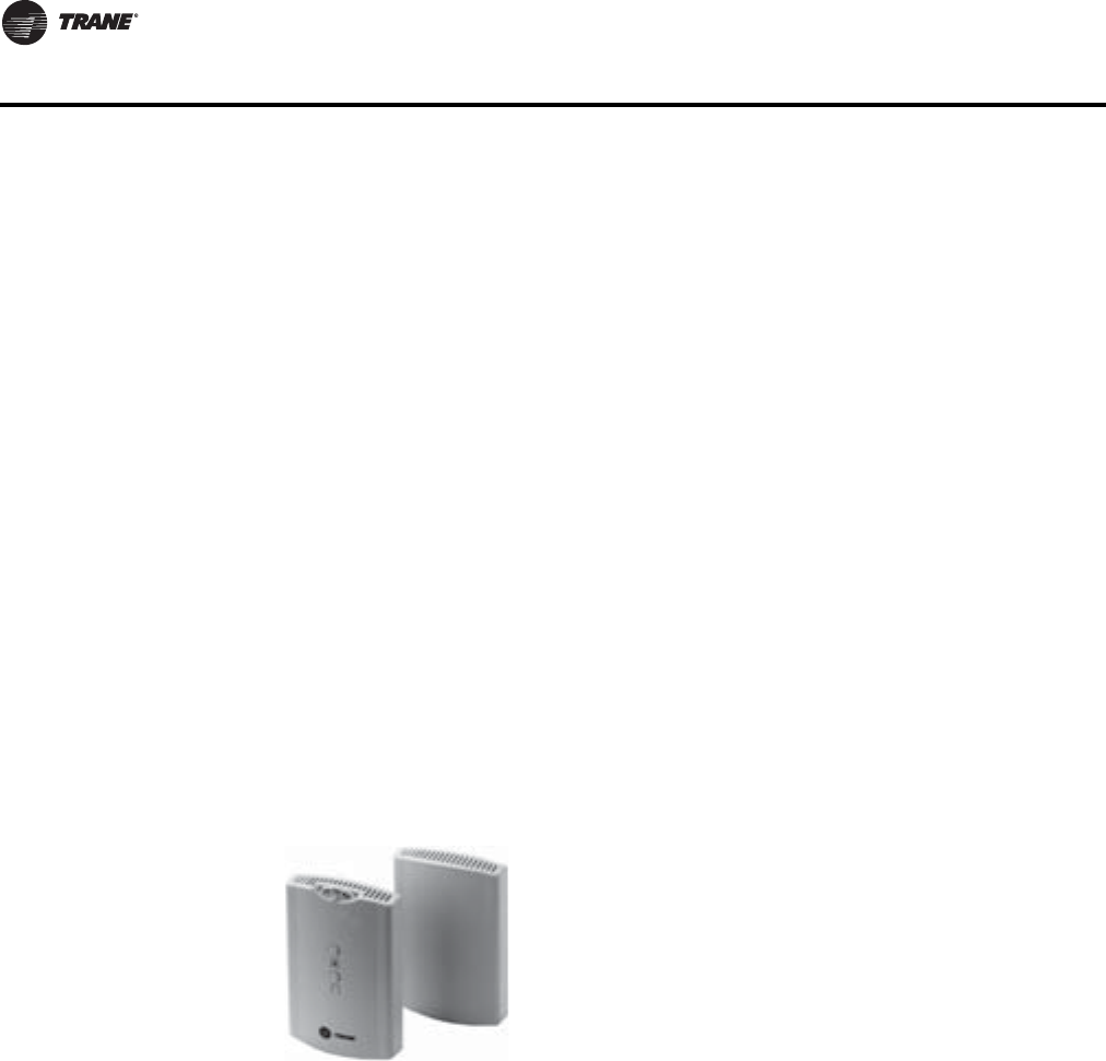
172 VAV-PRC012-EN
DDC Controls
not the limiting factor for proper signal quality. Signal quality is ffected by walls, barriers,
and general clutter. For more information os available at http://www.trane.com.
Output power
North America: 100 mW
Radio frequency
2.4 GHz (IEEE Std 802.15.4-2003 compliant) (2405–2480 MHz, 5 MHz spacing)
Radio channels
16
Address range
Group 0–8, Network 1–9
Mounting
Fits a standard 2 in. by 4 in. junction box (vertical mount only). Mounting holes are spaced 3.2 in.
(83 mm) apart on vertical center line. Includes mounting screws for junction box or wall anchors
for sheet-rock walls. Overall dimensions: 2.9 in. (74 mm) by 4.7 in. (119 mm)
Wireless protocol
ZigBee PRO—ZigBee Building Automation Profile, ANSI/ASHRAE Standard 135-2008 Addendum
q (BACnet™/ZigBee)
Wireless Receiver/Wireless Zone Sensor
The spread spectrum receiver/translator can be field or factory installed and functions as a
communication translator between spread spectrum radio communications and the VAV
communications link.
Specifications
Power Requirements
Receiver: 24 V nominal AC/DC ± 10% < 1VA
Zone Sensor: (2) AA lithium batteries
Sensor Operating Environments
32 to 122°F, (0 to 50°C); 5 to 95%RH, Non-condensing
Receiver Operating Environments
-40 to 158°F, (-40 to 70°C); 5 to 95%RH, Non-condensing
The wireless zone sensor system eliminates the
wiring problems associated with VAV temperature
sensors. It provides the flexibility to move zone
sensors after the occupants have revised the space
floor plan layout.The zone sensor houses the space
temperature sensor, local setpoint adjustment
thumbwheel, OCCUPIED/UNOCCUPIED button,
battery life, signal strength indicators, and spread
spectrum transmitter.
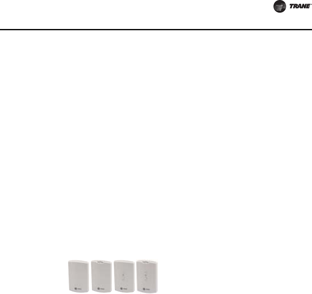
VAV-PRC012-EN 173
DDC Controls
Storage Environment—Sensor/Receiver
-40 to 185°F, (-40 to 85°C); 5 to 95%RH, Non-condensing
Mounting
Receiver: Suitable for mounting above or below ceiling grid. Requires 24V power. Factory installed
receiver comes mounted to the VAV unit with power provided by associated unit controller
transformer. Field installed option provided with associated wire harness for similar power and
communication connection.
Sensor: Mounts to a 2x4 handi-box or directly to the wall by attaching the backplate and then
snapping the sensor body into place.
Dimensions
DDC Zone Sensor
Specifications
Thermistor Resistance Rating
10,000 Ohms at 77°F (25°C)
Setpoint Resistance Rating
Setpoint potentiometer is calibrated to produce 500 Ohms at a setting of 70°F (21.11°C)
Electrical Connections
Terminal Block – Pressure Connections
Communications Jack – WE-616 (available for field installation)
Physical Dimensions
Width: 2.75" (69.85 mm)
Height: 4.5" (114.3 mm)
Depth: 1.0" (25.4 mm)
Receiver/Translator
Enclosure: Plastic
Height: 4.75" (120.6 mm)
Width: 2.90" (73.5 mm)
Depth: 1.08" (27.5 mm)
Sensor/Transmitter
Enclosure: Plastic
Height: 4.78" (121.4 mm)
Width: 2.90" (73.5 mm)
Depth: 1.08" (27.5 mm)
The DDC zone sensor is used in conjunction with the
Trane direct digital controller to sense the space
temperature and to allow for user adjustment of the
zone setpoint. Models with external zone setpoint
adjustments and occupied mode override
pushbuttons are available.
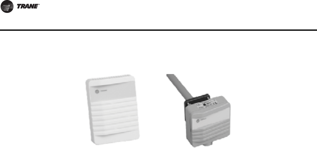
174 VAV-PRC012-EN
DDC Controls
CO2Wall Sensor and Duct CO2Sensor
The wall- and duct-mounted carbon dioxide (CO2) sensors are designed for use withTrane DDC/
UCM control systems. Installation is made simple by attachment directly to the DDC/ UCM
controller.This allows the existing communication link to be used to send CO2data to the higher-
levelTrane control system.
Wall-mounted sensors can monitor individual zones, and the duct-mounted sensor is ideal for
monitoring return air of a given unit. Long-term stability and reliability are assured with advanced
silicon based Non-Dispersive Infrared (NDIR) technology.
When connected to a building automation system with the appropriate ventilation equipment, the
Trane CO2sensors measure and record carbon dioxide in parts-per-million (ppm) in occupied
building spaces.These carbon dioxide measurements are typically used to identify under-
ventilated building zones and to override outdoor airflow beyond design ventilation rates if the CO2
exceeds acceptable levels.
Specifications
Measuring Range
0–2000 parts per million (ppm)
Accuracy at 77°F (25°C)
< ± (40 ppm CO2+ 3% of reading)
(Wall only)
< ± (30 ppm CO2+ 3% of reading)
Recommended calibration interval
5 years
Response Time
1 minute (0–63%)
Operating Temperature
59 to 95°F (15 to 35°C) (Wall only)
23 to 113°F (-5 to 45°C)
Storage Temperature
-4 to 158°F (-20 to 70°C)
Humidity Range
0–85% relative humidity (RH)
Figure 11. CO2wall sensor (L) and duct CO2sensor (R)

VAV-PRC012-EN 175
DDC Controls
Output Signal (jumper selectable)
4-20 mA, 0–20 mA,
0–10 VDC
Resolution of Analog Outputs
10 ppm CO2
Power Supply
Nominal 24 VAC
Power Consumption
<5 VA
Housing Material
ABS plastic
Dimensions
4 1/4" x 3 1/8" x 1 7/16" (Wall only)
(108 mm x 80 mm x 36 mm) (Wall only)
31/8"x31/8"x7¾"
(80mmx80mmx200mm)
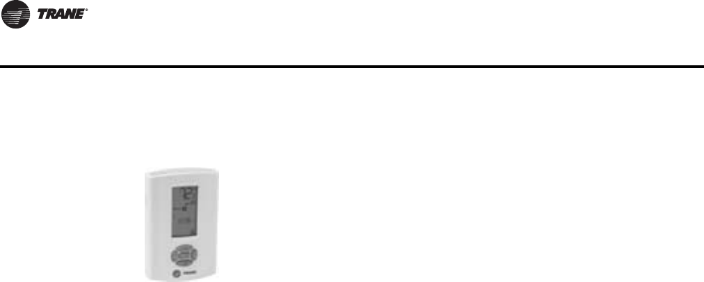
176 VAV-PRC012-EN
DDC Controls
DDC Zone Sensor with LCD
Specifications
Thermistor Resistance Rating
10,000 Ohms at 77°F (25oC)
Setpoint Resistance Rating
Setpoint potentiometer is calibrated to produce 500 Ohms at a setting of 70oF (21.11oC)
Temperature Range
Displays 40 to 99oF(5to35
oC)
With Setpoints 50 to 90oF (10 to 32oC)
Electrical Connections
Terminal Block – Pressure Connections
Communication Jack – WE – 616
4 VA maximum power input.
Physical Dimensions
Width: 2.8" (71.12 mm)
Length: 4.5" (114.3 mm)
Height: 1.1" (27.94 mm)
The DDC zone sensor with LCD has the look and functionality of the
standardTrane DDC zone sensor but has a LCD display.The sensor
includes setpoint adjustment, the display of the ambient temperature, a
communication jack, and occupied mode override pushbuttons. Also, it
can be configured in the field for either a Fahrenheit or Celsius display, a
continuous display of the setpoint and the offset of displayed
temperatures.
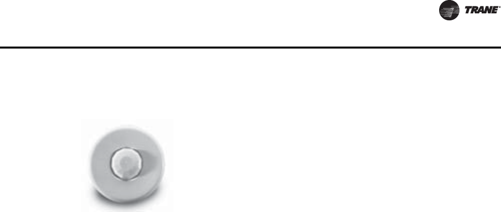
VAV-PRC012-EN 177
DDC Controls
Zone Occupancy Sensor
Sensor ships with 30-minute time delay pre-set from the factory.Time delay and sensitivity can be
field-adjusted.
Specifications
Power Supply
24VACor24VDC,±10%
Maximum VA Load
0.88 VA @ 24 VAC,
0.72 VA @ 24 VDC
Isolated Relay Rating
1 A @ 24 VAC or 24 VDC
Operating Temperature
32 to 131°F (0 to 55°C)
Storage Temperature
-22 to 176°F (-30 to 80°C)
Humidity Range
0 to 95% non-condensing
Effective Coverage Area
1200 sq ft
Effective Coverage Radius
22 feet
Housing Material
ABS Plastic
Dimensions
3.3" dia. x 2.2" deep (85 mm x 56 mm). Protrudes 0.36" (9 mm) from ceiling when installed.
The zone occupancy sensor is ideal for spaces with intermittent occupancy.
It is connected to theTrane DDC UCM and allows the zone to shift to
unoccupied setpoints for energy savings when movement is not detected
in the space.
The zone occupancy sensor has a multi-cell, multi-tier lens with a
maximum field of view of 360°.The maximum coverage area of the sensor
is 1200 square feet with a maximum radius of 22 feet from the sensor when
mounted at 8 feet above the floor.
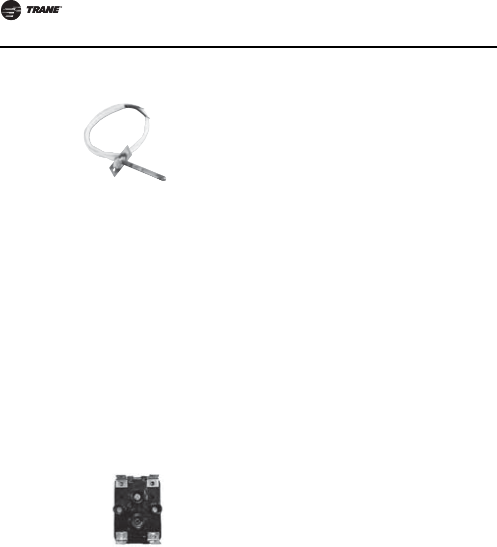
178 VAV-PRC012-EN
DDC Controls
Factory or Field Wired Auxiliary Temperature Sensor
Specifications
Sensing Element
Thermistor 10,000 Ohms @ 77°F (25°C)
Operating Environment
-4 to 221°F (-20 to 105°C), 5%-95%RH
Non-Condensing
Wiring Connection
8ft18awg
Sleeving for wire leads is acyrlic #5 awg grade C rated @ 155°C
Probe Dimensions
3.4" long x 5/16" diameter
(86 mm x 7.9 mm diameter)
Mounting
In any position on duct.
Mount the sensor to the duct using
#10 x ¾" (19.05 mm) sheet metal screws.
Control Relay
Specifications
Coil Rating
24 VAC, 50/60 Hz, pull in at 85%,
4 VA inrush, 3 VA sealed, Class B insulation
Contact Rating
120 VAC, 12 FLA , 60 LRA, 18A Resistive Pilot Duty – 125 VA/3A
277 VAC, 7 FLA, 42 LRA, 18A Resistive Pilot Duty – 277 VA/3A
347 VAC, 25 FLA, 50 LRA, 30A Resistive
The auxiliary temperature sensor is used in conjunction with theTrane DDC
controller to sense duct temperature.When the DDC controller is used with
a Building Automation System, the sensor temperature is reported as status
only. When the DDC control is used as stand alone configuration and the
sensor is placed in the supply air duct, the sensor determines the control
action of the UCM in a heat/cool changeover system.
When factory mounted, the sensor is terminated. If sensor is field mounted,
it is shipped loose and is terminated in the field.
The control relay is an output device used to provide on/off control of
electrical loads.The SPST relay also will isolate the electrical load from the
direct digital controller.
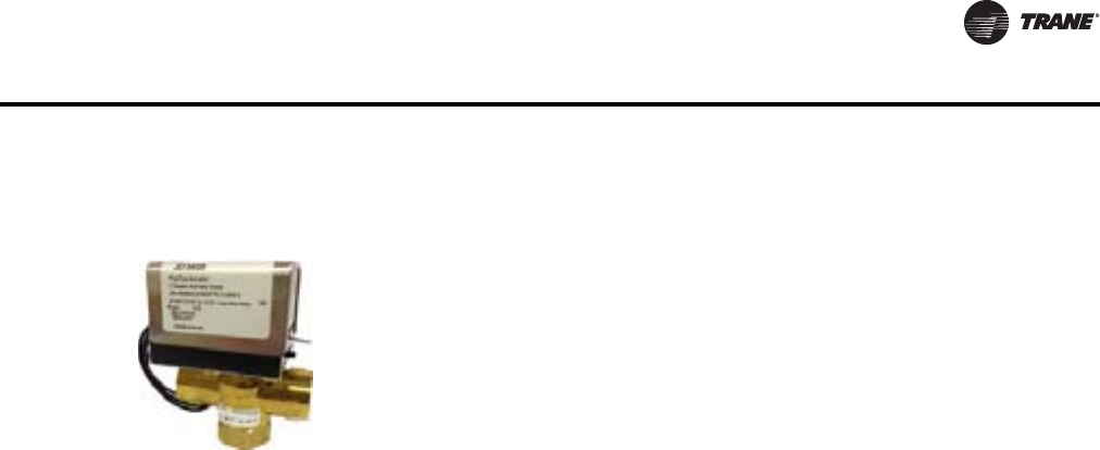
VAV-PRC012-EN 179
DDC Controls
Two-Position Water Valve
Specifications
Valve Design
Body: Brass
Cover: Aluminum
Case: Stainless Steel
Stem: Brass, Hard Chrome Plate
“O” Ring Seals: Viton
Operating Paddle: Buna N
Valve Body Ratings
UL 873 Listed File E27743
Plenum Rated CSA C22.2 No. 139
Certified, File LR85083, Class 3221 01
Temperature Limits
200°F (93.33°C) Fluid
104°F (40°C) Ambient
Maximum Operating Pressure
300 psi (2069 kPa)
Electrical Rating
Motor Voltage – 24 VAC, 50/60 Hz
Power Consumption – 7.0 VA of 24 VAC
Valve Offerings
All valves are spring returned.
1.17 Cv – ½" (12.7 mm) O.D. NPT
3.0 Cv – ¾" (19.1 mm) O.D. NPT
6.4 Cv – 1" (25.4 mm) O.D. NPT
Cv offered (Close-off Pressure):
1.1730 psi (207 kPa)
3.014.5 psi (100 kPa)
6.49 psi (62 kPa)
Two-position hot water valves are used withTrane DDC/UCM controls and
analog electronic controls. Valve actuation is by a hysteresis synchronous
motor.
All valves are field-installed and convertible from three-way to two-way by
means of an included cap.
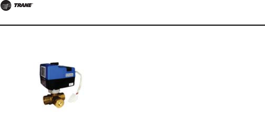
180 VAV-PRC012-EN
DDC Controls
Proportional Water Valve
The direct digital controller uses a time-based signal to drive the motor to its proper position.When
power is removed from the valve, it remains in its last controlled position.
Specifications
Valve Design:
Ball valve construction designed for chilled/hot water or water with up to 50% glycol
Temperature Limits
32 to 201°F (0 to 94°C) Fluid
23 to 122°F (-5 to 50°C) Ambient
Rated Body Pressure
300 psi (2.06 mPa)
Maximum Actuator Close-Off Pressure
60 psi (0.4 mPa)
Electrical Rating
Motor Voltage – 24 VAC, 50/60 Hz
Power Consumption – 3.0 VA at 24 VAC
Valve Offerings
All valves are proportional control with ½" (12.7 mm) O.D. NPT connections
Cv offered:
0.7
2.7
6.6
8.0
The proportional water valve is used to provide accurate control of a hot
water heating coil to help maintain a zone temperature setpoint.The valve
is a ball design and comes in available in four different flow capacities for
proper controllability.The valves are field-adjustable for use as a two- or
three-way configuration.The valves ship in a two-way configuration with a
plug that is installed loose in the bypass port. Conversion to three-way
operation is accomplished by removing the plug from the "B" port.The valve
actuator contains a three-wire synchronous motor.
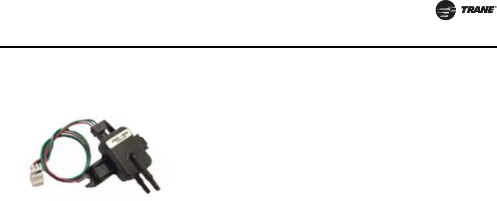
VAV-PRC012-EN 181
DDC Controls
Differential Pressure Transducer
Specifications
Input Pressure Range
0.0 to 5.0 in. wg
(Maximum input pressure 5 psig)
Operating Environment
32 to 140° F, (0 to 60°C)
5% to 95% RH, Non-Condensing
Storage Environment
-40 to 180° F, (-40 to 82.2°C)
5% to 95%RH, Non-condensing
Electrical Connections
Vin = 5.0 VDC nominal
(4.75 to 5.25 VDC acceptable)
Current Draw=5mAmaximum
Null Voltage = 0.250 VDC ± 0.06 VDC
Span = 3.75 VDC ± 0.08 VDC
Note: Null and Span are ratiometric with Vin
Physical Dimensions
Width: 2.5" (63.5 mm)
Length: 3.0" (76.2 mm)
Height: 1.5" (38.1 mm)
Pressure Connections
1/8" (3.175 mm) barbed tubing connections
The differential pressure transducer is used in conjunction with theTrane
direct digital controller and analog electronic controller.The pressure
transducer measures the difference between the high-pressure and low-
pressure ports of theTrane flow ring. The transducer is self-adjusting to
changes in environmental temperature and humidity.
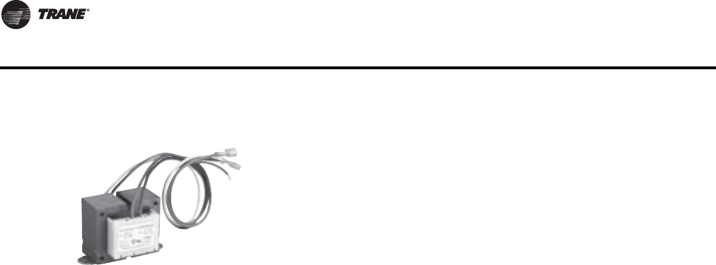
182 VAV-PRC012-EN
DDC Controls
Transformers
Specifications
Primary Voltage
120 VAC
208 VAC
240 VAC
277 VAC
347 VAC
480 VAC
575 VAC
Secondary Voltage
24 VAC
Power Rating
50 VA
Physical Dimensions
For all voltages:
The transformers will be no larger than the following dimensions:
Width: 2.63" (66.7 mm)
Length: 2.50" (63.5 mm)
Height: 2.30" (58.4 mm)
The transformer converts primary power supply voltages to the voltage
required by the direct digital controller and analog.The transformer also
serves to isolate the controller from other controllers which may be
connected to the same power source.

VAV-PRC012-EN 183
DDC Controls
Trane Actuator – 90 Second at 60 Hz DriveTime
This actuator is used with DDC controls and retrofit kits. It is available with a 3-wire floating-point
control device. It is a direct-coupled over the shaft (minimum shaft length of 2.1"), enabling it to be
mounted directly to the damper shaft without the need for connecting linkage.The actuator has an
external manual gear release to allow manual positioning of the damper when the actuator is not
powered.The actuator is Underwriters Laboratories Standard 873 and Canadian Standards
Association Class 3221 02 certified as meeting correct safety requirements and recognized industry
standards.
Specifications
Actuator Design
3-wire, 24-AC floating-point control. Non-spring return.
Actuator Housing
Housing type-NEMA 1
Rotation Range
90° clockwise or counterclockwise
Electrical Rating
Power Supply –24 VAC (20 to 30 VAC) at 50/60 Hz
Power Consumption – 1.8 VA maximum, Class 2
Electrical Connection
Box LugTerminals
Manual Override
External clutch release lever
Shaft Requirement
½" round
2.1" length
Humidity
5% to 95% RH, Non-Condensing
Temperature Rating
Ambient operating: 32 to 125°F
(0 to 52°C)
Shipping and storage: -20 to 130°F
(-29 to 66°C)
Torque
Running: 35 in.-lb (4 N-m)
Breakaway: 35 in.-lb (4 N-m) minimum
Stall: 60 in.-lb (4.5 N-m) minimum

184 VAV-PRC012-EN
DDC Controls
Belimo Actuator – 95 Second Drive Time
This actuator is used with DDC controls and retrofit kits. It is available with a 3-wire floating-point
control device. it is a direct-coupled over the shaft enabling it to be mounted directly to the damper
shaft without the need for connecting linkage. The actuator has an external manual gear release
to allow manual positioning of the damper. The actuator is UL listed and caries the CE mark.
Specifications
Actuator Design
3-wire, 24-AC floating-point control. Brushless DC motor with internal control electronics and
constant drive time.
Rotation Range
95° clockwise or counterclockwise
Electrical Rating
Power Supply –24 VAC/DC
Power Consumption – 2VA, 1.5W
Electrical Connection
Three box-type terminals for bare wire connections.
Manual Override
External clutch release lever.
Shaft Requirement
½" round
2.1" length
Humidity
5% to 95% Non-Condensing
Temperature Rating
Ambient operating: 32 to 125°F (0 to 52°C)
Shipping and storage: -20 to 130°F(-29 to 66°C)
Torque
45 in.-lb (5 N-m)
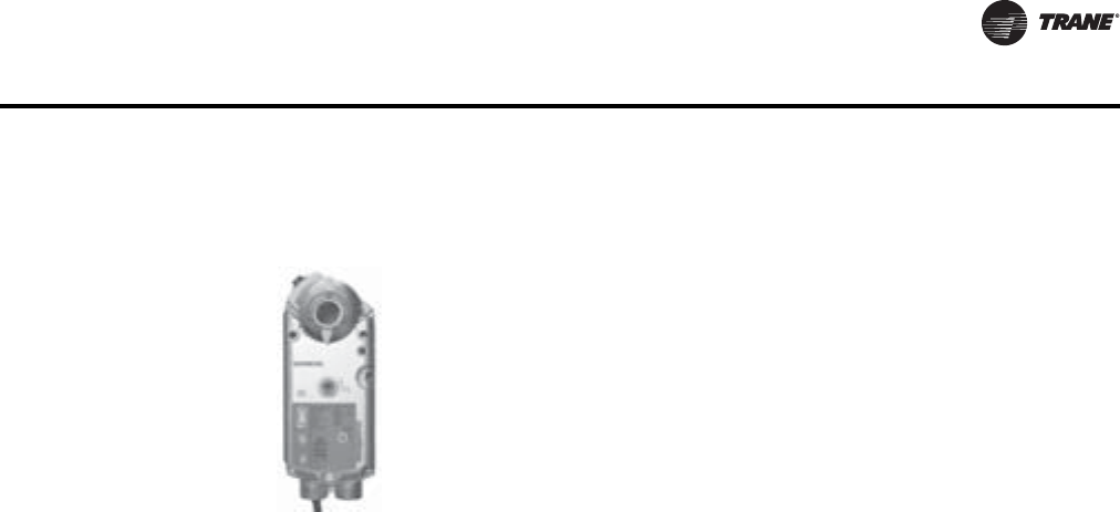
VAV-PRC012-EN 185
DDC Controls
Trane Spring Return Actuator
Specifications
Actuator Design
24-VAC, floating-point control. Spring return
Actuator Housing
HousingType-NEMA IP54
Rotation Range
Adjustable from 0° to 90° at 5° intervals, clockwise or counterclockwise
Electrical Rating
Power Supply – 24 VAC (19.2 to 28.8 VAC) at 50/60 Hz
Power Consumption – 4VA holding, 5VA running maximum, Class 2
Electrical Connection
6-pin female connector forTrane UCM (forTrane DDC controls)
Manual Override
Manual override key provided
Shaft requirement:
¼" to ¾" round
2.1" length
Humidity
95% RH, Non-Condensing
Temperature Rating
Ambient operating: 32 to 130°F
(0 to 54°C)
Shipping and storage: -40 to 158°F
(-40 to 70°C)
Torque
62 in.-lbs (7N-m)
This actuator is used with DDC controls and is a floating-point control
device. It is direct-coupled over the shaft (minimum shaft length of 2.1"),
enabling it to be mounted directly to the damper shaft without the need for
connecting linkage.The actuator is Underwriters Laboratories Standard
60730 and Canadian Standards Association C22.2 No. 24-93 certified as
meeting correct safety requirements and recognized industry standards.
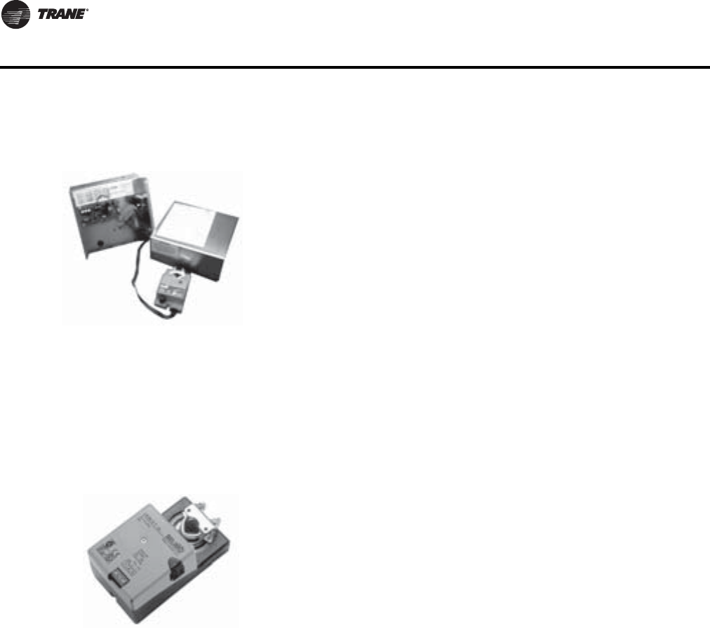
186 VAV-PRC012-EN
DDC Controls
VariTrane DDC Retrofit Kit
AVariTrane DDC-UCM, an electronic differential pressure transducer, and a six-pin connector with
wiring for an actuator, make up the assembly of the retrofit kit. All are housed inside a metal
enclosure. For maximum flexibility, the kit is available with one of two actuators or without an
actuator. If a kit is ordered without an actuator, ensure the actuator used has 24VAC three-wire
floating control. Other accessories are available with the retrofit kit which include zone sensors,
flow bars (used with units without a flow sensor), power transformers, control relays, and E/P
solenoid valves.
Retrofit Kit Actuator
Specifications
Actuator Design
on-off/floating-point
Actuator housing
HousingType-NEMA type 1
Housing Material Rating- UL 94-5V
Angle of Rotation
Max 95º, adjustable with mechanical stops
Electrical Rating
Power Supply – 24 VAC ± 20% 50/60 Hz 24 VDC ± 10%
Power Consumption – 2VA, 1.5W
Manual Override
External push button
The retrofit kit provides the system advantages ofVariTrane DDC controls to
building owners for existing systems.The kit can be applied when
converting from pneumatic or analog controlled systems to a DDC
controlled system.The kit may be used on existing single-duct units with hot
water and electric reheat (three stages), dual-duct units, and all fan-powered
units (both series and parallel) with hot water and electric reheat (two
stages).
This actuator is available with the DDC Retrofit Kit and is a 3-terminal,
floating-point control device. It is direct-coupled over the damper shaft so
there is no need for connecting linkage.The actuator has an external manual
gear release to allow manual positioning of the damper when the actuator
is not powered. A three-foot plenum-rated cable with bare ends will be sent
separately.The actuator is listed under Underwriters Laboratories Standard
873, CSA 22.2 No. 24 certified, and CE manufactured per Quality Standard
SO9001.
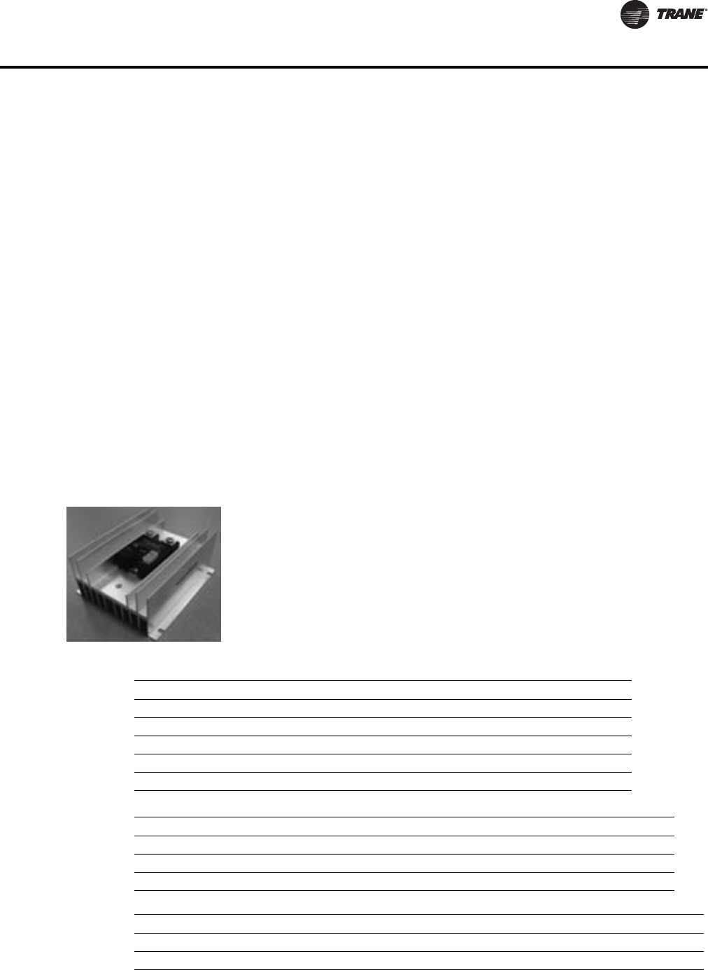
VAV-PRC012-EN 187
DDC Controls
Humidity
5% to 95% RH, Non-Condensing
Ambient Temperature
-22 to 122°F (-30C to 50°C)
Storage Environment
-40 to 176°F (-40 to 80°C)
Torque
45 in.-lb (5N-m)
Running Time
95 sec. for 0 to 45 in-lb
Noise Rating
Less than 35 dB (A)
Weight
1.2 lbs (0.55 kg)
Silicon-Controlled Rectifier (SCR)
Specifications
• Microprocessor based burst-fire controller / SSR
• Low-voltage control
• Output status indicator
• 0-100% Control Range
• Synchronized triggering output (P3)
• 20 AC Cycles Base Period
Input Specifications DC Control
Supply Voltage Range (VDC) (P1) 8-28
Input Current Range [mA] 20-30
Nominal Input Impedance [Ohms] 30K
PLV Range [VDC][P4] 0-10
Nominal Input Impedance [ohms][P4] 20K
Output Status Functions LED
Initial Logic Supply On Flash Once
Load Voltage Missing / Load Open (W/ PLV = 0V) Flash Once Intermittenly
Load Voltage Missing / Load Open (W/ PLV > 0V) Flash Twice Intermittently
General Specifications Parameters
Dielectric Strength, Input/Output/Base (50/60Hz) 4000 Vrms
Minimum Insulation Resistance (@ 500 V DC) 109 Ohm
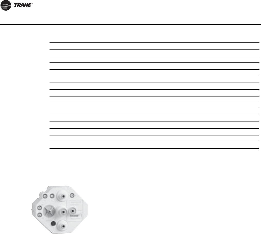
188 VAV-PRC012-EN
DDC Controls
Pneumatic Controls
3011 Pneumatic Volume Regulator
Specifications
Differential Pressure Range
0-1 in. wg (0–249 Pa)
Minimum Setpoint Range
0-1 in. wg (0–249 Pa)
Maximum Setpoint Range
0.05 in. wg (12.5 Pa) above minimum to 1 in. wg (249 Pa) above minimum
Operating Static Pressure Range
0.25 in. wg—6.0 in. wg (62.3–1494 Pa)
Reset Pressure Span
Factory-set at 5 psig (34.5 kPa)
Field-adjustable from 0 to 10 psig
(0 to 68.9 kPa)
Maximum Capacitance, Input/Output 10 pF
Ambient Operating Temperature Range -20 to 80°C
Ambient Storage Temperature Range -40 to 125 °C
Encapsulation Thermally conductive Epoxy
Input connector Header Connector 3.5mm
Output Terminals Screws and Saddle Clamps Furnished, Installed
Output Max Wire Size Output:2 x AWG 8 (3.8mm)
Output Screws Maximum Torque 20 in lbs (2.2 Nm)
Assembly Specifications
Weight (typical) 1.38 Lb (0.628 Kg.)
Heat Transfer Material Used Thermal Pad
Material Steel
Finish Nickel Plate
Torque Applied 20 in/lbs ± 10%.
General Specifications Parameters
The pneumatic volume regulator (PVR) is a controller that provides a
consistent airflow to the space, regardless of varying inlet duct pressure
conditions, in response to a pneumatic thermostat signal.The controller
maintains minimum and maximum airflow setpoints.The 3011 PVR can be
set to control either normally open or normally-closed air valve actuators
and can be calibrated to accept either direct-acting or reverse-acting
thermostat signals. Fixed reset control of maximum and minimum airflow
setpoints is provided.
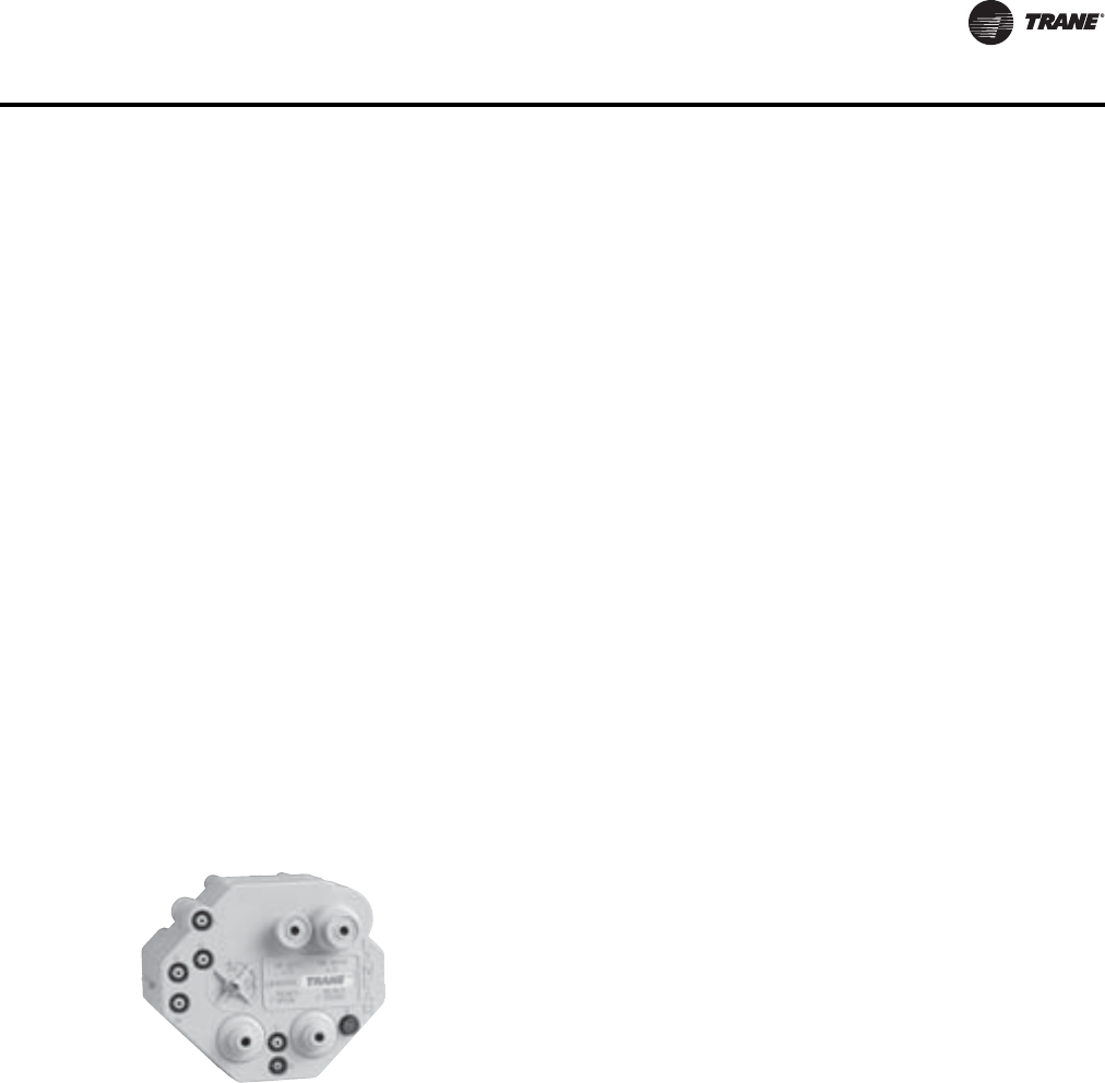
VAV-PRC012-EN 189
DDC Controls
Reset Start Point
Field-adjustable from 0 to 10 psig
(0 to 68.9 kPa)
Main Air Pressure
15 to 30 psig (103 to 207 kPa)
Air Consumption
28.8 scim (0.472 L/m) at 20 psig (138 kPa) main air pressure
Operating Environment
40 to 120ºF (4 to 49°C)
Storage Environment
-40 to 140ºF (-40 to 60°C)
Output Sensitivity
5 psig/0.02 in. wg (34.5 kPa/5.0 Pa)
Physical Dimensions
Width: 4.5" (114.3 mm)
Length: 2.3" (58.4 mm)
Height: 3.87" (98.3 mm)
Weight: 11 oz (312 g)
3501 Pneumatic Volume Regulator
This is in contrast to the 3011 PVR, which resets velocity pressure with a change in thermostat
pressure.This allows the 3501 PVR to have improved stability at low flows.
Specifications
Differential Pressure Range
0–1.0 in. wg (0–249 Pa)
Minimum Setpoint Range
0–1.0 in. wg (0–249 Pa)
Maximum Setpoint Range
Minimum to 1.0 in. wg (249 Pa)
Operating Static Pressure Range
0.25–6.0 in. wg (62.3–1494 Pa)
Tubing Connections:
1/4" O.D. tubing connections
The 3501 PVR can be set to control either normally open or normally-closed
air valve actuators and can be calibrated to accept either direct-acting or
reverse-acting thermostat signals. Fixed reset control of maximum and
minimum airflow setpoints is provided.The controller is used primarily in
dual-duct constant-volume applications because of its linear output
response characteristics.The controller resets the primary air velocity
linearly with a change in thermostat pressure.
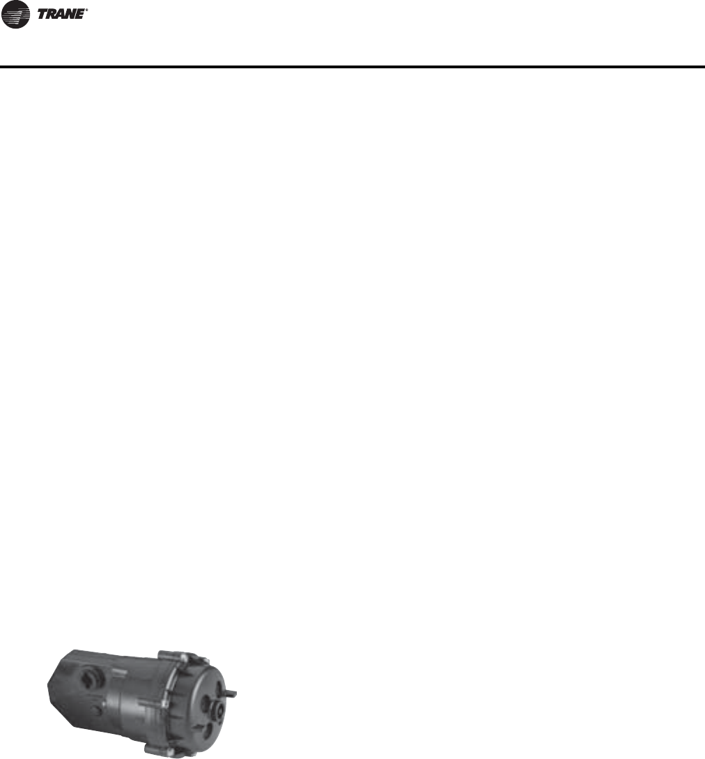
190 VAV-PRC012-EN
DDC Controls
Reset Pressure Span
Factory-set at 5 psig (34.5 kPa)
Field-adjustable from 0 to 7 psig
(0 to 48.3 kPa)
Reset Start Point
Factory-set at 8 psig (55.2 kPa)
Field-adjustable from 0 to 10 psig
(0 to 68.9 kPa)
Main Air Pressure
15–30 psig (103 to 207 kPa)
Air Consumption
43.2 scim (0.708 L/m) at 20 psig (138 kPa) main air pressure
Operating Environment
40 to 120ºF (4 to 49°C)
Storage Environment
-40 to 140ºF (-40 to 60°C)
Output Sensitivity
5 psig/ 0.02 in. wg (34.5 kPa/ 5.0 Pa)
Physical Dimensions
Width: 4.5" (114.3 mm)
Length: 3.87" (98.3 mm)
Height: 4.1" (104.1 mm)
Weight: 12 oz (340 g)
Pneumatic Damper Actuator
Specifications
Effective Area
8 sq inches (51.6 sq cm)
Normal Rotation
100 degrees
Spring Ranges
Model 3631–5000: 8-13 psi (55.2–89.6 kPa)
Model 3631–8000: 3-8 psi (20.7–55.2 kPa)
The pneumatic actuator is designed for use on VAV terminal units in HVAC
systems.The damper actuator mounts to a standard ½" diameter shaft by a
pin and cross hold arrangement, retaining clip, and non-rotation bracket.
Two model actuators are offered with spring ranges of 3–8 psi or 8–13 psi.
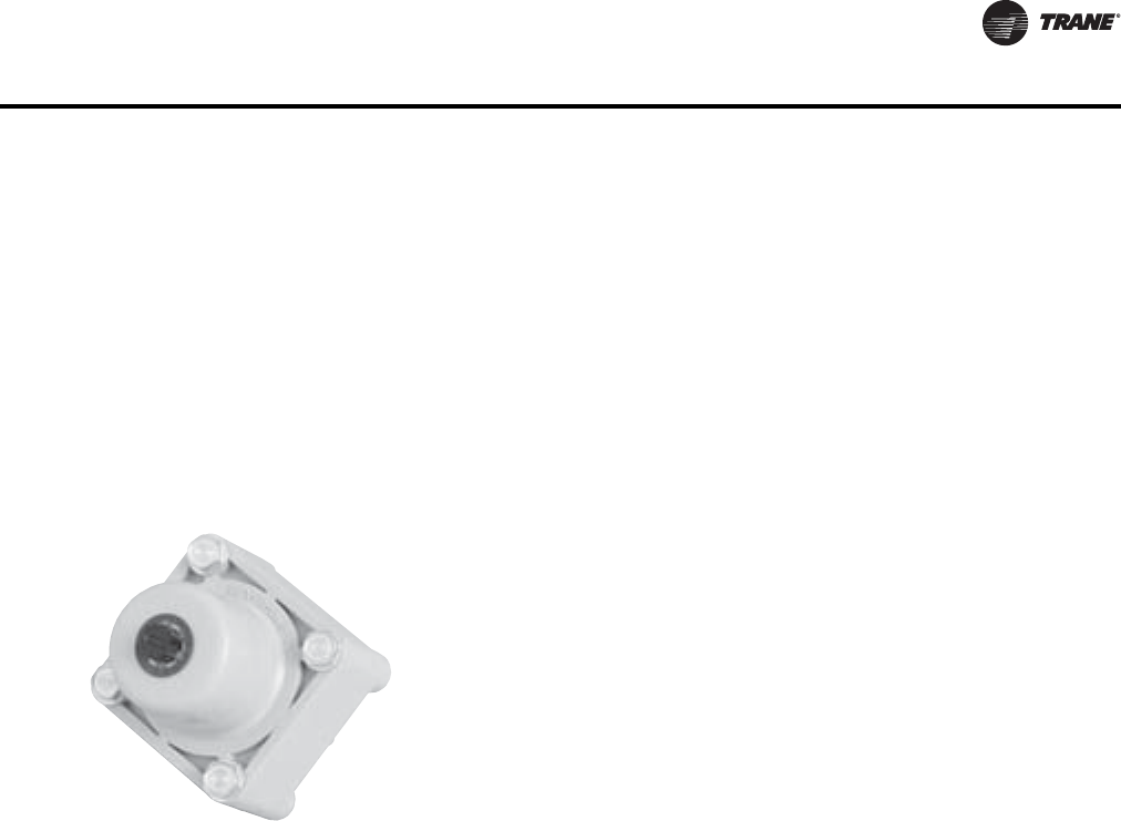
VAV-PRC012-EN 191
DDC Controls
Supply Connection
3/16" (4.8 mm) nipple for ¼" (6.4 mm) O.D. tubing
Weight
1.5 lbs (680 g)
Ambient Limits:
Operating:-20 to 120°F
(-28.889 to 48.889°C)
Shipping:-40 to 140°F (-40 to 60°C)
Reversing Relay
Specifications
Factory Setting
Contingent upon the selected control option
Generally set for 8 psig in. = 8 psig out or 9 psig in=9 psig out (55.2 kPa in. = 55.2 kPa out or 62.1
kPa in. = 62.1 kPa out)
Bias Adjustment
+/- 15 psig (103 kPa)
Main Air Pressure
15-30 psig (103–207 kPa)
Air Consumption
18 scim (0.295 L/m) at 20 psig (138 kPa) main air pressure
Operating Environment
40 to 120ºF (4°C to 49°C)
Storage Environment
-40 to 140ºF (-40 to 60°C)
Physical Dimensions
Width: 1.5" (38.1 mm)
Length: 1.5" (38.1 mm)
Height: 2.5" (63.5 mm)
Tubing Connections:
1/4" O.D. tubing connections
The pneumatic reversing relay is a proportional device that reverses the
action of the input signal. It is used to change a direct-acting signal into a
reverse-acting signal or to change a reverse-acting signal into a direct-acting
signal.This relay is used to match the operating pressure range of controlled
devices (valves, pressure switches, etc.) to the output pressure range of a
controller (such as a thermostat).The output response will always remain in
1:1 proportion to the input signal, but the relay includes the capability to bias
the output signal.
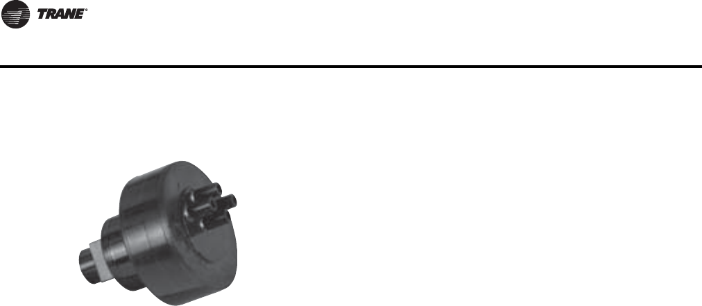
192 VAV-PRC012-EN
DDC Controls
Signal Limiter
Specifications
Factory Setting
Maximum output = 8 psig (55.2 kPa) Adjustable from 2–12 psig (13.8–82.7 kPa)
Main Air Pressure
Nominal 20 psig (138 kPa) 22 psig
(152 kPa) maximum acceptable pressure
Air Consumption
10 scim (0.164 L/m) at 20 psig (138 kPa) main air pressure
Operating Environment
50 to 120ºF (10 to 48.89°C)
Physical Dimensions
Width:. 1.1" (27.94 mm)|
Length: 0.9" (22.86 mm)
Height: 0.9" (22.86 mm)
Tubing Connections
9/100" (2.3 mm) nipples
Tubing Connections:
3/16" (4.8 mm) nipples for 1/4" (6.4 mm) polyethylene tubing
The pneumatic signal limiter is a pressure limiting type device.The output
pressure from the signal limiter is not allowed to rise above the signal
limiter’s setting. Adjustments to the output pressure setting are made via a
screw on the back side of the valve.
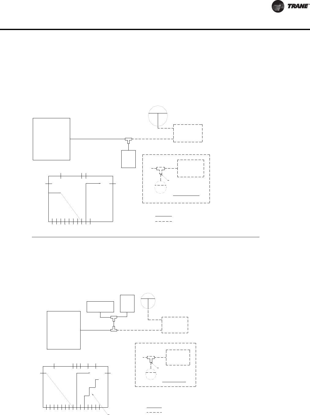
VAV-PRC012-EN 193
DDC Controls
Optional or installed by others.
Customer Notes:
1. Factory installed.
(Reverse-Acting)
Remote Mounted
One Pipe Inset
(Reverse-Acting)
Remote Mounted
Tee
T-Stat Pressure (PSI)
T-Stat Pressure (kPa)
3
100
Position %
Air Valve
20.7
Stages of Heat
14
8910 12
1st
96.5
2nd
Fan On
55.2
62.1
69
82.7
100
3rd
Restricted Leg
(137.9)
20
S
T-Stat
Actuator Tee
Terminal Box
Electric Heater
Fan P.E.
Tee
(N.O.)
Switch
(62.06 kPa)
9PSI
Restrictor
One Pipe
Two Pipe
T-Stat
(103.4)
15
(137.9)
20
S
T-Stat Pressure (kPa)
T-Stat Pressure (PSI)
100
Position %
Air Valve
3
20.7
Restrictor
Customer Notes:
100
89
Fan On
1.
Switch
(N.O.)
(62.06 kPa)
9PSI
55.2
62.1
Fan
P.E.
20
OnePipeInset
Factory installed.
Optional or installed by others.
One Pipe
T-Stat
Remote Mounted
(Reverse-Acting)
Restricted Leg
S
(137.9)
Tee
Actuator
15
(103.4)
Tee
(137.9)
Two Pipe
Remote Mounted
(Reverse-Acting)
T-Stat
20
S
Position %
Position %
PN00 – VPCF, LPCF Parallel Fan-Powered Without Reheat
(Normal Operation: Cooling Only)
Normally-Open Damper and Actuator (Reverse-Acting Thermostat)
With an increase in room temperature, the thermostat output pressure is decreased and the actuator opens to
increase primary cooling airflow to the space. With a decrease in room temperature, the opposite action occurs
until the damper is fully closed. Upon a continued decrease in zone temperature below setpoint, the parallel fan
is energized.
PN00 – VPEF, LPEF Parallel Fan-Powered with Electric Heat
(Normal Operation: Cooling Only)
Normally-Open Damper and Actuator (Reverse-Acting Thermostat)
With an increase in room temperature, the thermostat output pressure is decreased and the actuator opens to increase
primary cooling airflow to the space. With a decrease in room temperature, the opposite action occurs until the damper
is fully closed. Upon a continued decrease in zone temperature below setpoint, the parallel fan is energized. If zone
temperature continues to decrease after the fan has been energized, heating stages are energized at the appropriate
pressure settings.
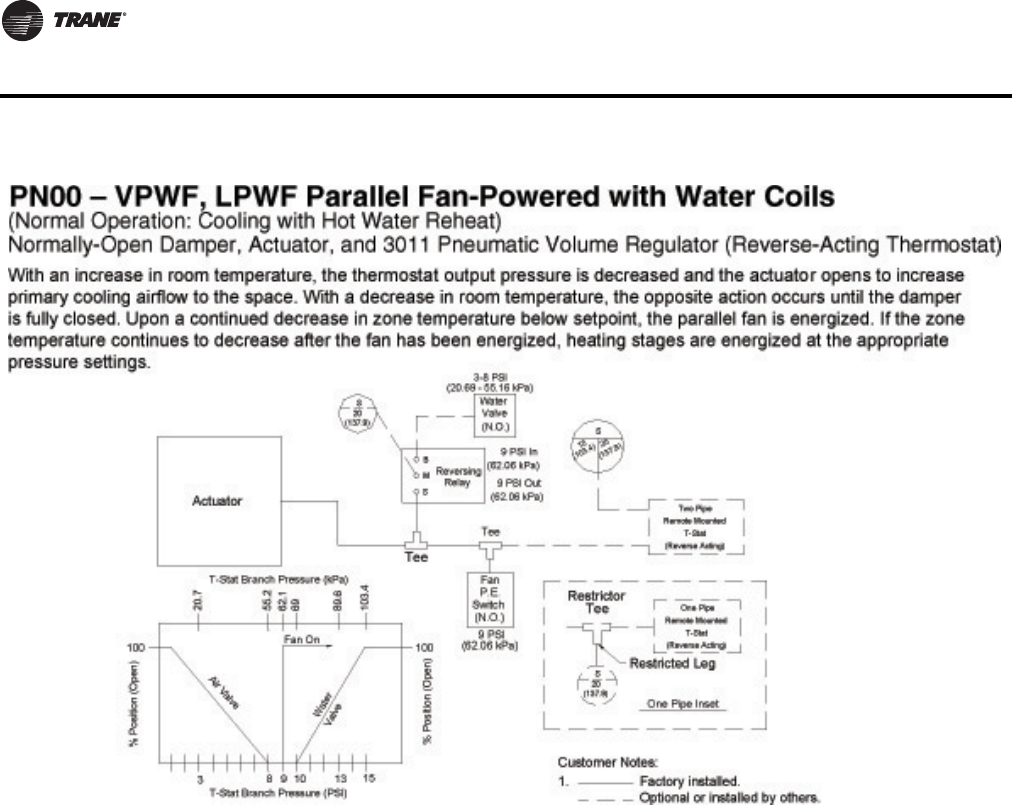
194 VAV-PRC012-EN
DDC Controls
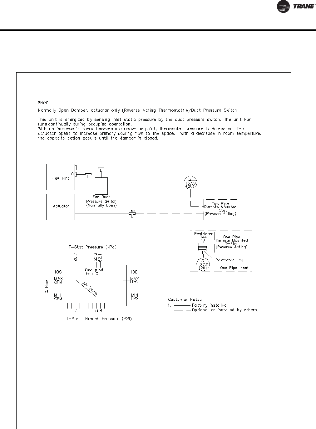
VAV-PRC012-EN 195
DDC Controls
PN00-VSCF, LSCF series fan-powered without reheat
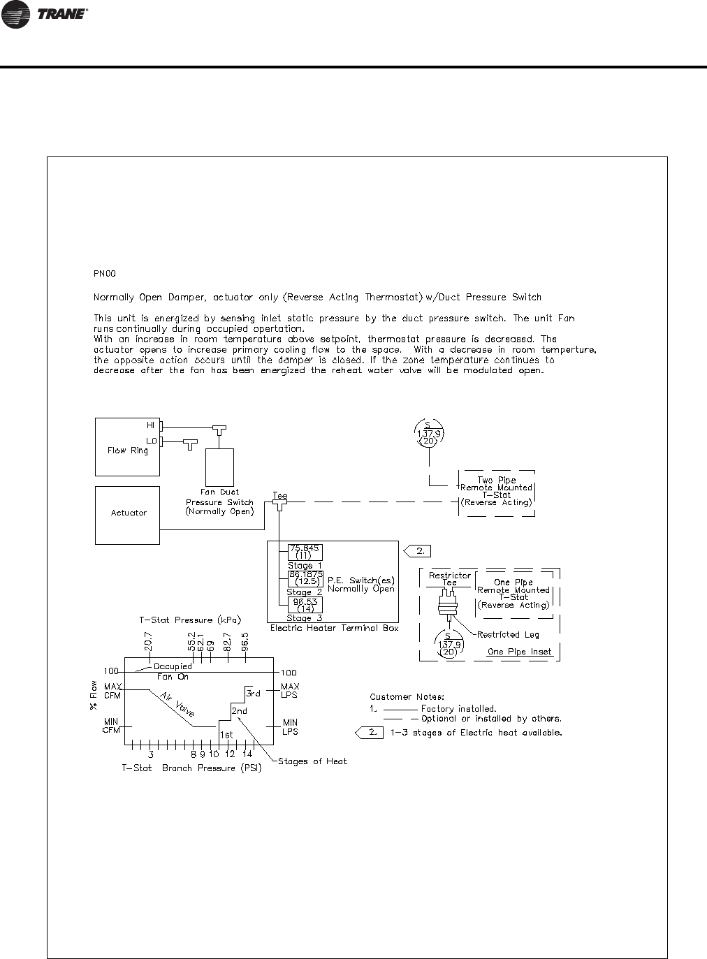
196 VAV-PRC012-EN
DDC Controls
PN00-VSEF, LSEF series fan-powered with electric heat
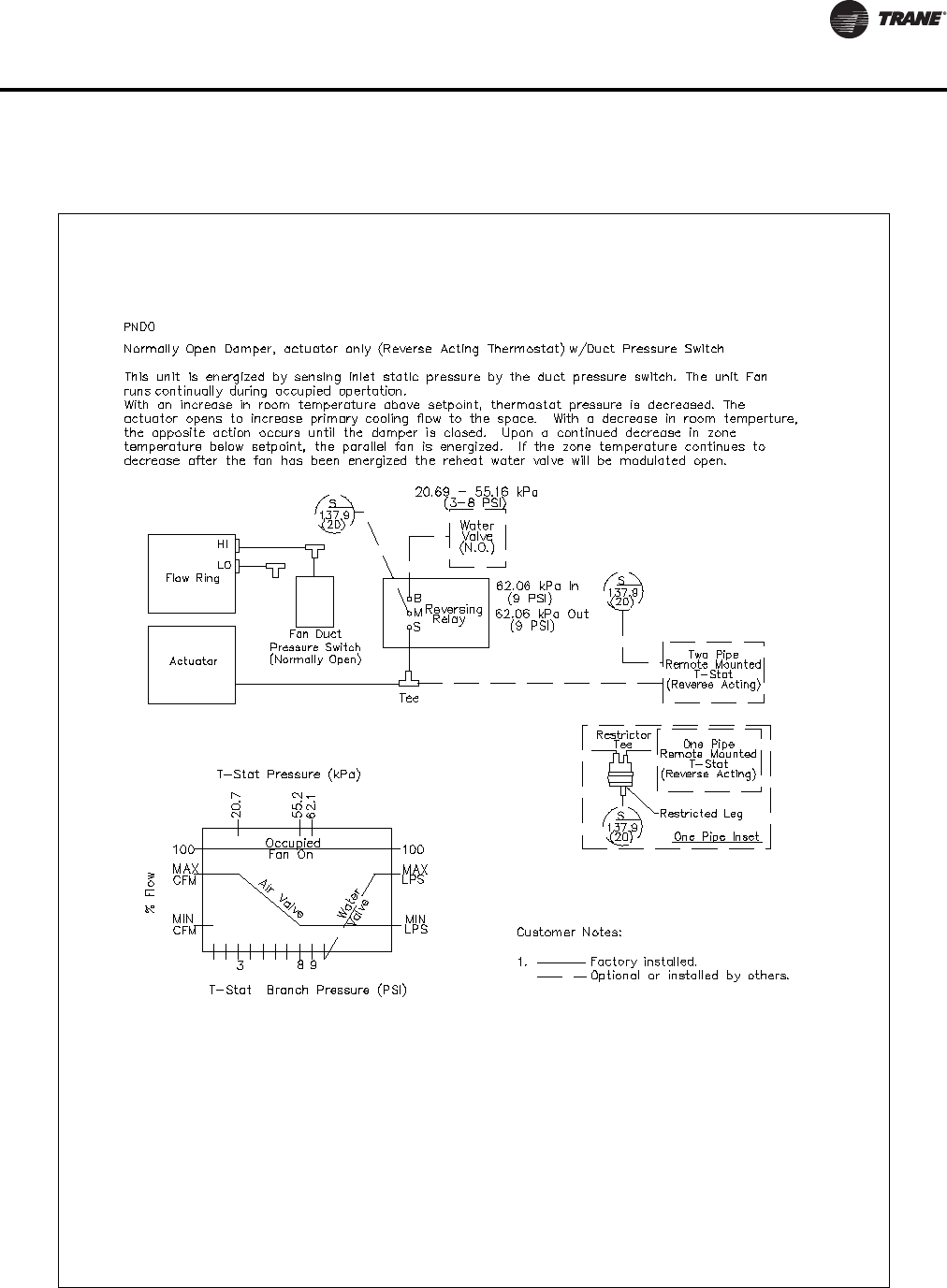
VAV-PRC012-EN 197
DDC Controls
PN00-VSWF, LSWF series fan-powered with water coils
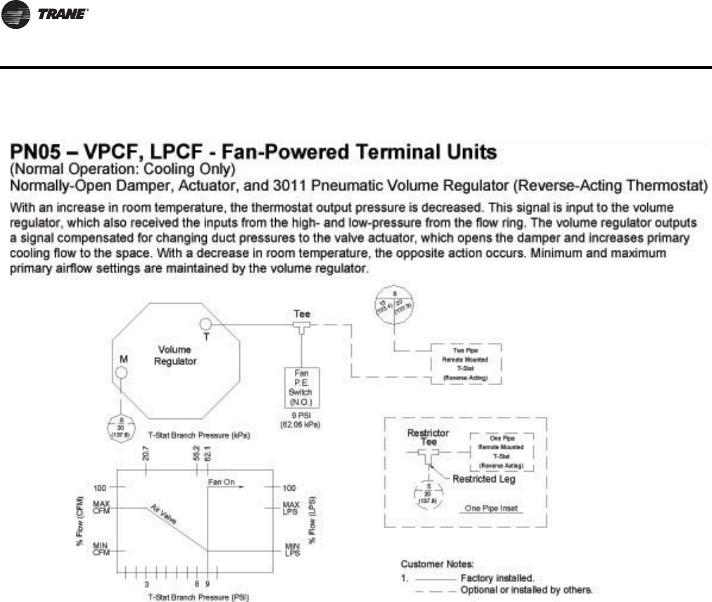
198 VAV-PRC012-EN
DDC Controls
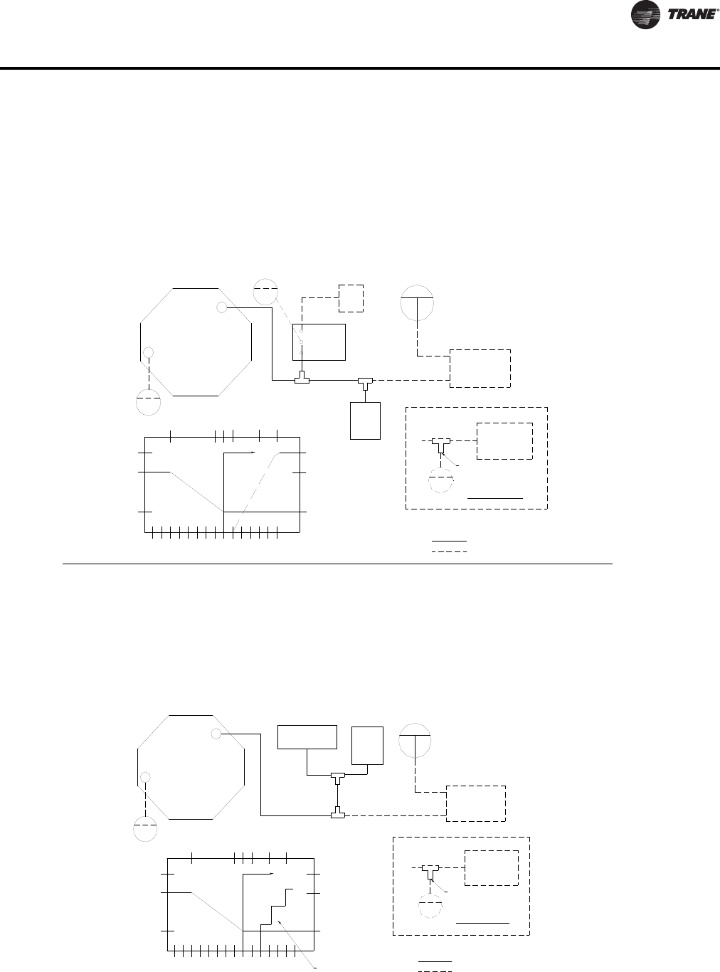
VAV-PRC012-EN 199
DDC Controls
Optional or installed by others.
Customer Notes:
1. Factory installed.
(Reverse Acting)
Remote Mounted
One Pipe
T-Stat
One Pipe Inset
(Reverse Acting)
T-Stat
Remote Mounted
Two Pipe
Fan On
T-Stat Branch Pressure (kPa)
T-Stat Branch Pressure (PSI)
%Flow(CFM)
3
MIN
CFM
89
MAX
CFM
100
20.7
AirValve
55.2
62.1
M
1310 15
Valve
Water
LPS
MIN
69
103.4
89.6
100
MAX
LPS
(62.06 kPa)
9PSI
(N.O.)
Switch
Fan
P.E.
Restrictor
Tee
Restricted Leg
T
(20.69 - 55.16 kPa)
9PSIOut
(62.06 kPa)
(62.06 kPa)
9PSIIn
Reversing
Tee
S
M
Tee
Relay
B
(N.O.)
Valve
Water
3-8 PSI
Tee
Tee
%Flow(CFM)
MIN
CFM
CFM
100
MAX
Air Valve
T-Stat Branch Pressure (PSI)
389
10 12 14
2nd
1st
3rd
Fan On
T-Stat Branch Pressure (kPa)
20.7
55.2
62.1
69
82.7
96.5
M
TTerminal Box
Electric Heater
Restricted Leg
Customer Notes:
Optional or installed by others.
Factory installed.
One Pipe Inset
Stages of Heat
MIN
LPS
LPS
1.
100
MAX
Tee
Restrictor
One Pipe
T-Stat
(Reverse Acting)
Remote Mounted
(Reverse Acting)
Remote Mounted
(62.06 kPa)
Fan P.E.
Switch
(N.O.)
9PSI
T-Stat
Two Pipe
(103.4)
15
(137.9)
20
S
S
(137.9)
20
Volume
Regulator
%Flow(LPS)
(Normal Operation: Cooling with Electric Reheat)
Normally-Open Damper, Actuator, and 3011 Pneumatic Volume Regulator
(Reverse-Acting Thermostat)
PN05 – VPEF, LPEF - Fan-Powered Terminal Units
15
(103.4)
20
(137.9)
S
(137.9)
20
S
S
(137.9)
20
(137.9)
20
S
(137.9)
20
S
Regulator
Volume
%Flow(CFM)
With an increase in room temperature, the thermostat output pressure is decreased. This signal is input to the volume regulator, which
also receives the inputs from the high- and low-pressure from the flow ring. The volume regulator outputs a signal compensated for
changing duct pressures to the valve actuator, which opens the damper and increases primary cooling flow to the space. With a
decrease in room temperature, the opposite action occurs. Minimum and maximum primary airflow settings are maintained by the
volume regulator. If the zone temperature continues to decrease after the fan has been energized, heating stages are energized at
the appropriate pressure settings.
(Normal Operation: Cooling with Hot Water Reheat)
Normally-Open Damper, Actuator, and 3011 Pneumatic Volume Regulator
(Reverse-Acting Thermostat)
PN05 – VPWF, LPWF - Fan-Powered Terminal Units
With an increase in room temperature, the thermostat output pressure is decreased. This signal is input to the volume regulator, which
also receives the inputs from the high- and low-pressure from the flow ring. The volume regulator outputs a signal compensated for
changing duct pressures to the valve actuator, which opens the damper and increases primary cooling flow to the space. With a
decrease in room temperature, the opposite action occurs. Minimum and maximum primary airflow settings are maintained by the
volume regulator. If the zone temperature continues to decrease after the fan has been energized, heating stages are energized at
the appropriate pressure settings.
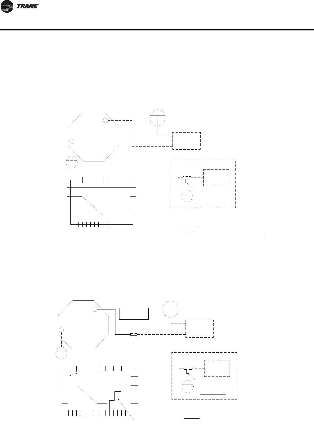
200 VAV-PRC012-EN
DDC Controls
Customer Notes:
1. Factory installed.
Two Pipe
Remote Mounted
T-Stat
(Reverse Acting)
One Pipe Inset
T-Stat
One Pipe
Remote Mounted
(Reverse Acting)
T-Stat Branch Pressure (PSI)
T-Stat Branch Pressure (kPa)
MAX
CFM
MIN
CFM
3
Air Valve
100
20.7
Fan On
Occupied
MRegulator
Volume
MAX
Stages of Heat
2nd
10
89 12
1st
14
LPS
3rd
MIN
LPS
55.2
69
62.1
82.7
96.5
100
Restrictor
S
Tee
Restricted Leg
TElectric Heater
Tee
Terminal Box
Volume
Regulator
Fan On
Occupied
T-Stat Branch Pressure (kPa)
T-Stat Branch Pressure (PSI)
3
20.7
100
CFM
CFM
MAX
% Flow (CFM)
MIN
Air Valve
M
98
Tee
Restrictor
Customer Notes:
62.1
55.2
LPS
MIN
1.
100
MAX
LPS
(Reverse Acting)
One Pipe Inset
Optional or installed by others.
Factory installed.
Restricted Leg
S
Remote Mounted
T-Stat
One Pipe
T
Two Pipe
Remote Mounted
T-Stat
(Reverse Acting)
(137.9)
S
20
(137.9)
20
(103.4)
S
20
(137.9)
15
also receives the inputs from the high- and low-pressure from the flow ring. The volume regulator outputs a signal compensated for
changing duct pressures to the valve actuator which opens the damper and increases primary cooling flow to the space. With a
decrease in room temperature, the opposite action occurs. Minimum and maximum primary airflow settings are maintained by the
volume regulator.
With an increase in room temperature, the thermostat output pressure is decreased. This signal is input to the volume regulator, which
Normally-Open Damper, Actuator, and 3011 Pneumatic Volume Regulator (Reverse-Acting Thermostat)
(Normal Operation: Cooling Only - Duct Pressure Switch)
This unit is energized by sensing inlet static pressure by the duct pressure switch. The unit fan runs continually during occupied operation.
% Flow (LPS)
% Flow (CFM)
(137.9)
20
S
(137.9)
20
(137.9)
20
15
(103.4)
S
This unit is energized by sensing inlet static pressure by the duct pressure switch. The unit fan runs continually during occupied operation.
With an increase in room temperature, the thermostat output pressure is decreased. This signal is input to the volume regulator, which
also receives the inputs from the high- and low-pressure from the flow ring. The volume regulator outputs a signal compensated for
decrease in room temperature, the opposite action occurs. Minimum and maximum primary airflow settings are maintained by the
changing duct pressures to the valve actuator which opens the damper and increases primary cooling flow to the space. With a
volume regulator. If the zone temperature continures to decrease after the fan has been energized, heating stages are energized at the
PN51 – VSEF, LSEF - Fan-Powered Terminal Units
Normally-Open Damper, Actuator, and 3011 Pneumatic Volume Regulator (Reverse-Acting Thermostat)
(Normal Operation: Cooling with Electric Reheat - Duct Pressure Main)
% Flow (LPS)
appropriate pressure settings.
Optional or installed by others.
PN51 – VSCF, LSCF - Fan-Powered Terminal Units
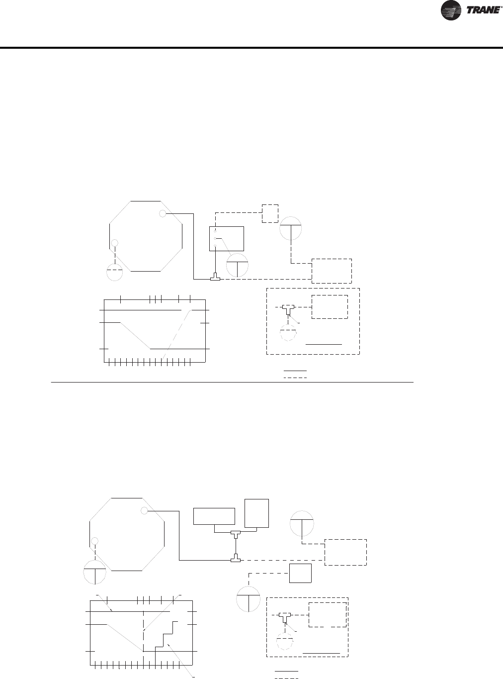
VAV-PRC012-EN 201
DDC Controls
Optional or installed by others.
Customer Notes:
1. Factory installed.
Two Pipe
Remote Mounted
T-Stat
(Reverse Acting)
One Pipe Inset
T-Stat
One Pipe
Remote Mounted
(Reverse Acting)
T-Stat Branch Pressure (kPa)
T-Stat Branch Pressure (PSI)
Air Valve
% Flow (CFM)
3
MIN
CFM
89
MAX
CFM
100
20.7
Fan On
Occupied
55.2
62.1
1310 15
Valve
Water
LPS
MIN
89.6
69
103.4
100
MAX
LPS
Restrictor
Tee
Restricted Leg
9 PSI In
(62.06 kPa)
(62.06 kPa)
9 PSI Out
(20.69 - 55.16 kPa)
Relay
Tee
S
Reversing
M
B
(N.O.)
3-8 PSI
Water
Valve
Regulator
Volume
M
T
T-Stat Branch Pressure (PSI)
T-Stat Branch Pressure (kPa)
100
CFM
MIN
CFM
MAX
% Flow (CFM)
3
Air Valve
Occupied
20.7
Fan On
Stages of Heat
1st
8910 1412
2nd
3rd
MIN
LPS
LPS
MAX
100
Fan On
Unoccupied
62.1
55.2
69
96.5
82.7
One Pipe Inset
Factory installed.
Optional or installed by others.
Customer Notes:
1.
(Reverse Acting)
Remote Mounted
Restricted Leg
Restrictor
Tee
T-Stat
One Pipe
Regulator
M
Volume
T
Fan P.E.
Switch-1
(62.06 kPa)
9 PSI
Tee
Electric Heater
Terminal Box
Tee
(N.O.)
20
(137.9)
S
15
20
(103.4)
(137.9)
S
% Flow (LPS)
PN52 – VSEF, LSEF - Fan-Powered Terminal Units
(Normal Operation: Cooling with Electric Reheat - Duct Pressure Switch)
Normally-Open Damper, Actuator, and 3011 Pneumatic Regulator
(Reverse-Acting Thermostat)
The unit is energized into occupied status by a setting of main system air pressure to 15 psi (103 kpa). At unoccupied, the main
system air is set to 20 psi (138 kpa). The unit fan cycles on as 1st stage heat when called for by the unit t-stat. Dual setpoint
pneumatic thermostat is suggested for this option. With an increase in room temperature, the thermostat output pressure is
decreased. This signal is input to the volume regulator, which also receives the inputs from the high- and low-pressure from
the flow ring. The volume regulator outputs a signal compensated for changing duct pressures to the valve actuator, which
opens the damper and increases primary cooling flow to the space. With a decrease in room temperature, the opposite action
occurs. If the zone temperature continues to decrease after the fan has been energized, heating stages are energized at the
appropriate pressure settings.
% Flow (LPS)
15
20
(103.4)
(137.9)
S
(137.9)
20
S
(137.9)
20
S
(103.4)
(137.9)
S
20
15
This unit is energized by sensing inlet static pressure by the duct pressure switch. The unit fan runs continually during occupied
operation. With an increase in room temperature the thermostat output pressure is decreased. This signal is input to the volume
regulator, which also receives the inputs from high- and low-pressure from the flow ring. The volume regulator outputs a signal
compensated for changing duct pressures to the valve actuator which opens the damper and increases primary cooling flow to
the space. With a decrease in room temperature, the opposite action occurs. Minimum and maximum primary airflow settings
are maintained by the volume regulator. If the zone temperature continues to decrease after the fan has been energized, heating
stages are energized at the appropriate pressure settings.
PN51 – VSWF, LSWF - Fan-Powered Terminal Units
(Normal Operation: Cooling with Hot Water Reheat - Duct Pressure Switch)
Normally-Open Damper, Actuator, and 3011 Pneumatic Volume Regulator
(Reverse-Acting Thermostat)
18 PSI
(124.11 kPa)
(N.C.)
Swtich-2
Fan P.E.
(103.4)
15
20
(137.9)
S
(Reverse Acting)
T-Stat
Remote Mounted
Two Pipe
(103.4)
15
20
(137.9)
S
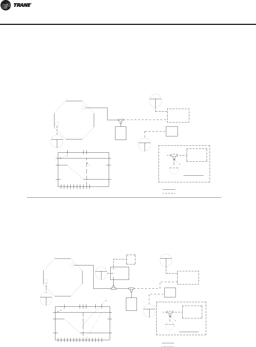
202 VAV-PRC012-EN
DDC Controls
Optional or installed by others.
Customer Notes:
1. Factory installed.
Restricted Leg
(Reverse Acting)
T-Stat
Remote Mounted
Two Pipe
T-Stat Branch Pressure (kPa)
T-Stat Branch Pressure (PSI)
MAX
CFM
MIN
CFM
3
Air Valve
100
20.7
Fan On
Occupied
MRegulator
Volume
MAX
89
Fan On
Unoccupied
LPS
MIN
LPS
62.1
55.2
100
(62.06 kPa)
9 PSI
Switch-1
(N.O.)
Fan
P.E.
(20)
S
137.9
18 PSI
Tee
Restrictor
(124.11 kPa)
(N.C.)
Swtich-2
Fan P.E.
T
Tee
(Reverse Acting)
One Pipe Inset
T-Stat
Remote Mounted
One Pipe
Remote Mounted
T-Stat Branch Pressure (PSI)
T-Stat Branch Pressure (kPa)
38
55.2
20.7
CFM
MIN
MAX
CFM
100
Air Valve
Occupied
Fan On
910 15
13
Unoccupied
103.4
89.6
62.1
Fan On
Water
Valve
69
MIN
LPS
LPS
MAX
Tee
P.E.
(N.O.)
Switch-1
9 PSI
(62.06 kPa)
Tee
Fan
One Pipe
Restrictor
One Pipe Inset
Restricted Leg
Factory installed.
Optional or installed by others.
Customer Notes:
1.
Tee
Remote Mounted
T-Stat
(Reverse Acting)
(124.11 kPa)
(N.C.)
Swtich-2
Fan P.E.
18 PSI
(Reverse Acting)
T-Stat
Regulator
M
Volume
T
B
Relay
Reversing
S
M
Valve
(N.O.)
Water
Two Pipe
(103.4)
15
20
(137.9)
S
(137.9)
20
S
15
(103.4)
20
(137.9)
(103.4)
15
S
(137.9)
20
S
15
(103.4)
(137.9)
20
S
9 PSI In
9 PSI Out
(62.06 kPa)
(62.06 kPa)
(20.69 - 55.16 kPa)
3-8 PSI
% Flow (CFM)
% Flow (LPS)
PN52 – VSWF, LSWF - Fan-Powered Terminal Units
(103.4)
15
20
(137.9)
S
(103.4)
15
20
(137.9)
S
(103.4)
15
20
(137.9)
S
% Flow (CFM)
% Flow (LPS)
The unit is energized into occupied status by a setting of main system air pressure to 15 psi (103 kpa). At unoccupied, the main
system air is set to 20 psi (138 kpa). The unit fan cycles on as 1st stage heat when called for by the unit's thermostat. Dual
setpoint pneumatic thermostat is suggested for this option. With an increase in room temperature, the thermostat output pressure
is decreased. This signal is input to the volume regulator, which also receives the inputs from the high- and low-pressure from the
flow ring. The volume regulator outputs a signal compensated for changing duct pressures to the valve actuator which opens the
damper and increases primary cooling flow to the space. With a decrease in room temperature, the opposite action occurs. Minimum
and maximum primary airflow settings are maintained by the volume regulator.
PN52 – VSCF, LSCF - Fan-Powered Terminal Units
(Normal Operation: Cooling with Electric Reheat - Dual Pressure Main)
Normally-Open Damper, Actuator, and 3011 Pneumatic Volume Regulator
(Reverse-Acting Thermostat)
(Normal Operation: Cooling with Electric Reheat - Dual Pressure Main)
Normally-Open Damper, Actuator, and 3011 Pneumatic Volume Regulator
(Reverse-Acting Thermostat)
The unit is energized into occupied status by a setting of main system air pressure to 15 psi (103 kpa). At unoccupied, the main
system air is set to 20 psi (138 kpa). The unit fan cycles on as 1st stage heat when called for by the unit's thermostat. Dual
setpoint pneumatic thermostat is suggested for this option. With an increase in room temperature, the thermostat output pressure
is decreased. This signal is input to the volume regulator, which also receives the inputs from the high- and low-pressure from the
flow ring. The volume regulator outputs a signal compensated for changing duct pressures to the valve actuator which opens the
damper and increases primary cooling flow to the space. With a decrease in room temperature, the opposite action occurs. If the
zone temperature continues to decrease after the fan has energized, heating stages are energized at the appropriate pressure settings.

VAV-PRC012-EN 203
DDC Controls
Controls Specifications
For allVariTrane units, the unit controller continuously monitors the zone temperature and varies
the primary airflow as required to meet zone setpoints. Airflow is limited by adjustable minimum
and maximum setpoints.
Additionally, for series fan-powered units, the controller will start and run the fan continuously
during the occupied mode and intermittently during the unoccupied mode. Upon a further call for
heat, any hot water or electric heat associated with the unit is enabled.
For parallel fan-powered units, the controller energizes the fan upon a call for heat. Upon a further
call for heat, reheat is enabled.
Fan Speed Control
Variable Speed Control Switch (SCR)
The SCR speed control device is standard on all fan-powered units.The SCR adjusts the fanspeed
and provides simplified system balancing.
Direct Digital Controls (DDC)
LonMark Direct Digital Controller
Trane-designed LonMark certified controller uses the space comfort control (SCC) profile to
exchange information over a LonTalk Network. LonMark networks provide the latest open protocol
technology.
Direct Digital Controller
The microprocessor-based terminal unit controller provides accurate, pressure-independent
control through the use of a proportional integral control algorithm and direct digital control
technology.The UCM, monitors zone temperature setpoints, zone temperature, the rate of
temperature change, and valve airflow. With the addition of optional sensors, room occupancy or
supply duct air temperature can be monitored.The controller is provided in an enclosure with 7/
8" (22 mm) knockouts for remote control wiring. ATrane DDC zone sensor is required.
DDC Actuator
Trane 3-wire, 24-VAC, floating-point quarter turn control actuator with linkage release button.
Actuator has a constant drive rate independent of load, a rated torque of 35 in-lb, a 90-second drive
time, and is non-spring return.Travel is terminated by end stops at fully opened and closed
positions. An integral magnetic clutch eliminates motor stall.
DDC Actuator - Belimo
LMB24-3-TTN 3-wire, 24VAC/DC, floating-point, quarter turn actuator with linkage release button.
Actuator has a constant drive rate independent of load, a rated torque of 45 in-lb, a 95 second drive
time, and is non-spring return.Travel is terminated by end stops at fully-opened and -closed
positions. Internal electronic control prevents motor stall when motor reaches end stops.
DDC Zone Sensor
The UCM controller measures zone temperature through a sensing element located in the zone
sensor. Other zone sensor options may include an externally-adjustable setpoint, communications
jack for use with a portable service tool, and an override button to change the individual controller
from unoccupied to occupied mode.The override button has a cancel feature that will return the
system to unoccupied. Wired zone sensors utilize a thermistor to vary the voltage output in
response to changes in the zone temperature. Wiring to the UCM controller must be 18 to 22 awg.
twisted pair wiring.The setpoint adjustment range is 50–88ºF (10–31°C) Depending upon the
features available in the model of sensor selected, the zone sensor may require from a 2-wire to
a 7-wire connection. Wireless zone sensors report the same zone information as wired zone

204 VAV-PRC012-EN
DDC Controls
sensors, but do so using radio transmitter technology. No wiring from the zone sensor to the UCM
controller is necessary.
Digital Display Zone Sensor with Liquid Crystal Display (LCD)
The direct digital zone sensor contains a sensing element which sends a signal to the UCM.A Liquid
Crystal Display (LCD) indicates setpoint, or space temperature. Sensor buttons allow setpoint
adjust, and allow space temperature readings to be turned on or off.The digital display zone sensor
also includes a communication jack, for use with a portable edit device, and an override button to
change the UCM from unoccupied to occupied.The override button has a cancel feature, which
returns the system to unoccupied mode.The digital display zone sensor requires seven wires, one
for 24-VAC power.
System Communications
The Controller UCM sends and receives data from aTracer SC or otherTrane Controller. Current
unit status and setpoints may be monitored and/or edited via this data communication feature.The
network type is a twisted wire pair shielded serial communication.
The following direct digital control features are available with VariTrane terminal units:
• Controls Option – DD00:Trane actuator for field-installed DDC controllers
• Controls Option – DD01: Cooling Only (DDC/UCM)
• Controls Option – DD02: Cooling with Normally-Closed On/Off hot water valve (Normally-Open
outputs) (DDC/UCM)
• Controls Option – DD03: Cooling with proportional hot water valve with optional spare On/Off
Output) (DDC/UCM)
• Controls Option – DD04: Cooling with staged On/Off electric heat (DDC/UCM)
• Controls Option – DD05: Cooling with pulse-width modulation electric heat (DDC/UCM)
• Controls Option – DD07: Cooling with Normally-Open On/Off hot water valve (Normally-Closed
outputs) (DDC/UCM)
• Controls Option – DD08: Cooling and Heating - Dual-Duct Constant Volume (DDC/UCM)
• Controls Option – FM00: Factory installation of customer supplied actuator and DDC controls.
Controls supplier is responsible for providing factory-installation and wiring instructions.
• Controls Option – FM01:Trane actuator with factory installation of customer supplied DDC
controls. Controls supplier is responsible for installing and wiring instructions.
• Controls Option – ENON: Shaft only for field-installation of customer-supplied actuator and
controls.The following override commands may be received by the Unit Control Module (UCM)
from aTracer SC or otherTrane controllers.
• Control Mode –The UCM Control Mode may be edited from occupied to unoccupied to
accommodate night setback/setup.
• Control Action –The Control Action may be edited from cooling to heating, changing the
primary air damper to a heating source.This will accommodate a cooling/heating changeover
system.
• Control Offset – Enabling Control Offset will increase the cooling temperature setpoint and
decrease the heating temperature setpoint by a control-offset value (Stored at limiting in the
occupied mode).
• Drive damper fully open
• Drive damper fully closed
• Drive damper to maximum airflow setpoint
• Drive damper to minimum airflow setpoint
• Disable unit heat

VAV-PRC012-EN 205
DDC Controls
• Reset-Enabling the reset function forces the controller and the flow sensor to recalibrate
• Programmable hot water valve drive time
• Programmable air damper drive time
The following unit setpoints reside in the UCM in nonvolatile memory.These setpoints are editable
from theTracer via the communications link.
• Occupied cooling temperature setpoint (60–80ºF (15–26°C))
• Occupied heating temperature setpoint (60–80ºF (15–26°C))
• Unoccupied cooling temperature setpoint (60–100ºF (15–37°C))
• Unoccupied heating temperature setpoint (30–100ºF (15–37°C))
• Minimum cooling flow setpoint (0, 10–110% of unit equivalent nominal airflow)
• Minimum heating flow setpoint (0, 10–110% of unit equivalent nominal airflow)
• Maximum flow setpoint (0, 50–100% of unit equivalent nominal airflow)
• Fan Control Offset –This determines at what operating point the fan in a parallel fan-powered
unit is energized.This can be specified as a function of temperature, degrees above heating
setpoint, or primary airflow (0–10°F (-17–12°C) or 0,10–100% of unit equivalent nominal airflow).
• Heating Setpoint Offset –This determines at what point the first stage of reheat turns on.
Expressed in degrees below cooling setpoint. (Only applicable when local thumbwheel is
enabled.)
• Zone temperature, auxiliary temperature, and zone setpoint calibration corrections (adjustable
from +/-10.0ºF (+/- -12°C)).
• Flow measurement calibration correction (50–150%)
• Cooling Setpoint Low Limit – Applies low limit to programmed occupied cooling setpoint or
zone sensor cooling setpoint (30–100°F (-1–37°C)).
• Heating Setpoint High Limit – Applies high limit to programmed occupied heating setpoint or
zone sensor heating setpoint (30–100ºF (-1–37°C)).
• RTD /Thermistor – Determines what type of zone temperature sensor will be used.
• Occupied and Unoccupied Outside Air Requirements – Determines the percent of outdoor air
required in the zone for air quality requirements.
• Series Fan Configuration – allows option of series fan-powered box to shut off fan and close air
valve when unit is unoccupied. Fan will operate in unoccupied mode if reheat is active.
• Heating setpoint low limit.
• Cooling setpoint high limit.
• Local heating flow setpoint enable/disable and setpoint.
• Auxiliary analog input mode select for either auxiliary temperature sensor or CO2detector.
• Binary input mode select for either generic or occupancy detector. In addition to the above
setpoints, the following status information can be transmitted to aTracer SC or otherTrane
controllers.
• Active cooling temperature setpoint
• Active heating temperature setpoint
• Current unit primary airflow
• Current zone temperature
• Re-heat status (On/Off)
• Auxiliary AirTemperature – Available only if the unit has an auxiliary temperature sensor.

206 VAV-PRC012-EN
DDC Controls
• Failure Indicators –The UCM will indicate the following: 1)Temperature Sensor Failure; 2) Flow
Sensor Failure; and 3) Local Zone Sensor Setpoint Failure.
• Ventilation Ratio
• Fan Status (on/off)
• Calibration Status (calibration/not-calibrating)
• BIP state
•CO
2Concentration—Available only if the unit has an auxiliary CO2sensor.This mode and
auxiliary air temperature are mutually exclusive.
Pneumatic Controls
Normally-Open Actuator
Pneumatic 3 to 8 psig (20 to 55 kPa) spring-range pneumatic actuator.
Normally-Closed Actuator
Pneumatic 8 to 13 psig (55 to 90 kPa) spring-range pneumatic actuator.
3011 Pneumatic Volume Regulator (PVR)
The regulator is a thermostat reset velocity controller, which provides consistent air delivery within
5% of cataloged flow down to 15% of unit cataloged cfm, independent of changes in system static
pressure. Factory-calibrated, field-adjustable setpoints for minimum and maximum flows.
Average total unit bleed rate, excluding thermostat, is 28.8 scim at 20 psig (7.87 mL/min at 138 kPa)
supply.
3501 Pneumatic Volume Regulator (PVR)
The 3501 regulator is a linear-reset volume controller.This PVR is used to maintain a constant
volume of airflow from the dual-duct unit when constant volume control is used. Average total unit
bleed rate, excluding thermostat, is 43.2 scim at 20 psig (11.8 mL/min at 138 kPa) supply.
Considerations for PneumaticThermostat
Field-supplied and -installed based on chosen control options, a direct-acting or a reverse- acting,
one-pipe or two-pipe pneumatic room thermostat will control the available air valve, reheat and
fan switch to maintain room temperature setpoint.
The following pneumatic control options features are available with VariTrane terminal units:
• PN00: Cooling with Normally-Open damper and actuator only (Reverse-ActingThermostat)
• PN04: Cooling with hot water reheat, Normally-Open damper, 3011 PVR (Direct-Acting
Thermostat)
• PN05: Cooling with electric reheat, Normally-Open damper, 3011 PVR (Reverse-Acting
Thermostat)
• PN08: Cooling and Heating, Normally-Open dampers, actuators only (Reverse-Acting
Thermostat)
• PN09: Cooling and Heating, Normally-Open dampers, 3011 PVR’s (Direct-ActingThermostat)
• PN10: Cooling and Heating, Normally-Open dampers, 3501 PVR’s, Dual-Duct ConstantVolume
(Direct-ActingThermostat)
• PN11: Cooling with hot water reheat, Normally-Open damper, 3011 PVR - Auto Dual Minimum
(Direct-ActingThermostat) (N.O. Water Valve)
• PN32: Cooling with hot water reheat, Normally-Open damper, 3011 PVR - Constant Volume
(Direct-ActingThermostat)
• PN34: Cooling with electric reheat, Normally-Open damper, 3011 PVR - Constant Volume
(Reverse-ActingThermostat)
• PN51: Cooling with reheat, Normally-Open damper, 3011 PVR Duct Pressure Switch (Reverse-
ActingThermostat)
• PN52: Cooling with reheat, Normally-Open damper, 3011 PVR - Dual Pressure Minimum
(Reverse-ActingThermostat)

VAV-PRC012-EN 207
DDC Controls
• PC00: Cooling Only with Normally-Closed damper - Direct-ActingThermostat
• PC03: Cooling and Heating, Normally-Closed heating damper, Normally-Open cooling damper,
actuators only - Direct-ActingThermostat
• PC04: Cooling with hot water reheat, Normally-Closed damper, 3011 PVR - Direct-Acting
Thermostat
• PC05: Cooling with electric reheat, Normally-Closed damper, 3011 PVR - Reverse-Acting
Thermostat
Options
Power Fuse (cooling only and hot water units, and VDDF)
An optional fuse is factory-installed in the primary voltage hot leg.
Transformer (Standard on fan-powered, optional on VCCF, VCWF, VDDF)
The 50-VA transformer is factory-wired and installed in an enclosure with 7/8" (22 mm) knockouts
to provide 24 VAC for controls.
Wireless Zone Sensor/Receiver
Factory mounted Receiver with field mounted Sensor accessory eliminates the need for the wiring
between the zone sensor and unit level controller. See specifications on Page C67XXX.
Disconnect Switch (Optional on VCCF, VCWF, VDDF)
Disengages power.
DDC Retrofit Kit (VRTO)
The kit consists of aTrane DDC Unit Control Module (UCM) VAV terminal unit controller and a
pressure transducer installed in a metal enclosure.The mechanical specifications of accessories
such as DDC zone sensors, hot water valves, and transformers are found elsewhere in this section.
Retrofit Kit Options
Flow Bar Sensor
The flow bar sensor is a multiple-point, averaging, pitot tube type flow sensor. It is intended for field
installation on terminal units that have no flow measurement device.The total and static pressure
outputs of the sensor are field-piped to the high and low inputs of the pressure transducer in the
retrofit kit.
Retrofit Kit Actuator
The electric actuator is a direct-coupled type actuator that utilizes three-wire, floating-point control.
The actuator is field-installed to the damper shaft and field-wired to the controller.
Trane Actuator – Actuator is rated at 4 VA at 24 VAC. Drive time is 90 seconds with 35 in.-lb (4 N-m).
Retrofit Actuator – Actuator is rated at 3 VA at 24 VAC. Drive time is 80 to 110 seconds for 0 to 35
in.-lb (0 to 4 N-m).
Other Options Available
• DDC Zone Sensors
• 2-Position & Modulating Water Valves
• ControlTransformer (Ships loose with mounting plate for 4x4 junction box)
• AuxiliaryTemperature Sensor
• Zone Occupancy Sensors
•Co
2Sensors (Room- or duct-mounted)
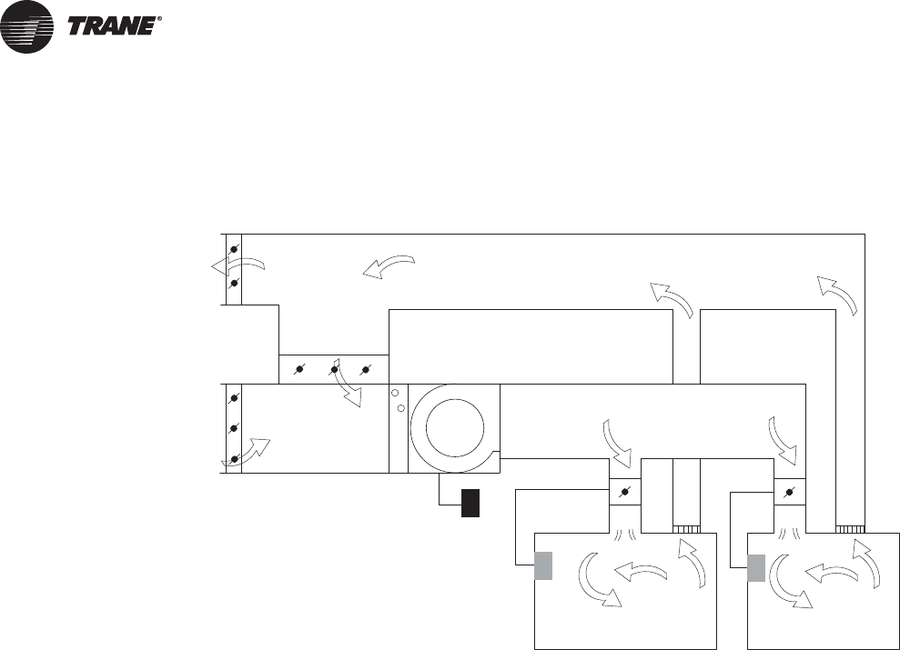
208 VAV-PRC012-EN
Application Considerations
VAV System
No Heat
Central Cooling Only—In some systems, the central air handler provides only cooling and
ventilation during zone occupied periods.The supply air is maintained at a constant temperature
and the supply airflow is modulated to match the VAV airflow rate with the zone cooling
requirements.
Central Heat
Central Heat for Morning Warm-up—Many buildings cool down during the night.To be at a
comfortable temperature in the morning when the building is again occupied, heat must be added
to the spaces. Heat provided by the central air handler for morning warm-up is supplied at constant
air volume to the zones, prior to the time of occupancy. During the morning warm-up period, the
VAV terminal units must open to allow heated air to flow into the zones. In most instances very little
additional heat is needed once the building is occupied.
Central Occupied Heating-Changeover—Some buildings use the same air handler to provide
both occupied cooling and occupied heating.This is commonly referred to as a changeover system.
The system changes between heating and cooling depending on the need of the zones on the
system. In a changeover system, the operation of the VAV terminal units must also change over,
opening to provide heat in the heating mode and opening to provide cooling in the cooling mode.
Trane's main product in this type of application is calledVariTrac™.VariTrane products can also be
used in these systems. (These types of systems are beyond the scope of this manual and are
discussed in detail in the VariTrac II Manual.
Variable-Air-Volume (VAV) System
RA
EA
OA PA
supply
fan
cooling
coil
variable-
speed drive
thermostat
VAV
box
SA
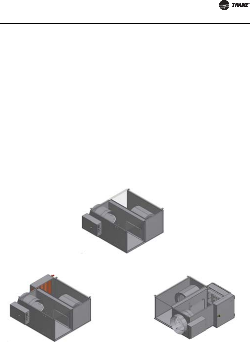
VAV-PRC012-EN 209
Application Considerations
Terminal Heat
Remote Heat—In some zones of a single-ductVAV system, perimeter heating equipment, remote
from the terminal unit, is used to add heat to the zone when the cooling load is lower than the
minimum cooling capacity of the VAV terminal unit. Heat is added directly to the zone while cool
supply air continues to enter the zone at a minimum rate for zone ventilation.
Terminal Reheat—In some zones of a single-ductVAV system, a minimum flow of cool supply air
is reheated at the terminal unit before entering the zone.Terminal reheat can be provided by
electrical resistance heaters or by hot water coils.
Parallel Fan-Powered Heat—In some zones of a single-duct VAV system, cool supply air at
minimum flow is mixed with warm plenum air before entering the zone at a constant flow rate. A
fan in the terminal unit, in parallel with the central fan, draws air from the plenum whenever the
zone requires heat.
Series Fan-Powered Heat—In some zones of a single-duct VAV system, the airflow to the zone
is held constant, during both heating and cooling, by a terminal unit fan that is in series with the
central fan.The terminal unit fan runs continuously. When the zone requires heat, cool supply air
at minimum flow is mixed with warm, return plenum air before entering the zone.
VariTrane VAV Terminal Units
The function of the VariTrane terminal unit in a VAV control zone is to vary the volumetric airflow
rate to the zone. VariTrane units are available with either microprocessor-based DDC controls or
pneumatic or analog electronic controls. Factory-installed controls are available with all types of
terminal units.
Figure 12. Parallel fan-powered unit cooling only
Figure 13. Parallel fan-powered unit with hot water coil (L) and parallel fan-powered unit with electric coil (R)
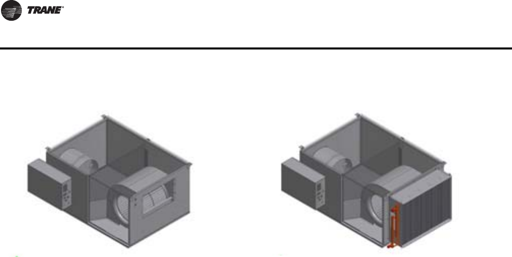
210 VAV-PRC012-EN
Application Considerations
VAV Terminal Unit Types
Parallel Fan-Powered
Parallel fan-powered units are commonly used in VAV zones which require some degree of heat
during occupied hours—when the primary supply air is cool.The terminal unit fan is in parallel with
the central unit fan; no primary air from the central fan passes through the terminal unit fan.The
terminal unit fan draws air from the space return plenum.
When no heat is needed, the local parallel fan is off and a backdraft damper on the fan’s discharge
is closed to prevent cool air entry into the return plenum. When cool airflow to the VAV zone is at
a minimum and the zone temperature drops below setpoint, the local parallel fan is turned on and
the backdraft damper opens. A constant volume of air is delivered to the zone because the fan
delivers a constant volume of warm plenum air which is mixed with cool primary air at a minimum
flow. Remote heat or terminal reheat can provide additional local heating.
Series Fan-Powered
Series fan-powered terminal units are used commonly in VAV zones that require heat during
occupied hours, desire constant air volume delivery, and are willing to pay for the additional energy
consumption required.The terminal unit fan is in series with the central fan. Primary air from the
central fan always passes through the terminal unit fan.
The local series fan within the terminal unit operates whenever the unit is in the occupied mode.
The volume of air delivered to the VAV zone is constant, but the temperature of the delivered air
varies. As the zone requires less cooling, the primary air damper closes. As the primary air damper
closes, the air mixture supplied to the zone contains less cool air and more warm plenum air.
Remote heat or terminal reheat can provide additional local heating.
Series fan-powered terminal units are also useful in low supply air temperature systems, since the
terminal unit fan can be sized so that warm plenum air is always mixed with low temperature
supply air.This raises the supply air temperature to an acceptable distribution level and reduces
condensation potential.
Low-Height Fan-Powered
Low-height fan-powered terminal units are a slightly modified version of a fan-powered terminal
unit. As its name suggests, the low-height fan-powered unit has a shorter height dimension to
accommodate applications where ceiling space is limited.To reduce the height, shorter terminal
unit fans are integrated into the standard height series or parallel terminal unit.The result is a unit
with a maximum height of 11.0" to 11.5".
For low-height units with the smaller fan sizes (sizes 08SQ and 09SQ), a single low-profile fan is
used. Low-height units with the largest fan size (size 10SQ) use two low-profile fans. Each fan
Figure 14. Series fan-powered unit cooling only (L) and series fan-powered unit with hot water coil (R)

VAV-PRC012-EN 211
Application Considerations
operates off a separate motor.The fans still remain in series or parallel with the primary system
central fan. Low acoustic levels are much more challenging in these low ceiling space applications,
due to the reduced radiated ceiling pleunum effect.
The operation of the low-height terminal unit is exactly the same as that of a series or parallel
terminal unit, as are the options for high-efficiency ECMs, insulation options, etc.As with the other
fan-powered terminal units, additional local heating can be provided by remote heat or terminal
reheat.
Parallel vs. Series
In many climates, fan-powered systems are a lower operating cost alternative than single-duct
systems.The energy inefficiencies inherent in reheating cold primary air can be eliminated with
a key design characteristic of fan-powered terminal units, plenum air heating. Heating with warmer
plenum air allows for recovery of heat from lighting and other heat sources in the building.
Comparison of Parallel and Series Models
Once it has been determined that a fan-powered system is to be specified, the designer must decide
between parallel and series configurations. Each model carries its own characteristics of delivered
airflow, energy consumption, and acoustics. For the end user, the designer might consider three
goals: a comfortable and productive tenant environment, acceptable installed cost, and low
operating costs.
Parallel and series fan-powered terminal units offer specific advantages for particular applications.
Table 139 compares the key similarities and differences between the models that the designer
should consider in performing an engineering analysis.
Typical Application of Parallel Units
Parallel intermittent fan-powered terminal units are very common in perimeter zones or buildings
where loads vary during occupied hours. Core zones, which maintain a more constant cooling
requirement, are better suited for variable airflow (single-duct) units.Typical jobs combine parallel
fan-powered units (exterior) and single-duct units (interior) to provide an efficient system with
lowest first cost. Although the overall NC of parallel systems is lower than an equivalent series
system, the intermittent fan is sometimes noticed when energized.To minimize the impact of this
NC change, an ECM (Electrically Commutated Motor) can be used which has soft-start technology.
Typical Application of Series Units
Applications requiring constant air movement or blending utilize series constant fan-powered
terminal units. Conference rooms, laboratories, and lobbies are common applications. Because the
series fan also adds to the system external static pressure, office buildings take advantage of this
design feature and down size main air handling equipment. Finally, series terminals are used in
low-temperature air systems to temper cold primary air with warm plenum air and deliver it to the
zone.
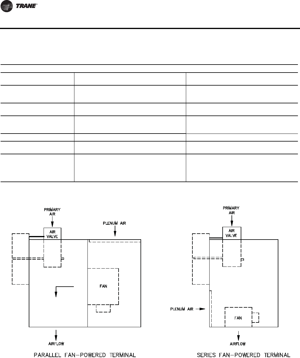
212 VAV-PRC012-EN
Application Considerations
Table 139. Parallel vs. series
Parallel Series
Fan Operation Intermittent operation during occupied and
unoccupied modes.
Continuous operation during the occupied modes.
Intermittent operation during unoccupied mode.
Operating Sequence
Variable-volume, constant-temperature device during
cooling. Constant-volume, variable-temperature
during heating.
Constant-volume, variable-temperature device at all
times. Delivers design airflow regardless of the load.
Fan Energization Based on zone temperature deviation from setpoint.
No interlock with central system fan required.
Interlocked with central system fan to deliver required
air to the zone in both heating and cooling modes.
Terminal Fan Operating and
Size
Fan runs during heating load. Size for design heating
load. Typically this is 40 to 60% of design primary
cooling airflow.
Fan runs continually. Fan sizing should meet the
greater of design cooling or heating airflow to the
zone.
Air valve Sizing Design cooling airflow. Design cooling airflow.
Minimum Inlet Static Pressure
Required for Central Fan Sizing
Sufficient to overcome unit, heating coil, downstream
duct and diffuser pressure losses. Sufficient to overcome air valve pressure loss only.
Acoustics
When operating under cooling loads the terminal fan
does not run, offering superior acoustic performance
similar to single-duct VAV. Under heating loads, the
fan operates intermittently. Acoustical impact can be
minimized by use of a ECM.
Produces slightly higher background sound pressure
levels in the occupied space. This sound level remains
constant and is less noticeable than intermittent fan
operation with PSC motors.
Figure 15. Parallel & series fan-powered terminal
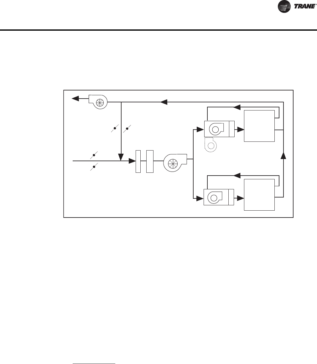
VAV-PRC012-EN 213
Application Considerations
Low-Temperature Air
Benefits of Low-Temperature Air
The benefits of low-temperature air systems include reduced first cost, reduced operating cost and
increased revenue potential. Since low-temperature air transports more energy per cubic foot,
smaller fans and ducts can be used. An EarthWise™ system takes that a step farther and includes
optimizing the waterside of the HVAC system as well with low flow rates through the chilled water
and condenser loops.
Since low-temperature water can transport more thermal energy per gallon, smaller pumps, pipes,
and valves can be used. Smaller HVAC equipment consumes less energy so both electrical demand
and consumption are lowered, reducing operating costs.The amount of revenue generated by a
commercial building is related to the amount and quality of rental floor space.The amount of rental
floor space is increased in a low-temperature air system, since air handlers, riser ducts, and
equipment rooms are smaller. Since smaller ducts reduce the required ceiling plenum, additional
floors may be included without increasing building height.
The concept of the EarthWise system is to deliver superior comfort and be less expensive to install
and operate.The method to do this involves both waterside optimization and airside optimization.
The waterside is optimized using techniques of low water flow through the evaporator and
condenser of the chiller as well as using chiller-tower optimization control strategies. For more
information on the waterside of the EarthWise system, contact your localTrane representative or
visit www.trane.com.
Airside savings are obtained using a combination of lower air temperature and intelligent control
strategies.The ability of the VAV unit to communicate information is vital to system coordination.
System Operation
A low-temperature air system could be done with chilled water or direct expansion equipment. A
chilled water system includes a chiller plant, VAV air handlers, and series or parallel fan-powered
VAV terminal units.The VAV air handlers use cold water, typically around 40°F (4.4°C), from the
chiller plant, to cool the supply air to 45–50°F (7.2–10°C).The volume of supply air is determined by
the airflow needs of the VAV terminal units. A direct-expansion system would include a VAV air
Figure 16. Low temperature air system layout
Variable
Volume
Exhaust
Fan
Preheat
Coil Variable Volume
Supply Fan
Series or Parallel
Fan-powered Unit
Cooling
Coil
Heating Coil
Zone 1
Zone 2
55°
48°

214 VAV-PRC012-EN
Application Considerations
handler or rooftop with series or parallel fan-poweredVAV terminal units.The supply air would be
cooled to 48–52°F (8.9–11.1°C).
The VAV terminal units include a parallel or series fan with the central air handler or rooftop fan.
The terminal unit fan operates continuously, mixing 45-50°F (7.2–10°C) supply air with warm
plenum air, to provide 50–55°F (10–12.8°C) cooling air to the occupied space at design conditions.
As the cooling load in the space decreases, the VAV terminal air valve closes to reduce the flow of
cold supply air and increase the flow of warm plenum air in the case of series terminal units.The
temperature of air supplied to the space rises, but the volume flow rate to the space is constant for
the series unit.
Considerations for VAV products
To achieve the maximum benefit from the low-temperature air system, severalVAV considerations
must be addressed.
Insulation
The units must be insulated to ensure that no condensation occurs on the units. How much
insulation is needed?Trane has tested its insulation with the goal of developing a thermal
resistance ratio for each type of insulation.The thermal resistance (TR) ratio can be used, along
with the properties of the insulation and the system operating conditions to determine the
necessary insulation thickness required.
In the low-temperature air system with fan-powered units, the ducts and diffusers downstream
from the terminal unit handle air that is 55°F (12.8°C) or warmer.Therefore, condensation
considerations are no different from conventional systems. Linear slot diffusers are
recommended to take advantage of the Coanda effect described in the Diffusers section later in the
catalog.
Terminal unit surfaces that are traditionally not insulated—electric and hot water reheat coils and
the primary air inlet for example—should be thoroughly field-insulated.
Leakage
When the terminal unit fan is off, the air valve will close, and not leak. Ducts upstream of the
terminal unit must also be thoroughly insulated and constructed for very low leakage.
Duct and terminal unit insulation can be internal or external. Keep in mind that internal insulation
has hidden thermal leaks at joints and seams.These areas must be located and insulated externally
to avoid condensation. External Insulation, on the other hand, allows a complete, uniform thermal
seal.
Minimum settings and IAQ
Indoor air quality is usually best when a specific quantity of outside ventilation air reaches each
building occupant. Maintaining a minimum ventilation rate is a challenge in any VAV system
because the amount of supply air that reaches a particular space decreases as the cooling load
decreases.To insure that a minimum amount of supply air reaches the space at all times, a
minimum flow setting on the terminal unit is used. In low-temperature air systems, when the space
needs heating, this minimum flow setting results in increased heating load.Therefore, it is
important to include the additional load imposed by the cold supply air when calculating heating
loads. Reheat may be required since the ventilation values are absolute requirements and not
percentage of total airflow requirements.
EarthWise or Low-Temperature Air Distribution Design Considerations with
Parallel Fan-powered Terminal Units
The parallel fan-powered unit needs to be set up to run continuously rather than intermittently.
Since it is in parallel, the airflow required by the fan is less than a comparable series unit.This
results in energy savings. Running the parallel fan continuously will take some minor control
changes. It will, however, create a better acoustical installation.
VAV-PRC012-EN 215
Application Considerations
The parallel fan should be large enough to temper the design cooling airflow at 45–50°F to 50–55°F
(7.2–10°C to 10–12.8°C). For instance, if the design cooling airflow is 1000 cfm at 55°F (472 L/s at
12.8°C), you will need 781 cfm of 48°F (368 L/s of 8.9°C) supply air and 219 cfm of 80°F (103 L/s of
26.7°C) plenum air.The parallel fan can be sized for the 219 cfm (103 L/s) rather than the total room
airflow.
The fan airflow plus the minimum primary airflow must be checked with the minimum airflow of
the diffuse
rs to insure that dumping doesn’t occur. If that is a concern, the minimum could be adjusted up or
the fan airflow could be adjusted up.
As the valve closes, the downstream static pressure will decrease because the pressure is related
to the airflow.The fan will supply more air at the valve minimum condition than at design due to
the decreased static pressure.This should be a consideration when calculating how much airflow
would occur at the minimum valve plus fan airflow condition.The new fan airflow would be found
by looking at a fan curve at the new SP point.The new SP can be calculated:
Table 140, p. 215 can be used to determine what percentage of the total airflow should come from
the fan to temper the supply air, assuming 80°F (26.7°C) plenum air.
If anything other than 80°F (26.7°C), the following equation can be used to calculate the percentage:
SupplyTemperature =(%*primarytemperature)+(1-%)*plenum temperature
Low-Temperature Air Distribution Design Considerations with Series Fan-
powered Terminal Units
The VAV terminal unit includes a fan that operates continuously.The series fan should be large
enough to insure that the mixture of cold supply air and warm plenum air is 50–55°F (10–12.8°C)
at design cooling flow conditions. In these types of systems, it is a good design practice to develop
the system based upon 55°F (12.8°C) air being provided to the space from the fan-powered terminal
unit. If a lower temperature air is used downstream of the VAV terminal unit, the system designer
will have some concerns related to condensation on diffusers and other low-pressure ductwork
accessories. For instance, if the occupied space must receive 1000 cfm of 55°F (472 L/s at 12.8°C)
air to satisfy to design cooling load, 715 cfm must be 45°F (337 L/s must be at 7.2°C) supply air and
285 cfm must be 80°F (135 L/s must be 26.7°C) plenum air.Therefore, the series fan-powered
terminal must be sized to have the air valve deliver 715 cfm (337 L/s) of supply air at design
conditions, but the fan must be sized to deliver 1000 cfm (472 L/s).
Fan Airflow Valve Minimum+
Fan Airflow Valve Design+
-----------------------------------------------------------------------------------------XSP
1SP2
=
Table 140. Percentage of airflow from fan
Primary Air Temperature (deg. F (C))
Supply Air Temp.
(deg. F (C) 45 (7.2) 46 (7.8) 47 (8.3) 48 (8.8) 49 (9.4) 50 (10)
50 (0) 14% 12% 9% 6% 3% 0%
51 (10.6) 17% 15% 12% 9% 6% 3%
52 (11.1) 20% 18% 15% 13% 10% 7%
53 (11.7) 23% 21% 18% 16% 13% 10%
54 (12.2) 26% 24% 21% 19% 16% 13%
55 (12.8) 29% 26% 24% 22% 19% 17%
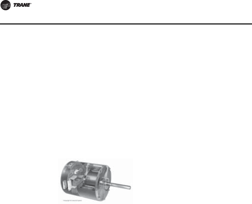
216 VAV-PRC012-EN
Application Considerations
Airside System Factors
A couple of system related factors should be noted as they apply to condensation.The first is the
advantage the colder primary air has from a humidity standpoint. As noted in the description
above, the low-temperature system operates at space relative humidity of 30–45% while a standard
system operates at space relative humidity of 50–60%.The drier zone air means that the plenum
air returning to the series terminal unit will also be drier and, therefore, less of a problem with
condensation.
The second condensation factor to note is related to systems that shut down in the evening. Many
people believe that immediately sending low-temperature primary air to these boxes that have
been off for some time will cause a shock to the system and may cause condensation problems at
startup.The solution to this has been the advent of gradual pull-down or “soft start” systems. In
this type of system, the primary air temperature is higher on initial startup (typically 55°F(12.8°C))
and then gradually reduced to the normal operating point over the next 30 to 60 minutes.
Energy Savings & System Controls
Electrically Commutated Motor
Operating Hours—The added cost of an ECM can be offset more quickly in applications which
require a relatively high number of hours of operation. However, if a space does not require
extensive running time for the unit fan, then it may not be a good candidate for this type of motor
based solely on payback.Therefore, the decision about using the ECM may be based on other
benefits, depending on the needs of the customer.
Airflow Flexibility—The ECM allows a greater airflow range per fan size. If a space is going to
change uses and load components frequently, the ability to change supply airflow with the ECM
without changing units will be a benefit.
Airflow Balancing—The ability of the ECM motor to self-balance to an airflow regardless of
pressure can be an asset when trying to air balance a job.This will help eliminate additional
dampers or changes to downstream ductwork to ensure proper airflow. For more information,
please contact your localTrane sales engineer.
Fan-Pressure Optimization
WithTrane's Integrated Comfort System, the information from VAV terminal units can be used for
other energy-saving strategies. Fan-pressure optimization is the concept of reducing the supply fan
energy usage based on the position of the terminal unit dampers.
The control system allows this scenario.The system polls the VAV units for the damper position
on each unit.The supply fan is modulated until the most wide-open damper is between 85% and
95% open.The correct airflow is still being sent to the zones since the controls of the VAV units are
pressure-independent, and the fan modulates to an optimal speed and duct static pressure which
results in fan energy savings.
The ECM provides an additional energy-saving option
to the system designer. Some of the advantages of the
motor include high efficiency, quiet operation, short
payback, and easy installation.There are several
considerations that need to be addressed when
deciding whether to use these motors or not.The
primary benefit may be seen as increased efficiency.
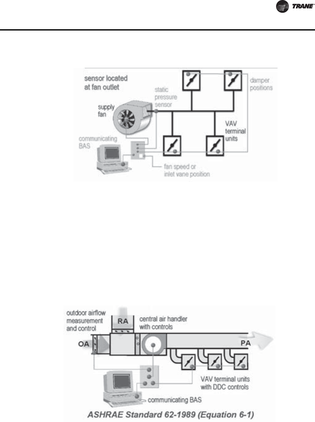
VAV-PRC012-EN 217
Application Considerations
Ventilation Reset
The Ventilation Reset control strategy enables a building ventilation system to bring in an
appropriate amount of outdoor air per ASHRAE Standard 62.1. The basis for the strategy is
measuring airflow at each zone, calculating current system ventilation efficiency using the
multiple-zone system equations of the standard, and communicating a new outdoor airflow
setpoint to the air handler.
This strategy continually monitors the zone ventilation needs and system outdoor air intake flow,
minimizing the amount of ventilation air and increasing the energy efficiency of the system.This
insures that the right amount of air is brought in at all times and that proper ventilation can be
documented.Trane has integrated this control ability into the VAV controls, air-handler controls,
and building controls.
For more detailed information on these energy-saving strategies, please refer to the “Additional
References” section at the end of this chapter for appropriate material.
Figure 17. Optimized static-pressure control
Figure 18. Ventilation reset
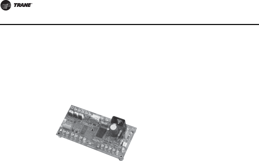
218 VAV-PRC012-EN
Application Considerations
Control Types
VAV terminal units are available with many different options.These options fall into three main
categories of controls: direct digital (DDC), pneumatic, and analog electronic. All of these control
types can be used to perform the same basic unit control functions, yet differences exist in accuracy
of performance, versatility, installed cost, operating cost, and maintenance cost.
Direct Digital Control (DDC) Systems
Benefits:
Performance—DDC controls offer PI control capability. A PI control scheme is the most accurate
and repeatable control scheme available in the VAV terminal unit industry.
Versatility—DDC controls accepts software commands to determine how its outputs will be
controlled. When a control sequence must be modified, making changes to the software
instructions is easier and quicker than changing hardware.
Operating and Maintenance Costs—DDC controls can be networked together to provide system-
control strategies for energy savings. Multiple controllers can be easily monitored and adjusted
from a remote location. DDC controls also have system and individual diagnostic capability.
Disadvantages:
Versatility—The communications protocol between controllers will be different from one controller
manufacturer to another.
Installed Cost—DDC controls are the most expensive of the three control types.
Operating and Maintenance Costs—Building personnel must be trained to operate and maintain
the system.
Pneumatic Control Systems
Pneumatic control systems use compressed air through simple mechanical control devices,
such as diaphragms, springs, and levers to change an output in response to a change in a
monitored variable. With VAV terminal units, the output is typically a primary airflow and the
monitored variable is zone temperature.
Benefits:
Performance—Pneumatic controls are a proven technology that is effective and has a long life
cycle.
Installed Cost—When a source of compressed air exists at the facility, pneumatics generally have
a lower installed cost than other types of controls when only a basic functionality is required.
Operating and Maintenance Costs—Pneumatics are still the most familiar control technology to
many building designers and maintenance people.
Direct digital control (DDC) systems became
available as advances in computer technology made
small microprocessors available and affordable.
Much of the hardware in DDC systems is similar to
analog electronic systems.The primary difference is
that DDC controllers allow system integration, remote
monitoring, and adjustment.The microprocessor is
programmed using software that gives the controller
a higher level of capability than either the pneumatic
or analog electronic options.

VAV-PRC012-EN 219
Application Considerations
Large Installed Base—Pneumatic systems are very common in existing buildings.This eliminates
the need to purchase the most expensive piece of equipment in a pneumatic control system—the
control air compressor. Extensions to existing pneumatic systems are generally very simple and
extremely cost-effective.
Disadvantages:
Performance—Pneumatic controls provide proportional-only control for VAV terminal unit
systems.This control scheme is less accurate than the more advanced control schemes. Improper
calibration of pneumatic controls leads to poor energy utilization.
Versatility—A central pneumatic control system, where each of the control zones can be monitored
and adjusted from a remote location, is extremely costly to configure and to modify.
Operating and Maintenance Costs—Pneumatics easily drift and require constant upkeep and
scheduled maintenance. Diagnostic capability for pneumatics is not available. A main compressor
which is not maintained and becomes contaminated with oil or water can pump those
contaminants into the compressed-air-distribution system.This may require costly cleaning of the
system and a possible replacement of system components.
DDC Controls Basic Information
DDC controls have become the industry standard for VAV terminal unit control systems. DDC
systems use electronic field devices such as a flow transducer, a primary air modulating damper,
and an electronic thermostat.These field devices report software instructions of how the outputs
are positioned in relation to the inputs to a controller.TheVariTranesystem uses a primary air valve
and flow transducer for both DDC systems and analog electronic systems. However, the DDC zone
sensor is different from the analog electronic thermostat.
DDC controls provide much flexibility and considerable diagnostic capability. DDC controllers can
be connected together to form a network of controllers. Once the controllers are networked, they
can be monitored for proper operation from a remote location. Commands and overrides can be
sent for groups of controllers at one time to make system-wide changes. Commands and overrides
can be sent to individual units to allow problem diagnosis, temporary shutdown, startup schedules
or other specialized changes. When integrated into a building management system, the operation
of the VAV terminal unit system can be modified to do such things, as coincide with occupancy
schedules and reduce energy charges.
DDC control ofVAV terminal units is a key element in providing intelligent and responsive building
management. Precision control, flexible comfort, and after hours access are all available with the
VariTraneDDC control system for VAV terminal units.
Key features of the system include:
• An advanced unit controller
• Flexible system design
• User-friendly interaction
Pneumatic Controls Basic Information
Pneumatic controls modulate air pressure of a controller to maintain setpoint. For VAV systems,
there are two primary types of pneumatic controllers—the room thermostat and the pneumatic
volume regulator (PVR).
Room Thermostats
The most visible controller to the customer is the room thermostat. Pneumatic room thermostats
can be classified by two characteristics: the tubing connection(s) to the thermostat and the action
of the thermostat output in response to a change in the input.
Room thermostats are available in models that require a one-pipe or a two-pipe configuration.The
name is derived from the number of tubes that must run to the thermostat location.The difference
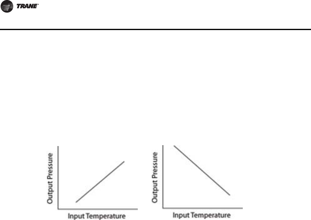
220 VAV-PRC012-EN
Application Considerations
is really in the construction of the thermostats.The two-pipe thermostats have a constant pressure
supply connected via an air tube to the thermostat supply air port.The supply air travels through
the thermostat’s relays, levers, diaphragm, and bleed port to produce an output.The output line
is connected to the output port of the thermostat and extends to the controlled device.The one-
pipe thermostat has, as its name suggests, only one air line connection.The thermostat works by
opening and closing an air bleed valve.This will either decrease or increase the pressure on the
controlled device, which is connected to the same line that runs to the thermostat.
Room thermostats also can be classified by their reaction to a change in temperature. Room
thermostats classified this way are denoted as either direct-acting or reverse-acting. Direct-acting
thermostats will increase their output pressure as the temperature the thermostat measures
increases.
On the contrary, reverse-acting thermostats will decrease their output pressure as the temperature
the thermostat measures increases.
Pneumatic Volume Regulators
These controllers accept the room thermostat signal and modulate the VAV terminal unit primary
air damper.The primary air damper is controlled for an airflow setpoint that is determined by the
room thermostat.The thermostat increases the PVR’s airflow setting when the temperature in the
space is warm. On the other hand, the thermostat decreases the PVR’s airflow setting when the
temperature in the space is cold.
Currently, VariTrane offers two models of pneumatic volume regulators in its controls offering—
the 3011 regulator (used in most applications) and the 3501 model (used in dual-duct constant-
volume applications).The primary difference is the 3501 PVR’s ability to change the velocity
pressure linearly with a change in thermostat pressure, which results in improved stability at low
flows. In contrast, the 3011 PVR resets the velocity pressure with a change in thermostat pressure.
Reset Control of Minimum and Maximum Flow—The 3011 PVR and 3501 use fixed reset control of
minimum and maximum flow settings.The primary benefit of fixed reset in a pneumatic volume
regulator is stable flow control without excessive damper movement.
Fixed Reset—A fixed reset controller operates over a thermostat signal change of 5 psi between
minimum and maximum flow, regardless of the differential pressure flow sensor signal.The
thermostat is usually set for a gain of 2.5; i.e. it produces a 2.5 psi output change per degree of space
temperature change.This control strategy provides stable flow control with the primary air valve
throttling between minimum and maximum flow over a 2°F space temperature change.
Example 1: Air valve with a 6" inlet, Pneumatic thermostat gain = 2.5 psi/degree:
Minimum Flow=0 cfm, 0.0 in. wg flow signal
Maximum Flow=680 cfm, 2.0 in. wg flow signal
2.0 in. wg signal range
Figure 19. Direct-acting thermostat response (L) and direct-acting thermostat response (R)
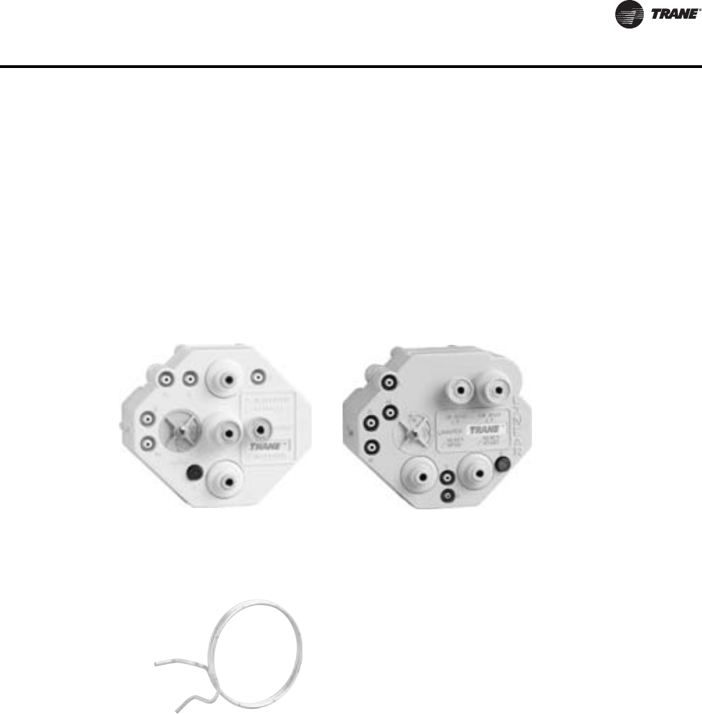
VAV-PRC012-EN 221
Application Considerations
The damper will modulate from zero to maximum position over a 2°F temperature change.
Bleed Port to Atmosphere—Bleeding air to the atmosphere is a normal operation for a volume
regulator.The 3011 volume regulator addresses this function with a dedicated bleed port.When air
is bled through the flow sensor, the differential pressure signal from the sensor is affected. As a
result, the flow sensor signal can be radically altered if the volume regulator is bleeding air, and
may cause excessive damper movement.
Calibration—The minimum and maximum settings are independent of each other and need to be
set only once during calibration.
Signal Configuration Flexibility—Both can be configured to work with both normally-open and
normally-closed pneumatic air valves, and both direct-acting and reverse-acting thermostats.
Pneumatic Volume Regulators
Flow Measurement and Control
The differential pressure signal output of the flow ring provides the terminal unit controller a
measurement of the primary airflow through the inlet.The terminal unit controller then opens or
closes the inlet damper to maintain the controller airflow setpoint
Flow Measurement
Most VAV terminal units contain a differential pressure airflow measurement device, mounted at
the primary air inlet, to provide a signal to the terminal unit controller. Numerous names exist for
the differential pressure measurement device—flow sensor, flow bar, flow ring.The differential
pressure measured at the inlet varies according to the volumetric flow rate of primary air entering
the inlet.
The total pressure and the static pressure are measurable quantities.The flow measurement
device in a VAV terminal unit is designed to measure velocity pressure. Most flow sensors consist
of a hollow piece of tubing with orifices in it.TheVariTrane air valve contains a flow ring as its flow
measuring device.The flow ring is two round coils of tubing. Evenly spaced orifices in the upstream
Figure 20.
One of the most important characteristics of a VAV terminal unit is
its ability to accurately sense and control airflow.The VariTrane
terminal unit was developed with exactly that goal in mind.The
patented, multiple-point, averaging flow ring measures the
velocity of the air at the unit primary air inlet.
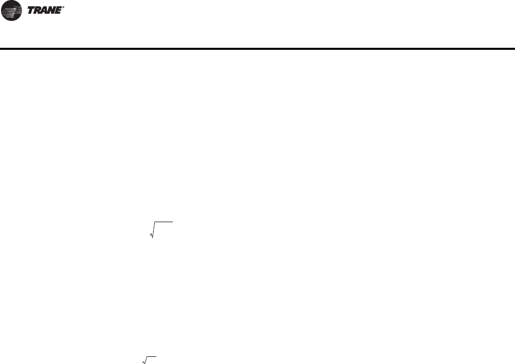
222 VAV-PRC012-EN
Application Considerations
coil are the high-pressure taps that average the total pressure of air flowing through the air valve.
The orifices in the downstream ring are low-pressure taps that average the air pressure in the wake
of flow around the tube. By definition, the measurement of static pressure is to occur at a point
perpendicular to the airflow.The low-pressure taps on theVariTrane flow ring measure a pressure
that is parallel to the direction of flow but in the opposite direction of the flow.This “wake pressure”
that the downstream ring measures is lower than the actual duct static pressure.The difference
between the “wake pressure” and the static pressure can be accounted for so that the above
relationship between flow and differential pressure remain valid.The difference also helps create
a larger pressure differential than the velocity pressure. Since the pressures being measured inVAV
terminal box applications are small, this larger differential allows transducers and controllers to
measure and control at lower flow settings than would otherwise be possible.
The average velocity of air traveling through the inlet is expressed in the equation:
Where:
Often, the density is assumed to be a constant for dry air at standard conditions (68°F (20°C)) and
sea level pressure of 14.7 psi (101.4 kPa)).These conditions yield the following commonly used
equation:
The velocity pressure is defined as the difference between the total pressure in the duct and the
static pressure in the duct:
VP =TP - SP (All units are expressed in inches of water)
The amount of air traveling through the inlet is related to the area of the inlet and the velocity of
the air:
AIRFLOW = AREA (square feet) x AVERAGE VELOCITY (feet per minute)
Accuracy
The multiple, evenly spaced orifices in the flow ring of the VariTrane terminal unit provide quality
measurement accuracy even if ductwork turns or variations are present before the unit inlet. For
the most accurate readings, a minimum of 1½ diameters, and preferably 3 diameters, of straight-
run ductwork is recommended prior to the inlet connection.The straight-run ductwork should be
of the same diameter as the air valve inlet connection. If these recommendations are followed, and
the air density effects mentioned below are addressed, the flow ring will measure primary airflow
within ±5% of unit nominal airflow.
FPM = Velocity of air in feet per minute
1096.5 = A constant
VP = The velocity pressure of the air expressed in inches of water
DENS = The density of the air expressed in pounds per cubic foot
FPM 1096.5 VP
DEN
S
--------------
-
=
F
PM 4005 VP=
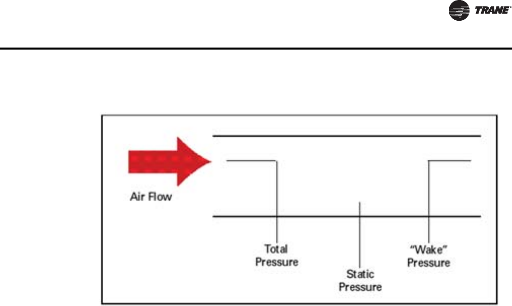
VAV-PRC012-EN 223
Application Considerations
Air Density Effects
Changes in air density due to the conditions listed below sometimes create situations where the
standard flow sensing calibration parameters must be modified.These factors must be accounted
for to achieve accuracy with the flow sensing ring. Designers, installers, and air balancers should
be aware of these factors and know of the necessary adjustments to correct for them.
Elevation
At high elevations the air is less dense.Therefore, when measuring the same differential pressure
at elevation versus sea level the actual flow will be greater at elevation than it would be at sea level.
To calculate the density at an elevation other than standard conditions (most manufacturers choose
sea level as the point for their standard conditions), you must set up a ratio between the density
and differential pressure at standard conditions and the density and differential pressure at the new
elevation.
Since the data from the manufacturer is published at standard conditions, this equation should be
solved for the differential pressure at standard conditions and the other quantities substituted to
determine the ratio for the differential pressure measured at the new conditions.
Duct Pressure and Air Temperature Variations
While changes in these factors certainly affect the density of air, most operating parameters which
VAV systems need keep these effects very small.The impact on accuracy due to these changes is
less than one half of one percent except in very extreme conditions (extreme conditions are defined
as those systems with static pressures greater than 5 in. wg (1245 Pa) and primary air temperatures
greater than 100°F (37.8°C)). Since those types of systems occur so infrequently, we assume the
effects of duct pressure and air temperature variations to be negligible.
Figure 21. Air pressure measurement orientations
PS dard Conditions
DENSS dardConditions
-----------------------------------------------------------------------------------P NewConditions
DENSNewConditions
-------------------------------------------------------------------
=
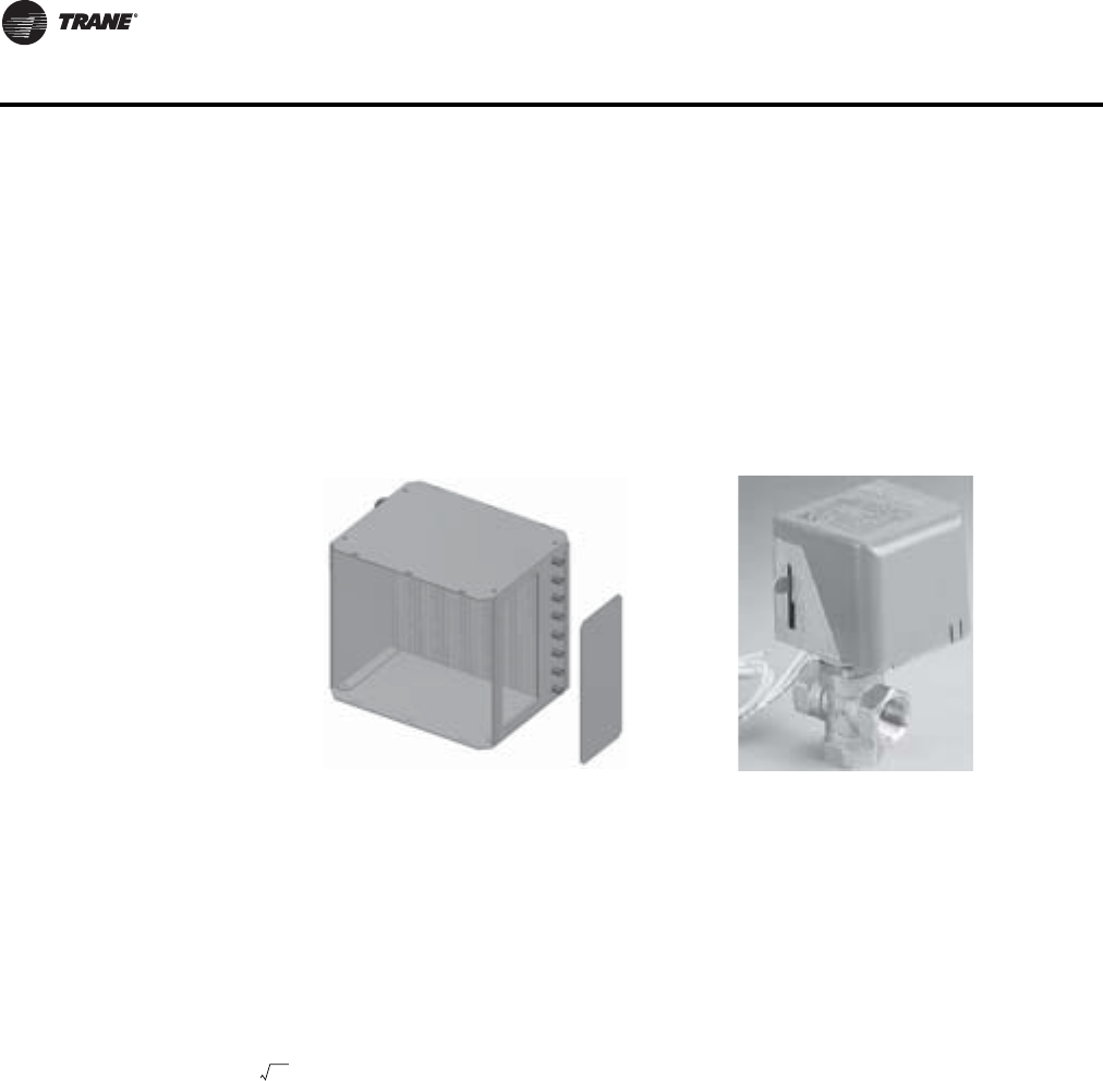
224 VAV-PRC012-EN
Application Considerations
Linearity
With the increase in DDC controls over pneumatic controls, the issue of linearity is not as great as
it once was.The important aspect of flow measurement versus valve position is the accuracy of
the controller in determining and controlling the flow. Our units are tested for linearity and that
position versus airflow curve is downloaded and commissioned in the factory to insure proper
control of the unit.
Reheat Options
Hot water heating coils are generally applied on VAV terminal units as reheat devices. When
applying these coils it is important to make sure that they are operating in the proper air flow and
water flow range. Either a two-way or a three-way valve controls the coils.
The most important factor when sizing valves is the coefficient of velocity or CV
.The CVis defined
as the flow rate, in gallons of 60°F (15.56°C) water, that will pass through the valve in one minute
with a one pound pressure drop.The coefficient of velocity, which is commonly called the flow
coefficient, is an industry standard rating. Valves having the same flow coefficient rating,
regardless of manufacturer, will have the same waterside performance characteristics.
The equation that governs valve sizing is:
Where
Cv=Flow coefficient
GPM=The maximum water flow rate through the valve in gallons per minute
P=The maximum allowable differential pressure across the valve in psi
The flow and differential pressure are generally the known quantities.The equation is solved for
the flow coefficient.The flow coefficient is then compared to the published CVvalues for the control
valves that are available.The control valve with the CVthat is the closest, but greater than, the
calculated flow coefficient is the correct choice for the control valve.This choice will keep the valve
pressure drop below the maximum allowable valve pressure drop.The valve pressure drop should
then be checked against the coil pressure drop. If the coil pressure drop is appreciably larger than
the valve pressure drop, a valve with a smaller CVshould be selected to produce a larger control
valve pressure drop. If this new valve has a pressure drop that is much larger than the maximum
allowable pressure drop for valves, the system designer should be consulted to make sure that the
system hot water pumps can deliver the water at the new conditions.
Figure 22. Hot water coil (L) & hot water valves (R)
CvGPM
P
--------------=
VAV-PRC012-EN 225
Application Considerations
Electric Reheat
Electric heating coils are applied onVAV terminal units as terminal reheat devices. Electric heat coil
capacity is rated in kilowatts (kW). Coils are available with the total capacity divided into one, two,
or three stages.
Electric heat coils are available in single-phase or three-phase models.This refers to the type of
power source connected to the coil. Single-phase models have resistance elements internally
connected in parallel.Three- phase models have resistance elements internally connected in a
delta or a wye configuration.
The current draw for the electric coil will depend upon whether it is a single-phase coil or a three-
phase coil.The current draw is necessary for determining what size wire should be used to power
the electric coils and how big the primary power fusing should be.
The equations for current draw for these coils are:
VariTrane three-phase electric heat is available in balanced configurations. For example,a9kW
three-phase coil, each stage would carry 1/3 or 3 kW of the load.
It is important to note that these coils have certain minimum airflow rates for each amount of kW
heat the coil can supply to operate safely.These airflow values are based upon a maximum rise
across the electric heat coil of 50°F (28°C).
The equation that relates the airflow across an electric coil to the temperature rise and the coil
change in temperature is:
Where
CFM=Minimum airflow rate across the coil
kW=The heating capacity of the electric coil
3145=A constant
P=The maximum rise in air temperature across the coil (usually 50 degrees F (28 degrees C))
Electric heat coils are available with magnetic or mercury contactors. Magnetic contactors are less
expensive than mercury contactors. However, mercury contactors can be cycled at a more rapid
rate without failing. Mercury contactors are rated for heavier duty use and should be used in as
many applications as possible. For pneumatic applications the electric coils are available with
factory-installed pressure-electric switches.
1amps kW 1000
PrimaryVoltage
--------------------------------------------------=
3amps kW 1000
PrimaryVoltage 3
-----------------------------------------------------------=
CFM kW 3145
T
-------------------------------=
226 VAV-PRC012-EN
Application Considerations
Insulation
Matte-Faced
This type of insulation is used for typical applications. It consists of a fiberglass core covered by
a high-density skin.The dual-density construction provides good sound attenuation and thermal
performance.
Foil-Faced
This type of insulation is used in applications where there is some concern regarding airborne
contaminants entering the space, or dirt being trapped in the fibers of the insulation.The insulation
is composed of a fiberglass core laminated to a foil sheet. Foil-faced insulation will provide the
same sound attenuation performance as matte-faced insulation.
Double-Wall
This type of insulation is used in applications where there is extreme concern regarding airborne
contaminants entering the space or dirt being trapped in the fibers of the insulation.The insulation
is the same as the matte-faced insulation. However, after the insulation is installed, a second solid
wall of 26-gage steel covers the insulation. All wire penetrations of this insulation are covered by
a grommet.This type of insulation will result in higher discharge and radiated sound power.
Closed-Cell
This type of insulation is used in applications where IAQ and fibers are of primary concern.The
acoustics of the closed-cell insulation are similar to double-wall insulation.The thermal properties
are similar to fiberglass insulation.This insulation contains no fiberglass.
Acoustics
Acoustical Best Practices
Acoustics with terminal units is sometimes more confusing than it needs to be. As we know, lower
velocities within a unit leads to improved acoustical performance. Additionally, if theVAV terminal
unit has a fan, a lower RPM provides better Acoustical performance. It is as simple as that—there
are some catches, however.
Additional considerations will be discussed in more detail throughout this portion of Application
Considerations, such as unit size and type, appurtenance affects (due to insulation, attenuation,
etc.), certification, and computer modeling. Let’s take a look at the first consideration, sizing of
units.
Encapsulated edges
Insulation in aVAV terminal unit is used to avoid condensation
on the outside of the unit, to reduce the heat transfer from the
cold primary air entering the unit, and to reduce the unit noise.
TheVariTrane line offers four types of unit insulation.The type
of facing classifies the types of insulation.To enhance IAQ
effectiveness, edges of all insulation types have metal
encapsulated edges.

VAV-PRC012-EN 227
Application Considerations
Sizing of Units
Before blindly increasing the size of units, we must first understand what is setting the acoustics
within the space. In general, over 95% of acoustics in VAV terminal units, which set the sound
pressure levels and ultimately the NC within the space, is from radiated sound.This is readily
known for fan-powered units, but less commonly known for single- and dual-duct units. Radiated
sound emanates from the unit and enters the occupied space via means other than through the
supply ductwork.The most typical path is through the plenum space, then through the ceiling, then
into the occupied space. While discharge sound should never be ignored, radiated sound is the
most dominant and usually the most critical sound source.
When increasing air valve sizes, BE CAREFUL. Oversizing an air valve can adversely impact
the ability to modulate and properly control temperature in the space. In extremely
oversized situations, the air valve will operate like a two-position controlled device, with air either
being “on”,or“off”, and not really much in between.The best way to avoid this is to understand that
the minimum for most air valves is 300 FPM.This is a function of the flow sensing device and the
ability of the pressure transducer and controller to properly read and report flow.This is not
manufacturer specific, as physics applies to all.Therefore, when sizing air valves, regardless of the
max cooling velocity the minimum velocity for proper pressure independent flow is 300 FPM.
Modulation capability and range is vital for proper operation ofVAV systems.With oversized units,
the unit will act as a constant volume system eliminating the energy savings and individual zone
control advantages ofVAV systems. A good rule of thumb is to size cooling airflow for around 2000
FPM. VAV systems only operate at full flow when there is a maximum call for cooling in the zone.
The greatest portion of the time, an air valve will be operating at partial flows.
When sizing fan-powered units, the fan airflow range can be determined by looking at the fan-
curve. Because parallel and series fan-powered units operate at a constant fan flow, selections can
be made all the way to the lowest flow ranges of the fan curve.A good balance of performance and
cost is to select fans at 70-80% of maximum fan flow.
Series vs. Parallel Fan-Powered Units
Acoustical considerations may affect whether a series or parallel fan-powered terminal unit is
selected. Both units have their advantages.
The parallel unit has the advantage of fan energization and fan acoustical impact only when heating
is needed. Parallel fans are smaller than series units because they are sized for 30–60% of total unit
flow.This creates a unit which is quieter than series units.The disadvantage of the parallel unit is
intermittent sound.This impact can be minimized by using an ECM, which has slow fan ramp-up
speed.
The primary acoustic benefit to the series fan-powered unit is that the fan runs continuously.
Sometimes the unit can be selected at slightly higher sound levels due to the constant nature of
the sound.
The primary acoustic disadvantage the series unit has compared to the parallel unit is the need to
size the unit fan for the total room airflow. Series units require a larger, louder fan than parallel
configurations.
Note: Operating parallel units with a continuously operating fan may be considered for some
applications.This provides the quietest overall fan-powered system with the benefit of
continuous fan operation. See your localTrane sales engineer for more details.
Insulation types
Insulation is a factor to consider when dealing with the acoustics of terminal units. Most insulation
types will provide similar acoustical results, but there are exceptions. Double-wall and closed-cell
foam insulation will generally increase your sound levels because of the increased reflective
surface area that the solid inner-wall and closed-cell construction provides.This increase in sound
will have to be balanced with the IAQ and cleanability considerations of the dual-wall and closed-
cell construction.
228 VAV-PRC012-EN
Application Considerations
Placement of units
Unit placement in a building can have a significant impact on the acceptable sound levels. Locating
units above non-critical spaces (hallways, closets, and storerooms) will help to contain radiated
sound from entering the critical occupied zones.
Unit Attenuation
Terminal unit-installed attenuators are an option available to provide path sound attenuation.
Manufacturer-provided attenuators on the discharge of a terminal unit are targeted at reducing
discharge path noise and are typically a simple lined piece of ductwork. It would often be easier and
less expensive to design the downstream ductwork to be slightly longer and require the installing
contractor to include lining in it. Attenuators on the plenum inlet of fan-powered terminals are
targeted at reducing radiated path noise since the plenum opening on a fan-powered terminal unit
is typically the critical path sound source. Significant reduction in radiated path noise can result
from a well-designed inlet attenuator.The attenuation from these attenuators is due to simple
absorption from the attenuator lining and occupant line of sight sound path obstruction.Therefore,
longer attenuators and attenuators that require the sound to turn multiple corners before reaching
the occupied space provide superior results, particularly in the lower frequency bands.
Attenuators that are simple “cups” at the plenum inlet(s) have been shown inTrane’s acoustical
mock-up to provide no measurable reduction in sound pressure in the critical octave bands which
set the occupied space noise criteria.
Certification and Testing
Terminal units should be submitted based on the same criteria.There are several ways to ensure
this by certification and testing.
Raw unit sound data can be good measurement criteria for evaluation. In using this as a basis for
comparison, the designer needs to make sure that the information is based on the AHRI Standard
880 that gives the procedure for testing.
Specifying NC or RC sound levels is a possible comparison, but the designer needs to be sure the
comparison is fair.Two options are to specify the attenuation effect on which you would like the
units to be evaluated or to specify that AHRI Standard 885-2008 transfer functions be used.The
importance of AHRI Standard 885-2008 is that it is the first AHRI Standard that specifies exact
transfer functions to be used for evaluation. Previous versions of the standard gave guidelines, but
the manufacturers could choose their own set of factors.
Table 141. Octave band frequencies
Octave Band Center Frequency Band Edge Frequencies
1
2
63
125
44.6-88.5
88.5-177
3 250 177-354
4 500 354-707
5 1000 707-1414
6 2000 1414-2830
7 4000 2830-5650
8 8000 5650-11300
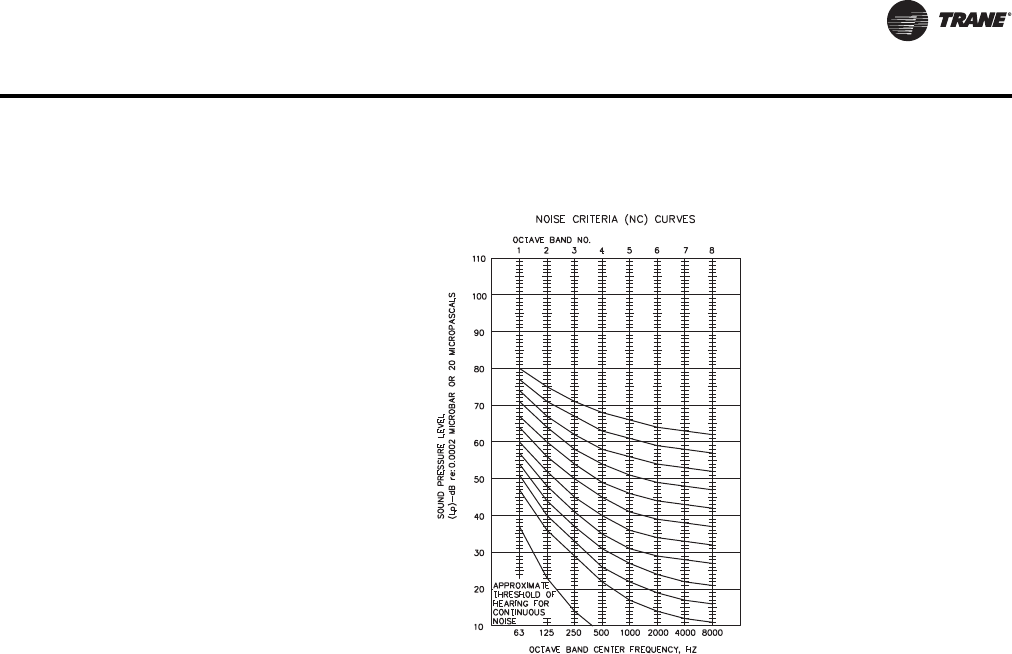
VAV-PRC012-EN 229
Application Considerations
By using NC sound levels, it is possible to express acceptable sound levels for various types of
buildings or environments. A few examples are:
Path Attenuation
Sound is generated by a terminal unit can reach the occupied space along several paths.The
terminal unit generated sound will lose energy—i.e., the energy is absorbed by path obstacles—
as it travels to the occupied space.This acoustical energy dissipation as it travels to the occupied
space is called path attenuation.The amount of energy lost along a particular path can be
quantified and predicted using the procedure outlined in AHRI-885. Each path must be considered
when determining acceptable sound power generated by a terminal unit.
The term “transfer function” is often used to describe the entire path attenuation value for each
octave band (i.e., the sum of all components of a particular path).
Examples of path attenuation include locating the terminal unit away from the occupied space,
increasing the STC (sound transmission classification) of the ceiling tile used, internally lining
ductwork, drywall lagging the ceiling tiles or enclosing the terminal unit in drywall. All of these
choices have costs associated with them that must be weighed against the benefits. Some of these
alternatives can be acoustically evaluated from application data provided in AHRI-885. Others may
require professional analysis from an acoustical consultant.
Concert Hall NC-22
Hospital Room NC-30
School Room NC-35
General Office NC-40
Cafeteria NC-45
Factory NC-65

230 VAV-PRC012-EN
Application Considerations
Computer Modeling
Computer modeling of acoustical paths is available to help estimate sound levels and determine
problem sources.The software used byTrane for computer modeling is calledTrane Acoustics
Program (TAP™).
TAP can analyze different room configurations and materials to quickly determine the estimated
total sound levels (radiated and discharged) in a space.TheTrane Official Product Selection System
(TOPSS™) can also be used to determine sound levels of terminal units.You can base selections
on a maximum sound level and enter your own attenuation factors (defaults based on AHRI-885
are also available).
Other Resources
Refer to "Additional References" at the end of this chapter to see a list of publications to help with
the basics of acoustical theory and modeling.You can also contact your localTrane salesperson
to discuss the issue.
Duct Design
Designing cost-effective VAV duct systems is challenging. Some duct design methods result in
better pressure balance than others do. Duct shape and duct material can influence duct system
design and cost. In addition, duct layout is properly designed for optimal duct installation and
operation.
Duct Design Program
Trane has developed a computer program, VariTrane™ Duct Designer, to aid in the duct design
process.This program is used to calculate duct sizes, fitting sizes, terminal unit sizes, and pressure
drops according to the equal friction or static regain method.The duct design program can be
easily incorporated into the selection ofVAV terminal units.The inputs and outputs for the program
enableVariTrane units to be selected based on the conditions you require.This makes selecting and
scheduling units much easier. Contact the local sales office or theTrane C.D.S.™ department for
more details on this program.
Design Methods
The two most widely used supply duct design methods—equal friction and static regain—are
discussed below.
Equal Friction – Using this method, ducts are sized at design flow to have roughly the same static
pressure drop for every 100 feet of duct. Static pressures throughout the duct system can be
balanced at design flow using balancing dampers, but are no longer balanced at part load flows.
For this reason, equal friction duct designs are better suited for constant volume systems than for
VAV systems. If the equal friction method is used for theVAV supply duct design, the terminal units
usually require pressure-independent (PI) control capability to avoid excessive flow rates when
duct pressures are high.
In VAV systems, the ducts located downstream of the terminal unit are usually sized for equal
friction.The advantage of this design method is its simplicity. Often, calculations can be made
using simple tables and duct calculators. Drawbacks include increased higher total pressure drops
and higher operating costs.
Static Regain – In the static regain method, ducts are sized to maintain constant static pressure
in each section, which is achieved by balancing the total and velocity pressure drops of each
section. In other words, static pressure is “regained” by the loss of velocity pressure. Since the
static pressures throughout the duct system are roughly balanced at design and part load flow,
static regain duct designs can be used successfully for either constant volume or VAV systems.
When the static regain method is used forVAV systems, the system is roughly pressure balanced
at design.

VAV-PRC012-EN 231
Application Considerations
Advantages of the static regain method include reduced total pressure drops, lower operating
costs, and balanced pressures over a wide range of flows.The drawback of this design is the time-
consuming, iterative calculation procedure and for large systems, it is essential to have a duct
design computer program.
Best Practices
Common Mistakes
Some of the most common system or installation errors are discussed below.
Reducers at Unit Inlet
This problem is a very common issue that is seen in applications of VariTrane products. It is often
mistaken by those in the field as an unacceptably large static pressure drop through the unit. It is
also sometimes mistaken as a malfunctioning flow ring, pressure transducer (if DDC or analog
electronic controls are present) or PVR (if pneumatic controls are present).
This problem is sometimes unknowingly encountered because of the capability of the VariTrane
unit to allow greater airflow for a specific size duct than other terminal units. For example, a project
engineer specifies an 8" (203 mm) round take off from the main duct trunk to theVAV terminal unit.
The person supplying the VAV terminal unit checks the required airflow and finds that aVariTrane
unit with a 6" (152 mm) inlet will provide the specified terminal unit performance.The terminal unit
supplier submits, receives approval, and orders the 6" (152 mm) inlet unit.While this is happening,
the installing contractor has run the connecting duct from the main trunk to the terminal unit in the
specified 8" (152 mm) round.The unit arrives at the job site, and the installer notices that the 8" (203
mm) duct and the 6" (152 mm) terminal unit inlet do not match.To get the unit installed, an 8- to
6-inch reducer is placed at the inlet to the terminal unit air valve.
The reducer will cause a phenomenon called flow separation at the unit inlet. Fluid dynamics
analysis can present a detailed technical explanation of flow separation, but the characteristics
important to this discussion are the production of pressure loss and turbulence.The reducer will
have a significant static pressure drop associated with it since the air velocity is increased (i.e.,
static pressure is given up for increased velocity pressure).The pressure loss is sometimes
mistaken as a loss due to the function of the terminal unit.The turbulence is at its greatest just
downstream of the reducer. Unfortunately, this is the location of the flow ring at the air-valve inlet.
The reducer will cause the flow ring to give an inaccurate and inconsistent reading because of the
turbulent air.
The solutions to this situation are:
• Locate the reducer upstream of the terminal unit at least three duct diameters to eliminate flow
separation and turbulence at the unit inlet and to improve the airflow measurement accuracy.
• Consider proper sizing of the terminal unit in the duct design and account for the pressure loss
of the reducer in the central fan selection if a reducer is required. Be cautious of “oversizing”
a VAV terminal. It is good practice to make sure that the inlet duct velocity at the minimum
airflow setting is no lower than 500 feet per minute.
Improper Use of Flexible Ductwork
While flexible ductwork has many benefits, improper use can cause numerous problems in aVAV
system. Flexible ductwork causes turbulent airflow and relatively large static pressure drops.
Flexible ductwork at a primary damper inlet (i.e., the flow sensor location) may cause flow accuracy
and repeatability problems due to turbulence.The use of flexible ductwork should be primarily
limited to the downstream side of the terminal units in a VAV system. Use of flexible ductwork
upstream of terminal units should be kept to an absolute minimum. All runs of flexible ductwork
should be kept as short as possible. While most know these guidelines, the ease of installation
which flexible ductwork provides is always an enticement to push the limits of what are acceptable
practices.

232 VAV-PRC012-EN
Application Considerations
Static Pressure Measurement Errors
Improper measurement techniques for static pressure can lead many to mistakenly believe that the
terminal unit is causing a large pressure drop in the system.The chief error made here is taking a
static pressure measurement in turbulent locations such as flexible ductwork or near transitions.
This produces invalid static pressure readings. Another error commonly made is trying to read the
static pressure at the same point as the flow sensing device.The inlets to VAV terminal units
produce turbulence and will give poor readings. Flow sensors with their multiple-point averaging
capability are best equipped to deal with this type of flow, while a single-point static probe is not.
Another common error is the incorrect orientation of the static pressure probe.The static pressure
is correctly measured when the probe is oriented perpendicular to the direction of airflow.The
probe, or a part of it, should never be facing the direction of airflow, because the total pressure will
influence the reading of the probe.
Unit Conversions
Table 142. Conversions of length and area
To convert From To Multiply by
Length
Length
In.
Ft
m
m
0.0254
0.3048
Length m In. 39.3701
Length m Ft 3.28084
Area In.2m20.00064516
Area Ft2m20.092903
Area m2In.21550
Area m2Ft2 10.7639
Table 143. Conversions of velocity, pressure, and flow rate
To convert From To Multiply by
Velocity
Velocity
Ft/min
M/s
M/s
Ft/min
0.00508
196.850
Pressure Psi Pa 6894.76
Pressure Ft of water Pa 2988.98
Pressure In. of water Pa 249.082
Pressure Pa Psi 0.000145038
Pressure Pa Ft of water 0.000334562
Pressure Pa In. of water 0.00401474
Flow Rate Cfm L/s 0.4719
Flow Rate Cfm m3/s 0.000471947
Flow Rate Gpm L/s 0.0630902
Flow Rate m3/s Cfm 2118.88
Flow Rate L/s Cfm 2.1191
Flow Rate L/s Gpm 15.8503

VAV-PRC012-EN 233
Application Considerations
Additional VAV System and Product References
VAV Systems Air Conditioning Clinic
This clinic is designed to explain the system components, the system configurations, many of the
VAV system options and applications. A great resource for VAV system understanding.
Literature Order Number:TRG-TRC014-EN
Indoor Air Quality – A guide to understanding ASHRAE Standard 62-2001
The guide helps to explain the ASHRAE Standard as well as the fundamentals of good indoor air
quality. A great resource for understanding the standard and ways of designing VAV systems
around that standard.
Literature Order Number: ISS-APG001-EN
Managing Outdoor Air –Traq™ Comfort Systems
This brochure is a good, quick reference of the issues of managing outdoor air for a VAV system.
Literature Order Number: CLCH-S-26
Ventilation and Fan Pressure Optimization for VAV Systems
An engineering bulletin designed to how aTrane Integrate Comfort™ system can effectively
control building ventilation and supply fan pressure for increased comfort and IAQ while keeping
energy costs to the lowest possible.
Literature Order Number: SYS-EB-2
Trane DDC/VAV Systems Applications Engineering Manual
This manual gives detailed descriptions of theTrane DDC/VAV system.Topics include system
components, how the system interacts and specific inputs and outputs of the system.
Literature Order Number: ICS-AM-6
Acoustics in Air Conditioning Applications Engineering Manual
This manual describes the basic fundamentals, behavior, measurement, and control of sound, all
directed at the design of quiet systems.
Literature Order Number: FND-AM-5
VariTrac®Catalog
The catalog will help explain features and benefits of VariTrac, how the VariTrac product works,
applications for the product, and selection procedures.
Literature Order Number: VAV-PRC003-EN
ASHRAE Handbook of Fundamentals
ASHRAE Handbook of HVAC Systems and Equipment
ASHRAE Handbook of HVAC Applications
ASHRAE Handbook of Refrigeration
Web sites:
• www.ashrae.org
• www.ahrinet.org
• www.trane.com

Trane optimizes the performance of homes and buildings around the world. A business of Ingersoll Rand, the leader in
creating and sustaining safe, comfortable and energy efficient environments,Trane offers a broad portfolio of advanced
controls and HVAC systems, comprehensive building services, and parts. For more information, visit www.Trane.com.
Trane has a policy of continuous product and product data improvement and reserves the right to change design and specifications without notice.
We are committed to using environmentally
conscious print practices that reduce waste.
© 2013Trane All rights reserved
VAV-PRC012-EN 16 Jul 2013
Supersedes VAV-PRC012-EN (23 Jun 2013)
