Trane Round In Out Installation And Maintenance Manual VAV SVX07A EN UC400 IOM
Trane-Fan-Powered-Low-Height-Series-Installation-And-Maintenance-Manual-684370 trane-fan-powered-low-height-series-installation-and-maintenance-manual-684370
Trane-Fan-Powered-Parallel-Terminal-Installation-And-Maintenance-Manual-684359 trane-fan-powered-parallel-terminal-installation-and-maintenance-manual-684359
Trane-Fan-Powered-Series-Terminal-Installation-And-Maintenance-Manual-684348 trane-fan-powered-series-terminal-installation-and-maintenance-manual-684348
Trane-Single-Duct-Installation-And-Maintenance-Manual-684326 trane-single-duct-installation-and-maintenance-manual-684326
Trane-Fan-Powered-Low-Height-Parallel-Installation-And-Maintenance-Manual-684381 trane-fan-powered-low-height-parallel-installation-and-maintenance-manual-684381
2015-04-02
: Trane Trane-Round-In-Round-Out-Installation-And-Maintenance-Manual-684316 trane-round-in-round-out-installation-and-maintenance-manual-684316 trane pdf
Open the PDF directly: View PDF ![]() .
.
Page Count: 96
- General Information
- VAV Start Up/Check Out Procedure
- Tracer UC400 Controller Pre-Power Check-Out
- Tracer UC400 Controller Power Wiring
- LED Description and Behavior
- Communication Wiring
- Space Temperature Control Wiring
- Ventilation Flow control
- Flow Tracking Control
- Wireless Zone Sensor
- Dimensional Diagrams
- Setting the Address, Mounting, Wiring, and Associating the Receiver and Sensor
- Choosing a Location for Mounting the Sensor
- Setting the Rotary Address Switches on the Receiver and the Sensor
- Factory Wiring of the Receiver to the VAV Unit Controller
- Replacing and Securing the Receiver Cover
- Applying Power to the Receiver
- Powering the Sensor and Associating the Sensor to the Receiver
- Testing Signal and Battery Strength
- Disassociation
- Configuring the Wireless Sensor (Model Digital Display WDS only)
- Tracer™ UC400 Controller Operations
- Sequence of Operation
- Troubleshooting
- Troubleshooting Procedures
- Diagnostics
- LED Operation
- Tracer UC400 Controller Failure Troubleshooting Procedures
- Tracer UC400 Controller Communication Loss Procedures
- Wired Zone Sensor Failure Troubleshooting Procedures
- Wired Zone Setpoint Failure Troubleshooting Procedures
- Wireless Zone Sensor Failure Troubleshooting Procedures
- Airflow Failure Troubleshooting Procedures
- Supply/Discharge Air Temp Sensor Failure Troubleshooting Procedures
- CO2 Sensor Failure Troubleshooting Procedures
- VAV Damper Failure Troubleshooting Procedures
- VAV Series Fan Failure Troubleshooting Procedures
- VAV Parallel Fan Failure Troubleshooting Procedures
- Trane/Honeywell Proportional Valve Check-Out Procedures
- Wiring Diagrams
May 2010 VAV-SVX07A-EN
Installation
Operation
Maintenance
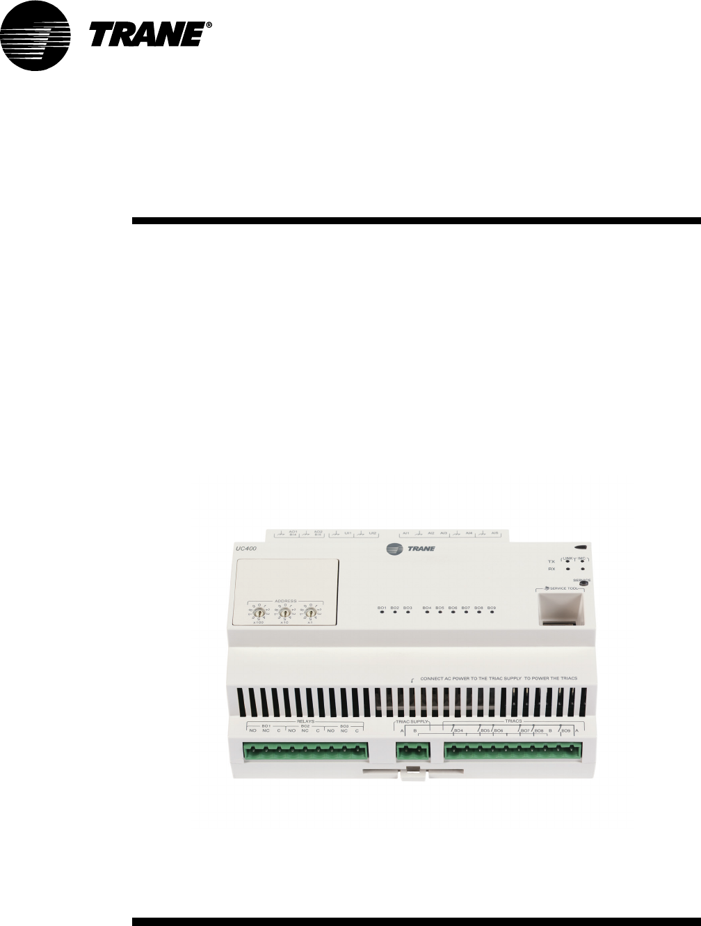
Tracer™ UC400
Programmable BACnet
Controller
For Factory Installation on Variable Air Volume
(VAV) Units
Warnings, Cautions and Notices
© 2010 Trane All rights reserved VAV-SVX07A-EN
Warnings, Cautions and Notices. Note that warnings, cautions and notices appear at
appropriate intervals throughout this manual. Warnings are provide to alert installing contractors
to potential hazards that could result in personal injury or death. Cautions are designed to alert
personnel to hazardous situations that could result in personal injury, while notices indicate a
situation that may result in equipment or property-damage-only accidents.
Your personal safety and the proper operation of this machine depend upon the strict observance
of these precautions.
Read this manual thoroughly before operating or servicing this unit.
WARNING
This equipment is to be serviced/installed by qualified personnel ONLY. Under NO
circumstances should an unqualified person service/install it. Servicing/installing this
equipment is a job requiring specific knowledge and MUST be left to a professional. It involves
working with hazardous components that are potentially life threatening if not handled
properly. Improperly installed, adjusted or altered equipment by an unqualified person could
result in death or serious injury.
WARNING
Electrocution and Fire Hazards with Improperly Installed and Grounded
Field Wiring!
Improperly installed and grounded field wiring poses FIRE & ELECTROCUTION hazards. To avoid
these hazards, you MUST follow requirements for field wiring installation and grounding as
described in NEC and your local/state electrical codes. All field wiring MUST be performed by
qualified personnel. Failure to follow these requirements could result in death or serious injury.
Overview of Manual
Note: One copy of this document ships inside the control panel of each unit and is customer
property. It must be retained by the unit's maintenance personnel.
This booklet describes proper installation, operation, and maintenance procedures for delivered
air systems. By carefully reviewing the information within this manual and following the
instructions, the risk of improper operation and/or component damage will be minimized. It is
important that periodic maintenance be performed to help assure trouble free operation. Should
equipment failure occur, contact a qualified service organization with qualified, experienced HVAC
technicians to properly diagnose and repair this equipment.
ATTENTION: Warnings, Cautions and Notices appear at appropriate sections throughout
this literature. Read these carefully.
WARNING: Indicates a potentially hazardous situation which, if not avoided, could
result in death or serious injury.
CAUTION: Indicates a potentially hazardous situation which, if not avoided, could
result in minor or moderate injury. It may also be used to alert against unsafe practices.
NOTICE: Indicates a situation that could result in equipment or property-damage only
accidents.

Table of Contents
VAV-SVX07A-EN 3
General Information . . . . . . . . . . . . . . . . . . . . . . . . . . . . . . . . . . . . . . . . . . . . . . . . . . . . 5
Tracer UC400 BACnet Unit Controller . . . . . . . . . . . . . . . . . . . . . . . . . . . . . . . . . 5
Shipping & Storage . . . . . . . . . . . . . . . . . . . . . . . . . . . . . . . . . . . . . . . . . . . . . . . . 6
Specifications . . . . . . . . . . . . . . . . . . . . . . . . . . . . . . . . . . . . . . . . . . . . . . . . . . . . . 6
Tracer UC400 Controller Features . . . . . . . . . . . . . . . . . . . . . . . . . . . . . . . . . . . . 8
VAV Start Up/Check Out Procedure . . . . . . . . . . . . . . . . . . . . . . . . . . . . . . . . . . . . . . 12
Tracer UC400 Controller Pre-Power Check-Out . . . . . . . . . . . . . . . . . . . . . . . . 12
Tracer UC400 Controller Power Wiring . . . . . . . . . . . . . . . . . . . . . . . . . . . . . . . 13
LED Description and Behavior . . . . . . . . . . . . . . . . . . . . . . . . . . . . . . . . . . . . . . 14
Communication Wiring . . . . . . . . . . . . . . . . . . . . . . . . . . . . . . . . . . . . . . . . . . . . 15
Space Temperature Control Wiring . . . . . . . . . . . . . . . . . . . . . . . . . . . . . . . . . . 17
Ventilation Flow control . . . . . . . . . . . . . . . . . . . . . . . . . . . . . . . . . . . . . . . . . . . 21
Flow Tracking Control . . . . . . . . . . . . . . . . . . . . . . . . . . . . . . . . . . . . . . . . . . . . . 21
Wireless Zone Sensor . . . . . . . . . . . . . . . . . . . . . . . . . . . . . . . . . . . . . . . . . . . . . 22
Tracer™ UC400 Controller Operations . . . . . . . . . . . . . . . . . . . . . . . . . . . . . . . . . . . 36
Connecting with the Tracer TU Service Tool . . . . . . . . . . . . . . . . . . . . . . . . . . 36
Status Button . . . . . . . . . . . . . . . . . . . . . . . . . . . . . . . . . . . . . . . . . . . . . . . . . . . . . 37
Data Log Button . . . . . . . . . . . . . . . . . . . . . . . . . . . . . . . . . . . . . . . . . . . . . . . . . . 41
Controller Settings Button . . . . . . . . . . . . . . . . . . . . . . . . . . . . . . . . . . . . . . . . . 45
Equipment Settings Button . . . . . . . . . . . . . . . . . . . . . . . . . . . . . . . . . . . . . . . . . 48
Sequence of Operation . . . . . . . . . . . . . . . . . . . . . . . . . . . . . . . . . . . . . . . . . . . . . . . . . 53
Calibration Sequence . . . . . . . . . . . . . . . . . . . . . . . . . . . . . . . . . . . . . . . . . . . . . . 53
Occupancy Modes . . . . . . . . . . . . . . . . . . . . . . . . . . . . . . . . . . . . . . . . . . . . . . . . 53
Space Temperature Control Single Duct/Fan-Powered Units . . . . . . . . . . . . 55
Ventilation Flow Control . . . . . . . . . . . . . . . . . . . . . . . . . . . . . . . . . . . . . . . . . . . 60
Flow Tracking . . . . . . . . . . . . . . . . . . . . . . . . . . . . . . . . . . . . . . . . . . . . . . . . . . . . 62
Troubleshooting . . . . . . . . . . . . . . . . . . . . . . . . . . . . . . . . . . . . . . . . . . . . . . . . . . . . . . . 64
Troubleshooting Procedures . . . . . . . . . . . . . . . . . . . . . . . . . . . . . . . . . . . . . . . 64
Diagnostics . . . . . . . . . . . . . . . . . . . . . . . . . . . . . . . . . . . . . . . . . . . . . . . . . . . . . . 64
LED Operation . . . . . . . . . . . . . . . . . . . . . . . . . . . . . . . . . . . . . . . . . . . . . . . . . . . . 65
Tracer UC400 Controller Failure Troubleshooting Procedures . . . . . . . . . . . 66
Tracer UC400 Controller Communication Loss Procedures . . . . . . . . . . . . . 67
Wired Zone Sensor Failure Troubleshooting Procedures . . . . . . . . . . . . . . . 68
Wired Zone Setpoint Failure Troubleshooting Procedures . . . . . . . . . . . . . . 70
Wireless Zone Sensor Failure Troubleshooting Procedures . . . . . . . . . . . . . 70

4 VAV-SVX07A-EN
Airflow Failure Troubleshooting Procedures . . . . . . . . . . . . . . . . . . . . . . . . . . 75
Supply/Discharge Air Temp Sensor Failure Troubleshooting Procedures . 77
CO2 Sensor Failure Troubleshooting Procedures . . . . . . . . . . . . . . . . . . . . . . 78
VAV Damper Failure Troubleshooting Procedures . . . . . . . . . . . . . . . . . . . . . 79
VAV Series Fan Failure Troubleshooting Procedures . . . . . . . . . . . . . . . . . . 80
VAV Parallel Fan Failure Troubleshooting Procedures . . . . . . . . . . . . . . . . . 81
Trane/Honeywell Proportional Valve Check-Out Procedures . . . . . . . . . . . . 84

VAV-SVX07A-EN 5
General Information
This chapter contains information about the following:
• Tracer™ UC400 BACnet Unit Controller
• Shipping & Storage
• Specifications
• Tracer UC400 Controller Enhancements
• Tracer UC400 Controller Features
Tracer UC400 BACnet Unit Controller
The Tracer UC400 controller is a programmable general purpose BACnet, microprocessor-based,
Direct Digital Controller (DDC). When factory installed on Trane (Variable Air Volume) VAV terminal
units, it is factory downloaded with appropriate VAV programs and configuration settings. Trane
VAV units have been made with either pneumatic, analog electronic, or microprocessor controls
(DDC VAV). This manual discusses only terminal units with BACnet Tracer UC400 controller DDC/
VAV controls. Factory installed DDC/VAV controls are available with all single duct terminal units,
dual duct units, parallel fan-powered, and series fan-powered units. A single Tracer UC400
controller is needed for dual duct units, but programming is not provided from the factory.
The Tracer UC400 controller can be configured from the factory with three different application
programs: Space Temperature Control (STC), Ventilation Flow Control (VFC), and Flow Tracking
Control (FTC).
The Tracer UC400 controller programmed for STC modulates a VAV's damper blade based on a
zone temperature, measured airflow, and setpoints to continuously control conditioned air
delivery to the space. The volume of incoming air is monitored and the damper adjusts to provide
accurate control independent of the duct pressure. The damper modulates between operator
setpoints depending on space conditions. Additionally, fan and heat outputs may be energized
depending on the application.
The Tracer UC400 controller configured for VFC can be applied to a VAV terminal and used to
temper cold outdoor air (OA) that is brought into a building for ventilation purposes. The tempered
air is intended to supply an air-handling unit (AHU), which provides comfort control to the zones
it is serving. The VAV terminal supplies the correct amount of ventilation air, and when reheat is
added, tempers the ventilation air to reduce the load on the air handler by sensing the discharge
air temperature of the VAV unit and controlling its long-term average to the discharge air
temperature setpoint.
The Tracer UC400 controller can be configured for FTC and has two VAV units with Tracer UC400
controllers working together to provide flow tracking control. One Tracer UC400 controller is
configured from the factory with the Space temperature program and the other is downloaded with
the FTC program. The STC airflow output is bound to the flow tracking controller airflow setpoint
input. The flow tracking controller adds the configured airflow tracking offset (positive or negative)
to the airflow setpoint (communicated airflow setpoint) and controls the airflow to this setpoint.
The Tracer UC400 controller is BTL compliant with BACnet, an open standard building automation
protocol. It meets the Application Specific Controller (ASC) profile per ASHRAE 135-2004. This
allows the Tracer UC400 controller to integrate with other BACnet systems.
Available Inputs
Inputs include a twisted/shielded communication link, zone sensor, duct temperature sensors
(optional), Occupancy Sensor (optional), Discharge Air Temperature (DAT) and/or Supply Air
Temperature (SAT), CO2 sensor, and 24 VAC power. In addition to the points used for the VAV
application, the spare inputs and outputs on the Tracer UC400 controller may be used for ancillary
control, which can be programmed using Tracer TU Tracer Graphical Programming 2 (TGP2).
Note: For more information on using spare points, see BAS-SVX20*-EN Tracer UC400
Programmable Controller Installation, Operation, and Maintenance.

6 VAV-SVX07A-EN
General Information
Shipping & Storage
Each VAV order ships with service literature. When unpacking, make sure that the literature is not
lost or discarded with the packing material. Visually inspect the individual components for obvious
defects or damage. All components are thoroughly inspected before leaving the factory. Any
claims for damage incurred during shipment must be filed with the carrier.
If any component of the VAV system and/or field installed accessories must be stored for a period
of time prior to installation, they must be protected from the elements. The storage location
temperature should be between -40° to 150°F (-40° to 65.6°C) and the relative humidity should be
10% to 90%, non-condensing. The warranty will not cover damage to the VAV or controls due to
negligence during storage. A controlled indoor environment must be used for storage.
Specifications
AC wiring specifications
Wire
16 AWG (maximum) copper wire
Tr a n s f o rm e r
• UL Listed, Class 2 power transformer 19-30 VAC (24 VAC nominal)
• The transformer must be sized to provide adequate power to the Tracer UC400 controller (24
VA) and outputs (maximum 12 VA for each binary output)
Storage
• Temperature: -48°F to 203°F (-44°C to 95°C)
• Relative humidity: Between 5% to 95% (noncondensing)
Operating
• Temperature: -40°F to 158°F (-40°C to 70°C)
• Humidity: Between 5% to 95% (noncondensing)
• Power: 19-30 VAC (24 VAC nominal) 50-60 Hz 24 VA
• Mounting weight (controller): Mounting surface must support .80 lb. (364 kg)
• Environmental rating (enclosure): NEMA 1
• Altitude: 6,500 ft. maximum (1,981 m)
• Installation: Category 3
• Pollution Degree 2
Analog inputs AI1 to AI5
• AI1: Space temperature; thermistor: 10 kΩ@ 77°F (25°C)
Range: 32°F to 122°F (0°C to 50°C)
• AI2: Space setpoint; potentiometer: 1 kΩ
From 50 to 90°F (10 to 32.2°C), */** (thumbwheel) functionality supported
• AI3: Spare
• AI4: Discharge air temperature: 10 kΩ@ 77°F (25°C)
From -40 to 212°F (-40 to 100°C)
• AI5: Supply air temperature: 10 kΩ@ 77°F (25°C)
From -40°F to 212°F (-40 to 100°C)
VAV-SVX07A-EN 7
General Information
Universal Inputs UI1 and UI2
• UI1: Spare, but recommended for Relative Humidity. Resistive/thermistor inputs, 0-10VDC
inputs, or 4-20 mA inputs. Current Mode Impedance: 200 ohm. Voltage Mode Impedance: 10
kohm min.
• UI2: Spare, but recommended for CO2. Resistive/thermistor inputs, 0-10VDC inputs, or 4-20 mA
inputs. Current Mode Impedance: 200 ohm. Voltage Mode Impedance: 10 kohm min.
Pressure Inputs P1 and P2
• P1: Supply air flow; pressure transducer: From 0 to 2 in. water column (0 to 498 Pa)
• P2: Spare, but recommended for dual duct secondary air flow
Binary input BI1 to BI3
• BI1: Occupancy
• BI2: Spare
• BI3: Spare
Binary outputs BO1 to BO9
Analog outputs AO1 and AO2
• AO1: Spare. Voltage output is 0 to 10 VDC, 500 ohm min. impedance. Current output is 4 - 20
mA, 500 ohm max. impedance
Note: ECM fan for future production.
• AO2: Spare. Voltage output is 0 to 10 VDC, 500 ohm min. impedance. Current output is 4 - 20
mA, 500 ohm max. impedance
Note: For more information about wiring spare I/O, see the Tracer™ UC400 controller Installation
Sheet X39641064*-01.
Agency listings/compliance
UL - Open Energy Management Equipment, 834Y
UL94-5V Flammability
CE marked
FCC Part 15, Subpart B, Class B Limit
AS/NZS CISPR 22:2006
VCCI V-3/2008.04
Table 1. Binary outputs
Binary Outputs Type Output Rating Pilot duty
BO1 Fan 10A up to 277 VAC 10A at 30 VAC/VDC, 2A at 120 VAC, 8A at 250 VAC,
BO2 Spare Relay 10A up to 277 VAC 10A at 30 VAC/VDC, 2A at 120 VAC, 8A at 250 VAC,
BO3 Spare Relay 10A up to 277 VAC 10A at 30 VAC/VDC, 2A at 120 VAC, 8A at 250 VAC,
BO4 Spare Relay 10A up to 277 VAC 10A at 30 VAC/VDC, 2A at 120 VAC, 8A at 250 VAC,
BO5 Heat stage 3 TRIAC 24-27 VAC, .5A Resistive VA
BO6 Heat stage 2/Water Valve Close TRIAC 24-27 VAC, .5A Resistive VA
BO7 Heat stage 1/Water Valve Open TRIAC 24-27 VAC, .5A Resistive VA
BO8 Air Damper Close TRIAC 24-27 VAC, .5A Resistive VA
BO9 Air Damper Open TRIAC 24-27 VAC, .5A Resistive VA
8 VAV-SVX07A-EN
General Information
ICES-003, Issue 4:2004
Mounting
The Tracer™ UC400 controller is factory installed in the VAV control box.
Setting up the Tracer UC400 Controller on a BACnet Link
Tracer SC and BACnet Communications Link Wiring
Use 18 AWG shielded communication wire for BACnet MS/TP installations. Limit BACnet MS/TP
wiring links to 4,000 ft. There is a 60 device maximum per link (without a repeater). Two BACnet
links are available on the SC. Connect the BACnet link to the Tracer UC400 controller terminals
labeled Link. Incoming wires can be connected to the first two terminals, and the outgoing wires
can be connected to the second set of terminals, such that there is only one wire per termination.
Refer to Chapters 2 and 3 for further information about wire selection. See also wiring guide BAS-
SVN03*-EN (Unit Controller Wiring for Tracer SC™System Controller) for required wire type,
topology, and active termination resistors for BACnet links.
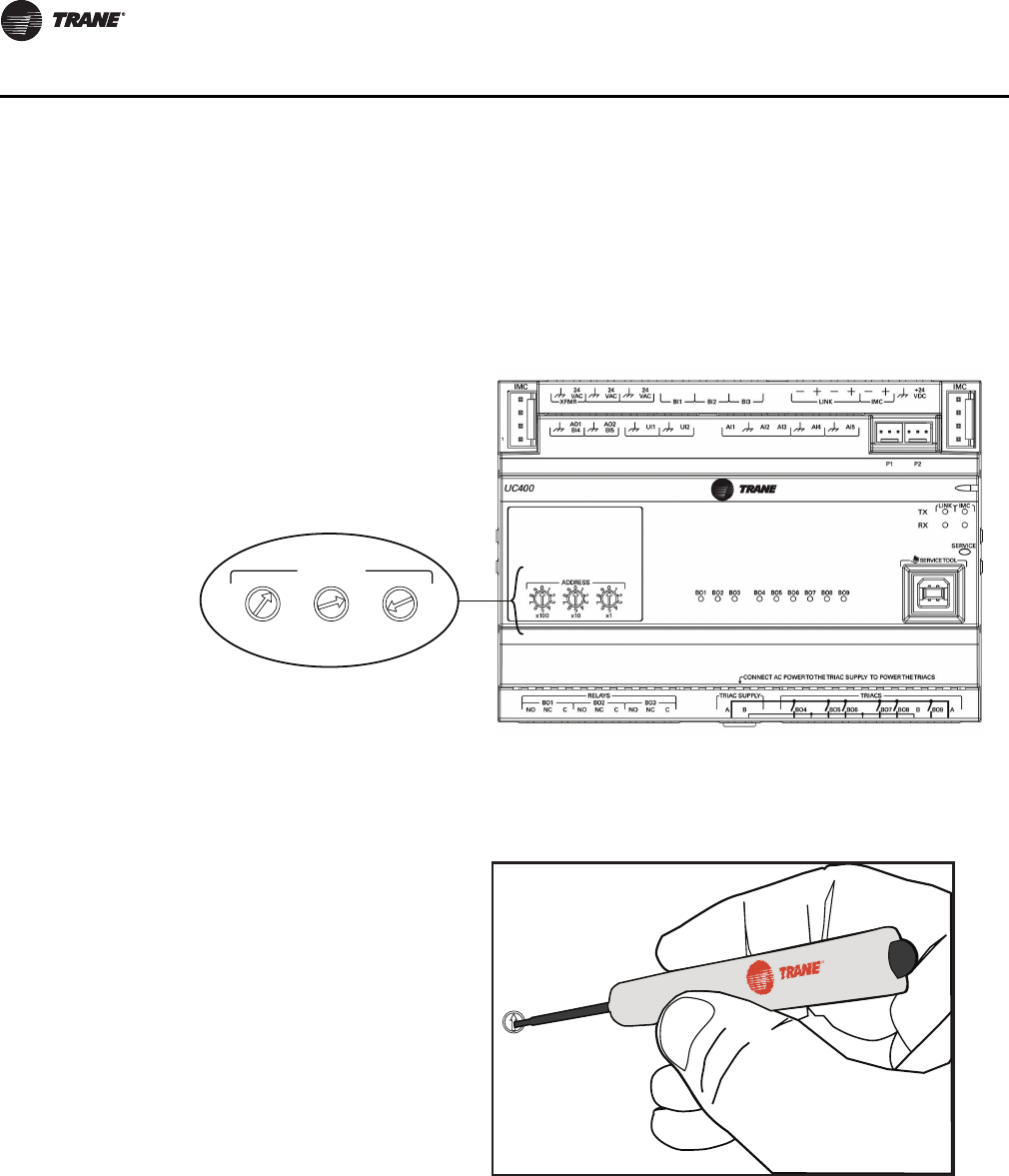
Rotary Switches
There are three rotary switches on the front of the Tracer UC400 controller (see Figure 3, p. 16). Use
these switches to define a three-digit address when it is installed in a BACnet system (for example,
107, 120, and so on), whether with other Trane BACnet controls or controls from another vendor.
This three-digit rotary switch setting is used as both the BACnet MAC address and the BACnet
Device ID.
Note: Valid addresses are 001 to 120.
Important: Each Tracer UC400 controller on the BACnet link must have a unique rotary switch
setting, otherwise communication problems will occur.
Tracer UC400 Controller Features
Controller Interface Flexibility
The Tracer UC400 controller allows VAV units to communicate on a BACnet MS/TP link. This
controller works in standalone mode, peer-to-peer with one or more other units, or when
connected to a Tracer SC or a 3rd party building automation system that supports BACnet.
Table 2. Agency listings/compliance
Standard Test Level
EN 61326-1: 2006 Electrical equipment for measurement, control and
laboratory use - EMC requirements, part 1: General Requirements.
EN 55022: 2006 (CISPR 22: 2005 + A1: 2005) Radiated Emissions Class B Limit (30 MHz - 1000 MHz, 1 GHz - 2 GHz)
EN 55022: 2006 (CISPR 22: 2005 + A1: 2005) Conducted Emissions 150 kHz - 30 MHz
EN 61000-4-2: 1995 + A1: 1998 + A2: 2001 Electrostatic Discharge
(ESD) 8 kV air, 4 kV contact
EN 61000-4-3: 2002 Radiated Fields 10 V/m, 80 MHz - 1000 MHz 3 V/m, 1.4 GHz - 2.0 GHz 1 V/m, 2.0 GHz
- 2.7 GHz
EN 61000-4-4: 2004 Fast Transients I/O port, 1 Kv AC inputs & output ports, 2 kV
EN61000-4-5: 1995 + A1: 2001 Surge Transients AC input ports (L? L), differential mode, 1 kV
EN61000-4-6: 1996 + A1: 2001 Conducted Disturbance 3 V, 0.15 MHz - 80 MHz
EN61000-4-8: 1993 + A1: 2001 Power Frequency Magnetic Field 30 A/m, 50 Hz
EN61000-4-11 Second Edition: 2004 Voltage Dips and Interruptions 0% Vnom, 1 cycle; 70% Vnom, 25 cycle; 40% Vnom, 10 cycle, 0%
Vnom, 250 cycle
Note: Trane declares that the product listed is in conformity with the essential requirements of Council Directive 2004/108/EC (electromagnetic
compatibility) and conforms to the standards in this table.

VAV-SVX07A-EN 9
General Information
Flow Tracking
The Tracer™ UC400 controller is designed with the ability to be applied in flow tracking
applications. This allows the controller to be paired with one of its peers to mirror the flow of the
lead unit, with or without an offset (positive or negative static pressure as desired).
Ventilation Flow Control with Tempering
The Tracer UC400 controller is designed with the ability to be applied in ventilation flow control
applications. These applications pair a fresh air unit with ventilation boxes to provide fresh
(tempered) air to a zone. This feature also includes a freeze protection sequence to protect the hot
water reheat coil from low supply air temperatures.
Auto-commissioning Sequence
The TracerUC400 controller is designed with an auto-commissioning sequence. With a discharge
air temperature sensor, this feature exercises the air valve, fan, and heat in the box and records the
temperature before and after the action. This allows the installer to more easily verify the operation
of the unit and commission by exception. An auto-commissioning report can be generated with
Tracer TU service tool.
Automatic Calibration
The Tracer UC400 controller is designed to automatically calibrate the flow transducer each time
the unit transitions to unoccupied. This eliminates the need to initiate/schedule calibration for most
installations. The exception is 24/7 sites, in which case Tracer SC can be used to initiate/schedule
calibration.
Temporary Heat (Construction Mode)
Upon reset (and power-up) if the controller does not detect a valid space temperature the controller
will provide temporary heat by driving the air valve to the heating maximum position.
Note: Note that the unit will only provide heat if hot air is being provided by the air-handling
unit.
Local Versus Remote Reheat Flexibility
The controller can be configured to have local and/or remote heat. Plus, configuration flexibility is
offered that allows the installer to select whether local or remote heat has priority.
Spare Inputs and Outputs
The Tracer UC400 controller has spare I/O that are not used by the VAV applications. These spare
I/O can be programmed using the Tracer Graphical Programming editor (by means of the Tracer
TU service tool) to measure and/or control ancillary devices such exhaust fans, second air valve for
dual duct VAV or sensing relative humidity.
Removable Terminals
The Tracer UC400 controller connectors are two-part connectors that have 5.08 mm pin separation.
The headers are attached on the Tracer UC400 controller itself. The other portion of the connector
is either a screw terminal (for field wiring) or a terminal housing (for factory wiring). Spare screw
terminals come factory installed for field mounted wired zone sensors and common accessories.
Wireless Zone Sensors
The Tracer UC400 controller is compatible with the latest wireless zone sensors available from
Trane. Wireless zone sensors provide flexibility of sensor location and re-location as well as
reducing the cost of installation. Wireless zone sensor receivers are available as a factory installed
option.

10 VAV-SVX07A-EN
General Information
Flash Download
The Tracer™ UC400 controller has been designed with flash memory. This allows the option of
upgrading the controller in the field (features, corrections to defects) without changing out the
controller.
Trane Controller Compatibility
The Tracer UC400 controller is a BACnet-compliant controller. As such, the controller is compatible
with the latest generation of Trane controls. This allows the Tracer UC400 controller to exist on the
same communication wire as the rest of our controllers and share data with them as required.
Drive Min and Max from Zone Sensor
When applied with a Trane zone sensor module that includes a thumbwheel setpoint or a LCD
display, the Tracer UC400 controller can easily be overridden to minimum and maximum flow. By
simply turning the thumbwheel to "*" or increasing the setpoint to maximum on display sensors
(end of range in one direction) the controller drives the air valve to the minimum cooling flow
setpoint. Similarly, turning the thumbwheel to the "**" or decreasing the setpoint to minimum on
display sensors (end of range in the other direction) the controller drives the air valve to the
maximum cooling flow setpoint.
Auto-commissioning Report (Tracer SC, Tracer TU)
Tracer SC and Tracer TU both include auto-commissioning reports that extracts and formats the
commissioning data for each VAV controller. This commissioning report is valuable both for the
installer and for the owner. The feature enables the system to be commissioned by exception -- a
benefit for the installer. The feature also can be used as validation -- valuable to the owner.
Simpler VAS
Tracer SC includes a new VAV Air System (VAS) specifically designed for both BACnet and LonTalk
VAV controllers. This new VAS was designed to be much simpler to understand and provides a
wizard to aid in first time setup of a VAS.
Static Pressure Optimization
As a part of the standard application, VAS calculates the duct static pressure setpoint based on the
VAV unit with a damper in the maximum flow position.
Ventilation Optimization
As a part of the standard application, the VAV system has the ability to calculate the ventilation
setpoint for the air-handling unit. In addition, the Tracer UC400 controllers have a ventilation ratio
limit feature that automatically increases airflow to maintain the required ventilation while
operating within system limits for outside air percent concentrations in the supply air stream.
CO2-Based Demand Control Ventilation
As a part of the standard application, the VAV system has the ability to calculate the ventilation
setpoint for the air-handling unit based on the CO2 concentration in one or more spaces.
Ventilation Flexibility
Ventilation can be managed in the following ways:
• Fixed occupancy ventilation setpoint
• Scheduled (or otherwise calculated) ventilation setpoint
• Occupancy sensor to switch between normal and reduced ventilation
•CO
2 sensor for demand-controlled ventilation
VAV-SVX07A-EN 11
General Information
Temperature Statistics
As a part of the standard application, both the VAS and Area applications calculate the minimum
space temperature (and source), maximum space temperature (and source), and the average space
temperature.
Tracer™ UC400 Controller Compatibility
The Tracer UC400 controller integrates with other BACnet systems and devices using BACnet MS/
TP. The Tracer UC400 controller provides standard BACnet objects (data points) that can be read
by and/or written to by other systems.
Note: See BACnet Integration Guide (BAS-SVP01*-EN) for more information on the Tracer UC400
controller interface to non-Trane systems.
Note: BACnet is the Building Automation and Control Network (BACnet and ANSI/ASHRAE
Standard 135-2004) protocol.
Table 3. Tracer UC400, Tracer VV550, and VAV 4.2 controller comparisons
Tracer UC400 VAV Tracer VV550/VV551 VAV 4.2
Supports BACnet. Supports LonTalk (Comm5). Supports only Comm4 or Comm3 (VariTrac or
VariTrane).
Local CO2 sensor input is available. No local CO2 sensor input. Uses only a
communicated value. Local CO2 sensor input is available.
Single star (*) initiates cool minimum
airflow override.(a)
Single star (*) initiates cool minimum
airflow override.(a)
Single star (*) initiates maximum flow override
after pressing the ON button. Override is held
until you move the thumbwheel.
Double star (**) initiates cool maximum
airflow override.(b)
Double star (**) initiates cool maximum
airflow override.(b)
Double star (**) initiates unoccupied override
after pressing the ON button. Override is held
until you move the thumbwheel.
Does not support VariTrac central control
panel (CCP2 and CCP3).
Does not support VariTrac central control
panel (CCP2 and CCP3). Does support VariTrac CCP2 and CCP3.
Supports ventilation flow control. Supports ventilation flow control. Does not support ventilation flow control.
Supports flow tracking control. Supports flow tracking control. Does not support flow tracking control.
Supports enhanced ventilation control
sequences.
Supports enhanced ventilation control
sequences.
Does not support enhanced ventilation control
sequences.
Supports auto-commissioning sequence. Supports auto-commissioning sequence. Does not support auto-commissioning
sequence.
Does not support zone sensor air balance
sequence.
Supports zone sensor air balance
sequence.
Does not support zone sensor air balance
sequence.
(a) By simply turning the thumbwheel to "*" or increasing the setpoint to maximum on display sensors (end of range in one direction) the controller
drives the air valve to the minimum cooling flow setpoint.
(b) Turning the thumbwheel to the "**" or decreasing the setpoint to minimum on display sensors (end of range in the other direction) the controller
drives the air valve to the maximum cooling flow setpoint.

12 VAV-SVX07A-EN
VAV Start Up/Check Out Procedure
This chapter contains information about the following:
• Tracer™ UC400 Controller Pre-Power Check-Out
• Tracer UC400 Controller Power Wiring
• Communication Wiring
• Space Temperature Control Wiring
•Zone Sensor Wiring
•Duct Temperature Sensor Wiring
•Binary Input Wiring
•Binary Output Wiring
• Zone Sensor Check-Out
• Ventilation Flow Control
• Flow Tracking Control
• Wireless Zone Sensor
Tracer UC400 Controller Pre-Power Check-Out
WARNING
Live Electrical Components!
During installation, testing, servicing and troubleshooting of this product, it may be necessary
to work with live electrical components. Have a qualified licensed electrician or other individual
who has been properly trained in handling live electrical components perform these tasks.
Failure to follow all electrical safety precautions when exposed to live electrical components
could result in death or serious injury.
• Check the supply voltage at XFRM. Proper polarity must be maintained. The 24 VAC is the hot
side (+) and is the ground side (-) of the 24 VAC input. Refer to Figure 4, p. 18 for the Tracer
UC400 controller terminal locations. The Tracer UC400 controller cannot be powered from a
common 24 VAC transformer that is supplying power to a device containing a full-wave rectifier
bridge in its power supply. The acceptable voltage is 19 to 30 VAC (24 VAC nominal). However,
voltages at either extreme may result in increased system instability.
• Verify communications wiring has properly been terminated to link plus and negative at XFRM
24 VAC (+) and (-) terminals. Polarity must be maintained on the BACnet communications
link.
• Verify that the zone sensor connections are correct as detailed in the Tracer UC400 controller
wiring section.
• If heat has been added to the unit, verify that the proper output connections have been made
as detailed in the Tracer UC400 controller wiring section.
• Verify that the tubing is properly connected to the differential pressure transducer.
VAV-SVX07A-EN 13
VAV Start Up/Check Out Procedure
Tracer UC400 Controller Power Wiring
Power Requirements
WARNING
Hazardous Voltage!
Disconnect all electric power, including remote disconnects before servicing. Follow proper
lockout/tagout procedures to ensure the power can not be inadvertently energized. Failure to
disconnect power before servicing could result in death or serious injury.
WARNING
Electrocution and Fire Hazards with Improperly Installed and Grounded
Field Wiring!
Improperly installed and grounded field wiring poses FIRE & ELECTROCUTION hazards. To avoid
these hazards, you MUST follow requirements for field wiring installation and grounding as
described in the National Electrical Codes (NEC) and your local/state electrical codes. All field
wiring MUST be performed by qualified personnel. Failure to follow these requirements could
result in death or serious injury.
NOTICE
Use Copper Conductors Only!
Unit terminals are not designed to accept other types of conductors. Failure to use copper
conductors could result in equipment damage.
Use at a minimum 16 AWG for power wiring and connect to terminal XFRM 24 VAC and . The 24
VAC is required to power the Tracer UC400 controller and has an acceptable voltage tolerance of
19 to 30 VAC. Refer to Figure 4, p. 18 and Figure 5, p. 19 for the Tracer UC400 controller terminal
locations. Replace the control box cover after field wiring to prevent any electromagnetic
interference.
Note: A dedicated 24 VAC, 75VA NEC class 2 transformer is recommended to power the Tracer
UC400 controller. When powering multiple controllers from one transformer, polarity must
be maintained. Terminal 24 VAC is designated positive (+) and terminal is negative (-) to
the unit casing ground.
The power consumption for cooling only Series F Models (VariTrac and VariTrane) is 28 VA. To
determine the total Tracer UC400 controller power requirement, add the power consumption per
stage to the circuit board power requirement. For example, a Series F unit containing magnetic
contactors with three stages of reheat would consume 54 VA.
Table 4. VA for factory installed component
Style Volt Amps
F - Style Actuator: 4 VA
Air Valve Actuator C through E Style: 12 VA
Fan Power Fan Output: 6 VA
Hot Water Proportional: 4 VA
Hot Water 2 Position: 6.5 VA
Electric Heater Magnetic Contactor: 10 VA
Electric Heater Mercury Contactor: 12 VA
Note: VariTrane cooling only Series D and E models consume 20 VA (12 VA for the actuator and 8 VA for the board). The heating
output ratings remain the same. Refer to Figure 4, p. 18 and Figure 5, p. 19 for the Tracer UC400 controller terminal
locations and for wiring of output devices.
14 VAV-SVX07A-EN
VAV Start Up/Check Out Procedure
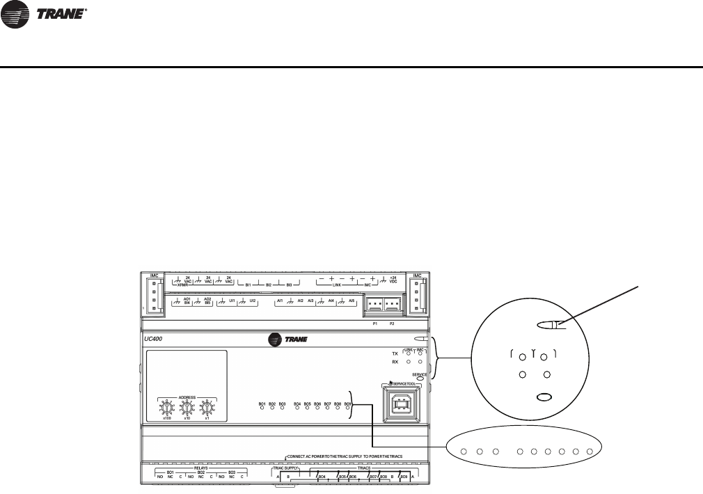
LED Description and Behavior
There are 15 LEDs on the front of the Tracer UC400 controller. Figure 1, p. 14 shows the locations
of each LED and describes the behavior of each.
Tracer UC400 Controller Module
LED Description and Operation
There are 15 LEDs on the front of the Tracer UC400 controller. Figure 1, p. 14 shows the locations
of each LED and a description of its behavior in specific instances.
Marquee LED
• Shows solid green when the Tracer UC400 controller is powered and operating normally.
• Shows solid red when the Tracer UC400 controller is powered, but represents low power or
a malfunction.
• Blinks red when an alarm exists.
LINK
•The TX LED blinks green at the data transfer rate when the Tracer UC400 controller transfers
data to other devices on the link.
•The RX LED blinks yellow at the data transfer rate when the Tracer UC400 controller receives
data from other devices on the link.
IMC
•The TX LED blinks green at the data transfer rate when the Tracer UC400 controller transfer data
to other devices on the IMC bus.
•The RX LED blinks yellow at the data transfer rate when the Tracer UC400 controller receives
data from other devices on the IMC bus.
Service
Shows solid green when pressed.
BO1 to BO9
Shows solid green when corresponding binary output is on.
Figure 1. LED locations
SERVI
C
E
IM
C
LINK
RX
TX
BO2 9OB1OBBO8BO7BO6BO5BO3 BO4
Marquee LED
VAV-SVX07A-EN 15
VAV Start Up/Check Out Procedure
Communication Wiring
WARNING
Electrocution and Fire Hazards with Improperly Installed and Grounded
Field Wiring!
Improperly installed and grounded field wiring poses FIRE & ELECTROCUTION hazards. To avoid
these hazards, you MUST follow requirements for field wiring installation and grounding as
described in NEC and your local/state electrical codes. All field wiring MUST be performed by
qualified personnel. Failure to follow these requirements could result in death or serious injury.
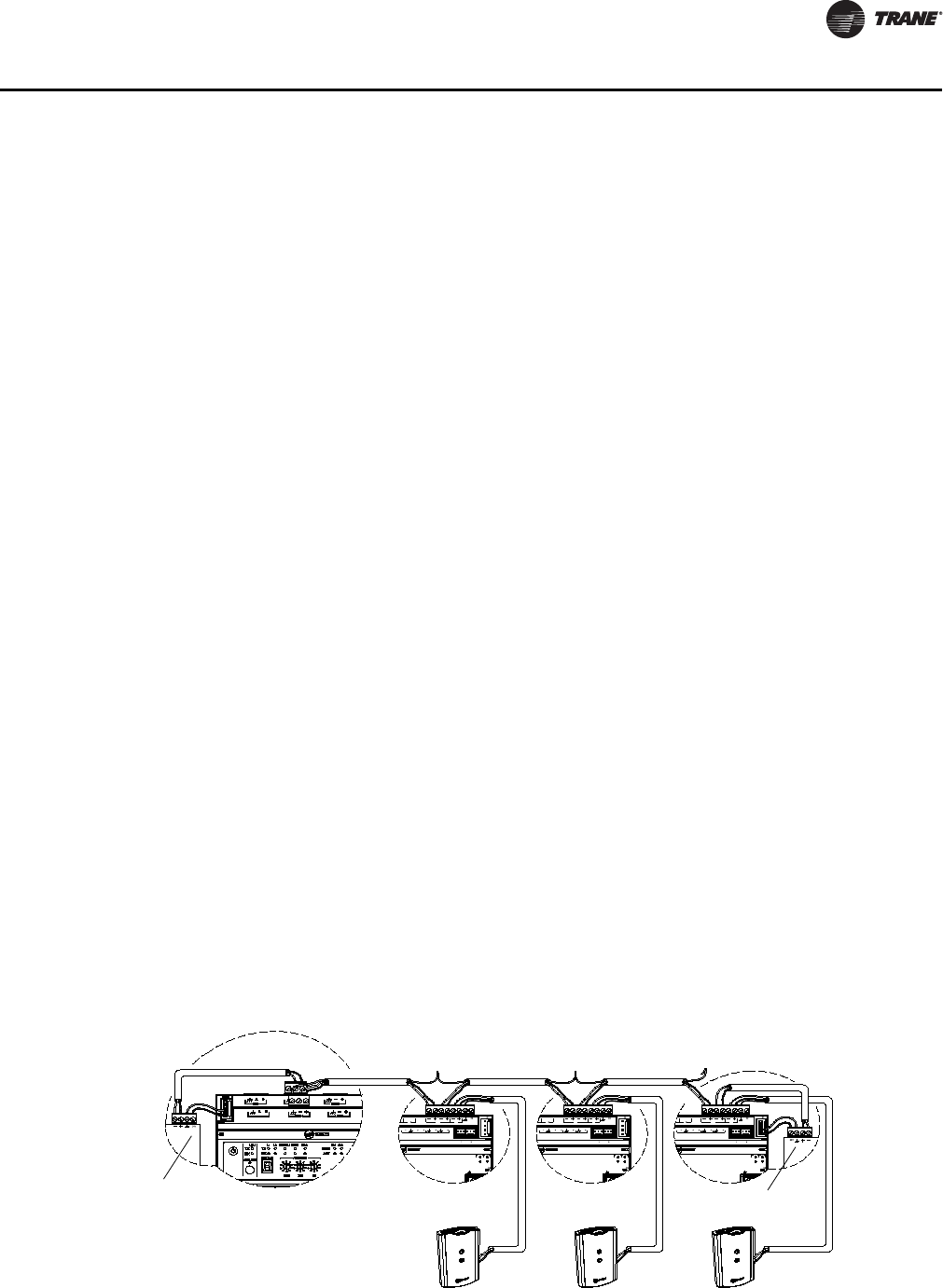
Communication Link Wiring Requirements
• Use 18 AWG Trane purple-shielded communication wire for BACnet installations.
• Link limit of 4,000 ft and 60 devices maximum (without a repeater).
• Use a Trane BACnet termination on each end of the link.
• Use daisy chain topology. See Figure 2, p. 15.
• Maintain polarity.
Recommended Wiring Practices
To ensure proper network communication, follow these recommended wiring and planning
guidelines when installing communication wire:
• All wiring must comply with the National Electrical Code (NEC) and local codes.
• Make sure that 24 VAC power supplies are consistent in how they are grounded. Avoid sharing
24 VAC between controllers.
• Avoid over tightening cable ties and other forms of cable wraps. This can damage the wires
inside the cable.
• Do not run communication cable alongside or in the same conduit as 24 VAC power. This
includes the conductors running from TRIAC-type inputs.
• In open plenums, avoid running wire near lighting ballasts, especially those using 277 VAC.
• Use same communication wire type, without terminators, for the zone sensor communication
stubs from the Tracer UC400 controller IMC terminals to the zone sensor communication
module.
Note: For more information see wiring guide BAS-SVN03*-EN, Unit Controller Wiring for Tracer
SC™ System Controller.
Figure 2. BACnet link wiring in daisy chain configuration with Trane BACnet terminators and zone senor
communication stubs
BI LINK IMC
+
VDC
AI
AIAI AI AI
P P
TX
RX
LINK IM
SERVI
SERVICE TOOL
IM
BI LINK IMC
+
VDC
AI
AIAI AI AI
P P
TX
RX
LINK IM
SERVI
SERVICE TOOL
IM
BI LINK IMC
+
VDC
AI
AIAI AI AI
P P
TX
RX
LINK IM
SERVI
SERVICE TOOL
IM
+
+
BACnet Terminator
BACnet Terminator
16 VAV-SVX07A-EN
VAV Start Up/Check Out Procedure
Rotary Switches
There are three rotary switches on the font of the Tracer™ UC400 controller device that are used
to define a three-digit address when the Tracer TU service tool is installed on a BACnet
communications network. The three-digit address setting is used as both the BACnet MAC address
and the BACnet device ID.
Note: Valid MAC addresses are 001 to 120 for BACnet.
Important: Each Tracer UC400 controller device on the BACnet link must have a unique rotary
switch setting, otherwise, communication problems will occur.
Figure 3. Setting rotary switches
ADDRESS
0
1
2
3
4
5
6
7
8
9
x1
0
1
2
3
4
5
6
7
8
9
x10
0
1
2
3
4
5
6
7
8
9
x100
Example of before and
after setting addresses
0
5
1
3
6
2
9
4
8
7
Use a 1/8 inch
flathead screwdriver
to set rotary switches.

VAV-SVX07A-EN 17
VAV Start Up/Check Out Procedure
Space Temperature Control Wiring
Zone Sensor Hardwired Option
Depending on the zone sensor options used, a maximum of seven wires may be required to run
from the Tracer™ UC400 controller to the zone sensor. The zone sensor options are:
• Zone sensor (temperature only) - Part Number X1351152801.
• Zone sensor with timed override (TOV) on/cancel button - Part Number X1351153001.
• Zone sensor with adjustable setpoint thumbwheel - Part Number X1351152901.
• Zone sensor with adjustable setpoint thumbwheel, timed override (TOV) on/cancel button - Part
Number X1351152701.
• Zone sensor with digital display - Part Number X1379088601. (Display sensor has factory
mounted communication module.)
• Communications module - Part Number X1365146702. (for one box of 12)
Zone Sensor Wireless Option
Wireless zone sensors are available individually or on sensor/receiver sets. A receiver is used to
receive the signal from the wireless zone sensor and can be factory installed. See BAS-SVX04*-EN
for additional details on setup of the wireless zone sensors.
Note: Currently, wireless sensors do not provide a communication module option. It is
recommended that at least one wired sensor with communications module be installed
within the network of controllers, for service tool connection.
• Wireless zone sensor (temperature only)
– Sensor/Receiver Set - Part Number X1379082301.
– Sensor only - Part Number X13790821.
• Wireless zone sensor with adjustable setpoint thumbwheel (°F), timed override (TOV) on/cancel
button
– Sensor/Receiver Set - Part Number X13790496.
– Sensor only - Part Number X13790492.
• Wireless zone sensor with adjustable setpoint thumbwheel (°C), timed override (TOV) on/cancel
button
– Sensor/Receiver Set - Part Number X13790498.
– Sensor only - Part Number X13790494.
• Wireless zone sensor with digital display
– Sensor/Receiver Set - Part Number X1379082401.
– Sensor only - Part Number X1379082201.
• Wireless receiver only - Part Number X13790854.
18 VAV-SVX07A-EN
VAV Start Up/Check Out Procedure
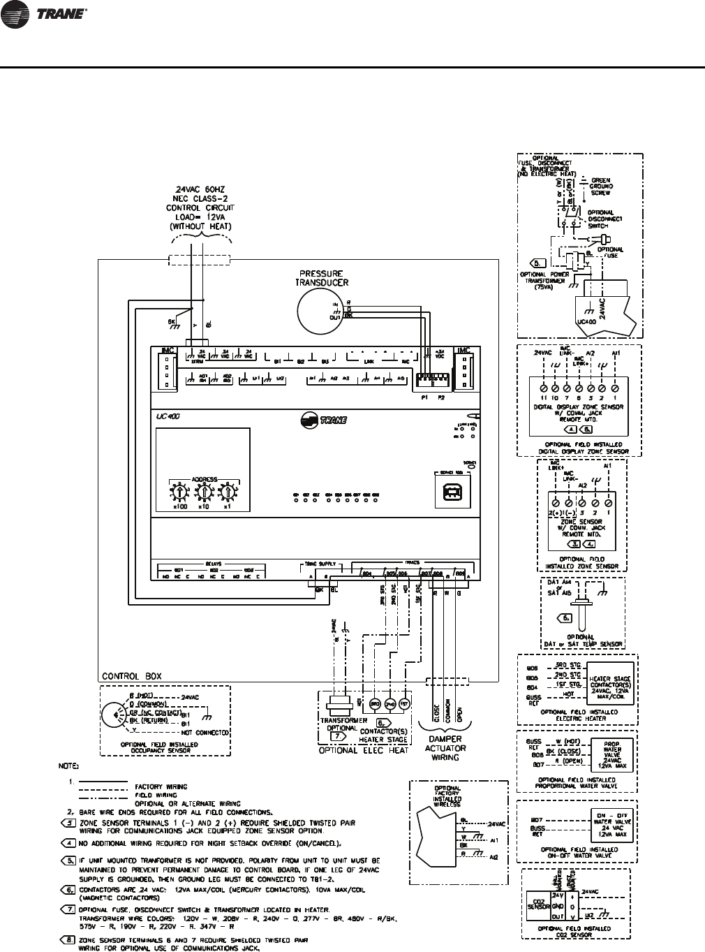
Figure 4. Tracer UC400 controller wiring connection diagram: single duct unit
VAV-SVX07A-EN 19
VAV Start Up/Check Out Procedure
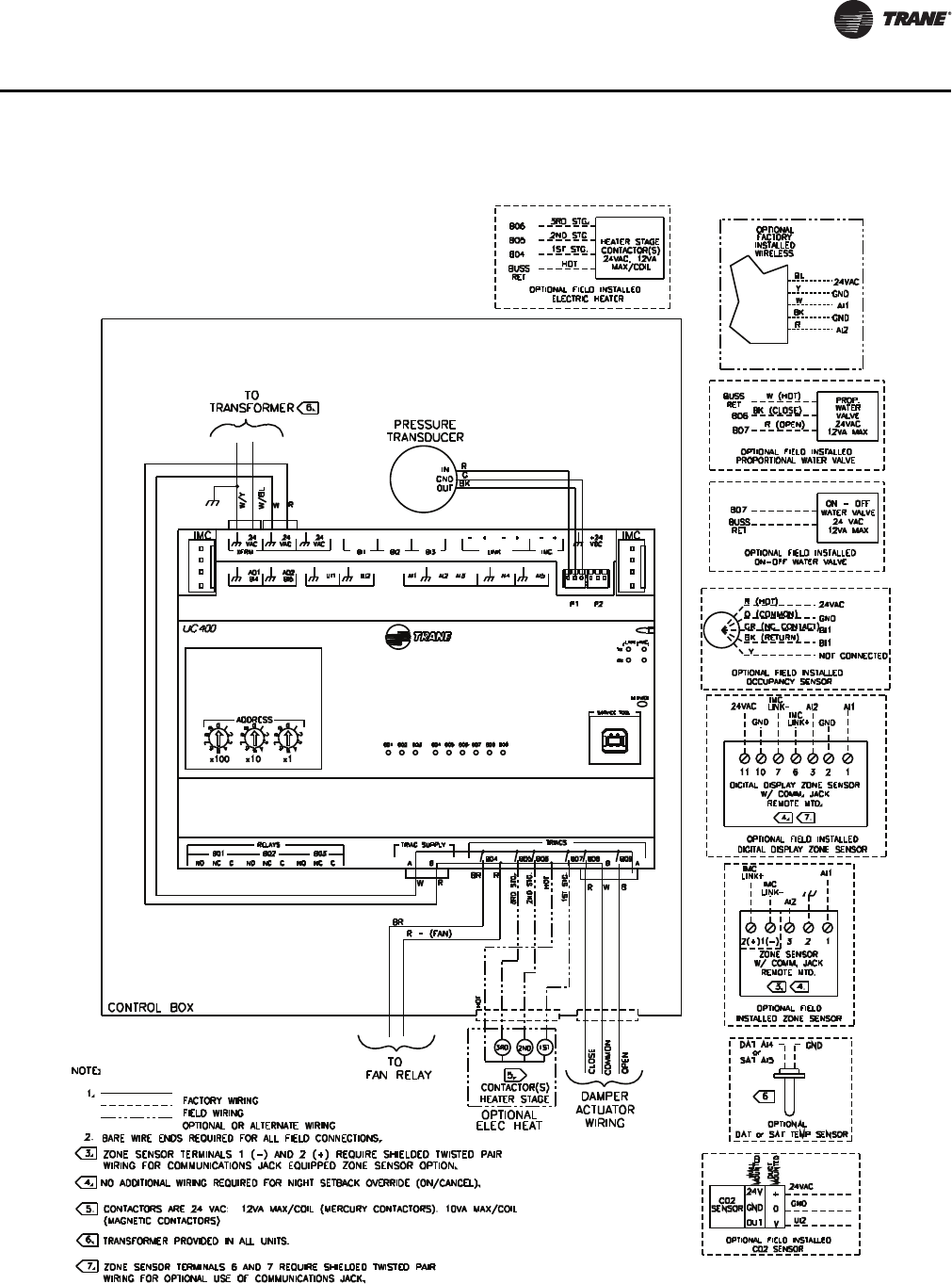
Figure 5. Tracer UC400 controller wiring connection diagram: fan powered unit

20 VAV-SVX07A-EN
VAV Start Up/Check Out Procedure
Zone Sensor Wiring
Location and Mounting
A zone sensor in each control zone should be located in the most critical area of the zone. Sensors
should not be mounted in direct sunlight or in the area's supply air stream. Subdivision of the zone
may be necessary for adequate control and comfort. Avoid mounting zone sensors in areas subject
to the following:
• Drafts or "dead spots" behind doors or corners.
• Hot or cold air ducts.
• Radiant heat from the sun or appliances.
• Concealed pipes or chimneys.
• Unheated or uncooled surfaces behind the sensor such as outside walls.
• Air flows from adjacent zones or other units.
Wiring
Each unit must be controlled by a zone sensor that utilizes a standard 10K ohm at 77°F thermister
for temperature outputs. Field wiring for the zone sensors must meet the following requirements:
• 18 to 22 AWG stranded, tinned-copper, shielded, twisted-pair wire is recommended.
• Maximum wire length 300 ft. (100 m).
•Refer to Figure 4, p. 18 and Figure 5, p. 19 and the sensor instructions for terminal connections.
• All wiring must be in accordance with the National Electrical Code and local codes.
• If local codes require enclosed conductors, the zone sensor wires should be installed in conduit.
Note: Do not route zone sensor wires in conduit with 24 VAC or other high power conducting
wires.
Zone Sensor Communication Stubs
The wire that runs from a zone sensor to a unit controller is commonly referred to as a
communication stub. Figure 2, p. 15 shows an example of communication stubs on a BACnet link.
The stub is not the BACnet link; it is a wire that goes from the Tracer™ UC400 controller IMC
terminal link down to the zone sensor. At least one zone sensor per area or controller network
should include the optional communications module. Installing additional sensors with the
communications module will provide added convenience for the service technician.
There is no limitation on the number of stubs that can be wired from the Tracer UC400 controller.
Polarity must be maintained and the length limit is 600 ft (182 m).
The wire for the communication stub must be the same as that used for BACnet communication
link wiring: low-capacitance, 18-gauge, shielded, twisted pair with stranded, tinned copper
conductors.
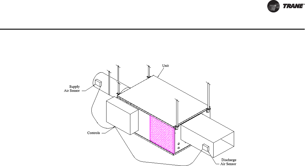
Duct Temperature Sensor Wiring
The Tracer UC400 controller has separate analog inputs for discharge air sensors and supply air
sensor. The typical mounting position of the supply air sensor is upstream of the VAV unit and
connected into the UC400 controller (Figure 6, p. 21) at AI5 and . However, the discharge air
temperature sensor may be downstream of the VAV unit, at the discharge, and connected into the
Tracer UC400 controller at AI4 and . Refer to Controller Diagrams Figure 4, p. 18 and Figure 5,
p. 19 for the Tracer UC400 controller terminal locations.
VAV-SVX07A-EN 21
VAV Start Up/Check Out Procedure
Binary Input Wiring
Each Tracer™ UC400 controller provides three binary inputs. On the Tracer UC400 controller
factory-installed controller, one of the binary inputs is configured in the factory for occupancy. The
binary inputs can be configured with the Tracer TU service tool for occupancy or other use. The
input associates 0 VAC with open contacts and 24 VAC with closed contacts. It is activated by a dry
contact switch closure.
• Must be 18 to 22 AWG.
• Maximum wire length 1,000 ft. (300 m).
•Refer to Figure 4, p. 18 and Figure 5, p. 19 and the sensor instructions for terminal connections.
Occupancy Binary Input
The occupancy binary input can be configured as NO or NC. Occupied is the normal state. It is also
the initial state at power-up and after a reset. Unoccupied is the other state. If the binary input is
configured as generic, the default occupancy mode is occupied.
Binary Output Wiring
Binary outputs that are required for unit operation are factory wired and commissioned. The Tracer
UC400 controller does have three extra binary outputs (BO2-BO4) available for other use. To
program the three extra outputs on the Tracer UC400 controller, see BAS-SVX20*-EN Tracer UC400
Programmable Controller Installation, Operation, and Maintenance.
Ventilation Flow control
See Duct Temperature Sensor wiring described on Space Temperature Control Wiring.
Note: If heat is installed Discharge Air sensor must be located at the discharge of the VAV unit.
Flow Tracking Control
Two controllers are used on to separate VAV units for flow tracking. One is a space temperature
controller, and the other is a flow tracking controller. The flow tracking unit does have inputs or
output connected to the controller.
Figure 6. Duct temperature sensors: upstream/downstream
22 VAV-SVX07A-EN
VAV Start Up/Check Out Procedure
Wireless Zone Sensor
The Trane Wireless Zone Sensor set includes a sensor and a receiver that work together to provide
the same functions as the equivalent Trane wired sensor, such as the standard 10k Ω temperature
input (with the exception of the communication jack). No further software or hardware is necessary
for site evaluation, installation, or maintenance.
The sensor transmits the zone temperature, all zone temperature setpoint functions, timed override
Occupied (On) and timed override Unoccupied (Cancel) information to the receiver. The receiver
electrically reproduces the zone temperature resistance, all zone temperature setpoint function
resistances, and timed override On and timed override Cancel information as sent by the sensor.
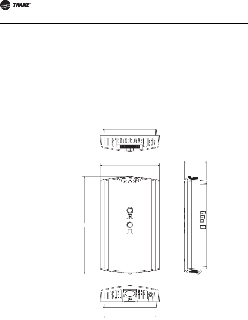
Dimensional Diagrams
See Figure 7, p. 22 and Figure 8, p. 23 for dimensions of the Wireless Zone Sensor set.
Figure 7. Outside dimensions for sensor
2.90 in (7.35 cm)
1.08 in (2.75 cm)
4.78 in (12.14 cm)
2.62 in (6.65 cm)
Note: The dimensions are the
same for both the sensor
and the receiver.
VAV-SVX07A-EN 23
VAV Start Up/Check Out Procedure
Setting the Address, Mounting, Wiring, and Associating the Receiver and Sensor
The following procedure list shows the recommended order for installation:
• Choosing a Location for Mounting the Sensor.
• Setting the Rotary Address Switches on the Receiver and on the Sensor.
• Replacing and Securing the Receiver Cover.
• Powering the Sensor and Associating the Sensor to the Receiver.
• Applying Power to the Receiver.
• Testing Signal and Battery Strength.
• Disassociation.
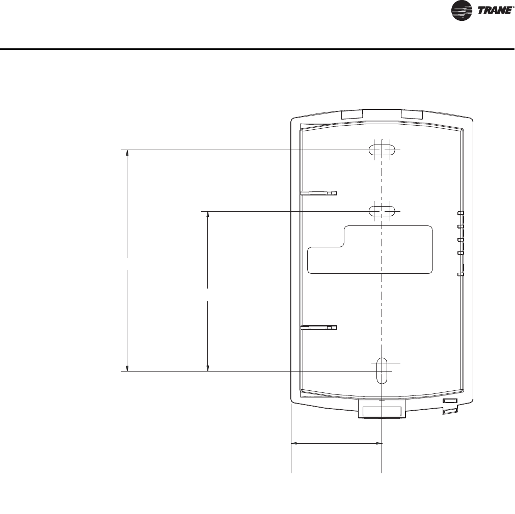
Figure 8. Mounting hole dimensions for sensor
3.27 in (8.30 cm)
2.36 in (6.00 cm)
1.34 in (3.41 cm)
Note: The dimensions are the
same for both the sensor
and the receiver.

24 VAV-SVX07A-EN
VAV Start Up/Check Out Procedure
Choosing a Location for Mounting the Sensor
Placement of the receiver and the sensor set is critical to proper operation. In most installations,
distance is not the limiting factor for proper radio signal quality. It is more greatly affected by walls,
barriers, and general clutter. For best radio transmission range and reliability, wherever possible,
mount the receiver and sensor in line of sight. Try to minimize the number of barriers between the
pair of devices. In general, sheetrock walls and ceiling tiles offer little restriction to the propagation
of the radio signal throughout the building; concrete or metal barriers offer the most restriction.
The transmission range for the sensor is as follows:
• Open range: 2,500 ft (762 m) (packet error rate = 2%)
• Usable range: 200 ft (61 m)
• Typical range: 75 ft (23 m)
Ambient considerations
Avoid locations that are outside the operating temperature and humidity range.
Location Considerations for the Sensor
When selecting a location for the sensor, consider both thermal and radio transmission
characteristics of the location.
Thermal considerations
• Avoid areas of direct sunlight.
• Avoid areas in the direct air stream of air diffusers.
• Avoid exterior walls and other walls that have a temperature differential between their two
sides.
• Avoid areas close to sources of heat such as sunlight, appliances, or other equipment.
• Avoid drafty areas.
• Avoid dead spots behind doors, projection screens, or corners.
Radio transmission considerations
• Avoid metal barriers between the sensor and receiver, such as plastered walls with metal lathe.
They will decrease radio signal quality.
• Avoid placing the sensor inside metal enclosures.
• Avoid radio transmissions through thick, solid concrete walls.
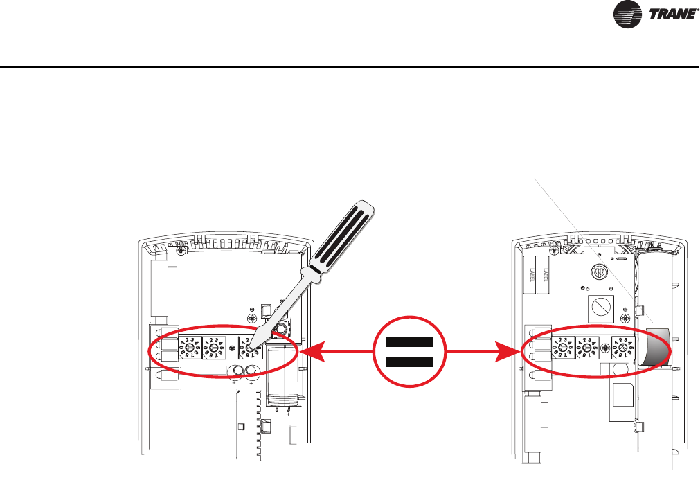
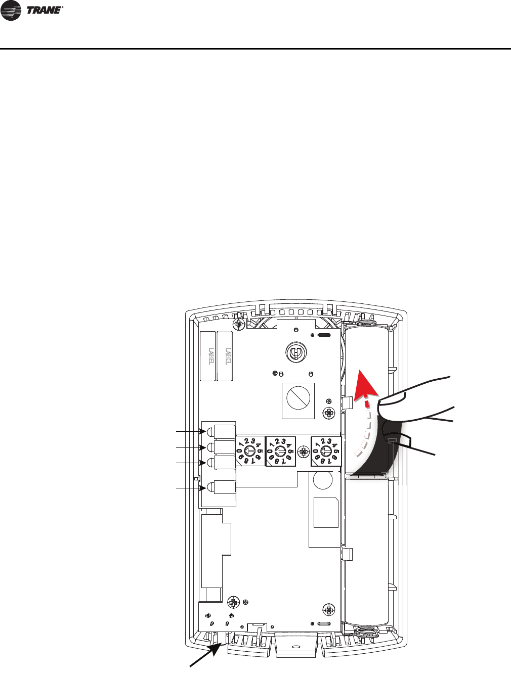
Setting the Rotary Address Switches on the Receiver and the Sensor
Note: To expedite the installation and association process, set the addresses before applying
power to the receiver.
The process of establishing communication between the receiver and sensor is referred to as
association. The receiver and the sensor must have their rotary switches set to the same address
in order to enable communication between the two devices (see Figure 9, p. 25). Important
limitations are as follows:
• Multiple pairs may be located in close proximity.
• It is not possible to associate more than one sensor to a receiver, nor is it possible to associate
more than one receiver to a sensor.
VAV-SVX07A-EN 25
VAV Start Up/Check Out Procedure
Setting the Receiver Address
1. Using a small screwdriver, set the three rotary address switches (locations S1, S2, S3) on the
receiver (Figure 9, p. 25) to an address between 001 and 999.
Note: Do not use 000 as an address for installation. If you set the receiver address to 000, it will:
– Return the receiver outputs to their factory defaults indefinitely (zone temperature and
setpoint outputs: 72.5°F [22.5°C]).
– Remove all association knowledge.
– Make the receiver unable to associate with a sensor.
•Read the switches from left to right in the order in which they are numbered (S1, S2, S3).
•Zero is at the nine o'clock position.
2. Make a notation of the address and location of the receiver.
Setting the Sensor Address
1. Using a small screwdriver, set the three rotary address switches (locations S1, S2, S3) on the
sensor (Figure 9, p. 25) to the same address used for the receiver it is to be associated with.
2. Make a notation of the address and location where this sensor is to be mounted.
Note: Do not use 000 as an address for installation. If you set the address to 000, it will:
– Remove all association knowledge.
– Revert to a low-power hibernation mode.
– Send a disassociation request to the receiver. If the sensor and receiver are associated and
communicating at the time the sensor is set to 000 and the Test button is pressed, the
receiver will also become unassociated and will be available for re-association.
• Read the switches from left to right in the order in which they are numbered (S1, S2, S3).
• Zero is at the 9 o'clock position.
Figure 9. Setting the rotary address switches on the receiver and the sensor
S5
GND
R77
C35
S1 S2
C33
LED4
S4
S5
S3
LED1
LED2
LED3
LED5
C34
J1
COMM -
24VAC/DC
SETPOINT
HEATING SET
SIGNAL
POWER
ADDDRESS
FAN/SYSTEM
ZONE
COMM +
INSTALL
WIRELESS
GND
!B1 +
INSTALL
WIRELESS
S4
S3
S2
S1
ADDRESS
STATUS
BATTERY
LED5
SIGNAL
LED3
LED2
LED1
Pb
Pb-FREE
STATUS
LED4
L
T
A
L
L
L
E
S
S
L
T
A
A
L
E
Do not remove the
insulation strip yet.
Receiver Sensor
26 VAV-SVX07A-EN
VAV Start Up/Check Out Procedure
3. Make a notation of the address and location of the sensor.
Factory Wiring of the Receiver to the VAV Unit Controller
The required power for the receiver is 24 VAC or 24 Vdc and is less than 1 VA. The receiver is
designed to be powered by the Tracer™ UC400 controller. Please see Figure 4, p. 18 and Figure 5,
p. 19 for wiring details.
Note: A dedicated transformer is not necessary or advised.
Note: The receiver is factory mounted and field wiring is not necessary. See Troubleshooting
section for wiring details.
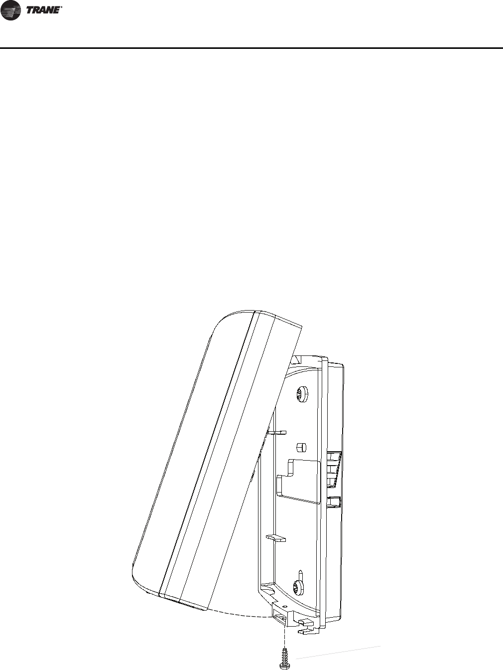
Replacing and Securing the Receiver Cover
1. To replace the receiver cover on the base plate, hook the cover over the top of the base plate.
Apply light pressure to the bottom of the cover until it snaps in place.
2. If necessary to keep the cover securely attached, install the security screw into the bottom of
the receiver (Figure 10, p. 26).
Figure 10. Snap receiver cover on base plate and attach security screw
Security screw
VAV-SVX07A-EN 27
VAV Start Up/Check Out Procedure
Applying Power to the Receiver
Restore power to the unit controller. Observe LED5 on the receiver (Figure 11, p. 27). It will light and
stay constantly On when 24 V power is normal.
Receiver Indicates Readiness to Associate
After initial power up, the receiver conducts a channel scan for 10 seconds. During this time, the
receiver selects from 16 available channels the clearest channel on which to operate. LED1, LED2,
and LED3 flash rapidly in succession while the channel scan is in progress.
Note: Do not attempt association until the channel scan is finished. After the channel scan is
finished, LED3 will begin blinking (one-blink pattern) to show that the receiver is ready to
be associated with a sensor. LED3 will stop blinking when association has been established
(Figure 12, p. 27).
Figure 11. LED5 stays on after applying power to the receiver
Figure 12. LED3 blinks when the receiver is ready to be associated with a sensor
LED5 stays constantly On
RECEIVER
LED3
LED3 will begin
to blink after
10 seconds
28 VAV-SVX07A-EN
VAV Start Up/Check Out Procedure
Powering the Sensor and Associating the Sensor to the Receiver
1. Verify that the sensor is set to the same address as the receiver it is to be associated with.
2. Remove the insulation barrier, which is a plastic strip located between the two batteries
(Figure 13, p. 28). Association will automatically occur between the sensor and the receiver. If
the first association attempt is unsuccessful, the sensor will automatically reattempt
association with the receiver every 10 minutes.
Note: A disassociated sensor will transmit an association request every 10 minutes. An associated
sensor that has lost communication with the receiver will transmit an association request
every 50 minutes.
Note: LED3 on the receiver stops blinking to indicate that association has been established.
Figure 13. Removing the insulation barrier on the sensor
B1 +
B2 -
I
INSTALL
WIRELESS
S4
S3
S2
S1
ADDRESS
STATUS
BATTERY
LED5
SIGNAL
J1
Pb
Pb-FREE
STATUS
LED4
LED5
LED1
LED2
LED3
S5
SENSOR
+
–
+
–
VAV-SVX07A-EN 29
VAV Start Up/Check Out Procedure
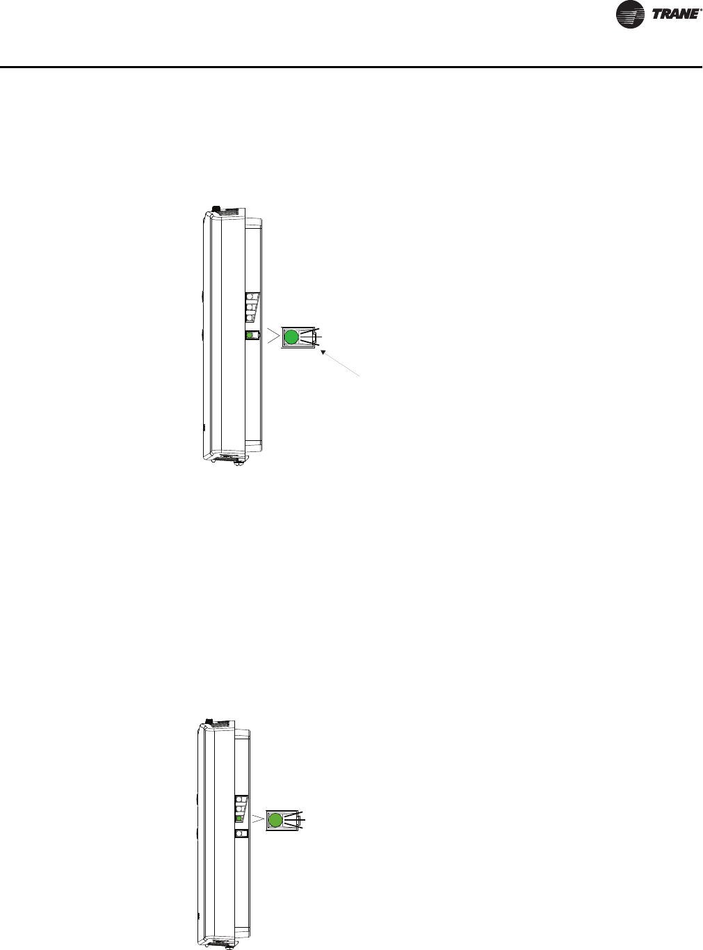
Testing Signal and Battery Strength
The following recommended test indicates signal and battery strength. It verifies that the
association process was successful and that the batteries have adequate charge. (For more
information on LEDs, see "Troubleshooting" chapter.)
1. Firmly press and release the Test button (S5) on the bottom of the sensor (Figure 14, p. 29).
2. View LED1, LED2, and LED3 to determine the strength of the signal. View LED5 to determine
the strength of the battery.
Note: The LEDs will turn Off after 5 seconds to conserve battery strength.
3. Record the results in your commissioning statement.
Disassociation
The receiver removes all stored association information, conducts a channel scan, and restarts
itself, if any of the following are true:
• The receiver address is changed from its current setting (001-999).
• The receiver receives a disassociation notification from its associated sensor.
• The receiver does not receive a communication from its associated sensor within 35 minutes.
Configuring the Wireless Sensor (Model Digital Display WDS only)
The configuration of the sensor determines which system features can be accessed and changes
can be made by the tenant (for example, changes to cooling/heating mode, setpoint, or fan speed.
Verify system and associated unit features before configuring the sensor.
Figure 14. Wireless sensors
LED1
LED2
LED3
LED5
srosnes SDW ledoMsrosnes SZW dna STW ledoM
Test b u tto n
Push firmly,
then release
Push firmly,
then release
Test b u tto n
30 VAV-SVX07A-EN
VAV Start Up/Check Out Procedure
Note: Not all features are applicable to VAV units.
The building owner or operator may choose to limit tenant access to certain features. This can be
done through configuration. Or, if a sensor is configured to match all control capabilities of the
building automation system, the locking feature can be used to restrict the tenant from making
changes.
Configuration Procedure
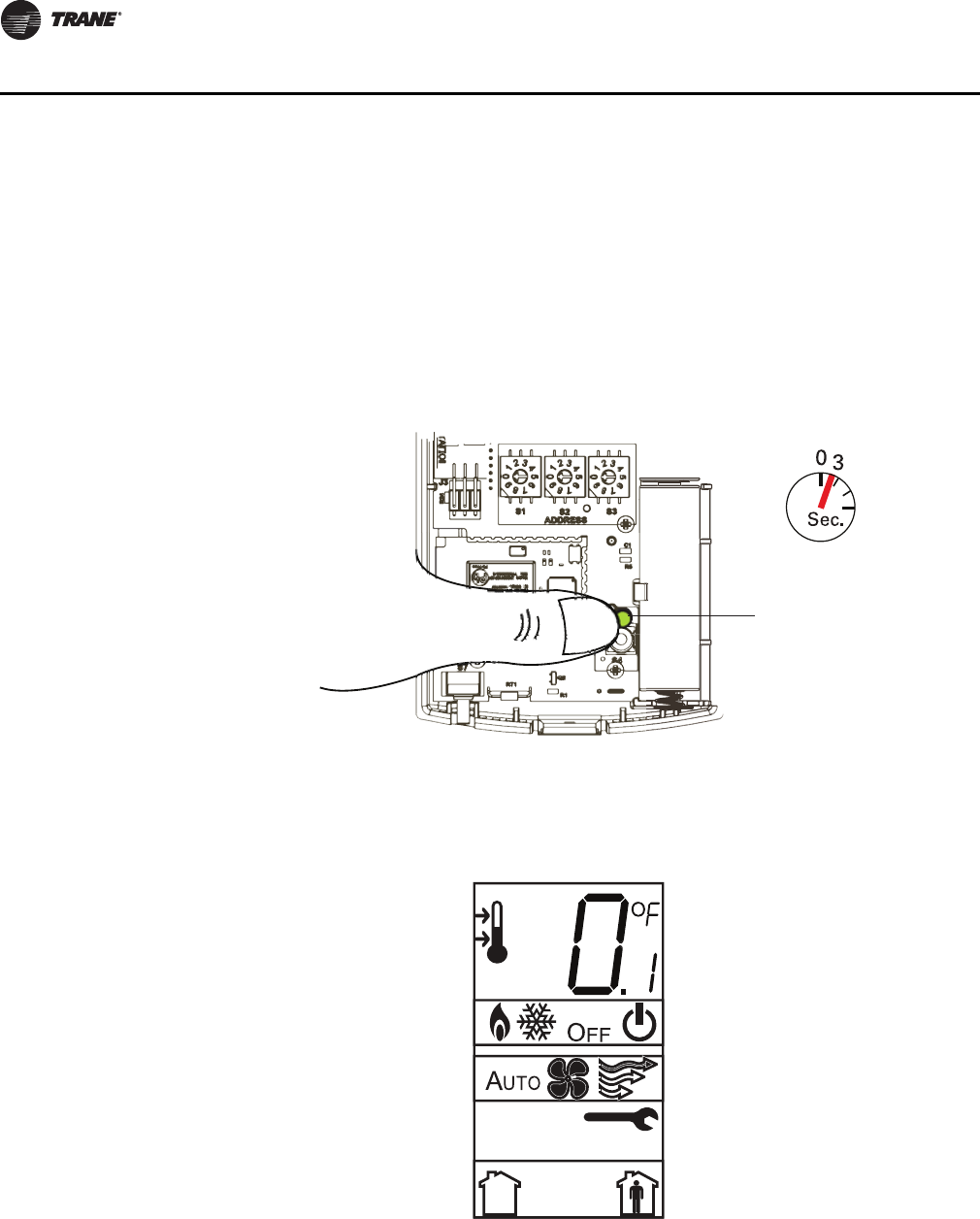
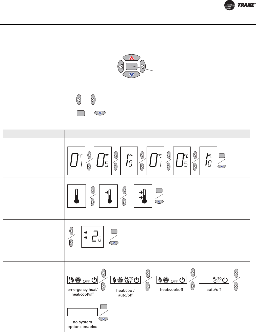
To configure settings on the model WDS sensor, follow this procedure in the order presented.
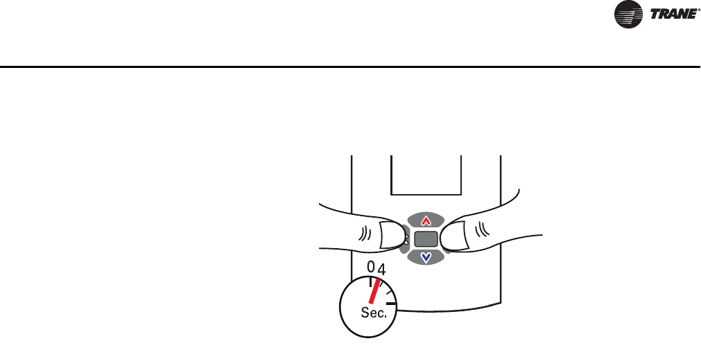
1. Press the configuration button for 3 seconds.
The display will change to configuration mode. When the sensor is in configuration mode, a
wrench symbol appears on the display and the menus are separated by lines, as illustrated in
Figure 16, p. 30.
2. Press the center button on the keypad to begin the configuration process.
Figure 15.
Figure 16.
Configuration button
VAV-SVX07A-EN 31
VAV Start Up/Check Out Procedure
3. Configure the sensor options in the order shown in Figure 18, p. 31. Review the display to
ensure that you have selected the correct configuration options.
•Press or to scroll to the next selection.
•Press or to move to the next menu.
Figure 17.
Center button
Figure 18. Wireless configuration
Setting Configuration options
Temperature
• Choose Fahrenheit or
Celsius
• Choose the degree
resolution (whole degrees,
half degrees, or tenths of
degrees).
Setpoint
Deadband (available for dual
setpoint system only)
Note: Deadband refers to the
minimum difference
between the heating and
cooling setpoints.
System
a) Single setpoint
. . .
.
.
.
dual setpoint
no
setpoint
single
setpoint
.
heat/cool setpoint offset
(1.8˚F – 10.8˚F, 1˚C – 6˚C)
Note: Dual setpoints are
not applicable to
VAV units.
Note: N/A for VAV units.
Note: For VAV, “no system
options enabled” should
be selected.
32 VAV-SVX07A-EN
VAV Start Up/Check Out Procedure
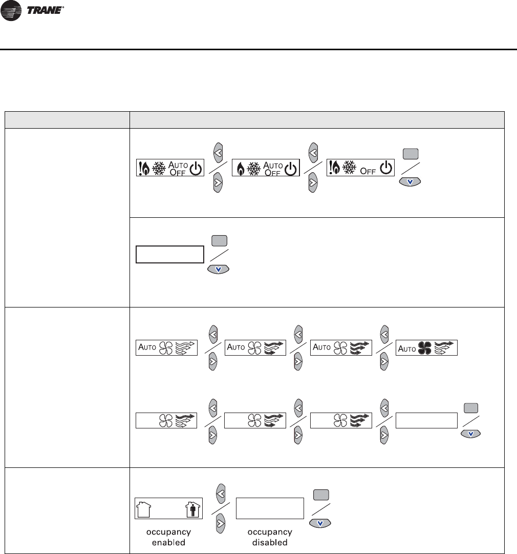
System (continued)
b) Dual setpoint
c) No setpoint
Fan
Note: Tracer UC400 controller
does not use this to
Occupancy (timed
override)
Setting Configuration options
emergency heat/
heat/cool/off
heat/cool/
auto/off
emergency heat/
heat/cool/auto/off
no system
options enabled
auto/off/low
med/high
auto/off/
low/high
auto/off
off/high (on) off/low/high off/low/
med/high
no fan options
enabled
auto/high (on)
control the fan in a VAV
fan-powered unit.
Note: N/A for VAV.
Note: N/A for VAV.

VAV-SVX07A-EN 33
VAV Start Up/Check Out Procedure
To return the display to operating mode, press the configuration button (See Step 1). The following
example shows a configured display in operating mode.
Note: The sensor will revert to operating mode if no buttons are pressed for 10 minutes.
If an error exists, it appears at the bottom of the display between the occupancy symbols, as shown
in Figure 21, p. 33.
Figure 19.
The example shows a display that has been configured for:
• Dual setpoint
• Temperature units (Fahrenheit)
• Temperature resolution to tenths of a degree
• System settings: Heat, Cool, Off
• Fan Settings: Auto and On
• Occupied/unoccupied option enabled
Figure 20.
Display shows the following:
• Temperature units (Fahrenheit)
• Temperature resolution to tenths of a degree
• System setting: Cooling
• Fan Setting: Auto
• Occupied/Unoccupied option enabled
Figure 21.

34 VAV-SVX07A-EN
VAV Start Up/Check Out Procedure
Optional Features
Displaying Setpoint or Temperature
You can configure the sensor to display either the temperature (default) or setpoint. To select either
option:
1. Verify that the sensor is in operating mode and at the home screen.
2. Press the up and down arrows for 3 seconds. The arrow indicates setpoint display, as shown
in Figure 22, p. 34.
Locking and Unlocking Settings
You can lock or unlock the setpoint, system, or fan setting to prevent changes. To lock or unlock the
settings:
1. Verify that the sensor is in operating mode and at the home screen.
2. Choose a setting to lock or unlock.
•Select the setpoint by pressing the up or down arrow.
•Select the system menu by pressing the center button. Use the left or right arrow to choose
the setting.
3. Press the left and right arrows for 4 seconds.
Figure 22.
Figure 23.
Arrow
indicates
setpoint is
shown on
display
Setpoint
VAV-SVX07A-EN 35
VAV Start Up/Check Out Procedure
If you try to access a feature that is locked, the lock symbol will appear on the displays. If you press
a keypad button to try and change a locked setting, the locked symbol will flash.
Figure 24.

36 VAV-SVX07A-EN
Tracer™ UC400 Controller Operations
This chapter contains information about the following:
• Connecting with Tracer TU Service Tool
• Status Button
•Data Log Button
• Controller Settings Button
• Equipment Settings Button
Connecting with the Tracer TU Service Tool
The Tracer TU service tool is a service tool that allows parameters to be viewed or adjusted in the
Tracer UC400 controller. It is a software application for monitoring, configuring, balancing, and
testing Trane unit controllers, such as the Tracer UC400 controller.
Installing Tracer TU Service Tool
Note: For PC requirements and detailed instructions, see Tracer™ TU Service Tool Getting Started
Guide, TTU-SVN02*-EN.
Note: For instructions on how to use the Tracer TU service tool, refer to the Tracer TU online Help
by clicking on Tracer TU Help in the Help menu.
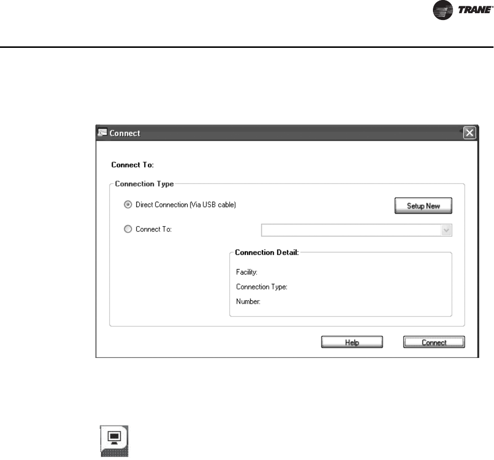
Connection Instructions
Unlike Comm4 or Comm5, the Tracer TU service tool connects directly to the controller, rather than
the communication link. To connect to a Tracer UC400 controller:
1. Install Tracer TU service tool onto the PC.
2. Connect the USB cable.
3. The PC may indicate "Found New Hardware." If the PC prompts you to install software, complete
the installation.
4. Double-click the Tracer TU service tool icon on the laptop PC desktop. The splash screen will
appear. You may need to click the Connect button to continue.
Figure 25. Splash screen
VAV-SVX07A-EN 37
Tracer™ UC400 Controller Operations
5. The Tracer TU service tool Connect dialog box will appear. Choose the Direct Connection (Via
USB cable) radio button and click Connect.
Status Button
The Status button is the first utility button that can be selected and has six section tabs available
for the selected device and utility.
Unit Summary Tab
The Tracer TU service tool will launch and display the status of the Tracer UC400 controller.
•The left-hand side contains the device tree listing all of the devices on the link. (To access
another controller on the link, click on the device on the tree.).
•The right-hand side of the screen contains four buttons for the Status, Data Logs (Trends),
Controller Settings, and Equipment. These are known as unitary buttons, and they are the
types of functions.
•There will be tabs across the top of the screen, and they will change depending upon the
unitary button being viewed.
•The body of the tab will contain fields, logically grouped.
Figure 26. Connect screen
Figure 27. Status button

38 VAV-SVX07A-EN
Tracer™ UC400 Controller Operations
Connected to:
Describes the type of device being communicated to via Tracer TU service tool. It also indicates the
general program that has been placed in controller and if communication is up. The two states for
communication are Configured On line or Not Communicating.
Alert Boxes
Points Out of Service: Indicates the number of points that are currently set to Out of Service.
Active Alarms: Indicates the number of active alarms requiring your attention. When active
alarms are present, the information icon displays the color of the highest priority alarm. Click
the Active Alarms box to go to the Alarms screen.
Overrides: Indicates the number of overrides that are currently active. If any overrides are
active, the icon displayed in the box turns blue.
Operating Status
Occupancy Status: The Tracer UC400 controller has four valid occupancy modes that display
under the operating status. They are Occupied mode, Unoccupied mode, Occupied Standby
mode, and Occupied Bypass mode.
Heat /Cool Status: The heat/cool status displays the heating and cooling mode of the Tracer
UC400 controller. This is where the controller will display the heating or cooling mode of the
controller. The controller can receive communicated requests for heating or cooling operation.
Responses are: Heating, Cooling, and Calibration.
Pressure-Dependent Control or Pressure-Independent Control Status: The Tracer
UC400 controller will display either pressure dependent or pressure independent status if it has
a valid flow input to the controller from the flow ring and pressure transducer. The controller
can operate with or without a valid flow value; the air flow is hardwired only. It operates under
pressure dependent control or pressure independent control.
Pressure dependent control: When a valid flow value is not present, the controller operates
under pressure dependent control (position control). Pressure dependent control substitutes
the air valve position for the flow measurement for all control actions.
Pressure independent control: When a valid flow value is present, the controller operates under
pressure independent control. If after an airflow sensor failure, the airflow returns to the valid
range (airflow value greater than 10% of configured nominal airflow), the controller
automatically resumes pressure independent control.
Local Setpoint: The Tracer UC400 controller will display a local setpoint if the thumbwheel
is enabled or disabled off of the zone sensor.
Space
Space Temperature: The temperature, as reported by the zone sensor.
Space Temperature (Active) Setpoint: The active (or actual) setpoint currently used by the
Tracer UC400 controller. Can be either Heating or Cooling depending on operating mode.
Space temperature from BAS: Shows the Setpoint being communicated to the VAV unit
from a BAS system.
Discharge Air Temperature: Shows the discharge air temperature input, which is the
temperature of the air leaving the VAV box.
Ventilation
Discharge Air flow: Measured in CFM. When a valid flow value is present, the controller
operates under pressure independent control. If after an airflow sensor failure, the airflow
returns to the valid range (airflow value greater than 10% of configured nominal airflow), the
controller automatically resumes pressure independent control. When the communicated
airflow setpoint is invalid, the flow sensor has failed, or calibration has failed, the controller

VAV-SVX07A-EN 39
Tracer™ UC400 Controller Operations
closes the air valve if the configured airflow tracking offset is negative for flow tracking control
units. If the configured airflow tracking offset is positive, the controller opens the air valve to
the configured maximum airflow. Once a valid differential pressure is established through the
local hardwired input and no longer present, the controller generates a flow sensor failure
diagnostic.
Active Airflow Setpoint: The Tracer UC400 controller supports one modulating air valve for
heating and cooling operation. The controller positions the modulating air valve to deliver the
desired airflow (cooling or heating capacity). The desired airflow is called the active flow
setpoint. The airflow control algorithm compares the active airflow setpoint with the measured
airflow and calculates the necessary air valve movement to minimize error. The airflow setpoint
is limited by applicable minimum and maximum flow setpoints.
Space CO2 Concentration: CO2-based demand control ventilation uses the space CO2 value.
The controller compares the space CO2 concentration to the configured band of CO2 values and
determines the demand ventilation rate of the zone. The resulting ventilation rate is called the
effective ventilation setpoint. The effective ventilation setpoint is the outdoor airflow required
to provide ventilation. It is used to calculate the ventilation ratio of the zone.
Outputs
Damper Position: Indicates air valve or damper position.
Fan Output: The Fan will be shown as On, Off or None.
Heat Output: Will indicate reheat capacity in Percentage.
Analog Tab
Use the Analog tab to view the analog inputs, outputs, and values. These three categories are
presented in expanding boxes that stretch across the middle of the screen, and they are defined
from the factory. To expand the box and view its contents, click the arrow icon on the left side of
the box header in each category. View Details dialog boxes may be accessed by clicking on the
details buttons, located at the end of each line item.
Note: For field use of spare analog points, see BAS-SVX20*-EN.
Grid Columns
Index: Displays the sequence number assigned to the point.
Name: Displays the name of the point.
Value: Displays the current or assigned value of the point.
Units: Displays the units of measure in which the point is expressed.
State: Displays the state of the point. Point states are Normal, Out of Service, Fault, Locked,
and Alarm.
Control: Click to bring up the Override Request dialog box on which you can change the state
of the point.
Details: Accesses the View Details - Analog dialog box that contains information about each
point including its reference, priority, owner, and control time remaining for the current priority
level or state.
Binary Tab
Use the Binary tab to view the binary inputs, outputs, and values. These categories are presented
in expanding boxes that stretch across the middle of the screen, and they are defined from the
factory. To expand the box and view its contents, click the arrow icon on the left side of the box
header in each category. View Details dialog boxes may be accessed by clicking on the details
buttons, located at the end of each line item.
Note: For field use of spare analog points, see BAS-SVX20*-EN.

40 VAV-SVX07A-EN
Tracer™ UC400 Controller Operations
Grid Columns
Index: Displays the sequence number assigned to the point.
Name: Displays the name of the point.
Value: Displays the current or assigned value of the point.
Units: Displays the units of measure in which the point is expressed.
State: Displays the state of the point. Point states are Normal, Out of Service, Fault, Locked, and
Alarm.
Control: Click to bring up the Override Request dialog box on which you can change the state
of the point.
Details: Accesses the View Details - Binary dialog box that contains information about each
point including its reference, priority, owner, control time remaining for the current priority
level or state, feedback reference, feedback value, change of state count, and number of starts.
Multistate Tab
Use the Multistate tab to view the multistate data points, grouped under inputs, outputs, and
values. To expand the box and view its contents, click the arrow icon on the left side of the box
header in each category.
Grid Columns
Index: Displays the sequence number assigned to the point.
Name: Displays the name of the point.
Value: Displays the current or assigned value of the point.
Units: Displays the units of measure in which the point is expressed.
State: Displays the state of the point. Point states are Normal, Out of Service, Fault, Locked,
and Alarm.
Control: Click to bring up the Override Request dialog box on which you can change the state
of the point.
Details: Accesses the View Details--Multistate dialog box that contains information about the
point's reference, priority, owner, control time remaining for the current priority level or state,
feedback reference, and feedback value.
Alarms Tab
This is a log that records each diagnostic independently of other diagnostics.
Model: Displays the model number of the equipment.
BAS Communication: Displays the status of the communications network.
Alarms Grid
The grid columns are as follows.
Alarm icon: There are four alarm icons indicating levels of severity:
•Red indicates an alarm requiring immediate attention;
•Orange indicates low priority alarm;
•Blue indicates a normal condition; and
•Yellow indicates a warning alarm.
Notification Class: Displays the class to which the notification is sent. (Classes are set up in
Event Routing on the Tracer SC.)
Date/Time: Displays the date and time of the event that produced the alarm.
VAV-SVX07A-EN 41
Tracer™ UC400 Controller Operations
Point Name: Displays the name of the affected point.
Description: Displays a short description of what occurred.
Acknowledgement Required: Indicates whether or not the alarm has to be acknowledged
at the parent Tracer SC level.
Controller Status Tab
BAS Communication: Displays the status of the communications network.
Program
The Tracer UC400 controller will have up to three VAV configurations downloaded and defined in
the factory as part of the factory commissioning process. The three programs will be a Base
program for damper control, Fan, and Reheat control. When looking at programming section of
Controller Status tab, operation of these programs can be monitored.
Grid Columns
Padlock icon: Indicates that the program is locked.
Index: Displays the sequence number assigned to the point.
Name: Displays the name of the program.
Status: Displays the current operating status, such as Idle or running.
Run Type: Indicates how execution is controlled (Scheduled or Triggered).
Interval: Displays the time between program starts (for example, 10 minutes).
Latency: Displays the time it takes for the program to run.
Error: Displays the operational state, whether Normal or Error Terminated.
Controller
Lists identifying and status information for the controller including Product Name, Product Version,
Hardware Part Number, Hardware Serial Number, Application Part Number, Application Version,
Application Build Number, Boot Part Number, Boot Version, Boot Build, Unit Sales Order Number,
and Model Number.
TGP2 Status: Displays the operational state of the TGP2 program engine in which all
programs execute.
TGP2 Resources: Displays the amount of memory consumed by the programs.
Data Log Button
The Data Graphing Utility available via the Data Log button provides the following capabilities:
• Capture all data or a subset of the data put out by a controller directly to a log file on your hard
drive. You can specify the data points you want to capture in a logging configuration created
on the Data Graphing Utility's Session Log Tab. (View up to eight data items in graph (strip chart)
format using the View Graphs Tabs. You can manually select any of the available data items in
the Available Data list or use a predefined graphing template. You can launch multiple graphs
and view them on your screen simultaneously.
• View archived data from any of the previous session logs or from the graphing data you have
saved on your hard drive.
Figure 28. Data log button

42 VAV-SVX07A-EN
Tracer™ UC400 Controller Operations
• Export captured data to various file formats in third-party software tools.
• Save graphs as image files.
View Graphs Tab
The View Graphs tab contains controls used to set up and generate graphs (line charts) presenting
a subgroup of logged data points. You can use the predefined templates, or you can define your
own custom graphs. You can also save your graph definition as a new template.
Note: When graphing live data, you must first configure and start a session log on the Session Log
screen before setting up graphs on the View Graphs screen. Graphing live data requires an
active session log. In addition, your session log configuration must include the data points
you want to graph.
Select Graph Template
When the tab appears, this field will be pre-populated. Leave the default response as is.
Choose Data (Settings)
This group box is the container for all of the following data selection controls.
Data Source Box: Contains controls you use to select the source of the logged data to be
graphed. You can select either the current live session, a device (the unit controller), or archived
log files on your PC hard drive.
Available Data: Select up to eight (8) data points you want to graph from this list box. (You
can select multiple items by holding down the Control key while clicking each item with a
mouse.)
Arrow Buttons: Use the arrow buttons to transfer items between the Available Data Objects
box and the Selected Data box.
Selected Data: Each box contains one of your selected data points. The color boxes indicate
the color line that is used to graph that data point on the generated chart.
Graph Titles (Lines 1 and 2): Use these entry boxes to specify a one or two line title for the
graph.
Axis Labels: Use these entry boxes to specify a short label for the graph axis.
Save as Template: Use this button to save the graph definition as a reusable template.
Start Graph: Click this button to start graphing the specified data points.
The Display Graph window appears after you click Start Graph. It displays the generated graph
you define in the Choose Data box. A legend is provided to pair colors with selected data points.
The following controls appear on the Display Graph window.
Data
•Save: Use this button to save the captured data in a comma separated variable (CSV)
format file written to your hard drive. All data recorded on the chart is saved in the file.
Graph Image
•Print: Use this button to print the graph image.
•Preview: Use this button to preview the graph image before you print it.
•Save: Use this button to save the graph image to a file for subsequent printing and
analysis.
•Copy: Use this button to copy the graph image to the clipboard so you can paste it in a
file.
Zoom
• Zoom Reset: Click this button to restore the graph to its original appearance after
zooming in on an area of interest.

VAV-SVX07A-EN 43
Tracer™ UC400 Controller Operations
Show Legend: Use this check box to show and hide the legend that displays the corresponding
color of each data point.
Stop Graph: Use this button to halt graphing when you have sufficient data for your purposes.
Session Log Tab
You can use the Tracer TU Data Logging Utility to capture live data from a controller at a specified
sampling rate. You can then graph subsets of the captured data in one or more graphs. To capture
live data, you first configure and start a session log that runs in the background using the Session
Log screen. You can then set up and launch one or more graphs that visually track data items
included in the session log using the View Graphs screen.
The Session Log tab allows you to select the specific data points tracked during session logging
along with the name and location of the log file. You can also save the setup definition and start
the session log from this screen. (See related topics below.)
Note: You cannot graph data items that are not included in the session log configuration.
Choose Data
Sampling Rate: Use the hh:mm:ss spin box to specify the time between each sample. For
example, a rate of 00:00:10 would result in a snapshot of data values being taken every 10
seconds.
File
Automatically name session log: Use this check box to accept the system generated log file
name and default location.
Browse: Click the Browse button to navigate to and specify an alternate file location, which is
then displayed in the entry box below.
(Log file entry box): Displays the selected path and file name, or use the entry box to manually
enter the full path and file name of the log file.
Data Selection
Category: Select a subsystem category from this drop-down list. For example, in the case of
a chiller, the list could include Compressor, Evaporator, Motor, Purge and so on.
Available Data: Lists all available data points associated with the category selected.
Selected Data: Displays all data points selected and transferred from the Available Data list
box.
Arrow buttons: Use these controls to transfer items back and forth between the Available Data
and Selected Data list boxes.
Save: Saves the session logging definition for future reuse.
Note: You must save the configuration before you can start data logging. Saving the session
log configuration activates the Start session logging button.
Cancel: Cancels session logging setup.
Start session logging: Click to start session logging after you have defined the sampling rate,
the log file name and location, and the data points to be included in the logging. (Session logging
continues until you terminate your connection to the controller and end your Tracer TU session.)
Data Log Setup Tab
Use the Data Log Setup tab to create up to 50 data logs-one for each point you want to track.
Data Logs Drop-Down Menu
The Data Logs drop-down menu allows the user to copy, edit, or delete.

44 VAV-SVX07A-EN
Tracer™ UC400 Controller Operations
Copy: Use this option to copy an existing data log definition under a different name and then
modify it to avoid extra typing.
Edit: Use this option to edit an existing data log definition. The Data Log Properties dialog box
appears.
Delete: Use this option to delete one or more data logs after you are finished with them.
Go button: Click this button to put the option you selected on the Actions drop-down list into
effect.
Add New button: Click this button to create a new data log. The Data Log Properties dialog
box appears.
Table Columns
Index: Sequence number.
Data Log Name: Name of the data log (the point you are logging).
Reference: Identifies the source or target of information supplied to or from the point.
Type: Indicates how the value is updated (pushed or pulled).
# of Samples: Shows the size of the buffer containing all values currently collected.
Since Notice: Number of samples harvested since the event notification buffer has last been
read.
Enabled: Select the corresponding check box for each data log you want to activate.
Save: Use to save the data log definitions to an new file. (Displays a save as dialog box.)
Save to File: Use for repeat saves to an existing file. Saves the data log definitions to an existing
file without bringing up a Save As dialog box.
Cancel: Returns the screen to its condition at the last save.
Capturing Data & Troubleshooting
Occasionally, you may need to troubleshoot a difficult equipment problem. You can use the Tracer
TU Data Logging Utility to view data at your desired sampling rate with no memory limitations
besides your laptop hard drive or USB jump drive.
To capture data in a live session log
1. If you are already in Tracer TU service tool and connected to a controller, but you have not yet
configured a session log, click the Data Log tab on the right side of the Tracer TU service tool
window. The View Graphs and Session Log tabs appear across the top of the viewing area.
2. Click the Session Log tab.
3. Set the time interval between samples on the Sampling Rate spin box. This setting specifies
how often Tracer TU captures a snapshot of the selected data points. (For example, a data
capture could occur every five seconds, 15 minutes, or once every hour.)
4. Select the Automatically Name Session Log check box to use a system-generated location and
file name or click the Browse button to specify an alternate path and filename.
5. Select a major category from the Categories drop-down list if you want to log only a subset of
the available data points.
6. Select individual data points or groups of data points for logging by using the arrow controls.
For Example:
To transfer just a few items from the Available Data box to the Selected Data box, highlight a
data point you want to log, then click the single right arrow key ( > ) to transfer it to the Selected
Data box. Repeat for each data point you want to transfer. (You can also highlight several data
points at once by pressing Ctrl while clicking each item with your mouse.)
VAV-SVX07A-EN 45
Tracer™ UC400 Controller Operations
To eliminate just a few items from a predefined category, first transfer all of the items to the
Selected Data box using the double arrow and then eliminate any items from the Selected Data
box by transferring them back to Available Data using the single left arrow button or by pressing
Ctrl and making selections with your mouse.
Note: If you make no selections, all data points generated by the controller are captured at the
interval you previously specified on the Sampling Rate spin box.
7. Click Save to save the session data log definition.
Note: Note You must save the configuration before you can start data logging.
8. Click Start session logging to start the session log immediately if it has not been scheduled with
a start time.
If a scheduled start time has been entered, the data logging begins when the start time matches
the current time in the device and ends when the stop time mas the current time in the device. The
data log is periodically and automatically saved to your hard drive.
Controller Settings Button
On Controller Settings button, you can:
• View points;
• Enable and setup points;
• Set the Tracer UC400 controller date and time, including format and time zone;
• Set the Tracer UC400 controller units (SI or IP);
• Set the protocol parameters; and
• Soft-set the BACnet Device ID.
Analog, Binary, and Multistate Tabs
Use the Analog, Binary, and Multistate tabs to create, edit, or delete the currently configured inputs,
outputs, and values residing on the equipment controller. This is the same as the Analog Status
tab in layout except now we have a screen design around editing.
Note: To create new points to utilize the spare I/O and/or software only points see the Tracer UC
400 programmable controller IOM.
Important: The following field descriptions apply to the Inputs, Outputs, and Values grid column
areas of the screen.
Actions (drop-down menu)
Copy: Use this option to copy an existing point configuration under a different name and then
modify it to avoid extra typing.
Edit: Use this option to edit an existing point configuration. The appropriate Properties dialog
box appears.
Delete: Use this option to delete one or more point configurations.
Add New button: Click this button to configure a new point. The appropriate Properties dialog
box appears.
Figure 29. The controller settings button

46 VAV-SVX07A-EN
Tracer™ UC400 Controller Operations
Grid Columns
Index: Displays the sequence number assigned to the point.
Name: Displays the name of the point.
Reference: Identifies the source or target of information supplied to or from the point.
Locked: Indicates if the point is locked (not modifiable).
State: Displays the current state of the point. (Point states are Normal, Out of Service, Fault,
and Alarm.)
Save: Saves the points to the controller.
Save to File: Saves the points listed on this screen to a new or existing file on your hard drive.
Cancel: Returns the screen to its condition at the last save.
To edit an existing point
Use the Analog, Binary, and Multistate tab screens on the Controller Settings button to edit point
definitions.
1. Click the Analog, Binary, or Multistate tab.
2. Select the radio button on the left side the row of the point you want to edit.
3. Select the Edit option from the Action drop-down menu. The appropriate Point Configuration
dialog box appears.
4. Edit the individual settings you want to change. (Click Help to see descriptions of the various
controls.)
5. Click Save when you are finished to save the point or points to the existing points file on your
hard drive.
Controller Settings Tab
The Controller Settings tab contains drop-down lists and options you can use to select some
controller and display settings. The content of this screen is dynamically generated depending on
the type of controller to which you are connected and the protocol your system is using to
communicate with the controller.
Date and Time
Current Time/Current Date: Displays the current date and time from the controller.
Time Format: Use this drop-down list to select your preferred time format.
Short Date Format: Use this drop-down list to select your preferred date format.
Long Date Format: Use this drop-down list to select a hyphen or slash separator or to omit
a separator.
To set the controller date and time
1. Click t h e Date and Time expanding box.
2. Select the preferred Time Format, Short Date Format, and Long Date Format from the
drop-down list boxes.
3. Click Save to save your selections
Units
Number Format: Use this drop-down list to choose from available number formats for data
display.
Default Units: Use these option buttons to indicate which measurement system you wish to
use: I-P (inches and pounds) or SI (Standard International Units).

VAV-SVX07A-EN 47
Tracer™ UC400 Controller Operations
Modify Default Units: Use these drop-down lists to change the default units of measure
displayed for various device inputs or capabilities, such as Temperature, Gaseous Pressure,
Fluid Pressure, Cooling Capacity, and so on.
To set the controller units of measure
1. Click t h e Units expanding box.
2. Select your preferred Number Format from the Number Format drop-down list.
3. Select your preferred units of measure by clicking either the I-P (Inches and Pounds) or SI
(Standard International Units) option button in the Default Units group box.
4. Check the Modify Default Units check box if you want to change the default units of measure
displayed for various device inputs or capabilities, such as Temperature, Gaseous Pressure,
Fluid Pressure, Cooling Capacity, and so on.
5. Modify any of the default units by selecting the appropriate option from the drop-down lists in
the Modify Default Units group box.
6. Click Save.
Communication
Type: Displays the protocol that controllers use to communicate with other controllers on the
link. (The controller uses a different protocol to communicate with Tracer TU.)
Baud Rate: If the protocol is BACnet or Modbus, you can use this drop-down list to specify the
baud rate of the link, which depends on the network device to which the controller is being
linked.
Device ID
• Current Device ID: Displays the Device ID of the controller. The default Device ID is set
to the UC800 MAC address set on the rotary dials. The Device ID can also be soft set.
• Soft Set Device ID: If the BACnet protocol is being used, you can enter a soft set Device
ID. This is useful for integration with third-party equipment. (Select the check box to
activate the entry box.)
• Remove Soft Set ID: Use this button to clear the current value out of the Soft Set Device
ID box. You can then enter a new value. (You do not need to click this button when you
enter the first Soft Set Device ID. Use it only to change the Soft Set Device ID.)
To Set Up the Soft Set Device ID
You can specify a soft set device ID using the Tracer TU service tool tab Controller Settings screen
on the Controller Settings Utility tab, if the BACnet protocol is being used at your job location. A
soft set device ID is useful when you are integrating Trane equipment into a non-Trane
environment.
1. Select the Soft Set Device ID check box.
2. If no soft set ID is present, or if you want to change the existing soft set ID:
a. Select the Soft Set Device ID check box.
b. Enter a new ID.
c. Click Save.
d. Cycle the power to the controller to make the change effective.
3. If a soft-set ID is present, and you want to return it to a hard set device ID.
a. Click Remove Soft Set ID.
b. Click Save.
c. Cycle the power to the controller to make the change effective.
48 VAV-SVX07A-EN
Tracer™ UC400 Controller Operations
Equipment Settings Button
On this button, you can set in the Tracer UC400 controller setpoints and other settings, as well as
configure the controller parameters. You can change a number of equipment setpoints and setup
parameters from the Equipment Utility screens. Scroll down through the expanding boxes to locate
the setpoints you need to change.
Setpoints Tab
1. Selecting a value from a drop-down list.
2. Entering a new value directly in the entry field. (The value entered must be within the minimum
and maximum limits.)
3. Clicking and moving the slider. (The value changes to match the slider position.)
4. Clicking the Revert button to restore the setting to a previous value.
5. Clicking the Default button to restore the setting to its system default value.
6. Click Save when you complete your changes.
Note: When you leave a screen without clicking Save, a dialog box appears asking if you want to
save the new values.
Default Setpoints
Unoccupied Cooling Setpoint: Setpoints have a range from 40.0°F to 115.0°F (4.44°C to 46.11°C).
This cooling setpoint is used when the UCM is unoccupied. The unoccupied cooling setpoint must
be greater than or equal to the unoccupied heating setpoint plus 2.0°F 1.1°C).
Occupied Standby Cooling Setpoint: Based on the controller occupancy mode, the active
space cooling setpoint is the occupied stand by cooling setpoint, The controller can be placed in
the occupied standby mode when a communicated occupancy mode request (from a
communicated occupancy override, occupancy schedule, or occupancy sensor) is combined with
an unoccupied request from the local (hardwired) occupancy binary input.
Note: This setpoint allows inactive spaces in the occupied mode to float to a more energy saving
setpoint until occupancy mode deems it necessary to use another setpoint as its active
setpoint.
Occupied Cooling Setpoint: Setpoints have a range from 40.0°F to 115.0°F (4.44°C to 46.11°C).
If a zone sensor thumbwheel setpoint is not being used, this setpoint will be used as the UCM's
active cooling setpoint during occupied times. The cooling setpoint must be greater than or equal
to the heating setpoint plus 2.0°F (1.1°C).
Note: Occupied cooling and heating setpoints must be set within the cooling setpoint high limit
and the heating setpoint low limit in order to control to the proper setpoints.
Occupied Heating Setpoint: Setpoints have a range from 40.0°F to 115.0°F (4.44°C to 46.11°C).
If a zone sensor thumbwheel setpoint is not being used, this setpoint will be used as the UCM's
active heating setpoint during occupied times. The cooling setpoint must be greater than or equal
to the heating setpoint plus 2.0°F (1.1°C).
Note: Occupied cooling and heating setpoints must be set within the cooling setpoint high limit
and the heating setpoint low limit in order to control to the proper setpoints.
Occupied Standby Heating Setpoint: Based on the controller occupancy mode, the active
space heating setpoint is the occupied standby heating setpoint, The controller can be placed in
Figure 30. Equipment settings button

VAV-SVX07A-EN 49
Tracer™ UC400 Controller Operations
the occupied standby mode when a communicated occupancy mode request (from a
communicated occupancy override, occupancy schedule, or occupancy sensor) is combined with
an unoccupied request from the local (hardwired) occupancy binary input.
Note: This setpoint allows inactive spaces in the occupied mode to float to a more energy saving
setpoint until occupancy mode deems it necessary to use another setpoint as its active
setpoint.
Unoccupied Heating Setpoint: Setpoints have a range from 40.0°F to 115.0°F (4.44°C to 46.11°C).
This heating setpoint is used when the UCM is unoccupied. The unoccupied cooling setpoint must
be greater than or equal to the unoccupied heating setpoint plus 2.0°F 1.1°C).
Setpoint Limits
Each point has its own min/max, so, these four limits are incorporated in the occupied setpoint
point, standby setpoint point, and unoccupied heat/cool setpoints. After the controller completes
all setpoint calculations, the calculated occupied setpoint is validated against the following
configured space setpoint limits:
• Heating Setpoint High Limit;
• Heating Setpoint Low Limit;
• Cooling Setpoint High Limit; and
• Cooling Setpoint Low Limit.
These setpoint limits apply only to the occupied and occupied standby, heating and cooling
setpoints. They do not apply to the unoccupied heating and cooling setpoints. When the controller
is in the unoccupied mode, it always uses the unoccupied heating and cooling setpoints. Unit
configuration enables or disables the local (hardwired) setpoint. This parameter provides
additional flexibility to allow you to apply communicated, hardwired, or default setpoints without
making physical changes to the unit. Similar to hardwired setpoints, the effective setpoint value for
a communicated setpoint is determined based on the stored default setpoints, configuration
values, and the controller occupancy mode.
Setup Parameters Tab
VAV Setup
Nominal Air Flow: Nominal flow is the total airflow capacity of the VAV box. Nominal Flow
becomes an active field when "Generic" is selected in Box Setup under the Unit Tab. Select the CFM
nominal flow for the unit. This is normally used when mounting the tracer UC400 controller on
someone else's VAV unit.
Unit Flow Gain: The flow gain is used to calibrate the value reported by the flow sensor so that
the reported airflow matches the actual airflow. The flow gain is determined during the air
balancing of system. A testing, adjusting, and balancing professional will use the Tracer TU service
tool to calculate this value and balance the VAV box. Normally, you should not need to change this
value here. For Trane units, the nominal airflow and unit flow gain are based on unit size. Generic
units just keep the unit flow gain to the default of 1.0.
Air flow Measurement Offset: The flow offset is used to calibrate the value reported by the flow
sensor so that the reported flow matches the actual flow. The flow offset is determined during the
air balancing process. A testing, adjusting, and balancing professional will use the Tracer TU
service tool to calculate this value and balance the VAV box. Normally, you should not need to
change this value here.
Note: The flow offset is calculated only for two-point balancing, which requires reading both the
maximum and minimum airflows during balancing. Two-point balancing ensure greater
accuracy over the entire range of air valve operation. Only controllers that support the Flow
Measurement Offset network variable, such as the Tracer UC400 controller, can use two-
point balancing.

50 VAV-SVX07A-EN
Tracer™ UC400 Controller Operations
AirFlow Gain: The airflow gain is used to calibrate the value reported by the flow sensor so that
the reported airflow matches the actual airflow. The flow gain is determined during the air
balancing process. A testing, adjusting, and balancing professional will use the TU Service Air and
Water Balancing tool to calculate this value and balance the VAV box. Normally, you should not
need to change this value here.
Minimum AirFlow Delta: The minimum amount of change in the primary airflow required before
airflow and the airflow setpoint are communicated on the communication link. The percentage of
change required is based on the nominal airflow. For example, if the nominal airflow is 1000 cfm
and the minimum delta is 2%, the primary airflow must increase or decrease by 20 cfm before the
change is communicated on the communication link.
Ventilation Setup
Ventilation Setpoint BAS: The Tracer Summit™ BAS uses the ventilation setpoint from all the
VAV boxes to calculate how much outdoor air (OA) the system needs. During the occupied mode,
this setpoint is the active setpoint for ventilation.
Ventilation Standby Setpoint: During the unoccupied mode, this setpoint is the active setpoint
for ventilation.
Space CO2 Setup
Low Limit: The controller adjusts the ventilation setpoint only when the CO2 concentration falls
within the high and low limits. When the CO2 concentration falls below the low limit, this indicates
that the zone is most likely unoccupied and that a minimum of ventilation air is required to ventilate
the zone.
High Limit: The controller adjusts the ventilation setpoint only when the CO2 concentration falls
within the high and low limits. When the CO2 concentration rises above the high limit, this indicates
that the zone is most likely at its maximum design occupancy and that a maximum of ventilation
air is required to ventilate the zone.
Flow Setpoints Setup
Minimum Airflow: Although the UCM will read flow down to 5% of cataloged, the range of MIN
FLOW settings is 0% or 10% to 100% of cataloged. The UCM will not drive its flow below this
minimum flow value under normal operating conditions while in the cool mode. Cool mode occurs
when cool air is in the supply duct. The entry in the Cooling Minimum field must be less than or
equal to the entry in the Maximum field.
Maximum: This range is 10% to 100% of the unit's cataloged CFM size. Cooling and heating flow
can be edited to zero.The UCM will not drive its flow above this maximum flow value under normal
operating conditions while in the Cool mode. Cool mode occurs when cool air is in the supply duct.
The entry for Maximum Flow must be greater than or equal to the entry in any of the Minimum
fields.
Standby Minimum Airflow: Occupied standby mode is used to reduce the heating and cooling
demands during the occupied hours when the space is unoccupied. It can be activated for a
classroom currently not in use. Standby Minimum is the minimum amount of airflow desired
during this mode.
Standby Heating Minimum Airflow: Occupied standby mode is used to reduce the heating and
cooling demands during the occupied hours when the space is unoccupied. It can be activated for
a classroom currently not in use. Standby Heating Minimum is the minimum amount of airflow
desired when in the heat mode during this mode.
Heating Minimum Airflow: The UCM will not drive its position/flow below this value under
normal operating conditions while in the HEAT mode (warm air in the supply duct) or while it is
using local heat.
Heating Maximum Airflow: The controller enters maximum flow heat on receipt of a
communicated command and remains in maximum flow heat until the command changes. The

VAV-SVX07A-EN 51
Tracer™ UC400 Controller Operations
controller maintains the flow rate at the heating maximum airflow. This is normally used with a
rooftop unit with staged heat that needs a Max constant volume of air movement to keep the heat
exchanger from overheating and tripping the heat in the rooftop unit tripping on a high limit safety.
Local Heat Minimum Airflow: If the Min Local Heat flow is enabled, then the Min Local Heat flow
is used to determine the minimum position/flow instead of the Min Heating Flow when local heat
is on. The entry for Min Heating Flow must be less than or equal to the entry for the maximum.
Commissioning Tab
Actions
Calibration (Start Button): The calibration sequence enables the controller to calibrate the air
valve position and the water valve position, as well as calibrate the flow sensor.
Auto-commissioning (Start Button): The controller auto-commissioning test sequence
validates both the proper operation of all outputs and the capability to measure all inputs. The
purpose of the test sequence is to minimize the labor required to commission the unit in the field.
The auto-commissioning test does not require a flow sensor or a Discharge or Supply air
temperature sensor. If there is no flow sensor, the controller runs in pressure-dependent mode. A
temperature sensor in the discharge air stream is required for testing of the fan and the reheat. The
fan and the reheat are not tested if the discharge air temperature sensor is not present. The fan is
not tested if there is no fan. Local reheat is tested, if it is present. Remote reheat is not tested.
The sequence starts on receipt of an auto-commission command from the Tracer TU service tool
start button or the Tracer SC. The auto-commission command contains a time/date stamp. No third
party tool can start the auto-commissioning sequence. The user then chooses to commission all
VAV boxes or one VAV box. The results of auto-commissioning are contained in a structured
network variable called reported auto commissioning report. The controller places the time/date
stamp in the report. The structure is loaded with the default values for all of the fields when the auto
commissioning test sequence starts. The fields are updated with the results as the sequence
progresses. The data is held until the next auto-commissioning test.
If an auto-commission command is received in the middle of an auto-commissioning cycle, the
auto-commissioning sequence restarts. If an auto-commission command is received during
calibration, calibration aborts and restarts after auto-commissioning finishes. If an abort auto-
commission command is received during the calibration portion of the primary air valve test, it is
honored after the air valve calibration finishes.
Air Balancing: Use the Tracer TU service tool Air Balancing tool and the Trane Air Balancing
Calculation spreadsheet to perform a basic two-point air balance for the Tracer UC400 controller
- VAV application.
Note: The Air Balancing Calculation spreadsheet is included with Tracer TU service tool.
Important: A full discussion of air balancing is beyond the scope of this document. See Air
Systems for Tracer SC Applications Guide (BAS-APG007-EN) for extended coverage
of this topic.
To perform a two-point air balance
1. Record job information and the VAV ID from NAV tree in the Job section of the calculations
spreadsheet.
2. Click the Equipment Utility button then click the Commissioning tab.
3. Verify the maximum and minimum airflow setpoints are set according to the job specification,
and record them in the Job section of the spreadsheet.
4. Enter the Nominal Air Flow reading in the Calculation section of the spreadsheet.
5. Click the Air Balancing Start button in the Actions expanding box.

52 VAV-SVX07A-EN
Tracer™ UC400 Controller Operations
6. Select Drive to Maximum Flow Position and allow sufficient time for the VAV damper to fully
open.
7. Enter the Current Discharge Airflow value in the MAX CFM field (blue) under Tracer UC400
controller Measurement on the spreadsheet.
8. Measure the actual airflow with the flow hood. (Add the totals if more than one diffuser is
present.)
9. Record them in the MAX CFM field under Flow Hood Measurement.
10. Select the Drive to Minimum Flow Position radio button, and repeat the process for
Minimum CFM, recording both the Tracer UC400 controller measurement and the flow hood
measurement on the spreadsheet.
11. The Air Flow Measurement Offset and Air Flow Gain values change dynamically as each value
is entered.
12. When the procedures for maximum and minimum flow are complete, enter the Air Flow
Measurement Offset and Air Flow Gain values in the corresponding fields on the
Commissioning tab screen of the Tracer TU service tool.
The Tracer UC400 controller reads the values and adjusts calibration to match the Maximum and
Minimum airflow values. (Retain a copy of the spreadsheet as a record of the air balancing
performed.)
Configuration Tab
Application
Equipment Type: This allows for selection between three operational programs. The three
programs are Space Temperature, Ventilation Flow, and Flow Tracking.
Fan Settings
Fan Configuration (Fan Present): This dialog box should be checked if the unit has a fan. Tracer
TU service tool automatically changes the entry to 0 (None). When the value of this field is not
None, the configuration of binary output 1 is set to Normally Open.
Fan Type: Select the type of fan used by the UCM. If you edit the unit type field, Valid Selections:
Parallel, Series.
Parallel Fan Control: This entry will determine if a parallel fan will be controlled based on zone
temperature or on flow conditions. The entry field on this line will disappear if the unit does not
have a parallel fan.
Parallel Fan Setup: If "Parallel fan control" has been edited to "Space Temperature" the fan control
offset will be entered as a temperature offset (.3°F to 8°F) which will be added to the heating
setpoint. If "Parallel fan control" has been edited to "Primary Flow" this line will be entered as a
percent (0 to 100%).
Note: See the Sequence of Operations section of this manual for details on parallel fan
operation.
Reheat Settings
Reheat: Choose between reheat options of None, Hot water or electric heat and then press the save
button.
Valve Control Type: The choices are two-position and modulating. Choose the correct valve and
press the save button.
Location of Reheat: Choices are Local and Remote. There is an additional binary value point to
select whether local or remote reheat has priority. By selecting Local the VAV unit will use local
reheat before remote reheat. If Remote is selected it does the opposite in that the VAV unit will use
remote heat before local heat.
VAV-SVX07A-EN 53
Sequence of Operation
This chapter contains information about the following:
• Calibration
• Occupancy Modes
• Space Temperature Control Single Duct/Fan-Powered Units
• Ventilation Flow Control
•Flow Tracking
Calibration Sequence
The calibration sequence enables the controller to calibrate the air valve position and the water
valve position. Calibration takes place if autocalibration is enabled and either a power cycle or a
transition from occupied to unoccupied has occurred.
Note: Whether or not autocalibration is enabled, the controller initiates calibration on a
communicated application mode command.
The building automation system is responsible for the staggering of the calibration sequence that
is needed between units. When autocalibration is enabled and a transition from occupied to
unoccupied occurs, the calibration sequence starts after a fixed delay of three minutes. The
controller effective occupancy mode is unoccupied, but runs like it is occupied during this three
minute period.
The mode field of reported unit status reports calibration when the controller is in the calibration
sequence. If autocalibration is disabled, the air valve and water valve are not driven closed and the
flow sensor zero flow voltage reading is not recorded. Refer to Table 5, p. 53 for calibration actions.
Occupancy Modes
TGP2 programs have four valid occupancy modes: Occupied Mode, Unoccupied Mode, Occupied
Standby Mode, and Occupied Bypass Mode.
Occupied Mode
Occupied mode is the normal (default) operating mode for occupied spaces or daytime operation.
When the controller is in the occupied mode, it uses occupied setpoints and runs in:
• Occupied space temperature control;
• Ventilation flow control (has no occupancy); and
• Flow tracking control (has no occupancy).
Table 5. Calibration actions
I/O device Calibration action taken Result after calibration
Air valve Drive the air valve closed to the stroke time plus 20
seconds.
Initialize the air valve position as closed when the air
valve is over-driven.
Flow sensor Record the flow reading when the air valve is fully closed Subtract the zero flow reading from all subsequent
readings.
Modulating hot water reheat Drive the water valve closed for the stroke time plus 20
seconds
Initialize the water valve position as closed when the
water valve is over-driven
Fan Enabled Enabled
Electric or On/Off hot water Disabled Enabled

54 VAV-SVX07A-EN
Sequence of Operation
Unoccupied Mode
Unoccupied mode (also known as night setback) is the normal operating mode for unoccupied
spaces or nighttime operation. Unoccupied setpoints enable or disable occupied space
temperature control.
When the controller is in the unoccupied mode and configured for space temperature control, the
controller attempts to keep the space temperature between the active unoccupied heating setpoint
and the active unoccupied cooling setpoint. When the controller is in the unoccupied mode and
configured for ventilation flow control, it will not run in unoccupied mode, the air valve is closed,
and local heat is disabled.
A flow tracking controller runs the same as when it is occupied. When the controller is in the
unoccupied mode and configured for flow tracking control, it runs the same as it does in occupied
mode.
Occupied Standby Mode
Occupied standby mode is used to reduce the heating and cooling demands during the occupied
hours when the space is unoccupied. It can be activated for a classroom currently not in use.
The controller can be placed in the occupied standby mode when a communicated occupancy
mode request (from a communicated occupancy override, occupancy schedule, or occupancy
sensor) is combined with an occupancy request from the local (hardwired) occupancy binary input.
Once in occupied standby mode, the controller uses the occupied standby cooling and heating
setpoints, which typically cover a wider range than the occupied setpoints. The wider range
reduces the demand for heating and cooling in the space.
When the communicated occupancy mode request is unoccupied, the occupancy binary input
signal (if present) does not affect the controller occupancy mode. When the communicated
occupancy mode request (communicated occupancy override not valid, communicated occupancy
schedule occupied, or communicated occupancy sensor not valid) is occupied, the controller uses
the local occupancy binary input to switch between the occupied and occupied standby modes.
When the controller is in the occupied standby mode, it uses occupied standby setpoints and runs
in:
• Occupied temperature control;
• Ventilation flow control or space temperature control; and
• Flow tracking control.
Occupied Bypass Mode
Occupied bypass mode is used for timed overrides. For example, if the controller is in unoccupied
mode or occupied standby mode, pressing the zone sensor ON button places the controller in
occupied bypass mode for 120 minutes (default configured occupied bypass time) or until
someone presses the zone sensor CANCEL button. The controller can be placed in occupied bypass
mode by either communicating an occupancy mode request of bypass mode (communicated
occupancy override) to the controller or by using the zone sensor timed override ON button. The
occupied bypass mode and the occupied mode operate similarly.
When the controller is in the unoccupied mode, pressing the zone sensor ON button places the
controller in the occupied bypass mode for the duration of the configured occupied bypass time.
When the controller is in the occupied standby mode, pressing the zone sensor ON button places
the controller in the occupied bypass mode for the duration of the configured occupied bypass
time.

VAV-SVX07A-EN 55
Sequence of Operation
Space Temperature Control Single Duct/Fan-Powered Units
Space Temperature Single Duct Units
Space Temperature Control Mode
Space temperature control (STC) is one of three supported control algorithms. Space temperature
control requires a valid space temperature. If there is no valid space temperature (communicated
or local), the space temperature control algorithm does not run; the unit either shuts down or goes
to construction mode.
The Tracer™ UC400 controllers use the active space temperature to maintain the space
temperature at the active space cooling setpoint or the active space heating setpoint.
The controller heat/cool mode is determined by either a communicated request or by the controller
itself, when the heat/cool mode is auto. When the heat/cool mode is auto, the controller compares
the supply air temperature with the configured auto-changeover setpoint to determine if the supply
air is hot or cold. This is called autochangeover. This determination may differ from the reported
heat/cool mode, which matches the zone demand.
The control compares the active space setpoint and the active space temperature and calculates
the desired capacity. The control positions the modulating air valve to deliver the desired airflow
(cooling or heating capacity).
Cooling Operation
Under space temperature control during the cooling mode (communicated heat/cool mode is cool),
the controller attempts to maintain the active space temperature at the active space cooling
setpoint. Based on the controller occupancy mode, the active space cooling setpoint is either the
occupied cooling setpoint, the occupied standby cooling setpoint, or the unoccupied cooling
setpoint.
The outputs are controlled based on the unit configuration and the required cooling capacity. At
0% required cooling capacity, the air valve is closed or at the active minimum flow setpoint. As the
required cooling capacity increases, the air valve opens above the minimum position. At 100%
required cooling capacity, the air valve opens to the maximum position or to the active maximum
flow setpoint.
All units have a modulating air valve. The modulating air valve is used to control the volume of air
flowing through the diffusers and into the space. Modulating the volume of air modulates the unit
cooling capacity.
Also, units may have local or remote reheat. The reheat may be hydronic or electric. Reheat is
allowed to turn On when the space temperature is below the heating setpoint.
Heating Operation
Under space temperature control, during the heating mode (communicated heat/cool mode is
heat), the controller attempts to maintain the space temperature at the active heating setpoint.
Based on the controller occupancy mode, the active space heating setpoint is either the occupied
heating setpoint, the occupied standby heating setpoint, or the unoccupied heat setpoint. All
ventilation requirements are in force during occupied heating and cooling.
The outputs are controlled based on the unit configuration and the required heating capacity. At
0% required heating capacity, the air valve is at its minimum flow setpoint. As the required heating
capacity increases, the air valve opens above its minimum position. At 100% required heating
capacity, the air valve opens to its maximum position.
All units have a modulating air valve. The modulating air valve is used to control how much air is
flowing through the diffusers and into the space. By modulating the volume of air flowing, the unit
heating capacity is modulated.
Units may also have local or remote reheat. This reheat may be hydronic or electric. Reheat is used
to maintain the space temperature at the heating setpoint.

56 VAV-SVX07A-EN
Sequence of Operation
Note: Heating operation and Reheat are two different entities.
Air Valve Control in Space Temperature Control Operation
Air delivered to the space is controlled with a three-wire, floating-point actuator that modulates the
air valve. The controller positions the modulating air valve to deliver the desired airflow (cooling
or heating capacity).
The desired airflow is called the active-flow setpoint. The controller positions the modulating air
valve to deliver the desired airflow (cooling and heating capacity) to within +/-2% of nominal
airflow.
The airflow control algorithm compares the active airflow setpoint with the measured airflow and
calculates the necessary air valve movement to minimize error. The airflow setpoint is limited by
applicable minimum and maximum flow setpoints.
Reheat Control
There are two types of reheat control: hydronic heat and electric heat. Reheat is allowed to turn On
if the zone temperature is below the heating setpoint. Space temperature control can use reheat
if the following conditions are all true:
• The unit is not calibrating;
• Reheat is enabled (communicated supply heat control request);
• For local reheat only, the fan, if present, is not being overridden to Off (communicated fan
override);
• The supply air temperature is less than the configured reheat enable setpoint (5°F [2.78°C]); and
• Local heat minimum airflow is used for both local and remote reheat.
Electric Heat
Pulse-Width Modulation of Electric Heat
One to three stages of Pulse-Width Modulation (PWM) of electric heat are available on single duct
units and fan powered units up to three stages are available for PWM heat control. Energizing for
a portion of a three-minute time period modulates the electric heater. This allows exact load
matching for energy efficient operation, and optimum zone temperature control. The heating
minimum airflow setpoint is enforced during reheat. The amount of reheat supplied is dependent
on both the degree that the space temperature is below the active heating setpoint and the time
that the space temperature has been below the active heating setpoint. If not already off, reheat de-
energizes when the zone temperature rises more than 0.5°F (0.28°C) above the heating setpoint.
The Stage 1 "on" time is proportional to the amount of reheat required. For example, when 50%
of stage 1 capacity is required, reheat is on for 90 seconds and off for 90 seconds. When 75% of
stage 1 capacity is required, reheat is on for 135 seconds and off for 45 seconds. When 100% of
stage 1 capacity is required, reheat is on continuously.
Stages 2 and 3 use the same "on" time logic as stage 1 listed above, except stage 1 is always
energized. For example, when 75% of unit capacity is required, stage 1 is energized continuously,
and stage 2 is on for 90 seconds and off for 90 seconds. When reheat is deenergized, the cooling
minimum airflow setpoint is activated.
Important: Discharge air temperatures/leaving air temperatures (LAT) should not exceed 100°F-
110°F, with 95°F being the optimal for zone temperature and comfort control. At
elevated DATs, room stratification may result in uneven air distribution and zone
temperature complaints. See Tab le 6, p. 57 for single duct reheat operation and
Tabl e 7, p . 58 for fan powered reheat operation.
On/Off Electric Reheat
One, two, or three stages of staged electric reheat are available on single duct units. The heating
minimum airflow setpoint is enforced during reheat.
VAV-SVX07A-EN 57
Sequence of Operation
• Stage 1 is energized when the space temperature falls below the active heating setpoint and
minimum airflow requirements are met. When the zone temperature rises above the active
heating setpoint by 0.5°F (0.28°C), stage 1 is de-energized.
• Stage 2 energizes when the space temperature is 1°F (0.56°C) or more below the active heating
setpoint, and is de-energized when the space temperature is 0.5°F (0.28°C) below the active
heating setpoint.
• Stage 3 energizes when the zone temperature is 2°F (1.11°C) or more below the active heating
setpoint, and de-energizes when the space temperature is 1.5°F (0.83°C) below the active
heating setpoint.
When reheat is de-energized, the cooling minimum airflow setpoint is activated. See Tabl e 6, p. 5 7
for single duct reheat operation and Table 7, p. 58 for fan powered reheat operation.
Hot Water Heat
Two types of control of hydronic heat are supported: On/Off and modulating. Hydronic heat is
enabled if there is no valid supply air temperature. Hydronic heat is disabled if the supply air
temperature is greater than the configured reheat enable setpoint.
Note: Steam is not supported.
On/Off Hot Water Heat
Refer to staged electric heat for operation. Difference is we are controlling a two position hot water
valve instead of contactor energizing an electric heat strip. See Ta b le 6 , p . 57 for single duct reheat
operation and Tab l e 7, p. 5 8 for fan powered reheat operation.
Proportional Hot Water Reheat
Proportional hot water reheat uses 3- wire floating-point-actuator technology. It is the same
operation for single duct units as it is for fan powered units. The heating minimum airflow setpoint
is enforced during reheat. The water valve opens as space temperature drops below the heating
setpoint. A separate reheat proportional plus- integral control loop from that controlling airflow
into the room is enforced. Water valve position is dependent on the degree that the space
temperature is below the active heating setpoint and the time that the space temperature has been
below the active heating setpoint. An additional on/off remote heat output is available and
energized when the proportional valve is driven 100% open and de-energized when the
proportional valve reaches 50% open. When reheat is de-energized, the cooling minimum airflow
setpoint is activated. See Tab l e 6 , p. 5 7 for single duct reheat operation and Table 7, p. 58 for fan
powered reheat operation.
Table 6. Local heat only with no fan present
Configuration Method of control
Local Remote Stage 1 Stage2 Stage 3
PWM electric
(1 to 3 stages)
Not applicable Local PI capacity loop
Each stage represents an equal percentage of total capacity PWM Output (one stage = 100%; two stages
= 50% each; three stages = 33.33% each). Total capacity is limited by communicated supply heat control.
On/Off electric
(1 to 3 stages)
Not applicable Local thermostatic
On: Zt < HSP
Off: Zt ≥ HSP + 0.5 °F
(0.28°C)
Local thermostatic
On: Zt <HSP - 1°F
(0.56°C)
Off: Zt ≥ HSP - 0.5°F
(0.28°C)
Local thermostatic
On: Zt < HSP - 2°F
Off: Zt ≥ HSP - 1.5°F
Each stage represents an equal percentage of total capacity. Total capacity is limited by communicated
supply heat control.
58 VAV-SVX07A-EN
Sequence of Operation
On/Off hot
water
(1 stage)
Not applicable Local thermostatic
On: Zt < HSP
Off: Zt ≥ HSP + 0.5°F
(0.28°C)
Not applicable Not applicable
Total capacity is limited by
communicated supply heat control
Not applicable Not applicable
Modulating hot
water
Not applicable Local PI capacity loop
Modulating valve capacity = Total capacity
Valve drive incrementally open/closed
Total capacity limited by communicated supply heat control
Not applicable
Note: Abbreviations: Zt = Zone Temperature; HSP = Heating setpoint
Table 6. Local heat only with no fan present (continued)
Configuration Method of control
Local Remote Stage 1 Stage2 Stage 3
Table 7. Local heat only with parallel fan present
Configuration Method of control
Local Remote Fan Stage 1 Stage 2 Stage 3
Fan Not
applicable Parallel fan Not applicable Not applicable Not applicable
Fan +
PWM electric
(1 to 3
stages)
Not
applicable
Parallel fan Local PI capacity loop
Each stage represents an equal
percentage of total capacity PWM
Output (one stage = 100%; two
stages = 50% each; three stages =
33.33% each). Total capacity is
limited by communicated supply
heat control.
Local PI capacity loop
Each stage represents an equal percent of total capacity
(1 stage = 100%, 2 stages = 50% each)
PWM output
Total capacity is limited by communicated supply heat control.
Fan +
On/Off
electric
(1 to 3
stages)
Not
applicable
Parallel fan Local thermostatic
On: Zt < HSP
Off: Zt á HSP + 0.5 °F
(0.28°C)
Local thermostatic
On: Zt < HSP - 1°F
(0.56°C)
Off: Zt ≥ HSP - 0.5°F
(0.28°C)
Local thermostatic
On: Zt < HSP - 2°F
(1.11°C)
Off: Zt ≥ HSP - 1.5°F
(0.83°C)
Each stage represents an equal
percentage of total capacity.
Total capacity is limited by
communicated supply heat control.
Each stage represents an equal percentage of total capacity.
Total capacity is limited by communicated supply heat control.
Fan +
On/Off hot
water
(1 to 3
stages)
Not
applicable
Parallel fan Local thermostatic
On: Zt < HSP
Off: Zt á HSP + 0.5°F
(0.28°C)
Local thermostatic
On: Zt < HSP - 1°F
(0.56°C)
Off: Zt ≥ HSP - 0.5°F
(0.28°C)
Not applicable
Total capacity is limited by
communicated supply heat
control
Total capacity is limited by
communicated supply heat control Not applicable
Fan +
Modulating
hot
water
Not
applicable
Parallel fan Local PI capacity loop
Modulating valve capacity = Total
capacity
Valve drive incrementally open/
closed
Total capacity limited by
communicated supply heat control
Local PI capacity loop
Modulating valve capacity = Total capacity
Valve drive incrementally open/closed
Total capacity limited by communicated supply heat control
Note: Abbreviations: Zt = Zone temperature; HSP = Heating setpoint

VAV-SVX07A-EN 59
Sequence of Operation
Space Temperature Fan-Powered Units
The Tracer™ UC400 controllers provide three fan options when in space temperature control
mode:
• One-speed ON/OFF series fan;
• One-speed ON/OFF parallel fan; and
• Flow control parallel fan.
This controller supports an electronically commutated motor (ECM). The controller turns the ECM
fan On and Off. It does not change dynamically the ECM fan airflow. To assist with flow balancing
the fan flow rate is stored as a configuration item.
Series Fan
The series fan is always controlled as a one-speed ON/OFF fan. The fan operates continuously in
the occupied or occupied standby mode. The fan cycles ON and OFF with calls for heating or
cooling in the unoccupied mode. The series fan operates in a manner that prevents reverse
rotational operation. The series fan is turned ON whenever one of the following occurs:
• Target airflow control point is greater than zero;
• Target air valve position is not closed; or
• Actual air valve position is not closed.
Series fan operation during calibration
During calibration, the series fan is OFF. The series fan is turned OFF for 10 seconds during
calibration after the air valve closes all the way. And, it remains OFF after the 10 seconds expires if:
• System mode (communicated application mode or communicated heat/cool mode) is ON;
• Occupancy mode is status unoccupied.
Otherwise the series fan is turned ON when the 10-second period expires.
Parallel Fan
The parallel fan is the first stage of heat. When the supply air temperature is cold, the parallel fan:
• Cycles ON as the first stage of heat during occupied mode or occupied standby mode;
• Cycles ON with a call for heat during unoccupied mode.
When the supply air temperature is warm or hot, the parallel fan is OFF unless the local reheat is
ON. Two methods of control are supported for energizing the parallel fan. One method is based on
space temperature; the other method is based on supply airflow. The parallel fan start points for
each method of control are able to be configured.
Parallel fan start based on space temperature
The parallel fan turns ON when the space temperature falls below the heat setpoint plus the
configured parallel fan delta temperature enable setpoint. It turns OFF when the space temperature
rises above the heat setpoint plus the configured parallel fan delta temperature enable setpoint by
0.5°F (0.28°C).
Parallel fan start based on supply airflow
The parallel fan turns ON when the supply airflow falls below the configured parallel fan airflow
enable setpoint or the supply airflow is less than the active minimum flow setpoint plus 2% of the
configured nominal airflow. The parallel fan turns OFF when the supply airflow rises above the
configured parallel fan airflow enable setpoint plus 5% of the configured nominal airflow and the
supply airflow is greater than the active minimum flow setpoint plus 5% of the configured nominal
airflow. In pressure dependent mode, the air valve position is substituted for the supply airflow.

60 VAV-SVX07A-EN
Sequence of Operation
Parallel fan operation during calibration
During calibration, the parallel fan is in the same state (ON or OFF) as it was before calibration
started. It remains in that state until one minute after calibration ends. One minute after calibration
ends, normal control of the parallel fan resumes. The one-minute period is ignored if reheat is
active or if the parallel fan is overridden.
Fan Off Delay
There is a 15-second fan OFF delay. When reheat is turned OFF, the controller turns the fan OFF 15
seconds later.
Ventilation Flow Control
Ventilation flow control (VFC) is one of three supported control algorithms. It is applied to a VAV
terminal and used to temper cold outdoor air (OA) that is brought into a building for ventilation
purposes. The tempered air is intended to supply an air-handling unit (AHU), which provides
comfort control to the zones it is serving. The VAV terminal supplies the correct amount of
ventilation air and, when possible, tempers the ventilation air to reduce the load on the air handler.
See Table 8, p. 60 for ventilation flow control output control.
The ventilation flow control process is a constant volume, variable temperature process. Single
duct VAV units with either electric or hot water reheat are used. Fan-powered units are not used
for ventilation flow control. Ventilation flow control must have a temperature sensor that is located
and setup as a discharge air temperature (DAT) sensor. The required range of discharge air
temperature setpoints is from 45°F to 70°F (7.22°C to 21.11°C).
Ventilation flow control staged reheat control (electric or hot water) achieves a 30-minute average
discharge air temperature to within ±5°F (±2.78°C) of the discharge air temperature setpoint when
the inlet temperature is within the control range. Ventilation flow control modulating reheat control
(hot water only) achieves a discharge air temperature to within ±5°F (±2.78°C) of the discharge air
temperature setpoint when the inlet temperature is within the control range.
Air Valve Control
Ventilation flow control uses the air valve as a constant volume device. The unit is given a constant
flow setpoint for air valve control (configured ventilation setpoint); the air valve only repositions
itself in response to changes in inlet static pressure. By using pressure independent control for
Table 8. Ventilation flow control outputs
Occupancy
mode Source temperature Air valve control Reheat control
Occupied,
Occupied Standby,
or Occupied Bypass
Any Constant volume (if valid,
communicated
ventilation setpoint; if not
valid, configured
ventilation setpoint)
electric VFC staged reheat
control
Staged hot water VFC staged reheat
control
Modulating hot water
VFC modulating reheat
control (same as STC
capacity control)
Unoccupied Communicated source temperature (if valid; if
not valid, discharge air temperature) greater
than configured OA low limit
Closed, 0% Electric Off
Staged hot water Off
Modulating hot water Off
Communicated source temperature (if valid; if
not valid, discharge air temperature) less than
configured OA low limit
Closed, 0% Electric Off
Staged hot water On, 100% freeze
protection
Modulating hot water On, 100% freeze
protection

VAV-SVX07A-EN 61
Sequence of Operation
ventilation purposes, a constant volume of fresh air can be maintained, regardless of small
fluctuations in inlet static pressure. Ventilation flow control unit can use a Ventilation Setpoint from
a BAS s yste m i f it i s v a li d . I f uni t is st a n d alo n e the ventilation flow control uses one of the following
two airflow setpoints:
• If no reheat being used, it uses the configured Ventilation Setup Occupied Setpoint.
• If reheat being used, it uses the configured Air Flow Setpoint Minimum Heat.
Staged Reheat Control (Electric and Hot Water)
The heat outputs of the controller are binary. Only discrete levels of discharge air temperature are
possible. Since discrete discharge air temperature levels do not always provide an instantaneous
temperature within the required band, staged reheat controls to a 30-minute average discharge air
temperature. The discharge air temperature setpoint is limited from 20°F to 70°F.
Staged Electric Reheat Control
Units that are equipped with electric reheat should be sized so that the maximum temperature rise
across the heating elements is from 40°F to 48°F (22.22°C to 26.67°C); it should never exceed 50°F
(27.78°C) for safety reasons. These values were selected to allow the largest control range without
damage to the heater elements.
For staged electric ventilation flow control, the number of installed stages can range from one to
three. Three stages are recommended, since finer control is available with more stages. In cases
where the outdoor air temperature is more than 48°F (26.67°C) below the discharge air temperature
setpoint, the controller cannot provide the requested control performance.
The controller provides no cooling capacity. If the outdoor air temperature (OAT) is above the
discharge air temperature setpoint, the discharge air temperature cannot be controlled and the
discharge air temperature is equal to the OAT.
Staged Hot Water Reheat Control
Units equipped with hot water coils should be sized so the maximum temperature of air leaving
the coil does not exceed 140°F (60°C F). Since only one stage of hot water reheat is available, staged
hot water does not allow tight control of the discharge air temperature. Although the controller
operates in this configuration, it is not recommended.
Staged Reheat Control Algorithm (Integral Only)
An incremental form of the integral PID algorithm computes the desired level of reheat capacity.
The algorithm is run once every 10 seconds.
Modulating Reheat Control (Hot Water Only)
Units equipped with hot water coils should be sized so the maximum temperature of air leaving
the coil does not exceed 140°F (60°C). If hot water reheat is installed, the preferred method of
control is with a modulating valve. The modulating valve enables an instantaneous discharge air
temperature within the dead band of the discharge air temperature setpoint. The reheat capacity
algorithm for modulating hot water discharge air temperature control is the same algorithm used
to control modulating hot water valves for a space temperature controller.
Modulating Reheat Control Algorithm (Proportional-Integral)
An incremental form of the proportional integral algorithm runs once every 10 seconds and
calculates the reheat capacity required to meet the discharge air temperature setpoint. The
required capacity is equal to valve position.
Freeze Protection (Hot Water Only)
Units with hot water coils installed are susceptible to freezing. It is important to prevent the water
coils from freezing. Freeze protection occurs only when the controller is in the Off state or during
the unoccupied period when the supply air valve is closed and the reheat is disabled. During
62 VAV-SVX07A-EN
Sequence of Operation
occupied operation, the control algorithm indirectly provides freeze protection. See Tab le 9, p. 6 2
for Unoccupied VFC control.
Note: See BAS-SVX20*-EN for details on BAS system control of the Tracer™ UC400 controller.
Stand-alone Controller Freeze Protection
Controllers operating without communications do not have the source temperature available to
them. In these cases, the discharge air temperature sensor is assumed to provide a reasonable
representation of the coil temperature at conditions with no airflow if the sensor is close to the coil.
If the discharge air temperature, at no airflow, falls below the configured outdoor air low limit, the
hot water valve is fully opened. The hot water valve remains open until the discharge air
temperature is 10°F (5.56°C) above the configured outdoor air low limit or occupied operation
begins. If the communicated source temperature is invalid and the local discharge air temperature
sensor has failed, freeze protection is active and the water valve is open.
Unoccupied Ventilation Flow Control
The controller closes the air valve. Local electric heat and hot water heat are disabled. The hot water
valves open if needed for freeze protection. The operation of freeze protection for local hot water
heat depends on whether the controller is operating as a network controller or a stand-alone
controller.
Flow Tracking
Flow tracking control (FTC) is one of three supported control algorithms. Two Tracer™ UC400
controllers work together to provide flow tracking control. See Figure 31, p. 63. The space
temperature controller outputs the airflow (reported airflow). The space temperature controller
airflow output (reported airflow) is bound to the flow tracking controller airflow setpoint input
(communicated airflow setpoint). The flow tracking controller adds the configured airflow tracking
offset (positive or negative) to the airflow setpoint (communicated airflow setpoint) and controls
the airflow to this setpoint. The flow tracking controller does not require a space temperature
sensor or a discharge air temperature sensor. If the calculated airflow setpoint is less than 10% of
the configured nominal airflow and the configured airflow tracking offset is less than zero, the air
valve is closed. If the calculated airflow setpoint is less than 10% of the configured nominal airflow
and the configured airflow tracking offset is greater than or equal to zero, the air valve is positioned
at the configured minimum airflow. The maximum airflow setpoint is limited by the configured
maximum airflow.
Air Valve Control in Flow Tracking Control Operation
The Tracer UC400 controllers support one modulating air valve for heating and cooling operation.
Air delivered to the space is controlled with a three-wire floating-point actuator that modulates the
Table 9. Unoccupied VFC control, freeze protection for hot water reheat
Controller
operation
Air valve
position Condition
Hot water valve
position
Networked and
valid
communicated
supply air
temperature
Closed no
flow
Communicated supply air temperature greater than configured outdoor air low limit Closed
Communicated supply air temperature less than or equal to configured outdoor air low limit,
freeze protection active diagnostic (with 10°F hysteresis) Open to 100%
Stand-alone coil
temperature
sensed at
discharge air
temperature(a)
Closed no
flow
Discharge air temperature greater than configured outdoor air low limit Closed
Discharge air temperature less than or equal to configured outdoor air low limit, freeze
protection active diagnostic (with 10°F hysteresis) Open to 100%
(a) Place the discharge temperature sensor in close proximity to the hot water coil discharge. The sensor effectively reports coil temperature when there is
no airflow through the coil. Therefore, the coil can be freeze protected by the discharge air temperature sensor.
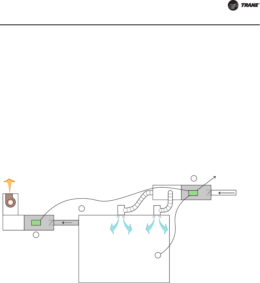
VAV-SVX07A-EN 63
Sequence of Operation
air valve. The controller positions the modulating air valve to deliver the desired airflow (cooling
or heating capacity). The desired airflow is called the active flow setpoint.
Flow tracking control is provided by two controllers working together: space temperature
controller and flow tracking controller. The space temperature controller outputs the airflow as
reported airflow. The airflow is determined by the airflow setpoint input (communicated airflow
setpoint) of the flow tracking controller. The flow tracking controller adds a configured airflow
tracking offset (positive or negative) to the communicated airflow setpoint and controls its airflow
to this new airflow setpoint.
Reheat Control in Flow Tracking Control Operation
Reheat is not an option on a flow tracking controller.
Unoccupied Flow Tracking Control
In unoccupied control mode, the controller operates the air valve the same as it does in occupied
control mode. The controller enters this mode from a communicated command or from a local
occupancy sensor.
Figure 31. Flow tracking control
B
A
C
Exhaust
Communication link
Supply VAV
To other VAVs or
Main Control Panel
How Does It Operate?
T
Primary Air
from Main
AHU
Occupied Space

64 VAV-SVX07A-EN
Troubleshooting
WARNING
Live Electrical Components!
During installation, testing, servicing and troubleshooting of this product, it may be necessary
to work with live electrical components. Have a qualified licensed electrician or other individual
who has been properly trained in handling live electrical components perform these tasks.
Failure to follow all electrical safety precautions when exposed to live electrical components
could result in death or serious injury.
This chapter contains the following troubleshooting procedures:
• Troubleshooting Procedures
• Diagnostics
• LED Operation
• Tracer ™UC400 Controller Failure Troubleshooting Procedures
• Tracer UC400 Controller Communication Loss Procedures
• Wired Zone Sensor Failure Troubleshooting Procedures
• Wired Zone Setpoint Failure Troubleshooting Procedures
• Wireless Zone Sensor Failure Troubleshooting Procedures
• Airflow Failure Troubleshooting Procedures
• Supply/Discharge Air Temperature Sensor Failure Troubleshooting Procedures
•CO
2 Sensor Failure Troubleshooting Procedures
• VAV Damper Failure Troubleshooting Procedures
• VAV Series Fan Failure Troubleshooting Procedures
• VAV Parallel Fan Failure Troubleshooting Procedures
• Trane/Honeywell Proportional Valve Check Out Procedures
Troubleshooting Procedures
Marquee Status LED will give you an indication if a diagnostic is present. If diagnostic is present,
use Tracer TU service tool to access Tracer UC400 controller diagnostics. See Table 10, p. 64 for
diagnostics. After diagnostics have been assessed, find correct procedures for troubleshooting
issue.
Note: The Tracer UC400 controller binary and analog outputs can be exercised by Tracer TU
service tool. See status and programming sections for detail.
Note: Each binary output has a yellow LED associated to it that lights up when TRIAC output has
been exercised.
Diagnostics
The diagnostic reports informational modes/items that are not in the unit's normal operation. See
Ta b le 10 , p. 64 for diagnostic.
Table 10. Controller diagnostics
Diagnostic Air valve Fan Reheat
Discharge air temperature failure (space
temperature control) Normal Normal Normal
Discharge air temperature failure (ventilation
flow control without reheat) Normal Do not care Do not care
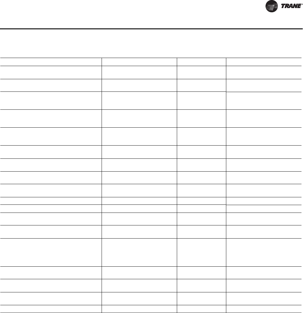
VAV-SVX07A-EN 65
Troubleshooting
LED Operation
LED Description and Operation
There are 15 LEDs on the front of the Tracer™ UC400 controller. Figure 1, p. 14 shows the locations
of each LED and a description of its behavior in specific instances.
Marquee LED
• Shows solid green when the Tracer UC400 controller is powered and operating normally.
• Shows solid red when the Tracer UC400 controller is powered, but represents low power or
a malfunction.
Discharge air temperature failure (ventilation
flow control with reheat) Closed Do not care Off
Discharge air temperature failure (flow tracking
control) Normal Do not care Do not care
Low airflow (space temperature control) Normal Normal
Local electric heat is Off; local
hydronic and all remote heat is
normal
Low airflow (ventilation flow control) Normal Do not care
Local electric heat is Off; local
hydronic is normal; remote is Don't
Care
Supply air temperature failure (space
temperature control) Normal Normal
Local electric heat is Off(a); local
hydronic and all remote heat is
normal
Supply air temperature failure (ventilation flow
control) Normal Do not care Normal
Supply air temperature failure (flow tracking
control) Normal Do not care Do not care
Space temperature fail (space temperature
control)(b)
Occupied: cool minimum flow
setpoint Unoccupied: closed
Series fan enabled;
parallel fan Off Off
Space temperature fail (ventilation flow
control)(b) Normal Do not care Normal
Space temperature fail (flow tracking control)(b) Normal Do not care Do not care
Local setpoint failure Normal Normal Normal
Flow sensor failure or flow sensor calibration
failure (space temperature control) Normal pressure dependent control Normal Normal
Flow sensor failure or flow sensor calibration
failure (ventilation flow control) Normal pressure dependent control Do not care Normal
Flow sensor failure or flow sensor calibration
failure (flow tracking control)
If the configured airflow tracking
offset is positive, configure
maximum airflow If the configured
airflow tracking offset is negative,
configure minimum airflow
Do not care Do not care
Freeze protection active (ventilation flow
control) Closed Off Off
Thumbwheel in */** position (single star
position) Minimum airflow Normal Normal
Thumbwheel in */** position (double star
position) Maximum airflow Normal Normal
Normal Normal Normal Normal
(a) If system mode is heat or auto with a warm or hot supply air temperature
(b) When a temperature sensor fails after being valid, the controller generates a diagnostic to indicate the sensor loss condition. The controller automatically
clears the diagnostic once a valid sensor temperature value is present (non-latching diagnostic).
Table 10. Controller diagnostics (continued)
Diagnostic Air valve Fan Reheat

66 VAV-SVX07A-EN
Troubleshooting
• Blinks red when an alarm exists.
LINK
• The TX LED blinks green at the data transfer rate when the Tracer™ UC400 controller transfers
data to other devices on the link.
• The RX LED blinks yellow at the data transfer rate when the Tracer UC400 controller receives
data from other devices on the link.
IMC
Not used.
Service
Shows solid green when pressed.
BO1 to BO9
Shows solid Yellow when corresponding binary output is on.
Green Service LED
Table 11, p. 66 shows and describes green service LED activity.
Tracer UC400 Controller Failure Troubleshooting Procedures
WARNING
Live Electrical Components!
During installation, testing, servicing and troubleshooting of this product, it may be necessary
to work with live electrical components. Have a qualified licensed electrician or other individual
who has been properly trained in handling live electrical components perform these tasks.
Failure to follow all electrical safety precautions when exposed to live electrical components
could result in death or serious injury.
1. Check the incorrect supply voltage or no voltage.
•Check Marquee LED.
•Shows solid green when the Tracer UC400 controller is powered and operating normally.
•Shows solid red when the Tracer UC400 controller is powered, but represents low power
or a malfunction.
• If marquee LED is solid red, check incoming power. Measure the power input to the
Tracer UC400 controller on XFMR 24 VAC input and . The supply voltage should be
between 19 and 30 VAC (24 VAC cataloged). However, voltages at either extreme may result
in system instability.
•If no voltage, check up stream of controller to see were voltage has been interrupted. See
complete wiring diagrams, Figure 37, p. 86 to Figure 44, p. 93.
Table 11. Green service LED activity
Green Service LED Activity Description
LED is Off continuously after power is applied to the
controller Normal operation
LED is On continuously, even when power is first applied to
the controller
Someone pressed the Service push button or the controller
failed
LED flashes approximately once every two seconds
Uninstalled (normal controller mode). Use the Tracer TU
service tool service tool to restore the unit to normal
operation.
VAV-SVX07A-EN 67
Troubleshooting
2. Check for short.
•Remove all wires from controller except incoming power.
•Check device using Tracer™ TU service tool to see if the Tracer UC400 controller is operating
properly. If it does operate properly check inputs/outputs for a short.
3. Check for alarms or diagnostics with Tracer TU service tool.
4. For final step check program by downloading good program using Tracer TU service tool.
Note: For Instructions on how to use Tracer TU, refer to the Tracer TU online Help by clicking
on Tracer TU Help in the Help menu, or see the Tracer TU Service Tool Getting Started
Guide TTU-SVN02*-EN.
5. If controller is still failed, replace controller.
Tracer UC400 Controller Communication Loss Procedures
WARNING
Live Electrical Components!
During installation, testing, servicing and troubleshooting of this product, it may be necessary
to work with live electrical components. Have a qualified licensed electrician or other individual
who has been properly trained in handling live electrical components perform these tasks.
Failure to follow all electrical safety precautions when exposed to live electrical components
could result in death or serious injury.
In the event that the Tracer UC400 controller is not communicating properly (No activity on the LINK
or IMC LED's) inspect the following:
•The TX LED blinks green at the data transfer rate when the Tracer UC400 controller transfers
data to other devices on the link.
•The RX LED blinks yellow at the data transfer rate when the Tracer UC400 controller receives
data from other devices on the link.
1. Check for incorrect supply voltage/ no voltage.
•Check Marquee LED.
•Shows solid green when the Tracer UC400 controller is powered and operating normally.
•Shows solid red when the Tracer UC400 controller is powered, but represents low power
or a malfunction.
• If marquee LED is solid red, check incoming power. Measure the power input to Tracer
UC400 controller on XFMR 24 VAC input and .
The supply voltage should be between 19 and 30 VAC (24 VAC cataloged). However, voltages
at either extreme may result in system instability.
•If no voltage, check up stream of controller to see were voltage has been interrupted. See
complete wiring diagrams, Figure 37, p. 86 to Figure 44, p. 93.
2. Check that the Tracer UC400 controller is addressed correctly.
•Each Tracer UC400 controller on the BACnet link must have a unique rotary switch setting,
otherwise communication problems will occur. There are three rotary switches on the front
of the Tracer UC400 controller. Use these switches to define a three-digit address when the
Tracer UC400 controller is installed in a BACnet system (for example, 107, 120, and so on),
whether with other Trane BACnet controls or controls from another vendor. This three-digit
rotary switch setting is used as both the BACnet MAC address and the BACnet Device ID.
Note: Valid addresses are 001 to 120.
•Verify the rotary switches on each Tracer UC400 controller is not duplicated on
communication link.

68 VAV-SVX07A-EN
Troubleshooting
3. Check for alarms or diagnostics with Tracer TU service tool, and check that the communication
link avoids interference.
•Communication link should not be routed near or with any voltage source.
•BACnet Wiring Best Practices. The following wiring practices are recommended:
•Strip no more than 2 inches (5 cm) of the outer conductor of shielded wire.
•Avoid sharing 24 VAC power between unit controllers.
•Ensure that 24 VAC power supplies are consistently grounded. If grounds are not
maintained, intermittent or failed communication could result.
4. Check that the correct wire is used.
•Recommended wire is twisted shielded pair. See Chapter 2 for the wiring specifications for
the Tracer™ UC400 controller.
•Using Shielded Wire. Follow these guidelines when using shielded wire:
•Connect the shield portion of the wire at the first unit controller in the link.
•Tape back the shield at the end of the unit controller line.
•Wire together and tape all other shields at each unit controller.
5. For final step check program by downloading good program using the Tracer TU service tool.
Note: For Instructions on how to use Tracer TU, refer to the Tracer TU online Help by clicking on
Tracer TU Help in the Help menu, or see Tracer™ TU Service Tool Getting Started Guide TTU-
SVN02*-EN.
If still not communicating to Tracer TU service tool and communication link, replace controller.
Wired Zone Sensor Failure Troubleshooting Procedures
WARNING
Hazardous Service Procedures!
The maintenance and troubleshooting procedures recommended in this section of the manual
could result in exposure to electrical, mechanical or other potential safety hazards. Always refer
to the safety warnings provided throughout this manual concerning these procedures. When
possible, disconnect all electrical power including remote disconnect and discharge all energy
storing devices such as capacitors before servicing. Follow proper lockout/tagout procedures to
ensure the power can not be inadvertently energized. When necessary to work with live
electrical components, have a qualified licensed electrician or other individual who has been
trained in handling live electrical components perform these tasks. Failure to follow all of the
recommended safety warnings provided, could result in death or serious injury.
In the event that the Tracer UC400 controller reports an incorrect zone temperature, properly
inspect the following:
1. Verify that the actual room temperature is higher or lower than what the Tracer UC400 controller
reads.
•Check the location and installation of the zone sensor. Change the calibration factor in the
Tracer UC400 controller setup screens.
Note: If Zone sensor is off more than ± 2 degrees continue to number 2.
2. Verify that the zone sensor is wired correctly.
•Check wiring for the correct connections. See section 2 for further details on zone sensor
wiring.
3. Verify that the zone sensor is working properly.
VAV-SVX07A-EN 69
Troubleshooting
•Disconnect the zone sensor terminal plug from the Tracer™ UC400 controller and using an
Ohmmeter, measure the resistance across the terminals 1 and 2. Compare the resistance to
temperature using Table 12, p. 69. The resistance should shown value should be within ± 2
degrees near those measured with an accurate temperature measuring device. If not, the
zone sensor needs to be replaced.
4. Verify that the wiring or the Tracer UC400 controller are not defective. With wires still connected
to the Tracer UC400 controller, disconnect zone sensor wires and check voltage (DC) from wires
that were connected to terminals 1 and 2 of zone sensor. You should measure 5VDC. If 5VDC
not present then see if the Tracer UC400 controller is outputting 5VDC. This can be done by
disconnecting the wires on the Tracer UC400 controller on terminals AI1 and and measure
the VDC. It should be 5VDC. If you have 5VDC at the Tracer UC400 controller the wires going
to the zone have an open. If 5VDC is not present check incoming power to the Tracer UC400
controller on XFMR 24 VAC input and should measure 24 VAC ± 10%. If you measure the
proper voltage at on XFMR 24 VAC input and and no voltage at AI1 and , replace the Tracer
UC400 controller.
5. Verify that the zone sensors are not shorted out. Check the resistance across the wires.
Disconnect wires from the Tracer UC400 controller and zone sensor making sure the ends are
not touching each other and measure resistance. It should be infinity or no conductivity. If lower
resistance is shown wires are shorted together and needs to be replaced.
Table 12. Zone sensor temperature resistance
Temp (oF) Thermostat Thumbwheel
Resistance (Ohms)
Sensor Resistance (k Ohms)
55
56
57
58
59
792
772
753
733
714
17.0
16.5
16.1
15.7
15.4
60
61
62
63
64
694
675
656
636
617
15.0
14.6
14.3
14.0
13.6
65
66
67
68
69
597
578
558
539
519
13.3
13.0
12.6
12.3
12.1
70
71
72
73
74
500
481
461
442
422
11.8
11.5
11.2
11.0
10.7
75
76
77
78
79
403
383
364
344
325
10.4
10.2
10.0
9.7
9.5
80
81
82
83
84
85
306
286
267
247
228
208
9.3
9.0
8.8
8.6
8.4
8.2
Note: Thumbwheel resistance checks are made at terminal 2 and 3 on the zone sensor. Temperature sensor resistance is
measured at terminal 1 and 2 of the zone sensor.
70 VAV-SVX07A-EN
Troubleshooting
Wired Zone Setpoint Failure Troubleshooting Procedures
WARNING
Hazardous Service Procedures!
The maintenance and troubleshooting procedures recommended in this section of the manual
could result in exposure to electrical, mechanical or other potential safety hazards. Always refer
to the safety warnings provided throughout this manual concerning these procedures. When
possible, disconnect all electrical power including remote disconnect and discharge all energy
storing devices such as capacitors before servicing. Follow proper lockout/tagout procedures to
ensure the power can not be inadvertently energized. When necessary to work with live
electrical components, have a qualified licensed electrician or other individual who has been
trained in handling live electrical components perform these tasks. Failure to follow all of the
recommended safety warnings provided, could result in death or serious injury.
In the event that the Tracer™ UC400 controller reports an incorrect zone setpoint, properly inspect
the following:
1. Verify that the zone sensor is wired correctly. Check wiring for the correct connections. See
section 2 for further details on zone sensor wiring.
2. Check that the zone sensor setpoint dial is not defective.
•Disconnect the zone sensor terminal plug from the Tracer UC400 controller and using an
Ohmmeter, measure the resistance across the terminals 2 (common) and 3 (setpoint).
Compare the resistance to specified setpoint on sensor using Table 12, p. 69. The resistance
shown should correlate within ± 2 degrees of setpoint shown onTabl e 12, p. 69 If not, the
zone sensor needs to be replaced.
3. Check the wiring and the Tracer UC400 controller.
•With wires still connected to Tracer UC400 controller, disconnect zone sensor setpoint wires
and check voltage (DC) from wires that were connected to terminals 2 and 3 of zone sensor.
You should measure 5VDC. If you do not have 5VDC then see if the Tracer UC400 controller
is outputting 5VDC. This can be done by disconnecting the wires on the Tracer UC400
controller on terminals Ground and AI2 and measure the VDC. It should be 5VDC. If you
have 5VDC at the Tracer UC400 controller the wires going to the zone have an open. If 5VDC
is not present check incoming power to the Tracer UC400 controller on XFMR 24 VAC input
and . Voltage should measure 24 VAC ± 10%. If you measure the proper voltage at on XFMR
24 VAC input and and no voltage at and AI2 replace Tracer UC400 controller.
4. Verify that the zone sensor setpoint is not shorted out.
•Check the resistance across the wires. Disconnect wires from the Tracer UC400 controller
and zone sensor making sure the ends are not touching each other and measure resistance.
It should be infinity or no conductivity. If lower resistance is shown wires are shorted
together and needs to be replaced.
Wireless Zone Sensor Failure Troubleshooting Procedures
Servicing and Testing Tools
No special tools or software are necessary to service and test the wireless sensor system. Test the
system by using:
• The LEDs on the receiver, LEDs on the model WTS and WZS sensor, and the display on the
model WDS sensor;
• The Test button on the sensor;
• The address test mode on the receiver; and
•A common volt-ohm meter.
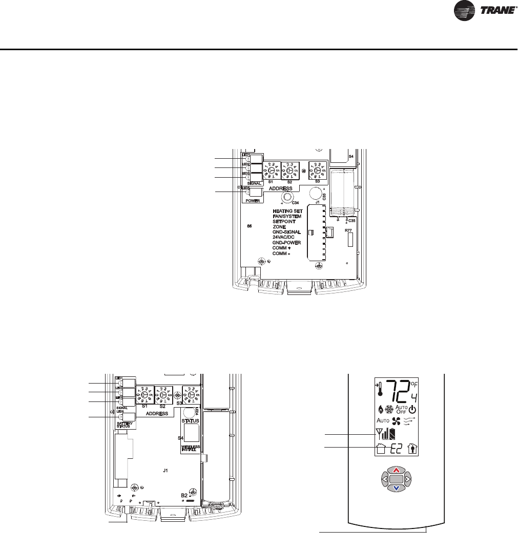
VAV-SVX07A-EN 71
Troubleshooting
In the event that the Tracer™ UC400 controller reports an incorrect zone temperature or setpoint,
properly inspect the receiver for all models has four LEDs: LED1, LED2, LED3, and LED5. Figure 32,
p. 71 shows their locations.
The sensor for models WTS and WZS have four LEDs: LED1, LED2, LED3, and LED5. The sensor
for model WDS has test symbols and error codes that appear on the display. All three sensor
models have a Test button. Figure 10, p. 26 shows their locations.
Diagnostics
Note: Reading diagnostics can show if the sensor has an issue or it has not been setup properly.
Use this information as a starting point.
LED1, LED2, and LED3, located on the sensor of models WTS and WZS, respond to diagnostics by
exhibiting specific blinking patterns. View their response by pressing the Test button. (See Tab l e 13,
p. 72.)
Error codes appear on the display of the model WDS sensor when diagnostics occur. (See Table 13,
p. 72.)
LED1, LED2, and LED3, located on the receiver of all models, respond to diagnostics by exhibiting
specific blinking patterns. They respond independently of any user action. (See Table 14, p. 72.)
Figure 32. LED locations on the receiver
LED1
LED2
LED3
LED5
Figure 33. LED, test button, and symbol locations on the sensor
.
Tes t sym bo l s
Error code
Tes t b ut to n
LED1
LED2
LED3
LED5
Tes t bu t to n
rosnes SDWrosnes SZW ,ZTW
72 VAV-SVX07A-EN
Troubleshooting
1. wireless zone sensor system failure.
•Observe LED5 on the receiver. LED5 will be On solid green whenever the receiver is
powered.
•Make sure the receiver is properly grounded. Both the black wire (GND SIGNAL) and the
yellow wire (GND-POWER) must be grounded.
•Press the Test button (S5) on the sensor. Models WTS, WZS LED5 should turn On solid green,
indicating proper battery strength. LED1, LED2, and LED3 will indicate signal strength (See
Tab le 1 7, p. 7 3).
Table 13. Diagnostics on the sensor
LED state when Test button is pressed
(WTS, WZS sensors)
Error code (WDS
sensor display) Indicates…
N/A E0, E5, E7 Sensor failure
- Replace sensor
LED1: Off
LED2: Off
LED3(a): 1-blink pattern repeated 3 times
E1 Disassociated
- Sensor is not associated with a receiver
LED1: Off
LED2: Off
LED3(a): 2-blink pattern repeated 3 times
E2 Address set to 000
- Address not set to between 001-999
LED1: Off
LED2: Off
LED3(a): 3-blink pattern repeated 3 times
E3 Software error
- Replace sensor
LED1: Off
LED2: Off
LED3(a): 4-blink pattern repeated 3 times
E4
Input voltage too high
- No RF transmission is permitted with an input battery voltage
greater than 3.9V
(a) Blink pattern is On for 1/4s, Off for 1/4s, with 2s OPff between repetitions.
Table 14. Diagnostics on the receiver
LED state Indicates…
LED1: Off
LED2: Off
LED3: 1-blink pattern repeated continuously(a)
Disassociated
* Receiver is not associated, waiting for a sensor
* Receiver lost communication with sensor
* Receiver has no devices on its wireless personal area network
* Association with a device has been manually removed
LED1: Off
LED2: Off
LED3: 2-blink pattern repeated continuously(a)
Address set to 000
* Address not set to between 001-999
LED1: Off
LED2: Off
LED3: 3-blink pattern repeated continuously(a)
Not configured
* Receiver configuration properties bot properly set (defective
receiver)
(a) Blink pattern is On for 1/4 s, Off for 1/4 s, with 2 s Off between repetitions.
Table 15. Battery status: LED5 on model WTS and WZS sensors
User action LED state (WTS, WZS) Indicates…
Press Test button Solid green for 5 seconds Battery is adequate for proper operation.
Solid red for 5 seconds 25% battery life left. Batteries should be replaced.
No light Batteries life expired or not installed properly, or sensor is
defective
None Blinking red: 1-blink pattern(a) repeated 5 times.
Cycle repeats every 15 minutes.
Approximately 14 days of operation remain before the battery
is too weak to power the sensor.
(a) Blink pattern is On for 1/4 s, Off for 3/4 s, with 2 s Off between repetitions.
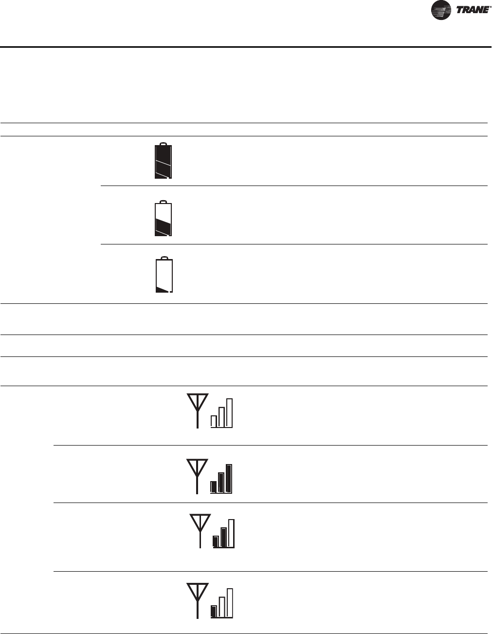
VAV-SVX07A-EN 73
Troubleshooting
•Model WDS: Battery life ("Testing Battery Status," Tab le 1 6 , p. 73) and signal strength
("Testing Signal Strength," Table 17, p. 73) are indicated.
Table 16. Battery status: Battery symbol on model WDS sensor display
User action Battery test symbol Indicates…
Press Test button XFull battery power
50% battery life left
25% battery life left. Replace batteries. Flashing symbol indicates that
approximately 14 days of operation remain before the battery is too weak to
power the sensor.
Table 17. Observing signal strength on the sensor
User action
LED state (WTS, WZS
sensors)
Symbol (WDS
sensor display) Indicates…
None LED1: Off
LED2: Off
LED3: Off
No Test symbols
appear
Normal state
* No Test button press
Press Test
button on
the sensor
LED1: Off
LED2: Off
LED3: Off
Associated; no communication with receiver
* Associated, but no signal from the receiver after pressing Test button
LED1: On
LED2: On
LED#: On
Displays for 5 seconds, then
constantly Off
Excellent signal strength
* Good signal margin for reliable communication
LED1: Off
LED2: On
LED3: On
Displays for 5 seconds, then
constantly Off
Satisfactory signal strength
* Adequate signal strength for reliable communication
* Moving sensor or receiver may improve signal strength
* Increased channel switching may reduce battery life
LED1: Off
LED2: Off
LED3: On
Displays for 5 seconds, then
constantly Off
Poor signal strength
* Unreliable communication
* Strongly recommend moving data sensor or receiver to a better
location
Note: When checking signal strength, both LED1 and LED3 on the receiver and sensor illuminate in unison if the sensor and receiver are associated. Use
this feature to confirm association.
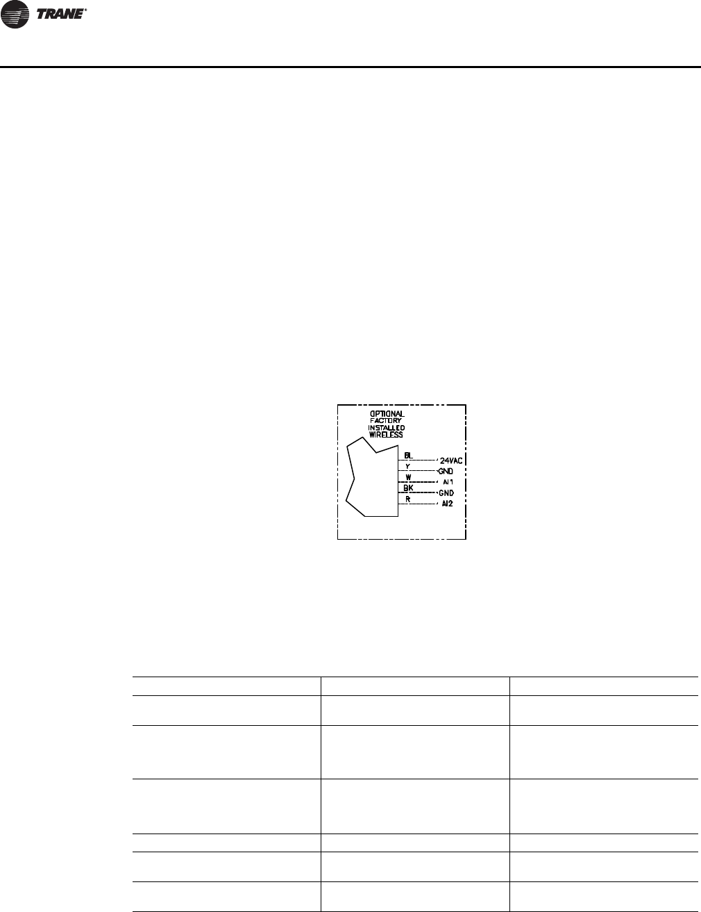
74 VAV-SVX07A-EN
Troubleshooting
WARNING
Hazardous Service Procedures!
The maintenance and troubleshooting procedures recommended in this section of the manual
could result in exposure to electrical, mechanical or other potential safety hazards. Always refer
to the safety warnings provided throughout this manual concerning these procedures. When
possible, disconnect all electrical power including remote disconnect and discharge all energy
storing devices such as capacitors before servicing. Follow proper lockout/tagout procedures to
ensure the power can not be inadvertently energized. When necessary to work with live
electrical components, have a qualified licensed electrician or other individual who has been
trained in handling live electrical components perform these tasks. Failure to follow all of the
recommended safety warnings provided, could result in death or serious injury.
2. Measure the receiver output resistance by following the procedures.
•Make sure the black wire (GNS-SIGNAL) and the yellow wire (GND-POWER) are grounded
(see Figure 34, p. 74 for wiring diagrams).
•Make sure the receiver is powered up.
•Disconnect the SETPOINT wire (red) and the ZONE wire (white) from the host unit controller.
•Measure resistance between the grounded GND-SIGNAL wire and either the SETPOINT or
ZONE wire. Compare resistance measurements to those presented in Table 19, p. 75.
•If resistance is not correct replace receiver.
•When the test is complete, reset the receiver address to its previous setting.
Figure 34.
Table 18. Output failure modes of operation
Situation Zone Temperature Output Zone Setpoint Output
Receiver address = 000 11.17 kΩ, 72.5 oF (22.5 oC),
indefinitely 451 Ω, 72.5 oF (22.5 oC), indefinitely
Receiver address = 001 to 999
Receiver has powered up, but has not
received a communication from
sensor.
11.17 kΩ, 72.5 oF (22.5 oC) 451 Ω, 72.5 oF (22.5 oC)
Receiver address = 001 to 999
Receiver does not receive a
communication within 35 minutes
from the sensor it is associated with
Open Open
Receiver has no power Open Open
Thermistor in sensor has failed to
either open or close Open Normal value
Setpoint potentiometer has failed to
either open or close Normal value Open
VAV-SVX07A-EN 75
Troubleshooting
•Press the Test button (S5) on the sensor to force re-association. Confirm association and
communication by noting LED1, LED2, and LED3 as described in "Signal Quality Test."
•Pressing the Test button (S5) on the sensor initiates a signal quality test. LED1, LED2, and
LED3 respond on the receiver by indicating excellent, marginal, or poor signal quality See
Tab le 1 7, p. 7 3. The Sensor LED's or LCD can be observed and verified using Tab l e 17, p . 7 3 .
•If Sensor and receiver still do not operate properly, replace bad components. If unit passes
tests Check Tracer UC400 controller operation.
3. Defective Tracer UC400 controller.
•Disconnect the receiver sensor wires on the Tracer UC400 controller on terminals AI1 and
and measure the VDC. It should be 5VDC. If 5VDC is not present check incoming power
to the Tracer UC400 controller on XFMR 24 VAC input and . Voltage should measure 24 VAC
± 10%. If you measure the proper voltage at XFMR 24 VAC input and and no voltage at
AI1 and replace the Tracer UC400 controller.
•Disconnect the receiver setpoint wires on the Tracer UC400 controller on terminals AI2 and
and measure the VDC. It should be 5VDC. If 5VDC is not present check incoming power
to the Tracer UC400 controller on XFMR 24 VAC input and . Voltage should measure 24 VAC
± 10%. If you measure the proper voltage at XFMR 24 VAC input and and no voltage at
AI2 and replace the Tracer UC400 controller.
Airflow Failure Troubleshooting Procedures
In the event that the air valve is reading position instead of flow or in the event that the measured
flow reads incorrectly, i.e. different from the balance report, properly inspect the following:
Recalibrate VAV unit by cycling power to unit. This can also be accomplished with Tracer TU service
tool or Tracer SC.
Note: Cycling power to the VAV board: The default is to automatically cause the unit to calibrate,
but this depends on binary value, autocalibrate enable/disable point. However, following
the procedure outlined below will provide a more accurate calibration. It is only necessary
to perform this procedure in instances where you are experiencing incorrect flow readings
or if the unit reverts to pressure dependent mode despite being above 5% and below 110%
of cataloged flow and performing a "normal calibration") and does not correct the problem.
1. Steps for Calibration
•Connect to the Tracer UC400 controller with Tracer TU service tool.
•Turn the central air handler "off." If this is not possible, Trane recommends pulling the
transducer tubes off during the calibration process to simulate this.
•Select the "calibrate unit" option button.
Table 19. Receiver resistance
Zone or Setpoint Temperature Nominal Zone Temperature
Output Resistance
Nominal Space Temperature
Setpoint Output Resistance
55 oF (12.8 oC) 17.47 k Ω812 Ω
60 oF (15.6 oC) 15.3 k Ω695 Ω
65 oF (18.3 oC) 13.49 k Ω597 Ω
70 oF (21.1 oC) 11.9 k Ω500 Ω
75 oF (23.9 oC) 10.5 k Ω403 Ω
80 oF (26.7 oC) 9.3 k Ω305 Ω
85 oF (29.4 oC) 8.25 k Ω208 Ω
76 VAV-SVX07A-EN
Troubleshooting
•Tracer™ TU service tool will indicate that calibration is taking place by a calibration percent
complete indicator.
•When calibration is complete, the box will release to auto. Drive the box open to make sure
that the box is not below 5% of its cataloged CFM. The controller is accurate in reading flow
from 5% to 110% of cataloged CFM.
•Release the box to auto and perform any necessary balancing work. See Tracer TU Help for
balancing details.
•Check to see if flow has been established, If flow not established or inaccurate proceed to
Step 2.
2. The tubing or flow ring is off, reversed, plugged, or has a leak.
•Check with a magnehelic gauge and compare with the delta pressure (DP) chart located on
the VAV box.
•Check the tubing for reversal and/or leaks.
•Check the flow ring for plugged holes. Blow out with compressed air if necessary.
3. Wrong unit size downloaded into the Tracer UC400 controller setup screen. (See programming
section for menu details.)
•Verify that the actual unit size matches the unit's nameplate.
4. Poor inlet configuration.
•Trane recommends 1½-duct diameters of straight duct before the inlet of the box (a 12-inch
box should have 18 inches of straight run duct before the inlet).
5. To determine whether or not the transducer has failed, perform the following steps:
•Check the 24 volts AC supply at XFMR 24 VAC input and on the Tracer UC400 controller.
Voltage should be between 20 volts AC and 28 volts AC.
•Read the input voltage to the transducer from the Tracer™ UC400 controller between the
green and red wires on P1 of the Tracer UC400 controller. The voltage should be between
Figure 35. Sensor signal vs. airflow delivery
0.01
0.1
1
5
10 100 1,000 10,000
Cfm
Flow Sensor DP (In . w g )
4" 12"10"8"6"
5" 14"16"
VAV-SVX07A-EN 77
Troubleshooting
4.50 volts DC and 5.50 volts DC (5 volts DC cataloged). If voltage not available replace the
Tracer UC400 controller.
•Remove the high and low tubes from the transducer (to simulate no flow). Read the
transducer output voltage on P1 of the Tracer UC400 controller between the green and the
black wires with a voltmeter. The voltage should be between 0.20 volts DC and 0.30 volts DC
(0.25 volts DC is the null voltage output of the transducer indicating zero flow). If voltage not
available replace transducer.
Note: The formula for the transducer output voltage is 0.25 + 0.75 * <delta P>, where delta P
is the pressure in inches of water column. Delta P can range from 0 to 5 inches of W.C.
•With flow going across the flow ring measure the differential pressure with a magnahelic
and use transducer output voltage formula to check accuracy of reported value. Read the
transducer output voltage between the green and the black wires. The measured value
should correspond to the value given in the transducer output formula. If transducer is off
by ± 5%, replace transducer.
Supply/Discharge Air Temp Sensor Failure Troubleshooting Procedures
WARNING
Hazardous Service Procedures!
The maintenance and troubleshooting procedures recommended in this section of the manual
could result in exposure to electrical, mechanical or other potential safety hazards. Always refer
to the safety warnings provided throughout this manual concerning these procedures. When
possible, disconnect all electrical power including remote disconnect and discharge all energy
storing devices such as capacitors before servicing. Follow proper lockout/tagout procedures to
ensure the power can not be inadvertently energized. When necessary to work with live
electrical components, have a qualified licensed electrician or other individual who has been
trained in handling live electrical components perform these tasks. Failure to follow all of the
recommended safety warnings provided, could result in death or serious injury.
In the event that the Tracer UC400 controller reports an incorrect or failed discharge or supply air
temperature, properly inspect the following:
1. Make sure Tracer UC400 controller has been configured for the input and the point has not been
set out of service.
2. Discharge or supply air temperature is higher or lower than what the Tracer UC400 controller
reads.
•Check the location and installation of the sensor. Change the calibration factor in the Tracer
UC400 controller setup screens.
Note: If sensor is off more than ± 2 degrees continue to number 3.
3. Sensor wired incorrectly.
•Check wiring for the correct connections. See Chapter 2 for further details on discharge or
supply air sensor wiring.
4. Defective sensor.
•Disconnect the sensor terminal plug from the Tracer UC400 controller and using an
ohmmeter, measure the resistance across the sensor wires. Compare the resistance to
temperature using Tabl e 12, p. 6 9. The resistance measured should correspond to a
temperature within ± 2 degrees near those measured with an accurate temperature
measuring device. If not, the sensor needs to be replaced.
5. Defective wiring or Tracer UC400 controller.
•See if the Tracer UC400 controller is outputting 5VDC. This can be done by disconnecting the
wires on the Tracer UC400 controller on terminals AI4 and for discharge air temperature
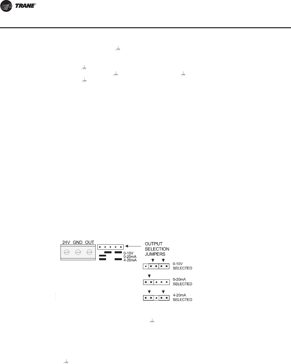
78 VAV-SVX07A-EN
Troubleshooting
sensor or AI5 and for supply air temperature sensor and measure the VDC. It should be
5VDC. If you have 5VDC at the Tracer™ UC400 controller the wires going to the zone have
an open. If 5VDC is not present check incoming power to the UC400 on XFMR 24 VAC input
and . Voltage should measure 24 VAC ± 10%. If you measure the proper voltage at XFMR
24 VAC input and and no voltage at AI4 and for discharge air temperature sensor or AI5
and for supply air temperature sensor. replace the Tracer UC400 controller.
CO2 Sensor Failure Troubleshooting Procedures
WARNING
Hazardous Service Procedures!
The maintenance and troubleshooting procedures recommended in this section of the manual
could result in exposure to electrical, mechanical or other potential safety hazards. Always refer
to the safety warnings provided throughout this manual concerning these procedures. When
possible, disconnect all electrical power including remote disconnect and discharge all energy
storing devices such as capacitors before servicing. Follow proper lockout/tagout procedures to
ensure the power can not be inadvertently energized. When necessary to work with live
electrical components, have a qualified licensed electrician or other individual who has been
trained in handling live electrical components perform these tasks. Failure to follow all of the
recommended safety warnings provided, could result in death or serious injury.
In the event that the Tracer UC400 controller reports an incorrect or failed CO2 sensor input
temperature, properly inspect the following:
1. Check that the CO2 point is not out of service.
•Checking the config will not be necessary. The point will exist and be locked from the factory.
2. Check jumper position on CO2 sensor.
•Need to be set up as 0-10VDC.
•Check voltage between UI2 and with the sensor connected.
•Should be between 1-10VDC. If it is not check incoming power.
•Check voltage input to CO2 sensor with voltmeter.
•Needs to be between 20 to 26 VAC; nominal 24 VAC.
3. If you measure the proper voltage at incoming power and you have no VDC output at UI2 and
, replace sensor. If no voltage, check up stream of controller to see were voltage has been
interrupted. See Figure 37, p. 86 to Figure 44, p. 93 for correct unit diagrams.
Figure 36. Jumper position
VAV-SVX07A-EN 79
Troubleshooting
VAV Damper Failure Troubleshooting Procedures
WARNING
Hazardous Service Procedures!
The maintenance and troubleshooting procedures recommended in this section of the manual
could result in exposure to electrical, mechanical or other potential safety hazards. Always refer
to the safety warnings provided throughout this manual concerning these procedures. When
possible, disconnect all electrical power including remote disconnect and discharge all energy
storing devices such as capacitors before servicing. Follow proper lockout/tagout procedures to
ensure the power can not be inadvertently energized. When necessary to work with live
electrical components, have a qualified licensed electrician or other individual who has been
trained in handling live electrical components perform these tasks. Failure to follow all of the
recommended safety warnings provided, could result in death or serious injury.
In the event that the air valve is not modulating, properly inspect the following:
1. Tracer™ SC or Tracer TU service tool has enabled an override function in the Tracer UC400
controller.
•The overrides are Open, Closed, Min, or Max. Disable all overrides.
Note: See programming and operation chapter to be able to release override with Tracer TU
service tool.
•The Tracer UC400 controller is going through a recalibrate (reset) command. This is shown
in the diagnostic list in Tracer TU service tool.
•Wait for calibration to finish.
2. Zone temperature is greater than the heat setpoint or less than the cool setpoint.
•Change the heat and/or cool setpoint.
3. Actuator not driving full drive time.
•Drive time in advanced configuration not set at 90 seconds on current Varitrane units.
•Adjust to correct damper travel time using Tracer TU service tool. See the Tracer UC400
Operation section.
•Damper actuator loose on shaft.
•Tighten damper actuator set screw to damper shaft.
•Measure the power input to XFMR 24 VAC input and on the Tracer UC400 controller. The
supply voltage should be between 20 and 28 VAC (24 VAC cataloged). However, voltages at
either extreme may result in system instability and cause damper to not be driven its full
range.
•If no voltage, check up stream of controller to see were voltage has been interrupted. See
Figure 37, p. 86 to Figure 44, p. 93 for correct unit diagrams.
4. Actuator motor has failed.
•Check voltage at B on TRIAC outputs to Common , you should have 24 VAC. If 24 VAC is
not present check incoming power to the Tracer UC400 controller on XFMR 24 VAC input and
. Voltage should measure 24 VAC ± 10%. If you measure the proper voltage at XFMR 24
VAC input and and no voltage at B and Common , replace the Tracer UC400 controller.
•Check motor by applying 24 VAC directly to common (blue) and jumper open (black) wire to
a ground to drive damper open.
•Damper should drive open.
•Check motor by applying 24 VAC directly to common (blue) and jumper closed (red) wire to
a ground to drive damper closed.

80 VAV-SVX07A-EN
Troubleshooting
•Damper should drive closed.
Note: The Tracer™ UC400 controller outputs are switched to ground. Do not jumper 24 VAC
to BO8 and BO9 because damage will occur.
•If damper actuator does not open or close replace actuator.
VAV Series Fan Failure Troubleshooting Procedures
WARNING
Hazardous Service Procedures!
The maintenance and troubleshooting procedures recommended in this section of the manual
could result in exposure to electrical, mechanical or other potential safety hazards. Always refer
to the safety warnings provided throughout this manual concerning these procedures. When
possible, disconnect all electrical power including remote disconnect and discharge all energy
storing devices such as capacitors before servicing. Follow proper lockout/tagout procedures to
ensure the power can not be inadvertently energized. When necessary to work with live
electrical components, have a qualified licensed electrician or other individual who has been
trained in handling live electrical components perform these tasks. Failure to follow all of the
recommended safety warnings provided, could result in death or serious injury.
In the event that the fan output is not energizing, properly inspect the following:
1. Verify the output configuration in the Tracer UC400 controller setup screen.
•Unit needs to be configured as series fan.
2. Outputs on the Tracer UC400 controller are configured as normally closed.
•Verify the output configuration in the Tracer UC400 controller setup screen.
Note: Series fan powered units in the occupied mode has the fan continuously energized. See
operation section for details.
3. Tracer SC has the fan output disabled.
•Check overrides to make sure they are not inhibiting fan operation.
4. A flow override exists locking out the fan output.
•Check to make sure Tracer SC or Tracer TU service tool has released fan disable override.
5. If the Tracer UC400 controller is calling in the status screen for the Fan to be on and it is not then
check TRIAC output wiring; and relay output.
•Override damper open.
•See if fan cycles on.
•Check BO4 to common . Should have 24 VAC; if it does not, measure the power input to
on XFMR 24 VAC input and of the Tracer UC400 controller. The supply voltage should be
between 20 and 28 VAC (24 VAC cataloged). However, voltages at either extreme may result
in system instability.
•TRIAC can be checked with purchasing a 24 VAC LED and see if it lights up on call for fan
Tracer UC400 controller. If LED does not light up replace the Tracer UC400 controller.
•Remove fan wires from the Tracer UC400 controller and apply 24 VAC directly to fan relay
wires.
•Fan relay should energize. If it does not energize check wiring. If wiring is OK replace fan
relay.

VAV-SVX07A-EN 81
Troubleshooting
Notice:
Equipment Damage!
The Tracer UC400 controller outputs are switched to ground. Do not jumper 24 VAC to Binary
output TRIAC(s) because damage will occur.
6. After all checks have been completed, check motor fan winding integrity and bearing failure.
VAV Parallel Fan Failure Troubleshooting Procedures
WARNING
Hazardous Service Procedures!
The maintenance and troubleshooting procedures recommended in this section of the manual
could result in exposure to electrical, mechanical or other potential safety hazards. Always refer
to the safety warnings provided throughout this manual concerning these procedures. When
possible, disconnect all electrical power including remote disconnect and discharge all energy
storing devices such as capacitors before servicing. Follow proper lockout/tagout procedures to
ensure the power can not be inadvertently energized. When necessary to work with live
electrical components, have a qualified licensed electrician or other individual who has been
trained in handling live electrical components perform these tasks. Failure to follow all of the
recommended safety warnings provided, could result in death or serious injury.
In the event that the fan output is not energizing, properly inspect the following:
1. Verify the output configuration in the Tracer UC400 controller setup screen.
•Unit needs to be configured as parallel fan.
2. Outputs on the Tracer UC400 controller are configured as normally closed.
•Verify the output configuration in the Tracer UC400 controller setup screen.
Note: Parallel fan can be enabled by either a differential temperature above the heating
setpoint or CFM flow. See Operation chapter for details.
3. Tracer SC has the fan output disabled.
•Check overrides to make sure they are not inhibiting fan operation.
4. A flow override exists locking out the fan output.
•Check to make sure Tracer SC or Tracer TU has released fan disable override.
Note: If fan cycling is based on temperature go to step 5 and if it is based on air flow go to step
6.
5. If fan control is based on temperature and zone temperature is at or above the heating setpoint
plus heating offset on units configured as temperature control. A factory set differential of 0.5°F
exists to prevent short cycling.
•Increase the Tracer UC400 controller heating setpoint causing fan to be cycled on.
•Lower the heating setpoint by 6 degrees and the fan should cycle off.
6. If the fan control is based on flow, the unit fan will be energized whenever supply airflow is
below this setpoint. For this parallel fan configuration, the fan control point, if specified in a
percentage of unit airflow, must be set between 15% and 30% of the units cataloged airflow to
assure proper operation. A differential of 5% exists to avoid excessive fan cycling.
•Override damper closed until CFM is below enabled flow setpoint.
•See if fan cycles on.
•Override damper open until CFM is above enabled flow setpoint fan should cycle off.
7. If the Tracer UC400 controller is calling in the status screen for the fan to be on and it is not then
check the Tracer UC400 controller TRIAC output, wiring, and relay output.
82 VAV-SVX07A-EN
Troubleshooting
•Check BO4 to common . Should have 24 VAC; if it does not, measure the power input to
on XFMR 24 VAC input and of the Tracer™ UC400 controller. The supply voltage should
be between 20 and 28 VAC (24 VAC cataloged). However, voltages at either extreme may
result in system instability.
•Triac can be checked with purchasing a 24 VAC LED and see if it lights up on call for fan the
Tracer UC400 controller. If LED does not light up replace the Tracer UC400 controller.
•Remove fan wires from UC400 and apply 24 VAC directly to fan relay wires.
•Fan relay should energize. If it does not energize check wiring. If wiring is OK replace fan
relay.
Notice:
Equipment Damage!
The Tracer UC400 controller outputs are switched to ground. Do not jumper 24 VAC to binary
output TRIAC(s) because damage will occur.
8. After all checks have been completed, check motor fan winding integrity and bearing failure.
PSC Variable Speed Motor Check Out
WARNING
Live Electrical Components!
During installation, testing, servicing and troubleshooting of this product, it may be necessary
to work with live electrical components. Have a qualified licensed electrician or other individual
who has been properly trained in handling live electrical components perform these tasks.
Failure to follow all electrical safety precautions when exposed to live electrical components
could result in death or serious injury.
If PSC Variable speed motor control is not changing speed of the motor inspect the following:
•Wires connected improperly.
•Check wiring to make sure speed control is wired correctly. See Figure 37, p. 86 and
Figure 44, p. 93 for wiring schematic.
•Check voltage selection switch on side of variable speed motor control.
•Should be set for motor voltage.
•To check speed control.
•Turn voltage selection switch fully CCW.
•Turn motor speed control potentiometer fully CCW.
•Motor should remain off.
•Turn voltage selection switch fully CW.
•Motor speed control potentiometer still fully CCW.
•Measure motor voltage. Should be no more than 8 VAC lower than line voltage.
•With voltage selection switch still fully CW.
•Turn Motor speed control potentiometer slowly fully CW (HI).
•Should go to full speed smoothly.
Note: If it fails any of these tests replace PSC motor speed controller.
VAV-SVX07A-EN 83
Troubleshooting
VAV Electric Heat Stage(s) Failure Procedures
WARNING
Live Electrical Components!
During installation, testing, servicing and troubleshooting of this product, it may be necessary
to work with live electrical components. Have a qualified licensed electrician or other individual
who has been properly trained in handling live electrical components perform these tasks.
Failure to follow all electrical safety precautions when exposed to live electrical components
could result in death or serious injury.
In the event that the heat outputs are not energizing, properly inspect the following:
1. Zone temperature is at or above the heating setpoint.
•Increase the Tracer UC400 controller heating setpoint.
2. Verify the output configuration in the Tracer UC400 controller setup screen.
•Unit needs to be configured as 3 stage electric heat.
3. Tracer SC has the electric heat output disabled.
•Check group, global, and/or Tracer overrides to make sure they are not inhibiting heat
operation.
4. Minimum heating CFM is not being met, airflow is too low.
•Increase the airflow or lower the minimum heating flow.
5. Heat relays have failed.
•If the Tracer UC400 controller is calling in the status screen for the electric heat and the LED
is on for correct binary output(s) for stage(s) of heat to be on and it is not on then check the
Tracer UC400 controller TRIAC output; wiring; and relay output.
•Check correct binary output to comman . See Figure 37, p. 86 should have 24 VAC; if it does
not measure the power input to on XFMR 24 VAC input and of the Tracer UC400 controller.
The supply voltage should be between 20 and 28 VAC (24 VAC cataloged). However, voltages
at either extreme may result in system instability.
•Heat TRIAC(s) can be checked with purchasing a 24 VAC LED and see if it lights up on call
for heat stage UC400. If LED does not light up replace Tracer UC400 controller.
Notice:
Equipment Damage!
The Tracer UC400 controller outputs are switched to ground. Do not jumper 24 VAC to binary
output TRIAC(s) because damage will occur.
•Move electric heat relay wires from the Tracer UC400 controller and apply 24 VAC directly.
•Electric heat stage should energize. If it does not; check wiring, safeties and electric heat
contactor. Replace components as necessary.

84 VAV-SVX07A-EN
Troubleshooting
VAV Proportional Hot Water Failure Troubleshooting Procedures
Check binary outputs
WARNING
Live Electrical Components!
During installation, testing, servicing and troubleshooting of this product, it may be necessary
to work with live electrical components. Have a qualified licensed electrician or other individual
who has been properly trained in handling live electrical components perform these tasks.
Failure to follow all electrical safety precautions when exposed to live electrical components
could result in death or serious injury.
In the event that the heat outputs are not energizing, properly inspect the following:
1. Zone temperature is at or above the heating setpoint.
•Increase the Tracer™ UC400 controller heating setpoint.
2. Verify the output configuration in the Tracer UC400 controller setup screen.
•Unit needs to be configured as proportional hot water.
3. Tracer SC has the heat output disabled.
•Check overrides to make sure they are not inhibiting heat operation.
4. Heat relays have failed.
•If the Tracer UC400 controller is calling in the status screen and LED is on for binary output
to open the valve and TRIAC is not closed then check the Tracer UC400 controller TRIAC
output; wiring; and relay output.
•Check binary outputs. See Figure 37, p. 86 and Figure 38, p. 87 for correct outputs. Should
have 24 VAC; if it does not measure the power input to XFMR 24 VAC input and of the
Tracer UC400 controller. The supply voltage should be between 20 and 28 VAC (24 VAC
cataloged). However, voltages at either extreme may result in system instability.
•Heat TRIAC(s) can be checked with purchasing a 24 VAC LED and see if it lights up on call
for Heat output to be open or closed by the Tracer UC400 controller. If LED does not light up
replace the Tracer UC400 controller.
Notice:
Equipment Damage!
The Tracer UC400 controller outputs are switched to ground. Do not jumper 24 VAC to binary
output TRIAC(s) because damage will occur.
Trane/Honeywell Proportional Valve Check-Out Procedures
Two problems can occur with the cartridge/ actuator or both that can result in over conditioning the
space.
Cartridge Failure
• If the actuator is driven closed but there is 1/8" or more play in the indicator (move with your
finger), or the piston has not returned up past the A port or has "frozen". In either case, the
cartridge is not closed off completely. This will result in over heating (or over cooling) in the
space.
VAV-SVX07A-EN 85
Troubleshooting
Actuator Failure
• If the actuator has stopped moving to the closed position when commanded to, and there is no
play in the lever, the actuator has failed.
• Remove the actuator and work the cartridge stem manually. If the stem moves freely, then only
the actuator has failed. If the stem is sluggish or stuck, the actuator and the cartridge have failed.
Note: The actuator fault is intermittent and the actuator may operate again when removed from
the valve, or if tapped with a tool while still on the valve.
Note: Actuator indicator on the side of the actuator should be positioned at the top of the actuator
when valve is closed.
VAV Two Position Hot Water Failure Troubleshooting Procedure
Check binary outputs
WARNING
Live Electrical Components!
During installation, testing, servicing and troubleshooting of this product, it may be necessary
to work with live electrical components. Have a qualified licensed electrician or other individual
who has been properly trained in handling live electrical components perform these tasks.
Failure to follow all electrical safety precautions when exposed to live electrical components
could result in death or serious injury.
In the event that the heat outputs are not energizing, properly inspect the following:
1. Zone temperature is at or above the heating setpoint.
•Increase the Tracer™ UC400 controller heating setpoint.
2. Verify the output configuration in the Tracer UC400 controller setup screen.
•Unit needs to be configured as two position hot water.
3. Tracer SC has the heat output disabled.
•Check overrides to make sure they are not inhibiting heat operation.
4. Heat relays have failed.
•If the Tracer UC400 controller is calling in the status screen for the valve to be open and it
is not then check the Tracer UC400 controller TRIAC output, wiring, and relay output.
•If the Tracer UC400 controller is calling in the status screen and LED is on for binary output
to open the valve and triac is not closed then check the Tracer UC400 controller TRIAC output;
wiring; and relay output.
•Check binary outputs. See Figure 37, p. 86 and Figure 38, p. 87 for correct outputs. Should
have 24 VAC; if it does not measure the power input to XFMR 24 VAC input and of the
Tracer UC400 controller. The supply voltage should be between 20 and 28 VAC (24 VAC
cataloged). However, voltages at either extreme may result in system instability.
Notice:
Equipment Damage!
The Tracer UC400 controller outputs are switched to ground. Do not jumper 24 VAC to binary
output TRIAC(s) because damage will occur.
•Heat TRIAC(s) can be checked with purchasing a 24 VAC LED and see if it lights up on call
for heat output to be open by the Tracer UC400 controller. If LED does not light up replace
the Tracer UC400 controller.
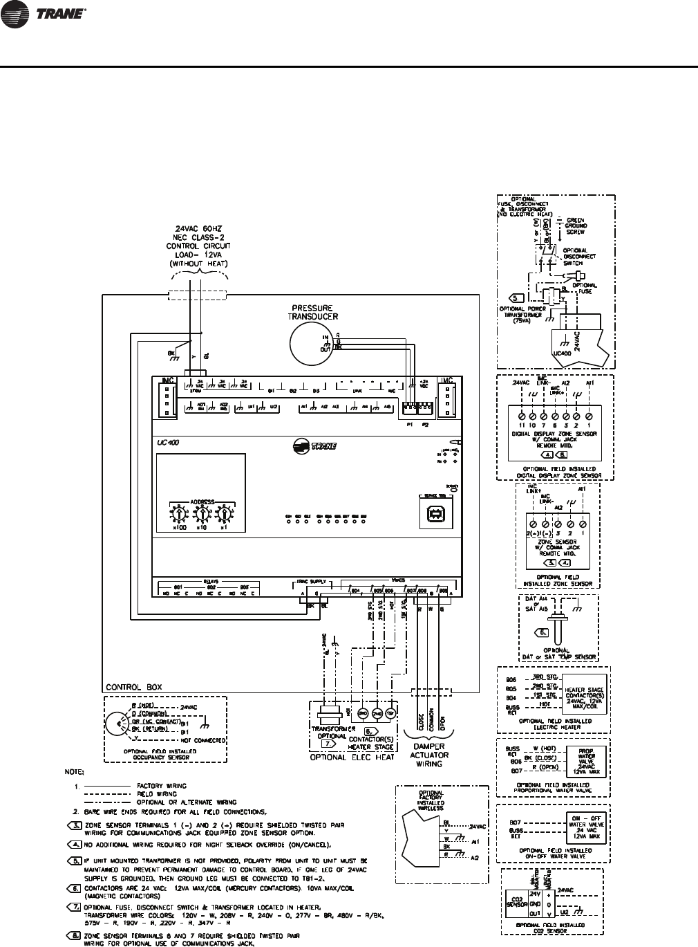
86 VAV-SVX07A-EN
Wiring Diagrams
Wiring Diagrams
Figure 37. Wiring diagram for single duct unit that is either cooling only, hot water, or field installed reheat
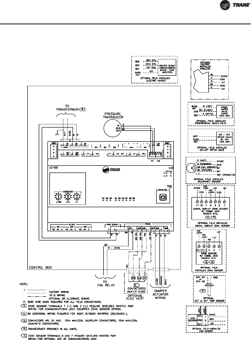
VAV-SVX07A-EN 87
Wiring Diagrams
Figure 38. Wiring diagram for fan-powered unit that is either cooling only, hot water, or field installed reheat
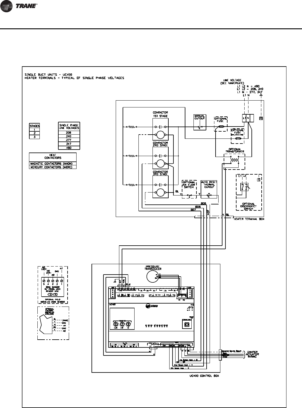
88 VAV-SVX07A-EN
Wiring Diagrams
Figure 39. Single duct with single phase voltage electric heat
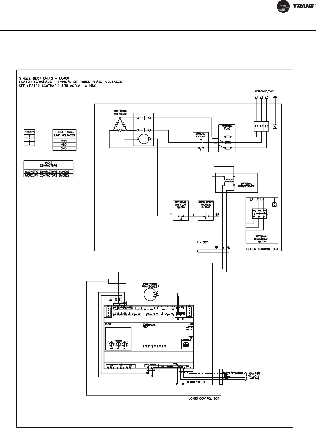
VAV-SVX07A-EN 89
Wiring Diagrams
Figure 40. Single duct with three phase voltage electric heat
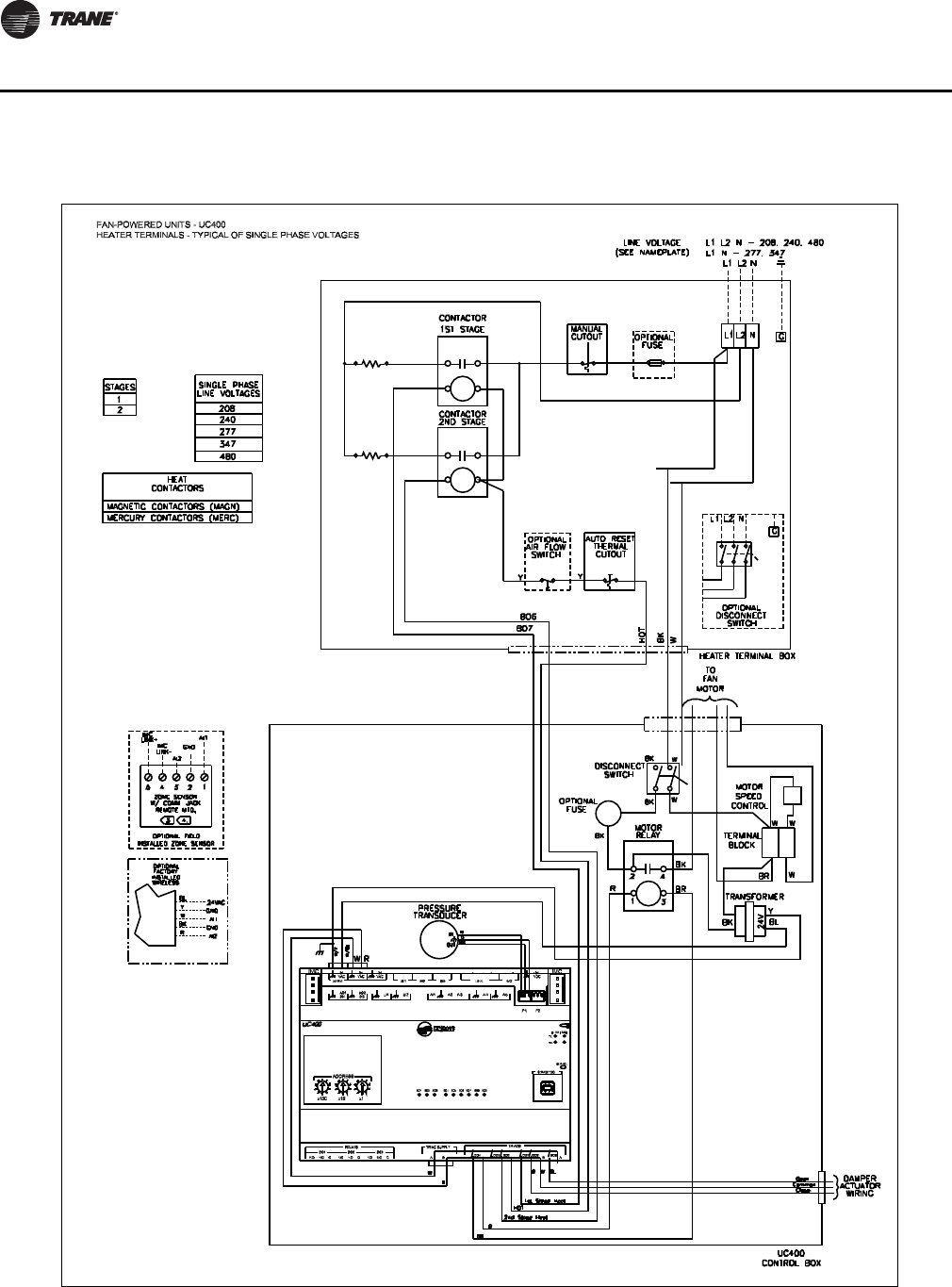
90 VAV-SVX07A-EN
Wiring Diagrams
Figure 41. SCR/PSC fan powered with single phase voltage electric heat
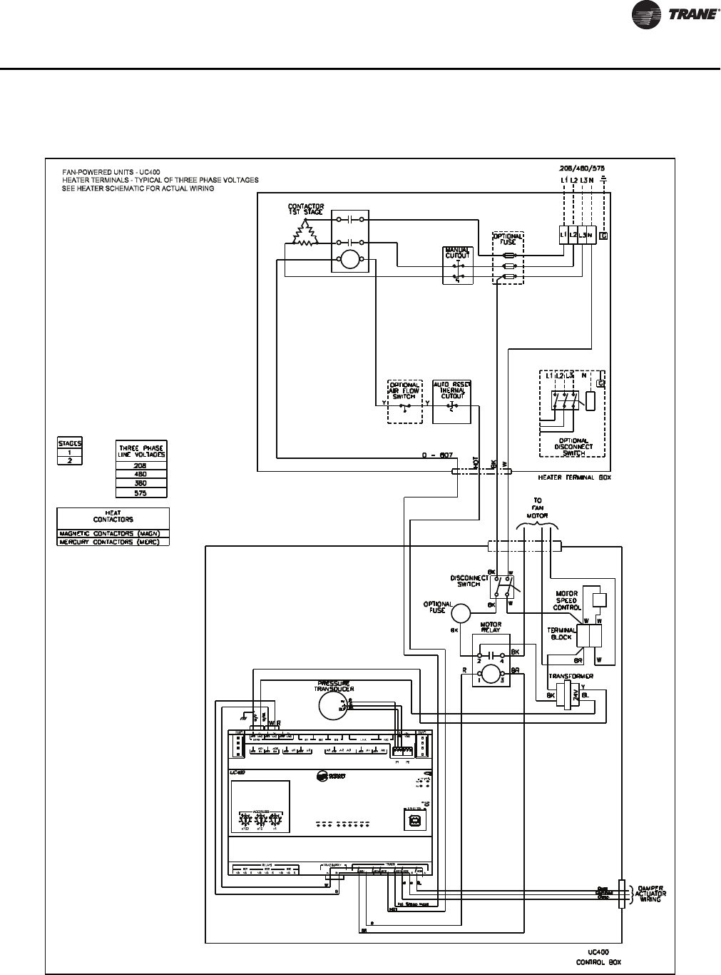
VAV-SVX07A-EN 91
Wiring Diagrams
Figure 42. SCR/PSC fan powered with three phase voltage electric heat
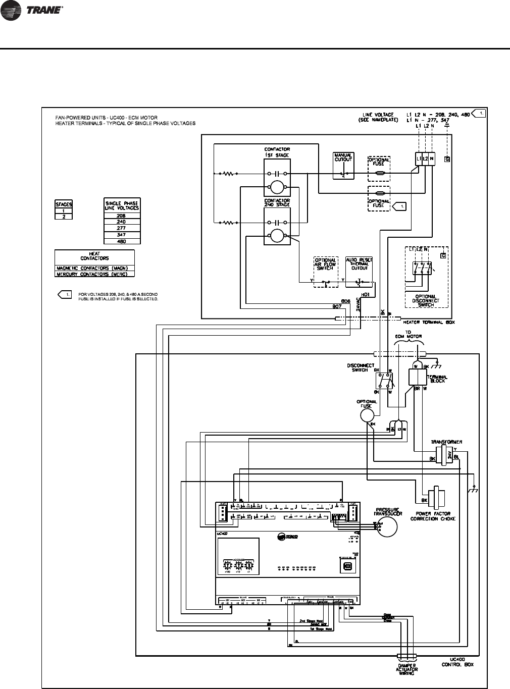
92 VAV-SVX07A-EN
Wiring Diagrams
Figure 43. ECM fan powered with single phase voltage electric heat
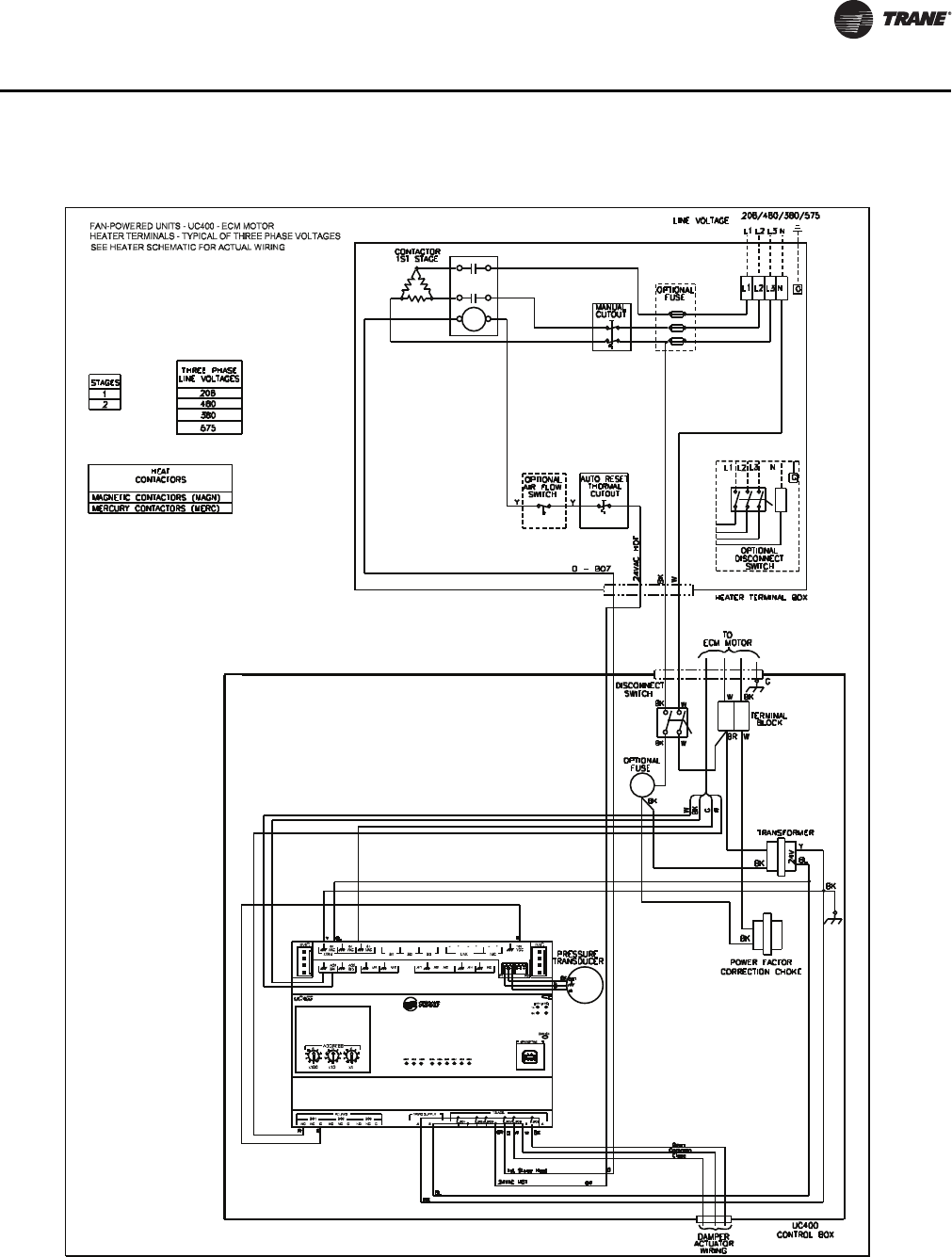
VAV-SVX07A-EN 93
Wiring Diagrams
Figure 44. ECM fan powered with three phase voltage electric heat

Declaration of CE Conformity
The manufacturer hereby declares that the product:
Conforms to the following standards or other normative documents:
Manufacturer name: Trane
Manufacturer address: 3833 White Bear Parkway
Saint Paul, MN 55110
USA
Product name: Tracer™ UC400 Unit Controller
Model numbers: X13651492-01
Electromagnetic Emission: EN61326-1:2006 Electrical equipment for measurement, control,
and laboratory use—EMC requirements, part 1:
General Requirements
(by Council Directive 2004/108/EEC) EN55022:2006 (CISPR
22:2005+A1:2005) Radiated
Emissions Class B Limit (30 MHz—1000 MHz, 1 GHz—2 GHz)
EN55022:2006 (CISPR
22:2005+A1:2005) Radiated
Emissions 150 kHz—30 MHz
Electromagnetic Immunity for Industrial: EN61326-1:2006
(by Council Directive 89/336/EEC) EN61000-4-2: 1995+A1:
1998+A2:2001 Electrostatic
Discharge (ESD) 8 kV air, 4 kV contact
EN61000-4-3: 2002 Radiated Fields 10 V/m, 80 MHz—1000 MHz
3 V/m, 1.4 GHz—2.0 GHz
1 V/m, 200 GHz—2.7 GHz
EN61000-4-4: 2004 Fast Transients I/O port, 1 kV
AC inputs and output ports, 2 kV
EN61000-4-5: 1995+A1: 2001
Surge Transients AC input ports (L/L), differential mode, 1 kV
EN61000-4-6: 1996+A1: 2001
Conducted Disturbance 3 V, 0.15 MHz—80 MHz
EN61000-4-8: 1993+A1: 2001
Power Frequency Magnetic Field 30 A/m, 50 Hz
EN61000-4-11: Second Edition:
2004 Voltage Dips and Interruptions 0% Vnom, 1 cycle; 70% Vnom, 25 cycle; 40%
Vnom, 10 cycle; 0% Vnom, 250 cycle
Where and When Issued: Electromagentic Emmission 09/03/2008
Electromagentic Immunity 02/19/2009
Mark of Compliance: European Contact
SocietE Trane (Epinal, France)
1, rue des Ameriques, B.P. 6
F-88191 Golbey Cedex, France
Phone: (33) 329.31.73.00
Fax: (33) 329.81.24.98
This document validates CE conformity of the Tracer UC400 Unit Controller
www.trane.com
For more information, contact your local Trane
office or e-mail us at comfort@trane.com
Literature Order Number VAV-SVX07A-EN
Date May 2010
Supersedes VAV-SVX07A-EN March 2009
Trane has a policy of continuous product and product data improvement and reserves the right to
change design and specifications without notice.
