Trane Rthd Users Manual RLC PRC020 EN_0606.P65
RTHD to the manual 8397ca68-2712-43c8-bfef-faeebaa3e298
2015-01-21
: Trane Trane-Rthd-Users-Manual-236151 trane-rthd-users-manual-236151 trane pdf
Open the PDF directly: View PDF ![]() .
.
Page Count: 32
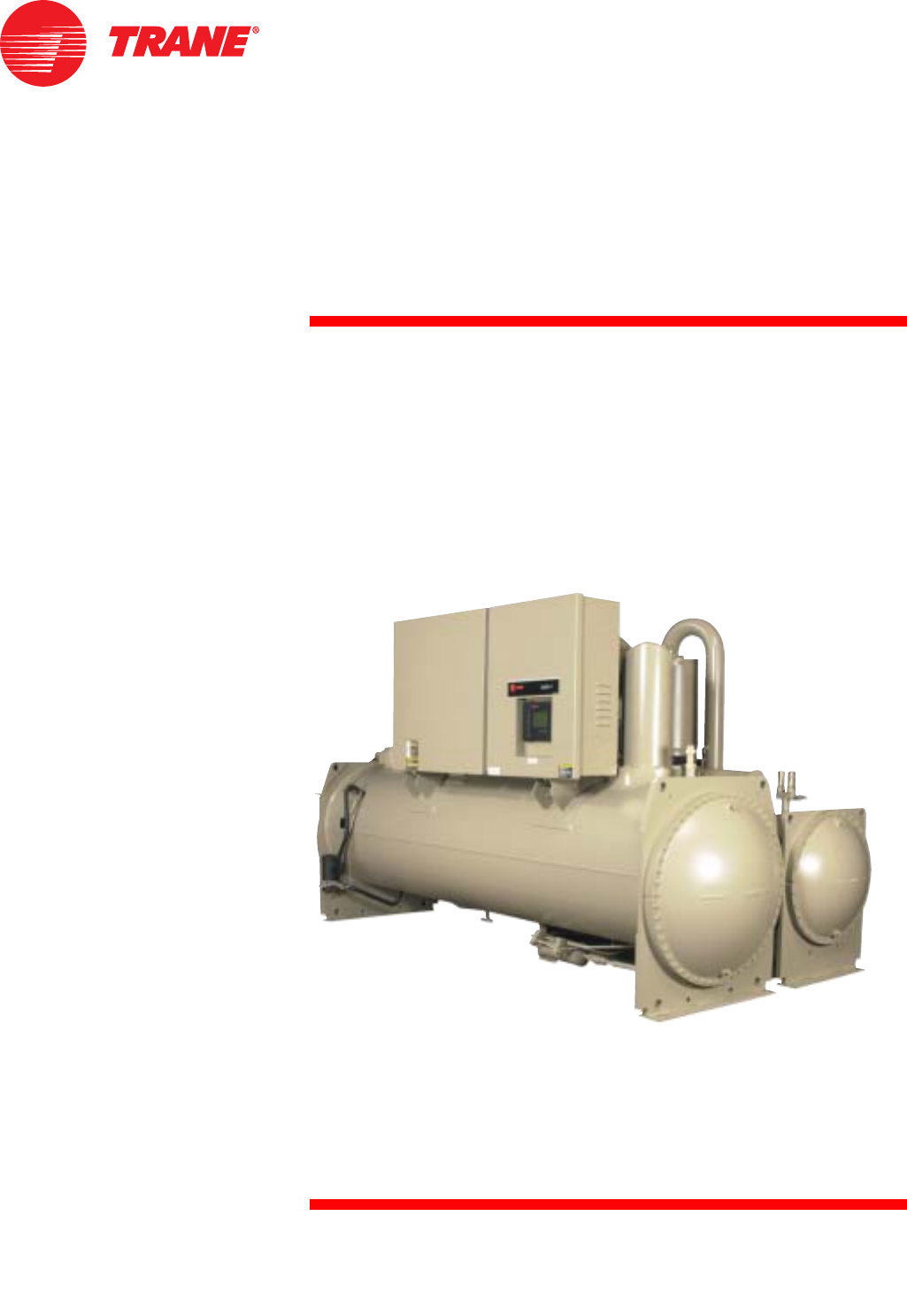
Series R™ Helical Rotary
Liquid Chillers
Model RTHD
175-450 Tons (60 Hz)
125-450 Tons (50 Hz)
Built for Industrial and Commercial Applications
RLC-PRC020-EN
June 2006
RLC-PRC020-EN© 2004 American Standard Inc. All rights reserved.
Introduction
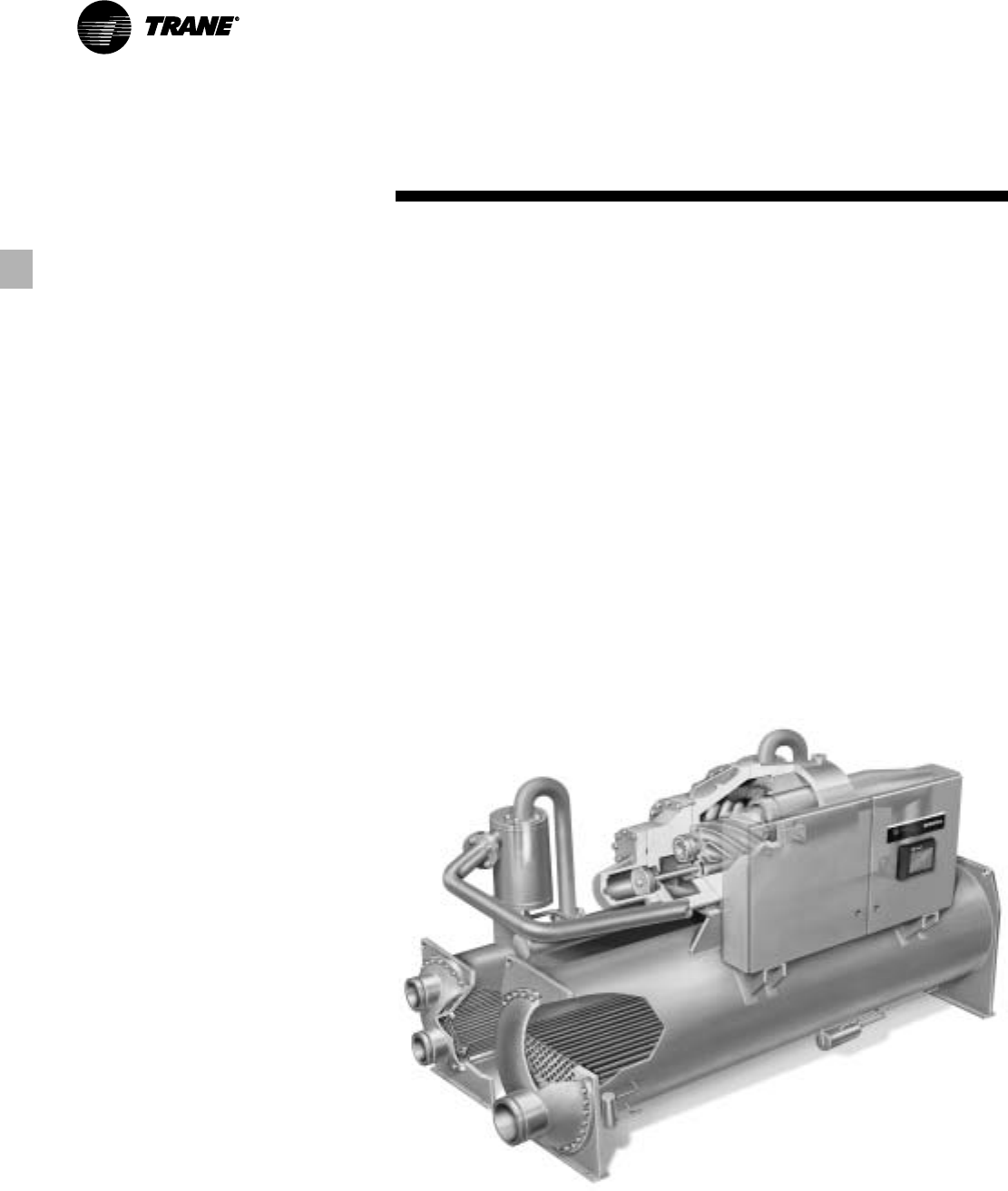
To meet a wide range of applications in
the medium-tonnage, water-cooled
market, Trane is proud to introduce the
model RTHD helical rotary liquid chiller.
The introduction of this next-generation
chiller an exciting step forward in
application versatility, ease of installation,
control precision, reliability, energy-
efficiency, and operational
cost-effectiveness. The new RTHD chiller
is designed to deliver proven Series R
performance, plus all the benefits of an
advanced heat transfer design and a low-
speed, direct-drive compressor.
Important Design Advances
and New Features
Major design advances include:
• Higher full-load energy efficiency
reduces both operating and life-cycle
costs.
• CH530 controls enable:
- scrolling access to inputs and operating
information via the LCD touch-screen
display;
- freedom from interoperability
concerns with LonMark
communications;
- job-specific communication options
that allow greater reporting flexibility.
• Improved startup temperature
capabilities and reduced sensitivity to
condenser water temperatures
alleviate the most common startup
concerns.
• Removed Liquid Vapor Separator,
providing lighter unit weight and
simplified refrigerant piping, for less
expensive handling, separation, and
installation.
The industrial-grade design of the Series
R helical rotary chiller is ideal for both
industrial and commercial markets, in
applications such as office buildings,
hospitals, schools, retail buildings, and
industrial facilities. The linear unloading
compressor, wide operating temperature
range, advanced controls, electronic
expansion valve, short anti-recycle
timers, and industry-leading efficiencies
mean that this latest Trane Series R chiller
is the perfect choice for tight temperature
control in almost any application
temperatures, and under widely varying
loads.
3
RLC-PRC020-EN
Contents
Introduction
Features and Benefits
Options
Controls
Application Considerations
Selection Procedure
Model Nomenclature
General Data
Electrical Data and Connections
Dimensions and Weights
Mechanical Specifications
Conversion Table
2
4
6
8
10
12
14
16
19
22
29
30

RLC-PRC020-EN4
Features and
Benefits
Applications in this catalog specifically
excluded from the ARI certification
program are:
• Low temperature applications, including
ice storage
• Glycol
• 50Hz units below 200 nominal tons
Application Versatility and High
Performance
• Screw compressor technology and the
electronic expansion valve provide
reliable performance in an expanded
range of operating temperatures.
• Tight water temperature control extends
to operation of multiple chillers in
parallel or series configurations, offering
further system design flexibility for
maximum efficiency.
• Advanced design enables chilled water
temperature control to +/- 0.5°F (.28°C)
for flow changes up to 10 percent per
minute, plus handling of flow changes up
to 30 percent per minute for comfort
cooling.
• Two-minute stop-to-start and five-minute
start-to-start anti-recycle timer allows
tight chilled water temperature control
in constant or transient low-load
applications.
• LonMark communications capability
provides excellent, trouble-free
interoperability.
• Generic Building Automation System
points are available for easy access to
operational information.
• Extensive information on professional
design selection and layout is available
in a simple, highly readable electronic
format.
• Standard model RTHD configurations
are in stock and available for immediate
delivery, and Trane offers the fastest
ship cycles in the industry for built-to-
order units.
• Industrial / Low Temperature Process
Cooling – Excellent operating
temperature range and precise control
capabilities enable tight control with
single chiller or series configuration.
• Ice/Thermal Storage – Specifiers and
operators benefit from dual setpoint
control and industry-leading
temperature, efficiency, and control
capabilities, plus outstanding support
through partnership with Calmac, a
strong Trane partner providing proven
installation examples, templates, and
references that minimize design time
and energy costs.
• Heat Recovery – Maximum condenser
temperature exceeds those of previous
technologies, providing hot water and
tight control that minimizes operating
costs for the chilled water plant and
boiler/hot water heater, and consistent
dehumidification.
Simple, Economical Installation
• Compact size makes the model RTHD
well suited for the retrofit and
replacement market.
• All units fit through standard double-
width doors.
• Bolt-together construction makes for
fast, easy unit disassembly.
• Small RTHD footprint saves valuable
equipment room space and alleviates
access concerns for most retrofit jobs.
• Lightweight design simplifies rigging
requirements, further reducing
installation time requirements and
costs.
• Full factory refrigerant or nitrogen and
oil charges reduce required field labor,
materials, and installation cost.
• Only evaporator and condenser water
piping is required; no starter water
cooling (with its associated safety
concerns) or field piping is necessary.
• Oil cooler and purge system
connections have been eliminated.
• Simple power connection simplifies
overall installation.
• Standard unit-mounted starter for
Wye-Delta and Solid State eliminates
additional jobsite installation
considerations and labor requirements.
• Trane has conducted extensive factory
testing, and also offers options for in-
person and/or documented system
performance verification.
• CH530 controls easily interface with
Tracer Summit™ building automation
systems through single twisted-pair
wire.
Pueblo
Business Unit
5
RLC-PRC020-EN
Features and
Benefits
State-of-the-Art, Precision Control
• Microprocessor-based CH530 controls
monitor and maintain optimal operation
of the chiller and its associated sensors,
actuators, relays, and switches, all of
which are factory-assembled and
extensively tested.
• Easy interface with computers hosting
Tracer Summit™ building automation/
energy management systems allows
the operator to efficiently optimize
comfort system performance and
minimize operating costs.
• PID (proportional integral derivative)
control strategy ensures stable, efficient
chilled water temperature control,
maintaining +/- 1°F (0.56°C) control by
proactively reacting to instantaneous
load changes of up to 50 percent.
• Adaptive Control™ attempts to maintain
chiller operation under adverse
conditions, when many other chillers
might simply shut down.
• Easy-to-use operator interface displays
all operating and safety messages, with
complete diagnostics information, on a
highly readable panel with a scrolling
touch-screen display.
• The RTHD features a complete range of
chiller safety controls.
• Over 120 diagnostic and operating
points are available, with standard
displays including chiller current draw,
condenser pressure, and evaporator
pressure.
Reliability and Ease of Maintenance
• Direct drive, low-speed compressor – a
simple design with only three moving
parts – provides maximum efficiency,
high reliability, and low maintenance
requirements.
• Electronic expansion valve, with fewer
moving parts than alternative valve
designs, offers highly reliable operation.
• Suction gas-cooled motor stays
uniformly cool at lower temperatures
for longer motor life.
• The Trane helical rotary compressor is a
proven design resulting from years of
research and thousands of test hours,
including extensive testing under
extraordinarily severe operating
conditions.
• Trane is the world’s largest
manufacturer of large helical rotary
compressors, with tens of thousands of
commercial and industrial installations
worldwide demonstrating a reliability
rate of greater than 99 percent in the
first year of operation.
Operating and Life Cycle
Cost-Effectiveness
• Electronic expansion valve enables
exceptionally tight temperature control
and extremely low superheat, resulting
in more efficient full-load and part-load
operation than previously available.
• Precise compressor rotor tip clearance
ensures optimal efficiency.
• Condenser and evaporator tubes use
the latest heat transfer technology for
increased efficiency.
• The RTHD includes standard electrical
demand limiting.
• Chilled water reset based on return
water temperature is standard.
• High compressor lift capabilities and
tight chilled water temperature control
allow highly efficient system design with
minimal operational concerns.
Design capabilities include:
• variable primary flow;
• series chiller arrangements for
evaporator and/or condenser;
• low evaporator and condenser flow.

RLC-PRC020-EN6
Options
Insulation
All low temperature surfaces are
covered with factory installed 3/4 inch
(19.05 mm) Armaflex II or equal (k=0.28)
insulation, including the evaporator and
water boxes, suction line, and motor
housing. 3/8" foam insulation is used on
the liquid level sensor and gas pump
assembly, including piping.
Low-Temperature Evaporator
Addition of an oil cooler to the oil circuit
enables evaporator operation down to
minimum leaving water temperature of
10°F (-12.2°C).
High-Temperature Condenser
Addition of an oil cooler to the oil circuit
enables condenser operation up to
maximum leaving water temperature of
114°F (45.6°C).
Smooth-Bore Condenser Tubes
Smooth-bore copper or premium cupro-
nickel condenser tubes, 3/4" (19.05 mm) in
diameter with .035" (0.889 mm) wall
thickness, are available for high fouling
water applications.
Refrigerant Isolation Valves
Factory-installed condenser inlet and
outlet refrigerant valves allow isolation of
the full refrigerant charge in the
condenser while servicing the chiller.
Marine Water Boxes
Addition of marine water boxes for the
condenser allows tube cleaning without
water pipe interference.
300 psig Evaporator and Condenser
Water Boxes
Water boxes are designed for 300 psig
maximum waterside working pressure,
and grooved pipe water connections are
provided for ease of installation.
2-Way Condenser Water Regulating Valve
For water regulation, a field-installed,
2-way butterfly-type (lug-style) valve,
with integral electrical operator and
factory-mounted valve actuator, is
available. The single-phase, reversible
motor can be factory-wired for 115 VAC,
60 Hz or 220 VAC, 50 Hz; the 2-way valve
is field-wired and controlled by the chiller
regulating valve control output; valves
are available in 6" and 8" (152.4 and
203.2 mm) sizes.
Nitrogen Charge
Unit is shipped with a nitrogen holding
charge in lieu of refrigerant.
Seal Kit for Reassembly
Ideal for situations when the bolt-together
construction of the RTHD will be
separated for installation, this seal kit
provides replacement gaskets and rings
for reassembly.
Solid State Starter
Solid State Starter is unit-mounted with a
NEMA 1 gasketed enclosure. To extend
starter life, contactors bypass current
from the silicon control rectifiers (SCRs)
after startup.
Under/Over-Voltage Protection
Unit receives protection against
variations in voltage (current lag and
spike protection is standard).
Performance and Witness Tests
ARI-certified RTHD Performance and
Witness Tests are available, based on
requested operating points, to certify
chiller performance before delivery.
Main Power Disconnect
Options:
Non-fused Disconnect
A UL-approved non-fused molded case
disconnect switch, factory pre-wired with
terminal block power connections and
equipped with a lockable external
operator handle, is available to
disconnect the chiller from main power.
Standard Interrupting Capacity Circuit
Breaker
A UL-approved standard interrupting
molded case capacity circuit breaker,
factory pre-wired with terminal block
power connections and equipped with a
lockable external operator handle, is
available to disconnect the chiller from
main power.
High Interrupting Capacity Circuit
Breaker
A UL-approved high interrupting molded
case capacity circuit breaker, factory pre-
wired with terminal block power
connections and equipped with a lockable
external operator handle, is available to
disconnect the chiller from main power.
Ground Fault Circuit Breaker
A UL-approved standard interrupting
molded case capacity circuit breaker with
ground fault interrupting capability,
factory pre-wired with terminal block
connections and equipped with a lockable
external operator handle, is available to
disconnect the chiller from main power.

7
RLC-PRC020-EN
Control Options:
Tracer Summit Communications
Link to factory-installed, tested
communication board, via single twisted-
pair wiring, adds Tracer Summit
communications to the system.
LonTalk LCI-C Interface
LonTalk (LCI-C) communications
capabilities are available, with
communication link via single twisted-pair
wiring to factory-installed, tested
communication board.
External Chilled Water Setpoint
External Chilled Water Setpoint is
communicated to a factory-installed,
tested communication board through a 2-
10Vdc or 4-20mA signal.
External Current Limiting
External Current Limit Setpoint is
communicated to a factory-installed,
tested communication board through a 2-
10Vdc or 4-20mA signal.
External Base Loading
External Base Loading is communicated
to a factory-installed and tested
communication board through a
2-10Vdc or 4-20mA signal.
Ice Making Control
Controls and safeties allow operation
with brine temperatures down to 20°F
(-6.7°C) , and dual setpoints enable both
ice making and daytime comfort cooling.
Options
Programmable Relays
Default-set, factory-installed,
programmable relays allow the operator
to select four relay outputs from a list of
eight. Available relays are: Alarm-
Latching, Alarm-Auto Reset, General
Alarm, Warning, Chiller Limit Mode,
Compressor Running, Head Pressure
Relief Request, and Tracer Control.
Chilled Water Reset – Outdoor Air
Temperature
Controls, sensors, and safeties allow
reset of chilled water temperature, based
on temperature signal, during periods of
low outdoor air temperature (chilled
water reset based on return chilled water
temperature is standard).
Condenser-Regulating Valve Control
Chiller applies a Proportional Integrative
Control (PID) algorithm to control water
regulating valve via 0-10Vdc signal.
Percent of Full Run Load Amps Output
Control system indicates the active chiller
percent of full run load amps, based on a
0-10Vdc signal.
Condenser Pressure Output
Control system indicates chiller
differential pressure or condenser
pressure, based on a 0-10Vdc signal.
Refrigerant Monitor Input
Control system indicates refrigerant
monitor status of 0-100 or 0-1000 ppm
(user selectable), based on a 2-10Vdc /
4-20 mA signal.
RLC-PRC020-EN8
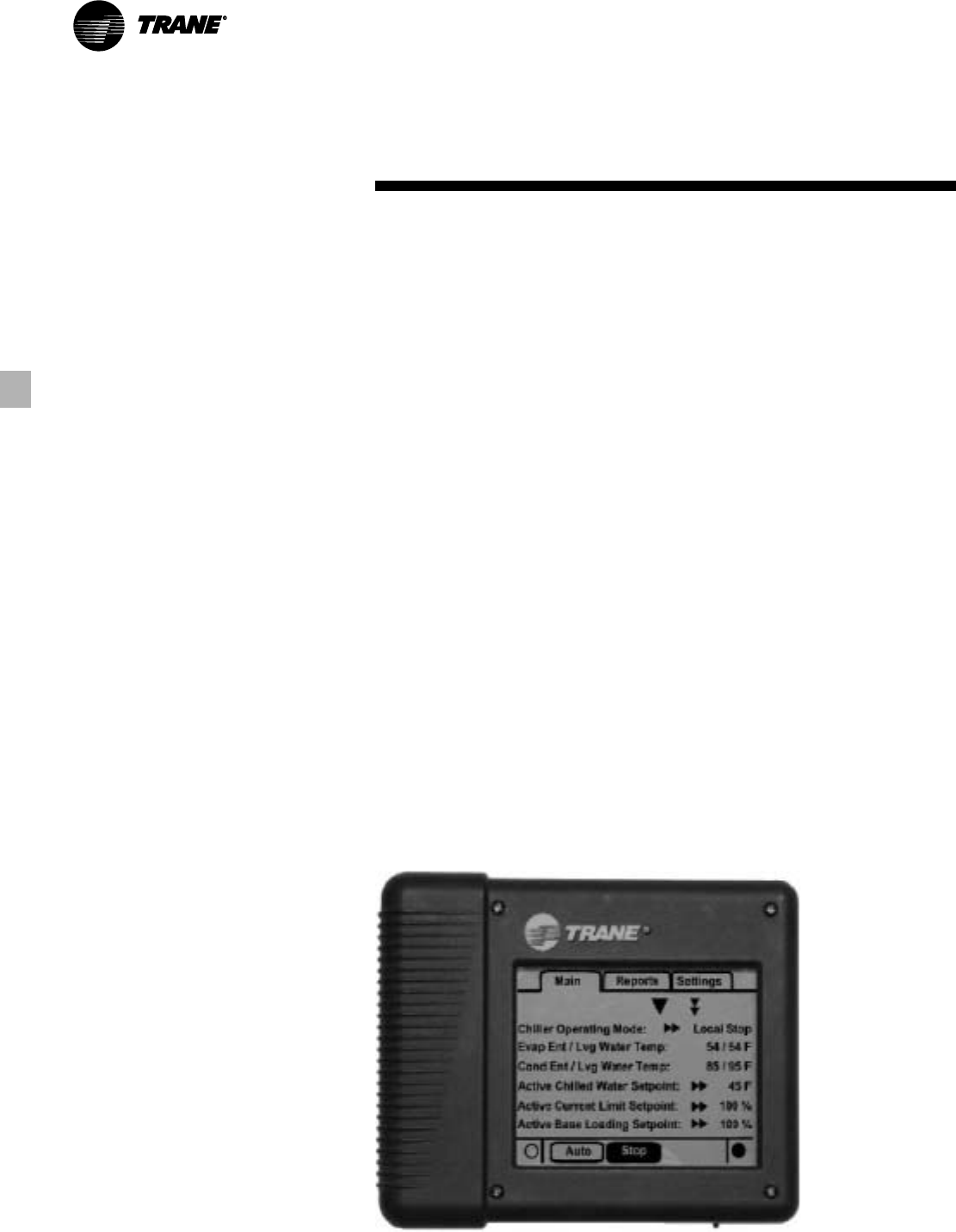
LCD Touch-Screen Display
with Multi-Language Support
The standard DynaView display provided
with the CH530 control panel features an
LCD touch-screen, allowing access to all
operational inputs and outputs. This
display supports eleven languages:
English, Chinese, Dutch, French, German,
Italian, Japanese, Korean, Portugese,
Spanish and Thai.
Additional Display Features Include:
• LCD touch-screen with LED backlighting,
for scrolling access to input and output
operating information
• Weather-proof enclosure for reliable
operation in non-standard indoor
environments
• Spin value buttons to allow continuously
variable setpoints when applicable
• Radio and action buttons for easy, one-
time actions and settings
• Single-screen, folder/tab-style display of
all available information on individual
components (evaporator, condenser,
compressor, etc.)
• Automatic and immediate stop
capabilities for standard or immediate
manual shutdown
• Manual override indication
• Password entry/lockout system to
enable or disable display
Controls
• Fast, easy access to available chiller
data in tabbed format, including:
— Modes of operation, including normal
cooling and icemaking
— Water temperatures and setpoints
— Loading and limiting status and
setpoints
— Average line current
— Outdoor air temperature
— Start/stop differential timers
— Auto/Manual mode for EXV, slide
valve, and head pressure control
— Pump status and override
— Chilled water reset, start point, ratio,
and outdoor start point
— External setpoints, including:
- chilled water
- current limit
- ice building
- base loading
— Display specifics, including:
- date
- format
- time
- display lockout
- display units
- language setting
- Reports, listed on a single tabbed
screen for easy access, including:
• ASHRAE, containing all guideline 3
report information
• Evaporator
• Condenser
• Compressor
— Evaporator, condenser, and
compressor reports containing all
operational information on individual
components, including:
- Water and air temperatures
- Refrigerant levels, temperatures,
and approach
- Oil pressure
- Flow switch status
- EXV position
- Head pressure control command
- Compressor starts and run-time
- Line phase percent RLA, amps, and
volts
— Alarm and diagnostic information,
including:
- Flashing alarms with touch-screen
button for immediate address of
alarm condition
- Scrollable list of last ten active
diagnostics
- Specific information on applicable
diagnostic from list of over one-
hundred
- Automatic or manual resetting
diagnostic types
9
RLC-PRC020-EN
Controls
Trane Chiller Plant Automation
Trane’s depth of experience in chillers and
controls makes us a well-qualified choice
for automation of chiller plants using air-
cooled Series R® chillers®. The chiller plant
control capabilities of the Trane Tracer
Summit® building automation system are
unequaled in the industry. Our chiller plant
automation software is fully pre-
engineered and tested. It is a standard
software application, not custom
programming which can prove to be
difficult to support, maintain, and modify.
Energy Efficiency
Trane chiller plant automation intelligently
sequences starting of chillers to optimize
the overall chiller plant energy efficiency.
Individual chillers are designated to
operate as base, peak, or swing based on
capacity and efficiency. Sophisticated
software automatically determines which
chiller to run in response to current
conditions. The software also
automatically rotates individual chiller
operation to equalize runtime and wear
between chillers.
Trane chiller plant automation enables
unique energy-saving strategies. An
example is controlling pumps, and chillers
from the perspective of overall system
energy consumption. The software
intelligently evaluates and selects the
lowest energy consumption alternative.
Regulatory Compliance Documentation
Comprehensive documentation of
refrigerant management practices is now
a fact of life. Trane chiller plant automation
generates the reports mandated in
ASHRAE Guideline 3.
Keeping Operators Informed
A crucial part of efficiently running a
chiller plant is assuring that the
operations staff is instantly aware of
what is happening in the plant. Graphics
showing schematics of chillers, piping,
pumps, and towers clearly depict the
chiller plant system, enabling building
operators to easily monitor overall
conditions. Status screens display both
current conditions and upcoming
automated control actions to add or
subtract chiller capacity. Series R™ and
other chillers can be monitored and
controlled from a remote location.
Tracer Summit features standard report
templates listing key operating data for
troubleshooting and verifying
performance. Reports for each type of
Trane chiller and three and six-chiller
systems are also standard. Detailed
reports showing chiller runtimes aid in
planning for preventative maintenance.
Swift Emergency Response
We understand the importance of
maintaining chilled water production
while protecting your chillers from costly
damage. If no water flow is detected to a
chiller’s piping, the start sequence is
aborted to protect the chiller. The next
chiller in the sequence is immediately
started to maintain cooling.
In the event of a problem, the operator
receives an alarm notification and
diagnostic message to aid in quick and
accurate troubleshooting. A snapshot
report showing system status just prior to
an emergency shutdown helps operators
determine the cause. If emergency
conditions justify an immediate manual
shutdown, the operator can override the
automatic control.
Integrated Comfort™ Capabilities
When integrated with a Tracer Summit
building management system
performing building control, Trane chiller
plant automation coordinates with Tracer
Summit applications to optimize the total
building operation. With this system
option, the full breadth of Trane’s HVAC
and controls experience are applied to
offer solutions to many facility issues. If
your project calls for an interface to other
systems, Tracer Summit can share data
via BACnet™, the ASHRAE open systems
protocol.
LonTalk Chiller Controls
LonTalk is a communications protocol
developed by the Echelon Corporation.
The LonMark association develops
control profiles using the LonTalk
communication protocol. LonTalk is a unit
level communications protocol, unlike
BACNet used at the system level.
LonTalk Communications Interface for
Chillers (LCI-C) provides a generic
automation system with the LonMark
chiller profile inputs/outputs. In addition to
the standard points, Trane provides other
commonly used network output variables
for greater interoperability with any
automation system. The complete
reference list of Trane LonTalk points is
available on the LonMark website. Trane
controls or another vendor’s system can
use the predefined list of points with ease
to give the operator a complete picture of
how the system is running.
Hardwire Points
Remote devices wired from the control
panel are another reliable method of
providing auxiliary control to a building
automation system. Inputs and outputs
can be communicated via a typical 4-20
mA electrical signal (or an equivalent Vdc
signal of 0-10 or 2-10) or by utilizing
contact closures.
• External Chilled Water Setpoint
• External Current Limit Setpoint
• Condenser-Regulating Valve Control
• Percent of Full Run Load Amps Output
• Condenser Pressure Output
• Refrigerant Monitor Input
• Programmable Relays
Allows the selection of 4 relay outputs
from a list of eight different default
settings: Alarm-Latching, Alarm-Auto
Reset, General Alarm, Warning, Chiller
Limit Mode, Compressor Running, Head
Pressure Relief Request, and Tracer
Control. These contact closures may be
used to trigger jobsite supplied audible or
visual alarms
• Ice Making Control
Provides an interface with ice making
control system and safeties, enabling
both ice making and daytime comfort
cooling
• Chilled Water Temperature Reset
Supplies controls, sensors and safeties to
reset the chilled water temperature
setpoint based upon return water
temperature (standard) or outdoor air
temperature (optional)
RLC-PRC020-EN10
Condenser Water Temperatures
Reduced sensitivity to condenser water
startup temperatures is one major
enhancement in the newest-generation
water-cooled Series R chiller. With the
model RTHD chiller, a condenser water
control method is necessary only if the
unit starts with entering water
temperatures below 55°F (12.8°C), or
between 45°F (7.2°C) and 55°F (12.8°C),
when a temperature increase of 1°F
(0.56°C) per minute to 55°F (12.8°) is not
possible.
When the application requires startup
temperatures below the prescribed
minimums, a variety of options are
available. To control a 2-way or 3-way
valve, Trane offers a Condenser
Regulating Valve Control option for the
CH530 controls. This option enables the
CH530 controls to send a signal for
opening and closing the valve as
necessary to maintain chiller differential
pressure. The 2-way valves are available
as a ship-with option. Tower bypass is
also a valid control method if the chiller
temperature requirements can be
maintained.
Trane Series R chillers start and operate
successfully and reliably over a range of
load conditions with controlled entering
condenser water temperature. Reducing
the condenser water temperature is an
effective method of lowering chiller
Application
Considerations
power input required, but the ideal
temperature for optimizing total system
power consumption will depend on the
overall system dynamics. From a system
perspective, some improvements in
chiller efficiency may be offset by the
increased tower fan and pumping costs
required to achieve the lower tower
temperatures.
Contact your local Trane
systems solution provider for more
information on optimizing system
performance.
The minimum acceptable refrigerant
pressure differential between condenser
and evaporator is 23 psid. The chiller
control system will attempt to obtain and
maintain this differential at startup, but for
continuous operation a design should
maintain a 25°F (13.9°C) differential from
evaporator leaving water temperature to
condenser leaving water temperature.
Variable Evaporator Flow and Short
Evaporator Water Loops
Variable evaporator flow is an energy-
saving design strategy which has quickly
gained acceptance as advances in chiller
and controls technology have made it
possible. With its linear unloading
compressor design and advanced CH530
controls, the RTHD has excellent
capability to maintain leaving water
temperature control within +/-0.5°F
(0.28°C) , even for systems with variable
evaporator flow and small chilled water
volumes.
Some basic rules should be followed
whenever using these system design and
operational savings methods with the
RTHD. The proper location of the chilled
water temperature control sensor is in
the supply (outlet) water. This location
allows the building to act as a buffer, and
it assures a slowly changing return water
temperature. If there is insufficient water
volume in the system to provide an
adequate buffer, temperature control can
be lost, resulting in erratic system
operation and excessive compressor
cycling. To ensure consistent operation
and tight temperature control, the chilled
water loop should be at least two
minutes. If this recommendation cannot
be followed, and tight leaving water
temperature control is necessary, a
storage tank or larger header pipe should
be installed to increase the volume of
water in the system.
For variable primary flow applications,
the rate of chilled water flow change
should not exceed 10 percent of design
per minute to maintain +/-0.5°F (0.28°C)
leaving evaporator temperature control.
For applications in which system energy
savings is most important and tight
temperature control is classified as
+/-2°F (1.1°C), up to 30 percent changes in
flow per minute are possible. Flow rates
should be maintained between the
minimum and maximum allowed for any
particular chiller configuration.
11
RLC-PRC020-EN
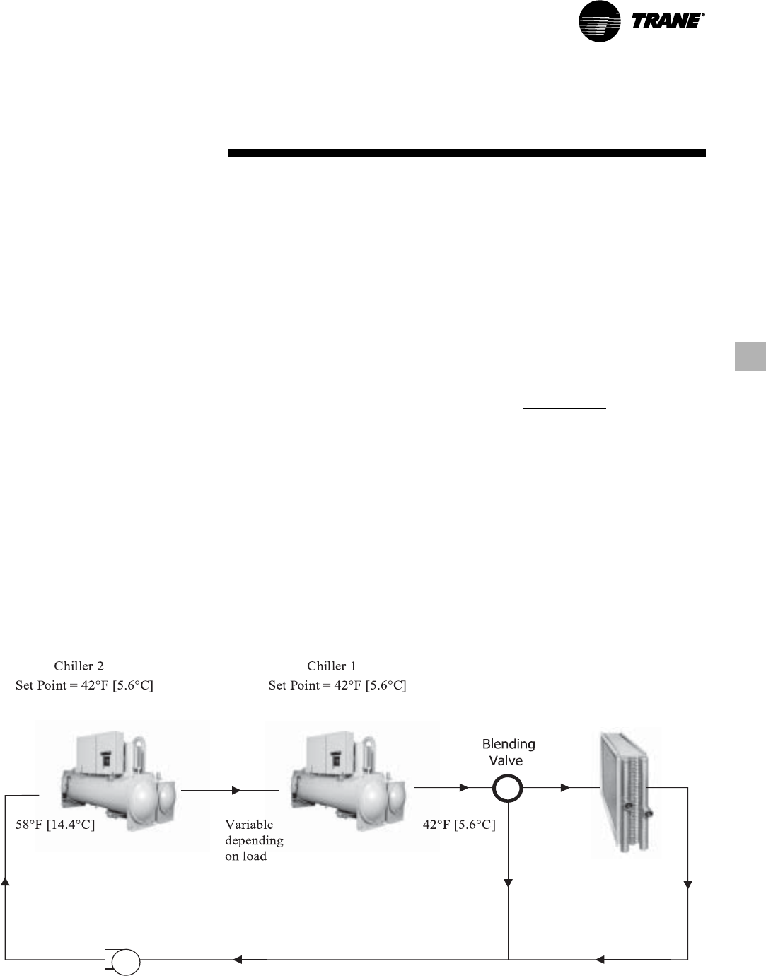
Series Chiller Arrangements
Another energy-saving strategy is to
design the system around chillers
arranged in series, on the evaporator,
condenser, or both. The actual savings
possible with such strategies depends on
the application dynamics and should be
researched by consulting your Trane
Systems Solutions Representative and
applying the Trane System Analyzer
program. It is possible to operate a pair of
chillers more efficiently in a series chiller
arrangement than in a parallel
arrangement. It is also possible to achieve
higher entering-to-leaving chiller
differentials, which may, in turn, provide
the opportunity for lower chilled water
design temperature, lower design flow,
and resulting installation and operational
cost savings. The Trane screw
compressor also has excellent
capabilities for “lift,” which affords an
opportunity for savings on the
evaporator and condenser water loops.
Application
Considerations
Like series arrangements on the
evaporator, series arrangements on the
condenser may enable savings. This
approach may allow reductions in pump
and tower installation and operating
costs. Maximizing system efficiency
requires that the designer balance
performance considerations for all
system components; the best approach
may or may not involve multiple chillers,
or series arrangement of the evaporators
and/or condensers.
This ideal balance of
design integrity with installation and
operating cost considerations can also be
obtained by consulting a Trane
representative and applying the Trane
System Analyzer program.
Water Treatment
The use of untreated or improperly
treated water in chillers may result in
scaling, erosion, corrosion, and algae or
slime buildup. It is recommended that the
services of a qualified water treatment
specialist be engaged to determine what
treatment, if any, is advisable. Trane
assumes no responsibility for the results
of using untreated or improperly treated
water.
Water Pumps
Where noise limitation and vibration-free
operation are important, Trane strongly
encourages the use of 1750-rpm (60 Hz),
1450-rpm (50 Hz) pumps. Specifying or
using 3600-rpm (60 Hz), 3000-rpm (50 Hz)
condenser water and chilled water
pumps must be avoided, because such
pumps may operate with objectionable
levels of noise and vibration. In addition, a
low frequency beat may occur due to the
slight difference in operating rpm
between 3600-rpm (60 Hz), 3000-rpm
(50 Hz) water pumps and Series R chiller
motors. Important Note: The chilled water
pump must not be used to stop the chiller.
Acoustic Considerations
For chiller sound ratings, installation tips,
and considerations on chiller location,
pipe isolation, etc., refer to
the Trane
Water-Cooled Series R Chillers Sound
Ratings and Installation Guide
. Using the
information provided in this bulletin,
contact a certified sound consultant to aid
in proper mechanical room design and
treatment.
Figure 1. Typical series chiller arrangement

RLC-PRC020-EN12
Selection
Procedure
Trane Series R chiller performance is
rated in accordance with the ARI
Standard 550/590-2003 Certification
Program. Chiller selection assistance and
performance information can be
obtained by using the Series R chiller
selection program, available through
local Trane sales offices.
Performance
The computerized Series R chiller
selection program provides performance
data for each possible chiller selection at
both full-load and part-load design points,
as required.
It should be noted that changing the
number of water passes or the water
flow rates will generally alter the
performance of a particular chiller. To
attain maximum benefit from the wide
range of chiller models and options
available, designers are encouraged to
first develop performance specifications
and then use the chiller selection program
to optimize all selections. This will help
ensure selection of the compressor-
evaporator-condenser combination that
most closely meets the job requirements.
To optimize system performance, all
selections should also be balanced with
other system components.
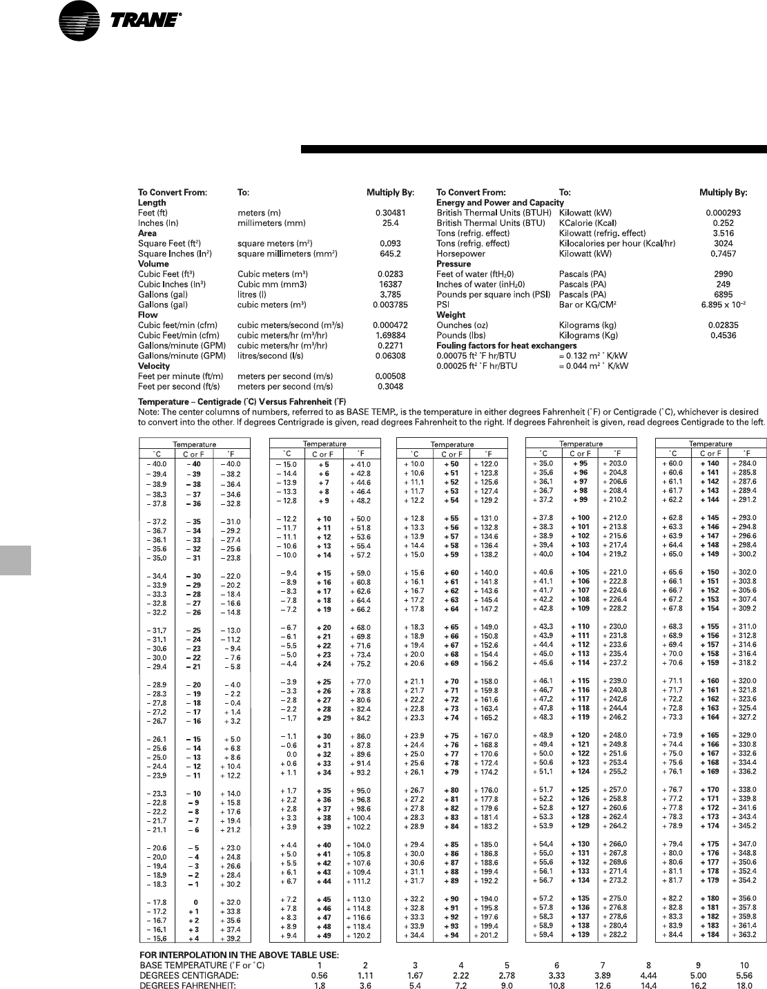
Fouling Factors
ARI Standard 550 includes a definition of
clean tube fouling. The recommended
standard fouling adjustments are 0.0001
hr-sq ft-deg F/Btu (0.0176 sq m-deg C/kW)
for the evaporator and 0.00025 hr-sq ft
deg F/Btu (0.044 sq m-deg C/kW) for the
condenser, from an increment of 0.0000
“clean.” Chiller specifications should be
developed using the most current
standard fouling factors.
Part Load Performance
Actual air-conditioning system loads are
frequently less than full-load design
conditions. Depending on the number of
chillers on the job and the load profile,
chillers may operate at full load a small
percentage of the time. With their
excellent part-load performance
characteristics and highly energy-efficient
operation, Series R chillers can provide
significant operating savings at these
part-load conditions.
System Considerations
Part-load chiller operation is frequently
associated with reduced condenser
water temperatures. However, rather
than focusing only on the chiller, it is
important to balance these temperatures
to achieve the most efficient system
operation possible. At part-load
operation, the heat rejected to the cooling
tower is less than at full-load operation.
Part-load chiller operation is also typically
associated with reduced outside wet bulb
temperatures, resulting in improved
cooling tower performance. The net result
of reduced heat rejection and lower wet
bulb temperatures can be cooler
condenser water entering the chiller,
ultimately improving unit performance.
However, this does not improve pump or
tower efficiency. To achieve the most
efficient system operation possible, it is
best to minimize the total power draw of
the chiller, tower, and pumps, which may
not mean limiting the condenser water
temperature to what the tower can
provide. To determine specific unit and
system part-load performance for chiller
selection purposes, use the Series R
chiller computer selection program or
contact the local Trane sales office.
13
RLC-PRC020-EN
Electrical Data Tables
Compressor motor electrical data is
provided in the data section for each
compressor size. Rated load amperes
(RLA), locked rotor wye amperes (LRA)
and expected inrush for the Wye-delta
and Solid State Starter configurations are
shown.
Although the terms “LRA” and “expected
inrush” are often used interchangeably,
the distinction applied here is that LRA is
the rated inrush for the motor, but
expected inrush is that allowed by the
starter, based on the specific
configuration.
Selecting starters in the Wye-delta or
Solid State configuration lowers
expected inrush vs. the Delta (or “across-
the-line”) configuration. A Solid State
Starter configuration lowers the
expected inrush by approximately 50
percent, while Wye-Delta lowers it by
approximately 66 percent.
The RLA is based on the motor’s
performance when reaching full rated
horsepower. The kW rating of the motor
will equal or exceed the kW requirement
indicated by the Series R computer
selection program at design conditions. If
motor kW draw at design conditions is
less than the kW rating of the motor, the
RLA at design conditions is determined
by multiplying the motor RLA (at the
desired voltage) by this ratio: design kW/
motor kW rating. This calculation is
performed within the Series R chiller
computer selection program, making
RLA available as part of the design
predictions. Predicted values include
power factor variation from point to point.
A voltage utilization range is tabulated for
each voltage listed. Series R chillers are
designed to operate satisfactorily over a
utilization range of ±10 percent of the
standard design voltages: (a) 200 V, 230 V,
380 V, 460 V, and 575 V for 60 Hertz, 3-
phase, and (b) 380 V, 400 V,
415 V for 50 Hertz, 3-phase.
Selection
Procedure
Unit Performance with Fluid Media
Other Than Water
Series R chillers can be provided with a
wide variety of fluid media other than
water, including ethylene glycol and
propylene glycol— in the evaporator,
condenser or both. Chillers using media
other than water are excluded from the
ARI 550/590-2003 Certification Program,
but are rated in accordance with ARI
Standard 550/590-2003. Trane factory
performance tests are only performed
with water as the cooling and heat-
rejection media. When considering
selection of media other than water,
contact the local Trane sales office for
chiller selections and factory
performance testing information.
Fluid media other than water lowers the
heat transfer coefficient, and therefore
reduces chiller performance. In general, it
is good practice to hold the percent glycol
added to within the minimum allowed by
the Trane selection program, based on
either (a) unit operating temperatures, or
(b) the operating temperatures the
evaporator or condenser water will
experience under its full range of
conditions. Adding more glycol than
required for the specific application is
equivalent to selecting a less efficient
chiller. Lower-viscosity glycols such as
ethylene will have less adverse impact
on chiller performance than higher-
viscosity glycols such as propylene.
Evaporator and Condenser Pressure
Drop
Pressure drop data is determined by the
Series R chiller computer selection
program available through local Trane
sales offices.
Dimensional Drawings
Dimensional drawings provided for
selection purposes illustrate overall
measurements of the unit. The
recommended service clearances are
those required to easily service the
Series R chiller.
All catalog dimensional drawings are
subject to change, and current submittal
drawings should be referenced for more
detailed dimensional information.
Dimensional drawings are also available
from the selection program. Contact the
local Trane sales office for submittal
information.
RLC-PRC020-EN14
Model
Nomenclature
RTH D U D 2 F 0 A0 U A G 3 A 4 L A L G 3 F 2 L A L
1,2,34 5 6 7 8 9 10,1112131415 16 17 1819 2021 222324 252627
Digits 01, 02, 03 – Series R™
RTH = Series R
Digit 04 – Dev Sequence
D = 4th Major Development
Digit 05 – Design Control
U = WCBU
Digit 06 – Compressor Frame
B = B Compressor
C = C Compressor
D = D Compressor
E = E Compressor
Digit 07 – Compressor Capacity
1 = Smaller Capacity for Frame
2 = Larger Capacity for Frame
3 = 50Hz Capacity
Digit 08 – Unit Power Supply
A = 200V/60Hz/3Ph power
C = 230V/60Hz/3Ph power
D = 380V/60Hz/3Ph power
R = 380V/50Hz/3Ph power
T = 400V/50Hz/3Ph power
U = 415V/50Hz/3Ph power
F = 460V/60Hz/3Ph power
H = 575V/60Hz/3Ph power
Digit 09 – Specials
X = No specials
C = All specials denoted by digits elsewhere
S = Uncategorized special not denoted by
other digits
Digits 10, 11 – Design Sequence
** = First Design, etc. increment when parts
are affected for service purposes
Digit 12 – Agency Listing
X = No agency listing
U = C/UL
Digit 13 – Pressure Vessel Code
A = ASME
L = Chinese Pressure Vessel Code
Digit 14 – Evaporator Frame
B = B Frame
C = C Frame
D = D Frame
E = E Frame
F = F Frame
G = G Frame
Digit 15 – Evaporator Capacity
1 = Tube count #1
2 = Tube count #2
3 = Tube count #3
4 = Tube count #4
5 = Tube count #5
6 = Tube count #6
Digit 16 – Evaporator Tube Type
A = Enhanced Fin Copper
Digit 17 – Evaporator Water Pass
Configuration
2 = 2 pass
3 = 3 pass
4 = 4 pass
Digit 18 – Evaporator Water Connection
L = Left Hand Evaporator Connection
R = Right Hand Evaporator Connection
Digit 19 – Evaporator Connection Type
A = Standard Grooved Pipe
Digit 20 – Evaporator Waterside Pressure
L = 150 psi
H = 300 psi
Digit 21 – Condenser
B = B Frame
D = D Frame
E = E Frame
F = F Frame
G = G Frame
Digit 22 – Condenser Capacity
1 = Tube count #1
2 = Tube count #2
3 = Tube count #3
4 = Tube count #4
5 = Tube count #5
Digit 23 – Condenser Tube Type
A = Enhanced Fin Copper
B = Smooth Bore Copper
C = Smooth Bore 90/10 CU/NI
Digit 24 – Condenser Passes
2 = 2 Pass
Digit 25 – Condenser Water Connection
L = Left Hand Connection
R = Right Hand Connection
Digit 26 – Condenser Connection Type
A = Standard Grooved Pipe
C = Marine
Digit 27 – Condenser Waterside Pressure
L = 150 psi
H = 300 psi
15
RLC-PRC020-EN
Model
Nomenclature
A V X Q X E X A A B D Y 444 D A X A 4 X X X R X V X
28 29 30 31 32 33 34 35 36 37 38 39 40,41,42 43 44 45 46 47 48 49 50 51 52 53 54
Digit 28 – Condenser Leaving Water
Temperature
A = Standard
Digit 29 – Refrigerant Specialties
X = No Refrigerant Isolation Valves
V = With Refrigerant Isolation Valves
Digit 30 – Oil Cooler
X = Without Oil Cooler
C = With Oil Cooler
Digit 31 – Thermal Insulation
X = No Insulation
Q = Factory Installed Insulation
Digit 32 – Acoustic Insulation
X = No Insulation
A = Standard Insulation
Digit 33 – Label and Literature Language
C = Spanish
E = English
F = French
Digit 34 – Safety Devices
X = Standard
Digit 35 – Factory Charge
A = Factory Refrigerant Charge (134a)
B = Factory Nitrogen Charge
Digit 36 – Shipping Package
A = No Skid (standard)
B = Shrink Wrap
C = Skid
D = Skid + Shrink Wrap
J = Special
Digit 37 – Flow Switch
X = No Flow Switch
A = Evaporator (NEMA 1)
B = Evaporator and Condenser (NEMA 1)
C = Evaporator (NEMA 4)
D = Evaporator and Condenser (NEMA 4)
Digit 38 – Factory Test
X = Standard Test
C = Witness Test
D = Performance Test
Digit 39 – Starter Type
Y = Wye Delta Closed Transition Starter
A = Solid State Starter
Digits 40, 41, 42 – Design RLA (for starter)
*** = Selection Assigned
Digit 43 – Power Line Connection Type
A = Terminal Blocks
B = Mechanical Disconnect Switch
D = Circuit Breaker
F = High Interrupt Circuit Breaker
H = Ground Fault Circuit Breaker
J = Ground Fault High Interrupt Circuit
Breaker
Digit 44 – Enclosure Type
A = NEMA 1
Digit 45 – Under/Over Voltage Protection
X = None
U = With Under/Over Voltage Protection
Digit 46 – Operator Interface Language
A = Dyna-View/English
B = Dyna-View/French
C = Dyna-View/Italian
D = Dyna-View/Spanish
E = Dyna-View/German
F = Dyna-View/Dutch
G = Dyna-View/Traditional Chinese
H = Dyna-View/Simple Chinese
J = Dyna-View/Japanese
K = Dyna-View/Portuguese
L = Dyna-View/Korean
M = Dyna-View/Thai
Digit 47 – Digital Communication Interface
X = None
4 = Tracer Interface
5 = LCI-C (LonTalk)
Digit 48 – External Chilled Water and Current
Limit Setpoint
X = None
4 = 4-20mA input
2 = 2-10Vdc
Digit 49 – External Base Loading
X = None
4 = 4-20mA input
2 = 2-10Vdc input
Digit 50 – Icemaking
X = None
A = Icemaking with Relay
B = Icemaking without Relay
Digit 51 – Programmable Relays
X = None
R = With
Digit 52 – Chilled Water Reset
X = Chilled Water Reset – Return Water
T = Chilled Water Reset – Outdoor Air
Temperature
Digit 53 – Control Outputs
X = None
V = Condenser Regulating Valve Control &
Percent RLA
P = Condenser Pressure (% HPC) & Percent
RLA
D = Chiller Differential Pressure & Percent
RLA
Digit 54 – Refrigerant Monitor Input
X = None
A = 100 ppm / 4-20mA
B = 1000 ppm / 4-20mA
C = 100 ppm / 2-10Vdc
D = 1000 ppm / 2-10Vdc
RLC-PRC020-EN16
Nominal Data
Nominal Compressor B1 B2 C1 C2 D1 D2 D3 E3
Tonnage (60 Hz) 175-200 200-225 225-275 275-325 325-400 375-450 N/A N/A
Tonnage (50 Hz) 125-150 150-175 175-225 225-275 275-325 300-350 325-375 375-450
Notes:
1. Chiller selections can be optimized through the use of the ARI-Certified Series R selection program and by contacting your local
Trane sales office.
General Data
General Data
Evaporator Condenser Refrigerant
Compressor Evaporator Condenser Water Storage Water Storage Refrigerant Charge
Code Code Code Gallons Liters Gallons Liters Type lb kg
B1 B1 B1 41 155 28 106 HFC-134a 410 186
B1 C1 D1 55 208 31 117 HFC-134a 490 222
B2 B2 B2 45 170 29 110 HFC-134a 410 186
B2 C2 D2 58 220 34 129 HFC-134a 490 222
C1 D6 E5 45 170 29 110 HFC-134a 490 222
C1 D5 E4 52 197 32 121 HFC-134a 490 222
C1 E1 F1 82 310 60 226 HFC-134a 525 238
C2 D4 E4 52 197 32 121 HFC-134a 490 222
C2 D3 E3 78 295 47 178 HFC-134a 490 222
C2 F2 F3 107 405 61 231 HFC-134a 625 284
D1 D1 E1 69 261 44 166 HFC-134a 475 216
D1 F1 F2 102 386 57 216 HFC-134a 625 284
D11G1 G1 136 515 79 299 HFC-134a --- ---
D12G2 G2 144 545 91 344 HFC-134a 700 318
D2/D3 D2 E2 74 280 47 178 HFC-134a 475 216
D2/D3 F2 F3 107 405 61 231 HFC-134a 625 284
D2/D31G2 G1 144 545 79 299 HFC-134a --- ---
D2/D32G3 G3 159 602 97 367 HFC-134a 700 318
E3 D2 E2 74 280 47 178 HFC-134a 475 216
E3 F2 F3 107 405 61 231 HFC-134a 625 284
E31G2 G1 144 545 79 299 HFC-134a --- ---
E32G3 G3 159 602 97 367 HFC-134a 700 318
Notes:
1. 50 Hz units only.
2. 60 Hz units only.
17
RLC-PRC020-EN
General Data
Minimum/Maximum Evaporator Flow Rates (Gallons/Minute )
Two Pass Three Pass Four Pass
Evaporator Nominal Nominal Nominal
Code Min Max Conn Size (In.) Min Max Conn Size (In.) Min Max Conn Size (In.)
B1 253 1104 8 168 736 6 —- —- —-
B2 288 1266 8 192 844 6 —- —- —-
C1 320 1412 8 213 941 6 —- —- —-
C2 347 1531 8 232 1022 6 —- —- —-
D1 415 1812 8 275 1206 8 —- —- —-
D2 450 1980 8 300 1320 8 —- —- —-
D3 486 2131 8 324 1417 8 —- —- —-
D4 351 1542 8 234 1028 8 —- —- —-
D5 351 1542 8 234 1028 8 —- —- —-
D6 293 1287 8 196 860 8 —- —- —-
E1 450 1980 8 300 1320 8 —- —- —-
F1 563 2478 10 376 1655 8 —- —- —-
F2 604 2667 10 404 1780 8 —- —- —-
G1 —- —- —- 505 2218 10 379 1666 8
G2 —- —- —- 550 2413 10 411 1807 8
G3 —- —- —- 622 2732 10 466 2050 8
Notes:
1. Minimum flow rates are based on water only.
2. All water connections are grooved pipe.
Minimum/Maximum Evaporator Flow Rates (Liters/Second)
Two Pass Three Pass Four Pass
Evaporator Nominal Nominal Nominal
Code Min Max Conn Size (mm) Min Max Conn Size (mm) Min Max Conn Size (mm)
B1 16 70 200 11 46 150 —- —- —-
B2 18 80 200 12 53 150 —- —- —-
C1 20 89 200 13 59 150 —- —- —-
C2 22 97 200 15 65 150 —- —- —-
D1 26 114 200 17 76 200 —- —- —-
D2 28 125 200 19 83 200 —- —- —-
D3 31 134 200 20 89 200 —- —- —-
D4 22 97 200 15 65 200 —- —- —-
D5 22 97 200 15 65 200 —- —- —-
D6 18 81 200 12 54 200 —- —- —-
E1 28 125 200 19 83 200 —- —- —-
F1 36 156 250 24 104 200 —- —- —-
F2 38 168 250 25 112 200 —- —- —-
G1 —- —- —- 32 140 250 24 105 200
G2 —- —- —- 35 152 250 26 114 200
G3 —- —- —- 39 172 250 29 129 200
Notes:
1. Minimum flow rates are based on water only.
2. All water connections are grooved pipe.
Minimum/Maximum Condenser Flow Rates
(Gallons/Minute)
Two Pass
Condenser Nominal
Code Min Max Conn Size (In.)
B1 193 850 6
B2 212 935 6
D1 193 850 6
D2 212 935 6
E1 291 1280 8
E2 316 1390 8
E3 325 1420 8
E4 245 1080 8
E5 206 910 8
F1 375 1650 8
F2 355 1560 8
F3 385 1700 8
G1 444 1960 8
G2 535 2360 8
G3 589 2600 8
Notes:
1. Minimum flow rates are based on water only.
2. All water connections are grooved pipe.
Minimum/Maximum Condenser Flow Rates
(Liters/Second)
Two Pass
Condenser Nominal
Code Min Max Conn Size (mm)
B1 12 54 150
B2 13 59 150
D1 12 54 150
D2 13 59 150
E1 18 81 200
E2 20 88 200
E3 21 90 200
E4 15 68 200
E5 13 57 200
F1 24 104 200
F2 22 98 200
F3 24 107 200
G1 28 124 200
G2 34 149 200
G3 37 164 200
Notes:
1. Minimum flow rates are based on water only.
2. All water connections are grooved pipe.
Water Flow Rates
RLC-PRC020-EN18
Minimum/Maximum Evaporator Flow Rates (GPM)
Two Pass Three Pass Four Pass
Evaporator Nominal Nominal Nominal
Code Min Max Conn Size (In.) Min Max Conn Size (In.) Min Max Conn Size (In.)
B1 303 1104 8 200 736 6 —- —- —-
B2 346 1266 8 233 844 6 —- —- —-
C1 346 1412 8 254 941 6 —- —- —-
C2 375 1531 8 276 1022 6 —- —- —-
D1 498 1812 8 330 1206 8 —- —- —-
D2 541 1980 8 357 1320 8 —- —- —-
D3 584 2131 8 389 1417 8 —- —- —-
D4 422 1542 8 281 1028 8 —- —- —-
D5 422 1542 8 281 1028 8 —- —- —-
D6 352 1287 8 233 860 8 —- —- —-
E1 487 1980 8 357 1320 8 —- —- —-
F1 676 2478 10 454 1655 8 —- —- —-
F2 725 2667 10 487 1780 8 —- —- —-
G1 —- —- —- 606 2218 10 454 1666 8
G2 —- —- —- 660 2413 10 492 1807 8
G3 —- —- —- 747 2732 10 557 2050 8
Notes:
1. Minimum flow rates are based on brine solution.
2. All water connections are grooved pipe.
General Data
Minimum/Maximum Evaporator Flow Rates (Liters/Second)
Two Pass Three Pass Four Pass
Evaporator Nominal Nominal Nominal
Code Min Max Conn Size (mm) Min Max Conn Size (mm) Min Max Conn Size (mm)
B1 19 70 200 13 46 150 —- —- —-
B2 22 80 200 15 53 150 —- —- —-
C1 22 89 200 16 59 150 —- —- —-
C2 23 97 200 17 65 150 —- —- —-
D1 31 114 200 21 76 200 —- —- —-
D2 34 125 200 23 83 200 —- —- —-
D3 37 134 200 25 89 200 —- —- —-
D4 27 97 200 18 65 200 —- —- —-
D5 27 97 200 18 65 200 —- —- —-
D6 22 81 200 15 54 200 —- —- —-
E1 28 125 200 23 83 200 —- —- —-
F1 43 156 250 29 104 200 —- —- —-
F2 46 168 250 31 112 200 —- —- —-
G1 —- —- —- 38 140 250 29 105 200
G2 —- —- —- 42 152 250 31 114 200
G3 —- —- —- 47 172 250 35 129 200
Notes:
1. Minimum flow rates are based on brine solution.
2. All water connections are grooved pipe.
Minimum/Maximum Condenser Flow Rates
(GPM)
Two Pass
Condenser Nominal
Code Min Max Conn Size (In.)
B1 230 850 6
B2 255 935 6
D1 230 850 6
D2 255 935 6
E1 350 1280 8
E2 380 1390 8
E3 390 1420 8
E4 295 1080 8
E5 250 910 8
F1 450 1650 8
F2 430 1560 8
F3 460 1700 8
G1 530 1960 8
G2 650 2360 8
G3 710 2600 8
Notes:
1. Minimum flow rates are based on brine solution.
2. All water connections are grooved pipe.
Minimum/Maximum Condenser Flow Rates
(Liters/Second)
Two Pass
Condenser Nominal
Code Min Max Conn Size (mm)
B1 15 54 150
B2 16 59 150
D1 15 54 150
D2 16 59 150
E1 22 81 200
E2 24 88 200
E3 25 90 200
E4 19 68 200
E5 16 57 200
F1 28 104 200
F2 27 98 200
F3 29 107 200
G1 33 124 200
G2 41 149 200
G3 45 164 200
Notes:
1. Minimum flow rates are based on brine solution.
2. All water connections are grooved pipe.
Brine Flow Rates
19
RLC-PRC020-EN
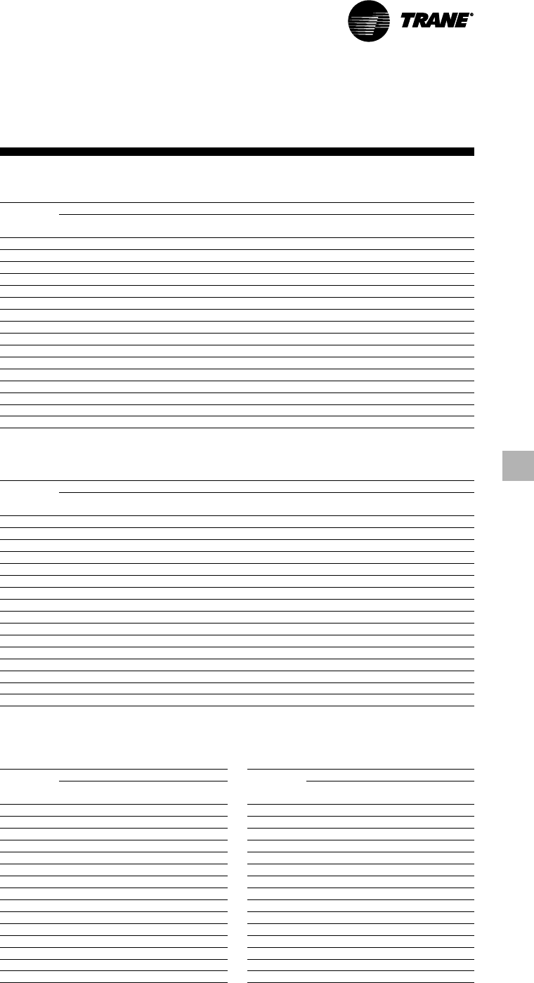
Electrical Data
and Connections
Compressor Motor Electrical Data (60 Hertz)
Nominal Voltage 200 230 380 460 575
Compressor Voltage 180/ 208/ 342/ 414/ 516/
Code Utilization Range 220 254 418 506 633
Max kW 174 174 174 174 174
B1, B2 RLA @ Max kW 557 484 291 241 193
LRAY 970 818 488 400 329
LRAD 3103 2617 1561 1280 1053
Max kW 249 249 249 249 249
C1, C2 RLA @ Max kW 812 698 421 349 279
LRAY 1173 936 558 469 375
LRAD 3634 2901 1727 1453 1162
Max kW 329 329 329 329 329
D1, D2 RLA @ Max kW 888 888 549 455 367
LRAY 1690 1532 850 730 612
LRAD 5477 4966 2755 2366 1984
Notes:
1. See Selection Procedure Section for details.
2. The RLA @ Max kW is based on the performance of the motor developing full rated horsepower.
3. Electrical component sizing should be based on actual jobsite operating conditions. This factor can be obtained through the
use of the Series R chiller selection program available through local Trane sales offices.
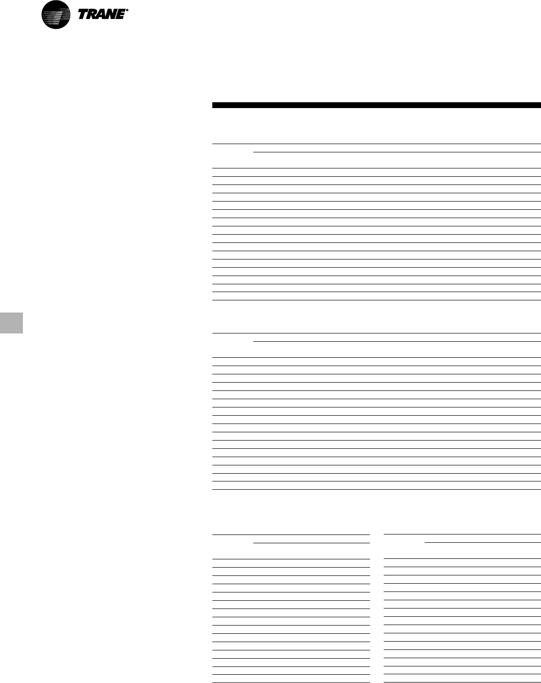
Compressor Motor Electrical Data (50 Hertz)
Nominal Voltage 380 400 415
Compressor Voltage 342/ 360/ 374/
Code Utilization Range 418 440 457
Max kW 139 145 148
B1, B2 RLA @ Max kW 233 233 233
LRAY 391 412 428
LRAD 1229 1296 1348
Max kW 201 209 213
C1, C2 RLA @ Max kW 349 349 349
LRAY 456 480 498
LRAD 1414 1488 1544
Max kW 271 280 284
D1, D2, D3 RLA @ Max kW 455 455 455
LRAY 711 748 776
LRAD 2303 2424 2515
Max kW 288 301 306
E3 RLA @ Max kW 488 488 488
LRAY 711 748 776
LRAD 2303 2424 2515
Notes:
1. See Selection Procedure Section for details.
2. The RLA @ Max kW is based on the performance of the motor developing full rated horsepower.
3. Electrical component sizing should be based on actual jobsite operating conditions. This factor can be obtained through the
use of the Series R chiller selection program available through local Trane sales offices.
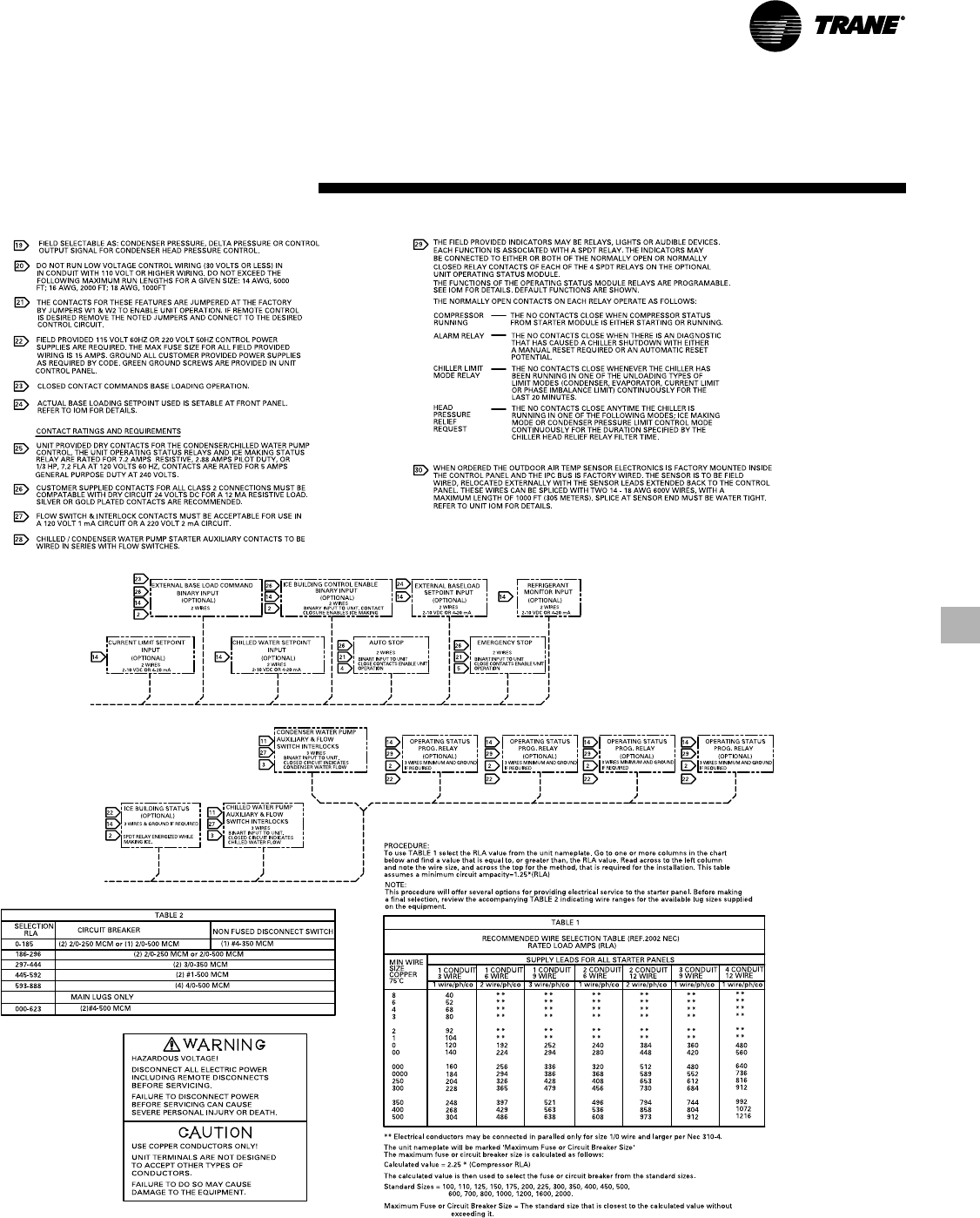
Electrical Connections
Starter Panel Selection Lug Size
Connection RLA L1-L3 (Each Phase)
Terminals Only 000-760 (2) #4-500 MCM
761-888 (4) 4/0-500 MCM
Main Circuit 000-185 (1) #4-350 MCM
Breaker or 186-296 (2) 2/0-250 MCM
Non-Fused 297-444 (2) 3/0-350 MCM
Disconnect Switch 445-592 (2) #1-500 MCM
593-888 (4) 4/0-500 MCM
Note:
1. Lug sizes are independent of starter type.
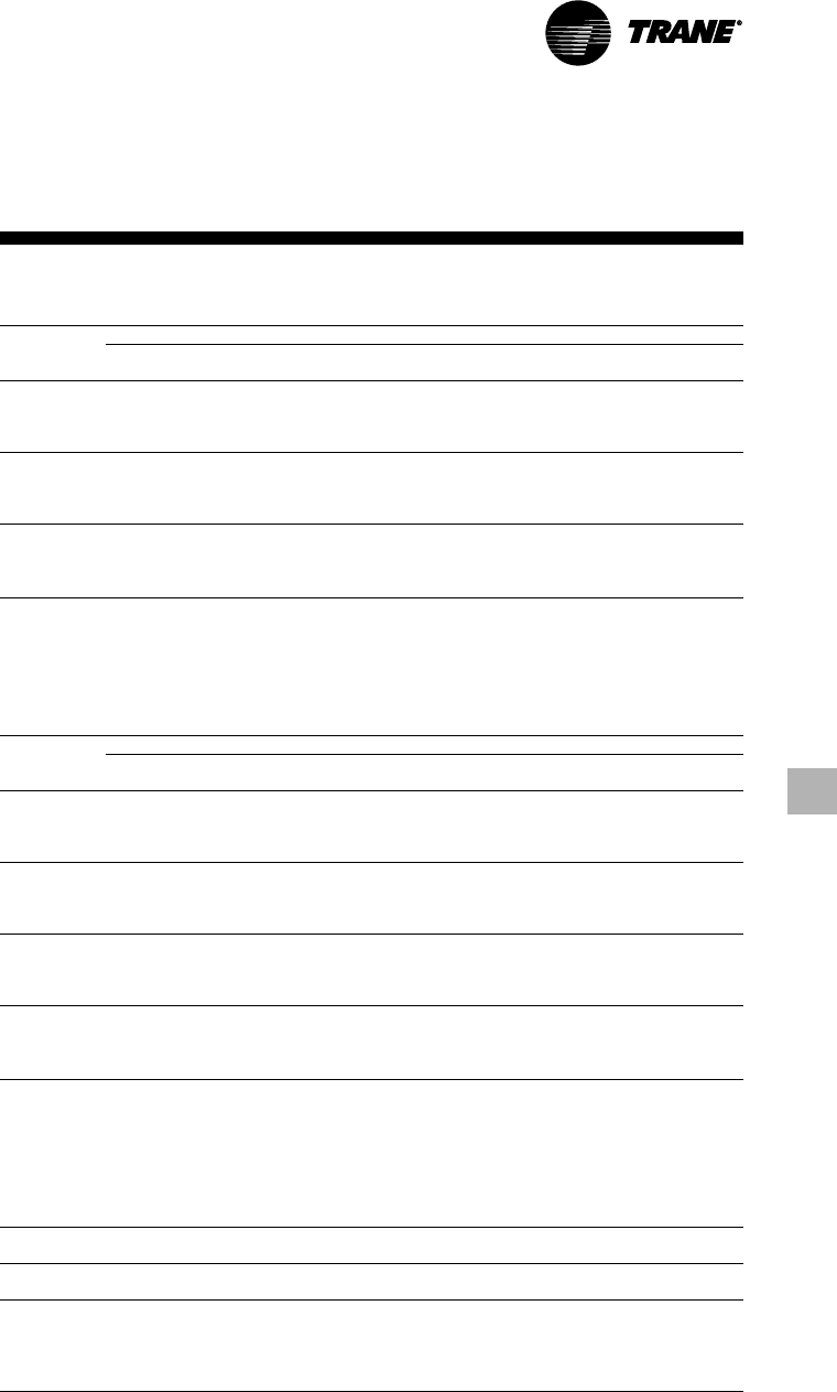
RLC-PRC020-EN20
Electrical Data
and Connections
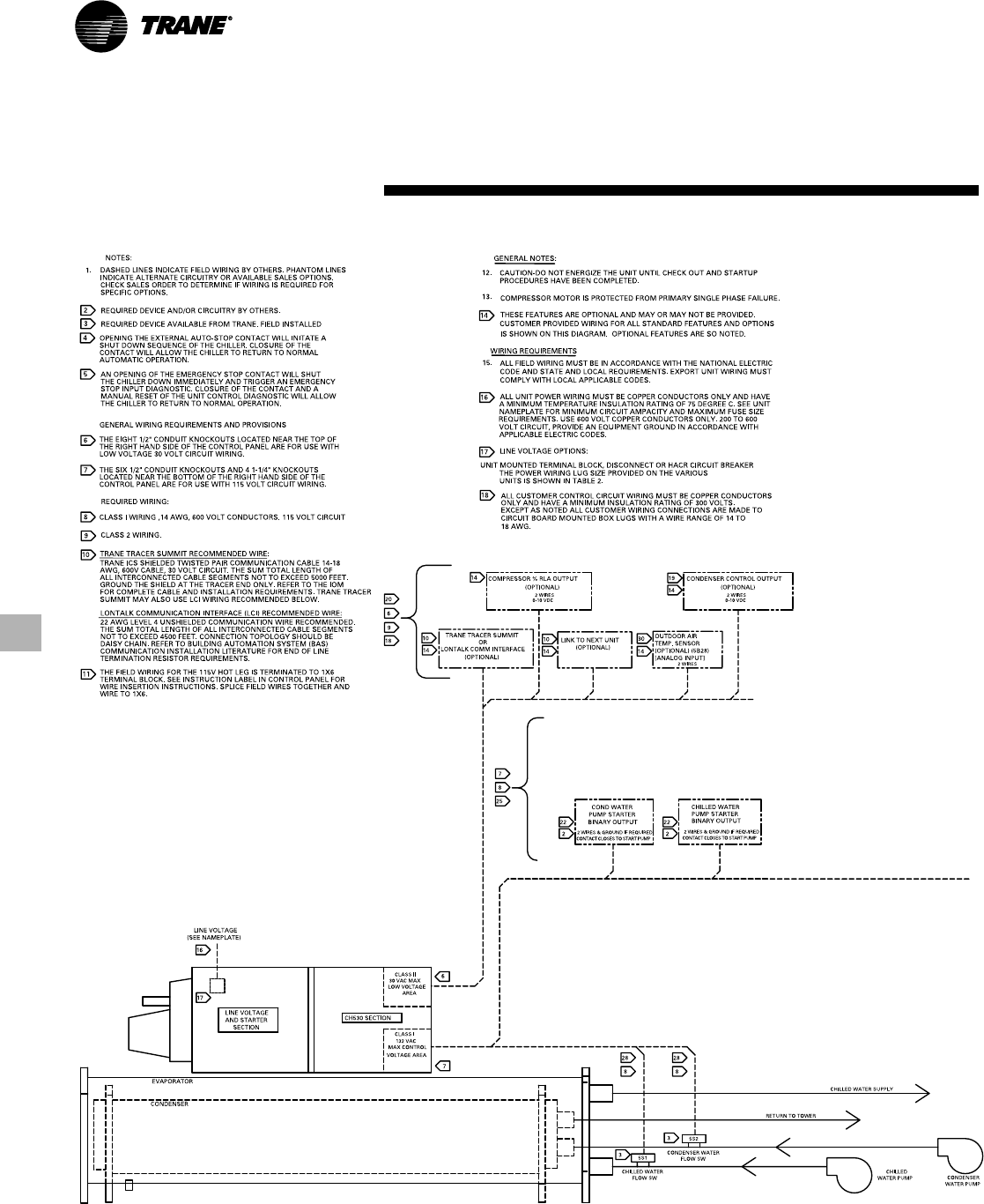
21
RLC-PRC020-EN
Electrical Data
and Connections
RLC-PRC020-EN22
Shipping and Operating Weights
Compressor Evaporator Condenser Operating Weight Shipping Weight
Code Code Code (lbs) (kg) (lbs) (kg)
B1 B1 B1 9,867 4,476 9,292 4,215
B1 C1 D1 10,554 4,787 9,837 4,462
B2 B2 B2 10,019 4,545 9,402 4,265
B2 C2 D2 10,653 4,832 9,953 4,515
C1 D6 E5 13,397 6,077 12,780 5,797
C1 D5 E4 13,673 6,202 12,973 5,884
C1 E1 F1 15,818 7,175 14,718 6,676
C2 D4 E4 13,672 6,201 12,972 5,884
C2 D3 E3 15,044 6,824 14,002 6,351
C2 F2 F3 17,560 7,965 16,168 7,334
D1 D1 E1 15,385 6,978 14,443 6,551
D1 F1 F2 17,537 7,955 16,187 7,342
D1 G1 G1 20,500 9,299 18,600 8,437
D1 G2 G2 21,065 9,555 19,107 8,667
D2, D3 D2 E2 15,570 7,062 14,562 6,605
D2, D3 F2 F3 18,220 8,264 16,820 7,629
D2, D3 G2 G1 20,700 9,389 18,700 8,482
D2, D3 G3 G3 21,641 9,816 19,508 8,849
E3 D2 E2 15,728 7,134 14,720 6,677
E3 F2 F3 18,356 8,326 16,956 7,691
E3 G2 G1 20,800 9,435 18,800 8,528
E3 G3 G3 21,786 9,882 19,653 8,914
Notes:
1. All weights +- 3%.
2. Shipping weights include standard 150 psig water boxes, refrigerant charge, and oil charge.
3. Operating weights include refrigerant, oil, and water charges.
Dimensions and
Weights
23
RLC-PRC020-EN
Dimensions and
Weights
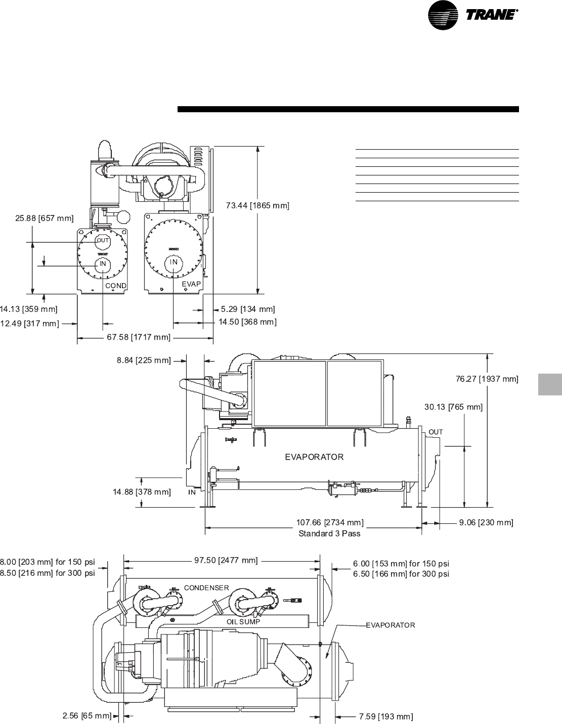
BBB Configuration
Recommended Clearances
Front 36" (914 mm)
Back 36" (914 mm)
Either End 36" (914 mm)
Other End* 108" (2743 mm)
Top 36" (914 mm)
* Clearance for tube removal
Note:
1. Dimensions are based on 3 Pass Evap / 2 Pass
Cond and LH/LH water connections. Refer to
submittals for exact configuration.
2. Refer to the Nominal Capacity Data table in the
General Data section for capacity ranges of each
compressor.
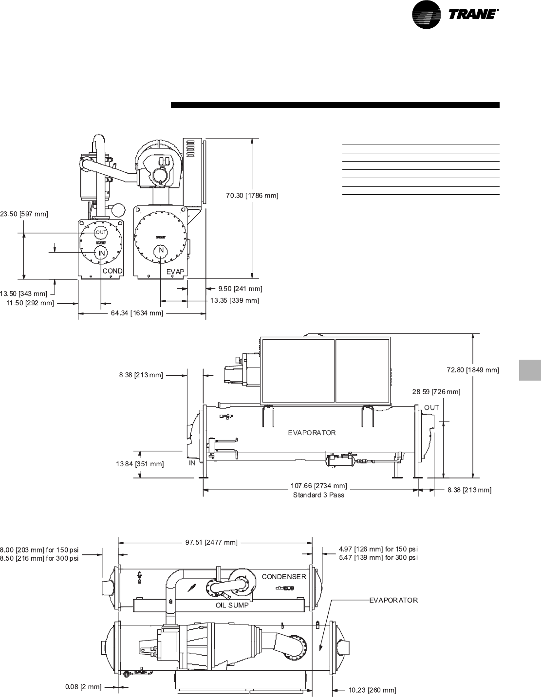
RLC-PRC020-EN24
Dimensions and
Weights
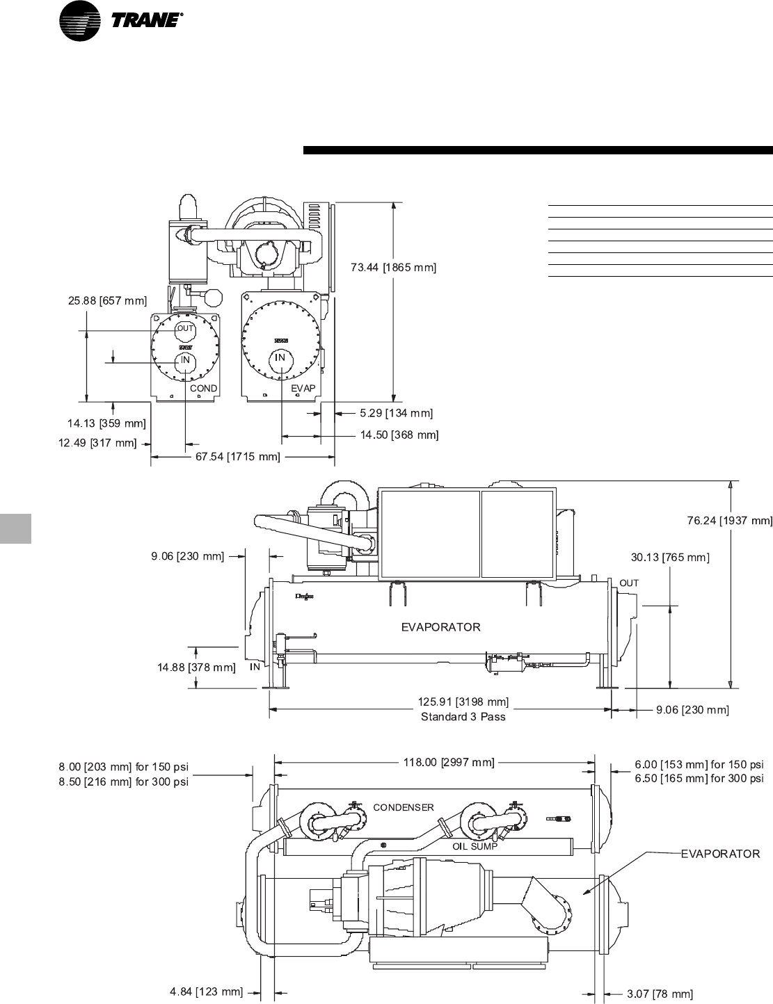
BCD Configuration
Recommended Clearances
Front 36" (914 mm)
Back 36" (914 mm)
Either End 36" (914 mm)
Other End* 126" (3200 mm)
Top 36" (914 mm)
* Clearance for tube removal
Note:
1. Dimensions are based on 3 Pass Evap / 2 Pass
Cond and LH/LH water connections. Refer to
submittals for exact configuration.
2. Refer to the Nominal Capacity Data table in the
General Data section for capacity ranges of each
compressor.
25
RLC-PRC020-EN
Dimensions and
Weights
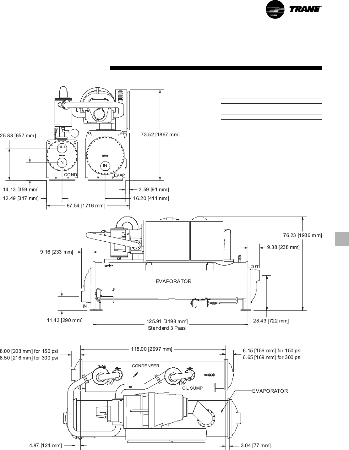
CDE, DDE, EDE Configuration
Recommended Clearances
Front 36" (914 mm)
Back 36" (914 mm)
Either End 36" (914 mm)
Other End* 108" (2743 mm)
Top 36" (914 mm)
* Clearance for tube removal
Note:
1. Dimensions are based on 3 Pass Evap / 2 Pass
Cond and LH/LH water connections. Refer to
submittals for exact configuration.
2. Refer to the Nominal Capacity Data table in the
General Data section for capacity ranges of each
compressor.
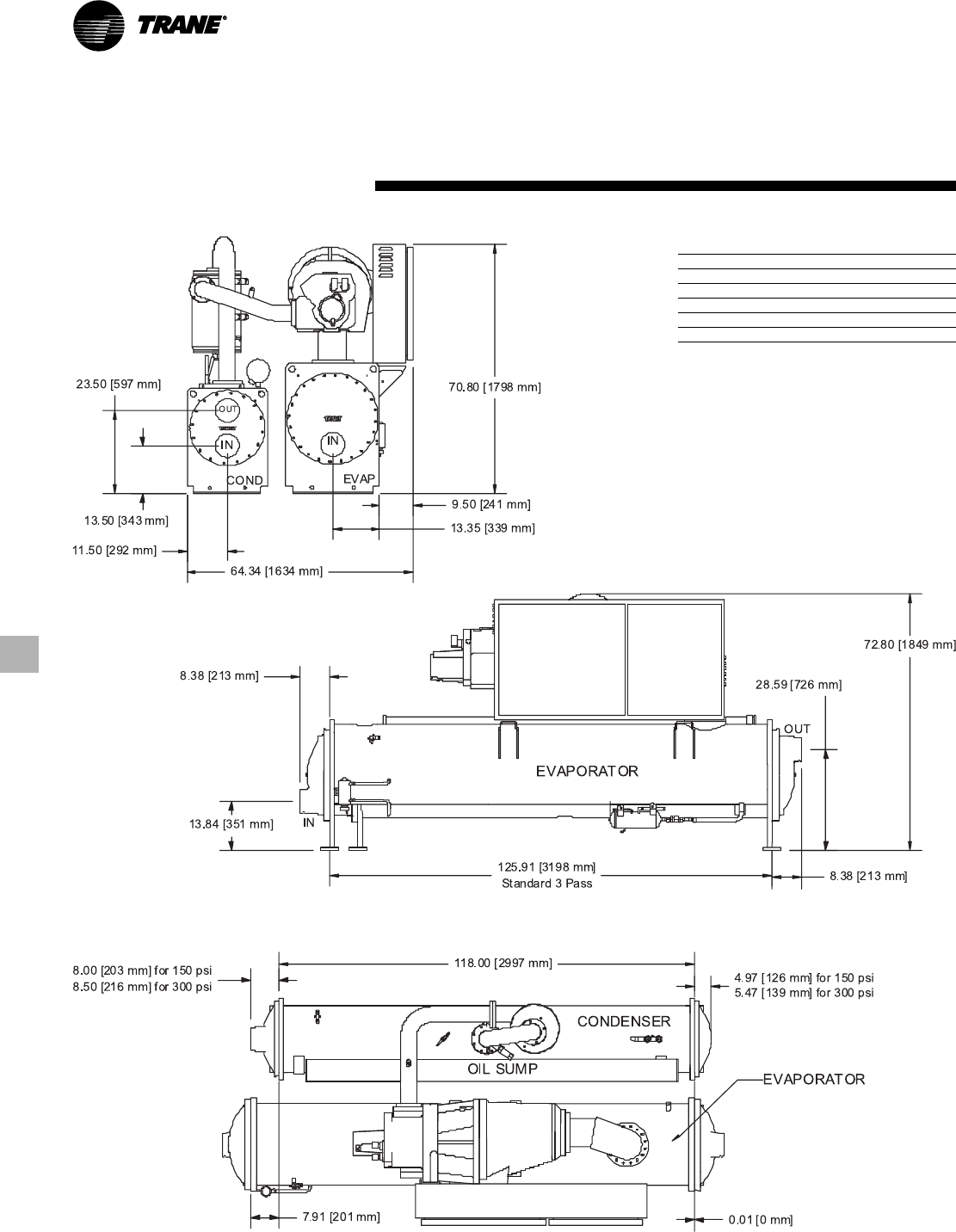
RLC-PRC020-EN26
Dimensions and
Weights
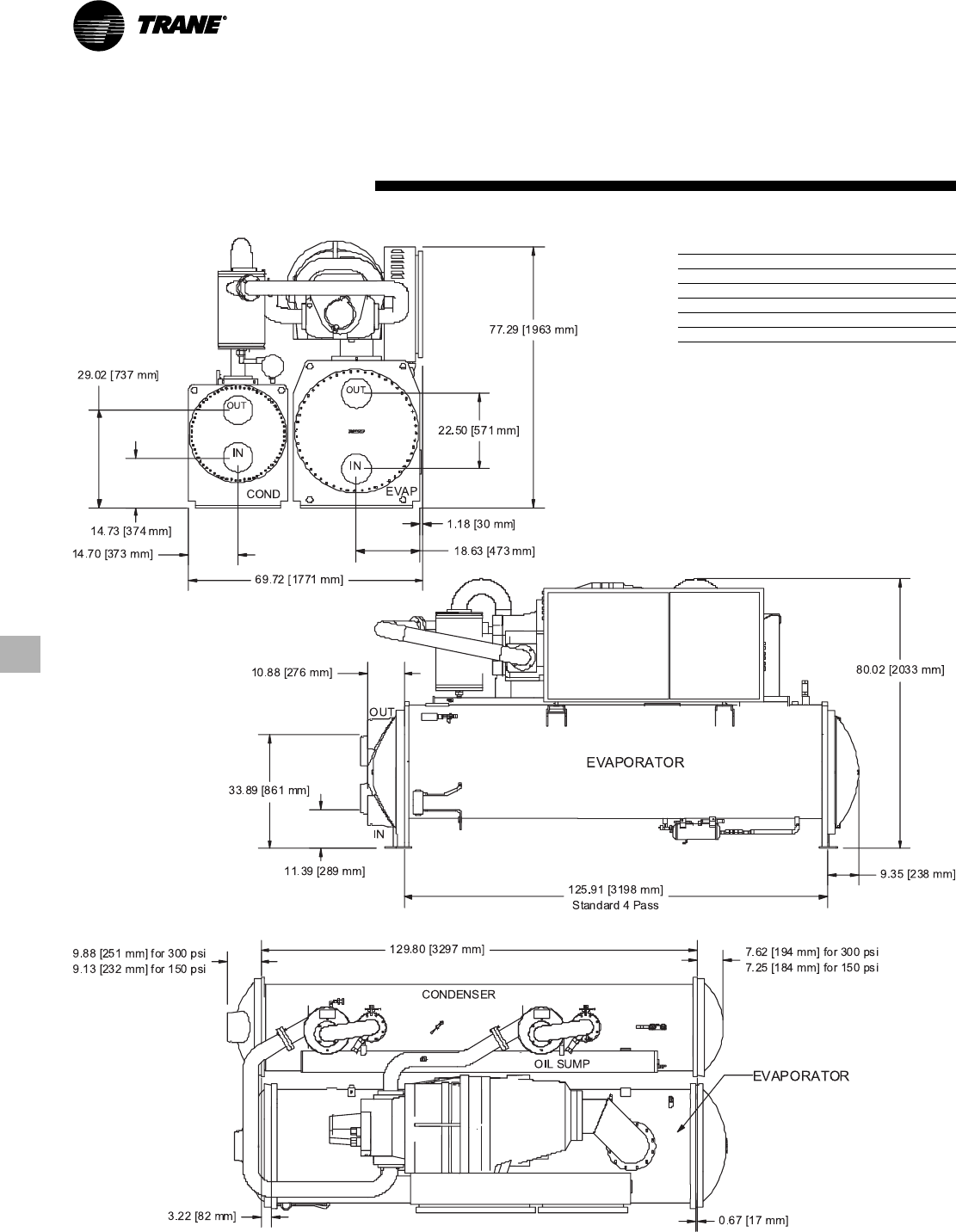
CEF Configuration
Recommended Clearances
Front 36" (914 mm)
Back 36" (914 mm)
Either End 36" (914 mm)
Other End* 126" (3200 mm)
Top 36" (914 mm)
* Clearance for tube removal
Note:
1. Dimensions are based on 3 Pass Evap / 2 Pass
Cond and LH/LH water connections. Refer to
submittals for exact configuration.
2. Refer to the Nominal Capacity Data table in the
General Data section for capacity ranges of each
compressor.
27
RLC-PRC020-EN
Dimensions and
Weights
CFF, DFF, EFF Configuration
Recommended Clearances
Front 36" (914 mm)
Back 36" (914 mm)
Either End 36" (914 mm)
Other End* 126" (3200 mm)
Top 36" (914 mm)
* Clearance for tube removal
Note:
1. Dimensions are based on 3 Pass Evap / 2 Pass
Cond and LH/LH water connections. Refer to
submittals for exact configuration.
2. Refer to the Nominal Capacity Data table in the
General Data section for capacity ranges of each
compressor.
RLC-PRC020-EN28
Dimensions and
Weights
DGG, EGG Configuration
Recommended Clearances
Front 36" (914 mm)
Back 36" (914 mm)
Either End 36" (914 mm)
Other End* 126" (3200 mm)
Top 36" (914 mm)
* Clearance for tube removal
Note:
1. Dimensions are based on 3 Pass Evap / 2 Pass
Cond and LH/LH water connections. Refer to
submittals for exact configuration.
2. Refer to the Nominal Capacity Data table in the
General Data section for capacity ranges of each
compressor.

29
RLC-PRC020-EN
Mechanical
Specifications
General
Exposed metal surfaces are painted with
air-dry beige, direct-to-metal, single-
component paint. Each unit ships with full
operating charges of refrigerant and oil.
Molded neoprene isolation pads are
supplied for placement under all support
points. Startup and operator instruction
by factory-trained service personnel are
included.
Compressor and Motor
The unit is equipped with a semi-
hermetic, direct-drive, 3600-rpm (3000
rpm @ 50 Hz) rotary compressor that
includes a capacity control slide valve, oil
sump heater, and differential pressure
refrigerant oil flow system. Four
pressure-lubricated, rolling-element
bearing groups support the rotating
assembly.
The motor is a suction gas-cooled,
hermetically sealed, two-pole, squirrel
cage induction-type.
Unit-Mounted Starter
The unit is supplied with a NEMA 1 type
enclosure with top power-wiring access
and three-phase, solid state overload
protection. The starter is available in a
Wye-Delta configuration, factory-
mounted and fully pre-wired to the
compressor motor and control panel. A
factory-installed, factory-wired 600VA
control power transformer provides all
unit control power (120 VAC secondary)
and CH530 module power (24 VAC
secondary). Optional starter features
include circuit breakers, ground fault
circuit breakers, and mechanical, non-
fused disconnects.
Evaporator and Condenser
Shells are carbon steel plate. The
evaporator and condenser are designed,
tested, and stamped in accordance with
ASME Code for refrigerant-side/
working-side pressure of 200 psig.
All tube sheets are made of carbon steel;
tubes are mechanically expanded into
tube sheets and mechanically fastened to
tube supports. Evaporator tubes are 1.0-
inch (25.4 mm) diameter and condenser
tubes are 0.75-inch
(19.05 mm) diameter. Both types can be
individually replaced. Standard tubes are
externally finned, internally enhanced
seamless copper with lands at all tube
sheets.
All water pass arrangements are
available with grooved connections (150
or 300 psig waterside). All connections
may be either right- or left-handed.
Waterside shall be hydrostatically tested
at 1.5X design working pressure.
Refrigerant Circuit
An electronically controlled expansion
valve is provided to maintain proper
refrigerant flow.
Unit Controls (CH530)
The microprocessor-based control panel
is factory-installed and factory-tested. The
control system is powered by a control
power transformer, and will load and
unload the chiller through adjustment of
the compressor slide valve.
Microprocessor-based chilled water reset
based on return water is standard.
The CH530 microprocessor automatically
acts to prevent unit shutdown due to
abnormal operating conditions
associated with low evaporator
refrigerant temperature, high condensing
temperature, and/or motor current
overload. If an abnormal operating
condition continues and the protective
limit is reached, the machine should shut
down.
The panel includes machine protection
shutdown requiring
manual reset
for the
following conditions:
• low evaporator refrigerant temperature
and pressure
• high condenser refrigerant pressure
• low oil flow
• critical sensor or detection circuit faults
• motor current overload
• high compressor discharge temperature
• lost communication between modules
• electrical distribution faults: phase loss,
phase imbalance, or phase reversal
• external and local emergency stop
• starter transition failure
The panel also includes machine
protection shutdown with
automatic
reset
for the following correctable
conditions:
• momentary power loss
• under/over voltage
• loss of evaporator or condenser water
flow
When a fault is detected, the control
system conducts more than 100
diagnostic checks and displays results.
The display will identify the fault, indicate
date, time, and operating mode at time of
occurrence, and provide type of reset
required and a help message. The
diagnostic history will display the last ten
diagnostics with their times and dates of
occurrence.
Clear Language Display Panel
Factory-mounted to the control panel
door, the operator interface has an LCD
touch-screen display for operator input
and information output. This interface
provides access to the following
information: evaporator report,
condenser report, compressor report,
ASHRAE Guideline 3 report, operator
settings, service settings, service tests,
and diagnostics. All diagnostics and
messages are displayed in “clear
language.”
Data contained in available reports
includes:
• Water and air temperatures
• Refrigerant levels and temperatures
• Oil pressure
• Flow switch status
• EXV position
• Head pressure control command
• Compressor starts and run-time
• Line phase percent RLA, amps, and
volts
All necessary settings and setpoints are
programmed into the microprocessor-
based controller via the operator
interface. The controller is capable of
receiving signals contemporaneously
from a variety of control sources, in any
combination, and priority order of control
sources can be programmed. The control
source with priority determines active
setpoints via the signal it sends to the
control panel. Control sources may be:
• the local operator interface (standard)
• a hard-wired 4-20 mA or 2-10 VDC
signal from an external source
(interface optional; control source not
supplied)
• Generic BAS (optional points; control
source not supplied)
• LonTalk LCI-C (interface optional; control
source not supplied)
• Trane Tracer Summit™ system (interface
optional)
RLC-PRC020-EN30
Conversion Table

31
RLC-PRC020-EN

Trane has a policy of continuous product and product data improvement and reserves the right to change design
and specifications without notice.
Literature Order Number
File Number
Supersedes
Stocking Location
Trane
A business of American Standard Companies
www.trane.com
For more information, contact
your local sales office or
e-mail us at comfort@trane.com.
RLC-PRC020-EN
PL-RF-RLC-000-PRC020-EN-0606
RLC-PRC020-EN-00406
Inland
