Trane Sandp Unit Heaters Catalogue UH PRC001 EN
2015-04-02
: Trane Trane-Sandp-Unit-Heaters-Catalogue-684290 trane-sandp-unit-heaters-catalogue-684290 trane pdf
Open the PDF directly: View PDF ![]() .
.
Page Count: 38

Propeller Unit
Heaters/Unitary
August 2007 UH-PRC001-EN
8.0 to 705.6 MBh
Two Versatile Models - Various Sizes
Easy Installation
Introduction
© 2007 American Standard All rights reserved UH-PRC001-EN
The square, compact design of the
Model P and rectangular Model S
allow easy handling and installation.
In most cases, only one person is
needed to carry a unit.
What’s more, the Model P can be
stored standing on end. This means
several units can be loaded on a
single skid for moving from one point
to another.
Yet, the benefits of this compact
design go beyond ease of
installation. They continue with
attractive styling. The Model S unit’s
simple, clean-line symmetry and the
Model P unit’s classic modern shape
enhance any industrial facility.

UH-PRC001-EN 3
Model Number Description . . . . . . . . . . . . . . . . . . . . . . . . . . . . . . . . . . . . . . . . . 4
Features & Benefits. . . . . . . . . . . . . . . . . . . . . . . . . . . . . . . . . . . . . . . . . . . . . . . . 5
Application Consideration . . . . . . . . . . . . . . . . . . . . . . . . . . . . . . . . . . . . . . . . . . 7
Selection Procedure . . . . . . . . . . . . . . . . . . . . . . . . . . . . . . . . . . . . . . . . . . . . . . 11
Performance Data . . . . . . . . . . . . . . . . . . . . . . . . . . . . . . . . . . . . . . . . . . . . . . . . 17
Steam Performance Data . . . . . . . . . . . . . . . . . . . . . . . . . . . . . . . . . . . . . . . . . . . . . . 17
Hot Water Performance Data . . . . . . . . . . . . . . . . . . . . . . . . . . . . . . . . . . . . . . . . . . 21
Technical & Mounting Data . . . . . . . . . . . . . . . . . . . . . . . . . . . . . . . . . . . . . . . . . . . . 26
Motor Characteristics Data . . . . . . . . . . . . . . . . . . . . . . . . . . . . . . . . . . . . . . . . . . . . 27
Wiring Diagrams . . . . . . . . . . . . . . . . . . . . . . . . . . . . . . . . . . . . . . . . . . . . . . . . . 31
Dimensional Data . . . . . . . . . . . . . . . . . . . . . . . . . . . . . . . . . . . . . . . . . . . . . . . . 32
Mechanical Specifications . . . . . . . . . . . . . . . . . . . . . . . . . . . . . . . . . . . . . . . . . 36
Contents

4UH-PRC001-EN
Service Model Number
Description
DIGIT 1,2,3 — PRODUCT TYPE
UHP
UHS
DIGIT 4— DEVELOPMENT
SEQUENCE
B
DIGIT 5, 6, 7—CAPACITY/COIL
TYPE
Hot Water Only "Serpentine Type
Coil" Model S
A08 8,030 BTU/HR
A18 18,400 BTU/HR
A25 24,800 BTU/HR
A36 35,900 BTU/HR
Steam or Hot Water "Header
Type Coil" Model S
018 18,000 BTU/HR
024 24,000 BTU/HR
036 36,000 BTU/HR
048 48,000 BTU/HR
060 60,000 BTU/HR
072 72,000 BTU/HR
084 84,000 BTU/HR
096 96,000 BTU/HR
108 108,000 BTU/HR
120 120,000 BTU/HR
132 132,000 BTU/HR
144 144,000 BTU/HR
156 156,000 BTU/HR
180 180,000 BTU/HR
204 204,000 BTU/HR
240 240,000 BTU/HR
280 280,000 BTU/HR
300 300,000 BTU/HR
360 360,000 BTU/HR
Steam or Hot Water Model P
042 42,000 BTU/HR
064 64,000 BTU/HR
080 80,000 BTU/HR
102 102,000 BTU/HR
122 122,000 BTU/HR
146 146,000 BTU/HR
166 166,000 BTU/HR
202 202,000 BTU/HR
252 252,000 BTU/HR
UHSBA181TAA101A0A0A
12345678910111213141516171819
280 280,000 BTU/HR
336 336,000 BTU/HR
384 384,000 BTU/HR
500 500,000 BTU/HR
600 600,000 BTU/HR
720 720,000 BTU/HR
DIGIT 8—VOLTAGE
1 115/1/60
3 230/1/60 (115 V motor with
Trans former)
4208/3/60
5230/3/60
6460/3/60
7 575/60/3 (Totally Enclosed)
(P only)
DIGIT 9 - MOTOR TYPE
E Explosion Proof
T Totally Enclosed
DIGIT 10- DESIGN SEQUENCE
A
DIGIT 11- TUBE MATERIAL
A Copper
B Steel (P only)
DIGIT 12- FAN GUARD
0 Standard Fan Guard
1 OSHA Fan Guard
2 Standard Fan Guard with
Shelf Mount
DIGIT 13 - SPECIAL COATING
0 No Special Coating
A Phenolic Coating (Baked)
BEpoxy
C Epoxy Phenolic
DIGIT 14 - DISCONNECT SWITCH
0None
1 Disconnect switch
DIGIT 15 - THERMOSTATS (LINE
VOLTAGE)
0None
A Light Duty TSTAT w/ subbase
Line Volts 8 Amps
B Heavy Duty TSTAT w/
subbase
DIGIT 16 - THERMOSTAT COVER
0None
A Locking Thermostat Cover
DIGIT 17 - Manual Starter
0None
AManual Starter
DIGIT 18 - STEAM & HOT WATER
CONTROL
0None
1 Strap on Hot Water Control
2 Steam Pressure Control
(Open on rise in pressure)
3 Steam Pressure Control
(Close on rise in pressure)
4 5.0 Amp Speed Control
Switch ( Capacities A08- 108
only)
5 Options 1 and 4
6 Options 2 and 4
7 Options 3 and 4
DIGIT 19 - VERTICAL LOUVER
0None
A Vertical Louver
B Louver Cone Diffuser (P only)
C Louver Cone Diffuser w/
Coating (P only)
Model Number Description

UH-PRC001-EN 5
Features & Benefits: Overview
Trane propeller unit heaters feature
the largest selection of standard
sizes from any line in the industry. In
fact, vertical Model P and horizontal
Model S unit heaters provide
enough ‘off-the-shelf’ selections to fit
almost any application.
The versatile two-in-one Model P is
available in 15 sizes with capacities
from 41.3 MBh to 705.6 MBh. The
companion standard and bypass
Model S is available in 23 sizes with
the capacities from 8.0 MBh up to
360 MBh. Both are designed for
durability, attractiveness and
compactness. These features
combined with economical
operation, give strategically sized
Trane unit heaters an edge
unmatched by any other
manufacturer.
Two Units in One – The
Versatile Model P
The Trane Model P can be quickly
field converted from standard to low
final temperature PL design simply
by removing the unit’s patented
knockout air ports. This unique
two-in-one design allows the
stocking wholesaler to cut
inventories in half and still meet
most customer application
requirements.
Patented Trane louver cone diffusers
allow directional flexibility of heated
air.
The Space Saving Model S
The Side Connection type Model S
unit features functional styling in a
space-saving design. This hot water
unit heater is available in capacities
from 8.0 to 35.9 MBh and is ideal for
applications where clearance is
limited.
The Heavy-Duty Model S
The versatile Header-Type unit can
be used with either steam or hot
water systems and is available in
capacities from 18.0 to 360.0 MBh.
Rugged cast brass headers and
mechanically bonded fins provide
reliable heating to suit a wide variety
of solutions.
Note: Vertical louvers are available
for all Model S units to put
heat where it’s needed.
Horizontal Unit Heaters
Construction and Features
Motors
115 volt, single speed motors are
standard. Most models can be
supplied with single phase,
explosion proof motors. For
standard motors in 230 volt or three-
phase configuration, and three-
phase explosion-proof motors, see
the motor data-portion of the
Performance Data chapter for
availability.
Fan Guards
All models with standard (non
explosion-proof) single phase 115 or
230 volt motors utilize a wire fan
guard as a motor mount. (Optional
OSHA type guards are also
available.) All models with three-
phase or explosion-proof motors are
shelf-mounted. Standard type fan
guards can be added as an optional
accessory.
Horizontal and Vertical Louvers
Horizontal louvers are standard on
all models. Vertical louvers are an
optional accessory on all models.
Vertical louvers are installed on built
to order units or shipped loose for
field installation.
Thermostats
Two, line voltage wall thermostats
are in stock for immediate shipment.
All models operate in a 45-85 degree
F range (7-28 degree C). Standard
duty model with “fan control” and a
heavy duty model with “auto-off-
fan” switching are available. Other
models available on request. Plastic
tamperproof one size fits all
thermostat guards are also available.
Strap-on Water Control
A SPDT strap-on type hot water
control with 100° to 240°F (38 to
116°C) rated at 10 amps at 120V is
also available. Control can be used
for direct or reverse acting
applications as a high or low limit.
Features & Benefits
6UH-PRC001-EN
Features & Benefits
Steam Pressure Control
SPST switch opens on a rise in
pressure. Control is automatically
reset, has a range of 0 to 15 PSIG (0
to 103 KPa) and has an adjustable
differential. Other actions, ranges,
circuits and manual reset models
are available on request.
Manual Starters
Single and three-phase models are
available. Standard models are
single-speed, toggle-operated,
NEMA Type 1 and are surface-
mounted.
Wall Mounted Speed Controllers
Units up to S-108 and P-104 with
standard motors (115V) can be
operated at reduced speeds by
addition of optional speed controller.
Controller is 5 amps, pre-set at
factory for maximum and minimum
speeds, with intermediate speeds
infinitely controllable. All 1/3, 1/2 H.P.
and 230V motors operate only at
rated speed and CFM – See tables.
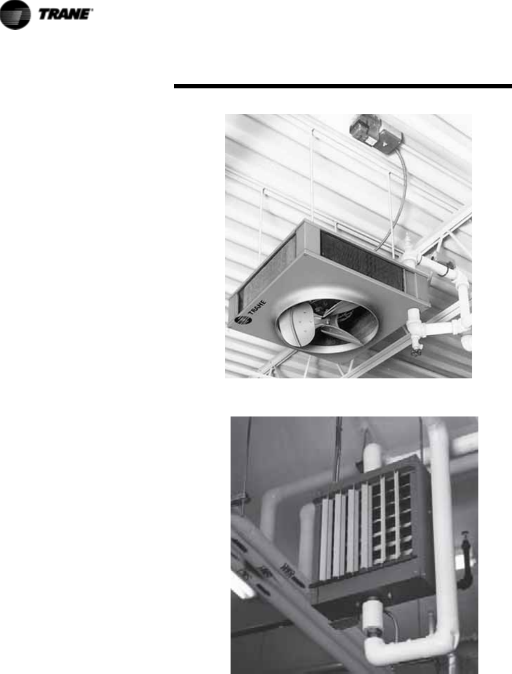
Vertical Unit Heaters
Construction and Features
Vertical projection unit heaters
provide heat where it is required in
commercial and industrial
applications. Mounted near the
ceiling, this unit provides air
circulation and reduces stratification,
without occupying otherwise usable
building space. Units can be
provided with an optional diffuser for
patterned discharge, or, without a
diffuser for higher velocity ‘spot’
heating near doorways and other
highloss areas.
Vertical units are available in fifteen
sizes for steam or hot water heating.
Steam capacities range from 140 to
2,580 E.D.R. (26.0 to 705 MBH) (2 PSI
w/60° E.A.T.). Hot water capacities
range from 18.9 to 519.4 MBH (200°
E.W.T./20° drop w/60° E.A.T.).
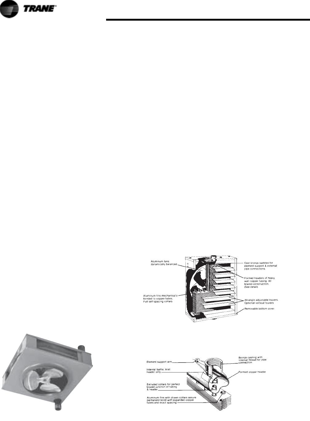
Construction
The unit casing is formed by two
square steel plates. The bottom plate
forms an orifice for air delivery. Air
ports are stamped in the top plate of
standard units for easy conversion of
low output units.
Fan
Aluminum blade fans are quiet,
factory balanced and sturdy for
standard or sparkproof applications.
Heating Element
Hot water-steam coils are rectangular
3 or 4-sided, one-pass, multiple
circuit, with aluminum fins
mechanically bonded to the tubes.
Standard coils are seamless copper
tubing. Coils tested at 375 psi under
water. Supply and return connections
are steel pipe. Standard coils have
.025 copper tubing suitable for use
on steam pressure to 75 psi or hot
water up to 225 psi or 325°F.
Figure 1.
Motors
Standard motors are 115/60/1, totally
enclosed, with thermal overload
protection for all units through size P-
280. Standard motors for sizes 42, 64
and 80 are shaded pole, sleeve
bearing. The P-102 motor is
permanent split capacitor type with
sleeve bearings. Motor for unit sizes
122 through 280 are permanent split
capacitor types with permanently
lubricated ball bearings. Motors used
on unit sizes 336 through 720 are 230/
460/60/3, totally enclosed, with
permanently lubricated ball bearings.
Unit sizes smaller than 336 are also
available with 230/460/60/3 motors.
All motors fractional H.P. and integral
H.P., have Class “B” insulation. The
115/60/1 motors used as standard on
unit sizes 42 through 102 can be
operated at multiple speeds with the
addition of a solid-state control.
All units are available with 1140 rpm
explosion-proof motors.
UH-PRC001-EN 7
General Rules
In locating or spotting Trane
Propeller Unit Heaters – either the
Model S Horizontal or Model P
Projection Unit Heater – the
following general rules should be
considered.
1. Spot units at points of greatest
heat loss. Blanket outside
doorways effectively and
provide ample coverage for
exposed window areas.
2. Units, especially in the case of
the Model S Horizontal Unit
Heater, should be arranged to
blow toward or along exposed
walls, preferably striking the
wall at a slight angle so that the
heated air exerts a wiping effect
along the wall. Balance of units
required to supply Btu
requirements should be spaced
strategically in balance of the
area.
3. Unit heaters should be arranged
to blow into open spaces such as
aisles and not directly at any
worker. An exception to this rule
involves the use of the Model P
Unit Heater equipped with the
Louver Cone Diffuser. This
combination can be used
effectively over closely spaced
bins or machines without regard
for open space. But not even the
Model P Unit Heater with Louver
Cone Diffuser should be in such
close proximity to the workers to
cause discomfort.
4. The Trane solid-state speed
control will provide maximum
capacity flexibility and quieter
operation. Note that this speed
controller is available only on
selected models.
5. Mounting heights and distance
of throw recommendations as
given elsewhere in this catalog
should be carefully observed.
6. In the case of Model P Units,
they should be spotted so that
they will most effectively
prevent stratification of
excessively warm air at the
ceiling. By carefully observing
this rule, this type of unit may be
used between seasons to tap
waste heat at the ceiling and
drive it down to occupied zones,
thereby eliminating the need for
added heat on the system.
7. Do not spot units close to any
obstruction that will impede the
full and natural air delivery of
the unit.
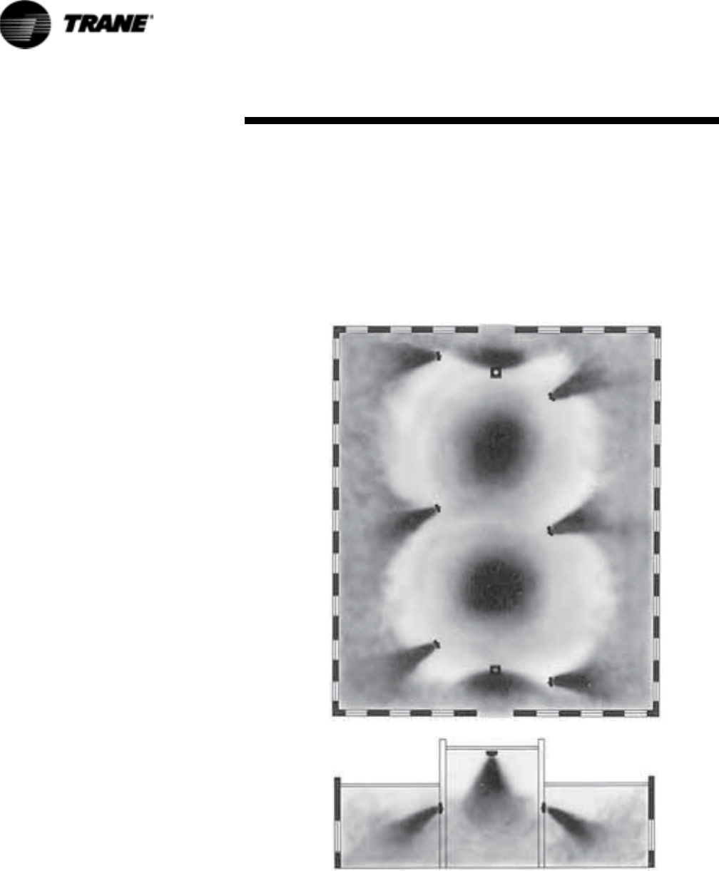
Figure 2. The floor plan and elevation of a typical industrial building
showing how a Trane Unit Heater System will heat various parts. Where
ceilings are high in the main manufacturing section, large Projection Heaters
without diffusers are used. Where ceilings are exceptionally high, as in crane
bays, Model P Units with Louver Cone Diffusers provide up to 45% greater
throw to top the “ceiling heat reservoir.” Model P Units with half closed Louver
Cones blanket doorways. Model S Units with Louver Fins blanket windows.
Typical Factory
In the typical industrial building,
where ceilings are high, Model P
Unit Heaters may be used without
diffusers.
In plants where the ceilings are
exceptionally high, such as in crane
bays as illustrated in Model P Units
with Louver Cone Diffusers can
Application Consideration
8UH-PRC001-EN
Application Consideration
increase the downward projection of
heat by as much as 45% over units
without diffusers.
Model P Units with the Louver Cone
Diffusers can also be used to blanket
doorways effectively, as shown in
Figure 2 by simply adjusting half of
the louvers vertically, and half closed.
Model S horizontal-type units are
ideal for mounting in plant areas
where ceilings are low. In fact, due to
the extremely small height of the
Model S, and because all piping
connections are made at the back of
the unit, the Model S provides a
greater saving in headroom than
other horizontal unit heater makes.
As illustrated in Figure 2, the Model S
Unit Heaters may be mounted
conveniently from the ceiling, or
from building structural supports and
beams. With Louver Fin Diffusers,
they are ideal for blanketing
windows, and Model S “Bypass”
Unit Heaters, provide further
flexibility of application where
greater throw and more effective
distribution of air in the living zone is
required.
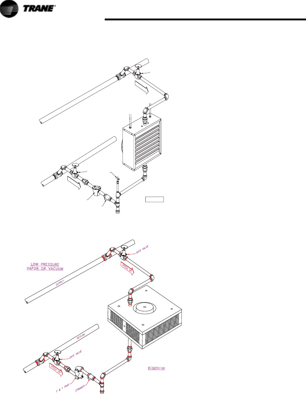
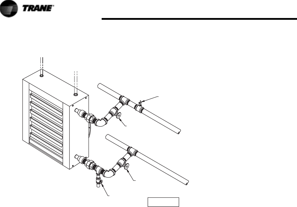
Horizontal and Vertical Unit
Heater Piping and Instalation
The illustrations in this portion of the
catalog depict five different typical
piping configurations. Proper
selection should be based on the
operational characteristics of the
source supply. For selection and
sizing of piping, traps, filters and
other piping specialities, ASHRAE
guides and specialty manufacturer's
literature should be consulted. We
assume that the type and total design
of systems has been selected or
approved by a qualified engineer.
The installation and service manual
should be consulted for further
information on installation,
operation, drainage and system
cleaning.
Piping and installation is typical for
both horizontal and vertical unit
heaters – except side connections.
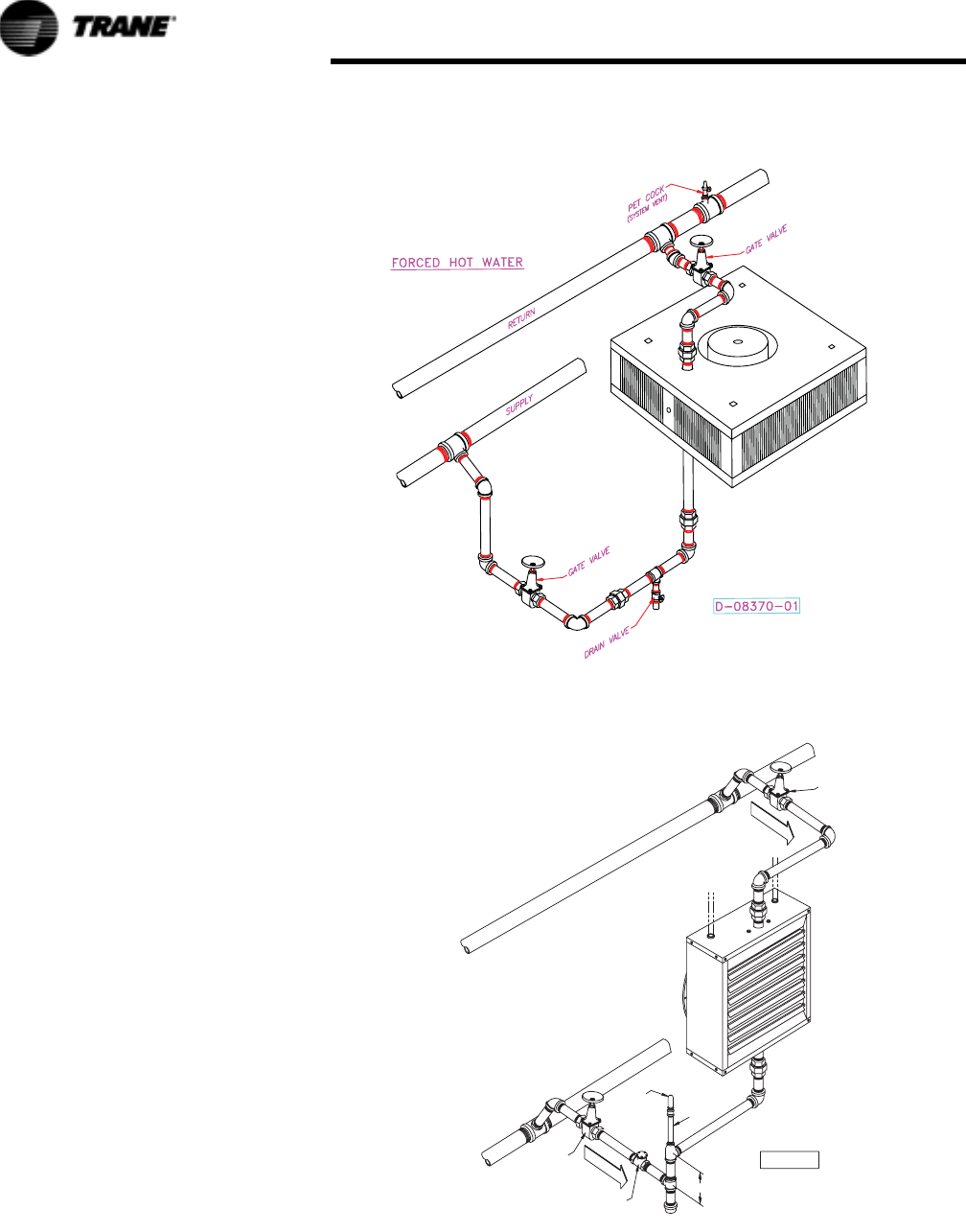
Figure 3.
Figure 4.
RETURN
SUPPLY
GATE VALVE
"LOW PRESSURE STEAM GRAVITY"
GATE VALVE
AIR VENT
MIN. SIZE 3/4
CHECK VALVE
PITCH UP
10" MIN. (254 MM)
PITCH UP
D-6059
UH-PRC001-EN 9
Application Consideration
Figure 5.
Figure 6.
PITCH UP
PITCH UP
RETURN
SUPPLY
PET COCK
GATE VALVE
"HIGH PRESSURE STEAM"
GATE VALVE
BUCKET TRAP
(WITH AIR BYPASS)
STRAINER
D-6058
10 UH-PRC001-EN
Application Consideration
Figure 7.
"FORCED HOT WATER"
(Serpentine Units)
RETURN
SUPPLY
PET COCK
(SYSTEM VENT)
GATE VALVE
GATE VALVE
DRAIN VALVE
D-6057

UH-PRC001-EN 11
Trane Propeller Unit Heaters
Both Model S and Model P Propeller
Unit Heaters are ideally suited to
such a wide variety of installations
that there can be no hard and fast
rules regulating their selection. In
determining the type and size of the
units for any building, the following
points are generally considered:
BTU Requirements
While the choice of units depends
upon several important factors, the
total Btu requirement is usually
determined first. In calculating heat
loss, methods as recommended by
the ASHRAE Guide may be used, or
any other procedure which is known
to be acceptable.
Type of Building
Once the total Btu requirement is
known, the type of building together
with its architecture and its purpose
is considered.
In the many cases where a
combination of space characteristics
is found, a combination of Model S
and Model P Unit Heaters may be
used to create the most satisfactory
heating system.
The Model P Unit Heater has the
natural ability to tap the reservoir of
heated air which collects at the
ceiling level and return it to active
service in the floor zone.
The Model P can be used on either
high or low ceilings. From high
mounting positions the Model P will
allow ample clearance for moving
objects and can project heat down
into occupied areas regardless of
obstacles which would restrict the
flow of air from horizontal units.
From low mounting positions the
Model P, with proper diffusion, can
be used without disturbing nearby
occupants with direct blasts of high
velocity heated air, or requiring
return lines so low as to leave
insufficient head room.
The superior horizontal action of the
Model S, on the other hand, is ideal
for creating a wiping effect of warm
air along exposed walls which
neutralizes drafts at their source,
beaming heat down narrow aisles
and production lines, and blanketing
large windows, doors and other
points of high heat loss.
Spacing of Units
It is the usual practice to divide the
building into areas with like
exposures, or in relation to heat load
distribution desired.
In general, Model S Unit Heaters
may be selected for buildings where
direct horizontal air currents are
desired and where there are no
obstacles to interrupt the flow of air
from the heaters.
Model P Unit Heaters are
successfully used where high or low
mounting heights are required and
should ordinarily be specified with
diffusers, depending upon the
mounting height and application.
Mounting Heights
The maximum effective mounting
height is determined by the outlet
temperature of the air, the outlet
velocity, the cfm for which the heater
is designed, and if a diffuser is used
– the setting of its blades.
The higher the outlet temperature of
the air, the more difficult it is to force
it down into the living zone.
The cfm also affects the mounting
height as a large volume of air will
travel farther than a small volume
under the same initial conditions of
temperature and velocity.
In the preliminary planning stages, it
is well to remember that the lowest
possible mounting height is
desirable in order to get the most
heat down to the floor line and to
allow the greatest possible diffusion
adjustment to provide tailor-made
distribution for each area.
In providing for the use of diffusers
please remember, adjustment of a
Louver Cone Diffuser to deflect the
air toward the horizontal
immediately lowers the mounting
height limit. Adjustment for lateral
deflection with the Louver Fin
Diffuser shortens the distance of
throw.
Diffusion
The use of Trane Louver Cone or
Louver Fin Diffusers influences the
selection of units in two principal
ways: First: It is seldom necessary to
install oversized heaters to extend
the maximum effective mounting
height of the Model P or the distance
of throw of the Model S. Conversely,
Trane Diffusers enable extremely low
mounting since the adjustable
blades direct heat where it is wanted
without creating uncomfortable hot
spots near the units.
Second: After the original selection
has been made, units may be located
with confidence because
adjustments in heat distribution are
possible to accommodate future
changes or unforeseen draft
conditions.
Air Changes
Better diffusion and more even
temperatures can be maintained in a
heated space when the rate of air
recirculation through the heaters is
relatively high. For buildings where
large numbers of people are
engaged, it is desirable to provide
for a greater number of air changes
than for sparsely occupied areas. A
greater number of small units are
used where wide diffusion and even
temperatures are necessary. A few
centrally located units of large
capacity would be used where there
are few occupants.
Comfort Conditions and
Economy
Air circulation, diffusion and spacing
of units are closely related to
economy and comfort in the
selection of unit heaters. The more
units used to provide the required
number of Btu’s, the more
comfortable will be the conditions
for personnel. On the other hand, a
few large units can be selected to
provide plenty of heat at low first
cost, but may be slower in response
and thorough distribution of heat.
Here again, adjustable diffusion
equipment can go a long way toward
saving the buyer first cost expense
while still providing completely
satisfactory comfort conditions.
Selection Procedure
12 UH-PRC001-EN
Selection Procedure
Formula
The following formula is used to
arrive at final air temperature volume
when 70 F (Standard Air Basis) is
known or vice versa:
Cfm at final temp. =
Cfm at 70 F =
Determining Special Steam
Capacities
Where capacity of the unit under
standard conditions is known – 2 lbs.
steam, 60 F entering air – and it is
desired to know the capacity of this
same unit under different steam and
air conditions, follow instructions
given in Example 1.
Where a set of conditions is given –
Btu, temperature rise, final
temperature, cfm, steam pressure
available, etc. Refer to Example 2.
Useful Data
Btu/240=Sq. Ft. of radiation (EDR)
Sq. ft. of radiation/4=Lbs. of
condensate per hour
Btu/Latent heat=Lbs. of water per
hour
Cfm x Temp. Rise x 1.085 = Btu.
Specific heat of air (70 F) = .241
Specific weight of one cubic foot of
air (70 F) =.075.
Cfm x 60 = cfh.
Therefore, .241 x .075 x 60 = 1.085
Example 1
Given: Model 60S Horizontal
Propeller Unit Heater with a rated
capacity of 60,000 Btu at 2 lbs. steam
with 60 F entering air.
Desired: Capacity of this unit using 15
lbs. steam and 40 F entering air.
Under 40 F and across from 15 lbs. in
Ta b l e 2 , we find the factor 1.34.
60,000 x 1.34 = 80,400 Btu per hour.
Cfm at 70F 460 Final temp+
460 70+
--------------------------------------------------
×
Cfm final air 460 70+
460 Final temp+
--------------------------------------------------
×
Determining Amount of
Condensate
To determine the amount of
condensate, divide the capacity in
BTU by the latent heat of steam:
80,400/945=85 lbs per hour.
945=Latent Heat of Steam at 15 psi.
(See Ta b l e 1 2 )
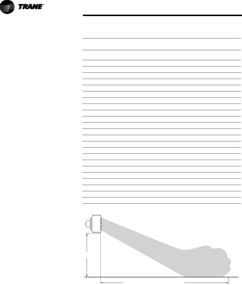
Table 1. Max. Mounting Heights and Distance of throw for Model S Units (based on
2 lbs Steam Pressure 60F entering Air)
Unit
Outlet
Velocity CFM
Final Temp
(F)
Mounting
Height Max Throw
A08* 250 245 91 8 20
A18* 500 500 94 8 25
A25* 590 580 102 9 29
A36* 550 850 99 9 29
018 395 395 102 8 20
024 450 450 109 8 24
036 550 550 119 9 28
048 550 750 119 9 30
060 650 900 121 10 30
072 800 1100 120 10 29
084 900 1400 115 10 30
096 930 1400 123 11 38
108 1000 1800 115 11 40
120 900 1900 118 12 40
132 950 2000 121 13 54
144 1000 2200 120 13 55
156 1150 2600 115 13 55
180 800 2200 135 13 53
204 1000 2900 124 13 55
240 900 3500 123 14 57
280 980 4200 121 14 57
300 700 5000 117 15 58
360 1000 5500 120 15 60
H
MAXIMUM DISTANCE OF THROW = T
Determining Final Temperature
Final temperature of air leaving Trane
Unit Heaters may be determined as
follows:
Inlet Air Temp. + Btu rating/Cfm X
1.085=Final Temp
Inlet Air Temp. 40F + 80,400/900
(from Ta b l e 7 ) X 1.085=Final Temp

UH-PRC001-EN 13
Selection Procedure
Example 2:
Problem: A Trane Model S Horizontal
Unit Heater is desired to deliver
200,000 Btu per hour in a garage
where ventilation is required.
Entering air temperature is 40 F.
Steam at 30 lbs. pressure is available.
Temperature to be maintained is 70 F.
Solution: Under 40 F and across from
30 lbs. in Ta b l e 2 , find the factor 1.51.
Equivalent capacity of required unit
at 2 lbs. steam 60 F entering air is
Required Btu per hour/F=200,000/
1.51=132,500 Btu
From Tabl e 7 , select a Number 132S
Unit Heater with a capacity of
132,000 Btu per hour with standard
coil, and at 2 lbs. steam and 60 F
entering air.
The capacity of this unit at 30 lbs.
steam and 40 F entering air is:
1.51 x 132,000 = 199,300 Btu per hour.
Surplus Capacity
While the ventilation load is being
handled, any air entering the space
over the desired room temperature
should be considered in the heating
calculations. This surplus capacity
can be found by multiplying the
difference between the final
temperature leaving the heater and
the room temperature to be
maintained by 1.085 and that by the
cfm. That amount of heat can be
used to offset heat losses.
Model S
Maximum mounting heights for
Model S Unit Heaters are given in
Ta b l e 1 . When equipped with
standard vertical Louvers, direction
of air flow can be adjusted both
horizontally and vertically.
Mounting the unit at or below
maximum mounting height will
insure that heated air reaches the
living zone.
Model P
Maximum mounting heights for
Model P Unit Heaters are given in
Ta b l e 4 . These distances are figured
from the floor line to the bottom
plate of the unit heater.
Where ceilings are unusually low, a
nearly horizontal flow of air can be
obtained by equipping these units
with Louver Cone Diffusers. The
individually adjustable blades of the
Louver Cone permit an infinite
variety of adjustments to meet any
on-the-job problems. By setting the
blades vertically to straighten the
airstream, as much as 45% increase
in throw can be obtained.
Hot Water Selection Example
Selection Procedure
Select the proper size of unit heater
for whatever application desired, as
illustrated by the following
examples.
Select a Model S horizontal unit
heater to deliver 95 MBH with 220°F
entering water temperature (EWT),
70°F entering air temperature (EAT)
and a 30°F water temperature drop
(WTD).
1. Determine GPM: GPM=Btu/hr/
(485) WTD=95000/485x30=6.53
2. Refer to Table 17 to select the
conversion factor at 220° EWT
and 70° EAT. Factor is 1.06.
3. Determine equivalent MBH at
standard conditions (200° EWT,
60° EAT). Equiv. MBH=MBH/
Factor=95/1.06=89.6.
Table 2. Factors for Determining Steam Capacity of Model S Horizontal Unit
Heaters at Various Pressures and Temperatures (Table based on 2 psig and 60F
entering Air)
Steam Pressure PSIG Temperature of Entering Air (F)
30 40 50 60 70 80 90 100
Blow
Through
Type
0 1.19 1.11 1.03 0.96 0.88 0.81 0.74 0.67
2 1.24 1.16 1.08 1.00 0.93 0.85 0.78 0.71
5 1.29 1.21 1.13 1.05 0.97 0.90 0.83 0.76
10 1.38 1.29 1.21 1.13 1.06 0.98 0.91 0.84
15 1.44 1.34 1.28 1.19 1.12 1.04 0.97 0.89
20 1.50 1.42 1.33 1.25 1.17 1.10 1.02 0.95
30 1.60 1.51 1.43 1.35 1.27 1.19 1.12 1.04
40 1.68 1.60 1.51 1.43 1.35 1.27 1.19 1.12
50 1.70 1.60 1.58 1.50 1.42 1.34 1.26 1.19
60 1.81 1.73 1.64 1.56 1.47 1.39 1.31 1.24
70 1.87 1.78 1.70 1.61 1.53 1.45 1.37 1.29
75 1.90 1.81 1.72 1.64 1.55 1.47 1.39 1.32
100 2.02 1.93 1.84 1.75 1.66 1.58 1.50 1.42
125 2.11 2.02 1.93 1.84 1.76 1.68 1.59 1.51
150 2.20 2.11 2.02 1.93 1.84 1.76 1.67 1.59
To determine the Btu per hour capacity of a Model S Horizontal Unit Heater at any steam pres-
sure and entering air temperature multiply rated capacity at 2 psig steam 60 F entering air
(Table 7) by factor from above table.
4. Select unit size from Tab le 13 .
Select the unit which will provide
89.6 MBH In this example, the
selection indicates a Model S 132
unit heater.
To determine the actual capacity of
this Model S 132 at operating
conditions (220° EWT and 70° EAT)
proceed as follows:
1. Determine the MBH at 6.53 GPM
by applying factor from Ta b l e 2 0 .
Multiply this MBH by the water
flow factor (95.8 MBH X .95=91.0
MBH)
2. Multiply this MBH by the
conversion factor 91.0 X 1.06 =
96,500.
3. The GPM remains constant =
6.53 GPM.
4. Calculate the water temperature
drop WTD=Btu/hr/GPM x 485 =
96,500/(6.53)(485) = 30.5
14 UH-PRC001-EN
Selection Procedure
Note:
To determine the Btu per hour capacity of a Model P projection unit heater at any steam pressure and entering air temperature, multiply rated capacity at
2 psig steam 60 F entering air (Table 8) by factor from Table 3. Factors in italics: Units should not be operated when entering air is below freezing at steam
pressures below 10 psig.
Table 3. Factors For Determining Steam Capacity Of Model P Projection Unit Heaters At Various Pressures And Temperatures
(Table based on 2 PSIG and 60 F Entering Air)
Steam Pressure PSIG Temperature of Entering Air (F)
-10 0 10 20 30 40 50 60 70 80 90 100
Draw-Through Unit
01.49 1.41 1.33 1.25 1.18 1.11 1.03 0.96 0.90 0.83 0.76 0.69
21.52 1.45 1.37 1.29 1.22 1.15 1.07 1.00 0.93 0.86 0.80 0.73
51.58 1.50 1.42 1.34 1.27 1.20 1.12 1.05 0.98 0.91 0.85 0.78
10 1.64 1.57 1.49 1.41 1.34 1.27 1.19 1.12 1.05 0.98 0.91 0.85
15 1.70 1.62 1.55 1.47 1.40 1.32 1.25 1.18 1.11 1.04 0.97 0.90
20 1.75 1.67 1.60 1.52 1.45 1.37 1.30 1.23 1.16 1.09 1.02 0.96
30 1.83 1.75 1.68 1.61 1.53 1.46 1.39 1.32 1.25 1.18 1.11 1.04
40 1.90 1.82 1.75 1.68 1.61 1.53 1.46 1.39 1.32 1.25 1.18 1.11
50 1.96 1.87 1.81 1.74 1.67 1.59 1.52 1.45 1.38 1.31 1.24 1.17
60 2.02 1.94 1.87 1.79 1.72 1.64 1.57 1.50 1.43 1.36 1.29 1.22
70 2.07 1.99 1.92 1.84 1.76 1.69 1.62 1.55 1.47 1.40 1.33 1.27
75 2.10 2.02 1.94 1.86 1.79 1.71 1.64 1.57 1.49 1.42 1.36 1.29
Table 4. Maximum Mounting Heights in Feet for Model P Unit Heaters with and without Louver Cone Diffuser
Unit
Size
Steam Pressure (PSI)
2 5 10 50 75
42-P 10.5
12.5
10.0
12.0
10.0
12.0
9.0
11.0
8.0
10.0
42-P LS* 8.0
9.0
8.0
8.5
8.0
8.5
8.0
8.0
8.0
8.0
42-P-L** 12.5
14.5
12.0
14.0
12.0
13.5
10.5
12.0
9.5
11.5
42-P-L LS 9.0
10.5
8.5
10.0
8.5
10.0
8.0
9.0
8.0
8.5
64-P 12.0
14.5
11.5
14.0
11.5
14.0
10.0
12.0
9.5
11.5
64-P LS 9. 5
11.5
9.0
11.0
9.0
11.0
8.0
9.5
8.0
9.0
64-P-L 15.0
19.0
14.5
18.5
14.5
18.5
12.5
16.5
12.0
16.0
64-P-L LS 11.5
14.0
11.0
13.5
11.0
13.5
9.5
12.0
8.0
11.5
80-P 15.0
18.5
14.5
18.0
14.0
17.5
12.0
15.5
11.5
13.5
80-P LS 11.0
13.5
10.5
13.0
10.5
13.0
9.0
11.5
8.5
11.0
80-P-L 18.0
22.0
17.5
21.0
17.5
21.0
15.0
19.0
14.0
18.0
80-P-L LS 13.0
17.0
12.5
16.5
12.0
16.0
11.0
14.0
10.5
13.5
102-P 14.0
17.0
13.5
16.5
13.0
16.0
11.5
14.0
11.0
13.5
102-P LS 11.0
13.5
10.5
13.0
10.5
13.0
9.5
12.0
9.0
11.5
102-P-L 17.5
21.5
17.0
21.0
16.5
20.5
15.0
18.5
14.5
17.5

UH-PRC001-EN 15
Selection Procedure
102-P-L LS 15.0
18.5
14.5
18.0
14.5
18.0
13.0
16.0
12.5
15.0
122-P 16.0
19.5
15.5
19.0
15.5
18.5
14.0
17.0
13.5
16.0
122-P-L 21.0
26.0
20.5
25.5
20.0
25.0
17.5
22.5
17.0
21.5
146-P 15.5
19.0
15.0
18.5
14.5
18.0
13.0
16.0
12.0
15.5
146-P-L 18.0
22.5
17.5
22.0
17.5
21.5
15.0
18.5
14.0
18.0
166-P 18.0
22.5
17.5
22.0
17.0
21.5
14.5
19.0
14.0
18.0
166-P-L 22.0
27.5
21.5
27.0
21.0
26.5
18.5
23.5
17.5
22.5
202-P 22.0
27.5
21.5
27.0
21.0
26.5
18.5
24.0
17.5
23.0
202-P-L 25.5
31.5
25.0
31.0
24.5
30.5
22.0
27.0
21.0
26.0
252-P 20.0
25.0
19.5
24.0
19.0
23.5
17.0
20.5
16.0
19.5
252-P-L 24.0
29.5
23.5
28.5
23.0
28.0
20.0
24.5
19.0
23.5
280-P 21.0
26.0
20.5
25.5
20.0
25.0
17.5
22.0
17.0
21.0
280-P-L 25.5
32.0
25.0
31.0
24.5
30.0
21.0
26.0
20.0
25.0
336-P 24.0
30.0
23.0
29.0
22.0
28.0
20.0
25.0
19.0
24.0
336-P-L 29.0
36.0
28.5
35.0
28.0
34.0
25.0
30.0
24.0
29.0
384-P 28.5
35.5
28.0
35.0
27.5
34.0
24.0
30.0
23.0
29.0
384-P-L 32.5
41.0
31.5
40.0
30.5
39.0
27.5
35.0
26.5
33.5
500-P 29.5
36.5
29.0
36.0
28.5
35.5
25.0
32.0
24.0
30.5
500-P-L 35.0
43.5
34.0
42.5
33.0
41.5
29.0
35.0
28.0
34.0
600-P 34.0
42.5
33.0
41.5
32.0
40.5
28.0
36.0
27.0
34.5
600-P-L 37.0
46.5
36.0
45.5
35.0
44.5
31.0
39.0
30.0
37.0
720-P 38.5
48.0
37.5
47.0
36.5
46.0
32.0
40.0
30.5
39.0
720-P-L 42.5
53.0
41.5
52.0
40.5
51.0
35.0
44.0
33.5
42.0
Notes:
*LS = Low speed.
**PL = Model P low final temperature model with all air ports open.
Figures in bold face show maximum mounting height with louver cone diffusers set vertically.
To meet CSA and OSHA requirements, Model P Unit Heaters mounted lower than 8.0 ft. from the floor must be equipped with an OSHA fan guard. Table 4
based on 60 F entering air temperature. In providing for the use of diffusers, it must be remembered that adjustment of a LCD to deflect air toward
horizontal immediately lowers the mounting height limit.
Table 4. Maximum Mounting Heights in Feet for Model P Unit Heaters with and without Louver Cone Diffuser (continued)
Unit
Size
Steam Pressure (PSI)
2 5 10 50 75

16 UH-PRC001-EN
Selection Procedure
Additional Selection Data
Motor and Fan Speeds
Motor and fan speeds are selected to
provide efficient performance. The
solid-state speed control will provide
an infinite number of speeds
between the highest and the lowest
cataloged fan speeds. The speed
control is not calibrated in specific
fan speeds. For use on units with 115
volt/60 cycle/1 phase, 1/8 hp and
smaller standard motors only.
Standard and Bypass Units
Standard models meet most
requirements and are most
economical. Bypass units meet
conditions as mentioned above, and
are also used where low final
temperature is specified.
Table 5. Maximum Spread in Feet
Unit Size: P 42 64 80 102 122 146 166 202 252 280 336 384 500 600 720
Spread ft 15 17 20 24 26 27 28 32 35 37 45 50 54 57 60
25 and 50 Cycle Unit Heat
Capacities
Ta b l e 6 shows the Btu, cfm, and the
hp required on unit heaters when
operated on 25 or 50 cycle circuits.
The multipliers in Ta b l e 6 may be
applied to standard 60 cycle unit
capacities to determine the capacities
of the same unit when operating on
25 or 50 cycle current. These
multipliers may be used on units
cataloged at 1050 to 1150 RPM.
For the smaller Trane Unit Heaters
cataloged at 1550 RPM, the capacity
data in the catalog may be applied to
either 25 or 50 cycle service.
Table 6. Factors for Determining Unit Heater Capacities at 25 or 50 Cycles
RPM Multiplier To Be Applied To 60-Cycle 1100 RPM Ratings
25 CY 50 CY BTU CFM HP
1425 1425 1.17 1.25 1.95
950 .87 .833 .572
710 710 .7 .623 .242
UH-PRC001-EN 17
Performance Data
Steam Performance Data
Horizontal Unit Heaters
Performance based on 2# steam pressure at heater with air entering @ 60° F (max working pressure 150 PSI,366° F)
* For the lower output, an optional Speed Controller must be ordered.
For Sound Ratings, see the Technical and Mounting Data-portion of this chapter.
Ta b l e 7.
Model
No.
Total
MBh
Cond.
lbs./hr.
E.D.R.
Sq. Ft. LAT °F
Motor
HP
Motor
RPM
Nominal
CFM
Outlet
Velocity
FPM
Sound
Rating
S-18
18,000 18.0 75 102
16 Watts
1550 395 395 II
16,200 16.2 68 105 1350 330 330 I
S-24
24,000 24.5 100 109
16 Watts
1550 450 450 II
21,600 22.0 90 112 1350 380 380 I
S-36
36,000 37.0 150 119
25 Watts
1550 550 550 II
32,400 33.0 135 120 1350 480 480 I
S-48
48,000 49.0 200 119
1/20
1000 750 550 II
43,200 44.0 180 123 900 630 460 I
S-60
60,000 61.0 250 121
1/20
1000 900 650 II
54,000 55.0 225 131 900 700 510 I
S-72
72,000 73.0 300 120
1/20
1000 1100 800 II
64,800 66.0 270 123 900 950 700 I
S-84
84,000 85.0 350 115
1/12
1000 1400 900 III
75,600 76.0 315 123 900 1100 750 II
S-96
96,000 97.0 400 123
1/12
1000 1400 930 III
86,400 88.0 360 132 900 1100 800 II
S-108
108,000 110.0 450 115
1/12
1000 1800 1000 III
97,200 98.0 405 120 900 1500 900 II
S-120 120,000 122.0 500 118 1/3 1140 1900 900 III
S-132 132,000 134.0 550 121 1/3 1140 2000 950 IV
S-144 144,000 146.0 600 120 1/3 1140 2200 1000 IV
S-156 156,000 160.0 650 115 1/3 1140 2600 1150 IV
S-180 180,000 190.0 770 135 1/3 1140 2200 800 III
S-204 204,000 208.0 850 124 1/3 1140 2900 1000 IV
S-240 240,000 244.0 1000 123 1/3 1140 3500 900 IV
S-280 280,000 280.0 1100 121 1/2 1100 4200 980 IV
S-300 300,000 310.0 1250 117 1/2 1100 5000 700 IV
S-360 360,000 366.0 1500 120 1/2 1100 5500 1000 IV
18 UH-PRC001-EN
Performance Data
Vertical Unit Heaters
Performance based on 2# steam pressure at heater with air entering @ 60°F.
Notes:
Constant speed units are rated at capacities shown in regular type; capacities shown in italic faced type apply only to units with multi-speed motors.
** To determine BTU per hour capacities at various steam pressures and entering air temperatures, use conversion factors from Table 11. Final temper-
atures at new conditions can be calculated by applying basic formula.
Table 8. Standard Units
Model
No.
Total
MBh
Cond.
lbs./hr.
E.D.R.
Sq. ft. LAT °F
Motor
HP
Motor
RPM
Nominal
CFM
Outlet
Velocity
FPM
Sound
Rating
P-42
41,300 43 172 124
1/40
1550 595 877
I
33,600 55 140 131 1150 436 658
P-64
65,500 68 273 121
1/20
1550 989 1005
II
52,800 55 220 129 1150 706 727
P-80
80,600 83 336 122
1/20
1550 1200 1220
II
65,100 67 271 130 1150 858 894
P-102
101,800 106 424 123
1/8
1070 1490 980
II
87,900 91 366 129 850 1180 783
P-122 124,400 129 518 124 1/6 1100 1790 1170 III
P-146 152,000 157 633 123 1/6 1100 2220 1045 III
P-166 173,000 179 720 121 1/6 1100 2620 1230 IV
P-202 210,200 208 838 118 1/4 1100 3200 1495 III
P-252 249,800 260 1040 115 1/4 1100 4180 1205 IV
P-280 283,800 294 1180 119 1/2 1100 4430 1275 IV
P-336 333,400 345 1390 119 3/4 1140 5210 1500 IV
P-384 386,000 400 1610 118 3/4 1140 6140 1770 IV
P-500 496,000 514 2070 117 1-1/2 1160 8020 1640 IV
P-600 585,000 605 2440 117 1-1/2 1160 9450 1930 IV
P-720 705,000 729 2940 119 3 1165 11,000 2250 IV

UH-PRC001-EN 19
Performance Data
NOTES:
Constant speed units are rated at capacities shown in regular type; capacities shown in italic faced type apply only to units with multi-speed motors.
**To determine BTU per hour capacities at various steam pressures and entering air temperatures, use conversion factors from Table 11. Final temperatures at new conditions
can be calculated by applying basic formula.
Table 9. Low Output Units: Standard Model Units w/All Air Ports Open
Model
No.
Total
MBh
Cond.
lbs./hr.
E.D.R.
Sq. ft. LAT °F.
Motor
HP
Motor
RPM
Nominal
CFM
Outlet Velocity
FPM
Sound
Rating
P-42L
34.8 36 145 108
1/40
1550 668 950
I
26.0 27 108 111 1150 470 672
P-64L
57.2 59 238 104
1/20
1550 1200 1190
I
45.8 48 191 109 1150 862 858
P-80L
68.0 71 283 106
1/20
1550 1360 1350
II
55.0 57 229 111 1150 995 992
P-102L
85.4 89 356 108
1/8
1070 1640 1050
II
71.2 74 296 111 850 1290 827
P-122L 111.0 115 462 107 1/6 1100 2180 1390 III
P-146L 125.0 130 524 109 1/6 1100 2360 1080 III
P-166L 149.0 154 620 107 1/6 1100 2920 1340 IV
P-202L 176.8 183 736 108 1/4 1100 3390 1560 III
P-252L 214.9 224 895 104 1/4 1100 4500 1270 IV
P-280L 251.8 260 1050 106 1/2 1100 5040 1420 IV
P-336L 291.0 302 1210 107 3/4 1140 5700 1610 IV
P-384L 344.0 356 1430 108 3/4 1140 6600 1870 IV
P-500L 428.0 446 1785 102 1-1/2 1160 9380 1860 IV
P-600L 515.0 533 2140 106 1-1/2 1160 10,300 2060 IV
P-720L 620.0 642 2580 108 3 1165 11,900 2380 IV
Table 10. STEAM CALCULATIONS AND CORRECTION FACTORS
EXAMPLE:
UNIT SIZE __________ P-42
Steam Pressure _____10 PSI
Entering Air Temp. ____ 40°F
I. CAPACITY
A. For 2 lbs. steam, 60° entering air
Read output directly from Ta b le 8 : 41,300 BTU/HR.
B. For higher steam pressures and/or E.A.T.'s above
or below 60°F
Multiply output from Ta b le 8 by appropriate
correction factor from Tab l e 11 .
41,300 x 1.27 = 52,451 BTU/HR.
II. FINAL AIR TEMPERATURE
A. For 2 lbs. steam, 60° entering air
Read temperature directly from Table 8 : 124°F.
B. For capacities calculated in I.B. (above) Output from I.B./1.085 x CFM from Ta b l e 8 +
E.A.T. = Final Air Temp
52,451/1.085 x 595 + 40 = 121.0°F
III. FINAL AIR VOLUME
A. For 2 lbs. steam, 60° entering air
460 + Final Air Temp from Tabl e 8/530 x Nom. CFM
from Ta b l e 8 = Final Air Volume
460 + 124/530 x 595 = 655 CFM
B. For final air temperatures calculated In II. B.
(above)
460 + Final Air Temp from II.B./530 x Nom. CFM
from Ta b l e 8 = Final Air Volume
460 + 121.0/530 x 595 = 652 CFM
IV. CONDENSATE PER HOUR
A. For 2 lbs. steam, 60° entering air
Read lbs. per hour from Tabl e 8 : 43 LBS./HR.
B. For capacities calculated in I.B. (above) Output from I.B./Latent Heat from Tabl e 1 2 = lbs.
per hour of condensate
52,451/953 = 55.0 LBS./HR.
20 UH-PRC001-EN
Performance Data
Note: Ratings apply only to free inlet and discharge without diffusers.
Note: All motors are constant speed and operate at top speed as indicated in motor data. Models 42 through 102 can
be run at reduced speed with addition of optional variable speed switch. This switch is factory-calibrated for low
and high speed ratings, with intermediate speeds infinitely controllable. Models 166 through 720 operate at
constant speed as indicated in motor data.
Note: For specific motor data, refer to motor specifications at the end of this chapter.
Note: To correct for entering air temperatures, use 1° temperature rise for each foot in mounting height. As an
example, 60° air is required at work area (5 ft. above floor) units are to be mounted at (20 ft.) above floor.
Mounting height (20 ft.) minus work height (5 ft.) equals differential (15 ft.) or, 15° rise in air temperature at unit
air inlet. Correct for actual inlet air temperature of 75° (60° + 15° = 75° E.A.T.) on Ta b l e 10
Table 11. STEAM CORRECTION FACTORS BASED ON 2 LBS. STEAM 60° E.A.T.
ENTERING
AIR TEMP
STEAM PRESSURE - LBS. PER SQ. IN. (SATURATED)
02510152030405075
30° 1.18 1.22 1.27 1.34 1.40 1.45 1.53 1.61 1.67 1.79
40° 1.11 1.15 1.20 1.27 1.32 1.37 1.46 1.53 1.59 1.71
50° 1.03 1.07 1.12 1.19 1.25 1.30 1.39 1.46 1.52 1.64
60° 0.96 1.00 1.05 1.12 1.18 1.23 1.32 1.39 1.45 1.57
70° 0.90 0.93 0.98 1.05 1.11 1.16 1.25 1.32 1.38 1.49
80° 0.83 0.86 0.91 0.98 1.04 1.09 1.18 1.25 1.31 1.42
90° 0.76 0.80 0.85 0.91 0.97 1.02 1.11 1.18 1.24 1.36
100° 0.69 0.73 0.78 0.85 0.90 0.96 1.04 1.11 1.17 1.29
Table 12. PROPERTIES OF SATURATED STEAM
STEAM PRESSURE IN LBS. PER SQUARE INCH GAUGE
02 5 10 15 20 30 40 50 75
Steam Temperature-°F 212.0 218.5 227.1 239.4 249.8 258.8 274.0 286.7 297.7 319.9
Latent Heat of Steam 970 966 961 953 946 940 929 920 912 891
UH-PRC001-EN 21
Performance Data
Hot Water Performance Data
Horizontal Unit Heaters
Peformance based on 200° EWT, 60° E.A.T., 20° WTD (max working pressure 150 PSI, 366° F)
* For the lower output, an optional Speed Controller must be ordered.
Table 13.
Model No. Total MBh GPM LAT °F WPD Motor HP RPM
Nominal
CFM
Outlet
Velocity
FPM Sound Rating
S-A08
8.0
0.80
91
.80 16 Watts
1550 245 250 II
6.8 90 1350 210 215 I
S-A18
18.4
1.9
94
2.2 16 Watts
1550 500 500 II
15.7 96 1350 420 420 I
S-A25
24.8
2.5
102
2.2 25 Watts
1550 580 590 II
21.2 106 1350 460 450 I
S-A36
35.9
3.6
99
3.0 1/20
1000 850 550 II
32.3 100 900 750 480 I
S-18
13.1
1.3
95
.005 16 Watts
1550 395 395 II
11.7 99 1350 350 350 I
S-24
17.4
1.8
96
.014 16 Watts
1550 450 450 II
15.6 98 1350 380 380 I
S-36
26.1
2.7
103
.09 25 Watts
1550 550 550 II
23.5 103 1350 480 480 I
S-48
34.8
3.5
103
.12 1/20
1000 750 550 II
31.3 111 900 630 460 I
S-60
43.6
4.4
105
.17 1/20
1000 900 650 II
39.2 112 900 700 510 I
S-72
52.3
5.3
104
.23 1/20
1000 1100 800 II
47.0 106 900 950 700 I
S-84
61.0
6.1
100
.24 1/12
1000 1400 900 III
54.9 106 900 1100 750 II
S-96
69.7
7.0
106
.29 1/12
1000 1400 930 III
62.7 113 900 1100 800 II
S-108
78.4
7.9
100
.36 1/12
1000 1800 1000 III
70.5 103 900 1500 900 II
S-120 87.1 8.8 102 .39 1/3 1140 1900 900 III
S-132 95.8 9.6 104 .41 1/3 1140 2000 950 IV
S-144 104.0 10.4 104 .43 1/3 1140 2200 1000 IV
S-156 113.0 11.3 100 .53 1/3 1140 2600 1150 IV
S-180 118.0 11.8 110 .60 1/3 1140 2200 800 III
S-204 148.1 14.9 107 .79 1/3 1140 2900 1000 IV
S-240 174.0 17.4 106 1.06 1/3 1140 3500 900 IV
S-280 209.1 21.0 106 1.33 1/2 1100 4200 980 IV
S-300 230.0 23.0 102 2.1 1/2 1100 5000 700 IV
S-360 261.3 26.2 103 2.1 1/2 1100 5500 1000 IV
22 UH-PRC001-EN
Performance Data
Vertical Unit Heaters
Table 14. Standard Output Units**
Model No.
Water
Temp.
Drop
Total
MBh GPM WPD LAT °F Motor HP RPM
Nominal
CFM
Outlet
Velocity
FPM Sound Rating
P-42
10° 28.8 5.93 .37 104.6°
1/40 1550 595 877 I
20° 22.7 2.34 .06 95.2°
30° 16.7 1.15 .02 85.9°
P-42*
10° 22.9 4.71 .24 108.3°
1/40 1150 436 658 I
20° 18.1 1.87 .04 98.3°
30° 13.4 .92 .01 88.4°
P-64
10° 48.1 9.92 1.05 104.8°
1/20 1550 989 1005 II
20° 39.6 4.08 .19 96.9°
30° 31.1 2.14 .06 89.0°
P-64*
10° 38.1 7.85 .67 109.7°
1/20 1150 706 727 II
20° 31.5 3.24 .13 101.1°
30° 24.8 1.71 .04 92.4°
P-80
10° 58.7 12.11 .98 105.1°
1/20 1550 1200 1220 II
20° 48.4 4.99 .18 97.2°
30° 38.1 2.62 .05 89.3°
P-80*
10° 46.5 9.59 .63 110.0°
1/20 1150 858 894 II
20° 38.5 3.97 .12 101.2°
30° 30.5 2.09 .03 92.7°
P-102
10° 77.2 15.91 2.06 106.6°
1/8 1070 1528 980 II
20° 68.3 7.03 .44 101.2°
30° 59.3 4.08 .16 95.8°
P-102*
10° 63.7 13.13 1.43 108.6°
1/8 850 1208 783 II
20° 56.5 5.82 .31 103.1°
30° 49.2 3.38 .11 97.6°
P-122
10° 94.9 19.55 3.04 108.9°
1/6 1100 1790 1170 III
20° 83.7 8.63 .65 103.1°
30° 72.5 4.98 .23 97.3°
P-146
10° 117.6 24.24 4.32 108.8°
1/6 1100 2220 1045 III
20° 105.2 10.84 .96 103.7°
30° 92.8 6.38 .36 98.5°
P-166
10° 132.4 27.29 3.67 106.6°
1/6 1100 2620 1230 IV
20° 118.6 12.22 .81 101.7°
30° 104.8 7.20 .30 96.9°
P-202
10° 156.2 32.20 5.02 105.0°
1/4 1100 3200 1495 III
20° 139.7 14.40 1.11 100.2°
30° 123.2 8.47 .41 95.5°
P-252
15° 188.9 25.95 3.92 101.8°
1/4 1100 4162 1205 IV
20° 180.1 18.56 2.10 99.9°
30° 162.7 11.18 .82 96.0°
P-280
15° 215.4 29.60 5.02 104.8°
1/2 1100 4430 1275 IV
20° 205.4 21.17 2.68 102.7°
30° 185.3 12.73 1.04 98.5°
UH-PRC001-EN 23
Performance Data
**Performance based on 200° EWT, 20° T.D., 60° E.A.T. Performance at 10° & 30° T.D. is also shown.
For capacities at other conditions, use the correction multipliers in Table 16, Table 17, Table 18, Table 19, and Table 20
*Speed controller option is required for reduced ratings.
P-336
15° 254.9 35.03 6.88 105.1°
3/4 1140 5210 1500 IV
20° 242.9 25.03 3.67 103.0°
30° 218.9 15.04 1.42 98.7°
P-384
15° 294.7 40.49 6.60 104.2°
3/4 1140 6140 1770 IV
20° 280.8 28.94 3.52 102.2°
30° 253.1 17.39 1.36 98.0°
P-500
15° ----- ----- ----- -----
1-1/2 1160 8020 1640 IV
20° 368.1 37.93 5.81 102.3°
30° 333.6 22.92 2.29 98.3°
P-600
15° 451.2 62.00 8.78 104.0°
1-1/2 1160 9450 1930 IV
20° 431.1 44.43 4.72 102.0°
30° 391.0 26.86 1.86 98.1°
P-720
15° ----- ----- ----- -----
3 1165 11,000 2250 IV
20° 519.4 53.52 5.29 103.5°
30° 470.9 32.35 2.08 99.5°
Table 15. Low Output Units Standard Model P Units with All Air Ports Open**
Model No.
Water
Temp.
Drop Total MBh GPM WPD LAT °F Motor HP RPM
Nominal
CFM
Outlet
Velocity
FPM Sound Rating
P-42L
10° 23.9 4.92 .26 92.9°
1/40 1550 668 950 I
20° 18.9 1.95 .04 86.1°
30° 14.0 .96 .01 79.3°
P-42L*
10° 16.7 3.45 .13 92.8°
1/40 1150 470 672 I
20° 13.5 1.39 .02 86.4°
30° ----- ----- ----- -----
P-64L
10° 41.5 8.56 .80 91.9°
1/20 1550 1200 1190 II
20° 34.2 3.53 .15 86.3°
30° 27.0 1.85 .04 80.7°
P-64L*
10° 32.4 6.68 .50 94.7°
1/20 1150 862 858 II
20° 26.9 2.77 .09 88.7°
30° 21.3 1.46 .03 82.8°
P-80L
10° 48.9 10.09 .69 93.2°
1/20 1550 1360 1350 II
20° 40.5 4.17 .13 87.4°
30° 32.0 2.20 .04 81.7°
P-80L*
10° 38.5 7.94 .44 95.7°
1/20 1150 995 992 II
20° 32.0 3.29 .08 89.6°
30° 25.4 1.75 .02 83.5°
P-102L
10° 63.7 13.13 1.43 93.5°
1/8 1070 1752 1050 II
20° 56.5 5.82 .31 89.7°
30° 49.2 3.38 .11 85.9°
P-102L*
10° 54.5 11.24 1.06 93.5°
1/8 850 1499 827 II
20° 48.5 4.99 .23 89.8°
30° 42.4 2.91 .08 86.1°
Table 14. Standard Output Units** (continued)
Model No.
Water
Temp.
Drop
Total
MBh GPM WPD LAT °F Motor HP RPM
Nominal
CFM
Outlet
Velocity
FPM Sound Rating

24 UH-PRC001-EN
Performance Data
**Performance based on 200° EWT, 20° T.D., 60° E.A.T. Performance at 10° & 30° T.D. is also shown.
For capacities at other conditions, use the correction multipliers in Table 16, Table 17, Table 18, Table 19, and Table 20.
P-122
10° 83.7 17.24 2.40 95.4°
1/6 1100 2180 1390 III
20° 73.9 7.62 .51 91.3
30° 64.2 4.41 .18 87.1°
P-146L
10° 95.4 19.66 2.92 97.3°
1/6 1100 2360 1080 III
20° 85.5 8.81 .65 93.4°
30° 75.6 5.20 .24 89.5°
P-166L
10° 112.3 23.15 2.70 95.4°
1/6 1100 2920 1340 IV
20° 100.7 10.38 .60 91.8°
30° 89.2 6.13 .22 88.1°
P-202L
10° 135.8 27.98 3.85 96.9°
1/4 1100 3390 1560 III
20° 121.8 12.52 .85 93.0°
30° 107.3 7.37 .32 89.2°
P-252L
10° 168.5 34.72 6.75 94.5°
1/4 1100 4507 1270 IV
20° 153.8 15.85 1.56 91.4°
30° 139.1 9.56 .61 88.4°
P-280L
10° 188.9 25.95 3.92 94.5°
1/2 1100 5040 1420 IV
20° 180.1 18.56 2.10 92.9°
30° 162.7 11.18 .82 89.7°
P-336L
10° 220.9 30.35 5.26 95.7°
3/4 1140 5700 1610 IV
20° 210.6 21.70 2.81 94.1°
30° 189.9 13.05 1.09 90.7°
P-384L
10° 260.7 35.82 5.24 96.4°
3/4 1140 6600 1870 IV
20° 248.5 25.61 2.80 94.7°
30° 224.2 15.40 1.09 91.3°
P-500L
10° ----- ----- ----- -----
1-1/2 1160 9380 1860 IV
20° 310.5 32.00 4.23 90.5°
30° 281.7 19.35 1.67 87.7°
P-600L
10° 394.4 54.19 6.83 95.3°
1-1/2 1160 10,300 2060 IV
20° 377.0 38.85 3.68 93.7°
30° 342.2 23.51 1.45 90.6°
P-720L
10° ----- ----- ----- -----
3 1165 11,900 2380 IV
20° 453.7 46.76 4.11 95.1°
30° 411.7 28.28 1.62 91.9°
Table 15. Low Output Units Standard Model P Units with All Air Ports Open** (continued)
Model No.
Water
Temp.
Drop Total MBh GPM WPD LAT °F Motor HP RPM
Nominal
CFM
Outlet
Velocity
FPM Sound Rating

UH-PRC001-EN 25
Performance Data
To obtain the BTU capacity for conditions other than those in the basic capacity tables, multiply the basic rating (200° entering water, 60° entering air) by the proper constant
from Table 17.
Table 16. HOT WATER CALCULATIONS AND CORRECTION FACTORS
EXAMPLE:
UNIT:__________________P-42
Entering Water Temp. _____160°F
Entering Air Temp. ________ 40°F
Water Temperature Drop ____ 10°F
I. CAPACITY @ 20° TD:
A. For 200° EWT, 60° EAT
Read output directly from Ta b l e 1 4 & Tab l e 15 ,
22,700 BTU/HR (Ref., Std. P-42, p. 22).
B. For EWT and/or EAT above or below
Standard
Multiply output from Ta b le 1 4 & Ta b le 1 5 by factor from
Ta b l e 1 7 .
22,700 x .878 = 19,931 BTU/HR.
II. CAPACITY AT OTHER TD's
A. For TD's from 5 to 60°F
Multiply output obtained in IA. or IB.
(above) by appropriate factor from Ta b le 1 8
IA - 22,700 x 1.15 = 26,105 BTU/HR.
-OR-
IB - 19,931 x 1.15 = 22,921 BTU/HR.
III. GPM AT OTHER TD's
A. For TD's from 5 to 60°F
Multiply GPM of unit for 20° TD, from Ta ble 1 4 by
appropriate factor from Ta b le 1 8
2.34 x 2.30 = 5.38 GPM (Applies only
to units with. Std. 200° EWT, 60° EAT.)
For all others calculate using formula -
GPM = BTU/500 x TD
IV. PRESSURE LOSS AT OTHER TD's
A.ForTD's from 5 to 60°F
Multiply P.D. of unit for 20° TD, from Ta b l e 1 4 & Ta b l e 1 5
by appropriate factor from Tabl e 18
.06 x 5.00 = .30 Ft. H2O
Table 17. HOT WATER CONVERSION FACTORS BASED ON 200° ENTERING WATER 60° ENTERING AIR 20° TEMPERATURE DROP
ENTERING AIR
TEMPERATURE
ENTERING WATER TEMPERATURE -20° WATER TEMPERATURE DROP
100° 120° 140° 160° 180° 200° 220° 240° 260° 280° 300°
30° 0.518 0.666 0.814 0.963 1.120 1.268 1.408 1.555 1.702 1.850 1.997
40° 0.439 0.585 0.731 0.878 1.025 1.172 1.317 1.464 1.609 1.755 1.908
50° 0.361 0.506 0.651 0.796 0.941 1.085 1.231 1.375 1.518 1.663 1.824
60° 0.286 0.429 0.571 0.715 0.857 1.000 1.143 1.286 1.429 1.571 1.717
70° 0.212 0.353 0.494 0.636 0.777 0.918 1.060 1.201 1.342 1.483 1.630
80° 0.140 0.279 0.419 0.558 0.698 0.837 0.977 1.117 1.257 1.397 1.545
90° 0.069 0.207 0.345 0.483 0.621 0.759 0.897 1.035 1.173 1.311 1.462
100° 0 0.137 0.273 0.409 0.546 0.682 0.818 0.955 1.094 1.230 1.371
Table 18. HOT WATER BTU, GPM AND PRESSURE LOSS FACTORS BASED ON STANDARD CONDITIONS OF 200°F ENTERING
WATER 60°F ENTERING AIR & 20°F WATER DROP
USE FACTORS FROM THIS TABLE TO OBTAIN
APPROXIMATE RESULTS
TEMPERATURE DROP °F
510152025 30 4050 60
To obtain BTU for other Water Temperature Drops,
multiply basic BTU rating by applicable Factor.
1.25 1.15 1.08 1.00 .94 .90 .83 .76 .72
To obtain GPM for other Water Temperature Drops,
multiply basic GPM rating by applicable Factor.*
5.00 2.30 1.44 1.00 .74 .59 .40 .30 .24
To obtain Pressure Loss Feet of Water for other
temperature Drops, multiply Basic loss at 20° drop by
Factor.
10.00 5.00 2.00 1.00 .60 .40 .20 .13 .07
Table 19. *MINIMUM WATER FLOW - GPM
MODEL No. 42 64 80 102 146 166 202 252 336 384 500 600 700
MIN. GPM .55 .55 .55 .55 .82 .82 1.10 1.10 1.10 1.10 1.0 1.4 1.6
Table 20. *HEATING CAPACITY FACTORS FOR VARIOUS RATES OF WATER FLOW
% of Rated Water Flow 25% 50% 75% 100% 125% 150% 175%
Btu/Hr Heating Capacity .80 .89 .96 1.00 1.04 1.07 1.10
26 UH-PRC001-EN
Performance Data
Technical & Mounting
Data
Horizontal Unit Heaters
Te c h n i c a l D a t a
The performance data listed in
Ta b l e 1 3 , Tab l e 14 , and Ta b l e 1 5
include sound ratings. The ratings
provide a guide in determining the
acceptable degree of loudness in
particular occupancy situations.
Certain general rules apply to specific
selection of unit heaters with regard
to degree of quietness (or loudness);
• The greater the fan diameter, the
higher the sound level.
• The higher the motor RPM, the
higher the sound level. Note that
on most units the lower the
speed mode results in lowering
the sound rating one increment.
• Selecting a larger number of
smaller units generally results in
lower overall noise levels than
fewer large units.
All horizontal steam and hot water
unit heater motors, whether fan
guard or shelf-mounted, are isolated
from the mechanical mount by
resilient isolators. This mounting
along with balanced fan blades and
excellent overall construction
integrity, assures you the utmost in
quiet operation.
The following table outlines sound
ratings for various applications. The
lower the number, the quieter the
unit and the lower the sound
requirement.
Mounting Heights and Throws
The following table is based on 60°
entering air and either 2 lb. steam or
200° water with a 20° T.D. The data is
based on the higher speed CFM
throughout and velocity. Care should
be exercised in locating adjacent unit
heaters and allowance should be
made for obstructions in the air
pattern and conflicting air currents
from other air moving devices.
*Depending on specific use in these facilities, size of operation, etc.
*Compared to water.
CATEGORY OF AREA SOUND RATING
apartment, assembly hall, classrooms, churches, courtrooms, executive
offices, hospitals, libraries, museums, theatres
I
dining rooms, general offices, recreation areas, small retail stores II
restaurants, banks, cafeterias, department stores, public buildings,
service stations
III
gymnasiums, health clubs, laundromats, supermarkets IV
garages, small machine shops, light manufacturing V
Factories, foundries, steel mills III-VII*
Table 21. Corrections When Using Glycol Solution in System
Propylene
Glycol
Heat transfer @ 180°F with no
increase inflow rate
20% solution .97*
50% solution .90*
G.P.M. Req'd. @ 180°F, 20°F ∆ t (no
correction to pump curve)
1.10%*
Pump Head Req'd. @ 180°F w/
increase in G.P.M.
1.23%*
Specify gravity (water = 1.0) 1.045-1.055*
Pounds/Gallons @ 60°F (water =
8.3453 Pound/Gallon)
8.77
pH @ 50% by volume 9.5
Freezing Point by volume
55% -
50% -28°F
40% 13°F
30% + 4°F
20% +17°F
Table 22. Approximate factors at varying altitudes
Altitude Factor
Sea level - 1000 ft. 1.00
1000 ft. - 3000 ft. .958
3000 ft. - 5000 ft. .929
5000 ft. - 7000 ft. .900
7000 ft. - 10000 ft. .871
UH-PRC001-EN 27
Performance Data
Motor Characteristics Data
Horizontal Unit Heaters
*Optional variable speed switch is available.
**These motors are without thermal overload protection.
†230/1/60 unit has 115/1/60 motor supplied with field installed stepdown transformer.
Note 1:
All motors are constant speed and operate at top speed as indicated in motor data. Models 18 through 108, including A08, A18, A25 and A36 can be run
at reduced speed with addition of optional variable speed switch. This switch is factory-calibrated for low and high speed ratings, with intermediate speeds
infinitely controllable. Models 120 through 360 operate at constant speed as indicated in motor data. All 1/4 H.P. motors are P.S.C.
Note 2:
Motors under 1/3 H.P. are totally enclosed, frame mounted, 115/1/60 with thermal overload protection and permanently lubricated sleeve bearings with
optional speed controller available. 1/3 H.P. (115/1/60) motors are open frame constant speed with thermal over-load protection and ball bearings. 1/3
H.P. (230V) and 1/2 H.P. (230V) motors are open frame constant speed with thermal overload protection and ball bearings.
Note 3:
1/3 and 1/2 H.P. motors are available as 230V single and 3 phase in open frame and explosion-proof housings, all available as options. 1/3 and 1/2 H.P.
motors operate at single speed only.
Note 4:
Stated AMP draw is Full Load Amp (FLA). AMP draw varies by motor manufacturer ± .2 AMPS. Verify FLA per unit motor data plate.
Table 23. Totally Enclosed Motor Type
S Unit Model No. AMP MCA MOP HP RPM
115/1/60
18, 24, A08, A18 0.8 1 1.8 16W* 1550
A36 1.4 1.8 3.2 1/20* 1000
36, A25 1.2 1.5 2.7 25W* 1550
48, 60, 72 1.4 1.8 3.2 1/20* 1000
84, 96, 108 2.2 2.8 5.0 1/12* 1000
120, 132, 144, 156,
180, 204, 240
4.5 5.6 10.1 1/3 1140
280, 300, 360 5.4 6.8 12.2 1/2 1100
230/1/60
18, 24, A08, A18 0.4 0.5 0.9 16W 1550
A36 1.4 1.8 3.2 1/20† 1000
36, A25 0.6 0.8 1.4 25W 1550
48, 60, 72 1.4 1.8 3.2 1/20† 1000
84, 96, 108 2.2 2.8 5.0 1/12† 1000
120, 132, 144, 156,
180, 204, 240
4.5 5.6 10.1 1/3† 1140
280, 300, 360 5.4 6.8 12.2 1/2† 1100
208-230/460/3/60
48, 60, 72, 84, 96,
108, 120, 132, 144,
156, 180, 204, 240,
280, 300, 360
2.6-2.6/1.3 3.3-3.3/1.6 5.9-5.9/2.9 1/2** 1140

28 UH-PRC001-EN
Performance Data
*Optional variable speed switch is available.
**These motors are without thermal overload protection.
***These motors are 115/230 volts.
†230/1/60 unit has 115/1/60 motor supplied with field installed stepdown transformer.
Note 1:
Models 120 through 360 operate at constant speed as indicated in motor data. All 1/4 H.P. motors are P.S.C.
Note 2:
Motors under 1/3 H.P. are totally enclosed, frame mounted, 115/1/60 with thermal overload protection and permanently lubricated sleeve bearings with
optional speed controller available. 1/3 H.P. (115/1/60) motors are open frame constant speed with thermal over-load protection and ball bearings. 1/3
H.P. (230V) and 1/2 H.P. (230V) motors are open frame constant speed with thermal overload protection and ball bearings.
Note 3:
1/3 and 1/2 H.P. motors are available as 230V single and 3 phase in open frame and explosion-proof housings, all available as options. 1/3 and 1/2 H.P.
motors operate at single speed only.
Note 4:
Stated AMP draw is Full Load Amp (FLA). AMP draw varies by motor manufacturer ± .2 AMPS. Verify FLA per unit motor data plate.
Table 24. Explosion Proof with Thermal Overload Motor Type
S Unit Model No. AMP MCA MOP HP RPM
115/1/60
48, 60, 72, 84, 96,
108, 120, 132
3.7 4.6 8.3 1/6 1140
144, 156, 180, 204 5.4 6.8 12.2 1/4 1140
240, 280, 300 7.4 9.3 16.7 1/3*** 1140
360 7.4 9.3 16.7 1/2*** 1140
230/1/60
48, 60, 72, 84, 96,
108, 120, 132
3.7 4.6 8.3 1/6† 1140
144, 156, 180, 204 5.4 6.8 12.2 1/4† 1140
240, 280, 300 3.7 4.7 8.3 1/3*** 1140
360 3.7 4.7 8.3 1/2*** 1140
230/460/3/60/TE
144, 156, 180, 204,
240, 280, 300, 360
2.2/1.1 2.8/1.4 5.0/2.5 1/3 1140
UH-PRC001-EN 29
Performance Data
Vertical Unit Heaters
* Optional variable speed switch is available.
** These motors have automatic thermal overload protection or impedance protection.
Note 1:
All motors are constant speed and operate at top speed as indicated in motor data. Models through 1/8 H.P. can be run at reduced speed with addition of
optional variable speed switch. This switch is factory-calibrated for low and high speed ratings, with intermediate speeds infinitely controllable. Models 166
through 720 operate at constant speed as indicated in motor data.
Note 2:
Stated draw is Full Load (FLA). AMP draw varies by motor manufacturer ± .2 AMPS.
Table 25. Totally Enclosed Motor Type
P Unit Model No. AMP MCA MOP HP RPM
115/1/60
42 1.23** 1.6 2.8 1/40* 1550
64, 80 2.1** 2.6 4.7 1/20* 1550
102 1.2** 1.5 2.7 1/8* 1070
122
2.3** 2.9 5.2 1/6 1100
146
166
202 3.6** 4.5 8.1 1/4 1100
252 3.6** 4.5 8.1 1/4 1100
280 5.4** 6.8 12.2 1/2 1100
208-230/460/3/60
42 0.98-1.1/0.55 1.2-1.4/0.7 2.2-2.5/1.2 1/6 1140
64, 80 0.98-1.1/0.55 1.2-1.4/0.7 2.2-2.5/1.2 1/6 1140
102 0.98-1.1/0.55 1.2-1.4/0.7 2.2-2.5/1.2 1/6 1140
122
0.98-1.1/0.55 1.2-1.4/0.7 2.2-2.5/1.2 1/6 1140
146
166
202 1.2-1.4/0.7 1.5-1.8/0.9 2.7-3.2/1.6 1/4 1140
252 1.2-1.4/0.7 1.5-1.8/0.9 2.7-3.2/1.6 1/4 1140
280 1.8-2.0/1.0 2.3-2.5/1.3 4.1-4.5/2.3 1/2 1140
336, 384 3.1-3.2/1.6 3.9-4.0/2.0 7.0-7.2/3.6 3/4 1140
500, 600 5.3-5.0/2.5 6.6-6.3/3.1 11.9-11.3/5.6 1-1/2 1160
720 9.9-9.8/4.9 12.4-12.3/6.1 22.3-22.1/11.0 3 1165
575/3/60
42, 64, 80, 102, 122,
146, 166, 202, 252
0.6 0.8 1.4 1/3 1140
280 0.8 1.0 1.8 1/2 1140
336, 384 1.3 1.6 2.9 3/4 1140
500, 600 2.0 2.5 4.5 1-1/2 1160
720 3.8 4.7 8.6 3 1165

30 UH-PRC001-EN
Performance Data
*** These motors are 230/460 volts only.
Note 1:
Models 166 through 720 operate at constant speed as indicated in motor data.
Note 2:
Stated draw is Full Load (FLA). AMP draw varies by motor manufacturer ± .2 AMPS.
Table 26. Explosion Proof with Thermal Overload Motor Type
P Unit Model No. AMP MCA MOP HP RPM
115/1/60
42 3.8 4.8 8.6 1/6 1140
64, 80 3.8 4.8 8.6 1/6 1140
102 3.8 4.8 8.6 1/6 1140
122
3.8 4.8 8.6 1/6 1140
146
166
202 4.4 5.5 9.9 1/4 1140
252 4.4 5.5 9.9 1/4 1140
280 7.8 9.8 17.6 1/2 1140
208-230/460/3/60
42 1.0-1.0/0.5 1.3-1.3/0.6 2.3-2.3/1.1 1/6 1140
64, 80 1.0-1.0/0.5 1.3-1.3/0.6 2.3-2.3/1.1 1/6 1140
102 1.0-1.0/0.5 1.3-1.3/0.6 2.3-2.3/1.1 1/6 1140
122
1.0-1.0/0.5 1.3-1.3/0.6 2.3-2.3/1.1 1/6 1140
146
166
202 1.1-1.1/0.55 1.4-1.4/0.7 2.5-2.5/1.2 1/4 1140
252 1.1-1.1/0.55 1.4-1.4/0.7 2.5-2.5/1.2 1/4 1140
280 1.9/0.95*** 2.4/1.2 4.3/2.1 1/2 1140
336, 384 3.1-3.2/1.6 3.9-4.0/2.0 7.0-7.2/3.6 3/4 1145
500, 600 5.0/2.5 6.5/3.3 11.3/5.6 1-1/2 1150
700 10.0/5.0*** 12.5/6.3 22.5/11.3 3 1150
UH-PRC001-EN 31
Wiring Diagrams
WARNING
Hazardous Voltage
Disconnect all electric power,
including remote disconnects before
servicing. Follow proper lockout/
tagout procedures to ensure the
power can not be inadvertently
energized. Failure to disconnect
power before servicing could result
in death or serious injury.
WARNING
Hazardous Voltage
Do not use any tools (i.e.
screwdriver, pliers, etc.) across the
terminals to check for power. Use a
voltmeter. Failure to disconnect
power before servicing could result
in death or serious injury.
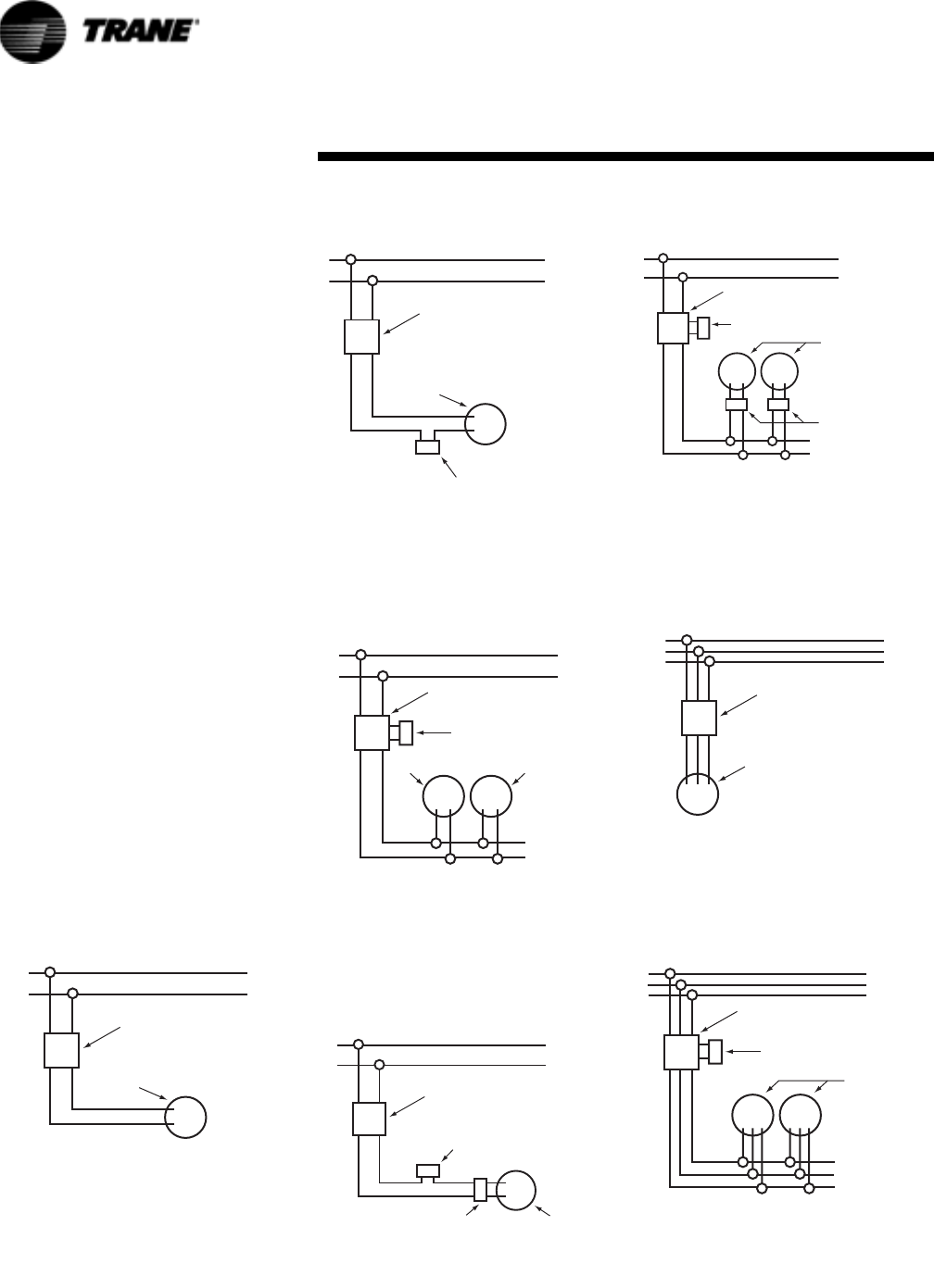
1. For internal wiring and overload
protection on all starters, consult
the control manufacturer for
details.
2. When using thermostatic control
with a manual starter, be sure
that the electrical rating of the
thermostat is sufficient to carry
the motor current.
Note: Refer to the Motor
Characteristics-portion of the
Performance Data chapter for
motor characteristics of
Individual Unit Heaters
Figure 8.
MOTOR
MANUAL STARTING
SWITCH
1 PHASE LINE
MANUAL CONTROL WITH
SINGLE PHASE MOTOR
Figure 9.
Figure 10.
Figure 11.
1 PHASE LINE
MOTOR
MANUAL STARTING
SWITCH
ROOM THERMOSTAT
THERMOSTATIC CONTROL
WITH MANUAL STARTER
1 PHASE LINE
MOTOR
MAGNETIC
STARTING SWITCH
THERMOSTAT
MOTOR
THERMOSTATIC CONTROL
USING MAGNETIC STARTER
OPERATING SEVERAL UNITS
1 PHASE LINE
MOTOR
MANUAL STARTING
SWITCH
THERMOSTAT
SPEED CONTROLLER
SPEED CONTROLLER WITH
MANUAL STARTING SWITCH
Figure 12.
Figure 13.
Figure 14.
1 PHASE LINE
MAGNETIC
STARTING SWITCH
THERMOSTAT
MOTORS
SPEED
CONTROLLERS
SPEED CONTROLLERS WITH
MAGNETIC STARTING SWITCH
FOR OPERATING SEVERAL UNITS
MOTOR
MANUAL STARTING
SWITCH
3 PHASE LINE
MANUAL CONTROL WITH
THREE PHASE MOTOR
3 PHASE LINE
MAGNETIC
STARTING SWITCH
THERMOSTAT
THERMOSTATIC CONTROL
OF SEVERAL THREE PHASE UNITS
MOTORS
Wiring Diagrams
32 UH-PRC001-EN
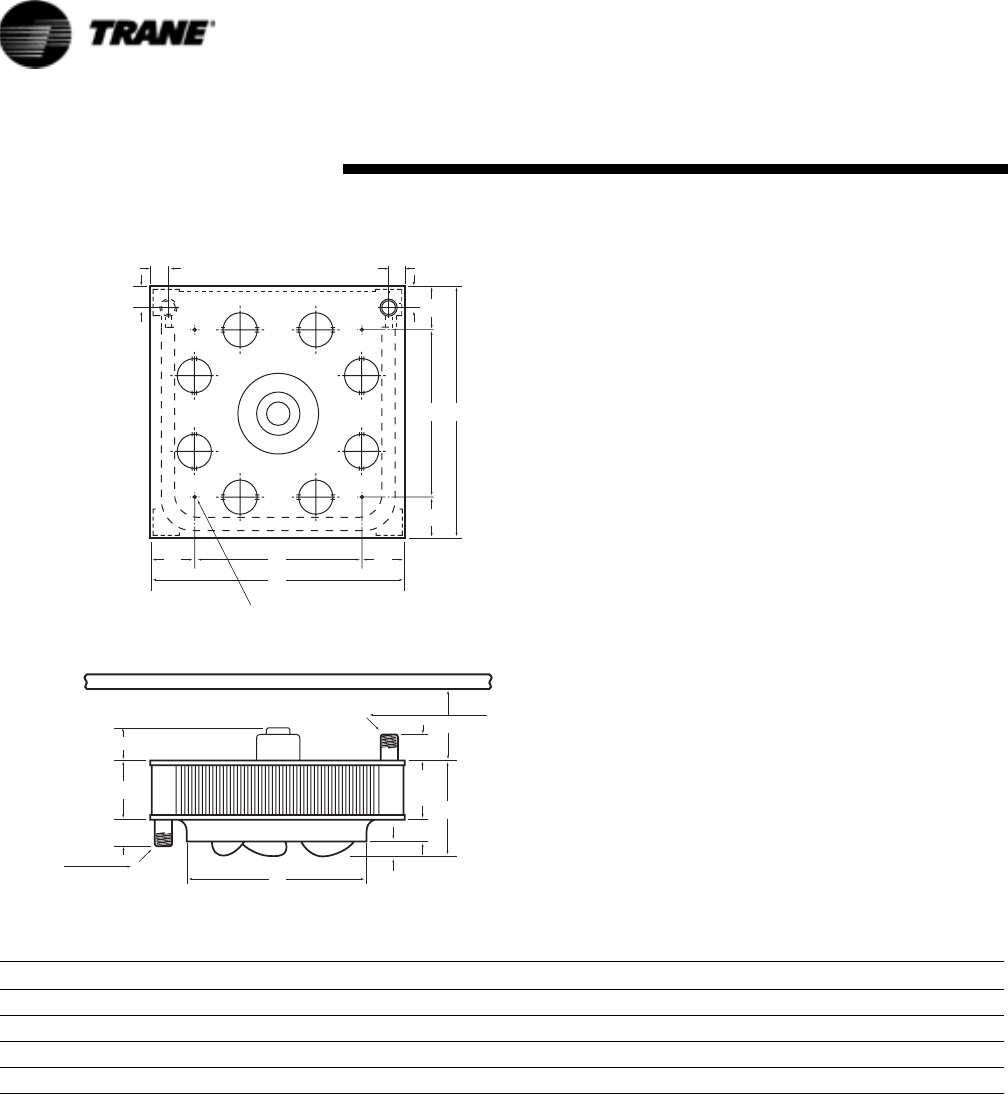
Dimensional Data: P Model
Figure 15. Models 42-80
Table 27. Roughing in Dimensional Data - Model Size 42-80
Unit Capacity (MBH) Fan Dia. A B C D E F G H K L (Min.) P (NPT) R S T U V
042 11 1/4 18 1/4 4 5/8 1 1/4 11 3/4 3/4 4 11 1 3/8 1 7/8 7 1 1/2 3 5/8 6 5/8 2 3/4 11 3 5/8
064 13 1/2 21 1/4 4 5/8 1 5/8 14 1 4 14 1 3/8 1 7/8 7 1 1/2 3 5/8 7 1/8 2 3/4 14 3 5/8
080 13 1/2 21 1/4 6 1/8 1 5/8 14 1 3 14 1 3/8 1 7/8 7 1 1/2 3 5/8 8 5/8 2 3/4 14 3 5/8
CEILING
S
B
F
P
P
C
E
L
D
T
T
STEAM
SUPPLY
OR
HOT WATER
RETURN
STEAM
RETURN
OR
HOT WATER
SUPPLY
V
R
G A
A
GR
K
H
K
H
R
(4) MOUNTING HOLES
THREAD TAPS 3/8 - 16 FOR 42P-80P
Dimensional Data
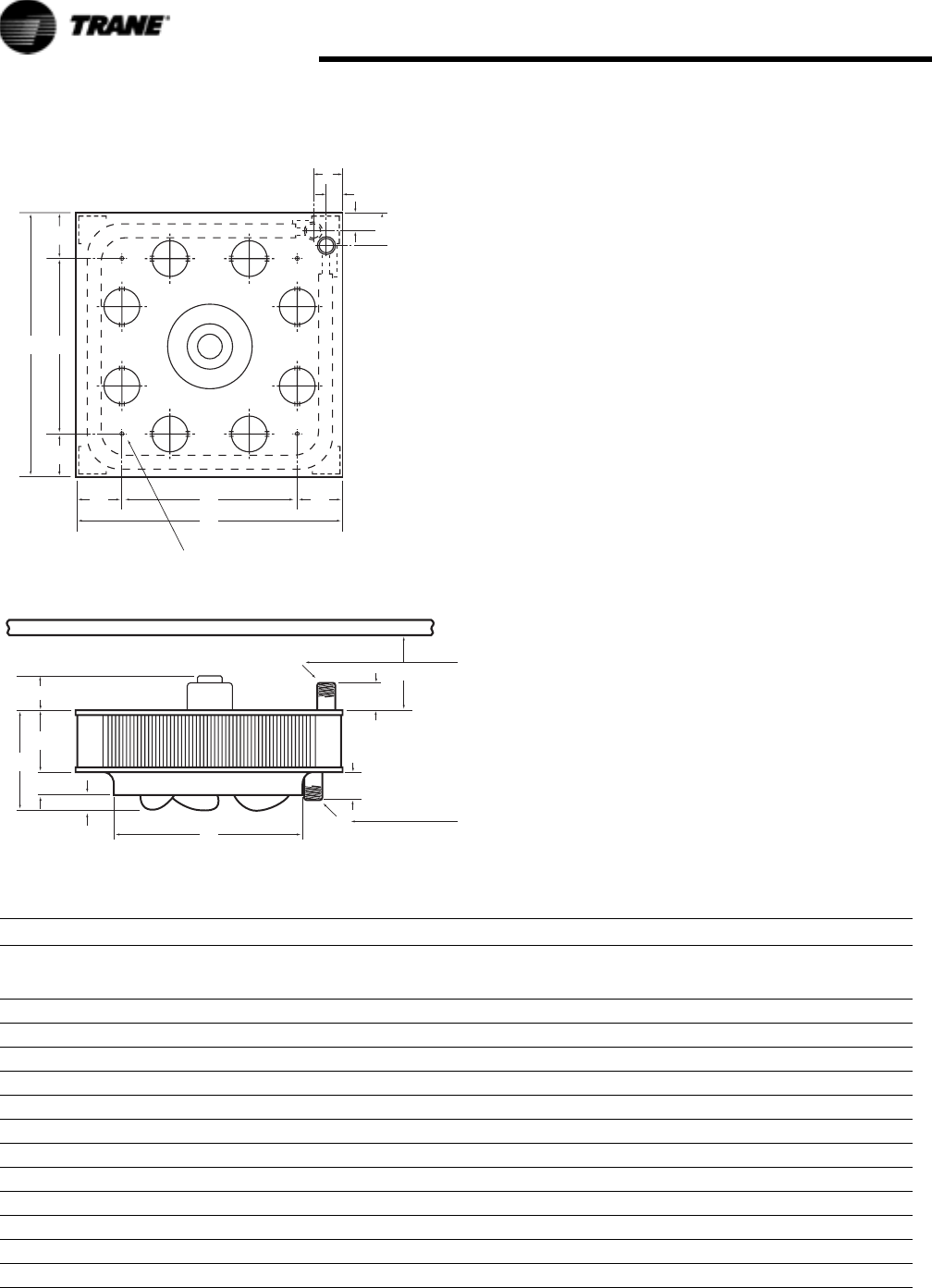
UH-PRC001-EN 33
Dimensional Data
Figure 16. Models 102-720
Table 28. Roughing in Dimensional Data - Model Size 102-720
Unit
Capacity
(MBH)
Fan
Dia. A B C D E F G H K
L
(Min.)
P
(NPT) R S T U V
102 16 3/4 25 1/4 6 1/8 2 17 1/2 1 1/8 3 17 1 3/8 2 3/4 7 1 1/2 4 1/8 9 1/8 2 3/4 17 4 1/8
122 16 3/4 25 1/4 6 1/8 2 17 1/2 1 3/4 3 17 1 3/8 2 3/4 7 1 1/2 4 1/8 9 3/4 2 3/4 17 4 1/8
146 19 3/4 29 1/2 6 1/8 2 3/8 20 5/8 1 1/4 4 20 1/2 1 3/4 3 1/2 7 2 4 1/2 9 5/8 2 3/4 20 1/2 4 1/2
166 19 3/4 29 1/2 6 1/8 2 3/8 20 5/8 1 3/4 4 20 1/2 1 3/4 3 1/2 7 2 4 1/2 10 1/8 2 3/4 20 1/2 4 1/2
202 19 3/4 29 1/2 7 5/8 2 3/8 20 5/8 2 4 20 1/2 1 3/4 3 1/2 7 2 4 1/2 12 2 3/4 20 1/2 4 1/2
252 25 1/4 37 1/2 7 5/8 3 26 3/8 1 3 1/2 28 1 3/4 3 1/2 7 2 4 3/4 11 5/8 2 3/4 18 9 3/4
280 25 1/4 37 1/2 7 5/8 3 26 3/8 1 1/4 3 1/2 28 1 3/4 3 1/2 7 2 4 3/4 11 3/4 2 3/4 18 9 3/4
336 25 1/4 37 1/2 7 5/8 3 26 3/8 2 1/8 4 28 1 3/4 3 1/2 7 2 4 3/4 12 3/4 2 3/4 18 9 3/4
384 25 1/4 37 1/2 9 1/8 3 26 3/8 2 3 1/2 28 1 3/4 3 1/2 7 2 4 3/4 14 1/8 2 3/4 18 9 3/4
500 30 42 9 1/8 3 1/2 31 1/4 1 5/8 3 30 2 1/4 4 1/4 7 2 1/2 6 14 1/4 3 30 6
600 30 42 12 1/8 3 1/2 31 1/4 2 1/8 3 30 2 1/4 4 1/4 7 2 1/2 6 17 3/4 3 30 6
720 30 42 13 5/8 3 1/2 31 1/4 3 4 30 2 1/4 4 1/4 7 2 1/2 6 20 1/4 3 30 6
CEILING
S
B
F
P
P
C
E
L
D
T
T
STEAM
SUPPLY
OR
HOT WATER
RETURN
STEAM
RETURN
OR
HOT WATER
SUPPLY
V
V
UA
A
GR
HK
K
H
R
(4) MOUNTING HOLES 3/8 - 16 FOR 102P-384P
THREAD TAPS 1/2 - 13 FOR 500P-720P
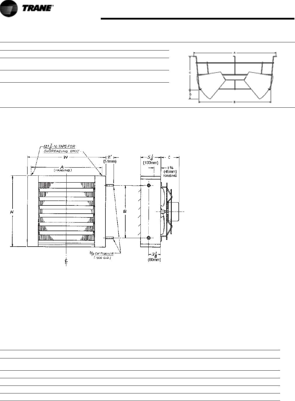
34 UH-PRC001-EN
Dimensional Data
Dimensional Data: S Model
Note: Motors are totally enclosed,
thermally protected, sleeve
bearing, with 4" (w) x 2" (h)
conduit connection boxes.
Nutserts are attached to
enclosure for balanced
hanging.
Table 29. Louver Cone Diffuser Roughing in Dimensions
Unit Size A B C D No. of Louvers
42
64 & 80
16 1/2
20
14 1/4
17
6 1/2
8
2 5/8
3 1/8
8
8
102 & 122
146, 166 & 202
24 1/4
28 3/8
21
24 3/4
9 3/4
11 1/2
3 15/16
4 5/8
8
8
252, 280, 336, & 384
500, 600 & 720
35 1/2
41 1/2
31 1/2
37 1/4
13 3/4
17
4
4 3/4
12
12
Figure 17. Serpentine Type Models A08, A18, A25, A36
Table 30. Serpentine Models
MODEL H W A B C
NO. OF
LOUVERS
NOM. FAN
DIAM.
APPROX.
SHIP WT.
A08 16 18 16 7/32 11 1/4 4 1/4 5 9 22
A18 16 18 16 7/32 11 1/4 4 1/4 5 10 24
A25 16 18 16 7/32 11 1/4 4 1/4 5 10 25
A36 18 1/2 20 1/2 18 23/32 13 3/4 5 1/8 6 12 31
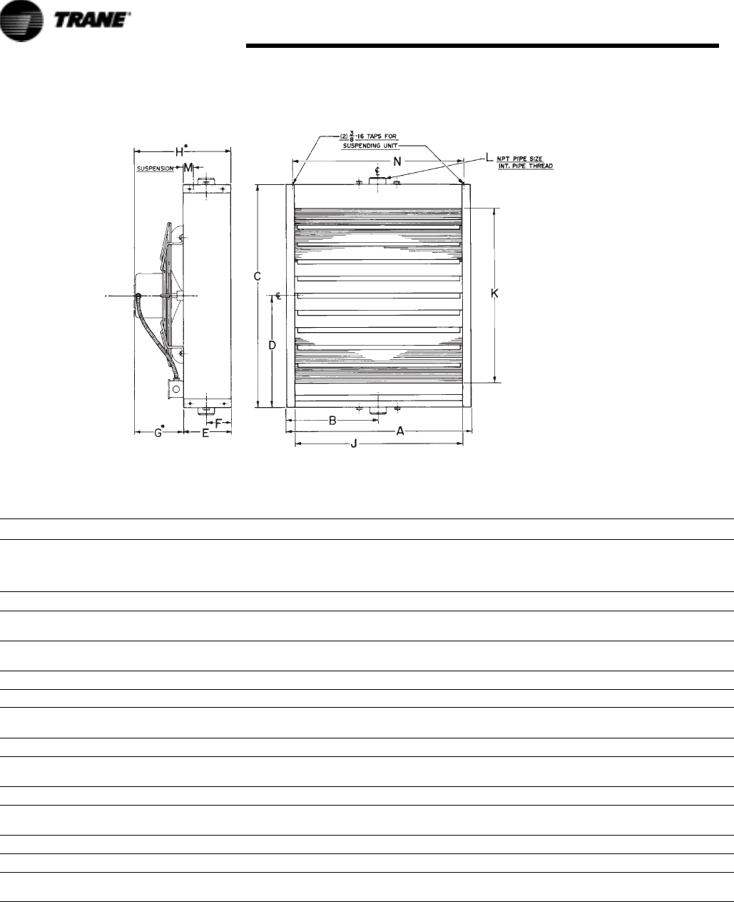
UH-PRC001-EN 35
Dimensional Data
* Applies to standard motor with standard fan guard. When optional motors or OSHA fan guards are requested, dimensions will change according to the
substitutions made.
NOTES
1. Standard motor and standard guard shown.
2. Optional OSHA guards available for all units with 1 phase motors.
3. All 3 phase and explosion proof motors are shelf mounted.
Figure 18. Header Type Models 18 thru 360
Table 31. Models S-18 Thru 360 (Header Type)
MODEL A B C D E F G* H* J K L M N
NO.
OF
LOU-
VERS
NOM.
FAN
DIAM.
APPROX.
SHIP
WT.
S-18 14 5/8 7 5/16 15 7 1/2 6 1/8 2 15/16 3 1/4 9 3/8 12 1/4 9 1/2 1 1/4 2 1/4 12 7/8 4 9 26
S-24
S-36
14 5/8 7 5/16 18 9 6 1/8 2 15/16 3 1/4 9 3/8 12 1/4 12 1/2 1 1/4 2 1/4 12 7/8 5 10 30
S-48
S-60
17 1/8 8 9/16 20 1/2 10 1/4 5 7/8 2 15/16 5 1/16 10 15/16 14 3/4 15 1 1/4 1 3/4 15 3/8 6 12 41
S-72 18 3/8 9 3/16 21 3/4 10 7/8 6 2 15/16 5 1/16 11 1/16 16 16 1/4 1 1/4 1 3/4 16 5/8 7 14 44
S-84 20 7/8 10 9/16 24 1/4 12 1/8 6 1/8 2 15/16 5 11/16 11 13/16 18 1/2 18 3/4 1 1/4 1 3/4 19 1/8 8 14 47
S-96
S-108
19 5/8 9 13/16 24 12 6 5/16 3 3/16 7 1/2 13 13/16 17 1/4 17 1/2 1 1/2 1 3/4 17 7/8 8 16 49
S-120 20 7/8 10 7/16 25 1/4 12 5/8 6 5/16 3 3/16 6 11/16 13 18 1/2 18 3/4 1 1/2 1 3/4 19 1/8 8 18 59
S-132
S-144
23 3/8 11 11/16 27 3/4 13 7/8 6 5/16 3 3/16 7 5/8 14 21 21 1/4 1 1/2 1 3/4 21 5/8 9 18 74
S-156 23 3/8 11 11/16 27 3/4 13 7/8 6 5/16 3 3/16 7 7/16 13 3/4 21 21 1/4 1 1/2 1 3/4 21 5/8 9 18 74
S-180
S-204
24 5/8 12 5/16 29 14 1/2 6 3/8 3 3/16 7 7/16 13 3/4 22 1/4 22 1/2 1 1/2 1 3/4 22 7/8 9 18 90
S-240 27 7/8 13 15/16 30 1/4 15 1/8 8 1/8 3 3/16 5 7/8 14 25 1/2 23 3/4 2 1 3/4 26 1/8 10 20 125
S-280 27 7/8 13 15/16 30 1/4 15 1/8 8 1/8 3 3/16 9-5/8 17 3/4 25 1/2 23 3/4 2 1 3/4 26 1/8 10 20 118
S-300
S-360
33 3/8 16 11/16 37 3/4 18 7/8 9 3 3/16 9 5/8 18 5/8 31 31 1/4 2 1 3/4 31 5/8 13 24 154
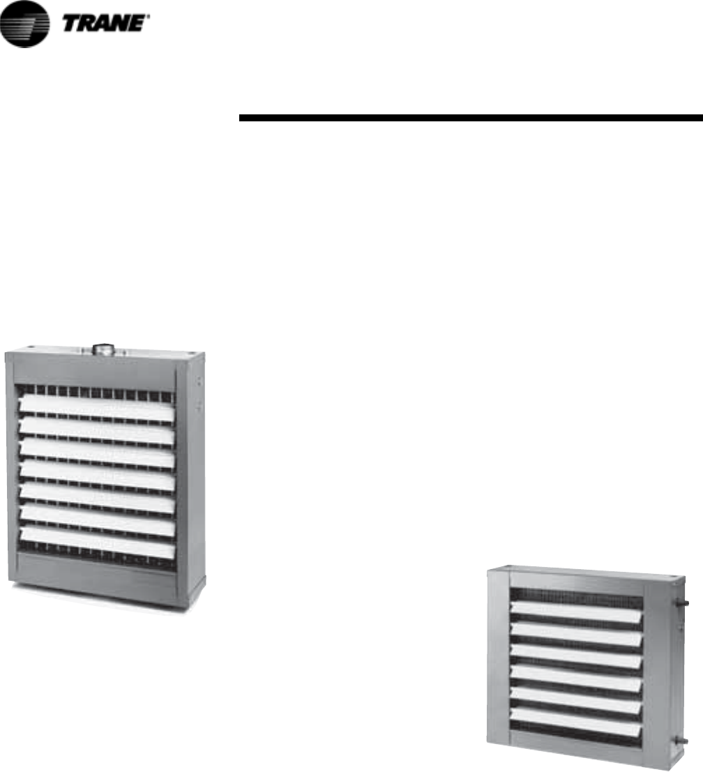
36 UH-PRC001-EN
Horizontal Specifications
General
Furnish and install, where indicated
or scheduled on plans Model S
horizontal steam/hot water unit
heaters. Unit shall be equipped as
specified herein. All units shall be
installed in a neat and workmanlike
manner in accordance with this
specification and the manufacturer's
installation instruction.
Casing
Casings are fabricated from 20
gauge die-formed steel. Casing
substrates are prepared for finishing
with a hot wash, iron phosphatizing
clear rinse, chromic acid rinse and
oven drying. Paint finish is leadfree,
chromate free, alkyd melamine resin
base and applied with an
electrostatic two-pass system. Finish
is baked at 350°F.
Coil Models 18 – 360
Coil elements and headers are heavy
wall drawn seamless copper tubing.
Element tubes are brazed into
extruded header junctions. Pipe
connection saddles are cast bronze.
Aluminum fins have drawn collars to
assure permanent bond with
expanded element tubes and exact
spacing. All Element Assemblies are
submersion tested at factory at 250
P.S.I., and are rated at 150 pounds of
saturated steam pressure at 366°F,
under maximum load conditions. We
recommend operating pressure of 75
P.S.I. at 320°F for long life.
Motors
Motors are totally enclosed, resilient
mounted with class “B” windings.
All motors are designed for
horizontal mounting. Motors under
1/3 H.P. are totally enclosed, frame
mounted, 115/1/60 with thermal
overload protection and
permanently lubricated sleeve
bearings with optional solid state
speed controller available. 1/3 H.P.
(115/1/60) motors are open frame
construction, with thermal overload
protection and ball bearings. 1/3 H.P.
at (230V) and1/2 H.P. (230V) motors
are open frame construction, with
thermal overload protection and ball
bearings. 1/3 and 1/2 H.P. motors are
available in single and 3 phase in
open frame construction or
explosion-proof housings, all the
above are available as options.
Explosion Proof Motors
An enclosed motor whose enclosure
is designed and constructed to
withstand an explosion of a specific
gas or vapor which may occur within
the motor and to prevent the ignition
of this gas or vapor surrounding the
machine.
Motors comply with the National
Electrical Code classification as
follows:
Class I, Group D; all sizes
Class II, Group F; all sizes
Class II, Group G; all sizes
Division I & II Installations
T-code (T3B)
Explosion proof equipment is not
generally available for Class I,
Groups A and B and it is necessary
to isolate motors from the hazardous
area. All explosion proof motors are
shelf mounted.
Fans
Fans are aluminum blade, hub type
designed and balanced to assure
maximum air delivery, low motor
horsepower requirements and quiet
operation. Blades are spark proof.
Fan Guards
Fan guards are welded steel, zinc
plated or painted. To meet CSA and
OSHA requirements, units mounted
below 8 feet from floor must be
equipped with an OSHA fan guard.
OSHA fan guards are optional.
Air Deflection Louvers
Units are equipped with horizontal,
individually adjustable louvers. An
optional vertical louver is available
for four-way air control.
Serpentine Coil Specifications
General
Furnish and install, where indicated
or scheduled on plans Model S-A
horizontal hot water unit heaters.
Unit shall be equipped as specified
herein. All units shall be installed in
a neat and workmanlike manner in
accordance with this specification
and the manufacturer's installation
instruction.
Casing
Casings are fabricated from 20
gauge die-formed steel. Casing
substrates are prepared for finishing
with a hot wash, iron phosphatizing
clear rinse, chromic acid rinse and
oven drying. Paint finish is leadfree,
chromate free, alkyd melamine resin
base and applied with an
electrostatic two-pass system. Finish
is baked at 350°F.
Mechanical Specifications

UH-PRC001-EN 37
Mechanical Specifications
Coil Models S-A08– S-A36
Coil is a serpentine design with
seamless copper tubing. Aluminum
fins have drawn collars to assure
permanent bond with expanded
tubes. Tubing connection are 3/8"
copper tubing, type “M” (.500 O.D.).
Coils are factory tested at 250 P.S.I.
Motors
Motors are totally enclosed, resilient
mounted with class “B” windings. All
motors are designed for horizontal
mounting.
Fans
Fans are aluminum blade type,
designed and balanced to assure
maximum air delivery, low motor
horsepower requirements and quiet
operation.
Fan Guards
Fan guards are welded steel, zinc
plated or painted. To meet CSA and
OSHA requirements, units mounted
below 8 feet from floor must be
equipped with an OSHA fan guard.
OSHA fan guards are optional.
Air Deflection Louvers
Units are equipped with horizontal,
individually adjustable louvers.
Vertical Specifications
General
Furnish and install, where indicated
or scheduled on plans Model P
vertical steam/hot water unit heaters.
Unit shall be equipped as specified
herein. All units shall be installed in
a neat and workmanlike manner in
accordance with this specification
and the manufacturer's installation
instruction.
Casing
Casing is formed by two square steel
plates. Bottom plate forms orifice for
air delivery. Air ports stamped in top
plate as standard for easy removal
for low final air temperature.
Coil
Hot water/steam coils are rectangular
3 or 4-sided, one-pass, multiple
circuit, with aluminum Sigma-Flow
(there should be a registered sign
after Sigma-Flow) fins mechanically
bonded to tubes. Standard coils are
tested at 375 psi under water. Supply
and return connections are steel
pipe. Standard coils have .025
copper tubing suitable for use on
steam pressure to 75 psi or hot water
up to 225 psi or 325 F. Optional .049
steel tubing is suitable for use for 450
F water at 400 psi.
Motors
Standard motors are 115/60/1, totally
enclosed, with thermal overload
protection for all units through size
280P. Standard motors for 42P, 64P
and 80P are shaded pole, sleeve
bearing. The 102P motor is
permanent split capacitor type with
sleeve bearings. Motor for unit sizes
122P through 280P are permanent
split capacitor types with
permanently lubricated ball bearings.
Motors used unit sizes 336P through
720P are 230/460/60/3, totally
enclosed, with permanently
lubricated ball bearings. Unit sizes
smaller than 336 are also available
with 230/460/60/3 motors.
All motors fraction hp and integral
hp, have Class "B" insulation. The
115/60/1 motors used as standard on
unit sizes 42P through 102P can be
operated at multiple speeds with the
addition of a solid-state speed
control.
Explosion Proof Motors
An enclosed motor whose enclosure
is designed and constructed to
withstand an explosion of a specific
gas or vapor which may occur within
the motor and to prevent the ignition
of this gas or vapor surrounding the
machine. All units are available with
1140 rpm explosion-proof motors.
Fan
Fans are aluminum blade designed
and balanced for quiet operation.
Blades are spark proof.
Louver Cone Diffuser
Optional louver cone diffuser is
available for complete versatility in
air diffusion patterns. Adjustable 18-
gauge steel blades are held in set
position by spring steel clips.

Tr a n e
A business of American Standard Companies
www.trane.com
For more information, contact your local Trane
office or e-mail us at comfort@trane.com
Literature Order Number UH-PRC001-EN
Date August 2007
Supersedes UH-PRC001-EN October 1999
Trane has a policy of continuous product and product data improvement and reserves the right to
change design and specifications without notice.
