Trane Scrh Users Manual PKG SVX14A EN 09/01/2007 Installation, Operation, And Maintenance Midrange Self Contained Units S SCWH/SCRH 3, 5, 7.5, 10,
SCRH to the manual f906bf1b-5828-4b51-a77e-fd202ba3fb5e
2015-01-21
: Trane Trane-Scrh-Users-Manual-236148 trane-scrh-users-manual-236148 trane pdf
Open the PDF directly: View PDF ![]() .
.
Page Count: 36
PKG-SVX14A-EN
Installation, Operation, and
Maintenance
Midrange Self-Contained Units
October 2008
Models SCWH/SCRH
3, 5, 7.5, 10, 12, & 15-tons
“AO” and later design sequence
2PKG-SVX14A-EN
general
information
About This Manual
Literature Change History
Use this manual for commercial self-
contained models SCWH and SCRH.
This is the original issue of this
manual. It provides specific installation,
owner maintenance, and diagnostic
troubleshooting instructions for “AO” and
later design sequences.
Note: The procedures discussed in this
manual should only be performed by
qualified, experienced HVAC technicians.
Note: This document is customer
property and must be retained for use by
maintenance personnel.
It is important to perform periodic
maintenance to help ensure trouble free
operation. Should equipment failure
occur, contact a qualified Trane service
organization for an experienced HVAC
technician to properly diagnose and
repair this equipment.
Warnings and Cautions
Warnings and cautions appear at
appropriate sections throughout this
manual. Read these carefully.
WARNING
Indicates a potentially hazardous
situation, which could result in death
or serious injury if not avoided.
CAUTION
Indicates a potentially hazardous
situation, which may result in minor or
moderate injury if not avoided. Also, it
may alert against unsafe practices.
CAUTION
Indicates a situation that may result in
equipment or property-damage-only
accidents.
Example Warnings and
Cautions
WARNING
Hazardous Voltage!
Disconnect all electric power,
including remote disconnects before
servicing.Follow proper lockout/tagout
procedures to ensure power cannot
be inadvertently energized. Failure to
disconnect power before servicing
could result in death or serious injury.
CAUTION
Use Copper Conductors Only!
Unit terminals are not designed to
accept other type conductors. Failure
to use copper conductors may result
in equipment damage.
Common HVAC Acronyms
For convenience, a number of acronyms
and abbreviations are used throughout
this manual. These acronyms are
alphabetically listed and defined below.
CFM = Cubic-feet-per-minute
CKT. = Circuit
CV = Constant volume
CW = Clockwise
CCW = Counterclockwise
E/A = Exhaust air
F/A = Fresh air
HGBP = Hot gas bypass
HVAC = Heating, ventilation and air
conditioning
IGV = Inlet guide vanes
I/O = Inputs/outputs
IOM= Installation/operation/maintenance
manual
LH = Left-hand
O/A = Outside air
psig = Pounds-per-square-inch, gauge
pressure
R/A = Return air
RH = Right-hand
RPM = Revolutions-per-minute
S/A = Supply air
SZ = Single-zone (unit airflow)
VAV = Variable air volume
w.c. = Water column
Special Note on Refrigeration
Emissions
World environmental scientists have
concluded that ozone in our upper
atmosphere is being reduced due to the
release of CFC fully halogenated
compounds.
Trane urges all HVAC service personnel
to make every effort to prevent any
refrigerant emissions while installing,
operating, or servicing equipment.
Always conserve refrigerants for
continued use.
© 2008 Trane All rights reserved
PKG-SVX14A-EN 3
contents
Cross reference to related publications/information:
Midrange Self-Contained catalog, PKG-PRC012-EN
Installation…………………………………………………2
general information ……………………………………………2
pre-installation considerations ………………………………6
dimensions & weights ………………………………………11
mechanical requirements ……………………………………17
electrical requirements ………………………………………19
installation procedure ………………………………………21
pre-startup requirements ……………………………………22
startup …………………………………………………………23
Operation…………………………………………………24
sequence of operation ………………………………………24
Maintenance ……………………………………………25
general information …………………………………………25
maintenance procedures ……………………………………26
periodic checklists ……………………………………………29
troubleshooting ………………………………………………30
typical wiring diagrams ……………………………………32
4 PKG-SVX14A-EN
Installation
general
information
Midrange Model Number Description
Following is a complete description of the midrange model number. Each digit in the model number has a corresponding code that
identifies specific unit options.
S C W H 075 4 2 A0 1 0 1 0
1 2 3 4 567 8 9 1011 12 13 14 15
Digit 1 - unit model
S = self contained
Digit 2 - unit type
C = commercial
Digit 3 - condenser medium
R = remote air-cooled
W = water cooled
Digit 4 - development sequence
H = development series
Digit 5, 6, 7- unit nominal capacity
030 = 3 tons
050 = 5 tons
075 = 7.5 tons
100 = 10 tons
120 = 12 tons
150 = 15 tons
Digit 8 - unit voltage
3 = 208 - 230 volt/60 hz/3 ph
4 = 460 volt/60 hz/3 ph
5 = 575 volt/60 hz/3 ph
Digit 9 - air flow configuration
2 = vertical discharge / front return
3 = vertical discharge / rear return
Digit 10, 11 - design sequence
A0 = design sequence
Digit 12 - air filter type
1 = one-inch fiberglass throwaway
Digit 13 - control
0 = control interface
Digit 14 - unit finish
1 = painted
2 = corrosion resistant coating
Digit 15 - coil finish/Cu-Ni Condenser
0 = none
E = evaporator coated (SCRH)
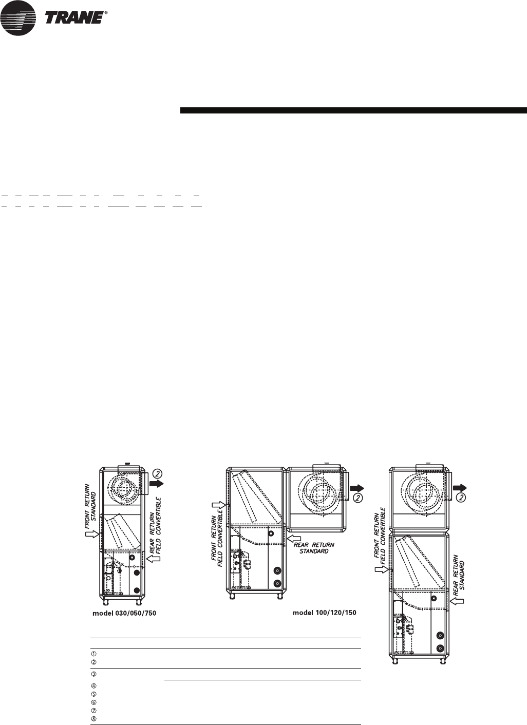
Unit Airflow Configurations
unit size discharge fan location comments
030/050/075 vertical CCW top standard
horizontal CW top field converted
100/120/150 vertical CCW top standard
vertical CW top field converted
horizontal CW top
vertical CW rear
horizontal CW rear
horizontal CCW rear
J = Cupronickel condenser &
Evaporator coated (SCWH)
PKG-SVX14A-EN 5
Installation
general
information
General
The midrange models SCWH/SCRH
is a high efficiency, vertical air
condioner. units have either front or top
discharge configuration options and easy
service access. Unit construction is heavy
gage steel with a baked enamel finish.
Available unit voltages are 208/3/60, 230/
3/60, 460/3/60, and 575/3/60.
Refrigeration Circuits
Units are configured in single or double
refrigeration circuits. Each circuit consists
of:
• high efficiency scroll compressor
mounted on rubber isolation grommets
• evaporator coils designed for optimum
performance and efficiency with lanced
fins and rifled tubing
• filter-drier
Evaporator Section
The evaporator fan section consists of
one or two forward curved centrifugal
fans powered by a premium efficiency
motor through an adjustable motor
sheave and fixed diameter blower pulley.
Controls
The standard control panel consists of a
high voltage terminal block, overload
relays for each fan motor, transformer, 3-
pole 24-volt contactors for eachmotor
and compressor, and a 5-second delay
timer. Remote thermostat controls are
field installed.
Field-Installed Accesories
These items ship separately for field
installation:
• steam coil
• hot water coil
• plenum
• oversized motors
• remote thermostat
Note: Application of the above options
and/or accessories may require field
adjustment of fan speeds to ensure
proper airflow and performance.
Unit Nameplate
The unit nameplate identifies the unit
model number, appropriate service
literature, and wiring diagrm numbers. It
is mounted on the control panel door.
Reference this information when making
inquires or ordering parts or literature.
Refrigerant Handling
Procedures
Environmental Accountability Policy
Trane urges that all HVAC servicers to
make every effort to eliminate, if possible,
or vigorously reduce the emission of CFC,
HCFC, and HFC refrigerants to the
atmosphere. Always act in a responsible
manner to conserve refrigerants for
continued usage even when acceptable
alternatives are available.
Recover and Recycle Refrigerants
Never release refrigerant to the
atmosphere! Always recover and/or
recycle refrigerant for reuse,
reprocessing (reclaimed), or properly
dispose if removing from equipment.
Always determine the recycle or reclaim
requirements of the refrigerant before
beginning the recovery procedure.
Obtain a chemical analysis of the
refrigerant if necessary. Questions about
recovered refrigerant and acceptable
refrigerant quality standards are
addressed in ARI Standard 700.
Refrigerant Handling and Safety
Consult the manufacturer’s material
safety data sheet (MSDS) for information
on refrigerant handling to fully
understand health, safety, storage,
handling, and disposal requirements. Use
the approved containment vessels and
refer to appropriate safety standards.
Comply with all applicable transportation
standards when shipping refrigerant
containers.
Service Equipment and Procedures
To minimize refrigerant emissions while
recovering refrigerant, use the
manufacturer’s recommended recycling
equipment per the MSDS. Use
equipment and methods which will pull
the lowest possible system vacuum while
recovering and condensing refrigerant.
Equipment capable of pulling a vacuum of
less than 1,000 microns of mercury is
recommended.
Do not open the unit to the atmosphere
for service work until refrigerant is fully
removed/recovered. When leak-testing
with trace refrigerant and nitrogen, use
HCFC-22 (R-22) rather than CFC-12 (R-
12) or any other fully-halogenated
refrigerant . Be aware of any new leak
test methods which may eliminate
refrigerants as a trace gas. Perform
evacuation prior to charging with a
vacuum pump capable of pulling a
vacuum of 1,000 microns of mercury or
less. Let the unit stand for 12 hours and
with the vacuum not rising above 2,500
microns of mercury.
A rise above 2,500 microns of mercury
indicates a leak test is required to locate
and repair any leaks. A leak test is
required on any repaired area.
Charge refrigerant into the equipment
only after equipment does not leak or
contain moisture. Reference proper
refrigerant charge requirements in the
maintenance section of this manual to
ensure efficient machine operation.
When charging is complete, purge or
drain charging lines into an approved
refrigerant container. Seal all used
refrigerant containers with approved
closure devices to prevent unused
refrigerant from escaping to the atmo-
sphere. Take extra care to properly
maintain all service equipment directly
supporting refrigerant service work such
as gauges, hoses, vacuum pumps, and
recycling equipment .
When cleaning system components or
parts, avoid using CFC-11 (R-11) or CFC-
113 (R-113). Use only cleaning-solvents
that do not have ozone depletion factors.
Properly dispose of used materials.
Refrigeration system cleanup methods
using filters and driers are preferred.
Check for leaks when excessive purge
operation is observed.
Keep abreast of unit enhancements,
conversion refrigerants, compatible
parts, and manufacturer’s recommenda-
tions that will reduce refrigerant emis-
sions and increase equipment operating
efficiencies.
6PKG-SVX14A-EN
Pre-Installation Considerations
Pre-Installation Checklist
Complete the following checklist before
beginning unit installation.
Verify the unit size and tagging with the
unit nameplate.
Make certain the floor or foundation is
level, solid, and sufficient to support the
unit and accessory weights. Level or
repair the floor before positioning the
unit if neccesary.
Allow minimum recommended
clearances for routine maintenance and
service. Refer to unit submittals for
dimensions.
Allow three fan diameters above the
unit for the discharge ductwork. Return
air enters the rear of the unit and
conditioned supply air discharges
through the top.
Electrical connection knockouts are on
the top, left side of the unit.
Allow adequate space for piping
access and panel removal. Condenser
water piping, refrigerant piping, and
condensate drain connections are on
the lower left end panel.
Electrical supply power must meet
specific balance and voltage
requirements as described in the
“Electrical Requirements” section.
Water-cooled units only: The installer
is responsible for providing a condenser
main, standby water pump, cooling
tower, pressure gauges, strainers, and
all components for waterside piping.
See the “Water Piping” section for
general waterside recommendations.
Air-cooled units only: The installer is
responsible for providing and installing
the remote air-cooled condenser and
refrigerant piping, including filter driers.
Receiving and Handling
Shipping Package
Midrange units ship assembled on skids.
Units ship assembled, piped, and charged
with either R410a (model SCWH)
or a dry nitrogen charge (model SCRH).
Receiving Checklist
Complete the following checklist
immediately after receiving unit
shipment to detect possible shipping
damage.
Inspect individual cartons before
accepting. Check for rattles, bent carton
corners, or other visible indications of
shipping damage.
If a unit appears damaged, inspect it
immediately before accepting the
shipment. Make specific notations
concerning the damage on the freight
bill. Do not refuse delivery.
Inspect the unit for concealed damage
before it is stored and as soon as
possible after delivery. Report
concealed damage to the freight line
within the allotted time after delivery.
Check with the carrier for their allotted
time to submit a claim.
Do not move damaged material from
the receiving location. It is the receiver’s
responsibility to provide reasonable
evidence that concealed damage did
not occur after delivery.
Do not continue unpacking the
shipment if it appears damaged. Retain
all internal packing, cartons, and crate.
Take photos of damaged material if
possible.
Notify the carrier’s terminal of the
damage immediately by phone and
mail. Request an immediate joint
inspection of the damage by the carrier
and consignee.
Notify your Trane representative of
the damage and arrange for repair.
Have the carrier inspect the damage
before making any repairs to the unit.
Unit Storage
Take precautions to prevent condensate
from forming inside the electrical
compartments and motors if the unit is
stored before it is installed.
Service Access
Maintain adequate clearances around
and above the unit to ensure proper unit
operationa nd allow sufficient service
accesss. Trane recommends 36-inches
service access on all sides fo the unit.
Service access locations are shown in
figures on pages 8 through 9.
WARNING
Hazardous Voltage!
Disconnect all electric power, including
remote disconnects before servicing.
Follow proper lockout/tagout
procedures to ensure power cannot
be inadvertently energized. Failure to
disconnect power before servicing
could result in death or serious injury.
Installation Preparation
Before installing the unit, perform the
following procedures to ensure proper
unit operation.
1. Verify the floor or foundation is level.
Shim or repair as necessary. To ensure
proper unit operation, install the unit
level in both horizontal axes.
2. Allow adequate service and code
clearances as recommended in
“Service Access” section. Position the
unit and skid assembly in its final
location. Test lift the unit to determine
exact unit balance and stability before
hoisting it to the installation location.
See the “Proper Lifting Procedure”
section for proper rigging procedures
and cautions.
3. Remove the skids from under the unit.
If you find internal damage, file a claim
immediately to the delivering carrier.
4. Remove the protective shipping covers
from the unit.
5. Verify the compressor isolator shipping
brackets are removed and the isolators
are properly tightened for operation.
Installation
pre-installation
considerations
PKG-SVX14A-EN 7
Installation
pre-installation
considerations
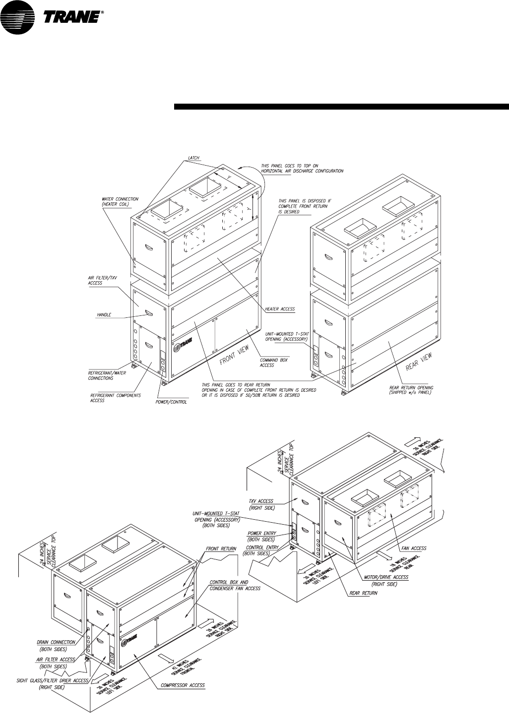
24"
FAN ACCESS
FRONT RETURN
COIL / ELECTRIC HEATER
ACCESS
MOTOR / DRIVE ACCESS
(RIGHT SIDE)
CONTROL BOX &
CONDENSER FAN ACCESS
TXV ACCESS
(RIGHT SIDE)
26" SERVICE CLEARANCE
RIGHT SIDE
UNIT-MOUNTED T-STAT
OPENING (BOTH SIDES)
POWER ENTRY
(BOTH SIDES)
CONTROL ENTRY
(BOTH SIDES)
COMPRESSOR ACCESS
42" SERVICE CLEARANCE FRONT
DRAIN CONNECTION
AIR FILTER ACCESS
(BOTH SIDES)
(BOTH SIDES)
26" SERVICE CLEARANCE
LEFT SIDE
SIGHT GLASS/FILTER DRIER ACCESS
(RIGHT SIDE)
24"
26" SERVICE CLEARANCE
LEFT SIDE
REAR RETURN
18" SERVICE CLEARANCE
REAR
26" SERVICE CLEARANCE
RIGHT SIDE
10 through 15-ton SCWH/SRCH with top-mounted fan configuration
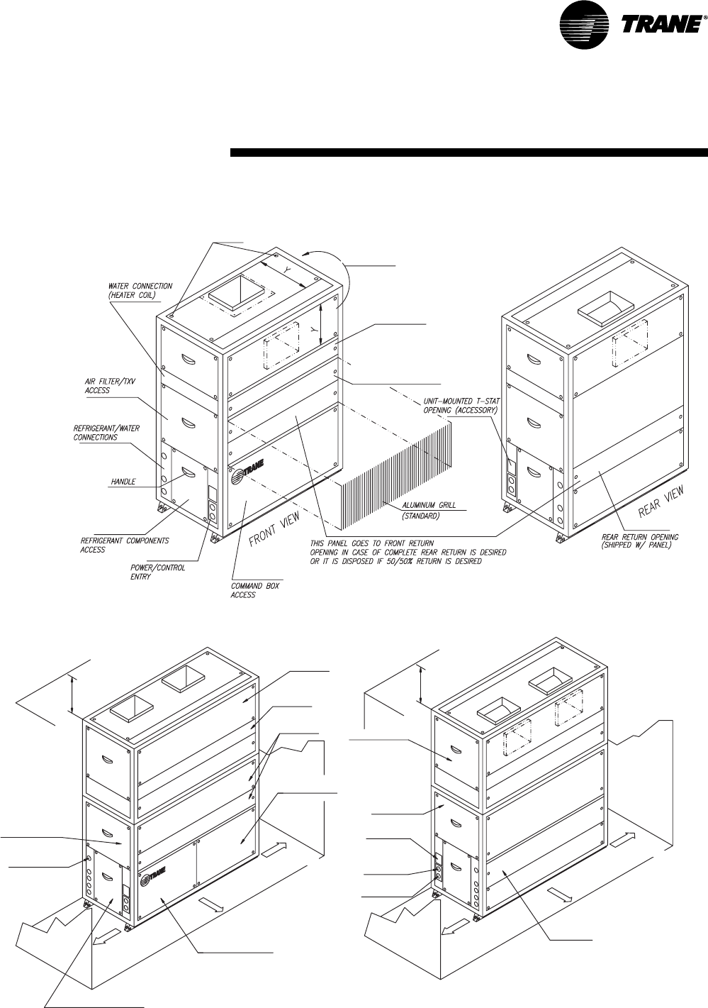
LATCH
HEATER
ACCESS
THIS PANEL GOES TO TOP ON
HORIZONTAL AIR DISCHARGE
CONFIGURATION
PROVIDED DISASSEMBLED
(FOR FIELD-INSTALLED REAR RETURN)
3 through 7.5-ton SCRH/SCWH
Service Access
8PKG-SVX14A-EN
Installation
pre-installation
considerations
Service Access
10, 12, & 15-ton SCWH/SRCH
with side-mounted fan configura-
tion, field converted
10 through 15-ton SCRH/SCWH
PKG-SVX14A-EN 9
Installation
pre-installation
considerations
Table I-PC-1. Isolator load points, units with a vertical discharge configuration, lbs.
model L1 L2 L3 L4 L1 L2 L3 L4
SCRB/SIRB SCWB/SIWB
3-ton 99 105 120 127 105 133 118 124
5-ton 115 122 157 166 129 165 166 165
7.5-ton 154 203 227 221 177 234 230 231
10-ton 208 266 273 253 263 334 293 300
15-ton 243 332 359 356 315 388 382 375
Table I-PC-2. Isolator load points, units with a horizontal discharge configuration, lbs.
model L1 L2 L3 L4 L1 L2 L3 L4
SCRB/SIRB SCWB/SIWB
7.5-ton 250 108 313 135 285 126 319 140
10-ton 318 150 363 169 383 211 383 211
15-ton 404 166 510 210 514 215 514 215
Table I-PC-3. Isolator load points & types, units with a horizontal discharge, inverted “L”
configuration, lbs.
air-cooled models water-cooled models
L1 L2 L3 L4 L1 L2 L3 L4
10-ton unit 318 150 363 169 383 211 383 211
spring red yellow red yellow red yellow red yellow
rubber-in-shear green red green red green red green red
15-ton unit 404 166 510 210 514 215 514 215
spring purple yellow purple yellow purple yellow purple yellow
rubber-in-shear gray red gray red gray red gray red
Note: Units ship with two different color isolators and should be placed as depicted in this chart to properly support the
unit weight. See Figures I-PC-1 & I-PC-2 for correct isolator positions by unit size.
3, 5, & 7.5-ton units
bottom view of unit
1 7/8
1 7/8
7/8” dia. hole under all 4 corners
Figure I-PC-1. Isolator mounting hole locations on 3, 5, &
7.5-ton units
10 & 15-ton units
bottom view of unit
1 3/8
3 3/4
9/16” dia. hole under all 4 corners
Figure I-PC-2. Isolator mounting hole locations on 10 & 15-
ton units
L1 L3
L2 L4
L1 L3
L2 L4
Isolator Placement
Note: Isolators are field-provided.
10 PKG-SVX14A-EN
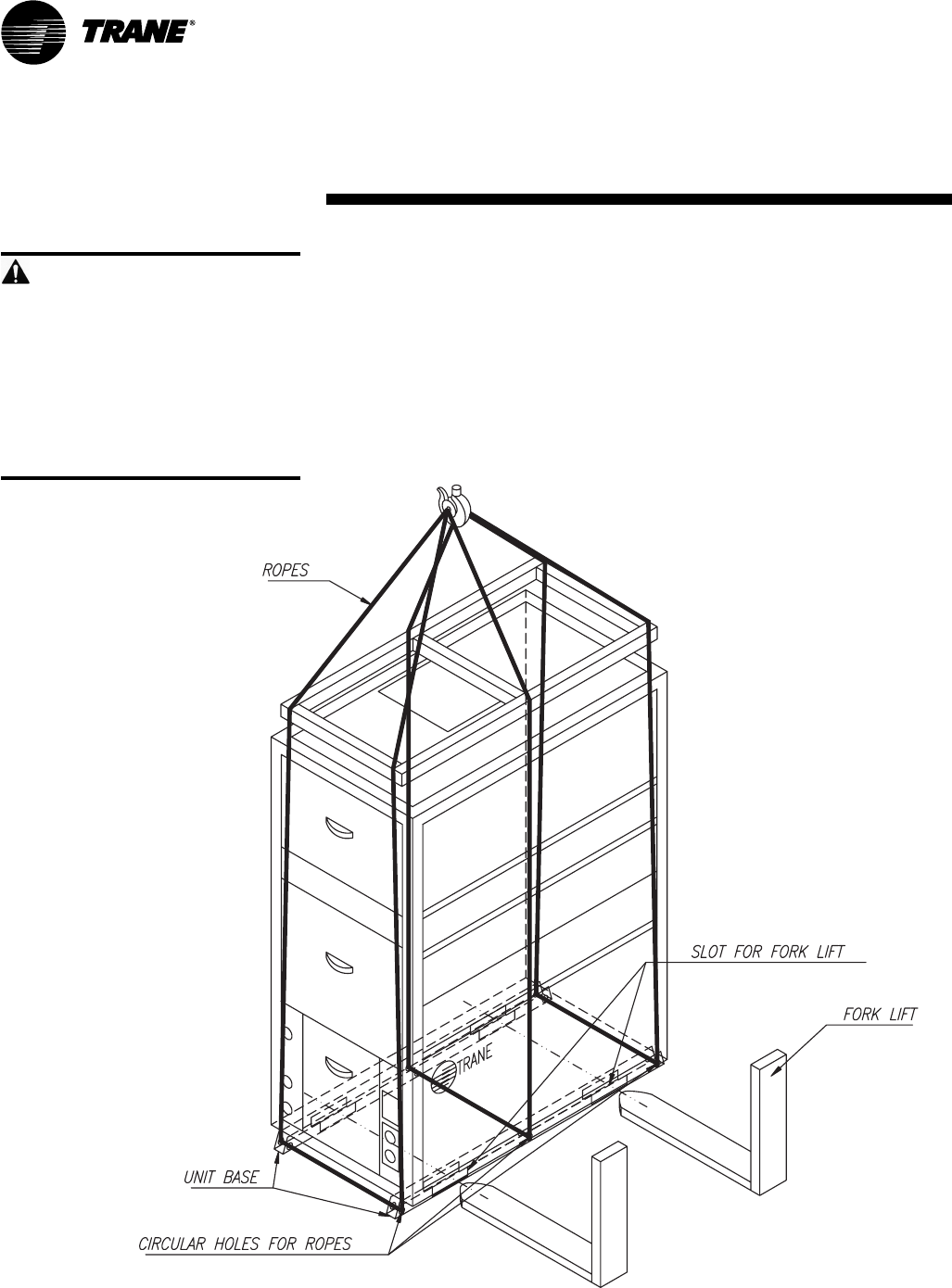
Proper Lifting Procedure
Follow these instructions and reference
Figure I-PC-3.
1. Slide a fork lift into the opening
provided on the unit base. Move the
fork lift carefully.
2. Using slings, attach through the circular
holes provided on the unit base. Protect
the unit from damage by rigging
equipment.
WARNING
Improper Unit Lift!
Test lift unit approximately 24 inches
high to verify the proper center-of-
gravity lift point. To avoid dropping the
unit, reposition the lifting point if the
unit is not level. Failure to properly lift
the unit could result in death, serious
injury, or possible equipment/
property-only damage.
Installation
pre-installation
considerations
Figure I-PC-3. Proper unit lifting procedure
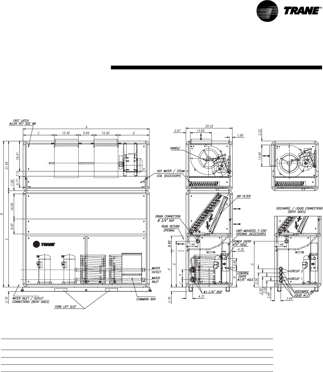
PKG-SVX14A-EN 11
dimensions &
weightsInstallation
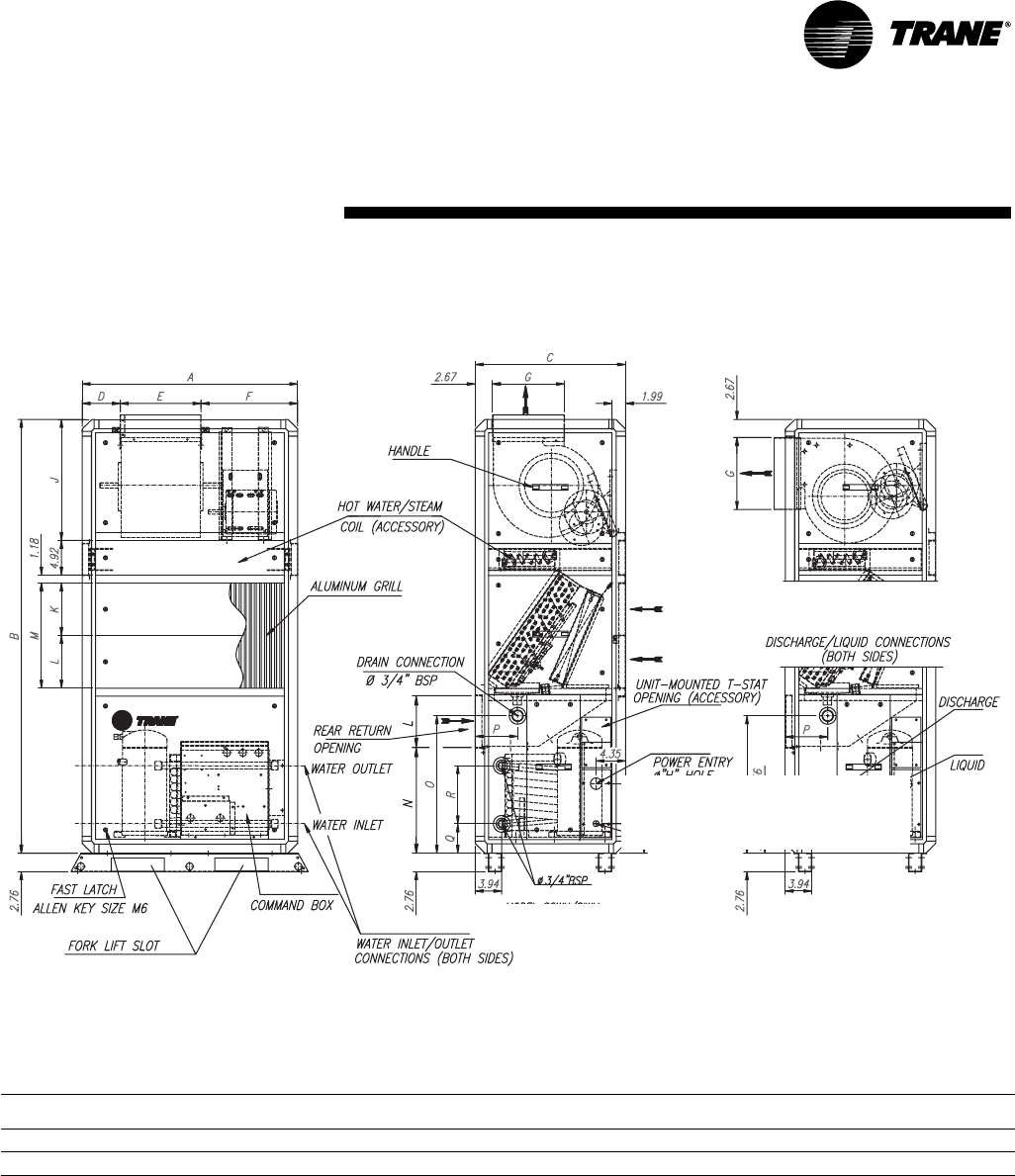
3 & 5-tons
SCWH/SCRH
SCRH
SCWH
vertical discharge horizontal discharge
(field converted)
SCWH/SCRH dimensions & weight, in-lbs.
unit shipping operating
size A B C D E F G J K L M N O P Q R S weight weight
3 31.89 64.17 22.24 5.65 11.93 14.31 10.63 18.00 7.80 7.80 15.60 15.63 20.20 6.28 4.33 8.58 4.37 494 459
5 36.41 75.98 24.01 7.73 13.03 15.65 11.61 20.31 12.32 8.66 20.98 18.58 24.20 7.10 5.43 6.38 7.12 592 555
12 PKG-SVX14A-EN
dimensions &
weights
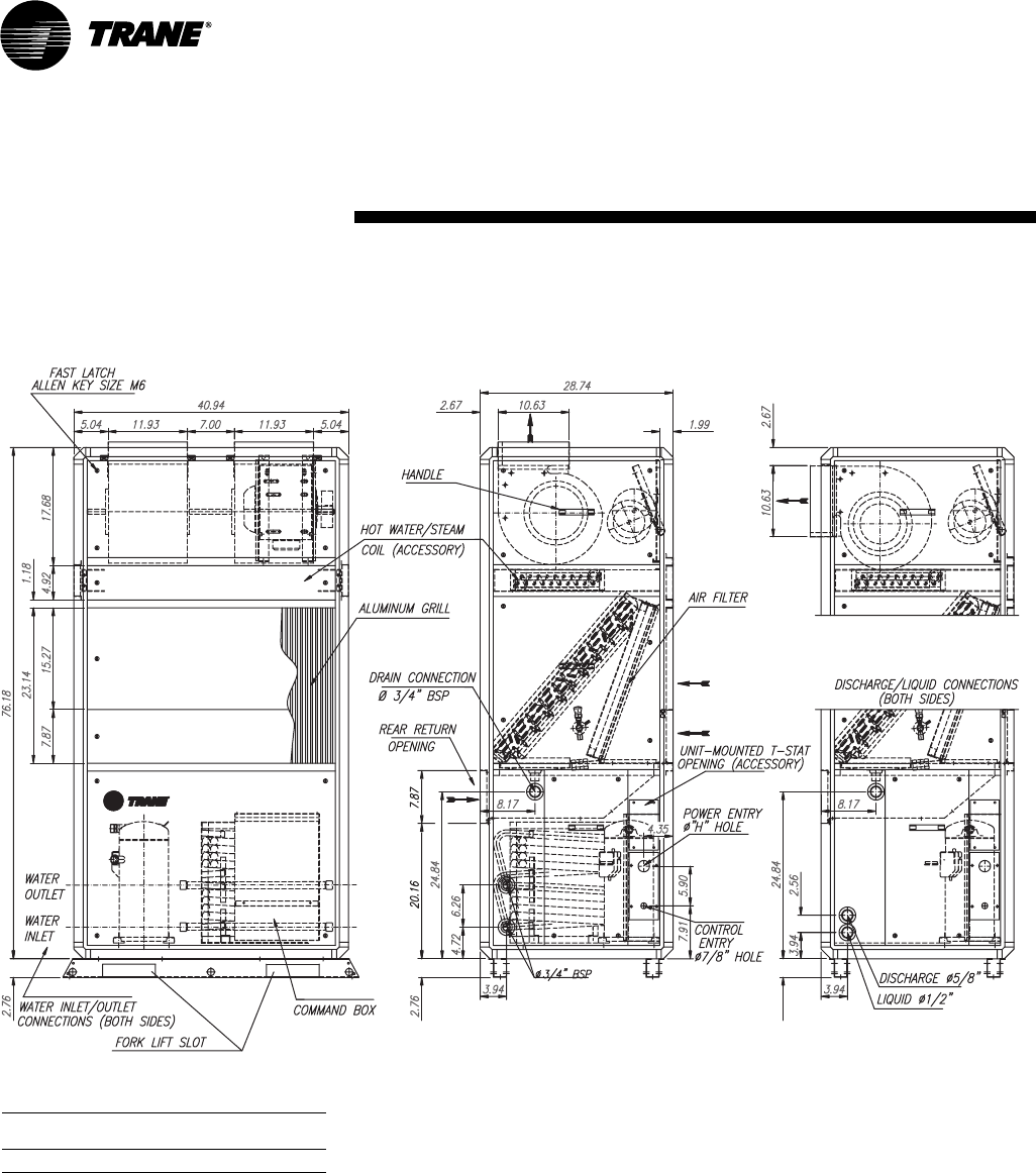
7.5-tons
SCWH/SCRH
Installation
SCWH
vertical discharge horizontal discharge
(field converted)
SCWH/SCRH weight, lbs.
unit shipping operating
size weight weight
7.5 702 657
SCRH
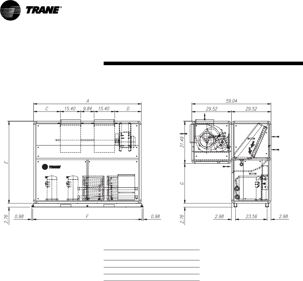
PKG-SVX14A-EN 13
dimensions &
weightsInstallation
10, 12, & 15-tons with top-mounted fan configuration
SCWH/SCRH
horizontal discharge
(field converted)
vertical discharge
SCRH
SCWH
SCWH/SCRH dimensions & weight, in-lbs.
unit shipping operating
tons A B C D E F G J K M N weight weight
10 66.75 88.78 7.04 18.07 57.28 19.01 25.0 5.23 7.48 5/88.30 984 917
12 65.75 92.71 7.04 18.07 61.22 22.95 29.01 5.23 7.48 5/812.24 977 907
15 80.31 92.71 19.83 19.83 61.22 22.95 29.01 4.76 5.12 3/412.24 1098 1021
14 PKG-SVX14A-EN
10, 12, & 15-tons with side-mounted fan configuration, field converted
SCWH/SCRH
SCWH/SCRH Dimensions, in.
unit
tons A C D E F G
10 65.75 7.04 18.07 57.28 66.93 25.79
12 65.75 7.04 18.07 61.22 66.93 29.73
15 80.31 19.83 19.83 61.22 81.49 29.73
Notes:
1. Base rail must be attached to the floor before converting
unit to side-mounted fan configuration.
2. Coil or electric heater cannot be assembed inside the
cabinet with the side-mounted fan configuration.
dimensions &
weightsInstallation
PKG-SVX14A-EN 15
dimensions &
weightsInstallation
Plenum
Plenum dimensions & weight, in-lbs.
unit size A B weight
3-ton 31.89 22.24 44
5-ton 36.41 24.01 54
7.5-ton 40.94 28.74 73
10 & 12-ton 65.75 29.52 120
15-ton 80.31 29.52 146
A
B
C
D
E
F
G
0.39
0.28
1.38 1.38
5.91 1.57 3.15
0.39
0.59
0.59
2.18
2.18 8.39
1.03 1.03
1.08
0.75
0.75
5.9
1.0 NPT
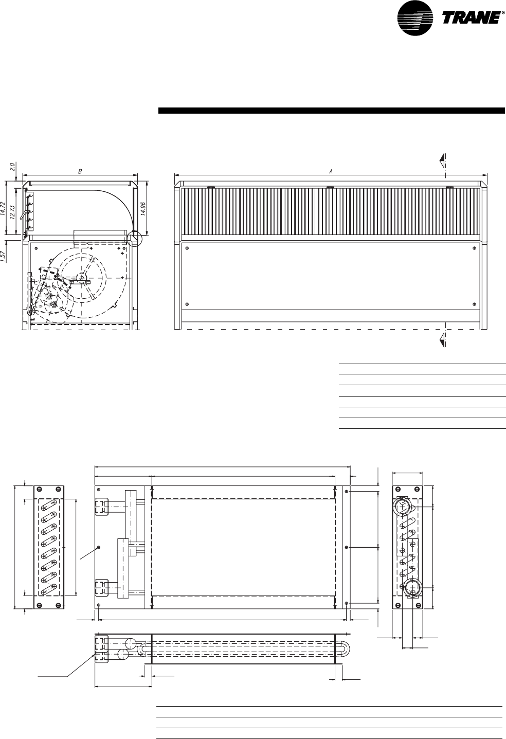
Hot water coil
3 & 5-ton units
SCWH/SCRH Hot water coil dimensions & weights, 3 & 5-ton units, in-lbs.
size A B C D E F G weight
3-ton 26.46 18.98 25.67 5.79 5.79 10.00 12.76 13
5-ton 30.98 23.50 30.20 7.040 7.040 12.50 15.26 18
16 PKG-SVX14A-EN
dimensions &
weightsInstallation
A
B
D
C
0.43
0.28
0.39 0.39
1.03
1.03
1.08
1.57
3.19
0.75
0.75
5.90
1.00 NPT
1.38
1.38
17.50
20.26
1.38
8.27
2.18
0.599.54
9.54
15.89
2.18
9.07
7.48
0.59
BLOCKOFF (SHIPS DISASSEMBLED)
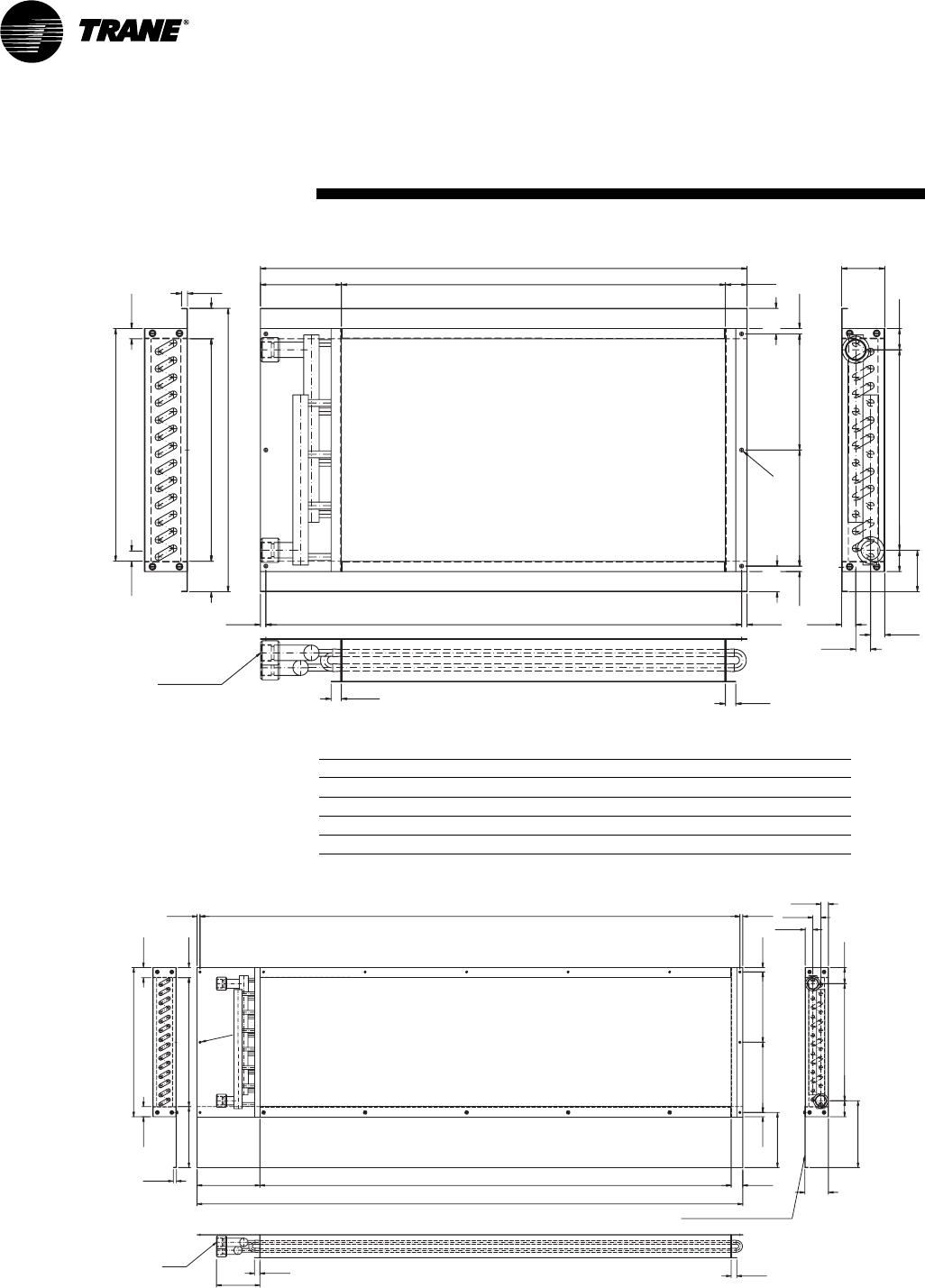
Hot water coil
10 thru 15-ton units
35.51
28.035.91
0.43
1.57
3.15
34.72 0.39
0.75
0.75
0.39
5.9
1.0 NPT
0.75
17.00
0.75
2.22 2.22
16.25
20.7
0.39
1.87
8.48
8.48
14.64
1.55 1.55
3.03
0.39
1.87
1.03
1.08
1.03
0.28
Hot water coil
7.5-ton units
SCWH/SCRH Hot water coil dimensions & weights, in-lbs.
size A B C D weight
7.5-ton - - - - 24
10-ton 58.72 50.98 6.95 59.51 49
12-ton 58.72 50.98 6.95 59.51 49
15-ton 73.29 63.98 8.52 74.07 55
PKG-SVX14A-EN 17
mechanical
requirements
Duct Connections
Install all air ducts according to the
National Fire Protection Association
standards for the “Installation of Air
Conditioning and Ventilation Systems
other than Residence Type (NFPA 90A)
and Residence Type Warm Air Heating
and Air Conditioning Systems (NFPA
90B).
Make duct connections to the unit with a
flexible material such as heavy canvas. If
a fire hazard exists, Trane recommends
using Flexweave 1000, type FW30 or
equivalent canvas. Use three inches for
the return duct and three inches for the
discharge duct. Keep the material loose
to absorb fan vibration.
Run the ductwork straight from the
opening for a minimum of three fan
diameters. Do not make abrupt turns or
transitions near the unit due to increased
noise and excessive static losses. Use
elbows with splitters or turning vanes to
minimize static losses.
Poorly constructed turning vanes may
cause airflow generated noise. Check
total external static pressures against fan
characteristics to be sure the required
airflow is available throughout the
ductwork.
WARNING
Hazardous Voltage!
Disconnect all electric power,
including remote disconnects before
servicing. Follow proper lockout/
tagout procedures to ensure power
cannot be inadvertently energized.
Failure to disconnect power before
servicing could result in death or
serious injury.
Water Piping
Condenser Connections
Note: To prevent water damage, install
piping drain and vent plugs.
Condenser water piping knockouts are in
the lower left end panel. If necessary,
remove insulation to gain access. All field
installed piping must conform to
applicable local, state, and federal codes.
To complete condenser water
connections follow the procedure below.
1. Remove back panel to access the
water connection fittings.
2. Attach the water supply line to the inlet
connection, and the return line to the
outlet connection. The water connection
fittings are copper, so exercise extreme
care when connecting steel piping to
copper fittings.
3. Ensure that water piping is aligned to
the unit connection fittings. Failure to
align piping could cause stripped
threads, leakage, and possible unit
failure.
4. Connection to the unit water piping
requires a backing wrench to prevent
distortion of connecting tubing. Apply
backing wrench to water connection
points on unit.
Condensate Drain Connections
Install a water regulating valve in the
water supply line to maintainhead
pressure when operating with city water
of varying temperature.
These units require a minimum water
pressure of 15 psig and will operate at a
maximum of 400 psig.
Provide safeguards against cold weather
drain line freeze.
Installation
Cooling Tower Piping
Cooling tower control affects the unit
cycle rates. Condenser water
temperature swings from 10-15°F may
cause excessive compressor, water
valve, and unit cycling. Be sure to set the
tower controls to minimize compressor/
unit cycling.
The cooling tower system requires a
separate drain in the water supply line for
service and repair.
Water Temperature Requirements
Install a water regulating valve in the
water supply line to maintain head
pressure when operating with water of
varying temperature. The valve
modulates condenser water flow to
control condensing pressure. The valve
opens or closes in response to
compressor discharge pressure as
sensed by its capillary line connection iin
the liquid line shrader valve. When the
valve is properly installed, water flow
automatically decreases as discharge
pressure falls and increases as discharge
pressure rises. Field installation of the
water regulating valve assembly
requires one valve for each refrigeration
circuit.
18 PKG-SVX14A-EN
mechanical
requirementsInstallation
Refrigerant Piping (Air-Cooled
Units Only)
Reference industry recommendations
for air-cooled unit refrigerant piping. If
suspending piping from the building, use
isolation hangers to prevent vibration
transmission.
Air-cooled units ship with a holding
charge of nitrogen. Before installing unit
piping, momentarily depress either the
suction or discharge line access valve to
verify that the holding charge has not
been lost. If nitrogen does not escape
when depressing the access valve, leak-
test the entire refrigerant system to
determine the source of loss.
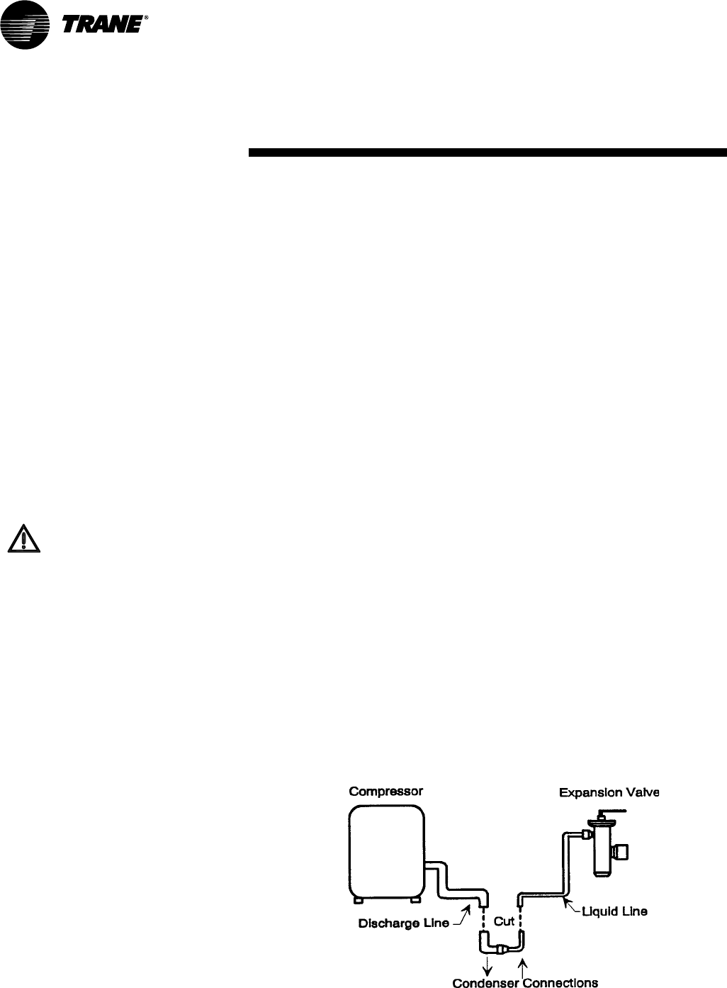
The charge is contained by a continuous
loop of both hot gas and liquid lines. You
must cut the loop for connection to
discharge and liquid lines. See Figure I-
MR-1.
Brazing Procedures
Proper brazing techniques are essential
when installing refrigerant piping. Keep
the following factors in mind when
making sweat connections.
1. When heating copper in the presence
of air, copper oxide forms. To prevent
copper oxide from forming inside the
tubing during brazing, sweep an inert
gas, such as dry nitrogen, through the
tubing. Nitrogen displaces air in the
tubing and prevents oxidation of
interior surfaces. A nitrogen flow of one
to three cubic feet per minute is
sufficient to displace the air. Use a
pressure regulating valve or flow meter
to control the flow.
2. Ensure tubing surfaces that require
brazing are clean and the ends of the
tubes are carefully reamed to remove
any burrs.
3. Make sure the inner and outer tubes of
the joint are symmetrical and have a
close clearance, providing an easy slip
fit. If the joint is too loose, the tensile
strength of the connection will be
significantly reduced. Make the overlap
distance equal to the inner tube
diameter.
4. Wrap the body of each refrigerant line
component with a wet cloth to keep it
cool during brazing. Excessive heat can
damage the components.
5. If using flux, apply it sparingly to the
joint. Excess flux will contaminate the
refrigerant system.
6. Apply heat evenly over the length and
circumference of the joint, making sure
the entire joint becomes hot enough to
melt the brazing material.
7. Begin brazing when the joint is hot
enough to melt the brazing rod. The hot
copper tubing, not the flame, should
melt the rod.
8. Continue to apply heat around the joint
circumference until the brazing material
is drawn into the joint by capillary
action, making a mechanically sound
and gas-tight connection.
9. Visually inspect the connection after
brazing to locate any pin holes or
crevices in the joint. Use a mirror to
inspect connections that are difficult to
see.
Figure I-MR-1. Air-cooled unit refrigerant piping
WARNING:
Hazard of Explosion and Deadly
Gases!
Never solder, braze or weld on
refrigerant lines or any unit com-
ponents that are above atmo-
spheric pressure or where
refrigerant may be present.
Always remove refrigerant by fol-
lowing the guidelines estab-
lished by the EPA Federal Clean
Air Act or other state or local
codes as appropriate. After refrig-
erant removal, use dry nitrogen to
bring system back to atmospheric
pressure before opening system
for repairs. Mixtures of refriger-
ants and air under pressure may
become combustible in the pres-
ence of an ignition source leading
to an explosion. Excessive heat
from soldering, brazing or weld-
ing with refrigerant vapors
present can form highly toxic
gases and extremely corrosive
acids. Failure to follow all proper
safe refrigerant handling prac-
tices could result in death or seri-
ous injury.
Electrical Requirements
Follow these guidelines, referring to unit
wiring diagrams and supply power
dimensional information to ensure
correct electrical requirements at the
installation site. Reference supply power
wiring locations on unit submittals orin
the “Dimensions and Weights” section.
Specific unit wiring diagrams are
provided on each unit. Use these
diagrams for connections or trouble
analysis.
Unit Wiring Diagrams
Specific unit wiring diagrams are
provided on the inside of the control
panel door. Use these diagrams for
connections or trouble analysis.
PKG-SVX14A-EN 19
electrical
requirementsInstallation
Supply Power Wiring
It is the installer’s responsibility to provide
power supply wiring to the unit terminal
block or the non-fused disconnect switch
option. Wiring should conform to NEC and
all applicable code requirements.
1. Verify the power supply available is
compatible with the unit nameplate
ratings. The supply power must be
within 10%of the rated voltage listed on
the unit nameplate.
2. Reference the electrical data in Table I-
ER-1. Protect the electrical service from
over current and short circuit
conditions in accordance with NEC
requirements. Size protection devices
according to the electrical data on the
unit nameplate.
3. If using a field-supplied disconnect,
install it at or near the unit in
accordance with NEC. Do not mount a
field-supplied disconnect on the unit.
Reference the electrical service
entrance location on unit submittals.
4. Complete the unit power wiring
connections onto either the main
terminal block or the field-provided non-
fushed disconnect switch.
5. Provide proper unit grounding in
accordance with local and national
codes.
Electrical Data Calculations
RLA = rated load amps
Compressor LRA = locked rotor amps
Fan motor LRA = locked rotor amps,
N.E.C. Table 430 - 151
FLA = Full load amps, N.E.C.
Table 430 - 150
Voltage utilization range is ±10%
Minimum circuit ampacity (MCA)
= 1.25 x largest motor amps (FLA or
RLA) + the sum of the remaining motor
amps.
Maximum fuse size (MFS) and maximum
circuit breaker size (MCB) = 2.25 x largest
motor amps (FLA or RLA) + the sum of
the remaining motor amps.
Note: If the rating value determined does
not equal a standard current rating of
over current protective device, use the
next lower standard rating for the
marked maximum rating.
Voltage Range
Voltages must be within +- 10% the
nameplate voltage. Ensure the unit
voltage is balanced by measuring at the
compressor terminals. Voltage imbalance
on three phase systems can cause motor
overheating and premature failure.
Maximum allowable imbalance is 2.0%.
Voltage Imbalance
Read the voltage at the compressor
terminals to determine if it is balanced.
Voltage imbalance on three phase
systems can cause motor overheating
and premature failure. The maximum
allowable imbalance is 2.0%. Voltage
imbalance is defined as 100 times the
sum of the deviation of the three voltages
from the average (without regard to sign)
divided by the average voltage. For
example, if the three measured voltages
are 221, 230, and 227, the average
voltage would be:
(221 + 230 + 227) = 226 volts
3
The percentage of voltage imbalance is
then:
100 * (226-221) = 2.2%
226
In this example, 2.2% imbalance is not
acceptable. Whenever a voltage
imbalance of more than 2.0% exists,
check the voltage at the unit disconnect
switch. If the imbalance at the unit
disconnect switch does not exceed 2.0%,
faulty unit wiring is causing the
imbalance. Conduct a thorough
inspection of the unit electrical wiring
connections to locate the fault, and make
any repairs necessary.
WARNING
Live Electrical Components!
During installation, testing, servicing,
and troubleshooting this equipment, it
may be necessary to work with live
electrical components. Have a
qualified licensed electrician or other
individual who is properly trained in
handling live electrical components
perform these tasks. Failure to follow
all electrical safety precautions when
exposed to live electrical components
could result in death or serious injury.
WARNING
Hazardous Voltage!
Disconnect all electric power,
including remote disconnects before
servicing. Follow proper lockout/
tagout procedures to ensure power
cannot be inadvertently energized.
Failure to disconnect power before
servicing could result in death or
serious injury.
CAUTION
Use Copper Conductors Only!
Unit terminals are not designed to
accept other type conductors. Failure
to use copper conductors may result
in equipment damage.
WARNING
Ground Wire!
All field-installed wiring must be
completed by qualified personnel.
All field-installed wiring must
comply with NEC and applicable
local codes. Failure to follow this
instruction could result in death
or serious injuries.
WARNING
Grounding Required!
Follow proper local and state elec-
trical code on requirements for
grounding. Failure to follow code
could result in death or serious in-
jury.
20 PKG-SVX14A-EN
electrical
requirements
Installation
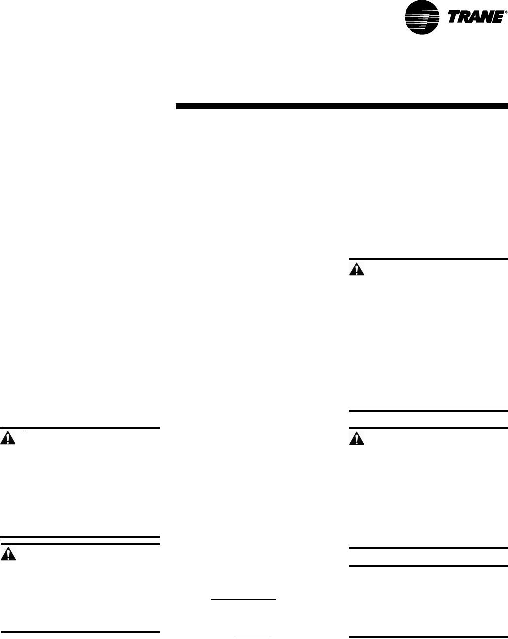
RLA LRA qty. hp FLA qty. hp FLA qty
SC*H0303.... 208-230V/60Hz/3Ph 12.9 77.0 0.5 2.21 118.3 30 3.15 19.3 30
SC*H0304.... 460V/60Hz/3Ph 5.7 35.0 1.00 8.1 15 1.42 8.5 15
SC*H0305.... 575V/60Hz/3Ph 4.8 31.0 0.80 6.8 15 1.14 7.1 15
SC*H0503.... 208-230V/60Hz/3Ph 22.9 155.0 5.00 33.6 50 5.81 34.4 50
SC*H0504.... 460V/60Hz/3Ph 10.7 75.0 2.50 15.9 25 2.63 16.0 25
SC*H0505.... 575V/60Hz/3Ph 8.5 54.0 1.50 12.1 20 2.10 12.7 20
SC*H0753.... 208-230V/60Hz/3Ph 27.9 164.0 6.30 41.2 60 5.81 40.7 60
SC*H0754.... 460V/60Hz/3Ph 13.6 100.0 3.10 20.1 30 2.63 19.6 30
SC*H0755.... 575V/60Hz/3Ph 10.2 78.0 2.40 15.2 25 2.10 14.9 25
SC*H1003.... 208-230V/60Hz/3Ph 22.9 155.0 6.30 57.8 80 13.70 65.2 80
SC*H1004.... 460V/60Hz/3Ph 10.7 75.0 3.10 27.2 35 6.18 30.3 40
SC*H1005.... 575V/60Hz/3Ph 8.5 54.0 2.40 21.5 30 4.94 24.1 30
SC*H1203.... 208-230V/60Hz/3Ph 25.4 147.7 9.40 66.5 90 13.70 70.8 90
SC*H1204.... 460V/60Hz/3Ph 11.8 75.0 4.60 31.2 40 6.18 32.7 45
SC*H1205.... 575V/60Hz/3Ph 9.3 59.6 3.40 24.4 30 4.94 25.9 35
SC*H1503.... 208-230V/60Hz/3Ph 27.9 164.0 9.40 72.2 100 13.70 76.5 100
SC*H1504.... 460V/60Hz/3Ph 13.6 100.0 4.60 35.2 45 6.18 36.8 50
SC*H1505.... 575V/60Hz/3Ph 10.9 78.0 3.40 27.9 35 4.94 29.5 35
12 2
tons MFS / MCBmodel voltage compressor evap. fan motor min. circuit
am
p
acit
y
10 2 2 1
21
evaporator standard motor evaporator oversized motor
evap. fan motor MFS /
MCB
min. circuit
am
p
acit
y
51
21
51
31 11
5111
7.5 1 2 1
31 51
15 2 3 1
Table I-ER-1. Model SCWH/SCRH electrical data
WARNING
Hazardous Voltage!
Disconnect all electric power,
including remote disconnects before
servicing. Follow proper lockout/
tagout procedures to ensure power
cannot be inadvertently energized.
Failure to disconnect power before
servicing could result in death or
serious injury.
CAUTION
Use Copper Conductors Only!
Unit terminals are not designed to
accept other type conductors. Failure
to use copper conductors may result
in equipment damage.
Notes:
1. Voltage range:
Nominal voltage 208 - 230V - acceptable range: 187 - 253V
Nominal voltage 460V - acceptable range: 414 - 506V
Nominal voltage 575V - acceptable range: 518 - 633V
2. Ampacity is calculated per UL formula, ampacity = (1.25 x compressor RLA + sum of the second compressor RLA (if
used) + evaporator motor FLA
3. Maximum fuse size is calculated per UL formula, MFS = (2.25 x compressor RLA) + sum of second compressor RLA (if
used) + evaporator motor FLA
PKG-SVX14A-EN 21
Installation Checklist
Reference the checklist below to verify all
steps required to successfully install a
deluxe self-contained unit are complete.
This checklist is intended to acquaint the
installing personnel with what is required
in the installation process. It does not
replace the detailed instructions detailed
in the applicable sections of this manual.
WARNING
Hazardous voltage!
Disconnect all electric power, including
remote disconnects before servicing.
Follow proper lockout/tagout procedures
to ensure the power can not be
inadvertently energized. Failure to
disconnect power before servicing
could result in death or serious
injury.
General Unit Requirements
Install and secure the ductwork to the
unit.
Check unit for shipping damage and
material shortage. Refer to the
Receiving Checklist.
Electrical Requirements
Verify that the electrical power supply
characteristics comply with the unit
nameplate specifications.
Inspect all control components; tighten
any loose connections.
Connect properly sized and protected
power supply wiring to a field supplied/
installed disconnect and unit power
terminal block, or to the optional unit
mounted disconnect switch.
Properly ground the unit.
Field Installed Control Wiring (Optional)
Complete the field wiring connections.
Note: All field installed wiring must
comply with NEC and applicable local
codes.
Fan Discharge Conversion
Complete the steps below to convert the
fan discharge from vertical to horizontal.
1. Remove all mid and top fan section
panels.
2. Loosen the brackets inside the unit that
clamp the mid and fan sections
together.
3. Remove the control box cover and
disconnect the motor power wires.
Feed wires up through the unit and
secure out of the way until rotation is
complete.
4. Rotate the fan section to desired
position.
5. Re-route the motor power wires back
to the control box. Ensure all wiring is
free and not routed over any sharp
edges.
6. Reconnect the motor power wires per
the unit wiring diagram.
7. Bolt and/or clamp all brackets back into
place.
8. Replace control box cover and all
exterior panels.
9. Verify the fan rotation and motor amp
draw.
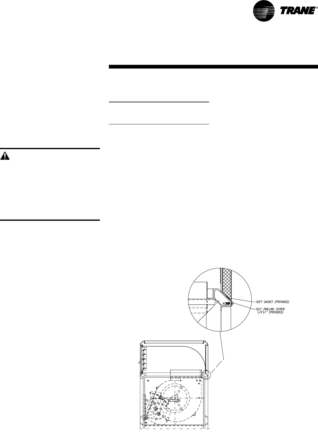
Plenum Installation
1. Uncrate the plenum and accessory
bag.
2. Rotate the evaporator blower to the
vertical discharge configuration.
3. Apply the soft gasket provided around
the aluminum frame on top of the unit
as shown in Figure I-IP-1.
4. Using a screwdriver, tighten the self-
drilling screws as shown in Figure I-IP-
1. Be sure to tighten all screws on the
rear, right, and left sides through the
pilot holes on the plenum panels.
5. When installation is complete, adjust
the motor pulley and the discharge
grille for proper airflow.
installation
procedure
Installation
Figure I-IP-1. Plenum installation
22 PKG-SVX14A-EN
pre-startup
requirements
Installation
Pre-Startup Checklist
Complete this checklist after installing the
unit to verify all recommended
installation procedures are complete
before unit startup. This does not replace
the detailed instructions in the
appropriate sections of this manual.
Always read the entire section carefully
to become familiar with the procedures.
WARNING
Hazardous Voltage!
Disconnect all electrical power,
including remote disconnects before
servicing. Follow proper lockout/tagout
procedures to ensure power cannot be
inadvertently energized. Failure to
disconnect power before servicing
could result in death or serious injury.
Receiving
Inspect unit and components for
shipping damage. File damage claims
immediately with the delivering carrier.
Check nameplate unit data so that it
matches the sales order requirements.
Check unit for missing material. Look
for ship-with accessories that are
packaged separately and placed inside
the access panel, fan section, or
compressor section. See the
“Receiving and Handling” section.
Unit Location
Ensure the unit location is adequate for
unit dimensions, ductwork, piping, and
electrical connections.
Ensure access and maintenance
clearances around the unit are
adequate. See the “Service Access”
section.
Unit Mounting
Remove shipping brackets on the
compressor assembly and supply fan.
Component Overview
Verify the fan and motor sheaves are
aligned.
Check the belt tension for proper
adjustment.
Ensure the fan rotates freely.
Tighten locking screws, bearing set
screws and sheaves.
Ensure bearing locking collars do not
wobble when rotated.
Ensure all air filters are properly
installed with consideration of size and
air flow.
Manually rotate the evaporator fan to
ensure free movement. Verify that all of
the fan mounting hardware is tight.
Ductwork
Verify that all ductwork conforms to
NFPA 90A or 90B and all applicable
local codes.
PKG-SVX14A-EN 23
Unit Startup Procedures
1. Check all electrical connections for
tightness.
2. Be sure all unit accessories are
properly set and installed.
3. Model SCWH: Verify condenser
water piping is properly connected,
supply, and return.
4. Model SCRH: Verify refrigerant
piping is properly connected, hot gas,
and liquid.
5. Inspect all ductwork and duct
connections.
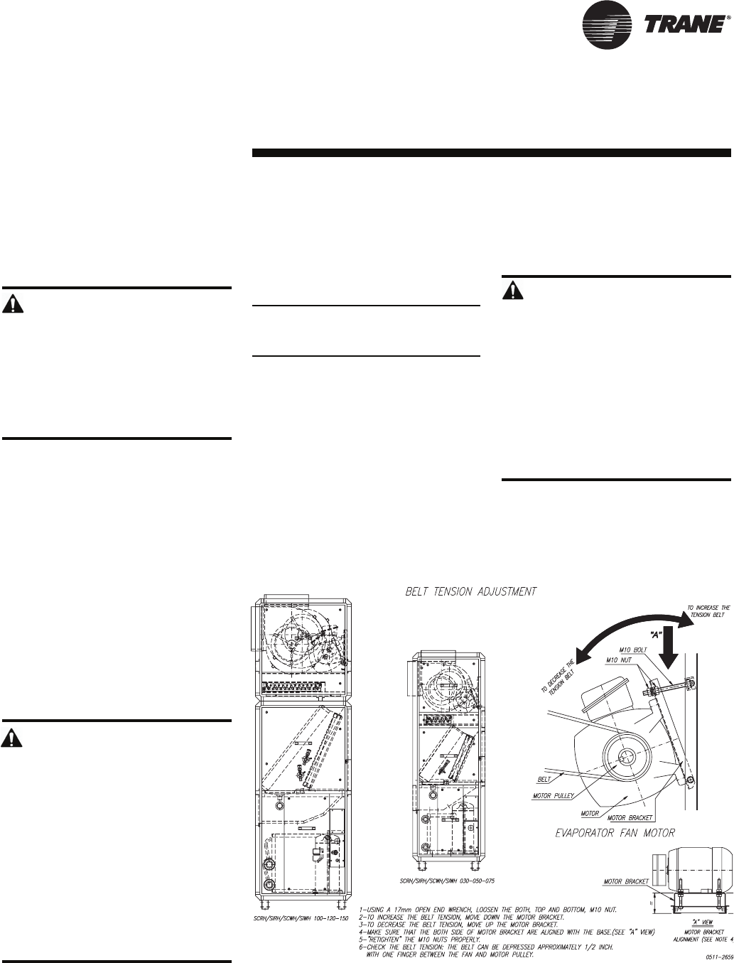
6. Check for proper belt tension.
7. Check fan drive sheaves, pulleys, and
bearings.
Unit Startup Checklist
1. Turn the thermostat to the OFF
position.
2. Engage power supply by closing
power disconnect.
3. Switch thermostat to fan position and
adjust temperature setting below room
temperature. Evaporator fan should
start.
startup
Installation
4. Check evaporator section for proper
operation.
5. Switch thermostat to cool position and
adjust temperature setting to below
room temperature. The evaporator fan
and compressor(s) should start.
Note: These units are equipped with high
efficiency scroll compressors. Check for
proper scroll rotation prior to operating
unit.
6. Check the evaporator fan for proper
rotation. If fan rotation is incorrect,
switch thermostat to Off position and
disconnect power. Reverse two phase
leads at disconnect and return back to
Step 1 of startup.
7. Allow unit to run until all system
temperatures and pressures stabilize.
8. Check systems for proper operation
and performance. Observe unit in
operation and check for unusual noise,
vibration, belt, and fan clearances.
WARNING
Hazardous voltage!
Disconnect all electric power, including
remote disconnects before servicing.
Follow proper lockout/tagout procedures
to ensure the power can not be
inadvertently energized. Failure to
disconnect power before servicing
could result in death or serious
injury.
WARNING
Rotating Components!
During installation, testing, servicing
and troubleshooting of this product it
may be necessary to measure the
speed of rotating components. Have a
qualified or licensed service individual
who has been properly trained in
handling exposed rotating
components, perform these tasks.
Failure to follow all safety precautions
when exposed to rotating
components could result in death or
serious injury.
The maintenance and trouble-
shooting procedures recom-
mended in this section of the
manual could result in exposure to
electrical, mechanical or other po-
tential safety hazards. Always refer
to the safety warnings provided
throughout this manual concerning
these procedures. When possible,
disconnect all electrical power in-
cluding remote disconnects before
servicing. Follow proper lockout/
tagout procedures to ensure the
power can not be inadvertently en-
ergized. When necessary to work
with live electrical components,
have a qualified licensed electri-
cian or other individual who has
been trained in handling live elec-
trical components perform these
tasks. Failure to follow all of the
recommended safety warnings
provided, could result in death or
serious injury.
WARNING
Hazardous Service Procedures !
24 PKG-SVX14A-EN
Operation
sequence of
operation
Sequence of Operation
The thermostat controls the unit
operation. It has both manual and
automatic switches so the thermostat
maintains desired comfort levels.
The fan switch allows manual selection of
the fan speed using the On or Auto
setting. With the switch set in the On
position, the evaporator fan runs
continously, independent from the
thermostat temperature setting. The
Auto position cycles the evaporator fan
on and off with the demand for heating or
cooling.
The system switch may have two or
more positions. For example, using a
cooling only thermostat, the system
switch can be set in the Off or the Cool
position. The Off position disconnects
power from the thermostat contacts that
control the condensing unit. This prevents
the condensing unit from running,
regardless of the thermostat tempera-
ture setting. The evaporator fan may
circulate air if the fan switch is in the On
position. With the switch in the Cool
position, the condensing unit and evapo-
rator will operate on a signal from the
thermostat calling for cooling.
With the fan switch set to Auto and the
system switch set to Cool, the following
sequence takes place. On a rise in room
temperature,t he thermostat contacts
close to provide power to the evaporator
fan contactor,t he condensing unit fan
contactor,a nd the condensingunit
compressor contactors. As the room
temperature reaches setpoing, the
thermostat contacts open to de-energize
all contactors,a nd the system cycles off.
This system will remain off until additional
cooling is required and the cycle repeats.
PKG-SVX14A-EN 25
Maintenance
general
information
Table M-GI-1. Midrange maintenance general data
SCWH030 SCWH050 SCWH075 SCWH100 SCWH120 SCWH150
dimensions, in-lbs.
height 66.93 78.74 78.94 91.54 95.47 95.47
length 31.89 36.41 40.94 65.75 65.75 80.31
depth 22.24 24.01 28.74 29.52 29.52 29.52
weight (shipping / net) 494 / 459 592 / 555 702 / 657 1094 / 1027 1133 / 1063 1249 / 1172
cooling performance
net cooling capacity, btu/h 36000 65290 87570 116986 138204 167303
EER 12.13 12.28 11.6 11.5 11.1 11.3
nominal air flow, cfm 1200 2000 3000 4000 4800 6000
system power, kW 3.0 5.3 7.6 10.2 12.5 14.8
Copeland scroll compressor
quantity 1 1 1 2 2 2
model ZP32 ZP57 ZP83 ZP57 ZP67 ZP83
indoor coil, 3/8" tube size
face area, sq. ft. 3.19 4.98 7.13 12.12 12.12 14.56
rows / fpf 4 / 144 4 / 144 3 / 168 2 / 168 2 / 168 3 / 168
water condenser, tube & tube
water connection, in. 3/4 NPT 3/4 NPT 3/4 NPT 1 1/4 NPT 1 1/4 NPT 1 1/4 NPT
indoor fan, belt-driven
quantity 1 1 2 2 2 2
diameter x width 9 x 9 10 x 10 9 x 9 12 x 12 12 x 12 12 x 12
motor 1 / 0.5 1 / 1.0 1 / 2.0 1 / 2.0 1 / 3.0 1 / 3.0
motor frame size 56 56 56 56 56 56
air filter, 1" throwaway
size / (quantity), in. 14 x 25 (1) 14 x 20 (1) +
20 x 20 (1) 18 x 24 (2) 18 x 24 (3) +
24 x 24 (1)
refrigerant, R-410A, TXV control
refrigerant charge (Ckt 1 / 2), lbs. 3.8 5.4 7.8 5.1 / 5.2 6.5/6.3 7.2/7.2
hot water coil, 2-row, 108 fpf, 1/2" tubes
face area, sq. ft. 1.42 2.08 3.27 6.2 6.2 7.78
Notes:
1. Net cooling capacity is rated at 95°F ambient, 80°F entering dry bulb and 67°F entering wet bulb @ SCFM air condition.
2. EER is rated at ARI condition.
12 x 24 (1) + 24 x 24 (2)
26 PKG-SVX14A-EN
Maintenance
maintenance
procedures
Maintenance Procedures
This section describes specific
maintenance procedures that must be
preformed as a part of the normal
maintenance program. Always
disconnect electrical power to the unit
before performing these procedures and
heed all warnings and cautions.
WARNING
Live Electrical Components!
During installation, testing, servicing,
and troubleshooting this equipment, it
may be necessary to work with live
electrical components. Have a
qualified licensed electrician or other
individual who is properly trained in
handling live electrical components
perform these tasks. Failure to follow
all electrical components could result
in death or serious injury.
WARNING
Hazardous Voltage!
Disconnect all electrical power including
remote disconnects before servicing
unit. Follow proper lockout/tagout
procedures to ensure power cannot be
inadvertently energized. Failure to
disconnect power before servicing can
result in death or serious injury.
Periodic Maintenance Checklist
Inspect coil surface for cleanliness.
Clean as required, referring to the “Coil
Cleaning” section.
Annual Maintenance Checklist
Perform all monthly maintenance
inspections.
Perform seasonal startup checks.
Leak test refrigerant circuits. Inspect
contacts of fan motor contactors and
relays. Replace all worn contacts.
Clean and repaint any corroded
surface.
Note: the following coil cleaning proce-
dures apply only to the outdoor condens-
ers. Do not use these procedures for the
reheat or evaporator coils.
Cleaning the Condenser Coils
Clean the coil at least once each year or
more frequently if located in a dirty
environment, to help maintain proper unit
operating efficiency. High discharge
pressures are a good indication that the
coil needs cleaning. Follow the detergent
manufacturer instructions as closely as
possible to avoid potential coil damage.
WARNING
Hazardous Chemicals!
Coil cleaning agents can be either acidic
or highly alkaline.Handle chemical
carefully. Proper handling should
include goggles or face shield, chemical
resistant gloves, boots, apron, or
protective suit as required. For personal
safety, refer to the cleaning agent
manufacturer’s materials safety data
sheet and follow all recommended safe
handling practices. Failure to follow all
safety instructions could result in death
or serious injury.
To clean the refrigerant coil, use a soft
brush and sprayer, such as a garden
pump up or high pressure type . In
addition, use a quality detergent; like
“SPREX AC’, “ OAKITE 161” or “OAKITE
166” and “COILOX.”
Note: If detergent is strongly alkaline (i.e.
has a pH value greater that 8.5 ) after
mixing, you must add an aluminum
corrosion inhibitor.
Coil Cleaning Procedure
1. Disconnect power to the unit.
2. Remove panels from the unit to gain
access to the coil.
3. Use a soft brush to remove loose dirt
and debris form both sides of the coil.
4. Straighten coil fins with fin comb as
required.
5. Mix the detergent with water
according to the manufacturers
instructions.
Observe all recommendations of the
cleanser manufacturer. The coil cleanser
manufacturer’s recommendations,
warnings and cautions will at all times
take precedence to these instructions.
1. Place solution in the sprayer. Be sure to
follow these guidelines if using a high-
pressure sprayer:
a) Keep minimum nozzle spray angle 15°.
b) Spray solution at a 90° angle to the coil
face.
c) Keep sprayer nozzle at least six inches
from the coil.
d) Sprayer pressure must not exceed
600 psi.
2. Spray leaving air side of the coil first
then spray the entering air side of the
coil. Allow the detergent and water
solution to stand on the coil for five
minutes.
3. Rinse both sides of the coil with cool,
clean water.
4. Inspect the coil. If it still appears dirty,
repeat the cleaning procedure.
5. Reinstall all unit components and
panels, and restore electrical power
and gas supply to the unit.
CAUTION
Freezing Temperatures!
Do not allow liquid refrigerant to come
into contact with the skin. If it does,
treat the injury similar to frostbite.
Slowly warm the ffected area with
lukewarm water and seek immediate
medical attention. Direct contact with
liquid refrigerant may cause minor or
moderate injury.
WARNING
Hazardous Voltage!
Disconnect all electrical power including
remote disconnects before servicing
unit. Follow proper lockout/tagout
procedures to ensure power cannot be
inadvertently energized. Failure to
disconnect power before servicing can
result in death or serious injury.
PKG-SVX14A-EN 27
• To assist in reducing power generation
emissions, always attempt to improve
equipment performance with improved
maintenance and operations that will
help conserve energy resources.
WARNING
Confined Space Hazards!
Do not work in confined spaces where
sufficient quantities of refrigerant or
other hazardous, toxic, or flammable
gas may be leaking. Refrigerant or
other gases could displace available
oxygen to breathe, causing possible
asphyxiation or other serious health
risks. Some gases may be flammable
and or explosive. Evacuate the area
immediately and contact the proper
rescue or response authority. Failure
to take appropriate precautions or to
react properly to a potential hazard
could result in death or serious injury.
WARNING
Hazard of Explosion!
Use only dry nitrogen with a pressure
regulator to pressurize the unit. Do not
use acetylene, oxygen, compressed
air, or mixtures containing them.
Do not use mixtures of a hydrogen
containing refrigerant and air above
atmospheric pressure for pressure
testing as they may become
flammable and could result in an
explosion. Refrigerant, when used as
a trace gas should only be mixed with
dry nitrogen for pressurizing units.
Failure to follow these
recommendations could result in
death, serious injury, equipment, or
property-only damage.
WARNING
Leak Testing!
Do not exceed 200 psig when leak
testing system. Failure to follow these
instructions could result in an
explosion causing death or serious
injury.
Refrigerant System
Special Note on Refrigerant Emissions
Follow the Trane recommended
procedures on operation, maintenance,
and service to ensure refrigerant
conservation and emission reduction.
Also, pay specific attention to the
following:
• Whenever removing refrigerant from
equipment, recover for reuse, recycle,
reprocess (reclaim), or properly destroy
it.
• Always determine possible refrigerant
recycling or reclaiming requirements
before beginning recovery. Questions
about recovered refrigerants and
acceptable refrigerant quality
standards are addressed in ARI
Standard 700.
• Use approved containment vessels and
safety standards. Comply with all
applicable transportation standards
when shipping refrigerant containers.
• To minimize emissions while recovering
refrigerant, use recycling equipment.
Always attempt to use methods that
pull the lowest possible system vacuum
while recovering and condensing
refrigerant into containment.
• When leak checking with trace
refrigerant and nitrogen, use HCFC22
(R22) rather than CFC12 (R12) or any
other fully halogenated refrigerants. Be
aware of any new leak test methods
that eliminate refrigerant as a trace gas.
• When cleaning system components or
parts, do not use CFC11 (R11) or
CFC113 (R113). Refrigeration system
clean up methods using filters and
dryers are recommended. Do not use
solvents that have ozone depletion
factors. Properly dispose of used
materials.
• Take extra care to properly maintain all
service equipment directly supporting
refrigerant service work such as
gauges, hoses, vacuum pumps, and
recycling equipment.
• Stay aware of unit enhancements,
conversion refrigerants, compatible
parts, and manufacturer’s
recommendations that reduce
refrigerant emissions and increase
equipment operating efficiencies.
Follow specific manufacturer’s
guidelines for conversion of existing
systems.
In the event of required system repair,
leak test the liquid line, evaporator coil,
and suction line at pressures dictated by
local codes, and using the following
guidelines.
1. Charge enough refrigerant and dry
nitrogen into the system to raise the
pressure to 100 psig.
2. Use a halogen leak detector, halide
torch, or soap bubbles to check for
leaks. Check interconnecting piping
joints, the evaporator coil connections,
and all accessory connections.
3. If a leak is detected, release the test
pressure, break the connections and
reassemble it as a new joint, using
proper brazing techniques.
4. If no leak is detected, use nitrogen to
increase the test pressure to 150 psig
and repeat the leak test. Also, use soap
bubbles to check for leaks when
nitrogen is added.
5. Retest the system to make sure new
connections are solid.
6. If a leak is suspected after the system
has been fully charged with refrigerant,
use a halogen leak detector, halide
torch, or soap bubbles to check for
leaks.
Refrigerant Evacuation
For field evacuation, use a rotary style
vacuum pump capable of pulling a
vacuum of 100 microns or less.
When connecting the vacuum pump to a
refrigeration system, it is important to
manifold the pump to both the high and
low side of the system. Follow the pump
manufacturer’s directions.
WARNING
Use of Pressure Regulator –
Valves – Gauges!
Always use pressure regulators,
valves, and gauges to control drum
and line pressures when pressure
testing equipment. Failure to follow
these instructions could result in an
explosion causing death, serious
injury, or equipment damage.
Maintenance
maintenance
procedures
28 PKG-SVX14A-EN
control disarmingrearming
high pressure control (air-cooled & 12-ton water cooled) 624±17.5 psig 464±29 psig
high pressure control (water-cooled except 12-ton) 450±10 psig 348±14.5 psig
low pressure contol 51±7 psig 94±7 psig
266±5F 194±5 3 / 204-230 & 575
275±5F 198 5 / 208-230
266±5F 198 5 / 575
194±5 F 135 7.5 - 10 / 208-230
248±5F 156 7.5 - 10 / 575
194±5F 135 12 - 15 / 208-230
221±5F 142 12 - 15 / 575
motor windings thermostat, standard motor only
unit (ton / voltage)
Maintenance
maintenance
procedures
water-cooled air-cooled
high pressure 280 to 430 psig320 to 570 psig
low pressure
superheat
subcooling
100 to 160 psig
4 to 9°F
5 to 10°F
Table M-MP-2. Controls adjustment
Table M-MP-1. Normal operation condition
CAUTION
Motor Winding Damage!
Do not use a megohm meter or apply
greater than 50 VDC to a compressor
motor winding while it is under a
deep vacuum. Voltage sparkover may
cause damage to the motor windings.
WARNING
Hazardous Pressures!
If a heat source is required to raise
the tank pressure during removal of
refrigerant from cylinders, use only
warm water or heat blankets to raise
the tank temperature. Do not exceed
a temperature of 150°F. Do not, under
any circumstances, apply direct flame
to any portion of the cylinder. Failure
to follow these safety precautions
could result in a violent explosion,
which could result in death or serious
injury.
Charging the Refrigerant System
To completely charge the system, charge
gaseous refrigerant into the suction line
shrader valve with the unit running.
However, make sure that some
refrigerant is present in each circuit
before starting the compressors.
CAUTION
Compressor Damage!
Do not allow liquid refrigerant to enter
the suction line. Excessive liquid
accumulation in the liquid lines may
result in compressor damage.
CAUTION
Compressor Damage!
Never manually or automatically
pump down below 7 psig. This may
cause the compressor to operate in a
vacuum and result in compresor
damage.
PKG-SVX14A-EN 29
Periodic Checklists
Monthly Checklist
The following checklist provides the
recommended maintenance schedule to
keep the unit running efficiently.
WARNING
Hazardous Voltage!
Disconnect all electrical power including
remote disconnects before servicing
unit. Follow proper lockout/tagout
procedures to ensure power cannot be
inadvertently energized. Failure to
disconnect power before servicing could
result in death or serious injury.
1. Inspect unit air filters. Clean or replace
if airflow is blocked or if filters are dirty.
2. Inspect coils for icing. Icing on the coils
may indicate low airflow supply,
restricted airflow from dirty fins.
3. Check the fan belt condition and
tension. Adjust tension if belt is floppy or
squeals continually.
4. Check and record operating pressures.
Semi-Annual Maintenance
1. Verify the fan motor is properly aligned
and bolted tight to the motor frame.
2. Lubricate fan bearings.
3. With power disconnected, manually
rotate the fan wheel to check for
obstructions in the housing or
interference with fan blades. Remove
obstructions and debris. Center the fan
wheel if necessary.
4. Check the fan assembly sheave
alignment. Tighten set screws to their
proper torques.
Note: Perform this procedure monthly if
the unit is in a coastal or corrosive
environment.
Annual Maintenance
Check and tighten all set screws, bolts,
locking collars and sheaves.
1. Inspect, clean, and tighten all electrical
connections.
2. Visually inspect the entire unit casing
for chips or corrosion. Remove rust or
corrosion and repaint surfaces.
3. Visually check for leaks in refrigerant
piping.
4. Inspect fan, motor, and control
contacts. Replace badly worn or eroded
contacts.
Maintenance
periodic
checklists
5. Inspect the thermal expansion valve
sensing bulbs for cleanliness, good
contact with the suction line, and
adequate insulation from ambient air.
WARNING
Live Electrical Components!
During installation, testing, servicing,
and troubleshooting this equipment, it
may be necessary to work with live
electrical components. Have a
qualified licensed electrician or other
individual who is properly trained in
handling live electrical components
perform these tasks. Failure to follow
all electrical components could result
in death or serious injury.
WARNING
Rotating Components!
During installation, testing, servicing
and troubleshooting of this product it
may be necessary to measure the
speed of rotating components. Have a
qualified or licensed service individual
who has been properly trained in
handling exposed rotating
components, perform these tasks.
Failure to follow all safety precautions
when exposed to rotating
components could result in death or
serious injury.
30 PKG-SVX14A-EN
Maintenance troubleshooting
Troubleshooting
Use the following steps and procedures to help correct these common problems.
Problem
The entire unit does not operate.
Possible cause
1. Power interruption
2. Thermostat not operating
3. Electrical panel: a) 24-volt transformer
defective; b) loose wire
Problem
Fan runs but compressor does not start.
Possible cause
1. Low voltage
2. Remote thermostat
3. Compressor contactor open or burned
4 .High pressure control cutting out unit
5. Refrigerant leak - no gas
6. Loose or defective wires.
7. Compressor shorted, open or burned
8. Defective compressor
Problem
Unit held off by safety.
Possible cause
1. Unit cutout on high pressure control, set at
385 psig
2. Refrigerant leak
3. Air restriction, dirty coils
4. Partial restriction in refrigerant system
5. High pressure control
6. TXV power element charge loss
7. Loose connection in electrical unit
Problem
Noisy operation.
Possible cause
1. Copper tubing vibrating
2. Machine vibrating out of level
Remedy
1. Check for blown fuses or tripped circuit breakers. Replace or reset if necessary.
2. Setting may be too high; check unit and reset. Thermostat may be out of calibration
or otherwise defective; replace.
3. Correct as required.
Remedy
1. Check power supply for voltage outside the acceptable voltage range.
2. Check the control unit for loose wires. Firm any loose connections.
3. Replace.
4. Check for loose wire connection, broken or burned contacts. If defective, replace.
5. Locate leak and repair. Recharge unit.
6. Tug on wires to see if they will separate from connections. Replace terminals if
necessary.
7. Check for shorts, opens, and grounded. Remove and replace compressor.
8. Remove and replace.
Remedy
1. Adjust tubes by bending slightly to firm position without touching other unit parts.
2. Level unit base. Fully support base.
3. Check and tighten loose screws.
4. Tighten screws on fan wheel shaft.
5. Adjust wheel position on motor shaft
6. Replace fan motor.
7. Replace fan bearing.
Remedy
2. See if unit is low on refrigerant charge. Repair leak and recharge unit.
3. Verify if the air filter is dirty or has an airflow restriction, and correct problem.
4. Locate restriction by inspecting refrigerant lines for temperature changes. Remove
restriction, evacuate, and recharge.
5. Replace, if defective.
6. Evacuate, replace element, recharge.
7. Trace and firm up connection.
WARNING
Hazardous voltage!
Disconnect all electric power, including
remote disconnects before servicing.
Follow proper lockout/tagout procedures
to ensure the power can not be
inadvertently energized. Failure to
disconnect power before servicing
could result in death or serious injury.
PKG-SVX14A-EN 31
Maintenance troubleshooting
Problem
Insufficient cooling
Possible cause
1. Insufficient air flow due to: a) dirty
evaporator; b) ice on evaporator coils
(indicates airflow restriction through
evaporator); c) dirty filter; d)
obstructed discharge air intake; e)
fan motor not running; f) evaporator
fan or fan wheel slipping on motor
shaft
2. Heat gain or loss in room exceeds
unit capacity
3. Defective compressor
4. Insufficient refrigerant charge
indicated
by: a) low wattage; b) condenser air
outlet cold
5. Overcharge of refrigerant indicated
by high wattage and sweating of the
compressor return line
6. Thermostat not set for full cooling
7. Insufficient airflow through
condenser
due to: a) dirty condenser; b) loose belt;
c) fan loose on shaft
8. Cutout on high pressure
9. Only one refrigerant circuit
operational
in 2-circuit units
Problem
Unit short cycles
Possible cause
1. Remote thermostat
2. Loose connection in electrical unit
3. Thermostat contacts fluttering
4. Air flow to evaporator is restricted
5. Insufficient charge
Problem
Compressor starts and runs, but fan
does
not run.
Possible cause
1. Faulty switch
2. Open fan motor coil circuit
3. Fan binding on shroud or venturi ring
Remedy
1. Correct as follows: a) clean; b) defrost (using fan operation only); c) clean or
replace filter; d) remove obstruction; e) check electrical system; f) adjust fan
position. Tighten set screw on fan wheel.
2. Refer to original load calculations. Recalculate heat gain or loss.
3. Replace, if necessary.
4. Check refrigerant charge pressure with gauges. If refrigerant is low, recharge
system.
5. Reclaim excess refrigerant.
6. Refer to thermostat operating instructions.
7. Correct as follows: a) clean coil; b) verify drive is adjusted correctly; c) tighten fan
on shaft.
8. See that air is flowing and that damper is set properly.
9. Reset high pressure cutout on inoperative circuit. Check contactor in inoperative
circuit.
Remedy
1. Repair or replace.
2. Trace and repair.
3. Repair or replace.
4. Flush or blow dirt out of coil.
5. Reclaim, evacuate, recharge per nameplate.
Remedy
1. Replace.
2. Replace.
3. Adjust fan mounting.
WARNING
Hazardous voltage!
Disconnect all electric power, including
remote disconnects before servicing.
Follow proper lockout/tagout procedures
to ensure the power can not be
inadvertently energized. Failure to
disconnect power before servicing
could result in death or serious
injury.
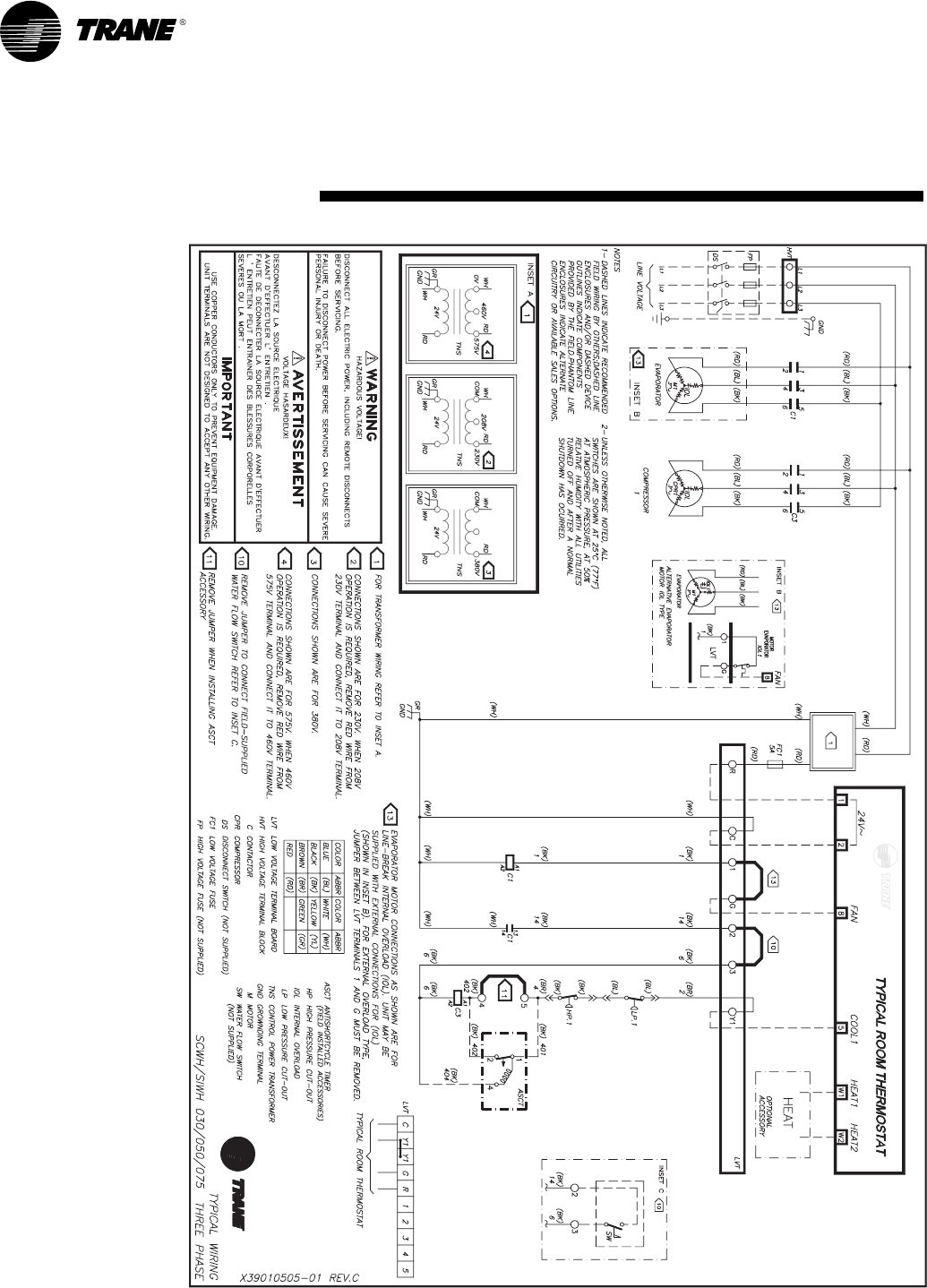
32 PKG-SVX14A-EN
typical wiring
diagramMaintenance
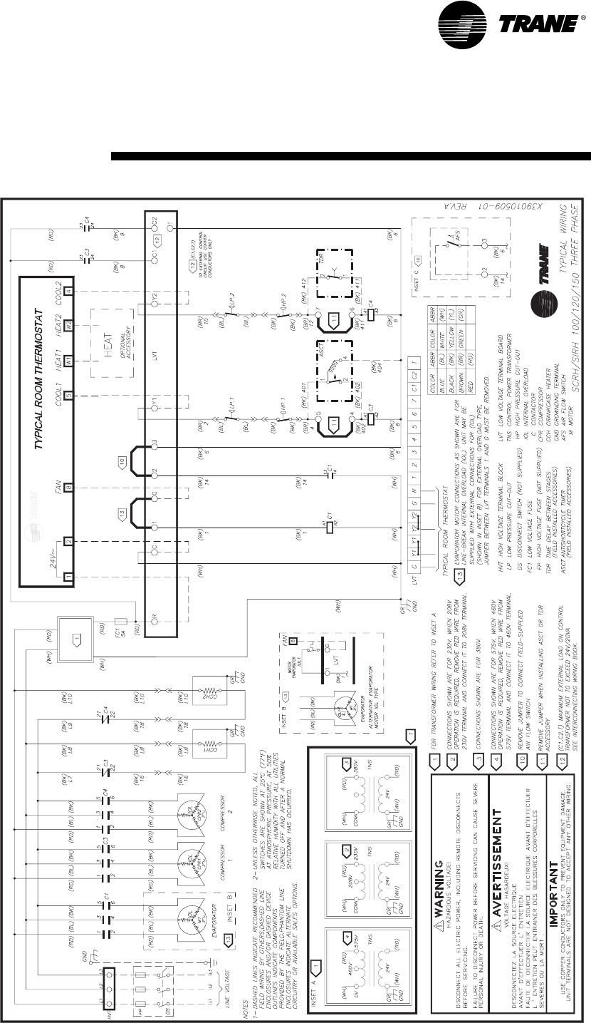
PKG-SVX01A-EN 33
typical wiring
diagramMaintenance
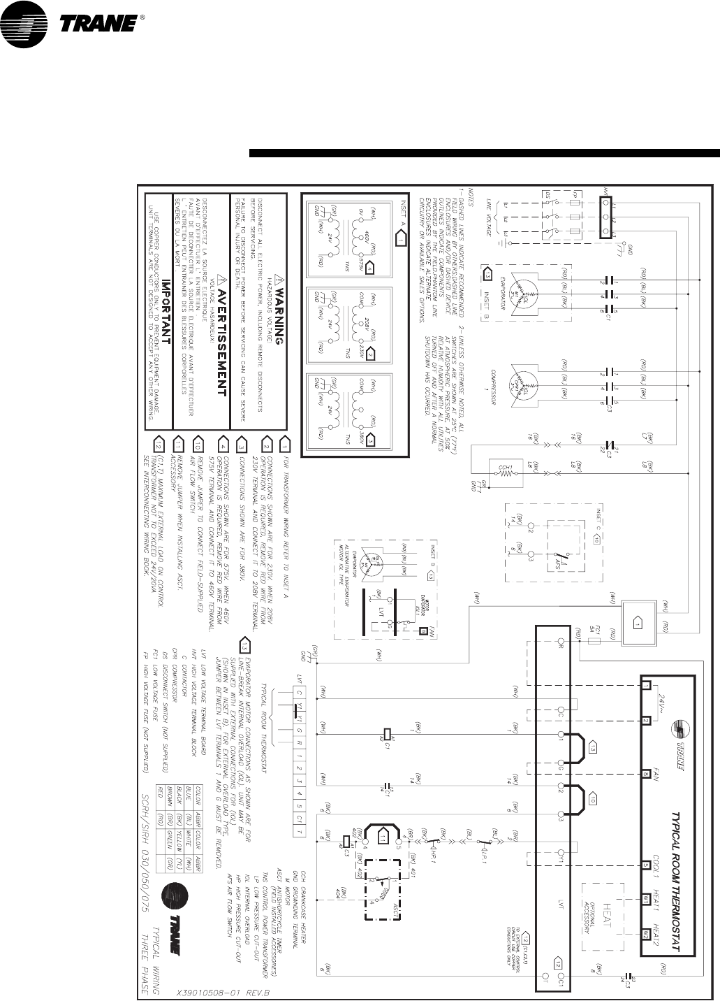
34 PKG-SVX14A-EN
typical wiring
diagramMaintenance
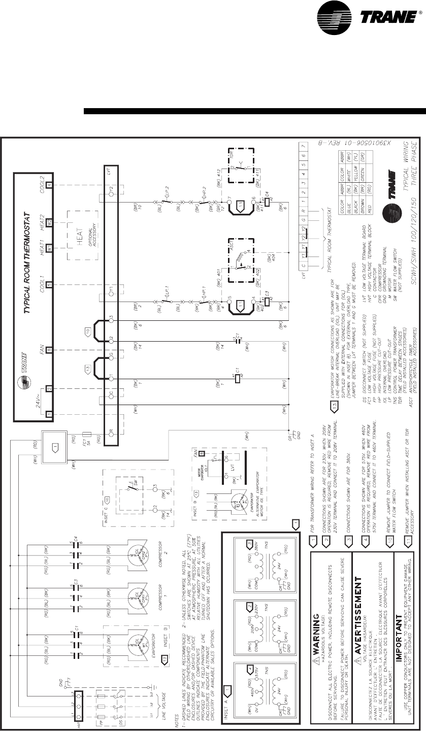
PKG-SVX01A-EN 35
typical wiring
diagramMaintenance

www.trane.com
For more information, contact your local Trane
office or e-mail us at comfort@trane.com
Literature Order Number
Date
Supersedes
Trane has a policy of continuous product and product data improvement and reserves the right to change design
and specifications without notice.
PKG-SVX14A-EN
October 2008
PKG-SVX14A-EN September 2007
