Trane Signature 20 To 110 Tons Catalogue PKG PRC002 EN (06/2014)
2015-04-02
: Trane Trane-Signature-20-To-110-Tons-Catalogue-684232 trane-signature-20-to-110-tons-catalogue-684232 trane pdf
Open the PDF directly: View PDF ![]() .
.
Page Count: 128 [warning: Documents this large are best viewed by clicking the View PDF Link!]
- Introduction
- Table of Contents
- Features and Benefits
- Application Considerations
- Selection Procedure
- Model Number Descriptions
- General Data
- Performance Data
- Controls
- Electrical Data
- Dimensions and Weights
- Mechanical Specifications
Commercial Self-Contained
Intellipak™ Signature Series
Remote Air-Cooled Condenser
20 - 110 Tons — Water-Cooled
20 - 60 Tons — Air-Cooled
June 2014 PKG-PRC002U-EN
Product Catalog
© 2014 Trane All rights reserved PKG-PRC002U-EN
Introduction
Affordable Self-Contained Value from Trane…
IntelliPak™ Signature Series Self-Contained Units
Copyright
This document and the information in it are the property of Trane, and may not be used or
reproduced in whole or in part without written permission. Trane reserves the right to revise this
publication at any time, and to make changes to its contents without obligation to notify any person
of such revision or change.
Trademarks
Trane and the Trane logo are trademarks of Trane in the United States and other countries. All
trademarks referenced in this document are the trademarks of their respective owners.
Revision History
PKG-PRC002-EN (26 Jun 2014). Updated evaporator fan and low flow fan information in
General Data tables. Reordered General Data tables
PKG-PRC002-EN (04 Apr 2013). Add wireless comm interface (WCI).
PKG-PRC002-EN (18 Oct 2012). Corrected Table 60 values. Updated fan FLA and LRA values
in Electrical Data tables.
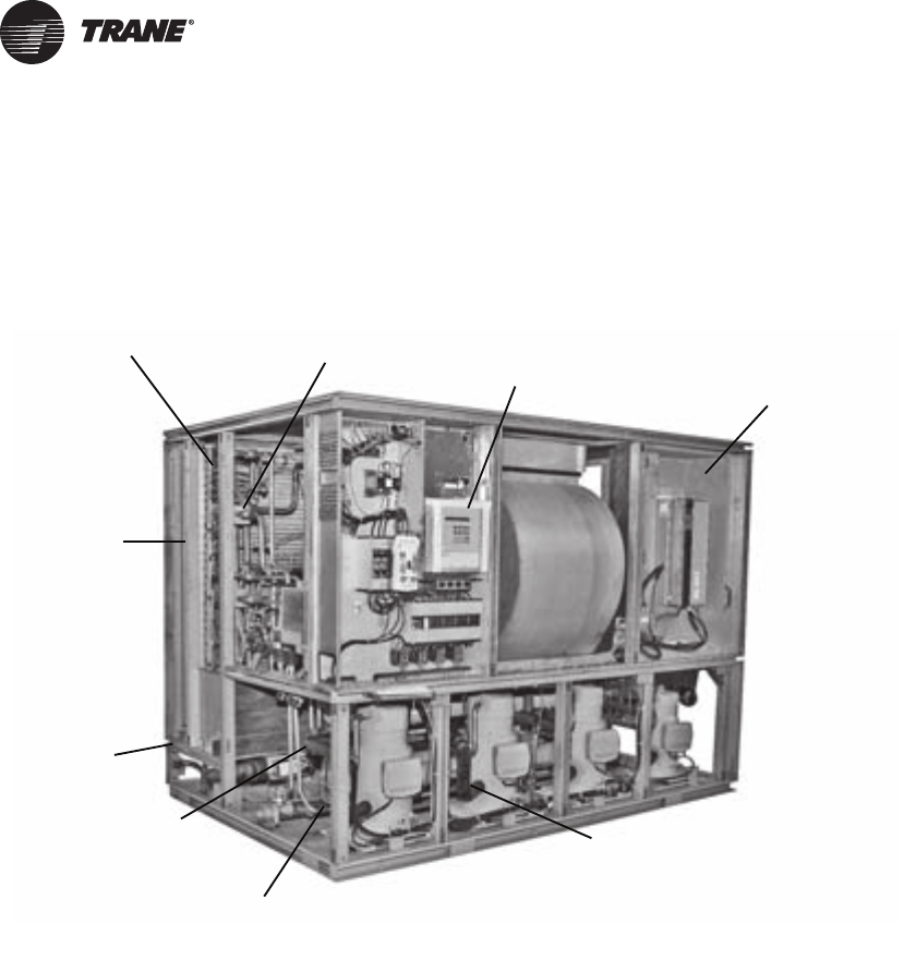
Waterside economizer
(cleanable option shown)
Sight glasses with
ports for viewing
while unit is running
Unit mounted microprocessor
control with easy-to-read human
interface panel Swing out VFO panel with
Tri-VFO for efficient VAV
operation
Trane 3-D® Scroll Compressor
for reliability, efficiency and
quiet operation
Two-bolt connection on
cleanable condenser for
quick, easy maintenance
Waterside valve
package option
to enhance system
efficiency
Internally trapped
drain for low cost
installation
2-inch flat filter
box inside unit
casing

PKG-PRC002U-EN 3
Table of Contents
Introduction ......................................................2
Affordable Self-Contained Value from Trane… ....................... 2
IntelliPak™ Signature Series Self-Contained Units .................... 2
Table of Contents ..................................................3
Features and Benefits ..............................................4
Application Considerations .........................................10
Selection Procedure ...............................................15
Model Number Descriptions ........................................17
Self-Contained Ship-With Accessory Model Number ................. 19
Remote Air-Cooled Condenser Model Number Description ............ 19
General Data .....................................................20
Performance Data ................................................27
Controls ........................................................84
IntelliPak™ Signature Series Self-Contained Units ................... 84
Zone Temperature Control Unit Sequence Of Operation .............. 92
Zone Sensor Options ........................................... 95
Electrical Data ....................................................98
Selection Procedures ........................................... 98
Determination of minimum circuit ampacity (MCA) .................. 98
Dimensions and Weights .........................................101
Field Installed Zone Sensors .................................... 112
Mechanical Specifications .........................................117

4 PKG-PRC002U-EN
Features and Benefits
Why consider Signature Series self-contained floor-by-floor systems?
Improved Cash Management
• Factory-installed and tested options reduce field labor and installation risk, while improving
system reliability
•Requires less sophisticated maintenance than built-up systems
Tenant Satisfaction
• Complete HVAC system on each floor minimizes tenant inconvenience during routine
maintenance
• Tenants can control system after hours to increase productivity and minimize expense
Low First Cost
• Reduce field labor, installation time, and cost with factory packaged controls and piping
• Reduce installed tonnage up to 20 percent by taking advantage of building diversity and VAV
flexibility
• Flexible air discharge arrangement matches most building configurations
Lower Installed Cost
• Single point power connection
• Single point water connection
• Factory commissioned and tested controls
• Factory installed options
• Internally trapped drain connection
Economical Operation
• Free cooling with waterside or airside economizer
• Energy savings with floor-by-floor system since only units on floors requiring cooling need to
operate
• Significant annual energy consumption reduction due to partial occupancy after-hours, when
compared to a central chilled water system
• Simple heating alternatives include perimeter radiation and fan-powered VAV
• Energy savings from the integrated water valve control using pump unloading
Assured Acoustical Performance
• Flexible, horizontal discharge plenum provides smooth airflow, reducing static pressure losses
for optimum acoustical performance
• Multiple compressor design reduces acoustical levels. Scroll compressor design smooths gas
flow for quieter operation
Indoor Air Quality (IAQ) Features
• Sloped drain pan
• Stainless steel sloped drain pan option
• Internally trapped drain connection
• Double wall construction option
• Matt-faced fiberglass insulation
• High efficiency throwaway filter option

PKG-PRC002U-EN 5
Features and Benefits
• Easily cleanable evaporator, condensers, and waterside economizers
• Filter access door allows easy removal to encourage frequent filter changing
• Airside economizer with Traq™ damper allows direct measurement and control of outdoor air
Enhanced Serviceability
• Self-supporting removable panels
• Quick access service panel fasteners
• Eye level control/service center
• Refrigerant line sight glasses in view during operation
Competitive Advantage
• Increased capacity to meet today’s growing floor plates and building loads
• Compact cabinet to minimize mechanical room requirements
• Up to 17% more efficient than competitive units
• Low leaving air temp capability to reduce fan motor energy, improve acoustical performance,
and minimize duct sizes
• Factory-installed and tested IntelliPak™ microprocessor controller
Standard Features
• 20 through 110 ton industrial/commercial water-cooled self-contained units
• 20 through 60 ton industrial/commercial remote air-cooled self-contained units
• Fully integrated, factory-installed, and commissioned microelectronic controls
• Unit mounted human interface panel with a two line x 40 character clear language (English,
Spanish, or French) display and a 16-function keypad that includes custom, diagnostics, and
service test mode menu keys
• Improved Trane 3-D™scroll compressor
• Compressor lead/lag
• CV or VAV system control
• Low ambient compressor lockout adjustable control input
• EISA efficiency open drip proof (ODP) and totally enclosed fan (TEFC) cooled supply fan motor
options
• FROSTAT™ coil frost protection on all units
• Daytime warm-up (occupied mode) on units with heat and morning warm-up operation on all
units
• Supply air static over pressurization protection on units with variable frequency drives (VFDs)
• Supply airflow proving
• Supply air tempering control with heating option
• Supply air heating control on VAV with hydronic heating option
• Emergency stop input
• Mappable sensors and setpoint sources
• Occupied/unoccupied switching
• Timed override activation
• Refrigeration circuits are completely factory piped and tested on water-cooled units
• Factory piped and tested, mechanically cleanable water-cooled condensers

6 PKG-PRC002U-EN
Features and Benefits
• Two-bolt removable condenser waterboxes for quick and easy cleaning
• Sloped drain pans to ensure complete condensate removal for IAQ
• Internally trapped drain connection with cleanout
• Internally isolated centrifugal supply fan
• Sturdy-gauge galvanized steel framework with easily removable painted galvanized steel
exterior panels
• UL listing on standard options
• Fan belts and grease lines are easily accessible
• Access panels and clearance provided to clean both evaporator and waterside economizer coil
fins
• Condensing pressure control on all variable water flow systems with valves
• Programmable water purge during unoccupied mode
• High entering air temperature limit
• Low entering air temperature limit with waterside economizer or hydronic heat
• Shipped with protective shrink wrap covering of unit and any indoor modules shipped loose
Optional Features
• Trane communication interface module: ICS interface control module
• BACnet Communication Interface Module
• Generic BAS interface
• Comparative enthalpy control
• Ventilation override from up to five external inputs
• Remote human interface controls up to four units
• Fully integrated, factory-installed/commissioned variable frequency drive control with or
without optional integrated bypass
• Waterside economizer with factory installed piping and controls
• Waterside modulating condensing temperature control valves include factory installed piping
and control wiring
• Removable cast iron headers on cleanable waterside economizer
• Flexible horizontal discharge plenum with or without factory cut holes
• Heating options include hot water, steam, and electric
• Refrigerant suction discharge line service (shut-off) valves
• Protective coatings for the unit and/or evaporator coils
• Double wall construction
• Stainless steel sloped drain pan
• Medium efficiency throwaway filters
• Through-the-door non-fused disconnect switch
• Trane’s air quality Traq™ damper in airside economizer mixing box
• High duct temperature thermostat
• Dual electrical power connection
• CO2 reset input
• 2 and 4-inch filter racks for all sizes
• Hi-capacity coils available on many models
PKG-PRC002U-EN 7
Features and Benefits
Variable Frequency Drives (VFD)
Variable frequency drives are factory installed, wired, and tested to provide supply fan motor speed
modulation. VFDs are quieter and more efficient than inlet guide vanes and may even be eligible
for utility rebates. The VFDs are available with and without a manual integrated bypass option,
controlled through the human interface (HI) panel. Bypass control provides full nominal airflow
control to CV zone setpoints in the unlikely event of a drive failure by manually placing the drive
in the bypass mode.
Field Installed Accessories
• Airside economizer control with or without mixing box
• Wireless comm interface (WCI)
• Programmable sensors with or without night set back for CV and VAV systems
• ICS zone sensors used with Tracer™ system for zone control
• Field installed module kits available for field upgrade of controls
• Ultra low leak dampers for 0-100 percent modulating fresh air economizer
Integrated Self-Contained Systems
Everything you need to know about your self-contained VAV system is available using Tracer,
Trane’s family of building automation products. Tracer is a software package that minimizes custom
programming requirements and allows easy system setup and control using your personal
computer. By enabling all CSC units to communicate using the LonTalk interface, transforming
your heating and cooling units into a true system is made simple.
Operating data from all system components is readily available for evaluation. You can control,
monitor, and service your facility—all from your personal computer. That is why all Tracer controls
have been designed to be LonTalk compatible.
The IntelliPak self-contained unit, as part of Trane ICS, provides powerful maintenance monitoring,
control, and reporting capabilities. Tracer places the self-contained unit in the appropriate
operating mode for: system on/off, night setback, demand limiting, setpoint adjustment based on
outside parameters and much more. You can monitor unit diagnostic conditions through Tracer
such as: sensor failures, loss of supply airflow, and an inoperative refrigerant circuit.
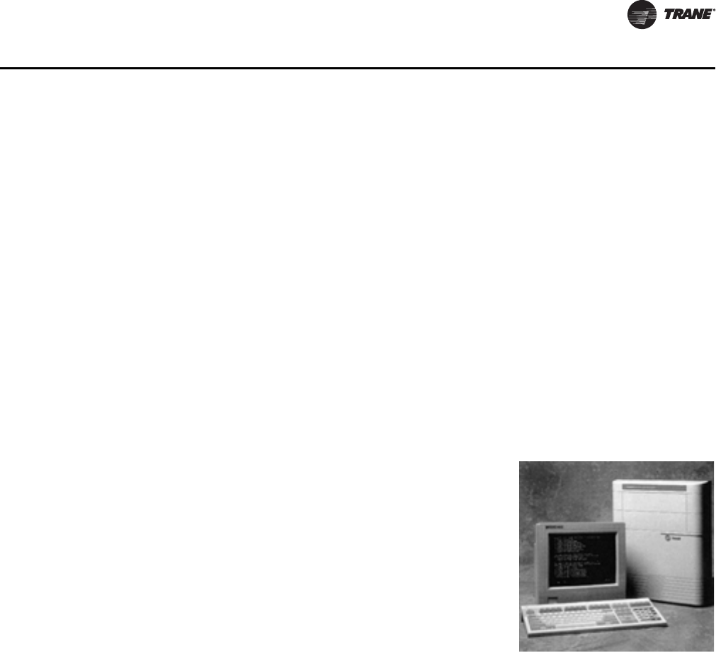
Integrated Comfort™ System (ICS)
Trane’s Integrated Comfort system (ICS) increases job control by
combining IntelliPak™ Signature Series self-contained units and
a Tracer™ building management system. This integrated system
provides total building comfort and control. Building owners
and managers not only save energy when using ICS. They have
the ability to automate their facilities and the convenience of a
control system interface.
Simplifying The Comfort System
Trane’s designers combined new technology and innovation to
bring you more system capabilities and flexibility. Our
Integrated Comfort System (ICS) with HVAC equipment is easy
to use, install, commission, and service.

8 PKG-PRC002U-EN
Features and Benefits
Tracer points monitored for IntelliPak Signature Series Self-Contained include:
• Compressor on/off status
• Ventilation status
• Condenser water flow status
• Heat status
• Supply air pressure
• Supply air temperature
• Suction temperature of each circuit
• Entering economizer water temperature
• Zone temperature
• Entering condenser water temperature
• Supply air temperature reset signal
• Morning warm-up sensor temperature
• Entering air temperature
Tracer control points available for IntelliPak Signature Series self-contained include:
• Cooling and heating setpoints
• VAV discharge air temperature setpoints
• Supply air pressure setpoint
• Cooling and heating enable/disable
• Air economizer enable/disable
• Airside economizer minimum position
• Unit priority shutdown
Commissioning, control, efficiency, and information…it simply all adds up to one reliable
source…Trane.
Interoperability with BACnet™
The Trane Tracer SC BACnet Control Interface (BCI) for IntelliPak self-contained offers a building
automation control system with outstanding interoperability benefits. BACnet, which is an industry
standard, is an open, secure and reliable network communication protocol for controls, created by
American Society of Heating, refrigerating and Air-Conditioning Engineers, Inc. (ASHRAE).
Interoperability allows application or project engineers to specify the best products of a given type,
rather than one individual supplier's entire system. It reduces product training and installation
costs by standardizing communications across products. Interoperable systems allow building
managers to monitor and control IntelliPak equipment with Tracer SC controls or a 3rd party
building automation system. It enables integration with many different building controls such as
access/intrusion monitoring, lighting, fire and smoke devices, energy management, and a wide
variety of sensors (temperature, pressure, humidity, occupancy, CO2 and air velocity).
Trane Wireless Comm Interface (WCI)
The Trane® Wireless Comm Interface (WCI) is the perfect alternative to Trane’s BACnet™ wired
communication links (for example, Comm links between a Tracer™ SC and a Tracer™ UC400).
Minimizing communication wire used between terminal products, zone sensors, and system
controllers has substantial benefits. Installation time and associated risks are reduced. Projects are
completed with fewer disruptions. Future re-configurations, expansions, and upgrades are easier
and more cost effective.
PKG-PRC002U-EN 9
Features and Benefits
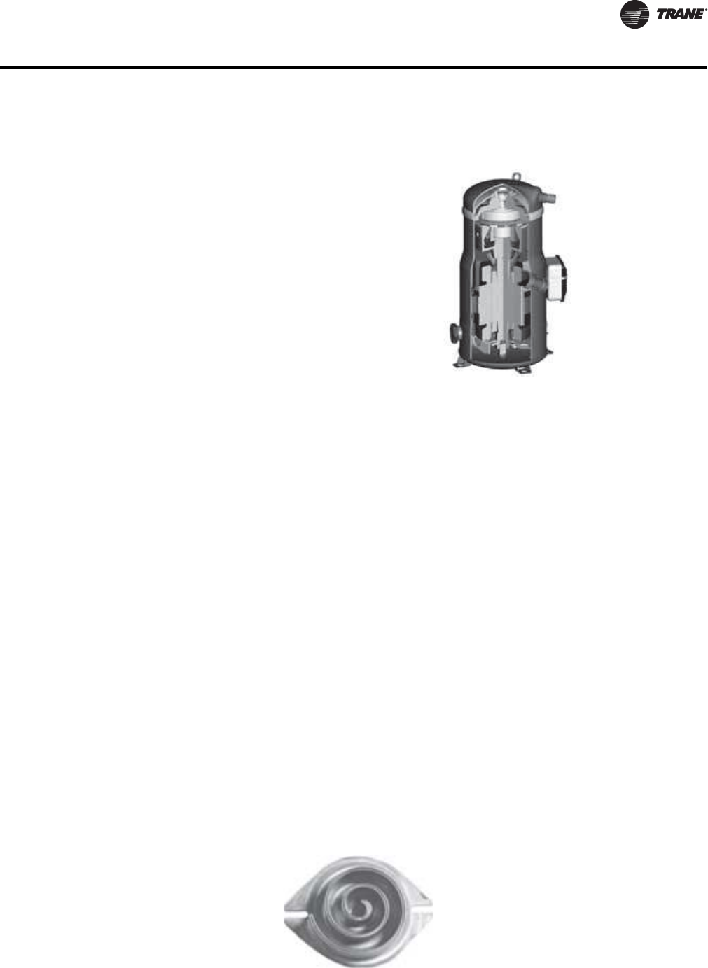
Trane R-410A 3-D™ Scroll Compressor
Features listed below optimize the compressor design and performance:
• Optimized scroll profile
• Heat shield protection to reduce heat transfer between discharge and suction gas
• Improved sealing between high side and low side
Additional features are incorporated in the compressor design for greater reliability:
• Patented design motor cap for improved motor cooling
• Improved bearing alignment
• Improved resistance to dry start-up
• Oil sight glass for evaluating proper oil levels
Low Torque Variation
The 3-D™ Scroll has a very smooth compression cycle, imposing very little stress on the motor and
resulting in greater reliability. Low torque variation reduces noise and vibration.
Suction Gas Cooled Motor
Compressor motor efficiency and reliability is further optimized with the latest scroll design. The
patented motor cap directs suction gas over the motor, resulting in cooler motor temperatures for
longer life and better efficiency.
Proven Design through Testing and Research
The new R-410A 3-D™ Scroll compressor is the next generation of reliable Trane 3-D™ Scroll
compressors provided by Trane, the leader in scroll compressor technology.
The R-410A Trane 3-D™ Scroll provides
important reliability and efficiency benefits
inherent in its design. The 3-D™ Scroll allows
the orbiting scrolls to touch in all three
dimensions, forming a completely enclosed
compression chamber which leads to increased
efficiency. In addition, the orbiting scrolls only
touch with enough force to create a seal,
eliminating wear between the scroll involutes.
The fixed and orbiting scrolls are made of high
strength cast iron which results in less thermal
distortion and minimal leakage. In addition,
improved part isolation provides reduced
compressor sound levels compared to previous
designs.
Figure 1. One of two matched scroll plates - the distinguishing feature of the scroll compressor
10 PKG-PRC002U-EN
Application Considerations
Self-Contained Acoustical Recommendations
Successful acoustical results are dependent on many system design factors.
Following are general acoustical recommendations. For more information, or if there is concern
about a particular installation, contact a professional acoustical consultant.
Location and Orientation of the Mechanical Equipment Room
Locate the equipment room adjacent to stairwells, utility rooms, electrical closets, and rest rooms
if possible (See figure below). This minimizes the acoustic effects and risk of workmanship or
installation errors. Place the discharge and return air ductwork over these less acoustically
sensitive areas, using vertical or horizontal fresh air shafts. Consult code requirements for fresh air
and smoke purge constraints.
Return Air Ductwork
Duct the return air into the mechanical equipment room. Connect ductwork to the unit if local code
dictates. The return air ductwork must have an elbow inside the equipment room. This elbow will
reduce sound transmissions through the return duct. Extend the ductwork from the elbow far
enough to block the “line of sight” to the exterior of the equipment room. Use a minimum ductwork
length of 15 feet to the equipment room exterior. Line the duct with two-inch, three-pound density
insulation. Use multiple, small return ducts for better acoustical performance to the occupied
space.
Supply Air Ductwork
Insulate the supply air duct with two-inch, three-pound density insulation. Extend this lining at least
15 feet out from the equipment room wall, keeping the duct aspect ratio as small as possible.
Minimize large flat panels since they transmit sound. In addition, small aspect ratios will minimize
potential “oil canning” of the duct due to flow turbulence.
The flexible horizontal discharge plenum option helps avoid complicated ductwork transitions.
Ductwork turning vanes typically improve pressure drop but degrade acoustical performance.
Recommended Maximum Air Velocities
The maximum recommended velocity for the discharge air duct is 2,000 fpm. The maximum
recommended velocity for the return air duct is 1,000 fpm. Limit air velocities below these
operating points to minimize the risk of flow turbulence that causes regenerated noise. Using
round supply duct and static regain allows maximum discharge air velocities up to 3,000 fpm.
Lining round supply duct also substantially lowers frequency noise attenuation. However, flow
regenerated noise potential increases dramatically at air velocities over 3000 fpm.
Figure 2. Equipment room location and orientation
Elevator Elevator
Supply
Air
Supply Air
Mechanical
Room
Self
Contained
Unit
Bathroom
Stairwell
Return Air
PKG-PRC002U-EN 11
Application Considerations
Equipment Room Construction Options
Locate the equipment room door away from acoustically sensitive areas like conference rooms.
The door should swing out of the equipment room, if possible, so that the low pressure in the
equipment room pulls the door in to help maintain a tight seal.
Equipment Options
The flexible horizontal discharge plenum allows multiple tested outlet options. This minimizes the
risk of acoustic and/or pressure drop problems by avoiding complex transitions close to the fan
discharge.
Static Pressure Versus Acoustics
Design the system to minimize the total static pressure required from the self-contained unit fan.
Typically a change in static pressure of only 0.5 inches can reduce NC level by approximately 2 or
3 in the occupied space.
Isolation Recommendations
Unit
The Signature Series unit fan and compressors are internally isolated. Therefore, external isolation
is not required. Consult a vibration specialist before considering external or double vibration
isolation.
Ductwork
Design duct connections to the unit using a flexible material. Consult local codes for approved
flexible duct material to prevent fire hazard potential.
Piping Connections
Rubber isolator connectors are recommended for condenser piping to prevent vibration
transmission to or from the building plumbing. The Signature Series self-contained unit is
internally isolated and does not require additional isolation. However, ensure proper system
vibration isolation design prevents vibration transmission from the building plumbing to the unit.
Also be sure to properly isolate the drain line.
Condenser Water Piping
Piping Location and Arrangement
Provide at least 24 inches of clearance between the piping and the unit for service. Place the risers
away from the side of the unit if possible. Be sure to allow sufficient space for valves and unions
between the piping and the self-contained unit. Lay out condenser piping in reverse returns to help
balance the system. This is accomplished by equalizing the supply and return pipe length. Multi-
The preferred equipment room wall construction is
concrete block. If this is not feasible then a double
stud offset wall is suggested (See figure). This
removes physical contact that would transmit sound
through the equipment room wall to the occupied
space. Interweave fiberglass insulation between the
wall studs. Use two layers of sheetrock on each side
of the wall.
Workmanship details are critical to acoustical
performance. Seal all wall and floor penetrations by
the ductwork, water piping, and equipment room
access doors with a flexible material such as caulk
and/or gasketing to stop noise and air leaks.

12 PKG-PRC002U-EN
Application Considerations
story buildings may use a direct return system with balancing valves at each floor. Install all heat
exchangers and most cooling tower piping below the sump operating water level to prevent
overflow during unit and/or system shut down.
Recommended Pump Location
Locate pump downstream of the cooling tower and upstream of the self-contained unit. This
provides smoother and more stable unit operation.
When the tower and pump are both roof mounted, be sure to provide the necessary net positive
suction head pressure to prevent cavitation. Raise the tower or submerge the pump in a sump to
provide positive suction. To prevent an on-line pump failure, use a standby pump to avoid a
complete system shutdown.
Several partial capacity pumps or variable speed pumps may be used. Review the economics of
these alternate pumping options.
Strainers and Water Treatment
Water strainers are required at the unit inlet to eliminate potential unit damage from dirty water.
Specify a water basket-type strainer to avoid an incorrect stream strainer application. Untreated or
poorly treated water may result in equipment damage. Consult a water treatment specialist for
treatment recommendations.
Isolation Valves
Install isolation valves at each unit before the strainer and after the condenser. This allows periodic
servicing of the unit or strainer while allowing other units in the system to remain in operation.
Pressure Gauges
Install pressure gauges on the inlet and outlet of the self-contained unit. Select the gauge’s scale
so that the unit design operating point is approximately mid-scale.
Thermometers
Install thermometers on the condenser water inlet and outlet lines to each unit for system analysis.
Trane Company recommends using a thermometer temperature range of 40 to 140°F, using a 2°F
temperature increment.
Drains
The unit condensate drain is internally trapped to offset the pressure differential that exists during
fan operation. Install a trapped drain in the low point of the mechanical equipment room floor to
collect water from cleaning operations.
Condensing Pressure Control (Water-Cooled condensers)
Often cold condensing water applications between 35°F and 54°F require a condensing pressure
control valve. Any unit with variable-flow waterside valves can modulate water flow to maintain
a user defined condensing temperature. However, to utilize this feature, the building water system
must be capable of operating at reduced water flow rates through the self-contained units. It is
imperative to install variable volume pumps or an external bypass in the water distribution system.
PKG-PRC002U-EN 13
Application Considerations
Free Cooling Opportunities and Alternatives
Free cooling is available with either the airside or waterside economizer options.
Waterside Economizer
The waterside economizer substantially reduces the compressor energy requirements because it
uses the cooling water before it enters the condensers. Additional equipment room space is not
required since the coils are contained within the overall unit dimensions.
Disadvantages include higher airside pressure drop and a higher head on condenser water pumps.
The coils may be mechanically cleanable (optional) for ease in maintenance versus expensive and
difficult chemical cleaning methods.
Airside Economizer
The airside economizer substantially reduces compressor, cooling tower, and condenser water
pump energy requirements using outside air for free cooling. It also reduces tower make up water
needs and related water treatment.
Disadvantages include building requirements that locate the mechanical room and self-contained
unit toward an exterior wall to minimize ductwork, building barometric control, or additional air
shafts. Also, airside economizers require additional mechanical room space.
Unit Operating Limits
Airflow
The minimum recommended airflow for proper VAV system staging and temperature control is 35
percent of nominal design airflow. Adjusting VAV boxes with the appropriate minimum settings
will prevent the self-contained unit from operating in a surge condition at airflows below this point.
Continuous operation in a surge condition can cause fan failure. Reference General Data Tables on
Table 1, p. 20 for minimum airflow conditions.
Waterside Economizer Flow
Control
Units equipped with waterside
economizer control valves can be set
up for variable or constant water flow.
Use constant water flow setup on
water systems that are not capable of
unloading water supply to the unit.
The economizer and condenser
valves will operate in complement to
one another to provide continuous
water flow.
Use variable water flow setup with
water flow systems that can take
advantage of pump unloading for
energy savings. Since non-cooling
operation restricts water flow during
part load economizing or condensing
temperature control, it is imperative
to install variable volume pumps or an
external bypass in the water
distribution system.

14 PKG-PRC002U-EN
Application Considerations
Signature Series self-contained units use fixed pitch sheaves. Adjust air balancing by obtaining
alternate fixed pitch sheave selections from the local Trane sales office.
Water Flow
Use 3 gpm/ton for optimum unit capacity and efficiency. Use 2.5 or 2 gpm/ton to reduce pump
energy, cooling tower and piping costs. However, these reduced water flows may impact unit
capacity and efficiency by one or two percent. Consult General Data Tables on pages 17-20 for unit
specific water flow ranges.
Remote Air-Cooled Condenser
Unit Location
Unobstructed condenser airflow is essential to maintaining capacity and operating efficiency.
When determining unit placement, give careful consideration to assure sufficient airflow across the
condenser coils. Avoid these two detrimental conditions: warm air recirculation and coil starvation.
Both warm air recirculation and coil starvation cause reductions in unit efficiency and capacity
because of the higher head pressure associated with them. In more severe cases, nuisance unit
shutdowns will result from excessive head pressures.
Clearance
Ensure vertical condenser air discharge is unobstructed. While it is difficult to predict the degree
of warm air recirculation, a unit installed with a ceiling or other obstruction above it will experience
a capacity reduction that will reduce the maximum ambient operation limit. Nuisance high head
pressure trips may also occur.
The coil inlet must also be unobstructed. A unit installed closer than the minimum recommended
distance to a wall or other vertical riser will experience a combination of coil starvation and warm
air recirculation. This may result in unit capacity and efficiency reductions, as well as possible
excessive head pressures. Reference the service clearance section on page 111 for recommended
lateral distances.
Ambient Limitations
Standard ambient control allows operation down to 45°F with cycling of condenser fans. Units with
the low ambient option are capable of starting and operating in ambient temperatures down to 0°F.
Optional low ambient units use a condenser fan damper arrangement that controls condenser
capacity by modulating damper airflow in response to saturated condenser temperature.
Maximum ambient operating temperature of a standard condenser is 115°F. Operation at design
ambient above 115°F can result in excessive head pressures. For applications above 115°F, contact
the local Trane sales office.

PKG-PRC002U-EN 15
Selection Procedure
Following is a sample selection for a standard applied water-cooled self-contained at particular
operating conditions. Use Trane Official Product Selection System, TOPSS™, for making all final
selections or contact your local Trane representative.
Unit Capacities
1. Determine entering air temperature dry bulb and wet bulb and entering water temperature.
2. See chapter “Performance Data,” p. 27 to find gross total and sensible capacity that best meets
capacity requirements.
3. Apply the cfm correction factors from the capacity correction factor Ta b l e 13, p. 37 to determine
gross total and gross sensible capacities at desired cfm.
4. Multiply condenser water delta T by the total capacity cfm correction factor to determine new
condenser water delta T.
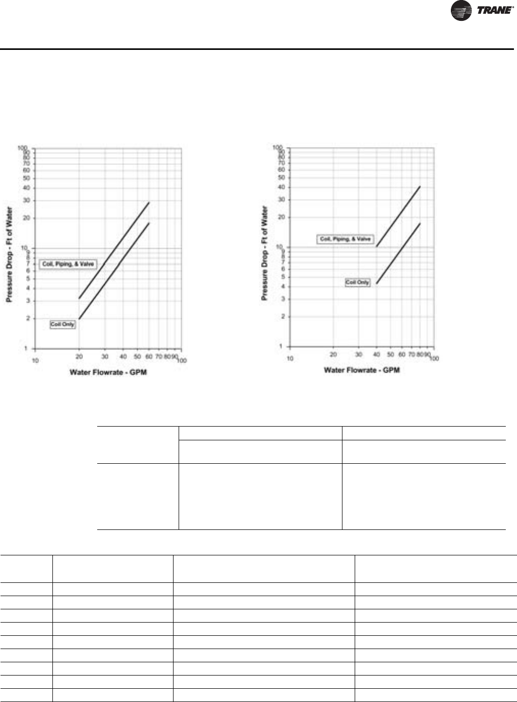
5. Using design cfm, determine static air pressure drops for accessories from the air pressure
drop Charts Figure 1, p. 27 through Figure 21, p. 33. Add accessory static pressure drops to
external supply and return static air pressure drops. Use the total air pressure drop to determine
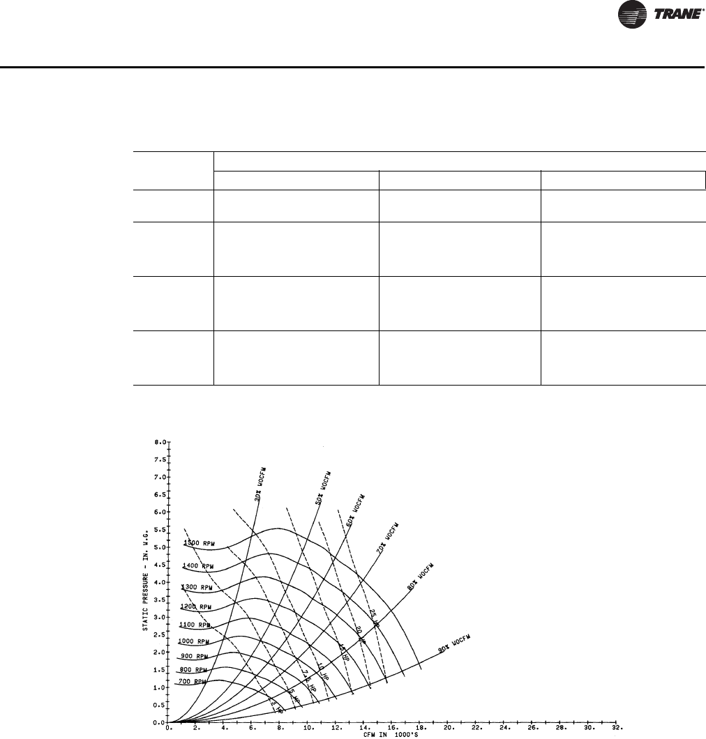
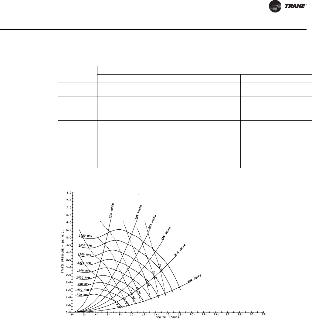
rpm and brake horsepower requirements from the appropriate fan curve. Note: The fan curves
include refrigerant coil and internal cabinet static loses.
6. Calculate supply fan motor heat by using the following equation:
Fan motor heat (MBh) = 2.8 x fan motor brake horsepower
7. Determine net total capacity and net sensible capacity by subtracting fan motor heat from gross
total capacity and gross sensible capacity.
8. Refer to Trane psychometric chart to determine leaving air temperatures.
Waterside Economizer Capacity
After determining that the unit will meet the required mechanical cooling capacity, determine the
waterside economizer capacity by referring to the appropriate two-row (low capacity) or four-row
(high capacity) waterside economizer capacity found in one of Table 15, p. 38 through Ta b l e 48 ,
p. 72.
9. Determine entering air temperature dry bulb and wet bulb, condenser water flow (gpm), and
economizer entering water temperature.
10. Refer to the appropriate waterside economizer table to find gross total and sensible capacity
and the leaving water temperature.
11. Apply the cfm correction factor for the waterside economizer from the appropriate table to
determine the gross total and sensible capacities at the desired cfm.
12. Multiply the condenser water delta T by the total capacity cfm correction factor to determine
the new delta T.
13. Calculate supply fan motor heat by using the following equation:
Fan motor heat (MBh) = 2.8 x fan motor brake horsepower
14. Determine net total and sensible capacity by subtracting fan motor heat from gross total and
sensible capacity.
15. Refer to the Trane psychometric chart to determine leaving air temperatures.
Selection Example
Design Conditions
Total gross capacity required = 420 MBh = 35.2 Tons
Total sensible capacity required = 315 MBh
Entering air temperature = 80/67°F

16 PKG-PRC002U-EN
Selection Procedure
Entering water temperature = 85°F
Water flow rate = 105 gpm
Airflow = 14840 cfm at 2.5-inch duct static pressure
Unit includes:
•Constant Volume
•Waterside economizer
•Medium velocity throwaway filters
Unit Selection
Tentatively select a 35 ton unit: Model SCWF 35.
Refer to Table 26, p. 49 to obtain gross total and sensible unit capacities, and gpm at the design
conditions:
Total capacity = 432.0 MBh
Sensible capacity = 329.0 MBh
Leaving water temperature = 95.1°F
Since the design cfm is greater than the nominal cfm, adjust the capacities and condenser water
delta T to reflect the higher cfm: design cfm 14840 = +6% of nom. Cfm nominal 14000 cfm
Refer to Tab l e 13 , p . 3 7 to obtain the capacity correction factors for +6% of nominal cfm:
Cooling capacity multiplier = 1.009
Sensible capacity multiplier = 1.027
Multiply the capacities by the correction factors:
•432 MBh x 1.009 = 435.89 MBh
•329 MBh x 1.027 = 337.88 MBh
The SCWF 35 meets the total and sensible design requirements.
Multiply the delta T of 10.1°F by the cooling capacity correction factor of 1.009 to obtain new delta
T of 10.19°F and add this to the entering water temperature to obtain the actual leaving water
temperature of 95.19°F.

PKG-PRC002U-EN 17
Self-Contained
Digit 1 - Unit Model
S = Self Contained
Digit 2 - Unit Type
C = Commercial
I = Industrial
Digit 3 - Condenser Medium
W = Water-cooled
R = Air-cooled
Digit 4 - Development Sequence
F = Signature Series
Digit 5 - Refrigerant Circuit
Configuration
U = Standard Capacity
V = High Capacity
Digit 6, 7 - Unit Nominal
Capacity
20 = 20 tons (water or air)
22 = 22 tons (water only)
25 = 25 tons (water or air)
29 = 29 tons (water or air)
30 = 30 tons (air only)
32 = 32 tons (water only)
35 = 35 tons (water or air)
38 = 38 tons (water only)
40 = 40 tons (air only)
42 = 42 tons (water only)
46 = 46 tons (water only)
50 = 50 tons (air only)
52 = 52 tons (water only)
58 = 58 tons (water only)
60 = 60 tons (air only)
65 = 65 tons (water only)
72 = 72 tons (water only)
80 = 80 tons (water only)
90 = 90 tons (water only)
C0 =100 tons (water only)
C1 =110 tons (water only)
Digit 8 - Unit Voltage
6 = 200 volt/60 hz/3 ph
4 = 460 volt/60 hz/3 ph
5 = 575 volt/60 hz/3 ph
Digit 9 - Air Volume/Temp
Control
2 = VFD and supply air temp ctrl
3 = VFD w/ bypass and supply
air temp ctrl
4 = Constant volume, zone temp cool
only
5 = Constant volume, w/ zone temp
heat/cool
6 = Constant volume and supply air
temp ctrl
Digit 10, 11 - Design Sequence
** = Factory Assigned
Digit 12 - Unit Construction
A = Vertical Discharge
B = Vertical Discharge With Double Wall
Digit 13 - Flexible Horizontal
Discharge Plenum Type
B = STD plenum w/ factory-cut holes
C = Low plenum w/ factory-cut holes
E = Std plenum w/ field-cut holes
F = Low plenum w/ field-cut holes
H = STD plenum double wall w/ field-cut
holes
J = Low plenum double wall w/ field-cut
holes
K = Extended height plenum w/factory-cut
holes, ship separate
L = STD plenum w/factory-cut holes, ship
separate
M =Low plenum w/factory-cut holes, ship
separate
N = Extended height plenum w/field-cut
holes, ship separate
P = STD plenum w/field-cut holes, ship
separate
R = Low plenum w/field-cut holes, ship
separate
T = Extended height double-wall plenum
w/ field-cut holes, ship separate
U = STD double-wall plenum w/field-cut
holes, ship separate
V = Low double-wall plenum w/field-cut
holes, ship separate
W =STD double-wall (perf) plenum
w/field-cut holes (90-110 ton only)
X = Low double-wall (perf) plenum
w/field-cut holes (90-110 ton only)
Y = Extended height double-wall (perf)
plenum w/field-cut holes, ship
separate (90-110 ton only)
0 = None
Digit 14 - Motor Type
2 = ODP motor
3 = TEFC motor
Digit 15, 16 - Motor HP
05 = 5 hp
07 = 7.5 hp
10 = 10 hp
15 = 15 hp
20 = 20 hp
25 = 25 hp
30 = 30 hp
40 = 40 hp
50 = 50 hp (400V, 460V, 575V only)
60 = 60 hp (90-110 ton only)
Digit 17, 18, 19 - Fan rpm
040 = 400 rpm
045 = 450 rpm
050 = 500 rpm
052 = 525 rpm
055 = 550 rpm
057 = 575 rpm
060 = 600 rpm
065 = 650 rpm
070 = 700 rpm
075 = 750 rpm
080 = 800 rpm
085 = 850 rpm
090 = 900 rpm
095 = 950 rpm
100 = 100 0 rpm
105 = 1050 rpm
110 = 110 0 rp m
115 = 1150 rpm
120 = 1200 rpm
125 = 1250 rpm
130 = 1300 rpm
135 = 1350 rpm
Digit 20 - Heating Type
A = Steam coil
B = Hot water coil
C = Electric heat, 1 stage
D = Electric Heat (2 Stage)
F = Hydronic heat ctrl interface
G = Elec. heat ctrl interface, 1 stage
H = Elec. heat ctrl interface, 2-stage (90-
110 ton only)
J = Elec. heat ctrl interface, 3 stage (90-1
10 ton only)
K = Steam coil ship separate, LH
L = Hot water coil ship separate, LH
T = Hot water coil, high capacity, LH
U = Hot water coil, high capacity, LH, ship
separate
0 = None
Digit 21 - Unit Isolators
A = Isopads
B = Spring isolators
0 = None
Digit 22 - Unit Finish
1 = Paint - slate gray
2 = Protective coating
3 = Protective coating w/ finish coat
Digit 23 - Supply Fan Options
0 = Standard fan
1 = Low CFM fan
Digit 24 - Unit Connection
1 = Disconnect switch
2 = Terminal block
3 = Dual point power (2 blocks)
Model Number Descriptions

18 PKG-PRC002U-EN
Model Number Descriptions
Digit 25 - Industrial Options
A = Protective coating evaporator coil
B = Silver solder
C = Stainless steel screws
D = A and B
E = A and C
F = B and C
G = A, B, and C
0 = none
Digit 26 - Drain Pan Type
A = Galvanized sloped
B = Stainless steel sloped
Digit 27 - Waterside Economizer
A = Mechanical clean full capacity (4-row)
B = Mechanical clean low capacity (2-row)
C = Chemical clean full capacity (4-row)
D = Chemical clean low capacity (2-row)
0 = None
Digit 28 - Ventilation Control
B = Airside econ w/ Traq damper, top O/A
C = Airside econ w/ std damper, top O/A
E = Airside econ w/ Traq damper &
comparative enthalpy, top O/A
F = Airside econ w/ std damper &
comparative enthalpy, top O/A
H = 2-position damper ventilation
interface
J = Airside economizer interface
K = Airside economizer interface w/
comparative enthalpy
Digit 29 - Water Piping
D = Left hand basic piping
F = Left hand Intermediate piping
K = Left hand basic w/ flow switch
M = Left hand intermediate w/ flow switch
0 = None
Digit 30 - Condenser Tube Type
A = Standard condenser tubes
B = 90/10 CuNi condenser tubes
0 = None (air-cooled only)
Digit 31 - Compressor Service
Valves
1 = With service valves
0 = None
Digit 32 - Miscellaneous System
Control
1 = Timeclock
2 = Interface For remote HI (IPCB)
3 = Dirty filter switch
4 = 1 and 2
5 = 1 and 3
6 = 2 and 3
7 = 1, 2 and 3
0 = None
Digit 33 - Control Interface
Options
A = Generic BAS Module; 0-5 VDC (GBAS)
B = Ventilation Override Module (VOM)
D = Remote Human Interface (RHI)
G = GBAS and VOM
H = GBAS and RHI
J = VOM and RHI
M =GBAS, VOM, and RHI
N = BACnet Communications Interface
(BCI)
P = BCI and GBAS
Q = BCI and VOM
R = BCI and RHI
T = BCI and GBAS and VOM
U = BCI and GBAS and RHI
V = BCI and VOM and RHI
W= BCI and GBAS and VOM and RHI
0 = None
1 = Lontalk Comm5 Interface (LCI)
2 = LCI and GBAS
3 = LCI and VOM
4 = LCI and RHI
5 = LCI and GBAS and VOM
6 = LCI and GBAS and RHI
7 = LCI and VOM and RHI
8 = LCI and GBAS and VOM and RHI
Digit 34 - Agency
T = UL agency listing
0 = None
Digit 35 - Filter Type
1 = 2” T/A w/ 2” rack
2 = 2” med. eff. T/A w/ 2” rack
3 = 4” bolt-on rack w/ 2” med eff. filter
4 = 6” rack w/ 2” construction T/A
pre-filter & 4” filter space
5 = 6” rack w/ 2” med. eff. T/A pre-filter &
4”filter space
Digit 36 - Miscellaneous Control
Option
A = Low entering air temp. protect device
(LEATPD)
B = High duct temp t-stat, ship separate
C = Plenum high static switch, ship
separate
E = A and B
F = A and C
H = B and C
L = A, B, and C
0 = None

PKG-PRC002U-EN 19
Model Number Descriptions
Self-Contained Ship-
With Accessory
Model Number
Digit 1 - Parts/Accessories
P = parts/accessories
Digit 2 - Unit Model
S=self-contained
Digit 3 - Shipment
W = with unit
Digit 4 - Development Sequence
F = signature series
G = modular series
Digit 5 - Sensors and Other
Accessories
S = sensors
Digit 6 - Sensors and
Thermostats (Field Installed)
A = BAYSENS077 - zone temp only
(CV and VAV)
B = BAYSENS073- zone temp with
timed override button (CV and
VAV)
C = BAYSENS074 - zone temp with
timed override button, setpoint
dial (CV and VAV)
E = BAYSENS108 - CV zone sensor
-dual setpoint, man/auto
changeover
F = BAYSENS110 - CV zone sensor-
dual setpoint, man/auto
changeover w, indicastor lights
G = BAYSENS119 - CV/VAV program-
mable night setback Sensor
H = BAYSENS021 - VAV zone sensor
with indicator lights
L = outside air temperature sensor kit
M = outside air humidity sensor kit
0 = none
Digit 7 - Mixed Air Temperature
Protection Kit (Field Installed)
1 = mixed air temperature protection
kit
0 = none
Digit 8 - Carbon Dioxide Sensor
(Field Installed)
1 = carbon dioxide sensor kit
0 = none
Digit 9 - Future Option
0 = none
Digits 10, 11 - Design Sequence
** = Factory Assigned
Remote Air-Cooled
Condenser Model
Number Description
Digit 1 - Unit Model
C = Condenser
Digit 2 - Unit Type
C = Commercial
I = Industrial
Digit 3 - Condenser Medium
R = Remote
Digit 4 - Development Sequence
C = C
Digit 5, 6, 7 - Nominal Capacity
020 = 20 tons
029 = 29 tons
035 = 35 tons
040 = 40 tons
050 = 50 tons
060 = 60 tons
Digit 8 - Unit Voltage
4 = 460 volt/60 hz/3 ph
5 = 575 volt/60 hz/3 ph
6 = 200 volt/60 hz/3 ph
Digit 9 - Control Option
0 = No low ambient damper, I-Pak.
A = No low ambient damper, t-stat.
B = Low ambient, I-Pak.
C = Low ambient, t-stat.
Digit 10, 11 - Design Sequence
** = Factory Assigned
Digit 12 - Unit Finish
1 = Paint, slate gray
2 = Protective coating
3 = Protective coating with
finish coat
Digit 13 - Coil Options
A = Non-coated aluminum
C = Protective coating aluminum
Digit 14 - Unit Isolators
0 = None
A = Spring isolators
B = Isopads
Digit 15 - Panels
1 = Louvered panels
Digit 16 - Agency Listing
0 = None
U = With UL listing
20 PKG-PRC002U-EN
General Data
Table 1. SCWF/SIWF Water-cooled self-contained, 20 to 42 tons
Unit Size 20 22 25 29 32 35 38 42
Compressor Data
Quantity 2 2 2 1/1 1/1 3 3 2/1
Nominal Ton/comp 10 10 10 15/10 15/10 10 10 10/15
Circuits 22222333
Evaporator Coil Data
Rows 2 2 3 or 6 2 4 or 6 3 4 or 6 3
Sq. Ft. 21.81 21.81 21.81 29.98 29.98 31.35 31.35 38.57
Fpf 144 144 144 144 144 144 144 144
Condenser Data
Minimum Gpm W/o Econ 36 36 36 46 46 54 54 64
Minimum Gpm W/ Econ 41 41 41 60 60 65 65 64
Maximum Gpm 80 80 80 102 102 119 119 142
Evaporator Fan Data
Quantity 11111111
Diameter 18” 18” 18” 18” 18” 20" 20" 25”
Minimum Hp 55555557. 5
Minimum Kw (3.73) (3.73) (3.73) (3.73) (3.73) (3.73) (3.73) (5.39)
Maximum Hp 20 20 20 20 20 25 25 30
Maximum Kw (14.91) (14.91) (14.91) (18.64) (18.64) (18.64) (18.64) (22.37)
Minimum Design Cfm 6325 6325 6500 8700 8700 9100 9880 11200
Maximum Design Cfm 8500 9350 10625 12325 13600 14875 16150 17850
High Capacity Option
Rows — — 6 — 6 — 6 —
Optional Low Flow Fan6
Diameter — — — — 18” —
Min/max Design Cfm — — — — 6000/10625 —
General Data R-410A
EER 14.0 14.0 14.0 14.0 14.3 14.0 14.2 14.2
IEER (CV) 15.3 15.3 15.0 15.6 15.2 15.2 14.9 15.6
IEER (VAV) 17.4 17.4 17.5 18.1 18.8 18.0 18.5 18.3
Refrigerant Charge, lbs. R-410A
Circuit A 19.5 19.5 21.5 22.0 28.5 21.5 23.5 22.0
Circuit B 19.5 19.5 21.5 19.5 23.5 21.5 23.5 22.0
Circuit C – – – – – 21.5 23.5 22.0
Capacity Steps - % 100/53/0 100/53/0 100/53/0 100/62/39/0 100/59/39/0 100/65/31/0 100/65/30/0 100/71/
43/26/0
Notes:
1. Compressors are Trane 3-D™ scroll.
2. EER and IEER are rated in accordance to AHRI Standard 340/360-2010. Based on 80/67° F (26.7/19.4 °C) to evaporator coil, nominal airflow and
85-95 °F (29.4/35 °C) condenser water.
3. All units operate with R-410A. Units ships with full operating charge.
4. Maximum cfm limits are set to prevent moisture carryover on the evaporator coil.
5. Minimum cfm limits are set to ensure stable thermal expansion valve operation at low load conditions.
6. Optional low flow fan (unit model number digit 23 = 1) is available ONLY when High Capacity option is selected (unit model number digit 5 = V).
PKG-PRC002U-EN 21
General Data
Table 2. SCWF/SIWF Water-cooled self-contained, 46-110 tons
Unit Size 46 52 58 65 72 80 90 100 110
Compressor Data
Quantity 2/1 3 3 3/1 3/1 4 5 2/4 6
Nominal Ton/Comp 10/15 15 15 15/10 15/10 15 15 10/15 15
Circuits 3 33444566
Evaporator Coil Data
Rows 4 or 6 2 4 or 6 3 4 or 6 6 6 6 6
Sq. Ft. 38.57 49.09 49.09 49.09 49.09 49.09 56.81 56.81 56.81
FPF 144 144 144 144 144 144 144 144 144
Condenser Data
Min GPM w/o Econ 64 84 84 102 102 112 140 168 168
Min GPM w/ Econ 64 84 84 102 102 112
Maximum GPM 142 186 186 226 226 248 300 350 350
Evaporator Fan Data
Quantity 1 11111111
Size (Dia.) 25” 25” 25” 27.5” 27.5” 27.5” 27.5” 27.5” 27.5”
Minimum HP 7.5 10 10 10 10 10 15 15 15
Minimum kW (5.59) (7.46) (7.46) (7.46) (7.46) (7.46) (11.19) (11.19) (11.19)
Maximum HP 30 50 50 50 50 50 60 60 60
Maximum kW (22.37) (37.29) (37.29) (37.29) (37.29) (37.29) (44.74) (44.74) (44.74)
Min Design CFM 11960 14250 15080 16900 18700 20800 17500 17500 17500
Max Design CFM 19550 22100 24650 27625 29800 29800 35000 35000 35000
High Capacity Option
Rows 6—6—6—888
Optional Low Flow Fan
Size (Dia.) 18” 18” 20”
Min./Max Design CFM 7700/13600 — 8900/
13600 —10700/
16150 —
General Data R-410A
EER 14.3 14.0 14.3 14.0 14.0 14.0 14.1 14.1 14.0
IEER (CV) 15.2 15.7 15.3 15.4 14.9 14.6 16.3 16.3 16.3
IEER (VFD) 18.8 17.9 18.9 18.2 18.5 19.3 18.6 18.5 18.1
Refrigerant Charge — lbs. R-410A
Circuit A 24.5 21.0 26.5 22.0 24.5 28.0 24.5 24.5 24.5
Circuit B 24.5 21.0 26.5 22.0 24.5 28.0 24.5 24.5 24.5
Circuit C 24.5 21.0 26.5 22.0 24.5 28.0 24.5 24.5 24.5
Circuit D – – – 21.0 22.0 28.0 24.5 24.5 24.5
Circuit E – – – – – – 24.5 24.5 24.5
Circuit F – – – – – – – 24.5 24.5
Capacity Steps - % 100/70/41/30/0 100/65/
32/0 100/65/
30/0 100/71/
44/24/0 100/71/43/
23/0 100/73/46/
20/0 100/80/40/
20/0 100/75/38/
19/0 100/66/33/
17/0
Notes:
1. Compressors are Trane 3-D™ scroll.
2. EER and IEER are rated in accordance to ARI Standard 340/360-2007. Based on 80/67° F (26.7/19.4 °C) to evaporator coil, nominal airflow and 85-
95 °F (29.4/35 °C) condenser water.
3. All units operate with R-410A. Units ships with full operating charge.
4. Maximum cfm limits are set to prevent moisture carryover on the evaporator coil.
5. Minimum cfm limits are set to ensure stable thermal expansion valve operation at low load conditions.
22 PKG-PRC002U-EN
General Data
Table 3. SCRF/SIRF Air-cooled self-contained
Unit Size 20 25 29 30 35 40 50 60
Compressor Data
Quantity 21/11/13 32/13 4
Nominal Ton/Comp 10 15/10 15/10 10 10 10/15 15 15
Circuits 22222222
Evaporator Coil Data
Rows 32434446
Sq. Ft. 21.81 29.98 29.98 31.35 31.35 38.57 49.09 49.09
FPF 144 144 144 120 144 144 144 144
Evaporator Fan Data
Quantity 11111111
Size (Dia.) 18” 18” 18” 20” 20” 25” 25” 27.5”
Minimum HP 555557.51010
Minimum kW (3.73) (3.73) (3.73) (3.73) (3.73) (5.59) (7.46) (7.46)
Maximum HP 20 20 20 25 25 30 40 50
Maximum kW (14.91) (18.64) (18.64) (18.64) (18.64) (22.37) (37.29) (37.29)
Minimum Design CFM 6500 8700 8700 9100 9880 11960 15080 20800
Maximum Design CFM 10625 12325 13600 14875 16150 19550 24650 29800
General Data
EER 10.0 10.0 10.5 10.4 10.6 10.7 10.5 10.3
IEER (CV) 10.8 11.6 12.2 12.5 12.0 12.7 12.1 11.2
IEER (VAV) 11.9 12.8 13.7 13.5 13.9 14.4 13.7 14.1
Refrigerant Charge See Note 6
Capacity Steps - % 100/53/0 100/62/39/0 100/59/39/0 100/65/31/0 100/65/30/0 100/70/41/
30/0 100/65/30/0 100/73/46/
20/0
CCRC/CIRC Unit Match 20 29 29 35 35 40 50 60
Notes:
1. Compressors are Trane 3-D™ scroll.
2. EER and IEER are rated in accordance to ARI Standard 340/360-2007. Based on 80/67° F (26.7/19.4 °C) to evaporator coil, nominal airflow and 85-
95 °F (29.4/35 °C) condenser water.
3. All units operate with R-410A. Units ship with a dry nitrogen holding charge. Field refrigerant system charge required. Refer to Table 5, p. 23 for
amounts required.
4. Maximum cfm limits are set to prevent moisture carryover on the evaporator coil.
5. Minimum cfm limits are set to ensure stable thermal expansion valve operation at low load conditions.
PKG-PRC002U-EN 23
General Data
Table 4. CCRC/CIRC Remote air-cooled condenser
Unit Size 20 29 35 40 50 60
Condenser Fan Data
Number/Type/Drive 4/Prop/Direct 4/Prop/Direct 6/Prop/Direct 6/Prop/Direct 8/Prop/Direct 8/Prop/Direct
Size (inches) 26 26 26 26 26 26
Size (mm) (660.4) (660.4) (660.4) (660.4) (660.4) (660.4)
HP ea. 111111
Nominal CFM 18,800 21,200 35,600 39,800 46,200 56,400
Nominal (liters / sec) (8873) (10005) (16801) (18784) (21804) (26618)
Condenser Coil Data
Circuit 1 Size (in.) 1/46x71 1/64x71 2/46x71 2/46x71 2/64x71 2/64x71
Circuit 1 Size (mm) (1/1168x1803) (1/1626x1803) (2/1168x1803) (2/1168x1803) (2/1626x1803) (2/1626x1803)
Circuit 2 No./Size (in.) 1/46x71 1/46x71 1/46x71 1/64x71 1/64x71 2/64x71
Circuit 2 No./Size (mm) (1/1168x1803) (1/1168x1803) (1/1168x1803) (1/1626x1803) (1/1626x1803) (2/1626x1803)
Face Area (sq. ft.) 45.4 54.2 68 76.9 94.7 126.2
Face Area (sq.m) (4.2) (5) (6.3) (7.1) (8.8) (11.7)
Rows/fpf 4/144 4/144 4/144 4/144 4/144 4/144
Ambient Temperature Operating Range
Standard Ambient (F) 50-115 50-115 50-115 50-115 50-115 50-115
Standard Ambient (C) (10 - 46.1) (10 - 46.1) (10 - 46.1) (10 - 46.1) (10 - 46.1) (10 - 46.1)
Low Ambient Option (F) 0-115 0-115 0-115 0-115 0-115 0-115
Low Ambient Option (C) (-17.8 - 46.1) (-17.8 - 46.1) (-17.8 - 46.1) (-17.8 - 46.1) (-17.8 - 46.1) (-17.8 - 46.1)
Note: Units ship with dry nitrogen charge. field refrigerant system charge required. See Table 5 for amounts required.
Table 5. SCRF/SIRF Air–cooled self–contained and CCRC/CIRC remote air-cooled condenser refrigerant data
SCRF/SIRF & CCRC/CIRC
Unit Size 20/20 25/29 29/29 30/35 35/35 40/40 50/50 60/60
No. of Refrigerant Circuits 22222222
Operating Charge - lbs. R-410A 35.5/35.5 44.5/33.5 51/37.5 71/35.5 75/37.5 86.5/39.5 98/50 101.5/101.5
Operating Charge - kg R-410A 16.1/16.1 20.2/15.2 23.1/17 32.2/16.1 34/17 39.2/17.9 44.5/22.7 46/46
Cond. Storage Cap. - lbs. R-410A 37/37 51/37 51/37 74/37 74/37 74/51 102/51 102/102
Cond. Storage Cap. - kg R-410A 16.8/16.8 23.1/16.8 23.1/16.8 33.6/16.8 33.6/16.8 33.6/23.1 46.3/23.1 46.3/46.3
Notes:
1. Refrigerant charges are listed as circuit 1 circuit 2 and provide only an estimate. Final charge requires sound field charging practice.
2. Operating charge is for entire system, which includes the air–cooled self–contained, remote air–cooled condenser, and 25 feet of interconnecting
refrigerant piping.
3. At conditions of 95° F (35° C), condenser storage capacity is 95% full.
4. To determine the correct amount of refrigerant needed for a particular application, reference the Trane Reciprocating Refrigeration Manual.
Table 6. SCWF/SIWF water flow volumes
Unit
Size
Water Volume in U.S. Gallons / Liters
W/o Economizer With Mech. Cleanable
Econ With Chem.
Cleanable Econ
Gallons Liters Gallons Liters Gallons Liters
20 9.0 34.1 17.4 65.9 16.9 64.0
22 9.0 34.1 17.4 65.9 16.9 64.0
25 9.0 34.1 17.4 65.9 16.9 64.0
24 PKG-PRC002U-EN
General Data
29 9.0 34.1 20.5 77.6 18.8 71.2
32 9.0 34.1 20.5 77.6 18.8 71.2
35 10.0 37.9 21.9 82.9 20.2 76.5
38 10.0 37.9 21.9 82.9 20.2 76.5
42 15.0 56.8 32.2 121.9 31.4 118.9
46 15.0 56.8 32.2 121.9 31.4 118.9
52 15.0 56.8 36.9 139.7 35.9 135.9
58 15.0 56.8 36.9 139.7 35.9 135.9
65 16.0 60.6 37.9 143.5 36.9 139.7
72 16.0 60.6 37.9 143.5 36.9 139.7
80 16.0 60.6 37.9 143.5 36.9 139.7
90 22.5 85.2 50.1 189.6 N/A N/A
100 23.0 87.1 50.6 191.5 N/A N/A
110 24.0 90.8 51.6 195.3 N/A N/A
Table 7. SCWF/SIWF Refrigerant circuits, number of compressors by circuit
Circuit
Unit Size 1 2 3 4 5 6
20/22/25 Ton 1- 10T 1- 10T
29/32 Ton 1- 15T 1- 10T
35/38 Ton 1- 10T 1- 10T 1- 10T
42/46 Ton 1- 15T 1- 10T 1- 10T
52/58 Ton 1- 15T 1- 15T 1- 15T
60/72 Ton 1- 15T 1- 15T 1- 15T 1- 10T
80 Ton 1- 15T 1- 15T 1- 15T 1- 15T
90 Ton 1- 15T 1- 15T 1- 15T 1- 15T 1- 15T
100 Ton 1-15T 1-15T 1-15T 1-15T 1-10T 1-10T
110 Ton 1- 15T 1- 15T 1- 15T 1- 15T 1- 15T 1- 15T
Note: This table depicts compressor location in unit, plan view from left corner.
Table 8. SCRF/SIRF Refrigerant circuits, number of compressors by circuit
Circuit 1 2
Unit Size
20 Ton 1-10T 1- 10T
25/29 Ton 1-15T 1-10T
30/35 Ton 2-10T 1-10T
40 Ton 1-10T, 1-15T 1-10T
50 Ton 2-15T 1-15T
60 Ton 2-15T 2-15T
Note: This table depicts compressor location in
unit, plan view from left corner.
Table 6. SCWF/SIWF water flow volumes (continued)
Unit
Size
Water Volume in U.S. Gallons / Liters
W/o Economizer With Mech. Cleanable
Econ With Chem.
Cleanable Econ
PKG-PRC002U-EN 25
General Data
Table 9. Filter data, water-cooled units models SCWF & SIWF
Unit Size 20- 38 tons 40-85 tons 90-110 tons
Number - Size (In.) 8 - 20x18 12 - 25 x 20 15 - 24 x 24
4 - 20 x 20 6 - 20 x 20 3 - 24 x 12
Units With Hot Water Or Steam
Number - Size (In.) 4 - 16x20 4 - 25 x 20
n/a
4 - 20 x 20 2 - 20 x 20
4 - 18 x 20 8 - 25 x 16
4 - 20 x 16
Table 10. Filter data, air-cooled units models SCRF & SIRF
Unit size 20- 35 tons 40-60 tons
Number - Size (in.) 8 - 20x18 12 - 25 x 20
4 - 20 x 20 6 - 20 x 20
Units With Hot Water Or Steam
Number - Size (in.) 4 - 16x20 4 - 25 x 20
4 - 20 x 20 2 - 20 x 20
4 - 18 x 20 8 - 25 x 16
4 - 20 x 16
Table 11. Self-Contained Heating Coil
Unit Size SCWF 20 - 38 SCWF 42 - 80 SCRF 20 - 35 SCRF 40 - 60
Steam Coil
Coil Type NS NS NS NS
Rows 1111
No./Size (inches) ((2) 24x58) ((2) 30x81) ((2) 24x58) ((2) 30x81)
No./Size (mm) ((2) 609.6x1473.2) ((2) 762x2057.4) ((2) 609.6x1473.2) ((2) 762x2057.4)
FPF 42424242
Hot Water Coil
Coil Type 5W 5W 5W 5W
Rows 1 or 2
No./Size (inches) (2) 24x58 (2) 30x81 (2) 24x58 (2) 30x81
No./Size (mm) ((2) 609.6x1473.2) ((2) 762x2057.4) ((2) 609.6x1473.2) ((2) 762x2057.4)
FPF 80 or 108 80 or 108 80 or 108 80 or 108
Notes:
1. Hot water and steam heating coils have Prima-Flo® fins without turbulators.
2. For coil capacities, use TOPSS™ (Trane Official Product Selection Program).
3. Full capacity coils consist of two coils stacked and piped in parallel.
26 PKG-PRC002U-EN
General Data
Table 12. Waterside Economizer Coil Physical Data
Model Unit Size Type Rows FPF Height
(in) Length
(in)
SCXF 20, 22 & 25 Chemically Cleanable 2 108 40 78.5
SCXF 20, 22 & 25 Mechanical Cleanable 2 108 40 78.5
SCXF 20, 22 & 25 Chemically Cleanable 4 108 40 78.5
SCXF 20, 22 & 25 Mechanical Cleanable 4 108 40 78.5
SCXF 29 & 32 Chemically Cleanable 2 108 55 78.5
SCXF 29 & 32 Mechanical Cleanable 2 108 55 78.5
SCXF 29 & 32 Mechanical Cleanable 4 108 55 78.5
SCXF 29 & 32 Chemically Cleanable 4 108 55 78.5
SCXF 35 & 38 Chemically Cleanable 2 108 57.5 78.5
SCXF 35 & 38 Mechanical Cleanable 2 108 57.5 78.5
SCXF 35 & 38 Chemically Cleanable 4 108 57.5 78.5
SCXF 35 & 38 Mechanical Cleanable 4 108 57.5 78.5
SCXF 42 & 46 Chemically Cleanable 2 144 55 101
SCXF 42 & 46 Mechanical Cleanable 2 144 70 101
SCXF 42 & 46 Chemically Cleanable 4 144 55 101
SCXF 42 & 46 Mechanical Cleanable 4 144 70 101
SCXF 52, 58, 65, 72, 80, 85 Chemically Cleanable 2 144 70 101
SCXF 52, 58, 65, 72, 80, 85 Mechanical Cleanable 2 144 70 101
SCXF 52, 58, 65, 72, 80, 85 Chemically Cleanable 4 144 70 101
SCXF 52, 58, 65, 72, 80, 85 Mechanical Cleanable 4 144 70 101
SCXF 90, 100 & 110 Mechanical Cleanable 4 144 70 119.3
PKG-PRC002U-EN 27
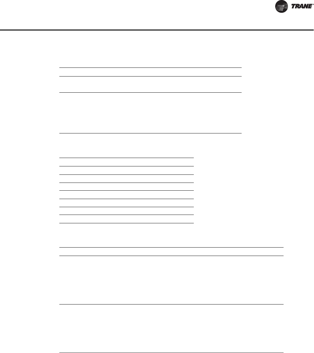
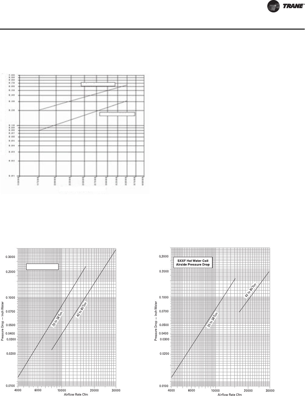
Performance Data
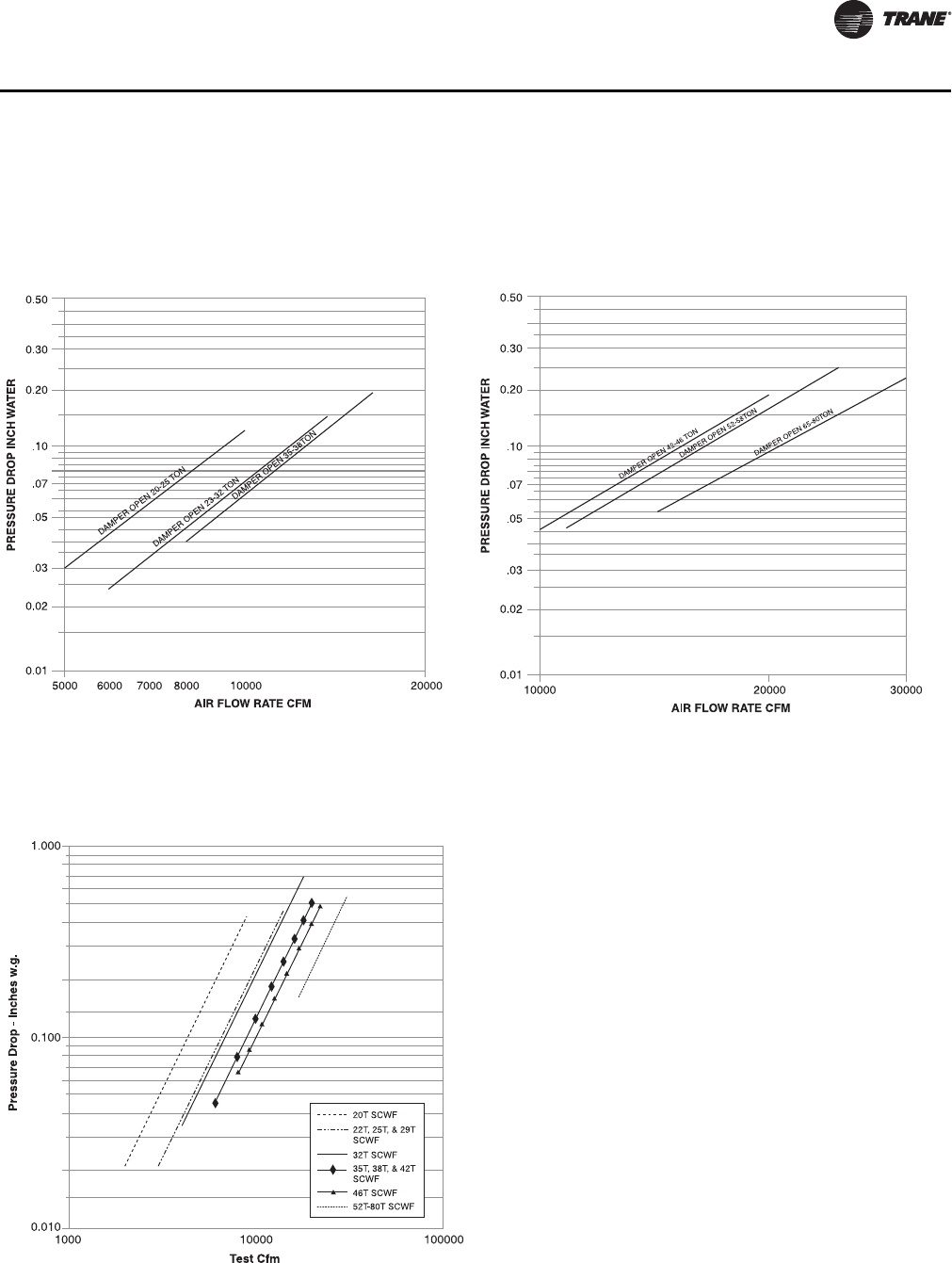
Airside Pressure Drops
The dotted line on construction filters indicates cfm where face velocity exceeds manufacturer’s
recommended maximum of 300 fpm. After startup, construction filters must be replaced with
medium velocity or high velocity filters.
Air pressure drops through electric heat is 0.5 inches WC.
See “Discharge Plenum,” p. 30 for pressure drop through flexible horizontal discharge plenum and
“Heating Coils,” p. 29 for pressure drop through heating coils.
For 4-inch cartridge filters, air pressure drops must be added to the external static pressure design
point.
Figure 1. Airside Pressure Drop SCWF/SIWF 20, 22, 25
and SCRF/SIRF 20
Figure 2. Airside Pressure Drop SCWF/SIWF 29, 32 and
SCRF/SIRF 25, 29
28 PKG-PRC002U-EN
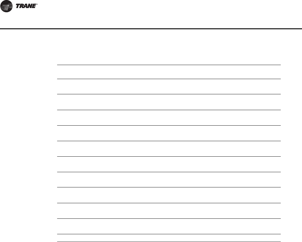
Performance Data
Figure 3. Airside Pressure Drop SCWF/SIWF 35, 38 and
SCRF/SIRF 30, 35
Figure 4. Airside Pressure Drop SCWF/SIWF 42, 46 and
SCRF/SIRF 40
Figure 5. Airside Pressure Drop SCWF/SIWF 52, 58 and
SCRF/SIRF 50
Figure 6. Airside Pressure Drop SCWF/SIWF 65, SCWF/
SIWF 72, SCWF/SIWF 80 and SCRF/SIRF 60
PKG-PRC002U-EN 29
Performance Data
Heating Coils
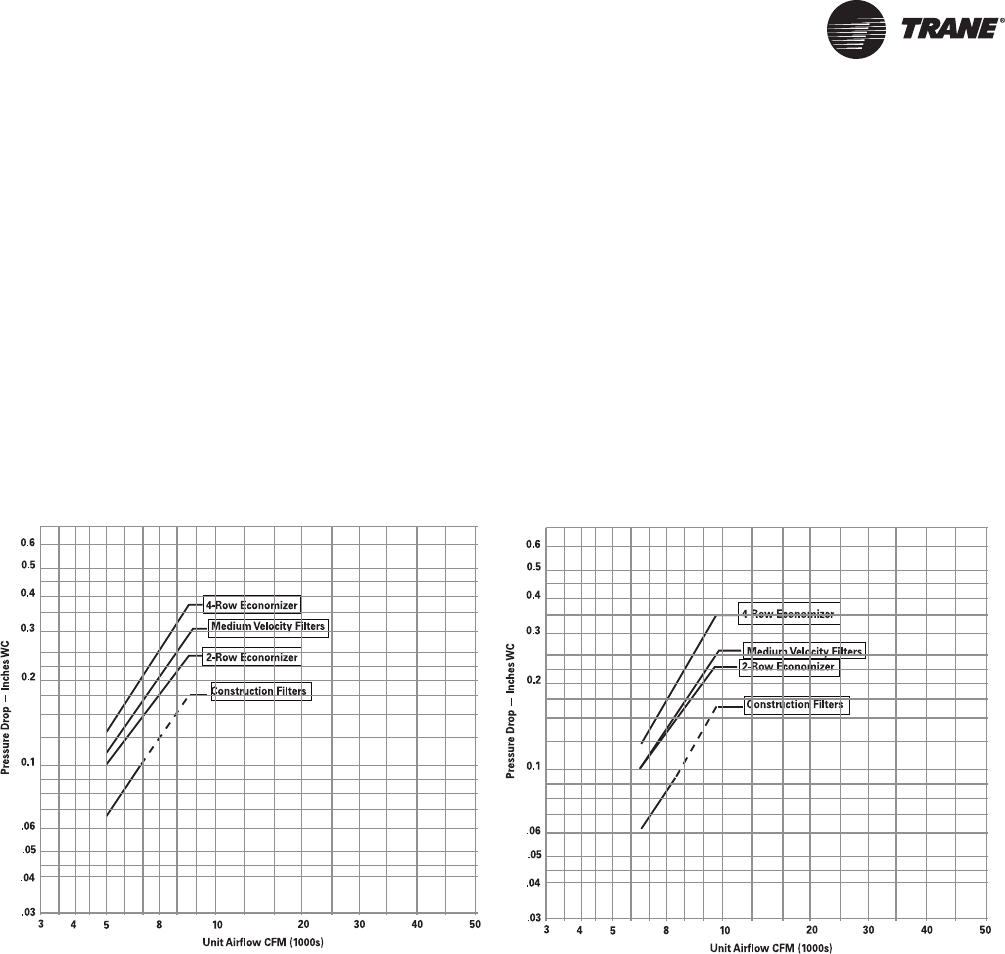
Figure 7. Airside Pressure Drop SCWF/SIWF 90-110
4 Row Economizer
2 Inch Med Eff Filter
Airflow - CFMAirflow - CFMAirflow - CFM
Air Pressure Drop - Inches of WaterAir Pressure Drop - Inches of Water
Figure 8. Airside Pressure Drop Steam Coil 20 to 80-Ton
Units
For NS Coils
Figure 9. Airside Pressure Drop Hot Water Coil 20 to 80-
Ton Units
30 PKG-PRC002U-EN
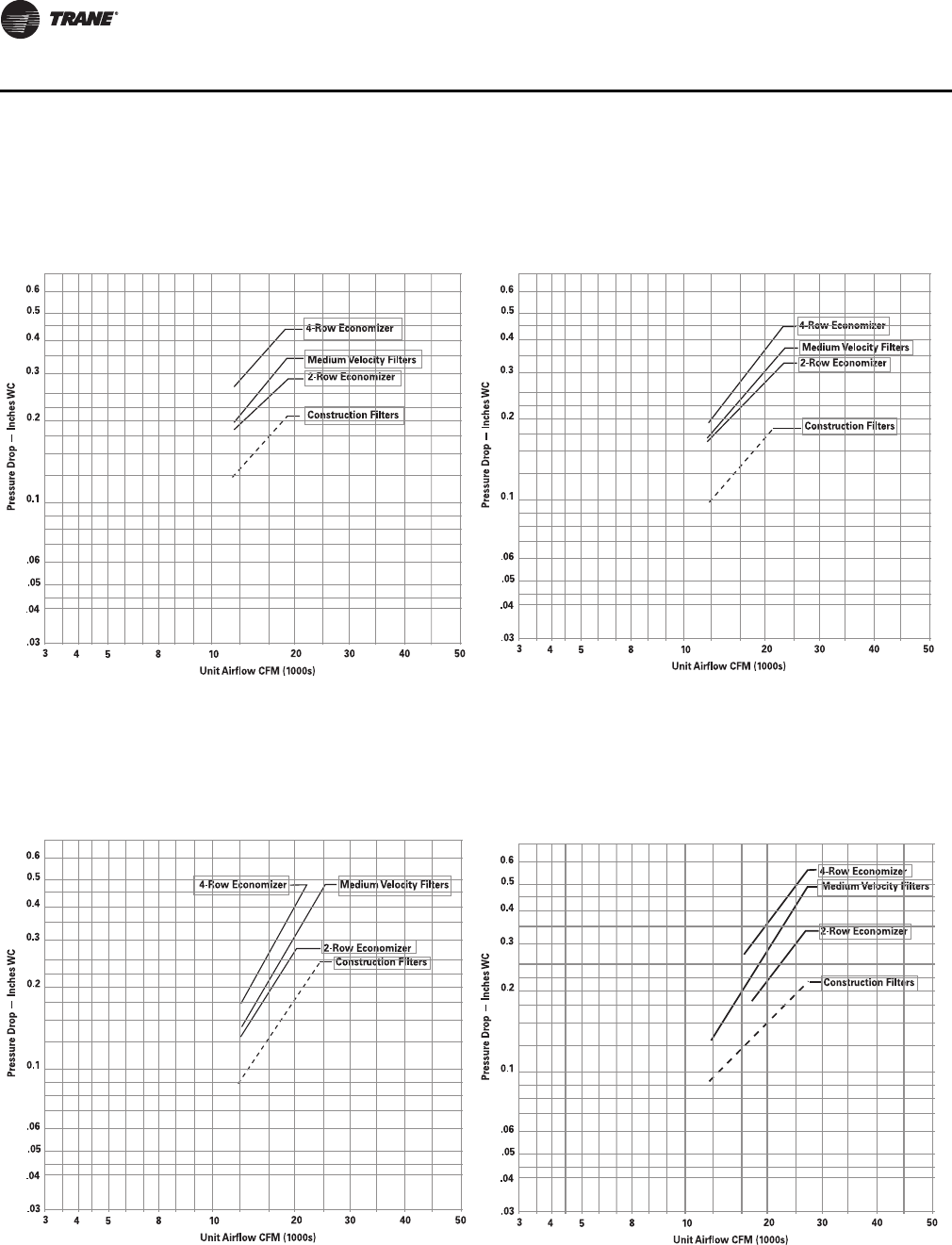
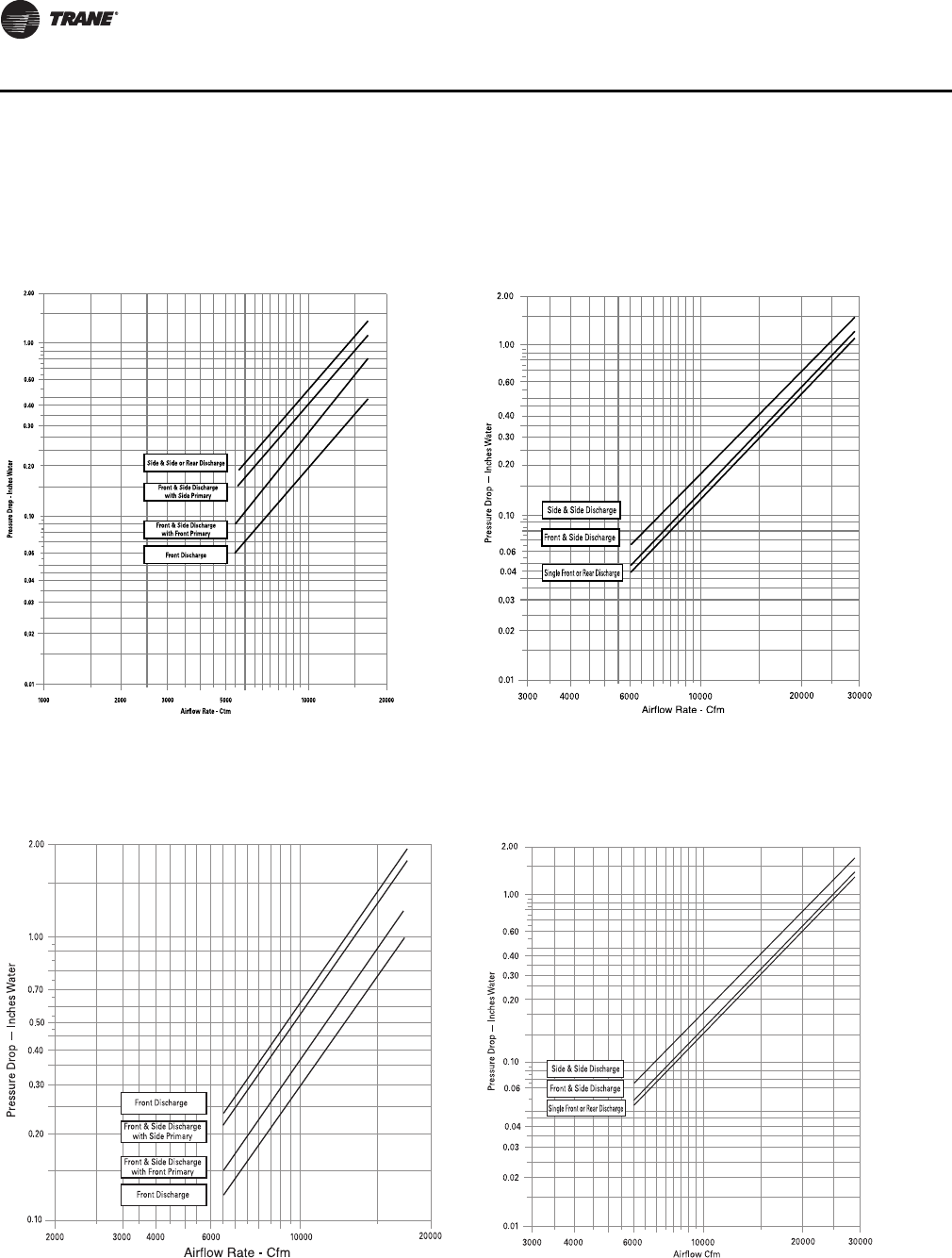
Performance Data
Discharge Plenum
Figure 10. Airside Pressure Drop, Standard Height
Discharge Plenum 20 to 38 Ton Unit
Figure 11. Airside Pressure Drop, Standard Height
Discharge Plenum 42 to 80 Ton Unit
Figure 12. Airside Pressure Drop, Low Height Discharge
Plenum 20 to 38 Ton Unit
Figure 13. Airside Pressure Drop, Low Height Discharge
Plenum 42 to 80 Ton Unit
PKG-PRC002U-EN 31
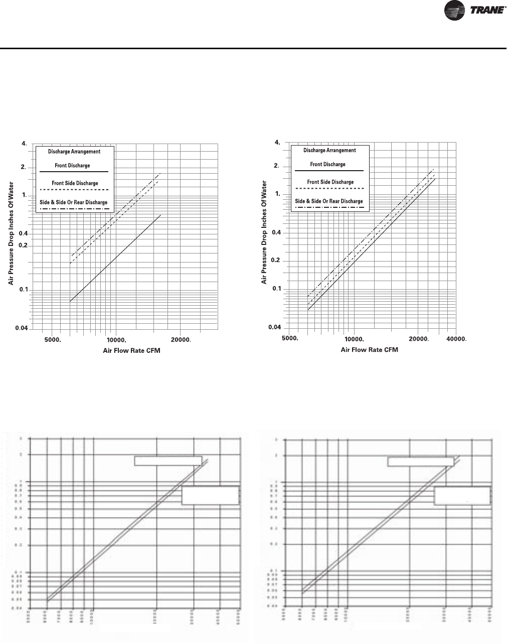
Performance Data
Figure 14. Airside Pressure Drop Extended Height
Discharge Plenum 20 to 38-Ton Unit
Figure 15. Airside Pressure Drop Extended Height
Discharge Plenum 42 to 80-Ton Unit
Figure 16. Airside Pressure Drop Standard Height
Discharge Plenum 90 to 100-Ton Unit
Dual Discharge
Front or Rear
Discharge
Airflow - CFMAirflow - CFM
Static Pressure - Inches of WaterStatic Pressure - Inches of Water
Figure 17. Airside Pressure Drop Low Height Discharge
Plenum 90 to 100-Ton Unit
Dual Discharge
Front or Rear
Discharge
Airflow - CFMAirflow - CFM
Static Pressure - Inches of WaterStatic Pressure - Inches of Water
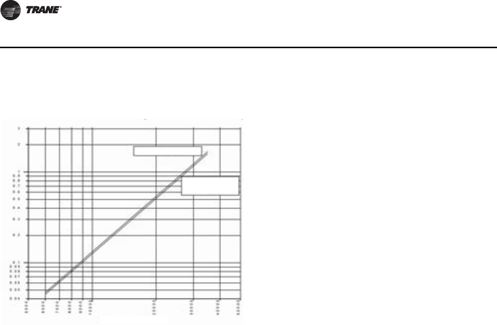
32 PKG-PRC002U-EN
Performance Data
Figure 18. Airside Pressure Drop Extended Height
Discharge Plenum 90 to 100-Ton Unit
Dual Discharge
Front or Rear
Discharge
Airflow - CFMAirflow - CFM
Static Pressure - Inches of WaterStatic Pressure - Inches of Water
PKG-PRC002U-EN 33
Performance Data
Airside Economizer with Standard Damper
Figure 19. Airside Pressure Drop: Airside Economizer with
Standard Damper 20 to 38-Ton Unit
Figure 20. Airside Pressure Drop: Airside Economizer with
Standard Damper 42 to 80-Ton Unit
Figure 21. Airside Pressure Drop Airside Economizer with
Traq™ Damper
34 PKG-PRC002U-EN
Performance Data
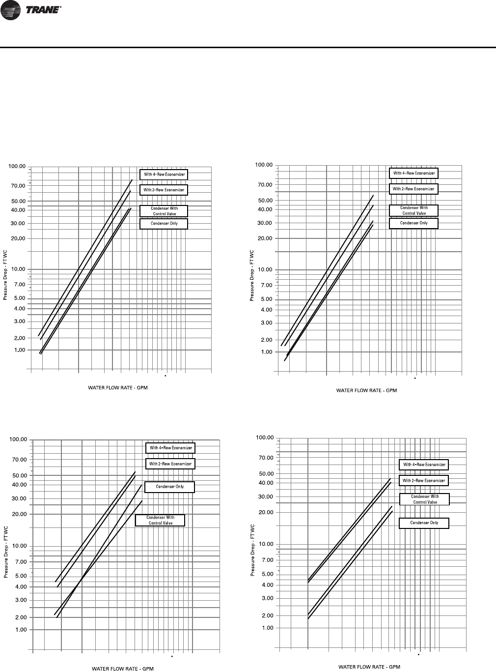
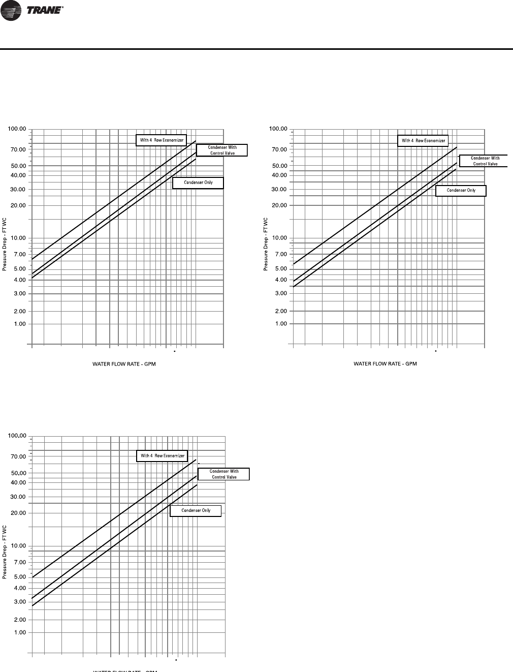
Waterside Pressure Drop
Note: Each curve provides total water pressure drop through the entire unit including all
accessories and internal valves and piping. Do not add curves together.
Figure 22. Waterside Pressure Drop SCWF/SIWF 20, 22, 25
50 75 100 125 150 175 200 250 300
25
Figure 23. Waterside Pressure Drop SCWF/SIWF 29, 32
50 75 100 125 150 175 200 250 300
25
Figure 24. Waterside Pressure Drop CWF/SIWF 35, 38
50 75 100 125 150 175 200 250 300
25
Figure 25. Waterside Pressure Drop SCWF/SIWF 42, 46
50 75 100 125 150 175 200 250 300
25
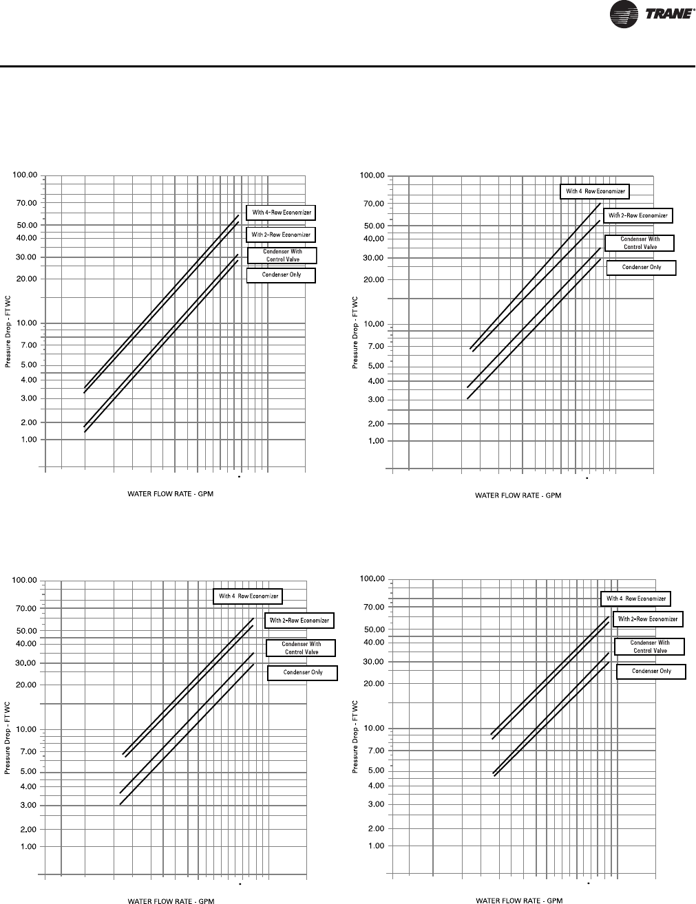
PKG-PRC002U-EN 35
Performance Data
Figure 26. Waterside Pressure Drop SCWF/SIWF 52, 58
50 75 100 125 150 175 200 250 300
25
Figure 27. Waterside Pressure Drop SCWF/SIWF 65
50 75 100 125 150 175 200 250 300
25
Figure 28. Waterside Pressure Drop SCWF/SIWF 72
50 75 100 125 150 175 200 250 300
25
Figure 29. Waterside Pressure Drop SCWF/SIWF 80
50 75 10 0 125 150 175 200 250 300
25
36 PKG-PRC002U-EN
Performance Data
Figure 30. Waterside Pressure Drop SCWF/SIWF 90
150 175 200 225 250 275 300 350 400
125
Figure 31. Waterside Pressure Drop SCWF/SIWF 100
150 175 200 225 250 275 300 350 400
125
Figure 32. Waterside Pressure Drop SCWF/SIWF 110
150 175 200 225 250 275 300 350 400
125
PKG-PRC002U-EN 37
Performance Data
Hot Water Coil
Note: Each curve provides total water pressure drop through the entire unit including all
accessories and tinternal valves and piping. Do not add curves together.
Figure 33. Hot Water Coil Pressure Drop SCXF 20-38
(one row)
Figure 34. Hot Water Coil Pressure Drop SCXF 42 - 80
(one row)
Table 13. CFM Capacity correction table
DX Cooling Waterside Economizer
Cfm Compared
To Rated Quanitity Cooling Capacity
Multiplier Sensible Capacity
Multiplier Cooling Capacity
Multiplier Sensible Capacity
Multiplier
-20% 0.970 0.910 0.970 0.910
-10% 0.985 0.955 0.985 0.955
Std 1.000 1.000 1.000 1.000
+3% 1.005 1.014 1.005 1.014
+6% 1.009 1.027 1.009 1.027
Table 14. SCWF/SIWF Water volume in u.s. gallons / liters
Unit W/O Economizer Unit with Mech. Cleanable Econ Unit with Chem. Cleanable Econ
Unit Size Gallons Liters Gallons Liters Gallons Liters
20, 22, 25 9.0 34.1 17.4 65.9 16.9 64.0
29, 32 9.0 34.1 20.5 77.6 18.8 71.2
35, 38 10.0 37.9 21.9 82.9 20.2 76.5
42, 46 15.0 56.8 32.2 121.9 31.4 118.9
52, 58 15.0 56.8 36.9 139.7 35.9 135.9
65, 72, 80 16.0 60.6 37.9 143.5 36.9 139.7
90 22.5 85.2 50.1 189.6 N/A N/A
100 23.0 87.1 50.6 191.5 N/A N/A
110 24.0 90.8 51.6 195.3 N/A N/A
38 PKG-PRC002U-EN
Performance Data
Water-Cooled Performance Data
Note: Fan curves include refrigerant coil and internal cabinet static losses. To determine static
pressure to be used with these curves, add filter, economizer, flexible horizontal discharge
and heat pressure drops to external duct static pressure.
Table 15. SCWF/SIWF 20 - Economizer performance - 8,000 cfm
Entering Air
Flow
Gpm
Full Capacity Low Capacity
Entering Water Temp Entering Water Temp
45°F 55°F 45°F 55°F
EDB
°F EWB
°F Total
MBh Sensible
MBh LWT
°F Total
MBh Sensible
MBh LWT
°F Total
MBh Sensible
MBh LWT
°F Total
MBh Sensible
MBh LWT
°F
75
62
50 210.3 189.3 53.4 132.5 132.5 60.3 140.0 135.3 50.6 92.8 92.8 58.7
60 220.8 193.7 52.4 136.2 136.2 59.5 147.0 144.0 49.9 96.1 96.1 58.2
70 228.8 197.1 51.5 138.9 138.9 59.0 152.4 146.2 49.4 98.4 98.4 57.8
67
50 265.7 160.4 55.6 155.2 119.1 61.2 175.6 114.8 52.0 102.0 88.3 59.1
60 284.6 167.9 54.5 164.4 122.4 60.5 188.4 119.7 51.3 107.8 90.3 58.6
70 299.0 173.7 53.5 171.8 125.0 59.9 198.0 123.3 50.7 112.6 92.0 58.2
72
50 339.2 133.9 58.6 221.4 92.8 63.9 224.3 90.6 54.0 146.7 64.5 60.9
60 364.8 143.3 57.2 238.3 98.5 62.9 241.1 96.5 53.0 157.3 68.0 60.2
70 383.9 150.5 56.0 251.4 103.0 62.2 253.7 101.0 52.2 165.5 70.7 59.7
80
62
50 230.9 226.2 54.2 165.6 165.6 61.6 160.2 160.2 51.4 116.1 116.1 59.6
60 239.2 234.5 53.0 170.2 170.2 60.7 166.4 166.4 50.5 120.1 120.1 59.0
70 245.2 240.6 52.0 173.5 173.5 60.0 170.7 170.7 49.9 123.0 123.0 58.5
67
50 271.3 204.6 55.9 171.1 166.8 61.8 177.8 149.8 52.1 116.4 111.3 59.7
60 288.1 211.3 54.6 178.2 169.4 60.9 189.3 154.2 51.3 120.8 115.7 59.0
70 300.9 216.5 53.6 183.7 171.4 60.2 198.1 157.5 50.7 124.2 119.1 58.5
72
50 338.5 176.3 58.5 222.0 135.4 63.9 223.8 124.8 54.0 146.2 98.8 60.8
60 363.9 185.8 57.1 238.0 140.8 62.9 240.5 130.7 53.0 156.8 102.2 60.2
70 383.0 193.1 55.9 250.6 145.1 62.2 253.1 135.2 52.2 165.0 104.8 59.7
85
62
50 262.5 262.5 55.5 198.6 198.6 62.9 183.2 183.2 52.3 139.3 139.3 60.6
60 270.4 270.4 54.0 204.1 204.1 61.8 190.2 190.2 51.3 144.1 144.1 59.8
70 275.9 275.9 52.9 208.0 208.0 60.9 195.1 195.1 50.6 147.6 147.6 59.2
67
50 283.5 251.3 56.3 199.2 199.2 63.0 188.1 187.8 52.5 139.6 139.6 60.6
60 298.0 257.1 54.9 204.8 204.8 61.8 197.7 191.4 51.6 144.4 144.4 59.8
70 309.0 261.6 53.8 208.8 208.8 61.0 205.0 194.3 50.9 147.9 147.9 59.2
72
50 340.7 219.3 58.6 230.6 180.5 64.2 223.6 158.9 53.9 151.1 134.6 61.0
60 364.4 228.2 57.1 244.2 185.1 63.1 240.0 164.7 53.0 159.8 137.4 60.3
70 382.6 235.1 55.9 255.1 188.8 62.3 252.6 169.2 52.2 166.7 139.7 59.8
PKG-PRC002U-EN 39
Performance Data
Note: Fan curves include refrigerant coil and internal cabinet static losses. To determine static
pressure to be used with these curves, add filter, economizer, flexible horizontal discharge
and heat pressure drops to external duct static pressure.
Table 16. SCWF/SIWF20 Gross cooling capacity - 8,000 cfm, 60 gpm
Entering Air
Entering Water Temperature
75°F 85°F 95°F
EDB
°F EWB
°F Total
MBh Sensible
MBh LWT
°F Total
MBh Sensible
MBh LWT
°F Total
MBh Sensible
MBh LWT
°F
75
62 266 194 84.8 257 190 94.7 246 184 104.6
67 292 160 85.6 281 155 95.5 269 150 105.3
72 319 125 86.5 307 120 96.3 294 115 106.1
80
62 268 227 84.8 258 223 94.7 248 217 104.6
67 292 195 85.6 282 190 95.5 270 185 105.3
72 319 159 86.5 308 155 96.3 294 149 106.1
85
62 267 267 84.8 260 260 94.8 251 251 104.7
67 293 227 85.6 283 223 95.5 271 217 105.4
72 320 193 86.5 308 189 96.3 295 184 106.1
Figure 35. SCWF/SIWF 20 Fan performance for CV or with VFD

40 PKG-PRC002U-EN
Performance Data
Table 17. SCWF/SIWF 22 - Economizer performance - 8800 cfm
Entering Air
Flow
Gpm
Full Capacity Low Capacity
Entering Water Temp Entering Water Temp
45°F 55°F 45°F 55°F
EDB
°F EWB
°F Total
MBh Sensible
MBh LWT
°F Total
MBh Sensible
MBh LWT
°F Total
MBh Sensible
MBh LWT
°F Total
MBh Sensible
MBh LWT
°F
75
62
50 226.8 205.7 53.2 143.3 143.3 60.2 150.1 145.0 50.5 99.6 99.6 58.6
60 237.6 210.2 52.2 147.3 147.3 59.5 157.1 155.1 49.8 102.9 102.9 58.1
70 245.9 213.8 51.4 150.2 150.2 58.9 162.5 157.3 49.2 105.4 105.4 57.7
67
50 286.3 173.7 55.4 167.0 129.3 61.1 188.1 123.5 51.8 108.9 95.1 59.0
60 305.8 181.4 54.3 176.4 132.6 60.3 200.9 128.4 51.1 114.8 97.1 58.5
70 320.8 187.5 53.3 184.2 135.4 59.8 210.7 132.1 50.5 119.7 98.9 58.1
72
50 365.5 144.5 58.3 238.0 100.2 63.7 240.1 97.1 53.7 156.6 69.2 60.7
60 391.8 154.1 56.9 255.6 106.1 62.7 256.9 103.0 52.8 167.3 72.6 60.1
70 411.9 161.6 55.7 269.5 110.8 62.0 269.8 107.6 52.0 175.9 75.4 59.6
80
62
50 249.7 244.6 54.1 179.1 179.1 61.5 172.2 172.2 51.3 124.5 124.5 59.5
60 258.1 253.0 52.8 184.0 184.0 60.6 178.4 178.4 50.4 128.6 128.6 58.9
70 264.5 259.4 51.9 187.6 187.6 59.9 182.9 182.9 49.7 131.7 131.7 58.4
67
50 292.3 222.0 55.6 184.5 181.5 61.7 190.4 161.4 51.9 124.8 119.3 59.5
60 309.6 228.8 54.4 191.8 184.1 60.8 201.9 165.8 51.1 129.2 123.7 58.9
70 322.9 234.2 53.4 197.6 186.2 60.1 210.8 169.2 50.5 132.7 127.1 58.4
72
50 364.6 190.8 58.3 238.6 146.7 63.7 239.6 134.1 53.7 156.1 106.2 60.7
60 390.8 200.5 56.8 255.2 152.2 62.7 256.4 140.0 52.8 166.8 109.7 60.1
70 410.9 208.1 55.7 268.6 156.8 62.0 269.2 144.6 52.0 175.3 112.4 59.6
85
62
50 284.2 284.2 55.3 214.8 214.8 62.8 196.8 196.8 52.2 149.5 149.5 60.4
60 292.5 292.5 53.9 220.7 220.7 61.7 203.9 203.9 51.2 154.4 154.4 59.7
70 298.4 298.4 52.7 225.0 225.0 60.8 209.0 209.0 50.4 158.1 158.1 59.1
67
50 305.7 273.1 56.1 215.5 215.5 62.8 201.6 195.7 52.3 149.7 149.7 60.4
60 320.5 279.0 54.7 221.4 221.4 61.7 211.1 206.2 51.4 154.7 154.7 59.7
70 332.0 283.6 53.6 225.8 225.8 60.9 218.5 209.0 50.7 158.4 158.4 59.1
72
50 366.9 237.7 58.3 247.9 195.9 64.0 239.3 171.1 53.7 161.4 145.1 60.9
60 391.3 246.8 56.9 262.1 200.7 62.9 255.8 177.0 52.8 170.1 147.9 60.2
70 410.3 254.0 55.7 273.5 204.6 62.1 268.6 181.5 52.0 177.3 150.2 59.6
PKG-PRC002U-EN 41
Performance Data
Note: Fan curves include refrigerant coil and internal cabinet static losses. To determine static
pressure to be used with these curves, add filter, economizer, flexible horizontal discharge
and heat pressure drops to external duct static pressure.
Table 18. SCWF/SIWF22 Gross cooling capacity - 8,800 cfm, 66 gpm
Entering Air
Entering Water Temperature
75°F 85°F 95°F
EDB °F EWB °F Total
MBh Sensible
MBh LWT
°F Total
MBh Sensible
MBh LWT °F Total
MBh Sensible
MBh LWT °F
75
62 272 202 84.1 262 197 94.0 251 192 103.9
67 297 165 84.8 287 161 94.7 274 156 104.5
72 325 127 85.6 313 123 95.4 299 118 105.2
80
62 273 238 84.1 264 233 94.0 253 228 103.9
67 298 203 84.8 288 198 94.7 275 193 104.5
72 325 164 85.6 313 160 95.4 299 155 105.2
85
62 276 276 84.2 268 268 94.1 259 259 104.1
67 299 238 84.8 289 233 94.7 277 228 104.6
72 326 201 85.6 314 197 95.4 301 192 105.3
Figure 36. SCWF/SIWF 22 Fan performance for CV or with VFD

42 PKG-PRC002U-EN
Performance Data
Table 19. SCWF/SIWF 25- Economizer performance - 10,000 cfm
Entering Air
Flow
Gpm
Full Capacity Low Capacity
Entering Water Temp Entering Water Temp
45°F 55°F 45°F 55°F
EDB
°F EWB
°F Total
MBh Sensible
MBh LWT
°F Total
MBh Sensible
MBh LWT
°F Total
MBh Sensible
MBh LWT
°F Total
MBh Sensible
MBh LWT
°F
75
62
50 250.7 229.6 53.0 159.0 159.0 60.0 164.5 158.7 50.2 109.2 109.2 58.5
60 261.4 234.1 52.0 163.2 163.2 59.4 171.1 170.9 49.6 112.6 112.6 58.0
70 265.2 235.7 51.6 164.6 164.6 59.1 173.5 171.9 49.3 113.7 113.7 57.8
67
50 316.1 193.1 55.0 183.8 144.0 60.8 205.7 136.0 51.5 118.7 104.8 58.8
60 335.6 200.8 53.9 193.5 147.5 60.2 218.1 140.7 50.8 124.5 106.8 58.3
70 342.5 203.6 53.6 197.0 148.7 59.9 222.4 142.3 50.6 126.7 107.6 58.2
72
50 404.1 160.2 57.8 262.3 110.9 63.3 262.5 106.4 53.3 170.7 75.8 60.4
60 429.9 169.5 56.5 280.2 116.9 62.5 278.7 112.1 52.4 181.4 79.2 59.8
70 439.1 172.9 56.0 286.5 119.0 62.2 284.5 114.1 52.1 185.2 80.4 59.6
80
62
50 276.9 271.1 53.8 198.7 198.7 61.3 189.1 189.1 51.0 136.5 136.5 59.3
60 285.3 279.5 52.6 203.9 203.9 60.4 195.2 195.2 50.2 140.7 140.7 58.8
70 288.2 282.4 52.2 205.6 205.6 60.1 197.2 197.2 49.9 142.2 142.2 58.6
67
50 322.6 247.4 55.2 203.9 202.9 61.5 208.1 178.0 51.6 136.8 136.8 59.3
60 339.8 254.2 54.1 211.3 205.6 60.6 219.1 182.2 50.8 141.1 134.8 58.8
70 345.9 256.6 53.6 213.9 206.5 60.3 223.1 183.7 50.6 142.6 136.4 58.6
72
50 403.2 212.1 57.8 262.8 163.2 63.3 262.0 147.5 53.3 170.2 116.9 60.4
60 428.9 221.6 56.4 279.7 168.8 62.5 278.1 153.2 52.4 180.8 120.4 59.8
70 438.1 225.0 56.0 285.8 170.9 62.1 283.9 155.2 52.1 184.6 121.6 59.6
85
62
50 315.6 315.6 55.0 238.3 238.3 62.6 216.2 216.2 51.9 163.9 163.9 60.2
60 324.1 324.1 53.6 244.6 244.6 61.5 223.0 223.0 50.9 168.9 168.9 59.5
70 326.9 326.9 53.2 246.6 246.6 61.2 225.4 225.4 50.6 170.6 170.6 59.3
67
50 337.7 304.9 55.7 239.1 239.1 62.6 220.7 214.1 52.0 164.2 164.2 60.2
60 352.4 310.7 54.4 245.3 245.3 61.5 229.7 227.2 51.1 169.2 169.2 59.5
70 357.6 312.8 53.9 247.4 247.4 61.2 233.0 228.4 50.8 170.9 170.9 59.3
72
50 404.8 264.6 57.9 273.0 218.6 63.7 261.5 188.6 53.3 175.9 160.0 60.6
60 429.2 273.6 56.4 287.4 223.4 62.7 277.6 194.2 52.4 184.5 162.8 59.9
70 438.0 276.9 55.9 292.5 225.1 62.3 283.2 196.2 52.1 187.7 163.8 59.7
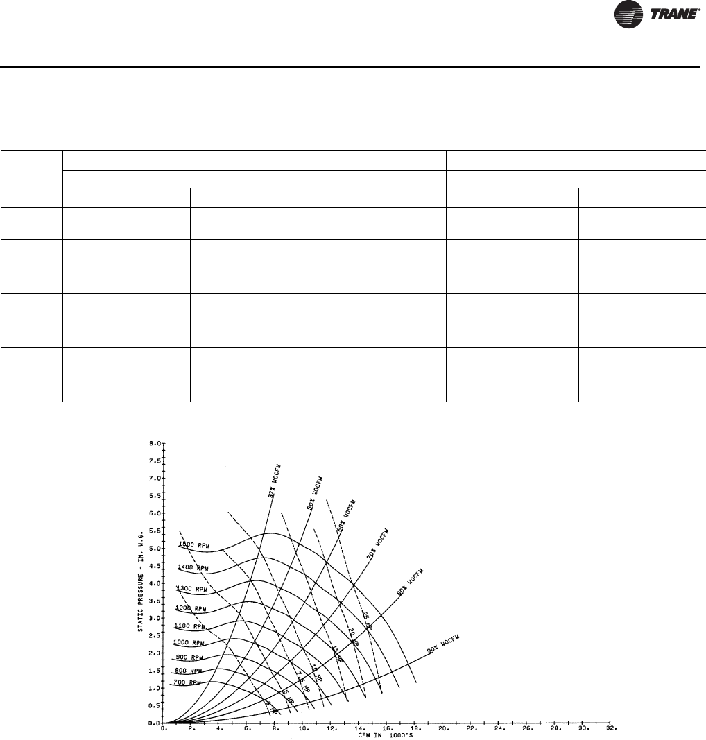
PKG-PRC002U-EN 43
Performance Data
Note: Fan curves include refrigerant coil and internal cabinet static losses. To determine static
pressure to be used with these curves, add filter, economizer, flexible horizontal discharge
and heat pressure drops to external duct static pressure.
Table 20. SCWF/SIWF25 Gross cooling capacity - 10,000 cfm, 75 gpm
Entering
Air
Standard Capacity High Capacity
Entering Water Temperature Entering Water Temperature
75°F 85°F 95°F 85°F 95°F
EDB
°F EWB
°F Total
MBh Sensible
MBh LWT
°F Total
MBh Sensible
MBh LWT
°F Total
MBh Sensible
MBh LWT
°F Total
MBh Sensible
MBh LWT
°F Total
MBh Sensible
MBh LWT
°F
75
62 285 228 83.7 274 223 93.6 261 217 103.5 - - - - - -
67 311 182 84.4 298 177 94.3 285 172 104.1 - - - - - -
72 338 134 85.2 325 129 95.0 309 124 104.7 - - - - - -
80
62 286 274 83.8 275 269 93.6 262 262 103.5 295 295 94.2 280 280 104.0
67 311 228 84.4 299 223 94.3 285 217 104.1 321 251 94.9 305 245 104.7
72 339 181 85.2 325 176 95.0 310 170 104.8 349 195 95.7 331 189 105.4
85
62 300 300 84.2 291 291 94.1 280 280 103.9 320 320 94.9 306 306 104.7
67 313 273 84.5 300 267 94.3 287 261 104.1 322 305 94.9 306 298 104.7
72 340 227 85.2 326 222 95.0 311 216 104.8 350 250 95.7 332 243 105.4
Figure 37. SCWF/SIWF 25 Fan performance for CV or with VFD

44 PKG-PRC002U-EN
Performance Data
Table 21. SCWF/SIWF 29 - Economizer performance - 11,600cfm
Entering Air
Flow
Gpm
Full Capacity Low Capacity
Entering Water Temp Entering Water Temp
45°F 55°F 45°F 55°F
EDB
°F EWB
°F Total
MBh Sensible
MBh LWT
°F Total
MBh Sensible
MBh LWT
°F Total
MBh Sensible
MBh LWT
°F Total
MBh Sensible
MBh LWT
°F
75
62
50 302.2 272.9 53.3 190.6 190.6 60.2 200.6 193.8 50.5 133.0 133.0 58.6
60 316.4 278.8 52.3 195.7 195.7 59.5 209.8 206.5 49.8 137.3 137.3 58.2
70 327.9 283.8 51.4 199.7 199.7 58.9 217.4 209.6 49.3 140.7 140.7 57.8
67
50 382.0 231.0 55.5 222.7 171.6 61.1 251.7 164.8 51.9 145.8 126.7 59.0
60 407.4 241.1 54.4 235.2 176.0 60.4 268.6 171.2 51.2 153.5 129.3 58.5
70 428.3 249.5 53.4 245.9 179.8 59.8 282.3 176.4 50.5 160.5 131.8 58.1
72
50 488.3 192.9 58.4 318.0 133.5 63.7 321.4 129.8 53.8 209.9 92.5 60.7
60 522.1 205.3 57.0 340.8 141.2 62.8 343.5 137.7 52.9 223.9 97.0 60.1
70 549.9 215.7 55.8 360.0 147.7 62.1 361.6 144.1 52.1 235.8 100.9 59.6
80
62
50 332.2 325.4 54.1 238.2 238.2 61.5 229.7 229.7 51.3 166.2 166.2 59.6
60 343.2 336.5 52.9 244.5 244.5 60.6 237.9 237.9 50.5 171.6 171.6 58.9
70 352.0 345.3 51.9 249.4 249.4 59.9 244.1 244.1 49.8 175.9 175.9 58.4
67
50 389.9 294.8 55.7 245.9 240.6 61.7 254.7 215.0 52.0 166.6 159.4 59.6
60 412.4 303.8 54.5 255.3 244.0 60.9 269.9 220.8 51.2 172.4 165.1 59.0
70 431.0 311.3 53.5 263.4 246.9 60.2 282.5 225.6 50.5 177.4 170.0 58.5
72
50 487.3 254.1 58.4 318.8 195.0 63.7 320.7 179.0 53.8 209.2 141.7 60.7
60 520.9 266.7 57.0 340.3 202.2 62.8 342.8 186.8 52.9 223.2 146.2 60.1
70 548.6 277.2 55.8 358.8 208.5 62.0 360.8 193.2 52.1 235.0 150.0 59.6
85
62
50 377.9 377.9 55.4 285.7 285.7 62.8 262.7 262.7 52.2 199.5 199.5 60.5
60 388.6 388.6 53.9 293.2 293.2 61.7 271.9 271.9 51.3 205.9 205.9 59.7
70 396.6 396.6 52.8 299.0 299.0 60.9 279.0 279.0 50.5 211.0 211.0 59.1
67
50 407.5 362.3 56.2 286.6 286.6 62.9 269.4 261.6 52.4 199.9 199.9 60.5
60 426.8 370.0 54.8 294.2 294.2 61.8 282.0 274.4 51.5 206.3 206.3 59.7
70 442.8 376.5 53.7 300.1 300.1 60.9 292.4 278.4 50.7 211.5 211.5 59.1
72
50 489.7 316.0 58.4 331.0 260.1 64.1 320.3 228.1 53.8 216.1 193.2 60.9
60 521.5 327.9 57.0 349.3 266.3 63.0 342.1 235.8 52.9 227.6 196.9 60.2
70 547.9 337.9 55.7 365.1 271.7 62.2 360.0 242.2 52.1 237.6 200.2 59.7
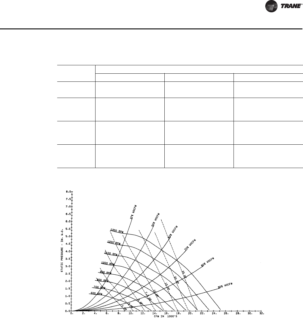
PKG-PRC002U-EN 45
Performance Data
Note: Fan curves include refrigerant coil and internal cabinet static losses. To determine static
pressure to be used with these curves, add filter, economizer, flexible horizontal discharge
and heat pressure drops to external duct static pressure.
Table 22. SCWF/SIWF29 Gross cooling capacity - 11,600 cfm, 87 gpm
Entering Air
Entering Water Temperature
75°F 85°F 95°F
EDB EWB Total Sensible LWT Total Sensible LWT Total Sensible LWT
°F °F MBh MBh °F MBh MBh °F MBh MBh °F
75
62 338 256 83.8 326 250 93.7 313 243 103.6
67 369 208 84.5 355 203 94.3 340 196 104.2
72 402 159 85.2 388 154 95.1 371 147 104.9
80
62 340 302 83.8 328 296 93.7 314 289 103.6
67 370 256 84.5 357 251 94.4 342 244 104.2
72 402 207 85.2 388 201 95.1 371 195 104.9
85
62 346 346 83.9 336 336 93.9 325 325 103.8
67 371 301 84.5 358 295 94.4 343 288 104.2
72 404 254 85.2 389 249 95.1 372 242 104.9
Figure 38. SCWF/SIWF 29 Fan performance for CV or with VFD

46 PKG-PRC002U-EN
Performance Data
Table 23. SCWF/SIWF 32- Economizer performance - 12,800 cfm
Entering Air
Flow
Gpm
Full Capacity Low Capacity
Entering Water Temp Entering Water Temp
45°F 55°F 45°F 55°F
EDB
°F EWB
°F Total
MBh Sensible
MBh LWT
°F Total
MBh Sensible
MBh LWT
°F Total
MBh Sensible
MBh LWT
°F Total
MBh Sensible
MBh LWT
°F
75
62
50 325.8 296.8 53.1 206.2 206.2 60.2 214.8 207.4 50.4 142.6 142.6 58.6
60 340.9 303.2 52.1 212.0 212.0 59.4 224.4 222.7 49.7 147.3 147.3 58.1
70 345.5 305.1 51.8 213.7 213.7 59.2 227.4 223.9 49.5 148.7 148.7 57.9
67
50 410.8 250.1 55.3 239.5 186.4 61.0 268.8 177.2 51.7 155.5 136.5 58.9
60 438.2 260.9 54.1 252.7 191.1 60.3 286.5 183.8 51.0 163.6 139.3 58.4
70 446.8 264.3 53.8 257.1 192.7 60.0 292.0 185.9 50.7 166.4 140.3 58.3
72
50 524.5 207.6 58.1 341.3 144.0 63.5 343.2 138.9 53.6 223.5 99.0 60.6
60 561.3 221.1 56.7 366.1 152.2 62.6 366.3 147.1 52.6 238.5 103.8 60.0
70 572.8 225.3 56.2 374.0 154.9 62.3 373.5 149.6 52.3 243.3 105.3 59.8
80
62
50 359.2 351.8 54.0 257.7 257.7 61.4 246.7 246.7 51.2 178.3 178.3 59.5
60 371.0 363.6 52.7 264.8 264.8 60.5 255.3 255.3 50.3 184.1 184.1 58.8
70 374.6 367.2 52.3 266.9 266.9 60.2 257.8 257.8 50.1 185.9 185.9 58.6
67
50 419.5 320.1 55.5 265.0 262.1 61.6 272.1 231.7 51.8 178.6 178.6 59.5
60 443.6 329.6 54.2 275.3 265.8 60.7 287.9 237.7 51.0 184.7 176.7 58.8
70 451.2 332.6 53.8 278.6 267.0 60.5 292.9 239.6 50.7 186.7 178.6 58.7
72
50 523.3 274.5 58.1 342.0 211.3 63.6 342.5 192.3 53.6 222.8 152.4 60.6
60 560.0 288.2 56.7 365.5 219.1 62.6 365.5 200.4 52.6 237.7 157.2 60.0
70 571.4 292.5 56.2 373.1 221.7 62.3 372.7 202.9 52.3 242.5 158.7 59.8
85
62
50 409.2 409.2 55.2 309.1 309.1 62.7 282.0 282.0 52.0 214.0 214.0 60.3
60 420.9 420.9 53.8 317.6 317.6 61.6 291.8 291.8 51.1 220.9 220.9 59.6
70 424.4 424.4 53.3 320.1 320.1 61.3 294.7 294.7 50.8 223.0 223.0 59.4
67
50 439.0 394.1 56.0 310.1 310.1 62.8 288.3 279.8 52.2 214.4 214.4 60.4
60 459.6 402.3 54.6 318.6 318.6 61.6 301.4 296.0 51.3 221.3 221.3 59.6
70 466.1 404.9 54.1 321.2 321.2 61.3 305.5 297.6 51.0 223.5 223.5 59.4
72
50 526.4 342.5 58.2 355.4 282.6 63.9 342.0 245.6 53.5 230.4 208.3 60.8
60 560.6 355.2 56.7 375.4 289.3 62.8 364.8 253.6 52.6 242.5 212.2 60.1
70 571.4 359.3 56.2 381.8 291.5 62.5 371.9 256.1 52.3 246.5 213.5 59.8
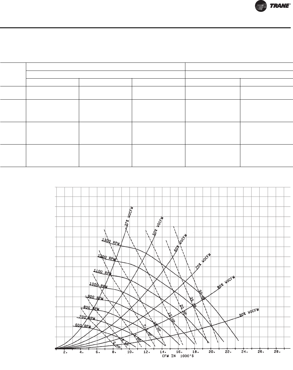
PKG-PRC002U-EN 47
Performance Data
Figure 39. SCWF/SIWF 32 Fan Performance for CV or w/VFD
Table 24. SCWF/SIWF 32 Gross cooling capacity - 12,800 cfm, 96 gpm
Entering
Air
Standard Capacity High Capacity
Entering Water Temperature Entering Water Temperature
75°F 85°F 95°F 85°F 95°F
EDB
°F EWB
°F Total
MBh Sensible
MBh LWT
°F Total
MBh Sensible
MBh LWT
°F Total
MBh Sensible
MBh LWT
°F Total
MBh Sensible
MBh LWT
°F Total
MBh Sensible
MBh LWT
°F
75
62 370 309 83.9 355 302 93.8 338 294 103.6 - - - - - -
67 403 244 84.6 386 237 94.5 368 230 104.2 - - - - - -
72 437 176 85.4 419 169 95.1 398 162 104.9 - - - - - -
80
62 371 365 84.0 356 354 93.8 340 340 103.6 368 368 94.1 350 350 103.9
67 404 307 84.7 387 300 94.5 369 292 104.3 400 317 94.8 381 309 104.5
72 438 241 85.4 420 234 95.2 400 227 104.9 434 246 95.5 413 238 105.2
85
62 396 396 84.5 383 383 94.4 368 368 104.2 400 400 94.8 384 384 104.6
67 405 370 84.7 389 363 94.5 370 355 104.3 402 385 94.8 382 373 104.6
72 439 305 85.4 421 299 95.2 401 291 104.9 435 315 95.5 414 308 105.2

48 PKG-PRC002U-EN
Performance Data
Table 25. SCWF/SIWF 35- Economizer performance - 14,000 cfm
Entering Air
Flow
Gpm
Full Capacity Low Capacity
Entering Water Temp Entering Water Temp
45°F 55°F 45°F 55°F
EDB
°F EWB
°F Total
MBh Sensible
MBh LWT
°F Total
MBh Sensible
MBh LWT
°F Total
MBh Sensible
MBh LWT
°F Total
MBh Sensible
MBh LWT
°F
75
62
50 335.2 309.5 52.6 212.8 212.8 59.8 216.3 208.3 49.9 143.3 143.3 58.3
60 349.5 315.4 51.7 218.4 218.4 59.2 224.9 223.6 49.3 147.5 147.5 57.8
70 358.9 319.4 51.0 221.9 221.9 58.7 230.7 225.9 48.9 150.3 150.3 57.5
67
50 425.7 260.8 54.7 246.3 194.3 60.6 274.3 179.6 51.2 157.0 137.4 58.6
60 451.9 271.0 53.6 259.2 198.8 59.9 290.2 185.6 50.5 164.7 140.1 58.1
70 469.1 277.9 52.9 268.1 202.0 59.5 300.7 189.6 50.1 170.1 142.0 57.9
72
50 544.6 216.1 57.4 354.1 149.9 63.0 350.3 141.5 53.0 228.0 100.5 60.2
60 579.2 228.9 56.0 377.7 157.7 62.2 371.3 148.9 52.1 241.7 105.0 59.6
70 602.1 237.4 55.1 393.3 162.9 61.6 385.1 153.9 51.5 250.9 107.9 59.2
80
62
50 370.3 362.2 53.4 265.9 265.9 61.0 248.2 248.2 50.6 179.2 179.2 59.1
60 381.4 373.3 52.3 272.9 272.9 60.2 255.9 255.9 49.9 184.4 184.4 58.5
70 388.6 380.5 51.5 277.3 277.3 59.7 260.8 260.8 49.4 187.8 187.8 58.2
67
50 432.4 333.5 54.8 272.4 263.1 61.2 275.7 233.7 51.3 179.5 179.5 59.1
60 455.5 342.6 53.7 282.1 277.2 60.4 290.3 239.2 50.5 184.9 176.3 58.5
70 470.9 348.7 52.9 288.7 279.6 59.9 300.2 243.0 50.0 188.6 179.9 58.2
72
50 543.4 286.3 57.3 353.7 220.4 63.0 349.6 195.1 52.9 227.3 154.2 60.2
60 577.9 299.0 56.0 376.4 228.0 62.2 370.5 202.4 52.1 241.0 158.6 59.6
70 600.6 307.6 55.1 391.9 233.1 61.6 384.3 207.4 51.5 250.1 161.5 59.2
85
62
50 422.4 422.4 54.6 319.0 319.0 62.2 283.7 283.7 51.4 215.0 215.0 59.9
60 433.8 433.8 53.3 327.3 327.3 61.2 292.5 292.5 50.6 221.3 221.3 59.2
70 440.9 440.9 52.4 332.5 332.5 60.6 298.0 298.0 50.0 225.3 225.3 58.8
67
50 451.5 410.9 55.3 319.9 319.9 62.3 290.3 281.2 51.6 215.4 215.4 59.9
60 471.1 418.7 54.0 328.3 328.3 61.3 302.1 297.2 50.8 221.7 221.7 59.2
70 484.1 423.9 53.1 333.5 333.5 60.6 310.0 300.2 50.2 225.7 225.7 58.8
72
50 544.2 357.0 57.4 365.6 294.8 63.3 348.9 248.6 52.9 232.4 209.6 60.3
60 577.1 369.2 56.0 384.6 301.2 62.3 369.7 255.9 52.0 243.8 213.2 59.6
70 599.3 377.5 55.1 397.7 305.6 61.7 383.5 260.8 51.4 251.6 215.8 59.2
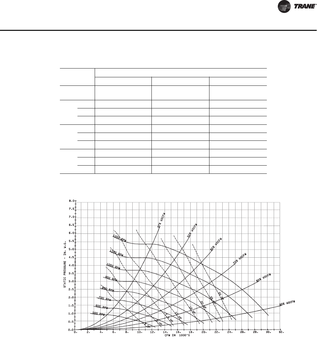
PKG-PRC002U-EN 49
Performance Data
Note: Fan curves include refrigerant coil and internal cabinet static losses. To determine static
pressure to be used with these curves, add filter, economizer, flexible horizontal discharge
and heat pressure drops to external duct static pressure.
Table 26. SCWF/SIWF 35 - Gross cooling capacity - 14,000 cfm, 105 gpm
Entering Air
Entering Water Temperature
75°F 85°F 95°F
EDB
°F EWB
°F Total
MBh Sensible
MBh LWT
°F Total
MBh Sensible
MBh LWT
°F Total
MBh Sensible
MBh LWT
°F
75
62 419 330 84.2 403 323 94.1 385 314 103.9
67 457 265 85.0 439 258 94.8 419 250 104.6
72 497 198 85.7 477 190 95.5 454 182 105.3
80
62 421 393 84.3 405 386 94.1 387 377 104.0
67 457 329 85.0 440 321 94.8 420 313 104.6
72 497 262 85.8 478 255 95.6 455 247 105.3
85
62 438 438 84.6 424 424 94.5 408 408 104.4
67 459 391 85.0 442 384 94.8 421 375 104.7
72 498 327 85.8 479 319 95.6 457 311 105.3
Figure 40. SCWF/SIWF 35 Fan Performance for CV or with VFD

50 PKG-PRC002U-EN
Performance Data
Table 27. SCWF/SIWF 38- Economizer performance - 15,200 cfm
Entering Air
Flow
Gpm
Full Capacity Low Capacity
Entering Water Temp Entering Water Temp
45°F 55°F 45°F 55°F
EDB
°F EWB
°F Total
MBh Sensible
MBh LWT
°F Total
MBh Sensible
MBh LWT
°F Total
MBh Sensible
MBh LWT
°F Total
MBh Sensible
MBh LWT
°F
75
62
50 355.5 330.9 52.5 226.5 226.5 59.8 228.0 219.3 49.8 151.4 151.4 58.2
60 370.6 337.2 51.5 232.7 232.7 59.1 237.0 228.2 49.2 155.9 155.9 57.7
70 374.1 338.7 51.3 234.0 234.0 58.9 239.0 238.1 49.0 156.9 156.9 57.6
67
50 450.7 277.7 54.5 260.8 207.6 60.5 288.5 190.0 51.1 165.1 145.8 58.5
60 478.7 288.7 53.4 274.4 212.4 59.8 305.2 196.3 50.4 173.1 148.5 58.0
70 485.0 291.2 53.2 277.6 213.5 59.7 308.9 197.7 50.2 175.0 149.2 57.9
72
50 576.2 229.0 57.1 374.4 159.1 62.9 368.4 149.1 52.8 239.5 106.0 60.0
60 613.4 242.7 55.8 399.7 167.5 62.0 390.3 156.8 51.8 254.0 110.7 59.5
70 621.8 245.8 55.4 405.4 169.4 61.8 395.3 158.6 51.6 257.3 111.8 59.3
80
62
50 394.0 385.2 53.3 283.0 283.0 61.0 262.3 262.3 50.5 189.2 189.2 59.0
60 405.8 397.1 52.1 290.7 290.7 60.1 270.4 270.4 49.7 194.9 194.9 58.4
70 408.5 399.7 51.9 292.4 292.4 59.9 272.2 272.2 49.6 196.1 196.1 58.3
67
50 457.8 356.0 54.6 289.1 279.0 61.1 290.0 247.8 51.1 189.5 189.5 59.0
60 482.4 365.7 53.5 299.5 296.9 60.3 305.3 253.5 50.4 195.2 185.9 58.4
70 488.0 367.9 53.2 301.8 297.8 60.1 308.8 254.8 50.2 196.5 187.2 58.3
72
50 574.9 304.5 57.1 374.0 235.0 62.9 367.6 206.3 52.7 238.7 163.2 60.0
60 612.0 318.2 55.7 398.4 243.1 62.0 389.5 213.9 51.8 253.2 167.9 59.4
70 620.3 321.3 55.4 404.0 245.0 61.8 394.5 215.7 51.6 256.4 168.9 59.3
85
62
50 449.7 449.7 54.5 339.5 339.5 62.1 299.8 299.8 51.3 227.1 227.1 59.8
60 462.2 462.2 53.1 348.7 348.7 61.1 309.1 309.1 50.4 233.8 233.8 59.1
70 464.8 464.8 52.8 350.7 350.7 60.9 311.1 311.1 50.2 235.3 235.3 59.0
67
50 478.6 439.4 55.1 340.5 340.5 62.2 305.9 296.1 51.4 227.5 227.5 59.8
60 499.4 447.7 53.8 349.7 349.7 61.1 318.2 315.4 50.6 234.2 234.2 59.1
70 504.2 449.6 53.5 351.7 351.7 60.9 321.0 316.5 50.4 235.7 235.7 59.0
72
50 575.8 380.7 57.1 386.7 315.1 63.1 366.9 263.3 52.7 244.3 222.3 60.1
60 611.1 393.6 55.7 407.1 321.9 62.1 388.7 270.9 51.8 256.2 226.2 59.5
70 619.2 396.6 55.4 411.8 323.5 61.9 393.6 272.7 51.6 259.0 227.1 59.4
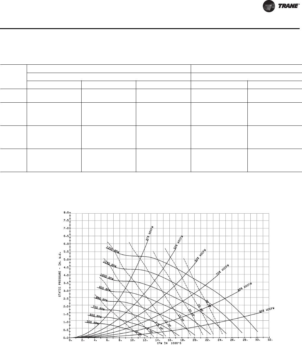
PKG-PRC002U-EN 51
Performance Data
Table 28. SCWF/SIWF38 Gross cooling capacity - 15,200 cfm, 114 gpm
Entering
Air
Standard Capacity High Capacity
Entering Water Temperature Entering Water Temperature
75°F 85°F 95°F 85°F 95°F
EDB
°F EWB
°F Total
MBh Sensible
MBh LWT
°F Total
MBh Sensible
MBh LWT
°F Total
MBh Sensible
MBh LWT
°F Total
MBh Sensible
MBh LWT
°F Total
MBh Sensible
MBh LWT
°F
75
62 443 367 83.9 425 359 93.8 405 349 103.6 - - - - - -
67 482 290 84.6 463 282 94.4 440 274 104.2 - - - - - -
72 523 211 85.4 501 203 95.1 477 194 104.9 - - - - - -
80
62 444 441 84.0 427 427 93.8 407 407 103.6 443 443 94.1 421 421 103.9
67 483 365 84.7 464 357 94.5 441 347 104.3 481 379 94.8 457 369 104.5
72 524 287 85.4 503 279 95.2 478 270 104.9 521 294 95.5 495 285 105.2
85
62 473 473 84.5 457 457 94.4 439 439 104.2 480 480 94.8 460 460 104.6
67 484 439 84.7 465 430 94.5 443 421 104.3 482 459 94.8 458 449 104.6
72 526 362 85.4 504 355 95.2 480 346 104.9 523 376 95.5 497 366 105.3
Figure 41. SCWF/SIWF 38 Fan Performance for CV or with VFD
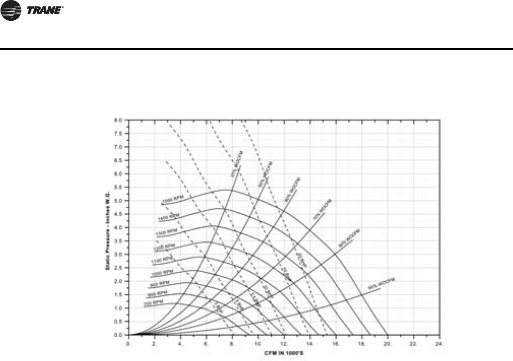
52 PKG-PRC002U-EN
Performance Data
Note: For optional low flow fan on high capacity coil.
Note: Fan curves include refrigerant coil and internal cabinet static losses. To determine static
pressure to be used with these curves, add filter, economizer, flexible horizontal discharge
and heat pressure drops to external duct static pressure.
Figure 42. SCWF/SIWF 38 — 18” Fan Performance for CV or with VFD

PKG-PRC002U-EN 53
Performance Data
Table 29. SCWF/SIWF 42- Economizer performance - 16,800 cfm
Entering Air
Flow
Gpm
Full Capacity Low Capacity
Entering Water Temp Entering Water Temp
45°F 55°F 45°F 55°F
EDB
°F EWB
°F Total
MBh Sensible
MBh LWT
°F Total
MBh Sensible
MBh LWT
°F Total
MBh Sensible
MBh LWT
°F Total
MBh Sensible
MBh LWT
°F
75
62
50 438.5 393.8 53.4 274.5 274.5 60.2 291.1 290.3 50.5 191.1 191.1 58.6
60 457.1 401.7 52.3 281.4 281.4 59.5 302.7 295.0 49.8 196.7 196.7 58.1
70 468.6 406.6 51.6 285.4 285.4 59.0 310.0 298.0 49.4 200.0 200.0 57.8
67
50 556.7 335.0 55.6 322.8 247.5 61.1 368.9 238.2 52.0 211.6 181.4 59.0
60 591.2 348.7 54.4 339.9 253.6 60.4 390.4 246.4 51.2 221.9 184.9 58.5
70 612.2 357.2 53.6 350.8 257.5 59.9 403.6 251.5 50.7 228.7 187.3 58.2
72
50 711.9 281.0 58.6 462.2 193.6 63.8 471.3 189.6 54.0 306.1 133.9 60.8
60 757.8 297.9 57.0 494.2 204.4 62.8 499.6 199.7 52.9 325.0 140.0 60.2
70 786.0 308.5 56.1 513.6 211.0 62.2 517.1 206.0 52.3 336.6 143.8 59.7
80
62
50 480.2 470.5 54.1 343.0 343.0 61.5 331.6 331.6 51.3 238.9 238.9 59.6
60 494.6 484.9 52.9 351.6 351.6 60.6 341.5 341.5 50.4 245.9 245.9 58.9
70 503.3 493.6 52.1 356.5 356.5 60.0 347.4 347.4 49.9 250.0 250.0 58.5
67
50 566.9 426.2 55.8 354.9 346.2 61.8 566.9 426.2 55.8 354.9 346.2 61.8
60 597.1 438.3 54.5 367.9 350.9 60.8 391.2 316.4 51.2 247.4 236.8 58.9
70 615.8 445.8 53.7 375.9 353.8 60.3 403.5 321.1 50.7 252.1 241.5 58.6
72
50 710.3 368.9 58.5 462.7 281.8 63.8 470.3 259.3 54.0 305.1 203.7 60.8
60 756.0 386.0 57.0 493.0 291.9 62.8 498.5 269.3 52.9 323.9 209.7 60.1
70 784.0 396.7 56.0 511.9 298.3 62.2 515.9 275.6 52.3 335.5 213.5 59.7
85
62
50 545.5 545.5 55.4 411.4 411.4 62.8 379.0 379.0 52.2 286.7 286.7 60.5
60 559.4 559.4 53.9 421.6 421.6 61.7 390.3 390.3 51.2 295.0 295.0 59.7
70 567.3 567.3 53.0 427.4 427.4 61.0 397.0 397.0 50.6 299.9 299.9 59.2
67
50 590.8 522.7 56.3 412.7 412.7 62.9 390.9 385.8 52.4 287.3 287.3 60.5
60 616.6 533.0 54.8 423.0 423.0 61.7 406.8 392.0 51.5 295.6 295.6 59.7
70 632.5 539.5 53.9 428.9 428.9 61.0 416.8 395.8 50.9 300.5 300.5 59.2
72
50 712.7 457.3 58.6 479.1 374.9 64.1 469.3 328.9 53.9 313.2 276.2 61.0
60 756.0 473.6 57.0 504.7 383.5 63.0 497.4 338.8 52.9 328.7 281.3 60.2
70 782.8 483.8 56.0 520.7 388.9 62.3 514.8 345.1 52.3 338.5 284.5 59.8
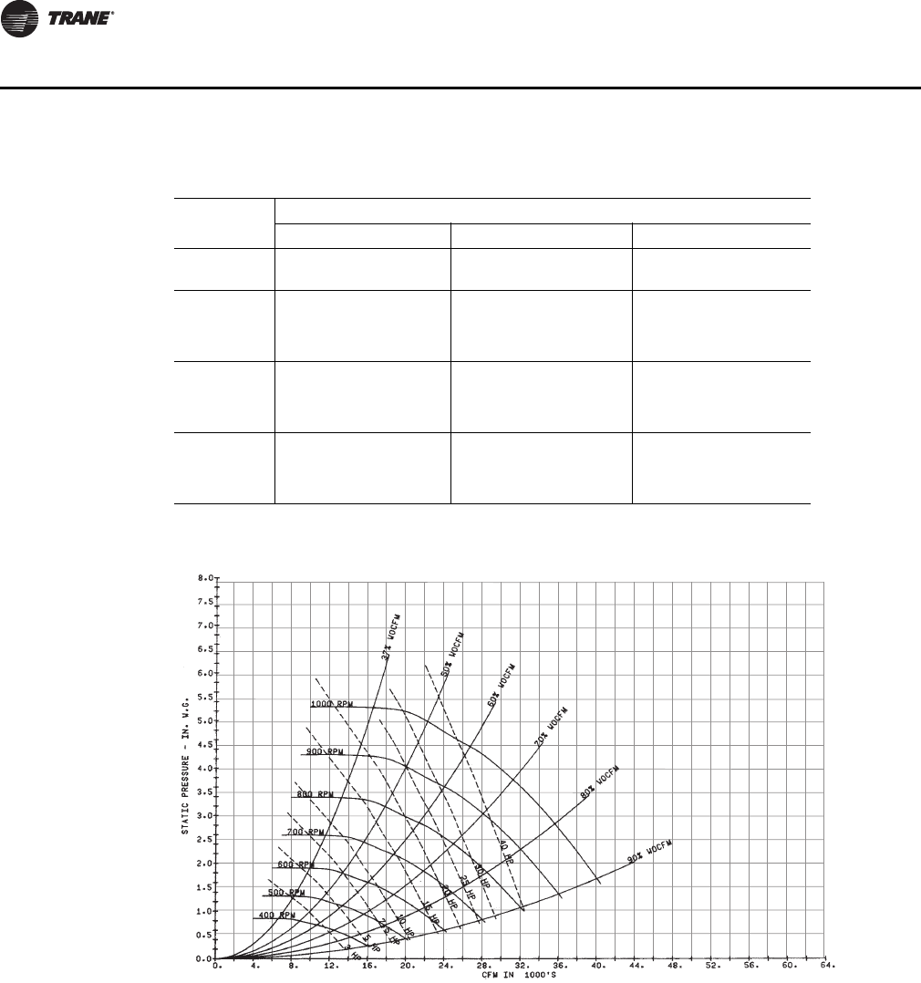
54 PKG-PRC002U-EN
Performance Data
Note: Fan curves include refrigerant coil and internal cabinet static losses. To determine static
pressure to be used with these curves, add filter, economizer, flexible horizontal discharge
and heat pressure drops to external duct static pressure.
Table 30. SCWF/SIWF42 Gross cooling capacity - 16,800 cfm, 126 gpm
Entering Air
Entering Water Temperature
75°F 85°F 95°F
EDB
°F EWB
°F Total
MBh Sensible
MBh LWT
°F Total
MBh Sensible
MBh LWT
°F Total
MBh Sensible
MBh LWT
°F
75
62 487 388 84.0 468 379 93.9 447 369 103.7
67 529 311 84.7 508 303 94.5 485 293 104.3
72 577 230 85.5 554 222 95.3 528 212 105.0
80
62 489 463 84.0 470 448 93.9 449 431 103.8
67 531 386 84.7 511 378 94.6 488 367 104.4
72 577 308 85.5 554 299 95.3 528 290 105.0
85
62 509 509 84.4 493 493 94.3 475 475 104.2
67 534 461 84.8 513 452 94.6 490 442 104.4
72 577 385 85.5 557 374 95.3 528 367 105.0
Figure 43. SCWF/SIWF 42 Fan Performance for CV or with VFD

PKG-PRC002U-EN 55
Performance Data
Table 31. SCWF/SIWF 46 - Economizer performance - 18,400 cfm
Entering Air
Flow
Gpm
Full Capacity Low Capacity
Entering Water Temp Entering Water Temp
45°F 55°F 45°F 55°F
EDB
°F EWB
°F Total
MBh Sensible
MBh LWT
°F Total
MBh Sensible
MBh LWT
°F Total
MBh Sensible
MBh LWT
°F Total
MBh Sensible
MBh LWT
°F
75
62
50 469.0 425.0 53.2 295.0 295.0 60.1 309.1 298.4 50.4 203.6 203.6 58.5
60 488.5 433.3 52.1 302.5 302.5 59.4 321.0 315.6 49.7 209.4 209.4 58.0
70 491.5 434.5 51.9 303.5 303.5 59.3 322.8 316.3 49.5 210.3 210.3 58.0
67
50 594.6 360.1 55.3 344.7 266.9 61.0 390.9 254.1 51.8 224.1 194.0 58.9
60 630.9 374.4 54.1 362.5 273.2 60.3 413.0 262.5 51.0 234.6 197.6 58.4
70 636.3 376.6 54.0 365.3 274.2 60.1 416.4 263.8 50.9 236.3 198.2 58.3
72
50 760.7 300.9 58.2 493.5 207.5 63.6 499.2 201.2 53.7 324.1 142.3 60.6
60 808.6 318.4 56.7 526.8 218.7 62.6 528.4 211.6 52.7 343.5 148.6 60.0
70 815.8 321.1 56.5 531.8 220.3 62.5 532.8 213.1 52.5 346.4 149.6 59.9
80
62
50 515.3 504.7 54.0 368.6 368.6 61.4 353.2 353.2 51.1 254.4 254.4 59.4
60 530.5 519.8 52.7 377.9 377.9 60.5 363.6 363.6 50.3 261.7 261.7 58.8
70 532.7 522.0 52.5 379.2 379.2 60.3 365.1 365.1 50.1 262.8 262.8 58.7
67
50 605.5 459.2 55.5 380.0 374.4 61.6 394.0 330.3 51.9 255.0 243.6 59.4
60 637.2 471.8 54.2 393.5 379.2 60.7 413.9 337.9 51.0 262.9 251.4 58.8
70 642.0 473.7 54.0 395.6 380.0 60.6 417.0 339.1 50.9 264.1 252.5 58.7
72
50 759.0 396.1 58.2 493.9 303.3 63.6 498.1 276.3 53.7 323.0 217.5 60.6
60 806.6 413.9 56.7 525.5 313.9 62.6 527.3 286.6 52.6 342.3 223.7 60.0
70 813.8 416.6 56.5 530.3 315.5 62.5 531.6 288.1 52.5 345.2 224.7 59.9
85
62
50 586.3 586.3 55.2 442.1 442.1 62.7 403.6 403.6 52.0 305.3 305.3 60.3
60 601.2 601.2 53.7 453.1 453.1 61.6 415.5 415.5 51.0 314.0 314.0 59.6
70 603.4 603.4 53.5 454.7 454.7 61.4 417.2 417.2 50.9 315.3 315.3 59.4
67
50 631.8 564.1 56.0 443.5 443.5 62.7 414.9 413.1 52.2 305.9 305.9 60.3
60 658.8 574.9 54.5 454.6 454.6 61.6 431.2 419.4 51.2 314.6 314.6 59.6
70 662.8 576.6 54.3 456.2 456.2 61.4 433.7 420.3 51.1 315.9 315.9 59.4
72
50 761.0 492.1 58.2 511.5 404.5 63.9 497.1 351.2 53.6 331.7 295.6 60.8
60 806.5 509.1 56.7 538.2 413.4 62.8 526.1 361.4 52.6 347.6 300.7 60.0
70 813.3 511.6 56.5 542.2 414.8 62.6 530.5 363.0 52.5 350.0 301.5 59.9
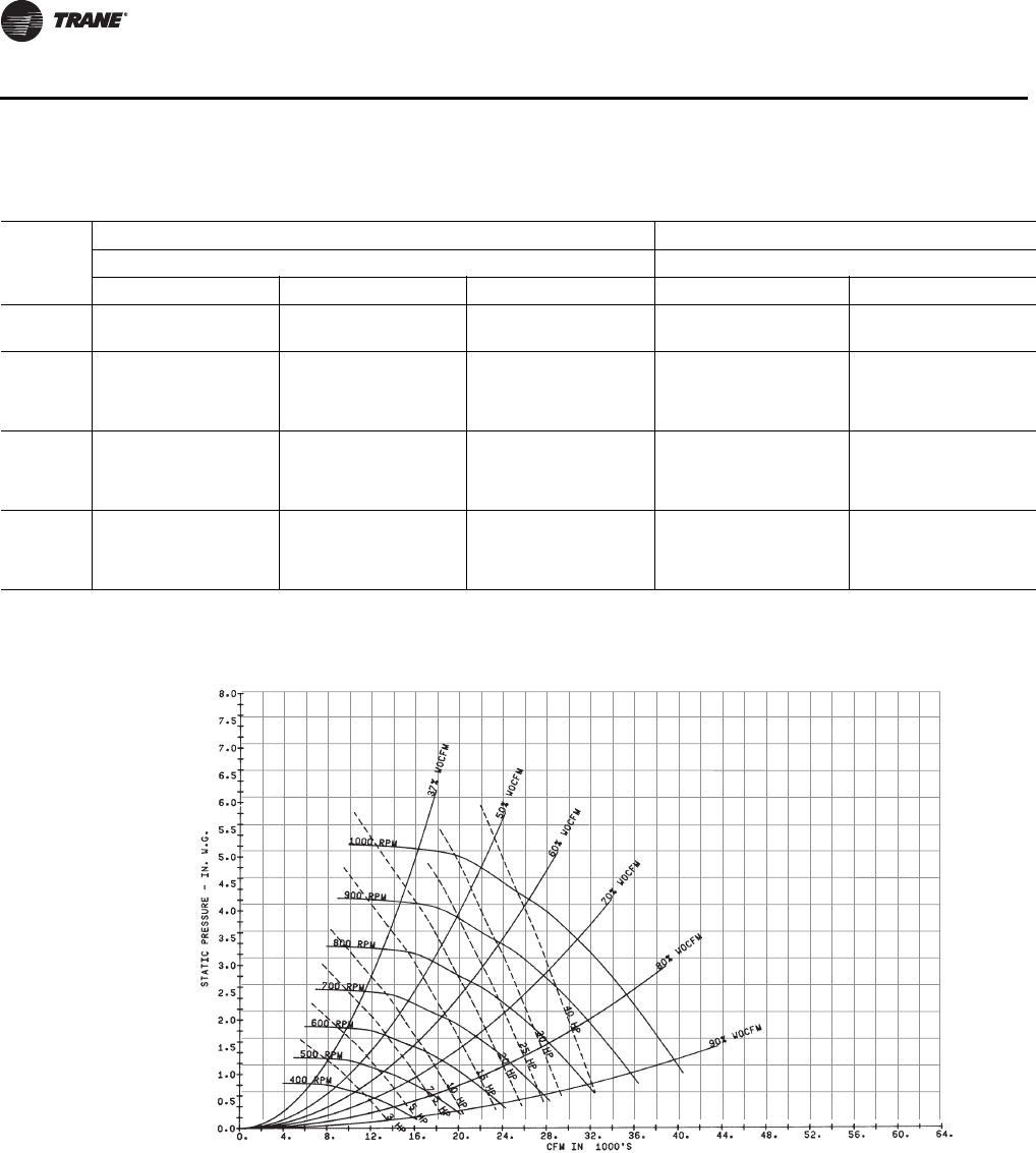
56 PKG-PRC002U-EN
Performance Data
Table 32. SCWF/SIWF46 Gross cooling capacity - 18,400 cfm, 138 gpm
Entering
Air
Standard Capacity High Capacity
Entering Water Temperature Entering Water Temperature
75°F 85°F 95°F 85°F 95°F
EDB
°F EWB
°F Total
MBh Sensible
MBh LWT
°F Total
MBh Sensible
MBh LWT
°F Total
MBh Sensible
MBh LWT
°F Total
MBh Sensible
MBh LWT
°F Total
MBh Sensible
MBh LWT
°F
75
62 515 431 83.6 495 422 93.5 472 411 103.3 - - - - - -
67 558 342 84.3 535 333 94.1 508 322 103.9 - - - - - -
72 608 246 85.0 582 237 94.8 554 227 104.5 - - - - - -
80
62 517 502 83.7 497 486 93.5 474 467 103.4 516 509 93.8 491 489 103.6
67 562 429 84.3 540 419 94.2 514 408 104.0 561 445 94.5 533 433 104.3
72 608 338 85.0 582 329 94.8 554 319 104.5 602 346 95.1 570 335 104.8
85
62 552 552 84.2 534 534 94.1 513 513 103.9 559 559 94.5 536 536 104.3
67 564 518 84.4 542 509 94.2 516 491 104.0 563 535 94.5 535 514 104.3
72 608 429 85.0 587 416 94.8 559 405 104.6 603 444 95.1 572 433 104.8
Figure 44. SCWF/SIWF 46 Fan Performance for CV or with VFD
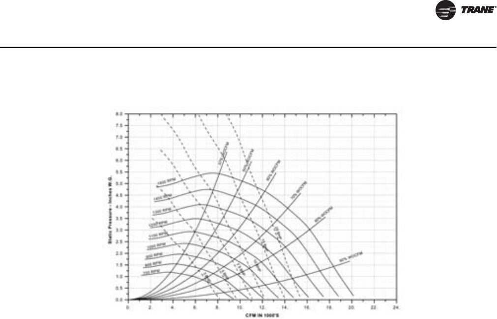
PKG-PRC002U-EN 57
Performance Data
Note: For optional low flow fan on high capacity coil.
Note: Fan curves include refrigerant coil and internal cabinet static losses. To determine static
pressure to be used with these curves, add filter, economizer, flexible horizontal discharge
and heat pressure drops to external duct static pressure.
Figure 45. SCWF/SIWF 46 18” Fan Performance for CV or with VFD

58 PKG-PRC002U-EN
Performance Data
Table 33. SCWF/SIWF 52 - Economizer performance - 20,800 cfm
Entering Air
Flow
Gpm
Full Capacity Low Capacity
Entering Water Temp Entering Water Temp
45°F 55°F 45°F 55°F
EDB
°F EWB
°F Total
MBh Sensible
MBh LWT
°F Total
MBh Sensible
MBh LWT
°F Total
MBh Sensible
MBh LWT
°F Total
MBh Sensible
MBh LWT
°F
75
62
50 546.6 489.7 53.4 341.8 341.8 60.3 363.7 361.8 50.6 238.6 238.6 58.7
60 570.0 499.6 52.3 350.4 350.4 59.5 378.3 367.7 49.9 245.6 245.6 58.1
70 588.4 507.5 51.5 356.6 356.6 58.9 390.1 372.6 49.3 250.9 250.9 57.8
67
50 694.3 417.0 55.7 402.7 307.8 61.2 461.2 297.3 52.1 264.6 226.1 59.1
60 737.5 434.2 54.5 424.2 315.4 60.4 488.3 307.6 51.3 277.6 230.6 58.6
70 771.2 447.8 53.5 441.7 321.7 59.9 509.6 315.8 50.6 288.6 234.5 58.2
72
50 887.8 350.3 58.7 576.6 241.3 63.9 589.2 236.9 54.1 382.8 167.2 60.9
60 945.5 371.6 57.1 616.7 254.8 62.9 625.0 249.6 53.0 406.6 174.9 60.2
70 990.6 388.5 55.9 647.8 265.4 62.1 653.2 259.8 52.2 425.4 181.1 59.7
80
62
50 598.2 586.1 54.2 427.0 427.0 61.6 413.9 413.9 51.4 298.2 298.2 59.6
60 616.2 604.1 52.9 437.6 437.6 60.6 426.4 426.4 50.5 306.9 306.9 58.9
70 630.1 618.1 51.9 445.4 445.4 59.9 435.8 435.8 49.8 313.5 313.5 58.4
67
50 707.0 530.2 55.9 442.3 430.2 61.8 464.9 385.4 52.2 299.4 286.4 59.6
60 744.9 545.4 54.5 458.6 436.1 60.9 489.3 394.7 51.3 309.0 295.9 59.0
70 774.8 557.5 53.5 471.5 440.8 60.2 509.2 402.3 50.6 316.7 303.6 58.5
72
50 885.8 459.3 58.6 577.3 350.6 63.9 588.0 323.6 54.0 381.6 254.0 60.9
60 943.2 480.9 57.1 615.2 363.4 62.9 623.6 336.3 53.0 405.2 261.7 60.2
70 988.1 498.1 55.9 645.6 373.7 62.1 651.7 346.4 52.2 423.9 267.8 59.7
85
62
50 679.1 679.1 55.4 512.1 512.1 62.9 473.1 473.1 52.3 357.9 357.9 60.5
60 696.3 696.3 53.9 524.8 524.8 61.7 487.2 487.2 51.2 368.3 368.3 59.7
70 708.9 708.9 52.8 534.0 534.0 60.9 497.9 497.9 50.5 376.1 376.1 59.1
67
50 736.6 649.9 56.3 513.8 513.8 62.9 488.4 480.9 52.5 358.6 358.6 60.5
60 769.0 662.9 54.9 526.6 526.6 61.8 508.5 488.6 51.5 369.0 369.0 59.7
70 794.5 673.3 53.7 535.8 535.8 60.9 524.8 494.9 50.8 376.9 376.9 59.1
72
50 888.9 569.1 58.7 597.7 466.2 64.2 586.7 410.2 54.0 391.6 344.3 61.0
60 943.3 589.5 57.1 629.7 477.0 63.1 622.2 422.8 53.0 411.1 350.7 60.3
70 986.2 606.0 55.8 655.5 485.8 62.2 650.2 432.9 52.1 427.1 355.9 59.7
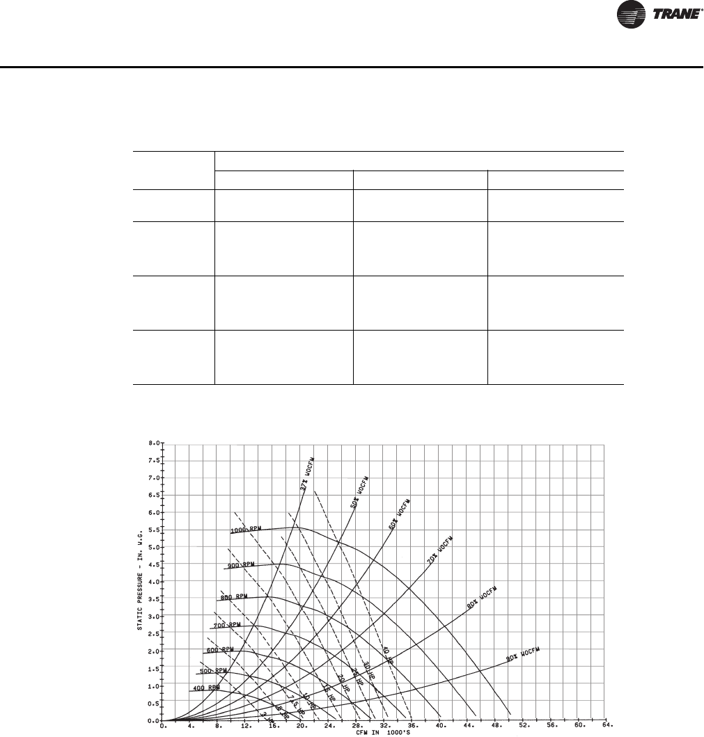
PKG-PRC002U-EN 59
Performance Data
Note: Fan curves include refrigerant coil and internal cabinet static losses. To determine static
pressure to be used with these curves, add filter, economizer, flexible horizontal discharge
and heat pressure drops to external duct static pressure.
Table 34. SCWF/SIWF52 Gross cooling capacity - 20,800 cfm, 156 gpm
Entering Air
Entering Water Temperature
75°F 85°F 95°F
EDB
°F EWB
°F Total
MBh Sensible
MBh LWT
°F Total
MBh Sensible
MBh LWT
°F Total
MBh Sensible
MBh LWT
°F
75
62 616 472 83.8 594 461 93.8 569 449 103.6
67 668 384 84.5 644 374 94.4 616 363 104.2
72 728 291 85.2 701 281 95.1 671 269 104.9
80
62 619 559 83.9 597 548 93.8 572 535 103.7
67 672 470 84.5 648 459 94.4 621 447 104.3
72 728 380 85.2 701 370 95.1 671 359 104.9
85
62 635 635 84.1 617 617 94.0 596 596 104.0
67 675 556 84.6 651 545 94.5 624 532 104.3
72 728 469 85.2 701 459 95.1 671 448 104.9
Figure 46. SCWF/SIWF 52 Fan Performance for CV or with VFD
60 PKG-PRC002U-EN
Performance Data
Table 35. SCWF/SIWF 58- Economizer performance - 23,200 cfm
Entering Air
Flow
Gpm
Full Capacity Low Capacity
Entering Water Temp Entering Water Temp
45°F 55°F 45°F 55°F
EDB
°F EWB
°F Total
MBh Sensible
MBh LWT
°F Total
MBh Sensible
MBh LWT
°F Total
MBh Sensible
MBh LWT
°F Total
MBh Sensible
MBh LWT
°F
75
62
50 592.9 536.8 53.2 372.8 372.8 60.1 391.0 377.5 50.4 257.4 257.4 58.6
60 617.6 547.2 52.1 382.2 382.2 59.4 406.1 398.9 49.7 264.8 264.8 58.0
70 626.2 550.8 51.7 385.2 385.2 59.1 411.4 401.1 49.4 267.3 267.3 57.9
67
50 751.8 454.9 55.4 435.8 337.1 61.0 494.5 321.3 51.8 283.6 245.2 58.9
60 797.7 473.1 54.2 458.4 345.1 60.3 522.7 331.9 51.0 296.9 249.8 58.4
70 813.5 479.4 53.7 466.5 348.0 60.0 532.4 335.7 50.7 301.9 251.5 58.2
72
50 961.6 380.3 58.3 623.9 262.3 63.6 631.6 254.6 53.7 410.1 180.0 60.7
60 1022.3 402.5 56.8 666.1 276.4 62.7 668.7 267.7 52.7 434.7 188.0 60.0
70 1043.5 410.3 56.2 680.7 281.3 62.3 681.6 272.3 52.3 443.2 190.8 59.8
80
62
50 651.2 637.7 54.0 465.7 465.7 61.4 446.6 446.6 51.2 321.8 321.8 59.4
60 670.3 656.9 52.7 477.4 477.4 60.5 459.8 459.8 50.3 331.0 331.0 58.8
70 676.9 663.4 52.3 481.2 481.2 60.2 464.3 464.3 50.0 334.1 334.1 58.6
67
50 765.5 580.0 55.6 480.3 472.7 61.6 498.5 417.6 51.9 322.6 308.1 59.4
60 805.6 595.9 54.3 497.4 478.9 60.7 523.8 427.2 51.0 332.5 318.0 58.8
70 819.6 601.5 53.8 503.4 481.0 60.4 532.8 430.6 50.7 336.0 321.4 58.6
72
50 959.5 500.5 58.2 624.4 383.1 63.6 630.3 349.4 53.7 408.7 275.0 60.6
60 1019.8 523.0 56.7 664.5 396.5 62.6 667.3 362.4 52.7 433.2 282.9 60.0
70 1040.9 531.0 56.2 678.6 401.3 62.3 680.1 367.0 52.3 441.8 285.6 59.8
85
62
50 740.7 740.7 55.2 558.6 558.6 62.7 510.4 510.4 52.0 386.1 386.1 60.3
60 759.6 759.6 53.7 572.5 572.5 61.6 525.4 525.4 51.0 397.1 397.1 59.6
70 765.8 765.8 53.2 577.0 577.0 61.2 530.5 530.5 50.7 400.8 400.8 59.3
67
50 798.6 712.4 56.0 560.3 560.3 62.7 524.8 522.1 52.2 386.8 386.8 60.3
60 832.8 726.1 54.6 574.3 574.3 61.6 545.5 530.1 51.3 397.9 397.9 59.6
70 844.7 730.9 54.1 578.9 578.9 61.2 552.8 532.9 50.9 401.6 401.6 59.3
72
50 962.1 621.6 58.3 646.7 510.8 63.9 628.9 444.0 53.7 419.7 373.6 60.8
60 1019.7 643.1 56.7 680.5 522.2 62.8 665.8 457.0 52.7 439.8 380.2 60.1
70 1039.8 650.7 56.2 692.4 526.2 62.4 678.6 461.5 52.3 447.0 382.5 59.8
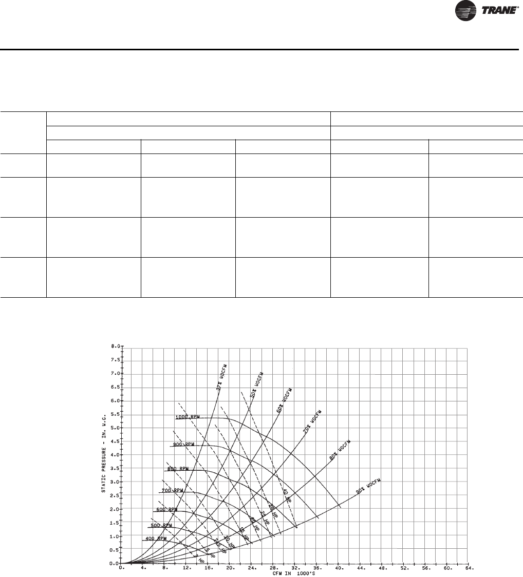
PKG-PRC002U-EN 61
Performance Data
Table 36. SCWF/SIWF58 Gross cooling capacity - 23,200 cfm, 174 gpm
Entering
Air
Standard Capacity High Capacity
Entering Water Temperature Entering Water Temperature
75°F 85°F 95°F 85°F 95°F
EDB
°F EWB
°F Total
MBh Sensible
MBh LWT
°F Total
MBh Sensible
MBh LWT
°F Total
MBh Sensible
MBh LWT
°F Total
MBh Sensible
MBh LWT
°F Total
MBh Sensible
MBh LWT
°F
75
62 663 552 83.8 637 540 93.7 608 526 103.5 - - - - - -
67 717 438 84.4 688 426 94.3 654 413 104.1 - - - - - -
72 780 316 85.2 748 305 95.0 711 292 104.7 - - - - - -
80
62 665 665 83.8 640 640 93.7 610 610 103.5 664 664 94.0 632 632 103.8
67 722 548 84.5 694 536 94.3 661 522 104.1 720 568 94.7 685 553 104.4
72 780 432 85.2 748 421 95.0 711 408 104.7 773 443 95.3 733 429 105.0
85
62 709 709 84.3 686 686 94.2 660 660 104.1 718 718 94.6 689 689 104.5
67 725 661 84.5 696 648 94.4 664 634 104.2 723 691 94.7 688 676 104.5
72 784 543 85.2 753 531 95.0 711 523 104.7 781 562 95.4 733 553 105.0
Figure 47. SCWF/SIWF 58 Fan Performance for CV or with VFD
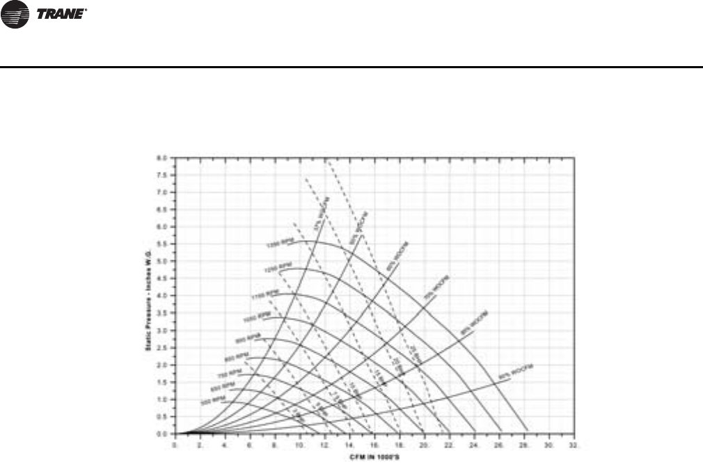
62 PKG-PRC002U-EN
Performance Data
Note: For optional low flow fan on high capacity coil.
Note: Fan curves include refrigerant coil and internal cabinet static losses. To determine static
pressure to be used with these curves, add filter, economizer, flexible horizontal discharge
and heat pressure drops to external duct static pressure.
Figure 48. SCWF/SIWF 58 18” Fan Performance for CV or with VFD

PKG-PRC002U-EN 63
Performance Data
Table 37. SCWF/SIWF 65- Economizer performance - 26,000 cfm
Entering Air
Flow
Gpm
Full Capacity Low Capacity
Entering Water Temp Entering Water Temp
45°F 55°F 45°F 55°F
EDB
°F EWB
°F Total
MBh Sensible
MBh LWT
°F Total
MBh Sensible
MBh LWT
°F Total
MBh Sensible
MBh LWT
°F Total
MBh Sensible
MBh LWT
°F
75
62
50 644.4 590.0 52.9 407.4 407.4 60.0 420.9 405.9 50.2 278.1 278.1 58.4
60 670.0 600.7 51.9 417.5 417.5 59.3 436.1 433.3 49.5 285.8 285.8 57.9
70 689.7 609.0 51.1 424.7 424.7 58.8 448.0 438.2 49.0 291.4 291.4 57.6
67
50 815.9 497.6 55.0 472.6 370.1 60.8 531.1 347.9 51.5 304.3 266.3 58.7
60 863.7 516.4 53.9 495.9 378.4 60.1 559.7 358.7 50.7 317.8 271.0 58.3
70 899.9 530.8 53.0 514.5 385.0 59.6 581.7 367.0 50.1 329.0 274.9 57.9
72
50 1043.3 413.8 57.8 676.7 285.8 63.3 678.2 274.0 53.3 440.0 194.2 60.4
60 1106.7 436.7 56.4 720.4 300.4 62.4 715.9 287.3 52.3 464.9 202.3 59.8
70 1155.0 454.5 55.2 753.5 311.5 61.7 744.8 297.6 51.6 484.1 208.5 59.3
80
62
50 710.6 695.5 53.7 509.0 509.0 61.2 482.5 482.5 50.9 347.6 347.6 59.3
60 730.5 715.4 52.5 521.6 521.6 60.3 496.2 496.2 50.1 357.2 357.2 58.7
70 745.5 730.4 51.6 530.5 530.5 59.7 506.4 506.4 49.5 364.2 364.2 58.2
67
50 830.6 636.1 55.2 522.6 520.8 61.4 535.3 453.2 51.6 348.2 348.2 59.3
60 872.3 652.6 53.9 540.3 527.1 60.5 561.0 463.0 50.8 358.2 342.1 58.7
70 904.5 665.4 53.0 553.9 532.0 59.9 581.3 470.7 50.1 365.8 349.7 58.2
72
50 1041.0 546.6 57.8 676.9 419.8 63.3 676.7 377.8 53.3 438.6 298.1 60.4
60 1104.0 569.9 56.3 718.5 433.6 62.4 714.3 391.0 52.3 463.4 306.1 59.8
70 1152.2 588.1 55.2 750.9 444.5 61.6 743.2 401.3 51.6 482.5 312.3 59.3
85
62
50 809.6 809.6 54.9 610.6 610.6 62.5 551.5 551.5 51.8 417.1 417.1 60.1
60 829.9 829.9 53.5 625.5 625.5 61.4 567.1 567.1 50.8 428.5 428.5 59.4
70 844.4 844.4 52.5 636.1 636.1 60.6 578.6 578.6 50.1 436.9 436.9 58.9
67
50 867.7 783.1 55.6 612.4 612.4 62.5 564.7 547.6 51.9 417.9 417.9 60.1
60 903.1 797.2 54.3 627.4 627.4 61.4 585.6 575.9 51.0 429.3 429.3 59.4
70 930.4 808.2 53.2 638.2 638.2 60.6 602.0 582.2 50.3 437.7 437.7 58.9
72
50 1043.6 680.9 57.8 701.3 561.3 63.6 675.3 481.4 53.3 450.5 406.1 60.5
60 1103.6 703.1 56.3 736.1 573.0 62.5 712.8 494.6 52.3 470.8 412.7 59.8
70 1149.9 720.5 55.2 763.4 582.1 61.8 741.5 504.8 51.6 486.9 417.9 59.3
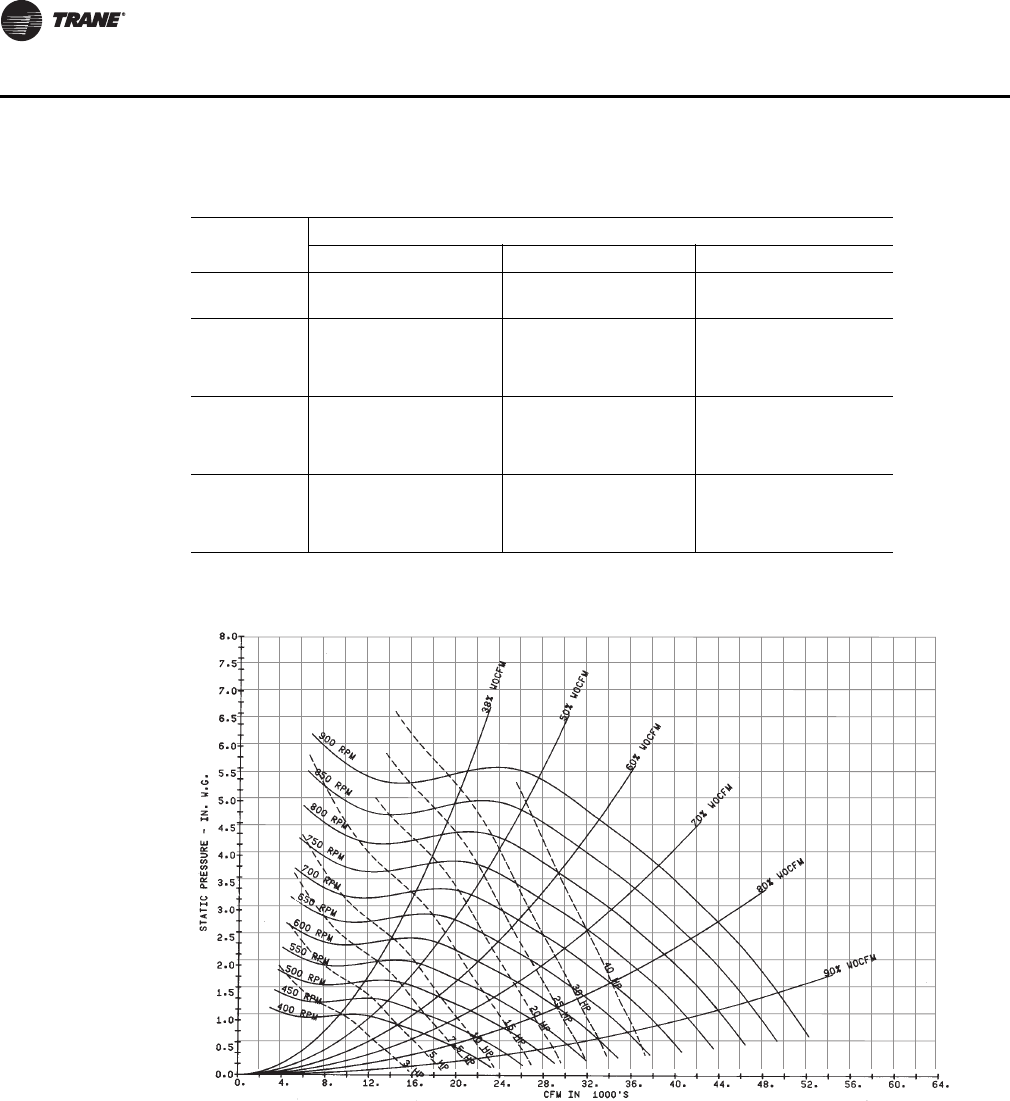
64 PKG-PRC002U-EN
Performance Data
Note: Fan curves include refrigerant coil and internal cabinet static losses. To determine static
pressure to be used with these curves, add filter, economizer, flexible horizontal discharge
and heat pressure drops to external duct static pressure.
Table 38. SCWF/SIWF65 Gross cooling capacity - 26,000 cfm, 196 gpm
Entering Air
Entering Water Temperature
75°F 85°F 95°F
EDB
°F EWB
°F Total
MBh Sensible
MBh LWT
°F Total
MBh Sensible
MBh LWT
°F Total
MBh Sensible
MBh LWT
°F
75
62 772 610 83.9 744 597 93.8 711 581 103.7
67 838 490 84.6 806 477 94.5 770 463 104.3
72 911 365 85.4 876 352 95.2 836 338 105.0
80
62 775 726 84.0 747 712 93.9 714 697 103.7
67 840 607 84.6 809 593 94.5 774 577 104.3
72 911 484 85.4 876 471 95.2 836 456 105.0
85
62 805 805 84.3 781 781 94.2 753 753 104.1
67 844 721 84.7 812 707 94.5 777 691 104.4
72 912 601 85.4 877 588 95.2 838 572 105.0
Figure 49. SCWF/SIWF 65 Fan Performance for CV or with VFD
PKG-PRC002U-EN 65
Performance Data
Table 39. SCWF/SIWF 72 - Economizer performance - 28,000 cfm
Entering Air
Flow
Gpm
Full Capacity Low Capacity
Entering Water Temp Entering Water Temp
45°F 55°F 45°F 55°F
EDB
°F EWB
°F Total
MBh Sensible
MBh LWT
°F Total
MBh Sensible
MBh LWT
°F Total
MBh Sensible
MBh LWT
°F Total
MBh Sensible
MBh LWT
°F
75
62
50 692.2 640.9 52.7 440.0 440.0 59.9 448.3 431.7 50.0 297.1 297.1 58.3
60 719.4 652.3 51.7 451.1 451.1 59.2 464.1 447.5 49.3 305.3 305.3 57.8
70 725.9 655.0 51.4 453.6 453.6 59.0 467.9 467.4 49.1 307.1 307.1 57.7
67
50 874.7 537.8 54.7 506.6 401.7 60.6 564.0 372.5 51.3 323.1 286.1 58.6
60 925.8 557.8 53.6 531.1 410.4 59.9 593.9 383.7 50.5 337.1 291.0 58.1
70 937.7 562.5 53.3 537.2 412.5 59.8 601.0 386.4 50.3 340.6 292.2 58.0
72
50 1117.6 443.9 57.4 724.9 307.7 63.1 720.0 291.7 53.0 466.8 207.2 60.2
60 1185.9 469.3 56.0 771.3 323.1 62.1 759.4 305.5 52.0 492.8 215.6 59.6
70 1201.8 475.0 55.6 782.2 326.7 61.9 768.7 308.8 51.8 499.0 217.5 59.4
80
62
50 766.5 749.8 53.5 549.8 549.8 61.1 515.6 515.6 50.7 371.4 371.4 59.1
60 787.8 771.1 52.3 563.5 563.5 60.2 530.2 530.2 49.9 381.5 381.5 58.5
70 792.8 776.1 52.0 566.6 566.6 60.0 533.5 533.5 49.7 383.9 383.9 58.4
67
50 890.5 689.6 54.9 562.1 542.9 61.2 568.5 486.6 51.3 372.0 372.0 59.1
60 934.9 707.0 53.7 580.8 573.8 60.4 595.3 496.7 50.5 382.2 364.5 58.5
70 945.5 711.2 53.4 585.3 575.4 60.2 601.8 499.1 50.3 384.7 366.9 58.4
72
50 1114.9 589.6 57.4 724.9 454.5 63.1 718.5 404.1 53.0 465.3 319.7 60.2
60 1183.0 614.7 56.0 769.1 469.2 62.1 757.7 417.8 52.0 491.2 328.0 59.5
70 1198.9 620.6 55.6 779.7 472.7 61.9 767.0 421.1 51.8 497.3 330.0 59.4
85
62
50 874.4 874.4 54.7 659.4 659.4 62.3 589.3 589.3 51.5 445.6 445.6 60.0
60 896.7 896.7 53.3 675.8 675.8 61.3 605.9 605.9 50.6 457.8 457.8 59.2
70 901.7 901.7 53.0 679.5 679.5 61.0 609.7 609.7 50.4 460.6 460.6 59.1
67
50 931.6 850.8 55.4 661.3 661.3 62.3 601.1 582.4 51.7 446.4 446.4 60.0
60 969.2 865.7 54.0 677.8 677.8 61.3 622.8 619.2 50.8 458.6 458.6 59.2
70 978.2 869.3 53.7 681.6 681.6 61.0 628.0 621.2 50.6 461.4 461.4 59.1
72
50 1118.3 737.1 57.4 751.4 609.6 63.3 716.9 516.2 53.0 478.3 436.6 60.3
60 1182.3 760.6 55.9 788.3 621.9 62.3 756.1 529.9 52.0 499.3 443.4 59.6
70 1197.5 766.2 55.6 797.1 624.8 62.1 765.4 533.2 51.8 504.4 445.1 59.5
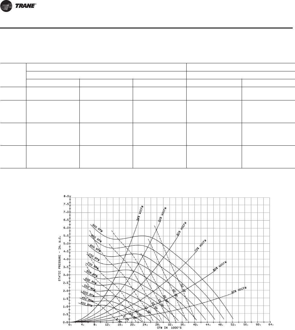
66 PKG-PRC002U-EN
Performance Data
Table 40. SCWF/SIWF72 Gross cooling capacity - 28,800 cfm, 216 gpm
Entering
Air
Standard Capacity High Capacity
Entering Water Temperature Entering Water Temperature
75°F 85°F 95°F 85°F 95°F
EDB
°F EWB
°F Total
MBh Sensible
MBh LWT
°F Total
MBh Sensible
MBh LWT
°F Total
MBh Sensible
MBh LWT
°F Total
MBh Sensible
MBh LWT
°F Total
MBh Sensible
MBh LWT
°F
75
62 809 674 83.6 778 660 93.4 743 663 103.3 - - - - - -
67 875 535 84.2 840 533 94.0 800 517 103.8 - - - - - -
72 952 389 84.9 913 375 94.7 870 360 104.5 - - - - - -
80
62 812 812 83.6 781 781 93.5 746 746 103.3 815 815 93.8 776 776 103.6
67 881 670 84.2 847 655 94.1 808 638 103.9 883 701 94.4 841 682 104.2
72 952 528 84.9 913 514 94.7 869 499 104.5 950 546 95.1 901 529 104.8
85
62 865 865 84.1 837 837 94.0 805 805 103.9 883 883 94.4 847 847 104.3
67 884 806 84.3 850 791 94.1 811 774 103.9 886 852 94.5 844 833 104.2
72 956 663 84.9 916 652 94.7 876 631 104.5 953 696 95.1 906 679 104.8
Figure 50. SCWF/SIWF 72 Fan Performance for CV or with VFD
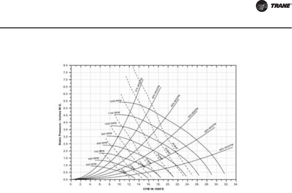
PKG-PRC002U-EN 67
Performance Data
Note: For optional low flow fan on high capacity coil.
Note: Fan curves include refrigerant coil and internal cabinet static losses. To determine static
pressure to be used with these curves, add filter, economizer, flexible horizontal discharge
and heat pressure drops to external duct static pressure.
Figure 51. SCWF/SIWF 72 20“ Fan Performance for CV or with VFD

68 PKG-PRC002U-EN
Performance Data
Table 41. SCWF/SIWF 80 - Economizer performance - 29,800 cfm
Entering Air
Flow
Gpm
Full Capacity Low Capacity
Entering Water Temp Entering Water Temp
45°F 55°F 45°F 55°F
EDB
°F EWB
°F Total
MBh Sensible
MBh LWT
°F Total
MBh Sensible
MBh LWT
°F Total
MBh Sensible
MBh LWT
°F Total
MBh Sensible
MBh LWT
°F
75
62
50 719.8 663.3 52.2 456.0 456.0 59.6 464.0 446.9 49.6 307.0 307.0 58.1
60 746.6 674.5 51.2 466.7 466.7 58.9 479.5 462.3 49.0 314.9 314.9 57.6
70 751.3 676.5 51.1 468.4 468.4 58.8 482.2 480.6 48.9 316.2 316.2 57.6
67
50 915.9 559.9 54.2 527.8 416.0 60.3 587.4 385.5 50.9 334.7 294.7 58.3
60 966.0 579.6 53.1 552.8 424.9 59.6 616.7 396.5 50.1 349.2 299.7 57.9
70 974.5 583.0 52.9 557.1 426.4 59.5 621.7 398.4 50.0 351.7 300.6 57.8
72
50 1171.5 464.7 56.7 760.6 321.6 62.6 750.3 303.3 52.5 486.5 215.0 59.9
60 1238.3 489.6 55.3 805.9 336.7 61.7 788.8 316.9 51.6 511.9 223.2 59.3
70 1249.7 493.8 55.1 813.6 339.3 61.6 795.4 319.2 51.4 516.3 224.6 59.2
80
62
50 794.7 777.5 52.9 569.7 569.7 60.7 533.0 533.0 50.3 383.7 383.7 58.8
60 815.5 798.2 51.8 583.0 583.0 59.9 547.1 547.1 49.6 393.5 393.5 58.3
70 819.0 801.7 51.6 585.1 585.1 59.7 549.4 549.4 49.4 395.2 395.2 58.2
67
50 929.2 715.3 54.3 583.4 563.2 60.8 590.6 502.1 50.9 384.4 384.4 58.8
60 973.1 732.5 53.1 601.8 592.6 60.0 617.2 512.1 50.1 394.3 375.9 58.3
70 980.7 735.5 52.9 605.0 593.8 59.9 621.8 513.9 50.0 396.0 377.7 58.2
72
50 1168.7 614.9 56.7 759.4 472.5 62.6 748.7 418.7 52.5 484.9 330.5 59.8
60 1235.3 639.5 55.3 803.2 487.1 61.7 787.1 432.2 51.6 510.2 338.7 59.3
70 1246.6 643.7 55.1 810.8 489.6 61.5 793.7 434.5 51.4 514.6 340.1 59.1
85
62
50 906.2 906.2 54.1 683.3 683.3 61.8 609.1 609.1 51.1 460.4 460.4 59.6
60 927.8 927.8 52.7 699.1 699.1 60.8 625.1 625.1 50.2 472.2 472.2 58.9
70 931.3 931.3 52.5 701.7 701.7 60.7 627.8 627.8 50.1 474.1 474.1 58.8
67
50 969.0 880.5 54.7 685.2 685.2 61.9 622.3 602.9 51.2 461.2 461.2 59.6
60 1006.1 895.3 53.4 701.2 701.2 60.8 643.6 637.3 50.4 473.0 473.0 58.9
70 1012.5 897.8 53.2 703.8 703.8 60.7 647.3 638.7 50.2 475.0 475.0 58.8
72
50 1170.1 766.1 56.7 783.6 631.4 62.8 747.1 533.8 52.5 496.6 450.0 60.0
60 1233.4 789.5 55.3 820.2 643.6 61.8 785.4 547.2 51.5 517.0 456.6 59.3
70 1244.3 793.5 55.0 826.5 645.7 61.7 791.9 549.5 51.4 520.6 457.8 59.2
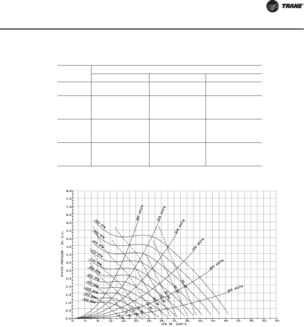
PKG-PRC002U-EN 69
Performance Data
Note: Fan curves include refrigerant coil and internal cabinet static losses. To determine static
pressure to be used with these curves, add filter, economizer, flexible horizontal discharge
and heat pressure drops to external duct static pressure.
Table 42. SCWF/SIWF80 Gross cooling capacity - 29,800 cfm, 240 gpm
Entering Air
Entering Water Temperature
75°F 85°F 95°F
EDB
°F EWB
°F Total
MBh Sensible
MBh LWT
°F Total
MBh Sensible
MBh LWT
°F Total
MBh Sensible
MBh LWT
°F
75
62 918 777 83.7 882 760 93.5 840 741 103.3
67 992 612 84.3 951 595 94.1 904 577 103.9
72 1078 438 85.0 1033 422 94.8 981 405 104.5
80
62 921 921 83.7 884 884 93.5 843 843 103.4
67 998 763 84.3 959 746 94.2 913 726 104.0
72 1077 599 85.0 1032 583 94.8 981 566 104.5
85
62 983 983 84.2 951 951 94.1 913 913 104.0
67 1002 921 84.4 962 903 94.2 917 884 104.0
72 1083 755 85.0 1039 738 94.8 985 722 104.6
Figure 52. SCWF/SIWF 80 Fan Performance for CV or with VFD
70 PKG-PRC002U-EN
Performance Data
Table 43. 90-ton SCWF economizer performance - 30,000 cfm
Entering Air
Flow
Gpm
Entering Water Temperature
45°F 55°F
EDB °F EWB °F Total
MBh Sensible
MBh LWT
°F Total
MBh Sensible
MBh LWT
°F
75
62
180 692.7 660.1 52.7 453.3 447.2 60.0
225 732.1 676.1 51.5 471.0 464.8 59.2
270 761.4 688.1 50.6 483.4 476.9 58.6
67
180 846.1 532.2 54.4 500.1 408.8 60.5
225 916.4 558.6 53.1 534.4 420.9 59.7
270 969.4 578.7 52.2 561.0 430.0 59.2
72
180 1074.0 420.9 56.9 698.1 296.9 62.7
225 1170.0 453.7 55.4 761.5 316.7 61.8
270 1242.0 478.8 54.2 809.8 332.3 61.0
80
62
180 785.1 776.3 53.7 566.6 560.2 61.3
225 817.5 793.9 52.2 588.6 582.0 60.2
270 839.5 830.0 51.2 603.9 597.3 59.5
67
180 875.2 717.7 54.7 571.8 547.5 61.3
225 937.4 722.0 53.3 598.5 573.5 60.3
270 984.2 739.9 52.3 618.7 605.4 59.6
72
180 1072.0 575.2 56.9 704.4 453.7 62.8
225 1168.0 608.4 55.3 763.0 472.6 61.8
270 1239.0 633.7 54.1 808.7 487.3 61.0
85
62
180 897.5 889.3 54.9 679.9 673.5 62.5
225 934.0 925.4 53.3 706.0 699.5 61.3
270 959.0 950.1 52.1 724.3 717.7 60.4
67
180 931.6 875.3 55.3 681.8 671.2 62.6
225 985.2 924.1 53.7 708.2 697.2 61.3
270 1026.0 939.4 52.6 726.6 715.4 60.4
72
180 1087.0 735.6 57.0 744.7 621.7 63.3
225 1174.0 766.2 55.4 794.6 638.0 62.1
270 1241.0 790.0 54.2 833.5 650.3 61.2
Table 44. SCWF/SIWF90 Gross cooling capacity - 30,000 cfm, 270 gpm
Entering
Air
Standard Capacity High Capacity
Entering Water Temperature Entering Water Temperature
75°F 85°F 95°F 85°F 95°F
EDB
°F EWB
°F Total
MBh Sensible
MBh LWT
°F Total
MBh Sensible
MBh LWT
°F Total
MBh Sensible
MBh LWT
°F Total
MBh Sensible
MBh LWT
°F Total
MBh Sensible
MBh LWT
°F
75
62 1071 836 84.2 1031 816 94.0 985 794 103.9 - - - - - -
67 1160 674 84.8 1115 656 94.7 1063 635 104.5 - - - - - -
72 1263 504 85.6 1213 486 95.4 1155 465 105.2 - - - - - -
80
62 1075 993 84.2 1035 973 94.1 989 950 103.9 1064 1006 94.3 1015 982 104.1
67 1166 830 84.9 1122 810 94.7 1071 788 104.5 1153 836 95.0 1099 812 104.8
72 1262 666 85.6 1212 647 95.4 1155 626 105.2 1245 667 95.7 1184 644 105.4
85
62 1115 1115 84.5 1081 1081 94.4 1040 1040 104.3 1113 1113 94.7 1070 1070 104.5
67 1171 985 84.9 1127 965 94.8 1076 942 104.6 1158 997 95.0 1104 973 104.8
72 1266 822 85.6 1217 802 95.5 1161 779 105.2 1251 827 95.7 1192 803 105.5
PKG-PRC002U-EN 71
Performance Data
Table 45. 100-ton SCWF economizer performance - 32,000 cfm
Entering Air
Flow
Gpm
Entering Water Temperature
45°F 55°F
EDB
°F EWB
°F Total
MBh Sensible
MBh LWT
°F Total
MBh Sensible
MBh LWT
°F
75
62
200 734.1 700.0 52.3 479.8 473.6 59.8
250 773.3 715.9 51.2 497.8 491.3 59.0
300 802.9 728.1 50.3 510.4 503.4 58.4
67
200 899.4 565.6 54.0 529.6 433.7 60.3
250 969.9 592.0 52.7 564.5 445.8 59.5
300 1024.0 612.5 51.8 591.5 454.8 58.9
72
200 1143.0 447.9 56.4 742.2 315.3 62.4
250 1239.0 480.9 54.9 806.5 335.7 61.4
300 1312.0 506.2 53.7 855.2 351.4 60.7
80
62
200 831.9 822.5 53.3 599.6 593.0 61.0
250 864.1 838.8 51.9 622.0 614.9 60.0
300 886.5 876.7 50.9 637.6 630.5 59.2
67
200 928.5 741.3 54.3 605.0 579.1 61.0
250 990.6 764.9 52.9 632.0 605.5 60.0
300 1038.0 782.9 51.9 652.3 625.7 59.3
72
200 1141.0 611.4 56.4 747.5 481.6 62.5
250 1237.0 644.8 54.9 807.3 500.7 61.4
300 1310.0 835.7 53.7 878.7 688.5 60.7
85
62
200 950.8 942.0 54.5 719.5 712.8 62.2
250 987.2 978.1 52.9 746.1 739.2 61.0
300 1013.0 1003.4 51.7 764.7 757.6 60.1
67
200 987.0 928.4 54.8 721.5 710.4 62.2
250 1040.0 981.5 53.3 748.3 736.8 61.0
300 1081.0 997.2 52.2 767.0 755.2 60.1
72
200 1154.0 781.2 56.5 788.5 659.3 62.9
250 1242.0 811.8 54.9 839.3 675.7 61.7
300 1310.0 835.7 53.7 878.7 688.5 60.9
Table 46. SCWF/SIWF100 Gross cooling capacity - 32,000 cfm, 280 gpm
Entering
Air
Standard Capacity High Capacity
Entering Water Temperature Entering Water Temperature
75°F 85°F 95°F 85°F 95°F
EDB
°F EWB
°F Total
MBh Sensible
MBh LWT
°F Total
MBh Sensible
MBh LWT
°F Total
MBh Sensible
MBh LWT
°F Total
MBh Sensible
MBh LWT
°F Total
MBh Sensible
MBh LWT
°F
75
62 1147 906 84.4 1104 879 94.3 1054 852 104.1 - - - - - -
67 1243 725 85.1 1193 709 95.0 1136 686 104.8 - - - - - -
72 1353 537 85.9 1298 517 95.7 1235 493 105.5 - - - - - -
80
62 1152 1057 84.5 1108 1028 94.3 1058 996 104.2 1138 1058 94.6 1085 1024 104.4
67 1249 892 85.2 1201 871 95.0 1146 846 104.8 1233 897 95.3 1175 871 105.0
72 1352 716 85.9 1297 695 95.7 1235 672 105.5 1330 707 96.0 1243 719 105.6
85
62 1193 1193 84.8 1155 1155 94.7 1112 1112 104.6 1188 1188 94.9 1142 1142 104.8
67 1254 1060 85.2 1206 1038 95.1 1151 1013 104.9 1238 1070 95.3 1180 1043 105.1
72 1355 886 86.0 1301 865 95.8 1238 841 105.5 1335 889 96.0 1270 863 105.8
72 PKG-PRC002U-EN
Performance Data
Table 47. 110-ton SCWF economizer performance - 32,000 cfm
Entering Air
Flow Gpm
Entering Water Temperature
45°F 55°F
EDB
°F EWB
°F Total
MBh Sensible
MBh lWT
°F Total
MBh Sensible
MBh LWT
°F
75
62
200 734.1 700.0 52.3 479.8 473.6 59.8
250 773.3 715.9 51.2 497.8 491.3 59.0
300 802.9 728.1 50.3 510.4 503.4 58.4
67
200 899.4 565.6 54.0 529.6 433.7 60.3
250 969.9 592.0 52.7 564.5 445.8 59.5
300 1024.0 612.5 51.8 591.5 454.8 58.9
72
200 1143.0 447.9 56.4 742.2 315.3 62.4
250 1239.0 480.9 54.9 806.5 335.7 61.4
300 1312.0 506.2 53.7 855.2 351.4 60.7
80
62
200 831.9 822.5 53.3 599.6 593.0 61.0
250 864.1 838.8 51.9 622.0 614.9 60.0
300 886.5 876.7 50.9 637.6 630.5 59.2
67
200 928.5 741.3 54.3 605.0 579.1 61.0
250 990.6 764.9 52.9 632.0 605.5 60.0
300 1038.0 782.9 51.9 652.3 625.7 59.3
72
200 1141.0 611.4 56.4 747.5 481.6 62.5
250 1237.0 644.8 54.9 807.3 500.7 61.4
300 1309.0 670.4 53.7 853.6 515.6 60.7
85
62
200 950.8 942.0 54.5 719.5 712.8 62.2
250 987.2 978.1 52.9 746.1 739.2 61.0
300 1013.0 1003.4 51.7 764.7 757.6 60.1
67
200 987.0 928.4 54.8 721.5 710.4 62.2
250 1040.0 981.5 53.3 748.3 736.8 61.0
300 1081.0 997.2 52.2 767.0 755.2 60.1
72
200 1154.0 781.2 56.5 788.5 659.3 62.9
250 1242.0 811.8 54.9 839.3 675.7 61.7
300 1310.0 835.7 53.7 878.7 688.5 60.9
Table 48. SCWF110 (High Capacity) Gross Cooling Capacity - 32,000 cfm, 300 gpm
Entering
Air
Standard Capacity High Capacity
Entering Water Temperature Entering Water Temperature
75°F 85°F 95°F 85°F 95°F
EDB
°F EWB
°F Total
MBh Sensible
MBh LWT
°F Total
MBh Sensible
MBh LWT
°F Total
MBh Sensible
MBh LWT
°F Total
MBh Sensible
MBh LWT
°F Total
MBh Sensible
MBh LWT
°F
75
62 1268 966 84.7 1221 943 94.6 1167 909 104.4 - - - - - -
67 1376 785 85.4 1323 762 95.3 1262 737 105.1 - - - - - -
72 1497 594 86.3 1439 573 96.1 1371 548 105.8 - - - - - -
80
62 1273 1130 84.7 1226 1106 94.6 1172 1079 104.4 1260 1141 94.8 1202 1112 104.7
67 1380 953 85.5 1328 930 95.3 1269 903 105.1 1365 957 95.6 1302 928 105.4
72 1497 772 86.3 1438 749 96.1 1371 724 105.8 1477 769 96.3 1406 743 106.1
85
62 1299 1299 84.9 1259 1259 94.8 1213 1213 104.7 1295 1295 95.1 1246 1246 105.0
67 1386 1122 85.5 1334 1098 95.3 1274 1070 105.2 1370 1131 95.6 1308 1102 105.4
72 1497 946 86.3 1439 923 96.1 1376 893 105.9 1480 947 96.4 1411 919 106.1
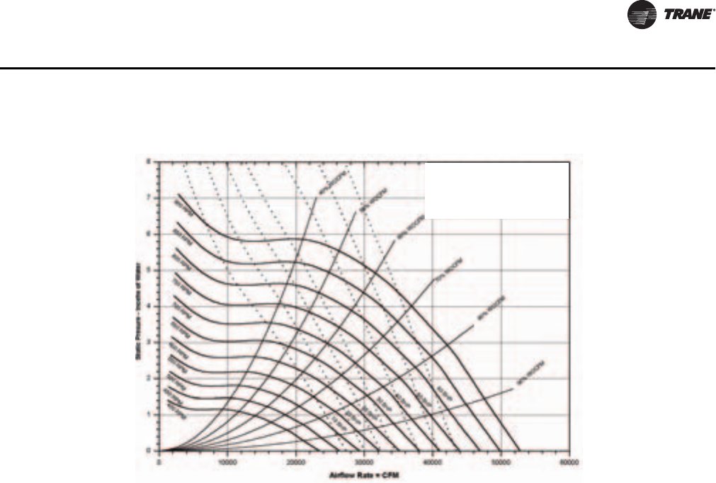
PKG-PRC002U-EN 73
Performance Data
Note: Fan curves include refrigerant coil and internal cabinet static losses. To determine static
pressure to be used with these curves, add filter, economizer, flexible horizontal discharge
and heat pressure drops to external duct static pressure.
Figure 53. SCWF90-110 Fan Performance with VFD
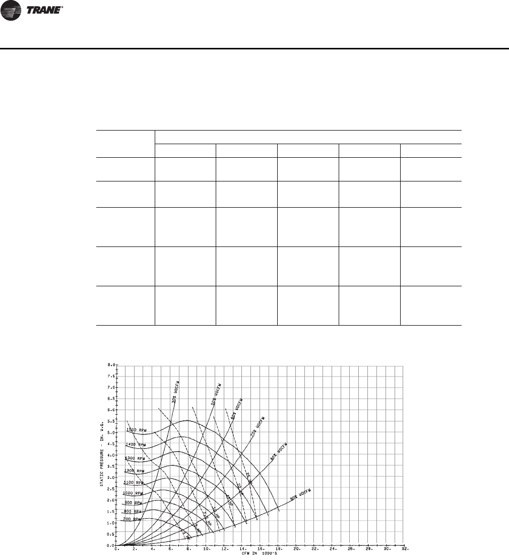
74 PKG-PRC002U-EN
Performance Data
Remote Air-Cooled Performance Data
Note: Fan curves include refrigerant coil and internal cabinet static losses. To determine static
pressure to be used with these curves, add filter, economizer, flexible horizontal discharge
and heat pressure drops to external duct static pressure.
Table 49. SCRF/SIRF 20 Gross Cooling Capacity - 10,000 cfm
Ambient
Entering Ambient Air Temperature
75 85 95 105 115
Tot
MBh Sen
MBh Tot
MBh Sen
MBh Tot
MBh Sen
MBh Tot
MBh Sen
MBh Tot
MBh Sen
MBhEDB EWB
70 62 285.0 183.9 273.7 178.7 260.6 173.0 245.9 166.6 229.9 159.8
67 313.8 137.0 301.0 132.0 286.5 126.2 270.2 119.9 252.8 113.2
75
62 286.8 228.9 275.7 223.5 262.8 217.5 248.4 210.6 233.0 203.3
67 313.9 183.6 301.1 178.5 286.5 172.7 270.3 166.3 252.9 159.6
72 343.9 136.3 329.7 131.2 313.5 125.4 295.6 119.1 276.7 112.6
80
62 288.0 274.1 276.9 268.7 264.0 262.6 249.6 249.6 234.1 234.1
67 315.1 228.9 302.6 223.4 288.3 217.2 272.4 210.4 255.6 203.1
72 344.0 182.6 329.7 177.4 313.5 171.6 295.7 165.2 276.8 158.6
85
62 302.3 302.3 292.7 292.7 281.5 281.5 268.9 268.9 255.2 255.2
67 316.4 273.6 303.9 268.1 289.6 261.9 273.8 255.0 256.9 247.7
72 344.6 228.0 329.8 223.3 314.8 216.3 295.8 211.0 276.9 204.4
Figure 54. SCRF/SIRF 20 Fan Performance for CV or with VFD
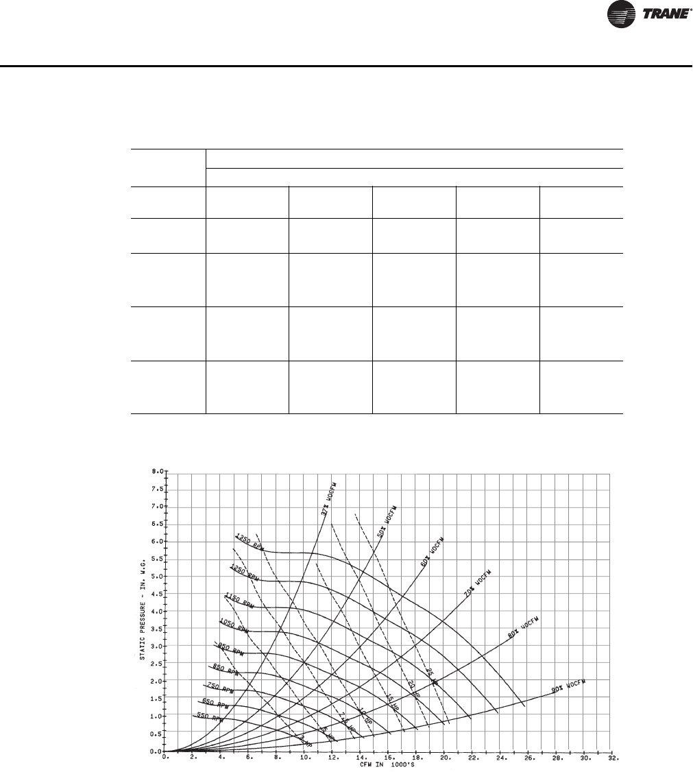
PKG-PRC002U-EN 75
Performance Data
Note: Fan curves include refrigerant coil and internal cabinet static losses. To determine static
pressure to be used with these curves, add filter, economizer, flexible horizontal discharge
and heat pressure drops to external duct static pressure.
Table 50. SCRF/SIRF 25 Gross Cooling Capacity - 11,600 cfm
Ambient
Entering Ambient Air Temperature
75 85 95 105 115
Tot
MBh Sen
MBh Tot
MBh Sen
MBh Tot
MBh Sen
MBh Tot
MBh Sen
MBh Tot
MBh Sen
MBhEDB EWB
70 62 334.5 207.6 322.1 201.9 307.7 195.3 291.4 187.9 273.7 180.1
67 367.8 160.1 353.9 154.3 337.8 147.7 319.8 140.3 300.5 132.6
75
62 336.2 253.6 324.0 247.6 309.8 240.6 293.9 232.8 276.6 224.4
67 367.9 207.5 354.1 201.6 338.0 194.9 320.1 187.5 300.8 179.7
72 403.1 159.3 387.5 153.4 369.6 146.7 349.7 139.4 328.7 131.7
80
62 337.8 299.2 325.6 293.1 311.5 286.0 295.5 278.2 278.2 269.7
67 368.9 253.7 355.3 247.6 339.6 240.5 322.0 232.7 303.1 224.3
72 403.3 206.4 387.6 200.4 369.8 193.6 350.0 186.3 328.9 178.6
85
62 343.5 343.5 333.5 333.5 321.7 321.7 308.2 308.2 293.5 293.5
67 370.8 298.8 357.1 292.6 341.4 285.5 323.8 277.5 304.9 269.1
72 403.4 253.0 387.8 247.0 370.0 240.2 350.1 232.8 329.1 225.1
Figure 55. SCRF/SIRF 25 Fan Performance for CV or with VFD
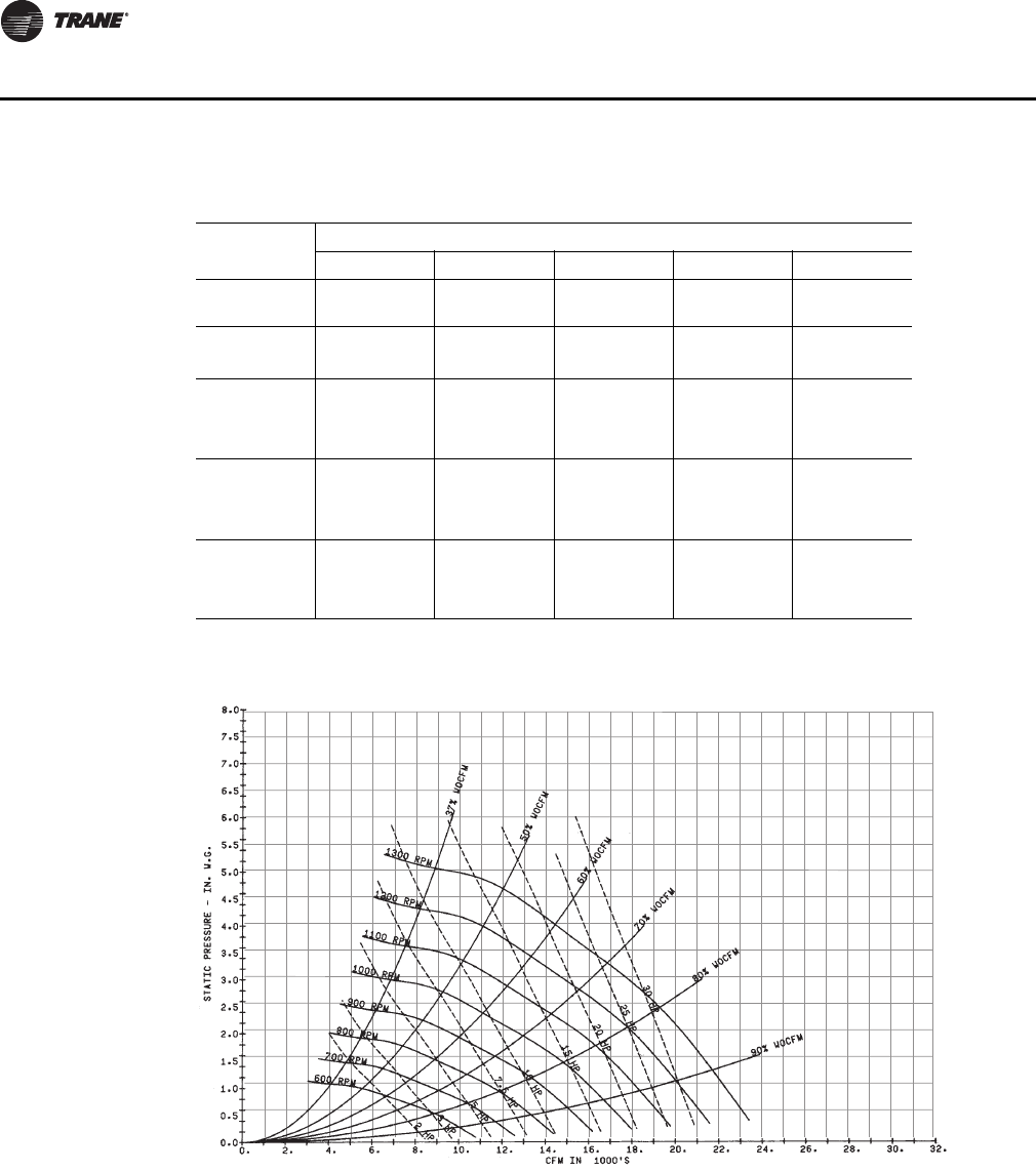
76 PKG-PRC002U-EN
Performance Data
Note: Fan curves include refrigerant coil and internal cabinet static losses. To determine static
pressure to be used with these curves, add filter, economizer, flexible horizontal discharge
and heat pressure drops to external duct static pressure.
Table 51. SCRF/SIRF 29 Gross Cooling Capacity - 12,800 cfm
Ambient
Entering Ambient Air Temperature
75 85 95 105 115
Tot
MBh Sen
MBh Tot
MBh Sen
MBh Tot
MBh Sen
MBh Tot
MBh Sen
MBh Tot
MBh Sen
MBhEDB EWB
70 62 371.1 245.8 355.3 238.6 336.1 231.5 315.7 224.2 296.3 212.0
67 406.2 180.0 388.2 173.0 367.8 165.1 345.5 156.6 322.0 147.8
75
62 373.1 309.2 357.4 301.8 339.6 293.4 320.0 284.1 299.2 274.4
67 406.1 245.2 388.1 238.0 367.8 230.1 345.5 221.5 321.9 212.6
72 443.4 178.2 423.2 171.1 400.7 163.3 376.3 154.9 350.8 146.3
80
62 374.4 367.9 358.7 355.3 340.8 340.8 321.2 321.2 300.4 300.4
67 408.2 308.0 390.7 300.4 370.9 291.9 349.3 282.6 326.8 272.9
72 443.3 242.8 423.1 235.6 400.6 227.7 376.2 219.2 350.8 210.6
85
62 398.6 398.6 384.7 384.7 368.6 368.6 350.9 350.9 332.0 332.0
67 409.7 371.0 392.1 363.3 372.3 354.8 350.7 342.2 328.2 324.6
72 444.5 305.9 425.1 298.0 401.1 291.3 377.0 282.5 354.1 271.7
Figure 56. SCRF/SIRF 29 Fan Performance for CV or with VFD
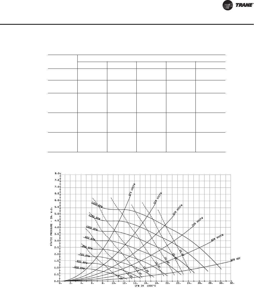
PKG-PRC002U-EN 77
Performance Data
Note: Fan curves include refrigerant coil and internal cabinet static losses. To determine static
pressure to be used with these curves, add filter, economizer, flexible horizontal discharge
and heat pressure drops to external duct static pressure.
Table 52. SCRF/SIRF 30 Gross Cooling Capacity - 14,000 cfm
Ambient
Entering Ambient Air Temperature
75 85 95 105 115
EDB EWB Tot
MBh Sen
MBh Tot
MBh Sen
MBh Tot
MBh Sen
MBh Tot
MBh Sen
MBh Tot
MBh Sen
MBh
70 62 419.7 268.8 404.4 261.1 385.9 253.2 365.2 243.9 342.4 233.9
67 461.7 202.5 444.1 195.3 423.8 187.2 400.9 178.1 376.0 168.3
75
62 422.4 331.6 406.7 324.0 388.7 315.3 368.4 305.6 346.2 295.0
67 461.6 267.4 444.1 260.2 423.8 252.0 400.9 242.9 376.0 233.0
72 505.4 201.0 485.8 193.8 463.4 185.6 438.3 176.6 411.1 167.0
62 423.7 394.5 408.3 386.9 390.4 378.2 370.1 364.9 347.8 346.3
80 67 462.9 330.9 445.6 323.3 425.8 314.6 403.4 304.8 379.1 294.3
72 505.4 265.4 485.8 258.2 463.4 249.9 438.3 240.8 411.1 231.2
85
62 440.4 440.4 427.1 427.1 411.8 411.8 394.2 394.2 374.7 374.7
67 464.7 393.3 447.5 385.6 427.6 376.8 405.2 367.0 380.9 356.3
72 505.8 329.1 486.5 321.5 463.5 313.9 438.3 304.7 411.1 295.0
Figure 57. SCRF/SIRF 30 Fan Performance for CV or with VFD
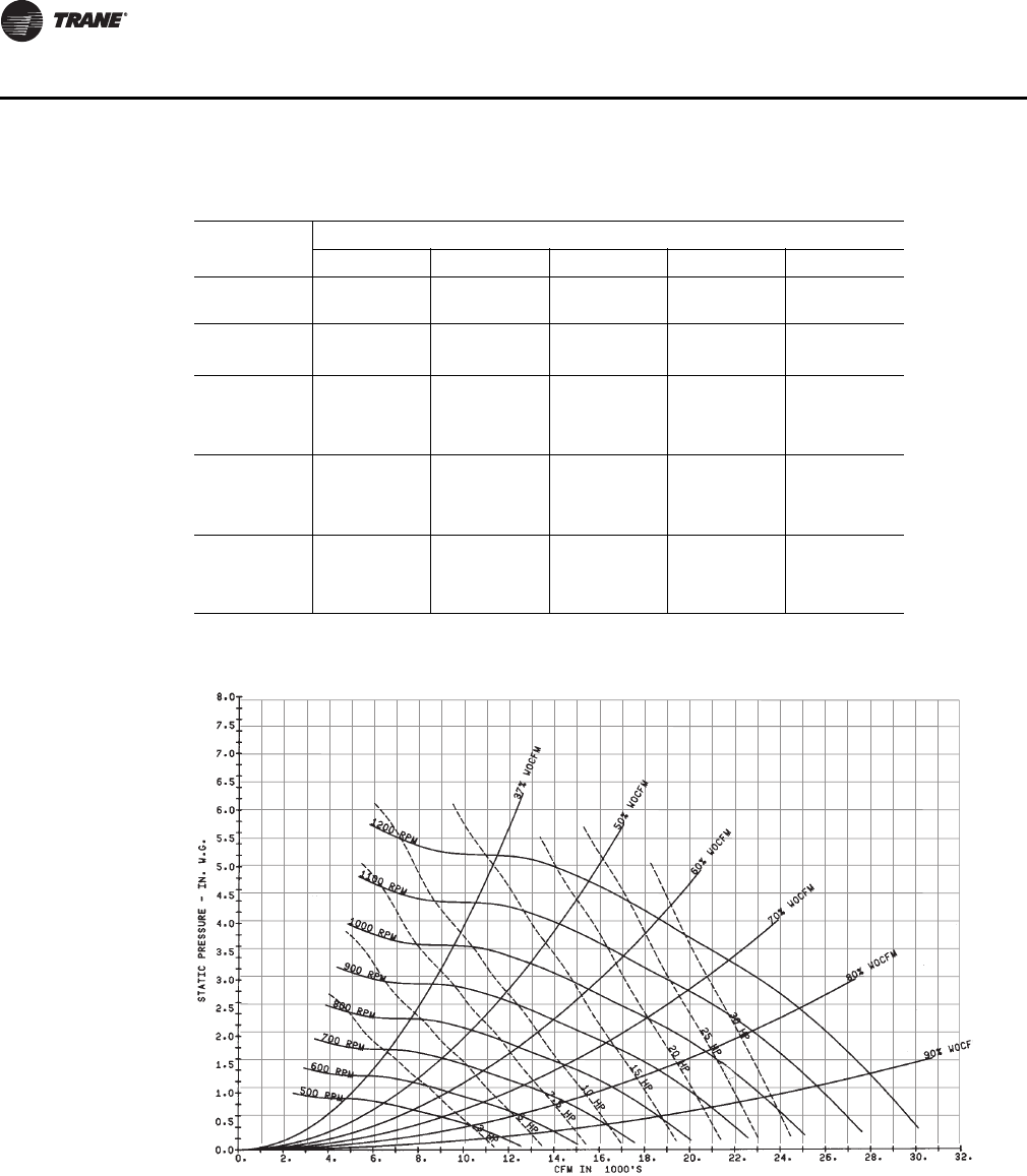
78 PKG-PRC002U-EN
Performance Data
Note: Fan curves include refrigerant coil and internal cabinet static losses. To determine static
pressure to be used with these curves, add filter, economizer, flexible horizontal discharge
and heat pressure drops to external duct static pressure.
Table 53. SCRF/SIRF 35 Gross Cooling Capacity - 15,200 cfm
Ambient
Entering Ambient Air Temperature
75 85 95 105 115
EDB EWB Tot
MBh Sen
MBh Tot
MBh Sen
MBh Tot
MBh Sen
MBh Tot
MBh Sen
MBh Tot
MBh Sen
MBh
70 62 444.1 293.4 426.7 285.4 405.6 277.5 366.0 212.2 359.4 254.7
67 487.0 215.9 467.3 208.1 444.7 199.3 419.4 189.6 391.9 179.2
75
62 446.3 367.8 429.0 359.6 409.1 350.2 386.6 339.6 362.3 328.2
67 486.9 292.3 467.2 284.5 444.6 275.6 419.3 265.8 391.9 255.3
72 532.5 214.0 510.6 206.1 485.6 197.4 457.8 187.7 428.0 177.5
80
62 447.8 440.3 430.4 425.9 410.5 409.3 388.1 388.1 363.7 363.7
67 488.8 366.6 469.5 358.2 447.5 348.7 422.9 338.2 396.4 326.8
72 532.4 289.8 510.5 281.9 485.6 273.0 457.8 263.3 428.0 253.0
85
62 475.7 475.7 460.5 460.5 442.9 442.9 422.8 422.8 400.9 400.9
67 490.5 440.4 471.2 432.0 449.2 422.5 424.5 411.8 398.0 392.9
72 533.4 364.2 512.0 355.8 485.5 348.3 457.7 338.5 431.1 325.3
Figure 58. SRF/SIRF 35 Fan Performance for CV or with VFD
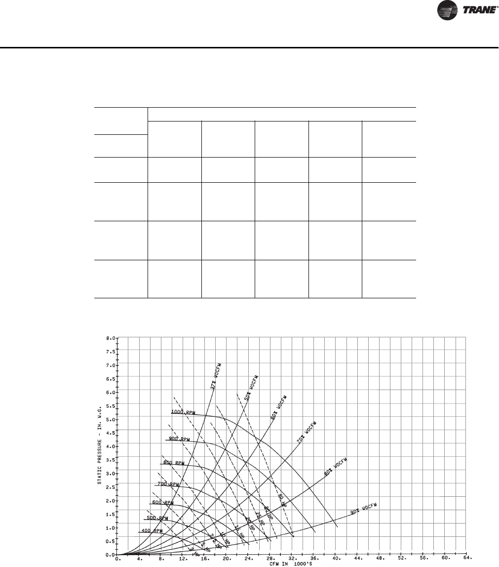
PKG-PRC002U-EN 79
Performance Data
Note: Fan curves include refrigerant coil and internal cabinet static losses. To determine static
pressure to be used with these curves, add filter, economizer, flexible horizontal discharge
and heat pressure drops to external duct static pressure.
Table 54. SCRF/SIRF 40 Gross Cooling Capacity - 18,400 cfm
Ambient
Entering Ambient Air Temperature
75 85 95 105 115
EDB EWB Tot
MBh Sen
MBh Tot
MBh Sen
MBh Tot
MBh Sen
MBh Tot
MBh Sen
MBh Tot
MBh Sen
MBh
70 62 521.3 346.2 499.5 338.3 476.9 325.4 450.2 312.9 416.4 305.8
67 570.5 253.8 546.9 244.6 519.9 234.2 489.6 222.7 457.0 210.4
75
62 524.6 435.9 503.9 426.0 480.2 414.8 453.6 402.2 424.9 388.7
67 570.4 346.5 546.8 337.2 519.8 326.6 489.6 315.0 457.0 302.6
72 624.2 251.8 597.9 242.5 567.9 232.0 534.7 220.6 499.2 208.6
80
62 526.6 518.3 505.9 505.0 482.2 482.2 455.6 455.6 426.8 426.8
67 574.9 434.5 551.8 424.5 525.5 413.1 496.3 400.5 465.0 387.0
72 624.1 343.7 597.8 334.3 567.8 323.7 534.6 312.2 499.2 300.0
85
62 562.6 562.6 544.2 544.2 522.9 522.9 498.8 498.8 472.5 472.5
67 577.2 523.9 554.1 513.8 527.8 501.5 498.5 483.6 467.2 464.7
72 626.2 434.4 600.2 423.4 572.9 410.2 536.9 401.0 499.0 395.7
Figure 59. SCRF/SIRF 40 Fan Performance for CV or with VFD
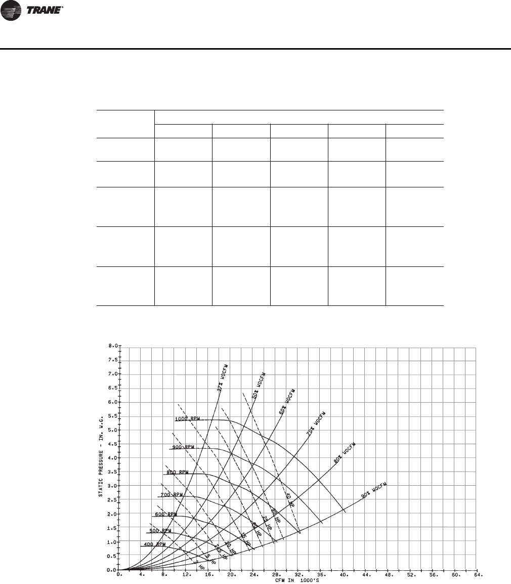
80 PKG-PRC002U-EN
Performance Data
Note: Fan curves include refrigerant coil and internal cabinet static losses. To determine static
pressure to be used with these curves, add filter, economizer, flexible horizontal discharge
and heat pressure drops to external duct static pressure.
Table 55. SCRF/SIRF 50 Gross Cooling Capacity - 23,200 cfm
Ambient
Entering Ambient Air Temperature
75 85 95 105 115
EDB EWB Tot
MBh Sen
MBh Tot
MBh Sen
MBh Tot
MBh Sen
MBh Tot
MBh Sen
MBh Tot
MBh Sen
MBh
70 62 669.2 444.2 642.2 431.6 611.5 417.1 572.6 408.5 534.4 389.5
67 730.5 326.1 699.8 314.0 664.8 300.5 626.0 285.6 584.5 270.0
75
62 673.2 557.6 646.3 544.8 615.6 530.2 581.4 514.0 544.7 496.6
67 730.3 443.3 699.6 431.2 664.7 417.5 625.9 402.5 584.4 386.7
72 797.1 322.4 762.8 310.2 724.1 296.7 681.5 282.0 636.5 266.7
80
62 675.7 671.9 648.8 648.8 618.0 618.0 583.8 583.8 547.0 547.0
67 735.6 554.8 705.7 541.7 671.7 527.0 634.1 510.7 594.2 493.4
72 796.9 438.7 762.6 426.4 723.9 412.8 681.4 397.9 636.4 382.5
85
62 720.0 720.0 696.0 696.0 668.2 668.2 637.1 637.1 603.5 603.5
67 738.5 667.9 708.5 654.7 674.4 639.8 636.8 623.5 596.9 596.9
72 801.2 550.3 767.8 537.1 723.8 528.3 681.3 513.3 645.6 488.9
Figure 60. SCRF/SIRF 50 Fan Performance for CV or with VFD
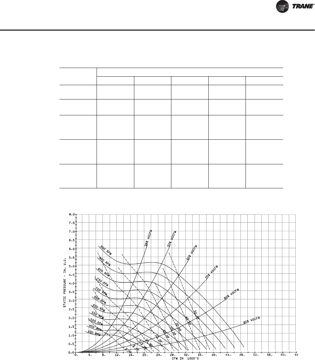
PKG-PRC002U-EN 81
Performance Data
Note: Fan curves include refrigerant coil and internal cabinet static losses. To determine static
pressure to be used with these curves, add filter, economizer, flexible horizontal discharge
and heat pressure drops to external duct static pressure.
Table 56. SCRF/SIRF 60 Gross Cooling Capacity - 29,800 cfm
Ambient
Entering Ambient Air Temperature
75 85 95 105 115
EDB EWB Tot
MBh Sen
MBh Tot
MBh Sen
MBh Tot
MBh Sen
MBh Tot
MBh Sen
MBh Tot
MBh Sen
MBh
70 62 905.7 607.8 868.9 588.8 826.0 568.6 778.5 546.3 718.9 530.6
67 989.0 442.6 945.7 425.9 896.6 407.2 842.5 386.8 785.0 365.4
75
62 911.8 762.5 874.0 744.5 831.2 724.2 783.8 701.8 733.4 678.0
67 988.6 603.6 945.3 586.6 896.3 567.5 842.3 546.7 784.7 525.0
72 1077.0 436.5 1029.0 419.6 974.4 400.9 915.2 380.8 853.0 359.9
80
62 914.6 914.0 876.9 876.9 834.0 834.0 786.6 786.6 736.2 736.2
67 994.9 757.5 952.8 739.2 905.4 718.6 853.4 696.2 798.6 672.5
72 1077.0 596.2 1028.0 579.0 974.1 559.9 914.9 539.4 852.7 518.2
85
62 977.8 977.8 943.7 943.7 904.7 904.7 861.2 861.2 814.7 814.7
67 998.3 912.9 956.2 894.5 908.7 873.8 856.6 850.6 801.9 801.9
72 1081.0 750.1 1034.0 731.5 973.7 717.8 914.6 697.0 852.5 675.6
Figure 61. SCRF/SIRF 60 Fan Performance for CV or with VFD
82 PKG-PRC002U-EN
Performance Data
Table 57. Hot Water Heating Capacity
Unit
Size Air Flow
cFm
180 °F 200 °F
Capacity
MBh LAT
°F Flow
Gpm Capacity
MBh LAT
°F Flow
Gpm
20 tons 8000 237.2 87.3 23.7 287.6 93.2 28.7
22 tons 8800 249.1 86.1 24.9 302.2 91.6 30.1
25 tons 10000 266.2 84.5 26.6 323.0 89.8 32.2
29 tons 11600 287.3 82.8 28.7 348.7 87.7 34.8
32 tons 12800 302.2 81.8 30.2 366.8 86.4 36.6
35 tons 14000 316.2 80.8 31.6 384.0 85.3 38.3
38 tons 15200 329.6 80.0 32.9 400.2 84.3 39.9
42 tons 16800 471.2 85.9 47.1 567.8 91.2 56.6
46 tons 18400 494.0 84.8 49.4 595.3 89.8 59.3
52 tons 20800 526.4 83.3 52.6 634.5 88.1 63.2
58 tons 23200 556.7 82.1 55.6 671.2 86.7 66.9
65 tons 26000 589.9 80.9 58.9 711.2 85.2 70.9
72 tons 28800 620.9 79.9 62.0 748.7 84.0 74.6
80 tons 29800 631.5 79.5 63.1 761.5 83.6 75.9
Note: Based on 60°F EAT with a 20°F water temperature difference.
Table 58. Steam Heating Capacity
Unit
Size Air Flow
cFm
2 psi 5 psi 10 psi
Capacity
MBh LAT
°F Capacity
MBh LAT
°F Capacity
MBh LAT
°F
20 tons 8000 257.4 89.7 271.6 91.3 291.6 93.6
22 tons 8800 272.2 88.5 287.1 90.1 308.3 92.3
25 tons 10000 292.7 87.0 308.8 88.5 331.6 90.6
29 tons 11600 317.6 85.2 335.1 86.6 359.9 88.6
32 tons 12800 334.7 84.1 353.2 85.4 379.3 87.3
35 tons 14000 350.5 83.1 369.9 84.4 397.3 86.2
38 tons 15200 365.3 82.2 385.4 83.4 414.0 85.1
42 tons 16800 500.5 87.5 528.1 89.0 567.1 91.1
46 tons 18400 526.7 86.4 555.7 87.8 596.8 89.9
52 tons 20800 563.0 85.0 594.1 86.3 638.1 88.3
58 tons 23200 596.3 83.7 629.3 85.0 675.9 86.9
65 tons 26000 631.7 82.4 666.7 83.6 716.2 85.4
72 tons 28800 663.9 81.3 700.7 82.4 752.8 84.1
80 tons 29800 674.7 80.9 712.1 82.0 765.1 83.7
Note: Based on 60°F EAT
PKG-PRC002U-EN 83
Performance Data
Table 59. Electric Heat Capacity
Unit Size
SCWF Unit Size
SCRF Heat
kW Air Flow
CFM Capacity
MBH LAT
20 18 8000 61.47 67.11
22 18 8800 61.47 66.47
25 20 18 10000 61.47 65.69
29 25 23 11600 78.54 66.27
32 29 23 12800 78.54 65.68
35 30 27 14000 92.21 66.10
38 35 27 15200 92.21 65.62
42 31.5 16800 107.57 65.93
46 40 31.5 18400 107.57 64.41
52 39 20800 133.18 65.93
58 50 39 23200 133.18 65.31
65 48 26000 163.92 65.84
72 48 28800 163.92 65.27
80 60 48 29800 163.92 65.09
90 76 30000 259.54 68.01
100 76 32000 259.54 67.51
110 76 32000 259.54 67.51
1. Based on 60°F EAT
2. or unit capacities at different conditions than those listed, use
TOPSS (Trane Official Product Selection Program).
3. Air temperature rise = kW x 3413 / (cfm x 1.085)

84 PKG-PRC002U-EN
Controls
IntelliPak™ Signature Series Self-Contained Units
We’ve redesigned the self-contained unit with the latest control technology to make it even better!
New modular DDC controls with human interface (HI) panel make self-contained units more
flexible and easier to operate.
Controls are Trane-designed to work with Trane equipment for optimum efficiency. The factory
installs and commissions each control component to ensure simple and reliable operation.
Furthermore, the DDC control’s modular design allows greater application flexibility using up to
twelve different modules, dependent upon unit options. You can order exactly what the job
requires as options, instead of one large control package. And since unit features are distributed
among multiple printed circuit boards, field replacement is easy.
Depending upon unit options, IntelliPak® units can operate as:
1. stand-alone
2. interface with Trane’s Tracer® building management system
3. interface with a generic (non-Trane) building management system.
Available Input and Output Points
RTM Module (on all units)
Binary inputs
• Emergency stop
• External auto/stop
• Unoccupied/occupied
• Dirty filter
• VAV changeover with hydronic heat
• Units with staged heat interface have 1-3 additional points
Binary outputs
• VAV box drive max (VAV units only)
• CV Unoccupied mode indicator (CV units only)
•Alarm
• Fan run request
• Water pump request (water-cooled only)
• Units with staged heat interface have 1-3 additional points
Analog input
• Airside economizer damper minimum position
Analog output
• Outside air damper actuator
Heat Module Option
• Analog output
Generic BAS Option (GBAS)
Binary inputs
• Demand limit contacts
Binary outputs

PKG-PRC002U-EN 85
Controls
• Dirty filter relay
• Refrigeration fail relay
• Heat fail relay
• Supply fan fail relay
• Active diagnostics
Analog inputs
• Occupied zone cooling setpoint
• Occupied zone heating setpoint
• Unoccupied zone cooling setpoint
• Unoccupied zone heating setpoint or minimum outside air flow setpoint
• Supply air cooling setpoint
• Supply air heating setpoint
• Supply air static pressure setpoint
Comparative Enthalpy Module (ECEM) Option
Analog inputs
• Return air temperature
• Return air humidity
Ventilation Override Module (VOM) Option
Binary inputs
• VOM mode A, unit off
• VOM mode B, pressurize
• VOM mode C, exhaust
• VOM mode D, purge
• VOM mode E, purge w/duct pressure control
Binary output
• V.O. relay
LonTalk® /Building Automation System
The LonTalk Communication Interface for IntelliPak self-contained (LCI-I) controller expands
communications from the unit UCM network to a Trane Tracer Summit or a 3rd party building
automation system, utilizing LonTalk, and allows external setpoint and configuration adjustment
and monitoring of status and diagnostics. The LCI-I utilizes an FTT-10A Free Topology transceiver,
which supports nonpolarity sensitive, free topology wiring, which allows the system installer to
utilize star, bus, and loop architectures.This controller works in standalone mode, peer-to-peer with
one or more other units, or when connected to a Trane Tracer Summit or a 3rd party building
automation system that supports LonTalk.
BACnet® /Building Automation System
The BACnet Communication Interface for IntelliPak self-contained (BCI-I) controller expands
communications from the unit UCM network to Tracer SC or a 3rd party building automation
system, utilizing BACnet, and allows external setpoint and configuration adjustment and
monitoring of status and diagnostics. The BCI-I utilizes the BACnet defined MS/TP protocol as
defined in ASHRAE standard135-2004. This controller works in standalone mode, with Tracer SC
or when connected to a 3rdparty building automation system that supports BACnet.

86 PKG-PRC002U-EN
Controls
Standard IntelliPak Unit Control Features
All set-up parameters are preset from the factory, requiring less start-up time during installation.
The human interface panel is easy to read and requires less time for building maintenance
personnel to learn to interact with the unit. It features a clear language display (in English, Spanish,
or French) that shows all of the self-contained unit control parameters, such as system on/off;
demand limiting type; night setback setpoints; and many other setpoints. All adjustments are done
through the human interface key-pad. Also the human interface panel allows you to monitor
diagnostic points such as; sensor failures; supply airflow loss; and inoperative refrigerant circuit.
No special tools are required for servicing the unit. Diagnostics are held in memory, even during
power loss. This allows the operator/servicer to diagnose the failure root cause.
IntelliPak Unit Features
• Unit mounted human interface panel with a two line x 40 character language (English, Spanish,
or French) display and a 16-function keypad that includes CUSTOM, DIAGNOSTICS, and
SERVICE TEST MODE menu keys on IntelliPak units
• Compressor lead/lag
• FROSTAT™ coil frost protection on all units
• Daytime warmup (occupied mode) on units with heating options and morning warmup
operation on all units
• Supply air static overpressurization protection on units with variable frequency drives (VFD’s)
• Supply airflow proving
• Supply air tempering control with heating option
• Supply air heating control on VAV with hydronic heating option
• Mappable sensors and setpoint sources
• Occupied/unoccupied switching
• Timed override activation
• Programmable water purge during unoccupied mode
Human Interface Panel (HI)
The human interface panel provides a 16-button keypad for monitoring, setting, editing and
controlling. The HI panel is mounted in the unit’s main control panel, accessible through the unit’s
control panel door.
The optional remote-mount version of the human interface (RHI) panel has all the functions of the
unit-mounted version, except for the service mode. To use a RHI, the unit must be equipped with
the remote HI interface option (model number digit 32 = 2), which includes an interprocessor
communications bridge (IPCB). The RHI can be located up to 1,000 feet (304.8 m) from the unit. A
The human interface panel provides a 16-button keypad for monitoring,
setting, editing and controlling. The HI panel is mounted in the unit’s
main control panel, accessible through the unit’s control panel door.
The optional remote-mount version of the human interface (RHI) panel
has all the functions of the unit-mounted version, except for the service
mode. To use a RHI, the unit must be equipped with the remote HI
interface option (model number digit 32 = 2), which includes an
interprocessor communications bridge (IPCB). The RHI can be located
up to 1,000 feet (304.8 m) from the unit. A single RHI can be used to
monitor and control up to four self-contained units, each containing an
IPCB.

PKG-PRC002U-EN 87
Controls
single RHI can be used to monitor and control up to four self-contained units, each containing an
IPCB.
The main menus of the human interface panels are:
STATUS is used to monitor all temperatures, pressures, humidities, setpoints, input and output
status.
CUSTOM key allows the user to customize a status report - consisting of up to four screens of the
data available in the main Status menu.
SETPOINT is used to edit all factory preset default setpoints.
DIAGNOSTICS allows the user to review active and historical lists of diagnostic conditions. A total
of 49 different diagnostics can be read at the human interface (HI) panel and the last 20 diagnostics
can be held in an active history buffer log at the HI panel.
SETUP allows the user to edit control parameters, sensor selections, setpoint source selections,
output definitions, and numerous other points in this menu. All points have factory preset values
to keep unnecessary editing to a minimum.
CONFIGURATION allows changing of factory-preset unit configuration information. This
information can be edited only if certain options are field-installed or deleted from the unit. For
example, if a Trane communication interface (TCI) module or ventilation override module (VOM)
were field-installed, the unit configuration will require editing to reflect those options for proper
unit operation.
SERVICE allows servicing or troubleshooting the unit by selecting component control outputs
such as compressors, fans, damper position, etc. This menu is accessible only at the unit-mounted
human interface panel.
Control Sequences of Operation
Morning Warmup
This feature is available on all types of factory-installed heat units and on units with no heat. This
function may still be selected to support systems with heat sources not provided by the self-
contained unit. At the conclusion of unoccupied mode, the selected zone is heated to the user-
defined morning warmup setpoint. The unit is then released to occupied mode. There are two types
of morning warmup: full capacity or cycling capacity.
Full Capacity Morning Warmup (MWU). Full capacity morning warmup uses full heating
capacity to heat the zone as quickly as possible. Full heating capacity is provided until the morning
warmup setpoint is met. At this point, the unit is released to daytime mode.
Cycling Capacity Morning Warmup (MWU). Cycling capacity morning warmup provides
gradual heating to overcome “building sink” as the zone is heated. Normal zone temperature
control with varying capacity is used to raise the zone temperature to the MWU zone temperature
setpoint. Cycling capacity MWU will operate until MWU setpoint is reached or for 60 minutes. Then
the unit switches to occupied mode. Cooling will suspend untill building load conditions exceed
the MWU setpoint of 3 F (1.7 C), which is field adjustable.
Note: When using the morning warmup option in a heating/cooling self-contained unit in a VAV
system, it is important to maintain airflow through the unit. This can be accomplished by
electrically tying the VAV boxes to the VAV drive max output relay contacts on the unit’s RTM
module board or by using changeover thermostats. Either of these methods will assure
adequate airflow through the unit and satisfactory heating.
Ventilation Override (VOM) Option
The user can customize up to five different override sequences for purposes of ventilation override
control. If more than one VOM sequence is being requested, the sequence with the highest priority
is initiated first. Priority schedule is that sequence “A” (unit off) is first, with sequence “E” (purge
with duct pressure control) last.

88 PKG-PRC002U-EN
Controls
UNIT OFF sequence “A”. When complete system shut down is required, the following sequence
can be used.
• Supply fan – Off
• Supply fan VFD – Off (0 Hz) (if equipped)
• Outside air dampers – Closed
• Heat – all stages – Off, Modulating heat output at 0 vdc
• Occupied/Unoccupied output – Deenergized
• VO relay – Energized
• Exhaust fan (field-installed) - Off
• Exhaust damper (field-installed) - Closed
PRESSURIZE sequence “B”. This override sequence can be used if a positively pressured space
is desired instead of a negatively pressurized space.
• Supply fan – On
• Supply fan VFD – On (60 Hz)\VAV boxes – Open (if equipped)
• Outside air dampers – Open
• Heat – all stages – Off, Modulating heat output at 0 vdc
• Occupied/ Unoccupied output - Energized
• VO relay - Energized
• Exhaust fan (field-installed) - Off
• Exhaust damper (field-installed) - Closed
EXHAUST sequence “C”. With the building’s exhaust fans running and the unit’s supply fan off,
the conditioned space becomes negatively pressurized. This is desirable for clearing the area of
smoke when necessary; i.e. from an extinguished fire, to keep smoke out of areas that were not
damaged.
• Supply fan – Off
• Supply fan VFD – Off (0 Hz) (if equipped)
• Outside air dampers – Closed
• Heat – all stages – Off, Modulating heat output at 0 vdc
• Occupied/Unoccupied output – Deenergized
• VO relay – Energized
• Exhaust fan (field-installed) - On
• Exhaust damper (field-installed) - Open
PURGE sequence “D”. This sequence could be used for purging the air out of a building before
coming out of unoccupied mode of operation on VAV units. Also, it can be used to purge smoke
or stale air.
• Supply fan – On
• Supply fan VFD – On (60 Hz)\VAV boxes – Open (if equipped)
• Outside air damper – Open
• Heat – all stages – Off, Modulating heat output at 0 vdc
• Occupied/Unoccupied output – Energized
• VO relay – Energized
• Exhaust fan (field-installed) - On

PKG-PRC002U-EN 89
Controls
• Exhaust damper (field-installed) - Open
PURGE WITH DUCT PRESSURE CONTROL “E”. This sequence can be used when supply air
control is required for smoke control.
• Supply fan – On
• Supply fan VFD – On (if equipped)
• Outside air dampers – Open
• Heat – all stages – Off, Modulating heat output at 0 vdc
• Occupied/Unoccupied output – Energized
• VO relay – Energized
• Exhaust fan (field-installed) - On
• Exhaust damper (field-installed) - Open
Note: Each system (cooling, exhaust, supply air, etc.) within the unit can be redefined in the field
for each of the five sequences, if required. Also the definitions of any or all of the five
sequences may be locked into the software by simple key strokes at the human interface
panel.
Generic Building Automation System Module (GBAS) Option
The generic building automation system module (GBAS) provides broad control capabilities for
building automation systems other than Trane’s Tracer® system. A field provided potentiometer
or a 0-5 vdc signal can be applied to any of the inputs of the GBAS to provide the following inputs
and outputs.
GBAS Analog Inputs . Four analog inputs that can be configured to be any of the following:
1. Occupied zone cooling
2. Unoccupied zone cooling
3. Occupied zone heating
4. Unoccupied zone heating
5. SA cooling setpoint
6. SA heating setpoint
7. Space static pressure setpoint
8. SA static pressure setpoint
GBAS Binary Outputs . Each of the five (5) relay outputs can be mapped to any/all of the
available diagnostics.
Demand Limiting Binary Input . This function is operational on units with a GBAS and is used
to reduce electrical consumption at peak load times. There are two types of demand limiting, 50%
and 100%. When demand limiting is needed, mechanical cooling and heating operation are either
partially (50%), or completely disabled (100%) to save energy. The demand limit definition is user
definable at the human interface panel. Demand limit binary input accepts a field supplied switch
or contact closure. When the need for demand limiting has been discontinued, the unit’s cooling/
heating functions will again become fully enabled.
Evaporator Coil Frost Protection FROSTAT™
A temperature sensor on the evaporator is used to determine if the coil is getting close to a freezing
condition. Mechanical cooling capacity is shed as necessary to prevent icing.
The FROSTAT™ system eliminates the need for hot gas bypass and adds a suction line surface
temperature sensor mounted near the TXV bulb location to shut off the cooling when coil frosting

90 PKG-PRC002U-EN
Controls
conditions occur. The supply fan is not shut off and will de-ice the coil. Timers prevent the
compressors from rapid cycling.
Occupied/Unoccupied Switching
There are four ways to switch occupied/unoccupied:
1. Programmable night setback sensor
2. Field-supplied contact closure (hardwired binary input to RTM)
3. Tracer®
4. Factory-mounted time clock
Field Supplied Occupied/Unoccupied input on the RTM. This input accepts a field
supplied switch or contacts closure such as a time clock.
Trane Tracer® System. The Trane Tracer® system can control the occupied/unoccupied status
of the self-contained unit.
Factory Mounted Time Clock. A time clock can control the occupied/unoccupied status of the
self-contained unit.
Timed Override Activation - ICS
This function is operational whenever the unit’s RTM module board is used as the zone temperature
sensor source, which can be set at the human interface panel. When this function is initiated by the
push of the override button on the zone sensor, the unit will switch to the occupied mode. Unit
operation (occupied mode) during timed override is terminated by a signal from Tracer.
Timed Override Activation - Non-ICS
This function is active whenever the unit’s RTM module board is selected as the zone temperature
source, which can be set at the human interface panel. When this function is initiated by the push
of the override button on the zone sensor, the unit will switch to the occupied mode. Automatic
cancellation of the timed override mode occurs after three hours of operation.
Low Ambient Compressor Lockout
This function will lock out the compressor if the outdoor air temperature is below the low ambient
compressor lock-out temperature setpoint when using a field-installed outside air sensor. This
setpoint is adjustable at the human interface panel. Compressors will lock out when outdoor air
temperature falls below that selected temperature and will start again when the temperature rises
5° F above the setpoint.
Comparative Enthalpy Control of Airside Economizer Option
An optional comparative enthalpy system is used to control the operation of the economizer and
measures the temperature and humidity of both return air and outside air to determine which
source has lower enthalpy. This system allows true comparison of outdoor air and return air
enthalpy by measurement of outdoor and return air temperatures and humidities.
Note: If comparative enthalpy is not ordered, the standard method compares outdoor air enthalpy
with a fixed reference enthalpy, set through the human interface panel.
Compressor Lead/Lag
Compressor lead/lag is a user-selectable feature through the human interface panel available on
all units. After each request for compressor operation, the lead refrigeration circuit or compressor
switches, thereby causing a more equitable or balanced run time among compressors.
Emergency Stop Input
A binary input is provided on the unit’s RTM module board for installation of a field-provided switch
or contacts to immediatly shutdown all unit functions.

PKG-PRC002U-EN 91
Controls
Water Flow Control
With compatible piping configurations, the unit can be configured to provide:
1) Constant water flow with basic or intermediate piping or 2) Variable water flow with intermediate
piping only.
Constant water flow is for condenser pumping systems that are not capable of unloading the water-
pumping system. Variable water flow maximizes energy saving by unloading the water pumping
system.
Head Pressure Control
Water-Cooled Condensers. Units that are set up for variable water flow will modulate a water
valve to maintain a user-defined condensing temperature setpoint. Condensing temperature will
be referenced utilizing factory installed sensors located at each condenser.
Air-Cooled Condensers. Condenser fans will stage per a user-defined setting. If the condenser
is equipped with head pressure control (air modulation on last stage of condenser capacity), the
condenser airflow will modulate to maintain condensing temperature setpoint. Condensing
temperature is determined by sensors located at each condenser coil.
Water Purge
This user-definable feature allows the user to select a purge schedule to automatically circulate
water through the economizer and condensers periodically during non-operational times. This
allows fresh chemicals to circulate in waterside heat exchangers.
Airside Options
Variable Frequency Drive (VFD) Control
Variable frequency drives are driven by a modulating 0-10 vdc signal from the RTM module. A
pressure transducer measures duct static pressure, and the VFD adjusts the fan speed to maintain
the supply air static pressure within an adjustable user-defined range. The range is determined by
the supply air pressure setpoint and supply air pressure deadband, which are set through the
human interface panel.
Variable frequency drives provide supply fan motor speed modulation. The drives will accelerate
or decelerate as required to maintain the supply static pressure setpoint.
Bypass control is offered as an option to provide full nominal airflow in the event of drive failure.
Manual bypass is initiated at the human interface panel. When in the bypass mode, VAV boxes will
need to be fully opened. The self-contained unit will control heating and cooling functions to
maintain setpoint from a user defined zone sensor. Supply air static pressure limit will be active
in this mode.
Supply Air Static Pressure Limit
The opening of the VAV boxes are coordinated during unit start up and transition to/from occupied/
unoccupied modes to prevent overpressurization of the supply air ductwork. However, if for any
reason the supply air pressure exceeds the user-defined supply air static pressure limit that was set
at the human interface panel, the supply fan/VFD is shut down. Then unit will attempt to restart,
up to three times. If the overpresssurization condition still occurs on the third restart, the unit shuts
down and a manual reset diagnostic sets and displays at the human interface panel.

92 PKG-PRC002U-EN
Controls
Zone Temperature Control Unit Sequence Of Operation
1
Occupied Zone Temperature Control
Cooling/Waterside Economizer
During occupied cooling mode, the waterside economizer option and mechanical cooling function
to control zone temperature. If the entering condenser water temperature is appropriate to use
“free cooling,” the economizer initiates to attempt to satisfy the cooling zone temperature setpoint
with the compressors staging on as necessary. Minimum on/off timing of compressors prevents
rapid cycling.
Waterside economizing enables when the unit’s entering water temperature is below the unit’s
entering mixed air temperature by 4°F plus the user adjustable economizer approach temperature.
The approach temperature default is 4°F and is adjustable from 0-9°F at the human interface (HI)
panel. Waterside economizing disables when the unit’s entering water temperature is not below
the unit’s entering mixed air temperature by at least the water economizer approach temperature.
The approach temperature defaults to 4°F and is adjustable from 0-9°F at the HI. The economizer
acts as the first stage of cooling. If the economizer is unable to maintain the zone temperature
setpoint, the compressor module will bring on compressors as required to meet the setpoint.
If the unit does not include an economizer, only mechanical cooling will operate to satisfy cooling
requirements.
Cooling/Airside Economizer
During occupied cooling mode, the economizer option and mechanical cooling operate to control
zone temperature. If the outside air enthalpy is appropriate for airside economizing or “free
cooling,” the economizer initiates to satisfy the cooling zone temperature setpoint with the
compressors staging on as necessary. Minimum on/off timing of compressors will prevent rapid
cycling.
On units with an airside economizer, a call for cooling will modulate the fresh air dampers open.
The rate of economizer modulation is based on deviation of the zone temperature from setpoint;
i.e., the further away from setpoint, the faster the fresh air damper will open. First stage of cooling
will start after the economizer reaches full open.
Note that the airside economizer will only function freely if ambient conditions are below the
enthalpy control settings or below the return air enthalpy if unit has comparative enthalpy installed.
If outside air is not suitable for “economizing,” the fresh air dampers drive to the minimum open
position. A field adjustable, factory default setting in the human interface panel or Tracer can
provide the input to establish the minimum damper position.
At outdoor air conditions above the enthalpy control setting, only mechanical cooling is used and
the fresh air dampers remain at minimum position.
If the unit does not include an airside economizer, only mechanical cooling will operate to satisfy
cooling requirements.
Heating: Electric
On units with electric heating, the zone temperature can be controlled to a heating setpoint during
the occupied mode by cycling a single stage electric heater. Interface is provided for field supplied
single stage electric heat. The zone temperature heating setpoint and deadband are user defined
at the human interface panel.
Heating: Hot Water or Steam
On units with hot water or steam heating, the zone temperature can be controlled to a heating
setpoint during the occupied mode. The zone temperature heating setpoint and deadband are user
defined at the human interface panel.

PKG-PRC002U-EN 93
Controls
Supply Air Tempering
For hot water, steam, or electric heat units in the heat mode but not actively heating, if the supply
air temperature drops to 10°F below the occupied zone heating temperature setpoint, one stage of
heat will be brought on to maintain a minimum supply air temperature. The unit transitions out of
heat mode if the supply air temperature rises to 10°F above the occupied zone heating temperature
setpoint.
Auto Changeover
When the system mode is auto, the mode will change to cooling or heating as necessary to satisfy
the zone cooling and heating setpoints. The zone cooling and heating setpoints can be as close as
2°F apart.
2
Unoccupied Zone Temperature Control
Cooling and Heating
Both cooling and heating modes can be selected to maintain unoccupied zone temperature
deadbands. For unoccupied periods, heating, economizer operation, or compressor operation can
be selectively locked out at the human interface panel.
Supply Air Temperature Control Unit Sequence Of Operation
1
Occupied Supply Air Temperature Control
Cooling/Waterside Economizer
During occupied cooling mode, the waterside economizer option and mechanical cooling are used
to control the supply air temperature. The supply air temperature setpoint and deadband are user
defined at the human interface panel. Waterside economizing enables when the units entering
water temperature is below the units entering mixed air temperature by 4°F plus the user
adjustable economizer approach temperature. The approach temperature default is 4°F and is
adjustable from 0-9°F at the HI. Waterside economizing disables when the units entering water
temperature is not below the units entering mixed air temperature by at least the water economizer
approach temperature.
The economizer acts as the first stage of cooling. If the economizer is unable to maintain the supply
air setpoint, the compressor module will bring on compressors as required to meet the setpoint.
If the unit does not include an economizer, only mechanical cooling will satisfy cooling
requirements.
Cooling/Airside Economizer
During occupied cooling mode of operation, the airside economizer option and mechanical cooling
are used to control the supply air temperature. The supply air temperature setpoint and deadband
are user-defined at the human interface panel. If the temperature of the mixed air is appropriate to
use “free cooling,” the economizer initiates to satisfy the supply air setpoint. Then if required, the
mechanical cooling stages on to maintain supply air temperature setpoint. Minimum on/off timing
of the mechanical cooling prevents rapid cycling.
On units with an airside economizer, a call for cooling will modulate the fresh air dampers open.
The rate of economizer modulation is based on deviation of the discharge temperature from
setpoint, i.e., the further away from setpoint, the faster the fresh air damper will open. First stage
of cooling initiates after the economizer reaches full open.
Note that the airside economizer is only allowed to function freely if ambient conditions are below
the setpoint control settings or below the return air enthalpy, if unit has the comparative enthalpy
option. If outside air is not suitable for “economizing,” the fresh air dampers drive to the minimum

94 PKG-PRC002U-EN
Controls
open position. A field adjustable, factory default setting in the human interface panel or Tracer can
provide the input to establish the minimum damper position.
At outdoor air conditions above the setpoint or comparative enthalpy control setting, only
mechanical cooling is used and the fresh air dampers remain at minimum position.
If the unit does not include an economizer, only mechanical cooling operates to satisfy cooling
requirements.
Heating: Hot Water or Steam
On units with hot water or steam heating, the supply air temperature can be controlled to a heating
setpoint during the occupied mode. The supply air temperature heating setpoint and deadband are
user defined at the human interface panel. VAV occupied heating on hot water and steam heat units
is initiated by closing a field-supplied switch or contacts connected to a changeover input on the
unit’s RTM module board .
Supply Air Setpoint Reset
Supply air reset can be used to adjust the supply air temperature setpoint on the basis of a zone
temperature or outdoor air temperature. Supply air reset adjustment is available from the human
interface panel for supply air heating and supply air cooling control.
Reset based on outdoor air temperature
Outdoor air cooling reset is sometimes used in applications where the outdoor temperature has
a large effect on building load. When the outside air temperature is low and the building cooling
load is low, the supply air setpoint can be raised, thereby preventing subcooling of critical zones.
This reset can lower usage of mechanical cooling, thus savings in compressor kW, but an increase
in supply fan kW may occur.
Outdoor air heating reset is the inverse of cooling, with the same principles applied.
For both outdoor air cooling reset and heating reset, there are three user defined parameters that
are adjustable through the human interface panel.
• Beginning reset temperature
• Ending reset temperature
• Maximum amount of temperature reset
Reset based on zone temperature
Zone reset is applied to the zone(s) in a building that tends to overcool or overheat. The supply air
temperature setpoint is adjusted based on the temperature of the critical zone(s). This can have the
effect of improving comfort and/or lowering energy usage. The user-defined parameters are the
same as for outdoor air reset.
Supply Air Tempering (Hot Water and Steam Units Only)
When supply air temperature falls below the supply air temperature deadband low end, the heating
valve modulates open to maintain the minimum supply air temperature setpoint.
2
Unoccupied Supply Air Temperature Control, Zone Heating, Cooling
During unoccupied mode, the unit operates to maintain zone temperature with fan cycling as
needed for building load. VAV boxes drive full open. However, unit airflow modulation control
operates to maintain duct static setpoint. The unit controls zone temperature within the unoccupied
zone cooling and heating (heating units only) deadbands.
Daytime Warmup
During occupied mode, if the zone temperature falls to a preset, user-defined zone low limit
temperature setpoint, the unit is put into daytime warmup. The system changes over to CV heating,
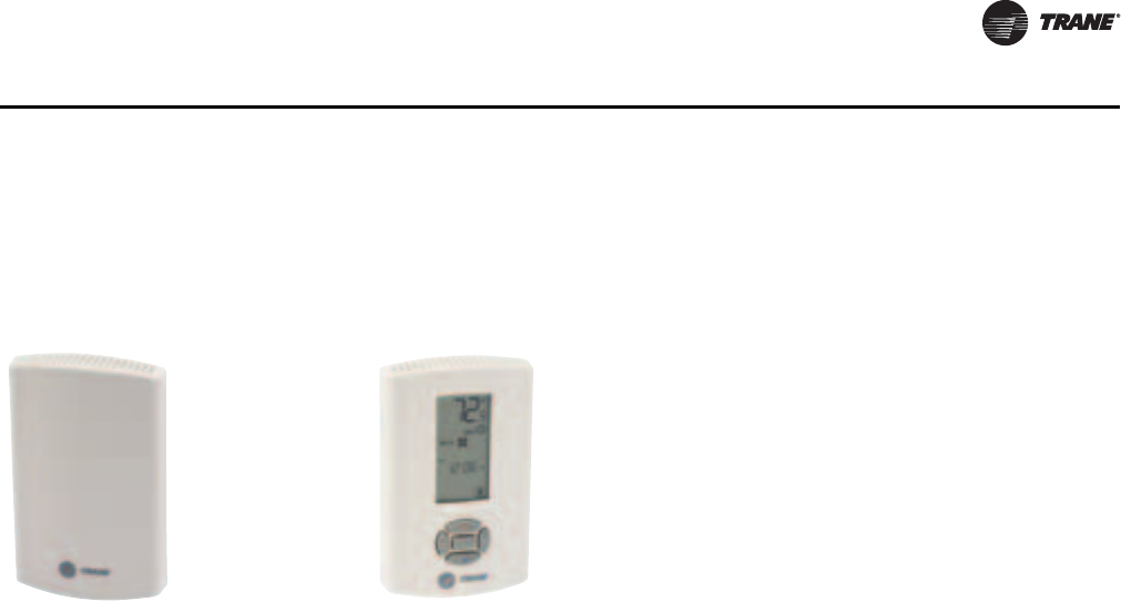
PKG-PRC002U-EN 95
Controls
the VAV boxes drive full open. However, unit airflow modulation control operates to maintain duct
static setpoint, and full heating capacity is provided until the daytime warmup setpoint is reached.
The unit is then returned to normal occupied mode.
Zone Sensor Options
Standard on all units CV/VAV
Zone temperature sensor, Accessory
Model Number Digit 6 = A,
BAYSENS077
This wall-mounted zone sensor ships
with every Signature Series unit, CV
or VAV. Additional sensors are also
available for order using the
accessory model number. It includes
an internal thermistor and should be
mounted in the zone. This sensor is
available for use with all zone sensor
options to provide remote sensing
capabilities.
Programmable zone sensor, Accessory Model Number Digit 6 = G, BAYSENS119
The BAYSENS119 programmable night set back sensor provides multi functional
flexibility for both Constant Volume and Variable Air Volume control. This
electronic programmable sensor includes auto or manual cooling and heating
changeover with 7 day programming. Five tactile feel buttons located on the
sensor front panel provide interface for all programming, including initial setup
for CV or VAV control. Sensor functionality includes up to four daily
programmable periods for Occupied/Unoccupied operation, and Override. The
dynamic LCD display indicates status for System On/Off, Heat, Cool, Fan Status,
Time of Day, Occupied/Unoccupied mode, Space Temperature, Space or
Discharge Air Heating and Cooling Setpoints. Additional features include
Service Indication for Heat Failure, Cool Failure, Fan Failure, and Test Mode if
system is operating in test mode.
A Check Filter Timer function is included. Filter service countdown time can be
set in one-day increments. Activation of the Test/Configuration button located
on the bottom of the sensor performs a sensor self-diagnostic routine and
indicates hours in service.
When the BAYSENS119 is programmed for CV or VAV control, Night Setback is
initiated through the scheduled Unoccupied time setting. When the sensor
switches to Night Setback, the outdoor dampers close and heating/cooling
functions are enabled/disabled based on set up parameters. As building load
changes, if heating/cooling functions are enabled, the Sensor energizes self-
contained unit and evaporator fan operation. The unit will cycle heating/cooling
operation throughout the Unoccupied period as required to maintain
Unoccupied space temperature setpoints. When the Unoccupied time period
has expired, all heating/cooling functions return to normal operation.
When Night Setback options are used with VAV heating/cooling, maintain
airflow through the self-contained unit by electronically tying the VAV terminals
to the unoccupied output relay contacts on the self-contained units low voltage
terminal board, or by using changeover thermostats. Either of these methods
will assure adequate airflow through the unit and satisfactory temperature
control of the space.
Refer to BAS-SVX17*-EN for complete installation, operation, and maintenance
instuctions.
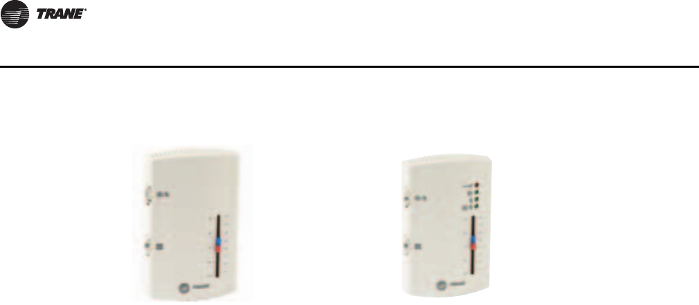
96 PKG-PRC002U-EN
Controls
CV CV
Dual setpoint, manual/automatic
changeover sensor, Accessory Model
Number Digit 6 = E, BAYSENS108
This zone sensor module is for use with
cooling/heating CV applications. It
provides the following features and
system control functions:
•System control switch (Heat/Auto/
Off/Cool): Allows you to select
heating mode, cooling mode,
automatic selection of heating or
cooling as required, or turn the
system off.
• Fan control switch (Auto/On): Allows
you to select automatic fan operation
while actively heating or cooling or
continuous fan operation.
• Dual temperature setpoint levers
allow you to set different cooling
(blue lever) and heating setpoints
(red lever).
• Thermometer to indicate
temperature in the zone.
Dual setpoint, manual/automatic changeover
sensor with system function lights, Accessory
Model Number Digit 6 = F, BAYSENS110
This zone sensor is for use with cooling/heating
CV applications. It provides the following
features and system control functions:
• System control switch to select heating
mode (HEAT), cooling mode (COOL), AUTO
for automatic selection of heating or cooling
as required, or OFF to turn the system off.
• Fan control switch to select automatic fan
operation while actively heating or cooling
(AUTO), or continuous fan operation (ON).
• Dual temperature setpoint levers for setting
cooling (blue lever) or heating (red lever).
• Thermometer to indicate temperatuare in
the zone.
• Function status indicator lights:
SYS ON glows continuously during normal
operation, or blinks if system is in test mode.
COOL glows continuously during cooling cycles
or blinks to indicate a cooling system failure.
HEAT glows continuously during heating cycles
or blinks to indicate a heating system failure.
SERVICE blinks or glows to indicate a problem.
These signals vary depending on the particular
equipment used.
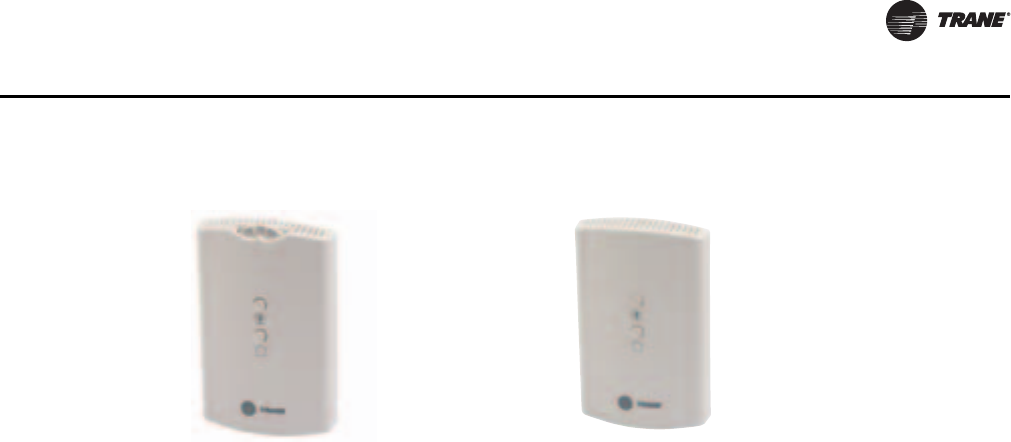
PKG-PRC002U-EN 97
Controls
Integrated Comfort™ Systems Sensors for CV and VAV Applications
Zone temperature sensor w/timed
override buttons and local setpoint
adjustment, Accessory Model Number
Digit 6 = C, BAYSENS074
This zone sensor is for use with cooling/
heating ICS™. It provides the following
features and system control functions:
• Remote temperature sensing in the
zone
• A timed override button to move an
Integrated Comfort ™ System or a
building management system from
unoccupied to occupied mode.
• Setpoint thumbwheel for local
setpoint adjustment
• Cancel button to cancel the
unoccupied override command.
Zone temperature sensor w/timed override
buttons, Accessory Model Number Digit 6 = B,
BAYSENS073
This zone sensor is for use with cooling/heating
Integrated Comfort™ Systems (ICS). It provides
the following features and system control
functions:
• Remote temperature sensing in the zone
• A timed override button to move an ICS or
building management system from it
unoccupied to occupied mode.
• Cancel button to cancel the unoccupied
override command.
98 PKG-PRC002U-EN
Electrical Data
Selection Procedures
RLA = Rated Load Amps
Compressor LRA = Locked Rotor Amps
Fan Motor LRA = Locked Rotor Amps, N.E.C. Table 430 - 150
FLA = Full Load Amps, N.E.C. Table 430 - 150
Voltage utilization range is ±10 percent
Determination of minimum circuit ampacity (MCA)
MCA = 1.25 x largest motor amps/VFD amps (FLA or RLA) + the sum of the remaining motor amps.
Determination of max fuse (MFS) and max circuit breaker (MCB) sizes
MFS and MCB = 2.25 x largest motor amps (FLA or RLA) + the sum of the remaining motor amps.
Units with the dual power option require separate MFS and MCB calculations for each electrical
circuit: 1) fans and 2) compressors.
If the rating value calulation does not equal a standard over current protective device rating, use
the next lower standard rating as the maximum.
Table 60. Number of Compressors per Unit
SCRF/SIRF 20 25 - 29 30 - 35 40 50 60
SCWF/SIWF 20 - 25 29 - 32 35 - 38 42 - 46 52 - 58 65 - 72 80 90 100 110
10 2 1 3 2 — 1 — — 2 —
15 — 1 — 1334546
Table 61. Compressor Electrical Data
SCWF/SIWF SCRF/SIRF
200V 460V 575V 200V 460V 575V
HP RLA LRA RLA LRA RLA LRA HP RLA LRA RLA LRA RLA LRA
10 41.4 267 18.6 142 15.8 103 10 41.4 267 18.6 142 15.8 103
15 56.9 351 25.5 197 23.1 146 15 56.9 351 25.5 197 23.1 146
PKG-PRC002U-EN 99
Electrical Data
Table 62. Fan motor electrical data
200V 460V 575V
HP TYPE FLA LRA FLA LRA FLA LRA
5OPD 15.7 107 6.7 48 5.4 40
TEFC 15.0 125 6.7 52 5.3 41
7.5 OPD 22.3 199 9.7 84.8 7.8 61.4
TEFC 23.2 162 9.4 74 7.6 58.5
10 OPD 29.5 260 12.6 118 10.1 72.3
TEFC 27.4 195 11.9 103 9.6 83.9
15 OPD 43.4 271 18.9 118 15.1 94
TEFC 42.5 235 18.5 122.9 14.8 99
20 OPD 57.0 373 24.5 160.8 19.6 130
TEFC 56.4 320 24.5 175 19.6 140
25 OPD 70.0 438 30.5 180 24.5 155
TEFC 69.0 385 30 200 23.9 153
30 OPD 82.2 514 36.6 223.6 28.5 179
TEFC 82.8 566 37.6 274 28.8 210
40 OPD 111.6 740 48.5 302 38.0 250
TEFC 106 734 47.4 320 38.0 280
50 ODP N/A N/A 60.5 380 47.0 305
TEFC N/A N/A 59.0 455 47.2 380
60 ODP N/A N/A 71.0 470 N/A N/A
Table 63. VFD electrical data
VFD L.I.C.
Without Bypass With Bypass
HP 200V 460V 575V 200V 460V 575V
7.5 23.8 10.6 8.8 32.2 10.6 8.8
10 32.2 14 11.1 48.3 14 16.6
15 48.3 21 16.6 61.9 21 16.6
20 61.9 27.6 21.4 78.2 27.6 21.4
25 78.2 34 26.3 92 34 26.3
30 92 41 31.2 117 41 31.2
40 117 53 39.9 139.2 53 39.9
50 NA 64 50.6 n/a 64 50.6
60 NA 77 NA n/a 77 n/a
Note: Values are at the maximum VFD input rating and not the reduced motor values. L.I.C. = Line Input Current.
100 PKG-PRC002U-EN
Electrical Data
Table 64. Electric heat electrical data
Single Stage Electric Heat
SXWF
Size SXRF
Size Heat
Kw 200V
Amps 460V
Amps
20 - 18 50 21.7
22 - 18 50 21.7
25 20 18 50 21.7
29 25 23 63.8 27.7
32 29 23 63.8 27.7
35 30 27 75 32.5
38 35 27 75 32.5
42 - 31.5 87.4 37.9
46 40 31.5 87.4 37.9
52 - 39 108.3 46.9
58 50 39 108.3 46.9
65 - 48 133.2 57.7
72 - 48 133.2 57.7
80 60 48 133.2 57.7
Two Stage Electric Heat
Unit Size Heat 200V 460V 575V
SCWF kW Amps Amps Amps
90 76 n/a 95.39 n/a
100 76 n/a 95.39 n/a
110 76 n/a 95.39 n/a
Note: Electric heat amperage should not be considered when
determining minimum circuit ampacity. The current of the unit in
the heating mode will not exceed the current of the unit in the
cooling mode.
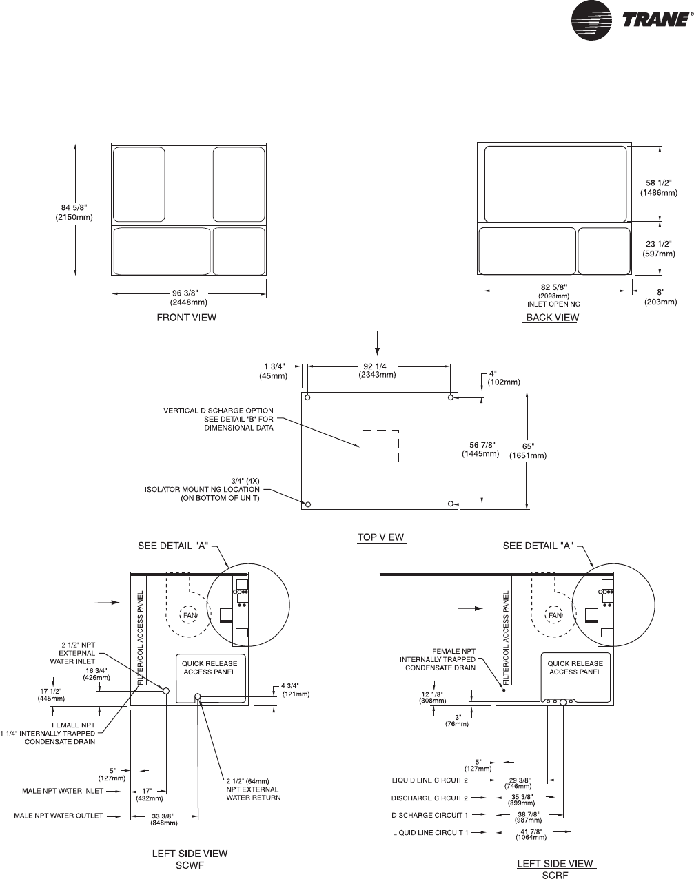
PKG-PRC002U-EN 101
Dimensions and Weights
Figure 62. 20-38 Ton Self-Contained
AIR INLET
AIR INLET
AIR INLET
AIR INLET
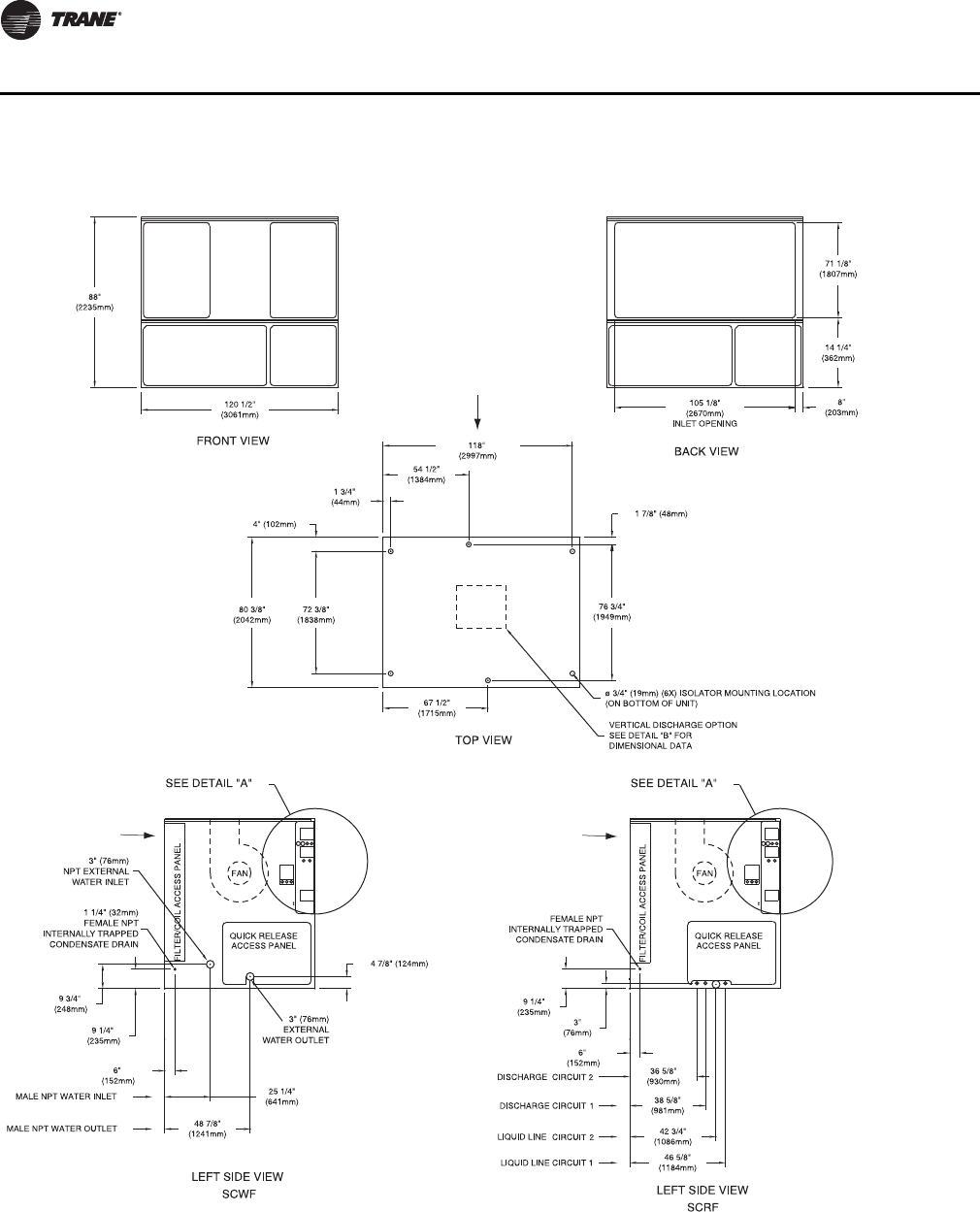
102 PKG-PRC002U-EN
Dimensions and Weights
Figure 63. 40-80 Ton Self-Contained
AIR INLET
AIR INLET
AIR INLET
AIR INLET
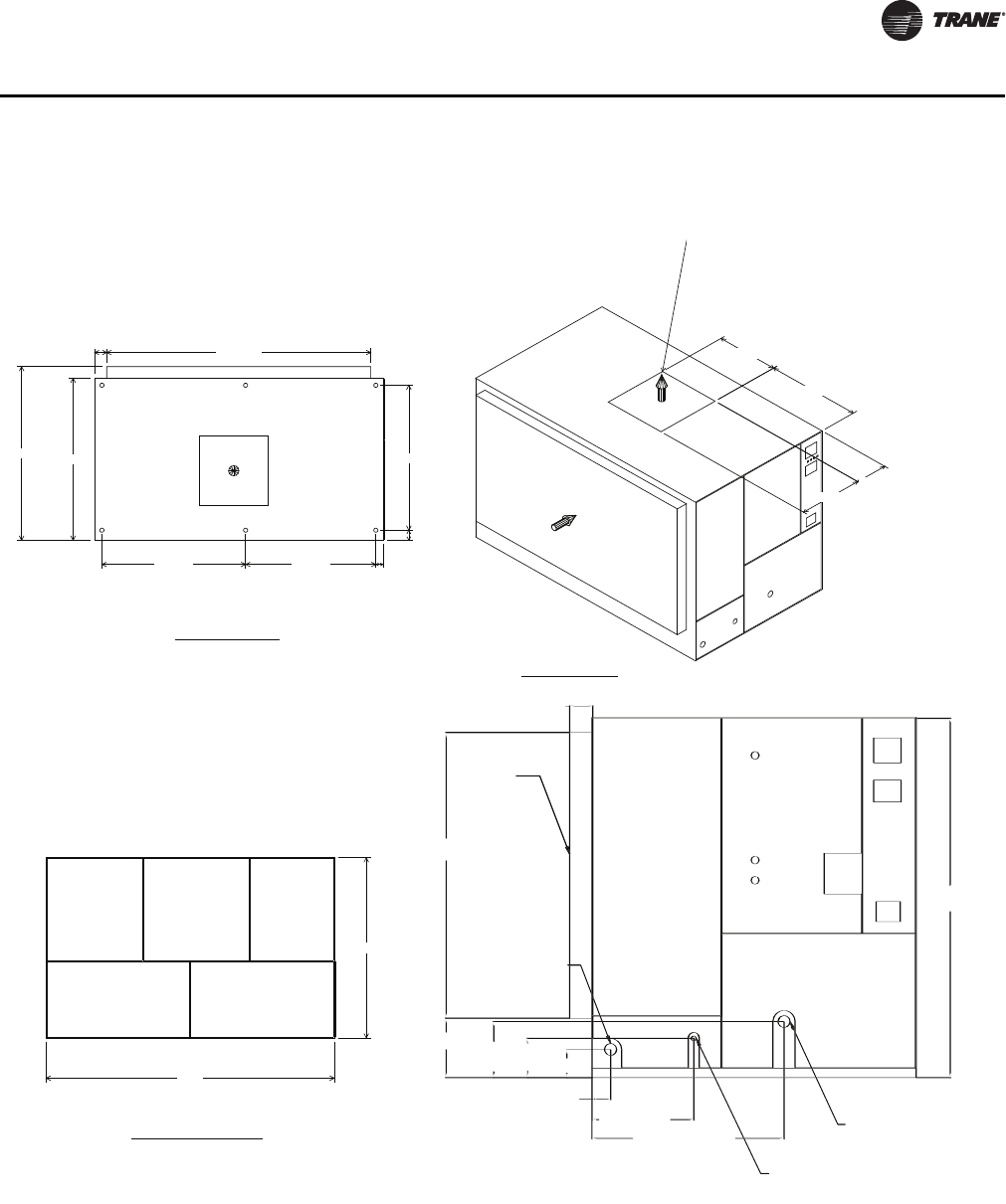
PKG-PRC002U-EN 103
Dimensions and Weights
Figure 64. 90- 110 Ton Self-Contained
89 1/2"
140"
17 1/4"
34 1/2"
50 3/4"
33 1/2"
VERTICAL DISCHARGE
WITHOUT ELECTRIC
HEAT
72"
6"
86 1/4" 80 1/2"
5 7/8" 128 1/4"
66 1/4" 66 3/4" 3 1/2"
FRONT VIEW
TOP VIEW
ISO VIEW
5 3/4” (146)
Filter Rack
71” (1803)
3” (76) NPT (EXT)
Water Inlet
14 3/4” (375)
13 15/16” (354)
9 3/4” (248)
7” (178)
4 5/8” (117)
24 1/4” (642)
47 11/16” (1211)
1 1/4” (32) Female NPT
Internally Trapped
Condensate Drain
3” (76) NPT (EXT)
Water Outlet
89 1/2” (2268)
LEFT SIDE VIEW
SCWF Top View (isolator mounting locations shown)
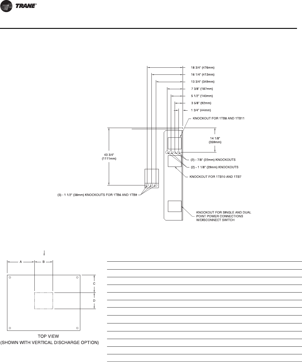
104 PKG-PRC002U-EN
Dimensions and Weights
Figure 65. Detail A Electrical Connections
Figure 66. Discharge Dimensions - High Capacity Option
AIRFLOW
Table 1. Discharge Dimensions inches (mm)
Unit Fan A B C D
SCWF 20-25/ SCRF 20 18 (457) 31.9 (809) 23.5 (597) 23.2 (589) 20.4 (518)
SCWF 29-32/SCRF 25-29 18 (457) 31.9 (809) 23.5 (597) 23.2 (589) 20.4 (518)
SCWF 35-38/SCRF 30-35 20 (508) 30.5 (775) 26.2 (665) 21.3 (540) 25.8 (654)
SCWF 42-58/SCRF 40-50 25 (635) 43.8 (1111) 33.0 (838) 31.5 (800) 31.5 (800)
SCWF 65-80/SCRF 60 27.5 (699) 43.5 (1105) 33.5 (851) 28.6 (727) 34.5 (876)
SCWF 90-110 27.5 (699) 50.7 (1288) 33.5 (85)1 28.8 (732) 34.5 (876)
Low Flow Fan Option - Discharge Dimensions
Unit Fan A B C D
SCWF 38 18 (457) 31.9 (810) 23.5 (597) 23.2 (589) 20.4 (518)
SCWF 46 18 (457) 44.8 (1139) 23.3 (591) 36.7 (933) 20.4 (518)
SCWF 58 18 (457) 44.8 (1139) 23.3 (591) 36.7 (933) 20.4 (518)
SCWF 72 / 80 20 (508) 43.4 (1103) 26.2 (664) 34.8 (884) 24.6 (624)
PKG-PRC002U-EN 105
Dimensions and Weights
Table 2. Unit Dimensions - inches (mm)
Unit Tons AA AB AC
CCRC/CIRC 20, 29 70 1/8 (1781) 7' - 4 (2235) 7' - 4 (2235)
CCRC/CIRC 35, 40 70 1/8 (1781) 10' - 10 3/4 (3321) 7' - 4 (2235)
CCRC/CIRC 50, 60 70 1/8 (1781) 14' - 8 (4470) 7' - 4 (2235)
Figure 67. CCRC/CIRC 20 and 29 Figure 68. CCRC/CIRC 35 and 40
(Optional) Low
Ambient Damper
(One Damper per Circuit)
Refrigerant Line
Connections
Frontal View
AC
AB
AA
(Optional) Low
Ambient Damper
(One Damper per Circuit)
Refrigerant Line
Connections
Frontal View
AC
AB
A
A
Figure 69. CCRC/CIRC 50 and 60
(Optional) Low
Ambient Damper
(One Damper per Circuit)
Refrigerant Line
Connections
Frontal View
AC
AB
A
A
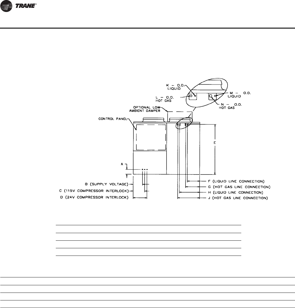
106 PKG-PRC002U-EN
Dimensions and Weights
Refrigerant and Electrical Connections
Figure 70. Front View Looking at Control Panel
Table 3. Electrical Connections - inches (mm)
Unit A B C D
CCRC/CIRC 20-32 6 3/8 (162) 12 1/4 (311) 15 1/4 (387 18 1/4 (464)
CCRC/CIRC 35-40 6 3/8 (162) 12 1/4 (311) 15 1/4 (387 18 1/4 (464)
CCRC/CIRC 50-60 6 3/8 (162) 12 1/4 (311) 15 1/4 (387 18 1/4 (464)
Table 4. Refrigerant Connections - inches (mm)
Unit E F G H J K L M N
CCRC/CIRC 20-29 66 7/8 (1699) 14 3/8 (365) 18 1/2 (470) 24 3/4 (629) 29 (737) 5/8 (16) 7/8 (22) 5/8 (16) 7/8 (22)
CCRC/CIRC 30-50 66 7/8 (1699) 14 3/8 (365) 18 1/2 (470) 24 3/4 (629) 29 (737) 7/8 (22) 1 3/8 (35) 5/8 (16) 7/8 (22)
CCRC/CIRC 60 66 7/8 (1699) 14 3/8 (365) 18 1/2 (470) 24 3/4 (629) 29 (737) 7/8 (22) 1 3/8 (35) 7/8 (22) 1 3/8 (35)
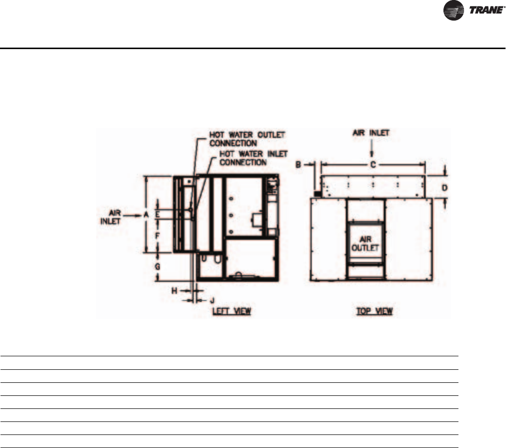
PKG-PRC002U-EN 107
Dimensions and Weights
Hot Water Coil
Figure 71. Hot Water Coil
Table 5. Hot Water Coil Piping Locations, inches
Unit Tons & Model Coil A B C D E F G H J
25 - 35 SXRF 29 - 38 SXWF Std 60 3/8 5 9/32 82 7/8 18 7 1/2 18 7/8 22 3/8 1 3/4 2 3/8
20 SXRF 20 - 25 SXWF Std 60 3/8 5 9/32 82 7/8 18 7 1/2 26 1/2 22 3/8 1 3/4 2 3/8
25 - 35 SXRF 29 - 38 SXWF Hi-cap 60 3/8 5 1/2 82 7/8 18 7 1/2 18 7/8 22 3/8 2 3/4 3 1/2
20 SXRF 20 - 25 SXWF Hi-cap 60 3/8 5 1/2 82 7/8 18 7 1/2 26 1/2 14 1/8 12 3/4 2 1/2
42 - 80 SXRF/SXWF Std 72 7/8 3 11/16 104 5/8 18 7 1/2 32 3/4 22 3/8 2 3/4 3 1/2
42 - 80 SXRF/SXWF Hi-cap 72 7/8 3 7/8 104 5/8 18 7 1/2 32 3/4 14 1/8 2 3/4 3 3/8
Notes:
1. All coils are factory mounted. The control valve ships loose.
2. All pricing connections are 1 1/2” (38.1mm) NFT (EXT) for 1 row coils and 2 1/2” (50.8mm) NPT (EXT) for 2 row coils (high capacity).
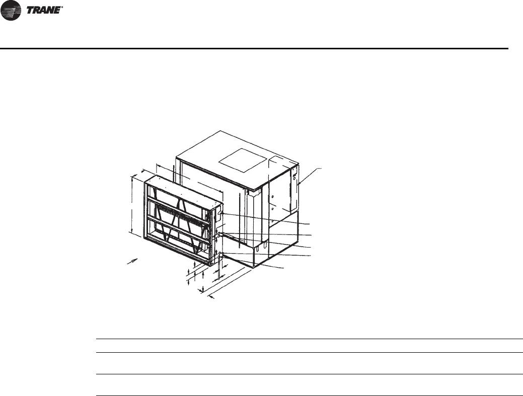
108 PKG-PRC002U-EN
Dimensions and Weights
Steam Coil
Figure 72. Steam Coil
Table 6. Piping Locations For Steam Coils - inches (mm)
ABCDEFGHJKLMN
Unit Sizes 20 - 38 60 3/8
(1534) 82 7/8
(2105) 18
(457) ——22 3/8
(568) —3
(76) 18 1/2
(470) 3 7/8
(98) 5
(127) 4 3/8
(111) 1 1/4
(32)
Unit Sizes 42 - 80 72 7/8
(1851) 105 1/4
(2680) 18
(457) ——13 1/4
(337) —3
(76) 22 1/8
(562) 6 3/8
(162) 5 3/8
(137) 4 3/8
(111) 1 1/4
(32)
Notes:
1. All coils are factory mounted, piped, and wired.
2. All piping connections are 1-1/2” (38.1mm) female NPT fittings.
Main Control Panel
Vacuum Trap Connection
Condensate Return
Vacuum Trap Connection
Steam Inlet Connection
Condensate Return
A
ir Inlet
LKF
N
M
H
J
A
C
Condensate Return
B
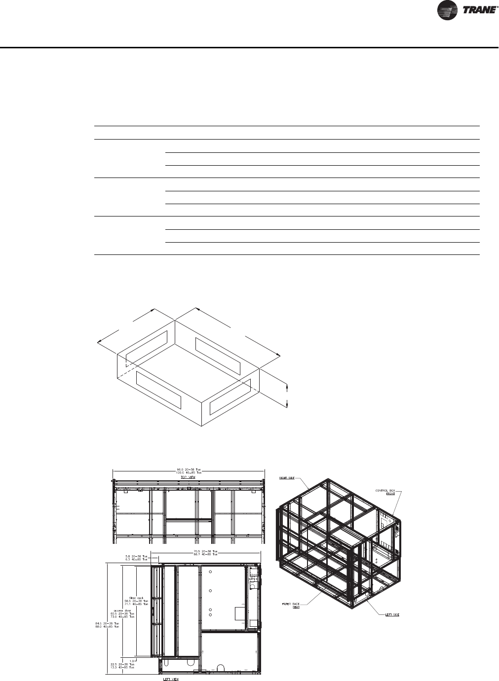
PKG-PRC002U-EN 109
Dimensions and Weights
Flexible Horizontal Discharge Plenum
Table 7. Plenum Dimensions -inches (mm)
Unit A B C Weight
Unit Sizes 20-38
Low 64 7/8 (1648) 95 7/8 (2435) 24 5/8 (625) 325 lbs. (147.4 kg)
Std. 64 7/8 (1648) 95 7/8 (2435) 32 3/8 (822) 430 lbs. (195.0 kg)
Ext. 64 7/8 (1648) 95 7/8 (2435) 45 (1143) 705 lbs. (320.0 kg)
Unit Sizes 42-80
Low 80 3/8 (2042) 119 7/8 (3045) 21 1/8 (537) 390 lbs. (176.9 kg)
Std. 80 3/8 (2042) 119 7/8 (3045) 28 5/8 (727) 540 lbs. (244.9 kg)
Ext. 80 3/8 (2042) 119 7/8 (3045) 45 (1143) 705 lbs. (320.0 kg)
* Unit Sizes 90-110
Low 80 1/2 (2044) 140 (3556) 19 5/8 (498) 430 lbs. (195.0 kg)
Std. 80 1/2 (2044) 140 (3556) 27 3/4 (704) 595 lbs. (269.9 kg)
Ext. 80 1/2 (2044) 140 (3556) 431/2 (1104.9) 795 lbs. (360.6 kg)
Note: * For 90-110 ton, plenum ship separate with field cut holes. Factory cut holes available as a design special only.
Figure 73. Plenum dimensions
Figure 74. 6-Inch Filter Rack Option
AB
C
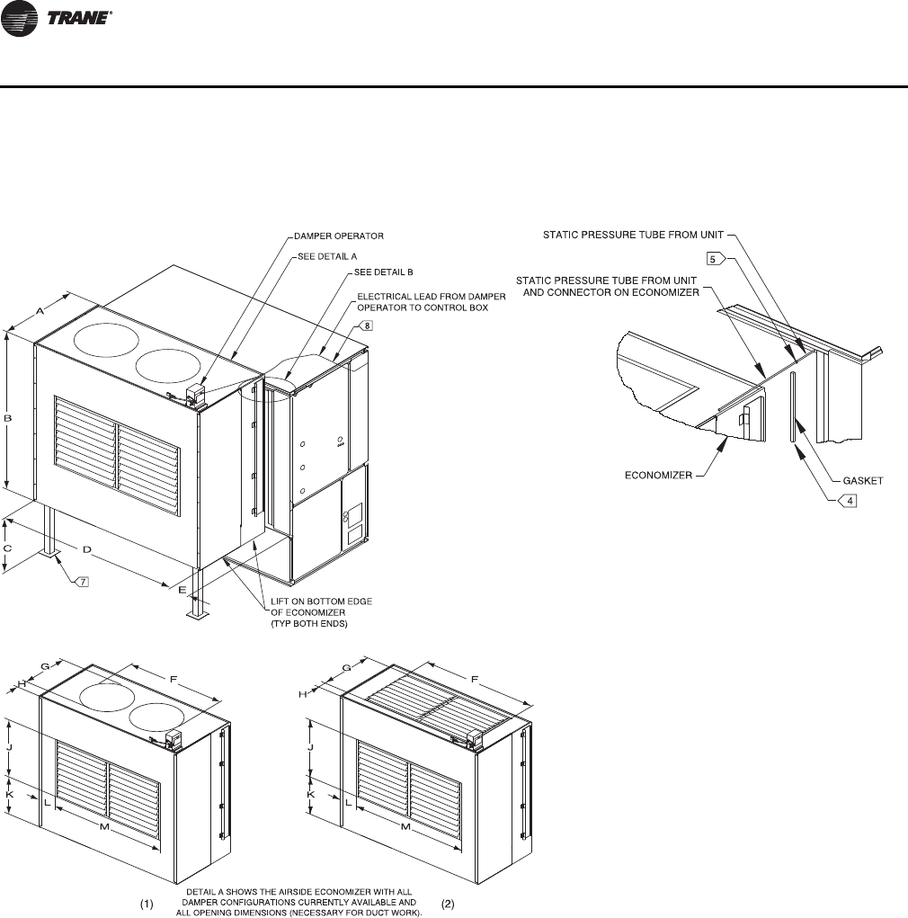
110 PKG-PRC002U-EN
Dimensions and Weights
Airside Economizer
Figure 75.
PKG-PRC002U-EN 111
Dimensions and Weights
Table 8. Airside Economizer Dimensions - English - (inches)
Unit Model A B C D E F (1) F (2) G (1) G (2) H (1) H (2) J K L M
20 SXWF 44 74 22 3/8 81 3/4 8 3/4 66 3/4 49 3/4 23 1/4 20 1/2 9 3/4 11 1/8 20 1/2 22 1/4 16 49 3/4
20 SXRF
25 SXRF 44 74 22 3/8 81 3/4 8 3/4 68 5/8 49 3/4 28 1/8 20 1/2 7 1/4 11 1/8 20 1/2 22 1/4 16 49 3/4
22 SXWF
29 SXWF 44 74 22 3/8 81 3/4 8 3/4 68 5/8 49 3/4 28 1/8 20 1/2 7 1/4 11 1/8 20 1/2 22 1/4 16 49 3/4
29 SXRF
32 SXWF 44 74 22 3/8 81 3/4 8 3/4 74 1/4 62 3/4 23 1/4 20 1/2 9 3/4 11 1/8 20 1/2 22 1/4 9 1/2 62 3/4
30 SXRF
35 SXRF 44 74 22 3/8 81 3/4 8 3/4 73 1/2 62 3/4 33 20 1/2 4 7/8 11 1/8 20 1/2 22 1/4 9 1/2 62 3/4
35 SXWF
38 SXWF 44 74 22 3/8 81 3/4 8 3/4 73 1/2 62 3/4 33 20 1/2 4 7/8 11 1/8 20 1/2 22 1/4 9 1/2 62 3/4
42 SXWF 57 3/8 86 1/2 13 1/4 104 3/8 8 7/8 83 5/8 63 1/2 33 26 2 1/2 15 26 24 3/4 20 3/8 63 1/2
40 SXRF
46 SXWF 57 3/8 86 1/2 13 1/4 104 3/8 8 7/8 94 1/8 63 1/2 28 1/8 26 6 7/8 15 26 24 3/4 20 3/8 63 1/2
50 SXRF
60 SXRF
52-80 SXWF 57 3/8 86 1/2 13 1/4 104 3/8 8 7/8 96 5/8 63 1/2 52 37 1/2 1 7/8 9 1/4 37 1/2 19 20 3/8 63 1/2
Table 9. Airside Economizer Dimensions - Metric - (mm)
Unit Model A B C D E F (1) F (2) G (1) G (2) H (1) H (2) J K L M
20 SXWF 1118 1880 568 2076 222 1695 1264 591 521 248 283 521 565 406 1264
20 SXRF
25 SXRF 1118 1880 568 2076 222 1743 1264 714 521 184 283 521 565 406 1264
22 SXWF
29 SXWF 1118 1880 568 2076 222 1743 1264 714 521 184 283 521 565 406 1264
29 SXRF
32 SXWF 1118 1880 568 2076 222 1886 1594 591 521 248 283 521 565 241 1594
30 SXRF
35 SXRF 1118 1880 568 2076 222 1867 1594 838 521 124 283 521 565 241 1594
35 SXWF
38 SXWF 1118 1880 568 2076 222 1867 1594 838 521 124 283 521 565 241 1594
42 SXWF 1457 2197 337 2651 225 2124 1613 838 660 64 381 660 629 518 1613
40 SXRF
46 SXWF 1457 2197 337 2651 225 2390 1613 714 660 175 381 660 629 518 1613
50 SXRF
60 SXRF
52-80 SXWF 1457 2197 337 2651 225 2454 1613 1321 953 48 235 953 483 518 1613
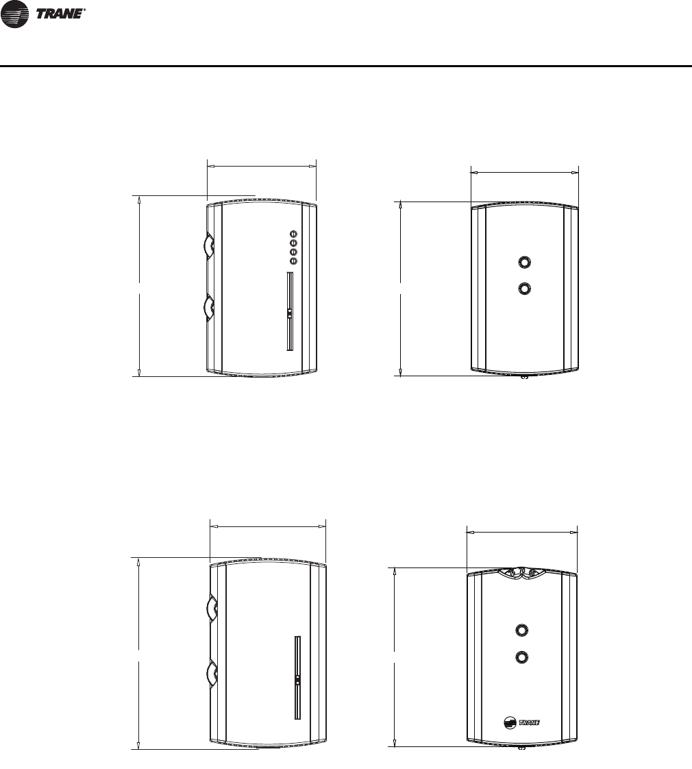
11 2 PKG-PRC002U-EN
Dimensions and Weights
Field Installed Zone Sensors
Dual Setpoint, Manual/Automatic
Changeover Sensor With System
Function Lights
BAYSENS110
Zone Temperature Sensor W/Timed
Override Buttons
BAYSENS073
Dual Setpoint, Manual/Automatic
Changeover Sensor
BAYSENS108
Zone Temperature Sensor W/Timed
Override Buttons and Local Setpoint
Adjustment
BAYSENS074
FRONT VIEW
<<4.68~ln>>
<<2.90~ln>>
FRONT
2-29/32 [73,55 mm]
4-11/16 [118,75 mm]
FRONT VIEW
<<4.68~ln>>
<<2.90~ln>>
FRONT
2-29/32 [73,55 mm]
4-11/16 [118,75 mm]
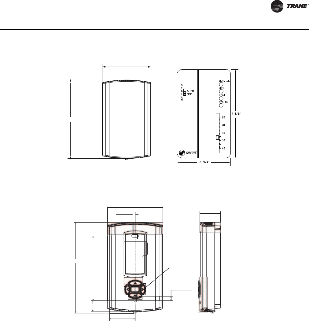
PKG-PRC002U-EN 11 3
Dimensions and Weights
Zone Temperature Sensor Only
BAYSENS077
Single Setpoint Sensor With System
Function Lights BAYSENS021
Zone sensor mounting hole locations for: BAYSENS119
FRONT
4-11/16 [118,75 mm]
2-29/32 [73,55 mm]
(70 mm)
(114 mm)
2.2.9 i in (7373.5 cm)
1.08
08 in (2(27.5 mmmm)
4.68
68 in (11118.9.9 mmmm)
1.34
34 in (3(34.14 mmmm)
0.58
58 in (1414.7676 mm)
0.12 i
in (3 mmmm)
TYP
TYP R.07R.07 in
(R1.80
80 mm)
3.39 i
in (8686 mm)
0.24
24 inin (6.00.00 mmmm)
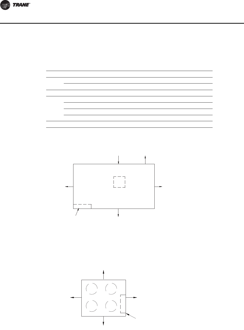
114 PKG-PRC002U-EN
Dimensions and Weights
Service Clearances
Self-Contained Models SCWF, SIWF, SCRF, SIRF
Note: Units (20 - 80) with VFD contain a swing out door. Allow 48” mimimum clearance.
Remote Air-Cooled Condensers Models CCRC,CIRC
Table 10. Service/Code Clearance Requirements
Side Distance Purpose
Front 42 in. (1066 mm) (20-38 Ton) NEC code requirement
48 in. (1219 mm) (42-80 Ton) Fan service/removal
Left 36 in. (914 mm) Filter, refrigeration and waterside component service
Right
9 in. (229 mm) Non VFD w/ open return
18 in. (457 mm) (20 - 80 ton) Non VFD w/ ducted return
9 in. (229 mm) ( 90 -110 ton) w/ VFD 7.5 to 50 HP
36 in. (914 mm) w/ VFD 25 to 50 HP
Inlet 18 in. (457 mm) Provides uniform airflow
Figure 76. Top View SCWF, SCRF, SIWF, SIRF
Figure 77. Top View CCRC,CIRC 20, 29
Air Inlet 18” (457.2mm)
Minimum
See Table
42” (1066.8mm) (20-38 Ton)
Minimum
48” (1219mm) (42-110 Ton)
Control
Panel
36” (914.4mm)
Minimum
Left side
Front
Right side
Left side
CB
DA
96” (2132 mm)
48” (1066 mm)
96” (2132 mm)
48” (1066 mm)
Control
Panel
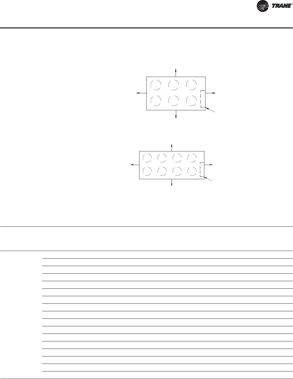
PKG-PRC002U-EN 11 5
Dimensions and Weights
Weights
Figure 78. Top View CCRC,CIRC 35, 40
Figure 79. Top View CCRC,CIRC 50, 60
96” (2132 mm)
48” (1066 mm)
96” (2132 mm)
48” (1066 mm)
Control
Panel
CB
DA
F
E
96” (2132 mm)
48” (1066 mm)
96” (2132 mm)
48” (1066 mm)
Control
Panel
CB
DA
F
E
G
H
Table 11. Unit Weights - SCWF/SCRF/SIWF/SIRF
Unit
Size
Base
Weight
lbs. (kg)
Airside
Economizer
lbs. (kg)
2-Row
Waterside
Economizer
lbs. (kg)
4-Row
Waterside
Economizer
lbs. (kg)
Heating
Coil Box
lbs. (kg)
6-Row
Evap. Coil
lbs. (kg)
6-inch filter
rack
lbs. (kg)
SCWF/SIWF
20 3102 (1407) 430 (195) 140 (64) 340 (154) 460 (209) - 212 (96)
22 3102 (1407) 430 (195) 140 (64) 340 (154) 460 (209) - 212 (96)
25 3170 (1438) 430 (195) 140 (64) 340 (154) 460 (209) 144 (65) 212 (96)
29 3326 (1508) 500 (227) 190 (86) 390 (177) 460 (209) - 212 (96)
32 3514 (1594) 500 (227) 190 (86) 390 (177) 460 (209) 132 (60) 212 (96)
35 3721 (1688) 500 (227) 280 (127) 505 (229) 460 (209) - 212 (96)
38 3819 (1732) 500 (227) 280 (127) 505 (229) 460 (209) 138 (63) 212 (96)
42 4615 (2093) 640 (290) 255 (116) 505 (229) 600 (272) - 257 (117)
46 4705 (2134) 640 (290) 255 (116) 505 (229) 600 (272) 170 (77) 257 (117)
52 4892 (2219) 700 (318) 335 (152) 665 (302) 600 (272) - 257 (117)
58 5142 (2332) 700 (318) 335 (152) 665 (302) 600 (272) 216 (98) 257 (117)
65 5371 (2436) 800 (363) 335 (152) 665 (302) 600 (272) - 257 (117)
72 5491 (2490) 800 (363) 335 (152) 665 (302) 600 (272) 216 (98) 257 (117)
80 5814 (2637) 800 (363) 335 (152) 665 (302) 600 (272) - 257 (117)
90 6330 (2871) - - 1015 (460) - 255 (116) -
100 6840 (3103) - - 1015 (460) - 255 (116) -
110 6852 (3108) - - 1015 (460) - 255 (116) -
11 6 PKG-PRC002U-EN
Dimensions and Weights
SCRF/SIRF
20 2887 (1310) 430 (195) - - 460 (209) - -
25 3041 (1379) 500 (227) - - 460 (209) - -
29 3231 (1465) 500 (227) - - 460 (209) - -
30 3321 (1506) 500 (227) - - 460 (209) - -
35 3421 (1552) 500 (227) - - 460 (209) - -
40 4294 (1948) 640 (290) - - 600 (272) - -
50 4731 (2146) 700 (318) - - 600 (272) - -
60 5288 (2399) 800 (363) - - 600 (272) - -
Notes:
1. All unit weights include refrigerant, water, and controllers, electric heat and valves.
2. Add 150 lbs. to total weight to obtain approximate shipping weight.
3. Flexible horizontal discharge plenum option weights: 45-inch plenum = 705 lbs., Standard height plenum = 430 lbs., Low height plenum = 325 lbs.
Table 11. Unit Weights - SCWF/SCRF/SIWF/SIRF (continued)
Unit
Size
Base
Weight
lbs. (kg)
Airside
Economizer
lbs. (kg)
2-Row
Waterside
Economizer
lbs. (kg)
4-Row
Waterside
Economizer
lbs. (kg)
Heating
Coil Box
lbs. (kg)
6-Row
Evap. Coil
lbs. (kg)
6-inch filter
rack
lbs. (kg)
Table 12. Unit Weights - CCRC/CIRC
Unit
Size
Shipping
Weight
lbs (kg).
Operating
Weight
lbs.(kg)
CCRC/CIRC 20 2030 (920) 1906 (865)
CCRC/CIRC 29 2084 (945) 1960 (890)
CCRC/CIRC 32 2138 (970) 2014 (915)
CCRC/CIRC 35 3018 (1370) 2833 (1285)
CCRC/CIRC 40 3072 (1395) 2887 (1310)
CCRC/CIRC 50 3995 (1810) 3695 (1675)
CCRC/CIRC 60 4275 (1940) 3975 (1805)
Table 13. VFD Weights
Without Bypass With Bypass
HP
200V 460V 575V
HP
200V 460V 575V
LBS Kg LBS Kg LBS Kg LBS Kg LBS Kg LBS Kg
7.5 126 57.153 114 51.710 114 51.710 7.5 215 97.522 170 77.111 170 77.111
10 126 57.153 114 51.710 126 57.153 10 215 97.522 215 97.522 215 97.522
15 152 68.946 126 57.153 126 57.153 15 220 99.790 215 97.522 215 97.522
20 152 68.946 126 57.153 126 57.153 20 220 99.790 215 97.522 215 97.522
25 152 68.946 126 57.153 126 57.153 25 250 113.398 215 97.522 215 97.522
30 177 80.286 152 68.946 152 68.946 30 250 113.398 220 99.790 220 99.790
40 177 80.286 152 68.946 152 68.946 40 290 131.542 220 99.790 220 99.790
50 NA NA 152 68.946 152 68.946 50 NA NA 250 113.398 250 113.398
60 NA NA 177 80.286 NA NA 60 NA NA 250 113.398 NA NA
Note: Weights include swing out door.

PKG-PRC002U-EN 11 7
Mechanical Specifications
Signature Series Self-Contained Units
Cabinet
The unit framework shall be formed structural steel members of sturdy-gauge galvanized steel.
Exterior panels shall be fabricated from industrial-gauge galvanized steel. The fan and compressor
sections shall be insulated with ¾-inch (19 mm) of 1.75 lb./cu. ft. (28 kg./cu. ft.) density fiberglass
insulation.
The unit shall be provided with removable panels to allow service access to compressors,
condensers, fan motor, fan bearings, coils, and valves. Removable panels shall be secured with
quick-acting fasteners. The refrigerant sight glasses shall be accessible during operation. The
control panel door shall have lift-off hinges.
The unit cabinet and any insulated ship-separate modules for indoor installation shall be wrapped
on top and 4 sides with a recyclable, transparent, seven-mil-thick, low-density polyethylene heat-
shrink film. The film shall have adequate transparency for unit nameplates and labels to be
readable through the film.
Cabinet corners shall have protective padding in place to prevent damage to the film.
All seams and edges in the film shall be heat welded and adequately taped to minimize unit
exposure to rain, snow, ice and road grime during shipping.
Compressors
Units shall have multiple compressors with independent circuits for water-cooled units and
manifolded circuits for air-cooled units. Compressors shall be manufactured by the unit
manufacturer. Scroll compressors shall be heavy duty suction cooled type with suction screen,
centrifugal oil pump with dirt separator, oil charging valve, and oil sight glass. Protective devices
for low pressure, high pressure, and motor temperature shall be provided. The compressors shall
be mounted on isolators for vibration isolation.
Condenser (SCWF/SIWF only)
One condenser shall be provided for each compressor. The condensers shall be shell-and-tube
design with removable heads and mechanically cleanable tubes. Tubes shall be ¾-inch (19mm) OD
and constructed of copper. Condenser waterside working pressure shall be 400 psig. All condenser
water piping including, cleanouts, shall be factory installed to provide single connections for water
inlet and outlet.
Evaporator
The evaporator coil shall be seamless copper tubes expanded into aluminum fins. Tubes shall be
½-inch (13mm) OD with internally enhanced surfaces. Coil shall have staggered tube arrangement
with intertwined circuiting and no more than 12 fins per inch.
The drain pan shall be positively sloped in all directions to ensure proper condensate removal. The
drain pan shall be fabricated of galvanized steel and insulated with ¾-inch (19 mm) of 1-lb. (0.5 kg)
density fiberglass. Drain piping, including a trap with cleanout, shall be provided with a single-
point connection to the unit’s exterior.
Refrigerant Circuit (SCWF only)
Refrigerant circuits shall be independent and completely piped including sight glasses,
distributors, thermal expansion valves with adjustable superheat and external equalizer, and high
pressure relief valves with ½-inch (13 mm) flare connection. Filter driers ship loose for field
installation. Unit shall be provided with adequate means of frost control. The circuits shall be
factory dehydrated, charged with oil and R-410A refrigerant. Compressors shall be mounted on
rubber-in-shear isolators for vibration isolation.

11 8 PKG-PRC002U-EN
Mechanical Specifications
Refrigerant Circuit (SCRF/SIRF only)
Two refrigerant circuits shall be piped to the unit’s exterior. The refrigerant piping includes filter
driers (shipped loose for field installation), sight glasses, distributors, thermal expansion valves
with adjustable superheat and external equalizer. Unit shall be provided with adequate means of
frost control. The circuits shall be factory tested, dehydrated and then charged with dry nitrogen.
Compressors shall be mounted on rubber-in-shear isolators for vibration isolation.
Supply Fan
The supply fan shall be a single forward curved medium pressure fan secured to a solid steel shaft
with grease lubricated bearings designed for 200,000 hours. Both fan bearings shall have
greaselines extended to a common location. The drive components shall include fixed pitch
sheaves and multiple V-belt sized for 130% nominal motor horsepower. All drive components shall
be accessible without using scaffolds or ladders.
Supply fan motors are either open drip-proof or totally enclosed fan cooled. The motors shall have
a standard NEMA T-frame and a service factor of 1.15. All 60 Hz motors meet the Energy
Independence and Security Act of 2007 (EISA).
The entire fan assembly, including drive components, shall be mounted on a common base. The
fan base shall be isolated inside the unit. The entire assembly shall be statically and dynamically
balanced at the factory.
Filters
Two-inch (51 mm) throwaway fiberglass filters shall be provided for installation during
construction. Optional two-inch and four-inch filter racks may also be provided.
Unit Controls - DDC
Microprocessor controls shall be provided to control all unit functions. The control system shall be
suitable to control CV or VAV applications. The controls shall be factory-installed and mounted in
the main control panel. All factory-installed controls shall be fully commissioned (run tested) at the
factory. The unit shall have a human interface panel with 16-key keypad, a
two line, 40 character clear language (English, French, or Spanish) display as standard to provide
the operator with full adjustment and display of control data functions. The unit controls shall be
used as a stand-alone controller or as part of a building management system involving multiple
units.
The unit shall be equipped with a complete microprocessor control system. This system shall
consist of temperature and pressure (thermistor and static pressure transducer) sensors, printed
circuit boards (modules) and a unit mounted human interface panel. Modules (boards) shall be
individually replaceable for service ease. All microprocessors, boards, and sensors shall be factory
mounted, wired, and tested.
The microprocessor boards shall be stand-alone DDC controls not dependent on communications
with an on-site PC or building management network. The microprocessors shall be equipped with
on-board diagnostics, indicating that all hardware, software, and interconnecting wiring are in
proper operating condition.
The modules (boards) shall be protected to prevent RFI and voltage transients from affecting the
board’s circuits. All field wiring shall be terminated at a separate, clearly marked terminal strip.
Direct field wiring to the I/O boards is not acceptable.
The microprocessor’s memory shall be nonvolatile EEPROM type requiring no battery or capacitive
backup, while maintaining all data.
Zone sensors shall be available in several combinations with selectable features depending on
sensor.
The human interface panel’s keypad display character format shall be 40 characters x two lines. The
character font shall be 5 x 7 dot matrix plus cursor. The display shall be supertwist liquid crystal

PKG-PRC002U-EN 119
Mechanical Specifications
display (LCD) with blue characters on a gray/green background which provides high visibility and
interface ease. The display format shall be in clear language: English, French, or Spanish.
The keypad shall be equipped with 16 individual touch sensitive membrane key switches. The
switches shall be divided into four separate sections and password protected to prevent tampering
by unauthorized personnel. The six main menus shall be STATUS, SETPOINTS, DIAGNOSTICS,
SETUP, CONFIGURATION, and SERVICE MODE.
Agency Listing
The unit shall have the US/Canada Underwriter’s Laboratory agency listing.
Remote Air-Cooled Condenser
Cabinet
The unit framework shall be formed structural steel members of sturdy-gauge galvanized steel.
Panels and access doors shall be sturdy-gauge galvanized steel. The unit exterior shall be
phosphatized and finished with air-dried enamel paint.
Refrigerant Circuits and Controls
All sizes shall have dual refrigerant circuits and shall include an integral subcooling circuit for each
circuit. All necessary controls to run unit fans shall be factory installed. The control panel shall
include fan motor contactors, terminal block connection for compressor interlock, and 115-volt
control power transformer.
Condenser Coils
The condenser coil arrangement shall be slab type. Coils shall be seamless
3/8-inch (10mm) OD copper tubes expanded into aluminum fins. Each circuit shall include an
integral subcooler. The coil shall be leak tested at 650 psig air pressure.
Condenser Fans and Motor
Vertical discharge direct drive fans shall be statically and dynamically balanced at the factory.
Motors shall be three-phase with permanently lubricated ball bearings, built-in current and thermal
overload protection and weathertight rain slinger over the fan shaft.
Protective Coating (Option)
Unit
The unit’s interior and exterior shall have a 4 to 6 mil coat of protective coating applied with an air-
dry process.
Condenser Coils
The condenser coil shall have a 4 to 6 mil coat of protective coating applied by a multiple dip-and-
bake process.
Low Ambient Operation Option
Standard ambient control allows operation down to 45°F by cycling the condenser fans. Low
ambient control damper shall allow the unit to operate down to 0°Fby utilizing additional fan
cycling and an external damper assembly. The low ambient control damper shall include an
industrial-gauge damper assembly. The damper is controlled by the air-cooled unit’s DDC
controller.
Louvered Coil Guards Option
The unit coils shall be covered with a factory installed decorative louvered grill type panel for
protection.

120 PKG-PRC002U-EN
Mechanical Specifications
Agency Listing
The unit shall have the US/Canada Underwriter’s Laboratory agency listing.
Self-Contained Options
Air Volume/Temperature Control
Zone Temperature Control
This option includes a zone sensor, microprocessor unit control module, a microprocessor
compressor controller, and a unit-mounted human interface panel. The unit operates at a design
airflow based on the fan and motor drive selections.
Supply Air Temperature Control With Variable Frequency Drive
This option controls the VAV self-contained unit from the discharge air temperature using a factory
mounted variable frequency drive (VFD). The VFD safely varies the fan motor speed to allow the
motor to meet the dynamic requirements at the motor shaft and meet the system static. Other
control components include a discharge air microprocessor controller and discharge air sensor.
The microprocessor controller coordinates the economizer control and the stages of cooling with
discharge air temperature reset capabilities. Includes factory installed and tested variable
frequency drive (VFD) to provide supply fan motor speed modulation. The VFD receives 0-10vdc
signal from the unit microprocessor based upon supply static pressure and causes the drive to
accelerate or decelerate as required to maintain the supply static pressure setpoint.
Supply Air Temperature Control With Variable Frequency Drive with Bypass
Manual bypass control provides full nominal airflow and zone temperature control in the event of
a drive failure. The VFD with bypass is factory mounted completely wired and tested. A motor
overload relay and fuses are provided to properly size motor protection during both drive and
bypass modes.
High Capacity Coils
The high capacity coil option (6 row evap) is a standard option on unit sizes 25, 32, 38, 46, 58, 72.
The high capacity coil option (8 row evap) is a standard option on unit sizes 90, 100, 110.
Economizer
The waterside economizer takes advantage of cooling tower water to either pre-cool the entering
air to aid the mechanical cooling process or, provides total system cooling if the water temperature
is low enough. Waterside economizing enables when the unit’s entering water temperature is
below the unit’s entering mixed air temperature by a minimum of 4°F plus the economizer’s
approach temperature. The approach temperature default is 4°F and is adjustable from 0 to 9°F.
Waterside economizing disables when the unit’s entering water temperature is not below the unit’s
entering mixed air temperature by at least the water economizer approach temperature. The
economizer acts as the first stage of cooling. If the economizer is unable to maintain the supply air
setpoint, the unit control module brings on compressors as required to meet the setpoint.
The waterside economizer includes a coil, modulating valves, controls, and piping with cleanouts.
All components are factory installed in the unit cabinet. The coil construction is ½-inch (13mm) OD
seamless copper tubes expanded into aluminum fins. The evaporator and economizer coils share
a common sloped (IAQ) drain pan. Drain pan options are either galvanized or stainless steel and
insulated and internally trapped.
The waterside economizer coil options have either two or four rows with no more than 12 fins per
inch. The tubes are arranged in a staggered pattern to copper supply and return headers with
removable cleanout and vent plugs. The optional mechanically cleanable economizer has
removable cast iron headers to allow easy mechanical cleaning of the tubes. The waterside
working pressure is rated for 400 psig (2758 kPa).

PKG-PRC002U-EN 121
Mechanical Specifications
Airside Economizer
Units with the airside economizer option are equipped with the necessary control sequences to use
outside air for the first stage of cooling, in occupied or unoccupied mode and when ambient
conditions are favorable for economizing. Inherent in the unit controller is the ability to suppress
the setpoint below the normal unit setpoint. This allows the building to improve comfort levels
when possible, and at the same time, optimize building mechanical cooling operation for peak
operating efficiency. An outside air temperature and relative humidity sensor are provided to allow
monitoring of reference enthalpy and are field installed. Economizer operation enables when the
outside air enthalpy is less than 25 BTU’s/lb. default (adjustable 19-28 BTU’s/lb.). During occupied
mode, the outside air damper opens to 15% (adjustable 0-100%) for ventilation purposes. Also, the
ability to alter the outside air damper position to compensate for VAV supply air modulation is
inherent in the unit controls, and can be enabled by the operator.
The mixing box fabrication is sturdy-gauge galvanized steel. Opposed low leak damper blades are
fabricated from sturdy-gauge galvanized steel and rotate on rustproof nylon bushings. A factory
installed 24V modulating spring return actuator controls both damper positions.
Comparative Enthalpy Control
Units with comparative enthalpy control are equipped with the necessary control sequences to
allow using outside air for the first stage of cooling, in occupied or unoccupied mode and when
ambient conditions are favorable for economizing. Inherent in the unit controller is the ability to
suppress the setpoint below the normal unit setpoint. This allows the building to improve comfort
levels when possible, and at the same time, optimize building mechanical cooling operation for
peak operating efficiency. A factory-installed control board, with field-installed outside and return
air temperature and relative humidity sensors, allows monitoring of outside and return air.
Economizer operation enables when the outside air enthalpy is 3 BTU’s/lb. less than the return air
enthalpy. During occupied mode, the outside air damper opens to 15% (adjustable 0-100%) for
ventilation purposes. Also, the ability to alter the outside air damper position to compensate for
VAV supply air modulation is inherent in the unit controls, and can be enabled by the operator.
The mixing box fabrication is sturdy-gauge galvanized steel. Opposed low leak damper blades are
fabricated from sturdy-gauge galvanized steel and rotate on rustproof nylon bushings. A factory
installed 24V modulating spring return actuator controls both damper positions.
Standard Two-Position Damper Interface
Units with the two-position damper interface are provided with a 0-10 VDC control output suitable
for controlling a field-provided modulating actuator. In occupied mode, the output drives to the
maximum position.
Airside Economizer Interface
Units with airside economizer interface are equipped with the necessary control sequences to
allow using outside air for the first stage of cooling, in occupied or unoccupied mode and when
ambient conditions are favorable for economizing. Inherent in the unit controller is the ability to
suppress the setpoint below the normal unit setpoint. This allows the building to improve comfort
levels when possible, and at the same time, optimize building mechanical cooling operation for
peak operating efficiency. An outside air temperature and relative humidity sensor are provided for
field installation to monitor reference enthalpy. Economizer operation enables when the outside
air enthalpy is less than 25 BTU’s/lb. (adjustable 19-28 BTU’s/lb). During occupied mode, the outside
air damper opens to 15% (adjustable 0-100%) for ventilation purposes. Also, the ability to alter the
outside air damper position to compensate for VAV supply air modulation is inherent in the unit
controls, and can be enabled by the operator. An analog 2-10 VDC output (adjustable (0-10 VDC)
is provided to modulate the field-provided 30 second damper actuators (adjustable 1-255 seconds).
Airside Economizer Interface with Comparative Enthalpy
Units with airside economizer interface and comparative enthalpy are equipped with the necessary
control sequences to allow using outside air for the first stage of cooling, in occupied or unoccupied

122 PKG-PRC002U-EN
Mechanical Specifications
mode and when ambient conditions are favorable for economizing. Inherent in the unit controller
is the ability to suppress the setpoint below the normal unit setpoint. This allows the building to
improve comfort levels when possible, and at the same time, optimize building mechanical cooling
operation for peak operating efficiency. A factory-installed control board, with outside and return
air temperature and relative humidity sensors, are provided for monitoring outside and return air.
The sensors are field installed. Economizer operation enables when the outside air enthalpy is 3
BTU’s/lb. less than the return air enthalpy. During occupied mode, the outside air damper opens
to 15% (adjustable 0-100%) for ventilation purposes. Also, the ability to alter the outside air damper
position to compensate for VAV supply air modulation is inherent in the unit controls, and can be
enabled by the operator. An analog 2-10 VDC output (adjustable (0-10 VDC) is provided to modulate
the field-provided 30-second damper actuators (adjustable 1-255 seconds).
Basic Water Piping
This option is available on units without a waterside economizer and with condenser water
applications above 54°F that do not require condensing pressure control. Left hand water
connections and piping are extended to the unit exterior. Manifold piping is factory installed.
Intermediate Water Piping
This option provides condensing temperature control when the unit is configured (user defined at
the HI) for variable water flow with or without a waterside economizer. A two-way modulating
control valve is wired and installed in the unit to maintain a specific range of water temperature
rise through the condenser when entering fluid temperature is less than 58°F. This option allows
the compressor to operate with entering fluid temperature down to 35°F.
Waterside Economizer Flow Control
Units equipped with a waterside economizer can be set from the human interface panel for variable
or constant water flow.
Constant Water Flow
Two-way modulating control shutoff valves are wired, controlled, and installed in the unit. One
valve is located in the economizer’s water inlet, and the other is in the condenser bypass water inlet.
When the waterside economizer enables, the two-way valve modulates to maintain the discharge
air temperature setpoint. As the economizer valve opens, the condenser bypass valve closes, and
vice versa. Full water flow is always maintained through the condensers. Both valves will close in
the event of a power failure.
Variable Water Flow
Two-way modulating control shutoff valves are wired, controlled, and installed in the unit. One
valve is located in the economizer’s water inlet, and the other is in the condenser bypass water inlet.
When the economizer valve is active, the condenser bypass valve closes. The economizer valve
modulates, thus water flow through the unit modulates. If the water is cool enough for
economizing, but mechanical cooling is also required, the economizer valve fully opens to establish
full water flow through the condensers. Whenever the water is too warm for economizing and there
is a call for cooling, the economizer valve fully closes and the bypass valve fully opens, establishing
full water flow through the condensers. Full water flow is always maintained through the
condensers when mechanical cooling is required. Both valves close whenever cooling is not
required and in the event of a power failure.
Water Flow Switch
A water flow switch is factory installed in the condenser water pipe within the unit. Whenever the
flow switch detects a water flow loss prior to or during mechanical cooling, compressor operation
locks out and a diagnostic code displays. If water flow is restored, the compressor operation
automatically restores.

PKG-PRC002U-EN 123
Mechanical Specifications
Service Valves
Service valves are factory installed on each circuit before and after the compressor to allow
compressor isolation for servicing.
Heating Coils
Electric Heat
A single stage electric heating coil and controls are factory installed inside the unit casing at the
fan discharge. An open construction type coil is provided. Power to the electric heater is factory
wired to the unit’s single-point power connection.
Hot Water
The hot water heating assembly includes the coil and filter section and is factory installed on the
unit’s inlet. A three-way modulating valve with actuator ships with the hot water coil rack option.
The coil is a Trane type 5W, constructed of 5/8-inch (16 mm) OD copper tubes arranged in a parallel
pattern. The copper tubes are expanded into aluminum fins positioned continuously across the
entire coil width, not exceeding 12 fins per inch. A one row or two row (high capacity) coil is
available. The coil casing is galvanized steel. Coil performance is rated at a maximum working
pressure of 200 psig in accordance with ARI Standard 410. Supply and return water header
connections are steel pipe and are accessed from the unit’s left side.
Steam
The steam heating assembly includes the coil and filter section, factory installed on the unit’s inlet.
A two-way modulating valve, actuator, and manifold piping are also factory installed. Also,
connections are provided for field installing a vacuum breaker. The coil is a Trane type NS,
constructed of one inch (25 mm) OD copper tubes arranged in a parallel pattern. The copper tubes
are expanded into aluminum fins positioned continuously across the entire coil width, not
exceeding 42 fins per foot. The coil casing is sturdy-gauge steel. Coil performance is rated at a
maximum working pressure of 100 psig in accordance with ARI Standard 410. Supply and return
steam header connections are female tapered NPT and are accessed from the unit’s left side.
Factory provided controls limit the steam coil leaving air temperature to no more than 105°F at all
operating conditions.
Single Stage Electric Heat Interface
A heat control module will be factory installed and wired for customer supplied and powered
electric heat. This module will allow the unit to stage the customer-provided electric heat. Single
stage electric heat control will be accomplished with one dry binary output rated at one amp for
11 5 VA C .
Hydronic Heating Control Interface
A heat control module will be factory installed and wired for customer supplied hydronic heating.
This control will be accomplished with a dry binary output, 0-10 VDC analog control signal.
Time Clock
A factory-installed programmable time clock is wired to the unoccupied mode binary input to
provide on/off control. The timer is accessible without opening the control panel door, and is a
seven-day type with a maximum of four operations per day. A permanent built-in rechargeable
battery pack is provided.
Low Entering Air Temperature. Protection Device
A thermostat limit switch is factory mounted on the unit’s entering air side with a capillary tube
serpentine across the coil face. If the temperature falls below 35°F, the fan shuts down and the
waterside economizer and/or hydronic heat valve option opens to allow full water flow. The heat
output also energizes. A manual reset is required. Note: this option is standard on units with a
waterside economizer or hydronic heat.

124 PKG-PRC002U-EN
Mechanical Specifications
Non-fused Disconnect Switch
The unit has a factory mounted non-fused disconnect switch accessible without opening the
control panel door.
Dual Point Power Terminal Blocks
Two separate power terminal blocks are available to bring power to the unit; one terminal block
provides power to the compressors and the other provides power to the fan motor and controls.
Note: A single point power terminal block is standard.
Flexible Horizontal Discharge Plenum
Low and Standard Height
Units are provided with a factory installed horizontal discharge plenum that permits multi-
directional duct connections. The plenum is insulated with two inches (51 mm) of 1.75 lb. (0.79 kg)
density fiberglass for sound attenuation. Discharge openings can either be field cut or factory cut
based on duct dimensions supplied by the customer. A two-inch duct collar is provided for field
duct connections. On unit sizes 20-38 tons, the low height plenum is 24 5/8 inches (625 mm) and
the standard height plenum is 32 3/8 inches (822 mm). On unit sizes 42-80 tons, the low height
plenum is 21 1/8 inches (537 mm) and the standard height plenum is 28 5/8 inches (727 mm).
Extended Height
Units are provided with a horizontal discharge plenum that permits multi-directional duct
connections. 20-80 Ton extended plenum height is 45’’, 90-110 Ton extended plenum height is 431/
2’’. The plenum is insulated with four inches (102 mm) of 1.75 lb. (0.79 kg) density fiberglass for
sound attenuation. Double-wall perf is also available. Discharge openings can either be field cut or
factory cut based on duct dimensions supplied by the customer. A two-inch duct collar is provided
for field duct connections.
High Duct Temperature Thermostat
A factory-supplied temperature limit switch with reset element detects the supply air duct
temperature. This sensor should be field-installed downstream from the unit’s discharge in the
supply air duct. If the supply air duct temperature exceeds 240°F, the unit shuts down and displays
a diagnostic. A manual reset is required at the unit. The high duct temperature can be adjusted at
the thermostat.
Plenum High Static Switch
A factory supplied sensor provides additional protection from ductwork over-pressurization. This
sensor should be field-installed downstream of the unit’s discharge in the supply air duct.
Protective Coating
• Cabinet
The unit exterior and exposed interior surfaces have a four to six mil coat of protective coating.
•Coils
A three to five mil coat of protective coating is applied to the coil using a multiple dip-and-bake
process.
Cupro-Nickel Condenser
One condenser is provided for each compressor. The condensers are a shell-and-tube design with
removable heads to allow mechanical tube cleaning. Tubes are ¾-inch (19mm) OD and constructed
of copper cupro-nickel (90/10).

PKG-PRC002U-EN 125
Mechanical Specifications
Stainless Steel Drain Pan
The drain pan is positively sloped, fabricated from 304L stainless steel, and insulated with ¾-inch
(19 mm) of 1-lb. (0.5 kg) density fiberglass. The drain pan contains a factory piped trap with
cleanout.
Dirty Filter Sensor
A factory installed pressure switch senses the pressure differential across the filters. When the
differential pressure exceeds 0.9-inches (23 mm) WG, contact closure occurs.
A field installed indicator device may be wired to relay terminals that indicate when filter service
is required. Contacts are rated at 115 VAC and are powered by a field supplied transformer.
Filters
Medium Efficiency
Two-inch (51 mm) medium efficiency throwaway fiberglass filters are installed in the unit filter
section. Optional two-inch and four-inch filter racks may also be provided. Four-inch cartridge filters
must be field purchased for installation.
Remote Human Interface Panel
The remote human interface panel (RHI) can perform all the same functions as the unit mounted
human interface panel, except the service mode function. A single RHI can monitor and control
up to four units. The panel includes a 2 x 40 character clear language (English, Spanish, or French)
display, a red LED light to indicate an alarm condition, a simple 16-key keypad for making unit
setpoint and configuration changes, and hinged access door. The panel can be mounted up to 5,000
feet (1524 m) from the unit and is wired to the inter-processor communications bridge (IPCB)
mounted in the unit with twisted wire pair communication wiring and 24V wiring.
Generic Building Automation System Module (GBAS)
The GBAS module is for use with a non-Trane building management system. The module provides
a binary input for demand limiting, four analog inputs for setpoint adjustment, and five relay
outputs for diagnostic reporting. Inputs can use a potentiometer or 0-5 vdc signal.
Ventilation Override Module (VOM)
The VOM allows you to program the unit with up to five ventilation sequences: smoke purge,
evacuation, pressurization, purge, and purge with duct control. Typically, a hard-wire short from
a smoke detector or fire control panel will cause a binary input on the VOM to close, thus causing
the programmed sequence to occur.
Trane Communication/LCI-I
The Trane Communication/LCI-I option (COMM5) provides interface to a Trane Integrated
Comfort™ system (ICS). It allows remote control and monitoring of the self-contained unit using
a personal computer with Tracer® building management software.
BACnet Building Automation System
The BACnet® Communication Interface for IntelliPak self-contained(BCI-I) controller expands
communications from the unit UCM network to Tracer SC or a 3rd party building automation
system, utilizing BACnet, and allows external setpoint and configuration adjustment and
monitoring of status and diagnostics.
Wireless Comm Interface - Field Installed
Trane Wireless Comm interface – Provides wireless communication between the Tracer™ SC,
Tracer Unit Controllers and BACnet Communication Interface (BCI) modules.

126 PKG-PRC002U-EN
Mechanical Specifications
Notes

PKG-PRC002U-EN 127
Mechanical Specifications
Notes
Trane optimizes the performance of homes and buildings around the world. A business of Ingersoll Rand, the
leader in creating and sustaining safe, comfortable and energy efficient environments, Trane offers a broad
portfolio of advanced controls and HVAC systems, comprehensive building services, and parts. For more
information, visit www.Trane.com.
Trane has a policy of continuous product and product data improvement and reserves the right to change design and specifications without notice.
We are committed to using environmentally
conscious print practices that reduce waste.
© 2014 Trane All rights reserved
PKG-PRC002U-EN 26 Jun 2014
Supersedes PKG-PRC002-EN (04 Apr 2013)
