Trane Trg Trc016 En Users Manual
TRG-TRC016-EN to the manual f7614185-5c74-4ff1-bcb5-f1f8214a58d5
2015-01-21
: Trane Trane-Trg-Trc016-En-Users-Manual-236147 trane-trg-trc016-en-users-manual-236147 trane pdf
Open the PDF directly: View PDF ![]() .
.
Page Count: 123 [warning: Documents this large are best viewed by clicking the View PDF Link!]
Air Conditioning
Clinic
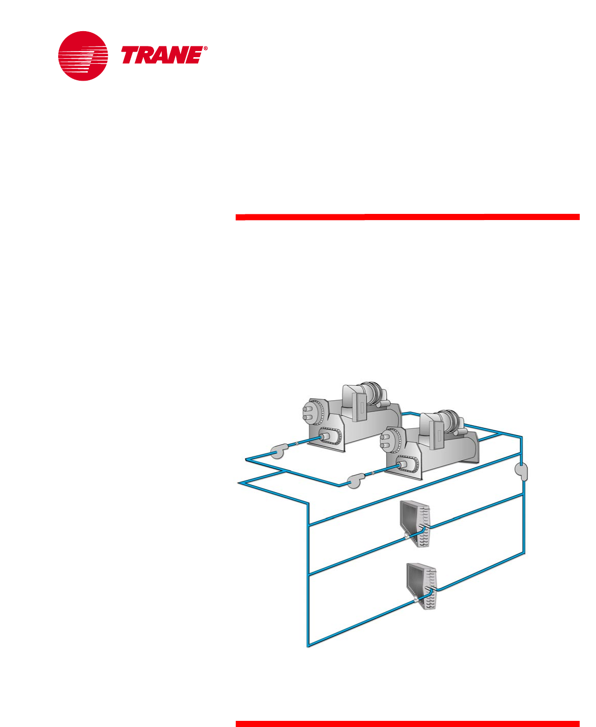
Chilled-Water Systems
One of the Systems Series
TRG-TRC016-EN
NO POSTAGE
NECESSARY
IF MAILED
IN THE
UNITED STATES
BUSINESS REPLY MAIL
FIRST-CLASS MAIL PERMIT NO. 11 LA CROSSE, WI
POSTAGE WILL BE PAID BY ADDRESSEE
THE TRANE COMPANY
Attn: Applications Engineering
3600 Pammel Creek Road
La Crosse WI 54601-9985
NO POSTAGE
NECESSARY
IF MAILED
IN THE
UNITED STATES
BUSINESS REPLY MAIL
FIRST-CLASS MAIL PERMIT NO. 11 LA CROSSE, WI
POSTAGE WILL BE PAID BY ADDRESSEE
THE TRANE COMPANY
Attn: Applications Engineering
3600 Pammel Creek Road
La Crosse WI 54601-9985
Crop to width of 7.75
Perforation 5.5 from bottom/top
Perforation 0.75 from edge
Comment Card
We want to ensure that our educational materials meet your ever-changing resource development needs.
Please take a moment to comment on the effectiveness of this Air Conditioning Clinic.
Chilled-Water Systems Level of detail (circle one) Too basic Just right Too difficult
One of the Systems Series
Rate this clinic from 1–Needs Improvement to 10–Excellent
…
TRG-TRC016-EN Content 12345678910
Booklet usefulness 12345678910
Slides/illustrations 12345678910
Presenter’s ability 12345678910
Training environment 12345678910
Other comments? _________________________________________________________
_______________________________________________________________________________
_______________________________________________________________________________
About me … Type of business _________________________________________________________
Job function _________________________________________________________
Optional: name _________________________________________________________
phone _________________________________________________________
address _________________________________________________________
Give the completed card to the
presenter or drop it in the mail.
Thank you!
The Trane Company • Worldwide Applied Systems Group
3600 Pammel Creek Road • La Crosse, WI 54601-7599
www.trane.com
An American-Standard Company
Response Card
We offer a variety of HVAC-related educational materials and technical references, as well as software tools
that simplify system design/analysis and equipment selection. To receive information about any of these
items, just complete this postage-paid card and drop it in the mail.
Education materials ❏Air Conditioning Clinic series About me…
❏Engineered Systems Clinic series Name ___________________________________________
❏Trane Air Conditioning Manual Title ___________________________________________
❏Trane Systems Manual Business type ___________________________________________
Software tools ❏Equipment Selection Phone/fax _____________________ ____________________
❏System design & analysis E-mail address ___________________________________________
Periodicals ❏Engineers Newsletter Company ___________________________________________
Other? ❏_____________________________ Address ___________________________________________
___________________________________________
___________________________________________
Thank you for your interest!
The Trane Company • Worldwide Applied Systems Group
3600 Pammel Creek Road • La Crosse, WI 54601-7599
www.trane.com
An American-Standard Company

Chilled-Water Systems
One of the Systems Series
A publication of
The Trane Company
Chilled-Water Systems

Preface
© 2001 American Standard Inc. All rights reserved
TRG-TRC016-EN
i
The Trane Company believes that it is incumbent on manufacturers to serve the
industry by regularly disseminating information gathered through laboratory
research, testing programs, and field experience.
The Trane Air Conditioning Clinic series is one means of knowledge sharing.
It is intended to acquaint a nontechnical audience with various fundamental
aspects of heating, ventilating, and air conditioning. We have taken special
care to make the clinic as uncommercial and straightforward as possible.
Illustrations of Trane products only appear in cases where they help convey
the message contained in the accompanying text.
This particular clinic introduces the reader to chilled-water systems.
A Trane Air Conditioning Clinic
Chilled-Water Systems
Figure 1

TRG-TRC016-EN ii
Contents
period one Types of Water Chillers ...................................... 1
Vapor-Compression Water Chillers .......................... 3
Air-Cooled or Water-Cooled Condensing .................. 6
Packaged or Split Components .............................. 11
Absorption Water Chillers ...................................... 15
Equipment Rating Standards ................................. 18
period two Chilled-Water System Design ........................ 26
Load-Terminal Control ........................................... 28
Parallel Configuration ............................................. 35
Series Configuration .............................................. 38
Primary-Secondary System Operation .................... 53
period three System Variations ............................................. 59
Alternate Fuel Choice ............................................ 59
Low-Flow Systems ............................................... 61
Variable-Primary-Flow Systems .............................. 64
Preferential Loading .............................................. 66
Heat Recovery ...................................................... 68
Asymmetric Design ............................................... 72
“Free” Cooling ...................................................... 75
Application Outside the Operating Range
of the Chiller ......................................................... 78
period four Chiller-Plant Control .......................................... 79
Chiller Sequencing ................................................ 82
Failure Recovery and Contingency Planning ........... 90
System Tuning ...................................................... 92
System Optimization ............................................. 96
Operator Interface ............................................... 100
period five Review ................................................................. 103
Quiz ....................................................................... 108
Answers .............................................................. 110
Glossary .............................................................. 112

iii TRG-TRC016-EN
TRG-TRC016-EN 1
notes
period one
Types of Water Chillers
Water chillers are used in a variety of air conditioning and process cooling
applications. They cool water that is subsequently transported by pumps
and pipes. The water passes through the tubes of coils to cool air in an air
conditioning system, or it can provide cooling for a manufacturing or industrial
process. Systems that employ water chillers are commonly called chilled-
water systems.
When designing a chilled-water system, one of the first issues that must be
addressed is to determine which type of water chiller to use. This period
discusses the primary differences in chiller types.
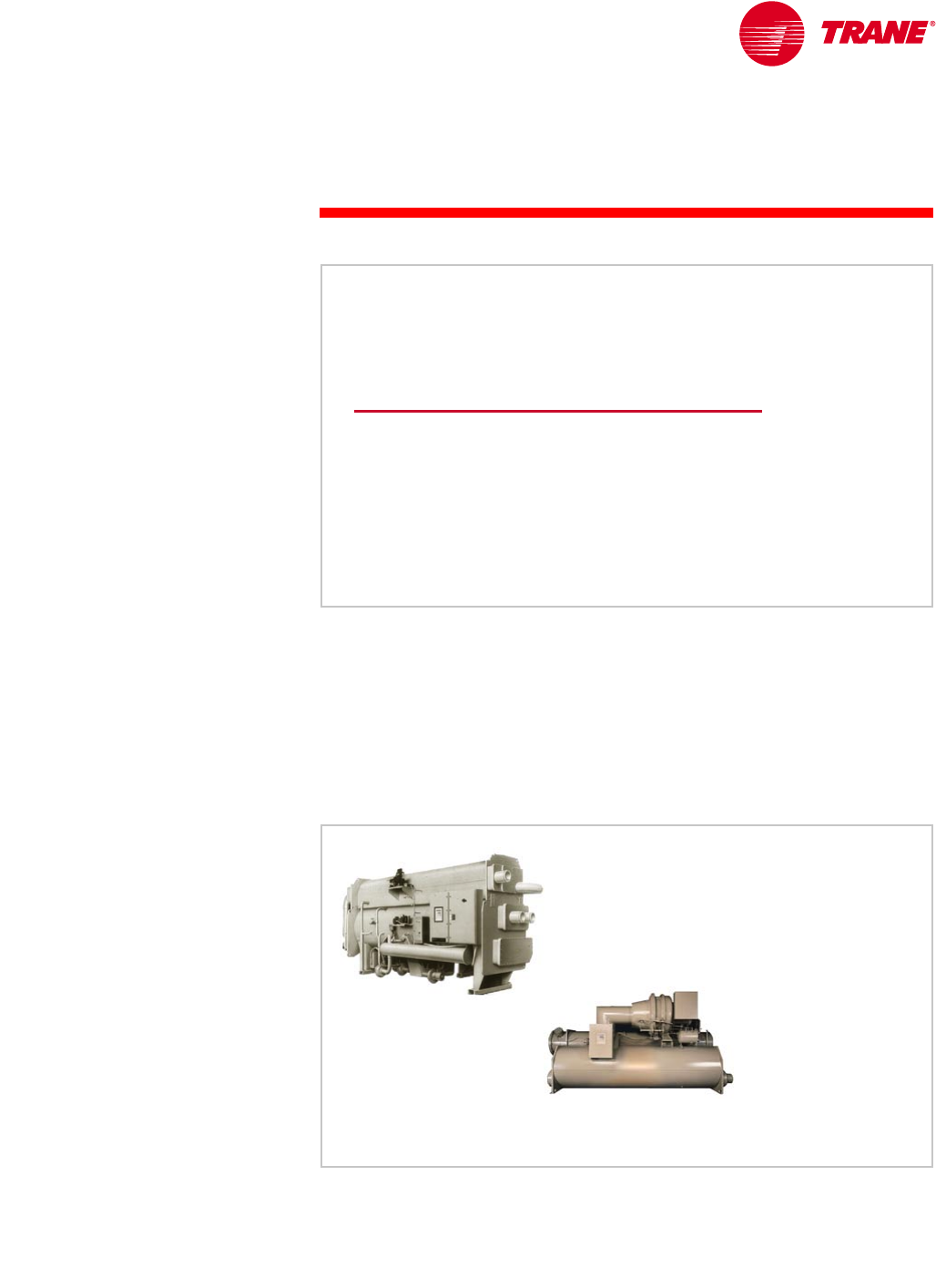
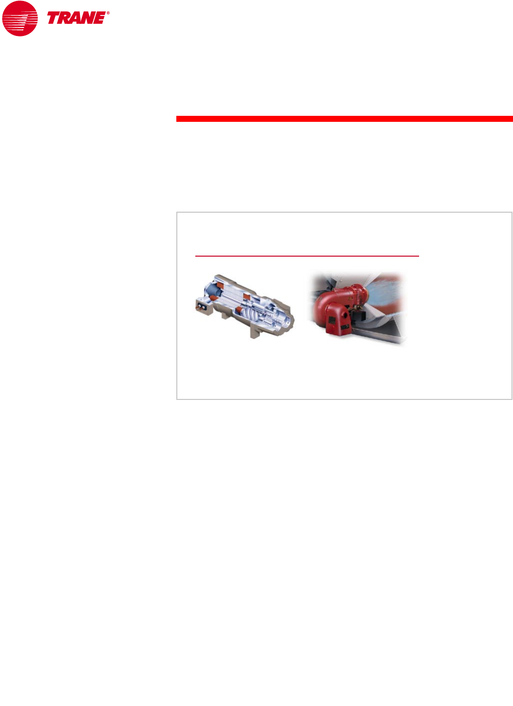
The refrigeration cycle is a key differentiating characteristic between chiller
types. The vapor-compression and absorption refrigeration cycles are the two
most common cycles used in commercial air conditioning.
period one
Types of Water Chillers
Chilled-Water Systems
Figure 2
absorption
water chiller
centrifugal
water chiller
Figure 3
2TRG-TRC016-EN
notes
period one
Types of Water Chillers
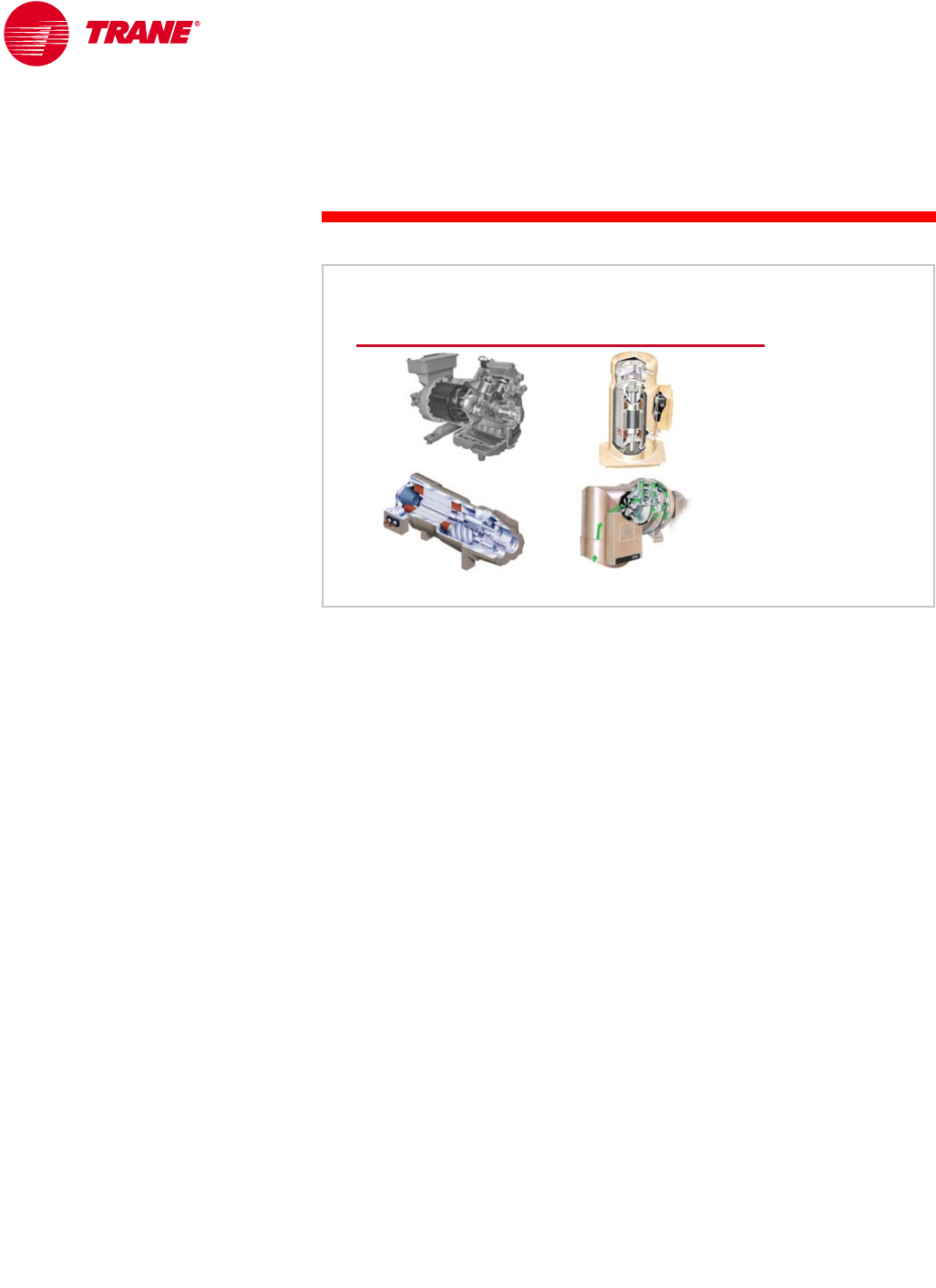
Water chillers using the vapor-compression refrigeration cycle vary by the type
of compressor used. Reciprocating, scroll, helical-rotary, and centrifugal
compressors are common types of compressors used in vapor-compression
water chillers.
Absorption water chillers make use of the absorption refrigeration cycle.
Vapor-compression water chillers use a compressor to move refrigerant around
the system. The most common energy source to drive the compressor is an
electric motor.
Absorption water chillers use heat to drive the refrigeration cycle. They do not
have a mechanical compressor involved in the refrigeration cycle. Steam, hot
water, or the burning of oil or natural gas are the most common energy sources
for these types of chillers.
Driving Sources
heat-driven
compressor-driven
Figure 4
TRG-TRC016-EN 3
period one
Types of Water Chillers
notes
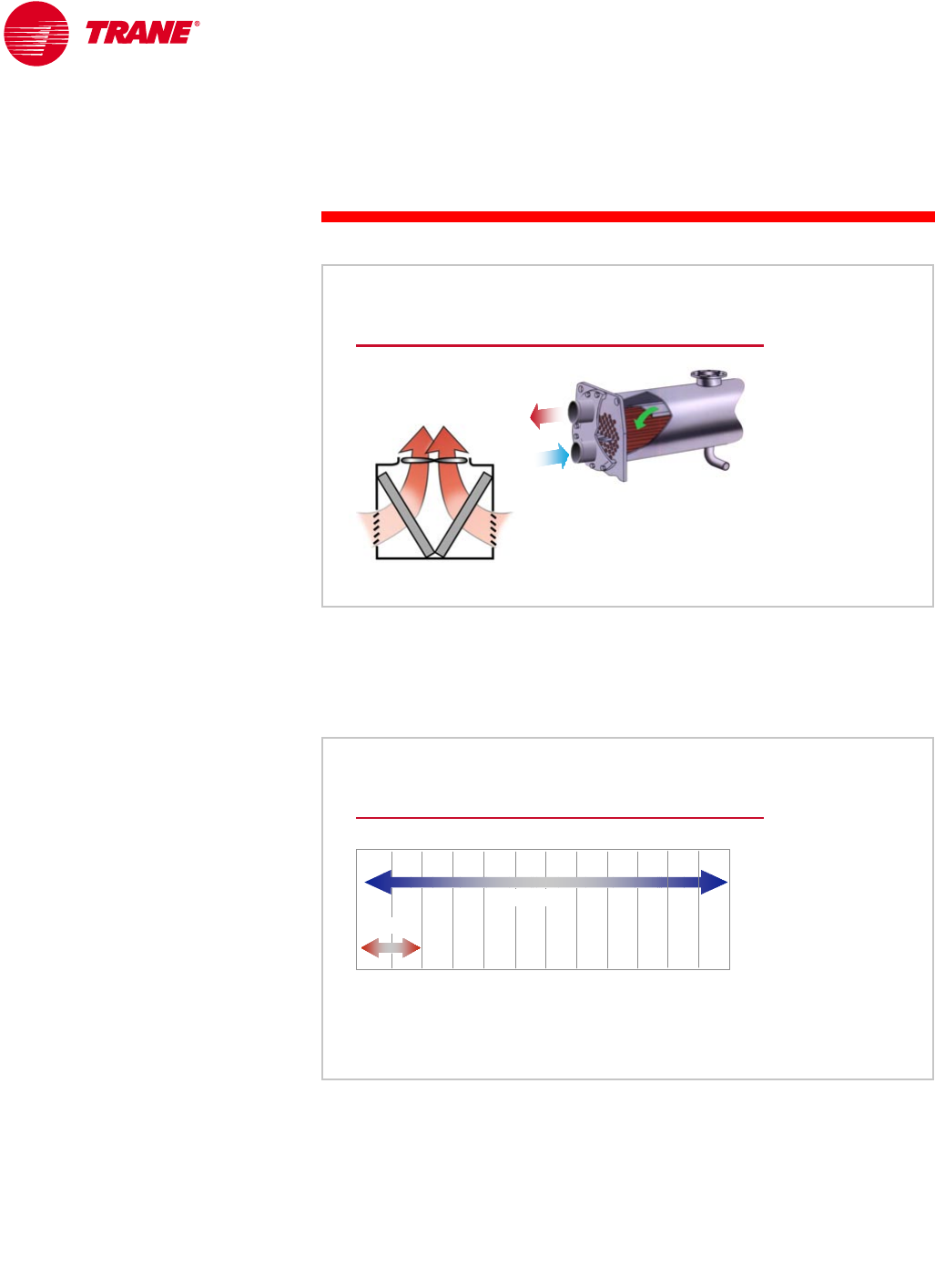
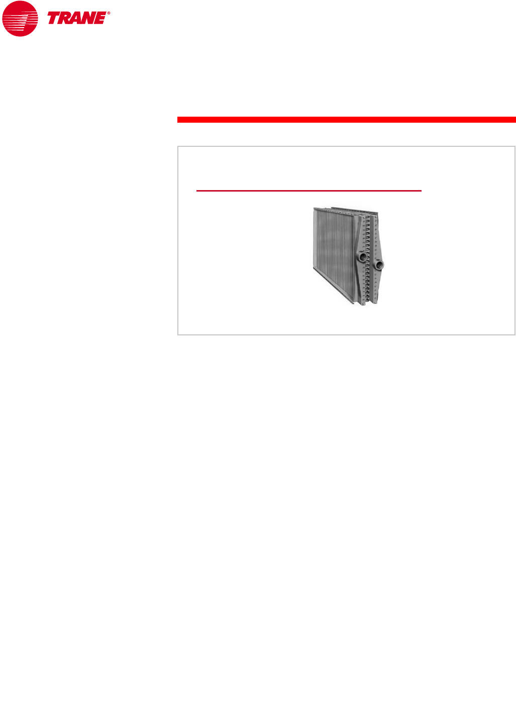
Vapor-Compression Water Chillers
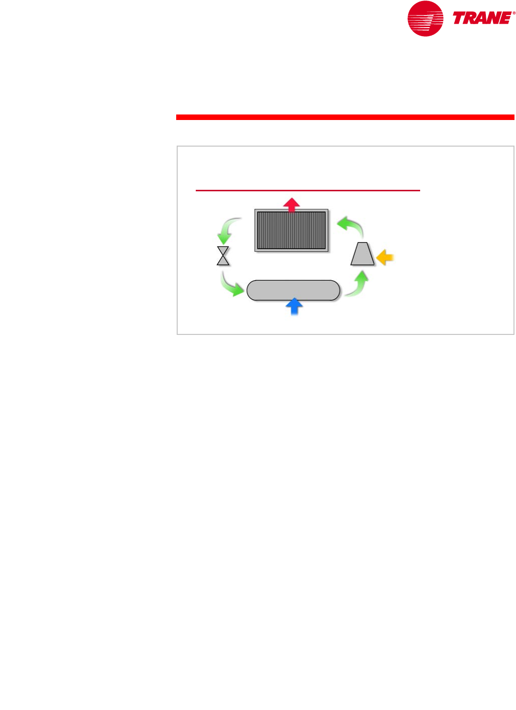
In the vapor-compression refrigeration cycle, refrigerant enters the evaporator
in the form of a cool, low-pressure mixture of liquid and vapor (A). Heat is
transferred from the relatively-warm air or water to the refrigerant, causing
the liquid refrigerant to boil. The resulting vapor (B) is then drawn from the
evaporator by the compressor, which increases the pressure and temperature
of the refrigerant vapor.
The hot, high-pressure refrigerant vapor (C) leaving the compressor enters
the condenser, where heat is transferred to ambient air or water at a lower
temperature. Inside the condenser, the refrigerant vapor condenses into a
liquid. This liquid refrigerant (D) then flows to the expansion device, which
creates a pressure drop that reduces the pressure of the refrigerant to that of
the evaporator. At this low pressure, a small portion of the refrigerant boils
(or flashes), cooling the remaining liquid refrigerant to the desired evaporator
temperature. The cool mixture of liquid and vapor refrigerant (A) travels to the
evaporator to repeat the cycle.
The vapor-compression refrigeration cycle is reviewed in detail in the
Refrigeration Cycle Air Conditioning Clinic.
Vapor-Compression Cycle
compressor
compressor
expansion
expansion
device
device
energy in
energy in
absorb heat
absorb heat
reject heat
reject heat
evaporator
evaporator
condenser
condenser
AB
C
D
Figure 5
4TRG-TRC016-EN
notes
period one
Types of Water Chillers
The type of compressor used generally has the greatest impact on the efficiency
and reliability of a vapor-compression water chiller. The improvement of
compressor designs and the development of new compressor technologies
have led to more-efficient and -reliable water chillers.
The reciprocating compressor was the workhorse of the small chiller market
for many years. It was typically available in capacities up to 100 tons [350 kW].
Multiple compressors were often installed in a single chiller to provide chiller
capacities of up to 200 tons [700 kW].
Scroll compressors have emerged as a popular alternative to reciprocating
compressors, and are generally available in hermetic configurations in
capacities up to 15 tons [53 kW] for use in water chillers. As with reciprocating
compressors, multiple scroll compressors are often used in a single chiller to
meet larger capacities. In general, scroll compressors are 10 to 15 percent more
efficient than reciprocating compressors and have proven to be very reliable,
primarily because they have approximately 60 percent fewer moving parts than
reciprocating compressors. Reciprocating and scroll compressors are typically
used in smaller water chillers, those less than 200 tons [700 kW].
Helical-rotary (or screw) compressors have been used for many years in
air compression and low-temperature-refrigeration applications. They are now
widely used in medium-sized water chillers, 50 to 500 tons [175 to 1,750 kW].
Like the scroll compressor, helical-rotary compressors have a reliability
advantage due to fewer moving parts, as well as better efficiency than
reciprocating compressors.
Centrifugal compressors have long been used in larger water chillers.
High efficiency, superior reliability, reduced sound levels, and relatively low
cost have contributed to the popularity of the centrifugal chiller. Centrifugal
compressors are generally available in prefabricated chillers from 100 to
3,000 tons [350 to 10,500 kW], and up to 8,500 tons [30,000 kW] as built-up
machines.
centrifugal
scroll
reciprocating
helical-rotary
Compressor Types
Figure 6
TRG-TRC016-EN 5
period one
Types of Water Chillers
notes These various types of compressors are discussed in detail in the Refrigeration
Compressors Air Conditioning Clinic.
The capacity of a centrifugal chiller can be modulated using inlet guide vanes
(IGV) or a combination of IGV and a variable-speed drive (adjustable-frequency
drive, AFD). Variable-speed drives are widely used with fans and pumps, and as
a result of the advancement of microprocessor-based controls for chillers, they
are now being applied to centrifugal water chillers.
Using an AFD with a centrifugal chiller will degrade the chiller’s full-load
efficiency. This can cause an increase in electricity demand or real-time pricing
charges. At the time of peak cooling, such charges can be ten (or more) times
the non-peak charges. Alternatively, an AFD can offer energy savings by
reducing motor speed at low-load conditions, when cooler condenser water
is available. An AFD also controls the inrush current at start-up.
Certain system characteristics favor the application of an adjustable-frequency
drive, including:
nA substantial number of part-load operating hours
nThe availability of cooler condenser water
nChilled-water reset control
Chiller savings using condenser- and chilled-water-temperature reset, however,
should be balanced against the increase in pumping and cooling-tower energy.
This is discussed in Period Four. Performing a comprehensive energy analysis
is the best method of determining whether an adjustable-frequency drive is
desirable. It is important to use actual utility costs, not a “combined” cost, for
demand and consumption charges.
Depending on the application, it may make sense to use the additional money
that would be needed to purchase an AFD to purchase a more efficient chiller
instead. This is especially true if demand charges are significant.
Variable-Speed Drives
variable
variable-
-
speed
speed
drive
drive
Figure 7
6TRG-TRC016-EN
notes
period one
Types of Water Chillers
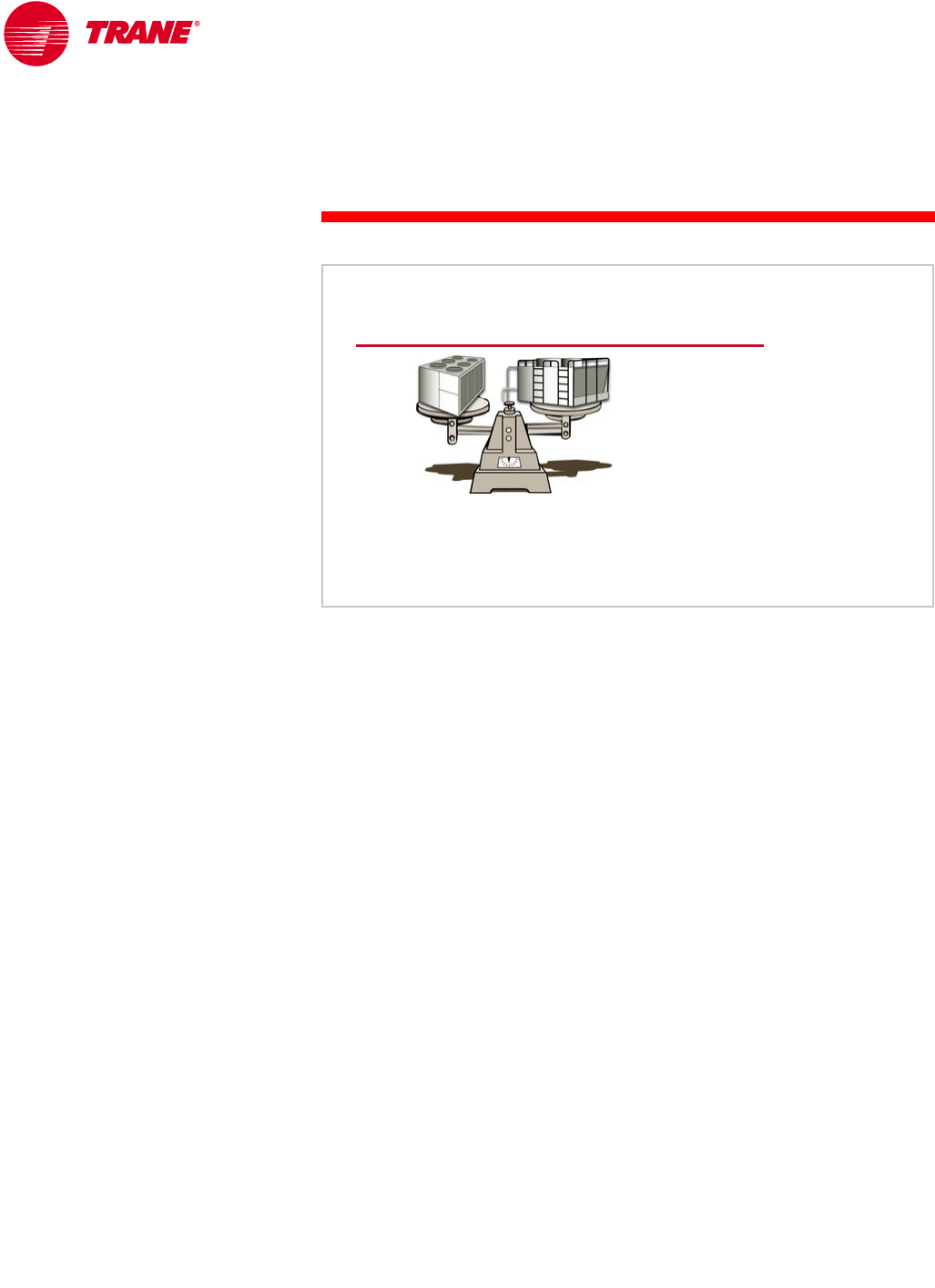
Air-Cooled or Water-Cooled Condensing
The heat exchangers in the water chiller (the condenser and evaporator) have
the second greatest impact on chiller efficiency and cost. One of the most
distinctive differences in chiller heat exchangers continues to be the type of
condenser selected—air-cooled versus water-cooled.
When comparing air-cooled and water-cooled chillers, available capacity is the
first distinguishing characteristic. Air-cooled chillers are typically available in
packaged chillers ranging from 7.5 to 500 tons [25 to 1,580 kW]. Packaged
water-cooled chillers are typically available from 10 to 3,000 tons [35 to
10,500 kW].
Condenser Types
water-cooled
air-cooled
Figure 8
Air-Cooled or Water-Cooled
0 tons
0 tons
[0 kW]
[0 kW]
1,000 tons
1,000 tons
[3,517 kW]
[3,517 kW]
2,000 tons
2,000 tons
[7,034 kW]
[7,034 kW]
chiller capacity
chiller capacity
water
water-
-cooled
cooled
air
air-
-cooled
cooled
1,500 tons
1,500 tons
[5,276 kW]
[5,276 kW]
2,500 tons
2,500 tons
[8,793 kW]
[8,793 kW]
500 tons
500 tons
[1,759 kW]
[1,759 kW]
3,000 tons
3,000 tons
[10,551 kW]
[10,551 kW]
Figure 9
TRG-TRC016-EN 7
period one
Types of Water Chillers
notes
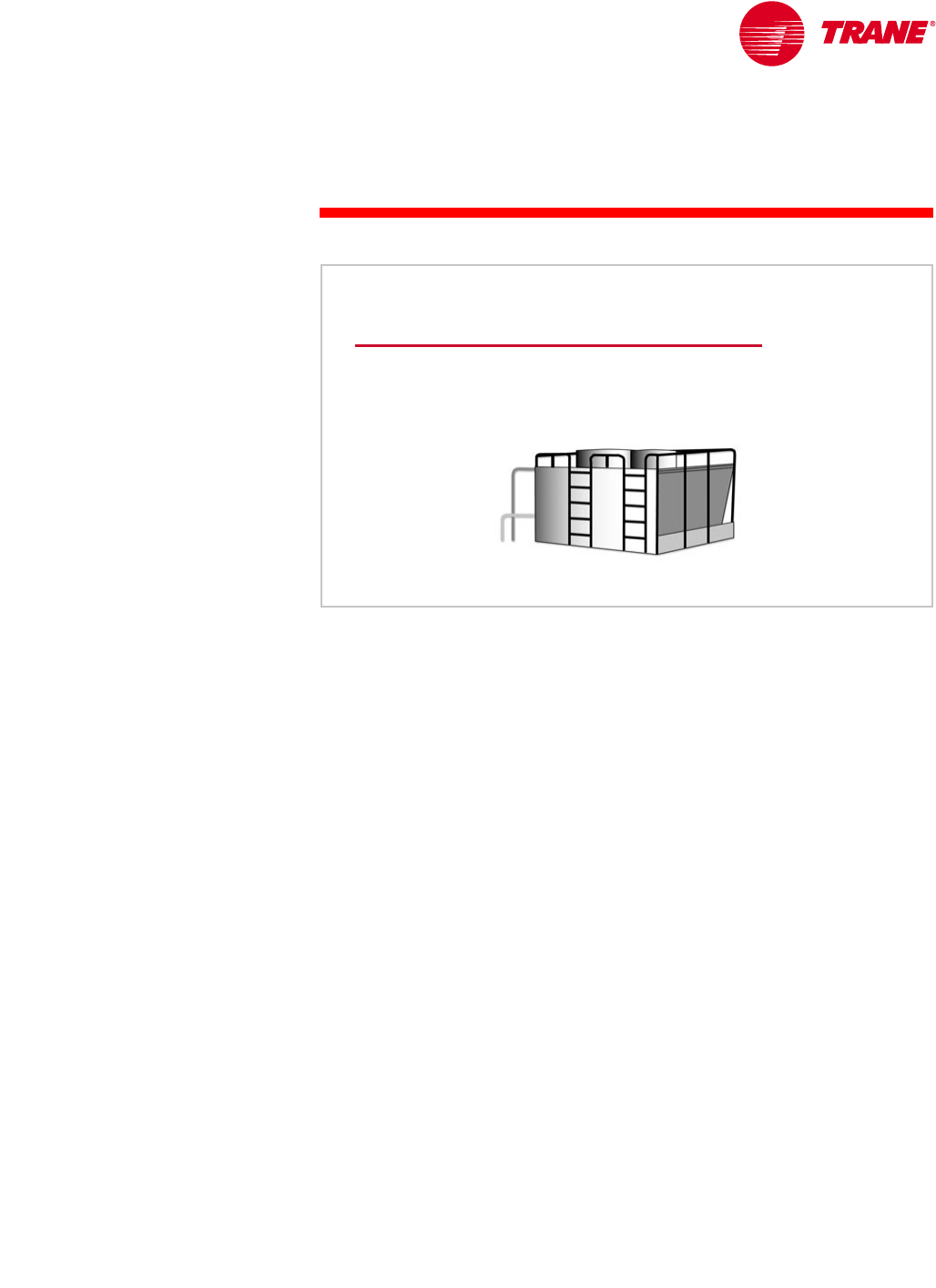
A major advantage of using an air-cooled chiller is the elimination of the cooling
tower. This eliminates the concerns and maintenance requirements associated
with water treatment, chiller condenser-tube cleaning, tower mechanical
maintenance, freeze protection, and the availability and quality of makeup
water. This reduced maintenance requirement is particularly attractive to
building owners because it can substantially reduce operating costs.
Systems that use an open cooling tower must have a water treatment program.
Lack of tower-water treatment results in contaminants such as bacteria and
algae. Fouled or corroded tubes can reduce chiller efficiency and lead to
premature equipment failure.
air-cooled or water-cooled
Maintenance
▲Water treatment
▲Condenser tube brushing
▲Tower maintenance
▲Freeze protection
▲Makeup water
cooling tower
cooling tower Figure 10
8TRG-TRC016-EN
notes
period one
Types of Water Chillers
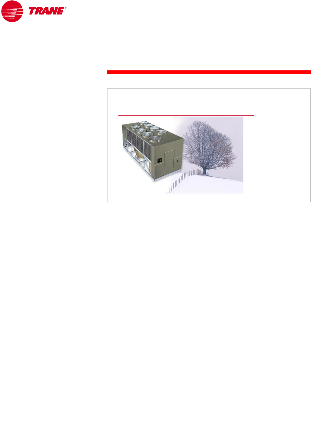
Air-cooled chillers are often selected for use in systems that require year-round
cooling requirements that cannot be met with an airside economizer. Air-cooled
condensers have the ability to operate in below-freezing weather, and can do so
without the problems associated with operating the cooling tower in these
conditions. Cooling towers may require special control sequences, basin
heaters, or even an indoor sump for safe operation in freezing weather.
For process applications, such as computer centers that require cooling year-
round, this ability alone often dictates the use of air-cooled chillers.
air-cooled or water-cooled
Low Ambient Operation
air
air-
-cooled
cooled
chiller
chiller
Figure 11
TRG-TRC016-EN 9
period one
Types of Water Chillers
notes
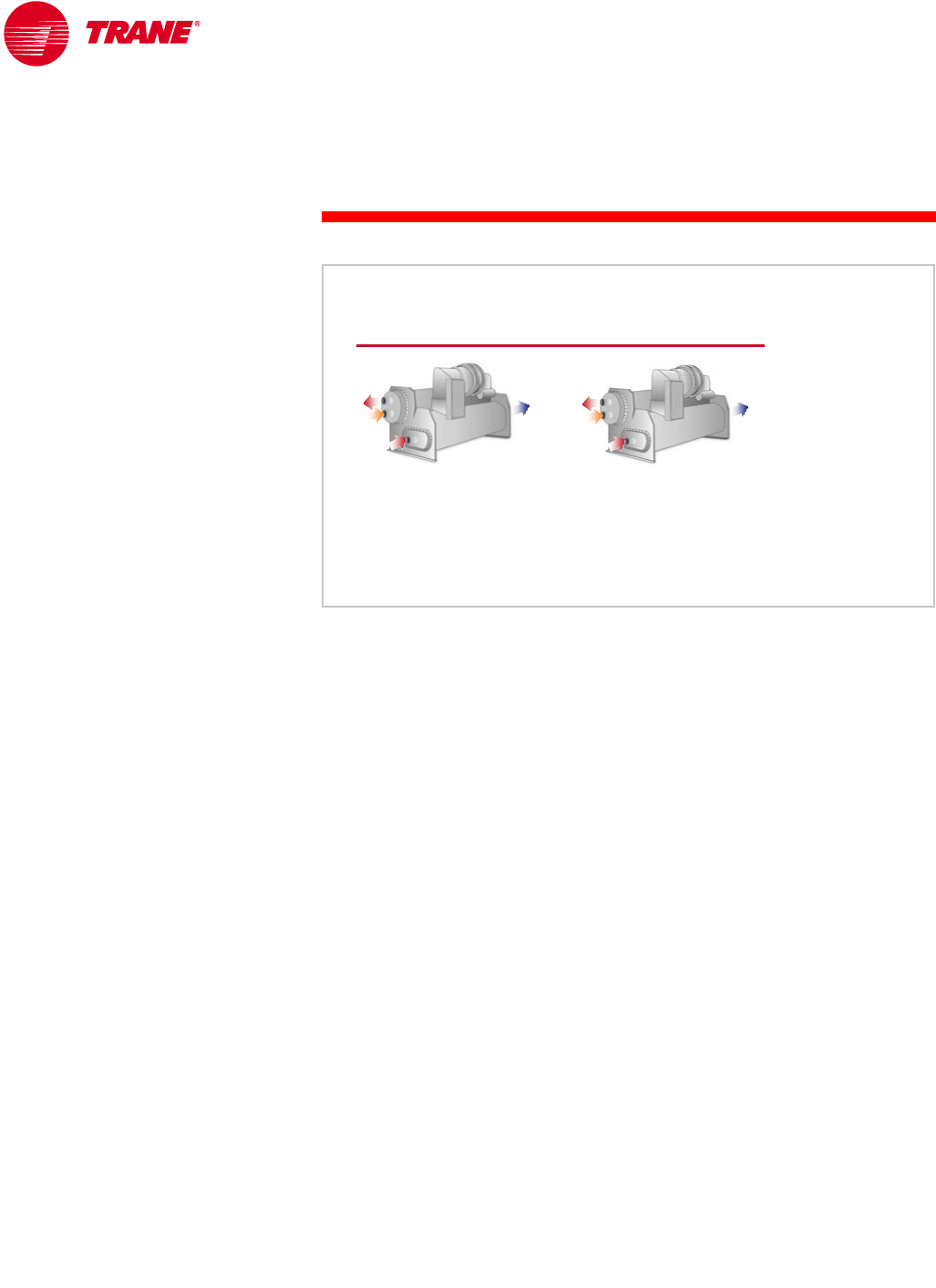
Water-cooled chillers are typically more energy efficient than air-cooled chillers.
The refrigerant condensing temperature in an air-cooled chiller is dependent
on the ambient dry-bulb temperature. The condensing temperature in a
water-cooled chiller is dependent on the condenser-water temperature, which
is dependent on the ambient wet-bulb temperature. Since the wet-bulb
temperature is often significantly lower than the dry-bulb temperature, the
refrigerant condensing temperature (and pressure) in a water-cooled chiller
can be lower than in an air-cooled chiller. For example, at an outdoor design
condition of 95°F [35°C] dry-bulb temperature, 78°F [25.6°C] wet-bulb
temperature, a cooling tower delivers 85°F [29.4°C] water to the water-cooled
condenser. This results in a refrigerant condensing temperature of
approximately 100°F [37.8°C]. At these same outdoor conditions, the refrigerant
condensing temperature in an air-cooled condenser is approximately 125°F
[51.7°C]. A lower condensing temperature, and therefore a lower condensing
pressure, means that the compressor needs to do less work and consumes
less energy.
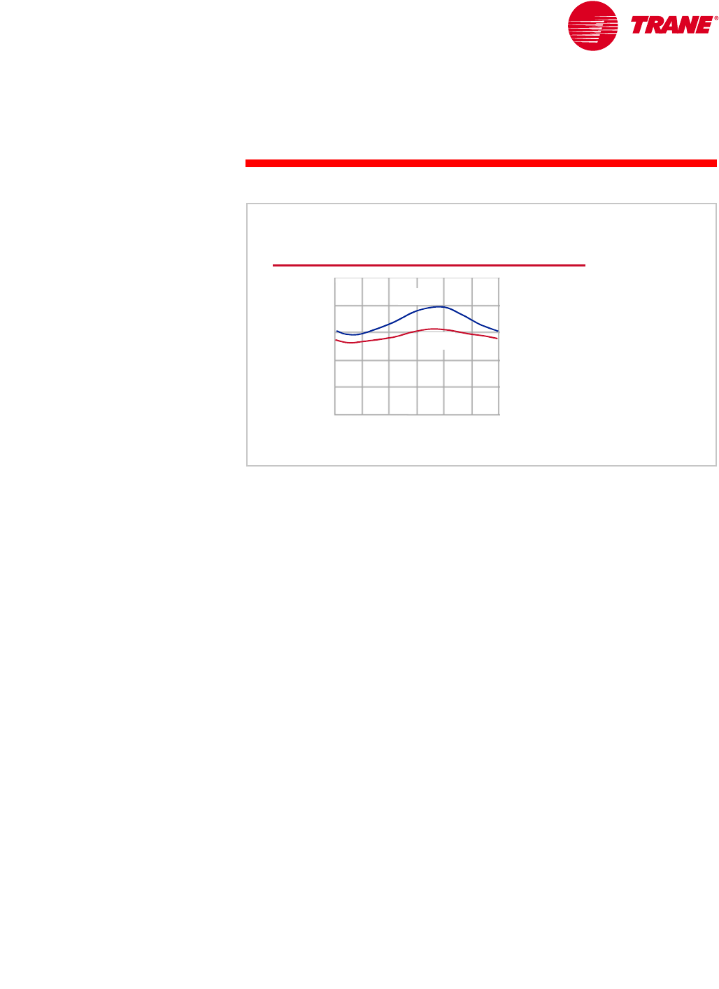
This efficiency advantage may lessen at part-load conditions because the
dry-bulb temperature tends to drop faster than the wet-bulb temperature
(see Figure 12). As a result, the air-cooled chiller may benefit from greater
condenser relief.
Additionally, the efficiency advantage of a water-cooled chiller is much less
when the additional cooling tower and condenser pump energy costs are
considered. Performing a comprehensive energy analysis is the best method
of estimating the operating-cost difference between air-cooled and water-cooled
systems.
air-cooled or water-cooled
Efficiency
outdoor temperature
outdoor temperature
12
12
midnight
midnight
12
12
noon
noon 12
12
midnight
midnight
dry bulb
dry bulb
wet bul b
wet bul b
Figure 12
10 TRG-TRC016-EN
notes
period one
Types of Water Chillers
Another advantage of an air-cooled chiller is its delivery as a “packaged
system.” Reduced design time, simplified installation, higher reliability, and
single-source responsibility are all factors that make the factory packaging of
the condenser, compressor, and evaporator a major benefit. A water-cooled
chiller has the additional requirements of condenser-water piping, pump,
cooling tower, and associated controls.
Water-cooled chillers typically last longer than air-cooled chillers. This
difference is due to the fact that the air-cooled chiller is installed outdoors,
whereas the water-cooled chiller is installed indoors. Also, using water as the
condensing fluid allows the water-cooled chiller to operate at lower pressures
than the air-cooled chiller. In general, air-cooled chillers last 15 to 20 years, while
water-cooled chillers last 20 to 30 years.
To summarize the comparison of air-cooled and water-cooled chillers, air-cooled
chiller advantages include lower maintenance costs, a prepackaged system for
easier design and installation, and better low-ambient operation. Water-cooled
chiller advantages include greater energy efficiency (at least at design
conditions) and longer equipment life.
water-cooled
▲Greater energy efficiency
▲Longer equipment life
air-cooled or water-cooled
Comparison
air-cooled
▲Lower maintenance
▲Packaged system
▲Better low-ambient
operation Figure 13
TRG-TRC016-EN 11
period one
Types of Water Chillers
notes
Packaged or Split Components
Water-cooled chillers are rarely installed with separable components. Air-cooled
chillers, however, offer the flexibility of separating the components in different
physical locations. This flexibility allows the system design engineer to place
the components where they best serve the available space, acoustic, and
maintenance requirements of the customer.
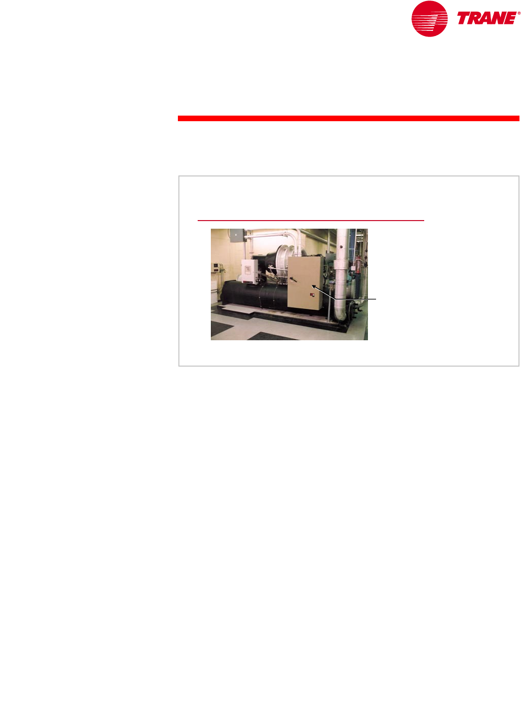
A packaged air-cooled chiller has all of the refrigeration components
(compressor, condenser, expansion device, and evaporator) located outdoors.
A major advantage of this configuration is factory assembly and testing of all
chiller components, including the wiring, refrigerant piping, and controls.
This eliminates field labor and often results in faster installation and improved
system reliability. Additionally, all noise-generating components (compressors
and condenser fans) are located outdoors, easing indoor noise concerns.
Finally, indoor equipment-room space requirements are minimized.
Packaged Air-Cooled Chiller
air-cooled chiller
Figure 14
12 TRG-TRC016-EN
notes
period one
Types of Water Chillers
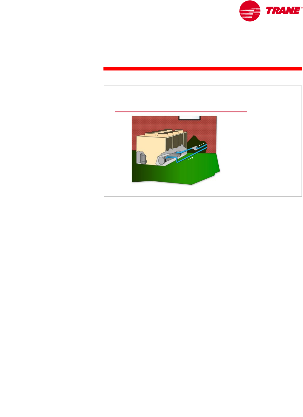
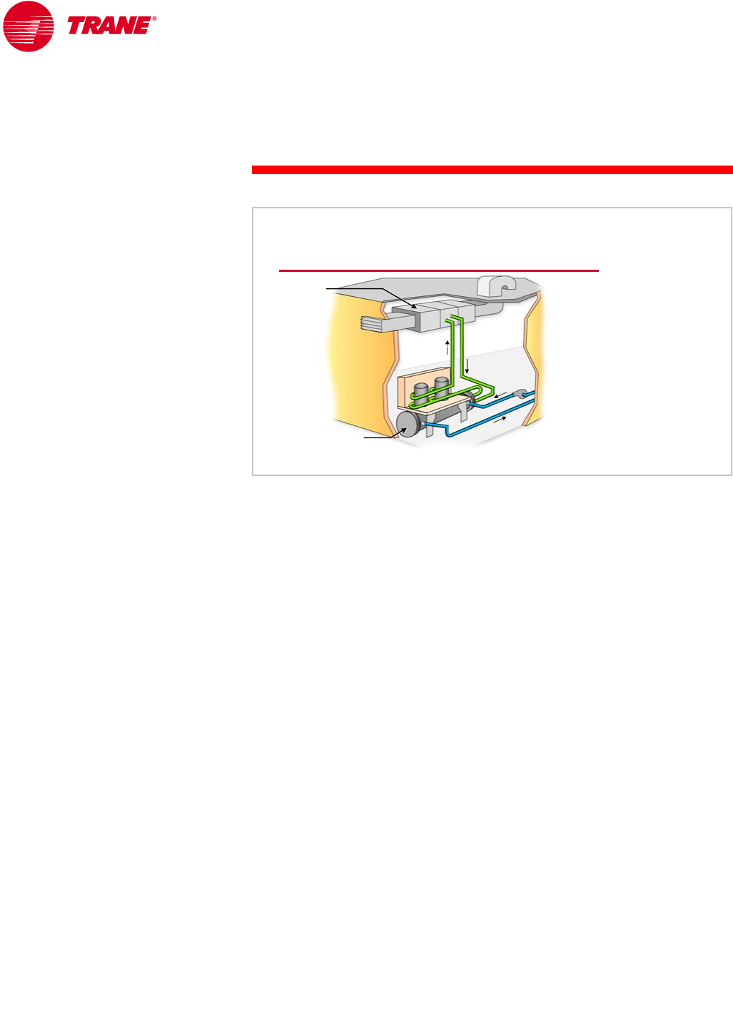
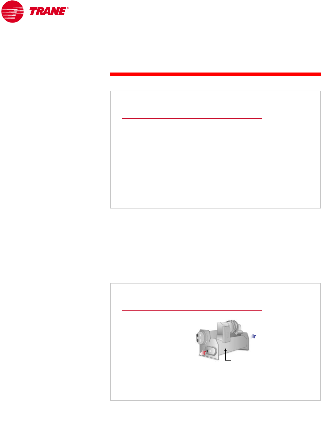
An alternative to the packaged air-cooled chiller is to use a packaged
condensing unit (condenser and compressor) located outdoors, with a remote
evaporator barrel located in the indoor equipment room. The two components
are connected with field-installed refrigerant piping. This configuration locates
the part of the system that is susceptible to freezing (evaporator) indoors and
the noise-generating components (compressors and condenser fans) outdoors.
This usually eliminates any requirement to protect the chilled-water loop from
freezing during cold weather.
This configuration is particularly popular in schools and other institutional
applications, primarily due to reduced seasonal maintenance for freeze
protection. A drawback of splitting the components is the requirement for
field-installed refrigerant piping. The possibility of system contamination
and leaks increases when field-installed piping and brazing are required.
Additionally, longer design time is generally required for the proper selection,
sizing, and installation of this split system.
Remote Evaporator Barrel
condensing unit
condensing unit
remote
evaporator
refrigerant
piping
Figure 15
TRG-TRC016-EN 13
period one
Types of Water Chillers
notes
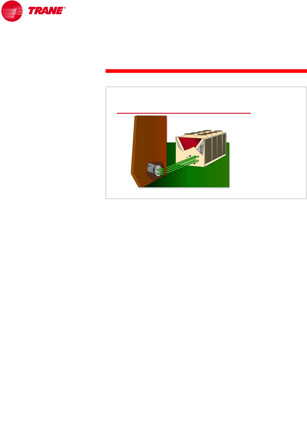
Another popular configuration is to use an outdoor air-cooled condenser
connected to a packaged compressor and evaporator unit (also called a
condenserless chiller) that is located in the indoor equipment room. Again,
the components are connected with field-installed refrigerant piping.
The primary advantage of this configuration is that the compressors are located
indoors, which makes maintenance easier during inclement weather and
virtually eliminates the concern of refrigerant migrating to the compressors
during cold weather.
Remote Air-Cooled Condenser
air
air-
-cooled
cooled
condenser
condenser
refrigerant
refrigerant
piping
piping
condenserless
condenserless
chiller
chiller
Figure 16
14 TRG-TRC016-EN
notes
period one
Types of Water Chillers
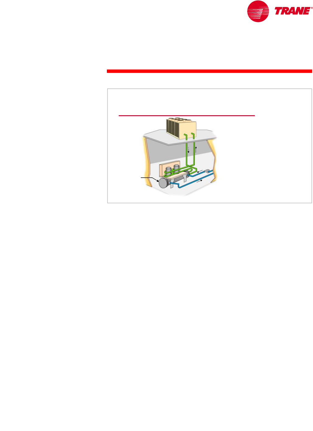
The final configuration includes a packaged compressor-and-evaporator unit
that is located in an indoor equipment room and connected to an indoor,
air-cooled condenser. The air used for condensing is ducted from outdoors,
through the condenser coil, and rejected either outdoors or inside the building
as a means for heat recovery. Indoor condensers typically use a centrifugal fan
to overcome the duct static-pressure losses, rather than the propeller fans used
in conventional outdoor air-cooled condensers. Again, the components are
connected with field-installed refrigerant piping.
This configuration is typically used where an outdoor condenser is
architecturally undesirable, where the system is located on a middle floor of a
multistory building, or where vandalism to exterior equipment is a problem.
A disadvantage of this configuration is that it typically increases condenser fan
energy within compared to a conventional outdoor air-cooled condenser.
Similarly, a packaged cooling tower in a water-cooled system can also be
located indoors. This configuration also requires outdoor air to be ducted to
and from the cooling tower, and again, typically requires the use of a centrifugal
fan. Centrifugal fans use about twice as much energy as a propeller fan, but can
overcome the static-pressure losses due to the ductwork. Alternatively, the
tower sump can be located indoors, making freeze protection easier.
Indoor Air-Cooled Condenser
condenserless
condenserless
chiller
chiller
indoor
indoor
air
air-
-cooled
cooled
condenser
condenser
refrigerant
refrigerant
piping
piping
Figure 17
TRG-TRC016-EN 15
period one
Types of Water Chillers
notes
Absorption Water Chillers
So far, we have discussed water chillers that use the vapor-compression
refrigeration cycle. Absorption water chillers are a proven alternative to vapor-
compression chillers. The absorption refrigeration cycle uses heat energy as the
primary driving force. The heat may be supplied either in the form of steam or
hot water (indirect-fired), or by burning oil or natural gas (direct-fired).
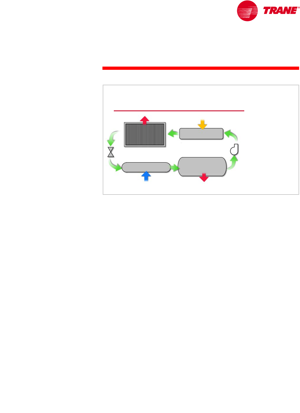
There are two fundamental differences between the absorption refrigeration
cycle and the vapor-compression refrigeration cycle. The first is that the
compressor is replaced by an absorber, pump, and generator. The second is
that, in addition to the refrigerant, the absorption refrigeration cycle uses a
secondary fluid called the absorbent. The condenser, expansion device, and
evaporator sections, however, are similar.
Warm, high-pressure liquid refrigerant (D) passes through the expansion
device and enters the evaporator in the form of a cool, low-pressure mixture of
liquid and vapor (A). Heat is transferred from the relatively-warm system water
to the refrigerant, causing the liquid refrigerant to boil. Using an analogy of the
vapor-compression cycle, the absorber acts like the suction side of the
compressor—it draws in the refrigerant vapor (B) to mix with the absorbent.
The pump acts like the compression process itself—it pushes the mixture of
refrigerant and absorbent up to the high-pressure side of the system. The
generator acts like the discharge of the compressor—it delivers the refrigerant
vapor (C) to the rest of the system.
The refrigerant vapor (C) leaving the generator enters the condenser, where
heat is transferred to cooling-tower water at a lower temperature, causing the
refrigerant vapor to condense into a liquid. This high-pressure liquid refrigerant
(D) then flows to the expansion device, which creates a pressure drop that
reduces the pressure of the refrigerant to that of the evaporator, repeating
the cycle.
The absorption refrigeration cycle is discussed in more detail in the Absorption
Water Chillers Air Conditioning Clinic.
Absorption Refrigeration Cycle
pump
pump
expansion
expansion
device
device
absorb heat
absorb heat
reject heat
reject heat
heat energy in
heat energy in
reject heat
reject heat
evaporator
evaporator
condenser
condenser
absorber
absorber
generator
generator
AB
C
D
Figure 18
16 TRG-TRC016-EN
notes
period one
Types of Water Chillers
Absorption water chillers generally have a higher first cost than vapor-
compression chillers. The cost difference is due to the additional heat-transfer
tubes required in the absorber and generator(s), the solution heat exchangers,
and the cost of the absorbent. This initial cost premium is often justified when
electric demand charges or real-time electricity prices are a significant portion
of the electric utility bill. Because electric demand charges are often highest at
the same time as peak cooling requirements, absorption chillers are often
selected as peaking or demand-limiting chillers.
Because the absorption chiller uses only a small amount of electricity, backup-
generator capacity requirements may be significantly lower with absorption
chillers than with electrically-driven chillers. This makes absorption chillers
attractive in applications requiring emergency cooling, assuming the alternate
energy source is available.
Some facilities, such as hospitals or factories, may have excess steam or hot
water as a result of normal operations. Other processes, such as a gas turbine,
generate waste steam or some other waste gas that can be burned. In such
applications, this otherwise wasted energy can be used to fuel an
absorption chiller.
Finally, cogeneration systems often use absorption chillers as a part of their
total energy approach to supplying electricity in addition to comfort cooling
and heating.
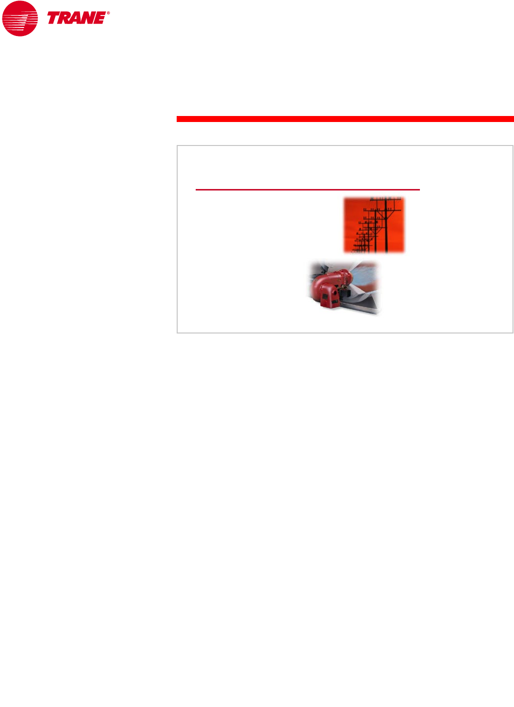
Absorption Chillers Offer Choice
▲Avoid high electric
demand charges
▲Minimal electricity
needed during
emergency situations
▲Waste heat recovery
▲Cogeneration
Figure 19
TRG-TRC016-EN 17
period one
Types of Water Chillers
notes
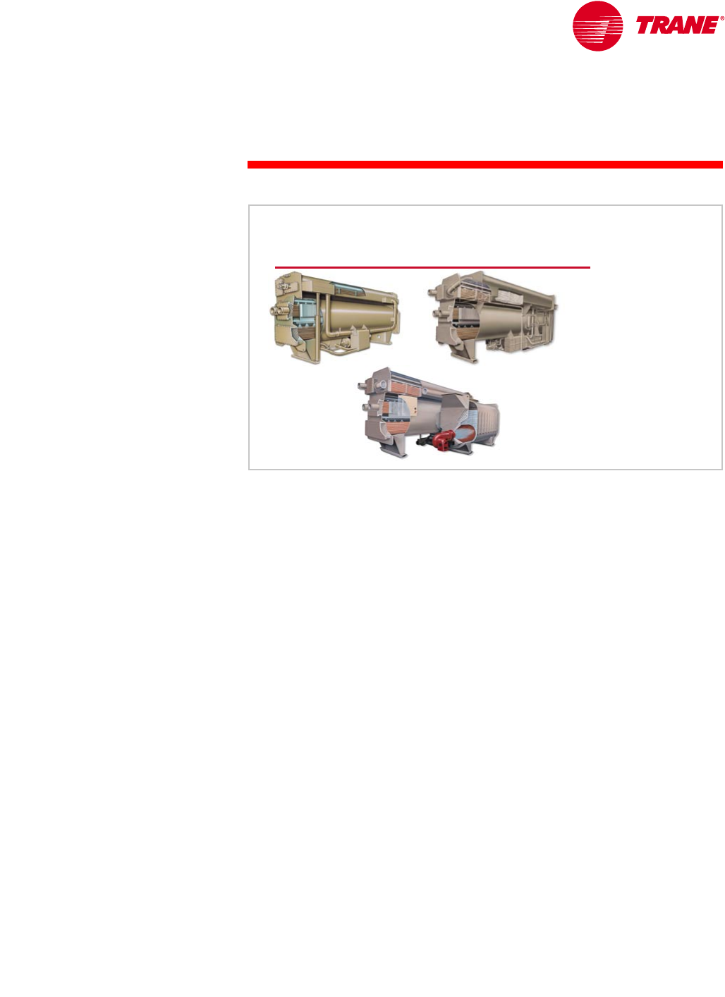
There are three basic types of absorption chillers. They are typically available
in capacities ranging from 100 to 1,600 tons [350 to 5,600 kW].
Indirect-fired, single-effect absorption chillers operate on low-pressure
steam (approximately 15 psig [205 kPa]) or medium-temperature liquids
(approximately 270°F [132°C]), and have a coefficient of performance (COP) of
0.6 to 0.8. In many applications, waste heat from process loads, cogeneration
plants, or excess boiler capacity provides the steam to drive a single-effect
chiller. In these applications, absorption chillers become conservation devices
and are typically base-loaded. This means that they run as the lead chiller to
make use of the “free” energy that might otherwise be wasted.
Indirect-fired, double-effect absorption chillers require medium-pressure
steam (approximately 115 psig [894 kPa]) or high-temperature liquids
(approximately 370°F [188°C]) to operate and, therefore, typically require
dedicated boilers. Typical COPs for these chillers are 0.9 to 1.2.
The direct-fired absorption chiller includes an integral burner, rather than
relying on an external heat source. Common fuels used to fire the burner are
natural gas, fuel oil, or liquid petroleum. Additionally, combination burners are
available that can switch from one fuel to another. Typical COPs for direct-fired,
double-effect chillers are 0.9 to 1.1 (based on the higher heating value of the
fuel). Higher energy efficiency and elimination of the boiler are largely
responsible for the increasing interest in direct-fired absorption chillers. These
types of absorption chillers have the added capability to produce hot water for
heating. Thus, these “chiller–heaters” can be configured to produce both chilled
water and hot water simultaneously. In certain applications this flexibility
eliminates, or significantly down-sizes, the boilers.
Absorption Chiller Types
single-effect double-effect
direct-fired
Figure 20
18 TRG-TRC016-EN
notes
period one
Types of Water Chillers
Equipment Rating Standards
The Air-Conditioning & Refrigeration Institute (ARI) establishes rating standards
for packaged HVAC equipment. ARI also certifies and labels equipment through
programs that involve random testing of a manufacturer’s equipment to verify
published performance. These equipment rating standards have been
developed to aid engineers in comparing similar equipment from different
manufacturers. Chiller full-load efficiency is described in terms of kW/ton and
coefficient of performance (COP). Additionally, two efficiency values developed
by ARI that are receiving increased attention are the Integrated Part-Load
Value (IPLV) and Non-Standard Part-Load Value (NPLV).
ARI’s part-load efficiency rating system establishes a single number to estimate
both the full- and part-load performance of a stand-alone chiller. As part of ARI
Standard 550/590–1998, Water-Chilling Packages Using the Vapor-Compression
Refrigeration Cycle, and ARI Standard 560–1992, Absorption Water Chilling-
Heating Packages, chiller manufacturers may now certify their chiller part-load
performance using the IPLV and NPLV methods. This gives the engineering
community an easy and certified method to evaluate individual chillers.
Understanding the scope and application limits of IPLV and NPLV is, however,
crucial to their validity as system performance indicators.
Equipment Rating Standards
▲Air-Conditioning &
Refrigeration Institute (ARI)
◆Standard 550/590–1998:
centrifugal and helical-rotary
water chillers
◆Standard 560–1992:
absorption water chillers
Figure 21

TRG-TRC016-EN 19
period one
Types of Water Chillers
notes
The IPLV predicts chiller efficiency at the ARI standard rating conditions, using
weighted-average load curves that represent a broad range of geographic
locations, building types, and operating-hour scenarios, both with and without
an airside economizer. The NPLV uses the same methods to predict chiller
efficiency at non-standard rating conditions. Although these weighted-average
load curves place greater emphasis on the part-load operation of an average,
single-chiller installation, they will not—by definition—represent any
particular installation.
Additionally, ARI notes that more than 80 percent of all chillers are installed in
multiple-chiller systems. Chillers in these systems exhibit different unloading
characteristics than the IPLV weighted formula indicates. Appendix D of
Standard 550/590–1998 explains this further:
The IPLV equations and procedure are intended to provide a single-
number, part-load performance number for water-chilling products.
The equation was derived to provide a representation of the average
part-load efficiency for a single chiller only. However, it is best to use a
comprehensive analysis that reflects the actual weather data, building
load characteristics, operational hours, economizer capabilities, and
energy drawn by auxiliaries, such as pumps and cooling towers, when
calculating the chiller and system efficiency.
Here is the important part:
This becomes increasingly important with multiple-chiller systems
because individual chillers operating within multiple-chiller systems
are more heavily loaded than single chillers within single-chiller
systems.
Part-Load Efficiency Rating
▲Integrated Part-Load Value (IPLV)
◆Weighted-average load curves
◆Based on an “average” single-chiller installation
◆Standard operating conditions
▲Non-Standard Part-Load Value (NPLV)
◆Weighted-average load curves
◆Based on an “average” single-chiller installation
◆Non-standard operating conditions
Figure 22
20 TRG-TRC016-EN
notes
period one
Types of Water Chillers
The standard rating conditions used for ARI certification represent a particular
set of design temperatures and flow rates for which water-cooled and air-cooled
systems may be designed. They are not suggestions for good design practice
for a given system—they simply define a common rating point to aid
comparisons.
In fact, concerns toward improved humidity control and energy efficiency have
changed some of the design trends for specific applications. More commonly,
chilled-water systems are being designed with lower chilled-water
temperatures and lower flow rates. The water flow rate required through the
system is decreased by allowing a larger temperature difference through the
chiller.
chiller type
evaporator
flow rate
vapor-compression
• reciprocating
•scroll
• helical-rotary
• centrifugal
2.4 gpm/ton
[0.043 L/s/kW]
absorption
• single-effect
• double-effect,
indirect-fired
• double-effect,
direct-fired
Standard Rating Conditions
condenser
flow rate
3.0 gpm/ton
[0.054 L/s/kW]
2.4 gpm/ton
[0.043 L/s/kW]
3.6 gpm/ton
[0.065 L/s/kW]
2.4 gpm/ton
[0.043 L/s/kW]
4.0 gpm/ton
[0.072 L/s/kW]
rating
standard
ARI
550/590–1998
ARI
560–1992
water leaving evaporator = 44°F [6.7°C]
water entering condenser = 85°F [29.4°C]
4.5 gpm/ton
[0.081 L/s/kW]
Figure 23

TRG-TRC016-EN 21
period one
Types of Water Chillers
notes
The temperature difference (∆T) through the chiller and the water flow rate are
related. For a given load, as the flow rate is reduced, the ∆T increases, and vice
versa.
where,
nQ = load, Btu/hr [W]
nflow rate = water flow rate through the chiller, gpm [L/s]
n∆T = temperature difference (leaving minus entering) through the chiller,
ºF [°C]
Realize that 500 [4,184] is not a constant! It is the product of density, specific
heat, and a conversion factor for time. The properties of water at conditions
typically found in an HVAC system result in this value. Other fluids, such as
mixtures of water and antifreeze, will cause this factor to change.
Density of water = 8.33 lb/gal [1.0 kg/L]
Specific heat of water = 1.0 Btu/lb°F [4,184 J/kg°K]
Flow Rates and Temperatures
equation for water only
QBtu/hr = 500 ×flow rate ×∆
∆∆
∆T
[QW= 4,184 ×flow rate ×∆T ]
Figure 24
Q 500 flow rate ∆T××=
Q 4,184 flow rate ∆T××=[]
8.33 lb/gal 1.0 Btu/lb°F 60 min/hr 500=××
1.0 kg/L 4,184 J/kg°K4,184=×[]
22 TRG-TRC016-EN
notes
period one
Types of Water Chillers
In the example system shown in Figure 25, the chilled water is cooled from 57°F
[13.9°C] to 41°F [5°C] for a 16°F [8.9°C] ∆T. This reduces the water flow rate
required from 2.4 gpm/ton [0.043 L/s/kW] to 1.5 gpm/ton [0.027 L/s/kW].
Reducing water flow rates either: 1) lowers system installed costs by reducing
pipe, pump, valve, and cooling tower sizes, or 2) lowers system operating costs
by using smaller pumps and smaller cooling tower fans. In some cases, both
installed and operating costs can be saved. Low-flow systems will be discussed
in more detail in Period Three.
The two ARI rating standards mentioned previously, as well as ASHRAE/IESNA
Standard 90.1–1999 (the energy standard), allow reduced chilled-water
temperatures and flow rates. System design engineers should examine the use
of reduced flow rates to offer value to building owners.
Flow Rates and Temperatures
2.4 gpm/ton
[0.043 L/s/kW]
44°F
44°F
[6.7°C]
[6.7°C]
54°F
54°F
[12.2°C]
[12.2°C]
85°F
85°F
[29.4°C]
[29.4°C]
95°F
95°F
[35°C]
[35°C]
3.0 gpm/ton
[0.054 L/s/kW]
ARI conditions
1.5 gpm/ton
[0.027 L/s/kW]
41°F
41°F
[5°C]
[5°C]
57°F
57°F
[13.9°C]
[13.9°C]
85°F
85°F
[29.4°C]
[29.4°C]
100°F
100°F
[37.8°C]
[37.8°C]
2.0 gpm/ton
[0.036 L/s/kW]
low-flow conditions
evaporator
flow rate
condenser
flow rate
evaporator
flow rate
condenser
flow rate
Figure 25
TRG-TRC016-EN 23
period one
Types of Water Chillers
notes
ASHRAE/IESNA Standard 90.1–1999, Energy Standard for Buildings, Except
Low-Rise Residential Buildings, went into effect in October 1999. ASHRAE
is the American Society of Heating, Refrigerating and Air-Conditioning
Engineers and IESNA is the Illuminating Engineering Society of North America.
This standard addresses all aspects of buildings except low-rise residential
buildings. It contains specific requirements for both water chillers and
chilled-water systems.
Standard 90.1 contains minimum full- and part-load efficiency requirements
for packaged water chillers. The table in Figure 27 is an excerpt from Table
6.2.1C of Addendum J to the standard. It includes the minimum efficiency
requirements for electric vapor-compression chillers operating at standard ARI
conditions. The standard also contains tables of minimum efficiency
requirements for these chillers operating at nonstandard conditions. The test
procedure for these chillers is ARI Standard 550/590–1999. Notice that these
requirements go into effect on October 29, 2001.
ASHRAE/IESNA Standard 90.1–1999
▲Energy Standard
◆Building design and
materials
◆Minimum equipment
efficiencies
◆HVAC system design
Figure 26
standard 90.1-1999 efficiency requirements
Electric Vapor-Compression Chillers
chiller type
air cooled
water-cooled
reciprocating
helical-rotary, scroll
centrifugal
chiller type
air cooled
water-cooled
reciprocating
helical-rotary, scroll
centrifugal
capacity
all capacities
all capacities
< 150 tons [528 kW]
150 to 300 tons [528 to 1,056 kW]
> 300 tons [1,056 kW]
< 150 tons [528 kW]
150 to 300 tons [528 to 1,056 kW]
> 300 tons [1,056 kW]
capacity
all capacities
all capacities
< 150 tons [528 kW]
150 to 300 tons [528 to 1,056 kW]
> 300 tons [1,056 kW]
< 150 tons [528 kW]
150 to 300 tons [528 to 1,056 kW]
> 300 tons [1,056 kW]
minimum efficiency*
2.8 COP 3.05 IPLV
4.2 COP 5.05 IPLV
4.45 COP 5.2 IPLV
4.9 COP 5.6 IPLV
5.5 COP 6.15 IPLV
5.0 COP 5.25 IPLV
5.55 COP 5.9 IPLV
6.1 COP 6.4 IPLV
minimum efficiency*
2.8 COP 3.05 IPLV
4.2 COP 5.05 IPLV
4.45 COP 5.2 IPLV
4.9 COP 5.6 IPLV
5.5 COP 6.15 IPLV
5.0 COP 5.25 IPLV
5.55 COP 5.9 IPLV
6.1 COP 6.4 IPLV
* as of October 29, 2001
* as of October 29, 2001 Figure 27
24 TRG-TRC016-EN
notes
period one
Types of Water Chillers
Note: Addendum J updates the minimum IPLV efficiency requirements in the
standard to match the methods included in the most current version of the ARI
rating standard. At the time this booklet was printed, Addendum J had not been
formally adopted as part of the standard. However, its adoption was deemed
sure enough to include in this publication.
The standard requires that both full- and part-load conditions be met. For
example, the efficiency of a water-cooled centrifugal chiller with a capacity
greater than 300 tons [1,056 kW] must be 6.1 COP, or better, at ARI standard
conditions. This is equivalent to 0.576 kW/ton. The part-load (IPLV) efficiency
must also be 6.4 (based on the efficiency units of COP) or better. This is
equivalent to an IPLV of 0.549 kW/ton.
Coefficient of performance (COP) is a unitless expression of efficiency, defined
as useful energy out divided by energy input. A higher COP designates a higher
efficiency.
The table in Figure 28 includes the minimum efficiency requirements for
absorption water chillers. For an absorption chiller, COP is defined as
evaporator cooling capacity divided by the heat energy required by the
generator, excluding the electrical energy needed to operate the pumps, purge,
and controls.
Again, these minimum efficiency requirements take effect on October 29, 2001.
The test procedure for these chillers is ARI Standard 560–1992. Note that the
efficiency requirement for single-effect absorption chillers is higher than many
manufacturers have offered in the past.
Section 6.3.4 of Standard 90.1 includes additional requirements for the design
and operation of chilled-water systems. These requirements will be mentioned
in later periods.
kW/ton 3.516
COP
---------------=
standard 90.1-1999 efficiency requirements
Water-Cooled Absorption Chillers
chiller type
single-effect
double-effect
indirect-fired
direct-fired
chiller type
single-effect
double-effect
indirect-fired
direct-fired
capacity
all capacities
all capacities
all capacities
capacity
all capacities
all capacities
all capacities
minimum efficiency*
0.7 COP
1.0 COP 1.05 IPLV
1.0 COP 1.0 IPLV
minimum efficiency*
0.7 COP
1.0 COP 1.05 IPLV
1.0 COP 1.0 IPLV
* as of October 29, 2001
* as of October 29, 2001
Figure 28
TRG-TRC016-EN 25
period one
Types of Water Chillers
notes
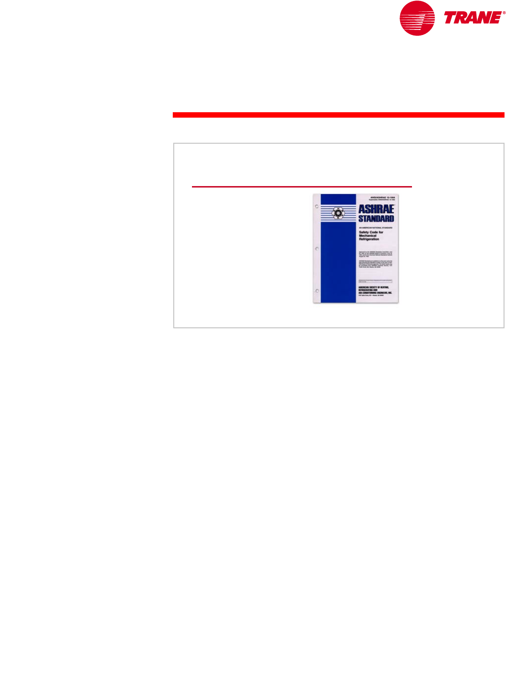
Another standard that is related to chilled-water systems, ASHRAE Standard
15–1994, Safety Code for Mechanical Refrigeration, is intended to specify
requirements for safe design, construction, installation, and operation of
refrigerating systems. This standard covers mechanical refrigeration systems
of all sizes that use all types of refrigerants. Because absorption chillers use
water as the refrigerant, however, they are exempt from this standard.
For many chilled-water systems in which the chillers are located indoors, the
standard requires the refrigeration equipment to be installed in a mechanical-
equipment room. The requirements for this mechanical-equipment room
include refrigerant monitors and alarms, mechanical ventilation, pressure-relief
piping, and so forth.
ASHRAE Standard 15–1994
▲Safety standard for
refrigerating systems
▲Mechanical equipment
room
◆Refrigerant monitors
◆Alarms
◆Mechanical ventilation
◆Pressure-relief piping
Figure 29
26 TRG-TRC016-EN
notes
Proper design of a chilled-water system can greatly impact the first cost,
operating costs, and flexibility of the HVAC system. The purpose of this period
is to discuss the design of reliable chilled-water systems.
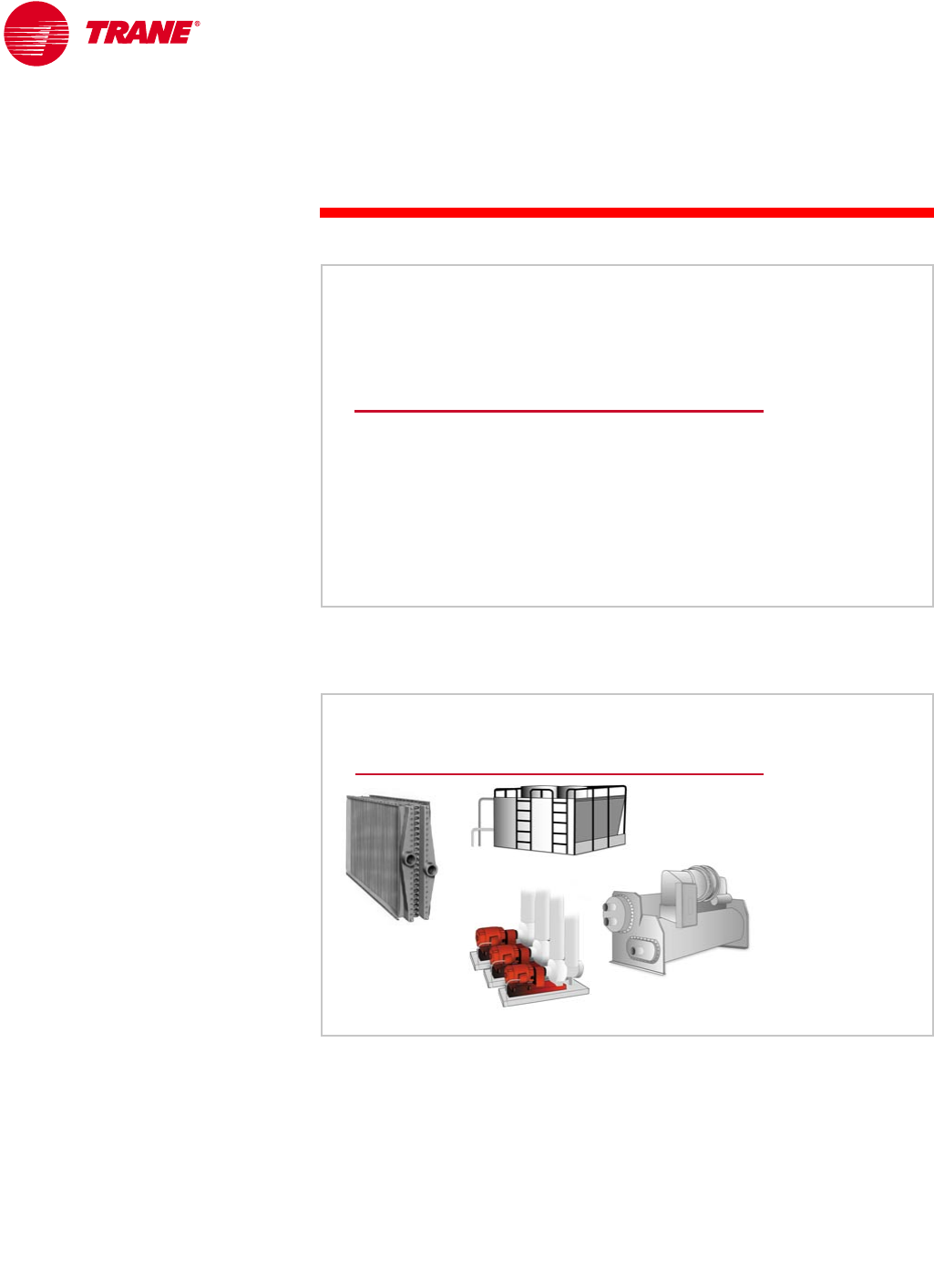
The conventional chilled-water system consists of combinations of the
following primary components:
nWater chillers
nLoad terminals (chilled-water cooling coils in comfort-cooling applications)
nCooling towers in water-cooled systems
nChilled- and condenser-water pumps
nChilled- and condenser-water distribution systems that include piping,
an expansion tank, control valves, check valves, strainers, and so forth.
period two
Chilled-Water System Design
Chilled-Water Systems
Figure 30
Chilled-Water System Components
chiller
pumps
cooling coil
cooling tower
Figure 31
period two
Chilled-Water System Design
TRG-TRC016-EN 27
period two
Chilled-Water System Design
notes
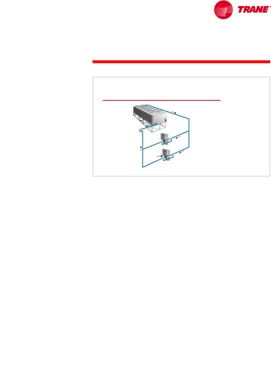
This period focuses on the chilled-water side of the system; that is, the water
that flows through the chiller evaporator and out through the load terminals.
Specifically, we will review methods of load-terminal control and various
multiple-chiller system configurations. These topics apply to systems using
both air-cooled and water-cooled chillers.
Fundamentally, the function of the chilled-water system is to transport the
cooling fluid from the chillers to the load terminals and back to the chillers.
Assuming that the distribution system is adequately sized, we will concentrate
on the hydraulic interaction between the load terminals and the chillers.
Chilled-Water System
pump
pump coil
coil
control
control
valve
valve
air
air-
-cooled
cooled
chiller
chiller
Figure 32
28 TRG-TRC016-EN
notes
period two
Chilled-Water System Design
Load-Terminal Control
The purpose of load-terminal control is to modulate the flow of air or water
through the coil to maintain building space comfort. This is accomplished by
measuring the temperature of the supply air or space. The temperature then
converted to an electronic signal that modulates the capacity of the cooling
coil to match the changing load in the space.
Three methods of load-terminal control are commonly used in
chilled-water systems.
nThree-way modulating valve control
nTwo-way modulating valve control
nFace-and-bypass damper control
Each of these methods has a different effect on the operation of the system.
Load-Terminal Control Options
▲Three-way
modulating valve
▲Two-way
modulating valve
▲Face-and-bypass
dampers
Figure 33
TRG-TRC016-EN 29
period two
Chilled-Water System Design
notes
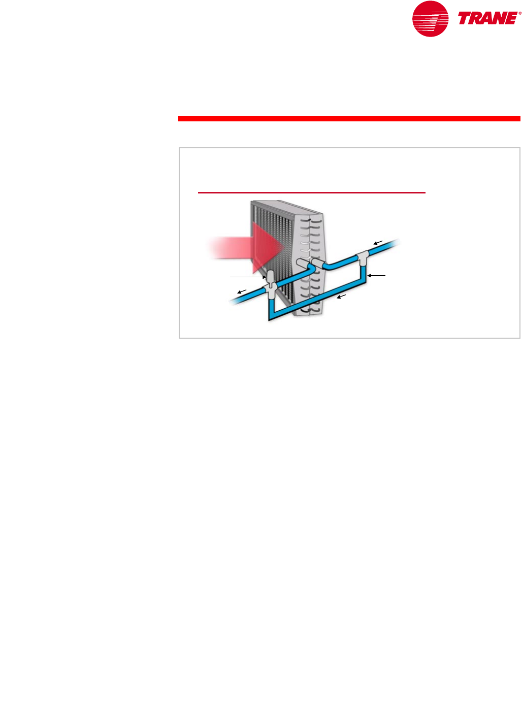
A three-way control valve is one method used to regulate the flow of chilled
water through a cooling coil. As the space cooling load decreases, the
modulating valve directs less water through the coil, decreasing its capacity.
The excess water bypasses the coil and mixes downstream with the water that
flows through the coil. As a result, the temperature of the water returning from
the system decreases as the space cooling load decreases.
Systems that use three-way valves have the following characteristics:
nThe temperature of the water returning from the system varies as the
cooling load varies.
nThe water flow through each load terminal (water through the coil plus
water bypassing the coil) is relatively constant at all load conditions.
nThe pump energy is constant at all loads because the use of three-way
valves results in constant water flow throughout the system.
nWater-flow balance is very critical to proper operation because the flow
is constant.
Three-Way Valve Control
three
three-
-way
way
modulating
modulating
valve
valve
airflow
airflow
bypass
bypass
pipe
pipe
Figure 34
30 TRG-TRC016-EN
notes
period two
Chilled-Water System Design
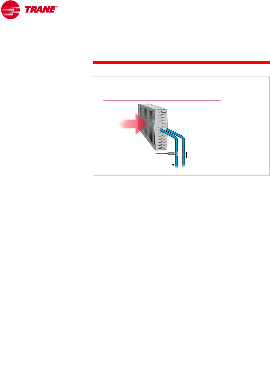
A two-way modulating valve is similar to a three-way valve in that the water
flow through the coil is modulated proportionately to the load. The primary
difference is that the two-way valve does not bypass any unused water, it
simply throttles the amount of water passing through the coil.
The coil and the air being conditioned experience no difference in the cooling
effect of using a two-way versus a three-way valve. The chilled-water system,
however, sees a great difference. Recall that with a three-way valve, the
terminal water flow (water through the coil plus the water bypassing the coil)
is constant at all loads. With a two-way valve, the terminal water flow varies
proportionately with the load. Because there is no mixing of coil and bypassed
water, the temperature of the water leaving the load terminal remains relatively
constant at all conditions. In fact, this return-water temperature may actually
rise slightly as the load decreases, due to coil heat-transfer characteristics.
Systems that use two-way valves have the following characteristics:
nThe temperature of the water returning from the system is constant
(or increases) as the cooling load decreases. This increases the effectiveness
of options such as heat recovery, free cooling, and base-loading, which will
be discussed further in Period Three.
nThe water flow through each load terminal varies proportionately to the
load, resulting in pump energy savings at part load.
nA variable-flow system is less sensitive to water balance than most
constant-flow systems.
A variable-flow, chilled-water distribution system, however, may require
another method to provide constant water flow though the chillers, or else
the chillers must be equipped to handle variable water flow.
Two-Way Valve Control
two
two-
-way
way
modulating valve
modulating valve
airflow
airflow
Figure 35
TRG-TRC016-EN 31
period two
Chilled-Water System Design
notes
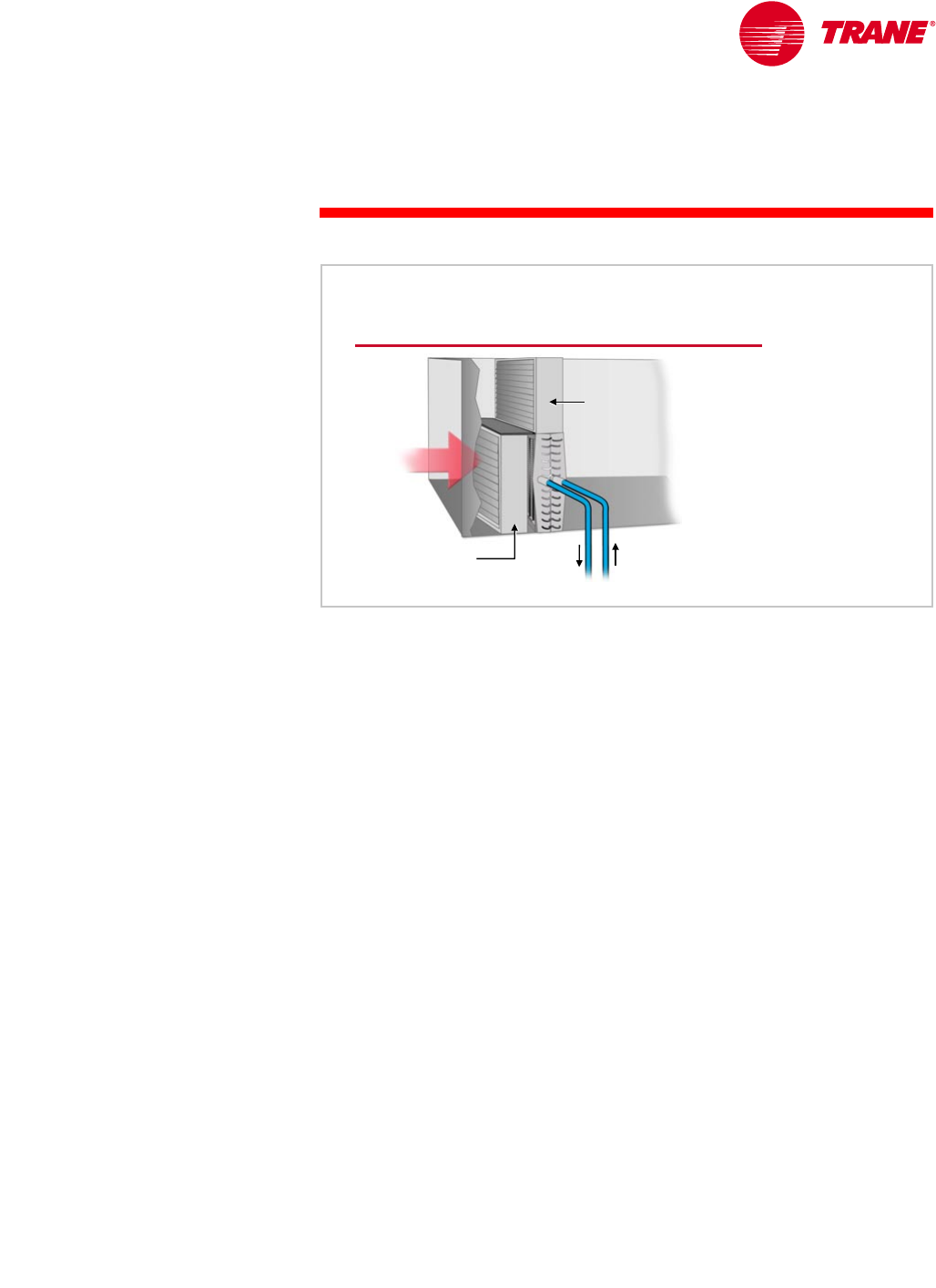
The final method of modulating the coil capacity to match the cooling load is
through the use of face-and-bypass dampers. A linked set of dampers varies
the amount of air flowing through the coil by diverting the excess air around
the coil. As the cooling load decreases, the face damper closes, reducing the
airflow through the coil and reducing its capacity. At the same time, the linked
bypass damper opens, allowing more air to bypass around the coil. A unique
characteristic of this method of load-terminal control is that the coil is allowed
to “run wild,” meaning that the water flow through the coil is constant.
Similar to the three-way valve, systems that use face-and-bypass dampers have
the following characteristics:
nThe temperature of the water returning from the system varies as the
cooling load varies.
nThe water flow through each load terminal and, therefore, pump energy are
constant at all load conditions.
An advantage of face-and-bypass control with a “wild” cooling coil is that it can
better dehumidifiy of the conditioned air when compared to varying the water
flow through the coil. As the airflow through the coil decreases at part-load
conditions, assuming that the temperature of the water entering the coil is
constant, the temperature of the air leaving the coil also decreases. That is,
the air is cooled further and more moisture is removed.
Face-and-Bypass Damper Control
bypass
bypass
damper
damper
face
face
damper
damper
airflow
airflow
Figure 36
32 TRG-TRC016-EN
notes
period two
Chilled-Water System Design
Properly designed, operated, and maintained, any of these three methods can
result in good space comfort control. However, they have different effects on
the chilled-water system.
The use of three-way valves or face-and-bypass dampers results in variable
return-water temperature and relatively constant chilled-water flow through
the entire system. The use of two-way valves results in constant return-water
temperature and variable water flow through the entire system. Before
choosing one of these control methods, it is necessary to determine the
effect that it will have on the other parts of the chilled-water system.
In the past, the water flow rate through the chiller evaporator was to remain
as constant as possible. The vast majority of chilled-water systems employ
pumping schemes that maintain a constant flow rate of water through each
chiller evaporator. Even in the most-carefully-designed chilled-water systems,
however, the flow through the chillers will still vary slightly due to system
Load-Terminal Control Options
▲Three-way modulating valve
◆Constant water flow
◆Variable system return-water temperature
▲Two-way modulating valve
◆Variable water flow (pump energy savings)
◆Constant system return-water temperature
▲Face-and-bypass dampers
◆Constant water flow
◆Variable system return-water temperature
◆Enhanced dehumidification capability with “wild” coils Figure 37
Chiller Evaporator Flow
▲Constant flow is most
common
▲Variable flow is
possible
◆Can reduce energy
consumption
◆Use only with
advanced chiller and
system controls
evaporator
evaporator
Figure 38
TRG-TRC016-EN 33
period two
Chilled-Water System Design
notes effects. System effects include pump–system curve interaction, dynamic head
variations, and variation in distribution system flow.
There are benefits to maintaining a constant water flow rate through the chiller
evaporator. Constant flow provides more-stable and-simple chiller and system
operation. However, there is potential for energy savings by varying the water
flow in the distribution system. Applying these two seemingly-conflicting
principles to chilled-water systems requires careful planning and a thorough
understanding of hydraulic system operation.
Due to advances in technology, however, many of today’s chillers can operate
with variable evaporator water flow. Chilled-water systems that are specifically
designed to vary evaporator water flow are discussed in Period Three. This
period focuses on systems that employ constant water flow through the chiller
and either constant or variable water flow through the rest of the distribution
system.
Another factor that influences chilled-water system design is the number of
chillers used. Single chillers are sometimes used in small systems (less than
100 tons [35 kW]), while larger or critical systems typically use multiple chillers.
Many single-chiller systems resemble the one shown in Figure 39. This system
uses a single pump to move water through the chiller and load terminals. The
load terminals are controlled using three-way modulating valves. The pump
delivers a constant flow of water throughout the entire system, and flow
balance is relatively easy.
Single-Chiller System
pump
pump coil
coil
three
three-
-way valve
way valve
air
air-
-cooled
cooled
chiller
chiller
Figure 39
34 TRG-TRC016-EN
notes
period two
Chilled-Water System Design
Multiple-chiller systems are more common than single-chiller systems for the
same reason that most commercial airplanes have more than one engine—
redundancy provides reliability. Additionally, because cooling loads typically
vary widely, multiple-chiller systems can often operate with less than the full
number of chillers. During these part-load periods, the system saves the energy
required to operate the additional chillers, pumps, and, in water-cooled
systems, cooling tower fans.
There are several configurations used to connect multiple chillers in these
systems. Some of these configurations work well, others do not. Next, we will
look at the most-commonly-used system configurations, including their
advantages and drawbacks.
Multiple-Chiller Systems
▲Redundancy
▲Part-load efficiency
Figure 40
TRG-TRC016-EN 35
period two
Chilled-Water System Design
notes
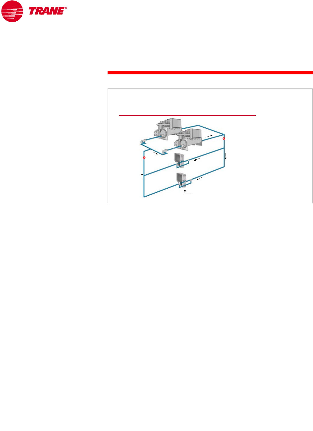
Parallel Configuration
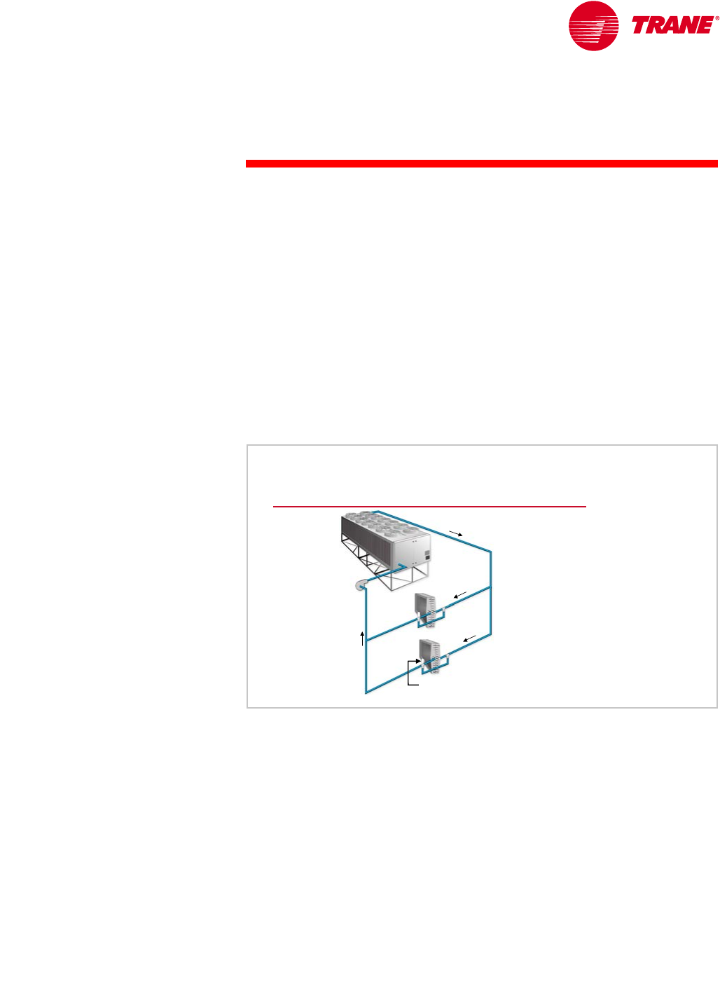
Parallel piping is one common configuration of multiple-chiller systems.
Figure 41 shows a system that uses a single pump to deliver chilled water both
to chillers and to the system load terminals. This configuration can be used in
systems that use constant-flow methods of terminal control (three-way valves
or face-and-bypass dampers), or in systems that use variable-flow methods of
terminal control (two-way valves). Varying the flow through the load terminals
using two-way valves in this type of system results in variable water flow
through the chiller evaporators. Chilled-water systems that are specifically
designed to vary evaporator water flow will be discussed in Period Three.
This section will focus on systems that use constant-flow methods of
terminal control.
Water is pumped through both chillers continuously, regardless of whether only
one chiller or both chillers are operating. This example system is at 50 percent
load, with one chiller operating and the second chiller off. Return water from the
system at 54°F [12.2°C] continues to flow through the non-operating chiller and
mixes with the chilled 42°F [5.6°C] water produced by the operating chiller. The
resulting mixed-water temperature leaving the plant is 48°F [8.9°C]. This rise in
supply-water temperature may result in problems with building comfort or
humidity control. A chiller-plant controller may be used to reset the set point of
the operating chiller downward, in an attempt to compensate for this condition,
and more-closely maintain the desired supply-water temperature. Reducing the
set point of the operating chiller has its limits, however, depending on the
operating characteristics and evaporator freeze limits of the specific chiller. The
more chillers in the system, the worse the problem becomes. For this reason,
this configuration is seldom used in systems with more than two chillers.
Additionally, ASHRAE/IESNA Standard 90.1–1999 (Section 6.3.4.2) prohibits this
type of system when the pump is larger than 10 hp [7.5 kW]. The standard
requires that, in systems that contain more than one chiller piped in parallel,
system water flow must be reduced when a chiller is not operating.
54° F
54° F
[12.2° C]
[12.2° C]
42°F
42°F
[5.6°C]
[5.6°C]
54°F
54°F
[12.2°C]
[12.2°C]
off
off
on
on
48° F
48°F
[8.9°C]
[8.9°C]
chillers piped in parallel
Single Pump
Figure 41
36 TRG-TRC016-EN
notes
period two
Chilled-Water System Design
If separate, dedicated pumps are used with each chiller, a pump-and-chiller pair
can be turned on and off together as the cooling load varies. This solves the
temperature mixing problem that occurred in the previous, single-pump
configuration, but it presents a new problem in a system that uses a constant-
flow method of terminal control.
Below 50-percent load, only one chiller and one pump are operating. The total
water flow in the system decreases significantly, typically 60 to 70 percent of
full system flow. Ideally, at this part-load flow rate, all of the coils will receive
less water, regardless of their actual need. Typically, however, some coils
receive full water flow and others receive little or no water. In either case,
heavily-loaded coils will usually be “starved” for flow. Examples of spaces
with constant heavy loads that may suffer include computer rooms, conference
rooms, photocopy rooms, and rooms with high solar loads.
54°F
54°F
[12.2°C]
[12.2°C]
42° F
42° F
[5.6°C]
[5.6°C]
off
off
on
on
60% to 70%
60% to 70%
of system flow
of system flow
coil starved for flow
coil starved for flow
chillers piped in parallel
Dedicated Pumps
Figure 42
TRG-TRC016-EN 37
period two
Chilled-Water System Design
notes
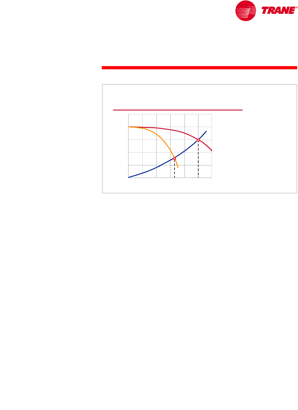
Figure 43 shows an example of the pump–system curve relationship. When
both pumps are operating, the system receives 100 percent of design flow.
When only one pump is operating, the intersection of the pump’s performance
curve with the system curve results in about 65 percent of design flow.
This configuration also presents problems to chiller operation. The starting or
stopping of a pump for one chiller affects the flow through the other chiller.
Using this same example, if one chiller is operating and a second chiller and
pump are started, the total water flow in the system does not double. The
system and pump performance curves will “rebalance,” resulting in an increase
in system flow of only 35 percent of total flow. The new total flow rate,
however, is now divided equally between the two chillers. This results in a rapid
reduction in water flow through the original operating chiller, from 65 percent of
total system flow to 50 percent. This rapid decrease in flow often results in a
loss of temperature control and may cause the chiller to shut off on a safety.
In order to overcome this problem, the chiller-plant control system should
anticipate the starting of additional pumps and unload operating chillers prior
to the start of an additional chiller. Again, this configuration is sometimes
acceptable for two-chiller systems, but is not often used in larger systems
because the part-load system flow problems are further multiplied.
head pressure
head pressure
percent flow
percent flow
2 pumps
2 pumps
1 pump
1 pump
system
system
curve
curve
100%
100%
65%
65%
chillers piped in parallel
Dedicated Pumps
Figure 43
38 TRG-TRC016-EN
notes
period two
Chilled-Water System Design
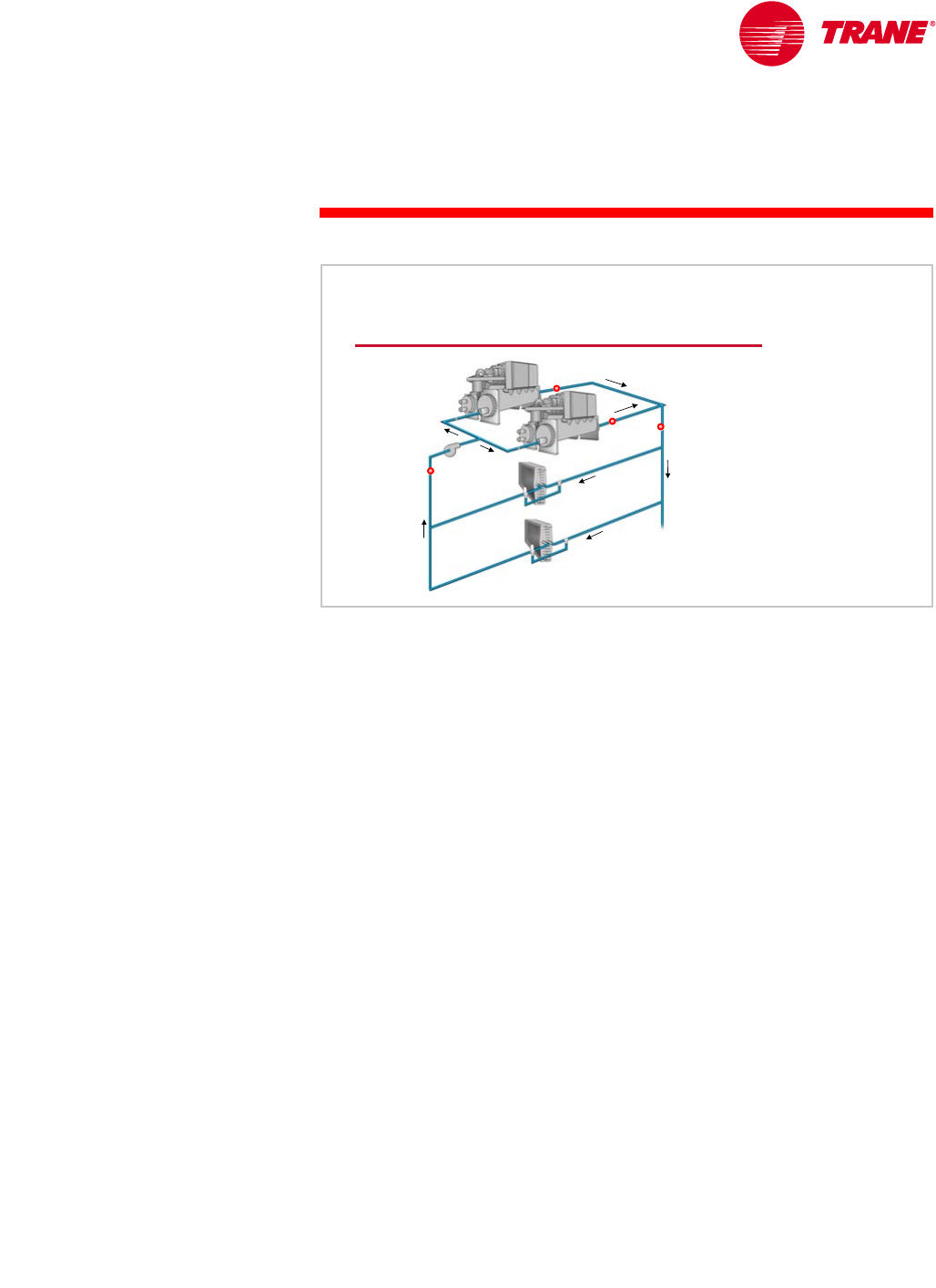
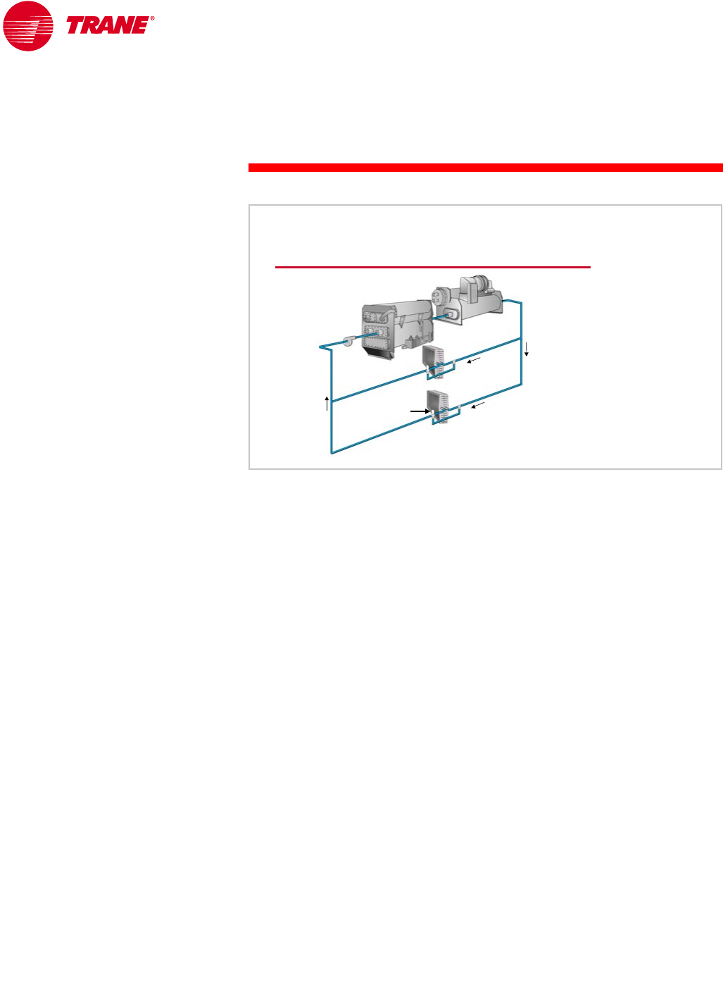
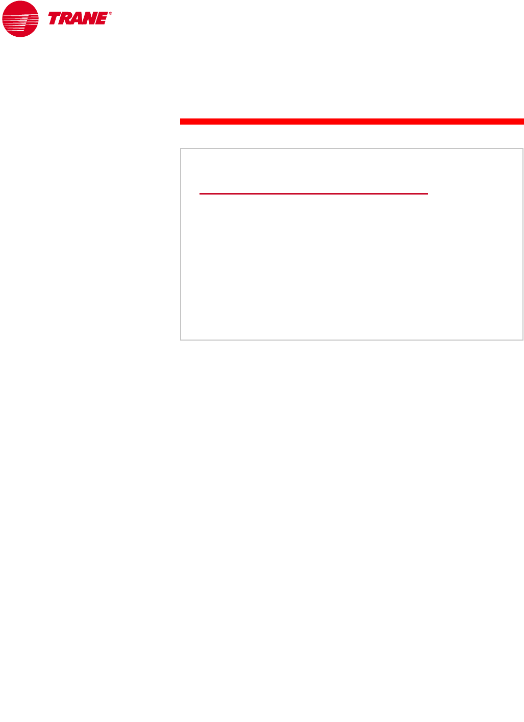
Series Configuration
Another way to connect multiple chillers is to configure the chiller evaporators
in series. Series chilled-water systems typically use three-way valves at the coils
to ensure constant system flow. With two chillers in series, both the
temperature mixing and the flow problems associated with the parallel
configurations shown previously disappear. All of the chilled water passes
through both chillers, and there is full system-water flow at all loads.
However, the flow rate through each individual chiller is equal to the entire
system flow rate. When compared to chillers piped in parallel at the same
system ∆T, this is twice as much water flowing through each chiller. This means
that the chiller-tube pass arrangement must accommodate double the water
quantity within acceptable velocity and pressure drop limits. This typically
requires a reduced number of passes in the evaporator and may impact chiller
efficiency. This efficiency impact, however, is often offset by the gain in system
efficiency due to thermodynamic staging.
System pressure drop also increases because the pressure drops through the
chillers are additive. This can result in increased pump size and energy costs.
This increase in pumping energy can be substantially reduced by designing the
system for a higher system ∆T and, therefore, a reduced water flow rate.
Because of the pressure drop limitations, it is difficult to apply more than two
chillers in series. Systems involving three or more chillers typically use either
the primary-secondary configuration or parallel sets of two chillers in series.
Chillers Piped in Series
three
three-
-way valve
way valve
absorption
absorption
chiller
chiller
electric
electric
chiller
chiller
Figure 44
TRG-TRC016-EN 39
period two
Chilled-Water System Design
notes
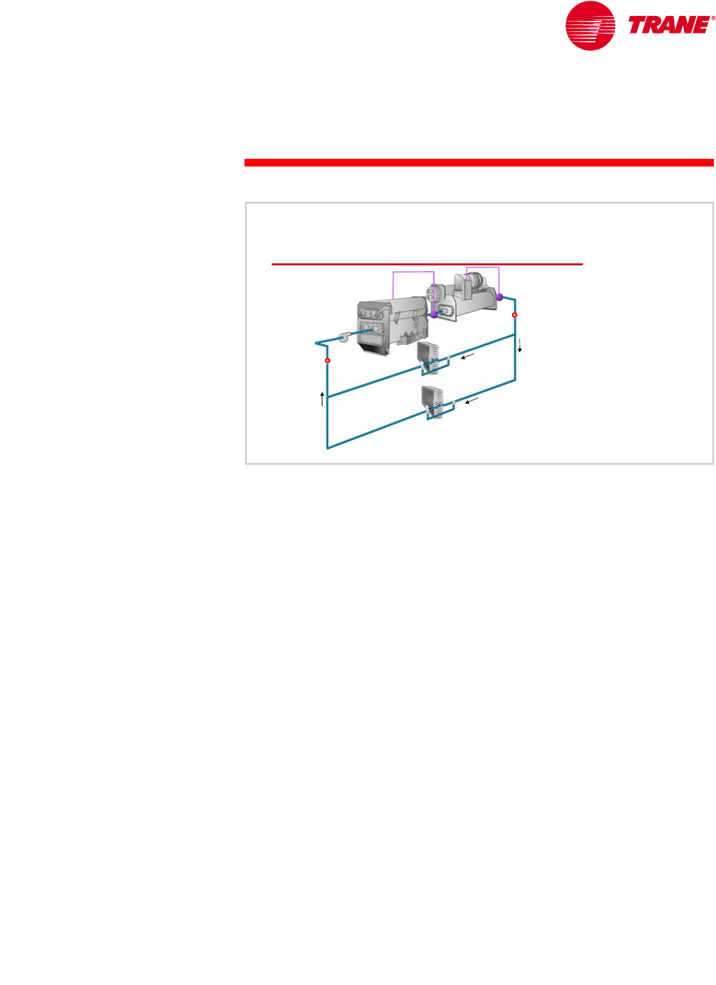
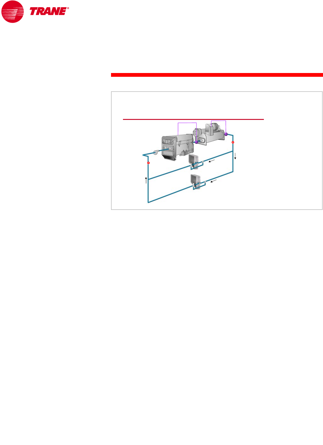
Temperature control in a series system can be accomplished in several ways,
depending on the desired operating sequence. The first method, shown in
Figure 45, has both set points adjusted to the desired system supply-water
temperature. Assuming equally-sized chillers, either chiller can meet the load
below 50 percent. Above 50-percent load, both chillers operate and the
upstream chiller is preferentially loaded. This means that the upstream chiller is
operated at full capacity and any portion of the load that remains is handled by
the downstream chiller.
This strategy may be desirable in systems that benefit from preferentially
loading the upstream chiller. Examples include:
nUsing a heat-recovery chiller in the upstream position. Because the chiller is
at full capacity whenever the system load exceeds 50 percent, the amount of
heat available for recovery is maximized.
nUsing an absorption chiller in the upstream position. An absorption chiller
works more efficiently, and has a higher cooling capacity, with higher
leaving-chilled-water temperatures. The absorption chiller in the upstream
position provides a warmer leaving-chilled-water temperature at design
conditions, 48°F [8.9°C] in this example. This arrangement preferentially
loads the gas-burning absorption chiller, allowing the system to maximize
the use of a lower-cost fuel during periods of high electrical-energy cost.
Alternatively, equal loading of the two chillers in series can be accomplished
using a chiller-plant control system to monitor system load and balance chiller
loading. The set point for the downstream chiller is set equal to the desired
system supply-water temperature, and the set point for the upstream chiller is
then dynamically reset to maintain equal loading on both chillers. The control
system must be stable enough to prevent control hunting or chiller cycling
during periods of changing load.
chillers piped in series
Equal Set Points
54° F
54°F
[12.2°C]
[12.2°C]
42°F
42° F
[5.6°C]
[5.6°C]
set point =
set point = 42° F
42° F [5.6°C]
[5.6°C] set point =
set point = 42° F
42°F [5.6°C]
[5.6°C]
48°F
48°F
[8.9°C]
[8.9°C]
Figure 45
40 TRG-TRC016-EN
notes
period two
Chilled-Water System Design
An alternative method of controlling chillers in series involves staggering the
set points of the two chillers. This results in the downstream chiller operating
first and being preferentially loaded. Any portion of the load that the
downstream chiller cannot meet is handled by the upstream chiller.
The example in Figure 46 shows the system operating at about 80 percent of
design cooling load. As we mentioned earlier, with three-way valves at the
coils, the temperature of the water returning to the chillers decreases at part
load. At 80-percent load, the return-water temperature is 52°F [11.1°C], instead
of the 54°F [12.2°C] at 100-percent load. The upstream chiller is partially loaded,
cooling the water to the 48°F [8.9°C] set point, while the downstream chiller
remains fully loaded, cooling the water the rest of the way to 42°F [5.6°C].
chillers piped in series
Staggered Set Points
52° F
52°F
[11.1°C]
[11.1°C]
42°F
42° F
[5.6°C]
[5.6°C]
set point =
set point = 48° F
48° F [8.9°C]
[8.9°C] set point =
set point = 42° F
42°F [5.6°C]
[5.6°C]
48°F
48°F
[8.9°C]
[8.9°C]
Figure 46

TRG-TRC016-EN 41
period two
Chilled-Water System Design
notes
Primary-Secondary (Decoupled) Configuration
If the water flow through the chillers (production) could be hydraulically
isolated from the water flow through the coils (distribution), many of the
problems encountered in parallel and series configurations could be
eliminated.
Figure 47 shows a configuration that separates, or “decouples,” the production
capacity from the distribution load. This scheme is known as a primary-
secondary system, also referred to as a decoupled system. This
configuration is unique because it dedicates separate pumps to the
“production” and “distribution” loops. A bypass pipe that connects the supply
and return pipes is the key component in decoupling the system.
The chillers in the production loop receive a constant flow of water, while the
coils in the distribution loop, controlled by two-way modulating valves, receive
a variable flow of water.
Primary-Secondary Configuration
production
production
pumps
pumps
two
two-
-way valve
way valve
distribution
distribution
pump
pump
distribution
distribution
loop
loop
production
production
loop
loop
bypass pipe
bypass pipe
Figure 47
42 TRG-TRC016-EN
notes
period two
Chilled-Water System Design
The bypass pipe is common to both production and distribution loops.
The purpose of the bypass pipe is to hydraulically decouple the production
(primary) and distribution (secondary) pumps. Because water can flow freely
between the supply and return pipes for both loops, a change in flow in one
loop does not affect the flow in the other loop.
The actual extent of hydraulic decoupling depends on the pressure drop due to
the bypass pipe. Total decoupling is accomplished only if the bypass pipe is free
from restrictions and large enough to produce no pressure loss at all flow rates.
Because zero pressure loss is not practical, some insignificant pump coupling
will exist. Bypass pipes are typically sized so that the water velocity in the pipe
will be 10 to 15 ft/s [3 to 4.5 m/s], based on the water flowing through the
bypass pipe at the design flow rate of the largest chiller in the system.
Additionally,
to further minimize pressure drop, the bypass pipe is usually relatively short in
length. To prevent random mixing of the supply and return water streams,
however, the minimum length of the bypass pipe is typically 5 to 10 pipe
diameters.
When designing the bypass pipe, an important issue to keep in mind is that the
bypass pipe must be kept free of unnecessary restrictions. For example, a check
valve must not be installed in the pipe. Restrictions cause hydraulic coupling
that can result in unacceptable chiller flow variations or unstable, and
potentially harmful, system pressure variations due to the resulting series-
pumping effects. If a manual isolation valve is required for service, it should
be large enough to ensure that it does not add significant pressure drop to the
bypass pipe.
Primary-Secondary System Rules
▲The bypass pipe should be free of restrictions
◆Sized for minimal pressure drop
◆Avoid random mixing of supply- and return-water
streams
◆No check valve
Figure 48
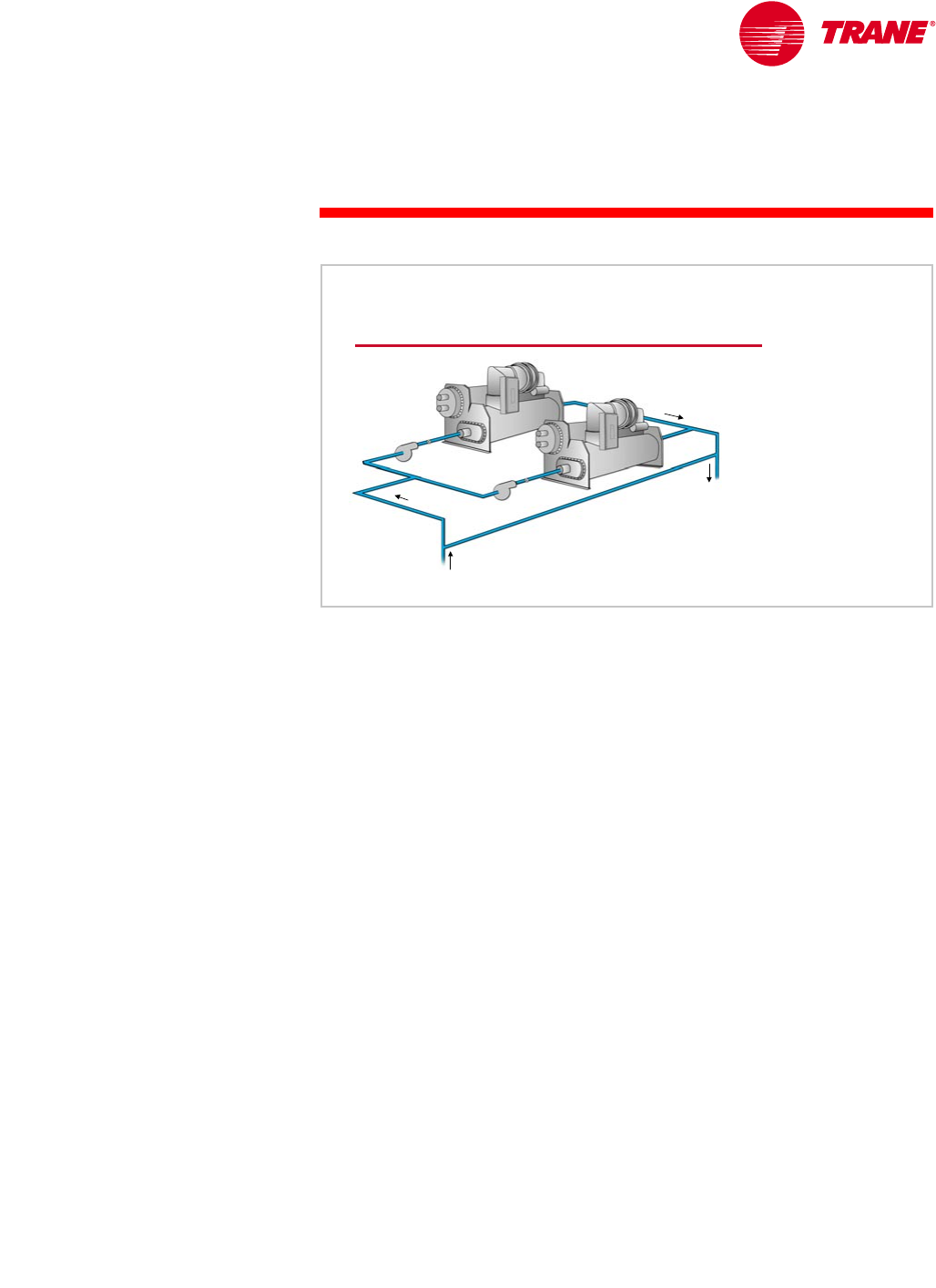
TRG-TRC016-EN 43
period two
Chilled-Water System Design
notes
The production pumps circulate water only from the return tee, through a
chiller, to the supply tee, and through the bypass pipe. This represents a
relatively-small pressure loss and, therefore, relatively-low pump energy. In
addition, each pump only operates when its respective chiller is operating.
A primary-secondary system provides a high degree of flexibility in the
production loop. Not only are the individual chiller “loops” decoupled from
the distribution loop, they are also decoupled from each another. In this
configuration, the production loop consists of independent pairs of chillers and
pumps. Each pump is turned on and off with its respective chiller. Supply water
temperature is maintained by the controls supplied with the chiller. Because the
bypass pipe prevents flow interaction between chillers, there is little worry of
flow disturbances. In addition, the chillers can be of any type, size, or age, or
even from different manufacturers. Because each chiller has a dedicated pump,
the chillers can have different evaporator pressure drops.
Production Loop
return
return
tee
tee
supply
supply
tee
tee
production
production
pumps
pumps
bypass pipe
bypass pipe
Figure 49
44 TRG-TRC016-EN
notes
period two
Chilled-Water System Design
Alternatively, the production loop can be configured with manifolded pumps
and automatic, two-position isolation valves at each chiller. When turning on a
chiller, a pump is turned on and the isolation valve is opened.
This manifolded-pump configuration provides greater redundancy because the
system can change the pump-and-chiller combinations. This redundancy is at
the cost of system complexity, and somewhat limits the flexibility of selecting
chillers of different capacities and types. If the production pumps are
manifolded, the chillers must be selected with the same evaporator-water
pressure drop, or else some method of flow balancing must be employed.
Pump sizing also becomes an issue if chillers are of different capacities and
flow rates, because the proper pump needs to be turned on to match the chiller
flow rate.
The drawback of manifolding production pumps is that the chiller flows become
hydraulically coupled again. If an isolation valve is opened before a pump is
started, flow through the operating chillers will drop suddenly, causing
potential control instability. If a pump is started before a valve is open, the
operating chillers will see a momentary flow increase, causing control
instability or water hammer.
Manifolded Production Pumps
production
production
pumps
pumps
bypass pipe
bypass pipe
isolation
isolation
valves
valves
Figure 50
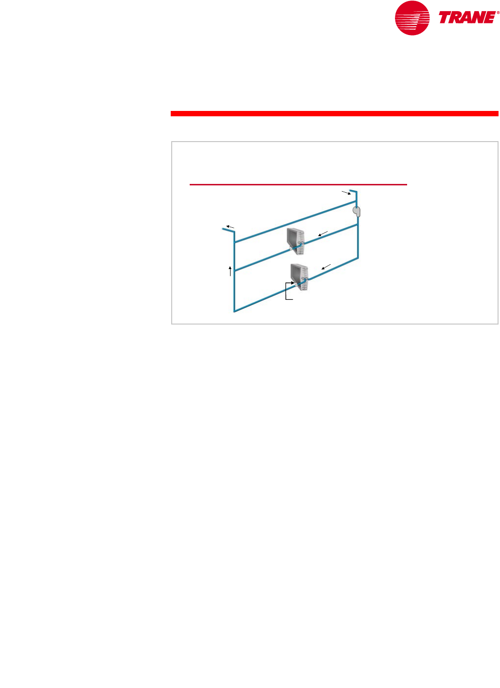
TRG-TRC016-EN 45
period two
Chilled-Water System Design
notes
The distribution pump circulates water from the supply tee, through the load
terminals, and back to the return tee. Although the same water is pumped twice
by different pumps, there is no duplication of pumping energy. The production
pumps overcome only the pressure drop through the production loop, and the
distribution pumps overcome the pressure drop through the distribution loop.
The distribution pump(s) should be capable of varying the flow through the
distribution loop. Typically this is accomplished by using a pump with a
variable-speed drive to modulate the flow of water through the pump.
In a properly-designed and -operating system, distribution-pump energy
consumption will decrease significantly at part load. The pump power reduction
approaches the theoretical cubic relationship to flow. That is, when the load is
50 percent of design, requiring 50 percent of design water flow, the energy
consumed by the variable-flow distribution pump is 12.5 percent of full load:
The total installed pump capacity required in a primary-secondary system is
typically less than in a system not designed for primary-secondary pumping.
This is because the total system head (production plus distribution) is divided
between pumps. Each pump is more efficient because it works against a lower
head. Furthermore, the distribution pump is sized to meet the diversified (block)
system load, not the sum-of-peaks coil loads. This can represent a 20- to
25- percent reduction in the size of the distribution pump.
Distribution Loop
two
two-
-way valve
way valve
distribution
distribution
pump
pump
bypass pipe
bypass pipe
return
return
tee
tee
supply
supply
tee
tee
Figure 51
0.50()
30.125=

46 TRG-TRC016-EN
notes
period two
Chilled-Water System Design
Obviously, in order to achieve variable flow at the distribution pump, the load
terminals must be configured to vary the system flow. This requires the use of a
modulating two-way control valve for each coil. Typically, no three-way valves
or wild coils need to be used in a primary-secondary system. Their use
decreases the energy savings potential from the variable-flow distribution
pump. In fact, ASHRAE/IESNA Standard 90.1–1999 (Section 6.3.4.1) requires
the use of modulating two-way control valves, and thus variable water flow,
in most systems. Primary-secondary systems comply with this requirement.
Some systems, however, will use one three-way valve at the load terminal
furthest from the distribution pump, to ensure that cold water is immediately
availability to all terminals in the system.
Primary-Secondary System Rules
▲The bypass pipe should be free of restrictions
▲Load terminals should use two-way
modulating control valves
Figure 52
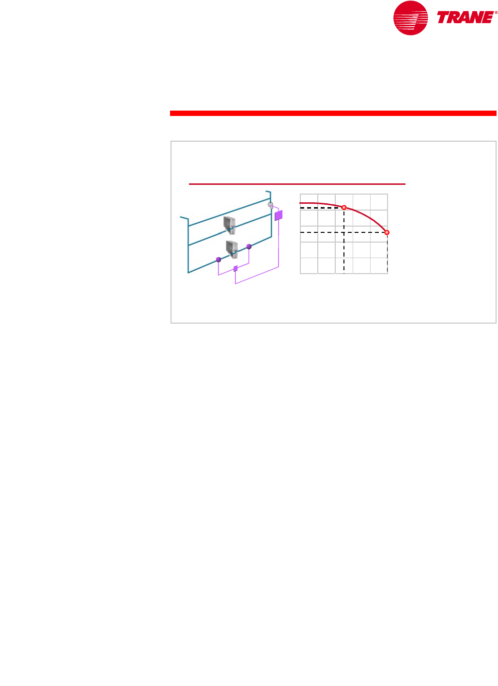
TRG-TRC016-EN 47
period two
Chilled-Water System Design
notes
The distribution pump is typically equipped with a variable-speed drive that is
controlled to maintain a certain pressure difference between the supply- and
return-water piping. In response to a reduced cooling load, the two-way valve
modulates closed, restricting the flow of water through the coil. This causes an
increase in system differential pressure, which can be measured and used to
signal a reduction in the speed of the distribution pump.
An alternative is to allow the pump to “ride its pump curve.” As the two-way
valves modulate closed, the increase in system pressure causes the pump to
“ride up” its performance curve (A to B), resulting in a reduction to 50 percent
of design flow in this example. This method, however, generally results in less
energy savings than a pump with a variable-speed drive. Also, proper pump
selection is important and part-load operating conditions must be considered.
In variable-flow systems, ASHRAE/IESNA Standard 90.1–1999 (Section 6.3.4.1)
requires the use of a modulation device, such as a variable-speed drive, on
pump motors larger than 50 hp [37 kW] that have a pump head greater than
100 ft H2O [300 kPa].
Varying Distribution Flow
pressure
pressure
difference
difference
riding the pump curve
variable-speed control
head pressure
head pressure
percent flow
percent flow
100
10050
50
0
0
B
A
pump
pump
curve
curve
Figure 53
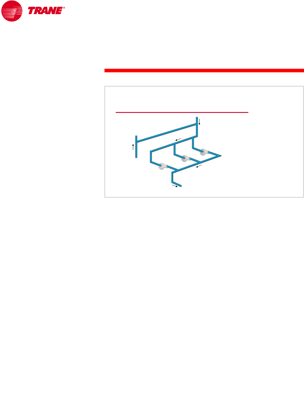
48 TRG-TRC016-EN
notes
period two
Chilled-Water System Design
Another advantage of the primary-secondary system is that the production loop
is not affected by the distribution pumping arrangement.
For example, multiple distribution pumps can be used to vary the flow within
the distribution loop. Providing variable flow through the application of
multiple pumps, or through variable-speed drives on one or more pumps, is
more energy efficient than simply riding the pump curve. It also provides
greater system redundancy.
Multiple Distribution Pumps
distribution
distribution
pumps
pumps
bypass pipe
bypass pipe
supply
supply
to loads
to loads
return
return
from loads
from loads
Figure 54
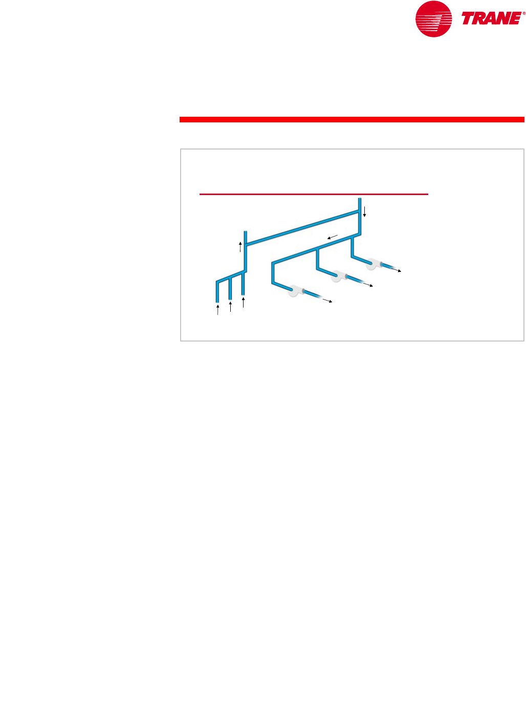
TRG-TRC016-EN 49
period two
Chilled-Water System Design
notes
A variation of the multiple-pump configuration is to use separate pumps to
deliver water to specific, dedicated loads. An example is a chilled-water system
serving a college campus. Separate distribution pumps supply water to the east
(A), west (B), and central (C) portions of the campus. A primary advantage of
this configuration is flexibility. Expanding the system can be achieved by simply
adding another distribution pump to the existing plant and connecting it to the
piping that runs to the new building.
A variation of this multiple, dedicated pump configuration is often called
distributed pumping. It is sometimes used in very large systems that serve
multiple buildings. In a distributed pumping system, a dedicated distribution
pump is located out in the system at each building, instead of all the pumps
being housed in the chiller plant. This configuration offers the potential for
additional pump energy savings, because each pump only needs to pump the
water required for the building it serves.
Multiple Distribution Pumps
distribution
distribution
pumps
pumps
bypass pipe
bypass pipe
supply
supply
to loads
to loads
return
return
from loads
from loads A
B
C
ABC
Figure 55
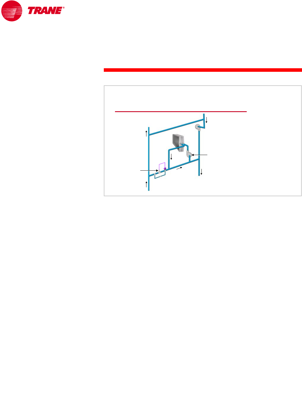
50 TRG-TRC016-EN
notes
period two
Chilled-Water System Design
In very large systems, a primary-secondary-tertiary pumping configuration is
sometimes used. The primary pumps circulate water through the chillers. The
secondary distribution pumps circulate the water around the distribution loop.
The individual load terminals are decoupled from the distribution loop and each
load terminal has a dedicated tertiary pump.
A “load terminal” in this case may be an individual cooling coil or an entire
building. In systems that use tertiary pumping, the load terminal must be
controlled so that only the quantity of water required is drawn from the
distribution loop. Water must not be allowed to flow into the return piping until
it has experienced the proper temperature rise. The two-way valve modulates
to maintain the design return-water temperature. A constant-volume tertiary
pump circulates water through the load terminal.
Some tertiary pumping systems use a small bleed line to ensure that water will
be immediately available when the tertiary pump is started, and to provide an
accurate control signal when the two-way valve is closed. It also keeps the
distribution pump from “dead-heading,” or trying to pump when all of the
two-way valves are closed. If a bleed line is used, it should be of a much smaller
diameter than the rest of the piping.
Tertiary Pumping
bypass pipe
bypass pipe
distribution
distribution
pump
pump
tertiary
tertiary
pump
pump
two
two-
-way
way
valve
valve bleed line
bleed line
Figure 56
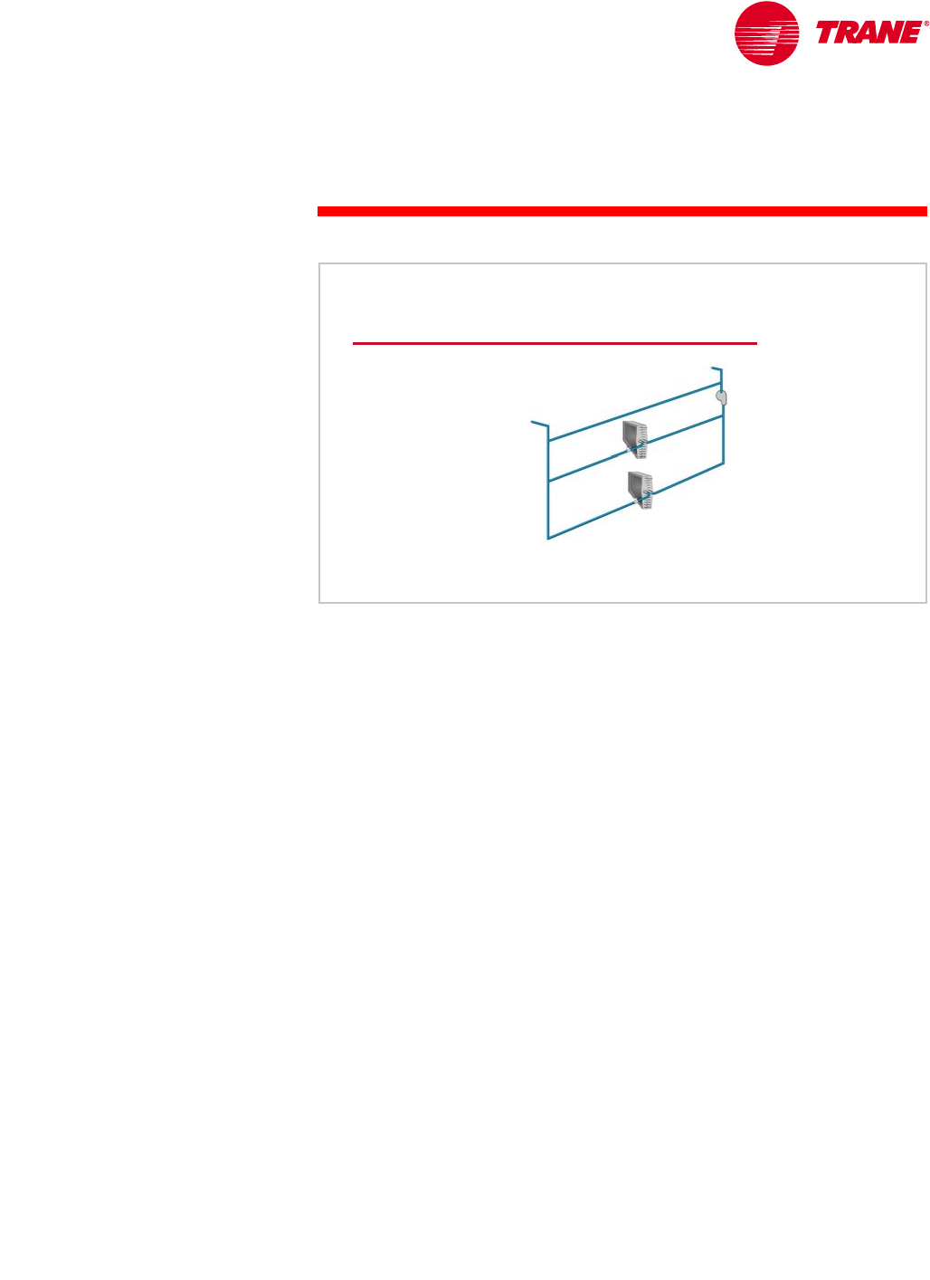
TRG-TRC016-EN 51
period two
Chilled-Water System Design
notes
Let’s summarize: When designed and operated correctly, the distribution loop
of the primary-secondary system has the following characteristics:
nVariable water flow. Only the amount of water that is actually used at the
load terminals is pumped throughout the distribution loop. Under most
operating conditions, this flow rate is less than the design flow rate,
resulting in reduced pumping energy.
nLoad diversity. Not all of the load terminals peak at the same time.
Therefore, the quantity of water that flows at any given time is less than
the constant water flow required in a system using three-way valves.
This allows for reduced distribution pump and pipe sizes.
nHigher return-water temperature at all loads. Properly-operating two-
way valves do not allow unused chilled water to bypass the load terminals.
Water is only allowed to enter the return pipe after it has accomplished
vague useful cooling. If the system is operating properly, the temperature
of the water returning from the load terminals will be at least as high as it
is at design load conditions, and may actually rise at part-load conditions.
This warm return water is especially advantageous in systems using heat
recovery, free cooling, or preferential loading of chillers. These options will
be discussed in Period Three.
Distribution Loop Characteristics
▲Reduced pump
energy use
▲Distribution loop
sized for system
diversity
▲Higher return-water
temperatures
Figure 57

52 TRG-TRC016-EN
notes
period two
Chilled-Water System Design
For simplicity of system control, all of the chillers in a primary-secondary
system should be selected to operate with the same leaving-water temperature
and with the same temperature difference (∆T). This allows all operating chillers
to be loaded to equal percentages.
Control of supply-water temperature is fairly simple. The set points of the
individual chillers are all equal to the desired system supply-water temperature.
Because water flows only through operating chillers, there is no water mixing in
the production loop, and the production loop supplies the water temperature
corresponding to the individual chiller set points.
Primary-Secondary System Rules
▲The bypass pipe should be free of restrictions
▲Load terminals should use two-way
modulating control valves
▲All chillers should be selected for the same
leaving chilled-water temperature and ∆
∆∆
∆T
Figure 58
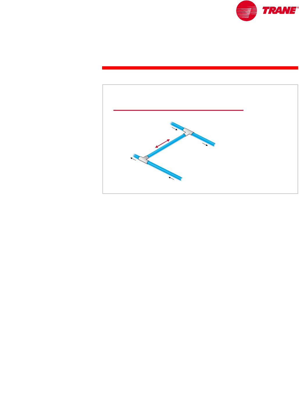
TRG-TRC016-EN 53
period two
Chilled-Water System Design
notes
Primary-Secondary System Operation
We have seen that the production and distribution loops of the primary-
secondary system act independently. The next consideration is to match the
capacity of the production loop to the load of the distribution loop. The
operation of a primary-secondary system focuses on the direction and
amount of flow in the bypass line.
At the supply tee, which connects the supply and bypass pipes, a supply-and-
demand relationship exists. The total water flow from all operating production
(chiller) pumps is the “supply” flow. The “demand” flow is the total water flow
required to meet the loads on the cooling coils. Whenever the supply and
demand flows are unequal, water will either flow into, or out of, the bypass
pipe at the supply tee.
System Operation
distribution
distribution
loop
loop
production
production
loop
loop
bypass pipe
bypass pipe
return
return
tee
tee
supply
supply
tee
tee
supply
supply
flow
flow
dem
and
dem
and
flow
flow
Figure 59
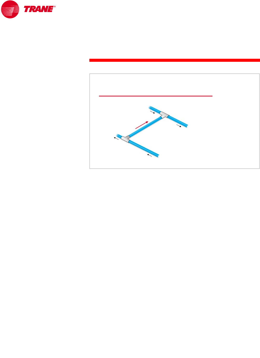
54 TRG-TRC016-EN
notes
period two
Chilled-Water System Design
If production supply is inadequate to meet the load demand, a “deficit” of
supply water exists. To make up for this deficit, the distribution pump will pull
water from the return pipe of the distribution loop through the bypass pipe.
This is called deficit flow.
In this example, the pumps operating in the production loop are supplying
1,000 gpm [63 L/s] of water while the distribution pump is pumping 1,200 gpm
[76 L/s] to meet the demand of the cooling coils. The result is that 200 gpm
[13 L/s] of system return water flows through the bypass pipe to be mixed with
the supply water from the production loop. The temperature of the mixed water
supplied to the distribution loop is 44.3°F [6.8°C].
Control of the water temperature supplied by the distribution loop is
compromised due to this mixing. When this deficit flow condition exists,
starting an additional chiller and pump increases the supply water flow from the
production loop. It also changes the supply-and-demand relationship in order to
restore the temperature of the chilled water supplied to the distribution loop.
Deficit Flow
1,200
1,200 gpm
gpm at 56°F
at 56°F
[76 L/s at 13.3°C]
[76 L/s at 13.3°C]
1,000
1,000 gpm
gpm at 56° F
at 56° F
[63 L/s at 13.3°C]
[63 L/s at 13.3°C]
1,000
1,000 gpm
gpm at 42°F
at 42°F
[63 L/s at 5.6° C]
[63 L/s at 5.6° C]
1,200
1,200 gpm
gpm at 44.3° F
at 44.3° F
[76 L/s at 6.8° C]
[76 L/s at 6.8° C]
200
200 gpm
gpm
at 56°F
at 56°F
[13 L/s at 13.3°C]
[13 L/s at 13.3°C
]
Figure 60

TRG-TRC016-EN 55
period two
Chilled-Water System Design
notes
When the flow of chilled water from the production loop exceeds the demand of
the distribution loop, the direction of flow in the bypass pipe reverses. Chilled
water flows from the supply side of the production loop, through the bypass
pipe, and mixes with warm water returning from the distribution loop. This is
called excess flow.
In this example, the pumps operating in the production loop are supplying
2,000 gpm [126 L/s] of water, while the distribution pump is pumping
1,800 gpm [114 L/s] to meet the demand of the cooling coils. The result is that
200 gpm [13 L/s] of supply water flows through the bypass pipe to be mixed
with the water returning from the production loop. The temperature of the
water returning to the chillers decreases to 54.6°F [12.6°C], reducing the load
on the operating chillers.
Some excess flow is normal in the operation of a primary-secondary system.
The amount of excess flow is almost always less than the flow of one
production pump. The energy consumed by pumping this excess water through
the production loop is typically very low, because the production pump only
needs to produce enough head to push the water through the chiller evaporator
and the bypass pipe.
If a pump-and-chiller pair is turned off as soon as this excess flow condition
occurs, deficit flow will result and the pump and chiller will be turned on again.
To prevent this from happening, a production pump and its respective chiller
are not turned off until the excess bypass flow exceeds the capacity of the next
production pump that is to be turned off.
Some systems are designed with variable flow also in the production loop.
Although this minimizes excess flow in the bypass pipe and further reduces
production-energy consumption, it results in a significantly-more-complex
control system. This type of system will be discussed in Period Three.
Excess Flow
1,800
1,800 gpm
gpm at 56°F
at 56°F
[114 L/s at 13.3°C]
[114 L/s at 13.3°C]
2,000
2,000 gpm
gpm at 54.6°F
at 54.6° F
[126 L/s at 12.6°C]
[126 L/s at 12.6°C]
2,000
2,000 gpm
gpm at 42°F
at 42°F
[126 L/s at 5.6° C]
[126 L/s at 5.6° C]
1,800
1,800 gpm
gpm at 42°F
at 42°F
[114 L/s at 5.6° C]
[114 L/s at 5.6° C]
200
200 gpm
gpm
at 42°F
at 42°F
[13 L/s at 5.6°C
]
[13 L/s at 5.6°C
]
Figure 61
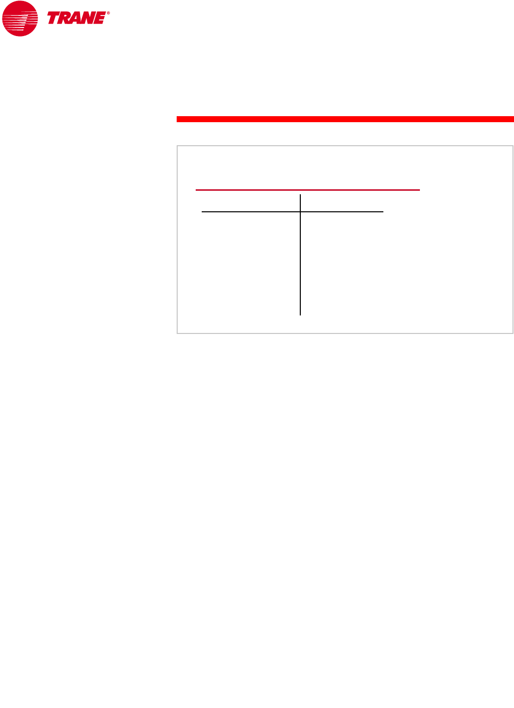
56 TRG-TRC016-EN
notes
period two
Chilled-Water System Design
Starting and stopping of pump-and-chiller pairs in a primary-secondary system
depends on the direction and quantity of water flow in the bypass pipe.
nWhenever there is deficit flow through the bypass pipe for a specified period
of time (typically 15 to 30 minutes in a comfort-cooling system), another
pump-and-chiller pair started.
nWhenever there is excess flow through the bypass pipe that is greater than
the flow being produced by the next pump-and-chiller pair to be turned off,
that pump and chiller are turned off. To prevent short cycling as the result of
a slight increase in load, the chiller-plant control system will typically allow
excess flow of from 110 to 115 percent of the flow produced by the next
production pump to be turned off.
nIf neither of the above conditions exist, no action is taken.
Control of Primary-Secondary System
condition
deficit flow for
specified period of
time
excess flow greater
than 110% to 115% of
next pump to turn off
neither
condition
deficit flow for
specified period of
time
excess flow greater
than 110% to 115% of
next pump to turn off
neither
response
start another
chiller and pump
turn off next chiller
and pump
do nothing
response
start another
chiller and pump
turn off next chiller
and pump
do nothing
Figure 62

TRG-TRC016-EN 57
period two
Chilled-Water System Design
notes
The direction and quantity of flow in the bypass pipe may be determined either
directly by using a flow meter or indirectly by sensing temperatures.
Direct flow measurement can be accomplished using a variety of flow-meter
technologies. These include pressure-based flow meters (pitot tubes, venturi
meters, orifice plates, and differential pressure sensors), turbine and impeller
meters, vortex meters, magnetic flow meters, and ultrasonic transit-time
meters. The accuracy, ease of installation, required maintenance, and cost of
these meter technologies vary widely. The accuracy and reliability of the flow
meter will directly impact the efficiency and reliability of the chilled-water
system. High-quality flow meters are critical to proper system operation.
When using a flow meter, it is important to understand the range of flows and
velocities that the specific device can accurately measure. The accuracy of
some flow meters is dependent on the velocity of the flow and the development
of a smooth flow profile in the stream being measured. To obtain accurate
measurements, several diameters of straight pipe may be required, both
upstream and downstream of the meter. Finally, in order to give accurate
results, many types of flow meters require periodic calibration. This is often
overlooked in the maintenance of chilled-water systems.
Types of Fluid Flow Meters
▲Pressure-based
◆Pitot tube
◆Venturi
◆Orifice plate
◆Differential pressure
▲Turbine and impeller
▲Vortex
▲Magnetic
▲Ultrasonic
Figure 63
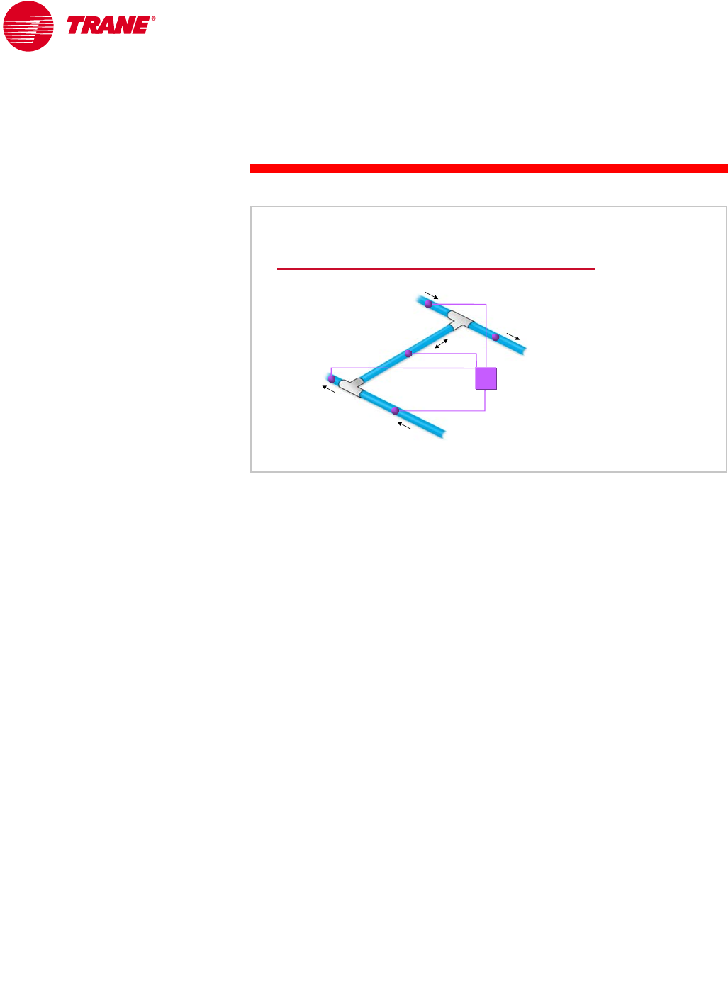
58 TRG-TRC016-EN
notes
period two
Chilled-Water System Design
The advent of microprocessor-based controls has led to another method for
determining flow in the bypass pipe. Temperature sensors are placed in the
supply and return pipes of the production and distribution loops, and in the
bypass pipe. With these temperatures, a chiller-plant control system,
programmed with fluid mixing equations, can determine the quantity of excess
or deficit flow that exists at any time. Because a small change in temperature
may indicate a relatively large change in load or flow in the bypass pipe,
it is important to use accurate, calibrated sensors to ensure acceptable system
operation.
The primary advantage of this method is that it does not depend on flow
velocity in the pipe. Also, it is reliable and cost effective because the
temperature sensors are relatively-low-cost devices.
Integrating the chiller controls with a chiller-plant control system, however, is
imperative for efficient system operation. The control of chilled-water systems
will be discussed further in Period Four.
Temperature-Based Calculations
bypass pipe
bypass pipe
return
return
tee
tee
supply
supply
tee
tee
system
system-
-level
level
controller
controller
Figure 64
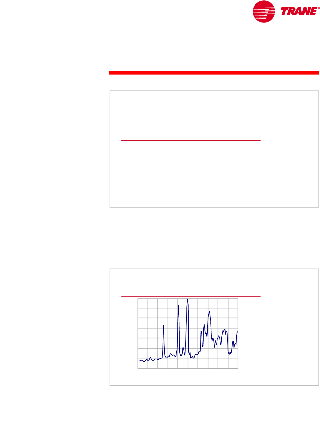
TRG-TRC016-EN 59
notes
period three
System Variations
Period Two discussed several standard configurations of chilled-water systems.
In addition, there are many variations available to reduce installed costs,
enhance the efficiency of the system, improve reliability, or increase operational
flexibility.
These variations are worth examining, because improving the reliability or
efficiency of the system by even a small percentage can result in a large
payback over the life of a building.
Alternate Fuel Choice
Many building owners and operators are investigating the use of fuels other
than electricity. There are several reasons for this renewed interest.
Today, the utility industry in many regions is going through some degree of
deregulation. One of the first United States locations to experience this was
San Diego, California. Due to a number of factors, the price of electricity
period three
System Variations
Chilled-Water Systems
Figure 65
Electric Utility Deregulation
price of electricity, $/kWh
price of electricity, $/kWh
0.20
0.20
0.10
0.10
0.30
0.30
May
May June
June July
July August
August September
September
San Diego, CA
San Diego, CA
2000
2000 Figure 66
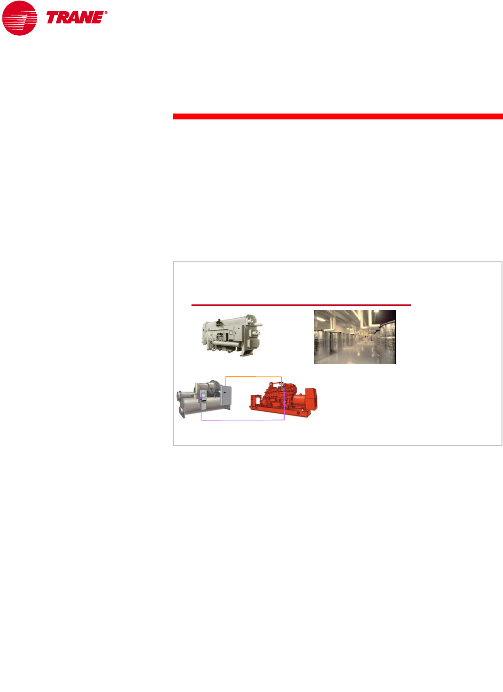
60 TRG-TRC016-EN
notes
period three
System Variations
doubled, and even tripled, during periods of high demand in the first summer
of deregulation. Utility deregulation will occur differently in various locations,
but the possibility of high electricity costs during peak periods has building
owners and operators looking for ways to use different fuels during those
periods.
Another reason for using different fuel types is that it provides the building
owner with leverage to negotiate for reduced utility prices from competing
utilities. If a building uses both electricity and natural gas for cooling, and
can switch between the two, the owner can often negotiate better rates for
both cooling and heating.
A chilled-water system that uses more than one type of fuel is referred to as a
hybrid system. The most obvious option for using an alternate fuel is an
absorption chiller. This type of chiller can be powered by natural gas, fuel oil,
or even waste heat in the form of steam or hot water.
Another option is to use natural gas to operate an engine-and-generator set that
produces electricity, and then use that electricity to run a standard electric
chiller. This indirect coupling of the gas engine to the chiller allows the flexibility
of operating the chiller using the gas engine during times of high electricity
costs, and operating the chiller on utility (line) electricity during times of low
electricity costs. A second benefit of indirect coupling is that the engine can
be sized to provide enough power for the chiller, the pumps, and, in a water-
cooled system, the cooling tower. If the engine is also to be used for emergency
backup, the pumps and cooling tower would not need a second generator to
provide them with power.
An alternative to this approach is to directly couple the engine and chiller.
A significant drawback of this approach is that the building owner does not
have the flexibility to switch between natural gas and electricity—the chiller
must always operate on natural gas. Also, only the chiller is connected to the
engine. If emergency backup is necessary, a second generator is required to
operate the pumps and cooling tower.
Fuel Choice Options
absorption thermal storage
indirectly-coupled,
gas-engine
chillers
control interface
control interface
power
power
Figure 67
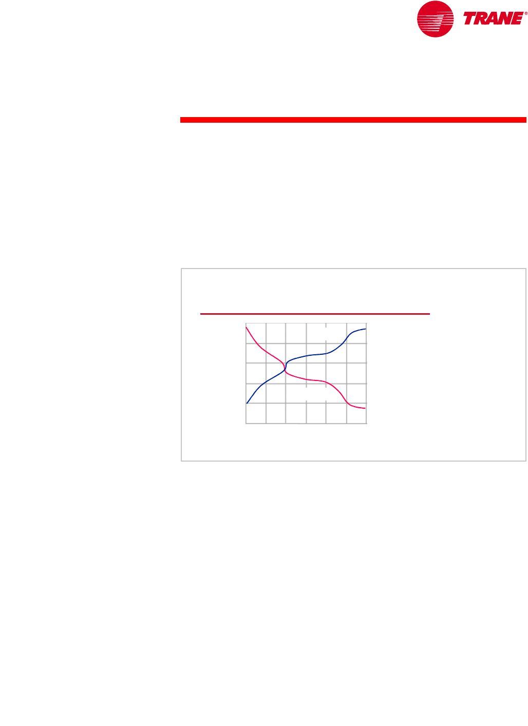
TRG-TRC016-EN 61
period three
System Variations
notes A third method of using an “alternate” fuel is actually to use the same fuel
(electricity) but to use it at a different time. The highest electricity costs occur at
the time of highest demand. For example, a real-time-pricing rate for electricity
may be $0.50/kWh at times of peak demand during the day but only $0.03/kWh
at night. By using either ice or chilled water to store cooling capacity at night
when the cost of electricity is low, and then using that stored energy to help
cool the building during the day when the cost of electricity is high, total electric
costs can be reduced substantially. Although thermal storage does not use a
different fuel, it is certainly an option for avoiding high electricity costs during
peak periods.
Low-Flow Systems
Building owners are becoming more conscious about how improved efficiency
reduces system operating costs and overall environmental impact. Typically,
the largest piece of equipment in the chilled-water system is the water chiller.
However, it is also the most efficient piece of equipment in the system.
Figure 68 shows the dramatic improvements in chiller efficiency, at standard
ARI conditions, since 1970. High-efficiency compressors and motors,
economizers on multiple-stage centrifugal compressors, more heat-transfer
tubes, and tubes with special geometry to enhance heat transfer in both the
evaporator and condenser, have all contributed to these efficiency
improvements. Manufacturers continue to strive to improve chiller efficiency
by redesigning chiller components.
Chiller Efficiency Improvements
chiller efficiency (kW/ton)
chiller efficiency (kW/ton)
1970
1970
year
year
1980
1980 2000
2000
COP
COP
kW/ton
kW/ton
1990
1990
chiller efficiency (COP)
chiller efficiency (COP)
0.9
0.9
0.8
0.8
0.7
0.7
0.6
0.6
0.5
0.5
8.0
8.0
7.0
7.0
6.0
6.0
5.0
5.0
4.0
4.0
Figure 68
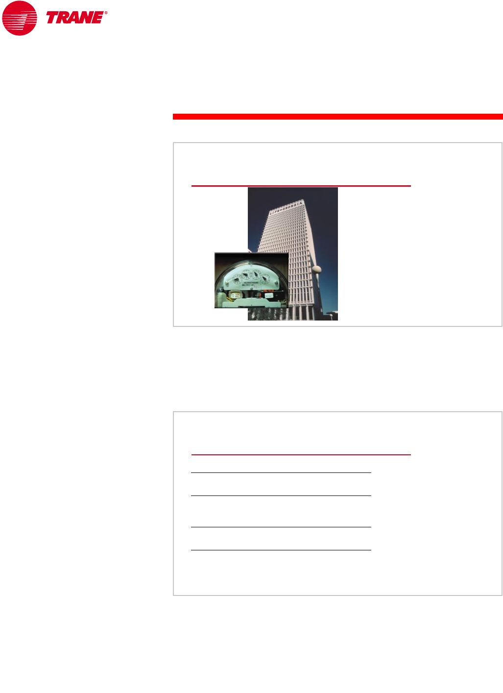
62 TRG-TRC016-EN
notes
period three
System Variations
Realize, however, that the chiller is only one component of the chilled-water
system. Although chiller efficiency is important, overall system efficiency is
more important because the building owner pays to operate the entire system,
not just the chiller. Said another way, “The meter is on the building!”
With this in mind, many system design engineers are looking for ways to
optimize the efficiency of the entire system, not just the chiller.
One approach to increase overall system efficiency has been to reduce pump
and cooling-tower energy by reducing the amount of water being pumped
through the system. In the past, the conditions shown in the center column of
the table in Figure 70 were often used when designing a water-cooled, chilled-
water system. These flow rates result in a 10°F [5.6°C] temperature difference
(∆T) through both the evaporator and the condenser. In fact, they are the
standard conditions at which electric, vapor-compression chillers are rated by
Greater Focus on System Efficiency
Figure 69
Trend Toward Lower Flow Rates
yesterday
evaporator
flow rate
leaving
chilled-water
temperature
condenser
flow rate
entering
condenser-water
temperature
2.4 gpm/ton
[0.043 L/s/kW]
44°F
[6.7°C]
3.0 gpm/ton
[0.054 L/s/kW]
85°F
[29.4°C]
today
1.5 gpm/ton
[0.027 L/s/kW]
41°F
[5°C]
2.0 gpm/ton
[0.036 L/s/kW]
85°F
[29.4°C]
electric-driven chiller
Figure 70
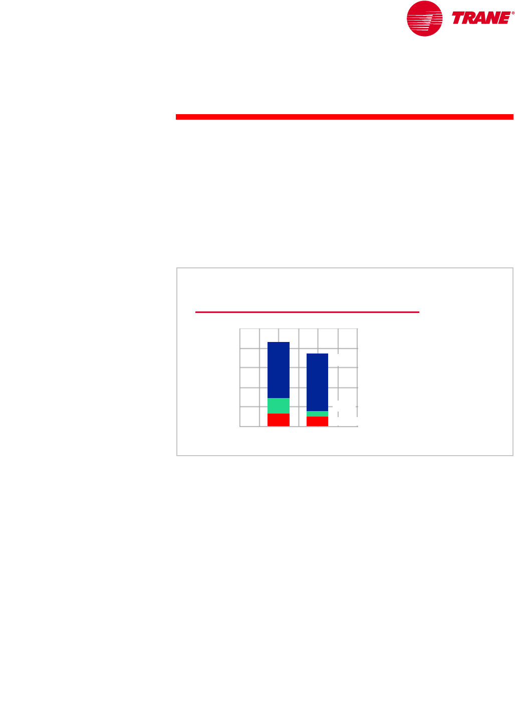
TRG-TRC016-EN 63
period three
System Variations
notes ARI. They are not, however, suggestions for good design practice for any given
system—they simply define a common rating point to aid comparisons.
Trends toward improved humidity control and system-level energy efficiency
have led many design engineers to reduce the flow rates on both the chilled-
and condenser-water sides of the system. This results in smaller motors in the
pumps and cooling-tower fans, as well as smaller pipes and control valves in
the distribution system. The right column of this table shows one possible set
of conditions for a low-flow system. For comparison, 1.5 gpm/ton [0.027 L/s/
kW] through the evaporator results in a 16°F [8.9°C] ∆T, and 2.0 gpm/ton
[0.036 L/s/kW] through the condenser results in a 15°F [8.3°C] ∆T.
Figure 71 shows the combined annual energy consumption of the chiller,
chilled- and condenser-water pumps, and cooling-tower fans for these two
system designs. In fact, a growing number of design engineers and utilities
have published papers or manuals that recommend that system flow rates be
reduced. A number of them have found that using lower flow rates can reduce
both installed and operating costs.
“…there are times you can ‘have your cake and eat it too.’ In most
cases, larger ∆T’s and the associated lower flow rates will not only save
installation cost but will usually save energy over the course of the
year. This is especially true if a portion of the first-cost savings is
reinvested in more efficient chillers. With the same cost chillers, at
worst, the annual operating cost with the lower flows will be about
equal to ‘standard’ flows but still at a lower first cost.”
(Source: Kelly, David W. and Chan, Tumin, “Optimizing Chilled Water Plants,”
Heating/Piping/Air Conditioning, January 1999)
Low-Flow Systems
annual energy consumption, kWh
annual energy consumption, kWh
base casebase case
base case
chiller
chiller
cooling tower fans
cooling tower fans
low flowlow flow
low flow
750,000
750,000
600,000
600,000
450,000
450,000
300,000
300,000
150,000
150,000 pumps
pumps
0
0
Figure 71
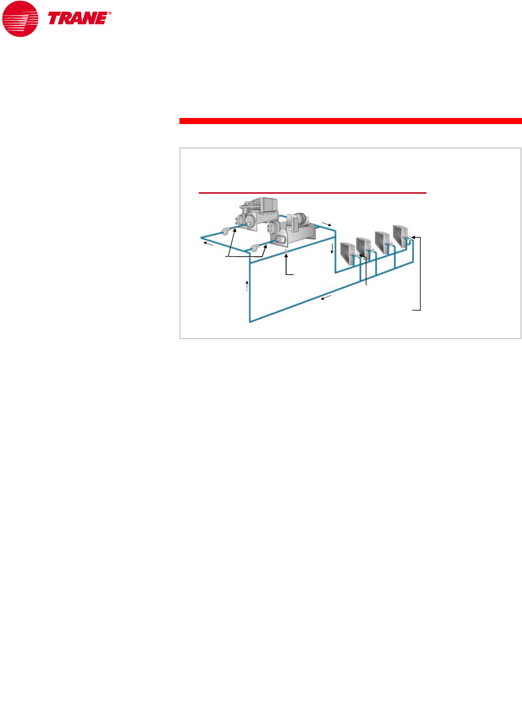
64 TRG-TRC016-EN
notes
period three
System Variations
Variable-Primary-Flow Systems
One of the reasons that many chilled-water systems are installed using the
primary-secondary configuration is that, in the past, chillers could not respond
well to varying water flow through the evaporator. Therefore, the production
loop was designed for a constant flow through the chillers, and the distribution
loop was designed for variable flow to take advantage of the pump energy
savings. The system was hydraulically decoupled to meet these two goals.
Alternatively, in a variable-primary-flow (VPF) system, the flow of water
varies throughout the entire system—through the evaporator of each operating
chiller as well as through the cooling coils. The VPF system differs from the
primary-secondary system in that it no longer hydraulically decouples the two
loops. The variable-flow pumps move the water through the entire system.
The primary benefit of this system is the elimination of the separate distribution
pump(s) and the associated electrical and piping connections. There is also a
small reduction in operating cost because there is seldom excess water flowing
through the bypass pipe.
VPF systems, however, require chillers that can operate properly when the
water flow through the evaporator varies. Many of today’s chillers can tolerate
variable water flow through the evaporator, within limits. These limits include
minimum and maximum flow rates and a limitation on how quickly the flow can
vary. Exceeding these operating limits may cause control instability or even
catastrophic failure. The VPF system therefore requires a method of monitoring
the flow rate through each chiller and a control system to ensure that the flow
through the evaporator stays within the limits for the specific chiller. Do not
attempt to use a VPF system with chillers that have older, analog electric,
or pneumatic controls that cannot handle variable evaporator flow.
Variable-Primary-Flow Systems
bypass
bypass
two
two-
-way
way
valve
valve
variable
variable-
-flow
flow
pumps
pumps
control
control
valve
valve
check
check
valves
valves
optional bypass
optional bypass
with three
with three-
-way valve
way valve Figure 72

TRG-TRC016-EN 65
period three
System Variations
notes Notice also that the VPF system must continue to include a bypass. Although
a control valve prevents flow in the bypass for most system operating
conditions, the modulating valve and bypass are required to ensure that the
water flow through the system remains above the minimum flow limit of the
operating chillers. This bypass may be in the same location as in the primary-
secondary system, or it may be a three-way valve on a few of the cooling coils.
Although VPF systems have been successfully installed and operated, they
are more complex both to design and to operate when compared to a primary-
secondary system. The sequencing of chillers and pumps requires a thorough
understanding of system dynamics because flow rates will vary through every
operating chiller. The control system needs to avoid cycling (restarting the
chiller too soon) and maintain the rate-of-flow variation through the chiller
evaporators within the allowable limits. This becomes very complicated as
the number of chillers increases.
Another important consideration when investigating VPF systems is the fact
that they take more time and planning to design and commission properly than
other systems. The system design engineer must thoroughly define the control
sequence early in the design process, and clearly communicate it to the
controls provider. Also, the system operators must understand how the VPF
system works; therefore, training is mandatory. The success of a system design
is directly related to the ability of the operator to carry out the design intent.
Critical VPF System Requirements
▲Chillers must handle variable evaporator flow
▲System must include a bypass
▲System-level controls must limit the rate-of-
flow change
▲Adequate time to design and commission
controls
▲Operator must understand the system
Figure 73
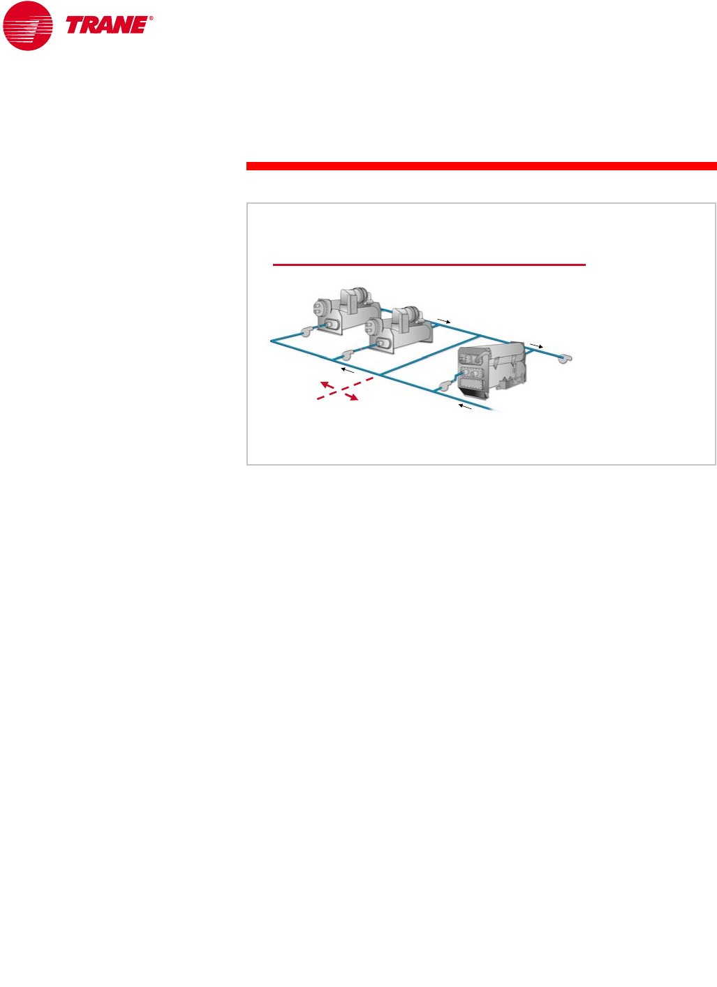
66 TRG-TRC016-EN
notes
period three
System Variations
Preferential Loading
To take full advantage of a high-efficiency, heat-recovery or alternate-fuel chiller,
the system may need a method to preferentially load these chillers. The
following two system configurations are variations of the primary-secondary
system.
In the basic primary-secondary system, all operating chillers are loaded to equal
percentages. In this first preferential-loading configuration, the preferentially-
loaded chiller is moved to the distribution side of the bypass pipe. This chiller
is preferentially (or most fully) loaded when it is turned on, because it always
receives the warmest system return water. In this example, an absorption chiller
is located on the distribution side of the bypass pipe so that it can be
preferentially loaded during periods of high electricity costs.
Preferential Chiller Loading
bypass pipe
bypass pipe
distribution
distribution
pump
pump
absorption
absorption
chiller
chiller
preferentially
preferentially
loaded
loaded
equally
equally
loaded
loaded
Figure 74
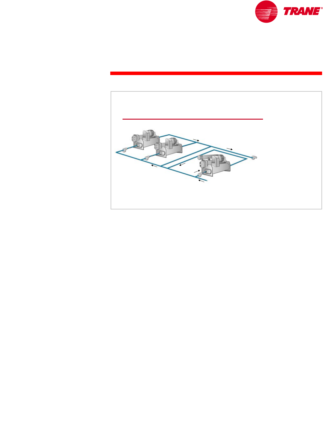
TRG-TRC016-EN 67
period three
System Variations
notes
The second preferential-loading configuration, shown in Figure 75, ensures
that the chiller in the sidestream position receives the warmest entering-water
temperature, and that it can be fully loaded whenever the system load is high
enough. This arrangement is unique because it not only allows preferential
loading, but it also permits the chiller (or other cooling device) in the sidestream
position to operate at any temperature difference. In other words, it does not
need to supply water at the same temperature that the other operating chillers
do. The chiller in this position precools the system return water, reducing the
load on the downstream chillers. In this example, a heat-recovery chiller is
located in the sidestream position so that it can be preferentially loaded to
maximize the amount of heat recovered, thus reducing the overall building
energy consumption. Because a heat-recovery chiller is typically less efficient
than a standard cooling-only chiller, the heat-recovery chiller only has to
provide as much cooling as is required to meet the heat-recovery load, letting
the more efficient cooling-only chillers meet the rest of the cooling load.
One drawback of the sidestream arrangement is that it does not add water flow
capability to the system, it simply reduces the load on other chillers. Therefore,
the other system pumps must ensure that the system flow requirements are
met. For this reason, the capacity of the sidestream chiller is often smaller than
the other chillers in the plant.
Either of these arrangements allows a chiller to be preferentially loaded.
Preferential loading is typically most beneficial in the following applications:
nIn a system that has a high-efficiency chiller along with several standard-
efficiency chillers, the high-efficiency chiller can be preferentially loaded to
reduce system energy consumption.
nIn a system with a heat-recovery chiller, preferentially loading the heat-
recovery chiller maximizes the amount of heat recovered, thus reducing
the overall building energy consumption.
Sidestream Configuration
bypass pipe
bypass pipe
distribution
distribution
pump
pump
heat
heat-
-recovery
recovery
chiller
chiller
Figure 75
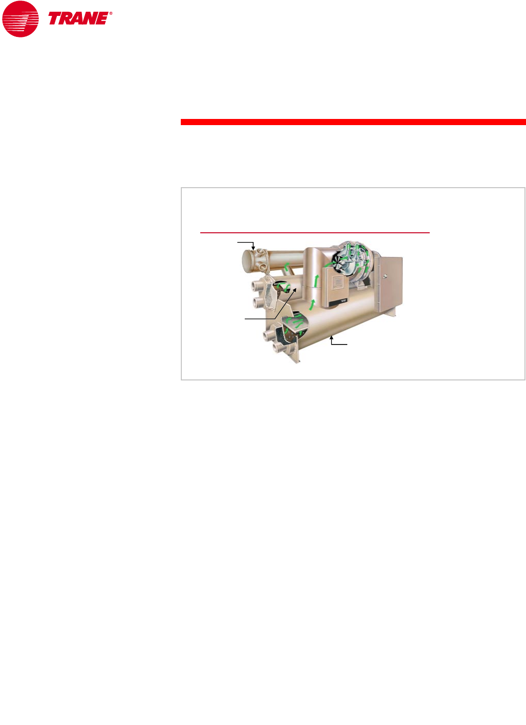
68 TRG-TRC016-EN
notes
period three
System Variations
nIn a system with an alternative-fuel chiller, such as an absorption chiller,
preferentially loading the alternative-fuel chiller during times of high
electricity costs minimizes system energy cost.
Heat Recovery
Heat recovery is the process of capturing the heat that is normally rejected from
the chiller condenser and using it for space heating, domestic water heating,
or another process requirement. Heat recovery has been successfully applied in
virtually all types of buildings, including hotels, schools, manufacturing plants,
and office buildings. It typically provides an attractive return on investment for
building owners. The use of heat recovery should be considered in any building
with simultaneous heating and cooling requirements, or in facilities where the
heat can be stored and used at a later time. Buildings with high year-round
internal cooling loads are excellent opportunities for heat recovery.
Additionally, ASHRAE/IESNA Standard 90.1–1999 (Section 6.3.2) includes
restrictions on the amount of reheat that can be performed in an HVAC system
unless it is recovered heat. It is therefore likely that heat recovery will be used
more in the future.
Heat recovery can be applied to practically any type of water chiller. It can be
accomplished either by operating at higher condensing temperatures and
recovering heat from the water leaving the standard condenser, or by using a
separate condenser, as shown in Figure 76 for a centrifugal chiller. In smaller
chillers, heat recovery is sometimes accomplished using a device called a
desuperheater. A desuperheater is a device that is connected to the
refrigeration circuit between the compressor and condenser to recover heat
from the hot refrigerant vapor.
Heat-Recovery Chiller
heat
heat-
-recovery
recovery
condenser
condenser
standard
standard
condenser
condenser
evaporator
evaporator
Figure 76

TRG-TRC016-EN 69
period three
System Variations
notes
For water-cooled centrifugal chillers, there are generally three methods of
implementing heat recovery.
The dual-condenser, or double-bundle, heat-recovery chiller contains a
second, full-size condenser that is connected to a separate hot-water loop.
It is capable of more heat rejection and higher leaving-hot-water temperatures
than an auxiliary condenser. The amount of heat rejected is controlled by
varying the temperature or flow of water through the standard condenser.
Chiller efficiency is degraded slightly in order to reach the higher condensing
temperatures.
An auxiliary-condenser, heat-recovery chiller makes use of a second, but
smaller, condenser bundle. It is not capable of rejecting as much heat as the
dual-condenser chiller. Leaving hot-water temperatures are also lower, so it is
often used to preheat water upstream of the primary heating equipment or
water heater. It requires no additional controls, and actually improves chiller
efficiency because of the extra heat-transfer surface for condensing.
A heat-pump chiller is a standard chiller (no extra shells are required) used
and controlled primarily for the heat it can produce in the condenser. The
evaporator is connected to the chilled-water loop, typically in the sidestream
position discussed earlier, but it only removes enough heat from the chilled-
water loop to handle the heating load served by its condenser. This application
is useful in a multiple-chiller system where there is a base or year-round heating
or process load, or where the quantity of heat required is significantly less than
the cooling load. The heating efficiency of a heat-pump chiller is the highest of
any heat-producing device.
Heat-Recovery Chiller Options
heat-recovery
(dual) condenser
auxiliary
condenser heat pump
◆No extra
condenser
◆Large base-heating
loads or continuous
operation
◆High hot-water
temperatures
◆Controlled
◆Good heating
efficiency
◆Second, full-
size condenser
◆Large heating
loads
◆High hot-water
temperatures
◆Controlled
◆Degrades
chiller efficiency
◆Second, smaller-
size condenser
◆Preheating loads
◆Moderate
hot-water
temperatures
◆Uncontrolled
◆Improves chiller
efficiency
Figure 77
70 TRG-TRC016-EN
notes
period three
System Variations
There is usually an efficiency penalty associated with the use of heat recovery
with a chiller. The cost of this efficiency penalty, however, is typically much less
than the energy saved by recovering the “free” heat.
The energy consumption of a heat-recovery chiller will be higher than that of
a cooling-only chiller, because of the higher pressure differential at which the
compressor must operate. In this example, the energy consumption of a
centrifugal chiller operating in heat-recovery mode (producing 105°F [40.6°C]
condenser water) is 0.69 kW/ton [5.1 COP]. The efficiency of the same chiller
operating in the cooling-only mode (no heat being recovered and producing
95°F [35°C] condenser water) is 0.60 kW/ton [5.9 COP]. A comparable cooling-
only chiller of the same capacity and operating at the same cooling-only
conditions consumes 0.57 kW/ton [6.2 COP]. In this example, the heat-recovery
chiller uses four percent more energy in the cooling-only mode than the chiller
designed and optimized for cooling-only operation. It is therefore important
to perform a life-cycle cost analysis to determine when heat recovery is a
viable option.
It should also be noted that the chiller can only recover the amount of heat
transferred into the evaporator plus the energy input to the compressor.
Therefore, the more load on the chiller evaporator, the more heat can be
recovered. To maximize the heat available for recovery, a heat-recovery chiller is
often piped in one of the preferential-loading configurations described earlier.
An advantage of the sidestream position is that the heat-recovery chiller is not
required to maintain a chilled-water temperature set point. It can be loaded just
enough to satisfy the heating load while the more efficient cooling-only chillers
provide the rest of the cooling. The heat removed from the chilled-water loop
benefits the system by precooling the return water.
Heat-Recovery Chiller Efficiency
chiller type
cooling
mode
cooling-only
centrifugal chiller
heat-recovery
centrifugal chiller
0.57 kW/ton
[6.2 COP]
heat-recovery
mode
0.60 kW/ton
[5.9 COP]
0.69 kW/ton
[5.1 COP]
cooling mode conditions:
• evaporator ∆T = 44°F to 54°F [6.7°C to 12.2°C]
• condenser ∆T = 85°F to 95°F [29.4°C to 35.0°C]
heat-recovery mode conditions:
• evaporator ∆T = 44°F to 54°F [6.7°C to 12.2°C]
• condenser ∆T = 85°F to 105°F [29.4°C to 40.6°C]
not
applicable
Figure 78
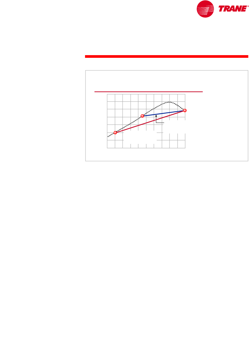
TRG-TRC016-EN 71
period three
System Variations
notes
The control of a heat-recovery centrifugal chiller, although seemingly simple,
is critical to reliable chiller operation. Typically, either the temperature or the
flow of the water entering the standard condenser is modulated to meet the
capacity required by the heat-recovery condenser.
Controlling heat-recovery capacity based on the temperature of the hot water
leaving the heat-recovery condenser can cause operational problems for a
centrifugal chiller. This is explained best by using a map of centrifugal-
compressor operation (see Figure 79). Control based on the temperature of the
water leaving the heat-recovery condenser causes the condenser-to-evaporator
pressure differential to remain relatively high at all loads (line A to B). High
pressure differentials at low cooling loads increases the risk of a centrifugal
compressor operating in its unstable region, commonly known as surge.
The preferred method is to control heat-recovery capacity based on the
temperature of the hot water entering the heat-recovery condenser. This allows
the condenser-to-evaporator pressure differential to decrease as the chiller
unloads (line A to C), thereby keeping the centrifugal chiller from surging and
resulting in more stable operation. If high leaving-hot-water temperatures are
required at low-cooling-load conditions, another method to prevent surge is
to use hot gas bypass on the centrifugal chiller.
For other types of chillers that are not prone to surge, operating at these high
pressure differentials at low cooling loads may cause the chiller to consume
more energy than it recovers in the form of heat.
Control of a Heat-Recovery Chiller
percent maximum pressure differential
percent maximum pressure differential
percent load
percent load
unstable
unstable
operation
operation
(surge)
(surge)
BA
unloading with
unloading with
constant
constant entering
entering hot
hot-
-
water temperature
water temperature
100
100
80
80
60
60
120
120
100
100
50
50
0
0
C
unloading with
unloading with
constant
constant leaving
leaving hot
hot-
-
water temperature
water temperature
Figure 79
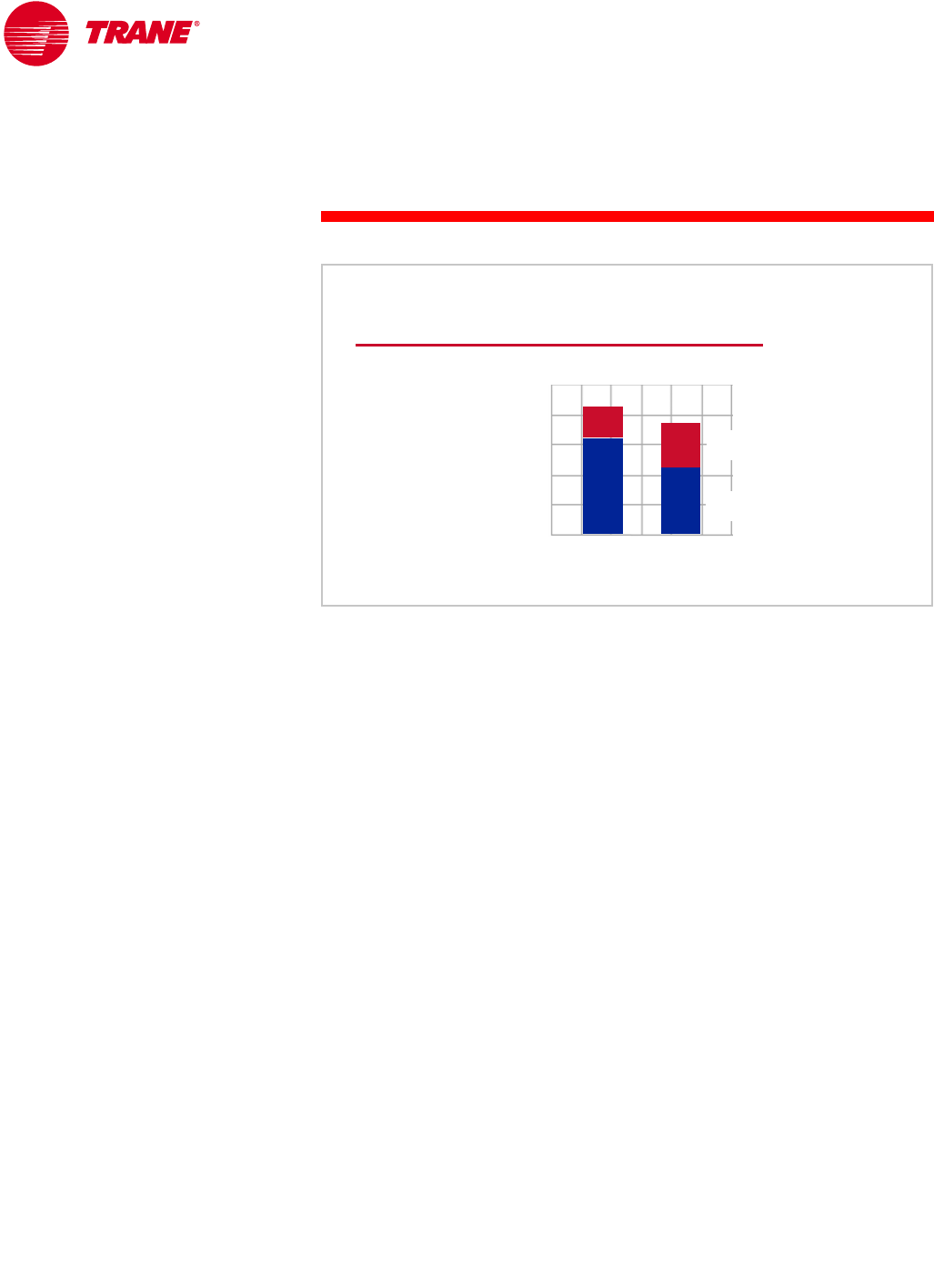
72 TRG-TRC016-EN
notes
period three
System Variations
Asymmetric Design
Many system design engineers seem to default to using chillers of equal
capacity in a multiple-chiller system. There are benefits to using chillers of
varying capacities to more favorably match the system loads. Remember that
when a chiller is started, so is the associated ancillary equipment (pumps and
cooling tower). In general, the smaller the chiller, the smaller the ancillary
equipment. Operating the least number of chillers, and the smallest chiller
possible, to meet the system load minimizes system energy consumption.
Figure 80 examines the use of a “60/40 split,” that is, one chiller (the “lead”
chiller) is sized for 40 percent of the total system capacity and the second chiller
(the “lag” chiller) for 60 percent. Notice that the number of hours of chiller (and
ancillary equipment) operation is reduced by 15 percent, by changing from two
chillers of equal capacity to one chiller at 40 percent capacity and the second
chiller at 60 percent. This is because up to 60 percent load, only one chiller is
operating. Below 40 percent load, only the lead chiller is operating; between
40 and 60 percent load, only the lag chiller is operating. In the same system with
chillers of equal capacity, both chillers and their ancillary equipment are
operating when the load is 50 percent or greater.
Asymmetric Design
annual operating hours
annual operating hours
50% / 50%
50% / 50%
lag
chiller
lag
chiller
60% / 40%
60% / 40%
10,000
10,000
8,000
8,000
6,000
6,000
4,000
4,000
2,000
2,000
0
0
lead
chiller
lead
chiller
▲Different chiller
capacities
▲Different chiller
efficiencies
chiller split
chiller split
Figure 80
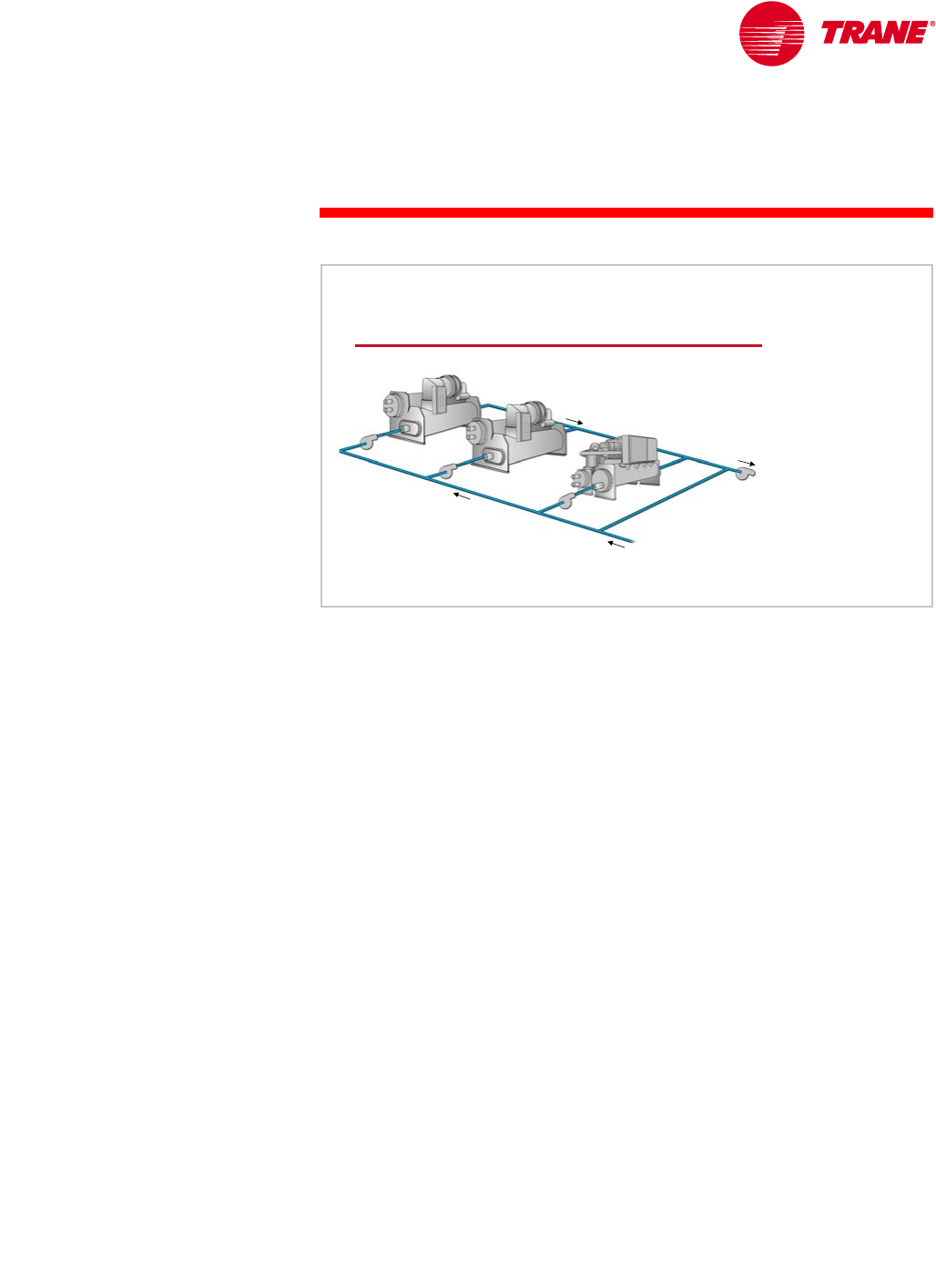
TRG-TRC016-EN 73
period three
System Variations
notes
Another benefit of unequal chiller capacities is that the system load can be
more closely matched with the operating chiller (and ancillary equipment)
capacity, increasing overall system efficiency.
Figure 81 shows a system that includes two large chillers of equal capacity,
along with one smaller capacity chiller. The smaller capacity chiller, called
a swing chiller, in this combination presents an opportunity for significant,
overall system-energy savings.
Swing Chiller
equal
equal-
-capacity
capacity
large chillers
large chillers
small
small-
-capacity
capacity
“swing” chiller
“swing” chiller
Figure 81
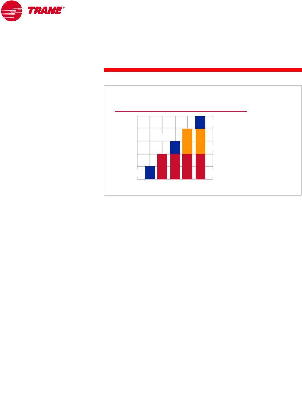
74 TRG-TRC016-EN
notes
period three
System Variations
The smaller swing chiller is turned on to handle the low cooling loads either
during the night or during unoccupied periods of time. When the building load
exceeds the capacity of the swing chiller, it is turned off and a larger chiller is
turned on. The larger chiller handles the building cooling load alone until it
becomes fully loaded. Then the swing chiller is turned on again. The swing
chiller is alternated on and off between the larger chillers' operation to serve
as a smaller incremental step of loading. This sequence more favorably
matches the capacity of the chiller plant to the system load. It keeps the large
chillers loaded in their peak efficiency range and operates with the fewest,
and smallest, pieces of ancillary equipment (pumps and cooling towers) at any
system load.
A common concern is to prevent the swing chiller from cycling too frequently,
which could shorten the life of the equipment. In large chilled-water systems,
however, the changes in building load typically occur slowly enough that this
is not a problem.
A final asymmetric design option is to use one high-efficiency chiller and one or
more standard-efficiency chillers. In this type of system, the high-efficiency
chiller should be preferentially loaded to minimize system energy consumption.
Swing Chiller
percent cooling load
percent cooling load
chiller 1
chiller 1
100
100
80
80
60
60
40
40
20
20
0
0
swing chiller
swing chiller
chiller sequence
chiller sequence
chiller 2
chiller 2
swing chiller
swing chiller
swing chiller
swing chiller
Figure 82

TRG-TRC016-EN 75
period three
System Variations
notes
“Free” Cooling
There are a number of methods that use cool outdoor conditions to reduce
cooling energy costs. They are often referred to as “free cooling” because they
reduce or eliminate the energy consumed by the compressor. They are not truly
free, but really reduced-cost cooling options.
The most prevalent method is the use of an airside economizer. When the
temperature, or enthalpy, of the outdoor air is low enough, the outdoor-air and
return-air dampers in the air handler are modulated and the cooler outdoor air
is used to reduce the temperature of air entering the cooling coil. This can
reduce or totally eliminate the requirement for mechanical cooling for much
of the year in many climates.
In water-cooled systems, there are also several types of waterside
economizers. The most direct method, but typically the least desirable, is to
use a strainer cycle. In this system, the condenser- and chilled-water systems
are connected. When the outdoor wet-bulb temperature is low enough, cold
water from the cooling tower is routed directly into the chilled-water loop.
Although the strainer cycle is the most efficient waterside economizer option, it
greatly increases the risk of fouling in the chilled-water system and cooling coils
with the same type of contamination that is common in open-cooling-tower
systems. A strainer or filter can be used to minimize this contamination, but the
potential for fouling prevents widespread use of the strainer-cycle system.
“Free” Cooling
▲Airside economizer
▲Waterside economizer
◆Strainer cycle
◆Plate-and-frame heat exchanger
◆Refrigerant migration
Figure 83
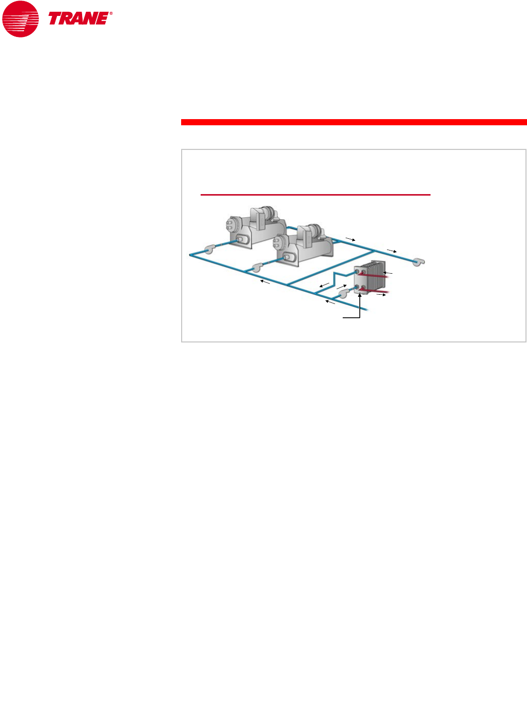
76 TRG-TRC016-EN
notes
period three
System Variations
A second type of waterside economizer is the plate-and-frame heat
exchanger. In this case, water from the cooling tower is kept separate from
the chilled-water loop by a plate-and-frame heat exchanger. This is a popular
configuration because it can achieve a high heat-transfer efficiency without the
potential for cross-contamination. With the addition of a second condenser-
water pump and proper piping modifications, this heat exchanger can operate
simultaneously with the chiller. As much heat as possible is rejected through
the heat exchanger, while the chiller handles any excess cooling load.
If the plate-and-frame heat exchanger is piped in the sidestream position, it can
be used for more hours in the year because it does not need to maintain a
leaving-chilled-water temperature set point. It can provide some useful cooling
at any time that it can precool the system return water.
If simultaneous free cooling and mechanical cooling are performed, care must
be taken to control the evaporator-to-condenser pressure differential inside the
chiller. When very cold condenser water flows through the chiller condenser for
an extended period of time, operational problems may result due to a low
pressure differential between the evaporator and the condenser. Using a
three-way, modulating bypass valve to mix the warm water leaving the chiller
condenser with the cold water entering the condenser, or a two-way
modulating valve and a variable-speed condenser water pump, can eliminate
this problem. Consult with the chiller manufacturer to determine the limits for
the specific chiller being used. This issue is discussed further in Period Four.
waterside economizer
Plate-and-Frame Heat Exchanger
bypass pipe
bypass pipe
distribution
distribution
pump
pump
plate
plate-
-and
and-
-frame
frame
heat exchanger
heat exchanger
condenser
condenser
water loop
water loop
Figure 84
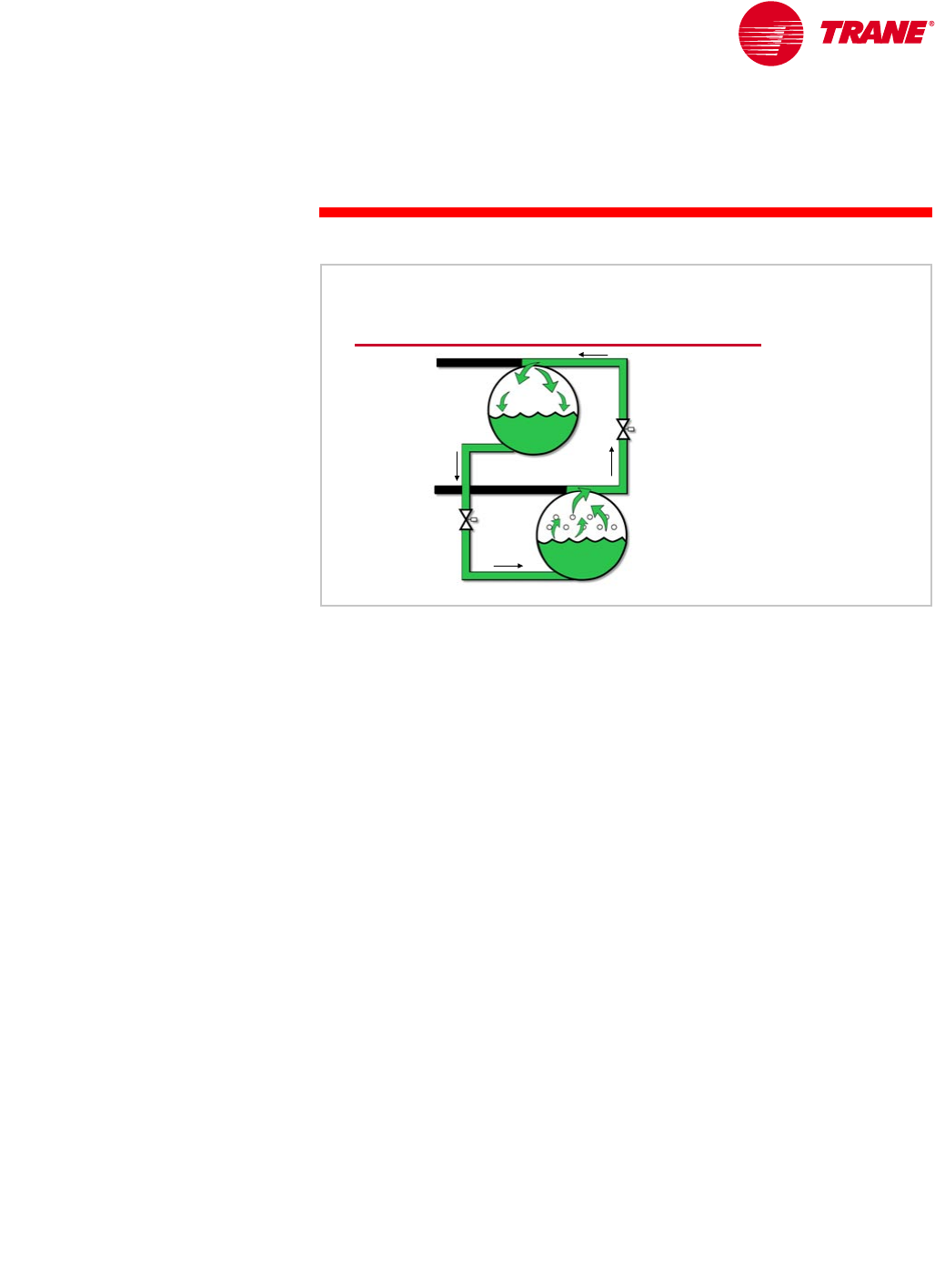
TRG-TRC016-EN 77
period three
System Variations
notes
The final method of “free” cooling is to transfer heat between the cooling tower
water and the chilled water inside a centrifugal chiller through the use of
refrigerant migration. When the temperature of the water from the cooling
tower is colder than the desired chilled-water temperature, the compressor is
turned off and automatic shutoff valves inside the chiller refrigerant circuit are
opened. This allows refrigerant to circulate between the evaporator and
condenser without the need to operate the compressor. Because refrigerant
vapor migrates to the area with the lowest temperature, refrigerant boils in the
evaporator and the vapor migrates to the cooler condenser. After the refrigerant
condenses into a liquid, it flows by gravity back into the evaporator.
There are no additional fouling concerns because the cooling-tower water flows
through the chiller condenser and is separated from the chilled-water loop.
Although not as effective as a plate-and-frame heat exchanger, it is possible for
refrigerant migration in a centrifugal chiller to satisfy many cooling load
requirements (up to 40 percent of the chiller’s design capacity) without
operating the compressor. This can increase further if the system can
accommodate warmer chilled-water temperatures at part-load conditions.
waterside economizer
Refrigerant Migration
from
from
compressor
compressor
to
to
compressor
compressor
evaporator
evaporator
condenser
condenser
shutoff
shutoff
valve
valve
shutoff
shutoff
valve
valve
vapor
vapor
migration
migration
liquid
liquid
flow
flow
Figure 85
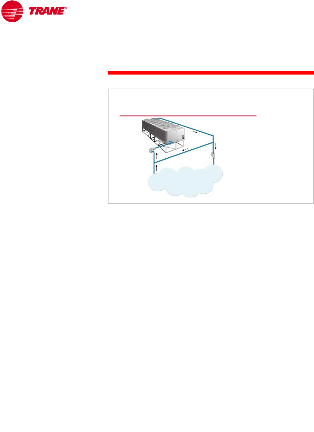
78 TRG-TRC016-EN
notes
period three
System Variations
Application Outside the Operating Range of the Chiller
Some process-load applications involve either temperatures or flow rates that
are outside the capabilities of any chiller. This may include high return-water
temperatures, high or low fluid flow rates, or high or low system ∆Ts. By using
special piping arrangements, a standard chiller can still be used to satisfy the
requirements of the process load.
Figure 86 shows a system in which the water flow requirement of the process
load is below the minimum flow rate for a chiller with the required capacity.
The system is designed like a primary-secondary system, but the production
loop has a higher design flow rate than the distribution loop. This allows the
water flow rate and ∆T through the chiller to be within the acceptable limits,
while the water flow rate and ∆T through the process meet its requirements.
Alternatively, in a smaller system with a single chiller, a single pump on the
chiller side of the bypass and a diverting valve to maintain the proper flow
through the process load can achieve the same result.
Application Outside Range of Chiller
air
air-
-cooled
cooled
chiller
chiller
240
240 gpm
gpm at 45° F
at 45° F
[15 L/s at 7.2°C]
[15 L/s at 7.2°C]
80
80 gpm
gpm at 45° F
at 45°F
[5 L/s at 7.2°C]
[5 L/s at 7.2°C]
160
160 gpm
gpm
at 45°F
at 45°F
[10 L/s at 7.2°C]
[10 L/s at 7.2°C]
process load
process load
240
240 gpm
gpm at 56.7°F
at 56.7° F
[15 L/s at 13.7°C]
[15 L/s at 13.7°C]
80
80 gpm
gpm at 80°F
at 80°F
[5 L/s at 26.7°C]
[5 L/s at 26.7°C]
Figure 86

TRG-TRC016-EN 79
notes
period four
Chiller-Plant Control
It is important to understand that no matter how good the system design is,
adequate controls are necessary for all the components to operate properly as
a system. It is equally important to understand that you cannot “control your
way out of a bad system design.”
The chiller plant consists of chillers, pumps, pipes, coils, cooling towers,
temperature sensors, control valves, and many other devices. It is similar to
an orchestra with many instruments. The existence of these pieces does not
guarantee that the system will work properly. There needs to be an orchestra
conductor. In the case of a chilled-water system, that conductor is a chiller-plant
control system. How well the plant works depends on how well the control
system gets all the pieces to work together.
period four
Chiller-Plant Control
Chilled-Water Systems
Figure 87
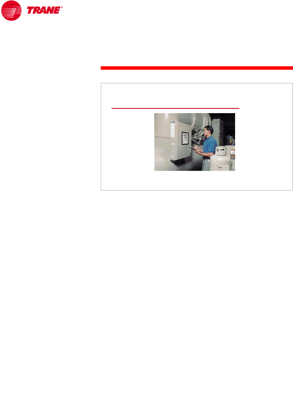
80 TRG-TRC016-EN
notes
period four
Chiller-Plant Control
The largest change to chillers in the last decade has undoubtedly been in the
area of controls. In the past, chillers were pneumatically controlled, and they
were protected by turning them off if the flow rates or temperatures changed
too quickly. Today’s microprocessor-based controls provide accurate chilled-
water temperature control, as well as monitoring, protection, and adaptive
limit functions.
These controls monitor chiller operation and prevent the chiller from operating
outside its acceptable limits. They can also adapt to unusual operating
conditions, keeping the chiller operating by modulating its components and
sending a warning message, rather than doing nothing more than shutting it
down when a safety setting is violated. Improved control accuracy allows
chillers to be applied in systems and applications that were previously avoided.
When problems occur, diagnostic messages aid troubleshooting. Modern
chiller controls also interface with a chiller-plant control system for integrated
system operation.
Chiller Controls
▲Start–stop
▲Chilled-water
temperature
control
▲Monitor and
protect
▲Adapt to
unusual
conditions
Figure 88

TRG-TRC016-EN 81
period four
Chiller-Plant Control
notes
There are primarily five issues to address in a chiller-plant control system.
1When should a chiller be turned on or off?
2After we know that a chiller must be turned on or off, which one should
it be?
3If we attempt to turn on a chiller, pump, or cooling tower, and there is a
malfunction, what do we do next?
4How can we minimize the energy cost of operating the system?
5How can the chiller-plant control system effectively communicate with the
operator?
What Is Important?
▲When to turn a chiller on or off
▲Which chiller to turn on or off
▲How to recover from an equipment failure
▲How to optimize system efficiency
▲How to communicate with the operator
Figure 89
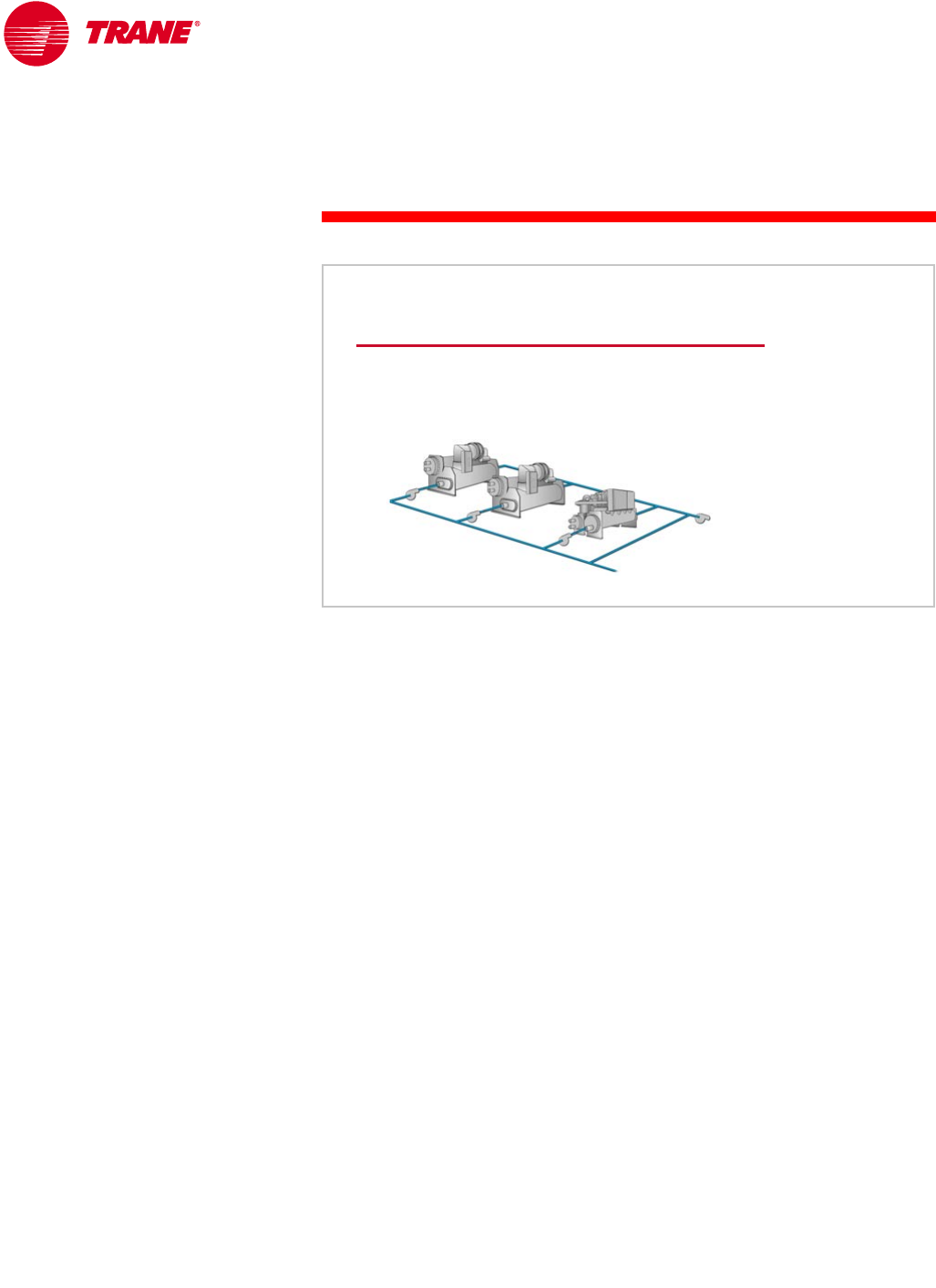
82 TRG-TRC016-EN
notes
period four
Chiller-Plant Control
Chiller Sequencing
Chiller sequencing refers to making decisions about when to turn chillers on
and off, and in what order. Typically, turning chillers on and off is performed
with the goal of matching the capacity of the chiller plant to the system cooling
load. In order to do this successfully, the design of the chilled-water system
must provide the control system with variables that are good indicators of
system load.
The hydraulic design and size of the chilled-water system will determine the
possible method(s) for effectively monitoring system load. Typical methods
for load monitoring include:
nIn series- or parallel-piped systems, the supply- and return-water
temperatures, and sometimes chiller current draw, are monitored.
nIn a primary-secondary system, the system supply and chiller return-water
temperatures and/or the direction and quantity of flow in the bypass pipe
are typically measured.
nIn a variable-primary-flow system, the system supply-water temperature
and the system flow rate may be monitored.
nDirect measurement of the system load (in tons, kW, or amperes) has also
been used in some systems.
Other methods are also possible. It is imperative that the chilled-water system
be designed with the control variables in mind; otherwise, the result may be a
system that is impossible to efficiently control.
Chiller Sequencing
▲Turning on an additional chiller
▲Turning off a chiller
▲Which chiller to turn on or off?
Figure 90

TRG-TRC016-EN 83
period four
Chiller-Plant Control
notes
Today’s chiller controls can very accurately control the chiller’s leaving-water
temperatures over a wide range of loads. This is especially true of centrifugal
and helical-rotary chillers. This fact allows constant-flow chilled-water systems,
similar to the system shown in Figure 91, to use the system supply- and return-
water temperatures to determine system load.
By sensing a rise in the temperature of the water leaving the chiller plant,
the control system can determine when the operating chillers can no longer
maintain the desired temperature. Often, the supply-water temperature is
allowed to drift a predetermined amount before an additional chiller is turned
on, to ensure that there is enough load to keep an additional chiller operating.
Deciding when it is appropriate to turn a chiller off is more complex. The control
system may monitor the system ∆T, that is, return-water temperature minus
supply-water temperature. This information, along with the capacities of the
operating chillers, allows the control system to determine when a chiller can be
turned off. To help stabilize system operation, the control system should use
logic to prevent load transients from causing unwarranted chiller cycling.
In constant-flow systems that are suffering from “low ∆T syndrome” (airside
systems that return water to the plant at lower temperatures than desired),
some of the load terminals may starve for flow before the capacity of the
operating chiller is exceeded. To preserve system efficiency, this situation is
best dealt with by solving the airside problem. Typical causes of low ∆T
syndrome include: a poorly-balanced flow system, dirty filters or coils,
poorly performing air-handler controls, incorrect coil control valves, or
undersized air handlers.
load indicators
Temperature
supply
supply-
-water
water
temperature
temperature
return
return-
-water
water
temperature
temperature
chiller
chiller-
-plant
plant
controller
controller
Figure 91
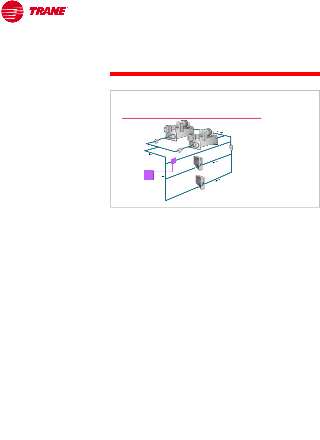
84 TRG-TRC016-EN
notes
period four
Chiller-Plant Control
In a primary-secondary system, the direction and quantity of flow in the bypass
pipe is an excellent indicator of when to turn a chiller on or off . As discussed in
Period Two, the water flow in the bypass pipe can be measured directly using a
flow meter, or indirectly by measuring system water temperatures and applying
flow-mixing equations. The rules applied to the bypass flow to determine when
to turn a chiller on and off are:
nWhen there is a deficit flow, a chiller may be added.
nWhen there is excess flow greater than that of the next chiller to be turned
off, plus a 10 to 15 percent safety factor, that chiller may be turned off.
nIf neither of the above conditions exists, do nothing.
As an alternative to measuring flow in a primary-secondary system with four or
less chillers, system supply and chiller-plant return-water temperatures may be
used to decide when to turn a chiller on or off. This is similar to the logic applied
to constant-flow systems. It is simple and has a low installed cost, but it is less
accurate than flow determination, especially as the number of chillers
increases.
“Low ∆T syndrome” can also affect the operation of primary-secondary
systems. Unlike constant-flow systems, the primary-secondary system will
maintain the required system flow and supply-water temperature, and therefore
maintain occupant comfort. However, it accomplishes this by turning on
additional chillers before all operating chillers are fully loaded. This may reduce
overall system efficiency.
Although some have proposed solutions such as putting a valve in the bypass
line, lowering the supply-water temperature, or controlling the system
differently, these are only band-aids that mask the actual problem and often
cause other operational difficulties. Fixing the root cause of low ∆T syndrome in
the distribution system is the best course of action for proper and efficient
system operation.
bypass pipe
bypass pipe
load indicators
Flow
flow
flow
meter
meter
chiller
chiller-
-plant
plant
controller
controller
Figure 92
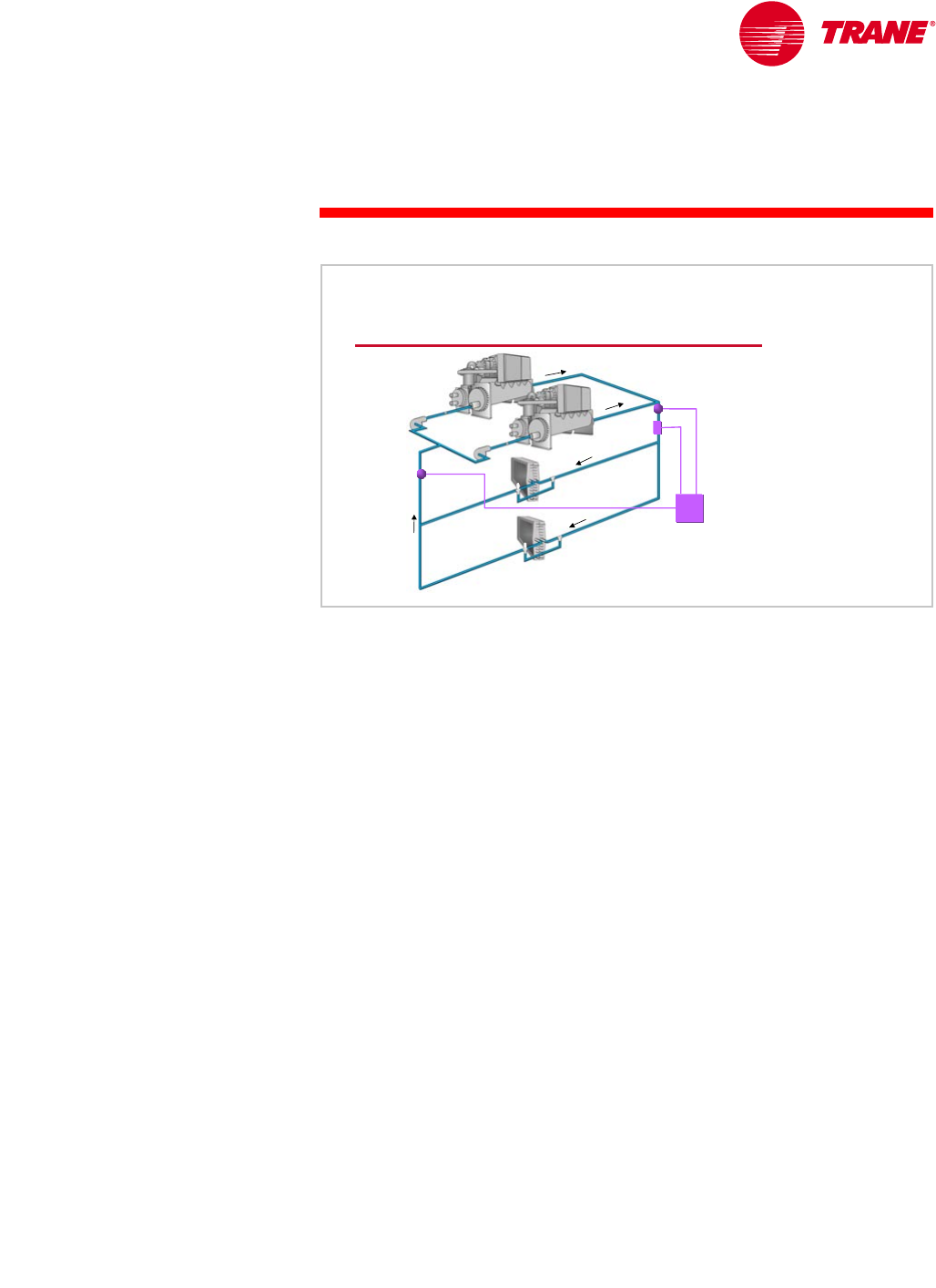
TRG-TRC016-EN 85
period four
Chiller-Plant Control
notes
Another method of monitoring system cooling load is to measure the system
water flow rate and temperatures directly, and then calculate the load. Although
it would appear that direct measurement of the actual system load would be an
excellent way to determine when to turn chillers on and off, this method has
several drawbacks. It requires the use of flow meters with high accuracy and
high turndown capacities. Although flow meters have become more accurate
and less expensive, they require special installation conditions for reliable
accuracy—conditions seldom achievable in real installations. Also, the
equipment typically requires regular calibration. For these reasons, direct
measurement of load has not been used as much as the simple and reliable
methods discussed previously.
An alternate way to monitor chiller load is by measuring the current draw of the
chiller motor. By itself, this does not provide an adequate control indicator, but
when used in conjunction with other information, such as system supply-water
temperature, it can be effective. System supply-water temperature is used to
determine when to turn an additional chiller on, and operating chiller
compressor-motor current draw is used to determine when a chiller can be
turned off.
The most effective load indicator for any chilled-water system is dependent on
the design of that system. Creative designers have used the control strategies
as described here and in various combinations to effectively control a wide
variety of chiller plants. It is highly recommended that one of the first tasks
undertaken in the design process is to create a simplified flow diagram and a
load model of the system that allows for the evaluation of various control
strategies and sensor placements. This will help to ensure that effective
chiller-plant control can be implemented.
load indicators
Capacity
flow
flow
meter
meter
chiller
chiller-
-plant
plant
controller
controller
supply
supply-
-water
water
temperature
temperature
return
return-
-water
water
temperature
temperature
Figure 93
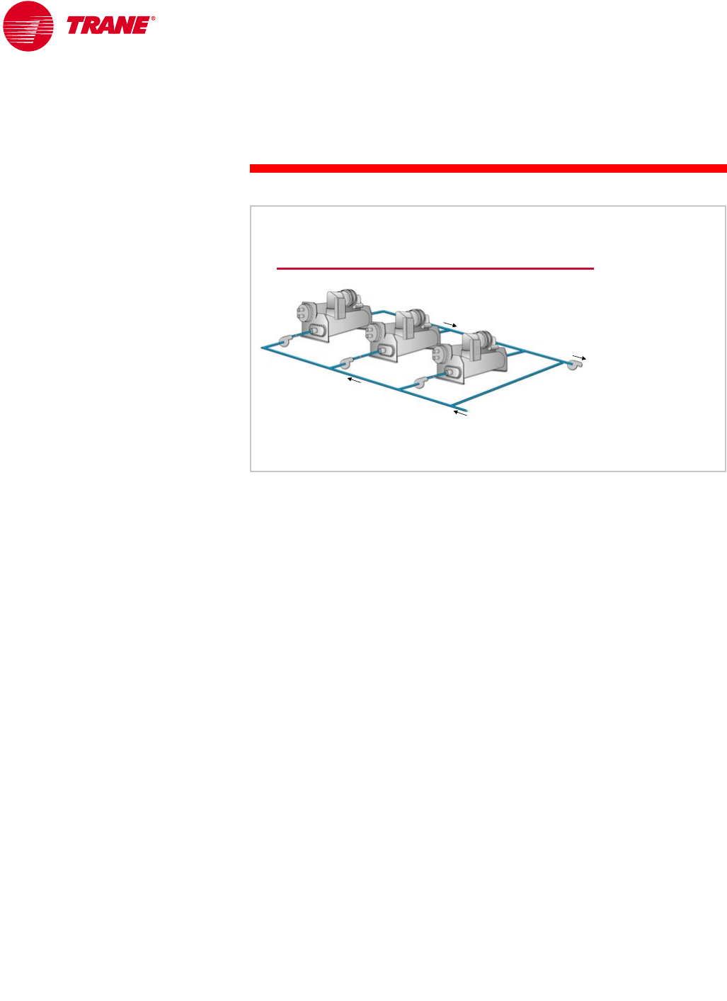
86 TRG-TRC016-EN
notes
period four
Chiller-Plant Control
When the system has determined that a chiller needs to be turned on or off,
the next issue is to determine the sequence in which to turn chillers on and off.
It is assumed that the first chiller in the sequence will always be turned on
whenever cooling is required.
When the system consists of identical chillers, the choice of which chiller is
turned on or off next has little impact on system efficiency. Some design
engineers and operators prefer to equalize the run time and the number of
starts for all chillers in the system. This is typically done by rotating the
sequence of chillers on a periodic basis, often every few days or weeks. This
method generally keeps the run time equalized reasonably well, and the
operator knows exactly when to expect the rotation to occur. An alternative
approach is to total the actual run hours on each chiller, in an attempt to rotate
the chillers when a significant imbalance in the run time or the number of starts
occurs. Rotation that is based on actual run time has the disadvantage of the
operator not knowing when rotation will occur. In some installations, operating
personnel prefer to manually initiate rotation.
On the other hand, some design engineers and operators believe that
equalizing run times will result in all of the chillers needing to be overhauled or
replaced at the same time. They tend to operate the most-efficient chiller first,
followed by the next-most-efficient, and so on. With this approach, all chillers
are turned on at least once a month to ensure that they will be able to start
when required.
Chiller Rotation
equally
equally-
-capacity chillers
capacity chillers
Figure 94
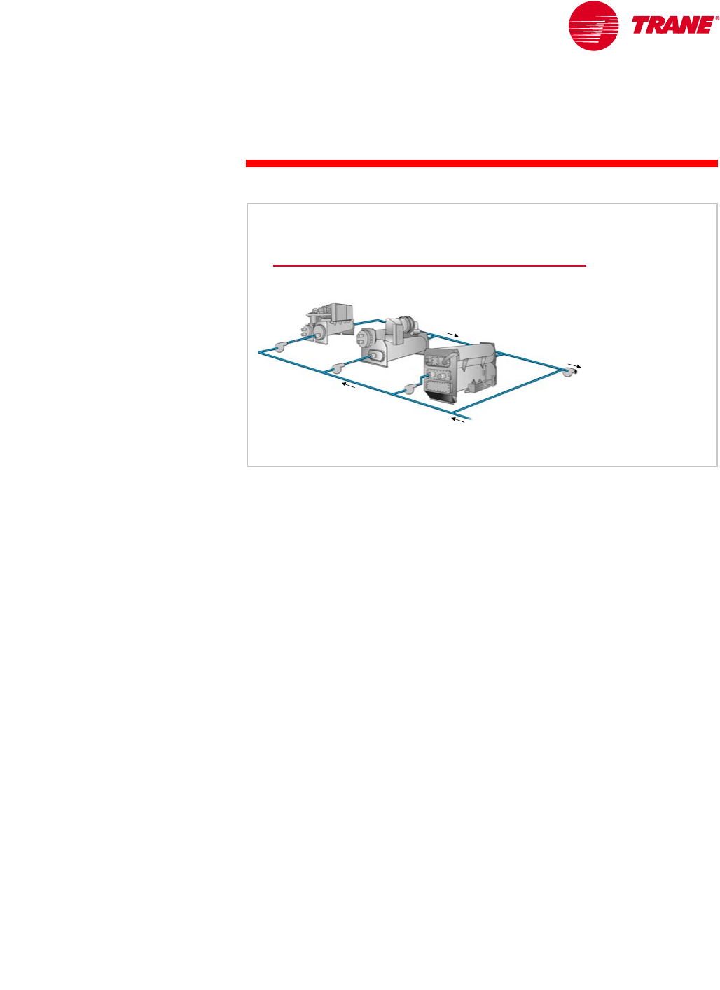
TRG-TRC016-EN 87
period four
Chiller-Plant Control
notes
When the system consists of chillers with different capacities, efficiencies, or
fuel types, the question of which chiller to turn on or off next becomes more
complex. Although each system requires a complete analysis, there are some
general principles that apply to most systems.
In systems with chillers of different capacities, such as the “swing” chiller
concept introduced in Period Three, the goal is to operate the least number
of chillers and the smallest chiller possible. This typically minimizes overall
system energy consumption by closely matching the capacity of the plant to
the system load, thus reducing the energy used by ancillary equipment.
In systems with chillers of different efficiencies, it makes sense to operate the
most efficient chillers first and the least efficient chillers last. If different fuel
types are involved, the control system may receive data on the costs of natural
gas and electricity and calculate the real-time cost of operating the electric-
versus gas-driven chillers.
large electric
large electric
chiller
chiller absorption
absorption
chiller
chiller
small electric
small electric
chiller
chiller
Chiller Rotation
Figure 95
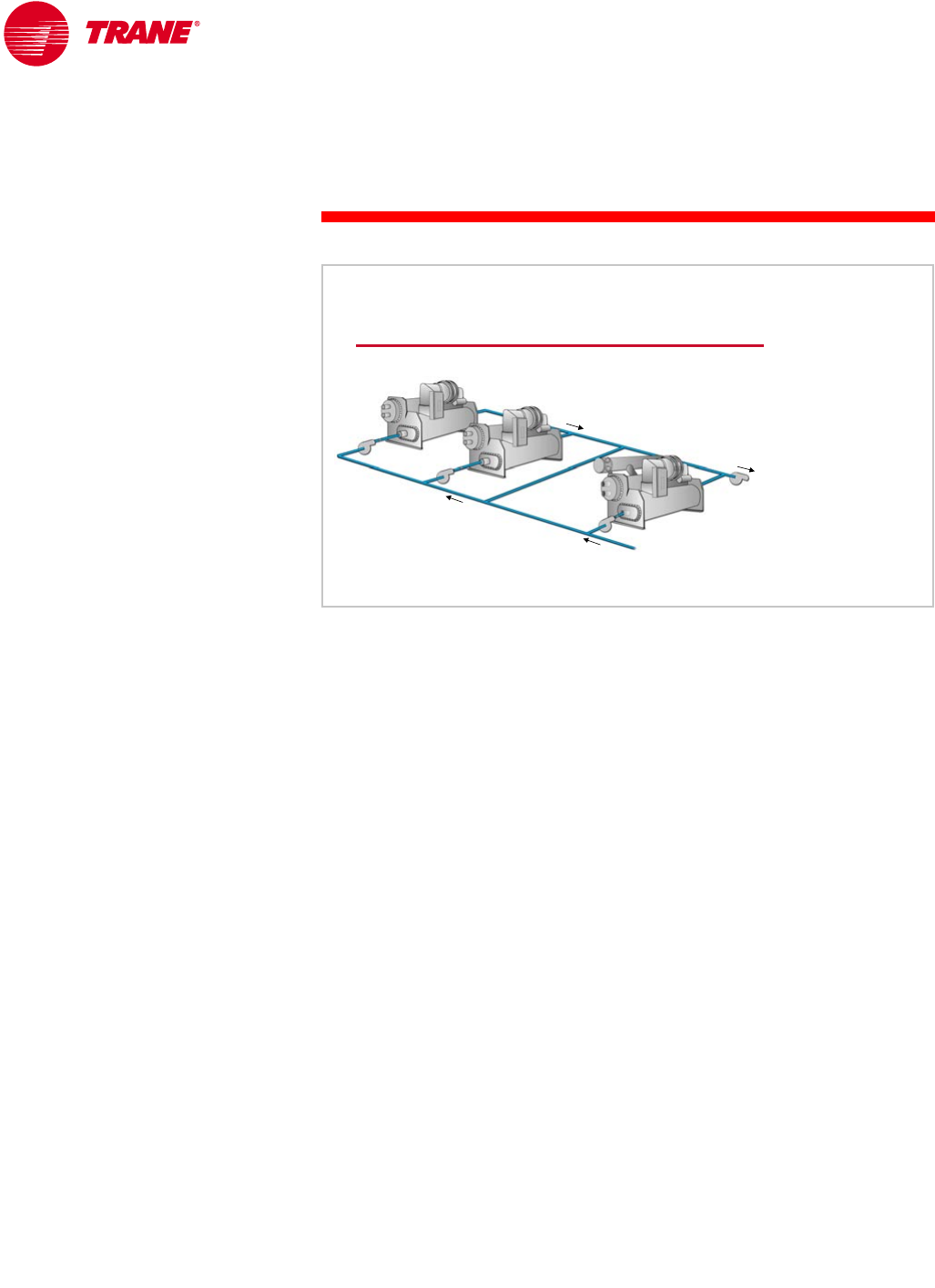
88 TRG-TRC016-EN
notes
period four
Chiller-Plant Control
The system might also benefit from having a heat-recovery chiller fully loaded.
As discussed in Period Three, to maximize the amount of heat recovered, it is
often desirable to preferentially load that chiller, sequencing it as a base
chiller—“first on” and “last off.” Other chillers can then be turned on when the
heat-recovery chiller cannot handle the cooling load alone.
A variation on this idea is an absorption chiller fueled by waste heat. It is
preferentially loaded to handle as much of the cooling load as possible before
turning on other chillers. The absorption chiller would be sequenced as a base
chiller to make use of the free energy operating this chiller.
Heat Recovery
preferentially
preferentially-
-loaded
loaded
heat
heat-
-recovery
recovery
chiller
chiller
standard
standard
electric chillers
electric chillers
Figure 96
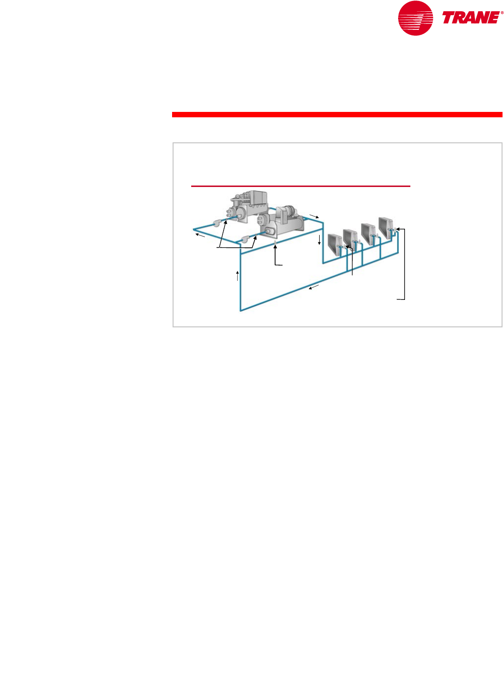
TRG-TRC016-EN 89
period four
Chiller-Plant Control
notes
The variable-primary-flow system, introduced in Period Three, is designed to
operate with variable flow through the chiller evaporators. Sequencing chillers
in this type of system cannot be based solely on temperature, because in a
properly-operating system the supply- and return-water temperatures will be
nearly constant. Determining when to turn chillers on or off is not a simple task.
For control stability and chiller reliability, the flow rates through the chillers,
and the rate of flow change, must be kept within allowable ranges.
Therefore, control of a variable-primary-flow system must:
nInclude a method to determine system load. Many systems measure flow
rates and temperatures.
nEnsure that flow rates through the chillers are within the allowable
minimum and maximum limits. Modulation of a control valve in the bypass
pipe is commonly used to ensure minimum flow rates through the chillers.
nControl the rate at which the system flow rate changes, to ensure that it does
not change more rapidly than the chillers can adapt. This is especially critical
when turning on additional chillers.
Adequate time must be spent designing the control sequence and
commissioning the system after installation, to ensure proper operation of a
variable-primary-flow system.
Variable-Primary-Flow Systems
bypass
bypass
two
two-
-way
way
valve
valve
variable
variable-
-flow
flow
pumps
pumps
control
control
valve
valve
check
check
valves
valves
optional bypass
optional bypass
with three
with three-
-way valve
way valve Figure 97

90 TRG-TRC016-EN
notes
period four
Chiller-Plant Control
Failure Recovery and Contingency Planning
In addition to normal chiller sequencing, the chiller-plant control system must
react when a chiller or another piece of associated equipment fails. Failure
recovery, or ensuring the reliable supply of chilled water, is a very important
part of the chiller-plant control system, and is an area where many systems
have fallen short. This is especially true in field-programmed systems because
of the difficulty of thorough debugging.
During periods of equipment malfunction, it is important to focus on the
primary goal of the system, which is to provide the required flow of chilled
water to the system at the proper temperature. It seems reasonable that the
simplest and most reliable failure-recovery sequence is to simply turn on the
next chiller in the sequence, and not try to turn several chillers on and off in
an attempt to re-optimize the system.
During an equipment failure, it is especially important to notify the operator
of the status, as well as to help the operator understand where the problem is
and what might be the cause. The control system must also allow the operator
to easily analyze the situation and to intervene if the failure condition will exist
for an extended period of time. A system that provides this information will
ensure that the system itself will be maintained and operated in proper
condition.
System Failure Recovery
▲Maintain flow of chilled water
▲Keep it simple
◆Lock out failed equipment
◆Turn on the next chiller in the sequence
▲Notify the operator
▲Allow the operator to intervene
Figure 98
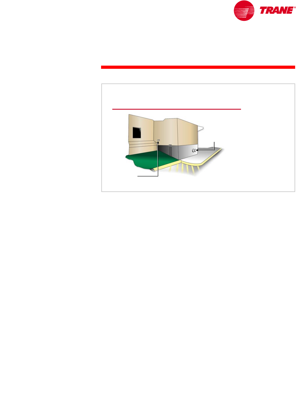
TRG-TRC016-EN 91
period four
Chiller-Plant Control
notes
In addition to failure recovery, it is wise for the system design engineer to
work with the building owner to develop a contingency plan for chilled water
in the case of an emergency shutdown or an extended breakdown. Many
organizations have contingency plans for critical areas of their business.
Some deal with natural disasters and others with the loss of power in critical
areas. However, few have taken the time to think about what a loss of cooling
would mean to their facility. This is often especially critical for process-cooling
applications.
Cooling contingency planning is intended to minimize the losses a facility
may incur as a result of a total or partial loss of cooling capacity. It allows a
building operator to act more quickly by having a plan in place and by
proactively preparing the facility. Such a plan often includes working with
suppliers to temporarily lease cooling equipment. During initial construction,
it is easy and cost-effective to provide piping stubs, which are built into the
chilled-water system for quick connection, and easily accessible electrical
connections. When equipment leasing is combined with these simple additions
to the system, a contingency plan can be put into action quickly and the system
can produce chilled water again in a short period of time.
It is important to first identify the minimum, or critical, cooling capacity
required. With multiple chillers in a facility, it may be acceptable to have less
than full capacity in an emergency situation. For example, the chiller plant
may consist of 1,800 tons [6,330 kW], but the minimum capacity required in
an emergency situation may only be 1,200 tons [4,220 kW]. Therefore, it is also
important to identify a contingency plan if Chiller 1 fails, if Chiller 2 fails, if
Chillers 2 and 3 fail, and so on.
Contingency Planning
electrical
electrical
connections
connections
piping
piping
stubouts
stubouts
Figure 99
92 TRG-TRC016-EN
notes
period four
Chiller-Plant Control
System Tuning
In addition to turning chillers on and off, there are other functions of the chiller-
plant control system that help prevent system flow instability from disrupting
chiller operation. Flow instability can often be caused by normal valve and
pump operation. The first is time delays.
Excessive cycling can be detrimental to the life of a motor. For this reason,
turning a large motor (such as those used in large chillers) on and off should
be minimized. Chilled-water systems typically have a large thermal mass
(water in the system) and benefit from the diversity and slow rate of change
of the system cooling load. Fast reactions, therefore, are typically not required.
In fact, a response that is too fast will often cause system instability, waste
energy, and cause unnecessary wear on mechanical equipment. To achieve
stable and accurate control, many chiller-plant control systems provide time
delays that can be adjusted by the operator to help minimize chiller cycling.
The first time delay is the load-confirmation timer. Its purpose is to delay
turning on an additional chiller for a period of time following the initial
indication that an additional chiller is required. This confirms that the indicated
load is not a transient condition that would cause the chiller to be turned on and
then quickly turned off.
The second time delay, which works in conjunction with the first, is a
staging-interval timer. Its purpose is to allow the system time to respond
after a chiller has been turned on. This prevents more chillers from turning on
than are actually required, particularly during periods of pull-down or rapid
load variation.
The third time delay is a minimum-cycle timer. This timer should have the
highest priority. It requires a fixed period of time between turning an individual
chiller on and turning it back off. This ensures that the chiller is not cycled too
frequently.
It is important to understand that these timers are lower priority than the
safeties built into the individual chiller controls. At all times, the individual
System Timers
▲Load-confirmation timer
◆Avoids transient conditions
▲Staging-interval timer
◆Allows time for the system to
respond to turning a chiller on
▲Minimum-cycle timer
◆Prevents excessive cycling
Figure 100
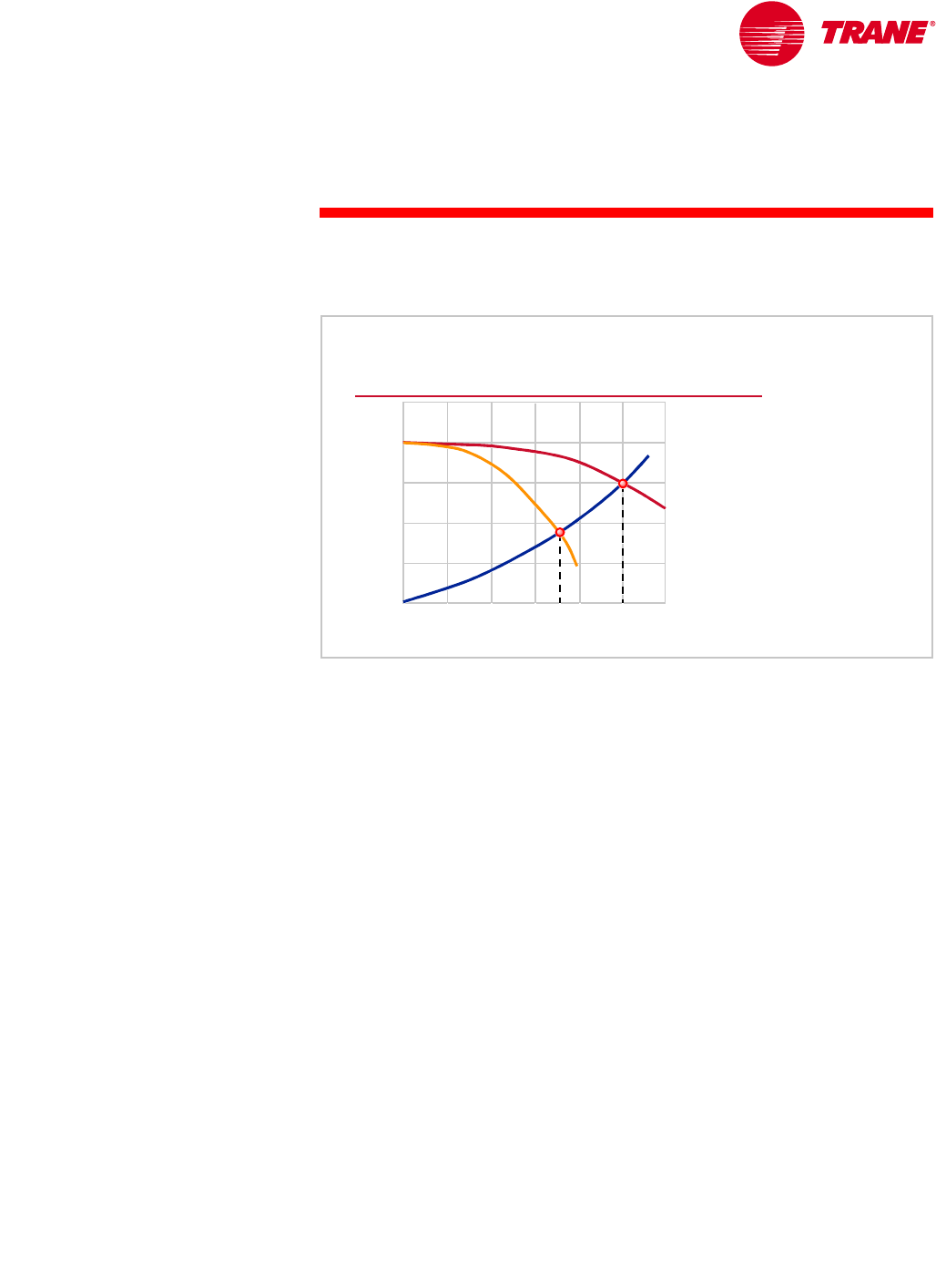
TRG-TRC016-EN 93
period four
Chiller-Plant Control
notes chiller safeties must be capable of shutting the chiller down to avoid equipment
damage.
The next control function is to partially unload the operating chillers before
an additional chiller and pump are turned on. Depending on the system
configuration, there can be very rapid variations in water flow through the
chiller evaporator when a pump is turned on or off, or when a control valve is
opened or closed. Partially unloading the chiller prior to such variations allows
the chiller to continue to operate without interruption.
This can be explained by looking at a flow diagram for a chilled-water system
with multiple pumps (see Figure 36). This diagram shows that, with one pump
and chiller operating, the flow rate through the chiller is 610 gpm [38.5 L/s].
When the second, same-size pump and chiller are turned on, the flow rate
through the system increases to 870 gpm [54.9 L/s], but the flow through each
chiller drops to 435 gpm [27.4 L/s]. This is an instantaneous reduction of
175 gpm [11 L/s], or 30 percent, through the first chiller.
The temperature of the water leaving the chiller and the temperature of the
refrigerant in the evaporator drop as a result of this drastic flow reduction.
New, advanced chiller controls may allow the refrigerant temperature to drop
below the fluid’s freezing point for a brief period of time while the compressor
unloads. The evaporator low-temperature safety may, however, turn off the
chiller if the controls and compressor cannot react quickly enough.
The “unload-before-start” function partially unloads the operating chillers,
raising the refrigerant temperature in the evaporator, before the flow reduction
occurs. The chillers are allowed to reload as soon as the additional chiller is
turned on.
Unload Before Start
head pressure
head pressure
system flow rate
system flow rate
2 pumps
2 pumps
1 pump
1 pump
system
system
curve
curve
870
870 gpm
gpm
[54.9 L/s]
[54.9 L/s]
610
610 gpm
gpm
[38.5 L/s]
[38.5 L/s] Figure 101
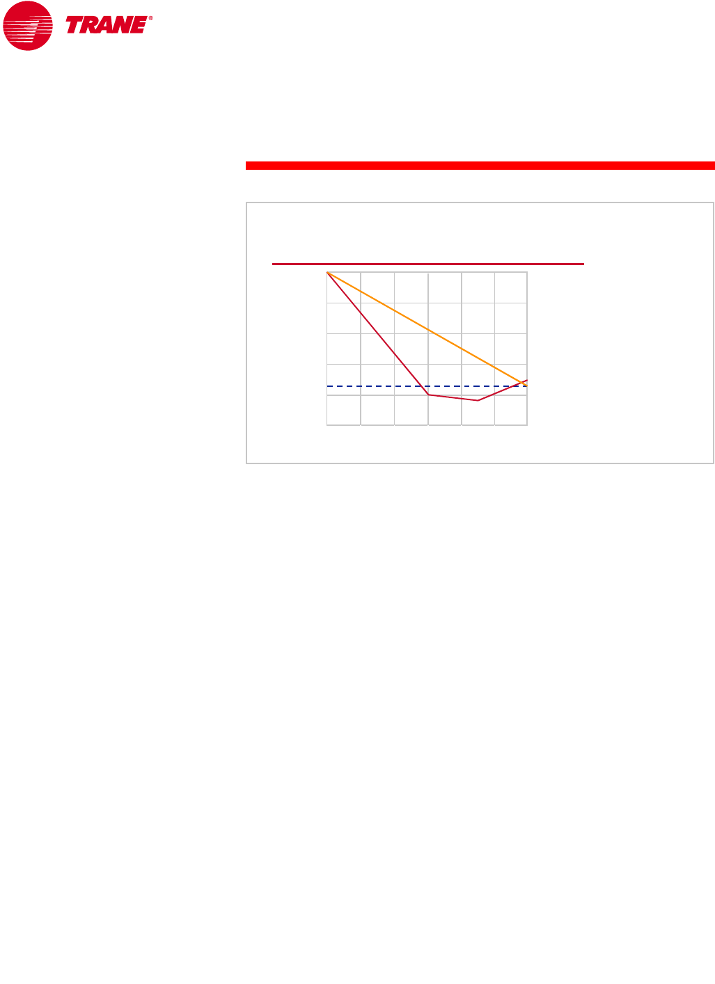
94 TRG-TRC016-EN
notes
period four
Chiller-Plant Control
Another control function that is desirable is called soft loading. It is typically
used when the system has been off for an extended period of time and the
chilled-water temperature is the same as the ambient temperature inside the
building.
Soft loading either delays turning on additional chillers or varies the chilled-
water set point, allowing the operating chillers to gradually catch up to the
building pull-down load. This results in a very smooth pull-down, prevents
overshooting the set point, and operates only the equipment required to satisfy
the actual system load.
Soft Loading
supply
supply-
-water temperature
water temperature
operating time, minutes
operating time, minutes
two chillers
two chillers
soft loading
soft loading
(one chiller)
(one chiller)
set point
set point
60
60
30
30
0
0
80°F
80°F
[26.7°C]
[26.7°C]
60°F
60°F
[15.6°C]
[15.6°C]
40°F
40°F
[4.4°C]
[4.4°C]
Figure 102

TRG-TRC016-EN 95
period four
Chiller-Plant Control
notes
Constant-flow chilled-water systems frequently require individual chiller set-
point control. Its purpose is to help maintain the system supply-water
temperature by compensating for the bypass of return water through
non-operating chillers.
The chiller-plant control system adjusts the individual set points for the
operating chiller to “overcool” the water before it mixes with the higher-
temperature water that bypasses through the non-operating chiller. The result
is that the chilled water supplied to the system is as close as possible to the
desired temperature. There are limits to the amount of overcooling. Depending
on the design of the chilled-water system, one of two situations may exist.
Either the chiller may not have been selected to produce cold-enough water,
or the temperature required may be below the freezing point of the water being
cooled. In either case, the control system must be intelligent enough to limit
overcooling in order to prevent damage to the chiller.
Additionally, the control system must know when to turn another chiller on to
meet the system chilled-water-temperature set point. Turning an additional
chiller on may be required to meet the system demand for flow, even though
the operating chiller may not be fully loaded.
constant-volume pumping system
Chilled-Water Set Point Control
54° F
54° F
[12.2° C]
[12.2° C]
37° F
37° F
[2.8°C]
[2.8°C]
54°F
54°F
[12.2°C]
[12.2°C]
off
off
on
on
45.5°F
45.5°F
[7.5°C]
[7.5°C]
lowering operating
lowering operating
chiller set point
chiller set point
helps regain control
helps regain control Figure 103

96 TRG-TRC016-EN
notes
period four
Chiller-Plant Control
System Optimization
The chiller-plant control system can also be used for system optimization.
For the purposes of this discussion, we will define optimization as minimizing
the energy used by the chiller plant (including chillers, chilled-water pumps,
condenser-water pumps, and cooling tower) while still maintaining comfort
or satisfying process loads.
The first step is to examine the energy use of the major components of the
chiller plant, to see what can be done to minimize each component individually.
The chiller energy usage can be reduced by lowering the condenser-water
temperature or by raising the chilled-water temperature.
In a variable-flow system, chilled-water pumping energy can be reduced by
lowering the chilled-water temperature while increasing the system ∆T. With
the lower water temperature and increased ∆T, the coil requires less water
flow to handle the same load.
Cooling-tower energy can be reduced by increasing the condenser-water
temperature. This allows the tower fans to cycle or slow down. Condenser-
water pumping energy can be reduced by increasing the ∆T through the
condenser side of the system, thereby pumping less water. This is achieved
by reducing the water flow through the condenser.
Obviously, looking at only a single component presents a conflicting picture for
energy reduction, and a change in one component has an impact on other
components. To truly optimize the chiller plant, all components must be
analyzed together.
System Optimization
▲Chiller
◆Decrease condenser-water temperature
◆Increase chilled-water temperature
▲Chilled-water pump (variable-flow system)
◆Increase chilled-water ∆T
▲Cooling tower
◆Increase condenser-water temperature
▲Condenser-water pump (variable-flow system)
◆Increase condenser-water ∆T
Figure 104

TRG-TRC016-EN 97
period four
Chiller-Plant Control
notes
As previously stated, as the chilled-water temperature set point is reset
upwards, the chiller will use less energy. In constant-flow systems, this
chilled-water reset strategy is fairly simple to implement and can be
controlled based on the drop in return-water temperature.
In a variable-flow system, however, as the chilled-water temperature increases,
the pumping energy also increases. While the COP of the chiller is
approximately 6.5, the COP of the pump is about 0.65. Often the increase in
pump energy will be more than the amount of chiller energy saved, especially
because the chiller will often operate at part-load conditions. Another potential
problem with resetting the chilled-water temperature upward is that space
humidity control can be compromised if the water gets too warm. Finally, the
chiller-plant control system must account for the changing supply-water
temperature.
ASHRAE/IESNA Standard 90.1–1999 (Section 6.3.4.3) requires the use of
chilled-water temperature reset in systems larger than 25 tons [88 kW]. It does,
however, exclude variable-flow systems and systems where space humidity
control will be compromised.
In Period Three, the concept of designing for reduced chilled-water temperature
and flow rates was briefly discussed. Some engineers feel that designing the
system for low flow rates and a lower supply-water temperature, thus
minimizing pump energy use, might be a better answer than attempting to
reset the temperature upward.
▲Cons
◆Increases pump energy
in variable-flow systems
◆Can cause loss of
space humidity control
◆Complicates chiller
sequencing control
Chilled Water Reset
▲Pros
◆Reduces chiller energy
◆Can work in constant-
flow systems
Figure 105
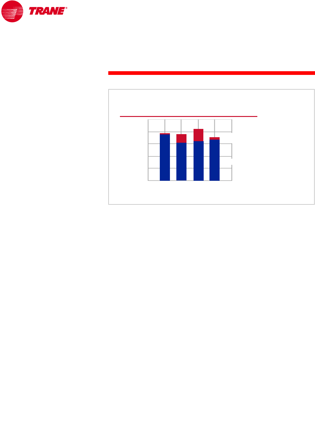
98 TRG-TRC016-EN
notes
period four
Chiller-Plant Control
Lowering the temperature of the condenser water can also reduce the energy
consumption of the chiller. Depending on the system load and outdoor
conditions, cooling towers typically have the ability to supply colder condenser
water than at design conditions. This, however, increases the energy
consumption of the cooling tower fans. The key to maximizing energy savings
is knowing the relationship of cooling-tower energy consumption to chiller
energy consumption.
At design conditions, a chiller typically uses five to ten times more energy
than a cooling tower. This would suggest that it might be beneficial to use
more cooling-tower energy to save chiller energy. However, there is a point of
diminishing return where the chiller energy savings is less than the additional
energy used by the cooling tower. Figure 106 shows the combined annual
energy consumption of a chiller and cooling tower in a system that is controlled
to various condenser-water-temperature set points. The third column shows a
system that attempts to supply 55°F [12.8°C] water from the cooling tower at
all times. Of course, at design conditions, the cooling tower may not be able to
supply this temperature, but it will supply the water at the coldest temperature
possible.
The fourth column shows a system that uses a control system to dynamically
determine the optimal condenser-water temperature that minimizes the
combined energy use of the chiller plus cooling tower. It is obvious that this
method of optimal control minimizes overall system energy consumption.
Condenser-Water Temperature
annual energy consumption, kWh
annual energy consumption, kWh
cooling
tower
cooling
tower
300,000
300,000
chiller
chiller
condenser-water temperature set pointcondenser
condenser-
-water temperature set point
water temperature set point
85°F
[29.4°C]
85°F
85°F
[29.4°C]
[29.4°C]
70°F
[21.1°C]
70°F
70°F
[21.1°C]
[21.1°C]
55°F
[12.8°C]
55°F
55°F
[12.8°C]
[12.8°C]
optimal
control
optimal
control
200,000
200,000
100,000
100,000
Figure 106
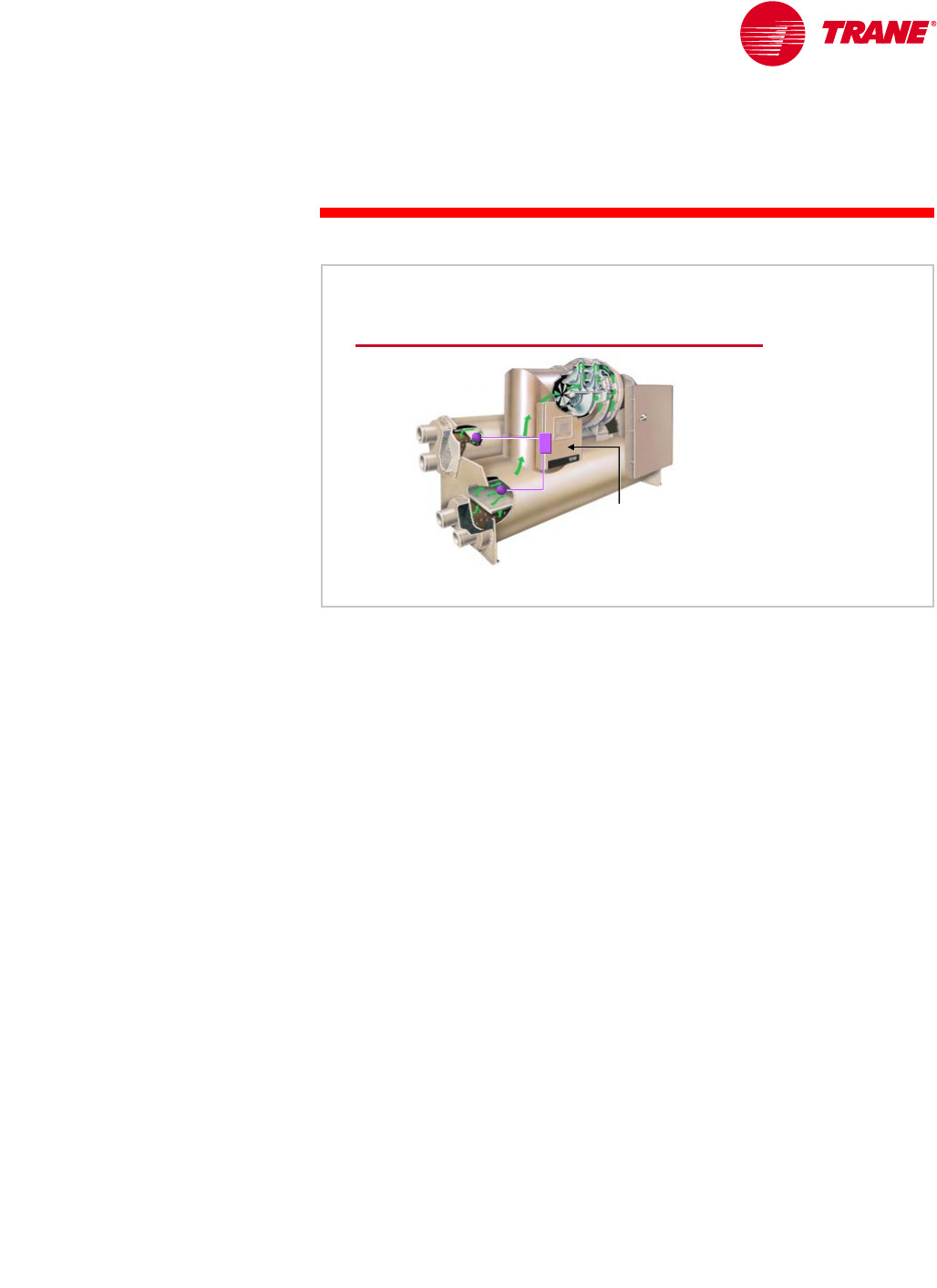
TRG-TRC016-EN 99
period four
Chiller-Plant Control
notes
Related to the issue of condenser-water-temperature control is the control of
condensing pressure. Every chiller requires a minimum refrigerant-pressure
difference between the evaporator and the condenser, in order to ensure that
refrigerant and oil circulate properly inside the chiller. This pressure difference
varies based on the chiller design and operating conditions. The chiller must
develop the required pressure difference within a certain amount of time, as
specified by the manufacturer, or the chiller controls will turn it off due to a
safety limit. During some start-up conditions, this pressure difference may be
difficult to achieve within the time required.
An example of such a condition is an office building that has been unoccupied
during a cool autumn weekend. The temperature of the water in the sump of
the cooling tower is 40°F [4.4°C]. Monday is sunny and warm, and the building
cooling load requires a chiller to be started. Because the chiller is operating
at part load and the tower sump is relatively large, the minimum pressure
difference may not be reached before the chiller is turned off on a safety.
If, however, the flow of water through the condenser is reduced, the minimum
pressure difference can be obtained. The lower flow rate increases the
temperature of the water leaving the condenser, which results in a higher
refrigerant pressure inside the condenser. After the minimum pressure
difference is reached, the flow may again be increased.
Either the refrigerant pressure in the condenser or the condenser-evaporator
refrigerant-pressure differential can be monitored and used to control the
temperature or flow rate of the condenser water, to prevent this pressure
differential from dropping below the limit.
Control of Condensing Pressure
condenser
condenser
control
control
panel
panel
evaporator
evaporator
Figure 107
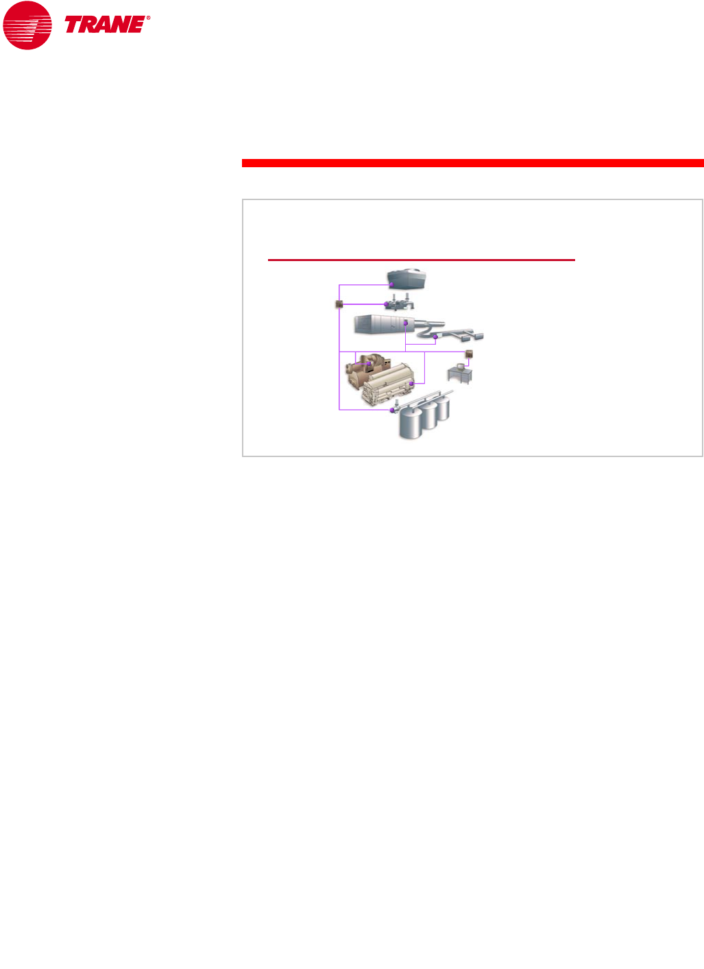
100 TRG-TRC016-EN
notes
period four
Chiller-Plant Control
Operator Interface
System-level communication and control is very important. Today, the amount
of communication between the components (chillers, cooling towers, pumps,
control valves, and so forth) has increased immensely, allowing many chilled-
water systems to be fully automated.
In some facilities, however, the largest energy user in the HVAC system (the
chiller plant) has not progressed beyond manual control. In some cases it was
reduced to manual control shortly after the building was commissioned.
Why does this occur? Chillers are large, with very expensive pieces of
equipment which, if damaged by incorrect operation, can cost the owner a
substantial amount of money to repair or replace. Operators are, therefore, very
sensitive to chiller plant operation. If the operator does not understand how the
system is designed and controlled, it is likely that the system will be put into a
manual control mode. Therefore, initial and ongoing operator training and
support is critical.
Operator Training and Support
Figure 108
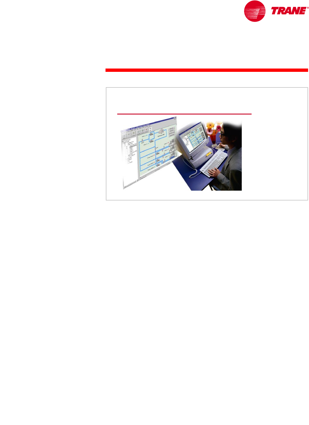
TRG-TRC016-EN 101
period four
Chiller-Plant Control
notes
There is an amazing amount of information available within a chilled-water
system. Often the problem is not a lack of information, but how to interpret
that information. Therefore, a clear and concise interface between the control
system and the system operator is extremely important.
Information that should be communicated to the operator includes:
nChiller-water system temperatures
nChiller status (on or off)
nInformation specified by ASHRAE Guideline 3
nAny pending control actions (chiller about to turn on or off)
nStatus of system time delays
nStatus of ancillary equipment (pumps, cooling towers, and so forth)
In addition, the chiller-plant control system should notify the operator of
problems that are occurring, or are about to occur, in the system. These
warning or diagnostic messages may point to a single piece of equipment
malfunctioning, or be indicative of system changes that may cause problems.
Diagnostics that occur at the chiller control panel should be communicated
to the chiller-plant control system.
Operator Interface
Figure 109
102 TRG-TRC016-EN
notes
period four
Chiller-Plant Control
ASHRAE Guideline 3, Reducing Emission of Halogenated Refrigerants in
Refrigeration and Air Conditioning Equipment and Systems, includes a list of
recommended data points to be logged daily for each chiller. Much of this data
may be available from the display on the chiller control panel. It is also helpful
to the operator if this information is available at the chiller-plant control system
and presented in a clear format.
In addition to current status, historical operating information is valuable for
keeping the equipment operating at peak efficiency and for identifying
operating trends that signal either impending problems or a drop in system
performance. For example, the condenser approach temperature is the
temperature difference between the water leaving the condenser and the
refrigerant inside the condenser. If there has been a problem with water
treatment in the cooling tower, fouling may build up inside the tubes in the
chiller condenser. This will cause the difference between the condenser water
and refrigerant temperatures to increase, reducing chiller efficiency. By noting
an increase in this approach temperature, the operator can schedule cleaning of
the condenser tubes. By monitoring system and equipment trends, the operator
has a chance to fix minor issues before they cause operational problems.
chiller operating log
ASHRAE Guideline 3
▲Chilled-water inlet and outlet
temperatures and pressures
▲Chilled water flow
▲Evaporator-refrigerant
temperature and pressures
▲Evaporator approach
temperature
▲Condenser-water inlet and
outlet temperatures and
pressures
▲Condenser water flow
▲Condenser-refrigerant
temperature and pressures
▲Condenser approach
temperature
▲Compressor-refrigerant suction
and discharge temperatures
▲Oil pressures, temperature, and
levels
▲Refrigerant level
▲Vibration levels
▲Addition of refrigerant or oil
Figure 110
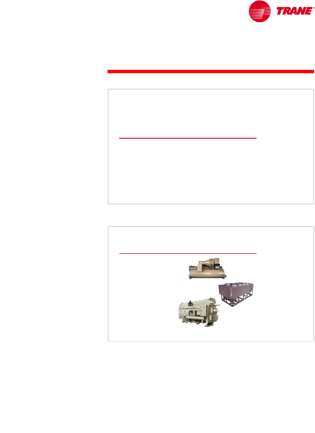
TRG-TRC016-EN 103
notes
We will now review the main concepts that were covered in this clinic on
chilled-water systems.
In Period One, we learned about the different types of vapor-compression and
absorption water chillers. Vapor-compression chillers are differentiated
primarily by the type of compressor used and whether they use an air-cooled
or water-cooled condenser. Absorption chillers are primarily differentiated by
whether they are indirectly or directly fired.
We compared the use of air-cooled versus water-cooled chillers. Air-cooled-
chiller advantages include lower maintenance costs, a prepackaged system for
easier design and installation, and better low-ambient operation. Water-cooled-
chiller advantages include greater energy efficiency (at least at design
conditions) and longer equipment life.
period five
Review
Chilled-Water Systems
Figure 111
Review—Period One
▲Vapor-compression
water chillers
◆Air-cooled versus water-
cooled
▲Absorption water
chillers
▲Equipment rating
standards
▲ASHRAE/IESNA
Standard 90.1-1999
Figure 112
period five
Review
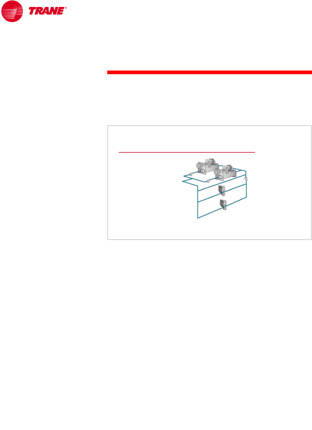
104 TRG-TRC016-EN
notes
period five
Review
ARI Standards 550/590 and 560 are common industry standards used for rating
water chiller performance. ASHRAE/IESNA Standard 90.1–1999, the energy
standard, contains minimum full-load and part-load chiller efficiency
requirements, as well as requirements for the design and operation of chilled-
water systems.
Period Two examined the methods of load-terminal control, including using
three-way modulating valves, two-way modulating valves, and face-and-bypass
dampers. We then examined several common system configurations, including
chillers piped in parallel, in series, and in a primary-secondary arrangement.
The majority of the time was spent discussing the design and operation of the
primary-secondary (or decoupled) chilled-water system. The primary-secondary
system eliminates many of the hydraulic problems associated with multiple-
chiller systems. It provides a reliable and energy-efficient supply of chilled
water, and its simplicity and flexibility make it easy to design, expand, and
operate.
Review—Period Two
primary
primary-
-secondary system
secondary system
▲Load-terminal control
◆Three-way valve
◆Two-way valve
◆Face-and-bypass
dampers
▲Parallel configuration
▲Series configuration
▲Primary-secondary
configuration
Figure 113

TRG-TRC016-EN 105
period five
Review
notes
Period Three reviewed several variations in the design of chilled-water systems.
These variations may allow the system design engineer to provide added value
to the building owner and operator in the areas of improved reliability, greater
flexibility, reduced installed costs, and lower operating costs.
Topics included:
nHybrid chilled-water systems using chillers that operate on different fuels
nLow-flow systems that use lower chilled-water temperatures and lower flow
rates
nVariable-primary-flow systems that are designed to vary the water flow
through the chiller evaporator
nConfigurations that allow a chiller to be preferentially loaded, specifically
in the case of a high-efficiency, heat-recovery or alternate-fuel chiller
nHeat-recovery chillers that are capable of providing heat to another part of
the system
nAsymmetric system designs using chillers of different capacities or
efficiencies, such as the “swing” chiller concept
nSeveral “free” cooling options that reduce cooling energy costs
nApplications in which the required conditions are outside of the normal
operating range of the chiller
Review—Period Three
▲Hybrid systems
▲Low-flow systems
▲Variable-primary-flow systems
▲Preferential loading
▲Heat recovery
▲Asymmetric design
▲“Free” (reduced-energy) cooling
▲Application of a chiller outside its normal
operating range
Figure 114
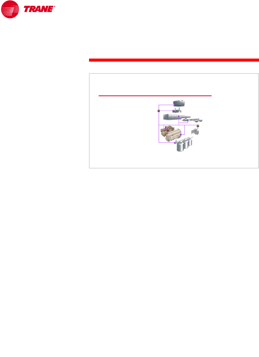
106 TRG-TRC016-EN
notes
period five
Review
Period Four discussed the issues related to chiller-plant control, including chiller
sequencing, failure recovery, contingency planning, system tuning, and system-
level optimization.
Remember that you cannot “control your way out of” a poor system design.
Although the control system can attempt to minimize the impact of a poor
design, it cannot eliminate the cause of the poor design.
Second, even a properly installed system with good components requires
system-level control to make those components work together effectively.
Third, even if the components are working together, the system, not the
individual components, needs to be optimized. Remember: the meter is on
the building.
Finally, a very important issue that is related to chiller-plant control is the issue
of interfacing with the person who is operating the system. Simplicity is
important, and it gives the system a much better chance of working without
intervention by the operator.
Review—Period Four
▲Chiller sequencing
▲Failure recovery
▲Contingency
planning
▲System tuning
▲System optimization
▲Operator interface
Figure 115
TRG-TRC016-EN 107
period five
Review
notes
For more information, refer to the following references:
nMultiple-Chiller-System Design and Control Applications Engineering Manual
(Trane literature order number SYS-APM001-EN)
nRefrigeration Cycle Air Conditioning Clinic (Trane literature order number
TRG-TRC003-EN)
nRefrigeration Compressors Air Conditioning Clinic (Trane literature order
number TRG-TRC004-EN)
nCentrifugal Water Chillers Air Conditioning Clinic (Trane literature order
number TRG-TRC010-EN)
nAbsorption Water Chillers Air Conditioning Clinic (Trane literature order
number TRG-TRC011-EN)
nHelical-Rotary Water Chillers Air Conditioning Clinic (Trane literature order
number TRG-TRC012-EN)
nASHRAE Handbook – Refrigeration
nASHRAE Handbook – Systems and Equipment
Visit the ASHRAE Bookstore at www.ashrae.org.
For information on additional educational materials available from Trane,
contact your local Trane sales office (request a copy of the Educational
Materials price sheet—Trane order number EM-ADV1) or visit our online
bookstore at www.trane.com/bookstore/.
Figure 116
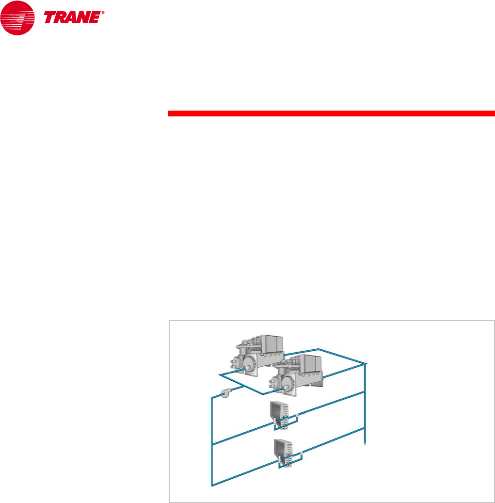
108 TRG-TRC016-EN
Questions for Period 1
1What are the four types of compressors commonly used in vapor-
compression water chillers?
2List one advantage of an air-cooled chiller and one advantage of a
water-cooled chiller.
3True or False: The IPLV equation included in the ARI standards for rating
chillers was derived to provide a representation of the average part-load
efficiency for a system with multiple chillers.
Questions for Period 2
4What are the three most common methods of load-terminal (coil) control?
5The system shown in Figure 117 contains two chillers piped in parallel with
a single, constant-volume pump. What is the drawback of this system
configuration when only one chiller is operating?
6In a conventional primary-secondary chilled-water system, each production
pump delivers a __________ (constant or variable) flow of water and the
distribution pump delivers a __________ (constant or variable) flow of water.
7What method of load-terminal control should be used in the distribution
loop of a primary-secondary chilled-water system?
8Deficit flow in the bypass pipe of a primary-secondary system is an
indication to turn an additional chiller __________ (on or off).
Figure 117
Quiz

TRG-TRC016-EN 109
Quiz
Questions for Period 3
9Why does a variable-primary-flow (VPF) system require a bypass in
the system?
10 Identify one scenario where preferential loading is beneficial to a
chilled-water system.
11 What is the benefit of using a smaller-capacity “swing” chiller in a
multiple-chiller system?
Questions for Period 4
12 Making decisions about when to turn chillers on and off is commonly
referred to as chiller __________.
13 Lowering the temperature of the water leaving the cooling tower __________
(increases or decreases) the energy consumption of the chiller and
__________ (increases or decreases) the energy consumption of the cooling
tower fans.
14 An increase in the condenser approach temperature (that is, the
temperature difference between the water and the refrigerant inside the
condenser) may be a sign of what?

110 TRG-TRC016-EN
1Centrifugal, helical-rotary, reciprocating, and scroll
2Air-cooled chiller advantages include lower maintenance costs, a pre-
packaged system for easier design and installation, and better low-ambient
operation. Water-cooled chiller advantages include greater energy efficiency
(at least at design conditions) and longer equipment life.
3False. The IPLV equation was derived to provide a representation of the
average part-load efficiency for a single-chiller system only.
4Three-way modulating control valve, two-way modulating control valve,
and face-and-bypass dampers
5When only one chiller is operating, warm return water continues to flow
through the non-operating chiller and mixes with the chilled water leaving
the operating chiller. The temperature of the mixture of these two streams
is higher than the desired supply-water temperature, possibly resulting in
building comfort or space humidity control problems.
6Constant; variable
7Two-way modulating control valves
8Tur n on
9To ensure that the water flow through the system remains above the
minimum flow limit of the operating chiller(s)
10 Preferential loading is typically most beneficial in the following scenarios:
nIn a system that has a high-efficiency chiller along with several
standard-efficiency chillers, the high-efficiency chiller can be
preferentially loaded to reduce system energy consumption.
nIn a system with a heat-recovery chiller, preferentially loading the
heat-recovery chiller maximizes the amount of heat recovered, thus
reducing the overall system energy consumption.
nIn a system with an alternate-fuel chiller, such as an absorption chiller,
preferentially loading the alternate-fuel chiller during times of high
electricity costs minimizes system energy cost.
11 The swing chiller is alternated on and off between the larger chillers'
operation, in order to serve as a smaller incremental step of loading.
This sequence more favorably matches the capacity of the chiller plant to
the system load and operates the fewest, and smallest, pieces of ancillary
equipment (pumps and cooling towers) at any system load.
Answers

TRG-TRC016-EN 111
Answers
12 Sequencing
13 Decreases; increases
14 Fouling inside the tubes of the condenser, possibly indicating a problem
with water treatment in the cooling tower

112 TRG-TRC016-EN
absorbent A substance used to absorb refrigerant and transport it from the
low-pressure to the high-pressure side of the absorption refrigeration cycle.
In absorption water chillers, the absorbent is commonly lithium bromide.
absorber A component of the absorption refrigeration cycle in which
refrigerant vapor is absorbed by the absorbent solution and rejects heat to
cooling water.
air-cooled condenser A type of condenser in which refrigerant flows through
the tubes and rejects heat to air that is drawn across the tubes.
airside economizer A method of free cooling that involves using cooler
outdoor air for cooling instead of recirculating warmer indoor air.
ARI Air-Conditioning and Refrigeration Institute
ARI Standard 550/590 A publication titled Standard for Water Chilling
Packages Using the Vapor-Compression Cycle that promotes consistent rating
and testing methods for all types and sizes of water chillers. It covers factory-
designed, prefabricated water chillers, both air-cooled and water-cooled, using
the vapor-compression refrigeration cycle.
ARI Standard 560 A publication titled Absorption Water Chilling and Water
Heating Packages that promotes consistent rating methods for many types and
sizes of absorption water chillers in which water is the refrigerant and lithium
bromide is the absorbent. It covers single-effect chillers operating on steam or a
hot fluid; indirect-fired double-effect chillers operating on steam or a hot fluid;
and direct-fired double-effect chillers operating on natural gas, oil, or liquid
petroleum (LP).
ASHRAE American Society of Heating, Refrigerating and Air-Conditioning
Engineers
ASHRAE Guideline 3 A publication titled Reducing Emission of Halogenated
Refrigerants in Refrigeration and Air Conditioning Equipment and Systems that
includes a recommended list of data points to be logged daily for each water
chiller.
ASHRAE Standard 15 A publication titled Safety Code for Mechanical
Refrigeration that specifies safe design, construction, installation, and operation
of refrigerating systems.
ASHRAE/IESNA Standard 90.1 A publication titled Energy Standard for
Buildings, Except Low-Rise Residential Buildings that provides minimum
requirements for the energy-efficient design of buildings (except low-rise
residential buildings), including the HVAC system.
centrifugal compressor A type of compressor that uses centrifugal force,
generated by a rotating impeller, to compress the refrigerant vapor.
Glossary

TRG-TRC016-EN 113
Glossary
chilled-water system Uses water as the cooling media. The refrigerant inside
the evaporator absorbs heat from the water, and this water is pumped to coils
in order to absorb heat from the air used for space conditioning.
coefficient of performance (COP) A dimensionless ratio used to express the
efficiency of a refrigeration machine. A higher COP designates a higher
efficiency. For an electric chiller, it is defined as evaporator cooling capacity
divided by the electrical energy input. For an absorption water chiller, it is
defined as evaporator cooling capacity divided by the heat energy required by
the generator, excluding the electrical energy needed to operate the pumps,
purge, and controls.
compressor A mechanical device used in the vapor-compression refrigeration
cycle to increase the pressure and temperature of the refrigerant vapor.
condenser A component of the refrigeration cycle in which refrigerant vapor is
converted to liquid as it rejects heat to air, water, or some other fluid.
cooling tower A device used to reject the heat from a water-cooled condenser
by spraying the condensing water over the fill while drawing outdoor air
upward through the fill.
decoupled system See primary-secondary system.
deficit flow A condition in a primary-secondary chilled-water system in which
the production loop provides less flow than is required by the distribution loop.
To make up for this deficit, water travels from the return side of the distribution
loop, through the bypass pipe, and mixes with the water supplied by the
production loop.
direct-fired A type of absorption chiller that uses the combustion of a fossil
fuel (such as natural gas or oil) directly to provide heat to the high-temperature
generator.
double-effect A type of absorption chiller that uses two generators,
a high-temperature generator and a low-temperature generator.
evaporator A component of the refrigeration cycle where cool, liquid
refrigerant absorbs heat from air, water, or some other fluid, causing the
refrigerant to boil.
excess flow A condition in a primary-secondary chilled-water system in which
the production loop is providing more flow than is required by the distribution
loop. This excess water travels from the supply side of the production loop,
through the bypass pipe, and mixes with the water returning from the
distribution loop.
expansion device A component of the refrigeration cycle used to reduce
the pressure and temperature of the refrigerant to the evaporator conditions.

114 TRG-TRC016-EN
Glossary
expansion tank A component of a closed piping system that accommodates
the expansion and contraction of the water as temperature and, therefore,
density, changes.
fouling Minerals in the water that form scaling on the internal surfaces of the
heat exchanger tubes.
generator A component of the absorption refrigeration cycle in which
refrigerant vapor boils and is separated from the absorbent solution as it
absorbs heat from the primary heat source.
heat recovery The process of capturing the heat that is normally rejected from
the chiller condenser and using it for space heating, domestic water heating,
or another process seems unnecessary.
helical-rotary (screw) compressor A type of compressor that uses two mated
rotors to trap the refrigerant vapor and compress it by gradually shrinking the
volume of the refrigerant.
hybrid system A chilled-water system that can use more than one type of fuel.
indirect-fired A type of absorption chiller that uses steam or a hot fluid
(such as water) from an external source to provide heat to the generator.
Integrated Part-Load Value (IPLV) An equation that predicts chiller efficiency
at the ARI standard rating conditions, using weighted-average load curves
that represent a broad range of geographic locations, building types, and
operating-hour scenarios, both with and without an air side economizer.
Nonstandard Part-Load Value (NPLV) An equation that predicts chiller
efficiency at nonstandard rating conditions, using weighted-average load
curves that represent a broad range of geographic locations, building types,
and operating-hour scenarios, both with and without an air side economizer.
primary-secondary (decoupled) system A configuration of a multiple-chiller
system that uses separate production and distribution pumps to hydraulically
decouple the production capacity of the chillers from the load of the distribution
system.
reciprocating compressor A type of compressor that uses a piston that travels
up and down inside a cylinder to compress the refrigerant vapor.
refrigerant migration A method of free cooling that allows the chiller to be
used as a heat exchanger without operation of the compressor. It is possible,
when the condensing temperature of the refrigerant is low enough, for
refrigerant to migrate from the evaporator to the condenser.
scroll compressor A type of compressor that uses two opposing scrolls to trap
the refrigerant vapor and compress it by gradually shrinking the volume of the
refrigerant.
single-effect A type of absorption chiller that uses a single generator.

TRG-TRC016-EN 115
Glossary
notes swing chiller A smaller-capacity chiller used in a multiple-chiller system.
It is alternated on and off between the larger chillers' operation to serve as
a smaller, incremental step of loading.
variable-primary-flow (VPF) system A type of chilled-water system that is
designed to vary the flow of water throughout the entire system—through
the evaporator of each operating chiller as well as through the cooling coils.
variable-speed drive A device used to vary the capacity of a centrifugal pump
by varying the speed of the motor that rotates the pump impeller.
water-cooled condenser A type of condenser in which water flows through the
tubes and absorbs heat from the refrigerant that fills the surrounding shell.

The Trane Company
An American Standard Company
www.trane.com
For more information contact
your local distict office or
e-mail us at comfort@trane.com
Literature Order Number TRG-TRC016-EN
File Number E/AV-FND-TRG-TRC016-0201-EN
Supersedes CWS-CLC-1, CWS-CLC-2, CWS-CLC-3, and CWS-CLC-4
Stocking Location La Crosse
Since The Trane Company has a policy of continuous product and product data improvement, it reserves the right
to change design and specifications without notice.
